Victor%20Series%20Workshop%20Manual%201966%20 %201968%2000 4128%20x[1]
User Manual: Victor%20Series%20Workshop%20Manual%201966%20-%201968%2000-4128%20x[1]
Open the PDF directly: View PDF ![]() .
.
Page Count: 176 [warning: Documents this large are best viewed by clicking the View PDF Link!]
{
0
T
x
o
I
0
U
3
D
z
c
l-
VICTOR SEFIIES HEZ
1966, 1967 and 1968 MODELS
REVISED EDITION
www.bsaunitsingles.com
WORKSHOP MANUAL
FOR 844 MODELS
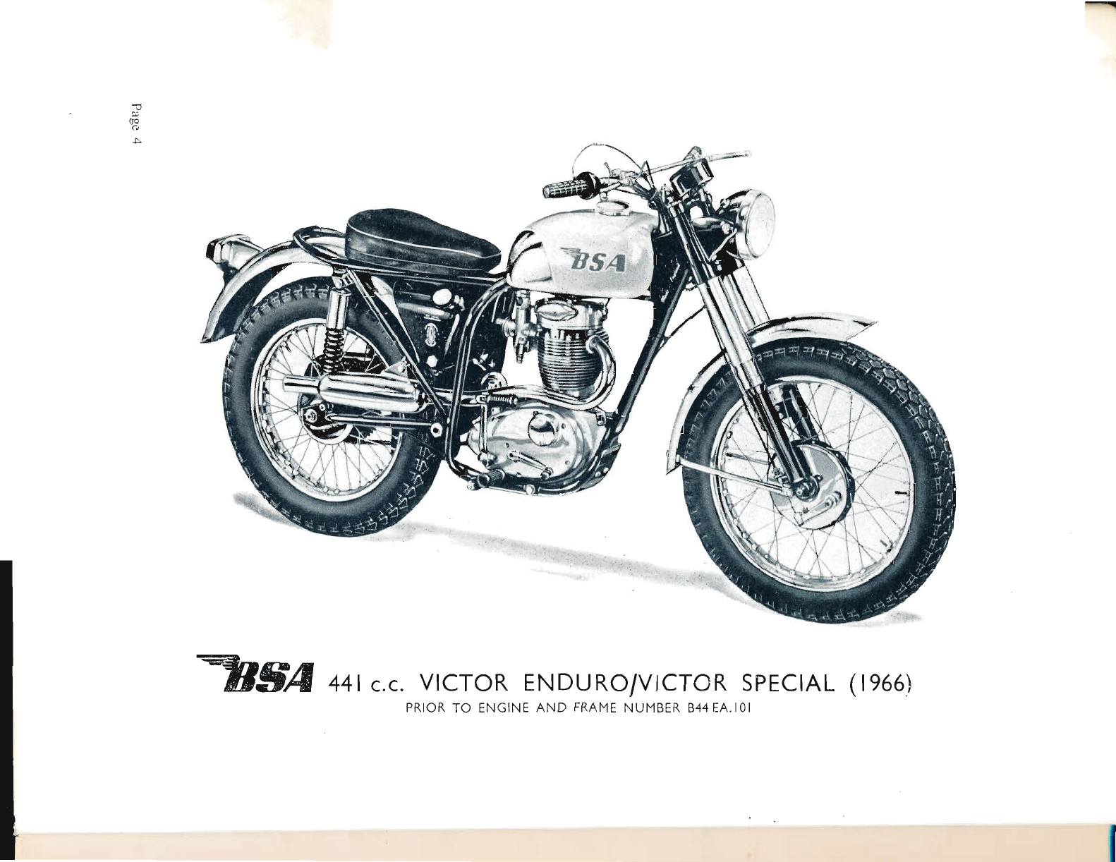
VICTOR GRAND PRIX
VICTOR ENDURO
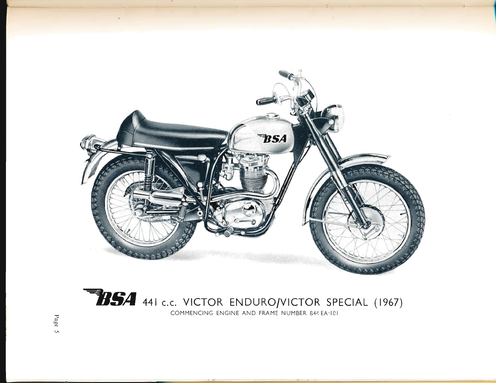
vrcToR SPECIAL (t967)
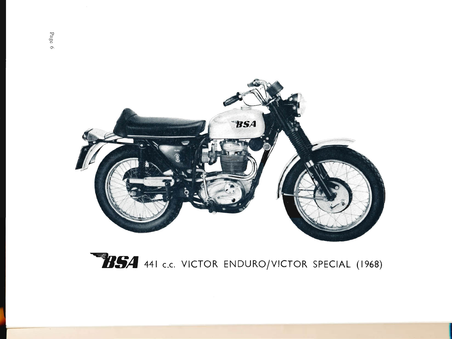
vrcToR SPECIAL ( le6B)
Service Department
B.S.A. MOTOR CYCLES
Publication Reference No. 00-4128/0/00.
LTD.
BIRMINGHAM II,
Telephone 02 a -772-2181
ARMOURY ROAD
www.bsaunitsingles.com
-
Please Note!
Replacement parts or accessories must be of
B.S.A. origin or as approved by B.S.A. Motor
Cycles Ltd.
In this respect your attention is drawn to the
Terms and Conditions of B.S.A. Guarantee.
I
www.bsaunitsingles.com
l--
1
X
a
o-
o
z
d.
(,
d.
o
F
9
(..)
(J
+
t
s
cs
r'F
www.bsaunitsingles.com
\o
\o
3
U
LU
o-
Aa
dfr
O+
rO
9H
>=
o;
d.4
r*
Oo
zi
LIJ ur
z
dt
o=
Fo
9:
>9
t
.*
u
L;
+
.t
ffi
tr
Pagc 4
www.bsaunitsingles.com
\o
3
S
U
LU
o-a
-s
d$
o-'
F ---
U=
)z
O=
di
Jo
nz
2:
t.tt z
(,
dfr
Ou
t-Z
Q9
t=
.o
(-,U
I
s
t
F
Page 5
www.bsaunitsingles.com
-
@
\o
o\
3
J
U
LU
o-
(t)
d.
o
F
I
o
&.
f
o
z
LU
d.
o
U
t
u"
I
+
$
F
www.bsaunitsingles.com
al-
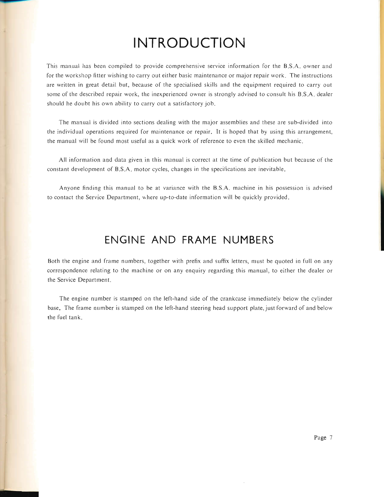
INTRODUCTION
This manual hars been compiled to provide comprehensive service information for the B.S.A. owner arld
for the workshop fitter wishing to carry out either basic maintenance or major repair work. The instructions
are written in great detail but, because of the specialised skills and the equipment required to carry out
some of the described repair work, the inexperienced owner is strongly advised to consult his B.S.A. dealer
should he doubt his own ability to carry out a satisfactory job.
The manual is divided into sections dealing with the major assemblies and these are sub-divided into
the individual operations required for maintenance or repair. It is hoped that by using this arrangement,
the manual will be found most useful as a quick work of reference to even the skilled mechanic.
All information and data given in this manual is correct at the time of publication but because of the
constant development of B.S.A. motor cycles, changes in the specifications are inevitable.
Anyone finding this manual to be at variance with the B.S.A. machine in his possession is advised
to contact the Service Department, uhere up-to-date information will be quickly provided"
ENGINE AND FRAME NUMBERS
Both the engine and frame numbers, together with prefix and suffix letters, must be quoted in full on any
correspondence relating to the machine or on any enquiry regarding this manual, to either the dealer or
the Service Department.
The engine number is stamped on the left-hand side ol the crankcase immediately below the cylinder
base. The frame number is stamped on the left-hand steering head support plate, just forward of and below
the fuel tank"
Page 7
www.bsaunitsingles.com
FACTORY SERVICE ARRANGEMENTS
UNITED KINGDOM
REPLACEMENT PARTS
B.S.A. replacement parts and exchange units are distributed through a national network of B.S.A. dealers,
each of whom holds a stock of fast moving parts. Approximately 200 of these dealers have been selected
for appointment as specialist B.S.A. replacement part stockists and each of these stockists holds a compre-
hensive stock of B.S.A. replacement parts.
A complete list of appointed stockists is printed at the end of this manual, and also in every B.S.A.
Parts Catalogue.
REPAIRS
Most appointeC B.S.A. dealers are able to carry out major repair work, and owners are asked to make
all repair arrangements through their chosen dealer.
In the great majority of cases local repair will be possible and this will avoid the expense, inconvenience
and the possibility ol the machine being damaged in transit to or from the Works for repair.
Should your B.S.A. dealer decide that Service Department attention is required he will know best
how to make suitable arrangements with the factory. It is important to remember that no machine can
be accepted at the Works without a prior appointment. This appointment can be made either by letter
or by telephone.
GUARANTEE CLAIMS
In the interests of all conccrned it is best that any owner of a new motor cycle, wishing to claim assistance
under the guarantee, should do so through the dealer from whom his machine was purchased. All B.S.A.
dealers are familiar with the proc€dure designed by B.S.A. to give quick service to any owner of a B.S.A.
motor cycle who may find himself in difficulty.
Page 8
www.bsaunitsingles.com
TECHNICAL ADVICE
B.S.A. Service Department staff are experienced in dealing with technical problems ol all kinds arrd will
be pleased to help in the event of difficulty. The correct address of the Service Department is as follows:-
B.S.A. MOTOR CYCLES LIMITED,
SERVICE DEPARTMENT.
ARMOURY ROAD,
BIRMINGHAM II.
Telephone No. 021-11?--2381
In all communications the model must be quoted with full engine and frame numbers
together with all prefix or suffix letters.
WORLD SERVICE ARRANGEMENTS
In most markets of the world, B.S.A. has an appointed distributor to whonr all service enquiries should
be addressed.
The names of these distributors will be lound at the back of this manual, and are also Iisted iu all
B.S.A. Replacement Part Catalogues.
Page 9
www.bsaunitsingles.com
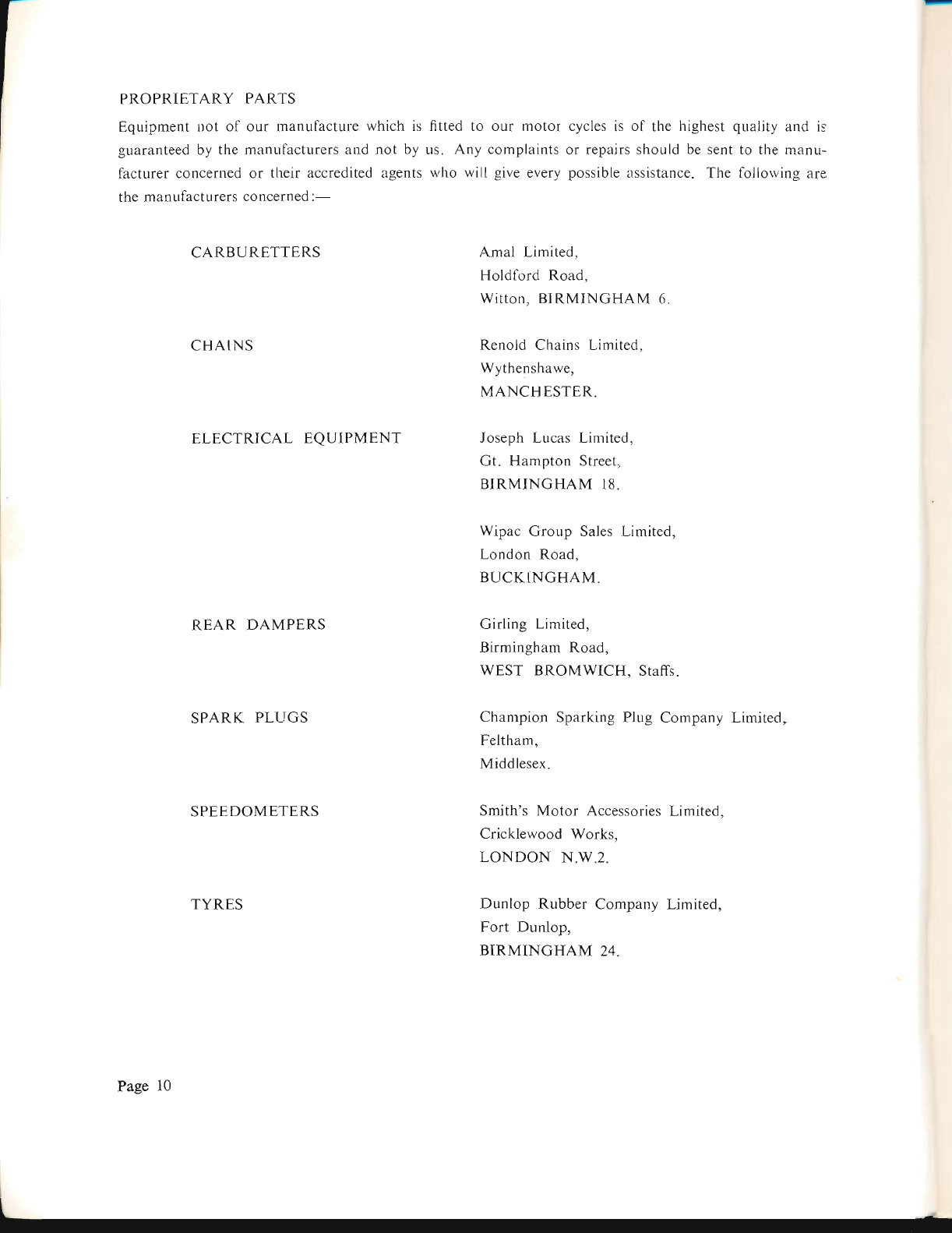
PROPRIETARY PARTS
Equipment uot of our manufacture which is
guaranteed by the manufacturers and not by
lacturer concerned or their accredited agents
the manufacturers concerned :-
CARBURETTERS
CHAINS
ELECTRICAL EQUIPMENT
REAR DAMPERS
SPARK PLUGS
SPEEDOMETERS
TYRES
cycles is of the highest quality and is
or repairs should be sent to tl.re manu-
possible assistance. The follorving are
fitted to our motor
us. Any complaints
who will give every
Amal Limited,
Holdford Road,
Witton, BIRMINGHAM 6.
Renold Chains Limited,
Wythenshawe,
MANCHESTER.
Joseph Lucas Limited,
Gt. Hampton Street,
BIRMINGHAM 18.
Wipac Group Sales Limited,
London Road,
BUCKINGHAM.
Girling Limited,
Birmingham Road,
WEST BROMWICH, Staffs.
Champion Sparking Plug Company Limited,
Feltham,
Middlesex.
Smith's Motor Accessories Limited,
Cricklewood Works,
LONDON N"W.2.
Dunlop Rubber Company Limited,
Fort Dunlop,
BIRMINGHA}'d 24.
Page 10
www.bsaunitsingles.com
T_
U.S.A. SERVICE ARRANGEMENTS
REPLACEMENT PARTS
B.S.A. replacement porls are ovailable tltrough a National Netvuorlc o.f B.S.A. dealers covering the entire
United States.
These B.S.A. rnotor cycle dealers are listed under "Motorc:ycles" in the yellow pages of -,-our locttl.
lelephone directory.
All requests for pLtrts inust be macle through li'anchised B.S.A. dealers. lhey are not sold clirecl to B.S.A.
ovners by the two Jactory branches.
GUARANTEE CLAIMS
In the interest o.f all concerned the ov'ner oJ a nev, motorc.ycle wishing to clairn assistance under the guorentee
must do so through the dealer f'ront whom his mqchine wos ptrrchased"
REPAlRS
B.S.A. dealers are capoble o.f servicing ancl repairing B.S.A.motoreycles, a.slc your dealer to help when repairs'
are needed.
Labour time v'ill be greatly redut'ed iJ proprietaD) articles, such qs legshields, t:rash bars, carriers or Jibre
glass.fairing! are removed be.fore handing the rnachine over.fbr repair. Ar:cessories suc'h as mirrors or badges
shoulcl always be removed before entrusting a nruchine to an independant carrier.
TECHNICAL A DI/ICE
The B.S.A. Service Departntent staff at tlte two U.S.A, f'actory brancltes are experienced in clealing w,itlt
tec'hnical questions o1'all lcinds ancl r,ill be pleused to help in the event oJ- difficulty
The Factory Branch Addresses ttre shotrn below':-
F,ASTERN
WESTERN
B.S.A. INCORPORATED.
639 Passaic Avenue,
Nutley,
NEw Jgnspy 07110.
B.S.A. MOTORCYCLES _ WESTERN,
2145 E Huntington Drive,
Duarte, C,q,I-tFonNtA. 91010.
In all comntunications the .full engine and .frante numbers with all prefx and sffix letlers and .figures
musl be quoted as v,ell as the year ttnd model o.l' the motorcyc'le in questiotl'
Page I 1
www.bsaunitsingles.com
WORLD DISTRIBUTORS
REMOVING THE MOTORCYCLE FROM THE CASE
Norn -Check that the packing case is the RIGHT SIDE UP before dismantling The TOP hers stencilled
markings on it, the bottom does not'
I Prise off the top boards with a suitable pinch bar
2 Take out the top packing and loose parts from around the motorcycle
3 Remove one side of the case and take out the motorcycle and auy remaining loose parts. Check that
you have all the small parts belore discarding the wrappings. Retain tlre Test Card in case you find
it necessary to report any loss of parts or damage during transit.
FITT'ING THE FRONT MIJDGUARD AND WHEEL
l. Put the machine on the prop stand and place a suitable support under the engine.
2. Locate the front mudguard between the fork legs and fit the braces"
3. Pull out the wheel spindie from the fork ends and fit the lront wheel. Insert the spindle from the left-
hand side and use a suitable bar to screw the spindle right home. The spindle has a left-hand thread.
4. Check that the brake plate stop is correctly located in its recess at the rear of the right-hand fork leg.
5. Depress the fbrks once or twice to enable the left-hand lork end to position itself on the spindle before
finally tightening the pinch bolt. If this precaution is not observed. the fork leg rnay be clipped out
of position and will not function correctly.
6. The support can now be removed from under the engine.
FITTING THE HANDLEBAR AND ATTACHING THE CABLES
l. Place the handlebar in position, fit the handlebar clips and after adjusting for suitable positiorr secure
with the four fixing bolts.
2" Feed the cables through the appropriate guides and re-position the control levers.
Page 12
www.bsaunitsingles.com
T
3.
4.
,5.
Attach the clutch, front brake, and exhaust valve lifter cables to tl-reir respective levers.
The front brake cable will be found among the loose parts and must also be connected at the fi'ont brake.
Fit the throttle control complete with cable and tighten the firing screws.
Check eacli control for correct operation and adjust as llecessary.
FITTING THE SILENCER.
Locate the silencer witl-r clip. over the er.rd ol tl-re exhaust pipe.
Secure to the frarne bracket with the nut and bolt and tighten the clip firrrrly on to the pipe.
FITTING THE REAR LIGHT
l. Pass the rear light cables through the hole iir the mudguard arrd colinect each cable to its respective
sr-iap connector.
l.
2.
nut
fir
2.
3.
2
)
Locate rear Iight on the mr-rdgr-rard ancl flx loosely at the top r,vith one
Position the number plate bracket over the lower rear light fixing holes
tighten secr-rrely.
from below the guard.
the two bolts with nuts and
4. Finally, tighten the top lixing nr-rt and check the cables
SI'ARK PLUG, TYRE PUMP AND TOOLS
Take out ancl discard the plastic plug from the spark plug hole, fit the spark plug and conr-rect the
high-tension lead. The plug supplied with the machine is best suited to all-round operating conditions
and sliould not be changed withor-rt tl.re advice of a plug specialist.
Snap the tyre purnp into its mount belorv the saddle on the right-hand side of the lrame.
The tools, instruction m:rnual and other literature can now be placed to one side.
FINAL CHECK
It is the duty of the dealer to see that every nut, bolt and screr'v is tight and correctly {rtted belore the ntotor
cycle leaves his shop. The dealer is responsible if a customer returns and complains of rattles. missing nuts
or fractures caused by vibration. It should be noted tliat 90f" of all vibration problems can be traced to
loose engiire mountings. Do not simply take it for granted that the factclry has done everything right.
Takc the precaution ol checking everything yourself.
STAR.TING THE MOTOR. CYCI,E
Fill the oil tank, primary drive and gearbox to tl.re required levels with correct grades of oil (see page
A.3).
Befbre starting the en-qine" nral<e sure that there is no packing material in or erround the carburetter
air intake.
While the engine is runniug, take offthe oii tank filler cap and check that the oil is circr-rlating correctly
througl.r the return pipe. After replacing the oil tank cap the machine u,ill be complete and ready for use.
Page I 3
www.bsaunitsingles.com
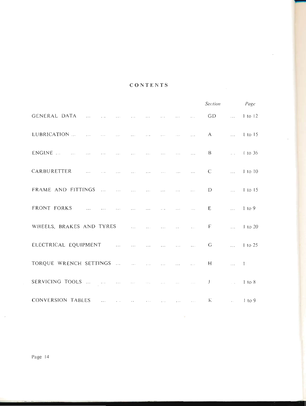
CONTENTS
GENERAL DATA
Section
GD
Page
Ito12
I to 15
Ito36
1to10
Ito15
1to9
1to20
Ito25
.l
1to8
LUBRICATION
ENGINE
FRAME AND FITTINGS
CARBURETTER
FRONT FORKS
SERVICING TOOLS
WHEELS, BRAKES AND TYRES
ELECTRICAL EQUIPMENT
TORQUE WRENCH SETTINGS
CONVERSION TABLES
Page 14
www.bsaunitsingles.com
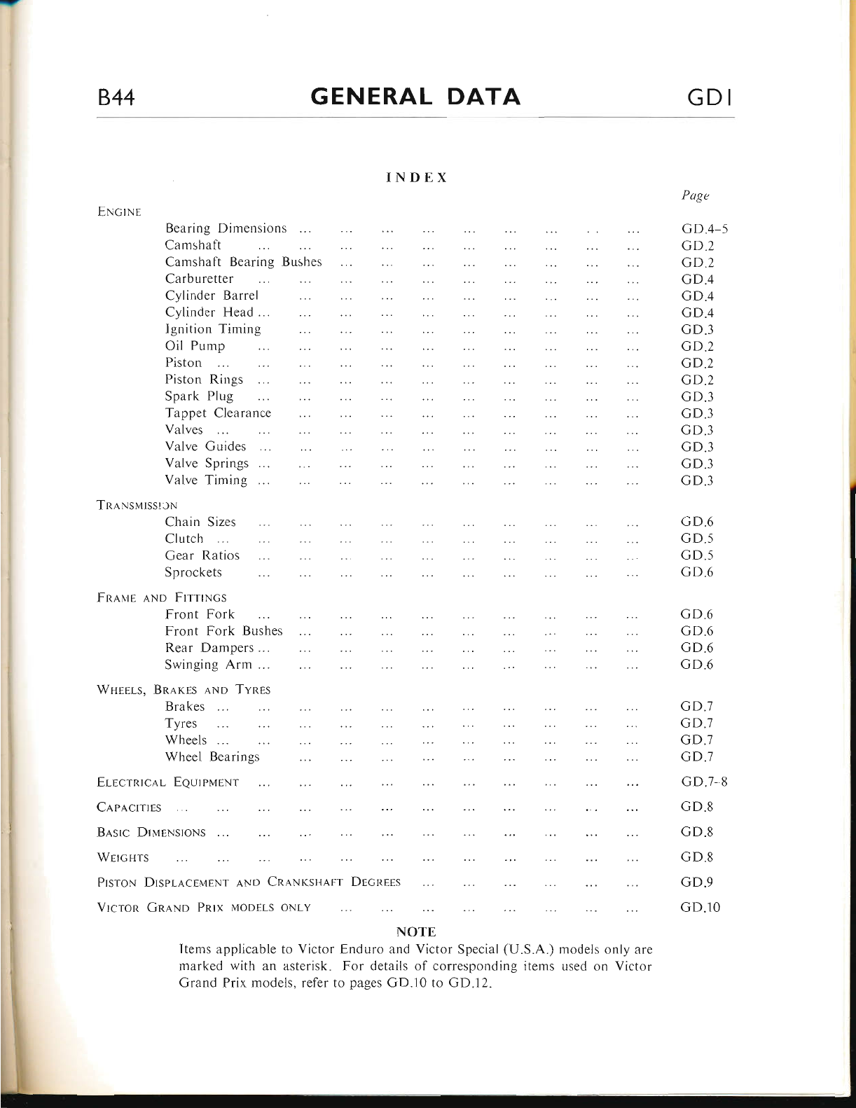
844 GENERAL DATA GDI
ENcrNs
INDEX
Bearing Dimensions
Camshaft
Camshaft Bearing Bushes
Carburetter
Cylinder Barrel
Cylinder Head
Ignition Timing
Oil Pum
Piston
Piston Rings
Spark Plug
Tappet Clearance
Valves
Valve Gr,rides
Valve Springs ...
Valve Timing
TnlNsurssltN
Chain Sizes
Clutclr
Gear Ratios
Sprockets
FR,q.us ,q.No FtrrtNcs
Front Fork
Front Fork Bushes
Rear Dampers ...
Swinging Arm ...
Wnrrls, BR,qrEs lNp Tvnes
Brakes
Tyres
Wheels
Wheel Bearings
ErecrRrclr-
ClpA.crrms
EeurpurNr
Ba,src DlueNsroNs
Wercgrs
PrsroN Drspla,ceinnNT AND CReNrslrapt DEcnErs
Vrcron GReNo PRrx uoonrs oNr-v
NOTE
Items applicable to Victor Enduro and Victor Special (U.S.A.) models only are
rnarked with an asterisk. For details of corresponding items used on Victor
Grand Prix models, refer to pages GD.10 to GD.l2.
Page
GD.4 5
GD.2
GD.2
GD.4
GD.4
GD.4
GD.3
cD.2
GD.2
GD.2
GD.3
GD.3
cD.3
GD.3
GD.3
GD.3
GD.6
GD.5
GD.5
GD.6
GD.6
GD.6
GD.6
GD.6
GD.7
GD.7
GD.7
GD.7
GD.7,8
GD.8
GD.8
GD.8
GD.9
GD.lO
www.bsaunitsingles.com
GD2 GENERAL DATA 844
ENGINE
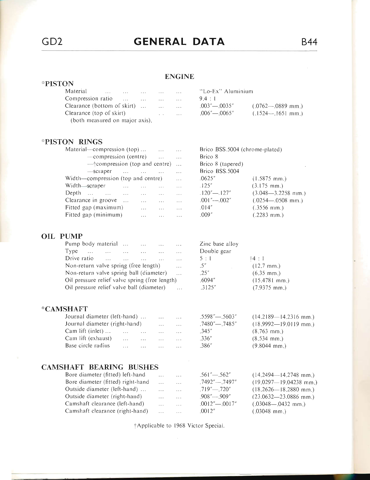
"PISTON
Material "Lo-Ex" Aluminium
9.4 : I
Compression ratio
Clearance (bottoni of skirt) .003'-.0035' (..0162-.0889 mm.)
Clearance (top of skirt) .006"-.0065' (.1524 .1651 mm.)
(both measured on major axis).
,I.PISTON RINGS
Material compression (top)... Brico 8SS.5004 (chrome-plated)
compression (centre) Brico 8
tcompression (top and centre) Brico 8 (tapered)
-scr aper Brico BSS.5004
Width-compression (top and centre) .0625' (1.5875 mm.)
Width-scraper .125' (3.175 mm.)
Depth .120'-.121' (3.048-3.2258 mm.)
Clearance in groove .001"-.002" (.0254-.0508 mm.)
Fitted gap (maximum) .014' (.3556 mm.)
Fitted gap (minimum) .009" (.2283 mm.)
OIL PUMP
Pump body material Zinc base alloy
Typ"
Drive ratio
Double gear
5:1 t4:l
Non-return valve sprirlg (free length) .5'
Non-return valve spring ball (diameter) .25'
(12.7 mm.)
(6.35 mm.)
Oil pressure relief valve spring (free length) .6094' (15.4781 mm.)
Oil pressure relief valve ball (diameter) .3125' (7.9375 mm.)
*CAMSH.AFT
Journal diameter (lefl-hand) ... .5598"-.5603' (14.2189-14.2316 mm.)
Journal diameter (right-hand) .7480'-.1485' (18.9992-19.0119 mm.)
Cam lift (inlet) . .345' (8.763 mm.)
Cam lift (exhaust) .336" (8.534 mm.)
Base circle radius .386' (9.8044 mm.)
CAMSHAFT BEARING BUSTIES
Bore diameter (fitted) left-hand .561'-.562' (.14.2494-14.2748 mm)
Bore diameter (fitted) right-hand .1492'-.7497' (19.0291-19.04238 mm.)
Outside diameter (left-hand) ... .719' .120' (18.2626-18.2880 mm.)
Outside diameter (right-hand) .908" .909' (23.0632-23.0886 mm.)
Camshaft clearance (left-hand) .0012'-.0017' (.03048-.0432 mm.)
Camshaft clearance (right-hand) .0012' (.03048 mm.)
tApplicable to 1968 Victor Special.
www.bsaunitsingles.com
844 GENERAL DATA GD3
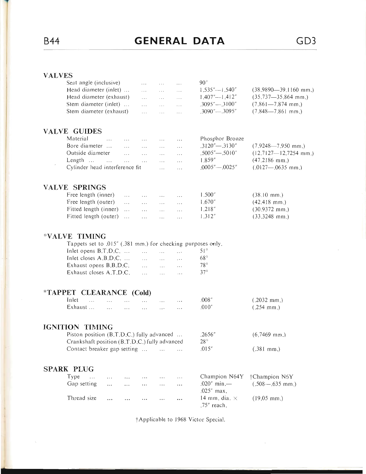
VALVES
Seat angle (inclusive)
Head diameter (inlet) ...
Head diameter (exhaust)
VALVE GUIDES
Material
Bore diameter ...
Outside diameter
Length
Cylinder
90"
1.535" t.540',
t.401'-1 .4r2',
.3095" .3100'
.3090" .3095"
Phosphor Bronze
.3120'-.3130'
(38.9890-39.1160 mm.)
(35.131-35.864 mm.)
(1 .861-1.814 mm.)
(.7 .848-7.861 mm.)
(7.9248 7.950 mm.)
(12.1121 12.7254 mm.)
(41.2186 mm.)
(.0127-.0635 mm.)
(38.10 mm.)
(42.418 mm.)
(30.9372 mm.)
(33.3248 mm.)
(.2032 mm.)
(.254 mm.)
(6.7469 mm.)
(.381 mm.)
Stem diameter (inlet) ...
Stem diameter (exhaust)
5005"-.5010"
head interference fit 1.859"
.0005'-.0025'
VALVE SPRINGS
Free length (inner)
Free length (outer)
Fitted length (inner)
Fitted length (outer)
,IVALVE TIMING
Tappets set to .015" (.381
Inlet opens B.T.D.C.
Inlet closes A.B.D.C.
Exhaust opens B.B.D.C.
Exhaust closes A.T.D.C.
mm.) for checking purposes only.
1.500'
t.670'
t.218'
1.312',
51"
68"
78'
)t
*TAPPET CLEARANCE (Cold)
Inlet
F,xhaust
IGNITION TIMING
Piston position (B.T.D.C.) fully advanced ...
Crankshaft position (B.T.D.C.) fully advanced
Contact breaker gap setting ...
SPARK P{,UG
Type
Gap setting
Thread size
Champion N64Y tChampion N5Y
.020" min.- (.508-.635 mm.)
.025" max.
14 mm. dia. x
.J 5" reach.
008"
.010'
.2656',
28"
.015',
fApplicable to 1968 Victol Special.
(19.05 mm.)
www.bsaunitsingles.com
a
GD4 GENERAL DATA 844
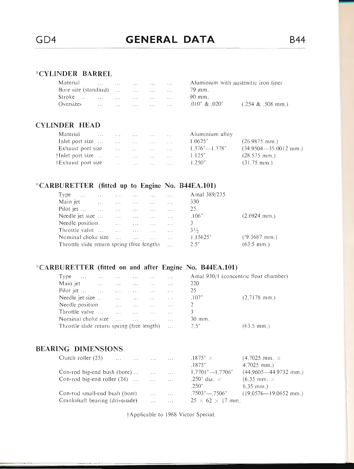
'KCYLINDER BARREL
Material Aluminium with austenitic iron iiner
79 mm.
90 mm.
.010' & .020' (.254 &..508 mm.)
Bore size (standard)
Stroke
Oversizes
CYLINDER TIE,A,D
Material Aiuminium alloy
lnlet port size ... 1.0625' (26.9875 mm.)
Exhaust port size 1.316'-1.318' (34.9504-35.0012 mm.)
f lnlei port size 1.125' (28.575 mm.)
tExhaust port size 1.250' (31.75 mm.)
x'CARBURETTER (fitted up to Engine No. ts44EA.101)
Type Amal 389/235
Main jet 330
Pilot jet ... 25
Needle jet size . . . .106' (2.6924 mm .)
Needle position
Throttle valve . 31L
Nominal choke size 1 .15625' ('9.3687 mm . )
Throttle slide return spring (free length) 2.5' (63.5 mm.)
'1'CARB{JRETTER (fitterl on and after Engine No. 84484.101)
Type
Main jet Amal 930/1 (concentric float chamber)
224
(63.5 mm.)
Pilot jet ... 25
Needle jet size ... .101' (2.1118 mm.)
Needle position 2
Throttle valve . 3
Nominal choke size 30 mm.
Thi'ottle slide retuni spring (free iength) 2..5'
BEARING DIMENSIONS
Clutch roller (25) .1875" x (4.1025 mm. x
.1815' 4.7025 mm.)
Con-rod big-end bush (bore) ... 1.1101'-1.1106" (44.9605-44 9732 mm.)
Con-rod big-end roller (24) .250" dia. x (6.35 mm. r
.254' 6.35 mm.)
Con-rod small-end bush (bore) .7503'-.7506' (19.0576-19.0652 mm.)
Crankshaft bearing (drive.side) 25 x 62 r 17 mm.
iApplica.ble to 1968 Victor Special
www.bsaunitsingles.com
844 GENERAL DATA GD5
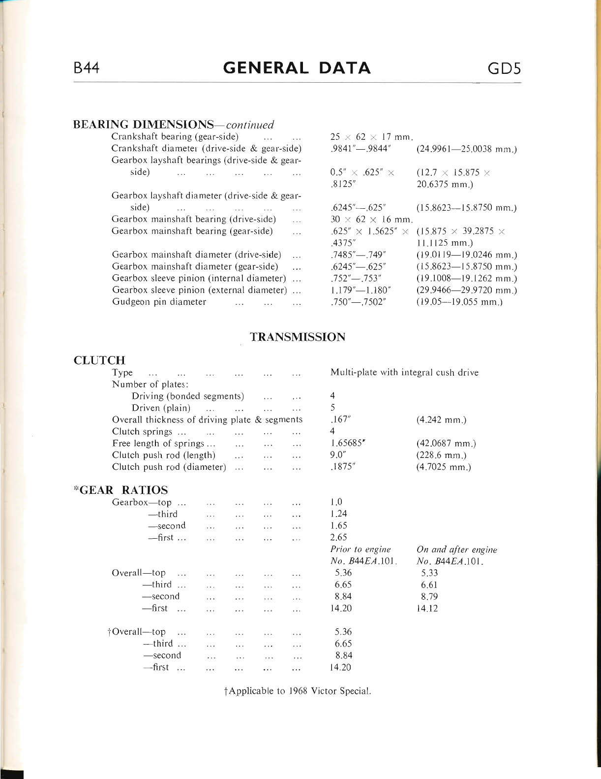
BEARING DIMENSIONS- co n t i nu e d
Crankshaft bearing (gear-side)
Crankshaft diameter (drive-side & gear-side)
Gearbox layshaft bearings (drive-side & gear-
side)
Gearbox laysha
side)
ft diameter (drive-side & gear-
Gearbox mainshaft bearing (drive-side)
Gearbox mainshaft bearing (gear-side)
8125',
6245',-.625',
25 t. 62 x 17 mm.
.9841',-.9844',
0.5" r .625" x
(24.9961-25.0038 mm.)
(12.1 >< 15.875 r
20.6375 mm.)
(15.8623-15.8750 mm.)
(15.875 /. 39.2815 y
11.1125 mm.)
(19.01l9-19 .0246 mm.)
(15.8623-15.8750 mm.)
(19.1008-19.1262 mm.)
(29 .9466-29.9720 nm.)
(19.05-19.055 mm.)
(4.242 mm.)
(42.0687 mm.)
(228.6 mm.)
(4.7025 mm.)
On and after engine
No. 844EA.101.
5.33
6.6r
8.79
14.12
Gearbox
Gearbox
Gearbox
Gearbox
Gudgeon
mainshaft diameter (drive-side)
mainshaft diameter (gear-side)
sleeve pinion (internal diameter) ...
sleeve pinion (external diameter) ...
pin diameter
TRANSMISSION
30 x. 62 x 16 mm.
.625" t. 1.5625" x
.4315',
.7485',-.149',
.6245',-.625',
.l52',-.7 53',
1.179"-1.180"
750',-.1502',
CLUTCH
TYPe Multi-plate r,vith integral cush drive
Number of plates:
Driving (bonded
Driven (plain) segments) 4
5
Overall thickness of driving plate & segments
Clutch springs ...
Free length of springs ...
Clutch push rod (length)
Clutch push rod (diameter)
,.GEAR RATIOS
Gearbox-top ...
-third
-second
-first
Overall-top
-third
-second
-first
f Overall-top
-third
-second
-first 14.20
.167',
4
r .65685',
9.o',
.1875',
1.0
1.24
1.65
2.65
Prior to engine
No. B44EA.l0l
s.36
6.65
8.84
14.20
5.36
6.6s
8.84
fApplicable to 1968 Victor Special.
www.bsaunitsingles.com
GD6 GENERAL DATA 844
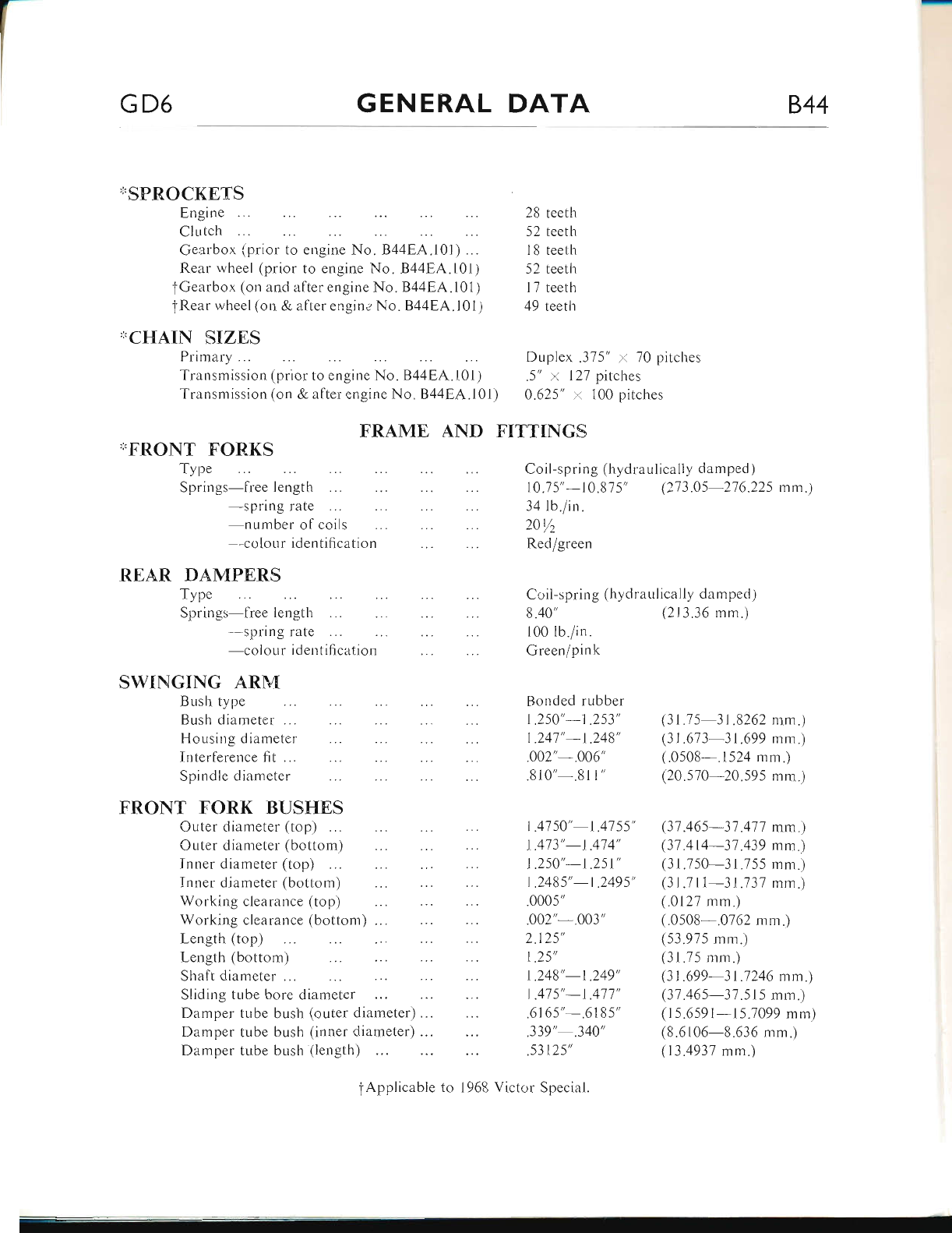
'I.SPR.OCKETS
Engine 28 teetli
Clutch 52 teeth
Gearbox (prior to engine No. B44EA.l0l) ... 18 teetlr
Rear wheel (prior to engine No. B44EA.l01) 52 teetlr
f Gearbox (on and after engine No. B44EA.l01) 17 teeth
'iRear wl-reel (on & alter engine No. B44EA.101) 49 teeth
':CHAIN SIZES
Primary ... Duplex .315" 't 70 pitches
Transmission (prior to engine No. B44EA.101) .5" 'x 127 pitches
Transmission (on & after engine No. B44EA.101) 0.625" 'r 100 pitches
FRAME AND FITTINGS
'I.FRONT F'ORKS
Type Coil-spring (hydraulically damped )
Springs-free length 10.15'-10.875' (213.05 276.225 mm.1
-spring rate 34 lb./in.
number of coils 20yz
colotir identification Red/green
REAR DAMPERS
Type Coil-spring (hydraulically damped)
Springs-free length 8.40' (213.36 mm.)
-spring rate 100 lb./in
-colour identification Green/pink
SWINGING ARM
Bush type Bonded rubber
Bush diameter ... 1.250'-1.253' (31.75 31.8262 mm.)
Housing diameter 1.241'-l .248' (31 .613 31.699 mm.)
Interferer-rce fit ... .002' .006" (.0508-.1524 mm.)
Spindle diameter .8i0" .811" (20.570 20.595 mm.)
FRONT FORK BUSHES
Cuter diameter (top) 1.4750'-1.4755' (31.465-37.417 mm.)
Outer diameter (bottom) 1 .413'-1 .414" (31.414-31.439 mm.)
Inner diameter (top) | .250'-1 .251' (31.750-31.755 mm.)
Inner diameter (bottom) I .2485'-1.2495' (31.711-31.737 mm.)
Working clearance (top) .0005' (.0127 rnm.)
Working clearance (bottom) .". .002' .003" (.0508 .0762 mm.)
Length (top)
Lengtlr (bottom) 2.125',
t.25',
(53.975 mm.)
(31.75 mm.)
Shaft diameter . .. 1 .248'-1.249' (31 .699 31 .1246 mrn.)
Sliding tube bore diameter 1.475'-1.471' (37.465-31.515 mm.)
Damper tube bush (outer diameter)... .6165'-"6185" (15.6591-15.7099 mm)
Damper tube bush (inner diameter) ... .339'-.340' (8.6106-8.636 mm.)
Damper tube bush (length) .53125' (13.4937 mm.)
tApplicable to 1968 Victor Special.
www.bsaunitsingles.com
844 GENERAL DATA GD7
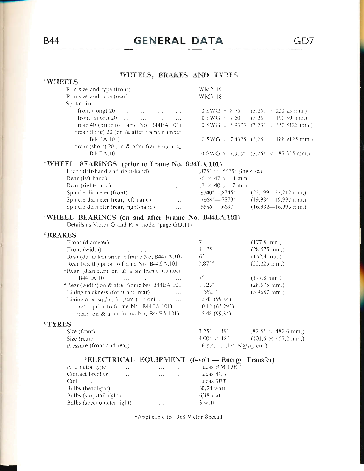
\&F{EtrI-S, IIRAKES ATqD TVT{ES
'I.WF{EEI,S
Rim size and type (lront)
Rim size anci tyyte (rear)
Spoke sizes:
front (lorr.a) 20
front (short) 20
rear 40 (prior to frame No. B44EA.l0l)
i'rear (long) 20 (on & alter fr:ilme nuinber
B44F:A.l0l) ...
'rrear (short) 20 (on & atter frame nuruber
844EA.101) . .
wvt2 19
wM3 l8
l0 SV/G ::. 8, "l5"
10 SWG ). 7.50"
t0 swc . 5.9375',
l0 SWG >:. 7"4375'
l0 SWG :.. 7.315'
7',
| "125',
6',
0.875 "
1',
1 .t25',
.15625',
rs.48 (99.84)
10.t2 (6s.292)
1 5.48 (99.84)
(3.251 )i 222.25 mm.t
(3.251 :: 190.50 mm.)
(3.251 I 150.8125 rnm.)
(3.251 r I88.9125 mm.)
(3.251 .r. 187.325 mm.)
i'WF{EEL EEARINGS (prior to Frame No. 84484"101)
Front (left-hand and right-hancl) .875" :. .5625" single scal
Rear (left-hand) 20 t 41 'r 14 nrm.
Rear (right-hancl) 17 l 40 x 12 mnr.
Spindle diameter (front) .8140" .8745' (22.199 22.212 rnm.)
Spindle diameter (rear, left-hand) .7868" .7813' (19.984-19.997 mm.)
Spindle clizrmeter (rcar, right-hand) . .6686' .6690" (16.982- 16.993 mm.)
+W[{EEL BEdRINGS (on and after Frame No. B44EA.X01)
Details as Victor Grand Prix model (page GD.li)
'TtsRAKES
Front (diameter)
Front (width)
Rear (diarneter) prior
Rear (wiclth) prior to
iRear (diameter) on
B44EA.l0l
tRear'(widtli) on & after frarne No. B44EA.l0l
Lining thickness (fr-ont and rear)
Lining area sq./in. (sq./cnr")-front .".
rear (prior to frame No. B44EA.l0l) ...
irear (on & after frame No. B44EA.10l)
"TYRES
Size (tiont)
Size (rear)
Pressure (front and rear)
*ELECTRICAL EQU{PMENT
Altcrnltor type
Corttret brcrrLer
Coil
Brrlb: (headlight)
Bulbs lstop'tail liglrt t ...
Bulbs (speedometer light)
3.25" y. 19" (82.55 x 482.6 mm.)
4.00' x 18" (101.6 )( 457.2 mm.)
l6 p.s.i. (1.125 Kg1sq. cni.)
(6-volt - Energy Transfer)
I-ucas RM .l9ET
Lucas 4CA
Ltrcas 3El
30i24 rvatt
5/18 watt
ll uratt
to lrame No. B44EA.l0l
frame No. B44EA.l01
& after frame number
(177.8 mm.)
(2E.575 mm.)
(152.4 mm.)
(22.225 mm.)
(177.8 mm.)
(28.575 mm.)
(3.9687 mm.)
tApplicable to 1968 Victor Special
www.bsaunitsingles.com
1-
GD8 GENERAL DATA 844
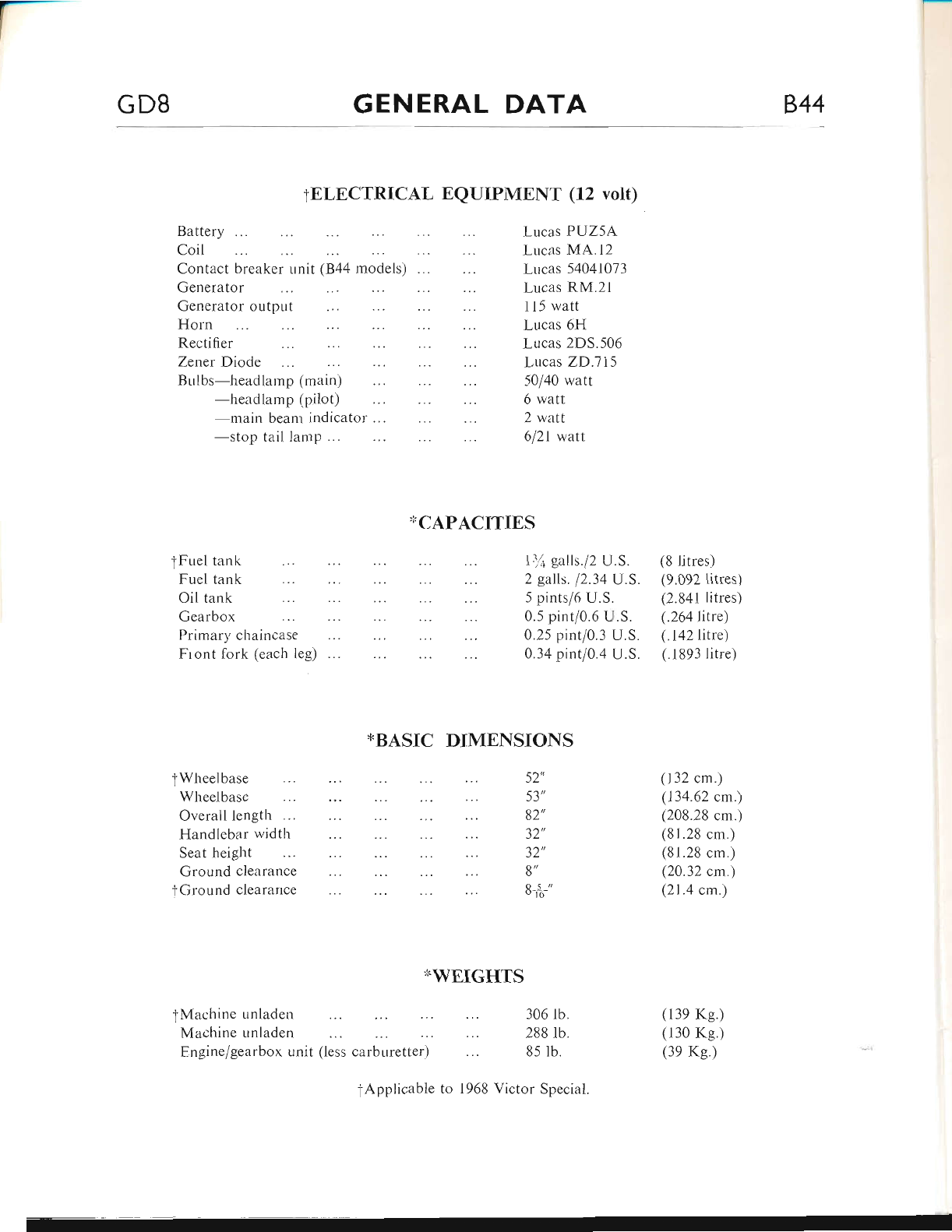
TELECTRICAL EQUIPMENT (12 volt)
Battery
Coil
Contact breaker r-rnit (B44 models) ..
Generator
Generator output
Horn
Rectifier
Zener Diode
Bulbs-headlamp (main)
-headlamp (pilot)
-main beam indicator'
Primary chaincase
Front lork (each leg)
tFuel tank
Fuel tank
Oil tank
Gearbox
{Wheelbase
Wheelbase
Overall length
Seat height
Lucas PUZ5A
Lucas MA.12
Lucas 54041073
Lucas RM.2l
115 watt
Lucas 6H
Lucas 2DS.506
Lucas ZD.7l5
50/40 watt
6 r.vatt
2 watt
612l watt
ll.( galls./2 U.S.
2 galls. 12.34 U.S.
5 pints/6 U.S.
0.5 pint/0.6 U.S.
0.25 pint/0.3 U.S.
0.34 pint/0.4 U.S.
(8 litres)
(9.092 iitres)
(2.841 litres)
(.264litre)
(.142 litre)
(.1893 litre)
-stop tail lamp...
XCAPACTTIES
Handlebar width
*BASIC DIMENSIONS
32',
8',
8+"
{.WEIGHTS
306 lb.
288 lb.
85 lb.
Victor Special.
(132 cm.)
(134.62 cm.)
(208.28 cm.)
(81.28 cm.)
(81.28 cm.)
(20.32 cm.)
(21.4 cm.)
(139 Ke.)
(130 Kg.)
(3e Ke.)
52',
53',
82',
32',
Ground clearance
tGround cleararrce
tMachine unladen
Machine unladen
Fngine/gearbox unit (less carburetter)
fApplicable to 1968
www.bsaunitsingles.com
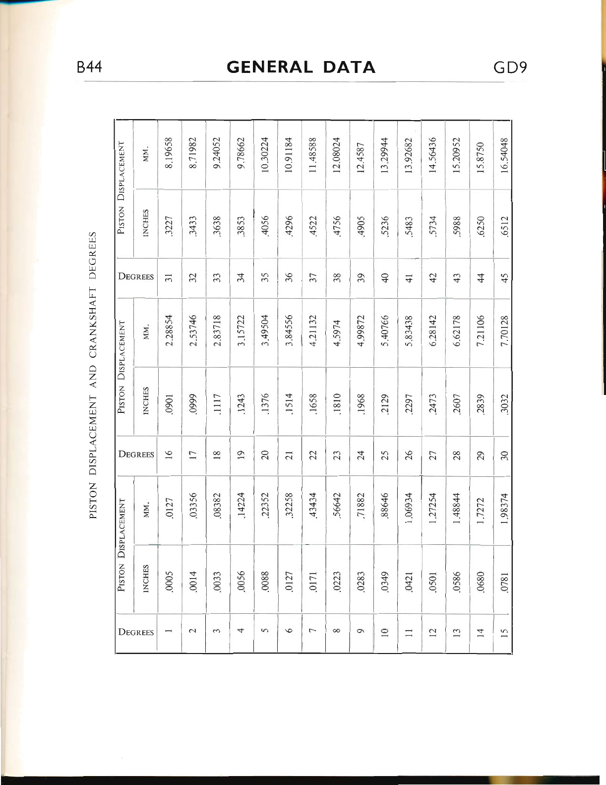
GENERAL DATA GD9
C\
co
f:
oo
o
E]
O
z
F
z
Lt1
tr..l
O
j
a
l-.1
z
o
F
q
a
F
z
ql
ti.l
O
tsl
a
tl
z
o
F
a
a
C\
o\
O
c\
\o
-i-
\o
r)
$
a.l
@
\o
(\
-;
$
$
o\
cl
m
t--
@
w.
(\
s
c'l
(>
@
O.
a.l
co
oo
@
-i..
.i-
@
q,
s
c\
(\
O
co.
O
O
t--
@.
\o
O
c.t
t-
oo
t--
o.l
\o.
al
.i-
oo
c\
co
cr)
$
ca
oq
\IJ
r-
O
'i-.
c\]
t--
oo
q
'i-
c..l
co
c'{
$
c.]
C\
tr-
-
@
t-
co
@.
o.t
\o
$
F-
a.l
.+
@
@
c.l
a\l
sf
F-
@
*.
...l
F-
N
\
a.l
a.l
c.t
o
t!
O
z
F
z
tr.l
F]
O
,t
a
I
z
F
@
...l
c.l
ca.
a
r!
ttl
&
U
F]
F
tri
a
!
Z
&
Q
IJ
z
F
Z
r!
z
r!
O
-.:1
(A
t-.l
z
F
a
*
www.bsaunitsingles.com
IF
GDIO GENERAL DATA 844
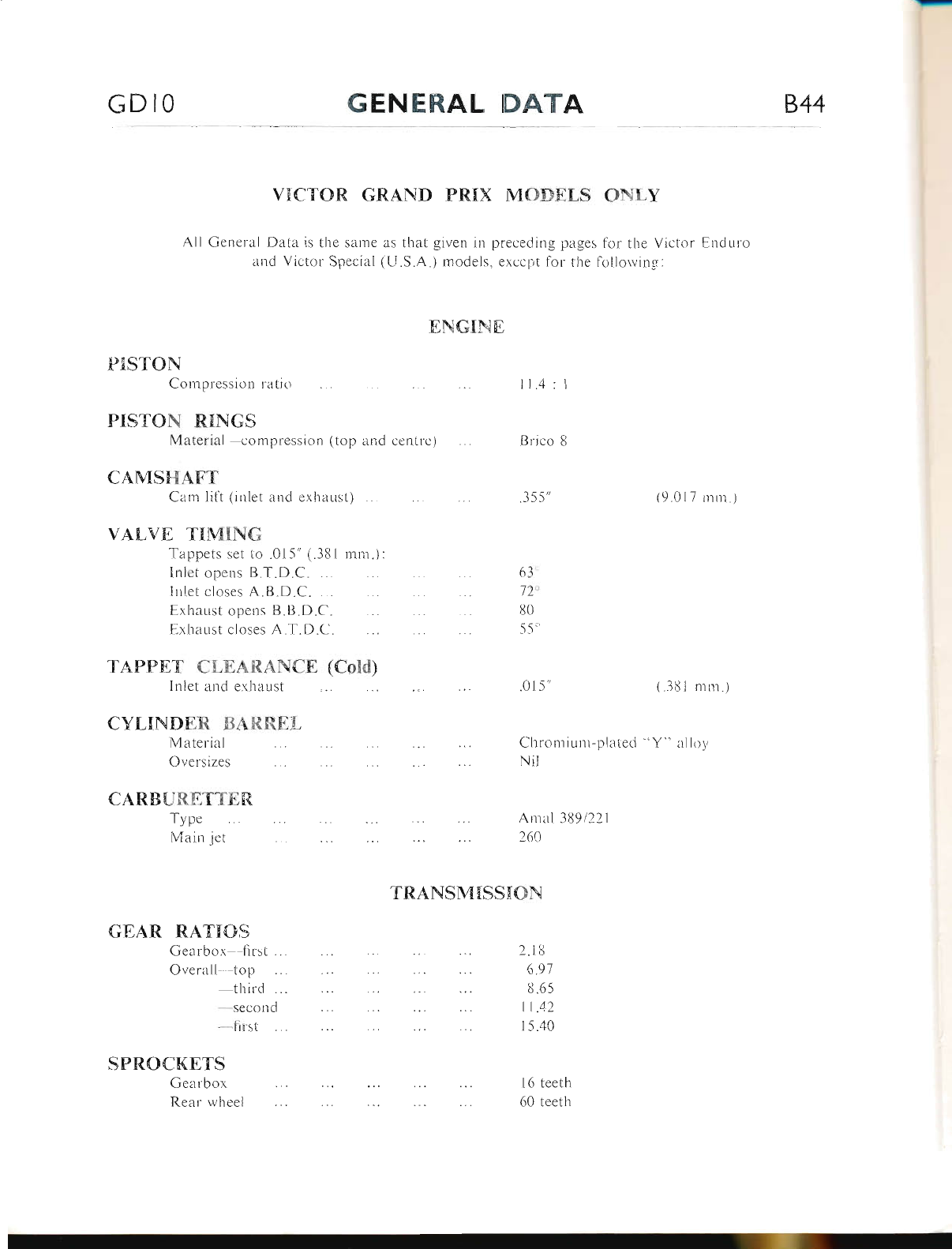
VICTOR GRAND PRIX MODELS ONLY
All General Data is the sarne as that given in preceding pages for the Victor Enduro
and Victor Special (U.S.A.) moclels, except for the follorving:-
ENGINE
ll.4:1
PISTON
Compression ratio
Oversizes
CARBURETTE[T
PISTON RINGS
Material--compression (top and centre) Brico 8
CAMSF{AFT
Cam lilt (inlet and exhaust) .355' (9.017 mm.)
VALVE TIMING
Tappets set to .015" (.381 mm.):
Inlet opens B"T.D.C. ... 63 -
lrrlet closes A.B.D.C. ... J2'
Exhaust opens B.I}.D.C. 80'
Exhaust closes A.T.D.C. 55'
TAPFET CLEARdNCE (Cold)
Inlet and exhaust 0l 5' ( .Jl( I ni ru. )
CYLINDER BARREL
Material Chromiuni-plated "Y" alltty
Type
Main jet
TRAI\SMISSION
GEAR RATIOS
Gearbox first... 2.18
Overall' top 6.91
thircl . 8.65
--second fl.42
--first 15.40
SPROCKETS
Nil
Amal 389/221
260
l6 teeth
60 teeth
Gearbor
Rear wheel
www.bsaunitsingles.com
-
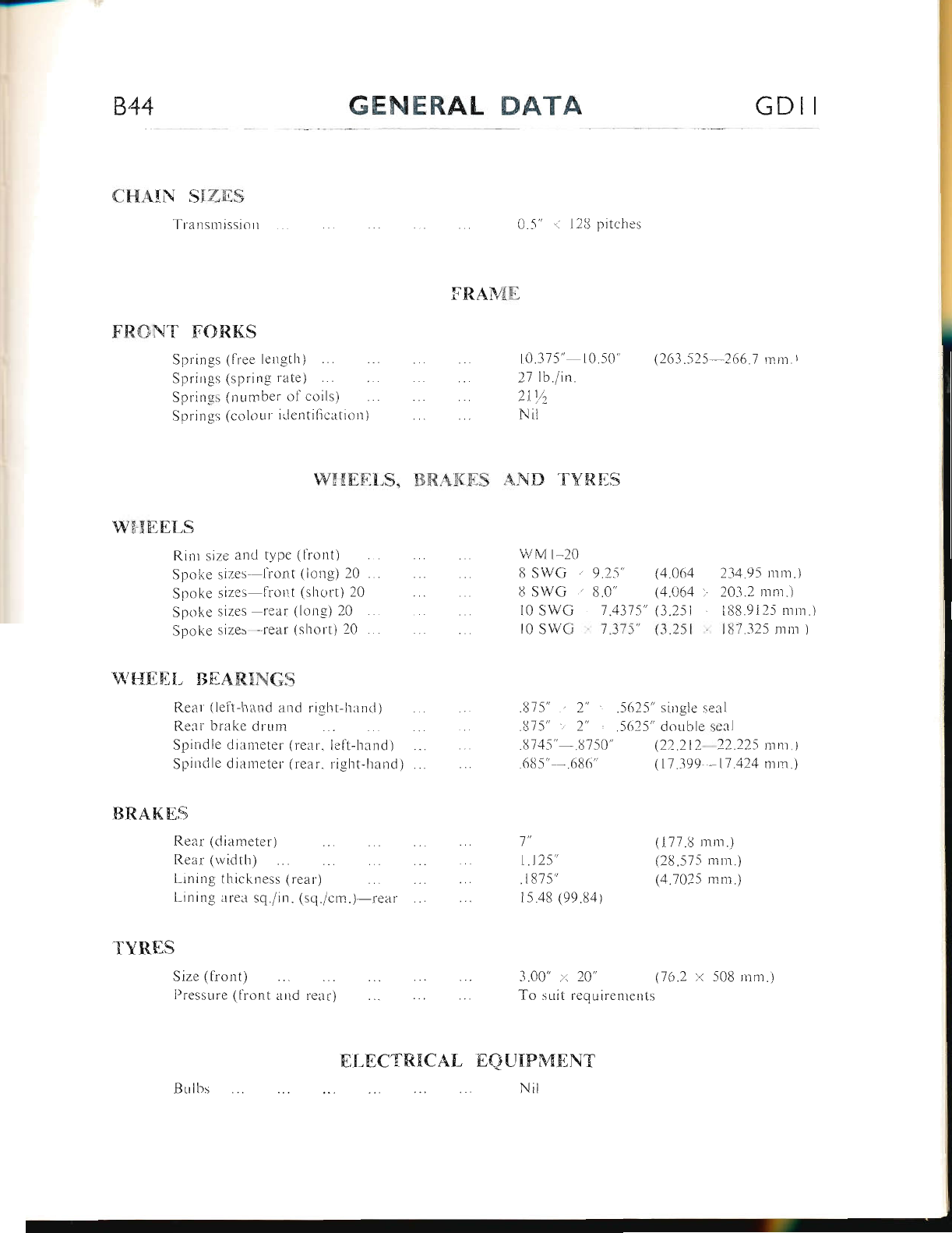
844 GENERAL DATA GDII
CHATN S{Zf,S
Tra nsm issiorr
F'R$NT FC}R.KS
Springs (free lerrgth)
Springs (spring rate)
Springi; (rrumber ol coils)
Spring:s (colour irlentifi cation )
FRAME
WF{EE[,S, X]R.AKES
(263.525 266"7 rrm.t
0.5' .,< 128 pitches
10.375', 10.50"
27 Ib.lin.
2I Y2
Nit
AND TVR.ES
WI{EEI,S
Rim size and type (fiont)
Spoke sizes lront (long) 20 ...
Spi:lke sizes fiont (short) 20
Spoke sizes rear (long) 20
Spoke sizes -.rear (short) 20 . .
WHEEL BEAI{TNGS
Rear ( leti-liand ar.rd riglit-hand )
Rear brake drurn
Spindle diameter (rear. left-hand)
Spindle diameter (rear. right-[rand)
BRAKES
Rear (diameter')
Rear (width)
Linirrg tliickness (refl r)
Lining area sq./in. (sq./cm.)-rear
"flYRES
Size (tiont)
[)ressure (liont
wM r-20
8 SWG ', 9.25" (4.064
8 SWG ),. 8.0" (4.064
10 swc .. 1.4375" (3.251
l0 SWG ' 7.315" (3.251
l"
1.125',
.r81s',
15.48 (99.84)
.875" .. 2" :':. .5625" single seal
.875" /. 2" t .5625" double seai
.8745"- .U750" (.22.212 ,22.225 mn.)
.685" .686" (11 .399 ,17 .424 mmj
234.95 nrm.)
203.2 mm")
188.9125 mm.)
IU7.325 mm )
(177.8 mn.)
(28.575 mrn.)
(4.7025 mm.)
3"00" .< 20" (16.2 x 508 rnnr.i
To suit requirentents
tsQUIPMF],NT
Nit
Bulbs
and rear)
ELECTRNCAL
www.bsaunitsingles.com
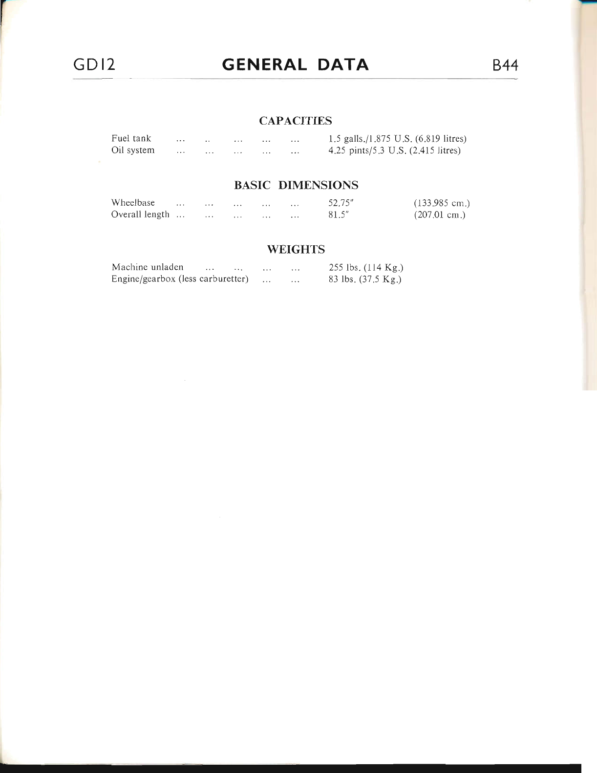
GD I2 GENERAL DATA 844
Fuel tank
Oil system
CAPACITIES
BASIC DIMENSIONS
\) '7 \il
81 .5"
WEIGHTS
1.5 galls./1.875 U.S. (6.819 litres)
4.25 pintsl5.3 U.S. (2.415 litres)
Wheelbase
Overall length
Machine unladen
Engine/gearbox (less carburetter)
(133.985 cm.)
(207.01 cm.)
255 lbs. (l1a Kg.)
83 lbs. (37.s Kg.)
www.bsaunitsingles.com
844 LUBRICATION AI
INDEX
RourrNn MlrNrsNaNcs
Lusnrcl.rloN PorNrs
RscoulreNoro LusRrcA.Nrs
ENcrNs LusRrcArroN Svsrnu
Orr- Fr-ow (GnlNo Pnrx uoppLs oNr-v)
CH,q.NcrNc Oll aNo Cr-naNrNc rnr Frlrrns
Orr- PREssunE AND NoN-RrrunN Var-vEs
DlsHrlNrLrNc nNo Rp.q.sspMBLrNG rns Or Pr;N,rp
CoNracr BnpmER
Grnnsox
Pnrlranv Dnrvr
Rrln Csa,rN
SreenrNc Hreo Racr
Fnour FoRr
WspBr- Br,q.nrNcs
CoNrRor CaeI-rs
Spreoourrrn C,q,sLE (Elouno .qNp Sprctnl (U.S.A.) r\roDELS oNLy)
Page
4.2
4.2
A.3
A.5
A.5
A.5-9
A.9-10
A.r0-ll
A.l1-12
A.t2
4.12-13
A.13
A.t4
A.t4
4.14
A.l4-15
A.15
www.bsaunitsingles.com
A2 LUBRICATION 844
Re./'. No
1
12.
4.
10.
2.
9.
)
11.
5.
l.
(t.
J.
9.
10.
13.
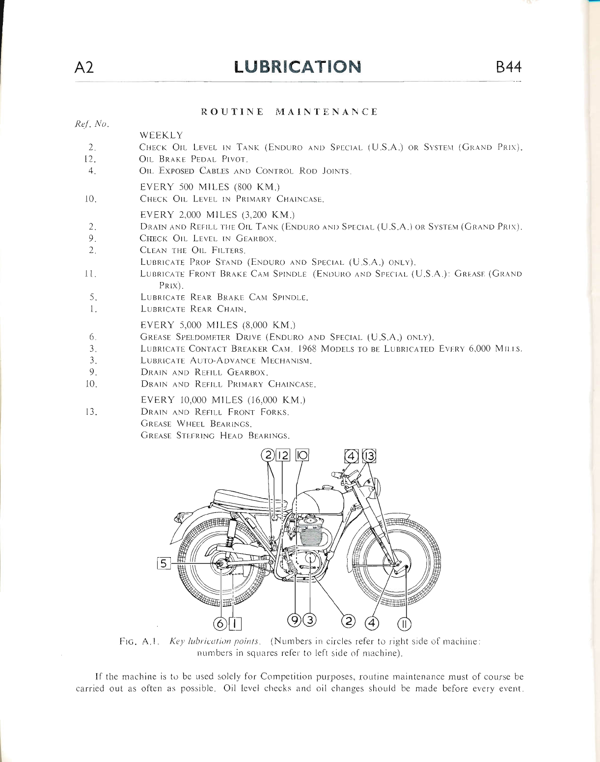
ROUTINE I,{AINTENAN CE
WFtrKT-Y
Crrrcn Orl LEvEr- rN TANK (ENouno ANI) SpricrAr- (U.S.A.1 oR SvsrEu (GraNo Pnrx)"
OrL Bn.,\Ks Pro,q.l Prvor.
Orr- Exposnp Caet-ps .tND Col{rnol Roo JorNrs.
EVERY 500 MrLES (800 KM.)
Cnrcr Orl LEvsr- rN PnrurRv Cs,rrNcasr.
EVERY 2,000 MILES (3,200 KM.)
DRarN nNo RerrlL rue Olr TaNr< (ENouRo ANr) Specrrrl (U.S.A.) on Sys'rclr (GnaNo Pnlx).
Crrncr Orr- Lpvsr- rr.r GE.Ansox.
ClEa.N rnp Orl Frlrnns.
LusRrcA.rE Pnop Sr,qNp (ENouno .quo Spncra,l (U.S.A.) oNr-v).
LusRrcA.rs FROr.-r BR,q.rp C,qu SplNpr-E (ENouno aNo Spr,crrl (U.S.A.): GRnesp (GnaNo
Pnrx).
Lusnrc.Arn REan Bnaxr C,qun SprNorn.
Lunnrcars Rsa.n Cu,q,ru.
EVERY 5,000 MTLES (8,000 KM.)
Cnra.sr Sprluomnrln L)nrvr (ENnuno aNo SpECral (U.S.A.) oNr-v).
LusnrcrrE CoNracr Bnra.run C,qn. I968 Moorls ro sr LusRlc.q.rrp E,vrRv 6.000 Mtr-r.s.
LusnrcA.rE Auro-Aova,Nce l\lpcu,a.Nrsl'r.
DRa.tN ,q.No Reprrl Gl,qnnox.
DRnrN aNo Rlpru- Pnrurny CHa.rNc.q.ss.
EVERY 10,000 MTLES (16,000 KM.)
Dn,trN ,qNo Rrrrll FnoNr FoRrs.
Gng,qse Wurnl BllnrNcs.
GnEnsn SrnnRrNc Hrap BpanrNcs.
F'rc- A.l Ke1: lx6rir,ur,itt'r ltoints" (Numbers
numbers in squares reler to
Il the machine is to be used solely for Competition
carried out as often as possible. Oil levei checks and
in circles refer to right side e.f machine:
left side of machine).
purposes, routine maintenance must ol course be
oil changes should be made before every event.
www.bsaunitsingles.com
844 LUBRICATION A3
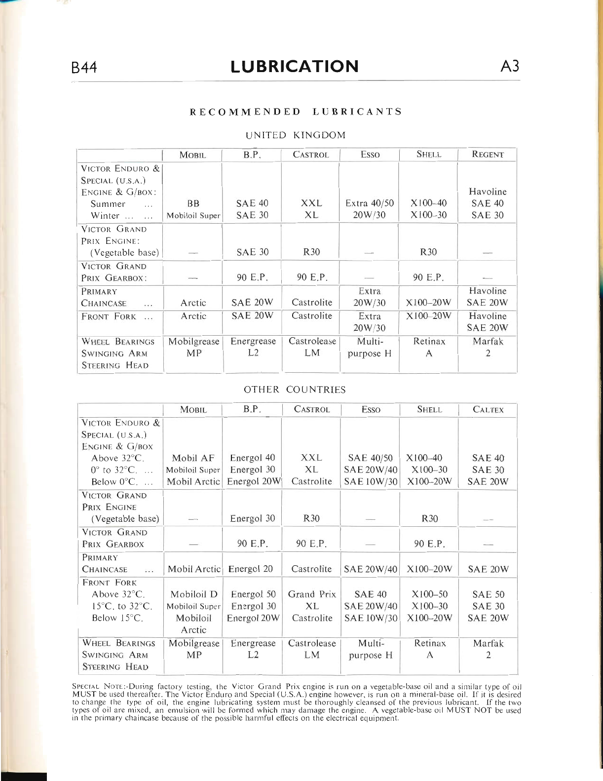
RECOMMENDED LUBRICANTS
UNITED KINGDOM
MoetL
Vrcron ENpuno &
Splcr.q.L (u.s.,r.)
E,Nc;rNE & G/eox:
Summer
Winter ...
BB
Mobiloil Strper
Vrcron CRaNo
PRrx ENcrNr:
(Vegetable base)
Vrcron Gn.q.No
Pnrx Gr,qp.sox:
PRru.qnv
CrrrrNclsr-
FnoNr Fonr
Wgct l Be'\ntNcs
SwrrrrcrN<; Anvr
St'r,enrNc HEap
VrcroR ENnuno &
Sprcra.l 1u.s.a.)
ENcrNe & G/eclx
Above 32'C.
0'to 32'C. ...
Below 0'C. ...
Vrcron GnlNo
Pnlx ENcTNE
(Vegetabie base)
Vrcron GnaNp
Pnlx Grlnnox
Pnrr'raRv
CHn rNc,A.sE
FnoNr Fonr
Above 32'C.
l5'c. to 32'C.
Below l5'C.
Wtrerl BraRrxcs
SwrNcrNc Ann,r
SreERrNc Hrlo
Arctrc
Mobilgrease
MP
SAE 2OW
Energrease
L2
Castrolite
I
Castrolease
LML
XXL
XL
Castrolite
Grand Prix
XL
Castrolite
Extra
20w/30
Multi-
purpose H
sAE 40/50
sAE 20W/40
sAE 10W/30
xr00-20w
Retinax
A
xl00 40
xl00 30
x100 20w
Havoline
SAE 2OW
Marfak
2
SAE 40
SAE 30
SAE 2OW
OTHER COUNTRIES
Cnsrnor ]
Mobil AF
Mobiloil SLrper
MobilArctic
Energol
Energol
Energol
I
40
30
20wl
Mobiloil D
Mobiloil Supcr
Mobiloil
Arctic
Energol 30
Energol 50
Enorgol 30
Energol 20W
SAE 40
sAE 20W40
sAE r0w30
x100-50
x100 30
x100*20w
Retinax
A
SAE 2OW
SAE 50
SAE 30
SAE 2OW
Marf ak
2
Mobilgrease
MP Energrease
L2
Castrolease
LM Multi-
purpose H
Sqrcl,rl. Norn:-During lacfory testing, tl-re Victor Grand Prix engine is run on a vegetable-base oil and a sirnilar type of oil
MUSTbeusedthereafter.TheVictorEnduroandSpecial({.J.S.A.)enginehowever,isrunonamineral-baseoil. Ilitlidesirecl
to change the type of oil, the engine lubricating system must be thoror-rghly cleansed of the previous lubricant. If the two
types of oil are r-nixed, an emulsion will be forrled which may damage the engine. A vegetable-base oil MUST NOT be used
in the primary chaincase because of the possible l-rarmful effects on the electrical equiprrent.
I Cnsrnor I
Extra 40/50
20w/30
Havoline
SAE 40
SAE 30
www.bsaunitsingles.com
A4 LUBRICATION 844
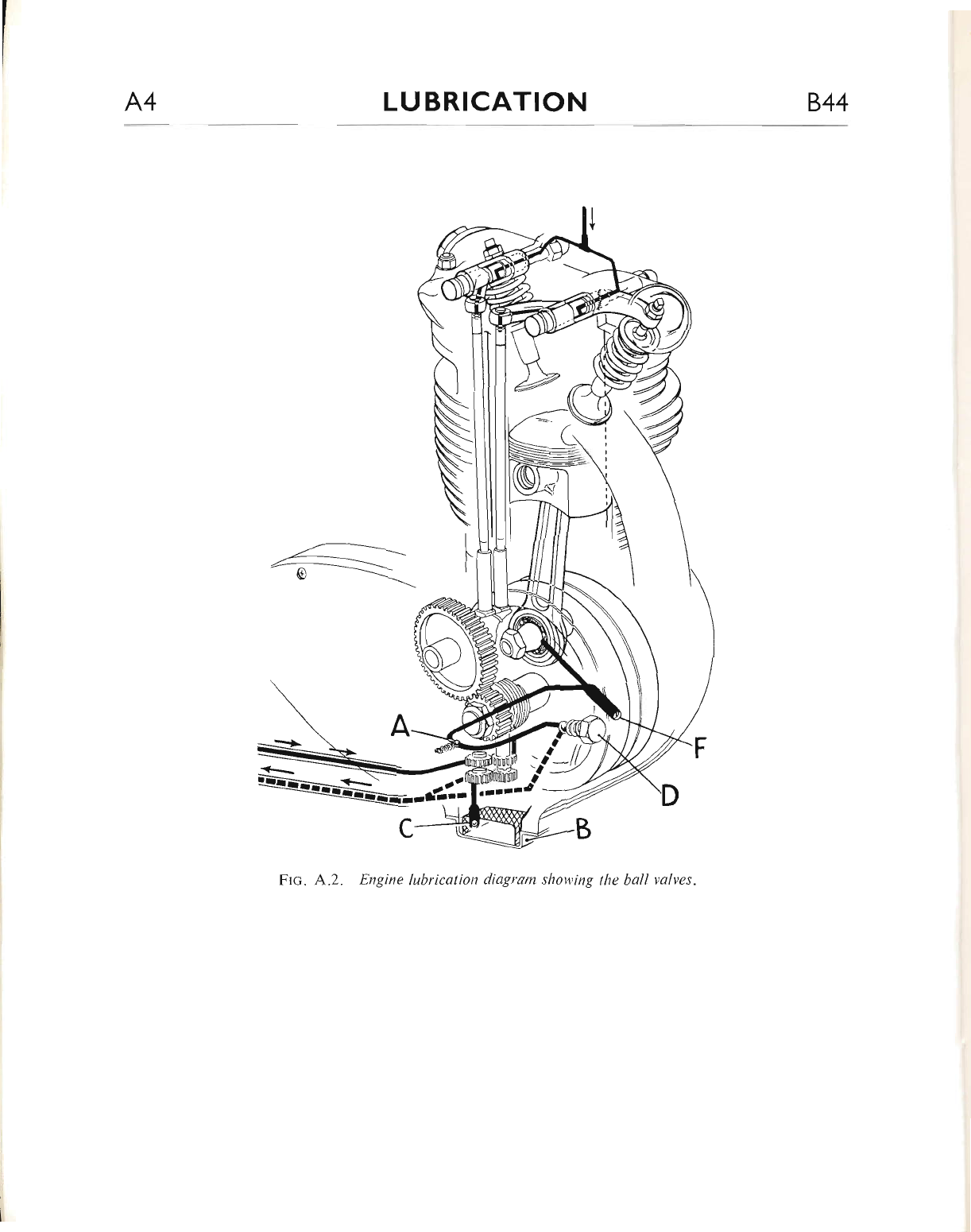
Frc. A.2. Engine lubrication diagram shov'ing tlte ball valves.
www.bsaunitsingles.com
844 LUBRICATION A5
THE LUBRICATION SYSTEM
The lubrication system is of the dry sump type,
i.e. the oil is fed by gravity from a tank to a
dor-rble-gear pun.rp situated in the crankcase base
at the right-hand side (see Fig. A.2).
The top set of gears in the pump draws oil
fron-r the tank through a gauze filter and circu-
lates it under pressure, past a pressLlre release
valve (o), a non-return valve (a) and through the
drilled crankshaft to the big-end bearing. Excess
oil is thrown off by centritugal force, onto the
cylinder walls, the underside of the piston (to
lubricate the gudgeon pin) and fills various r,vells
to lubricate the camshaft and gears.
After lubricating the various internal com-
ponents ol the engine, the oil drains down into
the crankcase.
From here the lower, and larger set ol pump
gears, draws oil from the gauze sump filter
througl-r anotl.rer non-return valve (c) and pumps
it back to the tank at a greater rate thalt that of
the feed side. This ensures that the sump never
floods; heuce the term "dry sump."
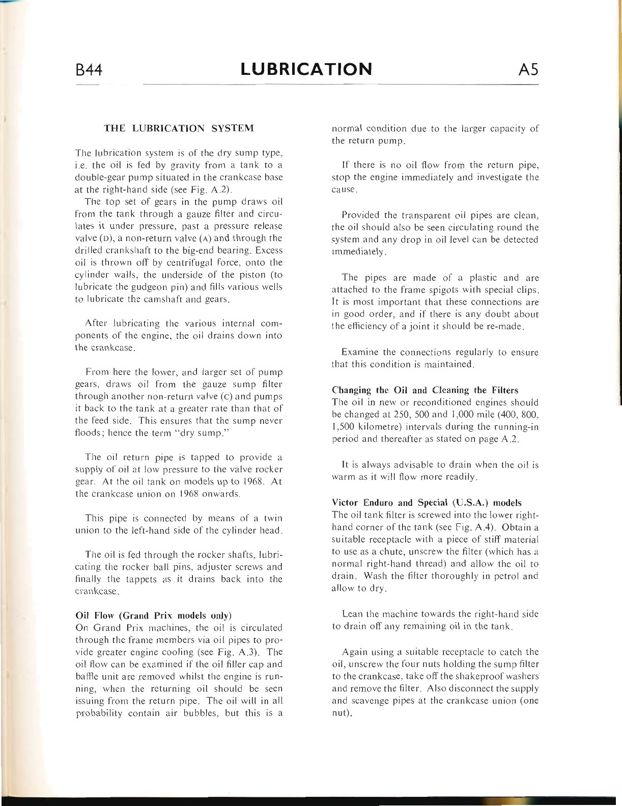
The oil returr.r pipe is tapped to provide a
sLrpply ol oil at Iow pressure to the valve rocker
gear. At the oil tank on models up to 1968. At
the crankcase union on I958 onwards.
This pipe is connected by ineans ol a twin
union to the left-hand side of the cylinder head.
The oil is led througl-r the rocker shafts, lubri-
cating the rocker ball pins, adjuster screws and
finalty the tappets as it drains back into the
crankcerse.
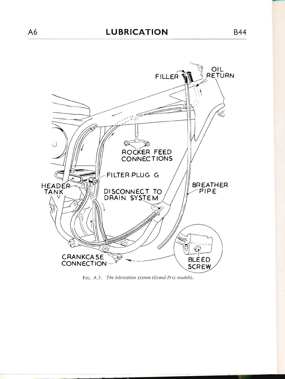
Oil Flow (Grand Prix models only)
On Grand Prix machines, the oil is circulated
through the fiame nrembers via oii pipes to pro-
vide greater engine cooling (see Fig. A.3). The
oil flow can be examined if the oil filler cap and
ballle unit are removed whilst tlie engine is run-
ning, when the returning oil should be seen
issuing from the return pipe. The oil will in all
probability contain air bubbles, but this is a
nonnal condition due to the larger capacity of
the return pump.
If there is no oil flow from the retr-rrr.r pipe,
stop the engine immediately and investigate the
cause.
Provided the transparent oil pipes are ciean.
the oil should also be seen circulating round the
system and any drop in oil level can be detected
immediately.
The pipes are made ol a plastic and are
attached to the frame spigots with special clips.
It is most important that these connections are
in good order, and if there is any doubt about
the eltrciency of a joint it should be re-made.
Examine tl.re connections regularly to ensure
that this condition is maintained.
Changing the Oil and Cleaning the Filters
The oil in nerv or reconditioned engines should
be changed at250" 500 and 1.000 mile (400, 800,
1,500 kilometre) intervals during the running-in
period and thereafter as stated on page A.2.
It is always advisable to drain when the oil is
warm as it will flow more readily.
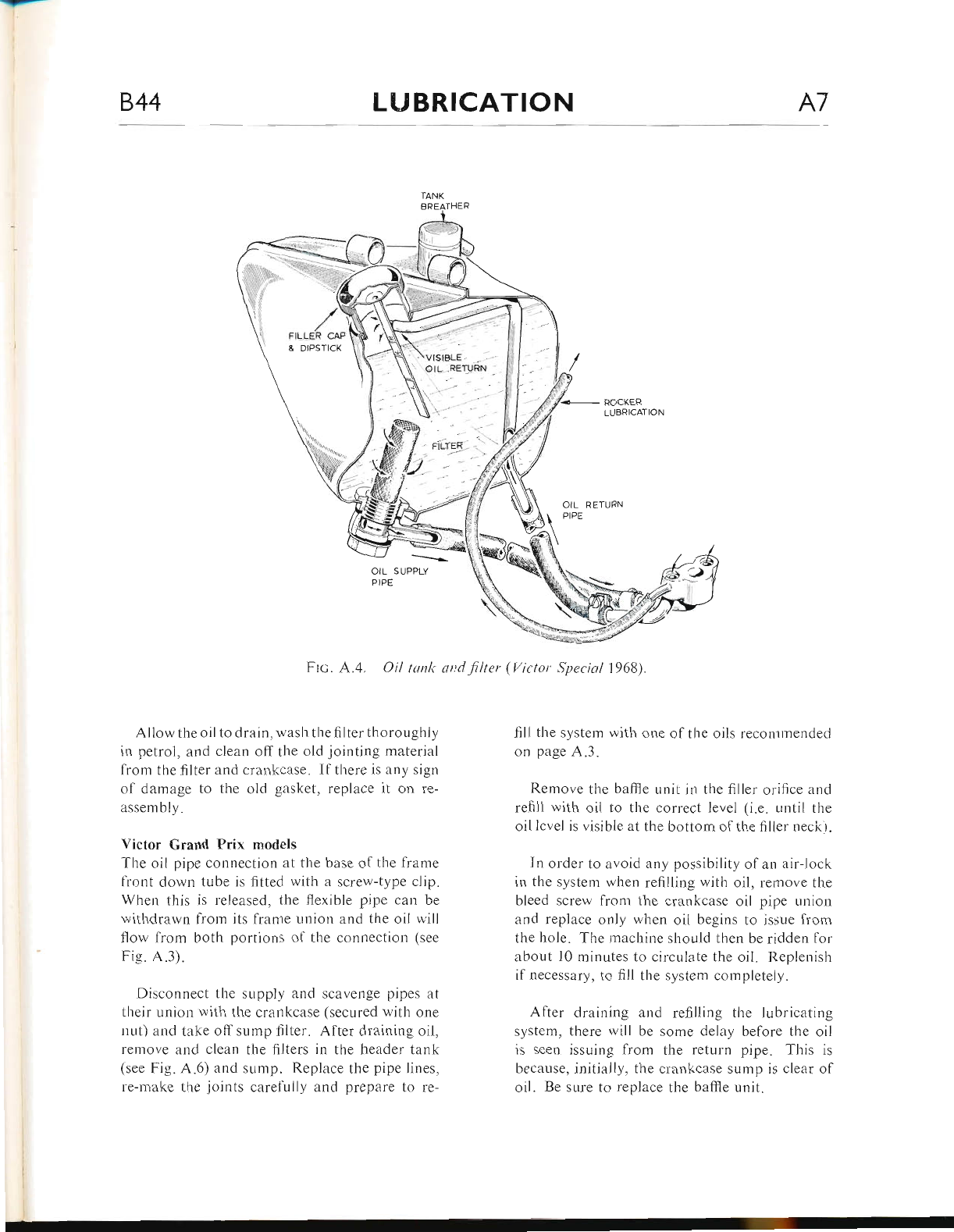
Victor Enduro and Special (U.S.A.) models
The oil tank filter is screwed into the lower right-
hand corner of the tank (see Fig. A.4). Obtain a
suitable receptacle with a piece of stiff material
to use as a chute, Llnscrew the filter (which has a
normal right-hand thread) and allow the oil to
drain. Wash the filter thoroughly in petrol and
allow to dry.
Lean the machine towards the right-hand side
to drain off any remaining oil in the tank.
Again using a suitable receptacle to catch the
oii, unscrew the four nuts holding the sump filter
to the crankcase, take offthe shakeproolwashers
and remove the filter. AIso disconnect the supply
and scavenge pipes at the crankcase union (one
nut).
www.bsaunitsingles.com
A6 LUBRICATION 844
orL
RETURN
HEADE
TAN K
BR EATHEFI
P,P E
CRANKCA SE
CONNECTION
Frc. A.3. The lubricqtion system (Grand Prix models).
ROCKER FEED
CONNEC T IONS
FILTEI? PLUG G
DI SCONNECT TO
DFIAIN SYSTE M
\-\
I(
si 1
Yo) c "/
l-
www.bsaunitsingles.com
-.-
844 LUBRICATION A7
TANK
BREATHER
Ftc. A.4. Oil tank artdfilter (Victor Special lg68).
Aliow the oil to drain, wash the filter thoroughly
in petrol, and clean off the old jointing material
lrom the filter and crankcase. Ifthere is any sign
of damage to the old gasket, replace it on re-
assembly.
Victor Grand Prix motlels
The oil pipe connection at the base of the frame
lront down tube is fitted with a screw-type clip.
When this is released, the flexible pipe can be
withdrawn from its frame uniou and the oil will
flow lrom both portions of the connection (see
Fig. A.3).
Disconnect the supply and scavenge pipes at
their union with the crankcase (secured with one
nut) and take off sump filter. After draining oil,
remove and clean the filters in the header tank
(see Fig. A.6) and sump. Replace the pipe lines,
re-make the joints carefully and prepare to re-
fill the system with one of the oils recommended
on page A.3.
Remove the baffie unit in the filler orifice and
refill with oil to the correct level (i.e. until the
oil lcvel is visible at the bottom of the filler neck'r.
In order to avoid any possibility of an air-lock
in the system when refilling with oil, remove the
bleed screw from the crankcase oil pipe union
and replace only when oil begins to issue lrom
the hole. The machine should then be ridden for
about 10 rninutes to circulate the oil. Replenish
if necessary, to fiIl the system completely.
After draining and refilling the lubricating
system, there will be some delay before the oil
is seen issuing from the return pipe. This is
because, initially, the crankcase sump is clear of
oil. Be sure to replace the baffie unit.
www.bsaunitsingles.com
A8 I-UBRICATION 844
ROCKER
LUBRICATION
TANK BREATHER
orL
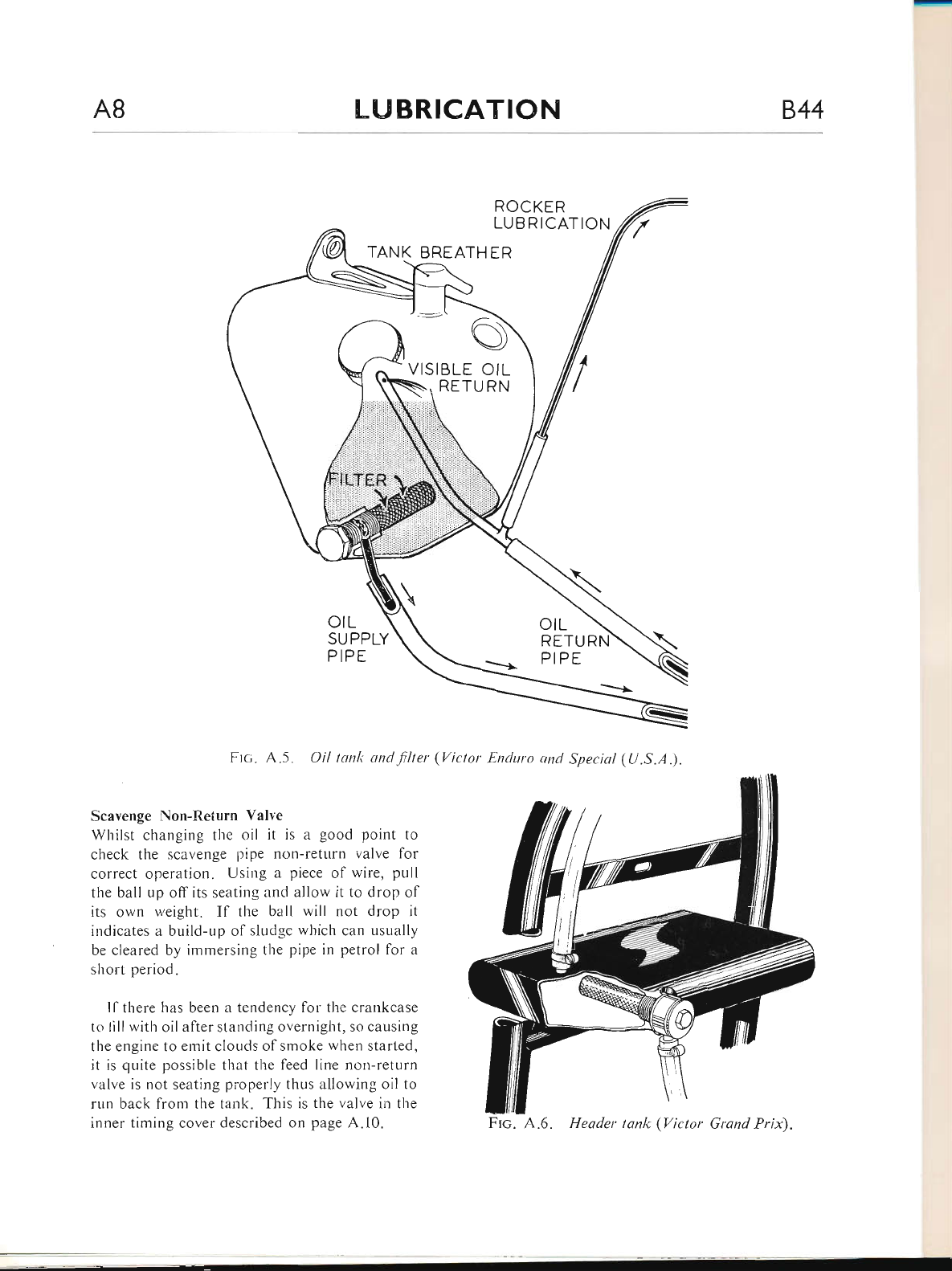
Ftc. A.5. Oil tanlt and.filter (Victor Enduro antl Special (Lf .S.A.).
Scavenge Non-Return Valve
Whilst changing the oil it is a good point to
check the scavenge lripe ncln-return valve for
correct operation. Using a piece of wire, pull
the ball up off its seatiug and allow it to drop of
its own rveight. If the ball will not drop it
indicates a build-up of sluclge which can usually
be cleared by immersing the pipe in petrol for a
short period.
ll there has been a tendency for the crankcase
to lill with oil after standing overnight, so causing
tl.re engine to ernit clouds of smoke when started,
it is quite possible that the feed line non-return
valve is not seating pioperly thus allowing oil to
rr-rn back fron.r tl.re tank. This is the valve in the
inner timing cover described on page A.10. Ftc. A.6. Header tanlc (Victor Grand Pri$.
www.bsaunitsingles.com
-rF
844 I.UBRICATION A9
SCAVENGE
BALL VALVE
FILTER
JOINT
WASHER
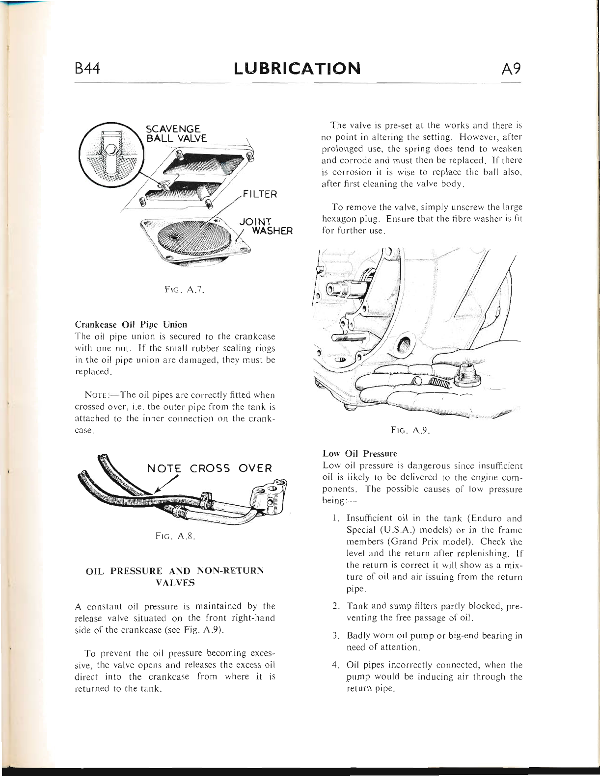
Frc. A.7.
Crankcase Oil Pipe Union
The oil pipe union is secured to the crankcase
witl'r one nut. If the small rubber sealing rings
in the oil pipe ur.rion are damaged, the1, must be
replaced.
NorE:-The oil pipes are correctly fitted when
crossed over, i.e. the outer pipe from tl-re tank is
attached to the inner connection on the crank-
case.
Frc. A.8.
OIL PRESSURE AND NON-RETURN
VALVES
A constant oil pressure is maintained by the
release valve situated on the front right-hand
side of the crankcase (see Fig. A.9).
To prevent the oil pressure becoming exces-
sive, the valve opens and releases the excess oil
direct into the crankcase from where it is
returned to the tank.
The valve is pre-set at the works and there is
no point in altering the setting. However, after
prolonged use, the spring does tend to weaken
and corrode and must then be replaced. lf there
is corrosion it is wise to replace tlie ball also,
after first cleaning the valve body.
To remove the valve, simply unscrew the large
hexagon plug. Ensure that the fibre washer is fit
lor further use.
Frc. A.9.
Low Oil Pressure
Lor.v oil pressure is dangerous since insufficient
oil is likely to be delivered to the engine com-
ponents. The possible caLlses ol low pressure
being:-
1. Insufficient oil in the tank (Enduro and
Special (U.S.A.) models) or in the frame
members (Grand Prix model). Check the
level and the return after replenishing. If
the return is correct it will show as a mix-
ture of oil and air issuing from the return
pipe.
2. Tank and sump filters partly blocked, pre-
venting the free passage of oil.
3. Badly worn oil pump or big-end bearing in
need of attention.
4. Oil pipes incorrectly connected, when the
pump would be inducing air through tl-re
return pipe.
www.bsaunitsingles.com
At0 LUBRICATION 844
ffis
@^
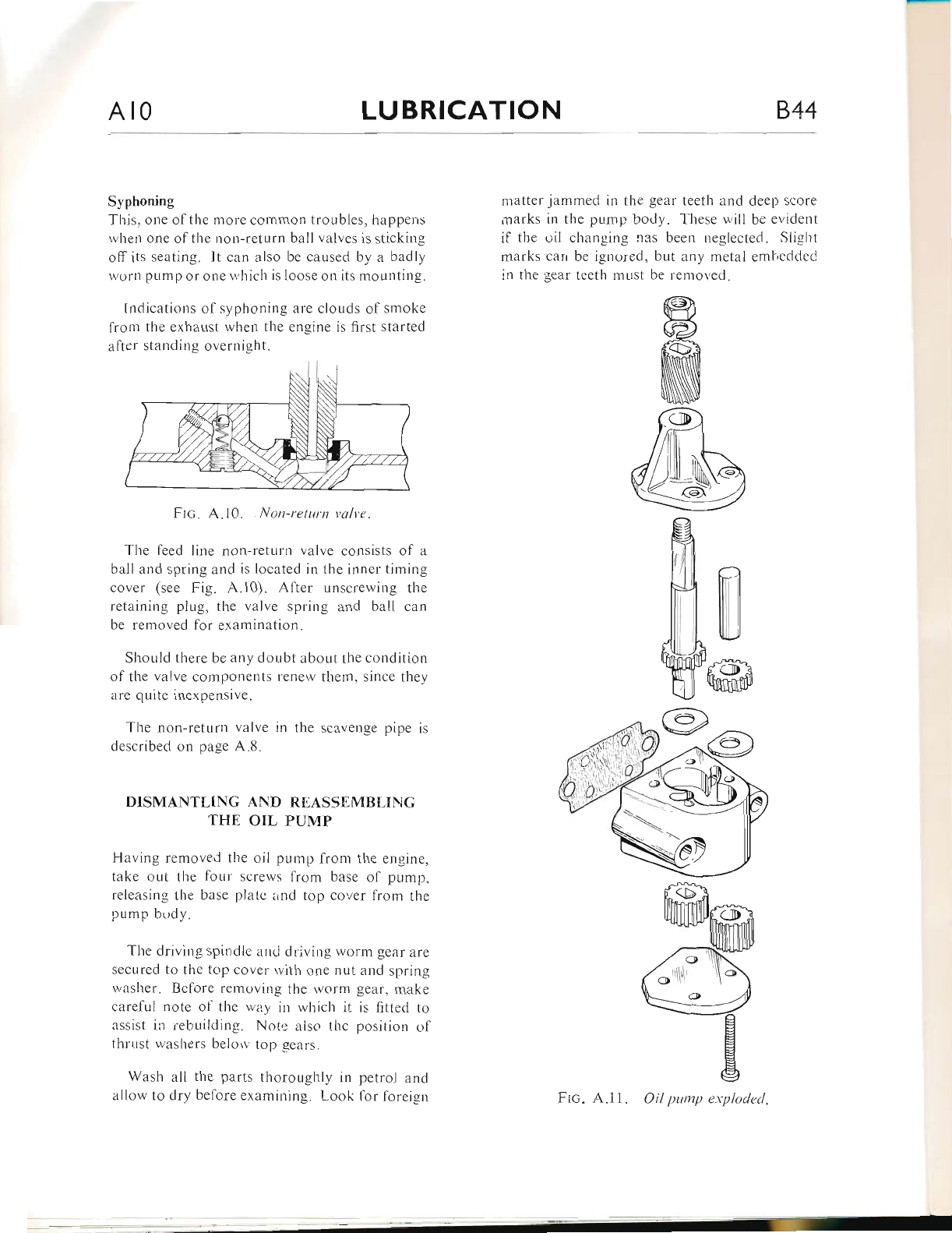
Syphoning
This, one of the more common troubles, happeus
when one of the non-return ball valves is sticking
off its seating. It can also be caused by a badly
worn pump or one whicl-r is loose on its mounting.
Indications of syphoning are clouds of smoke
from the exhaust when the engine is first started
after standing overnight.
Frc. A.10. Non-return yalve.
The feed line non-return valve consists of a
ball and spring and is located in the inner timing
cover (see Fig. A.10). After unscrewing the
retaining plug, the valve spring and ball can
be removed for examination.
Should there be any doubt about the condition
of the valve components renew them, since they
are quite inexpensive.
The non-return valve in the scavenge pipe is
described on page A.8.
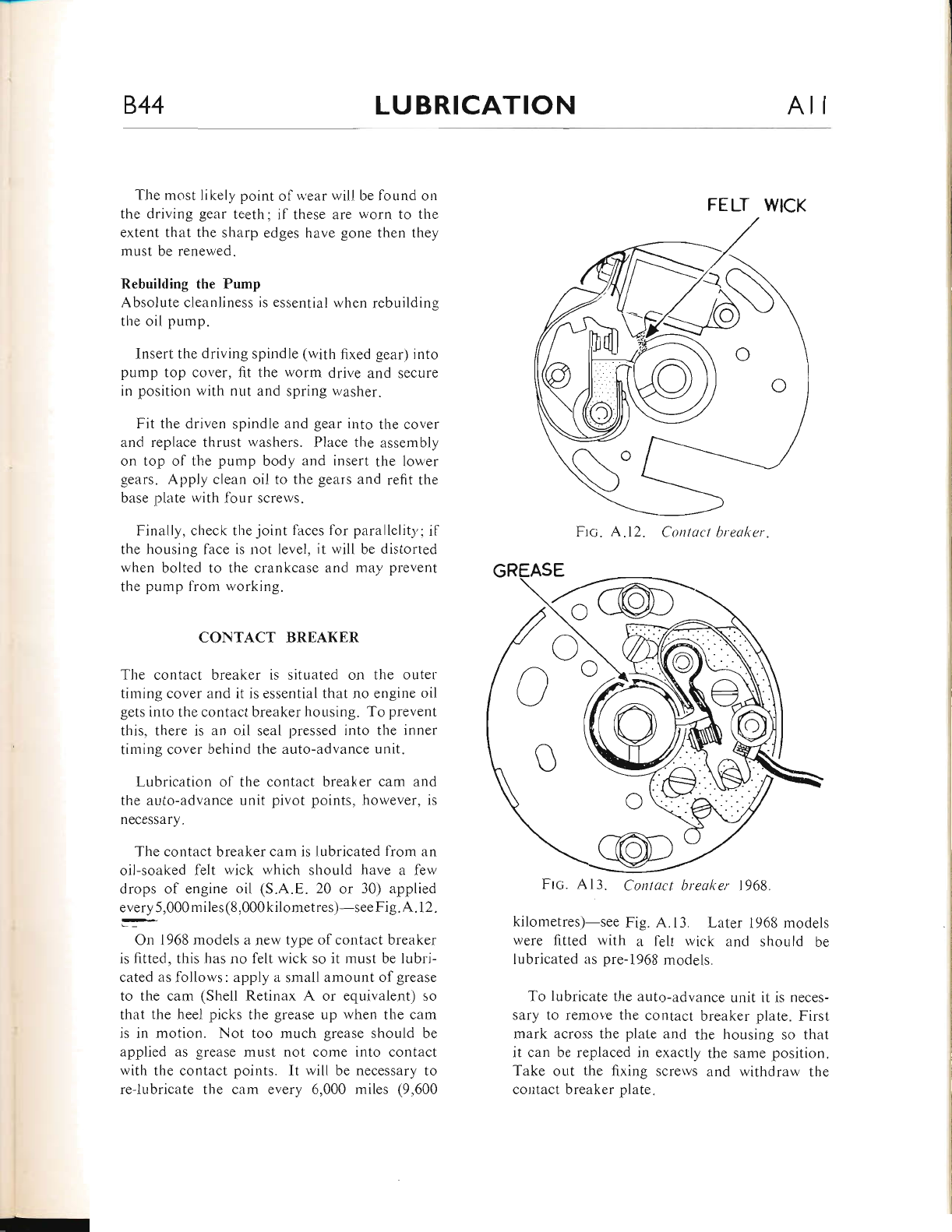
DISMANTLING AND REASSEMBLING
THE OIL PUMP
Flaving removed the oil pump froni the engine,
take out the four screws from base of pump,
releasing the base plate rind top cover lrom the
pump body.
The driving spindle arrci driving wonr gear are
secured to the top cover rvith one nut and spring
washer. Belore removing the rvorm gear, make
carelul note ol the r,viiy in which it is fitted to
assist in rebuilding. Note also thc position ol
fhrr,rst washers beloiv top gears.
Wash all the parts thoroughly in petrol and
allow to dry before examining. Look lor foreign
matter jammed in the gear teeth and deelt score
marks in the pump body. T'hese will be evident
if the oil changing nas been neglected. Slight
marks carr be ignored, but any metal emhcddecJ
in the gear teeth must be removed.
Frc. A.11. Oil pump explodecl.
www.bsaunitsingles.com
844 LUBRICATION Ail
The most Iikely point of wear will be found on
the driving gear teeth; if these are worn to the
extent that the sharp edges have gone then they
must be renewed.
Rebuilding the Pump
Absolute cleanliness is essential when rebuilding
the oil pump.
Insert the driving spindle (with fixed gear) into
pump top cover, fit the worm drive and secure
in position with nut and spring washer.
Fit the driven spindle and gear into the cover
and replace thrust washers. Place the assembly
on top of the pump body and insert the lower
gears. Apply clean oil to the gears and refit the
base plate with four screws.
Finally, check the joint faces for parallelity; if
the housing face is not level, it will be distorted
when bolted to the crankcase and may prevent
the pump from working.
CONTACT BREAKER
The contact breaker is situated on the outer
timing cover and it is essential that no engine oil
gets into the contact breaker housing. To prevent
this, there is an oil seal pressed into the inner
timing cover behind the auto-advance unit.
Lubrication of the contact breaker cam and
the auto-advance unit pivot points, however, is
necessary.
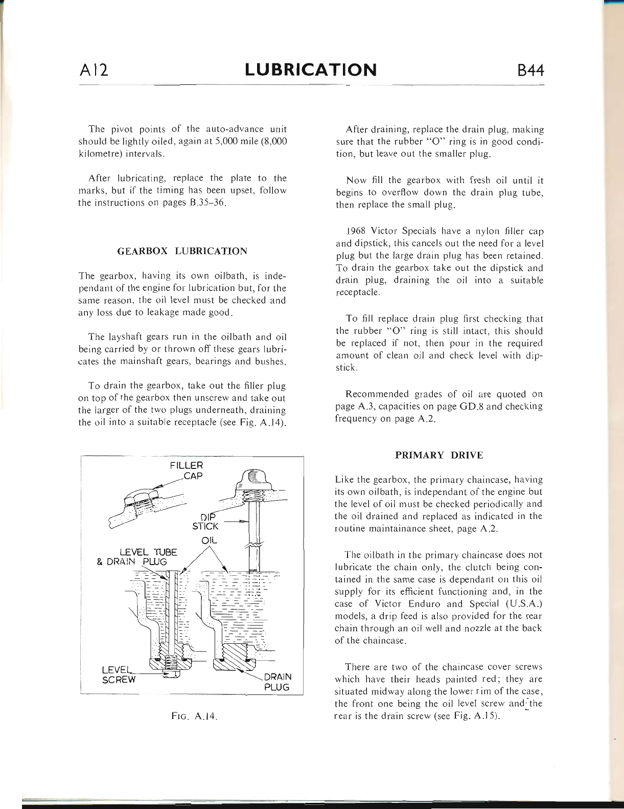
The contact breaker cam is lubricated from an
oil-soaked felt wick which should have a few
drops of engine oil (S.A.E. 20 or 30) applied
every 5,000miles (8,000kilometres)-see Fig.A. 1 2.
:-'On 1968 models a new type of contact breaker
is fitted, this has no felt wick so it must be lubri-
cated as follows: apply a small amount of grease
to the cam (Shell Retinax A or equivalent) so
that the heel picks the grease up when the cam
is in motion. Not too much grease should be
applied as grease must not come into contact
with the contact points. It will be necessary to
reJubricate the cam every 6,000 miles (9,600
FIc. Al3. Contact breaker 1968.
kilometres)-see Fig. A.13. Later 1968 models
were fitted with a felt wick and should be
lubricated as pre-1968 models.
To lubricate the auto-advance unit it is neces-
sary to remove the contact breaker plate. First
mark across the plate and the housing so that
it can be replaced in exactly the same position.
Take out the fixing screws and withdraw the
contact breaker plate.
FELT WICK
Frc. A.12. Contact breaker.
www.bsaunitsingles.com
At2 LUBRICATION 844
The pivot points of the auto-advance urrit
should be lightly oiled, again at 5,000 mile (8,000
kilometre) intervals.
After lubricating, replace the plate to the
marks, but if the timing has been upset, follow
the instructions on pages B.35-36.
GEARBOX LUBRICATION
The gearbox, having its own oilbath, is inde-
pendant ofthe engine for lubrication but, for the
same reason, the oil level must be checked and
any loss due to leakage made good.
The Iayshalt gears run in the oilbath and oil
being carried by or thrown off these gears lubri-
cates the mainshaft gears, bearings and bushes.
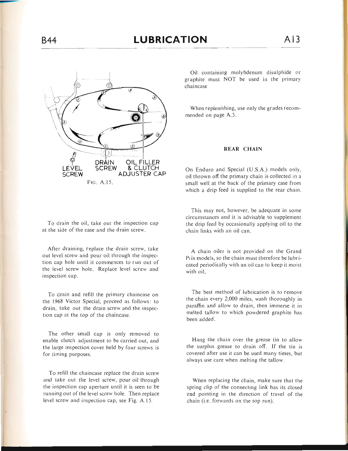
To drain the gearbox, take out the filler plug
on top ofthe gearbox then unscrew and take out
the larger of the two plugs underneath, draining
the oil into a suitable receptacle (see Fig. A.14).
After draining, replace the drain plug, making
sure that the rubber "O" ring is in good condi-
tion, but leave out the smaller plug.
Now fill the gearbox with fresh oil until it
begins to overflow down the drain plug tube,
then replace the small plug.
1968 Victor Specials have a nylon filler cap
and dipstick, this cancels out the need for a level
plug but the large drain plug has been retained.
To drain the gearbox take out the dipstick and
drain plug, draining the oil into a suitable
receptacle.
To fill replace drain plug first checking that
the rubber "O" ring is still intact, tbis should
be replaced jf not, then pour in the required
amount ol clean oil and check level with dip-
stick.
Recommended grades of oil are quoled on
page A.3, capacities on page GD.8 and checking
frequency on page A.2.
PRIMARY DRIVE
Like the gearbox, the primary chaincase, having
its own oilbath, is independant of the engine but
the level of oil must be checked periodically and
tl,e oil drained and replaced as indicated in the
routine maintainance sheet, page A.2.
The oilbath in the primary chaincase does not
lLrbricate the chain only, the clutch being con-
tained in the same case is dependant on this oil
supply for its efficient functioning and, in the
case of Victor Enduro and Special (U.S.A.)
models, a drip feed is also provided for the rear
chain through an oil well and nozzle at the back
of the cl.raincase.
There are two of the chaincase cover screws
which have their heads painted red; they are
situated midway along the Iower rim of the case,
the front one being the oil level screw andithe
rear is the drain screw (see Fig. A.l5).
FILLER
CAP
D
STiCK
olL
LEVEL TUBE
DRAIN
LEVE
SCREW
Frc. A.l4
www.bsaunitsingles.com
844 LUBRICATION Ar3
t ',:t-l
vi
Frc, A.15.
To drain the oil, take out the inspection cap
at the side of the case and the drain screw.
After draining, replace the drain screw, take
out level screw and pour oil through the inspec-
tion cap hole until it commences to run out of
the level screw hole. Replace level screw and
inspection cap.
To drain and refill the primary chaincase on
the 1968 Victor Special, proceed as follows: to
drain, take out the drain screw and the inspec-
tion cap at the top of the chaincase.
The other small cap is only removed to
enable clutch adjustment to be carried out, and
the large inspection cover held by four screws is
for timing purposes.
To refill the chaincase replace the drain screw
and take out the level screw, pour oil through
the inspection cap aperture until it is seen to be
running out ofthe level screw hole. Then replace
level screw and inspection cap, see Fig. A.15.
Oil containing molybdenum disulphide or
graphite must NOT be used in the primary
chaincase
When replenishing, use only the grades recom-
mended on page A.3.
REAR CHAIN
On Enduro and Special (U.S.A.) models only,
oil thrown off the primary chain is collected in a
small well at the back of the primary case from
which a drip feed is supplied to the rear chain.
This may not, however, be adequate in some
circumstances and it is advisable to supplement
the drip feed by occasionally applying oil to the
chain links with an oil can"
A chain oiler is not provided on the Grand
Prix models, so the chain must therefore be lubri-
cated periodically with an oil can to keep it moist
with oil.
The best method of lubrication is to remove
the chain every 2,000 miles, wash thoroughly in
paraffin and allow to drain, then immerse it in
melted tallow to which powdered graphite has
been added.
Hang the chain over the grease tin to allorv
the surplus grease to drain off. lf the tin is
covered after use it can be used many times, but
always Llse care when melting the tallow.
When replacing the chain, make sure that tl.re
spring clip of the connecting link has its closed
end pointing in the direction of travel of the
chain (i.e. forwards on the top run).
n
€'J
r-etrer-
SCREW
DRAI N
SCREW OIL FILLER
& CLUTCH
ADJUSTER CAP
www.bsaunitsingles.com
Al4 LUBRICATION 844
STEERING HEAD
The steering head bearings are packed with
grease on assembly and only require repacking
at the intervals quoted on page A.2. Removal
and replacement of the steering is dealt with on
pages E.3 and E,.4 in the fork section.
Wipe out all the old grease from the bearing
cups and clean the ball bearings, by rolling them
in a clean rag.
After cleaning, carefully examine the bearings,
cups and cones for pitting, corrosion or cracks,
and renew if necessary.
The fresh grease will hold the ball bearings in
position during reassembly. Check that the
grease is as quoted on page A.3.
There are several methods for determining the
correct number of ball bearings to use, but the
most effective method is to fill the cup completely
with ball bearings and then extract one. The
correct number of ball bearings for each cup is
twenty.
FRONT FORK
The oii contained in the lork legs not only lubri-
cates the bearing bushes, but also acts as the
damping medium. Because of the latter function,
it is essential that the amount of oil in each fork
leg is exactly the same.
Oil leakage midway up the forks usually indi-
cates that an oil seal has failed and requires re-
placement; this is dealt with on page E.5 cover-
ing the dismantling and reassembly of the forks.
Correct period for changing the oil as quoted
on page A.2 is every 10,000 miles (16,000 kilo-
metres) but some owners may not cover this
mileage in a year, in which case it is suggested
that the oil be changed every l2 months.
To drain the oil, unscrew the fork cap nuts
and the small drain plugs in the lower ends of
the fork sliding members. Allow the oil to drain
out then, whilst standing astride the machine,
apply the front brake and slowly depress the
forks a few times to drain any oil remaining in
the system.
Replace the drain plugs, raise tl-re cap nuts a
few inches and pour fi-pint of oil into each fork
leg (see page A.3 for recommended grades of oil).
Ensure that the rubber sealing washer and
special retainer are correctly fitted below the
damper rod locknut before replacing the cap nuts.
WHEEL BEARINGS
The wheel bearings are packed with grease on
assembly and only require repacking at the inter-
vals given on page A.2.
The bearings should be removed as quoted on
pages F.4, F.B and F.9. After removal, the bear-
ings must be washed thoroughly in paraffin and,
if possible, an air line should be used to blow out
any remaining grit or paraffin.
Pack with correct grade of grease as quoted
on page A.3 alter assembling the first bearing.
Do not over-lubricate and avoid handling the
brake shoes with greasy lrands.
CONTROL CABLES
Exposed sections ol inner cables should be lubri-
cated periodically (see page A.2). This can be
done either by greasing or applying the oil can.
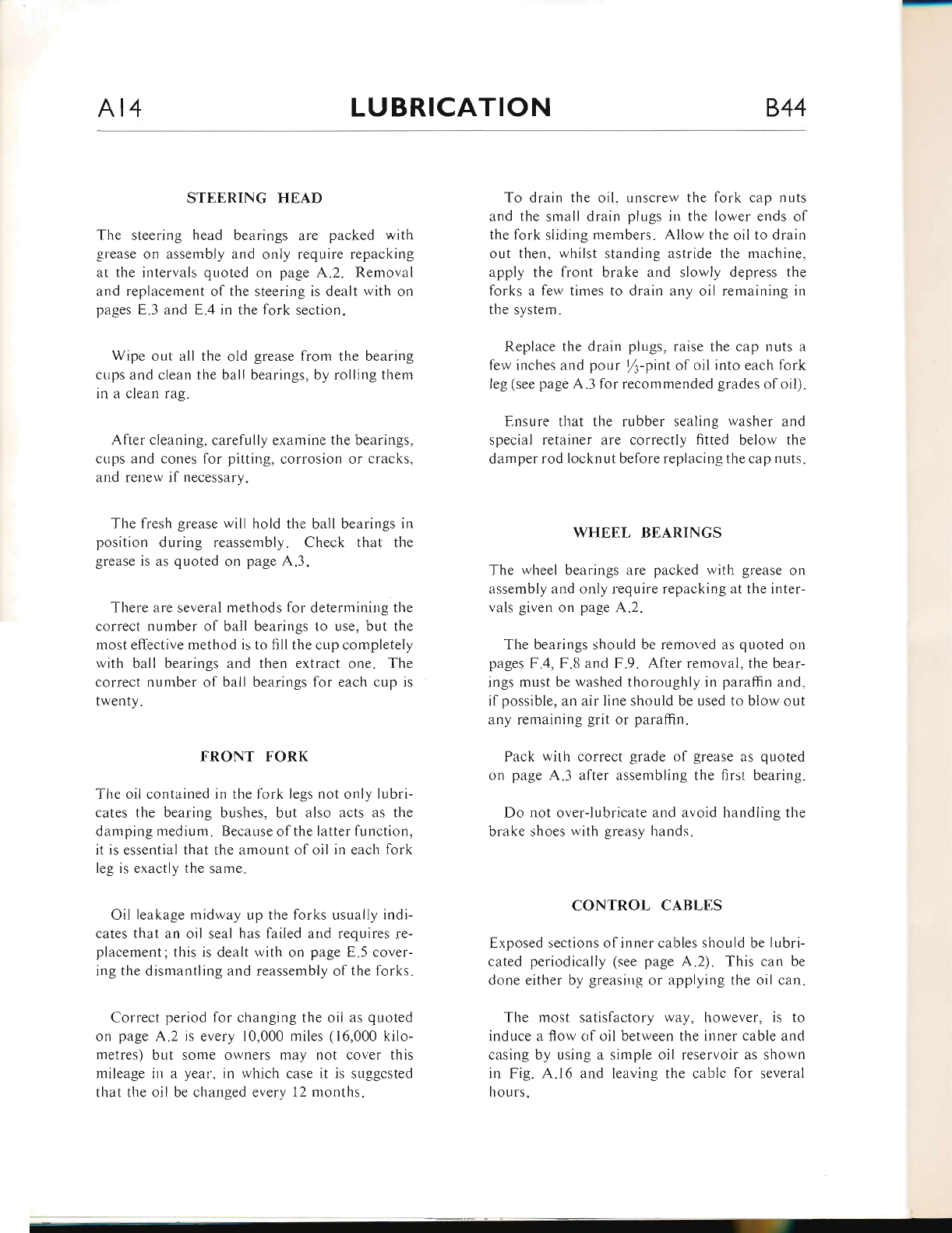
T1.re rnost satisfactory lvay, however, is to
induce a flow of oil between the iuner cable and
casing by using a simple oil reservoir as shown
in Fig. A.16 and leaving the cablc for several
hours.
www.bsaunitsingles.com
844 LUBRICATION At5
Frc. A.16.
During their manufacture, the inner cables are
greased with a molybdenum based grease which
forms a semi-permanent lubricant and should
therefore give long service before needing atten-
tion.
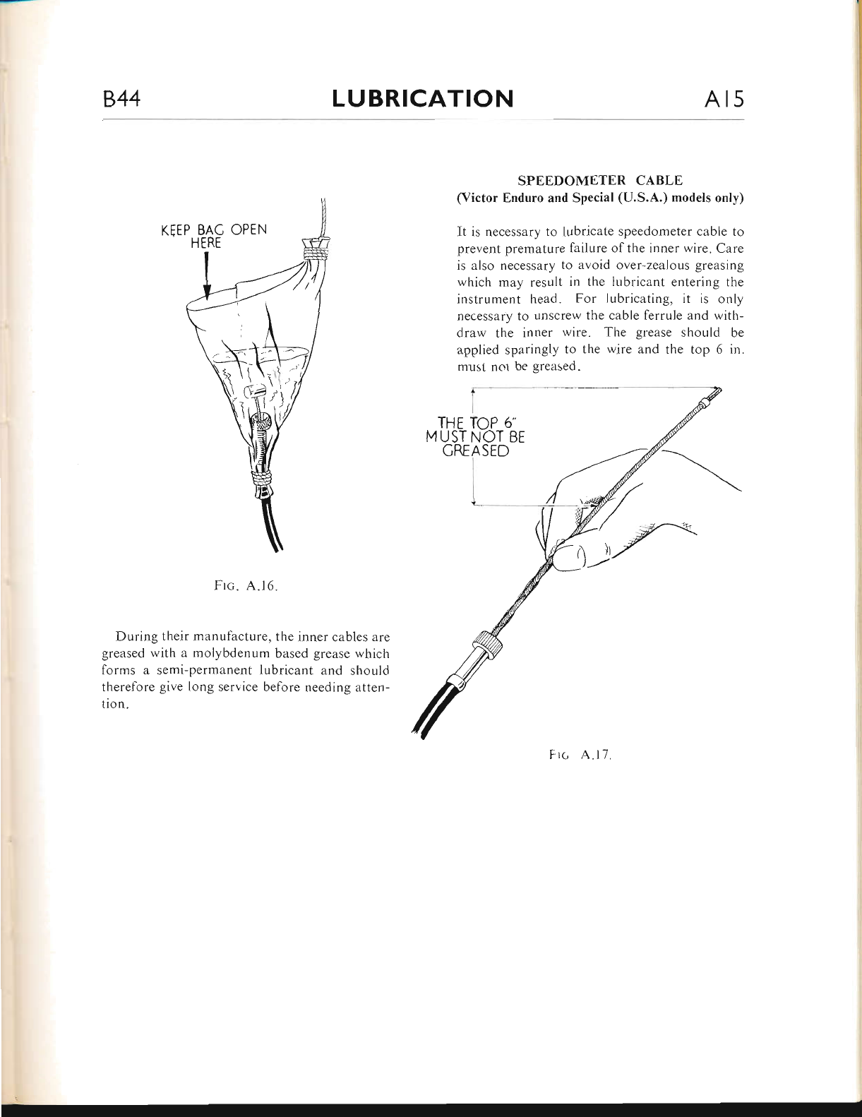
SPEEDOMETER CABLE
(Victor Enduro and Special (U.S.A.) models only)
It is necessary to lubricate speedometer cable to
prevent premature failure of the inner wire. Care
is also necessary to avoid over-zealous greasing
which may result in the lubricant entering the
instrument head. For lubricating, it is only
necessary to unscrew the cable ferrule and with-
draw the inner wire. The grease should be
applied sparingly to the wire and the top 6 in.
must nol be greased.
F rc A.l1
wH
www.bsaunitsingles.com
844 ENGINE BI
INDEX
Page
B.5
DEscnlprroN
DpcARnoNrsrNc
Prgparing to Decarbonise
Push Rods
Valve Guides
B.s-12
B.5-5
B.6
8.6-7
8.1
8.7
8.7
8.7-8
8.8
8.8-9
8.9
B.9
B.9-10
B.t 0
B.l0-12
8.12
Removing the Cylinder Head
Removing the Valve Springs
Valves
Valve Grinding
Reassembling the
Cylinder Barrel
Removing the Piston
Cylinder Head
Removing the Cylinder Barrel
Reassembly after Decarbonising
Small-End Bush
Piston Rings
Description
Cush Drive
Checking Valve Clearances
ReN{ovrNc rHr ENcNe UNrr
TnLltsurssroN
B.t2-14
Removing Primary Drive Cover
B.l4
B.t4
8.14
8.14-15
B.l5
B-16
8.16
B.l6
B.t6-17
8.17-18
Clutch Dismantling
Generator Removal
Inspecting the ilutch
Clutch Chainwheel
Gearbox or Final Drive Sprocket
Clutch Operation
Reassembling the Primary Drive
www.bsaunitsingles.com
82 ENGINE 844
INDEX
CoNracr BnEarpn
Description
Page
B.18
B.18
B.l8-20
B.20
B.2t
821-22
Removing the Contact
Contact Breaker Points
Breaker
TrnrNc Covrns
On Purrar, TrutNc Gra.ns aNo Tapprrs
Oil Pump Removal
Replacing the Oil Pump
Timing Gears ...
Tappets...
Gee,Reox DtslteNrrtNc
Gearchange Mechanism
Gear Cluster ...
Gearbox Bearings
Gra.Rnox RsassnN.Islv
SreusNcE
SpurrrNc
op GBancneNGrNG
Brc-ENo l,Nr Fr-vwnrEr- AssEMsI-v
RrAssnrr.rsuNc THE Cna.Nrcesr
lcNrrroN TrurNc
Piston Position
Setting the Contact Breaker Cam ...
Setting the Ignition Timing ...
Checking the Ignition Timing with a Stroboscope
8.21
B.2t
rnu CRl.Nrcasr, Harvps
8.22-23
8.23
8.23-24
8.24-26
8.26-31
8.32
8.32-33
B.33
B.33-36
B.33
8.34-35
8.35-36
8.36
www.bsaunitsingles.com
844 ENGINE B3
i-r'\)\
l<=Q' t; \Q
i/,mc
\ \@'
',/ -*-cw
- A/ riJ-]
\nsv /^ Y
NJr \-jy :-
d- ,(S
,r4\ds"=
www.bsaunitsingles.com
B4 ENGINE 844
J,d
\>--
sr,!-
/,i
raES -ft.
s'trzq)
c\
,Y
\s-
^- (
6Y
/t\
\g:\
''9/'Y{
i'</,aW!
r\
lti
)
,€
(/ ]7
v
g(
@
\
@-N\\-_
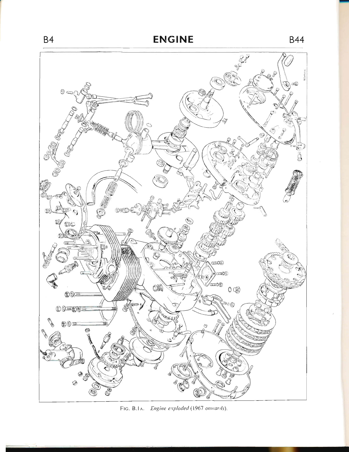
FIc. B.ln. Engine eryloded (1967 onwards).
www.bsaunitsingles.com
844 ENG IN Ets5
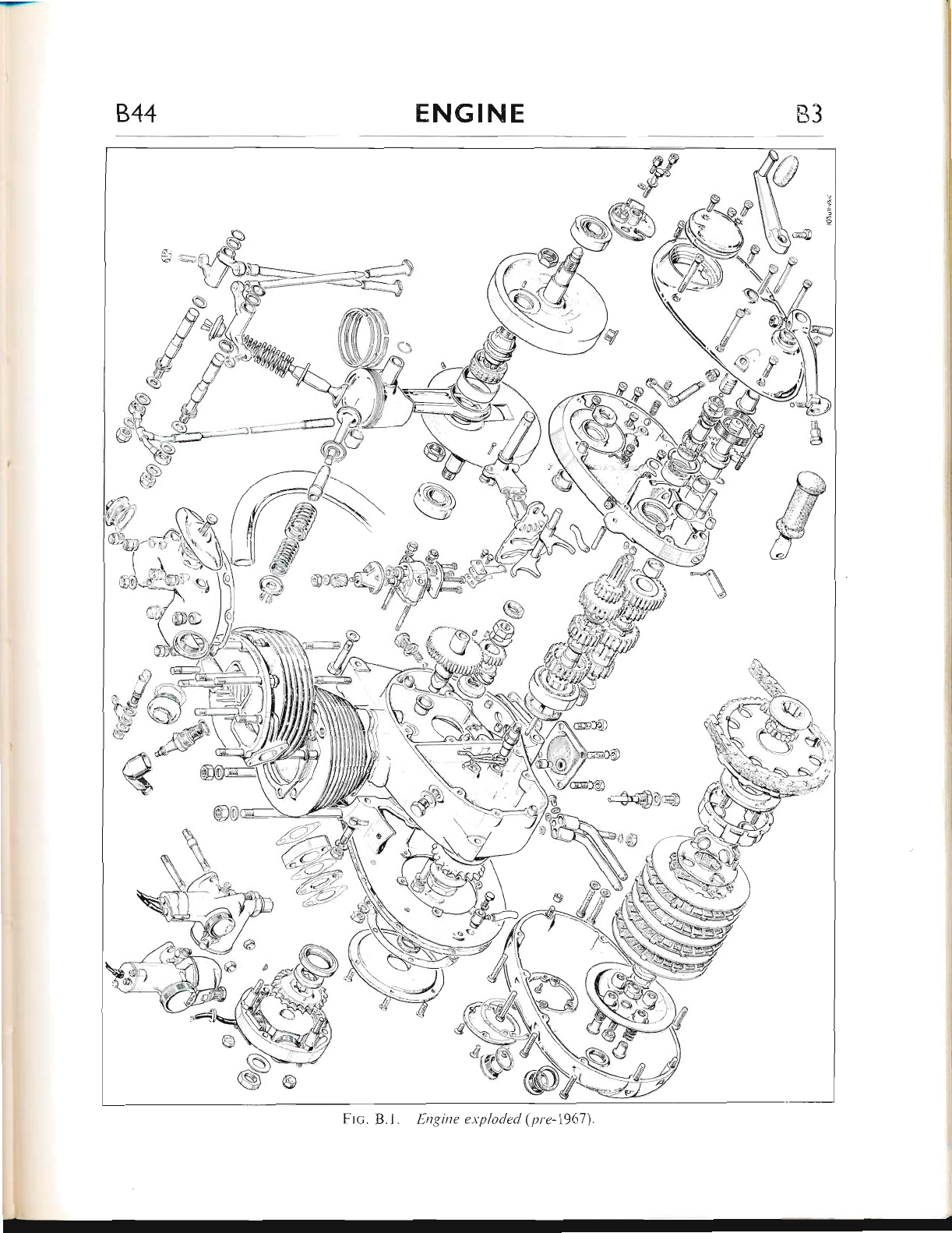
DNSCRIPTION
The o.h.v. four-stroke engine is of the unit con-
structiorr type and has a single cylinder barrel
fitted with an austenitic iron liner. Victor Gr.and
Plix engines, however, h:rve a chlomium-plated
"Y" alloy barrel.
A specizil "Lo-Ex" aluminium piston having
two tapered contpressiorr rings and one scraper
ring is r-rse d on a H-section connecting rod,
employing a roller bearing big-end assembly. It
should be noted that on Victor Enduro and
Special (U.S.A.) errgine only, where an austenitic
iron lirrer is fitted. the piston rings are chromium-
plated. These rings must not, of course, be used
in tlie chromium-plated bore of the Victor Grand
Prix engine. Chrome rings on the Victor Special
htrve now been car.rcelled for 1968.
Two balanced flywheels (rvith crankshaflts) and
tlie crankpin are held togetl'rer by two Ial'ge nuts.
the r"rnit revolving on two crankcase bearings.
The aluminium alloy cylinder head has cast-in.
heavy duty cast-iron valve seats and removable
valve guides. Housed within the top of the
cylinder head are two valvc rocker spindles,
carrying the inlet rocker at the rear and the
exhaust rocker at tl're front.
The one-piece. high perlormance camshaft
operates in two busl.res, one of phosphor bronze
and the other ol sintered bronze.
Contained within the primary drive case on
the left-hand hall ol the crankcase are the clutch
assembly, primary chain and the alternator. The
alternator unit consists of a six-coil stator,
rnounted on three shouldered studs and a rotor.
secured to the drive-side shaft.
A vertically mounted oil pump of the double
gear type is driven off a wolm wheel on the gear-
side crankshalt and supplies oil to the big-end
assembly, piston, cylinder walls and the timing
geafs.
The gearbox, at the rear olthe right-hand half
of the crankcase, and the primary chaincase are
independent ofthe engine lubrication system and
each contain their owrr oilbath.
Power from the engine is transmitted through
the engine sprocket and duplex primary chain to
the clutch assembly which has a built-in cush
drive. Here the drive is taken up by the bonded
friction plates and is transmitted through the
four-speed constant-mesh gearbox to the final
drive sprocket.
DECARBONIS]NG
Decarbonising or "top overhar-rl" as it is some-
times called. means the removal of carbon de-
posits fiom the combustion chamber, piston
crown, valve heads and inlet and exl.raust ports,
and to restore a smooth finish to these surfaces.
Obviously, whilst the upper portion olthe engine
is dismantled for this purpose, opportunity will
be taken to examine the valves, valve seats,
springs, guides. etc., for general "wear and tear",
hence the term "top overhaul."
Carbon, produced by combustion taking place
irr the engine when running, is not harmful pro-
viding it is not allowed to become too heavy and
therefbre likely to cause pre-ignition or other
symptoms which may impair the engine per-
formance.
The usual symptoms indicating the need for
decarbonising, are an increased tendency for the
engine to "pink" (metallic knocking sound when
under load), a general decrease in power and a
tendency for the engine to run hotter than usual.
An increase in petrol consumption may also be
apparent.
Preparing to Decarbonise
Before commencing with the work, it is advisable
to have the following equipment available:-
Spanners for 116 in. W., /a in. B.S.F. to rt-
in. W., /s in. B.S.F.
Set of Scrapers
Set of Feeler Gauges
Supply of fine grade emery cloth
Jointing compound or cenrent
www.bsaunitsingles.com
B6
-
ENGINE 844
Valve Grinding Tool No.65-9240, and course/
fine grade grinding paste
Valve Spring Compressor No. 61-3340
Clean engine oil
Pieces of hard wood to support piston
Top Overhaul Gasket No. 00 3163
Gudgeon Pin Circlips No. 66-954 (2)
Valve Springs (set) Nos. 65-2494 (outer) and
65-2495 (inner)
Paraffin and clean rag for cleaning
Perfect cleanliness is essential to etrsure success
in any service task so, before statting ajob such
as this, make sure that you have a clean bench
or working area on which to operate and room
to place parts as they are removed.
Victor Grand Prix models
Because the clearance between the cylinder head
and frame top tube is not sufficient to allow the
head to be lifted off, it will be necessary to take
the engine out of the frame (see page B.12).
An alternative to this is to extract all the
rocker box studs, allowing the rocker box to be
removed from one side, so providing the neces-
sary clearance for removal of the cylinder head.
Continual extraction ol the studs will eventu-
ally impair the threads in the head and it is
preferable therefore, to remove the complete
engine.
The Victor Grand Prix machine, however, is
built specially for use in Scrambles events aud
hence it will almost never be necessary to dis-
mantle the engine solely for a simple decar-
bonising job, as is usual rvith a machine for
road use.
Yictor Enduro and Special (U.S.A.) models
To facilitate removal of the cylinder head, first
take off the petrol tank (see page B.13).
With the tank removed, the engine steady
bracket can be disconnected, together with the
exhaust valve lifter cable.
The exhaust pipe is a push-fit into the cylinder
head and can be withdrawn after releasing the
nuts holding the exhaust system to the frame.
Disconnect the rubber adaptor between the
air clearrer and carburetter, so that the latter can
be withdrawn from its studs and tied back out
of the rvay. On 1968 models the air cleaner is
screwed on to the back of the carburetter there-
fore they can be removed together.
The oil feed pipe to the rocker spindles should
now be removed and the sparking plug taken out.
Rernoving the Cylinder Head
Set the piston at top dead centre on the com-
pression stroke (both valves closed) and take off
tire nuts holding the cylinder head to the barrel.
Leave the rocker box assembly in position on
the cylinder head, and raise the latter until it
clears its fixing studs. On Victor Enduro and
Special (U.S.A.) models, when the engine is in
the frame, it will be necessary to rotate the
cylinder head assembly about the push rods so
as to clear the frame top tube. The rocker box
can no\,v be removed from the cylinder head,
thus exposing the valves and springs.
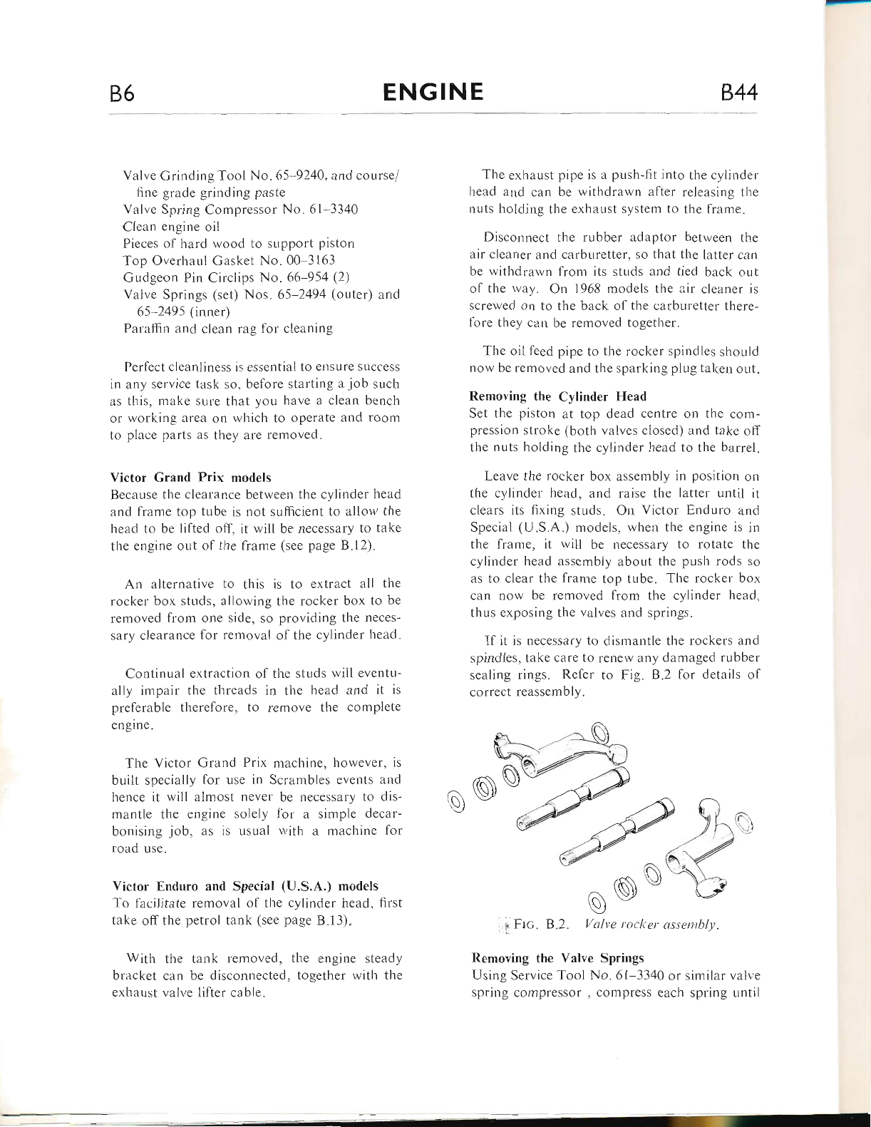
If it is necessary to dismantle the rockers and
spindles, take care to renew any damaged rubber
sealing rings. Refer to Fig. B.2 for details of
correct reassembly.
rA
--c, \Jl
R)
\c\\ v
wt
A
r6Nw
a^\ \y-/
AJ
, p Frc. B.2. Valve rocker assentbly.
Removing the Valve Springs
Using Service Tool No. 61-3340 or similar valve
spring compressor , compress each spring until
www.bsaunitsingles.com

844 ENGINE 87
the split collets can be removed. The valve springs
and top collars can ltow be lifted from the valve
stems, slvilled in paraffin, then placed orr a
numbered board to indicate their position in the
cylinder head.
The springs mny have settled through long use
ancl they should therefore be checked in accord-
ance rvith 1l.re dimer.rsions quoted on page GD.-1 .
Ifthe springs have settled appreciably, or there
are signs of cracking, they should be replacecl.
Push Rods
Examine the pusl.r rod end cups to see ilthey arre
chipped. worn or loose, and check that the rods
are not bent by rolling them on a flat surface
(i.e. a piece ol plate glass). Tf any of these
faults are etident the rod(s) should be renewed.
Valve Guides
Check the valves in the guides; there should be
no excessive side-play or evidence ol carbor.r
bLrild-up on that portion of tl-re stem whicl'r
operates in the guide. Carbon deposits can be
removecl by carefLrl scraping and very light use
of fine grade emery cloth. If there are signs ol
scoring on the valve stems. indicating seizure,
both valve and guide should be renewed.
Ar-r old valve guide can be driven out with
Service Tool No. 61-3382 but, the aluminiun.r
head should first be heated by irnrnersing in l-ro
water. The new guide can be driven in with the
sarne punch whilst the head is still warm. Note
lhat the exl.raust guide is counterbored at tl.re end
rvhich protrudes into the port.
Whenever new guicies have been fitted, each
valve seat must be refaced with a piloted valve
seat cutter, to ensllre that the seat is concentric
with the guide bore.
Valyes
Valve heads can be relaced on a valve refacer
but if pitting is deep or the valve head is burnt,
then a new valve must be fitted and ground-in.
The valve seats in the cylinder head are un-
likely to require any attentior.r, but il they are
marked, they should be relaced with valve seat
cutter tool No. 6l-3300, used with pilot No.
61 3293 and holder No.6l-3290. The seat arr-sle
is 45 degrees.
Sometimes when the engine has been decar-
bonised many times, valves become "pocketed".
This is wl"ren the valve head and seat are below
the surface of the combustior-r chamber, so impair-
ing the efiiciency of the valve and affecting the
gas l1ow. The "pocket" should be removecl r.vith
a special 30' angle cutter before re-cutting thc
seat or grinding-in the valve.
Valve Grinding
ll tl-re valves have bcen rcnewed or relaced thev
must be lightly gror:;td-in to thcir seats to ensure
a good gas-seal.
This operation is carried out only afier all
carbon deposits have been removed from the
combustion chamber.
Removal of carbon flom the head, inlet and
exhaust ports can be carried out with scrapers
or rotary files, but wl.richever method is used,
great care must be taken to avoid scoring the
valve seats.
Ftc. B.3. Pocliete'd yalt,e
www.bsaunitsingles.com
B8 ENGINE 844
A final "polish" can be achieved with the use
ol fine emery cloth wetted by paraffin.
Do not attempt to decarbonise the cylinder
head by immersing it in caustic soda solution;
tl.re solution l.ras a harmful effect on aluminium.
Having removed all traces of carbon, smear a
srnall quantity of fine grinding paste over the lace
of the valve and return the valve to its seat.
Now, using Service Tool No. 65-9240, rotale
the valve backwards and forwards, maintaining
steady pressure. Every few slrokes, raise the
valve and turn it to a new position. A light
spring inserted under the valve head greatly
assists ir1 raising the valve to enable it to be re-
positioned.
Grinding should be continued until the mating
surfaces of both the valve and seat show a uni-
lorm matt finish all round.
NorE:-Prolonged grinding-in ol the valve
does not produce the same results as re-cutting
and must be avoided at all costs.
Re-assembling the Cylinder Head
Before reassembling the valves and springs, all
traces of grinding paste must be removed from
both the valves and their seats.
Smear each valve stem with clean engir.re oil
and replace the valves in the head.
Fit the spring cup, valve springs (with close
coils at the bottom), and top collar over each
valve stem, then compress the springs with
Service Tool No. 61*3340 to allow the split
collets to be inserted in the top collar. A little
grease on tl-re valve stem will assist in keeping
the collets in position as the valve springs are
released.
Make sure that the collets are correctly seated
in the recess on the valve stem.
Cylinder Barrel
Unless the condition of the engine indicates tliat
the piston, piston rings or cylinder bore require
attention, the cylinder barrel shor-rld not be
disturbed.
If tl-ie bore is worn it can sometimes be detected
by placing the fingers on top of the piston and
attempting to push the piston backwards and
forwards in the direction of flywheel rotation.
Symptoms indicating faulty piston rings might
include heavy oil consumption and poor com-
pression, but only if the valves are known to be
in good order. If the valves require attention
they are much more likely to be the cause ol
5uch symptoms.
Excessive piston slap when warm may indicate
a worn bore or severe damage through seizure.
The cylinder bore can be measured for wear
with a suitable dial gauge, after moving the piston
to the bottom of the bore.
If the barrel is not being removed, bring the
piston to the top of the bore and, after plugging
the push rod opening with clean rag, proceed to
remove the carbon lrom tl.re piston crown. A
stick of tinsmiths solder, flattened at one end,
provides an ideal scraper tool and will not
damage the alloy piston.
Always leave a ring of carbon around the edge
of the piston crown and around the top of the
cylinder bore. This will help to provide an
additional seal.
Ftc. B.4. Grincling-in valve.
www.bsaunitsingles.com
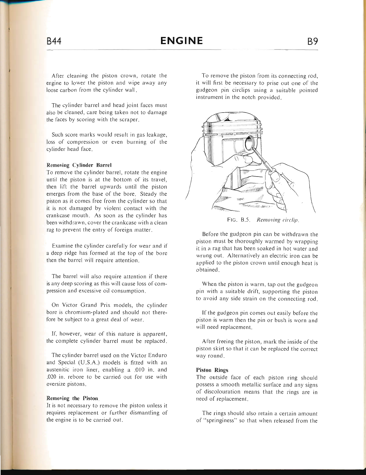
844 ENGINE B9
After cleaning the piston crown, rotate the
engine to lower the piston and wipe away any
loose carbon from the cylinder wali.
The cylinder barrel and head joint faces must
also be cleaned, care being taken not to damage
the faces by scoring with the scraper.
Sucl.r score marks would result in gas leakage,
loss of compression or even burning ol the
cylinder head face.
Removing Cylinder Barrel
To remove tl-re cylinder barrel, rotate the engine
until the piston is at the bottom of its travel,
then lift the barrel upwards until the piston
emerges from the base of the bore. Steady the
piston as it comes free from the cylinder so that
it is not damaged by violent contact with the
crankcase mouth. As soon as the cylinder has
been withdrawn! cover the crankcase with a clean
rag to prevent the entry of foreign matter.
Examine the cylinder carefully for wear and if
a deep ridge l-ras formed at the top of the bore
then the barrel wili require attention.
The barrel will also require attention if there
is any deep scoring as this will cause loss of com-
pression and excessive oil consumption.
On Victor Grand Prix models, the cylinder
bore is chromium-plated and should not there-
fore be subject to a great deal of wear.
If, however, wear ol this nature is apparent,
the complete cylinder barrel must be replaced.
The cylinder barrel used on the Victor Enduro
and Special (U.S.A.) models is fitted with an
austenitic iron liner, enabling a .010 in. and
.020 in. rebore to be carried out for use with
oversize pistons.
Removing the Piston
It is not necessary to remove the piston unless it
requires replacement or further dismantling ol
the engine is to be carried out.
To remove the piston from its connecting rod,
it rvill first be necessary to prise out one of the
gudgeon pin circlips using a suitable pointed
instrument in the notch provided.
Ftc. B.5. Removing circlip.
Before the gudgeon pin can be withdrawn the
piston must be thoroughly warmed by wrapping
it in a rag that has been soaked in hot water and
wrung out. Alternatively an electric iron can be
applied to the piston crown until enough heat is
obtained.
When the piston is warm, tap out the gudgeon
pin with a suitable drift, supporting the piston
to avoid any side strain on the connecting rod.
If the gudgeon pin comes out easily before the
piston is warm then the pin or bush is worn and
will need repiacement.
After freeing the piston, mark the inside of the
piston skirt so that it can be replaced the correct
way round.
Piston Rings
The outside face of each piston ring should
possess a smooth metallic sul'face and any signs
of discolouration means that the rings are in
need of replacement.
The rings should also retain a certain amount
of "springiness" so that when released from the
www.bsaunitsingles.com
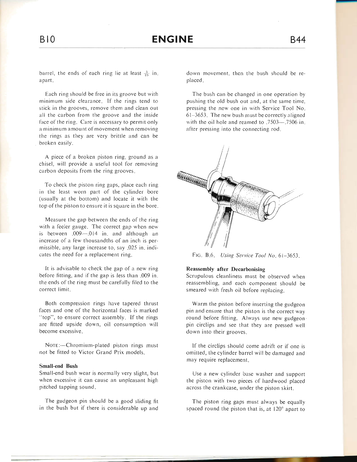
Bt0
-
ENGINE 844
barrel, the ends of each ring lie at Ieast fr in.
apart.
Each ring should be free in its groove but with
minimum side clearance. If the rings tend to
stick in the grooves, remove them and clean out
all the carbon from the groove and the inside
face of the ring. Care is necessary to permit only
a minimum amourlt of movement when removing
the rings as they are very brittle and can be
broken easily.
A piece of a broken piston ring, ground as a
chisel, will provide a useful tool for removing
carbon deposits from the ring grooves.
To check the piston ring gaps, place each ring
in the least worn part of the cylinder bore
(usually at the bottom) and locate it with the
top of the piston to ensure it is square in the bore.
Measure the gap between the ends of the ring
with a feeler gauge. The correct gap when new
is between .009-.014 in. and although an
increase of a few thousandths of an inch is per-
missible, any large increase to, say .025 in. indi-
cates the need for a replacement ring.
It is advisable to check the gap of a new ring
before fitting, and if the gap is less than .009 in.
the ends of the ring must be carefully filed to the
correct limit.
Both compression rings have tapered thrust
faces and one of the horizontal faces is marked
"top", to ensure correct assembly. If the rings
are fitted upside down, oil consumption will
become excessive.
Nors: Chromium-plated piston rings mr-rst
not be fitted to Victor Grand Prix models.
Small-end Bush
Small-end bush wear is normally very slight, but
when excessive it can cause an unpleasant high
pitched tapping sound.
The gudgeon pin should be a good sliding fit
in the bush but if there is considerable up and
down movement, then the bush should be re-
placed.
The bush can be changed in one operation by
pushing tire old bush out and, at the same time,
pressing the new one in with Service Tool No.
61 3653. The new bush must be correctly aligned
r.vith the oil hole and rearned to .7503- .7506 in.
after pressing into the connecting rod.
Ftc. 8.6. Using Service Tool No.6l-3653.
Reassembly after Decarbonising
Scrupulous cleanliness must be observed when
reassembling, and eacl.r component should be
smeared rvith fresh oil before replacing.
Warm the piston before inserting the gudgeon
pin and ensure that the piston is the correct way
round before fitting. Always use new gudgeon
pin circlips and see that they are pressed well
down into their grooves.
If the circlips should come adrift or if one is
omitted, the cylinder barrel will be damaged and
rnay require replacement.
lJse a new cylinder base washer and support
the piston with two pieces of l-rardwood placed
across the crankcase, under the piston skirt.
The piston ring gaps must alu,ays be equally
spaced round the piston that is, at l20o apart to
www.bsaunitsingles.com
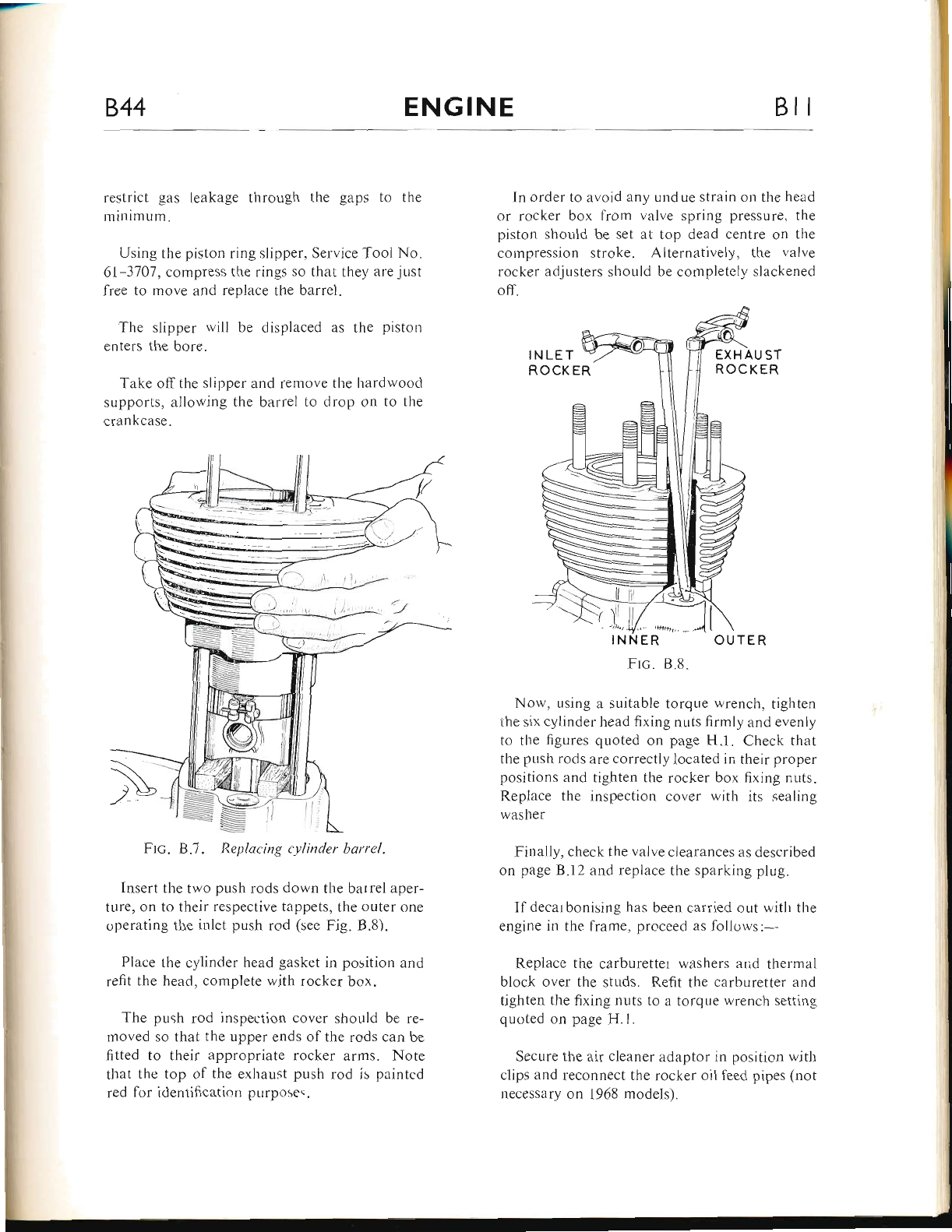
-
I
844 ENGINE BII
restrict gas leakage through the gaps to the
minimum.
Using the piston ring slipper. Service Tool No.
6l-3101, compress the rings so that they arejust
free to move and replace tlre barrel.
The slipper will be displa.ced as rhe piston
enters the bore.
Take off the slipper and remove the hardwoocl
supports, allowing tlre btrrrel to drop on to the
crankcase-
Insert the two push rods down the barrel aper-
ture, on to their respective tappets, the outer one
operating the inlet push rod (sec Fig. B.8).
Place the cylinder head gasket in position and
refit the head, complete with rocker box.
The push rod inspection cover should be re-
rnoved so that the upper er.rds of the rods can be
fitted to their appropriate rocker arms. Note
that the top of the erhaust push rod is painted
red lor identification pLlrposes.
In order to avoid any undue strain on the head
or rocker box from valve spring pressure. the
piston should be set at top dead centre on the
coinpression stroke. Alternatively, the r.,alr,e
rocker adjusters should be completely slackenecl
off.
INNER OUTER
Frc. 8.8.
Nolv. using a suitable torqr-re wrench, tighten
the six cylinder head fixing nuts firmly and evenly
to tl.re figures quoted on page H.l. Check that
the pr-rsh rods are correctly located in their proper
positions and tighten the rocker box fixing nuts.
Replace the inspection cover with its sealing
washer
Finaily, check the valve clearances as described
on page B.l2 and replace the sparking plug.
If decarbonising has been carried out with the
engine in the frame, proceed as follows:--
Replace the carburetter washers and thermal
block over the studs. Re{it the carburetter ancl
tighten the fixing nuts to a torque wrench setting
quoted on page H.1.
Secure the air cleaner adaptor in position with
clips and reconnect the rocker oil leed pipes (not
necessary on 1968 models).
Ftc. B.7. Rcplat'ing cylinder barrcl.
www.bsaunitsingles.com
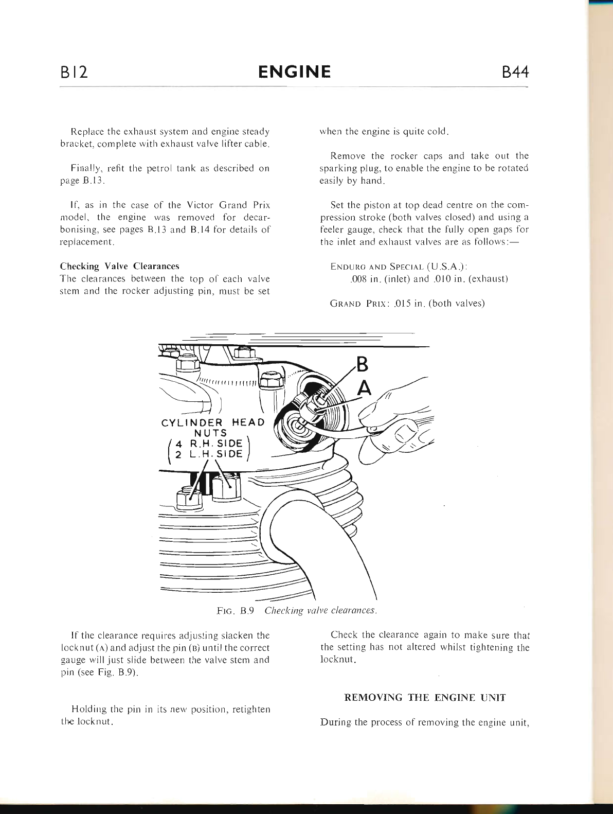
Bt2 ENGINE 844
Replace the exhaust system and engine steady
bracket, complete with exhaust valve lifter cable.
Finally, refit the petrol tank as described on
page B.13.
If, as in the case of the Victor Grand Prix
nrodel, the er.rgine was removed for decar-
bonising, see pages B.l3 and B.l4 for details of
replacement.
Checking Valve Clearances
The clearances between the top of each valve
stem ar,d the rocker adjusting pin, must be set
CYLINDER HEAD
Frc. 8.9 Checlting
lf the clearance requires adjusting slacken the
locknut (,q) and adjust the pin (n) until the correct
gauge will just slide between the valve stem and
pin (see trig. B.9).
Holding the pin in its neu, position, retighten
the locknut.
when the engine is quite cold.
Remove the rocker caps and take out the
sparking plug, to enable the engine to be rotated
easily by hand.
Set the piston at top dead centre on the com-
pression stroke (both valves closed) and using a
feeler gauge, check that the fully open gaps for
the inlet and exhaust valves are as follows:-
ENpuno .rNp Sprcl,rL (U.S.A.) :
.008 in. (inlet) and .010 in. (exhaust)
Gn,q.No Pnrx: .015 in. (both valves)
valve clearances.
Check the clearance again to make sure that
the setting has r.rot altered whilst tightening the
locknut.
REMOVING TTiE ENGINE UNIT
During the process of removing the engine unit,
B
A
TS
SIDE \
.srDE /
NU
4 R.H.
2 L.H.
www.bsaunitsingles.com
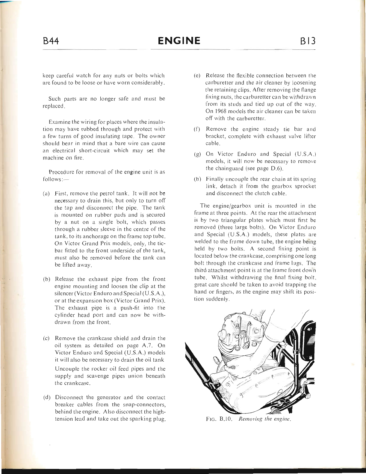
844 ENGINE Bl3
keep carefi-rl watch for any nuts or bolts which
are found to be loose or have worn considerably.
Such parts are no longer sale and must be
replaced.
Examine the wiring for places where the insula-
tion may have rubbed tl-rror.rgh and protect with
a few turns ol good insulating tape. The owner
should bear in mind that a bare rvire can cause
an electrical short-circr-rit which mav set the
machine on fire.
Procedure lor removal of the engine unit is as
lollows:-
(a) First, remove the petrol tank. lt will not be
necess.rry to drain this, but only to turn off
the tap and disconnect the pipe. The tank
is mounted on rubber pads and is secured
by a nut on a single bolt, which passes
through a rubber sleeve in the centre of the
tank, to its anchorage on the frame top tube.
On Victor Grand Prix n.rodels, only, the tie-
bar fitted to the front underside of the tank,
must also be removed belore the tank can
be lifted away.
(b) Release the exl-raust pipe from the front
engine mor-rnting and Ioosen the clip at the
silencer (Victor Enduro and Special (U.S.A.),
or iit the expansion box (Victor Grand Prix).
The exhaust pipe is a push-fit into the
cylinder head port and can now be with-
drawn from the front.
Remove the crankcase shield and drain tl-re
oil system as detailed on page A.7. On
Victor Enduro and Special (U.S.A.) models
it will also be necessary to drain the oii tank
Uncouple the rocker oil feed pipes and the
supply and scavenge pipes union beneath
the crankcase.
Disconnect tl.re generator and the contact
breaker cables from the snap-connectors,
behind the engine. Also disconnect the high-
tension lead and take out the sparking plug.
(e) Release the flexible conuection between the
carburetter and the air cleaner by loosening
the retaining clips. After removing the flange
fixing nuts. the carburetter can be withdrau,n
lrom its sttrds and tied up out ol the way.
On 1968 models the air cleaner can be takcn
off ivith the carburetter.
(f) Remove the engine steady tie bar ancl
bracket, cclmplete ri,ith exl.rar-rst valve lilter
cable.
(g) On Victor E,r.rduro and Special (U.S.A.)
models, it will now be necessary to remove
the chainguard (see page D.6).
(h) Finally uncouple the rear chain at its spring
link, detach it from the gearbox sprocket
and disconnect the clutcl.r cnble.
The engine/gearbox unit is mounted in the
lrame at three points. At the rear the attachment
is by two triangular plates which must first be
removed (three large bolts). On Victor Endurcr
and Special (U.S.A.) models, tl-rese plates are
welded to the frame down tube, the engine being
held by two bolts. A second fixing point is
iocated below the crankcase, comprising one lon-e
bolt throLrgh the crankcase and frame lLrgs. The
third attachment point is at the frame front dou n
tube. Whilst withdrawing the finerl fixing bolt,
great care should be taken to avoid trapping the
hand or fingers, as the engine may shift its posi-
tiorr suddenly.
(c)
Ftc. B.10. Rentot'ing tlte engine.
(d)
www.bsaunitsingles.com
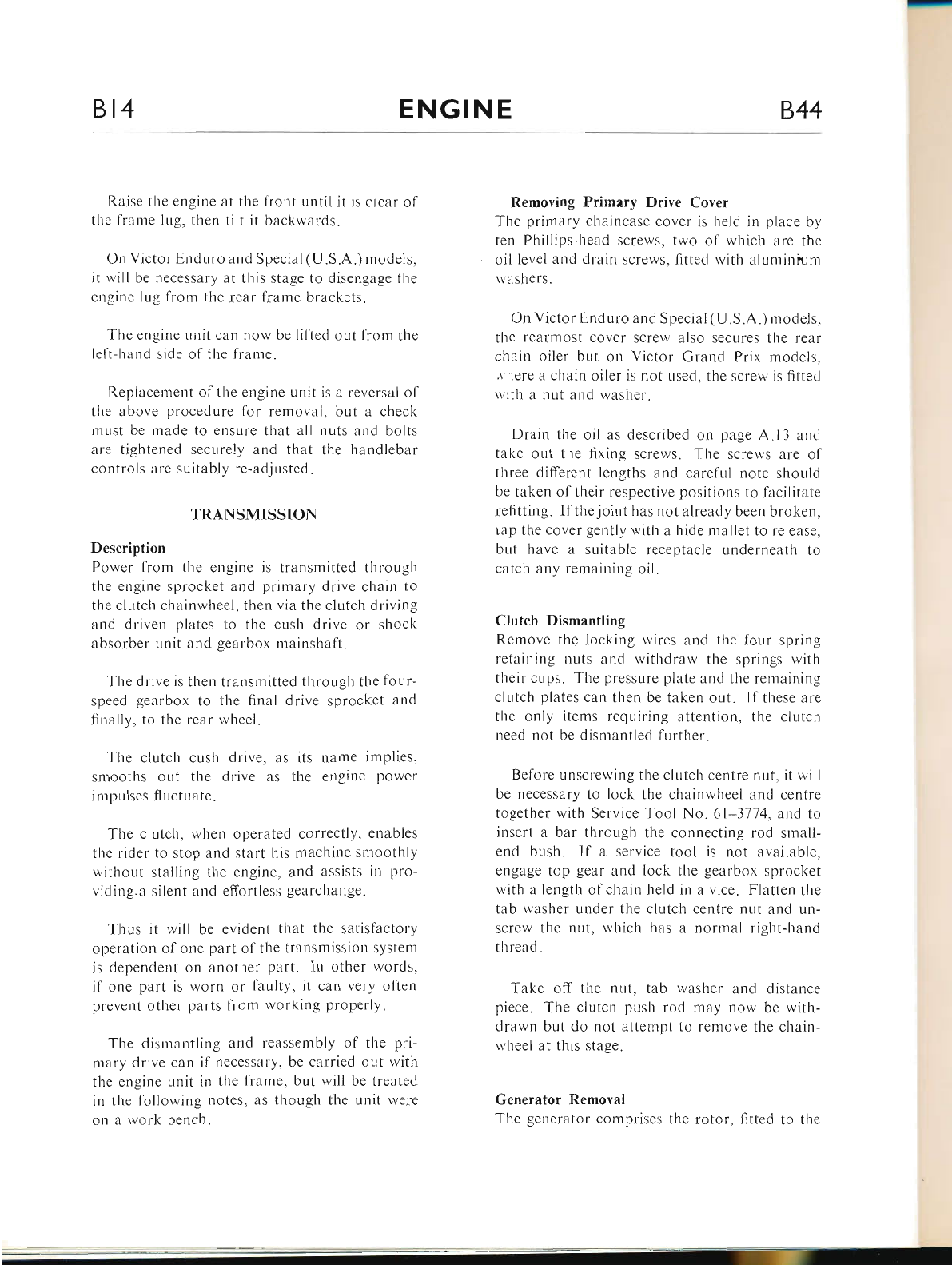
Bt4 ENGINE 844
Raise tl.re engine at the front until it rs clear of
the franre lug, then tilt it backrvards.
On Victor Er-rduro and Special (U.S.A.) models,
it rvill be necessary at this stage to disengage the
engine lug from the rear frame brackets.
Tl.re engine Lrnit can now be lilted or,rt from the
left-hand side o1'the lrame.
Replacenrent ol the engine unit is a reversal ol
the above procedure for removal, but a check
must be made to ensure that all nuts and bolts
are tightened securely and that the handlebar
controls are suitably re-adjusted.
TRANSMISSION
Description
Power from the engine is transmitted through
the engine sprocket and primary drive chain to
the clutch chainwheel, then via the clr-rtch driving
and driven plates to the cush drive or shock
absorber unit and gearbox mainshaft.
'Ihe drive is then transmitted through the fbur-
speed gearbox to the final drive sprocket and
finally, to the rear wheel.
The clutch cush drive, as its nanre implies,
smooths out the drive as the engine power
impulses fluctuate.
The clutch, when operated correctly, enables
the rider to stop and start his machine smoothly
r,i,ithout stalling tl.re engine, and assists in pro-
viding.a silent and effortless gearchange.
Thus it will be evidenl that the satisfactory
operation ol one part ol the transmission system
is dependent on another part. In other words,
il one part is worn or faulty, it can very often
pl'event other parts from working properly.
The dismantling and reassembly of the pri-
mary drive can il necessary, be carried out with
the engine unit in the fi'ame, but will be treated
in the following notes, as though the unit rvere
on a rvork bench.
Removing Prirnery Driye Coyer
The primary chaincase cover is held in place by
ten Phillips-head screws, two of whicl.r are the
oil level and drain screws. fitted r,vith aluminium
u ashers.
On Victor End uro and Special ( U .S.A .) models,
the rearmost cover screrv also secures the rear
chain oiler but on Victor Grand Prix models.
,l'here a chain oiler is not used, the screw is fitted
ri ith lr nut lnd washer.
Drain tlre oil as described on page A.13 and
take out the fixing screws. The screws are of
three different lengths and carelul note should
be taken of their respective positions to facilitate
refitting. Ifthejoint has not already been broken,
rap the cover gently with a hide mallet to release,
but have a suitable receptacle underneath to
catch any remaining oil.
Clutch Dismantling
Remove the locking wires and tl.re lour spring
retairling r.ruts and withdraw the springs with
tl.reir cups. The pressure plate and the ren.raining
clutch plates can then be taken out. Ifthese are
the only items reqr-riring attention, the clutch
need not be dismantled further.
Before unscrewing the clutch centre nut, it will
be necessary to lock the chaini,vheel and centre
together with Service Tool No. 61-3174, and to
insert a bar througl-r the connecting rod small-
er.rd bush. If a service tool is not available,
engage top gear and lock the gearbox sprocket
with a length of chain held in a vice. Flatten the
tab rvasher under the clutch centre nut and un-
scrcw tlle nut. rvhich Iras a rrormal right-hand
thread.
Take off the nut, tab rvasher and distance
piece. The clutch push rod may now be with-
drawn but do not attempt to remove the chain-
rvheel at this stage.
Gcnerator Removal
The generator comprises the rotor, fitted to the
www.bsaunitsingles.com
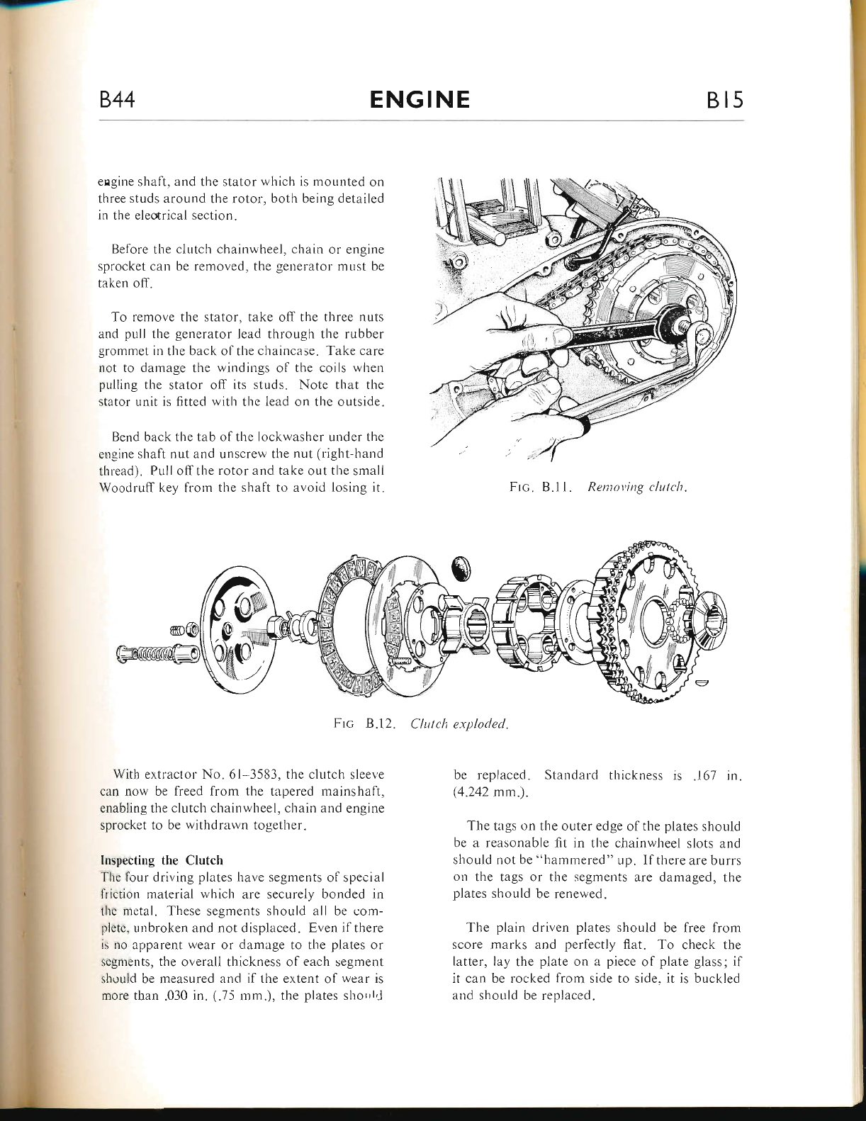
844 ENGINE Bt5
engine shaft, and the stator which is mounted on
three studs around the rotor, both being detailed
in the electrical section.
Before the clutch chainwheel, chain or engine
sprocket can be removed, the generator must be
taken off.
To remove the stator, take off the three nuts
and pull the generator lead through the rubber
grommet in the back olthe chaincase. Take care
not to damage the windings of the coils when
pulling the stator off its studs. Note that the
stator unit is fitted with the lead on the outside.
Bend back the tab of the lockwasher under the
engine shaft nut and unscrew the nut (righrhand
thlead). Pull offthe rotor and take out the smali
Woodruff key frorn the shaft to avoid losing it. Ftc. B.11. Rentoving clutclt.
Ftc B.12. Clulch exploded.
With extractor No. 61 3583, the clutch sleeve
can now be freed from the tapered mairrshaft,
enabling the clutch chainwheel, chain and engine
sprocket to be withdrawn together.
Inspecting the Clutch
The four driving plates have segments of special
friction material which are securely bonded in
the metal. These segments should all be com-
plete, unbroken and not displaced. Even if there
is no apparent wear or damage to the plates or
segnents, the overall thickness of each segment
should be measured and if the extent of wear is
more than .030 in. (.75 rnm.), the plates shorrl,J
be replaced. Standard thickness is .167 in.
(4.242 mm.).
The tags on the outer edge ofthe plates should
be a reasonable fit in the chainwheel slots and
should not be "l.rammered" up. If there are burrs
on the tags or the segments are damaged, the
plates should be renewed.
The plain driven plates should be free from
score marks and perfectly flat. To check the
latter, lay the plate on a piece of plate glass; if
it can be rocked from side to side. it is buckled
and should be replaced.
www.bsaunitsingles.com
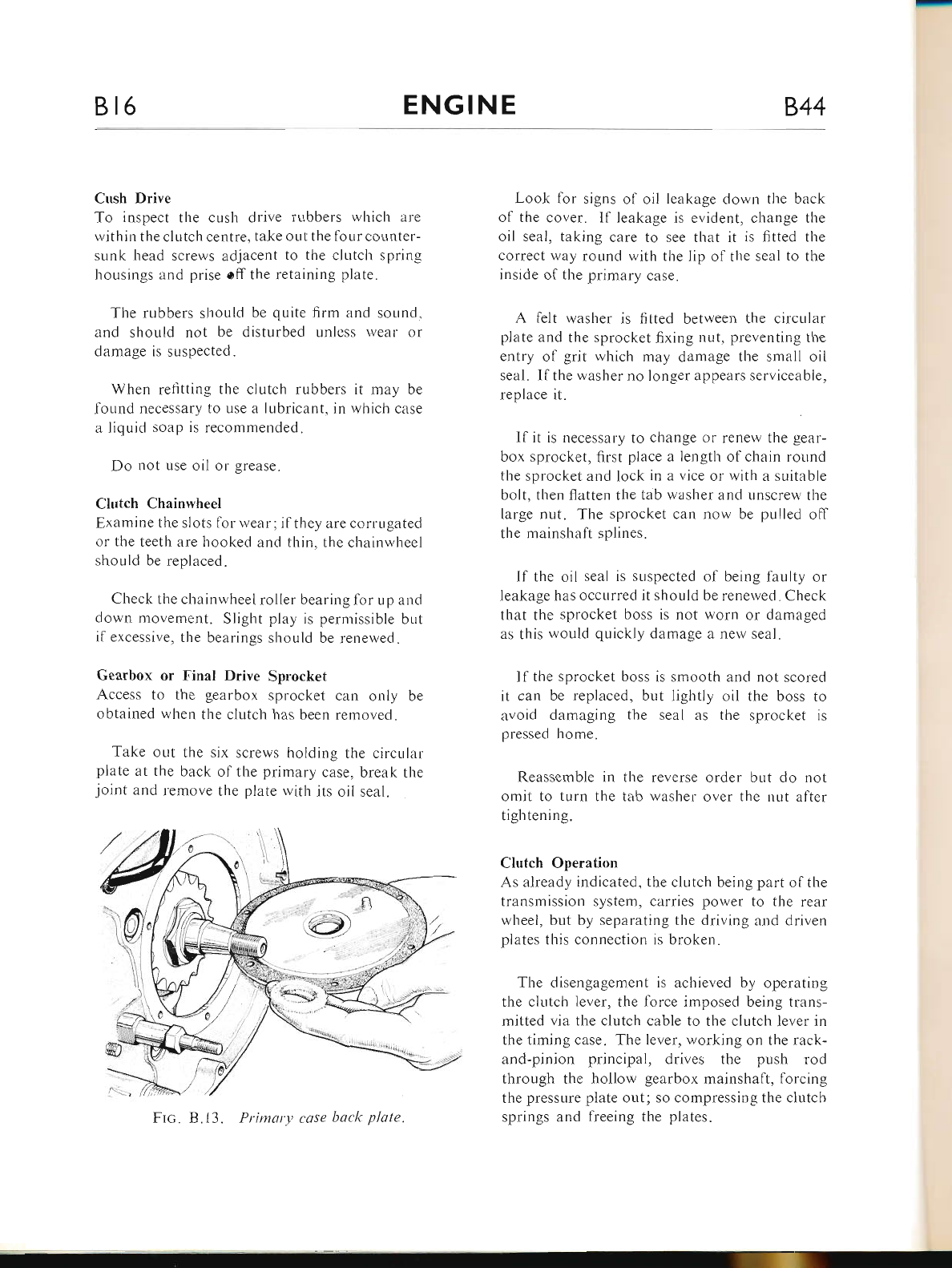
Bl6 ENGINE 844
Cush Drive
To inspect the cush drive rr-rbbers which arre
within the clutch centre, take out the four counter-
sunk head screws adjacent to tlie clutch sprirrg
housings and prise off the retaining plate.
The rubbers should be quite firm and sound,
and should not be disturbed unless wear or
damage is suspected.
When refitting the clutch rubbers it may be
found necessary to use a lubricant, in which case
a liquid soap is recommended.
Do not use oil or grease.
Clutch Chainwheel
Examine the slots for wear ; if they are corrugated
or the teet}r are hooked and thin. the chainwheel
should be replaced.
Check the chainwheel roller bearing for up ar.rd
down movement. Sliglit play is permissible but
if excessive, the bearings should be renewed.
Gearbox or Final Drive Sprocket
Access to the gearbox sprocket can only be
obtained when the clutch has been removed.
Take out the six screws holding the circular
plate at the back of the primary case, break the
joint and remove the plate with its oil seal.
Look for signs of oil leakage down tl-re back
of the cover. lf leakage is evident, cl.range the
oil seal, taking care to see that it is fitted the
correct way round rvith the lip of the seal to the
inside of the primary case.
A felt washer is {rtted between the circular
piate and the sprocket fixing nut, preventing the
entry of grit which may damage the small oil
seal. lfthe washer no longer appears serviceable,
replace it.
lf it is necessary to change or renew the gear-
box sprocket, first place a length of chain round
the sprocket and Iock in a vice or with a suitable
bolt, then ffatten the tab washer and unscrew the
large nut. The sprocket can no$' be pulled off
the mainshaft splines.
If the oil seal is suspected of being faulty or
leakage has occurred it should be renewed. Check
tlrat the sprocket boss is not worn or damaged
as this would quickly damage a nerv seal.
lf the sprocket boss is smooth and not scored
it can be replaced, but lightly oil the boss to
avoid damaging the seal as the sprocket is
pressed home.
Reassemble in the reverse order but do not
omit to turn the tab washer over the nut after
tightening.
Clutch Operation
As already indicated, the ch-rtch being part of the
transmission system, carries power to the rear
wheel, but by separating the driving and driven
plates this connection is broken.
The disengagement is acl-rieved by operating
the clutch lever, the force imposed being trans-
mitted via the clutch cable to the clutch lever in
the timing case. The lever, rvorking on the rack-
and-pinion principal, drives the push rod
through the hollow gearbox mainshaft, forcing
the pressure plate out; so compressing the ciutch
springs and freeing the plates.
Ftc. 8.13. Primary case baclt plate.
www.bsaunitsingles.com
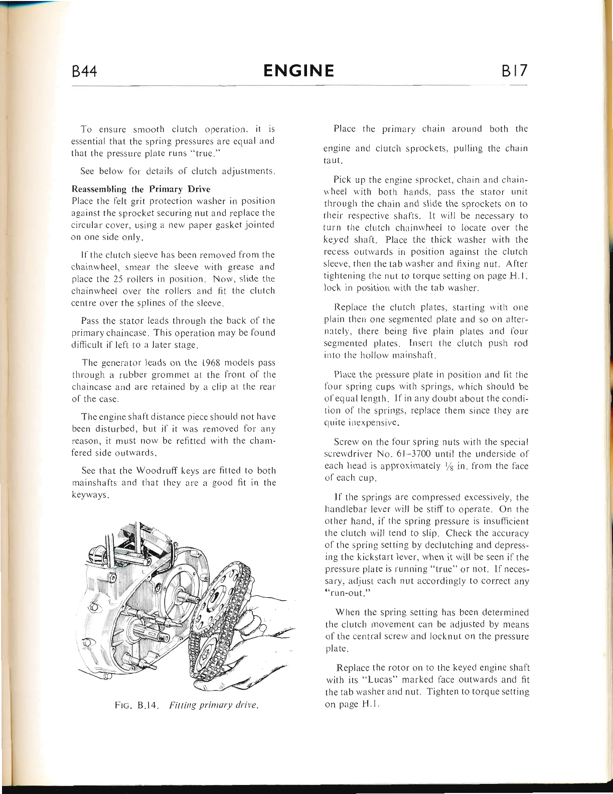
844 ENGINE Bt7
To ensure smooth clutch operation. it is
essential that the spring presslrres are equal and
that the pressure plate runs "true."
See below for details of clutch adjustnients.
Reassembling the Primary Drive
Place the felt grit protection washer in position
against the sprocket securing nut and replace the
circular cover, usir.rg a new paper gasket jointed
on one side only"
lf the clr-rtch sleeve has been removed from the
chainwheel, smear the sleeve with grease and
place tl.re 25 rollers in position. Now, slide the
chainwheel over the rollers and fit the clutch
centre over the splines of the sleeve.
Pass the stator leads through the back ol tiie
prinrary chaincase. This operation may be lound
diflicult il lelt to a later stage.
The generator leads on the 1968 models pass
through a rubber grontmet at the front of the
chaincase and are retained by a clip at the rear
of the case.
The er.rgirre shaft distance piece should not herve
been disturbed, but if it was removed fbr ar-ry
reilson, it must now be refitted with the cham-
fered side outwards.
See that the Woodrlrff keys are fitted to both
mainshafts and that they are a good fit in the
keyways.
Place the primary chain around both the
engine and clutch sprockets, pulling the chain
taut.
Pick up the engine sprocket, chain :rnd chain-
ri'heel u'ith both hands, pass the stator unit
throLrgh the chain and slide the sprockets on to
their respective shalls. lt will be necessary to
turn the cltitch chainwheel to locate over the
keyed shaft. Place the thick washer with the
recess outwarcls irr position against the clutch
sleeve. then the tab washer and fixing nut. Afler
tightening the nut to torque setring on page H.l.
lock in position with the tab washer.
I{eplace the clirtch plates" starting I,vith one
plain then one segmented plate and so cln alter-
netely', there being live plain plates aud lour
segmentecl plates. Insert the clutcl.r push rod
into the hollow rnainshalt.
Place the pressure plate in position ancl lit the
fbur spling cr-rps rvith springs, which should be
of equal length. If in arny doubt about the condi-
tion ol the springs, repluce them since they are
quite incxpensive.
Screw on the lbur spring r-ruts with the special
scrervclriver No. 6l-3700 r-rntil the ur.rderside of
each lread is approximately I in. fron.r the face
ol each cup.
ll the springs are compressed excessively, the
handlebar lever will be stiff to operate. On the
other Jrand, if the spring pressure is insufficient
the cllrtch will tend to slip. Check the accuracy
of the spring setting by declutching and depress-
ing the kickstart lever, when it will be seen if the
presslrre plate is running "true" or not. If neces-
sary. acljust each nut accordingly to correct any
n'run-out,'o
When the spring setting has been determined
ti-re clutch movement can be adjusted by means
of the central screr,v and locknut on the pressure
plate.
Replace the rotor on to the keyed engine shaft
with its "Lucas" marked face outwards and fit
the tab washer and nut. Tighten to torque setting
on page H.1.
Fitting prinrury clrive.
www.bsaunitsingles.com
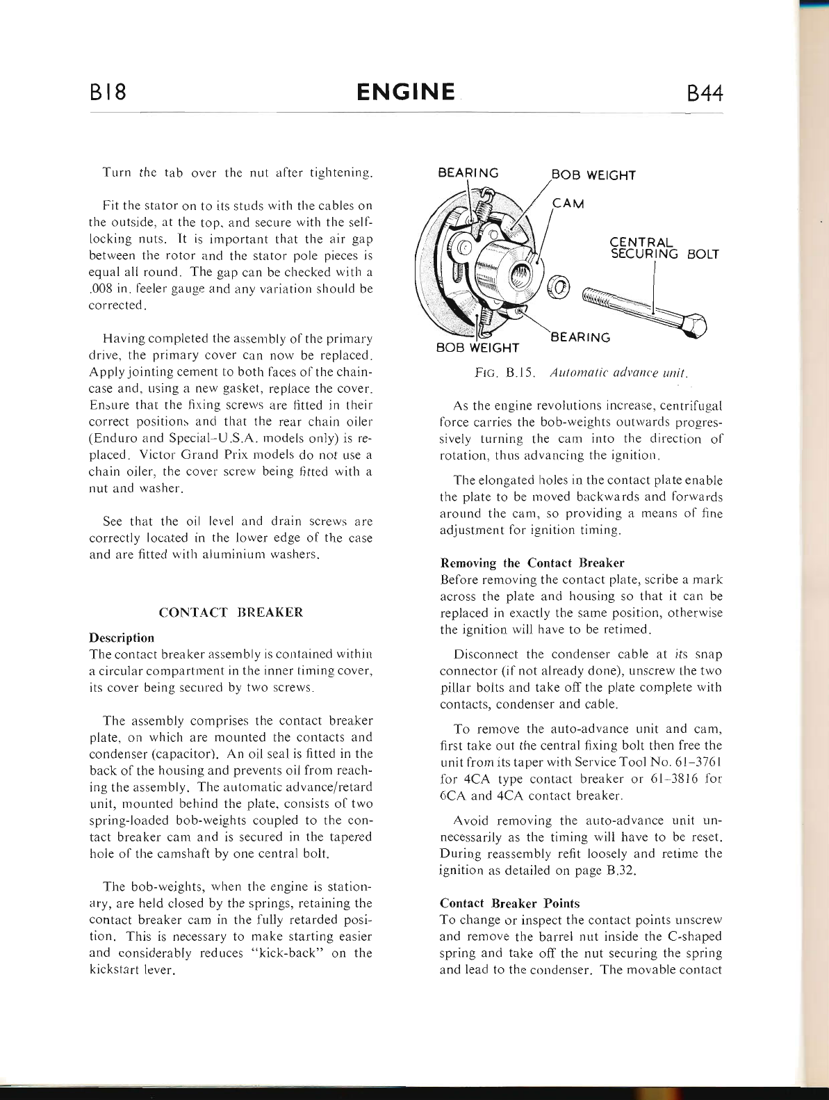
Bt8 ENGINE 844
Tr-rrn the tab over the nut afier tightenin-e.
Fit the stator on to its studs with the cables or-t
the outside, at the top, and secure with the self--
locking nuts. It is important that the air gap
between the rotor and the stator pole pieces is
equal all round. The gap can be checked with a
.008 in. feeler gauge and zrny variation should be
corrected.
Having completed the assen.rbly ol the primary
drive, the primary cover can now be replaced.
Apply jointing cement to both laces ol the chain-
case and, using a new gasket, replace the cover.
Ensure that the fi.ring scrervs are fitted in their
correct positions and that the rear chain oiler
(Enduro and Special U.S.A. models oniy) is re-
placed. Victor Grand Prix models do not use a
chain oiler, the cover screw being fitted with a
nut and washer.
See that the oil level and drain screws are
correctly localed in the lower edge of the case
and are fitted \\'ith aluminium washers.
CONT.{CT BREAKER
Description
The contact breaker assembly is contained within
a circular compartment in the inner timing cover,
its cover being secured by two screws"
The assembly comprises the contact breaker
plate, on which are mounted the contacts and
condenser (capacitor). An oil seal is fitted in the
back ofthe housing and prevents oil from reach-
ing the assembly. The automatic advance/retard
unit, mounted behind the plate, consists of two
spring-loaded bob-weights coupled to the con-
tact breaker cam and is secured in the tapered
hole of the camshaft by one central bolt.
The bob-weights, when tl.re engine is station-
ary, are held closed by the springs, retaining the
contact breaker cam in the fully retarded posi-
tion. This is necessary to make starting easier
and considerably reduces "kick-back" on the
kickstart lever.
BEARI NG
CENTRAL
SECURING BOLT
BOB WEIGHT
FIc. B.15. Automatic atlvan<'e unit.
As the engine revolutions increase, centrifLrgal
force carries the bob-rveights outwards progres-
sively turning the cam into tl.re direction ol
rotation, thus advancing the ignition.
The elongated holes in the contact plate enable
the plate to be moved backwards and forwards
around the carn, so providing a means of fine
adjustment lor ignition timing.
Removing the Contact Breaker
Before removing the contact plate, scribe a mark
across the plate and housing so that it can be
replaced in exactly the same position, other*'ise
the ignition will have to be retimed.
Disconnect the condenser cable at its snap
connector (ifnot already done), unscrew the two
pillar bolts and take off the plate complete rvith
contacts, condenser and cable.
To remove the auto-advance unit and cam,
first take out the central fixing bolt then free the
unit from its taper with Service Tool No. 61-3161
lor 4CA type contact breaker or 61 3816 1or
6CA and 4CA contact breaker.
Avoid removing the auto-advance unit un-
necessarily as the timing will have to be reset.
During reassembly refit loosely and retime the
ignition as detailed on page B.32.
Contact Breaker Points
To change or inspect the contact points unscrew
and remove the barrel nut inside the C-shaped
spring and take off the nut securing the spring
and lead to the condenser. The movable contact
BEARING
www.bsaunitsingles.com
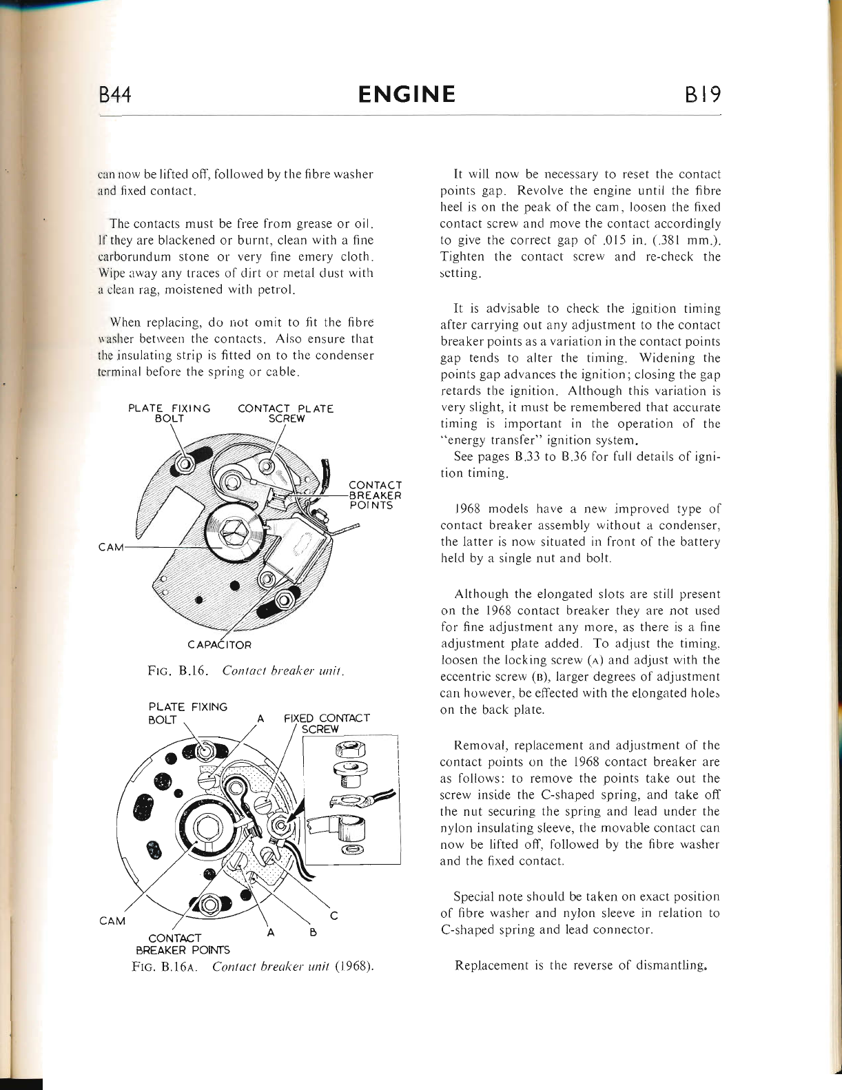
ENGINE Bl9
i
lt: can now be lifted off, followed bv the fibre washer
and fixed contact.
The contacts must be lree from grease or oil.
ll they are blackened or burnt, clean with a fine
carborundum stone or very fine emery cloth.
Wipe away any traces of dirt or rnetal dust with
a clean rag, moistened with petrol.
When replacing, do not omit to fit tl-re fibre
washer betrveen the contacts. Also ensure that
the insulating strip is fitted on to the condenser
terminal before the spring or cable.
PLATE FIXING CONTACT PLATE
BOLT SCREW
Ftc. B.16. Contact brea.l<.er unit.
CONTrcT
BREAKER POINTS
Flc. 8"16r. Contact breaker unit (1968).
It rvili now be necessary to reset the contact
points gap. Revolve the engine until the fibre
heel is on the peak of the cam, loosen the fixed
contact screw and move the contact accordingly
to give the correct gap of .015 in. (.381 mm.).
Tighten the contact screw and re-check the
sctting.
It is advisable to check the ignition timing
after carrying out any adjustment to the contact
breaker points as a variation in the contact points
gap tends to alter the timing. Widening the
points gap advances the ignition; closing the gap
retards the ignition. Although this variation is
very slight, it must be remembered that accurate
timing is important in the operation of the
"energy transfer" ignition system.
See pages B.33 to B.36 for full details ol igni-
tion timing.
1968 models have a new improved type of
contact breaker assembly without a condenser.
tl.re latter is now situated ir-r front ol the battery
held by a single nut and bolt.
Although the elongated slots are still present
on the 1968 contact breaker tl-rey are not used
for fine adjustment any more, as there is a fine
adjustment plate added. To adjust the timing.
Ioosen the locking screw (e) and adjust with the
eccentric screw (e), larger degrees of adjustment
can however, be effected with the elongated hole"
on the back plate.
Removal, replacement and adjustment of the
contact points on the 1968 contact breaker are
as follows: to remove the points take out the
screw inside the C-shaped spling, and take off
the nut securing the spring and lead under the
nylon insulating sleeve, the movable contact can
now be lifted off, lollowed by the fibre washer
and the fixed contact.
Special note should be taken on exact position
ol fibre washer and nylon sleeve in relation to
C-shaped spring and lead connector.
Replacement is the reverse of dismantling.
t:
i,.
lli
l,
l.
t,r:
[.
i
ti
'4.
CONTACT PLATE
SCREW
PLATE FIXING
www.bsaunitsingles.com
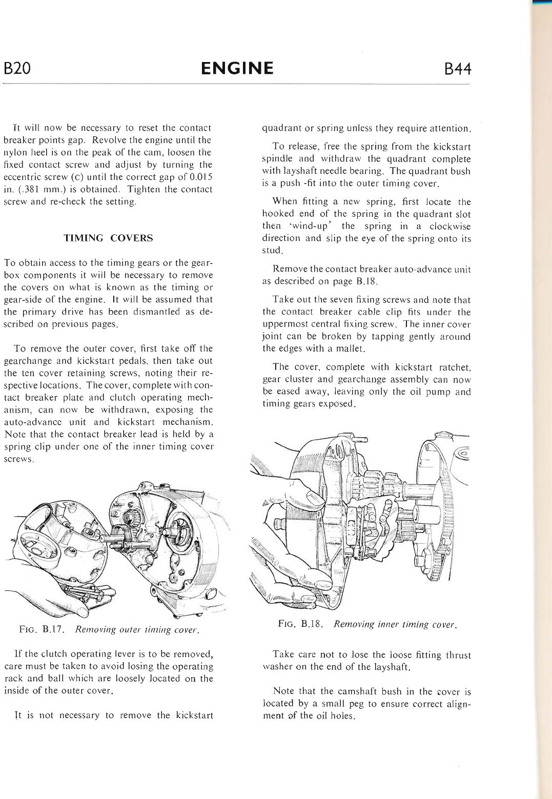
B20 ENGINE 844
It will now be necessary to reset the contact
breaker points gap. Revolve the engine until the
nylon heel is on the peak of the cam, loosen the
fixed contact screw and adjust by turning the
eccentric screw (c) until the correct gap of0.015
in. (.381 mm.) is obtained. Tighten the contact
screw and re-check the setting.
TIMING COVERS
To obtain access to the timing gears or the gear-
box components it will be necessary to remove
the covers on what is known as the timing or
gear-side of the engine. It will be assumed that
the primary drive has been dismantled as de-
scribed on previous pages.
To remove the outer cover, first take off the
gearchange and kickstart pedals, then take out
the ten cover retaining screws, noting their re-
spective locations. The cover, complete with con-
tact breaker plate and clutch operating mech-
anism, can uow be withdrawn, exposing the
auto-advance unit and kickstart mechanism.
Note tliat the contact breaker lead is held by a
spring clip under one ol the inner timing cover
screws.
Ftc. 8.17. Removing outer tinring cover.
If the clutch operating lever is to be removed,
care must be taken to avoid losing the operating
rack and ball which are loosely located on the
inside of the outer cover.
Jt is not necessary to remove the kickstart
quadrant or spring unless they require attention.
To release, free the spring from the kickstart
spindle and withdraw the quadrant complete
with layshaft needle bearing. The quadrant bush
is a push -fit into the outer timing cover.
When fitting a new spring, first locate the
hooked end of the spring in the quadrant slot
then'wind-up'the spring in a clockrvise
direction and slip the eye of the spring onto its
stud.
Remove the contact breaker auto-advance uuit
as described on page B.18.
Take out the seven fixing screws and note that
the contact breaker cable clip fits under the
uppermost central fixing screw. The inner cover
joint can be broken by tapping gently around
the edges with a mallet.
The cover, complete with kickstart ratchet,
gear cluster and gearchange assembly calt now
be eased away, leaving only the oil pump ar.rd
timing gears exposed.
Frc. B.18. Removing inner timing cover.
Take care not to lose the loose fitting thrust
washer on the end of the layshaft.
Note that the camshaft bush in the cover is
located by a small peg to ensure correct align-
ment of the oil holes.
www.bsaunitsingles.com
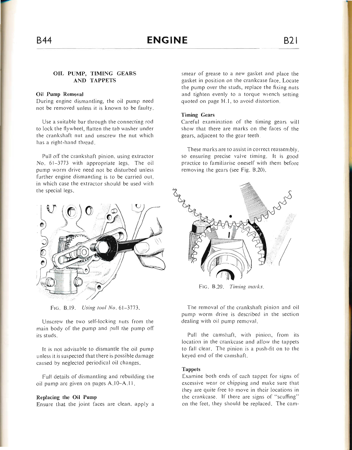
844 ENGINE 82t
OIL PUMP, TIMING GEARS
AND TAPPETS
Oil Pump Removal
During engine dismantling, the oil pump need
not be removed unless it is known to be faulty.
Use a suitable bar through the connecting rod
to lock the flywheel, flatten the tab washer under
the crankshaft nr,rt and unscrew the nut which
has a right-hand thread.
PLrll off the cranksl.raft pinion, using extractor
No. 6l-3773 with appropriate legs. The oil
pulxp worm drive need not be disturbed unless
further engir.re dismantling is to be carried out,
in which case the extractor should be used with
the special Iegs.
[L'
Frc. B.19. Using tool No.6l-3113.
Unscrew the two self-locking nuts from the
main body of the pump and pull the pump off
its studs.
lt is not advisable to dismantle the oil pump
r.rnless it is suspected that there is possible damage
caused by neglected periodical oil changes.
Fuli details of dismantiing and rebuilding the
oil pump are given on pages A.l0-A.11.
Replacing the Oil Pump
Ensure that the joint faces are clean, apply a
smear of grease to a new gasket and place the
gasket in position on the crankcase face. Locate
the pump over the studs, replace the fixing nuts
and tighten eveniy to a torque wrench setting
qLroted on page H.1, to avoid distortion.
Timing Gears
Carefui examination of the timing gears will
show that there are marks on the faces of the
gears, adjacent to the gear teeth.
These marks are to assist in correct reassenrbly,
so ensuring precise valve timing. It is good
practice to familiarise oneself with tlrenr before
removing the gears (see Fig. B.20).
Frc. B
The removal of the crankshaft pinion and oil
pump worm drive is described in the section
dealing with oil pump renroval.
Pull the camshaft, with pinion, from its
location in the crankcase and allow the tappets
to fall clear. The pinion is a push-fit on to the
keyed end of the camshaft.
Tappets
Examine both ends of each tappet for signs of
excessive wear or chipping and make sure that
they are quite free to move in their locations in
the crankcase. ll there are signs of "scuffing"
on the feet, they should be replaced. The cam-
lr.r
o**
marks.
www.bsaunitsingles.com
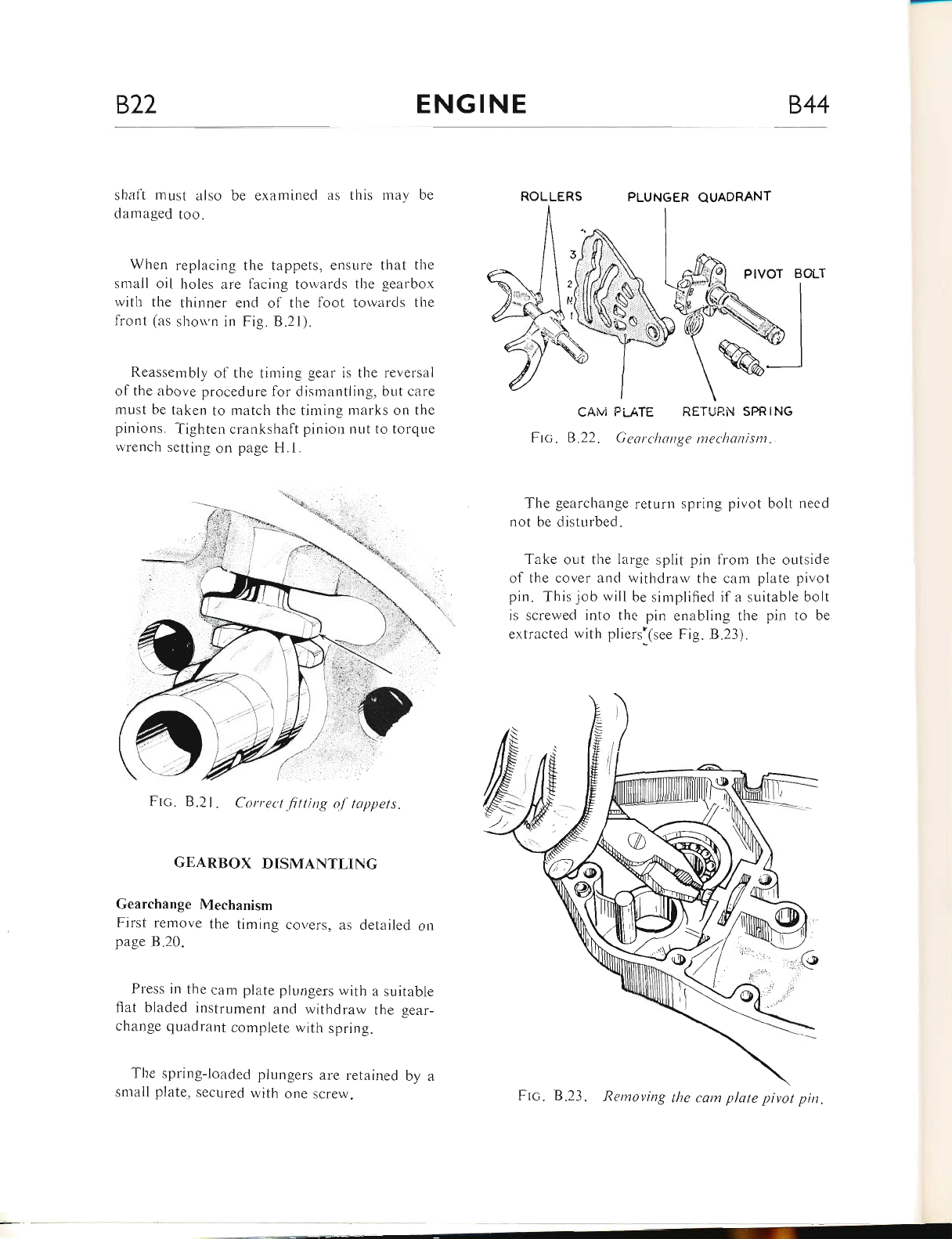
822 ENGINE 844
shaft must also be examined as this mav be
damaged too.
When replacing the tappets, ensure that the
small oil holes are facing towards the gearbox
with the thinner end of the foot towards the
front (as shor.vn in Fig. B.21).
Reassembly of the timing gear is the reversai
of the above procedure for dismantling, but care
must be taken to match the timing marks on the
pinions. Tighten crankshaft pinion nut to torqlle
wrench setting on page H.1.
Frc. B.2l . Correct fitting o.l-tappets.
GEARBOX DISMANTLING
Gearchange Mechanism
First remove the timing covers, as detailed on
page B.20.
Press in the cam plate plungers with a suitable
flat bladed instrument and withdraw the gear-
change quadrant complete with spring.
The spring-loaded plungers are retained by a
small plate, secured with one screw.
PLUNGER
CAM PLATE RETURi.I SPRING
Ftc. 8.22. Gearchange mechonism.
The gearchange return spring pivot bolt need
not be disturbed.
Take out the large split pin from the outside
of the cover and witl-rdraw the cam plate pivot
pin. This job will be simplified if a suitable boit
is screwed into the pin enabling the pin to be
extracted with pliers'(see Fig. 8.23).
the cam plate pivot pin.
ROLLERS
CAM PLATE
QUADRANT
Ftc. B.23. Removing
www.bsaunitsingles.com
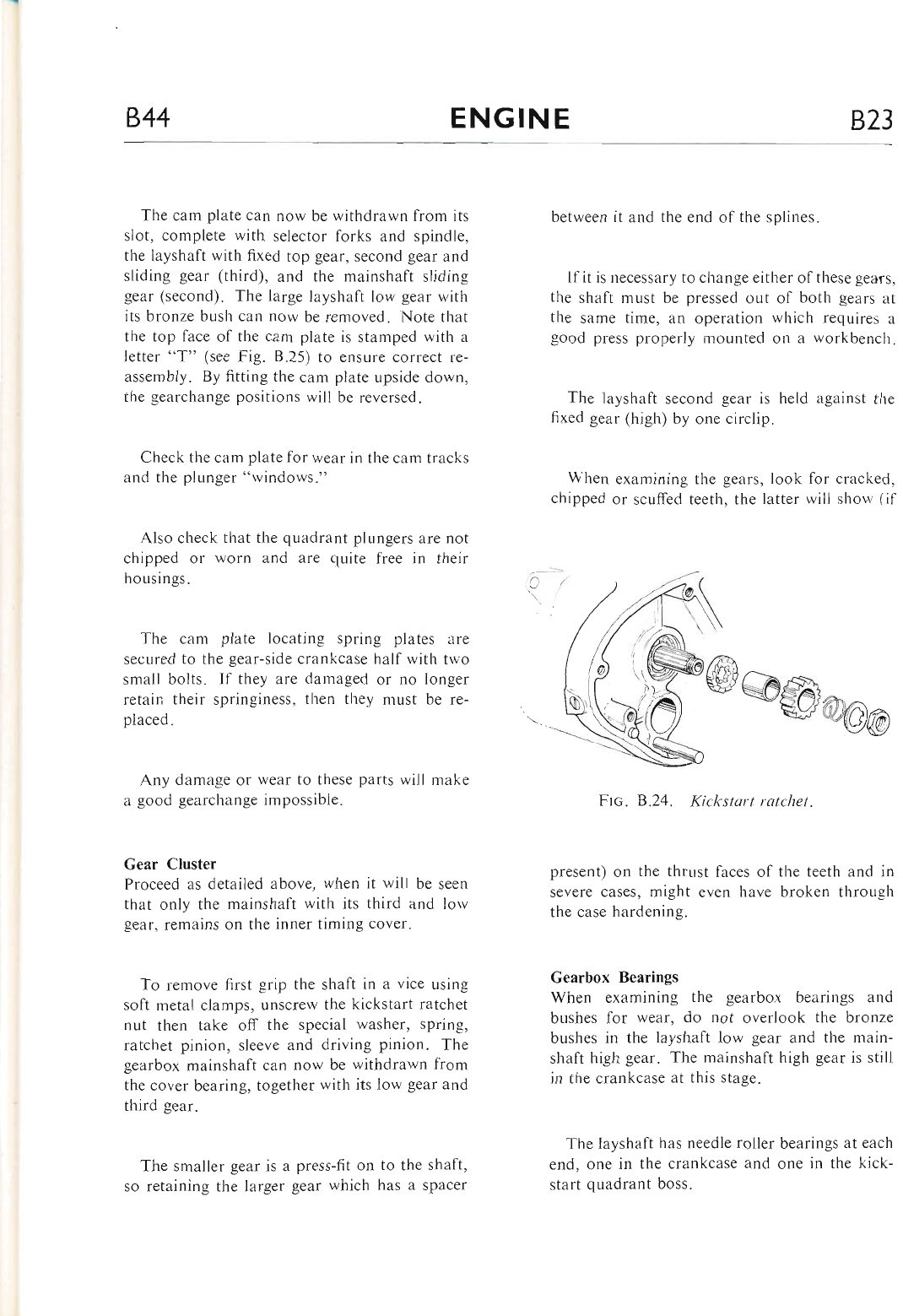
844 ENGINE B23
The cam plate can now be withdrawn from its
slot, complete with selector forks and spindle,
the layshaft with fixed top gear, second gear and
sliding gear (third), and the mainshaft sliding
gear (second). The large layshaft low gear with
its bronze busl-r can now be removed. Note that
the top face of the cam plate is stamped with a
letter "T" (see Fig. 8.25) to ensure correct re-
assembly. By fitting the cam plate upside down,
the gearchange positions will be reversed.
Check the cam plate for wear in the cam tracks
and the plunger "windows."
Also check that the quadrant plungers are not
chipped or worn and are quite free in their
housings.
The cam plate locating spring plates are
secured to the gear-side crankcase half with two
small bolts. If they are damaged or no longer
retain their springiness, then they must be re-
placed.
Any damage or wear to these parts will make
a good gearchange impossible.
Gear Cluster
Proceed as detailed above, when it will be seen
that only the mainshaft with its third and lorv
gear. remains on the inner timing cover.
To remove first grip the shaft in a vice using
soft metal clamps, unscrew the kickstart ratchet
nut then take off the special washer, spring,
ratchet pinion, sleeve and driving pinion. The
gearbox mainshaft can now be withdrawn from
the cover bearing, together with its low gear and
third gear.
The smaller gear is a press-fit on to the shaft,
so retaining the larger gear which has a spacer
between it and the end of the splines.
Ifit is necessary to change either ofthese gears,
the shaft must be pressed out of both gears at
the same time, an operation which requires a
good press properly mounted on a workbench.
Tire layshaft second gear is held against the
fixed gear (high) by one circlip.
When examining the gears, look for cracked,
chipped or scuffed teeth, the latter will show (if
Frc, B.24. Kickstart rqtchet.
present) on the thrust faces of the teeth and in
severe cases, might even have broken through
the case hardening.
Gearbox Bcarings
When examining the gearbox bearings and
bushes for wear, do not overlook the bronze
bushes in the layshaft low gear and the main-
shaft high gear. The mainshaft high gear is still
in the crankcase at this stage.
The layshaft has needle roller bearings at each
end, one in the crankcase and one in the kick-
start quadrant boss.
www.bsaunitsingles.com
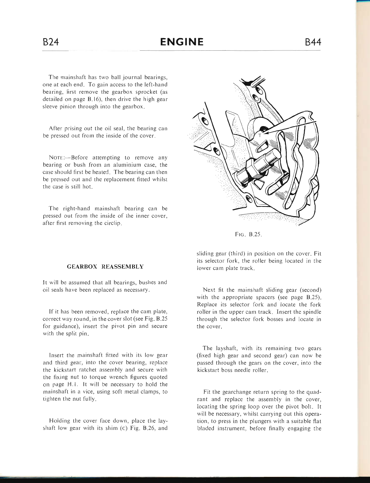
874 ENGINE B,44
The mainshaft has two ball journal bearings,
one at each end. To gain access to the left-hand
bearing, first remove the gearbox sprocket (as
detailed on page B.16), then drive the high -eear
sleeve pinion through into the gearbox.
After prising out the oil seal, the bearing can
be pressed out from the inside of the cover.
Norr:-Before attempting to remove any
bearing or bush from an aluminium case, the
case should first be heated. The bearing can then
be pressed out and the replacement fitted whilst
the case is still hot.
The right-hand mainshaft bearing can be
pressed out from the inside of the inner cover,
after first removing the circlip.
GEARBOX REASSEMBLY
It will be assumed that all bearings, br-rshes and
oil seals have been replaced as necessary.
If it has been removed, replace the carn plate,
correct way round, in the cover slot (see Fig. B.25
for guidance), insert the pivot pin and secure
with the split pin.
Insert tl.re mainshaft fitted with its low gear
and third gear, into the cover bearing, replace
the kickstart ratchet assembly and secure with
the fixing nut to torque wrench figures quoted
on page H.l. It will be necessary to hold the
mainshaft in a vice, using soft metal clamps, to
tighten the nut lully.
Holding the cover face down, place the lay-
shaft low gear with its shim (c) Fig. 8.26, and
F-rc.8.25.
sliding gear (third) in position on the cover. Fit
its selector fork, the roller being located in the
lower cam plate track.
Next fit the mainshaft sliding gear (second)
with the appropriate spacers (see page B.25).
Replace its selector fork and locate the fork
roller in the upper cam track. Insert the spindle
through the selector fork bosses and locate in
the cover.
The layshaft, with its remaining two gears
(fixed high gear and second gear) can now be
passed through the gears on the cover, into the
kickstart boss needle roller.
Fit the gearchange return spring to the quad-
rant and replace the assembly in the cover,
locating the spring loop over the pivot bolt. It
will be necessary, whilst carrying out this opera-
tion, to press in the plungers with a suitable flat
bladed instrument, before finally engaging the
www.bsaunitsingles.com
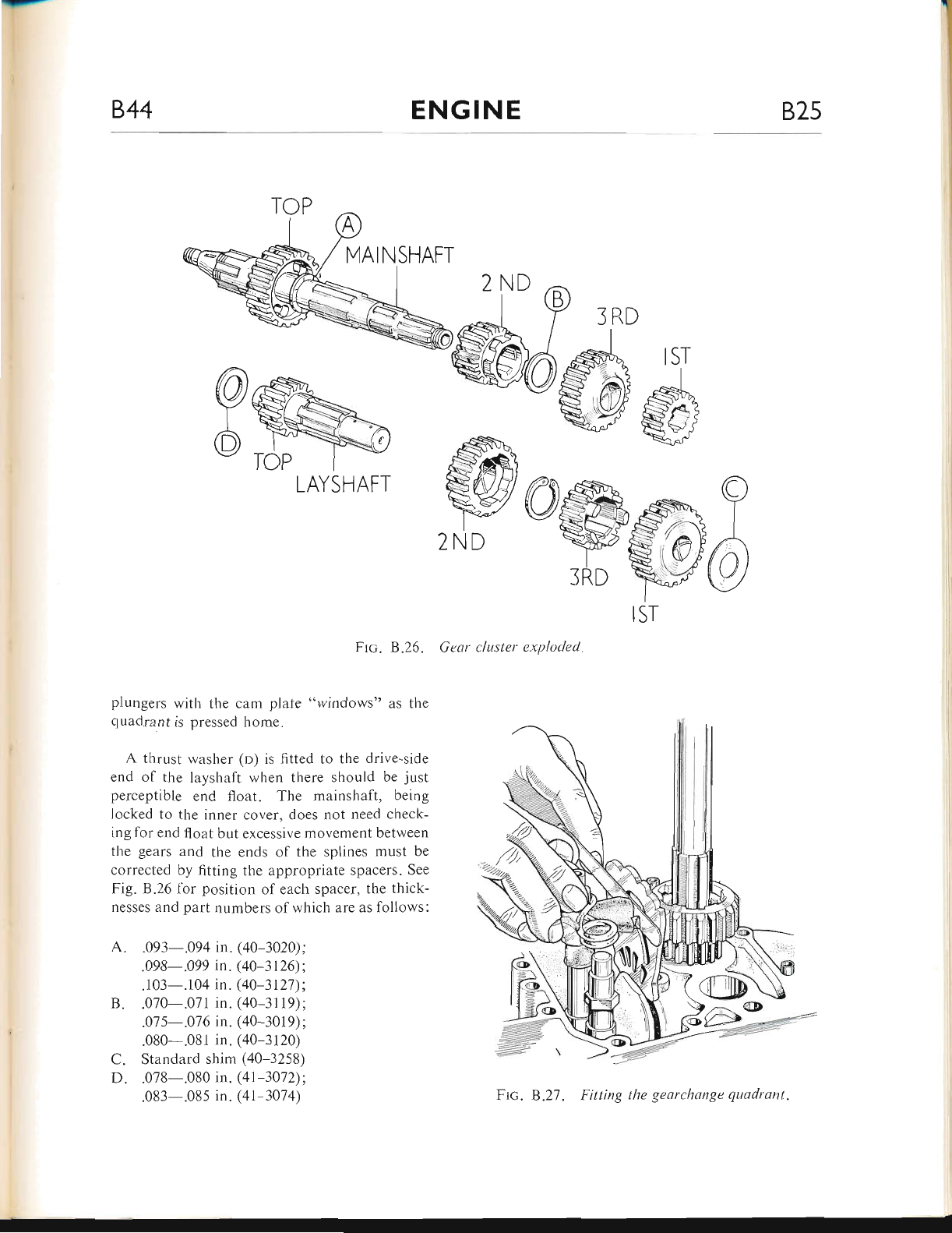
.J-
844 ENGINE B25
Frc. B.25. Gear cluster exploded
f srRD
@#$'
'Wffi
iRD tr
IST
plungers with the cam plate "windows" as the
quadrant is pressed home.
A thrust washer (o) is fitted to the drive-side
end ol the layshaft when there should be just
perceptible end float. The mainshaft, being
locked to the inner cover, does not need check-
ing for end float but excessive movement between
the gears and the ends of the splines must be
corrected by fitting the appropriate spacers. See
Fig. 8.26 for position of each spacer? the thick-
nesses and part numbers of rvhich are as follows:
.093-.094 in. (40-3020) ;
.098-.099 in. (40 3126):
. 103-.1 04 in. (40-3 127) ;
.070-.071 in. (40-31 19) ;
.07 5-.01 6 in. (40-3019) ;
.080-.081 in. (40-3 120)
Standard shim (40-3258)
.078-.080 in. (41 -307 2) ;
.083-.08s in. (41-3074)
B.
C.
D.
LAYSHAFT
2ND
Ftc. 8.27. Fitting the gearchange quadrant.
www.bsaunitsingles.com
826 ENGINE 844
(l)
(2)
Before proceeding with assembly, check tl-re
gclrr selection for corrcct operation.
SEQUENCE OF GEAR. CHANGING
To understand this descriptior-r of the gear
changing sequence, it will be necessary to refer
to the various drawings and to understand some
of the terms used.
Ca,r,r Pl,q.rp-this is the large fan-shaped
component that has "windows" for the gear-
change quadrar-rt plungers, cam tracks lor
the selector fork rollers and notches to
locate the gear positions.
Ca,M Pt-,q.rp Loc,qrrNc SpnrNc PlerEs-
these are secured to tl.re crankcase. the
larger of which locates in the can.r plate
notches ut various gear positions.
QuaNnn,rNr Pluncrns these are held in
the gearchange quadrant and operate in the
cam plate "windows."
Snr-ecroR FoRrs-each selector fork has a
roller rvhich locates in the cam plate tracks.
When the cam plate is turned about its pivot
pin, these selector forks are moved back-
wards or forwards.
(5) Sr-rprNc Gsrns-botl.r the layshaft and the
rnainslraft have one sliding gear each. They
are operated by the selector forks anci are
carried along the splined shafts.
The gears must always be in the neutral posi-
tion for starting the engine, this is the position
shown in Fig. 8.28.
The sprir-rg plate is holdrng the cam plate by
the second notcl.r. At the other end of the cam
plate the selector quadrant plungers are com-
pressed ready to operate either way the pedal is
moved.
When the pedal is moved down, to engage
first gear, the plungers will enter the cam plate
and move it to first gear position, this in turn
u'ill operate the layshaft selector fork and will
mesh the layshaft sliding gear with the layshalt
first gear.
Reference to Fig. B.29 will now show the
qr-radrant plunger in the second window ready
to move the cam plate from first to second gear.
This time the cam plate moves in the opposite
direction and again operates the ltryshaft selector
fork moving the layshaft sliding gear in tl-re
opposite direction to mesh with the second gear.
Reference to Fig. B.30 will show both quadrant
plungers in the cam plate windows ready to
move the gears from second to first or neutral
or back again.
When the cam plate is moved to third gear
position as will be seen by reference to Fig. 8.31,
the action moves both selector forks, drawing
the I:ryshaft sliding gear to a neutral position and
n.roving the mainshaft sliding gear into mesh
rvith the mainshaft third gear. Again the quad-
rant plungers are ready to move the gears either
\\'ay,
Finally, the move into fourth or top gear
(Fig. B.32) operates the mainshaft selector fork
only, again sliding the gear the opposite way to
mesh with tire sleeve pinion. After each move-
ment of the gearcl.range pedal the quadrant re-
turns to a static position so that the plungers are
ready to operate the cam plate. Tl-re large spring
plate at the large end of the cam plate is the
positive gear location and it also serves to steady
the cam plate whilst the quadrant plungers are
returning to their static position.
Nore:-The cam plate can be reversed il
required, to give an opposite gearchange action.
(3)
(4)
www.bsaunitsingles.com
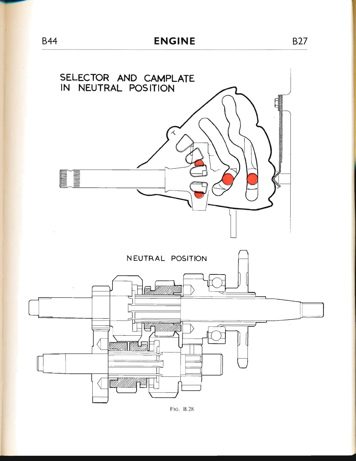
-r-
844 ENG!NE 827
SELECTOR AND CAMPLATE
IN NEUTRAL POSITION
www.bsaunitsingles.com
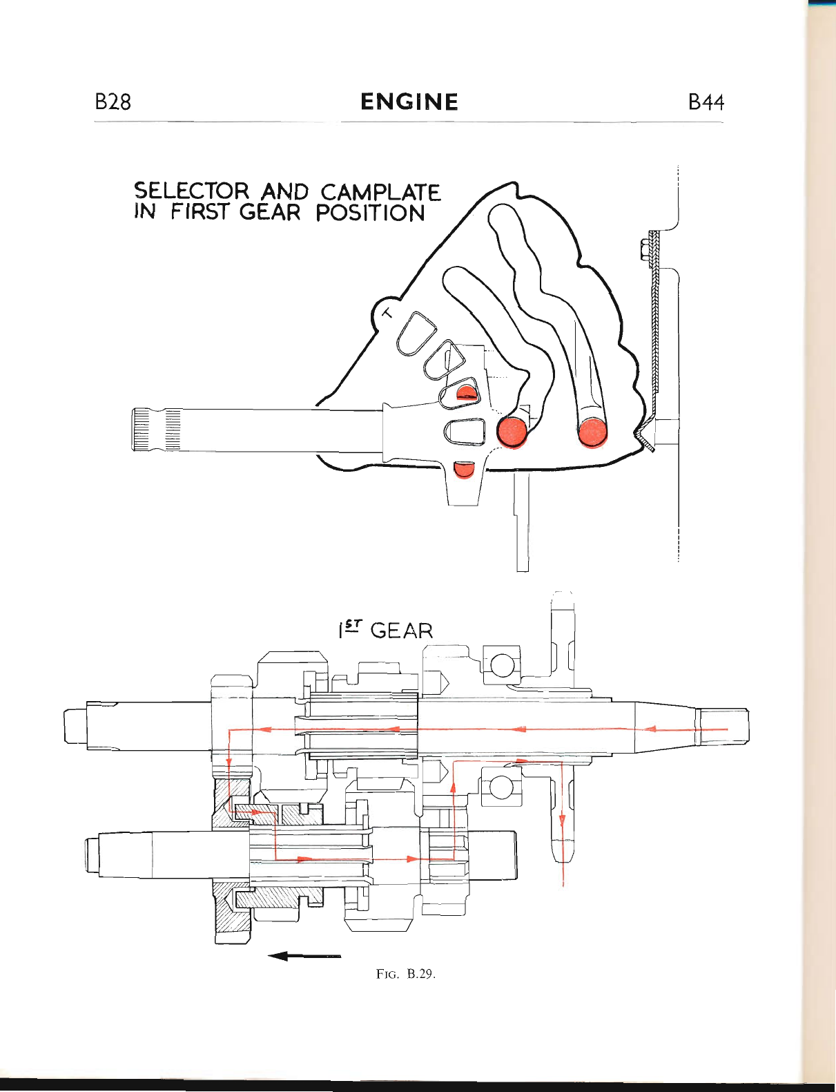
828 ENGINE 844
SELECTOR AND CAMPLATE
IN FIRST GEAR POSITION
IgI GEAR,
<<- Frc. B.29
www.bsaunitsingles.com
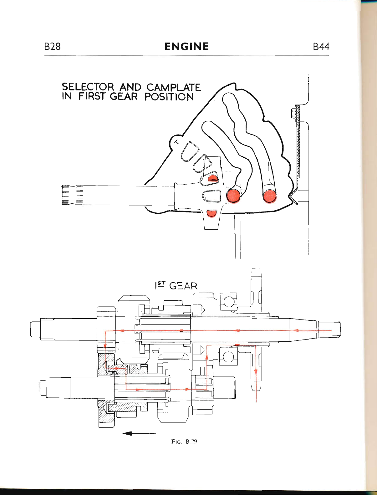
--------
828 ENGINE 844
SELECTOR AND CAMPLATE
IN FIRST GEAR POSITION
I{ GEAR
<<l-
Frc. B.29.
www.bsaunitsingles.com
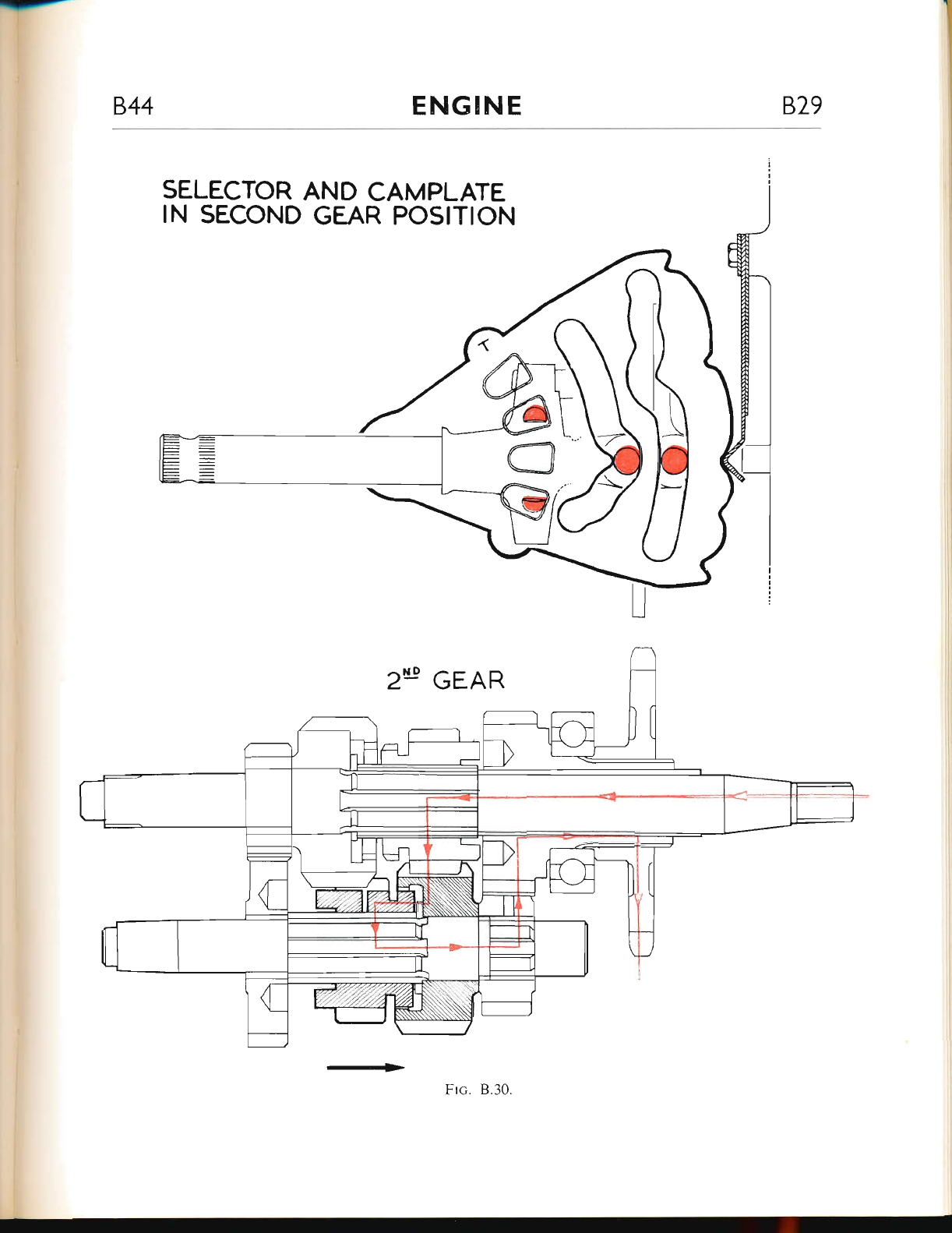
--
844 ENGINE 829
SELECTOR AND CAMPLATE
IN SECOND GEAR POSITION
GEAR
->
www.bsaunitsingles.com
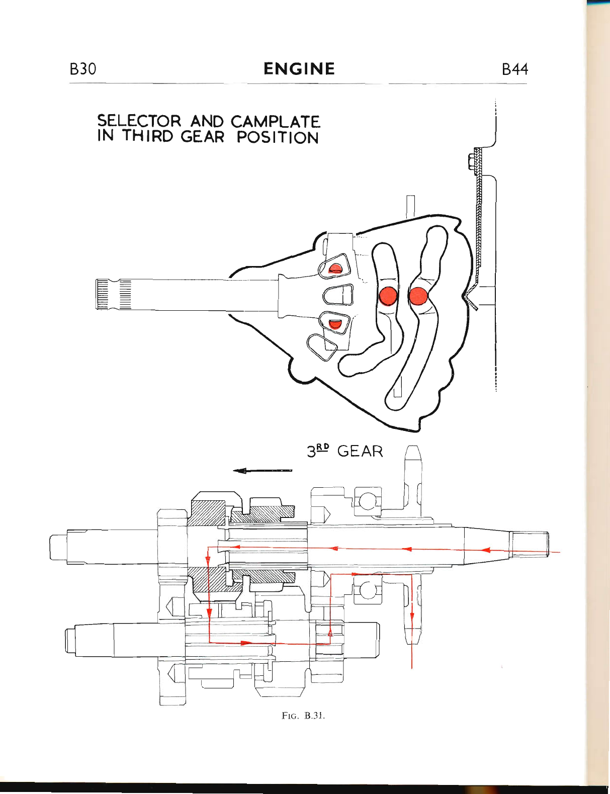
830 ENGINE 844
SELECTOR AND
IN THIRD GEAR
3LP GEAR
CAMPLATE
POSITION
www.bsaunitsingles.com
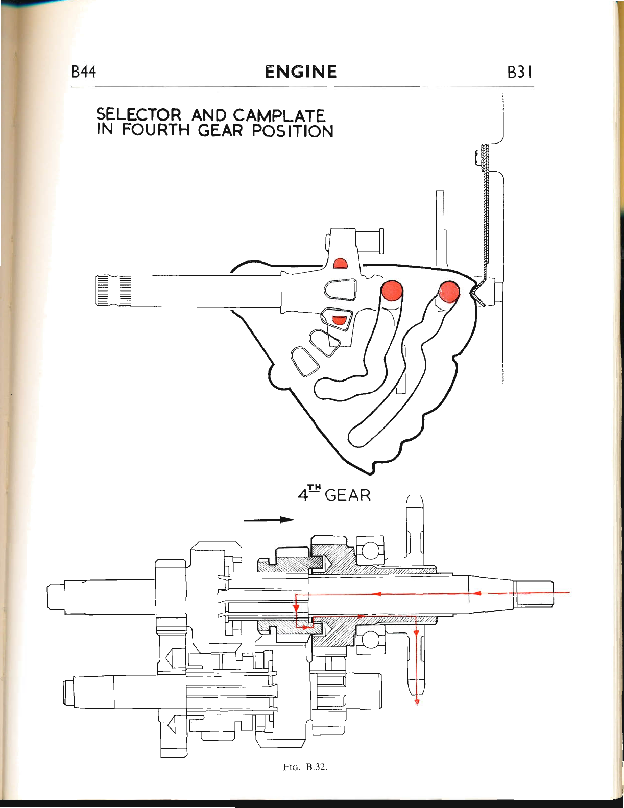
ENGINE 83 I
SELECTOR AND CAMPLATE
IN FOURTH GEAR POSITION
www.bsaunitsingles.com
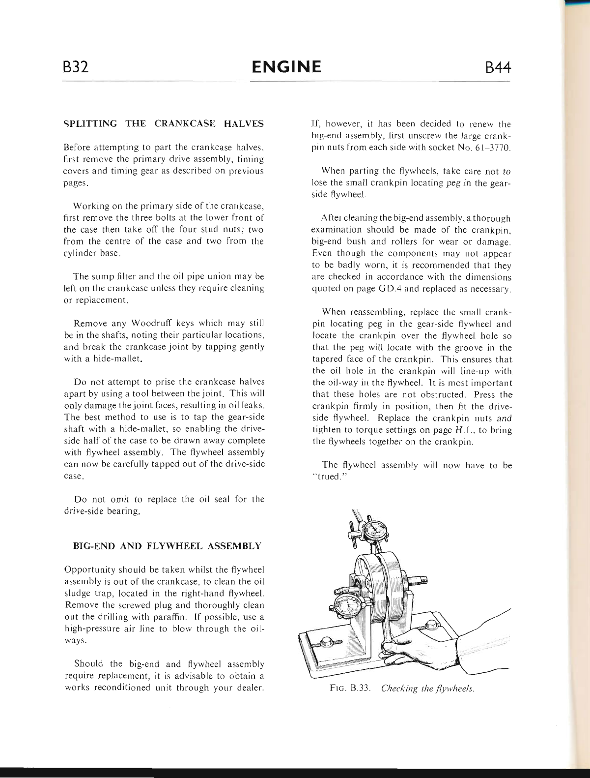
B32 ENGINE 844
SPLITTING THE CRANKCASE HALVES
Before attempting to part the crankcase halves,
first remove the primary drive assembly, timing
covers and timing gear as described on previous
pages.
Working on the primary side of the crankcase,
first remove the three bolts at the Iower front ol
the case then take off the four stud nuts; two
from the centre of the case and two from the
cylinder base.
The sump filter and the oil pipe union may be
left on the crankcase unless tl-rey reqr,rire cleaning
or replacement.
Remove any Woodruff keys wliich may still
be in the shafts, noting their particular locations,
and break the crankcase joint by tapping gently
with a hide-mallet.
Do not attempt to prise the crankcase halves
apart by using a tool between the joint. This will
only damage the joint faces, resulting in oil leaks.
The best method to use is to tap the gear-side
shaft with a hide-mallet, so enabling the drive-
side half of the case to be drawn away complete
with flywheel assembly. The flywheel assembly
can now be carefully tapped out ofthe drive-side
case.
Do not omit to replace the oil seal for the
drive-side bearing"
BIG-END AND FLYWHEEL ASSEMBLY
Opportunity should be taken wl-rilst the flywheel
assembly is out of the crankcase, to clean the oil
sludge trap, located in the rigl-rt-hand flywheel.
Remove the screwed plug and thoroughly clean
out the drilling with paraffin. Il possible, use a
high-pressure air line to blow through the oil-
ways.
Should the big-end and flywheel assembly
require replacement, it js advisable to obtain a
works reconditioned unit through your dealer.
I1, however, it has been decided to renew the
big-end assembly, first unscrew the large crzrnk-
pin nuts from each side with socket No. 61 3770.
When parting the flyr,vheels, take care not to
lose the small crankpin locating peg in the gear-
side flywhee[.
After cleaning the big-end assembly, a thorough
examination should be made ol the crankpin.
big-end bush and rollers for wear or damage.
Even though the components may not appear
to be badly worn, it is recommended that they
are checked in accordance with the dimensions
quoted on page GD.4 and replaced as necessary.
When reassembling, replace the small crank-
pin locating peg in the gear-side flywheel and
locate the crankpin over the flywheel hole so
that the peg will locate with the groove in the
tapered farce of the crankpin. This ensures that
the oil hole in the crankpin will line-up with
the oil-way irr the flywheel. It is most important
that these holes are not obstructed. Press the
crankpin firmly in position, then fit the drive-
side flywheel. Replace the crankpin nuts and
tighten to torque settings on page H.1.. to bring
the flywheels together on the crankpin.
The flywheel assembly will now have to be
"trued. "
Frc. B.33. Clteclting the flyv'heels
www.bsaunitsingles.com
T
833
ENGINE
B,44
Place the bearings on to the shafts ernd mount
the assembly in vee-blocks. True-up the fly-
wheels as indicated in Fig. B.33. using a dial
indicator gauge for checking.
Each r.vheel sl'rould be "trued" to within .005
in.. the drive-side shaft to rvithiri .002 in. and
the gear-side shaft to rvithin .0005 in.
RE,ASSEMBLII.NG THE CRANI(CASE
Assr-rming that the beerrings, bushes and oil seals
hlve been checlcecl and, rvhete neccssary, re-
placed, the cranhcase can now be reassembled.
Place the flywheel assembly into the drive-side
case. This operation will be simplified ilthe case
is supported on a large block ol wood, dcep
enough to keep the end ol the shaft clear of the
workbench.
Apply a coating of jointing compound to the
joint faces ol each crankcase half and refit the
gear-side case.
Replace the three bolts at the lront of the case
and the four nuts (two at the base of the cylinder
iind two in the primary r:ase).
Tighten bolts and nuts evenly, to avoid dis-
torting the joint faces.
Check'rhat the flywheel assembly rotates quite
freely. If it does not, then the alignment may be
incorrect and the cause of the trouble must be
rectified.
Fit the engine shalt sprocket distance piece
and the oil pump worm drive thrust washer, each
with its chamfered face outwards. The sprocket
distance piece is available in three thickrlesses to
provide accurate alignment of the primary chain
in relation to the clutch sprocket. The sizes are
as follows:- 294-.297 in.;.309-,312 in.;
.324-.321 in.
Reassembly from this point is described in the
previous sections, but do not omit to replace the
keys in the ends of the shafts before fitting the
pinions or sprockets.
IGNITION TIMING
Belore carrying out any check on the ignition
tirning, tl.re contact points gap should first be
veiified and, if necessary, re-adjusted as des-
cribed on page B.lB.
Remove the sparking plug to ertable the engine
to be rotated ri,itlrout any resistance due to com-
pression. Ilthe engine is in the lrame, it will also
help ii top gear is obtained, so that the engine
rnay be turued eitl'rer backr'vards or forwards by
rotatioll of the rear wl'reel.
Piston Position
Bclore checking tire igrrition timing, the piston
mLrst {rlst be set at the recommended position
belore top dead centre ot.t its compression stroke
(both valves closed).
This position can be set most accurately with
the aid of a degree plate. The primary chaincase
should first be removed and the degree plate
rnounted centrally on the engine shaft (see Fig.
8,34). A sr-ritable pointer should then be attached
to some convenient part ol the engine with the
point adjacent to the plate.
On 1968 models there is a pointer mounted
at tl.re base of the inspection aperture which is
sitr"rated at the front ol the primary case. Also
a mark is scribed on the generator rotor (see
Fig. B.34n).
Rotate the engine slowly until the pointer
coincides with the timing mark to obtain the
correct piston setting.
Rotation of the engine through several degrees
near the top dead centre position produces very
little piston movemeut, making the top dead
centre position extremely difficult to find. Is is
preferable, therefore, to use a suitable stop (such
as a dummy plug with a projection into the
cylinder head) so that the piston can be brought
www.bsaunitsingles.com
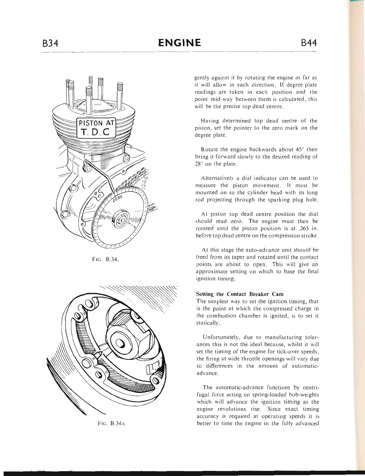
B34 ENGINE 844
Frc. B.34"
gently against it by rotating the engine as lar as
it will allow in each direction. If degree plate
readings are taken in each position and the
point mid-way between them is calculated, this
will be the precise top dead centre.
Having determined top dead centre of the
piston, set the pointer to the zero mark on the
degree plate.
Rotate the engine backwards about 45' then
bring it forward slowly to the desired reading of
28' on the plate.
Alternativelv a dial indicator can be used to
trleasure the piston movement. It must be
mounted on ro the cylinder head with its long
rod projecting through the sparking plug hole.
At piston top dead centre position the dial
should read zero. The engine must then be
rotated until the piston position is at .265 in.
belore top dead centre on the compression stroke.
At this stage the auto-advance unit should be
fieed from its taper and rotated until the contact
points are about to open. This will give an
approximate setting on which to base the final
ignition timing.
Setting the Contact Breaker Cam
The simplest way to set the ignition timing, that
is the point at which the compressed charge in
the combustion chamber is ignited, is to set it
statically.
Unfortunately, due to manufacturing toler-
ances this is not the ideal because, whilst it will
set the timing of the engine for tick-over speeds.
the firing at wide throttle openings will vary due
to differences in the amount of automatic-
advance.
The ar,rtomatic-advance functions by centri-
fugal force acting or.r spring-loaded bob-weights
which will advance the ignition timing as the
engine revolutions rise. Since exact timing
accuracy is required at operating speeds it is
better to time the engine in the fully advanced
N
Frc. B.34a.
www.bsaunitsingles.com
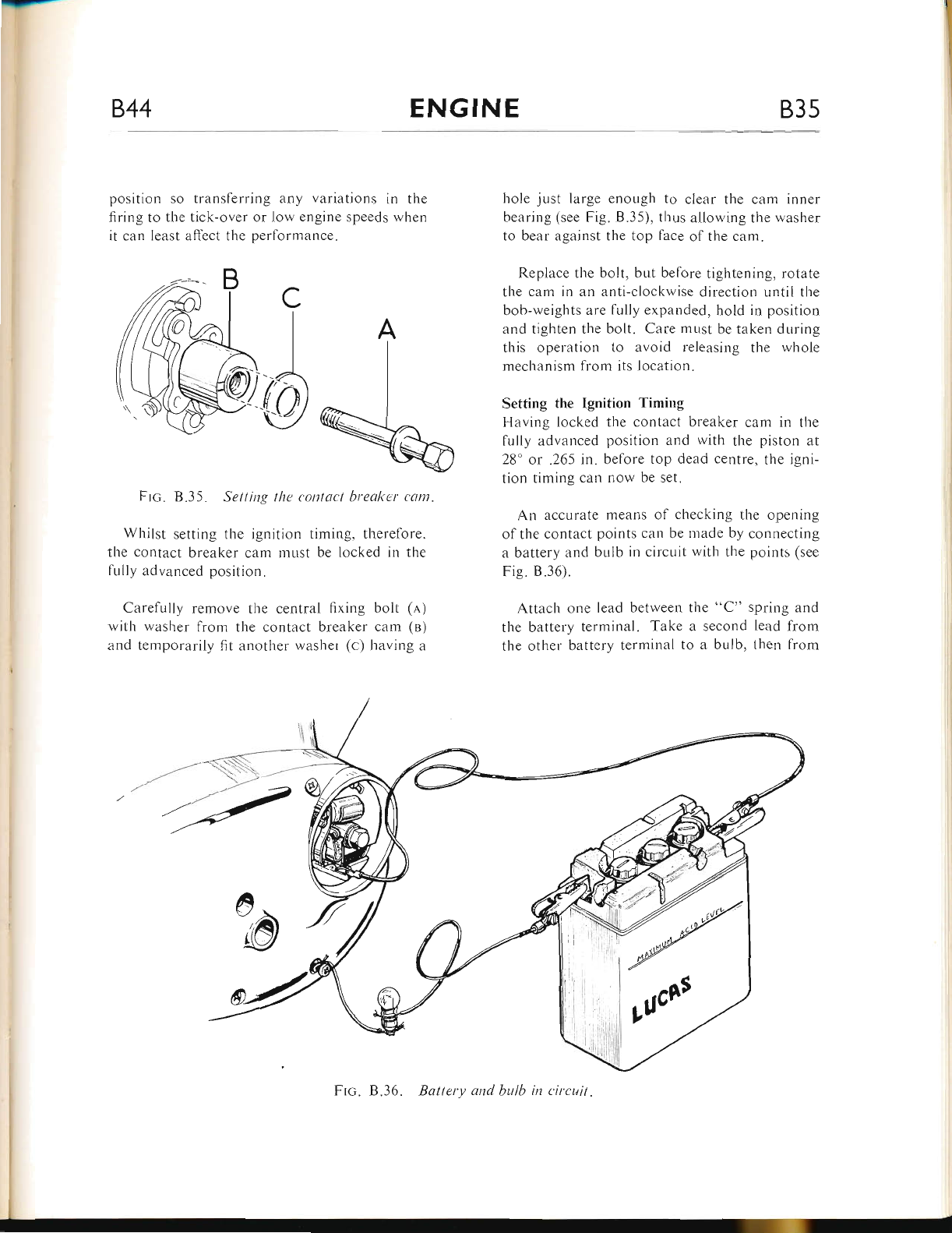
.J-
844 ENGINE 835
position so transferring any variations in the
firing to the tick-over or low engine speeds rvhen
it can least affect the performauce.
Frc" B.35. Setting the t'ontact hreakar cant.
Whilst setting the ignition timing, therefore.
the contact breaker cam must be locked in the
fully advanced position.
Carelully remove the central fixing bolt (a)
with washer from the contact breaker cam (n)
and temporarily fit another washer (c) having a
hole just large enough to clear the cam inner
bearing (see Fig. 8.35), thus allowing the washer
to bear against the top face of the cam.
Replace the bolt, but before tightening, rotate
the cam in an anti-clockwise direction until the
bob-weights are lully expanded, hold in position
and tighten the bolt. Care must be taken during
this operation to avoid releasing the whole
mechanism lrom its location.
Setting the Ignition Timing
Having locked the contact breaker cam in the
fully advanced position and with the piston at
28' or .265 rn. before top dead centre, the igni-
tion timing can llow be set.
An accurate means of checking the opening
of the contact points can be made by connecting
a battery and br-rlb in circuit with the points (see
Fig. 8.36).
Attaclr one lead between the "C" spring and
the battery terminal. Take a second lead from
the other battery terminal to a bulb, then frorn
A
;0
Frc. B.36. Battery and bulh in circuit.
www.bsaunitsingles.com
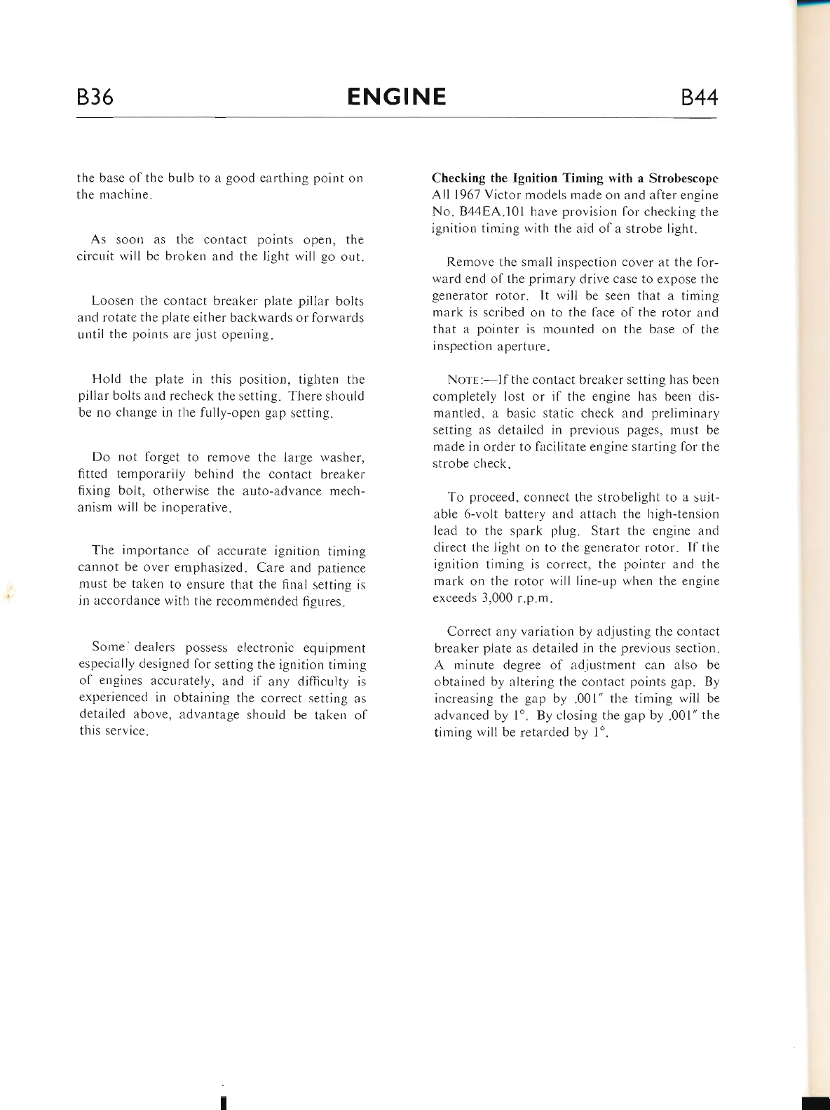
836 ENGINE 844
the base of the bulb to a good earthing point on
the machine.
As soon as the contact points open, the
circuit will be broker.r and the light will go out.
Loosen the contact breaker plate ptllar bolts
and rotate the plate either backwards or forwards
until the points are just opening.
Hold the plate in this position, tighten the
pillar bolts and recheck the setting. There should
be no cl-range in the fully-open gap setting.
Do not forget to remove the large washer,
fitted temporarily behind the contact breaker
fixing bolt, otherwise the auto-advance mech-
anism will be inoperltive.
The importance of accurate ignition timing
cannot be over emphasized. Care and patience
must be taken to ensure that the finai setting is
in accordance rvith the recommended figures.
Some.' dealers possess electronic equipment
especially designed for setting the ignition timing
of engines accurately, and if any difficulty is
experienced in obtaining the correct setting as
detailed above, advantage should be taken ol
this service.
Checking the Ignition Timing with a Strolrescope
All 1961 Victor models made on and after engine
No. B44EA.101 have provision for checking the
ignition timing with the aid of a strobe light.
Remove the small inspection cover at the for-
ward end of the primary drive case to expose tl.re
generator rotor. It wilt be seen that a timing
mark is scribed on to the face of the rotor and
that a pointer is mounted on the base of the
inspection aperture.
Nors:-If the contact breaker setting has been
completely lost or if the engine has been dis-
mantled, a basic static check and preliminary
setting as detailed in previous pages. must be
made in order to facilitate engine starting for the
strobe check.
To proceed, connect the strobelight to a suit-
able 6-volt battery and attach the high-tension
lead to the spark plug. Start the engine and
direct the light on to the generator rotor. If the
ignition timing is correct, the pointer and the
mark on the rotor will line-up when the engine
exceeds 3,000 r.p.m.
Correct any variation by adjusting the contact
breaker plate as detailed in the previous section.
A minute degree of adjustment can also be
obtained by altering the contact points gap. By
increasing the gap by .001" the timing will be
advanced by 1'. By closing the gap by .001" the
timing will be retarded by 1'.
www.bsaunitsingles.com
844 CARBURETTER CI
INDEX
C,qReuR.erren (Expr-ooao DRAwTNG)-fitted up to Engine No. 844EA.101 on Victor Enduro
and Special (U.S.A.) models ...
Ca.nsuRprrER (EXeLoDED on,rwrNc)-CoNcnNrntc Floer CHrrMeen-fitted on and after
Engine No. B44EA.101 on Victor Enduro and Special (U.S.A.) models only ...
DgscnrptroN ...
Page
c.2
c.3
c.4
c.4-5
c.5
c.5-6
c.6-7
c.7-8
c.8-9
c.9-10
Dtsir.raNtI-tNc AND RseutI.otNc
Dtsua.NrlrNc .q.No RrsunorNc
INspscrrNc rnp CoupoNsNts
(CoNclNrnrc Floa.r CHllrsrn)
HrNrs ,q.No Tlps
TRa.crNc Faulrs
Ve,nrAer-s SprrrNcs nNo PnR.rs
TuNrNc rHr C.q.nsunsrrgn
www.bsaunitsingles.com
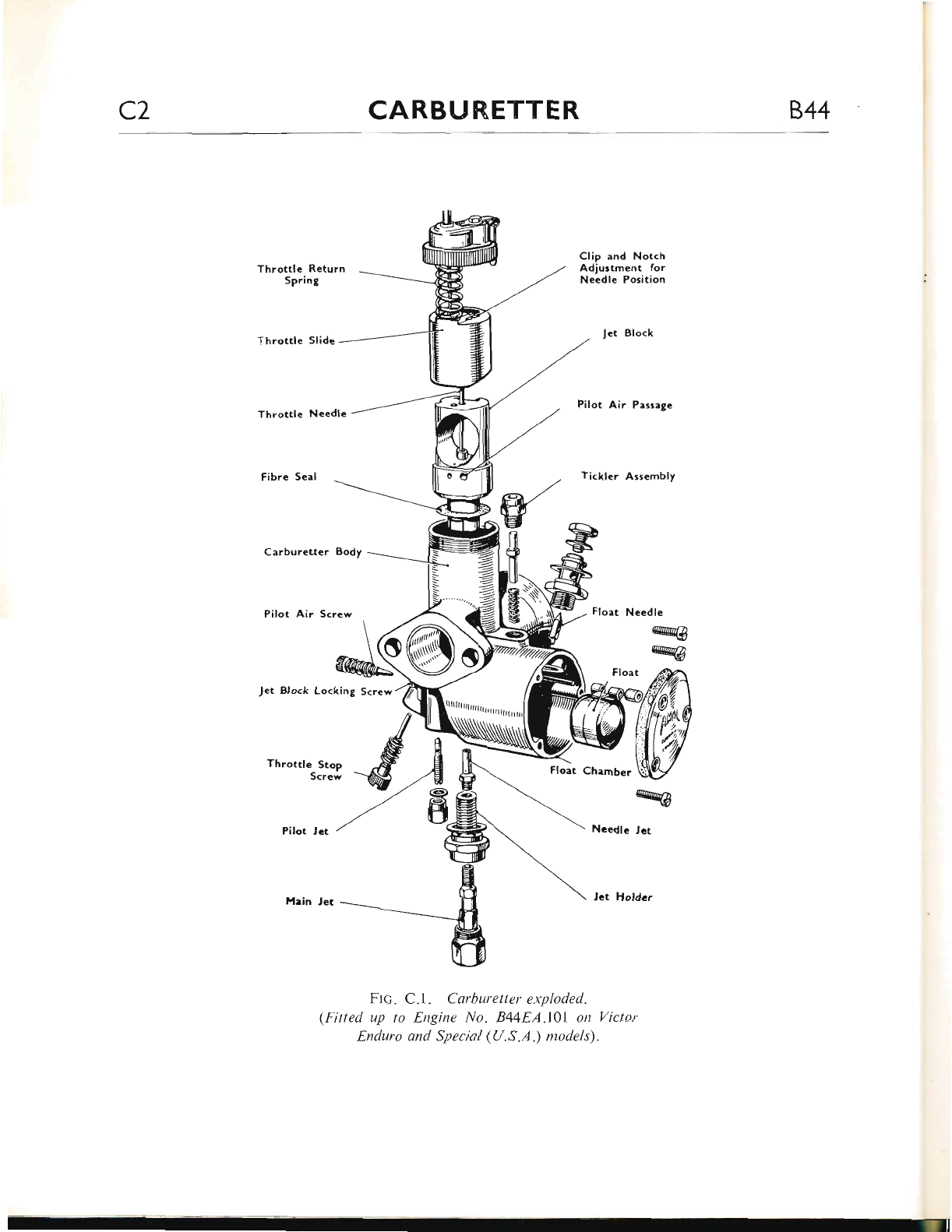
C2 CARBURETTER 844
Throttlc Return
Spring
Throttle Slide
Throttle Needle
Carbureuer Body
Pilot Air Screw
Jet Block Locking Screw
Clip and Notch
Adjustment for
Needle Position
Jet Block
Pilot Air Passage
Tickler Assembly
Float Needle
w
w
Float Chamber
Ncedlc Jct
rhrottrerstop -d--A
-',. @
,/ts
Pilot let /
Frc. C.l. Carburetter exploded.
(Fitted up to Engine No. B44EA.l0l on Victor
Enduro ond Special (U.S.A .) models).
ryg
www.bsaunitsingles.com
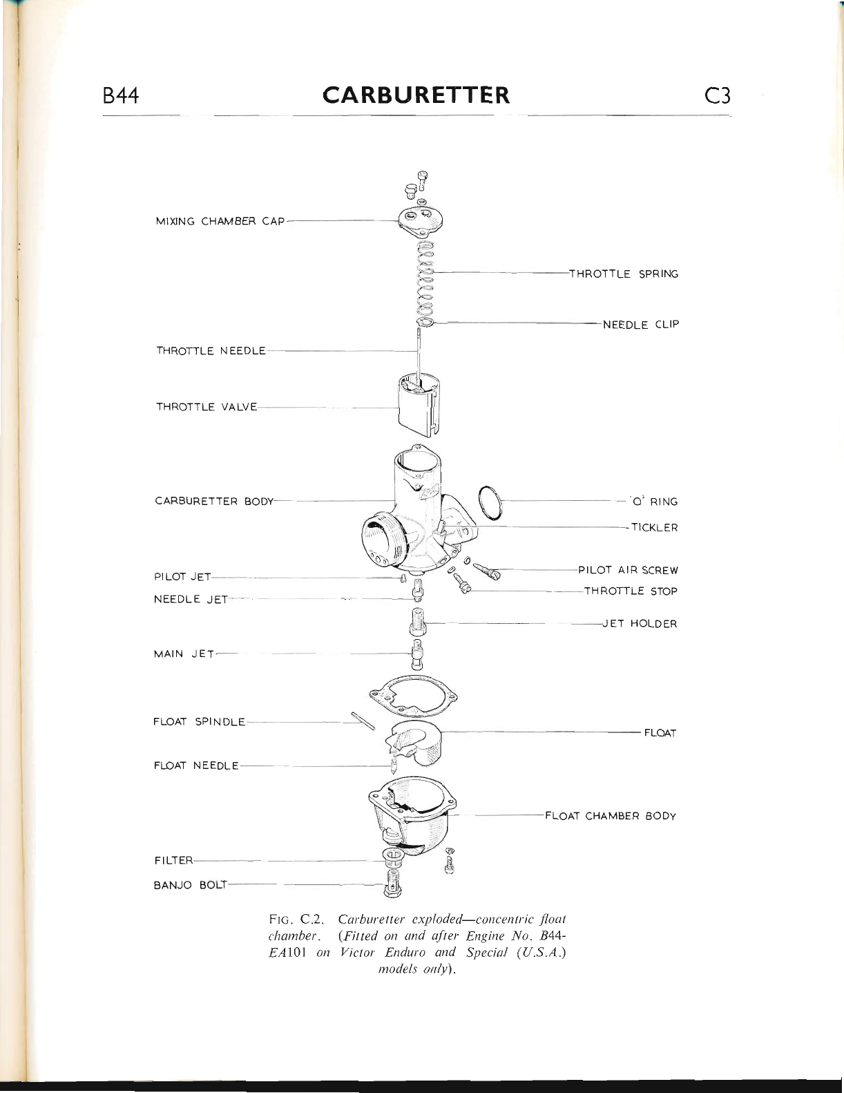
II
i
844 CARBURETTER C3
THROTTLE SPRING
NEEDLE CLIP
THROTTLE VALVE-
THROTTLE NEEDLE
CARBURETTER
FLOAT SPINDLE
FLOAT NEEDL
FIUTER
BANJO
{-9
iJr- ET HOLDER
5]
FLOAT CHAMBER BODY
Frc. C.2. Carburetter exploded-concentric float
chamber. (fltted on emd after Engine No. 844-
EAl\l on Victor Enduro and Special (U.S.A.)
models only).
MAIN J ET-
PTLOT JET- --- ];
-t
NEEDLE JET -__ !
www.bsaunitsingles.com
C4 CARBURETTER 844
DESCRIPTION
The Victor Grand Prix, the Victor Enduro and
Special (U.S.A.) are fitted with Amal Monobloc
carburetters, the only variation being that a
larger main jet is usecl on the Enduro and Special
(U.S.A.) carburetter.
Later E,nduro and Special (U.S.A.) models (on
and after Engine No. B44EA.l0l) are fitted with
e concentric float chamber carburetter.
The carbnretter, because ol its jets and choke
bore, proportions ernd atomises just the right
amount of petrol and air which provides a highly
inflarlable mixture. The mixture is drawn into
the engine and ultimately burnt within the
cylinde r head, herrce the terrn "combustiorr
chamber."
The float chamber nraintains a corrstant Jevei
ol fuel iit the jets a.nd incorporates a valve which
cuts off the supply when the engine stops.
The throttle, being operated from the handle-
bar twist grip, controls the volunre of mixture
and therefore the power.
When the engine is ticking-over. the mirture
is supplied by the pilot jet. As the throttle is
opened, lia tlre pilot by-pass, the pilot mixture
is augmented by the supply fron.r the rnain jet;
the initial stages of which, being controlled by
tlie taper needle in the needle jet.
The pilot supply is controlled by er jet which
can easily be removed lol cleaning purposes.
When assembled in the carburetter body, the
pilot jet is sealed by a cover nut. On later Victor
E,r-rduro and Special (U.S.A.) models (on and
alter Engine No. B44EA.l0l) the pilot jet is
situated within the concentric float chamber.
The main jet does not spray directly into the
mixing chanrber, but discharges through the
needle jet into the prir.r.rary air charnber, and goes
from there as a rich petrol/air mixture througl-r
the primary air choke, into the main air cl"roke.
This primary air choke has a compensating
action in conjunction with bleed holes in the
needle jet, which serve the double purpose of
compensating the r.niriture from the needle jet
and allowing the fuel to provide a well outside
and around the needle jet, which is available lor
snirp acceleration.
DISMANTLING AND ITEBUILDING
THE CARBURETTER
First, remove the two fixing nuts and withdra*,
the carburetter fiom its studs: it rvill not be
necessary to disconnect the cable fiom the tr.vist
grip.
Unscrew the miring chamber top ring and
r.r'ithdraw the top cap with throttle slide, spring
and needle. Remove the needle retaining spring
clip and take or-rt the needle. By compressing the
slide return spring, the cable nipple cern be pLrshed
down and out of the slide.
Unscrew three slotted screws and take off the
float chamber cover. The float spindle bush, float
ancl float needle c.ln now be rvithdraivn.
Take out the "banjo" bolt which secures the
luel pipe "banjo" coirnector to tl.re float needle
seatir.rg block and rvithdraw the "b:rnjo" filter
and r.vashers.
The r-reedle seating block may r"row be un-
screwed from the float chamber top.
Unscrerv the tickler (or primer) body and take
out the tickler witlr spring.
Remove the pilot air screrv and the throttle
stop screw, then take or-rt tl.re main jet cover nut
from below mixing chamber.
Unsci'ew the main jet, rnain jet holder and
needle jct. To release the jet block, it rnay be
necessary to re-insert the main jet holder, until
a few screu' tl.rreads are engaged then tap it with
a hide-mallct. This will release the jet block
through the 'Lop of the carbr-rretter body.
Unscrew the pilot jet cover and screw out the
pilot jet. All that remains to be removed at this
stage is the hexagonal locating peg, the end ol
rvhich can be seen protruding within the mixing
chamber.
Carefully clean all parts in petrol (gasoline).
flard deposits on the carburetter body are best
removed with a Iight grade wire brush. After
u,lshing the parts several times each in clean
www.bsaunitsingles.com
al'rr-
844 CARBU RETTER C5
petrol, allow to dry. To ensure that all holes
and drillings are fiee of dirt and are not blocked,
blow through with a jet of compressed air (a
hand pump is ideal for this operation).
Inspect tl-re component parts for wear artd
clieck tlrat the jets are in accordance rvith tlte
recommended sizes given in Ceneral Data.
Apart from the few points metttioned belori.
reassembly is a reversal of tl.re above instructions.
Ref-er to Fi-e. C.1 for guidance.
Do not replace any fibre washer tlrat looks
unserviceable. It is advisable to buy a set of re-
placement wnshers befbre dismantling the carbu-
retter.
When replacing the jet block, ensure that the
fibre seal is in position; locate the slot in the jet
block with tl-re peg in the carburetter housing and
drive the block horne.
Before screwing down the mixing chamber top
ring, cl.reck that the top cap locating peg is
correctly fitted in the slot in the top edge of tlie
mixing clramber.
Finally, rvhen replacing the float note that the
front is marked to assist in reassembly. Do not
omit to fit the float spindle busl.r on the outside
end of the spindle.
DISMANTLING AND REBUILDING
THE CARBURETTER (Concentric Float
Chamber)
Unscrew the two fixing nuts and withdraw tlre
carburetter from its mounting studs; it will not
be necessary to detach the cable from the t\\'ist
grip.
Take out the two Phillips-head fixing scrervs
and remove the carburetter top cover complete
with throttle valve assembly. Compress the
tl-rrottle spring and remove the needle clip to
release the needle. Whilst still compressing the
spring, puslr the cable downwards to release the
nipple from its location in the valve. Take care
not to lose the needle clip when taking off the
spring and top cover.
Unscrew the "banjo" bolt which secures tlre
fuel pipe "banjo" connector to the float needle
seatin-q block and withdraw the nylon filter.
The float chamber is secured to the base of
the rnixing chamber by two screws with spring
washers. On removal, it witl be noted tlrat tlie
float spindle is a press-fit into the chamber body
and that the needle is retained in position by the
rear forked end of the float.
The pilot jet, needle jet and main jet (with
holder) can now be unscrewed from the mixing
chamber base.
Take out the throttle stop adjusting and pilot
air adjusting screws and ensure that the small
rubber "O" ring on each screw is in good condi-
tion before replacing.
The float chamber tickler (or primer) consists
of a spring and plunger, splayed at one end to
retain it in the mixing chamber. This item should
r.rot be subjected to a great deal of wear and is
therefore unlikely to require replacement.
Having dismantled the carburetter, carefully
clean all parts in petrol (gasoline). Hard deposits
on the carburetter body are best removed with a
light grade wire brush. After washing the parts
in clean petrol, allow to dry and ensure that all
holes or small drillings are free from dirt. A
hand pump is ideal for "blorving through" any
blockages in the drillings. lnspect the component
parts for wear and check that the jets are in
accordance with the recommended sizes given
in General Data.
Reassembly is simply a reversal of the above
instructions but remember to replace any gaskets
or "O" rings that appear unserviceable. Reler
to Fig. C.2 for guidance.
INSPECTING THE CARBURETTER
COMPONENTS
The parts most liable to show wear after consider-
able mileage are the throttle valve slide and the
mixing chamber.
(1) Inspect the throttle valve slide for excessiie
scoring ofthe fiont area and check the extent
www.bsaunitsingles.com
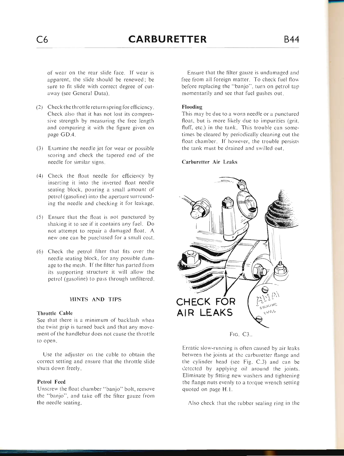
-
C6 CARBURETTER 844
(4)
(5)
(6)
of wear on the rear slide face. If wear is
apparent, the slide should be renewed: be
sure to fit slide with correct degree of cut-
:rway (see General Data).
(2) Check the tl-rrottle return spring for efficiency.
Check also that it has not lost its compres-
sive strength by measuring the free length
and comparing it with the figure given on
page GD.4.
(3.) Examine the needle iet for weilr or possible
scoring ernd check the tapered end of the
necdle for similar signs,
Check tl-ie float needle for efficiency by
inserting it into the inverted float needle
seating block, poLrring a small amount of
petrol (gasoline) into the aperture surround-
ing the needle and checking it lor leakage.
Ensure that the float is not punctured by
shaking it to see if it contains any luel. Do
not attempt to repair a damaged float. A
new one can be purchased for a snrarll cost.
Check the petrol filter that fits over the
needie seating block, for any possible darn-
age to the mesh. If tlre filter has parted lrom
its supporting structure it will allow the
petrol (gasoline) to pass throllgh unfiltered.
HINTS AND TIPS
Throttle Cable
See that there is a minimum of backlash rvheir
the twist grip is turned back and that any move-
ment of the handlebar does not cause the throttie
to open.
Use the adjuster on the cable to obtain the
correct setting and ensure that the throttle slide
shuts down freely.
Petrol Feed
Unscrew the float chamber "banjo" bolt, remove
the "banjo", and take off tl-re filter gauze fron.r
the needle seating.
Ensure that the {ilter gauze is undamaged and
free from all foreign matter. To check fuel flor,r
before replacing the "banjo", turn on petrol tap
momentarily and see that lLrel gushes out.
Flooding
This may be due to a worn needle or a punctured
float, but is more likely due to impurities (grit.
fluff, etc.) in the tank. This trouble can some-
times be cleared by pericdically cleaning out the
float chamber. If however, the trouble persists
the tank must be drained and swilled out.
Carburetter Air Leaks
Frc. C3..
L,rratic siov,,-running is often caused by air leaks
between the joints at thc carbr,rreiter flange and
the cylinder head (sec Fig. C.3) and can be
clctccted bir applying oil arould the joints.
Eliminate by fitting nerv r.vashers and tightening
the flange nuts evenly to a torque wrench setting
quoted on page H.1.
Also check that the rubber sealing ring in the
b
r.l
CHECK FOR
AIR LEAKS
www.bsaunitsingles.com
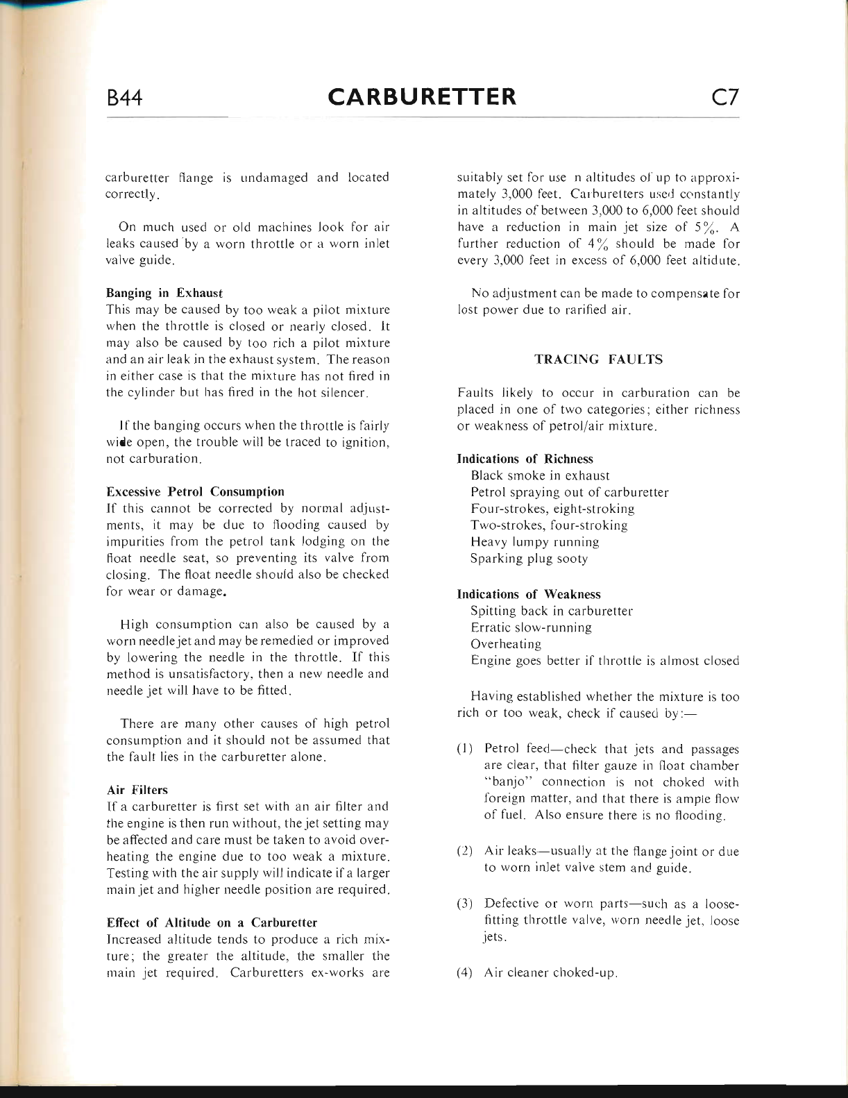
--_
844 CARBURETTER C7
carburetter flange is undamaged and located
correctly.
On much used or old machines look for air
leaks caused by a worn throttle or a worn inlet
valve guide.
Banging in Exhaust
This may be caused by too weak a pilot mixture
when the throttle is closed or nearly closed. lt
may arlso be caused by too rich a pilot mixture
and an air leak in the exhzrust system. The reasort
in either case is that the mixture has not fired in
the cylinder br-rt has fired in the hot silencer.
Ifthe banging occurs rvhen the throttle is fairly
wide open, the trouble will be traced to ignition.
not carburation.
Excessive Petrol Consumption
If this cannot be corrected by normal adjust-
ments, it may be due to flooding caused by
impurities from the petrol tank lodging on the
float needle seat, so preventing its valve from
closing. The float needle should also be checked
for wear or damage.
High consumption can also be caused by a
wom needle jet and may be remedied or improved
by lowering the needle in the throttle. lf this
method is unsatisfactory, then a new needle and
needle jet will have to be fitted.
There are many other causes of high petrol
consumption and it should not be assumed that
the fault lies in the carburetter alone.
Air Filters
lf a carburetter is first set with an air filtel and
the engine is then run without, the jet setting may
be affected and cerre must be taken to avoid over-
heating the engine due to too weak a mixture.
Testing with the air supply will indicate if a larger
main jet and higher needle position are required"
Effect of Altitude on a Carburetter
Increased altitude tends to produce a rich mix-
ture; the greater the altitude. the smaller the
main jet required. Carburetters ex-works are
suitably set fbr use n altitudes of'up to approxi-
mately 3,000 feet. Calhuretters useri cc'nstantly
in altitudes of betrveen 3,000 to 6,000 feet should
have a reduction in main jet size of 5\. A
further reduction of 4\ should be made for
every 3.000 feet in excess of 6,000 leet altidute.
No adjustment can be made to compensate for
lost porver due to rarified air.
TRACING FAULTS
Faults likely to occur in carburation can be
placed in one of two categories; either richness
or weakrress of petrol/air mixture.
Indications of Richness
Black smoke in exhaust
Petrol spraying out of carburetter
Four-strokes, eight-stroking
Two-strokes, four-stroking
Heavy lumpy running
Sparking plug sooty
Indications of Weakness
Spitting back in carburetter
Erratic slow-running
Overheating
Engine goes better if throttle is almost closed
Having established whether the mixture is too
rich or too weak, check il caused by:-
(1) Petrol feed-check that jets and passages
are clear, that filter gauze in float chamber
"banjo" connection is not choked rvith
foreign matter, and that there is ample florv
of fuel. Also ensure there is no flooding.
(2) Air leaks-usually at the flange joint or due
to worn inlet valve stem and guide.
(3) Defective or worn parts-such as a loose-
fitting throttle valve, rvorn needle jet, loose
jets.
(4) Air cleaner choked-up.
www.bsaunitsingles.com
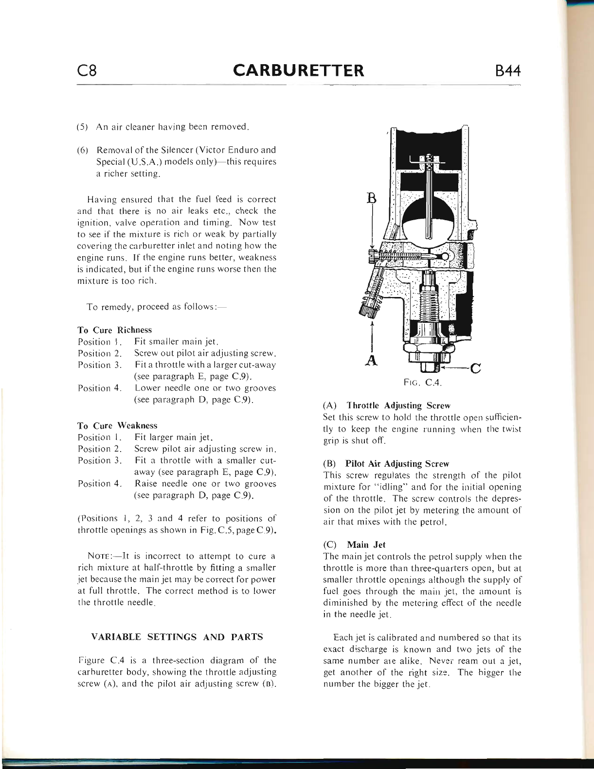
-
C8 CARBURETTER 844
(5) An air cleaner having becn removed.
(6) Removal olthe Silencer (Victor Enduro and
Special (U.S.A.) models onlv) this requires
a richer setting.
Having ensured that the fuel leed is correct
and that there is no air leaks etc.. check the
ignition. valve operation and timing. Now test
to see if the mixture is rich or weak by partially
covering the calburel.ter inlet and noting how the
engine runs. If the engine runs better, weakness
is indicated, but if the engine runs worse then the
mixture is too rich.
To remedy, proceed as follows: -
To Cure Richness
Position I . Fit smaller main jet.
Positiorr 2. Screw out pilot air ad,justing screw.
Position 3. Fit a throttle with a larger cut-away
(see paragraph E, page C.9).
Position 4. Lower needle one or two grooves
(see paragraph D, page C.9).
To Cure Weakness
Positiou I . Fit larger main jet.
Position 2. Screw pilot air adjusting screw in.
Position 3. Fit a throttle with a smaller cut-
away (see paragraph E, page C.9).
Position 4" Raise needle one or two grooves
(see paragraph D, page C.9).
(Positions l, 2, 3 and 4 refer to positions ol
throttle openings as shown in Fig. C.5, page C 9)"
Nors:-It is incorrect to attempt to cure a
rich mixture at half-throttle by fitting a smaller
iet because the rnain jet may be correct for power
at full thrclttle. The correct method is to lower
the throttle needle.
VARIABLE SETTINGS AND PARTS
Figure C.4 is a three-section diagram of the
carburetter body, slrowing the throttle adjusting
screw (a), and the pilot air adjusting screw (n).
Frc. C.4.
(A) Throttle Adjusting Soew
Set this screw to hold the throttle open sufficien-
tly to keep the engine Iunning r.vhen the twist
grip is shut off.
(B) Pilot Air Adjusting Screw
This screw regulates the strength of the pilot
mixture for "idling" and for the initial openirrg
ol the throttle. The screw controls the depres-
sion on the pilot jet by metering the amount ol
air that mixes witlr the petrol.
(C) Main Jet
The main jet controls the petrol sLrpply when the
throttle is more than three-quarters opcn. but at
smaller throttle openings although the supplv of
fuel goes through the mairr jet, the amount is
diminished by the metering effect of the needle
in the needle jet
Each jet is calibrated and nuntbered so that irs
e.ract discharge is known and two iets of the
same number are alike. Nevsi ream out a jet,
get another of the right size. The bigger llre
number the bigger the jet.
www.bsaunitsingles.com
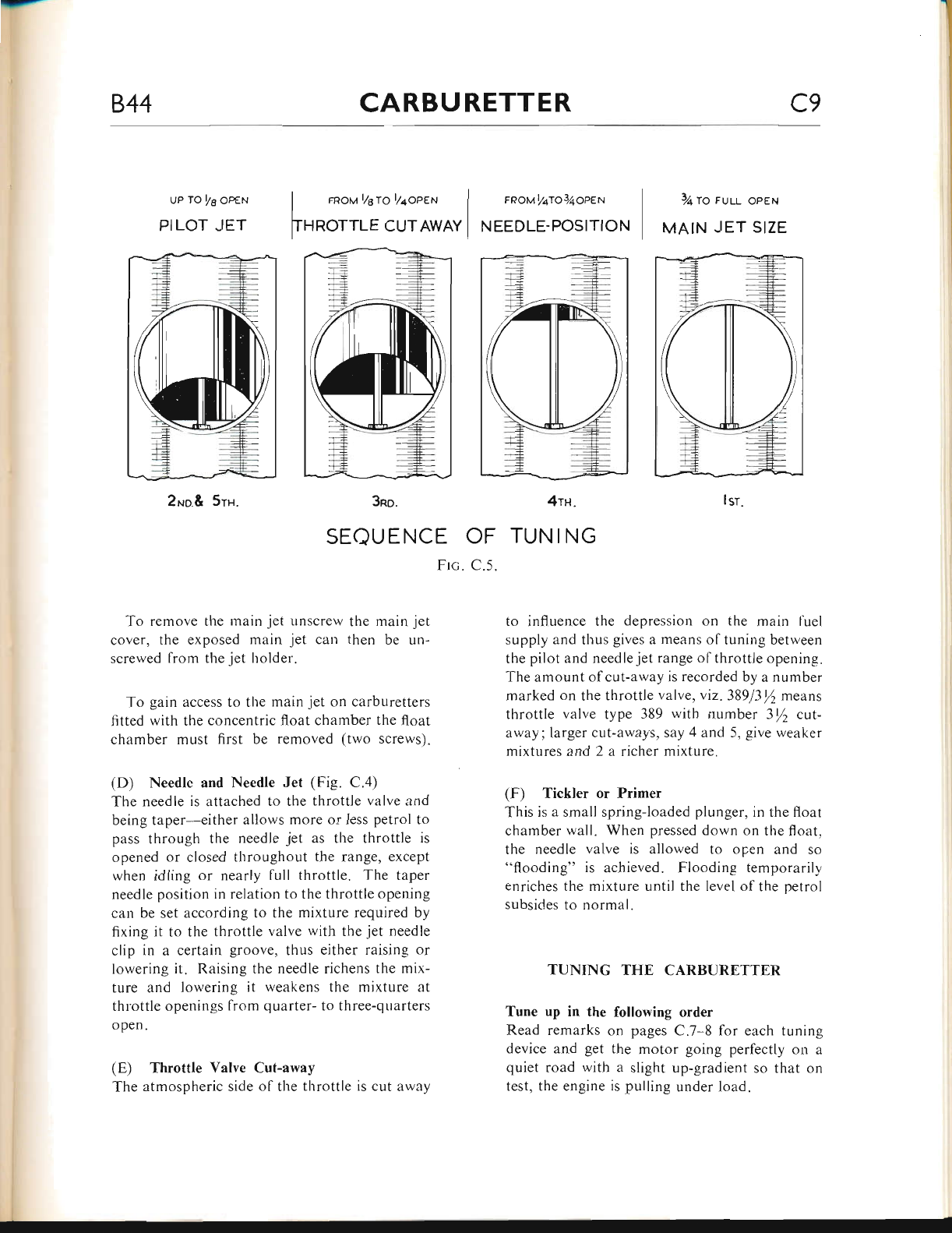
aJ,-
844 CARBURETTER C9
Up TO t/6 OpEN
PILOT JET
2No.& 5rH.
rRou TeTO t/4oPEN
HROTTLE CUTAWAY
FRoMlATo3/4opEN
NEEDLE.POSITION
7+ TO FULL OPEN
MAIN JET SIZE
3no. 4rn.
SEQUENCE OF TUN ING
Frc. C.5.
Jsr
To remove tl.re rnain jet unscrew the main jet
cover, the exposed main jet carl then be un-
screwed from the jet holder.
To gain access to tl.re main jet on carburetters
fitted with the concentric float chamber the float
chamber must first be removed (two screws).
(D) Needlc and Needle Jet (Fig. C.4)
The needle is attached to the throttle valve and
being taper-either allows more or less petrol to
pass through the needle jet as the throttle is
opened or closed throughout the range, except
when idling or nearly full throttle. The taper
needle position in relation to the throttle opening
can be set according to the mixture required by
fixing it to the throttle valve with the jet needle
clip in a certain groove, thus either raising or
lowering it. Raising the needle richens the mix-
ture and lowering it weakens the mixture at
throttle openings from quarter- to three-quarters
open.
(E) Throttle Valve Cut-away
The atmospheric side of the throttle is cut away
to influence the depression on the rnain fuel
supply and thus gives a rneans of tuning between
the pilot and needlejet range ofthrottle opening.
The amount of cut-away is recorded by a number
marked on the throttle valve, viz. 38913y2 means
tlrrottle valve type 389 with number 3/2 cut-
away; larger cut-aways, say 4 and 5, give weaker
mixtures and 2 a richer mixture.
(F) Tickler or Primer
This is a small spring-loaded plunger, in the float
chamber wall. When pressed down on the ffoat,
the needle valve is allowed to open and so
"flooding" is achieved. Flooding temporarily
enriches the mixture until the level of the petrol
subsides to normal.
TUNING THE CARBURETTER
Tune up in the following order
Read remarks on pages C.7- 8 for each tuning
device and get the motor going perfectly on a
quiet road with a slight up-gradient so that on
test, the engine is pulling under load.
www.bsaunitsingles.com
cr0 CARBURETTER 844
lsr Main .Iet with throttle in position I trig.
C.5. tf at full ttrrottle the engine runs "heavily".
the main jet is too large. If at full throttle" the
engine seems to have better power when the
throttle is eased off or the carburetter intake is
slightly covered, then the main jet is too small.
With the correct sized main jet, the engine at
firll throttle should run evenly and regularly witli
maximum power.
If testing lor speed work, ettsure that the main
iet size is sullcient for the mixture to be lich
enough to maintain a cool engine. To verity this,
examine the sparking plug after taking a fast run
declutching and stopping the engine quickly. If
the sparking plug has a cool appearance the mix-
ture is correct; if sooty, the mixture is rich; ii
however, there are signs of intertse heat, the plug
being very white in appearance. the mixture is
too rveak and a larger main jet is necessary.
2Np Pilot Jet (Fig. C.5) with throttle ir-r posi-
tions 2 and 5. With engine idling too fast with
the twist grip shut off and the throttle shut down
on to the throttle adjusting screw, and ignition
set for best slow-running: (1) Screw out throttle
adjusting screw until the engine runs slower and
begins to falter, then screw pilot air adjusting
screw in or out, to make engine run regularly and
faster. (2) Now gently lower the throttle adjust-
ing screw until the engine runs slower and just
begins to falter, adjust the pilot air adjusting
screw to get best slow-running, if this second
adjustment leaves the engine running too fast, go
over the iob a third time.
3nn Throttle Cut-away with throttle ir-r position
3 (Fig. C"5). If, as you take off from the idling
position, there is an objectionable spitting from
the carburetter, slightly richen the pilot mixture
by screwing in the air screw. If this is not effec-
tive, screw it back again, and fit a throttle with
a smaller cut-away. If the engine jerks under
load at this throttle position and there is no
spitting, either the jet needle is much too high or
a larger throttle cut-away is required to cure
richness.
4ru Needle with throttle in position a (Fig. C.5).
The needle controls a wide range of throttle
openings and aiso the acceleration. Try the
needle in as low a position as possible, viz rvith
the clip in a groove as near the top as possible;
il acceleration is poor and with the carburetter
inlet partially covered, the results are better,
raise the needle by two grooves; if very much
better try lowering the needle by one groove and
leave it where it is best. If mixture is still too
rich with clip in groove number I nearest the top,
the needle jet probably wants replacement because
ofwear. lfthe needle itselfhas had several years'
use replace it also.
5rs Finally, go over the idling again for final
touches.
www.bsaunitsingles.com
844 FRAME AND FITTINGS Dfl
INDEX
VrcroR ENouno ,rNp Specla.l
Vrcron GRl.No PRrx Fna.ue
(U.S.A.) Fnaur
Fn,qMe Ar-rcNrvreNt
CrutNcua.no (Vrcron ENouno lNp SpecrnL (U.S.A.) rtr.rlv)
Rran Suocr AssoR.euns
SwrNcrNc Anru
Removal
Bushes
Alignment
Page
D.2
D.3
D.4-6
D.6
D.6-7
D.7
D.1
D.8
D.9
D.10
D.10
D.10
D.l0
D.10-ll
D.tt-r2
D.t2-t3
D.l3
D"l4
D.l4
D.l4
D.l4
D.l5
S,q.opLr
Pnop Srlxo (Vrcron ENpuRo nNp Sprcrnl (U.S.A.) oNr-v)
ENrncv TneNspsR Corr-
RErR Bnn<e Pnnrr.
RE,rn" Muoculnn
C.q.RsunErrsn Arn Frlrnn
OIL ra.Nr RsN,{oveL (Vrcron ENnuno aNn
SprlooNrrrsn HEa.o (VlcroR ENouno a,No
CoNrRol Clsrs Rnpra.cenmqr
Specr.lr- (U.S.A.) oNrv)
Sppcra,l (U.S.A.) oNr-v)
Throttle Cable
Throttle Cable (Carburetter with Concentric Float Chamber)
Front Brake Cable
Clutch Cable
Exhaust Valve Lifter Cable
Toor-sox aNo B.qrrrny C.qnRrrn
www.bsaunitsingles.com
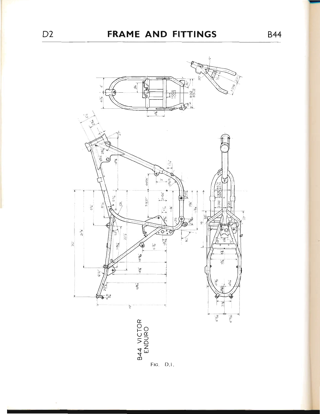
D2 FRAME AND FITTINGS 844
c
Po
u{
rd
sfr
!q-
oFrc. D.l.
www.bsaunitsingles.com
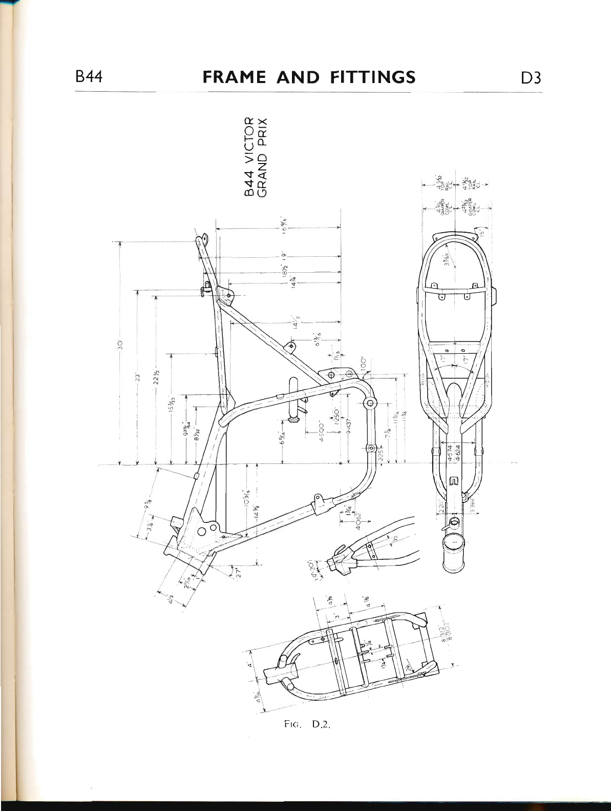
844 FRAME AND FITTINGS D3
c><
Oa
uo.
;2
$<
$c
cog)
T--
l
_{1
tvs
www.bsaunitsingles.com
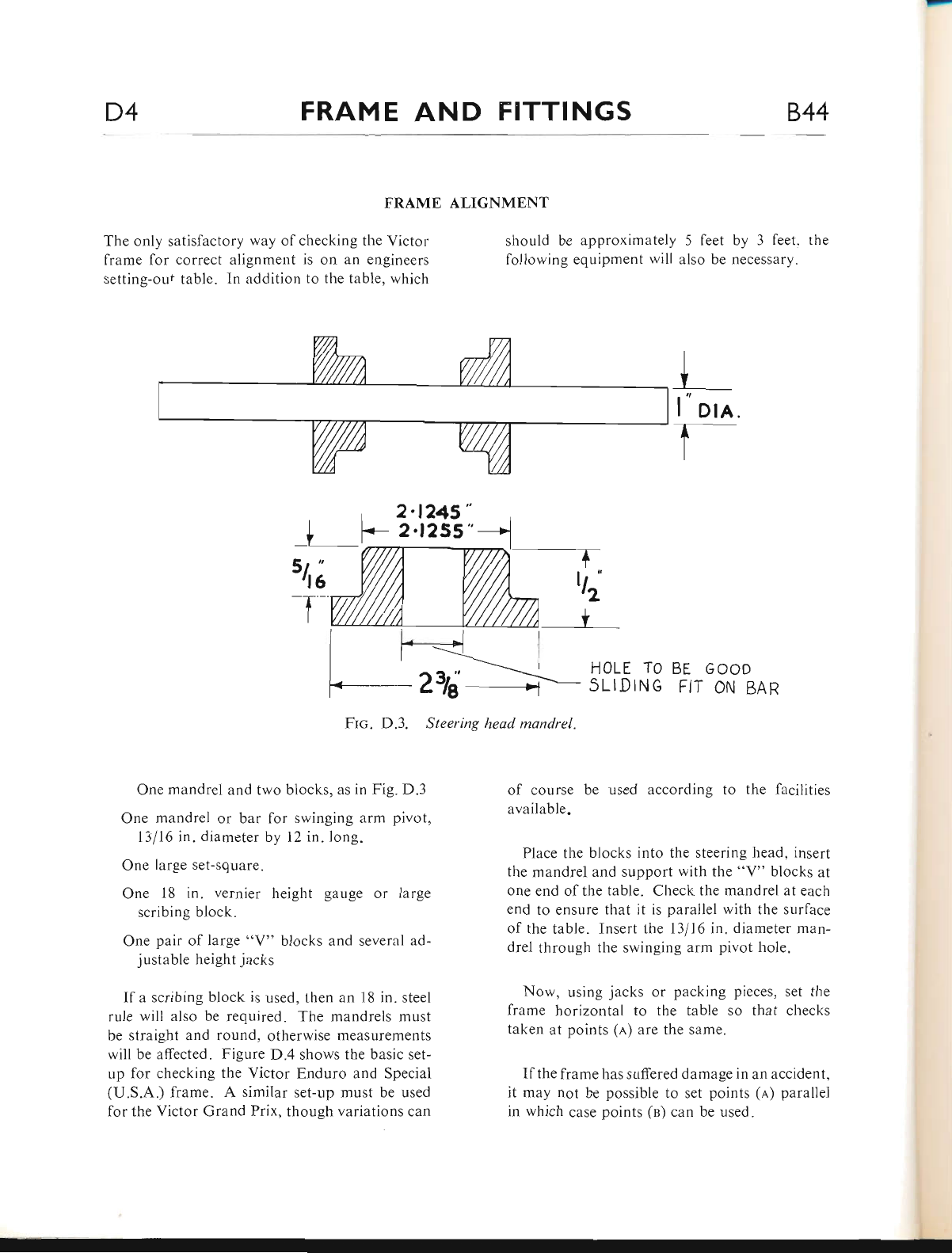
D4 FRAME AND FITTINGS 844
FRAME
The only satisfactory way of checking the Victor
frame for correct alignment is on an engineers
setting-out table. In addition to the table, which
ALIGNMENT
should be approximately
following equipment will 5 feet by 3 feet. the
also be necessary.
5t"
rl6
-T t6'
I
I F-=<r_ |
i -----'--.- H0LE T0 BE GOOD
!__ Z3l;___+ Sirirue Flr oN BAR
2.t245"
2.l2SS"
--r
Frc. D.3. Steering head mandrel.
One mandrel and two blocks, as in Fig. D.3
One mandrel or bar for swinging arm pivot,
13l16 in. diameter by l2 in. long.
One large set-square.
One 18 in. vernier height gauge or large
scribing block.
One pair of large "V" blocks and several ad-
justable height jacks
If a scribing block is used, then an 18 in. steel
rule will also be required. The mandrels must
be straight and round, otherwise measurements
will be affected. Figure D.4 shows the basic set-
up for checking the Victor Enduro and Special
(U.S.A.) frame. A similar set-up must be used
for the Victor Grand Prix" though variations can
of course be used according to the facilitres
available.
Place the blocks into the steering head, insert
the mandrel and support with the "V" blocks at
one end of the table. Check the mandrel at each
end to ensure that it is parallel with the surface
of the table. Insert the 13/16 in. diameter man-
drel through the swinging arm pivot hole.
Now, using jacks or packing pieces, set the
frame horizontal to the table so that checks
taken at points (a) are the same.
If the frame has suffered damage in an accident,
it may not be possible to set points (a) parallel
in which case points (n) can be used.
| " Dln.
www.bsaunitsingles.com
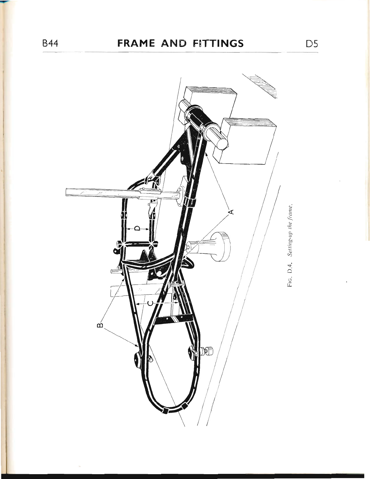
844 FRAME AND FITTINGS D5
c)
\
S
b4
ai
q
$.
o
LL
www.bsaunitsingles.com
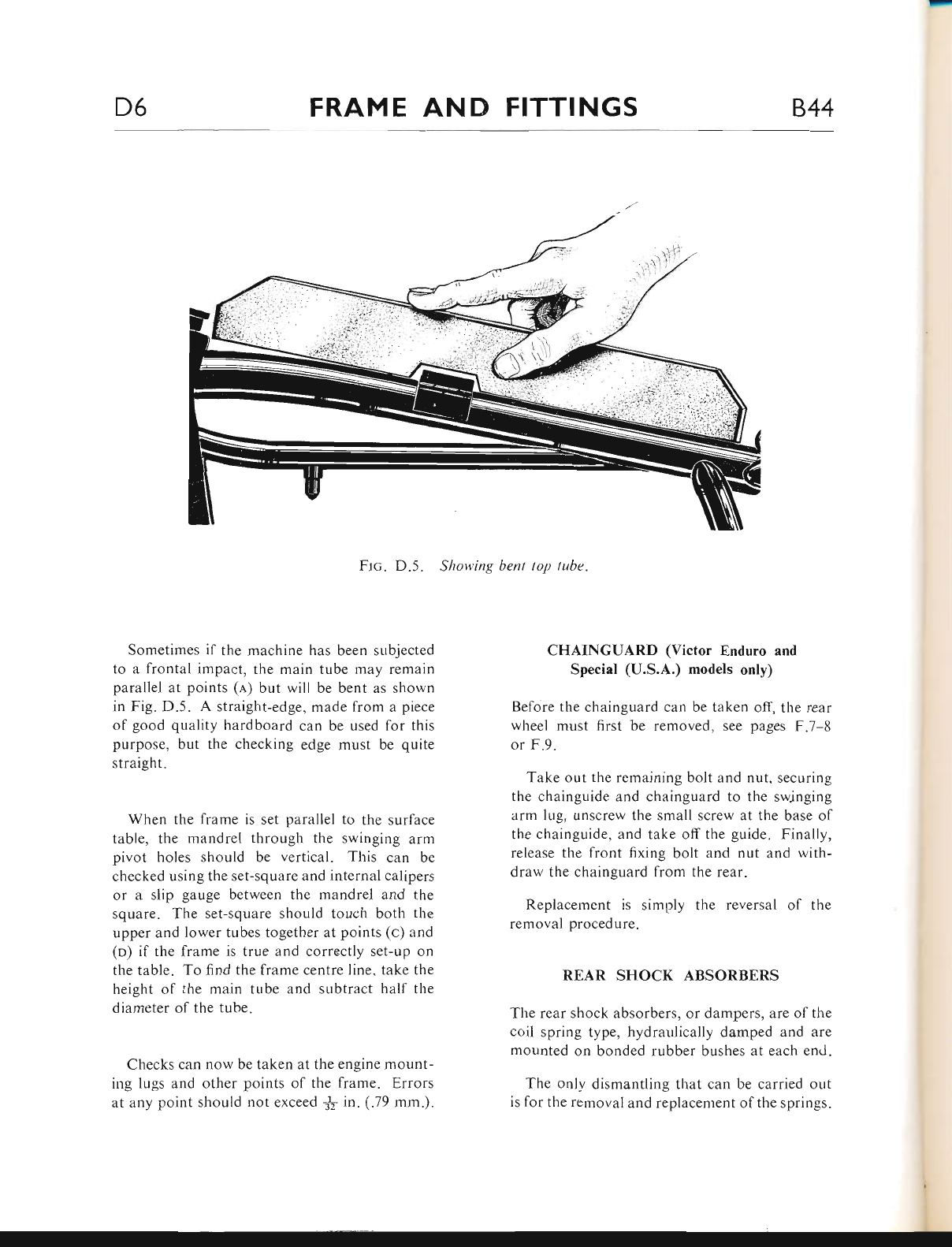
D6 FRAME AND FITTINGS 844
Ftc. D.5. Showing bent top tube.
Sometimes if the machine has been subjected
to a frontal impact, the main tube may remain
parallel at points (a) but will be bent as shown
in Fig. D.5. A straight-edge, made from a piece
of good quality hardboard can be used for this
purpose, but the checking edge must be quite
straight.
When the frame is set parallel to the surface
table, the mandrel through the swinging arm
pivot holes should be vertical. This can be
checked using the set-square and internal calipers
or a slip gauge between the mandrel and the
square. The set-square should touch both the
upper and lower tubes together at points (c) and
(o) if the frame is true and correctly set-up on
the table. To find the frame centre line. take the
height of the main tube and subtract half the
diameter of the tube.
Checks can now be taken at the engine mount-
ing lugs and other points of the frame. Errors
at any point should not exceed j! in. (.79 mm.).
CHAINGUARD (Victor Enduro and
Special (U.S.A.) models only)
Before the chainguard can be taken ofl the rear
wheel must first be removed, see pages F.7-8
or F.9.
Take out the remaining bolt and nut, securing
the chainguide and chainguard to the swjnging
arm lug, unscrew the small screw at the base of
the chainguide, and take off the guide. Finally,
release the front fixing bolt and nut and with-
draw the chainguard from the rear.
Replacernent is simply the reversal of the
removal procedure.
REAR SHOCK ABSORBERS
The rear shock absorbers, or dampers, are of the
coil spring type, hydraulically damped and are
mounted on bonded rubber bushes at each end.
The only dismantling that can be carried out
is for the removal and replacement of the springs.
www.bsaunitsingles.com
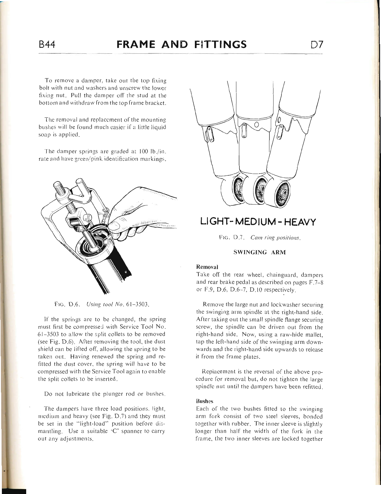
844 FRAME AND FHTTINGS D7
To remove a damper. take out the top fixing
bolt with nut and washers and unscrerv the lower
fixing nut. Pull the damper off the str,rd at tl're
bottom and withdraw lrom the top fr-ame bracket.
Tl're removal ancl replaccment o1'the mountin,e
buslies will be found r.nLrcli easier il a little liqLrici
soap is applied.
The damper springs are graded at 100 lb./in.
rate and have green/pink identification markin".
Ftc. D.6. Using tool l/o. 6l-3503.
Il the sprirrgs are to be changed, the spring
must first be compresse,l with Service Tool No.
61-3503 to allow the split collets to be removed
(see Fig. D.6). After removing the tool, the dust
shield can be lifted off, allowing the spring to be
taken out. Having renewed the spring and re-
fitted the dust cover, the spring wiil have to be
compressed with the Service Tool again to enable
the split collets to be ir-rserted.
Do not lubricate the plr-rnger rod or bushes.
The darrpers have three load positions. Iight,
nredir-rm and heavy (see Fig. D.7) and they nrr-rst
be set in the "light-load" position before cii:-
mantling. Use a suitable ,C' spanner to carry
oLlt any adjustments.
LIGHT- MEDIUM - HEAVY
Frc. D.7. Cam ring positions.
SWINGING ARM
Removal
Take off the rear wl.reel, cl.rainguard, dampers
and rear brake pedal as described on pages F.7-g
or F.9, D.6, D.6 7, D.l0 respectively.
Remove the large nut and lockwasher securing
the swinging alrn spindle at the right-hand side.
After taking out the small spindle flange securing
screw, the spindle can be driven out from the
right-hand side. Now, using a raw-hide mallet,
tap the left-hanC side of the swinging arm down-
wards and the right-hand side upwards to release
it from the frante plates.
Replacemont is the reversal ol the above pro-
ccdure lor removal but, do not tighten the large
spindlc nut Lllttil the dampers have been refitteci.
Bushes
Each ol the two bushes fitted to the swinging
arn fork consist of trvo steel sleeves, bonded
together with rubber. The inner sleeve is slightly
longer than hall the width ol the fork in the
frame, the trvo inner sleeves are locked together
www.bsaunitsingles.com
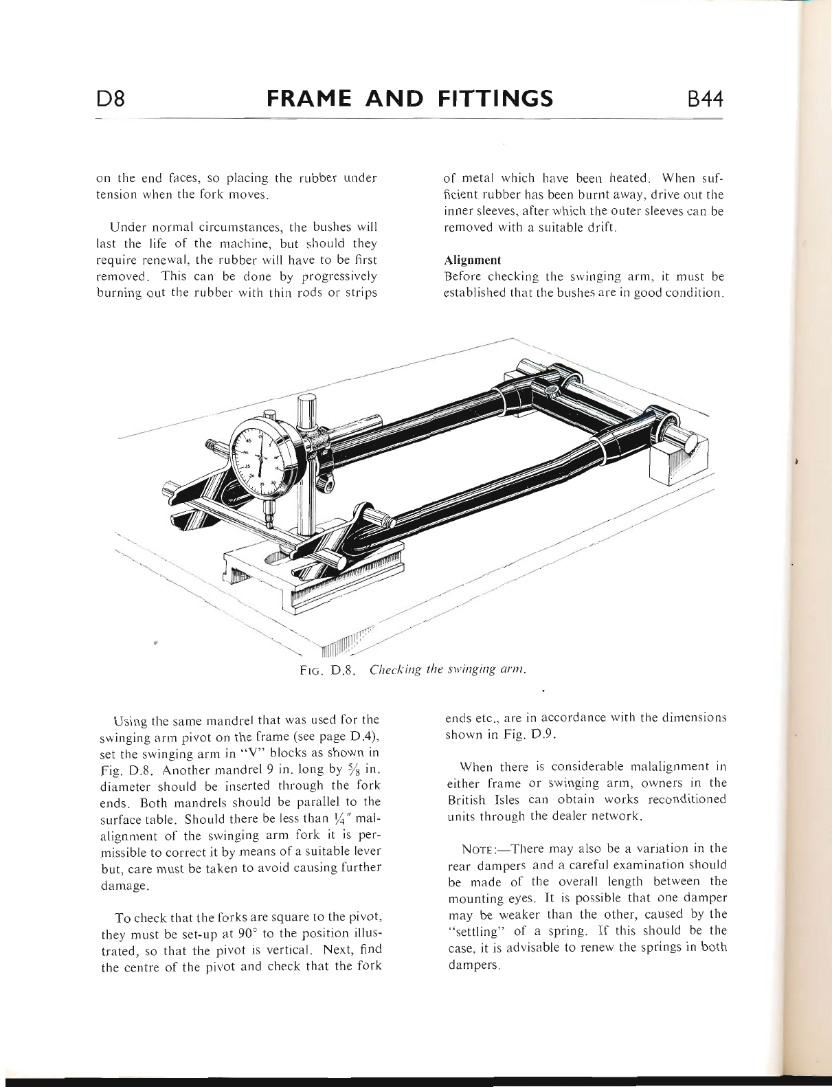
D8 FRAME AND FITTINGS 844
on the end faces, so placing the rubber under
tension when the fork moves.
Under normal circuntstances, the bushes will
last the life of the nracl.rine, br-rt should they
require renewal, the rubber will have to be first
removed. This can be done by progressively
burning out the rubber with thin rods or strips
of metal which have been heated. When suf-
ficient rubber has been burnt away, drive ont the
inner sleeves, after which the outer sleeves can be
removed with a suitable drift.
Alignment
Before checking the swinging arm, it must be
established tlrat the bushes are in good condition.
,,-"t,
t-'tt'
--,---
-,-''tt--
-''
irl l,
\Yilll -'
FIc. D.8. Cltecking the stt:inging arm.
Using the same mandrel that was used for the
swinging arm pivot on the frame (see page D.4),
set the swinging arm in "V" blocks as shown iu
Fig. D.8. Another mandrel9 in. long by sl irr.
diameter should be inserted through the fork
ends. Both mandrels should be parallel to the
surface table. Should there be less tltan /a" mal-
alignment of the swinging arm fork it is per-
rnissible to correct it by means of a suitable lever
but, care must be taken to avoid causing further
damage.
To check that the forks are square to the pivot,
they must be set-Lrp at 90' to the position illus-
trated, so that the pivot is vertical. Next, find
the centre of the pivot and check that the fork
ends etc., are in accordance wit}r the dimensions
shown in Fig. D.9.
When there is considerable malalignment in
eitl.rer frame or swinging arm, owners in the
British lsles can obtain works reconditioned
units through the dealer network.
Norr:-There may also be a variation in the
rear dampers and a careful examination should
be made of the overall length between the
mounting eyes. It is possible that one damper
rnay be weaker than the other, caused by the
"settling" of a spring. If this should be the
case, it is advisable to renew the springs in both
dampers.
www.bsaunitsingles.com
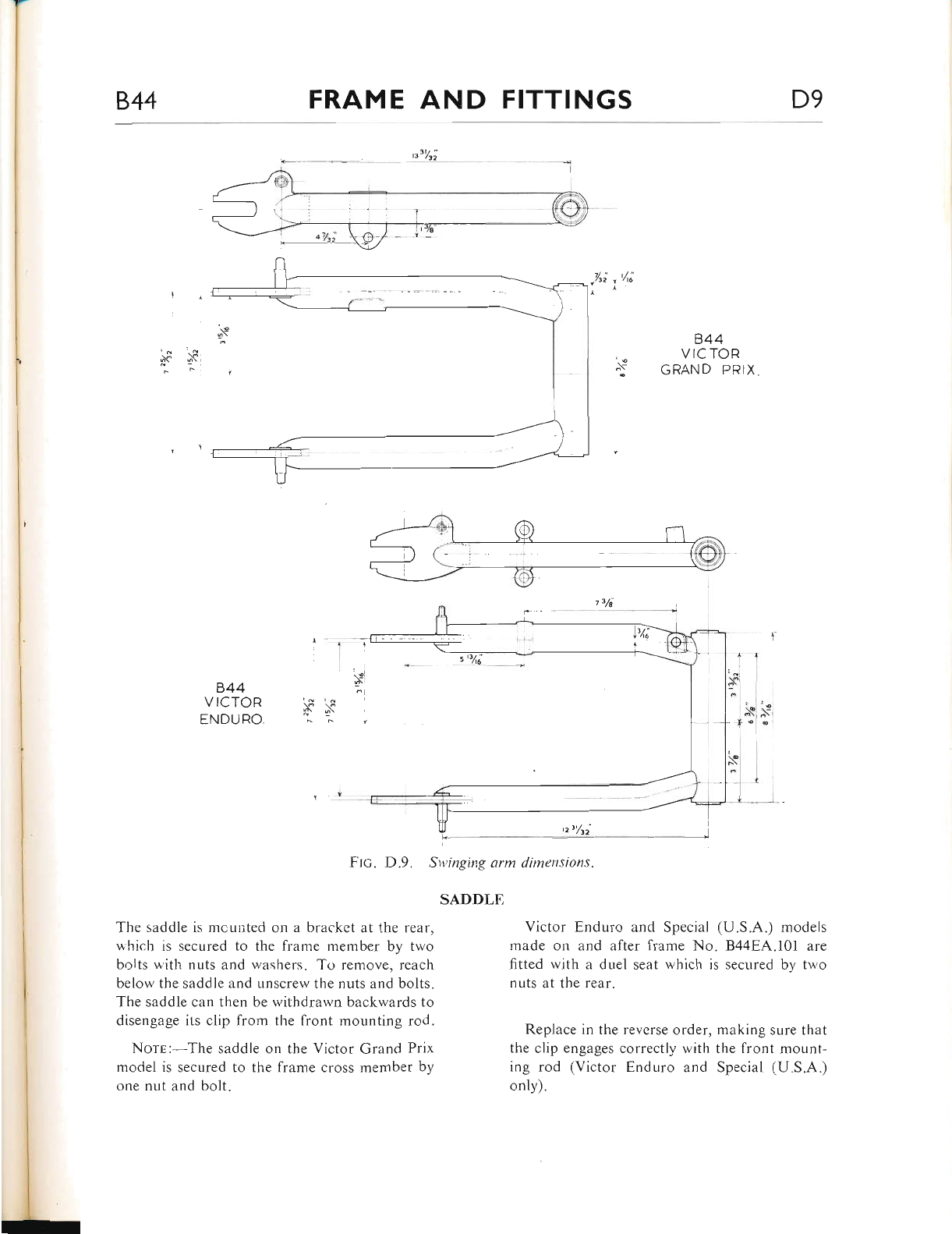
844 FRAME AND FITTINGS D9
p3t/zi
844
VICTOR
ENDURO.
Ftc. D.9. Swinging arm dimensions.
SADDLE
The saddle is mcunted on a bracket at the rear,
which is secured to the frame member by two
bolts with nuts and washers. To remove, reach
below the saddle and unscrew the nuts and bolts"
The saddle can then be withdrawn backwards to
disengage its clip lrom the front mounting rod.
Norr:-The saddle on the Victor Grand Prix
model is secured to the frame cross member bv
one nut and bolt.
844
VICTOR
GRAND PRIX
Victor Enduro and Special (U.S.A.) models
made on and after frame No. 8448,4'.101 are
frtted with a duel seat which is secured by two
nuts at the rear.
Replace in the reverse order, making sure that
the clip engages correctly with the front mount-
ing rod (Victor Enduro and Special (U.S.A.)
only).
www.bsaunitsingles.com
Dt0 FRAME AND FITTINGS 844
PROP STAND (Victor Enduro and
Special (U.S.A.) models only)
The prop stand is secured to the frame lug with
one bolt and lockwasher. Bend back the tabs of
the lockwasl'rer and unscrew the bolt. The return
spring will be released as the stand is drawn off
the frame lug.
ENERGY TRANSFER COIL
Victor Enduro and Special (U.S.A.)
Take off the saddle (see page D.9) and dis-
connect the sparking plug lead. Unclip the
"Lucar" connector at the coil to free the small
leed wire. Remove tl-re two nuts and washers,
securing the coil to the fiame cross member and
pull the coil dou'nwards to release.
Befbre replacing the coil, locate the connector
for the twin red wire on to the right-hand fixing
bolt (between the coil and lrame cross member)
and the connector fbr the thin lvire on to the
left-hand fixing bolt.
Victor Special (1968)
The coil is positioned beneath the tank on the
I968 Victor Specials. and is secured by a single
nut and bolt. Take:r careful note of the terminal
location of each cable.
To replace the coil proceed in the reverse
orcler as removal.
Victor Grand Prix
The coil is secured to the rear right-hand fiame
down tube by two nuts and bolts.
Remove as described above but, when re-
placing. do not omit to locate the cable con-
nectors on to tl-re lower fixing bolt.
REAR BRAKE PEDAL
Take out one screw and nut (spring pin on 1968
mod,els) securing the brake rod to the brake
pedal. Remove the central fixing bolt with large
plain washer from the fulcrum pin and take off
the pedal rvith retur"n spring. The fulcrum prn
is fixed to the frame with one large nut and
washer.
Nore:-On Victor Grand Prix machine, the
brake pedal fulcrum pin is held in place with one
nut and washer and is removed with the pedal.
REAR MUDGUARD
It u,ill not be necesserry to remove the rear wheel,
but on Victor Enduro and Special (U S.A.)
models the saddle may have to be taken off to
provide access to the tail lamp cable connection.
The tail lamp is secured by tlvo bolts with nuts
from the top (also holding the number plate
bracket). and one nut from belorv tl.re guard.
When these are released, the cable at the lamp
and at the connectors belou'the energy transfer
coil can be disconnected, enabling the tail lamp
to be withdrawn.
After taking out tl,e six {ixing bolts with nuts
and washers, the mudguard can be pulled gently
away from the rear.
The short aluminium n.rudguard on the Victor
Grand Prix is retained in position b_v" four bolts
r,vith nuts and large washers.
Replace in the reverse order but on Victor
Enduro and Special (U.S.A.) models, ensure that
the tail lamp connectors are in good order and
that the.cable is not "bared" at any point.
CARBT.iRETTER AIR FILTER
Victor Enduro and Special (U.S.A.)-If the
machine is being used regularly for competition
ivork or under exceptionally severe conditions,
the air filter should be cleaned at intervals of not
more than one week and preferably before every
event.
First undo the three locknuts with washers
holding the triangular fibreglass cover at the left-
hand side of the machine. On removal of the
cover, it will be seen that the air filter element is
located loosely over the housing mouth"
www.bsaunitsingles.com
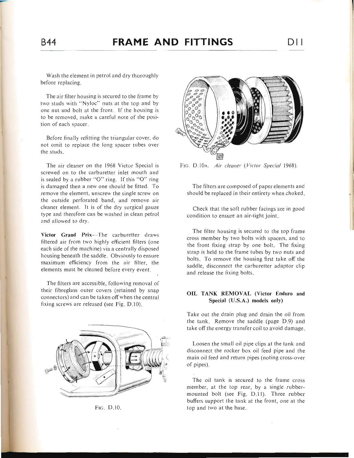
844 FRAME AND FITTINGS Dlt
Wash the ele ment in petrol and dry thoroughlv
before replacing.
The air filter housing is secured to the frame by
two studs with "Nyloc" nuts at the top and by
one nut and bolt at the liont. lf the housing is
to be removed. make a careful note o1' the posi-
tion ol each spercer.
Befbre finally lelittir.rg the triangular cover, do
not omit to replace tl-re long spacer tubes over
the studs.
The air cleaner on tl.re 1968 Victor Special is
screwed on to the carburetter inlet mouth and
is sealed by a rubber "O" ring. lf this "O" rin-e
is damaged then a new one should be fitted. To
remove the elen.rent, unscrew the single screw on
the outside perforated band, and remove air
cleaner elernent. lt is ol the dry surgical gauze
type and therelore can be washed in cleern petrol
and allowed to dry.
Victor Grand Prix -The carburetter dr.aws
filtered air from two highly efficient filters (one
each side of the machine) via a centrally disposed
l.rousing beneath the saddle. Obviously to ensure
maximum efficiency from the air filter, the
elements must be clearred before every event.
The filters are accessible, following removal ol
their fibreglass outer covers (retained by snap
connectors) and can kre taken offwhen the central
fixing screws are released (see Fig. D.l0)"
-(il
,-':| o
Ftc. D. I0a. Air cleaner (Vit'tctr Sltecial 19681.
The filters are composed of paper elements and
should be replaced in their entirety wlren choked.
Check that tbe soft rubber tacings are in good
condition to ensLlre an air-tight joint.
The filter housing is secured to the top frame
cross member by two bolts with spacers, and to
the front fixing strap by one bolt. The fixing
strap is held to the frame tubes by two nuts and
bolts. T'o remove the housing first take ofl the
saddle, disconnect the carbrrretter adaptor clip
and release the fixing bolts.
OIL TANK REMOVAI, (Victor Enduro and
Special (U.S.A.) models only)
Take out the drain plug and drain lhe oil from
the tank. Remove the saddle (page D.9) and
take offthe energy transfer coil to avoid damage.
Loosen the small oil pipe clips at the tank and
disconnect the rocker box oil feed pipe and the
main oil f-eed and return pipes (noting cross-over
of pipes).
The oil tank is secured to tl-re lrame cross
ntenber, at the top rear, by a single rubber-
mounted bolt (see Fig. D.ll). Three rubber
buffers support the tank at the lront. one at the
top and two at the base.
i."t
l.ora
;t$
/a <" <2
al2i
A'a Ail
) ^o'^c/ Il
'ro aoa,
ooo?-o,
n-S i
'*^o"''
sLPst'
s-o- \
lst**j
Frc;. D.10.
www.bsaunitsingles.com
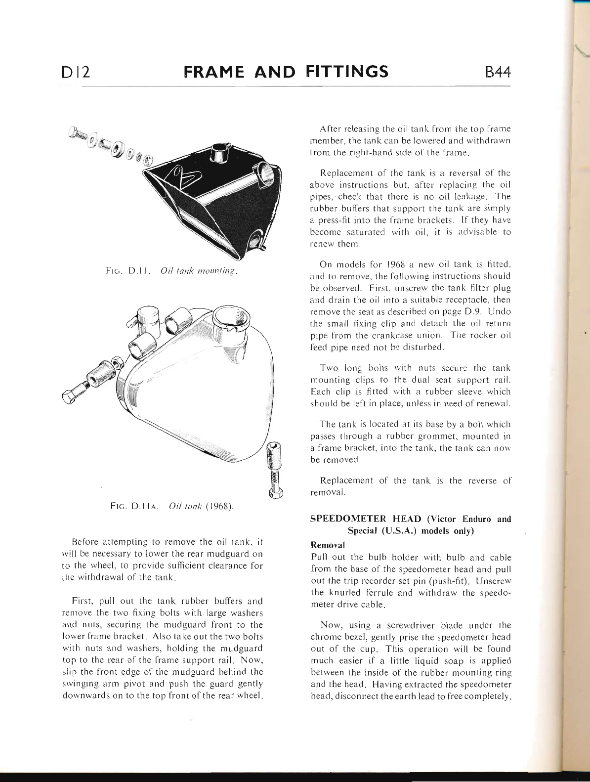
Dt2 FRAME AND FITTINGS 844
Frc. D.ll. Oil lonli mounting.
Frc. D.ll,a,. Oil tonl< (1968).
Betole attempting to remove the oil tanl<, it
rvill be necessary to lotver the rear mudguard on
to thc wl'reel, to provide sr-r1trcient clearance lbr
the withclrawal olthe tank.
First. pull out tl.re tank rubber buffers and
remove the two fixing bolts r.vith large washers
and nuts, securing the n.rudguard front to the
lorver fiame bracket. Also take out the two bolts
rvith nuts and washers, holding the mudguard
top to the rear ol the frame support rail. Now,
slip the lront edge ol the mudguard behind the
srvinging ann pivot and pusl.r the guard gently
downwards on to the top tiont of tl.re rear wheel.
Alter releasing the oil tank fr-om the top lrame
r.nember. the tank can be loli'ered and u,ithclrawn
from tlre right-hand side ol the fraine.
R.eplacemerrt o{'tl.re tank is a reversal ol' the
above instrr-rctioi.rs but. a11er replacing the oil
pipes, check that there is no oil leakaee. The
rubber buffcrs that sr-rpport the tank iLre simply
a press-fit into l-he llame brackets. lf'they have
become saturateC lvith oil. it is advisable to
renew them.
On models for 196t3 a neu, oil tank is fitteci.
and to re move. the lollori'ing iirstructions should
be observed. Firsl. unscrew the tzink filt:r plug
and drain the oil into a suitable receptercle, then
terrove thc seat as describeC on page D.9. Undo
tl.re small fixing clip and detach the oil returrr
pipe from the crankcl.rse urrion. The rocker oil
I'eed pipe need not be distLrrbed.
Tu,o long bolts tvith nuts secur. the tank
mounting clips to the clual seat supltort ra-il.
Each clip is fitted with a rubber sleeve which
should be left in place. unless in need of renewal.
The tank is located at its base by zr bolt rvhich
passes through a rubber grommet, mounted in
a lrame bracket. into the iank. the tank cetn novn,
be removed.
Replacement ol tlre tank is the reverse ol
removal.
SPEEDOMETER HEAD (Victor Enduro and
Special (U.S.A.) models only)
Removal
Pull out the bulb holder with bulb arrd cable
from the base of the speedometer head and pull
out the trip recorder set pin (push-fit). Unscrew
the knurled ferrule and withdrarv the speedo-
meter drive cable.
Now, using a screwdriver blade under the
chrome bezel, gently prise the speedon-reter head
out of the cup. This operation will be lound
much easier if a little liquid soap is applied
Lretrveen the inside of the rubber mounting ring
and the head. Having extracted the speedometer
head, disconnect the earth lead to free completely.
/, A\ r,
-. -si/ rr
, w 1,4
www.bsaunitsingles.com
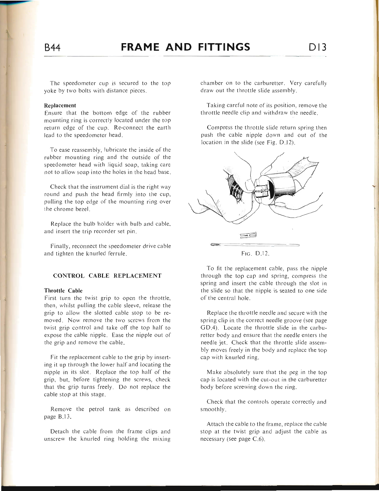
-r--
844 FRAME AND FITTINGS Dl3
The speedorxeter cup is secured to the top
yoke by tu'o bolts rvith distance pieces.
Replacement
Ensure that the bottom edge of the rubber
mounting ring is correctly located under the top
return edge of the cup. Re-connect the eartl.t
lead to the speedometer head.
To ease reassernbly, lubricate the inside of the
rubber mounting ring and the outside ol the
speedometer head ivith liquid soap, taking care
not to allow soap into the holes in the head base.
Check that the instrument dial is the right rvay
round and push the head firmly into the cup,
pulling the top edge ol the mountin-q ring over
the chrome bezel.
Replace the bulb holder rvith bulb
and insert the trip recorder set pin"
Finally, reconnect the slreedometer
and tighten the knurled f-errule.
and cable.
drive cable
CONTROL CABLE REPLACEMENT
Throttle Cable
First turn the twist grip to open tl.re throttle,
tlrer.r, whilst pulling the cable sleeve, release tl.re
grip to allow the slotted cable stop to be re-
moved. Now remove the two screws from the
twist grip control and take off the top half to
expose the cable nipple. Ease the nipple out of
the grip and remove the cabie"
Fit the replacement cable to the grip by insert-
ing rt up through the lower half and locating the
nipple in its slot. Replace the top hall of the
grip, but. before tightening the screws, check
tlrat the grip turns freely. Do not replace the
cable stop at this stage.
Remove the petrol tank as described on
page 8.13.
Detach the cable from the frame clips and
Llnscrew tl.re knurled ring holding the miring
chamber on to the carburetter. Very carefully
draw out the throttle slide assembly.
Taking carelul note of its position, remove the
throttle needle clip and r.r,ithdraw tl're needle.
Compress the tl-rrottle slide return spring then
push the cable nipple dor','n arrd out ol the
location in the slide (see Fig. D.l2).
Frc;. D.12.
To fit the replacement cable, pitss the nipple
thror-rgh the top cap zrnd spring, compress the
spring and insert tlie cable through the slot in
the slide so that the nipple is seated to one sicle
of the central hole.
Replace the throttle needle and secure with the
spring clip in the correct needle groove (see page
GD.4). Locate the throttle slide in the carbu-
retter body and ensure that the r.reedle enters the
needle jet. Check that the throttle slide assem-
bly moves freely in the body and replace the top
cap with knurled ring.
Make absolutely sure thiit the peg in the top
cap is located rvith the cut-oLlt in the carburetter
body before screrving down the ring.
Check that the controls operate correctlv and
smootbly.
Attach the cable to the frame, replace the cabie
stop at tl.re trvist grip and adjusl the cable as
necessury (see page C.6).
www.bsaunitsingles.com
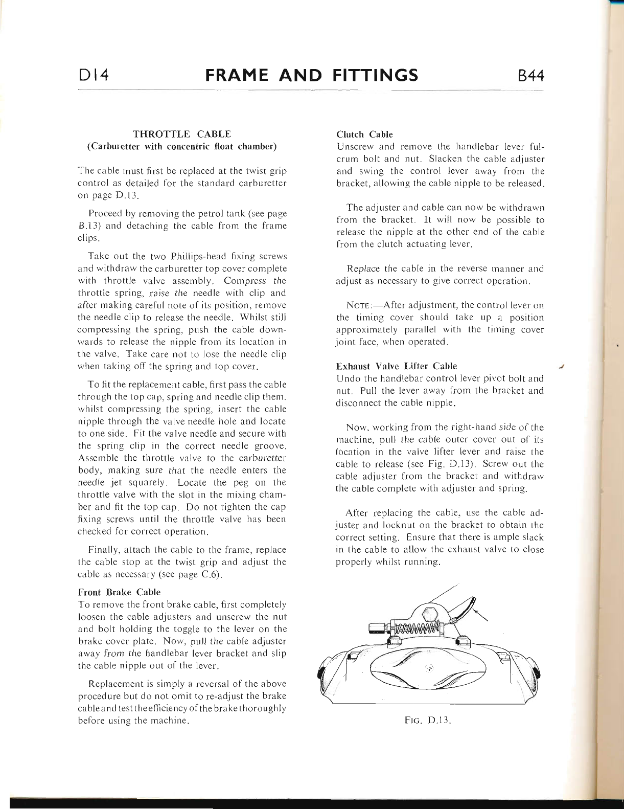
Dt4 FRAME AND FITTINGS 844
THROTTLE CABLE
(Carburetter with concentric float chamber)
The cable must first be replaced at the twist grip
control as detailed for the standard carburetter
on page D.13.
Proceed by removing the petrol tank (see page
B.l3) and detaching the czrble from the fiame
c1ips.
Take out the two Pl-rillips-head fixing screws
and withdraw the carburetter top cover compiete
rvith throttle valve assembly. Compress the
throttle spring, raise the needle with clip and
alter making careful note of its position, remove
the ncedle clip to release the needle. Whilst still
cornpressing the spring, push the cable dorvn-
rvalds to release tlie nipple frorn its location in
the valve. Take care not to lose the needlc clip
w'hen taking off the spring and top cover.
To 1it the replacement cable, first pass the cable
thror-rgh the top cap, spring and needle clip them.
rvhilst compressing the spring, insert the cable
nipple through the valve needle hole and locate
to one side. Fit the valve needle and secure with
the spring clip in the correct needle groove.
Assemble the throttle varlve to the carburetter
body, making sure that the needle enters the
needle jet squarely. Locate the peg ou the
throttle valve with the slot in the mixing cham-
ber and fit the top cap. Do not tighten the cap
fixing screws until the throttle valve has been
clrecked lor colrect operation.
Finally, attach the cable to tl.re frame, replace
the cable stop at the twist grip and adjust the
cable as necessary (see petge C.6).
Front Brake Cable
To remove the lront brake cable, first completely
loosen the cable adjusters and unscrew the nut
and bolt holding the toggle to the lever on the
brake cover plate. Now, pull the cable adjuster
away lrom the handlebar lever bracket and slip
the cable nipple out o1'tl.re lever.
Replacement is simply at reversal of the above
procedure but do r.rot omit to re-adjust the brake
cable and test the efficiency of the brake thoroughly
belore using the machine.
Clutch Cable
Unscrew and remove the handlebar lever ful-
crum bolt and nut. Slacken the cable ad-juster
and swing the control Iever away frorn the
bracket, allowing the cable nipple to be released.
The adjuster and cable can now be withdrarvn
from the bracket. It will now be possible to
release the nipple at the other end of the cable
lrom the clutch actuating lever.
Replace the cable in the reverse mauner and
lrdjust as necessary {o give correcI operati()n.
Norr.:--After acljustment, the control Iever on
the timing cover should take up a position
approximately parallel with the timing cover
joint face, rvhen operated.
Exhaust Valve Liller Cable
Undo the handlebar control lever pivctt bolt and
nr-rt. Pull the lever away licrrl the bracket and
disconnect the cable nipple"
Now. rvorking from the right-hand side of the
machine. pull the cable outer cover out of its
location in the valve lifter iever and raise tire
cable to release (see Fig. D.13). Screw out the
cable adjuster from the bracket and withdraw
the cable complete with adjuster and spring.
After replacing the cable, use the cabie ad-
jLrster and locknut on the bracket to obtain the
correct selting. E.nsure that there is ample slack
in the cable to allow the exhaust valve to close
properly whilst running.
Frc. D.13"
www.bsaunitsingles.com
844 FRAME AND FITTINGS Dt5
TOOLBOX AND BATTERY CARRIER
(1968 Victor Special)
For 1968 the Victor Special has been fitted witl-L
a battcry carrier and toolbox. This is positioned
on the left-hand side of the machine, the follow-
ing paragraphs give instruction on removing arrd
replacement. Access is gained to the battery
carrier and toolbox by removing the sidecover:.
This is retained by two "Oddie" studs rvhicl-r
require only half a turn to release.
Battery Carrier Removal
Disconnect the battery terminal connections, un-
clip the fixing straps and lift out the battery.
Note that a vent pipe is connected to the battery
top and is so arranged that corrosive fumes from
the battery cells are directed clear ol the machine.
Proceed by removing the rubber mat from the
carrier base to expose the three fixing bolts. The
two outer bolts are each fitted with two rubber
bushes, two plain washers and a nut.
A third nut retains the sidecover buffer bracket
on to the end of the lront bolt. The inner fixirrg
point consists of one long bolt, three rubber
bushes. a spacer tube. four plain washers and
a nut.
The rubber bushes lielp to insnlate tlre batter-y
and carrier from road shocks and vibratiorr. It
is most important, therefore, that a r.rote is made
of the way in which they are fitted in order to
enslrre corlect reassemblv.
Toolbox Removal
To remove the toolbox, first take out the tool
ro11 then release the two fixing bolts and nuts.
The lower bolt is fitted with a spacer between
tlre toolbox base arrd the frame bracket. Gently
pull awav the toolbox and noting their tetminal
locations, disconnect the rectifier cables, allou'-
ing tlre assembly to be withdrawn lrom the lrame.
The rectifier is heid to the toolbox by a single
nut and should not be disturbed unnecessarily. -
When either unscrewing or tightening the fixin-s
nul, the bolt head should be held firmly witli a
second spanner to prevent it from turning. If
this precaution is not taken, the rectifier plates
may twist and break the internal corinections.
Reassembly
Reassembly is the reverse of removal.
www.bsaunitsingles.com
844 FRONT FORKS EI
INDEX
DrscnrprroN
ReltovtNc axo RtrtttrNc rIiE Hreola.np (Vrcron ENpuRo aNo Sprcra.l (U.S.A.) MoDELS
oNr-v)
Page
E.2
E.2
8.2-3
E.3-4
E.4-5
E.s-6
E.6
E.6-7
E.7
E.7-8
E.9
AprusrrNc SrrnRlNc HEno
RpxswrNc SrrrnrNc HsA.n
Racss
Recps
ReprovrNc Fonx Lrcs
DlsnaxnrNc Fonr Lrcs
Orl Sea,rs
Rrgurr-olNc Fonr l-Ecs
Repr-,c.clNc Fonx Lrcs
FoRr AlrcNurNr
Hvpna.ulrc DalrprNc
www.bsaunitsingles.com
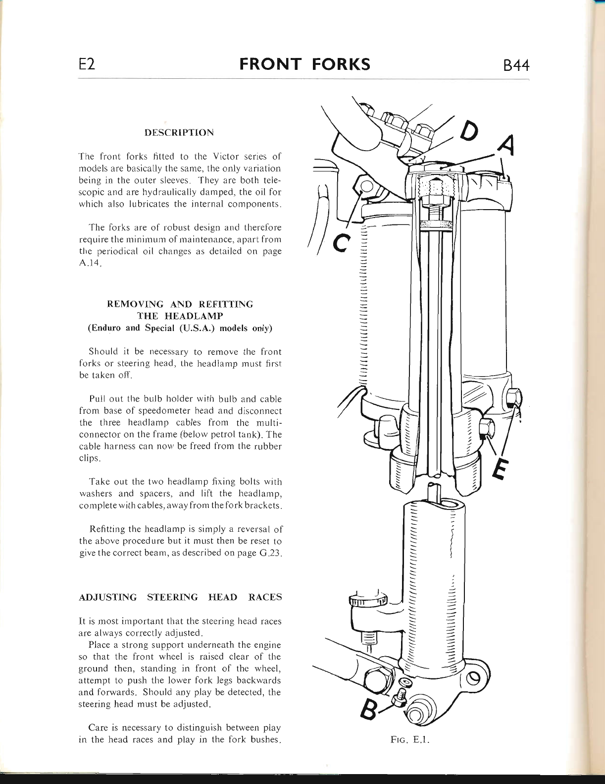
E2 FRONT FORKS 844
DESCRIPTION
The fiont f'orks fitted to the Victor series ol
models are basicaliy the sarne, the only variatior.r
being in the outer sleeves. They are both tele-
scopic and are hydraulically damped, the oil for
which also lubricates the internal components.
The forks are of robust design and therefbre
require the minimum of mainterrance, apart from
the periodical oil changes as detailed on page
A.14.
REMOVING AND REFITTING
THE HEADLAMP
(Enduro anrl Special (U.S.A.) models only)
Should it be necessary to remove the front
forks or steering head, the headlamp must first
be t:rken off.
Pull out the bulb holder with bulb and cable
fiom base of speedometer head and disconnect
the three headlamp cables fiom the multi-
connector on the frame (below petrol tank). The
cable harness can now be freed from the rr-rbber
clips.
Take out the two headlamp fixing bolts with
washers and spacers, and lift the headlamp,
complete with cables, away from thefork brackets.
Refitting the headlamp is simply a reversal of
the above procedure but it must then be reset to
give the correct beam, as described on page G.23.
ADJUSTING STEERING HEAD RACES
It is most important that the steering head races
are always correctly adjusted.
Place a strong support underneath the engine
so that the front wheel is raised clear of the
ground then, standing in front of the wheel,
attempt to push the lower lork legs backwards
and forwards. Should any play be detected, the
steering head must be adjusted"
Care is necessary to distinguish between play
in the head races and play in the fork bushes.
/)
t\
S
Frc. E.l.
www.bsaunitsingles.com
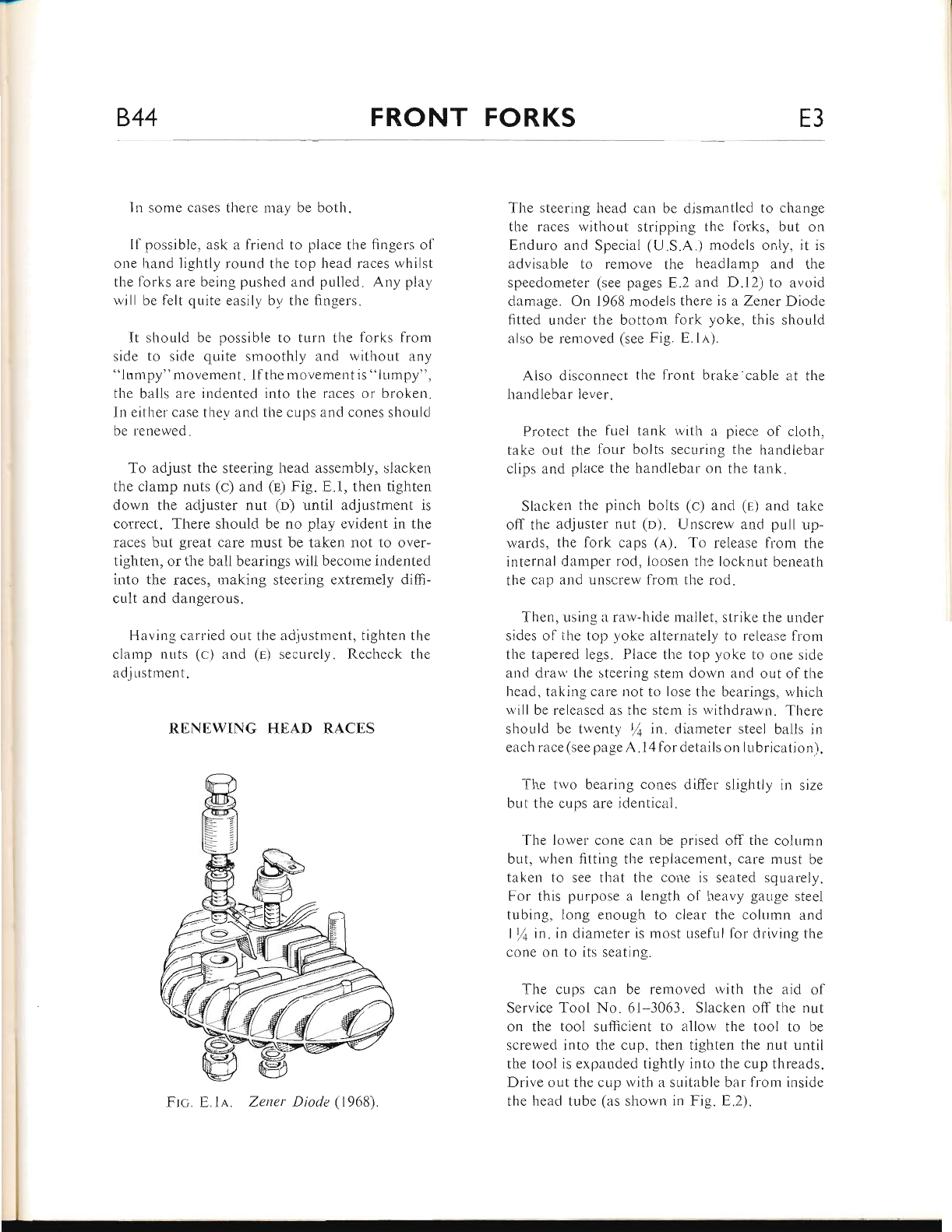
844 FRONT FORKS E3
In some cases there rnay be both.
Il possible, ask a friend to place the fingers of
one hand lightly round the top head races whilst
the torks are being pushed and pulled. Any play
will be felt quite easily by the fingers.
It should be possible to turn the forks lrom
side to side qLrite smoothly and without any
"lumpy" movement. lf the movementis "lumpy".
the balls ar-e indented into the races or broken.
In either cilse thev and the cups and cones should
be renewed.
To adjust the steering head assembly, slacken
the clamp nuts (c) and (E) Fig. E.1, then tighten
down the adjuster nut (D) until adjustment is
correct. There should be no play evident in the
races but great care must be taken not to over-
tighten, or the ball bearings will become indented
into the races, making steering extremely difli-
cult and dangerous.
Havir.rg carried out the adjr-rstment, tighten the
clamp nuts (c) and (r) securely. Recheck the
adjustment.
RENEWING HEAD RACES
The steerir.rg head can be dismantled to change
the races without stripping the forks, but on
Enduro and Special (U.S.A.) models only, it is
advisable to remove the headlamp and the
speedometer (see pages E,.2 and D.12) to avoid
damage. On 1968 models there is a Zener Diode
fitted under the bottom fork yoke, this should
also be removed (see Fig. E.1E).
Also disconnect the front brake'cable at the
handlebar lever.
Protect the fuel tank with a piece of cloth,
take out the four bolts securing the handlebar
clips and place the handlebar on the tank.
Slacken the pinch bolts (c) and (e) and take
off the adjuster nut (o). Unscrew and pull up-
wards, the fork caps (.q). To release from the
internal damper rod, Ioosen the locknut beneath
the cap and unscrew from the rod.
Tl-ren, using a raw-hide mallet, strike the under
sides of ihe top yoke alternately to release from
the tirpered legs. Place the top yoke to one side
and drau' the steering stem down :rnd out of the
head, taking care not to lose the bearings, which
il,ill be released as the stem is withdrawn. There
should be twenty % in. diameter steei ba1ls in
each race (see page A. I 4 for details on I ubrication).
The tr'vo bearing cones differ slightly in size
but the cups are identical.
The lower cone can be prised off the column
but, when fitting the replacement, care must be
taken to see that the cone is seated squarely.
For this purpose a length of l-reavy gauge steel
tubing, long enough to clear the column and
I/a n't. in diameter is most useful for driving the
cone on to its seating.
The cups can be removed with the aid of
Service Tool No. 61-3063. Slacken off the nut
on the tool sufficient to allow the tool to be
screwed into the cup, then tighten the nut untii
the tool is expanded tightly into the cup threads.
Drive out the cup with a suitable bar from inside
the head tube (as shown in Fig. 8.2).
Frc. Zener Diode (1968)
www.bsaunitsingles.com
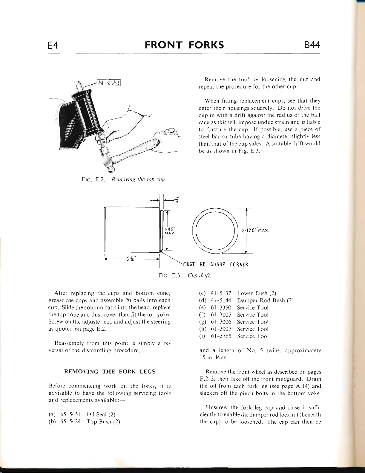
E4 FRONT FORKS 844
Ftc. E.2. Rentoving lhe top ctrp.
Remove the tool by loosening the nut anc'l
repeat the procedure for tl.re other cup.
When fitting replacement cups, see that they
enter their housings squarely. Do not drive the
cup in with a drift against the radius of the ball
race as this will impose undue strain and is liable
to fracture the cup. If possible, use a piece of
steel bar or tube having a diameter slightly less
than that of the cup sides. A suitable drift would
be as shown in Fig. E.3.
2'lZO" na'x.
I r"
i.-*
G-_--zz" __--f
Frc
After replacing the cups and bottom cone,
grease the cups and assemble 20 balls into eacl.r
cup. Slide the column back into the head, replace
the top cone and dust cover then fit the top yr-rke.
Screw on the adjuster cap and adjust the steering
as quoted on page E.2.
Reassembly frorn this point is simply a le-
versal of the dismantling procedure"
REMOVING THE FORK LEGS
Before commencing rvork on the forks, it is
advisable to have the lollowing servicing tools
and replacements available :--
(a) 65-5451 Oil Seal (2)
(b) 65-5424 Top Bush (2)
\flUgT BE SHABP CORNER
E.3. Cup driJt.
(c) 4l-5137 Lower Bush (2)
(d) 4l-5144 Damper Rod Bush (2)
(e) 61-3350 Service Tool
(f) 61-3005 Service Tool
(g) 6l-3006 Service Tool
(h) 6l-3007 Service Tool
(i) 6l-3765 Service Tool
and a length of No. 5 twine, approximately
l5 in.long
Remove the front wheel as described on pages
F.2-3, then take offthe front mudguard. Drain
tlie oil from each fork leg (see page A.14) and
slacken off the pinch bolts in the bottom yoke.
Unscrew the fork leg cap and raise it sr.rffi-
ciently to enable the damper rod Iocknut (beneath
the cap) to be loosened. The cap can then be
---*i
www.bsaunitsingles.com
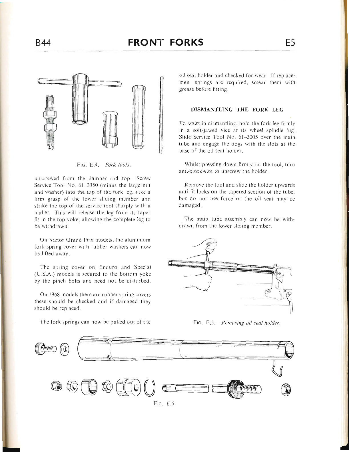
844 FRONT FORKS E5
oil seal holder and checked lor wear. Il replace-
men springs are required, smear them with
grease before fitting.
DISMANTLING THE FORK LEG
To assist in dismantling, liold the fork leg firmly
in a soflt-jawed vice at its wheel spindle lug.
Slide Service Tool No. 61 3005 over the main
tube and engage the dogs with the slots at the
base of the oil seal holder.
Whiist pressing down firmly on the tool, turn
anti-clockwise to unscrew the holder.
Remove the tool and slide the holder uprvards
until it locks on the tapered section of the tube,
but do not Llse force or the oil seal may be
damag,:d.
The main tube assembly can now be with_
drawn from the lower sliding member.
Ftc. E.5. Removing oil seal holcler.
Frc. E.4. Fork tools.
unscrewed from the darnpor roC top. Screw
Servioe Too[ No. 61-3350 (minus rhe large nLrr
and rvasher) into the top of th: lork leg. take a
firm grasp of the loiver sliding mernber aird
strike the top ol lhe service tool sl.utrplv lvitlr a
mallet. This will release the leg lrorn its taper
fit in the top yoke, allowing the complete leg to
be withdrawn.
On Victor Grand Prix models, the aluminium
fork spring cover wiih rubber washers can now
be lilted away.
The spring cover on Enduro and Special
(U.S.A.) models is secured to the bottom yoke
by the pinch bolts and need not be disturbed.
On 1968 models there are rubber spring covers
these should be checked and if damaged they
should be replaced.
The fork springs can now be pulled out ol tlre
@@
@rc) re)@@0 tu
@
Frc. E.6.
www.bsaunitsingles.com
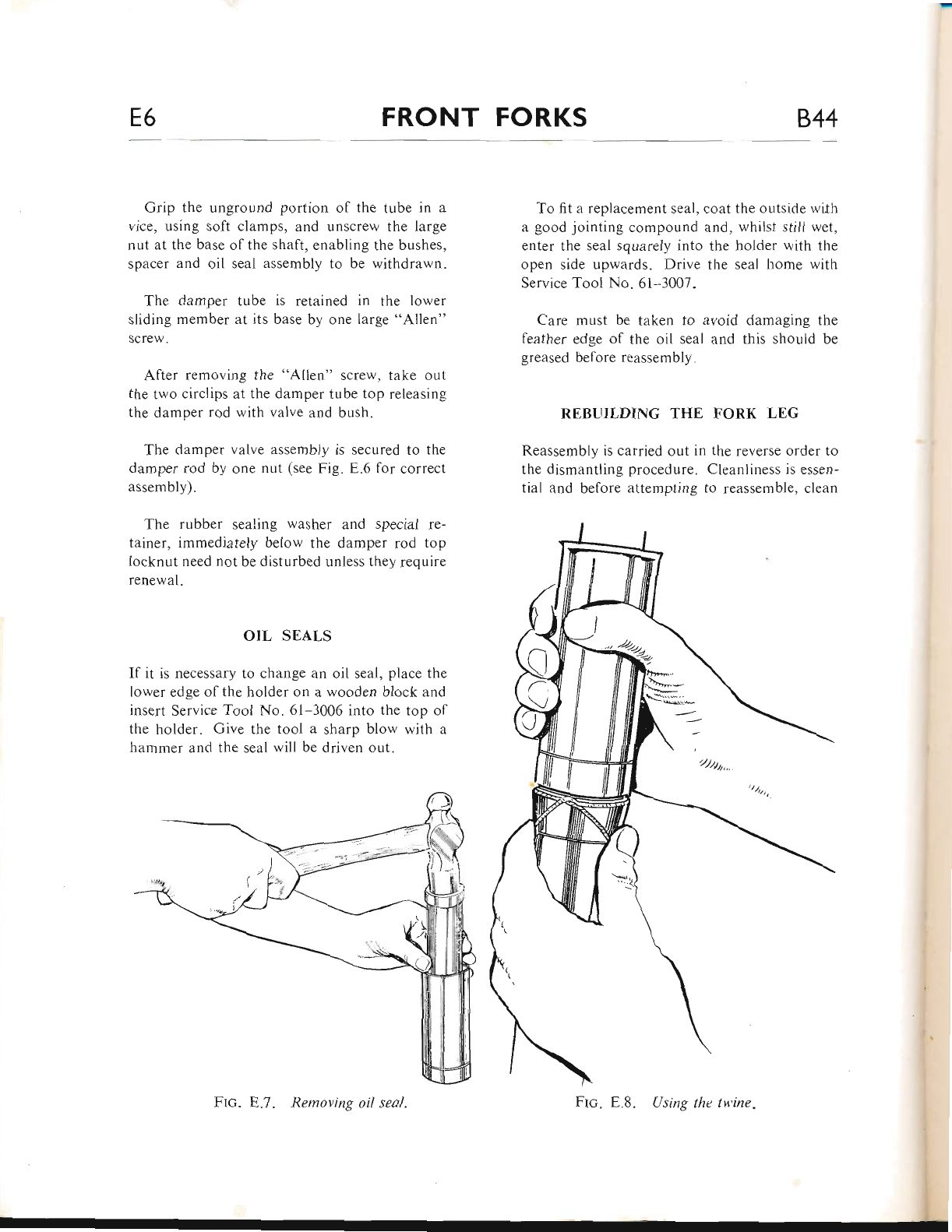
E6 FRONT FORKS 844
Grip the unground portion of the tube in a
vice, using soft clamps, and unscrew the large
nut at the base of the shaft, enabling the bushes,
spacer and oil seal assembly to be withdrawn.
The damper tube is retained in the lower
sliding member at its base by one large "Allen"
screw.
After removing the "Allen" screw, take out
the two circlips at the damper tube top releasing
the damper rod with valve and bush.
The damper valve assembly is secured to the
damper rod by one nut (see Fig. E.6 for correct
assembly).
The rubber sealing washer and special re-
tainer, immediately below the damper rod top
locknut need not be disturbed unless they require
renewal.
OIL SEALS
If it is necessary to change an oil seal, place the
lower edge of the holder on a wooden block and
insert Service Tool No. 61-3006 into the top of
the holder. Give the tool a sharp blow with a
hammer and the seal will be driven out.
To fit a replacement seal, coat the outside wi.th
a good jointing compound and, whilst still wet,
enter the seal squarely into the holder with the
open side upwards. Drive the seal home with
Service Tool No" 6l-3007.
Care must be taken to avoid damaging the
feather edge of the oil seal and this should be
greased belore reassemblY
REBUILDING THE FORK LEG
Reassembly is carried out in the reverse order to
the dismantling procedure. Cleanliness is essen-
tial and before attempting to reassemble, clean
Flc" E.7. Removing oil seal. Using the tu'ine"
www.bsaunitsingles.com
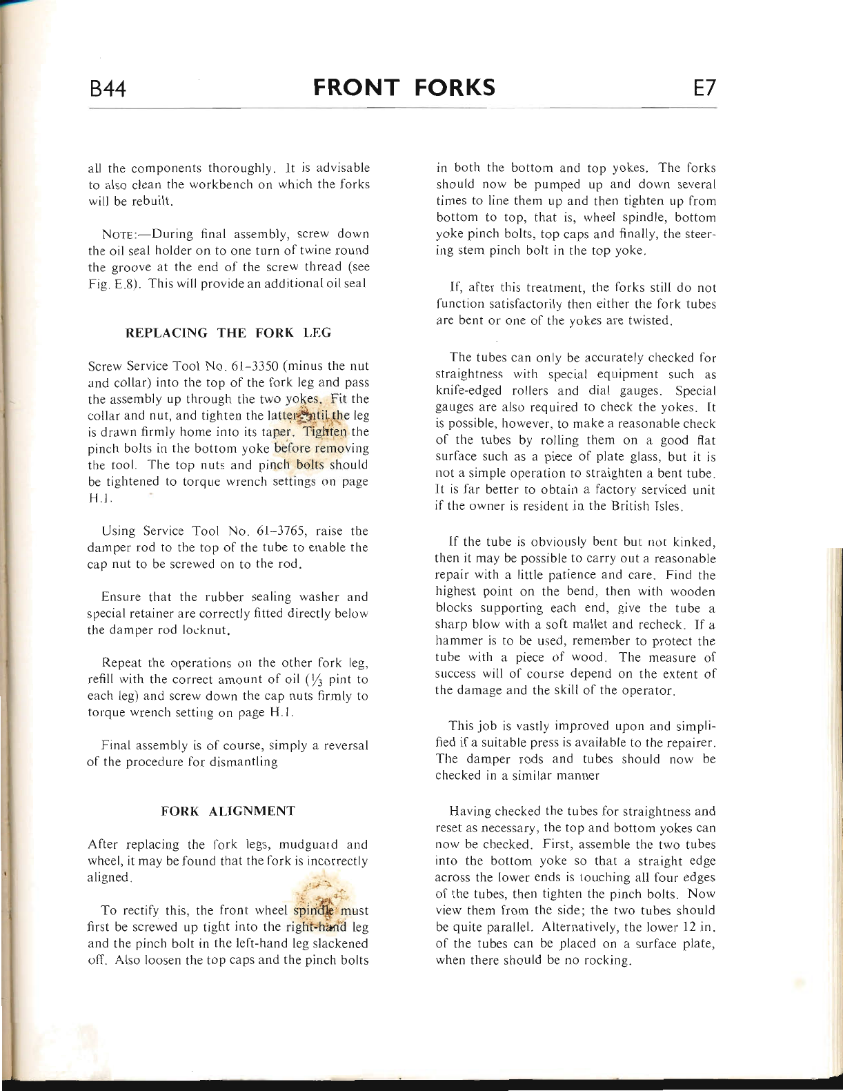
844 FRONT FORKS E7
all the components thoroughly. lt is advisable
to also clean the workbench on which the forks
will be rebuilt.
NorE:-During final assembly, screw down
the oil seal holder on to one turn of twine round
the groove at the end of the screw thread (see
Fig. E.8). This will provide an additional oil seal
REPLACING THE FORK LEG
Screw Service Tool No. 6l 3350 (minus the nut
and collar) into the top of the fork leg and pass
the assembly up through the two yo(es. Fit the
collar and nut, and tighten the latte{$rtif,the leg
is drarvn firmly home into its taper. Tighie4 the
pinch bolts in the bottom yoke before removirrg
the tool. The top nuts and pinch bolts should
be tightened to torque wrench settings on page
H.l.
Using Service Tool No. 6l-3765, raise the
damper rod to the top of the tube to enable the
cap nut to be screwed on to the rod.
Ensure that the rubber sealing washer and
special retainer are correctly fitted directly below
the damper rod locknut"
Repeat the operations on the other fork leg,
refili with the correct amount of oil (tl pint to
each ieg) and screrv dorvn the cap nuts firmly tcr
torque wrench setting on page H.l.
Final assembly is of course, simply a reversal
of the procedure lor dismantling
FORK ALIGNMENT
After replacing the lork legs, mudguard and
wheel, it may be found that the fork is incorrectly
aligned ). ,
'' . -i"i,t
To rectily this, the front wheeI spinff must
first be screwed up tight into the right'hariil leg
and the pinch bolt in the left-hand leg slackened
off. Also loosen the top caps and the pinch bolts
in both the bottom and top yokes. The forks
should now be pumped up and down several
times to line them up and then tighten up from
bottom to top, that is, wheel spindle, bottom
yoke pinch bolts, top caps and finally, the steer-
ing stenr pinch bolt in the top yoke.
lf, after this treatment, the forks still do not
function satisfactorily then either the fork tubes
are bent or one of the yokes are twisted.
The tubes can only be accurately checked for
straightness witl-r special equipment such as
knife-edged rollers and dial gauges. Special
gallges are also required to check the yokes" It
is possible, however, to make a reasonable check
of the tubes by rolling them on a good flat
surface such as a piece of plate glass. but it is
not a simple operation to straighten a bent tube.
It is lar better to obtain a factorl' serviced unit
if the owner is resiclent in the British Isles.
If the tube is obviously benr bur not kinked,
then it rnay be possible to carry out a reasonable
repair with a little patience and care" Find the
highest point on the bend, then with wooden
blocks supporting each end, give the tube a
sharp blow with a soft mallet and recheck. If a
hammer is to be used. remeniber to protect the
tLrbe with a piece of wood. The measure of
success will of course depend on the extent of
the damage and the skill of the operator.
This job is vastly improved upon and simpli-
fied ifa suitable press is available to the repairer.
The damper rods and tubes should now be
checked in a similar manner
Having checked the tubes for straightness and
reset as necessary, the top and bottom yokes can
now be checked. First, assemble the two tubes
into the bottom yoke so that a straight edge
across the lower enc'ls is touching all lour edges
of the tubes, then tighten the pinch bolts. Now
view them lrom the side; the two tubes should
be quite parallel. Alternatively, the lower 12 in.
of the tubes can be placed on a surface plate.
rvhen tl.rere should be no rocking.
www.bsaunitsingles.com
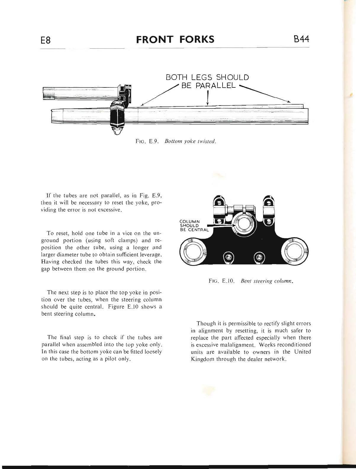
E8 FRONT FORKS 844
If the tubes are not parailel, as in Fig. E.9,
then it will be necessary to reset the yoke, pro-
viding the error is not excessive.
To reset, hold one tube in a vice on the un-
ground portion (using soft clamps) and re-
position the other tube, using a longer and
larger diameter tube to obtain sufficient leverage.
Having checked the tubes this way, check the
gap between them on the ground portion.
The next step is to place the top yoke in posi-
tion over the tubes, when the steering column
should be quite central. Figure E.l0 shows a
bent steering column.
The final step is to check if the tubes are
parallel when assembled into the top yoke only.
In this case the bottom yoke can be fitted loosely
on the tubes, acting as a pilot only.
BOTH LEGS SHOULD
PARALLEL
Ftc. E.10. Bent steering column.
Though it is permissible to rectify slight errors
in alignment by resetting, it is much safer to
replace the part affected especially when there
is excessive malalignrnent. Works reconditioned
units are available to owners in the United
Kingdom through the dealer network.
Ftc. E.9. Bottom yoke tv,isted.
www.bsaunitsingles.com
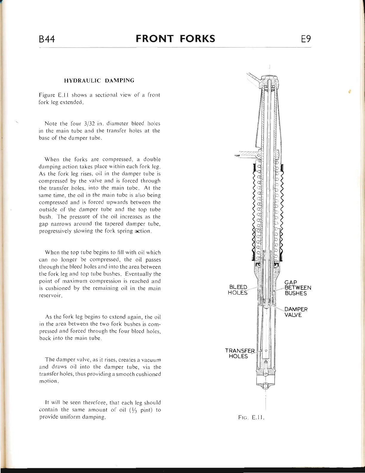
844 FRONT FORKS E9
HYDRAULIC DAN{PING
Figure E,.11 shows a sectional view of a fronl
lork leg ertended.
Note the four 3132 in. diameter bleed holes
in the main tr,rbe and the transler holes at the
base of tlie damper tube.
Wher-r the fbrks are compressed, a double
darnping action takes place within eacl.r fork leg.
As the fork leg rises, oil in the damper tube is
compressed by the valve and is lbrced through
the transfer holes. into the main tube. At the
same time, the oil in the main tube is also being
compressed and is forced upwards between the
outside of the damper tube and the top tube
bush. T'he pressure of the oil increascs as the
gap narrows around the tapered damper tube,
progressively slowing the fork spring action.
When the top tube begins to fill with oil which
can no longer be compressed, the oil passes
through the bleed holes and into the area between
the fork leg and top tr-rbe bushes. Eventually the
point of maximum compression is reached and
is cushioned by the remaining oil in the rnain
reservoir.
As the fork leg begins to extend again, tl.re oil
in thc area between the two fork bushes is com-
pressed and lorced tlirough the four bleed holes,
back into the main tube.
The damper valve, as it rises, creates a vacuum
and draws oil into the damper tube, via the
transfer holes, thus providing a smooth cushioned
motion.
It will be seen therefore, that each leg should
contain the same amount ol oil (tl pint) to
provide uniform damping.
BLEED
HOLES
TRAN
HOLES
GAP
BETWEEN
BUSHES
--.-DAMPER
VALVE
Frc. E.l1.
www.bsaunitsingles.com
844 WHEELS, BRAKES AND TYRES FI
INDEX
FnoNr WUEEI-
Removal
Replacement
Brake Cam
Brake Shoes
Checking Bearings
Fitting New Bearings
Fnonr Wlrrrr---Vrcron Sercr,rl (1968)
Removal and Replacement ...
Brake Shoes
Rran WueEl (Vrcron ENouRo AND SIECIAL (U.S.A.) models prior to Frame No. B44EA.l01)
Removal and Replacement ...
Brake Shoes
Renewing Bearings
Rran WHEEI- (Vrcron ENouno AND SIECIAL (U.S.A.) commencing Frame No. B44EA.l01
and Grand Prix models)
Removal and Replacement ...
Hub Shell Bearings
Brake Drum and Bearing
Brake Drum Replacement
Bnaxn AplusrlmNts
Rs,q.n CHaIN AorusrurNr
ReNnwrNc Bnnxe LrNrNcs
WHnnr- Br-rrlorNc
Srcunrrv Borrs
WHEEI- Ba,laNcrNc ...
Wsrrl AlrcNrwrNr...
Tvnss
Removal
Replacement
Pressures
Page
F.2-3
F.3
F.3-4
F.4
F.4
F.4-5
F.5
F.6
F.7*8
F.8
F.8*9
F.9
F.9-10
F.10-l r
F.t I
F.11-12
F.12
F.t2-13
F.l3
F.l4
F.l4-15
F.l5
F.l5-17
F.17-20
F.20
www.bsaunitsingles.com
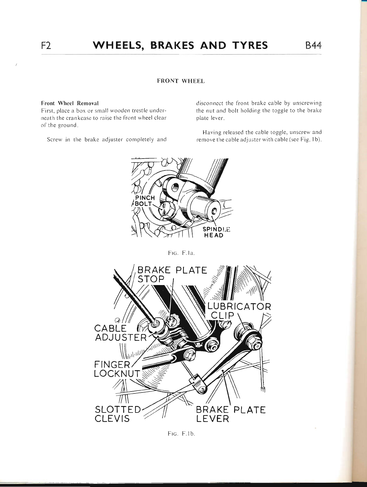
F2 WHEELS, BRAKES AND TYRES 844
Front Wheel Rernoval
First, place a box or srnlll wooden trestle under-
neath the crankcase to raise thc fiont wheel clear
of the ground.
Screw in the brakc erdjuster completely ernc'l
disconnect the front brake cable by unscrer'ving
the nut and bolt holding the toggle to the brake
plate lever.
Having released the cable toggle, unscrew and
reffrove the cable adju.;ter witl-r cable (see Fig. lb).
FRONT WHEEL
Frc. F. la
B RAKE
STOP
a
CA BLE
ADJ U STE R
FINGER
SLOTTE D
CLEVIS
SPINDI-E
HEAD
LUBRICATOR
CLIP \ ,)
tsRAKE PLATE
LEVER
Frc. F.lb.
www.bsaunitsingles.com
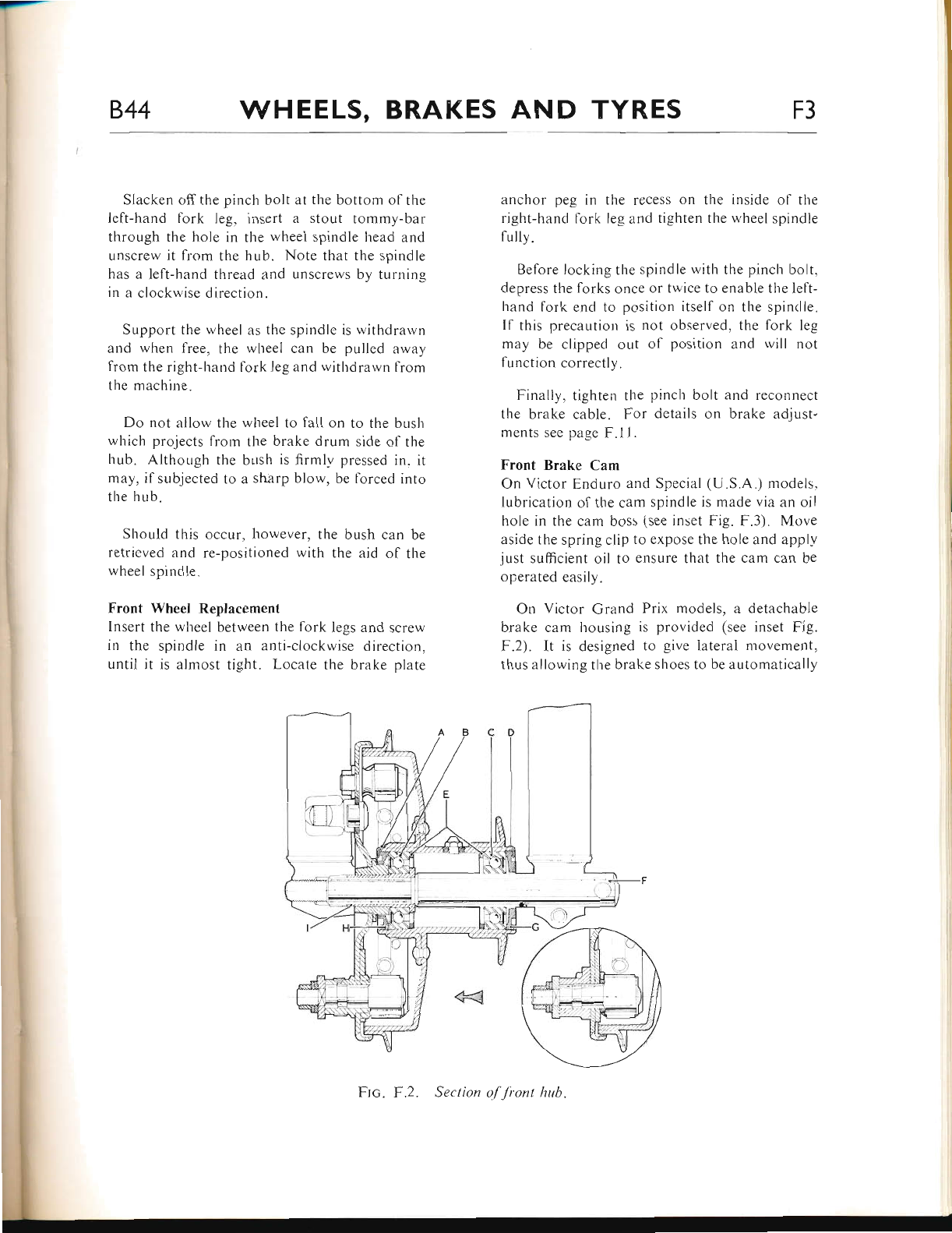
-_
844 WHEELS, BRAKES AND TYRES F3
Slacken off the pinch bolt at the bottom of the
left-hand fork leg, insert a stout tommy-bar
through the hole in the wheel spindle head and
unscrew it from the hub. Note that the spindle
has a left-hand thread and unscrews by turning
in a clockwise direction.
Support the wheel as the spindle is withdraivn
and when free, tl.re wheel can be pulled away
from the right-hand fork leg and withdrawn from
the machine.
Do not ailow the wheel to fall on to the bush
which projects from the brake drum side of the
hub. Although the bush is firmlv pressed in. it
may, if subjected to a sharp blow, be forced into
the hub.
Should this occur, however, the bush can be
retrieved and re-positioned with the aid of the
wheel spindle.
Front Wheel Replacemenl
Insert the wheel between the fork legs and scre'"v
in the spindle in an anti-clockwise directiorr,
until it is almost tight. Locate the brake platte
anchor peg in the recess on the inside of the
right-hand lork leg and tighten the wheel spindle
fully.
Before locking the spindle with the pinch bolt,
depress the forks once or twice to enable the left-
hand fork end to position itsell on the spinclle.
ll this precaution is not observed, the fork leg
may be clipped out of position and rvill not
function correctly.
Finally, tighten the pinch bolt and reconnect
the brake cable. For details on brake adjust-
ments see page F.l l.
Front Brake Cam
On Victor Er.rduro and Special (U.S.A.) models,
lubrication ol the cam spindle is made via an oil
hole in the cam boss (see inset Fig. F.3). Move
aside the spring clip to expose the hole and applv
just suflicient oil to ensure that the cam can be
operated easily.
On Victor Grand Prix models, a detachable
brake cam l.rousing is provided (see inset Fig.
F.2). It is designed to give iaterai movement,
thus allowing the brake shoes to be automatically
Section o/'Jronl hub.
www.bsaunitsingles.com
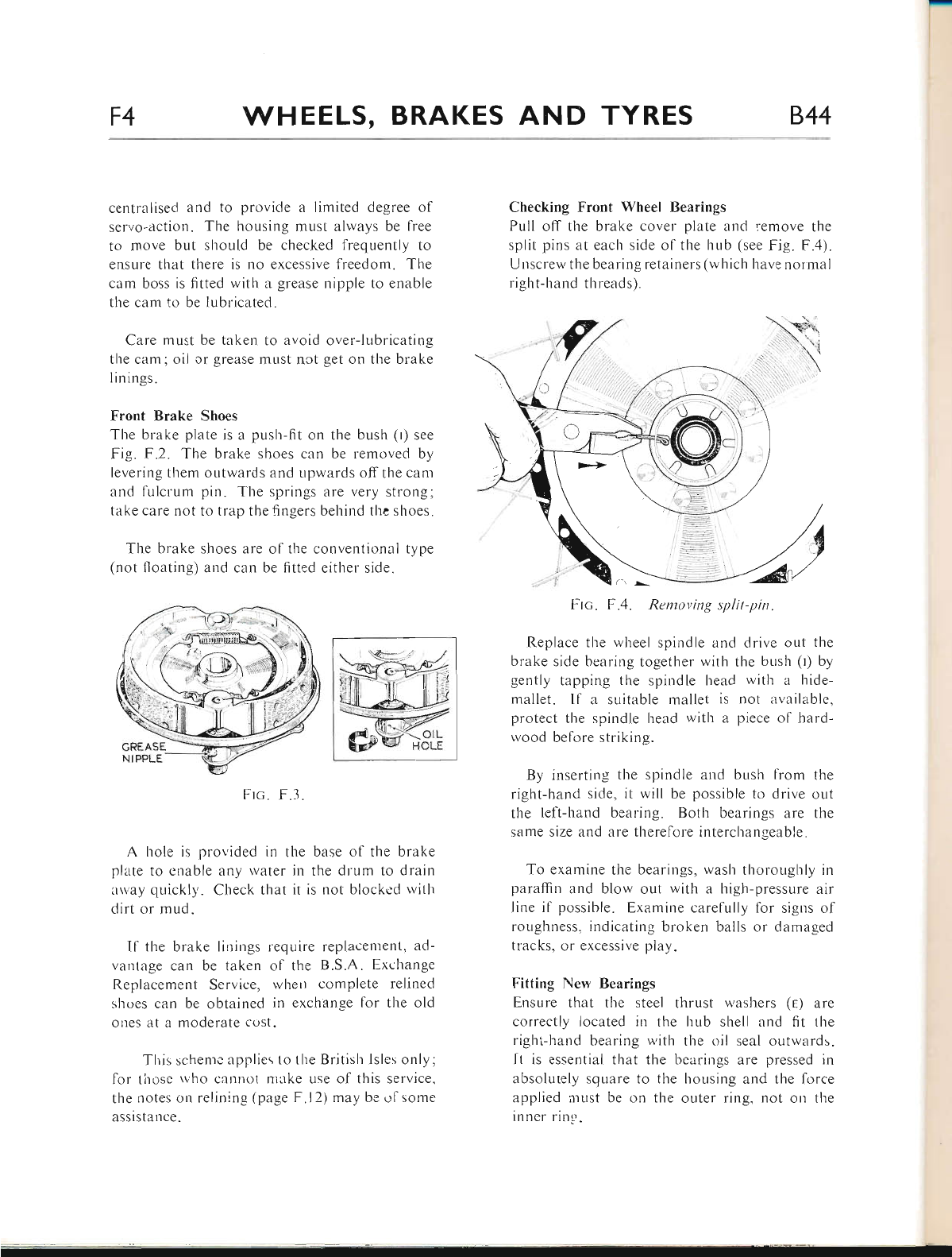
l-
F4 WHEELS, BRAKES AND TYRES 844
centralised and to provide a limited degree of
servo-action. The housing must always be free
to move but should be checked frequently to
ensure that there is no excessive freedom. The
cam boss is fitted with a grease nipple to enable
the cam to be lubricated.
Care must be taken to avoid over-lr-rbricating
the cam; oil or grease must nct get on the brake
linings.
Front Brake Shoes
The brake plate is a push-fit on the bush (r) see
Fig. F.2. The brake shoes can be removed by
levering them outwards and upwards off the cam
and frllcrum pin. The springs are very strong;
take care not to trap the lingers behind tlre shoes.
The brake shoes are of the conventional type
(not floating) and can be fitted either side.
Checking Front Wheel Bearings
Pull off the brake cover plate and remove the
split pins at each side of the hub (see Fig. F.4).
Uuscrew the bearing retainers (which have normal
right-hand tl-rreads).
F-tc. F.4. Rentoving split-pin"
Replace tl-re wheel spindle and drive out the
brake side bearing together with the bLrsh (r) by
gently tapping the spindle head rvith a hide-
mallet. If a suitable mallet is not available,
protect the spindle head with a piece of hard-
wood before striking.
By inserting the spindle and bush from the
right-hand side, it rvill be possible to drive out
the left-hand bearing. Both bearings are the
same size and are therefore interchangeable.
To examine the bearings, wash thoroughly in
paraffin and blow out with a high-pressure air
line if possible. Examine carefully for sigr.rs of
roughness, indicating broken balls or damaged
tracks, or excessive play.
Fitting New Bearings
Ensure that the steel thrust washers (e) are
correctly located in the hub shell and fit the
right-hand bearing u,ith the oil seal outwards.
lt is essential that the bearings are pressed in
absolutely sqllare to the hor,rsing and the lorce
applied must be on the outer ring. not or1 the
inner ring.
OIL
Frc. F.3.
A hole is pror.'ided in the base of the brake
plate to enable any water in the dlum to drain
arvay quickly. Check that it is not blocked with
dirt or mud.
Il the brake linings require replacenlent, ad-
vantage can be taken of the B.S.A. Exchange
Replacement Service, when complete relined
shoes can be obtained in exchange for the old
olres at a moderate cost.
This schemc applies to the British lsles only;
for lirose 'ovho cannot niake use of this service"
the rrotes or.r relining (page F.l2) may be ol some
assistance -
GREASE
www.bsaunitsingles.com
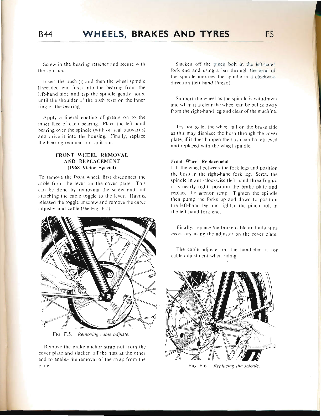
I
844 WHEELS, BRAKES AND TYRES F5
Screr,v in the bearing retainer atrd secure lvith
the split pin.
Insert the bush (l) and then tl,e r'vheel spindle
(threaded end first) into the bearing lrom the
left-hzrnd side and tap the spindle gently home
until the shoulder of the bLrsh rests on the itrner
ring of the bearing.
Apply a liberal coating ol grease on to the
inner face of each bearing. Place the left-hand
bearing over the spindle (with oil seal outwards)
and drive it into tlie housing. Finally, replace
the bearing retainer and split pin.
FRONT WHEEL REMOVAI,
AND REPLACEMENT
(1968 Victor SPecial)
To remove the front whcel, first disconnect the
cable from the lever on the cover plate. This
can be done by removing the screw and nut
rLttaching the cable toggle to the lever. Havirrg
released the toggle tlnscrew and remove the cable
adjuster and cable (see Fig. F.5).
Frc. F.5. Rentoving cable ttd.itrster
Remove tlie brake anchor strap nut from the
cover plate lnd slzrcken off the nuts at the other
end to enable the removal ol the strap from the
plate.
Slacken off the pinch bolt in thc lett-hand
lork end and using a bar through thc head ot'
the spindle unsclew the spindle in tr clockrvise
direction (left-hand thrcad).
Support the wheel as the spindle is withdrawrr
and when it is clear the wheel can be pulled away
from the right-hand leg iind clear of the machine.
Try not to let the wheel fall on the brake side
as this may displace the bLrsh through the cover
plate, if it does happen the bush can be retlieved
and replaced witli the wheel spindle.
Front Wheel Replacement
Lift the wheel between the tork legs and position
tl.re bush in the right-hand fbrk leg. Screw the
spindle in anti-clockwise (left-hand thread) until
it is nearly tight, position the brake plate and
replace the zrnchor strap. Tighten the spindle
then pump the fbrks up and down to position
the left-hand leg and tighten tlie pinch bolt in
the left-harrd folk cnd.
Finally, replace the brake cable and adjust ers
necessary using the adjuster on tl're cover plate.
The cable adjuster on the handlebar is lor
cable ad jr-rstment when riding.
Frc. F.6 Replttcing the spindle
www.bsaunitsingles.com
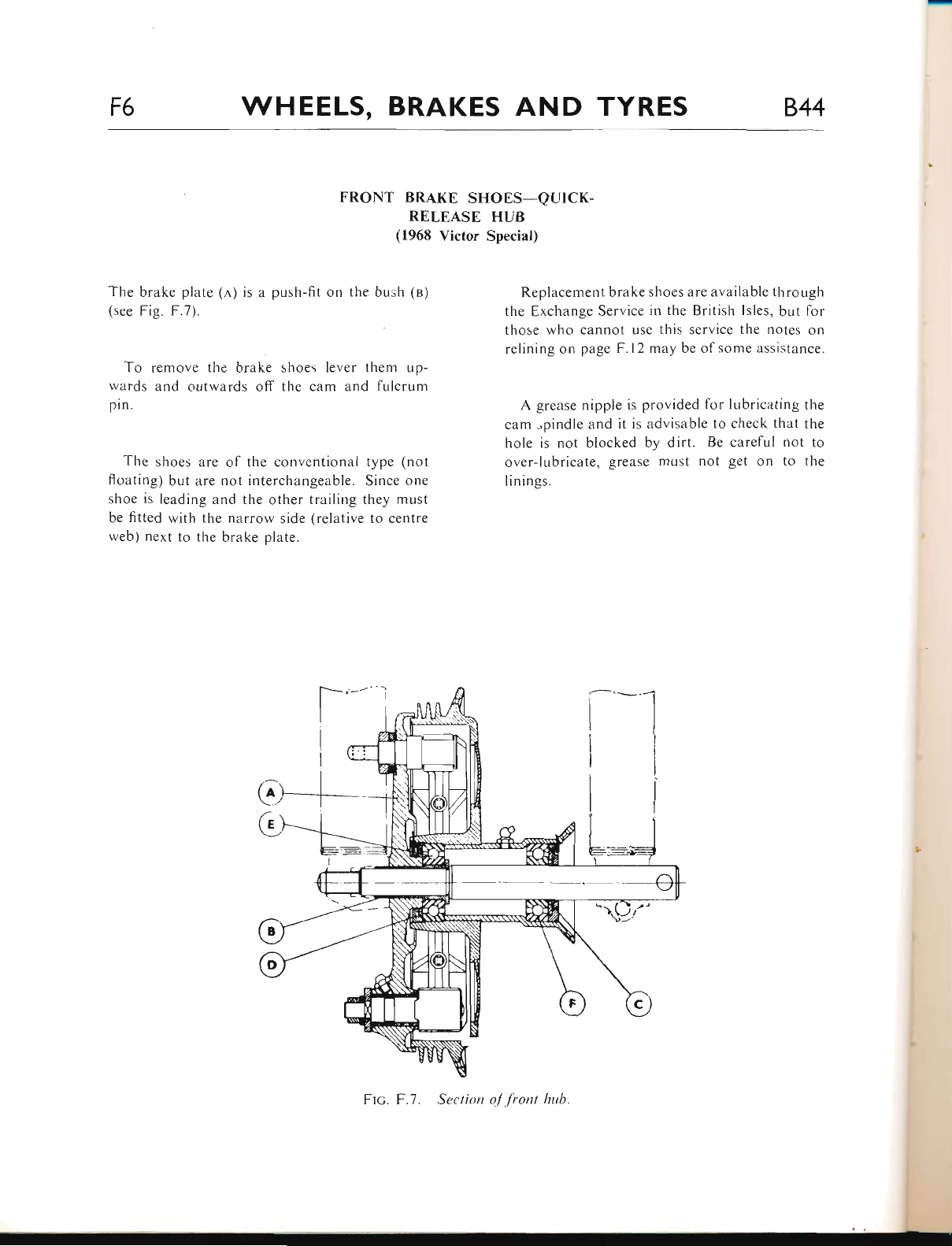
F6 WHEELS, BRAKES AND TYRES 844
FRONT BRAKE SHOES-QUICK-
RELEASE HUB
(1968 Victor Special)
The brake plate (,4,) is a push-fit on the bush (o)
(see Fig. F.7).
To remove the brake shoes lever tlrem up-
wards and outwards off the cam and fulcrum
pin.
The shoes are of the conventional type (not
floating) but are not interchangeable. Since one
shoe is leading and the other trailing they must
be fitted witlr the nilrrow side (relative to centre
web) next to the brake plate.
Replacement brake shoes are available tlrrough
the Exchange Service in the British lsles, but fbr
those who cannot use this service the notes on
relining on page F.l2 may be of some assistance.
A grezrse nipple is provided for lubricating the
cam "pindle and it is advisable to check that the
hole is not blocked by dirt. Be careful not to
over-lubricate, grease must not get on to the
linings.
FIc. F.7. Section o/ lront ltub.
www.bsaunitsingles.com
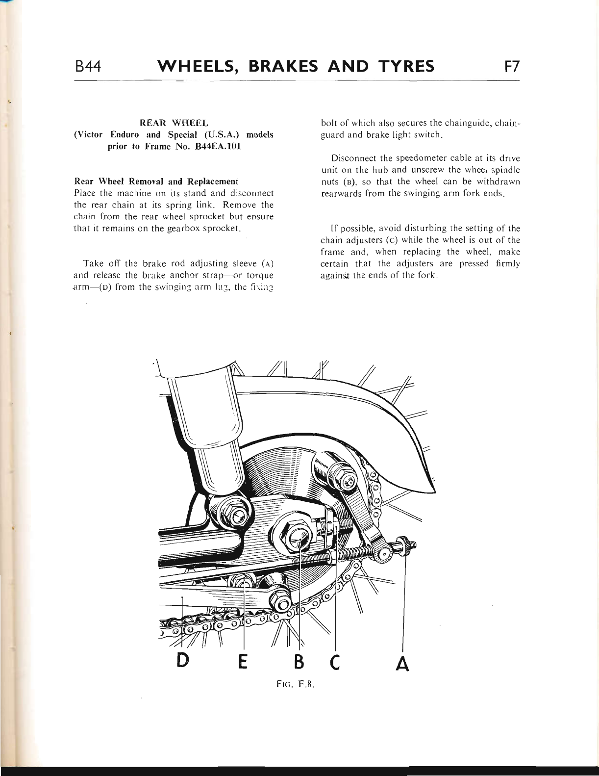
844 WHEELS, BRAKES AND TYRES F7
REAR WHEEL
(Victor Enduro and Special (U.S.A.) models
prior to Frame No. B44EA.10I
Rear Wheel Removal and Replacement
Place the machine on its stand and disconnect
the rear chain at its spring link. Remove the
chain from the rear wheel sprocket but errsure
that it remains on the gearbox sprclcket.
Take off tlie brake rod adjusting sleeve (n)
and release the brake eutchcr strap--or torque
arm (o) lrom the srvinging arnt ILr3, the {i.lil3
bolt of which also secures the chainguide, chain-
guard and brake Iight switch.
Disconnect the speedometer cable at its drive
unit on the hLrb and unscrew the wheel spindle
nuts (n), so that the rvheel can be withdrawn
rearwards from the swinging arm fork ends.
Il possible, avoid disturbing the setting of the
chain adjusters (c) while the wheel is out of the
lrame and, when replacing the wheel, make
certair-r that the adjusters are pressed firmly
againsJ the errds ol the fork.
NJ
Frc. F.8.
www.bsaunitsingles.com
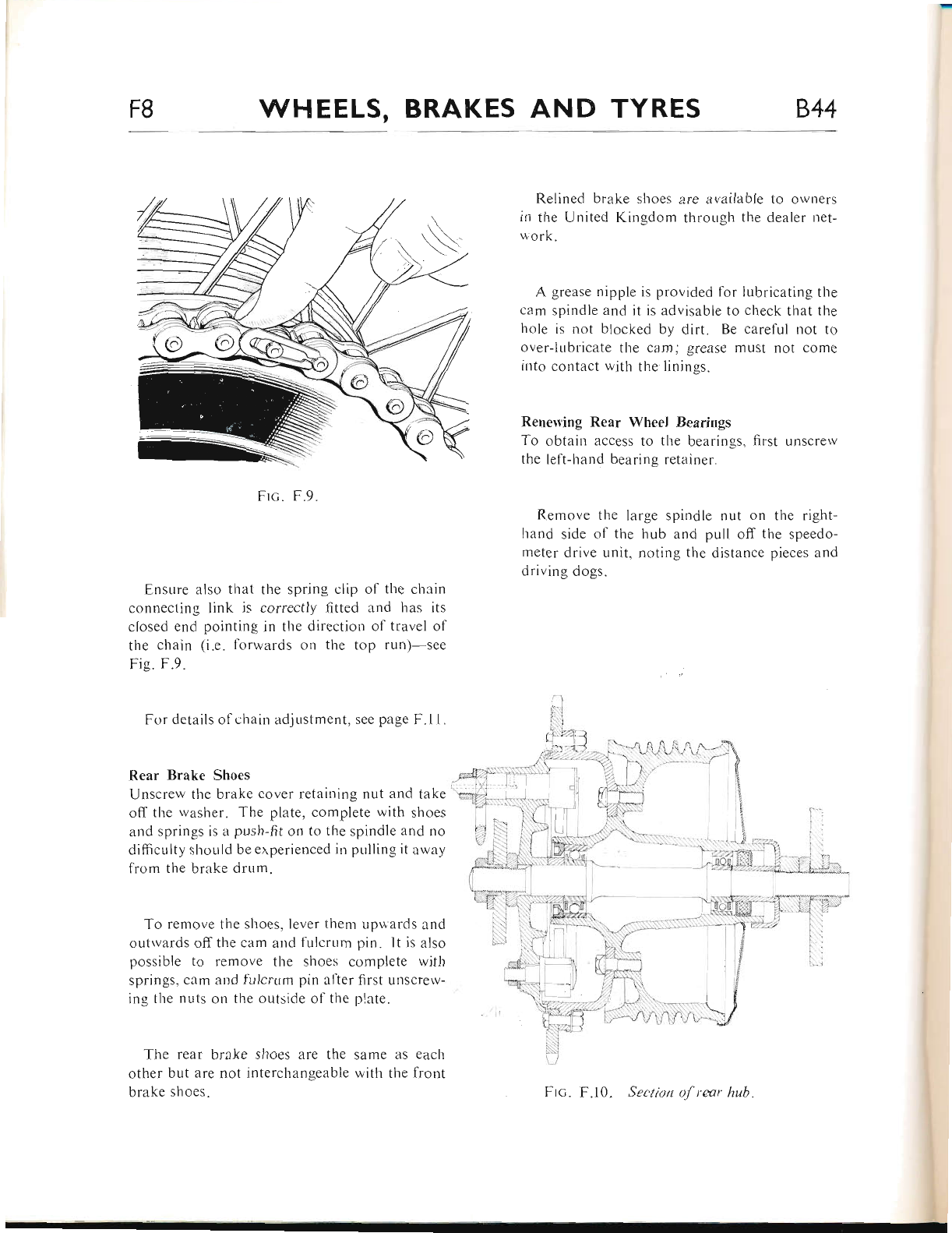
F8 WHEELS, BRAKES AND TYRES 844
Frc. F.9.
Ensure also that the spring clip of tl.re chatn
connecting link is correctly fitted and lras its
closed end pointing in the direction of travel of
the chain (i.e. forwards ort the top rtrn)-see
Fig. F.9.
For details of chain adjustment, see page F.1 I .
Rear Brake Shoes
Unscrew the brake cover retaitiing nut and take
off the rvasher. The plate, complete with slroes
and springs is a push-fit on to tl"re spindle and no
difficulty should be erperienced in pLrlling it ar'vay
fronr the brake drum.
To remove the shoes, lever thenr rrpuards and
outrvards offthe cam and fulcrtrm pin. lt is also
possible to remove the shoes complete with
springs, citm attd fulcrttm pin after first uuscrew-
ing the nuts on the outside of the plate"
Tl.re rear brake shoes are the same as each
other but are not interchar.rgeable with the front
brerke shoes.
Relined brake shoes are available to ou'ners
in the United Kingdom through the dealer net-
work.
A grease nipple is provided for lubricating the
cam spindle and it is advisable to check that the
hole is not blocked by dirt. Be careful not to
over-lubricate the cam; grease must not come
into corttact u itli the linings.
Renen'ing Rear Wheel Bearings
To obtain access to tlre bearings, first unscrerv
the lelt-hand bearing retainer.
Remove the large spindle nut on the right-
hand side of the hub and pull off the speedo-
meter drive unit, noting the distance pieces and
driving dogs.
Frc. F.10. Section of rear hub
www.bsaunitsingles.com
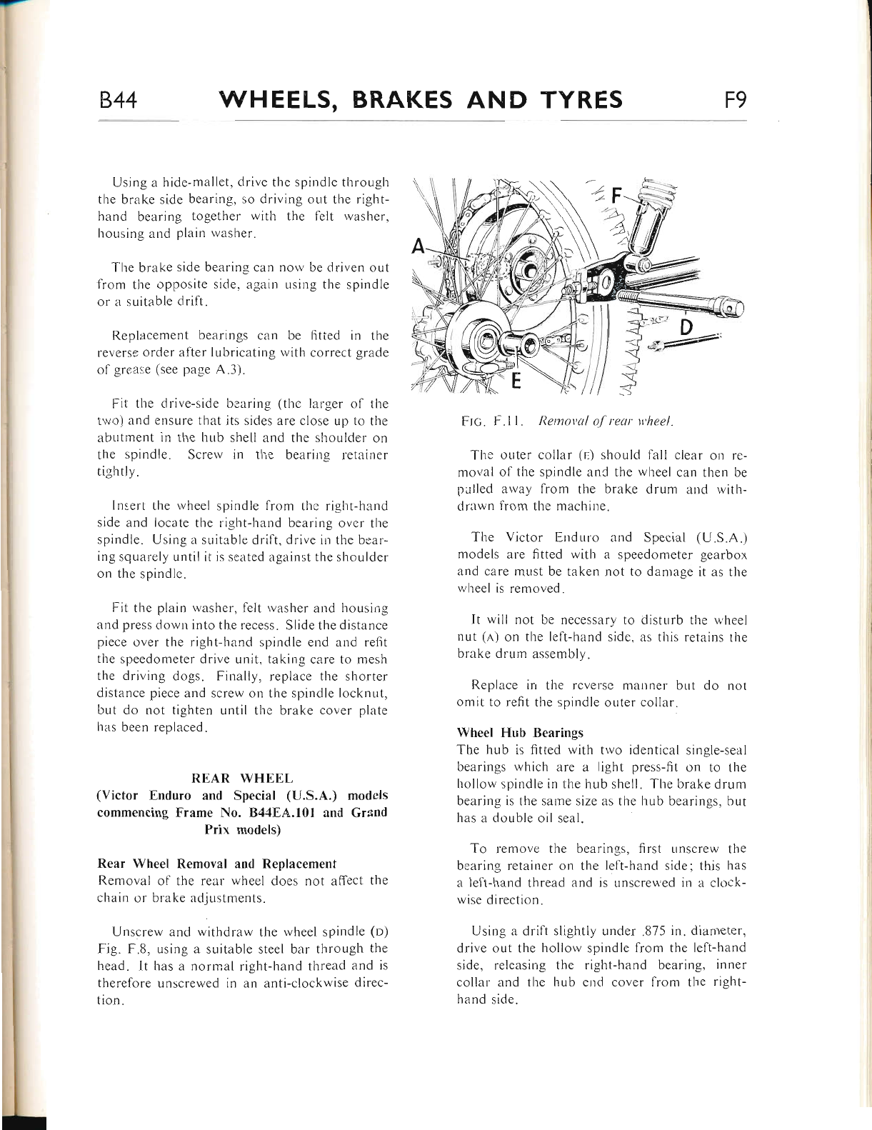
844 WHEELS, BRAKES AND TYRES F9
Using ar hide-mallet, clrive the spindle througlt
thc brake side bearing, so driving out the right-
hand bearing together with thc felt washer.
housing and plain rvashcr.
The brake side bearing car.t
l-rtrn the oppo)itL' side. lr3lirr
or a suitable clril't.
Replacement bearir.rgs can
re\ crse ordcr llter lubrierrting
ol grc:r:e (see page A .3 ) .
nou'be driven out
Lrsing the spindle
be litted in tlie
r,vith correct grade
Fit the drive-side bcarir.rg (tlie larger of tl're
two) arrcl cnsure that its sides:rre close up to tlte
irbutinent in the hub shell and the shor-rlder on
the spindle. Screrv in tl.re bearing relainer
tightly.
Ins.ert the rvheel spindle fi'om tlie right-hand
side and locate tl.re risht-hanci bearir.rg ovcr the
spindle. Using a suitable drift, drive in the be:rr-
ing squarely Lrntil it is seated against the shoulder
on the spindle.
Fit the plain washer-, t-elt rvasher and housirtg
and press down into the recess. Slicle the distance
piecc over the right-hand spiudle end ar.rd refit
the speedometer drive unit, taking care to mesl.r
the clriving dogs. Finally, replace the shorter
distancc piece and screw on the spirrdle locknLrt.
but do not tighten until the brake cover plate
has been replaced.
R.EAR WHEEL
(Victor Enduro and Special (U.S.A.) models
commencing Frame No. B4,tEA.l0l and Grand
Prix models)
Rear Wheel Removal and Replacernent
Rernoval of the real wheel does not affect the
qhain or brake adjr-rstments.
Unscrew and withdrarv the rvheel spindle (o)
Fig. F.8. using a suitable steel bar through the
head. It has a normal right-hand thread and is
therefore unscrewed in an anti-clockwise direc-
tion.
Ftc. F.l l. Rernoyal ol reur n'heel
Thc outer collar (r,) should fLrll clear on re-
r.r.roi,al of the spindle ar.rC ihe v,,heel can then be
pulled away from the brake drr-rm and with-
drawn 1'rom tl.rc machine.
The Victor Enduro and Specieil (U.S.A.)
models are fitted witl-r a speedometer gearbor
and care must be taken not to dantage it as the
lvheel is removed.
It rvill not be necessary to disturb the lvheel
nul (e) on the lcft-hancl side. as titis rctains the
brake drum assembly"
Replace irr the rcversc mauuer br-rt dcl nol
omit to refit the spindle outer collar.
Wheel Hub Bearings
The hub is fitted *'itl-r two identical single-seal
bearings which are a light press-fit on to the
hollow spindle in the hub shell. The brake drr-rn.r
bearing is the sarre size as the hub bearings. but
has a double oil seal.
To remove the bearir.rgs. lirst unscrew the
bearing retainer on the lelt-hand side: this has
a left-hand thread and is unscreu'ed in a clclck-
lvise direction.
Using a drift sli-elitly under "875 in. diarneter,
drive out the hollorv spindle from tl.re left-hand
side, releasing the right-hand bearing. inner
collar and the hLrb end cover tiom the right-
hand side.
E
www.bsaunitsingles.com
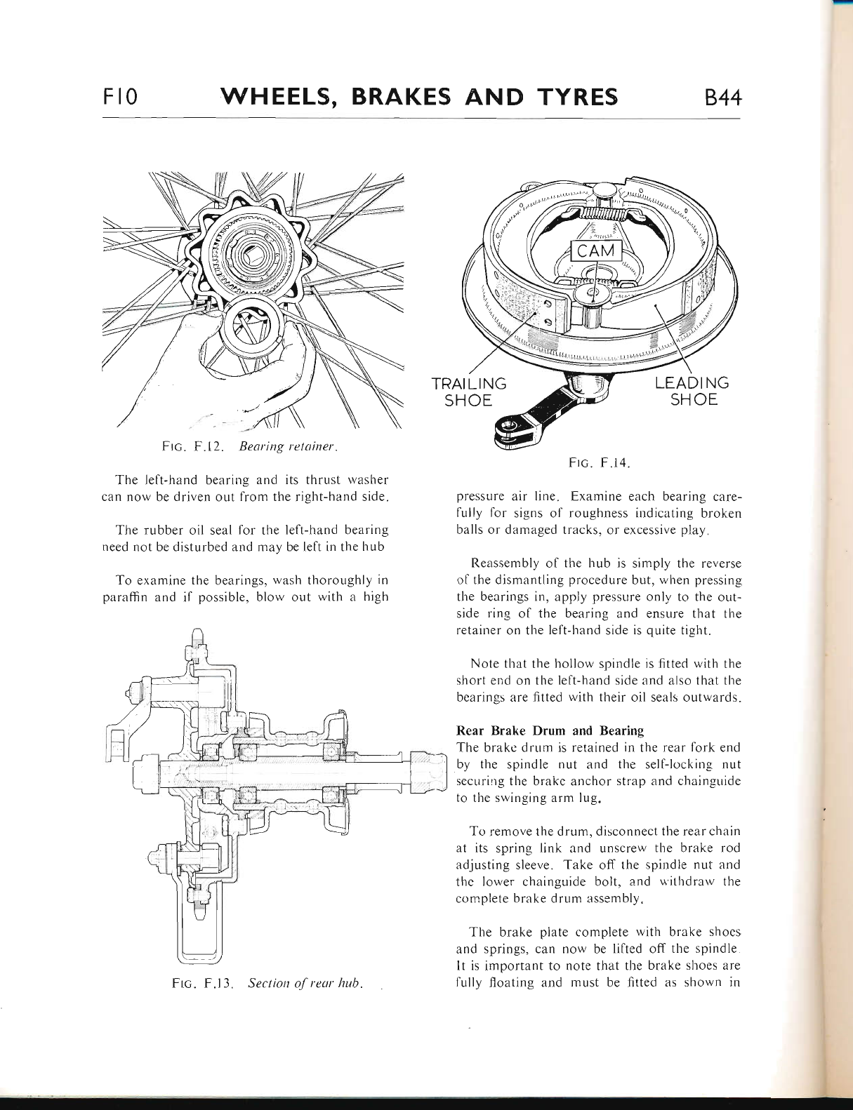
Ft0 WHEELS, BRAKES AND TYRES 844
TRAI LI NG
SHOE LEAD I NG
SH OE
Ftc. F.12. Bearing retainer.
The left-hand bearing irnd its thrust rvasher
can now be driven out from the right-hand side.
The rubber oil seal for the left-hand bearing
need not be disturbed and may be left in the hub
To examine the bearings, wash thoroughly in
paraffin and if possible, blow out with a high
Frc. F.14.
pressure air line. Examine eaclr bearing care-
fully for signs of roughness indicating broken
balls or damaged tracks, or excessive play.
Reassembly of the hub is simply the reverse
of the dismantling procedure but, when pressing
the bearings in, apply pressllre onl1, to the out-
side ring of the bearing and ensure that the
retainer on the left-hand side is quite tight.
Note that the hollow spindle is fitted with the
short er.rd on the left-hand side and also that tlre
bearings are fitted with their oil seals outwards.
Rear Brake Drum and Bearing
The brake drum is retained in the rear fork end
by the spindle nut and the self-locking nut
securing the brake anchor strap and chainguide
to tl-re srvinging arm lug.
To remove the drr,rm, disconnect the rear chain
at its spring link and unscrew the brake rod
adjusting sieeve" Take off the spiudle nut and
tl.re lower chainguide bolt, and uilhdraw the
cornplete brake drum assembly.
The brake plate complete with brake sl.roes
and springs, can now be lifted off the spindle
It is important to note that the brake shoes are
fully floating and must be fitted as shown in
l
Frc. F.13. Section of reur hub.
www.bsaunitsingles.com
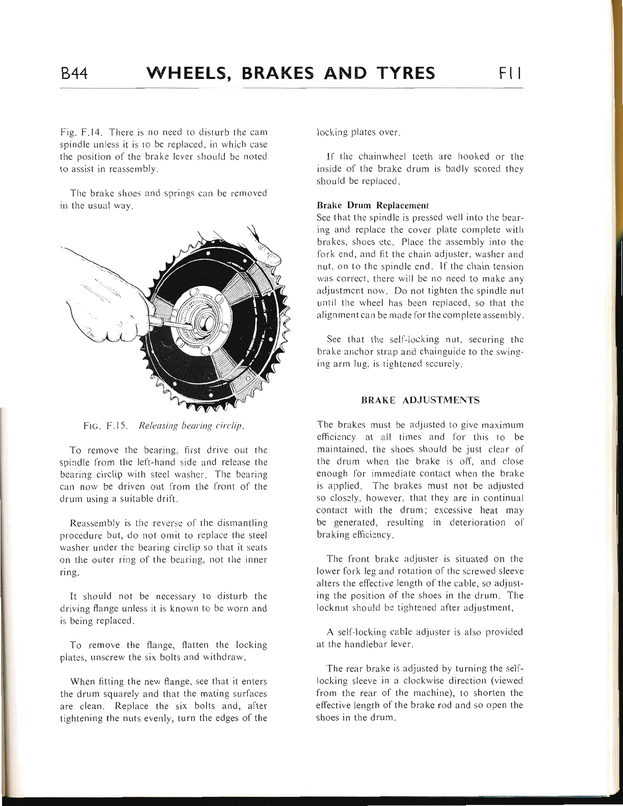
844 WHEELS, BRAKES AND TYRES Flt
Fig. F.14. There is no need to disturb the cam
spindle unless it is to be replaced, iit which case
the position of the brake lever should be noted
to assist in reassembly.
The brake shoes and springs can be removed
in the usual way.
Ftc. F.15. Releasing bearing circlip.
To remove the bearing, first drive out the
spindle tiom the left-hand side and release the
bea,ring circlip with steel washer. The bearing
cau now be driven out from the front of the
drum using a suitable drilt.
Reassembly is the reverse oI the dismantling
procedure but, do not omit to replace the steel
washer under the bearing circlip so that it seats
on the outer rir.rg of the bearing, not the inner
ring.
It should not be necessary to disturb the
driving flange unless it is knor.vn to be worn and
is being replaced.
To remove the flange, flatten the locking
plates, unscrew the six bolts and withdraw.
When fitting the new flange, see that it enters
the drum squarely and that the mating surfaces
are clean. Replace the six bolts and, after
tightening the nuts evenly, turn the edges of the
locking plates over.
If ti-re chainwheel teeth are hooked or the
inside of the brake drum is badly scored they
should be replaced.
Brahe Drurn Replacement
See that the spindle is pressed well into the bear-
ing and replace the cover plate complete with
brakes, shoes etc. Place the assembly into the
fork end, and fit the chain adjuster, washer and
nut, on to the spindle end. If the chain terrsion
was correct, there will be no need to make any
adjustmcnt nor,v. Do not tighten the spindle nut
until the rvheel has been replaced, so that the
alignment can be made for the complete assen.rbly.
See that the self-locking nr-rt, securing the
brake anchor strap and chainguide to the swing-
ing arm lug. is tightened sccurely.
BRAKE ADJUSTMENTS
The brakes must be adjusted to give maximum
efficier.rcy at all times and for this to be
maintained, the shoes should be just clear of
the drum when the brake is off, and close
enough for immediate contact when the brake
is applied. The brakes must not be adjusted
so closely, however, that they are in continual
contact with the drum; excessive heat may
be generated, resulting in deterioration of
braking efficiency.
The front brake adjuster is situated on the
lower fork leg and rotation ol the screwed sleeve
alters the effective length of tl.re cable, so adjust-
ing the position of the shoes in the drum. The
iocknut should be tightened after adjustment.
A self-locking cable adjuster is also provided
at the handlebar lever.
'fhe rear brake is adjusted by turning the self-
locking sleeve in a clockwise direction (viewed
from the rear of the machine), to shorten the
effective length of the brake rod and so open the
shoes in the drum.
www.bsaunitsingles.com
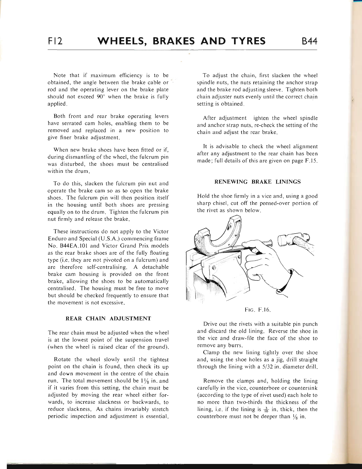
Fl7 WHEELS, BRAKES AND TYRES 844
Note that if maximum efliciency is to be
obtained, the angle between the brake cable or
rod and the operating lever on the brake plate
should not exceed 90' when the brake is fully
applied.
Both front and rear brake operating levers
have serrated cam holes, enabling them to be
removed and replaced in a new position to
give finer brake adjustment.
When new brake shoes have been fitted or if.
during dismantling of the wheel, the fulcrum pin
was disturbed, the shoes must be centralised
within the drum.
To do this, slacken the fulcrum pin nut and
operate the brake cam so as to open the brake
shoes. The fulcrum pin will then position itself
in the housing until both shoes are pressing
equally on to the drum. Tighten the fulcrum pin
nut firmly and release the brake.
These instructions do not apply to the Victor
Enduro and Special (U.S.A.) commencing frame
No. B44EA.l0l and Victor Grand Prix models
as the rear brake shoes are of the fully floating
type (i.e. they are not pivoted on a fulcrum) and
are therefore self-centralising. A detachable
brake cam housing is provided on tl.re front
brake, allowing the shoes to be automatically
centralised. The housing must be free to move
but should be checked frequently to ensure that
the movement is not excessive.
REAR CHAIN ADJUSTMENT
The rear chain must be adjusted when the wheel
is at the lowest point of the suspension travel
(when the wheel is raised clear of the ground).
Rotate the wheel slowly until the tightest
point on the chain is found, then check its up
and down movement in the centre of the chain
run. The total movement should be lls in. and
if it varies from this setting, the chain must be
adjusted by moving the rear wheel either for-
wards, to increase slackness or backwards, to
reduce slackness. As chains invariably stretch
periodic inspection and adjustment is essential.
To adjust the chain, first slacken the wheel
spindle nuts, the nuts retaining the anchor strap
and the brake rod adjusting sleeve. Tighten both
chain adjuster nuts evenly until the correct chain
setting is obtained.
After adjustment ighten the wheel spindle
and anchor strap nuts, re-check the setting ofthe
chain and adjust the rear brake.
It is advisable to check the wheel alignment
after any adjustment to the rear chain has been
made; full details of this are given on page F.15.
RENEWING BRAKE LININGS
Hold the shoe firmly in a vice and, using a good
sharp chisel, cut off the peened-over portion of
the rivet as shown below.
Frc. F.16.
Drive out the rivets with a suitable pin punch
and discard the old lining. Reverse the shoe in
the vice and draw-file the face of the shoe to
remove any burrs.
Clamp the new lining tightly over the shoe
and, using the shoe holes as a jig, drill straight
through the lining with a 5132 in. diameter drill.
Remove the clamps and, holding the lining
carefully in the vice, counterbore or countersink
(according to the type of rivet used) each hole to
no more than two-thirds the thickness of the
lining, i.e. if the lining is -$ in. thick, then the
counterbore must not be deeper than tl in"
www.bsaunitsingles.com
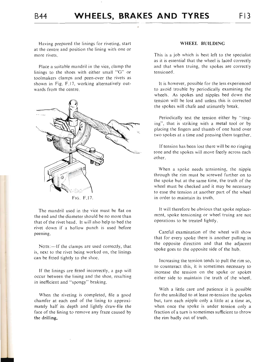
844 WHEELS, BRAKES AND TYRES Fr3
.^'l
Having prepared the linings for riveting, start
at the centre and position the lining with one or
more rivets.
Place a suitable mandril in the vice, clamp the
linings to the shoes with either small "G" or
toolmakers clamps and peen-over the rivets as
shown in Fig. F.17, working alternatively out-
wards from the centre.
Frc. F.17.
The mandril used in the vice must be flat on
the end and the diameter should be no more than
that of the rivet head. It will also help to bed the
rivet down il a hollow punch is used before
peening.
NorE:-If the clamps are used correctly, that
is, next to the rivet being worked on, the linings
can be fitted tightly to the shoe.
If the linings are fitted incorrectly, a gap will
occur between the lining and the shoe, resulting
in inefficient and "spongy" braking.
When the riveting is completed, file a good
chamfer at each end of the lining to approxi-
mately half its depth and lightly draw-file the
face of the liningto remove any fraze caused by
the drilling.
WHEEL BUILDING
This is a job which is best left to the specialist
as it is essential that the wheel is laced correctly
and that when truing, the spokes are correctly
tensioned.
It is however, possible for the less experienced
to avoid trouble by periodically examining the
wheels. As spokes and nipples bed down the
tension will be lost and unless this is corrected
the spokes will chafe and utimately break.
Periodically test the tension either by "ring-
ing", that is striking with a metal tool or by
placing the fingers and thumb of one hand over
two spokes at a time and pressing them together.
lf tension has been lost there will be no ringing
tone and the spokes will move freely across each
other.
When a spoke needs tensioning, tlie nipple
through the rim must be screwed further on to
the spoke but at the same time, the truth of the
wheel must be checked and it may be necessary
to ease the tension at another part of the wheel
in order to maintain its truth.
It will therefore be obvious that spoke replace-
ment, spoke tensioning or wheel truing are not
operations to be treated lightly.
Careful examination of the wheel will show
that for every spoke there is another pulling in
the opposite direction and that the adjacent
spoke goes to the opposite side of the hub.
Increasing the tension tends to pull the rim so,
to counteract this, it is sometimes necessary to
increase the tension on the spoke or spokes
either side to maintain the truth of the wheel.
With a little care and patience it is possible
for the unskilled to at least re-tension the spokes
but, turn each nipple only a little at a time as,
when once the spoke is under tension only a
fraction of a turn is sometimes sufficient to throw
the rim badly out of truth.
www.bsaunitsingles.com
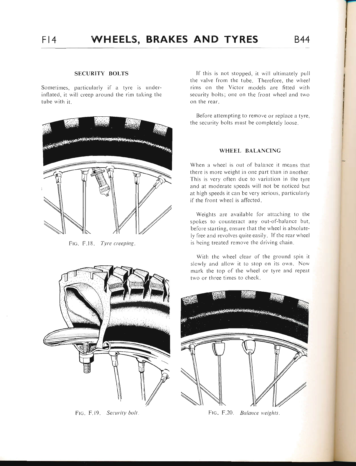
Ft4 WHEELS, BRAKES AND TYRES 844
SECURITY BOI,TS
Sometimes, particularly if ii tyre is undcr-
inflnted, it rvill creep around the rim taking the
tube lvith it.
Ftc. F.18. Tyre creeping.
If this is not stopped, it will ultimately pull
the valve from the tube. Therefore, the rvheel
rims on the Victor: models are fitted u'itl.r
security bolts; one on the lront r.vheel and two
on the rear.
Before attenrpting to remove or replace a tyre"
the security bolts must be completely loose.
WFIEEL I]ALANCING
Wher.r a rvheel is out of balance it means that
there is more weight in one part than in anothet'.
This is very often due to variation in the tyre
and at nroderate speeds will not be rroliccd br.rt
at high speeds it can Lre very serious. particularly
if the front wheel is affected.
Weights are available for attaching to the
spokes to counteract any out-of-balance but,
befole starting, ensure that the wheel is absolute-
ly lree and revolves quite easily. Ifthe rear wheel
is heing treated remove the ciriving chain.
With the rvheel clear- o1' the ground spin it
slor,vly :irrd allolv it to stop on its orvn. Non,
mark the top of tl're wheel or tyre and repeat
t\\,o or three times to check.
Frc. F.19. Securit)t bolt Ftc. F.20. Balance v'eights.
www.bsaunitsingles.com
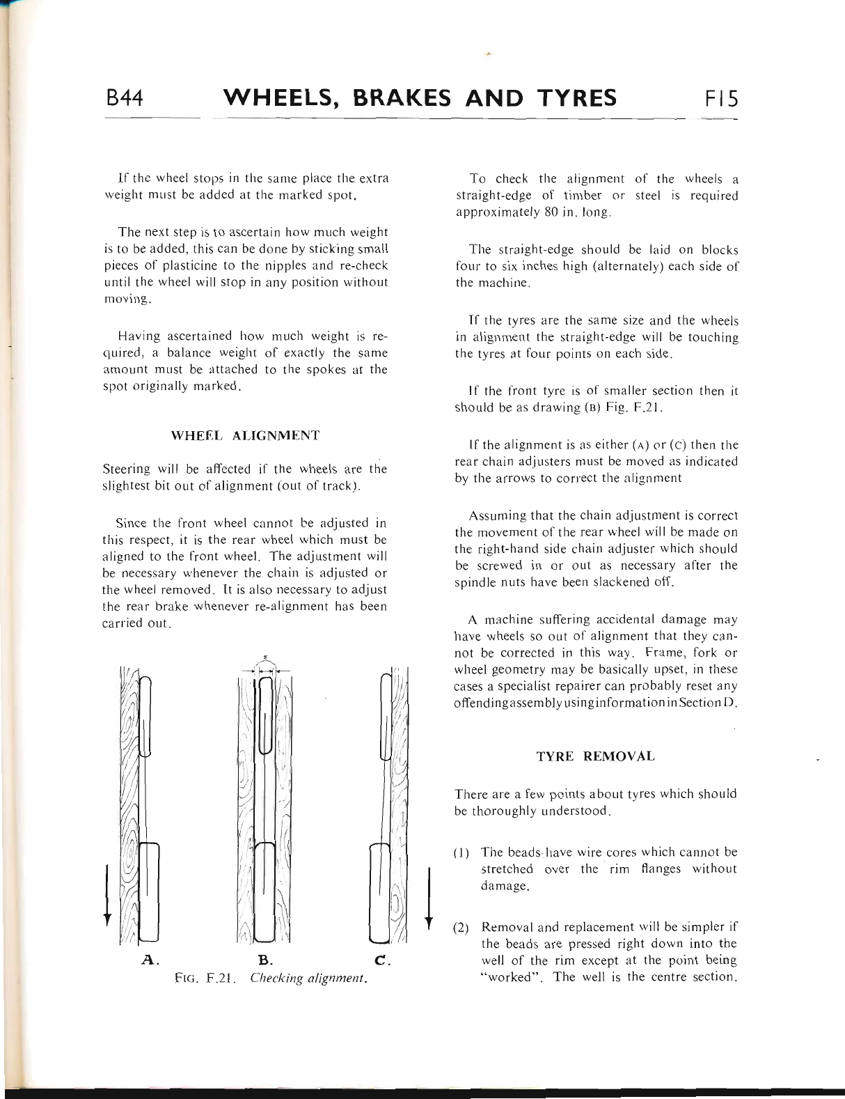
844 WHEELS, BRAKES AND TYRES Ft5
lf tlre wheel stops in the sanre place the extra
weight must be added at the marked spot.
The next step is to ascertain how much weight
is to be added, this can be done by sticking srnall
pieces of plasticine to the nipples and re-check
until the wheel will stop in any position without
moving.
Having ascertained how much weight is re-
quired, a balance weight ol exactly the same
amount must be attached to the spokes at the
spot originally marked.
WHEIL ALIGNMENT
Steering will be affected if the wheets are the
slightest bit out of alignment (out of track).
Since the front wheel cannot L.e adjusted in
this respect, it is the rear wheel which must be
aligned to the lront wheel. The adjustment wilt
be necessary w,henever the chain is adjusted or
the wheel removed. lt is also necessary to adjust
the rear brake whenever re-alignment has been
carried out.
B.
F .21 . Checking alignment.
To check the alignment of the wheels a
straight-edge of tiniber or steel is required
approximately 80 in. long.
The straight-edge should be laid on blocks
four to six inches high (alternately) each side of
the machine.
If the tyres are the same size and the wl.reels
in alignment the straight-edge will be touching
the tyres at four points on each side.
If the front tyre is of smaller section then it
should be as drawing (n) Fig. F.21.
lf the alignment is as either (n) or (c) then the
rear chain adjusters must be moved as indicated
by the arrows to correct tl.re aligr.rment
Assuming that the chain adjustment is correct
tlre movement of the rear wheel will be made on
the right-hand side chain adjuster which should
be screwed in or out as necessary after the
spindle nuts have been slackened off.
A machine suffering accidental damage may
have wheels so out of alignment that they can-
not be corrected in this way. Frame, fork or
wheel geometry may be basicallv upset, in these
cases a specialist repairer can probably reset any
offendingassembly usin ginformation in Section D.
TYRE REMOVAL
There are a few points about tyres which should
be thoroughly r.rnderstood.
The beads.have wire cores which cannot be
stretched over the rim flanges without
damage.
Removal and replacement rvill be simpler if
the beads are pressed right down into the
well of the rim except at the point being
"worked". The well is the centre section.
(l)
I (2,
c.
www.bsaunitsingles.com
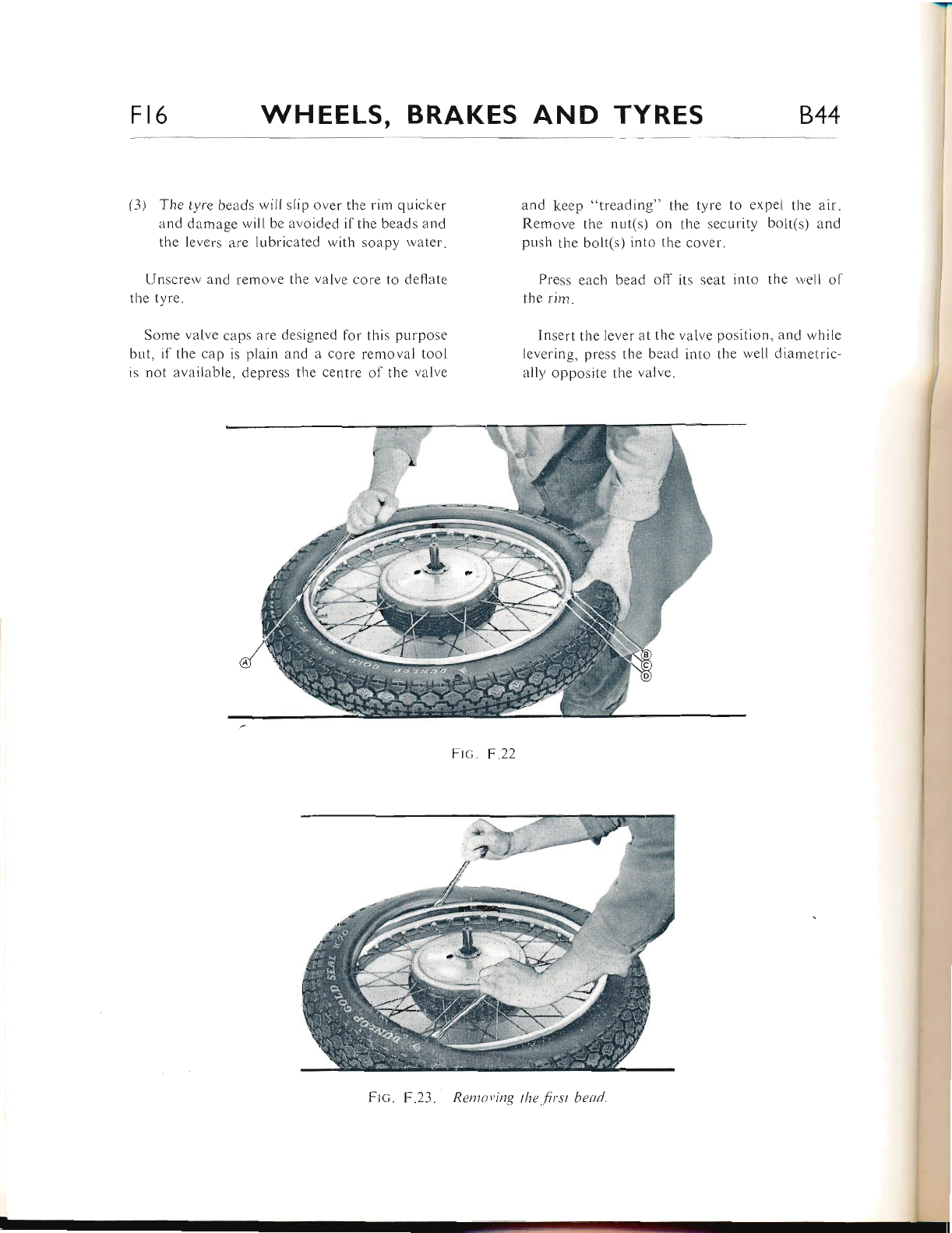
Fr6 WHEELS, BRAKES AND TYRES 844
(3) The tyre beads will slip over the rim qr-ricker
and damage rvill be avoided if the beads and
the levers are lubricated with soapy welter.
Unscrew and remove the valve core to deflate
the tyre.
Some valve caps are designed for this purpose
but, if the cap is plain and ii core removal tool
is not available, depress the centre of the valve
and keep "treadir.rg" the tyre to expel the arr.
Remove the nut(s) on the security bolt(s) and
pr"rsh the bolt(s) into the cover.
Press each bead off its seat into the well of
the rim.
Insert the lever at the valve position, and rvhile
levering. press the bead into the rvell diametric-
ally opposite llte rrtlre.
F
F tc. F .22
Frc. F.23. Rentoving the .first head.
I
www.bsaunitsingles.com
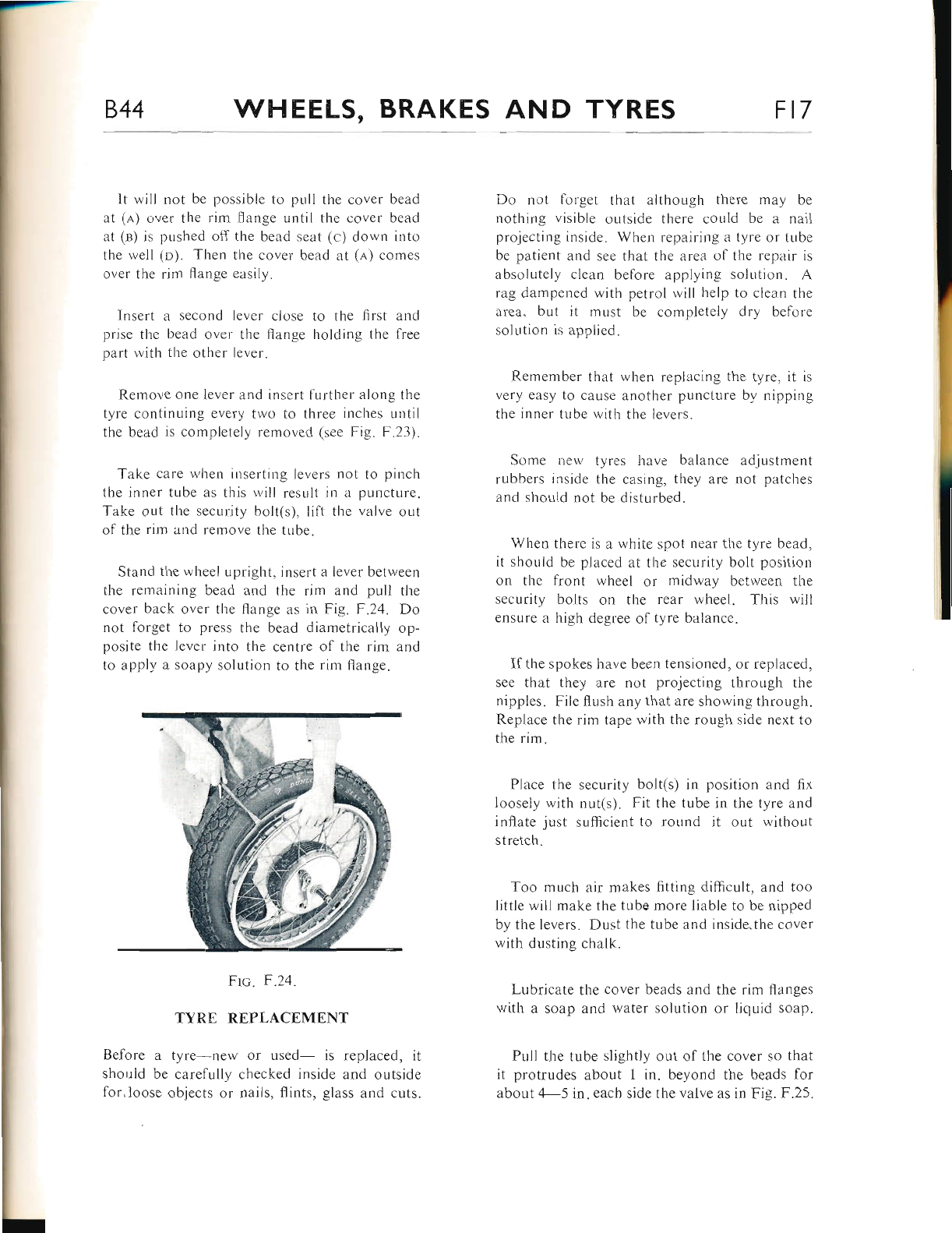
844 WHEEI.S, BRAKES AND TYRES Ft7
It will not be possible to pull the cover bead
at (r) over the rim llange until the cover bead
at (B) is pushed off the bead seat (c) down into
the well (o). Then the cover bead at (n) comes
over the rim flange easily.
Insert a second lever close to the first ancl
prise the bead over the flange holding the free
part with the other lever.
Remove one lever and inse rt further along the
tyre continuing every two to three inches until
the bead is ccmpletely removecl (see Fig. F.23).
Take care wlten inserting levers not to pinch
the inner tube as this will result in a pllnctLlre.
Take out the security bolt(s), lift the valve out
of the rim and remove the tube.
Stand the wheel upright. insert a lever between
the remaining bead and the rim and pull the
cover back over the flange as in Fig. F.24. Do
not forget to press the bead diametrically op-
posite the lever into the centre of the rim and
to apply a soapy solution to the rim flange.
Frc. F.24.
TYR.E REPLACEMENT
Before a tyre new or used- is replaced, it
shorrid be carefully checked inside and outside
for, loose objects or nails, flints, glass and cuts.
Do not lolget that although there may be
nothing visible outside there could be a nail
projecting inside. When repairing l tyre or tube
be patient and see that the area ol the repair is
absolLrtely clean before applying solution" A
rag dampened with petrol will help to clean the
area, but it must be completely dry before
solution is applied.
Remember that when replacing the tyre, it is
very easy to cause another puncture b;, nipping
the inner tube witir the levers.
Some nen,tyres have balance adjustment
rubbers inside the casing, they are not patches
and should nof be disturbed.
When there is a tvhite spot nsar thc tyre bead,
it should be placed at tl"re security br:rlt position
on the fiont wheel or midway between the
security bolts on the rear wheel. Ihis will
ensure a high degree of tyre balance.
Ifthe spokes have been tensioned, or replaced,
see that they are not projecting through the
nipples. File flush any that are showing through.
Replace the rim tape with the rough side next to
the rim.
Place the security bolt(s) in position and fix
ioosely with nut(s). Fit the tube in the tyre and
inflate just sufficient to round it out without
stretch.
Too much air makes fitting difficult, and too
little will make the tube more liable to be nipped
by the levers. Dust the tube and inside.the cover
with dusting chalk.
Lubricate the cover beads and the rim flanges
with a soap and water solution or liquid soap"
Pull the tube slightly out of the cover so that
it protrudes about I in. beyond ihe beads for
about 4-5 in. each side the valve as in Fig. F.25.
www.bsaunitsingles.com
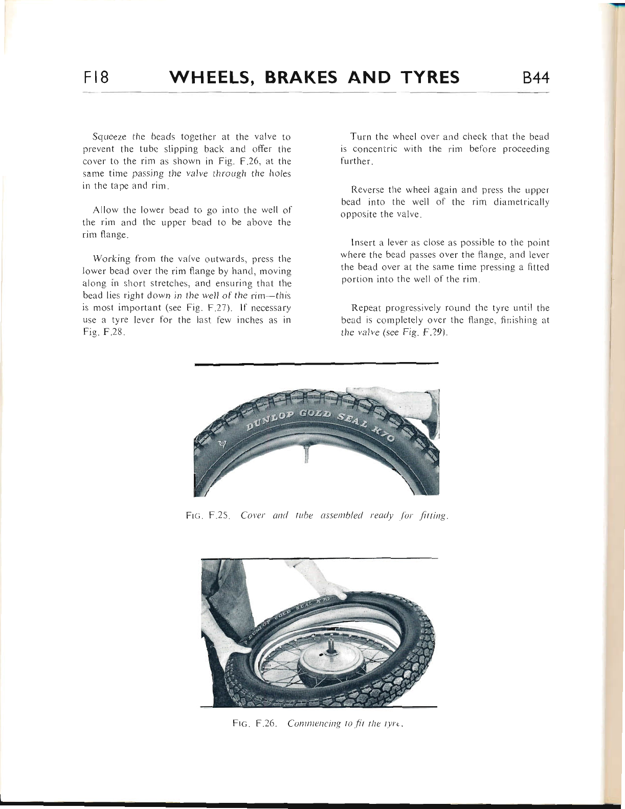
Fr8 WHEELS, BRAKES AND TYRES 844
Squeeze the beads together at the valve to
prevent the tubc slipping back and offer the
cover to the rim as shown in Fig. F.26, at the
same time passing the valve through the holes
in the tape and rim.
Allow the lor'ver bead to go into the rvell of
the rim and the r-rpper bead to be above the
rim flange.
Working from the valve outwards, press the
lower bead over the rim ffange by hancl, moving
along ir.r short stretches, and ensttring that the
bead lies right down in the well of the rim-this
is most important (sec Fig. F.27). lf necessary
use a tyre lever for the last few inches as in
Fig. F.28.
Turn the wheel over arld check that the bead
is conceniric with the rim before proceeding
fi-rrther.
Reverse tlie wheel again and press the upper
bead into tl-re well of the rim diametrically
opposite the valve.
lnsert a lever as close as possible to the point
where the bead passes over the flange, and lever
the bead over at tl.re same time pressing a fitted
portion into the well of the rim.
Repeat progressively round the tyre until the
bead is completely o'rer the flange, liLrishing at
the valve (see Fig. F.29).
Frc. F.25. Coter ctncl luhe ussentbled ready /'or fitting
Frc. F.26. Cotttntencittg trt .fit tlte tyrt.
www.bsaunitsingles.com
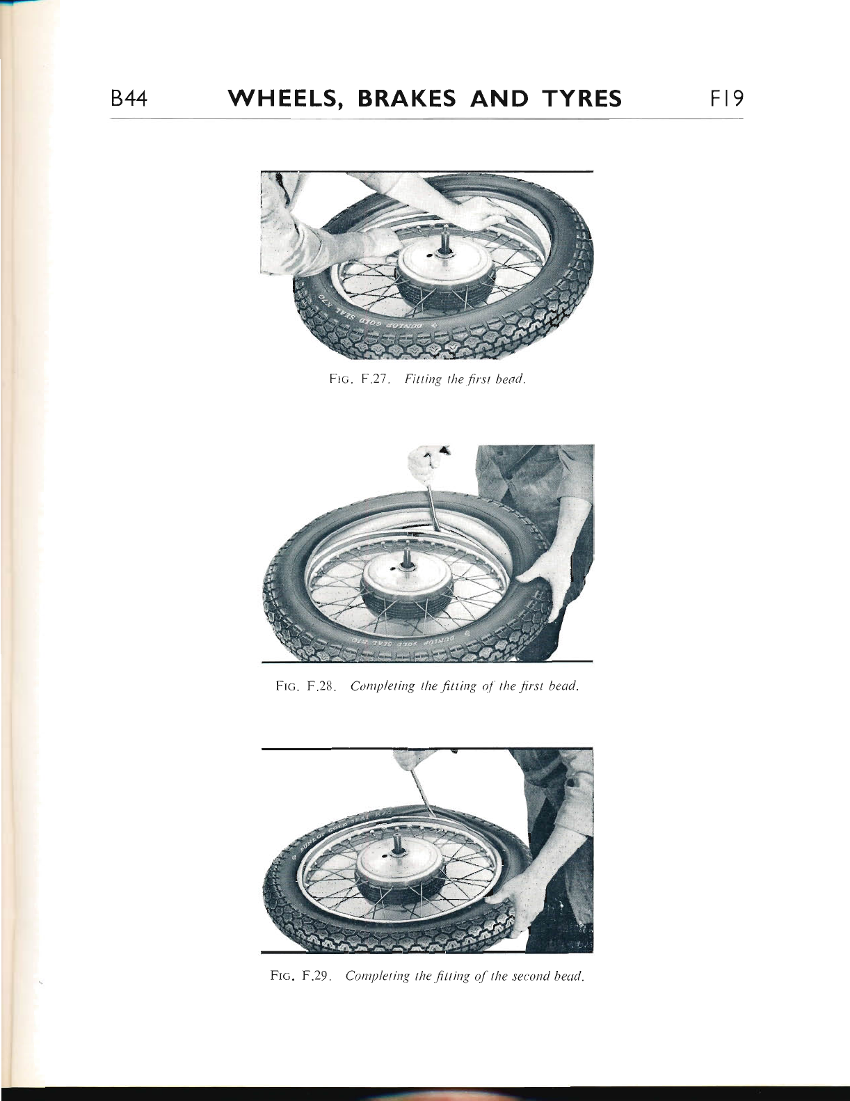
844 WHEELS, BRAKES AND TYRES Fl9
Frc. F.27. Fittittg the first bead.
Ftc. tr.28. Completing the fitting oJ' the f rst bead.
Frc. F.29. Completing the fitting of the second bead.
www.bsaunitsingles.com
F20 WHEELS, BRAKES AND TYRES 844
Push the valve inwards to ensure that the tube
adjacent to the valve is not trapped under the
bead, then pull the valve back firmly into posi-
tion. Also ensure that the tube is resting on the
flapG) ol the security bolt(s) and is overlapping
the sides.
Before inflating, check that the fitting line on
the tyre wall just above the bead on each side
is concentric with the rim.
If necessary bounce the wheel to help seat tire
tyre but, see that there is adequate pressure to
prevent damaging the tyre or tube and only use
moderate force" If the tyre will not seat, it is
better to release the pressnre, apply soap solution
to lubricate and re-inflate.
Inflate to the required pressure and check fit-
ting lines again" Inflation should not be too
rapid, particularly at the commencement, to
allow the beads to seat correctly on the rim.
See that the valve protrudes squarely through
the valve hole before screwing down the knurled
nut and replace the dust cap.
Finally, tighten down the nut(s) on the secu-
rity bolt(s).
TYRE PRESSURES
Victor Entluro and Special (U.S.A.):-The recom*
mended inflation pressures of 16 lb. per square
inch for each tyre are based on a riders'weight
of 140 1b. lf the riders' weight exceeds 140 lb.
the tyre pressure should be increased as follows:
FnoNr Tvru:-Add I lb. per square inch for
every 28 lb. in excess of 140 lb.
Rr,A.n Tvns:-Add I lb. per square inch for
every 14 lb. in excess of 140 lb.
Victor Grand Prix:-The tyre pressures should
be determined by the riders' own requirements
and the nature of the terrain in which the machine
wili be used.
www.bsaunitsingles.com
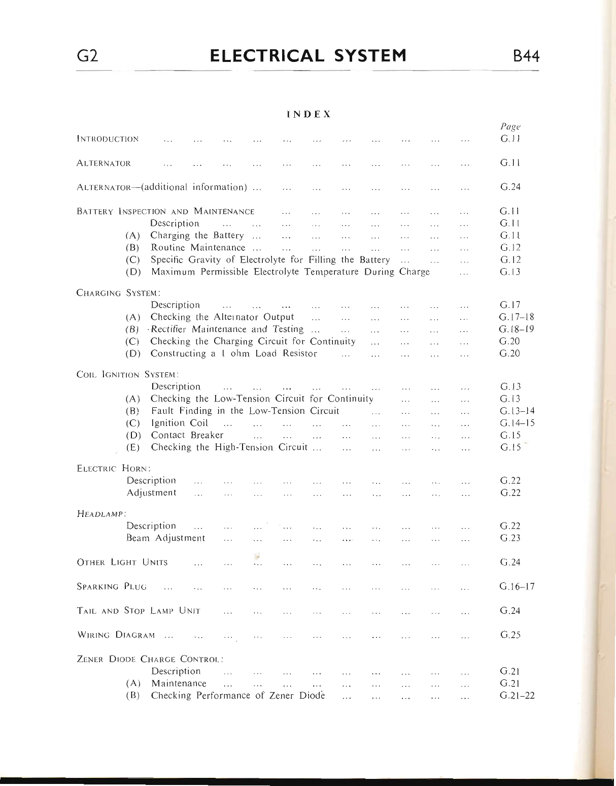
G2 ELECTRICAL SYSTEM 844
INDEX
lNtnonucrtoN
AlllnNeton
Ar-rnRNa.ron-(additional information) ...
Barrenv lNspscrtoN lNo MATwTENANCE
Description
(A) Charging the BatterY
(B) Routine Maintenance ...
(C) Specific Gravity of Electrolyte f<rr Filling the Battery
(D) Maximum Permissible Electrolyte Temperature Dtrring Charge
Cu,qncrNc Svsrpn;
Description
for Continuity
Circuit
Page
G.1l
G.1r
G.24
G.l l
G.1 l
G.r1
G.12
G.12
G.r 3
G.l7
G.l7-18
G.18-19
G.20
G.20
G. t3
G.l3
G.13 14
G.14-15
G.15
G.l5-
G.22
G.22
G.22
G.23
G.24
G.16-17
G.24
G.25
G.21
G.21
G.21-22
(A)
(B)
(c)
(D)
Corr.. IcNtrtoN
Checking the Alternator OutPut
.Rectifier Maintenance and Testing ...
arging Circuit lor Continuity
Checking the Ch
Constructing a 1
Svsrspt:
Description
ohm Load Resistor
(A) Checking the Low-Tension Circuit
(B) Fault Finding in the Lorv-Tension
(C) Ignition Coil
(D) Contact Breaker
(E) Checking the High-Tension Circuit .-.
ElEctRtc HonN:
Description
Adjustment
HEaoLn up:Description
Beam Adjustment
OrHen LtcHr UNtrs
Spa.nrrNc PI-uc
WrnrNG Dl,tcn,q,\,1
Tnrl lNo Srop L,q.Htp UNtr
ZnNen Dtopr Cuancr CoNtnol:
Description
(A) Maintenance
!
i
!
I
(B) Checking Performance of Zener Diode
www.bsaunitsingles.com
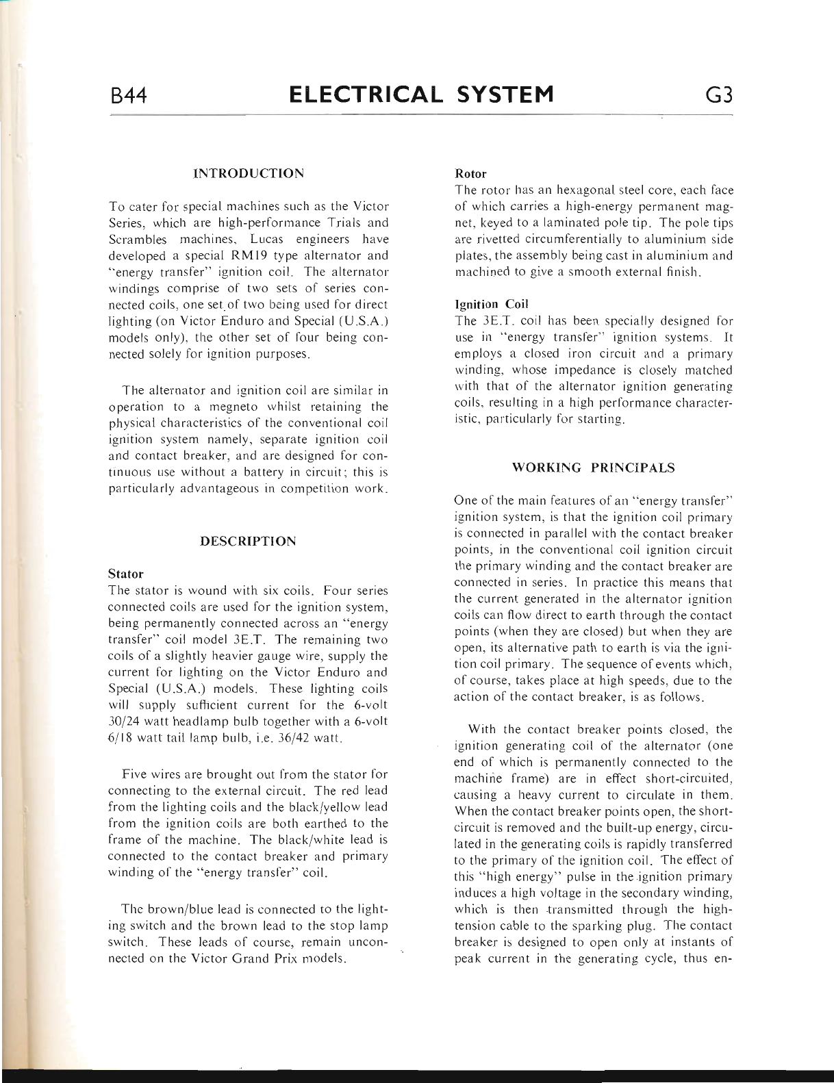
844 ELECTRICAL SYSTEM G3
INTRODUCTION
To cater for special machines sLlch as the Victor
Series, which are high-performance Trials and
Scrambles machines, Lucas engineers have
developed a special RMl9 type alternator and
('energy transf'er" ignition coil. The alternator
uindings comprise of two sets of series con-
nected coils, one set.of trvo being used lor direct
Iighting (on Victor E,nduro and Special (U.S.A.)
models only), the other set of four being con-
nected solely for ignition purposes.
The alternator and ignition coil are similarr in
operation to a megneto rvhilst retaining tl.re
physical cl.raracteristics of the conventional coil
i-enition system namely. separate ignition coil
and contact breaker. and are designed for con-
tinuous use without a battery in circuit; this is
particularly adviintageous in competition work.
DESCRIPTTON
Stator
The stator is wound with six coils. Four series
connected coils are used for the ignition system,
being permanently connected across an "energy
transfer" coil model 3E.T. The remaining two
coils of a slightly heavier gauge wire, supply the
current for lighting on the Victor Enduro and
Special (U.S.A.) models. Tliese lighting coils
rvill supply suffjcient current for the 6-volt
30124 watl headlamp bulb together with a 6-volt
6/18 watt taillamp bulb, i.e. 36l42watt.
Five wires are brought out from the stator for
connecting to the external circuit. The red lead
from the Iighting coils and the black/yellow lead
from the ignition coils are both earthed to the
frame of the machine. The black/white lead is
connected to the contact breaker and primary
winding of the "energy transfer" coil.
The brown/blue lead is connected to the light-
ing switch and the brown lead to the stop lamp
switch. These leads of course, remain uncon-
nected on the Victor Grand Prix models.
Rotor
The rotor has an hexagonal steel core, each lace
of which carries a high-energy permanent mag-
net, keyed to a laminated pole tip. The pole tips
are rivetted circumferentially to aluminium side
plates, the assembly being cast in aluminium and
rnachined to give a smooth external flnish.
Ignition Coil
The 3E.T. coil has beer-r specially designed for
use irr "energy transfer" ignition systems. It
emplovs a closed iron circuit and a primary
rvinding, whose impedance is closely matcl.red
rr ith tlrat ol' tlre rltentator ignirion generating
coils, resulting in a high perlormance character-
istic. palticulrrrly li'r sterting.
WORKING PRINCIPALS
One ol tl.re main features ol an "energy transfer"
ignition system, is that the ignition coil primary
is connected in parallel with the contact breaker
points, in the conventional coil ignition circuit
the primary winding and the contact breaker are
connected in series. In practice this means that
the current generated in the alternator ignition
coils can flow direct to earth through the contact
points (when they are closed) but when they are
open, its alternative path to earth is via the igni-
tior-r coil primary. The sequence of events whicl'r,
of course, takes place at high speeds, due to the
action of the contact breaker. is as follows.
With the contact breaker points closed, the
ignition generating coil of the alternator (one
end of which is permanently connected to the
machine frame) are in effect short-circuited,
causing a heavy current to circulate in them.
When the contact breaker points open, the short-
circuit is removed and the built-up energy, circu-
lated in the generating coils is rapidly transferred
to the primary of the ignition coil. The effect of
this "high energy" pulse in the.ignition primary
induces a high voltage in the secondary winding,
rvhich is then transr.nitted through the high-
tension cable to the sparking plug. The contact
breaker is designed to open only at instants of
peak current in the generating cycle, thus en-
www.bsaunitsingles.com
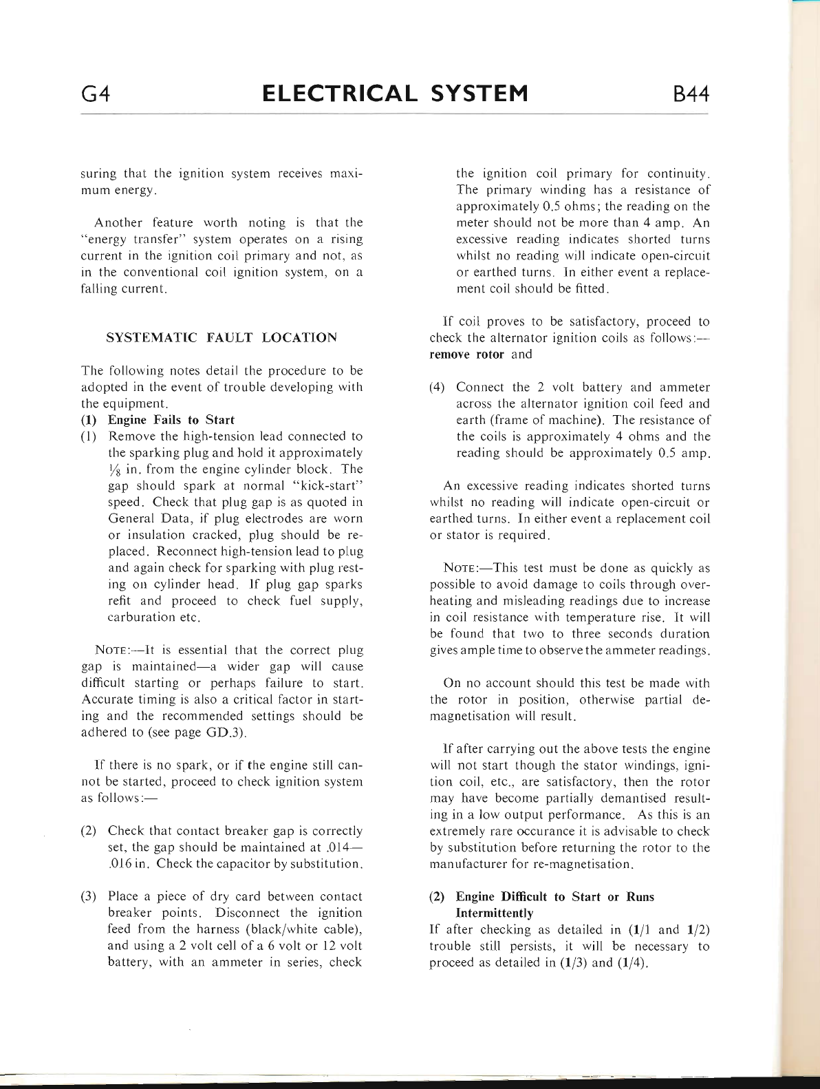
G4 ELECTRICAL SYSTEM 844
suring that the ignition system receives maxr-
mum energy.
Another feature worth noting is that the
"energy transfer" system operates on a rising
current in the ignition coil primary and not, as
in the conventional coil ignition system, on a
falling current.
SYSTEMATIC FAULT LOCATION
The following notes detail the procedure to be
adopted in the event of trouble developing with
the equipment.
(1) Engine Fails to Start
(l) Remove the high-tension lead connected to
the sparking plug and hold it approximately
ft in. from the engine cylinder block. The
gap should spark at normal "kick-start"
speed. Check that plug gap is as quoted in
General Data, if plug electrodes are worn
or insulation cracked, plug should be re-
placed. Reconnect high-tension lead to piug
and again check for sparking with plug rest-
ing on cylinder head. If plug gap sparks
refit and proceed to check fuel supply,
carburation etc.
Norr:-It is essential that the correct plug
gap is maintained-a wider gap will cause
difficult starting or perhaps failure to start.
Accurate timing is also a critical factor in start-
ing and the recommended settings should be
adhered to (see page GD.3).
lf there is no spark, or if the engine still can-
not be started, proceed to check ignition system
as follows:-
(2) Check that contact breaker gap is correctly
set, the gap should be maintained at .014-
.016 in. Check the capacitor by substitution.
(3) Place a piece of dry card between contact
breaker points. Disconnect the ignition
feed from the harness (black/white cable),
and using a 2 volt cell of a 6 volt or 12 volt
battery, with an ammeter in series, check
the ignition coil primary for continuity.
The primary winding has a resistance ol
approximately 0.5 ohms; the reading on the
meter should not be more than 4 amp. An
excessive reading indicates shorted turns
whilst no reading will indicate open-circuit
or earthed turns. In either event a replace-
ment coil should be fitted.
lf coil proves to be satisfactory, proceed to
check the alternator ignition coils as follows:-
remoYe rotor and
(4) Connect the 2 volt battery and ammeter
across the alternator ignition coil feed and
earth (frame of machine). The resistance of
the coils is approximately 4 ohms and the
reading should be approximately 0.5 amp.
An excessive reading indicates shorted turns
whilst no reading will indicate open-circuit or
earthed turns. In either event a replacement coil
or stator is required.
Norp:-This test must be done as quickly as
possible to avoid damage to coils through over-
heating and misleading readings due to increase
in coil resistance with temperature rise. lt will
be found that two to three seconds duration
gives ample time to observe the ammeter readings.
On no account should this test be made with
the rotor in position, otherwise partial de-
magnetisation will result.
If after carrying out the above tests the engine
will not start though the stator windings, igni-
tion coil, etc., are satisfactory, then the rotor
may have become partially demantised result-
ing in a low output performance. As this is an
extremely rare occurance it is advisable to check
by substitution before returning the rotor to the
man ufacturer for re-magnetisation.
(2) Engine Difficult to Start or Runs
Intermittently
If after checking as detailed in (f/1 and ll2)
trouble still persists, it will be necessary to
proceed as detailed in (1/3) and (ll4).
www.bsaunitsingles.com
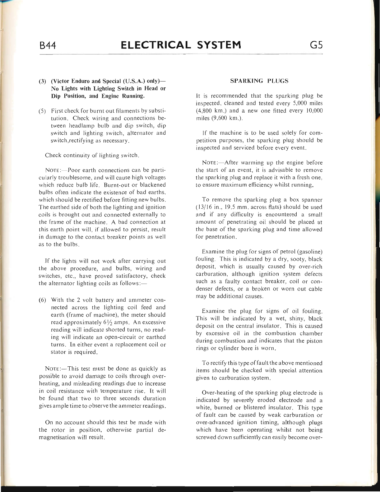
844 ELECTRICAL SYSTEM G5
(3) (Victor Enduro and Special (U.S.A.) only)-
No Lights with Lighting Switch in Head or
Dip Position, and Engine Running.
(5) First check for burnt out filaments by substi-
tution. Check wiring and connections be-
tween headlamp bulb and dip switch, dip
switch and lighting switch, alternator and
switch,rectifying as necessary.
Check continuity of lighting switch.
NorE:-Poor earth connections can be parti-
cularly troublesome, and will cause high voltages
which reduce bulb life. Br-rrnt-out or blackened
bulbs often indicate the existence of bad earths,
which should be rectified before fitting new bulbs.
The earthed side of both the lighting and ignition
coils is brought out and connected externally to
the frame of the machine. A bad connection at
this earth point will, if allowed to persist, result
in damage to the contact breaker points as well
as to the bulbs.
If the lights will not work after carryirrg out
the above procedure, and bulbs, wiring and
switches, etc., have proved satisfactory, check
the alternator lighting coils as follows:-
(6) With the 2 volt battery and ammeter con-
nected across the lighting coil feed and
earth (frame of machine), the meter should
read approximately 6/2 amps. An excessive
reading will indicate shorted turns, no read-
ing will indicate an open-circuit or earthed
turns. In either event a replacement coil or
stator is required.
Norr:-This test must be done as quickly as
possible to avoid damage to coils through over-
heating, and misleading readings due to increase
in coil resistance with temperature rise. It will
be found that two to three seconds duration
gives ample time to observe the ammeter readings.
On no account should this test be made with
the rotor in position, otherwise partial de-
magnetisation will result.
SPARKING PLUGS
It is recommended that the sparking plug be
inspected, cleaned and tested every 5,000 miles
(4,800 km.) and a new one fitted every 10,000
miles (9,600 km.).
ll the machine is to be used solely for com-
petition purposes, the sparking plug should be
inspected and serviced before every event.
Nors:-After warming up the engine before
the start of an event, it is advisable to remove
the sparking plug and replace it with a fresh one,
to ensure maximum efficiency whilst running.
To remove the sparking plug a box spanner
(13/16 in., 19.5 mm. across flats) should be used
and if any difficulty is encountered a small
amount of penetrating oil should be placed at
the base of the sparking plug and time allowed
for penetration.
Examine the plug for signs of petrol (gasoline)
fouling. This is indicated by a dry, sooty, black
deposit, which is usually caused by over-rich
carburation, although ignition system defects
such as a faulty contact breaker, coil or con-
denser defects, or a broken or worn out cable
may be additional causes.
Examine the plug for signs of oil fouling.
This will be indicated by a wet, shiny, black
deposit on the central insulator. This is caused
by excessive oil in the combustion chamber
during combustion and indicates that the piston
rings or cylinder bore is worn.
To rectify this type of fault the above mentioned
items should be checked with special attention
given to carburation system.
Over-heating of the sparking plug electrode is
indicated by severely eroded electrode and a
white, burned or blistered insulator. This type
of fault can be caused by weak carburation or
over-advanced ignition timing, although plugs
which have been operating whilst not being
screwed down sufficiently can easily become over-
www.bsaunitsingles.com
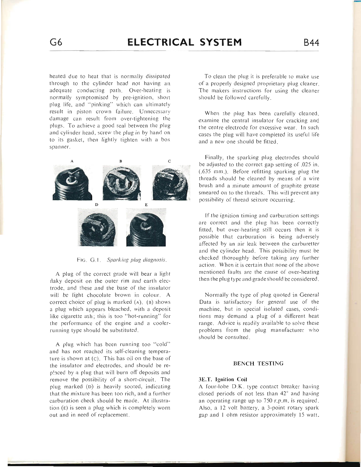
G6 ELECTRICAL SYSTEM 844
heated due to heat that is nonnally dissipatecl
through to the cylinder head not having an
adequate conducting path. Over-heating is
normally syt'tlpton"Iised by pre-ignition, short
plug life. and "pinking" which can ultimatell,
result in piston crown fhilr-rre. Unnecessary
damagc can result from over-tigl,terring tlie
plLrgs. To achieve a good seal between the plug
and cylinder head. scren' thc plLrg in by l.rand on
to its gersket, ther.r lightlv tighten rvitli a box
spanner.
To clean the plug it is pref'erable to make use
ol a properly designed proprietary plug cleaner.
The makers instructiot.ts for usir.rg the cleaner
shor-rld be followed carefullr,.
When the plug has been carelully cleaned"
examine the central insulator for cracking ar.rd
the centre electrode fbr excessive wear. ln such
cases the plug will have completed its Lrseful lif-e
and a new one should be fitted.
Finally. the sparking piug electrodes shouid
be adjusted to the correct gap setting of.025 in.
(.635 mm.). Before refitting sparking plug the
threads should be cleaned by means of a lvire
brush and a minute amount ol graphite grease
smeared on to the tl.rreads. This rvili prevent any
possibility ol thread seizure occurring.
tl the ignition liming and carblrratior-r settings
are correct and the plug has beett correctly
fitted. bLrt over-heating still occurs then it is
possible that carbr-rration is being aclve rsely
affected by an air leal< between the carburetter
and the cylinder head. This possibility must be
checked thoroughly before taking any further
action. When it is certain that none of the above
rnentioned faults are the cause ol over-heating
then tl.re plug type and grade should be cor.rsidered.
Normally the type of plug quoted in General
Data is satisfactory for general use of the
machine, but in special isolated cases. condi-
tions may demand a plu-e of n different heat
range. Advice is readily available to solve these
problems lrom tl-re plug manufacturer rvho
should be consulted.
ffi@ffi
ffiffi
Frc. G.l . Sparl<ing plug diognosis.
A ;llug of the correct grade will bear a liglit
rlaky deposit on the outer lim and earth elec-
trode, :rnd these and the base of the insrtlator
will be light chocolate browt.t in colottr. A
correct choice of plr.rg is marked (r). (n) shows
a plug which appears blenched, rvith a deposit
like cigarette ash; this is too "l-rot-running" for
the performance of the engine and a cooler-
running type should be substituted.
A plug wl.rich l.ras been running too "cold"
and has not reached its self-cleaning ternpera-
ture is shown at (c). Tliis has oii on the base of
tl.re insulator irud electrodes. aud should be re-
phced by ;r plug that will burn off deposits and
remove the possibility of a short-circr,rit. The
plug marked (n) is heavily sooted, indicating
that the mixture l.ras been too rich, and a further
cai'buration check should be made. At illLrstra-
tion (e) is seen a plug which is completely worn
out and in need of replacement.
BENCH TESTING
3E.T. Ignition Coil
A tbur-lobe D.K. type contact breaker havirrg
closed periods of not less than 42' and having
an operating range up to 750 r.p.m. is required.
Also, a 12 volt battery, a 3-point rotary spark
gap and 1 ohm resistor approximatelv l5 watt.
www.bsaunitsingles.com
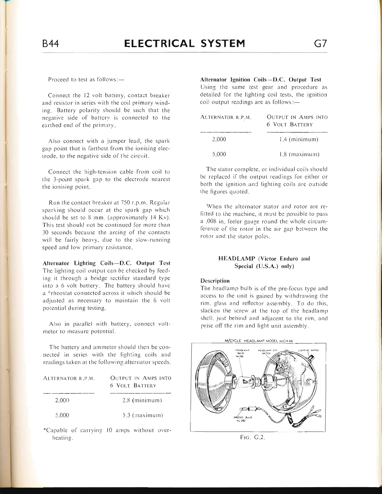
844 ELECTRICAL SYSTEM G7
Proceed to test as lollows:-
Connect the I2 volt battery, corlt.rct bleaker
and resistor in series with the coil primary wind-
ing. Battery polarity shoLrld be such that the
negative side ol battery is connected to the
earthed end of the primar1,.
Also connect with a .jr-rmper leacl, the spark
gap point that is larthest from the ionising elcc-
trode. to the negative side of the circrrit.
Connect the high-tension cable lrom coil tcr
the 3-point spark gep to the electrocle nearest
tlie ionising point.
RLrn ihe contact brelrker ert 750 r.p.m. Regular
sparking should occur at the spark gap which
shor-rlcl be set to 8 mm. (approximately l4 Kv;.
This test shoulcl not be continueci for rnore thalt
30 seconds because the arcing of the contacts
will be fairly heavy, due to the slorv-running
speed and low prirnlrrl r.'sistlnce.
Alternator Lighting Coils-D"C. Output Test
The lighting coil output cau be checked by f'eed-
ing it through a bridge rectifier standard type
into a 6 volt battery. The battery shor-rld havc
a "rhcostat connected across it lvhich should be
adj usted :rs necessary to maintain the 6 volt
potential during testing.
Also in parallel with batterv. connect volt-
meter to measure potential.
The bzrtlery and ammeter should then be con-
nected in series with the lighting coils and
readings taken at the lollowing alterrrator speeds.
ALTERNATOR u-P.r\,1. Ourpur rN AN{PS rNTo
6 Volr Barrnnv
Alternator Ignition Coils-D.C. Output Test
Using tl-re same test gear ernd procedure as
detailed fbr the lighting coil tests, the ignition
coil outpLrt readings are as follows:-
AL'fEr{NAt'oli R.P.M Ourpur rN AMPS rN'ro
6 Volr Barrenv
2,000
5.000
I.4 (minimum)
1.8 (maximum)
2.000
5.000
*Capable ol carrying
heiiting.
2.8 (minimr-rm)
5.3 (lraxirirum)
l0 amps rvithout over-
The stator complete, or individual coils sliould
bc replaced il the output readings for either or
both the ignition anC lighting coils arc outside
the figr-rres quoLed.
When the alternator statcr and rotor are re-
fitted to the machine, it m,"rst be prossible to pass
a .008 in. leeler gauge ror-rnd the rviiole circum-
f-erence ol tire rotor in the air gap botrveen the
rotor arrd the stator poles.
F{EADLAMP (Victor Enduro and
Special (U.S.A.) only)
Description
The headl:rmp bulb is of tlie pre-focus type and
access to the irnit is gained by withdrarving the
rim" glass and reflector assembly. To do this.
slackcn thc screr.v at the top of the headlamp
shell. .just behirrd and irdjacent to the rim, and
prise off the rim arrd light rrnit assembly.
Frc G.2.
www.bsaunitsingles.com
G8 ELECTRICAI- SYSTEM 844
To remove the bulb, press the cylindrical cap
inwards and turn anti-clockwise to release. The
bulb can now be withdrarvn lrom its housing.
When frtting a new bulb, note that it locates
by means ol a cut-away and projection arrange-
ment. Also note that the tabs on the cap are
staggered to prevent incorrect reassembly. Check
the replacement bulb type voltage and wattage
specificalion belore fitting.
Focussing lor tliis type ol unit is not necessary
and no provision has been made for such.
Beam Adjustment
The beam must at all times be set as specified by
local lighting regulations. For the United King-
dom, the Transport Lighting Reguiations read
as follows:-
A lighting system must be arranged so that
it can give a light which is incapable of
dazzling any person standing on the same
horizontal plane as the vehicle at a greater
distance then 25 feet from the lamp, whose
eye level is not less than 3 feet 6 inches
above that plane.
Ol coLrrse. lhese instructions may require
amendment to comply with overseas lighting
regulations.
The headlamp must therefore be set so that
the main beam is directed straight ahead and
parallel with the road when the motorcycle is
fully loaded. To achieve this, place the machine
on a level road, facing a wall at a distance of
25 feet away. With a rider and passenger seated
on the machine, sla"ken the headlamp fixing
bolts and move the lamp until the correct setting
is obtained. Tighten the fixing bolts and re-
check the setting. Do not forget that the head-
lamp should be on "full-beam" lighting rvhen
carrying out the above adjustment.
TAIL AND STOP LAMP UNIT
(Victor Enduro and Special (U.S.A.) only)
Access to the double filament, tail and stop lamp
bulb is achieved by unscrewing the two lens
retaining screws. The bulb is of the offset pin
type, thus ensuring that the replacement is fitted
correctly into the bulb holder.
Check that the two supply ieads are properly
connected and see that the earth lead to the bulb
holder is in satisfactory condition. When refit-
ting the lens, do not overtighten the fixing screws
or the lens may fracture.
SPEEDOMETER LIGHT
(Victor Enduro and Special (U.S.A.) only)
The bulb holder is simply a press-fit into the
base of the speedometer head and is withdrawn
cornplete with the screw type 6 volt 3 watt bulb.
Check that its cable is securely connected to the
dip switch terminal.
Also check that the grommet in the headlamp
shell is in good condition, otherwise the insula-
tion on the cable may begin to wear and eventu-
ally cause a short-circuit.
www.bsaunitsingles.com
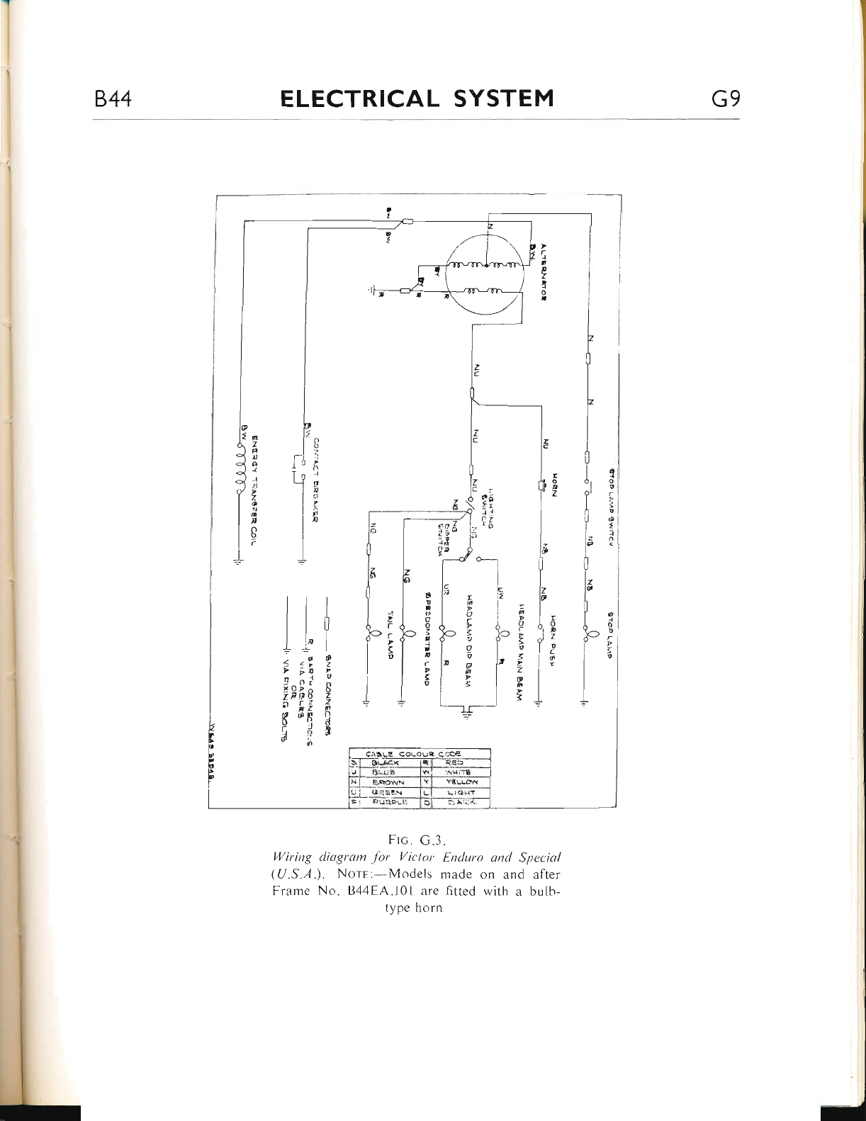
844 ELECTRICAL SYSTEM G9
I
I"
ll
6.
j
I
I
I
'1
l
r
&
o
5
0
I
w
n
a
U
p
o
o
I
-{
FI
r
P
s
g
tll
ltl
ti0
llr
I It i
-.sO
t :, z
D en u
4 nr' X
i^fi'Fq Z
"' nI P
F {PF (l
o 'i d
\ 4 r
&i
o
()
-l
€
tr
a
n
*_l
i
lc
it
I6
o
u
r
u
i
f,
ct
r
g
v
z
@
c
Ftc. G.3.
Wiring cliagram .for Victor Enduro and Special
(U.S.A.). Norr:-Models made on and after
Frame No. B44EA.l0l are fitted with a bulb-
type horn
www.bsaunitsingles.com
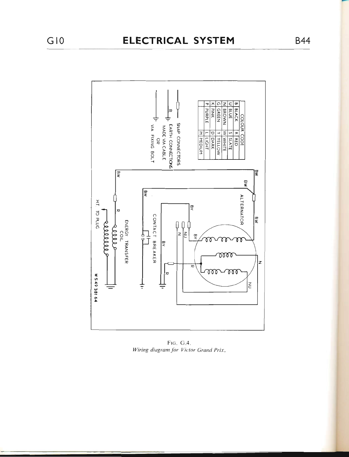
Gr0 ELECTRICAL SYSTEM 844
!7ozc@
n
o
-
o
c
,
o
o
a
fr
T
c
v
T
-
m
:9
z
xo
v
m
m
z
@
v
o
{
z
@
r
c
m
@
-
o
7
3-o€
3
o
c
3
-
o
:c
--{
a
v-
-
t
{
I
=
m
-
-l
h
v
m
0
1l+
?-r'g
;;t!9-r
T fnI ^
jef s e
6) o2 Z
@ B= R
q 'a g
6
r
J
o
P
c
o
t
ul
A
\o
g
o
!
r
--t
m
u
z
--t
o
D
o
o
z
I
o
-t
@
t
m
x
m
u
Frc.
14iring diugram for
G.4"
Vit'tor Grqnd Prix.
www.bsaunitsingles.com
844 ELECTRICAL SYSTEM Glr
844 VTCTOR SPECTAL (1968)
INTRODUCTION
The electrical system is supplied from generator.
model RM.2l contained in the primary ci-rain-
case and driven from the engine shalt.
A Zener Diode is connected in circuit to
regulate the battery charging surrent and thereby
prevents over-charging.
The current supplied to the ignition system
is controlled by a contact breaker, driven direct
from the camshaft.
Routine maintenance needed by the variolis
components is detailed in the following sections.
Whilst checking the electrical system, opport-
unity should be taken to ensure that all wiring
connections and frame earthing points are clean
and secure.
ALTERNATOR
The alternator consists of a spigot-rnounted 6-
coil laminated encapsulated stator with a rotor
carried on and driven by an extension of the
crankshaft. The rotor has an hexagonal steel
core, each face of which carries a high-energy
permanent magnet keyed to a laminated pole tip.
The pole tips are riveted circumferentially to
aluminium side plates, the assembly being cast
in aluminium and machined to give a smooth
external finish.
There are no rotating windings, commutator,
brushgear, bearings or oil seals and consequently
the alternator requires no maintenance apart
from occasionally checking that the snap con-
nectors in the output cables are clean and tight.
If rotor removal is necessary, there is no need
to fit magnetic keepers to the rotor poles. When
removed, wipe off any swarf which may have
been attracted to the pole tips and put the rotor
in a clean place until required for refitting.
BATTERY INSPECTION AND
MAINTENANCE
Description
The container for the model PUZ5A battery is
moulded in transparent material through whicir
the acid can be seen. The tops of the containers
are so designed that when the covers are in
position, the special anti-spill liller plugs are
seaied in a common venting chamber. Gas from
the filler plugs leaves this chamber through a
vent pipe. PoJythene tubing may be attached to
the vent pipe to lead the corrosive fumes away
from any parts of the machine where they might
cause damage.
PART A.
Charging the Battery
Whilst the battery leaves the factory in the fully
"dry-charged" condition, it may slowly lose some
charge in storage. In view of this, the following
filling instructions must be carefully observed:-
With the acid, battery and room temperature
between 60'F., and 100'F" (15.5--31 .7"C.), re-
move the vent plugs and fili each cell to the
coloured marker line.
Measure the temperature and specific gravity
ol the electrolyte in each of the cells.
Allow to stand for 20 minutes and then re-
check the temperature and specific gravity of the
electrolyte in each cell.
The battery is then ready for service unless the
above checks show the electrolyte temperature
to have risen by more than 10"F. (5.5"C.) or
the specific gravity to have fallen by more than
l0 "points", i.e., by more than 0"010 specific
gravity. In this event, it will be necessary to re-
charge the battery at the appropriate charge rate
(0.7 amperes) until the specific gravity values
remain constant for three successive hourly read-
ings and all cells are gassing freely.
www.bsaunitsingles.com
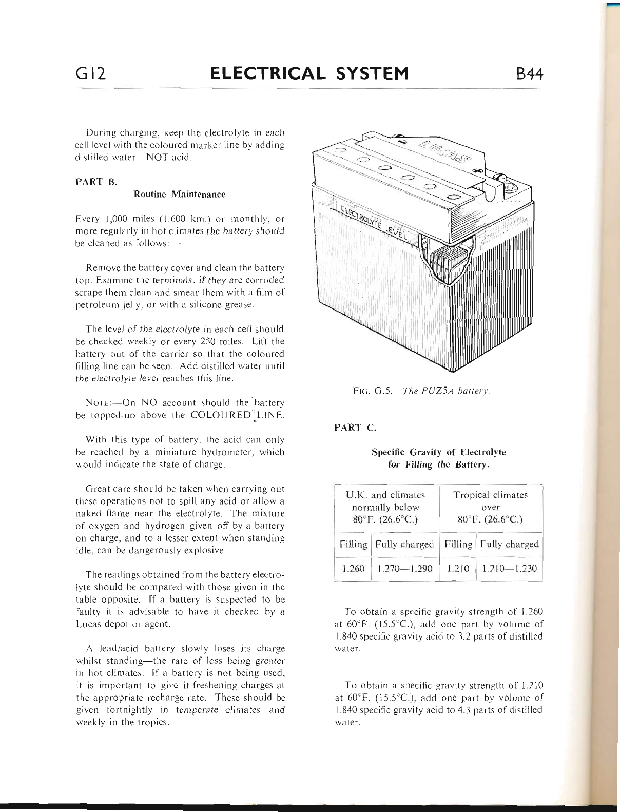
Gt2 ELECTRICAL SYSTEM 844
During charging. keep the electrolyte in each
cell level with the coloured marker litle by adding
distilled water-NOT acicl.
PART B. Routine Maintenance
Every 1,000 miles (1.600 km.) or monthiy. or
more regularly in l-rot climates the battery shouid
bc clerrrted rts follows:
Remove the battery cover and clean the battery
top. Examine the terminals: if they are corroded
scrape them clean and smear them with a filnr of
petroleum jelly, or with a silicone grease.
Tlie level of the electrolyte in eacli cell should
bc checkecl weekly or every 250 miles. Liff the
b:rttely out of tl.re carrier so that the colclured
filling line cart be seen. Add distilled water urrtil
tlie electrolyte levei reaches this line'
NorE:--On NO accourlt should the battery
bc topped-up above the COLOURED'LlNE.
Witl-r this type of battery, the acid can only
be reacl.red by a miniature hydrometer, wl.ricl.r
lvould indicate tl"re state of charge.
Great care shoirld be taken when carrying out
these operations not to spili any acid or allow a
naked flame near the electrolyte. The mixture
of oxygen and hydrogen given off by a battery
on charge, and to a lesser extent when standing
idle. can be dangerously explosive'
The readings obtained from the battery electro-
lyte should be compared with those given in the
table opposite. If a battery is suspected to be
faulty it is advisable to have it checked by a
Lucas depot or agent.
A lead/acid battery slowly loses its charge
whilst standing-the rate of loss being greater
in hot climates. ll a battery is not being used.
it is important to give it freshening charges at
the appropriate recharge rate. These should be
given fortnightly in temperate climates and
rreekly irr the tropics.
Frc. G.5. The PU25A hatterY.
PART C.
Specific GravitY of ElectrolYte
for Filling the BatterY.
U.K. and climates
normally below
80'F. (26.6"C.)
Tropical climates
over
80'F. (26.6"C.)
To obtain a specific gravity strength of 1.260
at 60'F. (15.5'C.), add one part by volume of
l.840 specific gravity acid to 3.2 parts of distilled
water.
To obtain a specific gravity strength of 1.210
at 60'F. (15.5'C.), add one part by volume of
1.840 specific gravity acid to 4.3 parts of distilled
lvater.
Filling Fully charged
www.bsaunitsingles.com
aa-
844 ELECTRICAL SYSTEM Gr3
PART D.
N{aximum Permissible
Temperature During
Cljrnates frequently
above
80"F. (26.6"C.)
r20'F. (49"C.)
Notes.--The .pecilic gravity of the electrolvte
varies with tl.re temperature. For convenience
in comparing specific gravities, they are always
corrected to 60"F., whiclr is adopted as I
reference temperatur e. The metl-rod of correctior.r
is at as follows:-
For every 5.F. below 60'F. dedr"rct .002 front
the observed reading to obtain the true specific
gravity at 60'F. For every 5'F. above 60'F..
add .002 to the observed reading to obtain the
true specific gravity at 60'F.
The ternperature must be indicated by a
thermometer having its bulb actually immersed
in the electrolyte and not tl.re ambient tempera-
ture. To take a temperature reading tilt the
battery sidewavs and then insert the thermo-
meter.
COII, IGNITION SYSTEM
Description
The coil ignition system comprises an ignition
coil, mounted below the petrol tank, and a con-
tact breaker unit fltted in the timing cover. Apart
lrom cieaning in-between the terminals, and
checking the connections for soundness, the coil
will not require any other attention. Testing the
ignition coil is amply covered in Part C, page
G.14, whilst testing the contact breaker is
detailed in Part D.
The best method of airproach to a taLrlty igrri-
tion system is to first check the low-tension
circuit for continr-rity as showu in Part A, then
lbllorv the procedure laid out in Part B to locat.e
the laLrlt(s).
Failure to locate ri fairlt in the lorv-lensiorr
circuit indicates that the higl-r-tension circuit or
sparking plug is laulty, and the procedr-rrc
detailed in Part E must be adopted" Befbre
commencing any of the follorving tests, however.
the contact breaker and sparking plug gaps mrrst
be cleaned and adjusted to eliminate this possible
source of faLrlt.
PART A.
Checking the Low-Tension Circuit for Continuity
To check whether there is a fault ir.r the lou,-
tension circuit and to locate its position, the
following tests should be carriecl otrt:-
First inspect the in-line fuse in the battery
positive cable and replace ifsuspect, then connect
an ammeter betweerr the battery ( -) and the
ignition switch (f).
Turn the ignition on and slowly crank the
engine. At the same time, observe the ermmeter
needle. which should fluctuate between zero and
a slight discharge, as the contact breaker points
open and close respectively.
If the ammeter needle does not fluctuate in
tlre described way, then a faLrlt in the low-tension
circuit is indicated.
First, examine the contact breaker points for
pitting, piling or presence of oxidation, oil or
dirt, etc. Clean and ensure that the gap is set
correctly to .015 in. (.381 mm.) as described on
page B.19.
PART B.
Fault Finding in the Low-Tension Circuit
To trace a lault in the low-tension wiring, turn
on the ignition switch and crank the engine until
the contacts are opened, or alternatively, place
a piece of insulating material between the con-
tacts whilst the lollowing test is carried out:-
Electrolyte
Charge
www.bsaunitsingles.com
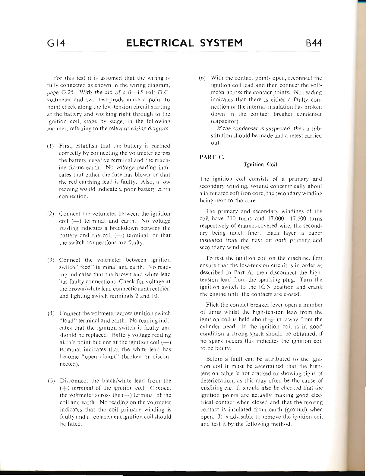
Gt4 ELECTRICAL SYSTEM 844
For this test it is assumed that the wiring rs
fuily connected as shown in the wiring diagram'
page G.25. With the aid of a 0-15 volt D.C.
voltmeter and two test-prods make a point to
point check along the low-tension circuit starting
at the battery and working right through to the
ignition coil, stage by stage, in the following
manner, referring to the relevant wiring diagram.
(1) First, establish that the battery is earthed
correctly by connecting the voltmeter across
the battery negative terminal and the mach-
ine frame earth. No voltage reading indi-
cates that either the fuse has blown or that
the red earthing lead is faulty. Also, a low
reading rvould indicate a poor battery earth
connection.
(2) Connect the voltmeter between the ignition
coil (-) terminal and earth. No voltage
reading indicates a breakdown between the
battery and the coil (-) terminai, or that
the switch connections are fanlty.
(3) Connect the voltmeter between ignition
switch "feed" terminal and earth. No read-
ing indicates that thc brown and white lead
has faulty connections. Check for voltage at
the brown/white lead connections at rectifier,
and ligh.ting switch terminals 2 and i0.
(4) Connect the voltmeter across ignition switch
"load" terminal and earth. No rea.ding indi-
cates that the ignition switch is faulty and
shouid be replaced. Battery voltage reading
at this point but not at the ignition coil 1-)
terminal indicates that the white lead has
become "open circuit" (broken or discon-
nected).
(5.) Disconnect the black/white lead fr:om the
({) terminai of the ignition coil. Connect
the voltmeter across the (*) terminal of the
coil and earth. No reading ou the voltmeter
indicates that the coil primary winding is
faulty and a replacement ignition coil should
be fitted.
(6) With the contact points opell, reconnect the
ignition coil lead and then connect the volt-
meter across the contact points. No reading
indicates that there is either a faulty con-
nection or the internal insuiation has broken
down in the contact breaker condenser
(capacitor).
If the condenser is suspected, then a sub-
stitution should be made and a retest carried
out.
PART C. Ignition CoiI
The ignition coil consists of a primary and
secondary winding, wound concentrically about
a laminated soft iron core, the secondary winding
being next to the core.
The primary and secondary windings of the
coil have 310 turns and 17,000-17,600 turns
respectively of enamel-covered wire, the second-
ary being much finer. Each layer is paper
insulated from the next on both primary and
secondary windings.
To test the ignition coil on the machine, first
erisure that the low-tension circuit is in order as
described in Part A, then disconnect the high-
tension lead from the sparking plug. Turn the
ignition switch to the IGN position and crank
the engine until the contacts are closed.
Flick the contact breaker lever open a number
of times whilst the high-tension lead from the
ignition coil is held about f, in. away from the
cylinder head. If the ignition coil is in good
condition a strong spark should be obtairred, if
no spark occurs this indicates the ignition coil
to be faulty.
Before a fault can be attributed to the igni-
tion coil it must be ascertained that the high-
tension cable is not cracked or showing sigrrs of
deterioration, as this may often be the cause of
misfiring etc. It should also be checked that the
ignition points are actually making good elec-
trical contact when closed and that the moving
contact is insulated from earth (ground) when
open. It is advisable to remove the ignition coil
and test it by the following method.
www.bsaunitsingles.com
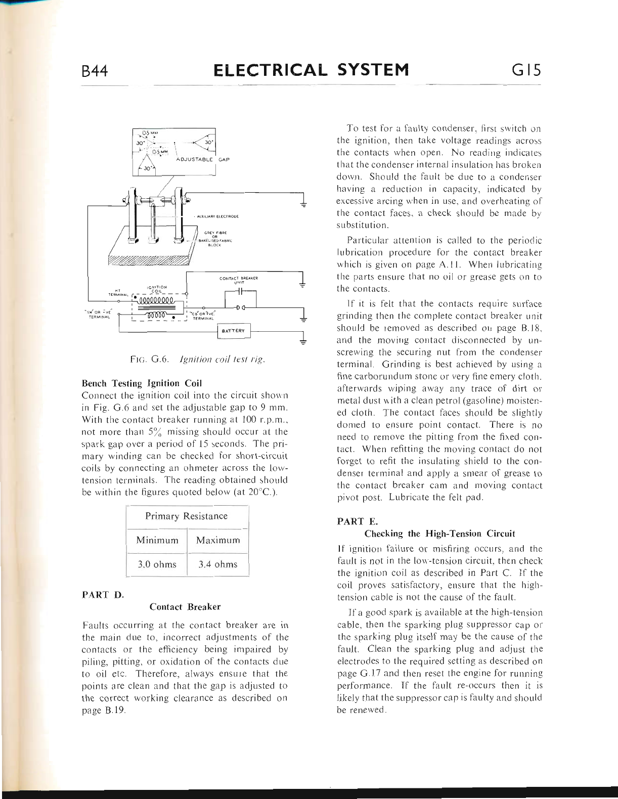
844 ELECTRICAL SYSTEM Gls
trrc;. G.6. Ignition t.oil test rig.
Bench Testing Ignition Coil
Conrrect the ignition coil into the circuit sho\\,rl
in Fig. G.6 and set the adjustable gap to 9 mm.
With the contact breaker running at 100 r.p.m.,
not more than 5\ missing should occur at the
spark gap over a period of 15 seconds. The pri-
mary winding can be checked for short-circLrit
coils by connecting an ohmeter across the lorv-
tension terminals. The reading obtained should
be within the figures qr-roted beiorv (at 20'C.).
PART D.
Contact Breaker
Faults occurring at the contact breaker are in
the main due to, incorrect adjustments of the
contacts or the efficiency being impaired by
piling, pitting, or oxidation of the contacts due
to oil etc. Therefore, always ensure that the
points are clean and that the gap is adjusted to
the correct working clearance as described on
page B.19.
To test for a laulty condenser, firsr srvitch on
the ignition, then take voltage readings across
the contacts when open. No reading indicates
that the condenser internal insulation has broken
dorvn. Should the fault be due to a condenser
having a reduction in capacity, indicated by
excessive arcing when in use, and overheating of
tl-re contact faces, a check shoLrld be rnade bv
substitution.
Particular attention is called to tl.re perioriic
lubrication procedure lor the contact breaker
which is given on page A.11. When lLrbricatirg
the parts ensure that no oil or grease gets on to
the contacts.
If it is felt that the contacts require surf:rce
grinding then the complete contact breaker unit
shorrid be removed as described orl page 8.18.
and tlie movirrg colltact disconnected by un-
screrving the securing nut from the condenser
terminal. Grinding is best achieved by using a
fine carborundum stone or very fine emery cloth.
altenvards wiping away any trace ol dirt or
nietal dust r,tith a clean petrol (gasolirre) moisten-
ed cloth. The contact faces should be slightly
domed to ensure point contact. There is no
need to remove the pitting from the fixed con-
tact. Wherr refitting the moving coutact do not
forget to refit the insulating shield to the con-
denser telminal and appiy a smear of grease to
the contact breaker cam and moving contact
pivot post. Lubricate the feit pad.
PART E.
Checking the High-Tension Circuit
If ignitiorr failure or misfiring occurs, and the
far-rlt is not in the lou-tension circuit, then check
the ignition coil as described in Part C. If the
coil proves satisfactory, eltsure that the high-
tension cable is not tlre cause <if the fault.
Ifa good spark is available at the high-tension
cable, then the sparking plug suppressor cap or
the sparking plug itself may be the cause of the
fault. Clean the sparking plug and adjust the
electrodes to the required setting as described on
page G.17 and t}ren reset the engine for running
perfcrrmance. If the fault re-occurs then it is
likely that the suppressor cap is faulty and should
be renewed.
Resistance
Minimum MaximLrm
3.0 ohms
www.bsaunitsingles.com
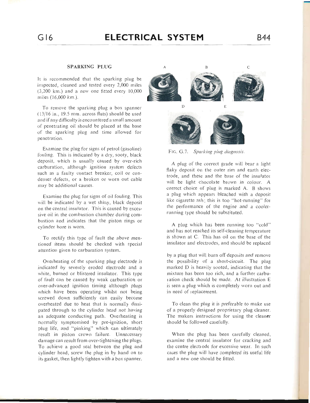
Gt6 ELECTRICAL SYSTEM 844
SPARKING PI,UG
It is recommended that the sparking piug be
inspected, cleaned antl tested every 2,000 miles
(3,200 km.) and a new one fitted every 10,000
rriles (16,000 1.:m.).
To remove the sparking plug a box spatrtler
(13/16 in., 19.5 mm. across flats) should be used
and if any difficulty is encountered a small amount
ol penetratir.rg oil should be placed at the base
ol the sparking plug and time allowed for
penetration.
Examine the plug ior signs c'f petrol (gasoline)
lorrling. This is indicated by a dry, sooty' black
deposit, lvlrich is usuaiiy caused by over-rich
carburation, although ignition svstem defects
such as a faulty contact breaker, coil or con-
clenser deflects, or a broken or worn out cable
may be additional causes.
Examine the plug for signs of oil fouling. Tl-ris
will be indicated by a wet shir"ry, black deposit
or-r tl.re centrai insutator. This is caused by exces-
sive oil in the combustion chamber during com-
bustion and indicates that the piston rings or
cylinder bore is worn.
To rectify ttris type ol lault the above men-
tioned items should be checked with special
attentiorr given to carburation system.
Overheating of the sparking plug electrode is
indicated by sevetely eroded electrode and a
white, burned or blistered insulator. This type
of fault can be caused by weak carburation or
over-advanced ignition timing although plugs
rvhich have been operating whilst not being
screwed down sufficiently can easily become
overheated due to heat that is normally dissi-
pated througl-r to tire cylinder head not having
zrn adequate conducting path' Overheating is
normally symptomised by pre-ignition, short
plug life, and "pinking" which can ultimately
result in piston crown failure. Unneoessary
damage can resttlt from over-tightening the plugs.
To achieve a good seal between the plug and
cylinder head, screw rhe plug in by hand on to
its gasket, then lightly tighten with a box spanner.
A plug of the correct grade will bear n light
flaky deposit on the outer rim and earth elec-
trode, and these and the base of the insulator'
will be Iight chocolate brown in colour. A
correct choice ol plug is marked A. B shows
a plug which appears bleached with a deposit
like cigarette ash; this is too "hot-running" for
the performance of the engine and a cooier-
running type should be sLrbstituted.
A plLrg which has been running too "cold"
and has not reached its self-cleaning temperatttre
is shcwn at C. Tiris has oil on the base of the
insulator and electrodes, and should be replaced
by a piug that will burn off deposits and remove
the possibility of a short-circuit. The plug
marked D is heavily sooted, indicating that the
mixture has been too rich, and a further carbu-
ration check should be made. At illustration E
is seen a plug which rs completely woru out and
in need of replacement.
To clean the plug it is preferable to make use
of a properly designed proprietary piug cleaner.
The makers instructions for using the cleaner
should be followed catefully.
When the plug has been carefuily cieaned,
examine the central insulator for cracking and
the centre electlode for excessive wear. In such
cases the plug will have completed its useful lile
and a nerv one shor-r1d be fitted.
"ffi
ffi E
ffi
ing plug diagnosis.
ffi
Frc;. G.7. SparA
www.bsaunitsingles.com
844 ELECTRICAL SYSTEM Gt7
Finally, the sparking plug electrode should be
ad_iusted to the correct gap setting of .025 in.
(.635 mm.). Before refiiting sparking plug the
threads should be cleaned b), means of a wire
brush and a minute amount ol grapl-rite grease
smeared on to the threads. This lvrll prevent any
possibility of thread seizure occurring.
If the ignition timing and carburation settings
are correct and the plug has been correctly fitted,
but overheating still occurs, then it is possible
that carburation is being adversely affected by
an air leak between the carburetter and the
cylinder head. Tiris possibility must be checked
thoroughly before taking any lurther action.
When it is certain that none of the above men-
tioned faults are the cause ol clverheating then
the plug type and grade should be considered.
Normally the type of plug quoted in General
Data is szrtisfactory for general use of the mach-
ine, but in special isolated cases, conditions may
demand a plug of a different heat range. Advice
is readily available to solve these problems from
the plug manufacturer who should be consulted.
CHARGING SYSTEM
Description
The alternator gives "maximum" output with
the lighting switch in all switch positions, the
coils being permanently connected across the
rectifier. Excessive charge is absorbed by the
Zener Diode which is connected in parallel with
the battery.
Always ensure that the ignition switch is in the
OFF position whilst the machine is not ilr use.
Proceed to test the alternator as descr-ibed in
Part A" If the alternator is satisfactory, the fault
must lie in the charging circuit, hence the recti-
fier must be checked as given in Part B and then
the wiring and connections as shown in Part C"
PART A.
Checking the Alternator Output
Disconnect the three aiternator output cables
and run the engine at 3,000 r.p"m.
Connect an A.C. voltmeter (0-15 volts) with
I ohm load resistor in parallel with each of the
alternator leads in turn as shown in the tabie,
on page G.24, and observe the voltmeter read-
ings. A suitable I ohm load resistor can be made
from a piece of nichrome wire as shown in part
D, page G.20.
The test is conducted by connecting a volt-
meter and the I ohm load resistor between the
following cables and note the readings:-
(o) White/green and green/black cables-volt-
meter should read 4.0 volts (minimum).
(b) White/green and green/yellow cables-volt-
meter should read 6.5 volts (minimum).
(c) White/green and joined green/black and
green/yellow cables-voltmeter should read
8.5 volts (minimum).
From the results obtained, the following dedLrc-
tions can be made:--
(1) If the readings are all equal to or higher
than those quoted then the alternator is
satisfactory.
(2) A low reading on any group of coils indi-
cates either that the leads concerned are
chafed or damaged due to running on the
chains or that some turns of the coils are
short-circuited.
(3) Low reading for all parts ofthe test indicate
that either the green/white lead has become
chafed or damaged due to rubbing on the
chains or that the rotor has become partially
demagnetised. As the latter is an extremely
rare occurrence it is advisable to check by
substitution before returning the rotor to
the manulacturer for re-magnetisation. Il
it is found that the rotor has become de-
magnetised, check that it has not been
caused by a faulty rectifier and that the
battery is of correct polarity.
www.bsaunitsingles.com
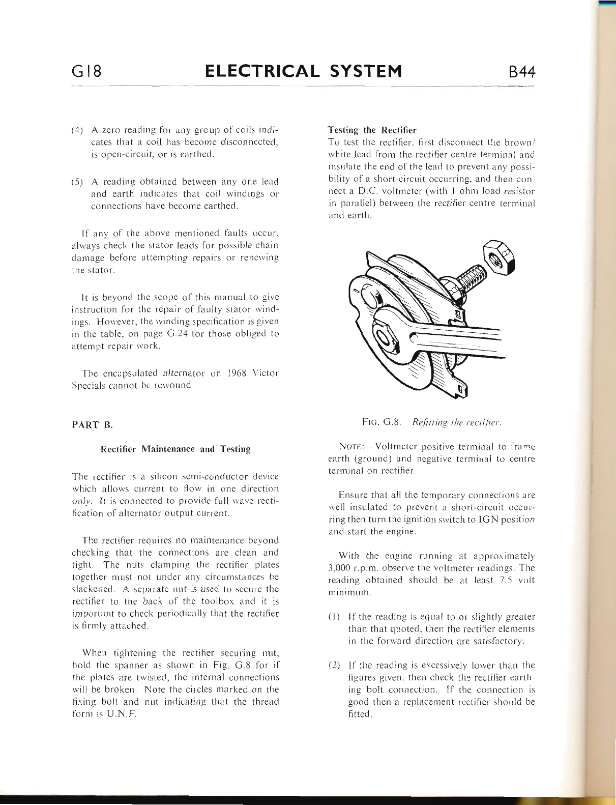
Gr8 ELECTRICAL SYSTEM 844
(4) A zero reading lbr any grcup ol coils indi-
cates that it coii has become disconr.rected.
is open-circLrit, or is earthed"
(5) A reading obtained between any one lead
and earth indicates that coil vvindings or
connections have become earthed.
Il any of the above mentioned laults occur.
alrvays check the stator leads for possible chain
tlamage befor; atlenrptitlP t'cpairs or rencrr ing
the stator.
It is beyond the scope of this t.tiatrual to give
instrLiction for tl're repair ol faulty stator lvind-
ings. Hou'ever. the rvinding specification is given
irr the table, on pa-qe G.24 for those obliged tcr
ilttempt repair work.
The cnci'.psLrlatecl alteri.ratol' on 1968 \'ictor'
iJpr:cials cannot bc rctvottnd.
PART B.
trtectifier Maintenance and Testing
The rectifier ir a silicorr semi-corrductor cle','icc
which allows current tcr flow in one directiorr
trnlv. It is cotrnected to provide full lvzrve lecti-
ficatior.r ol alternator outpttt current.
The rectifier requires no mainteirance beyolld
checking that the connections are cleatl and
tight. Tlre nuts clamping the rectifiel plates
togetl,er must not under any circumstances he
slackeriecl. A separate nrrt is used to sect,tt'e the
recti{rer to the back of the toolbox zrnci it is
ir.nportant to check periodically that the rcctilier
is firmly attl'ched.
When tightening the rectifier securing ntlt.
hold the spanner iis shor'vn in Fig. G.8 for il
the plc-tes zrre twisted, the internal connectiotls
will be broken. Note the circles marked on the
firing bolt and trut indicating that the thread
l'orm is U.N.F.
Testing the Rectifier
To test thc rectifier. fir.st disconnect 1he brown/
lvhite lead lronr the recti{ier centre termiual ancl
insulate the end of the leacl to prevent any possi-
bility of a short-circuit occurring, and then con-
nect a D.C. voltmeter (with l ohnr load resistor
ir, parnllel) between the rectilier centre termitial
and earth.
Fr<;. G.8. Refitting the rectifier
Norr: Voltmeter positive terminai to f rame
earth (ground) and negative terminal to centre
terrninal on rectifier.
Ensure that all the tenrporary connections are
uell insulated to preverrt a short-circuit occur'-
ring then turn tl-re ignition srvitch to IGN position
and sterrt the engine.
With the engine running at approxirnately
3.000 r.p.m. c.bserve the voltmeter readings. The
reading obtained shoLrld be at least 7.5 volt
minimunr.
(l) lf the rea.ding is eqLral tc or slightly greater
than that quoted, lhen the rectifier elentents
in tlre lorward direciion are satislactory.
(2) Il ';lTe reading is excessively lorver than tl.ie
fig-iires given. then cl-reck tl-re rectifier e;rrtLr-
ing bolt connection. Il the connection is
good ttren a rel;lacement rectifier shorrld be
fitted.
www.bsaunitsingles.com
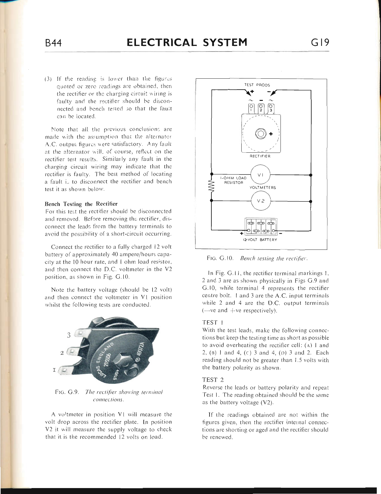
a-l-
844 ELECTRICAL SYSTEM Gr9
(3) lf tlie readirrg is loi'er than tl.rc fisLi.;:.i
quoted oi zerc ieadings a|e obtained. thert
the rectifier or thc chargils circuil lriling is
iar,rlty anC the rcr-tifier shoirld he discon-
llected and hench teslecl .io that the 1'auit
c:rri be located.
Note that ail the previous conclusion: are
maCe v,ith the ass:umpticrn thai tiie altelnatr:i.
A.C. outpni figurcs r,r ere satislactorv. A. ny lar-rlt
lrt the a-lternator' ..1'ill. o1l course. reflr-,ct on trre
rectifiei tesf results. Similarly any lault in the
chargirrg circuit wiring mzry indicate that the
rectifier is lar-rlty. The best method ol locating
a far-rlt i- to disconnect the rectifier and berrch
lest il irs shou n bclor .
Bench Testing the Recti{ier
For tliis te:;t the rectifier sl'rould be disconnected
and removed. Before removing tho rectifier, dis-
connect the leads from the battery terminals tcr
avoid the possibility of a short-circuit occurrir.rg.
Connect the rcctifier to a fully cl.rarged 12 volt
battery of approrimately 40 iimpere/hours capa-
city at the l0 hour rate, and 1 ohm load resistor.
and then connect the D.C. voltmeter in the V2
position, as shown in Fig. G.10.
Note the battery voltage (shoLrld be l2 voltl
arrd then connect tl.re voltmeter in Vl position
rvliilst tl.re fc.llowing tests are conducted.
Frc. G.9. The rec'tifier shott'ing lerntinal
r ttntl(t li0n3.
A vortmeter in position Vl rvill measure the
volt drop across the rectifier plate. In position
V2 it uill measure the supply voltage to check
that it is the recommended l2 volts or.r load.
Ftc. G. 10. Rent'lt testing tlte rectifier.
ln Fig. G.ll, the rectifier tern.rinal markings l.
2 arrd 3 are as showrr physically in Figs G.9 and
G.10, rvhile termina[ 4 represents the rectifier
cer,tre bolt. I and 3 erre the A.C. input ternrinals
while 2 and 4 are the D.C. oLttput terminals
( ve and rve respecrively).
TEST I
With the test leads, make the lollowing coltnec-
tiorrs but keep the testing time as short as possible
to avoid overheating the rectifier cell: (e.) I and
2, (n) I and 4, (c ) 3 and 4, (o) 3 and 2. Each
reading should not be greater than 1.5 volts with
the battery polarity as shown.
TE,ST 2
Reverse the leads or battery polarrit,v and repeat
Test l. The reading obtained should be the same
as the battely voltage (V2).
If tlre readings obtained are not witliin the
ligures given. then the rectifier ir.rternal connec-
tions zrre shortirrg or aged and the rectifier should
be renewed.
I-OHM LOAD
RESISTOR
VOLTMETERS
www.bsaunitsingles.com
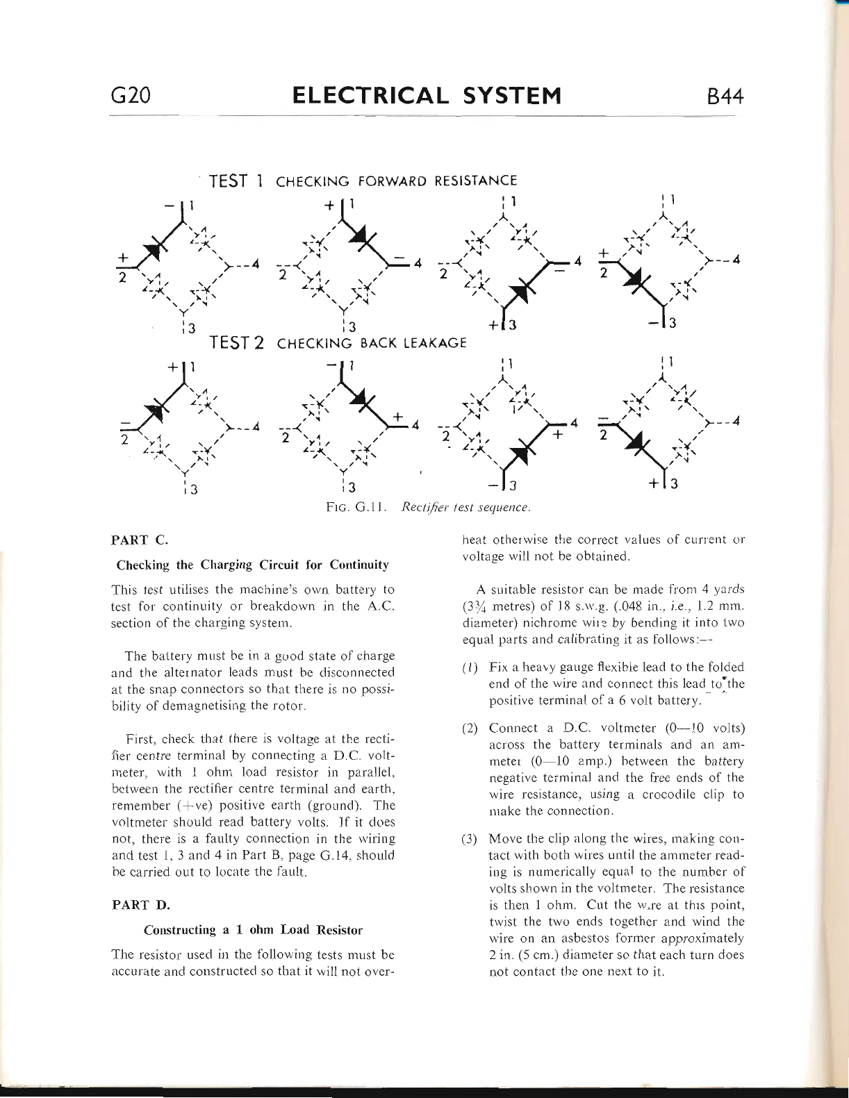
G20 ELECTRICAL SYSTEM 844
.l{
I
lit
';{..
lr
A
2-t
l/ 'r
TEST 1 cHrcrtNc FORWARD RESISTANCE
+\,
.-{
'^'l t
4 --<
t\,
L Yr.
z_r-
/'r
lr ir
A
'>--4
t-t1t
TEST 2
I
. IY:
lg
\
+
LEAKAGE
,-_{
'>-- 4
r-{
,){'
3
. -t{t
')\,
z Ytt
z-r\
CHECKING BACK
\/
-;I'
>--4 ? r,t
L f ta
,-i.
ir
Frc. G.11.
PART C.
Checking the Charging Circuit for Continuity
This test utilises tl"re machine's own battery to
test for continuity or breakdown in the A.C.
section of the charging system.
The battely must be in a gc'od state of charge
and the alternator leads must be disconnected
at the snap connectors so that there is no possi-
bility of demagnetising the rotor.
First, check that there is voltage at the recti-
fier centre terminal by connecting a D.C. volt-
neter, with I ohni load resistor irt parallel,
between the rectifier centre terminal and earth,
remember (fve) positive earth (ground). The
voltmeter should read battery volts. lf it dcres
not, there is a faulty connection in the wiring
and test 1,3 and 4 in Part B, page G.14, should
be carried out to locate the fault.
PART D.
Constructing a 1 ohm Load Resistor
The resistor used in the following tests must be
accurate and constructed so that it will not over-
Rect iJier test se(luence.
heat otherwise the correct values ol curtetrt or
voltage will not be obtained.
A suitable resistor can be made front 4 yards
(3:zi metres) of l8 s.rv.g. (.048 in., i.e., 1.2 mm.
diameter) nichrome r,viIe by bending it into two
equal parts and calibrating it as follorvs:--
(1) Fix a heavy gauge flexible lead to the folded
end of the wire and connect this lead to"the
positive terminal of a 6 volt battery.
(2) Connect a D.C. voltmeter (0-10 volts)
across the battery terminals and an am-
meter: (0-10 amp.) between the battery
negative terminal and the free ends of the
wire resistance, using a crocodile clip to
trrake the connection.
(3) Move the clip along the wires, making con-
tact with both wires until the ammeter read-
ing is numerically equal to the number of
volts shown in the voltmeter. The resistance
is then 1 ohm. Cut the w're at thrs point,
twist the two ends together and wind the
wire on an asbestos former approximately
2 in. (5 cm.) diameter so that each turn does
not contact the one next to it.
^ i\
ls
\/
-iK
, /'1
42 'r1,
' '7{.
lr
,^>y,
www.bsaunitsingles.com
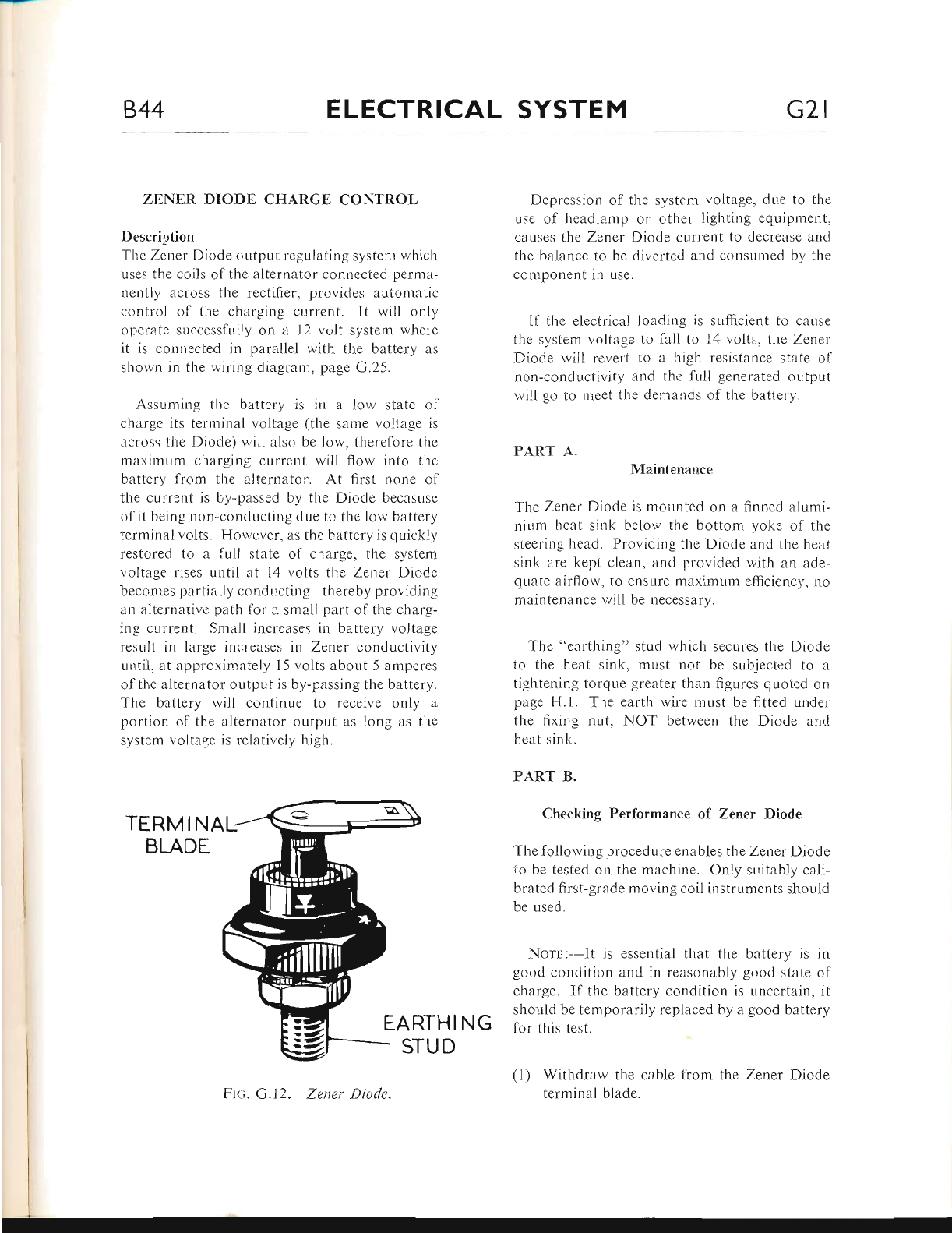
844 ELECTRICAL SYSTEM G2l
ZENER DIODE CHARGE CONTROL
Description
The Zener Diode output legulating systenl whicl-i
uses the coils olthe alternator connected peima-
nently across the rectifier, provides automaiic
control of the charging clrrrent. lt will only
operate successfully on a l2 volt system where
it is connected in parallel with the battery as
sholi'lr in the wiring diagranr, page G.25.
Assuming the battery is in a low state ol
charge its terminal voltage (the same vcitage is
across the Diode) r.r'it[ also be low, therelore the
maximum charging current will flow into the
battery lrom tl-re alternator. At first none of
the current is by-passed by the Diode becasuse
of it being non-conductirrg due to the lo'nv battery
terminal volts. However, as the t"attery is cluickly
restored to a full state of charge, the systern
voltage rises until at l4 volts the Zener DioCe
beconres partially conducting. thereby providing
ar.r alternative path for a smzril part of the charg-
ing curlent. Small increaseg in battery voJtage
result in large incr"ease-s in Zener conductivity
until, at approximately l5 volts about 5 amperes
ofthe alternator output is by-passing the battery.
The battery will continue to receive only a
portion ol the alternator output as long as the
system voltage is relatively high.
TERM I NAL
BLADE
EARTHING
G
Depression of the system voitage. due to the
use ol headlamp or other lighting equipment,
causes tlie Zener Diode current to decrease and
the balance to be diverted and consumed bv the
component in use.
Il the electrical loar|ng is sulicient to cause
the system voltage to iali to 14 volts, tl-re Zener
l)rode rvill revert to a high resistance state clf
non-condu.ctivity and tht, full generated output
will go to nreet the demancs of the batlety.
PART A.
Mainlenance
The Zener Diode is monnted on a linned alurni-
nium heat sink belor,v the bottom yoke of the
steering head. Providing the Diode and the heat
sink are kept clean, and provided with an ade-
quate airllolv, to ensure maximum efficiency, no
maintenance will be necessary.
The "earthing" stud which secures the Diode
to the l-reat sink, must not be sub_iected to a
tightening torque greater than figures quoted on
page l{.1. The earth wire must be fitted under
the fixing nut, NOT betrveen the Diode and
heat sink.
PART B.
Checking Performance of Zener Diode
The follorving procedure enables the Zener Diode
io be tested on the machine. Only sLritably cali-
brated first-grade moving coil instruments shoulcl
be used.
Norr,:--lt is essential that the battery is in
good condition and in reasonably good state of
charge. If the battery condition is uncertain, it
should be temporarily replaced by a good battery
lor this test.
Withdraw the cable from the Zener Diode
terminal blade.
Zener f)irtde.
STUD
www.bsaunitsingles.com
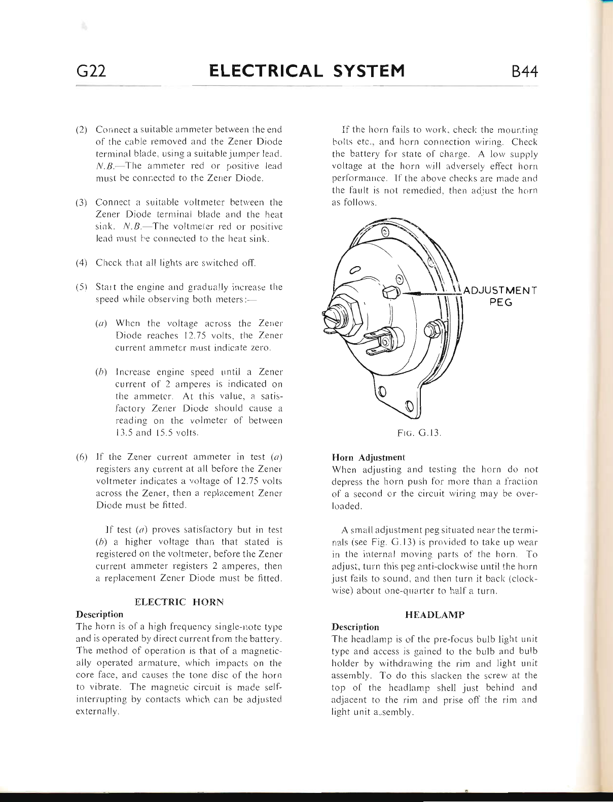
G22 ELECTRICAL SYSTEM 844
(:.)
(3)
Connect a suitable ammeter betrveen the end
of the cabie removed and the Zenel Diode
terminal blade, r-rsing a suitable jLrmper lead.
N.B. The ammeter red or pc.siti.,,e leacl
rnust L.e connected to the Zener Diode.
Connect a suitable voltmeter hetn,een the
Zener Diodu' termin:rl blade and the heat
sink. N.B. The voltmeler red or positive
lead must tre connected to the heat sink.
Chcck that all lights are switched off.
Start the errgine and gradually increasc the
speed wliile observing both meters:-
(u) Whcn the voltage across the Zerier
Diode reaches 12.75 volts. the Zener
current ammetsr must irrdicate zero.
(6) Inclease engine speed until a Zener
current of 2 arrperes is indicated on
the ammeter. At this value. a satis-
factory Zener Diode shor-rld cause il
reading on the volmeter ol betr.veen
ll.5 and t5.5 ', olrs.
(6) Il the Zener clrrrent ammeter in test (a)
registers any current at all before tlre Zener
voltnreter indicates a voltage of 12.75 volts
across the Zener, then a replacement Zener
Diode must be fitted.
lf test (a) proves satisfactory br-rt in test
(b) a higher voltage than that stated is
registered on the voltmeter, before the Zener
current ammeter registers 2 amperes, then
a replacemer:/L Zencr Diode mr-rst be fitted.
EI,ECTRIC HORN
Description
The liorn is of a high frequency single-riote typre
and is operated by direct current from the battery.
The method ol operation is that of a magnetic-
ally operated armature, which impacts on the
core face. and causes the tone disc of the horn
to vibrate. The magnetic circuit is rnaCe self-
inlerruptin-e by contacts which can be adjustecl
externally.
If the horn fails to work. checl., the mour,tinq
bolts etc.. and horn connection rviring. Check
the battery lor state of cltar-se. A low supply
voltage at the horn rvill ..id.",ersely eflect horrr
performarrce. If the above checks are made and
the fault is not remedied. then aciiust the hori'r
as follows.
\no.lusrueNr
PEG
Frc. G.13.
Horn Adjustment
When adjusting and testing the horn do not
depress the horn pusl'r for more than a liaction
of a second or the circuit u,iring may be cver-
loaded.
A small adjr-rstment peg sitr-rated near the termi-
nals (see Fig. G.l3) is provided to take up wear
in the internal moving parts ol the horn. To
adjust, turn this peg anti-clockwise until the hon.r
just fails to sound, and then turr-r it bacl< (cJock-
wise) about one-qll.irter to l..alf a turn.
HEADLAMP
Description
The headlamp is c.f the pre-focus bulb light unit
type and access is gained to the bulb and bulb
holder by withdrawing the rim and light urrit
assembly. To do this slacken the screw at the
top of the headlamp shell just behind and
adjacent to the rim and prise off the rim :rnd
light unit a-sembly.
(4)
(5)
www.bsaunitsingles.com
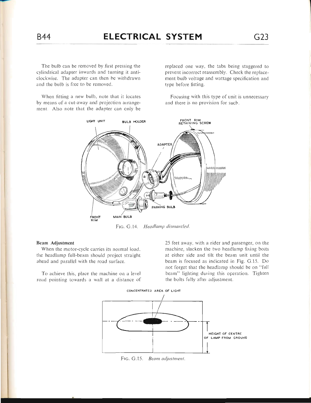
B.44 ELECTRICAL SYSTEM G23
'fhe bulb can be removed by first pressing the
cylindrical adapter inwards and turning it anti-
clockwise. The adapter can then be withdrarvn
and the bulb is free to be removed.
When fitting a new bulb, note tl-rat it locates
by means of a cut-away and projection arrange-
nrent. Also note that the adapter can only be
LIGTfT UNIT EULB
replaced one way, the tabs being staggered to
prevent ilcorrect reassembly. Check the replace-
ment bulb voltage and wattage specification and
type before fitting"
Focusing r.vith this type of unit is unnecessary
arrd there is no provision for such.
FRONT RIM
RETAINING SCREW
25 feet away, rvith a rider arnd passenger, on the
machine, slacken the two headlamp fixing boits
at either side and tilt the beam unit until the
beam is locused as indicated in Fig. G.15. Do
not forget that the ireadlamp should be on "full
beam" lighting during this operation. Tighten
the bolts fi,rlly alter ardjustment.
AREA OF LICHT
Beam Adjustment
When the motor-cycle
the headlamp full-beam
ahead and parallel with
To achieve this, place
road pointing towards
carries its nolmal load"
should project straight
the road surface.
the machine on a level
a wall at a distance ol
Ftc. G. 15. Beont adjrrstnrcnt
IIEIGHT OF CEN1RE
OF LAMP FROM CROUNO
ADAPTER
Ftc;. G. 14. Heodlamp dismantled.
www.bsaunitsingles.com
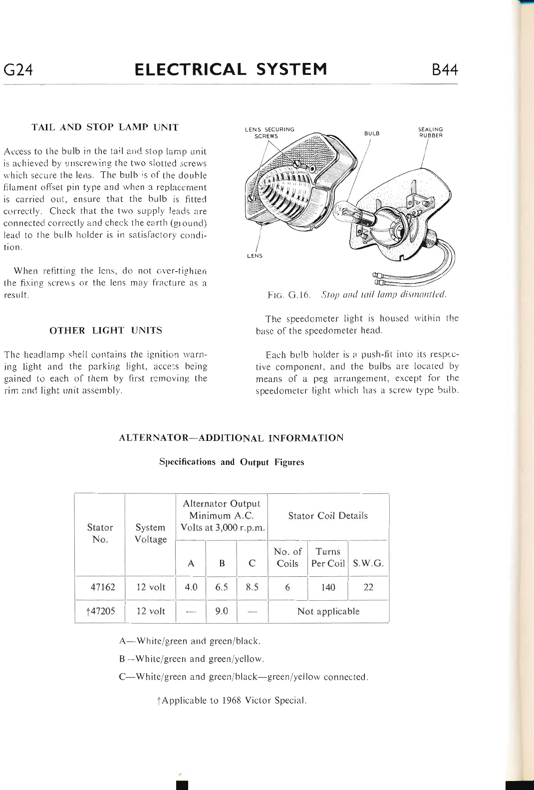
G24 ELECTRICAL SYSTEM 844
TAIL AND STOP LAMP UNIT
Access to 1he bulb in the tail ancl stop lamp unit
is achievecl by ,-rnscrer,l'ing the two slotted screws
lvhich secure the lens. The bulb is of the double
filament offset pin type and when a replacerrrent
is carried out, ensure that the bulb is fitted
correctly. Check tlrat the two supply leacls are
connected correctly and check the earth (ground)
lead to the br.rlb holder is irr satislactory condi-
tion.
When refitting the iens, do not over-tighten
the fi>,.ing -qcre\\s or the lens may ft'ttcture as a
result.
OTHER LIGHT UNITS
The headlamp shell c-ontains the ignitiou warn-
ing light and the parking light, acce:s being
gained to each of them by first rcrroving the
rim and light unit assernbly.
Frc. G.16. Stop and tail lamp disntantled.
The speedometer lighl is housed within the
base of the speedometer head.
Each bulb l-rolder is a push-fit into its resp€c-
tive component, and the bulbs are located by
means of a peg arrangement, except for the
speerlometer light rvhich has a screw type bLrlb.
Stator Coil Detaiis
s.w.G.
Not applicable
ALTERNATOR-ADDITIONAL INFORMATION
Specifications and Output Figures
Alternator Output
Minimum A.C.
Volts at 3,000 r.p.mStator
No.
41162
t4120s
System
Voltage
22
A-White/green and green/black.
B -White/greeri and green/yellow.
C-White/green and green/black-green/yellorv connected.
Tnrns
Per Coil
tApplicable to 1968 Victor Special
www.bsaunitsingles.com
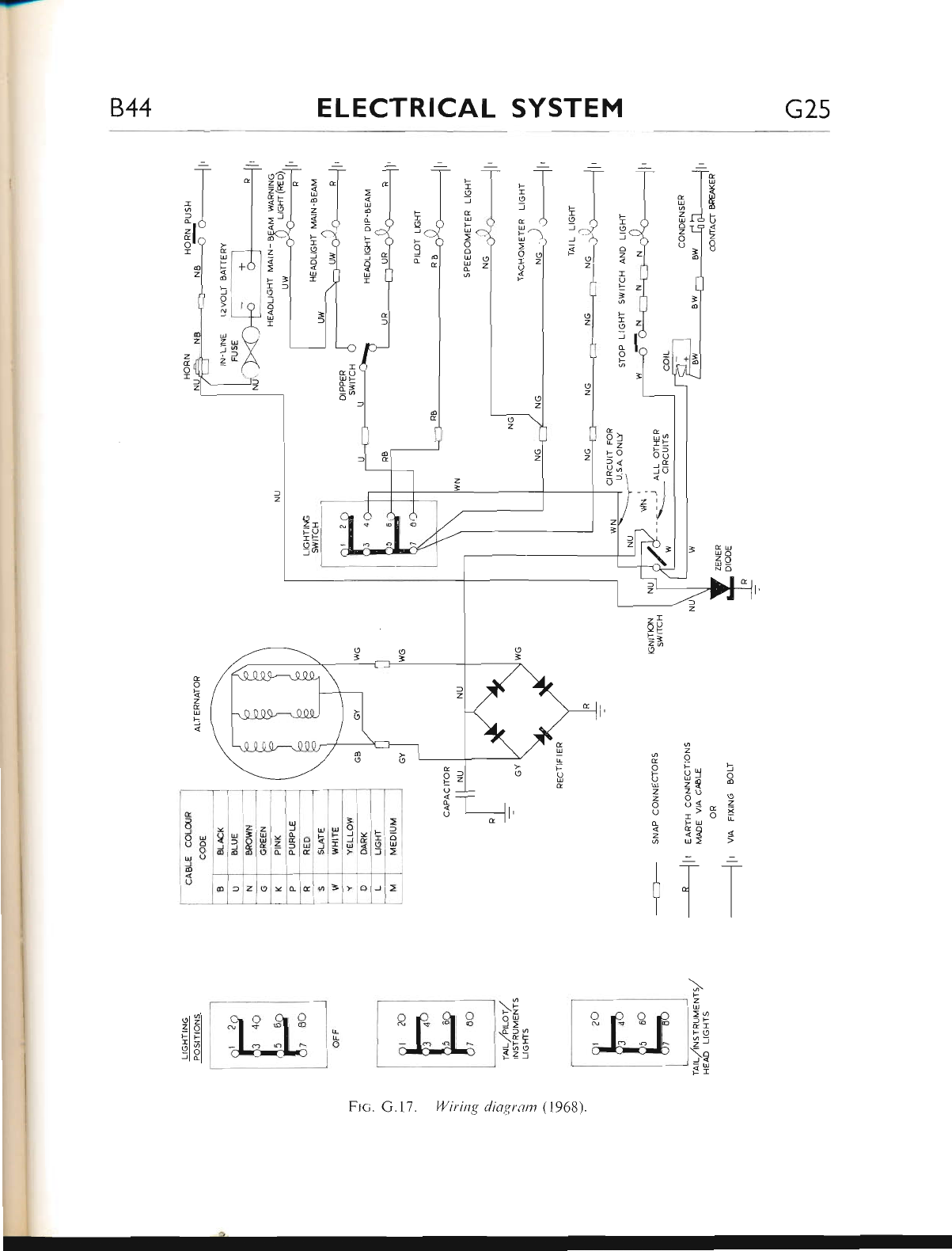
844 ELECTRICAL SYSTEM G2s
f*
IU
IY
IH
rlu
.Tg
lo
;l u
z
X g5 d
Y) 2e o
4 7o o
6 d< - =
o -> X x
d FU
I 1?
6 u>
::
I]_T
rtt
;F
z
U
>o
fF
CI
FO
G
U
z
U
o
z
o
U
F
I
a
J
F
I
c
Its
:E
JO
I
- -- I
z tl
= tr/
1l
F
r
o
J
o
z
I
U
t
]
F
I
I
J
c
o
F
F
I
o
l
J
trz
F
-
(9
J
c
U
F
U
o
I
U
F
I
f
t
U
F
U
o
o
U
U
c
U
d
L
o
F
I
o
J
o
u
I
r
l
o
z
c
o
Ic
U
E
@
f
o
a
U
z
J
zI
co
UT
&t_
o
d
o:
Lz
to
?<
Yo
O
o
2T
L-U
iL
o=
-a
2e
I
c
U
I
F
O
U
&
o
<
z
E
U
5
2i 3l
Elbl
Jl al
E _l
oJt
E-l
o --l-
S -r-
6 L-]t,
r I'
\F
r-z
9E
.cf9
)F!
=oOaz-
('
z
z
t
]<
B
6
I
z
F
I
o
J
o
U
I
G
9
OU
o8
uL)
J
o
O
lt
{sE
JIJ d
'l'" z
U
U
c
oz
o
U
J
G
E
f, o
U
t
.1.
d=
=
o
JC
ul<
>1o
i
l
F
I
J
l
o
U
.].]= oE,i=
I'1" J
3*
Ftc. G.17. l4/iring diagrom (1968)
www.bsaunitsingles.com
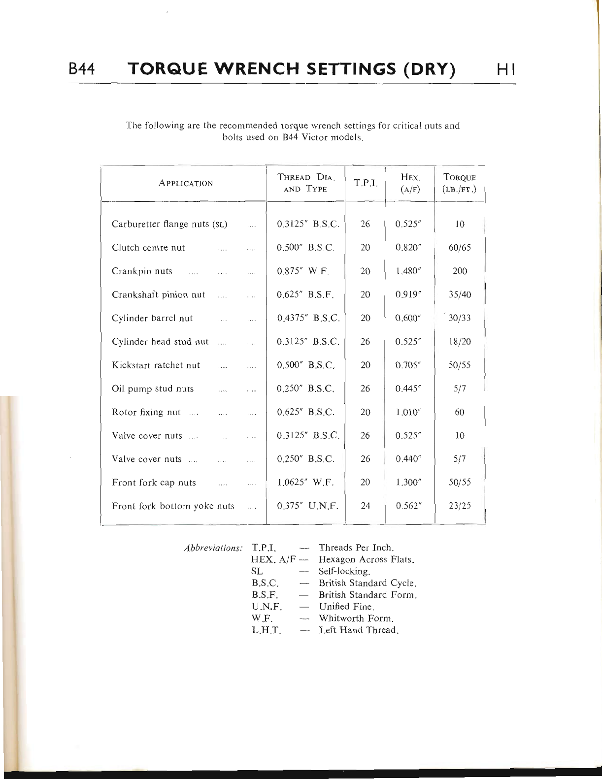
844 TORQUE WRENCH SETTTNGS (DRY) HI
The following are the recommended torque wrench settings for critical nuts and
bolts used on 844 Victor models.
Appltc,q.rroN
Abbreviqtions: T.P.l.
HEX. A/F -
SL
B.S.C.
B.S.F.
U.N.F.
w.F.
L.H.T.
Threads Per Inch.
Hexagon Across Flats.
Self-locking.
British Standard Cycle.
British Standard Forrn.
Unified Fine.
Whitworth Form.
Left Hand Thread.
Toneun
(rn./rr.)
10
6016s
200
3sl4A
30/33
18120
s0/55
\11
60
10
sl7
5o/ss
2312s
0.3125',
0.500'
0.87 5',
0.625',
0.437 5',
43125',
0.s00"
0.250'
0.625',
0 "3125',
0.2s0'
r.062s'
0.37s'
26 I 0.s2s'
20 I 0.820',
20 I 1.480',
20 I 0.919'
20 I o.ooo'
26 I o.szs'
20 0.J05"
26 ) 0.44s',
20 I 1.010"
26 ) 0.SZS',
26 ) o.qqo'
20 I 1.300"
24 ) 0.s62',
Carburetter flange nuts (sl)
CIutch centre nu[
Crankpin nuts
Crankshaft pinion nut
Cylinder barrel nut
Cylinder head stud nut
Kickstart ratchet nut
Oil pump stud nuts
Rotor fixing nut
Valve cover nuts
Yalve cover nuts
Front lork cap nuts
Front fork bottom yoke nuts
www.bsaunitsingles.com
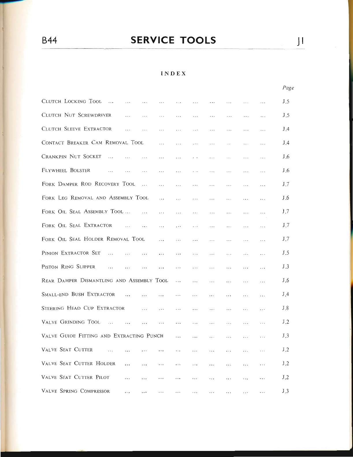
844 SERVICE TOOLS Jr
INDEX
Clurcn Nur ScnnwDRrvER
Cr-urcH STEEvE Exrracron
ClurcH LocxrNc Toor-
CnaNrpru Nur Socrur
FLvwttsnr- Bor-srsn
PrNroN ExrRa.croR Spr
PrsroN RrNc Srrppnn
Vl,Lvr GRrNuNc Tool
V.q,LvB Gurpn FrtrrNc
Valvr Srar Currpn
CoNrl.cr BnE.q.rnR Calr Rpuovar Toor
Fonr Dauprn R.oo Rrcovrny Toor-
Fonx Lnc REuov.q.r lNn Assrirlsly
J.6
J.6
1.7
J.5
J.1
1.1
J.l
J.5
J.3
J.6
J"4
J.8
1.2
J.3
J.2
J.2
1"2
J.3
Fonr On Ssar Assnr4nry Toor
Fonr On Srar ExrnLcron
Fonr Otr Srar, Holorn Rrtlrova.r Tool
REa.n Dllrppn DrslrrrNruxc
Slrar-r-pNn Busu ExrnacroR
SrsnRrNc Hnao Cup Exrnacron
aNo Assnl.rsrv Toor-
aNn Exrnacrrl.lc PUNCH
Varvp Srnr CurrEn Hor-unn
V,q.rvr Sr,q.r CurrrR Prr-or
Valvr Spnwc Conapnnsson
Page
J"5
J.5
J.4
J.4
www.bsaunitsingles.com
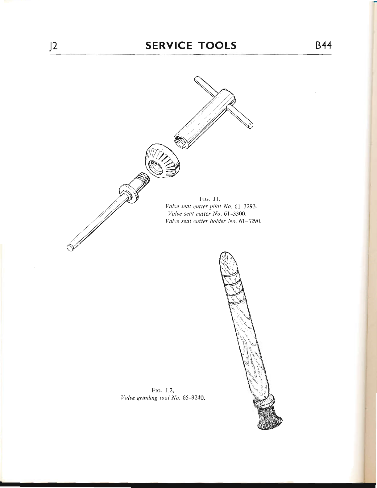
l2 SERVICE TOOLS B^44
Ftc. Jl.
Valve seat cutter pilot No.6I-3293.
Valve seat cutter No.61-3300.
Valve seat cutter holder No.6l-3290"
Ftc. J.2.
Valve grinding tool No.65-9240.
www.bsaunitsingles.com
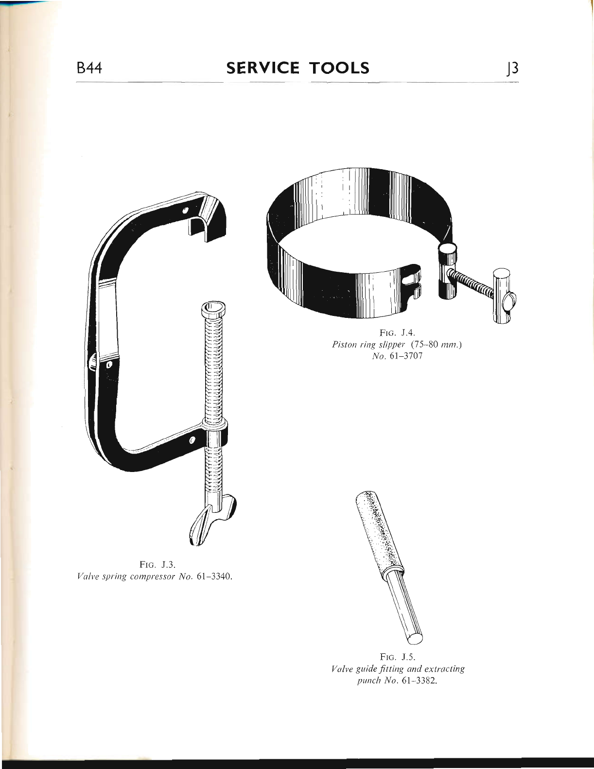
u-r-
844 SERVICE TOOLS J3
Frc. J.3.
Yalve spring compressor |tlo. 6l-3340.
Frc. J.4.
Piston ring slipper (75 80 ntnt")
No.61-3707
Frc. J.5.
Valve gtride ftting and extracting
punch No. 6l-3382.
www.bsaunitsingles.com
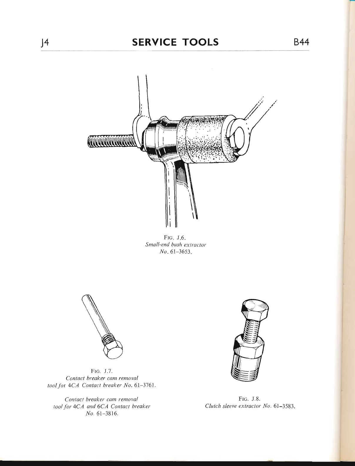
J4 SERVICE TOOLS 844
Frc. J.6.
S mall- e nd bus h ext r act o r
No " 61-3653.
Frc. J.7.
Contact breaker cam remaval
toal .ftir 4CA Contact breaker No. 6l-3761
Contact breaker cam removal
tool Jbr 4CA and. 6CA Contact breaker
-n/o. 61-3816.
Frc. J.8.
Clutch sleeve extractor No. 61-3583.
www.bsaunitsingles.com
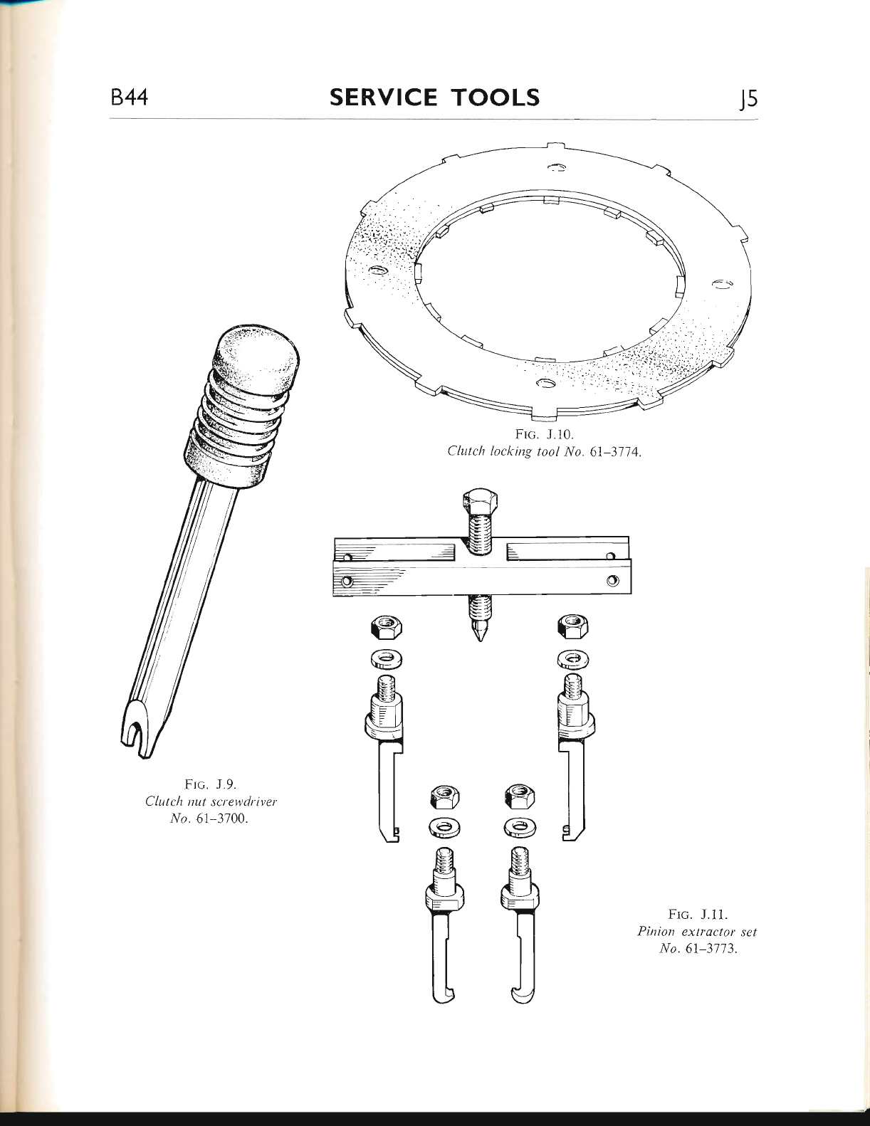
844 SERVICE TOOLS Js
Frc. J.i0.
Clutch loclcing tool No. 6l-3714.
@
fA')
t\-/
ffi
T
@
@
fl
Frc. J.9.
C lutch nut screyvdriver
l/o. 6l-3700.
Frc" J.11.
Pinion extlactor set
No. 61-3773"
@
@)
\z
fl
@
ae)
V
g
ff
www.bsaunitsingles.com
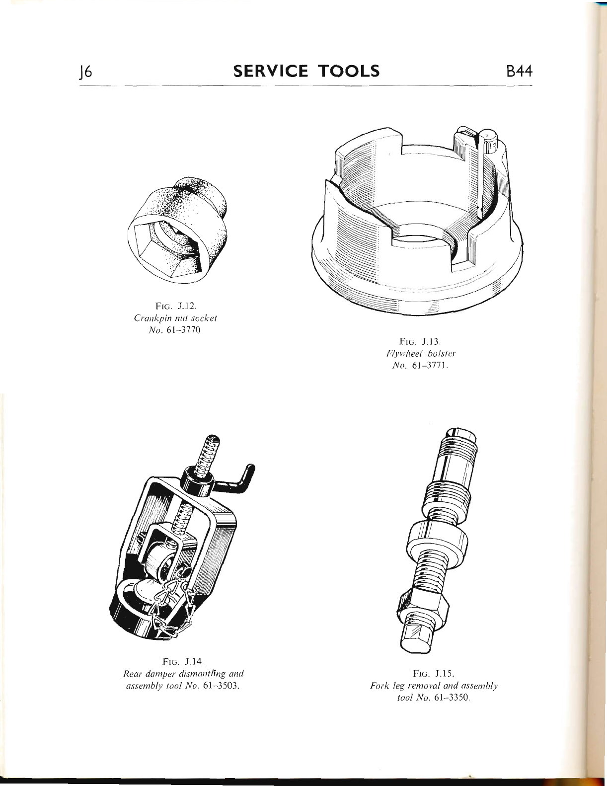
)6 SERVICE TOOLS 844
Ftc. J. t2.
Crankpin nLtt socket
No.61 31lA
Frc. J.14.
Rear damper dismantllng and
assembly tool No. 6l-3503"
Frc. J.13.
Flywlteel bolster
No. 61-3711.
Frc. J.15.
Fork leg removal and assembll,
tool No.61-3350.
www.bsaunitsingles.com
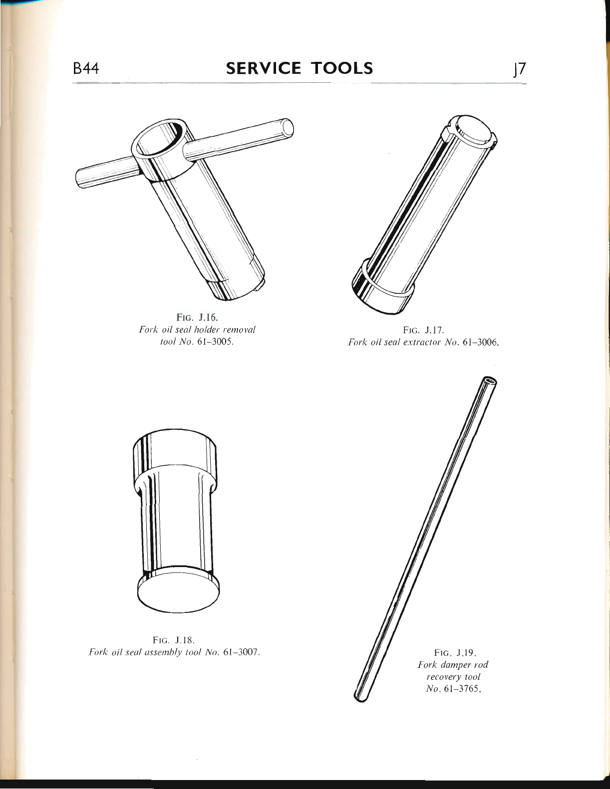
--
844 SERVICE TOOLS 17
Frc. J.16.
Fork oil seql holder removal
tool No.6l-3005.
Frc. J.18.
Fork oil seal ussembly tool llo. 6l-3007.
Frc. J.17.
Forlt oil seal extrector i/o. 6l--1006"
Frc. J.19.
f ork damper rod
recovery tool
No.61-3765.
www.bsaunitsingles.com
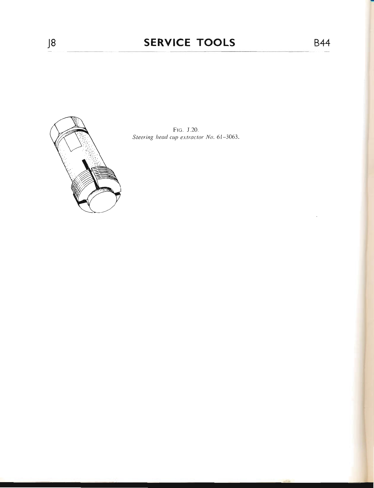
J8 SERVICE TOOLS B.44
Frc. J.20.
Steering head cup extractor No.6l-3063.
www.bsaunitsingles.com
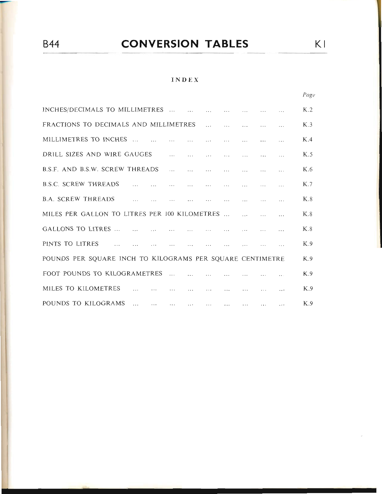
844 CONVERSION TABLES KI
INDEX
INCHESiDECIMALS TO MILLIMETRES
FRACTIONS TO DECIMALS AND MILLIMETRES
MILLIMETRES TO INCHES
DRILL SIZES AND WIRE GAUGES
B.S.F. AND B.S.W. SCREW THREADS
B.S.C. SCREW THREADS
B.A. SCREW THREADS
MILES PER GAI,LON TO LITRES PER IOO KILOMETRES
GALLONS TO LITRES
PINTS TO LITRES
POUNDS PER SQUARE INCH TO KILOGRAMS PER SQUARE CENTIMETRE
FOOT POUNDS TO KILOGRAMETRES
MILES TO KILOMETRES
POUNDS TO KILOGRAMS
Page
K,2
K.3
K.4
K.5
K.6
K.7
K.8
K.8
K.8
K.9
K.9
K.9
K.9
K.9
www.bsaunitsingles.com
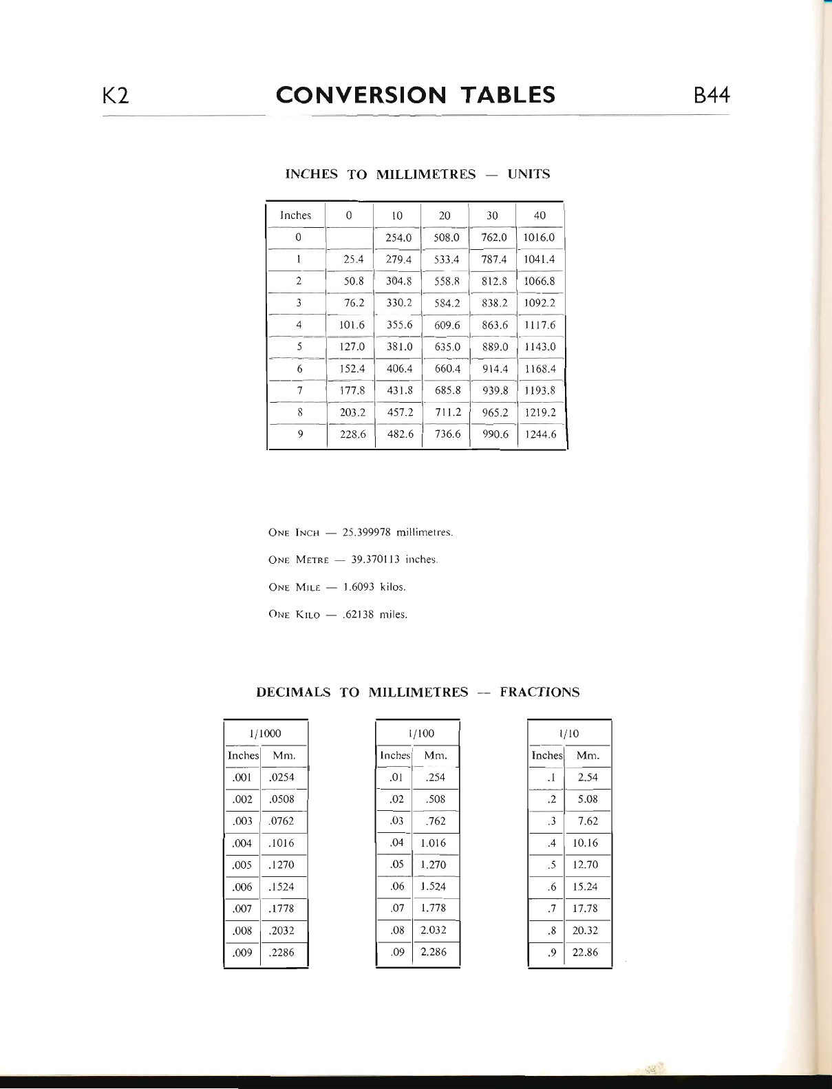
K2 CONVERSION TABLES 844
Inches 010 20 30 40
0254.0 508.0 762.0 1016.0
I25.4 279.4 533.4 '787.4 1041.4
250.8 304.8 558.8 812.8 1066.8
376.2 330.2 584.2 838.2 t092.2
410 r.6 3s5.6 609.6 863"6 1117.6
5t27.0 381 .0 635.0 889.0 l143.0
6t52.4 406.4 660.4 914.4 1 168.4
'7 177.8 43 1.8 685.8 939.8 1 193.8
8203.2 457.2 711.2 965.2 t219.2
9228.6 482.6 736.6 990.6 t244.6
INCHES TO MILLIMETRES - UNITS
ONr INcs - 25.3999'78 millimetres.
ONp Mprnr - 39.370113 inches.
ONE Mrr-E - 1.6093 kilos.
oxe Krro - .62138 miles.
DECIMALS TO MILLIMETRES -- FRACTIONS
l/r00
Mm.
.01 .254
.02 .508
.03 .762
.04 1.0t 6
.05 1.270
.06 1.524
.07 1.778
.08 2.032
.09 2.286
1/1000
nches Mm.
.001 .0254
.002 .0508
.003 .0762
.004 .1016
.005
.006
.t270
.t524
.007 .t'178
.008 .2032
"cro9 .2286
l /10
Inches Mm.
I2.54
') 5.08
7.62
.4 10.16
.5 12.70
.6 15.24
.7 17.78
.8 20.32
.9 22.86
www.bsaunitsingles.com
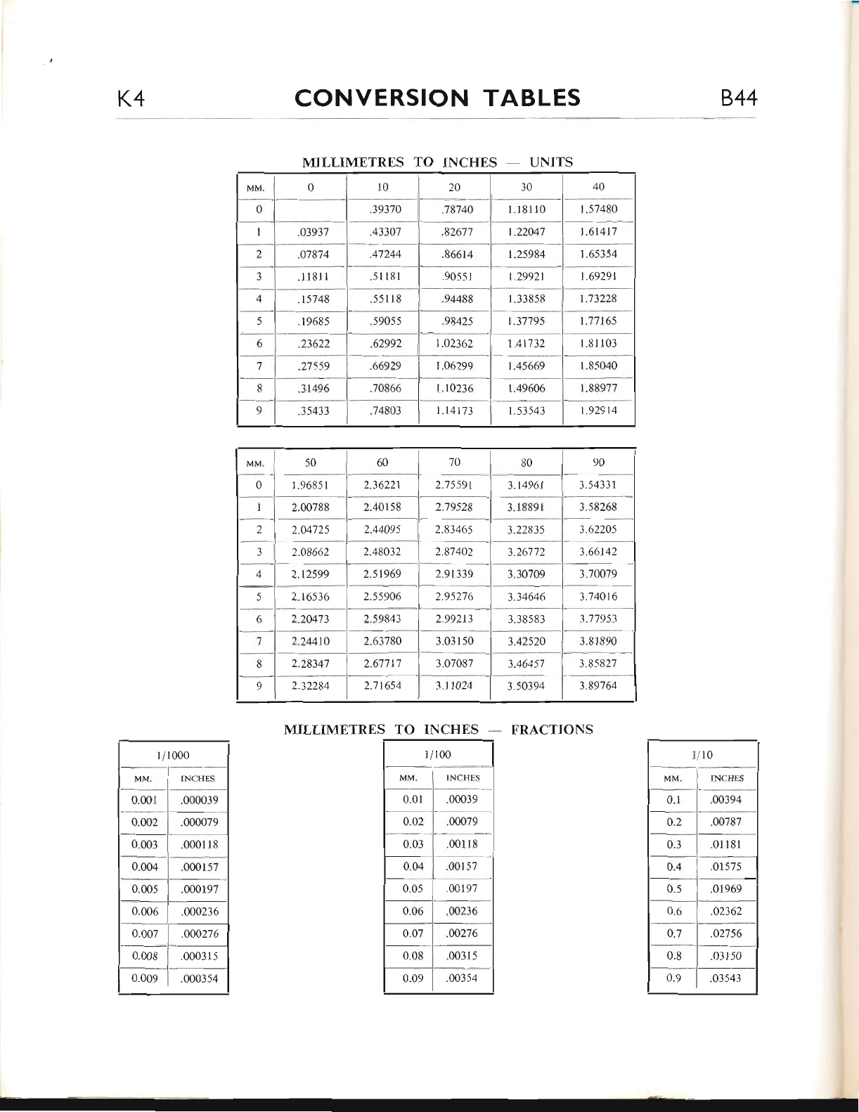
K4 CONVERSION TABLES 844
"78740
"82677
s6614
1.14t73
t.614t7
I 65354
1.69291
1.73228
.03937
.07874
.1181I
I
2
.
-1
i
-
5
;
7
t
1.25984
1.29921
.51 1B I
.s51 1 8
.1968-s I .59055
.23622 | .62992
.2'7\59 .66929
31496 | .70866
e l .is433 L74803
1 .7'7165
1"81103
1.8s040
1.53543
MILLIMETRES TO INCHES - UNITS
MILLIMETRES TO INCHES - FRACTIONS
1i100
MM- 1 INCHLS
0.0i
0.02
0.03
0.04
0"05
00039
.001 18
"00r57
.00197
0.06 .002-16
0.07
0"08
.00276
.003 l-5
0.09 .00354
2"40158
2.75591
2'79528
3.70079
3.74016
3.22835
3.30709
3.34646
t3B5s3
2.83465
2
.
J
4
5
6
7
B
9
2.16536
2.2047 3 | 2.59843
2.24410 | 2.63780
2.28347 | 2.67717
2.32284 I 2.7 t654
.0001s7
.000197
0.004
0"00.5
0"006
l./10
MM,
0.1
INCH!]S
.00394
0.2
0.3
.00787
"0t l8l
01 5?5
o"5 .01969
0.(l .02362
-02756
JRI50
4.7
0"8
0"9 .03543
www.bsaunitsingles.com
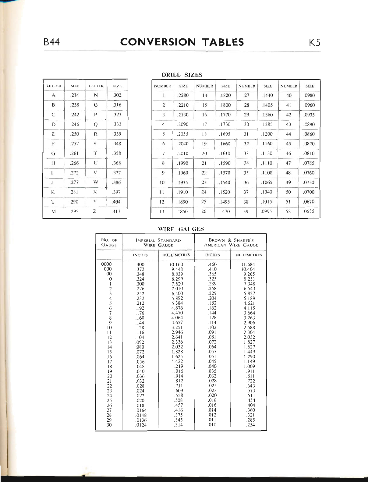
CONVERSION TABLES
DRII,L SIZES
NUlvlBtR
.2280
.22t0
.Il0
"2090
.2055
.2040
.20r0
.1 990
N TJ M RI.]T{
,17
48
4;
50
I,ETTER SIZI I-E'I'I'FR SIZE
.234 N.302
B.2-r8 o316
C.242 P]:J
D.246 o332
E,250 It l-r9
F 257 S348
C.26t T3 5ti
H.266 TJ 368
272
.277 386
K.231 X391
L,290 Y404
M.29\ 7. 413
WIRE GAIIGES
No, op
Gnuce luprnr,qL SrnNo.q.no
Wlnn Gaucr BnowN & Snanpn's
Aunnrcax Wrnl (inucr
INCHES MILLIMEI RES INCHES MII-Lf METR!-S
0000
000
00
0
1
2
"400
3',72
.348
.324
.300
.276
.2s2
.232
.212
.t92
.176
.160
.144
128
.116
.104
.092
.080
.072
.064
.056
"048
.040
.036
"o32
.028
.024
.022
.o20
.018
.0164
.0148
.0136
.0124
10. I 60
9.448
8.839
8.299
7.620
7.010
6.400
5.892
5 384
4.676
4.470
4.064
3.657
3.251
2.946
2"64t
2.336
2.O32
1.828
1.625
1.422
1.219
1.016
.914
"B l2
.7ll
.609
.558
.508
.457
.416
.37s
.345
.314
.460
.410
.365
.3 25
.289
.258
.229
.204
. r82
.t62
.t44
.128
.114
.r02
.091
"081
.o72
"464
.057
.051
"045
.040
.035
.032
.028
.o25
.023
.020
.018
.016
"014
.012
.01r
.0t 0
r 1.684
10"404
9.265
8.251
1.348
6.543
5.827
5.189
4.62t
4.11 5
3.664
3.263
2.906
2.588
2..304
2.052
L827
1.627
1.449
L.290
t.149
r.009
.911
.81 l
.722
.643
.573
.511
.454
404
.360
.321
.285
.254
3
4
5
6
7
8
9
l0
1l
12
l3
14
15
l6
t7
l8
t9
20
21
22
23
24
25
26
27
28
29
30
www.bsaunitsingles.com
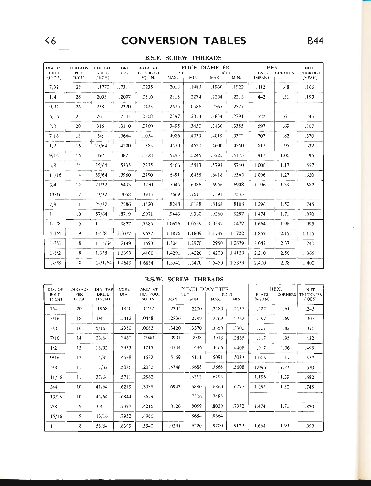
K6 CONVERSION TABLES 844
B.S.F. SCREW THREADS
1.1077
1.2149
AREA AT
THD. ROOT
SQ. IN. FLATS CORNERS
(rrlelN) |
.412 | .48
NTJT
THICKNESS
(lrnlN)
PITCH DIAMETER
NUT I BOLT
r.0472
t.1722
Lr8'7l.
1.4129
1.5450 I 1.5379
.177C
.2055
.238
.16r
27164
-A;
3s164
3e164
18
16
.3430
.4019
.4600
.307
.370
.43'
.495
.557
620
-.68;
ttit6
2132
B.S.W" SCREW THREADS
DIA. OF
BOLT
fiNcs)
THREADS
PER
INCH
DIA. TAT
DRIIL
(rNcH)
CORE
DIA. AREA AT
THD. ROOT
sQ. rN.
P
N
MAX.
ITCH D
:IT
MIN,
AMETE
B(
MAX.
)LT
MIN.
H
FLATS
(unnN)
x.
CORNERS
NIJT
THICKNTSS
(.005)
tl4 20 .1 968 .1860 .0272 2245 2200 21 80 2135 .522 61 .245
slt6 l8 rl4 .2412 .0458 .2836 .2789 .2769 .2722 .597 69 .307
3/8 16 5116 .2950 .0683 .3420 3370 3350 .3300 .707 82 -370
7116 I4 23164 .3460 .0940 .3991 .3938 ,3918 .386s .81 795 .432
lt2 12 t3132 .3933 .t2ts .4544 .4486 .4466 4408 .917 1.06 .495
9lt6 t2 tsl32 .4558 .1632 5169 .511I .5091 .5033 1.006 l.t7 .557
s/8 ll 17132 .5086 .2032 .5748 .s688 .5668 .5608 1.096 t.27 .620
1tlt6 1l 37164 .5711 .2s62 .631 3 .6293 I196 1.39 .682
314 10 4t 164 .6219 .3038 .6943 .6880 .6860 .6797 1.296 1.50 .745
13116 10 45164 .6844 .3679 .7506 .7485
718 93i4 "7327 .4216 8126 .8059 .8039 .7972 1.474 | -71 .870
rslt6 913116 .7952 .4966 .8684 .8664
I8s564 .8399 .5540 "9291 .9220 9200 9129 1,664 r.93 ,995
www.bsaunitsingles.com
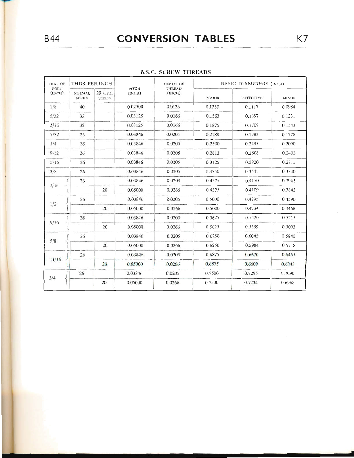
844 CONVERSION TABLES K7
I].S.C. SCREW TIIREADS
0.0312s
.BASIC DIAMETERS (rNcs)
0.1397 i o.tzzt
0.03846
0,03846
0.1983 I 0.1778
0.2295 0.2090
0.2608 ) a.2403
0.3545
0.4170
0"03846
o.05000
rllL6
0.521s
0.6609 | 0.634i
oJrr5 ] oJoro
a.7234 I o.ssra
0.7500
o.7.500
www.bsaunitsingles.com
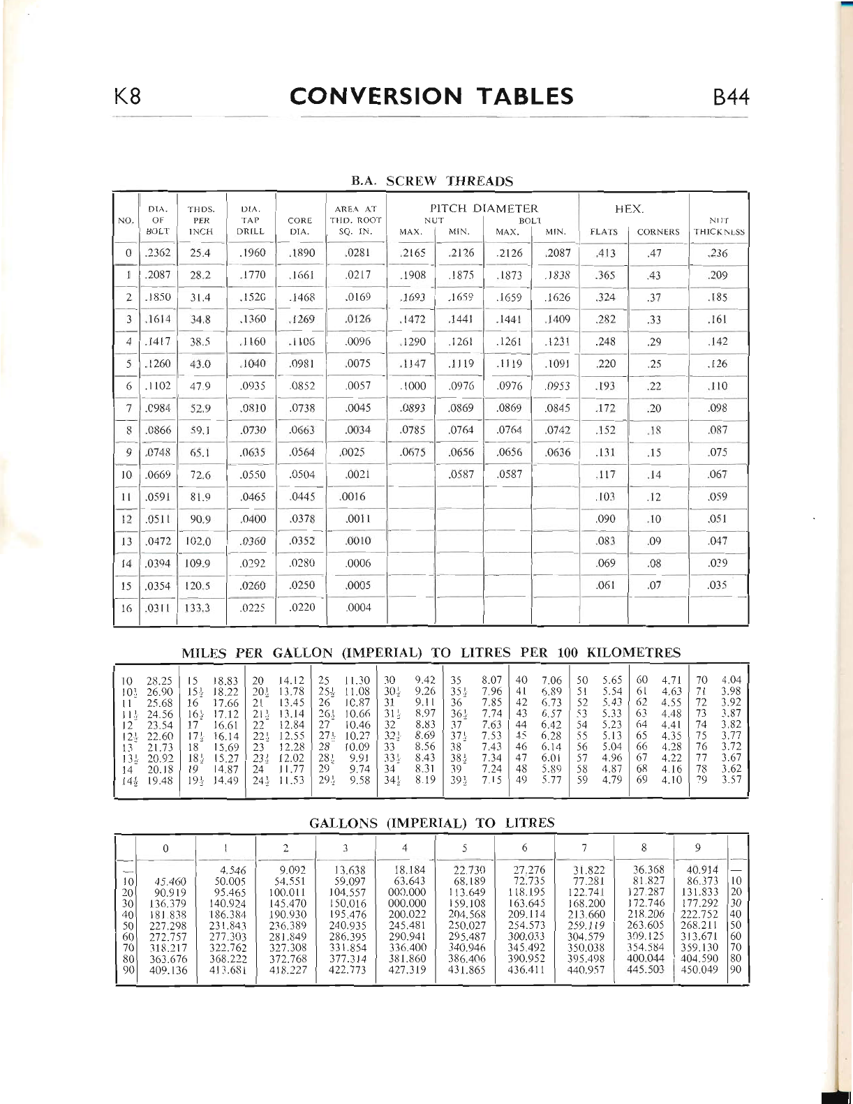
K8 CONVERSION TABLES 844
B.A. SCREW THREADS
fLAI5 I CORNTRS IIHICK\I-SS
ARr,rA. Ar I PlrcH DIAMETER
r ilr). Ro( )T I NL t I ",,'- '
scr. r\. I ver. I \41N. I MAX. I vt'.t.
DIA.
TAP
DRTLL
.t269
.llc5
.0981
.0310
.0352
.0280
.1468
.1 t60
.1 040
.0935
.0663
0564
.0504
.0445
.037u
.026C
.a225 .0220
"2t16
.1 8?5
.1659
.126t
.11 t9
.o976
;s6,
.o764
{)656
.248
.224
lr3
.172
-.15'
1il
.t260
"l 102
-c9,%
.0866
^c?48
.0669
.0591
.051 I
.o4n
MILES ['ER GALLON (IMPERIAL) TO I-ITRES PER lOO KILOMETRES
GAI,LONS (IMPtrRIAL) TO I-ITRES
0
01
t
1j
2
2i
3
3i
4
4)z
28.25
26.90
25.68
24.56
23.54
22.64
21.73
20.92
20.i8
19.48
5
5j
6
6i
7
1l
8
8J
9
9"1
8.83
8.22
7.66
7.12
6.61
6.14
5.69
5.27
4.87
4.49
20
20j
2l
zll
22
22\
23
231.
') /.
)41
4.t2 | 25
3.78 I 25-l
3.45 I 26
-1.14 I 161
?-.84 I 27
r << | ort
2.28 I 28
2.o21 n!
1.77 | 2e
I st I 291,
1."10 | -10 9.42
1.0s | 3ol e.16
c.R7 I 31 9.1 r
0.66 | 3l1 R.97
0.46 | 32 8.83
o.2,1 | 321. 8.69
0.09 I -13 8.-56
9,9r I33t 8.43
s.74 | 3J' 8.3 t
9.58 l3trl 819
35 8.07
35 rl 7 .96
36 7.85
36:, 7.74
37 7.6]
37!. 7.53
38 7.43
381 7 "34
39 7.24
391, 7 15
40 7.06
41 5.89
42 6.73
43 6.s7
44 6.42
-4,5 6.28
46 6.14
47 6.01
48 5.89
49 5.77
so 5.6s | 60 1.7t
sl s.54 | 61 4.63
s2 s.43 t 62 4.55
53 5.33 I 63 4.48
sJ -s.23 I 64 4.41
-s5 s.13 165 4.35
56 s.04 I 66 4.:B
s7 4.s6 | 67 4.22
s8 4.s7 | 63 4.16
59 4.7s 159 4. l0
70
7l
"t2
73
74
75
76
11
78
79
4.04
3.98
3.92
3.8?
3.82
3.71
3"'72
3.67
3.62
3.57
0a34516 189
l--
1o I 4s.460
l0 I 90.919
t0l 136.379
101 18l8-r8
501 227 .298
60 I 272.7 57
70l "r1s.2l7
80 I -163.676
nol 4oe.l36
4.546
50.005
95.465
140.924
I 86.384
231.843
277.303
322.762
368.222
4t 3.6B I
9.092
54.551
1 00.01 i
t45.470
1 90.930
236.38e
281 .849
327.308
372.768
418.221
13.638
s9.o91
I 04.5s7
r 50.016
195.476
240.935
286.395
33 1.854
377.314
422.773
I 8.1 84
63.643
000.000
000.000
200.022
245.481
290.941
336.400
381.860
427.319
22.734
68.1 89
I t3.649
159.103
204.56r1
250.027
295.487
340.946
386.406
431 .865
21 .2'76
72.735
1 18.195
163"645
209.114
f </ <71
300.033
345.492
390.9,{2
436.411
31.822 | -16.168
1'7.28t 1 81.827
122.141 I 127.287
r 68.200 | nz.t+e
21-1.660 | 218.206
2ss.tt9 I :e:.eos
304.579 | _r09.1 25
350"038 | ,rS+.SUq
395 498 | +OO.O++
4409.\'7 1 445.50.1
4A.914
86.37-1
l3 1 .833
177.292
222.152
268.211
313.67 I
359. I 30
40,1.590
450.049
10
20
30
40
50
60
70
80
9Cr
www.bsaunitsingles.com
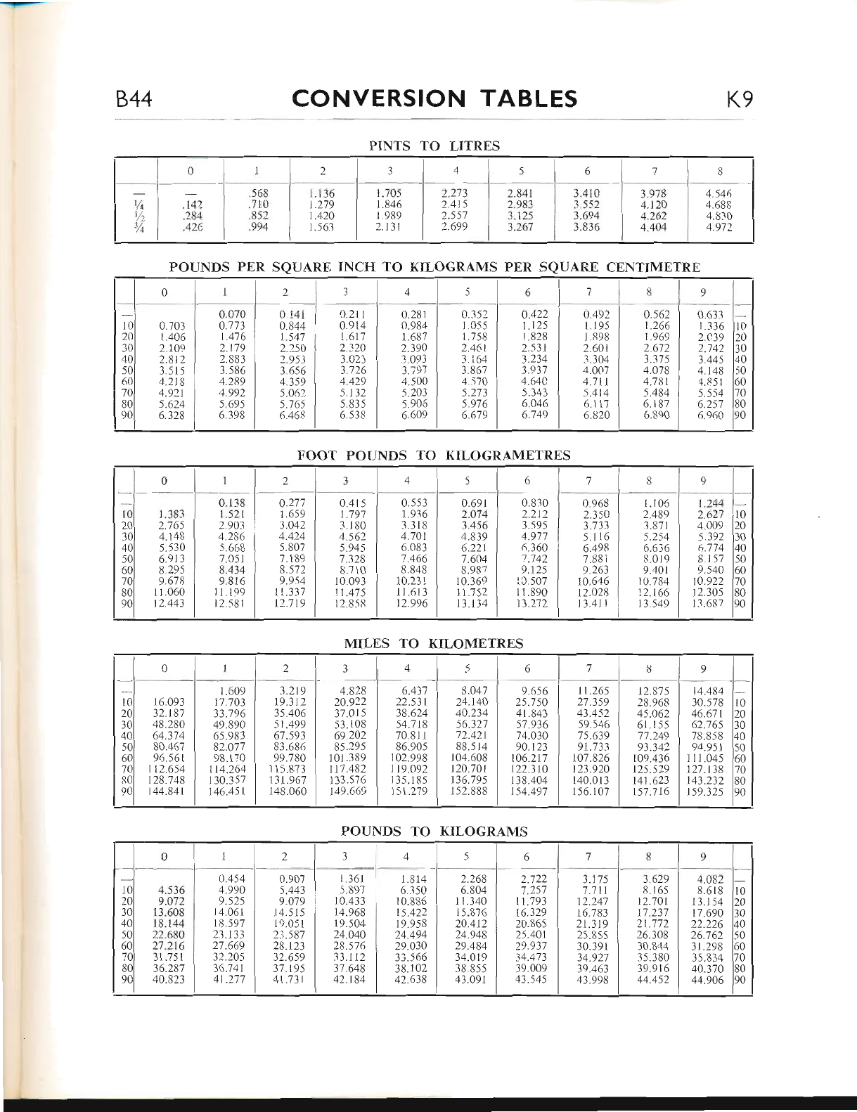
-
844 CONVERSION TABLES K9
.568
.714
.852
.994
1. 136 I t.70s I 2.273
t.279 I t.8+r- I 2.4t5
r.420 I 1.999 I 2"ss7
r.s63 | :.r-rr I z.tgg
PINTS TO LITRES
POUNDS PER SQUARE INCH TO KILOGR.AMS PER SQUARE CENTIMETRE
FOOT PO{JNDS TO KILOGRAMETRES
MILES TO KILOMETRES
0rl2 34567B9
10
2A
30
40
50
60
70
80
90
0.703
1.406
2.1 09
2.812
3.5 15
4.218
4.921
5.624
6.328
0.070 | 0 141
o.zz: I o s44
t"qta I r.s47
z.ng I 2.?so
:.ss: | 2.e51
3.s86 I 3.6s6
+.zss I 4.3s9
+.sgz I s.o6t
s.oss I s.76s
o.:qs I 6.46x
o.ztt
0.914
1.617
2.320
3.023
3.726
4.429
5.132
5.83 5
6.538
0.281
0.984
1.687
2.390
3.093
3.797
4.500
5.203
5.905
6.649
0.352
1.0,s5
1.758
2.461
3.i64
3.867
4.570
5.273
5.976
6"679
o.422
1.125
i.828
2.531
3.234
3.937
4.64C
5.343
6.046
6.749
0.492
1 .195
1.898
2.601
3.304
4.007
4.7 r1
5.4t4
6.117
6.820
o.562
1.266
1.969
2.672
3.375
4.O78
4.781
5.484
6.1 87
6.890
0.633
1.336
2.C39
2.'742
3.445
1.148
4.851
5.554
6.257
6.960
10
20
30
40
50
60
70
80
90
l0
2A
30
40
50
60
70
80
90
0z34s le l j8o
1.Jd-1
2.755
4.148
5.530
6.913
8.?95
9.678
11.060
12.443
0.1 38
1.521
2.903
4.286
5.668
7.051
8.434
9.81 6
I 1.199
12.581
0.277
1.659
3.042
4.424
5.807
7.1 89
8"572
9.954
1r.337
12.719
0.415
1.'797
3.180
4.562
5.945
L)ZA
8.710
10.093
11.475
12.8-5 8
0.553
1.936
3"318
4.701
6.083
7.466
8.848
r0.231
I1.61 3
t2.996
0.6er | 0.830 | 0.e(r8
2.074 1 2.2t2 1 2.150
3.456 1 3.5s5 i 3.73.1
4.839 | 1.e77 | 5.il6
6.22t1 6.360 I 6.498
7.60+ I 7.742 | 7.881
8.s87 I 9. t2s I q.263
to.36q I tc.5o7 I t0.646
il.7s2) lt.sool t2.028
Il.l34 I t3.272| t3.4||
1.105 | 1.244
z.qss I 2.627
:.gzr I 4 ooe
s.zsq ) -s..192
o.e:e | 67i4
g.ors I 8rs7
l.+or I e.540
t0.7s4 | t0.922
12.166 | 12.305
13 549 I l.r.637
10
z0
30
40
50
50
70
30
)0
0I23456 7 89
10
20
30
40
-)(,
60
70
fi0
90
16.093
32.187
48.280
o+-3 l +
80.467
96.561
t 12.6s4
t28.748
t44.841
1.609
17.703
33.796
49.89A
6s.983
82.O77
98. I 70
114.264
I 30.357
146.451
3.219
19.312
35.406
51.499
67.593
83.686
99.780
1 1 5.873
13t.967
148.060
4.828
24.922
37.015
53.1 08
69.202
85.295
101.389
117.482
133.s76
149.669
6.437
22.531
38.624
54.718
70"81 1
86.90s
102.998
I 19.092
135.185
151.279
8.047
24.140
40.234
56.327
72.42.t
88.5 14
104.608
120.7A1
136.79s
1 52.888
9.6s6
25.750
41.843
s7.936
74.030
90.123
t46.217
122.310
138.404
154.497
11.26s
27.3s9
43.452
s9.546
'7s.639
91.733
107.826
123.920
140.013
r 56.1 07
12.875
28.968
4s.062
61 .1 55
77.249
93.342
109.436
125.529
141.623
157 .716
14.484
-10.578
46.67 t
62.76s
78.858
94"951
I I 1.045
127.t38
t43.232
t59.325
IO
20
30
40
50
60
70
80
90
POUNDS TO KILOGRAMS
oll 234 ,5 6789
10
20
30
40
50
60
70
80
go
I 0.4s4
q.sze I 4-ssa
qnrr i o()s
ri.eoi I v.o?i
rs"r++ | r8.s97
22.6B0 I 23.1-13
zt "zte | 27 .56s
lt "751 I 32.205
36.287 | 76.741
qo.szt I 4r.277
0.907
5.443
9.479
14.51s
19.051
23.587
28.123
32.659
37.195
41.731
r.361 I i.814
-<.892 I 6.350
10.433 10.886
i4"968 t5.422
tp.so+ I l9.es8
zq.oqo I 24.494
za.szc | 29.030
33.112 3-'i..s66
:r.o+s I 38.r02
qz.ts+ I 42.61s
2.268
6.804
1 1.340
I 5.876
20.412
24.948
29.484
34.019
38.8s5
43.091
2.722
11.793
16.329
20.865
2s.401
29.937
34"473
39.009
43.545
3.175
1 .711
12.247
16.783
21.319
2s"855
30.39 1
34.927
39.463
43.998
3"629
8.1 65
12.70t
17.237
21.772
26.308
30.844
35.380
39"9t6
44.452
4.082
8.618
1 3.1 54
17.690
22.226
26.762
31.298
35.834
40.374
44.906
10
z0
30
10
50
50
70
30
)0
www.bsaunitsingles.com
PI'BLIS}IED'BY SBRVICE DBPAR iMENT'
Printed in England at the B.S'A. Press
BS.A. MOTOR CYCLES LTD, ARMOURY ROAD, BIRMINGHAM 11' ENGLAND.
CopFight,
www.bsaunitsingles.com

{1
,,.,{
;r!,
www.bsaunitsingles.com
