Victor ST411C 1A Acetylene Torch Manual
User Manual: Victor-ST411C-1A-Acetylene-Torch-Manual Igor's of metalworking and electrical manuals
Open the PDF directly: View PDF ![]() .
.
Page Count: 12
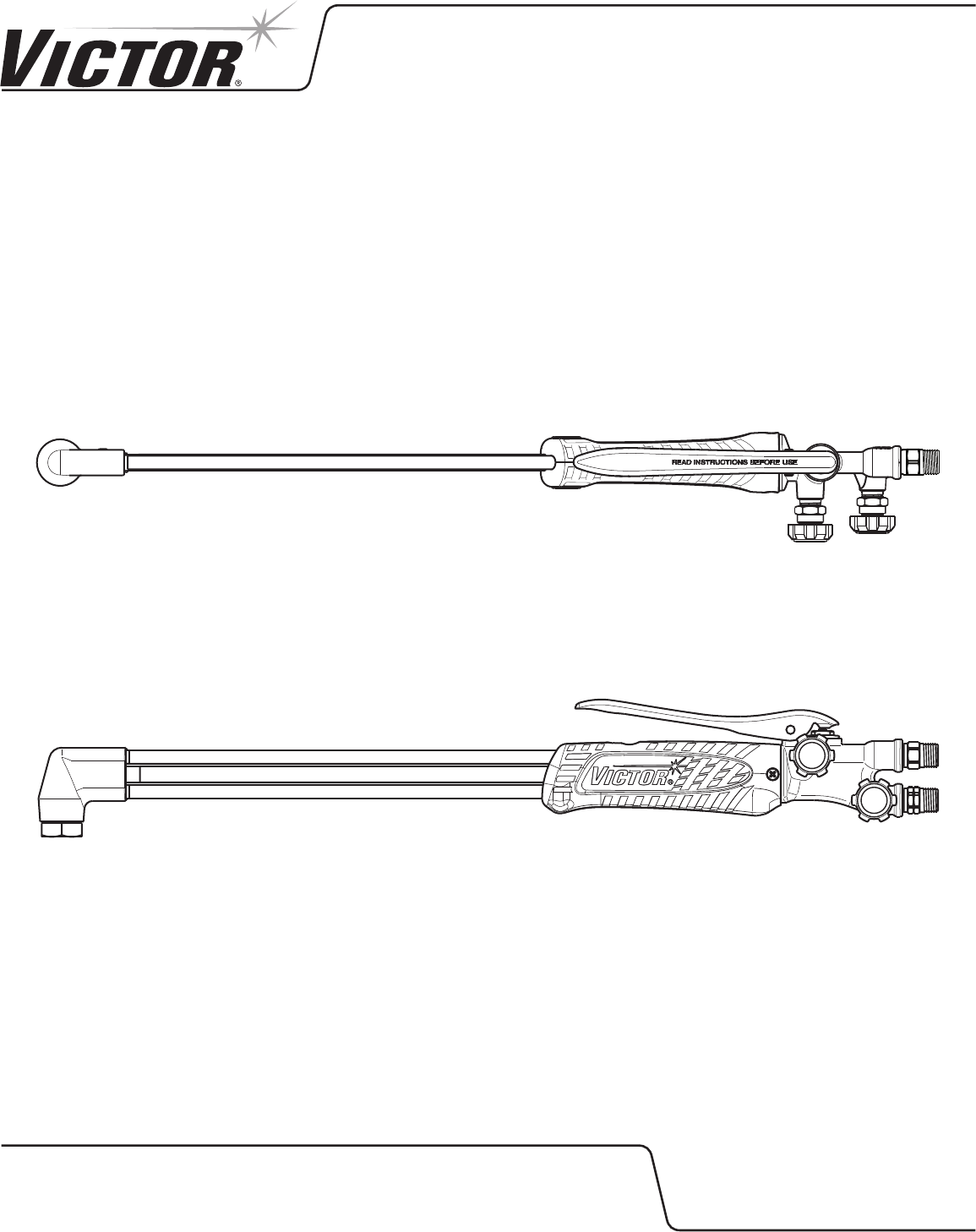
400 SERIES HEAVY DUTY
STRAIGHT TORCH, TIP SERIES 1
PARTS, SERVICE
& REPAIR BULLETIN
ST411C-1A
VictorTechnologies.com
Issue Date: September 27, 2013
Manual No: 0056-3761 Revision: AA

2
Table of Contents
SECTION 1: GENERAL SAFETY INFORMATION ......................................2
1.01 Commonly Used Terms ...................................................2
SECTION 2: SPECIFICATIONS ................................................................3
2.01 ST411C-1A Victor Straight Torch ....................................3
2.02 Repair Parts List ..............................................................3
SECTION 3: SERVICE & REPAIR INSTRUCTIONS ...................................4
3.01 Recommended Tools & Supplies for Repair Procedures . 4
3.02 Cleaning Procedures .......................................................4
3.03 Handle for 400 Series Straight Torch ...............................4
3.04 Control Valve Repair Kit ...................................................5
3.05 Cutting Lever ................................................................... 5
3.06 High Pressure (H.P.) Oxy Valve Repair Kit .......................6
3.07 Check Valve Repair Kit .....................................................6
3.08 Fuel and Oxygen Inlet Connections..................................7
3.09 400 Series Head Repair Kit ..............................................7
3.10 Gas Feed Tubes ...............................................................8
SECTION 4: TEST PROCEDURES ...........................................................9
4.01 Recommended Tools & Supplies for Test Procedures .....9
4.02 Leak Testing the Torch .....................................................9
4.03 Flame Testing the Torch ...................................................9
SECTION 1: GENERAL SAFETY INFORMATION
Read and understand all safety and operating instructions provided before using this apparatus. RETAIN THESE INSTRUCTIONS IN A
READILY AVAILABLE LOCATION FOR FUTURE REFERENCE.
!
WARNING
DO NOT attempt to use this apparatus unless you are trained in its proper use or are under competent supervision. For your safety, practice
the safety and operating procedures described in this booklet every time you use the apparatus. Deviating from these procedures may result
in fire, explosion, property damage, and/or operator injury. If at any time the apparatus you are using does not perform in its usual manner, or
you have any difficulty in the use of the apparatus, STOP using it immediately. DO NOT use the apparatus until the problem has been corrected!
!
WARNING
Apparatus improperly operated, maintained or repaired can be dangerous. Some parts and accessories manufactured by others may fit
VICTOR apparatus but not conform to VICTOR’s exacting standards. For your own protection, specify and use ONLY VICTOR-made parts and
accessories with your VICTOR apparatus.
!
WARNING
Service or repair of apparatus should be performed only by a qualified repair technician capable of servicing gas apparatus in strict accordance
to applicable Part and Service bulletins for VICTOR manufactured products. Improper service repair, or modification of the product could result
in damage to the product or injury to the operator.
!
WARNING
WARNING: This product contains chemicals, including lead, known to the State of California to cause birth defects and other reproductive
harm. Wash hands after handling.
1.01 COMMONLY USED TERMS
BACKFIRE - The return of the flame into the torch, producing a popping sound. The flame will either extinguish or reignite at the tip.
SUSTAINED BACKFIRE - The return of the flame into the torch with continued burning within the torch. This condition may be accompanied
by a popping sound followed by a continuous hissing or whistling sound.
FLASHBACK - The return of the flame through the torch into the hose and even into the regulator. It may also reach the cylinder. This
condition could possibly cause an explosion in the system.
3
SECTION 2: SPECIFICATIONS
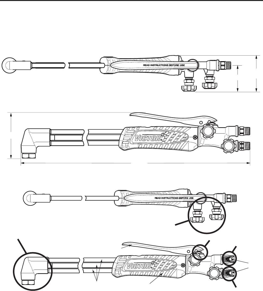
2.01 ST411C-1A VICTOR STRAIGHT TORCH
Cutting Tip Series 1
• Intuitive knobs: color coded, clearly marked lettering with increase/decrease label. Understandable in any language.
• Improved stainless lever provides increased comfort and reduced operator hand fatigue.
• Uses #000 - #8 cutting tips. One torch for all fuel gases (with proper tip).
• Inline stainless tubes for better visibility and reduced prole vs triangular design.
• Efcient universal head mixer reduces torch prole for better visibility. Optimized to use one cutting torch for all fuel gases.
1-7/8
2-1/2
21-1/8
3-1/4
All dimensions are approximate.
2.02 REPAIR PARTS LIST
Control Valve
Assemblies
400 Series Head 90˚
Gas Feed Tubes
Cutting Lever
High Pressure (H.P.) Oxy Valve
Tip
Nut
Inlet
Connection
Oxygen
Inlet
Connection
Fuel
Handle
Check
Valves
ST411C-1A
4
SECTION 3: SERVICE & REPAIR INSTRUCTIONS
3.01 RECOMMENDED TOOLS & SUPPLIES FOR REPAIR PROCEDURES
3/8”, 5/8”, 9/16”, and 11/16” Open-End Wrenches Vise
15/16” Box-End Wrench 45% Silver Solder
3/16” Drift Punch Silver Solder Flux
Small Hammer Loctite® #222 (Part Number 0028-0081)
1/4-20 Bolt Christo-Lube® 129 (Part Number 0034-0021)
Brazing Torch Hand Reamer RT-181
Pliers Fixture RT-148
Phillips Head Screwdriver Air Hose
NOTE
Disconnect the torch from any gas lines or other hardware before beginning any service or repair.
3.02 CLEANING PROCEDURES
Contact your local chemical supplier for recommended cleaning solvents applicable to the metals used in this product. Always use
cleaning solvents in accordance with the manufacturer’s instructions.
WARNING
DO NOT allow nonmetal components (seat, O-rings, dust seal, gaskets) to contact cleaning solvents! Cleaning solvents cause elastomeric
and plastic parts to swell and stress crack. If these parts require cleaning, use a mild soap solution, followed by a thorough rinsing in water.
Dry these parts completely before installing. REPLACE NONMETAL PARTS THAT HAVE COME IN CONTACT WITH OIL, GREASE OR ANY OTHER
PETROLEUM-BASED SUBSTANCE! Petroleum-based substances become dangerously flammable in the presence of oxygen.
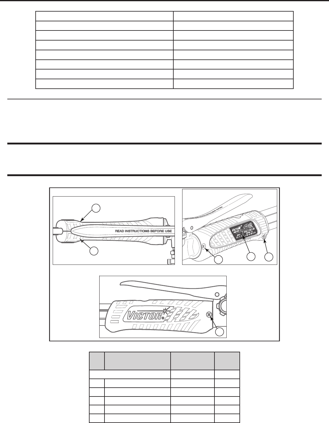
3.03 HANDLE FOR 400 SERIES STRAIGHT TORCH
1
2
3
45
4
Figure 3-1
Item
No. Description Part number Qnty
Handle for 400 Series Straight Torch 0390-0096 1
1 Left Handle 0306-0296* 1
2 Right Handle 0306-0297* 1
3Long screw (self-threading) 1400-0250* 1
4Short screw (self-threading) 1400-0251* 2
5 Decal for ST411C-1A 1415-0847* 1
*Sold as part of kit only.
5
3.05 CUTTING LEVER
1
Figure 3-3
Item
No. Description Part number Qnty
1 Cutting Lever 0307-0004 1
Service
• Check the roll pin for wear.
• Make sure the cutting lever tabs are aligned with the groove
in the high pressure (H.P.) oxy valve stem.
Disassembly
Remove the handle before beginning this task (see Section 3.03).
1. Place xture RT-148 in a vise and place the torch in the
xture.
2. Use a drift punch to tap the roll pin out of the cutting lever
and the torch body. Inspect the roll pin and discard it if it is
deformed.
NOTE
The replacement roll pin part number is 1404-0002.
3. Slide the cutting lever forward.
Assembly
If the roll pin was discarded, acquire a replacement roll pin before
beginning this step.
1. Align the cutting lever tabs with the groove in the H.P. oxy
valve stem.
2. Insert the roll pin into the cutting lever and torch body. Gently
tap in the roll pin.
3. Make sure the cutting lever tabs are still properly aligned
with the groove in the H.P. oxy valve stem.
4. Remove the torch from RT-148 and reattach the handle.
Disassembly
1. Use a phillips head screwdriver to remove the three screws
from the handle.
2. Separate the left handle from the right handle and remove
them from the torch.
Assembly
1. Position the right and left handles in place over the gas feed
tubes. Ensure that the handles t over the tubes correctly.
2. Align the screw hole in each handle with the holes in the
torch and install both short, self-threading screws (see Figure
3-1).
3. Fasten the long, self-threading screw through the right
handle into the left handle.
4. Place the decal on the right handle as shown in Figure 3-1.
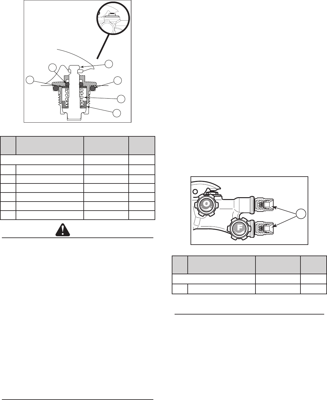
3.04 CONTROL VALVE REPAIR KIT
+
+
1
3
2
Figure 3-2
Item
No. Description Part number Qnty
Control Valve Repair Kit 0390-0086 2
1Valve Stem Assembly 0662-0102* 1
2Knob Decal (Red “F”) 1415-0864* 1
3Knob Decal (Green “O”) 1415-0863* 1
*Sold as part of kit only.
NOTE
This torch uses two control valves. Follow these steps to
service, disassemble, and assemble either control valve. The
control valve repair kit includes only one valve stem assembly.
Service
• Wipe with a dry cloth. Do not use any cleaning solvents.
• Check for leaks.
Disassembly
Remove the handle before beginning this task (see Section 3.03).
1. Place xture RT-148 in a vise and place the torch in the
xture.
2. Use a wrench to unscrew the control valve nut.
Assembly
1. Apply Christo-Lube® to the assembly threads.
2. Screw the control valve assembly into the torch body.
3. Use a wrench to tighten the control valve nut.
4. Place the correct decal on the knob (see Figure 3-2).
5. Remove the torch from RT-148 and reattach the handle.
6
1. Install the seat assembly bushing on the valve stem with
the open end facing up.
2. Install the spring on the valve stem until it is against the
bushing.
3. Install the washer followed by the small O-ring on the valve
stem.
4. Apply Christo-Lube® to the outside of the small O-ring and
along the valve stem.
5. Insert the seat assembly with the bushing, spring, washer,
and O-ring in through the valve cap.
6. Place the large O-ring around the outside of the valve cap
and apply Christo-Lube® to the large O-ring.
7. Screw the oxy valve assembly into the torch body and
wrench tighten. Confirm that the O-rings are seated
properly.
8. Reattach the cutting lever.
9. Remove the torch from RT-148 and reattach the handle.
10. Check for leaks.
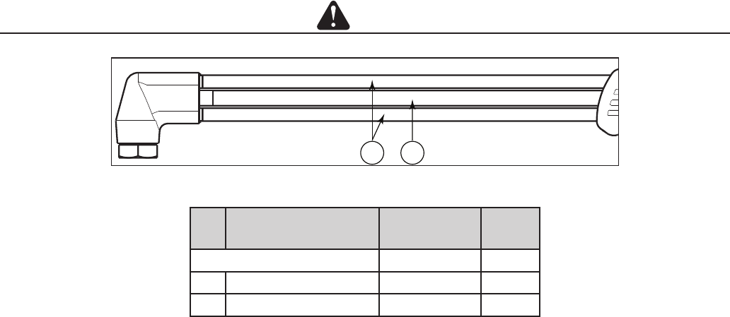
3.07 CHECK VALVE REPAIR KIT
+
+
1
Figure 3-5
Item
No. Description Part number Qnty
Check Valve Repair Kit 0690-0027 1
1Check Valve 0652-0029 2
NOTE
Follow these steps to disassemble and assemble either
check valve.
Disassembly
1. Screw the 1/4-20 bolt into either check valve until it is nger
tight.
2. Place the shank of the bolt in the vise. The head of the bolt
must catch on the vise jaws, and the bolt must be able to
move freely.
3. Grab the torch rmly and pull the torch up. The head of the
bolt will catch on the vise jaws, and the check valve will pull
out of the torch.
4. Repeat steps 1 through 3 for the other check valve.
3.06 HIGH PRESSURE (H.P.) OXY VALVE REPAIR KIT
1
2
3
6
5
4
Figure 3-4
Item
No. Description Part number Qnty
H.P. Oxy Valve Repair Kit 0390-0043 1
1Seat Assembly 0320-0079 1
2Seat Assembly Bushing 0320-0108 1
3 Valve Spring 0320-0024 1
4Washer 1406-0006 1
5O-Ring (Small) 1407-0005 1
6O-Ring (Large) 1407-0016 1
CAUTION
Discard the used O-rings, seat assembly, seat assembly
bushing and washer. Replace them each time you reassemble
the torch.
Service
• Wipe with a dry cloth. Do not use any cleaning solvents.
• Check for leaks. Replacing O-rings requires disassembly.
Disassembly
Remove the handle and cutting lever before beginning this task
(see Sections 3.03 and 3.05).
1. Place xture RT-148 in a vise and place the torch in the
xture.
2. Use a wrench to loosen and unscrew the H.P. oxy valve
assembly from the torch body.
3. Remove the H.P. oxy valve assembly from the torch body.
Make sure the large O-ring is also removed.
Assembly
NOTE
Check the valve cap for wear. If the valve cap was discarded,
acquire a replacement valve cap before beginning these steps.
The replacement valve cap part number is 0320-0017.
7
Assembly
NOTE
This assembly requires a class “B” dual hose for oxygen and
fuel. The red hose connects to the fuel inlet connection. The
green hose connects to the oxygen inlet connection.
1. Press the check valve into the inlet connection.
2. Place the hose connection over the check valve and thread
it onto the inlet connection. Use a wrench to tighten the
hose connection onto the inlet connection until the check
valve is properly seated.
3. Remove the hose.
4. Repeat steps 1 through 3 for the other check valve.
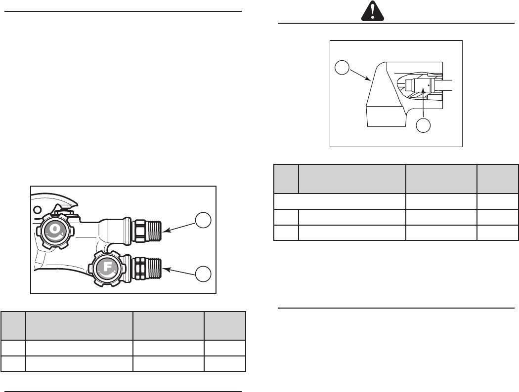
3.08 FUEL AND OXYGEN INLET CONNECTIONS
+
+
1
2
Figure 3-6
Item
No. Description Part number Qnty
1 Inlet Connection Oxygen 0950-0099 1
2 Inlet Connection Fuel 0960-0073 1
NOTE
Follow these steps to disassemble and assemble either inlet
connection.
Disassembly
Remove the handle before beginning this task (see Section 3.03).
1. Place xture RT-148 in a vise and place the torch in the
xture.
2. Use a wrench to loosen and unscrew either inlet connection
from the torch.
3. Clean all debris from the inlet connection threads.
4. Repeat steps 2 and 3 for the other inlet connection.
Assembly
1. Apply a small amount of Loctite® to the beginning of the
inlet connection threads. Loctite® must completely cover
the beginning two threads of the inlet connection.
2. Screw the inlet connection onto the torch and wrench tighten.
3. Repeat steps 1 and 2 for the other inlet connection.
4. Remove the torch from RT-148 and reattach the handle.
5. Install the check valves (see Section 3.07, Assembly).
3.09 400 SERIES HEAD REPAIR KIT
CAUTION
Always wear gloves when handling heated parts.
1
2
Figure 3-7
Item
No. Description Part number Qnty
90° Victor Series 1 Head Repair Kit 0390-0085 1
1400 Series Head-90° Victor 0302-0247* 1
2 Mixer 0305-0519* 1
*Sold as part of kit only.
Service
• Remove the tip nut and tip and use an air hose to clear
any debris from the opening. Reattach the tip nut and tip.
NOTE
The 400 Series Head Repair Kit does not include the tip nut.
The tip nut part number is 0390-0088.
Disassembly
Remove the handle, control valves, cutting lever, H.P. oxy valve,
inlet connections, tip, and tip nut before beginning this task (see
Sections 3.03-3.06 and 3.08).
1. Place the torch body in a vise, positioned so that you have
full access to the 400 Series head.
2. Heat the gas feed tubes until the solder liquees. Use pliers
to remove the 400 Series head.
Assembly
1. Clean all solder and debris from the gas feed tubes.
2. Place the new 400 Series head on the gas feed tubes.
Conrm correct orientation to the 400 Series body.
3. Ensure that the center tube is pressed rmly against the
mixer of the head.
4. Solder the ttings and allow them to cool before beginning
the next step.
5. Use RT-181 to nish hand reaming the torch seat.
6. Remove all chips and debris from around the torch seat
area.
7. Reattach the tip nut, tip, inlet connections, H.P. oxy valve,
cutting lever, control valves, and handle.
8. Check for leaks and remove the torch from the vise.
8
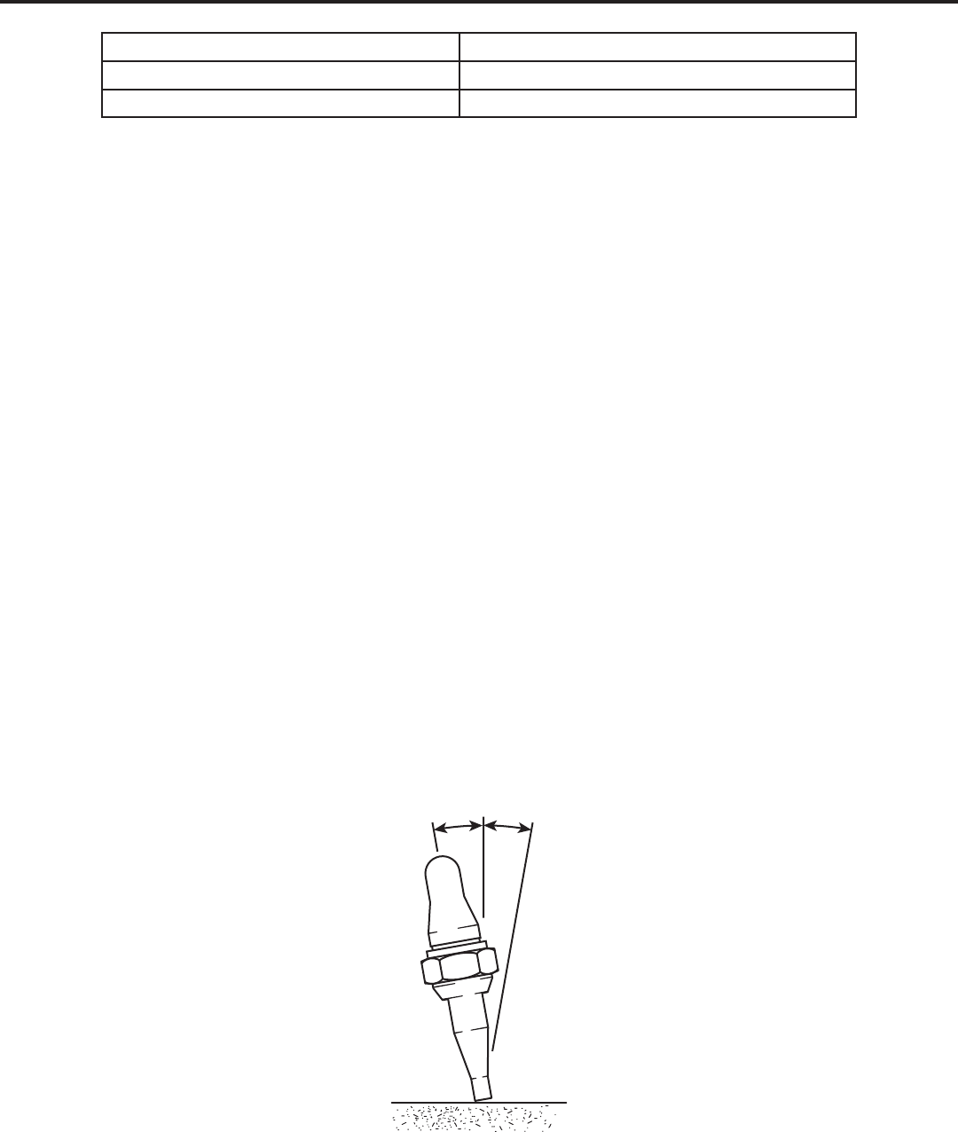
3.10 GAS FEED TUBES
CAUTION
Always wear gloves when handling heated parts.
1 2
Figure 3-8
Item
No. Description Part number Qnty
Gas Feed Tubes 0390-0095 1
15/16” Tube 0303-0562* 2
23/8” Tube 0303-0564* 1
*Sold as part of kit only.
Service
• Check the tubes for leaks and wear.
Disassembly
Remove the handle, control valves, cutting lever, H.P. oxy valve, inlet connections, tip, tip nut, and 400 Series head before beginning
this task (see Sections 3.03-3.06 and 3.08-3.09).
1. Place the torch body in a vise, positioned so that you have full access to the gas feed tubes.
2. Heat the gas feed tubes until the solder liquees. Use pliers to remove all tubes.
3. Allow the torch body to cool before beginning assembly.
Assembly
1. Clean all solder and debris from the torch body.
2. Place a new 400 Series head in a vise, positioned so that the tube bores face up.
3. Insert the gas feed tubes into the 400 Series head, followed by the torch body. Conrm correct orientation to the 400 Series
head.
4. Ensure that the center tube is pressed rmly against the mixer of the head.
5. Solder the tting around the 400 Series head and repeat for the torch body side. Allow all parts to cool before beginning the
next step.
6. Complete steps 5 - 8 in Section 3.09, 400 Series Head Repair Kit, Assembly.
9
SECTION 4: TEST PROCEDURES
4.01 RECOMMENDED TOOLS & SUPPLIES FOR TEST PROCEDURES
Oil-free air or dry nitrogen supplies 2-1-101 Cutting tip
Oxygen and acetylene gas supplies 3/8”, 5/8”, 9/16”, and 11/16” Open-end wrenches
Small water tank 15/16” Box-end wrench
4.02 LEAK TESTING THE TORCH
1. Connect the torch to oil-free air or dry nitrogen supply lines with a matching type regulator.
2. Insert a plugged cutting tip into the torch.
3. Pressurize the hoses to 50+/-5 PSIG.
4. Completely submerse the torch in water.
5. Open the valve stem assemblies. Check for leaks around all external connections. Observe the valve stem assemblies. If bubbles
are escaping from around the valve stem assembly packing, tighten the packing nut until it takes 1-1/4 to 2 in-Ibs of torque to
adjust the valve stem assembly knobs.
6. Close the valve stem assembly knobs to a torque of 7-8 in-Ibs.
7. Remove the plugged cutting tip from the torch. Observe the torch head. If bubbles appear at the torch head, one or both of the
valve stem assemblies is leaking. Ream the valve seating surface using the RT-33 reseating tool. Repeat steps 2 through 7.
4.03 FLAME TESTING THE TORCH
1. Remove the torch from the water. Open the valve stem assemblies for 10 seconds. Once all the water has been removed from
the torch, disconnect the hoses from the oil-free air or dry nitrogen supply. Attach them to oxygen and acetylene gas supplies.
2. Install a 2-1-101 cutting tip in the head. Tighten the tip nut to 15-20 ft-Ibs of torque.
3. Adjust the oxygen to deliver 50+/-5 PSIG. Adjust the acetylene to deliver 7+/-2 PSIG.
4. Open the oxygen valve and purge the oxygen line for ve seconds. Then, close the oxygen valve. Open the fuel valve and purge
the fuel line for ve seconds.
5. Open the fuel valve stem assembly about 1/8 of a turn. Ignite the gas with a spark lighter. Continue opening the fuel valve until
the flame stops smoking.
6. Open the oxygen valve until a bright neutral flame appears.
7. Place the tip on a re brick at approximately 10° from the vertical (See Figure 4-1). Depress the cutting oxygen lever. Rock the
torch from side to side for 5-8 seconds. The torch will “pop” during this operation.
10˚
10˚
Fire Brick
Figure 4-1

10
!
WARNING
If you experience a backfire or backflash (flame disappears suddenly and/or a hissing sound IS heard when the flame is burning inside the
torch), IMMEDIATELY turn OFF first the oxygen valve and then the fuel valve. Allow the torch to cool before reusing it. If the trouble reoccurs,
disassemble the torch. Replace any damaged parts.
8. After testing is completed, release the cutting oxygen lever. Close the oxygen valve and the fuel valve.
9. Close the cylinder valve or gas supply.
10. Open the oxygen valve. Release the oxygen from the system. Once all the oxygen is released from the system, close the oxygen
valve.
11. Open the fuel valve. Release the fuel gas from the system. Once all the fuel gas is released from the system, close the fuel
valve.
12. Remove the hoses from the torch.
11
This page intentionally blank

© 2012 Victor Technologies International, Inc. www.victortechnologies.com Printed in China
THE AMERICAS
Denton, TX USA
U.S. Customer Care
Ph 1-800-426-1888 (tollfree)
Fax: 1-800-535-0557 (tollfree)
International Customer Care
Ph 1-940-381-1212
Fax: 1-940-483-8178
Miami, FL USA
Sales Office, Latin America
Ph 1-954-727-8371
Fax: 1-954-727-8376
Oakville, Ontario, Canada
Canada Customer Care
Ph 1-905-827-4515
Fax: 1-800-588-1714 (tollfree)
EUROPE
Chorley, United Kingdom
Customer Care
Ph +44 1257-261755
Fax: +44 1257-224800
Milan, Italy
Customer Care
Ph +39 0236546801
Fax: +39 0236546840
ASIA/PACIFIC
Cikarang, Indonesia
Customer Care
Ph 6221-8990-6095
Fax: 6221-8990-6096
Rawang, Malaysia
Customer Care
Ph +603 6092-2988
Fax: +603 6092-1085
Melbourne, Australia
Australia Customer Care
Ph 1300-654-674 (tollfree)
Ph 61-3-9474-7400
Fax: 61-3-9474-7391
International
Ph 61-3-9474-7508
Fax: 61-3-9474-7488
Shanghai, China
Sales Office
Ph +86 21-64072626
Fax: +86 21-64483032
Singapore
Sales Office
Ph +65 6832-8066
Fax: +65 6763-5812
U.S. Customer Care: 800-426-1888 / FAX 800-535-0557
Canada Customer Care: 905-827-4515 / FAX 800-588-1714
International Customer Care: 940-381-1212 / FAX 940-483-8178
INNOVATION TO SHAPE THE WORLD™
TECHNOLOGIES
™
