08HE175CE Viostor NVR 5020 CE Certificate
User Manual:
Open the PDF directly: View PDF ![]() .
.
Page Count: 61

Issue Date: 2008/08/08
Ref. Report No. ISL-08HE175CE
Product Name: : Network Attached Storage
Model Number(s) : Please reference the attachment
Responsible Party : QNAP System, Inc.
Address : 21F,No.77,Sec. 1,Xintai 5th Rd.,
Xizhi City,Taipei Country,221, Taiwan,R.O.C
Contact Person :
We, International Standards Laboratory, hereby certify that:
The device bearing the trade name and model specified above has been shown to
comply with the applicable technical standards as indicated in the measurement report
and was tested in accordance with the measurement procedures specified in European
Council Directive- EMC Directive 2004/108/EC. The device was passed the test
performed according to :
Standards:
EN55022: 2006 / CISPR 22:2005; AS/NZS CISPR 22: 2006: Limits and methods of
measurement of Radio Interference characteristics of Information Technology
Equipment. (* Remarks: Testing radiated emissions above 1 GHz is not yet required in
Australia.)
EN55024: 1998/A1:2001/A2: 2003; AS/NZS CISPR 24: 2002: Information technology
equipment-Immunity characteristics-Limits and methods of measurement.
EN61000-3-2: 2006; AS/NZS 61000.3.2: 2007: Limits for harmonics current emissions
EN61000-3-3: 1995/A1: 2001/A2:2005; AS/NZS 61000.3.3: 2006: Limits for voltage
fluctuations and flicker in low-voltage supply systems.
I attest to the accuracy of data and all measurements reported herein were performed by
me or were made under my supervision and are correct to the best of my knowledge and
belief. I assume full responsibility for the completeness of these measurements and
vouch for the qualifications of all persons taking them.
___________________________
Jim Chu/ Director
International Standards laboratory
Lung-Tan LAB:
No. 120, Lane 180, San Ho Tsuen, Hsin Ho Rd.
Lung-Tan Hsiang, Tao Yuan County 325, Taiwan
Tel: 886-3-407-1718; Fax: 886-3407-1738
His-Chih LAB:
No. 65, Gu Dai Keng St.. Hsichih, Taipei Hsien
22117, Taiwan.
Tel: 886-2-2646-2550; Fax: 886-2-2646-4641

Attachment:
Model Number(s):
TS-509 Pro; TS-509; TS-509 Pro II; TS-509 II; TS-508 Pro; TS-508; TS-508 Pro
II; TS-508 II; TS-519; TS-519 Pro; TS-519 II; TS-519 Pro II;TS-2509 Pro;
TS-2509; TS-2509 Pro II; TS-2509 II; NAS-501; NAS-502; NS-501; NS-502;
MTS-509 Pro; MTS-509; MTS 508 Pro; MTS-508; MTS-509 Pro II; MTS-509 II;
MTS-508 Pro II; MTS-508 II; NVR-509; NVR-509P; NVR-509V; NVR-509A;
NVR-509C; NVR-509D; NVR-509S; NVR-509G; NVR-509U; NVR-509M;
NVR-509Pro; NVR-509P-Pro; NVR-509V-Pro; NVR-509A-Pro; NVR-509C-Pro;
NVR-509D-Pro; NVR-509S-Pro; NVR-509G-Pro; NVR-509M-Pro;
NVR-509U-Pro; VioStor-509; VioStor-509P; VioStor-509V; VioStor-509A;
VioStor-509C; VioStor-509D; VioStor-509S; VioStor-509G; VioStor-509U;
VioStor-509M; VioStor-509Pro; VioStor-509P-Pro; VioStor-509V-Pro;
VioStor-509A-Pro; VioStor-509C-Pro; VioStor-509D-Pro; VioStor-509S-Pro;
VioStor-509G-Pro; VioStor-509M-Pro; VioStor-509U-Pro;NVR-501; NVR-501P;
NVR-501V; NVR-501A; NVR-501C; NVR-501D; NVR-501S; NVR-501G;
NVR-501U; NVR-501M; NVR-501Pro; NVR-501P-Pro; NVR-501V-Pro;
NVR-501A-Pro; NVR-501C-Pro; NVR-501D-Pro; NVR-501S-Pro;
NVR-501G-Pro; NVR-501M-Pro; NVR-501U-Pro;VioStor-501; VioStor-501P;
VioStor-501V; VioStor-501A; VioStor-501C; VioStor-501D; VioStor-501S;
VioStor-501G; VioStor-501U; VioStor-501M; VioStor-501ro; VioStor-501-Pro;
VioStor-501V-Pro; VioStor-501A-Pro; VioStor-501C-Pro; VioStor-501D-Pro;
VioStor-501S-Pro; VioStor-501G-Pro; VioStor-501M-Pro;
VioStor-501U-Pro;NVR-5012; NVR-5012-Pro; NVR-5016; NVR-5016-Pro;
NVR-5020; NVR-5020-Pro; NVR-5012P; NVR-5012P-Pro; NVR-5016P;
NVR-5016P-Pro; NVR-5020P; NVR-5020P-Pro; NVR-5012A; NVR-5012A-Pro;
NVR-5016A; NVR-5016A-Pro; NVR-5020A; NVR-5020A-Pro; NVR-5012V;
NVR-5012V-Pro; NVR-5016V; NVR-5016V-Pro; NVR-5020V; NVR-5020V-Pro;
NVR-5012U; NVR-5012U-Pro; NVR-5016U; NVR-5016U-Pro; NVR-5020U;
NVR-5020U-Pro; NV-5012; NV-5012-Pro; NV-5016; NV-5016-Pro; NV-5020;
NV-5020-Pro; NV-5012P; NV-5012P-Pro; NV-5016P; NV-5016P-Pro; NV-5020P;
NV-5020P-Pro ; NV-5012A-Pro; NV-5012A-Pro; NV-5016A-Pro; NV-5016A-Pro;
NV-5020A-Pro; NV-5020A-Pro; NV-5012V-Pro; NV-5012V-Pro; NV-5016V-Pro;
NV-5016V-Pro; NV-5020V-Pro; NV-5020V-Pro; NV-5012U; NV-5012U-Pro;
NV-5016U; NV-5016U-Pro; NV-5020U; NV-5020U-Pro
CE MARK TECHNICAL FILE
AS/NZS EMC CONSTRUCTION FILE
of
Product Name
Network Attached Storage
Model
Please reference the attachment
Contains:
1. Declaration of Conformity
2. EN55022/CISPR 22, AS/NZS CISPR 22 EMI test report
3. EN55024, AS/NZS CISPR 24, EN61000-3-2 / AS/NZS 61000.3.2, and
EN61000-3-3 / AS/NZS 61000.3.3 test report
4. Certificate of EN60950-1
5. Block Diagram and Schematics
6. Users’ manual

Page 1 of 2
Report No. ISL-08HE175CE
Declaration of Conformity
Name of Responsible Party: QNAP System, Inc.
Address of Responsible Party: 21F,No.77,Sec. 1,Xintai 5th Rd.
Xizhi City,Taipei Country,221
Taiwan,R.O.C
Declares that product: Network Attached Storage
Model: Please reference the attachment
Assembled by: Same as above
Address: Same as above
Conforms to the EMC Directive 2004/108/EC as attested by conformity with the
following harmonized standards:
EN55022: 2006 / CISPR 22:2005; AS/NZS CISPR 22: 2006: Limits and methods of
measurement of Radio Interference characteristics of Information Technology Equipment. (*
Remarks: Testing radiated emissions above 1 GHz is not yet required in Australia.)
EN55024: 1998/A1: 2001/A2: 2003; AS/NZS CISPR 24: 2002: Information technology
equipment-Immunity characteristics-Limits and methods of measurement.
Standard Description Results Criteria
EN61000-4-2: 1995/A1: 1998/A2: 2001
AS/NZS 61000.4.2: 2002 Electrostatic Discharge Pass B
EN61000-4-3: 2006
AS/NZS 61000.4.3: 2006 Radio-Frequency, Electromagnetic
Field Pass A
EN61000-4-4: 2004
AS/NZS 61000.4.4: 2006 Electrical Fast Transient/Burst Pass B
EN61000-4-5: 2006
AS/NZS 61000.4.5: 2006 Surge Pass B
EN61000-4-6: 1996/A1: 2001
AS/NZS 61000.4.6: 2006 Conductive Disturbance Pass A
EN61000-4-8: 1993/A1: 2001
AS/NZS 61000.4.8: 2002 Power Frequency Magnetic Field Pass A
EN61000-4-11: 2004
AS/NZS 61000.4.11: 2005 Voltage Dips / Short Interruption and
Voltage Variation
>95% in 0.5 period Pass B
30% in 25 period Pass C
>95% in 250 period Pass C
<to be continued>
Page 2 of 2
Report No. ISL-08HE175CE
Standard Description Results
EN61000-3-2: 2006
AS/NZS 61000.3.2: 2007 Limits for harmonics current emissions Pass
EN61000-3-3: 1995/A1: 2001/A2:2005
AS/NZS 61000.3.3: 2006 Limits for voltage fluctuations and flicker in
low-voltage supply systems. Pass
Conforms to the Low Voltage Directive 2006/95/EC, 93/68/EEC as attested by
conformity with the following harmonized standard:
EN60950-1: 2001+A11: Safety of Information Technology Equipment
Including electrical business equipment
We, QNAP System, Inc., hereby declare that the equipment bearing the trade name and
model number specified above was tested conforming to the applicable Rules under the
most accurate measurement standards possible, and that all the necessary steps have been
taken and are in force to assure that production units of the same equipment will continue to
comply with the requirements.
---------------------------
QNAP System, Inc.
Date: 2008/08/08

Page 1 of 2
Report No. ISL-08HE175CE
Declaration of Conformity
Name of Responsible Party: QNAP System, Inc.
Address of Responsible Party: 21F,No.77,Sec. 1,Xintai 5th Rd.
Xizhi City,Taipei Country,221
Taiwan,R.O.C
Declares that product: Network Attached Storage
Model: Please reference the attachment
Assembled by: Same as above
Address: Same as above
Conforms to the C-Tick Mark requirement as attested by conformity with the following
standards:
EN55022: 2006 / CISPR 22:2005; AS/NZS CISPR 22: 2006: Limits and methods of
measurement of Radio Interference characteristics of Information Technology Equipment. (*
Remarks: Testing radiated emissions above 1 GHz is not yet required in Australia.)
EN55024: 1998/A1: 2001/A2: 2003; AS/NZS CISPR 24: 2002: Information technology
equipment-Immunity characteristics-Limits and methods of measurement.
Standard Description Results Criteria
EN61000-4-2: 1995/A1: 1998/A2: 2001
AS/NZS 61000.4.2: 2002 Electrostatic Discharge Pass B
EN61000-4-3: 2006
AS/NZS 61000.4.3: 2006 Radio-Frequency, Electromagnetic
Field Pass A
EN61000-4-4: 2004
AS/NZS 61000.4.4: 2006 Electrical Fast Transient/Burst Pass B
EN61000-4-5: 2006
AS/NZS 61000.4.5: 2006 Surge Pass B
EN61000-4-6: 1996/A1: 2001
AS/NZS 61000.4.6: 2006 Conductive Disturbance Pass A
EN61000-4-8: 1993/A1: 2001
AS/NZS 61000.4.8: 2002 Power Frequency Magnetic Field Pass A
EN61000-4-11: 2004
AS/NZS 61000.4.11: 2005 Voltage Dips / Short Interruption and
Voltage Variation
>95% in 0.5 period Pass B
30% in 25 period Pass C
>95% in 250 period Pass C
<to be continued>

Page 2 of 2
Report No. ISL-08HE175CE
Standard Description Results
EN61000-3-2: 2006
AS/NZS 61000.3.2: 2007 Limits for harmonics current emissions Pass
EN61000-3-3: 1995/A1: 2001/A2:2005
AS/NZS 61000.3.3: 2006 Limits for voltage fluctuations and flicker in
low-voltage supply systems. Pass
We, QNAP System, Inc., hereby declare that the equipment bearing the trade name and
model number specified above was tested conforming to the applicable Rules under the
most accurate measurement standards possible, and that all the necessary steps have been
taken and are in force to assure that production units of the same equipment will continue to
comply with the requirements.
---------------------------
QNAP System, Inc.
Date: 2008/08/08

Report Number: ISL-08HE175C Issue Date: 2008/08/08
ISL-T10-R2-11
CE TEST REPORT
of
EN55022 / CISPR 22 / AS/NZS CISPR 22
Class A
EN55024 / AS/NZS CISPR 24 / IMMUNITY
EN61000-3-2 / EN61000-3-3
Product : Network Attached Storage
Model(s): Please reference the attachment
Applicant: QNAP System, Inc.
Address: 21F,No.77,Sec. 1,Xintai 5th Rd.
Xizhi City,Taipei Country,221
Taiwan,R.O.C
Test Performed by:
International Standards Laboratory
<HC LAB>
*Site Registration No.
BSMI:SL2-IN-E-0037; SL2-R1/R2-E-0037; TAF: 1178;
IC: IC4067; VCCI: R-341,C-354; NEMKO: ELA 113A
*Address:
No. 65, Gu Dai Keng St.
Hsichih, Taipei Hsien 22117, Taiwan
*Tel: 886-2-2646-2550; Fax: 886-2-2646-4641
Report No.: ISL-08HE175CE
Issue Date : 2008/08/08

International Standards Laboratory Report Number: ISL-08HE175CE
-i-
Contents of Report
1. General.............................................................................................................................1
1.1 Certification of Accuracy of Test Data ........................................................................1
2. Summary..........................................................................................................................2
2.1 Operation Environment ................................................................................................2
2.2 Test Standards ..............................................................................................................2
3. Description of EUT..........................................................................................................4
4. Description of Support Equipment ..................................................................................5
4.1 Description of Support Equipment...............................................................................5
4.2 Software for Controlling Support Unit.........................................................................6
4.3 I/O Cable Condition of EUT and Support Units ..........................................................7
5. Power Main Port Conducted Emissions ..........................................................................8
5.1 Configuration and Procedure........................................................................................8
5.1.1 EUT Configuration......................................................................................................................... 8
5.1.2 Test Procedure................................................................................................................................ 8
5.1.3 EMI Receiver/Spectrum Analyzer Configuration (for the frequencies tested)............................... 8
5.2 Conduction Test Data: Configuration 1 .......................................................................9
6. Telecommunication Port Conducted Emissions............................................................11
6.1 Configuration and Procedure......................................................................................11
6.1.1 EUT Configuration....................................................................................................................... 11
6.1.2 Test Procedure.............................................................................................................................. 11
6.1.3 EMI Receiver/Spectrum Analyzer Configuration (for the frequencies tested)............................. 11
6.2 Test Data: LAN 1--GIGA (Voltage) ..........................................................................12
6.3 Test Data: LAN 2--GIGA (Voltage) ..........................................................................13
6.4 Test Data: LAN 1--100M ...........................................................................................14
6.5 Test Data: LAN 2--100M ...........................................................................................15
6.6 Test Data: LAN 1--10M .............................................................................................16
6.7 Test Data: LAN 2--10M .............................................................................................17
7. Radiated Disturbance Emissions ...................................................................................18
7.1 Configuration and Procedure......................................................................................18
7.1.1 EUT Configuration....................................................................................................................... 18
7.1.2 Test Procedure.............................................................................................................................. 18
7.1.3 Spectrum Analyzer Configuration (for the frequencies tested).................................................... 18
7.2 Radiation Test Data: Configuration 1.........................................................................19
8. Electrostatic discharge (ESD) immunity .......................................................................21
8.1 Electrostatic discharge (ESD) immunity test .............................................................21
9. Radio-Frequency, Electromagnetic Field immunity......................................................22
9.1 Radio-Frequency, Electromagnetic Field immunity test............................................22
10. Electrical Fast transients/burst immunity ......................................................................23
10.1 Electrical Fast transient/burst immunity test...........................................................23
11. Surge Immunity .............................................................................................................25
11.1 Surge immunity test ................................................................................................25
12. Immunity to Conductive Disturbance............................................................................26
12.1 Immunity to Conductive Disturbance.....................................................................26

International Standards Laboratory Report Number: ISL-08HE175CE
-ii-
13. Power Frequency Magnetic Field immunity .................................................................27
13.1 Power Frequency Magnetic field immunity test.....................................................27
14. Voltage Dips, Short Interruption and Voltage Variation immunity ..............................28
14.1 Voltage Dips, Short Interruption and Voltage Variation immunity test.................28
15. Harmonics......................................................................................................................29
15.1 Harmonics test.........................................................................................................29
16. Voltage Fluctuations......................................................................................................32
16.1 Voltage Fluctuations test.........................................................................................32
17. Appendix........................................................................................................................34
17.1 Appendix A: Measurement Procedure for Main Power Port Conducted Emissions34
17.2 Appendix B: Measurement Procedure for Telecommunication Port Conducted
Emissions..............................................................................................................................35
17.3 Appendix C: Test Procedure for Radiated Emissions.............................................36
17.4 Appendix D: Test Equipment..................................................................................37
17.4.1 Test Equipment List...................................................................................................................... 37
17.5 Software for Controlling Spectrum/Receiver and Calculating Test Data...............39
17.6 Appendix E: Layout of EUT and Support Equipment............................................40
17.6.1 General Power Main Port Conducted Test Configuration............................................................ 40
17.6.2 General Telecommunication Port Conducted Emission Test Configuration................................ 41
17.6.3 General Radiation Test Configuration.......................................................................................... 42
17.7 Appendix F: Uncertainty of Measurement..............................................................43
17.8 Appendix G: Photographs of EUT Configuration Test Set Up...............................44
17.8.1 Photo of Main Power Port Conducted Emission and Telecommunication Port Conducted Emission
Measurement ................................................................................................................................................ 44
17.8.2 Photo of Radiated Emission Measurement................................................................................... 46
17.8.3 Photo of ESD Measurement ......................................................................................................... 47
17.8.4 Photo of RF Field Strength Susceptibility Measurement.............................................................. 47
17.8.5 Photo of Electrical Fast Transient/Burst Measurement ................................................................ 48
17.8.6 Photo of Surge Measurement........................................................................................................ 48
17.8.7 Photo of Conductive Measurement...............................................................................................49
17.8.8 Photo of Magnetic field Measurement.......................................................................................... 49
17.8.9 Photo of Voltage Dips Measurement............................................................................................ 50
17.8.10 Photo of Harmonics and Voltage Fluctuations......................................................................... 50
17.9 Photographs of EUT Please refer to the File of ISL-08HE175P ...........................51

International Standards Laboratory Report Number: ISL-08HE175CE
-1-
1. General
1.1 Certification of Accuracy of Test Data
Standards: Please refer to 2.2
Equipment Tested: Network Attached Storage
Model: Please reference the attachment
Applied by QNAP System, Inc.
Sample received Date: 2008/08/01
Final test Date : 2008/08/06
Test Site: OATS 01; Conduction 01;
HC Test Site
Test Result: PASS
Report Engineer: Lily L.C. Tseng
Test Engineer:
______________________
David Y.Y. Wu
Approve & Signature
---------------------------------------------
Jim Chu / Director
Test results given in this report apply only to the specific sample(s) tested under stated test conditions.
This report shall not be reproduced other than in full without the explicit written consent of ISL. This report totally
contains 54 pages, including 1 cover page , 2 contents page, and 51 pages for the test description.
This test report accurately contains the test results of the above standards at the time of the test.
The results in this report apply only to the sample(s) tested.
This test report shall not be reproduced except in full, without the written approval of International Standards
Laboratory.
International Standards Laboratory Report Number: ISL-08HE175CE
-2-
2. Summary
2.1 Operation Environment
Test Distance 10M (EMI test)
Temperature refer to each site test data
Humidity: refer to each site test data
input power: Conduction input power: AC 230 V / 50 Hz
Radiation input power: AC 230 V / 50 Hz
Immunity input power: AC 230 V / 50 Hz
2.2 Test Standards
The tests which this report describes were conducted by an independent electromagnetic
compatibility consultant, International Standards Laboratory in accordance with the
following
EN55022: 2006 / CISPR 22:2005; AS/NZS CISPR 22: 2006: Class A: Limits and methods of
measurement of Radio Interference characteristics of Information Technology Equipment. (*
Remarks: Testing radiated emissions above 1 GHz is not yet required in Australia.)
EN55024: 1998/A1: 2001/A2: 2003; AS/NZS CISPR 24: 2002: Information technology
equipment-Immunity characteristics-Limits and methods of measurement.
Standard Description Results Criteria
EN61000-4-2: 1995/A1: 1998/A2: 2001
AS/NZS 61000.4.2: 2002 Electrostatic Discharge Pass B
EN61000-4-3: 2006
AS/NZS 61000.4.3: 2006 Radio-Frequency, Electromagnetic
Field Pass A
EN61000-4-4: 2004
AS/NZS 61000.4.4: 2006 Electrical Fast Transient/Burst Pass B
EN61000-4-5: 2006
AS/NZS 61000.4.5: 2006 Surge Pass B
EN61000-4-6: 1996/A1: 2001
AS/NZS 61000.4.6: 2006 Conductive Disturbance Pass A
EN61000-4-8: 1993/A1: 2001
AS/NZS 61000.4.8: 2002 Power Frequency Magnetic Field Pass A
EN61000-4-11: 2004
AS/NZS 61000.4.11: 2005 Voltage Dips / Short Interruption and
Voltage Variation
>95% in 0.5 period Pass B
30% in 25 period Pass C
>95% in 250 period Pass C
International Standards Laboratory Report Number: ISL-08HE175CE
-3-
Standard Description Results
EN61000-3-2: 2006
AS/NZS 61000.3.2: 2007 Limits for harmonics current emissions Pass
EN61000-3-3: 1995/A1: 2001/A2:2005
AS/NZS 61000.3.3: 2006 Limits for voltage fluctuations and flicker in
low-voltage supply systems. Pass

International Standards Laboratory Report Number: ISL-08HE175CE
-4-
3. Description of EUT
EUT
Product Name: Network Attached Storage
Condition: Pre-Production
Model Number(s): Please reference the attachment
Serial Number: N/A
Power Supply Type: Seasanic (Model: SS-250SU) 250W
AC Input: 100~240V~5A, 50-60Hz
Power Switch Button: one
Back Up Button: one
USB 2.0 Connector: Five (4-pins)
E-Serial ATA Port: one-7pin
RJ45 Connector: one (8-pins) (10/100Mbps/1Gbps)
VGA Port: one-15pin
COM Port: one-9pin
Hard Disk1: Seagate (Model: ST3750640AS) 750GB (Option)
Hard Disk2: Seagate (Model: ST3250620AS) 250GB (Option))
Hard Disk3: Western Digital (Model: WD4000KS) 400GB (Option)
Hard Disk4: Western Digital (Model: WD4000KS) 400GB (Option)
Hard Disk5: Western Digital (Model: WD3200AAKS) 320GB (Option)
All types of EUT Connect have been tested. The worst data listed in this test report.
Test Configuration:
Seagate (Model: ST3750640AS) 750GB + Seagate (Model: ST3250620AS) 250GB +
Western Digital (Model: WD4000KS) 400GB + Western Digital (Model: WD4000KS)
400GB + Western Digital (Model: WD3200AAKS) 320GB + USB2.0 connect + LAN
(1Gbps) + Seasanic (Model: SS-250SU) 250W Switching Power Supply.
EMI Noise Source:
Crystal: 4MHz (Y1), 25MHz (X1), 25MHz (X2), 25MHz (X3), 25MHz (X4), 25MHz (X5),
25MHz (X6).
Clock Generator: ICS 95412BAFLF (U11)
EMI Solution:
None.
International Standards Laboratory Report Number: ISL-08HE175CE
-5-
4. Description of Support Equipment
4.1 Description of Support Equipment
Unit Model
Serial No. Brand Power Cord FCC ID
External HDD
Enclosure*5 OT-201
S/N: NA A-TEC N/A FCC DOC
E-SATA External
Hard Disk QBack-35S QNAP
Non-shielded,
Detachable FCC DOC
Rack mountable
Switch DGS-1008D D-Link
D-Link
(Model:AF-1205-B) FCC DOC
International Standards Laboratory Report Number: ISL-08HE175CE
-6-
4.2 Software for Controlling Support Unit
Test programs exercising various part of EUT were used. The programs were executed as follows:
A. Read and write to the disk drives.
B. Send package to the Router LAN port (Router).
C. Receive and transmit package of EUT to the Rack mountable Switch HUB through LAN port.
D. Read and write data in the E-SATA Hard Disk through EUT E-SATA port.
E. R/W External HDD Enclosure from USB Port.
F. Used Tfgen.exe to Send signal to EUT RJ45 port through PC RJ45 Port.
G. Search External HDD from PC RJ45 to EUT RJ45 with InterEMC.exe.
H. Repeat the above steps.
Filename Issued Date
External Hard Disk InterEMC.exe 5/21/1996
E-SATA Intel EMCTEST.exe 9/04/2000
Rack mountable Switch ping.exe 05/05/1999
Router LAN Port Ping.exe 5/5/1999
EUT Hard Disk InterEMC.exe 04/16/2003
RJ45 Tfgen.exe 05/22/2001
International Standards Laboratory Report Number: ISL-08HE175CE
-7-
4.3 I/O Cable Condition of EUT and Support Units
Description Path Cable Length Cable Type Connector Type
AC Power Cord 110V (~240V) to
EUT SPS 1.8M Nonshielded, Detachable Plastic Head
USB Data Cable*5 External HDD
Enclosure USB
Port to PC USB
Port
0.98M Non-shielded, Detachable
(With Core) Metal Head
E-SATA Data
Cable
External Hard disk
E-S ATA Port to
EUT E-SATA
Port
1.0M Shielded, Detachable Metal Head
LAN Data Cable PC LAN Port to
Router LAN Port. 1.0M Nonshielded, Detachable RJ-45, with
Plastic Head
VGA Data Cable VGA Port dummy
load 1.98M Shielded, Detachable
(with cord) Metal Head
COM port Data
Cable COM port with
dummy load 1.5M Shielded, Detachable Metal Head

International Standards Laboratory Report Number: ISL-08HE175CE
-8-
5. Power Main Port Conducted Emissions
5.1 Configuration and Procedure
5.1.1 EUT Configuration
The EUT was set up on the non-conductive table that is 1.0 by 1.5 meter, 80cm above ground. The
wall was 40cm to the rear of the EUT.
Power to the EUT was provided through the LISN. The impedance vs. frequency characteristic of
the LISN is complied with the limit of standards used.
Both lines (neutral and hot) were connected to the LISN in series at testing. A coaxial-type
connector which provides one 50 ohms impedance termination was connected to the test
instrument. The excess length of the power cord was folded back and forth at the center of the lead
to form a bundle 30cm to 40cm in length.
Any changes made to the configuration or modifications made to EUT during testing, are noted in
the following test record.
If EUT has an extra auxiliary AC outlet which can provide power to an external monitor, all
measurements will be made with the monitor power from EUT-mounted AC outlet and then from
floor-mounted AC outlet.
5.1.2 Test Procedure
The system was set up as described above, with the EMI diagnostic software running. The main
power line conducted EMI tests were run on both hot and neutral conductors of the power cord and
the results were recorded. The effect of varying the position of the interface cables has been
investigated to find the configuration that produces maximum emission.
At the frequencies where the peak values of the emissions were higher than 6dß below the
applicable limits, the emissions were also measured with the quasi-peak detectors. At the
frequencies where the quasi-peak values of the emissions were higher than 6dß below the
applicable average limits, the emissions were also measured with the average detectors.
The highest emissions were analyzed in details by operating the spectrum analyzer in fixed tuned
mode to determine the nature of the emissions and to provide information which could be useful in
reducing their amplitude.
5.1.3 EMI Receiver/Spectrum Analyzer Configuration (for the frequencies tested)
Frequency Range: 150KHz--30MHz
Detector Function: Quasi-Peak / Average Mode
Resolution Bandwidth: 9KHz
International Standards Laboratory Report Number: ISL-08HE175CE
-9-
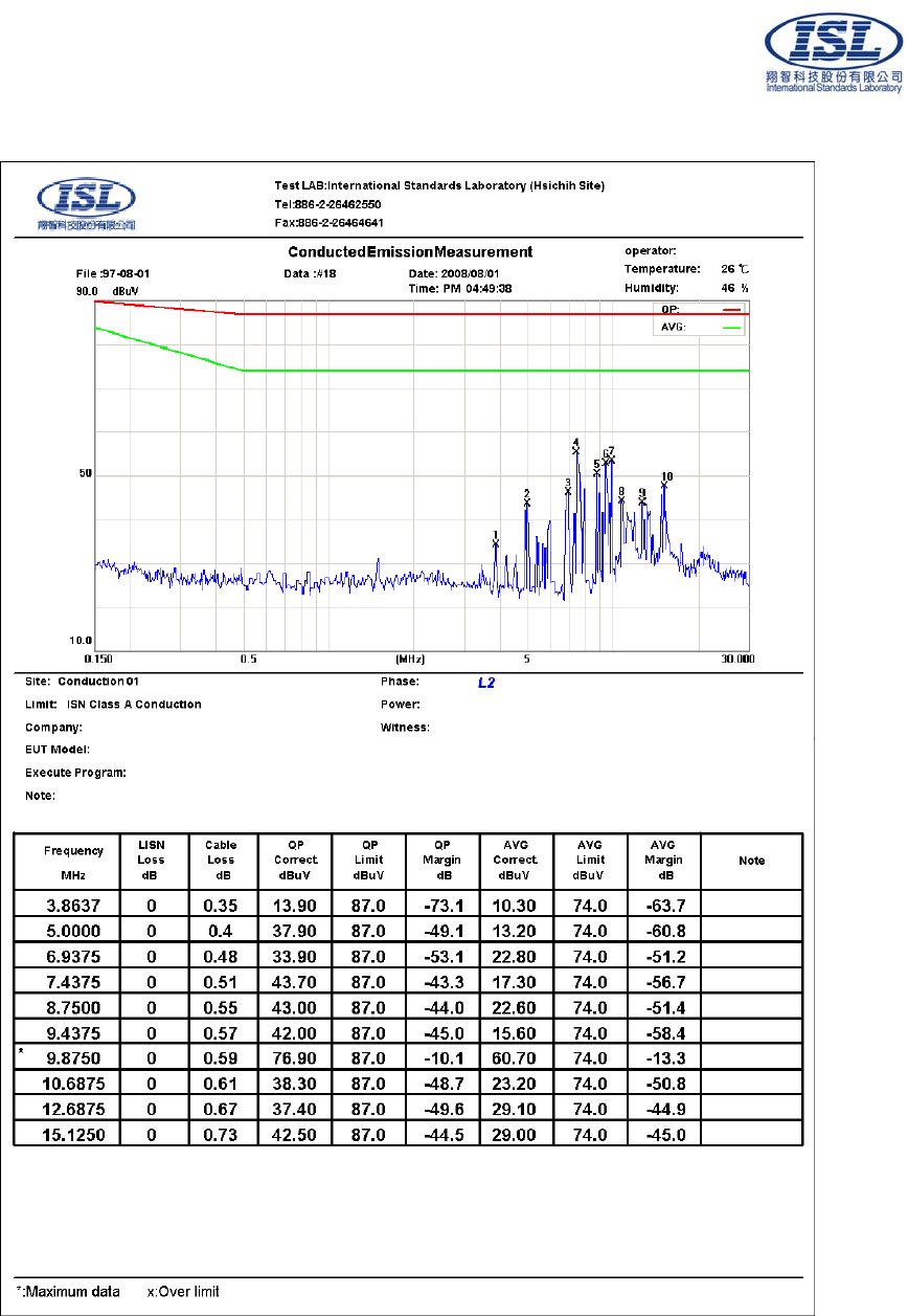
5.2 Conduction Test Data: Configuration 1
Table 5.2.1 Power Line Conducted Emissions (Hot)
Note:
Margin = Corrected Amplitude - Limit
Corrected Amplitude = Receiver Reading + LISN Loss + Cable Loss
A margin of -8dB means that the emission is 8dB below the limit
The frequency spectrum graph is for final peak graph, and the attached table is for QP/AVG test result.
If peak data can pass, it will be shown in “QP/AVG Correct” column, if not, QP/AVG data will instead.
International Standards Laboratory Report Number: ISL-08HE175CE
-10-
Table 5.2.2 Power Line Conducted Emissions (Neutral)
Note:
Margin = Corrected Amplitude - Limit
Corrected Amplitude = Receiver Reading + LISN Loss + Cable Loss
A margin of -8dB means that the emission is 8dB below the limit
The frequency spectrum graph is for final peak graph, and the attached table is for QP/AVG test result.
If peak data can pass, it will be shown in “QP/AVG Correct” column, if not, QP/AVG data will instead.

International Standards Laboratory Report Number: ISL-08HE175CE
-11-
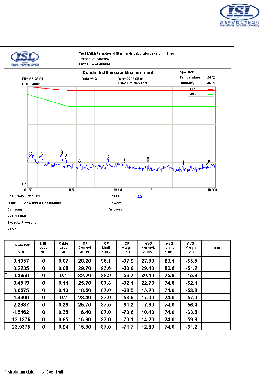
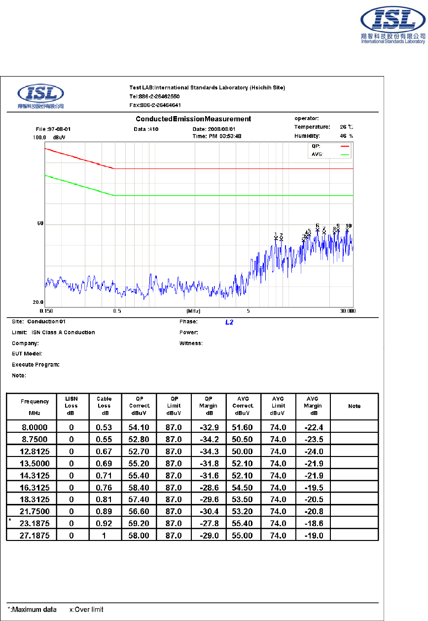
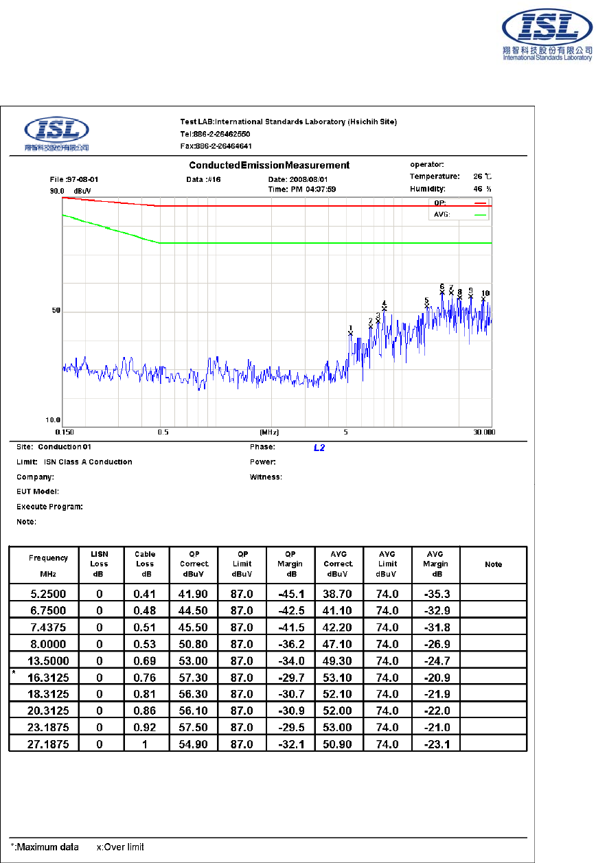
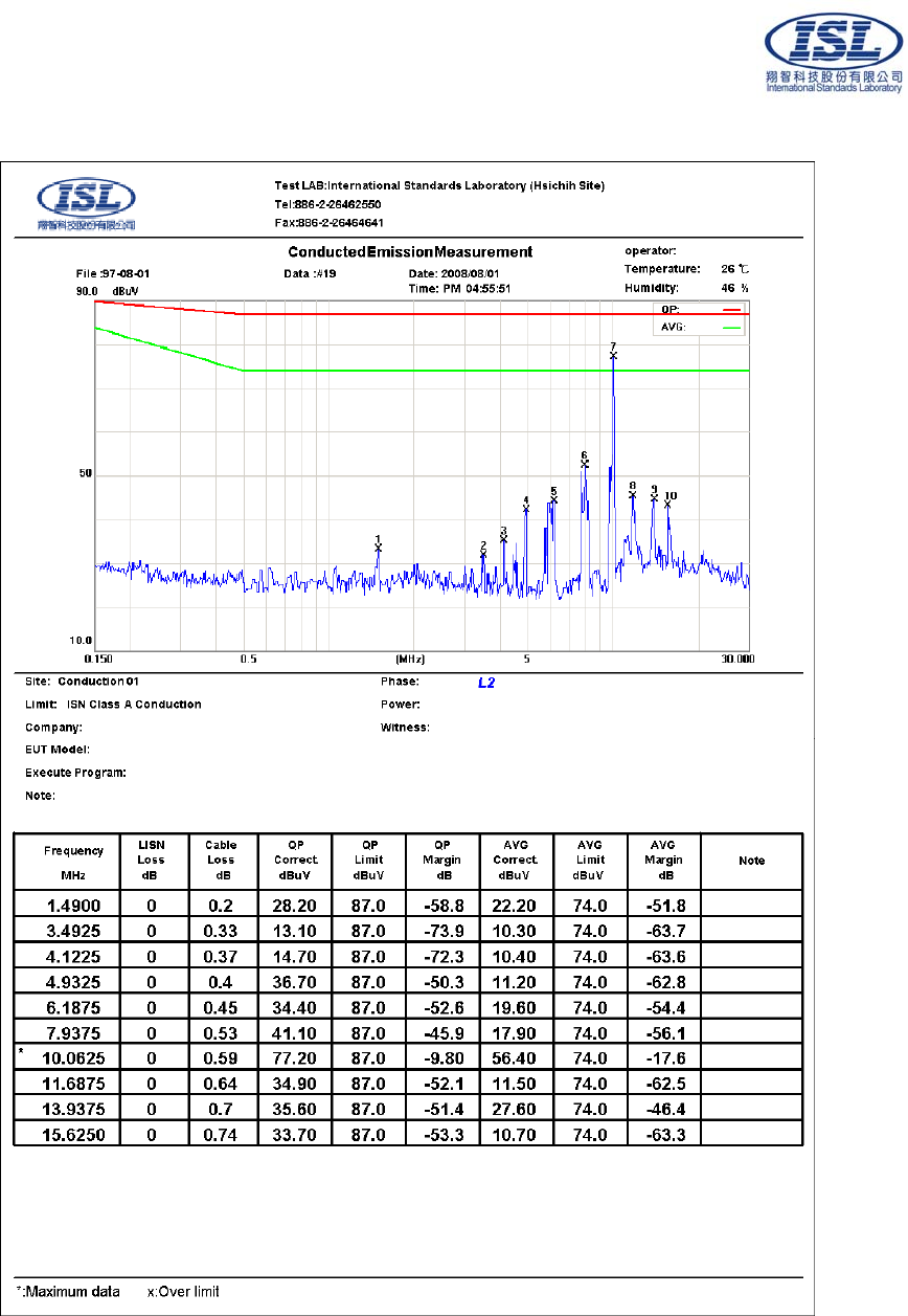
6. Telecommunication Port Conducted Emissions
6.1 Configuration and Procedure
6.1.1 EUT Configuration
The EUT was set up on the non-conductive table that is 1.0 by 1.5 meter, 80cm above ground. The
wall was 40cm to the rear of the EUT. The excess length of the power cord was folded back and
forth at the center of the lead to form a bundle 30cm to 40cm in length. The distance between EUT
and CDN is 80cm. CDN is connected to the reference ground plane. Any changes made to the
configuration, or modifications made to the EUT, during testing are noted in the following test
record.
6.1.2 Test Procedure
The system was set up as described above, with the EMI diagnostic software running. The content
of the software consist of both periodic and pseudo-random messages. The effect of varying the
position of the interface cables has been investigated to find the configuration that produces
maximum emission. The highest emissions were analyzed in details by operating the spectrum
analyzer in fixed tuned mode to determine the nature of the emissions and to provide information
which could be useful in reducing their amplitude.
6.1.3 EMI Receiver/Spectrum Analyzer Configuration (for the frequencies tested)
Frequency Range: 150KHz--30MHz
Detector Function: Quasi-Peak / Average Mode
Resolution Bandwidth: 9KHz
International Standards Laboratory Report Number: ISL-08HE175CE
-12-
6.2 Test Data: LAN 1--GIGA (Voltage)
Table 6.2.1 Telecommunication Port Conducted Emission
Note :
Margin = Corrected Amplitude - Limit
Corrected Amplitude = Receiver Reading + LISN Loss + Cable Loss
A margin of -8dB means that the emission is 8dB below the limit
The frequency spectrum graph is for final peak graph, and the attached table is for QP/AVG test result.
If peak data can pass, it will be shown in “QP/AVG Correct” column, if not, QP/AVG data will instead.

International Standards Laboratory Report Number: ISL-08HE175CE
-13-
6.3 Test Data: LAN 2--GIGA (Voltage)
Table 6.3.1 Telecommunication Port Conducted Emission
Note :
Margin = Corrected Amplitude - Limit
Corrected Amplitude = Receiver Reading + LISN Loss + Cable Loss
A margin of -8dB means that the emission is 8dB below the limit
The frequency spectrum graph is for final peak graph, and the attached table is for QP/AVG test result.
If peak data can pass, it will be shown in “QP/AVG Correct” column, if not, QP/AVG data will instead.
International Standards Laboratory Report Number: ISL-08HE175CE
-14-
6.4 Test Data: LAN 1--100M
Table 6.4.1 Telecommunication Port Conducted Emission
Note :
Margin = Corrected Amplitude - Limit
Corrected Amplitude = Receiver Reading + LISN Loss + Cable Loss
A margin of -8dB means that the emission is 8dB below the limit
The frequency spectrum graph is for final peak graph, and the attached table is for QP/AVG test result.
If peak data can pass, it will be shown in “QP/AVG Correct” column, if not, QP/AVG data will instead.
International Standards Laboratory Report Number: ISL-08HE175CE
-15-
6.5 Test Data: LAN 2--100M
Table 6.5.1 Telecommunication Port Conducted Emission
Note :
Margin = Corrected Amplitude - Limit
Corrected Amplitude = Receiver Reading + LISN Loss + Cable Loss
A margin of -8dB means that the emission is 8dB below the limit
The frequency spectrum graph is for final peak graph, and the attached table is for QP/AVG test result.
If peak data can pass, it will be shown in “QP/AVG Correct” column, if not, QP/AVG data will instead.
International Standards Laboratory Report Number: ISL-08HE175CE
-16-
6.6 Test Data: LAN 1--10M
Table 6.6.1 Telecommunication Port Conducted Emission
Note :
Margin = Corrected Amplitude - Limit
Corrected Amplitude = Receiver Reading + LISN Loss + Cable Loss
A margin of -8dB means that the emission is 8dB below the limit
The frequency spectrum graph is for final peak graph, and the attached table is for QP/AVG test result.
If peak data can pass, it will be shown in “QP/AVG Correct” column, if not, QP/AVG data will instead.
International Standards Laboratory Report Number: ISL-08HE175CE
-17-
6.7 Test Data: LAN 2--10M
Table 6.7.1 Telecommunication Port Conducted Emission
Note :
Margin = Corrected Amplitude - Limit
Corrected Amplitude = Receiver Reading + LISN Loss + Cable Loss
A margin of -8dB means that the emission is 8dB below the limit
The frequency spectrum graph is for final peak graph, and the attached table is for QP/AVG test result.
If peak data can pass, it will be shown in “QP/AVG Correct” column, if not, QP/AVG data will instead.

International Standards Laboratory Report Number: ISL-08HE175CE
-18-
7. Radiated Disturbance Emissions
7.1 Configuration and Procedure
7.1.1 EUT Configuration
The equipment under test was set up on a non-conductive table 80cm above ground, on open field or
chamber. The excess length of the power cord was folded back and forth at the center of the lead to
form a bundle 30cm to 40cm in length. Any changes made to the configuration, or modifications
made to the EUT, during testing are noted in the following test record.
If EUT has an extra auxiliary AC outlet which can provide power to an external monitor, all
measurements will be made with the monitor power from EUT-mounted AC outlet and then from
floor-mounted AC outlet.
7.1.2 Test Procedure
The system was set up as described above, with the EMI diagnostic software running. The
maximum emission was measured by varying the height of antenna and then by rotating the
turntable. Both polarization of antenna, horizontal and vertical, were measured.
The highest emissions between 30 MHz to 1000 MHz were analyzed in details by operating the
spectrum analyzer and/or EMI receiver in quasi-peak mode to determine the precise amplitude of
the emissions. While doing so, the interconnecting cables and major parts of the system were moved
around, the antenna height was varied between one and four meters, its polarization was varied
between vertical and horizontal, and the turntable was slowly rotated, to maximize the emission.
7.1.3 Spectrum Analyzer Configuration (for the frequencies tested)
Frequency Range: 30MHz--1000MHz
Detector Function: Quasi-Peak Mode
Resolution Bandwidth: 120KHz
International Standards Laboratory Report Number: ISL-08HE175CE
-19-
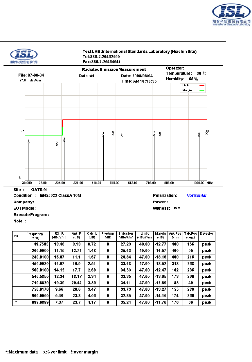
7.2 Radiation Test Data: Configuration 1
Table 7.2.1 Radiated Emissions (Horizontal)
* Note:
Margin = Corrected Amplitude – Limit
Corrected Amplitude = Radiated Amplitude + Antenna Correction Factor + Cable Loss – Pre-Amplifier Gain
A margin of -8dB means that the emission is 8dB below the limit
BILOG Antenna Distance: 10 meter, Frequency: under 1000MHz
Horn Antenna Distance: 3 meter, Frequency: 1000MHz—18GHz

International Standards Laboratory Report Number: ISL-08HE175CE
-20-
Table 7.2.1 Radiated Emissions (Vertical)
* Note:
Margin = Corrected Amplitude – Limit
Corrected Amplitude = Radiated Amplitude + Antenna Correction Factor + Cable Loss – Pre-Amplifier Gain
A margin of -8dB means that the emission is 8dB below the limit
BILOG Antenna Distance: 10 meter, Frequency: under 1000MHz
Horn Antenna Distance: 3 meter, Frequency: 1000MHz—18GHz

International Standards Laboratory Report Number: ISL-08HE175CE
-21-
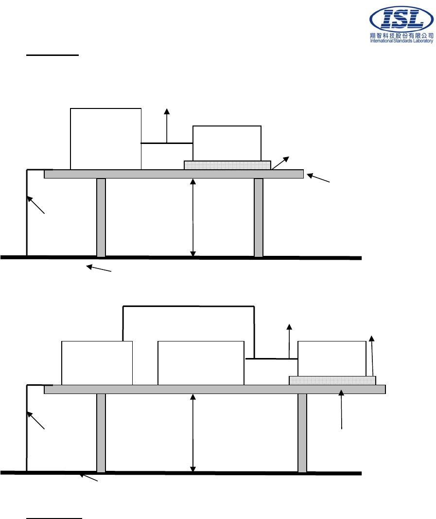
8. Electrostatic discharge (ESD) immunity
8.1 Electrostatic discharge (ESD) immunity test
Port: Enclosure
Basic Standard: EN61000-4-2/ AS/NZS 61000.4.2
(details referred to Sec 2.2)
Test Level: Air +/- 2 kV, +/- 4 kV, +/- 8 kV
Contact +/- 2 kV, +/- 4 kV
Criteria: B
Test Procedure refer to ISL QA T04-S03
Temperature: 26 °C
Humidity: 50%
Selected Test Point
Air: discharges were applied to slots, aperture or insulating surfaces. 10 single air
discharges were applied to each selected points.
Contact: Total 200 points minimum were to the selected contact points.
Indirect Contact Points: 25 discharges were applied to center of one edge of VCP and each
EUT side of HCP with 10 cm away from EUT.
For final test points, please refer to EUT 6 to EUT 7 of “Appendix: Photographs of EUT”.
Red arrow lines indicate the contact points, and blue arrow lines indicate the air points.
Test Setup
EUT is 1m from the wall and other metallic structure. When Battery test mode is needed, a cable
with one 470KΩ resister at two rare ends is connected from metallic part of EUT and screwed to
HCP.
Test Result
Performance of EUT complies with the given specification.
10cm
EUT
470KΩ
For battery
test mode VCP: 0.5m x 0.5m
HCP: 1.6m x 0.8
m
Non-Metallic Table
0.5mm insulation
470
K
470
K
Ω
Ground reference Plane
80cm
International Standards Laboratory Report Number: ISL-08HE175CE
-22-
9. Radio-Frequency, Electromagnetic Field immunity
9.1 Radio-Frequency, Electromagnetic Field immunity test
Port: Enclosure
Basic Standard: EN61000-4-3/ AS/NZS 61000.4.3
(details referred to Sec 2.2)
Test Level:: 3 V/m
Modulation: AM 1KHz 80%
Frequency range: 80 MHz~1 GHz
Frequency Step: 1% of last step frequency
Dwell time: 3s
Polarization: Vertical and Horizontal
EUT Azimuth Angle 0° 90° 180° 270°
Criteria: A
Test Procedure refer to ISL QA T04-S017
Temperature: 25°C
Humidity: 49%
Test Setup
The field sensor is placed at one calibration grid point to check the intensity of the
established fields on both polarizations. EUT is adjusted to have each side of EUT face
coincident with the calibration plane. A CCD camera and speakers are used to monitor the
condition of EUT for the performance judgment.
Test Result
Performance of EUT complies with the given specification.
International Standards Laboratory Report Number: ISL-08HE175CE
-23-
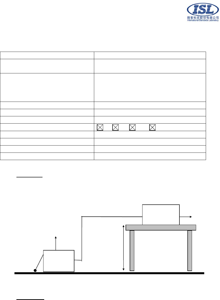
10. Electrical Fast transients/burst immunity
10.1 Electrical Fast transient/burst immunity test
Port: AC mains; Twisted Pair LAN Port
Basic Standard: EN61000-4-4/ AS/NZS 61000.4.4
(details referred to Sec 2.2)
Test Level: AC Power Port: +/- 1 kV
Twisted Pair LAN Port (I/O Cables): +/- 0.5 kV
Rise Time: 5ns
Hold Time: 50ns
Repetition Frequency: 5KHz
Criteria: B
Test Procedure refer to ISL QA T04-S05
Temperature: 26 °C
Humidity: 50%
Test Procedure
The EUT was setup on a nonconductive table 0.8 m above a reference ground plane.
Test Points Polarity Result Comment
Line + N 60 sec
- N 60 sec
Neutral + N 60 sec
- N 60 sec
Ground + N 60 sec
- N 60 sec
Line to + N 60 sec
Neutral - N 60 sec
Line to + N 60 sec
Ground - N 60 sec
Neutral to + N 60 sec
Ground - N 60 sec
Line to Neutral + N 60 sec
to Ground - N 60 sec
+ N 60 sec Capacitive coupling
clamp - N 60 sec
Note: ’N’ means normal, the EUT function is correct during the test.
International Standards Laboratory Report Number: ISL-08HE175CE
-24-
Test Setup
EUT is at least 50cm from the conductive structure.
Test Result
Performance of EUT complies with the given specification.
Grounding
cable
Metallic table
EUT
80cm
Signal lines
Capacitive
Coupling Clamp
Test Generator
Metal Full Soldered Ground Plane
0.1m insulation support
Grounding
cable
Metallic table
EUT
Test Generator
80cm
Supply line
Metal Full Soldered Ground Plane
0.1m insulation support
International Standards Laboratory Report Number: ISL-08HE175CE
-25-
11. Surge Immunity
11.1 Surge immunity test
Port: AC mains
Basic Standard: EN61000-4-5/ AS/NZS 61000.4.5
(details referred to Sec 2.2)
Test Level: AC Power Port:
Line to Line: +/- 0.5 kV, +/- 1 kV
Line to Earth: +/- 0.5 kV, +/- 1 kV, +/- 2kV
Rise Time: 1.2us
Hold Time: 50us
Repetition Rate: 30 second
Angle: 0° 90° 180° 270°
Criteria: B
Test Procedure refer to ISL QA T04-S04
Temperature: 26°C
Humidity: 50%
Test Setup
AC power supply and
Voltage Supply to EUT
To the Peripherals
To AC main Supply Non-Metallic /
Non-Conducted Table
80 cm
Metal Full Soldered Ground Plane
Test Result
Performance of EUT complies with the given specification.
Test
Generator
EUT
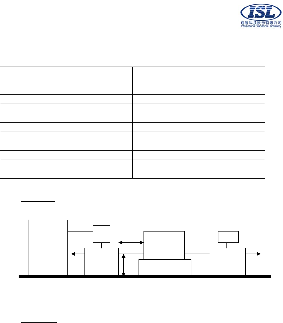
International Standards Laboratory Report Number: ISL-08HE175CE
-26-
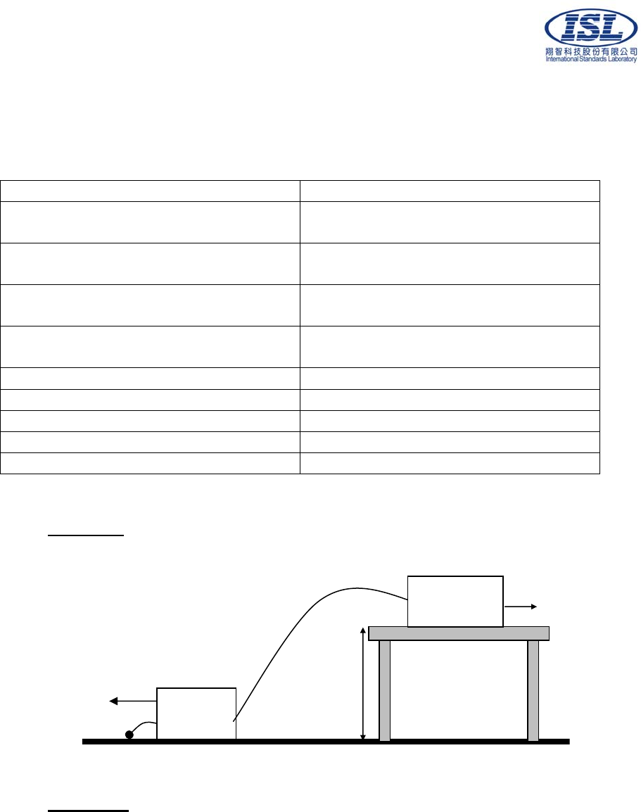
12. Immunity to Conductive Disturbance
12.1 Immunity to Conductive Disturbance
Port: AC mains; Twisted Pair LAN Port
Basic Standard: EN61000-4-6/ AS/NZS 61000.4.6
(details referred to Sec 2.2)
Test Level:: 3 V
Modulation: AM 1KHz 80%
Frequency range: 0.15 MHz - 80MHz
Frequency Step: 1% of last Frequency
Dwell time: 3s
Criteria: A
Test Procedure refer to ISL QA T04-S08
Temperature: 26°C
Humidity: 50%
Test Setup
Test Result
Performance of EUT complies with the given specification.
0.1 m support
EUT
CDN CDN
To AC main
50
To AE
Test
Generator
>3c
m
10~30cm
6d
B
Reference Ground Plane

International Standards Laboratory Report Number: ISL-08HE175CE
-27-
13. Power Frequency Magnetic Field immunity
13.1 Power Frequency Magnetic field immunity test
Port: Enclosure
Basic Standard: EN61000-4-8/ AS/NZS 61000.4.8
(details referred to Sec 2.2)
Test Level: 1A/m
Polarization: X, Y, Z
Criteria: A
Test Procedure refer to ISL QA T04-S02
Temperature: 26°C
Humidity: 50%
Test Setup
Test Result
Performance of EUT complies with the given specification.
A
E
Insulation
Test
Generator
EUT
<3M Induction Coil (1m x 1m)
80cm
To AC main
N
on-Metallic
Ground Reference Plane
Metal
Ground
plane
strip
Metal
Ground
Plane
To AC main
International Standards Laboratory Report Number: ISL-08HE175CE
-28-
14. Voltage Dips, Short Interruption and Voltage Variation
immunity
14.1 Voltage Dips, Short Interruption and Voltage Variation immunity test
Port: AC mains
Basic Standard: EN61000-4-11/ AS/NZS 61000.4.11
(details referred to Sec 2.2)
Test Level:
Criteria: >95% in 0.5 period
B
Test Level:
Criteria: 30% in 25 period
C
Test Level:
Criteria: >95% in 250 period
C
Phase: 0°; 180°
Test intervals: 3 times with 10s each
Test Procedure refer to ISL QA T04-S01
Temperature: 26°C
Humidity: 50%
Test Setup
Test Result
Performance of EUT complies with the given specification.
Test
Generator
EUT
80cm
To AE
Ground Reference Plane
Non-Metallic Table
To AC main
EUT AC supply

International Standards Laboratory Report Number: ISL-08HE175CE
-29-
15. Harmonics
15.1 Harmonics test
Port: AC mains
Active Input Power: >75W
Basic Standard: EN61000-3-2/AS/NZS61000.3.2
(details referred to Sec 2.2)
Test Duration: 2.5min
Class: D
Test Procedure refer to ISL QA T04-S43
Temperature: 27°C
Humidity: 56%
Test Procedure
The EUT is supplied in series with shunts or current transformers from a source having the
same nominal voltage and frequency as the rated supply voltage and frequency of the EUT. The
EUT is configured to its rated current with additional resistive load when the testing is performed.
Equipment having more than one rated voltage shall be tested at the rated voltage producing
the highest harmonics as compared with the limits.
Result
Performance of EUT complies with the given specification.

International Standards Laboratory Report Number: ISL-08HE175CE
-30-
Test Data
Date : 2008/8/5 AM 09:36:10 V4.16
Urms = 229.9V Freq = 49.987 Range: 2 A
Irms = 0.446A Ipk = 0.767A cf = 1.718
P = 96.35W S = 102.6VA pf = 0.939
THDi = 21.0 % THDu = 0.20 % Class D
Test - Time : 5min ( 100 %)
Limit Reference: Pmax = 111.76W
Test completed, Result: PASSED

International Standards Laboratory Report Number: ISL-08HE175CE
-31-
Order Freq. Iavg Iavg%L Imax Imax%L Limit Status
[Hz] [A] [%] [A] [%] [A]
1 50 0.4608 0.4991
2 100 0.0007 0.0060
3 150 0.0918 24.163 0.0964 25.378 0.3800
4 200 0.0000 0.0007
5 250 0.0115 5.3964 0.0118 5.5760 0.2124
6 300 0.0000 0.0005
7 350 0.0035 3.1244 0.0067 6.0071 0.1118
8 400 0.0000 0.0006
9 450 0.0138 24.753 0.0154 27.524 0.0559
10 500 0.0000 0.0009
11 550 0.0058 14.720 0.0063 16.227 0.0391
12 600 0.0000 0.0010
13 650 0.0103 31.009 0.0114 34.298 0.0331
14 700 0.0000 0.0011
15 750 0.0062 21.620 0.0109 37.873 0.0287
16 800 0.0000 0.0012
17 850 0.0136 53.802 0.0143 56.426 0.0253
18 900 0.0000 0.0011
19 950 0.0095 42.068 0.0138 60.908 0.0226
20 1000 0.0000 0.0011
21 1050 0.0068 33.378 0.0084 41.107 0.0205
22 1100 0.0000 0.0010
23 1150 0.0000 0.0000 0.0043 22.837 0.0187
24 1200 0.0000 0.0009
25 1250 0.0040 23.083 0.0071 41.135 0.0172
26 1300 0.0000 0.0009
27 1350 0.0027 16.863 0.0062 39.064 0.0159
28 1400 0.0000 0.0006
29 1450 0.0000 0.0000 0.0033 22.213 0.0148
30 1500 0.0000 0.0007
31 1550 0.0000 0.0000 0.0046 33.419 0.0139
32 1600 0.0000 0.0010
33 1650 0.0000 0.0000 0.0049 37.447 0.0130
34 1700 0.0000 0.0010
35 1750 0.0000 0.0000 0.0040 32.766 0.0123
36 1800 0.0000 0.0009
37 1850 0.0000 0.0000 0.0048 40.936 0.0116
38 1900 0.0000 0.0009
39 1950 0.0000 0.0000 0.0038 34.298 0.0110
40 2000 0.0000 0.0007
International Standards Laboratory Report Number: ISL-08HE175CE
-32-
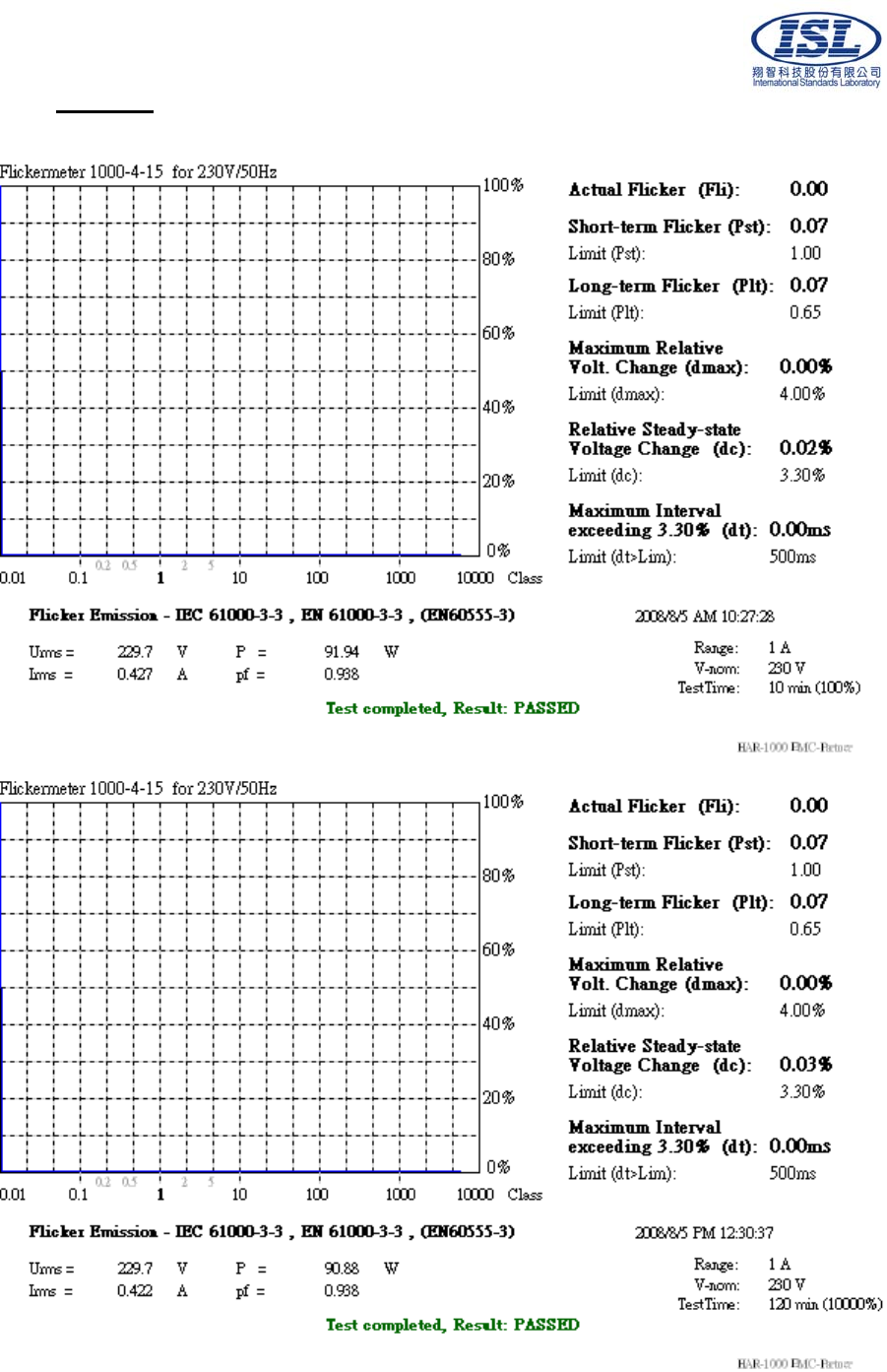
16. Voltage Fluctuations
16.1 Voltage Fluctuations test
Port: AC mains
Basic Standard: EN61000-3-3/AS/NZS61000.3.3
(details referred to Sec 2.2)
Test Procedure refer to ISL QA T04-S44
For Pst 10min Observation period: For Plt 2 hours
Temperature: 27°C
Humidity: 56%
Test Procedure
The EUT is supplied in series with reference impedance from a power source with the voltage
and frequency as the nominal supply voltage and frequency of the EUT.
Result
Performance of EUT complies with the given specification.
International Standards Laboratory Report Number: ISL-08HE175CE
-33-
Test Data
10 min
120min

International Standards Laboratory Report Number: ISL-08HE175CE
-34-
17. Appendix
17.1 Appendix A: Measurement Procedure for Main Power Port Conducted Emissions
The measurements are performed in a 3.5m x 3.4m x 2.5m shielded room, which referred as
Conduction 01 test site, or a 3m x 3m x 2.3m test site, which referred as Conduction 02 test site. The
EUT was placed on non-conduction 1.0m x 1.5m table, which is 0.8 meters above an
earth-grounded.
Power to the EUT was provided through the LISN which has the Impedance (50ohm/50uH) vs.
Frequency Characteristic in accordance with the standard. Power to the LISNs were filtered to
eliminate ambient signal interference and these filters were bonded to the ground plane. Peripheral
equipment required to provide a functional system (support equipment) for EUT testing was
powered from the second LISN through a ganged, metal power outlet box which is bonded to the
ground plane at the LISN.
If the EUT is supplied with a flexible power cord, the power cord length in excess of the distance
separating the EUT from the LISN shall be folded back and forth at the center of the lead so as to
form a bundle not exceeding 40cm in length. If the EUT is provided with a permanently coiled
power cord, bundling of the cord is not required. If the EUT is supplied without a power cord, the
EUT shall be connected to the LISN by a power cord of the type specified by the manufacturer
which shall not be longer than 1 meter. The excess power cord shall be bundled as described above.
If a non-flexible power cord is provided with the EUT, it shall be cut to the length necessary to
attach the EUT to the LISN and shall not be bundled.
The interconnecting cables were arranged and moved to get the maximum measurement. Both the
line of power cord, hot and neutral, were measured.
The highest emissions were analyzed in details by operating the spectrum analyzer in fixed tuned
mode to determine the nature of the emissions and to provide information which could be useful in
reducing their amplitude.

International Standards Laboratory Report Number: ISL-08HE175CE
-35-
17.2 Appendix B: Measurement Procedure for Telecommunication Port Conducted
Emissions
The measurements are performed in a 3.5m x 3.4m x 2.5m shielded room, which referred as
Conduction 01 test site, or a 3m x 3m x 2.3m test site, which referred as Conduction 02 test site. The
EUT was placed on non-conduction 1.0m x 1.5m table, which is 0.8 meters above an
earth-grounded.
The EUT, any support equipment, and any interconnecting cables were arranged and moved to get
the maximum measurement.
Power to the EUT was provided through the LISN which has the Impedance (50 Ohm/50uH) vs.
Frequency Characteristic in accordance with the standard. Power to the LISN was filtered to
eliminate ambient signal interference and this filter was bonded to ground. Peripheral equipment to
provide a functional system (support equipment) for EUT testing was powered through a ganged,
metal power outlet box bonded to the ground. AC input power for the auxiliary power outlets was
obtained from the same filtered source that provides input power to the LISN.
If the EUT is supplied with a flexible power cord, if the power cord length in excess of 1 m, the
excess cable shall be bundled at approximate center of the power cord with the bundles 30 cm to 40
cm in length. If the EUT is provided with a permanently coiled power cord, bundling of the cord is
not required. If the EUT is supplied without a power cord, the EUT shall be connected to the LISN
by a power cord of the type specified by the manufacturer which shall be 1 meter in length. If a
non-flexible power cord is provided with the EUT, it shall be cut to the length necessary to attach
the EUT to the LISN and shall not be bundled.
The highest emissions were analyzed in details by operating the spectrum analyzer in fixed tuned
mode to determine the nature of the emissions and to provide information could be useful in
reducing their amplitude.

International Standards Laboratory Report Number: ISL-08HE175CE
-36-
17.3 Appendix C: Test Procedure for Radiated Emissions
Preliminary Measurements in the Anechoic Chamber
The radiated emissions are initially measured in the anechoic chamber at a measurement distance of
3 meters. Desktop EUT are placed on a wooden stand 0.8 meter in height. The measurement
antenna is 3 meters from the EUT. The test setup in anechoic chamber is the same as open site. The
turntable rotated 360°C. The antenna height is varied from 1-2.5m. The primary objective of the
radiated measurements in the anechoic chamber is to identify the frequency spectrum in the absence
of the electromagnetic environment existing on the open test site. The frequencies can then be
pre-selected on the open test site to obtain the corresponding amplitude. The initial scan is made
with the spectrum analyzer in automatic sweep mode. The spectrum peaks are then measured
manually to determine the exact frequencies.
Measurements on the Open Site or Chamber
The radiated emissions test will then be repeated on the open site or chamber to measure the
amplitudes accurately and without the multiple reflections existing in the shielded room. The EUT
and support equipment are set up on the turntable of one of 10 meter open field sites. Desktop EUT
are set up on a wooden stand 0.8 meter above the ground.
For the initial measurements, the receiving antenna is varied from 1-4 meter height and is changed
in the vertical plane from vertical to horizontal polarization at each frequency. Both reading are
recorded with the quasi-peak detector with 120KHz bandwidth. For frequency between 30 MHz
and 1000MHz, the reading is recorded with peak detector or quasi-peak detector.
At the highest amplitudes observed, the EUT is rotated in the horizontal plane while changing the
antenna polarization in the vertical plane to maximize the reading. The interconnecting cables were
arranged and moved to get the maximum measurement. Once the maximum reading is obtained, the
antenna elevation and polarization will be varied between specified limits to maximize the readings.

International Standards Laboratory Report Number: ISL-08HE175CE
-37-
17.4 Appendix D: Test Equipment
17.4.1 Test Equipment List
Location Equipment Name Brand Model S/N Last Cal. Date Next Cal. Date
Conduction Coaxial Cable 1F-C1 Harbourindustr
ies RG400 1F-C1 10/25/2007 10/25/2008
Conduction Hygro-Thermo Meter
11 N/A TH-400 ISL-002 02/19/2008 02/19/2009
Conduction LISN 02 EMCO 3825/2 1407 07/07/2008 07/07/2009
Conduction LISN 03 R&S ESH3-Z5
831.5518.52 828874/010 07/07/2008 07/07/2009
Conduction ISN T4 04 Schaffner ISN T400 21644 02/19/2008 02/19/2009
Conduction Current Probe 01 SOLAR 9208-1 0411602 02/19/2008 02/19/2009
Conduction Capacitive Voltage
Probe 01 Schaffner CVP2200A 18711 07/12/2008 07/12/2009
Conduction EMI Receiver 08 Schwarzbeck
Mess-Elektroni
k
FCKL 1528 1528-202 09/05/2007 09/05/2008
Conduction Spectrum Analyzer 05 HP 8594EM 3619A00192 02/19/2008 02/19/2009
Radiation BILOG Antenna 10 Sumol
Sciences JB1 A013004-1 07/24/2008 07/24/2009
Radiation Coaxial Cable 3F-10M MIYAZAKI 8D-8F 10M-1 10/25/2007 10/25/2008
Radiation Coaxial Cable 3F-3M BELDEN RG-8/U 3F-3M 10/25/2007 10/25/2008
Radiation Spectrum Analyzer 12 Advantest R3132 130200208 03/05/2008 03/05/2009
Radiation Hygro-Thermo Meter
10 N/A TH-400 ISL-001 02/19/2008 02/19/2009
Rad. above
1Ghz Horn Antenna 01 EMCO 3115 9504-4462 10/30/2007 10/30/2008
Rad. above
1Ghz Horn Antenna 03 COM-Power AH-826 100A 02/20/2008 02/20/2009
Rad. above
1Ghz Microwave Cable
RF07-3 HUBER+SUH
NER AG. Sucoflex 103 42728/3 07/17/2008 07/17/2009
Rad. above
1Ghz Preamplifier 01 R&S ESMI-Z7 1045.502 07/17/2008 07/17/2009
Radiation Signal Generator 01 HP 8656B 2635A04675 08/17/2007 08/17/2008
Radiation EMI Receiver 09 Schwarzbeck
Mess-Elektroni
k
FCVU 1534 1534-150 05/08/2008 05/08/2009

International Standards Laboratory Report Number: ISL-08HE175CE
-38-
Location Equipment Name Brand Model S/N Last Cal. Date Next Cal. Date
EN61K-3-2/3 DC Burn-In Load 02 D-RAM DBS-2100 2100-910027 N/A N/A
EN61K-3-2/3 Harmonic/Flicker Test
System 03 EMC Partner HARMONICS-
1000
178 03/27/2008 03/27/2009
EN61K-3-2/3 Hygro-Thermo Meter
15 N/A TH-400 ISL-006 02/19/2008 02/19/2009
EN61K-4 Hygro-Thermo Meter
14 N/A TH-400 ISL-005 02/19/2008 02/19/2009
EN61K-4-,4,5,
8,11 TRANSIENT 2000 01 EMC Partner TRANSIENT-
2000 950 10/30/2007 10/30/2008
EN61K-4-2 ESD GUN 04 Schaffner NSG 438 489 03/07/2008 03/07/2009
EN61K-4-3 BILOG Antenna 06 Schaffner CBL6112B 2754 N/A N/A
EN61K-4-3 Amplifier 80Mz~1GHz
250W AR 250W1000A 312494 N/A N/A
EN61K-4-3 Amplifier
800MHz~3.0GHz 60W AR 60S1G3 312762 N/A N/A
EN61K-4-3 Broadband coupler
10K~220Mhz Amplifier
Research DC2500 19810 N/A N/A
EN61K-4-3 Broadband Coupler
80M~1GHz Amplifier
Research DC6180 20364 N/A N/A
EN61K-4-3 Broadband Coupler
1~4GHz Werlatone C5291 6516 N/A N/A
EN61K-4-3 Coaxial Cable Chmb
04-3M-2 Belden RG-8/U Chmb
04-3M-2 N/A N/A
EN61K-4-3 Signal Generator 03 Anritsu MG3642A 6200162550 02/27/2008 02/27/2009
EN61K-4-4 Digital Oscilloscope Tektronix TDS 684A B010761 N/A N/A
EN61K-4-4 EFT Clamp Precision 1604242 CNEFT1000-1
03 N/A N/A
EN61K-4-5 CDN-Kit -4 Precision 1604243 CDNKIT1000-
32 N/A N/A
EN61K-4-5 CDN Surge Kit 01 EMC-PARTN
ER CDNKIT1000
T; DN-T1;
DN-T2;
CN-T1; CN-T2
CDNKIT1000-
24 08/06/2006 08/06/2009
EN61K-4-6 6dB Attenuator Weinschel
Corp 33-6-34 BC5975 N/A N/A
EN61K-4-6 Amplifier 4-6 Amplifier
Research 150A100 1-1-R-02157 N/A N/A
EN61K-4-6 Attenuator 6dB 4-6 BIRO 100-A-FFN-06 0123 N/A N/A
EN61K-4-6 CDN M2+M3 Frankonia M2+M3 A3011016 07/08/2008 07/08/2009
EN61K-4-6 CDN T2 01 Frankonia T2 A3010003 07/08/2008 07/08/2009
EN61K-4-6 CDN T4 01 FCC Inc. FCC-801-T4 9721 07/08/2008 07/08/2009
EN61K-4-6 EM-Clamp 01 FCC F-203I-23MM 539 N/A N/A
EN61K-4-6 Coaxial Cable 4-6 01-1 Harbour
Industries M17/128-RG4
00 4-6 01-1 N/A N/A
EN61K-4-6 Coaxial Cable 4-6 01-2 Harbour
Industries M17/128-RG4
00 4-6 01-2 N/A N/A
EN61K-4-6 Coaxial Cable 4-6 01-3 Harbour
Industries M17/128-RG4
00 4-6 01-3 N/A N/A
EN61K-4-6 KAL-AD RJ45S BIRO N/A N/A
EN61K-4-6 KAL-AD T2 BIRO N/A N/A
EN61K-4-6 Passive Impedance
Adaptor 4-6 FCC FCC-801-150-
50-CDN 9758;9759 N/A N/A
EN61K-4-6,
CISPR 13,
Antenna
Signal Generator 01 HP 8656B 2635A04675 08/17/2007 08/17/2008
EN61K-4-8 Clamp Meter 4-8 TES 3090 990900322 07/11/2008 07/11/2009
EN61K-4-8 Magnetic Field Antenna Precision TRAIZ44B MF1000-23 N/A N/A
International Standards Laboratory Report Number: ISL-08HE175CE
-39-
17.5 Software for Controlling Spectrum/Receiver and Calculating Test Data
Test Item Filename Version
EN61000-3-2 HARCS.EXE 4.16
EN61000-3-3 HARCS.EXE 4.16
EN61000-4-3 Tile.Exe 2.0.P
EN61000-4-6 EN61000-4-6 Application
Software 1.13.e
EN61000-4-2 N/A 2.0
EN61000-4-4 Tema.EXE 1.69
EN61000-4-5 Tema.EXE 1.69
EN61000-4-8 N/A
EN61000-4-11 VDS-2002Rs.EXE 2.00
Radiation/Conduction Filename Version Issued Date
Hsichih Conduction EZ EMC 1.1.4.2 2/10/2007
Hsichih Radiation EZ EMC 1.1.4.2 1/24/2007
Lung_Tan Conduction EZ EMC 1.1.4.2 2/10/2007
Lung_Tan Radiation EZ EMC 1.1.4.2 1/24/2007
International Standards Laboratory Report Number: ISL-08HE175CE
-40-
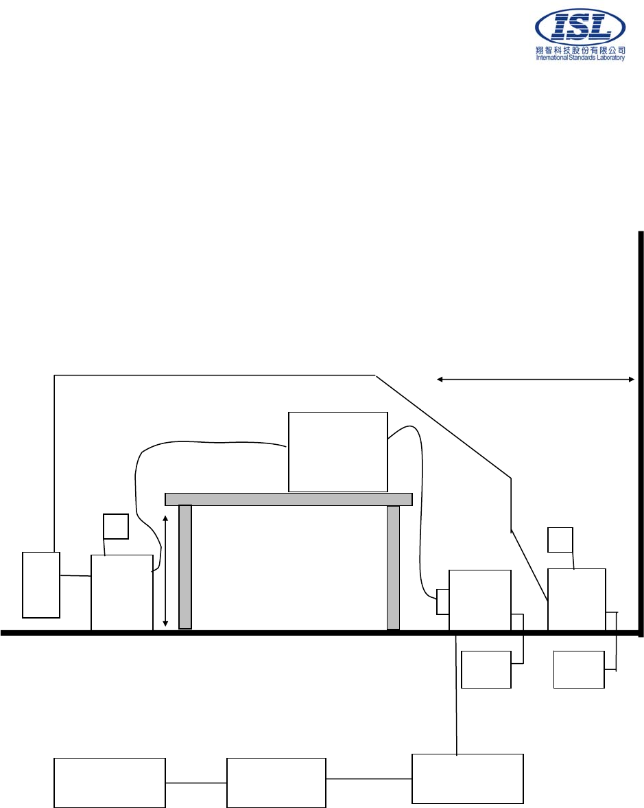
17.6 Appendix E: Layout of EUT and Support Equipment
17.6.1 General Power Main Port Conducted Test Configuration
40 cm
Non-Conducted Table
80 cm
Metal Ground Plane
LISN
EUT
Printer Receiver
Control PC
CDN
AE
Filter Filter
LISN
50Ω 50Ω
International Standards Laboratory Report Number: ISL-08HE175CE
-41-
17.6.2 General Telecommunication Port Conducted Emission Test Configuration
40 cm
Non-Conducted Table
80 cm
Metal Ground Plane
LISN
EUT
Printer Receiver
Control PC
CDN
AE
Filter Filter
LISN
50Ω50Ω
International Standards Laboratory Report Number: ISL-08HE175CE
-42-
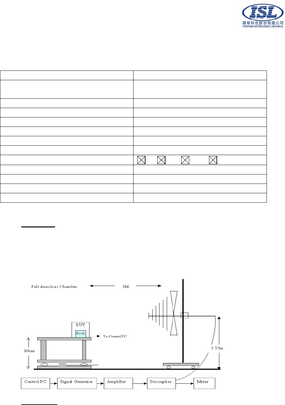
17.6.3 General Radiation Test Configuration
10 M
1-4M
Non-Conducted
Table To Spectrum
80 cm To Remote
Controller
To Remote Controller
Metal Full Soldered Ground Plane
To Turntable
To Antenna
To Antenna
Antenna and
turntable distance:
10 M
Load
Active
EUT
Printer Spectrum
Control PC
Remote
Controller
International Standards Laboratory Report Number: ISL-08HE175CE
-43-
17.7 Appendix F: Uncertainty of Measurement
The measurement uncertainty refers to CISPR 16-4-2:2003. The coverage factor k = 2
yields approximately a 95 % level of confidence.
<Conduction 01>: ±1.57dB
<OATS 01 (10M)>
30MHz~1GHz: ±2.60dB
<Immunity 01>
Test item Uncertainty
EN61000-4-2 (ESD) ±38.43%
EN61000-4-3 (RS) ±2.56dB
EN61000-4-4 (EFT) ±17.16%
EN61000-4-5 (Surge) ±14.79%
EN61000-4-6 (CS) ±2.93dB
EN61000-4-8 (Magnetic) ±0.01%
EN61000-4-11 (Dips) ±4.61%
EN61000-3-2 (Harmonics) ±0.01%
EN61000-3-3 (Fluctuations and Flicker) ±0.01%

International Standards Laboratory Report Number: ISL-08HE175CE
-44-
17.8 Appendix G: Photographs of EUT Configuration Test Set Up
17.8.1 Photo of Main Power Port Conducted Emission and Telecommunication Port
Conducted Emission Measurement
Front View
International Standards Laboratory Report Number: ISL-08HE175CE
-45-
Back View

International Standards Laboratory Report Number: ISL-08HE175CE
-46-
17.8.2 Photo of Radiated Emission Measurement
Front View
Back View
International Standards Laboratory Report Number: ISL-08HE175CE
-47-
17.8.3 Photo of ESD Measurement
17.8.4 Photo of RF Field Strength Susceptibility Measurement
.

International Standards Laboratory Report Number: ISL-08HE175CE
-48-
17.8.5 Photo of Electrical Fast Transient/Burst Measurement
17.8.6 Photo of Surge Measurement
International Standards Laboratory Report Number: ISL-08HE175CE
-49-
17.8.7 Photo of Conductive Measurement
17.8.8 Photo of Magnetic field Measurement

International Standards Laboratory Report Number: ISL-08HE175CE
-50-
17.8.9 Photo of Voltage Dips Measurement
17.8.10 Photo of Harmonics and Voltage Fluctuations

International Standards Laboratory Report Number: ISL-08HE175CE
-51-
17.9 Photographs of EUT
Please refer to the File of ISL-08HE175P
