VisionSDK_DeveopmentGuide Vision SDK Linux Development Guide
User Manual:
Open the PDF directly: View PDF ![]() .
.
Page Count: 16

Page 1 of 16
Vision SDK
(v03.xx)
Linux Development Guide

Page 2 of 16
IMPORTANT NOTICE
Texas Instruments and its subsidiaries (TI) reserve the right to make changes to their products or to
discontinue any product or service without notice, and advise customers to obtain the latest version of relevant
information to verify, before placing orders, that information being relied on is current and complete. All
products are sold subject to the terms and conditions of sale supplied at the time of order acknowledgment,
including those pertaining to warranty, patent infringement, and limitation of liability.
TI warrants performance of its products to the specifications applicable at the time of sale in accordance with
TI’s standard warranty. Testing and other quality control techniques are utilized to the extent TI deems
necessary to support this warranty. Specific testing of all parameters of each device is not necessarily
performed, except those mandated by government requirements.
Customers are responsible for their applications using TI components.
In order to minimize risks associated with the customer’s applications, adequate design and operating
safeguards ought to be provided by the customer so as to minimize inherent or procedural hazards.
TI assumes no liability for applications assistance or customer product design. TI does not warrant or represent
that any license, either express or implied, is granted under any patent right, copyright, mask work right, or
other intellectual property right of TI covering or relating to any combination, machine, or process in which such
products or services might be or are used. TI’s publication of information regarding any third party’s products or
services does not constitute TI’s approval, license, warranty or endorsement thereof.
Reproduction of information in TI data books or data sheets is permissible only if reproduction is without
alteration and is accompanied by all associated warranties, conditions, limitations and notices. Representation
or reproduction of this information with alteration voids all warranties provided for an associated TI product or
service, is an unfair and deceptive business practice, and TI is neither responsible nor liable for any such use.
Resale of TI’s products or services with statements different from or beyond the parameters stated by TI for
that product or service voids all express and any implied warranties for the associated TI product or service, is
an unfair and deceptive business practice, and TI is not responsible nor liable for any such use.
Also see: Standard Terms and Conditions of Sale for Semiconductor Products.
www.ti.com/sc/docs/stdterms.htm
Mailing Address:
Texas Instruments
Post Office Box 655303
Dallas, Texas 75265
Copyright © 2014, Texas Instruments Incorporated

Page 3 of 16
TABLE OF CONTENTS
1 Introduction ................................................................................................. 4
2 Application Overview ................................................................................... 5
3 Use Case Development ................................................................................. 7
4 Link Development ........................................................................................ 7
5 Algorithm Link Development ........................................................................ 7
6 Memory map of the application .................................................................... 7
6.1 Adding a new section to memory map ................................................................ 8
6.2 Changing size of a section in the memory map .................................................... 8
7 Hardware Resources Split ............................................................................ 9
8 Inter-Processor Communication ................................................................. 10
9 EVE Support in Linux .................................................................................. 14
9.1 EVE Loader .................................................................................................... 14
9.2 A15<->EVE inter-processor communication....................................................... 15
10 Revision History ......................................................................................... 16

Page 4 of 16
1 Introduction
Vision Software Development Kit (SDK) is a multi-processor, multi-channel software
development platform for TI family of ADAS SoCs. The software framework allows
users to create different ADAS application data flows involving video capture, video
pre-processing, video analytics algorithms, and video display.
This document explains procedure for following
1. To develop a use case application using Vision SDK when Linux is running on A15
2. To develop a new link in Linux + vision sdk scenario
This document assumes that the reader is familiar with basics of links and chains
architecture used in Vision SDK and has gone through
VisionSDK_DevelopmentGuide.pdf under vision_sdk/docs
This document explains linux part of vision sdk, how it works and developing
application on Linux for vision_sdk. The motivation behind introducing Linux to
vision_sdk is to utilize SGX through OpenGL APIs and other functionalities provided
by this commonly used OS like file management, storage and network streaming.
Page 5 of 16
2 Application Overview
The demo vision_sdk_linux_demo.out is a single process multi-threaded application
in Linux user space that enables users to run / validate supported ADAS usecases
and demonstrates how SGX can be used to render video frames captured through
VIP on IPU1 & transported on A15. Any other application that needs to work on
vision_sdk from Linux side should have similar structure.
Things to be noted here are
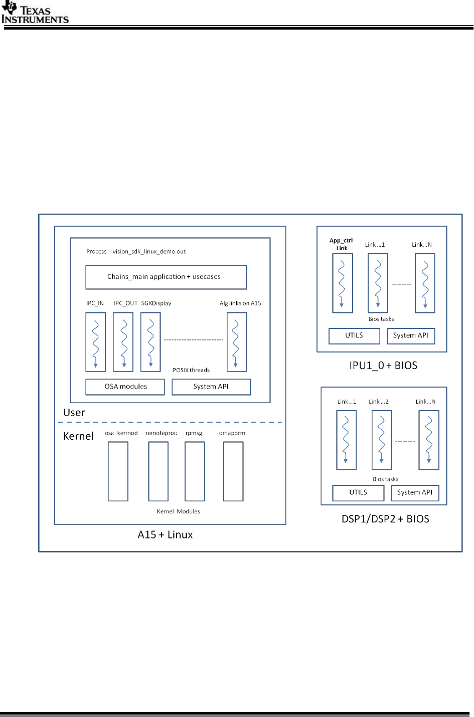
1. Figure 1 below depicts building blocks of application running on Linux and its
counterparts on the other cores.
Figure 1 : Linux + Vision SDK application overview
2. The application is mainly a chain of links required for the usecase and these links
can be instantiated / started / stopped irrespective of which core they are
running on.
3. Links which are in Linux user space have exactly same structure as that of bios
side except they are pthreads within the same process. These links use OSA
modules to interact with Linux for resources; this also includes system calls to
interact with kernel modules. System API is used to interact with links on remote
cores.

Page 6 of 16
4. Kernel modules involved
a. osa_kermod – Used for marking the mapping of physical address space as
cached / non-cached
b. remoteproc (also referred as rproc)– Used to load firmware binaries on
remote cores at linux boot time. The module with help of iommu driver
programs the L2MMU of slave core based on the information available in
the executable. This module is also responsible to manage state of remote
cores in the defined platform.
More information on remoteproc is available in kernel documentation
$INSTALL_DIR/ti_components/linux/kernel/omap/Documentation/remotep
roc.txt
c. rpmsg – Used for inter-processor communication between A15 and other
remoteproc managed slave cores. This is a vring based implementation.
More information on remoteproc is available in kernel documentation
$INSTALL_DIR/ti_components/linux/kernel/omap/Documentation/rpmsg.t
xt
d. omapdrm – Used for managing display subsystem (DSS) from A15 and
displays the video content on HDMI / LCD
5. AppCtrl Link on IPU1 – This is link on IPU1_0 that accepts commands from A15
application to initialize/deintialize peripherals like Video Sensors / HDMI receiver
which are controlled from IPU. The implementation of this link is not part for
standard link set on bios side but its implemented in
$INSTALL_DIR/vision_sdk/apps/src/rtos/common/chains_main_linux.c This link
is instantiated when ipu1_0 binary starts execution.
6. Application’s runtime flow
a. Board boots using uboot flashed in to SD / other boot media
b. Uboot configures PLLs and clks (the work that’s done by SBL in bios case)
and loads kernel image to memory.
c. Kernel mounts filesystem and loads required drivers.
d. In the process of booting kernel loads firmware placed in /lib/firware
directory on slave cores e.g. dra7-ipu1-fw.xem4 for ipu1, dra7-dsp1-
fw.xe66 for dsp1, dra7-dsp2-fw.xe66 for dsp2 and boots the remote core
CAUTION : the firmware names are fixed, if kernel doesn’t find the
firmware in /lib/firmware the corresponding remote proc is not loaded /
booted/
e. The moment boot process completes and prompt is visible to user, one
can expect remotecores to have all links instantiated and running idle /
ready to receive commands from Application on A15.
f. Now user inserts required additional kernel modules through
vision_sdk_load.sh and then runs the application to create a chain and
interact with links on remote cores.

Page 7 of 16
3 Use Case Development
Refer VisionSDK_DevelopmentGuide.pdf under $INSTALL_DIR/vision_sdk/docs
The vision sdk usecase built for BIOS can be used as it is from linux side just by
replacing UTILS calls with OSA and providing supporting build structure.
4 Link Development
Refer VisionSDK_DevelopmentGuide.pdf under vision_sdk/docs
Refer Link implementations under
$INSTALL_DIR/vision_sdk/links_fw/src/hlos/links_a15
5 Algorithm Link Development
Refer VisionSDK_DevelopmentGuide.pdf under vision_sdk/docs
6 Memory map of the application
Memory map of the entire usecase is governed by following following artifacts.
1. DDR_MEM variable in Rules.make
2. $INSTALL_DIR/vision_sdk/apps/build/tda2xx/mem_segment_definition_linux.xs
3. $INSTALL_DIR/ti_components/kernel/omap/arch/arch/dts/dra7-evm-infoadas.dts
#1 – DDR_MEM is a environment variable that tells build system which .xs is to be
picked up for the final executable.
#2 – The .xs file overrides default implementation for the platform defined by
xdc.runtime. This file can be modified to increase / decrease size of the section or
add / remove sections from the memory map. As linux enables L2MMU for each core
all the addresses mentioned in the .xs file are slave virtual addresses.
#3 – The .dts file is used to reserve memory from linux, this is a platform specific
file. This ensures linux and bios side don’t overwrite into each other. Typically the
bios side needs approximately 320 MB and rest all (remaining out of 1.5 GB for evm)
can be given to linux. Essentially this creates a hole in linux memory that is later
mapped to user space at the application startup time.
In general, if you are planning to have your own memory map for the application,
you can follow these steps
1. Evaluate memory requirements of the sections e.g. (Is 128MB SR1 sufficient or
you need more?)
2. Add appropriate .xs file under $INSTALL_DIR/vision_sdk/apps/build/tda2xx/ and
modify DDR_MEM in Rules.make or use existing one.
3. Ensure memory is correctly reserved from linux in .dts file in linux kernel
4. Update the resource table in
$INSTALL_DIR/vision_sdk/links_fw/src/rtos/links_common/system/system_rsc_t
able_ipu.h or dsp.h as required by your memory map.

Page 8 of 16
6.1 Adding a new section to memory map
While adding new section in the memory map from ipu / dsp side following things
needs to be taken care of:
1. The section doesn’t overlap with linux region. It should lie within the hole of
memory declared in .dts file in kernel using /memreserve
2. If needed, /memreserve can be used to increase the size of the hole
accommodate new section’s memory requirement.
3. This newly added section has to be mapped into L2MMU of ipu / dsp by linux and
hence it needs to be added in the resource table i.e. in system_rsc_table_ipu.h or
system_rsc_table_dsp.h accordingly.
4. If this section is going to be accessed from Linux user space or kernel space, this
mapping needs to be taken care by the application or through OSA_mem module
in vision_sdk
6.2 Changing size of a section in the memory map
While changing the size of the section in the memory map from ipu / dsp side
following things needs to be taken care of:
1. After making changes in respective .xs file for the section sizes, sections
shouldn’t overlap with each other or with Linux memory.
2. As you are modifying existing section, no need to change resource table
mappings, the updated value will be picked up in resource table in the build
process.
3. If you are changing base addresses and sizes for IPU’s, DSP’s carveout sections
(code/data)and if you plan to change CMA address in linux kernel (.dts) please
ensure you also make this changes to
vision_sdk\links_fw\include\links_api\system_vring_config.h.
Following addresses between linux kernel and system_vring_config.h should
match with CMA sections for corresponding IPUs and DSPs
#ifdef BUILD_M4_0
#define IPU_PHYS_MEM_IPC_VRING 0xXX000000
#endif
#ifdef BUILD_DSP_1
#define DSP_PHYS_MEM_IPC_VRING 0xXX000000
#endif
#ifdef BUILD_DSP_2
#define DSP_PHYS_MEM_IPC_VRING 0xXX000000
#endif
#ifdef BUILD_M4_2
#define IPU_PHYS_MEM_IPC_VRING 0xXXX00000
#endif

Page 9 of 16
7 Hardware Resources Split
When A15 is running Linux and IPU is running bios it is important to have hardware
resources split mutually exclusively. For example, if an i2c instance is being
accessed/owned by A15, IPU shouldn’t register handler for the same and vice versa.
Another example would be Ethernet ip incase of NDK running on IPU, it should be
disabled from dts file in the kernel.
Hardware resources used by Linux are defined / specified in
$INSTALL_DIR/ti_components/linux/kernel/arch/arch/dts/dra7-evm-infoadas.dts
This is a platform specific file in kernel where devices are mentioned in form of a
device tree. These can be added / removed by system integrator if the owner ship of
the hardware resource changes.
Current changes in default dra7-evm.dts -> dra7-evm-infoadas.dts
removed – VIPs, Vin, dpi3, sound
Please refer below tables for platform wise hardware resource split when A15 is
running Linux. Note - this is not comprehensive list of resources, it enlists only
resources in contention and their current ownership with cores. For more details one
can refer to corresponding .dts file in kernel.
Platform – TDA2xx
Owner Core
Hardware resources
A15
I2C for sensors*
Display
SGX
EDMA CHs - 0 to 31
IPU1_0
VIP
VPE
GP Timer 9
EDMA CHs - 32 to 47
IPU1_1
GP Timer 11
EDMA CHs - 48 to 55
DSP1
GP Timer 5
EDMA CHs - 56 to 59
DSP2
GP Timer 6
EDMA CHs - 60 to 63
EVEs
GP Timer 13
GP Timer 14
* - I2C initialization happens on A15 through camnodes.sh
Page 10 of 16
Platform – TDA2ex
Owner Core
Hardware resources
A15
I2C for sensors*
Display
SGX
EDMA CHs - 0 to 31
IPU1_0
VIP
VPE
GP Timer 9
EDMA CHs - 32 to 47
IPU1_1
GP Timer 11
EDMA CHs - 48 to 55
DSP1
GP Timer 5
EDMA CHs - 56 to 59
DSP2
NA
EVEs
NA
* - I2C initialization happens on A15 through camnodes.sh
8 Inter-Processor Communication
Application writers need not look in to this section unless something related to inter-
processor communication needs to be changed. The section briefly describes IPC
mechanism used by vision_sdk when Linux is running on A15. It is assumed that
reader has gone through rpmsg and remoteproc basic documentation given in the
kernel and familiar with socket API from linux user space.
In the entire tda2xx system there are two types of IPCs
1. BIOS<->BIOS
2. Linux<->BIOS
In the 1st case the ipc package existing under $INSTALL_DIR/
ti_components/os_tools/ipc_<version_number> is used, while in 2nd case a
combination of linux kernel modules (rpmsg and rproc) and a part of ipc package
(counter part of rpmsg i.e. RPMessage on BIOS) is used.
Once remoteproc loads the slave cores (IPUs/DSPs), it instantiates vrings that are
used by rpmsg later for IPC. vrings are circular lists with configurable buffer size of
512 bytes. There are two vrings per pair of processors used for to & fro
communication from A15. Based on vrings rpmsg channels are created to connect
endpoints and operations on these rpmsg channels are exposed to linux user space
through socket API and special type of socket named AF_RPMSG. “rpmsg-proto” is
the driver in kernel used by vision_sdk that manages state of skbs belonging to type
AF_RPMSG.

Page 11 of 16
Vision SDK implements system API to encapsulate the socket based system calls that
are used to utilize functionalities provided by rpmsg driver. These system API are
used by links on A15 and IPU / DSP to send /receive commands to / from links on
other cores.
Based on rpmsg, Vision SDK system API implements two important modules
system_rpmsg_msgq and system_rpmsg_notify.
Linux side implementation -
$INSTALL_DIR/vision_sdk/links_fw/src/hlos/system/system_rpmsg_notify.c
and system_rpmsg_msgq.c
Bios side counterpart - $INSTALL_DIR/ vision_sdk/src/links_common/system/
system_rpmsg_notify.c and system_rpmsg_msgq.c
These modules are functionally similar to MessageQ and Notify modules provided by
ipc package but they are based on rpmsg with minimal overhead in Linux user space.
These modules create unique rpmsg endpoints for exchanging messages and their
acks.
Linux kernel 3.14 onwards, rpmsg-proto in the kernel actually has changed its
behavior to support only one endpt per slave. This was done to support features like
error recovery from remoteproc module. Now each slave has one endpt and receives
all messages through that.
To support this single endpt systems following message types are created
SYSTEM_RPMSG_MSGTYPE_NOTIFY = 0x0,
/** \brief rpmsg based Notify functionality, payload is linkId */
SYSTEM_RPMSG_MSGTYPE_MSGQ_DATA = 0x1,
/** \brief rpmsg based MsgQ functionality, payload is pointer to data msg */
SYSTEM_RPMSG_MSGTYPE_MSGQ_ACK = 0x2,
/** \brief rpmsg based MsgQ functionality, payload is pointer to ack msg */
And these are used from A15 to any slave combination (DSP1, DSP2, IPU1_0). On
the slave side System_rpmsgCbHandler() decides action on the message based on
message types. If it is a notify appropriate notify handler is called in callback
context. if it is msgQ data or ack it is put in appropriate queue based on message
type, these queues are blocking on get (UTILS_QUE_FLAG_BLOCK_QUE_GET), when
System_rpmsgCbHandler puts the message in the respective queue it Utils_queGet
unblocks on the rx side.
There are reserved endpoint numbers, defined in
$INSTALL_DIR/vision_sdk/include/link_api/system_common.h

Page 12 of 16
/**
* \brief Remote end point, This will be created on slave cores
*/
#define SYSTEM_RPMSG_ENDPT_REMOTE 80
/**
* \brief This will be created at host and used by rpmsg notify module
* to receive notifications from slave
*/
#define SYSTEM_RPMSG_NOTIFY_ENDPT_HOST 81
/**
* \brief This will be created at host and used by rpmsg msgQ module
* to receive data messages from slave
*/
#define SYSTEM_RPMSG_MSGQ_DATA_ENDPT_HOST 82
/**
* \brief This will be created at host and used by rpmsg msgQ module
* to receive ack messages from slave
*/
#define SYSTEM_RPMSG_MSGQ_ACK_ENDPT_HOST 83
If user is planning to add a new rpmsg channel for own purpose, ensure that the End
point numbers don’t overlap with already reserved ones.
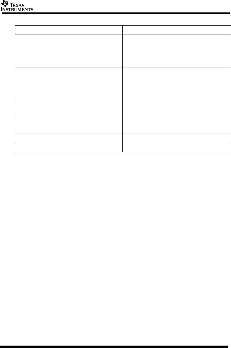
Overall the Linux<->BIOS IPC appears as shown in the figure below.
Page 13 of 16
Figure 1 : Inter Processor Communication
The figure shows pseudo operations on Tx and Rx paths to / from Host (A15) to
other slave cores for system_rpsmg_msgq & system_rpmsg_notify. Based on the
module just the recv mechanism changes, in case of notify registered callback is
executed in interrupt context on bios side while in case of msgq it is still in task
context on receipt of message.
DSP1/DSP2 + BIOS above is used just for example, same ipc mechanism is
replicated for each of A15<->DSP or any other slave core. Essentially, a pair of
sockets (named Tx and Rx) is used for IPC with slave cores. These sockets are of
type AF_RPMSG. Typically Tx sockets are “connected” (see system call connect()) to
remote end point to send msg while Rx sockets on A15 are “bound” (see system call
bind()) to specific address (end pt number) to receive message from particular
remote core. Address of the Tx socket is usually allocated by kernel and hence
mentioned as <local_addr> in the figure. Each message send is followed by ack msg
from both Host and slave cores to ensure sequential execution of commands.
This kind of IPC mechanism is used for two purposes in vision SDK
1. Inter link communication
2. Notifications
Page 14 of 16
#1 involves command messages and well as video frame transfer. In case of video
frame transfer only physical address of the frame (4 bytes) is sent across to
minimize any copies. This is typically achieved using System_rpmsgMsgQSendMsg().
Note that mapping is already taken care at the init time for both cores.
#2 Involves notifications to the next link. This is achieved using
System_rpmsgSendNotify()
It is important to note that system_rpmsg_msgq and system_rpmsg_notify are used
by links for IPC, these are not generic modules to be used outside Vision SDK.
9 EVE Support in Linux
9.1 EVE Loader
remoteproc is the linux kernel module that supports boot loading of IPUs and DSPs,
it picks up binaries from file system (/lib/firmware), parses binary for a special
section (.resource_table), programs L2MMU using IOMMU driver and manages PRCM
for the remote core.
This remoteproc module in kernel does not support loading EVEs from A15. There are
4 EVEs in TDA2x and this limitation makes EVEs unusable when Linux is running on
A15.
EVE loader is implemented using a scheme described below
– Starterware SBL is built for M4, it is ensured it can control PRCM for EVE and
bringup EVEs from IPU
– EVE binaries are built before IPU in the build system
– Convert .xearp32F -> .h (bin to hex converter utility was used)
– Include .h in the IPU’s application
It means A15+ Linux loads IPU and IPU intern loads each of the EVEs
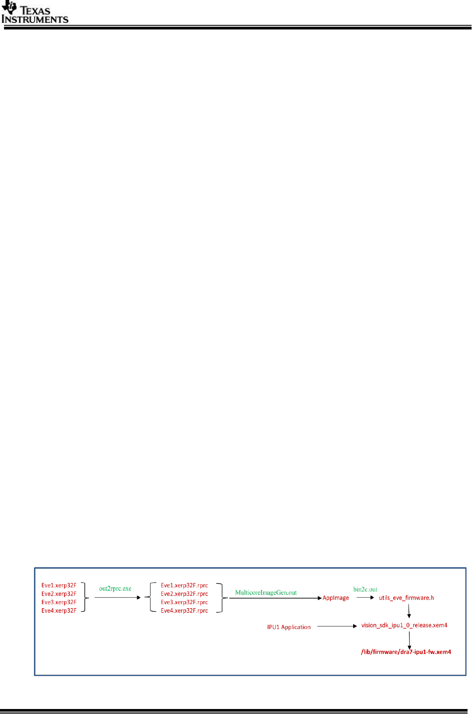
The picture next describes the executable generation of EVE executables and
embedding that into IPU executable
Page 15 of 16
Figure 3 : EVE executable creation and embedding into IPU1 executable
Finally, dra7-ipu1-fw.xem4 used by Linux remoteproc to load and run EVEs through
IPU1, System integrator ensures a hole is created in Linux memory for EVEs code &
Data so that Linux doesn’t overwrite it.
EVE MMU/TLB entries are programmed by IPU when it parses EVE executables in rprc
format.
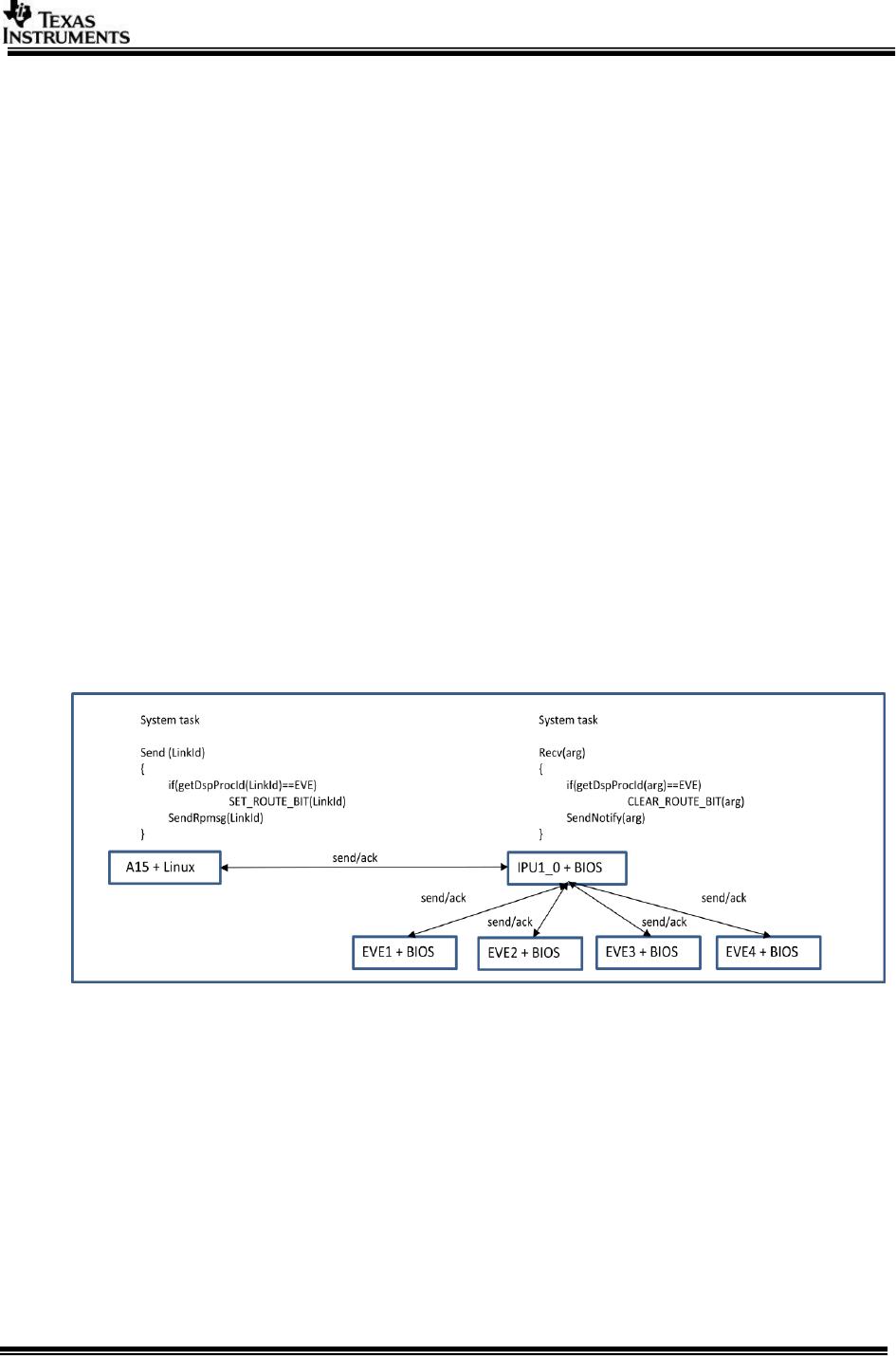
9.2 A15<->EVE inter-processor communication
For A15<->EVE communication, a routing message protocol is designed, Each
system command is an atomic message to EVE is sent through IPU1_0.
System command sends a 32 bit value across which embeds the task Id (LinkId) for
receiving task and the command (same ioctl command but executing on remote
core). We use the most significant bit of LinkId to indicate if the message is a routing
to EVE or vice versa, and the decision of performing operation / forwarding message
is take on IPU1.
Figure below depicts A15->EVE communication, similar logic applies to EVE->A15
communication
Figure 4 : A15 <-> EVE inter-processor communication
Page 16 of 16
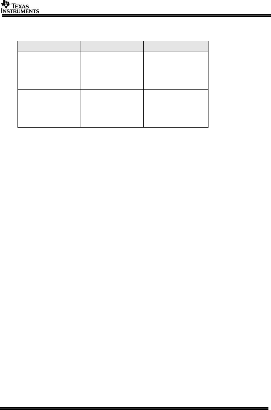
10 Revision History
Version
Date
Revision History
0.10
18 July 2014
First Draft
0.20
17 Dec 2014
EVE loader details added
0.30
28 Feb 2015
Updated for v2.6
0.40
08 Apr 2015
Updated IPC for single
end pt per slave
0.50
09 Oct 2015
Updated h/w resource
split
0.60
5th July 2017
Updated for 3.0 Rel
««« § »»»
