Vision_SDK_UserGuide Vision SDK User Guide TDA2Ex
User Manual:
Open the PDF directly: View PDF ![]() .
.
Page Count: 33
- TABLE OF CONTENTS
- 1 Introduction
- 2 System Requirements
- 2.1 Windows Installation
- 2.2 Linux Installation
- 2.3 Hardware Requirements
- 2.4 Software Installation
- 3 Build and Run
- 4 TDA2Ex_17x17
- 5 TDA2Ex Ethernet Surround View Starter Kit
- 6 Revision History

Copyright © 2016 Texas Instruments Incorporated. All rights reserved.
Information in this document is subject to change without notice. Texas Instruments may have pending
patent applications, trademarks, copyrights, or other intellectual property rights covering matter in this
document. The furnishing of this documents is given for usage with Texas Instruments products only and
does not give you any license to the intellectual property that might be contained within this document.
Texas Instruments makes no implied or expressed warranties in this document and is not responsible for
the products based from this document.
Page 1 of 33
Vision SDK TDA2Ex
(v03.03.00)
User Guide

Page 2 of 33
IMPORTANT NOTICE
Texas Instruments and its subsidiaries (TI) reserve the right to make changes to their products or to
discontinue any product or service without notice, and advise customers to obtain the latest version of relevant
information to verify, before placing orders, that information being relied on is current and complete. All
products are sold subject to the terms and conditions of sale supplied at the time of order acknowledgment,
including those pertaining to warranty, patent infringement, and limitation of liability.
TI warrants performance of its products to the specifications applicable at the time of sale in accordance with
TI’s standard warranty. Testing and other quality control techniques are utilized to the extent TI deems
necessary to support this warranty. Specific testing of all parameters of each device is not necessarily
performed, except those mandated by government requirements.
Customers are responsible for their applications using TI components.
In order to minimize risks associated with the customer’s applications, adequate design and operating
safeguards ought to be provided by the customer so as to minimize inherent or procedural hazards.
TI assumes no liability for applications assistance or customer product design. TI does not warrant or represent
that any license, either express or implied, is granted under any patent right, copyright, mask work right, or
other intellectual property right of TI covering or relating to any combination, machine, or process in which such
products or services might be or are used. TI’s publication of information regarding any third party’s products or
services does not constitute TI’s approval, license, warranty or endorsement thereof.
Reproduction of information in TI data books or data sheets is permissible only if reproduction is without
alteration and is accompanied by all associated warranties, conditions, limitations and notices. Representation
or reproduction of this information with alteration voids all warranties provided for an associated TI product or
service, is an unfair and deceptive business practice, and TI is neither responsible nor liable for any such use.
Resale of TI’s products or services with statements different from or beyond the parameters stated by TI for
that product or service voids all express and any implied warranties for the associated TI product or service, is
an unfair and deceptive business practice, and TI is not responsible nor liable for any such use.
Also see: Standard Terms and Conditions of Sale for Semiconductor Products.
www.ti.com/sc/docs/stdterms.htm
Mailing Address:
Texas Instruments
Post Office Box 655303
Dallas, Texas 75265
Copyright © 2016, Texas Instruments Incorporated

Page 3 of 33
TABLE OF CONTENTS
1 Introduction ................................................................................................. 4
1.1 References ...................................................................................................... 4
2 System Requirements .................................................................................. 5
2.1 Windows Installation......................................................................................... 5
2.2 Linux Installation ............................................................................................. 5
2.3 Hardware Requirements .................................................................................... 7
2.4 Software Installation ...................................................................................... 12
3 Build and Run ............................................................................................. 13
3.1 Overview of application in release .................................................................... 13
3.2 Building the application ................................................................................... 13
3.3 UART settings ................................................................................................ 16
3.4 Boot Modes ................................................................................................... 16
3.5 Load using SD card ........................................................................................ 16
3.6 Load using QSPI ............................................................................................. 18
3.7 Load using NOR ............................................................................................. 20
3.8 Load using CCS .............................................................................................. 22
3.9 Run the demo ................................................................................................ 27
4 TDA2Ex_17x17 ........................................................................................... 28
5 TDA2Ex Ethernet Surround View Starter Kit ............................................... 28
5.1 Hardware Setup ............................................................................................. 28
5.2 Building VSDK for ETH SRV board .................................................................... 30
5.3 Run the demo ................................................................................................ 30
6 Revision History ......................................................................................... 33

Page 4 of 33
1 Introduction
Vision Software Development Kit (Vision SDK) is a multi-processor software
development package for TI’s family of ADAS SoCs. The software framework allows
users to create different ADAS application data flows involving video capture, video
pre-processing, video analytics algorithms, and video display. The framework has
sample ADAS data flows which exercises different CPUs and HW accelerators in the
ADAS SoC and shows customer how to effectively use different sub-systems in the
SoC. Frame work is generic enough to plug in application specific algorithms in the
system.
Vision SDK is currently targeted for the TDA2xx and TDA3xx family of SoCs
This document explains the HW/SW setup for TDA2Ex EVM. Refer to
VisionSDK_UserGuide_TDA2xx.pdf and VisionSDK_UserGuide_TDA3xx.pdf for
respective EVM related Hw/SW setup
1.1 References
Refer the below additional documents for more information about Vision SDK
Document
Description
VisionSDK_ReleaseNotes.pdf
Release specific information
VisionSDK_UserGuide_TDA2Ex.pdf
This document. Contains install,
build, execution information
VisionSDK_ApiGuide.CHM
User API interface details
VisionSDK_SW_Architecture.pdf
Overview of software architecture
VisionSDK_DevelopmentGuide.pdf
Details how to create data flow (s)
& add new functionality
VisionSDK_SurroundView_DemoSetUpGuide.pdf
Document contains the steps for
hardware setup for calibrated
surround view demo
VisionSDK_FAQs.pdf
Document contains FAQ

Page 5 of 33
2 System Requirements
This chapter provides a brief description on the system requirements (hardware and
software) and instructions for installing Vision SDK.
2.1 Windows Installation
2.1.1 PC Requirements
Installation of this release needs a windows machine with about 8GB of free disk
space. Building of the SDK is supported on windows environment.
2.1.2 Software Requirements
All software packages required to build and run the Vision SDK are included as part
of the SDK release package except for the ones mentioned below.
2.1.2.1 A15 Compiler, Linker
The windows installer for the GCC ARM tools should be downloaded from below link
https://launchpad.net/gcc-arm-embedded/+milestone/4.9-2015-q3-update
The tools need to be installed under
“<install dir>/ti_components/cg_tools/windows/”.
IMPORTANT NOTE: A15 Compiler and linker MUST be installed before
proceeding else compile will fail. Also make sure the compiler is installed at
the exact path mentioned above
2.1.3 Code Composer Studio
CCS is needed to load, run and debug the software. CCS can be downloaded from
the below link. CCS version 6.0.1.00040 or higher should be installed.
http://processors.wiki.ti.com/index.php/Download_CCS
2.2 Linux Installation
2.2.1 PC Requirements
Installation of this release needs a Linux Ubuntu 14.04 machine.
IMPORTANT NOTE: If you are installing Ubuntu on a virtual machine, ensure it’s a
64 bit Ubuntu.
2.2.2 Software Requirements
All software packages required to build and run the Vision SDK are included as part
of the SDK release package except for the ones mentioned below.
2.2.2.1 A15 Compiler, Linker
The Linux installer for the GCC ARM tools should be downloaded from below link
https://launchpad.net/gcc-arm-embedded/+milestone/4.9-2015-q3-update
The tools need to be installed under
“<install dir>/ti_components/cg_tools/linux/”.
IMPORTANT NOTE: A15 Compiler and linker MUST be installed before initiating the
build else compilation will fail. Also make sure the compiler is installed at the exact
path mentioned above after installation of vision sdk.
Use following steps to install the toolchain
$> cd $INSTALL_DIR/ti_components/cg_tools/linux
$> tar -xvf gcc-arm-none-eabi-4_9-2015q3-20150921-linux.tar.tar

Page 6 of 33
IMPORTANT NOTE: Ensure the toolchain is for 32 / 64 bit machine as per
configuration of installation machine
If your machine is 64 bit and you have downloaded toolchain from link above
Execute following step on installation machine
$>sudo apt-get install ia32-libs lib32stdc++6 lib32z1-dev lib32z1 lib32ncurses5
lib32bz2-1.0
2.2.3 Other software packages for build depending upon OS baseline
Ensure these packages/tools are installed on the installation machine
uname, sed, mkimage, dos2unix, dtrx, mono-complete, git, lib32z1
lib32ncurses5 lib32bz2-1.0 libc6:i386 libc6-i386 libstdc++6:i386
libncurses5:i386 libz1:i386 libc6-dev-i386 device-tree-compiler mono-
complete
To install
$>sudo apt-get install <package_name>
Page 7 of 33
2.3 Hardware Requirements
Hardware setup for Single Camera View (SCV) and LVDS Multi Camera View
(LVDS MCV) use-case is described in this section
2.3.1 SRV Use-cases / Multi Channel Use-cases
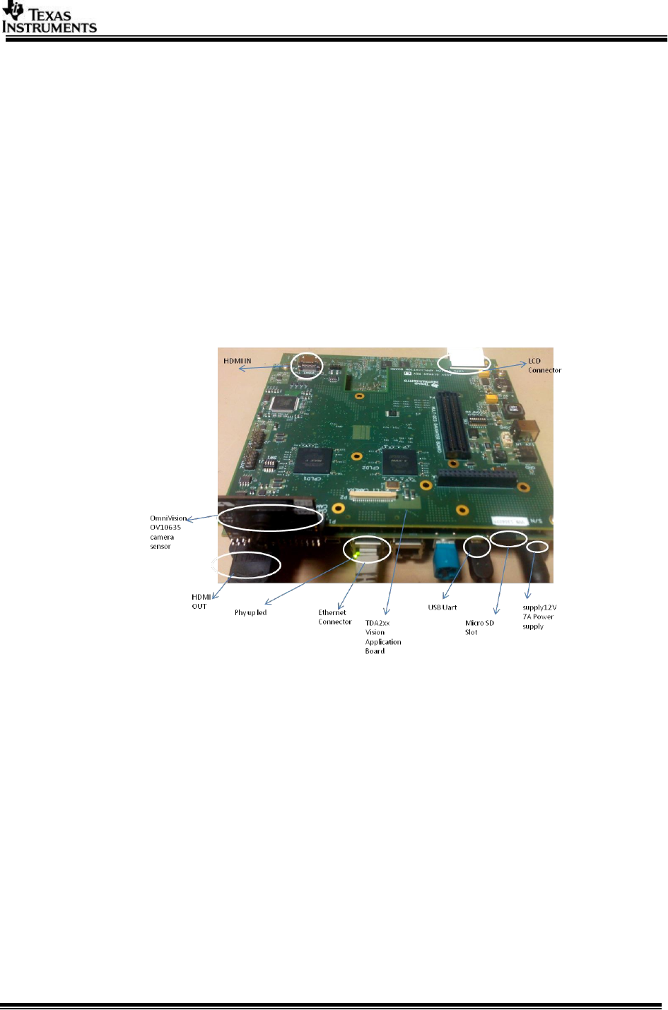
SRV use-case needs the below hardware
1. TDA2Ex EVM (Rev D)
2. TDA2xx Vision Application Board (Rev C)
3. OV10635 Sensor (for SCV only)
4. WVGA LCD DC from Spectrum Digital (part #703663) OR
5. HDMI 1080p60 capable Display Monitor
Setup is shown below
(Physical components placement might have changed in different board versions)
2.3.2 With multides-surround-view-kit
LVDS MCV Use-case Hardware Setup
1. TDA2Ex EVM (Rev B)
2. TDA2xx Vision Application Board (Rev C)
3. 6 channel FPD-Link III FMC SV600964 Daughter Board (Rev E1)
4. 4 x DS90UB913A EVMs (Rev A)
5. 4 x OV10635 Sensor (additional 5th DS90UB913A EVM, OV10635 sensor and
cable would be required in order to run the Surround view demo).
6. 4 x Rosenberger HSD connectors and cables
7. WVGA LCD DC from Spectrum Digital (part #703663) OR
8. HDMI 1080p60 capable Display Monitor
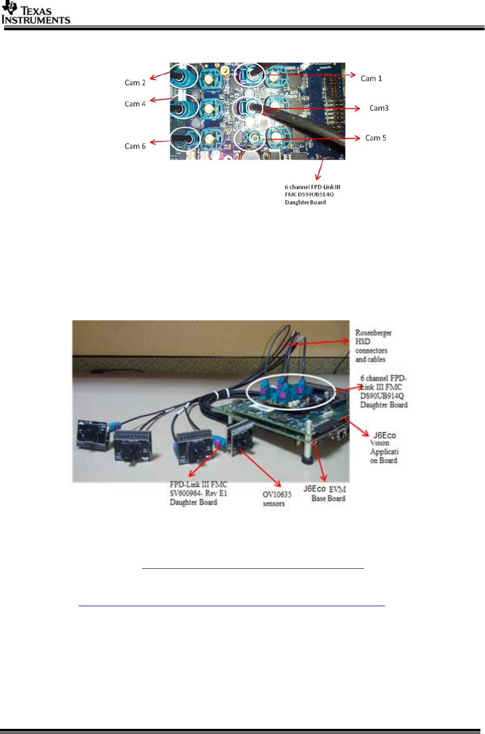
The LVDS MCV use case setup is shown in the snapshots below:
Page 8 of 33
2.3.2.1 DeSerializer board
IMPORTANT NOTE: Camera 1, Camera 2, Camera 3 and Camera 4 are used for 4
channel LVDS use-case and MUST be connected as shown in above figure.
IMPORTANT NOTE: There is a board modification required for LVDS capture on
TDA2EX boards. Refer to BSP user guide under section “Changes needed for 4
Channel Multi-deserializer on TDA2EX EVM” for more information.
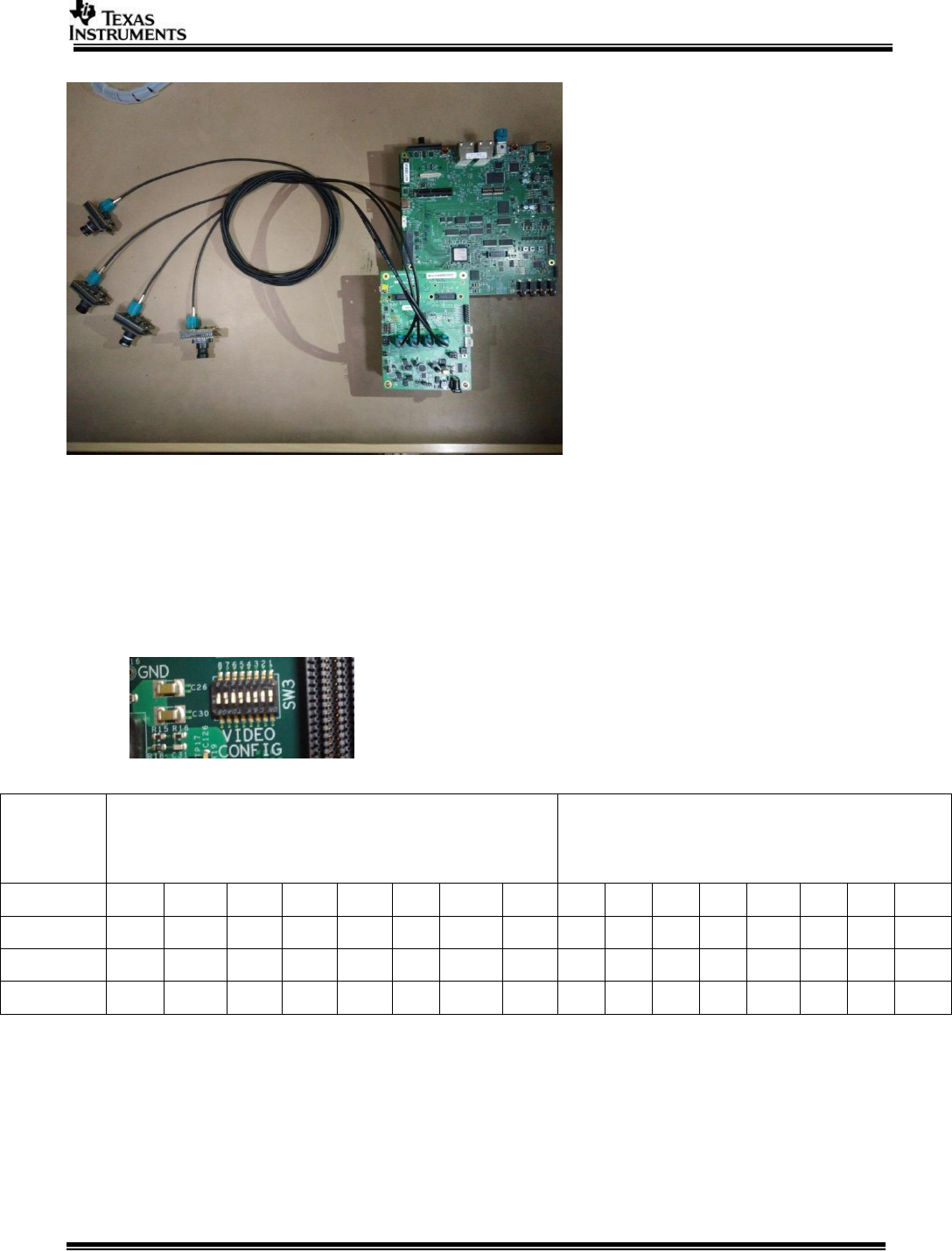
2.3.2.2 Complete LVDS Setup
2.3.2.3 With UB964 EVM (CSI2 based capture only)
Multi-channel usecases and surround view based on CAL / CSI2 would require
1. TDA2Ex EVM
2. UB964 EVM (http://www.ti.com/tool/ds90ub964-q1evm)
3. 4 X OV10635 sensor modules
4. 4 X DS90UB913A serializer (SAT0088)
(http://support.spectrumdigital.com/boards/sat0088_0089/)
5. 4 X FAKRA Cables
6. TV (1080P60 Capable) Connected to HDMI out of TDA2Ex EVM
2.3.2.4 UB964 EVM Configurations
1. Separate power to UB964 EVM
a. UB960 EVM require separate power, please power TDA2Ex EVM &
UB964 EVM separately
2. Power over FPD Link III

Page 9 of 33
a. Depending on Camera module (OV10635 & SAT0088) you would
require to source appropriate voltage
b. The UB964 EVM user guide documents the option to choose different
voltages, please refer http://www.ti.com/lit/pdf/snlu177
c. The picture of UB964 below, highlights the connector J14 / J16 with an
arrow. This could be used to select different voltage, it’s recommended
to refer the UB964 EVM guide for up-to-date/accurate configs
3. Mode Selection
a. UB964 Require to operate in “RAW10 (DS90UB913A compatible)”
b. This can be achieved with DIP switches on UB964 EVM, please refer
the EVM user guide (link above)
c. The picture below highlights the switch with a circle for RAW10 mode
4. Connecting UB964 to TDA2Ex EVM
a. There are two CSI2 connectors on top of EVM
b. Highlighted with white rectangular boxes
c. Recommended not to use these (would require an additional CSI2 /
differential cable to connect to TDA2Ex EVM)
d. Use the male CSI2 connector (back of EVM) to connect to TDA2Ex EVM
2.3.2.5 TDA2Ex CSI2 receiver port
The CSI2 receiver is highlighted with a red circle, please connect UB964/CSI 2 source to this.
Page 10 of 33
2.3.2.6 Complete setup
WARNING: CSI2 Clock: The maximum CSI2 clock could be 750 MHz, please refer
the device data manuals for details. Some of the VisionSDK use cases (UB964
based), overclocks by 50 MHz (i.e. 800 MHz) and it works as expected. This over
clocking is due the crystal (25 MHz) used in UB964 EVM, by choosing 24 MHz crystal
UB964 CSI2 clock can be operated with-in specified limits.
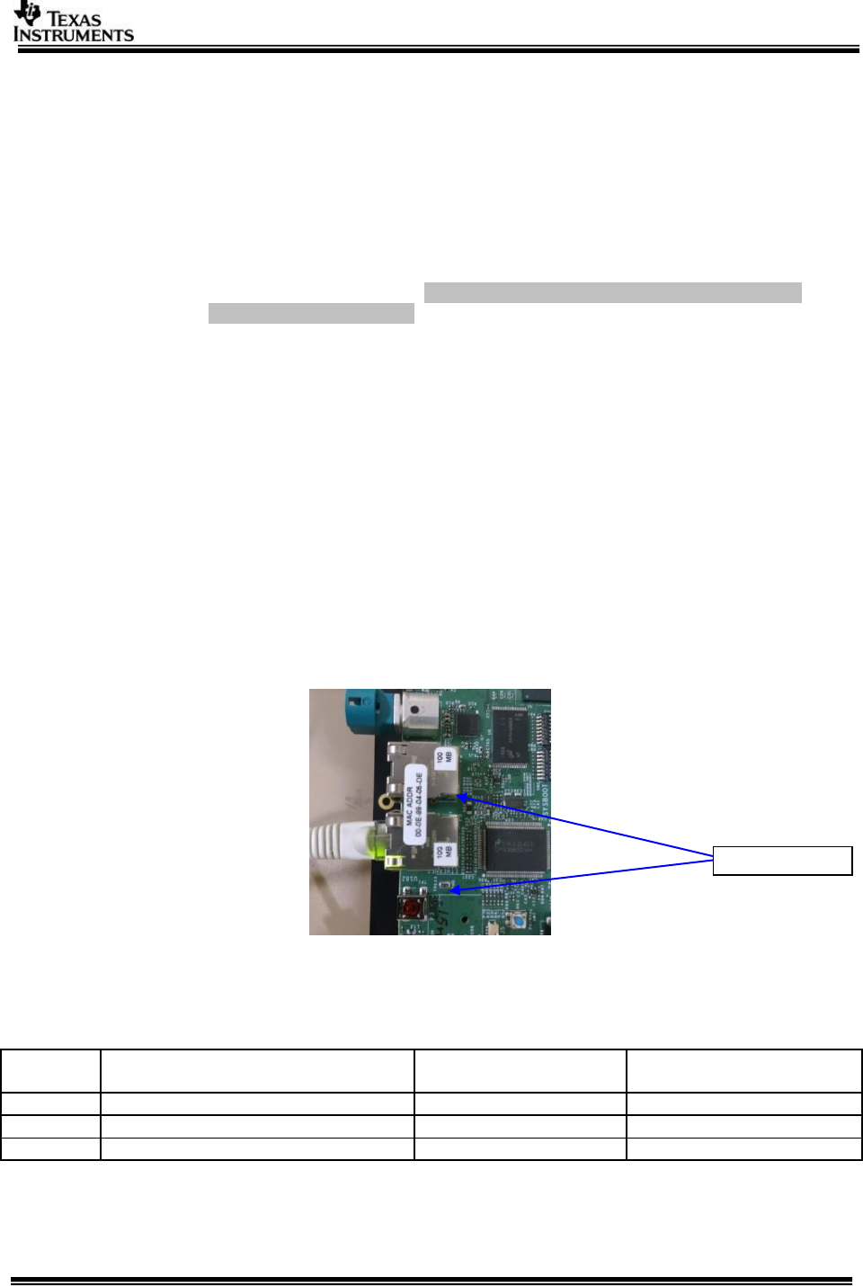
2.3.3 Capture Pin Settings
Video Config pins needs to set for different capture inputs
VIDEO CONFIG switch settings (SW3 on TDA2xx Vision Application
Board (set for Ov10635 in Original version of CPLD))
Capture
Type
Hardware controlled pin settings
Vision Application Board (Rev C CPLD)
(default cpld image)
Software controlled pin settings
New Version Of CPLD flashed
(cpld_1_cam3_shift.pof)
1
2
3
4
5
6
7
8
1
2
3
4
5
6
7
8
OV10635
OFF
ON
OFF
ON
OFF
ON
OFF
ON
OFF
OFF
OFF
OFF
OFF
OFF
OFF
OFF
LVDS
OFF
OFF
ON
OFF
OFF
ON
OFF
ON
OFF
OFF
OFF
OFF
OFF
OFF
OFF
OFF
HDMI
OFF
OFF
ON
ON
OFF
ON
OFF
ON
OFF
OFF
OFF
OFF
OFF
OFF
OFF
OFF
CPLD image is required for VIP input Muxing,
With the cpld_1_cam3_shift.pof and later the software control will work,
On default Rev C board the captured image won’t be proper. Either program the Cpld
with new image or use hardware controlled pin settings.
Page 11 of 33
2.3.4 EDID Programming for HDMI Capture
EDID information needs to be programmed on the EEPROM present on Vision
Application Board. This is required for the HDMI capture source to recognize the
format and resolution in which to send data to the TDA2Ex SoC. If this step is not
done or if this step fails, then TDA2Ex SoC will not be able to receive data via HDMI
capture source
IMPORTANT NOTE: It’s recommended to program the HDMI receivers EDID. The default
EDID is programmed to receive 1080P60 video streams only. If stream of different
resolution is required (or EDID is corrupted), the EDID would require an update. Refer the
EDID programming points in the section Running VPS Application on (TDAXXX EVM)
documented in VPS User Guide in PDK.
2.3.5 1Gig Ethernet link does not come up on some EVMs
On few of TDA2xx EVMs, we have seen stability issues with 1Gbps Ethernet link. The
issue symptoms are
1. Link not detected when connected to 1Gbps switch/router
2. Stability issues with 1Gbps link - multiple connect/disconnect
3. Data transfer not happening due to CRC errors on Ethernet Rx
These are known timing issues due to PHY “wire” side connection and not with the
TDAx processor. Spectrum Digital screens all the EVMS and places a sticker labelled
100Mbps if any of EVM fails such test. The EVM boards having TI DP83867 PHY do
not have this issue.
Note: Not all failing EVMs have 100Mbps sticker, in order to identify if 1Gbps link is
supported run VSDK network application.
2.3.6 TDA2ex Board Rev Ethernet care-about
In order for correct operation of the TDA2ex Ethernet use-cases kindly ensure the physical
connection of the Ethernet cable is as per the table below:
Sr. No.
TDA2ex EVM revision
Use-case
Recommended Ethernet
port connection
1.
Rev A/Rev B
Any
RGMII0 (Port0)
2.
Rev C
LVDS
RGMII1 (Port1)
3.
Rev C
HDMI Capture
RGMII0 (Port0)
100Mbps sticker

Page 12 of 33
2.4 Software Installation
PROCESSOR_SDK_VISION_03_xx_xx_xx_setupwin.exe is the SDK package installer.
Copy the installer to the path of your choice.
Double click the installer to begin the installation.
Follow the self-guided installer for installation.
IMPORTANT NOTE: On some computers running as administrator is needed. Right
click on the installer and select option of “Run as administrator”. If this is not done
then you may see a message like “This program might not have installed correctly”
On completion of installation a folder by name
PROCESSOR_SDK_VISION_03_xx_xx_xx would have got created in the installation
path.
2.4.1 Uninstall Procedure
To uninstall, double click on uninstall.exe created during installation in the folder
PROCESSOR_SDK_VISION_03_xx_xx_xx.
At the end of uninstall, PROCESSOR_SDK_VISION_03_xx_xx_xx folder still remains.
It is just an empty folder. It can be deleted manually.

Page 13 of 33
3 Build and Run
This chapter provides a brief overview of the sample application or use case present
in the SDK and procedure to build and run it.
3.1 Overview of application in release
The Vision SDK supports the following use-cases as examples
Single channel capture use-cases
o All single camera usecase.
Multi-channel LVDS capture use-cases
o All LVDS camera usecase.
AVB RX Use-cases,
o All AVB usecase.
Dual Display Use cases
o All Dual display usecase.
ISS Use cases
o All ISS capture usecase
Network RX/TX Use cases
o All Network test usecase
Refer to VisionSDK_DataSheet.pdf for detailed description of use-case.
The demos support following devices as capture source
OV10635 sensor (default)
HDMI source
The demos support following devices as display devices
LCD 800x480
HDMI 1080p60 (default)
Use option "s" on the main menu in UART to select different capture and display
devices.
3.2 Building the application
1. On windows command prompt, go inside the directory
PROCESSOR_SDK_VISION_03_xx_xx_xx\vision_sdk\build.
2. Open file \vision_sdk\build\Rules.make and set required config
MAKECONFIG=tda2ex_evm_bios_all
3. Open file \vision_sdk\$(MAKEAPPNAME)\configs\tda2xx_evm_bios_all\cfg.mk
a. For Building AVB application
NDK_PROC_TO_USE is to be set for ipu1_1
4. Build is done by executing gmake. “gmake” is present inside XDC package.
For “gmake” to be available in windows command prompt, the XDC path must
be set in the windows system path.
IMPORTANT NOTE: xdc path is needed to be set in environment variables.
If not, then set it using the set PATH =
<Install_dir>/ti_components/os_tools/windows/xdctools_x_xx_xx_xx;%PATH
% in command prompt
Ensure that gmake is picked from vision sdk xdc path only.
Use which gmake or where gmake depending upon the git bash or win cmd

Page 14 of 33
IMPORTANT NOTE: A15 Compiler and linker MUST be installed before
proceeding else compile will fail. Also make sure the compiler is installed at
the exact path as mentioned in <install_dir>/vision_sdk/build/tools_path.mk.
IMPORTANT NOTE: If the installation folder depth is high then
windows cmd prompt fails with error that it cannot find a file, even in
file is present in mentioned path, this is because Windows has a
limitation of 8191 characters for the commands that can execute. In
such a situation as a workaround either restrict the folder depth to
d:/ or if it cannot be restricted use git bash to build. Refer
https://support.microsoft.com/en-in/kb/830473 for more details.
Git version used for testing is 2.13
(Always point to xdc path gmake only)
5. Under vision_sdk directory
a. When building first time run the below sequence of commands
> gmake -s -j depend
> gmake -s -j
b. When building after the first time or incremental build, run the below
command
> gmake -s -j
Executing “gmake -s -j depend” will build all the necessary components (PDK drivers, EDMA
drivers and sdk dependent files) and “gmake -s -j” will build the Vision SDK framework and
examples.
IMPORTANT NOTE: For incremental build, make sure to do "gmake -s -j depend"
before "gmake -s -j" when below variables specified in
\vision_sdk\$(MAKEAPPNAME)\configs\$(MAKECONFIG)\*cfg.mk are changed
when PROC_$(CPU)_INCLUDE is changed
when DDR_MEM is changed
when PROFILE is changed
when ALG plugin or usecase is enabled or disabled in
\vision_sdk\$(MAKEAPPNAME)\configs\$(MAKECONFIG) \*_cfg.mk
when any .h or .c file in TI component is installed in ti_components is changed
when any new TI component is installed in ti_components
If "gmake -s -j depend" not done in these cases then build and/or execution may fail
IMPORTANT NOTE: When options (other than those specified above) are changed
in \vision_sdk\$(MAKEAPPNAME)\configs\$(MAKECONFIG)\cfg.mk a clean build is
recommended for the updated settings to take effect.
6. On a successful build completion, following executables will be generated in
the below path
\vision_sdk\binaries\$(MAKEAPPNAME)\$(MAKECONFIG)\vision_sdk\bin\tda2ex-evm
vision_sdk_a15_0_release.xa15fg
vision_sdk_c66xdsp_1_release.xe66
vision_sdk_ipu1_0_release.xem4
vision_sdk_ipu1_1_release.xem4
7. To speed up the incremental builds the following can be done as required.
The number of processors included in the build can be changed by modifying
below values in
\vision_sdk\$(MAKEAPPNAME)\configs\$(MAKECONFIG)\cfg.mk. A value of

Page 15 of 33
"no" means CPU not included in build, value of "yes" means CPU included in
build. Make sure to do “gmake -s -j depend” before “gmake -s- j” when
number of CPUs included is changed
PROC_DSP1_INCLUDE=yes
PROC_A15_0_INCLUDE=yes
PROC_IPU1_0_INCLUDE=yes
PROC_IPU1_1_INCLUDE=yes
8. The build config that is selected in config file can be confirmed by doing below
> gmake -s showconfig
Cleaning the build can be done by following command
> gmake -s clean
Built binaries need to deleted by
> rm -rf ../binaries/$(MAKEAPPNAME)/$(MAKECONFIG)
Page 16 of 33
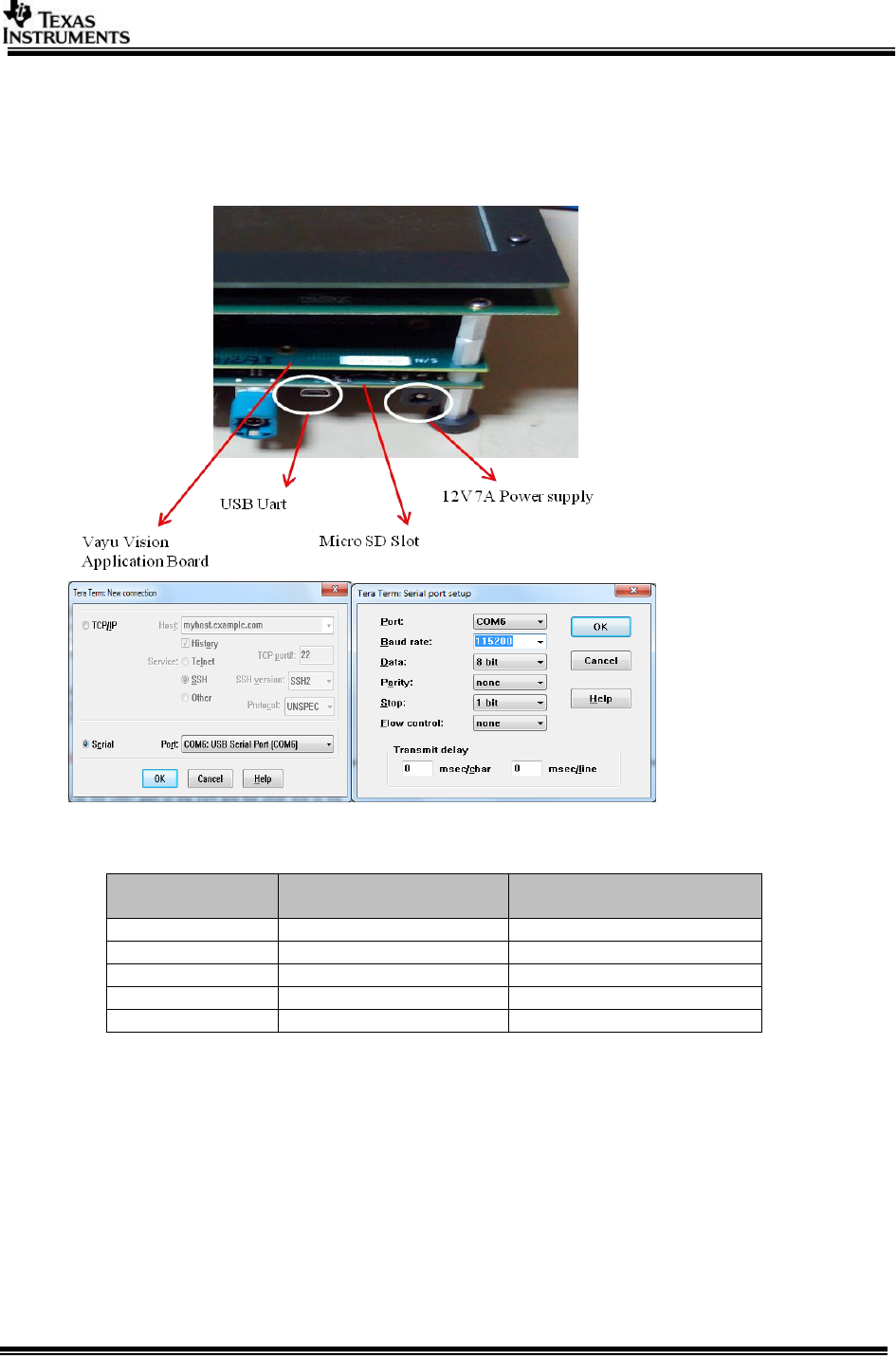
3.3 UART settings
Connect a serial cable to the UART port of the EVM and the other end to the serial
port of the PC (configure the HyperTerminal at 115200 baud rate) to obtain logs and
select demo.
3.4 Boot Modes
Supported boot modes on TDA2Ex ES1.0 device:
Boot Mode
EVM Switch Setting
SYSBOOT(SW2)[1:16]
EVM Switch Setting
SW5[1:10]
QSPI_1
01101100 10000001
0001100000
QSPI_4
11101100 10000001
0001100000
NOR
10101100 10000101
0100100000
SD
00001100 10000001
0001100000
Debug
00000000 10000001
XXXXXXXX
3.5 Load using SD card
NOTE: The application can be run using SD card and SD card boot or using CCS. This
section shows how to run using SD card boot.
Application image is run on the SoC via Secondary Boot Loader (SBL) present in SD
card.
3.5.1 Option 1: Steps to prepare a bootable SD card
Ensure Empty SD card (at least 256MB, preferably 4GB SDHC) is available.
Ensure SD memory card reader is available.

Page 17 of 33
Create a primary FAT partition on MMC/SD card (FAT32 format with sector
size 512) and mark it as Active. A partition manager utility has to be used for
the same.
Format SD card from DOS command line as below.
“format <drive> /A:512 /FS:FAT32”
Make SD card partition as active using below tool
http://www.pcdisk.com/download.html
IMPORTANT NOTE: Create a primary FAT partition on MMC/SD card (FAT32
format) with sector size 512 bytes mark the partition as active.
3.5.2 Option 2: Steps to prepare a bootable SD card using DISKPART
Open windows 7 Command prompt and Run as Administrator mode
Enter command "diskpart.exe"
C:\Windows\system32>diskpart.exe will take you DISKPART prompt
Warning: Enter below command carefully w.r.t your computer/laptop SD card
disk number. Choosing wrong disk number may delete data present in other
drive
To list all disk drive present on computer
DISKPART> list disk
Select the SD card disk number, in my case it is disk 1
DISKPART> select disk 1
Now all next command applicable only to disk 1(SD card)
Delete entire partition
DISKPART> clean
To create Primary partition
DISKPART> create partition primary
To list partition
DISKPART> list partition
Select partition
DISKPART> select partition 1
To list volume
DISKPART> list volume
Select volume associated with SD card, In my case its 3
DISKPART> select volume 3
Format SD card, please wait this may take few seconds
DISKPART>format quick fs=fat32 unit=512 label=SD_BOOT
Make disk active
DISKPART> active
To exit utility
DISKPART> exit
Page 18 of 33
3.5.3 Steps to generate MLO
NOTE: SBL MLO image is built from PDK package.
To build MLO Run the command gmake -s sbl from vision_sdk\build dir
This generates an MLO under
vision_sdk\binaries\$(MAKEAPPNAME)\$(MAKECONFIG)\sbl\sd\$(OPP)\$(PLATFORM)
To build the mlo for different memory map, select required configuration in
Makefile under vision_sdk (follow comments from Makefile under SBL build
Targets).
3.5.4 Steps to generate appImage
Following steps need to be followed to generate the application image
1. Make sure the executables are built as shown in Building the application
2. To generate the application image run below command from “vision_sdk”
folder
> gmake -s appimage
IMPORTANT NOTE: The config options, like CPUs to use, debug or release
profile etc, used to make the application image will be the values specified in
\vision_sdk\$(MAKEAPPNAME)\configs\$(MAKECONFIG)\cfg.mk file
3.5.5 SD Card setup
Once the AppImage and MLO are generated, Copy the MLO and AppImage at
root folder of formatted SD Card
3.5.6 Hardware Pin settings for SD Boot
Make sure the Boot Mode Select Switch is set for the SD boot mode on
TDA2Ex Base EVM. This is done by setting the pins SYSBOOT (SW2+SW3)
[0:15] to the below shown position
Please refer Boot Modes
3.6 Load using QSPI
3.6.1 Steps to generate qspi writer tools
NOTE: SBL qspi image is built from PDK package.
To build qspi Run the command gmake -s sbl from vision_sdk\build dir
This generates all required tools under
vision_sdk\binaries\$(MAKEAPPNAME)\$(MAKECONFIG)\sbl\qspi\$(OPP)\$(PLATFORM)
vision_sdk\binaries\$(MAKEAPPNAME)\$(MAKECONFIG)\sbl\qspi_flash_writer\$(PLATF
ORM)
1. sbl_qspi_$(OPP_MODE)_a15_0_release.tiimage
2. qspi_flash_writer_ipu1_0_release.xem4
To build the qspi for different memory map, select required configuration in
Makefile under vision_sdk (follow comments from Makefile under SBL build
Targets).
IMPORTANT NOTE: Refer section “Board Modification” under SBL_userguide
for hardware modifications if required.
3.6.2 Steps to generate appImage
Following steps need to be followed to generate the application image
Make sure the executables are built as shown in Building the application
To generate the application image run below command from
“vision_sdk\build” folder
> gmake -s appimage
Page 19 of 33
IMPORTANT NOTE: The config options, like CPUs to use, debug or release
profile etc, used to make the application image will be the values specified in
\vision_sdk\$(MAKEAPPNAME)\configs\$(MAKECONFIG)\cfg.mk file
The Surround View LUT and Perspective Matrix are flashed at
an offset of 20 MB in the QSPI hence make sure the generated
appImage doesn’t exceed 20 MB in case Surround View use
cases are intended to be run.
3.6.3 Flashing steps
Flashing pin settings:
Please refer Boot Modes
For loading binaries using CCS refer Load using CCS till step 8.
1. Connect A15. Do CPU reset
Select CortexA15_0, navigate to Scripts->TDA2Ex MULTICORE Initialization
TDA2Ex_MULTICORE_EnableALLCores
2. Connect M4 (IPU)
Halt A15 core, and Load image on M4
vision_sdk\binaries\$(MAKEAPPNAME)\$(MAKECONFIG)\sbl\qspi_flash_writer
\$(SOC)\qspi_flash_writer_ipu1_0_release.xem4
3. Run the core. You would see below console logs
[Cortex_M4_IPU1_C0]
QSPI Flash writer application
Enter Device type to use
1 - 1 bit read from flash
2 - 4 bit (Quad) read from flash
Select appropriate Device Type, for TDA2ex EVM, press ‘2’.
MID - 1
DID - 18
Enter 0 for Erase-Only (without flashing any image)
Note : File size should be less than 33554432 Bytes.
Enter the file path to flash:
<PATH>\sbl_qspi_$(OPP_MODE)_a15_0_release.tiimage
Enter the Offset in bytes (HEX) 0x00
Erase Options:
---------------
0 -> Erase Only Required Region
1 -> Erase Whole Flash
2 -> Skip Erase
Enter Erase Option: 1
Load Options:
-------------
0 -> fread using code (RTS Library)
1 -> load raw using CCS (Scripting console)
Enter Load Option: 0
Read xxxxxx bytes from [100%] file...Done.
QSPI whole chip erase in progress
QSPI file write started
**********QSPI flash completed sucessfully**************
4. Reset the board and Repeat step 1, 2 and 3.
5. Reset the board and Repeat step 1 and 2
[Cortex_M4_IPU1_C0]
QSPI Flash writer application
Enter Device type to use
1 - 1 bit read from flash
2 - 4 bit (Quad) read from flash
Select appropriate Device Type, for TDA2ex
EVM, press ‘2’.
MID - 1
Load Options:
-------------
0 -> fread using code (RTS Library)
1 -> load raw using CCS (Scripting console)
Enter Load Option: 1
Page 20 of 33
DID - 18
Enter the File Name
C:\vision_sdk\binaries\$(MAKEAPP
NAME)\$(MAKECONFIG)\vision_sdk
\bin\$(SOC)\sbl_boot\AppImage_B
E
Enter the Offset in bytes (HEX): 0x80000
Erase Options:
---------------
0 -> Erase Only Required Region
1 -> Erase Whole Flash
2 -> Skip Erase
Enter Erase Option: 0
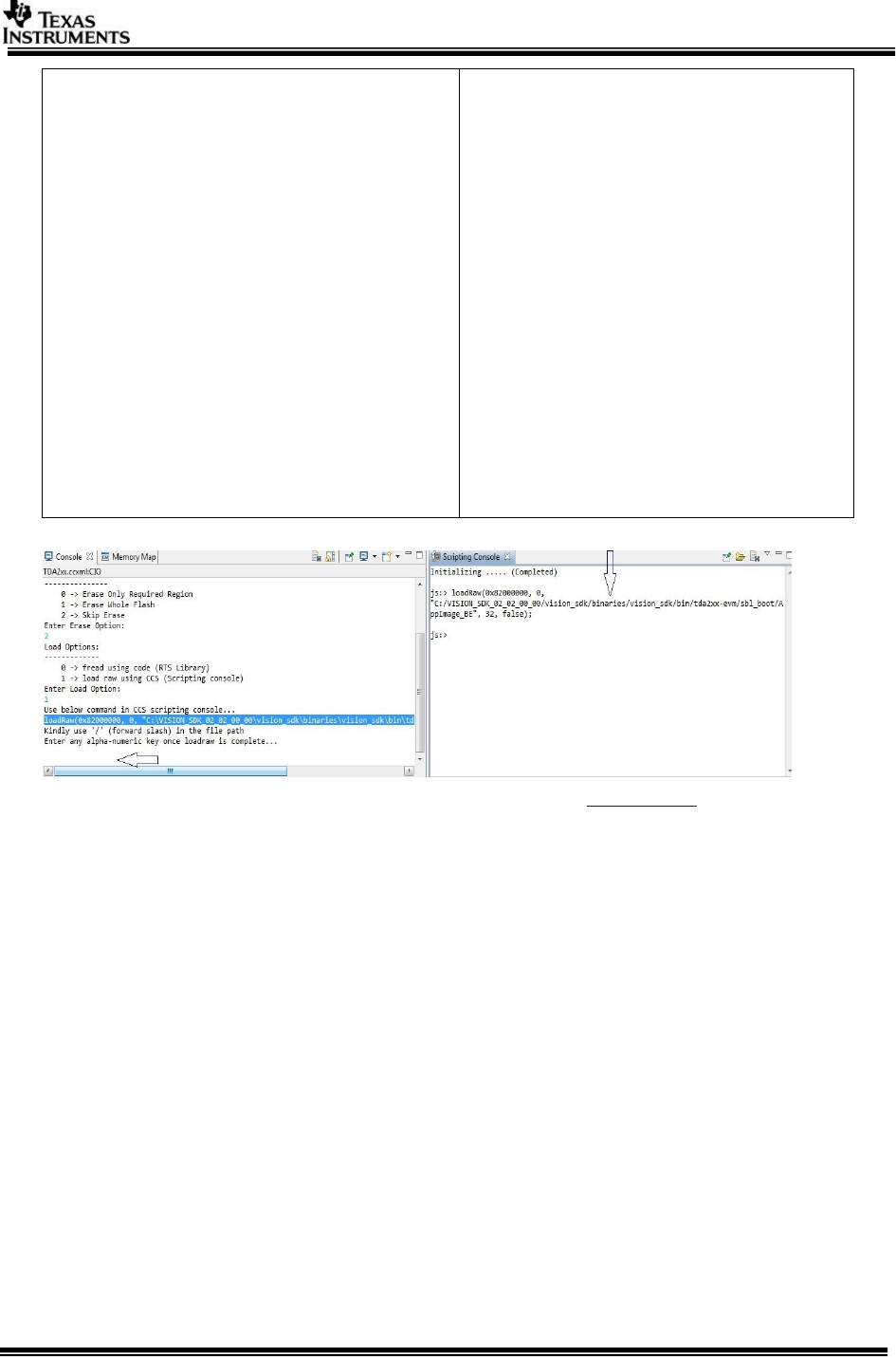
Open Scripting console window by clicking
“Menu -> View -> Scripting console” and enter
below command on scripting console as shown
3.5.3.1
loadRaw(0x80500000, 0, "C:/
vision_sdk/binaries/$(MAKEAPPNAME)/$(
MAKECONFIG)/vision_sdk/bin/$(SOC)/sbl
_boot/AppImage_BE ", 32, false);
IMPORTANT NOTE: The load address in
loadRaw command could be different based on
the board/SBL size etc. SBL figures out the
address and prints it on CCS console. Use this
address in loadRaw command for copying
AppImage_BE.
In CCS console Enter any alpha-numeric key
once loadraw is complete... as shown in below
image
QSPI file write started
****QSPI flash completed successfully*******
CCS console and scripting console
6. On completion change the pin setting as shown in Boot Modes table.
3.7 Load using NOR
3.7.1 Steps to generate nor writer tools
NOTE: SBL nor image is built from PDK package.
To build nor Run the command gmake -s sbl from vision_sdk\build dir
This generates all required tools under
vision_sdk\binaries\$(MAKEAPPNAME)\$(MAKECONFIG)\sbl\nor\$(OPP)\$(PLATFORM)
vision_sdk\binaries\$(MAKEAPPNAME)\$(MAKECONFIG)\sbl\nor_flash_writer\$(PLATF
ORM)
1. sbl_nor_$(OPP_MODE)_a15_0_release.bin
2. nor_flash_writer_ipu1_0_release.xem4
To build the nor for different memory map, select required configuration in
Makefile under vision_sdk (follow comments from Makefile under SBL build
Targets).
IMPORTANT NOTE: Refer section “Board Modification” under SBL_userguide
for hardware modifications if required.
3.7.2 Steps to generate appImage
Following steps need to be followed to generate the application image
Page 21 of 33
Make sure the executables are built as shown in Building the application
To generate the application image run below command from
“vision_sdk\build” folder
> gmake -s appimage
IMPORTANT NOTE: The config options, like CPUs to use, debug or release
profile etc, used to make the application image will be the values specified in
\vision_sdk\$(MAKEAPPNAME)\configs\$(MAKECONFIG)\cfg.mk file
3.7.3 Flashing steps
Flashing pin settings:
Please refer Boot Modes
For loading binaries using CCS refer Load using CCS till step 8.
1. Connect A15. Do CPU reset
Load image
vision_sdk\binaries\$(MAKEAPPNAME)\$(MAKECONFIG)\sbl\nor_flash_writer\$(S
OC)\ nor_flash_writer_ipu1_0_release.xem4
2. Run the core.
[CortexA15_0] Starting NOR Flash Writer.
CFI Query...passed.
NOR Initialization:
Command Set: Spansion
Manufacturer: SPANSION
Size: 0x40 MB
Enter the File Name
<PATH>\sbl_nor_ $(OPP_MODE)_a15_0_release.bin
Enter the Offset in bytes (HEX) 0x00
Erase Options:
---------------
0 -> Erase Only Required Region
1 -> Erase Whole Flash
2 -> Skip Erase
Enter Erase Option: 1
Erasing the NOR Flash
Erased through 0x8020000
.
.
Erased through 0x9000000
Load Options:
-------------
0 -> fread using code (RTS Library)
1 -> load raw using CCS (Scripting console)
Enter Load Option:
0
Reading 71896 bytes from file...
Read 16384 bytes [22%] from file...
Read 32768 bytes [45%] from file...
Read 49152 bytes [68%] from file...
Read 65536 bytes [91%] from file...
Read 71896 bytes [100%] from file. Done!!
Writing 0x118D8bytes to NOR...
NOR Write OK through 0x8008000.
NOR Write OK through 0x8010000.
NOR Write OK through 0x80118D8.
Done.
!!! Successfully Flashed!!!
NOR boot preparation was successful!
3. Reset the board and Repeat step 1 & 2
4. Reset the board and Repeat step 1
Page 22 of 33
[CortexA15_0] Starting NOR Flash Writer.
CFI Query...passed.
NOR Initialization:
Command Set: Spansion
Manufacturer: SPANSION
Size: 0x40 MB
Enter the File Name
<PATH>\sbl_nor_ $(OPP_MODE)_a15_0_release.bin
Enter the Offset in bytes (HEX) 0x80000
Erase Options:
---------------
0 -> Erase Only Required Region
1 -> Erase Whole Flash
2 -> Skip Erase
Enter Erase Option: 2
Load Options:
-------------
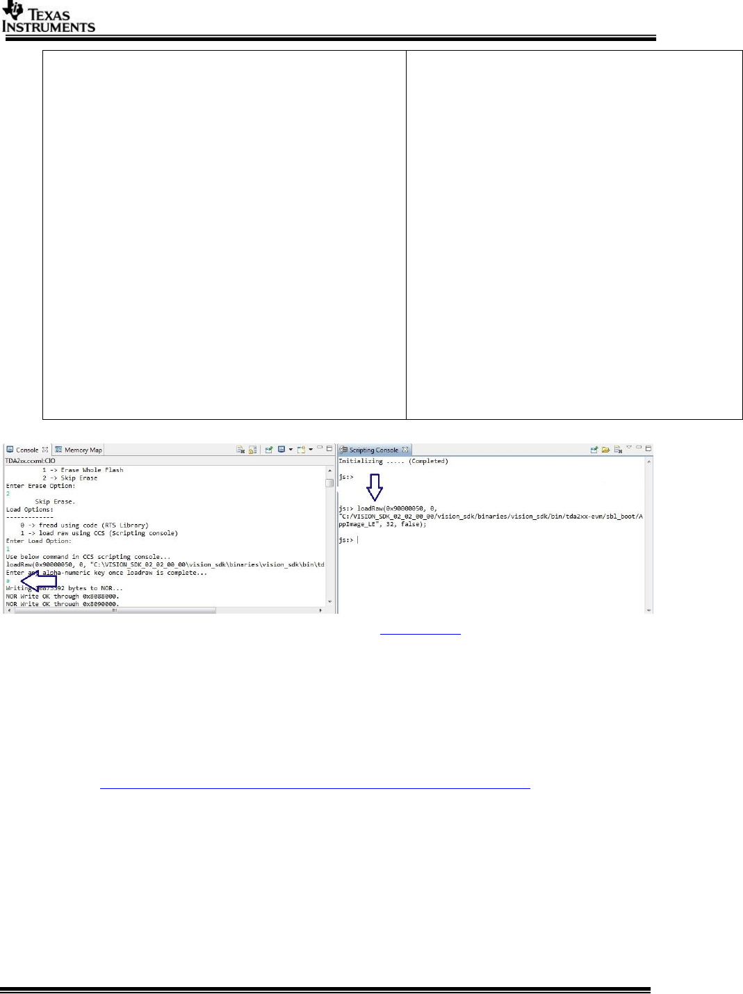
0 -> fread using code (RTS Library)
1 -> load raw using CCS (Scripting console)
Enter Load Option:
1
Use below command in CCS scripting console...
loadRaw(0x90000050,0,"<PATH>/AppImage_LE", 32, false);
Kindly use '/' (forward slash) in the file path
Enter any alpha-numeric key once loadraw is complete...
s1
Writing 0x1175F10bytes to NOR...
NOR Write OK through 0x8088000.
.
.
NOR Write OK through 0x91F5F10.
Done.
!!! Successfully Flashed!!!
NOR boot preparation was successful!
CCS console and scripting console
5. On completion change the pin setting as shown in Boot Modes table.
3.8 Load using CCS
After installing CCS, follow below steps to complete the platform setup,
1. GELs are available in
<Install_dir>\ti_components\ccs_csp \auto_device_support_x.x.x.zip
NOTE:
1. GELs are also be available at
http://processors.wiki.ti.com/index.php/Device_support_files
Under Automotive pick
Automotive vX.X.X
2. To install the new GEL versions, you need to extract the zip to
<CCS_INSTALL_DIR>/ccsv6/ccs_base
Change the following GEL files for vision SD as below,
- TDA2Ex_multicore_reset.gel
Set VISION_SDK_CONFIG to 1 always
Set VISION_SDK_CONFIG_OLD to 0
Page 23 of 33
For older versions of VisionSDK (2.08 and older) this should be set to 1
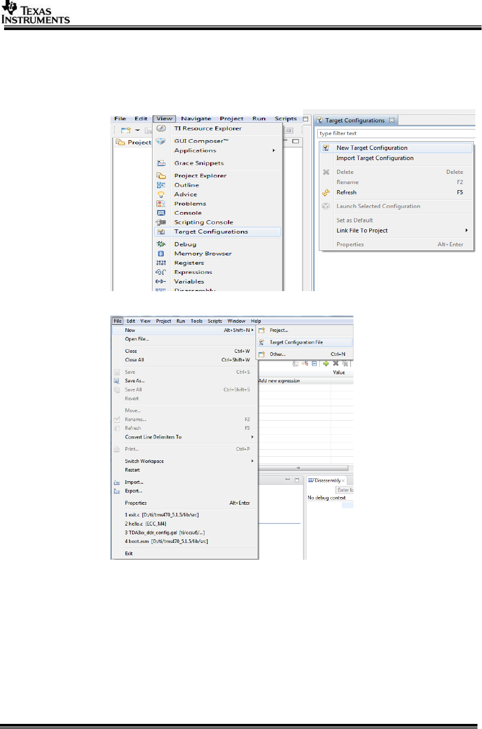
2. CCS Target Configuration creation:
a. Open “Target Configurations” tab, by navigating through the menu
“View ->Target Configurations”.
b. Create a new Target Configuration (TDA2Ex Target Configuration) by
navigating through the menu “File->New->Target Configuration File”.
c. Specify Connections as “Spectrum Digital XDS560V2 STM USB
Emulator”. Specify Board or Device as “TDA2Ex”.
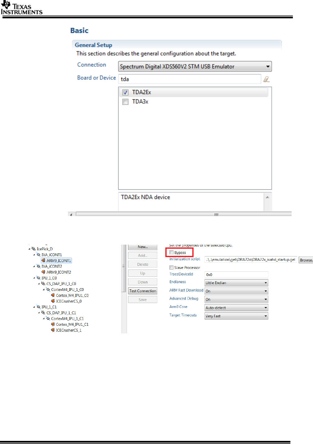
Page 24 of 33
d. ByPass unused cores. Click on the core which needs to be bypassed and check
ByPass under Bypass Properties. The settings is under advance setup tab.
3. Connect JTAG to the board.
IMPORTANT NOTE: There are two JTAG connectors on the board. The one shown below MUST
be used for CCS debug.
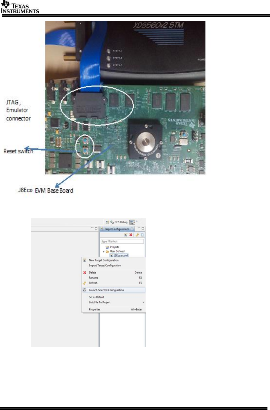
Page 25 of 33
Reset EVM through the blue button (SW4, out of two, the one away from the JTAG).
4. Now launch the previously created TDA2Ex Target Configuration.
Page 26 of 33
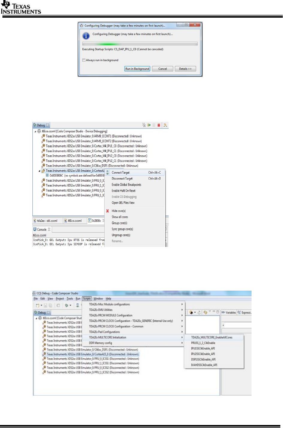
5. Once the target configuration is launched successfully, the following log should be observed
on the CCS console:
CortexA15_0: GEL Output: --->>> TDA2Ex Cortex A15 Startup Sequence DONE! <<<--
6. Connect to core CortexA15_0.
7. On successful connect, the following log appears on CCS console:
CortexA15_0: GEL Output: --->>> TDA2Ex Target Connect Sequence DONE !!!!! <<<---
8. Select CortexA15_0, navigate to Scripts->TDA2Ex MULTICORE Initialization
TDA2Ex_MULTICORE_EnableALLCores
9. On successful script execution, the following log appears on CCS console:
Page 27 of 33
CortexA15_0: GEL Output: --->>> PRUSS 1 and 2 Initialization is in complete ... <<<---
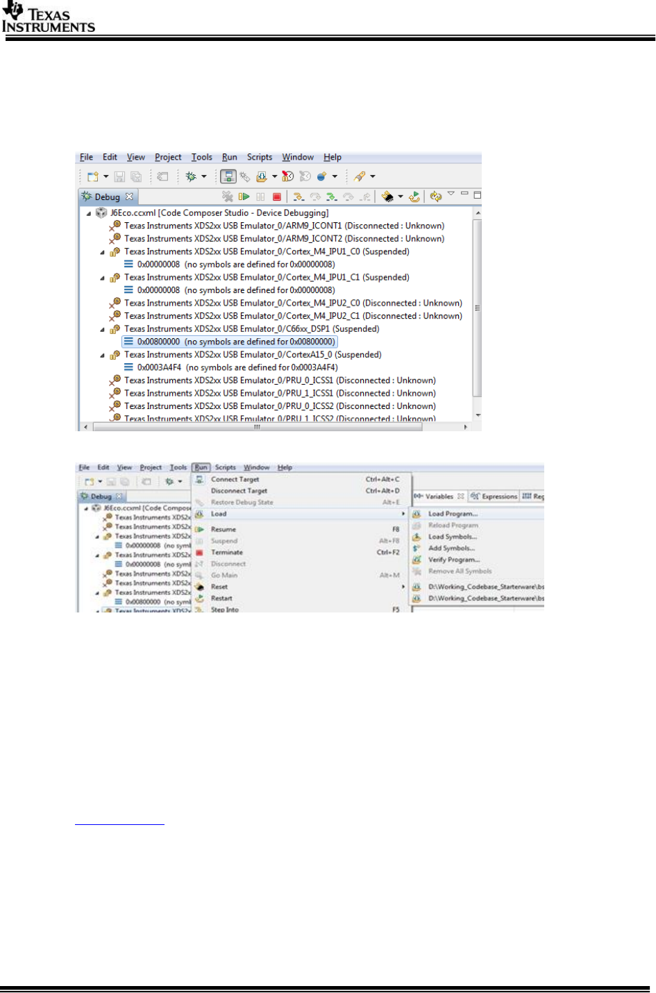
10. Now connect the core shown below,
C66xx_DSP1,Cortex_M4_IPU1_C0, Cortex_M4_IPU1_C1.
11. Once the cores are connected, do CPU Reset for all the cores.
12. On the cores load the binaries as mentioned below
On C66xx_DSP1, load the binary, “vision_sdk_c66xdsp_1_release.xe66”.
On Cortex_M4_IPU1_C0, load the binary, “vision_sdk_ipu1_0_release.xem4”.
On Cortex_M4_IPU1_C1, load the binary, “vision_sdk_ipu1_1_release.xem4”.
On CortexA15_0, load the binary, "vision_sdk_a15_0_debug.xa15fg”
IMPORTANT NOTE: Binary for Cortex_M4_IPU1_C0 MUST be loaded before
Cortex_M4_IPU1_C1 since IPU1-0 does MMU config for the complete IPU1 system. Other
binaries can be loaded in any order.
3.9 Run the demo
1. Power-on the Board after loading binaries by (SD, QSPI, NOR or CCS) and follow
Uart settings to setup the console for logs and selecting demo.
2. Select demo required from the menu by keying in corresponding option from uart
menu.
IMPORTANT NOTE: Make sure you select SCV (1Ch VIP capture) use-case or LVDS (4Ch VIP
capture) use-case depending on the camera that is connected

Page 28 of 33
NOTE 1: For AVB MCV Demo Ethernet port must be connected as shown in SCV/AVB Use-case
Hardware Setup
NOTE 2: Data is streamed from Linux talker (Ref: AVB Used guide for building talker binaries)
VMware can also be used but the throughput of talker is not as desired and depends on PC
configurations.
NOTE 3: For AVB use-cases with AVBTX, run PC listener on Ubuntu PC. Also install ffplay for
using listener as AVBTP Listener launches ffplay internally. Please close ffplay window before
stopping listener from terminal. Check orphan ffplay tasks via “ps –al” and kill all of them
explicitly.
sudo bash ./avbtp_listener.sh
4 TDA2Ex_17x17
TDA2Ex has two variants 23x23 referred as TDA2Ex and 17x17 referred as
TDA2Ex_17x17. The steps and procedure defined in this document is applicable to
both the devices. Please refer the device specific data manual for detailed feature
set.
When VisionSDK is used on TDA2Ex_17x17 device, please ensure to build for
TDA2Ex. The software (VisionSDK and its components) would determine the package
type and act accordingly.
Determining SoC type: Please use API Bsp_platformGetSocId(), in case of TDA2Ex,
BSP_PLATFORM_SOC_ID_TDA2EX is returned.
Determining TDA2Ex_17x17: Below code could be used to identify
if (BSP_PLATFORM_SOC_ID_TDA2EX == Bsp_platformGetSocId())
{
if (BSP_PLATFORM_PACKAGE_TYPE_17x17 == Bsp_platformGetPackageType())
{ /* any TDA2Ex_17x17 specific operations */
}
}
5 TDA2Ex Ethernet Surround View Starter Kit
This document explains the HW/SW setup for TDA2Ex Ethernet SRV starter kit. The
TDA2EX Ethernet SRV Starter Kit developed by D3 Engineering is one of the
evaluation platforms for Vision SDK, used for evaluating the Ethernet Surround View
use-case along with other networking use-cases. The starter kit supports the
following Vision SDK data flows:
Ethernet Surround View (SRV) Auto Calibration
Ethernet SRV 2D
Network Tx/Rx
Multi-channel DMA Mosaic.
The steps to install and run the use-cases on TDA2Ex Eth SRV board are same as of
TDA2Ex EVM. Please refer to respective section in this document above for this
information. This document details only additional set up and build requirements.
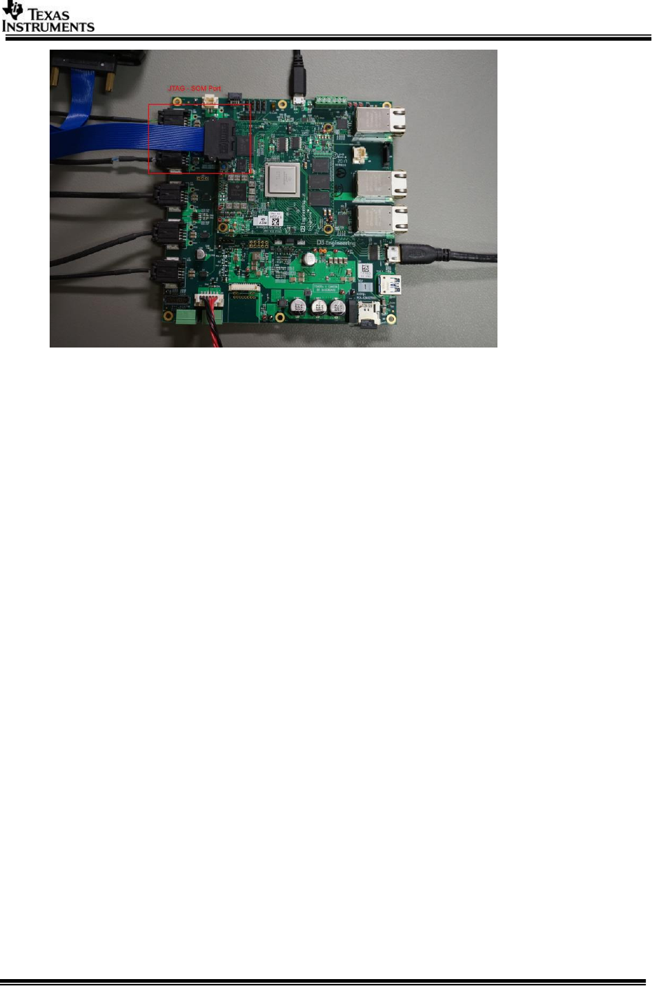
5.1 Hardware Setup
1. Power supply (12V, 5 - AMP)
2. Four camera modules and JST-to-Mini50 cables to connect to the 100BASE-T1
input ports of the TDA2Ex Ethernet Surround View Board.

Page 29 of 33
Note: For VSDK testing on starter kit, AVB camera modules from TrulyTM are
used. The camera configuration as below
i. 1MP (1280x720) H264 all I frames @30fps
ii. Camera module configured in master mode (this is needed as switch on the
starter kit is in slave mode)
iii. Firmware images on Camera flashed with below stream id’s (which are used
in the VSDK use-cases)
{0x01, 0x23, 0x45, 0x67, 0x89, 0xAB, 0xCD, 0xE0}
{0x01, 0x23, 0x45, 0x67, 0x89, 0xAB, 0xCD, 0xE1}
{0x01, 0x23, 0x45, 0x67, 0x89, 0xAB, 0xCD, 0xE2}
{0x01, 0x23, 0x45, 0x67, 0x89, 0xAB, 0xCD, 0xE3}
3. Display – Display can be via HDMI or Ethernet (AVB listener)
4. USB micro-B cable for user inputs.
Page 30 of 33
5.2 Building VSDK for ETH SRV board
To enable build for TDA2Ex Ethernet surround view starter kit, enable below macro
in the
#
# Enable below macro to run ETH SRV on TDA2EX ETH SRV Board
#
TDA2EX_ETHSRV_BOARD=yes
Note 1: The TDA2Ex Eth SRV starter kit supports only below use-cases; please
disable other use-cases form use-case config file.
UC_avbrx_dec_display_avbtx
UC_avbrx_sv_display_avbtx
UC_srv_calibration
UC_network_rx_tx
UC_saveDisFrame
5.3 Run the demo
Steps to run any use-case on TDA2Ex Eth starter kit is same as of TDA2Ex EVM.
Please refer to
5.3.1 Streaming data via talker or AVB Camera
On TDA2Ex, AVB use-cases can be run either with TrulyTM camera modules or AVBTP
PC talker application. Also if sufficient camera modules are not available,
combination of talker and camera can be used to make 4-channels. This needs
modification in stream id’s of talker to make sure those are not conflicting.
By default, PC talker uses stream id 01_23_45_67_89_AB_CD_Ex (x - channel
number). So if you start 2 streams it would use stream id E0 and E1. This should not
clash with camera stream id.
Page 31 of 33
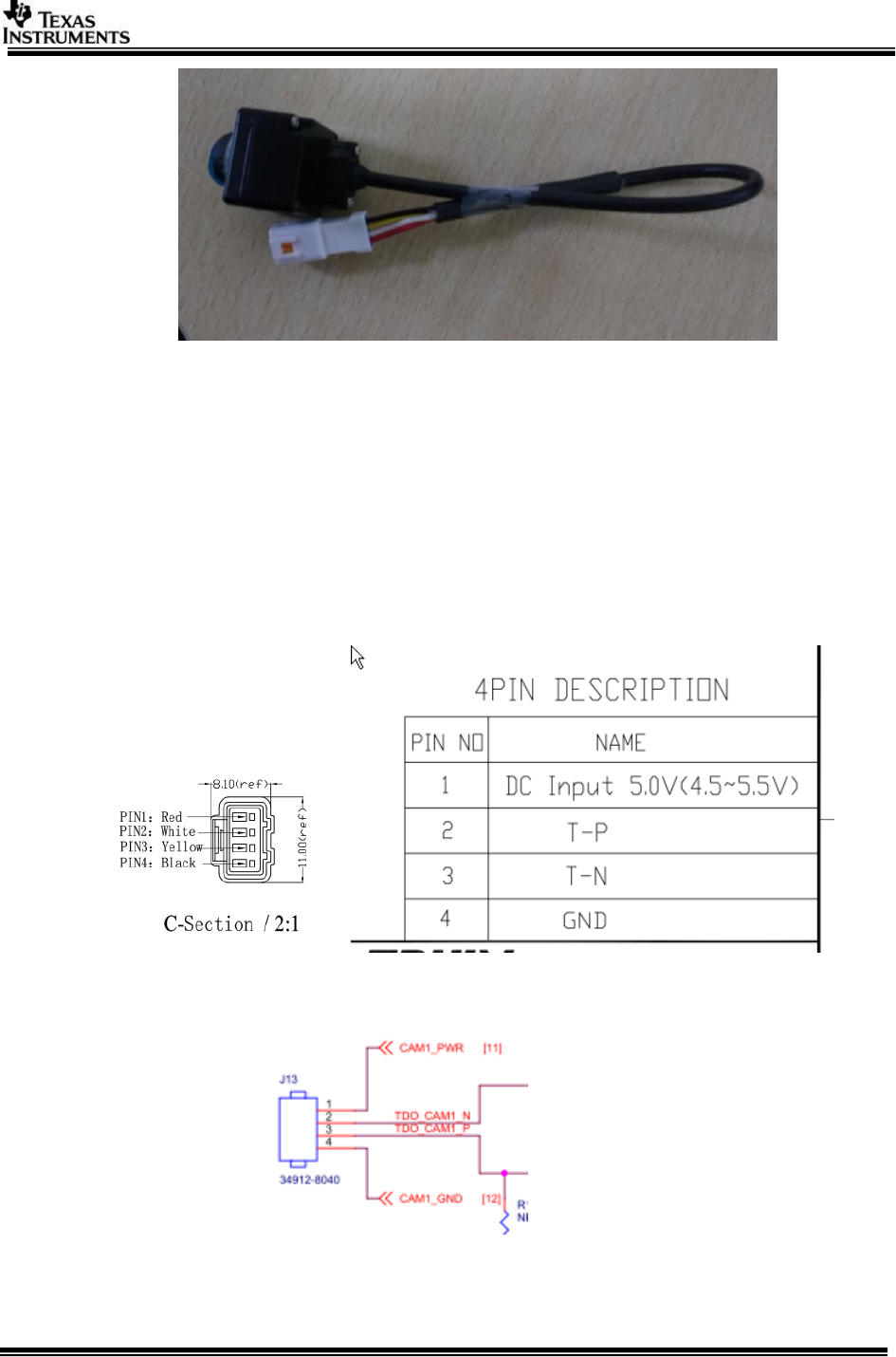
Figure TrulyTM camera module
5.3.1.1 Streaming with Camera modules
a. For using camera make sure camera modules are started and data is being
streamed.
Note: When using PC talker make sure camera modules are not powered on
disable capture start and capture stop from the use-case main file). The stream
from the camera module can interfere with the AVB talker and causes decode
errors.
b. Pin connections for TrulyTM camera and TDA2Ex Eth SRV board
i. TrulyTM Camera
ii. 4-Cam BR Baseboard

Page 32 of 33
5.3.1.2 Streaming with PC talker
a. Refer to AVB Used guide for building talker binaries.
b. VMware can also be used but the throughput of talker is not as desired and
depends on PC configurations.
NOTE: AVB Talker code present at
ti_components\networking\avbtp_0_10_00_00\utils\avbtp_talker
5.3.2 Display – HDMI or AVB listener
Display can be via HDMI or Ethernet (AVB listener)
1. HDMI 1080p60 capable Display Monitor and Type C HDMI cable.
2. Display via AVB listener – needs below
a. PC (preferably Ubuntu) for running AVB listener – current AVB Tx use-
cases uses spoofed MAC address for constructing the AVB packets to be
sent out to AVB listener, address used is ab:cd:ef:ab:cd:ef. Run AVB
listener with this MAC address as source.
b. Ethernet Media converter – BroadReach to 100BaseTx/1000BaseT
converter to connect to PC (media conveter from TechnicaTM is used for
testing)

Page 33 of 33
6 Revision History
Version
Date
Revision History
1.0
22th August 2014
Initial Version
1.1
14th November 2014
Added QSPI+SD boot,
GCC and CCSversion
1.2
31st December 2014
Some minor changes
1.3
4th July 2015
Updated for 2.7 release
1.4
16th Oct 2015
Updated for 2.8 release
1.5
18th March 2016
Updated for 2.9 release
1.6
4th July 2016
Updated for 2.10 release
1.7
2nd Nov 2016
Updated for 2.11 release
1.8
8th Feb 2017
Updated for 2.12 release
TDA2Ex 17x17 package
details added
1.9
19th June 2017
Updated linux installer
2.0
27th June
Updated for release 3.0
2.1
10th Oct 2017
Updated for release 3.1
TDA2Ex Ethernet SRV
Starter kit details added
and release 3.1
2.2
20th Dec 2017
Updated for release 3.2
2.3
3rd April 2018
Updated for release 3.3
««« § »»»
