1361X10 Vista 20P Transformer Kit
User Manual: Vista-20P 1361X10 Transformer Kit AlarmHow.net Library
Open the PDF directly: View PDF ![]() .
.
Page Count: 2
K9508 7/03
1361X10
Transformer/X-10 Interface Kit
Installation and Setup Guide
The 1361X10N Transformer/X-10 Interface contained in this kit is used in place of the standard system
transformer for the purpose of controlling X-10 devices from an alarm control panel. It is a replacement for
the 4300 transformer, which is no longer available.
This installation kit contains:
(1) 1361X10N Transformer/X-10 Interface
(1) SA4120XM-1 Trigger Cable (Refer to Figure 1 for where-used information)
(1) SA4142TR Trigger Cable (Refer to Figures 2 and 3 for where-used information)
Install the 1361X10N as follows:
1. Wire as shown for the applicable control panel, using the specified cable.
2. Plug the trigger cable into the trigger connector on the control.
3. Plug the 1361X10N into an AC wall outlet.
4. Program the alarm panel as required for output device control.
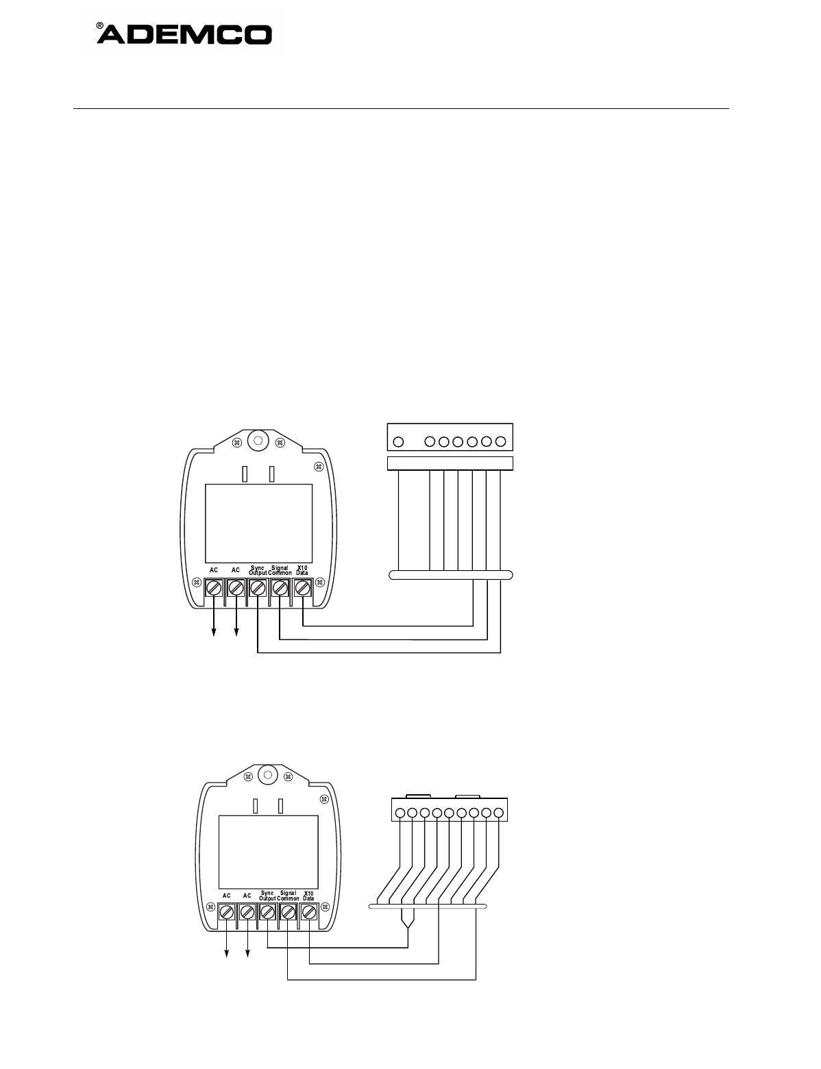
TRANSFORMER/X10 INTERFACE
TERMINALS
ON CONTROL
BOARD
1361X10-001-V0
8-PIN CONNECTOR
ON CONTROL PANEL
SA4120XM-1 CABLE
BLACK (SYNC)
BLUE (DATA)
PURPLE (COM)
1345678
KEY
+12 AUX.
DATA
COM
SYNC
GND (-)
OUTPUT 17 (RED)
OUTPUT 18 (GREEN)
(ORANGE)
(YELLOW)
(BLUE)
(PURPLE)
(BLACK)
8-PIN TRIGGER CONNECTOR
PINS (1,3,4,5) NOT USED
Figure 1. Connections for Vista-15P, Vista-20P, Vista-20PS, FA148CP, FA168C/P/S, or equivalent
TRANSFORMER/X10 INTERFACE
TERMINALS
ON CONTROL
BOARD
1361X10-002-V0
123456789
9-PIN CONNECTOR
ON CONTROL PANEL
BLACK
BLUE
BROWN
GREEN
RED
WHITE
YELLOW
GRAY
VIOLET
4142TR CABLE
PINS (1,2,5,7,8) NOT USED
J8 CONNECTOR
YEL/WHT (SYNC)
GREEN (DATA)
BLACK (COM)
Figure 2. Connections for Vista-40, Vista-50, Vista-128B, Vista-128BP, Vista-250BP,
FA1220C, FA1340C, FA1660C, or equivalent
¬.#l
K9508 7/03
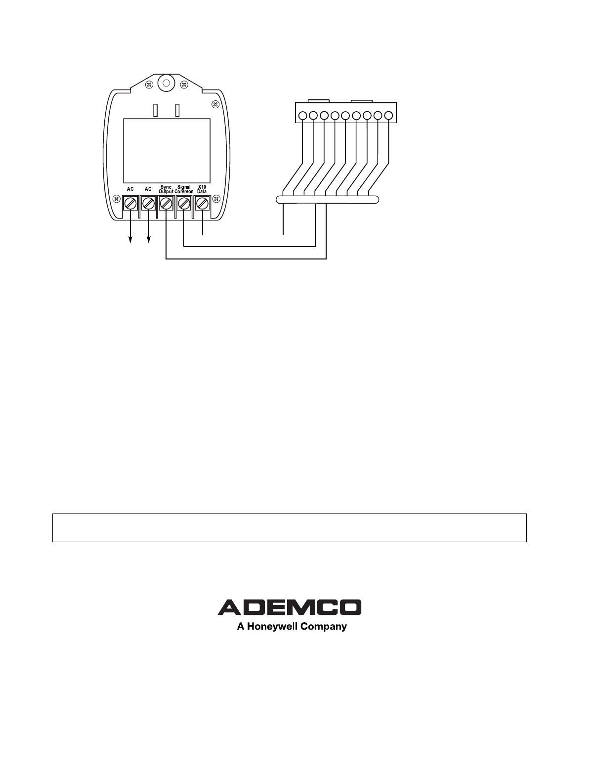
TRANSFORMER/X10 INTERFACE
TERMINALS
ON CONTROL
BOARD
1361X10-003-V0
RED (SYNC)
VIOLET (DATA)
WHITE (COM)
123456789 CONNECTOR ON
CONTROL PANEL
BLACK
BLUE
BROWN
GREEN
RED
WHITE
YELLOW
GRAY
VIOLET
4142TR CABLE
PINS (2,3,6,7,8,9) NOT USED
9-PIN CONNECTOR
Figure 3. Connections for Vista-15, Vista-20SE, FA148C, FA162C, or equivalent
SEE THE CONTROL PANEL’S INSTALLATION INSTRUCTIONS FOR COMPLETE
INFORMATION REGARDING THE LIMITATIONS OF THE ENTIRE SECURITY SYSTEM.
165 Eileen Way, Syosset, NY 11791
Copyright © 2003 Honeywell International Inc.
www.ademco.com
