VistaLINK® Pro User Manual Vista LINK 11v0
VistaLINK%20User%20Manual
User Manual:
Open the PDF directly: View PDF ![]() .
.
Page Count: 100
- 1. OVERVIEW
- 2. INSTALLATION
- 3. HARDWARE DISCOVERY IN VISTALINK® PRO
- 3.1. NAVIGATION TREE
- 3.2. MANUALLY ADDING HARDWARE
- 3.3. AUTO DISCOVERY AND SYSTEM SETTINGS
- 4. DEVICE CONFIGURATIONS
- 5. ALARM MONITORING
- 5.1. ABOUT ALARM INDICATION
- 5.2. ALARM VIEW WINDOWS
- 5.2.1. Alarm View Layout
- 5.2.2. Viewing Alarms
- 5.2.3. Opening an Alarm View Window
- 5.2.4. Acknowledging and Correcting Alarms
- 5.2.5. Acknowledging All Alarms
- 5.2.6. Adding a Custom Alarm Entry
- 5.2.7. Filtering Alarms From the Alarm View
- 5.2.8. Default and Custom Filters
- 5.2.9. Constructing Filters
- 5.2.10. Clearing Filter Options
- 5.2.11. Saving and Loading Filters
- 5.2.12. Default “Unresolved Alarm” Filter
- 5.2.13. Suspending View Updates
- 5.2.14. Saving the Current Alarm View
- 5.3. CONFIGURING ALARM PROPERTIES
- 5.4. SERVICES
- 5.5. EMAIL NOTIFICATION SYSTEM
- 6. ADVANCED CONTROL
- 7. CLIENT, SERVER AND HARDWARE MAINTENANCE
VistaLINK® PRO
Instruction Manual
© Copyright 2007 - 2013
EVERTZ MICROSYSTEMS LTD.
5288 John Lucas Drive,
Burlington, Ontario,
Canada L7L 5Z9
Phone: 905-335-3700
Sales: sales@evertz.com Fax: 905-335-3573
Tech Support: service@evertz.com Fax: 905-335-7571
Web Page: http://www.evertz.com
Version 11.0 June 2013
The material contained in this manual consists of information that is the property of Evertz Microsystems and is
intended solely for the use of purchasers of VistaLINK®. Evertz Microsystems expressly prohibits the use of this
manual for any purpose other than the operation of VistaLINK®.
All rights reserved. No part of this publication may be reproduced without the express written permission of Evertz
Microsystems Ltd. Copies of this manual can be ordered from your Evertz dealer or from Evertz Microsystems.
This page left intentionally blank

VistaLINK® PRO User Manual
Revision 11.0 VistaLINK® PRO - i
TABLE OF CONTENTS
1. OVERVIEW .................................................................................................................................... 1-1
1.1. VISTALINK® PRO’S MAIN FEATURES ................................................................................. 1-1
1.1.1. VistaLINK® PRO Alarm Management.......................................................................... 1-1
1.1.2. VistaLINK® PRO Configuration Management .............................................................. 1-1
2. INSTALLATION .............................................................................................................................. 2-1
2.1. INSTALLATION OF THE VISTALINK® PRO SERVER .......................................................... 2-1
2.1.1. Component Check-List ............................................................................................... 2-1
2.1.2. Initiating the Software Installation for the Server ......................................................... 2-1
2.1.3. Important Menu........................................................................................................... 2-2
2.1.4. Introduction Menu ....................................................................................................... 2-3
2.1.5. License Agreement ..................................................................................................... 2-3
2.1.6. Select the Installation Folder ....................................................................................... 2-4
2.1.7. Install Complete .......................................................................................................... 2-4
2.2. VISTALINK® PRO SERVER .................................................................................................. 2-5
2.2.1. Starting the VistaLINK® PRO Server ........................................................................... 2-5
2.2.2. VistaLINK® PRO Server Login Screen ........................................................................ 2-5
2.2.3. Verifying Server Startup Operations ............................................................................ 2-6
2.3. CLIENT INSTALLATION INSTRUCTIONS ............................................................................ 2-6
2.3.1. Executing the Client Installer....................................................................................... 2-6
2.3.2. VistaLINK® PRO Client Installer Welcome Screen ...................................................... 2-7
2.3.3. Client Selection Menu ................................................................................................. 2-7
2.3.4. License Agreement Menu ........................................................................................... 2-8
2.3.5. Select the Installation Folder ....................................................................................... 2-8
2.3.6. Installation Complete .................................................................................................. 2-9
2.4. CLIENT CONFIGURATIONS AND STARTUP ....................................................................... 2-9
2.4.1. Client Server Configuration ......................................................................................... 2-9
2.4.2. Client Startup and Logon .......................................................................................... 2-10
3. HARDWARE DISCOVERY IN VISTALINK® PRO .......................................................................... 3-1
3.1. NAVIGATION TREE .............................................................................................................. 3-1
3.1.1. Hardware .................................................................................................................... 3-1
3.2. MANUALLY ADDING HARDWARE ...................................................................................... 3-1
3.2.1. To Force a Frame Discovery ....................................................................................... 3-1
3.3. AUTO DISCOVERY AND SYSTEM SETTINGS .................................................................... 3-2
3.3.1. Automatic Discovery ................................................................................................... 3-2
3.3.2. Broadcast Traffic Note ................................................................................................ 3-2
3.3.3. Configuring Discovery Settings ................................................................................... 3-2
3.3.4. Displaying the Discovery Status Panel ........................................................................ 3-3
3.3.4.1. Lock Discovery ............................................................................................. 3-3
3.3.5. Setting Discovery Cycle Duration ................................................................................ 3-4

VistaLINK® PRO User Manual
VistaLINK® PRO - ii Revision 11.0
3.3.5.1. Subnet Mask Configuration .......................................................................... 3-4
3.3.5.2. Ranged Discovery ........................................................................................ 3-4
3.3.6. Refresh Network View ................................................................................................ 3-5
3.3.7. Cleanup Network View ............................................................................................... 3-5
3.3.7.1. Server Hardware Discovery .......................................................................... 3-5
3.3.7.2. DiscoverySettings.xml .................................................................................. 3-6
4. DEVICE CONFIGURATIONS ......................................................................................................... 4-7
4.1. CONFIGURATION ................................................................................................................. 4-7
4.1.1. About Configuration Windows ..................................................................................... 4-7
4.1.2. Working With Configuration Windows ......................................................................... 4-9
4.1.2.1. Viewing Configurations ................................................................................. 4-9
4.1.2.2. Refreshing the View ................................................................................... 4-10
4.1.2.3. Automatic Refresh ...................................................................................... 4-10
4.1.3. Applying Changes Made to Configuration ................................................................. 4-10
4.1.3.1. Deferred ..................................................................................................... 4-10
4.1.3.2. Default Dynamic Apply ............................................................................... 4-11
4.2. BATCH CONFIGURATIONS ............................................................................................... 4-11
4.2.1. Saving and Loading Configurations .......................................................................... 4-11
4.2.2. Saving Configurations ............................................................................................... 4-11
4.2.2.1. Standard Local Configurations.................................................................... 4-12
4.2.2.2. Save Configurations ................................................................................... 4-13
4.2.2.3. Export Configurations ................................................................................. 4-14
4.2.3. Loading Configurations ............................................................................................. 4-15
4.2.3.1. Loading Local Configuration Files ............................................................... 4-15
4.2.3.2. To Load a Configuration File ...................................................................... 4-15
4.2.3.3. Loading System Configuration Files ........................................................... 4-16
5. ALARM MONITORING ................................................................................................................... 5-1
5.1. ABOUT ALARM INDICATION ............................................................................................... 5-1
5.1.1. Rules of Broadcast ..................................................................................................... 5-1
5.2. ALARM VIEW WINDOWS ..................................................................................................... 5-2
5.2.1. Alarm View Layout ...................................................................................................... 5-2
5.2.2. Viewing Alarms ........................................................................................................... 5-3
5.2.2.1. Hardware Super-Node .................................................................................. 5-3
5.2.2.2. Frame Node ................................................................................................. 5-3
5.2.2.3. Product Node ............................................................................................... 5-3
5.2.2.4. Product Video Input Node ............................................................................. 5-4
5.2.3. Opening an Alarm View Window ................................................................................. 5-4
5.2.4. Acknowledging and Correcting Alarms ....................................................................... 5-4
5.2.4.1. Corrected but Not Acknowledged ................................................................. 5-4
5.2.4.2. Self Correcting Alarms .................................................................................. 5-4
5.2.5. Acknowledging All Alarms ........................................................................................... 5-5
5.2.6. Adding a Custom Alarm Entry ..................................................................................... 5-5
5.2.7. Filtering Alarms From the Alarm View ......................................................................... 5-5
5.2.8. Default and Custom Filters ......................................................................................... 5-6
5.2.9. Constructing Filters ..................................................................................................... 5-6
5.2.10. Clearing Filter Options ................................................................................................ 5-7
5.2.11. Saving and Loading Filters ......................................................................................... 5-8

VistaLINK® PRO User Manual
Revision 11.0 VistaLINK® PRO - iii
5.2.12. Default “Unresolved Alarm” Filter ................................................................................ 5-8
5.2.13. Suspending View Updates .......................................................................................... 5-8
5.2.14. Saving the Current Alarm View ................................................................................... 5-8
5.2.14.1. Saving to a New File ................................................................................... 5-8
5.2.14.2. Appending to an Existing File ..................................................................... 5-9
5.3. CONFIGURING ALARM PROPERTIES ................................................................................ 5-9
5.3.1. Viewing and Modifying Alarm Properties ..................................................................... 5-9
5.3.1.1. Severity Options ........................................................................................... 5-9
5.3.2. To View or Modify Alarm Properties .......................................................................... 5-10
5.3.3. Factory Defaulting ..................................................................................................... 5-12
5.3.4. Bulk Operations ........................................................................................................ 5-12
5.3.5. Alarm Thresholds ...................................................................................................... 5-12
5.3.5.1. Disabling/Enabling Alarms .......................................................................... 5-13
5.3.6. Inhibiting and Sleeping Hardware or Services ........................................................... 5-14
5.3.6.1. Inhibited/Sleep Colours ............................................................................... 5-15
5.3.6.1.1. To Inhibit / Sleep a Device .................................................................. 5-15
5.3.6.1.2. To Remove Inhibit / Sleep Status ........................................................ 5-16
5.4. SERVICES ........................................................................................................................... 5-16
5.4.1. Creating and Editing Services ................................................................................... 5-16
5.4.1.1. To Create a New Service ............................................................................ 5-16
5.4.1.2. Adding Hardware to a Service .................................................................... 5-16
5.4.2. Right Click Service Creation ..................................................................................... 5-17
5.4.3. Renaming a Service ................................................................................................. 5-17
5.4.4. Removing a Service .................................................................................................. 5-17
5.4.5. Service Grouping Mode ............................................................................................ 5-17
5.4.6. Creating a Service Group ......................................................................................... 5-18
5.4.6.1. Alarm Sets .................................................................................................. 5-18
5.5. EMAIL NOTIFICATION SYSTEM ........................................................................................ 5-19
5.5.1. Configuring the Email Alert System ........................................................................... 5-19
5.5.2. Delivery Options ....................................................................................................... 5-20
5.5.3. To Configure the Email Recipients ............................................................................ 5-21
5.5.4. Advance Configuration.............................................................................................. 5-22
5.5.5. Audible Alert System ................................................................................................ 5-22
5.5.5.1. Audible Alerts (Playing Sounds When an Alarm Occurs) ............................ 5-22
5.5.5.2. Audible Alert Playback Mode ...................................................................... 5-23
5.5.6. Alarm Log Management ............................................................................................ 5-24
5.5.6.1. Logging, Holding and Ignoring Alarms (Server Properties) ......................... 5-24
5.5.7. Event Archiving (Database Administrator)................................................................. 5-25
5.5.7.1. To Enable or Disable the Database Administrator ...................................... 5-25
5.5.7.2. To Set the Log Administration Duration and Save Location ........................ 5-25
5.5.7.3. To Run the Database Administrator Immediately ........................................ 5-26
6. ADVANCED CONTROL ............................................................................................................... 6-27
6.1. MVP CONTROL ................................................................................................................... 6-27
6.1.1. MVP DVL Introduction .............................................................................................. 6-27
6.1.2. DVL Creation Dialog ................................................................................................. 6-27
6.1.3. Change Stream DVL ................................................................................................. 6-28
Figure 6-6: DVL Editor with active windows ............................................................... 6-29
6.1.4. Change Stream DVL Source List .............................................................................. 6-29

VistaLINK® PRO User Manual
VistaLINK® PRO - iv Revision 11.0
6.1.5. Save/Load DVL ........................................................................................................ 6-30
6.1.6. Audio Route DVL ...................................................................................................... 6-31
6.2. CROSSPOINT CREATION .................................................................................................. 6-32
6.2.1. Router Selection Section .......................................................................................... 6-33
6.2.2. Content Section ........................................................................................................ 6-33
6.2.3. Open Ended Crosspoint............................................................................................ 6-34
6.2.4. Label Tracked Crosspoint ......................................................................................... 6-35
6.2.5. Output Referenced Crosspoint ................................................................................. 6-35
6.2.6. Editing of Crosspoints ............................................................................................... 6-37
6.3. LAUNCHES ......................................................................................................................... 6-37
6.3.1. Creating Launches.................................................................................................... 6-37
6.3.1.1. HTTP (URL) Launches ............................................................................... 6-37
6.3.1.2. Executable (.exe) Launches ....................................................................... 6-38
6.3.2. Accessing / Using Launches ..................................................................................... 6-38
6.4. INTRODUCTION TO MACRO’S .......................................................................................... 6-38
6.4.1. Cycling Macro’s ........................................................................................................ 6-40
6.4.2. Running Cycling Macro’s .......................................................................................... 6-40
6.4.3. Macro Property Selection .......................................................................................... 6-41
6.5. INTRODUCTION TO MIBS .................................................................................................. 6-44
6.5.1. The MIB Control Set ................................................................................................. 6-45
6.5.2. MIB Control Set Dialog in Detail ................................................................................ 6-46
6.5.3. Creating a MIB Control Set ....................................................................................... 6-47
6.5.4. Running the MIB Control Set .................................................................................... 6-48
7. CLIENT, SERVER AND HARDWARE MAINTENANCE................................................................. 7-1
7.1. FIRMWARE UPGRADES ...................................................................................................... 7-1
7.1.1. Upgrading Frame Controllers ...................................................................................... 7-1
7.1.2. Module Firmware Management .................................................................................. 7-3
7.2. PRODUCT JAR UPGRADES ................................................................................................ 7-5
7.2.1. Client Product JAR Support ........................................................................................ 7-6
7.3. SERVER RESTORE MANAGER ........................................................................................... 7-7
7.3.1. Restoring Databases .................................................................................................. 7-7
7.4. USER ADMINISTRATION ..................................................................................................... 7-8
7.4.1. User Permissions........................................................................................................ 7-8
7.4.1.1. Adding or Modifying a User Account ............................................................. 7-8
7.4.1.2. Deleting a User Account ............................................................................. 7-11
7.4.2. Audit Logging ............................................................................................................ 7-12
7.4.2.1. About the Audit View Window ..................................................................... 7-12
7.4.2.2. Manually Adding an Audit Entry .................................................................. 7-13

VistaLINK® PRO User Manual
Revision 11.0 VistaLINK® PRO - v
Figures
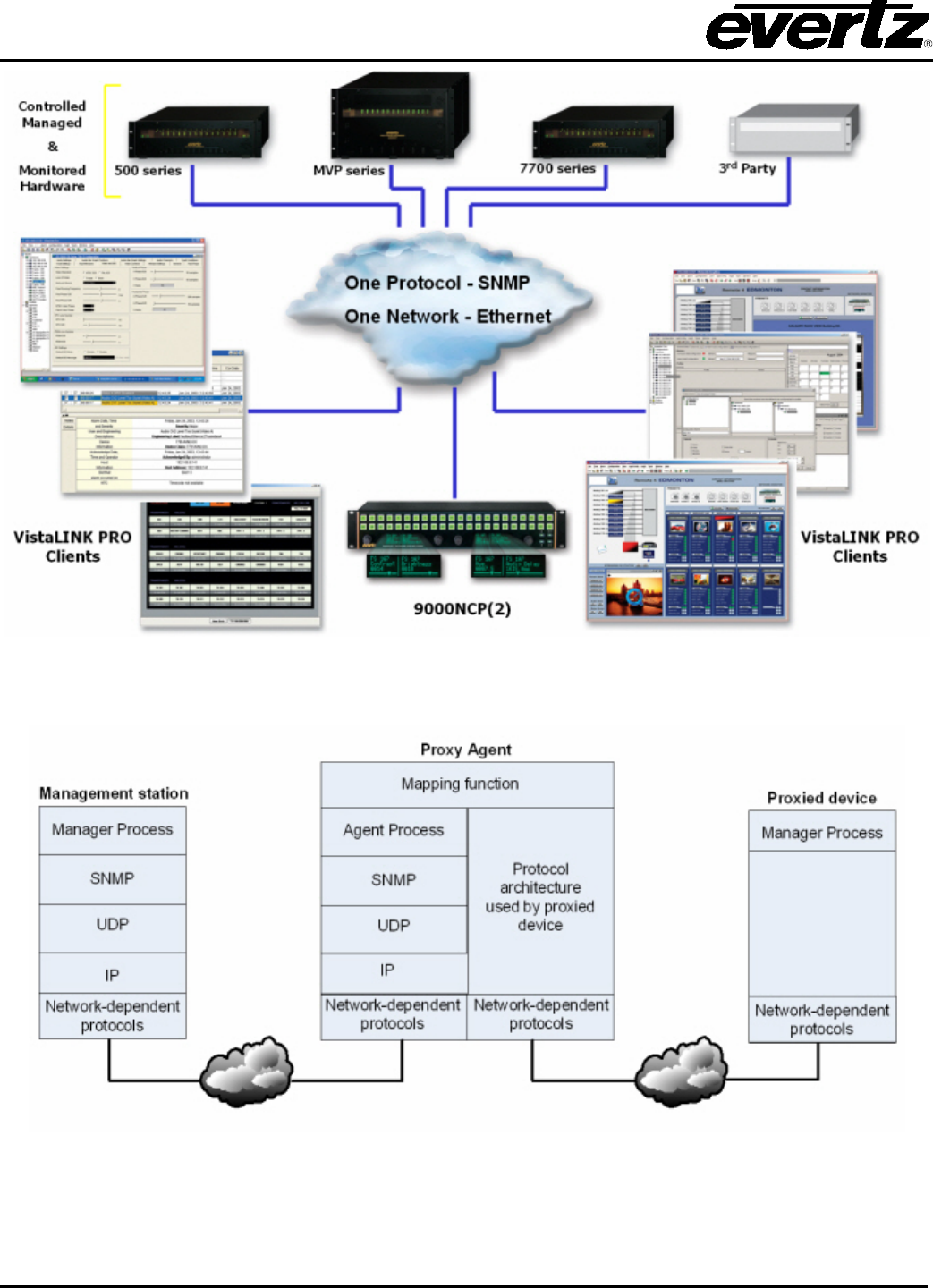
Figure 1-1: VistaLINK® Architecture ................................................................................................................... 1-2
Figure 1-2: Proxy Configuration.......................................................................................................................... 1-2
Figure 2-1: VistaLINK® Monitoring Toolkit Screen ............................................................................................. 2-2
Figure 2-2: Important Information ....................................................................................................................... 2-2
Figure 2-3: Introduction Information ................................................................................................................... 2-3
Figure 2-4: License Agreement .......................................................................................................................... 2-3
Figure 2-5: Select Installation Folder .................................................................................................................. 2-4
Figure 2-6: Install Complete Window ................................................................................................................. 2-4
Figure 2-7: Accessing VistaLINK® PRO Server ................................................................................................. 2-5
Figure 2-8: Login Screen .................................................................................................................................... 2-5
Figure 2-9: Startup Operations ........................................................................................................................... 2-6
Figure 2-10: Executing Client Installer ............................................................................................................... 2-6
Figure 2-11: Installer Welcome Screen .............................................................................................................. 2-7
Figure 2-12: Client Selection .............................................................................................................................. 2-7
Figure 2-13: License Agreement ........................................................................................................................ 2-8
Figure 2-14: Install Folder ................................................................................................................................... 2-8
Figure 2-15: Install Complete Screen ................................................................................................................. 2-9
Figure 2-16: Accessing Client Configuration Editor............................................................................................ 2-9
Figure 2-17: Client Properties Editor ................................................................................................................ 2-10
Figure 2-18: VistaLINK® Logon ........................................................................................................................ 2-10
Figure 2-19: VistaLINK® Logon ........................................................................................................................ 2-10
Figure 3-1: Navigation Tree ................................................................................................................................ 3-1
Figure 3-2: Add/Update Evertz Frame ............................................................................................................... 3-2
Figure 3-3: Discovery Settings General Tab ...................................................................................................... 3-3
Figure 3-4: Discovery Status Panel .................................................................................................................... 3-3
Figure 3-5: Discovery Setting Advanced Tab ..................................................................................................... 3-4
Figure 3-6: Server Hardware Discovery Editor ................................................................................................... 3-5
Figure 4-1: Configuration Panel ......................................................................................................................... 4-7
Figure 4-2: Configuration Window ...................................................................................................................... 4-9
Figure 4-3: Methods of Applying Changes ....................................................................................................... 4-10
Figure 4-4: Saving Configurations .................................................................................................................... 4-12
Figure 4-5: Config Editor .................................................................................................................................. 4-13
Figure 4-6: Save Configuration......................................................................................................................... 4-13
Figure 4-7: Configuration Editor ....................................................................................................................... 4-14
Figure 5-1: Alarm Indication ............................................................................................................................... 5-1
Figure 5-2: Example of an Alarm Condition ....................................................................................................... 5-2
Figure 5-3: Alarm Layout View ........................................................................................................................... 5-2
Figure 5-4: Add Custom Note Window ............................................................................................................... 5-5
Figure 5-5: Filter Options .................................................................................................................................... 5-7
Figure 5-6: Save Alarm Log ................................................................................................................................ 5-9
Figure 5-7: Alarm Configuration Window ......................................................................................................... 5-11
Figure 5-8: Input Configuration Window ........................................................................................................... 5-13
Figure 5-9: Video Fault Traps ........................................................................................................................... 5-14
Figure 5-10: Example of Status on Frame and Products ................................................................................. 5-15
Figure 5-11: Alarm Set ..................................................................................................................................... 5-18
Figure 5-12: Service Alarm Group Assignment Window .................................................................................. 5-19
Figure 5-13: Email – General Tab .................................................................................................................... 5-20
Figure 5-14: Status ........................................................................................................................................... 5-22
Figure 5-15: Advanced Tab .............................................................................................................................. 5-22
Figure 5-16: Audio Configuration...................................................................................................................... 5-23
Figure 5-17: Logging Mode Tab ....................................................................................................................... 5-24
Figure 5-18: DBAdmin Tab ............................................................................................................................... 5-25
Figure 6-1: Properties Side Bar ........................................................................................................................ 6-27
Figure 6-2: DVL Editor ...................................................................................................................................... 6-27
Figure 6-3: Source List View ............................................................................................................................ 6-28
Figure 6-4: DVL Editor with active windows ..................................................................................................... 6-28

VistaLINK® PRO User Manual
VistaLINK® PRO - vi Revision 11.0
Figure 6-5: Source List View ............................................................................................................................ 6-29
Figure 6-6: DVL Editor with active windows ..................................................................................................... 6-29
Figure 6-7: Source List Panel and Editor Opened ........................................................................................... 6-30
Figure 6-8: Save Load Selection ...................................................................................................................... 6-30
Figure 6-9: Windows Sources Panel ................................................................................................................ 6-31
Figure 6-10: Audio Route Window ................................................................................................................... 6-31
Figure 6-11: Crosspoint Creation Dialog .......................................................................................................... 6-32
Figure 6-12: Selected Router ........................................................................................................................... 6-33
Figure 6-13: Open Ended Crosspoint .............................................................................................................. 6-34
Figure 6-14: Label Tracked Crosspoint ............................................................................................................ 6-35
Figure 6-15: Output Referenced Crosspoint .................................................................................................... 6-36
Figure 6-16: Create a Launchable ................................................................................................................... 6-37
Figure 6-17: Create a Launchable ................................................................................................................... 6-38
Figure 6-18: Macro Editor ................................................................................................................................. 6-39
Figure 6-19: Control Panel of Macro Editor ...................................................................................................... 6-40
Figure 6-20: An empty MIB Control Set Dialog ................................................................................................ 6-45
Figure 6-21: MIB Control Set… ........................................................................................................................ 6-47
Figure 6-22: Sample MIB Control Set Being Created ...................................................................................... 6-47
Figure 6-23: Super Switch MIB Control Set in Action ...................................................................................... 6-48
Figure 7-1: Navigation Tree ................................................................................................................................ 7-2
Figure 7-2: Control Tab ...................................................................................................................................... 7-2
Figure 7-3: Version Information .......................................................................................................................... 7-3
Figure 7-4: Upgrade Firmware Screen ............................................................................................................... 7-4
Figure 7-5: Product Update Tab ......................................................................................................................... 7-5
Figure 7-6: Product Update Alert Message ........................................................................................................ 7-6
Figure 7-7: Version Information .......................................................................................................................... 7-6
Figure 7-8: Calendar .......................................................................................................................................... 7-7
Figure 7-9: Restore Manager Calendar ............................................................................................................. 7-8
Figure 7-10: User Manager ................................................................................................................................ 7-9
Figure 7-11: Edit User Window ........................................................................................................................ 7-10
Figure 7-12: Remove User(s) Dialog Box ........................................................................................................ 7-12
Figure 7-13: Audit Log ...................................................................................................................................... 7-12
Figure 7-14: Add Custom Audit Entry .............................................................................................................. 7-13
Tables
Table 5-1: Visual Alarm Indication...................................................................................................................... 5-4
Table 6-1: Standardized MIBs .......................................................................................................................... 6-44

VistaLINK® PRO User Manual
Revision 11.0 VistaLINK® PRO - vii
REVISION HISTORY
REVISION DESCRIPTION DATE
10.4 Updated to reflect Version 10.4 build 512 Dec 2007
10.5 Updated component check list Apr 2008
10.6 Updated “Component Check-List” section Dec 2012
11.0 Updated software screenshots and document text June 2013
Information contained in this manual is believed to be accurate and reliable. However, Evertz assumes no responsibility for the use thereof nor for
the rights of third parties, which may be effected in any way by the use thereof. Any representations in this document concerning performance of
Evertz products are for informational use only and are not warranties of future performance, either express or implied. The only warranty offered
by Evertz in relation to this product is the Evertz standard limited warranty, stated in the sales contract or order confirmation form.
Although every attempt has been made to accurately describe the features, installation and operation of this product in this manual, no warranty is
granted nor liability assumed in relation to any errors or omissions unless specifically undertaken in the Evertz sales contract or order confirmation.
Information contained in this manual is periodically updated and changes will be incorporated into subsequent editions. If you encounter an error,
please notify Evertz Customer Service department. Evertz reserves the right, without notice or liability, to make changes in equipment design or
specifications.

VistaLINK® PRO User Manual
Revision 11.0 Page 1-1
1. OVERVIEW
VistaLINK® is Evertz’s true Simple Network Management Protocol (SNMP) configuration and monitoring
platform. Evertz’s VistaLINK® PRO application software unites Evertz 7700 Series Fiber, Conversion,
NCP, VIP™, MVP®, 500 Series DA and AVM product lines as well as selected third party equipment
through a customized, detailed, java-based monitoring and configuration tool that is ready-to-use for signal
monitoring and "real-time" equipment configuration. VistaLINK® provides a complete, uncomplicated and
cost-effective network monitoring & configuration solution. It is also an effective local and remote
monitoring tool for both incoming and departing signals at strategic locations throughout your video
network enterprise.
Through VistaLINK® and SNMP, Evertz offers a simple, reliable, secure and efficient method of monitoring
and configuring your facility equipment. Real-time, reliable configuration and control is possible through
SNMP implementation, utilizing simple protocol commands that travel over your secure network.
VistaLINK® enables thousands of network nodes in mission critical applications to be monitored and
configured world-wide via SNMP.
Features:
• Full alarm monitoring and logging to a storage database
• Individual or batch card configuration with setting change confirmations and audit trails
• Create system wide presets that span multiple products and frames
• Alarm severity configuration and acknowledgement levels
• Alarm and event logging, human-readable file exporting for record-keeping and trend analysis
• Visual video confidence monitoring
• Automated hardware configuration driven by fault alarming
• User customizable graphical interface
1.1. VISTALINK® PRO’S MAIN FEATURES
1.1.1. VistaLINK® PRO Alarm Management
VistaLINK® PRO is equipped with comprehensive alarm event monitoring capabilities, including
configurable alarm severity settings, descriptions and user notes for each VistaLINK® - enabled Evertz
products. Alarm event acknowledgement, per alarm type or per service and alarm logging, with date, time
and type descriptions offer the end-user a complete database of alarm events for subsequent analysis and
trend tracking.
1.1.2. VistaLINK® PRO Configuration Management
Card configuration through VistaLINK® PRO can be performed on an individual or multi-card basis using
simple copy/paste routines reducing the time to configure each module separately. Configuration changes
can be performed immediately, making it possible to quickly change individual card parameters "on the
fly", or delayed in order to methodically configure and review changes before full deployment.
Configuration settings can be imported and exported in human-readable format, and configuration
messages inform the user of parameter setting changes. All changes are recorded in VistaLINK® PRO's
audit trail tool in the full version. A configuration-only VistaLINK® PRO tool (VLPRO-C) is provided free
with 7700FC VistaLINK® Frame Controllers for convenient card configuration.
VistaLINK® PRO User Manual
Page 1-2 Revision 11.0
Figure 1-1: VistaLINK® Architecture
Figure 1-2: Proxy Configuration

VistaLINK® PRO User Manual
Revision 11.0 Page 2-1
2. INSTALLATION
2.1. INSTALLATION OF THE VISTALINK® PRO SERVER
2.1.1. Component Check-List
To start working with the VistaLINK® monitoring suite, your machine must meet the following requirements:
VistaLINK PRO Server (or Server and Client):
• Server Class Platform
• Intel Xeon Processor (5xxx or equivalent)
• 4GB RAM (minimum)
• 100GB HDD (minimum)
• 100/1000 Network Adapter
• Windows Server 2008 64-bit (recommended)
Most commonly used platform is HP DL360/380 servers
VistaLINK PRO Client Only:
• 2 GHz or faster 32-bit (x86) or 64-bit (x64) Core2Duo
• 2 GB RAM (minimum)
• 10 GB available disk space
• DirectX 9 graphics processor with WDDM 1.0 or higher driver
• 100/1000 Network Adapter
• Windows 7 (recommended)
Compatible Operating Systems:
• Windows XP
• Windows Server 2003
• Windows Server 2003 x64
• Windows Server 2008
• Windows Server 2008 x64 (recommended for VLPRO Server)
• Windows 7
• Windows 7 x64 (recommended for VLPRO Client)
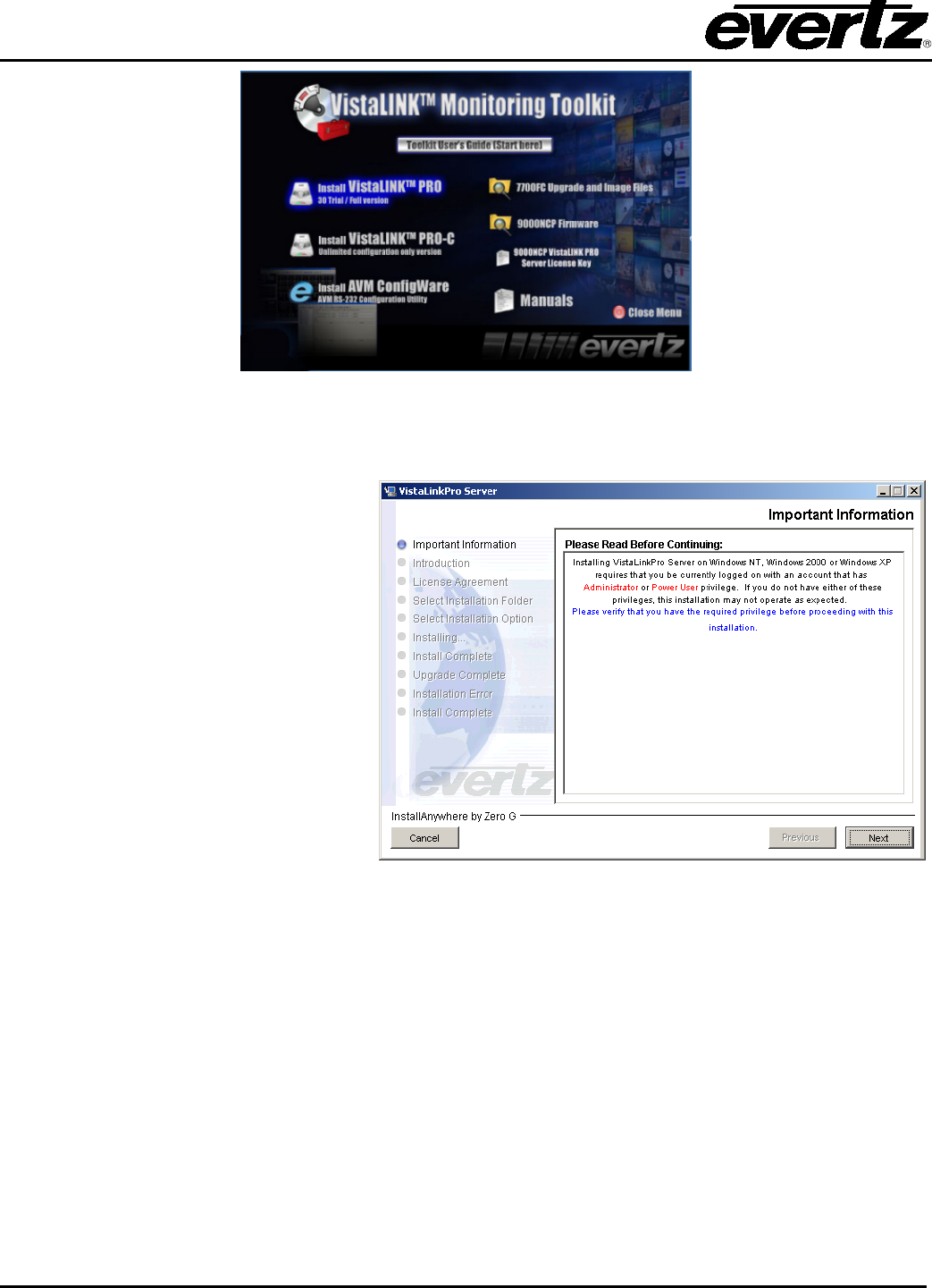
2.1.2. Initiating the Software Installation for the Server
From the CD-ROM Monitoring Toolkit splash screen, select “Install VLPRO (30 day Trial/Full Version)”.
This selection will initiate the software installation procedure for the VistaLINK® PRO Server.
VistaLINK® PRO User Manual
Page 2-2 Revision 11.0
Figure 2-1: VistaLINK® Monitoring Toolkit Screen
2.1.3. Important Menu
When the installer package finishes
extracting, th
e first menu will appear
outlining user privileges. Click the
‘Next’ button once you have verified
that you are using a Windows login
account that has administrative
privileges.
Figure 2-2: Important Information
VistaLINK® PRO User Manual
Revision 11.0 Page 2-3
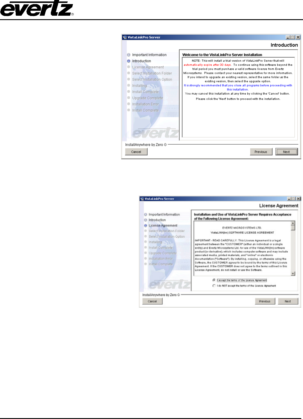
2.1.4. Introduction Menu
The Introduction menu describes what
license will be active once the
installation has been finished. The
license included with the install
package provides a 30-
day trial period.
You will be given the ability to apply
your
purchased license once the
installation is complete. Select the
‘Next’ button to proceed to the next
menu.
Figure 2-3: Introduction Information
2.1.5. License Agreement
Review the License Agreement to determine
if you are able to accept the terms and
agreements that are provided. Use the
bottom radial buttons to make your selection.
Select “Next” to proceed to the next menu if
you have accepted the Terms & Conditions.
Figure 2-4: License Agreement
VistaLINK® PRO User Manual
Page 2-4 Revision 11.0
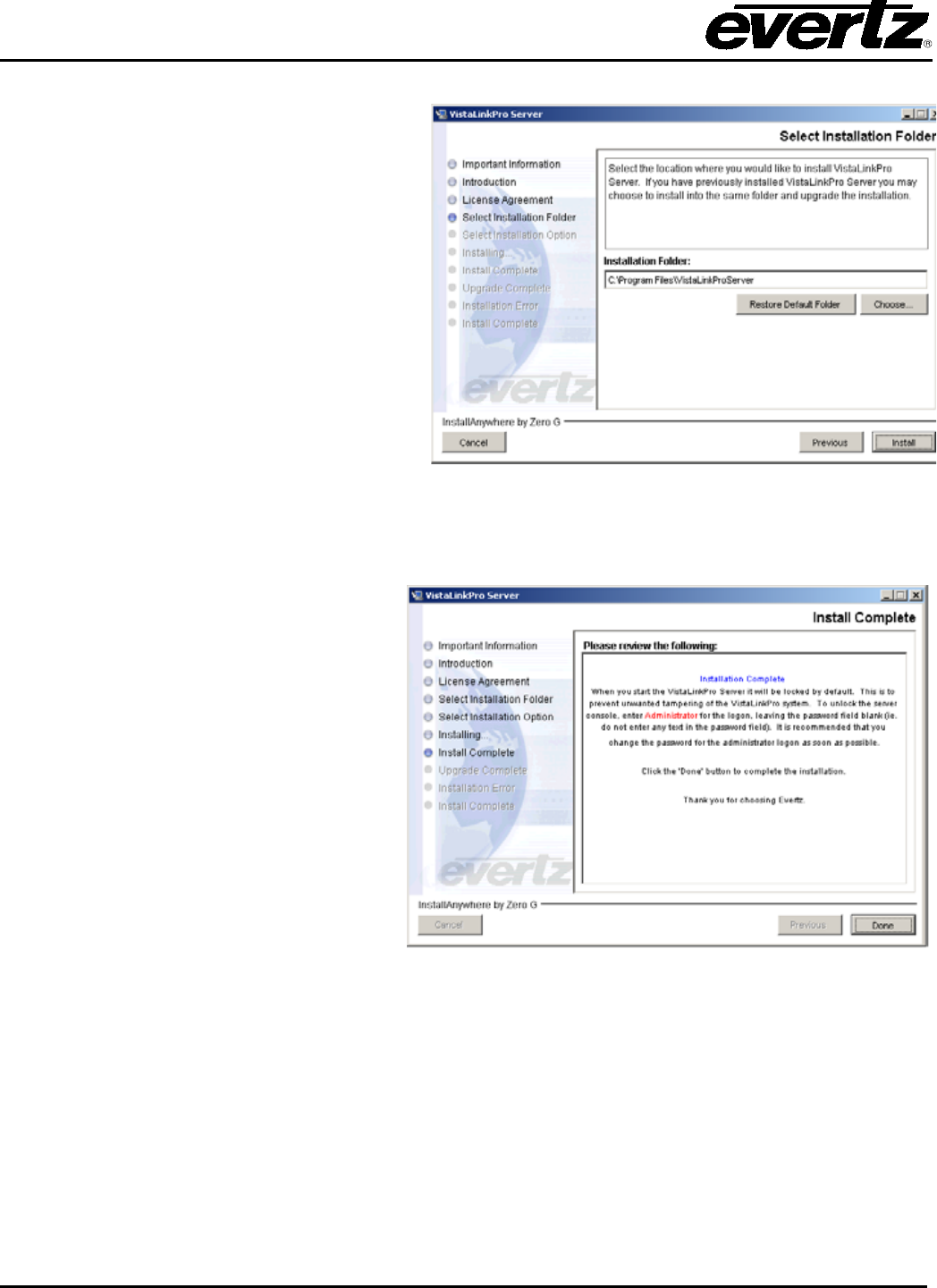
2.1.6. Select the Installation Folder
From the installation folder menu, a custom
installation path can be made with either the
text box or the ‘Choose…’ button. If the
‘Installation Folder’ path contains an existing
VistaLINK® PRO Server installation, an option
will be provided in the next menu to either
‘Upgrade Installation’ or ‘Full Installation’.
Select the ‘Install’ button when ready to start
installing the application.
Figure 2-5: Select Installation Folder
2.1.7. Install Complete
Once the installation is complete,
information is provided about the VLPRO
default Administrator account. If the
installation has encountered errors,
information will be provided at this menu. If
you require assistance troubleshooting
these errors, please record the details of
the encountered error so that a VLPRO
specialist can more easily assist you.
Select the ‘Done’ button to quit the
installer.
Figure 2-6: Install Complete Window
VistaLINK® PRO User Manual
Revision 11.0 Page 2-5
2.2. VISTALINK® PRO SERVER
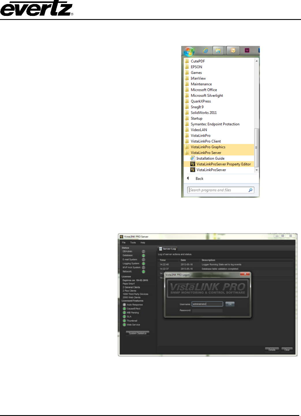
2.2.1. Starting the VistaLINK® PRO Server
To start the VistaLINK
®
PRO Server use the
shortcut provided in the start menu programs
group.
Start > Programs > VistaLinkPro Server >
VistaLinkProServer
The following is a list of additional items
provided:
• HTML system wide help program
• Installation Guide for the VLPRO server
• MySQL database manual in HTML
• The VistaLinkProServer Property Editor
• Shortcut to launch the server
• Shortcut to launch the installer for client
installations
Figure 2-7: Accessing VistaLINK® PRO Server
2.2.2. VistaLINK® PRO Server Login Screen
When the Logon screen appears, you
must use the default Administrator
account. This account does not have
a password set by default. It is
recommended to change the
Administrator account password from
<blank>, to a secure password. Use
the ‘Users’ menu from the ‘Tools’ drop
down menu to change the password.
Click the ‘Unlock’ button once the
u
sername field is filled with
‘administrator’ and the password field
is blank.
Figure 2-8: Login Screen
VistaLINK® PRO User Manual
Page 2-6 Revision 11.0
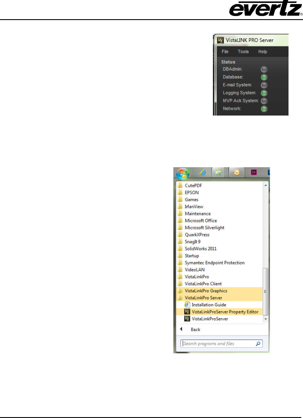
2.2.3. Verifying Server Startup Operations
The server status section allows the administrator to verify which
components are loaded and running. The states can be verified by
its virtual LED colour. The basic components that must be running
are:
Network
Database
Logging System
Ensure that the virtual LED’s are Green so that the VistaLINK® PRO
Server can operate correctly.
Figure 2-9: Startup Operations
2.3. CLIENT INSTALLATION INSTRUCTIONS
2.3.1. Executing the Client Installer
When installing your first client, it is
recommended that it be installed on the same
machine as the VistaLINK® PRO Server. To
start the client installer, navigate through the
start menu to the ‘Install VistaLink Pro Clients
(on this machine)’ shortcut.
Start > Programs > VistaLinkPro Server >
Install VistaLinkPro Clients (on this machine)
The cl
ient installer can also be executed
directly from the following directory:
<VistaLink Server install directory>
\VistaLinkProClient\Client.exe
This file can also be copied to another
computer for remote client setups.
Figure 2-10: Executing Client Installer
VistaLINK® PRO User Manual
Revision 11.0 Page 2-7
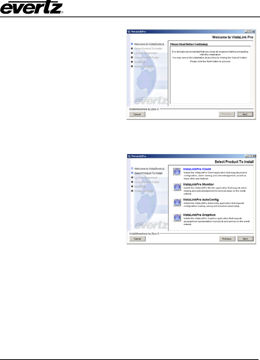
2.3.2. VistaLINK® PRO Client Installer Welcome Screen
After the installer finishes extracting its contents,
the install script starts with a note that mentions
to shut down any programs that may be
running. Select the ‘Next’ button when ready.
Figure 2-11: Installer Welcome Screen
2.3.3. Client Selection Menu
This menu allows the user to select a particular
VistaLINK® PRO client to install. The remainder
of t
his manual will refer to the “VistaLinkPro
Client”. Select the “VistaLinkPro Client”
graphics button and click the ‘Next’ Button to
advance to the next menu.
***Note: The other client types have the same
installation and setup method. Please refer to your
VistaLINK® PRO Server license information on client
support.
Figure 2-12: Client Selection
VistaLINK® PRO User Manual
Page 2-8 Revision 11.0
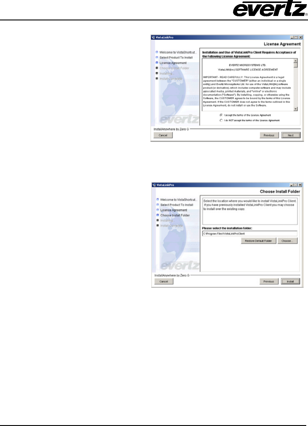
2.3.4. License Agreement Menu
Review the License Agreement to determine if
you are able to accept the terms and agreements
that are provided. Use the bottom radial buttons
to make your selection. Select “Next” to proceed
to the next menu if you have accepted the Terms
& Conditions.
Figure 2-13: License Agreement
2.3.5. Select the Installation Folder
From the installation folder menu, a custom
installation path can be made with either the text
field or the ‘Choose…’ button. A note is provided
about existing VistaLINK®
PRO client
installations. If the ‘Installation Folde
r’ path
contains an existing VistaLINK®
PRO client
installation, the install script will write over top of
it. Select the ‘Install’ button when you are ready
to start installing the application.
Figure 2-14: Install Folder
VistaLINK® PRO User Manual
Revision 11.0 Page 2-9
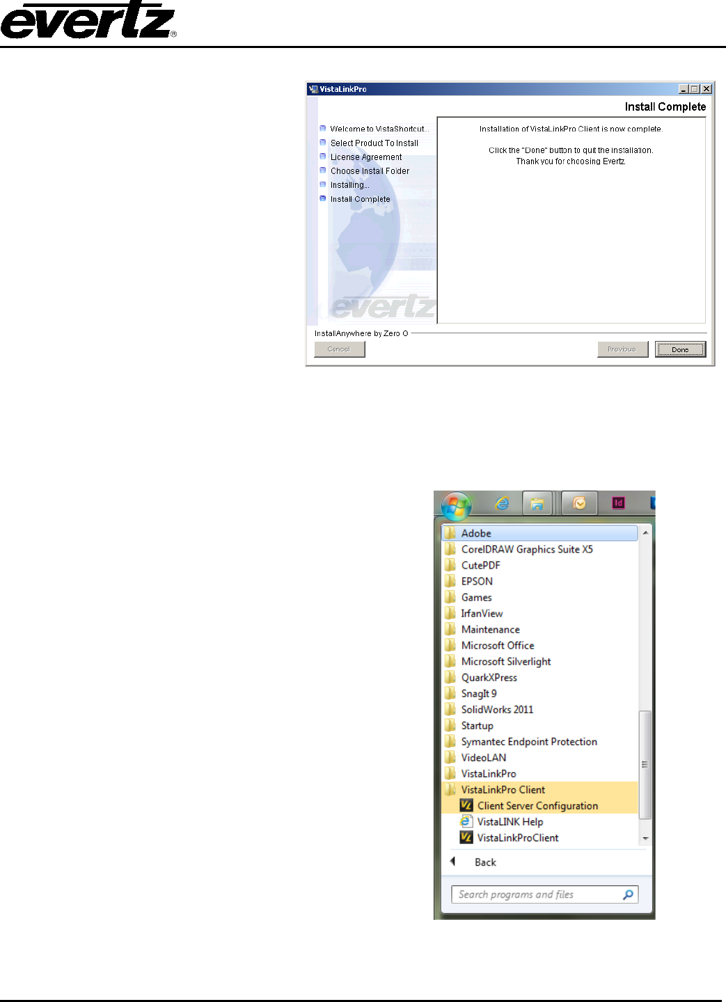
2.3.6. Installation Complete
Once the VistaLINK
®
PRO client has
been successfully installed, select the
‘Done’ button to quit the installer.
Figure 2-15: Install Complete Screen
2.4. CLIENT CONFIGURATIONS AND STARTUP
2.4.1. Client Server Configuration
To ensure the VistaLINK
®
PRO client
communicates to the server correctly, you will
need to ensure the connection settings are set
correctly. Start the ‘Client Server configuration’
tool from the ‘VistaLinkPro Client’ group in the
start menu.
Start > Programs > VistaLinkPro Client > Client
Server Configuration
Figure 2-16: Accessing Client Configuration
Editor
VistaLINK® PRO User Manual
Page 2-10 Revision 11.0
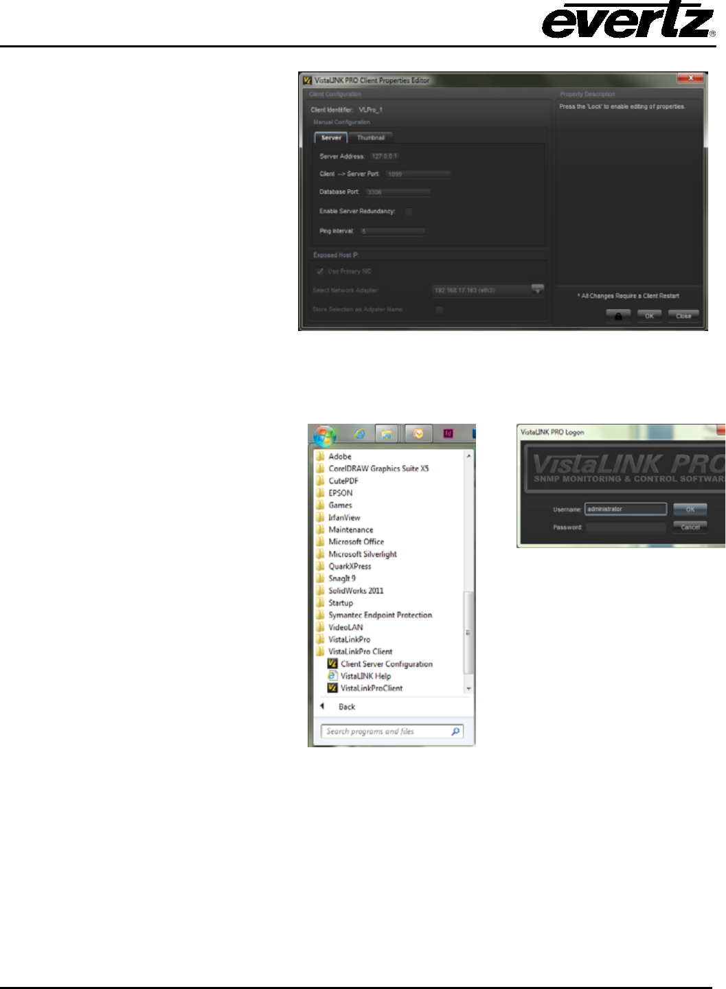
To edit the settings you must click the
button with the key lock icon. Once the
editor window is unlocked, settings can
then be changed. In the ‘Manual
Configuration’ frame, set the ‘Alarm
Server Address’ and ‘Database
Address’ to the VistaLINK® PRO Server
computer IP address. Select the Lock
butto
n again so the editor is in lock
mode. Click ‘OK’ and then click ‘OK’ to
the pop-up message.
**Note: This setting needs to be
implemented on all clients that are installed
on all machines.
Figure 2-17: Client Properties Editor
2.4.2. Client Startup and Logon
To Start the VistaLINK
®
PRO client use
the shortcut from the start menu.
Start > Programs > VistaLinkPro Client
> VistaLinkPro Client
Once the logon prompt appears, use
the same credentials as the VistaLINK®
PRO Server.
Figure 2-18: VistaLINK® Logon
Figure 2-19: VistaLINK®
Logon
VistaLINK® PRO User Manual
Revision 11.0 Page 3-1
3. HARDWARE DISCOVERY IN VISTALINK® PRO
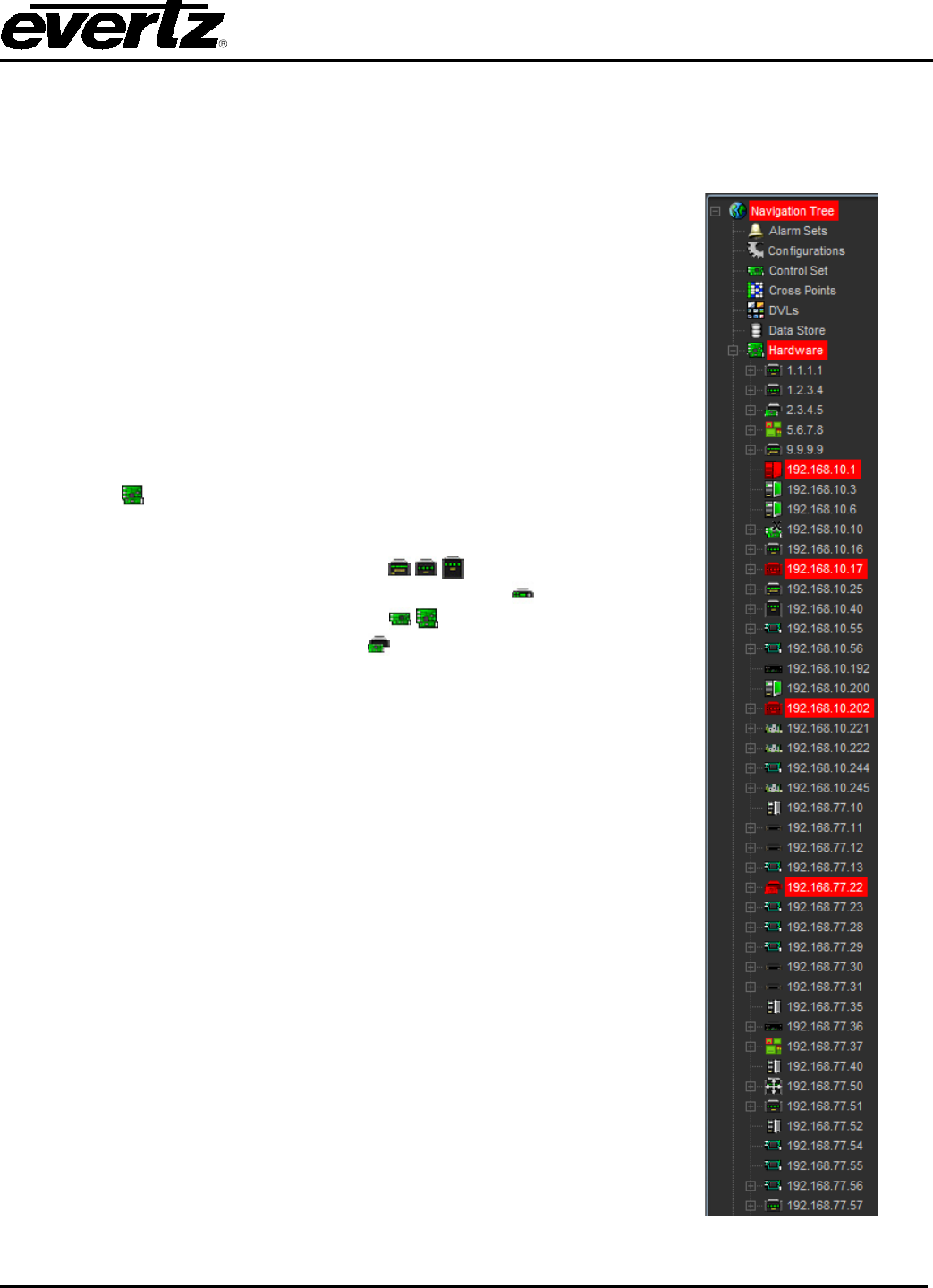
3.1. NAVIGATION TREE
The Navigation Tree is located on the left side of the VistaLINK® PRO
window. The navigation tree displays super-nodes and sub-nodes that
organize the VistaLINK® enabled hardware found by the system and
displays all Evertz VistaLINK® - enabled products found on the network
(see section 3.3). Nodes with a plus sign beside them can be
expanded to expose underlying elements and similarly, nodes with a
minus sign can be collapsed to hide unwanted information. Each node
in the Hardware View has an associated icon that indicates the type
and alarm state of the hardware device. For the VistaLINK® PRO
Standard and Monitor Client applications there are five super-nodes
under which all other nodes will appear.
3.1.1. Hardware
All hardware devices that are auto discovered or entered manually
will appear under this super-node. The Hardware super-node can
contain any of the following hardware node types:
• Frame nodes, denoted by the icons ( )
• Network Control Panel nodes, denoted by the icon
• Module nodes, denoted by the icons
• VIP modules, denoted by the icon
3.2. MANUALLY ADDING HARDWARE
Depending on network conditions or if the Discovery Subsystem is
disabled, the Automatic Discovery System may not find your frame or
products. In this case you can choose to manually force discovery on
a frame that is known to be connected to the network. Performing an
Add/Update Frame function on a device, which is already present in
the Hardware view will cause the discovery system to rediscover and
verify the device and all contained modules.
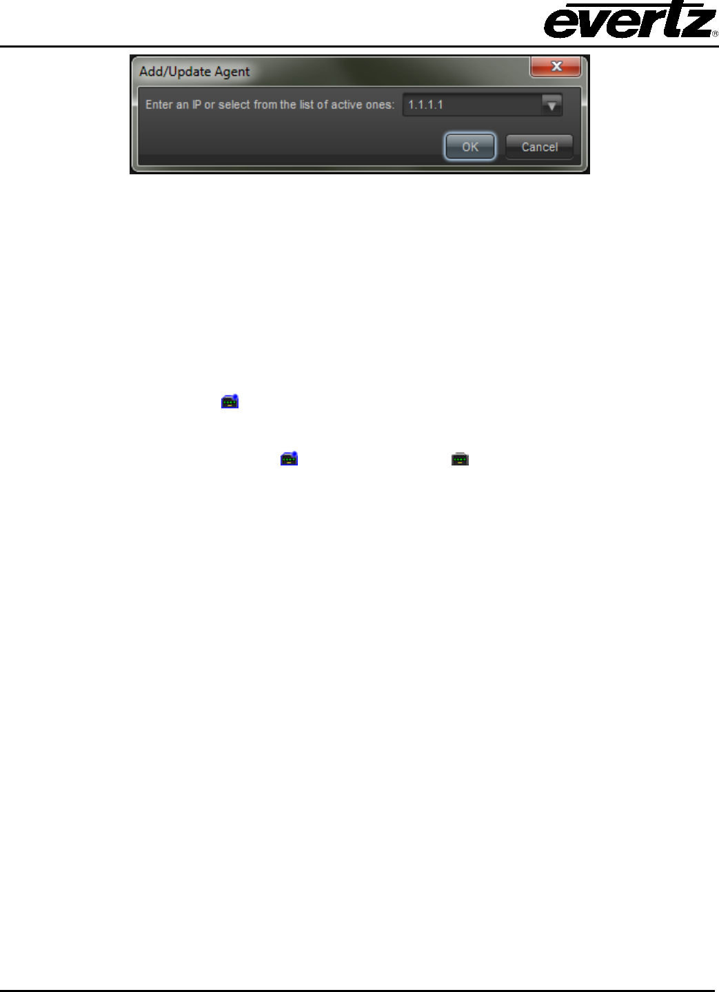
3.2.1. To Force a Frame Discovery
1. Select Tree -> Add/Update Frame. The Add/Update Frame dialog
box will appear.
2. Enter the IP address of the frame that you want to manually add,
and then select the "OK" button. If the frame is already in the
Hardware View you can select the IP address from the drop-down
list presented.
3. The Discovery Subsystem will now attempt to directly contact the
specified frame.
• If the frame cannot be contacted it will not be added to the
Navigation Tree's Hardware super-node.
• If contact is established then the Discovery Subsystem will detect
all products in the frame and the frame will be added to the
Navigation Tree's Hardware super-node.
Figure 3-1: Navigation Tree
VistaLINK® PRO User Manual
Page 3-2 Revision 11.0
Figure 3-2: Add/Update Evertz Frame
3.3. AUTO DISCOVERY AND SYSTEM SETTINGS
3.3.1. Automatic Discovery
In order for VistaLINK® PRO to monitor and control connected hardware it must first perform a network
auto discovery or have frame locations manually entered. The software searches for VistaLINK® (SNMP)
enabled frames present on the network by sending a broadcast message out on the network adapter and
waiting for a response. If multiple network cards are installed on the local machine then a broadcast
message will be sent for each adapter. When a valid frame response is received the frame will be added
to the Navigation Tree and the Discovery Subsystem will automatically begin product detection for this
frame, as indicated by the icon - .
When all products in the frame have been found, or the frame detection cycle has ended, the frame node
icon will change from the detection icon - to an idle frame icon - . Detected products will be added as
sub-nodes of the frame node. Any products that have multiple video inputs, as in the 7761AVM-DC will be
added with additional sub-nodes, listed per-input.
Once the initial detection phase has completed VistaLINK® PRO will enter into a discovery interval cycle
where it will awake at regular intervals, checking for new VistaLINK® enabled frames and verifying that all
previous frames and products are still responding across the network. If during this discovery cycle a new
device is found, the device will be added to the Navigation Tree. If a device can no longer be contacted
the icon for the device node will be changed to reflect the condition while leaving the device in the
Navigation Tree to alert the operator of the error condition.
The Auto Discovery subsystem can be configured for various detection cycle times and discovery options.
3.3.2. Broadcast Traffic Note
If a device is located on a separate network or isolated by a firewall or router that does not allow the
passage of broadcast traffic the VistaLINK® PRO broadcast discovery system will be unable to add the
frame to the hardware list. In the event that a frame cannot be reached via the broadcast discovery
system it will need to be manually added in to the hardware list (see section 3.2). After the frame has
been manually added to the tree, all subsequent polling attempts will utilize a direct SNMP connection to
the device that does not rely on the passage of broadcast traffic.
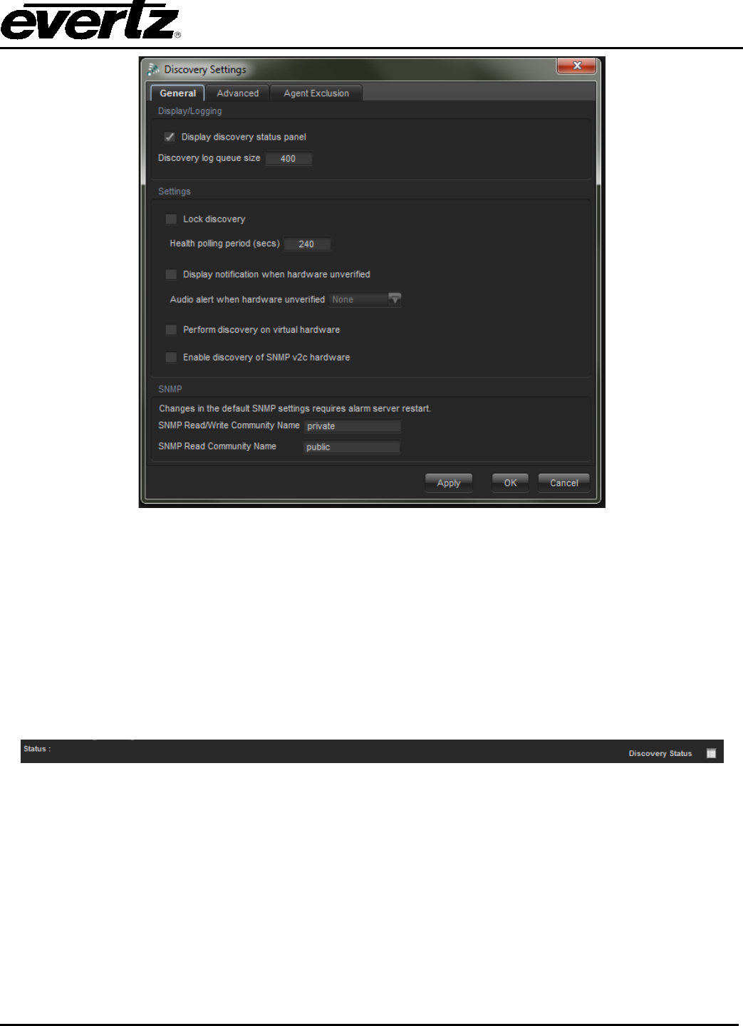
3.3.3. Configuring Discovery Settings
To configure the automatic discovery settings select File -> Discovery Settings from the main menu. The
Discovery Settings dialog will open allowing the user to set options for the discovery status panel and
queue size, the discovery system itself and the unverified hardware notification system.
VistaLINK® PRO User Manual
Revision 11.0 Page 3-3
Figure 3-3: Discovery Settings General Tab
3.3.4. Displaying the Discovery Status Panel
To access the Discovery Status Panel, select File->General Settings->Display Status Bar. When the
automatic discovery system is enabled, it may be beneficial to the user to view status information on what
the discovery system has found and information on how it is interacting with devices. When the discovery
status panel is enabled a discovery status bar will appear at the bottom of the client application window to
inform the user when the auto discovery systems are active and provide details regarding the devices that
have been discovered. When the discovery status panel is visible, clicking the Discovery Log button will
open a log file containing all recent entries.
Figure 3-4: Discovery Status Panel
3.3.4.1. Lock Discovery
By default, VistaLINK® PRO comes pre-configured with the Discovery System option enabled. Lock
discovery disables the Auto Discovery system. When in lock discovery the program will then unicast
query each device in the hardware tree at the default health-polling interval. When lock discovery is
enabled, it is not possible to add new devices to the hardware tree.
VistaLINK® PRO User Manual
Page 3-4 Revision 11.0
3.3.5. Setting Discovery Cycle Duration
This setting will determine how often VistaLINK® PRO will check the status of equipment already present
in the Navigation Tree, as well as search for new VistaLINK® enabled equipment connected to the
network. VistaLINK® PRO keeps the network connection open during the discovery cycle and closes the
connection immediately before the next discovery cycle. If you experience heavy load conditions, or
delays in packet responses on your network, you can increase this value to wait longer for equipment to
respond to the discovery process. To change the discovery cycle interval:
1. Locate the New Discovery period (secs) field directly below the Discovery Enabled setting and
enter the desired value (in seconds) into the field provided.
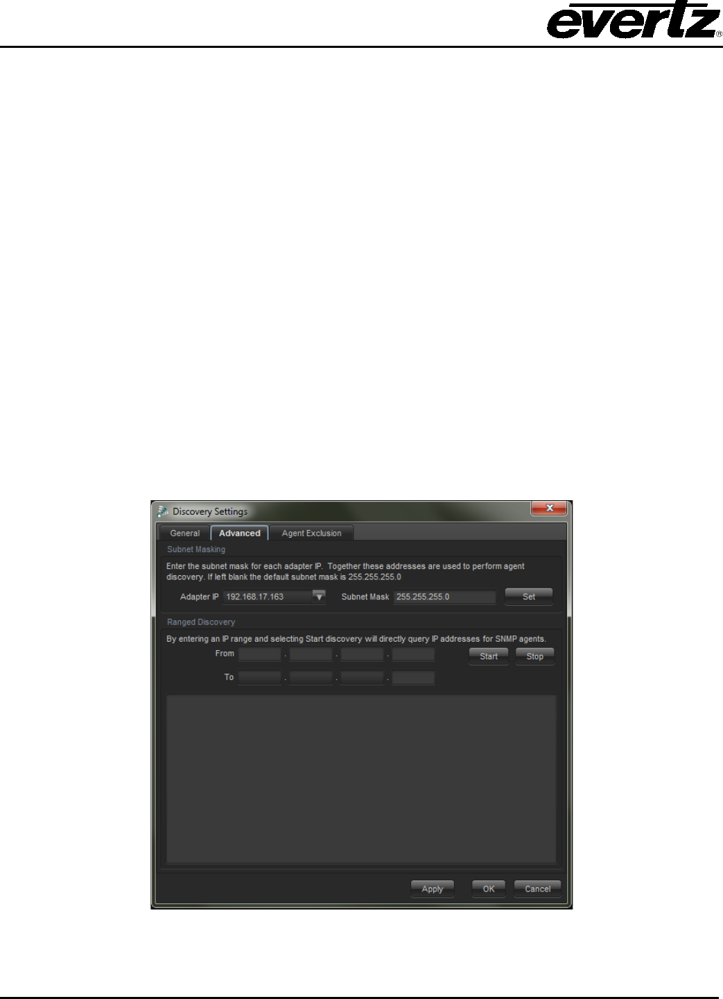
3.3.5.1. Subnet Mask Configuration
It is important to verify the subnet mask configuration in the application. Incorrect subnet masks will cause
the Auto Discovery process to function incorrectly. This setting can be configured through the ‘Advanced’
Tab from the ‘Discovery Settings’ dialog.
3.3.5.2. Ranged Discovery
When it is not possible for Auto Discovery to work because of network topologies, the Ranged Discovery
feature can be used. The Ranged Discovery works when a user manually types in a range of IP
addresses that the program can perform a unicast query against. This feature allows for a maximum
number of 255 IP address’s to be queried. This feature can be accessed through the ‘Advanced’ tab of
the Discovery Settings dialog.
Figure 3-5: Discovery Setting Advanced Tab

VistaLINK® PRO User Manual
Revision 11.0 Page 3-5
3.3.6. Refresh Network View
The Navigation Tree discovered hardware can be refreshed at any time by selecting Tree -> Refresh from
the main menu. Selecting this option will initiate an Auto Discovery cycle disregarding the Discovery
Interval setting.
All present frames will be updated with any newly added or removed modules. All newly added or
previously undiscovered hardware will be added to the Navigation Tree's Hardware super-node.
The toolbar button labeled "Refresh Network View" can also be used to perform this action.
3.3.7. Cleanup Network View
If products have been removed from a frame or a frame has been disconnected from your network the
Navigation Tree will show the frame and/or products, however, they will appear disabled. If you are aware
that the hardware does not exist on the network or has been permanently removed you can force
VistaLINK® PRO to "clean up" the Navigation Tree by removing the disabled hardware. To do this, select
Tree -> Cleanup from the main menu.
The toolbar button labeled "Cleanup Network View" can also be used to perform this action.
3.3.7.1. Server Hardware Discovery
Server hardware discovery is a system that allows the VistaLINK® PRO Server to keep a detailed record of
the available hardware on the network. Normally this process is an automated system. When the
VistaLINK® PRO Client discovers a new device, it will push the support to the VistaLINK® PRO Server.
This system is used to help the Server calculate alarm severities and to do other functions. To view what
hardware the VistaLINK® Server has, it is possible to use the clients to see this information. To do this,
select the Discovery Tab in the VistaLINK Pro Server window. The dialog houses the various tabs to do
range discovery and hardware client/refreshing. It is also possible to configure the subnet mask so the
Server calculates the right broadcast address for auto discovery.
Figure 3-6: Server Hardware Discovery Editor

VistaLINK® PRO User Manual
Page 3-6 Revision 11.0
3.3.7.2. DiscoverySettings.xml
The discovery settings file is a local database that clients use to remember what hardware was
discovered. The file gets re-written/created once the client is shutdown. If the client is forcibly closed
through the windows task manager, the file will not be updated/created. The DiscoverySettings.xml can be
accessed from the client installation folder in the config directory. It is possible to copy this file to other
clients to maintain a uniform hardware tree. Discovery Settings configured at the client are also stored in
this local database. The DiscoverySettings.xml can also be found in the VistaLINK® Server config
directory. Below is what the file looks like when it stores some information of different settings.
<?xml version="1.0" encoding="UTF-8" ?>
- <DiscoverySettings xmlns="http://castor.exolab.org/">
- <Discovery IsLocked="false" DiscoverVirtual="false" DiscoverV2C="false" QueueSize="400"
ShowStatus="false" PollingInterval="240">
<NotifyOnNonVerifiedDiscovered Enabled="false" Severity="Critical Blink" />
</Discovery>
<Adapter AdapterIP="1.1.1.6" Netmask="255.255.255.0" />
<Adapter AdapterIP="1.1.1.5" Netmask="255.255.255.0" />
<Adapter AdapterIP="192.168.3.14" Netmask="255.255.255.0" />
- <StaticHardware>
<SNMP_Agent Identifier="192.168.192.230::mvpd-agent" Type="AGENT-MVP-SERVER"
Virtual="false" />
<SNMP_Agent Identifier="192.168.192.32::90002ru" Type="AGENT-NCP-2RU" Virtual="false" />
<SNMP_Agent Identifier="192.168.1.246::mvpd-agent" Type="AGENT-MVP-SERVER" Virtual="false"
/>
- <SNMP_Frame Identifier="192.168.192.8::evertz" Type="AGENT-7700-FRAME" Virtual="false">
<SNMP_Product
Identifier="192.168.192.8::1::1.3.6.1.4.1.6827.10.17.3.1.1.1::7700FC::7700FC"
Type="CARD-7700" Virtual="false" />
<SNMP_Product
Identifier="192.168.192.8::5::1.3.6.1.4.1.6827.10.109.2.1.1.1::7707ADVT::7707ADVT"
Type="CARD-7700" Virtual="false" />
<SNMP_Product Identifier="192.168.192.8::8::1.3.6.1.4.1.6827.10.44.2.1.1.1::7720DAC-
A4::7720DAC-A4" Type="CARD-7700" Virtual="false" />
<SNMP_Product
Identifier="192.168.192.8::9::1.3.6.1.4.1.6827.10.77.2.1.1.1::7703BPXRF::7703BPXRF"
Type="CARD-7700" Virtual="false" />
<SNMP_Product
Identifier="192.168.192.8::15::1.3.6.1.4.1.6827.10.93.2.1.1.1::7751TG2HD::7751TG2H
D" Type="CARD-7700" Virtual="false" />
</SNMP_Frame>
</StaticHardware>
<Exclude />
</DiscoverySettings>
VistaLINK® PRO User Manual
Revision 11.0 Page 4-7
4. DEVICE CONFIGURATIONS
4.1. CONFIGURATION
Using VistaLINK® PRO a user can change individual module setups by accessing and changing values in
its associated Configuration View. Configuration Views provide access to all controllable parameters
available on a module similar to its card edge controls or OSD menu system. Configurations can be saved
and loaded into hardware using the VistaLINK® PRO system.
By taking advantage of VistaLINK® PRO's Advanced System Configurations feature many powerful and
scalable system presets can be defined and used to quickly and accurately change hardware setups.
Figure 4-1: Configuration Panel
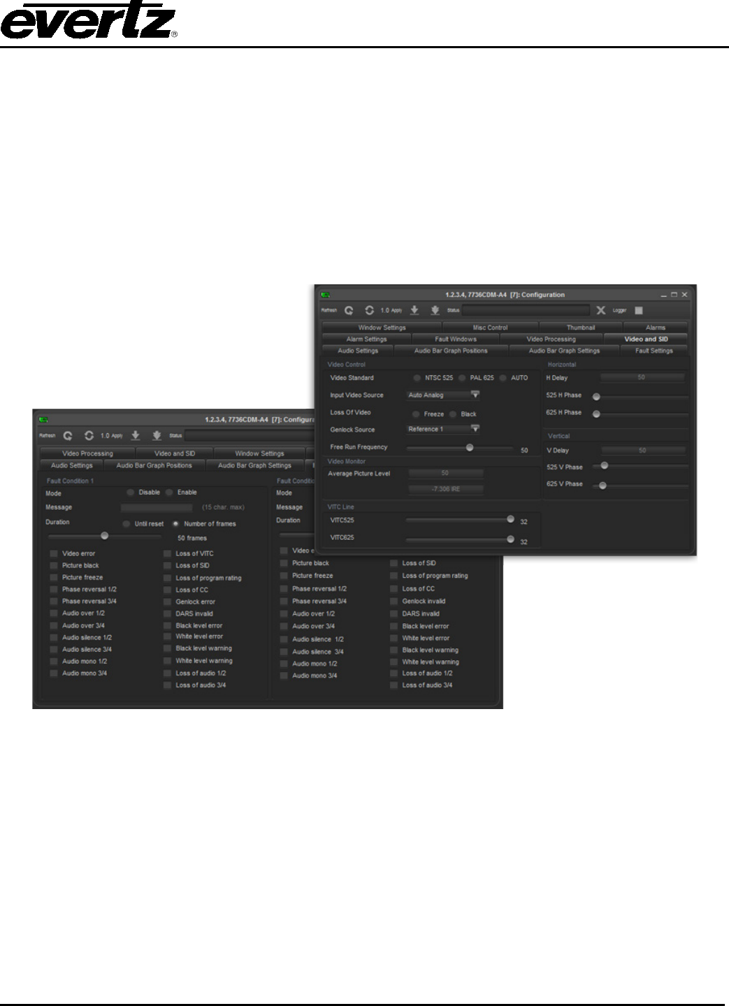
4.1.1. About Configuration Windows
Each Configuration View window provides a means of remotely viewing and setting the various
parameters within a product. The configuration view window is composed of a series of tabs along the top
of the window and a content area for each tab that contains the various configuration options. The
configuration options, also known as components, can be broken down into six basic categories.
Described below are the six basic component categories with function descriptions.
• Monitored Text Component - The text component is a descriptive label. This type of component
cannot be selected and does not represent a modifiable option.

VistaLINK® PRO User Manual
Page 4-8 Revision 11.0
• Group Box Component - The group box component is used to represent a group of common or
related configuration options.
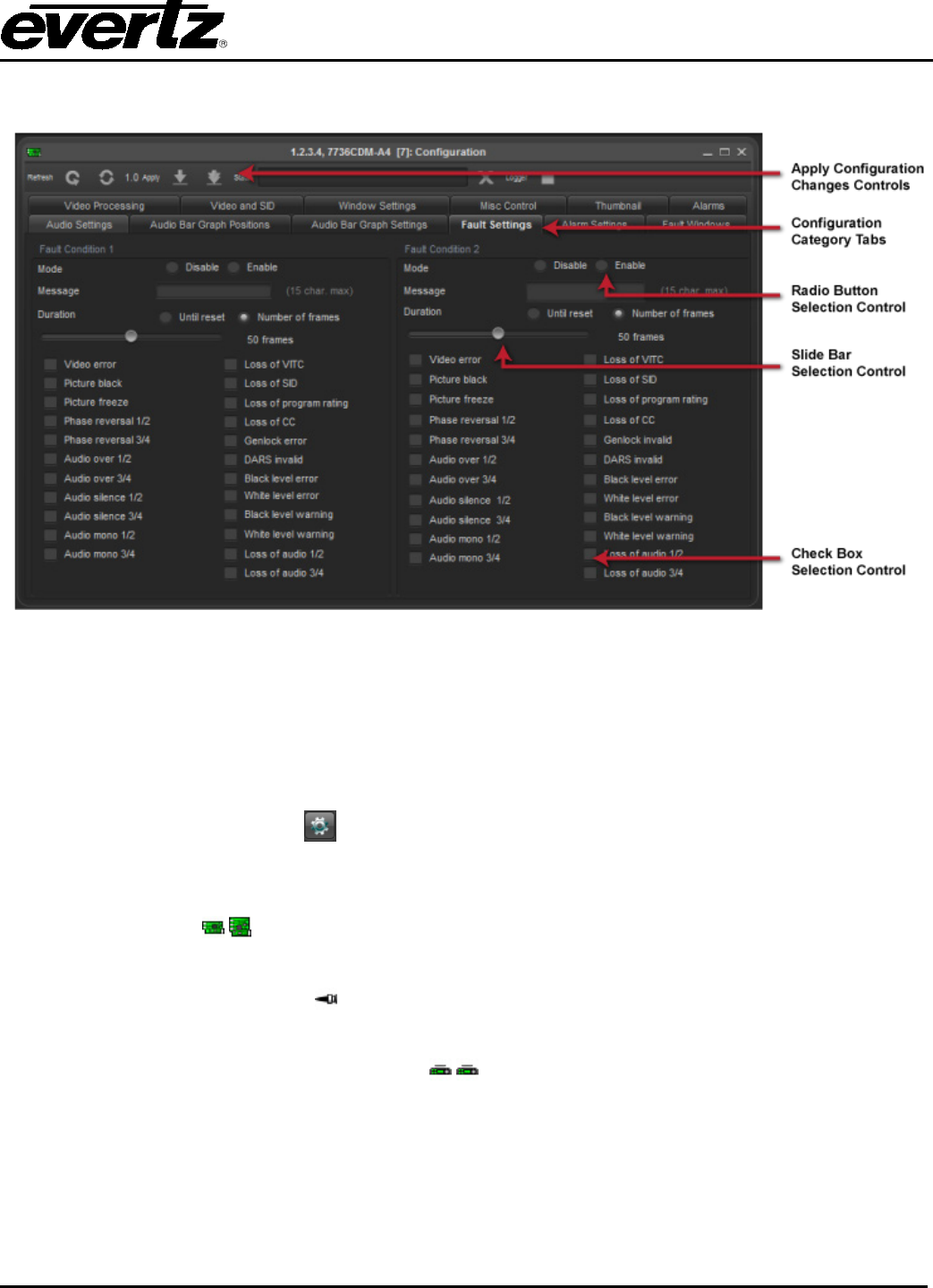
• Radio Button Component - Radio button components are used to represent a choice in
configuration options. A single radio button represents each option. Only one radio button item
can be selected within the group of radio buttons present. Since at least one option must be
selected within a group of radio buttons, to remove the selection from one radio button you must
select a different radio button within that group.
• Check Box Component - The check box component is used to represent an ON or OFF condition.
If the component has a check mark to its left then it is enabled (or ON). If there is no check mark
beside the component then the component is de-selected (or OFF). Check boxes can only exist in
one of the two described states. Check boxes differ from that of Radio buttons since check boxes
can be grouped together with each check box being selected. To change the setting of a check
box component click on the component with the left mouse button or press the space bar on the
keyboard.
• Slider Component - The slider component is used to represent a range of possible values. Slider
components have a minimum value and a maximum value. The current value of a slider is
represented by the position of the thumb box. To change the value of a slider component, click
and hold the left mouse button on the thumb box and drag the box either left or right. Once you
have selected your desired value, release the left mouse button. You can also change the value
by pressing the left or right arrow keys on the keyboard.
• Dropdown Component - The dropdown component is very similar to a group of radio button
components. The dropdown component presents a list of options when expanded. Only one of
the options in the list can be selected at one time. To expand the list of options, click on the down
arrow. To select one of the items in the list, click on the item with the left mouse button. An
alternative is to scroll to the item with the arrow keys and press the Enter key on the keyboard.
VistaLINK® PRO User Manual
Revision 11.0 Page 4-9
Below is a screenshot containing the various component types:
Figure 4-2: Configuration Window
4.1.2. Working With Configuration Windows
4.1.2.1. Viewing Configurations
In order to change a module’s parameters the Configuration View for that product must be opened. To
open a product’s Configuration View, right click the product desired and select -> View Configuration or
click the Open Configuration View toolbar icon.
Below is a description of the various types of nodes that a Configuration View can be opened for.
• Product Node
Opening this node will display the complete configuration view for the product selected.
• Product Video Input Node
Opening this node displays the configuration view for the selected video input.
• 9000NCP Network Control Panel Node
Opening this node allows setup and configuration of a 9000NCP(2)
(See the 9000NCP(2) manual for information on how to use the Network Control Panel with
VistaLINK® PRO)
VistaLINK® PRO User Manual
Page 4-10 Revision 11.0
4.1.2.2. Refreshing the View
At any time you may refresh the configuration view that you have open. Performing this option will
synchronize your view with the information contained in the product. Any configuration changes that have
not been applied to the product will be overwritten after executing a refresh.
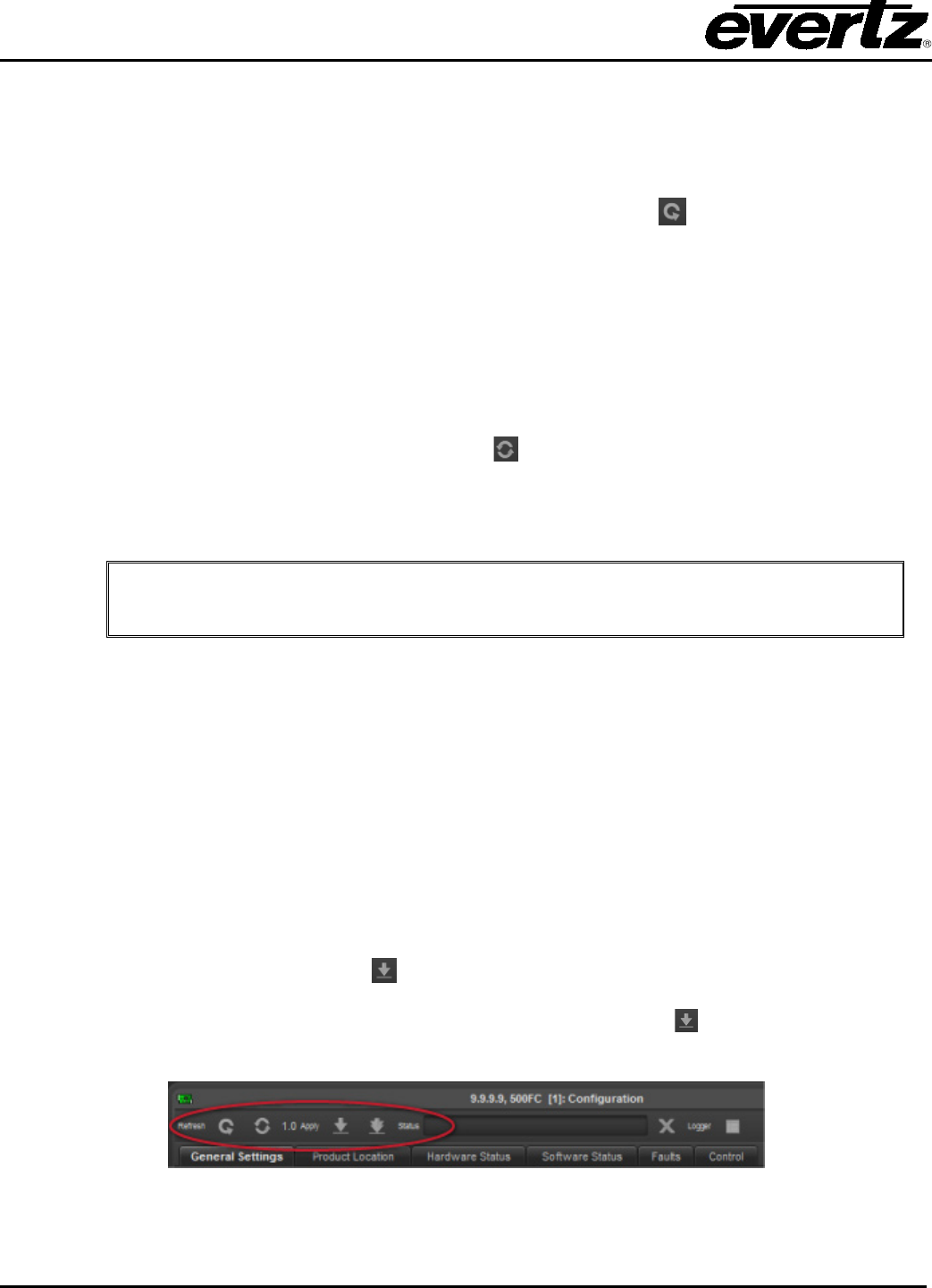
To refresh the view, select Configuration -> Refresh or click the Refresh button found on the top of
each configuration view window.
4.1.2.3. Automatic Refresh
VistaLINK® PRO can automatically refresh an open configuration view. This is useful if you want to
monitor a parameter that changes frequently. To enable Automatic refresh, select Configuration -> Default
Auto Refresh from the main menu. A check mark should appear to the left of the menu item. To disable,
select Auto Refresh again. The check mark should disappear.
An alternate method would be to select the Auto refresh button on the toolbar
The refresh interval will depend on your network conditions. The refresh operation is a continuous cycle
meaning that the refresh will start with the first parameter, continue until the last parameter has been
refreshed and start from the beginning again.
Note: Automatic Refresh and Dynamic Apply cannot be enabled at the same time.
4.1.3. Applying Changes Made to Configuration
When changes are made to a product's configuration settings, these changes must to be applied. There
are two methods of applying changes: Deferred and Dynamically.
4.1.3.1. Deferred
Deferred apply refers to the process of making one or more changes and then manually requesting for
those changes to be sent to the product. Deferred apply also has the advantage of being able to select
how the changes are to be applied. Applying changes using this method can be performed using the
toolbar buttons found at the top of each Configuration View window. The following outlines the deferred
options:
• Apply Configuration Changes - applies only the configuration settings that have been
changed in the configuration view since the last apply operation. To apply just the changed
settings, select click the Apply Configuration Changes toolbar button located at the top of each
Configuration View window.
Figure 4-3: Methods of Applying Changes

VistaLINK® PRO User Manual
Revision 11.0 Page 4-11
Note: Deferred apply is a verified process. This means that once the
configuration has been applied the same configuration will be read back from
the product to verify that all settings have indeed been set to the proper value.
4.1.3.2. Default Dynamic Apply
Dynamic apply refers to the process of updating the product in real time as the configuration settings are
being made. Unlink Deferred apply, Dynamic apply cannot be applied to all product types. To enable
dynamic apply, select Configuration -> Default Dynamic Apply. A check mark should appear to the left of
the menu option. To disable, select the Dynamic Apply option again. The check mark should disappear if
disabled.
An alternate method would be to select the Dynamic Apply button on the toolbar.
Note: When Dynamic apply is enabled, the Apply and Apply to Same Product
type buttons will be disabled. Dynamic Apply cannot be enabled if Auto
Refresh is active.
4.2. BATCH CONFIGURATIONS
4.2.1. Saving and Loading Configurations
VistaLINK® PRO provides the ability to save the configuration for a product to an external file or system file
so that the saved configuration can be loaded at a later date using the Load feature. This is useful if you
want to create a backup of your product's configuration settings or if you want to use the saved
configuration file as a template and rubber stamp the configuration settings to all like product types by
loading the configuration file into those products. It also provides a method to create custom scalable
presets for any single or group of hardware with resolution down to the individual parameter level.
Configurations can be stored in several different formats depending on its intended use.
4.2.2. Saving Configurations
When saving a Configuration file for a product(s) there are several different methods to choose from
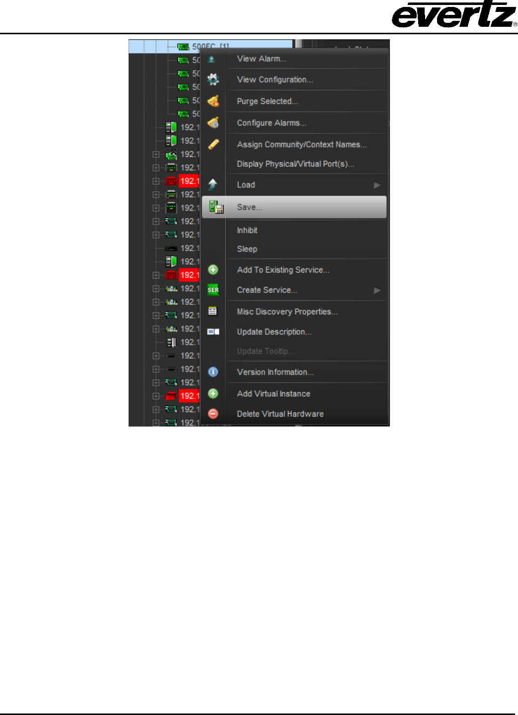
depending on the intended use for the Configuration file. To save a configuration file select the products in
the Navigation Tree (hold the Ctrl key to select multiple products) right click the selected product(s) and
choose Save -> <save options below>. System configuration files can also be saved/created by right
clicking the Configurations super-node and selecting New -> Configuration.
VistaLINK® PRO User Manual
Page 4-12 Revision 11.0
Figure 4-4: Saving Configurations
4.2.2.1. Standard Local Configurations
If Local is selected as the format for the configuration save, all parameters for the product(s) selected will
be stored to an external .xml file. This file can be copied to a disk for transfer to a different location. The
user will be prompted to enter a name and location to store the configuration file to.

VistaLINK® PRO User Manual
Revision 11.0 Page 4-13
Figure 4-5: Config Editor
4.2.2.2. Save Configurations
Save configurations are stored in the VistaLINK® PRO Server database and will appear under the
Configurations super-node in the Navigation Tree. System configurations are advantageous in that they
can be run directly from the Navigation Tree, they are immediately available to all remote connected
clients and they can be used with other systems such as the 9000NCP Control Panels or placed on a
View in the VistaLINK® PRO Graphics Client.
Figure 4-6: Save Configuration
the user is presented with a dialog during the save operation to choose what individual parameters from
each product(s) will be saved as part of the configuration file. Save configurations are advantageous as
they allow the user to load settings onto a module(s) for a specific parameter without affecting other non-
related parameters on the same module(s). The Configuration Editor will appear allowing you to create the
configuration file.
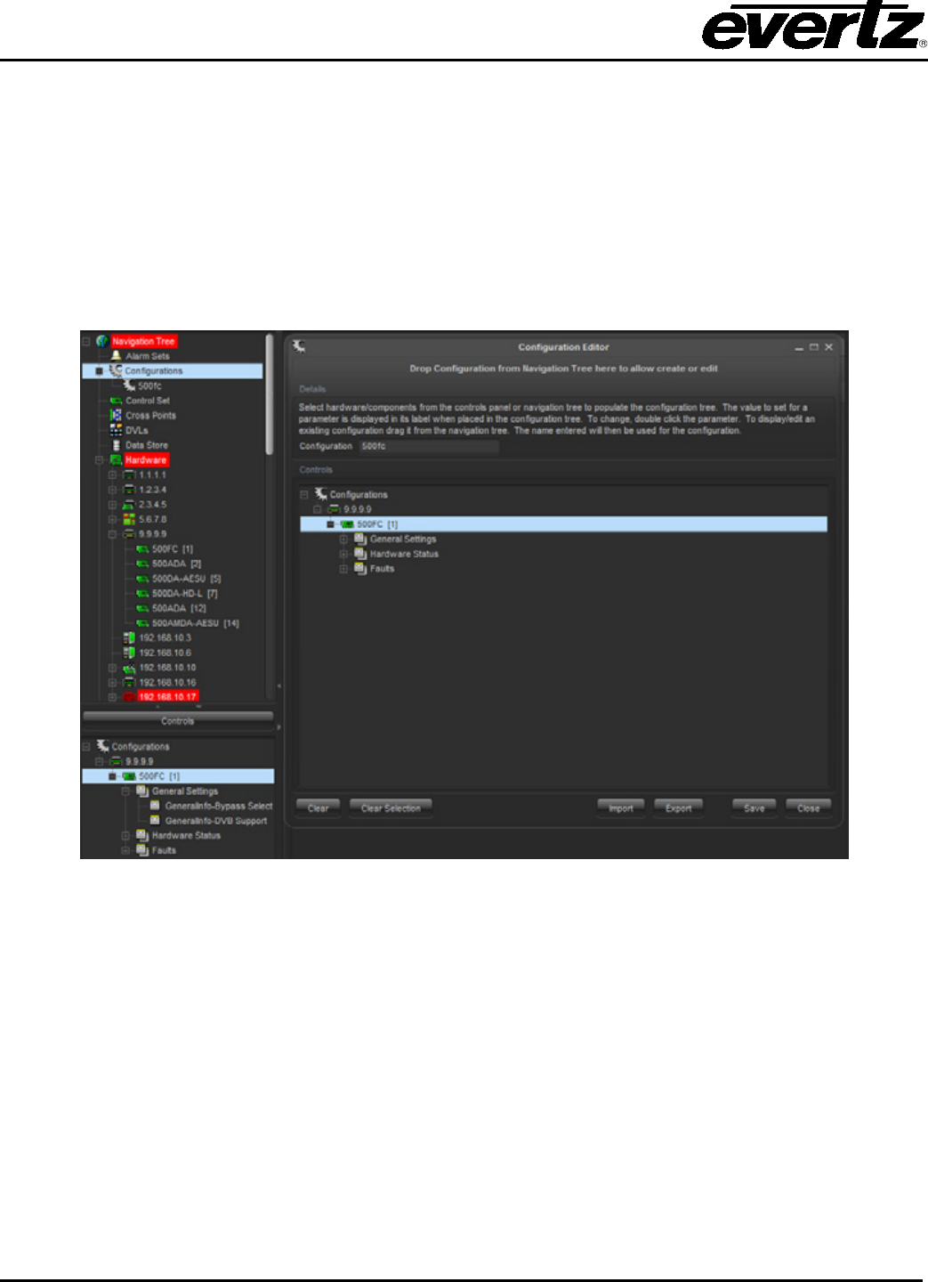
VistaLINK® PRO User Manual
Page 4-14 Revision 11.0
1. Notice the card automatically appears in the ‘Controls’ section at the bottom. It is possible to
remove hardware and add hardware to the ‘Controls’ section using the drag and drop method.
2. Navigate through the Controls section tree to find a parameter and drag and drop it into the
Configuration Tree. It is possible to add more than one control from different types of devices to the
Configuration Tree.
3. Once the parameter has been added to the Configuration Tree it can be modified by double clicking
the parameter to change it.
4. Provide a name and location to save the configuration file to and click save.
Figure 4-7: Configuration Editor
4.2.2.3. Export Configurations
If the user wishes to save to an external file select Export in the Configuration Editor. File will be stored to
an external file.
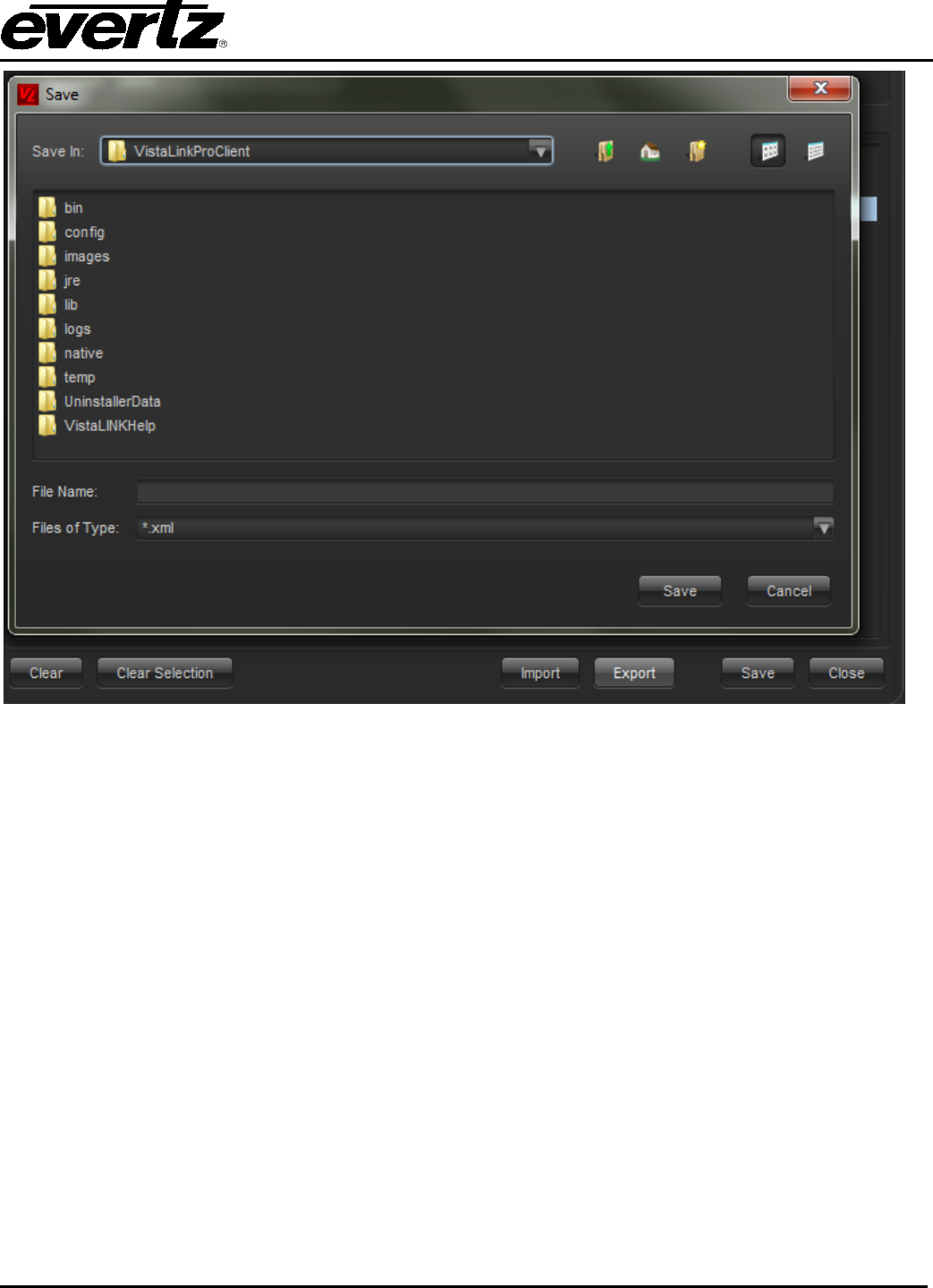
VistaLINK® PRO User Manual
Revision 11.0 Page 4-15
Figure 4-8: Configuration Editor
4.2.3. Loading Configurations
4.2.3.1. Loading Local Configuration Files
VistaLINK® PRO provides the ability to configure a product by loading settings from an external file created
by the Save feature. A configuration file may contain the configuration settings for one product, multiple
products, one parameter or multiple parameters. Saved Local configurations can only be applied to the
same product or multiple products that they were saved from.
For example:
A save operation was executed on a frame with an AVM in Slot 4 and an AVM-DC in Slot 8. This
configuration file can only be loaded into a frame that contains an AVM in slot 4 and an AVM-DC in slot 8.
If the saved Local configuration is limited to a specific module or sub parameter, that saved configuration
can be loaded into a similar product anywhere in the system.
4.2.3.2. To Load a Configuration File
1. Select the desired node(s) in the Navigation Tree.
2. Right click the selected nodes and choose Load -> Local. The Config Local Load dialog box will
appear. Select the saved configuration file and then select Open.

VistaLINK® PRO User Manual
Page 4-16 Revision 11.0
4.2.3.3. Loading System Configuration Files
System configuration files can be loaded into modules in a similar manner to local files, however, System
configurations can also be launched directly from the Navigation Tree. When initiated in this manner the
System configuration will apply its settings strictly to the exact hardware that the configuration was built
from.
System configurations can also be added to VistaLINK® PRO Graphics Views as well as attached to a
9000NCP(2) preset button.
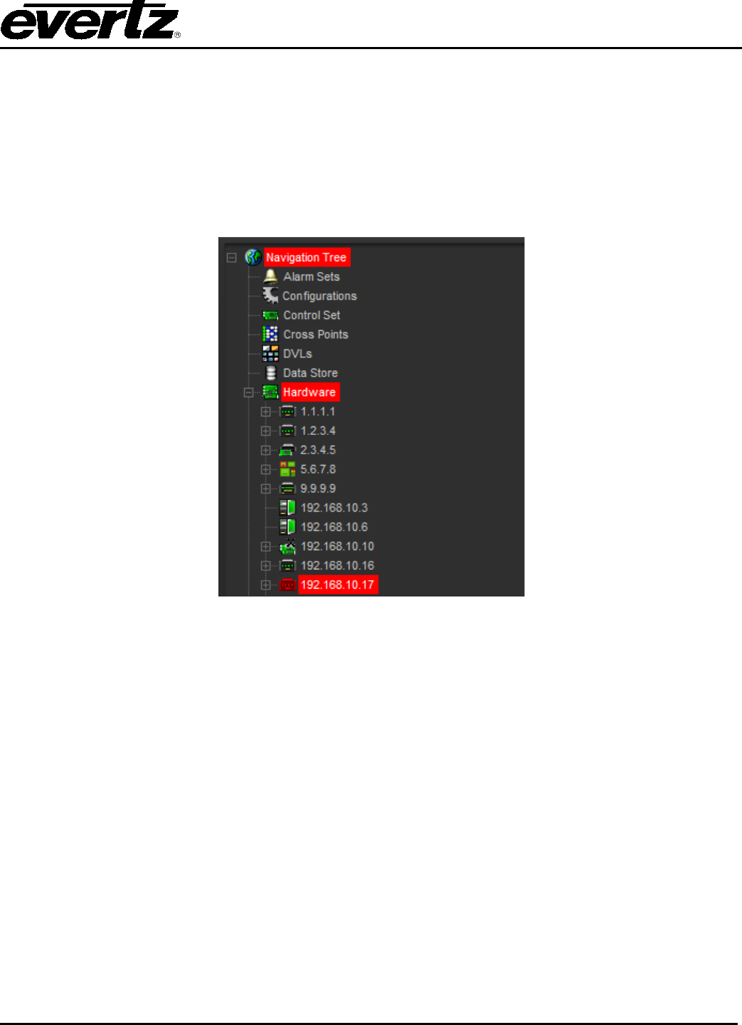
VistaLINK® PRO User Manual
Revision 11.0 Page 5-1
5. ALARM MONITORING
5.1. ABOUT ALARM INDICATION
The Hardware and Service super-nodes in the Navigation Tree provide a means of immediately alerting
the operator when an alarm condition exists on a hardware device or in a service. Alarm events that have
been setup to generate alerts will colour key the nodes presently in the alarm and will use the “Rules of
Broadcast” to determine which alarm alerts the operator first.
Figure 5-1: Alarm Indication
5.1.1. Rules of Broadcast
Broadcast of alarms depends on the severity assignment of the alarm. If more than one alarm condition is
present for the same device the alarm with the higher severity assignment will take priority over the lower
severity assignment. When broadcasting alerts back to the root (Hardware or Services) node, the highest
product node severity will take priority. When the higher severity alert has been acknowledged, the next
highest severity alert will be shown if one is present.
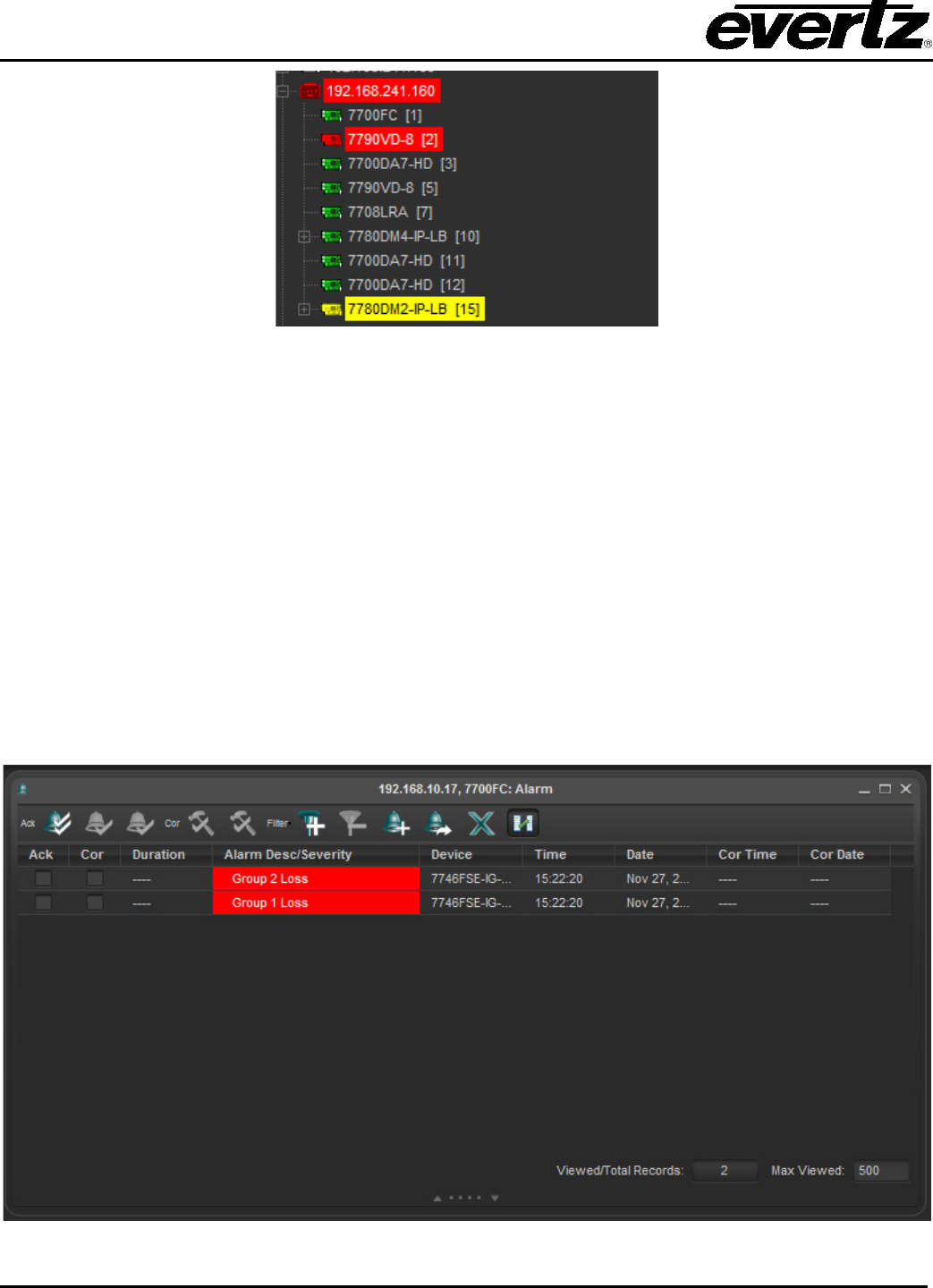
VistaLINK® PRO User Manual
Page 5-2 Revision 11.0
Figure 5-2: Example of an Alarm Condition
Figure 5-2 displays that the products in slot 2 and 15 have alarm conditions. The product in slot 2 has a
critical alarm and the product in slot 15 has a minor alarm. Even though both products have alarms, the
highest severity alarm has been broadcasted to the frame node, and subsequently, the Hardware super-
node. The Rules of broadcast allow the operator to address the most critical alarms first.
5.2. ALARM VIEW WINDOWS
The Alarm view window provides a means of viewing, acknowledging and correcting alarms that have
been logged to the alarm database. Alarms can be arranged by column and filtered by acknowledged,
corrected, severity settings, etc.
Depending on the node selected in the Hardware or Service section of the Navigation Tree, the Alarm
view window will tailor the display to show only the information that is pertinent for that device or service.
5.2.1. Alarm View Layout
Figure 5-3: Alarm Layout View

VistaLINK® PRO User Manual
Revision 11.0 Page 5-3
The Alarm View window is comprised of 3 primary areas:
• The status area at the top of the window displays the Navigation Tree node selected for display,
toolbar icons and the current filter settings.
• The alarm content area in the middle of the window displays the individual alarm events for that
node that are in the active alarm database.
• The “Notes” and “Details” panel at the bottom of the window shows extended information about a
selected alarm. See section 5.2.4 for more information.
5.2.2. Viewing Alarms
Individual alarms are viewed using the Alarm View Window. An Alarm View Window can be opened for
any node on the tree in the Hardware or Service super-node sections. The node that is selected by the
user will determine what alarm information will be displayed once the Alarm View Window is opened.
Sections 5.2.2.1 to 5.2.2.4 provide descriptions of the various types of nodes that can be opened:
Note: There is no limit to the number of Alarm View Windows that can be opened
simultaneously. Each time the user makes a new selection in the Navigation Tree
and launches the Alarm View a new Alarm View Window will open displaying alarm
information for the selected node. The "Window" menu found on the menu bar
provides options for configuring multiple open windows such as the ability to
cascade or tile the windows. This menu also provides the ability to minimize,
restore and close multiple windows simultaneously.
5.2.2.1. Hardware Super-Node
Opening an alarm view from the Hardware super-node will display all alarm events in the alarm
database (alarm information for all hardware currently in the Navigation Tree) including current alarm
events as well as alarm events that have occurred under the following conditions:
• Hardware that has generated alarms but are longer connected to the network.
• Hardware that has generated alarms but have had their IP addresses changed.
• This also includes notes from any of the below mentioned node types.
5.2.2.2. Frame Node
Opening this node will only display alarm events that have occurred for all products in the selected
frame.
• Includes alarm events for products that were previously in one slot but have since been moved to a
different slot. This also includes products that were in the frame at one time but are no longer
present in the frame.
5.2.2.3. Product Node
Opening an alarm view from this node will only display alarm events that have occurred for the selected
product.

VistaLINK® PRO User Manual
Page 5-4 Revision 11.0
5.2.2.4. Product Video Input Node
Opening an alarm view from this node will only display alarm events that have occurred for the selected
video input.
5.2.3. Opening an Alarm View Window
To open an alarm view window use one of the following methods after selecting a node in the Navigation
Tree (node selected will determine alarms displayed as stated above)
1. Select Alarm -> View Alarm from the main menu.
2. Click the Open Alarm View toolbar button - .
3. Right click the selected node and choose View Alarm from the pop-up menu.
5.2.4. Acknowledging and Correcting Alarms
Each alarm in the alarm view has two distinct operator states. The first state, acknowledged, indicates
that the operator has seen the alarm condition and has dispatched a request to correct the problem. The
second state, corrected, indicates that the alarm condition has been corrected either by intervention of an
engineer or the source of the problem has restored itself. By utilizing these two alarm states it is possible
to give an accurate representation of the whole network system by keying alarm states in the Hardware or
Service views with various colours, and steady or flashing states.
The following table shows the acknowledged and corrected state and the visual indication that will occur.
Acknowledged Corrected Visual Alarm Indication
No
No
Flashing, in assigned severity colour
Yes
No
Steady, in assigned severity colour
No
Yes
Flashing green - this state indicates that an alarm occurred and
corrected itself before an operator acknowledged the error con
dition.
This is the lowest priority alarm state. See section 5.2.4.1.
Yes
Yes
No alarm indication
Table 5-1: Visual Alarm Indication
5.2.4.1. Corrected but Not Acknowledged
This is the lowest priority alarm condition. This means that if there is more than one alarm event for the
same product then Flashing and Steady alarm conditions will be displayed before Flashing green alarm
conditions. In other words, alarms that are not corrected, or alarms that have been acknowledged and not
corrected will generate operator alerts first.
5.2.4.2. Self Correcting Alarms
VistaLINK® PRO will report all alarm information from enabled devices including alarm conditions that
have corrected themselves without user intervention (E.g. Momentary loss of video). If the alarm
generated to the system has corrected itself, VistaLINK® PRO will place a check in the corrected column
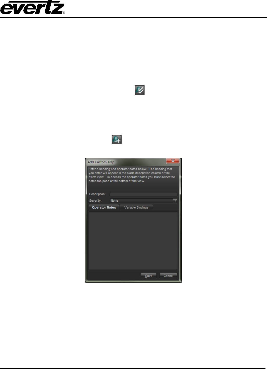
VistaLINK® PRO User Manual
Revision 11.0 Page 5-5
check box for the particular alarm event and make that column check box unavailable. The system makes
this column unavailable in order to indicate to the user that the alarm situation has returned to normal on
its own as opposed to an alarm entry that has been corrected by a user manually checking the corrected
column check box.
5.2.5. Acknowledging All Alarms
The Alarm view window provides a single click action to acknowledge all alarms presently in the view.
Alarms that are already acknowledged when this action is performed will not be processed therefore the
date and time stamps on those alarms will not be updated.
To acknowledge all alarms in the view, click on the button located in the bottom-right corner of the
alarm view window
5.2.6. Adding a Custom Alarm Entry
Each alarm view window allows for the entry of additional custom note alarm entries. These custom
entries will appear in the Alarm View Window, however, will not be associated with a particular system
event. To enter a custom note click the Add Custom Note button located in the toolbar of the
currently displayed alarm view window.
Figure 5-4: Add Custom Note Window
The Add Custom Note dialog box will open allowing the operator to enter a description for the custom note
(displayed in the description column of the alarm view window), a severity setting and any extended
operator notes that should be included with this entry. Click Save to add the Custom note to the alarm
view window.
5.2.7. Filtering Alarms From the Alarm View
Normally when an alarm view is opened all alarm events for the selected node are shown. This may not
be the desired functionality. VistaLINK® PRO provides an option to display only alarms that match
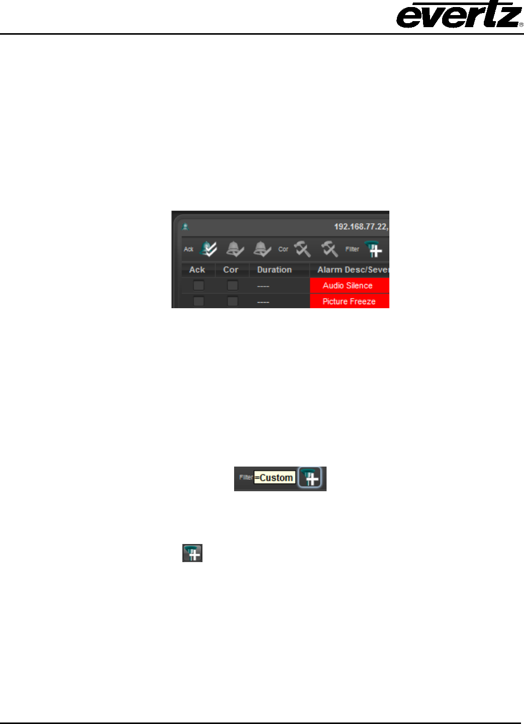
VistaLINK® PRO User Manual
Page 5-6 Revision 11.0
specified filter criteria. For example, the system can be set to filter out any alarm events that have been
previously acknowledged or corrected thus only displaying the alarm events that have not been
addressed.
In the event that new alarms are generated while a filter is enabled, the new events will be displayed in the
alarm view only if the event passes the filter criteria.
5.2.8. Default and Custom Filters
A filter can be applied to an alarm view window in two different ways:
1. A Default Filter is established that will be applied to all alarm view windows each time they are
opened.
When A Default Filter has been activated the Default Filter indicator will appear in the top left corner of
alarm view windows each time they are opened.
To setup a Default Filter select Alarm -> Setup Default Filters... from the main menu. This will open the
Filter Options dialog box allowing creation of the default filter (see section 5.2.9 for additional details).
Select Data Field, Test Condition and Criteria, then “Save” filter. Upon reopening the alarm view, the
default filter is applied.
2. A Custom Filter is applied to an open alarm view window that will apply to the alarms currently
being displayed. However, when an alarm view window with a Custom Filter is closed and then
reopened the filter will be removed and the display will return to the default view.
When a Custom Filter has been activated the Custom Filter indicator will appear in the top left corner of
the alarm view it has been applied to.
To setup a Custom Filter click the Filter Alarms toolbar button found at the top of the alarm view
window. This will open the Filter Options dialog box allowing the creation of the custom filter (see section
5.2.9 for additional details).
5.2.9. Constructing Filters
Default and Custom filters are both created using the Filter Options dialog. This dialog allows the user the
ability to establish a filter set that will limit which alarms are displayed in an alarm view window.
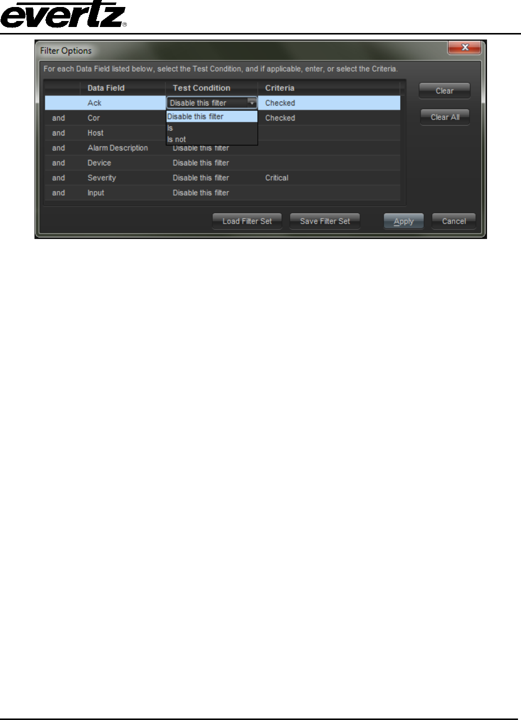
VistaLINK® PRO User Manual
Revision 11.0 Page 5-7
Figure 5-5: Filter Options
The Filter Options dialog box presents individual filter options (per row) that can be enabled or disabled in
order to build the desired filter. Each filter option (row) has three columns that make up the filter option
parts. Each filter option can be enabled or disabled as part of the final filter criteria by changing the Test
Condition to any value other than “Disable this filter”. When the Test Condition column has been changed
for a filter option, that option becomes active and is indicated active by displaying the rows background
colour in yellow.
• Data Field: This is the field in the alarm view that will be checked when this filter option is
enabled.
• Test Condition: This drop down box is used to enable a filter option by selecting the appropriate
Test Condition for the Data Field (if set to “Disable this filter”, the filter option specified on this row
will not be part of the criteria for the filter being created).
• Criteria: This sets what criteria the Test Condition should look for when checking the Data Field.
Example: Changing the first Test Condition drop down box to “Is not” will establish a filter that will only
display alarms where the Acknowledged Status (Data Field) Is not (Test Condition) Checked (Criteria) or
simply, will only display alarms that are unacknowledged.
The user can enable as many filter options (rows) as necessary, in order to build the appropriate filter.
When using more than one filter option the user has the ability to set each additional option as an AND
option, meaning the alarm must meet all filter requirements (Option 1 AND Option 2), alternatively,
additional options can be set as OR options, meaning the alarm will be shown if it meets any of the filter
options (Option 1 OR Option 2). After all filter option selections have been made, clicking the Apply Filter
button will activate the filter (Default or Custom depending on how the Filter Options dialog was
accessed).
5.2.10. Clearing Filter Options
The Clear and Clear All buttons can be used to reset filter options back to a disabled state. Clear will
reset only the selected row, while Clear All will reset all selected filter options.

VistaLINK® PRO User Manual
Page 5-8 Revision 11.0
5.2.11. Saving and Loading Filters
Once a filter has been created, it can be saved for future use or copied to other clients. To save a created
filter, click “Save Filter Set”. VistaLINK® PRO will prompt for a name and location to save the filter set to.
Saved filters can be loaded back into the Filter Options dialog by clicking “Load Filter Set” and then
browsing to the saved filter and clicking “Open”.
5.2.12. Default “Unresolved Alarm” Filter
With this filter applied, the alarm view window will only display alarms if they have neither been
acknowledged nor corrected thus eliminating all alarms from the view that have been fully addressed. To
load the Unresolved Alarm filter click Load Filter Set in the Filter Options dialog, browse to the
VistaLINKProClient folder (C:\Program Files\VistaLINKProClient by default) and select the
“Filter_UnresolvedAlarms.xml” file. This will load the default Unresolved Alarms filter into the Filter
Options dialog enabling the first two rows. (Ack Status Is not Checked OR Cor Status Is not Checked).
5.2.13. Suspending View Updates
While an alarm view window is open it may be desirable to temporarily hold new alarms from interrupting
the display of existing alarms. In this case it is possible to suspend the processing of alarm updates by
clicking on the Suspend toolbar button in the top-right corner of the alarm view window. The button will
stay depressed and the alarm view will display the button to indicate that the alarm view window is
currently suspended.
While in this mode, the alarm view window will not receive any new alarm events. The alarm view will
continue to update the status of any events in the view if the status changes.
To resume receiving new alarms, click on the Suspend button once again. The button will restore to its
normal state and the alarm view will immediately catch up on any alarms that have occurred during the
suspended period.
5.2.14. Saving the Current Alarm View
This feature allows you to save (or export) the alarms in the alarm view window to an external file. Any
filter settings that are currently applied to the view will also be applied to the save operation. Note that any
customizations to the headings will not be inherited by the save. All headings are saved when the current
view is saved.
5.2.14.1. Saving to a New File
1. Click the Save Alarm log to disk button on the toolbar. A dialog box will appear asking for a
location and filename for the new alarm log file.
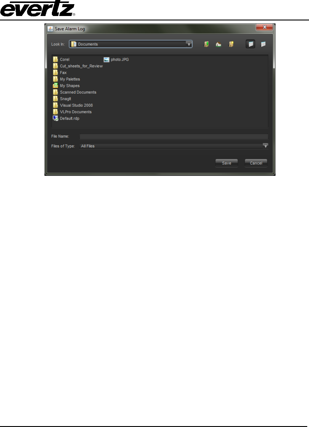
VistaLINK® PRO User Manual
Revision 11.0 Page 5-9
Figure 5-6: Save Alarm Log
2. Select the desired location for the file and enter a filename in the file name area. If no extension to
the filename is specified a .txt extension will be appended.
5.2.14.2. Appending to an Existing File
Follow the steps outlined in section 5.2.14.1 to specify the filename of an alarm log file that already exists
on your system. You will then be prompted to select whether or not you wish to append to the end of this
file. If you choose to append, the alarm information will be appended to the end of the specified file,
separating existing information from new information with a single line header describing the date and time
the new append occurred.
5.3. CONFIGURING ALARM PROPERTIES
5.3.1. Viewing and Modifying Alarm Properties
The Alarm Severity Configuration dialog provides a means of custom tailoring each alarm event to meet
the requirements of your installation. The hardware devices connected to your network generate alarm
events, also known as “TRAPS”. These traps are received by the VistaLINK® PRO Server and stored in
VistaLINK® PRO's alarm database. The alarm properties determine if, when and how VistaLINK® PRO
clients are informed of these alarm events.
Upon installation, VistaLINK® PRO is configured with all alarms set to their highest severity setting
(critical). You should review these settings as soon as possible to ensure that they are setup correctly for
your broadcast center.
5.3.1.1. Severity Options
VistaLINK® PRO provides five severity level options. The following is a list of severities and their
description:

VistaLINK® PRO User Manual
Page 5-10 Revision 11.0
• Critical - The highest level of severity that can be set for an alarm. This severity setting should be
used for alarm events that are critical in nature and require immediate attention. All critical alarms
will be shown in red.
• Major - This setting is of a lesser importance than the Critical alarm setting above. This setting
should be used for alarm events that are still important in nature but can be looked at after all
critical alarm events have been acknowledged. All major alarms will be shown in orange.
• Minor - This setting is of a lesser importance than both the Critical and Major alarm settings above.
All minor alarms will be displayed in yellow.
• Warning - This setting is the lowest severity that can be assigned to an alarm event and still
generate an operator alert in the Device View. Use this setting for alarms that are of lowest
importance. All warning alarms will be displayed in dark gray.
• None - This setting will cause the alarm event to be ignored. Alarms with this setting can still be
acknowledged but do not generate an operator alert in the Device View. All alarms of this type will
not have a colour associated with them.
5.3.2. To View or Modify Alarm Properties
1. Select Alarm -> Configure Alarms or right click a hardware device in the Navigation Tree and select
the Configure Alarms... option. The Alarm Severity Configuration dialog box will appear displaying the
User Label, Severity, Auto-acknowledge, Email and Alarm Note settings for all "TRAPS" of the
product type selected. Severities other than "None" will be colour-keyed to the severity setting.
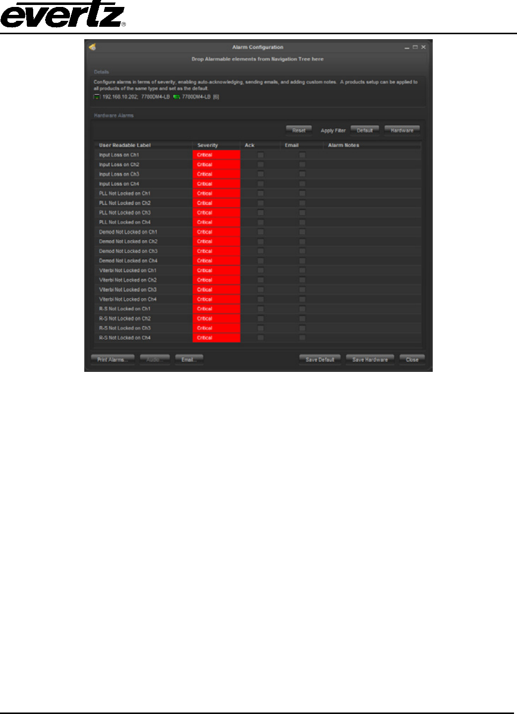
VistaLINK® PRO User Manual
Revision 11.0 Page 5-11
Figure 5-7: Alarm Configuration Window
It is possible to drag and drop another element from the navigation tree to update the dialog to show the
elements alarm listings.
2. When you have completed making changes select either the Set Current or Set Default button.
Pressing the Set Default makes the alarm configuration apply to all products of that type. The Set
Current button allows for customized alarm configuration to that specific card. It is possible to mix
and match configuration using both methods. Below is a list of the columns that can be modified:
• User Readable Label - This is a friendly version of the engineering label. This is the text that
will be shown in the Description column of the Alarm View Window displays.
• Severity - This setting determines the severity of the alarm event. When the event occurs and
is reported to the Clients the Navigation Tree indication and the Alarm View Description
column background colour will match the severity colour level set in this dialog.
• Ack - If this option is checked, the alarm event will automatically be marked as acknowledged
at the time it is stored in the alarm database. Having an event marked as acknowledged
means that an operator has seen the alarm and knows that there is a problem. See section
5.2.4 for more information about this setting.
• Email - This setting will cause an email to be dispatched to a list of recipients describing the
alarm condition. (See section 5.5.1 for more information)

VistaLINK® PRO User Manual
Page 5-12 Revision 11.0
• Alarm Notes - Alarm notes are additional pieces of information that can help the operator
diagnose a problem. These notes will be displayed in the Alarm Notes section of the Alarm
View for each alarm of this type that is logged by the system.
5.3.3. Factory Defaulting
You can clear all changes you have made to a product by clicking the Default button. A confirmation box
will appear asking you to verify the operation. A Defaults operation will reset all severity settings back to
critical and clear the auto acknowledge and email flags. It is possible to use the current button to reset
recent changes to what is currently applied.
5.3.4. Bulk Operations
Programming each alarm event for every product can be a tedious task. To ease this process you can
perform bulk apply and clear operations. First, select the alarm events that you want to modify. This can
be done either by holding down the control (Ctrl) key and highlighting each alarm event individually, or by
selecting one alarm event, holding down the shift key and selecting a second alarm event. All events that
lie in between the first and second selections will be highlighted.
Once you have selected the events, click the right mouse button while the mouse pointer is over top of any
one of the selected items. This will display a pop-up menu with the following items:
• Enable Autoack
• Enable Email
• Set Severity: The Set Severity menu item has a sub-menu that will pop-up when the mouse is
hovering over the menu item text. The sub-menu contains all severity option settings.
• Clear Autoack
• Clear Email
• Clear Alarm Notes
Selecting any one of these items will apply the operation to all selected alarm events the same as if you
had performed the action on one item.
5.3.5. Alarm Thresholds
Some alarming products have the ability to configure thresholds. Thresholds provide a way to ensure the
alarm is sent when a real fault condition occurs. Thresholds come in different settings and it is a feature of
the device itself. Common thresholds are:
• Error Duration: This is the time in seconds or in number of frames the error has to be present
until an alarm is sent from the device. Common error durations can be:
1. Audio Missing Error Duration (seconds)
2. Video Missing Error Duration (frames)
3. Video Black detection Duration (frames)
• Error Levels: Often special levels are needed to provide accurate fault alarming. Error Levels
and Error Durations are combined together to determine a fault. For an audio silence type of
alarm, it is possible to configure that audio has to be below a certain level at a certain amount of
time before an alarm is sent. Common level thresholds are:
1. Audio Silence Level (dB FS)
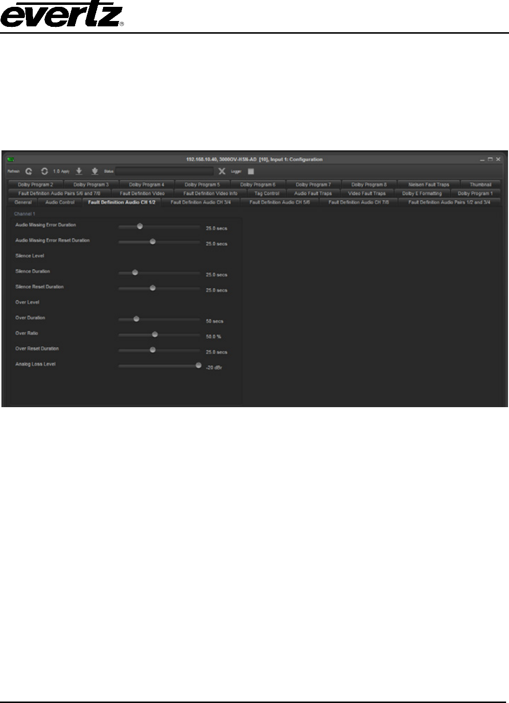
VistaLINK® PRO User Manual
Revision 11.0 Page 5-13
2. Audio Over Level (dB FS)
3. MAX APL Level (IRE)
• Reset Duration: The Reset Duration setting specifies when the program should be flagged as
cleared. This special type of alarm is recognized by VistaLINK® PRO to auto correct alarms in the
alarm view. This setting is used to prevent false indications specifying problems have occurred
but are ok. When configuring Reset thresholds, is it specified in the number of seconds the
monitoring parameter must be out of the error condition before a correction alarm is sent.
Figure 5-8: Input Configuration Window
5.3.5.1. Disabling/Enabling Alarms
Alarms can be disabled at the device itself. These settings are commonly found on a single tab containing
check boxes. Modify the state to true and false disables or enables the alarm condition from being sent
from the card.
Every alarm condition has a fault status condition box. This box represents the current status of that
parameter. This fault status box can either be red or green, meaning bad or good. These fault status
indicators can be used for poll monitoring in systems where an operator always needs to see what the
current value is at. The fault status indicators operate always whether the alarm is enabled or disabled.
The fault status indicators will follow any threshold rules that may be configured.
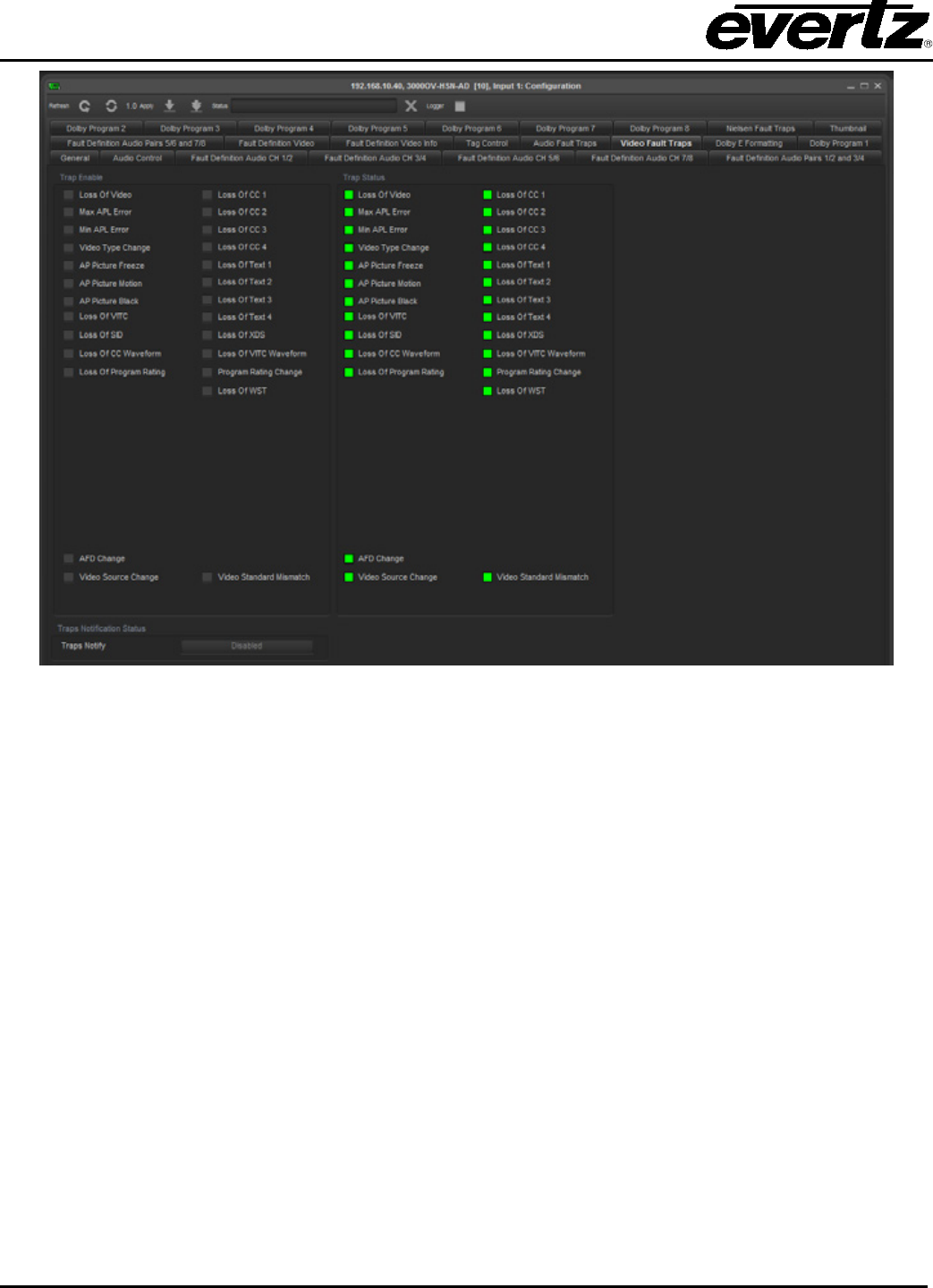
VistaLINK® PRO User Manual
Page 5-14 Revision 11.0
Figure 5-9: Video Fault Traps
It is important that alarm enabling/disabling and alarm thresholds are properly configured. This is to ensure
that accurate notifications are sent when real problems occur.
5.3.6. Inhibiting and Sleeping Hardware or Services
Inhibiting or Sleeping hardware or services is a means of disabling the alarm capabilities of the device
from VistaLINK® PRO without physically disconnecting the device from the network.
Inhibiting Hardware:
When a device has been inhibited fault alarms generated by the device will not show any indication in the
Navigation Tree view and the fault will not be logged to the VistaLINK® PRO trap database. When a
device is inhibited in VistaLINK® PRO the device will still be visible in the Network and Service views but
will be displayed in a blue colour where the shade of blue will determine how the device has been inhibited
(See section 5.3.6.1 for more information on inhibited/sleep colours).
Sleeping Hardware:
When a device has been put to sleep, fault alarms generated by the device will not show any indication in
the Navigation Tree view, however, the fault will be logged to the VistaLINK® PRO trap database. When
a device is put to sleep in VistaLINK® PRO the device will still be visible in the Network and Service views
but will be displayed in a orange colour where the shade of orange will determine how the device has
been inhibited (see “Inhibited/Sleep Colours”).
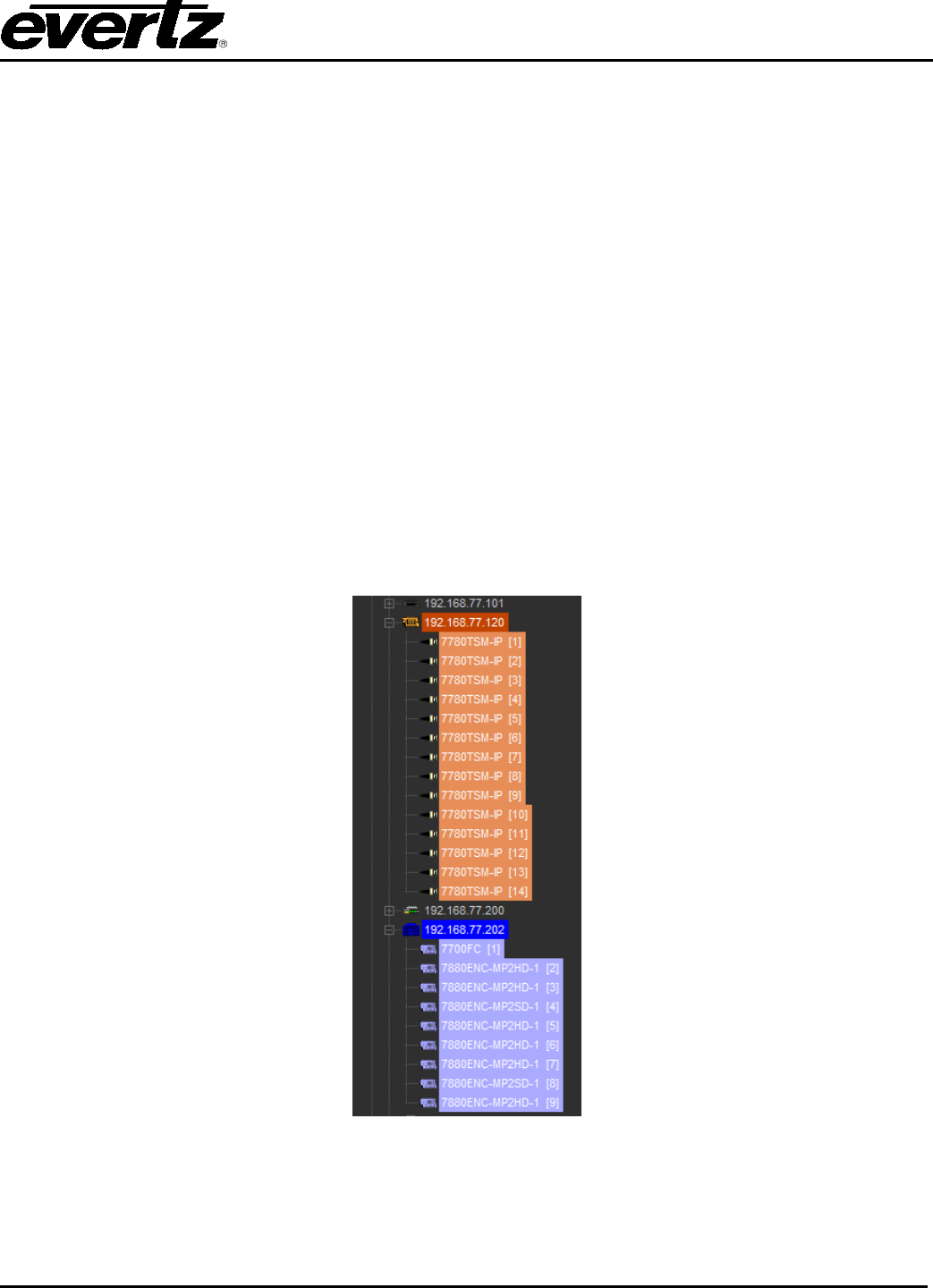
VistaLINK® PRO User Manual
Revision 11.0 Page 5-15
5.3.6.1. Inhibited/Sleep Colours
There are two types of colours displayed for both the Inhibit and Sleep features. Inhibited hardware will be
displayed in either dark or light blue. Sleeping hardware will be displayed in dark or light orange.
• Direct Inhibit – (Dark Blue) - This status indicates that the device has been directly inhibited by the
Inhibit menu option.
• Direct Sleep – (Dark Orange) - This status indicates that the device has been directly put to sleep
by the sleep menu option.
• Inherited Inhibit – (Light Blue) - This status indicates that this “child” device is being inhibited by
the Direct Inhibit status of another higher (“parental”) device. One of the many scenarios that this
will occur is when a frame is inhibited and all of the products within the frame inherit the inhibit
status from the frame.
• Inherited Sleep – (Light Orange) - This status indicates that this “child” device is being put to sleep
by the Direct sleep status of another higher (“parental”) device. One of the many scenarios that
this will occur is when a frame is put to sleep and all of the products within the frame inherit the
sleep status from the frame.
Figure 5-10 shows examples of inhibit status on frames and/or products:
Figure 5-10: Example of Status on Frame and Products
5.3.6.1.1. To Inhibit / Sleep a Device
1. Select a node in the Hardware or Service View and then click the right mouse button. A pop-up
menu will appear.

VistaLINK® PRO User Manual
Page 5-16 Revision 11.0
2. Select the Inhibit or Sleep option in the pop-up menu. The selected node will change to a dark
blue or dark orange to indicate that this device is now inhibited or put to sleep.
5.3.6.1.2. To Remove Inhibit / Sleep Status
1. Select the inhibited nodes in the Hardware or Service View and then right-click the mouse button.
A pop-up menu will appear.
2. Select the Allow Alarms or Waken option in the pop-up menu. The blue or orange inhibit/sleep
status indicator will be removed from the node and the node will return to normal alarm indicating
state.
5.4. SERVICES
The Service super-node is located within the Navigation Tree. It appears directly below the Hardware
super-node. Refer to section 5.4.1 for additional information on creating, editing and deleting services.
Services allow the user to logically group or isolate hardware from one or more frames to create a logical
relationship between the physical characteristics of your network and the actual setup of your broadcast
center. The hardware contained in a service view follows the same "Rules of Broadcast" outlined in the
5.1.1 section. When an alarm occurs on a hardware device contained in a service, the alarm condition is
broadcasted up to the Service, and subsequently the service super-node.
Note that there are exceptions to this rule when viewing alarms in the service view. Consider where a
frame has two products but only one of the products has been added to the service view. If the product in
the service view displays a minor alarm condition, but the product is not contained in the service view and
has a critical condition, the frame in the service will reflect a critical alarm condition. This is because the
service view indicates the actual state of the frame, not the perceived state of the frame in the service. In
other words, the frame contained in the service does not simply show the alarm status of only the products
contained in that service.
It is also possible to see an alarm condition on a frame in the service but not see any alarm conditions on
any of the products shown in the service. In this scenario the frame has an alarm condition and you
should check the Hardware super-node to determine which product is causing the frame to show an
alarm.
5.4.1. Creating and Editing Services
5.4.1.1. To Create a New Service
1. Ensure the Services super-node is visible by enabling though the Tree Properties dialog.
2. Right click the Services super-node and select New -> Service.
3. The user will be prompted to enter a name for the new service. Once the service has been named
clicking the OK button will add the new service as a sub-node under the Services super-node. The
user is now ready to add hardware to the new service.
5.4.1.2. Adding Hardware to a Service
VistaLINK® PRO allows the user to add hardware to a Service using two different methods.

VistaLINK® PRO User Manual
Revision 11.0 Page 5-17
Method One (Drag and Drop):
1. In the Navigation Tree under the Hardware super-node, locate the hardware device you wish to
add to the newly created service.
2. While holding down the left mouse button, drag the selected hardware device over the name of the
service you wish to add it to and release the mouse button to add it to the service.
Method Two (Right Click Add):
1. In the Navigation Tree under the Hardware super-node, locate the hardware device you wish to
add to the newly created service.
2. Right click the hardware device and select the "Add to Existing Service..." option.
3. A dialog will appear listing all created Services, which allow the user to select the service the
hardware device should be added to.
5.4.2. Right Click Service Creation
An alternate and faster way to create a service is to highlight all devices to be part of the service in the
Navigation Tree (hold the "Ctrl" key to select multiple items). After all items are highlighted, right click the
selected devices and choose the "Create service from selection" option from the pop-up menu. The user
will be prompted to enter a name for the service, which will then be added to the Service Tree View list.
5.4.3. Renaming a Service
A user created service can be renamed at any time. To rename a created service:
1. In the Navigation Tree, right click the service to be renamed and select the "rename service"
option.
2. The Rename Service dialog will open allowing the user to enter a new name for the service, enter
the new name and click "OK".
All local and remote clients will immediately update their Navigation Tree as well as any Monitoring Client
grid cells containing the service to display the new service name.
5.4.4. Removing a Service
To remove a Service, right click the Service in the Navigation Tree and select the Delete Service option.
5.4.5. Service Grouping Mode
To provide a second level of organization for Services in the Navigation Tree, VistaLINK® PRO
provides the ability to further group user created services into Service Groups. Grouping services into
Service Groups provides a method for the user to logically organize created services according to their
environment. Service Groups also provide a better view of the Service Tree View fault indications for
installations that utilize a large list of services. The Service Group Mode feature can quickly be enabled or
disabled allowing the user to easily switch between a short Service Group list or a complete Service list
display in the Navigation Tree.
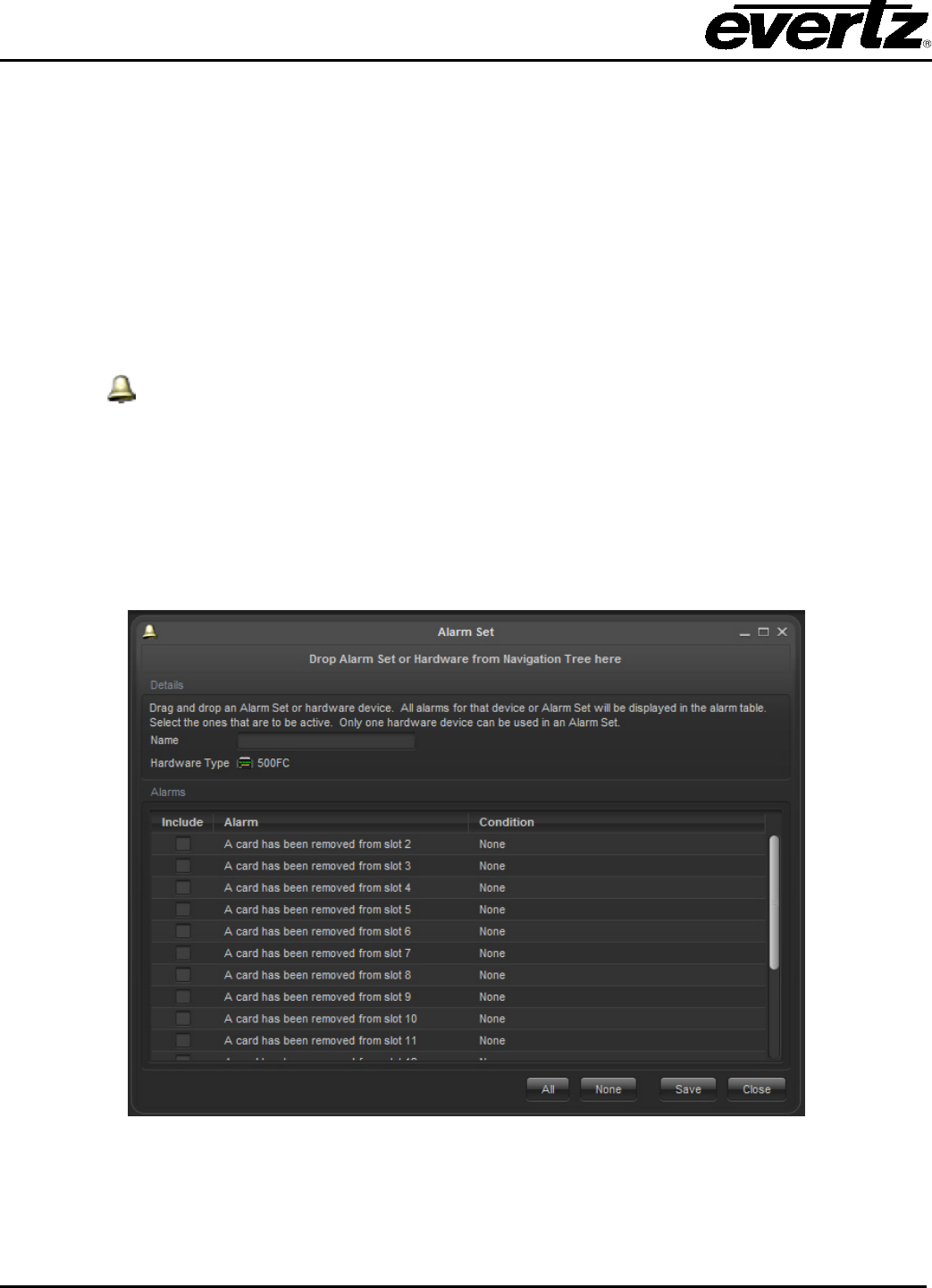
VistaLINK® PRO User Manual
Page 5-18 Revision 11.0
5.4.6. Creating a Service Group
1. Ensure the Services super-node is visible by enabling though the Tree Properties dialog. (The
Groupings option must be enabled in order to create Service Groups.)
2. Select one or more Services in the Navigation Tree (use the ctrl key to select multiple services).
Once the selection is complete, right click the selected services and choose the Create Service
Bundle from Selection... option.
3. Service Groups can also be created by right clicking the Service super-node then selecting New ->
Service Group. Once the new Service group is created services can be added by dragging them to
the new group while holding the left mouse button down.
5.4.6.1. Alarm Sets
Alarm Sets provide a filter mechanism to service alarms. Setting alarms only enables certain alarms
to contribute to raising severities of specific services. One could make an Alarm Set that only enables the
optical input alarms for a certain service. This tool is most useful when a card houses multiple services.
Video multiplexes and GPIO cards can be divided up into separate alarm entities for monitoring.
The first step to using Alarm Sets is to create the Alarm Set. This is done by right clicking Alarm Sets and
choosing New -> Alarm Sets. Once the dialog opens, a device from the hardware tree can be dropped
into the Alarm Set Editor. A list of alarms will appear that can be enabled in the Alarm Set. Each Alarm
Set that gets created will require a unique name.
Figure 5-11: Alarm Set
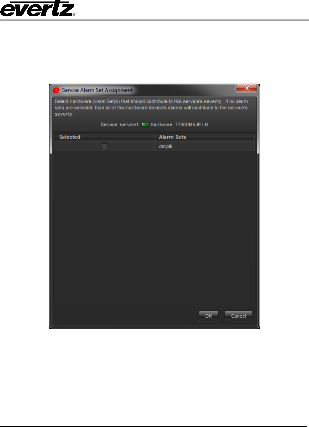
VistaLINK® PRO User Manual
Revision 11.0 Page 5-19
To apply an Alarm Set to a Service, first navigate to the device in the Service. Right mouse click on the
hardware device in the Service and select Assign Alarm Sets. A popup window will appear presenting
which Alarm Set to enable for this device. The program will automatically figure out which Alarm Sets are
compatible for use.
There will be future uses for Alarm Sets but currently this is one way of using them to control service
severities at an alarm level.
Figure 5-12: Service Alarm Group Assignment Window
5.5. EMAIL NOTIFICATION SYSTEM
5.5.1. Configuring the Email Alert System
VistaLINK® PRO can be configured to dispatch email when an alarm event occurs if the alarm "TRAP"
event has the email option checked in the Configure Alarms dialog. The Email system must be enabled
and properly configured with valid SMTP mail server and recipient addresses for email notification to
function.

VistaLINK® PRO User Manual
Page 5-20 Revision 11.0
To configure the email system, select Tools -> Email. The Configure Email dialog box will appear
displaying options for the email system.
Figure 5-13: Email – General Tab
To enable or disable the email alert system, check or un-check the Enable Notification option in this
dialog.
Enter a valid mail server address in the Outgoing Mail Server text area. VistaLINK® PRO will use this mail
server for sending email notifications.
Important SMTP Mail Server Note:
VistaLINK® PRO will issue email notification packages to a valid SMTP mail server on port 25. The mail
server (e.g. Microsoft Exchange Server) must be set up to accept unsolicited mail on port 25 for relay.
Note: If the SMTP Server does not accept unsolicited mail and requires the use of
SMTP AUTH, enter in the Account, username and password for SASL
authentication.
5.5.2. Delivery Options
New Alarms Only: Email notification will be sent only when a new alarm event is received. Recipients
will only be notified once for a particular new event according to the Check and Send time interval.
New and Previous Uncorrected: Email notification will be sent for new alarm events as well as existing
events that have not been corrected. Existing alarm events that have not been corrected will persist in the
email alerts up to the Remove alarm if not corrected after ____ email count
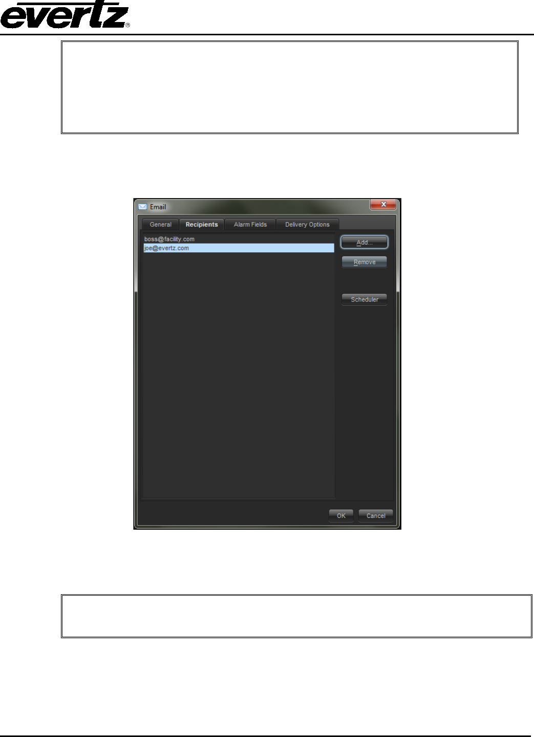
VistaLINK® PRO User Manual
Revision 11.0 Page 5-21
Note: Enter a number in Remove alarm if not corrected after _____ email option to
change the count for how many email alerts an existing uncorrected alarm will persist for,
before being removed.
Set the Check and send alarm email every _____ seconds to set the duration in seconds
for the VistaLINK®
PRO system to check for alarms and send email notifications
according to the Delivery Options.
5.5.3. To Configure the Email Recipients
Select Tools>Email Change to the Recipients tab of the Configure Email dialog.
To add a recipient address to the list, click Add, then enter the email address and click OK.
To remove a recipient from the list highlight the address and click Remove.
Note: All addresses displayed in the Recipients list will receive email notifications
from VistaLINK® PRO. Email notifications will only be sent for those alarms that have
the email notification option enabled in the Alarm Configuration setup.
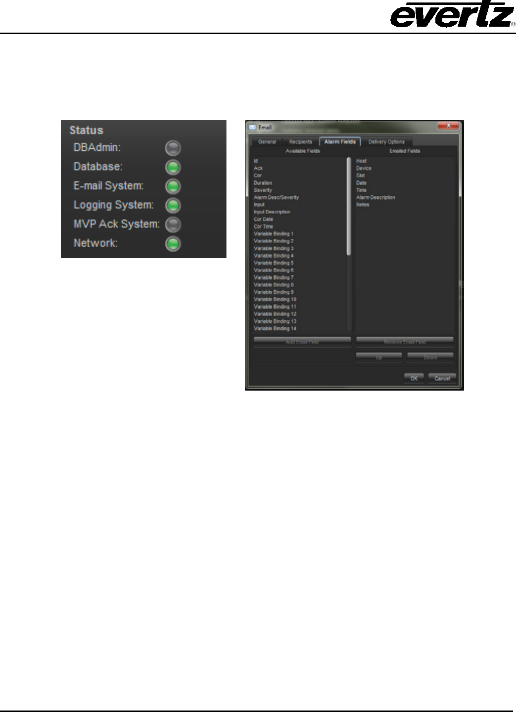
VistaLINK® PRO User Manual
Page 5-22 Revision 11.0
5.5.4. Advance Configuration
Including extra information in the email can create additional configuration options. Select the Advanced
tab from the Email setup. It is possible to add more information to the email by moving the available field
items to the rendered field items list. Once the email system has been configured, its virtual LED status
will change colour to denote it is now running.
Figure 5-14: Status
Figure 5-15: Advanced Tab
5.5.5. Audible Alert System
5.5.5.1. Audible Alerts (Playing Sounds When an Alarm Occurs)
When an alarm is displayed in the Navigation Tree, a corresponding sound that matches the severity
condition can be played (if programmed) up to the repeat count, or until acknowledged, depending on how
the sound is configured. To play sounds when alarms are received:
1. Select Alarm -> Configure Sounds. This will open the Audio Configuration dialog box allowing
sounds (.wav files) to be linked to each of the 9 severity states for an alarm (4 severities
unacknowledged [flashing], 4 severities acknowledged [non flashing] and the OK state).
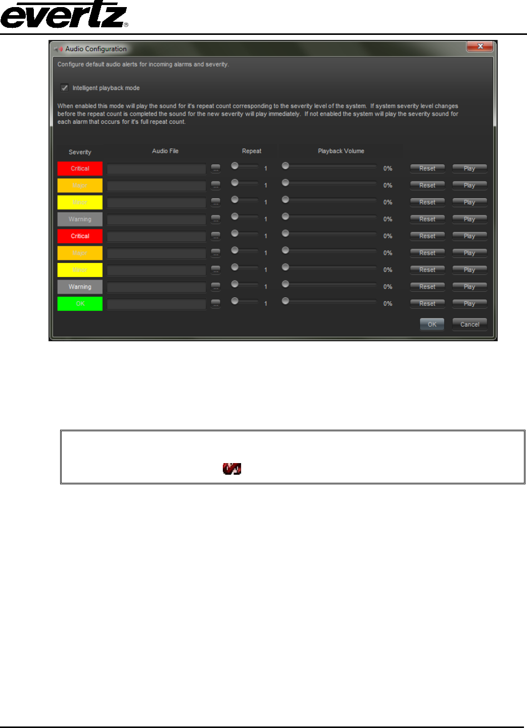
VistaLINK® PRO User Manual
Revision 11.0 Page 5-23
Figure 5-16: Audio Configuration
2. Click the browse button (...) next to the Audio File text box to enter a sound file to play when an
alarm with the selected severity is displayed in the Navigation Tree. Set the repeat count and
playback volume for each sound.
Note: To program the sound to repeat forever (intelligent mode only) until the
alarm condition is acknowledged, set the repeat count to the maximum setting
until the count value shows .
5.5.5.2. Audible Alert Playback Mode
The Enable intelligent alarm sound playback option can be enabled or disabled to switch between the two
available operating modes for audible alerts.
Intelligence Enabled (checked): This mode will play a sound for it's repeat count corresponding to the
severity level of the system. If the system severity level changes before the repeat count is completed the
sound for the new severity level will play immediately.
Intelligence Disabled (unchecked): This mode will play the severity sound for each alarm as they occur
for it's full repeat count (max repeat count = 10) regardless of current system severity level.
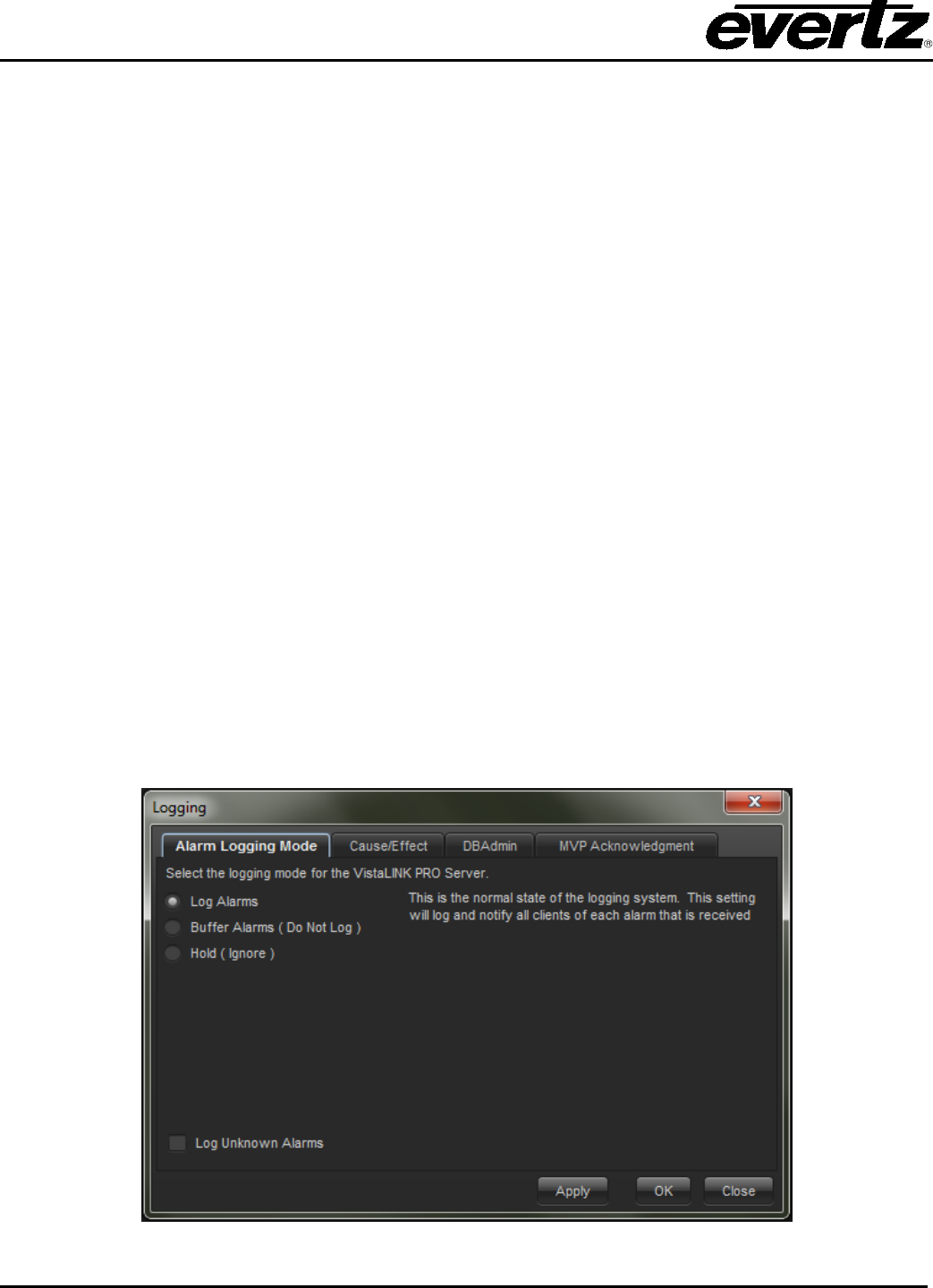
VistaLINK® PRO User Manual
Page 5-24 Revision 11.0
5.5.6. Alarm Log Management
5.5.6.1. Logging, Holding and Ignoring Alarms (Server Properties)
Upon installation, VistaLINK® PRO comes pre-configured to log all alarms that are received. If you are
designing and setting up the infrastructure of your broadcast center you may not want to be notified, or
may not want to log any alarms that are being generated during this process. In this scenario you can
choose to hold the logging of alarms or ignore alarms completely. Below are the possible logging states
with descriptions:
• Log Alarms (Log Events) - This is the normal state of the logging system. This setting will log
and notify all clients of each alarm that is received.
• Buffer Alarms (Do Not Log) - This setting will put the logging system on hold and buffer the
alarms in memory. Alarms will not be logged to the database while in this mode. If while in this
mode alarms are received and the logging system is switched to the normal mode, the alarms held
in the buffer will be dumped to the database and the logging and notification system will continue
as usual.
• Hold (Ignore Events)- This setting will completely ignore all received alarms. Alarms will not be
buffered, or logged, thus any alarms generated will be ignored.
To change the logging system setting:
1. The Logging System settings can be accessed from either the VLPRO Server or VLPRO client
applications. To change the Logging System settings:
From the Server application: Select Tools -> Logging.
From the Client application: Select Tools -> Logging from the main menu.
2. In the Logging dialog box select the logging option of your choice and click the OK button. The
transaction will occur immediately and the Server logging system will be adjusted to reflect the new
setting.
Figure 5-17: Logging Mode Tab

VistaLINK® PRO User Manual
Revision 11.0 Page 5-25
5.5.7. Event Archiving (Database Administrator)
VistaLINK® PRO incorporates an automatic Database Administration feature. It is possible to direct the
VistaLINK® PRO Server to archive any alarms older than a specified duration to an external file. The
VistaLINK® PRO Server achieves this by periodically querying the alarm database for any alarms older
than the specified duration. If alarms are found the server runs the Save alarm log feature storing the
alarms to an external report file. The Database Administrator can also be run manually at any time. A
proper database administration cycle will keep the active alarm database running at best performance.
The archive duration should be selected according to the amount of hardware being monitored and how
often fault alarms are reported to the VistaLINK® PRO Server.
5.5.7.1. To Enable or Disable the Database Administrator
1. Select Tools -> Logging in the VLPRO Server application or select Tools -> Server->Server
Properties in the VLPRO Client application. Either of these two methods will open the Logging
dialog box.
2. Select the Database Administrator tab and check or un-check the Enable Database Administrator
option to enable or disable this feature.
5.5.7.2. To Set the Log Administration Duration and Save Location
1. Select Tools -> Logging in the VLPRO Server application or select Tools -> Server ->Server
Properties in the VLPRO Client application. Either of these two methods will open the Logging
dialog box.
2. Select the Database Administrator tab and change the Archive events that are older than ___
day(s) duration.
3. Select the OK button. Your new duration will take effect the next time the VistaLINK® PRO Server
queries the alarm database.
Figure 5-18: DBAdmin Tab

VistaLINK® PRO User Manual
Page 5-26 Revision 11.0
The Logging dialog also allows the user to select a different location to save the archived alarm and audit
logs to. Use the browse button to select a different path location.
5.5.7.3. To Run the Database Administrator Immediately
Clicking the Run Database Administrator button found in the Logging / Database Administrator dialog will
immediately run the Database Administrator feature, bypassing its regular schedule thus immediately
archiving events according to the Archive events that are older than duration.
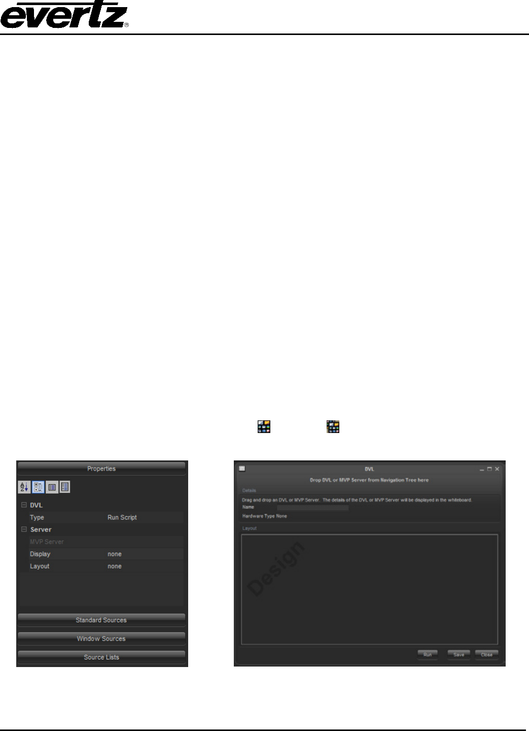
VistaLINK® PRO User Manual
Revision 11.0 Page 6-27
6. ADVANCED CONTROL
6.1. MVP CONTROL
6.1.1. MVP DVL Introduction
MVP DVLs are macro-based controls that gain access to the running MVP Software Server for layout
changes. From VLPRO, the user can recall predetermined layouts or possibly make custom source
changes to the layout boxes. VLPRO provides MVP monitoring and the necessary layout control in a
dynamic environment. There are many types of strategies that are involved in giving operator access to
the multi viewer. Some are listed below using various techniques.
• Global Preset like launches across multiple MVP systems (one click)
o NCP Panel
o Graphics Client with touch screen or mouse click
• Scheduled layout changes using the +SCH option or cycling macro’s
o Reduce display burnings
o Operator comfort
o Layout scrolling
• A navigational system of drill down layouts for supervisors (mouse click or touch screen). Ideal for
Pod environments.
• Grouping monitoring sources in a drill down interface (VLPRO Graphics using video overlay)
• Source redirection for fault analysis
o Automatically using +SCH option
o NCP Panel
o Graphics Client
6.1.2. DVL Creation Dialog
To create a DVL, first right click on the DVL node ( ) or group ( ) to bring up the popup menu. Select
NEW -> then DVL. Once this is done the editor and side bar control area will appear.
Figure 6-1: Properties Side Bar Figure 6-2: DVL Editor

VistaLINK® PRO User Manual
Page 6-28 Revision 11.0
This dialog uses drag and drop to facilitate ease of creation. Select a DVL server from the Navigation
Tree. This icon can be identified in the tree with the following symbol, ( ). Drag this component into the
DVL editor. The server will then be contacted and all its available Layouts and Displays will be populated
in the side bar control area. The available hardware will also be pulled from the server and shown in the
Standard Sources section of the side bar area.
Design a layout in Maestro as you would like to have it display on the MVP wall Including the actual
sources
A standard Run Script DVL can be made in a few quick steps:
1. Drag and Drop the MVP Server from the hardware tree into the DVL Editor window.
2. Ensure the Type property is set to Run Script.
3. Configure the Display property so that a display is targeted for change.
4. Select the Layout parameter and choose a layout that is available for use. After choosing the
layout, the DVL editor window will display the appearance of the layout.(See Error! Reference
source not found.).
Figure 6-3: Source List View Figure 6-4: DVL Editor with active windows
Click the save button to save the DVL.
Once the DVL is saved, it can then be executed from the Navigation Tree by double clicking the DVL. It
was also possible to click the RUN button from the editor to have it execute from within the editor without
saving it.
6.1.3. Change Stream DVL
It is possible to make a DVL that changes an input assignment to a particular window on a layout,
which will not affect the entire layout running on the display. When the change stream DVL runs, it
requires that the layout is already present on the current display.
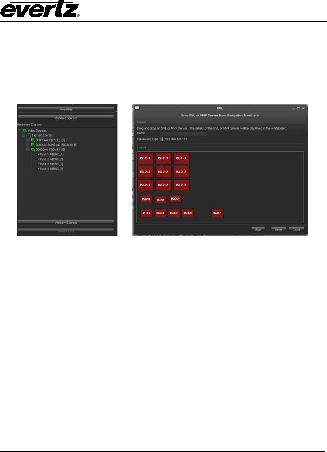
VistaLINK® PRO User Manual
Revision 11.0 Page 6-29
Follow the steps outlined below the make a basic change stream DVL:
1. Drag and Drop the MVP Server from the hardware tree into the DVL Editor window.
2. Ensure the Type property is set to Change Stream.
3. Configure the Display property so that a display is targeted for change.
4. Select the Layout parameter and choose a layout that is available for use. After choosing the
layout, the DVL editor window will display the appearance of the layout.The layout selected has to
be designed to allow for video replacement.
5. Adjust the side bar properties area so the Standard Sources are shown. (See Figure 6-5)
Figure 6-5: Source List View Figure 6-6: DVL Editor with active windows
6. Select a source input and drag and drop it into one of the available windows in the DVL editor.
Figure 6-6 shows that the window turns green to denote that it has an active input assignment in its
window. When using Change stream DVL’s, it is not possible to change multiple windows at once.
7. Click the Save button to save the DVL into the system.
6.1.4. Change Stream DVL Source List
It is possible to make special source groups. The source groups can then be applied to a particular
window. When the Change Stream DVL runs, the list box is presented with available sources that the
user can choose from. This can create a more intuitive method for having the user manage the available
sources.
To create a Source List, click Source lists from the properties side bar. If this option is disabled, it is
because the Change Stream is not used as a DVL type. Click the New button on the editor window.
Figure 6-7 shows the Source List panel and editor opened.
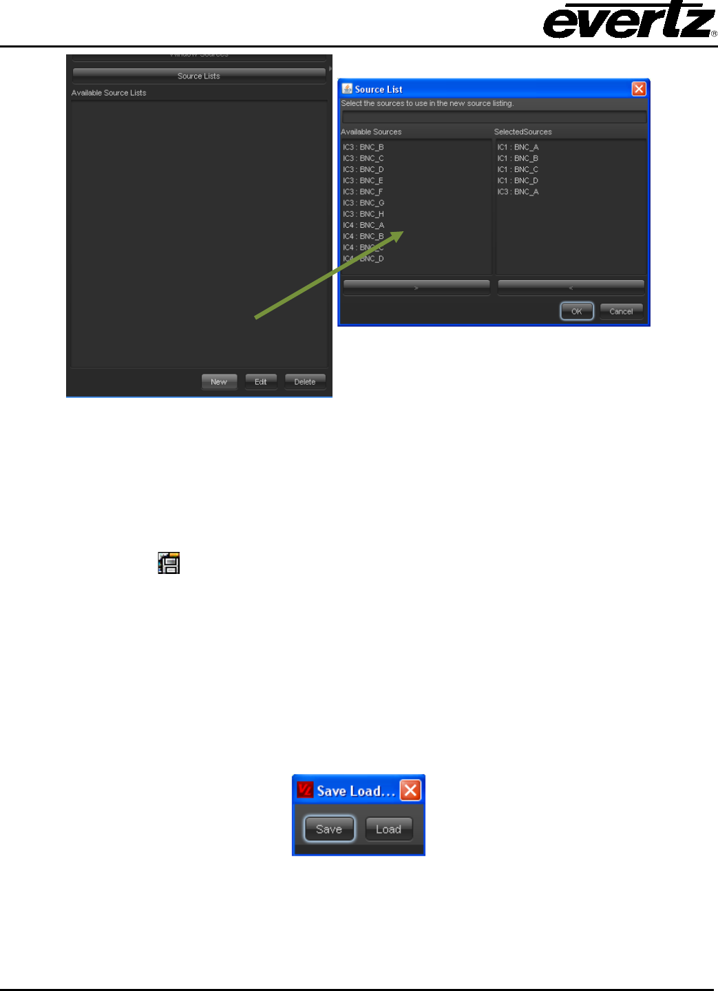
VistaLINK® PRO User Manual
Page 6-30 Revision 11.0
Figure 6-7: Source List Panel and Editor Opened
Once the Source List editor is shown, a custom source list can be made for the available sources. Click
the OK button to save the source list. Once a source list is made it can than be dropped into a window on
the layout of the DVL Editor.
6.1.5. Save/Load DVL
A Save and Load DVL provides a function to save layouts running on a certain display. The Save and
Load DVL can also be executed as a Load method to run previously saved layouts. Creating a Save and
Load DVL can be done in the following steps.
1. Drag and Drop the MVP Server from the hardware tree into the DVL Editor window.
2. Ensure the Type property is set to Save/Load Display.
3. Configure the Display property so that a display is targeted for change.
4. Click the Save button to save the DVL into the system.
To run the Save/Load DVL, double click the function from the Navigation Tree. The Save Load Selection
window, shown in Figure 6-8, appears and presents two options.
Figure 6-8: Save Load Selection
Click the Save button to save the layout on the running display. Clicking the Load button will load a
previously saved layout onto the display.
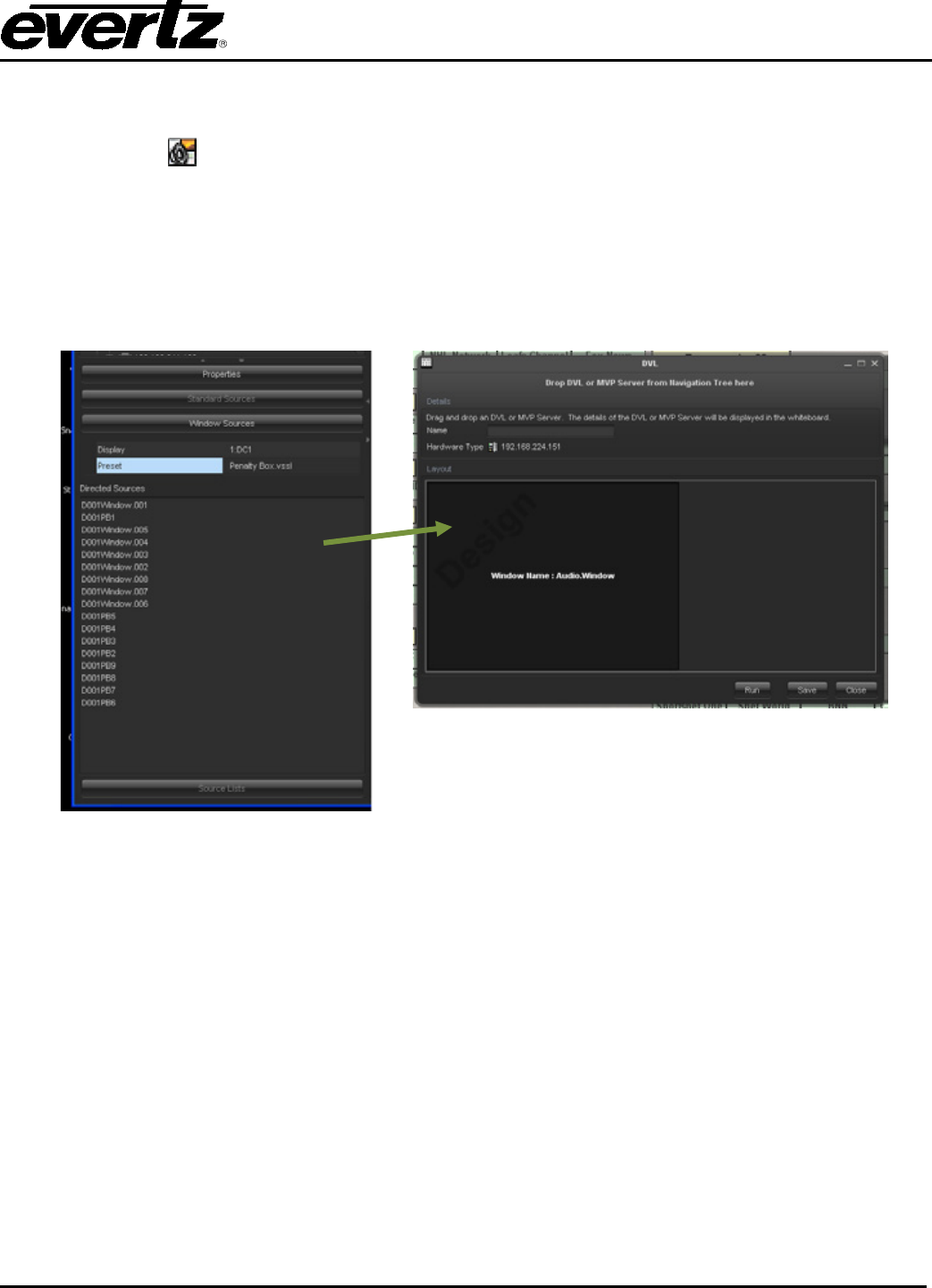
VistaLINK® PRO User Manual
Revision 11.0 Page 6-31
6.1.6. Audio Route DVL
DVL audio routing is a function to route the audio from any given source out to the AES outputs of the
MVP. The system targets input assignments rather than sources directly. This means that when using
Audio Routing DVLs, it requires that layouts be already running on the display. The creation of an Audio
Route DVL is explained below.
1. Drag and Drop the MVP Server from the hardware tree into the DVL Editor window.
2. Ensure the Type property is set to Audio Route
3. Click the Window Sources Panel to open the window.
Figure 6-9: Windows Sources Panel Figure 6-10: Audio Route Window
4. Configure the Display parameter to display the layout that will be running.
5. Select a layout that will be running on the display.
6. After selecting the layout, the available layout windows will appear in the Directed Sources list.
Drag and drop one of the Directed Sources list into the DVL Editor. Figure 6-10 shows the DVL
Editor containing the audio routing window.
7. Click the Save button to save the DVL into the system.
To run the Audio Route DVL, double click it on the Navigation Tree.

VistaLINK® PRO User Manual
Page 6-32 Revision 11.0
6.2. CROSSPOINT CREATION
To create a Crosspoint, first right click on the Crosspoint node ( ) or group ( ) to bring up the
Crosspoint creation dialog. When this dialog first appears it will contain only a listing of routers that can be
controlled. Figure 6-11 illustrates the initial appearance of the Crosspoint creation dialog.
Figure 6-11: Crosspoint Creation Dialog
This dialog uses drag and drop to facilitate ease of creation. Select a Router from the tree; there exist
several types of routers that can be used in this dialog. For example each of the ptx ( )’s ports can be
used as a router for control in a Crosspoint.
The creation dialog consists mainly of four sections, the label field, and the sections: Routers; Content,
and Crosspoint Type. Each of these sections will allow for a partial definition of a crosspoint.
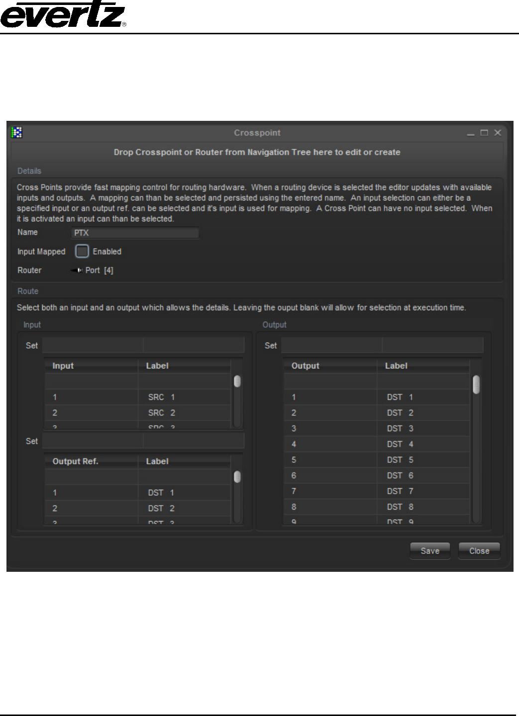
VistaLINK® PRO User Manual
Revision 11.0 Page 6-33
6.2.1. Router Selection Section
On the left hand side of the dialog is a section that allows for the selection of the router to be controlled.
Select and click on a router in the tree. Components that cannot be used as routers will not affect the
dialog. Once a router has been selected the input and output areas in the Content section will be filled in
as shown in Figure 6-12.
Figure 6-12: Selected Router
The available inputs and outputs are populated through direct communication with the router. If for any
reason communication with the router is hindered, a warning will be displayed and Crosspoint creation
may be prevented.
6.2.2. Content Section
To fully define a Crosspoint you are required to select both an input and an output. Inputs are displayed
on the left, while outputs are on the right. While the definition of a Crosspoint is simply a Router along with
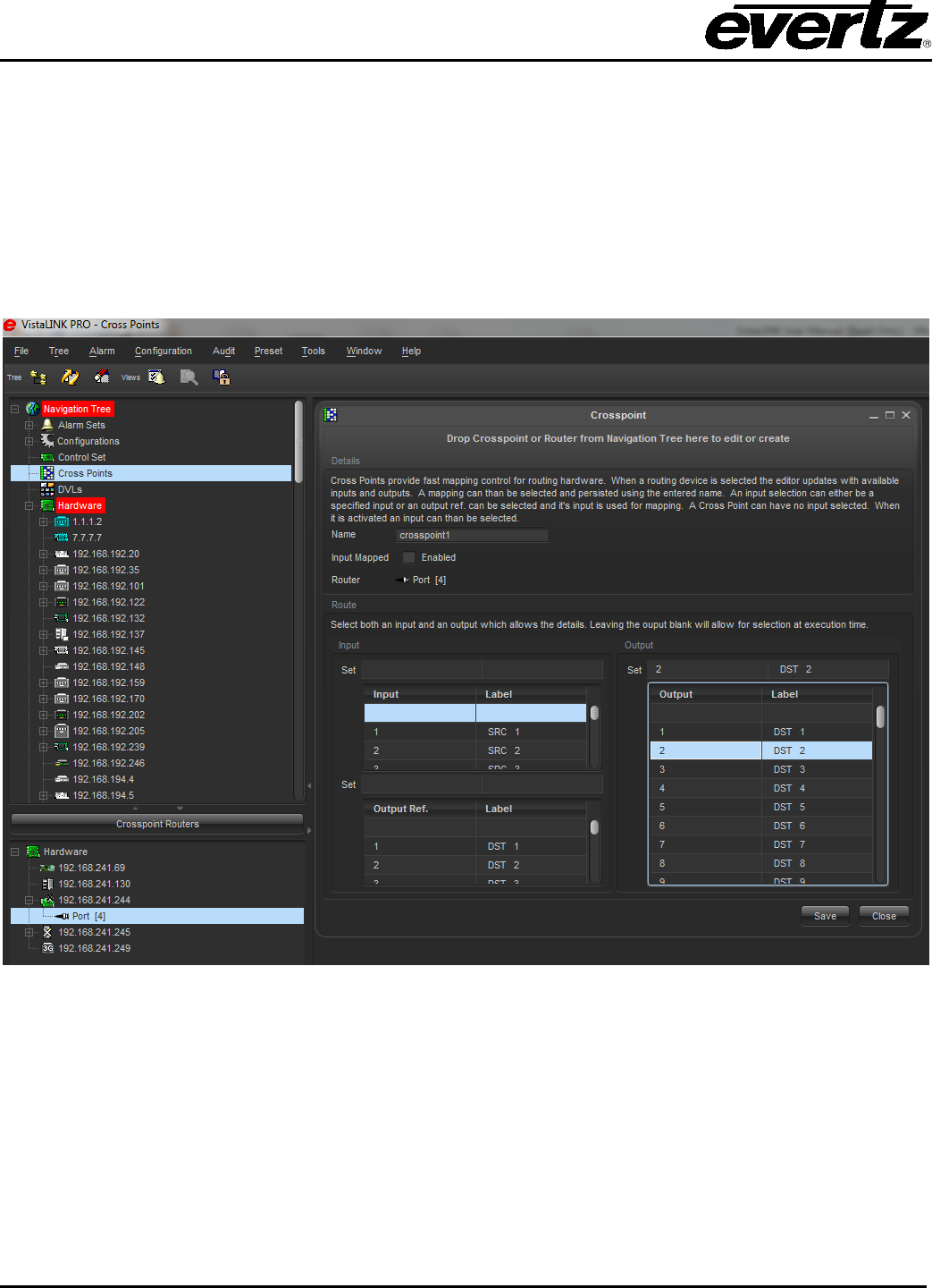
VistaLINK® PRO User Manual
Page 6-34 Revision 11.0
and input and an output, there are some additional options that are facilitated. These include open-ended
Crosspoints, Label tracked Crosspoints, and output referenced Crosspoints.
6.2.3. Open Ended Crosspoint
Normally when we create a Crosspoint we specify both an input and an output, this fully describes a
Crosspoint. However this dialog allows for the specification of only an output as in Figure 6-13. If the
input is left empty, when the Crosspoint is about to be launched, a dialog will appear and at run time
prompt the user for the desired input. This allows users to create Crosspoints for a specific output, in
which the input is only known at run time.
Figure 6-13: Open Ended Crosspoint

VistaLINK® PRO User Manual
Revision 11.0 Page 6-35
6.2.4. Label Tracked Crosspoint
A Crosspoint defined by input number and output number is only useful if all the video inputs and outputs
are on fixed numbers. However, some routers allow for inputs and outputs to be tracked dynamically by
assigning input and output labels. On occasion this labeling affects the ordering of the inputs and outputs
on a router. Therefore, if the label tracking option is selected, then the input/output numbers are not used
as the references for the Crosspoints, but the input/output labels are used as in Figure 6-14. This feature
is only available on some routers, if the feature is enabled for a given router then the bottom section of the
dialog (Crosspoint Type) will be enabled, otherwise this feature will be disabled.
Figure 6-14: Label Tracked Crosspoint
6.2.5. Output Referenced Crosspoint
Sometimes it is useful to create a Crosspoint in which we do not directly know which input is to be
connected to an output, however, we do know that another output is already pointing to the desired input.
This is where output referenced Crosspoints come into play. These Crosspoints function by selecting an
output as normal, however, instead of specifying an input, we specify another output (output reference) as
in Figure 6-15. If this is selected, then at run time, the input that is feeding the output reference is
determined by querying the router; this input is then substituted for the input of the new Crosspoint.
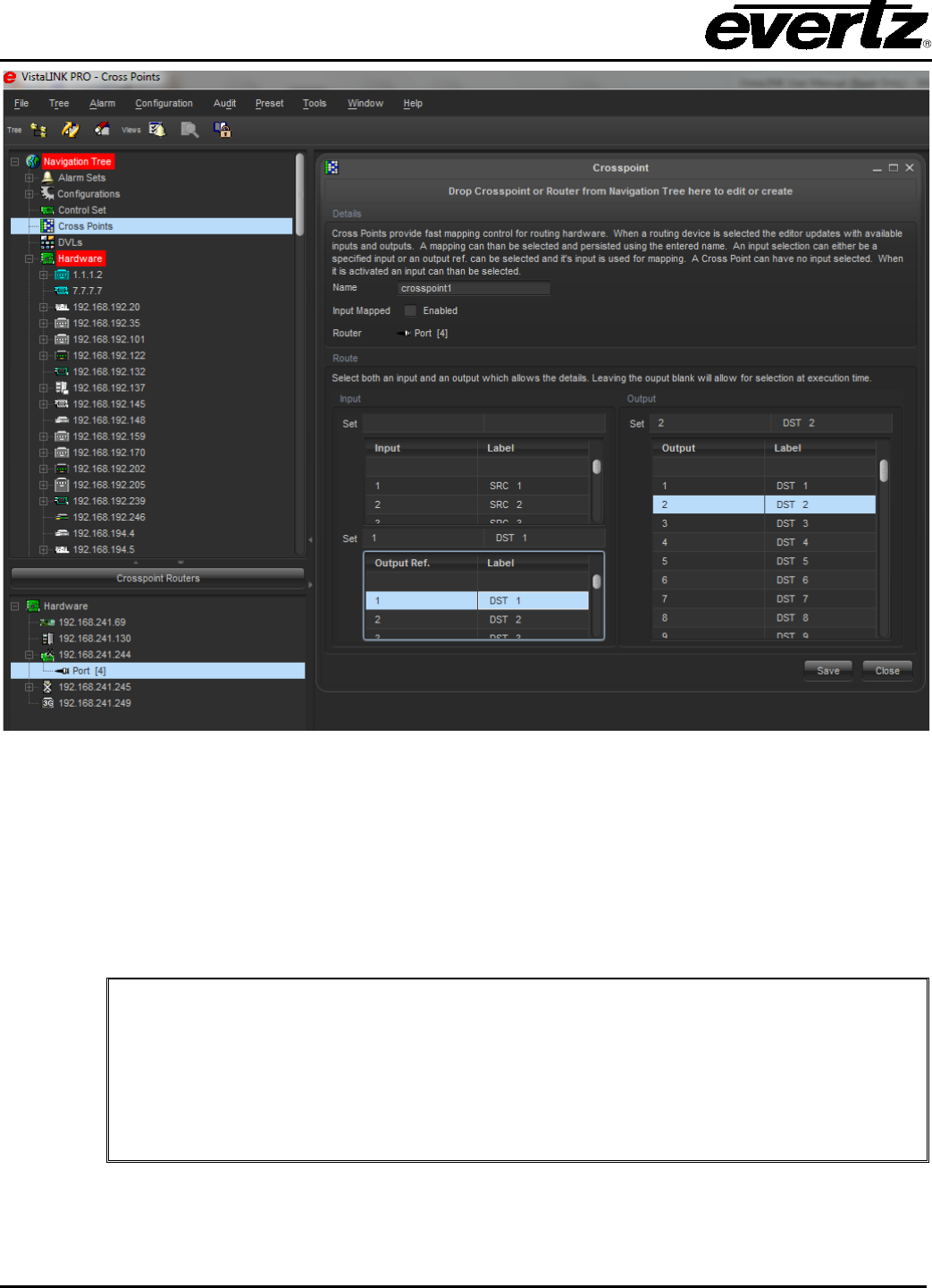
VistaLINK® PRO User Manual
Page 6-36 Revision 11.0
Figure 6-15: Output Referenced Crosspoint
Once a router has been selected and the content specified, the new settings can be saved into a
Crosspoint. Specify a name for the Crosspoint in the Crosspoint Field at the top of the dialog. Once this
is done either press the Apply button if more than one Crosspoint is to be created, or press the OK button
if only one is to be created at this time.
Once the Crosspoint(s) have been created, they can be executed by right clicking on the Crosspoint in the
main tree and selecting launch in its popup menu options.
Helpful Hints:
Some routers have thousands of inputs or outputs, which means that scrolling through
each of these lists may take a long time. To speed up this process the Set fields for each
of the input selection and output selection lists can be typed into. When typing into these
fields a search will be performed to select the closest input or output to the description that
has been typed. Once an input or output has been found, press enter to ensure that the
correct input or output will be used.
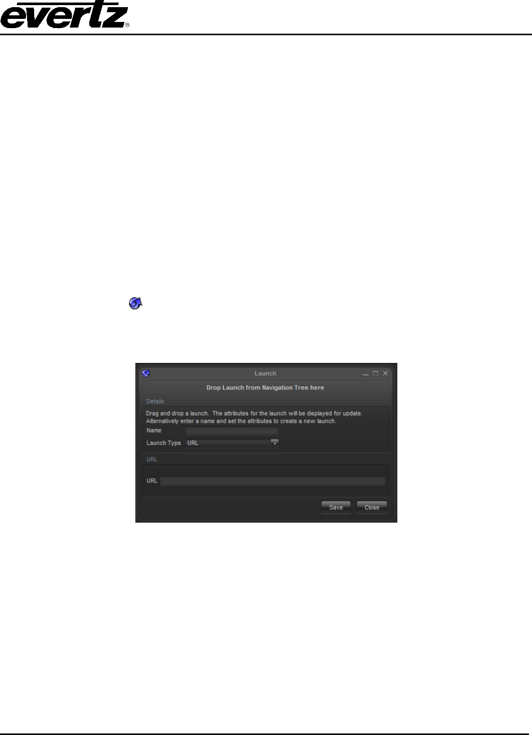
VistaLINK® PRO User Manual
Revision 11.0 Page 6-37
6.2.6. Editing of Crosspoints
To edit a Crosspoint simply take any Crosspoint from the main tree and drag it into the description field at
the top of the Crosspoint creation dialog. The existing Crosspoint description will be displayed and
modification of any field can be performed. When finished with the changes simply press the Apply or OK
buttons. If you wish to discard your changes simply select the Cancel button.
6.3. LAUNCHES
VistaLINK® PRO Launches provide a convenience method of launching an external application or http link
without exiting the VistaLINK® PRO client application. Launches can be set up to provide quick access to
such items as:
• Third party control applications
• Utility service applications
• Product manuals
• Product HTTP control interfaces
- Internet links
6.3.1. Creating Launches
To create a new Launch , use one of the two methods described below depending on whether it is an
executable launch or an HTTP launch.
6.3.1.1. HTTP (URL) Launches
Figure 6-16: Create a Launchable
1. Ensure the Launches super-node is displayed (see section 3)
2. Right click the Launches node and select New -> Launch.
3. In the Launch Name field, enter a name for the new Launch and enter the URL in the URL Action
field to have your default browser open when this Launch is accessed. Once the fields are filled
out, select OK.
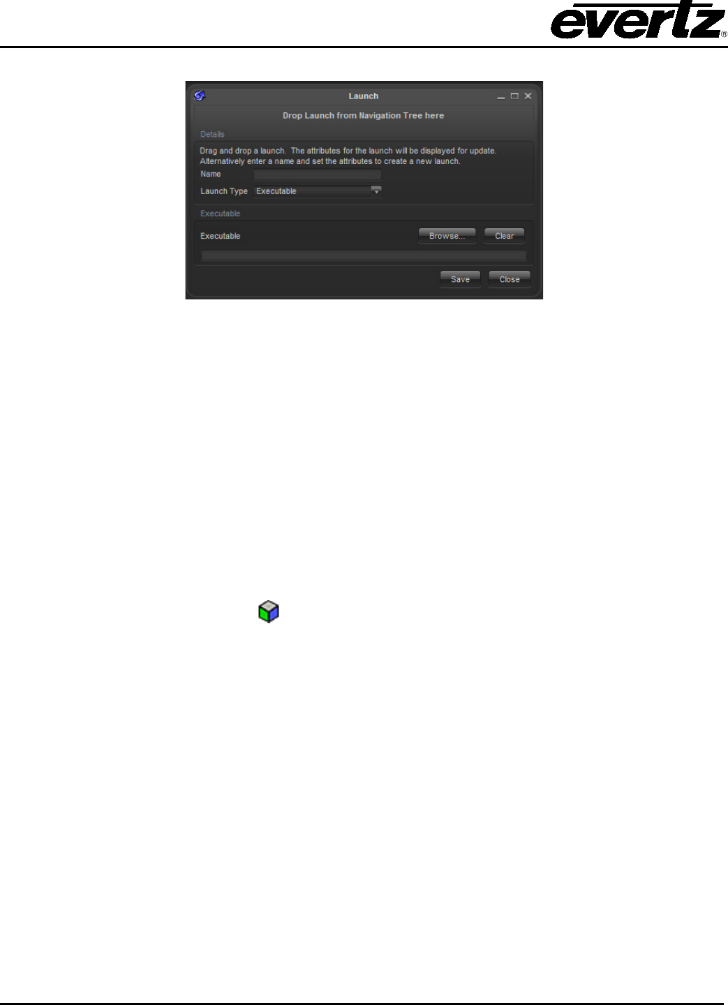
VistaLINK® PRO User Manual
Page 6-38 Revision 11.0
6.3.1.2. Executable (.exe) Launches
Figure 6-17: Create a Launchable
1. Ensure the Launches super-node is displayed (see section 3)
2. Right click the Launches node and select New -> Launch.
3. In the Launch Name field, enter a name for the new Launch and use the Select button to browse to
and select the executable (program) that will be run when this Launch is accessed.
6.3.2. Accessing / Using Launches
Once new Launches have been created, they will appear in the Navigation Tree under the Launches
super-node. To use a Launch, right click the Launch node and select -> Launch.
The right click menu will also allow you to Edit or Delete the selected Launch node.
6.4. INTRODUCTION TO MACRO’S
The VistaLINK® PRO macro system provides a flexibility to do almost any task. This system allows
the software manager to access the internals of the application for unique control. Using the Macro
system, a developer can gang multiple actions into a single click. The macro system is unique enough
that it does not require the user to know a lot about how VistaLINK® works. The macro system gives the
user an intuitive interface for accessing the internals of the application through a drag and drop, and a
point and click system.
Macros provide a way to target certain clients to run different tasks. Through macros a user can target a
client and have that client open up a specific configuration view or a graphical view. Creating and
manipulating macro’s is done through the main macro editor. The macro editor can be accessed from the
Navigation Tree by right clicking on Macro and choosing New -> Macro -> Basic.

VistaLINK® PRO User Manual
Revision 11.0 Page 6-39
Figure 6-18: Macro Editor
The Macro editor is composed of three columns.
The left column contains the macro features that are available for use. This list changes frequently as
new features are added to the system. Some of these features relate to manipulating the application,
while others allow the executions of the features in the VistaLINK® System.
The middle column is for containing what the macro is going to do. The list will show the order in which
the function is going to run. The middle column can be modified in two ways.
1. Items from the left column can be dragged and dropped into the middle column.
2. Items from the navigation tree can be dragged and dropped into the middle column.
Items can also be re-organized by using the bottom UP and Down arrows. If an item needs to be deleted,
select the Remove button.
The right column called Macro Property Panel is a panel that allows the user to modify the properties of
each Macro element. By selecting the macro item, the Property Panel will update to show the relevant
settings. Common settings are typing intervals, selecting configurations and typing in email messages.

VistaLINK® PRO User Manual
Page 6-40 Revision 11.0
Some macro functions may not need additional settings, therefore, the Property Panel may not show any
information.
Macro items can have a special property to target certain clients. The below image is the control panel for
this feature. It is located at the bottom of the Macro Editor.
Figure 6-19: Control Panel of Macro Editor
The default settings for functions that support this are Executing_Client. This option dictates that the
client who runs the macro will be executing the contents. The option button ‘…’ will allow the user to
choose which client will run the contents. This feature is used for systems when a remote client needs to
change graphical views on other remote clients.
After configuring the Macro, a name must be given to the macro to uniquely identify it. Once the macro is
saved, it can be executed from the Navigation Tree.
6.4.1. Cycling Macro’s
Unlike the basic Macro’s mentioned above, Cycling Macro’s are re-occurring. Cycling Macro’s can be
configured to run in an infinite cycle or a set amount of times. It is possible when making Cycling Macro’s
that the existing Basic Macro’s can be added. The cycling macro editor has additional properties for
managing the cycling process.
To open the Cycling Macro Editor, right click on Macro’s and choose New -> Macro -> Cycling
Three additional properties are available compared to the Basic Macro editor.
Cycle Pause (ms): Cycle Pause indicates the duration of a pause when moving from the last execution to
the first execution.
Action Pause (ms): Action Pause indicates the duration of a pause when moving between each
execution in the cycling macro.
Cycle Count: Cycle count indicates the amount that the Cycling Macro will run. The default setting is
Infinite.
6.4.2. Running Cycling Macro’s
Cycling Macro’s have two states. The idle state means that the cycling macro is not running. The macro
can be identified in this state by its idling icon from the Navigation Tree. Actively running Cycling
Macro’s has a unique icon that can be identified from the Navigation Tree . When a Cycling Macro is
active, it is possible to right click the Cycling Macro and choose the ‘Terminate Cycling’ to stop the Cycling
Macro.

VistaLINK® PRO User Manual
Revision 11.0 Page 6-41
6.4.3. Macro Property Selection
There are many features with macros. The following list outlines a sample of the features of the Macros.
ALARMS
Create Custom Alarm Allows for the creation of a custom alarm.
Purges Alarms Purges the logging system of all alarms.
Open Alarm View Opens an alarm view for the given hardware.
Service Alarm Viewer Opens an alarm view for a particular service.
AUDIO
Clear Sound Buffer
Stops currently playing sounds and removes all queued sounds from the
Audio Manager’s sound buffer.
AUDIT
View Log Opens the Audit Log for viewing.
Purge Entries Removes all existing audit entries.
AUTO RESPONSE
Alarms
Response Trap
Generator
Generates a customized Response trap originating from the Primary Auto
Response Server. The response server must be online for this macro to
function properly.
AUTO RESPONSE
Redundancy
Promote Response
Server
Promotes a redundant Auto Response Server from a redundant status to
a primary status.
AUTO RESPONSE
Triggers
Fire Trigger Fires a trigger. A mechanism for raising custom Auto Response event.
CONFIGURATION
Load
Load Configuration Loads a Configuration. The control values in the configuration will be
applied to relevant hardware devices
Load Directed
Configuration Applies a Configuration to a set of hardware, the types of which must
match the hardware defined within the specified configuration.
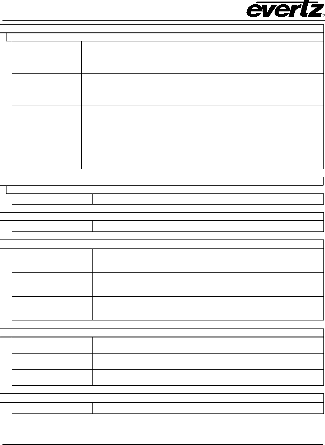
VistaLINK® PRO User Manual
Page 6-42 Revision 11.0
CONFIGURATION
Utility
Update
Configuration Updates a Configuration. The control values in the configuration will be
updates with the current values retrieved from relevant hardware devices.
Copy Configuration Copies the controls from one configuration into another configuration. This
action will overwrite any pre-existing controls in the configuration that it is
being copied to.
Control Change
Notifier
Detects control value changes; issues traps to a specified IP upon value
change detection. Typically called from a cycling macro or an interval-
triggered response. Requires a licensed, running VistaLINK® PRO Auto
Response system.
Parameter Shuttler Transfers parameter values from one device to another. Parameter shuttling
is defined within a user-defined shuttle configuration file resident within the
Alarm Server.
CONFIGURATION
View
Fire Trigger Fires a trigger. A mechanism for raising custom Auto Response events.
CROSSPOINT
Launch Crosspoint Launches a Crosspoint
DISCOVERY
Refresh Tree Causes the discovery tree to be ‘refreshed’. This involves setting all
hardware markers in the system to an ‘unknown’ state. Each piece of
hardware is then queried, in turn, to ensure that it is still functioning.
Refresh Agent Causes discovery to be ‘refreshed’ for a particular agent.
Remove Dead
Hardware
Removes ‘dead’ hardware from the system tree. When VistaLINK
®
PRO
is unable to communicate with hardware, it is marked as dead, and is
coloured gray in the system tree.
DVL
Run Script DVL Launches a Run Script DVL.
Run change Stream
DVL
Launches a Change Stream DVL.
Save/Load DVL Launches a Save/Load DVL.
GRAPHICS
Open Graphics View Macro to open a graphics view on a selected client.

VistaLINK® PRO User Manual
Revision 11.0 Page 6-43
HARDWARE
Device Label Sets a custom label for a hardware device.
LAUNCH
Execute Launch Executes a pre-configured launch.
MACRO
Cycling
Stop All cycling Macros Stops all actively cycling macros.
Stop Cycling Macro Stops all instances of a specified cycling macro, if they are running.
NEIGHBORHOOD
Open View Opens the VistaLINK® PRO Neighborhood view.
SERVER
Message Causes a message to be delivered to all logged in clients.
Email Sends an email to identified recipients.
UTILITY
Authorization
Used to request user authorization before proceeding with macro
execution.
Pause Used to insert a wait period in between macro executions. For example:
Suppose you require a macro that needs to perform two sequential
actions with a five-second interval between them; simply insert a Pause
with a value of 5000 (5 seconds expressed in milliseconds) between the
two actions.
Show Client ID
Prominently displays a VistaLINK
®
Clients identifier. Useful for
troubleshooting client IDs.
VISIBILITY
Tree Shows and Hides the system Tree
Menu Bar Shows/Hides the system menu bar.
Tool Bar Shows/Hides the system tool bar.
WINDOWS
Minimize Minimizes any open views on a client.
Restore Restores all minimized views on a client.
Cascade Lays out all open client views in a cascading fashion.
Tile Lays out all open client views in a tiled fashion.

VistaLINK® PRO User Manual
Page 6-44 Revision 11.0
6.5. INTRODUCTION TO MIBS
The MIB Control Set was introduced in VistaLINK® 10.2.266 as an entry-level open control system for
third-party SNMP devices outside of the Evertz product realm. The goal of the MIB Control set is to supply
an open dialog that can access all the different SNMP enabled parameters on any SNMP managed
device. This document will provide information on how to build up an MIB Control Set, as well as possible
SNMP functionality that could exist throughout one’s hardware plant.
The MIB Control Set is composed of a new node element in the Navigation Tree of any VLPRO Control or
Monitoring Client. From this node, users can create saved sets of control and monitoring dialogs.
Operators or engineers would access these sets for SNMP monitoring and control of the managed
equipment. SNMP control of a device could be almost anything as long as it is within the scope of the
device capabilities through SNMP. A Management Information Base (MIB) provides information on
determining a devices control and monitor capabilities.
The MIB can be provided straight from the equipment vendor for vendor specific controls. Also, public
standard MIBs can be downloaded from a variety of the Internet resources. A very helpful Internet
resource for viewing, downloading and searching all the different kinds of MIBs is
http://www.oidview.com/mibs/detail.html. Deciding whether the vendor-specific or standardized control
level is appropriate is solely based on the specific application. The MIB Control Set is designed to
accompany any kind of SNMP accessible parameter, therefore, it is possible to mix and match between
the different MIBs. When deciding to use standardized MIB objects in the MIB Control Set, it is important
that you consult the product documentation to find out if the MIB object has been implemented in the
device. Usually, it would be documented in the SNMP Specific sections as “RFC <number> compliant”.
Each standardized MIB is ruled into a Request for Comment, and it is necessary that the vendor
implements the RFC Spec. fully before claiming it in product advertisements and documentation. If the
vendor does not indicate compliance in documentation, the device may still only implement part(s) of a
particular MIB standardization.
Below is a short list of useful standardized MIBs that may be implemented on a SNMP managed device.
RFC Date Name Description
1213
March 1991
Management Information Base for
Network Management of TCP/IP-
based Internets: (known as MIB-II)
Includes Ethernet, IP and TCP/UDP
statistics information
1514
Sept. 1993
Host Resources MIB
Provides details about CPU, program
processes, disk storage and file system
statistics.
1628 March 1994 UPS MIB
Battery backup control and monitoring
statistics
1595
March 1994
Definitions of Managed Objects for
the SONET/SDH Interface Type
Statistics on interfaces and rings for
SONET/SDH devices
1850
Nov 1995
OSPF Version 2 MIB
Statistics and information of OSPF
processes in a dynamic routing environment
1697
Aug 1994
Relational Database Management
System MIB
Contains information on installed
databases, servers, and on the relation of
databases and Servers.
Table 6-1: Standardized MIBs
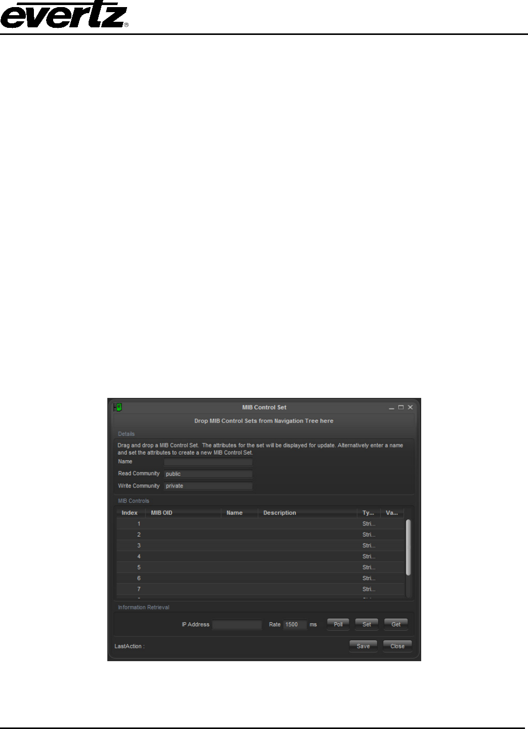
VistaLINK® PRO User Manual
Revision 11.0 Page 6-45
A vendor may also provide a private MIB that is specific to the device functionality. All vendors use private
MIBs when the standardized MIBs do not support a definition to a particular control that the equipment
supports. The vendor is free to provide descriptions about the controllable objects, or even the MIB itself
at their discretion. Sometimes vendors will choose to fully develop SNMP support privately, even though
all the controls could have been implemented through a standardized MIB. This is usually because the
vendor feels they need to present the monitoring and control access in a different way so that the system
is easier to manage through SNMP.
6.5.1. The MIB Control Set
The MIB Control Set dialog is illustrated in section 6.5.2. The dialog can be in the following two modes:
Edit Mode: This mode gives the MIB Control Set designer a enviroment to create or make changes to
MIB Control Sets and save them for later use.
View Mode: The ideal working enviroment for an operator to gain access to the custom MIB Control Set
and utilize the parameter setup for read and write operations to the device. From this mode,
a user cannot change the MIB Control Set setup.
When designing the MIB Control Sets, it is useful to develop them on a per device basis. Each MIB
Control set would be associated to a particular device for ease-of-use. Multiple MIB Control Sets can be
opened at any time and can partition the computer monitor logically so that each area of the monitor is
devoted to a particular device.
It is possible to create a one-time MIB Control Set which the operator can recall and manually input the IP
address of the managed device to access it. With this method, the managed device would respectively
need to have the same SNMP monitoring and control characteristics to work correctly.
Figure 6-20: An empty MIB Control Set Dialog

VistaLINK® PRO User Manual
Page 6-46 Revision 11.0
6.5.2. MIB Control Set Dialog in Detail
Name: Used to describe the custom dialog. This entry is also reflected in the Navigation Tree
when managing saved MIB Control Sets.
Read Community: The community name that is used to pass to the Agent for verification in get
operations. By default, this is set to “public”.
Write Community: Community name that is used to pass to the Agent for set operations. By default, this
is set to “private”.
Index Column: Up to 10 rows are available per dialog. This uniquely identifies a row in each dialog.
MIB OID: The object identifier (OID) numerical string is placed in this column to create a monitoring or
control parameter in one of the rows. This OID is in the format of a dotted decimal string,
and it would look similar to: 1.3.6.1.2.1.1.4.0. The example OID addresses the sysContact
leaf from the RFC 1213 (MIB II) MIB definition. It is vital to have the MIB file when deciding
on SNMP enabled parameters because the OID is derived from the MIB files.
Name: Textural string that describes the leaf object that is being accessed (through the OID)
Description: More textural documentation about the leaf object. It is ideal to write a small description
about the parameter to help validate what the return value means. Possible entries would
be ‘CPU Load 0-100%’ so the operator would know what a ‘66’ return value would mean.
With some leaf objects, this documentation is necessary because they may only return a ‘1’
or a ‘2’. For example, a ‘1’ could mean a network interface is up and a ‘2’ could mean the
interface is down.
Type: Used for set operations and formats, this column identifies the type of leaf object being
accessed. This can be set to a “String” (Octet String), “Integer” or “IP Address”.
Value: This column holds any returned value for each row using the Get function. This column is
fully changeable for changing a leaf object value using the Set operation
IP Address: Used to direct the dialog action controls to the appropriate device on the computer network.
Rate: This control tells the Poll button how often it should issue a get SNMP command.
Poll: After selecting the desired rows either using the mouse, or the CTRL, or SHIFT key for
multi-select, repeated get SNMP commands are issued. The frequency is dictated by the
Rate control. This control is desirable for watching real-time changes about the parameter
in question and the return value is updated in the Value column.
Set: The set function is used to change a value of the SNMP object for a particular row in the
MIB Control Set dialog. The Value column is always in edit mode, therefore changes to the
field value can be made first before the Set button is clicked. This button will issue a Set
SNMP command with the Private community string
Get: After selecting the desired rows either using the mouse or the CTRL or SHIFT key for multi-
select, a single get SNMP command is used using the Public community string. The return
value is updated in the Value column.
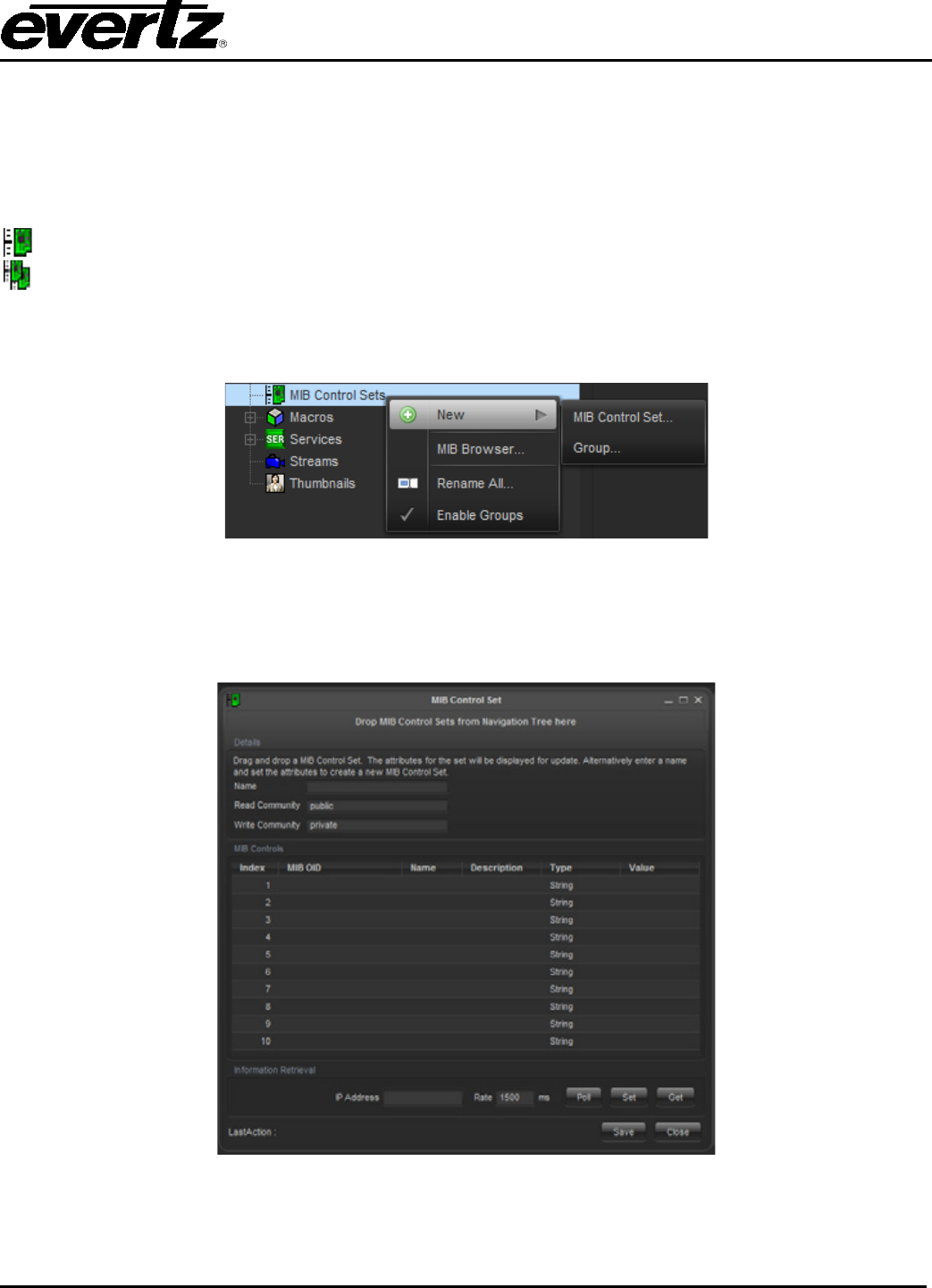
VistaLINK® PRO User Manual
Revision 11.0 Page 6-47
Last Operation Result: This field provides notes on successful and unsuccessful actions that were made
contacting the device with either the Set or Get button.
6.5.3. Creating a MIB Control Set
The MIB Control Sets are stored in the Navigation Tree from the following node icons.
MIB Control Set super node
MIB Control Set groups
To create a new MIB Control Set, right mouse click the MIB Control Set node from the Navigation Tree to
bring up a small menu system. Select New, and then select MIB Control Set. See Figure 6-21.
Figure 6-21: MIB Control Set…
Once the blank dialog starts up, the form elements can be changed. The below steps instruct how to
create a MIB Control Set to monitor switch port status from a Ethernet switch that supports the RFC1213
MIB.
Figure 6-22: Sample MIB Control Set Being Created
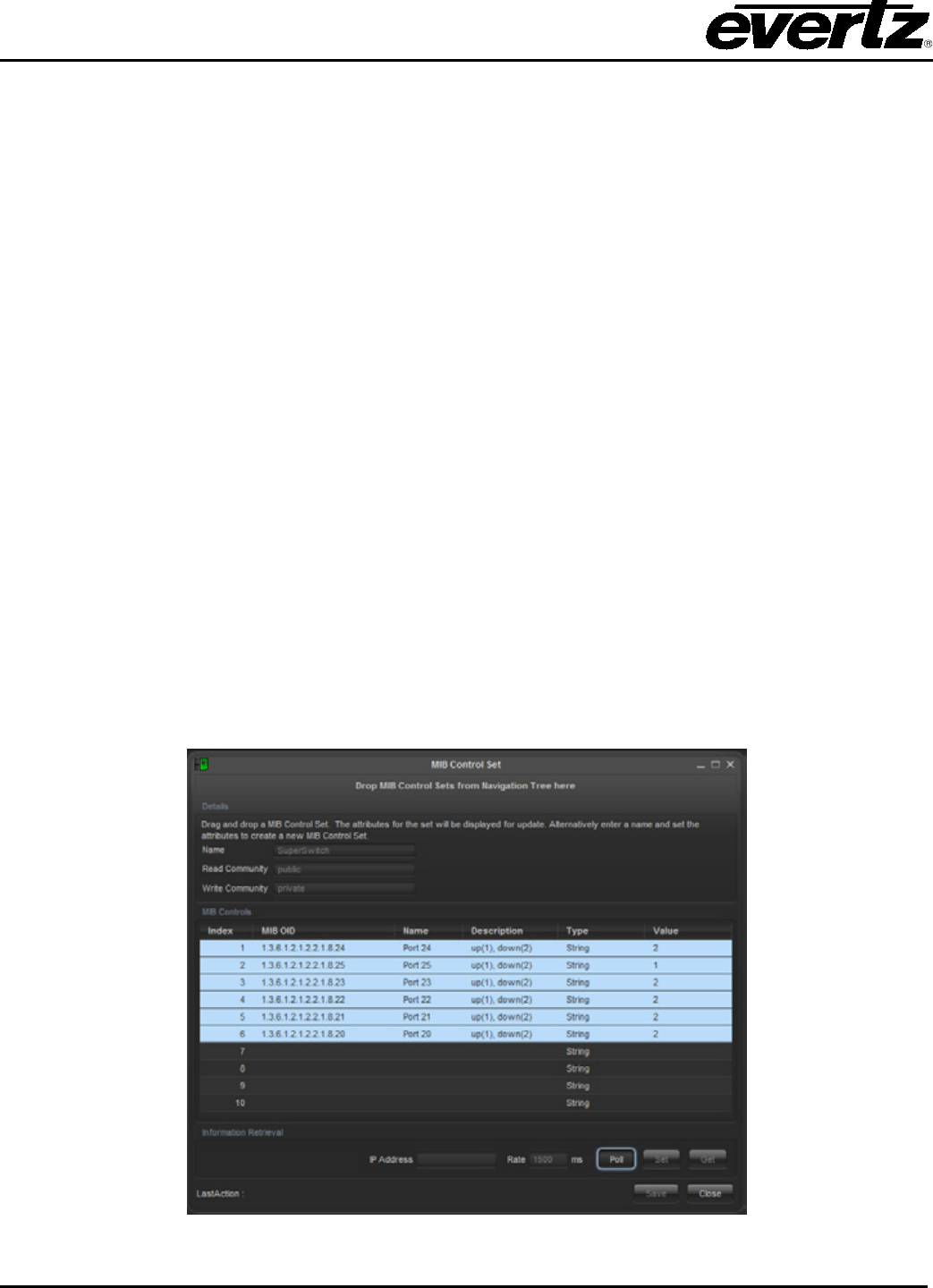
VistaLINK® PRO User Manual
Page 6-48 Revision 11.0
1. The first task would be to find the right OID for the SNMP accessible parameter. This example
‘Super Switch’ MIB Control Set uses the ifOperStatus object from the RFC1213 MIB (known as
MIB II). The ifOperStatus object provides information whether the network interface is either up (1)
or down (2). Since this example is setup to monitor an Ethernet switch, the ifOperStatus object is
going to have the same amount of rows, as there are switch ports. The RFC1213 MIB provides all
the details on how this works.
2. A textural name is then applied to the Name column for indication on what parameter is being
accessed. This entry is custom and the example uses ‘Port #’ for simplicity.
3. The Description column can be filled in with a functional description on how the ifOperStatus
behaves. This information is always provided in the object description field from the MIB. The
example uses ‘up (1), down (2)’ to help determine what the value from the Value column means.
4. An IP address may be inserted into the IP Address field. Filling in this field will trigger the dialog to
be remembered for future startups.
5. Making changes to the Rate, community string fields and the Type column will also be
remembered for future startups. The Type column is only needed when doing set SNMP
operations. Since the ifOperStatus object is read-only, this setting has no effect on the Value
column.
6. Once done, click OK and the dialog will close and be saved in the Navigation Tree.
6.5.4. Running the MIB Control Set
After saving the Super Switch MIB Control Set, it can be opened again from the Navigation Tree in View
mode. Figure 6-23 demonstrates that all rows are being polled at every 1500ms through the Poll button.
The return values are than inserted into the Value column.
Figure 6-23: Super Switch MIB Control Set in Action

VistaLINK® PRO User Manual
Revision 11.0 Page 7-1
7. CLIENT, SERVER AND HARDWARE MAINTENANCE
7.1. FIRMWARE UPGRADES
It is possible to manage firmware upgrades from VistaLINK® PRO for 7700, 500 and standalone
equipment. Firmware upgrades for the 7700 and 500 frame controllers are managed separately from the
modular card upgrade process. Firmware upgrading over TCP/IP involves using the FTP transfer
protocol. VistaLINK® PRO does not do any serial transferring of the device firmware upgrade. Since
VistaLINK® PRO uses TCP/IP to upgrade the device firmware, VLPRO will need full network connectivity
to the device. During the device firmware upgrade, it is important that the card is not used for live
services. The process will put the device in a temporary mode that prohibits its normal functionality. It is
important to check the products documentation if the device supports VistaLINK® remote upgrading.
7.1.1. Upgrading Frame Controllers
VistaLINK® PRO can facilitate frame controller upgrades. This process is handled differently than
standard module upgrade. The below steps outline how to upgrade the 7700 Frame Controller.
1. Start a VistaLINK® PRO client and login using the Administrator user account (VLPRO-C does not
use login accounts).
2. Expose the 7700FC in the hardware tree using ‘Add/Update Frame’ and collapsing the nodes in
the tree appropriately.
3. Use the right-click mouse button on the ‘7700FC’ in the tree and select ‘View configuration’, as
shown in Figure 7-1.
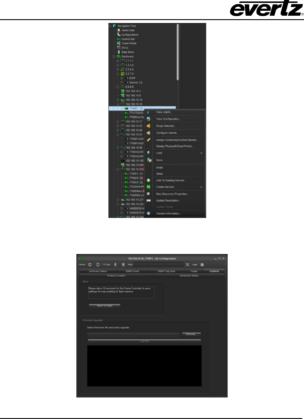
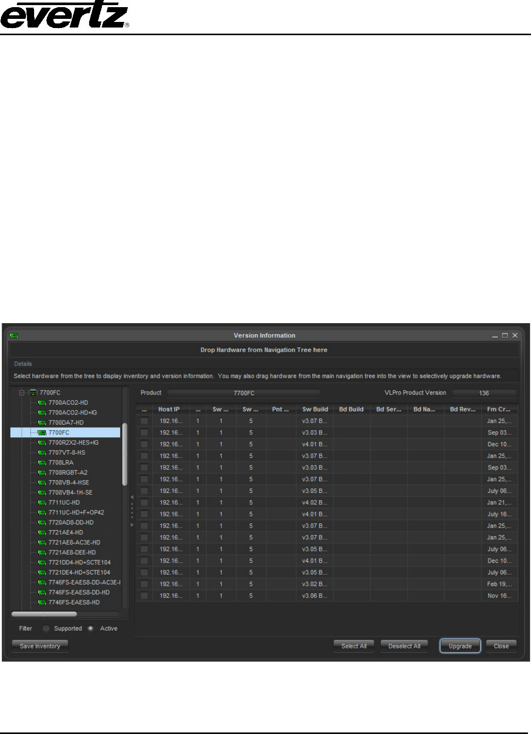
VistaLINK® PRO User Manual
Revision 11.0 Page 7-3
5. Click the ‘Browse’ button to select the unzipped 7700FC Image file downloaded.
6. Click the Upgrade button and wait for the upload to complete. This will take approximately 5 to10
minutes depending on network traffic.
Upon completion, the 7700FC module will reboot automatically and return online in normal “run” mode. If
for any reason the upload is interrupted, you must execute the recovery procedures described in the frame
control manual. To upgrade the 500FC, the exact steps shown for the 7700FC can be used.
7.1.2. Module Firmware Management
To bring up the version information dialog go to Tools->Products->Version Info. VistaLINK® PRO supports
module and standalone firmware monitoring and upgrading. This process is handled through the Version
Information Dialog. The Version Information provides a great way for inventorying hardware. It can
display firmware information, device IP information and provide an upgrade system for the module and
standalone devices.
To access the version information dialog, use the below steps.
1. From the VistaLINK® PRO client select Tools ->Products->Version Information.
2. Once the dialog opens, adjust the List control at the bottom left from Supported to Active.
Figure 7-3: Version Information

VistaLINK® PRO User Manual
Page 7-4 Revision 11.0
When the Active List mode is used, the tree on the left resembles the available hardware on the network.
Selecting a device from the tree will update the table view on the right. The table view provides the
following information:
Host IP: IP address used to access the device.
Slot: If the device is a modular card, the slot location will be reported.
Sw Major: The firmware major number release.
Sw Minor: The firmware minor number release.
Sw Build: The firmware build number.
Hw Build: Hardware revision information.
It is important to note that if the table does not display any information about the firmware version, it is
because it is a limitation of the module not supporting it.
To upgrade modules or standalone devices, first select a device from the left tree of the Version
Information dialog, then click the Upgrade button. The Upgrade Firmware dialog is shown in Figure 7-4.
Figure 7-4: Upgrade Firmware Screen
It is possible to upgrade more than one module at a time. The Upgrade checkboxes allow the exclusion
and inclusion of modules or devices to be included in the upgrade process. The Browse button allows for
the firmware file to be selected from the file system. Once the file is selected, the Start button can be
pressed to start the upgrade process.
It is important to note that if the upgrade process does not start correctly, it might
be that the module or standalone device does not support a remote upgrade
method. Please consult the product documentation if the feature is implemented
on the device.
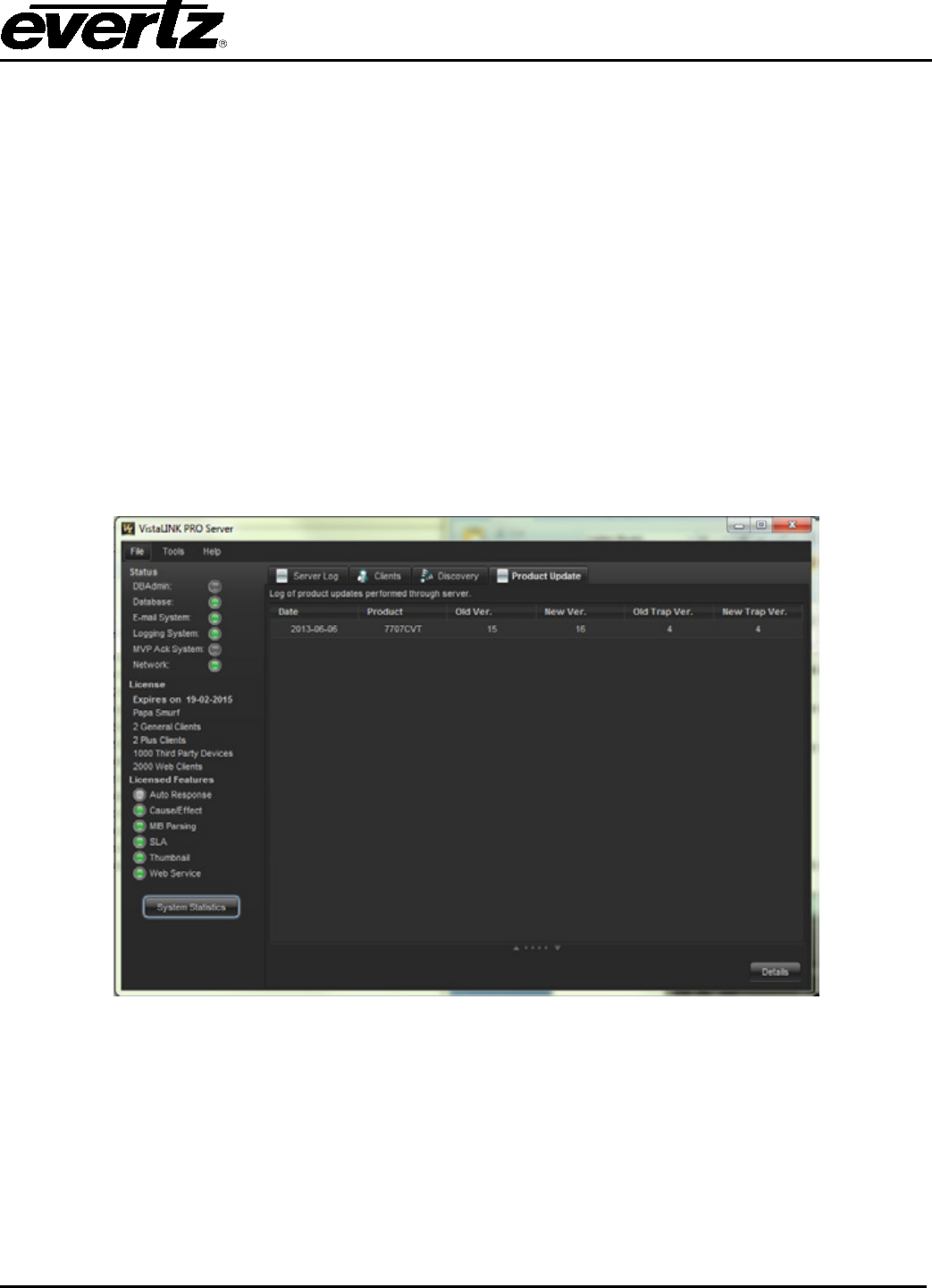
VistaLINK® PRO User Manual
Revision 11.0 Page 7-5
7.2. PRODUCT JAR UPGRADES
VistaLINK® PRO supports the addition of new product support through a method known as JAR
upgrading. Product support is centralized around a JAR file system built into the application. Each
product support has its on JAR file. Adding or Removing JAR files from VistaLINK® modifies how VLPRO
supports products. Often products are released or enhanced which require updates to the software.
Applying a newer jar file to VistaLINK®, will update the software to make it aware of the changes.
The JAR update system in VLPRO is managed centrally from the VistaLINK® Server. To update VLPRO
for new or modified product support, only the VLPRO Server will receive the manual update. The
VistaLINK® Server will negotiate product support with the connected clients and will push any new updates
downstream to the software clients. This makes managing product support very easy and cost effective.
To apply a product JAR file to the VistaLINK® Server, select Help -> Apply Update -> Product. Once the
VistaLINK® Server receives the updated JAR file, it will instruct for a manual restart. Product updates can
be monitored from the VistaLINK® Server using the Product Update tab from the VistaLINK® Server
To expose the tab, select Tools -> View -> Show/Hide Product Update. Figure 7-5 shows the Product
Update Tab from the VistaLINK® Server.
Figure 7-5: Product Update Tab
The Product Update table provides information about the product support. The information is listed below.
Date: The date when the product support was modified
Product: The type of product that was modified
Old Ver.: The old version number of the previous product JAR file
New Ver.: The new version number of new product JAR file
Old Trap Ver.: The old trap revision for the product trap support
New Trap Ver.: The new trap revision, which changes with the product support update
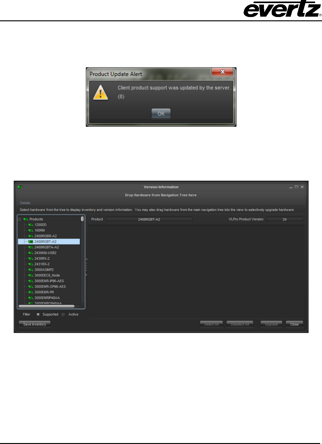
VistaLINK® PRO User Manual
Page 7-6 Revision 11.0
7.2.1. Client Product JAR Support
When product support is applied to the VistaLINK® Server, the support is pushed to the clients when they
first reconnect back to the server. The Product Update Alert message appears to signify that the product
update procedure was successful. Figure 7-6 displays the appearance of the Product Update Alert
message from a client.
Figure 7-6: Product Update Alert Message
Product support can also be monitored from the VistaLINK® PRO Client through the Version Information
program. To access the Version Information from a VistaLINK® Client first select Help -> Version
Information. The below image resembles the Version Information dialog when it firsts starts up.
Figure 7-7: Version Information
The hardware list on the left of Figure 7-7 displays the product support at the VistaLINK® Client. Selecting
the products from the list on the left will update the VLPRO Product Version field in the upper right. This
number denotes the JAR version currently installed in the VistaLINK® Client.
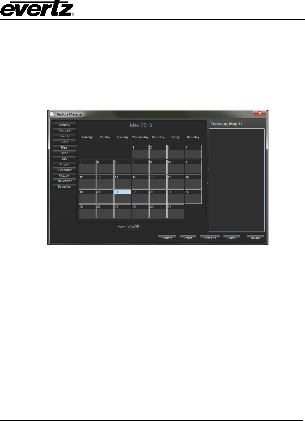
VistaLINK® PRO User Manual
Revision 11.0 Page 7-7
7.3. SERVER RESTORE MANAGER
The restore manager provides an easy way to backup and restore VistaLINK® PRO Databases. The
system can create backups without having to shutdown the mySQL server process. The Restore
Manager is a valuable tool when making significant or large changes to the system. The restore
databases is an automatic process performed by the VistaLINK® PRO Server after the user selects a
previously made restore point.
Follow the steps below to create a restore point:
1. From the VistaLINK® PRO Server, select Tools -> Restore Manager. See Figure 7-8.
Figure 7-8: Calendar
2. Click the Create button to create a restore point.
3. It is possible to include details about the restore point (ie. who is creating it and for what reason).
Once the restore point is made, it will be available from the calendar. Clicking on each date will
update the list on the right to indicate which restore points are available.
7.3.1. Restoring Databases
Restoring databases is a method of loading a previously made restore point back into the system. This
step is valuable when design mistakes or accidental deletions of important settings have been made.
The steps to restore a previously created restore point are outlined below:
1. From the VistaLINK® PRO Server, select Tools -> Restore Manager.
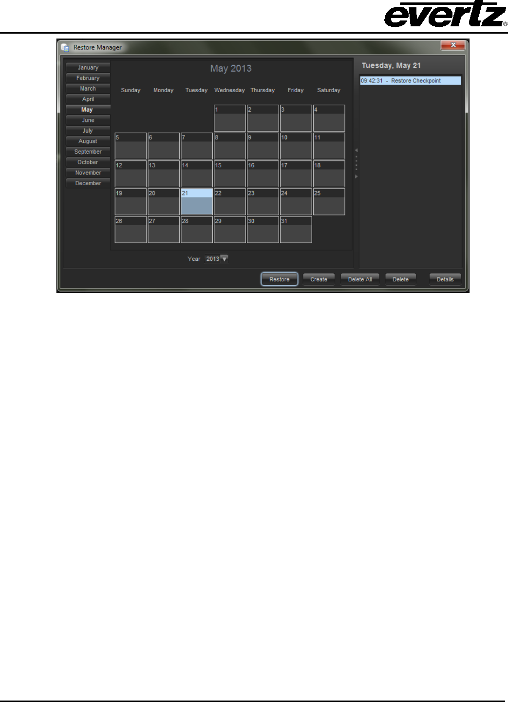
VistaLINK® PRO User Manual
Page 7-8 Revision 11.0
Figure 7-9: Restore Manager Calendar
2. Select a calendar date that contains previously created restore points.
3. Select a restore point from the list on the right in Figure 7-9. Clicking the Details button will show
any details that have been made.
4. Click Restore to start the restore process. Once the restore process has finished, the VistaLINK®
PRO Server will need to be restart for the changes to take effect.
The restore points are stored locally on the VistaLINK® PRO Server. These restore points can be
accessed for offline storage incase of computer hardware failure. The restore point files can be found in
the following directory: C:\Program Files\VistaLinkProServer\dbadmin\backup\
7.4. USER ADMINISTRATION
7.4.1. User Permissions
VistaLINK® PRO provides audit tracking and restricts access to features by requiring operators to Logon
with an appropriate user account before gaining access to the software. Each user that requires access to
VistaLINK® PRO should have a unique logon. Doing so ensures that a user will only have access to areas
defined by the account privileges and allow for an audit trail indicating which users handled certain events.
7.4.1.1. Adding or Modifying a User Account
1. In order to add or modify user accounts you must be logged onto VistaLINK® PRO with an account
that has access to the Configure Users option. The Administrator account has this ability by default.
2. User accounts can be added, edited or removed through the User Manager dialog. Select Tools ->
Users from the main menu. The User Manager dialog box will open displaying all current users
accounts for the system.
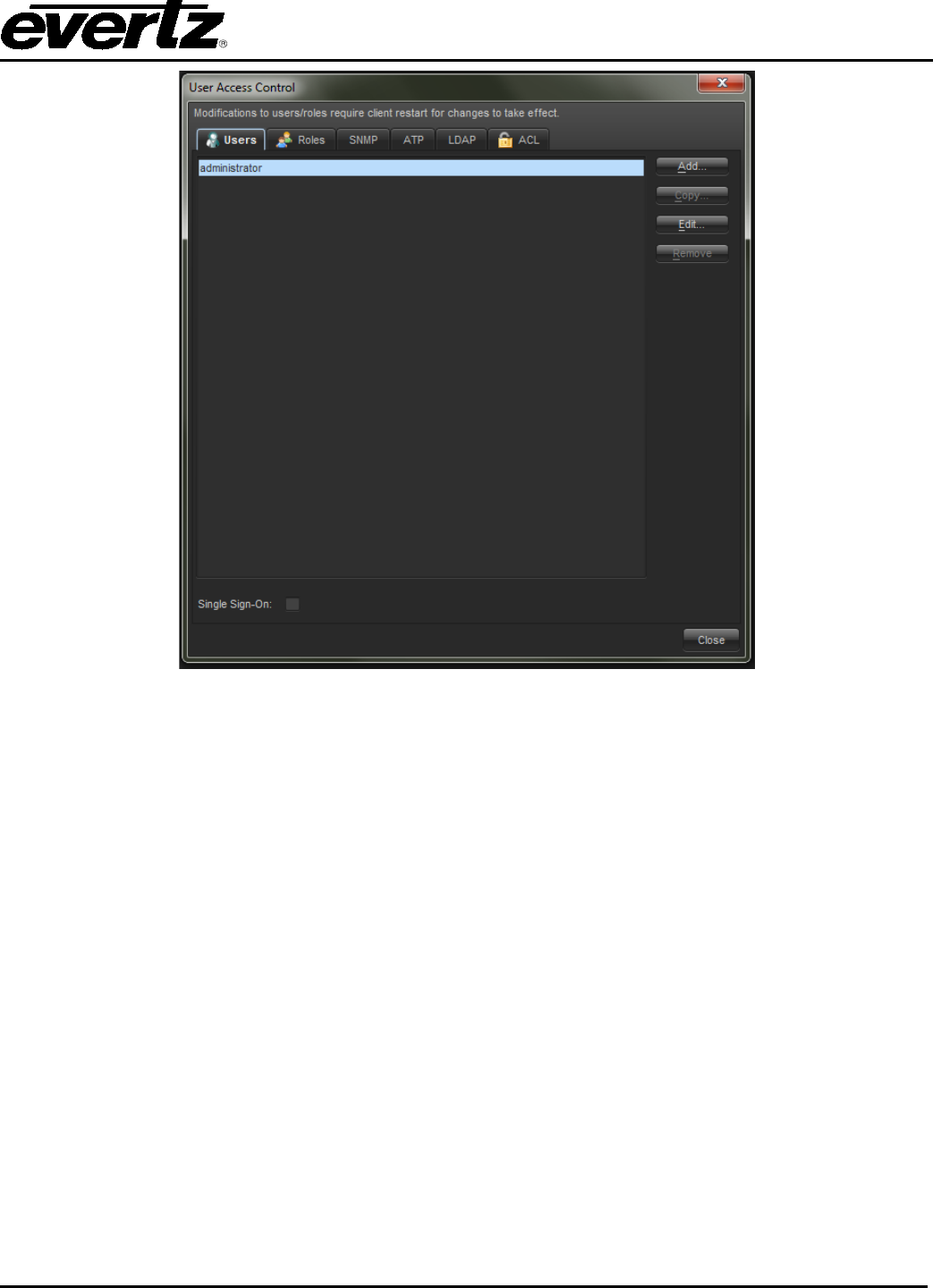
VistaLINK® PRO User Manual
Revision 11.0 Page 7-9
Figure 7-10: User Manager
3. If adding a new user, select the Add button. If modifying an existing user, highlight the user in the list
and select the Edit button. The Add New/Edit User dialog box will open allowing configuration of the
user account username, password and privileges.
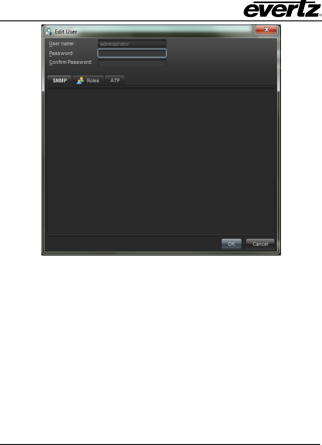
VistaLINK® PRO User Manual
Page 7-10 Revision 11.0
Figure 7-11: Edit User Window
4. The user account dialog contains the following fields that can be changed when adding a new user or
editing an existing user account:
User name: The name of the account being created/edited. This is the name the user will use
to logon to the VistaLINK® PRO system. All audit log entries will reference this account’s
actions by the name entered in this field.
Password: The password this account will use to logon to the system with the appropriate
account privileges.
Add Roles (Privilege Class): This dropdown menu will change the privilege authorization
screen to allow privileges to be assigned for any feature type in VistaLINK® PRO. The available
options are: Common Privileges, Monitoring Privileges, Scheduling Privileges and Server
Privileges. Change this selection and then use the Authorization area to select specific access
rights. In the User Access Control, click on the Roles tab and click the Add button.
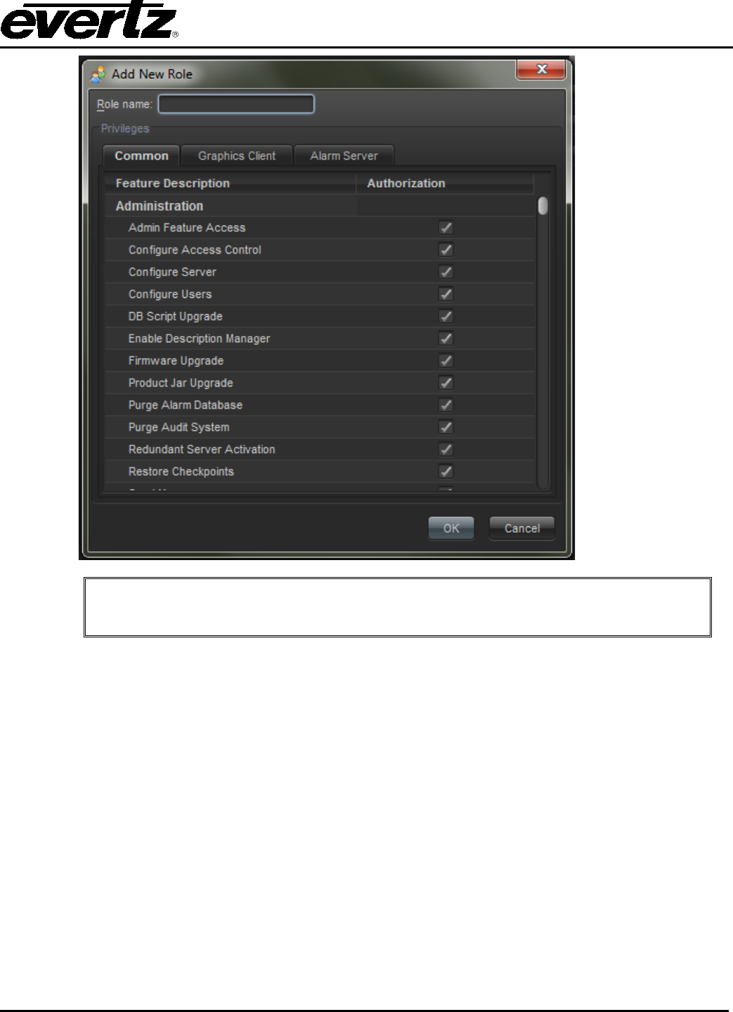
VistaLINK® PRO User Manual
Revision 11.0 Page 7-11
Note: The Privilege Class is not a user account type; it simply changes what
options are displayed in the Authorization area.
Authorization: This area presents all features for a Privilege Class with an Authorization check
box for each. Access per feature can be enabled or disabled for the current account by
checking or un-checking the Authorization check box for the feature that is selected.
5. After setting up a user account, click OK to add the user (or update if editing) to the User Manager
list. Continue steps 2 - 3 for additional users or click the OK button to close the User Manager and
save changes. Click the Cancel button to abort all changes.
7.4.1.2. Deleting a User Account
Deleting a user will remove the ability for that user to Logon to the VistaLINK® PRO software. Deleting a
user will not delete any actions the user has performed prior to the delete. All audit entries, acknowledged
or corrected alarms, etc. remain as-is with the user's name attached to the operation.
To delete a user:
1. Selecting Tools -> Users from the main menu. The User Manager dialog box will open displaying
all current users of the system.
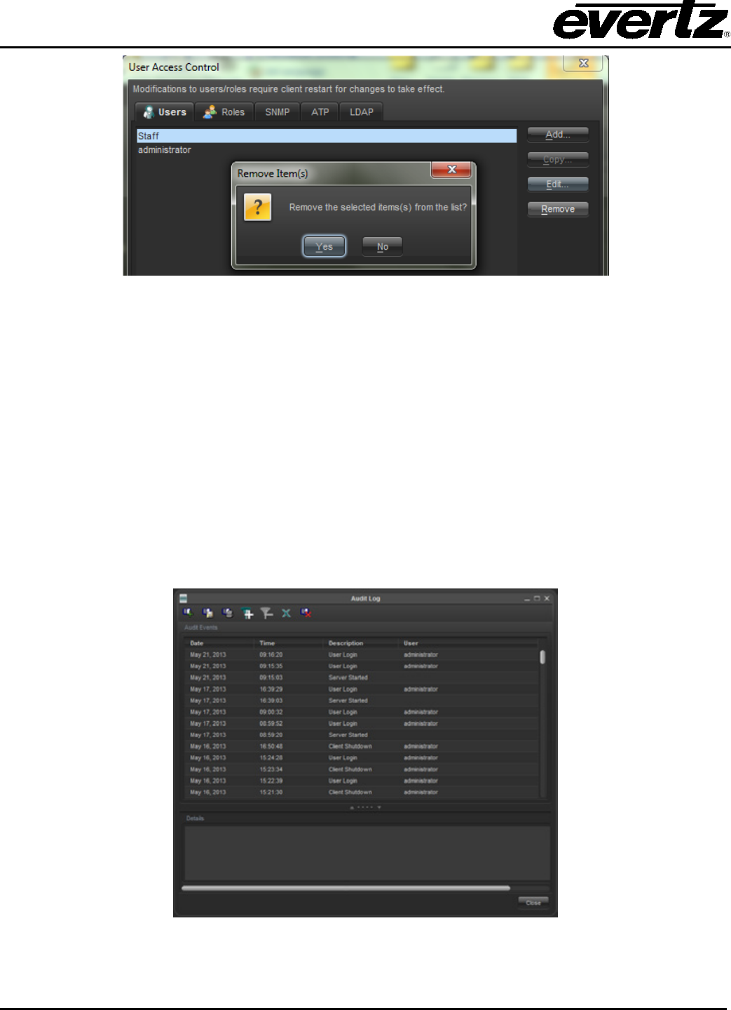
VistaLINK® PRO User Manual
Page 7-12 Revision 11.0
Figure 7-12: Remove User(s) Dialog Box
2. Highlight the user you wish to delete from the list of users and select the Remove button. You will
be prompted to confirm the action. Select Yes to delete the user or No to abort the operation.
7.4.2. Audit Logging
7.4.2.1. About the Audit View Window
The Audit View window provides a means of viewing activity that has occurred in the VistaLINK® PRO
system. Each audit entry is stamped with the user logon name, date and time of the action, a description
of the activity and a detailed breakdown of data that was changed. The audit system also allows
operators to add custom audit entries so that operator issues can also be tracked through the audit
system. For more information on custom audit entries, see section 7.4.2.2.
To view the Audit Log select Audit -> View Audit Log.
Figure 7-13: Audit Log
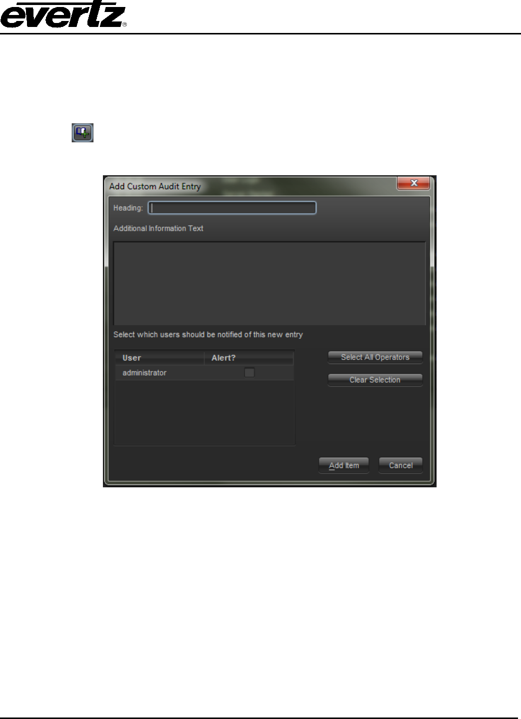
VistaLINK® PRO User Manual
Revision 11.0 Page 7-13
7.4.2.2. Manually Adding an Audit Entry
The Audit system in VistaLINK® PRO allows an operator to add a custom audit entry. In addition to adding
the audit entry into the audit database, the audit entry can be addressed to a specific operator of the
system, notifying that operator immediately if logged on, or prompting the operator the next time he/she
logs into the VistaLINK® PRO system. To add a custom audit entry:
1. Select Add/edit Audit Entry (the Audit Log must be visible). The audit entry dialog will appear
allowing you to enter an audit heading and detailed description.
Figure 7-14: Add Custom Audit Entry
2. Enter a heading and additional information description.
3. Optionally, select the users that you want to notify of this entry by placing a check mark in the alert
column next to the user name.
4. Click on the Add Item button to save your changes or click on the Cancel button to abort the
operation.
If you selected to notify a user in the above operation the user will be immediately notified of the audit
entry if they are presently logged onto VistaLINK® PRO. If the user is not logged on, he/she will be notified
of the entry the next time he/she logs onto VistaLINK® PRO.

VistaLINK® PRO User Manual
Page 7-14 Revision 11.0
This page left intentionally blank
