PDF Vodavi Infinite DVX I & II Installation
Infinite DVX I & II Install Infinite DVX I & II Install
User Manual: PDF T E X T F I L E S
Open the PDF directly: View PDF ![]() .
.
Page Count: 477 [warning: Documents this large are best viewed by clicking the View PDF Link!]
SYSTEMS
/
r
ir;rfini& DVX’aadDVX”
Di@t.d ZKey Tcleplxoxte Systems
300.48
300.49
300.50
300.51
300.52
300.53
300.54
300.55
300.56
300.57
300.58
300.59
300.60
300.61
300.62
300.63
300.64
300.65
300.66
300.67
300.68
300.69
300.70
300.71
300.72
300.73
300.74
300.75
300.76
300.77
.
300.78
300.79
300.80
300.81
300.82
300.83
300.84
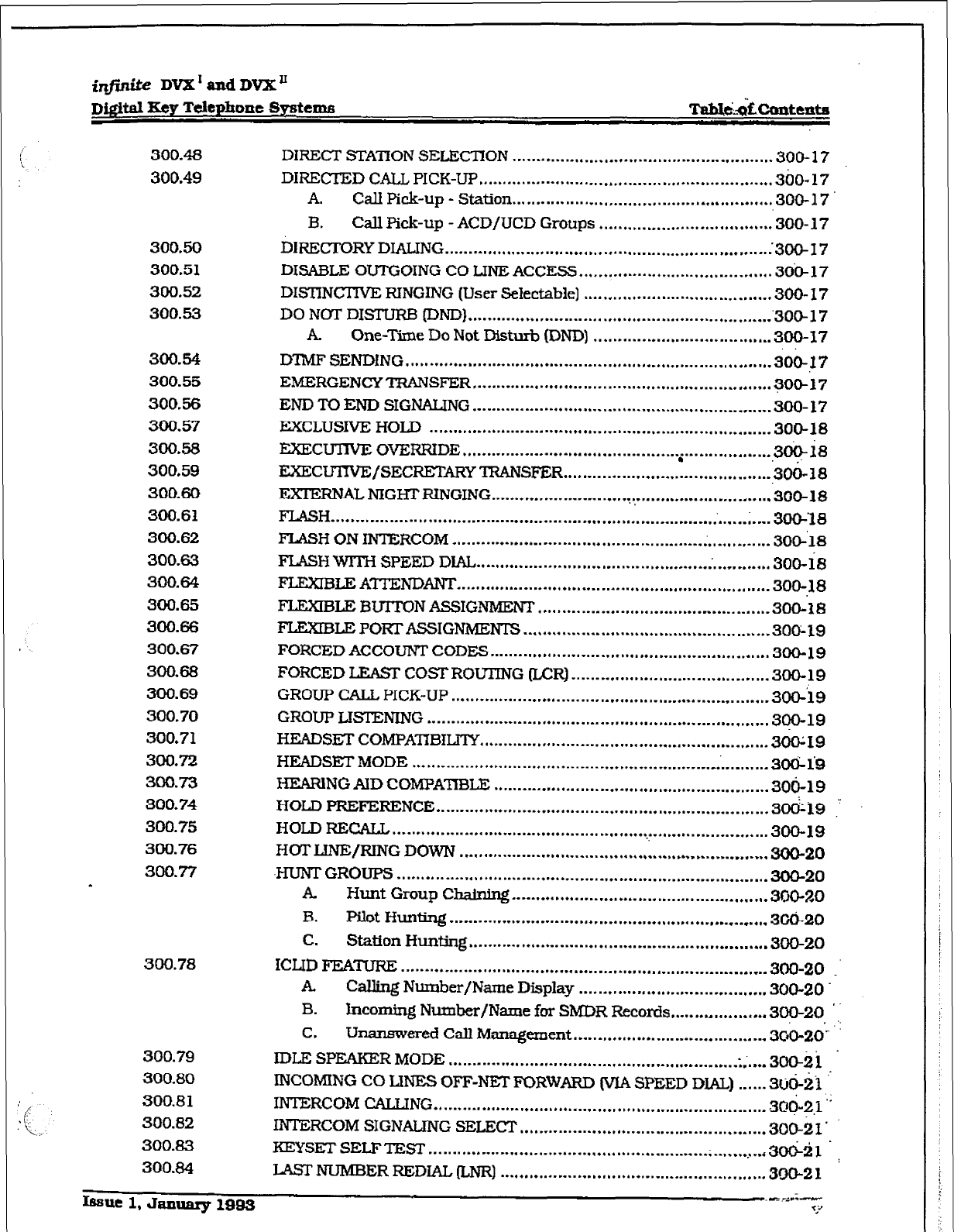
DIRECT STATION SELECHON ...................................................... 300-17
DIRECTED CALL PICK-UP .......................................... ................... 360-17
A. Call Pick-up - Station ...................................................... 300-17
B. Call Pick-up - ACD/UCD Groups .................................... .300-17
DIRECTORY DIALING ................................................................. ..:3oo-I 7
DISABLE OUTGOING CO LINE ACCESS ........................................ 30&17
DISTINCTTVE RINGING (User Selectable]
.......................................
300- 17
DO NOT DISTURB (DND]
...............................................................
‘30@17
. One-Time Do Not Dishrb DND) ..................................... 300-17
DTMF SENDING
............................................................................
300-17
EMERGENCY TRANSFER
..............................................................
300-17
END TO END SIGNALING .............................................................. 300-17
EXCLUSIVE HOLD ....................................................................... 300-18
EXECUTNE OVERRIDE ............................................. i.. ................ ,3+i8
EXECUTIVE/SECRETARY TRANSFER ........................................... ,300-18
E.XJ.-ERNAI, NIGHFRINGING ......................... ...? ............................. 300-18
FLASH ............................................................................................ 3(30-‘18
FLASH ON INTERCOM .................................................................. 306’18
FLASH WlTH SPEED DIAL ............................................................. 300-k
FLEXIBLEATfENDANT
.................................................................
300-,lB
FLEXIBLEB~NASSIGNMENT ................................................ 300-18
FLEXIBLE PORT ASSIGNMENTS .................................................. -300; 19
FORCEDACCOUNTCODES.. ...................................................... ..300-19
FORCED LEAST COST ROUTING (LCR) ....................................... ..300-19
GROUP CALL, PICK-UP .................................................................. 3occl9
GROUP LTSTENING ....................................................................... 300-19
HEADSET COMPATTBILITY ............................................................ 36049
HEADSET MODE
............................................................. .C.. .........
3ocb is
HEARING AID COMPATIBLE ......................................................... 3ofj-19
HOLD PREFERENCE ..................................................................... 3&s
HOLD FiECALL .............................................................................. 300-19
HOT LINE/RING DOWN ................................................................ 300-20
.HUNT GROUPS ............................................................................. 300-20
. Hunt Group Chainhg
.....................................................
300-20
B. Pilot Hunting
..................................................................
3GCi-20
C. Station Hunting
..............................................................
300-20
ICLID FEATURE ............................................................................ 3o0-20
A Calling Number/Name Display ....................................... 300-20.
B. Incoming Number/Name for SMDR Records.. .................. 300-20
C. Unanswered Call Management ........................................ 3C0-20:’
IDLE SPEAKER MODE ............................................................ . ...... 30ckii
INCOMING CO LINES OFF-NET FORWARD (VIA SPEED DIAL) ...... Srjo-ii ’
INTERCOM C4LLING ..................................................................... 3oc+
INTERCOM SIGNALING SELECT ................................................... 300-2 I .
KEYS= SELFTEST .......................................................... .
............ 3tiil.
LAsrNUMBERREDIAL(LNR) ....................................................... 300-2 1
r
_.:_ fqfinite DVX I and DVX *
300.85
300.86
‘.TL’.:’ .
_ ‘-
2 300.87
,,’ r300.88
4300.89
1’-r300.90
3-3 <300,91
-?I 300.92
.-r
- : . 300.93
:I !‘ 300.94
-, -300.95
300.96
4 300.97
,
:I #--
\-
:e>
I-rz I
6, r ;r.,-
,.. 7.
1‘-<.
.m.. :-
..?‘
300.100
i!l 300.10 1
&Jc:-
. 300. x02
.?<-: 2 300.103
- 300.104
-. .-.
i: -. 300.105
.-
vi
DQitd Sty Telephone Systtms
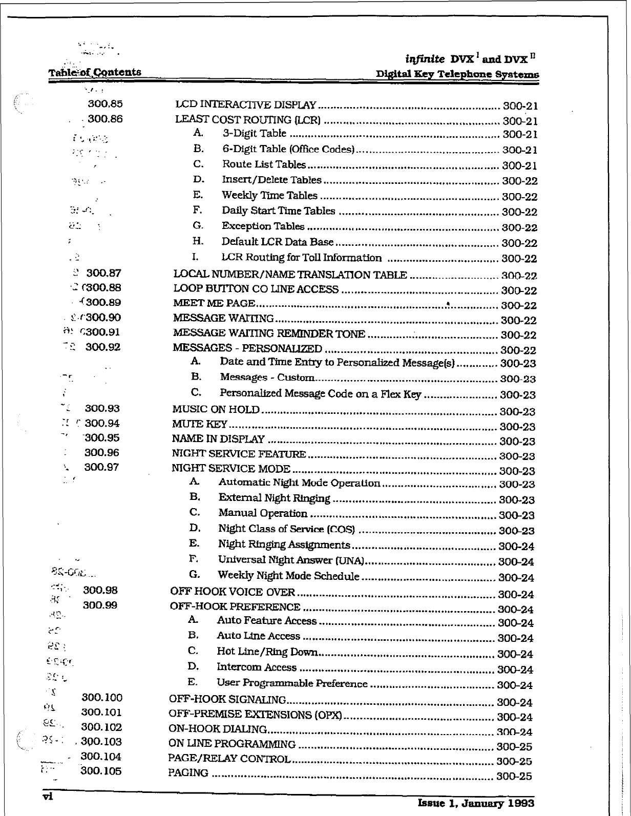
IA33 II’ITERACT~VE DISPLAY ......................................................... 300-Z 1
LEAST COST ROUTING &CR)
.......................................................
300-2 1
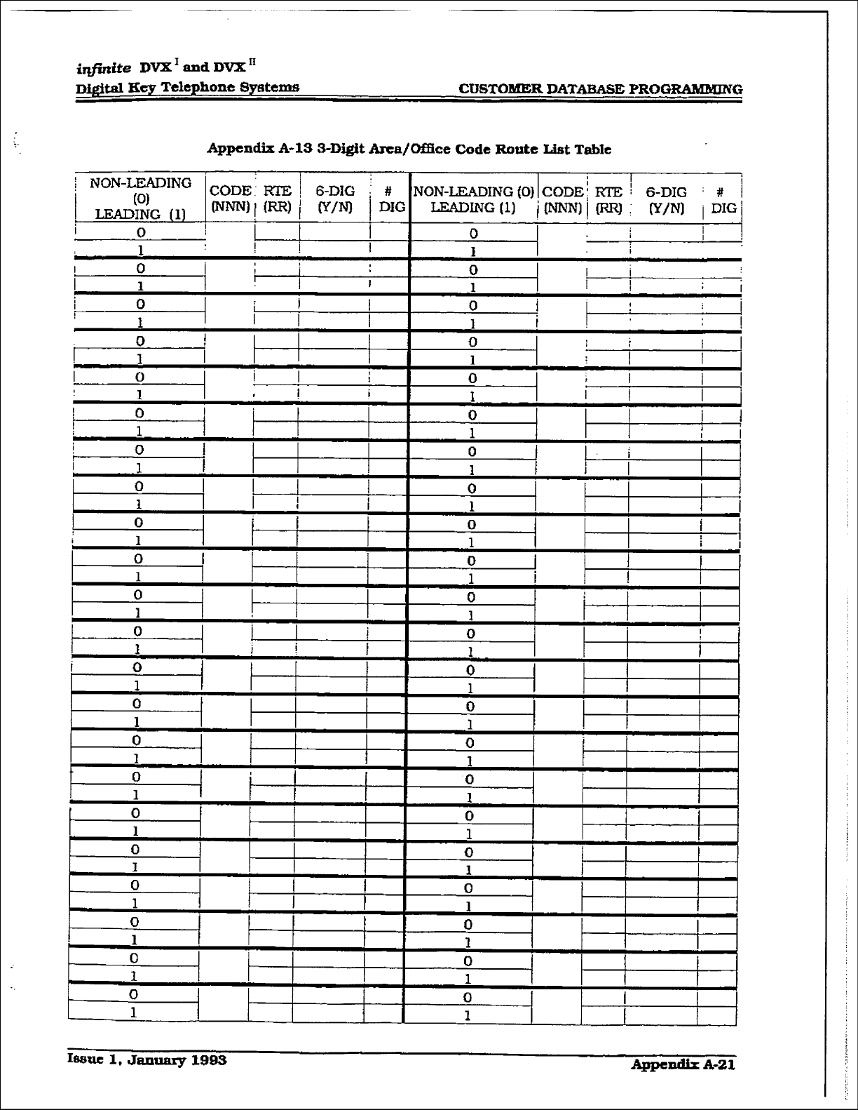
A. 3-Digit Table .................................................................. 300-2 1
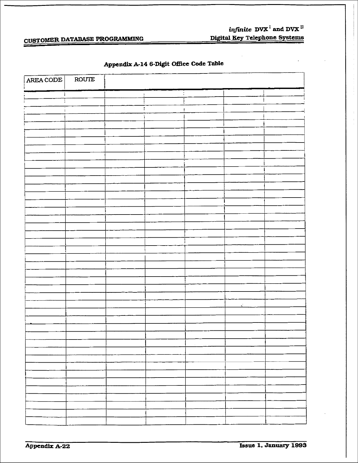
B. S-Digit Table (O&e Codes) ............................................. 300-2 1
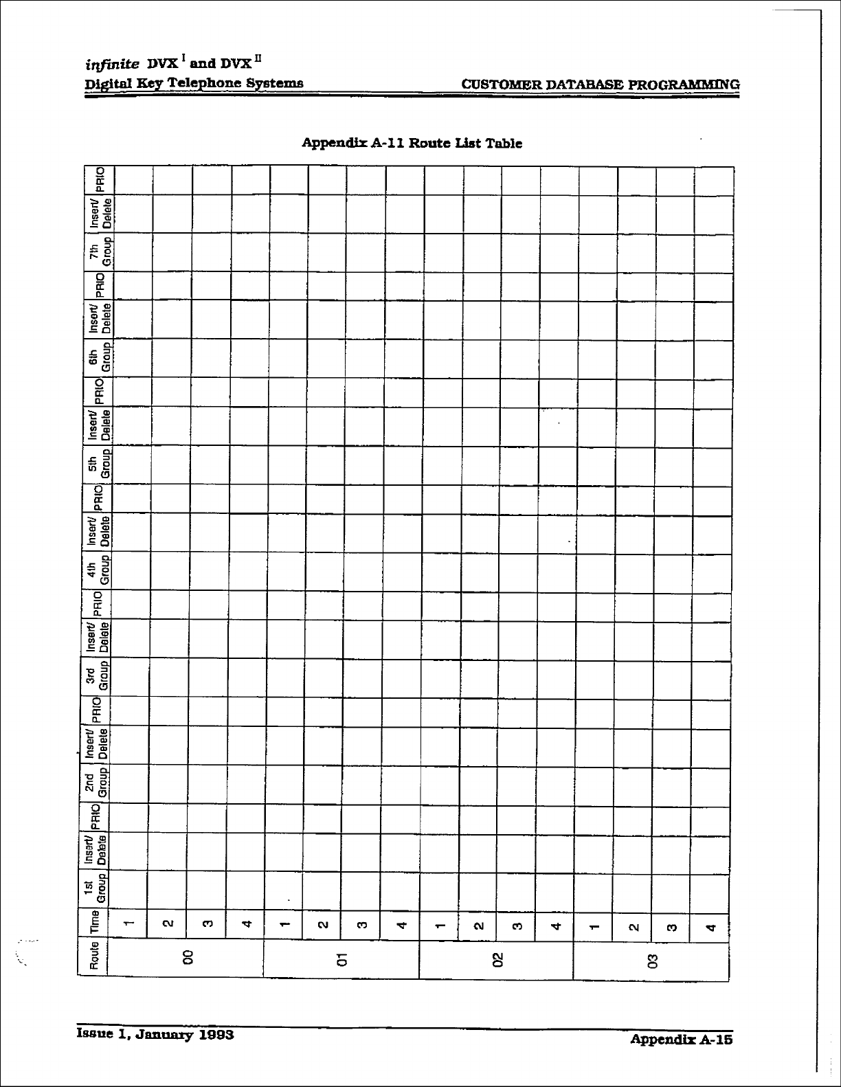
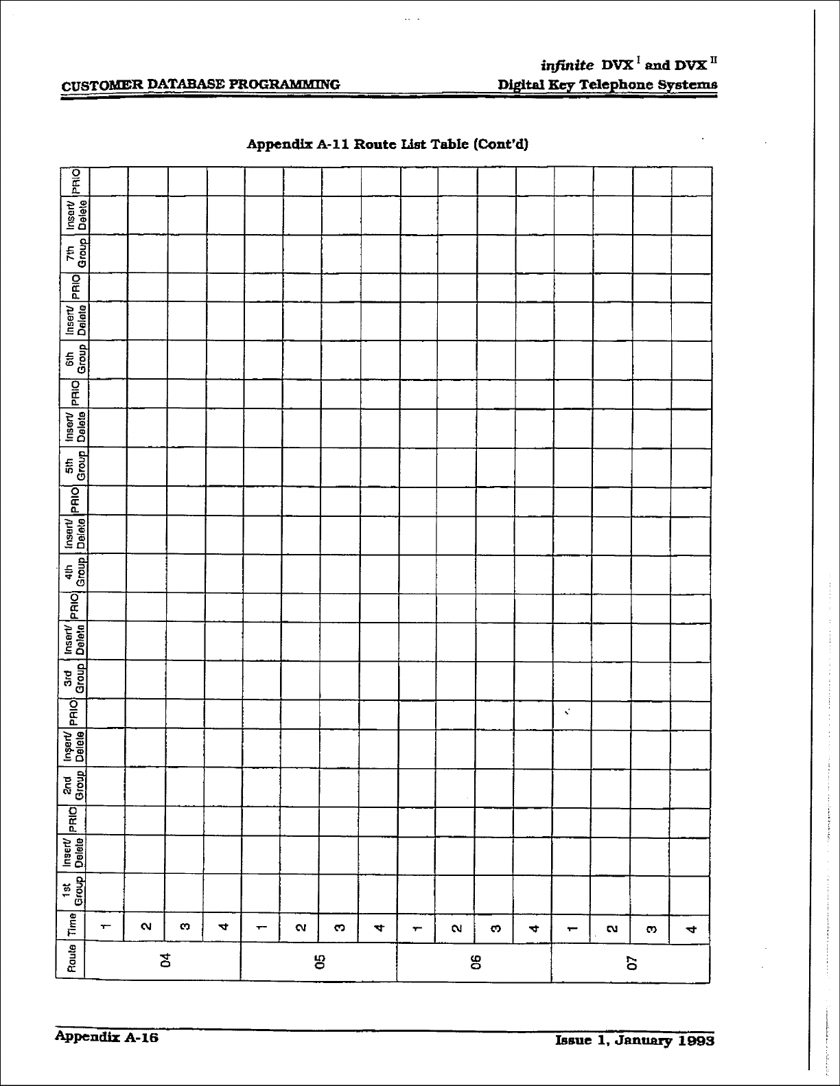
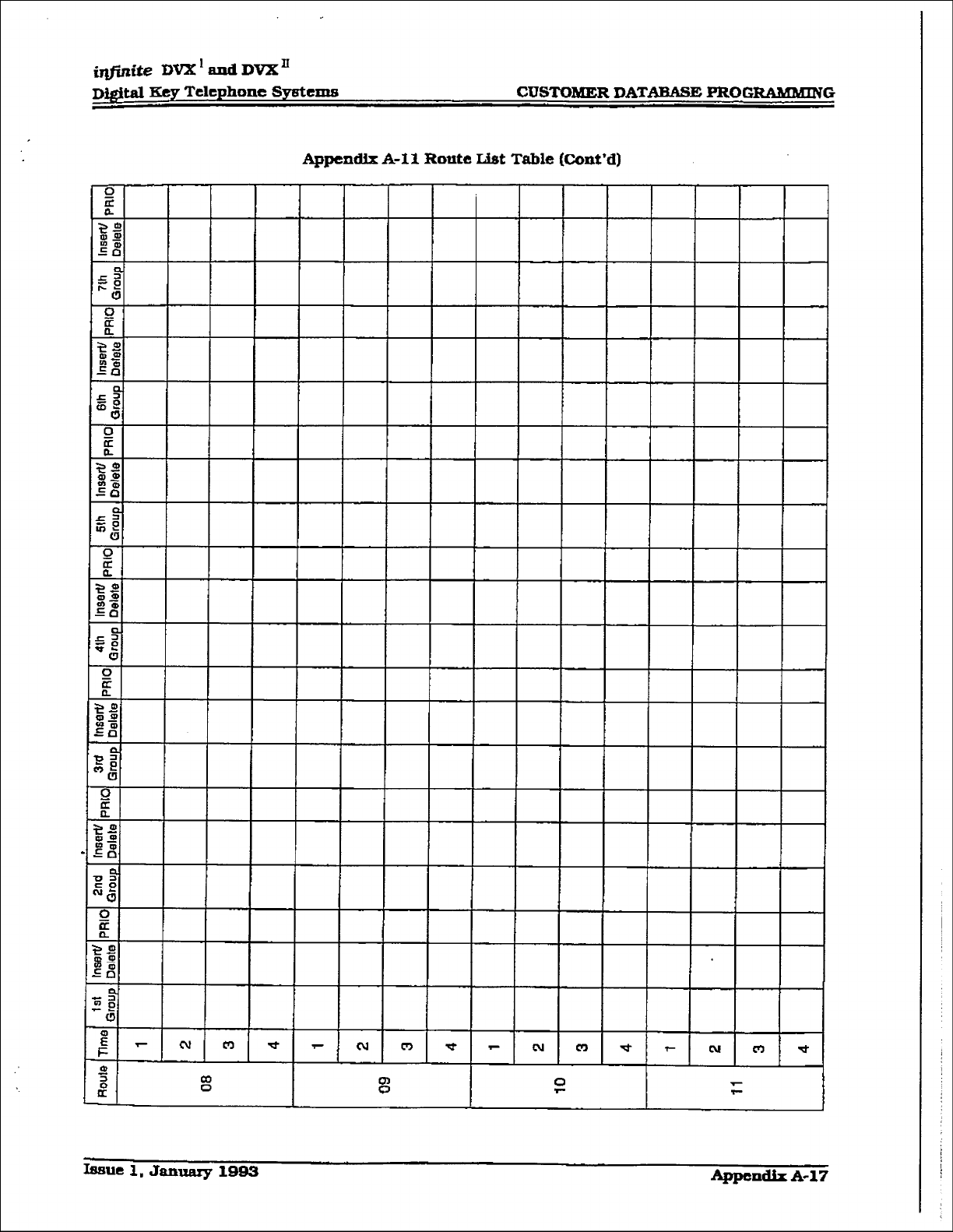
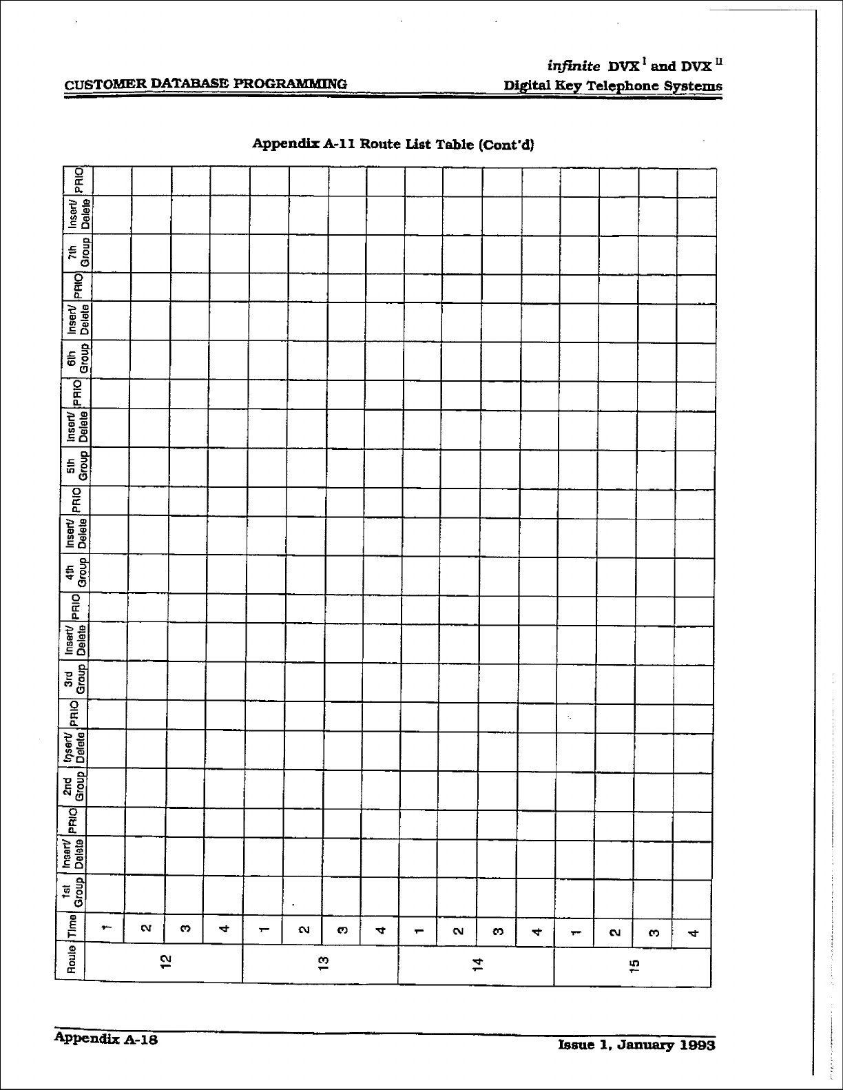
C. Route List Tables
............................................................
300-2 1
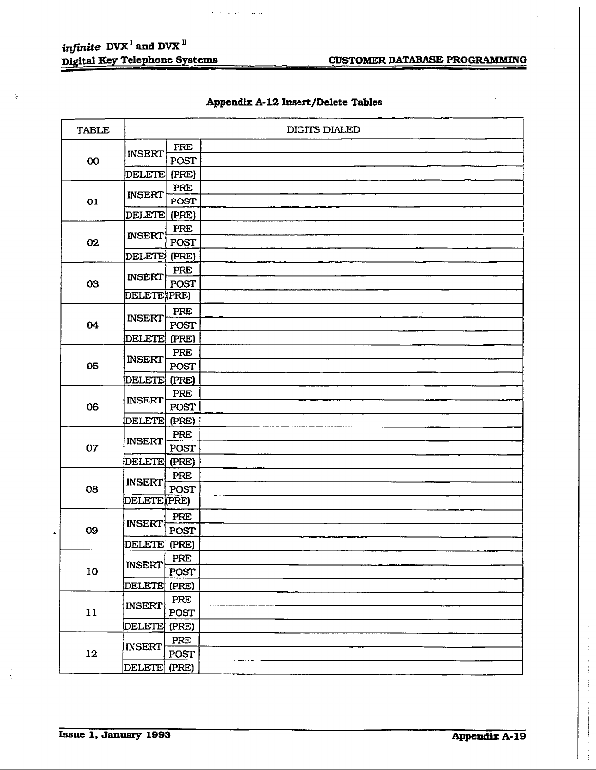
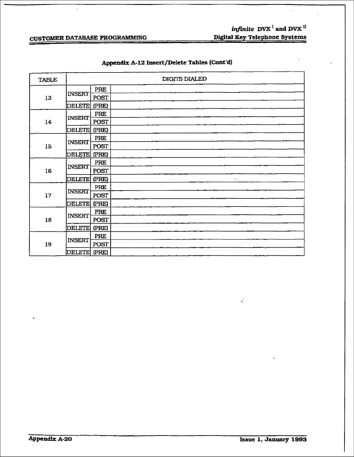
D. Insert/Delete TabIes ....................................................... 300-22
E. Weekly Time Tables ........................................................ 300-22
F. Daily Start Time Tables .................................................. 300-22
G. Exception Tables ............................................................ 300-22
H. Default LCR Data Base ................................................... 300-22
I. LCR Routing for Toll Information ................................... 300-22
LOCALNUMBER/NAMETIUNSI.X~ON TABLE ............................ 300-22
LOOP BUTTON CO LINE ACCESS ................................................. 300-22
MEET ME PAGE
............................................................ . ...............
3O(F22
MESSAGE WAITING ...................................................................... 300-22
MESSAGE WAITING REMINDERTONE .............. . .......................... 300-22
MESSAGES - PERSONALIZED
......................................................
300-22
A. Date and Time Entry to Personalized Message(s) ............. 300-23
B. Messages - Custom.. ....................................................... 300-23
C. Personaked Message Code on a Flex Key.. ..................... 300-23
MUSIC ON HOLD .......................................................................... 300-23
MUTEKEY .................................................................................... 300-23
NAME IN DISPLAY ........................................................................ 300-23
ITIGHT SERVTCE FEATURE ........................................................... 300-23
NIGHT SERVICE MODE ................................................................ 300-23
A Automatic Night Mode Operation .................................... 300-23
B. External Night Ringing ................................................... 300-23
C. Manual Operation .......................................................... 3OU23
D. Night Class of Sewice (COS) ........................................... 300-23
E. Night RfngingAssignments ............................................. 300-24
F. Universal NightAnswer (UNAj ......................................... 300-24
G. Weekly Night Mode Schedule.. ........................................ 300-24
OFF HOOK VOICE OVER .............................................................. 300-24
OF-F-HOOK PREFEFUZNCE ............................................................ 300-24
. Auto Feature Access ....................................................... 3OG24
B. Auto Line Access ............................................................ 300-24
C. Hot Line/Ring Dmn ....................................................... 30&24
D. Intercom Access ............................................................. 300-24
E. User Fhgrammable Preference ...................................... .3oO-i~
OFF-HOOK SIGNALING ................................................................. 300-24
OFF-PREMISE EXTENSIONS (OPX) ............................................... 300-24
ON-HOOK DlALING ....................................................................... 30@24
ON LINE PROGRAMMING ............................................................. 300-25
PAGE/RELAY CONTROL ............................................................... 300-25
PAGING ........................................................................................ 300-25
rssut
1, Jarmary 1993
r
J ’
,::
i,
,<:
i;;
i@Znite DVX I aad DVX’
D&WI Key Telephone Sy&ems Table of Contents
300.106
300.107
300, LOS
300.109
300.110
300.111
300.112
300.113
300.114
300.115
300.116
300.117
300.118
300.119
300.120
300.121
300.122
300.123
300.124
300.125
300.126
300.127
- 300.128
300.129
300.130
1.. _.
-
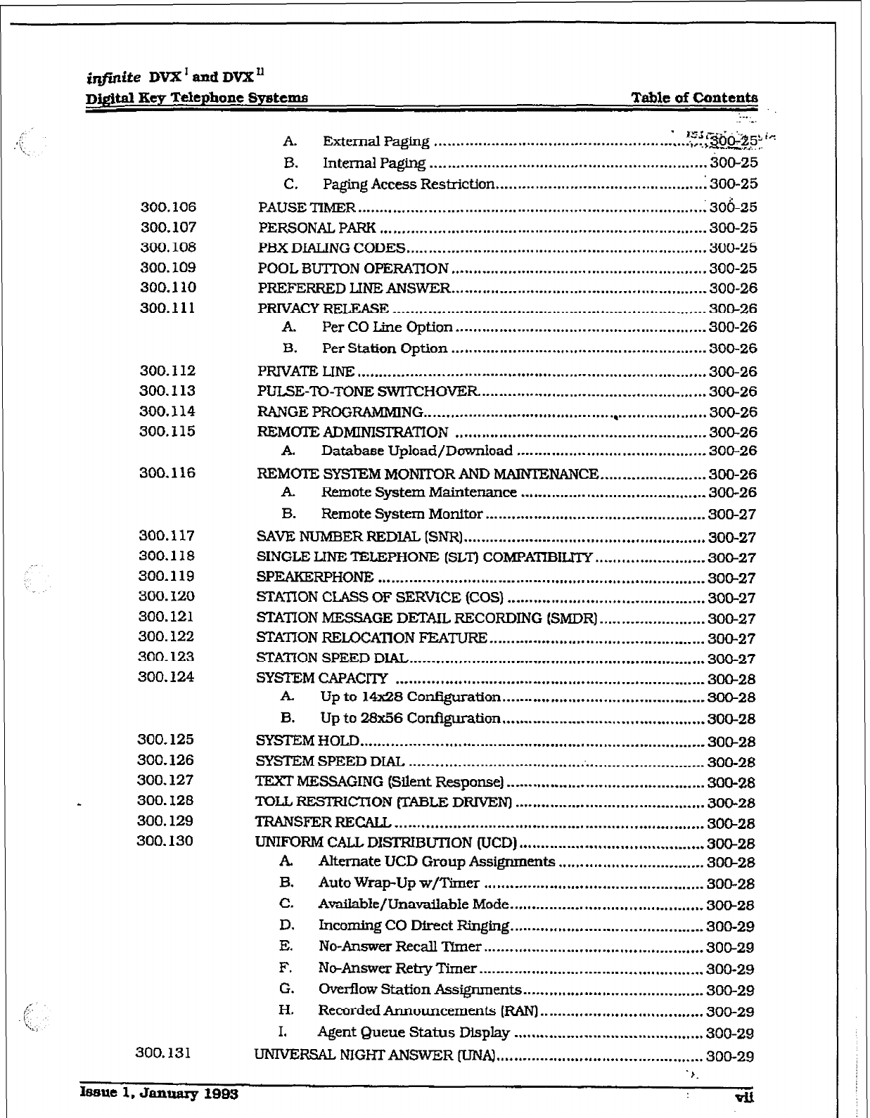
A. External Paging ..................... xi’; L~(jgg5~ i<
..................................... I) ,.. + I-......
B. 1nten-d paging.. ............................................................. 300-25
C. Paging Access Restriction ................................................. 300-25
PAUSE TIMER ................................................................................ 30&25
PERSONAL PARK .......................................................................... 300-25
PBX DLALING CODES .................................................................... 300-25
POOL EWTIQN OPERATION
..........................................................
300-25
PREFERREDLINEANSWER ......................................................... -300-26
PRIVACYRELEASE ...................................................................... .300-26
. Per CO Line Option ......................................................... 300-26
B. Per Station Option .......................................................... 300-26
PRIVATE UNE ............................................................................... 300-26
PUISE-TO-TONE SWITCHOVER .................................................... 300-26
RANGE PROGRAMMlNG
.. ..‘......................................, ....................
300-26
REMOTEfiDMINISIRATION ......................................................... 360-26
. Database Upload/Download ........................................... 300-26
REMOTE SYSTEM MONITOR AND MAINTENANCE.. ...................... 300-26
. Remote System Maintenance .......................................... 300-26
B. Remote System Monitor .................................................. 300-27
SAVE NUMBER REDlAL (SNR) ....................................................... 300-27
SINGLE UN-E ‘DZLEPHONE (SLTI COMPA~ILZIY ........................ -300-27
SPEAKFRPHONE
..........................................................................
300-27
STATION CLASS OF SERVICE (COS) ............................................. 300-27
STATION MESSAGE DETAIL RECORDING (SMDR) ....................... .300-27
STATION REmCATION FEATURE ................................................. 300-27
STAI-ION SPEED DIAL ................................................................... 300-27
SYSIXM CAPACllY ..................................................................... -300-28
A Up to X4x28 Configuration.. ........................................... -300-28
B. Up to 23x56 Configuration .............................................. 300-28
SYSTEM HOLD.. ........................................................................... -300-28
SYSTEMSPEEDDIAL .................................................................... 300-28
TEXT MESSAGING (Silent Response) ............................................. 300-28
TOLLRESll?ICTiON (TABLE DRIVEN) ........................................... 300-28
TRANSFER REWLL, ...................................................................... 300-28
UNIFORM CALL DKfRIBUTiON (UCD) .......................................... 300-28
. Alternate UCD Group Assignments ................................. 300-28
B. Auto Wrap-Up w/Timer .................................................. 300-28
C. Avafiabe/UnavaiiabIe Mode ............................................ 3OCk28
D. Incoming co Dfrect Ftinghlg.. .......................................... 300-29
E. No-Answer Recall Timer .................................................. 300-29
F. Ntwlnswer RetryTimer ................................................... 300-29
G. owx-fhv Station Assignments.. ...................................... -300-29
H, Recorded Announcements (RAN) ..................................... 300-29
I. Agent Queue Status Display ........................................... 300-29
UNIVERSAL NIGHTANSWER TCMA) ............................................... 300-29
F.
300.131
issue 1, Januaxy 1903 vu
-..^
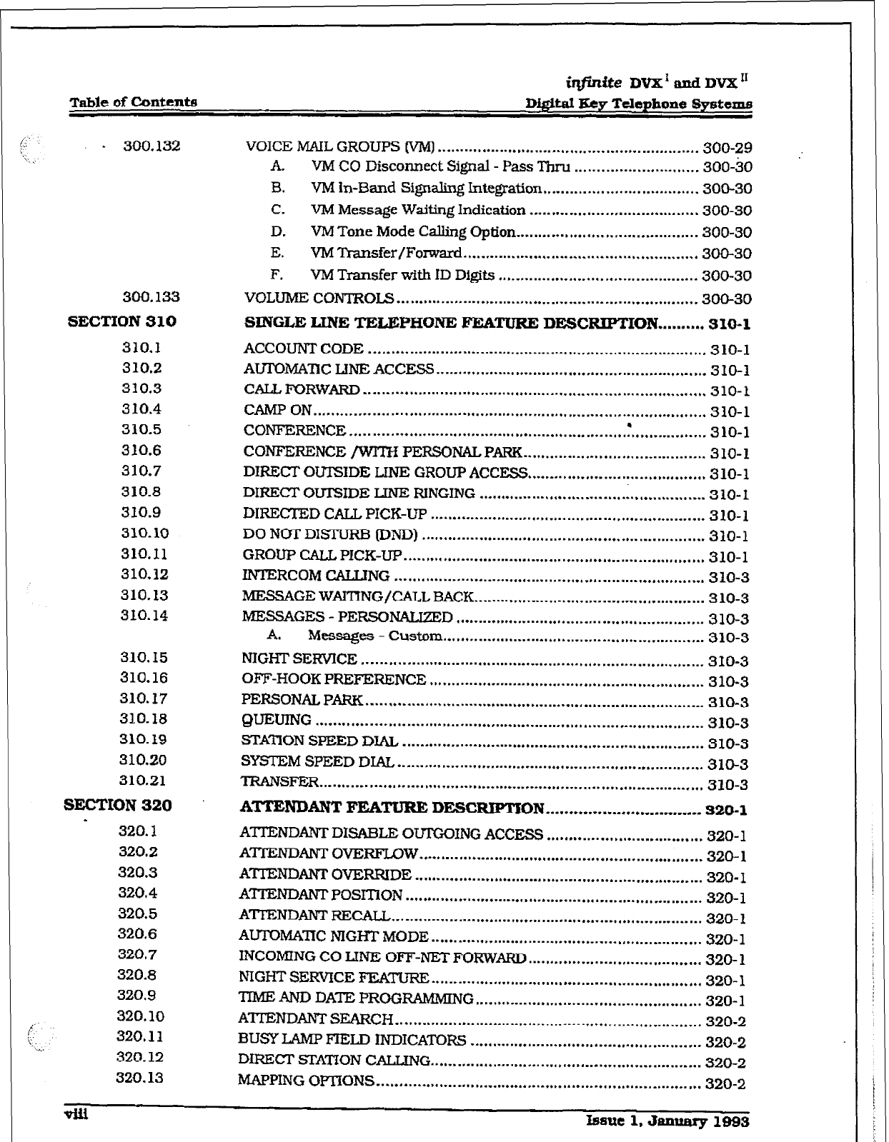
Table of Contenta
i?fin~eDVX'adDvX"
Di@d Key Telephone Systems
- 300.132
300.133
SECTION 310
310.3
310.2
310.3
310.4
310.5
310.6
310.7
310.8
310.9
310.10
310.11
310.12
310.13
310.14
310.15
310.16
310.17
310.18
310.19
310.20
310.21
SEZTICIN320
320.1
320.2
320.3
320.4
320.5
320.6
320,7
320.8
320.9
320.10
320.11
320.12
320.13
VOICE MAIL GROUPS [VM)
........................................................... 300-29
A. VM CO Disconnect Signal - Pass TYhru ............................ 300-80
B. VM In-Band Signaling Integration ................................... 300-30
C. VM Message Waiting Indication ...................................... 300-30
D. VMTone Mode Calling Option.. ....................................... 300-30
E. VMTramfer/Fomard ..................................................... 300-30
F. VM Transfer Wth ID Digits ............................................. 300-30
VOLUME CONTROLS .................................................................... 300-30
SINGLE m TELEPHONE FEATURE DEWXUPTION .......... 310-l
ACCOUNT CODE ............................................................................ 310-l
AUlDMA~C LINE ACCESS ............................................................. 310-l
CALL FORWm ............................................................................. 310-l
CAMP ON ........................................................................................ 310-l
CONFERENCE ,
................................................................................ 310-l
CONFERENCE /WlTH PERSONALPARK.. ....................................... 310-l
DIRECT’ OUTSlDE LINE GROUP ACCESS
........................................
310-l
DIRECT OUTSIDE LJN-E RINGING ................................................... 310-I
DIRECIED CALL PICK-UP .............................................................. 320-l
DO NCrr DXSTURB (‘DND) ................................................................ 310-l
GROUP CALL PICK-UP
....................................................................
310-l
INTERCOM CALTJNG ...................................................................... 310-3
MESSAGE WAITING/CALL BACK.. .................................................. 3 10-3
MESSAGES - PERSONALIZED ........................................................ 310-3
A. Messages - Custom ........................................................... 310-3
NIGHT SIXVICE ............................................................................. 3 IO-3
OFF-HOOK PREFERENCE .............................................................. 310-3
PERSONAL PARK ............................................................................ 310-3
gUEtJlNG
.......................................................................................
310-3
STATION SPEED DlAL .................................................................... 310-3
SYSTEM SPEED DIAL. ..................................................................... 310-3
TRANSFER ...................................................................................... 310-3
ATTENDANT FUTURE DEscRIpTlON ................................. 320-l
AXENDANT DISABLE OUI’GOING ACCESS ................................... 320-l
ATIENDANTOVTmFLOW ................................................................ 320-l
ATTENDANT OVERRIDE ................................................................. 320- 1
ATl-EIYDANT POSITiON ................................................................... 320-l
AIITENDANTRECALL ...................................................................... 320-l
AUTOMA-ITC NIGHT MODE ............................................................. 320-l
INCOMING CO LINE OFF-NET FORWARD
.......................................
320- 1
NIGHT SERVICE FE;ATuRE
.............................................................
320- 1
TXME AND DATE PROGRAMMING ................................................... 320-l
ATI’ENDANTSEARCH ..................................................................... 320-2
EKJSY LAMP FIELD INDICATORS .................................................... 320-2
DIRECT SlYAnON CALLING ............................................................. 320-2
MAPPING OPTiONS ......................................................................... 320-2
lsaut 1, &m!ary 1993
imite DVX’ and DVX’
nigital Key T&phone Systems Table of Contents
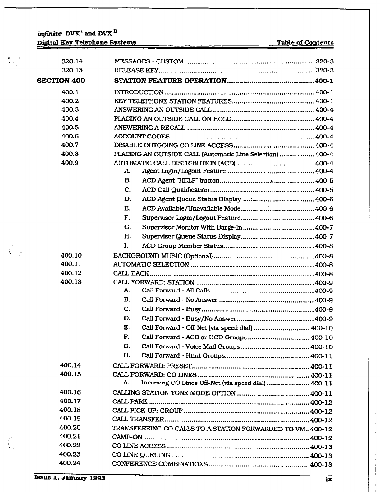
320.14 MESSAGES - CUSTOM .* ,......,.. . . . . . . . . . . . . . . . . . . . . . ,.......I.. . . . . . --........ . . . . . . . . . 320-3
320.15 REIJ3ASEKEY ,*.......,.........,,....,. ~ .,...,....... f.... . . . . . . . . . . . . . ** . . . . a* . . . . . -...a..-. ‘320-3
SECTION 400 STATION FEATURE OPERATION ..r...**.*.,*,.......*........**....*......
400-l
400.1 INTRODUCTION
..,......,.. l ..,.. l ,... +*.I . . . . . . **..w.a*I . . . . . . . . . . . . . . . . . . . . . . . . -.s . . . . . e...
400-l
400.2 KEY TELEPHONE STATION FEATURES
I.,,.., l . . . . . . . . . . . . * . . . . . . . a... . . . . . . . . . . .
400-l
400.3 ANSWERINGAN OUTSIDECALL........ . . . . . . . . . . ~ . . . . . . . . . . . . . ..t.. . . . ..-.....I.... 400-4
400.4 PLACiNG AN OUTSIDE CAL& ON HOLD
..* . . . . . . . . . . . . * ,.... l ,,.............. * ,...
400-4
400.5 ANSWEFZING A RECALL . . . . . . . . . . . . . . . . . . . . . . . . . . . . . . * . . . . . I . . . . . . . . . * . . . . . . . . . . . . . . * . . . . 400-4
400.6 ACCOUNT CODES.. ,. .a . . . . . . . . . . . . . . . . ,.a, . . . . . . . . . . . . . . . . . . . . . . . . . . . . . . . . .-. . . . . . . . . . _ . . . .400-4
400.7 DISABLE OUTGOING CO Llm ACCESS a ,,.. * ,... * . . . . . . * .,.. . ,,,............,... 400-4
400.8 PLACING AN OUTSIDE CALL (Automatic Line Selection) . . . . . . . . . . . . . . . . . . 400-4
400-g AUTOMATlC CALL DISTRIBU’IJON (ACD) . . . . . . . . . . . *..* *....... . . . . . . . . *... . . . . . 400-4
A. Agent Login/L,ogout Feature . . . . -..* . . . . . * ..*...**..,.... * . . . . . . . . . . *...* 400-4
B. ACD Agent
‘wELF” button . . . . . . . . . . . . . . ..~..~.......4 . . . . . . . ..* .,... *.,.*e
400-5
C. ACD CalI QuaXfkxttion . . . . . . . *.,.- . . . . . . . * . . . . . . . . . *** . . . . . . . . . . . . . . . . . - . . . . 400-5
D. ACD Agent Queue Status Dfsplay . . . . ::.. . . . . . . . . . . . . . . . . . . . . . . . . . . . . . 400-6
E. ACD Available/Unmailab~e Mode . . . . . . . . . . . . . . . . . . . . . . I* . . . . . . . *.a ..,, 400-6
F. Supervisor L.ogfn/Logout Feature ** . . . . . * . . . . . . . . . . ..I ,,........... *... 400-6
G. Supervisor Monitor With Eiarge-In . . . . . *....* .,.,., 0 . . . . . . . . . * . . . . . . . . . 400-7
H. Supervisor Queue Status Display . ..-...-* . . . . . . ..-..................I. 400-7
1. ACD Group Member Status.. ..__ .._. . . . . . . . . . . . . . . . . . . . . . . . . . . . . . . . . . . . . .400-8
400.10 BACKGROUND MUSIC (Optional) ,...,.,.,...,...................-.... v . . . . . . . . . . . ,., 400-8
400.11 AUTOMATIC! SELECTION . . . . . ..,...,....I. *.,a ,...... a.,. ..,,.,.... *...*...*.* ..,.,,.... 400-8
400.12 CALL BACK . . . . . . -..- . . . . . . . . . *...* . . . . . . . a.* . . . . . . . . . . . * . . . . . . . . . . . . . . . . . . . . . . . . . . . . ..*........ 400-8
400.13 CALL FORWARD: STATiON . . . . . . . . .-.. . . . . . . . . . . . . . . . . . ..a . . . . . . . . . . . . . . . . .._. . . . . ,... ,400-g
k
Cdl Forward - All Calls .* . . . . a..*..........*..* ,............ * . . . . . . . . . . * . . . . 400-g
B. Cdl Forward - No Answer . . . . . . . ..,..,......... * . . . . . . . . *.......-.a .,,,.,. 400-9
C. Cdl Forward - Busy .* f...... * . . . . * . . . . . ..-.-.... *...a . . . . . . . . . . . *.- . . . . . . . . . . 400-9
D. CdJ Forward -
Busy/No Answer
,....... * . . . . . . . . . . . ,...**..*...* .,,... l 400-9
E. Call
Forward - Off-Net (via speed dial) . . . . . . . . * . . . . . . . . . . . . . . . . . . . . 400-10
F. Call Forward - ACD or UCD Groups . . . . . . . . . . . . . . . . . . . . . ..-........ 400-10
G. Call Forward -
Voice Mall
Groups . . . . . . . ..*........**..*............. 400- 10
H. Call Forward - Hunt Groups . . . . . . . . . . . . . . . . . . . . *... . . . . . . . . . . a . . . . . -... 400-l 1
400.14 CALL FORWARD: PFXESET
a.* . . . . . . . . . *.* . . . . . . . . . . . . . . . . . . . . . . . . . . . ..-..*........ . .,,. 400-l 1
400.15 CALL FORWARD: CO LINES . . . . . ..I.......................~.~......~~~.~..~~~........ 400-l 1
A. Incoming CO Lines Of&Net [via speed dial) . . . ..-. . . . . . . . . . . . . . . . 4O@ll
400.16 CALLJNG STATION TONE MODE OPTION . . . . . . s . . . . . . . . ** . . . . . . . . . . . . . . . . . . . . . 400-11
400.17 CALLPARK ..a . . . . *..*...*.*...a . . . . . . . . . . . . . . .a . . . . . . . - . . . . . . . . - . . . . . . . . . ..-.... . .,... * .,.... 400-12
400.18 CALL PICK-UP: GROUP . . . . . . . . m......,.. . . . . . . . . . . . . . . ..I.. . . . . * . . . . . . . . . . . . . aa..,,.... 400-12
400.19 cALL?RANSFER . . . . . * . . . . *.., . . . . . ...*...- . . . . . . . . . . . . . . . . . - . . . . . . . . . . . ** . . ..I....... ~..,,
400-12
400.20 TRANSFERRING CO CALLS TO A STATION FORWARDED TO VM.. 4OO- 12
400.2 1 CAMP-ON ..* . . . . . . . . . . f,.. . . . . . . . . . ..I . . . . . . a . . . . . . . . . . . . . . . . . . . . . . . . . . . . . . . . . . . . . . . . . . . . . . *... 400-12
400.22 CO LINE ACCESS . . . . . . . . . . . . . . . . . . . . . . ..*..........................**.......*....~........ 400-13
400.23 COW&‘-E QUEUING . . . . . . . . . . . . . . . . . . . . . . . . . . . . . . . . . . . . . . . ..*..............*......-....... 400- 13
400.24 CONFERENCE COMBINA‘IlONS *..........,...........,..***......*..,.,..........* 400-
13
Ifwlt 1. January 1983 lx
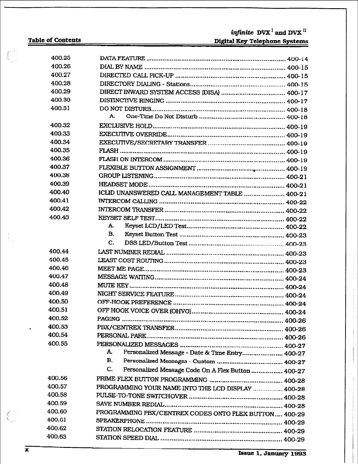
Table of Contents
;zfinite DVX’tmdDVX”
Digital Key Telephone Systems
400.25
400.26
400.27
400.28
400.29
400.30
400.31
400.32
400.33
400.34
400.35
400.36
400.37
4Oix3a
400.39
400.40
400.41
400.42
400.43
400.4-4
400.45
400.46
400.47
400.48
400.49
4OQ.50
400.5 1
400.52
* 400.53
400.54
400.55
400.56
400.57
4uO.58
400.59
400.60
400.61
400.62
400*63
DATA FEATLIRJZ ............................................................................ 400-14
DLAL, BY NAME
.............................................................................
400-‘15
DIRECTED CALL PICK-IX
............................................................
400-15
DIRECTORY DIALING - Stations.. .................................................. 400-15
DIRECJT INWARD SYSTEM ACCESS 113ISA) ................................... 400-17
DISTINCTIVE: RINGING ................................................................. 400-17
DO NOT DISTURB ......................................................................... 400- 18
A. One-Time Do Not Disturb ............................................... 400- 18
EXCLUSIVE HOLD ........................................................................ 400- 19
EXECUTNE OVERRIDE ................................................................ 400- 19
EXECUTNE/SECREIXFZY TRANSFER .......................................... 400-19
FLASH .......................................................................................... 400-19
FLASH ON INTERCOM .................................................................. 400-19
F’LEXIBm BUTTON ASSIGNMENT ............................. “I.. .............. 4OO- 19
GROUP LISTENING
.......................................................................
400-Z 1
HEADSEiT MODE .......................................................................... 400-2 1
ICUD UNANSWERlED CALL MANAGEMENT TABLE ...................... 400-2 1
INTERCOM CALLING .................................................................... 400-22
INTERCOM TRANSFER ................................................................. 400-22
KEYSET SELF ‘IESr ...................................................................... 400-22
A Keyset LCD/LED Test ..................................................... 400-22
B. Keyset Button Test ......................................................... 400-23
c. DSS LED/Button Test .................................................... 400-23
LASTNUMBER REDIAL ................................................................ MO-23
LEASI’ COST ROUTING ................................................................. 400-23
MEET ME PAGE ............................................................................ 400-23
MESSAGE WAITING
......................................................................
400-24
IvrulzKEY
....................................................................................
400-24
NIGHT SERVICE FEATLTRE ........................................................... MO-24
OFF-HOOK PREFERENCE ............................................................ 400-24
OFF HOOK VOICE OVER (OHVO) .................................................. 400-24
PAGING ........................................................................................ 400-26
PBX/CENI’REX TRANSFER ........................................................... 400-26
PERSONAL, PARK
..........................................................................
4OB26
PERSONALIZED MESSAGES ........................................................ 400-27
A Personalized Message - Date & Time Entry ...................... 400-27
B. Personalized Messages - Custom .................................... 400-27
C. Personalized Message Code On A Flex Button ................. 400-27
I’~ FLEX BUITON PROGRAMMING ........................................ 400-28
PROGRAMMING YOUR NAbIf3 IN-IO THE LCD DISPLAY ................ 400-28
PULSE-TO-TONE SWITCHOVER ................................................... 400-28
SAVE NUMBER REDIAL ................................................................ 400-28
PROGRAMMING PBX/CENIREx CODES ONi’ FLEX BUrrON .... 400-29
SPEAKERPHONE .......................................................................... 400-29
STATION RELOCATION FEATURE ................................................ 400-29
STAnON SPEED DIAL, .................................................................. 400-29
x Issue 1, Jammy 1993
imite Dm’ and DVX ’
D&itd Xcy Telephone Systems Table of c43ntents
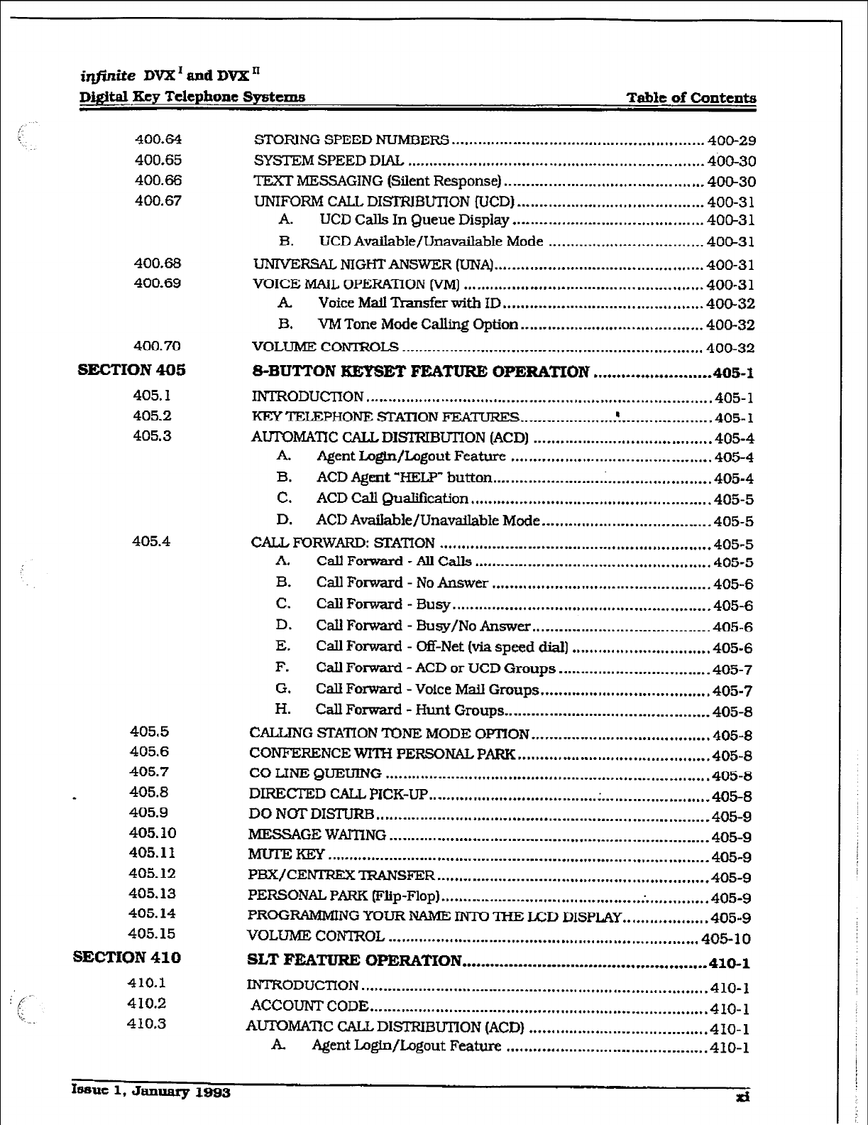
400.64 STORlNG SPEED NUMBERS . . . . . . . . . . . . . . . . * . . . . . . . . . . ~...~.~ . . . . . . . . . . . . . . . ,,...... 400-29
400.65 SYSTEMSPEEDDIAL . . . . . . .,........ .~ . . . . . . . . . . . . . . . . . . . . . . . . . . . . . . . . . . . . . . . . . . . . . . ...4&-30
400.66 TEXT MESSAGING (Silent Response) .-.-.* . . . . . . . . . . . . . . . . a..... . . . . . . . . . . . . . . . . . 400-30
400.67 UNIFORM CALL DISITU3UTlON fUCD1 . . . . . . . . . . . . . . . . . . . . . . . . . . . . . . . . ...*.*.*.. 400-3 1
A. UCD Calls In Queue Display . . . . ..-_ . . . . . . . . . . . . . . . . . . . . _. . . . . . . . . . . . . . 400-3 1
3. UCD Available/Unavaihble Mode . . . . .,.. . . . . . . . . ,... . . . . . . . . . . . . . . . 400-31
400.68 UNIVERSAL NIGHTANSWER (UNA) .L...... . ,..... * . . . . . . ..f ..f........ *,..** . . . . . 400-3 1
400.69 VOICE MAIL OPERATION IVM)
.* . . . . . . . . . . . . . . . . . . l . . . . . . . . - . . . . . . . . . . . . . . 1.... l . . . .
400-3 1
A Voice Mail Thantier with ID .., . . . . . . . . . -.- . . . . . . . . . . . . . . . * . . . . . . *..* . . . . 400-32
B. VM Tone Mode Calling Option ..* . . . . . * . . . . . . . . . . . . . . . . . . . . . . * . . . . . . . . . 400-32
400.70 VOLUME CONTROLS
. . . . . . . . . . . . . . . . . . . . . . . . . . . . . ..I . . . . . . . . l .*.* . . . . . . . . . . . . . . . . . . . . . . .
400-32
sEcTroIv 405 S-BUTTON KEPSET FEATURE OPERATION
l
..* . . . . .
l
***.* . . . . . . . ...405-I
405.1 INTRODUCTION ..a . . . . . . . ..t.. . . . . . 0. . . . . .*.a . . . . . . . ** . . . . . . . . * . . . . . ,* ,.,..... ~ . . . . . ..f . . . . . . 405-l
405.2 KEY TELEPHONE STAnON FEATURJZS . . . . . . . . . ...*..... . ..A . . ..I.......... * . . . . 405-I
405.3 AUTOMA’lX CALL DISTRIBUTON (ACD] . . . . . . . ..L... . . . . . ..I.. . . . . . . . . . . . . . . . . . 405-4
A Agent Login/Logout Feature . . . . . . . . . . . . . . . . . . . . . . . . . . . .*. . . . . . . * ..-.... .405-4
B. ACD Agent “HELP” button ..- . . . . . . . . . . . -.-* . . . . . . . . . . * . . . . . . . . . ~..., ..,... 405-4
C. ACD Call Qualification .I.... . . . . . e.. . . . . . . . . . . . . . . . . a.. . . . . . . . . . . . I... . . . . . . 405-5
D. ACD Available/Unavailable Mode . . . . . . . . . ,, . . . . . ..-.................. -405-5
405.4 CALL FORWARD: STATION
. ..1..1..1.....*.1...* . . . . m.. . . . . . a..*.** . . . . . l . . . . . . . . . . . l . .
405-5
A. CallFomard-AllCalls . . . ..-.--. _..*- . . . . . . . * . . . . . . . . . A . . . . . . . . . . **.. ,..... 405-5
B. CallForward - NoAnswer. . . . . . . . . . . . . . . . . . . . . . . . . . . . . . . . . . . . . . . . . . . . . . . . . 405-6
C. Call Forward - 3usy . . . . . . . . . . . . . . . . . . . ..-*...........................*....... 405-6
D. Call Forward - Busy/No Answer . ..-.................................... 405-6
E. Call Forward - Off-Net (via speed dial)
. . . . . . . . . ..*m. . . . . . . . . . . . . . . . . l
405-6
F. Call Forward - ACD or UCD Groups . . . . ..-....1...-- . . . . . . . . . . . . . . . . . 405-7
G, Call Forward - Voice Mti Groups . . . . . . . . . . . ..~....~...rn............... 405-7
H. Call Forward - Hunt Groups . . . . . . . . . . . . . . . . . . , . . . . . . . . . . . . . . . . . . . . . . . ..-. 405-8
4055 CALLING Sl=A’i-lON TONE MODE OPTION
. ..* . . . . . . . . . **.*.* . . . . . . . . . . l ..,...,..,
405-8
405.6 CONFERENCE WITH PERSONAL PARK m.... . . . . . . . . . . . a..... . . . . . *...a . . . . . . . . . . . 405-8
405.7 CO LINE QUEUING .*..........-...-I...............*...~.............,..*....~........*..,, 405-8
405.8
- DIRECTED CALL PICK-UP .s . . ..I..., I.. . . . . . * . . . . . . . . . . . . . . . . . . . * .............l...,..,,. 405-8
405.9 DO NOT DISTUF2B .a..*...* . . . . . . . . . . 0.. . . . . a.. . . . . I . . . . . . . . . . . . . . . . . ~ . . . . . . *...* . . . ...*...*. 405-9
405.10 Ml3SSAGE WAMING .I.... . . . . . . . . ..a . . ..-....-........................-.................... 405-9
405.1 I .IvrurEKEY . . . . - . . . . . a..- . . . . . . . a--..-a . . . . . . . -..*..I . . . . . . * . . . . . . . . . . . ..C... . . . ..I..... * . . . . . . . . 405-g
405.12 PBX/CENIXEX’IRANSFER . . . ..I . . . . . . . . . . - . . . . -.-..I. . . . . . . 4.. ..I... *..* . . . . . . . . . . . . . . 405-9
405.13 PERSONAL PARK (Flip-Flop] .* . . . ..I.. --.------...-.I-.... . . . . . v.........;.... . . . . . . . . . . 405-9
405.14 PROGRAMMING YOUR NAME MM THE ED DISPLAY.. <... . . . . . . . . . ..m ,405-g
405.15 VOLUME CONTROL
. . . . . ..I......... . . . . . . . -.... . . . . . . . . . . . . . I. . . . . . . . ,.....,..,.. ~ . . . . . l
405-10
SECTION 410 SLT IWWURE OPERATKON . ..*.*....-........-...............*.........**..... 410-l
410.1 l.NTRODUC’iION . . . ...* . . . . . . . . . . . . . . . . . . . -*-.-.-.-.._ . ..I............,., ..* . . . . . . . . . . . . . . . . . . 410-l
410.2 ACCOUNT CODE
.--.-.-.--.*.* . . . . . --.-.----a . . . . . l . . . . -...a...* . . . . . . . . . . . . . . ..*.......... *
410-l
410.3 AUT’OMA’IX CALL DISTRIBUTION (ACD] . . . . . . b...... . . . . . . . . . . . ** .,.....*..,.. * 410- 1
A Agent Login/Logout Feature . . . . . ..*..a . . . . . . . . . . . * . ..I.. * . . . . . . ..*.*.... 410-l
hn~ 1, January 1993 xi
r
Table of ~ntCntS
@finite DVX’ and DVX”
Digital Key Telephone Systems
410.4
410.5
410.6
410.7
410.8
410.9
410. IO
410.13
410.12
410.13
410.14
410.15
410.16
410.17
410.18
410.19
410.20
410.21
410.22
410.23
410.24
410.25
4 10.26
410.27
410.28
410.29
410.30
410.31
410.32
410.33
SW!I’ION
420
420.1
420.2
420.3
420.4
420.5
420.6
420.7
420.8
420.9
420.10
420.11
420.12
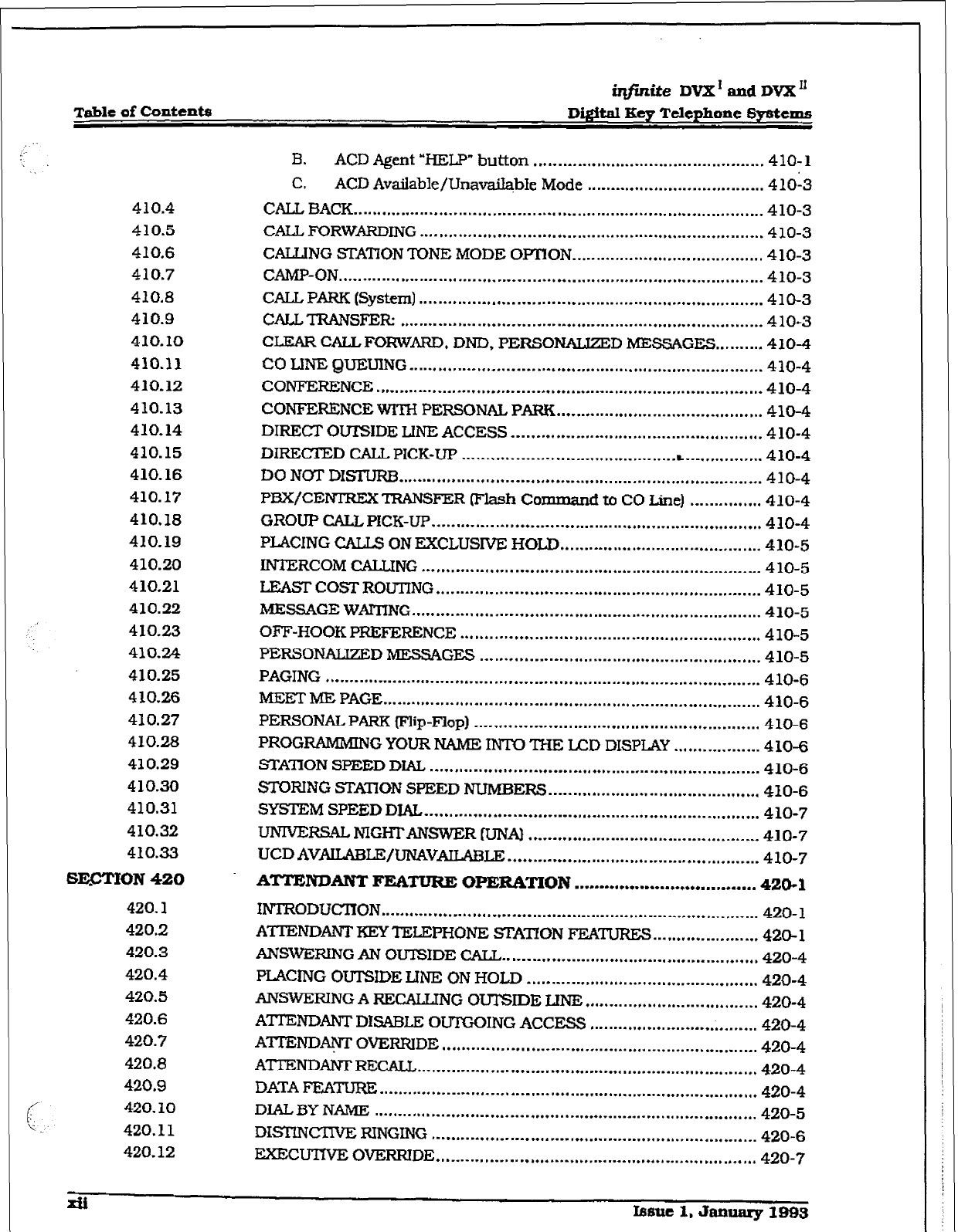
B. ACD Agent “BELP” button ................................................ 410-l
C. ACD Avdable/Unava&bIe Mode ..................................... 41013
CALL BACK ..................................................................................... 410-3
CALL, FORWARDING
.......................................................................
410-3
CALLING STATION TONE MODE OFRON.. ...................................... 4 10-3
CAMP-ON ........................................................................................ 410-3
CALL PARK (System)
.......................................................................
410-3
CALLTRANSFER
...........................................................................
410-3
CLEAR CALL FORWARD, DND, PERSONALJZED MESSAGES .......... 410-4
co LINE QUEUING
.........................................................................
410-4
CONFERENCE ................................................................................ 410-4
CONFERENCE WITH PERSGNAL PARK ........................................... 410-4
DIRECT OUTSIDE LlNE ACCESS .................................................... 410-4
DIRECTED CALL PICK-UP
............................................ . ................
410-4
DO NGTDISTURB.. ......................................................................... 410-4
PBX/CENIREX TRANSFER Flash Command to CO Line) ............... 410-4
GROUP CALL PICK-UP
....................................................................
410-4
PLACING CALLS ON EXCLUSIVE HOLD .......................................... 410-5
INTERCOM CALLING ...................................................................... 410-5
LEASTCOSTROUTING.. ................................................................. 410-5
MESSAGE WAITING.. ...................................................................... 410-5
OFF-HOOKPREFERENCE
..............................................................
410-5
PERSONALJZED MESSAGES .......................................................... 410-5
PAGING .......................................................................................... 410-6
MEET ME PAGE .............................................................................. 410-6
PERSONALPARK (Flip-Flop) ........................................................... 410-6
PROGRAMMING YOUR NAME INTO THE LCD DISPLAY .................. 4 10-6
STATION SPEED DIAL .................................................................... 410-6
STORING S-TXI’ION SPEED NUMBERS
............................................
410-6
SYSTEM SPEED DIAL ..................................................................... 410-7
IJNIWRSAL NIGHTANSWER IUNA) ................................................ 410-7
UCD AVAILABLE/UNAVAILABLE
....................................................
410-7
ATTENDANT
R-ZA- OPERATION .................................... 420-l
INTRODUC’ITON
..............................................................................
420- 1
ATIENDANTKEYTELEPHONE STATION FEATURE5 ...................... 420-l
ANSWERINGAN OUTSIDE CALL ..................................................... 420-4
PLACING OUTSIDE LJNE ON HOLD ................................................ 420-4
ANSWERING A RECALUNG OUTSIDE LINE .................................... 420-4
ATI’ENDANT DL5ABI.E OUTGOING ACCESS ................................... 420-4
A’ITEND~OVERRIDE ................................................................. 420-4
ATTENDANTREcALL ...................................................................... 420-4
DATA FEATURE ............. ................................................................. 420-4
DIAL3Y NAME
...............................................................................
420-5
DIS!JNCUVE RINGING ................................................................... 420-6
EX?CuTNE OVERRIDE .................................................................. 420-7
Jdi Issue 1. amlary 1993
iqjidte Dvx’andDvxn
Digital Key Telephone Systems Table of Contenta
420.13
420.14
420.15
420.16
420.17
420.18
420.19
420.20
420.21
420.22
420.23
420.24
420.25
420.26
420.27
420.28
420.29
420.30
420.31
420.32
420.33
420.34
430.1
SECTION 500
500. I
*
500.2
500.3
500.4
500.5
ICLID UNANSWERED CALL MANAGEMENT TABLE ........................ .420-7
INTERCOM CALLING
.......................................................................
420-a
INCOMlNG CO LINES OFF-NET (via speed dial) ............................... 420-8
KEYSET SELF TEST ........................................................................ 420-9
A. Keyset LCD/LED Test ....................................................... 420-9
B. Keyset Button Test ............................................................ 420-9
C. DSS IJZD/Button Test ...................................................... 420-9
MESSAGES - CUSTOM.. ................................................................ 420-10
DIRECi’0RY DIALING -Attendant ................................................. 420-l 1
A. Prog ‘g-Attendant ................................................ 420-12
NIGHT SERVICE
............................................................................
420-14
OFF HOOK VOICE OVER [OHVO) ................................................. .420- 14
SETITNG SYSTEMTIMEAND DATE
..............................................
420-15
STORING SYSlXM SPEED NUMBERS. ...................... . .................. .420- 15
TEXT MESSAGING (Silent Response) ............................................. 420-15
ATTENDANTTRANSFER SEARCH ................................................. 420- 16
PLACING AN OUTSIDE CALL (Automatic Line SeIection) ............... .420- 16
CAILPARK ................................................................................... 420-17
DO NOT DISTURB INDICATION
.....................................................
420-17
RElWEWNGAPARKED CALL.. .................................................. .,.420-l 7
CALLTRANSFER ........................................................................... 420-17
CAMP-ON ...................................................................................... 420-17
FLEXIBLE BUIT0N PROGRAMMING.. ........................................... 420-17
MEET ME PAGE ............................................................................ 420-17
PAGING ......................................................................................... 420-17
. External Paging .............................................................. 420-17
B. Internal Paging ............................................................... 420-18
C. All Call Paging (Intemal/Extemal) ................................... 420-18
RELEASEBUTI0N ........................................................................ 420-18
LCD DISPLAYS ................................................................................ 43O- 1
INSTALLATION ....... ..r..................................~.............* .............
500-l
SITE PLANNING .............................................................................. 500-l
A System Grounding
............................................................
500-l
B. Iigbtnirig Protection
..........................................................
5Qo-1
INSTU~ON PLANNING FORTHE DVX I SYSTEM ....................... 500-2
COMMON EQUIPMENT FoRTI% DVX ’ SYSTEM ........................... .500-2
. Basic Key Sewice Unit with Paver Supply (BKSU) ............ -500-2
B. Expansion KSU with Power Supply (EKSU) ...................... .500-g
C. 2x4 *anda Module ..................................................... 500-13
D. 2x4 SLT Expander Module .............................................. 500-16
E. 4x8 Expander Module ..................................................... 500-19
INSTAUATION PLANNING FORTHE DVX ’ SYSTEM .................... 500-21
SYSTEM COMPOIQZ,NTS FORTHE DVX I1 SYSTEM ........................ 500-21
k Equipment Cabinet With Power Supply (KSU) ................ .500-21
B. Cabinet In&&&ion
........................................................
500-22
Issue 1, January 1993
r
Table of contents
in#inite DVX I
and JIVX I’
Digital Key Telephone Systems
500.6
500.7
500.8
500.9
500.10
sEcrIoN 600
600.1
600.2
600.3
SECTI0N 700
700.1
700.2
700.3
700.4
700.5
700-6
* 700.7
700.8
SECTION 710
710.1
C. Central Processor
Board (CPBJ ........................................ 500-25
D. 4x8 Key
Interface
Board [CKB) ........................................ 500&3
E. 4x8 SLT Interface Board (CSB)
........................................
500-33
APPLICATION
MODULE(S) INSTAUA’XO~ .................................... 500-36
A
Expansion I/O
Module BOM) for the DVX’ System ......... 500-36
B. Expansion I/O Module (IOMj for the DVX’ System ....... .500-36
c. 1200 Baud Modem Module [MM] .................................... 500-39
13. Installing the DTMF Receiver Module (RMJ ...................... 500-39
DIGIT&TERMINALS
....................................................................
500-44
A. Digital Terminal Instaktion- ...........................................
500-44
B. Digital DSS Console Installation: .................................... 500-44
C. Wall Mc~unting the 33-Button Digftal Terminal ................ 500-44
D.
Wazl Mounting the
8-Button Digital Terminal .................. 500-46
E. Singie Line Telephone Installation .
.................................. 500-46
F. SLTAdapter / Off-Premise Extension Module [OPX] ........ 500-46
POWERFAILURETRANSl?ER. ............................ i.‘......................... 500-48
A Relay / Sensor interface Module ..................................... 500-48
B.
Power Failure Transfer
Unit PFTU) ................................. 500-48
IN-G RECORDED
ANNOUNCEMENT DEVICE (RAN) .......... 500-53
DATA FEATURE ............................................................................ 500-54
sYsT.EMcHEc3-ouT ...................... ..*...............................* .... 600-l
INTRODUC’IION
..............................................................................
600-l
PRELiMINARY PROCEDURES ......................................................... 600-
1
POWER UP
SEQUENCE ................................................................ ..600- 1
CUSTOMER DATA BASE PROGRAWiUNG ............................
700-l
INl-RODUCTION
..............................................................................
700- 1
PROGRAM MODE ENTRY Ney Station] ........................................... 700- 1
PROGRAM MODE ENTRY (Data Terminal or PC) ........................... 700-10
BEGINNING To PROGRAM ........................................................... 700- 10
IIVIlUUZATION ............................................................................ 700-10
CUSTOMER DATA WORKSHEETS ................................................ 700-11
DATA BASE FIELDS
......................................................................
700-11
DATABASE UPLOAD/DOWNLOAD ROWlINE ................................ 70&l 1
A Using the PC to UpIoad/Downbad thou
Remote
Administration .............................................................
70&l 1
s=b¶ P-RS PROGRAMMING ............................. 710-r
SYSTEMTlMERs ............................................................................ 710-l
A System Hold Recall Timer ................................................. 710-2
B. Exclusive Hold Recall
Timer .............................................. 710-Z
c. Attendant
Recall Timer ..................................................... 710-3
D.
Transfer Recall Timer .......................................................
710-3
E. Preset Forward Timer
....................................................... 710-4
F. Call Forward No/Answer Tlmer ......................................... 710-4
G. Pause Timer ..................................................................... 710-5
xiv
Issue 1. January
1993
irIfinfte DVX’ and DVX’
710.2
710.3
710.4
710.5
710.6
710.7
710.8
710.9
710.10
D&itd Key Telephone
Systems Table
of Contents
H. Call Park Recall Timer ....................................................... 7 10-5
1. Conference/DISA Timer .................................................... ‘710-6
J. Paging Timeout Timer ....................................................... 710-6
. CO Ring Detect Timer ...................................................... .710-7
L. SLT MMF Receiver Timer ................................................. 710-7
M. Message Waft Reminder Tone ............................................ 710-8
N. SLT Hook Flash Timer ....................................................... 710-a
0. SLT Hook Flash Debounce Timer ...................................... 710-9
P. SMDR Call Qualification Timer ....................................... 710-10
9. Automatic Call Back Timer
.............................................
710-10
SYSTEM FEATURES PROGRAMMlNG ........................................... 710-l 1
A. Attendant Override ......................................................... 710-13
B. Hold Preference ............................................................... 710-13
c. External Night Ring
l
........................................................
710-14
D. Executive Override Warning Tone ................................... 710-14
E. Page Warning Tone ......................................................... 710-15
F. Background Music Channel ............................................ 7X0-15
G. LCR Enable .................................................................... 710-16
H. Account Codes - Forced .................................................. 710-16
I. Group Listening .............................................................. 710-17
J. Idle Speaker
Mode
.......................................................... 710-17
. Call Cost Display Feature ................................................ 710-18
L. Music On Hold ................................................................ 710-18
ATIENDANT STATION ASSIGNMENT ............................................ 710-19
SYSTEM TIME AND DATE ............................................................. 710-19
PBX DIALING CODES .................................................................... 710-20
ExEcuTlvE/sEcmARy PAIRS .................................................. 710-20
RELAY/SENSOR PROGRAMMING ................................................. 710-21
A Progmnmingmlayfor -l ........................... 710-22
B. Programdng relay for RAN Starting:. ... (. ......................... 71U22
C.
Progxx~ relay
for Power Failure Transfer: ............... -7 1 O-23
D. progranrming relay for Loud Bell Control:. ...................... .7 l&24
E. F%-ogramniq relay for CO Line Control- ........................... 710-25
F. Assign Relay/Sensor Interface Module to a statio& ........ .7X&25
G. Program sensing circuit as a RAN Sensing (RAN END)
CiK!Uk
.......................................................................... 710-26
BAUD RATE ASSIGNMENTS .......................................................... 71&27
ACCESS CODES ........................................................................... 710-28
A DlSAAccess Code ........................................................... 71e28
B. Database Admin. Password ............................................. 710-29
STAnON MESSAGE DETAIL RECORDING (SMDR) ........................ 710-30
A SMDR Enable/Disable .................................................... 710-30
B. Long Distanc!e/Local Asdgnment .................................... 710-30
c. Character Print Assignment ............................................ 710-31
iqjinite
DVXI and DVX”
Table
of Contents Digital Iky Tclephoae Systems
710.11
710.12
710.13
710.14
SECTION 720
720. I
720.2
720.3
smroN 730
730.1
730.2
D. Baud Rate Display .......................................................... 710-31
E. SMDR Port Assignments ................................................. 710-31
WEEKLY MGHTMODE SCHEDULE.. ............................................ 710-32
A. Automatic/Manual
Operation.. ....................................... 7 IO-32
B. Day of
Week programming.. ............................................ 710-32
DIRECTORY DIALING ................................................................... 710-33
HUNT GROUPS ............................................................................. 710-36
A. Hunt Group Prog ramming .............................................. 710-36
B.
Station/Pilot
Hunting
Assignment ..................................
710-36
LOCAL NUMEtER/NAME
TRANSMTlON TABLE ............................ 710-37
CO LJNE AmUTI3S PROGRAMMING ...............................
720-l
INTRODUCIION.. .......................................................................... ..720- 1
A. D?xF/D.ialPulseProg -g ........................................ 720-2
3. co/PBx Programming I
.....................................................
720-2
c. UNAProgmnmit~ ............................................................ 720-3
D. DISA Trunk-to-Trunk
IPer CO L&e) ..................................
720-3
E. Privacy .............................................................................
720-4
I?.
Loop Supervision Programming ........................................
720-5
G.
DISA Rogmmming ...........................................................
720-6
H. FlashTimer Progamming ................................................ 720-7
1.
Line Group Programming .................................................
720-7
J. CIass of Service (COS) Pro@mntning
.................................
720-G
.
CO Line Ringing Assignments.. ......................................... 720-9
. CO Line Identication Display ........................................
720-10
DlALPULSE PARAMETERS ........................................................... 720-l 1
FLEXIBLE PORT ASSIGNMENT FEATURE ..................................... 720-12
STATION
ATTRIBUTES
PROGRAMMUYG ..............................
750-l
INTRODUcrlON .............................................................................. 730-l
A. Pagfng Access
................................................................... 730-2
B. Do Not Disturb ................................................................. 730-2
c.
Conference Enable/Disable (Per Station] ..........................
730-3
D.
Executive Override ...........................................................
730-3
E. Privacy (Per Station) .........................................................
730-4
F.
System
Speed Dial Access
.................................................
730-5
G. Line Queuing .................................................................... 730-5
H. Preferred Line Answer .......................................................
730-6
1. Off-Hook Voice Over ......................................................... 730-6
J. Call Forwarding ................................................................
730-7
.
Forced Least Cost Roumg (Ux) .......................................
730-7
L.
ACD Supervisor Monitor w/Barge-In ................................ 730-B
M. lhxutive Override Blocking ............................................. 730-8
PAGE ‘B” INTRODUC!‘lION
.............................................................. 730-9
.
Station Identification ...................................................... 730-10
mPI
Issue 1, Januaq 1993
iq@ite DVX’andDVXn
Dj@td Ecy Telephone Syetcxm Table of Contents
730.3
730.4
SECTXON 740
740. I
740.2
740.3
740.4
SECTXON 746
745.1
745.2
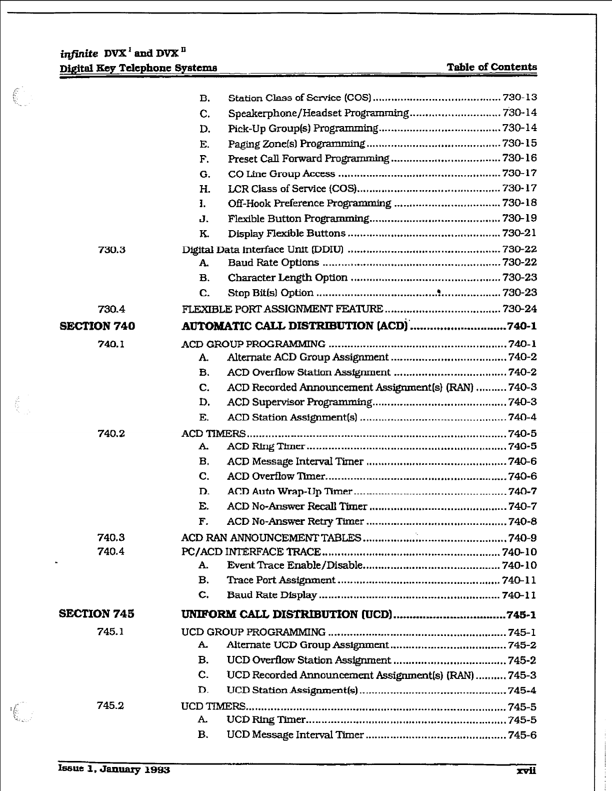
B. Station Class of Semice (COS) ......................................... 730-13
C. Speakerphone/Headset Programming ............................. 730-14
D. Pick-Up Group(s) Programming ....................................... 730-14
E. Paging Zone(s) Programming ........................................... 730-15
F. Preset CaIl Forward Prog~ . 3 ................................... 730- 16
G. CO Line Group Access .................................................... 730-17
H. LCR Class of Service (COS) .............................................. 730-17
I. Off-Hook Preference Programming .................................. 73O- 18
J. FIexible Button Programming .......................................... 736-19
. Display Flexible Buttons ................................................. 730-21
Digital
Data
Interiace Unit fDDIUl
.................................................
730-22
. Baud Rate Options ......................................................... 730-22
B. Character Length Option ................................................ 730-23
c. Stop Bit(s) Option ....................................... . ................... 730-23
FLEXIBLE POKl- ASSIGNMENT FEA-TUR?Z ..................................... 73524
AUTOMATXC CALL DISTRIBUTKIN (ACDj’ .............................
740-l
ACD GROUP PROGRAMMING ......................................................... 740-l
. Alternate ACD Group Assignment ..................................... 740-Z
B. ACD Over&low Station Assignment .................................... 740-Z
C. ACD Recorded Announcement Assignment(s) (RAN) ......... .740-3
D. ACD Supervisor Programming .......................................... .74-O-3
E. ACD Station Assignment(s) .............................................. .74O-4
ACD TIMERS ................................................................................... 740-5
. ACD Ring Timer
................................................................
740-5
B. ACD Message IntemaI Timer ............................................. 740-6
C. ACD Overflow Timer .......................................................... 740-6
D. ACD Auto Wrap-Up Timer ................................................. 740-7
E. ACD No-Answer Recall Timer ............................................ 74-Q-7
F. ACD No-Answer Retry Timer ............................................. 740-8
ACD RAN ANNOUNCEMBNTTAI3LES
.............................................. 740-9
PC/ACD INTERFACE TRACE ......................................................... 740-10
A. ES-at Trace Enable/Disable
............................................
740-10
B. Trace Port Assignment
....................................................
74cbll
C. Baud Rate Display .......................................................... 740-11
UNIFORM CALL DXSTFtXBUTXON [UCD) ..................................
746-l
UCD GROUP PROGRAMMING ......................................................... 745-1
. Alternate UCD Group Assignment ..................................... 745-2
B. UCD Overflow Station Assignment
....................................
745-2
C. UCD Recorded Announcement Assignment(s) (RAN) .......... 745-3
D. UCDStationAssignment(s). .............................................. 745-4
UCD TIMERS ................................................................................... 745-5
. UCD Ring Timer ................................................................ 745-5
B. UCD Message Interval Timer ............................................. 745-6
h3sue 1. January 1983
r
irlfinite DVX’ and DVX”
Table of contents
Digital Key Telephone Systems
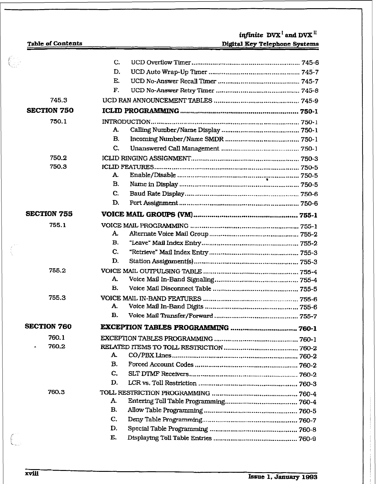
745.3
SECTION
750
750.1
750.2
750.3
SECTION 755
755.1
755.2
755.3
C.
LJCD Overflow Timer ......................................................... 745-6
D. UCD Auto Wrap-Up Tier
................................................
74517
E. UCD No-Answer Recall Timer ........................................... 745-7
F. UCD No-Answer Reiry Tier
............................................
745-3
UCD RAN ANNOUNCEMENTTABLES ............................................. 745-9
ICLID PROGRAMMING ...........................................................
750-I
INTRODUCTION .............................................................................. 750- 1
A. Calling Number/Name Display ......................................... 750- 1
B. Incoming Number/Name SMDR ....................................... 750- 1
C. Unanswered Call Management ......................................... 750-l
ICLID RINGIIVG ASSIGNMENT ......................................................... 750-3
ICLID FEATURES.. .......................................................................... 750-5
A. Enable/Disable ............................................. ..;. ............... 750-5
B. Name in Display.. ............................................................. 750-5
C. Baud Rate Display.. .......................................................... 750-6
D.
Port Assignment ............................................................... 750-6
VOICE MAIL GROUPS (VM) ....................................................
765-l
VOICE MA% PROGRAMMING
.........................................................
755-1
. Alternate Voice
Mail
Group ............................................... 755-z
B. ‘Leave” Mail Index Entry ................................................... 755-2
C. “Retrieve” Mail Index Entry.. ............................................. 755-3
D. Station Assignment(s) ....................................................... 755-3
VOICE MAIL OUTPULSING TASLE .................................................. 755-4
. Voice Mail In-Band Signaling ............................................ 755-4
B. Voice Mail Disconnect Table ............................................. 755-5
VOICE hML
IN-BAND FEATURES .................................................. 755-6
. Voice Mail In-Band Dfgits ................................................. 755-6
B. voice. M&I l?Iansfm/Fom
............................................ 755-7
SECTION 760
760.1
. 760.2
760.3
EXCEPTION TABLES PROGRAMMING .................................
760-l
EXCEPI’ION TABLES PROGRAMMING ............................................ 760- 1
RELATED ITEMS
TO ‘KILL RESTRICTION .......................................
760-Z
. CO/PI3X Lines
..................................................................
760-2
B. Forced Account Codes ...................................................... 760-Z
C. SLT DTMF Recehrs ......................................................... 760-2
D. LCR vs. Toll Restriction .................................................... 760-3
TOLL RESrRIc?ION PROGRAMMING ............................................. 760-4
. Entering Toll Table Programming ...................................... 760-4
B. Allow Table Programming ................................................. 760-5
C. Deny Table Programming .................................................. 760-7
D. Special Table Programmhg .............................................. 760-8
E. Dfsplaylng Toll Table Entries ............................................ 760-g
Issue 1, January 1883
r
iqflnite DVX’cmdDVXn
Diffital~yTdephone
Systems Table
of
contents
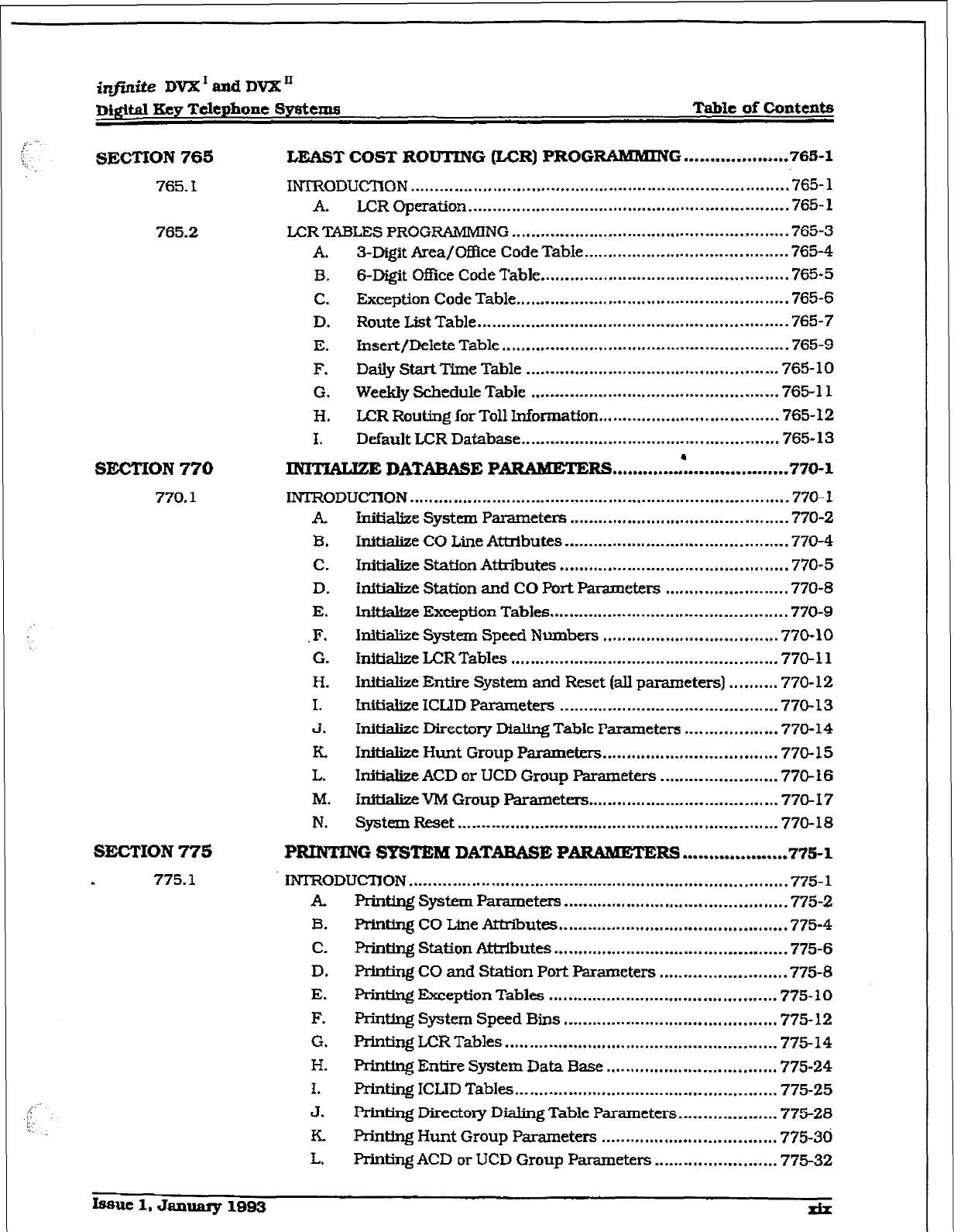
SECTION 765
765.1
765.2
SECTION 770
770.1
LEAST COST ROUTING &CR) PROGRAMMING
................. ...765-1
IN’I’RODUCZION .............................................................................. 765-
1
A. LCR Operation ..................................................................
765- 1
LCR TBLES
PROGRAMMING .........................................................
765-3
A. 3-Digit Area/OfZice Code Table.. ....................................... .765-4
B. s-Digit Ofhe Code Table ...................................................
765-5
C.
Exception
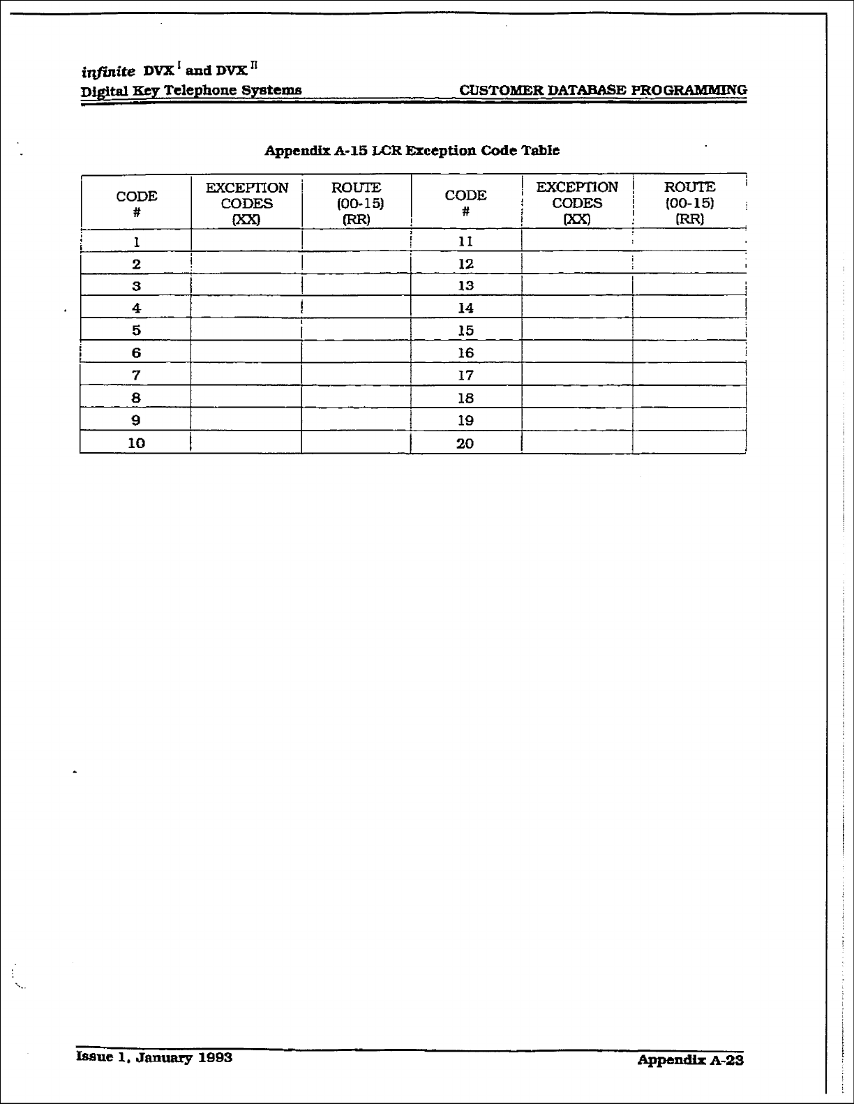
Code
Table
........................................................
765-6
D.
Route List Table ................................................................
765-7
E. Insert/Delete Table ........................................................... 765-9
F. Daily StartTime Table ....................................................
765-
10
G. Weekly Schedule Table ................................................... 765-l 1
Ii*
LCR
Routing
for
Toll
Momnation ..................................... 765-12
I.
Default LCR Database ..................................................... 765- 13
.
- DATABASE PARAMETERS
..................................
770-l
INTRODUCTION ..............................................................................
770- 1
A.
B.
C.
D.
E.
.F.
0.
H.
I.
J.
EL
L.
M.
N.
Initialize System Paraxnetus .............................................
770-Z
hi&&e CO Line Atibutes ............................................. -770-4
Initialize
Statfon Attributes ............................................... 770-S
Initialize Station and CO Port Parameters
......................... 770-8
Irdthhze Exception Tables.. .............................................. .770-g
Initialize System Speed Numbers .................................... 770-10
initialize LCR Tables .......................................................
77&l 1
Initialize Entire System and Reset (all parameters) .......... 770-12
Initialize ICUD Parameters ............................................. 770-13
Initkdize Directory Dialog Table Parameters .................. -770-14
Initialize
Hunt Group Parameters .................................... 770-15
Ini~ ACD or UCD Group Parameters ....................... .77@ I6
InftfalizeVM Group Parameters ....................................... 770-17
System Reset .................................................................. 770-18
SECTION 775
. 775.1
PRINTING SYSTEM DATAEASI3 PARAMETERS
... ..*..............775- 1
INTRODUCTION ................................ ..~......~....................................775- 1
. Print.ingSystemParameters.. ............................................ 775-2
B. F’rinting CO Line Attributes
...............................................
775-4
C.
Printing
Station
Attributes ................................................ 775-6
D. Printing CO and Station Port Parameter5 ......................... .775-8
E. F+intin.g Exception Tables
...............................................
775-10
F. Fkinting System Speed Bins ............................................
775- 12
G.
Mting LCR Tables ........................................................ 775-14
H. Fkinting Entire System Data Base ................................... 775-24
I.
Printing
ICLID
Tables ...................................................... 775-25
J.
Prinling Directory Dialing Table Parameters.. .................. 775-28
K PrlnUng Hunt Group Parameters ....................................
775-30
I..
Printing ACD or
LJCD
Group Parameters ......................... 775-32
r
iqfinite DVX’ and DVXn
Table of Contents Dl@tal Eey Tekphone Syntemn
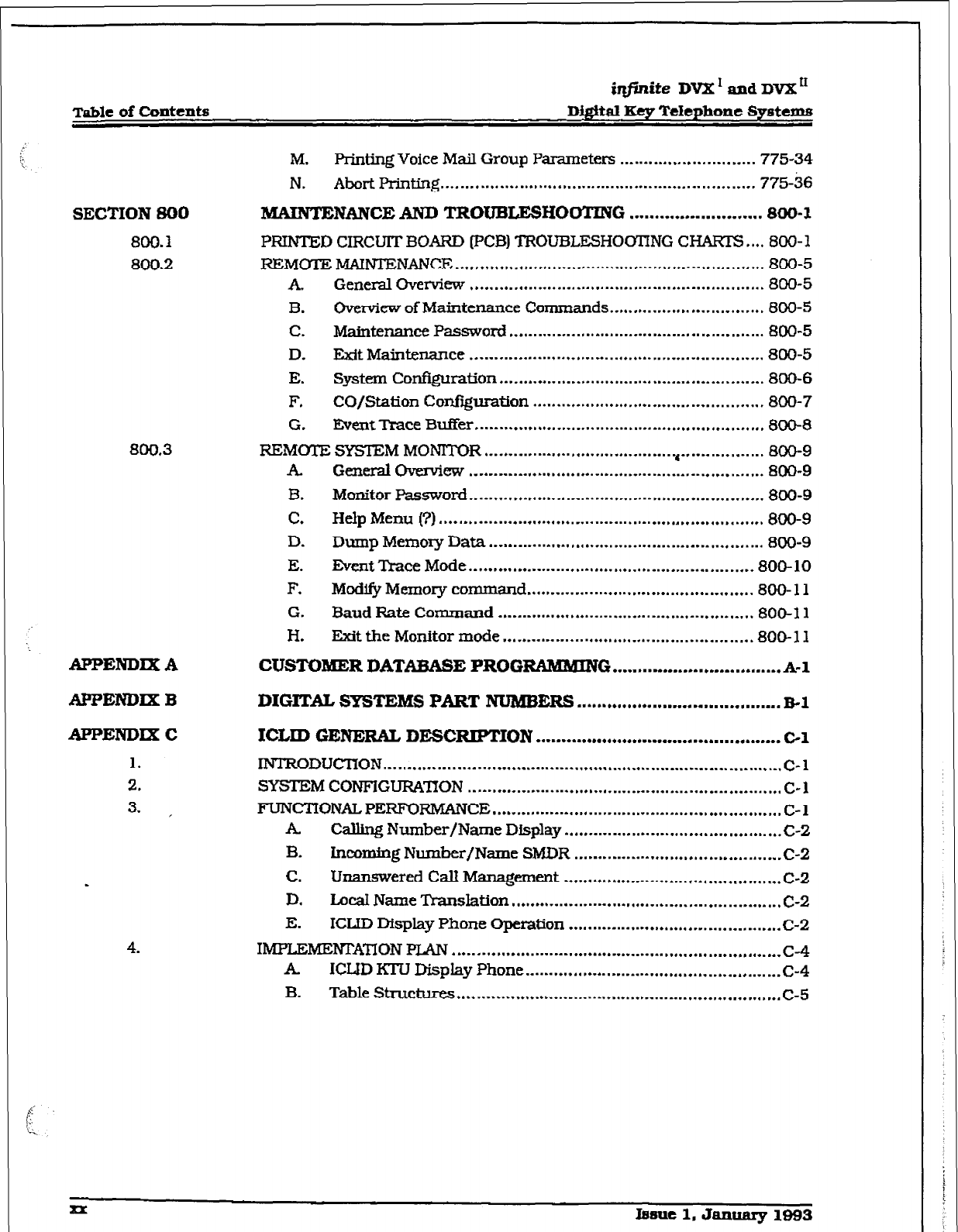
SECTION SO0
800.1
800.2
800.3
APPENDIX A
M. FYinting Voice Mail Group Parameters ............................ 775-34
N. Abort Printing ................................................................. 775-i6
&TA?NTENANCEAeND TROUBLESHOOTIlVG .......................... 800-l
PRINTED CIRCUIT BOARD IpCB) TROUBLESH0011NG CHAF3-S .... 800-l
REMOTE MAINTENANCE
................................................................
800-5
A. General Overview ............................................................. 800-5
B. Ovtmiew of Maintenance Commands ................................ 800-5
C. Maintenance Password ..................................................... 800-5
D. Exit Maintenance ............................................................. 800-5
E. system conAguration ....................................................... 800-6
F. CO/Station Confiiuration ................................................ 800-7
G. Event Trace Buffer
............................................................
800-8
REMOTE
SYSTEM MONITOR ........................................ (......... ........ NO-9
k GeneralOverview ............................................................. 800-9
B. Monitor Password.. ........................................................... 800-9
c. HdpMenu (?I ................................................................... 800-9
D. Dump Memory Data ......................................................... 800-9
E. Event Trace Mode ........................................................... 800-10
F. Modify Memory command ............................................... 800- 11
G. Baud Rate Command ..................................................... 800-l 1
H. Exit the Monitor mode .................................................... 800-l 1
CUSTOMER DATABASE PROGRAMMING ................................. A-l
APPENDIX B
APPEND= C
1.
2.
3. .
.
4.
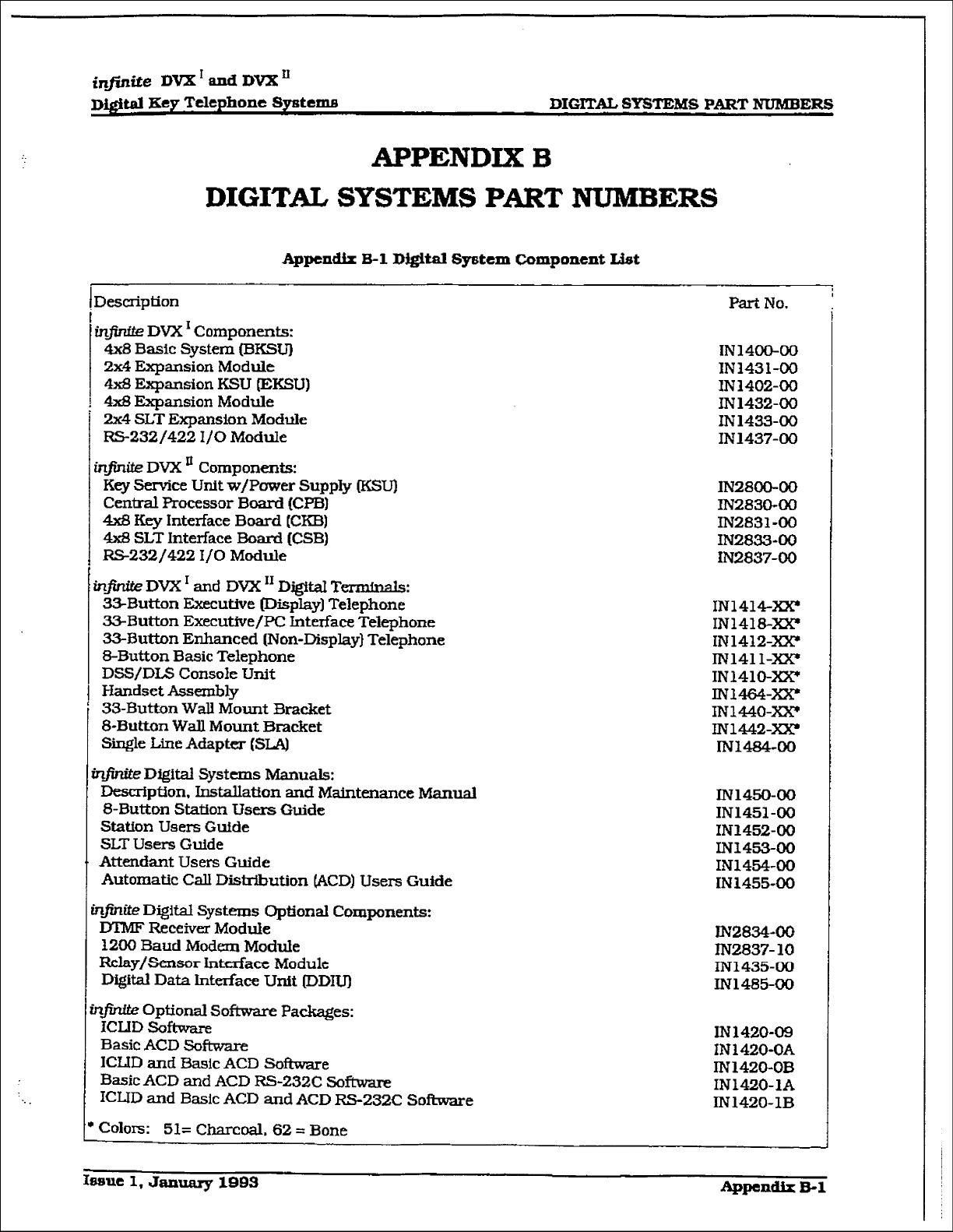
DIGITAL SYSTEMS PART NUMBERS ........................................ B-1
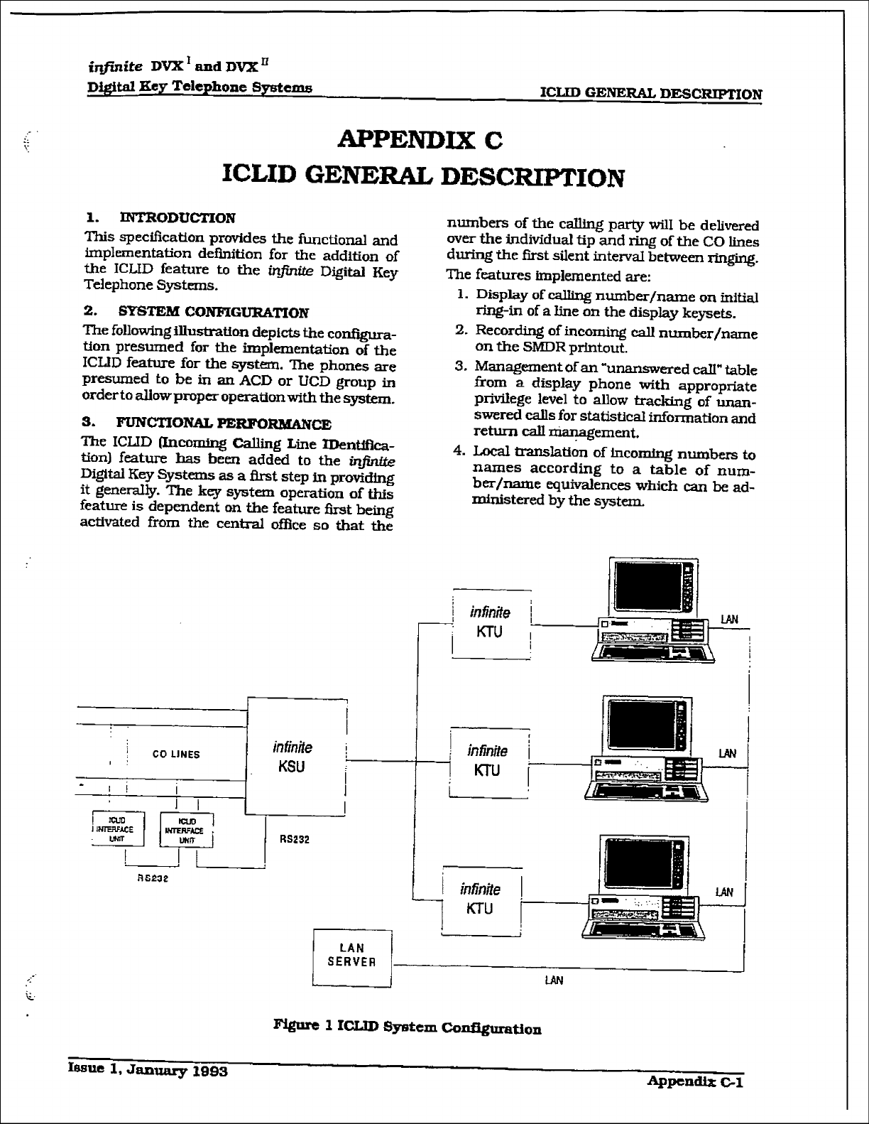
ICLID GENERAL DESCIUPT’ION ................................................ c-1
IIWRODUCIION
.................................................................................. C-l
SYSTEM CONFIGURA~ON ................................................................. C-l
FUNCTIONAL PERFORMANCE
............................................................ C-l
A
Calling Number/Name Display ............................................. c-2
B. Lncotig Number/Name SMDR
...........................................
c-2
c. Unanswered Call Management ............................................. c-2
D. LocaI Name Translation
........................................................
c-2
E. ICLID Display Phone Operation .......................................... ..c- 2
IIVIPLEME~A~ONPLAN
....................................................................
c-4
. ICLID KTU Display Phone ..................................................... c-4
B. Table Structures ................................................................... c-5
xx Iasuc1,Januarg1f393
irlfinite DVX’ and DVX”
Dfdital
Key
Telephone Systems LIST OF FIGulREs
LIST OF FIGUREf3
SECTION 100
INTRODUCTION
...............................................................
100-l
SECTION 200 GENE&XL DESCFWTION .................................................
200-l
Figure 200- 1 Main Key Service Board of the Basic KSU ............................................... 200-3
Figm 200-2 Main Key Service Board of the Expansion KSU
.......................................
200-5
Figure 200-3 2x4 Expander Module ............................................................................ 200-7
Figure 200-4 2x4 SLT Expander Module
.....................................................................
200-S
Figure 200-5 4x8 Expander Module ............................................................................ 200-9
Figure 200-6 Basic KSU Equipment Cabinet ............................................................. zoo-1 1
Fi@m 200-7 Cent-x& Processing Board [CPB) ............................................................ 200-12
Figure 200-S 4z& Key Interface Board (CKB) ............................................................. 200-13
Figure 200-9 4x8 SLT Interface Board (CSB) ............................................................. 200-14
Figure 200- 10 33-Button Executive Digital Terminal
............................ ?. ...................
200-18
Figure 200-1133-Button Enhnced Digit& Terminal ................................................ 200-20
Figure 20Q 12 S-Button Basic Digital Ttmninal ......................................................... 200-22
Figure ZOO- 13 48-Button DSS/DLS Console ............................................................. 200-24
Figure 20@17 W-Premise Extension (OPX) ModuIe
..................................................
200-28
Figure 200- 18 Relay / Sensor Interface Module ......................................................... 200-29
Figure 200- 19 Power F&me TYansfer Wiring Options ............................................... 200-30
Figure 200-20 Digital Data Interface Unit (DDIU) wiring ............................................ 200-32
SECTION 300
KEY STATION FEATURE DESCRIPTION ...........................
300-l
Figure 300-l 33-Button Default Button Map ............................................................ 300-15
Figure 300-2 S-Button Default Button Map ............................................................... 300-16
SECTION
310 SINGLE LINE TELEPHONE FEATURE DESCRIPTION.. ......
310-l
SECTION 320
A’M.“ENDm FEATURE DESCRIPTION
.............................
320-l
SECTION 4-00 STATfoN FEATURE OPEX#YMOH
......................................
400-l
Figure 400- 1 33-Button Digital Display Terminal
........................................................
400-2
SECTION 405
8-BUTTON EEYSET FEATURE OPE.RATIOiv ......................
405-l
Figure 405- 1 S-Button Digital Terminal ...................................................................... 405-2
. SECMON 410
SLT FEATURE OPERATION
..............................................
410-l
SECTION 420
AZTENDANT FEATURE OPERATION ................................
420-l
Figure 420-133-Button Attendant Display Terminal ................................................... 420-2
SECTION 500
INSTAUATION ................................................................ 600-l
FrgUre 50@- 1 Diglti FIatpack Mounting Ammgements ............................................... 500-3
Figure 500-2 Digital Flatpack
Mounting
Dimen.sions ................................................... 500-4
Figure 500-3 Main Key &mice Board of the Basic KSU ............................................... 500-7
Figure 500-4 Digital Flatpack RS-232C Connections ................................................... 500-S
Figure 500-5 Main Key Service Board of the Expansion KSU ..................................... 500-10
Figure 500-6 2x4 Expander Module .......................................................................... 500-13
Figure 500-7 2x4 SLT Expander Module ................................................................... 500-16
Figure 500-S 4x8 Expansion Module ......................................................................... 500- 19
&m~c 1, January
1993
LIST OF FIGURE3
ittfinite
DVX’ and DVXn
DigitdKeyTclephoneSystcxns
Figure 500-9 Basic KSU Equipment Cabinet .............................................................
500-23
Figure
500- 10 Basic KSU Cabinet Mounting Dimensions ..........................................
500-24
Figure 500-I
1 Central Processor Board (CPB) ...........................................................
500-26
Figure 500-12 Basic KSU CPB RS-232C Connections ...............................................
500-27
Figure 500-13 4x8 Key Interface Board (CKB) ........................................................... 500-29
Figure 500- 14 Shielded Cable Terminations .............................................................
500-30
Figure 500-l 5 4x8 SLT Interface Board [CSB) ...........................................................
500-34
Figure 500- 16 DVX I Expansion I/O Module Pin-outs
...............................................
500-37
Figure 500- I7 DVX ’ Expansion I/O Module pin-outs
..............................................
500-38
Figure 500- 18 Basic KSU Application Card Locations ...............................................
500-42
Figure 500- 19 Expansion KSU AppIication Card Locations
.......................................
500-43
Figure 500-20
D@tal Terminal Moduhr Block Wiring ..............................................
500-45
Figure 500-21 Digital
Terminal Wall Mounting ......................................................... 500-47
Figure 500-22 Off-Premise Extension (OPX) Module.. ............................... v.. ............. 500-49
Figure 500-23 Relay / Se.nsor Interface Module ........................................................
500-50
Figure 500-24 Power Failure Transfer Wiriug Options ............................................... 500-5 1
Figure 500-25 CO and SLT RATV Connections ...........................................................
500-53
Figure 500-26 Digital
Data Interface Unit (DDIU) wh-ing ...........................................
500-54
SECTION 600 SpsrnM cm?AxGouT
................................... -. ............ *. ....
600-l
SECTION 700 CUSTOMER DATA BASE PROGRAMMING ..........................
700-l
Figure 700- 1
Data Terminal Program Codes Cross Reference ...................................... 700-2
Fig= 700-2
lnfhite
DigitaI Programming Button Mapping ........................................
700-3
SECTION 710
SYSTEM PARhMETERS PROG-G ...........................
710-l
Figure 710- 1 Hook Switch Activity ..............................................................................
710-9
SECTION 720 CO LINE ATTRIBUTES PROG-G .................. ...* ......
720-l
SECTION 730
STATION ATTRIBUTES
PROGRAMMING
..................... -. ....
730-l
SECTION 740
AUTOMATIC
CALL DISTRIBUTION
(ACD) ..........................
740-x
SECTION 745
UNIFORM CALL DISTRIBuTfoN @JCD) ......................... W ....
745-l
SECTION 750 ICLlD PROGIUUKWNG .......... ..t........................- ................
750-l
-
SECTION 755 VOICE MAIL GROUPS [VM)
... . ....................... l ...................
755-l
SECTION 760 EXCEPTION TABLES PROGRAMMING
......... *.*. ...... *W.-e.* .....
780-l
SECTION 765 LEAST COST ROUTING &CR) PROGRAMMING.. .............. ..765- 1
Figure 765-l Fx 3-DigitArea/Office Code Table Pgm Form ........................................ 765-4
Flgm 765-2 Ex 6-D@ Office Code Table Pgm Form .................................................
765-5
Frg= 765-3 Ex Exception Code Table P&m Form ......................................................
765-6
Fig=e 7fi5-4
Ex: Insert/Delete Pgm Form ................................................................... 765-9
l”%gu.re 765-5 Daily Si%zt Time & Weekly Schedule Tables
.........................................
765-10
Figure 765-6
Ex Daily & Weekly Start The TabIes
.................................................. 765-l
1
Fig-e 765-7 Ex LCRToll Information Routing Pgru Form ........................................ 765-12
~git.d Key Telephone System6 LWT OF FIGURES
SBCTlON 770 INITlALlZE DATABASE PARAMETERS .............................
770- 1
Figure 770- 1 33-Button Default Button Mapping
........................................................
‘770-6
Figure 770-2 &Button Default Button Mapping .......................................................... 770-7
SECTION 775 PFUNTING SYSTEM DATAEASE P
AEUMEZERS ....... . .......... 775-l
Figure 775-I. DB Printout of System Parameters ......................................................... 775-3
Figure 775-2 DB Printuut of CO Line Attributes
..........................................................
775-5
Figure 775-3 DB Printout of Station Attributes ........................................................... 775-7
Figure 775-4 DB Printout of CO/Station Parameters ................................................... 775-9
Figure 775-5 DB Printout of Exception Tables ........................................................... 775- 11
Figure 775-6 DB Printout of System Speed Numbers ................................................. 775-13
Figure 775-7 DB Printout of LCRTables ................................................................... 775-15
Figure 7759 DB Printout
of
ICLJD Table
...................................................................
775-26
Figure 775 12 DB Prtntout of Directory
Dial
Table .................................................... 775-29
Figure 775-13 DB Printout of Hunt Group Parameters ......................... . ................... .775-31
Figure 775 14 DB Printout of ACD Group farameters ............................................... 775-33
Figure 778 15 DB Printout of
Voice MafI
Group Parameters . .
...................................... 775-35
SECTION
800
-NANCE AND TR0tJBLEZSHOOTING.r.. .................... 800-l
Ffgure 800- 1 Remote Maintenance Help Menu ............................................................ 800-5
Figure 800.2 System Configuration w/LCR ................................................................. 800-6
Figure 800-3 CO/Station ConfIguration ...................................................................... 800-7
Figulre 800-4 Event Trace as It appears on Display
.................................................... 800-l 1
APPENDIX A
CUSTOMER DATABASE PROGRAMMING
.............................. A-l
APPENDIX B DIGITAL SYSTEMS PART NUMBERS . ..**.....................*.......*.
B-f
APPENDIX C ICLID GENERAL DESCRIPTXON
............................................ c-1
F@re 1 ICLID System Conf.@ratim ............................................................................. C-l
ls~uc 1,
Januarg 1993
r
irifbriie DVX’andDVX”
LIST OF TABLES Di&alKcyTclephoneSpetems
LIST OF TABLES
SECTION LOO I.NTRODUcTION
. . . . . . l .* . . . . . . . . . . . . . . . . . . . l ..** . . . . . . . . . . . . . . . . . . . . . . . . . ..r...
100-I
SECTION 200 GENERAL DESCRIPTION
..................................................
200-l
Table 200- 1 - Digital System Capacities .................................................................... 200-35
Table 200-2 . Electrical Specifications ...................................................................... 200-37
Table 200-3 - Environmental Specifications
..............................................................
200-37
Table ZOO-4 - Loop Limits
.........................................................................................
200-38
Table ZOO-5 - Dialing Specifimtions
..........................................................................
200-38
Table 200-6 . FCC Registration Numbers .................................................................. 260-38
Table 200-7 - Dimensions and Weight ...................................................................... 200-39
Tabie 200-8 - Miscellaneous Specifications
...............................................................
ZOO-40
Table 200-9 . DigitaI Terminal Audible Signals .........................................................
200-4 1
Table 2OO- 10 - Single Line Telephone Audible Signals.. ............................ .‘.
............... 200-4 1
Table 200- 11 - OPX Telephone Audible Signals.. ...................................................... -200-42
Table ZOO- 12 . DSS/BLF Button Visual Lndieators ...................................................
200-43
Table 200- 13 - CO Line Button
Visual Indicators ......................................................
200-43
Table 200-14 - Function Button Visual Indicators ................................................... -200-43
SECTION 300 KEY STATlON FEATURE DESCHPTION ............................ 300-l
Table 300- 1 Key Station Feature Index .......................................................................
300-2
SECTION 310
SINGLE IJNE ‘I‘ELEP3ONE FEATURE DESCRIPTION ........ .3X0-1
Table
3 lO- 1 Single Line Telephone
(SLT) Feature Index ...............................................
310-2
SECTION 320 ATTENDANT
FEATURE
DESCIUPTION
..............................
320-l
Table 320-
1
Attendant Feature Index .......................................................................... 320-2
SECTION 400
STATION FEATURE OPERATION
.......................................
dQ0-1
Table 40@1 DigftalTerminal Numberjng Plan.. ........................................................... 400-3
Table
400-2 Flex Button programming Codes ...........................................................
400-20
SECTION 406
8-BU‘l'lWN
KEYSET FEATURE OPERATION .................... ...405- 1
Table 405-l Digital System 8-Button Numbering Ran ................................................
405-3
SECTION 410
SLT FEATURE OPERATION
...............................................
410-l
.
Table 4 1 O-1
Digital System SLT Numbering Plan ........................................................
4 10-2
SECTION 420
ATl'ENDANTFEATURE
OPERATION
.................................
420-l
Table 420- 1
Digital System Attendant Numbering Ran
...............................................
420-3
Table 430-l Liqtid Crystal Displays
(LCD) .................................................................. 430-r
SECTION 500
INSTaTION
.................................................................
500-l
Table 500- 1 Basic KSU
Jl 1
Station Connections ........................................................
500-8
Table 500-2
Expansion KSU
Jl 1
Station Connections .............................................. 500-l 1
Table
50&3 2x4
Expander Module
Jl 1
BKSU Connections .......................................
500-14
Table 5OG4 2x4 Expander Module Jll EKSU Connections.. ..................................... 500-15
‘hide 500-5
2x4
SLT
Expander Module
Jl 1
BKSU Connections ................................ 500-17
Ta?de 500-6 2x4
SLT
Expander
Module Jll EKSU Connections ................................ 500- 18
Table 500-7
4~8 Expander Module EKSU Station Connections .................................
500-23
Iseut 1. January 1993
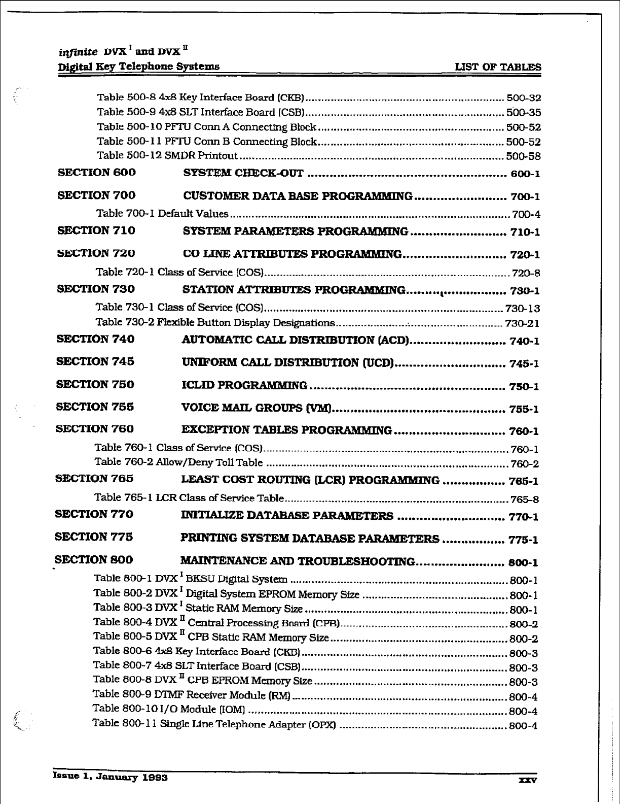
imite DVX I and DVX’
Digital Key Telephone
Systems LET
OF
TABLEG
Table 500-8 4x8 Key Interface Board (CKB) ............................................................... 500-32
Table 500-9 4x8 SLT Interface 3oard (CSB) ............................................................... 500-35
Table 5ClO- 10
PFTU
COM A Connecting Block
...........................................................
500-52
Table 500- 11 PFTU Conn B Connecting Block
...........................................................
500-52
Table 5OO- 12 SMDR Printout ....................................................................................
500-58
SECTION 600 SYSTEM cHEcK-ouT
...................................... l ...............
600-I
6EcTION700 CUSTOMER DATA BASE PROG RAMMING
......................... 700-1
Table 70s 1 Default Values .........................................................................................
700-4
SECTION710 SYSTEM P ARAMETERS PROGRAMMING
..........................
710-I
SECTION720 CO IJNEiATTRIBUlm3 PROGRAMHING ............................
720-l
Table 720-l Class ofService (COS). ............................................................................ .720-8
SECTION730 STATION ATTRIBUTES PROGRfWMtNG
....... .., . l ...............
750-l
Table 730-l Class ofService (COS) ............................................................................ 730-13
Table 730-2 FQxibIe Button Display Designations ...................................................... 730-Z 1
SEcTloN740 AUTOMATIC 42U.L DISTRIBUTION @CD)
....................... l ..
740-l
SECTION74Ei UNIFORM CALL DISTRIBUTION (UCD) . .............................
748-l
SECMON750 ICLID PROGRAMlKlNG
............................. l ........ l ..............
750-I
SECTION 75s VOICE MAIL GROUPS fVM)
... .,L ... l .* ........ l ................. l ........
irsfi-l
SECTION760 EXCEPTION TABLES PROG-G *..., .........................
760-l
Table 760-l Class of Service (COS) .............................................................................. 760-l
Table 760-2 Allow/Deny Toll Table ............................................................................. 760-2
SECTION766 LEAST COST ROUTING &CR) PROGRAMMING
..... l
........... 705-l
Table 765- 1 LCR Class of Service Table ....................................................................... 765-8
SECTION
770 INM!MWZ DATABASE PARAMETERS .............................
770-1
SECTION
776
PRINTING SYSTEM DATARASE PARAZYIETERS ........... ..a ... 775-l
S-ON SO0 MAINTENANCE ANTI TROUBLESHOOTING ................... m
.... 8Oo- 1
-
Table 80&l DVX’ BKSU Digital System ..................................................................... 800-l
Table 800-2 DVX ’ Digital System EPROM Memory Size .............................................. 800- 1
Table 800-3 DVX ’ Static RAM Memory Size ................................................................ 800- 1
Table 800-4 DVX ’ Central Processing Board (CPB) ..................................................... 800-2
Table 800-5 DVX ’ CPB Static RANl Memory Size ........................................................ 800-2
Table 800-6 4x8 Key Interface Board (CKB) ................................................................. 800-3
Table 800-7 4x8 SLT Interface Board (CSB) ................................................................. 800-3
Table 800-8 DVX ’ CPB EPROM Memory Size ............................................................. 800-3
Table 80&9 DTMF Receiver Module (RM) .................................................................... 800-4
Table 800- 10 I/O Module (IOM) .................................................................................. 800-4
Table 8OO- 11 Single Line Telephone Adapter (OPX) ................................................... ..800- 4
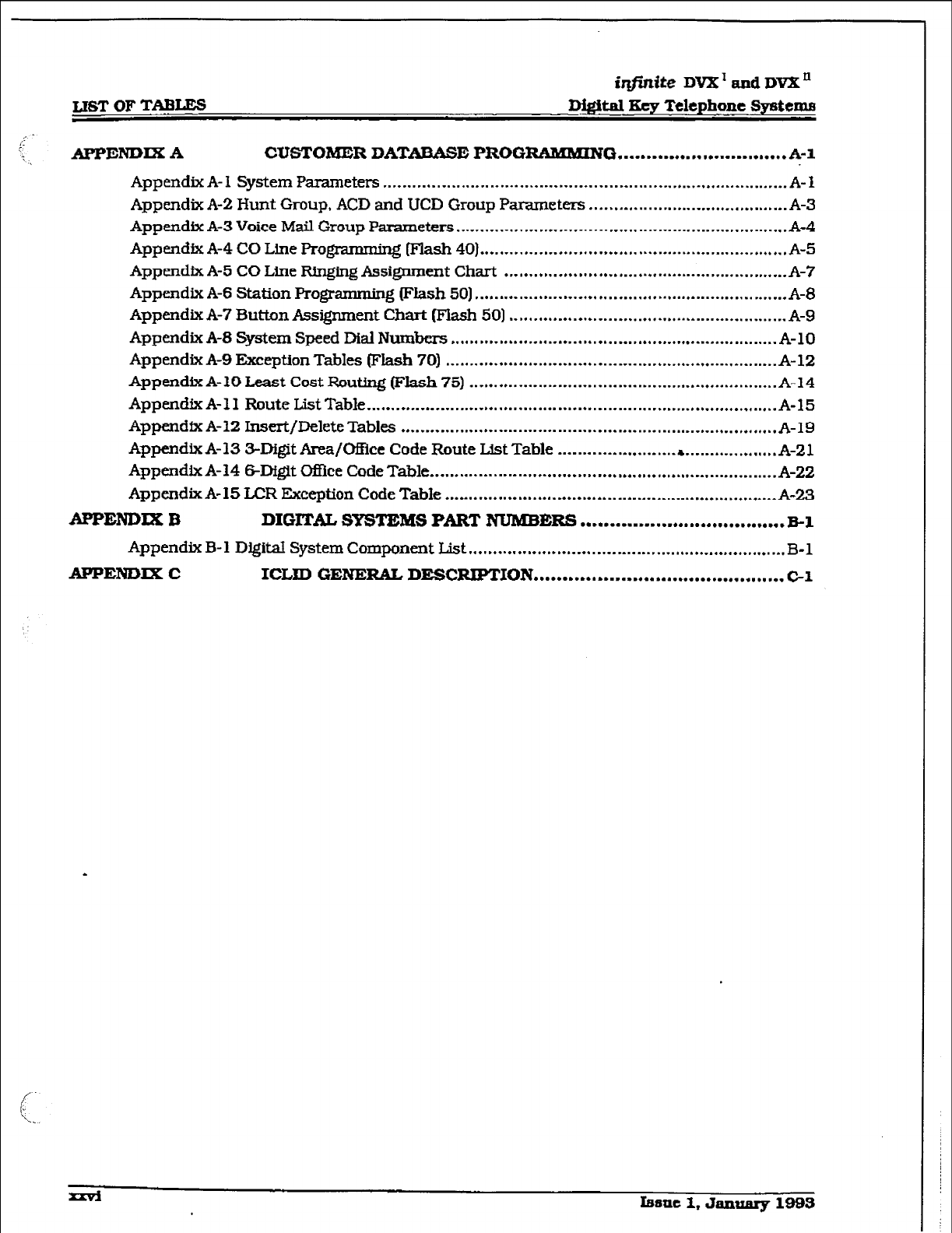
L16T OF
TABLES
irlfinite
DVX’ and DVX’
Digftd Key Telephone Systema
APPENDLXA CUSTOMER DATABASE PROGRABKMING .............................. A-l
Appendix A- 1 System Parameters ................................................................................... A-l
Appendix A-2 Hunt Group, ACD and UCD Group Parameters ......................................... A-3
Appendix A-3 Voice Mail Group
Parameters
....................................................................
A-4
Appendix A-4 CO Lme Progmmming Wash 40) ............................................................... A-5
AppendixA- COLme FQngingAssignment Chart .......................................................... A-7
Appendix A-6 Station Programming (Flash 50) ................................................................ A-0
Appendix A-7 Button Assignment Chart @‘lash 50) ......................................................... A-9
Appendix A-8 System Speed Dial Numbers ................................................................... A-10
Appendix A-9 Exception Tables (Flash 70) .................................................................... A-12
Append& A- 10 Least Cost Routing (Flash 75)
...............................................................
A-14
Appendix A- 1 I Route L&t Table
....................................................................................
A-15
Appendfx A-12 Insert/Delete Tables ............................................................................. A-19
Appendix A-13 3-Digit Area/CHkt Code Route L&t Table ............................................ A-21
Appendix A-14 digit #fEke Code Table ....................................................................... A-22
AppendixA- LCR Exception Code Table .................................................................... A-23
APPENDIX B DIGITAL SYSTEBt¶S PART NUMBl5RS
....................................
El
Appendix B- 1
DlgitaI
System Component List ................................................................. B-l
APPENDIXC ICLID GENERAL DESCRIPTION
............................................
C-l
.
Issue 1, January 1993
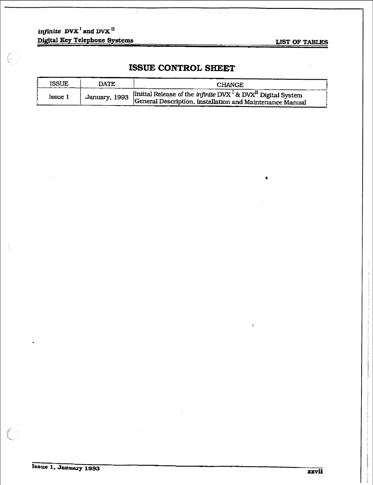
r
iqjlnite DVX*andDVXn
Di&d Eey Telephone Systems LIST OF TABLE-S
ISSUE CONTROL SHEET
1 lSSuJ3 i
DATE I CHANGE
1
b
! Issue 1
January. 1993 I
‘Initial Release of the ir&ife DVX’ & Dvx” Digital System
General Description. hstallation
and
Maintenance MamaI !
i
I~auc 1, January
1993
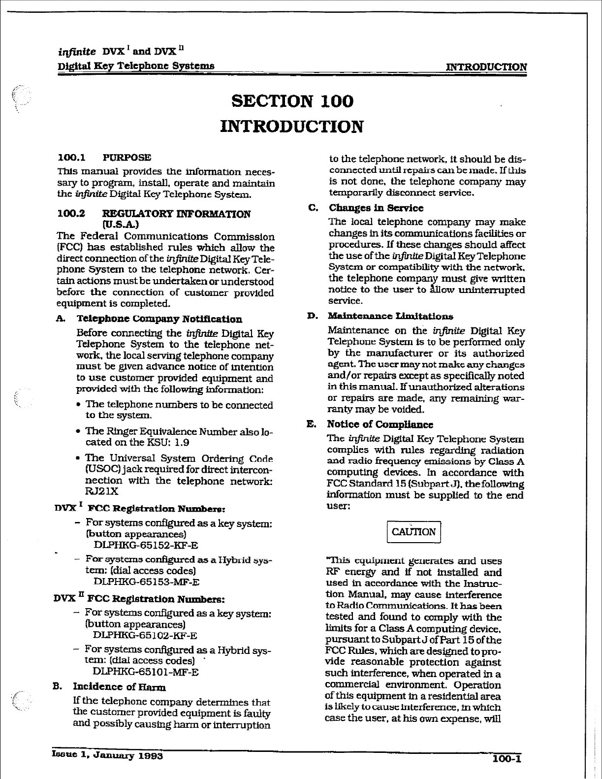
iqjinite DVX’ and
DVX’
D&itd Eey Telephone Systems INTRODUCTION
SECTION I.00
INTRODUCTION
100.1 PURPOSE
This manual provides the information neces-
sary to program, install, operate and maintain
the i&in&z DigitaI Key Telephone System.
100.2 REGULATOFtY INPORMATION
(u.8.A)
The Federal Communications Commission
(FCC) has established rules which a&w the
direct connection of the injir&eDigital Key Tele-
phone System to the telephone network. Cer-
tain actions must be undertaken or understood
before the connection of customer provided
equipment is completed.
A. TdephoneCompanyNotifkatfon
Before cm.neciing the ir3finfte Digital Key
Telephone System to the telephone net-
work, the local serving telephone company
must be given advance notice of intention
to use customer provided equipment and
prwided with the following information:
l
The telephone numbers to be connected
to the system.
l
The Ringer Equivalence Number also Io-
cated on the KSU: 1.9
. The Universal System Ordering Code
(USOC) jack required
for
direct intercon-
nection with the telephone network
w2
1x
DVX’ FCC Re@tration Number8:
- For systems comigured as a key system:
lbutton appearances)
DLPHKG-65152~KF-E
- - For systems cor@ured as a Hybrid sys-
tem: (dial access codes)
DLPHKG-65 153~ME-E
DVX = FCC RcgietrafAon Numbers:
- For systems configured as a key system:
(button appearances)
DWHKG-65102~KF-E
- For systems configured as a Hybrid sys-
tern: (dial access codes) *
DLPHKG65101-MF-E
B.
Incidence
of warm
If the telephone company determines that
the customer provided equipment is faulty
and p~~~l%ly causing harm or interruption
to the telephone network, ft should be dis-
connected until repairs can be made. If this
is not done, the telephone company may
temporarily disconnect service.
c. Changce ill service
The loczil telephone company may make
changes in its communications facilities or
procedures. If these changes should affect
the use of the ~I.I. DigitaI Key Telephone
System or compatibility with the network.
the telephone company must give written
notice to the user to &xv uninterrupted
semice.
D. MaintcnanctLimitatio~s
Maintenance on the infinUe Digital Key
Telephone System is to be performed only
by the manufacturer or its authorized
agent. The user may not make any changes
and/or repairs except as specifically noted
in this msnuaI. Ifunauthorized alterations
or repairs are made, any remaining war-
ranty may be voided.
E. Notice
of
Compliance
The intite Digital Key Telephone System
complies with rules regarding radiation
and radio frequency emissions by Class A
computing devices. In accordance with
FCC Standard 15 [SubpartJ). the following
information must he suppled to the end
user:
This equipment generates and uses
RF energy and if not tnstalled and
used in accordance wftb the Instruc-
tion Manual, may cause interference
to Radio Communications. It has been
tested and found to comply with the
limits for a Class A computing device,
PursuanttoSubpartJofFart Eofthe
FCC Rules. which are designed topro-
vide reasonable protection against
such interference, when operated in a
commercial environment. Operation
of this equipment in a residential area
is likely to cause interference, fn which
case the user, at his own expense, will
Issue 1, January
1993 100-I
r
INTRODUCTION
infinite DVX ’ and DV2L’
Digital Key Telephone Spstems
be required to take whatever measures
may be required to correct the inter-
ference.”
F.
Hearing
Aid cOmpat?bility
AI1 infinrte Digital Terminals are Bearing
Aid Compatible, as defined in Section
68.316 of Part 68 FCC Rules and Regula-
tions.
G. OPX Circutt
The in&&e Digital Key Telephone System
may be equipped with Single Line Adapters
(OF%) modules which provide a 48V FCC
registered 2500~type single line off-prem-
ise extension interface port.
l
Each OPX port when used to support an
off-premise extension requires an
OL13C network circuit.
0 An FCC registered interface such as a
RJl lC/W is also required to connect to
the public network
loo.3 REGULATOZWINFORMATION (CA-
NADM+Jl
l
Department of CommLmieations [DOC}
CerHGcation Number: 526 2933 A
l
Load Number: 20
l
Standard Connector: CA1 lA/CA2 lA
l
Canadian Standards Association (CSA)
File Number: I357228
A. Notice
The Canadian Department of Communica-
tions* label identifies certified equipment.
This certification means that the equip-
ment meets certain
tdec0rnmunic2tions
network protective, operational and safety
requirements. This Department does not
guarantee the equipment will operate to
- the user’s satisfaction.
Before instalhg this equipment, users
should ensure that it is permissible to be
connected to the facilities of the local tele-
communications company. The equipment
must also be installed using an acceptable
method of connection. In some cases, the
company’s inside wiring associated with
single he individual service may be ex-
tended by means of a certified connector
assembly (telephone extension cord]. The
customer should be aware that compliance
with the above condition may not prevent
degradation of service in some situations.
Repairs to certified equipment should be
made by an authorized Canadian mainte-
nance facility designated by the supplier.
Any repairs or alterations made by the user
to this equipment. or equipment ma&me-
tions. may give the telecommunications
company cause to request the user to dis-
connect the equipment.
Users should ensure for their own protec-
tion that the electrical ground connections
of the power utility, telephone lines and
internal metallic water pipe system, if pre-
sent, are connected together. ‘Ihis precau-
tion may be particularly important in rural
areas.
Users should not attempt to make
such connections themselves, but
should contact the appropriate Alec-
irk inspectton authority. or electri-
cian, as appropriate.
B. Explanation of ‘Load Number
The Load Number (LN) assigned to each
terminal device denotes the percentage of
the total load to be connected to a tele-
phone loop which is used by the dwice to
prevent overloadmg. The termination on a
loop may eons&t of any combination of
devices subject only to the requirement
that the total of the load numbers of all the
devices does not exceed 100.
c. hwntenancc XAmitatiolla
Maintenance on the infinite Digital Key
Telephone System is to be performed only
by the manufacturer or its authorized
agent. The user may not make any changes
and/or repairs except as specif?cally noted
in this manual. If unauthorized alterations
or repairs are made, any remaining war-
ranty may be voided.
D. Notice of Compllarlce
The infintte Digital Key Telephone system
complies with Class A or Class B limits of
the Canadian Radio Interference Regula-
tions. ln accordance with FCC Standard 15
(Subpart J). the following information
must be supplied to the end usen
100-Z Issue 1, January 1993
INTKODUCTION
* CAUTION 1
7Xs equipment generates and uses
RF energy and if not installed and
used in accordance with the Instruc-
tion Manual, may cause interference
to Radio Communications. It has been
tested and found to comply with the
limits for a Class A or Class B comput-
ing device,
pursuant
to Subpart
J
or
Part 15 of the FCC Rules. which are
designed to provide reasonable protec-
tion against such interference, when
operated in a commercial tnviron-
rnent. Operation of this equipment in
a residential area is likely to cause
interference, in which case the user,
at his own expense. xvillbe required to
take whatever measures may be re-
quired to correct the interference.”
E. OPXCirr.x&
The infinite Digital
Key
Telephone System
maybe equipped with Sfngle Line Adapters
(OPXJ modules which provide a 48V FCC
registered 25OWype single line off-prern-
ise extension interface port.
l
A DOC registered interface such as a
CA1 1 is also required to connect to the
public network.
100.4 IJL/txA SAFETY co-CE
The infinite Digital Key Telephone System has
met all safety requirements and was found be
in compliance with the Underwriters Laborato-
ries (UL) 1459
Second Edition
and
Canadian
Standards Association (CSA] C22.2, No. 225
Standard.
The
h_fintte Digital Key Telephone
System is authorized to bear the UL and CSA
. marks.
loo.5 TOLL
FRAUD DISCLMMER
‘WHlLE THIS DEVICE IS DESIGNE?D TO BE
WONABLY SECURE AGAINST IWI’RU-
SION5 FROM FRAUDULENT CAUiER5. IT 18
BYNO-S KNVULNERABm TO FRAUD.
TEEREFORE NO E
XPRESS OR IMPLIED
WARRANTY IS MADE AGAINST SUCH
-UD ~CLtJDlNG lNTERCONNEOTION TO
THE LONG DISTANCE NETWORKm”
‘WHILE THIS DEVICE IS DESIGNED TO BE
REA5ONABLY SECURE AGAINST INVASION
OF PRIVACY, IT IS BY NO MEAN5 INVUL-
NERABLE TO SUCH INVASXONS. TKERE-
FORE NO EXPRESS OR IMPLIED
WARRANTP IS MADE AGAZNST UNL4WFClL
OR UNAUTIIORIZED UllLIZATXON WHICH
RESULTS m THE INVASION OF ONE’S
RIGHT OF PRIVACY.-
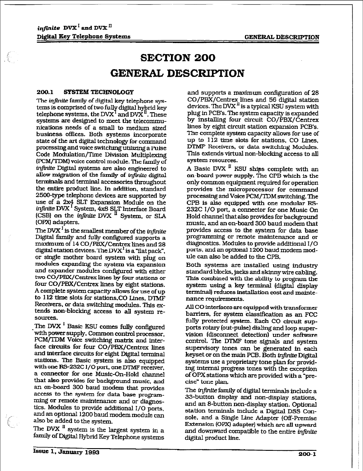
D&itd Key Telephone Systen~~
GENERAL
DESCRIPTION
SECTION 200
GENERAL DESCRIPTION
200.X SYSTEM TECHNOLOGY
?he infinue family of digital key telephone sys-
terns is comprised of two f”$ digital herid key
telephone systems, the DVX and DVX . These
systems are designed to meet the telecommu-
nications needs of a small to medium sized
business ofihx.s. Both systems incorporate
state of the art digital technology for command
processing and voice switching utilizing a Pulse
Code Modulation/Time Division Multiplexing
(PCM/TDM) voice control module. The family of
infinite Digital systems are also engineered to
allow mfgration of the
family of
infinite digital
terminals and terminal accessories throughout
the entire product line. In addition. standard
2500-type telephone devices are supported by
use of a 2x4 SLT Expansion Module on the
in- DVX I System, 4x8 SLT Interface Board
(CSB) on the infinite DVX ’ System, or SLA
(OPXJ adapters.
The DVXI is the smallest member of the &~&i&z
Digital family and fully conf@.n-ed
supports
a
maximum of 14 CO/PBX/Centrex lines and 28
digital station devices. The DVX’ is a “flat pack”,
or single mother board system with plug on
modules expanding the system via expansion
and expander modules configured with either
two CO/PBX/Centrex lines by four stations or
four CO/PE!X/Centrex lines by eight stations.
A complete system capacity allows for use of up
to 112 time slots for stations.CCl Lines. DlMF
Receivers. or data switching modules. This ex-
tends non-blocking access to alI system re-
sotll-ces.
-The DVX I Basic KSU comes fully configured
with power supply, Common control processor.
PCM/TDM Voice switching matrix and inter-
face circuits for four CO/PBX/Centrex lLnes
and interface circuits for eight Digital terminal
stations. The Basic system is also equipped
with one RS-232C I/O port. one DTMF receiver,
a connector for one Music-On-Hold channel
that also provides for background music, and
an on-board 300 baud modem that provides
access to the system for data base program-
ming or remote maintenance and or
diagnos-
tics. Modules to provide additional I/O ports,
and an opffona.I 1200 baud modem module can
also be added to the system.
The DVX Ii system is the largest system in a
family of Digital Hybrid Key Telephone systems
and supports a maximum configuration of 28
CO/PBX/Centrex lines and 56 digital station
devices. The DVXn is a typical KSU system with
plug in PCB’s. The system capaciv is expanded
by installing four circuit CO/PBX/Centrex
lmes by eight circuit station expansion PCB’s.
The complete system capacity allows for use of
up to 112 tjme slots for stations, CO Lines,
EYIMF Receivers, or data switchfng Modules.
This extends virtual non-blocking access to all
system resources.
A Basic DVX ’ KSU ships complete with an
on-board power supply. The CPB which is the
only common equipment required for operation
provides the micrbprocessor for command
processing and Voice PCM/TDM switching. The
CPB is also equipped with one modular RS-
232C I/O port, a connector for one Music On
Hold charme that also provides for background
music, and an on-board 300 baud modem that
provides access to the system for data base
programming or remote maintenance and or
diagnostics. Modules to provide additional I/O
ports. and an optional 1200 baud modem mod-
ule can also be added to the CPB.
Both systems are installed using industry
standard blocks, jacks and &&my wire cabling.
This combined with the
ability
to program the
system using a key terminal (digital display
termfnal) reduces inshllation cost and mainte-
nance requirements.
All CO interfaces are equipped with transformer
bar&m. for system &ssif?cation as an FCC
fully protected system. Each CO circuit sup-
ports rotary (out-pulse) dialing and loop super-
vision (disconnect detection1 under softsvare
control. The lYl7vIF tone signals and system
supervisory tones can be generated in each
keyset or on the main PCB. Both @nite Digital
systems use a proprietary tone plan for provid-
ing intema.l progress tones with the exception
of OPX
stations
which are provided with a ypre-
cise” tone plan.
The infintte family of digital terminals include a
33-button display and non-display stations,
and an 8-button non-display station. Optional
station terminals Include a Digital DSS Con-
sole, and a Shxgle Line Adapter (Off-Premise
Extension (OPX) adapter) which are all upward
and downward compatible to the entire ti@-~ite
digital product line.
Issue I, January
1993
200-I
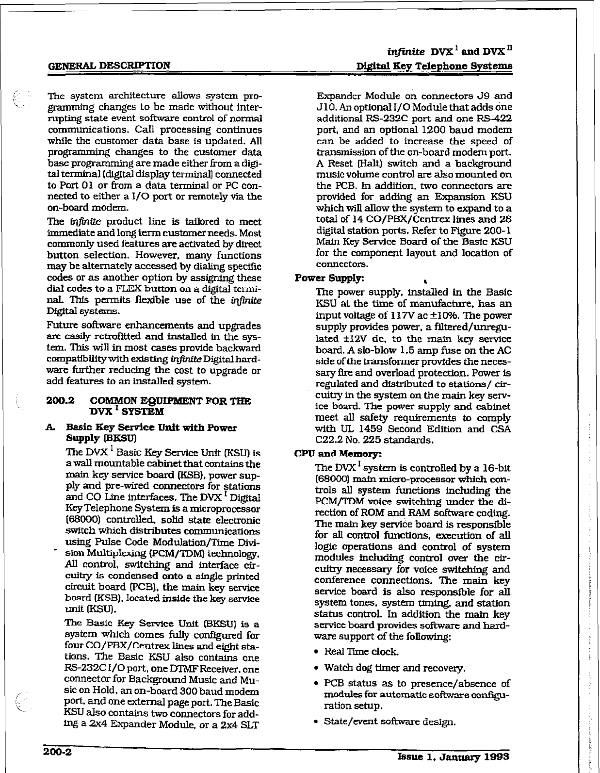
GENERAL DESCRWMON
@finite DVX’ and DVX”
Digital Key Telephane systems
The system architecture allows system pro-
gramming changes to be made without inter-
rupting
state event software control of normal
communications. Call processing continues
while the customer data base is updated. All
programming changes to the customer data
base progrwg are made either 6-om a digi-
tal terminal [digital display terminal) connected
to Port 01 or from a data terminal or PC con-
nected to either a If0 port or remotely via the
on-board modem.
The in- product line is tailored to meet
immediate and long term customer needs. Most
commonly used features are activated by direct
button selection. However, many functions
may be alternately accessed by dialing specific
c-odes or as another option by assigning these
dial codes to a FLEX button on a digital termi-
naL l%fs permits flexible use of the i~jhite
Dfgital systems.
Future software enhancemuris and upgrades
are easily retrofitted and fnstalled in the sys-
tem. This will in most cases provide backward
compatibility with existing infinite Digital hard-
ware further reducing the cost to upgrade or
add features to an installed system.
200.2 COMMON EQtJfPMENT FOR TEE
mm I SBTEM
A. Basic Key Semke Unit with Power
SuPPlY 0
The DVX I Basic Key service Unit (‘KSU) is
awall mountable cabinet that contains the
main key service board WB). power sup-
ply and pre-wired connectors for stations
and CO Line interfaces. The DVX ’ DigitaI
Key Telephone System is a microprocessor
P33000) controlled, solid state electronic
switch which distributes communications
uskng Pulse Code Modulation/Time Divi-
* sion MultipIexing (PCMJTDM) technology.
Al control. switching and interface cir-
cuitry is condensed onto a sjngle printed
circuit board (PCB], the main key service
board (KSB), located inside the key senoice
unit WXJ).
The Basic Key Service Unit ISKSU) is a
system which comes fully coni3gured for
four CO/PBX/Centrex lines and eight sta-
tions. The Basic KSU also contains one
RS-232C
I/O
port,
one DTMFReceiver, one
connector for Background Music and
MU-
sic on Hold. an on-board 300 baud modem
POk and one external page port. The Basic
KSU aIs contains two connectors for add-
ing a
2x4
Expander Module, or a 2x4 SLT
Expander Module on connectors J9 and
J 10. An optional I/O Module that adds dne
additional RS-232C port and one M-422
port, and an optional 1200 baud modem
can be added to increase the speed of
transmission of the on-board modem port.
A Reset (Halt) switch and a background
music volume control are also mounted on
the PCB. In addition, two connectors are
provided for adding an Expansion KSU
which will allow the system to expand to a
toti of 14 CO/PEX/Centrex lines and 28
digital station ports. Refer to Figure 200- 1
Main Key Service Board of the Basic KSU
for the component layout and location of
coIlnectors.
Power SuppIyz
The power supply, insbed in the Basic
KSU at the time of manufacture. has an
input voltage of 117V ac *lO%. The power
supply provides power, a filtered/unregu-
lated rtlZV de. to the main key service
board. A slo-blow 1.5 amp fuse on the AC
side of the transformer provides the neces-
sary Are and overload protection. Power is
regulated and distributed to stations/ cir-
cuitry in the system on the main key sew-
ice board. The power supply and cabinet
meet all safety requirements to comply
with UL 1459 Second Edition and CSA
C22.2 No. 225 standards.
CPU and Bknorg:
The DVX I system is controlled by a 16-bit
(68000) Enafn micro-processor which con-
trols all system functions including the
PCM/TDM voice switching under the di-
rection of ROM and RAM software coding.
The main key se&e board is responsl%le
for all control functions, execution of all
logic operations and control of system
modules incIuding control over the cir-
cuitry necessary for voice switching and
conference connections. The main key
service board is also responsible for all
system tones. system timing. and station
status control, In addition the mm key
semice board provides software and hard-
ware support of the folhwing:
l
Real ‘Time clock.
l
Watch dog tLmer and recovery.
l
PCB status as to presence/absence of
modules for automatic software conf?gu-
ration setup.
l
State/went software design.
200-2 lrrsue 1, dally 1993
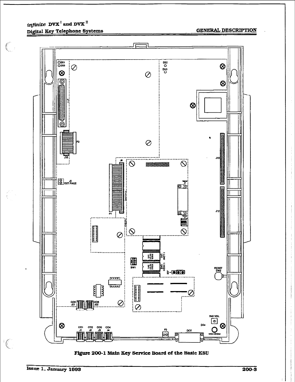
irlfinite DVX’aadDVX”
~~igitd Key Telephone Systems GENERAL DESCRIPTION
;
: .*
: ::
: ::
0
: ::
: i)
is.
Jl2
F&urc 200-l
Main Key serpicc Board of the Baafc
KStl

GElQERAL DESCRIPTIOl?I
iqfinite
DVX’amiDVX”
Digital Key Telephone Systems
4 Backup of customer database RAh4
memory via a ‘Super Cap” (super capaci-
tar) .
System software is provided in EPROM
memory and is installed on the main key
service board. The system contains 512K
of EPROM storage and is equipped with
128K of ‘battery--backed static RAM. Pro-
visions have been made on the card to
address up to two megabytes of EPROM
memory and up to two megabytes of static
RAM.
LEDS & Indicators:
Four green LEDs are located on the main
key service board along the top of the PCB,
Two of the LEDs (DS2 & DS3) indicate the
presence of +5V h -5V dc. LEDs DSI and
DS5 indicate the present of +12V dc used
to supply power to the key stations (one
LED per four stations). An extinguished
JLED indicates the absence of the associ-
ated voltage.
A red LED (DS4) located in the lower right
portion of the main key service board pro-
vides a system “heart beat” indication.
co Line/station
lntcrhces:
The Basic Key Service Unit (BKSUJ con-
tabs the necessary circuitry to connect
four CO/Centrex/P3X loop start lines and
eight digital key telephones to the system.
This card also contains one additional
voice ~transmit) path for external paging.
The main key service board contains four
Central Of&e, Centrex or PBX loop start,
line interfaces. The protection circuitry to
allow the system to be classified as a fully
protected system are located on the card
for each CO clrcuit. The CO circuits are
a equipped with current sensing circuitry
that
fdentifkzs distant end disconnect Qoop
supervision). Each CO line interface design
also provides properfusing or protection to
comply with the rc@rements of UL 1459
Second F&ion and CSA C22.2 No. 225
standards. CO lines are connected to the
system via RI- 11 modular jacks mounted
on the bottom of the main key semce
board.
The main key service board also provides
the interface for eight Digital Key Tel+
phones using two 64K channel me-
me&s. Stations connect to the board via
the MDF thrcmgh a 50-pan connector lo-
cated inside the Basic KSU. Each station
connection requires four wires to connect
to the board.
A Digital DSS Console. Single Line Tele-
phone Adapter (OPX) or other specifically
designed adapter with a digital interface
can be assigned to any one of the interface
circuits. ‘Ihe key station interface circuits
are protected from mis-wiring and over-
current.
The main key service board also contains
an on-board modem that is capable of
transmitting data at a rate of 300 Baud.
The modem supports and is compatible
with the Hayes command protocol. The
Bell System (Western Electric] standards
103 and 212A for modem design is incor-
porated into the design af this modem. The
modem operates on-line in both Full and
Half duplex modes. An optional 1200 Baud
module may be added to the main key
service unit to allow transmission at the
rate of 1200 Baud.
B. DVX’ Erpansion ESUwith Power
SUPflY
m=Jl
The Expansion Key Service Unit (EKSU) is
a unit which comes equipped with a pawer
supply and circuitry providing four addi-
tional loop start CO/PBX/Centrex line
ports and eight digital key telephone ports
to the Expansion KSU. All prccessing and
control functions as well as voice connec-
tions and switching are controlled by cir-
cuitry on the Basic KSU and transmitted
to the Expansion KSU through the ribbon
cables.
The ma.iu key service board on the Expan-
sion KSU allows connection of one optional
application module (i.e. DTMF Receiver) to
the system and connector(s] for installing
an additional 2x4 Expander Module, 2x4
SLT Expander Module or a 4x8 Expander
Module. Refer to F’igurc 200-2 Main Key
Service Board of the Expansion KSU
Power Supply
The power supply, installed in the Expan-
sion KSU at the time of manufacture, has
an input voltage of 117V ac *I@?&. The
power supply provides power, a ffltered/
unregulated +12V dc, to the Expansion Key
Service Board WKSB). A slo-blow 1.5 amp
fuse on the AC side of the transformer
provides the necessary fire and overload
protection. Power is regulated and distrib-
uted to staffons/circui~ in the system on
the main key service board on the Expan-
200-4
tEIsue 1. Janaary 1095
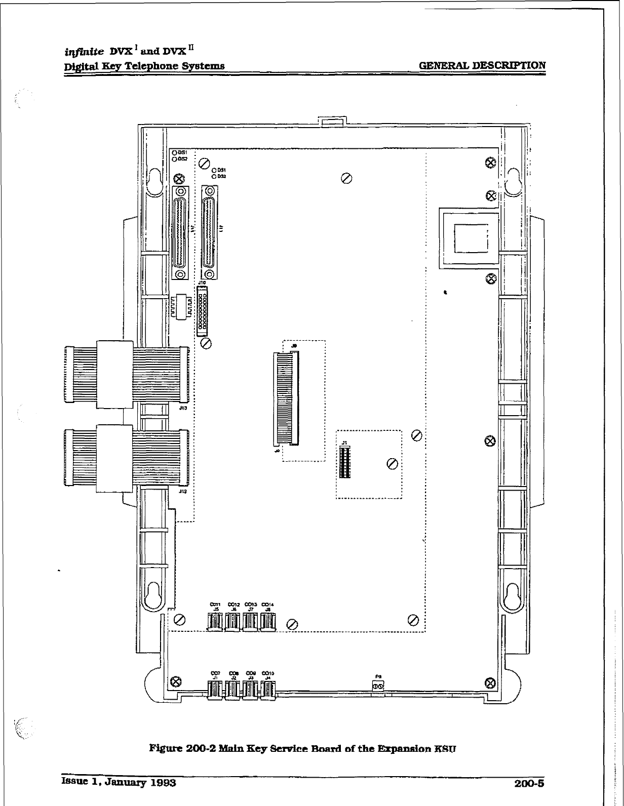
iqjinfte DVX’ and DVX *
~&&al Xcy Telephone Systems GENERAL DESCRIPTION
om’ :
o- :
i 8,m,
ODB
0
Issue 1, January 1993 200-S
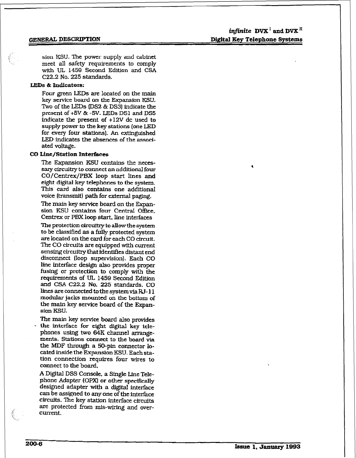
i@dte DVX I and BITE”
Digital Key
Ttlephone Systems
sion KSU. The power supply and cabinet
meet all safety requirements to comply
with UL 1459 Second Edition and CSA
C22.2 No. 225
standards.
LEDS a IndicatoI8:
Four green LEDs are located on the main
key service board on the Expansion KSU.
Two of the LEDs (DS2 & DS31 indicate the
present of +5V & -5V. LEDs DSZ and DS5
indicate the present of +12V dc used to
supply power to the key stations (one LED
for every four stations). An extinguished
LED indicates the absences of the associ-
ated voltage.
co Line/station
Intcrfkcts
The Expansion KSU contains the neces-
sary circuitry to connect an additional four
CO/Centrex/PBX loop start lines and
eight dgital key telephones to the system.
‘ibis card also contains one additionaf
voice (lransmit) path for ex.temal paging.
The main key service board on the Expan-
sion KSU contains four Central Office,
Centrex or PBX loop start, line interfaces
The protection circuttry to allow the system
to be classtied as a fully protected system
are located on the card for each CO circuit.
The CO circuits are equipped with current
sensing circuitry that identJfies distant end
disconnect (loop supervision). Each CO
line interface design also provides proper
fusing or protection to comply with the
requirements of UL 1459 Second Edition
and CSA C22.2 No. 225 standards. CO
lines are connected to the system vfa RJ- 11
modular jacks mounted on the bottom of
the main key service board of the &pan-
sion KSU.
The main key service board also provides
- the interface for eight digital key tele-
phones using two 64K channel arrange-
ments. Stations connect to the board via
the MDF through a ?jO-pin connector lo-
cated inside the Expansion KSU. Each sta-
tion connection requires four wires to
connect
to the board,
A Digital DSS Console, a Single Line Tele-
phone Adapter (OPXI or other spec%eally
designed adapter with a digital titerface
can be assigned to any one of the interface
circuits. ‘Ihe key station interface circuits
are protected from mis-wlrlng and over-
current.
.
Zoo-6
Iaue1,JanumylB93
i&mite DVX’andDVX’
Digital Kty Telephone Systems GENERAL DESCRIETION
C. 2x4 Expander Module
LED8 & Illdicators:
The 2x4 Expander Module is a two CO by
four key station interface module that
plugs onto the main key service board of
the Basic KSU or the main key service
board of the Expansion KSU through the
use of two ribbon cables. This module is a
combination board that contains the nec-
essary circuitry to connect two CO/Cen-
trex/PBK loop start lines and four digital
key telephones to the system. ‘Ibis card
also contains one additional voice [trans-
raft) path for external paging. and a con-
nector for adding one apphcation module
(i.e. IYIMF Receiver] to the system.
Three green LEDs are located on the 2x4
Expander Module. ?‘wo of the LEDs (DS3 &
DS2) indicate the presence of +5v & -5v dc.
LED DS1 monitors the +12V dc used to
supply power to the key stations. An extin-
guished L.ED indicates the absence of the
associated voltage.
co UJle~station
IIItclfaces:
‘Ibe 2x4 Expander Module provides the
interface for two Centi Of&e, Centrex or
PBX loop start Ifnes. The protection cir-
cuitry necessary to atfow the system to be
classified as a fury protected system are
located on the card for each CO circtit.
The CO circuits are equipped with current
sensing circuitry that identifies distant end
disconnect floop supervfsion). The module
design also provides proper fusing or pro-
tection to comply with the requirements of
UL 1459 Second Edition and CSA C22,2
No. 225 standards. CO lines are connected
to the system via RI-1 1 modular connec-
tors mounted on the bottom edge of the
board. The 2x4 Expander module also pro-
vides the interface for four digital key tele-
phones using two 64K channel
arrangements. Stations connect to the
board via the MDF through a 5%pin con-
nector located on the main key service
board inside the Basic KSU or a similar
connector on the main key service board
when installed in the Expansion KSU.
Each station connection requires four
wires to connect to the board.
0
0
Dsl
0
Y-
053Ds
0 0
.Bv dy
0
Figure 200-S -4 Expander Module
A Dig&l DSS Console. a Single Line Tele-
phone Adapter (OFT), or other spec&ally
designed adapter with a digital interface
CZUI be assigned to any one of the interface
ciradts. The key station interface circuits
are protected fi-om m&wiring and over-
currtrlt.
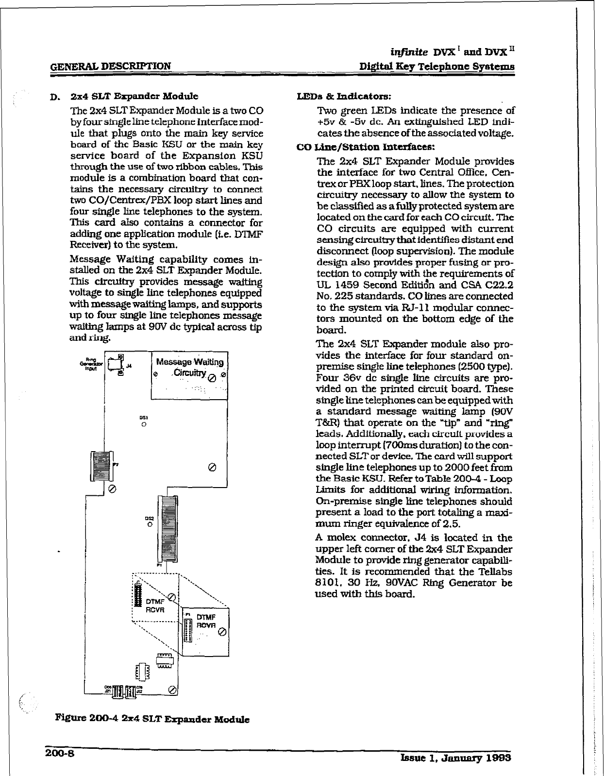
hifinite DVX’ axid DVX”
D&itaI Key Telephone Spsttme
D. 2x4 SLT Expander Module
The 2x4 SLT Expander Module is a two CO
by four single line telephone Interface mod-
ule that plugs onto the main key service
board of the Basic KSU or the main key
service board of the Expansion KSU
through the use of two ribbon cables, This
module is a combination board that con-
tains the necessary circuiby to connect
two CO/Centrex/PBX loop start lines and
four single line telephones to the system.
This card also contains a connector for
adding one application module (i.e. D?MF
Receiver) to the system.
Message Waiting capability comes in-
stalled on the 2x4 SLT Expander Module.
This circuitry provides message waiting
voltage to single line telephones equipped
with m-waiting lamps, and supports
up to four single line telephones message
waiting lamps at 9W dc typical across tip
0
F%Wc 200-Q 2x4 SLT Expaadcr Module
LEIM & Indicators:
Two green LET% indicate the presence of
+5v & -5v dc. An extinguished LED indi-
cates the absence of the associated voltage.
CO Line/Station Iritcdaces:
The 2x4 SLT Expander Module provides
the interface for two Central Of3ice. Cen-
trex or PEX loop sbrt, lines. The protection
circuitry necessary to allow the system to
be classified as a fully protected system are
located on the card for each CO circuit. The
CO circuits are equipped with current
sensing circuitry that identifies distant end
disconnect (loop supervisionI. ‘Ihe module
design also provides proper fusing or pro-
tection to comply with the requirements of
UL 1459 Second Edit&r and CSA (X2.2
No. 225 standards. CO lines are connected
to the system via RJ-11 modular connec-
tors mounted on the bottom edge of the
board.
The 2x4 SLT Expander module also pro-
vides the interface for four standard on-
premise single line telephones (2500 type).
Four 36v dc single line circuits are pro-
vided on the printed circuit board. These
single line telephones canbe equippedwith
a standard message waiting lamp (9OV
T&R) that operate on the Yip” and ‘ring”
leads. Additionally, each circuft provides a
loop interrupt (7OOms duration) to the con-
nected SLT or device. The card will support
single line telephones up to 2000 feet fkom
the Basic KSU. Refer toTable 200-4 - Loop
IArMs for additional wiring information.
On-premise singie line telephones shoutd
present a load to the port totaling a maxi-
mum ringer equivalence of 2.5.
A molex connector. 54 is located in the
upper left comer of the 2x4 SLT Expander
Module to provide ring generator capabili-
ties. It is recommended that the Tellabs
8101, 30 Hz. SOVAC Ring Generator be
used with th% board.
200-S Issue 1, Jannary 1-3
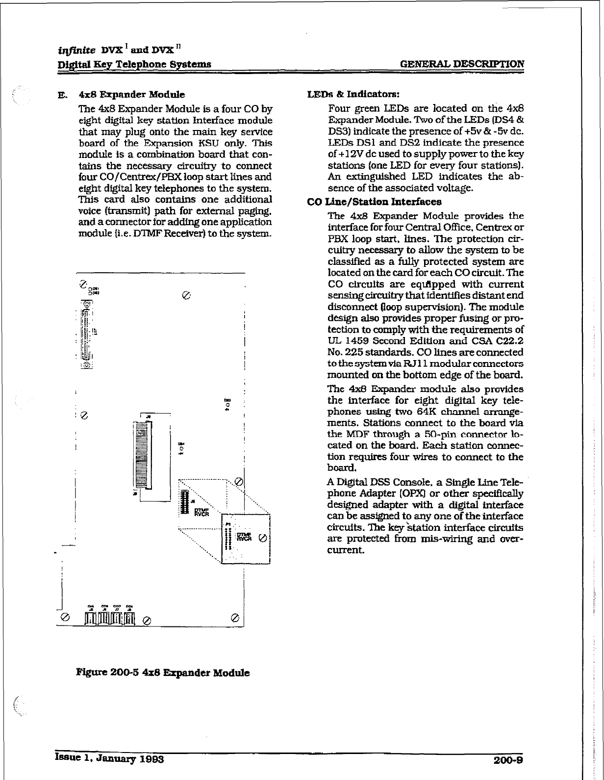
i@inite DVX’andDI&
Dfffital Key T&phone Systems GENERAL DESCRIPTION
E. 4x8 Expander Modalt LLEDS L Indioators:
The 4x8 Expander Module is a four CO by
eight digital key station Interface module
that may plug onto the main key service
board of the Expansion KSU only. This
module is a combination board that con-
tains the necessary eircuit3-y to connect
four CO/Centrex/PEX loop start lines and
eight digital key telephones to the system.
This card also contains one additional
voice b-ansmit) path for external pagjng.
and a connector for adding one application
module {i.e. DTMF Receiver) to the system.
Four green LF,Ds are located on the 4x8
Expander Module. Two of the LEDs (IIS4 &
DS3) indicate the presence of +5v & -5v dc.
LEDs DSl and DS2 indicate the presence
of + 12V dc used to supply power to the key
stations (one LED for every four stations).
An extinguished LED indicates the ab-
sence of the associated voltage.
CO tie/Station Interfaces
The 4x8 Expander Module provides the
interface for four Central Office. Centrex or
PBX loop start, lines. The protection cir-
cuitry necesszy to aLlow the system to be
classified as a fully protected system are
located on the card for each CO circuit. The
CO circuits are eqflpped with current
sensing tzircuiw that identifies distant end
disconnect (loop supervision). The module
design also provides proper rUsing or pro-
tection to comply with the requirements of
LIL 1459 Second Edition and CSA C22.2
No. 225 standards. CO lines are connected
totbesyst~vfaRJl1mod~arronnectors
mounted on the bottom edge of the board.
The 4x8 Expander module also provides
the interface for eight digital key tele-
phones using two 64K channel arrange-
ments. Stations connect to the hoard via
the MDF through a 50-pin connector lo-
cakd on the board. Each station connec-
tion requires four wires to connect to the
board.
i.9 :
FQurc
ZOO-8
4x8 bpandcr Module
A Digital DSS Console. a Single Line Tele-
phone Adapter [OPX) or other specifkally
dessigned adapter with a digital interface
can be assigned to any one of the interface
circuits.
The key ‘station interface circuits
are protected f&m mis-wirinp and over-
current.
16sue 1, January l9B3 200-B
GENERAL DEXXUPTION
irLfinite DVX’ and
DVX”
Digftal
Rev Telephone Sy&cms
200.3
COMMON EQUIPMENT FOR TEE
DVX = SYSTEM
The following components are necessary to op-
erate the in..ite Digital Key Telephone System.
Refer to Appendix B for a complete infinite Digi-
tal Key Telephone System component list with
Part ws.
l
Equipment Cabinet w/Power Supply
IK=Jl
l
Central Processing Board (CPB)
l
4xS Key Interface Board (CKB)
. 4 SLT Interface Board [CSB)
A Equipment Cabinet With Power
SUPplY u=uI
The DVX ’
system main cabinet contains
the power supply and mother board to
support a fully configured system of 28 CO
Lines and 56 Stations. The mot&r board
has eight card slots. Card Slot 58 (the right
most card slot) is used for the CenkaI
Processor Soard (CPB)
PCB. Card slots J1
through 57 each support a four CO line by
eight station PCB’s. Cable exits through
the bottom of the KSU through a cable exit
raceway near the back of the KSU. Refer to
Figure ZOO-6 Basic KSU Equipment
Cabinet
Power Supply
B.
The power supply is installed in the KSU
cabinet at the time of manufacture and
ships with the KSLJ. The power supply in-
put voltage is 117V ac +10?/6. The power
supply provides power distribution of fil-
tered f unregulated 12V dc and a regulated
-5V de to the back plane bus. An ON/OFF
switch is located on the front of the power
supply along with
a
&-blow 5 amp fuse on
the AC side of the transformer. The power
supply provides an input for a 4SV dc
source for future use. Power is regulated
and distributed to stations/circuitry in the
system on each printed circuit board.
Three fuses located inside the power sup-
ply protect the system from over-current
situations. The Power supply and cabinet
meet aU safety requirements to comply
with UL 1459 Second Edition and CSA
C22.2 No. 225 standards.
central Roccssor Board [CFB)
This plug-in card is the only common
equipment card required to make the sys-
tem operational and controls all system
activity. The CPB contains the main micro-
Processor a 16-bit [&3000) and a real tLme
clock which controls all system functions
including the PCM/IDM voice switching
under direction of ROM and RAM software
coding. The CPB is responsible for alI con-
trol functions, execution of all logic opera-
tions and control of system modules
including control over circuiky necessary
for voice switching and conference connec-
tions. The CPB is also responsible for all
system
tones.
system
timing,
and station
status control. In addition the CPB also
provides software and hardware support to
ensure the following:
l
Watch dog timer and recovery.
l
PCB status as to presence/absence of
cards for automatic spftwarc configura-
tion setup.
l
Interpret an ID code from each PCB so
that card type can be determined auto-
matically.
l
State/event software design.
l
Battery backup of customer database
RAM memory.
The CPB contains the circuiuy and con-
nection @K!A type] for background mu-
sic/music on hold, and the standard 300
baud modem. An optionaI 1200 baud mo-
dem can be installed on the CPB to allow
the on-board modem to transmit at a 1200
baud rate. In addition there is one RS-
232C (modular connector) input/output
port on the CP3 and a connector to
support
the use of an optional I/O expansion mod-
ule. The I/O expansion module adds RS-
232C I/O port and RS-422 I/O port to the
system for a system total of three I/O ports.
A reset 0 push button switch and a
BGM/MOH volume control pot is located
on the front of tie PCB. Refer to Figure
200-7 Central Processing Board (CPB) for
the location of the Central. Processing
Board connectors.
System software is provided in EPROM
memory and is fnstalled on the CPB. The
CPB contains 512k of EPROM storage and
is equipped with 256K of battery-backed
static RAM. Provisions have been made on
the card to address up to four megabytes
of EPROM memory and up to two mega-
bytes of static RAM.
dcm Interface
The Central Processor Board (CPB) con-
tains an on-board modem that is capable
of transmitting data at a rate of 300 baud.
200-10
Issue
1. Januarp 1993
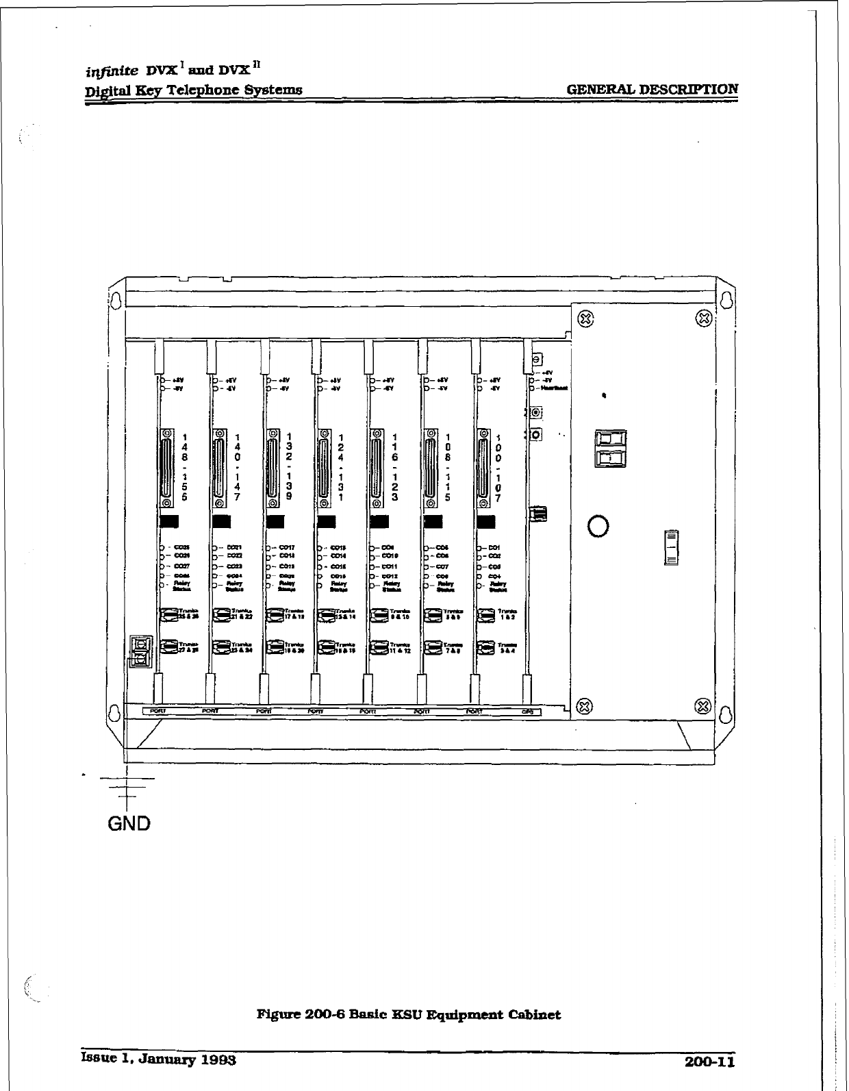
. - -
I I
I I
.
l.Ei
0
GND
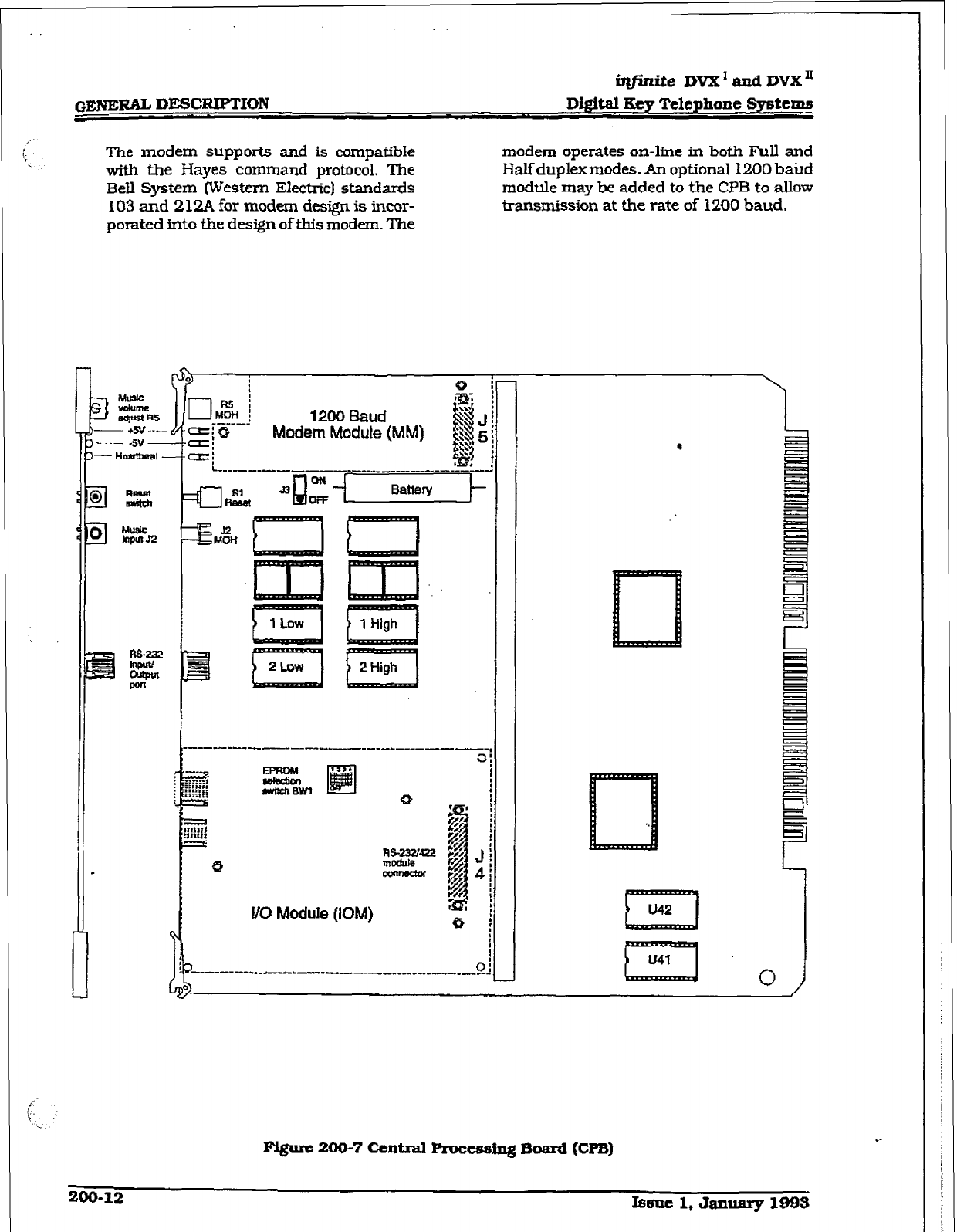
i@rzite DVX’ and DVXT’
Dtgital Key Telephone Spetenzs
The modem supports and is compatible
with the Hayes command protocol. The
Bell System Western Electric) standards
103 and 2l2A for modem design is incor-
porated
into
the design of this modem. The
modem operates on-he in both Full and
Htiduplexmodes. An optional 1200 batid
module may be added to the CPB to allow
transmission at the rate of 1200 baud.
(_
i
r-J& i
---- -1 1200 bud
ZiQ Modem Modute (MM)
cz=i
L ---- -__-_____ ---- _-_______-___--_
-_-
a& J3 t3
Ll
l/O Module (KIM)
Fl@rc 200-7 Central F’roceasfng Board (Cm)
200-12 It3eae 1, January 1993
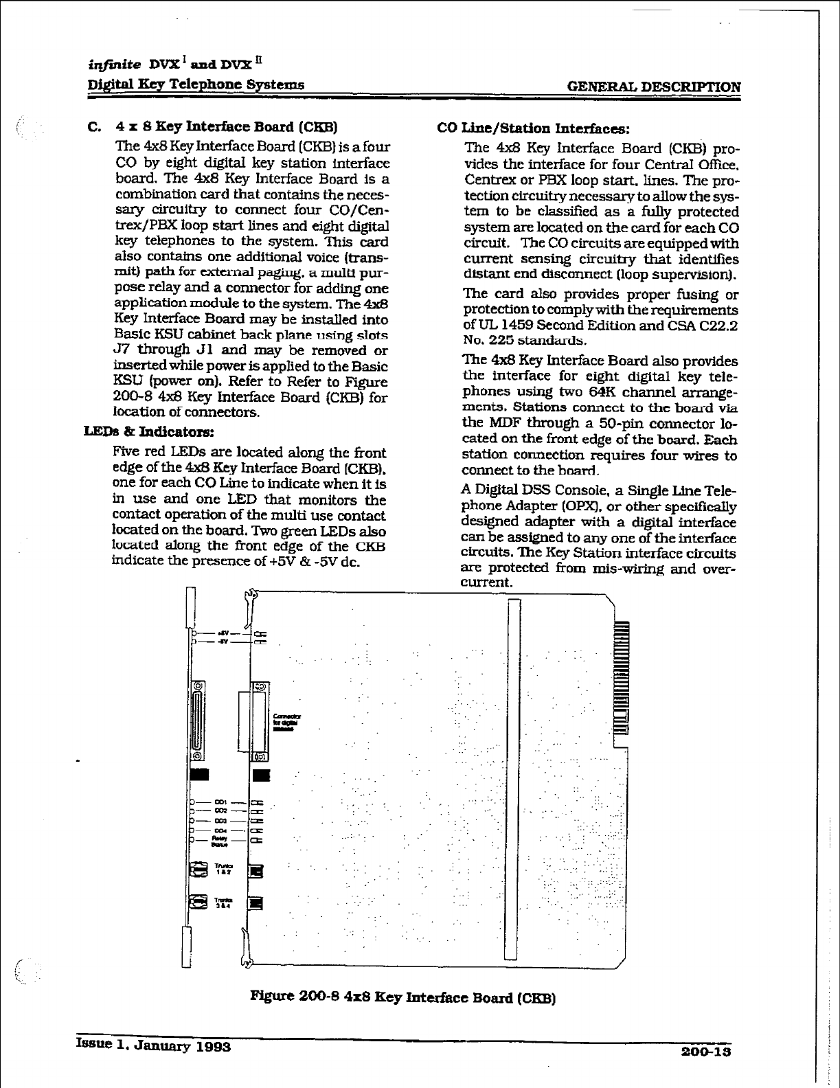
iqfinite DVX’ and DVXn
Di@tal Key Telephone Systems
GENERAL
DE!ERIPTlON
C. 4
x 8 Key titerface Board (CKB)
The 4x8 Key Interface Board (CKB) is a four
CO by eight digital key station interface
board. The 4x8 Key Interface Board is a
combination card that contains the neces-
sary clrcultry to connect four CO/Cen-
trex/PBX loop start lines and eight digital
key telephones to the system. ‘This card
also contains one additional voice (trans-
mit) path for external paging. a multi pur-
pose relay and a connector for adding one
application module to the system. The 4x8
Key Interface Board may be installed into
Basic iGU cabinet back plane using slots
57 through Jl and may be removed or
inserted while power is apphed to the Basic
KSU (power on). Refer to Refer to Figure
200-8 4x8 Key Interface Board (CKB) for
location of connectors.
LEDS L
Indicators:
Five red LEDs are located along the front
edge of the 4x8 Key Interface Board (CKB).
one for each CO Line to indtcate when
it
is
in use and one I&D that monitors the
contact operation of the multi use contact
located on the board. l%o green LEDs also
located along the front edge of the CKl3
indicate the presence of +5V & -5V dc.
co Line/station hltedacts:
The 4x8 Key Interface Board (CKB) pro-
vides the interface for four CentraI Ofhce.
Centiex or PBX loop start. lines. The pm-
tection circuitry necessary to allow the sys-
tem to be classified as a fUny protected
system are located on tbe card for each CO
circuit. The CO circuits are equipped with
current sensing circuitry that identifies
distant end disconnect (loop supervision).
The card also provides proper fusing or
protection to comply with the requirements
of UL 1459 Second Edition and CSA C22.2
No. 225 standards.
The 4x8 Key Interface Board also provides
the interface for eight digital key tele-
phones usa two f34K channel arrange-
ments. Stations connect to the board via
the MDF through a 50-pin connector lo-
cated on the fmnt edge of the board. Each
station connection requires four wires to
connect to the board.
A Digital DSS Console, a Single Line Tele-
phone Adapter (Opx), or other specifically
designed adapter with a digital interface
can be assigned to any one of the interface
circuits. The Key Station interface circuits
are protected from m&wiring and over-
current.
---a#---~
-a-.= “:.
‘.. ..
w . .
:. :. ..‘.
m . . .
- : ‘..
. .
z .: .:
A ..’ .’ : ,... ., ...:R :‘: ::
.
-a.
-aa--cII’ ..-:, ‘. : ,,,
: ‘.
---a= .., -.., y, ‘.,
---.a
s-a ‘: . . . . . .: : ,’ ~
:
PQurc 200-S 4x8 Key Interface Board (Cm)
Issue 1,
January 1993 2u0-13
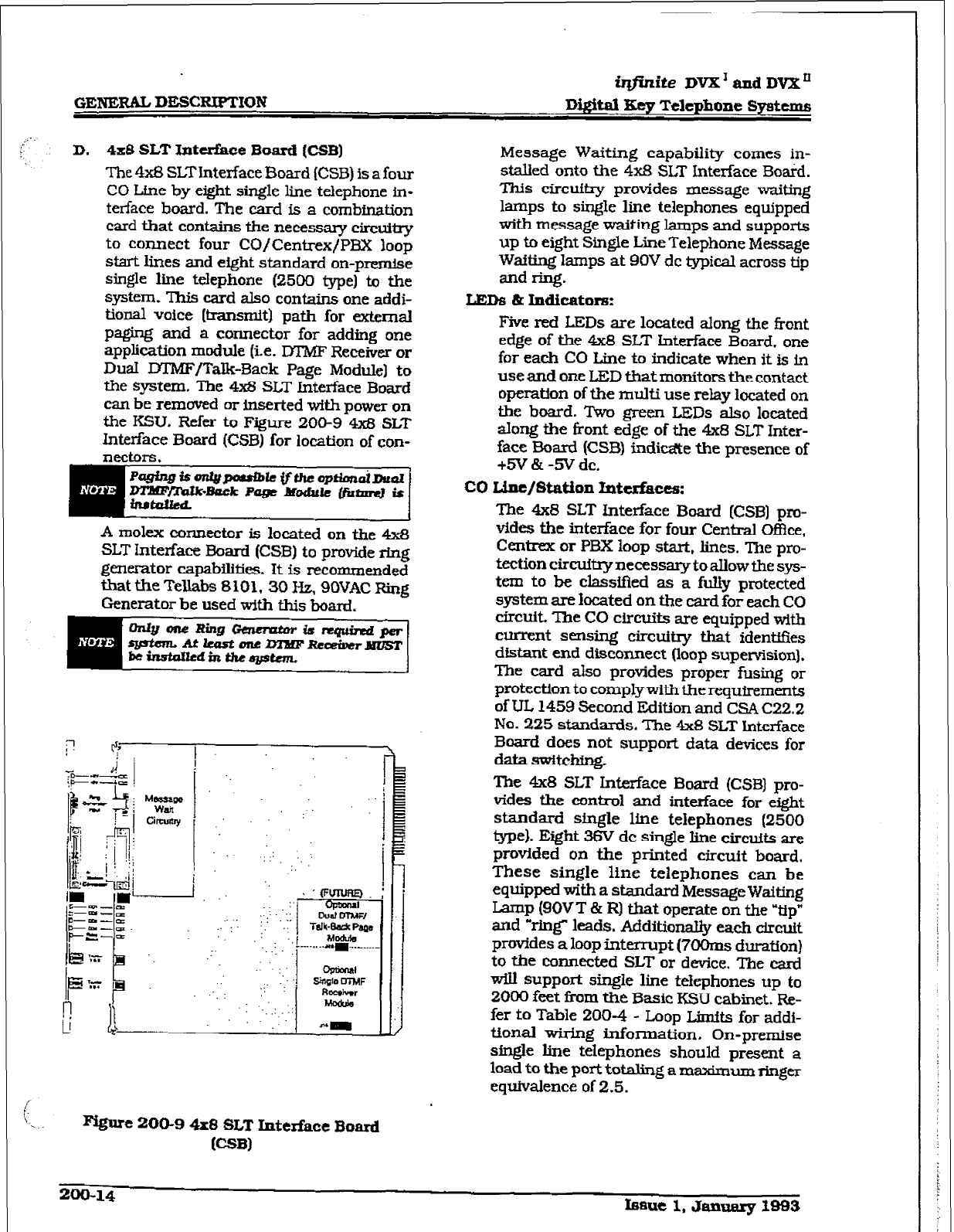
,:
GENERU
DESC~BN?
iq.j%nite
DVX’amiDVXn
DQital IEey Telephone Systems
D. 4x8
SLT Jr&t&&e Board (CSB)
The 4x8 SLTInterface Board ICSB) is a four
CO Line by eight single line telephone in-
terface board. The card is a combination
card that contains the necessary circuiny
to connect four CO/Centrex/PBX loop
start lines and eight standard on-premise
single line telephone (2500 fype) to the
system. This card also contains one addi-
tional voice [trammitl path for external
paging and a connector for adding one
application module (ie. D’l’XlF Receiver or
DuaI IYIMF/TaIk-3ack Page Module] to
the system. The 4x8 SLT Interface Board
can be removed or inserted with power on
the KSU. Refer to Figure 200-9 4xB SLT
Interface Board (CSB) for location of con-
nectors.
A molex connector is located on the 4x8
SLT Interface Board (CSB) to provide ring
germator capabikties. It is recommended
that the Tell&s 8101.30 Hz, SOVAC Ring
Generator be used with this board.
. . . ..’
Pvgure
ZOO-9
4x8 SLT InterEace Board
@Ml
Message Waiting capability comes in-
stalled onto the 4x8 SLT Interface Board.
This circuitry provides message waiting
lamps to single line telephones equipped
with message waiting
lamps and supports
up to eight Single Line Telephone Message
Waiting lamps at BOV dc typical across tip
and ring.
LBDS & Indicators:
Five red LEDs are located along the front
edge of the 4x8 SLT Interface Board. one
for each CO Line to indicate when it is in
use and one LED that monitors the contact
operation of the muhi use relay located on
the board. Two green LEDs also located
along the front edge of the 4x8 SLT Inter-
face Board (CSB) indime the presence of
+5V & -5V dc.
co Line/station hesfaces:
The
4x8
SLT Interface Board [CSB] pro-
vides the interface for four Central Of&e,
Centrex or PBX loop start, lines. The pro-
tectioncircuilxynecessarytoallowthesys-
tem to be classified as a fully protected
system are located on the card for each CO
circuit. The CO circuits are equipped with
current sensing circuitry that identifies
distant end disconnect (loop supervision),
The card also provides proper fusing or
protection to comply with the requirements
of UL 1459 Second Edition and CSA C22.2
No.
225
standards. The 4x8 SLT Interface
Board does not support data devices for
data switchfng.
The
4x8
SLT Interface Board (CSB) pro-
vides the control and interface for eight
standard single line telephones (2500
type). Eight 36V dc single line circuits are
provided on the printed circuit board.
These single line telephones can be
equipped with a standard Message Waiting
Lamp (90VT & RI that operate on the -tip”
and “ring’” leads. Additionally each circuit
provides a loop interrupt (7OOms duration)
to the connected SLT or device. The card
will support single line telephones up to
2000 feet from the Basic KSU cabinet. Re-
fer to Table 200-4 - Loop Limits for addi-
tional wiring information. On-premise
single line telephones should present a
load to the port totaling a maximum ringer
eqllfvalence of 2.5.
200-14
tme 1, Januarg 1-3
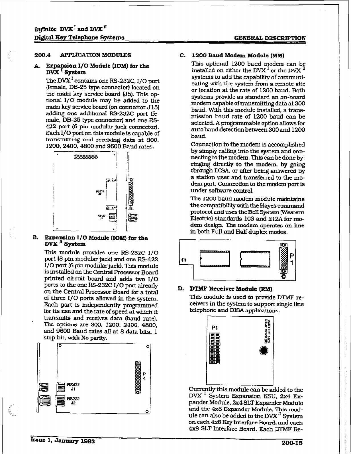
i@ite DVX I and DVX”
Di@ti ISty Telephone Systems GENERAL DESXIPTION
200.4
API’LICXrION MODULES
A. Erpansion I/O Module (IO&I) for the
DVX r System
The DVX r contains one BS-232C. I/O port
(female. DB-25 type
co~ector]
located on
the main key sentice board (J5). This op-
tional l/O module may be added to the
main key sewice board (on connector J 15)
adding one additional RS232C port (fe-
male, DB-25 type connector) and one RS-
422
port
(6
pin modular jack connector).
Each I/O port on this module is capable of
transmitting and receiving data at 300,
12#.2400,4800 and 9600 Baud rates.
c
0 . I u
B. Expansion I/O
Module QOM)
for
the
Dvx E
sy6ttm
This module provides one RS232C I/O
port (8 pin modular jack) and one RS-422
I/O port (6
pin
modular jack). This moduie
is
installed on the
Central Processor Board
printed circuit board and adds two I/O
ports to the one FS232C I/O port already
on the Central Processor Board for a total
of three I/O ports allowed in the system.
Each port is independently programmed
for its use and the rate of speed at which it
transmits and receives data (baud rate).
The options are 300, 1200,
2400, 4800,
and 9600 Baud rates all at 8 data bits, 1
stop bit, with No parity.
n
0 0
E
P
4
lx422
Jl
-- Fvs.232
52
I
0
C. 1200 Baud Modem ModuIe (MMJ
This optional 1200 baud modem C&-I be
installed on either the DVX ’ or the DVX o
systems
to add the capability of communi-
cating with the system from a remote site
or location at the rate of 1200 baud. Both
systems provide as standard an on-board
modem capable of transmitting data at 300
baud. With this module Installed,
a trans-
mission baud rate of 1200 baud can be
selected. A programmable optton aIlows
for
auto baud detection
between 300 and 1200
baud.
Connection to the modem is accomplished
by simply calling into the system and con-
necting to the modem. This can be done by:
ringing directly
to
the modem, by going
through DISA. or after being answered by
a
station user
and
u-ansferred to the mo-
dem
port. Connection to the modem port is
under soti control.
The 1200 baud modem module maintains
the compatibilitywlth the Hayes command
protocol and uses theBell System (Western
Electric) standards 103 and 212A for mo-
dem
design. The modem operates on-line
in both Full and Half duplex modes.
i
0
D. DTMF Receiver ModtiIe m
This module is used to provide DTMF m-
ceivers in the system to support singIe line
telephone and DISA applications.
1
Currently this module can be added to the
DVX I System Expansion KSU, 2x4 Ex-
pander Module. 2x4 SLTExpander Module
and the 4x8 Expander Module. This mod-
ule can also be added to the DVX IT System
on each 4x8 Key Interface Board. and each
4x8 SLT Interface Board. Mach MMF Re-
Issue 1. January
1993
200-16
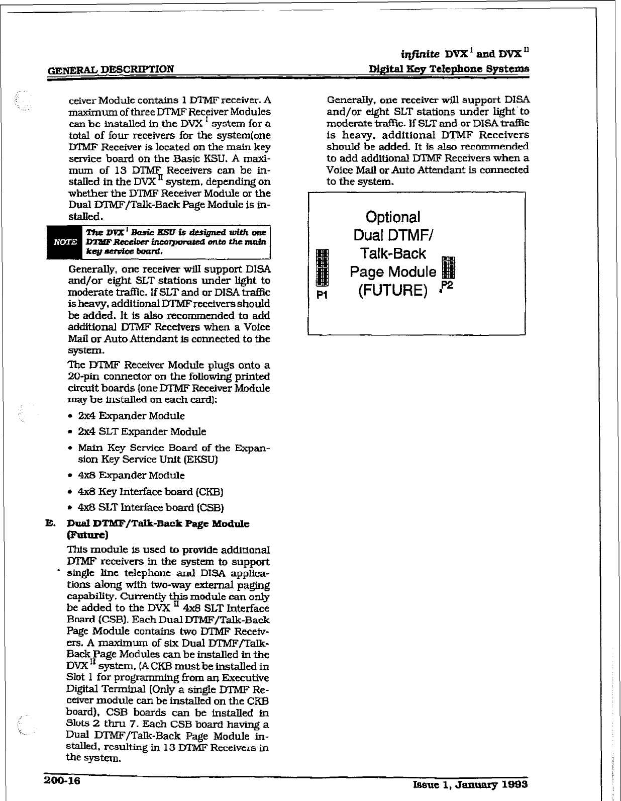
.1
/:
i
I
/,;
ceiver Module contains 1 DTMF receiver. A
maz&rnrm of three DTMF Receiver Modules
can be installed in the DVX ’ system for a
total of four receivers for the system(one
IYTMF Receiver is located on the main key
service board on the Basic KSU. A maxi-
mum of 13 IYIMF Receivers can be in-
stalled in the DVX ’ system, depending on
whether the Dl?vlF Receiver Module or the
Dual DTMF/Talk-Back Page Module is in-
stalled.
Generally, one receiver will support DISA
and/or eight SLT stations under light to
moderate traffic. If SLT and or DISA trafi%z
is heavy, additional -receivers should
be added. It is also recommended to add
additional DTMF Receivers when a Voice
M&I
or
Auto Attendant is connected to the
system-
The DTMF Receiver Module plugs onto a
ZO-pin connector on the following printed
circuit boards (one DTMF Receiver Module
may be installed on each card):
. 2x4 Expander Module
. 2x4 SLT Expander Module
l
Main Key Service Board of the Expan-
sion Key Service Unit (EKSU)
l
4x8 Expander Module
l
4x8 Key Interface board (CKB)
l
4x8 SLT Interface board (CSB)
E. Dlraf DTIUF/Talk-Back Page Module
-1
This module is used to provide additional
lYIMF receivers Ln the system to support
- sin&e line telephone and DISA apphca-
tions along with two-way external paging
capability. Currently this module can only
be added to the DVX ’ 4x3 SLT Interface
Board (CSB). Each Dual lYl’MF/Talk-Back
Page Module contains two DTMF Receiv-
ers. A maximum of six Dual lX’MF/Talk-
Back Page Modules can be installed in the
DVX ‘I system, (A CKB must be installed in
Slot 1 for programmin g i?om an Executive
Digital Terminal (only a single DTMF Re-
ceiver modu.Ie can be instaIled on the CKB
board), CSB boards can be installed in
Slots 2 thou 7. Each CSB board havnxg a
Dual DTMF/TaIk-Back Page Module in-
stalled. resulting in 13 DTMF Receivers in
the system.
Genera@. one receiver will support DISA
and/or eight SLT stations under light‘to
moderate tra%c. If SLT and or DISA traffic
is heavy. additional DTMF Receivers
should be added. It is also recommended
to add additional DTMF Receivers when a
Voice Mail or Auto Attendant is connected
to the system.
Optional
Dual DTMF/
Talk-Back
Page Module
Pl
(FUTURE)
200-16 Iw5uel,Jan~lsss
i@.r&e DVX’andDVX’
lM,gitsl Key Tclcphone Sywtems GENF,RALDESCRFT’XcIN
200.5
DKXTAL TERMINKLS
A. 33-Button Extcllt.ive (Display]
TCrmtnal
The 33button Digital Terminal is one in a
line of Digital electronic telephone terrni-
nals. The line consists of an Executive @is-
play] telephone. an Executive/PC Interface
telephone, an Enhanced (nan-display) telt-
phone and an 8-hutton Basic telephone.
These telephones arc designed to operate
with the new line of h-@-de Digital Key
Systems and PBX
Systems.
The 33-button and &button DigitaITermi-
I-E& are connected to the
KSU via a four
wire (two twisted pair] connections from an
appropriate electronic terminal interface
board.
LCD Display:
The 33-button Dfgital Display Terminal
has a 48 character IAquid Crystal
DispIay.
The display pnwides
information such as
station
extensions caIling, Line ringing in-
formation, camp-on information, Message
waiting tionnation and so on. The LCD
Display is a 48- character display
divided
into 3 fields:
- Field 1 - Current Status (top hne, 24-
characters)
- Field 2 = Date &eft half of bottom line,
12-characters)
- Field 3 = Time of day @Z&t half
of
bot-
tom line, 12-characters)
These fields are separately maintained by
the. KSU processing to shaw current and
pending statton activfty. Each field is rec-
reated upon any display change except
additional
digits which are added to the
end
of the existing display.
- The terminal communicate5 to the K3.I
tbrougl-~ two 64K digital channel arrange-
ments. One channel is used as the p&xx-y
voice channel, a
second is used for termi-
nal to KSU command transmission.
Power
is also provided to the tenninattia the four
wire connection.
Buttons and I.BDa:
The 33-button Digital terminal key
boamt
PCB
provides long ltfe “sup& bright” I+ht
Emitting Diodes WDs) and button asset-
blies that profrude through the top hous-
ing. The buttons are small rectangular- In
shape with a Clear end for proper LED
visibility and diffusion, the 33-button
DWd Ternhal has 33-buttons all con-
taining LEDs except the pickup and Flash
buttons plus a 12-key dial pad.
The 33-button DigitaJ Terminal scans the
key board for dial pad and
button
de-
bounces and depressions for command
transmission to the KSU. The keyset has
the following buttons defined as follows:
Display and Non-Display
- 12 DialKeyPad*
- 24 Flexible Buttons
- I ON/OFF button
[fixed]
- I MLrE button (fKecI)
- 1 SPEED button [fixed)
-
1
FLASH button (fjxedl
- I TRANSfer buttondfixed)
- 1 HOLD button (fured)
- 1 CAMP-ON button
(fmed)
- 1 MSG button (f&d)
- 1 PICKUP button (fixed)
l
Au buttons except the 12-key dial pad,
Pickup
and
Flash button have an LED
assocfated with it. Refer to Figure 200-10
33-ButianE2am.1tfve~gigitai
Terminal.
Spmkerphont:
Each 33-button Digital Terminal is
equipped with a unit that enables the
tele-
phone to be used
handsfree in two-way
conversations. The user
activates the
speakerphone by pressfng the ON[OFF
button
&ED hghts
steady).
To tWt.e a
speakerphone call, the ON/OFF button is
toggled OFF (LED extinguished). The
MUTE feature is
used in conjunction with
the speakerphone option. To mute the
speakerphone microphone, the MUTE
but-
ton is pressed &ED lights steady).
To reac-
tivate the mimphone, the MUTE button is
pushed again (LED extinguished),
Several pro-able options control the
speakerphone operation. Each digital ter-
minal can be programmed for full speaker-
phone
operation. or monitor/On-Hook
dialing capabilities with
no full speaker
phone operation.
When Automatic R-e-selection is enabled
at the station when any button is pressed
(i.e. CO, DSS, Page etc...) the station and
speakerphone is automatically activated.
v01tmle controlr3:
Separate ‘slide” switches are provided on
the tiont of the G-@-&e Digital Terminal to
Issue I, January 1993 2cm17
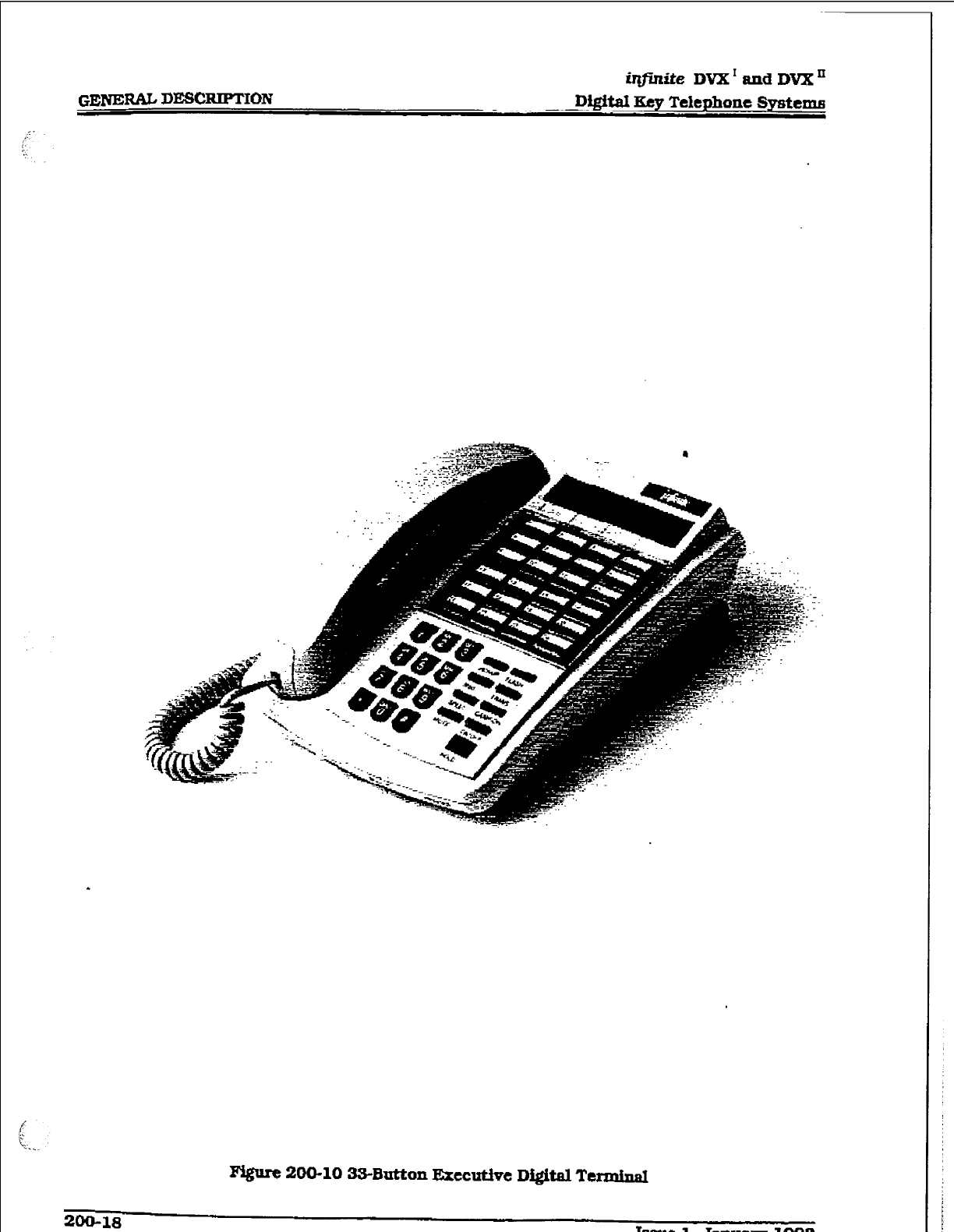
iqfinite DVX’ andDVXn
GENE= DEMX.IFTION
Di@aI
I& Telephone Systema
:.
‘::
m 200-10 3S-Button
E;xtCUtiQC
Digital Termimd
ZOO-18
i&de DVX’ and DVX’
Digftal Key Telephone Systems GENBIZAL DBSCBJPTION
adjust the volume of the voice and tones
presented to the terminal speaker.
- The speaker volume (center switch] will
contro’l all voice signals sent to the
speaker i.e. Speaker Phone conversa-
tions,
BGM,
and Page announcements.
- The ringing volume (right switch] wiU
control all tone signals presented to the
speaker i.e. Ringing. splash tones.
Camp-On etc... Muted ringing will also
be conkoIled by the ringing volume slide
switch. ‘l%e muted ringing volume will
be proportionately quieter than normal
ringing based on the current switch set-
ting-
HF-W-TN Switch:
A three position slide switch is located on
the front of the Digital Display Termhal
that controls the method of receiving inter-
com cans.
- The “HF” position allows intercom call
am~ounce with hands free reply.
- The “W position allows Call Announce
intercom calls only.
- The TN” position provides Tone only
intercom
ringing.
This switch allows users to set and corm-o1
the method in which they receive the&
intercom calls. However. af%aIcodethat
users can dial before placing an intercom
call can override a ealleci station’s switch
setting of HF or PV to force the station to
Tone ring.
Directory Ray:
Each 33-button Digital Terminal
is
equipped with a slide-out Directory Tray
accessed from the front of the digital termi-
nal.
e
wall Mounting:
The 33-button Wall Mount Bracket is de-
signed to allow the 33-button digital termi-
nal to be waII mounted on industry
standard 630 @pe wall jacks. A 4-inch line
cord is also provided as a standard item
with each wall bracket.
EIandset/une cords:
The 33-button Digital Terminal uses a
color coordinated K-Style handset with a
makb.ing la-foot handset cord. A g-foot
four conductor base line cord is included
with ewryTermi&.
The 33-button Digital Terminal. uses an
.e.&tret type transmitter. Comp&tible
headsets can be plugged into the Tern%
nals handset jack for headset operation.
B. 33-Button Bxecutfve/PC Intuface
Terminal QCLID)
The 33-button Executive/PC InterfaceTer-
minal is similar to the 33-button Executive
Display model and all of the information
listed above applies to the Executive/PC
Interface model except this terminal is
used to deliver specffic data messages
identifying call states to a device attached
to the phone via a serial channel following
the data transmission requirements of BS-
232C. The
interface parameters to be used
arc 2400bps. no parity, 8 data bits, and 1
stop bit. This featurew%l deliver ICLID data
to a Personal Computer attached to the
phone for look-up of customer records and
subsequent processing by the individuaI
answering the telephone call. Calls can
also originate from the Personal Computer
through the digital tenntnat.
The 33-button Executive/PC Interface ter-
minal provides transmit, receive, and
ground data lines from the phone micro-
processor which are used on command
i%om the KSU to output information. The
use of this capability would be to output
the ICLlD information to a PC attached to
the phone. The VODAVI CalI ‘Tracker soft-
ware program is available to support these
Caller ID applications. fiture use couId be
made of this capability for low speed data
provided to equipment attached to the
phone.
C. 33-Buttoa Di@hd Terminal IEnhapccd)
The 33-button Enhanced Digital Terminal
is similar to the 33button Executive Digi-
tal TerminaI and all of the information
listed above applies except there is no IX3D
display.
IBsue I. Jaauarg 1993
209-19
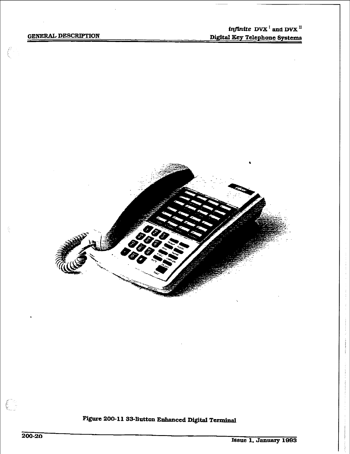
GENERAL DEKXIPTION
infinite DVX I
and
DVX’
D&bit Key Telephone Systemis
F’Qurc 206113343utton Enhanced Digital TcrminaI
200-20
Lssut 1, January l-3
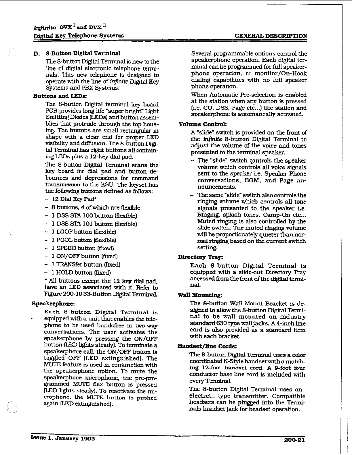
iqfhfte DVX I aPd DVXn
Dj#td Eey Telephone Systems GENERAL DESCRIPTION
D. &Button
Digital Terminal
The 8-button Digital Terminal is new to the
line of digital electronic telephone
termi-
nals. This new telephone is designed to
operate with the line of in$nrte Digital Key
Systems and PBX Systems.
Buttons and LEDs:
The g-button Digital terminal key board
PCB provides long life ‘super bright” Light
Emitting Diodes (LED-s) and button assem-
blies that protrude through the top hous-
ing. The buttons are small rectang&r tn
shape with a clear end for proper LED
visibility and diflixion. The &button Digi-
tal Tcnninal has eight buttons all contain-
ing LEDs plus a 12-key dial pad.
me S-button Digital T erminal scans the
key board for dial pad and button de-
bounces and depressions for command
transmission to the KSU. The keyset has
the following buttons defined as follows:
- 12DiaIKeyPad*
- 8 buttons, 4 of which are flexible
- 1 DSS STA 100 button (flexible)
- 1 DSS STA 101 button (flexible)
- 1 Ix)OP button @zxible)
- 1 POOL button (fle~&le)
- 1 SPEED button [fnted)
- 1 ON/OFF button (tied)
- 1 TRANSfer button (fixed)
- 1 HOLD button (fjxecl)
l
All buttons except the 12 key dial pad,
have an LED associated with it Refer to
Figure200-1033Button DigitalTerminal.
speakerphoItc:
Each 8-button Digital Terminal is
* equipped with a unit that enables the tele-
phone to be used handsfree fn two-way
conversations. The user activates the
speakerphone by pressing the ON/OFF
button (LED lights steady). To termmate a
speakerphone call, the ON/OFF button is
toggled OFF (LED extinguished). The
MUTE feature is used in conjunction with
the speakerphone option. To mute the
speakerphone microphone, the pre-pro-
grammed MUTE flex button
is
pressed
&ED Qhts steady). To reactivate the mi-
crophone. the MUTE button is pushed
qain (LED extinguished].
Several prog rammabie options control the
speakerphone operation. Each digital ter-
minal can he programmed for full speaker-
phone operation, or monitor/On-Book
dialing capabilities with no full speaker
phone operation.
When Automatic Pre-selection is enabled
at the station when any button is pressed
(i.e. CO, DSS, Page etc...) the station and
speakerphone is automatically activated.
v01ume controh
A “slide” switch is provided on the front of
the w 8-button Digital Terminal to
adjust the volume of the voice and tones
presented to the terminal speaker.
- The -slide” switch sontrols the speaker
v&me which controls all voice signals
sent to the speaker i.e. Speaker Phone
conversations. BGM. and Page an-
nouncements.
- The same ‘slide” switch also controls the
ringing volume which controls a.tl tone
signals presented to the speaker i.e.
Ringing, splash tones, Camp-On etc...
Muted ringing is also controJled by the
slide switch. The muted ringing volume
wUl be proportionately quieter than nor-
mal ringing based on the current switch
setting.
DirectorgTxar
Each 8-button Digital Terminal is
equipped with a shde-out Directory lYay
accessed from the front of the digital termi-
nal.
wall Motmthg:
The Bbutton WAl Mount Bracket is de-
sfgned to allow the &button Digital Tern&
nal to be wall mounted on industry
standard 630 type walljacks. A 4-inch he
cord is also provided as a standard item
with each bracket.
HaIldsct/line
c!ords:
The &button Digital Terminal uses a color
coordinated K-Style handsetwith a match-
ing 12-foot handset cord. A Q-foot four
conductor base line cord is included with
every Terminal.
The 8-button Digital Terminal uses an
&&XL type transmitter. Compatible
headsets can be plugged into the Termi-
nals handset jack for headset operation.
lsfmc 1. January 1993 20&21
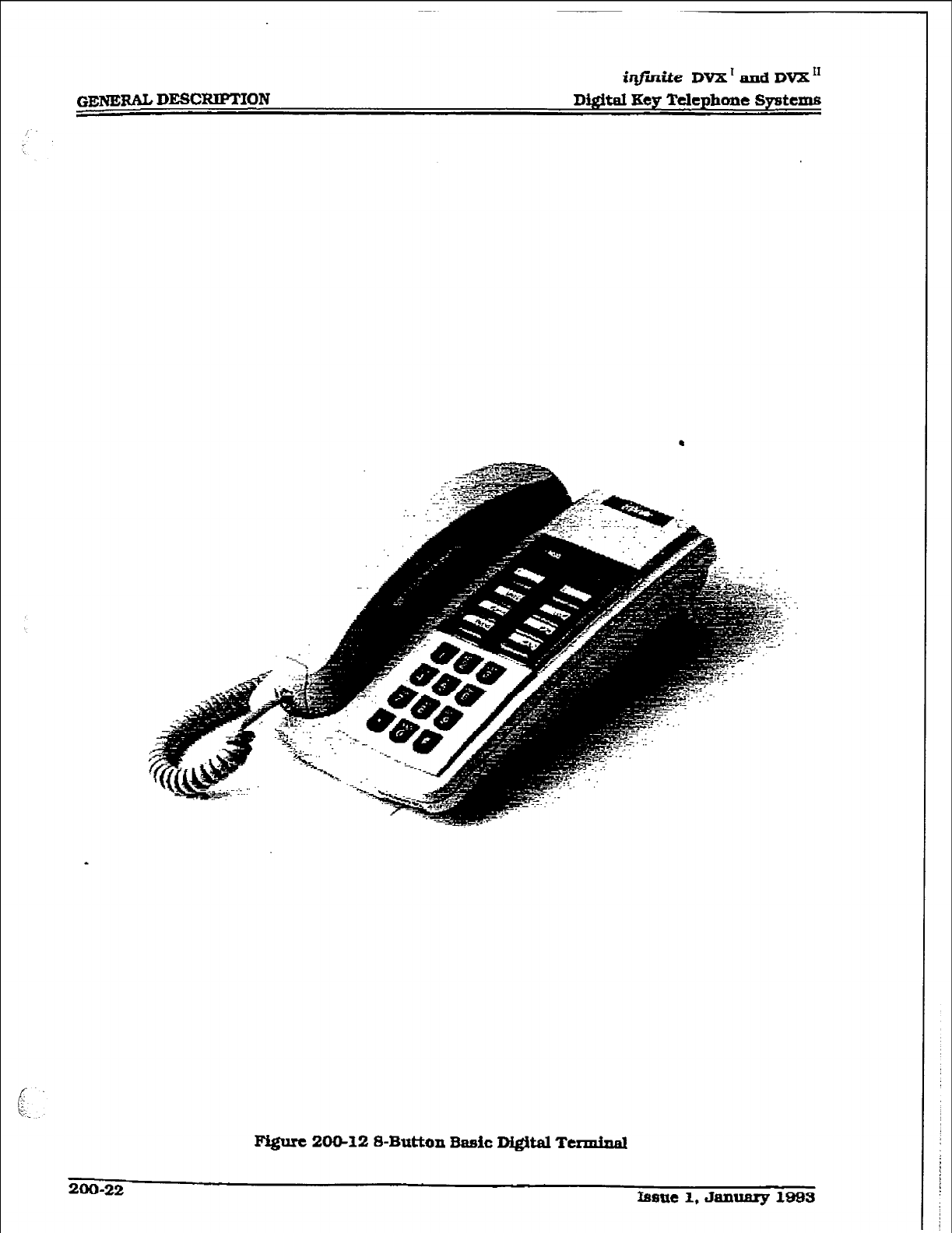
i@nite DVX’ taxad DVX”
DQitaI Key Telephone Systems
Ipigurc 2-12 8-Button 3asic D&Ml TerminaI

@finite DVX’ and DVX’
~)@t.aI K.ey Telephone S~ttrns GENERAL DESCRIPTION
E. Mgit.al DSS/DLS Consok
The Digital Direct Station Selector /Direct
Line Selector (D.SS/DLS) Consoles can be
installed in place of any digital terminal
circuit. The DSS/DLS Digital Console was
designed in a housing similar in looks to
the 33-button digital terminal.
The Direct Station Selector/Direct Line Se-
lector (DSS/DLS) Console to be used witi
the family of infinite digital systems is
modular in nature. The DSS/BLF console
provides 48 buttons (4 columns of 12 but-
tons) and requires a separatefour-conduc-
tor line cord each connected to a digital
terminal station port.
The DSS/DLS Console unit can access
Stations, Direct Appe&ng CO Lines, or
features that may be assigned to any of the
fladble buttons.
A DSS/DLS unit may be assigned to one of
the different MAP configurations available.
Any one of the three MAP configurations
may be assigned to a DSS/DLS and up to
three maps may be assigned to one station.
However. ‘duplicate” MAPS or appearances
of Stations and/or CO lines between the
MAPS are not allowed.
D8S/DLS Console Buttan Mappiq$
The buttons on the DSS/DLS console can
be mapped with either a combination of
fixed and flexible or completely flexible but-
tons where tbe station user may change
the button programming to suit their
needs.
There are three pre-deIined MAPS for the
DSS Console with default Button Aogram-
ming. Refer to Figure 200- 14 DSS Console
Map 1, Figure 200- 15 DSS Console Map 2.
and Figure 200-l 6 DSS Console Map 3 for
a button layout of each DSS Console But-
ton Map.
Issue 1, January 1993 20@23
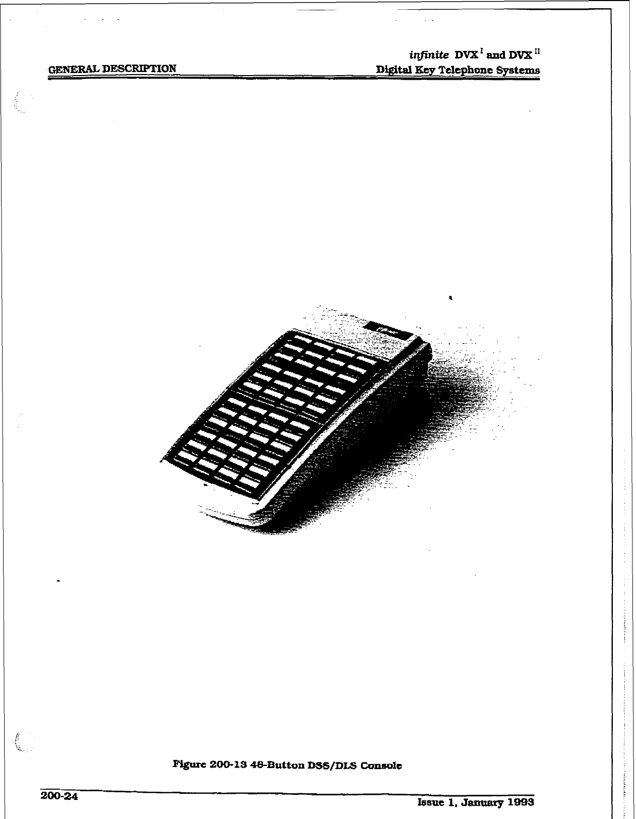
r
ir#idte DVX’ and DVX”
D&.&al Key Telephone Spstcms
(!
'Q;
Ngum 200-18 48-Button Dss/DLs
con6ok
200-24 Issue 1, Jaaaarp m93
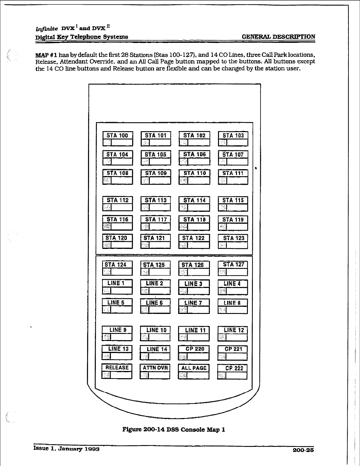
iqfmite DVX’ and DVX”
D@.d Eey Tckphone Syattma GENERAL DESC-ON
MAF#l hasbydefaultthefirst28Stations(Stas 100-127). and 14COLines, threeC!allParklocations.
Release, Attendant Override. and an All Call Page button mapped to the buttons. All buttons except
the 14 CO line buttons and Release button are flexfble and can be changed by the station user.
Fi@m 200-14 085 Console Map 1
Issue 1, Janumy 1993 2ocb26
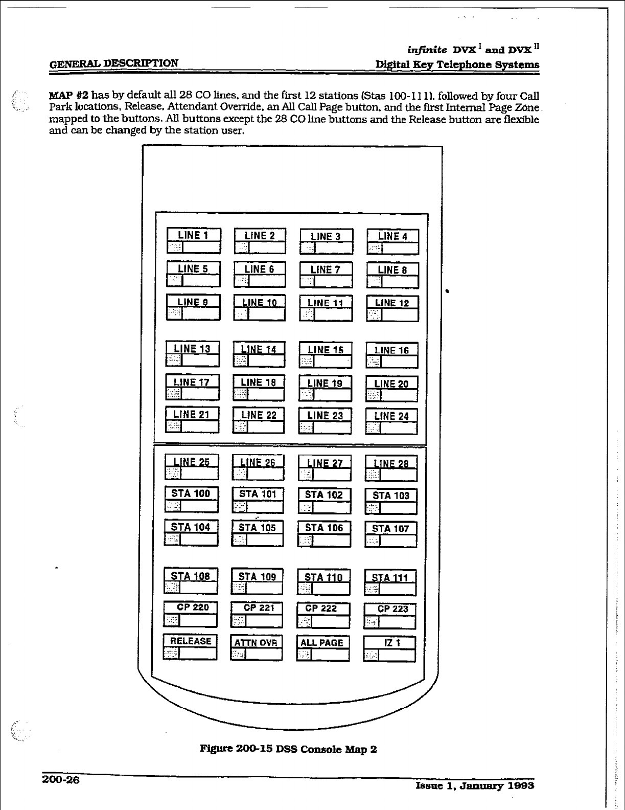
GENE&!&L DESCRIPTION
.
infinite DVX’ and DVX ‘I
Di#taI I.&v Telephone Systems
MAP #2 has by default all 28 CO lines. and the first 12 stations (Stas 100-l 1 l), followed by four Call
park locations, Release. Attendant Override. an All CaH Page button, and the first Internal Page Zone
mapped to the buttons. AU buttons except the 28 CO line buttons and the Release button are flexible
and can be changed by the station user.
200-26 Is5ue1,Jnxmq71993
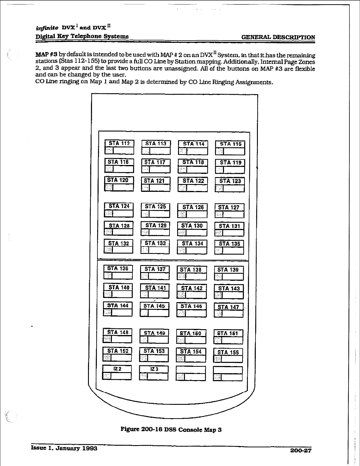
I.
digital
Key Telephone Systems
GENERAL DESC!RPl’ION
t
MAP #S by default is intended to be used with MAP # 2 on an DVX” System, in that it has the remaining
stations (Stas 112- 155) to provide a full CO Une by Station mapping. Additionally, Internal Page Zones
2. and 3 appear and the last two buttons are unassigned. All of the buttons on MAP #3 are flexible
and can be changed by the user.
CO Line ringing on Map I and Map 2 is determined by CO Line Ringing Assignments.
STA 136
El
Figure 200-16 DS!3 Console Map 3
Imue 1, January 1993 -27
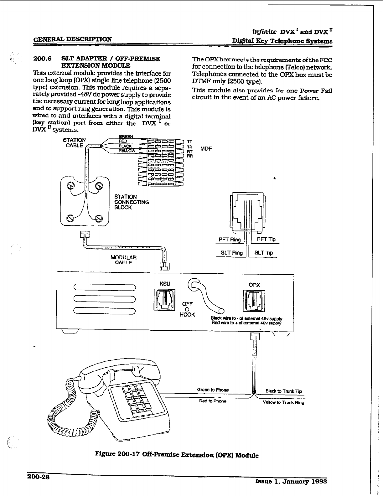
iqjhite DVX’autdDVXn
GENE= DESCRT.PTION D#td key Telephone Spstcms
200.6
SLT ADAPTER / OFF-PREMISE
EXTENSION MODULE
This external module provides the interface for
one long loop (OPX) single line telephone (2500
type) extension. This module requires a sepa-
rate&provided -48V dc power supply to provide
the necessary current for long loop applications
and to support ring generation. This module is
wired to and interfaces with a digital terminal
Fey
station)
port from either the DVX ’ or
DVX a systems.
The OPXboxmeek the requirements of the FCC
for connection to the telephone relco) netwbrk.
Telephones connected to the OPX bax must be
DTMF only (2500 Qpe).
This module also provides for one Power Fail
circuit in the event of an AC power failure.
l-r
m
K
MDF
CONNECTING
.
OPX
Bbek wim b - of exfernal48Y supply
Fled wfra to + of external 4Bv supply
I, BJadc to
Trunk lip
Yellow to Trunk Ring
200-28
bsue 1. January 1993
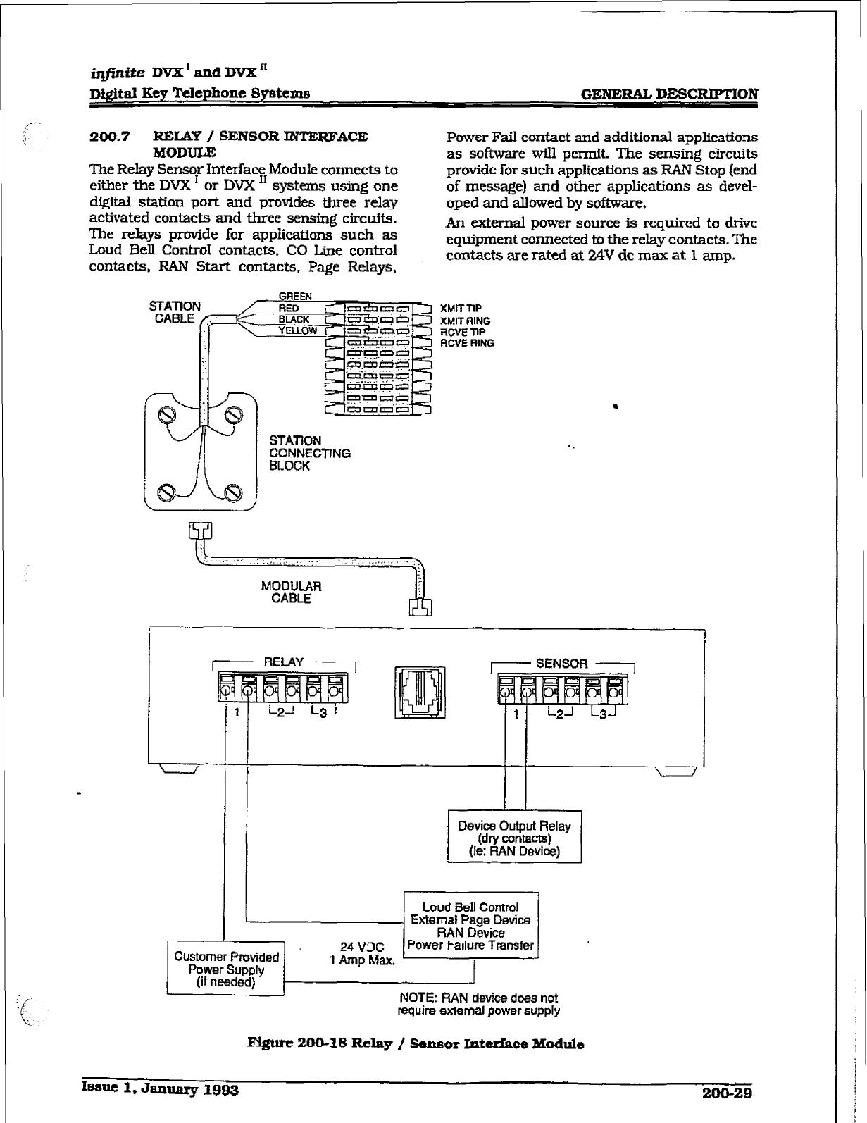
irlfinite DVX’ and DVXn
n&itaI Key Tdephone Systems
/.-
;-
y
:c.
. ,:
GENERAL DESCRIPTION
200.7
RELAY / SENSOR INTERFACE
MODULE
The Relay Sensor Interface Module connects to
either the DVX ’ or DVX ‘I systems using one
digital station port and provides three relay
activated contacts and three sensing circuits.
The relays provide for applications such as
Loud Bell ControI contacts. CO Line control
contacts, FWU Start contacts, Page Relays,
Power Fail contact and additional applications
as software will permit. The sensing dkuits
provide for such applications as RAN Stop (end
of message) and other applications as devel-
oped and allowed by software.
An external power source is required to drive
equipment connected to the relay contacts. The
contacts are rated at 24V dc max
at 1
amp.
xwr nnp
XMIT RING
mm np
ACVE RING
.
Oevim Output Relay
(dry mntacts)
(ie:
RAN Device)
Customer Provided
Power Supply
(if needad) NOTE: RAN
device
does not
require external power supply
Pvgwe
200-18
Rclag / 8ensor Interface Module
Itssue 1. Janunry
1993 200-29
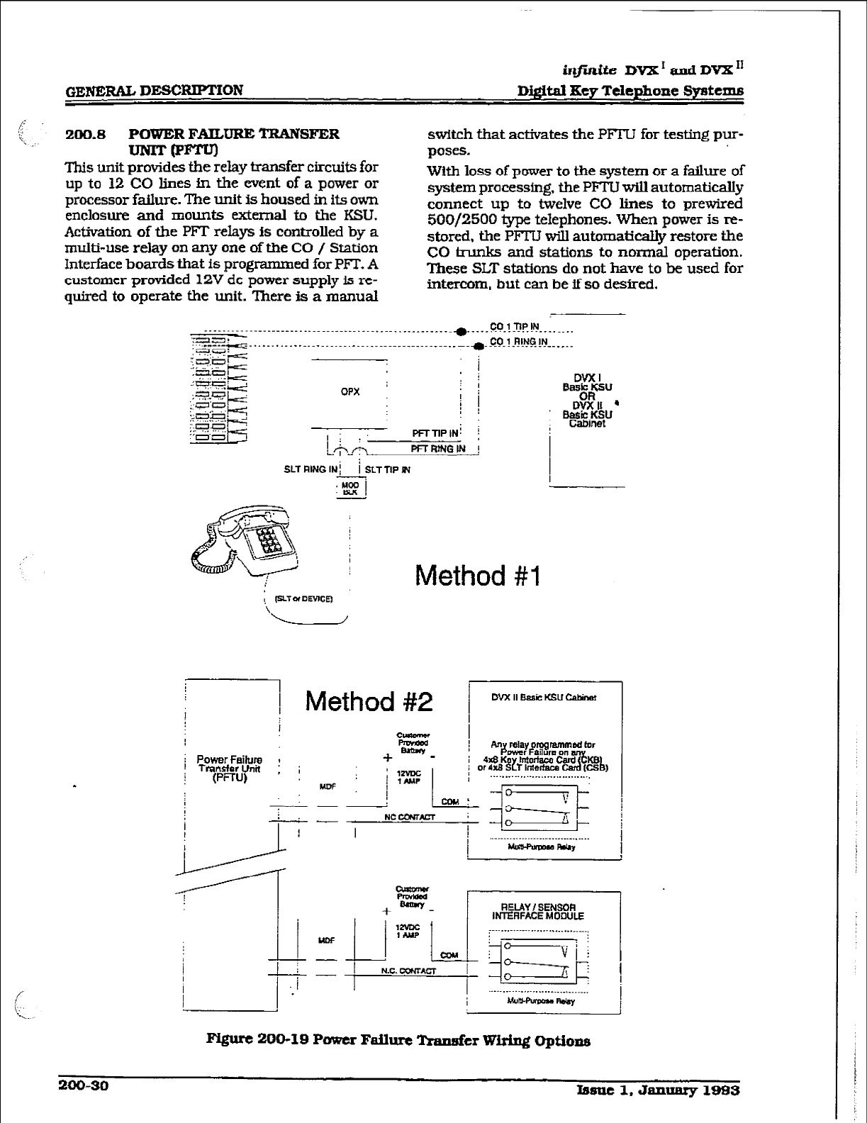
in..ite DVX’ and DVX I1
GEI’iERAL DESCRIPTION Digital IKey
Telephone Systems
200.8
POWER FAILURE TRANSFER
=IpFTu)
This unit provides the rely tmnsfer circuits for
up to 22 CO lines in the event of a power or
processor failure. The unit is housed in its own
enclosure and mounts external to the KSU.
Activation of the PFT relays is controlled by a
multi-use relay on any one of t&e CO / Station
Interface boards that is programm ed for PJ3. A
customer provided 12V dc power supply is re-
quired to operate the unit. There
is
a manual
switch that activates the PFTU for testing pur-
poses.
With loss of power to the system or a failure of
system processing. the PFTU will automatically
connect up to twelve CO lines to prewired
WI/2500 type telephones. When power is re-
stored, the PFTU will automatically restore the
CO hunks and stations to normal operation.
These SLT stations do not have to be used for
intercom, but can be if so desired.
Method #I
1 Method #2
.
I
=z
i Power Faibm ; +--
I Transfer Unit , j
(PFmJ) : ’
1zvDc
Mm I 1N.w
I
DVX II t&a& KSU China!
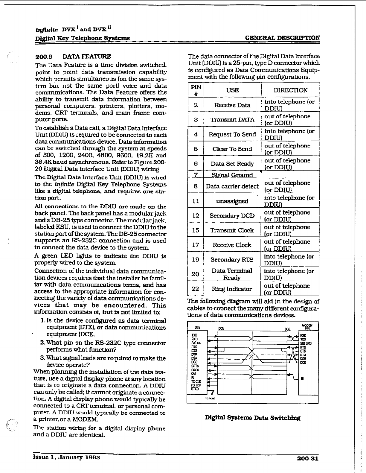
irlfinite DVX * and DVX’
D&&&d Xey Telephone Systems GENE&% DESCRIPTXON
200.9 DATA FEATURE
me Data Feature is a time division switched.
point to point data transmission capability
which perrrdts simultaneous
(on the same sys-
tem but not the same port) voice and data
communications. The Data Feature offers the
abUy to transmit data information between
personal computers, prh-iters, plotters. mo-
dems, CFZT terminals,
and main frame
com-
puter ports.
To establish a Data call, a Digital Data Interface
Unit [DDIV is required
to be
connected to each
data communications device. Data information
can be switched through the system at speeds
of 300, 1200, 2400, 4800. 9600, 19.2K and
38.4Kbaud asynchronous. Refer to Figure 200-
20
Digital Data Interface Unit tDDIU) wiring
The Digital Data Interface Unit (DDIU) is wired
to the in&&e Digital Key Telephone Systems
like a digital telephone. and requires one sta-
tion port.
All connections to the DDIU are made on the
back panel. The back paneI has a modular jack
andaDB-25Qpeconnector.Themoclularja&
labeled KSLJ. is used to connect the DDIU to the
station port of the system. The DB-25 connector
supports an FLS-232C connection and is used
to connect the data device to the system.
A green LED lights to indicate the DDIU is
properly wired to the system.
Connection of the individual data communica-
tion devices requires that the installer be famil-
iarwith data communications terms. and has
access to the appropriate tionnation for con-
necting the variety of data communications de-
vices that may be encountered. This
information consists of. but is not knited to:
1.1s the device configmed as data terminal
equipment [DTE), or data communications
- equipment (DCE.
2.What pin on the RS-232C type connector
performs what function?
3.What sfgnal leads are required to make the
device operate?
When planning the installation of the data fea-
ture, use a digital display phone at any location
that is to originate a data connection. A DDIU
can onlybe called, it cannot originate a connec-
tion. A digital display phone would typically be
connected to a CRT terminal, or personal com-
puter. A DDIU would typically be connected to
a printer,or a MODEM.
The station wiring for a digital display phone
and a DDIU are identical.
The data connector of the Digit& Data Interface
Unit
[DDIW is a 25-pin. type D connector which
is configured as Data Communications Eqtip-
ment with the following
pin
configurations.
-- -
PIN
# USE ! DIRECTION ;
2 I
Receive Data i into telephone (or i
: DDI 1
3 i -tit DATA ; ;rt;g$phone 1
4
Request
TO
Send i
i into telephone (or
I DDIU)
5 Clear To Send 1 out of telephone i
, or DDIU
Data Set Ready 1 o$$T
7
6
1
7
SignaIGround 1
out of telephone
8 Data wrrier.detect o= DDI
11 unassigned into telephone (or
DDIU)
12 Secondary DCD If out of telephone
or DDIU)
15 Transmit
Clock I(
out
of telephone
or DDIU)
17 ;
Receive Clock I(
out of telephone
or DDIU)
19 I Secondary riTs tnto telephone (or
DDIU)
20 I
Data Terminal into telephone (or
Ready
I DDIU)
22 Rtng indicator
out of telephone
(or DDIU)
The following diagram will aid in the design of
cables to connect the many
different
configura-
tions of data communications devices.
DigItaX Systems Data Switching
Issue 1.
January 1993
200-31
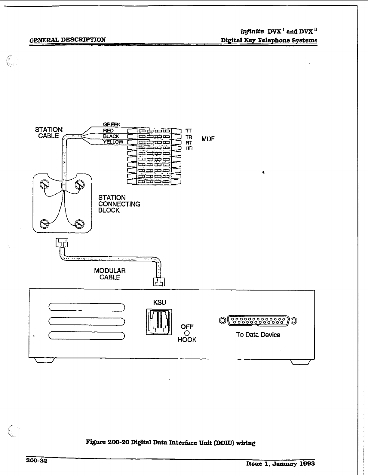
iqjinite
DVK’ and DVX”
Digital Key TeIephone Systems
GREE
II -
t STATION
CONNECTING
BLOCK
7-r
TR
RT
RR
MODULAR
( )
KSU
( > OFF 8( oo”oo*ooooooooooooooooooo ] Q
- m HoOoK To
Data
Device
I / \ /
200-32
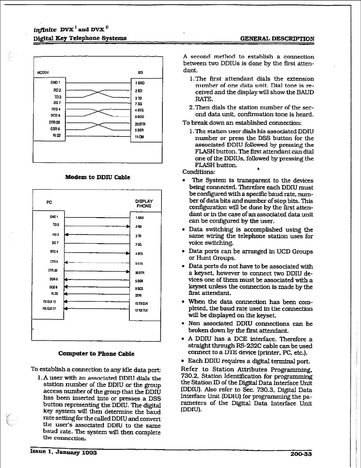
i&.&e DVX’andDVXn
Digital
Key Tekphone Systems GENERAL DEXRPTION
MODEM
GNDl
RD2
Tm
567
mss
DcDa
DTFl2D
WI6
RI22
Modem to DDN Cable
PC
DISPLAY
PHONE
Computer to Phone Cable
To establish a connection to any idle data pork
1, A user with an associated DDIU dials the
station number of the DDIU or the group
access number of the group that the DDIU
has been inserted into or presses a DSS
button representing the DDIU. The digital
key system wilI then determine the baud
rate setting for the called DDIU and c0nveI-t
the user’s associated DDIU to the same
baud rate. l’he system will then complete
the connection.
A second method to establish a connection
between two DDIUs is done by the first &ten-
dant.
1 .The first attendant dials the extension
number of one data unit. Dial tone is re-
ceived and the display will show the BAUD
RATE.
Z-Then dials the station number of the sec-
ond data unit, confirmation tone is heard.
To break down an established connection:
1. ne station user dials his associated DDIU
number or press the DSS button for the
assocfated DDIU followed by pressing the
FLASH button. The first attendant can dial
one of the DDIUs. followed by pressing the
FJ..ASH button.
Conditions: .
l
The System is transparent to the devices
being connected. Therefore each DDIU must
be configured with a specific baud rate, num-
ber of data bits and number of stop bits. This
configuration wiIl be done by the iirst atten-
dant or in the case of an associated data unit
can be conf@ured by the user.
l
Data switching is accomplished using the
same wMng the telephone station uses for
voice switching.
* Data ports can be arranged in UCD Groups
or Hunt Groups.
l
Data ports do not have to be associated wltb
a keyset, however to connect two DDIU de-
vices one of them must be associated with a
keyset unless the connection is made by the
first attendant.
l
When the data connection has been com-
pleted, the baud rate used in the connection
will be displayed on the keyset.
l
Non associated DDIU connections can be
broken down by the Brst attendant.
l
A DDIU has a DCE interface. Therefore a
straight through RS-232C cable can be used
connect to a DTE device [printer, PC, etc.).
l
Each DDIU requires a digital terminal port.
Refer to Station Attributes Programming,
730.2, Station Identification for progrmg
the Station ID of the Digital Data interface Unit
(DDiU). Also refer to Sec. 730.3, Digital Data
Interface Unit (DDIU) for progmmming the pa-
rameters of the Digital Data interface Unit
(DDIU).
GENERAI,
DESCRIPTION
iqfisttte DVX’andDVX”
D&WI Key Telephone Systems
4
200.10 SYSTEM SPECIFICATIOHS AND
The DVX I Basic KSU is housed in a wall-
mountable mbinet that contains the system
power supply and the mother board for stations
and COlines. This Basic KSU supports a loaded
capacity of 6 CO lines
and 12
stations.
DSS/DLSs can be
installed in
place of any
Digital Key terminal. Standard single line tele-
phones (2500 type] can be installed by using
Single Line Telephone Adapters (OPX) boxes, or
the
2x4
SL.T Eqander Module.
The DVX ’ Basic KSU is
housed &-A
a wa&
mountable cabinet that contains the system
power supply and the back plane for station
and CO line boards. This Basic RSU supports
a loaded capacity of 28 CO lines and 56 sta-
tions. DSS/DLSs can be installed in place of
any Di@aI Key
terminal.
Standard single line
telephones (2500 type) can be installed by re-
placing the ed3 Key lnterfaee Board(s) (CKB)
with the 4x8
SLT Interface Board(s) (CSB).
Eight sfngle line telephones can replace eight
Digital Display Terminals for each board ex-
changed. An ON/OFF switch is located on the
tiont of the power supply.
The system capacities are listed in Table ZOO-1
- Digital System Capacities. Electrical specifi-
cations. environmental specifkations, and
Loop limits are listed in Table 20@2 - Elecirical
Specikations, Table 200-3 - Environmental
Spedfcations and Table 200-4 - Loop Limits.
Dialing specifications are listed in Table 200-5
- Dialing Specifications. FCC Registrations
Numbers for DVX I and DVX ’ are listed in Table
200-6
- FCC Registration Numbers. Miscellane-
ous Specifications are listed in TabIe 200-8 -
Miscellaneous Specifications. Key telephone,
Single Line Telephone and OPXAudible lndica-
tions are
listed
in Table 200-S - Digital Terminal
Audible Signals, Table 200-10 - Single Line
Telephone Audible Signals and Table 200- 11 -
OPXTelephone Audible
Signals. Key
Telephone
Visual Indications are l&ted in Table 200-12 -
DSS/BLF Button Visual Indicators, Table 200-
13 - CO Line Button Visual Indicators, and
Table 200-14 - Function Button Visual
Indicators.
Issue 1, January 1993
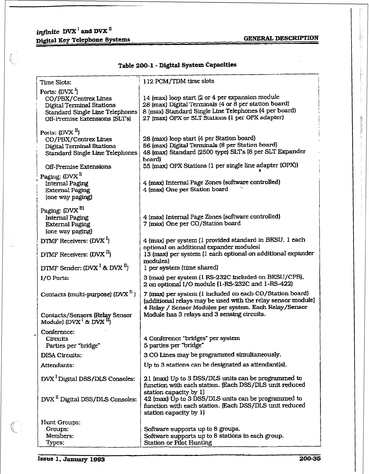
i-&e DVX’andDmn
D3&w Key Telephone Systems GENERAL DESCRIPTION
Table 200-l - Dig&al System Capacities
1
Time Slots: i 112 PCM/TDM time slots
i
Ports: (Dvx’)
! CO/PBX/Centrex Lines
; Digital Terminal Stations
Standard Single Line Telephone
Off-Premise Extensions (SLTsl :s
i
:s
14
(max) loop start (2 or 4 per expansion module
28 (max] Digital Terminals (4 or 8 per station board)
8 (max) Standard Single Line Telephones (4 per board)
27 [max) OPX or SLT Stations (1 per OPX adapter)
I
Ports: (Dvxnl
i CO/PBX/CentreX Lines
Digital Terminal Stations
! Standard Single Line Telephone
, Off-Premise Extensions
External Paging
(one way pagW
Paging: @wn’
Internal Paging
External Paging
(one my p@fgl
DTMF Receivers: [DVX ‘I
DTMF Receivers: (DVX “)
D’TMF Sender: (DVX r & DW ‘)
I/O Ports:
Contacts [multi-purpose) (DVX I1
Contacts/Senso15 (Rda~ Sensor
Module) (DVX’ & DWi 1
Conference:
Circuits
Parties per “bridge”
DISA Circuits:
Attendants:
DVX ’ Digital DSS/DLS Consoles:
DVX ’ Digital DSS/DLS Consoles
Hunt Groups:
Groups:
Members:
Tvues:
28 (ma) loop start (4 per Station board)
56 (max) Digital
Termfnals
(8 per Station board)
48 (max] Shndard (2500 type) SLTs (8 per SLT Expander
b0EU-d)
55 (max) OPX Stations (1 per single line adapter (OPX))
.
4 (max) Internal Page Zones (software controlled)
4
(max) Chx per Station board ‘.
4
[rnax) internal Page Zones [software controlled)
7 [max) One per CO/Station board
4 (maxI per system (1 provided standard in BKSU, 1 each
optional on additional expander modules)
13 (max) per system (1 each optional on additional expander
modules)
I per system &me shared)
4 Relay / Sens& Mock&s per system. Each~Relay/Sensor
Module has 3 relays and 3 sensing circuits.
4 Conference “bridges” per system
5 parties per “bridge”
3 CO Lines may be programmed simultaneously.
Up to 3 stations can be designated as attendant(s).
21 (max) Up to 3 DSS/DLS units can be prq$rammed ta
function with each station. Wch DSS/DLS unit reduced
station capaeity by 1)
42 (max) Up to 3 DSS/DLS units can be programmed to
function with each station. @kch DSS/DLS unit reduced
station capacity by 1)
software supports up to 8 groups.
Software supports up to 8 stations in each group.
Station or Pilot Hunting
3 (max) per system (1 RS-232C included on BKSUKPB).
2 on optional I/O module (I-RS232C and 1 RS-422)
7 (max) per system (1 included on each CO/Station board)
[additional relavs may be used with the relay sensor module)
Issut 1. January 1993 200-35
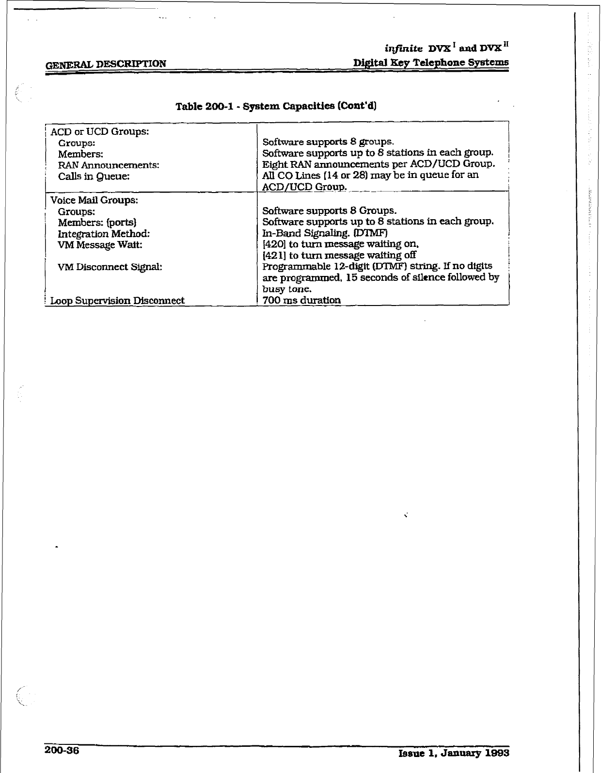
iqjkite DVX’ and DVX”
Digital Rcy Telephone Systems
Table 200-l - System Capacities (Cont’d)
ACD or UCD Groups:
Groups:
Members:
RAN AmlounceInent5:
Calls in Queue:
Voice Mail Groups:
Groups:
Members: (ports)
Integration Method:
V&l Message
Wait:
VM Disconnect Signal:
Loop Supenrision Disconnect
Software support5 8 groups. I
Software support5 up to 8 station5 in each group. I
Eiiht RAN announcements per ACD/UCD Group. l
AIlCOLiies[14or28)maybetiqueueforan i
ACD/UCD Group.
Software supports 8 Groups.
Software supports up to 8 stations in each group.
In-Band S@naIing. ID’lMF) ,
I4201 to turn message waiting on,
[42 1) to turn message wafting off 1
Programmable 12-digit (DTMF) string. If no digit5 [
are programmed, 15 seconds of silence followed by
busy tone. I
700 ms duration
200-36 bsue 1, Jamary 1995
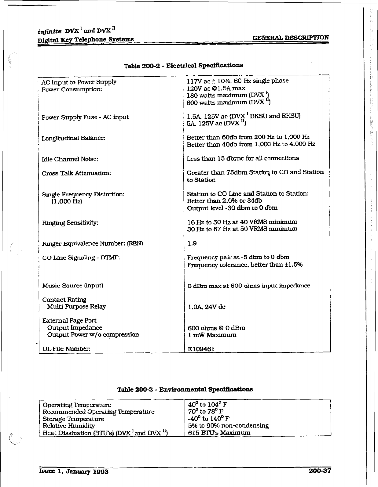
f&fnite DVX I and DVX I1
D#td Key Telephone Systems
GENiCRAT., DESCRIPTION
Table 200-2 - Electrical Gpccificaticu15
AC Input to Power Supply
I Power Consumption:
I
117’V ac 110%. 60 Hz single phase
12OV ac @lSAmax
180 watts m-urn (DVX !]
600
watts m-urn (DW ‘1
Power Supply Fuse - AC input j 1.5A. 125V ac (ID- I BKSU and EKSU)
Longitudinal Balance:
Idle Channel Noise:
Cross Talk Attenuation:
5A, 125V ac (DVX “1
Setter than 60db from 200 Hz to 1,000 Hz
Better than
40db from 1,000 )fi to 4,000 Hz
Less than 15 dbmc for alI connections
3reakr than 75dbm Statiox~ to CO and Station
to
Station
-L
SingIe Frequency Distortion:
(1,000 Hz)
Ringing Sensitivity:
Rin@r Equivalence Number: IREN)
CO Line SignaIing - DTMF;
Music Source (input)
Contact Rating
Multi Purpose Relay
External
Page Port
Output Impedance
Output Power w/o compression
UL File Number:
Station to CO Ltne &id Station to Station:
Better than 2.0% or 34db
Chtput level -30 dbm to 0 dbm
16Hzto30Hzat40VRMSminimum
3OHzto67Hzat5OVRMSmirhnum
1.9
Frequency pair at -5 dbm to 0 dbm
Frequency tolerance. better than +1.5%
0 dBm max at 600 ohms input impedance
l.OA 24V dc
6OOohms@OdBm
1 mW Makmum
El09461
Table 2Mb3 - Environsnental fi3pedfimthns
Operating Temperature
Recommended Operatfng Temperature
Storage Temperature
Relative Humidity
Heat Dissipation (BTU’s) (TWX I and DVX ‘)
Issue 1, January
loa3 200-37
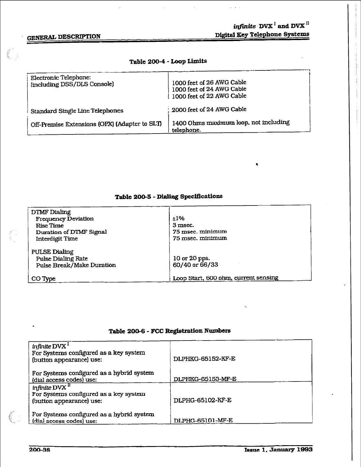
GE- DESCRIPTION
iqflniie DVX’andDVX’
D&&al
Ecy Telephone SyAcms
Table 200-4 - Loop Limits
[ Electronic Telephane:
( [including DSS/DL.S Console)
1
Standard
Single Line Telephones
i
, Off-Premise Extensions (OPX) (Adapter to SLlJ
I
-
1000 feet of 26 AWG Cable
1000 feet of 24 AWG Cable
1000 feet of 22 AWG Cable
2000 feet of 24 AWG Cable
1400 ohms maximum loop, not including
telephone.
.
Table 200-S - Dialing
SpccUicatians
I
DTMFDialing
kequency Deviation
RiseTime
Duration of DTMF Si@
Interdigit Time
HJLSEDialing
Plilse Dialing Rate
pulse Break/Make Duration
COTvpe
i
-i-
*10/b
3 msec.
75 msec. minimum
75 msec. minknan
10 or 20 pps.
60/40 or 66/33
Loop start, 600 ohm, current sensing
Table 20&6 - FCC Rc#stition Numbers
For Systems configured as a key system
(button appearan ce) use:
For
Systems
configured as a hybrid system
(dial access codes) use:
infiniteDvXU
DLPHKG-65 153~MF-E
For Systems cor&gu.red as a key system
(button appearance) use: DLPHG-6510%KF-E
For Systems configured as a hybrid system
(dial access codes) use: DLPI-IG-65101-m-E
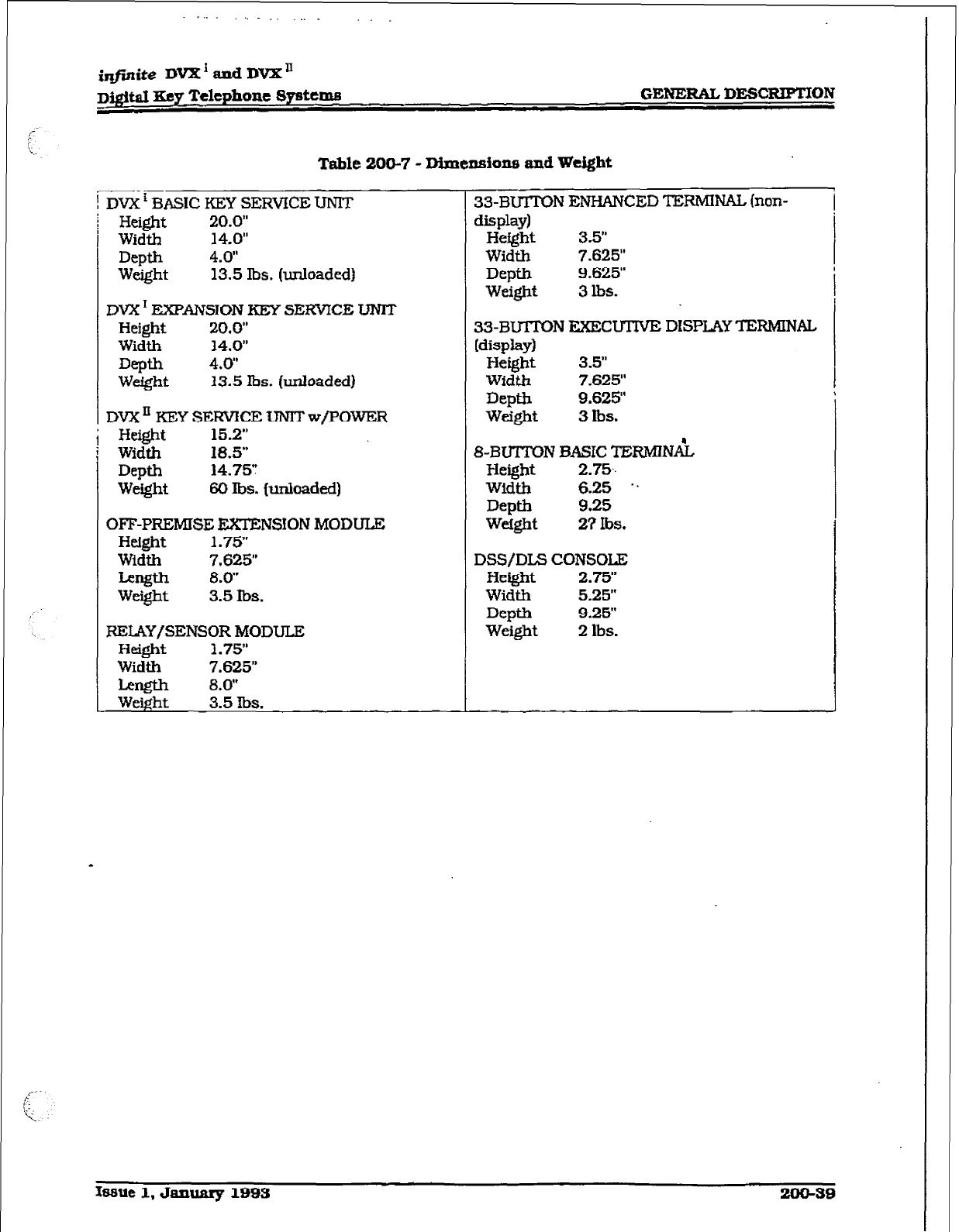
irIfinite DVX’andDVXn
DigitaI Key Telephone 8ysttms GENERAL DESCRWMON
Table 200-7 - Dimensiona and Weight
kVX ’ BASIC KEY SERVICE UNIT
Height 20.0”
Width 14.0”
Depth 4.0”
Weight 13.5 lbs. (unloaded)
DVX I EXPANSION KEY SERVICE TJNIT
Height 20.0”
Width 14.0”
Depth 4.0’
Weight 13.5 lbs. (unloaded)
DVX ’ KEiY SERVICE ?JN?T w/POWER
He&$-it 15.2”
Width 18.5”
Depth 14.751
Weight 60 lbs. (UnIoaded)
OFF-PREMISE EXIENSION MODULE
Height 1.75’
Width 7.625”
Length 8.0”
Weight 3.5 lbs.
RELAY/SENSOR MODULE
Height 1.75’
Width 7.625”
Len@31 8.0”
Weight 3.5 lbs.
33-BUITON ENHANCED TEXMINAL (non-
display)
Height 3.5”
Width 7.625”
Depth 9.625”
Weight 3 lbs.
33-B-N EXECU’ITVE DISPLAY TERMINAL
Misplay1
Height 3.5”
Width 7.625”
Depti 9.625”
weight 3 lbs.
&BUTTON BASIC TERMlNAi
Height 2.75..
Width 6.25 ..
Depth 9.25
weight 21 lbs.
DSS/DLS CONSOLE
Height 2.75”
Width 5.25”
Depth 9.25”
Weight 2 lbs.
hmue 1, January 1993
200-39
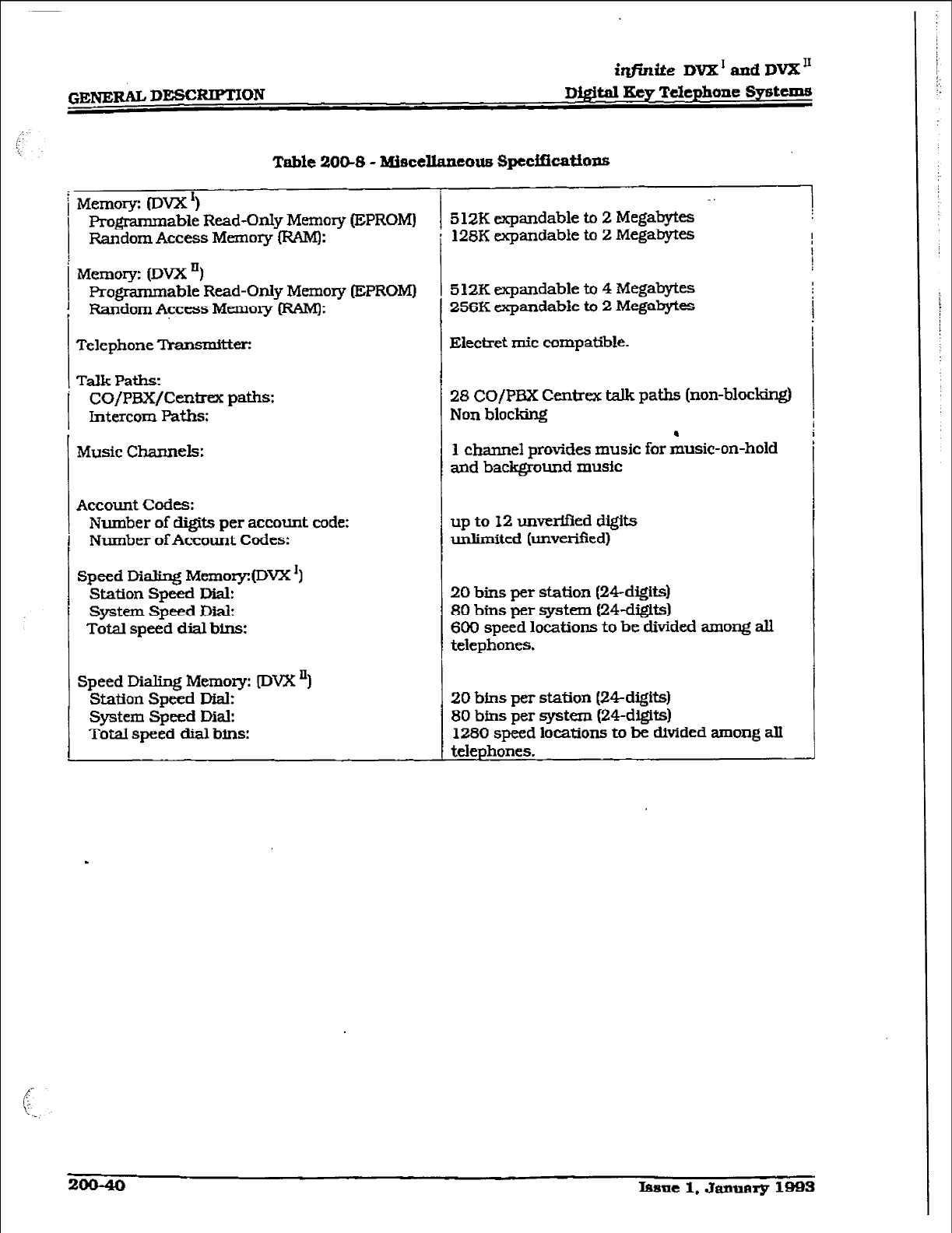
GENERALD=RIPTJON
i@niteDVX'audDVB;"
Digital Key T&phone Systems
Table 2OW3 - BUaceUancous Specffications
f-
Memory: (DVX ‘)
Programmable Read-Only Memory (EPROM)
I
! Random Access Memory (RAM):
Telephone Transmitter:
Talk Paths:
CO/PEH/Centrex paths:
Intercom Paths:
Memory: 03vX I)
F3x@ammable Read-Only Memory (EPROM)
Random Access Memory (RAM):
Music Channels:
Account codes:
Number of digits per account code:
Number of Account Codes:
Speed Dialing Memory:(DVX’)
Station Speed Rial:
System Speed Dial:
Total speed dial bins:
Speed Dialing Memory: (DVX ‘)
Station Speed J&k
System Speed Dial:
Total speed dial bins:
. .
5 1ZK expandable to 2 Megabytes
128K expandable to 2 Megabytes
5 12K expandable to 4 Megabytes
256K expandable to 2 Megabytes
Eiectret mic compatible.
28 CO/PEX Centrex talk paths (non-blocking)
Non blocking
1 channel provides music for &sic-on-hold
and background music
up to 12 unverified digits
unlimited (unverified)
20
bins per station (24-digits)
80 bins per system (24-cligits)
600
speed locations to be divided among ali
telephones.
20
bins per station (24digits)
80 bins per system (24-digits)
1280 speed locations to be &tided among all
J
telephones.
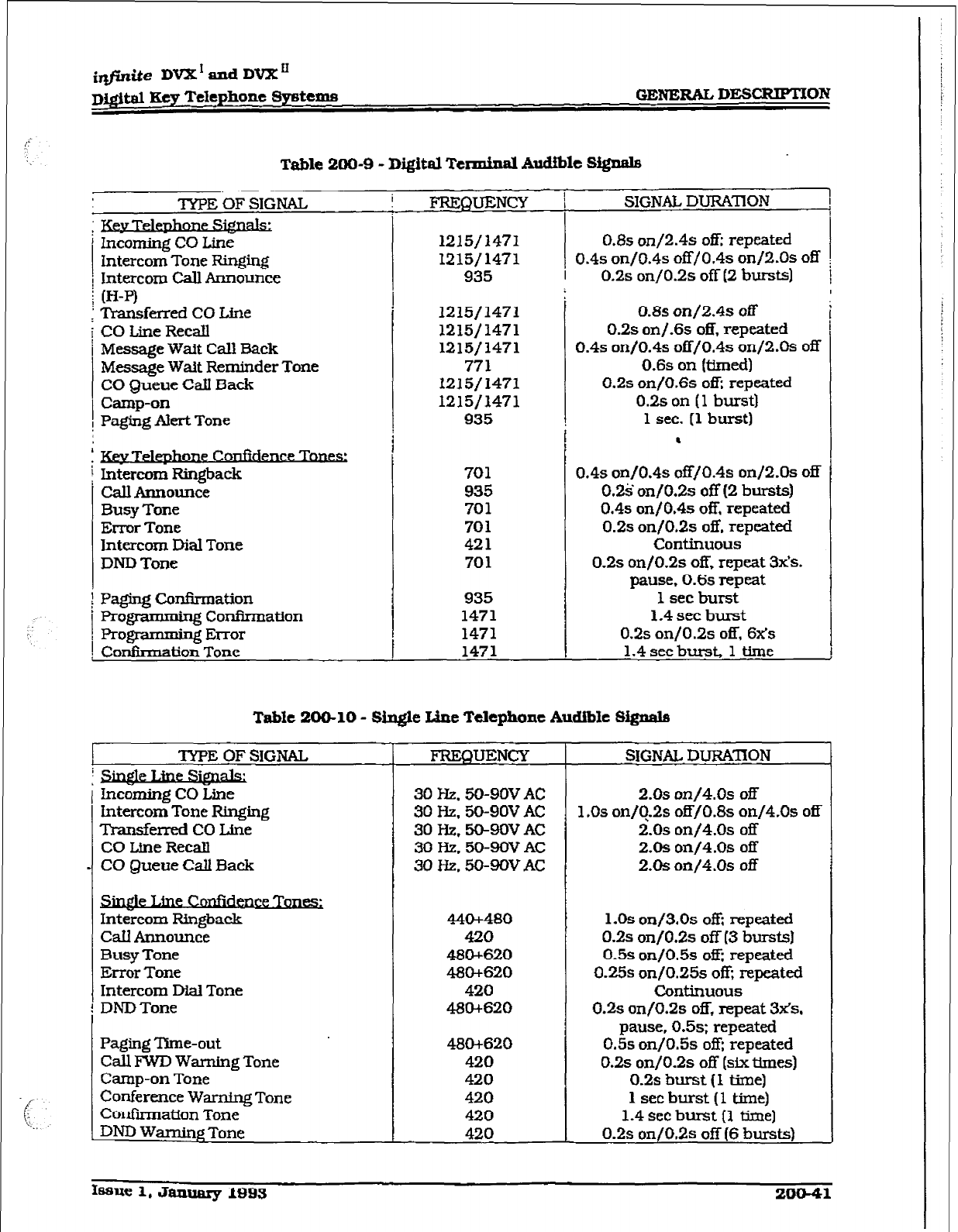
i@d.te DVX’dDVXn
D&$tal Key Telephone Systems GENERAL DESCRIPTXOA?
Table 200-9 - Digital
Terminal Audible Stgnals
‘IYPE OF SIGNAL
.
Kw Tel-
i Incoming CO Line
Intercom Tone Ringing
i Intercom Call Announce
; (H-P)
; Transferred CO Lhe
i CO Line RecaIl
/ Message Wait Call Back
Message Wait Reminder Tone
CO gueue CaJl Back
1 Camp-on
, Paging Alert Tone
Call Announce
Busy Tone
Error Tone
Intercom IXaI Tone
DND Tone
Paging Co&n-nation
Propamming Confirmation
Pro@ * gError
Confhnation Tone
FREQUEiNCY / SIGNAL DURATlON I
2
I
1215/ 1471
1215/ 1471
935
0.8s on/2.4s off: repeated I
0.4s on/0.4s ofUO.4~ on/2.0s off :
0.2s on/0.2s off (2 bursts] i
1215/1471
1215/1471
1215/1471
771
1215/1471
1215/1471
935
701
935
701
701
421
701
935
147 1
1471
1471
-
0.8s on/2.4s off
0.2s on/.6s off, repeated
0.4s onf0.4~ 05/0.4s on/2.0s off
0.6s on (timed)
0.2s on/O.6s off; repeated
0.2s on (1 burst)
1 sec. (1 burst)
.
0.4s on/OAs off/OAs on/2.Os 0fK
0.2% onfO.2s off (2 bursts)
0.45 on/O.4s off, repeated
0.2s on/O.2s off, repeated
Continuous
0.2s on/o.as off, repeat 32s.
pause, 0.6s repeat
1 set burst
1.4 see burst
0.2s on/O.25 05, 6x’s
1.4 set burst, 1 time
Table 200-10 - Single Line Telephone Audible Signals
I
1
‘IYPE OF SIGNAL
intercom Tone Ringing
Transferred CO Line
CO Line Recall
CO Queue CaU Back
Intercom Ringback
Call Announce
Busy Tone
Error Tone
Intercom IXal Tone
DND Tone
Paging Time-out
Call FWD Warnhg Tone
Camp-on Tone
Conference Warning Tone
Confkmation Tone
DND Warning Tone
L
f
FREQUENCy
30 Hz. 50-90VAC
30 Hz. 50-9OVAC
30 Hz. 50-90V AC
30 Hz. 5Q90V AC
30 Hz. 50-9OV AC
440+480
420
480+620
480+620
420
480+620
480+620
420
420
420
420
420
SIGNAL DURATION
2.0s on/$.Os off
1 ,Os on&2s off/O.Bs on/4.0s off
2.0s on/4.0s off
2.0s on/$.Os off
2.0s on/4.0s off
1.0s on/3.0s off; repeated
0.2s on/O.2s off 13 bursts1
0.5s on/0.5s off repeated
0.25s on/O.25s off; repeated
colltinuous
0.2s on/O.2s off, repeat 32s.
pause, 0.5s; repeated
0.5s on/O.5s off; repeated
0.2s on/0.2s off (six times)
0.2s burst (1 time)
1 set burst (1 time)
1.4 set burst [I time]
0.2s on/0,2s 05 (6 bursts)
bisue 1. January 1993
201141
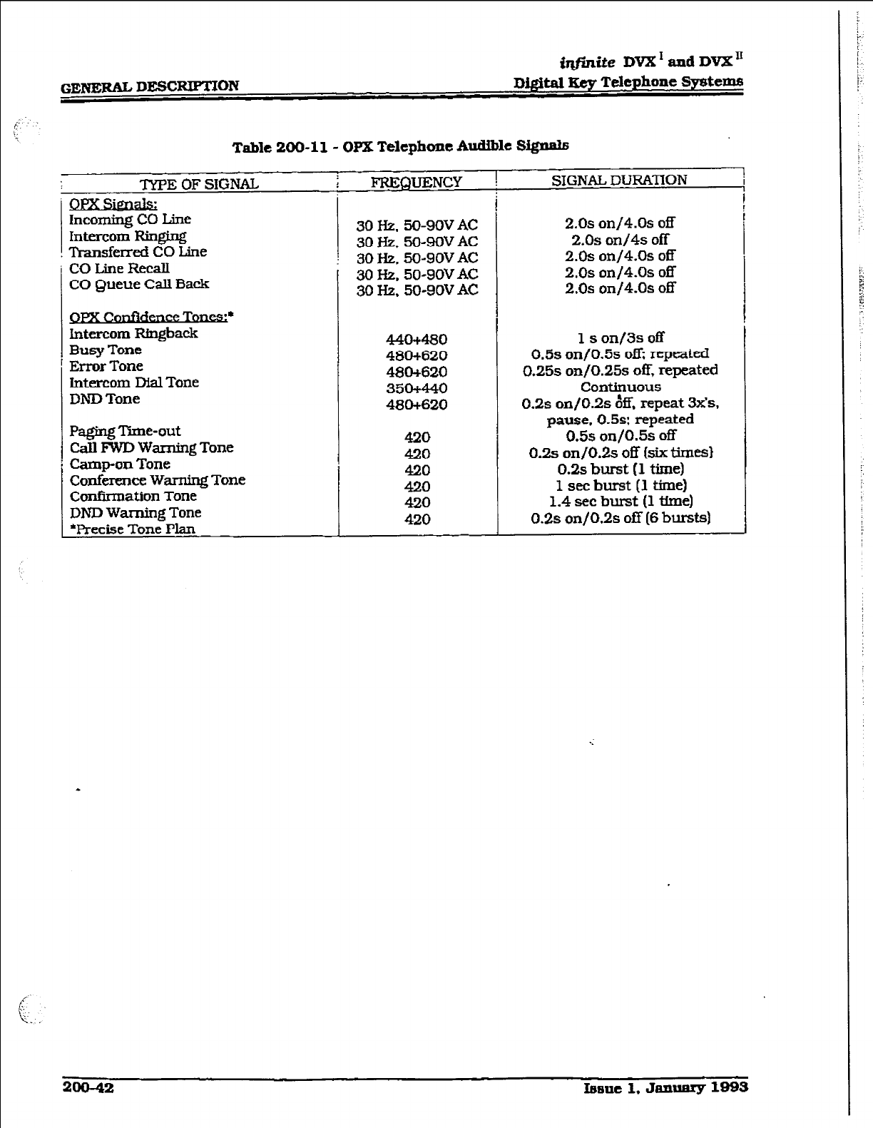
GENERAL DESCRIPTION
tqfinite DVX’and DVX’
Di@W Key Telephone System5
Table
200-ll- OPX Telephone Audible S&nab
TYPE OF SIGNAL
Incoming CO Line
Intercom Ringing
! Transferred CO Line
CO Line Recalt
CO
Queue
Call Back
FI?EQUENCY
30 Hz. 50-9OV
AC
30
Hz. 50-9OV
AC
I 30 Hz. 50-9OV AC
I 30 I-k 50s9OVAC
30 Hz. 50-9oV
AC
.L
CanfidenreTa
Intercom Rfngback
Busy Tone
Error Tone
Intercom Dial Tone
DND Tone
Paging Time-out
Call lWD Warning
Tone
Camp-on Tone
Conference Warning Tone
Confirmation Tone
DND Warning Tone
*Precise Tone Plan
440480
480+620
480+620
350+440
480+620
420
420
420
420
420
420
T
r
i
SIGNAL DuRAnON
2.0s
on/4.Os off
2.0s on/4s off
2.0s on/4.Os off
2.0s on/4.0s off
2.0s on/4.0s off
1 s on/3s off
0.5s on/0.5s oti repeated
0.25s on/O.25s off, repeated
Continuous
0.2s onjO.2~ & repeat 3x’s,
pause, 0.5s: repeated
0.59 on/0.5s off
0.2s on/O.2s off (six times)
0.2s burst (1 time)
1 set burst (1 time)
1.4 set burst (1 time)
0.2s on/0.2s off (6 bursts)
2oo-42 Irrenc 1. Janwary 1993
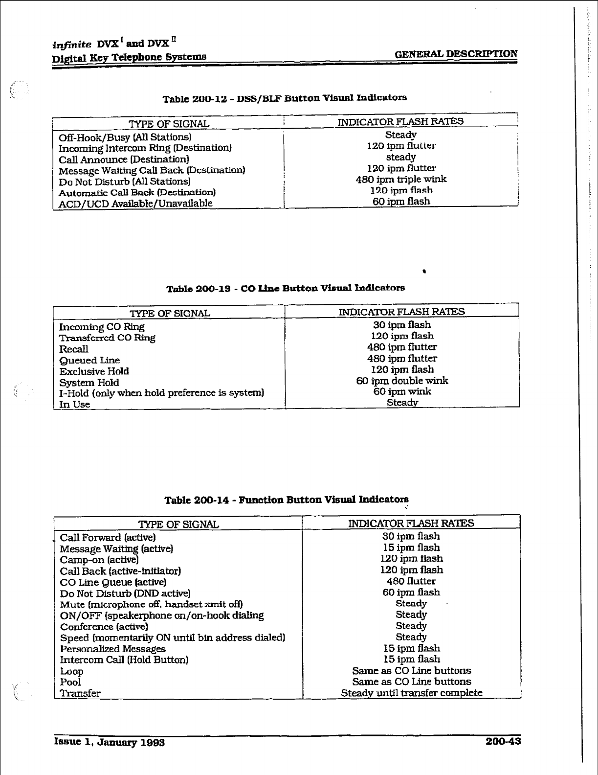
tqfinfte DVX’ and DVXn
Digital Key Telephone Systema GENERAL DESCRIPTION
Table 200-12 - DSS/BLF Button Vieti
bdiCStO=
TYPE OF SIGNAL,
Off-Hook/Busy (All Stations]
Incoming Intercom Ring (Destination)
Cd Announce (Destination)
Message Waiting Call Back (Destination)
Do Not Disturb (All Stations)
Automatic Call
Back (Destination)
ACDjUCD Available/Unavailable
INDICATOR FLASH RATES
Steady
120 fpm flutter
steady
120 ipm flutter
480 ipm triple wink
120 ipm fiash
60 ipm fiash
.
Table 200-13 - CO Line Button Vimal lndieators
TYPE OF SIGNAL INDICAmR FLASH RA’lES
Incoming co Fting
30
ipm flash
Transferred CO Ring 120 ipm flash
Recall 480 ipm flutter
Queued Line 480 ipm flutter
Exclusive Hold 120 ipm flash
System Hold 60 ipm double wink
I-Hold (only when
hold
preference is system) 60 ipm wink
In Use steady
Table 200-14 - Fun&ion Button Visual
ladiC8tOIS
.:
TYPE OF SIGNAL
Call Forward (actWe)
Message Waitfng (active)
Camp-on (active)
Cdl Back (active-initiator)
CO Line Queue (active)
Do Not Disturb (DND active]
Mute (microphone off, handset xmit ofQ
ON/OFF (speakerphone on/on-hook dialing
Conference (active)
Speed (momentarily ON untiI bin address dialed)
Personalized
Messages
Intercom Call (Hold Button)
hOP
Pool
Ti-ansfer
INDICATOR FLASH RATES
30
ipm flash
15 ipm flash
120
ipm flash
120 ipm flash
480 flutter
60 ipm flash
Steady +
Steady
Steady
Steady
15 ipm flash
15ipmflash
Same as CO Line buttons
Same as CO Line buttons
Steady until transfer complete
Is~~ue 1, January 1993 20043
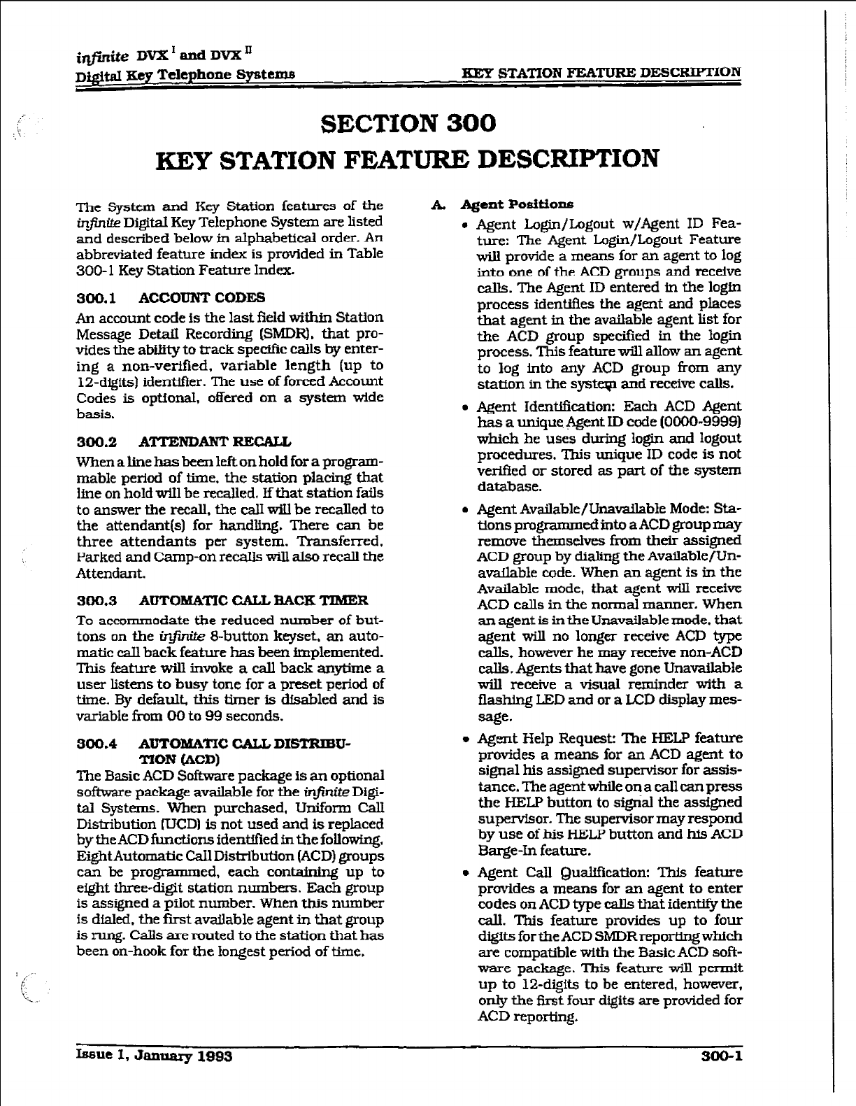
i&l&e DVX’andDVX’
Di,@at my T&phone systeme - STATION FEATURE DESCRfPTlON
SECTION 300
KEY STATION FEATURE DESCFUPTION
The System and Key Station features of the
tirite
Digiti Key
Telephone System are listed
and described below in alphabetical order. An
abbreviated feature index is provided in Table
300- 1 Key Station Feature Index.
300.1
ACCOUNT CODES
An account code is the last
field within
Station
Message DetaiI Recording (SMDRL that pro-
vides the abtity to track spedfc calls by enter-
ing a non-verified, variable length (up to
1%digits) identifier. The use of forced Account
Codes is optional,
offered
on a system wide
basis.
300.2
ATTENDANT
RECALL
When a line has been left on hold for a program-
mable
period
of time, the station placing that
line on hold will be recalled. If that station fails
to answer tbe recall, the calI wiU be recalled to
the attendant(s) for handling. There can be
three attendants per system. Transferred,
Parked
and
Camp-on recalls will also recall the
Attendant.
300,s
AWTOMATIC
CALL BACE TIMER
To accommodate the reduced number of but-
tons on the irlfinite &button keyset, an auto-
matic caIl back feature has been implemented.
This feature will
invoke a call
back anytime a
user listens to busy tone for a preset period of
time. By default, this timer is disabled and is
variable from 00 to 99 seconds.
300.4
AUTOMATIC CXLL DISTRIBU-
TION (ACD)
The Basic
ACD Software package is an optional
sofhmre package available for the w Digi-
tal Systems. When purchased, Uniform CalI
Distribution fIJCD1 is not used and is replaced
by tbe ACD functions identified in the
followir$,
EightAutomatic CaIl Distribution (ACD) groups
can be programmed, each containing up to
eight three-digit station numbers. Each group
is assigned a piiot number. When this number
is dialed. tbe first available agent in that group
is rung. Calls are routed to the station that has
been on-hook for the longest period of time.
k Agent Podtiom3
l
Agent Login/LDgout w/Agent ID Fea-
ture: The Agent Login/Logout Feature
will provide a means for an agent to log
into one of the ACD groups and receive
calls. The Agent ID entered in the login
process identifies the agent and places
that agent in the available agent list for
the ACD group specified in the login
process. This feature will alIow an agent
to log into any ACD group from any
station in the system and receive calls.
l
Agent
IdqM%zation: Each
ACD Agent
has a unique. Agent ID code (0000-9999)
which he uses during login and logout
procedures. This unique ID code is not
vetied or stored as part of the system
database.
l
Agent Available/Unavailable Mode: Sta-
tionsprogrammedint.oaACDgroupmay
remove themselves from their assigned
ACD group by dialing the Available/Un-
available code. When an agent is in the
Available mode, that agent will receive
ACD calls in the normal manner. When
an agent is in the Unavailable mode. that
agent will no longer
receive
ACD type
calls, however
he
may receive non-ACD
dls v Agents that have gone Unavailable
will receive a visual reminder with a
flashing LED and or a IED display mes-
sage-
l
Agent Help Request: The HELP feature
provides a means for an ACD agent to
signal his assigned supervisor for assis-
tance. The agent while on a call can press
the HELP button
to
sigrial the assigned
supenrisor. The supervisor may respond
by use of his HELP button and his ACD
Barge-h feature.
l
Agent Call Qualification: This feature
provides a means for an agent to enter
codes on ACD type calls that ident@ the
call. This feature provides up to four
digitsfortheACD SMDRreportingwhich
are compatible with the Basic ACD soft-
ware package. This
feature will
permit
up to l2-digits to be entered, however,
only the f5rst four digits are provided for
ACD reporting.
Issue I, January 1993 300-l
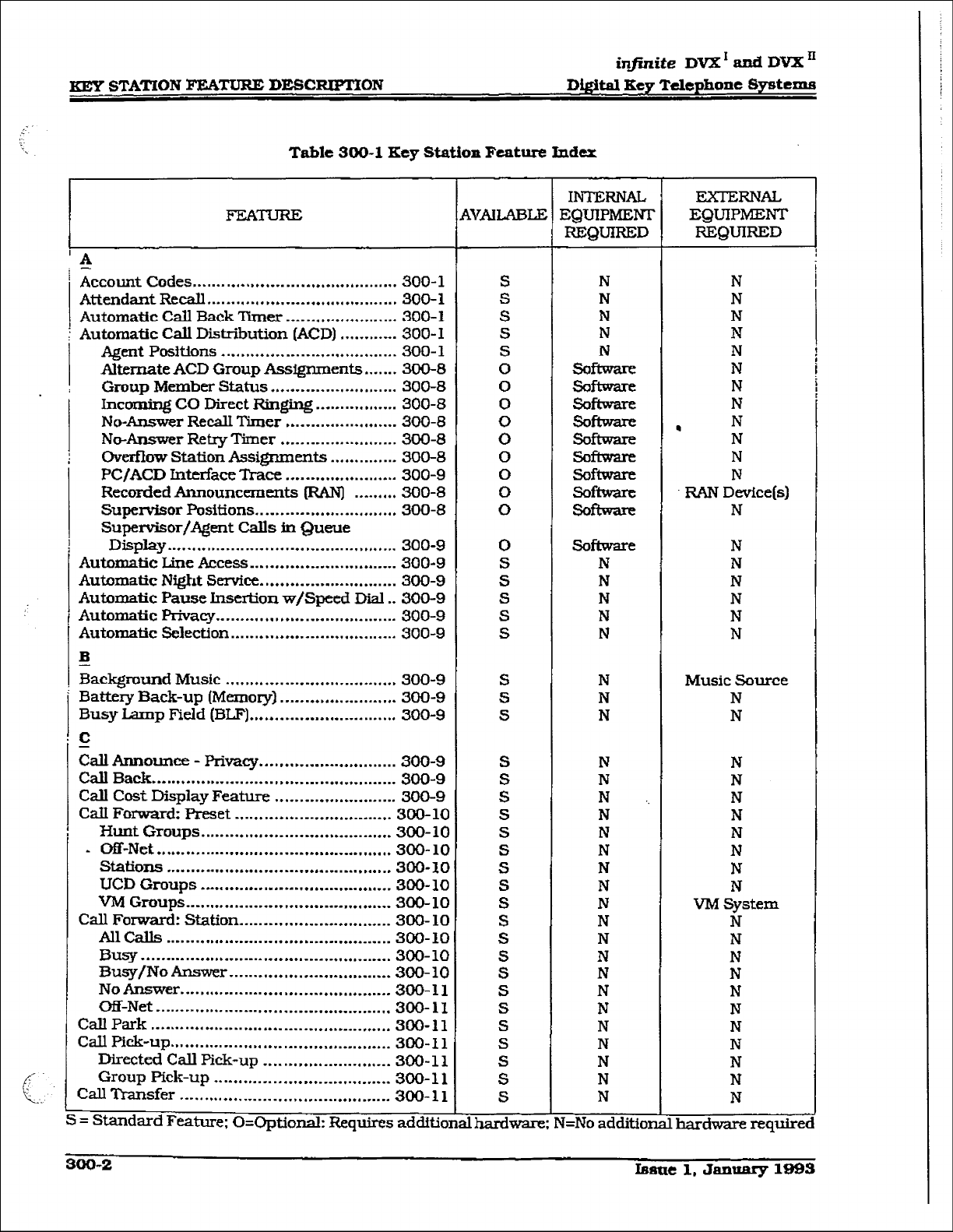
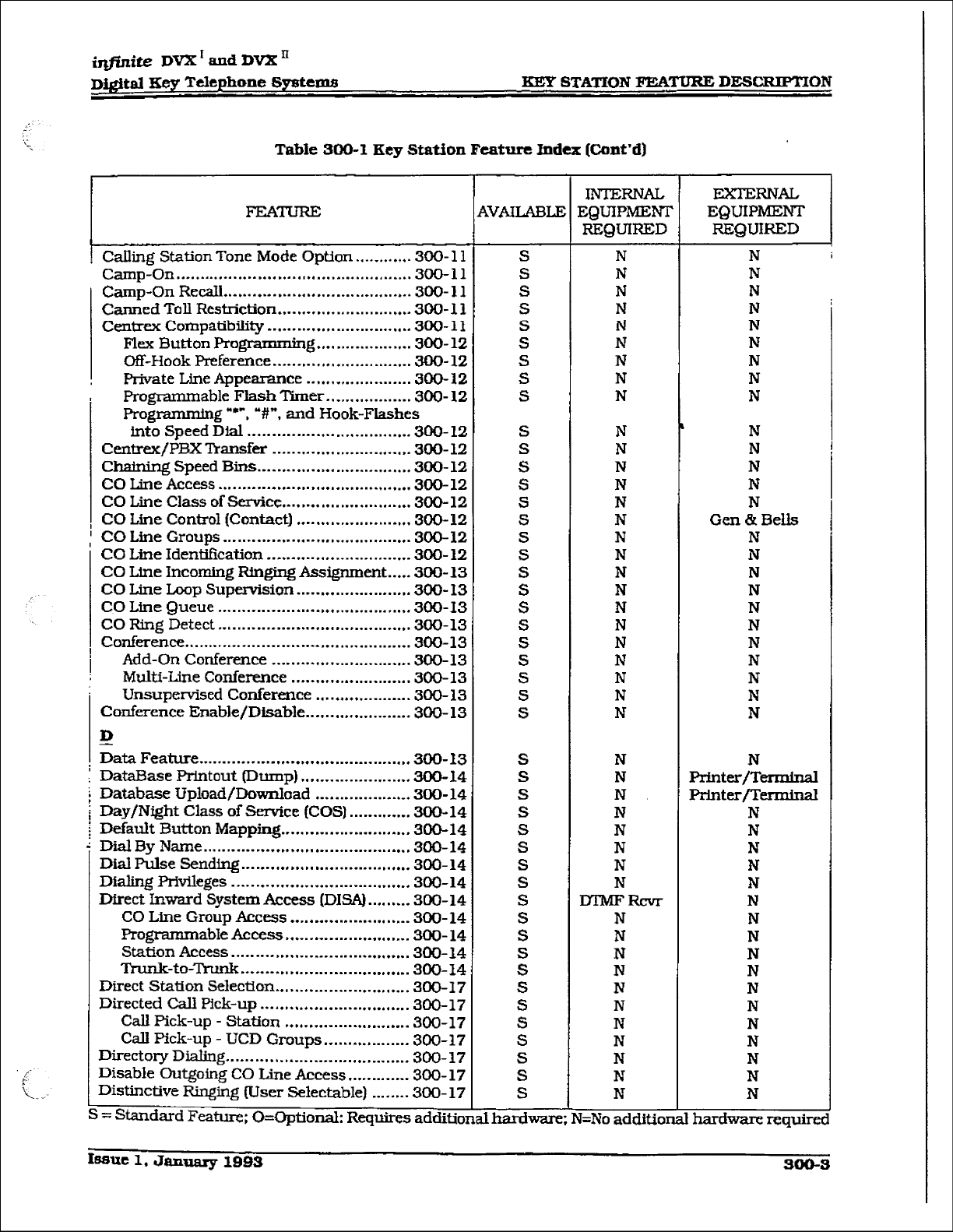
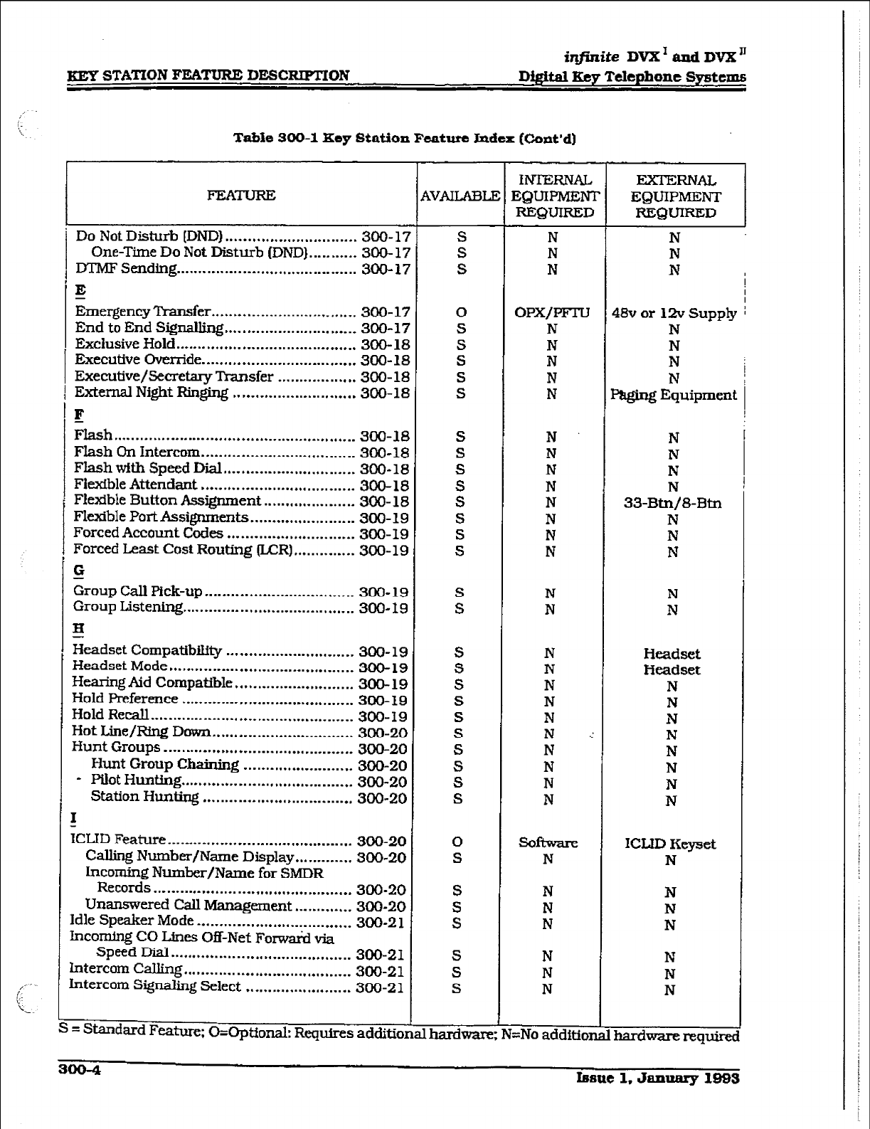
IlEy STATION FEATURE DESC~ON
iqjinite DV2I’ and DVX”
D&&al Key Telephone Systems
Table 300-l Key Station Feature Index [Cont’d)
FEATURE
Do Not Disturb [DND) .............................. 300-17
One-Time Do Not Disturb (DND}. .......... 300- 17
DTMF Sending ......................................... 300-17
E
Emergency Transfer ................................. 300-17
End to End Signailing .............................. 300-17
Exclusive Hold ......................................... 300-18
Executive Gvcn-ide ................................... 300-18
Executive/Secretary lkmsfer .................. 300-N
External Night Ringing ............................ 300-18
F
&ash ....................................................... 300-18
Flash On Intercom ................................... 300-18
Flash with Speed Dial .............................. 300-M
Fiexible Attendant ................................... 300-18
Fletibfe Button A&went ..................... 300- 18
Fltible PortAssignrnents.. ...................... 300-19
Forced Account Cock ............................. 300-19
Forced Least Cost Routing (UZR) .............. 300-19
G
Group Call Pick-up.. ................................ 300-19
Group Listening.. ..................................... 300-19
H
Headset Compatibihty ............................. 300-19
Headset Mode .......................................... 300-19
HezuingAid Compatible.. ......................... 300-19
Hold Preference ....................................... 300-19
Hold Recall .............................................. 300-19
Hot Line/Ring Down ................................ 300-20
Hunt Groups ........................................... 300-20
Hunt Group Chaining ......................... 300-20
- Pilot Hunting ....................................... 300-20
Station Hunting .................................. 300-20
E
ICLID Feature
..........................................
300-20
Calling Number/Name Display ............. 300-20
Lncoming Number/Name for SMDR
ReC0l-h ............................................. 300-20
Unanmered Call Management ............. 300-20
Idle Speaker Mode ................................... 300-21
hcorning CO Lines Off-Net For-w&d via
Speed Dial ......................................... 300-21
Lntercom CaIling ...................................... 300-21
Lntercom Signaling Select ........................ 300-21
. . .
= Standard Feature; O=Opti~nal: Requires additiona naraware
~VAXAELE
S
S
S
0
S
S
S
S
S
S
S
S
S
S
S
S
S
S
S
S
S
S
S
S
S
S
s
S
S
0
S
S
S
S
S
S
S
INTERN& ExrERNAI,
EQUIPMENT EQTJIPMENT
REQUIRED REQUIRED
N
N
N
N
N
N !
I
OPX/PFl-LJ
N
N
N
N
N
48v or 12v Supply i
N
N
N
paging E&ipment
N N
N N
N N
N N
N 33-Btn/8Btn
N N
N N
N N
N
N N
N
N Headset
N Headset
N N
N N
N N
N .: N
N N
N N
N N
N N
software ICED Keyset
N N
N
N
N
N
N
N
J=No addftior
N
N
N
N
N
N
Ihard-requirec
I
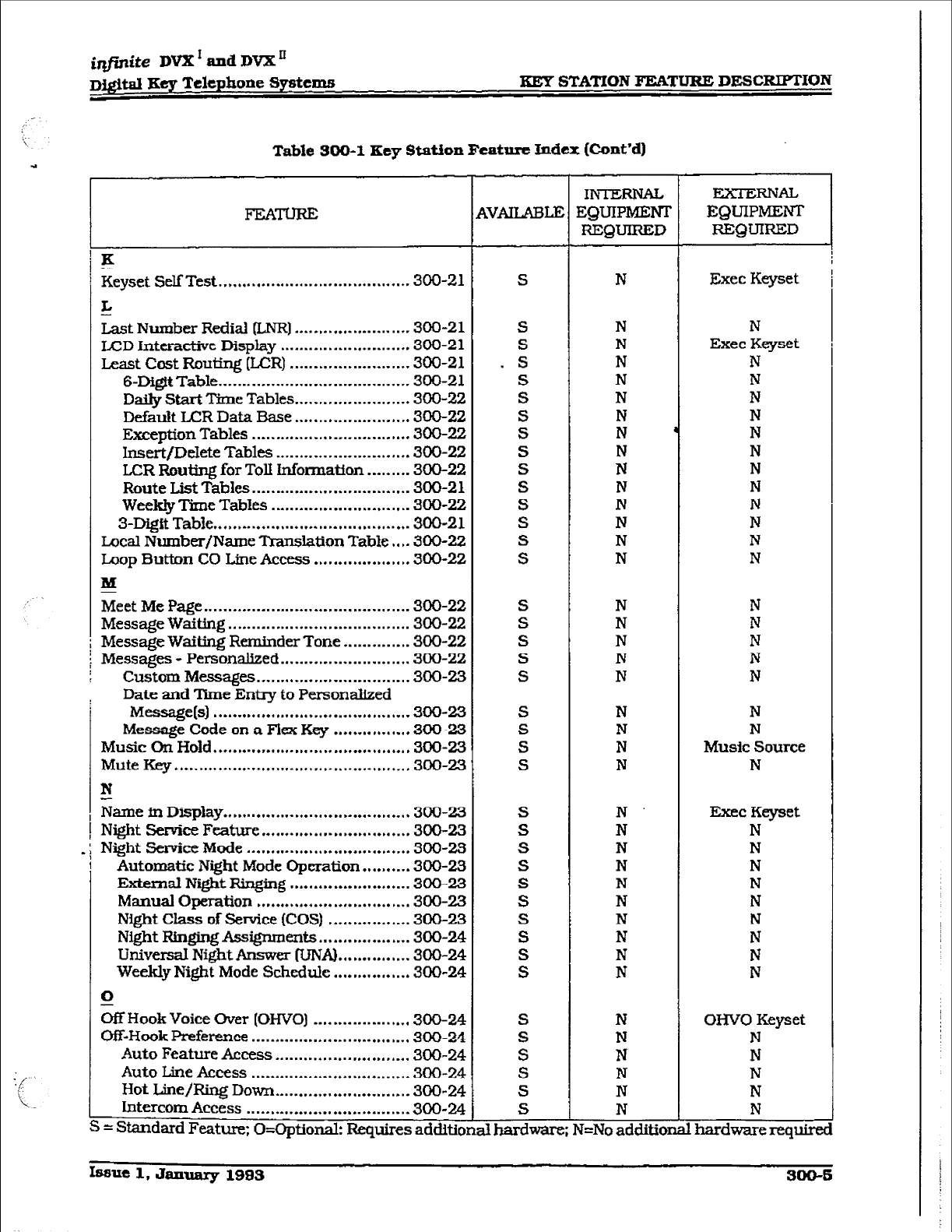
iqfinite DVX’ and DVX=
Digital Key Telephone Systems KEY STATION FEAX’URE DEBC~ON
Table BOB-1 Key Station Featnro Index (Cont’d)
FEATURE $VAIUBLE
K
keyset Self Test ........................................ 300-21 S
_L
Last Number Rediai &NR] ........................ 300-21 S
LCD interactive Display ........................... 300-21 S
Least Cost Routing (LfJR) ........................ .300-21 . s
6-Digit Table.. ...................................... 300-21
D&ly Start Time Tables.. ...................... 300-22 :
Default LCR Data Base ........................ 300-22 S
Except&m Tables ................................. 300-22 S
Insert/DeJete Tables ............................ 300-22 S
LCR Routing for Toll Information ......... 300-22 S
Route List Tables ................................. 300-2 1 S
Weekly Time Tables ............................. 300-22 S
3-D@ Table ......................................... 300-21 S
Local Number/Name ‘IYansIation TabIe . , . .300-22 S
hop Button CO Line Access.. ................. .300-22 S
M
Meet Me Page ........................................... 300-22 S
Message Waiting ...................................... 300-22 S
Message Waiting Reminder Tone.. ........... .300-22 S
Messages - Personalized.. ........................ .300-22 S
Custom Messages.. ............................. -300-23 S
.: 1
S
Date and Time Entry to Personalized
Mewgels) . . . . . . . . . . . . . . . . . . . . . . . . . . . . . . . . . . . . . . ...300-23
Message Code on a FlexKey . . . . . . . . . . . . . ...300-23
Music On Hold . ...*. . . . . ,.I.*...* . . . . . . . . . . . . . . *a . . . . 1. 300-23
Mute Key
l *...*. . . . . . . . . . . . I*..** . . . . *,...* . . . . . . . * . . . . . . .
300-23
N
-
Name in Display ..P . . . . . I...... . . . . . . . . . . . . . . . - . . . . . . a* 300-23
Night Service F&m-c. . . . . . . -,.....m.,., . . . . . . . . . . . . . 300-23
S
S
S
S
S
S
Night service Mode .................................. 300-23 S
Automatic Night Mode Operation.. ....... .300-23 S
External Night Ringing ......................... 300-23 S
Manual Operation ................................ 300-23 S
Night Class of Service (COS) ................. 300-23 S
Night Rtn@ng Assignments.. ................. 300-24 S
Universal Night Answer TcMA) ............... 300-24 S
Weekly Night Mode Schedule ................ 300-24 S
0
% Hook Voice Over (OHVO] .................... 300-24 S
Off-Hook Preference ................................. 300-24 S
Auto Feature Access ............................ 300-24 S
Auto Line Access ................................. 300-24 S
Hot Line/Ring Down ............................ 300-24 S
Intercom Access .................................. 300-24 S
= Standard Feature; O=OptionaI: Requires addltIonaIhan+are
INTERNAL
EQUIPMENI
REQUIRED
N
N
N
N
N
N
N
N
N
N
N
N
N
N
N
N
N
N
N
N
N
N
N
N
N
N
N
N
N
N
N
N
N
N
N
N
N
N
N
N
g=No additia
lzxTmNAL
EQUIPMENT
REQUIRED
Exec Keyset
N
Exec Keyset
N
N
N
I?
N
N
N
N
N
N
N
N
N
N
N
N
N
N
N
Music Source
N
Exec Keyset
N
N
N
N
N
N
N
N
N
OHYO Keyset
N
N
N
N
N
1 hardware requim
Issue 1, January 1995 900-S
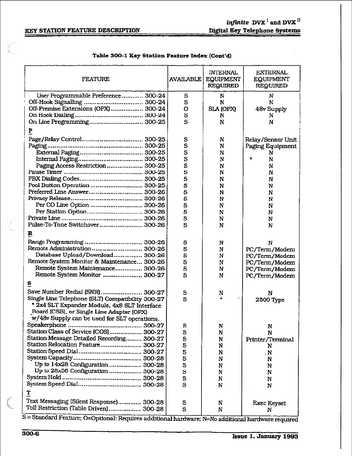
iqfinite DVX’ and DVX I’
xSY STATION FEATURE DESCRWMON Digital Key Telephone Sy8tcm.s
Table 300-1 Key Station Fcabre Index [Cont’d)
FEATURE
user Programnl able Preference.. .......... 300-24
’ Off-Hook Signauing ................................. 300-24
i Off-Premise Extensions (OPX) .................. 300-24
On Hook Dialing
......................................
300-24
On Line Programmhg .............................. 300-25
IP
-
i Page/Relay Control . . . . . . -.* . . . . . . . . . . . . . . . . . . . ...-.* 300-25
pti -
..... ................................................
300-25
ExternalPaging ................................... 300-25
intemalPagi.ng
.....................................
300-25
paging Access Restriction.. .................. 300-25
Pause Timer ............................................ 300-25
PBX Dialing Codes ................................... 300-25
PA Button Operation ............................. 300-25
Preferred Line Answer .............................. 300-26
Privacy Release
........................................
300-26
Per CO Line Option
.............................
300-26
Per Station Option ............................... 300-26
PrivateLine ............................................. 300-26
Pulse-To-Tone Swltchover ........................ 300-26
E
Range Programmhg ................................ 300-26
Remote Adminisiration ............................ 300-26
Database UpIoad/Download.. .............. 300-26
Remote System Monitor & Maintenance. ,* 300-26
Remote System Maintenance.. ............. 300-26
Remote System Monitor ...................... 300-27
s
gave Number Redial
(SNR)
....................... 300-27
Single Line Telephone (SLT) CompattbWy 300-27
* 2x4 SLT Expander ModuIe, 4x8 SLT Interface
-Board (CSB), or Single L;ine Adapter (OPX)
w/4& Supply can be used for SLT operations.
Speakerphone ......................................... 300-27
Station Chss of !%mice
[COS)
.................. 300-27
Station Message Detailed Recording.. ....... 300-27
Station Relocation Feature ....................... 300-27
Station Speed Dial ................................... 300-27
System Capacity.. .................................... 300-28
Up to 1m8 Cor@$ration .................. 300-28
Up to 28x56 Confiiuratfon .................. 300-28
system Hold ............................................ 300-28
system Speed Dial ................................... 300-28
r
I
!
,
I
c
S
rat Me=ging (Silent Response). ............ 300-28
rd.I Restriction (Table Driven) ............. . .... 300-28
= St.amhrd Feature; O=Optfonak Requires adduo
INTERNAL licxTERNAL
EQUIPMEM EQUIPMENT
EQUIFZED REQUIRED
N
N
SLA (OPX)
N
N
N
N
48v Supply
N
N
N
N
N
N
N
N
N
N
N
N
N
N
N
N
Relay/Sensor Unil
Paging Equipment
N
4 N
N
N
N
N
N
N
N
N
N
N
N N
N PC/Term/Modem
N PC/Term/Modem
N PC/Term/Modern
N PC/Term/Modem
N PC/Term/Modem
N
l .:
N
2500 Qpe
N
N
N
N
N
Printer/Terminal
N
N
N
.N
N
N
N
N
N
N
N
N
N
N
N
N
I=No additior
Exec KeyseA
N
hardwarereq~
300-6 Iesue 1. January 1983
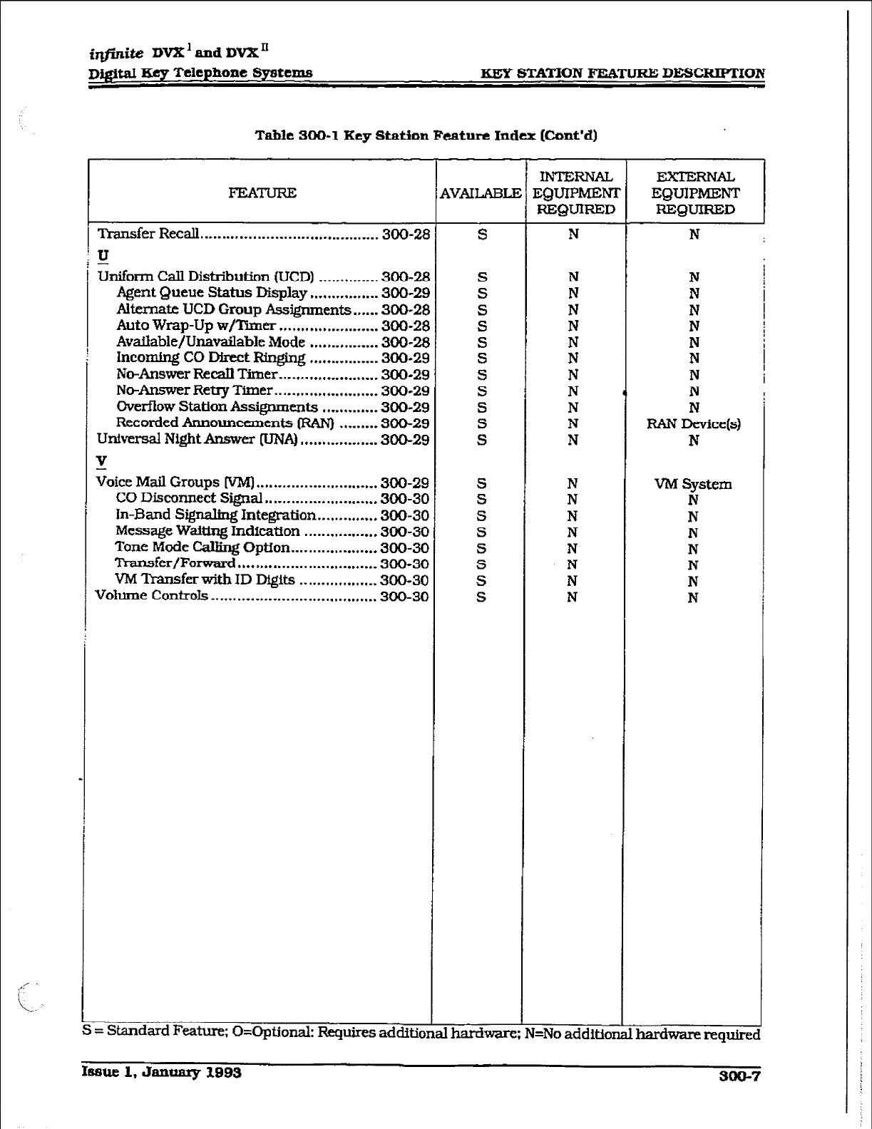
irlfinite DVX’ and DVX’
I)Jgital Ecy Telcphane Systems KEY STATION FEATURE DESCRWMON
Table 300-1 Key Station Fcaturc Index [Cont’d)
Transfer Recall . . . . . . . . . . . . . . . . . . . . . ..e... . . . . . . . . . . . ..w 3OCk2E
‘u
-
&form CalI Distribution (UCD) ............. .300-28
Agent Queue Status Display ............... -300-2s
Alternate UCD Group Assignments ...... 300-21
Auto wrap-up w/Timer ....................... 300-2E
Avaflable/Unavailable Mode ................ 300-Z
Incomhg CO Dkect Ringing ................ 300-2s
No-Answer Rec.&l Timer ....................... 300-2s
No-Answer Retry Timer
........................ 300-2C
Overfiow Station Assignments ............. 300-2E
Recorded Announcements CRAN) ........ -300-2:
universal NightAnswer pJNA)
.................. 300-25
v
Voice
Mail
Groups [VM) ............................
300-26
CO Disconnect SeaI ..........................
300-3c
In-Band Signaling
Integration.. ........... .300-3C
Message
Waiting Indication ................ .300-X
Tone
Mode
Calling Option.. ................. .300-X
Transfer/Forward ................................
300-3c
VMTransferwithIDDQits ................ ..300-3 C
Vohme
Controls..
.................................... 300-3c
4VAILAEU
S
S
S
S
S
S
S
S
S
S
S
S
S
S
S
S
S
S
S
S
= Standard Feature; O=Optional: Requires additional
hardware
IIvTTsRNAL
FQUIPMENI
REQUIRED
N
N
N
N
N
N
N
N
N
N
N
N
N
N
N
N
N
N
N
N
I=No addition
N
N
N
N
N
N
N
N
N
RAN Device(s)
N
VM System
N
N
N
N
N
N
N
hardware require!
Isauc 1, Jammy 1993 300-7
m STATION FEATURE DESCRIPTION
iqfinite DVX’andDVXn
D$jital Key Telephone Syntems
13. Alternate ACD Gmup Aaaignmenta
An alternate ACD group can be pro-
gmmmed so that if stations in one group
are busy, the alternate group will be
checked for an available station.
C. Group Member Status
The SupeTYisors Group Member Status
feature provides a means for an ACD su-
pervisor to view the status of each of the
eight ACD groups in the system individu-
ally. This display will teI1 the supervisor
which stations are logged into the group,
and if the station logged in is available,
unavailable, out of service, in DND. or busy
on a call. The supervisor can use this dis-
play to determine why there are a lot of
queued calls in a specific group.
D. Incoming CO Ditect Ripging
CO Lines can be programmed to ring di-
rectly into a ACD group. When ali agents
are busy and RAN is enabled, the system
will answer the caller and present the 1st
RAN announcement automatically.
E.
No-Answer l&call Timer
If a call routed to a station via ACD is not
answered by the ACD Agent/Station before
theNo-AnswerRecalltirnerexpires.tbecd
will be
returned to ACD Queue with the
highest priority, in addition, the station
that failed to answer the ringing ACD call
will be placed into an out of service @OS]
state.
F. No-An8wcr R&q mmcr
When the No-Answer Recall timer cx@m.s.
a station that failed to answer the ringing
ACD call is placed into an out-of-service
(00s) state. The station that was taken
out-of-service (OOS] will be placed back in
- service if the agent hits hf.51 available flex
button or dials the available flex code. In
addition, the agent will be placed back in
service if the No-Answer Retry timer ex-
pires. If the agent does not answer his next
ACD call. he will again be taken out-of-
service. This cycle will continue until the
station answer5 calls, logs out, or goes
unavailable.
G. ovemow station #l88ignlncnts
An overflow station may be assigned to
route callers in queue to a designated sta-
tion after a specified time, The
ovdow
station may not be one of the ACD group
stations.
R. Recorded houncementt3 (RANj
Recorded announcement devices can ‘be
assigned to provide up to eight different
messages. ifall stations in aACD group are
busy. The eight messages are available to
all eight ACD groups in different conf@ura-
tions. A RAN device can provide an an-
nouncement to one caller at a time.
Subsequent callers will be queued onto the
message on a first-in basis.
I. supeld8or Po8ition8
l
Supervisor Login/Logout Feature: The
Supervisor Login/Logout Feature will
provide a means for a supervisor to log
into one of the ACD groups. ‘The Super-
visor ID entered in the login process
identifies the supeti&~br for the specific
ACDgroup he is assigned to. This feature
will allow a supervisor to log into any
ACD group from any station in the sys-
tern. However, to have the supervisor
monitorwithbarge-infeatunz, tbesuper-
visor must log in at a station with moni-
tor barge-in capability.
l
Supavisor Identification: Each ACD Su-
pervisor has a unique Supervisor ID code
(0000-9999) which he uses during login
and logout procedures. This unique ID
code is not verified or stored as part
of
the system database.
l
Supervisor Help Request: The HELP fea-
ture provides a means for an ACD agent
to signal his assigned supervisor for as-
sistance. The agent while on a call can
press the HELP button to signal the as-
signed supenisor. The supexisor may
respond by use of his HELP button and
his ACD Barge-In feature.
l
Sup&or Monitor w/Barge-In Feature:
TheACDSupewisor MonitorwithBarge-
In feature provides a means for an ACD
supervisor to monitor an agent% call in
progress or provide assistance in train-
ing ACD personne1. When used, a super-
visor may intrude onto an agents call in
a listen onlymode or in a true conference
mode. This feature is available with or
without
a warning tone.
6 Supervisor Station Assignment Feature:
The ACD Supervisor Station Assignment
feature provides a means to assign each
ACD group a supervisor. This supervisor
station can receive the calls in
queue
display in
real
time. receives No An-
swer/Out of Service, receives TIEW
300-S l8auc 1, January 1093
imite DVX’ and DVX”
Digiti Key Telephone Sy&ems KEY
STATION
FEATURE DESCRIPTJON
displays from the groups that the super-
visor is assigned to and can barge in on
active calls in his ACD group or groups.
J. Supervifmr/Agent Calls in Queue
DOPEY
This feature provides a means for an agent
and
ACD
supervisor to view the status of
their ACD group. This display is an idle
state display and will prompt a supervisor
that his agents in the group are having
problems answering all their calls. The dfs-
play will tell the agent and his supervisor
how many ealk are in queue, how many
agents are logged into the ACD group, and
the length of time in minute.5 that the oldest
call ha5 been in queue.
IL PC/ACD Interface Tract
This feature is only available when the
Basfc
ACD Software
package is purchased
separately. The PC/ACD Interface ‘II-ace
provides a series of events trace output
which is compatible with the fn@.&e
PC/ACD Reporting package.
300.6 AUTOMATIC LINE ACCESS
Each station, key or SLT, may have their phone
programmed to access a particular CO Line
such a5 a private line or a line from a Group of
CO line5 upon going off-hook. This IS useful in
Centrex or PBXapplications when station users
have dedicated or individual lines. Outside line
dial tone is received just by going off-hook,
without the need to dial an access code.
300.6
ATJTOMM’IC MIGHT SERVXE
The system may optionally be programmed to
go into and out-of night service automatically.
This method does not require the attendant to
activate or deactivate night senrice on a dnily
basis. The automatic night service is enabled
and disabled on a programmable
daily
schedule
including Saturday and Sunday schedules. A
time can be set to enable Night Service and to
Disable Night Service on a per day basis.
300.7
AUTOMATIC PAUSE INSElyITON
WITH SPEED DIAL
If a flash command is placed into system speed
dial numbers, station speed dial numbers, save
number redial or last numbeT redfal, a pause
will automatically be inserted after the flash. A
pause wfll also be automatically inserted after
a PBX diakng code has been used.
300.8
AUTOMATIC PRIVACY
Privacy is automaticaliy provided on all calls. if
one station is conversing, another station can-
not intrude on that line. The Automatic Privacy
feature can be disabled, allowing one other
station to join in on fzi5ting CO line conversa-
ti0l-E..
300.9
AUTOMATlC
SELECTION
The user can select an outside line, intercom
station, speed dial button, or dial a feature and
automatically place the phone in the dialing
mode without pressing the ON/OFF button or
lifting the handset.
300.10 BACKGROUND MUSIC
Each Digital Terminal user may receive music
over their speaker whed an optional music
source is connected to the system. This feature
can be allowed or denied on a system-wide basis
by programming.
300.11
BATTERY BACK-UP @UQdORy)
A
‘Super Cap” is located on the Main Key Serv-
ice Board WB) of the t$.@n.WDVX I System, and
a NICAD battery is located on the Central Proc-
es&g Board (CPBI of the tn&k!e DVX ’ System
to protect system memory in case of commercial
power outage or the system powerbeing turned
off for a period of time. Battery Back-up Memory
retains all system features including both sys-
tem and station speed dial durjng a power out-
age-
300.12 BUSYI.&UPFlEIlD('f3~
When a button on a Digital Terminal is assigned
as a DSS, it also smes as a Busy lamp Field to
display the status of that telephone.
.:
300.13 CAttANNOUNCE-PRIVACY
Each telephone user can set their titercorn
signaling switch to receive intercom call an-
nouncements without having the calling party
hear any convemations in progress.
SW.14 CALL RACK
A station can initiate a call back request to
another busy statton. As soon as that station
becomes idle, the station that left the caU back
request is signaled.
300.18
CALL COST DISPLAY FEATURE
The Call Cost Display Feature provides a user
to view the appmximate cost of each call made.
This approximate cost will also be printed as
part of the SMDR record.
Issue
1,
JammrylBBS
300-B
ir@ite DVX I and DVX”
gEp STATION FEATURE DESCRIPTION D@a.t Key Telephone Systems
The call Cost Display will replace the call dura-
tion display when a call is made using LCR. This
display is enabled in programming.
The cost information is programmable by se-
lec!ing one of the 16 route list tables and one of
the four time periods. This allows the user to
program four separate costs based on the time
of day for each of 16 routes. The costs entered
in the tables will be a cost for one minute,
however. costs are calculated using a 1/ 10th of
a minute value. These costs are rounded down
and are based on the start time of the call, even
if the call extends into a different time period.
The SMDR printout will contain a cost calcu-
lated using a l/ 10th of a minute increment and
the display will update approximately every 30
seconds. The user must have LCR enabled to
get the call cost display.
300.16 CALL FORWARD: PRESET
This feature allows the system database to be
configured so that incoming CO Lines, which
are programmed to ring at a particular station.
can be forwarded elsewhere in the system pre-
determined by programming. This feature is
am tithe station ringing is not answered in a
specified time. This is particularly useful in
kverflow” applications where a Voice Mail or
Auto Attendant may be in use.
. A station may have one designated preset
forward location defined in the database.
* Preset Cdl Forward is chainable only to other
predetermined preset forward stations speci-
fied in the database up to a chain of 5 sta-
ti0I-B.
l
Chainable Preset Call Forwarding will force
the incoming CO he to ring at each station
preassigned in the database for the Beset
Forward Ring Tfmer specffied in the database
_ before forwarding.
l
Each station in the system may, inde-
pendently, have incoming CO calls preset
forwarded to the following destinations:
A.
Preset
Call Fommrd - Hunt Groups
CO Lines can be preset forwarded to ring
into a Hunt Group from any station. A CO
line will not preset forward to a busy Hunt
group. however each time the preset for-
ward timer expires {for a total of tie at-
tempts) the group ~II be checked for an
idle station. If a member of the group is idle
the ca.li wIl.l then be presented to that mem-
ber.
B.
c.
D.
E.
Reset Cdl Forward - Off-Net
CO Lines can be preset forwarded to r&g
Off-Net via speed dial kom any station.
After the expiration of the preset forward
timer, the system will select an idle CO line
and dial the off-net location, then connect
the two CO lines.
Reset Call Forward - Stations
Each Digital Terminal user may have pre-
set in the database Initial Ringing Incom-
ing to be directed to another station in the
system, if the call goes unanswered for a
predetermined amount of time.
Reset Cdl
Forward - UCD Groups
CO Lines can be preset forwarded to ring
into a UCD Group fro- any station. A CO
line will not preset forward to a busy UCD
group, h owever each time the preset for-
ward timer expiiks (for a total of five at-
tempts1 the group will be checked for an
idle station. If a member of the group is idle
the callwill then be presented to that mem-
ber.
Preset Call Forward - VM Groups
CO Lines can be preset forwarded to ring
into a Voice Mail Group from any station.
A CO Iine will not preset forward to a busy
Voice Mail group, however each time the
preset forward timer expires (for a total of
five attempts) the group will be checked for
an idle Voice Mail port. If a V&f port is idle
the call will then be presented toVoice Mail.
300.17 CALL FORWARD:
STATXON
;
A. CaIlFomard-AUCdb
This feature allows a station the abiLity to
have all their calls (internal or external)
forwarded immediately to a designated sta-
tion. a UCD group pilot mxnber. Voice Mail
group number. or Hunt group. (See Note)
3. CallForward-Busy
This feature allows a station the ability to
have their calls forwarded to a designated
station, a UCD group pilot number, Voice
Mail group number, or Hunt group when
their station is busy. (See Note)
C. Call Forward - Busy/No An~wcx
Allows a stations the ability to forward a
combination busy/no answer calls to a
designated station. a UCD group pilot
number, Voice Ma.3 group number, or Hunt
300-10 beue 1, January 1893
ifiite DVX’ amI DVX’
D&itaI Key Telephone
Systems
EEY STATION FFiATURE DESCRIPTION
D.
E.
group. No answer calls fomard when the
system-wide “no answer timer” expires. In-
itial CO ringing, transferred CO ringing
and intercom ringing calls can ak be for-
warded. CaUs that ring to an idle station
wfll be call forwarded after expiration of the
No Answer ring timer.(See Note)
CalI Forward - No Answer
This feature allows a station the ability to
have their calls forwarded to a designated
station. a UCD group pilot number, Voice
Mail group number or Hunt group number
when there is no answer at the station. No
answer calls forward when the system-
wide *no answer tlmef expires. [See Note)
Call Forward - M-Net
Stations will be allowed to forward inter-
com and transferred CO line caUs to an
off-net location This allows a station to
reroute calls that would normally be lost.
Calls can be forwarded to home or another
off-net site. Initially rlngmg CO calls can-
not
be forwarded with this feature [see
Incoming CO lines O&Net Forward fea-
ture).
300.18 CALLPAEE
An outside line can be placed into one of eight
parking locations and can be retrieved by any
station that has a direct line appearance or an
available loop button. Parked cabs have their
own recall timer and wiII recall the originating
station and if still unanswered, the atten-
dant(s) .
300.19 CALL. PICK-tIPz
A Dtccted call Pick-up
A station can pick up an intercom call,
transferred. incoming, or recalling outside
line call to a specfic unattended station.
The call must be a tone ringing caL
B. Group
Pick-up
Stations can be placed in one or more of
four pick-up groups. Stations within a
group can pick up tone ringing intercom
calls, transferred. incoming. or recalling
outside line calls for another station in that
&roup .
300.20 GAIL
TRANSFER
AII outside CO line can be transferred f&m one
keyset to another. l3y using the TRWIS button,
screened (announced) or unscreened transfers
can be
made. The line being
transferred rings
on the keyset and provides Exclusive Hold
flashing indication to the receiving party’s
keyset. Any number of attempts can be made to
locate someone by calling different keysets
without losing the call. Ifa line is transferred to
a busy
station,
it will receive muted ringing.
300.21 CAWING STATION TONE
MODE
OPTION
This feature til provide an easy means for a
Calling station to ovenide a desired stations HF
(handsfree) or PV (call announce) intercom
switch setting. A dial cod& has been added that
is dialed in front of the extension number to
force the tone ringing.
300.22 CAMP-ON
A station may alert a busy party that an outside
line is on hold and waiting for them by using
the CAMP-ON button. To camp on a call, press
the TRANS button to tisfer the call to the
desired busy station. then press the CAMP ON
button. The busy party will receive amuted ring
over the keyset speaker, and a visual flashing
CAMP ON LED. By pressing the CAMP ON but-
ton, the person called places his existing out-
side call on hold and is connected to the person
placing the Camp On. He can then pick up the
call on the appropriate line. Calls cannot be
camped on when a station is in DND or in
COIlk~Ce.
300.23 CAMP-ONREcALt
When a station does not answer a Camp On.
that call will recall the person placing the Camp
Onandif unanswered by them, will recall the
attendant(s).
900.24 CANNED TOLL RESTRICTION
The system provides an easy means of applying
the most common form of toll restriction where
l+ and 0+ along wftb 976,555. and 4 11 tvpe of
caUsa.rerestrictedwHhalllocalcallsand l-800.
911, l-911,and l-611typeofcalIsarealIowed.
This canned toll restriction is applied through
the use of a single pre-built Class-of-Servfce
and can be assigned to stations using range
pmgmmming.
300.26 CENTREX CODKPA~
The infinite Digital Key Telephone System pro-
vides features that are Centrex compatible so
Issue 1, January 1993 300-11
KEY STATION FEATURE DESCRIPMQN
i@nite DVX’
and DVX’
Di@tal
Kqy Telephone Spetcms
that Centrex users can utilize the infinite Digital
Key Telephone System to enhance their Centrex
capabilities. The system actually simplifies and
provides easier access to many Centrexfeatures
by offering the following features:
A Flex Button Frog-g
Flexible button programming allows Cen-
trex users to program complexCentrexdial
codes onto a
keyset
button for easy one
touch access to Centrex features.
B. Off-Hook Rdcrcnct
Both Digital
Terminals
and Single line tele-
phones may be programmed to have their
personal Centrex line accessed automat-
icaKy just by lifting the handset or pressing
the ON/ OFF button. Internal features to
the in. Digital Key Telephone System
are still made available to DigitaITemUnais
by accessing intercom before going off-
hook.
C. Private Line Agbpearance
The in$.rr.& Digital Key Telephone System
aIlows for private line assignment on an
unlimited basis. Each station may have
sole access to a particular outside line if
desired and may also be assigned to receive
incoming ringing on that line.
D. Programmable
Flash Timer
CO line flash is a momentary opening on a
CO Iine used
for signaling. When usingthe
m&e Digital Key Telephone System in a
Centrex environment the CO line flash is to
signal the intention to transfer a calier
using Centt-cx transfer. The CO line flash
timer is programmable on a per CO line
bases to facilitate a mixture of Centrexand
CO
line5 within the same system.
E: Prow “W, *#“, and
Hook-Flashes
into Speed
Dial
Many Centrex codes utilize a hook-flash
followed by in many cases the
digit [*]
and
or I#]. The in.@.mYe Digital Key Telephone
System allows these codes to be pro-
grammed as a part of system or station
speed dial sequences.
300.28 CENTREX /PBX TRANSFER
WbenCenixxorPEXlines areconnectedtothe
tifiti Digital Key Telephone System, users
may, by using the
Flash
button, transfer callers
to other Centrex or PBX extensions. Addition-
ally. the Flash command may be included
within a Speed Bfn and programmed onto a flex
button for one button transfer.
300.27 C
HAINXNG SPEED
BINS
Speed dial bins may be chained together ‘by
simply pressing one speed bin, then another
and another as required.
This is helpful for accessing Long Distance car-
tiers or banking services when account codes
may be required.
300.28 CO LlNE ACCESS
Through programming, telephones are allowed
or denied access
to
particular outside lines or
Iine groups.
300.29 CO LINE CUSS OF SERVICE
Each CO Line may be programmed with a
Class-of-Service to provide dialing privileges.
The in@ni& Digital Key Telephone System uses
an array between CO Line Class-of-Service and
Station Class-Of-Service to offer a wide variety
of dialing privilege possibilities.
300.30 CO IJNE CON!l’ROL
(CONTACT)
On the infinite DVX ’ System. there are four
control contacts, and seven control contacts on
the irsfintce DVX ’ System which may be indi-
vidually programmed as either CO Line Control
(to control ancillary equipment) or Loud BeIl
ControI to control a customer provided ringing
device to external areas. When programmed as
CO Une Control and assigned to a CO line. the
corresponding contact will close whenever that
CO line is accessed by a station. Since no *on-
poard” relay contacts are available on the DVX
for CO Line Conkol. the Relay/Sensor Inter-
face module is used for this purpose. On the
i#.de DVX ’ System, there is one contact for
each 4x8 port card.
300.51 CO UNE
GROUPS
Outside lines can be placed in one of eight
groups if the customer’s business requires such
grouping. Stations are. then individually as-
signed access to these groups and given the
ability to dial on particular lines.
300.32 CO LINE IDENTIpIICAmON
This feature allows a name to be entered into
the database progr * g for each individual
line &tunk) connected to the system. The name
may be entered in any combination up to 1%
characters in length (this will represent 24dig-
its entered). Once entered, LCD digital
terminals includingthe attendant station(s) WU
receive the programmed line *name” in place of
the default ‘LINE XX” message. This applies to
all line call processing conditions where the
current ‘LINE XX message appears.
300-12 bsttc 1, Jsnuary 1993
infinite DVX ’ and DVX n
Di@taI Key Telephone System KEY STATION FEATURE DES-ON
SMDR will continue to print out the line num-
berm place of the programmed name. If the line
name has not been programmed. then the cur-
rent ‘WNE XX” display will be used as the
default. A programmable data field is available
for each line in the system.
300.33 co LINE INCOMING RINGING As-
SIGNMENT
Each CO line may be programmed (in database
admin) so that incoming ringing on the speci-
fied CO line[sl may be assigned initial ringing
to one of the following destinations:
l
one or more stations fKeyset or SLTJ
l
To an ACD, UCD, Voice Mail or Hunt
Group
l
Off-Net [via Speed Dial)
The ring-in will follow Day King assignments
unless Njght Service mode is active, in which
case all incoming CO calls will follow Night Ring
aSSigllIll~tS.
When ringing is assigned to a keyset, a direct
line appearance or an idle Loop button must be
available to receive the call. Station call for-
warding of initial ringing CO mll is possible and
can be directed to other keysets with an avail-
able Loop button or direct appearance,
lf the inMaNy ringing CO call cannot ring at the
destination assigned. it will ring at the tit
Attendant station.
300.34 CO LINE LOOP SDPERVISION
- The injh.& Digital Key Telephone System can
be programmed to monitor CO lines while on-
hold or connected to RAN devices or Voice Mail
systems or in Trunk-to-M connections for
disconnect signal provided by the Telco.
After a disconnect signal is detected, the in&We
Digital Key Telephone System will release the
CO lines and automatically place them back in
service. The Loop Supervision disconnect sig-
nal is 700 msec. In duration.
300.35 co LmE QUEUE
When all the outside hnes in a group are busy,
stations can be placed in queue awaiting a line
in the same group to become available. If a
station doesn’t answer the queue signal within
15 seconds, that station is dropped from the
queue.
300.36 CO RING DETECT
The duration of the ringing signal from the CO
or the PBX is matched with ringing detection
circuitry in the KSU. The ring detect can range
horn 200 to 900 msec. programmed in 100
msec increments. This timer helps prevent false
ringing.
300.37 CONFERENCE
There are three dffferent types of conferencing:
A Add On Conftrence
Up to fwe internal parties can engage in a
conference, or four internal parties with a
limit of one external party.
B. Multi-Ldae Confcrellcc
One internal station can engage in a con-
ference with two outside parties.
c. IJnsupvpieed Conference
The conference initiator can exit a confer-
ence with two outside parties and leave
them in an unsumed conference. The
initiator can r-e-enter the conference at any
time. The &I Digital Key Telephone
System can automatically terminate the
call whenboth parties hangup. whenLoop
Supervision is provided by the telco and
enabled in the database.
A programmable conference timer will dis-
connect the unsupervised conference tithe
initiator does not re-enter.
300.98 CONFERENCE ENAB~/DBAB~
This feature will allow the system conference
feature to be administered on a per station
basis for the ability of a station to initiate a
conference.
300.39 DATA FEATURE
The Data Feature offers the ability to transmit
data information between personal computers,
printers, plotters, modems, CI?Tterminals. and
main frame computer ports. To establish a data
call, a Digital Data Interface Unit (DDIU) is
required to be connected to each data commu-
nications device. The Digital Data Interface Unit
(DDIUI allows any serial data communications
device {which conforms to RS-232C) to be con-
nected to the fnjinfte Digital systems. This re-
quires a digital port.
Ieaue 1. rfanurvp 1993 SOB-13
h@Gte DVX ’ aad DVX I1
fEEp STATION FEATURE DESCRTPTION Dig&al Key Telephone Systems
WO.40 DATABASE PFUNTOUT (DUMP)
Through a system programming command.
either potions of or a complete database
dump
can be printed using the FS232C connector
located on the infinite Digital Key Telephone
System Central Processing Board (CPB).
300.41 DATABASE UPLOAD/DOWNLOAD
DataBase Upload/Download Feature provides a
maintenance facility which has been added to
the Remote Administration routine. This rou-
tine will permit the database to be downloaded
to a PC. when a software change is made or
when the system needs to be initialized and
reprogrammed. In addition. the routine will
facilitate the pro@ * 2 of a database on an
in-house system which can be downloaded to a
PC and then uploaded to a system in the field.
After the system maintenance is completed. the
fiIe saved in the PC can then be uploaded to the
System.
300.42
DAY/NIGHT CLASS OF SEKVICE
WOSI
This feature allows stations
that
are a c&sin
COS during the day, to be assigned a different
COS when the system is put in the night mode.
The night COS goes into a&& when the system
is placed into the night mode, manually or
automatically. This prevents the misuse of
phones after hours.
300.43 DEFAULT BUTTON MAPPING
‘!h infinite Digital Key Telephone System al-
lows for 24 flexible buttons on each Enhanced
or Executive Digital Terminals to be flexibly
assigned to CO/PBX lines, DSS buttons, Speed
Dial or Feature buttons. However, the system
will power up witb a default button mapping as
shown in Figure 300-l 3SButton Default
Button Map . The infinite Digital Key Telephone
System also
supports an &button Digital Ter-
minal with 4
fixed feature buttons, 4 flexible
buttons, a message wait LED and full speaker-
phone capability. This keyset provides the same
functionality that the standard non-display 33-
button keyset provides. The 8-button keyset
default button map is shown in Figure 300-2
8-Button Default Button Map.
300.44
DIAL BYNAME
The system will allow station users to dial ex-
tension numbers. or speed bins by entering the
name of a person that has been programmed
for that station. The system database will
allow
entryafa~ehlphanunm-ic)~pto
24digits
ii-~ length for each station. The programmed
name can be used for dial-by-name station
users and in directory dialing.
300.45
DIAL PULSE SENDING
Each CO interface circuit for outside lines can
be progmmm ed to send dial pulse or DTMF
signals. Dialing speed and break/make ratios
are progrsmmable .
300.46 DUG PRWTLEGES
The systexn provides a flexible means of provid-
ing toll or dialing restriction. Through the as-
signment of class of service (both station and
outside line) many combinations
of
allow and
deny numbers can be set. Both area and office
codes can be screened for allow/deny privi-
leges. .
300.47
DIRECT INWARD SYSTEM AD
cE6s mm
Allows as many as three simultaneous outside
line calls to be programmed to provide direct
access to the system and the use of features
such as WATS lines. intercom dial tone or the
ability to dial out on outgoing trunks
without
going through the attendant. The duration of a
‘ll-unk to Trunk DisA call can be set by the
system administrator.
A.
B.
c.
D.
CO Wne Group Access
Incoming DISA callers may access all line
groups such as FX or WATS lines or other
outgoing services fi-om home orwbile away
horn the offke.
Frogrammable Access
A 3-d@ securlly code can be assigned in
the system database to restict unwanted
use of the DISA circuits. E&h DISA line
can be programmed independently
for
24
hour DISA use or night DISA use only.
station Access
DISA callers may dfal any station directly
without going thru the attendant.
If a DIU caller attempts to call a station
that is busy or does not answer the
system
wiU return ICM &al tone
at the
end of
a
programmable timer (Preset Forward
Timer). This will allow the DISA caller to try
another station without havfng to dial into
the system again.
Trunk-to-Tntnk:
The DISA Trunk-to-Trunk [or Confkxnce)
option on the CO line governs a DISA call-
ers ability to access other outside Ilnes. CO
lines must have DISA Trunk-to-m en-
abled to allow a DISA caller to establish an
300-14
Issue 1, Jamxary 1983
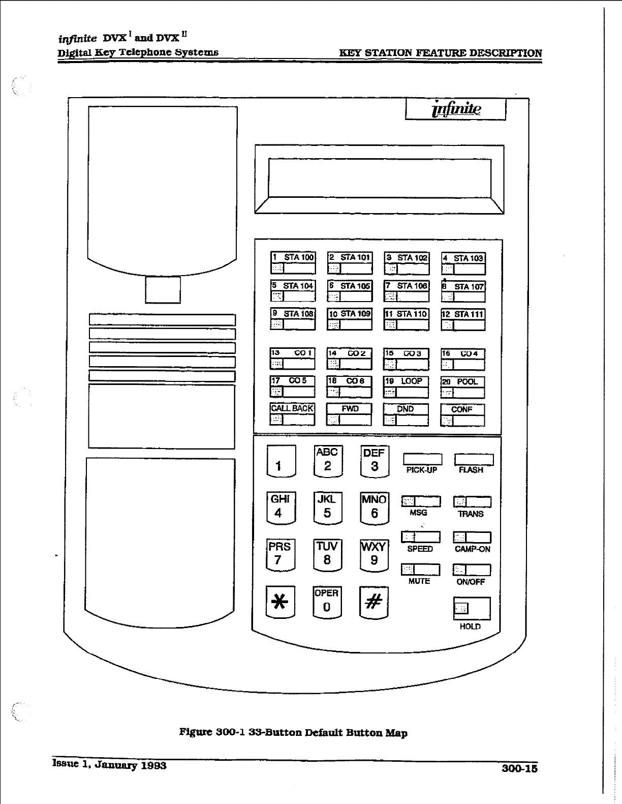
j@ntte DVX’ and DVX’
D&+II Key Telephone Syetems
KEY STATION FEATURE DESCRFIION
I-
pvgute 300-l 33-Butt.011 Dcikdt Button
Map
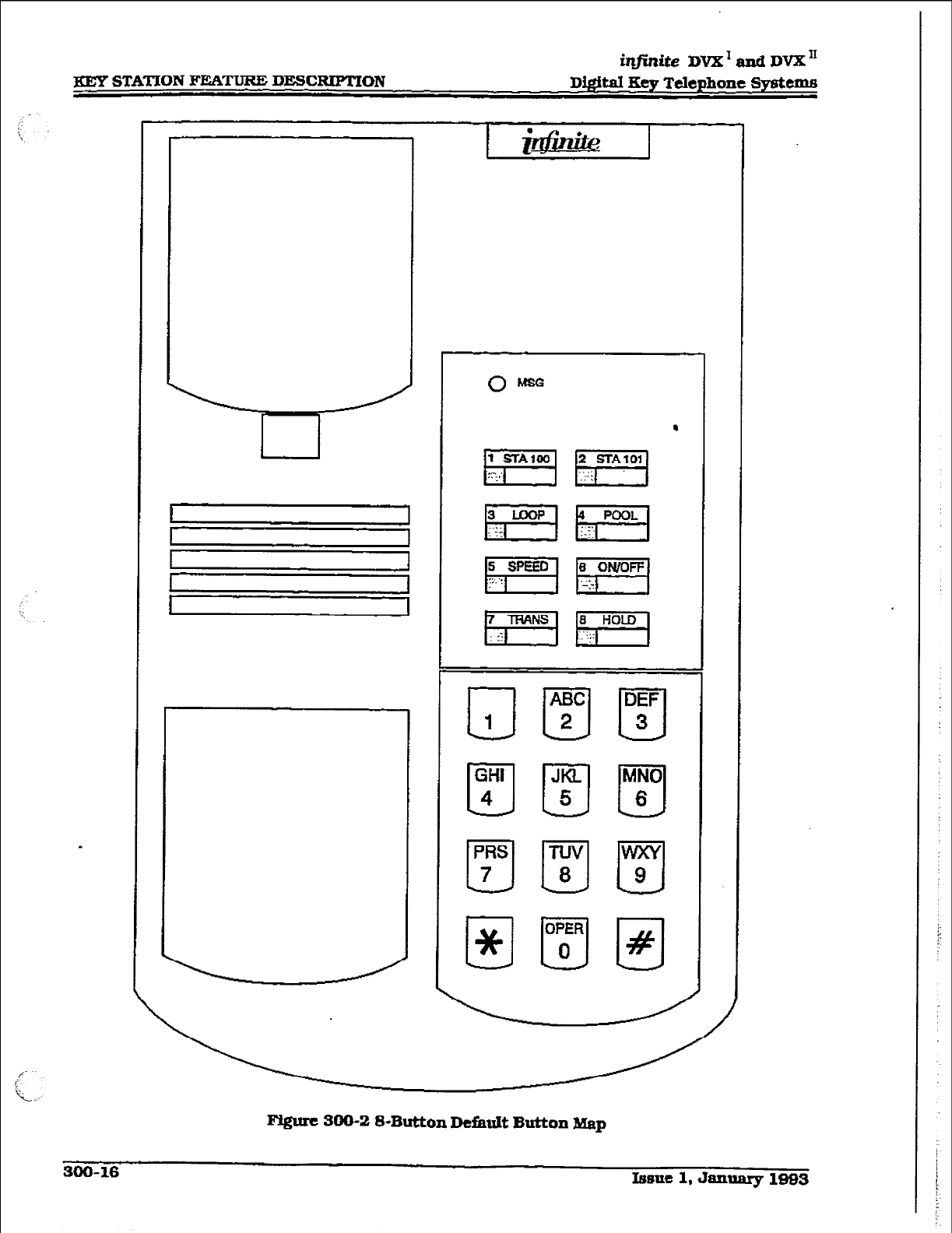
i?@nite DVXTad DVX”
XEY STATION FEATURE DE!XRIPTION Di@aI Key Telephone Systenm
Ffgure 300-Z S-Button Ddault Button Map
MO- 16
Itmuc1,Jamary1883
in,,ite
DVX’ aad DVX’
~&ital Eey Telephone Systems EEY STATloN FEATURE DESCRIPTION
outgoing trunk-to-trunk connection. This
allows for specific CO line access restric-
tion on DISA calls.
300.48
DIRECT STATION SELECTION
The user with DSS
buttons assigned at their
Dig&d
Terminal can call an intercom station by
simply
pressing the appropriate DSS button.
The called station is automaticaIIy signaled.
300.49 DIRECTED CALL PICX-UP
k cdl Pick-up - station
A station can pick up an intercom caIl,
transferred. incoming, or recaEng outside
line cab to a specif3c unattended station.
The call must be a tone ringing caIl.
B. call Pick-up - ACD/UCD Groups
Stations outside of an ACD or UCD group
can pick up an intercom call, transferred,
incoming, or recalling outside Iine caIl
ringing to a specific UCD station. The call
must
be a tone ringing call.
300.50
DIRECTOIW DIALING
Directory dialing allows station users to obtain
a directory of station users and have the system
dial the extension that is currently on the dis-
play. The fr@Me DVX I System provides loca-
tions for up to 100 names, while the infinite
DVX ’ System provides locations for up to 200
names.
Directory dialing also allows users to program
a ‘name” along with a speed dial bin for use in
later locating a speed dial number. When
promPted to do so, the system will display the
name associated with a speed dial number on
the LCD display so that when the desired name
is shown, the user may then have the system
dial the number.
-Directory dialing also allows users to associate
a *name” with an entry in the local
rum-
her/name translatfon table. When prompted to
do so, the system wiII display the name associ-
ated with the table on the IED dispIay so
that
when the desired name is shown, the user may
then have the system dial the number. The
ir@die DVX I System provides locations for up
to 100 names. whiIe the &#ni&z DVX ’ System
provides locations for up to 200 names.
300.51 DISABIIE OUTGOING CO LUVE AC-
CESS
This feature allows the first Attendant station
to dial a code and disable a CO line from outgo-
iry! CO calls. This applies to all station(s) that
have access to that line. I,IICO~~~ status is not
affected. This feature is a part of the ‘Maim&
nance” package.
300.52
DISTINCTIVE RINGING (User 8e-
lectahle)
The tone ring signal used to notify stations of
an incoming call can be changed by each sta-
tion user to provide distinctive ringing among a
group of stations. Each station user may select
a distinctive ringing tone that will be used to
ring their station. The system provides 81 dif-
ferent ring patterns that the station users may
select tiom.
300.53
DO NOT DISTUM (DND)
Placing a kqset in DND will ebminate incoming
outside line ringing. intercom calls, transfers
and paging announcements. A ringing station
may go into DND to silence ringing. The atten-
dant can override a station in DND. The station
in DND can use the telephone to make normal
outgoing calls. A station can be denied this
feature through programming.
A. One-Time Do Not Disturb (DND)
Allcms a station user to turn off muted
ringing that occurs while off hook (handset
or ON/OFF) on another call. Useful when
having an important conversation and do
not wish to be distur&d by ringing. The
station, while off hook, ION/OFF or hand-
set) depresses the DND button which
eliminates muted ringing. When the sta-
tion goes on-hook the DND button is e&in-
guished and DND is canceled.
900.54 DTMF SENDING
Each CO interface circuit for outside lines can
be individually programmed to send DTMF
(tone) or diaI pulse si&als.
300.55
EMERGENCY TRANSFER
Each OPX box wfll provide power transfer to
spedfied customer provided SLTs. or up to 12
CO lines using the Power Failure Transfer Unit
PF=Jl.
300.56
END TO END 8IGNAIBVG
This feature indicates the capability of the sys-
tem to accept DTMF tones from stations, send
them through the public network and have
them received at the distant end for computer
access, or a variety of control functions or in-
ward call completion at a distant switching
system.
Issue 1, January 1993
3oa-17
gEy STATION FEATURE DESCRIPTIJON
iqjinite
DVX’andDVX”
D&ital Key
Telephone
Systems
300.57 ExcLu8lvE HOLD
When a line is placed on Exclusive Hold, no
other station in the system canretrieve this call.
Hold may be programmed to be activated on the
first or second depression of the Hold button.
CO Lines whiIe in a transfer hold are ahvays
placed in an Exclusive Hold condition.
XKLSS EXECUTIVE OVERRIDE
This feature allows certain stations to be desig-
nated as executive stations with the ability to
*override” and “Barge in” on other keysets en-
gaged in conversation on a CO line or intercom
Cdl.
In addition to the station programmable option,
a system programmable option will enable or
disable a warning tone when the station
marked as an executive is cut-thru to the con-
versation. This is useful for an ACD agent su-
pervisors or training personnel who require a
service observing option.
A separate condition has been added to this
feature which will allow or d&&low an Execu-
tive to override an extension. This prevents an
extension with override capability from ovenid-
ing an Execu five’s station.
USE OF THIS FEATURE W3IEN THE
EXECTJTIVE OVERRIDE WARNING
TONE IS DISABLED MAY BE INTER-
PRETED AS A VIOLVION OF FED-
ERAL OR STATE LAWS,, AND AN
INVASION OF PRIVACY. CONSULT
COUNSEL WITH RESPECTTG APPLI-
- CABLE LAW BEFORE INTRUDING ON
CALLS USING THIS FEATURE
300.89 EXECUTIVE/8ECBETARY TBANG-
FER
There are four sets of Executive/ Secretary
pairings available. When the Executive station
is busy or in DND, the Secretary station will
receive intercom CaTIs and transfers. The Seere-
tay station can signal the Executive in DND by
using the Camp On feature.
300.66 EXTERNAL NIGET RINGING
The system can be programmed so
that
CO
lines marked for UNA will provide ringing out
the external page ports when the system is
placed fnto Night mode.
500.61 FLASH
Provides telephone users with the abihty. to
terminate an outside call or transfer a call be-
hind a PBX or Centrex and restore dial tone
without hanging up the handset. A FLASH but-
ton is located on each Digital Terminal.
300.62 FLA!3H ON INTERCOM
This feature enables key station users to utilize
the Flash Key to terminate pages and intercom
calls. While connected to a page zone or another
i.ntemaI station pressing the Flash key will ter-
minate the call and return intercom dial tone.
300.63 FLASH WXTH SPEED DIAL
A flash can be programmed within a speed dial
number. When this is done, a pause will auto-
matically be inserted before the remaining
speed dial digits are sent.
300.64
FMZXIBLE ATTENDANT
Any three DigitaI Terminals in the system can
be assigned as attendant stations. These sta-
tions will receive recalls and can place the sys-
tem into Night Service. The attendant stations
must be eitherEr&mced or Executive stations.
300.6S FLEXIBLE BUTTON ASSIONMENT
Each 33-button digiti terminal has 24 fle.xible
buttons which can be individually pro-
grammed. Each &-button digital terminal has 4
flexible buttons which can be individually pro-
grammed. One of the following operations can
be selected for each button. Refer to Section
400.37, Flexiile Button Assignment.
l
Outside line: Automatically accesses as-
signed kne. (Assigned in database)
l
DSS/BLF: Automatically signal as-
signed station and provides BLF for off-
hook and DND. (User programmable)
l
Feature: Any feature with a dialing code
(Le.: Personalized Messages. Paging, Ac-
count Code. Cdl Park Music, etc.) can
be assigned to a flexible button. lJJser
programmable)
l
Group Access: (i.e. ACD. ‘UCD. Hunt,
Voice Md group pilot numbers) (User
programmabIe)
l
Speed dial: Automatically dials a Speed
number. Eystem. Station, Saved Num-
ber Redial, Last Number Redial) (User
programmable)
l
Pooled group access: Some or ail out&de
lines can he grouped: pressing this but-
ton accesses the highest numbered un-
300-18 Isane 1. January 1993
__
infinite DVX’
and DVK” .
I
Digital
Key Telephone Systems KEY STATION FEATURE DESCRXPTION
used CO hne in that group. [Assigned in
database)
l
Ioop: Used to answer a transferred call
on
a line
for which
a user does not have
a button assigned.
&Mgned in data-
base)
300.66 FLEXIBLE FORT ASSIGNMENT6
The Flexible Port
Assignment feature will pm-
vide
a means to
assign
stations and CO line
numbers to any station or CO line port in the
system. This provides complete
flexibility in
determining station and CO line numbers
withh the system as long as they stay within
the system numbering plan, Therefore a station
can be assigned any
number between 100 and
127
on the infiiteDVX1 system and any num-
ber between 160 and 155 on the in&&z DVX”.
A CO line can be assigned any number between
01 and
14onthein#niieDVX’systemandany
CO fine can be assigned any number between
01 and 28 on the infinite DVX I1
system. This
restriction is required to ’ * ’ memory re-
qutrements on the smaller systems.
300.67 FORCED ACCOUNT CODE6
The f@nite Digital Key
Telephone
System al-
lows the system to be arranged so that station
USFXS must enter an account code before pfac-
ing an outside call. Account codes can also be
used as
a Traveling Class-of-Service to upgrade
a
restricted stations class-of-service for unre-
stricted
dialing. Account codes must be entered
- before the call when forced.
3 00.68 FORCED &EA6T COST ROUTING
NW
The infinfte Digital Key Telephone System may
be programmed on a per station basis to force
the use of LCR for outgoing accessed. This
allows the system
admini5trator to maintain
greater control over dialing pattern5 and the
lines
used for
placing outgoing CO calls.
300.69
GROUP CALL PICK-UP
Stations can be placed in one or more of four
pick-up
groups.
Stations
within
a group can
pick up tone ringing intercom calls, recalling
outside line ringing. or transferred
outside line
calls for another station in that group.
300.70 GROUP LWI’FMNG
All digital key stations have built-in speaker-
phones. Station users may use the
speaker
to
monitor a call while using the handset to con-
veme with the outside party. This enable5 other
people in the room to listen to both parties in
the conversation.
This flmm? is not asaiIubb nh?n the 1
.
stafwnisirlhta&otmod& 1
300.71 HEADSET COM.PA’I’lBILITY
The in$ni.&? Digital
Terminals
are designed to
allow the connection of an industry standard,
electret mic compatible, modular headset. The
user
COMECt5
the modular headset to the
handset jack on the telephone leaving the
handset in place. The ON/OFF button on the
Digital
Terminal
is then used to activate the
hcad5et..
300.72 HEAD- MODE
Each digital terminal can be individually pro-
grammed for headset operation. When pro-
grammed, an industry standard headset with
it’s adapter box may be connected to a digital
terminal for headset use.
This
allows handset
or headset operation by switching the selector
switch on the adapter box. Speakerphone op-
eration and call announce on intercom are
dis-
abled while a station has enabled headset
mode.
Once programmed in
station
progmmming, the
user may then select between headset mode or
nonnalhandset/speakcrphone mode by simply
dialing a code or pressing a user programmable
flex button.
300.73 HEARING +ID COMPA’IIBLE
All Electronic Digital Termin& and Single Line
Telephones are hearing aid compatible in com-
pliance with the FCC Pti 68. Section 68.316.
This allows the telephone to
be
used in conjunc-
tion with users wearing hearing aids.
306.74
HOLD PREFERENCE
This allcsws either Exclusive or
System
hold as
the primary hold on the tit depression of the
HOLD button,
deper&ng on
pro@, * g.
300.75 HOLD RECALL
When an outside call has been on Hold for a
prog&unmabIe length of time, recall ringhg
tone is sent to the station placing the call on
Hold. If this station does not answer the recall,
a recall tone is sent to the attendant(s).
Issue 1, January 1993 300-18
iqfinite DVX I and DVX”
KEY STATION F%ATuRE DBSCBIPTION Digital Key Telephone Systems
900.76 HOT IJIVEVRING DOWN
~@tal terminals may be programmed to imme-
diately call or ring down a particular station or
outside number upon going aff hook. This is
done by programming the stations Off-Hook
preference to activate a DSS or Speed dial fea-
ture key. This feature can be overridden if the
station user selects a CO line first when going
off-hook.
300.77 HUNT GROUPS
The
system
can be arranged for up to eight Hunt
groups. Each Hunt group cari contain up to
eight stations each. Each Hunt group is inde-
pendently arranged to utihze either a pilot
hunting technique or station hunting tech-
nique.
k Hunt GroupChaining
Hunt Groups can be chained or joined
together forming larger Hunt Groups. This
is accomplished by assigning a pilot hunt
group number as the last member of a
group-
B. pilot Hunting
Inc~mfng CO, transferred CO, and inter-
com calls can be directed to a pilot exten-
sion number of a Hunt group. The system
wfIl search sequentially (in the order the
extensions were entered in the database
programmU@ for an idle station in the
@OUP
and will ring that
station.
Calls di-
rected directly to stations (by calling the
extension number1 within the
hunt
group
w-lllnothunt but receive call progress tones
ofthe extension dialed.
C. Stathu Hunting
Incoming CO, transferred CO, and inter-
com calls that are presented to a busy. or
_ DND statton, that Is a member of a Station
Hunt group. will search sequentially [in the
order the extensions were entered in data-
base programming) for an idle station in
the group and will ring that station, Calls
can also be dtiected to the groups pilot
number for hunting.
300.78 ICLTD FEATURE
The ICLID 0ncoming Galling Line IDentlfrca-
tion) feature has been added to the &@-&e
Digital Key Telephone Systems. H owever, these
features are not available unless the Basic
ICLID Software package has been purchased
sew-ately. In order for this faux-e to operate
Proper@ it must be activated from the central
of&e So that the numbers of the calling party
will be delivered over the individual tip and ring
of the CO lines during the first silent interiral
between ringing. The following features have
been implemented:
A CalJitq Numbcr/Namc Dtiplay
This feature is intended as the basic offer-
ing of the ICUD service when associated
with the infintte Digital Key Telephone Sys-
tern. Whenever an incoming call is received
at the system, the number received along
with the ringing signal will be stored in the
line control tables and used at various
points in the processing of the call.
The primary function will be that the call-
ing number will be displayed [if avaiiable)
at any point at which the “UNE RINGING”
is displayed in the s&m.
In addition. with the aMilability of the call-
fng name feature. if the calling name is
provided, the systemwill deliver that to the
display instead of the calling number.
B. Incoming Numbcr/Nsme for GMBR
Records
Thfs feature will operate normally in the
absence of ICUD information or the failure
of the ICLID equipment. If the information
is present at the time that an SMDRrecord
is generated for a caIl. it will alter the
content and format of the SMDR output
record.
If the calling number is available, the nurn-
ber will be output in the Sh4DR record in
the same location as the dialed number is
located in the outgoing calIs.
If the calling name is present, an additional
line will be output in the SMDR record
identifying the name. This record will im-
mediaMy follow the normal SMDR record.
The normal SMDR record wilI include an
indicator which identifies that a following
record
with name idcntifkatfon is present.
Unanswered calts will be recorded on the
SMDR for incoming as a system option to
ahow the identification of callers for statis-
tical and call-back purposes. These calls
wJlI be fdentit3ed with an indicator in the
SMDR record.
C. Unanswered call
IWuqement
An Unanswered Call Management Table
Fth 50 entry capacity for the in@M!e DVX
system, and 100 entxy capacity for the
in$hite DVX II system is mairitajned in the
system database. The calling num-
ber/name information pertains to any
soo-zo Issue 1, January 1993
frlfinite DVX1aadDV2Lu
R@.sl Rcy Telephone Svatems KEY STATION FEATURE DESCRIPTION
unanswered call will be placed in this table
at the time the system has determined that
the caIl has been abandoned.
This table may be administered from ap-
propriately privileged phones so that the
unanswered calls may be reviewed and
handled by the customer.
300.79 xDLE8PEmERMODE
This feature allows the system to determine
whether the first digit dialed is heard over the
digital termIna.l speaker. This feature is allowed
or denied on a system-wide basis in program-
ming.
300.80 XNCOMXNG CO LINES OFF-NET
FORWARD m SPEED DIAL)
Allows the first attendant to forward incoming
CO calls to an off-net location. The attendant
can forward a group of CO lines or all CO lk4es
to a off-net location. The attendant must have
a direct appearance of the CO line[s) to be
forwarded. Off-net fonvarding is accomplished
via use of a speed dial bin-
300.81 XNTERCOMCAURUG
The system’s architecture allows non-blocking
of intercom calls. A station is reached on inter-
com by dialing the associated three-digit num-
ber.
300.82 INTERCOM SIGNATJIVG SEW
Users can control the method by which they
receive intercom calls and signals. Aconvenient
intercom signal switch is located on each Digi-
talTcrminal for easy selection. The choims am:
l
Handsfree (HF)(leftposition). 7he station
user, upon hearing a tone burst and
voice announcement over the speaker,
can reply hand&me.
l
Rivacy (Wl(center position). The station
user receives a burst of tone and
a voice
announcement over his/her speaker.
The microphone is deactivated for pri-
vacy. The called party must lift the hand-
set or press the MUTEI button to answer
the call.
l
Tone Ringing [TN)(right position). A
standard tone rmg notifies the party of
an incoming intercom call. The called
party answers by lifting the handset or
moving the switch to the handsfree (HF)
position orpressingtheON/OFFbutton.
300.83 KEYSET SEL3E TEST
The infinite Digital Key Telephone System con-
tains a test mode feature that supports the
ornine
testing of digital terminals and DSS con-
soles. The term offline means that the unit
under test is disconnected from the system
during the test operation. Digital terminals not
under test continue to operate in the normal
manner. Tests are provided to verify the keyset
and DSS LED, LCD. and keypad button opera-
iiOnS*
SOCkEM
LAST
NulldBER REDIAL [LNR)
Pen-nits the automatic redialing of the last tele-
phone number dialed on an outside line. Up to
32 digits can be stored. Outside line selection
of the same tie used is aujomatic.
300.85 LCD XNTERACTXVE DXSPLAY
The 33-button Executive Digital Terminal pro-
vides the user with visual indication of call
status, Calls to and f?om other extensions,
number dialed. line used and camp-on are
some of the features &splayed.
SOO.S6 LEAST COST ROUTLNG &CR)
Allows the system to automaticahy select the
least costly route available according to the
number dialed, the time of day/day ofweek, the
class of service (COS) assigned to the sta-
tion/trunk group priori@ level assigned.
k
smgit
Table
This table is divided into 2 sections: “Lead-
ing 1” (” 1” fs dialed before the number) and
“Non Leading 3” (no “1” is dialed before the
number). This g&s the system the ability
to handle c&l routing in areas that require
a ” 1” before a long distauce number as well
as in areas that do not require the “1”.
B. 6-Digit Table (053~~ Codu3)
The 6-Digit Table can include 20 office code
maps. Each map can be programmed to
route up to 800 of&e codes to one of the
16 possible route lists. Each map must be
associated with a specific area code in the
3-Digit Table. Several dif5zrent office code
maps can be used with the same area code
to provide additional routing flexibility.
C. Route L&t Tables
Up to 16 djfferent routes can be pro-
grammed. J3aeh route can contain up to
four route lists - one for each of the 4 time
periods. Up to seven CO line groups (rout-
ing choices] and their corresponding In-
x5sue 1, January 1993 300-21
in@xite DVX ’ and DVX I1
BEG STATION F&%TURE DE!XRKPMON Digital Key Telephone systems
sex-t/Delete Tables may be programmed
300.87
IsXUXU, NIlMBER/NAblE TRANSLA-
within each route list. TION TABLE:
D. Insert/Delete Tables
There are 20 Insert/Delete Tables. Up to
20-digits, inchrding pauses. can he in-
serted and up to 1Sdigits deleted. Digits
can be inserted before or after the number
dialed, but can be deleted only from the
beginning of a number diaied.
E. Weekly Time Tables
The least costlyroute for a particular dialed
number may be different at d&rent times
ofthedayandondif%erentdaysoftheweek.
To accommodate this situation, there are
two Trme-of-Day tables: a Daily Start Time
Table and a Weekly Schedule Table.
The Week@ Time table determines which
one of the four Routes L.CR should use
based on the Time-of-Day and Day-of-the-
Week.
An administer-able table provid& a local trans-
lation from a received calling number to a name.
This table can be administered
by
the customer
from the attendant consoIe location. This table
is also shared by the ICLJD features. In eases of
confkt between the name delivered from the
CO and that in the local translation table. the
local translation table shall rule. 100 entries
are provided in this table for the ti@ni& DVX ’
system, and 200 entries are provided for the
in&&e DVX ’ system.
F. DaiIy Start ‘Nme Tables
The Daily Start Time tables allow the user
to match the Time Periods discount struc-
ture to the carriers rate schedule.
Gw Exception Tables
This table is used to route operator as-
sisted calls and any other calls which
would use a one- or two-digit number
rather than a three-digit area code.
& Default LCR Data Base
In an efYort to de crease installation and set
up time usually assodated with LCR a
default LCR database. has been incorpo-
rated. The default LCR database will pro-
vide basic routing for all local and hmg
distance dialing.
1. - LCR Routing for Toll Information
This feature adds provisions to the LCRcall
processing which wilI allow common call
routing for a.U toll tiormaffon c&Is.
l-(XXX)555-1212, (XXXJ555-1212, l-555-
1212 and 5551212 calls will all be inter-
cepted and sent to a selected route in the
Route List Table. Numbers dfaled will be
integrated and ifit is determined to bea toll
information ca.Il. either preceded with an
area code or without or with a leading digit
1 or not. the CdlI will be sent to the route
designated in prom.
300.88
LOOP BUTTON CO LINB ACCESS
A station not having a direct appearance for a
CO line will receive inconling CO calls and
transferred CO calls under the loop button.
Only one call
at
a time can be connected to a
keyset on the loop button. If more than one loop
button is on a key set, the loop buttons may be
conferem& together. If all programmed Loop
buttons on a keyset are busy or have a CO call
on hold, the party attempting to iransfer a CO
line to that station will receive busy tone and
cannot txansfer the call to that station. If a
transfer
is
attempted, the CO line will recall the
in.iiIator immediately.
CO lines are also presented to a Loop when
dialing out using LCR orwhen using speed dial
to dial out and the line chosen does not appear
on the key station.
300.89 MEET ME PAGE
Users may answer a page call from any phone
in the system by dialing a special code. The
party who
initiated
the page must remain off-
hook.
300.90 MESSAGE WARING
Stations that are busy, unattended, or in DND
can be Eft a message indication by other sta-
tions in the system. Up to five messages can be
left at one keyset. Upon return to the station.
the user can press the fIasbing MSG WAIT
b.utton to ring each psrty in sequential order.
300.81 -GE WAtTXNG REMINDER
TONE
A key station with a message waiting can be
reminded at a programmed timed
intend
with
a tone.
300.92
-GES - PERSONALIZED
Each station (Key and SLq can select a pre-as-
signed message to be displayed on the LCD of
the digital key tmmfnd calling that station.
300-22
Lsue
1, JaIUmly 1993
i@ite DVX’andDVXn
D&iti Kev Telephone Systems KEY STATION FEATURE
DESCRIPTION
There are ten possible messages which
can
be
displayed:
- OO= Clears Messages
- 01= ON VACATION
- 02=REruFzNAM
-03=-PM
- 04= RETURN TOMORROW
- 05=RFXURNNEXTWEEK
- 06=ONTRIP
- O?= M MEETING
- O8=AT HOME
- 09=ON BREAK
- lO=ATLUNCH
k Date and Time Entry
to Ptrs-d
MC&S&g~[6)
As an enhancement to the original person-
alized message(s), staffon users can acti-
vate certain messages that will allow the
user to enter a spedtic ttme or a date of
return.ThesemessageswUappearoneaU-
ing stations display to alert tfiem of the
desired party’s return lime or date.
- 11= ON VACATION W MM/DD
- 12= RETURN: Hfl:MM xm or MM/DD
- 13= ON TRIP UNTIL: MM/DD
- 34= MEE’I’lNG UNTIL: HH:MM xm
- 15=ATHOMEuNTIL:HK:MMxtn
- 16=ONBREAKLJWIL:HHMMxm
- 17=ATLUNCHUN?ILzHH:MMxm
B. Messages -
Custom
This feature allows the
system adminislra-
tor to enter up to ten custom messages for
use by station users of the system. These
messages maybe specified and customized
by the customer on a system-wide basis.
- c. PctaoMIized Message code on a Flex
=Y
This feature allows a key station user to
progmm the personalized message code
[633#] onto a flex button. This speeds ac-
cess of the preselected messages.
300.93 MUSIC
ON HOLD
A music source, when connected to the system,
provides music to all lines on Hold, parked
calls, transferred calls and calls waiting to be
answered by Automatic Call Distribution (ACID)
or Uniform Call Distribution [UCD). This fea-
ture can be allowed or denied on a system-wide
basis in programming.
390.94 MUTE=
Pressing the MUTE button while in the speak-
erphone mode or using the handset will disable
the microphone but not affect the speech com-
mg over the speaker or handset. Pressing the
ilhuninated MUTE button again will reactivate
the microphone.
900.96 NAME IN DISPLAY
This feature allows every extension my or SLTI
the capability to program tie users name, for
that station. so that people using display tele-
phones will see the name instead of the station
number
on their display. The name is pro-
grammed at each station by the user and may
be up to seven letters In length.
300.96 NIGHT SERVICE FEATURE
The
Night
Service feature will provide a means
toputthesysteminnightmodefromanykeyset
orremovethe system~omnightmodefromany
keyset as long as the system was put in night
mode by the night service feature flex button. If
the system was placed in night mode by the
attendant using her DND button or if the sys-
tem was placed in night
mode
by the automatic
schedule, the nQht setice flex button can not
remove the system from night mode.
300.97 NIGHT SERVICE
MODE
A.
B.
42,
D.
Antometic Night Mode Operation
The inftzife Digital Key Telephone System
can be programmed so that the system is
automatically placed mto night mode.
The Attendant(s) can ovenide the Auto-
matic Night mode schedule simply by
pressing the NIGHT, (DND) button.
Ertcmal Night kIq$ng
The system can be programmed so that CO
lines marked for UNA will ring on the ex-
ternal page speakers.
Manllal operation
The Attendant(s) can control the use of
Night Mode manually
by
pressing the
NIGHT (DND) button. An LED wiil indicate
when the system is in Night Mode opera-
tion.
Night CIaas
of SeAce (COS)
The system allows ea& station to be as-
signed a different COS for mght operation.
The night COS goes into effect when the
system is put into night mode manually or
via the automatic schedule. Prevents the
misuse of phones after hours.
Issue 1. January lSQ3
300-23
iq#inite DVX * rind
DVX’
m STATION FEATURE DESCRIPTION
bigital Key Telephone Gystcms
F,. Night Ringipg A88i@xrntnts
EELCII CO line may be individually pro-
grammed for Night ringing to other sta-
tions, to Hunt groups, ACD
groups.
UCD
groups. Voice Mail groups, or off-net via
speed dial. When the system is placed into
night mode. manually or automatically,
ringing will follow the night ringing assign-
ments
for each CO line.
F.
Universal Night Answer [muA)
incoming CO lines can be programmed for
Universal Night Answer (UN& Stations
which do not have access to a line during
the day can answer that line while the
System is in the Night Mode by dishrig a
UNA code.
G.
Weekly
Ntght Mode Schedule
A programmableweekly nightmode sched-
ule provides for 24 hour, 7 day a week
automatic night mode operation. The sys-
tern can be put into and out of night mode
automatically on a daily basis.
300.98 OFF EOOK
VOICE OVER
This feature allows users, off-hook on a call [CO
or Intercom), to receive a voice atmouncernent
through the handset receiver without jnter-
rupting the &sling caU. Ihe Voice Over is
muted so as not to ‘override” or “drown” out the
existing conversation. The overridden party
may then respond to the calhng party using
CAMP-ON procedures to talk to the calling
party or use Silent Text Messaging to reapond
to the dling partyvia LCD displays. The calling
loriginatin@ station and receiviug station
MUST be a digital texmii&. The receiving sta-
tion MUST also be programmed to receive
OHVO calls.
300.99 OFF-HOOK PREFERENCE
k Auto Feature Access
In addition to auto line access DigitalTer-
rnhals have the ability to have their off-
hook preference select a DSS or feature
button upon going ofi-book or pressing the
ON/OFF button.
3. Auto Line Access
Each station, key or SLT. may have their
phone programmed to access a particular
CO Line such as a private line or ahnefrom
a Group of CO lines upon going off-hook.
This is useful in Centrex or PBX apphca-
tions when station users have dedicated
lines. Outside line dial tone is received just
by going off-hook, without the need to dial
an access code.
C. Hot I&e/Ring Down
Electronic Dgitd Terminals may be pro-
grammed to mediately call or ring down
a particular station or outside number
upon going off hook This is done by pro-
gramming the stations Off-Hook prefer-
ence to activate a DSS or Speed dial feature
key. This feature can be overridden if the
station user selects a CO line f?rst when
going off-hook.
D. Intercom&cuss ’
When off-hook preference is enabled. at a
key station. that statton may still obtain
intercom dial tone for accessing internal
stations or other system features. Tlzis is
done either by pressing an intercom button
or diahng their own intercom station num-
ber prior to going off-hook.
E.
User
Programmable Preference
Based on a station programmable option
Digital Tern&&s may be given the ability
to enable, disable or change their off-hook
preference by diahng a code. This option
can be denied in station prog * g on
a per key station basis.
300.100 OFF-HOOK SIGNALING
If a station has been programmed to receive
direct outside line ringing and is busy on an-
other call, that station will receive muted ring
to indicate another call is ringing in. Addition-
al& CO calls may
be
“camped-on” to a busy
station and receive muted ringing.
300.101 OFF-PREMISE
EXTENSIONS (OPX)
The
Off-Premise Extension Box (OPXJ provides
one FCC registered 25OOQpe single line inter-
face port. ‘Ibis enables the use of one Off-Prem-
ise 2500 telephone set. A precise tone plan is
provided to OPX stations. A 48v power supply
is required when installing an OPX box.
300.102
ON-HOOK DIMZNG
The Digital TerminaI user can place calls with-
out Iiftlng the handset. If the speakerphone is
disabled, the handset must be lifted to con-
verse.
300-24
Issue 1, Januury 1993
iqfmite DVX * and DVX”
Dig&d Ecy Telephone Systems KEY STATION FEATURE DESCBB’TION
300.103 ON LINE PROGRAMMING
Changes to the system database can be made
without.
interrupting normal system operation.
Frm may be performed using a key
station terminal connected to tbe system (Sta-
tion 100) or via a external terminal either on-
site or remotely.
300.104 PAGE/REL&Y CONTROL
The ttfinite Digital Key Telephone Systems offer
relays that may be individuaIly
programmed
for: External Page, Loud Bell Control, CO Line
ControI, Power Failure IYansfer, and Recorded
Announcement uses. Up to
four Relay/Sensor
intdace modules may
be
installed on either
system. Each
relay/sensor
interface module
contains three independent relays and three
sensing input circuits. In addition, each 4x8
CO/Station Interface card of the DVX *I
system
contains a Relay Contact [for up to seven *on-
board” relays) that may also be assigned to any
of the functions mentioned above.
300.105 PAGING
A. ExtcnlalPaging
There are four external paging zones
avaiI-
able in the DVX I and seven available in the
DVX I1 systems. External Paging requires a
three-digit dialing code. External paging
requires an externally provided amplifier
and paging system. One make and one
break contact are provided with the page
zone on the 4x8 Key Interface Board (Cm).
Since no ‘on-board” relay contacts are
available on the DVX ’ for external paging,
the Relay/Sensor Interface module is used
for this purpose.
If the 4x8
SLT Iuterhce Board (CSB) in-
stalled in the DVX ’ System, the
r&y
b contact used to provide external paging is
provided using the Dual m/Talk-Page
Module.
B.
Internal
Paging
There are four internal paging zones avail-
able in the in&!nire Digital
Key
Telephone
Systems. A
station can
be in any or all
zones or in no zone at all.
Stations
not
assigned to a page group can still make
page announcements. if allowed in station
Pmgramming.
Stations
can be assigned to
a page group in order to receive pages but
not allowed to make page announcements.
c. PagLngAcccss Restriction
Programming on a per-station basis. can
deny any station the
ability to make any
type of page.
300.106 PAUSE TIBKBR
When dialing a speed number. a timed pause
between digit sending can be placed in the
number. The length of this pause can be pro-
grammed in the
system
database.
300.107
PERSONAL PARII
Each digital terminal in the system can place
a
call into a
personal
park location and then later
retrieve that call from the originating station.
intercom calls and CO line calls can be placed
into the stations’ personaI
park location. Calls
parked in a personal pa& location are subject
to the ‘system” catI
park recall timer. A station
retrieving a personal parked CO call must have
either a direct CO line appearan
ce or an
avail-
able loop button to retieve the parked call.
300.108 PBX
DI&ING CODBS
The System will allow five one or two-digit ac-
cess codes to be entered into memory. When
one of these codes is dialed, this signals the
KSU that toll restxiction is to be applied at the
next dialed digits after the code. If one of these
codes is not dialed. toll restriction does not
apply. This allows the dialing of P3X
extensions
100, 110, 111, etc. This functions on lines
marked as PBX type lines in progra 3s
300.109
POOL BUTTON OPBBATION
The Pool Group Key is used primarily to access
CO lines that do not appear on a station so that
outgoing calls may be made. Pooled group keys
are associated to CO line groups and may be
programmed for
use
on any of the flexible line
buttons. CO lines are accessed in descending
order of priority starting with the highest
num-
bered
available (not busy) CO line in a CO hne
group-
Stations may have as many POOL
buttons as
their are CO line groups. Multiple POOL but-
tons for the same group are also allowed.
Issue 1, Jan- lQ93 303-25
KEY
STATION
FEATURE DESCRIP’IXGN
iqfinite DVX’ and DVX”
D&&al Key Telephone SysWns
300.110 PREF’EFtRED LINE ANSWER
A st,ation with Preferred Line Answer can an-
swer any assigned outside, transferred, or re-
calling line. or queue callbacks by lifting the
handset or pressing the ON/OFF button. The
station MUST be physically ringing, to function
properly.
300.111 PRIVACYRELEASE
Privacy is insured on all communkations in the
system. If desired, the customer may elect to
disable the Automatic Privacy feature. Thus
aIlowing another station to join in on existing
CO Line conversations.
A Per CO Une Option
This feature allows each CO line to be
individually programmed for privacy. This
feature is useful for maintaining security
on such lines as Data lines, Private lines,
or special circuits requiring privacy. Ifpri-
vacy is disabled on a CO line then. while in
use, another station may enter the conver-
sation simply by pressing the CO line but-
ton. A warning tone is presented to all
parties prior to actual cut-thru. The station
attempting to enter the conversation must
also have privacy disabled.
33. Per Station Option
Each station may be programmed to give
the station the capability to jofn an exkting
conversation simply by pressing the CO
line button that is in use. A warning tone
is presented to all parties when the statfon
enters the conversation. The CO line must
also have privacy disabled to allow the
cut-thru.
300.112
PRIVAm UNE
Private line programming allows certain lines to
ring at a specific station only. When placed on
Hold. these lines are active at the programmed
station only. A private line can be transferred
to other stations, provided the station receivfn.g
the call has a loop button or direct appearance
of that CO lfne.
300.113
PULSE-TO-TONE SWITCHOVER
When commanded, the system ti change the
signaIing on an outside line from dial pulse to
DTMF (tone). allowing the use of common car-
rim-s behind a dial pulse outside line. This can
be done manually when dialing, or can be
stored within a speed dial number,
300.114 RANGE PROGRAMMING
The in$.ni.te Digital Key Telephone System al-
lows for range programming when program-
ming CO lines and Stations. Range
programming allows you to program all pa-
rameters alike for the entire range or you can
change or modify a few items that wiK be copied
to all members in the range.
500.115 REMOTE ADIKINISTRATION
‘I’he Remote Administration feature allows
authorized personnel to access the administra-
tion programming via a terminal device (port-
able terminal device or personal computer with
communkations software package).
The feature permits the review and entry of the
customer database in the same manner as via
the digital terminal at *ADMIW Station 100.
The terminal device can be connected directly
to the Rs-232C connector on the CPE3 board, or
can be accessed by a telephone modem linking
the CPB’s R!S-232C connector (via a CO line) to
a remote location. When entering the system
remotely via a termmal device. access to the
on-board modem is accomplished by accessing
Port 199 either through a direct ringiig assign-
ment or through DISA or by being transferred
to Port 199 by any internal station.
A. Database Upload/Download
Data&se Upload/Download provides
a
maintenance facility which ti be added to
the Remote A ’ *, ’ k-ation routfne. This
routine permits the database to be down-
loaded to a PC. when a software changes is
made or when the system needs to be in-
itialized and re-programmed. In addition,
the routine facilitates the pro@ ’ rg of
a database on an in-house system which
can be downloaded to a PC and then
uploaded to a system in the field. After the
system maintenance is completed. the Ble
saved in the
PC
can then be uploaded to
the system.
300. I16 FiEMOTE SYSTEM MONITOR AND
MAINTENANCE
A Remote System Maintenance
The Remote Maidenaxe feature allows
the interconnects’ technical staff to review
the systems configuration data and indi-
vidual card slot configuration data. This
can be done “on site” using a data terminal
or remotely using modem to modem access
to a remote data terminal. When entering
the system remotely via a terminal device,
access to the on-board modem is accom-
300-26
Issue 1, Januaq 1893
infirrite DVX I and DVX”
~&&al Key Telephone Systems KEY STATION FEATURE DESCRIPI’IUN
plished by accessing Port 199 either
through a direct ringing assignment or
through DISA or by being transferred to
Port
199
by any internal station.
B. Remote System Monitor
The Remote Monitor feature provides re-
mote access to the installed system far
diagnostic purposes. These capabilities
benefit Service personnel enabling them to
support the end user remotely~ Dgerent
levels
of
access, via password, allows
authorized personnel to trace, monitor and
‘up-load” crftical informatton directly from
the in..& Dfgftal Key Telephone System.
This provides a more accurate means of
acquiring system information that leads to
a quick resolution of problems that may
occur. Thfs is all done without interfering
withongoing~processtngornormalsys-
tern operation, and in many cases may be
performed without a site visit
Capabilities allowed and resvved for tbfs
&High level troubleshooting” in addition
aIf?:
l
Monitor Mode
l
Enable & Disable Event YlIace”
l
Dump “Trace Bu3er” (up-load)
300.117 SAVE NUMBER RRDIAL (SNR)
Any number dialed on an outside line can be
saved permanently to be used at any time. This
number is saved until a new number is stored.
30Q.llSSlNGUCIJNETELEPHONE (SLT)
COBEPATIi3ILWY
The @%I& Digital Key Telephone System sup-
ports industry standard 2500 Type (IYl’MF] sin-
gle line instruments. When the 2x4 SLT
Expander Module is installed in the DVX * sys-
Jem, a maximum of eight single line telephones
may be supported. When the 4x8 SLT Interface
Board (CSB) is installed in the DVX ’ system, a
maximum of 48 single line telephones may be
supported.
300.119 sPRAREF@EIoNE
Both Enhanced and Executtve Digital Termi-
nals are equipped with a speakerphone.
How-
ever, the speakerphone can be programmed to
work in one of three ways:
l Normal
speakerphone operation.
l
Disabled for outgoing and incoming co
calls but handsfree on intercom allowed.
l
Headset operation
avowed.
300.120 STATION CUSS OF
SERVICE
(C=4
Each station is assigned a Class of Service
which governs that stations dialing privileges.
Day Class of Service and
Night Class of !%xvice
assignments to stations provide the system ad-
ministrator additional control over station dial-
ing, preventing misuse of phones after hours.
Six uniquely defined Classes of Service are
available for assigm-nent to stations on a per
station basis and all six are available for day
and night assignment. Station Class of Service
works in conjunction with CO line Class of
Service to provide the most flexible means for
offering custom toil restriction. As a
part
of the
Dfahg privilege assjgnment through Class of
Service the system offers two programmable
Aliow and Deny tables foq additional customi-
zation of a toll restriction plan for a particular
customer. In addition, each station can refer-
ence up to four special area code tables.
300.121 STATION ME!WAGE DETAIL RE-
CORDING (SMDR)
The &@I& Digital Key Telephone System pro-
vides one industry standard RS-232C port for
duaI purpose use
and
a second port is optionaI
for SMDR output, each allowing connection to
an external printer or call accounting device.
The system provides details on both incoming
and outgoing calls. This feature is programma-
ble
to allow all calls or just outgoing long dis-
tance calls to be recorded. The system tracks
calls by outside line, number dialed, time
of
day, date, station that placed the call and du-
ration of call. Account codes may also be en-
tered and recorded.
300.122 STATION REWCA’MON FBATURR
The Station Relocation feature provides a
means to allow a user to unplug their station
and
plug it in at another location. Then by
dialing a code followed by the old statton num-
ber, all station attributes, including extension
number, button mapping. speed dial. and class
of servfce are transferred to the new location.
mui
300.123
STATION
SPEED DIAL
Each station user can program up to 20 fre-
quently dialed numbers of up to 24-digits in
length. Pauses, flash commands, pulse-to-tone
switchover, and NO-DISPLAY characters take
up digit spaces. Ln the in@-& DVX I System,
Issue 1. January 1993
300-27
KEY STATION FEATURE DESCRIFTION
iqfutite DVX’ and DVX’
Digital
Xey Telephone Systems
there are a total of 600 speed
locations,
and
there are a total of 1280 speed locations in the
ti@.r~ti DVX ’ System to be divided among ah
telephones.
Numbers are dialed by use of the SPEED button
and a two-digit code. This feature can addition-
ally be assigned to any of the buttons in the
flexible button field on each keyset for one-but-
ton activation.
300.124 SY6TEM CAPACITY
A. up to
14x26 Comtion
The DVX’ system WilI support amaximum
of 14 outside CO circuits and 28 station
circufts.
B. Up to 26~56 Configuration
The DVX ’ system will support a mar&nun
of 28 outside CO circuits and 56 statfon
Cil-CtlitS.
300.125 SYSTEM HOLD
When a line is placed on System Hold, any
station in the system with an appearance of
that line can retieve the call.
300.126 SYSTEM SPEED DIAL
Up to 80 commonly dialed numbers can be
programmed into System Speed Dial for use by
stations allowed this feature. These numbers
can be up to 24-digits including pauses, flash
commands, pulse-to-tone switchover, and no-
display characters. T&he last 40 numbers will
not be monitored by toli restriction.
300.127 TEXT blESSAGING [Silent Rc-
This fature allows a station user to use text
messages
to respond to a caller that has either
Camped-On or has used the Off-Hook Voice
Over lOHVO1 feature to alert a busy station of a
whiiting call or message. The “camped-on” sta-
tion may respond to the caller via the personal-
ized. custom, and response text (LCD)
messages. The text message appear on the
calling party LCD display. The calling (originat-
ing) station and receiving station MUST be a
digital terminal. The receiving station MUST
also be programmed to allow OHVO cak
300.128 TOLL RESTRICTION (TARIE
DDRIVENI
The system provides a flexible means of provid-
ing toll restriction to internal stations of the
infinite Digital Key Telephone System. Each
station is assigned a Class of Service for day
mode operation and one for night mode opera-
tion these station COB work in conjunction
with a CO line Class of service to allow for
customized toll restriction. Two Allow and Deny
tables along with four special tables afford the
system administrator to devise a variety of com-
plex toll restriction or dialing privilege schemes.
300.129
TRANSFER RECAU
Screened and unscreened transfers will recall
the initiating party ff unanswered for a pro-
grammable length
of
time, and then if unan-
swered. win recall the attendant.
300.130 UNIFORM CALL DISTRIBUT’ION
[UC~I
Eight Uniform Call Distribution (UCD) groups
can be programmed, each containjng up to
eight three-digit station numbers. Each group
is assigned a pilot number. When this number
is dialed. the fmt available agent in that group
is rung. Calls are routed to the station that has
been on-hook for the longest: period of time.
A Atttnratc UCD Group Ass@unents
Au alternate UCD group can be pro-
grammed so that if stations in one group
are busy, the alternate group will be
checked for an available station.
B. Auto
Wrap-Up w/Timer
After completion of a UCD call (on-book)
the agent will not be subjected to another
UCD ca.Il for the duratfon of the Auto Wrap-
Up timer (regardless of the number of calls
in queue). allowing the agent to finish call
related work or access other facilities. This
will allow agents to remove themsehres
from the group (i.e.. DND. Unavailable,
Call Forward or originate another &I). The
auto wrapup timer-is programmed as part
of the UCD database. (System-wide)
C.
Avaihhle/Unavallable Mode
Stations programmed mto a UCD group
may log off and on to their assigned
UCD
group by dialing an Auailable/Unavailable
code. When an agent is in the Aeble
mode that agent will receive UCD calls in
the normal manner. When an agent is in
the Unavailable mode that agent will no
longer receive UCD type calls, however may
receive non-UCD cdlls. Agents that have
logged off by going Unavailable will receive
a visual reminder that they arc logged off
with a flashing LED and or a LCD display
message.
300-28
Isaue
1, Jsnuarg 1993
i@&e DVX’ and DVX’
Dfgttal Key Telephone Syetems KEY STAmON FEATURE DESCRIPTION
D.
E.
F.
G.
EL
I*
~ncomhgj CO Direct Ringing
CO E-ES can be programmed to ring di-
rectly into a UCD group. When all agents
are busy and RAN is enabled, the system
will answer the caller and present the Ist
RAN announcement automatically.
No-Answer Recall Timer
If a call routed to a station via UCD is not
answered by the UCD Agent/Station be-
fore the No-Answer Recall timer expires,
the call will be returned to UCD Queue with
the highest priority. In addition, the station
that failed to answer the ringing UCD call
will be placed into an Out-Of-Service (OOS]
state..
No-Answer Retry Timer
When the No-Answer Recall
timer expm,
a station
that
failed to answer the ringing
UCD call is placed into an out of service
(00s) state. The station thatwas taken out
of service (00s) will be placed back in
servfce if the agent hits his avalIable flex
button or diaIs the avaikble flex code. In
addition, the agent will be placed back in
service if the No-Answer Retry timer ex-
pires. Iftbe agent does not answer his next
UCD cab, he win again be taken out of
service. This cycle will continue until the
station answers calls, logs out, or goes
unavailable.
overflow station AsfJignments
An overflow station may be assigned to
route callers in queue to a designated sta-
tion after a specifkd time. The overflow
station may not be one of the
UCD
group
stations.
Recorded Announcements IRAN)
Recorded announcement devices can be
assigned to provide up to eight d&rent
messages, ifaII stations in a UCD group are
busy. The eight messages are available to
all eight UCD groups in different coniigu-
rations. A RAN table can be the answer port
for unanswered incoming calls to a UCD
group, while another table can provide the
secondary message. Each RAN device can
provide an announcement to one caller at
a time. Subsequent callers will be queued
onto the message on a first-in basis.
Agtnt Queue St&us Display
The Agent Queue Status feature provides
a means for an agent and UCD supervisor
to view the status of their LJCD group. This
display is an idle state display and will
prompt a supervisor that Agents in a group
are
having
problems answering all their
calls. The display will tell the agent and his
supervisor how many cabs are in queue,
how many agents are available or logged
into the group. and the length of time in
minutes that the oldest caIl has been in
queue. The agent will receive the calls in
queue display whenever there is a caII in
queue.
There are two methods of viewing UCD
Group call queue status.
1. In-service UCD agents and the assigned
cwerflow station wiiI see the quantity of
calls in queue on the LCD of their station
for the UCD group of which they are a
member. If every member of a UCD group
is busy and calIs are.* queue, the Super-
visor/Agent Queue Status display will be
seen at all UCD members of that group.
2.Any station not assigned in a UCD group
can view the number of calIs in queue for
any given UCD Group. To view the number
of caIls in queue the station user dials the
Calls In Queue code (or presses a pro-
grammed FLEX button with this code) then
enters the UCD group desired. The LCD
will display, on a real time basis, the num-
ber of c&s in queue for that group.
300.131 UNNERML NIGHT ANSWER
Incoming CO lines can be programmed for Uni-
vewal Night Answer (UNAJ. Stations which do
not have access to a line during the day can
answer that hne while the System in the Night
Mode by dialog a LJNA code. In order to utilize
this feature. a loop button or an appearance of
the trunk must be present on-the station.
300.132 VOICE MAIL GROUPS (V&I)
The Voice Mail feature automatIcally handles
unanswered calls. Stations may forward ca.lls
to a voice mail &oup (for leaving mail) or may
CalI the voice mail group directly (to rehieve
mail) with no assistance hm the attendant. Up
to eight voice mail groups can be configured in
the system. Each group can conta.in up to eight
voice mafl stations. each of which interfaces
with a port on either the 2x4 SLT Expander
Module on the DVX I System, or on the 4x8 SLT
Expander Module on the DVX ’ System. Each
voice mail
%&ion” can be shared by a number
Issue 1, Janwy 1993
300-29
infinite DVX I and DVX ’
m STATION FEA’IXIRE DEWXD’TION
Digital Key T&phone Systcxm
of actual users. An 2x4 SLT Expander Module
or 4x8 SLT Interface Board (CSB) are required
when utilizing the k$nti Digital Key Telephone
System Voice Mail ‘In-Band” integration.
A VM CO Disconnect Sfgaal - Pass Thru
To avoid Voice Mail ports from being tied
up, as a result of CO line callers abandon-
ing the caII or not exiting the VM system
properly, a disconnect signal has been pro-
vided to notify the VM system that a CO
caIler has hung up or abandon the call.
‘Silence” is provided to the VM port fol-
lowed by “busy tone” to aid the VM system
to recognize tbat an intercom caller has
abandoned the call.
Disconnect digits may also be programmed
for outside line callers.
B. VM In-Band Srernating
lnteg&ion
The in@We Digital Key Telephone System
allows the system to be programmed so
that if a station programmed to receive
incoming CO line ringing is forwarded to
Voice Mail they may have direct incoming
callers routed directly into their stations
voice mail boxthrough the use of X-Band”
signaling. Alternately, when disabled, call-
ers wiU be answered by the Voice Mail or
Auto Attendant Main greeting.
Incoming CO calIers can be Station CalI
Forwarded into voice maiI on& when the
ringing CO line is programmed to ring at
one station. AdditionaUy CO lines pro-
grammed to ring at an attendant station
will station call forward into the Voice Mall
system [if p rogrammed to ring only at one
attendant station) and be presented to the
main greeting (not the attendant stations
mail box) even when ID digits are enabled.
c. VlM Message waiting Indication
* When Voice Mail has received a voice mes-
sage for a user who has a station on the
infinite Digital Key Telephone System. the
VM connected to the system will leave a
message waiting indication at the VM us-
ers station. When the station user retrieves
their mail, the VM system will cancel the
message waiting indication left at a station
viaaVMport.
The message waiting indication wilI appear
on the programmed Voice Mail (group) but-
ton. If such a button has not been pro-
grammed, a voice mail message waiting
indication will appear on the MSC WI&T
buttonasanormalmessagewai~sq+.
D. VM Tone Mode CaWqj option
Voice mail systems and/or Automated At-
tendants can utilize the Calling Station
Tone Mode option. This is useful when
using supervised transfer or call screening
options on voice mail or auto attendant(s)
requiring ringback tone for proper call
handling.
E. VM TrrInsfer/Folward
This future allows Voice MaiI calls, upon
reaching a forwarded to VM station, to
fort%ard back into the Voice Mail unit. This
is useful when VM ports are being used as
both Auto Attendant and VM ports. This
feature can be enabled/disabled for all VM
groups.
F. VM ean!4fcr with ID Digit5
This feature provides an attendant or sta-
tion user a way to transfer a caIIer directly
into a voice mail box This allows the sta-
tion identification digits to be entered by
the txansfening par&. Using this feature,
acalIercanbetransferredtoavoicemaiI
box when I) a station user on the system
is not forwarded to VM or 2) the destination
voice maiI box owner is not a station user.
CO trunks and internal calls may be frans-
ferred into voice mail using this feature. If
no voice ma.iI ID digits are dialed by the
transferring station, then the idezltication
digitsofthetransferrtngstationwillbesent
to the voice mail.
300.13s voI#ullm cmlTRoLs
Both speaker and tone ringing volumes can be
separateIy adjusted by utilizing the two slide
switches on the front of the digitaI keyset.
. .
300-30 Issue 1, January 1993
irlfinite DVX’ and
DVX’
Dj.@tat Key Telephone
System SINGLE
LINE TE$LEPHONE FEATURE DESCRIPTION
SECTION 310
SINGLE LINE TELEPHONE FEATURE DESCRIPTION
Single Line telephones have access to most of
the system and station features listed in the
previous section. however, the additional fea-
tures listed below are unique to Single Line
Telephones. The 2x4 SLT
Expander
Module is
required in the DKX I System, and the 4&3 SLT
Interface Board (CS3) is required in the DVX ’
System for proper SLT operation. A Single Line
Adapter (OFX) box and 48v Power Supply may
also provide single line operation. An abbrevi-
ated
feature
index is provided in Table 310-l
Single Line Telephone (SLTI J?eature Index.
310.1 ACCOUNT CODE
SLT
stations may enter an account code, up to
K&digits in length, to identify calls for bill-
ing/tracking purposes. The account code may
be entered either before the call or during the
call (the outside caller is placed on hold while
the account code is entered ri during the call.).
The account code is recorded on the SMDR
printout. Account codes are non-verified and
can vary in length from 1 to 12 digits.
310.2 AUTOMATlC LINE ACCESS
SLTs may have their station programmed to
access
a particular CO I&e such as a private
line or a line from a Group
of CO lines
upon
going off-hook. This is useful in Centrex or PBX
applications when station users have dedicated
or individual lines. Outside tine diat tone is
received just by going off-hook, witbout the
need to dial access codes.
310.3 CALLFORWART)
- Single line telephones may direct intercom caIls
and
transferred CO lines to be
forwarded
to
another station. SLTs have access to all for-
warding options that Key station users have:
l
Cdl Forward -All Calls
l
CalI Forward - No Answer [7]
* Call Forward - Busy (81
l
CalI Forward - Busy/No Answer [9]
l
CalI Forward - Off-Net [+E]
l
Preset Call Forward
310.4 CAMPON
A busy sMi011 can be notified that an outside
he is on hold and waiting for them. The busy
station is notified of this by a beep tone. Single
line telephones can receive a camp on indica-
tion or initiate one by using an access code.
310.5 CONFERENCE
An SLT user can initiate a conference with an
outside line and one other internal station.
310.6 CONFERENCE /WITH PERSONAL
PARE
Single Line Telephones (SLT) can initiate a con-
ference between two ou$sfde (CO) calls. The
Personal Park feature is used in confunction
with the SLT conference code to make this
possible. A combination of features are derived
from these dial codes (Personal Park. Flip/Flop,
and Multi-line Conference).
310.7 DIRECT OUTSIDE LINE GROUP
ACCE66
Single line telephones can access outside lines
by dialing CO line group access codes 9 or
81-87.
310.8 DIRECT OUTSIDE IJNE RINGING
Single line telephones can be set up to receive
direct outside line ringing. SLT& may be pro-
grammed to receive incoming CO Ringing on
more than one CO line. However. an SLT can
answeronlyQNEcaUatatime.IfaSLTisbusy
when a CO call rings in, camp-on tone will be
given to that SLT station.
310.9 DIRECTED CALL PICK-UP
Tone ringing intercom calla, Imtial pinging CO
calls and -ierred outside line calls to spe-
cific stations can be picked up by single line
telephones. For this type of pickup, the stations
do not have to be in the same pickup group.
310.10 DO NOT DI- @ND)
Each telephone user can be allowed to place
their phone in Do Not Disturb. The user will
receive error tone if they are not allowed this
feature. They will also receive a confidence tone
when lifting the handset to remind them they
are in Do Not Disturb. The attendant can over-
ride a station in DND.
3 10.11
GROUP CALL PER-UP
Tone ringing intercom calls, transferred outside
he calls, and fnitially ringing calls can be
Issue 1, January 199s 310-l
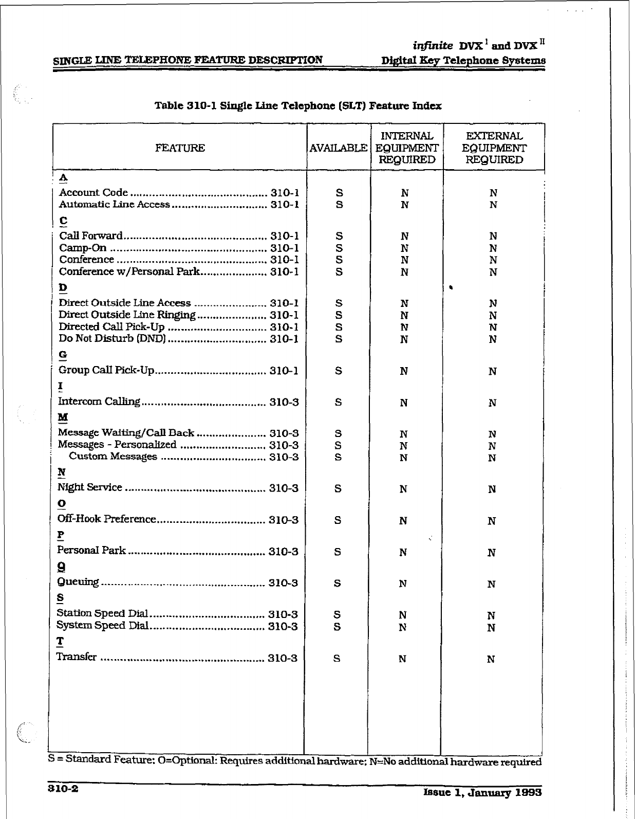
infinite
DVX1 and DVX”
SINGLE
LXNE =L&PIXONE PEA- DEWJUPTXON D&im Xty Telephone Sytittms
Table 310-l Single Line Teltphont (SLT) Ftabrt Index
x
i -
Account Code ........................................... 310-I
Automatic Line Access.. ............................ 310-I
C
&ll Forward ............................................. 310-l
camp-on ................................................. 310-l
COnfer~Ce
............................................... 310-I
conferenct w/F’ersonaI Park ..................... 3 lo- 1
D
-
Direct Outside Line Access ....................... 3 1 O-1
Dirtct Outside Line FGnging ...................... 310-l
Directed Cdl Pick-Up ............................... 310-l
Do Not Disturb (DND) ............................... 310-I
G
Croup call pick-up ................................... 310-l
I
intercom cw ....................................... 310-3
aa
Message Wailing/Call Back.. .................... 310-3
Messages - Personalized ........................... 310-3
Custom Messa@s
.................................
310-3
N
-
Night Service
............................................
310-3
0
Off-Hook preference .................................. 31ck3
I!
Ptrsoti Park
...........................................
310-3
9
Quelling
...................................................
310-3
S
&ion Speed Dial .................................... 310-3
System
Speed Dial .................................... 310-3
T
n-ansfer ................................................... 3 LO-3
L
S ._ -
= Standard Feature: CkOptionak F&quires additionalmrdware
9VALABLE
S
S
S
S
S
S
S
S
S
S
S
S
S
S
S
S
S
S
S
S
S
S
INTERNAL
EQUIPMENT
REQUIRED
N
N
N
N
N
N
N
N
N
N
N
N
N
N
N
N
N
.:
N
N
N
I4
N
I=No addition
EXTERNAL
.
hardwwerequh-ec
i’
Issue 1,
January 1993 310-S
infinite DVX’ and DVX’
~&&al Key Tekphone
Systems SINGLE, LINE TELEPHONE FEATURE DESCRIF’TION
picked up by single line telephones by dialing a
special pickup code. The telephones must be in
the same pickup group.
310.12 INTERCOM CALLJNG
Single
tie telephones can make and receive
intercom calls.
310.13
MESSAGE WAlTlNG/CAU BACK
Single Line Telephones calling a station that is
busy, idle. or in Do Not Disturb can leave a
message waiting indication to signal the station
to call back.
310.14 MESBAGES - PERSONAclzED
Each SLT station mn select a preassigned
message to be displayed on the I.ZD of the
Digit& Terminal receiving that message. There
are ten possible messages which can be dis-
played:
- 00= Clears Messages
- Ol= ON VACA’l’?ON
- 02=REmRNAM
- 03=REXURNPM
- 04= FETURN TOMORROW
- 05= RElWRN NEXTWEEK
- 06=ONTRIP
- 07=INMEE’IIlVG
- OB=ATHOMB
- 09=ONBR.EAK
- lO= AT LUNCH
A Messages - custom
This feature allows the system administra-
tor to enter up to ten custom messages for
use by station users of the system. These
messages maybe specified and customized
by the customer on a system-wide basis,
- 310.15 NIGHT SERVICE
When outside lines are marked UNA and the
system is placed into night service, a single line
telephone can answer incoming calls on lines it
does not norma@ have access to by dialing [#3].
When External Night figlng is enabled in da-
tabase progmmming ringing is outputted on
the external page PO&S.
SlO. 16
OFF-EWK PREFERENCE
SLTs may have their station programmed to
access a particular CO Line such as a private
line or a line from a Group of CO lines upon
going off-hook. This is useful in Centi or PBX
applications when station users have dedicated
lines. Outside line dial tone is received just by
going off-hook. without the need to dia3 access
codes.
3 10.17 PERSONAL
PARK
Single line telephones can be connected to two
calls (Intercom or CO lines) at the same time
and “flip/flop” between the two calls. This can
be performed with originated or received calls.
This feature is also used with SLT multi-line
conference feature.
3 10.18 QUEUING
Single iine telephones can be placed in a queue
swatting the tit available outside Une in a
group to
become available.
310.19 GTATION
SPEED DIAL
EachSLTusermayprogr&1upto20individual
speed dial numbers. Each speed dial number
can be up to 24-digits in length.
310.20 BYSTEM SPEED DIAL
Each SLTuser can be allowed access to system
speed dial numbers on a programmable basis.
The last for& system speed numbers override
toll resfxiction.
310.21 TRANSFER
Outside lines may be transferred by or to single
line telephones. These transfers can be either
announced or unannounced.
i@,nite DVX I and DVX *
DQital Key Telephone Spetems ATTENDANT FEATURE DES-ION
SECTION 320
ATTENDANT FEATURE DESCRPTION
The Attendant and Attendant(s) with DSS/DLS
features of the infintte Digital Key Telephone
System are listed and described below in alpha-
betical order. An abbreviated feature index is
provided in Table 320-l Attendant Feature
Index.
320.1
ATTENDm
DISABIJ3 OUTGO-
ING
ACCESS
The fmt attendant can disable CO lines, pre-
venting outgoing access to those lines. This is
useful for removing a faulty line from servim.
or for reserving CO lines
for important USe. AlI
stations that can normally make caJls on the
lines are affected. but incoming Cans are not
affected. A CO line may be disabled while it
is
being used; when the &unk becomes idle, fur-
ther outgoing access will be prevented.
320.2 ATTENDANT OVERFLOW
System programmmg allows the attendant sta-
tion to be programmed so that if the attendant
is busy or not there. the call wilI be automat-
ically forwarded to another predetermined sta-
tion, VM Group, Hunt Group, ACD or UCD
group after a programmed period of time. (Refer
to Call Forward, Station and Preset)
320.5
A~NDANTOVERRIDE
Attendant stations may override a busy station
or ring a station in DND. While busy, pressing
the override key provides override tone and a
five second delay before voice cut-through to
the called party occurs. automatically placing
any outside line call on Hold. The Attendant
. Override function may be programmed on to a
flex button and can be enabled or disabled in
Programmtng-
320.4
ATTENDANT POSITION
The system identif2es a mrudmum of three pro-
grammabk stations as attendants for line re-
calls and attendant features. The first
programmed attendant can enter system date
and time information as well as System Speed
numbers from this position without
entering
the programmfn@ mode. The in@nf& Digital Key
Telephone System is placed in Night Service by
any programmed
attendant pressing the
NIGHT DND) button or dialing the NIGHTcode.
320.5 ATTENDANTRECALL
A held CO call left unattended by a station will
recall the attendant(s) aftxr a programmable
period of time has elapsed. A recalling CO line
flashes at a distinctive rate and has an LCD
display that identifies tie originating station of
the unanswered call.
320.6
AUTOMATlC HIGET MODE
In addition to the attendants capability to
place
the system into and out of night mode manu-
ally. by
pressing the Night key.
an automatic
night mode schedule has been. added to the
system. The automatic schedule is set in data
base programming on a week day basis, in&d-
ing Saturday and Sunday. The Attendant can
override the automatic schedule by pres$ng
the NIGHT (DND) button.
320.7 INCOMING co LlNE OFF-NET
FORWARD
Allows the first attendant to forward incoming
CO calls to an Off-Net location. The attendant
must have a direct appearance of the CO line to
be forwarded. Forwarding can be established
on a per CO line group basis, or all CO lines may
be simultaneously forwarded to an off-net loca-
tion.
320.8
NIGHT SERVICE FEMTJRE
The Night Senriee feature will provide a means
toputthesysteminnigbtmodefromanykeyset
orremovetheqstem.fromnightmodefromany
keyset as long as the system was put in night
mode by the night service
featute flex
button If
the system was placed in night mode by the
attendant using her DND button or if the sys-
tern was placed in night
mode
by the automatic
schedule, the night service flex button can not
remove the system f&om night mode.
320.9 TIME AND
DATE PROGRAMMMG
ThisfeahrreEtllowsthe~tprogrammedatten-
dant to set the time and date without entering
the programming mode.
Issue 1, Janurq X993 320-l
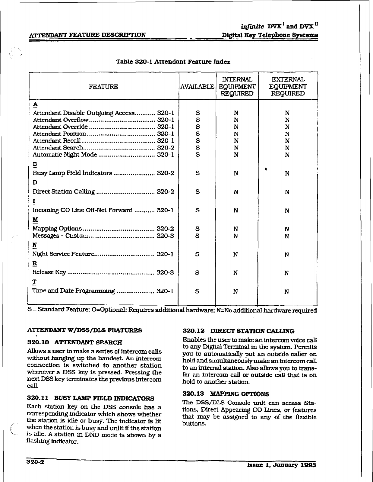
irlfinffe DVX’ andDVX”
Digital gey Telephone Syeteme
Table 320-l Attendant Feature Index
FEATURE
IA
: Attendant Disable Outgoing Access... . . . ,. -.. 320-l
Attendant overflow . . . . . . . . . . . . . . . . . . . I . . . . . . . . , , , , . . , 320-l
Attendant Override . . . . *.a..-.,* .,,.... * . . . . . . . . . . . . . .
320-I
( Attendant Position .**.........,,*.,...........,.,.....
320-l
1 Attendant Recatt . . . . . . . . . . . . . . . . . . . . . . . . . w w..... a . . . . . . 320-l
! Attendant &arch . . . . . . . . . . . . . . . . . . . . . . * . . . . . . . . . . ..,.-
320-Z
Automatic Nfght Mode .*..* . . . . . . . . . . . . . . . . *...* ,,..
320-l
: E
Busy Lamp Field Indicators . . . . . . . . . . . . . . . . . . . . . . 320-2
D
Dfrect Statfon CalIing . . . . . . . . . . . ..I.... * . . . . a.. . . . . .
320-2
i 1
, -
Incomfng CO Line m-Net Forward .,.. . . . . .,. 3!20- 1
!!!I
Mapping Options
.*. .,,,... l . . . . . . . * . . . . . . . . . * . . . . . . . . *
320-2
Messages - Custom ..,*.*.......... a . . . . . . . . * . . . . . . . . .
320-3
I!
Night Service Feature ..*.*........-I......*...*......
326 1
3
Release Key .a . . . . m I....,..,..__............... * . . . . . . . . . .
320-3
T
?ime and
Date Pm grammhg . . ..*............... 320-l
i
1
t
4VAIIMXE
S
s
S
S
S
S
S
S
S
S
S
S
S
S
S
S
= Standard Feature: O=Optionalz Requires additional hardware ?=No addition
INTERNAL EXTERNAL
EQUIPMENT EQUlPNE;NT
REQUIRED REQUIRED
N
N
N
N
N
N
N
N
N
N
N
N
N
N
N
ATTENDANT WfDSS/DLS FEATURES 320.12 DlRECT STATION CALUNG
.
320.10 AmBJDANT SEMXCH
Allows a
user to make a series of
intercom calls
without hanging
up the handset. An intercom
connection is switched to another station
whenever a DSS key is
pressed. Pressing the
next
DSS key terminates the previous intercom
Cdl.
Enables the user to make an
intercom
voice call
b any Digital TeIlninal in the system. Permits
you to automatically put an outside caller on
hold and simukaneously make an intercom call
to an fllterTlal station. Also allows you to trans-
fer an fntercom calI or outside call that is on
hold to another station.
320.11 BUSY LAMP FIELD INDfCA’I’O~
Each
station key on the DSS console has a
corresponding fndfcator whfch shows whether
the station is idle or
busy,
T&e indicator fs lft
when the station is busy and unlft ff the station
is idle. A station in DND mode fs shown by a
flashing
indicator.
320.13 MAPPING OPTIONS
The
DSS/DLS Console unit can access Sta-
tions, Direct Appearhg CO Lines. or features
that may be assigned to any of the flexible
buttons.
320-2 hsttt 1. January 1993
iq@ite DVX I
and
DVX”
~&itd geY Telephone 8yStemtI A?TENDANTFEATUREDESCEUFTION
z7te folbwingfeatum am
NOT
cdbwai to
be progrcunmed
mta
IWWIJLS
Conaale
$e?siblt? buizons: ACD Agent or &xl-r
A DSS/DL.S unit may be assigned to one of the
different MAP configurations available. Any one
of the three M&P conGguraffons may be as-
signed
to a DSS/DLS and up to three maps
may
be
assigned to one
station.
However. “dupli-
cate” MAPS or appearances of Stations and/or
CO lines between the MAPS are not allowed.
There are three pre-defined MAPS for the
DSS/DLS console wH.h default button pro-
g ’ lg. Refer to Figure 320-l DSS Console
Map 1.
F’igure 320-2 DSS Console Map 2.
and
Frgure 320-3 DSS Console Map 3 for a button
layout of each DSS Console Button Map. Each
Attendant may have up to three DSS/DIS Con-
soles assigned to work with one
Attendant sta-
tion.
320.14 IHESSAOES - CUSTOM
This feature allows the
first programmed atten-
dant
(system admini&at.or) to enter up to ten
custom messages for use by station users
of the
system. Up to 24-characters may be entered as
the custom message (this will represent 48
digits entered). A station user may store any of
the available messages under a fipldble button
assigned as a Message Access button. These
messages may be specified and customized by
the customer on a system-wide basis. Message
status
is
stored in battery protected area of
memory for retention in the event of a power
failure or system
reset
(soft
or
hard).
320.16 RELEME KEY
Allows the user to disconnect calls while oii-
hook,
speeding up call handling time (MAP f
and MAP 2 only).
.
Issue 1, &mxary 19533 320-s
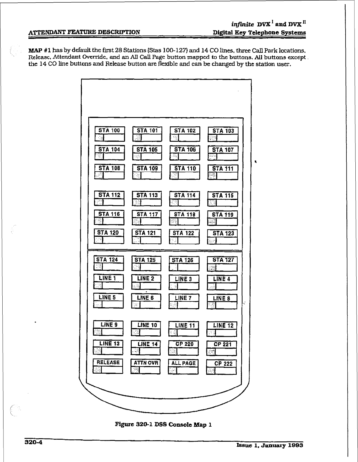
AITEm FEATURE DESCRTPTION
infinite
DVX ’ aad DVX ’
D&it& Key Telephone Systems
B&W #l has by default the first 28 Stations (&as 100-127) and 14 CO lines, three Call Park locations.
. . Release, Attendant Override, and an All Call Page button mapped to the buttons. AlI buttons except
the 14 CO brie buttons and Release button are flexible and can be changed by the station user.
PVgure 320-l
DSS Coneole Map
1
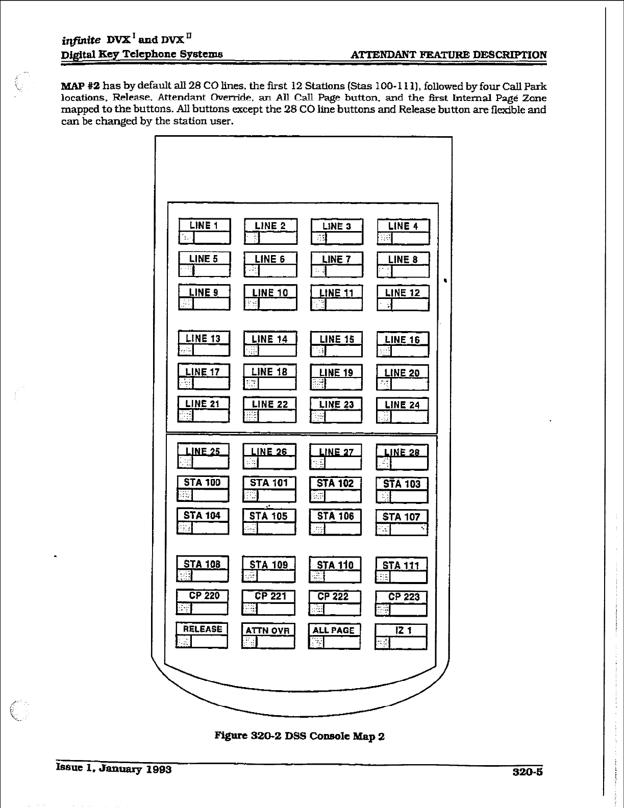
itzfiniie DVX I and DVX ’
r
ATTENDANT FEA- DICSCRIPTlON
MAP #2 has by default all 28 CO lines. the first 12 Stations (Stas 1 OO- I I 11, followed bv four Call park
locations, Rel&e. Attendant Override, an All Call Page button. and the first He&al Page Zone
mapped to the buttons. All buttons except the 28 CO line buttons and Release button are flexible and
can be changed by the station user.
.
Figure 320-2 Dss CoPsofe Map 2
Issue 1. smmaly I993 320-6
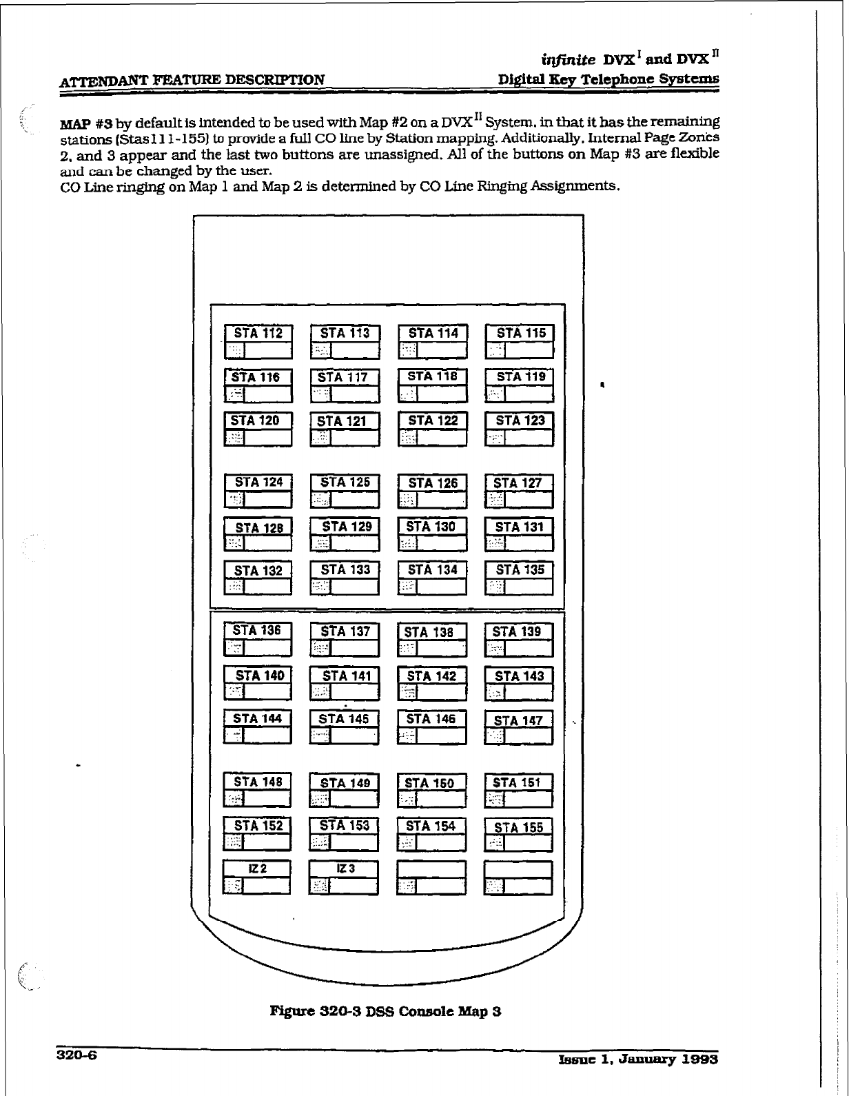
iqjinite DVX’ and DVB;”
D&ital Iky Telephone Sytstexhs
BNP #S by default is intended to be used with Map #2 on a
DVX”
System, in that it has the remaining
stations (Stas 11 l-1 551 to provide a full CO line by Station mapping. Additiona&. Internal Page Zonks
2. and 3 appear and the last two buttons are unassigned. Al1 of the buttons on Map #3 are flexible
and can be changed by the user.
CO Line ringing on Map 1 and Map 2 is d&x-mined by CO Line Ringing Assignments.
320-S Lsne 1. Janumy 1993
imite DVK ’ and DVK ’
Dj@taI Key Telephone Systems STATION FI%m OI?KHATION
SECTION 400
STATION FEATURE OPERATION
400.1 INTRODUCTION
The in.tte Digiti Key Telephone System has a
wide variety of features and flexible program-
ming, allowing each telephone user to program
his/her telephone to meet his/her oxen individ-
ual needs.
This section of the manual contains the operat-
ing instructions for Digital Key Terminals and
includes an illustxation of the key telephone
used in the ti@aite Digital Key Telephone Sys-
tem and description of the keys on the tele-
phones and their functions. It is designed to
provide step-by-step instructions for operating
the Digital Key Terminals in the system. Visual
and audible cues which accompany the various
steps in the operation of the features are also
included.
Literature similar to these operating instruc-
tions has beenpreparedforusebythecustomer
in the form of a Station Users Guides.
400.2 KEYTELEPHONE STATION FKA-
Each irz,finffeDigitaIKeyTelephone Systempro-
vides the following keys, indicators and fea-
tures:
HANDSET AND SPEABER are located at the
left side of the front panel.
A
handset is provided
to allow confidential conversation when de-
sired. Lifting the handset f+om its cradle (going
off-hook) disengages the station’s built-in
speaker.
The speaker is located direct& below the center
portion of the handset. The station may be
operated with the handset on-hook. When this
* occurs, audio is transmitted to the station user
through the station’s speaker.
FLEXIBLE BUTTONS are used to access idle
outside lines, provide DSS/HLF for internal
stations. access speed dial number and activate
features. These buttons are programmed by the
individual station user. The default flex feature
buttons are described below:
CAU BACg (flex) button allows you to
initiate an automatic call back request to
another busy station. As soon as that sta-
tion becomes idle, the station that left the
call back request is signaled. A fiex button
must be assigned to use this feature.
CALL FWD (flex] button allows you to for-
ward your calls to another station.
DO
NOT DISTURB (DND] (flex) button al-
lows the user to phce his/her telephone
into a Do Not Disturb mode to eliminate
incoming outside line tigjng. intercom
calls, transfers and paging an-
nouncements. The station in Dm can use
the telephone to make normal outgoing
calls. On Attendant stations, this button
becomes the system Night Mode button. A
flex button must be ,=signed to use this
feature.
CONI%-NCE (CONF) (flex] button is
used to establish and build conference
calls.
FIXED FEATURE BUTTONS:
PICK-UP button allows you to pickup a
tone ringing intercom call, transferred, in-
comtng, or recalling outside line call to a
spedic unattended station eitberby group
or directed call pick-up.
FLASH button is used to terminate an
outside call and restore dial tone without
having to hang up the handset It is also
used to transfer calls behind a PBX or
Centrex within those systems.
MESSAGE WAIT
(BESG) button allows you
to initiate a message waiting indication at
stations that are busy, unattended, or in
Do Not Disturb. Message Waiting Callback
request left at your station is indicated by
a &shing Msg wait LED.
TRANSFER (TRAMI) button is used to
harder an outside call from one station to
another.
SPEED button provides you with access to
speed dialing, save number redial and last
number redial. This button is also used to
access speed dial and flex button program-
ming.
CAMP-ON button enables you to alert a
busy party that an outside line is on hold
and waiting for them.
MUTE button allows you to switch the
built-in microphone on or off when using
the speakerphone, or the handset micro-
phone when using the handset.
Issue 1, Jan- 1993 400-l
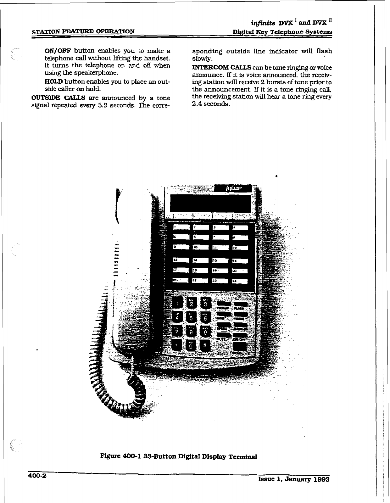
ir?j%Ste DVX’andDVXn
STATION FEATURE OPERATION Digital Key Telephone Sptems
ON/OFF button
enables you to make a
telephone call without lifting the handset.
It turns the telephone on and off when
using the speakerphone.
HOLD button enables you to place an out-
side caller
on
hold.
OUTSIDE CALLS are announced
by
a tone
signal repeated every 3.2 seconds. The con-e-
sponding outside line indicator will flash
slowly.
INTERCOM CALLS can be
tone ringing or voice
announce. lf it is voice announced, the receiv-
ing station will receive 2 bursts of tone prior to
the announcement. If it is a tone ringing call,
the receiving station will hear a tone ring every
2.4
seconds.
Ffgurt 400-l 33-Button Digital Diqday Termbud
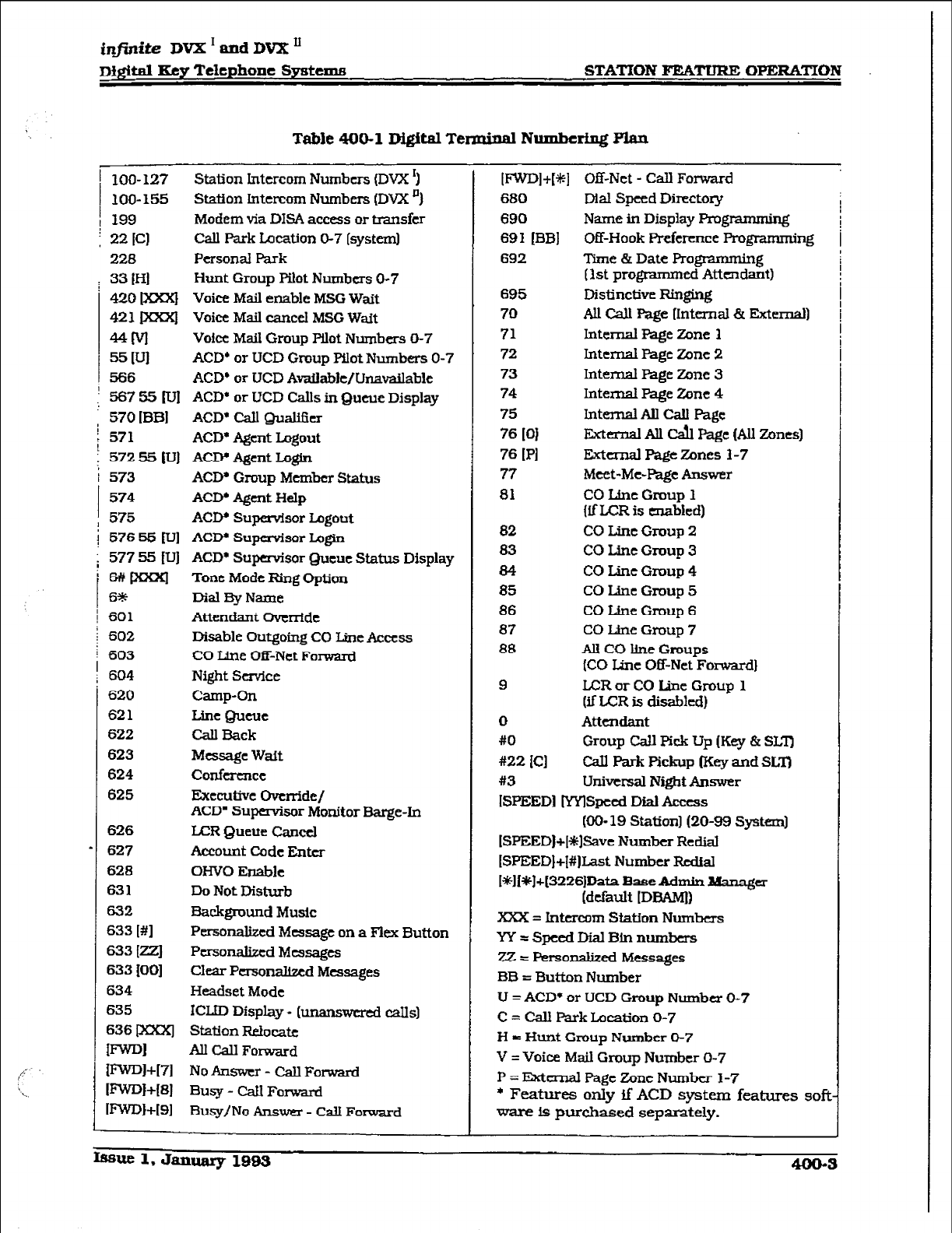
infinite DVX I and
DVX II
~fgital Key Telephone Smtuns STATION FEATURE OPERATION
Table 400-l Digital Tennind Numbering Elan
1 loo-127 Station Intercom Numbers (DVX ‘)
100-155
I
Station Intercom Numbers (DVX *)
199 Modem via DISA access or tmnsfcr
f 22 [Cl
call Park Location 0-7 [system)
228
Personal Park
: 33
IHI
420 m
421 Ixxrq
MM
55 WI
566
i 56755pJj
Hunt Group
Pilot
Numbers O-7
Voice Mail enable MSG Wait
Voice Mail cancel MSG Wait
Voice Mail Group Wet Numbers O-7
ACD+ or UCD Group pilot Numbers O-7
ACD+ or UCD Available/Unavailable
ACD* or UCD Calls in Queue Display
ACD* Call Qualihr
ACD* Agent Logout
ACIY Agent Lctgh
ACD’ Group Member Status
ACD, Agent Help
ACD, Supervisor Logout
ACDL Supervisor Lz@n
ACD* Supervisor Queue Status Display
Tone Mode Ring Option
Dial w Name
Attendant Override
Disable Outgoing CO Line Access
CO Line Off-Net Forward
Night Scwice
Camp-On
Line Queue
Call Back
Message Wait
conference
Exeeulive Override/
ACD’ Supervisor Monitor Barge-In
LAZR Queue Cancel
Account Code Enter
oHvo Enable
Do Not Disturb
Fiackgrwnd Music
Personalized Message on a Flex Button
Personalized Messages
Clear Pcrsonaltxd Messages
Headset Mode
ICLJD Display - [
unanswered CaIls]
Station Relocatt
All Cdl Forward
No Answer - CalI Forwami
Busy - Call Forward
Busy/No Answer - Call Forward
i
570
[BB]
571
572
55 IV]
573
574
575
576 55 rul
577 55 fUJ
~paoq
f5*
601
602
603
604
620
621
622
623
624
625
626
627
628
631
632
633 [#]
633 [ZZJ
633 iOO]
634
635
636 pwrl
II-=4
mQl+[71
ImI+H
I~l+I91
I~l+V+l
680
690
691 [BB]
692
695
70
71
72
73
74
75
76 IO1
76
PI
77
81
a2
83
84
85
86
87
88
9
0
#O
x22 ICI
#3
Off-Net - Call Fonvard
Dial Speed Directory
Name in Display Programming
Off-Hook Preference Programming
Time & Date Rogrammm
[ist prograrnrncd Atten&&
Distinctive Ringing
All Cdl Page IIntemal & External)
Internal Page Zone 1
Internal Page Zone 2
Internal Page Zone 3
Internal Page Zane 4
Internal All Call Page
External AU Cd Page (AU Zunes)
External Page Zones l-7
Meet-Me-me Answer
CO Uric Group 1
{if LCR is enabled)
CO Lint Group 2
CO Line Group 3
CO Line Group 4
CO Line Group 5
CO lhe Group 6
CO Line Group 7
All CO Iine Groups
(CO Line Off-Net Fon%ard]
LCR or CO Line Group 1
(if L-CR is
disabled)
Attendant
Group Call Pick Up (Key & SLZI
Cal h-k Pickup f.Key and SLT)
universal NigbtAnswer
[SPEED] ~Spccd Dial Access
(cm- 19 StationJ (20-99 system)
[SPEEDl+[+$%avc Number Redial
(SPEED]+I#]Last Number &dial
[*][~]+(3226jData Base Aclmin lk%na@
(default IDBAMI)
Xxx = Intercom Station Numbas
W=SpcedDialBlnnumbcrs
22 = Personalized Messages
BB = Button Number
U = ACD* or UCD Group Number O-7
C = CaII Park Location O-7
I-l = Hunt Group Number O-7
V = Voice Mail Group Number O-7
P = External Page Zone Number J-7
* Features only if ACD system features soft
ware is purchased separately.
I
Issue 1, January lSa3 40043
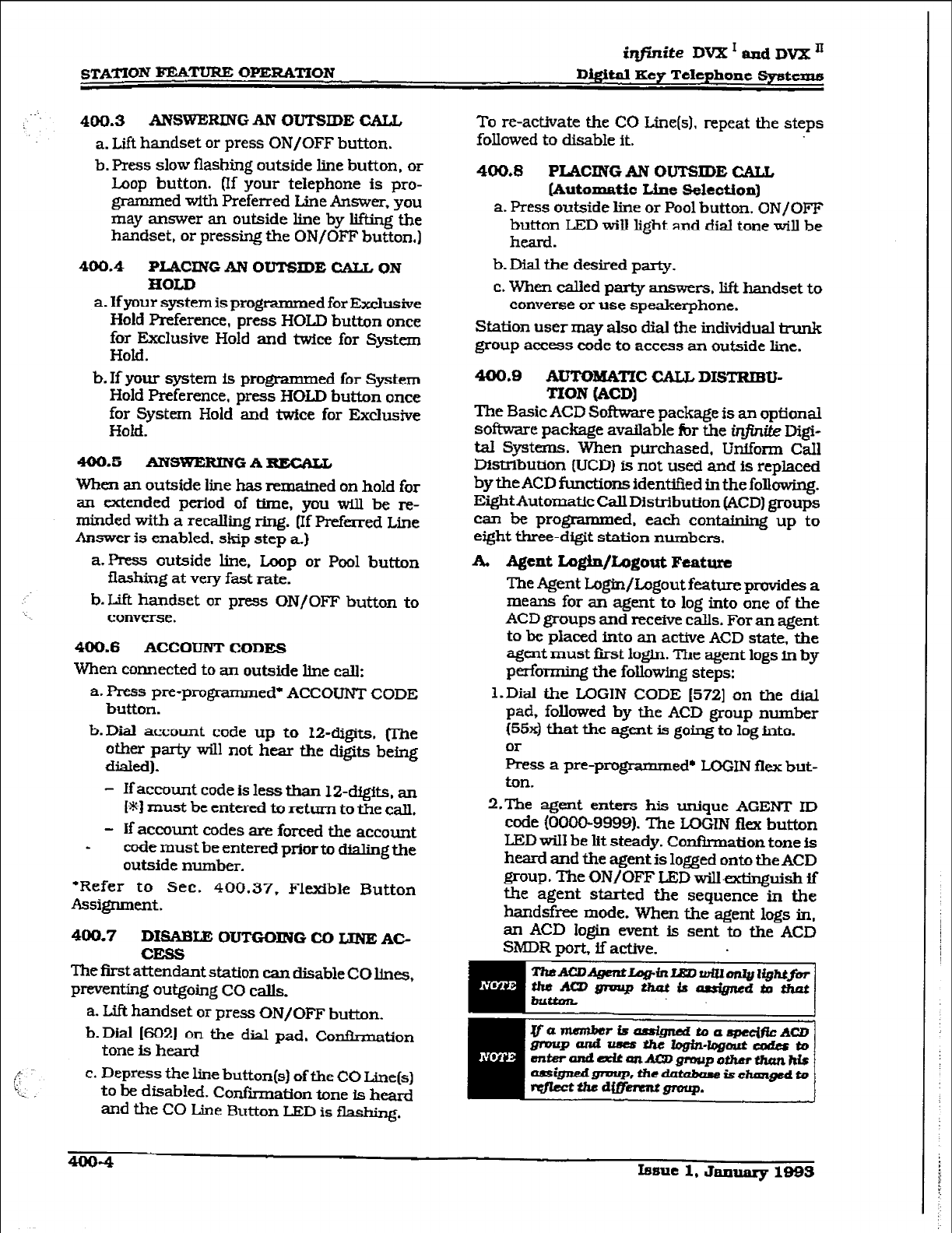
STATION FEATURE OPERATION
iqfinite DVX I amd DvI[: A
Dipital Key Telephone !$y&ems
4~).3 ANSWERDIG
AN OU’IWDE CALL
a. Lift handset or press ON/OFF button.
b. Press slow flashing outside line button, or
Loop button. (If your telephone is pro-
grammed with Preferred Line Answer. you
may answer an outside line by lifting the
handset, or pressing the ON/OFF button.)
400.4 PLACING
AN OUTSIDE CALL ON
HOLD
a. If your system is programm ed for Exclusive
Hold preference, press HOLD button once
for Exclusive Hold and twice for System
Hold.
b. If your system is programmed for System
Hold Preference, press HOLD button once
for System Hold and twice for Exclusive
Hold.
400.5 ANSWERING
A
RECALL
When an outside line has rematned on hold for
an extended period of time, you will be re-
minded with a recalling ring. [If Preferred Line
Answer is enabled. skip step a)
a.Press outside line, L.oop or Pool button
flashinog at very fast rate.
b. Lit? handset or press ON/OFF button to
converse.
400.6 ACCOUNT CODES
When connected to an outside line call:
a. Press pre-programmed’ ACCOUNT CODE
button.
b-Dial account code up to l2-digits, (‘I’he
other party will not hear the digits being
dialed).
- If account code is less than I2-digits. an
W) must be entered to return to the call.
- If account codes are forced the account
- code must be entered prior to dialing the
outside number.
*Refer to Sec. 400.37, Flexible Button
Assignment.
400.7
DISABLE OUTGOING CD LINE AC-
CESS
The first attendant station can disable CO lines,
preventing outgoing CO calls.
a. Lift handset or press ON/OFF button.
b. Dial (6W on the dial pad, Con&maton
tone is heard
c. Depress the line button(s) of the CO Line(s)
to be disabled. Confiiation tone is heard
and the CO Line Button LED is flashing.
To re-activate the CO Line(s). repeat the steps
followed to disable it.
400,8 PLACING AN
OUTSIDE CAL&
[Automatic Line !Mection]
a. Press outside line or Pool button. ON/OFF
button LED will light and dial tone will be
heard.
b. Dial the desired party.
c. When called party answers. lift handset to
converse or use speakerphone.
Station user may also dial the individual trunk
group access code to access an outside line.
400.9 AUTOmmC CALL DISTRIBU-
!I’lON (ACD]
The Basic ACD Softmre package is an optional
software package avatlable for the infinite Digi-
tal Systems. When purchased, Uniform CaIl
Diskibution [UCD) is not used and is replaced
by the ACD functions identified in the following.
Eight Automatic Call Distribution (ACD) groups
can be programmed, each containing up to
eight three-digit station numbers.
A. Agent Lq#n/Logout Feature
The Agent tO@n/logout feature Provides a
means for an agent to log into one of the
ACD groups and receive calls. For an agent
to be placed into an active ACD state, the
agent must first login. The agent logs in by
perfo-rming the following steps:
I-Dial the LOGIN CODE I5721 on the dial
pad, followed by the ACD group number
(55x) that the agent is going to log into.
or
Press a pre-programm ed* LOGIN flex but-
ton.
2.Tbe agent enters his unique AGENT ID
code (00009999). The LOGIN flex button
LED will be lit steady. Conffnnation tone is
heard and the agent is logged onto the ACD
group. The ON/OFF LED will-extinguish ti
the agent started the sequence in the
handsfree mode. When the agent logs in,
an ACD login event is sent to the ACD
SMDR port, if active.
4004
Issue 1, Jmuaqr 1993
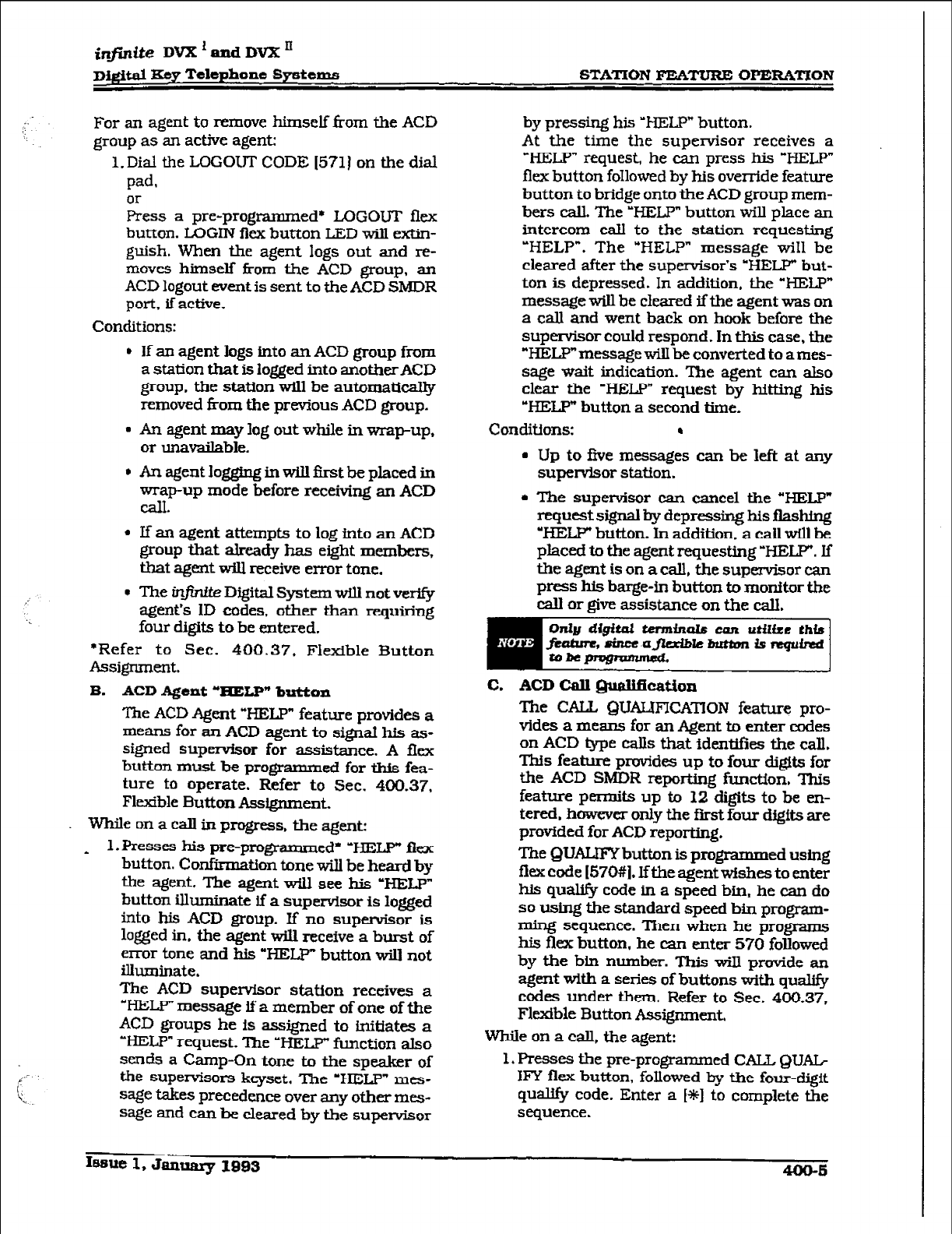
infinite DVX ’ and DVX ’
D&$ti Xey Telephone Systems STATION FEATURE OPERATION
FOG an agent to remove himself from the ACD
group
as an active agent:
l.Dial the LOGOUT CODE [571] on the dial
pad.
or
Press a pre-programm ed* LOGOUT flex
button. LOGIN ficx button LED will extin-
guish. When the agent logs out and re-
moves himself from the ACD group, an
ACD
logout event is sent to the ACD SMDR
port, if active.
Conditions:
l
If an agent logs into an ACD group from
a station that is logged into anotherACD
group, the station will be automati&ly
removed &om the previous ACD group.
l
An agent may log out while in wrap-up,
or unavailable.
l
An agent logging in will ihst be placed in
wrap-up mode before receiving an ACD
CalI.
l
If an agent attempts to log into an ACD
group that already has eight members,
that agent will receive error tone.
l
The infinite Digital System will not verify
agent’s ID codes, other than requiring
four digits
to
be entered.
‘Refer to Sec. 400.37. Flexible Button
Assignment.
B. ACD Agent ‘HELP” button
The ACD Agent “HELP” feature provides a
means for an ACD agent to signat his as-
signed supervisor for assistance. A fkx
button must be programmed for this fea-
ture to operate. Refer
to Sec. 400.37,
Flexible Button Assignment.
While on a call in progress. the agent:
* l.Presses his pre-programmed’ ‘HELP” flex
button. Confirmation tone will be heard by
the agent. The agent will see his ‘HELP”
button illuminate if a supervisor is logged
into his ACD group. If no supervisor is
logged in. the agent will receive a burst of
enor tone
and his “HELP”
button will not
illuminate.
The ACD supervisor station receives a
“HELP” message if a member of one of the
ACD
groups he is
assigned to Lnitiates a
‘HE&P” request. lhe ‘HELP” function also
sends
a Camp-On tone to the speaker of
the supenrisors keyset. The ‘HE&P” mes-
sage takes precedence over any other mes-
sage and can he cleared by the supervisor
by pressing his ‘HELP” button.
At the time the supervisor receives a
‘HELP” request, he can press his ‘HELP”
flex button foIlowed by his override feature
button to bridge onto the ACD group mem-
bers call. The ‘HELP” button will place an
intercom call to the station requesting
“HELP”. The “HELP” message wiI1 be
cleared after the supervisor’s *HELP”
but-
ton is depressed. In addition. the “HELP”
message will be cleared ifthe agent was on
a call and went back on hook before the
supervisor could respond. In this case, the
“HELP” message wilI be
converted
to
a mes-
sage wait indication. The agent can also
clear the ‘HELP” request by hitting his
“HELP” button a second time.
Conditions: I
. Up to five messages can be left at any
supenrisor station.
l
The supervisor can cancel the “HELP”
request signal hy depressing his flashing
‘HELP” button. In addition. a tail will be
placed to the agent requesting ‘BELT. If
the agent
is
on a call, the supervisor can
press
his barge-in button to monitor the
call
or
give assistance on the call.
C. ACD Call Quali5caiion
The CALL QUAIJFICATION feature pro-
vides a means for an Agent to enter codes
on ACD type calls that identifies the call.
This feature provides up to four digits for
the ACD SMDR reporting function. This
feature permits up to 12 digits
to be en-
tered.
however only the first. four
digits are
provided for ACD reporting.
The QUALIFYbutton is programmed using
flex code [57#1. Iftbe agent wishes to enter
his qualify code in
a speed
bin. he can do
so using the standard speed bin program-
ming sequence.
Then
when he programs
his flex button, he can enter 570 followed
by the bin number. This will provide an
agent with a series of buttons with qualify
codes under them. Refer to Sec. 400.37,
Flexible Button Assignment.
While on a call, the agent:
1. Presses the pre-programmed CALL QUAG
IFY flex button, followed by the four-digit
qualify code. Enter a [*I to complete the
sequence.
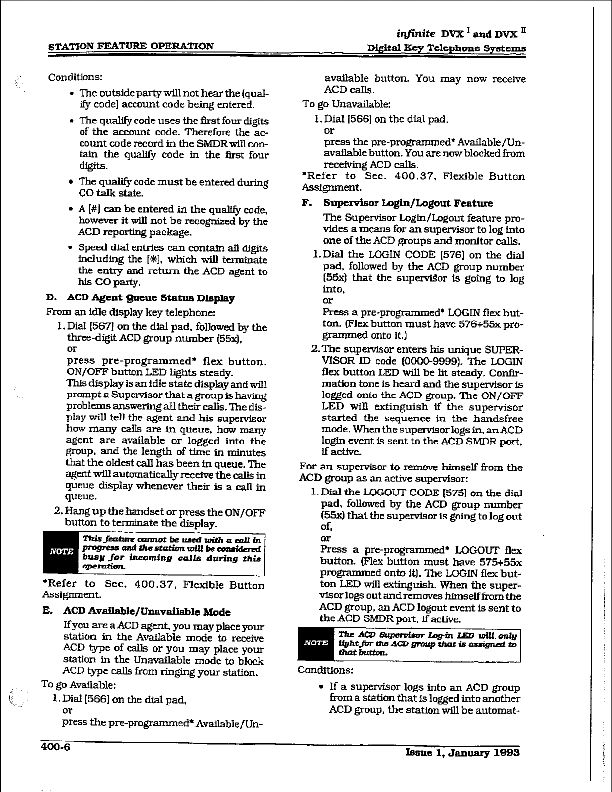
STAT’ION FE.t%TWtE OPERATION
infinite DVX I aad DVX II
DQitaI Key Telephone Systems
Conditions:
l
The outside party will not hear the (qual-
ify code) account code being entered.
l
The qualify code uses the Grst four digits
of the account code. Therefore the ac-
count code record in the SMDRwill con-
tain the quaI@ code in the first four
digits.
l
The quaI@ code must be entered during
CO talk state.
. A [#] can be entered in the qualify code,
however it will not be recognized by the
ACD reporting package.
l speed dial entries can contain all digits
including the [%I. which will terminate
the entry and return the ACD agent to
his co party.
D. ACD Agent *cue Matus Display
From an idle display key telephone:
1. Dial (5673 on the dial pad, followed by the
three-digit ACD group number (55x).
Or
press pre-programmed* flex button,
ON/OFF button LED lights steady.
This display is an idle state display and will
prompt a Supervisor that a group is having
problems answering ail their calls. The dis-
play will tell the agent and his supervisor
how many calls are in queue. how many
agent are available or logged into the
group, and the length of time. in minutes
that the oldest call has been in queue. The
agent will automatically receive the calls in
queue display whenever their is a call in
queue.
2. Hang up the handset or press the ON/OFF
button to terminate the display.
mui
*Refer to Sec. 400.37, Flexible Button
Assignment.
E. ACD Available/Un~&able Mode
If you are a ACD agent, you may place your
station in tbe Avaflable mode to receive
ACD type of ca& or you may place your
station in the Unavailable mode to block
ACD type calls from ringing your station.
To go Available:
1. Dial (566) on the dial pad,
or
press the pre-programmed* AvailabIe/Un-
available button. You may now receive
ACD eaIls.
To go Unavailable:
1. Dial 1566) on the dial pad,
;ess the pre-programmed* Available/Un-
available button. You are now blocked from
receiving ACD calls.
*Refer to Sec. 400.37. Flexible Button
Assignment.
F.
Supemisor Login/Lagout Feature
The Supervisor Login/Logout feature pro-
vides a means for an supervisor to log fnto
one of the ACD groups and monitor calls.
1. Dial the LUGIN CODE (576) on the dial
pad, followed by the ACD group number
[55x)
that the supdor is going to log
into,
or
Press a pre-programmed* LUGIN flex but-
ton. (‘Hex button must have 576+55x pro-
grammed onto it.)
2.‘I’he supervisor enters his unique SUPER-
VISOR ID code (000@9999). The LOGIN
flex button LED will be lit steady. Confir-
mation tone is heard and the supervfsor is
logged onto the ACD group. ‘Ihe ON/OFF
LED wiI1 extinguish if the supervisor
started the sequence in the handsfree
mode. When the supervisor logs in, an ACD
logtn event is sent to the ACD SMDR port,
if active.
For an supervisor to remove himself from the
ACD group as an active supervisor:
1. Dial the LOGOUT CODE
[57!51
on the dial
pad, followed by the ACD group number
[55x)
that the supervisor is going to log out
of,
Eess a pre-programmed* LOGOUT flex
button. (Flex button must have 575+55x
progmmmed onto it). ‘Ihe LCKXN flex but-
ton LED will extinguish. When the super-
visorlogs out andremoves himselffromthe
ACD group, an ACD logout event is sent to
the ACD SMDR port, if active.
ThcAWt3qmhorLqgin~~.~
fi@tJi?rtfteAQ)fpvipthaisiassipdEo
Conditions:
l
If a supervisor logs into an ACD group
tiorn a station that is logged into another
ACD group. the station will be automat-
400-6
Issue 1, January 1893
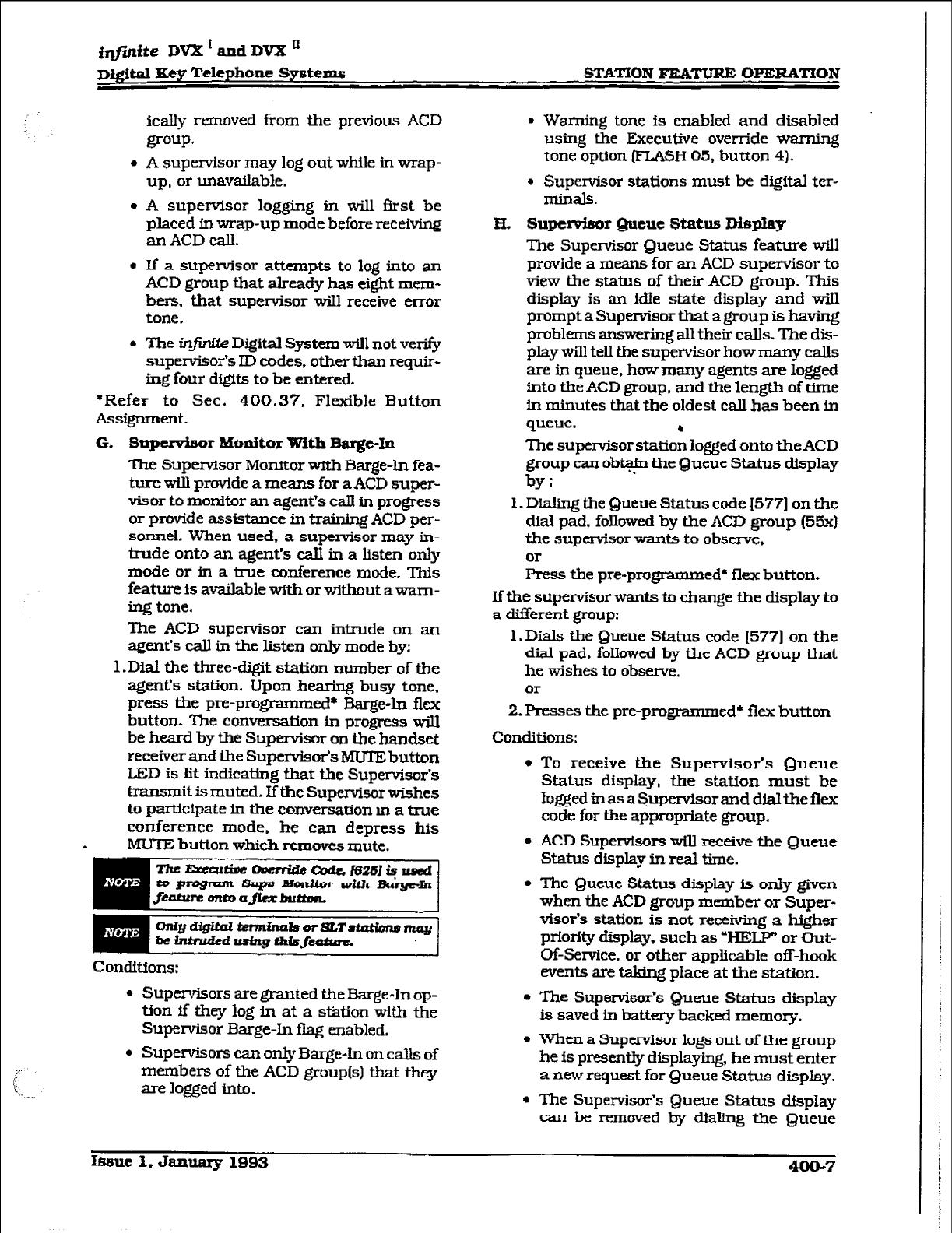
i@tite DVX * and
DVX ’
digital Key Telephone Systems STATION FEATURE OPERATION
icaI,ly removed from the previous ACD
group*
l
A supervisor may log out while in wrap-
up, or unavailable.
l
A supervisor logging in will fist be
placed in wrap-up mode before receiving
an ACD call.
l
K a supervisor attempts to log into an
ACD group that already has eight mem-
bers, that supervisor will receive error
tone.
l
The in.@& Digital System will not verify
supervisor’s ID codes, other than requir-
ing four digits to be entered.
*Refer to Sec. 400.37. Flexible Button
Assignment.
G. S-r
Monitor With Barge-In
The Supervisor Monitor wfth Barge-In fea-
ture will provide a means for a ACD super-
visor to monitor an agent’s call in progress
or provide assistance in training ACD
per-
sonnel. When used, a supervisor may in-
trude onto an agent’s call in a listen only
mode or in a true conference mode. This
feature is available with or without a warn-
ing tone.
The ACD supervisor can intrude on an
agent’s call in the listen only mode by:
1.Dia.l the three-digit station number of the
agent’s station. Upon bearing busy tone,
press the pre-progmmmed* Barge% flex
button. The conversation in progress will
be heard by the Supervisor on the handset
receiverand the Supervisor’s MUTE button
LED is lit indicating that the Supervisor’s
transmit is muted. If the Supervisor wishes
to participate in the conversation in a true
conference mode, he can depress his
MUTE button which removes mute.
Conditions:
l
SupervIsors are granted the Barge-In op-
tion if they log in at a station with the
Supervisor Barge-In flag enabled.
l
Supervisors can only Barge-In on calls of
members of the ACD group(s) that they
are logged into.
l
Warning tone is enabled and disabled
using the Executive override warning
tone option (FLASH 05, button 4).
l
Supervisor stations must be digital ter-
nlinals.
H. SupcMsor Queue Status Display
The Supervisor Queue Status feature wtll
provide a means for an ACD supervisor to
view the status of their ACD group. This
display is an idle state display and wiIl
prompt a Supervisor that a group is having
problems answering all their calls. The dis-
play will tell the supervisor how many calls
are in queue, how many agents are logged
into the ACD group, and the length of time
in minutes that the oldest call has been in
queue.
The supenrisor statiofi logged onto the ACD
group can obt.a$ the Queue Status display
by:
1. Dialing the Queue Status code I5771 on the
dial pad. followed by the ACT, group (55x)
the supervisor wants to observe,
01
press the pre-programmed’ flex button.
If the supervisor wants to change the display to
a different goup:
1. Dials the Queue Status code [577] on the
dial pad, followed by the ACD group that
he wishes to observe.
or
2. presses the pre-programmed+ flex button
Conditions:
l
To receive the Supervisor’s Queue
Status display, the station must be
IoggedinasaSupervisorand dfaltheflex
code for the appropriate group.
l
ACD SupervIsors will receive the Queue
Status display in real time.
l
The Queue Status display is only given
when the ACD group member or Super-
visor’s station is not receivjng a
higher
prfority display, such as ‘HELP” or
Out-
Of-Service. or other applicable off-hook
events are taking place at the station.
l
The Supervisor’s Queue Status display
is saved in battery backed memory.
l
When a Supervisor logs out of the group
he is presently displaying, he must enter
a new request for Queue Status display.
l
The Supervisor’s Queue Status display
can be removed by dialing the Queue
Iseue I, January 1993 400-7
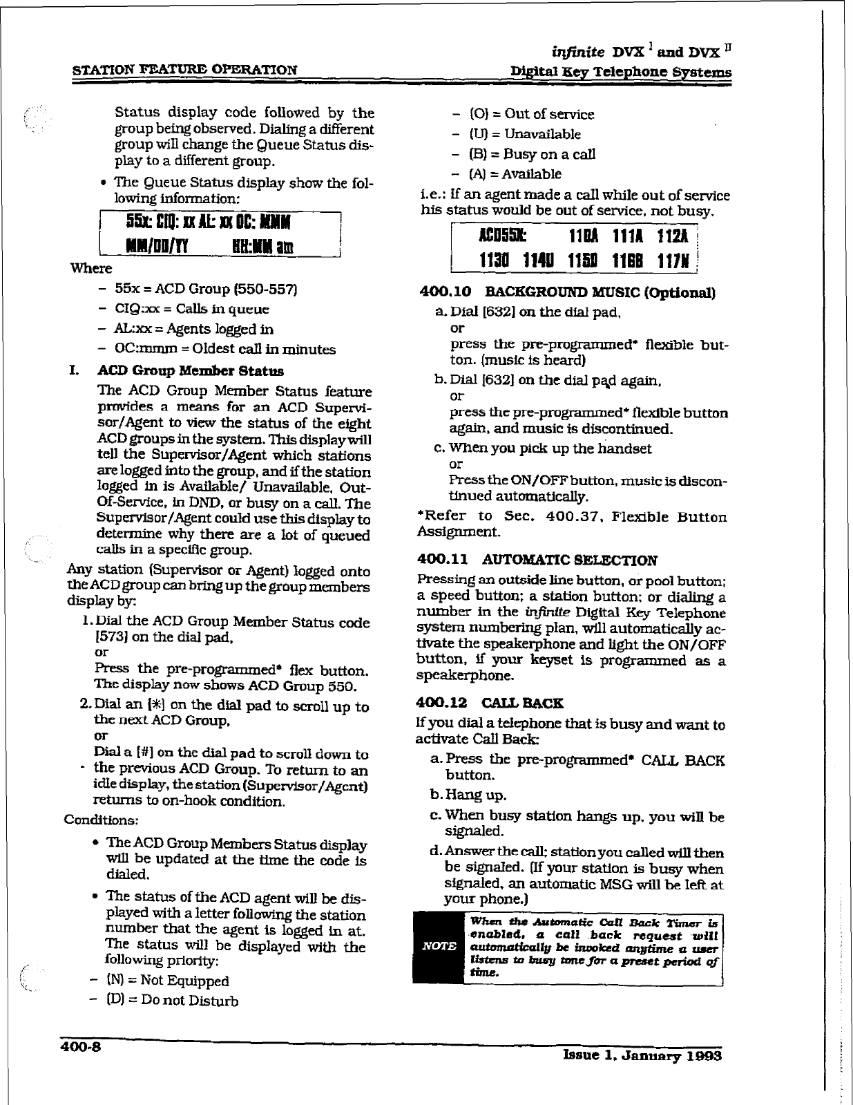
STATION FEATURE O=‘TTON
iqj?nite DVX 1
and DVX ’
Digital Xey Telephone Gystems
Status display code folIowed by the
group
being observed. Dialing a different
group will change the Queue Status dis-
play to a different group.
l
The Queue Status
dispIay show the fol-
lowfng information:
- 55x = ACD Group (550-557)
- CIQ:xx = Calls in queue
- &xx = Agents logged in
- 0C:rmnrn = Oldest call in minutes
I. ACD Group Member Status
The ACD Group Member Status feature
provides a means for an ACD Supervi-
sor/Agent to view the status of the eight
ACD groups in the system. This displaywilI
tell the Supervisor/Agent which stations
are logged into the group, and ifthe station
logged in is Available/ Unavailable, Out-
Of-Servfce, fn DND. or busy on a call. The
Supervisor/Agent couId use this display to
determine why there are a lot of queued
calls in a specific group.
Any station (Supetisor or Agent) logged onto
the ACD group can bring up the group members
display by:
1. Dial the ACD Group Member Status code
15731 on the dial pad.
or
Press the preprogrammed* ilex button.
The display now shows ACD Group 550.
2,Dial an [%I on the diaI
pad
to scroll up to
the next ACD Group.
or
Dial a WI on the dial pad to scroll down to
- the previous ACD Group. To return to an
We display, the station (Supervisor/Agent)
returns to on-hook condition.
Conditions:
l
The ACD Group Members Status display
will be updated at the time the code is
dialed.
l
The status of the ACD agent will be dis-
played with a letter foIIow%ng the station
number that the agent is log& in at.
The status wiII be displayed with the
following priority:
- (IV) = Not Equipped
- [D) = Do not Disturb
- (0) = Out of se&es
- (U) = Unavailable
- (B)=BusyonacaIl
- (A) = Available
i.e.: If an agent made a call while out of service
his status would be out of service. not busy,
400.10 EAcxG~amD MUSIC (optional)
a. D&l16321 on the dial pad,
Eess the pre-programmed* flexible but-
ton. [music is heard)
b. Dial 1632) on the dial pqd again,
gess the pre-programmed* flexible button
again, and music is discontinued.
c. When you pick up the handset
or
Press the ON/OFF button, music is discon-
tinued automatically.
*Refer to Sec. 400.37. Flexible Button
ASSigIUDtXlt.
400.11 AUTOkWI’IC SELECTION
Pressing an outside Iine button, or pool button;
a speed button; a station button: or diahng a
number in the infinite D@al Key Telephone
system numbering plan, will automaticaIly ac-
tivate the speakerphone and light the ON/OFF
button, If your keyset is programmed as a
speakerphone.
4u0.12 CALLaAcs
If you dial a tekpbone tlmt is busy and want to
activate Call Back
a-Press the pre-programmed* CAL& BACK
button.
b. Hang up.
c. When busy station hangs up. you wiII be
signaled.
d. Answer the call; station you called will then
be signtied. W your station is busy when
signaled, an automatic MSG wiU be Ieft at
your phone.)
4ocb8
Issue 1. Jan- 1995
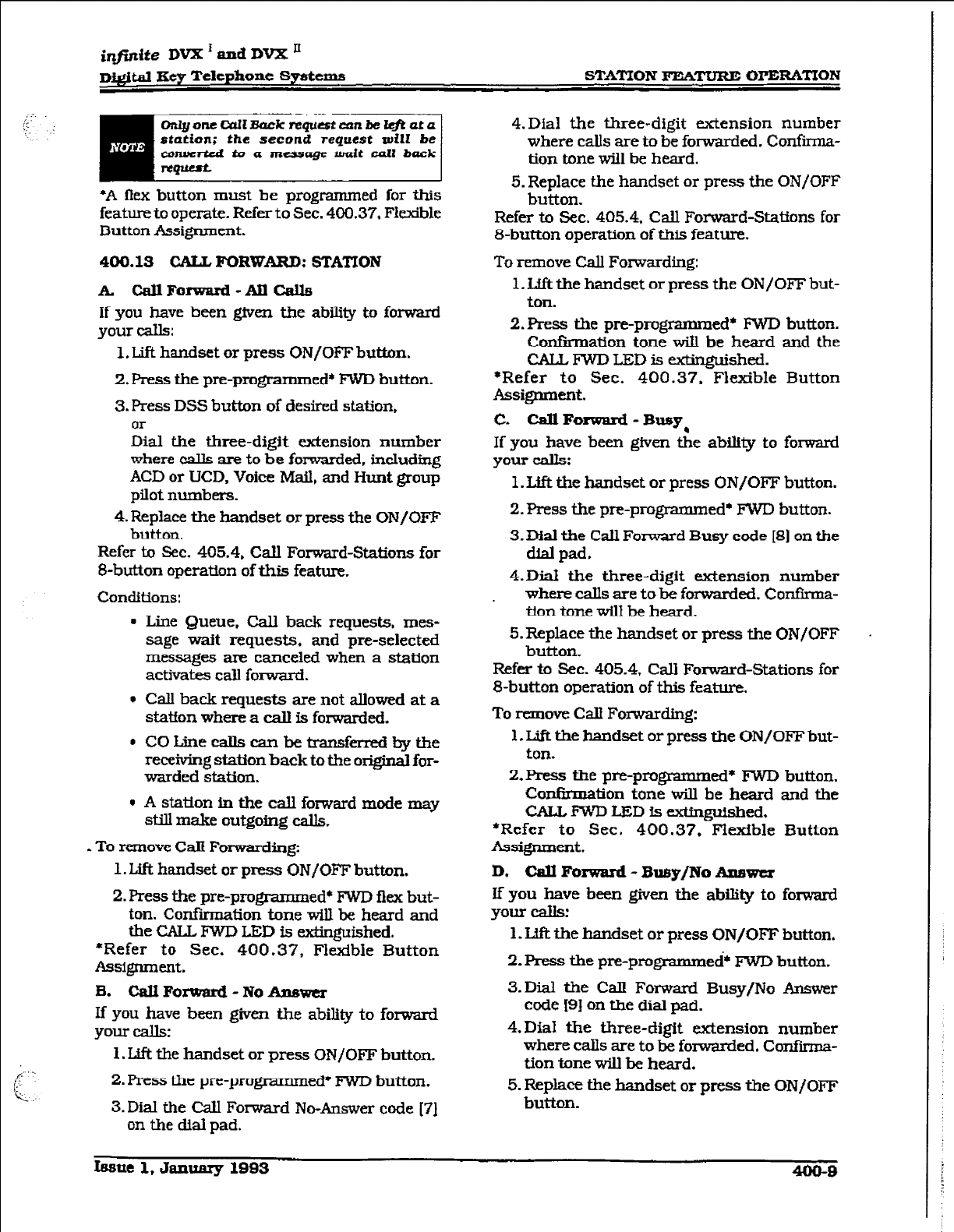
ir@ife DVX ’ ad DVX ’
digital
Key Telephone Systems STATION FEATURE OPEMTION
Or@oneC%ZLBuckrequestcunbeZ@uta
station; the second request will be
converted to a message wait call back
*A flex button must be programmed for this
feature to operate. Refer to Sec. 400.37. FI&ble
Button Assignment.
400.13 GALZ,
FORWARD: STATION
A. CallForward-AllCalls
If you have been given the abiity to forward
your calls:
1, Lift handset or press ON/OFF button.
2. Fess the pre-programmed* FWD button.
3. Press DSS button of desired station,
or
Dial the three-digit extension number
where calls are to be forwarded, including
ACD or UCD. Voice Mail, and Hunt group
pilot numbers.
4. Replace the handset or press the ON/OFF
button.
Refer to Sec. 405.4, Call Forward-Stations for
&button operation of this feature.
Conditions:
l
Line Queue. Call back requests, mes-
sage wait requests. and pre-selected
messages are canceled when a station
activates call forward.
l
Call back requests are not allowed at a
station where a call is forwarded.
l
COLinecallscanbetransf&bythe
receiving station back to the original for-
warded station.
1 A station in the call forward mode may
still make outgoing calls.
- To remove Call Forwarding:
1. Lift handset or press ON/OFF button.
2. Press the pre-proved* FWD flex but-
ton. Confirmation tone will be heard and
the CALL FWD LED is extinguished.
*Refer to Sec. 400.37, Flexible Button
Assignment.
B.
CallForward-NoAnswer
If you have been given the abiuty to forward
your calls:
1. Lift the handset or press ON/OFJ? button.
2. Press the pre-programmed* FWD button.
3.Dial the Call Forward No-Answer code [71
on the dial pad.
4.Dial the three-digit extension number
where calls are to be forwarded. Confirma-
tion tone will be heard.
5. Replace the handset or press the ON/OFF
button.
Refer to Sec. 405.4, Call Forward-Stations for
B-button operation of this feature.
To remove Call Forwarding:
1. Lift the handset or press the ON/OFF but-
ton.
2.Press the pre-programm ed* IWD button.
Confirmation tone will be heard and the
CALL FWD LED is extinguished.
*Refer to Sec. 400.37. Flexible Button
Assignment.
C. Call Forward - Busy,
If you have been given the ability to forward
your cam
1. Lift the handset or press ON/OFF button.
2. Press the pre-programmed* FWD hutton.
3. Dial the Call Forward Busy code 181 on the
dial pad.
4.Dia.l the three-digit extension number
where calls are to be forwarded. ConfIrma-
tion tone will be heard.
5. Replace the handset or press the ON/OFF
button.
Refer to Sec. 405.4, Call Forward-Stations for
8-button operation of this feature.
To remove Calf Forwarding:
1. Lift the handset or press the ON/OFF but-
ton.
2.Fkess the pre-progmmmed* lWD button.
Confirmation tone will be heard and the
CALLIWD LED is extinguished,
*Refer to Sec. 400.37. Flexible Button
Assignment.
D. CaJJ Foxward - Busy/No Answer
If you have been given the ability to forward
your calls!
1. I.Jft the handset or press ON/OFF button.
2. Press the prc-programmed* FWD button.
3.Dial the Calz Forward Busy/No Answer
code I91 on the dial pad.
4.DM the three-digit extension number
where calls are to be forwarded. Confii-
tion tone will be heard.
5. Replace the handset or press the ON/OFF
button.
zssue 1, Jall~ 1903
400-B
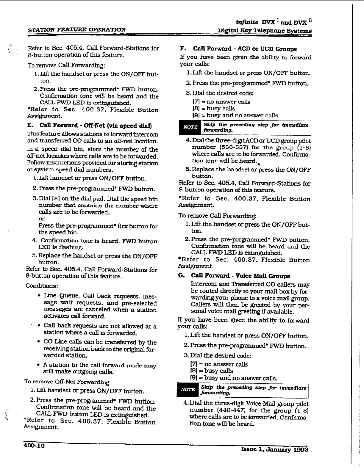
STATXON FEATURE OPERATlON
infinite DVX ’ and Dvx n
Diffital Key Telephone Systems
Refer to Sec. 405.4, Call Forward-Stations for
&button
operatiOn
Of this feature.
To remove Call Forwarding:
1. Lift the handset or press the ON/OFF but-
ton.
2.Press the pre-programmed* FWD button.
Confi!iation tone will be heard and the
CALL FWD LED is extinguished.
*Refer to Sec. 400.37, Flexible Button
ASSignmWt.
E. CalI Forward - Of&Net (via speed dial)
This feature allows stations to forward intercom
and transferred CO calls to an off-net location.
In a speed dial bin, store the number of the
off-net location where calls are to be forwarded.
Follow insticl9ons provided for storing station
or system speed dial numbers.
1.
Lift handset or press ON/OFF button.
2. Press the pre-programmed’ FWD button.
3. Dial IS+] on the dial pad. Dial the speed bin
number that contains the number where
calls are to be forwarded,
or
FYess the pre-programmed* flex button for
the speed bin.
4. Confirmation tone is heard. FWD button
LED fs flashing.
5. Replace the handset or press the ON/OFF
button.
Refer to Sec. 405.4, Call Forward-Stations for
&button operation of this feature.
Conditions:
l
Lfne Queue, Call back requests, mes-
sage waft requests, and pre-selected
messages are canceled when a station
activates call forward.
- l
Call back requests are not allowed at a
station where a call is forwarded.
l
COLinecaIlscanbetransfm-redbythe
receiving station back to the O~QIIIA for-
warded station.
. A station in the call forward mode may
still make outgoing calls.
To remove Off-Net ForwardLTlg
1. IJft handset or press ON/OFF button,
2.Press the pre-programmed* FW’D button.
Confirmation tone will be heard and the
Q%JL FWD button
LED is extinguished.
*Refer to Sec. 400.37, Fl&ble Button
AsQnment.
F. Call Forward - ACD or UCD Groups
If you have been given the ability to fomai-d
your calls:
1. Lift the handset
or
press ON/OFF button.
2. Press the pre-programmed* FWD button.
3. Dial the desired code:
171 = no answer calls
18]= busy calls
191= busy and no answer calls.
skip thepnceding step
for immediate
fding.
4. Dialthe three-digttACD or UCD group pilot
number (550-557) for the group (l-8)
where calls are to be forwarded. Confkna-
tion tone will be heard.,
5. Replace the handset or press the ON/OFF
button.
Refer to Sec. 405.4, Call Forward-Stations for
8-button operation of this feature.
*Refer to Sec. 400.37. Flexible Button
Assignment.
To remove Call Forwarding:
1. Lift the handset or press the ON/OFF but-
ton.
2.Press the pre-programmed* FWD button.
Confirmation tone will be heard and the
CALL FWD LED is extinguished.
*Refer to Sec. 400.37, Flexible Button
Assignment.
G. Call Forward - Voice Mdl
Groups
Lntercom and Transferred CO callers may
be routed ditectiy to your mail box by for-
warding your phone to a voice mail group.
Callers will then b? greeted by your per-
sonal voice mail greeting ff available.
If you have been given the abtity to forward
your calls:
1. LAft the handset or press ON/QFl? button.
2. Press the pre-programmed* FWD button.
3. Dial the desired code:
I7l=noanswercalls
IS] = busy cak
[9]= busy and no answer calls,
skip ftac precdfng step for iIrtmdm
-I?.
4. Dial the three-digit Voice Mail group pilot
number (440-447) for the group (l-81
where calls are to be forwarded. Confirma-
tion tone will be heard.
400-10 Iseue 1. January 1993
irzfznite DVX I and DVX ’
Digital IKey Telephone Syetm STATION FEATURE OPERATION
5. Replace the handset or press the ON/OFI”
button.
Refer to Sec. 405.4, Call Forward-Stations for
S-button operation of this feature
To remove Call Forwarding:
1. Lift the handset or press the ON/OFF but-
ton.
ZPress the pre-programm ed* FWD button.
Confirmation tone will be heard and the
CALL FWT, LED is extinguished.
*Refer to Sec. 400.37, Flexible Button
ASSigIlRlWlt.
H. Call Forward -
Hunt Groups
If you have been gWn the abtity to forward
your calls:
1. L.ift the handset or press ON/OFF button.
2. Press the pre-programmed* FWD button.
3.Dial the desired code:
- 171 =noanswcrcaUs
[S] = busy calls
(9]= busy and no answer calls.
4.
Dial the three-digit Hunt group pilot num-
ber (330337) for the group (l-8) where
calls are to be forwarded. Confirmation
tone wfll be heard.
5. Replace the
handset
or press the ON/OFF
button.
Refer to Sec. 405.4, Call Forward-Stations for
B-button operation of this
feature.
To remove Call
Fommrding:
1. Lii? the handset or press the ON/OFF but-
ton.
2.Fres.s the preprogrammed* lWD button.
Confirmation tone will be heard and tie
. CAL& lWD LED is errtinguished.
*Refer to Sec. 400.37. Flexible Button
Ass@lment.
400.14 CALL FORWARD: PREsm
If a CO Line fomarded by Preset Call Forward
encounters a manually forwarded station (Call
Forward - Station], or a station in DND, then
the ir~~rnjng CO Line will bypass that station
and forward to the next in the chain. lfthat
station is the last in the chain, then the call WU
not
forward any further and will continue to
Wg at
that station until answered or termi-
nated.
400.15 CALL FORWARD: CO LINES
A. Incoming CO fJn#i Off-Net (via speed
dW
This feature allows the first attendant sta-
tion to forward incoming CO calls to an
off-net location.
In a speed dial bin. store the number of the
off-net location where calIs are to be for-
warded. Follow instructions provided for
storing station or system speed dial num-
bers.
1. Dial [603] on the dial pad.
2. Dial the CO group access code for the CO
Une group to be forwarded,
or
Press an individual CQ Line button.
m=co Group 1
82=CO Group 2
83=CO Group 3
84=CO Group 4
85=CO Group 5
86=CO Group 6
87=CO Group 7
88=All CO Line
3.Dial the speed bin number that contains
the number where calls are to be for-
warded,
or
Press the pre-programtned* flex button for
the speed bin. Confirmation tone is heard.
To remove Off-Net Forwarding
a. Dial [603] on the dial pad.
b. Dial the CO group
access code,
or
press an individual CO Line button.
c. Dial [#I on the dial pad. Confkmation tone
is heard.
400.16 CAIUNG STATION TONE MODE
OPTION
Allows a calling
station to override a called
stations HF or W intercom switch settings.
When pladng a call to a station and Tone ring-
ing
is
desired:
a Dial [6#] on the dial pad.
b. Dial the three-digit extension number,
gess DSS button of desired station. (call
tone rings station).
Issue 1. January 1999 MO-11
infinite DVX I
and DVX ’
Di@talKeyTdephoneSystems
400.17 CAJL PARK
To place an outside call in park and consult
with, page, or call an internal party
While connected to an
outside line:
a. Press TRANS button. The
caller is put
on
Exclusive hold.
b. Dial parking location (220 to 227). Co&u-
mation
tone is heard.
c. If you
hear busy tone. press TRANS and
dial another parking
location.
Relieving a Parked Call
a. Lift handset or
press ON/OFF
button.
b.
Press the pound I#]
button.
c. Dial parking location (220 to 227) where
the call was parked.
400.18 CAtLPICIc-up: GROUP
When intercom tone rMging, transferred out-
side line ringjng, redl ringing or iniUaIIy ring-
ing call is heard
at
an unattended telephone:
a. Lift the
handset or press the ON/OFF
but-
ton.
b. Dial I#O] on the dial
pad,
Ol-
press the pre-programmed* PICK UP but-
ton
to be connected to the calling party.
-- _
Yolrnuutbeinthc
4-00.19 CALI.+ TRANSFER
Outside lines can be transferred from one
phone
to another within the system. The trans-
fer can be
either srxeened (announced)
or un-
screened to either an idle or busy station. ACT.3
or UCD Group. or I-hurt Group.
ScreenedTransfer
While connected
to an outside line:
Prks
station
button where call is to
be Wurs-
fen-cd (if prog rammed
on your telephone),
or
press TRANS button
and dial three-digit
station
number (100 to 155).
a.The
called extension signals according to
the intercom signal switch position.
b. When that extension answers, announce
the transfer.
c. Hang up to complete
transfer.
Unscreened Transfer
When the called extension begins to sign&
hang up to transfer the call (Recall timer starts].
Transfer Search
When attempting to locate a party:
a. Press a station button to
signal the
desired
station.
b.If the party is not located. press another
station button to continue the search.
If the party is not located:
c. Press another station button to continue
the search.
d.When the called party answers, hang up to
complete the transfer.
Answering a Screened tiler
a. Your intercom will be signaling
according
to the intercom signal swjtch position.
b. Answer the intercom and receive the trans-
fer notice.
c. Press the outside line button orloop button
flashing on hold.
400.20
TRANSFERRING CO CALLS TO A
STATION FORWARDEXB TO VM
While connected to
a CO line:
a.Press the TRANS button and dial the ex-
tension number of the
station
forwarded to
voice mail.
b. The transferring
station hangs
up. The CO
calI will be directed to the mailbox of the
forwarded
station.
400.21 CAM&ON
Ifyou cdl a
station that is
busy and wish to alert
them to your call:
a. Press the pre-programmed* CAMP ON but-
ton. Called station will receive
one-burst of
ringing. Wait
for their response
b.When
calted party answers,
consult with
them or hang up to transfer the call.
Ifa8WtIm~s.kDND,unIgtheatiendant
ccmi7amponauingtheattendtmt-
feature.
400-12 Issue 1, January 1993
iqfmite DVX ’ and DVX II
D&ital Key Telephone Systems STATION FEMURE OPERATION
Answering a Camp On
If you are on a connected call, hear one burst
of muted ringing, and your CAMP ON button is
flashing, you have a call waiting for you.
To answer:
a. Press the CAMP ON button. Any outside
Iine you are connected to wiU be placed on
hold. You may converse with the station
placing the call.
b. Press flashing outside line button. ff a call
is being transferred.
If you do not have a pre-programmed* Camp-
On button either:
a. Go on-hook with present eaIL Camp-On
will ring through,
Or
place present call on hold. Then go on-
hook. Camp-On will ring through.
*Refer to Sec. 400.37, Flexible Button
A5?qnment.
400.22 CO LINE ACCESS
To access outside Iine:
a. Press idle CO line button, Pool button,
& CO line group access code or LCR
access code.
b. Dial number desired for outside call.
c. Lift handset to converse or use speaker-
phone.
400.23 CO LINE QUEUlNG
A station can queue only one he at a time. If
you see that a particular outside line is busy
and you wish to be placed on a list waiting for
that line to become available:
To Place a Queue
. a. Press desired busy outside line button,
Twl button. (Busy tone is heard)
b. Press pre-programmed* IJNE QUEUE but-
ton.
c. Hang up.
To Answer a Queue
If you hear ringing and an outside line of the
line group {or a Loop or Group Key), you queued
onto is rapidly flashing:
a. Lift handset or press ON/OFF button,
b. Press flashing outside line button to an-
swer.
*A flex button must be programmed for this
feature to operate. Refer to Sec. 400.37, Flexible
Button Assignment.
400.24 CONFERENCE COMBINATIONS
Only stations that have conference enabled will
be able to institute a conference.
l
Add-on Conference: Four internal and one
external or f3ve party internal
l
Multi-Line Conference: One titemal and two
external.
Establishing a Conference
a. Lift handset.
b.
Select
intercom station or dial desired out-
side party.
c. When called party answers. press the pre-
programmed* COW button.
d.Add next conference party by selecting an-
other outside line or intercom station.
e.When party answers, press the pre-pro-
grammed* CONF button twice.
f. All parties are connected.
Exiting a Conference (Controller only)
There are three methods of exiting a conference:
1. Press the ON/OFF button to ON, press the
MUTE button, and replace the handset (to
monitor a conference).
Use the following method only if multi-line con-
ference is in progress:
2. Press HOLD button to place outside parties
on hold. Hold timer starts. If one of the two
parties is internal. that party will be
drvped.
3.Press the pre-programmed* COW and
hang up or press the ON/OFF button to
leave the other conference parties still con-
nected In an unsupervised conference.
CONF button will flash and ttmerwill start.
There wiU be a warning tone before the
other parties are dropped.
Re-entering
a Conference
When the controller re-enters the conference,
the disconnect timer is reset.
a. I&2 handset to re-enter a monitored con-
ference.
b.To re-enter a conference placed on hold,
repeat steps for establishing a conference.
hue 1, January lS93 4Qo-13
r
sTATiON P’i!Si’l”URE OPEZWMON
C. To re-enter an unsupervised conference.
lift handset and press flashing pre-pro-
grarmned* CONFbutton. The CONEbutton
lights steady and confkmation tone will be
heard.
Termktating a Conference
To terminate a conference the conference initia-
tor who is actively in the conference repfaces
handset or push ON/OFF button to OFF. To
terminate an unsupervised conference, press
the flashing pre-programmed* CONF button
while on hook, all parties wilI be dropped.
*Refer to Sec. 400.37, PlexibJe Button
Assignment.
400.2s DATA FEATURE
The Data Feature is a time division switched,
point to point data transmission capability
which permits simultaneous voice and data
communications (within the same system but
not the same
port). The Data
Feature offers the
ability to transmit data information between
personal computers, printers, plotters, mo-
dems. CRT tennids. and main frame com-
puter ports.
To establish a Data call a Digital Data Interface
Unit (DDIUj is required to be connected to each
data communications device. Data information
can be switched through the system at speeds
of 300, 1200, 2400, 4800, 9606,
19.2K
and
38.4K baud asynchronous,
To establish a connection to any idle data port:
a.A user with an associated DDIU dials the
station number of the DDIU or the group
accessnumberofthegroupsthattheDDIU
has been inserted into or depresses a DSS
button representing the
DDIU. The key
system will then determine the baud rate
setting for the called DDIU and convert the
- user’s associated DDIU to the same baud
rate. The system will then complete the
connection.
A second method to establish a connection
between two DDIU is done by the Srst atten-
dant.
a.The first attendant dfals the extension
number of one data unit. Dial tone is re-
ceived and the display will show the BAUD
RATE.
b.The first attendant then dials the station
number of the second data unit. Confirma-
tion tone is heard. This connection will be
maintained until the first attendant dials
the
station
number of one DDIU followed
by pressing the FLASH button.
To break down an established connection:
a.The user dials his associated DDIU num-
ber or depress the DSS button for the as-
sociated DDITJ.
b. Press the “FLASH” button.
A station user can configure his associated
DDIU by:
a. Dialing the DDIU access code [637] on the
dial pad.
b. Enter the three-digit extension number of
the DDTU. The display will
show
the Baud
Rate setting. the character length (8 or 9).
and the number of stop bits (I or 2).
’ To
change the Baud
Rate:
a. Press the HOLD button Then enter the
desired one-digit Baud Rate.
- 1=300
- 2= I200
- 3=2400
- 4=4800
- 5=9600
- 6= 19.2K
- 7=38.4K
b.Press the SPEED button to save any
changes made.
To change the character length:
a-Press the TRAN button. Then enter the
desired one-digit character length, either 8
or 9.
b.Press the SPEED button to save any
changes made.
To change the number of stop bits:
a. Press the MUTE button. Then enter the
desired one-digit stop bit, 1 or 2.
b.Press the SPEED button to save any
changes made.
Refer to Station Attributes Programming,
730.2. Station Identfffcation for programming
the Station ID of the Digital Data Interface Unit
Interface Unit fDDlUl for programmmg
(DDIU). AlSo refer to Sec. 730.3, D!gititik$
rameters of the Digital Data Interface Unit
(DDIU).
Conditions:
0 The system is transparent to the devices
being connected. Therefore each DDIU
must be configured with a specific baud
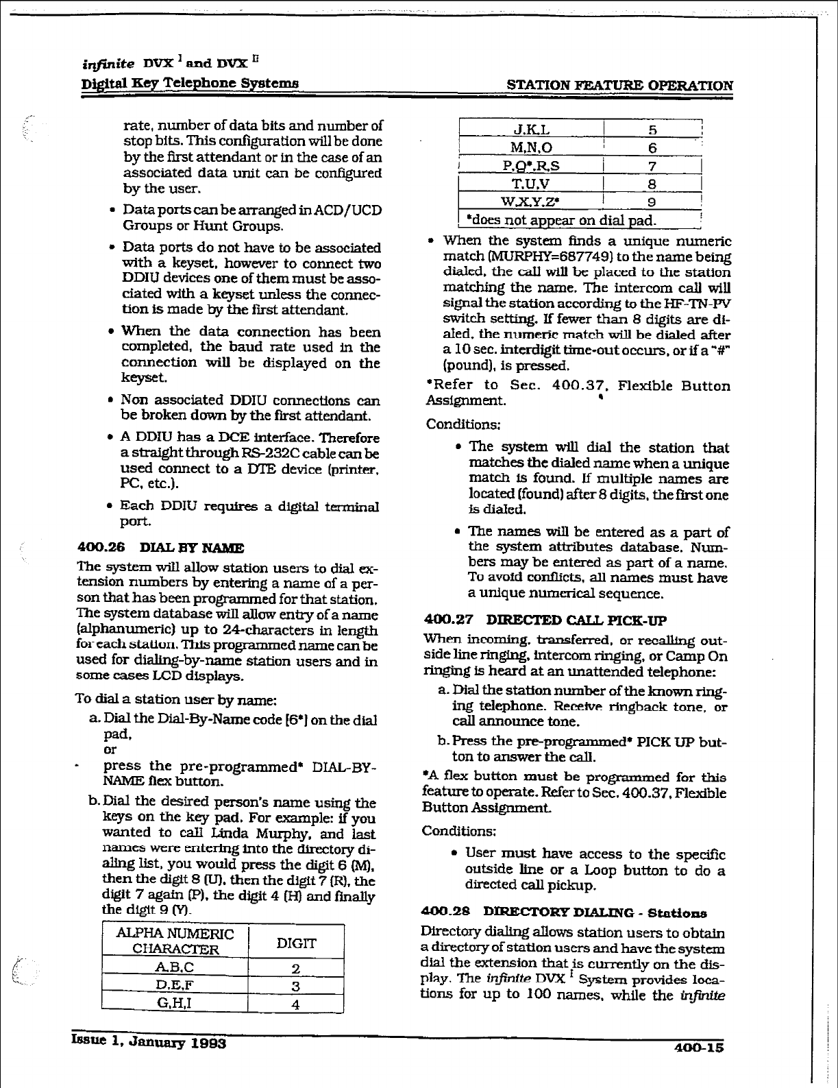
r
i@ite DVX ’
and DVX ’
Dfffital Key Telephone Systems
STATION BWU’URE OPERATION
rate, number of data bits and number of
stop bits. This configuration will be done
by the first attendant or in the caSe of an
associated data unit can be confiied
by the user.
l
Data ports can be arranged in ACD/UCD
Groups or Hunt Groups.
l
Data ports do not have to be associated
with a keyset. however to connect two
DDIU devices one of them must be asso-
ciated with a key& unless the connec-
tion is made by the first attendant.
l
When the data connection has been
completed, the baud rate used in the
connection will be displayed on the
keyset.
. Non associated DDIU connections can
be broken down by the Rrst attendant.
l
A DDfU has a IK!E interface. Therefore
a straight through RS-232C cable can be
used
connect to a IYIE device (printer,
PC, etc.).
l
Each
DDIU requires a digital terminsl
Port-
400.26
DIAL By NAME
The system will allow station users to dial ex-
tension numbers by entering a name of a per-
son that has been programmed for that station.
‘Ihe system database will allow entry of a name
(alphanumeric) up to 24-characters in length
for each station. This progxammed name can be
used for dialtng-by-name station users and in
some cases LCD displays.
To dial a station user by name:
a. Dial the Dial-By-Name code (6’1 on the dial
pad,
I zess the pre-programmed* DIAL-BY-
NAME flex button.
b.Dial the desired person’s name using the
keys on the key pad. For example: if you
wanted to calI Linda Murphy, and last
names were entering into the directory di-
aling list. you would press the digit 6 &I).
then the digit 8 Wl. then the digit 7 (RI, the
digit 7 again PI. the digit 4 (Hj and finally
the digit 9 (Y).
JKL I 5 i
MN.0 I 6 -:
i
P,QL.RS / 7
T.U.V
1 8 1
W.X.YZ I 9 I
*does not
appear on
dial pad. I
l
When the system finds a unique numeric
match (MURPHE687749) to the name being
dialed, the caIl will be placed to the station
matching the name. The intercom call will
signal the station according to the HF-TN-W
switch setting. if fewer than 8 digits are di-
aled. the numeric mat& will be dialed after
a 10 sec. interdigittime-out occurs, orifa’#”
(pound], is pressed.
‘Refer to Sec. 400.37. Flexible Button
ASS@lIIlUlt.
.
Conditions:
. The system will dial the station that
matches the dialed name when a unique
match is found. If multiple names are
located (found) after 8 digits, the first one
is dialed.
. Thenameswillbeenteredasapartof
the system attributes database. Num-
bers may be entered as part of a name.
To avoid conflicts, all names must have
a unique numerical sequence.
MO.27
D IRECTED GAIL PICK-UP
When incoming. transferred. or rec&ing out-
side line ringing, intercom ringing, or Camp On
ringing is heard at an unattended telephone:
a. Dial the station number of the known ring-
ing telephone. Receive ringback tone, or
call announce tone.
b. Press the pre-programmed* PICK UP but-
ton to answer the call.
*A flex button must be programmed for this
feature to operate. Refer to Sec. 400.37. Flexible
Button AssigmnenL
Conditions:
l
User must have access to the specific
outside line or a Loop button to do a
directed call pickup.
400.28
DIREcTG Kp DIALING - Statfons
Directory dialing allows station users to obtain
a directory of station users and have the system
dial the extension that is currently on the dis-
play. The @.@-r0?e DVX ’ System provides loea-
tions for up to 100 names. while the i.r$dk
I.szmc 1, January 1993
400-W
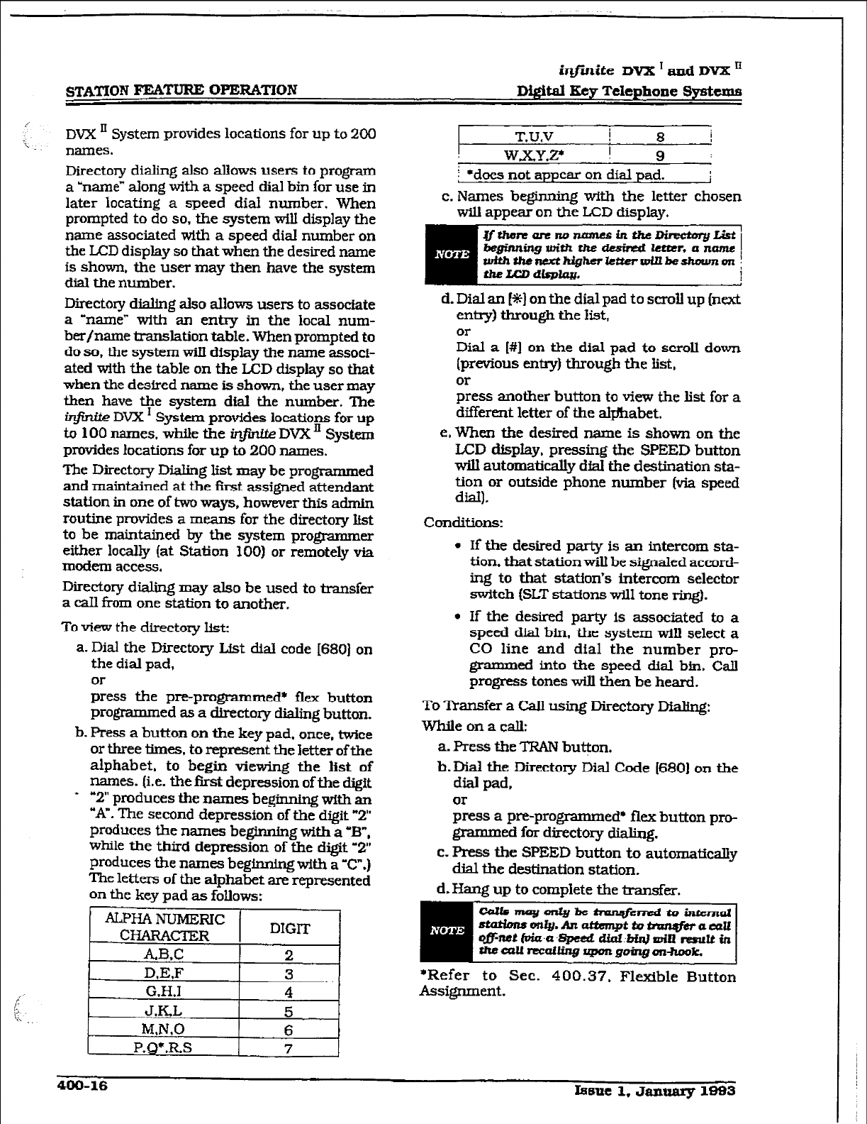
iqjlnite DVX I and DVX '
Digital Key Telephone Sy&c.ms
DW II System provides
loCatiOnS
for up to 2OCl
names.
Directory dialing also
allows
users to
program
a ‘name” along with a speed dial bin for use in
later locating a speed dial number. When
prompted to do so. the system will display the
name associated with a speed dial number on
the LCD display so that when the desired name
is shown, the user may then have the system
dial the number.
Directory dialing also aIlows users to associate
a Ynamec with an entry in the local num-
ber/name translation table. When prompted to
do so, the system wiII display the name associ-
ated with the table on the LCD display so
that
when the desired name is shown, the user may
then have the system dial the number. The
ir@.W DVX I System provkks locations for up
to 100 names. while the inftzrte
DVX ’ System
provides locations for up to 200 names.
The Directory DiaIing list may be programmed
and maintained at the f&t assigned attendant
station in one of two ways, however this admin
routine provides a means for the directory list
to be maintained by the system programmer
either locally (at Station 300) or remotely via
modem access.
Directory dialing may also be used to transfer
a caIl from one station
to another.
To view the
directory list:
a. Dial the Directory List dial code [680) on
the dial pad,
Ol-
press the pre-progrxmmed* flex button
programmed as a directory dialing button.
b. Press a button
on
the key pad, once, twice
or three times,
to
represent
the letter
of the
alphabet, to begin viewing the
list
of
names. (i.e. the f%st depression of the digit
+ “2” produces the names beginning with an
“A”. The second depression of the digit “2”
produces the names beginning with a -B”,
while the
third
depression of the digit ‘2”
produces the names beginning wkh a “C”.)
The letters of the alphabet are represented
on the key pad as follows:
ALPHANUMERIC!
CHARACI’ER DIGIT
ABX
2
D&F
3
G.H.1 4
J.KL 5
M,N,O 6
P,Q)*.RS
7
T.U.V I
8 i
W.x.YZ ! 9 :
I *does not appear on dial pad. i
c. Names beginning with the letter chosen
will appear on the LCD display.
Jfthmtarerw zaam?siltthe~ I
7
beginning with th.e desired letter. a name
with~RetthigherkttcrwinbesJwnm~
t&LCD
dlplq
d.
Dial an [*I on the dial pad to scroll up ~next
entry) through the list,
or
Dial a [#I on the dial pad to scroll down
(previous entry) through the list,
or
press another button to view the list for a
different letter of the s&&abet.
e.When the desired name is shown on the
LCD dispIay, pressing the SPEED button
will automatically dial the destination sta-
tion or outside phone number (via speed
dial).
Conditions:
l
If the desired party is an intercom sta-
tion.
that
station will be signaled acmrd-
ing to that station’s intercom selector
switch (SLT stations WilI tone ring).
l
If the desired party is associated to a
speed dial bin, the system will select a
CO line and dial the number pro-
grammed into the speed dial bin. Call
progress tones will then be heard.
To Transfer a Call using Directory IXalfng:
Whileonacalk
a. Press the TRAN button.
b.Dial the Directory &I Code (6801 on the
dial pad,
or
press a pre-programmed+ flex button pro-
grammed for directory dialing.
c. Press the SPEED button to automaticaky
dial the destination station.
d. Hang up to complete the transfer.
-J~moyonty~ tlvz+mdtoinLernal
stattrnso9aIy.Andiwpttvtnrn@brawU
QJyML ti6aaglx2td cud.-MnJ am reouu in
thealullxai~~goingoltheok.
*Refer to Sec. 400.37, Flexible Button
Assignment.
400-16 &ume 1, Jaymary 1883
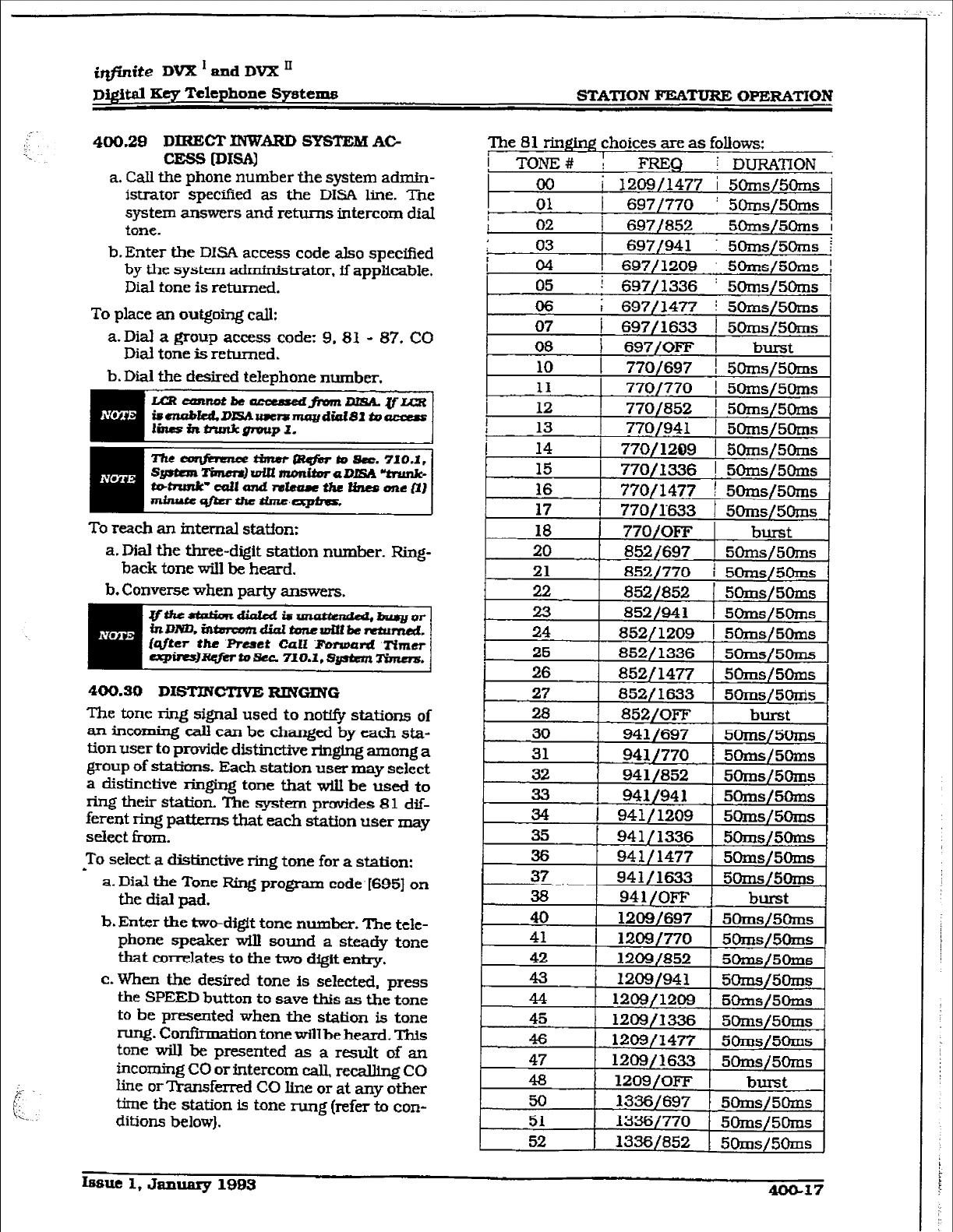
&finite DVX’undDVX’
~i@tal Key Telephone Systems STATION FEATURE OPERATION
400.29
DIRECT XNWARD SYSTxcM AC-
CESS [DISAI
a. Call the phone number the system admk-
istrator specifkd as the DISA line. The
system answers and returns intercom dial
tone.
b. Enter the DISA access code also specified
by the system administrator, if applimble.
Dial tone is
returned.
To place an outgoing call:
a. Dial a group access code: 9. 82 - 87, CO
Diat tone is returned.
b. Dial the desired telephone
number.
JxucanRDthe -fram=uL[=R
hnablaLDIZWwe~mnydiaiSlto-
linBininmkg?vupl.
To reach an internal statfon:
a. Dial the three-digit station number. Ring-
back tone will be heard.
b. Converse when party answers.
4430.30 DISTJNCTiVE RINGING
The tone ring signal used to not@ stations
of
an incoming call can be changed by each sta-
tion
user to provide dM.incttve ringing
among a
group of stations. Each station user may select
a distinctive ringing tone that will
be used to
ring their station. The system provides 81 dif-
ferent ring patkms that each station user may
select from.
To select a distinctive ring tone for a station:
h a. Dial the Tone Ring program code. [695] on
the dial pad.
b.
Enter the two-digit tone number. The tele-
phone speaker will sound a steady tone
that correlates to the two digit entry.
c. When the desired tone is selected, press
the SPEED button to save this as the tone
to be
presented
when the station is tone
rung. Confirmation tone wiU
be heard. This
tone will be presented as a result of an
incoming CO or intercom call, recalling CO
line or Transferred CO line or at any other
time the station is tone rung (refer to con-
ditions below).
The 81 ringtng
choices are as follows:
I TONE# : FRJ3Q i DURATION
I 00 i 120!3/1477 i 5Orns/50ms
01 I 697/770 ! 50rns/5oms
Ifislle 1, &l.nuary 1993 4oGl7
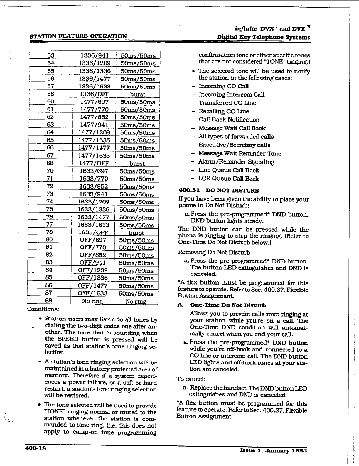
r
STATION FEA’XPRE OPER4TION
infinite DVX ’ and
DVX ’
Digit4 Kq Telephone Systems
Conditions:
l
Station users may listen to alI tones by
dialing the two-digft codes one after an-
other. The tone that is sounding when
the SPEED button is pressed will be
saved as that station’s tone ringing se-
lection.
l
A station’s tone rhxging selection will be
maintained in a battery protected area of
memory. Therefore if a system experi-
ences a power fa&xe, or a soft or hard
restart, a station’s tone ringing selection
will be restored.
l
The tone selected will be used to provide
TONE” ringfng normal or muted to the
station whenever the staffon is com-
manded to tone ring. (i.e. this does not
apply to camp-on tone programming
conf&mation tone or other specific tones
that are not considered YKXVE” ringirig.]
l
The selected tone will be used to notify
the station in the following cases:
- Incoming CO Call
- Incoming Intercom Call
- Transferred CO Line
- Re&GngCOLine
- Call Back Notification
- Message Wait Call Back
- All types of forwarded calls
- Executive/Secretary calls
- Message Wait Reminder Tone
- Ala.tm/Reminder Signaling
- Line Queue Call Back
- LCR Queue Call Back
400.31 DO NOT DkJRB
If you have been given the ability to place your
phone in Do Not Disturb:
a. Press the pm.-programmed* DND button.
DND button lights steady.
The DND button can be pressed while the
phone is ringing to stop the ringing. (Refer to
One-Time Do Not Disturb below.)
Removing Do Not Disturb
a. F?ress the pre-promed* DND button.
The button LED extinguishes and DND is
canceled.
*A flex button must be progkxnmed for this
feature to operate. Refer to Sec. 400.37, Flexible
Button Assignment
A. One-Time Do Not Disturb
Allows you to prevkt calls from ringing at
your station while you’re on a call. The
One-Time DND condition will automat-
ically cancel when you end your call.
aPress the pre-promed* DND button
while you’re off-hook and connected to a
CO line or intercom call. The DND button
LED lights and off-hook tones at your sta-
tion are canceled.
To cancel:
a. Replace the handset The DND button LED
exkinguishes and DND is canceled.
*A flex button must be programmed for this
feature to operate. Refer to Sec. 400.37, Flexible
Button Assignment
irlfSnite
DVX’andDVXn
~j.@taI Key Telephone Systema STATION FEATURE OPERATION
466.32 EXCLUSIVE
HOLD
When a line is placed on Exclusive Hold. no
otherstationfnthesystemmnretrievethiscall.
Exclusive Hold may be programmed to be acti-
vated on the fist or second depression of the
Hold button. CO Lines while in a transfer hold
are always placed in an Exclusive Hold condi-
tion.
400.33 EXECUTIVE
OVERRIDE
Allows stations designated as “Executive” the
ability to override and ‘barge in” on other
keysets engaged in conversation.
lfyoucallabusy
station:
a.Pres.5 the pre-progrzunmed’ EXECUTIVE
OVERRIDE button. Executive station will
be bridged onto the CO line conversation
in progress at the calted station. Optional
wamjng tone is heard and presented to all
parties prior to cut-thru.
b.Replace handset at Executfve station to
terminatethe
override.
Condftions:
0 An error tone will occurs
- if the called party is in a conference.
- if the called party is already on an OHVO
call.
- tithe called party has a Camp-On at his
station
l
If the Executive joins a call and
one
of
the members does a hook-flash or de-
presses his transfer button, the Execu-
tive wiU be dropped.
l
If the Executtve does a hook-flash or
depresses his &ansfer button, it will be
ignored.
l
When the Executfve jumps in on an in-
- tercom call or CO call and the Executive
is not in amute condition, and anymem-
berofthepa.rtyhangsup,tbecallwillbe
converted to a two-party conversation.
l
When the Executive jumps in on an in-
tercom call or CO call and the Executive
is in the mute condition and
either
of the
two parties in the intercom call hang up,
the call will be dropped. Ifthe Executive
hangsup,tbeeallwillremainasatwo-
party conversation.
‘A Flex button must be progmmmed for this
feature to operate. Refer to Sec. 400.37. Flexible
Button Assignment.
piGiG- ..
USE OF THIS FEATURE WHEh’ THE
EXECllTIVE OVERRIDE WARNING
TONE IS DISABLED MAY BE INTER-
PRETED AS A VIOLATION OF FED-
Em OR STATE LAWS, AND AN
INVASION OF PFUVACY. CONSULT
COUNSELWllX RESPECTTO APPLI-
CABLE
MWS
BEFORE INTRUDING
ON CALLS USING THIS FEATURE.
400.34 ExE-/ymY TRANS-
FER
l
If you are designated the Executive station
and your phone is busy
or in
DND. all calls
will be routed to the Secre&y station.
l
If you are the designated Secretary station.
you can signal the Executive that is busy or
in DND by
using the
Camp On feature.
400.35 FUSH
When connected to an outside he:
a. Press FLASH button to disconnect outside
line and
re-seize
outside line dial
tone.
400.96 FLASH ON INTERCOM
When connected
to a page
zone
or another
internal
party. press FLASH button to discon-
nect page or intercom call. Intercom dial tone
will be heard.
406.37 FUXBLE BUTTON ASSIGNMENT
If you have buttons on your telephone which
have NOT been assigned as CO lines, Pooled
group, or Loop
buttons, you
may program them
to suit your own individual needs. There are fwe
possible functions you may +ssign to these
buttons;
l
DSS/BLF: ‘Ibis
button. when
pressed, Ml
automatically signal the assigned fntercom
station. DSS/BLF buttons a~ programmed
by the station user.
l
FBWURES: This button can be programmed
so that when pressed it Ww activate a par-
ticular feature, thus elimimi- the need for
dialing the feature code. Some features re-
cpire a flexbutton to be
programmed for
that
feature to be accessible to the station user.
Where this is the case it is so designated in
this Feature Operation Section and user
guide. Feature buttons arc programmed by
km@ 1, dammy lBB3
400-19
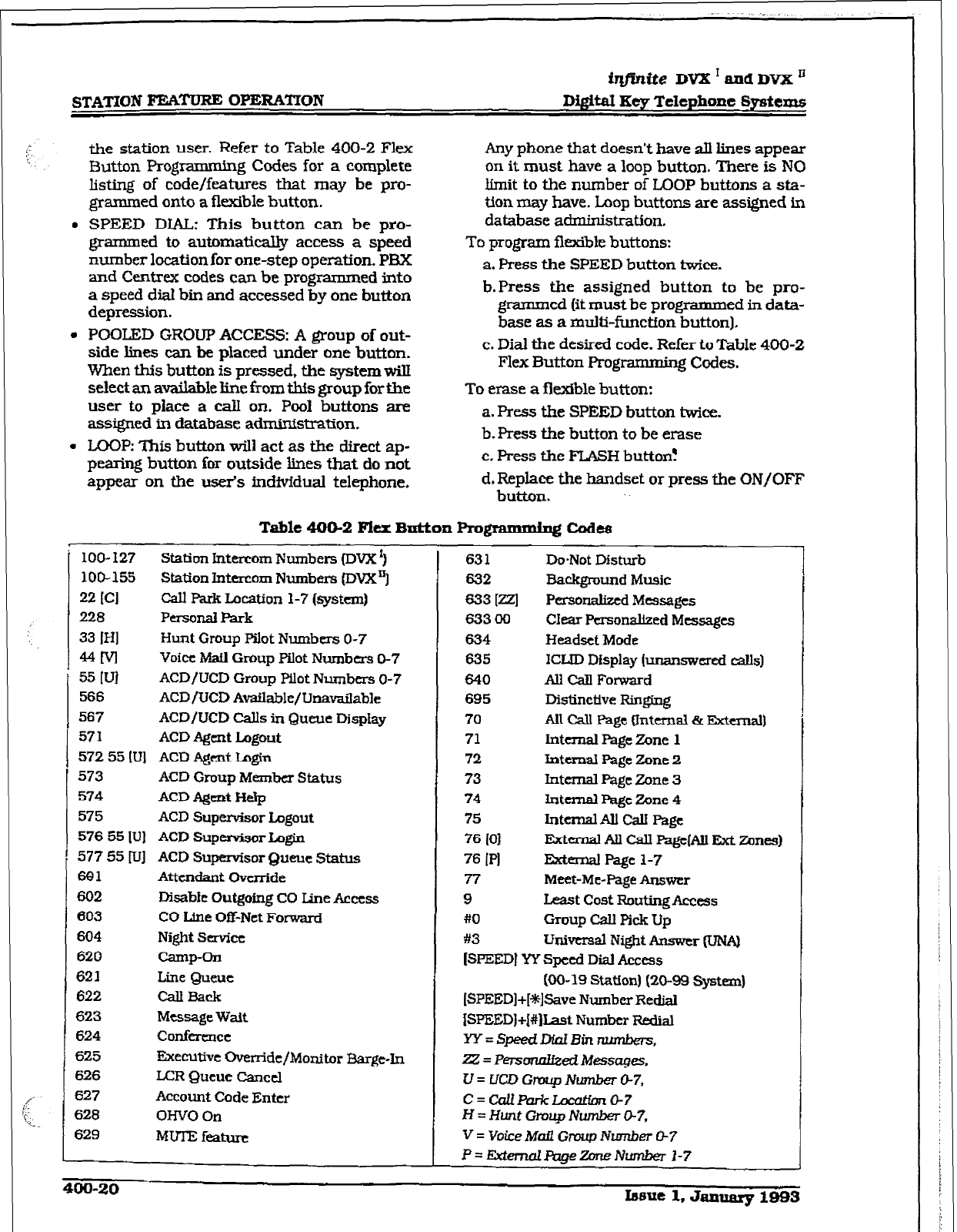
iqfinite DVX I and DVX ’
the station user. Refer to Table 400-2 Flex
Button Prog ramming Codes for a complete
Ming of code/features that may be pro-
grammed onto a flexible button.
l
SPEED DIAL: This button can be pro-
grammed to automaticaS@ access a speed
number location for one-step operation. PBX
and Centrex codes can be programs ed into
a speed dial bin and accessed by one button
depression.
l
POOLED GROUP ACCESS: A group of out-
side lines can be placed under one button.
When this button is pressed, the system will
select an available line from this group for the
user to piace a calI on. Pool buttons are
assigned in database administration.
l
LOOP: This button will act as the direct ap-
pearing button for outside lines that do not
appear on the user’s individual telephone.
Any phone that doesn’t have all lines appear
on it must have a loop button. There is NO
limit to the number of LOOP buttons a sb-
tion may have. Loop buttons are assigned in
database administration.
To program flexible buttons:
a. Press the SPEED button twice.
b.Press the assigned button to be pro-
grammed (it must be programmed in data-
base as a multi-function button).
c. Dial the desired code. Refer to Table 400-2
Flex Button Programming Codes.
To erase a flexible button:
a. Press the SPEED button twice.
b. F’ress the button to be erase
c. Press the FLASH button!
d, Replace the handset or press the ON/OFF
button.
Table 400-2 Flex B&on Rogrammipg Cod-
loo- I27
100-155
22
ICI
228
33 IHI
MM
55 WI
566
567
571
572 55 IV]
573
574
575
576 55 [UJ
577 55 [u]
691
602
603
604
620
621
622
623
624
625
626
627
628
629
Station
hterwm
Numbers (DVX’)
Station Intercom
Numbers (DWtq
Call Park Location 1-7 (systcmj
PersonalPark
Hunt Group Pilot Numbers O-7
Voice Mafl
Group
Pilot
Numbtrs O-7
ACD/UCD Group Pilot Nlunbers O-7
ACDfUCD
Available/Unavailable
ACD/UCD Calls in Queue Display
ACD A#nt Logout
ACD Agent Lu@n
ACD Group
Member
Status
ACD Agent Hi+
ACD Supervisor lagout
ACD Supehrisor Login
ACD Supervisor Queue Status
Attendant Override
Disable Outgoing CO line Access
CO Llne Off-Net Forward
Night Service
camp-on
Line Queue
CauEack
Message Wait
collfkrcncc
Executive Override/Monitor Barge-In
LCR Queue Cancel
Account Code Enter
OHVO on
MUIEfeatum
631 Do-Not Disturb
632
Background
Music
633 WI
Personalized
Messages
63300 CIear Pa-sonalked Messages
634 Headset Mode
635 ICI-ID Display (unanswered calls)
640 Au Cdl Forward
695 Distinctive Ringing
70 All cdl page fIntcn.ld ei Extema.l)
71 Internal Page
Zone
1
72 fntcmal Page Zone 2
73 Internal Page Zane 3
74 fntcmal Page Zone 4
75 Intclnal All cd Page
76
IO1 Ektcmal All Call Fag&Ml Fkt Zones)
76 IR Exkmal Page l-7
77 Meet-Me-Page Answer
9 Last cost RDutingAccess
#O Group call pick Up
#3
Universal Night hswcr (UN&
[SPEED] YY Speed Dial Access
(00-19 Statton) (20-99 Systczn)
ISPEED]+[+%lSave Number Redial
WEED]+I#Iht Number I?edial
W=Sp!?edLml3inn,
22 = Personaiized Messiqes.
U=UWGraupNumberO-7,
c=cdPtlrkLocatfon~?
H =
Hunt
Gmup Number O-7,
V = Voice
Mafl
Gnntp NLmLber 07
P=Eitem&&gezOneNwr&r1-7
4M)-20 lmue 1. Jalllxfq? 1993
1
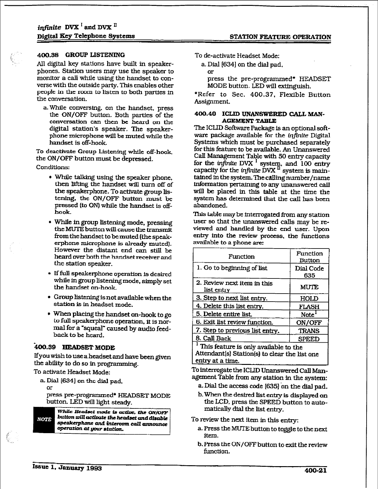
i@nite DVX I and DVB: ’
~M@al IKey Telephone Systems STATfON FEATUW% OPEBA~ON
400.38
GROUP LISTENING
All digital key stations have built in speaker-
phones. Station users may use the speaker to
monitor a calI while using the handset to con-
verse with the outside party. This enables other
people
in the
room
to listen to both
parties in
the conversation.
a.While conversing. on the handset. press
the ON/OFF button. Both parties of the
conversation can then be heard on the
digital station’s speaker. The spealcer-
phone microphone wiII be muted while the
handset is off-hook.
To deactivate Group Listening while off-hook,
the ON/OFF button must be depressed.
Conditions:
l
While talking using the speaker phone,
then Iifting the handset will turn off of
the speakerphone. To activate group Iis-
tening, the ON/OFF button must be
pressed (to ON) while the handset is off-
hook.
l
WhiIe in group listening mode, pressing
the MUTE button will cause the transmit
from the handset to bemuted [the speak-
erphone microphone is already muted).
However the distant end can stiII be
heard over both the handsetreceiver and
the station speaker.
. Iffull speakerphone operation is desired
while in group listening mode, simply set
the handset
on-hook
l
Group listening is not
available
when the
station is in headset mode.
l
when placing the handset on-hook to go
to full speakerphone operation. it is nor-
mal for a %queal” caused by audio feed-
back to be heard.
-400.39 HEADSET
MODE
Ifyouwishtouseaheadsetand havebeengiven
the abflity to do so in progmmming.
To activate Headset Mode:
a. Da [6341 on the dkl pad,
>ss pre-programmed+ HEADSET MODE
button. LED WLzl Ii&t steady.
To de-activate Headset Mode:
a. Dial 16341 on the dial pad,
$ss the pre-programmed* HEADSET
MODE button. LED will extinguish.
*Refer to Sec. 400.37, Flexible Button
Assignment.
400.40 ICLID uNAlvswERED CALLMAN-
AGEMENT TABLE
The ICIJD Software Package is an optional soft-
ware package available for the infin2e Digital
Systems which must be purchased separately
for this feature to be available. Au Unanswered
Calf Management Table with 50 eniry capacity
for the in&.&e DVX I system, and 100 entry
capacfty for the in#.r& DVX ’ system is main-
tained in the system.Tbe caIlingnumber/name
information pertaining to any unanswered caII
wilI be pkced in this table at the time the
system has determined that the call has been
abandoned.
This table may be interrogated from any station
user so that the unanswered calls may be re-
viewed and handled by the end user. Upon
entry into the review process, the functions
available to a phone are:
Function Function
Button
1.
Gotobeginningoflist
To interrogate the ICIJD Unanswered Call Man-
agement ‘Fable from any station in the system:
a. Dial the access code [635) bn the dial pad.
b. When the desired list entry is displayed on
the LCD, press the SPEED button to auto-
matidly dial the hst entxy.
To review the next item in this entry:
a. Press the MUTE button to toggle to the next
item.
b. Press the ON/OFF button to &t the review
function.
Iaaue 1, January 1983
400-21
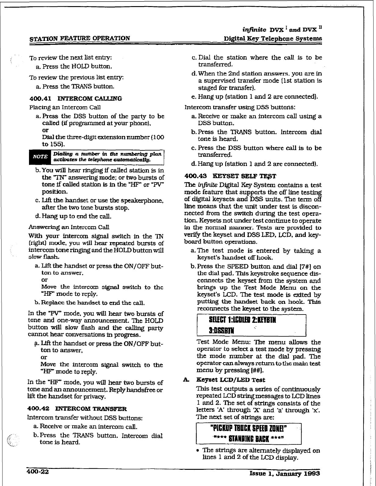
STATION FEATURE OPERATION
infinite DVX ’ and DVX ’
DigWal Key Telephone Systems
TO review the next l&t entry: c. Dial the station where the call is to be
a. Press the HOLD button. transferred.
To
review the prwious list en-
a. Press the TRANS button.
d. When the 2nd station answers, you are in
a supervised transfer mode [lst station is
staged for transfer].
400.41
RVTERCOM CALTJNG
Placing an Intercom Call
a. Press the DSS button of the party to be
called (if prograrnm ed at your phone).
& the three-digit extension number (100
to 155).
e. Hang up (station 1 and 2 are connected].
Intercom transfer using DSS buttons:
a. Receive or make an intercom calI using a
DSS button.
b.Press the TRANS button. Intercom dial
tone is heard.
c. Press the DSS button where call is to be
transferred.
d. Hang up (station 1 and 2 are connected).
b.You witi hear ringing if called station is in
the TN” answering mode; or two bursts of
tone ff called statfan is in the “HF” or “PV”
position.
c. Uft the handset or use the speakerphone,
after the i3vo tone bursts stop.
d. Iiang up to end the call.
Answering an Intercom Call
With your intercom signal switch in the TN
(right) mode, you will hear repeated bursts of
intercom tone ringing and the HOLD button wU1
slow flash.
a. Lift the handset or press the ON/OFF but-
ton to answer.
or
Move the intercom signal switch to the
‘HJ? mode to reply.
b. Replace the handset to end the call.
In the “W mode, you will hear two bursts of
tone and one-way announcement. The HOLD
button will slow flash and the calling party
cannot hear conversations in progress.
a. Lift the handset or press the ON/OFF but-
ton to answer,
Or
Move the intercom signal switch to the
“HF mode to reply.
400.43 KEY?SET SELF Tl@T
The infinite Digital Key System contains a test
mode feature that Supports the off line testing
of digital keysets and ‘DSS units. The term off
line means that the unit under test is discoa-
netted from the switch during the test opera-
tion. Keysets not under test continue to operate
in the normal manner. Tests are provided to
verify the keyset and DSS LED, LCD, and key-
board button operations.
a.The test mode is entered by taking a
keyset’s handset off hook.
b. Press the SPEED button and dial I7#] on
the dial pad. This keystroke sequence dis-
connects the keyset from the system and
brings up the Test Mode Menu on the
keyset’s LCD. The test mode is exited by
putting the handset back on hook. This
reconnects the keyset to the system.
;j
Test Mode Menu: The menu allows the
operator to select a test mode by pressing
the mode number at the dial pad. The
operator can always return to the
main test
menu by pressing I##].
In the WI?” mode. you wi.Il hear two bursts of
tone and an announcement. Replyhandsfree or
lift the handset for privacy,
MO.42 INTERCOM TRANSFER
Intercom transfer without DSS buttons:
a. Receive or make an intercom call,
b.Press the TRAM button, Intercom dial
tone is heard.
A Eeyset LCD/LED
Tc&
This test outputs a series of continuously
repeated LCD string messages to LCD lines
I and 2. The set of strings consists of the
letters ‘A’ through X and ‘a’ through ‘x’.
The next set of sirkrgs are:
l
The strings are alternately displayed on
lines 1 and 2 of the LCD display.
400-22 r8slle 1. JaIluEry 1993
iqfinite DVX’andDVKn
~jgital Key Telephone Systems STATION FEM’URK OPERATION
l
In addition, all the LEDs are flashed at
the rate of 15 IPM.
B. Keyset Button Test
1. Pressing a keyset button turns on the LED
and displays an LCD message identifying
the button number.
1
Pm m mTm.s
I +**+t** ******* I
In addition swWhing the I-TIP switch from
one position to another will cause the letter
‘HJOS”, T-POS”, or “PPOS” to be ciis-
played.
2.Pressing dial pad keys dispIays an LCD
message that indicates which digit was
pressed.
3.LEDs can be tested independent@ of the
KEYS by pressing the flex LEJD number at
thedialpad.Fore.xample,LED lOisturned
on by pressing dial Pad digits “1” “0”. As
each set of new numbers Is entered the
previously lit LED is turned off and tbenew
LED is turned on. Invalid flex values [ex
00.99) turn off currently lit LED.
C. DSS ISD/Button Test
When the DSS test is selected and a DSS
test is invoked ALL DSSs associated with
the keyset running the test are placed in
test mode.
Ifno DSS unit is associated tit the keyset,
the keyset display wilI indicate “NO DES.
The DSS LED test will cause all the LEDs
to flash at a 15 IPM rate. Once started the
DSS LED test will continue until a DSS flex
button is depressed. Pressing a DSS flex
* button turns on the flex key LED and dis-
plays an LCD message on the associated
keyset fdenfi@ng the flex button number
(01 to 48). In addition. it turns off the
previously selected flex LED.
Conditions
l
Test mode interrupts the normal opera-
tion of a keyset or DSS.
400.44 LAST NUMSER REDIAL
a. Press the SPEED button.
b-Press the pound I#] key. T’he last number
dialed over an outside line will be automat-
ic&y re-dialed.
- The system will automatically select the
original line used to place the calI and
redial the number.
- If that line is busy, the system will auto-
matically select another Line from the
same group and redial the number.
- If no lines are available in the same
group, station will receive busy tone and
can queue for a line.
- If the station user preselects a line before
activating LNR the preselection will
override the line which was used origi-
nauv-
400.45 LEAST COST ROUTING
To place an outside call when LCR has been
enabJed in the system:
a. Dial [9] on the dial pa;.
b. Dial the desired seven-digit telephone
number (Le.: 1+ area code+7-&git num-
ber).
c. Wait for an answer. Uft the handset or use
the speakerphone to converse.
If all hnes available to you are busy, remain
off-hook for four seconds to automatically be
queued onto LCR for an available line.
If an LCR Queue Callback has been activated:
a When telephone is signaled, answer the
Call.
b-Desired telephone number will automat-
idly be re-dialed.
If an LCR Queue Callback has been a-ted
and you wish to cancel that callback request:
a. Dial the LCR Queue Cancel code, 16261 on
the dial pad.
b. Replace the handset or press the ON/OFF
button.
400.46 MEET ME PAGE
To request another party to meet you on a page:
a.Dial the desired two-c&it or three-digit
pa.gQ code,
y- pre-programmed* PAGING but&n.
b. Request that party meet you on the page.
c. Do not hang up: wait for the requested
parSto ansWer.Assoonasthepagedparty
answers and is connected to you, the page
circuit is released.
~asue 1, January
1993
400-23
infinite DVX ’ and DVX ’
Digital Key Telephone Systems
hswering a Meet Me Page
a. Go to the nearest telephone and dial 1771
on the dial pad,
Eess the pm-programmed* MEET ME
PAGE ANSWER button. You will be con-
nected to the party that paged you.
*Refer to Sec. 400.37. Flexible Button
Assignment.
400.47 IlEES%GE WAlTING
Leaving a Message Waiting Indication:
If you dial a station that is busy, unattended,
or in DND, you can leave a message waiting
indication.
a. Dial the Message Waiting Code I6231 on the
dial pad,
Eea.s the MSG button. Called party’s MSG
button wiIl siow flash.
b. Replace the handset to end the call,
Answering a Message Waiting Indication
If your MSG button is flashing at a slow rate,
you have a message waiting for you. The i%rst
message left will be the tit one c&ed.
a. Press flashing MSG button. Station that
Ieftmessagewill be signaled with tone ring-
ing*
b. If called station does not answer, press
MSG button once to leave message.
400.48 MUTEKEY
The MUTE button provides privacy during
speakerphone or handset operation by dis-
abling the microphone.
a. Press the MUTE button while off-hook on
- speakerphone or handset to activate,
b. Press the MUTE button again to deactivate,
The mute feature automatically deacttvates
upon call tertmnation.
400.48 NIGHT SERVICE FEATURE
The Night Service feature will provide a means
to put the system in night mode ffrom any keyset
or remove the system from night mode from any
keyset as long as the system was put in night
mode by the Night Service feature flex button.
If the system was placed in night mode by the
attendant using her Night Sentice (DND) button
or ifthe systemwas placed in night mode bythe
automatic schedule, the Night Service flex but-
ton can not remove the system from night
mode.
From an idle station:
a Dial the Night Service feature code [604] on
the dial pad.
or
Press the pre-programmed* Night Service
flex button. The system is now in the Night
Service Mode.
To remove the Night Sewice Mode:
b. Dial the Night Service feature code 16041 on
the did pad again,
or
Press the pre-programmed’ Night Service
flex button again. The system is now re-
moved fkom the Night Service Mode.
400.50 OFF-EXKIK PREF&ENCE
If your phone has been programmed for 0ff-
Hook Preference, you will access an outside
line, or a feature by going off-hook or pressing
the ON/OFF button.
While OfHIook Preference is enabled. you may
access LnternaI intercom dial tone by:
a. Pressing your pre-programmed* ICM but-
ton,
or
dial your own three-digit intercom num-
ber. (Do not lift handset or press ON/OFF
button before diaXng intercom number.)
LED lights steady and intercom dial tone
wiIl be heard.
b.You may now dial an internal station or
Feature Access code.
*Refer to Sec. 400.37, Flexible Button
Assignment.
400.61
OFF
HOOK V&E OVER (OHVO)
This feature allows users, off-hook on a call [CO
or Intercom). to receive a voice announcement
through the handset receiver without inter-
rupting the exisiing call. The V&e Over
is
muted so as not to ‘override” or ‘drown” out the
&sting conversation. The overridden party
may then respond to the calling party using
CAMP-ON procedures to talk to the calling
party or may use Silent Text Mess- to IX-
spend to the calling partyvia U3D Displays.
Placing an Off-Hook Voice Over [OHVO) call:
When an OHVO station calls a busy OHVO
station, and busy tone is received.
a. The calling OHVO station dials the OHVO
code (6283 on the dial pad,
or
presses a pre-progrred* OHVO button
400-24 Issue 1. January 1993
*tie DVX’andDvX’
D&ftal Key Telephone Systems STATION FEATURE OPERATION
I-. to initiate an OHVO announcement. The
HOLD button LED will flash at the called
l
The calling (originating] station and re-
CR-IV0 station. ceiving station (STA B) must
be
OHVO
digital terminals.
b . Both OHVO stations will receive a one-beep
warning tone. The station receiving the
OHVO call must be off-hook and in the
“HF” mode,
and then the calling OHVO
party may begin the voice announcement
to the
called
OHVO party. The called OHVO
station’s existing conversation will not be
interrupted and the voice over an-
nourxement will not “drowned” out the
existing conversation. The calling OHVO
station will not be connected
to or other-
wise be able to hear the called station’s
conversation (the connection will
only al-
low the calling station to transmit to the
called station).
ti When the dialed station responds via
Camp-On all conditions and options
available to Camp-Gn apply (refer to the
feature description for Camp-On).
l
OHVO may be used to notify the called
party of a transferred call (CO Line or
Lntercom) by announcing the call. then
releasing to complete the transfer. When
t+is occurs, the receiving station does
not need to respond to the OHVO.
11
Responding
to
an Off-HookVoice Over (OHVO):
After receiving an OHVO announcement, two
options are available to respond to the calling
Partu;
l
When a call is transferred via OHVO. the
receiving station will not receive muted
ringing after the transfer is complete.
l
Any messages including ‘CANNED”,
‘CUSTGM”, or ‘SIL?ZNTRESPONSE” text
messaging may be used to respond to an
OHVO call. The message will appear on
the calling station and called station
LCD displays.
l.The called OHVO station may respond to
the calling OHVO station by using the
Camp-On
feature. The called OHVO sta-
tion presses the flashing HOLD button to
consult with the calling station. The exist-
ing call (CO line) goes on Exclusive Hold
automatically. This method, then follows
Carnp-On procedures and operation.
2. The called station may respond to the call-
ing station by using the Silent Text MIX+
sagtng [this feature is only available to
digital key terminals, and the calling sta-
tion mustbe a dfgftal display
terminal.) The
-
c&xi OHVO station may press pre-pro-
grammed Message button to respond to the
voice over announcement without being
released from the current call, (i.e. by
pressing a flex button pre-programmed for
the message “IN MEETING”), the calling
station will receive this message on the
calling station’s LCD display.
l
If the calling station is a non-LCD term&
nal, the called station will receive error
tone when responding via text messag-
ing.
l
The called station may press a flex but-
ton programmed as a Text Message but-
ton, (633#+XXl. This flex button may
then be pressed
to
respond to the calling
station. MMF digits will not be heard by
eftber party.
i
‘k... _
Conditions
l
The station receiving the OHVO call
MUST be off-hook and in the ‘HF mode.
l
The receiving station must be pro-
grammed to allow OHVO MRS.
l
When silent messaging is used to rez-
spond to an OHVO call, the r&sting call
on the called station will not be discon-
nected. while the messages are being
sent to the caUng station.
l
The calling station of an OHVO caIl must
remain off-hook to receive silent mea-
sages. The calling station’s voice trans-
mitwill remain connected to the called
station
and
may respond verbally to the
text
messages. The OHVO
call
ends
when the calling station goes on-hmk.
l
lf the receiving station is on-hook in
speakerphone mode and a calling party
initiates OHVO. the receiving station will
receive a Camp-On warning tone and
normal Camp-On procedures are fol-
lowed.
Issue I. &muary 1993 400-25
STATION FEA’WRE OPERATION
.
iqfinite DVX’andDVX*
DigItal
Key
Telephone Systems
l
The calfed station may send (multiple
messages) and even after sending a mes-
sage, may press the Camp-On button to
talk to the calling station, Each time a
message is sent, the spksh tone will be
heard and both displays will be updated.
l
LED’s will follow Camp-On iJ3D lamping
sequences.
Each station can be programmed to allow re-
ceiving
OHVO cds as part of Station Program-
ming. Each station may be programmed for
OHVO in one of two ways, as follows:
- OHVO disaIlowed (may not receive
OH-v0 calls).
- May receive OHVO calls.
400.52 PAGIWG
If you have been given the ability to make page
armouncements:
a. Lift the handset or press the ON/OFF but-
ton.
b.lI)ze “,’ two-digit or three-digit paging
p& pre-programmed5 PAGE button.
7O=AlI Call - Internal & l3xterna.I
7 l= Internal Zone 1
72= 1ntema.I Zone 2
73= Internal Zone 3
74= Internal Zone 4
75= Internal AU CaU
76[0]= External All CaIl (AU Ext tines]
?SIZ]= External Zone
(DVX I 1-4. DVX ’ l-7)
c. Speak in normal tone of voice to deliver
message.
k reweave
.ringback
tone until
the zone
400.53 PBX/CENTREX TRANSFER
While connected to an outside line IpBX/Cen-
trex):
a.
Press the FUSH button. Receive transfer
dial tone.
b. Dial a PBX/Centrex station number.
C. Hang up to complete transfer.
400.54 PERSONAL
PARK
Each station in the system (digital terminals
and SLTs can piace a call into a personal park
looation and then later retrieve that call from
the originating station.
While connected to an outside line:
a. Press the TRANS button. The caller is put
on Exclusive Hold.
b. Dial the Personal Parklocation (2281 on the
dial pad. Confirmation tone will be heard.
Retrieving a Parked Call:
a. From the station that parked the call, dial
the Personal CalI Park Iocation code 12281
on the dial pad. Both the station and the
call wiIl receive a warning tone and then a
talk path is established between the two
parties.
Conditions: . .
l
Only one call can be parked in a Personal
Call Park location at cme time. When
dialing the personal park location and
that location is already occupied, the
initiating party receives a busy tone. The
user may then press the TRANsfer but-
ton to return to intercom dial tone to try
a system park location
l
Intercom calls and CO line calls can be
placed into the station’s personal park
location.
l
Calls parked in a personal park location
are subject to the “system” call park
recall timer.
* A call parked in a personal call park
locatfon will recall to the station that
parked the caIl when the call park recall
timer expires. The call win ring fnto this
station until the system hold timer ex-
pires. The call will then reoaIl to the
attendant(s) (at this point, the attendant
station and the initiating station arc
rh@r@. and the attendant recall timer
is initiated. When the attendant recall
timer expires. the eaU will be discon-
nected.
* A digital terminal user can program a
flexible button as a Personal CaIl Park
feature button which when pressed WIU
park the call. Call
Park
retrieval can be
performed by going off-hook, dialing the
pound [#I key. then press the pro-
grammed Personal Call Park button.
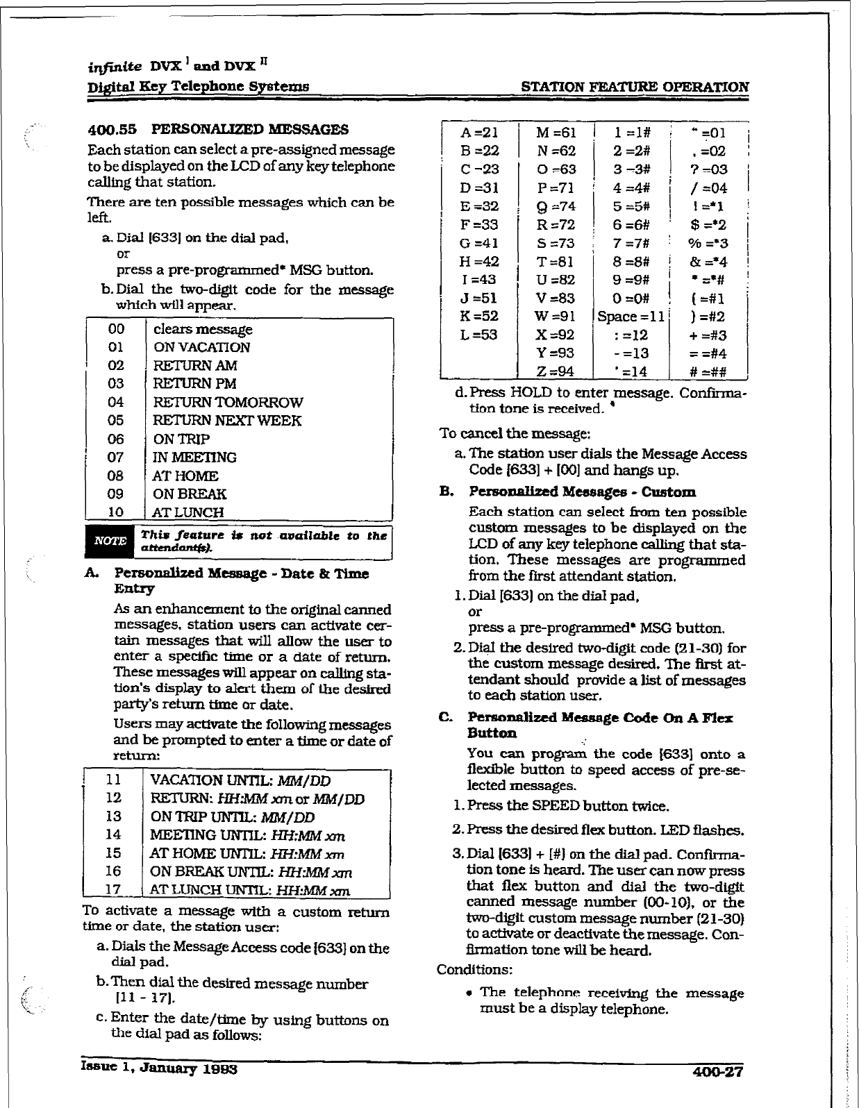
i@nLte DVX ’ and DVX J-I
D&it,aI Ecy Telephone Spsteme STATION FEATURE OPERATION
400.55
PERSONALIZED -GES
Each station can select a preassigned message
to be displayed on the LCD of any key telephone
calhg that station.
There are ten possible messages which can be
left.
a. Dial 16331 on the dial pad,
Or
press a pre-programmed* MSG button.
b.Dial the two-digit code for the meSSage
which will appear.
00
01
t
02
03
04
05
06
07
08
09
1
clears message
ON VACATION
RETURNAM
RETURNPM
RETURNTOMORROW
REruRNNExTwEER
ON TRIP
IN MElEnNG
AT HOME
ON BREAK
AT LUNCH
I
As an enhancement to the original canned
messages, station users can actiwte cer-
tain messages that xxill allow the user to
enter a spedfc time or a date of return.
These messages will appear on calling sta-
tion’s display to alert them of the de&red
par&% return time or date.
Users may activate the following messages
and be prompted to enter a time or date of
return:
I 11 VACATION UNTIL: h4M/DD
12 RETURNz I3WMM xrn or MM/DD
13
ON TRIP UNTUz
MM/DD
14
MEEnNG
UNTIL HHrMMxm
15
AT HOME UIVlE HH:MMxm
16 ONBREAKUNTIL: HZ%IiWxm
17 AT LUNCH LINT& HFI:M?vf xm
To activate a message with a custom return
time or date, the station user:
a. Dials the Message Access code {6X3] on the
dial pad.
b.Then dial the desired message number
Ill - 171.
c. Enter the date/time by using buttons on
the dial pad a~ follows:
A-21
’ M =61 I 1 =l# ( “qO1 i
B=22
IV=62 i 2=2# 1 .=02 :
c =23
D =31
E =32
F =33
G =41
H =42
I =43
J -51
K =52
L=!53
0~63 ] 3=3# ] ?=03
P =71
Q =74
: 4=4# j /=04
5=5#
I I=*1
Rs72 ; 6=6# ’ $=*2
1
s =73 i 7 =7# j o/b =*3
T=Bl
U ~82
V =83
w=91
X ~92
Y =93
Z=94
8 =8#
9 =9#
o=MI
Space =ll
: 212
- =13
’ =14
I
1
& =*4
l G#
I=#1
] =#2
+ =#3
= =#4
# =##
d.Press HOLD to enter message. Confi-
tion tone is received. ’
To cancel the message:
a. The station user dials the
Message
Access
Code (6331+ IO01 and hangs up.
B. Pe.rsonaziz;ed Mtzrsages - Custom
Each station can select fi-om ten possible
custom messages to be displayed on the
LCD of any key telephone calling that sta-
tion. These messages are programmed
from the first attendant station,
1. Dial 1633) on the dial pad,
or
press a pre-programmed* MSG button.
2. Digl the desired two-digit code (2 l-30) for
the custom message desired. ‘Ihe first at-
tendant should provide a list of messages
to each station user.
C. Ftrsonalizcd M-e
Codt
On
AFkx
Button
You c2in pqrani the code [633) onto a
flexible button to speed access of pre-se-
lected messages.
1. Press the SPEED button twice.
2. Press the desired flex button. L3ZD flashes.
3. Dial I6331 + I#] on the dial pad. ConfIrma-
tion tone is heard. The user can now press
that flex button and dial the two-digit
canned message number @O-10), or the
two-digit custom message number
(21-30)
to activate or deactivate the message. Con-
fInnation tone will be heard.
Conditions:
* The telephone receiving the message
must be a display telephone.
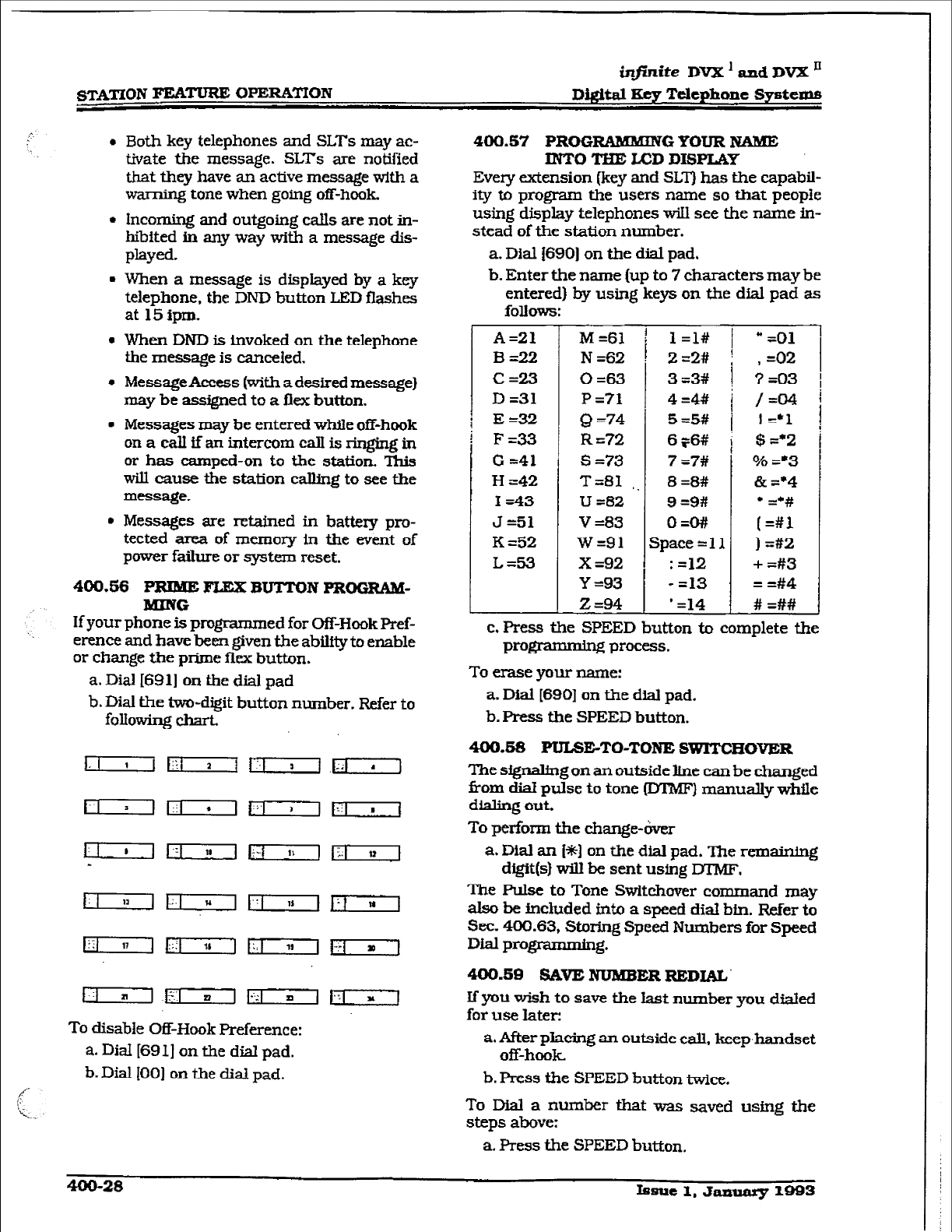
~mYI”ION =- OPERA’i’TON
infinite DV22’ and DVX ’
Digital Key Telephone Systems
l
Both
key telephones and SLTs may ac-
tivate the message. SLTs are notified
that they have an active message with a
warning tone when going off-hook,
l
Incoming and
outgoing calls are not in-
hibited in any way with a message dis-
PlaYed.
l
When a message is displayed by a key
telephone. the DND button LED flashes
at
15ipm.
l
When DND is invoked on the telephone
the message is canceled.
l
Message Access (with a
desired message)
may be assigned to a flex
button.
. Messages may be entered while
off-hook
0nacallffanintercomcalIisringingin
or has
camped-on to the station. This
will cause the station calling to see the
message.
. Messages are retained in battery pro-
tected area of memory In the event of
power failure or system reset.
400.66 PRIME FLEX BUTTON PROGRAM-
MING
If your phone is programmed for
Of&Hook Pref-
erence and have been given the ability to enable
or change the prime flex button.
a. Dial
16911 on the
dial Pad
b. Dial the two-digit button number. Refer to
following chart”
~~~Jq-y---]
To disable Off-Hook Preference:
a. Dial [691] on the dial pad.
b. Dial IO01 on the dial pad.
400.57 PROG RAMMING YOUR NAME
INTO THE LCD DISPLAY
Every
extension
[key and SLT) has the capabil-
ity to program the users name so that
people
using display telephones wiIl see the name in-
stead of the station number.
a. Dial ISSO]
on
the dial pad.
b. Enter the name [up to 7 characters may be
entered) by using keys on the
dial
pad as
follows:
A=21
B=22
C=23
D =31
E =32
F=33
G
=41
H =42
I =43
J =51
K =52
L=53
M =61
N =62
0 =63
P =?I
Q =74
R =?2
s=73
T&1
,.
U =82
v =83
w=91
X =92
Y =93
z =94
l=l# 1
“-01
Z=2# i ,=02
1
3 =3#
4 =4#
5 =5#
6r6#
7 =7#
8 =8#
9 =9#
Q=O##
space = 11
: =12
- =13
’ =14
3 =03
/=04
I =*1
$ =*2
% =‘3
& =*4
;==#‘;
) =#2
+ =#3
= 3#4
# =##
1
c. Press the SPEED button to complete the
programmbg
process.
To erase your name:
a.
Dial
[690] on the dial pad.
b. Press the SPEED button.
400.5S PULSE-TO-TONE SWM’CHOVER
The signabng
on
an outside lfne can be changed
Corn dial
pulse to tone (DTMF)
manually while
dialing out
To perform the change-over
a. Dial an I*] on the dial pad. The remaining
digit(s) will be sent using DTMF.
The Pulse to Tone Switchover command may
also be included into a speed dial bin. Refer
to
Sec. 400.63,
Storing Speed Numbers for
Speed
Dial
programming.
400.88 SAVE NUMBER REDIAL’
If you wish
to save the last number you dfalecl
for use later:
a. After placing an outside call, keep,handset
off-hook
b. Press the SPEED button twice.
To Dial a number that was saved using the
steps above:
a. Press the SPEED button.
400-213 hsue 1. JamaIy 1993
i@nite DVX’~dDVX’
~i@taI Key Telephone Systems STATION FEATURE OPERA’ITO~V
b. Dial the asterisk [*I button.
- System will automatically select the
original line used to place the call and
r&al the number.
- If that line is busy. the system will auto-
matically select another line from the
same group and redial the number.
- If no lines are avaiiable in the same
group. station wfll receive busy tone and
c3.n queue for a line.
- If the station user preselects a line before
activating SNR. the preselection will
override the line which was used origi-
n*-
400.60 PRoGRAMhaN G ~/CENTREX
CODES ONTO F= BUTTON
For easy one-button access to Centrex or PBX
features, perform the following steps:
a.Program the Centrex or PBX code into a
station or system speed dial bin, including
hook-flash (flash key], I*], and [#I com-
mands. Refer to station or system speed
dial prom.
b.Program that speed bin onto a flexible*
button.
*Refer to Sec. 400.37, Flexible 3utton
Assignment.
400,61 SPEAKER.EIONE
a.Press ON/OFF button to “ON”. Intercom
dial tone w-ill be heard.
b.F’ress the DSS button of the desired party,
or press an available outside line button
and dial number. Speakerphone is acti-
c. Press ON/OFF button to “OFF” to end the
ii
400.62
STATION
RELOCATION lVi2iTURE
The Station Relocation Feature will provide a
means to allow a user to unplug their station
and plug it in at another location. Then by
dialing a simple code followed by his old station
number, bring all the station attributes includ-
ing extension number, button mapping, speed
dfal, and class of service to the new location.
a. A station can be relocated by unplugging it
and then ph@ng it in
at a new location.
b.Dial 16361 on the dial pad. Then dial the
extension number of the station beingre-
located. Once this is done, ah station at-
tributes are copied to the current station.
mm
Conditions:
l
The station number that is dialed as the
relocated station must be currently out
of service.
l
The relocated station will be given the
station attrIbutes of the station doing the
relocating. The two stations have traded
station numbers aqd station attributes.
. If a keyset is piugged into the relocated
position it will have all the station attrib
utes of the relocating station.
l
This feature onIyis appkcable to keysets.
l
If a call is on hold at the relocating sta-
tion or the relocated station is in service,
error tone will be received.
400.63 STATION WEED DIAL
Ifno outside line has been speclfied in program-
ming, one w-ill be chosen automatically or you
can choose one now.
a. Press the SPEED button and dial bin loca-
tion.
Eess the pre-programmed* speed bin but-
ton. Station Speed numbers are 00 to 19.
b. when the called party answers. pickup the
handset or use the speakerphone to con-
verse. J
*Refer to Sec. 400.37, Flexible Dutton
Assignment.
400.64 STORING SPEED NUMBERS
Station Speed numbers can be entered
by
keyset users. System Speed numbers must be
entered by the first programmed attendant. If
no attendant is specified, enter at Station 199.
a. Press the SPEED button once.
b. Press a desired outside tie button or pool
button
or
select an outside line automat.icaIly by
pressing the SPEED button a second time.
c. Dial the speed bin location.
- 00 to 19 for Station Speed numbers:
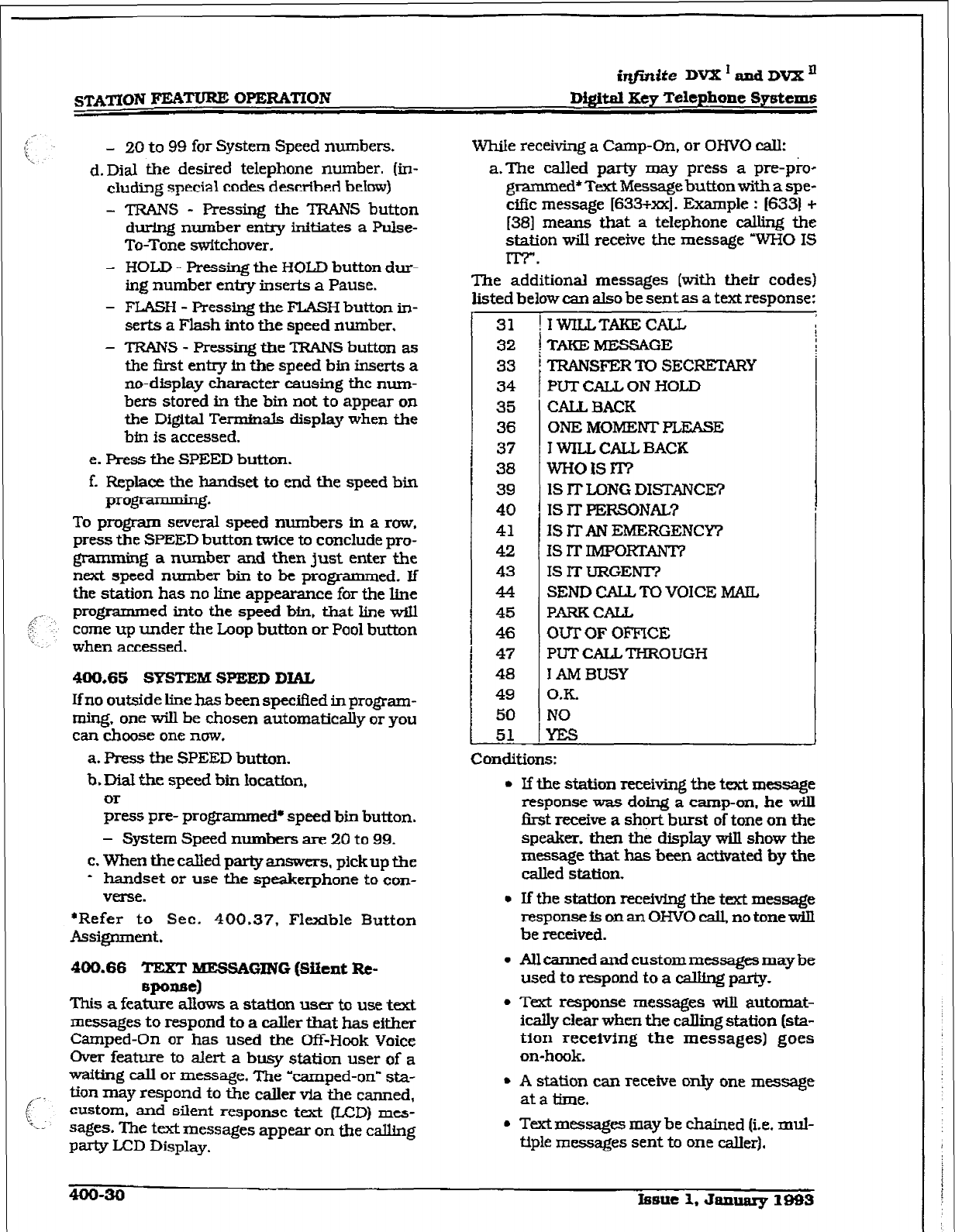
iqfmite DVX * and
DVX I1
Digrti Key Telephone Sy&ems
- 20
to 99 for System Speed numbers.
d.Dj& the desired telephone number. (in-
cluding special codes described below)
- TRANS - Pressing the TRANS button
during number entry initiates a Pulse-
To-Tone switchover.
- HOLD - Pressing the HOLD button dw-
ing number entry inserts a Pause.
- FLASH - Pressing the FLASH button in-
serts a Flash into the speed number.
- TRANS - Pressing the TRANS button as
the first entry in the speed bin inserts a
no-display character causing the num-
bers stored in the bin not to appear on
the Digital Terminals display when the
bin is accessed.
e. Press the SPEED button.
f. Replace the handset to end the speed bin
p=)gramming*
To program several
speed
numbers
In
a row,
press the SPEED button twice to conclude pro-
gramming a number
and then just
enter the
next speed number bin to be programmed. zf
the station has no line appearance for the line
programmed into the speed bin. that line will
come up under the Loop button or Pool button
when accessed.
400.65
SYSTEM SPEED DIAL
If no outside line has been spec3fied in program-
ming, one will be chosen automatically or you
can choose one now.
a. Press the SPEED button.
b. Did the speed bin location,
or
press pre- programmed8 speed
bin
button.
- System Speed numbers are 20 to 99.
c. When the called party answers, pickup tbe
- handset or use the speakerphone to con-
verse.
*Refer to Sec. 400.37, Flexible Button
Assignment.
400.66 TEXT
MESSAGING (Went Rc-
BP-4
This a feature allows a staUon user to use text
messages to respond to a caller that has either
Camped-On or has used the m-Hook Voice
Over feature to alert a busy station user of a
waiting call or message. The ‘camped-on” sta-
tian may respond to the caller via the canned,
custom, and silent
response text WD) me+
sacSes. The text messages appear on the calling
PW
LCD Display.
While receiving a Camp-On, or OHVO call:
a.The called party may press a pre-pro-
granxned* Text Message button with a spe-
cific message (633+xx]. Example : (6331 +
[3S] means that a telephone calling the
station wiIl receive the message WHO IS
ITT.
The additional messages (with their codes)
listed below can also be sent as a text response:
31
32
33
34
35
36
37
38
39
40
41
42
43
44
45
46
47
48
49
50
51
!IWILLTAKECALL
T-MESSAGE
TRANSFER TO SECRETARY
PUT CALL ON HOLD
CALL BACK
ONE MOMENTPLZASE
I WILL CALL BACK
wH01sm
IS ITLONG DISTANCE?
IS lT PERSONAL?
IS ITAN EMERGENCY?
IS IT IMPORTANT?
IS IT URGENT?
SEND CALL TO VOICE MAIL
PARKCALL
OUT OF OFFICE
PUT CALL THROUGH
I AM BUSY
O.K.
NO
Conditions:
l If the station receiving the text message
response was doing a camp-on, he will
first receive a short burst of tone on the
speaker, then the display will show the
message that has been activated by the
called station.
l
If the station reee.iving the text message
response is on an OHVO call, no tone will
be received.
l
All canned and custom messages may be
used to respond to a calling party.
l Text
response messages will automat-
ically clear when the calling station (sta-
tion receiving the messages] goes
on-hook.
l
A station can receive only one message
at a time.
l
T&messages may be chained (i.e. mul-
tiple messages sent to one caller).
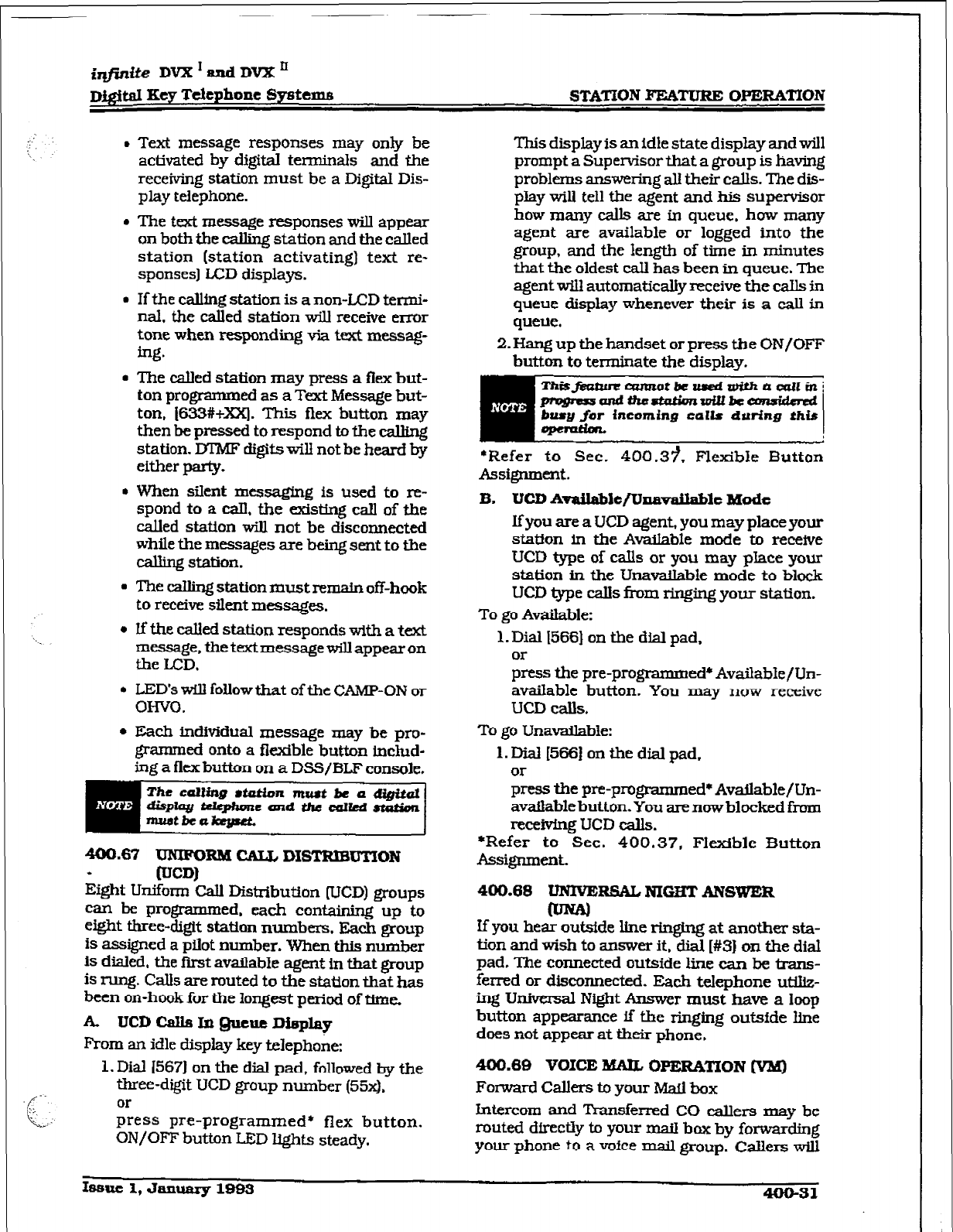
..:
‘\,.
\. .
.-.
cc
: f
-.
. :’
iqfinib DV2Z’andDVX’
~i#z.al Key Telephone Systems STATION FEATURE OPERA’IYON
4 Text message responses may only be
activated by digital terminals and the
receiving station
must be a Digital Dis-
play telephone.
4 The text message responses will appear
on both the calling station and the called
station (station activating) text re-
sponses] LCD displays.
l
If the cdlfng station is a non-LCD tetmi-
ml. the called station will receive error
tone when responding via text messag-
ing.
l
The &led station may press a flex but-
ton programmed as a Text Message but-
ton, j633#+xx). This flex button may
then be pressed to respond to the calling
station. DIM? digits will not be heard by
either party.
4 When silent messaging is used to re-
spond to a ca.U. the existbg call of the
called station will not be disconnected
while the messages are being sent to the
calling station.
4 The calling station must remain off-hook
to receive silent messages.
l
If the called station responds with a text
message, the text message will appear on
the LCD.
l
LED’s will follow that of the CAMP-ON or
OH-W.
l
Each individual message may be pro-
grammed onto a fIexIble button Lnchd-
ing a flex button on a DSS/BLF console.
400.67 UNIFOEM CfU, DISTRIBUTION
* [UCD)
Eight Uniform CalI Distribution WCD) groups
can be programmed, each containing up to
eight three-digit station numbers. Each group
is assigned a pilot number. When this number
is dialed, the first available agent in that group
is rung. Calls are routed to the station that has
been on-hook for the longest period of time.
A TJCDCdsIn@ucueDieplay
From an idle display key telephone:
1. Dial 15671 on the dial pad, followed by the
three-digit UCD group number (SW.
or
press preprogrammed* flex button.
ON/OFF button LED lights steady.
This display is an idle state display and will
prompt a Supervisor that a group is having
problems answering all their calls. The dis-
play will tell the agent and his supervisor
how many calls are in queue, how many
agent are available or logged into the
group, and the Iengtb of time in minutes
that the oldest caIl has been in queue. The
agent will automatically receive the calls in
queue display whenever their is a call in
queue.
2. Hang up the handset or press the ON/OFF
button to terminate the display.
Thisfeab-cuuwtotbcaedrrtWtaarllin~
pfvgnssaltdtfro-tpittbcw
busy for incoming calls during this
*Refer to Sec. 400.3?. Flexible Button
Assignment.
B. UCD Availa?de/Unavdable Mode
If you are a UCD agent, you may place your
station in the Available mode to receive
UCD type of calls or you may place your
station in the UnaWIable mode to block
UCD type calls from ringing your station.
To go Available:
1. Dial 15661 on the dial pad,
or
press the pre-programmed* AvailabIe/Un-
available button. You may now receive
UCD calls.
To go Unavailable:
1. Dial [566] on the dial pad,
or
press the pre-programmed* Available/Un-
available button. You are now blocked from
receivfng UCD calls.
*Refer to Sec. 400.37, Flexible Button
Assignment.
400.68 UNIVEiRSAL NIGB’T ANSWER
If you hear out&de line WI&~ at another sta-
tion and wish to answer it, dial [#3] on the dial
pad. The connected outside line can be trans-
ferred or disconnected. Each telephone utillz-
fng Universal Night Answer must have a loop
button appearance if the ringing out&de hne
does not appear at their phone,
400.69 VOICE MAIL
~PERA’MON
[vaa)
Forward Callers to your Mall box
Intercom and T’kansferred CO callers may be
routed dfrectiy to your maiI box by fomding
your phone to a voice mail group. Callers will
Issue 1, January lQB3 400-31
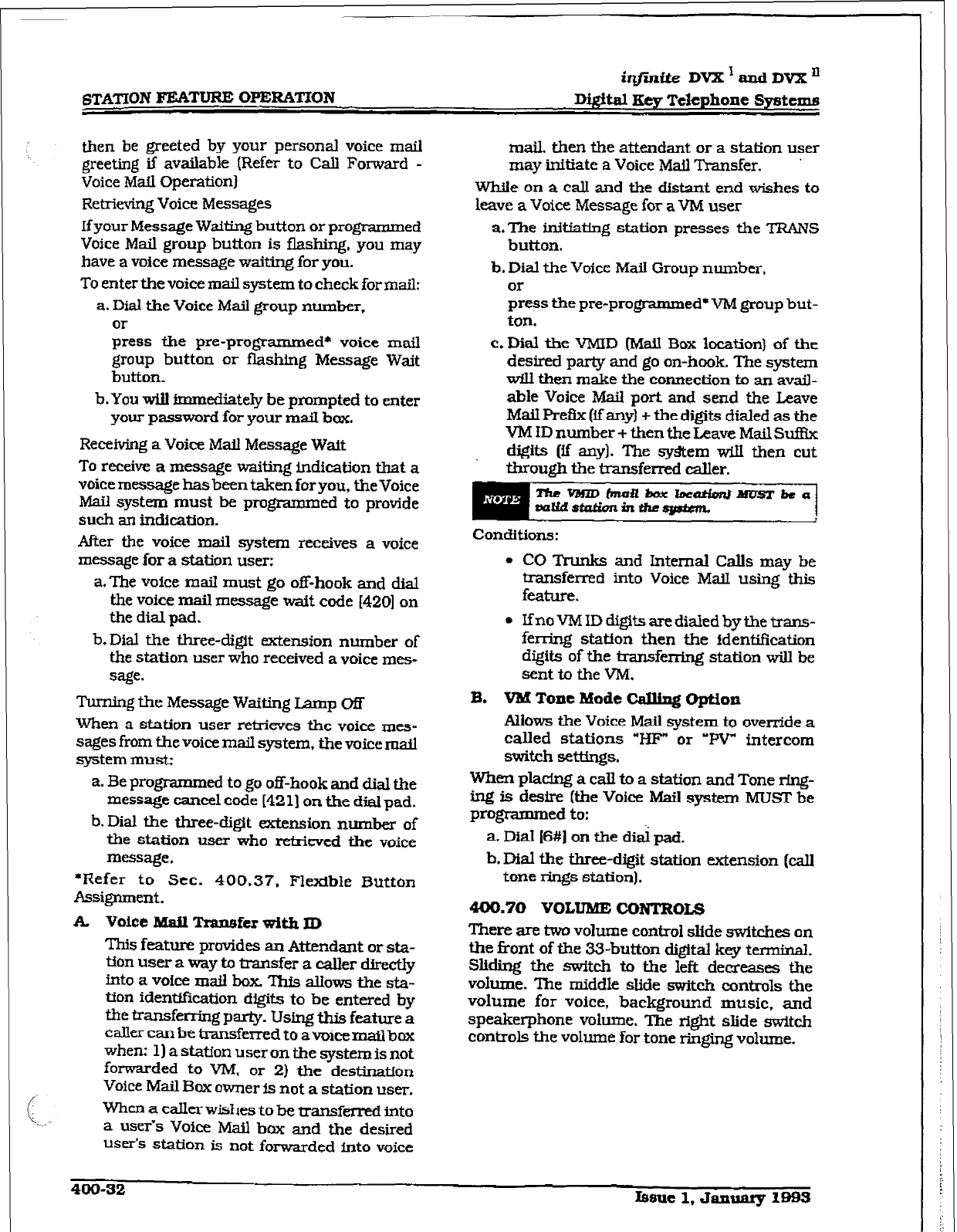
irlfinite Dvx’andDvxn
Dwtal Key Telephone Systems
then be greeted by your personal voice mail
greeting
if available (Refer
to
CalI Forward -
Voice Mail ~t?rationl
Retrieving Voice Messages
If your Message Waiting button or programmed
Voice Mail group button is flashing. you may
have a
voice
message waiting for you.
To enter the voice mail system to check formail:
a. Dial the Voice Mail group number,
or
press the pre-programmed* voice mail
group button or flashing
Message
Wait
button.
b.You will immediately be prompted to enter
your password for your maiI box.
Receiving a Voice Mail Message Wait
To receive a message waiting indication that a
voice message has been taken for you, the Voice
Mail system must be programmed to provide
such an indication.
After the voice mail system receives a voice
message for a station user:
a.The voice mail must go off-hook and dial
the voice mail message wait code I4201 on
the dial pad.
Turning the Message Waiting Lamp m
When a station user retrieves the voice mes-
sages from the voice mail system, the voice mail
system must;
b.Dial the three-digit extension number of
the station user who received a voice mes-
sage.
a. Be programmed to go off-hook and dial the
message cancel code [421] on the dial pad.
b. Dial the three-digit extension number of
the station user who retrieved the voice
message.
l Kefer to Sec. 400.37. Flexible Button
Assignment.
A Voice Mail
Trapefer
with ID
This feature provides an Attendant or sta-
tion user a way to transfer a caller dfretiy
mto a vofce mail box TI&3 allows the sta-
tfon identif?cation digits to be entered by
the tmnsfening party. Using this feature a
caller can be transferred to a voice mail box
when: 1) a station user on the system is not
forwarded to VM, or 2) the destination
Voice Mail Bcoc owner is not a station user.
When a caller wishes to be transferred into
a usefs Voice Mail box and the desired
user’s station is not forwarded into voice
mail, then the attendant or a station user
may initiate a Voice Md Transfer. ’
While on a calI and the distant end wishes to
leave a Voice Message for a VM user
a. The initiating station presses the TRAIVS
button.
b. Dial the Voice Mail Group number,
or
press the pre-programmed’ VM group but-
ton.
c. Dial the VMID (Mail Box location) of the
desired party and go on-hook. The system
will then make the connection to an avail-
able Voice Mail port and send the Leave
Mail Refix (if any) + the digits dialed as the
VM ID number + then the Leave Mail Suffix
djgits (if any). The system wiIl then cut
through the transferred caIler.
Conditions:
0 CO Trunks and Internal Calls may be
transferred into Voice Mail using this
feature.
l
Ifno VM ID digits are dialed by the trans-
fer-ring station then the identification
digits of the IransfwrLng station will be
sent to the VM.
B. VMToneModeCalhgOption
Allows the Voice Mail system to override a
called stations “H??” or ‘RV” intercom
switch settings.
When pladng a call to a station and Tone rfng-
ing is desire (the Voice Mail system MUST be
programmed to:
a Did i6#1 on the dik pad.
b. Dial the three-digit station extension (call
tone rings station).
400.70 VOLUME cONrBoU3
There are two volume control slide switches on
the front of the 33-button digital key terminal.
Sliding the switch to the left decreases the
volume. The middle slide switch controls the
volume for voice, background music, and
speakerphone volume. The right slide SwiLch
controls the volume for tone ringing volume.
400-32 mnle 1, January less
i*ite
DVX ’ and DVX ’
D@al Key Telephone Sjmtemfi S-BUTTON BXYSET FEATURE OPERATION
!;
SECTlON4Otj
&BUTTON KEYSET FEATURE OPERATION
405.1
INTRODUCMON
The infinite Digital Key Telephone System has a
wide var3ety of features and fl&ble program-
ming, allowing each telephone user to program
his/her telephone to meet his/her own individ-
ual needs.
This section of the manual contains the operat-
ing insk~~ctions for features that work differ-
ent&on the &button digital key telephone than
on the 33-button display key telephone. Also
included is an Illustration of the B-button digi-
tal key telephone used in the in&&e Digital Key
Telephone System and description of the keys
on the telephone and its functions. It is in-
tended that this section be used in conjunction
with the Station Operation section to p&de a
complete. set of fnstructions to all features in
the system. Visual and audible cues which
accompany tie various steps in the operation
of the features are also inchaded.
Literature simUar to these operating instruc-
tions has been prepared for use by the customer
intheformofan&buttonStatfonUser’sGtide.
406.2 KEY TEIJWHONB STATION FEA-
The in&& Digital Key Telephone System pro-
vides the following keys. indicators and fea-
tures on the &button dig&al terminal:
HANDSET AND SPEAKER are located at the
left side of the front panel. Ahandset is provided
to allow conbdential conversation when de-
sired. Ltfting the handset from its cradle [going
off-hook) disengages the station’s built-in
speaker.
The speaker is located directly below the center
portion of the handset. The station may be
operated wfth the handset on-hook. When this
occurs, audio is transrnwted to the station user
through the station’s speaker.
FLEXIBLE BUTTONS are used to access idle
outside lines. provide DSS/BLF for internal
stations. access speed dial number and activate
features. These buttons are programmed by the
individual station user. The default flex feature
buttons are described below:
h
i
DSS/BLZ (flex) button allows you to auto-
rnatictiy signal the assigned intercom sta-
tion. DSS/BLF buttons are programmed
by the station user. By default, flex buttons
1 and 2 are set for Stations 100 and 101.
L0OP (flex) button will act as the direct
appearing button for outside lines that do
not appear on the user’s individual tele-
phone. Any digital terminal that doesn’t
have all lines appear on it must have a loop
button. ‘There is NO limit to the number of
LOOP buttons a station may have. Loop
buttons are assigned in database admini-
stration.
POOL (fief) button &bles a group of out-
side lines to be placed under one button.
When this button is pressed, the system
will select an available line from this group
for the user to place a crib on. Pool buttons
are assigned in database administration.
FXED FEATURE BUTTONS:
WSFER [TRANS) button is used to
transfer an outside oL1 from one station to
XlOthher.
SPEED button provides you with access to
speed dialing, save number redial and last
number redial. This button is also used to
access speed dial and flex button program-
mLng.
ON/OFF button enables you to make a
telephone call without l@ing the handset
It turns the telephone on and off when
using the speakerphone.
HOLD button er@les you to place an out-
side caller on hold.
MSG IABEP indicates Message Waiting
Callback requests left at you station.
OUTSIDE CALLS are announced by a tone
signal repeated every 3.2 seconds. The corre-
sponding outside line indicator will flash
slowly.
IRTRRCOM CALLS can be tone @#ng or voice
announce If it is voice announced. the recetving
station will receive 2 bursts of tone prior to the
announcement. If it is a tone ringing calI+ the
receiving station will hear a tone ring every 2.4
seconds.
Issuel,
January
1993
405-l
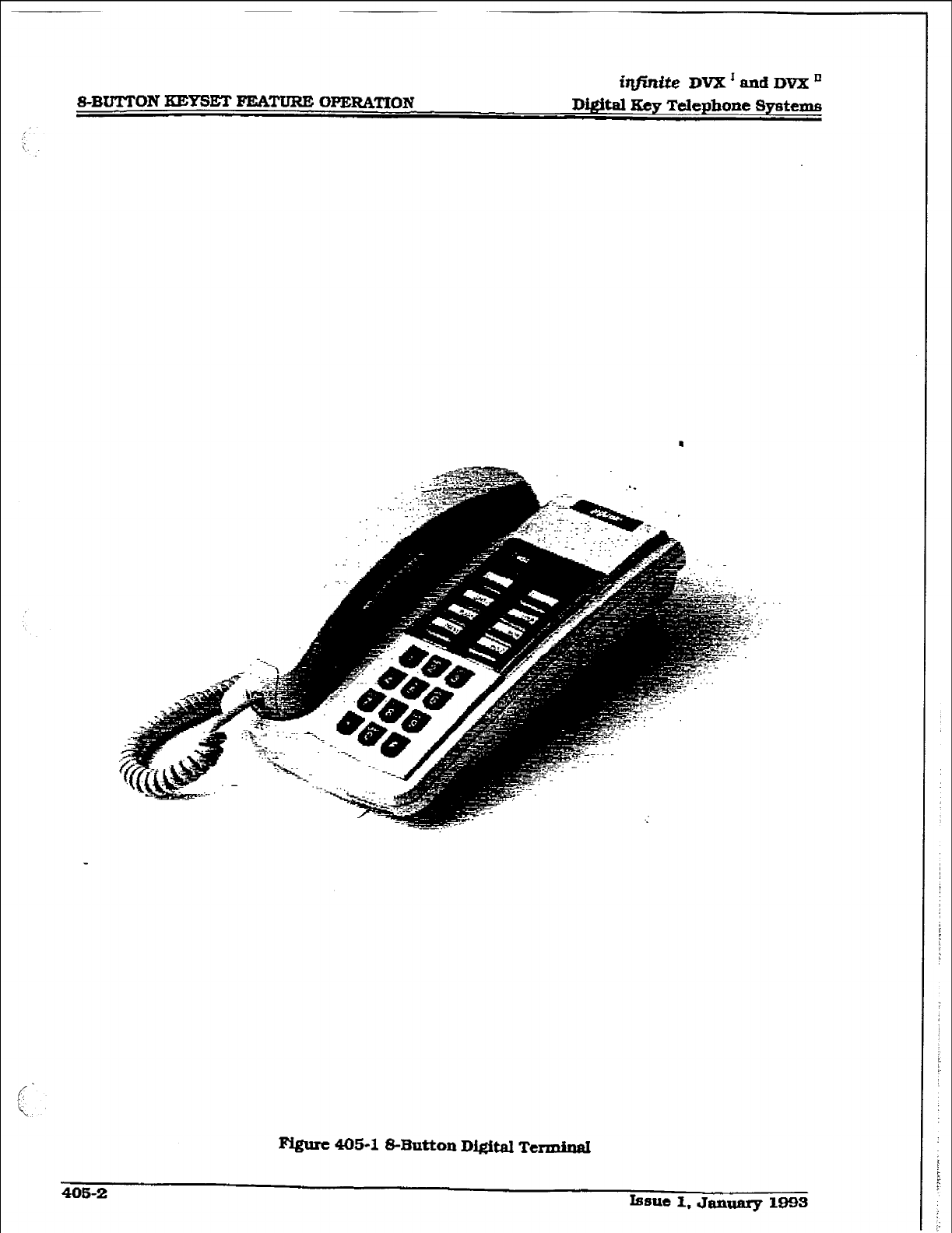
Digital Ecy Telephone Systems
Figure 405-l S-Button
Digital Termin&
us-2
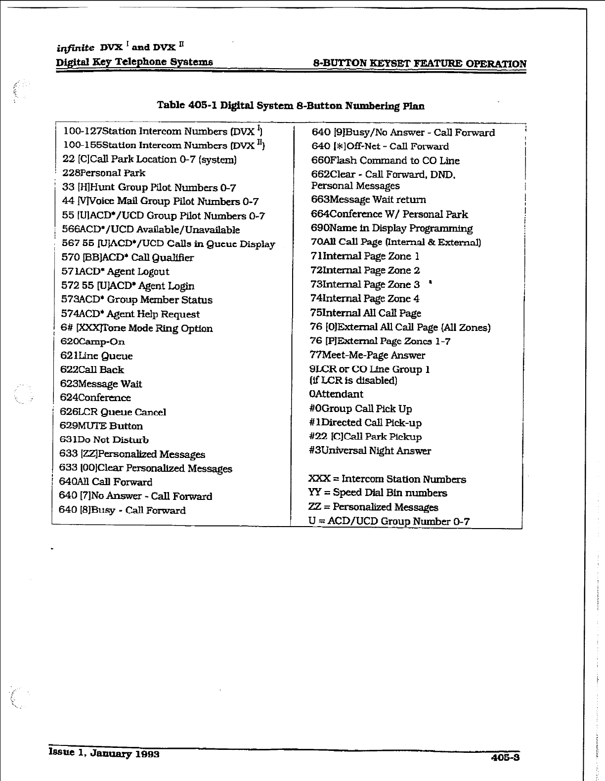
iqjlntie DVX I and
DVX ’
D&itd Key Telephone
Sy&ems
Table 405-Z
Digitnl
System 8-Button Numbering plan
i 1 OO- 127Station Intercom
Numbers DVX ‘1
100- 155Station Intercom Numbers DVX ‘)
22
[ClCalI Park Location O-7 (system)
i 228PersonaI Park
: 33 D-ID-Iunt Group Pilot Numbers O-7
4% IVlVoice Mail Group
Pilot
Numbers O-7
55 [UlACD*/UCD Group Pilot Numbers O-i’
; 566ACD’/UCD Available/Unavailable
’ 567 55 rVbCD*/UCD Calls in Queue Display
570
@BlACD’ Call Qualifier
57
lACD* Agent Logout
572 55
ILIIACD* Agent Login
573ACD* Group
Member Status
574ACD* Agent Help Request
6# IXXXJTone Mode Ring Optron
62oCamp-o~
621he Queue
622Call Back
623Message Wait
624Confermce
626LCR Queue Cancel
629MU7E
Button
63
1Do Not Disturb
633
IZZlPersonalized Messages
633 IOOlClear Personalized Messages
64oAllcanForward
640 [7lNo Answer - Call
Forward
640 I8JBusy
- Cdl Forward
840 IS]Busy/No Answer - Call Forward
640 (S]Off-Net - Call Forward
66OFlash Command to CO Line
662Clear
- Call Forward, DND.
Personal Messages
663Message Wait return
664Conference W/ Personal Park
690Name in Display Programming
7OAll Call Page (Internal & External)
7 1 Internal
Page
Zone 1
72hternal
Page Zone 2
73Internal Page Zone 3 ’
74Intemal
Page Zone 4
75lnternal &.I Call Page
76
fOJExtemd Ail Cdl Page
(All
Zones)
76
[PJExtemal Page Zones l-7
7’?Meet-Me-Page Answer
9JXR or CO Lfne Group
1
(if LCR is disabled)
OAttendant
#OGroup Call Pick Up
# 1Directed Call Pick-up
#22
1CJCa.U Park Pickup
#3Univcrsal Night Answer
Xxx = Intercom Station Numbers
YY = Speed Did Bin numbers
22 = Personalized Messages
U = ACD/UCD Group Number O-7
J
Issue 1, January 1893 4Q6-3
@in&? DVX I aad DVX ’
~.IHJTTON KEYS= F’EATUFUZ OPERATION Digital Xey T&phone Systems
405.3 AuTOmTIC CALL DISTRIW-
TION (ACDJ
The Basic ACD Software package is an optional
software package available for the infinite Digi-
tal Systems. When purchased, Uniform CalI
Distribution (vCD) is not used and is replaced
by the ACD functions identified in the following.
E&l-&Automatic Call Distribution [ACDJ groups
can be programmed, each containing up
to
eight three-digit station numbers.
A Agent Lq#n/Logout Ftaturt
The Agent I.ogin/Logout feature provides a
means for an agent to log into one of the
ACD groups and receive calls. For an agent
to be placed into an active ACD state, the
agent must first logfn. The
agent
logs in by
performing the following steps:
1. Dial the LOGIN CODE [57!2] on the dial
pad, followed hy the ACD group number
(55x)
that the agent is going
to
Iog into,
or
Press a pre-programmed’ LOGIN flex but-
ton.
2.The
age.& enters his unique AGENT ID
code KKKN3-9999). The LOGIN flex button
LED will be lit steady. Confirmation tone is
heard and the agent is Iogged anti the ACD
group. The ON/OFF LED will artlnguish if
the agent started the sequence in the
handsfree mode. When the agent logs in,
an ACD login event is sent to the ACD
SMDR port, if active.
MUi
For an agent to remwe himself from the ACD
group as an active agent:
1. Dial the LUGOUT CODE [571] on the dial
pad,
Kess a pre-programmed* LOGOUT flex
button. The LOGIN flex button U3D wilf.
extinguished. When the agent logs out and
removes himself from the ACD group, an
ACD Iogout event is sent to the ACD SMDR
port, if active.
Condftions:
l
If an agent logs into an ACD group from
a statton that is logged into another ACD
group, the station will be automatica@
m-noved hm the previous ACD
group.
l
An agent may log out while in wrap-up,
or unavailable.
9 An agent logging in will first be placed. Ln
wrap-up mode before receiving an ACD
call.
l
If an agent attempts to log into an ACD
group that already has eight members,
that agent will receive error tone.
e The i@nite Digital System wiU not verify
agent’s ID codes. other than requiring
four digits to be entered.
*Refer to Sec. 400.37, Fletible Button
Assignment.
B.
ACD
Agent
“HZLP” button
The ACD Agent ‘HELP” feature provides a
means for an ACD agent to signal his as-
signed supervisor for assistance. A flex
button must be progra&med for this fea-
ture to operate. Refer to Sec. 400.37,
Flexible Button Assfgnment.
While on a call in progress, the agent:
1. Presses his pre-programmed* “HELP” flex
button. ConfIrmatlon tone will be heard by
the agent. The agent wiU see his “HELP”
button illuminate if a supervisor is logged
into his ACD group. If no supervisor is
logged in. the agent wiIl recefve a burst of
error tone and his “HELP” button will not
illuminate.
The ACD supervisor station receives a
WELT message if a member of one of the
ACD groups he is assigned to
initiates
a
“HELP” request. The “HJZLP” function also
sends a Camp-On tone to the speaker of
the supervisors keyset. The ‘HELP” mes-
sage takes precedence over any other mes-
sage
and can be deared
by the supervisor
by pressing his “BE&P” butin.
At the time the supenrisor receives a
-HELP” request he can press his WXP”
flex button foIlowed by his override feature
button to bridge onto the ACD group mem-
bers call. The ‘HELF’” button will place an
intercom call to the station requesting
“HELP”. The ‘HELP” message will be
cleared after the supervfsor’s ‘HELP” but-
ton is depressed. In addition, the “HELP”
message will be cleared ff the
agent
was on
a call and went back on hook before the
supervisor could respond. In this case, the
“HELP” message will be converted to a mes-
sage wait indication. The agent can also
clear the ‘HEW” request by hifzting his
“HELP” button a second time.
405-4 Isme 1, January 1995
i@mite DVX I and DVX I1
D&Ml Key Telephone Systems
Conditions:
l
Up to five messages can be left at any
supervisor station.
l
The supervisor can cancel the “HELP”
request signal by depressing his flashin&
‘HELP” button.
In
addition, a call will be
placed to the agent requesting “HELP”. If
the agent is on a call, the supervisor can
press his barge-in button to monitor the
cdl or give assistance on the call,
l
The “HELP” feature access code (FA-
CODE) will permit a single line telephone
to access the WEIF feature. The SLT
after hook-flashing whiIe on a call can
dial the F’LRX CODE [574J to leave the
“HELP’ message. The SLT will be re-
turned to his call after the code is dialed.
C. ACD Call ~catiou
The CAL QUALJFICA~ON feature pro-
vides a means for an Agent to enter codes
on ACD type calls that identifies the call.
This feature provides up to four digits for
the ACD SMDR reporting function. This
feature permits up to 12 digits to be en-
tered, however only the flrst four digits are
provided for ACD reporting.
The QUALIFY button is programmed using
flex code [570#1. Ifthe agent wishes to enter
his quallfy code in a speed bin.
he can do
so using the standard speed bin program-
ming sequence. Then when he programs
his flex button, he can enter 570 followed
by the bin number. This will provide an
agent with a series of buttons with qualify
codes under them. Refer to Sec. 400.37.
Flexible Button A&gnment.
bhile on a call, the agent:
1. Presses the pm-programmed CALL QUAL.-
IFY flex button, foIlowed by the four-digit
quAUfy code. Enter a [+#I to complete the
sequence.
Condttions:
l
The outside party will not hear the (qual-
ify code) account code being entered.
l
The qualify code uses the first four di@ts
of the account code. Therefore the ac-
count code record in the SMDR will con-
tain the quali@ code in the fist four
digits.
l
The qualify code must be entered during
CO talk state.
l
A I#) can be entered in the qualify code.
however it will not be recognized
by the
ACD reporting package.
l
Speed dial entries can contain all digits
including the I%], which will terminate
the entry and return the ACD agent to
his co party.
D. ACD Amilab~c/IJnavailab~e Mode
If you are
a ACD agent, you may place your
station in the Available mode to receive
ACD type
of
calis or you may place your
station in the Unavaiiable mode to block
ACD type calls from ringing your station.
To go Available: q
1. Dial 15661 on the dial pad,
or
press the pre-programmed* AvaiJable/Un-
available button. You may now receive
ACD calls.
To go Unavailable:
1. Dial 15661 on the dial pad,
Eess the pre-programmed* Available/Un-
available button. You are nowblocked from
receiving ACD calls.
*Refer to Sec. 400.37, Flexible Button
Assignment.
405.4 CAW, FORWARD:
STATION
A CallP’ommrd-AllCalls
If you have been given the abilfty to forward
your cans:
1. Wt handset or press ON/OFF button.
2. Dial the Call For&&d code 16401 on the dial
pad.
k the pre-programmed* FWD flex but-
ton.
3. Press DSS button of desired station,
or
dial the three-digit extension number
where calls are to be forwarded, including
ACD or UCD Group, Voice Mail Group. and
Hunt group pilot numbers.
4. Replace the handset or press the ON/OFF
button.
Conditions:
m Line Queue, Call back requests, mes-
sage watt requests, and pre-selected
Issue 1, January 1995
405-5
in.ite DVX ’ and DVX ’
8%BUTTON KEYSET FEATUREZ OPERATION D#itml Key Telephone Systems
messages are canceled when a station
activates call forward.
. cdl back requests are not allowed at a
station where a call is forwarded.
l CO
Line calls can be transferred by the
receiving station back to the original for-
warded station.
l
A station in the call forward mode may
still make outgoing calls.
To Remove Call Forwarding:
1. Uft handset or press ON/OFF button.
2. Dial the CalI Forward Cancel code, I6621 on
the dial pad.
or
Press the pre-programmed* FWD flex but-
ton. Confirmation tone will be heard.
*Refer to Sec. 400.37, Flexible Button
Lkssi@meIlt.
B. CalfForward-Nohwu
if you have been given the ability to forward
your calls:
1, Lift the handset or press ON/OFF button.
2. Dial the Call Forward code [640] on the dial
pad,
or
Press the pre-programmed* FWD flex but-
ton.
3.Dial the Call Forward No-Answer code [7]
on the dial pad.
4.Dial the three-digit extension number
where calls are to be forwarded. Confii-
tion tone wfll he heard.
5. Replace the handset or press the ON/OFF
button.
To cancel Call Forwarding:
3. Lift the handset or press the ON/ OFF but-
ton.
2. Dial the Call Forward Cancel code, [662] on
the dial pad,
or
Press the pre-programmed* FWD flex but-
ton. Con&nation tone will be heard.
*Refer to Sec. 400.37, Flexible Button
Assignment.
C. CXIFCWVWY~-B~
If you have been given the ability to forward
your calls:
1. Lift the handset or press ON/OFF button.
2-Dkd
the Call Forward code, [6401 on the
dial pad.
or
Press the pre-programmed* FWD flex but-
ton.
3. Dial the Call Forward Busy code 181 on the
dial pad.
4.Dial the three-digit extension number
where calls are to be forwarded. Confirma-
tion tone will be heard.
5. Replace the handset or press the ON/OFF
button.
To cancel Call Forwarding:
1. LifI the handset or press the ON/OFT but-
ton.
2. Dial the Call Forward Cancel code, 16621 on
the dial pad.
Ls the pre-programmed* lWD flex but-
ton. Con&nation tone will be heard.
*Refer to Sec. ;QCl9.37. Flextble Button
Assignment.
D. Call
Fonvard
- Busy/No Answer
If you have been given the ability to forward
your calls:
1. L&t the handset or press ON/OFF button.
2.Dial the Call Forward code, I6401 on the
dial pad,
or
Press the pre-programmed* IWD flex but-
ton.
3.Dia.l the Call Forward Busy/No Answer
code (91 on the dial pad.
4.Dial the tlxrce-digit extension number
where calls are to be forwarded. Con&ma-
tion tone will be heard.
5. Replace the handset or press the ON/OFF
blltt0l-L
To cancel CaU Forwarding:
1. LB the handset or press the ON/OFF but-
ton.
2. Dial the Call Forward Camel code, 16621 on
the did pad.
or
Press the pre-programmed* FWD flex but-
ton. Confirmation tone will be heard.
‘Refer to Sec. 400.37, Flexible Button
Assignment.
E. Cd Fomvard - Off-Net [via speed dial)
In a speed dial bfn, store the number of the
off-net location where calls are to be forwarded.
Follow instructions provided for storing station
or system speed dial numbers.
This feature allows sbtfons to forward intercom
and transferred CO calls to an off-net location.
405-6 Issue 1, January 1993
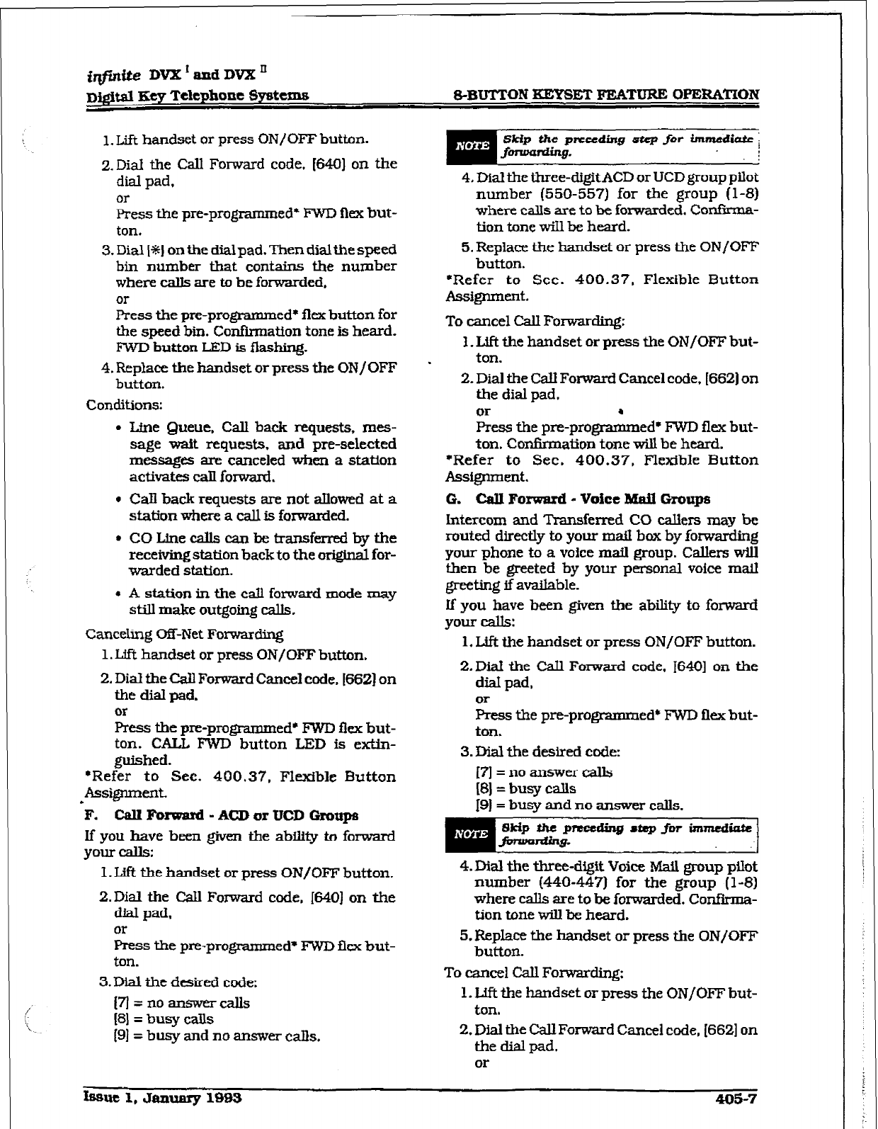
1. Lift handset or press ON/OFF button.
2.
Dial the Call Forward code. 16401 on the
dial pad,
or
press the pre-programmed’ FWD flex but-
ton.
3.Dial[%Jonthedialpad.Thendialthespeed
bin number that contains the number
where calls are to be forwarded.
or
Press the pre-programmed* flex button for
the speed bin. Confirmation tone is heard.
FWD bution LED is flashir@
4. Replace the handset or press the ON/OFF
button.
Conditions:
l
Line Queue, Call back requests, mes-
sage wait requests. and pre-selected
messages are canceled when a station
activates call forward.
l
Call back requests are not allowed at a
station where a call is forwarded.
l
COLinecaUscanbetransferredbythe
receiving station back to the original for-
warded station.
l
A station in the call forward mode may
still make outgoing calki.
Canceling C&Net Forwarding
1. LffI handset or press ON/OFF button.
2.
Dial the CaU Forward Cancel code. [66Z] on
the dial pad.
Or
Press the pre-programmed* FWD flex but-
ton. CALL FWD button LED is extin-
guished.
*Refer to Sec. 400.37, Flexible Button
l ASSi~eIlt.
F. Call Forward - ACD or UCD Groupa
If you have been given the abruty to forward
your calls:
I. Lift the handset or press ON/OFF button.
2.Dial the Call Forward code, 1640) on the
dial pad,
or
Press the pre-programmed* FWD flex but-
ton.
3.
Dial the desired code:
(il=noanswercalls
PI= busy calls
(91= busy and no answer calls.
Skip the step for
4.
Dial the three-digitACD or UCD group pilot
number (550-557) for the group (l-8)
where calls are to be forwarded. Confyma-
tion tone will be heard.
5. Replace the handset or press the ON/OFF
button.
*Refer to Sec. 400.37. Flexible Button
Assgrlment.
To cancel Call Forwarding:
3. Uft the handset or press the ON/OFF but-
ton.
2.
Dial the CalI Forward Cancel code, [662] on
the dial pad.
Eess the pre-pro&ed* FWD flex but-
ton. Con&nation tone will be heard.
*Refer to Sec. 400.37. Flexible Button
Assignment.
0. call Forward - voice Mail Groups
Intercom and Transferred CO cal3ers may be
routed directly to your mail bax by forwarding
your phone to a voice mail group. Callers will
then be greeted by your personal voice mall
greeting if ava.Uable.
If’ you have been given the ability to forward
your lxius:
1. Lift the handset or press ON/OFF button.
2.Dial the CaU Forward code, 16401 on the
diaI pad,
St’ the pre-programmed* FWD flex but-
ton.
3.
Dial the desired code:
[7]
= no answer calls
[8]
= busy calls
19]= busy and no answer calls.
4.
Dial the three-digit
Voice Matl
group pIlot
number (440-447) for the group (l-8)
where calls are to be forwarded. ConfIrma-
tion tone will be heard.
5.
Replace the handset or press the ON/OFF
button.
To cancel Call Forwarding:
1. Uft the handset or press the ON/OFF but-
ton.
2.
Dial the Call Forward Cancel code, (6621 on
the dial pad,
or
hue 1, January 1%
405-7
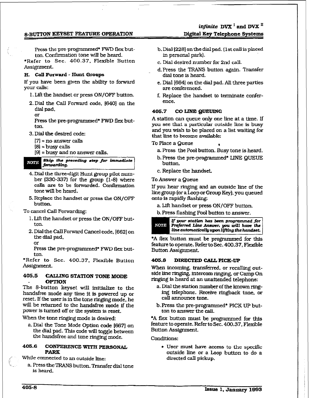
in_finite DVX I and
DVX ’
&BUTTON KEY-SET FEA’MJRE OPERATION
Di@iz3l Key Telephone Systems
Press the pre-programmed+ FWD flex but-
ton. confirmation tone wiu be heard.
*Refer to Sec. 400.37, Flexible Button
Assi&nmeilt.
H. Cdl Forward - Hunt Groups
If you have been given the ability to forward
your calls:
1. L..ift the handset or press ON/OFF button.
2. Dial the call Forward code, 16401 on the
dial pad,
or
Press the pre-programmed+ FWD flex but-
ton.
3. Dial the desired code:
[7]=noaIlswercails
[S] = busy calls
4. Dial the three-digit Hunt group pilot num-
ber (330-337) for the
group (l-8)
where
calls are to be forwarded. Confkmation
tone will be heard.
5. Replace the handset or press the ON/OFF
button.
To cancel Cdl Forwarding:
1. L,ift the handset or press the ON/OFF but-
ton.
2. Dial the Call Forward Cancel code, [662] on
the dial pad,
or
Press the pre-programmed* FWD flex but-
ton.
*Refer to Sec. 400.37, Flexible Button
Assignment.
405-b
CALLING STATION TONE MODE
OPTION
The 8-button keyset will initialize to the
handsfree mode any time it is powered up or
reset. If the user is in the tone ringing mode, he
will be returned to the hands&e mode if the
power is turned off or the system is reset.
When the tone ringing mode is desired:
a. Dial the Tone Mode Option code 16673 on
the dial pad. This code will toggle between
the handsfree and tone rhging mode.
405.6 CONFERENCE WXEI PERSONAL
PARK
While connected to an outside he:
a. Press t-beTRANS button. Transfer dfal tone
is heard.
b.Dial~228]onthedialpad.(lstcallisplaced
in personal
park].
c. Dial desired number for 2nd call.
d.Press the TRANS button again. Transfer
dial tone is heard.
e. DiaI [664] on the dial pad. All three parties
are conferenced.
f. Replace the handset to terminate confer-
ence.
405.7 CO IJNE QUEUING
A station can queue only one line at a time. If
you see that a particular outside line is busy
and you wish to
be
placed on a list waiting
for
that line to become available:
To Place a Queue .
a. Press the Pool button. Busy tone is heard.
b. Press the pre-programmed* LINE QUEUE
button.
c. Replace the
handset.
To Answer a Queue
If you hear ringing and an outside line of the
line group (or a Loop or Group Key), you queued
onto is rapidly flashing:
a. L&t handset or press ON/OFF button.
b. Press flashing Pool button to answer.
*A flex button must be programmed for this
ftaturt to operate. Refer to Sec. 400.37, Flexible
Button ~sigmnent.
405.8
DIRECTED GAIL PICK-UP
When incoming, transferred, or recalling out-
side line ringing, fntercom ringing, or Camp On
ringing is heard at an unattended telephone:
a. Dial the station numbr of the lu10wn ring-
ing telephone. Receive rfngback tone,
or
call announce tone.
b. Press the pre-programmed* PICK UP but-
ton to answer the call.
*A flex button must be programmed for this
feature to operate. Refer to Sec. 400.37. Flexible
Button Assignment.
Conditions:
l
User must have access to the spcdfc
outside line or a Loop button to do a
directed will pickup.
405-S
Issue
I, Januarp I993
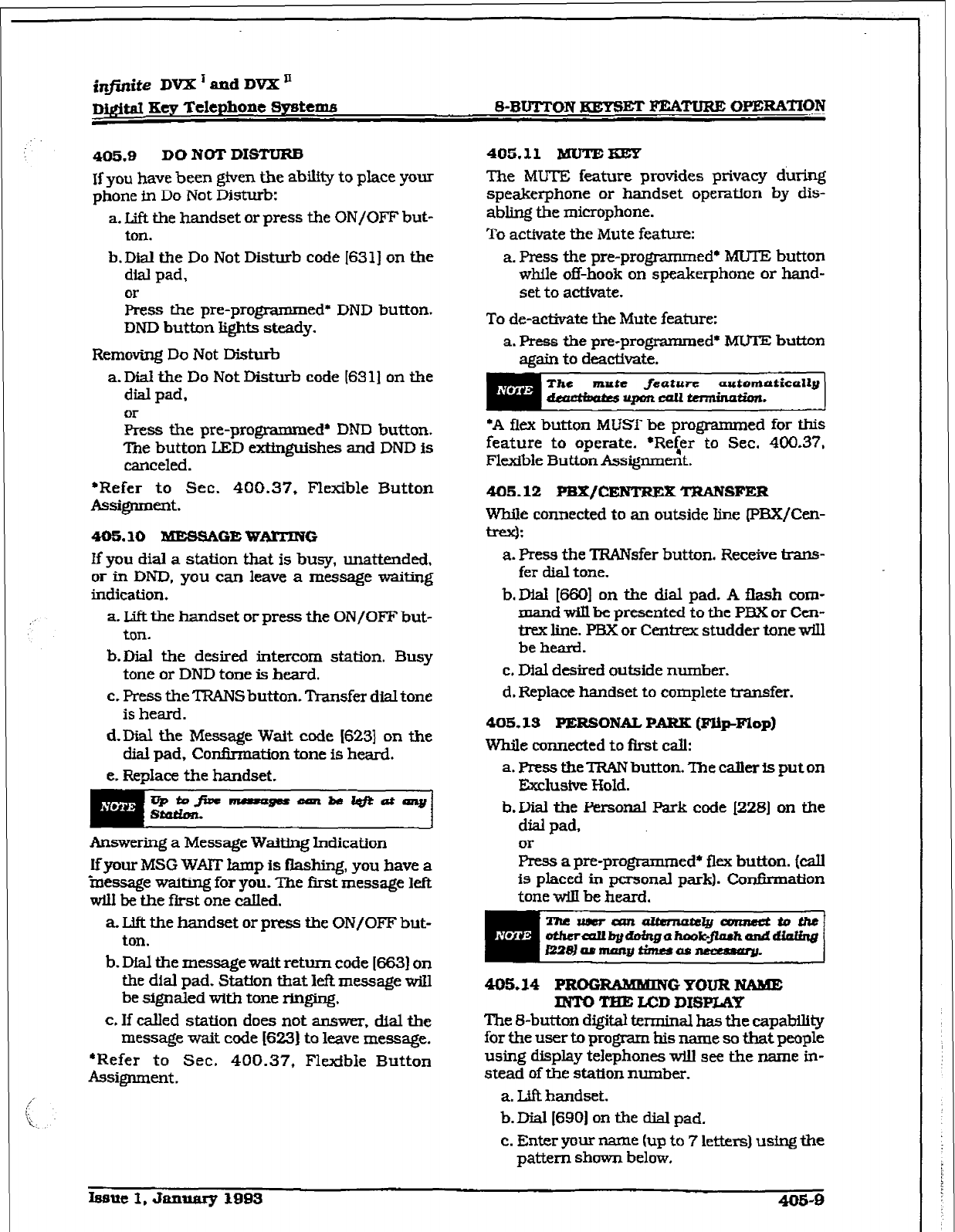
infinite DVX ’ and DVX n
-
Dfgi&d Key Telephone Systems S-BUTTON HEYSET FEATURE OPERATION
405.9 DO NOT DISTURB
If you
have been given the ability to place your
phone in Do Not Disturb:
a. Lift the handset
or press the UN/OFF but-
t0Il.
b. Dial the Do Not Disturb code I63 l] on the
dial pad,
or
hess the pre-programmed* DND button.
DND button lights steady.
Removing Do Not Disturb
a. Dial the Do Not Disturb code (6311 on the
dial pad.
or
Press the pre-programmed* DND button.
The button LED e.xtin@shes and DND is
canceled.
*Refer to Sec. 400.37, Flexible Button
Assignment.
405.10 BUES!UGE WARTNG
lf you dial a station that is busy, unattended,
or in DND, you can leave a message waiting
indication.
a. Lift the handset or press the ON/OFF but-
ton.
b.Dial the desired intercom station. Busy
tone or DND tone is heard.
c. Press the TRANS button. Transfer dial tone
is heard.
d-Dial the Message Wait code (6231 on the
dial pad, Confnmation tone is heard.
e. Replace the handset.
Answering a Message Waiting Indication
If your MSG WAIT lamp
is
flashing, you have a
‘message waiting for you. The first message left
will be the first one called.
a. Ldft the handset or press the ON/OFF but-
ton.
b. Dial the message wait return code I6631 on
the dial pad. Staffon that I& message will
be signaled with tone ringing.
c, If called station does not answer, dial the
message wait code [6231 to leave message.
*Refer to Sec. 400.37, Flexible Button
Assignment ~
405.11 MUTE-
The MUTE feature provides privacy dutig
speakerphone or handset operation by dis-
abling the microphone.
To activate the Mute feature:
a. Press the pre-progmmmed+ MU’lE button
while off-hook on speakerphone or hand-
set to act&ate.
To de-activate the Mute feature:
a. Press the pre-programmed’ MUTE button
again to deactimte.
The mnte feature auronmticoaly
d4!admwrrpbncall-*.
*A flex button MUST be programmed for this
feature to operate. *Re<er to Sec. 400.37.
Flexible Button Assignment.
405.12 P%X/CENTREX TmNsFER
z connected to an outside line (PBX/Cen-
:
a. Press the TRANsfer button. Receive trans-
fer dial tone.
b. Dial [660] on the dial pad. A flash com-
mand will be presented to the PEE or Cen-
trex line. PEK or Centrex studder tone will
be heard.
c. Dial desired outside number.
d. Replace handset to complete transfer.
405.13
PERSONAL PARK (FR~FIop)
While connected to first call:
a. PresstheTRANbutton.Thecallerisputon
Ihlusive Hold.
b.Dial the Personal &rk code (2281 on the
dial pad,
k a pre-programmed* flex button. (call
is placed in Personal park). Conflnnatton
tone wilI be heard.
405.14 PROG- GYOURNAME
MT0 TFIE U=D
DISPLAP
The S-button digital terminal has the capability
for the user to program his name so that people
using display telephones will see the name in-
stead of the station number.
a. Uft handset.
b. Dial I6901 on the disl pad.
c. Enter your name (up to 7 lettexs) using the
pattern shown below,
bmx? 1, January 1993
405-O
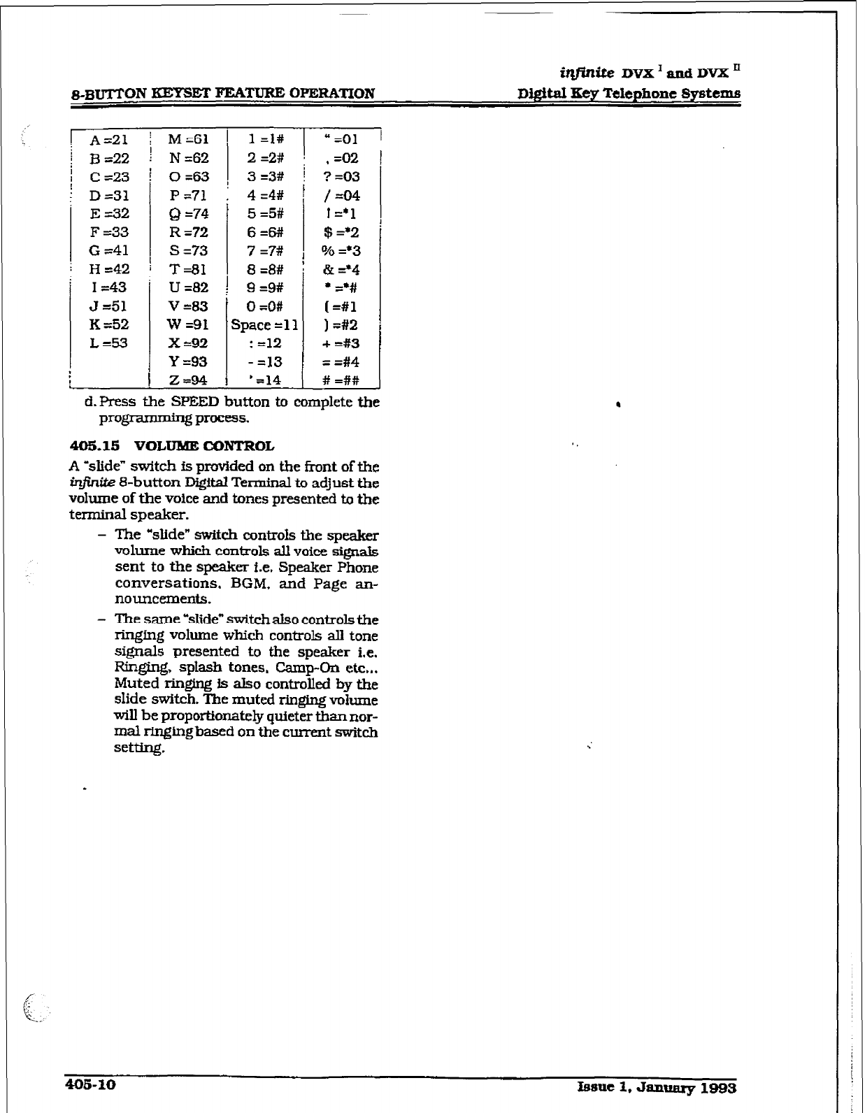
s-3uTrON
KEYSET FEAT- OPERATION
i&n&e DVX1andDVXn
D@itaI
FKey Telephone Systems
A=21 j
M=61
[ l=l# 1 “=Ol 1
33 =22 ! N&2 1 2=2# I ,=02
C =23
D=31
E=32
F =33
G 741
H =42
I =43
J =51
K =52
L=!%
!
L
L
o&3 ! 3=3# ! ?=03
P -71 1 4 =4#
!
Q =74
R =?2
s =73
T=81
u =82
v-83
W=91
x =92
Y =93
Z=94
I
!
1
-
5 =5#
6=6#!
7 =7#
8 =8#
9 =9#
0 =O#
Qace =ll
: =12
- =13
’ =14
/ =04
1=*1
$ =*2
% =*3
&=‘4
l =a#
(=#l
I=#2
+ =#3
= =#4
# =##
d. Press the SPEED button to complete the
programming process.
405.15 VOLUME CONTROL
A ‘slide” switch is provided on the front of the
infinite S-button DgitaI Terminal to adjust the
volume
of the voice and
tones presented to the
tmninat speaker.
- The “slide” switch controls the speaker
volume which conlrols alI voice signals
sent
to fhe speaker i.e.
Speaker Phone
conversations, BGM, and Page an-
nouncements.
- The same blide” switcfi aIso
controls the
ringfng volume which controls all tone
signals presented to the
speaker i.e.
Fagirlg, sptash tones. camp-OII etc.,.
Muted ringing is also controlled by the
slide switch. The muted ringing volume
will be proportionately quieter than nor-
mal ringingbased on the current switch
setting.
r
imite DVX I ad
DVX ’
D@$tal Key Telephone Systems
SLT FTXTURE OPERATION
SECTION 410
SLT FEATURE OPERATION
410.1 INTRODUCTION
This section of the manual contains the operat-
ing instnxtions for Sfngle Line users. It is de-
signed to provide step-by-step instructions for
operating the Single L3ne telephones in the
system.
Literature similar to these operating hsiruc-
tions has been prepared for use by the customer
in the form of a Single Line Teiephone User’s
Guide.
410.2 ACCOUNT CODE
SLT stations can enter an
account code to
iden-
tlfy the call or calling station.
Entering Account Code before a talk
a. Wt the handset.
b. Dial 16271 on the dial pad.
c. Dial the account code. If the account code
contains fewer than 12-digits, dial I+&] to
return to intercom dial tone. Dial tone fs
heard.
d. Dial [9] or CO Access code and the desired
number.
Entering Account Code during a call:
a. Depress the hookswitch momentarily.
Your call til be placed on hold while you
enter your account code.
b. DiaI [627j on the dial pad.
c. Dial the account code. Ifthe account code
contains fewer than X2-digits, dial [St] to
retum automatically to the call.
,410.3 AUTOMA’l’X CALLDISTIUBU-
TION &CD)
The Basic ACD Software package is an optional
software package available for the in$n&z Digi-
tal Systems. When purchased, Uniform Call
Distribution (UCD) is not used and is replaced
by the ACD functions identffied in the foIiowing.
Eight Automatic CallDistribution (AC01 groups
can be programmed, each containing up to
eight three-digit statfon numbers.
k
Agent
Lagin/Ingout Feat&
The Agent Login/Logout feature provides a
means for a.n agent to log into one of the
ACD @mps and receive calls. For an agent
to be placed into an active ACD state, the
agent must f&t logfn.
1. Dial the LOGIN CODE 15721 on the dial
pad, followed by the ACD group number
(55x)
that tbe agent is going to log into.
2.The agent enters his unique AGENT
ID
code (0000-9999). ConfFnnation tone is
heard and the agent is logged onto the ACD
group. When the agent logs in. an ACD
login event is sent
to the
ACD SMDR
port.
if active,
mm
For an agent to remove himself from the ACD
group as an active agent:
l.DiaI the LOGOUT CODE I5711 on the dial
pad. When the agent logs out and removes
himself fi-om the ACD group, an ACD lo-
gout event is sent to the ACD SMDR port,
if active.
Conditfons:
l
If an agent logs into an ACD group from
a station that is
logged
into another ACD
group, the station w-III be automatically
removed Tom the previous ACD group.
l
An agent may log out while in wrap-up,
or unavailable.
l
An agent logging in wiIl first be placed in
wrap-up mode before receiving an ACD
CaIL
l
If an agent attempts
to log
into an ACD
group that already has eight members.
that agent
will receive
error tone.
l
The in#t&eDfgltal System will not verify
agent’s ID codes, other than requiring
four digits to be entered.
B. ACD Agent “HELP” button
The
ACD Agent XELP” feature provides a
means for an ACD agent to signal his as-
signed supervisor for assistance.
Wldle on a call in progress, the agent:
I.Aft.er hook-flashing, dial the “HELP” code
on the dial pad. The agent must hook-flash
again to return to his call after the code
is
dWed. Ii no supervisor is logged in. the
agent will receive one-burst of error tone.
The ACD super&or station recetves a
Issue 1, Jammy 1993 410-l
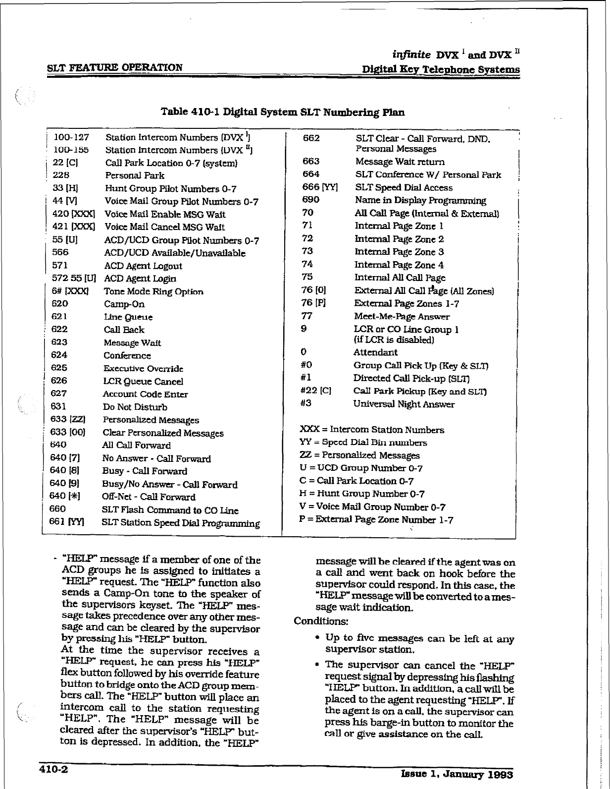
iqjinite DVX’endDVXn
lX&d Key Telephone Systems
Table 410-l Digital System SLT Numbering Plan
IOO- 127 Station Later-corn Numbers (DVX ‘I
lo&155 Station Intercom Numbers (DVX ‘1
22
ICI
call Park Location O-7
(system)
226
Personal Park
33 IHI Hunt Group Pilot Numbers 0-7
MM
Voice Mail
Group
Pilot Numbers O-7
420 m Voice Mail Enable MSG Wait
42 1 [xrorl
Voice Mail CanceI MSG
Wait
55 P.Jl
ACD/LJCD Group
Pilot Numbers O-7
566 ACD/LJCD Available/Unavaiiable
571
ACD Agent Logout
572 55 [Llj ACD Agent Login
Mm Tone Mode Ring Option
620 Camp-On
621 Line Queue
622
Cd Rack
623
Message
Waft
624 Conference
625 Executive Override
626
LCR Queue Cancel
627 Account Code Enter
631 Do Not Disturb
633 I221 Personalized Messages
633 IOO] Clear
Personalized Messages
640 AU Call Forward
640 I71
No Answer - Cdl Forward
640 I81 Busy - Cab Fowarcl
6fK’ 191
Busy/No Answer - Call Forward
640 14 Off-Net - Call Forward
660 SLT Flash Co mmandtoCOLine
sslfwl SLT Station Speed Dial Progmmrmng
- “HELP” message if a member of one of the
ACD
groups he is assigned
to initiates a
“HELP” request. The ‘HELP”
function also
sends a Camp-On
tone to the speaker of
the supervisors keyset. The ‘HELP” mes-
sage takes precedence over any other
mes-
sage and can
be cleared by the
supervisor
by pressing his “HELP button.
At tie time the
supervisor
receives a
“HELP” request, be can press his ‘HEI;p”
flex button followed by his override feature
button to bridge onto tie
ACD
group
mem-
bers call. The “HELP” button will place an
intercom call to the station requesting
“HELP”. The ‘HELP” message
will be
cleared
after the supemisor’s “HELP” but-
ton is depressed. In addition, the ‘HELP”
662
663
664
666 m
690
70
71
72
73
74
75
76 WI
76
[PI
77
9
0
#O
#1
#22 [Cl
#3
SLT Clear - call Forward. DND.
Personal Messages
Message Watt return
SLT Conference W/ Personal Park
SLT Speed Dial Access
Name in Display Programming
All Call Page Qm.mal & Extemal~
lnteraal Page Zone 1
Internal
Page Zone 2
Internal hge Zone 3
Inten-& Page Zone
4
Internal AU Cdl Page
External All Call *ge (All Zones)
memal Page Zones 1-7
Meet-Me-Page Answer
LCR or CO Line Group 1
(if LCR is disabkxl)
Atttndant
Group CalI pick
Up [Key & SIX)
Directed Call Pick-up [SLT]
CalI Park pfckup IKey and SLT]
UnWwsal Night Answer
I
XXX = Intercom Station Numbers
YY = Speed Dial
Bin numbers
Zz = PeraonaIized Messages
U = UCD
Group Number O-7
C = Call Park Location 0-7
H = Hunt Group Number O-7
V = Voice Mail
Group Number O-7
P = External Page Zone Number 1-7
..’
message will
be
cleared if’the agent was on
a call
and went
back on hook
before the
supewfsor
could
respond.
In this case, the
‘~~message~be~nvertedtoames-
sage
wait
indication.
Conditions:
l
Up to fhte messages can be left
at any
supervisor
statfon.
* The supetisor can cancel the ‘HELP”
request signal by depressfng his &shing
‘HELP” button. In addition,
a call wiLl be
placed to the
agent
requesting “HEW. If
the agent is on a call. the supervisor can
press
his barge-in button to monitor the
call or give assistance on the call.
410-2 Issue
1,
January 199s
i@nite DVX’andDKXn
Dj#tal Key Telephone Systems SLT FEATURE OPERATION
c. Skip Step c. for immediate forwarding, oth-
erwise dial the appropriate code:
[7j
= Cdl Forward No Answer
IS]= Call Forward Busy
[9f = Call Forward Busy/No Answer
[jkj = Call Forward W-Net (via speed dial)
d.Dial the three-digit extension number or
. speed bin number where calls are to be
forwarded. Confirmation tone will be
heard.
e. Replace handset.
To Remove Call Forwarding:
a. Lift handset.
b. Dial (6401 on the dial pad or [662] on the
dial pad. ConfIrtnation tone will be heard.
c. Replace the handset.
c. ACD Avaihhk/Ihundhble Mode
lfyou are a ACD agent, you may place your
station in the Available mode to receive
ACD we of calls or you may place your
station in the UnaMilable mode to block
ACD type calls from ringing your station.
To go Available:
1.
Dial I5661 on the dial pad.
Coniirmation
tone will be heard through the handset,
You may now receive ACD calls.
To go Unavailable:
1. Dial [ 5661 on the dial pad. ConfG-mation
tone will be heard through the handset
You are now blocked from receiving ACD
CEilIS.
410.4 CALL BACK
You call a busy station and receive busy:
a-Briefly depress and release the hook-
switch.
b. Dial (6221 on the dial pad.
c. Replace handset.
Ch@onefhUBackmquutcabtl@atu
stution;6he-n~wiuoorPmttD
JmsQ~waitingReqaut.
410.5 CALL FQRWARDIIYG
To call forward calls to another station:
a. I& handset.
b. Dial (6401 on the dial pad.
410.6 f2AILlNG STATJON TONE MODE
OPTION
Allows a calbng station to override
a called
key
station’s ‘HF” or ‘w” intercom switch setting.
When placing a caU to a key station and Tone
ringing is desired:
a. Dial [6#] on the dial pad.
b. Dial three-digit station extension [call tone
rings station) -
410.7 CAMP-ON
After receiving intercom busy tone:
a. Briefly depress and release the hook-
switch.
b. Dial [6261 on the dial pad. When the called
party answers. consult with them.
While on a CO line you receive a Camp-on
warning tone through handset:
a. Choose desired call (bang up on present
call and take the new one. or ignore the
Camp-on signal). (also see Personal Park)
410.8 CALL PARK [System)
To place an outside call on hold and consult
with, page, or call an internal party before
transferring the outside call.
While connected to an outside line:
a Depress and release ihe hookswitch. The
caller is put on Exclusfve hold.
b. Dial parking location 1220 to 227) on the
dial pad. ConfInnation tone is heard.
c. If you hear busy tone, depress and release
the hookswitch and dial another parking
lomtion.
Retrieving a Parked Call
a. Wt handset.
b. Dial a pound [#I on the dial pad.
C.
Dial parking location (220 to 227) where
tie call was parked.
410.9 CArLTRANsFER:
Making an Unscreened Transfer
a.Briefly depress and release the hook-
Switch.
b. Dial desired intercom number.
c. Hang up to complete the transfer.
Making a Screened Transfer:
a. Briefly depress and release the hook-
SwftCb.
b. Dial desired telephone number. Announce
the call.
Isauc 1, Jazluary 1993 410-S
SLT FJCATURE OPERATXON
irzfnite DVX ’
and DVX ’
Digitat Eey Telephone Systems
c. Hang up to complete the transfer.
410.10 CLEAR CALL FORWXRD, DND.
PERsoNALfzED MESSAGES
SLTs can
activate and cancel call forward by
dialing
(64OJon the dial pad and DND by dialing
(63 11 and enable and cancel personalized mes-
sages by dialing [f533xxI.
A convenient code I6621 has been incorporated
to cancel either Cal3 forwarding. DND. or
Per-
sonalized Messages when the SLT user has
forgotten which code has been programmed on
the phone
To
cancel Call Forward.
DND,
Personalized
Messages:
a. Lift handset. Notification tone will be
heard.
b-Dial E62]
on
the dial pad. Con&nation
tone will be heard.
c. Replace the
handset.
410.11 CO LINE QUEUING
a. Dial
outsfde line
access
code. Receive
busy
tone.
b.Briefly depress and release the hook-
switch.
c.
Dial
I6211
on
the dial pad. Con&-nation
tone is heard.
410.12 CONFERENCE
You
may
set
up
a
conference of 1 external and
1 other intemal station.
a. Lift handset.
b. Make outside calL
c. Briefly depress and release the hookswitch
to
put the call on hold,
d. Dial number of intcmal station you wish to
add.
k. When that station answers,
briefly depress
and release the hookswltch again and all 3
parties will he connected.
410.13 CONFERENCE WITH PERSONAL
PAXZK
While connected to an outside line:
a. Depress the hookswitch momenWy. In-
tercom dial tone is heard.
b. Dial 12281
on
the dfalpad. (1st call is placed
in personal park).
c. Dial desired number for 2nd call.
d. Depress the hookswitch momentarily. in-
tercom dial tone is hcarcl.
e. Dial [664J on the dial pad. All three parties
are conferenced.
f. Hang up to terminate
conference.
Thewm!anazItFnrabelyaon~etto~~
daermI1bgdoingahook-flashanddinlimg 1
/2281rrrmangtklrsasn.err?sjary. :
410.14 DIRECT OUTSIDE LKiVE ACCESS
a. Lift handset..
b. Dial access code (9.81- 87) on the dial pad.
c. Dial desired telephone
number.
410.lS DIRECTED CALL PICK-UP
Upon hearing an unattended telephone ring:
a. Lift handset.
b. Dial [#Xl on the dial pad.
c. Dial station number of ringing telephone.
You wiIl be connected to intercom. incom-
ing, recaIl.ing or
transferred outside line.
410.16 DO NOT DBTURB
ActMating Do Not Disturb:
a. Lift handset.
b. Dial [631] on the dial pad,
c.
Replace
handset.
To cancc1 Do Not Disturb:
a. Lift handset.
b. Dial 1631 J on the dial pad or 16621 on the
dial pad.
c. Replace handset.
410.17 PEBX/CENTREX TRANSFER (Flash
Command
to
CO Line)
To
iniuate a PBX or Centrexl’I-ansfer
command
from an SLT.
While connected to a PHX or Centrex line:
a.Briefly depress and release the hook-
switch. intercom dial tone will be heard.
b.Dial I6601 on the dial pad. A Flash com-
mand will be presented to the PEG% or Cen-
frex line.
c. PBX or Centrex &udder tone wfll be heard.
Did number
of desired
extension.
d. Replace handset to complete uansfer.
410.18 GROUP CALL PICK-up
Upon hearing au unattended telephone ringing:
a. Uft the handset.
b.Dial [#O] on the dial pad. You will be con-
nected to intercom or transferred or recall-
ing outside line call.
4lO-4 Lseue 1. January 1993
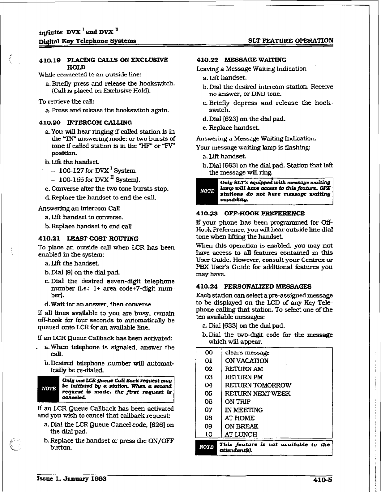
irIfin$te DVX l ftnd DVX II
~@lt.al Key T&phone
Systems
SLT FUYMJRE OPERATION
410.19
PIAClNG CALLS ON EXCLUEXVE
HOLD
While
connected to
an outside
line:
a. Briefly press and release the hookswitch.
(Call is placed on Exclusive Hold).
To retrieve the call:
a. Press and
release the ho&switch again.
410.20 INTERCOM CALLING
a. You will hear ringing if called station is in
the TN” answering mode: or two bursts of
tone if called station is in the “HF’
or “PV”
positton.
b. Lift the handset.
- 1 OO- 127 for DVX I System,
- 100-155
for DVX ’ !System).
c. Converse after the two tone bursts stop.
d. Rep&e the handset to
end tie call.
Answering an Intercom Call
a. Lift handset
to
convex-se.
b. Replace handset to end call
410.21
LEAST COST
ROUTING
To place an outside caII when IER has been
enabled in the system:
a. Lfft the handset.
b. Dial [9J on the dial pad.
c. Dial the desired seven-digit telephone
number (i.e.: 1+ area code+7-digit num-
bed.
d. Wait for an answer, then converse.
If all lines avaiIabIe to you are
busy. remam
off-hook
for four seconds to automatically
be
queued
onto
LCR for an available line.
If an
LCR
Queue CaIlback has
been
activated:
- a. When telephone is ~signaled, answer the
can.
b.Desired telephone number will automat-
ical& be re-dialed.
lf an LCR Queue Callback has been activated
and you wish to cancel that caIlback request:
a. Dial the U=R Queue Cancel code, [626] on
the dial pad.
b. Replace the handset or press the
UN/OFF
button.
410.22 MEssAGE WAITING
Leaving a
Message
Waiting Indication
a. Lift handset.
b.DiaI the desired intercom station. Receive
no answer. or DND tone.
c. Briefly depress and release the hook-
switch.
d. Dial [623] on the dial pad.
e. Replace handset.
Answering a Message Waiting Indication.
Your message waiting lamp is flashing:
a. Lift handset.
b.DiaS 16631 on the
dial
pad. Station that left
the message will ring.
410.23 OFF-HOOK PREFZRENCE
If your phone has been programmed for Off-
Hook Preference, you wiIl hear outside line dial
tone when lifting the handset.
When thls operation is enabled, you may not
have access to all features contained in this
User Guide. However, consult your Centrex or
PBX User’s Guide for addftional features you
may have.
410.24 PERSONAIZZED MESSAGES
Each station can select a pre-assigned message
to be displayed on the LCD of any Key
Tele-
phone c&g that station. To select one of the
ten available messages:
a. Dial 16331 on the dial pad.
b-Dial the two-d&it code for the messa,qe
which will app&.
00
01
02
03
CM
05
06
07
08
09
10
clears message
ON VACATION
R.ElwKNAM
RETLJRNPM
RETURN TOMORROW
RETURN NEXTWEEK
ON TRIP
IN MEEnNG
AT HOME
ON BREAK
AT LUNCH
This $ieutzwe Ir not amzilable
to.
the
hmue 1, January 1993
410-b
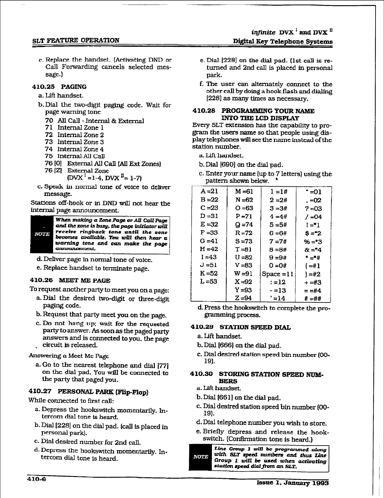
iqfkite DVX’amiDVXn
D&&al Eey Telephone Systems
c. Replace the handset. (Activating DND or
Call Fomrding cancels selected mes- e. Dial I2281 on the dial pad. (1st call is re-
sage.) turned and 2nd call is placed in persofial
park.
410.25 PAGING
a. LifI handset.
b-Dial tie two-digit paging code. Wait for
page warning tone
70 AU Call - Internal & External
71 Internal Zone 1
72 Internal Zone 2
73 Internal Zone 3
74 Internal Zone 4
75 Internal AU CaII
76 tOI Ektemal All Cdl (All Ext Zones)
76 (21 External Zone
(Dvx I =1-4, Dvx L 1-7)
c. Speak in normal tone of voice to deliver
message.
f. The user can alternately connect to the
other call by doing a hook flash and dialing
I2281 as many times as necessary.
410.28 PROGRAMMTN GYOURNAME
INTO TEE LCD DISPLAY
EV~IY SLT extension has the capability to pro-
gram the users name so that people using dis-
play telephones will see the name instead of the
station number.
a. Lift handset.
b. Dial I6901 on the dial pad.
c. Enter your name (up to 7 letters) using the
pattern shown below. ’
Stations off-hook or in DND will not heaf tfie
internal page announcement.
A=21 M=61 1 =l# - =Ol
B=22 Nz62 2 =2# .=02
C=23 0=63 3 =3# 3 =03
D =31 P=71 4 =4# /=04
E =32 Q =74 5 =5#
F -33 R ~72 6=6# ill;
G =41 s =73 7 =7# o$f) =*3
H =42 T=61 8 =8# & =*4
I =43 U&2 9 =9# * G#
J=51
K =52 I v=83 0 =O# (=#l
I W=91 Space=11 ) =#2
L=53 x=92 : =12 + =#3
Y=93 - =13 = =#4
294 ’ =14 # =##
1
amithe~-isbrrsy,tlw-~bl~rroilL
receive ringback tone .unkil ths zone
becomee~le.Ymwilltlu~2heura
warning tone wtd can muke the
pqe
d. Deliver page in normal tone of voice.
e. Replace handset to terminate page.
410.26 MEET BEE PAGE
To request another party to meet you on a page:
a-Dial the desired two-digit or three-digit
paging code.
b. Request that party meet you on the page.
c. Do not hang up; wait for the requested
partyto answer. As soon as the paged party
answers and is connected to you. the page
_ circuit is released.
Answering a Meet Me Page
a. Go to the nearest telephone and dial 177)
on the dial pad. You will be connected to
the party that paged you.
410.27 PERSONAL PARX @‘Up-Flop)
WhiIe connected to first call:
a. Depress the hookswitch momentarily. hi-
tercom dial tone is heard.
b. Dial 1228) on the dial pad. (call is placed in
personal park].
c. Dial desired number for 2nd tail.
d. Depress the hookswitch motientarily. In-
tercom dial tone is heard.
d. Press the ho&switch to complete the pro-
I3 - 1g process.
410.29 STATION S-D DIAL
a. LiR
handset.
b. Dial 1666) on the dial pad.
c. Dial desired station speed bin number (Oo-
19).
410.30 STORING
STATION
SPEED NUBI-
BERG
a. Lift handset.
b. DiaI [SSl) on the dial pad.
c. Dial desired station speed bin number [OO-
19).
d. Dial telephone number you wish to store.
e. Briefly depress and release the hook-
switch. (Confkmation tone is heard.)
410-6 Issue 2, Jaauaq 1993
iqfmite DVX1andDVXn
Dfgitd 3.~9 Tclephoae
Sy&ema SLT FEATURE OPERATION
410.31
SYSTEM SPEED DIAL
a. Lift handset.
b. Dial I6661 on the dial pad.
c. Dial desired system speed bin number (ZO-
99).
410.32 UNWERWW NIGHT ANSWER
Upon hearing an incoming signal
a. IAl handset.
b-Dial the UNA
access
code I#31 on the dial
pad. You wi.lI be connected to ringing out-
side Me.
410.33 UCD AVNLAi3LE/UNAVAlL#LBLE
If you are a UCD Agent. you may place ymxr
station in the AvaiIable mode to receive UC.13
type of calls
or
you may place your station in
the Unavailable mode to block UCD type of calls
f?om ringing at your station.
To go Available:
a.Mal [566] on the dial pad. You may now
receive calls.
To go Unavailable:
a. Dial [5661 on the dial pad. You are now
blocked from rtxeivhg UCD calls.
Iague 1.
January
1993 410-7
i@ite DVX ’ and DVX ‘I
Digital Key Telephone Systems A’l”I’ENIMNT F&i- OPEEWI’ION
SECTION 420
ATTENDANT FSATURE OPERATION
420.1 INTRODUCTION
The infinite Digital Key Telephone System has a
wide variety of features and flexible program-
ming, allowing each telephone user to program
his/her telephone to meet his/her own in&id-
ual needs.
This section of the manual
contains the operat-
ing instructions for Attendant Key Telephone
user[s) and includes an illustration of the 33-
button digital key telephone used in the in@Ue
Digital Key Telephone System and description
of the keys on the telephones and their func-
tions. It is intended
that this section
be used in
conjunction with the Station
Operation section
to provide step-by-step instructions for operat-
ing tie Attendant(s) Digital Termiual(s] in the
system. Visual and audible cues which accom-
pany the various steps in the operation of the
features are also include
LiteratLlrE similar to thesse 0pel-atin.g instruc-
tions has been prepared foruse by the customer
in the
form
of an Attendant User’s Guide.
420.2 ATTENDANTHEpTELEpHONE
STATION FE&m
Each tiQi.r&z Digital Key Telephone System pro-
vides the following
keys,
indicators and fea-
tures:
HANDSET AND SIJEAHER
are located at the
left side ofthefrontpanel. Ahandsetis provided
to allow cotidenttal conversation
when
de-
sired. Lifting the handset from its cradle (going
off-hook)
disengages the station’s built-in
speaker.
*The speaker is located dii-ectlybelowthe center
portion of the handset. The station may be
operated with the handset on-hook. When this
occurs. audio
is
transmitted to the station user
through the station’s speaker.
FLEXIBLE BUTTON8 are used to
access idle
outside lines, provide DSS/BLF
for internal
stations.
access speed dial number and activate
features. These buttons are programmed by the
individual station user. The default flex feature
buttons are described below:
CALL HACK Ulexl button allows you to
initiate an automatic call back request to
another busy station. As soon as that sta-
tion
becomes
idle, the station that left the
call back request Is
signaled.
A flex button
must be assigned to use this feature.
CALL FWD (flex) button allows you to for-
ward your calls to another station.
DO NOT DISTURB @NIB) (flex} button al-
lows the user to place his/her telephone
into a Do Not Disturb mode to eliminate
incoming
outside line ringing. intercom
calls, transfers
and
paging an-
nouncements. The station in DND can
use
the telephone to make normal outgoing
calls. On Attendant &ations. this button
becomes the system Nfght Mode button. A
flex button must be assigned to use this
feature.
COKFERENCE (CONF) (flex) button is
used to establish and build conference
C&S.
FIXED FEATURE BUTTONS:
PICK-UP button allows you to pickup a
tone ringing intercom cdll, msferred. in-
coming, or recalling outside line call to a
sped& unattended station either hy group
or
directed call
pick-up.
F'IA6H button is used to terminate an
outside call and restore dial tone
without
having to hang up the
handset. It is also
used to transfer calls behind a PBX or
Centrex within those systems.
MESSAGE WAIT &¶SG) button allows you
to initiate a message waiting indication at
stations that are-busy, unattended, or in
Do Not Disturb. Message Waiting C&back
request left at your station will indicated by
a fktshing
Msg
Wait LED.
‘IBANS- (TRANS) button is
used to
transfer an outside call from one station to
another.
SPEED button provides you with access to
speed diakng, save number rediat and
last
number red&L This button is aiso used to
access speed dial and flexbutton program-
ming-
CAMP-ON button enables you to alert a
busy party that an outside line is on hold
and waiting for them.
MUTE button allows you to swkch the
built-in mimphone on or off when using
Issue 1, Janusry 1993 420-l
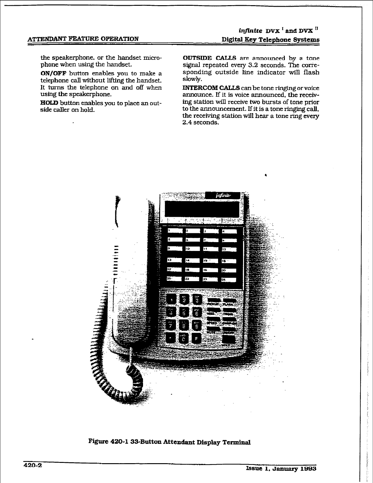
r
the speakerphone, or the handset micro-
phone when using the handset.
ON/OFF button enables you to make a
telephone call without lifting the handset.
It turns the telephone on and off when
using the speakerphone.
HOLD
button enables you to place an out-
side
caller on hold.
OUTSIDE CALLS are announced by a tone
signal repeated every 3.2 seconds. The corie-
sponding outside line indicator will flash
slowly.
INTERCOM CALLS can
be tone ringing orvoice
announce. If it is voice announced, the receiv-
ing station will receive two bursts of tone prior
to the announcement. Ifit is a tone ringing call,
the receiving station wiI1 hear a tone ring every
2.4
seconds.
l
m 420-l 33-Button Attendant DispLay Ttrmfnal
420-2 belle 1. January 1993
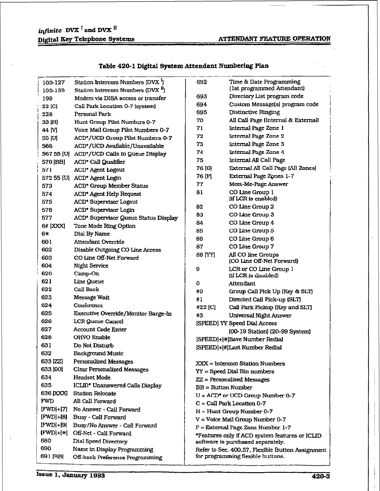
AmmhNT FEATURE OPERATION
Table 420-l Digital System Attendant Numbering Plan
j 1.00-127 Station Intercom Numbers [DVX ‘1
j 100-155 Station intercom Numbers (DVX ‘1
199 Modern v-la DISA access or transfer
; 22 ICI Call Park Location O-7 (system)
/
228
Personal Park
33 IHI Hunt Gmup Pilot Numbers O-7
MM
Voice
Mail
Group Pilot Numbers O-7
55 IV1 ACD./UCD Gmup Wet Numbers @7
! 566 ACD*/UCD Avatlable/Unavailable
; 567 55 IV] ACD*/UCD Calis in Queue Display
I 570[BB] ACD’ Call Quah&r
571
ACD+ Agent Logout
572 55
IUj ACD* Agent hgin
573
574
575
576
577
6#
K=‘l
6*
601
602
603
604
620
621
622
623
624
625
626
627
628
631
632
633
Ia
633
IO01
634
635
636
m
mw+I71
IFWIN +I81
mm1 +I91
mml+[*l
680
690
691 [BB]
ACD’ Group Member Status
ACD’ Agent Hdp Request
ACD* Supervisor Logout
ACD’ Supervisor Iqin
ACD* Supervisor Queue Status Display
Tone Mode Ring Option
Dial 3y Name
Attendant Ove&de
Disable Outgoing CO Line Access
CO Line Off-Net Forward
Night Service
Camp-Oil
Line Qucuc
CallBack
Message Wait
conrereTlce
Executive Override/Monitor Barge-In
ICR Queue Cancel
Account Code Enter
OHVO Enable
Do Not Disturb
Background Music
Pcrsonabmd Messages
Clear
Personalized
Messages
Headset Mode
ICLID’ Unanswered Calls
Display
Station Relocate
m Cd Forward
No Answer - Call Forward
Busy - Cd Forward
Busy/No Answer - Call Fomard
Off-Net - Cdl Forward
Dial Speed Directory
Name
in Display Programming
Off-hook
Prefmce PI-U-
692
693
694
695
70
71
72
73
74
75
76
tOI
76 14
77
81
82
83
84
a5
86
87
88 ml
9
0
#O
#1
At22 [Cl
#3
Time & Date Programrnm
(1st progmmmed Attend&
Directory List program code
Custom
Message(s) program code
Dlsttncttvc Ringillg
All Call Page (Intcmal & External]
In- Page zol-le I
Internal Page Zone
2
Internal Page Zone 3
IntemaI Page Zone 4
lntemal All Call Page
ISternal All Call Page (AR zones)
External Page ZQncs l-7
Meet-Me-Page Answer
CO Line Group 1
(if LCFt is enabled)
CO tine Group 2
CO Line Gmup 3
CO Line Group 4
CO Line Group 5
CO Line Group 6
CO Line Gmup 7
ti CO line Groups
(CO Line Off-Net
Forward)
LCR or CO IJne Gmup 1
(if LCR is disabled)
Attendant
Group Cal1 Pick Up (Key & SLT]
Directed Call Pick-up (SLT)
CJall Park Pickup (Key and SLZ’)
Univnsal Night Answer
[SPEED] YY Speed Dial Acctss
(OO- 19 Station] (20-99 System)
ISPEED]+~~)Save Number Redid
ISPEED]+[#~Last Number Reckd
XXX = inta-com Station Nunhers
YY=SpetdDtiBinnun~bcrs
Z = Personalized Messages
BB = 3utton Number
U = ACD* or UCD Croup Number &7
C = Call Park Location O-7
H = Hunt Group
Number
O-7
V = Voice Mail Group Number 0-7
P = External Page Zone Number l-7
‘Features only if ACD system features or ICLID
software is purchased separately.
Refer tr, Sec. 400.37, Flexible Button Assignmmt
for prograaag flexible buttons.
infinite DVX I
and DVX ’
Digital Key Telephone &ystems
420.3
ANSWERINGAN OUTSIDE CALL
a. Lift handset.
b. Press slow flashing outside line button. (If
your telephone is programmed with Bre-
fen-& Line Answer, you may answer an
outside line by lifting the handset.)
420.4 PLACING OUTSXDE LINE ON HOLD
a. If your system is programmed for Exclusive
Hold Preference. press HOLD button
once
for Exclusive Hold and twice for System
Hold.
b.If your system is programmed for System
Hold Preference, press HOLD button once
for
System
Hold
and twice for
Exclusive
Hold,
420.5 ANSWERING A REcAtcING Om-
SIDE LINE
When an outside line has remained on hoId for
an extended period of time, you will be re-
minded with a recalling ring.
a. Press outside line button flashing at very
fast rate.
b. Lift handset to converse.
420.6 ATTENDANT DIMBLE OUTGO-
INC; ACCESS
The attendant station can disable CO lines,
preventing outgoing CO calls.
a. Lift handset or press ON/OFF button.
b.Dial [602] on the dial pad. Confirmation
tone is heard.
c. Depress the line button(s) of the CO Line(s)
to be disable. Conflnnation tone is heard
and the CO Line Button(s) LED
is flashing.
d.To re-activate the CO Line@], repeat the
steps followed to disable it.
420.7
ATTENDANTOVERRRIE
If Attendant
Override is
allowed, Attendant(s)
stations may override or call
stations that are
either
busy or in Do
Not Disturb.
If
the Attendant calls a station that is busy on
a CO call and wishes to alert them of a
waiting
CEiJk
a. Press the pre-programmed*
ATIN
OVER-
RIDE button. Three short tone bursts will
be presented to the called party.
b-After five (51 seconds. the station’s CO line
WJ automatial@ be placed on hold and
the Attendant will be cut-&-u.
If the Attendant calls a station that is in Do Not
Disturb mode and wishes to alert them of a call;
a. Press the pre-programmed* Am OVER-
RIDE button. The station will be signaled
with a Camp-on tone.
*Refer to Sec. 400.37, Fiexible Button
Assignment.
420.8 ATTENDANTRECALL
When an outside line has remained
on
hold for
an extended period of time, you will be re-
minded with a recalling ring.
a. Press outside
line
button flashing at a very
fast rate.
b.
Lift
handset to converse.
420.9 DATAFEATURE’
The Data Feature is a time division
switched,
point
to
point data transmission capability
which permits simultaneous voice and data
communimtfons (within the same system but
not the same port). The Data Feature offers the
ability to transmit data information between
personal computers. printers, plotters. mo-
dems, CRT terminals,
and main frame com-
puter ports.
To establish a Data call, a Digital Data Interface
Unit (DDIU) is required to be connected to each
data communications device. Data information
can be switched through the system at speeds
of 300. 1200. 2400, 4800, 9600. 19.2K and
38.4K baud asynchronous.
To estab&h a connection between two DDIU:
a.The first attendant dials the extension
number of one data unit. Dial tone is re-
ceived and the
display will show the BAUD
RATE. ..-
b-The fkst attendant then dials the station
number
of the
second data unit. Confii-
tion tone is heard. This connection will be
maintained until the f%st attendant dials
the station number of one DDIU followed
by pressing the FLASH button,
To break down an established connection:
a. The first attendant dials one of the DDIU
extension numbers
gesses the DSS button for the DDIU.
b. Press the “FIJGH” button. The connection
is removed.
The
first
attendant can configure any DDW by:
1. Dial the DDIU access code (631 on the dial
pad.
420-4
Issue
~.dtm~1Bos
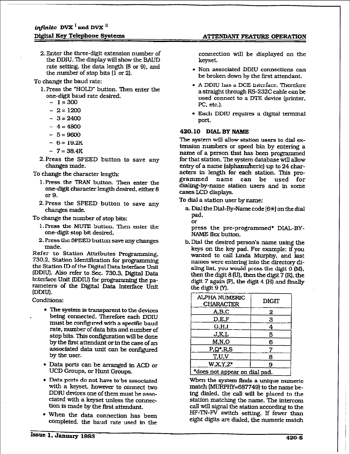
@ft.dte DVX I and DVX I1
Digital Key Telephone Systems ATTENDANT EEMWRE CWERATlON
2, Enter the three-digit extension number of
the DDIU. The display will show the BAUD
rate setting. the data length [8 or 9). and
the number of stop bits (1 or 2).
To change the baud rate:
1. Press the “HOLD” button. Then enter the
one-digit baud rate desired.
- 1=300
- 2=1200
- 3=2400
- 4=4800
- 5=9600
- 6= 19.2K
- 7= 38.4K
2.Press the SPEED button to save any
changes made.
To change the character length:
1. Press the TRAN button. Then enter the
one-digit character length desired, either 8
or 9.
2,Press the SPEED button to save any
changes made.
To change the number of stop bits:
l.Press the MUTE button. Then enter the
one-digit stop bit desired.
2. Press the SPEED button save any changes
made.
Refer to Station Attributes Programming,
730.2, Station Identification for programming
the Station ID of the Digilzd Data Interface Unit
(DDITJ. Also refer to Sec. 730.3. Digital Data
Lnterface Unit fDDIv) for progmmming the pa-
rameters of the Digital Data Interface Unit
[DDIU).
Conditions:
l
The system is transparent to the devices
. being connected. Therefore each DDIU
must be conf?gured with a sped&z baud
rate. number of data brts and number of
stop bits. This con&guration will be done
by the first attendant or in the caSe of an
associated data unit can be configured
by the user.
l
Data pork can be arranged in ACD or
UCD Groups, or Hunt Groups.
l
Data ports do not have to.be associated
with a keyset, however to connect two
DDIU devices one of them must be asso-
ciated with a keyset unless the cormec-
tion is made by the first attendant.
l
When the data connection has been
completed, the baud rate used in the
connection will be displayed on the
keyset.
l
Non associated DDIW connections can
be broken down by the first attendant.
l
A DDIU has a DCE interface. Therefore
a straight through RS-232C cable can be
used connect to a DTE device (printer.
PC, etc.).
l
Each DDIU requires a digital terminal
port.
420.10 DIALBYNAME
The system will allow station users to dial ex-
tension numbers or speed bin by entering a
name of a person
that
has been programmed
for that station. The system database will allow
entty of a name (alphanumeric) up to 24 char-
acters in length for each station. This pro-
grammed name can be used for
dialing-by-name station users and in some
cases LCD displays.
To dial a station user by name:
a Dialthe Dial-BY-Name code [6*] on the dial
pad.
;ess the pre-programmed* DlAL-BY-
NAME flex button.
b.Dial the desired person’s name using the
keys on the key pad. For example: if you
wanted to call Linda Murphy, and last
names were entering into the directory di-
aling list. you would press the digtt 6 (M),
then the digit 8 Iv). then the digit 7 (RI. the
digit 7 again PI, the digit 4 N and finally
the digit 9 0.
When the system finds a unique numeric
match bdlJRPHY=687749) to the name be-
ing dialed. the call will be placed to the
station matching the name. The intercom
Cal will signal the station according to the
HF-TN-W switch setting, If fewer than
eight digrts are diafed. the numeric match
ksuc 1, January 1993 429-5
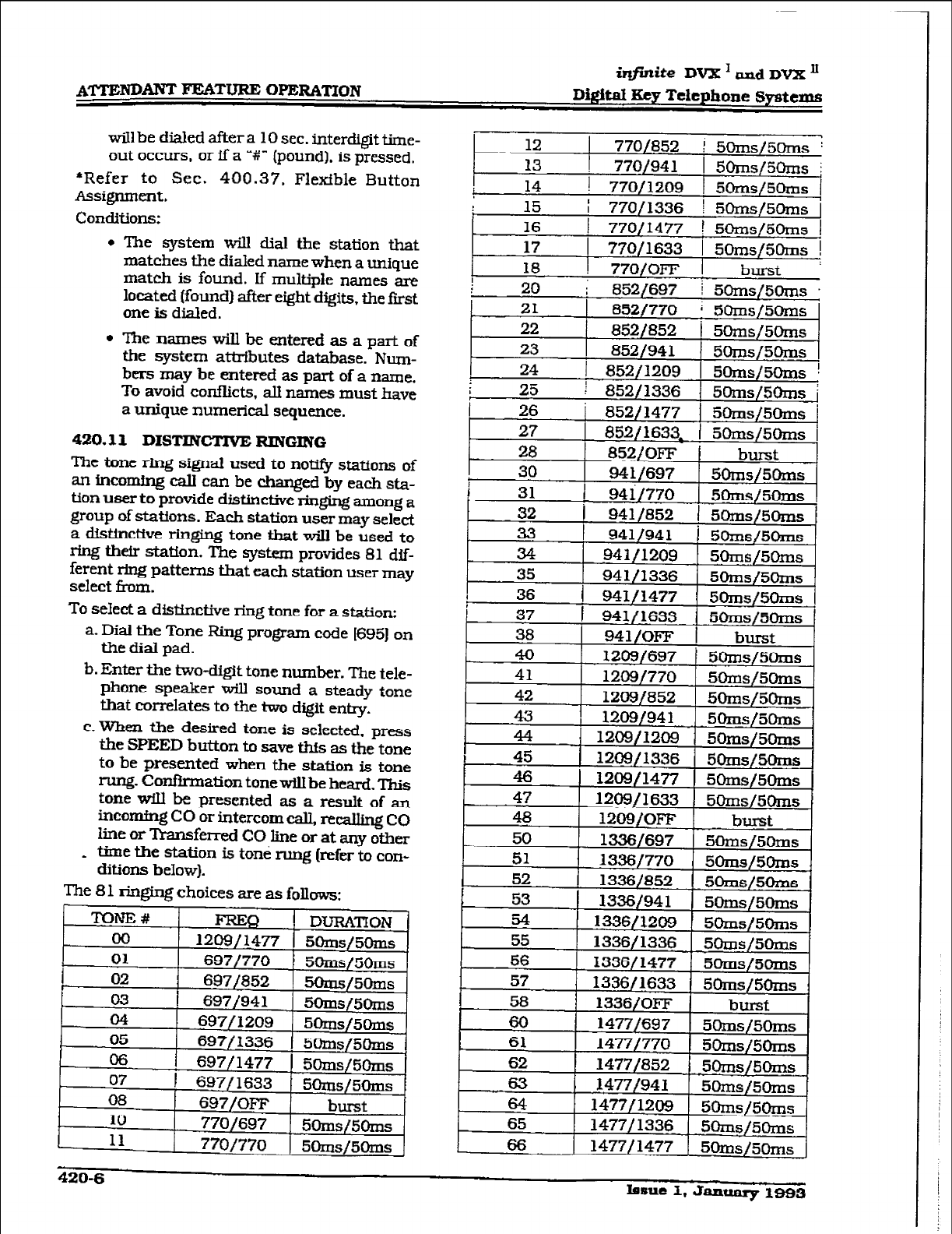
wi11 be dialed after a 10 sec. interdigit time-
out occurs, or if a ^+Y” (pound]. is pressed.
*Refer to Sec. 400.37. Flexible Button
Assignment.
Conditions:
l
The system wiII dial the station that
matches the dialed name when a unique
match is found. If multipie names are
located (found) after eight digits. the fast
one is dialed.
l
The names will be entered as a part of
the system attributes database. Num-
bers may
be
entered as part of a name.
To avoid confhcts. all names must have
a unique numerical sequence.
420.11 DISTINCTIVE RINGING
The tone ring signal used to no* stations of
an incw cdl can be changed
by
each sta-
tion user
to
provide distinctive ringing among a
group of stations. Each station user may select
a distinctive ringing tone that will be used to
ring their statfon. The system provides 81 dif-
ferent ring patterns that each station user may
select from.
To select a distictive ring tone for a station:
a. Dial the Tone Ring program code [695) on
the dial pad.
b. Enter the two-digit tone number. The tele-
phone speaker will sound a steady tone
that correlates to the two digit entry.
c. When the desired tone is selected. press
the SPEED button to save thts as the tone
to be presented when the station is tone
rung- Confirmation tonewihbe heard. This
tone will be presented as a result of an
incoming CO or intercom call, recalling CO
line or Transferred CO line or at any other
* time the station is tone rung (refer to con-
ditions
below).
The 81
ringing choices are as follows:
12 1 770/852 i 5Oms/50ms :
I
! I ~~-
13
770/941 5onls/5clns j
14
1 770/1209 I 5Oms/5Olns I
15 i 770/1336 1 5Oms/5Oms
16 I
1
770/1477 I 5Oms/5Orns I
17 1 770/1633 1 5Oms/5Orns !
18 ! 77O/OFF I burst :
420-6 Issue I, January 1993
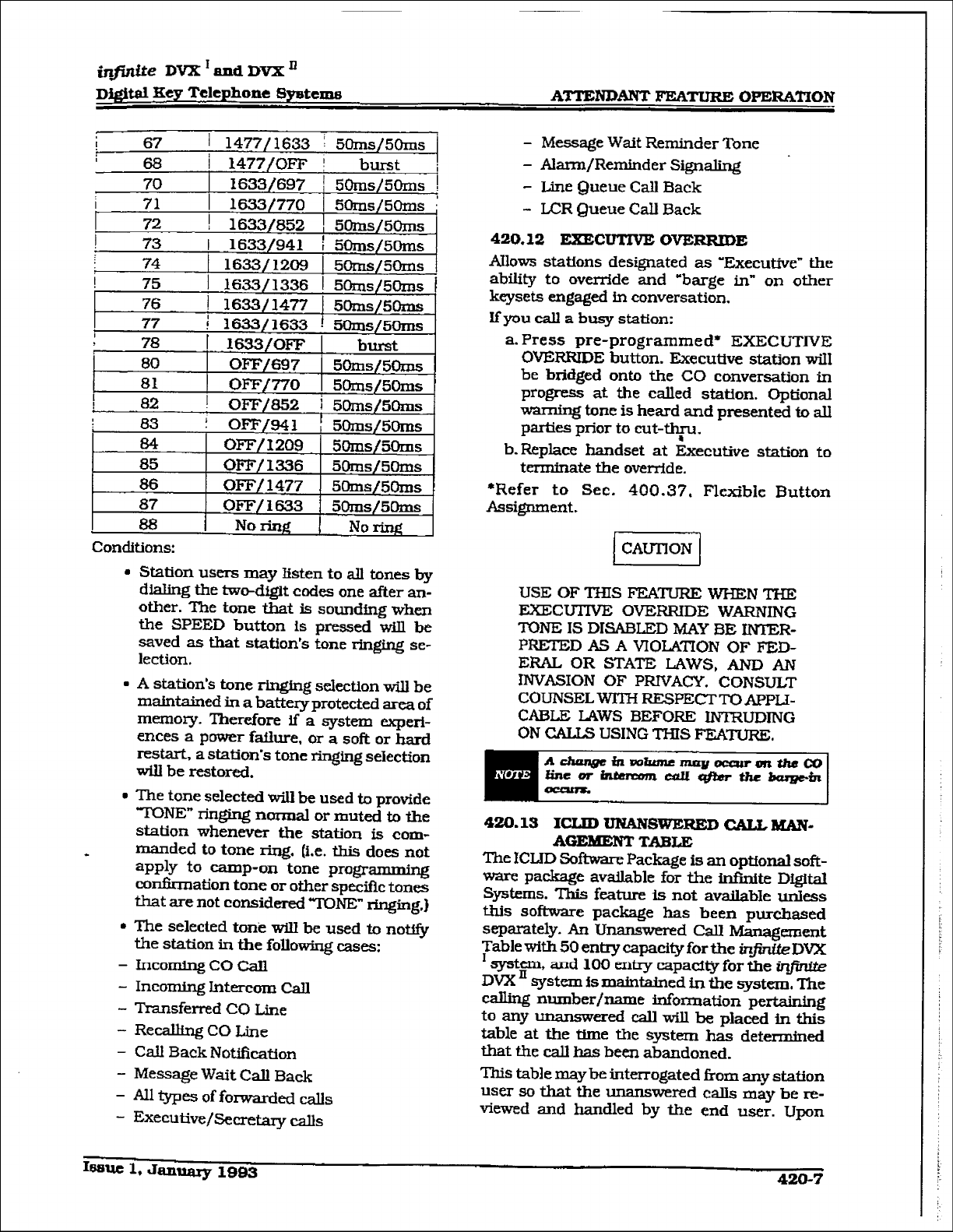
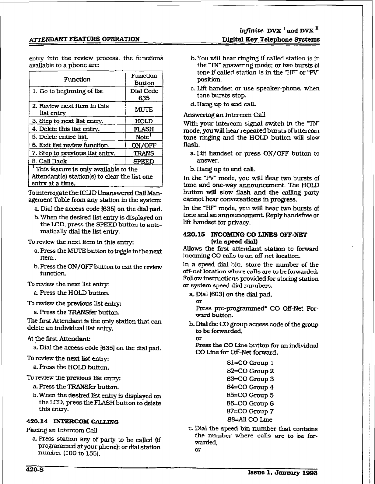
infinite DVIL: I and DVX I1
A’I’TEPJD~ FEATURE OFERATION Digital Key Telephone Gystems
entry into the review process, the
functions
available to a phone are:
Function
Function
Button _
1. Go to beginning of list 1 Did Code
I
I 635
2. Reviewnextitem in this
list entry ! &
I
i
3. Step to next
list entry. ! HOLD
4. Delete this Ii& e.nW.
5. Delete entire list., 1 FLASH
! Note1
6.
Exit list review function. ! ON/OFF
7.
Step to previous list entty. I TRANS
8. Call Back 1 SPEED
’ This feature
is oIlly
available to the
Attendant(s) station(s) to clear the list one
entry at a time.
To interrogate the ICUD Unanswered CalI Man-
agement Table from any station in the system:
a. Dial the access code 16351 on the dial pad.
b. When the desired list entry is displayed on
the LCD, press the SPEED button to auto-
matically dial the list entry.
To review the next item in this entry:
a. Press the MUTE button to toggle to the next
item,.
b. Press the ONfOFFbutton to exit the review
function.
To review the next list entry:
a. Press the HOLD button.
To review the previous list entry:
a. Press the TRAIVSfer button.
The first Attendant is the only station that can
delete an tidividuat list entry.
At the first Attendant:
a. Dial the access code I6351 on the diaI pad.
To review the next list enky:
a. Press the HOLD button,
To review the previous list entry:
a. Press the TRANSfer button.
b.When the desired Ifst entry is displayed on
the LCD. press the FLJ&H button to delete
this ently.
420.14 DJTlliRCOIk¶ UG
Placing an Intercom CalI
a. Press station key of party to be caIIed (if
programmed at your phone); or dial station
mtnber (100 to 155).
b, You will hear ringing if called station is in
the TN” answering mode; or two bursts bf
tone if called station is in the ‘W or “W
position.
c. Lift handset or use speaker-phone, when
tone bursts stop.
d. Hang up to end call.
Answering an Intercom Call
With your intercom signal switch in the ‘TN”
mode, you will hear repeated bursts of intercom
tone ringing and the HOLD button will slow
flash.
a. Lift handset or press ON/OFF button to
an!swer.
b. Hang up to end call.
In the “IV mode, you will Ilear two bursts of
tone and one-way announcement. The HOLD
button wiII slow flash
and the caUing
party
cannot
hear
conversations in progress.
In the “HF” mode, you will hear two bursts of
tone and an announcement. Reply hands& or
lift handset for prIvaoy.
420.15 INCOMING CO IJNES OFF-NET
f* spetd Ml
AUows the first attendant station to forward
incoming CO calls to an off-net location.
In a speed dial bin. store the number of the
off-net location where calIs are to be forwarded.
FoUow instructions provided for storing station
or system speed dial numbers.
a. Dial 16031 on the dial pad,
Or
Press pre-programmed* CO Off-Net For-
ward button.
b. DIaI the CO group access code
of the
group
to be fotied,
kss the CO Une button for an individual
CO Line for W-Net forward.
81=CO Group 1
82=CO
Group 2
83=CO Group 3
84=CO Group 4
85=CO Group 5
86=CO
Group 6
87=CO Group 7
88=AIl CO Une
C.
Dial the speed bin number that contains
the number where calls are to be for-
warded,
or
420-S Iseuc 1, Janwary 1993
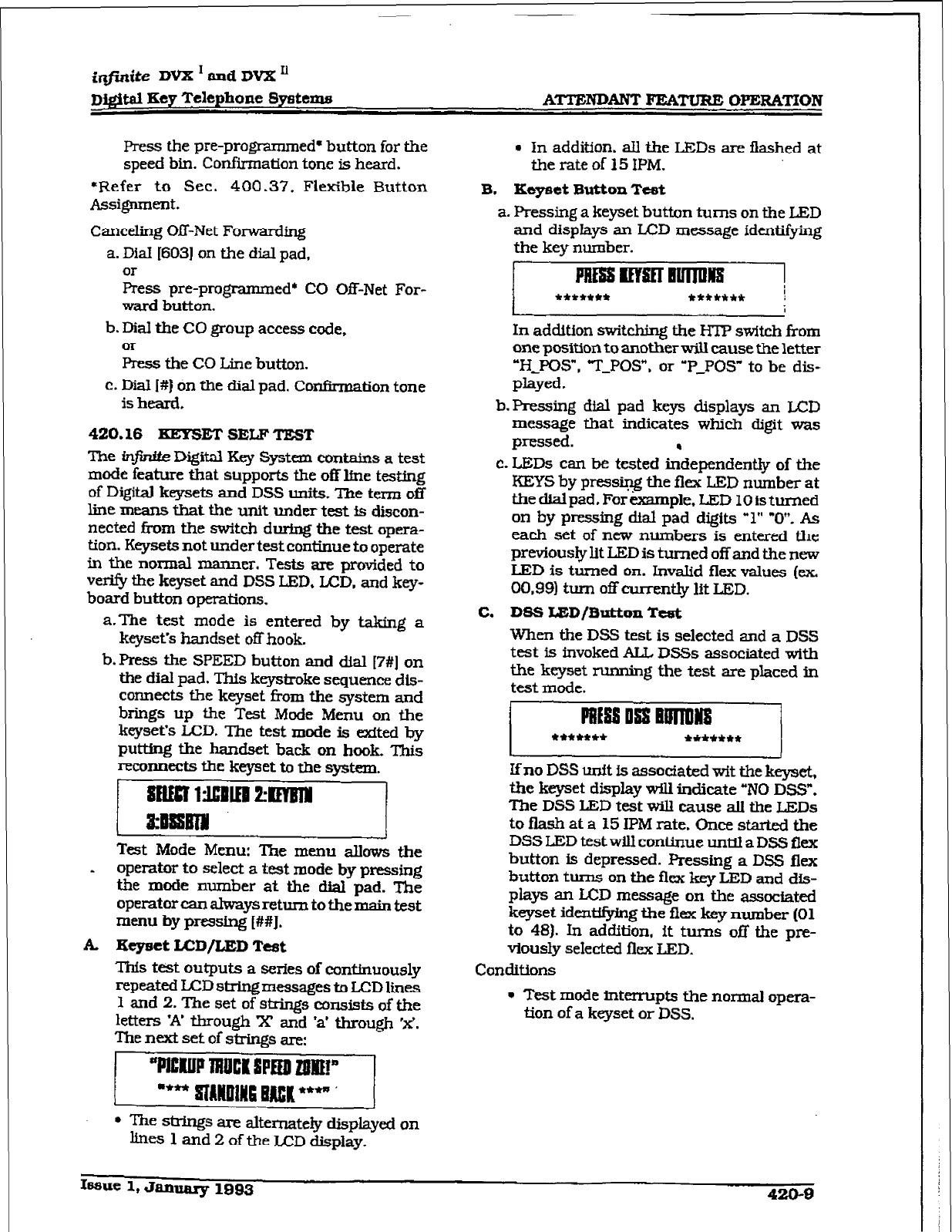
imite DVX I and DVX n
Digital Key Telephone Systems ATTENDANT FEATURE OPERATION
Press the pre-programmed* button for the
speed bin. Confirmation tone is heard.
*Refer to Sec. 400.37, FlexZble Button
Assignment.
Canceling Off-Net Forwarding
a. Dial [603) on the dial pad,
OI-
Press pre-programmed* CO Off-Net For-
ward button.
b. Dial the CO group access code,
Or
Press the CO Line button.
c. Dial I#) on the dial pad. Confirmation tone
is heard.
420.16 EEYSEI’ SELF TEST
The tnjtLtte Digital Key System contains a test
mode
feature that supports the off line testing
of Digital keysets and DSS units, me term off
line means
that
the unit under test is discon-
nected i?om the switch during the test opera-
tion. Keysets not under test continue to operate
in the normal manner. Tests are provided to
verify the keyset and DSS LED, LCD. and key-
board button operations.
a.The test mode is entered by taking a
keyset’s handset off hook.
b. Press the SPEED button and dial [7#] on
the dial pad. This keystroke sequence dis-
connects the keyset Corn the system and
brings up the Test Mode Menu on the
keyset’s LCD. The test mode is exited by
putting the handset back on hook. This
reconnects the keyset to the system.
51
Test Mode Menu: The menu allows the
. opera& to select a t-t mode by pressing
the mode number at the dial pad. The
operator can ahways return to the m&n test
menu by pressing t##J.
A. Eeyset LCD/LED Test
This test outputs a series of continuously
repeated LCD string
messages to
LCD lines
1 and 2. The set of strings consists of the
letters ‘A’ through X and ‘a’ through ‘x’.
The next set of strings are:
31
l
The stnings are alternately displayed on
lines 1 and 2 of the LCD display.
l
ln addition, all the LEDs are flashed at
the rate of 15 IPM.
B. Kcyset Button Test
a. Pressing a
keyset button turns on the LED
and displays an LCD message identifying
the key number.
1;
In addition switching the IITP swftch from
one position to another will cause the letter
“H_pOS”, “TYPOS”. or ‘P-POS” to be dis-
played.
b.Pressing dial pad keys displays an LCD
message that indicates which digit was
pressed. .
c. =Ds can be tested independently of the
KEYS by pressing the flex LED number at
the did pad. For example. LED 10 is turned
on by pressing dial pad digits “1” “0”. As
each set of new numbers is entered the
previously IX LEDis turned off and the new
LED is turned on. Invalid flex values (ex,
00.99) turn off -tIy lit LED.
C. DSS Id3D/Button Teat
When the DSS test is selected and a DSS
test is invoked ALL DSSs associated with
the keyset rurming the test are placed in
test mode.
11
lfno DSS unit is associated wit the keyset,
the keyset display will indicate “NO DSS”.
The DSS LED test will cause all the LEDs
to flash
at a 15 IPM rate. Once startexl the
DSS LED testwill continue until a DSS flex
button is depressed. Pressing a DSS flex
button turns on the flex key LED and dis-
plays an LCD message on the associated
keyset ide&f@ing the flex key number [Ol
to 481. In addition, it turns off the pre-
viously seIected flex LED.
Conditions
l
Test mode interrupts the normal opera-
tion of a keyset or DSS.
Issue 1, January 1993
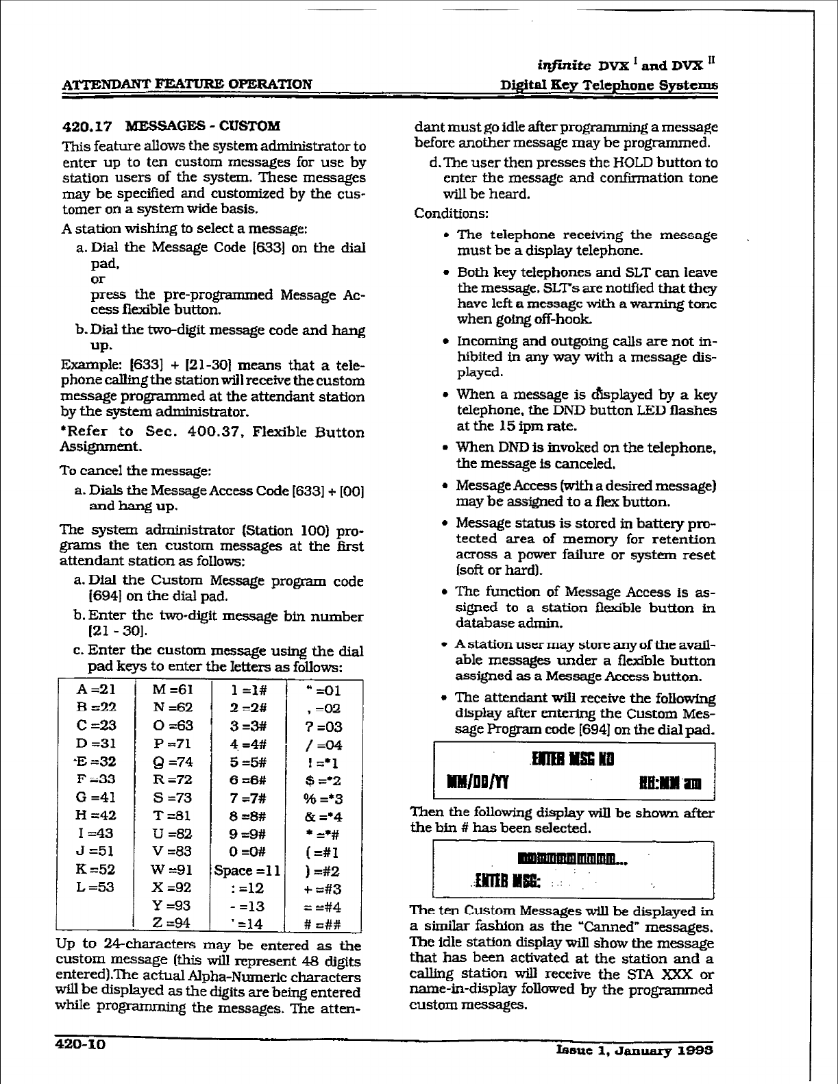
i@nike
Dvx ’ and DVX I1
Digital
Key
Telephone Systems
420.17 ME!3sAG= - CUSTOM
This feature allows the system administrator to
enter up to ten
custom rmssages
for use by
station users of the system. These messages
may be specified and customized by the cus-
tomer on a system wide basis.
A station wishing to select a message:
a. Dial the Message Code [633] on the dial
pad.
or
press
the preprogrammed Message Ac-
cess flexible button.
b.DiaI the two-digit message code and hang
UP-
Example: 16331 + 121~301 means that a tele-
phone calling the stationwill receive the custom
message programmed at the attendant station
by the system administrator.
*Refer to Sec. 400.37, Flexible Button
Assignment.
To cancel the message:
a. Dials the Message Access Code [633] + [OO]
and hang up.
The system administrator (Station 100) pro-
grams the ten custom messages at the first
attendant station as foIIow5:
a. Dial the Custom Message program code
I6941 on the dial pad.
b. Enter the two-digit message bti number
I21 - 301.
c. Enter the custom message using the dial
pad keys to enter the Ietters as follows:
A =21
B-22
c=23
D =31
% =32
F ~33
G =41
H -42
I =43
J=51
K =52
L =53
T
-
M =61
N =62
0 =63
P =71
Q =74
R =72
s =73
‘I’=81
U =82
v =83
w =91
x =92
Y =93
2=94
1 =1#
2 =2#
3=3#
4=4#
a4 =Ol
, =02
7 =03
/=04
! =*1
$ =‘2
Oh =*3
& =*4
l =*#
(=#I
I =#2
+ =#3
= =#4
# =##
Up to 24characters may be entered as the
custom
message (this will
represent 48 digits
entered).The actual Alpha-Numeric characters
wiII be displayed as the digits are being entered
while programming the messages. The atten-
dant must go idle after programming a message
before another message may be programmed.
d.The user then presses the HOLD button to
enter the message and confirmation tone
will be heard.
Conditions:
l
The telephone receiving the message
must be a display telephone.
l
Both key tekphones and SLT can Ieave
the message. SLTs are notified that they
have left a message with a warning tone
when going off-hook
l
Incoming and outgoing calIs are not in-
hibited in any way with a message dis-
played.
l
When a message is &played by a key
telephone, the DND button LED flashes
at the 15 ipm rate.
l
When DND is invoked on the telephone,
the message is canceled.
l Message
Access (with a desired message)
may be assigned to a flex button.
l
Message status is stored in battery pro-
tected area of memory for retention
across a power failure or system reset
(soft or hard).
l
The function of Message Access is as-
signed to a station ilezdble button in
database admin.
l
A station user may store any of the avait-
able messages under a il&ble button
ass@ned as a
Message
Access button.
l
The attendant wilI receive the foIkswing
display after e&zing the Custom Mes-
sage Program code [694] on the dial pad.
llllOQm1
Then the foIIowing dispIay wiII be shown after
the bin # has been selected.
21
The ten Custom Messages will be displayed in
a similRr
fashion as the
“Canned” messages.
The idle station display will show the message
that has been activated at the station and a
calIing station wiIl receive the STA m or
name-in-display followed by the programmed
custom messages.
420-10 fssue 1, January 1-S
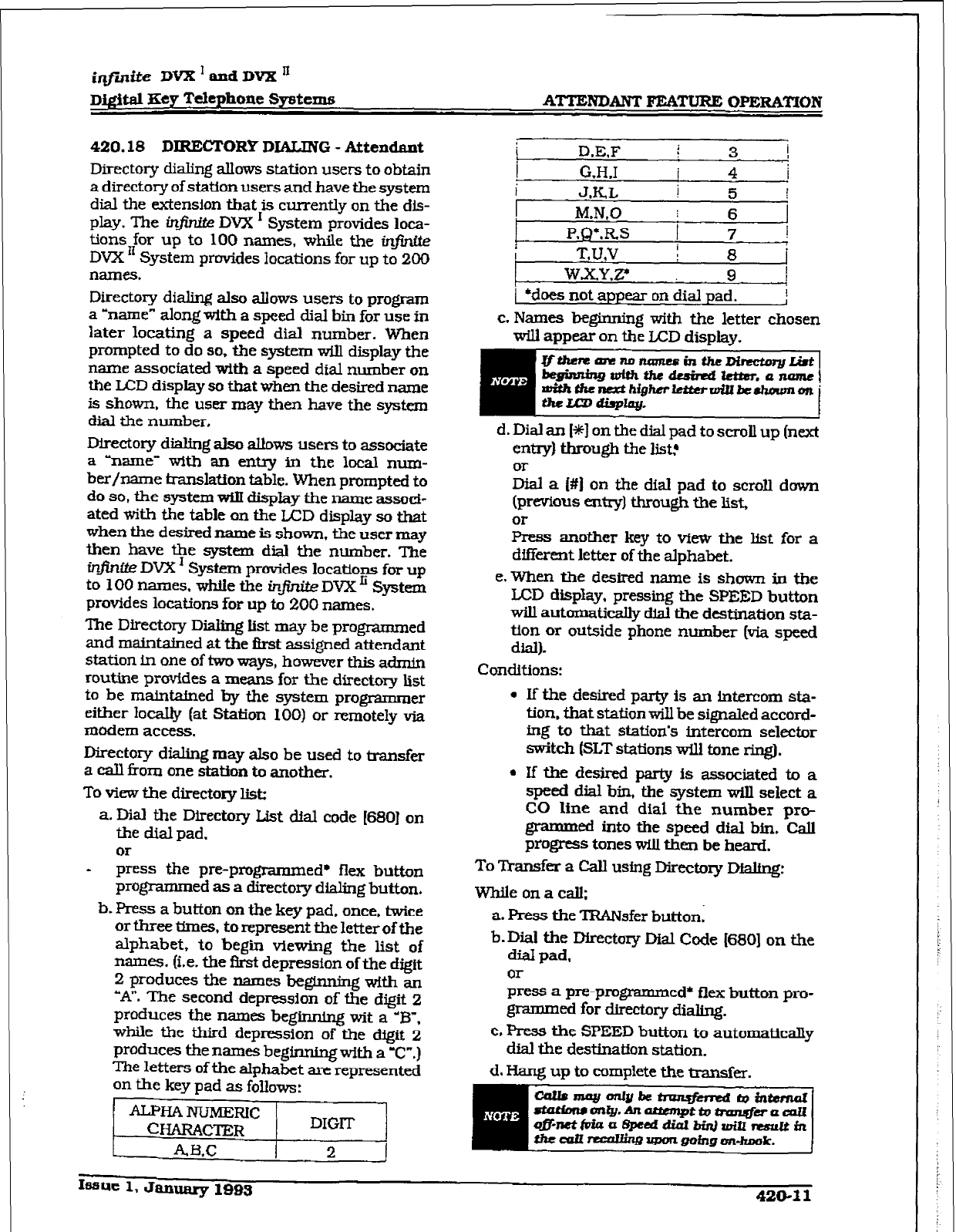
irlfinite DVX 1 and DVX ’
Di@al Hey Telephone Spstexns ATTENDANT FEATURE OI’ICRA’ITON
420.18
DIRECTORY DIALXNG - Attendant
Directory dialing allows station users to
obtain
a directory of station users and have the system
dial the extension that is currently on the dis-
play. The in$n&.e DVX I System provides loca-
tions for up to 100 names, while the in.
DVX ’ System provides locations for up to 200
names.
Directory dialing also allows users to program
a ‘name” along with a speed dial bin for use in
later locating a speed dial number. When
prompted to do so, the system will display the
name associated with a speed dial number on
the LCD display so that when the desired name
is shown. the user may then have the system
dial the mnnber,
Wectory dialing also allows users to associate
a “name” with an entry in the local mxn-
her/name translation table. When prompted to
do so, the system win dispkxy the name associ-
ated with the table on the LED display so that
when the desired name is shown, the user may
then have the system dial the number. The
b-@nrte DVX’ System provides locations for up
to 100 names, whiie the in#niteDvXIi System
provides locations for up to 200 names.
The Directory Dii kt may be programmed
and maintained at the first assigned attendant
station in one of two ways, however this adrnin
routine provides a means for the directory list
to be maintatned by the system programmer
either IocaIly (at Station 100) or remotely via
modem access.
Directory dialing may also be used to transfer
a call from one station to another.
To view the directory list:
a. Dial the Directory List dial code [680] on
the dial pad,
* kss the pre-programmed* flex button
programmed as a directory dialing button.
b. Press a button on the key pad. once, twice
or three times, to represent the letter of the
alphabet, to begin viewing the list of
names. [i.e. the f3rst depression of the digit
2 produces the names beginning with an
“A”. The second depressjon of the digit
2
produces the names beginning wit a ‘B”.
while the third depression of the dfgit 2
produces the names beginning with a 7.)
The letters of the alphabet are represented
on the key pad as follows:
I
D.E.F i 3- I
I G.H.1 I 4 /
i JKL ! 5 !
M.N,O : 6
P.Q*.RS 1 7 1
T,U.V I 8
WXY.2 9
*does not appear on dial pad.
J
c. Names beginning with the letter chosen
will appear on the LCD display.
grhempnno r!4ml!sinthe-a(at
begimbgdthiheduimdWtar.anamu~
mithtfun&htgherltttrrwill&shaunmon
thcumdbplq. I
d. Dial an [*I on the dial pad to scroll up (next
entry) through the list?
L a I#1 on the dial pad to scroll down
(previous entry) through the list,
or
Press another key to vkw the list for a
different letter of the alphabet.
e.When the desired name is shown in the
LCD display. pressing the SPEED button
will automatically dial the destination sta-
tion or outside phone number (via speed
dial).
Conditions:
9 if the desired party is an intercom sta-
tion, that station will be signaled accord-
ing to that station’s intercom selector
switch (SLT stations wili tone ring).
l
If the desired party is
associated
to a
speed dial bin, the system will select a
CO line and dial the number pro-
grammed into the speed dial bin. Call
progress tones will then be heard.
To Transfer a Call using Directory Dialing:
Whileonacail;
a. Press the TRANsfer button;
b. Dial the Directory Dial Code [SSO] on the
dial pad,
or
press a pre-programmed* flex button pro-
grimmned for directory dialing.
c. Press the SPEED button to automatically
dial the destination station.
d. Hang up to complete the transfer.
Issue 1, January 1993 420-I 1
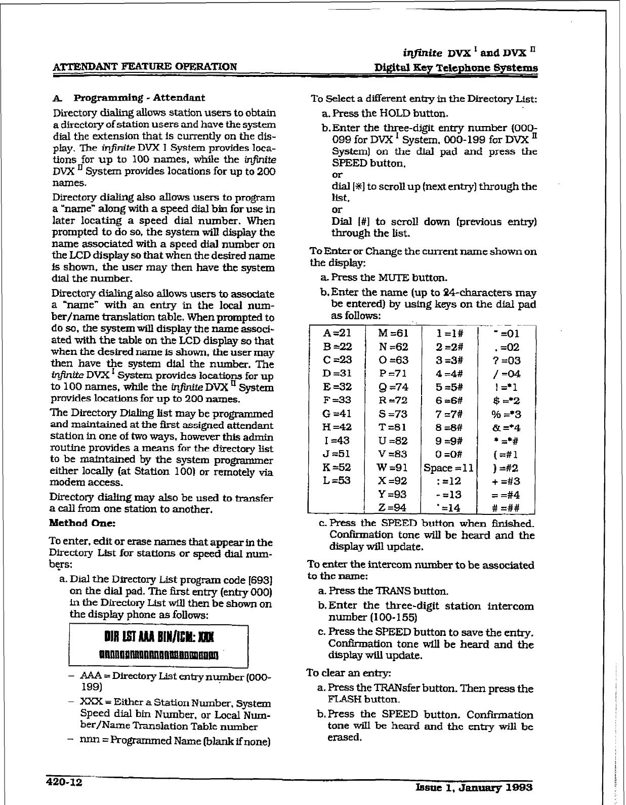
iqfinite DVX r and DVX ’
ATTENl&%NT FEATURE
WEXZA~ON
Digital Key Telephone Syf&ems
A. x’rogrammiq - Attendant
Directory dialing allows station users to obtain
a directory of station users and have the system
dial the extension that is currently on the dis-
play. me injinite DVX I System provides loca-
tions for up to 100 names, while the ir@r&e
DVX IJ System provides locations for up to 200
names.
Directory dialing also allows users to program
a ‘name” along with a speed dial bin for use in
later locating a speed dial number. When
prompted to do so, the system will display the
name associated with a speed dial number on
the LCD display so that when the desired name
is shown, the user may then have the system
dial the number.
Directory dialing also allows users tc assodate
a “name” with an entry in the local num-
ber/name translation table. When prompted to
do so. the system will display the name associ-
ated with the table on the LCD display so that
when the desired name is shown, the user may
then have the system dial the number. The
infinite DVX’ System provides Iocations for up
to 100 names, while the in.. DVX ’ System
provides Iocations for up to 200 names.
The Directory Dialing list may be programmed
and maintained at the i3rst assigned attendant
station in one of two ways, however this admin
routine provides a means for the directory Iist
to be maintaIned by the system programmer
either locally (at Station 100) or remotely via
modem access.
Directory dialing may also be used to transfer
a calI from one station to another.
Method One:
To enter, edit or erase names that appear in the
Directory L&t for stations or speed dial num-
bqs:
a. Dial the Directory List program code [693)
on the dial pad. The first entry (entry 000)
in the Directory List will then be shown on
the display phone as follows:
xi
- AAA=Directmy~tmtryn~er(00(>-
199)
- XXX = Either a Station Number, system
Speed dial bin
Number, or Local Num-
ber/Name Translation Table number
- IU-UI = Programmed Name (blank if none)
To Select a different entry in the Directory List:
a. Press the HOLD button.
b-Enter the three-digit entry number (OOO-
099 for DVX I System, 000- 199 for DVX ’
System) on the dial pad and press the
SPEED button.
Or
dial I*] to scroll up (next entry] through the
list,
or
Dial I#] to scroll down (previous entry)
through the list.
To Enter or Change the current name shown on
the display:
a Press the MUTE button.
b. Enter the name (up to P4-characters may
be entered) by using keys on the dial pad
as fonows:
r
A=21
B=22
C=23
D=31
E=32
F=33
G =41
H=42
I =43
J =51
K&2
L&3
M =61
N =62
0 =63
P=71
Q =74
R 372
s =73
T=81
U =82
V =83
w=91
x =92
Y =93
Z=94
L
:
1 =I#
2 =2#
3 =3#
4 =4#
5=5#
6=6#
7 =7#
8=8#
9 =9#
0 =O#
Space = 11
: =12
- =13
- =14
T
” =Ol
, =02
7 =03
/=04
! =*1
$ =*2
o/g =*3
& =*4
* G#
(=#l
) =#2
+ =#3
= =#4
# =##
c. Press the SPEED button when finished.
Confirmation tone will be heard and the
display wiI1 update.
To enter the intercom number to be associated
to the name:
a. Press the TRANS button.
b-Enter the three-digit station intercom
number (loo- 155)
c. Press the SPEED button to save the entry.
Confirmation tone will be heard and the
display will update.
To clear an entry:
a. Press the TRANsfer button. Then press the
FLASH button.
b.Press the SPEED button, Confirmation
tone wiIl be heard and the entry will be
erased.
420-12 Imllc 1, YaxWary 1993
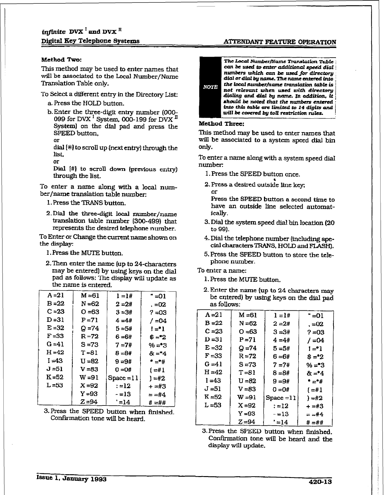
@finite DVXrandDVXn
Digital Key Telephone Systems
ATTENDANT
FEATURE OPERATION
MethodTwo:
This method may be used to enter names that
will be associated to the Local Number/Name
Translation Table only.
To
Select a diiierent entry in the Directory List:
a. Press the HOLD button,
b.Enter the three-digit enlry number (OOO-
099 for DVX I System, 000-199 for DVX ’
System) on the dial pad and press the
SPEED button,
%il [*ii to scroll up (next entq) through the
list,
zial I#) to scroll down (previous entry)
through the list.
To enter a name along with
a
local n~m-
her/name translation table number:
1. Press the TRANS button.
Z.Dial the three-digit local number/name
translation table number (300-499) that
represents the desired telephone number.
To Enter or Change the current name shown on
the display:
1, Press the MUTJ3 button.
Z.Then enter the name (up to 24-characters
may be entered) by using keys on the dial
pad as follows: The displav will update as
thename is entered. - -
A=21
B=22
C=23
D=31
E =32
F=33
G =41
H =42
I=43
3 =51
K =52
L&33
M=61
N =62
0 =63
P=71
Q =74
R=72
s =73
T=81
u =82
v =83
w=91
X =92
Y =93
Z=94
1 =l#
2 =2#
3=3#
4=4#/
5=5#
6=6#
7 =7#
8=8#
9 =9#
O=O#
Space =I1
: =12
- =13
’ =14
J
* =01
, =02
7 =03
/=04
1 =‘l
$ =*2
Oh =*3
& =*4
* =‘#
(=#l
) =#2
f =#3
= =#4
# =##
3.Press the SPEED button when finished.
Confirmation tone wiU be heard.
This method may be used to enter names that
will be associated to a system speed dial bin
04Y*
To enter a name along with a system speed diaI
number:
1. Press the SPEED button once.
2. Press a desired outside line key
or
Press the SPEED button a second time to
have an outside line selected automat-
ically.
3. Dial the system speed dial bin location (20
to 99).
4. Dial the telephone number (including spe-
clal ch;lracte~~TRANS, HOLD and FLASH).
5. Press the SPEED button to store the teIe-
phone number.
To enter a name:
1. Press the MUTE bution.
2. Enter the name (up to 24 characters may
be entered) by using keys on the dial pad
as foIlows:
A=21
B =22
c=23
D=31
E =32
F -33
G-41
H =42
I=43
J =51
K =52
L=53
M =61
N =62
0=63
P=71
Q =?4
R =72
s =73
T=81
u =82
v -83
w=9x
x =92
Y =93
Z=94
1 =I#
2 =2#
3 =3#
4=4#
5 =5#
6 =6#
7 =7#
8 =8#
9 =9#
0 =O#
space =11
: =12
- =13
’ =14
= =Ol
* =02
?=03
/=04
;z:;
96 =*3
& =‘4
l =‘#
(=#l
) =#2
+ =#3
= =#4
# =##
3.Press the SPEED button when fInished.
Con&-m&ion tone wiU be heard and the
display wflI update.
~uc1,Jan~1993 420-13
iqftnite DVX ’ and DVX ’
DWtal Key Telephone Systems
4.
Either hang up to end programming or
begin
at step ‘2” to program another Sys-
tem
Speed Dial bin/Name combination.
420.18
NIGHT SERVICE
a-Any designated attendant can place the
system into Night Service by pressing the
pre-programmed Night Service button
{DND) or by dialing IS041.
b. Pressing the pre-programmed Night Serv-
ice button again removes the system from
Night Service.
420.20 OFF HOOK VOICE OVER [OHVO)
This feature allows users, o&hook on a call (CO
or Intercom). to receive a voice annaunccment
through the handset receiver without inter-
rupting the existjng call. The Voice Over is
muted so as not to “override” or “drown”
out the
existing conversation. The overridden party
may then respond to the calling party using
CAMP-ON procedures to talk to the calling
par& or may use Silent Text
Messaging
to re-
spond to the calling party via LCD Displays.
Placing an Off-Hook Voice Over (OHVO) caU:
a. When an OHVO station calls. a busy OHVO
station. and busy tone is received, the call-
ing OHVO station can dial tbe OHVO code
[SZS]
on the dial pad.
&ss a pre-programmed* OHVO button to
initiate an OHVO announcement. The
HOD button LED will flash at the called
oHvo station.
b. Both OI-WO
stations w-ill receive a
one-beep
B tone. The station receiving the
OHIO call must be off-hook and in the
?-IF mode, and then the calling OHVO
party may begin the voice announcement
- to the called OHVO par&. Thecalled OHVO
station’s exisfing conversation will not be
interrupted and the voice over an-
nouncement will not ‘drowned” out the
existing conversation. The calling OHVO
station will not
be connected to or other-
wise be able to hear the called station’s
conversation (the connection will only al-
low the calling station to transmit to the
called stationl.
Responding to an OK-Hook Voice Over (OHVO):
After receiving an OHVO announcement, two
options are available
to
respond to the calling
party:
l.Tbe called OHVO station may respond to
the calling OHVO station by using the
Camp-On feature. The called OHVO sta-
tion presses the flashing HOLD button to
consult with the calling station. The exist-
ing call (CO line) goes on Exclusive Hold
automat&&y. This method. then follows
Camp-On procedures and operation.
2. The called station may respond to the call-
ing station by using the Silent Text Mes-
saging (this feature is only available
to
digital key terminals, and the called station
must be a digital display terminal.) The
called OHVO station may press pre-pro-
grammed
Message
button to respond to the
voice
over
announcement without being
released from the current call. (i.e. by
pressing a flex button pre-programmed for.
the message “IN MEETING”), the calling
station TKul receive this message on the
calling station’s U3D display.
Ifmecaui8anln- ca.l&th.ein~
calrwill be dripped and an+llruwm~d
wiLibeestnbli.sh&ktwenthta4Z&gamd
ca&d8tationc ‘.
Conditions
l
The station receiving the OHVO call
MUST be off-hook and in the “FfF mode.
l
The calhg (originating) station and re-
ceiving station must be OHVO digital
terminals.
l
when the dialed station responds vh
Camp-On all conditions and options
available to Camp-On apply [refer to the
feature description for Camp-On).
l
OHIO may be used to nof@ the called
party of a transf&-red call (CO Line or
Intercoms by announcing the call. then
releasing to complete the t3xnsfer. When
this occurs, the receiving station does
not need to respond to the OHVO.
l
WbcnacallislransferredvfaOHVO,the
recetving station will not receive muted
ringtig after the transfer is complete.
9 Any messages including “CANNED”.
‘CUSTOM”. or ‘SILENTRESPONSE” text
messaging may be used to respond to an
OHVO call. The message will appear on
the calling station and called station
LCD displays.
420-14 bsue 1, Jamxary 1993
imite DVX ’ and DVX II
D&itni Key Telephone Systems ATTENDANT FEAT’ORE OPERATION
l
If the calling station is a non-LCD term&
nal, the called station will receive en-or
tone when responding via text messag-
ing.
l
The called station may press a flex but-
ton programmed as a TIM: Message but-
ton, [633#+XXI.
This flex button may
then be pressed to respond to the caUng
station. MMF’ digits wiIl not be heard by
either party.
l
The receiving station must be pro-
grammed to anow OHVO calls.
l
When silent messaging is used to te-
spond to an OHVO call, the existing call
on the called station will not be discon-
nected, while the messages are being
sent to the calling station.
0 The calhgstation of an OHVO call must
re.rnain off-hook to receive silent mes-
sages. The calling station’s voice tram+
mit wilI remain connected to the called
station and may respond verbally to the
text
messages. The OHVO caIl ends
when the calling station goes on-hook.
l
If the receiving station is on-hook in
speakerphone mode and a calling party
initiates OHVO. the receiving station-
receive a Camp-On warning tone and
normal Camp-On procedures are fol-
lowed.
l
The c&led station may send (multiple
messages) and even after sending a mes-
sage, may press the Camp-On button to
talk to the calling station. Each time a
message is sent., the splash tone will be
heard and both displays will be updated.
’ LED’s will follow Camp-On LED lampfng
sequences.
Each station can be Programmed to allow re-
ceiving OHVO calls as part of Station Program-
ming. Each station may be programmed for
OHVO in one of two ways. as follows:
- OHVO disallowed (may not receive
OH-v0 cans}.
- May receive OHVO calls.
420.21 SETTING SYSTEM TIME AND
DATE
Must be set by the first programmed attendant,
a. Dial (6921 on the dial pad. Con&nation
tone is heard.
b. Enter date and time as follows:
YYMWIDDHHMM
YY=year 00-99
MM = month 01-12
DD = day 01-31
HH = hour 00-23
MM=minute 00-59
When the correct number of digits are entered,
co&&nation tone wilI be heard and the display
will update.
420.22
STORING SYSTEM SPEED NUM-
BERS
System Speed numbers must be entered by the
first programmed attendant. lf no attendant is
speciikl. enter at Station 100.
a. Press SPEED once, then press a desired
outside line key or sqect an outside line
automatically by pressing the SPEED but-
ton a second time.
b. Dial the System speed bin location (20 to
99).
c. Dial telephone number.
d. Press the SPEED button.
e. Hang up.
- PressingtheTRANSbuttonduringnum-
ber entry initiates a Pulse-To-Tone
switchover. Pressing the HOLD button
during number entxy inserts a Pause.
Pressing the FLASH key inserts a Flash
into the speed number.
- Pressing the TRANS button as the first
enby in the speed bin inserts a no-dis-
play character causing the numbers
stored in the bin not to appear on the
Di@tlTerm~& display when the bin
is accessed.
Speed Bin numbers 60-99 are NOT monitored
by Toll Restriction.
420.23 TEXT ~~EBSAGIIUG (Siitnt Rt-
sP=el
This a feature allows a station user to use text
messages to respond to a caller that has either
Camped-On or has used the Off-Hook Voice
Over feature to alert
a busy station user of a
waiting call or message. The “camped-on” sta-
tion may respond to the caller via the canned,
custom. and silent response text &CD) mes-
sages. The text messages appear on the calling
par& LCD Display.
While receiving a Camp-On. or OHVO call:
a. The called partymaypress a flexible button
programmed for message access, then dial
the two digit message code (or press a
pre-programmed flex button for a particu-
bmlt 1, January 1993
420-15
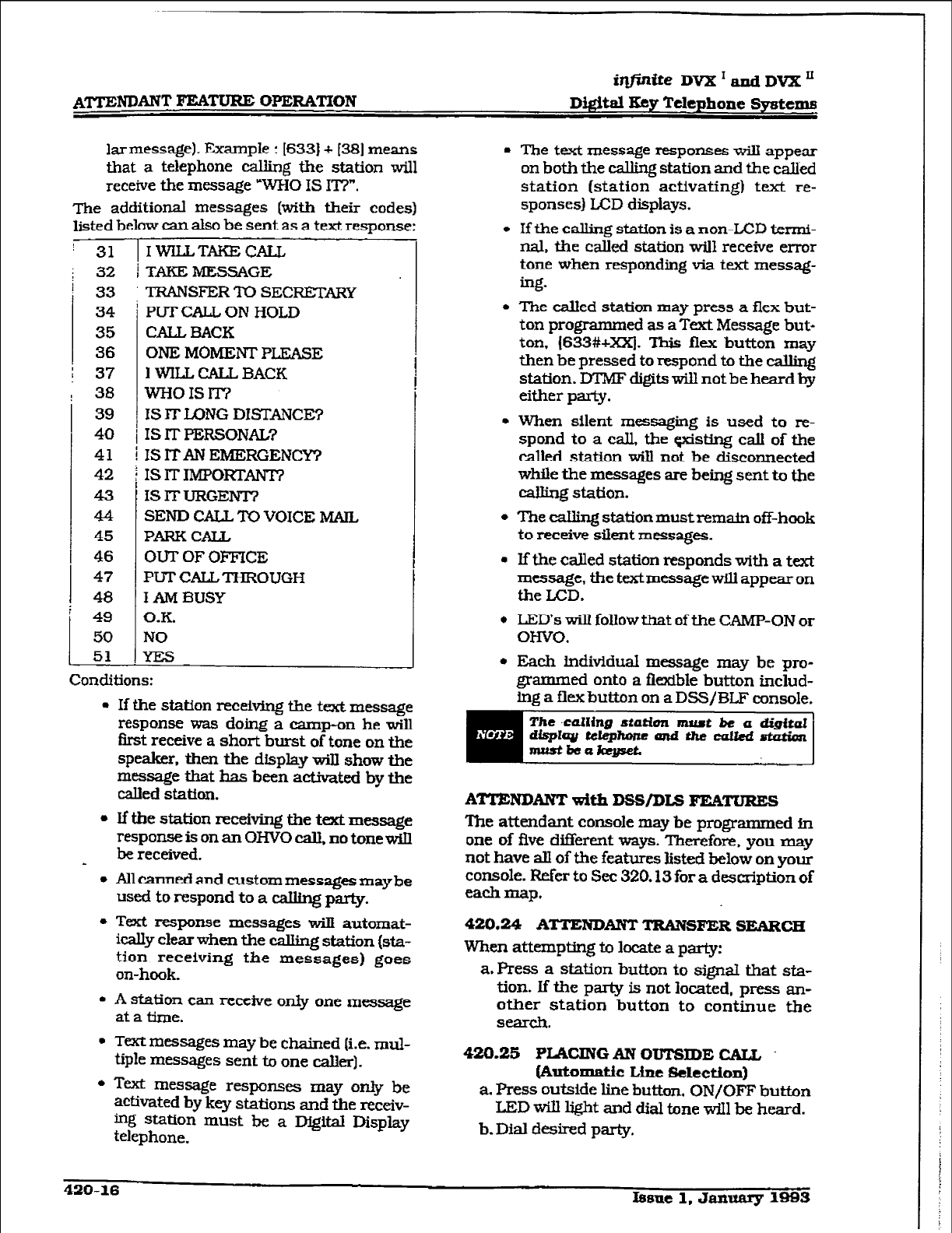
i#@J&e Dm’andDVX”
D&iti Key Telephone Systems
lar message). Example : I6331 + 1381 means
that a telephone calling the station will
receive the message WHO IS IT?“.
me additional messages [with their codes)
listed below can also be sent as a text response:
j 31 1 IWILLTAKECALL
: i 32 1 TAKE MESSAGE 33 TRANSFER l-0 SECRETARY
1
34
35
36
37
38
39
40
41
42
43
44
45
46
47
48
49
50
51
t
PUTCALL ON HOLD
CALL, BACK
ONE MOMENTPLEASE
I WILL CALL BACK
wHOISlT7
IS IT LONG DISTANCE?
IS IT PEXSOIWL?
IS ITAN EMERGENCY?
IS IT Ih@ORTANT?
fS IT URGENT?
SEND CALL ‘I’0 VOICE MAIL
PARK CALL
OUT OF OFFICE
PUT CALL THROUGH
I AM BUSY
O.K.
NO
L
Conciitions:
l
If the station receiving the text message
response was doing a camp-on he will
first receive a short burst of tone on the
speaker. then the display wilI show the
message that has been activated by the
called station.
l
If the station receiving the text message
response is on an OHVO calL no tone wiIl
be received.
l
AIlcannedand custommessagesmaybe
used to respond to a calling party.
l
Text response messages will automat-
ically clearwhen the eaIIing station (sta-
tion receiving the messages) goes
on-hook.
l
A station can receive only one message
at a time.
l
Text messages may be chained (i.e. mul-
tiple messages sent to one caller).
l
‘kxt message responses may only be
activated by key
stations
and the
receiv-
bg station must lx a Digital Display
telephone.
0 The text message responses wiII appear
on both the caIling station and the called
station (station activating) text re-
sponses) LCD displays.
l
If the calliug station is a non-LCD termi-
nal, the called station will receive error
tone when responding via text messag-
ing.
l
The called station may press a flex but-
ton programmed as a Text Message but-
ton, (633#+XXj, This flex button may
then be pressed to respond to the caIling
station. DTMF digits will not be heard by
either Party.
l
When silent messaging is used to re-
spond to a call., the gxisting call of the
called station wiIl not be disconnected
while the messages are being sent to the
calling station.
l
The calling station must remain off-hook
to receive silent messages.
l
If the &led station responds with a text
message, the textmessage will appear on
the ED.
0 LED’s will follow that of the CAMP-ON or
OHVO.
l
Each Inditidud message may be pro-
grammed onto a fIexibIe button includ-
ing a flex button on a DSS/BLF console.
The -calling sCation nuut be a
dig&al
dit@~W@toneandthewUed-
mistb8aksgseL
ATTENDANT
with DSS/DIs FEATURES
The attendant console may be programmed in
one of five different ways. Therefore. you may
not have all of the features listed below on your
console. Refer to See 320.13 for a description of
each map.
420.24
ATTENDANT
TRANSFER SEARCH
When attempting to locate a party:
a. Press a station button to signal that sta-
tion. If the party is not located. press an-
other station button to continue the
SS3dl.
420.25 fLMXNGAN OTJTSIDE GAIL
&Itolllatic Line selectioxl)
a. Press outside line button. ON/OFF button
LED will light and dial tone will be heard.
b. Dial desired party.
420-16 Issue 1. January 1983
@@d&e DVX’andDVXn
Dwa 3ey Telephone 8y8textIs ATTENDANT FEATURE OI’ER&‘MON
c. When called party answers, lift handset to
converse or use speakerphone
420.26 CALLI’=
While connected to an outside line:
a. Press programmed CALL PARK button.
The caller is put on Exclusive hold.
b.At this time, you can page or call another
internal station.
c. When the party you calIed responds, an-
nounce the call park location and replace
handset.
420.27 DO NOT DISTURB INDICATION
The associated station button wiIl flash at a
medium rate to indicate that station is In Do
Not Disturb.
420.28
RETREWNG
A
PARgeD CALL
a. Lift handset or press ON/OFF button.
b.Dial I#] on the dial pad.
c. Dial the parking location (220 to 227)
where the call was parked.
420.20 CALL TRANSFER
Outside lines can be transferred from one
phone to another within the system. The &ITJS-
fer can be either screened (announced) or un-
screened to either an idle or busy station.
Bcrccned Transfer:
While connected to an outside line:
a.Press station button where call is to be
transferred lif programmed on your tele-
phone).
or
pressTRANS button and dial station num-
ber (loo to 155).
b.The c&led extension signals according to
the intercom signal switch position.
c. When that extension answers. announce
the tifer.
d. Hang up to complete transfer.
Unscreened Transfer:
When the called extension begfns to signal,
hanguptotransferthe&l(Recalltimerstarts)).
Transfer Search:
When attempting to locate a pa&
a. Press a
station
key to signal a station.
b.If the party is not located, press another
station key to continue the search.
If the party is not located:
c. Press another station button to co&me
the search.
d. When the caLled party answers, hang up to
complete the transfer.
420.30 CAMP-ON
While connected to an outside line:
a. Press desired station button.
b. When busy tone is heard, press CAMP-ON
button.
c. Replace handset, access another CO Line
or press RELEASE button (ifyou have one).
420.51
FIJCXIBIE BUTTON FROGRAM-
MING
a. Press SPEED button &ice.
b.Press FLEX button to be programmed (it
must be programmed In database as a
flexible button).
c. Dii desired code (Refer to Table 4-00-2 Flex
Button Programming Codes).
420.32
MEET ME PAGE
To request another party meet you on a page:
a. Dfal the desired two-digit paging code
or
press pre-progxammed* flex button.
b. Request that party meet you on the page.
c. Do not hang up: wait for the requested
party to answer.
Answering a Meet
Me
Page
a. Go to the nearest telephone and dial 177)
onthedialpad.
b.You will be connected to the party that
paged you.
*Refer to Sec. 400.37. Flexible Button
Assignment.
420.33
PAGING
A. Extemalpagiag
1. Dial the two-or three-digit External paging
code. Wait for page warning tone.
76 [Ol= Ekternal All Call (Zones l-7)
76 [I)=ExternalZone 1
76 I21 = External Zone 2
76 !31= External Zone 3
76 (41= External Zone 4
76 15]= External Zone 5
76 IS] = Extermd Zone 6
76 [7] = External Zone 7
Issue 1, January 1989 42CL17
L
2.
Speak in normal tone of voice to deliver
message.
stations off-hook or in DND will not hear the
internal page announcement.
3.
Deliver page ~II normal tone of voice.
4. Replace
handset to
terminate page an-
nouncement.
B. InternalPaging
Stations off-hook or in DND will not reeefve the
page announcement.
1. Press the pre-progrred’ PAGE button,
or dial one of the following codes:
7O=AllCall-lntemal&Extemal
71= Internal Zone 1
72=
Internal Zone 2
73=
Internal Zone 3
74=
Internal Zone 4
75=
Internal AU Call
76[0]=
Exkmal All Call [All Ext Zones)
76(zJ=
External
Zone (2=1-7)
2.Speak in
normal tone of voice to
deliver
message.
3.Replace handset to terminate page an-
nouncement,
c. All CallPaging lrnternal/Extcmal)
1. Dial I701 on the dial pad,
or
press the pre-programmed* PAGE button.
2.
Speak in normal tone of voice to deliver
message.
S.Replace handset to terminate page an-
nouncement.
*Refer to Sec. 400.37. Flexible Button
Assignment.
420.34
RELEASE BW’TON
All DSS/DLS maps contain a Release button
that may be pressed to disconnect or terminate
an intercom call, transfer sequence, page an-
nouncement or CO call.
.
420-18 Ifmu 1. Jannary 19%
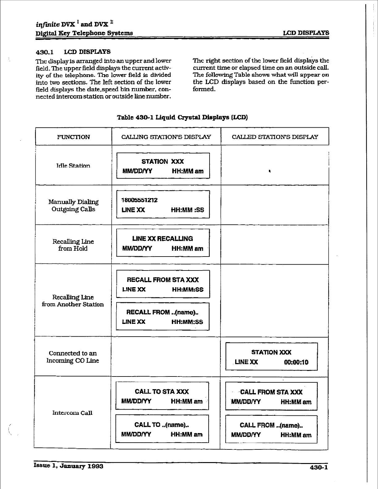
iqjintieDVXTandDVX’
Digital Eey Telephone Systems LCD
D1SPIa.K~
490.1 LCD DISPLAYS
The display is arranged into an upper and lower
field. ‘Zhe upper field displays the current activ-
ity of tie telephone. The lower field is divided
into two sections. The left section of the lower
field displays the date.speed bin number, con-
netted intercom station or outside line number.
The right section of the lower field dispkys the
current time or elapsed time on an outside call.
The following Table shows what will appear on
the LCD displays based on the function per-
formed.
Table 430-1
Liquid Cqwtal Displays [LCD]
FUNCTION
CALLING STA3OWS DISPLAY CALLED STATION’S DISPLAY
I I
Idle Station qyii?TJ! !
ManuaIIy
Dialing
outgoing CaIIs piiiezq
Recalling Line
from Hold ,a1
Recalling Line piii=q
from Another Station
31
Connected to an
Incoming CO Line p=iq
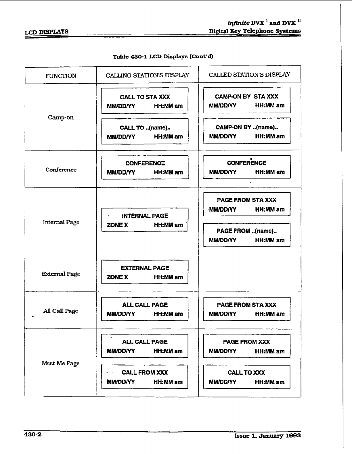
LCD DISPLa’
i@nite DVX ’
and DVX *
Digital Xey Telephone
Systems
Table
430-l LCD Displays (Co&d)
FUNCTION I CALLINGSTATION’SDISPi.AY
I
I I
I
CALL TO STA XXX I
ckmp-on
Conference
IntemalPage
Exttzrnal
Page
AllCaUPage
I
Meet MePage
MMhlD/W
HH:MMam
I
1
CALL TO ..(name)..
MNUDD/YY
HH:MM 81tl
CONFERENCE
I MWWW
HH:MMam 1
AU
CALL
PAGE
I
MMiDDPP( .HH:Mhl am
CALL FROM XXX
MkVDD/YY
HH:MM
am
CALLJ3DSTAnONSDISPLAY I
I I I
I
CAMP-ON BY STA XXX
I
MIWDD/W
HH:MM
am I
CAMF-ON BY ..(name)..
MM/DDlYY
HH:MM am
CONFER’IENCE
MMIDDIYY HH:MM
8m
I
PAGE FROM STA XXX I
I
MNyDDlW -HH:MM am f
PAGE FROM ..(name})..
MWUDDlYY
HH:MM
am
I
PAGE FROM STA XXX I
I
MMlDDm HH:MM
am 1
PAGE FROM XXX
MMfDDIYY HH:MM am
.CALLTOXXX
MMIDDIYY .HH:MM
am
430-2 lsaue 1, Jall~ 1093
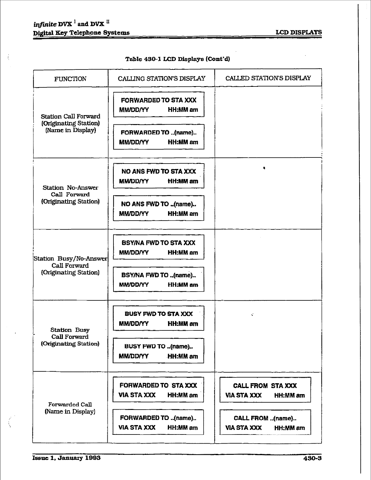
LCD DISPLAYS
Station Call Forward
(originating Station)
(Name in Display)
Station No-Answer
Call Forward
(or@nating Station)
X&ion Busy/No-Answe
CaIl Forward
(originating Station)
Station Busy
CalI Forward
Or@inating Station)
Forwarded Call
Phne in Display)
Table 43&l
LCD Display8 (Co&d)
CALLING STATIONS DISPLAY
FURWARDEDfO 8-I-A XXX
MJk#DD/YY HH:MM am
I
NOANSFWDTOSTAXXX
MMlDD/YY HH:MM am
1 NO ANS FWDfo .&tame).. 1
I MMlDD/YY HH:MMam 1
BUSY FWD To ..(name)..
MM/DD/YY .HH:MM am
VIA STA Xxx
CALLED STA’IIONS DISPLAY 1
.
I
CALL FROM STA XXX I
I VIASTAXXX HH:MMarn 1
CALL FROM .&tame)..
VIASTAXXX
HH:MM am
188lxc 1, January 1993
430-3
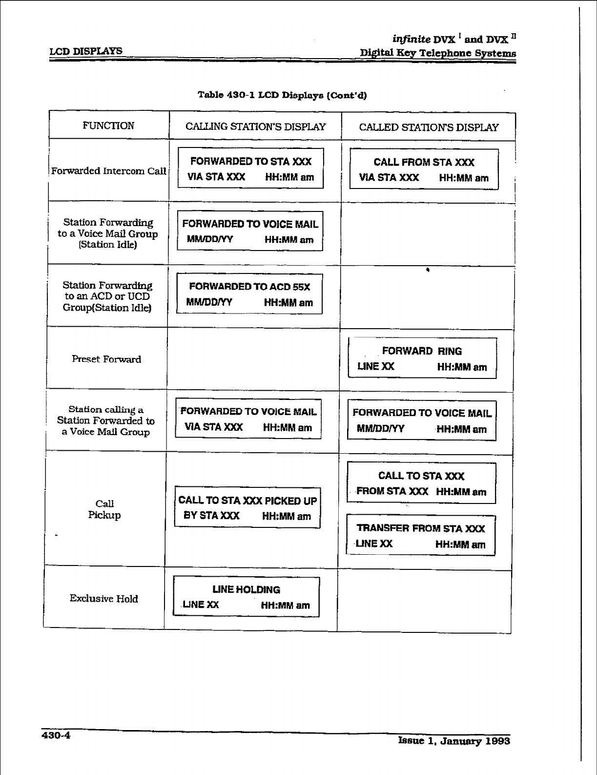
LCD DISPLAYS
iqfMtenVX’an.dDVxn
Digital Key Telephone Sgstcm~
Table 430-l
LCD I3isplays &ont-d)
FUNCTION
Forwarded Intercom Call
’ Station Forwarding
to a Voice Mail Group
i
(Station Idle)
* Station Forwarding
to an ACD or TJCD
Group(Station Idle)
I
Preset Forward
Station calling a
Station Forwarded to
a Voice Mail Group
II
1’
I
-
1
[
1
[
-
[
[
[
CAU TO STA XXX PICKED UP
BY STA XXX HH:MM am
Exch~~ive Hold
LINE Xx
FORWARDED TO STA Xxx
VIASTAXXX HH:MM am
FORWARDED TO VOICE MAIL
MM/DD/yy HH:MM
am
FORWARDED TO ACD 55X
Mhd/DDlYY HH:MM am
FORWARDED TO VOlCE MAIL 1
VIASTAXXX HH:hlM
am 1
LfNE HOLDING
HH:hIMam 1
CALLED STATIONS DISPLAY I
/I (
I
FORWARD RfNG
LINE XX HH:MM ttm
I I
FORWARDED TO VOtCE MAIL
MM/DDMv -HH:MM am
CALL TO STA XXX
I.-FFIOMSTAXXX HH:MMam
TRANSFER FROM STA XXX
.UNE XX HH:MM am I
4304 Issue 1, Januarp 1993
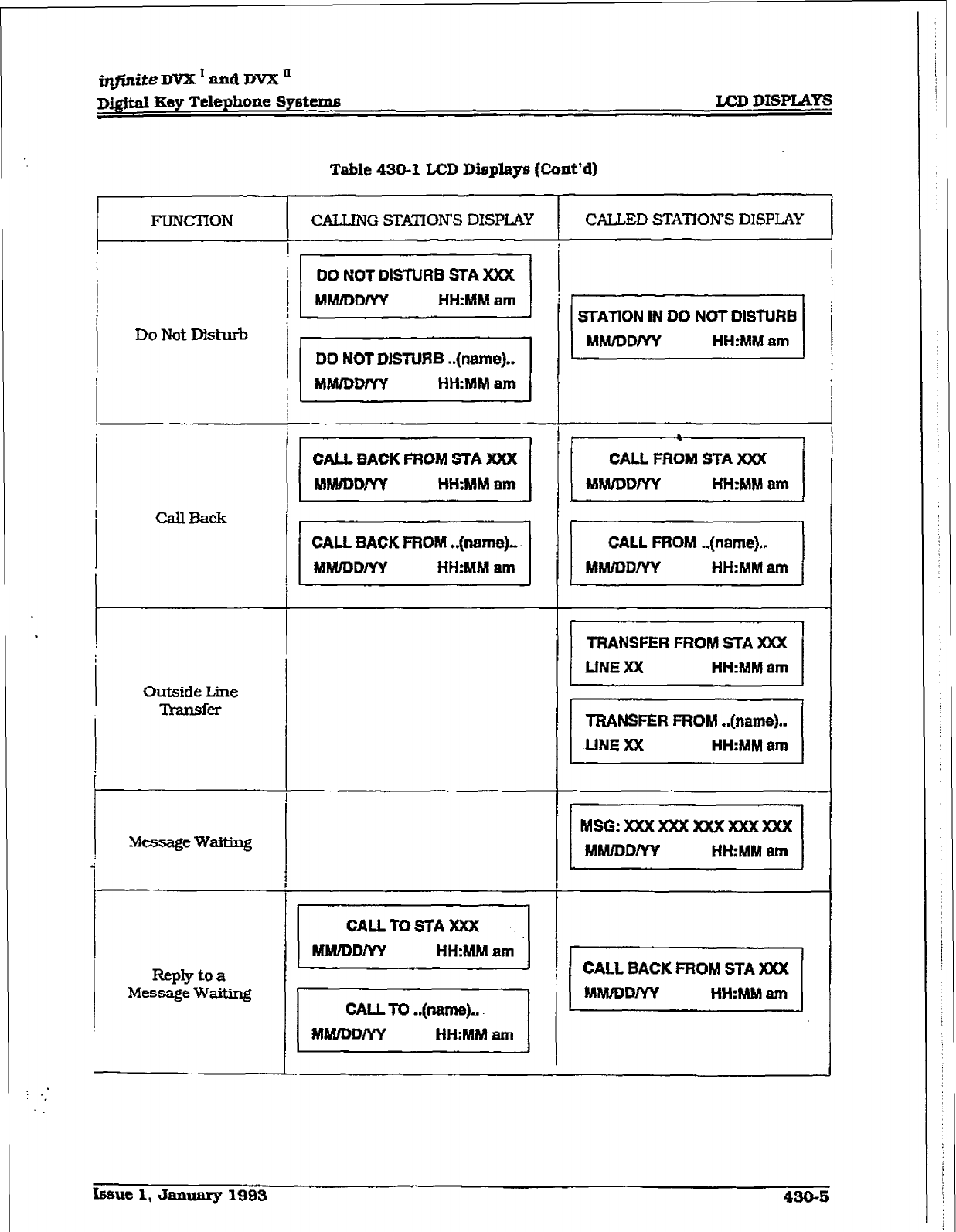
irlfinite DVX I and DVX ’
~&$al Key Telephone Syetcms
LCD DXSPLAYS
Table 430-I LCD IXsplaps (Co&d)
FLIIWXION CALLING STATION’S DISPLAY CALLED STATION’S DISPLAY
Do Not Disturb
Call Back
Outside Line
Transfer
Message WaiEng
Reply to a
Message Waiting
I
T
i
DO NOT DISTURB ..(name)..
MfNDDlYY HH:MM am
CALL 8ACK FROM STA XXX
MhVDDM HHMM am
STAllON IN DO NOT DISTURB i
MhUDDlYY
HH:MM
am
I MMIDDp(Y HH:MMam 1
I
CALL FROM STA XXX
MSG:XXXXXXXXXXXXXXX
MMIDDNY HH:MM
6m
CALL BACK FROM STA XXX
MMIDDIYY
HH:MM am
Issue 1, January
1993 430-E
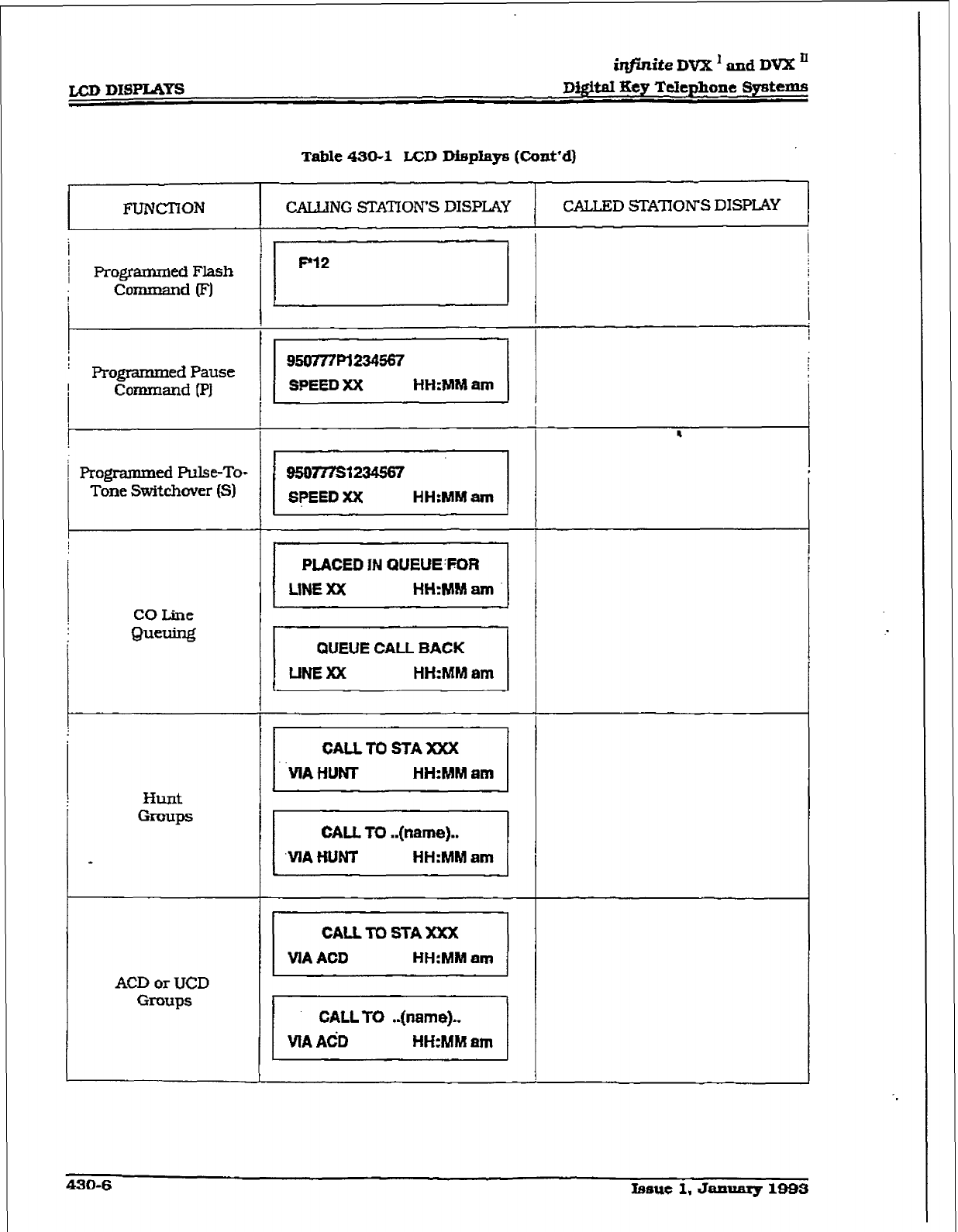
LCD DISPLAYS
imite DVX ’ and DVX ’
Digital Key
Telephone Systems
Table 430-I LCD Displays (Cont’d)
FUh’C’I7ON
I
I
I Programmed Flash
! Co-d (FJ
Programmed Pause
Command (PI
1 Programm
ed Pulse-To-
Tone Switchover (Sl
CO Line
0ueW
ACD or UCD
Groups
CALLING STATION’S DISPLAY
F12
950777Fl234567
SPEED XX HH:MM
am
I
95mvst234S67
SPEED XX HH:MM am
QUEUE CALL BACK
LlNExx HH:MM
am
CALLED STATION’S DISPLAY
430-6 bsue 1, January l-3
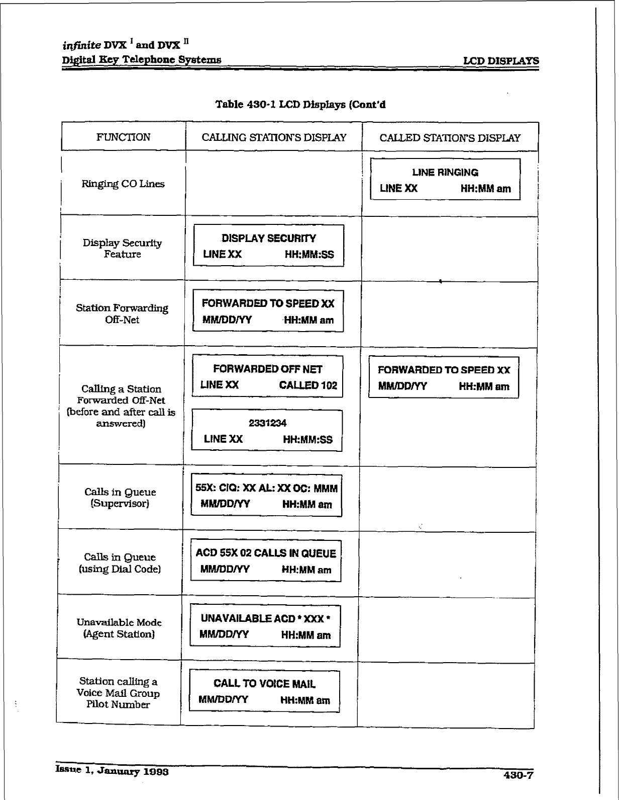
iqfinite
DVX ’ and DVX JJ
D@itd
Key Telephone~Spstems LCD DISPLAYS
Table 430-I LCD Displays (Cont’d
FUNCTION CALLING STATIONS DISPLAY
I
mging co Lines
p------
I DispIay Security
Feature
t
Staticm Fomardiq
Off-Net
Cal&g a Station
Forwarded m-Net
lbeiore and after call is
answered)
Calls in Queue
ISupervisor)
Calls in Queue
(using Dial Code)
-I
!
Unavailable Mode
(Agent St&on)
Station calltng a
Voice Mail Group
Pilot Number
L
I
CALLED SJZAlION’S DISPLCI’Y
Iasuc1,Jan~1993 430-7
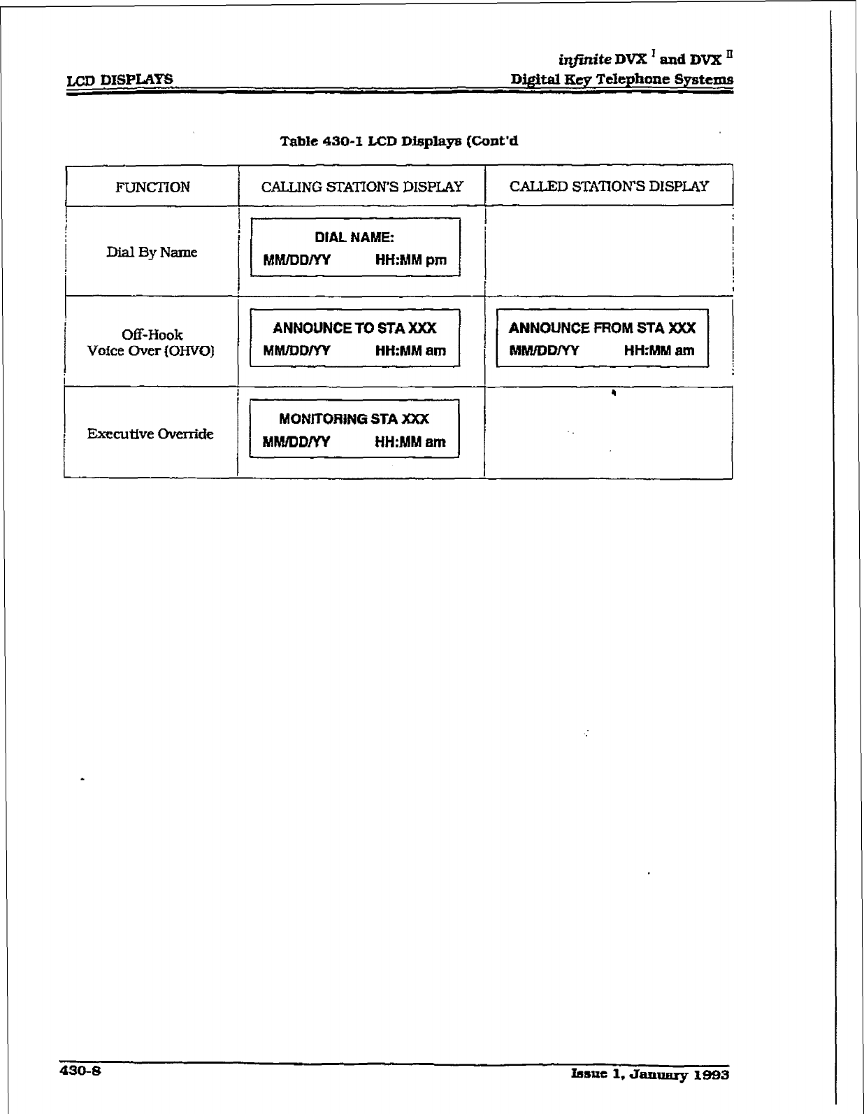
JXII DISPLAYG
iqfinite DVX ’ and DVX ’
Digital Key Telephone Systems
Table 430-l LCD Dfl3plays (Cont’d
I
FUNCTION 1 CALLING STATION’S DISPLAY
I
1 I 1 I
;
1 /I
DIAL NAME:
Dial By Name MRUDDIYY
HH:MM pm
Off-Hook
Voice tier (OHVO)
ANNOUNCE TO STA XXX
MMIDDNY H&MM am
I I/
MONlTORtNG STA XXX
i Executfve Override
MWDDIYY HH:MM 8m
I’ 1
CALLED STA’IIOWS DISPLAY
1
-
430-s
Issue 1. JaQufiry 1999
infinite DVX ’ and DVX’
Di#t,al Key Telephone
Systtms
INSTALLATION
SECTION 500
INSTALIATION
500.1 SITEPIANNING
Selection of a suitable Iocation is the most
basic, yet most critical consideration in the
installation of a telephone system. The follow-
ing should be considered when choosing an
appropriate location for equipment installation:
l
Ampie space must be allowed to remove
the KSU cover. to access assemblies and
cards within the cabinet and allow space
for the MDF (Main Distribution Frame).
l
Location of CO/PBX line terminations
must be considered when selecting a
location for the KSU. In the case of tele-
phone company line, FCC approved con-
nectors supplied by the telephone
company. should be within 5 feet (I .5
meters) of the cabinet/main distribution
fiane.
l To
nxinimb the length of cable runs
between the stations and the system
KSU. the location of the majority of the
telephone sets (stations) should be taken
iuto consideration when selecting a loca-
tion for the cabinet.
l
A well ventilated, and well lighted area
having an
optima-n
temperature range
of 60 degrees to 80 degrees F and a
reMive humidity range of 5 to 90% [non-
condensing) must be provided.
0 Area lighting should be adequate for in-
stallation and maintenance of the sys-
tem. Hazardous or flammable materials
should be removed from the vicinity. The
immediate area must not be subject to
flooding or excess moisture. The KSU
should be isolated from areas of moving
machinery or equipment. It is also rec-
ommended that static electxicity-pro-
ducing vts not be installed in this
area.
l
A separately fused. dedicated 117V ac,
HO?%. 15 Amp., 60 Hz. single phase,
3wire (parallel blade with ground]
power outlet should be located within 5
feet (1.5 meters) of the system power
SUPPlY.
l
‘he Ksu and main distribution frame
should be placed in au electrkally noise
free environment, isolated and shielded
from equipment that causes eleceo-
magnetic interference @Ml) or radio fre-
quency interference WI). Examples of
electrical noise are rotating electrical
machinery and arc welding equipment,
refrigerators. copy machines, etc. Floor
coverings that generate static electricity
should also be avoided.
l
The system KSU should not be installed
close to any equipment which may pro-
duce RF7 (Radio Frequency Interference)
such as a radio frequencytransmitter, or
microwave oven.
l
lfthesystemistoheinstiedinaloca-
tion prone to lightning strikes, provide
lightming protection on the power Line.
any station cable runs outside the build-
ing, and CO lines.
A. Symtem Grouadisg
To ensure that the system WllI operate
properly. a good earth ground is required.
Use of the Telco ground (source not de-
mark) or a mekllic COLD water pipe usu-
ally provides a reliable ground path.
Care- check
that
the pipe does not con-
tain insulated joints that could isolate the
ground. in the absence of the COLD water
pipe, a ground rod or other source may be
used. A No. 12 AWG copper wire should be
used between the ground source and the
KSU (25 feet maxirmxn). The farther from
the ground sours the larger the ground
wire used should be. The wire should be
kept as short as possible and can be con-
nected to the ground fug provided on the
lower left side of the backplane on the KSU
with the cover off.
B. Lightningptottction
The @fir& Digital Key Telephone System
should have Central Office lines, Single
Line Telephones and O&F?emfse Exten-
sion stations protected with proper light-
ning surge arrestors. This will provide
protection from damaging surges on sensi-
tive cabliug by non-direct lightning sties.
The protection should contain a compli-
ment of three-element gas-d&charge tubes
to ground high potential surges. and asso-
ciated circuits to absorb and filter lower
kvel surges. This type of lightning protec-
Issue 1, Jixnuxu-y 1993 500-l
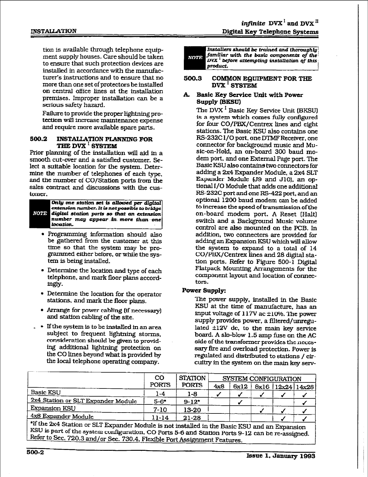
infinite DVX ’ and DVX ‘*
Digital Key Telephone Systems
tion is available through telephone eqtip-
ment supply houses. Care should be taken
to ensure that such protection devices are
installed in accordance with the manufac-
turer’s instructions and to ensure that no
more than one set of protectors be installed
on central office lines at the installation
premises. Improper installation can be a
serious safety hazard.
Failure to provide the proper lightning pro-
tection wilI increase maintenance expense
and require more available spare parts.
SO0.2
INSTALLATION PLANNING
FOR
TEE Dvx I SYSTEM
Prior planning of the installation will aid in a
smooth cut-over and a satisfied customer. Se-
lect a suitable location for the system. Deter-
mine the number of telephones of each type.
and the number of CO/Station ports from the
sales contract and discussions with the cus-
tomer.
. programming information should also
be gathered from the customer at this
tfme so that the system may be pro-
grammed either before. or while the sys-
tem is being installed.
l
Determine the location and type of each
telephone, and mark floor plans accord-
m&Y-
. Determine the location for the operator
staticms.
and mark the floor plans,
. Arrange for
power cabling Iif necessary)
and station cabling of the site.
.
- Ifthe system is to be installed in an area
subject to frequent lightning storms,
consideration should be given to protid-
ing additional lightning protection on
the CO lfnes beyond what Is provided by
the local telephone operatmg company.
hzstol~ ahmrld be trained and thmmgh@i
fmWut with the basic wmponmts of thei
lm~bejim nttnnpting in8taLIotion Qfthis:
produd. I
500.3
COMMON EQUIPMENT FOR THE
DVX I SY!3TBM
k Basic Key Service Unit ~4th
Power
Supply @rrsvl
The DVX ’ Basic Key Service Unit (BKSU)
is a system which comes fully confIgured
for four CO/PBx/Centrex lines and eight
stations. The Basic KSU also contains one
RS-232C I/O port. one DTMFRecetver. one
connector for background music and
Mu-
sic-on-Hold, an on-board 300 baud
mo-
dem port. and one External Page port. The
Basic KSU also contains two connectors for
adding a 2x4 Expander Module, a 2x4 SLT
Expander Module (J9 and JlO). an op-
tional I/O Module that adds one additional
RS-232C port and one RS-422 port, and an
optional 1200 baud modem can be added
to increase the speed of transmission of the
on-board modem port. A Reset (Halt)
switch and a Background Music volume
control are also mounted on the PCB. In
addition, two connectors are provided for
adding an Expansion KSU which will allow
the system to expand to a total of 14
CO/PBX/Centrex lines and 28 digital sta-
tion ports. Refer to Figure 500-l Digital
Flatpack Mounting krangements for the
component layout and location of connec-
tors.
Power Supply:
The
power supply, installed fn the Basic
KSU at the time of manufacture, has an
input voltage of 11 iv ac f10%. The power
supply provides power, a fiItered/unregu-
lated 112V dc. to the main key senrice
board. A slo-blow 1.5 amp fuse on the AC
side of the transformer provides the neces-
sary fire and overload protection. Power is
regulated and distrfbuted to stations / cir-
cuttry in the system on the main key serv-
co
! STAmO& ,
PORK5 PORTS
r Basic IEW 4x8 1 6x:- t v.,
1 l-4 l-8 J J JIJ J
2x4 Station or SLTExpander Module 1 5-6* g-12* J I /
Expansion KSU 7-10 13-20 1
4x6 Expander Module 11-14 21-28 1
*If the 2x4 Station or SLT Ekpander Module is not installed in the Basic KSU and an Expansion
KSU is part of the system cor&guration. CO Ports 5-6 and Station Ports 9- 12 can be r-e-assigned.
Refer to Sec. 720.3 and/or Sec. 730.4. Flexible Port Assignment Features.
soo-2
Issue 1, January 1883
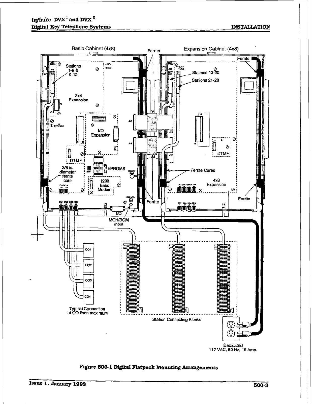
irlfinite
DVX’ 8xM DVX’
Digital Kep Telephone Systems INSTALLATION
Basic Cabinet (4x81
Ferrite
I* I, Expansion Cabinet (4x8)
)7’
-mm- ----e
---------
:a a :
:i!
:.t
1
0;
I DTMF:
--r---^-.C
,
L
[ ExpZion
-:I:”
B K.’
+I- ,I,, +Tl”lf
.,::;.:
1 . , .
. . . .._
nr _.I
.* , , . .
r
E
3/8 in.
*- F --- -
,nr ------7
am 12c
-PI ! :I3 Ra;pd -i
.--J
pL”---.
MOlUBdM
input
Typical Conni3ction
14 CO has maximum
----------------------_^___-__________I
Connectho Blocks I I
Dedicated
117 VAC, 60 Hz, 15 Amp.
Isme 1, Janumy 1993
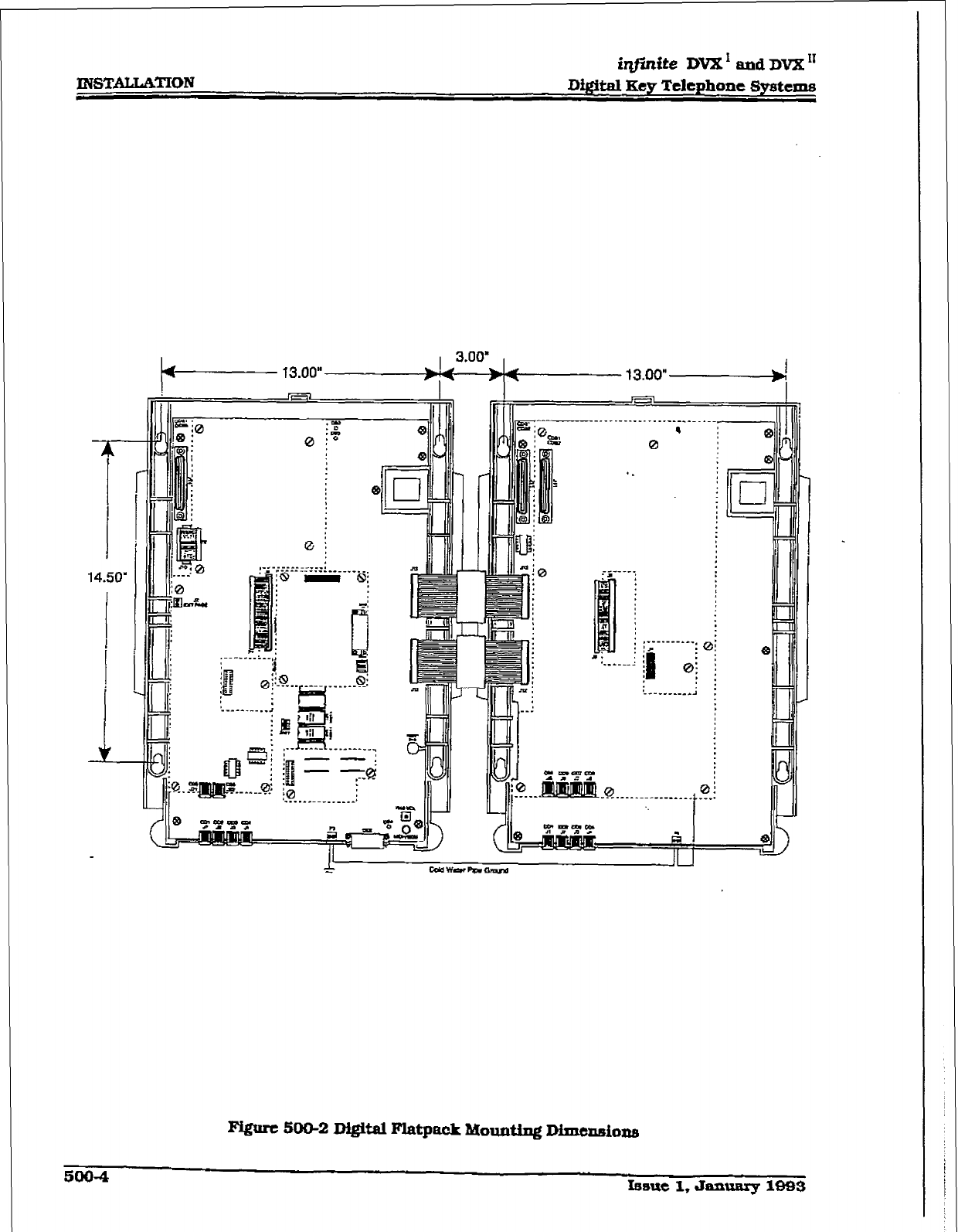
INSTALLATION
iqjinite
DVX’ and DVX”
Di@al Key Telephone Systems
14.50’
Figure 500-2 D&Hal Flatpack Mounting Dimcnaions
5004 rssue 1, Janauuy 1093
ice board. The power supply and cabinet
meet all safety requirements to comply
with UL 1459 Second Edition and CSA
~22.2 No. 225 standards.
LED5 a
hldicators:
Four green LEDs are located on the main
key seTYice board along the top of the PCB.
lXvo of the LEDs IDS2 & DS3) indicate the
presence of +5V & -5V dc. LEDs DSl ad
DS5 indicate the presence of +12V dc used
to
supply power to the key stations (one
LED per four stations). An extinguished
LED indicates the absence of the associ-
ated voltage.
A red LED
(DS4)
located in the lower right
portion of the main key service board pro-
vides a system “heart beat” indication.
Basic ESU BAotmting:
The DVX’ Basic Key Service Unit (E3KSI-J)
is housed iu a wall mountable cabfnet
which contains the main key service board,
power supply and pre-wired connectors for
stations and CO Line interfaces. Once the
zuea for the telephone equipment has been
selected, mount a plywood back board to
the wall. The back board size will vary
depending upon the size of the MDF. The
entire system and frame can be mounted
ona 4’~6’~3/4”plywood. Ifmounwthe
Basic KSU alone, the mfnimum backboard
size is 25”~ 17”
x
3/4”. A fully loaded KSU
can weigh approrcimately 15 lbs. Make cer-
tain proper mounting procedures are fol-
IOwed.
1. Mount the KSU to the plywood using 3/4”
L #I2 pan-head sheet metal su-ews such
that the top of the KSU is appmately
three feet (1 meter) from the ceiling. and
bottom is four feet (1.2 meters) Corn the
floor.
2, Use the mounting template supplied with
the cabinet to locate the mounting holes.
Refer to Figure 500-2 Digital F&pack
Mounting Dimensions.
3. Drill the holes and mount the Basic KSU.
Gro-:
A
NO.
12 AWG
copper wire
should be used
to connect a ground between the ground
source and the Basic KSU (25 feet maxi-
mum). A two position terminal strip P3 is
hated along the bottom edge of the main
key service unit and is accessible through
the bottom of the KSU. One terminal posi-
tion can be used to connect the ground wire
from a ground source and the other posi-
tion may be used to connect the ground
from the Basic KSU to the Expansion KSU.
CPU and Memory:
The DVX ’ system is controlled by a 16-bit
(68000) main micro-processor which con-
trols all system functions including the
PCM/TDM voice switching under the di-
rection of ROM and RAM software coding.
The r&n key service board is responsible
for all control functions, execution of all
logic operations and control of system
modules including control over the cir-
cuitry necessary for yoice switching and
conference connections. The main key
service board is also responsible for all
system tones, system timing, and station
status control. Refer to Figure 500-3 Main
Key Service Board of the Basic KSU. In
addition the main key service board pro-
vides software and hardware support of the
following:
l RealThnecibck
l
Watch dog time-r and recovery.
l
PCB status as to presence/absence of
modules for automatic software confQu-
ration setup.
. State/event software design.
l
Backup of customer database RAM
memory via a “Super Cap” (super capaci-
tori .
System software is provided in EPROM
memory and is @staWcl on the main key
service board. The system contains 512K
of EPROM storage and is equipped with
l28K of “battery”-backed static RAM. Pro-
visions have been made on the card to
address up to two megabytes of EPROM
memory and up to two megabytes of static
RAM.
An option’dip” switch (S’WI) located on the
main key service board a&ws the system
EPROM memory to be configured utilizing
dffferent size EPROM chips. 1 Megabit, 2
Megabit, 4 Megabit and 8 Megabit chips
may be used to provide the generic soft-
ware. Refer to Section 800, Maintenance
and Troubleshooting for *dip” switch (SW 1)
settings for various allawable configura-
tlOllS.
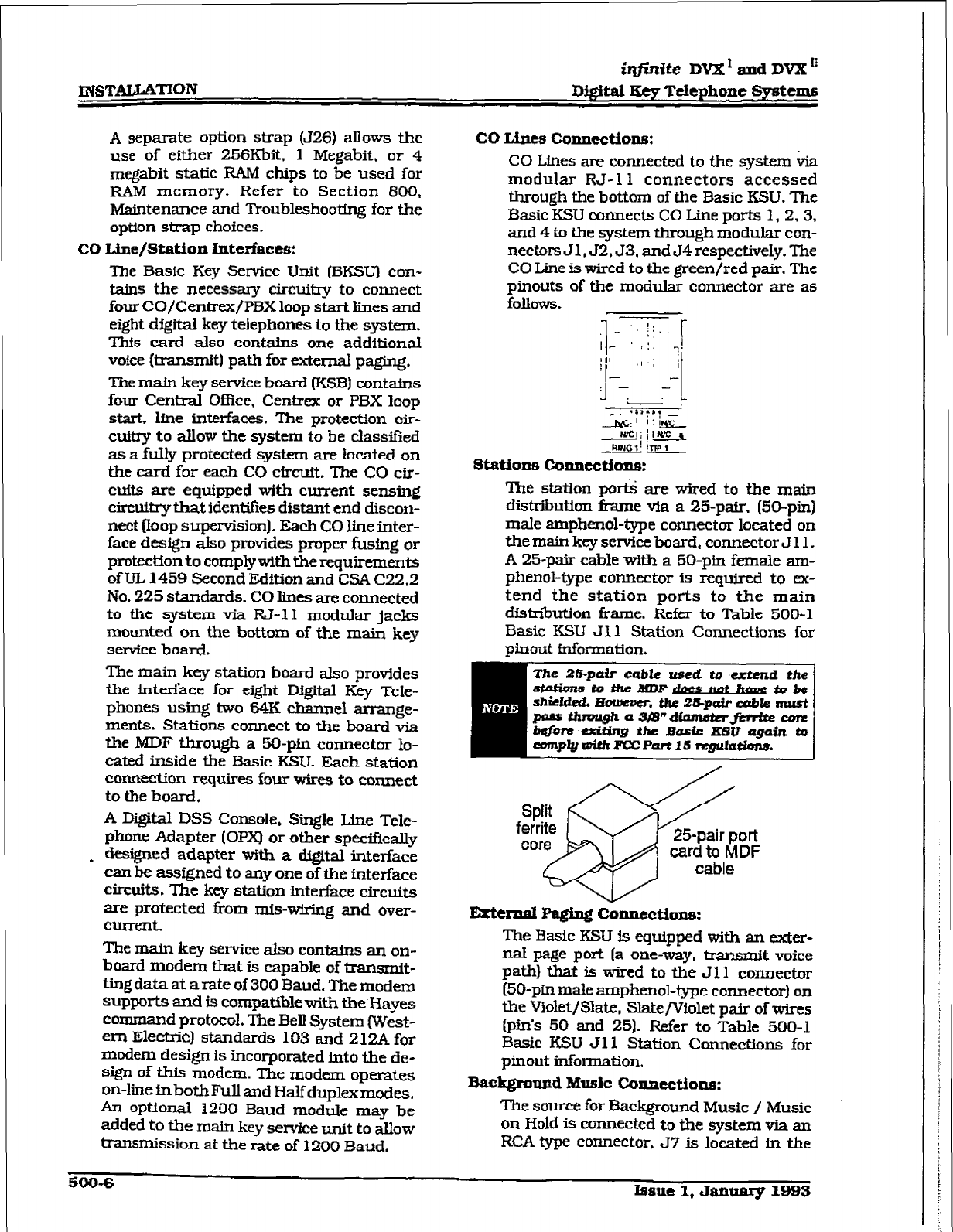
A separate option strap (J26) allows the
use of either 256Khit. 1 Megabit, or 4
meabit static RAM chips to be used for
RAM memory. Refer to Section 800.
Maintenance and Troubleshooting for the
option strap choices.
CO Line/Station Interfaces:
‘Ihe Basic Key Sertrice Unit (BKSUI con-
tains the necessary circuitry to connect
four CO/Centrex/PBX loop start lines and
eight digital key telephones to the system.
Thfs card also contains one additional
voice (lransmit) path for external paging.
The maCn key service board (KSB) conWns
four Central Office. Centrex or PBX loop
start. line interfaces. The protectfon cir-
cuitry to allow the system to be classffied
as a fully protected system are located on
the card for each CO circufL The CO cir-
cuits are equipped with current sensing
circuitry that Identlfres distant end discon-
nect (loop supervision). Each CO line inter-
face design also provides proper fusing or
protection to comp+vith the requirements
of UL 1459 Second Edition and CSA C22.2
No. 225 standards. CO lines are connected
to the system via W-11 modular jacks
mounted on the bottom of the main key
service board.
The main key station board also provides
the interface for eight Digital Key Tele-
phones using two 64K cbarmel arrange-
ments. Stations connect to the board via
the MDF through a 50-pfn connector lo-
cated inside the Basic KSU. Each station
connection requires four wires to connect
to the board.
A Digital DSS Console, Single Line Tele-
phone Adapter (Opx) or other spedficaIly
_ designed adapter with a digital interface
can be assigned to any one of the interface
circuits. The key station interface circuits
are protected from mis-wiring and over-
ClUTfXk
The m&n key service aIs0 cor~tains an on-
board modem that is capable of msmit-
ting data at a late of 300 Baud. The modem
supports and is compatiblewith the Hayes
command protocol. The Bell System (West-
em Electric) standards 103 and 212A for
modem design is incorporated into the de-
sign of this modem. The modem operates
on-line inbothFull and Halfduplexmodes.
An optional 1200 Baud module may be
added to the main key seme tit to ~.IIOW
transmission at the rate of 1200 Baud.
co Ldnes conxlcctioM:
CO Lines are connected to the system &a
modular RJ- 11 connectors accessed
through the bottom of the Basic KSU. The
Basic KSU connects CO Line ports 1.2.3.
and 4 to the system through modular con-
nectors J 1,52,53. and J4 respectively. The
CO Line is wired to the green/red pair. The
pinouts of the modular connector are as
follows.
l- I I:, _
L I,;: r
b in :!
II-
.i.l 1
!
Ll -LY-,
I .*,yr.
Jj&l-l’&
-A!!Qj j@L-a
m-1 FUNGI’
stations connections:
The station pm& are wired to the main
distribution frame via a 25-p&r. (50-pin)
male amphenol-type connector located on
the main key sewIce board, connector J 11,
A 25-pair cable w&b a 50-pin female am-
phenol-type connector is required to ex-
tend the station ports to the main
dfstriiution tiame. Refer to Table 500-l
Basic KSU Jl 1 Station Connections for
pinout fnfoxmation.
External Paging conntction5:
The Basic KSU is equipped with an exter-
nal page port [a one-way, tramxnit voice
path) that is wired to the Jll connector
(50-pin male amphenol-type connector) on
the Violet/Slate, Slate/Violet pair of wires
(pin’s 50 and 25). Refer to Table 500-l
Basic KSU Jll Station Connections for
pinout information.
Background Music Connection:
The source for Background Music / Music
on Hold is connected to the system via an
RCA type connector, 57 is located Fn the
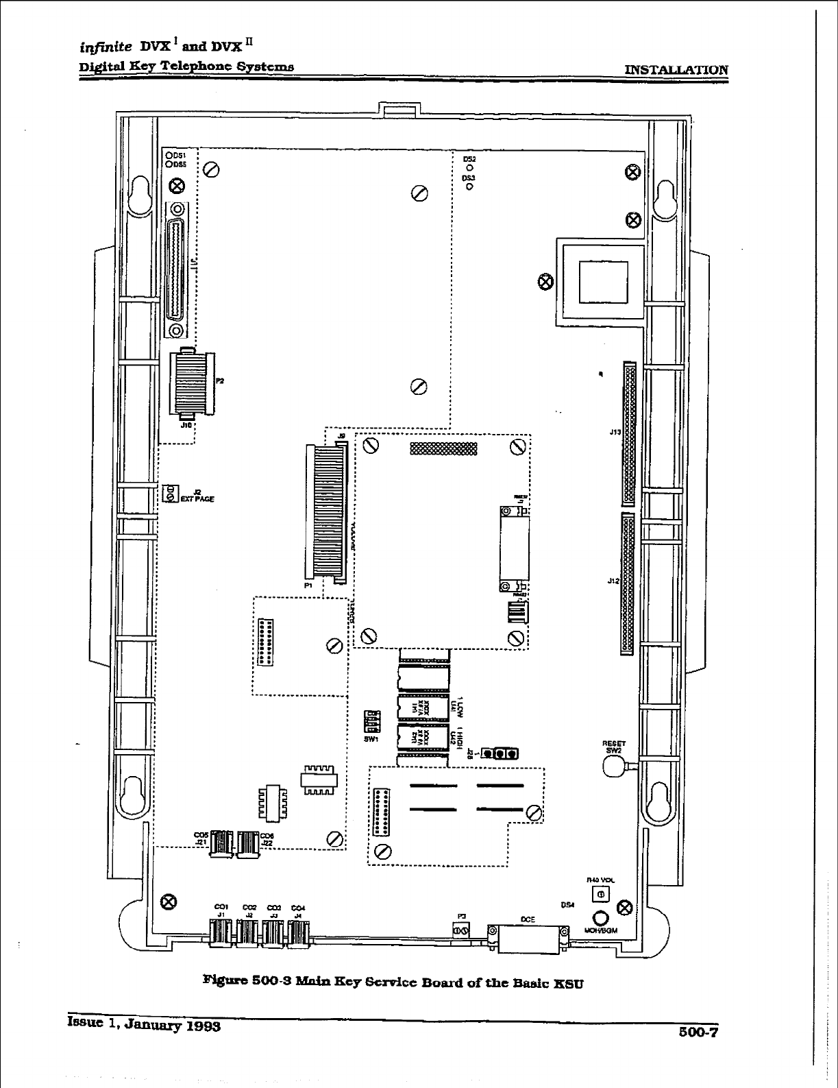
irlfnite
DVX ’ and IX%
Drprital Key Telephone
Systenm INSTATAKIION
0
;--‘** ________-----*- * _____.
*.-*._____-__-_--*--*-*--------.
T
0
rs -5
E
8
----I-----*-~‘~T ______---.--__.,
:
.---.-..----------*--; I
E$
gg
I = 2-m
rpssurt 500-3 Main Key Service Board of the Basic KSU
IwnIc
1, Jaauary lB93 two-7
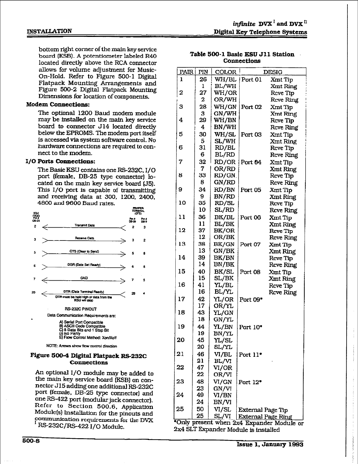
INSTATLATION
injhite DVX’
and DVX’
Drpital Key TeIepbone Systems
bottom right comer of the main key service
board (KSB). A potentiometer labeled R40
located directly above the RCA connector
allows for volume adjustment for Music-
On-Hold. Refer to Figure 500-l Digital
Flatpack Mounting Arrangements and
Figure 500-2 Digital Flatpack Mounting
Dimensions for location of components.
Modem Connections:
The optional 1200 Baud modem module
may be installed on the main key service
board to conneotor 514 located directly
below the EPROMS. The modem port itself
is accessed via system software control. No
hardware connections are required to con-
nect to the
modem.
x/o Ports connectioll5:
The Basic KSLJ contains one RS-232C, I/O
port [fern&e, DB-25 type connector] lo-
cated on the main key service board (55).
This I/O port is oapabIe of transmitEng
and receivhg data at 300, 1200, 2400.
4800 and 9600 Baud rates.
3 RmhaDam
> 3 2
RS-23ZC PINOUT
Data ccmmuniealbn Re.wirem8nts em:
1 A) Bekl Port compaWa
8) ASCII Code Compatible
f $taas and 1 Stop Bii
4 F!aw Cantmf Methad: xarlxoff
NOTE: Amws show fbw mnrml dimeM
F’igure 5004 Digital Flatpack RS-232C
colJnectioll5
An optional I/O module may be added to
the main key service board &!jB) on con-
nector J15 adding one additional RS-232C
Poti b-de, DB-25 type connector] and
one
l?S422 port
(modular jack connector).
Refer to Section 500.6. Appli&ion
Modul&l hxtaliation for the pinouts and
~O~~cation requirements for the DVX
RS-232C/R.S-422 I/O Module.
Table
500-l Baefc IESU 511 Station
COpnCCtiOXM
pAII
1
2
3
4
5
6
7
8
9
10
11
12
13
14
15
16
17
18
19
20
21
22
23
24
25
m
26
1
27
2
28
3
29
4
30
5
31
6
32
7
33
8
34
9
35
10
36
11
37
12
38
13
39
14
40
15
41
16
42
17
43
18
44
19
45
20
46
21
47
22
48
23
49
24
50
25
COLOR
WWBL
BL/WH
WH/OR
ORm
wH/GN
GN/WH
WH/BN
BNlUrH
wH/SL
SL/wH
RD/BL
BL/RD
RD/OR
OR/RI3
RD/GN
GN/RD
RD/BN
BN/RD
RD/SL
SL/RD
BK/BL
BL/BK
BK/OR
OR/BK
BK/GN
GN/BK
BK/BN
BN/BK
BK/SL
SL/BK
YL/BL
BLrYL
n/OR
OR/=
YL/GN
GNlVL
YL/BN
BN/m
YL/SL
SW=
VI/BL
BLm
VI/OR
OR/VI
VI/GN
GNrVI
VI/BN
BN/VI
VIjSL
nt
-T
DESIG
Port 01 Xmt Tip
XmtRing
Rcve Tip
RcveRing
Port 02 xmt Tip
m.itRing
Rcve Tip
RcVeRing
Fort 03 XmtTip
XmtRtng
Rcve Tip
Rcve Ring
Port04
xmtl-ip
-tw
Rove Tip
RcveRIng
Port 05 xmt Tip
antRing
Rcve Tip
-m
Port06 XmtTip
XmtRing
Rcve Tip
me-%
?ort 07 xmt Tip
XintRing
Rcve Tip
&Ring
‘m-t 08 xmt Tip
xntRing
RCWTip
RcveRing
‘art oQ*
Port 10s
?ort 118
‘al-t 125
kternd Page Tip
Sxtemal Page Ring
P Expander Module or
2x4 SLT Expander Module is installed
500-S
fssuc 1, Jantury 1993
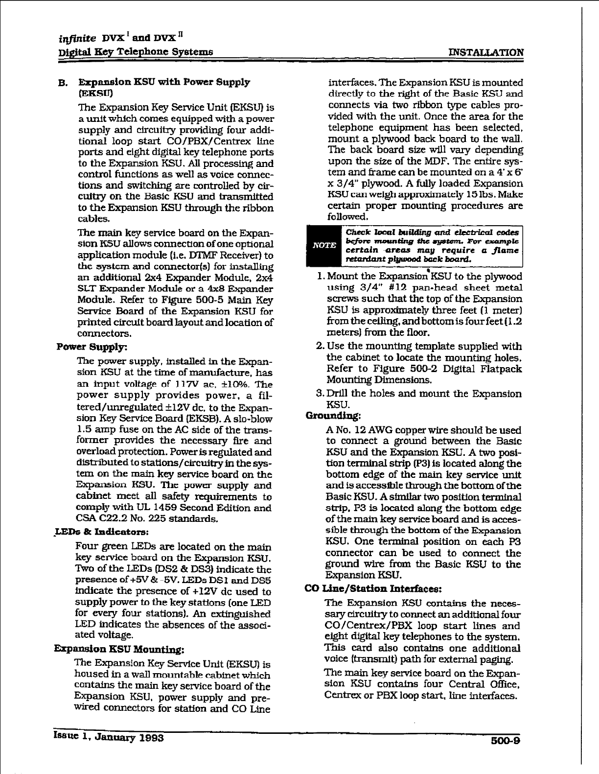
iqffnite DVX’andDVX”
Mgital Key Telephone Sy&exm mSTALT,ATION
B.
Eagyi~n
KSU with POmr Supply
T’he Expansion Key Service Unit F.KSu) is
a unit which comes equipped with a power
supply and circuitry providing four addi-
tionaI loop start CO/PBX/Centrex Ltae
ports and eight digital key telephone ports
to the Expansion KSU. All processing and
control functions as well as voice connec-
tions and switching are controlled by cir-
cuitry on the Basic KSU and transmitted
to the Expansion KSU through the ribbon
cables.
The main key service board on the Expan-
sion KSU allows connection of one optional
application module (Le. IYI’MF Receiver) to
the system and connectorfs) for installing
an additional 2x4 Expander Module, 2x4
SLT Expander Module or a 4x8 Expander
Module. Refer to Figure 500-5 Main Key
Service Board of the Expansion KSU for
printed circuft board layout and location of
connectors.
Power 8upply-z
The power supply, installed in the Expan-
sion KSU at the time of manufacture, has
an input voltage of 117V ac, &lO%. The
power supply provides power, a fil-
tered/unregulated +12V dc, to the Expan-
sion Key Service Board (EKSB). A slo-blow
1.5 amp fuse on the AC side of the bans-
former Provides the necessary fire and
overload protection. Power is regulated and
disixibuted to stations/circuitry in the sys-
tan on the main key sewice board on the
Expansion KSU. The power supply and
cabinet meet ail safety requirements to
comply with UL 1459 Second Edition and
CSA C22.2 No. 225 standards.
,LEDs a
Indicators:
Four green LEDs are located on the main
kqr service board on the Eqxmsion KSU.
Two of the LEDs (DS2 & DS3) indicate tie
presence of +5V & -5V. LEDs DS 1 and DS5
indicate the presence of +I2V dc used to
supply power to the key stations (one LED
for every four stations). An extinguished
LED indicates the absences of the assoei-
ated voltage.
Expansion KSU Mounting:
The Expansion Key Service Unit (EKSU] is
housed in a wall mountable cabinet which
cmtains the main key setice board of the
EXPEUIS~OII KSU, power supply and pre-
wired connectors far station and CO Z;ine
interfaces. The Expansion RSU is mounted
directly to the right of the Basic KSU and
connects via two ribbon type cables pro-
vided with the unit. Once the area for the
telephone equipment has been selected,
mount a plywood back board to the wall.
The back board size will vary depending
upon the size of the MDF. The entie sys-
tem and f&u-he can be mounted on a 4’x 6’
x 3/4” plywood. A hlly loaded Expansion
KSU can weigh approximately 15 Ibs . Make
cer&in proper mounting procedures are
followed.
1. Mount the ExpsnsionaKSU to the plywood
using 3/4” #12 pan-head sheet metal
s- such that the top of the Expansion
KSU is approximately three feet (1 meter)
from the ceiling, and bottom is four feet (I .2
meters) from the floor.
2. Use the mountmg template supplied with
the cabinet to locate the mounting holes.
Refer to Figure 500-2 Digital Flatpack
Mounting
Dhnensions.
3.m the holes and mount the Expansion
KSU.
Gr0U.U~:
A No. 12 AWG copper wire shouId be used
to connect a ground between the Basic
KSU and the Expansion KBU. A two posl-
tian terminal strip (p3) is located along the
bottom edge of the main key service unit
and is accessible through the bottom of the
Basic KSU. A sfmllar two position
terminal
strip. P3 is located along the bottom edge
of the main key sentice hoard and is acces-
sible through the bottom of the Expansion
KSU, One terminal position on each P3
connector can be used to connect the
ground wire fimn the Basic KSU to the
Expansion KSU.
co Line/station Intufact8:
The Expansion KSU contains the neces-
sary circuitry to connect an additional four
CO/Centrex/PBX loop start lines and
eight digital key telephones to the system.
This card also contains one additional
voice Itransmit) path for external paging.
The main key service board on the Expan-
sion KSU contains four Central Gffice,
Centrat or PBX loop start, line interfaces.
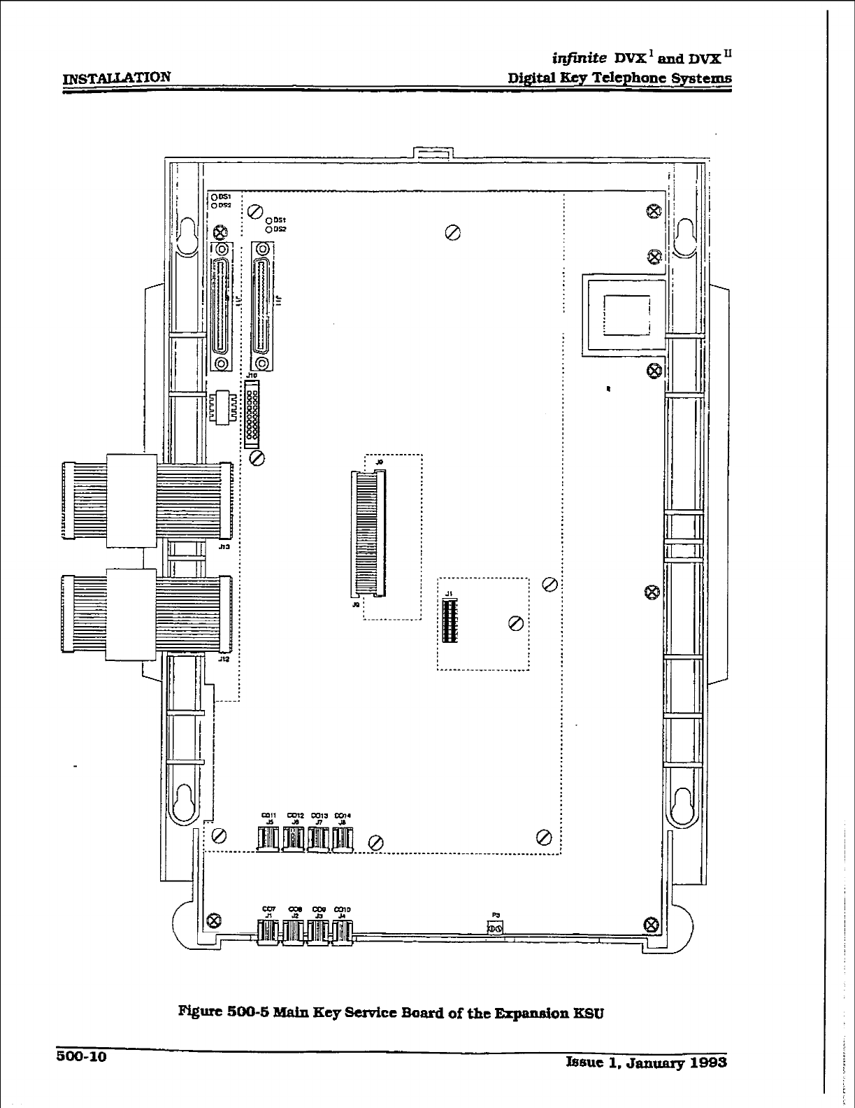
INSTALtATIOs
ini@de DVXl and Dvx”
Di@id Key Tdephone Systems
i)-
L
I-
.
i
-r
!
-
,_ . _ -. _ _ _ _ _ _ _ _.
: *
Ri
_.--__--_-__
I
/
-
L
r
L
t
Fi@uc 500-S Main Key Se&cc Bard of the Expaxmion KSU
600-10 J66UC 1. Jamary 1993
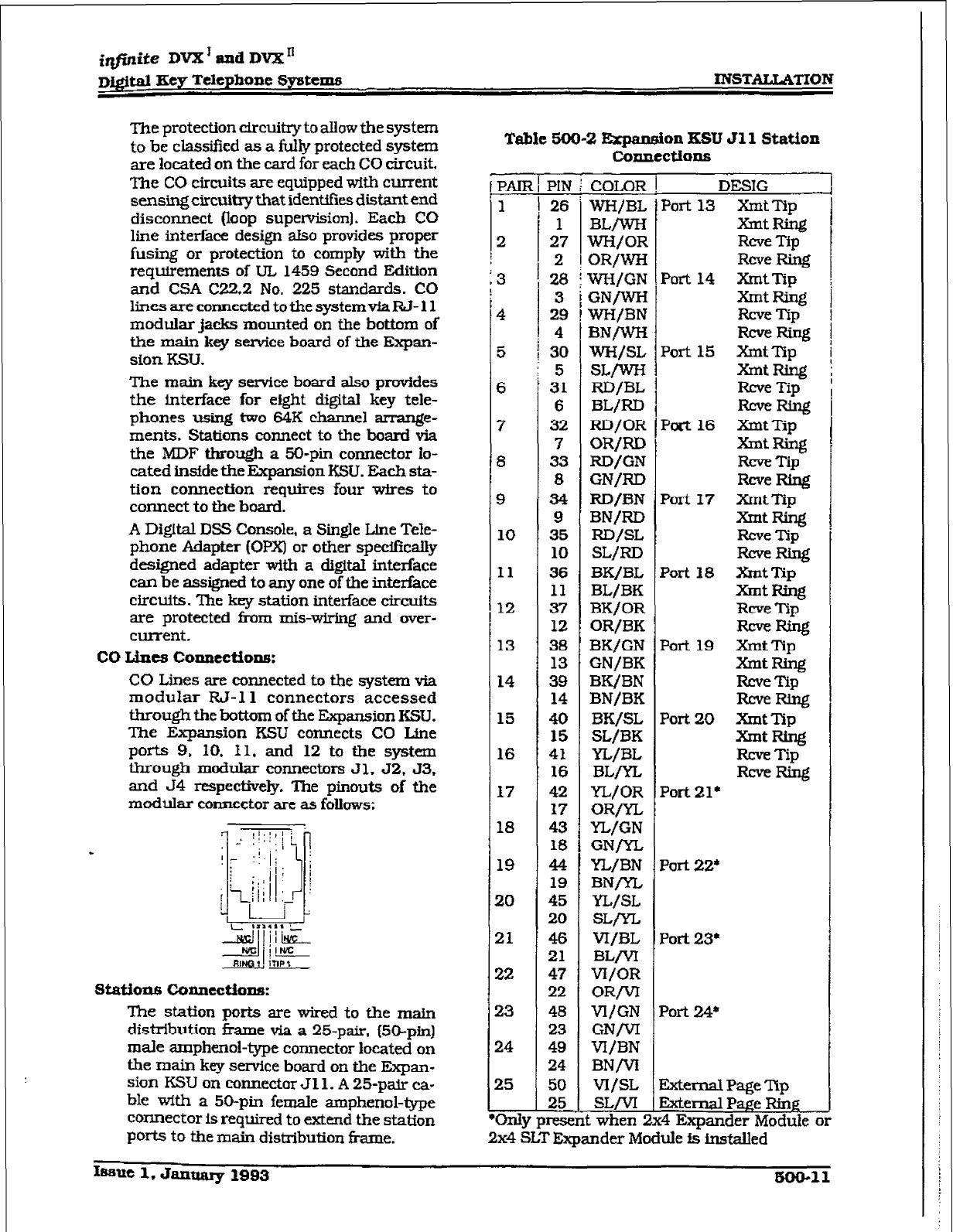
c
irlfinite DVX’ and DVX”
~&it.& Key Telephone
6yatems INSTALLATION
The protection circtilxy to allow the system
to be classified as a fill@ protected system
are located on the
card for each CO circuit.
The CO
circuits
are equipped with current
sensing circuitry that identifies distant end
disconnect (loop supetiion). Each CO
line interface design also provides proper
fusing or protection to comply with the
requirements of UL 1459 Second Edition
and CSA C22.2 No. 225 standards. CO
lines are connected to the systemvfaRJ-
11
modular lacks mounted on the bottom
of
the ma&
key service
board of the Expan-
sion KSTJ.
The main key service board also provides
the interface
for
e&ht digital key tele-
phones using two 64K channel arrange-
ments. Stations connect to the board via
the MDF through a %-pin connector lo-
cated inside the Expansion KSU. Each sta-
tion connection requires four wires to
connect to the board.
A Digital DSS Console, a Single Line Tele-
phone Adapter (OPX) or other specif~caliy
designed adapter with a digital interface
can be assigned to any one of the interface
circuits. The key station interface circuits
are protected fi-om mis-wfrfng and over-
currentt.
co Lines conRections:
CO Lines are connected to the system via
modular RJ-11 connectors accessed
through the bottom of the Expansion KSU.
The Expansion KSU connects CO Line
ports 9. 10. Il. and 12 to the
system
through
modular connectors Jl. 52, 53.
and 54 respectively. The pinouts
of the
modular connector are as follows:
djiy::&
d,j in*
Sbdkm5 Connections:
The station ports are wired to the main
distribution frame via a 25-pair, (XI-pfn)
male amphenol-type connector located on
the main key service board on the Expan-
sion KSU on connector Jl 1. A 25-p& ca-
ble with a 50-pin female amphenol-type
connector is required to extend the station
ports to the main distribution hme.
Table 500-2
Erpanaion KSU Jll Station
Connections
PAIR
1
2
E
13
Fi-
L
!
!
COLOR
WHjBL
BLlWK
WH/OR
OR/W
WH/GN
GNrWH
4 WH/BN
BNlwH
5 wH/SL
SL/wH
6 RD/BL
BL/RJJ
7 FZD/OR
OR/RD
8 RD/GN
GN/RD
9 RD/BN
BN/RD
10 RD/SL
SLIRD
I1 BK/BL
BL/BK
12 BK/OR
OR/BK
13 BK/GN
GN/BK
14 BK/BN
BN/BK
15 BK/SL
SL/BK
16 YL/BL
BL,ln,
17 YL/OR
ORrYL
18 YL/GN
GNW
19 YL/BN
BN/YL,
20 YL/SL
SLryL
21 VI/BL
=/VT
22 VI/OR
OR/VI
23 Vl/GN
GN/vI
24 Vi/BN
BN/VI
25 vI/SL
=/VI
‘Only present when
PIN
26
1
27
2
28
3
29
4
30
5
31
6
32
7
33
8
34
9
35
10
36
11
37
12
38
13
39
14
40
15
41
16
42
17
43
18
44
19
45
20
46
21
47
22
48
23
49
24
50
25
DESIG I
I
Port 13 xmt ?Yp
XmtRing I
Rcve Tip
Reve Ring I
Port 14 Xmt Tip
XmtRillg j
Ez& /
Port 15 XmtTip 1
?hltRing j
Rcve Tip
Port 16 km 1
Xmt Tip
XTntRing
RCWZTip
WeRIng
Port 17
%ntTip
XntRing
Rcve Tip
-RLng
Port 18 XmtTip
XmtRing
Rcve Tip
-w
Port 19 XTltTip
-tw
=-=-m
-Ring
Port 20 xmt Tip
tit RinE!
RCWTip
-Ring
Port 21+
Fort 22’
Fort 23+
Fort %I*
:4 Expander Module or
Sternal Page Tip
2x4 SLT Expander Module is installed
Issue 1. Jan- 1993
ESOO-11
:
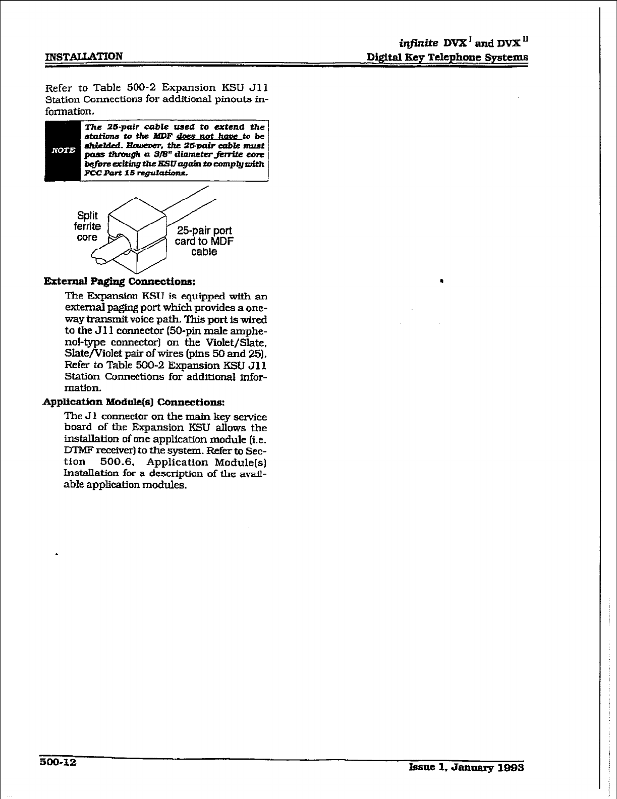
INSTALLATIQN
iqfinite DvX*anrd~vX~
Di@tal
KeyTelephoneSystcnm
Refer to Table 500-2 Expansion KSU Jll
station Connections for additional pinouts in-
formation.
The 25-p& cable used to extend &he
-tothexuPrIwP~to&
Ehiddai. liimemr, the 25pair cable must
pass thtvagh a S/8” CiinmeterftrrIte core
b@imazit@theESUq@ntocomplywith
Fz!cponll6 rqpkdms
Split rcx//
ferrite
core \ 25-pair port
card to MDF
cable
Exted Pa@ng c&tctions:
The Expansion KSU is equipped with an
external paging port which provides a one-
way transmit voice path. This port is wired
to the JI 1 connector (50-pin male amphe-
nol-type connector) on the Violet/Slate,
Slate/Violet pair of wires (pins 50 and 25).
Refer to Table 500-2 Expansion KSU J 11
Station Connections for additional infor-
IIBti0l-L
Application Moaule(s] Connections:
The Jl connector on the main key service
board of the Expansion KSU allows the
installation of one application module (i.e.
DTlvIF reeeiverl to the system. Refer to Sec-
tion 500.6. Application Module(s]
Installation for a description of the avail-
able application modules.
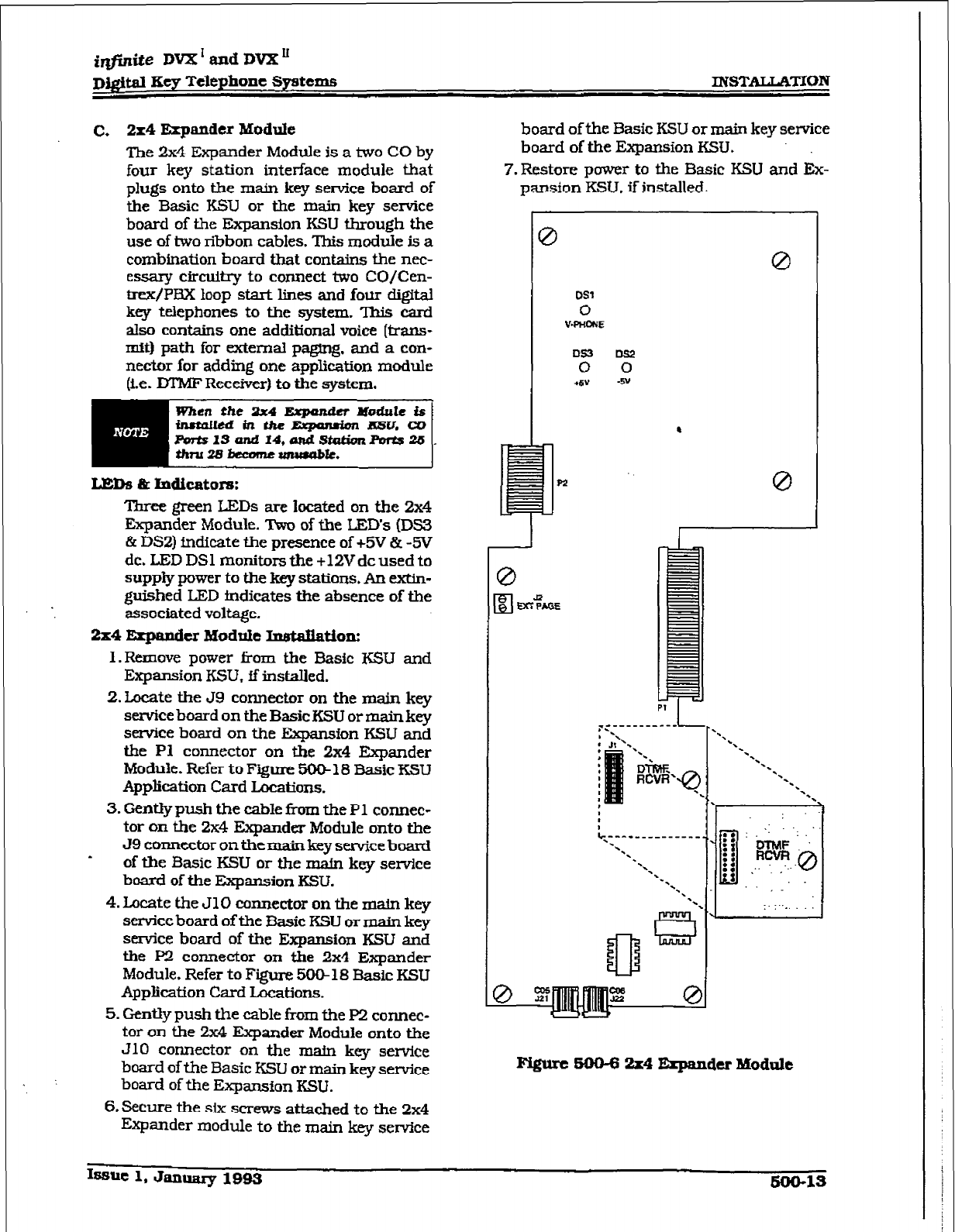
irlfinite DVX ’
and DVX ’
mgitd Key Telephone Syatcms INSTALLATION
c. 2x4 Expander Module
The 2x4
Expander Module is a two CO by
four key station interface module that
plugs onto the main key service board of
the Basic
KSU or the main key service
board of the Expansion KSU through the
use of two ribbon cables. This module is
a
combination board that contains the nec-
essary circuitry to connect two CO/Cen-
?r&PBX loop start lines and four digiti
key telephones to the
system.
This card
also contains one additional voice (trans-
tit) path for external paging, and a con-
nector for adding one application module
(i.e. DI’MF ReceWer) to the system.
Lmkl L Indicators:
.
Three green LEDs are located on the 2x4
Expander Module. Two of the LED’s (DS3
Br DS2) fndieate the presence of +!5V & -!TV
dc. LED DSl monitors the +12Vdc used to
supply power to the key stations. An extin-
guished LED mdicates the absence of the
associated voltage.
2x4 l!iqmdcr Module bmtaiiation:
1 .Rernove power f&n the Basic KSU and
Expansion KSU, ff instaIled.
2.Locate the J9 connector on the main key
service board on the
Basic KSU
or
main
key
sewice board on the &pan&on KSU and
the Pl
connector on the 2x4 Expander
Module.
Refer to Figure 500-l 8 basic KSU
Application Card Lomtions.
3.
Gently push the cable f?om the Pl connec-
tor on the 2x4 Expander Module onto the
J9 cmx.m.ncct.or on tit main key service
board
of the Basic KSU or the m&n key sew-ice
board of the
Expansion KSU.
4.
Locate the JlO connector
on the
main
key
service board of the Basic
KSU or main
key
service board of the Expansion KSU and
the P2 connector on the 2x4 Expander
Module. Refer to
Figure
50@ 18 Basic KSU
Application Card Locations.
5. Gently
push the cable from the P2 connec-
tor on the 2x4
Expander
Module onto the
JlO connector on the mafn key service
board of the Basic KSU or
main key service
board of the Expansion KSU.
6.
Sa.m the six screws attached to the 2x4
Expander module to the main key sewice
board of the Basic KSU or main key service
board of the Expansion KSU.
7. Restore power
to the
Basic KSU
and Ex-
pansion KSU. if installed.
0 0
0
-.
-.
5.
4,
..-1-_-_-------,;
::
:
:t
& :, ‘.
--\
RcvR..@
-.
-.
.n
‘.
*.
c3
g
tt -.’ ‘.
,-
: .
0
Issue 1. Januay 1993 600-1s
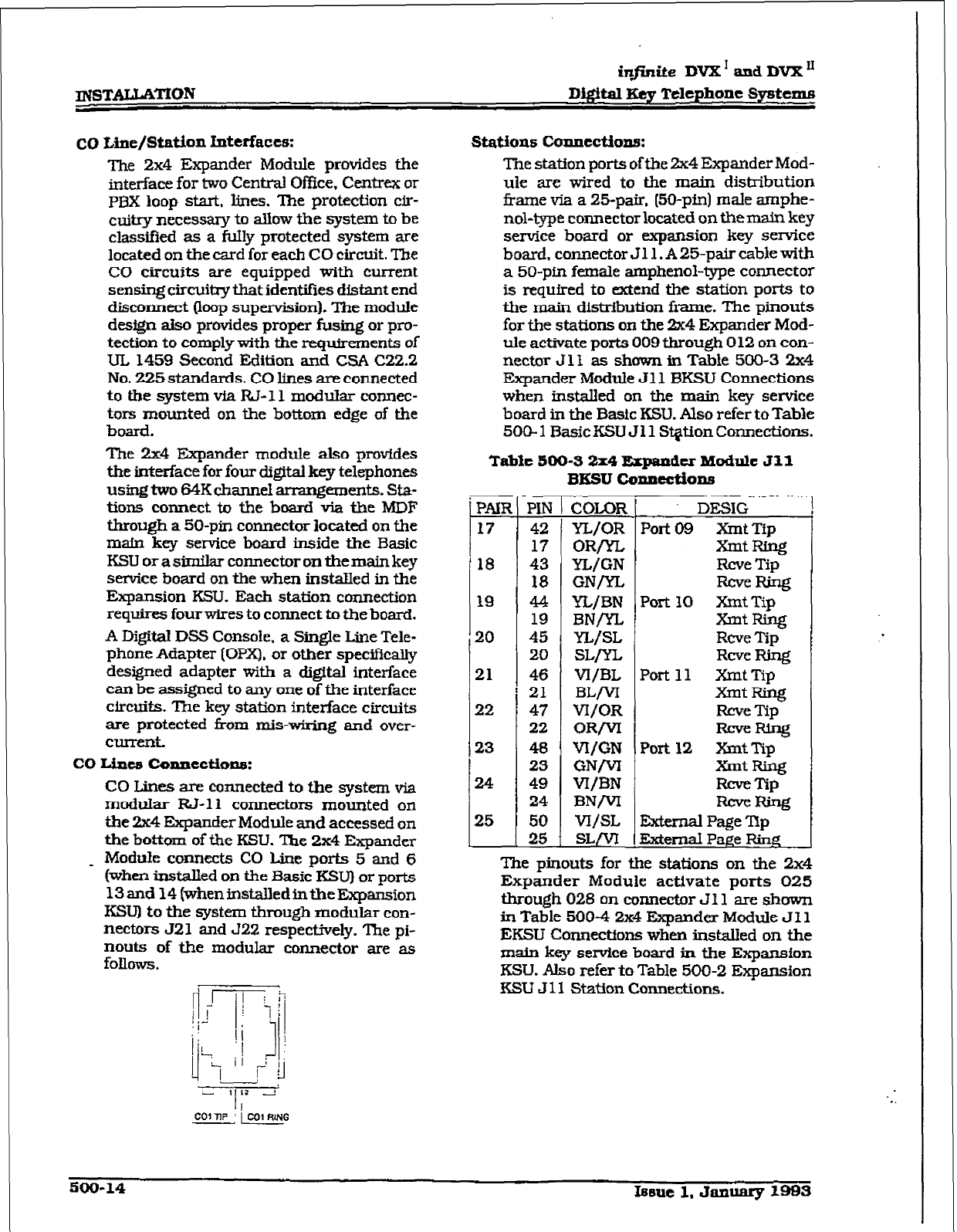
~sTALLAT~ON
in@nite DVX’ and DVX li
D&ital Key Telephone Spsttms
CO
Line/StatioJl
Interfaces: Station6 Counections:
me 2x4 Expander Module provides the The station ports of the a4 Expander Mdd-
interface for two Central Of&e, Centiex or ule are wired to the main distribution
PBX loop start, lines. The protection cir- frame via a 25pair. [5O-pin) male amphe-
cuitry necessary to allow the system to be nol-type connector located on themain key
classified as a fuIly protected system are service board or expansion key service
located on the card for each CO circuit. The board, connector Jl 1. A 25pair cable with
CO
circuits are equipped pvith current a 50-pm female amphenol-type connector
sensing circuitry that identifies distant end is required to extend the station ports to
disconnect (ioop supervision). The module the main distribution frame. The pinouts
design aiso provides proper fusing or pro- for the stations on the 2x4 Expander Mod-
tection to comply with the requirements of ule activate ports 009 through 0 12 on con-
UL 1459 Second Edition and CSA C22.2 nector J 1 I as shown in Table 500-3 2x4
No. 225 standards. CO lines ate connected Expander Module Jll BKSU Connections
to
the system via RJ-11 modular connec- when installed on the main key service
tors mounted on the bottom edge of the board in the Basic KSU. Also refer to Table
board. 500-l BasicKSU Jll St@ionConuections.
The 2x4 Expander module also provides
the interface for four digital key telephones
us~two 64K cllanne!l armngemerlts. sta-
tions connect to the board via the MDF
through a 50-pin connector located on the
main key service board inside the Basic
KSLJ or a similar connector on the main key
service board on the when installed in the
Expansion KSU. Each station connection
requires four wires to connect to the board.
A Digital DSS Console, a Single Line Tele-
phone Adapter [OPX), or other specifically
designed adapter with a digital interface
can be assigned to any one of the interface
circuits. The key station interface circuits
are protected from mis-wiring and over-
C-t.
co wmu, conllcctiorl6:
Table 500-S 2x4 Expander Moddc Jll
BKSU Connections
CO Lines are connected to the system via
moth&r RJ-11 connectors mounted on
the 2x4 Expander Module and accessed on
the bottom of the KSLJ. The 2x4 Expander
_ Module connects CO Line ports 5 and 6
(when installed on the Basic KSU) or ports
13 and 14 (wheninsta.IledintheExpansion
KSUI to the system through modular con-
nectors 521 and J22 respectfvely. The pi-
nouts of the modular connector are as
follows.
PAlft
17
18
19
20
21
22
23
24
25
Yj&
COLOR
42 YL/OR
37 OR/yL
43 YL/GN
18 GNryL
44 yL/BN
19 BNln
45 YL/SL
20 SL/yL
46 Vl/BL
21 BL/VI
47 W/OR
22 OR/VI
48 VI/GN
23 GNrVr
49 VI/BN
24 BN/VI
50 W/SL
25 sL/vT
DESIG
Port 09 XmtTip
-tRing
Rcve Tip
RcveFthg
Port 30 Xmt Tip
XmtFklg
Rcve Tip
Rcve Ring
Port 11 xmt Tip
XintRing
Rcve Tip
RcveRing
Port 12 Bit Tip
XntRillg
RCVC?Tip
hRm2
El3cbmd Page lip
External Page Ring
The pinouts for the stations on the 2x4
Expander Module activate ports 025
through 028 on connector Jl 1 are shown
in Table 500-4 2x4 Expander Module Jl 1
EKSU Connections when installed on the
maiu key setice board in the Expansion
KSU. Also refer to Table 500-2 Expansion
KSU J 11 Station Connections.
CO1 TIP t
CO1 RING
500-14 I6eut 1. Januacy 1993
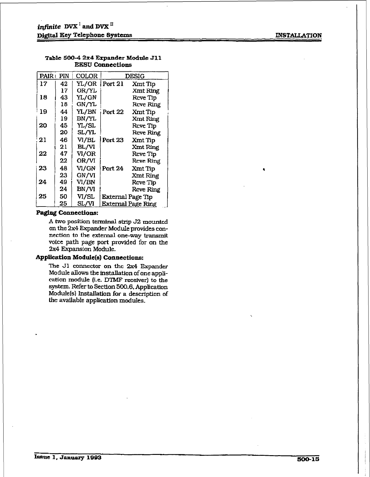
INSTALUITION
Table 500-4 2x4 Expander Module Jll
EKSU Connectione
PAJR
t 17
18
i 19
20
;21
22
‘23
24
PIN
42
17
43
18
4-4
19
45
20
46
21
47
22
48
23
49
24
50
25
T
COLOR
YL/OR
ORm,
YL/GN
GNrYt
YL/BN
BN/YL
YL/SL
SL/n
vI/BL
BW-
VI/OR
ORlVI
WGN
GNjVI
VI/BN
BN/VI
vI/SL
sL/vI
-i
7
DESIG
Port 2 1 Xmt Tip
-tRtng
Rcve Tip
Rcve Ring
Port 22 Xmt Tip
y-t Ring
Rcve Tip
heRlng
Port23 XmtTip
XmtRing
Rcve Tip
RcveRing
Port 24 Xmt
Tip
XrntRing
RCVt?TSp
-m
External Page Yip
External PaPe Ring
Paging c4Iulectione:
A two position termhal strip 52
mounted
on the 2x4 Expander Module provides con-
nection to the exkmal one-way transmit
voice path page port provided for on the
2x4
Expansion
Module.
Application
Moduk(e) Connections:
The Jl connector on the 2x4 Expander
Module &lows the installation of one appli-
cation module (i.e.
DTMJT
receiver) to the
system. Refer to Section 500.6, Application
Module(s)
Installation for a description of
the available
application modules.
.
.
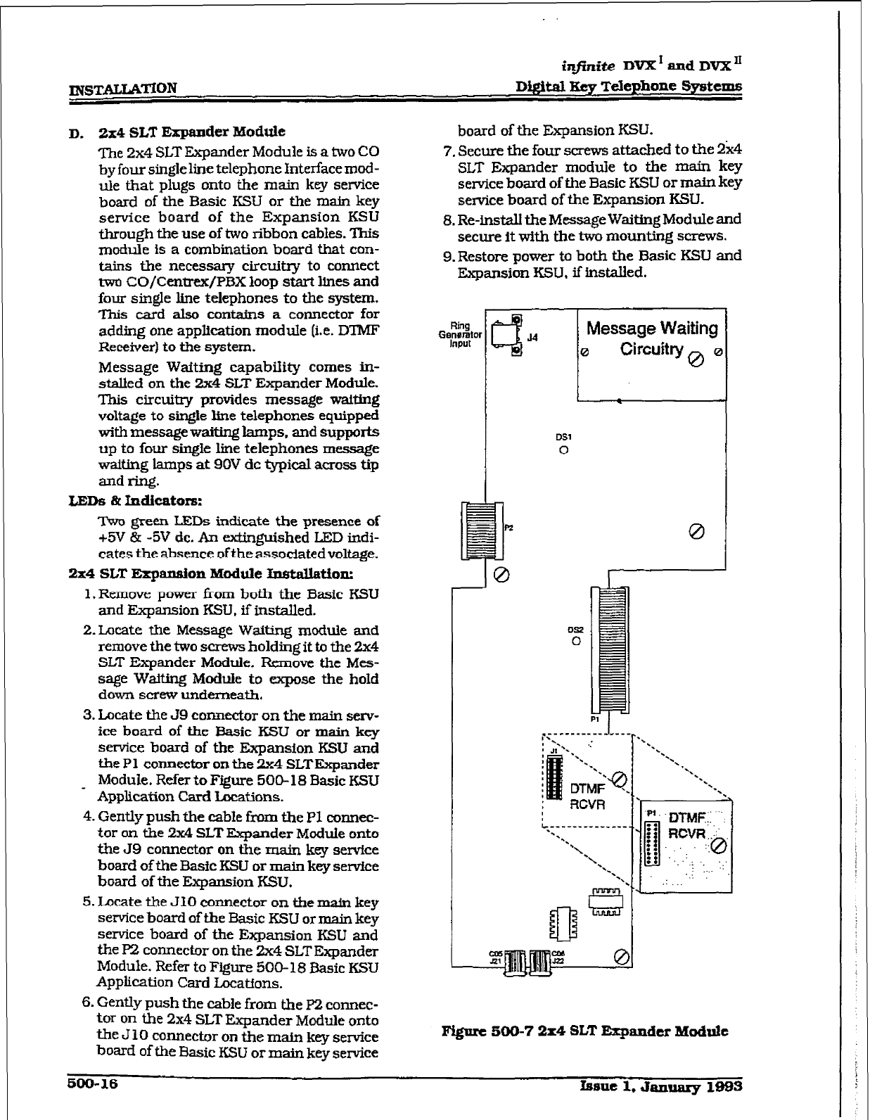
infinite DVX I and DVX”
Digital Key Telephone Systems
D. 2x4
SLT Expander Module
me
2x4
SLT Expander Module is a two CO
by four single line telephone Interface mod-
tie that plugs onto the main key service
board of the Basic KSU or the main key
service board of the Expansion KSU
through the use of two ribbon cables. This
module is a combination board that con-
tains the necessary circuitry to connect
two CO/Centrex/PBX loop start lines and
four single line telephones to the system.
This card also conks a connector for
adding one application module (i.e. DTMF
Receiver) to the system.
Message Wafting capability comes in-
staked on the 2x4 SLT Expander Module.
This circuiby provides message waiting
voltage to single line telephones equipped
with message wafting lamps, and supports
up to four single line telephones message
waiting lamps at 9OV dc typical across tip
and ring.
LED5 clt
Indicator8:
Two green LEDs indicate the presence of
+5V & -5V dc. An extinguished LED indi-
cates the absence ofthe associated voltage.
2x4 SLT Expansion Module InstAation:
l.Remove power from both the Basic KSU
and Expansion KSTJ, if installed.
2.Lucate the Message Waiting module and
remove the two screws holding it to the 2x4
SLT Expander Module. Remove the Mes-
sage Waiting Module to expose the hold
down screw underneath.
3. Locate the J9 connector on the main serv-
ice board of the Basic KSU or main key
service board of the Expansion KSU and
the Pl connector on the 2x4 SLTExpander
Module. Refer to Figure 500-18 Basic KSU
Application Card Locations.
4. Gently push the eabfe from the PI connec-
tor on the 2x4 SLT Expander Module onto
the J9 connector on the main key service
board of the Basic KSU or main key servfce
board of the Expansion KSU.
5. Locate the J10 connector on the main key
service board of the Basic KSU or main key
service board of the Expansion KSU and
the p2 connector on the 2x4 SLT Expander
Module. Refer to Figure NO- 18 Basic KSU
Appfication Card Locatfons.
6. Gently push the cable from the pz connec-
tor On the 2x4 SLT Expander Module onto
the. 3 10 connector on the main key service
board of the Basic KSU or main key service
board of the Expansion KSU.
7. Secure the four screws attached to the 2&4
SLT Expander module to the main key
service board of the Basic KSU or main key
service board of the Expansion KSU.
8. Re-install the Message Waiting Module and
secure It with the two mounting screws.
9. Restore power to both the Basic KSU and
Expansion KSU, if installed,
I
i
0
Pi?
0
0
Figiuc 500-7 2x4 SLT Expander Module
500-16 knlc 1. J8nuary 1993
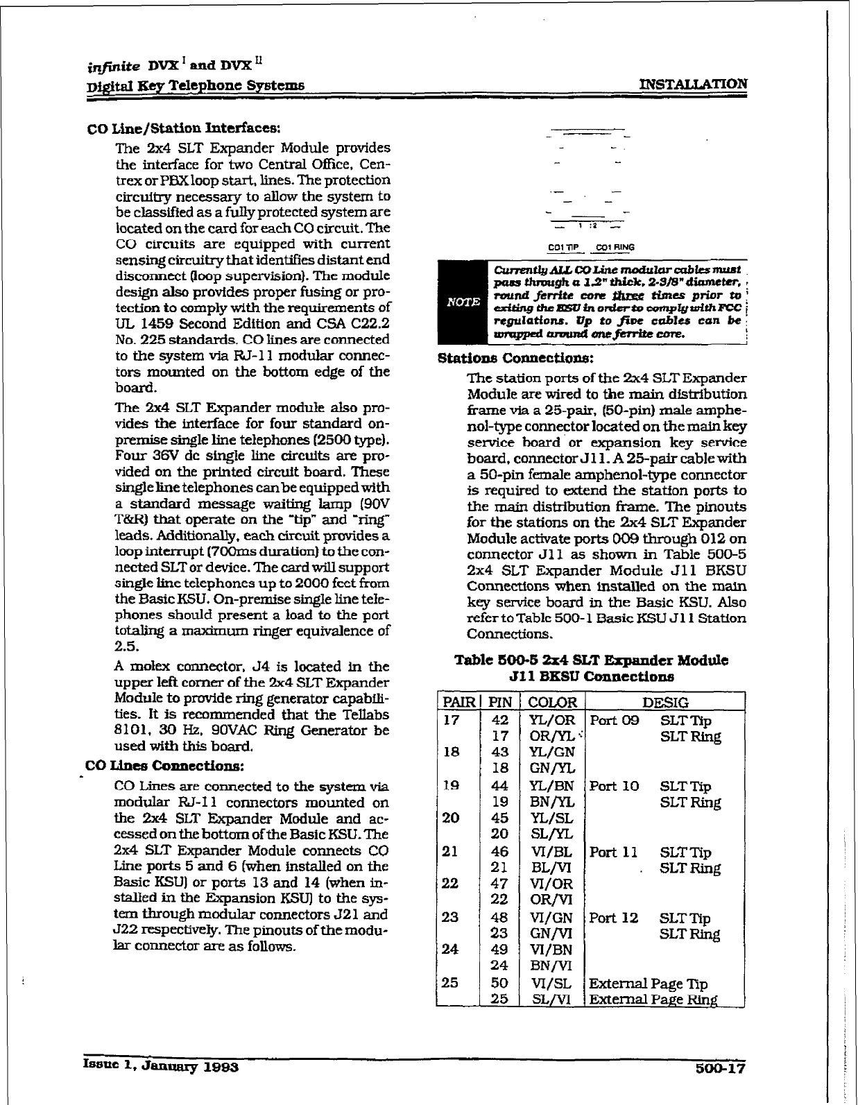
jnfinite DVX’andDVX’
Di@atEeyTelephoneSystems INSTALIATION
CO
Line/St&on Interfaces:
The 2x4 SLT Expander Module provides
the interface for two Central Office, Cen-
trex or PBXloop start, lines. The protection
circuitry necessary to allow the system to
be classified as a fully protected system are
located on the card for each CO circuit. The
CO circuits are equipped with current
sensing circuitry that identifies distant end
disconnect (loop supervision). The module
design also provides proper fusing or pro-
tection to comply with the requirements of
UL 1459 Second Edition and CSA C22.2
No. 225 standards. CO lines are connected
to the system via W-1 1 modular connec-
tors mounted on the bottom edge of the
board.
The 2x4 SLT Expander module also pro-
vides the interface for four standard on-
premise single line telephones (2500 type).
Four 3W dc single line circuits am pro-
vided on the printed circuit board. These
singleline telephones canbe equipped with
a standard message waiting lamp (9OV
T&R) that operate on the -tip” and ‘ring”
leads. Additionally, each circuit provides a
loop intenupt (7OOms duration) to the con-
nected SLT or device. ‘Ihe card will support
single line telephones up to 2000 feet from
the Basic KSU. On-premise single line tele-
phones should present a load to the port
totaling a maximum ringer equivalence of
2.5.
A mdex connector. 54 is located in the
upper left comer of the 2x4 SLT Expander
Module to provide ring generator capabfli-
ties. It is recommended that the TelIabs
8101. 30 Hz. SOVAC Ring Generator be
used with this board.
co Lines conneetione:
CO Lines are conuscted to the system via
modular R&l1 connectors mounted on
the 2x4 SLT Expander Module and ac-
cessed on the bottom of the Basic KSU. The
2x4 SLT Expander Module connects CO
Line ports 5 and 6 (when fnstalled on the
Basic KSU) or ports 13 and 14 (when in-
stalled in the Expansion KSU) to the sys-
tem tbm~gb modular connectors 521 and
J22
respectively. The pinouts of the modu-
lar connector are as follows-
.- -
- -
- -
- 1:z -
co1 TIP tot RING
--
The station ports of the 2x4 SLT Expander
Module are wired to the main distribution
frame via a 25pair, (50-pin) male amphe-
nol-type connector located on the main key
service board or expansion key service
hoard, connector J 11. A 25-p& cable with
a 50-pin female amphenol-type connector
is required to extend the station ports to
the main distribution frame. The pinouts
for the stations on the 2x4 SLT Expander
Module activate ports 009 through 012 on
connector Jll as shown in Table 500-5
2x4 SLT Expander Module Jl 1 BKSU
Connections when installed on the main
key service board in the Basic KSLJ. Also
refer to Table 500- 1 Basic KSU J 11 Station
COMCCtiOnS.
Table 500-S 2x4
SLT
Expander Module
Jf 1 BKSU Connections
pALR
17
18
19
20
21
22
23
24
25
ml
42
17
43
18
44
19
45
20
46
21
47
22
fi
49
24
50
25
I
COLOR
YL/OR
OR/n, >
?ZL/GN
GN/n.
YL/BN
BNrYL
YL/SL
SLrn
VI/BL
BL/VI
VI/OR
OR/VI
VI/GN
GN/VI
VI/BN
BN/vI
vI/SL
SLrvl
DESIG
Port 09 SLT Tip
SLT Ring
Port 10 SLTTip
SLT Ring
Port 11 SLTTip
. SLTRing
Port 12 SLT Tip
SLT Ring
External Page Tip
External Pwe Ring
Issa~l,January19Q3 500-17
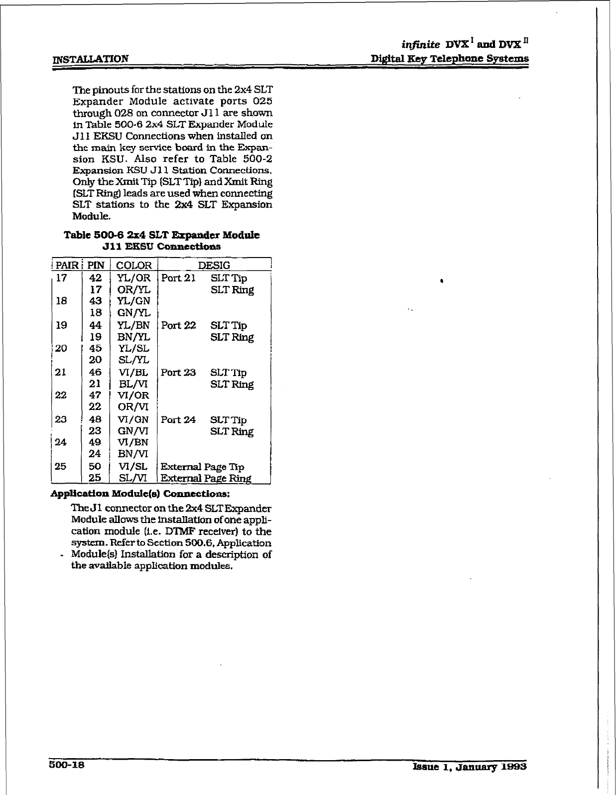
~STALMTION
itlfinite DvX’andDVX’
D&ital Key Telephone Systems
The pinouts for the stations on the 2x4 SLT
Expander Module activate ports 025
through 028
on connector Jl 1 are shown
in Table 500-6 2x4 SLT Expander Module
Jl I
EKSU Connections
when installed on
the main key service
board in the Expan-
sion KSU. Also refer to Table 500-Z
Expansion
KSU J Z 1
Station Connections.
On& the Xmit Tip (SLTTip] and Xnit Ring
[SLT Ring) leads are used when connecting
SLT stations to the 2x4 SLT Expansion
Module.
Tabie 500-6 2x4 SLT Expander Module
Jll EKSU mnne&ons
i PAIR
17
18
19
20
21
22
23
124
25
PIN
42
17
43
18
44
19
45
20
46
21
47
22
48
23
49
24
50
25
i
j
I
1
I
COLOR
YL/OR
OR/YL
YL/GN
CN/YL
YL/BN
BN/YL
YL/SL
sL/n.
VI/BL
BLM
VI/OR
OR/VI
WGN
GNM
VI/BN
BNM
vI/SL
sL/vl
DESIG
Port
21 SLT Tip
SLT Ring
Port 22 SLTTlp
SLT Ring
Port 23 SLTTIp
SLT Ring
Port 24 SLTTip
SLT Ring
External Page Tip
ExtfmdPa.geRinP
Application Module(s) Connection:
The J 1 connector on the !Zx4 SLT Expander
Module allows the insta.Hation of one appli-
cation module (i.e.
DTMF receiver) to the
system. Refer to Section 500.6. Application
* Module(s) hW.allation for a description of
the available application modules.
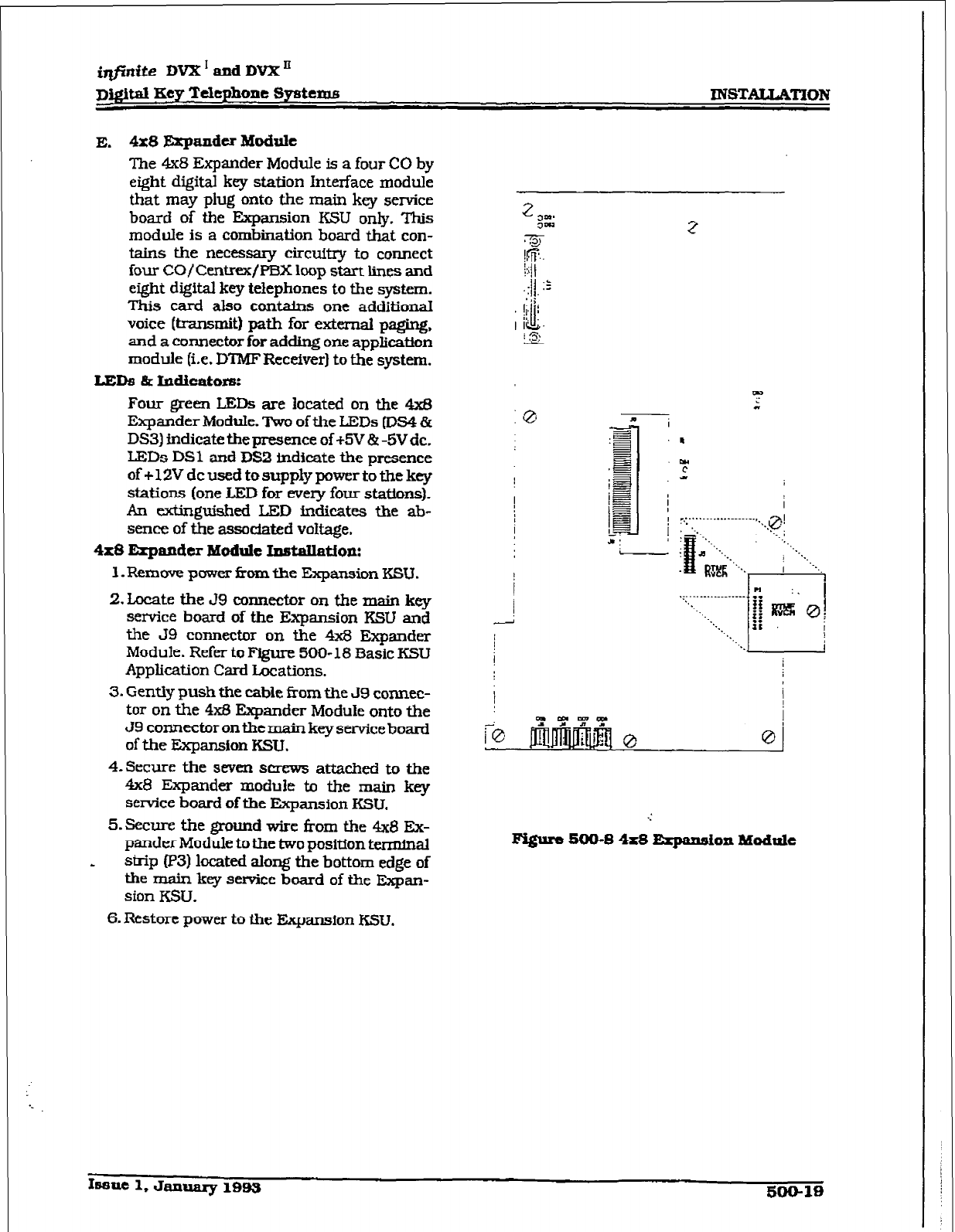
irtfirtite DVX * and DVX’
p&$N Key Telephone SysWxui
E.
4x8 Expandu Module
The 4x8
Expander Module is a four CO by
eight digital key station Interface module
that may plug onto the main key service
board of the Expansion KSU only. This
module is a combination board that con-
tains the necessary Circuitry to connect
four CO/Centrfx/F’EIX loop start lines and
eight digital key telephones to the system.
This card also contains one additional
voice (transmit) path for external paging,
and a connector for adding one applicatton
z
E
!@..
module (i.e. DTMF Receiver] to the system.
LEDB & Indicators:
Four green LEDs are located on the 4x8
Expander Module. Two of the LEDs [DS4 &
DS3) indicate the presence of +5V % -5Vdc.
LEDs DSl and DS2 indicate the presence
of c 12V dc used to supply power to the key
stations (one LED for every four stations).
An dinguishecl LED indicates the ab-
sence of the associated vokage.
4x8 Erpandtr Yoduk InstalIation:
l.Removepxwzrfromthe ExpansionKSU.
2.
Locate the J9 connector on the main key
service board of the Expansion KSU and
the J9 connector on the 4x3 Expsnder
Module. Refer to Fiiure 500- 18 3asic KSU
Application Card Locations.
3. Gently push the cable from the J9 connec-
tor on the 4x5 Expander Module onto the
J9 connector on the main key service board
of the Expansion KSTJ.
4.Secure
the seven screws attached to the
4x8 Expander module to the main key
service board of the Expansion KSU.
5.Eiemn-e the ground wire
from the 4x8 EX-
pander Module to the two position terminal
h
strip (P3) located along the bottom edge of
the main key service board of the Expan-
sion KSU.
,
I
/
I
0
.:
Figure SW-8 4x8 Erpanaion Modttk
6.
Restore power to the Expansion
KSU.
Issue 1,
January 199s
50@19
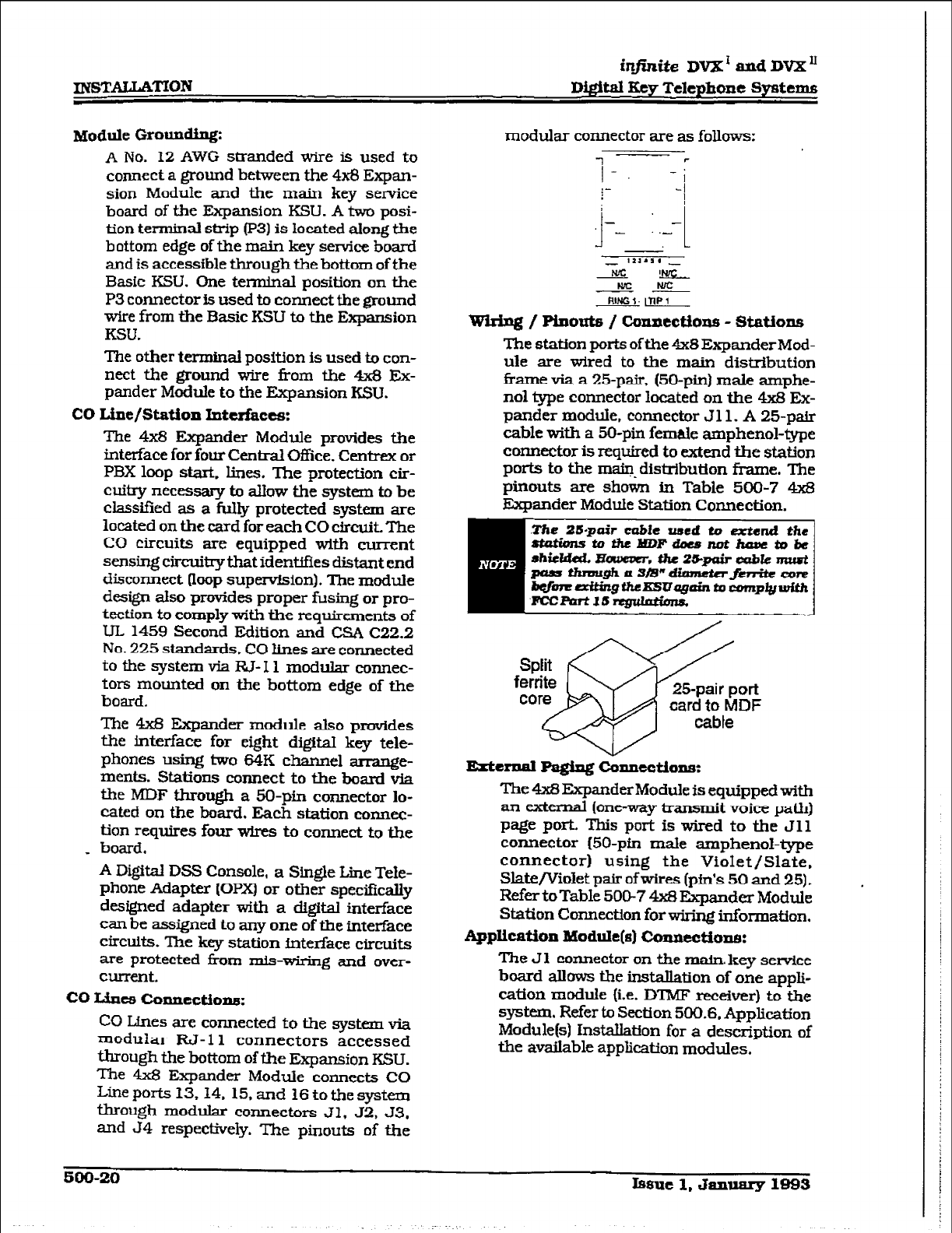
INSTAUATION
Module Grounding:
A No. 12 AWG stranded wire is used to
connect a ground between the 4x8 Expan-
sion Module. and the main key service
board of the Expansion KSU. A two posi-
tion terminal strip (p3) is located along the
bottom edge of the main key service board
and is accessible through the bottom of the
Basic KSU. One terminal position on the
P3 connector is used to connect the ground
wire from tbe Basic KSU to the Expansion
KSU.
The other
terminal
position is used to con-
nect the ground wire from the 4x8 Ex-
pander Module to the Expansion KSU.
CO Line/Station lntcrhces:
The 4x8 Expander Module provides the
interface for four Central Office. Centrex or
PBX loop start. lines. The protection cir-
cuitry necessary to allow the
system
to be
classtfied as a fully protected system are
located on the card for each CO circuit The
CO circuits are equipped with current
sensing circuilrythat identifies distant end
disconnect Poop supewision). The module
design also provides proper fusing or pro-
tection to comply with the requirements of
UL 1459 Second Edition and CSA C22.2
No. 225 standards. CO lines are connected
to the system via I?& I 1 modular connec-
tors mounted on the bottom edge of the
board.
The 4x8 Expander module also provides
the hterface for eight digiital key tele-
phones using two 64K channel arrange-
ments. Stations connect to the board via
the MDF through a 50-pin connector lo-
cated on the board. Each station
connect-
tion requires four w&s to connect to t,he
_ board.
A Digital DSS Console, a Single Liie Tele-
phone Adapter (OPXj or other specifically
designed adapter with a digital interface
can be assigned to any one of the interface
circuits. The key station interface circuits
are protected hm mis-wiring and over-
current.
co Liucs conne!ctiope:
CO Lines are connected to the system via
modular RJ-11 connectors accessed
through the bottom of the Expansion KSU.
The 4x8 Expander Module connects CO
J.&x pods 13,14. 15, and 16 to the system
through modular connectors Jl. J2, 53.
amI 34 respectively. The pinouts of the
modular connector are as follows:
I-. -j
,... I
wsriug / Piuouts / coxlntctlon8 - station8
The station ports of the 4xSExpanderMod-
ule are wired to the main distribution
frame via a 25-pair. (50-pin) male arnphe-
no1 type connector located on the 4x8 Ex-
pander module, connector Jl 1. A 25-p&
cable with a 50-pin female amphenol-type
connector is required to extend the station
ports to the m~@~distribution frame. The
pinouts are shown in Table 500-7 4x8
Expander Module Station Connection.
The 4x8 Expander Module is equipped with
an external (one-way transmit voice path)
page port. This port is wired to the J 11
connector (50-pin male amphenol-type
connector) using the Violet/Slate.
Slate/Violet pair of wires (pin’s 50 and 25).
Refer toTable 500-7 4x8 Expander Module
Station Connection for wiring information,
Application Module(s) Conntctiope:
The J 1 connector on the main. key service
board allows the installation of one appli-
cation module (i.e. IYIMF receiver) to the
system. Refer to Section 500.6. Application
Module(s) installation for a description of
the available application modules.
5OQ-20
b8ut
1, hnuary 1993
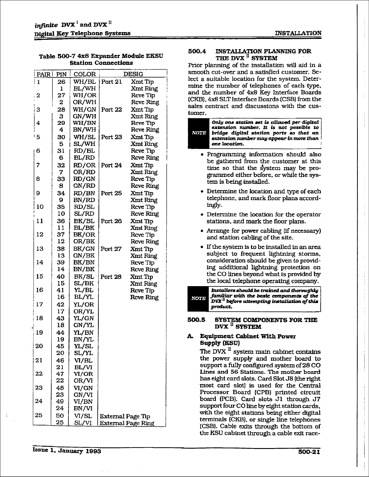
IIUSTAUATION
infinite DWZ’ and DVX’
Digi@l Key Telephone Sy8tcms
way near the back of the KSU cabinet.
Refer to Figure 500-9 Basic KSU
Equipment Cabinet for circuit board layout
and location of connectors.
Power supply:
The power supply is installed in the KSU
cabinet at the time of manufacture and
ships with the KSU. The power supply in-
put voltage is 117V ac. i-10?!. The power
supply provides power distribution
of
fiI-
tered/unregu.lated 12Vdc and aregulated
-EN dc to the backplane bus. An ON/OFF
switch is located on the front of the power
supply along with a slo-blow 5 amp fuse on
the AC side of the transformer. The power
supply provides an input for a 48V dc
source for future use. Power is regulated
and distributed to stations/circuitry inthe
system on each printed circuit board.
Three fuses located inside the power sup-
ply protect the system fi-om over-current
situations. The power supply and cabinet
meet all safe@ requirements to cornply
with UL 1459 Second Edition and CSA
C22.2 No. 225
standards.
The power supply is installed inside the
system cabinet, on the right side, in the
first card slot (J9). The power supply is
designed to be an integral, structural part
of the system. Do not attempt to install the
system. or interface car&unless the power
supply is installed with 3l.l four
spews
securely in place. The cabinet. includes the
power supply already installed. The power
supply is recognized underthe Component
Program of Underwriters Laboratories Inc.
The power supply is unique in
that
the
transformer is not present on the power
supply card and its enclosure. The trans-
former is mounted inside the cabinet next
to the bottom right of the backplane. When
the power supply card is installed. the
transformer is totally enclosed by the
power supply card’s “L” shaped enclosure,
and the right side of the cabinet. l’his cre-
ates a totally enclosed. operational, power
supply. Since the transformer is installed
in the cabinet. and the power suppIy card
is
removable from the cabinet, the AC coh-
nections are made directly to the system
backplane.
[WARNING!
Since hazardous voltages are always
present on the backplane while the
system AC power cord is plugged in.
AT NO TIME SHOULD ‘I3IE POWER
SUPPLY CARD BE REMOVED WHILE
THE SYSTEM
AC POWER CORD IS
PLUGGED IN. THE POWER SUPPLY
BOARD AND iTS ‘L” SHAPED METAL
ENCLOSURE PROVIDE THE ONLY
PROTECTION mane
SHOCK mu-
ARDWHILETHEACPOWERCORDIS
PLUGGED IN. There are very few in-
stances when the power supply card
should be removed. If an instance
arises where it must be removed, AL
WAYS unplug the system AC power
cord FIRST.
The power supply cord plugs into an iso-
lated, dedicated, (with dedicated ground)
1 I7V ac outlet for power. This is necessary
to prevent possiblevoltage spikes and tran-
sients that may be caused by equipment
sharing the same AC circuit.
The AC connection to the power supply
requires a parallel blade with a ground
receptacle. A three wire to two wire isola-
tion adapter should not be used. The use
of a surge suppressor is required.
G1ollmuxlg:
A No. 12 AWG copper wire should be used
to connect a ground between the ground
source and the KSU (25 feet m-urn). A
two position terminal strip (J10) is located
on the lower left comer of the motherboard
and is accessible through the left side of
the KSU. One tennina position can be
used to connect the ground wire &om a
ground source.
B. Cabinet Iu&aUation
Once the area for the telephone equipment
has been selected. mount a plywood back
board to the wall. ‘Ihe back board size will
vary depending upon the size of the MDF.
The entire system and frame can be
mounted on a 4’ x 6’ x 3/4” plywood. If
mounting the cabinet alone, the minimum
back board size is 25” x 17” x 3/4”.
A fully
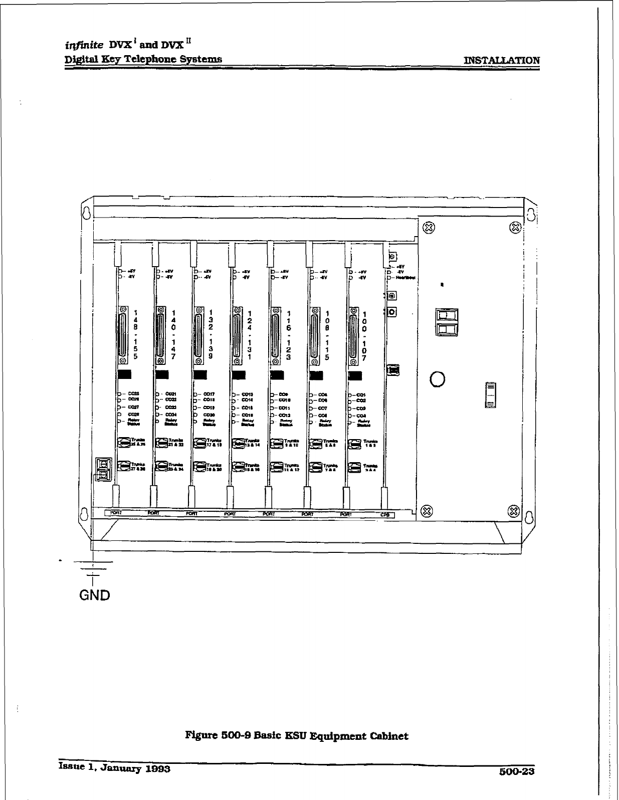
iqfinite DVX’ and DVX ’
DIgital Eey Telephone Systems
! i
GND
Figure soo-sBa!31c KSIJ Eqtdpment cabinet
bmc 1, Januq 1093
500-23
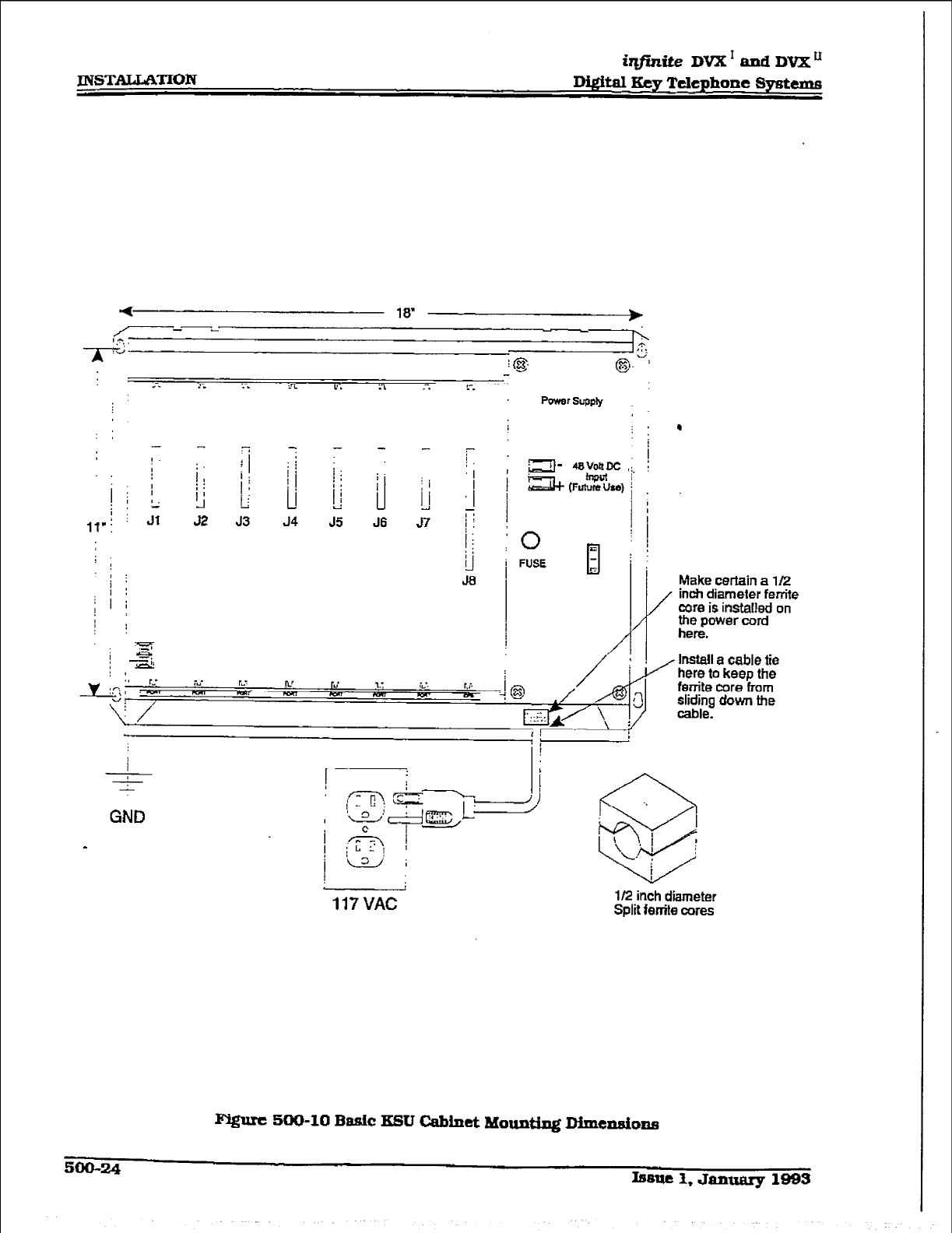
JNSTALLATION
i@,niteDVX1andDVXu
DQit8.l Key Telephone Systems
,,v! j Jl 52 J3 J4 J5 J6 57 i j
1
iJ
i FUSE
J8 ’ Make certain a l/2
in& diameter ferrite
core is installed on
117 VAC
l/2 inch diameter
Split ferrite cores
Qzurc 500-10 Basic ESU Cabinet Mounting D.imensions
500-24 h8Ue I, Jantmry 1993

iq#idte
DVX1 and DVX
D&&al Key Telephone Spetexm INSTALLATION
loaded cabinet can weigh approzdmately 64
lbs. Make certain proper mounting proce-
dures are followed.
CJuck
local bdding and &CM codes
bqfore mounhg the sgstem. For example,
ccrtafn ureas
mag require a flame
rata&ant &wood back board. :
1 -Mount the cabinet to the plywood using
3/4” #12 pan-head sheet metal screws
such that the top of the cabinet is approxi-
mately three feet (1 meter) from the ceiling,
and bottom is four feet (1.2 meters) from
the fl oar. Make certain before mounting the
cabinet that circuit cards slide easily in
and out of their respective card slots.
Z.Use the mounting template supplied with
the cabinet to locate the mounting holes.
Also refer to Figure 500-10 Basic KSU
Cabinet Mounting Dimensfons.
3.Drill the holes and mount the cabinet.
c. central Prooessor Board (CPB)
This plug-in card is the only common
equipment card required to make the sys-
tem
operational and controls all system
activity. The CPB contains the rnatn micro-
processor a 16-bit (68000) and a real time
clock which controls all system functions
including the PCM/TDM voice switching
under direction of ROM and F&M software
coding. The CP3 is responsible for aJl con-
trol functions. execution of ail logic opera-
tions and control of system modules
including control over circuitry necessary
forvoice swftching and confkence connec-
tions. The CPB is also responsible for all
system tones, system timing, and station
status control. ln addition the CPB also
provides software andhardware support to
ensure the following:
L
l
Watch dog timer and recovery.
l
PCB status as to presence/absence of
cards for automatic software confiiura-
tion setup.
. Interpret an ID code from each PCB so
that card type can be determined auto-
matically.
l
State/event so- design.
l
Battery backup of customer database
RAM memory.
The CPB contains the circuitry and
con-
nection (RCA type) for background mu-
sic/music on hold, and the standard 300
Baud Modem. An optional 1200 Baud Mo-
dem can be iastalled on the CPB to allow
the on-board modem to transmit at ti 1200
baud rate. In addition there is one RS-
232C modular connector input/output
port on the CPB and a connector to support
the use of an
optional
I/O expansion mod-
ule. The I/O expansion module adds RS-
23X!. I/O port and one RS-422 l/O portto
the system for a system total of three I/O
ports. A reset (halt) push button switch
and a BGMjMOH volume control potenti-
ometer is located on the front of the printed
circuit board. Refer to Figure 500-9 Basic
KSU Equipment Cabinet for CPB layout
and location of connectors.
System software is provided in EPROM
memory and is installed on the CPB. The
CPB contains 512K of%PROM storage and
is equipped with 256K of battery-backed
static RAM. Rovisions have been made on
the card to address up to four megabytes
of EPROM memory and up to two mega-
bytes of static RAM.
An option -dip” switch located on the CPB
allows the system EPROM memory to be
configured
utiliziq difh-ernt size EPROM
chips. 1 Megabit, 2 Megabit, 4 Megabit and
8 Megabit chips may be used to provide the
generic software. Refer to Section 800,
Maintenance and Troubleshooting for
‘dip” switch settings for various allowable
confiiffoRs.
The CPB allows tie use of either
1
Megabit
or 4 megabit static RAM chips to be used
for F?AM memory. The size and type of
memory used is automatically determined
and set by the system.
The battery backup strap must be
placed in the “ON” position to activate
memory battery backup (J3}. Do this
prior to inserting the CPB into the
KSU. Refer to Figure 500-9 Basic KSU
Equipment Cabinet. If the optional
1200 baud modem module or expan-
slon I/O module are to he installed. do
this now prior to inse*g the CPB.
The CPB board is inserted into the 58
slot with components on the card fac-
ing the wt. This board must NOT be
installed with the power on. The edge
connector on the CPB is offset to pre-
vent it corn being installed in an incor-
rect slot. Do not force the card into
Iasuc 1, Jammy lfH33
500-26
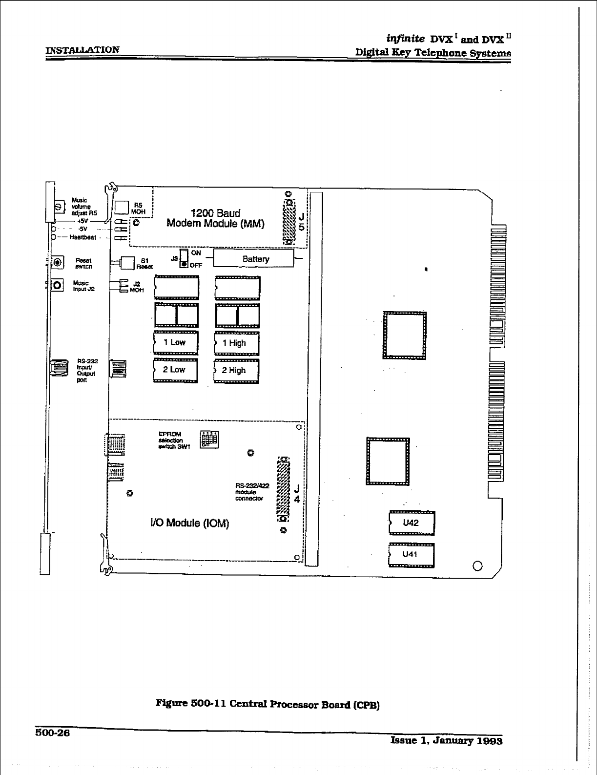
INSTALLATION
illrfinite IWx’ and wXLI
DfgitalKey
TelephoneSystems
1200 Baud
Modem Module {MM}
l/O Module (IOM)
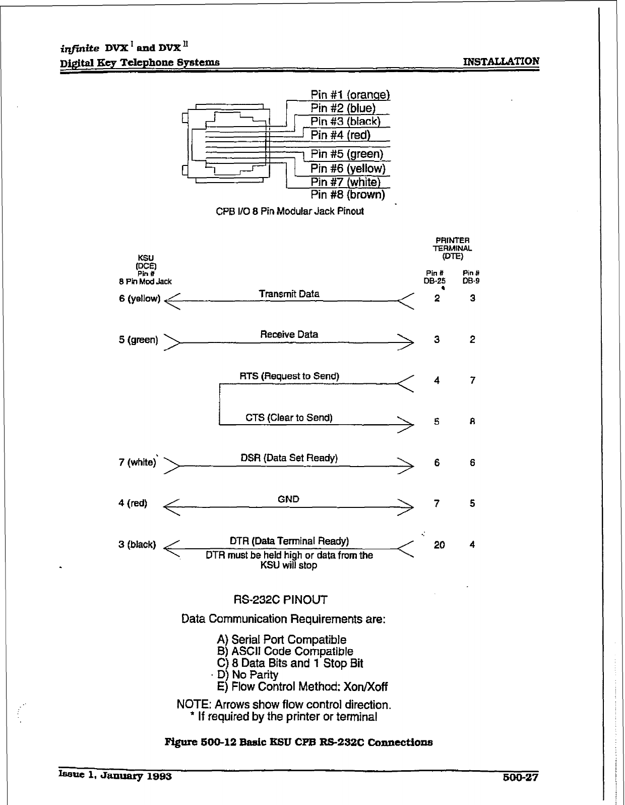
imite DVX’ and DVX’
Ecy Telephone Systems KNSTALUCI’ION
I
‘2
c’l
Pin #1 (orange)
Pin #2 (blue)
Pin #3 (black)
1 Pin #4 (red)
I
I 1 Pin #5 (green)
Pin #6 (yellow)
1 Pin #7 (white)
Pin #8 (brown)
-
CPB l/O 8 Pin Modular Jack Pinout
8 PI Mod Jack
6 (yellow) Transmit Data
5 (w=n) Receive Data
RTS (Request to Send)
I
CTS (Clear to Send1 \
I
7 (white) DSR (Data Set Ready)
3 (black) DTR (Data Terminal Ready)
DTR must be held high or data from the
KSU will stop
RS-232C PI NOUT
Data Communication Requirements are:
A) Serial Port Compatible
B) ASCIJ Code Compatible
C) 8 Data Bits and 1 Stop Bit
. D) No Parity
E) Flow Control Method: Xon/Xoff
NOTE: Arrows show fiow control direction.
l
If required by the printer or terminal
PAINTER
TERMINAL
W-W
Pin # Pin#
D&25 DB-9
2’ 3
3
4
5
6 6
7 5
Fi@re 590-12 Basic KSU CPB R5-232C Connectiona
-Ue 1. January 199s 500-27
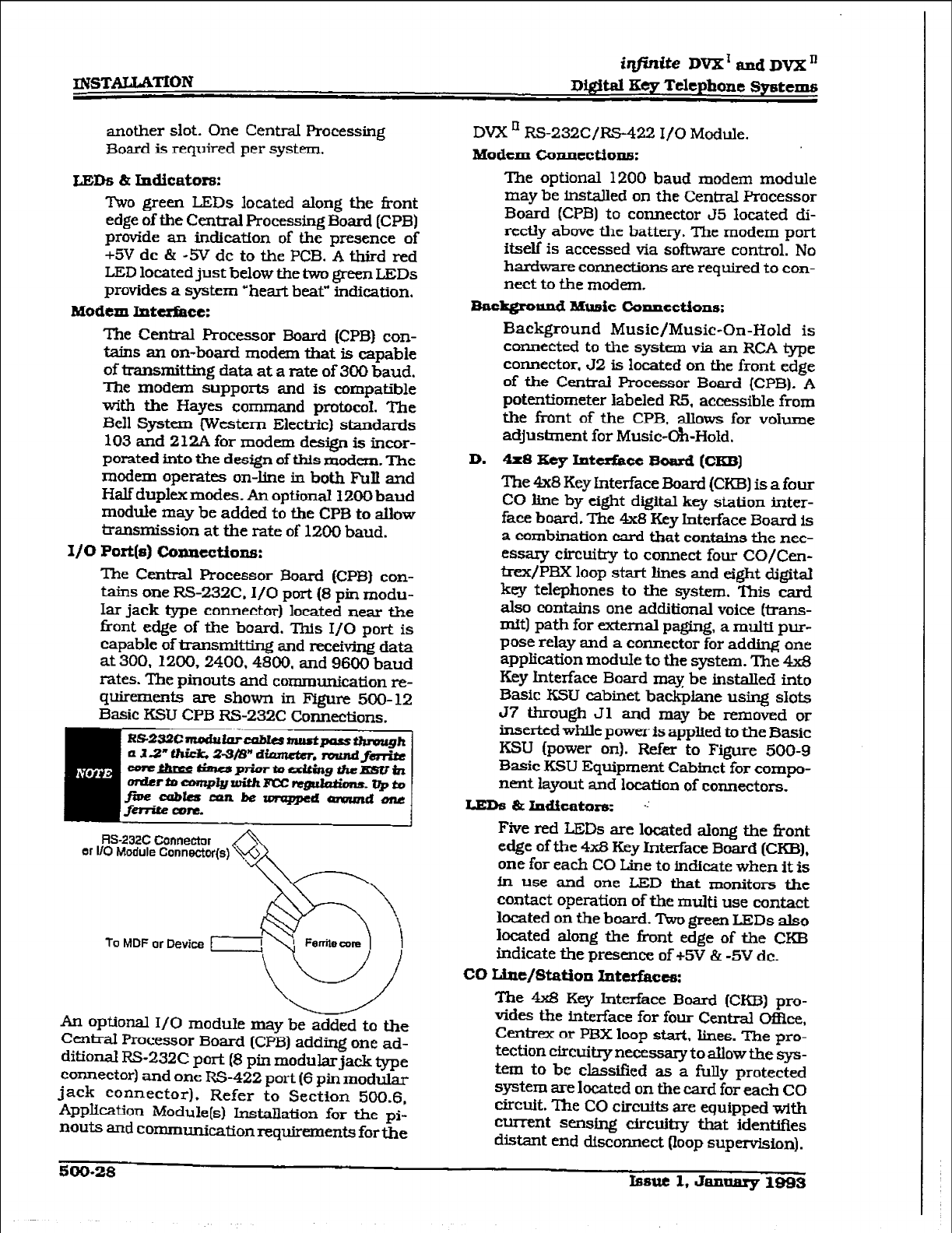
another slot. One Central Processing
Board is required per system,
ids & Indicators:
?kro green LEDs located along the iiont
edge of the Centrat Processing Board (CPB)
provide an indication of the presence of
+5V dc & -5V dc to the PCB. A third red
LED located just below the two greem LEDs
provides a system ‘heart beat” indication.
Modem Intcsfkce:
The Central Processor Board (CPB) con-
tains au on-board modem that is capable
of transmitting data at a rate of 300 baud.
The modem supports and is compatiile
with the Hayes command protocol. The
Bell System (Western Electric) standards
103 and 212A for modem design is incor-
porated into the design of this modem. The
modem operates on-line in both Full and
Half duplex modes. An optional 1200 baud
module may be added to the CPB to allow
transmission at the rate of 1200 baud.
x/o Port(a) comlections:
The CentraI Processor Board (CPB) con-
tains one RS-232C. I/O port (8 pin modu-
Iar jack type connector) located near the
tiont edge of the board. This I/O port is
capable of transmMin.g and receiving data
at 300.1200,2400.4800. and 9600 baud
rates. The pinouts and communication re-
quirements are shown in Figure 500-12
Basic KSU CPB RS-232C Connections.
RS-232C Connector
or I/O Module Connector(s)
To MDF or Device
An optional I/O module may be added to the
Central Processor Board (CPB) adding one ad-
ditional RS-232C port (8 pin modularjack type
connector) and one RS-422 port (6 pin modular
jack connector). Refer to Section 500.6,
Application Module[s) Installation for the pi-
nouts and communication requirements for the
DVX ’ RS-232C/RS-422 I/O Module.
Modem Cxuu.tcctionrx
The optional 1200 baud modem module
may be installed on the Central Pxxessor
Board (CPB) to connector 55 located di-
rectly above the battery. The modem port
itself is accessed via software control. No
hardware connections are required to con-
nect to the modem.
BackgrouIld Music canucctions:
Background Music/Music-On-Hold is
connected to the system via an RCA type
connector, 52 is located on the front edge
of the Central Processor Board (CPB). A
potentiometer labeled R5, accessible from
the front of the CPB. allows for volume
adjustment for Music-Oh-Hold.
D. 4x8 Key Interface Board (CKB]
The 4x8 Key Interface Board (CKBI is a four
CO line by eight digital key station inter-
face board. The 4x8 Key Interface Board is
a combination card that contains the nec-
essary circuiby to connect four CO/&m-
trex/PBX loop start lines and eight digital
key telephones to the system. This card
also contains one additional voice (trans-
mft) path for external paging, a multi pur-
pose relay and a connector for adding one
appliication moduIe to the system. The 4x8
Key Interface Board may be installed into
Basic KSU cabinet backplane using slots
J7 through Jl and may be removed or
inserted whLle power is applied to the Basic
KSU (power on). Refer to Figure 500-9
Basic KSU Equipment Cabinet for compo-
nent layout and location of connectors.
LEDS
8clJldicators:
.:
Five red LEDs are located along the front
edge of the 4x8 Key
Interface
Board (CKE!),
one for each CO Line to indicate when
it
is
in use and one LED that monitors the
contact operation of the multi use contact
located on the board. Two green LEDs also
located along the tint edge of the CKB
indicate the presence. of +5V & -5V dc.
CO Line/Station Intcrfkc#r:
The 4x8 Key Interface Board (CKB) pro-
vides the interface for four Central Of&x.
Cedrex or PBX loop start. lines. The pro-
tection circuitry necessary to allow the sys-
tern to be classified as a fully protected
system are located on the card for each CO
circuit. me CO circuits are equipped with
current sensing circuitry that identifies
distant end disconnect (loop supervision).
500-28 Psuc 1, January 1993
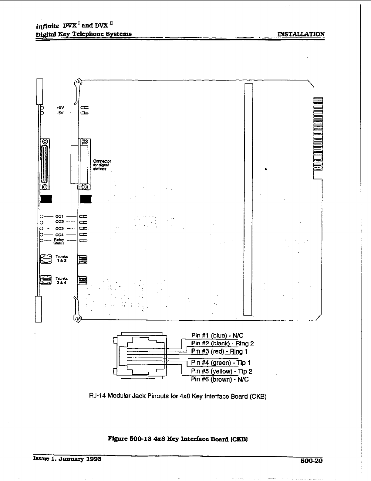
i@nite DVX’ and DVX’
Digital Key Telephone Systems INSTAILATION
F
-co1 -e
.- CM --- a .:.. . .
- co3 -.-. a. :. ‘:.
---a
- F-MAY -- a.
StEllV5
:: .:
I.
i : *... .‘..
., ‘.
: ,.: .:, : *-
:.
1 I
c Pin #l (blue) - N/C
Pin #2 (black) - Ring 2
I 1 Pin #3 (red) - Ring 1
1 Pin #4 (green) - Tip 1
c I Pin #5 (yellow) - Tip 2
I I Pin #6 (brown) - N/C
RJ-14 Modular Jack Pinouts for 4x8 Key Interface Board (CKB)
Figure 600-13 4x8 Rcy Intufacc Board K?EBl
Issue 1. January 1993 500-29
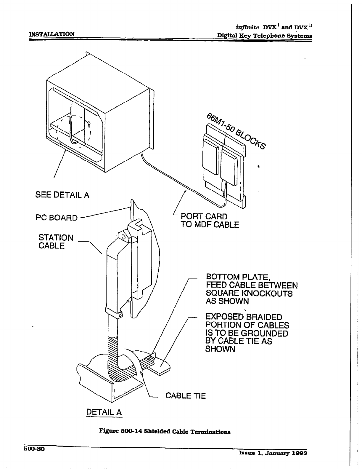
INSTALLATION infinite DVX I and DVX’
D&&al Key Telephone 8yitems
SEE DETAIL A
PORT CARD
TO MDF CABLE
DETAIL A
BOTTOM PLATE,
FEED CABLE BEI-VVEEN
SQUARE KNOCKOUTS
AS SHOWN
EXPOSEDhRAIDED
PORTION OF CABLES
IS TO BE GROUNDED
BY CABLE TIE AS
SHOWN
Figure 600-14 Shielded Cable Ttrminatione
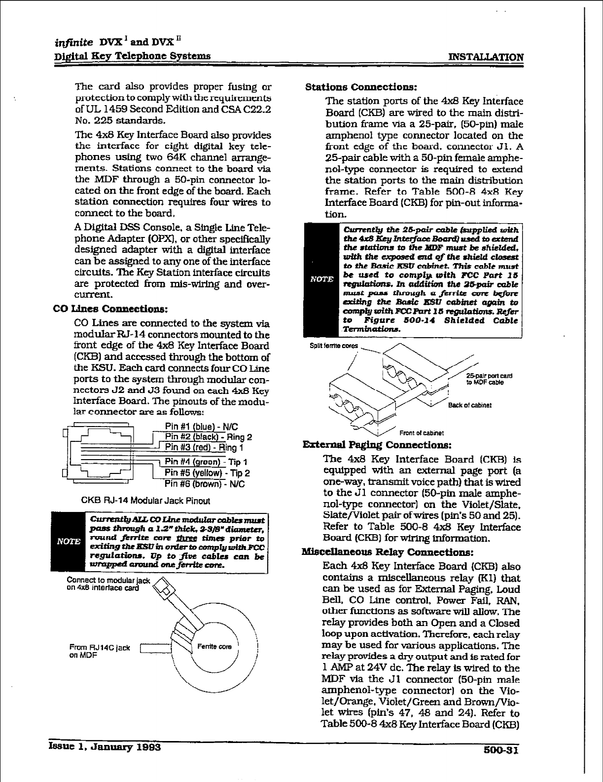
The
card
also provides proper fusing or
protection to comply with the requirements
of UL 1459 Second Edition and CSA C22.2
No. 225 standards.
The 4x8 Key Interface Board also provides
the interface for eight digital key teie-
phones using two 64K channel arrange-
ments. Stations connect to the board via
the MDF through a 50-pin connector lo-
cated on the front edge of the board. Each
station connection requires four wires to
connect
to the
board.
A Digital DSS Console, a Single Line Tele-
phone Adapter (OPX), or other spe&cally
designed adapter with a digital interface
can be assigned to any one of the interface
circuits. The Key Station interface circuits
are protected from mis-wMng and over-
current.
co Lines conuectioncr:
CO Lines are connected to the system via
modular RI- 14 connectors mounted to the
front edge of the 4x8 Key Interface Board
(CKBI and accessed through the bottom of
the KSU. Each card connects four CO Line
ports to the system through modular con-
nectors 52 and 53 found on each 4x8 Key
Interface Board. The pinouts of the modu-
lar connector anz
as
follows:
Pin #1 (blue) - N/C
Pin #2 (black) - Ring 2
Pin #3 (red) - Ring 1
i Pin #4
(green) - lip 1
Pin #5 (yellow) - Tip 2
Pin #6 (brown) - N/C
CKB RJ-14 Modular Jack Pinwt
Stations colmections:
The station ports of the 4x8 Key Interface
Board (CKB) are wired to the main distri-
bution frame via a 25-pair. (56pin) male
arnphenol type connector located on the
front edge of the board. connector JI. A
25-pair cable with a 50-pin female amphe-
nol-type connector is required to extend
the station ports to the main distribution
frame. Refer to Table 500-8 4x8 Key
Interface Board (CKB) for pin-out informa-
tion.
w Fmnl 01 cabinet
szkkmd Paging connectiollE:
The 4x8 Key Interface Board (CKB) is
ecfuipped with an external page port (a
one-way, iransmit voice path) that is wired
to the Jl connector (50-pin male amphe-
nol-type connector) on the Violet/Slate.
Slate/Violet pair of wires (pin’s 50 and 25).
Refer to Table 500-8 4x8 Key Interface
Board (CKBI for wMng information.
lku5ccxlaueous Relay connections:
Each 4x8 Key Interface Board (CKB) also
contains a miscellaneous relay (KI) that
can be used as for External Paging, Loud
Bell. CO Line control. Power Fail, RAN,
other functions as software will allow. The
relay provides both an Open and a Closed
loop upon activation. Therefore. each relay
may be used for various applications. The
relay provides a dry output and is rated for
lAMPat24Vdc.Therelayfswiredtothe
MDF via the Jl connector (50-pin male
amphenol-type connector) on the Vio-
let/Orange, Violet/Green and BrownfVio-
let wires (pin’s 47, 48 and 24). Refer to
Table 500-8 4x8 Key Interface Board (CKI3)
Connect to modular jack
on 4x8 interface card
Gh
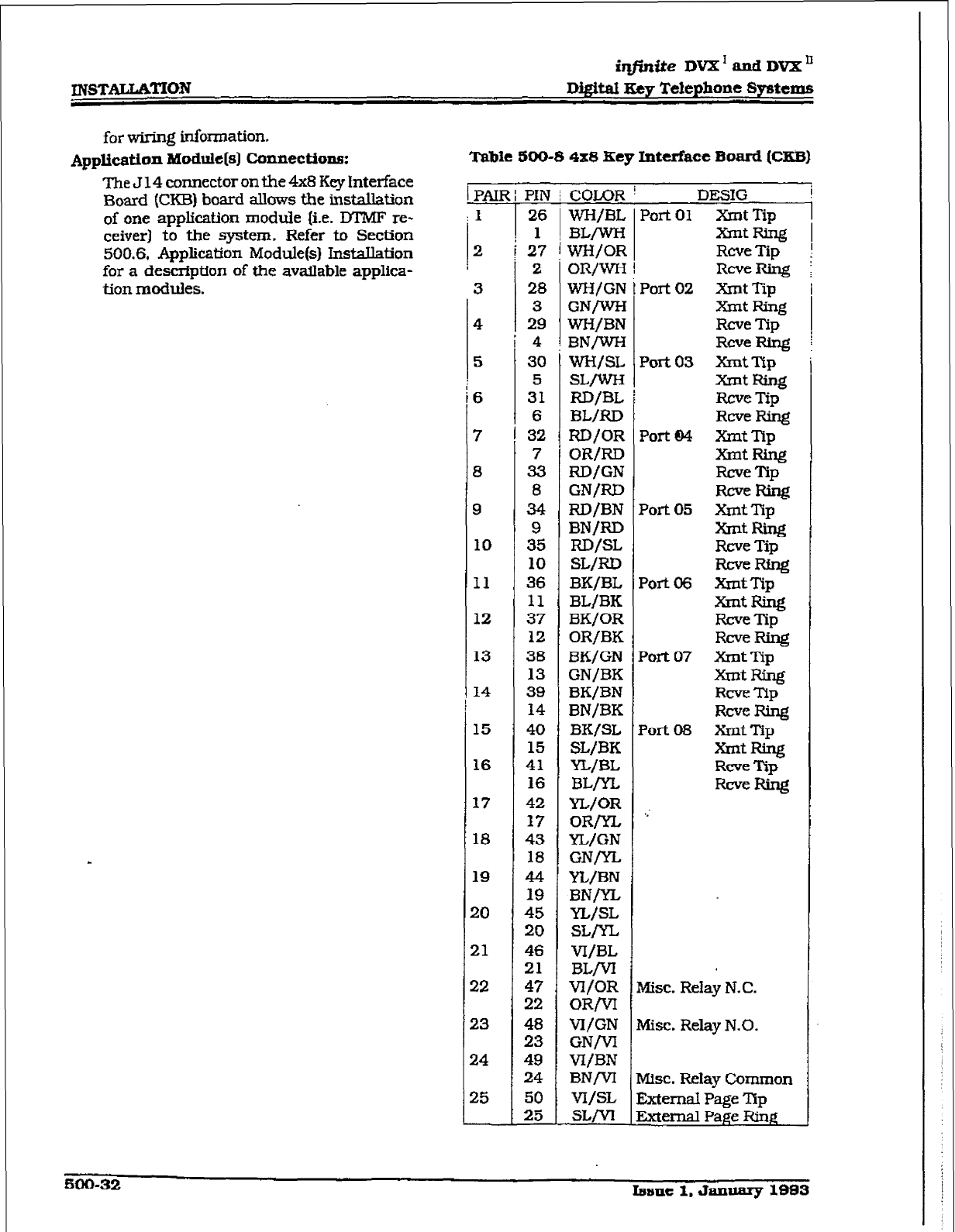
INSTALLATION
iqf?nfte DVX’andDVXn
Dig&al Key Telephone Systems
for wiring information.
Application Module(s) Connections: Table 500-S 4x8 Key Interface Board (CEB)
The J 14
connector
on the 4x8 Key Interface
Board (CKB) board allows the installation
of one
application
module
{i.e. DT’MF re-
ceiver) to the system. Refer to Section
500.6, Application Module(s) InstaJhtion
for a description
of
the available applica-
tion modules.
1 PAIR 1 PIN j COLOR ’ DESIG
: 1 26
WH/BL Port 01
Xmt
Tip
i 1 =/wH
2 27 1
j W/OR
2 i OR/WH 1
!i 3 28 WH/GN
I I
3 GN/W-H
4 29 WH/BN
5
6
7
8
9
10
I1
12
13
14
15
16
17
18
19
20
21
22
23
14
25
30
5
31
6
32
7
33
8
34
395
10
36
11
37
12
38
13
39
14
40
15
41
16
42
17
43
18
44
19
45
20
46
21
47
22
48
23
49
24
50
25
wH/SL
SLrwH
RD/BL
BL/RD
RD/OR
OR/RD
RD/GN
GN/RD
RD/BN
BN/RD
RD/SL
SL/RD
BK/BL
BL/BK
BK/OR
OR/BK
BK/GN
GN/BK
BK/BN
BN/BK
BK/SL
SL/BK
YL/BL
BL/YL
YL/OR
OR/n,
YL/GN
GN/yL
YL/BN
BN/YL
YL/SL
SL/yL
VI/BL
BLM
W/OR
OR/VI
VI,‘GN
GNM
V?/BN
BNM
vI/SL
SLM
X-ntRiig
Rcve Tip
Rcve Ring
Port 02 Xmt Tip
xmt Ring
Rcve Tip
Rcve Ring
Port 03 xl-& -lip
XnltRing
Rcve Tip
RCVFRiIlg
Port04 XntTIp
-tRLng
Ftcve lYp
-Ring
Port 05 xnlt Tip
XrntRing
Rcve Tip
-Ring
Port06 XlntTip
XrntRing
Rcve Tip
mew
Port 07 xrnt Tip
XmtFang
Rcve Tip
RcveRing
Port 08 XrIltTip
XnltRing
Rcve Tip
RcveRing
Misc. Relay N.C.
Misc. Relay N.O.
h&c. Relay Common
External Page Tip
External Page Ring
600-32 Isslle 1. January 1883
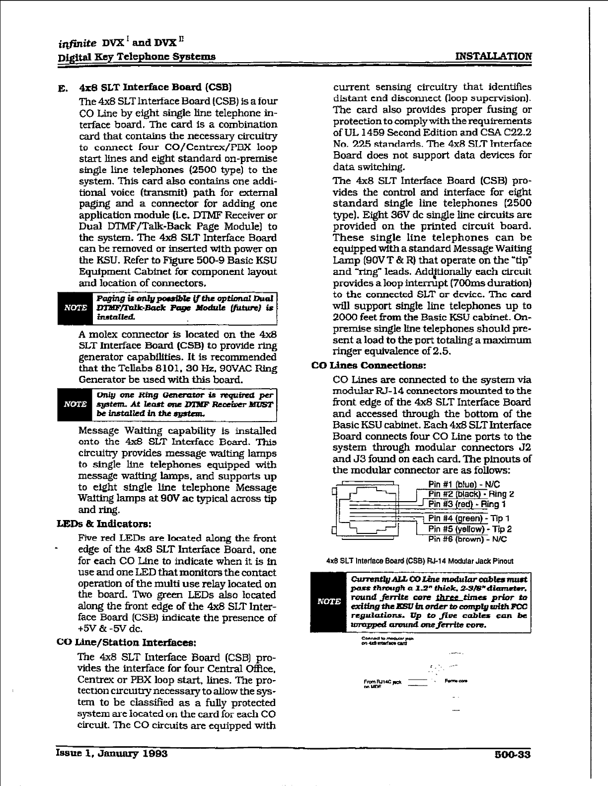
i@nite DVX’ and DVX”
D&WI Key Telephone Systems
E. 4x8 SLT Interface Board (CSB]
The 4x8 SLT Interface Board (CSB) is a four
CO Line by eight single line telephone in-
terface board. The card is a combination
card that contains the necessary circtitry
to connect four CO/Centrex/PBX loop
start Ihes and eight standard on-premise
single line telephones (2500 type) to the
system. This card also contains one addi-
tionaI voice (transmit) path for external
paging and a connector for adding one
application module (ix. DTMF Receiver or
Dual DTMF/Talk-Back Page Module] to
the system. The 4x8 SLT Interface Board
can be removed or inserted with power on
the KSLJ. Refer to Figure 500-9 Basic KSU
Equipment Cabinet for component layout
and location of connectors.
A molex connector is located on the 4x8
SLT Interface Board (CSB) to provide ring
generator capabilities. It is recommended
that the Tellabs 8101.30 Hz, SOVAC Ring
Generator be used with this board.
Message Waiting capability is installed
onto the 4x8 SLT Interface Board. This
circuitry provides message waiting lamps
to single line telephones equipped with
message waiting lamps. and supports up
to eight single line telephone Message
Waitjng lamps at 9OV ac typical across tip
and ring.
LEDS &
Indicatorr3:
Five red LEDs are located along the front
- edge of the 4x8 SLT Interface Board, one
for each CO Line to indicate when it is in
use and one LED that monitors the
contact
operation of the multi use relay located on
the board. Two green LEDs also located
along the front edge of the 4x8 SLT
Inter-
face Board (CSB) indicate the presence of
&‘V & -5V dc.
co uIle/Station
I.ntelfhces:
The 4x8 SLT Interface Board (CSB] pro-
vides the interface for four Central Offke.
Centrex or PBX loop start. lines. The pro-
tection circuitry necessary to allow the sys-
tern to be classified as a fully protected
system are located on the card for each CO
circtit. The CO circuits are equipped with
current sensing circuitry that identifies
distant end disconnect (loop supeniision].
The card also provides proper fusing or
protection to complywith the requirements
of UL 1459 Second Edition and CSA C22.2
No. 225 standards. The 4x8 SLT Interface
Board does not support data devices for
data switching.
The 4x8 SLT Interface Board (CSB) pro-
vides the control and interface for eight
standard single line telephones (2500
type). Eight 36V dc single line circuits are
provided on the printed circuit board.
These single line telephones can be
equipped with a standard Message Waiting
Lamp (9OV T & R) that operate on the ‘tip”
and ‘%ng” leads. Addationally each circuit
provides a loop interrupt (7OOms duration)
to the connected SLT or device. The card
will support single line telephones up to
2000 feet from the Basic KSU cabinet. On-
premise single line telephones should pre-
sent a load to the port totaling a maximum
ringer equivalence of 2.5.
co Line5 calnections:
CO Lines are connected to the system via
moduIar RJ-14 connectors mounted to the
front edge of the 4x8 SLT Interface Board
and accessed through the bottom of the
Basic KSU cabinet. Each 4x8 SLT Interface
Board connects four CO Line ports to the
system through modular connectors 52
and 53 found on each card. The pinouts of
the modular connector are as follows:
~~~~~
4x6 SLT Interface Board (CSB) RC14 Modular Jack Pinout
BEi
t2ttZi2ZW ._-.-.
i.‘.. ---
~. kn*cuo
EELFPJI -
-
Issue 2, January 1883 500-33
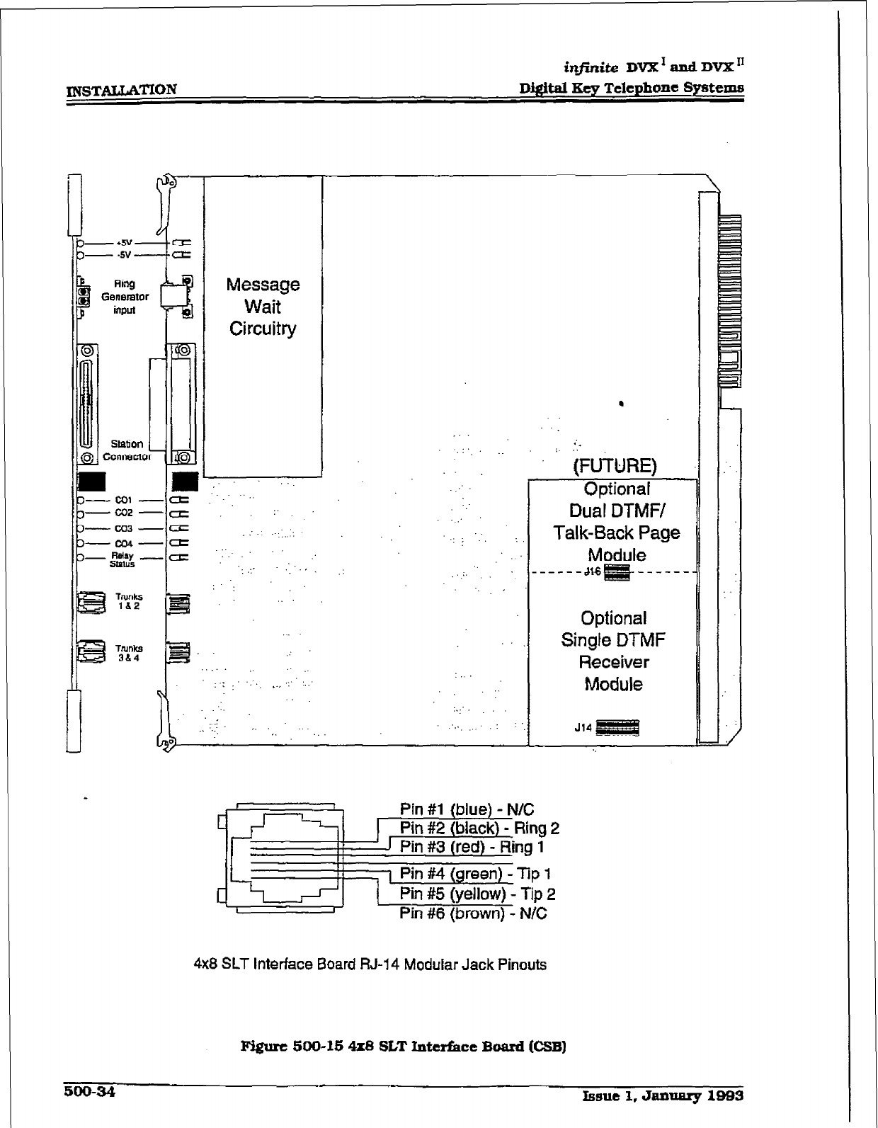
XNSTAwcATfON
in.ite Dd and DVX I1
Digital Key Telephone Systems
0
I
Station
0 connect0
Message
Wait
Circuitry
,. . . .
: ..::.. :
:.. ,.
. . .
.:
‘.
:..
. ..:, ,.
I
.
*‘.
: ‘, :
_.
:
., . . .
:.:..
(FUTURE)
Opfionaf
Dual DTMFI
Talk-Sack Page
Module
---JqE!F&----
Optional
Single DTMF
Receiver
Module
Pin
#l
{blue) - N/C
Pin #2 (black) - Ring 2
1 Pin #3
(red} - Ring 1
1 Pin #4 (green) - Tip 1
c,
Pin #5 (yellow) -
tip 2
1 I Pin #6 (brown] -
N/C
4x8 SLT Interface Board RJ-14 Modular Jack Pinouts
Pvgure 500-15 4x8 SLT Interface Bard (CSB)
500-34 Issue 1, Jamnary 1993
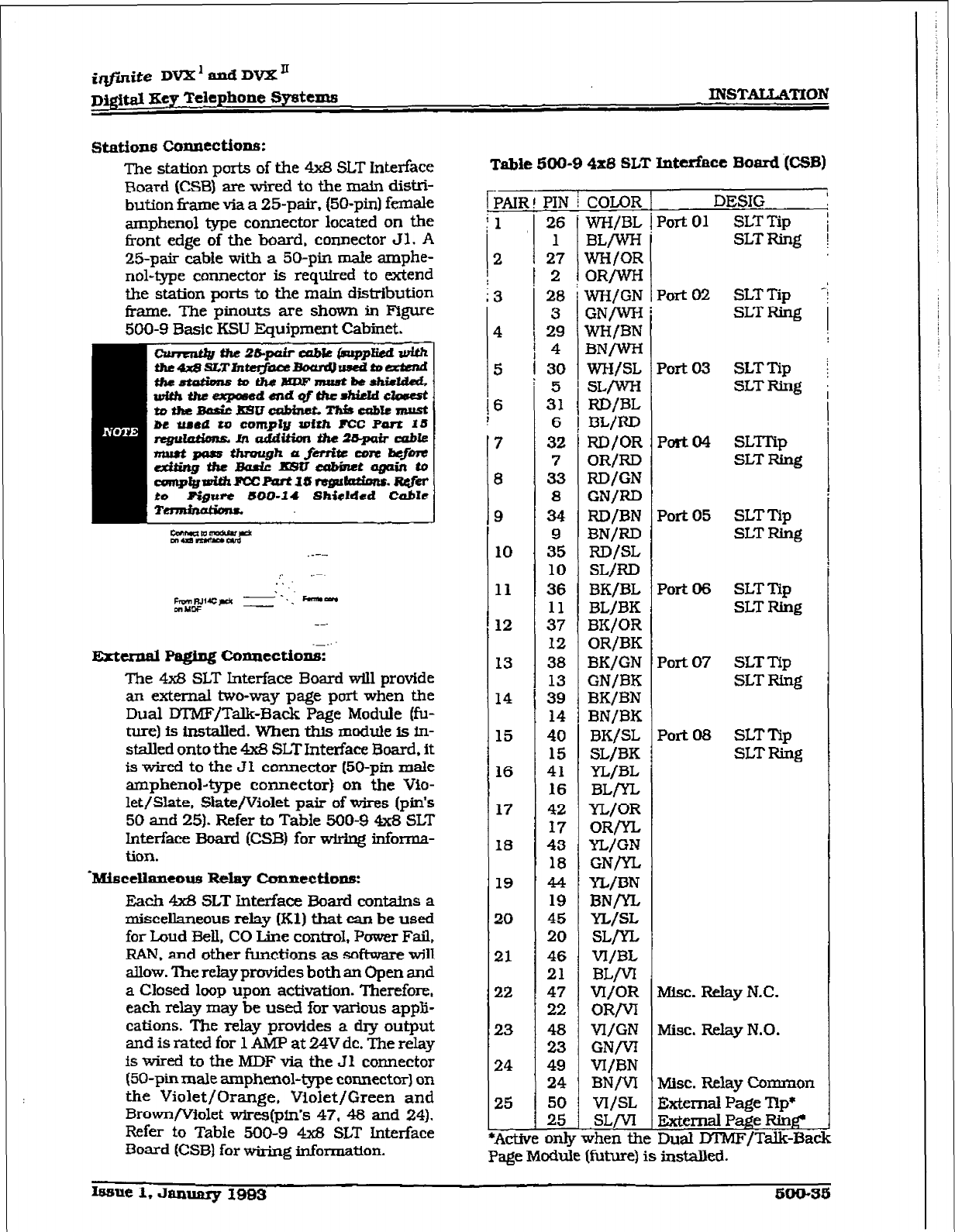
iq,@ite DV2Cx& DVX’
DQ#al Xcy Telephone Systems INST2U.LAmON
stations
coIulection6:
The station ports
of the 4x8 SLT Interface
Board (CSB) are wired to the main distri-
bution iiame via a 25-pair. (50-pin) female
amphenol type connector located on the
tkont edge
of the
board, connector 53. A
25-p&
cabie with a 5O-pin male smphe-
nol-type connector is required to extend
the station ports to the maLn distribution
frame. The pinouts are
shown in Figure
500-9 Basic KSU Equipment Cabinet.
czmnltbffic2E~a7bk(impp~~
the4xe5&TlllttzfootBoctfru~to-
.
lBt&KmsbbUtCmmkahicw
fi%wte~.andqfthc~ldc&wt
totheBasicJn3rioabinet.Thfscablemust
be rued
to
EompIy with FCC Port 16
n?fpwk-xnaddftioni?u~ircubk
must paas
through
a fmtoc cmv btfm
oddingthe~Ksr.rcubiRet~to
cmnp~nrzt)rpccRvtlsnsgu~~ff
to
pigu+c 500-14 ShScldad CubIt
9-a
* _.-
Ertd hgilg coxlnection6:
The 4x8 SLT Interface Board will provide
an external two-way page port when the
Dual DTMF/Talk-Back Page Module (fu-
ture) is installed. When t&i module is in-
stalled onto the 4x8 SLT Interface Board. it
is wired to the JI connector (50-pin male
amphenol-type connector) on the Vio-
let/Slate.
Slate/Violet
pair of
wires
(pin’s
50
and
25). Refer to Table 500-Q 4x8
SLT
Interface E&u-d (CSB) for wiring informa-
tion.
%i6cellsncoue Relay Connections:
Each 4x8 SLT Interface Board contains a
miscellaneous relay (Kl) that can be used
for Loud Bell. CO Line control, Power Fail,
RAN, and other functions as software will
allow. The relay pmvldes bothan Open and
a
Closed
loop
upon activation.
Therefore.
each relay may be used for various appli-
cations. The relay provides a dry output
and is rated for 1 AMP at 24V dc. The relay
is wired to the MDF via the Jl
connector
(50-pin male amphenol-type connector) on
the Violet/Orange, Violet/Green and
Brown/Violet whs(pin’s 47, 48
and 24).
Refer to Table 500-9 4x8 SLT
Interface
Board (CSB) for wiring
information.
Table
500-9
4x8 SLT Intcrfme Board (CSB)
3
I
4
5
6
7
8
9
10
11
12
13
14
15
16
17
18
19
20
21
22
23
24
25
PIN
26
1
27
2
28
3
29
4
30
5
31
6
32
7
33
8
34
9
35
10
36
11
37
12
38
13
39
14
40
15
41
16
42
17
43
18
44
19
45
20
46
21
47
22
48
23
49
24
50
25
y- COLOR
WH/BL
BL/WH
WH/OR
0RM.H
WH/GN
GNP=
WH/BN
BN/Wf-I
WWSL
SL/wH
RD/BL
BL/RD
RD/OR
OR/RD
RD/GN
GN/RD
RD/BN
33N/RD
RD/SL
SL/RD
BK/BL
BL/BK
BK/OR
OR/BK
BK/GN
GN/BK
BK/BN
BN/BK
BK/SL
SL/BK
YL/BL
BLfYL
YL/OR
OR/n.
YL/GN
GNryL
YL/BN
BN/YL
YL/SL
SL/n,
VI/BL
BL/VI
VI/OR
OR/VI
VI/GN
(=/VI
VI/BN
BN/VI
Vl/SL
i
!’
DESIG t
1
SLT Tip
SLT Ring
I
?ort 01
?ol-t 02
Fort 03
?ortcM
?ort 05
?ort 06
Port 07
Fort 08
SLT Tip
SLT RiTlg
SLT
Tip
SLT Ring
SLTTip
SLT Ring
SLT Tip
SLT Ring
SLT Tip
SLT Ring
1 SLT
Tip
SLT Ring
1
SLT Tip
SLT Ring
Misc. Rfzlay N.C.
Misc. Relay N.O.
hbc. Relay Common
~LxternalPageRin~
External
Page Trip*
-
the Dual JYiMF/Talk-l3ac
SLrvI
._ _
when
is
installed.
Issue
1. January I9BS 500-s5
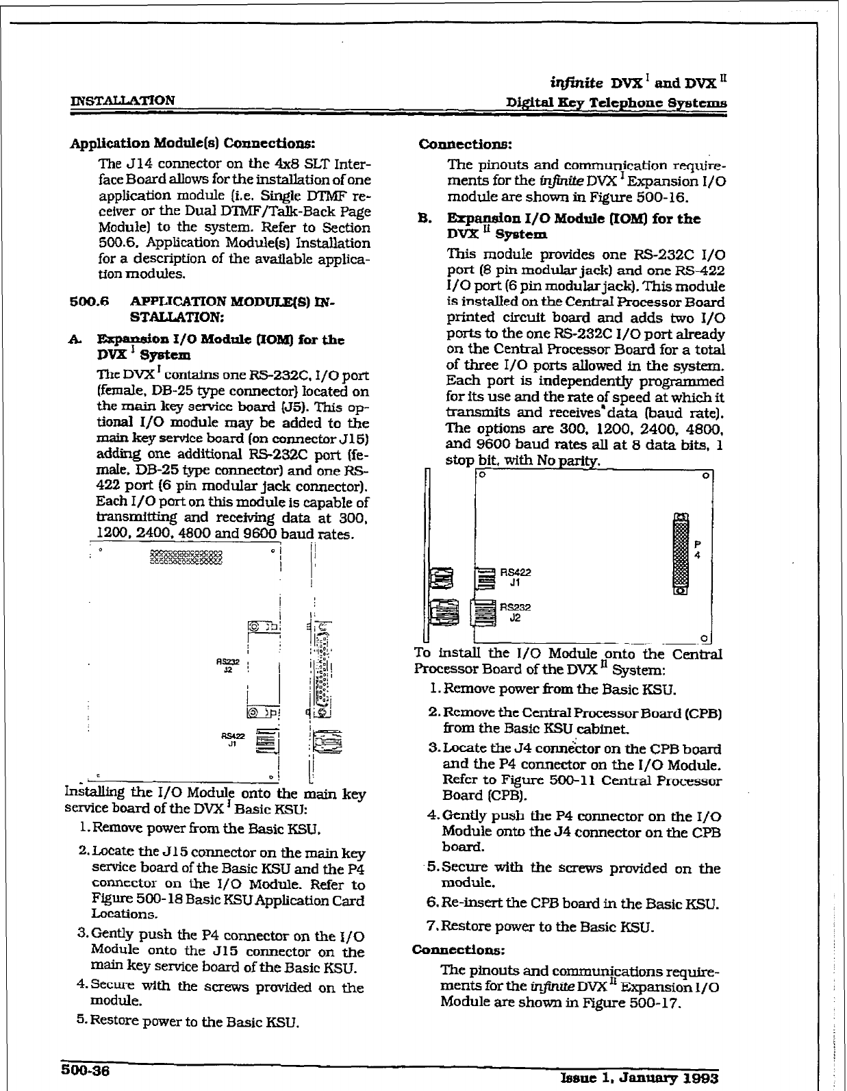
r
ZNSTALLYITON
iq#.nite DVX’
and
DVX’
D&ital
Key Telephone Systems
Application
Module(s) Connections:
The 514 connector on the 4x8 SLT Inter-
face Board allows for the installation of one
application module (i.e. Single D’i’MF re-
cefver or the Dual DTMF/Talk-Back Page
Module) to the system. Refer to Section
500.6. Application Module(s) Installation
for a description of the available applica-
tion modules.
500.6 APPLICATION
MODULX(S) IN-
STAUATION:
k ~md/& Module QOM) for the
The DVX ’ contains one RS-232C. I/O port
(female. DB-25 type connector} located on
the main key service board (55). This op-
tional I/O module may be added to the
main key service board (on connector J 15)
adding one additional RS-232C port (fe-
male. DB-25 type connector) and one RS-
422 port (6 pin modular jack connector).
Each I/O port on this module is capable of
transmitting and receiving data at 300.
1200.2400.4800 and 9600 baud rates.
0
I
oi c
In&akg the I/O Module onto the main key
service board of the DVX ’ Basic KSU:
1. Remove power from the Basic KSU.
2. Locate the J15 connector on the main key
service board of the Basic KSU and the P4
connector on the I/O Module. Refer to
Figure 500- 18 Basic KSUApplication Card
Locations.
3.
Gently
push the P4 connector on the l/O
Module onto the J15 connector on the
main key service board of the Basic KSU.
4.Secure with the screws provided on the
module.
5.
Restore power to the Basic KSU.
coIlnections:
The pinouts and communication req&e-
ments for the @%-G& DVX I Expansion I/O
module are shown in Figure 500-16.
B. Eqmydbn& Module (IOM) for the
This module provides one FS232C I/O
port (8 pin modular jack) and one RS422
I/O port (6 pin modular jack). This module
is installed on the CentraI Processor Board
printed circuit board and adds two I/O
ports to the one RS-232C I/O port already
on the Central Processor Board for a total
of three I/O ports allowed in the system.
Each port is independently programmed
for its use and the rate
of
speed at which it
transmits and receives’ data (baud I-ate).
The options are 300. 1200, 2400, 4800,
and 9600 baud rates atl
at 8
data MS, 1
stop bit, with No parity.
n to
0
Rs232
52
0
To instd the I/O Module onto the Central
Processor Board of the DVX ’ System:
I. Remove power tiom the Basic KSU.
2. Remove the Central Processor Board (CPB)
from the Basic ESU &met.
3. Locate the 54 corm&or on the CPB board
and the P4 connector on the I/O Module.
Refer to Figure 500-l 1 Central Processor
Board (CPB) .
4. Gently push the P4 connector on the I/O
Module onto the 54 connector on the CPB
board.
-5. Secure with the screws provided on the
module.
6. Re-insert the CPB board in the Basic KSU.
7. Restore power to the Basic KSU.
Connectlomi:
The plnouts and communications require-
ments for the in&&e DVX’ Expansion J/O
Module are shove in Figure 500-17.
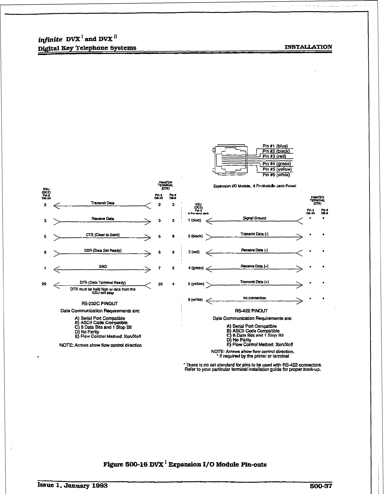
@fir&e DVX I and DVX’
~&&al Key Telephone Systcmts
<
Tnmmil Dam 2
>
Rabivscma
> 3
>
CT.5 (ChuulvSend) 5
\ 0s.R (Data se! RMdy) 6
<
GND
> 7
DTR tDam?enninal Rsadyj
20
DTR mm Wz;z ‘8”
~ckam h-cm the
RS-232C PINQUT
Data Communication R~uirwnent6 are:
A) seri8l Port Compatible
6) ASCII coda compatible
C)8Data~BltsandlStopB11
3 RZ%trol Melhod: xon/xoff
NOTE Arrows show flow control direction
SIrrNla) <-.-.-.- nccmnscfim ---_---.--
>’ l
Rs-422 PlNwT
DaU Communkation Flequiremanta are:
A) setid port compa!w
B) ASCII Code Compatible .
g 1 fl&!aai and 1 Slop &I
E) now corltml Methcd: xolv?Ioff
NOW Arrows show flow contml direction.
* If nzqulmd by the printer or terrnlnel
* There is no set standard for pins to be used with RS-422 connectors.
Refer to your particular terminal instellation guide for proper hook-up.
pigurt SOO-16 DVX’ Erpansfon f/O Module pin-oats
Issue 1, January 1QQQ 500-37
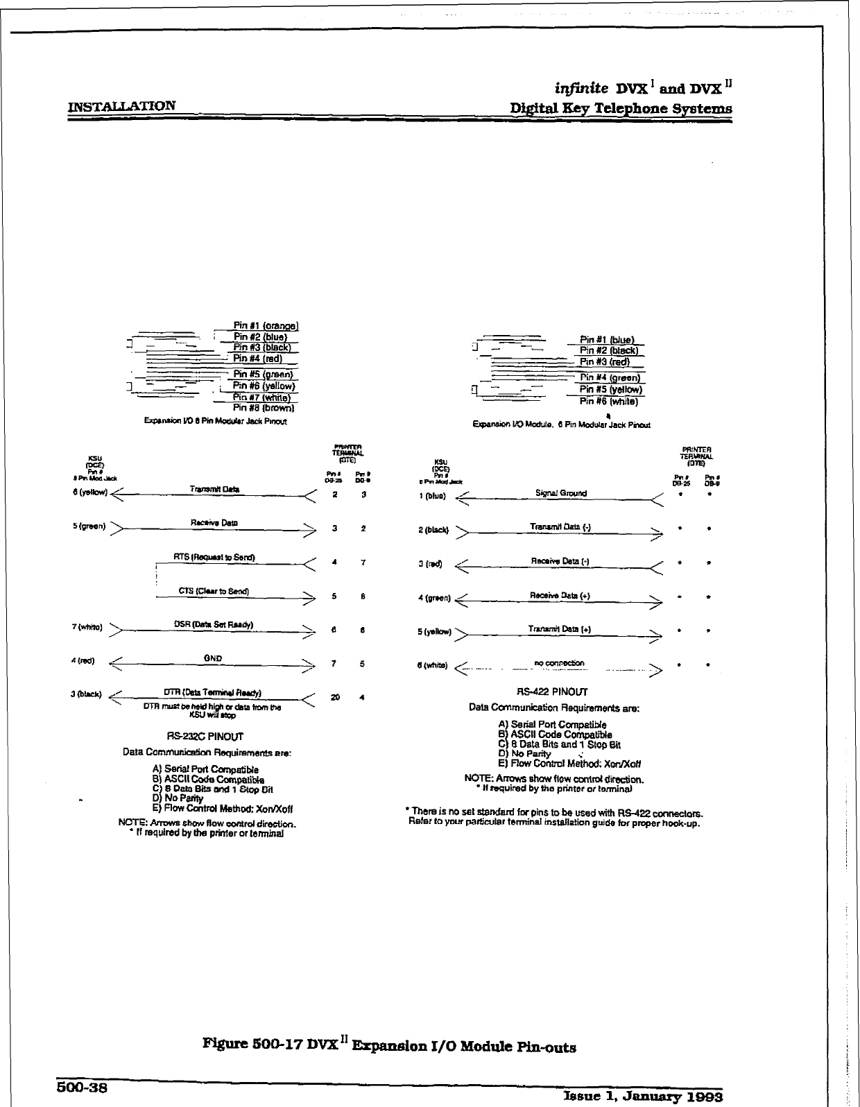
r
INSTALLATION
iqfhite DVX’tmdDV2K”
DigitalEeyTelephone8ystems
.
Pin I1 Ioranaal
Jy; Pin #2 (blue)
Pin #3 (black)
Pin M (red)
tin #a {brown)
cKs{clurtu&cq ’ 5 6
A) SerfsI Porn Compatible
5) ASCII code compalti
C)8DataSf!sand1StcpBH
8 I!EZZLA Mehd: iadx0n
NOTE: Amws show ffow oomrd direction.
* ff mqulred by tha prfnter or
t6fr~inal
3 -----
.-
Pin fll (blue)
Pin #2 (bkick)
Pin #3 (tad)
- Pin 114 (grew)
g -----
Pii x5 (yellow)
pilnrfs (white)
2
(bWJ Tmrumtl dpm {-) > . .
4 wd < Recsiva Oala (+)
.’ l
6WM8~
< .._.... -.._. “?“.???!?.. . - __.. > l l
AS422 PINOUT
Data CPnmunfcation Requirements are:
A) Serial Port Compatible
ASCII CQde ConlpatiIlla
e$i$aE$k and 1 Stop Bit
E) Fkw Contml &hod: Xmlxoff
NOTEc Amws show How cadd dimciion.
* H required by the pdntsr or tennfnal
l
There is no sst standard for pins to be usad with RS-422 mm.
Refer to your pa&~lar terrnfnat instak~ion guide for proper hook-up.
500-38 bsne
1, January
19B3
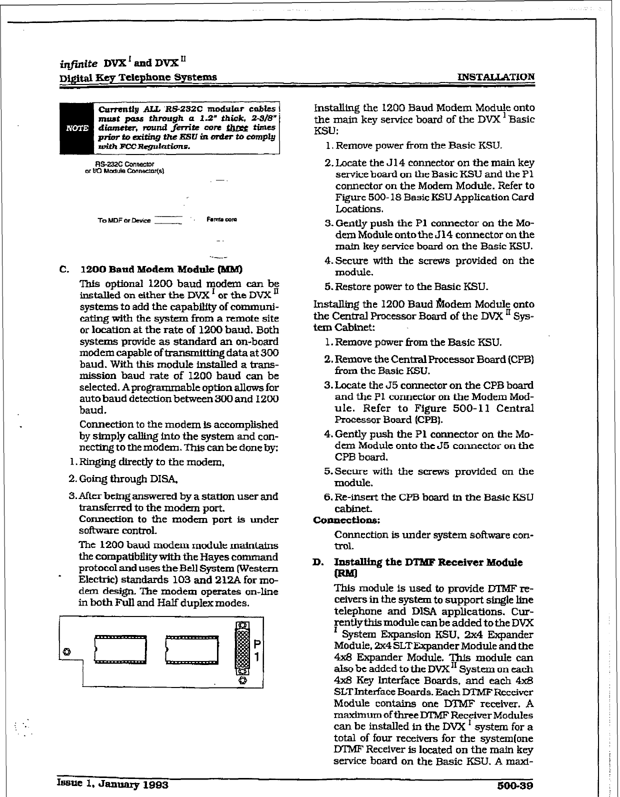
r
INSTALLATiON
RS-23% Cmnttctor
or M Wute Comxtor(5~
-fo~DFor D&n
-
I=.*~~
-.
C. 12QO Band Modem
Module (MM)
This optional 1200 baud modem can be
installed
on either the DVX ’ or the DVX JJ
systems to add the capability of communi-
cating with the system from a remote site
or location at the rate of 1200 baud. Both
systems provide as standard an on-board
modem capable of transmi tting data at 300
baud. With this module installed a trans-
mission baud rate of 1200 baud can be
selected. Aprogramma ble option allows for
auto baud detection between 300 and 1200
baud,
Connection to the modem is accomplished
by simply w into the system and con-
necting to the modem. This can be done by:
1. Ringing directly to the modem,
2.
Going through DISA.
3.
After being answered by a station user and
transferred to the modem port.
Connection to the modem port is under
sofimare control.
The 1200 baud modem module maintains
the compatibilitywitb the Hayes command
protocol and uses theBell System (Western
I Electric) standards 103 and 21ZA for mo-
dem design. The modem operates on-line
in both Full and Half duplex modes.
1
0
P
1
I Q 1
Installing the I200 Baud Modem Module onto
the main key service board of the DVX l Basic
K!3J:
1, Remove power from the Basic KSU.
2.
Locate the J 14 connector on the main key
service board on the Basic KSU and the Pl
connector on the Modem Module. Refer to
Figure 500-18 Basic KSU AppIication Card
Locations.
3. Gently push the P1 connector on the Mo-
dem Module onto the J 14 connector on the
main key service board on the Basic KSU.
4.Sectu-e with the screv?s provided on the
module.
5.
Restore power to the Basic KSLJ.
Installing the 1200 Baud &odem
Module
onto
the Central Processor Board
of the DVX ’ Sys-
tern Cabinek
1. Remove power from the Basic KSU.
2.
Remove the Central Processor Board (CPB)
i+om the Basic KSU.
3.
Locate the 55 connector on the CPB board
and the PI connector on the Modem Mod-
ule. Refer to Figure 500-l 1 Central
Processor 3oard (CPB).
4.
Gently push the Pl connector on the Mo-
dem Module onto the J5 connector on the
CPB board.
S.Secu.re with the s(lfews provided on the
module.
6.
Re-insert the CPB board in the Basic KSU
cabinet.
COontcti0nS:
Connection is under system software con-
trol.
D. Ipstalllng the DTMF Rtceiver M~ule
This module is used to provide DTMF re-
ceivers in the system to support single line
telephone and DISA applications. Cur-
Fntiylhfs module can be added to the DVX
System Expansion KSU, 2x4 Expander
Module, 2x4 SLTExpander Module and the
4x8 Expander Module. This module can
also be added to the DVX” System on each
4x8 Key Interface Boards. and each m
SLTInterface Boards. Each DTMF Receiver
Module contains one DTMF receiver.
A
maximum of three MMF Receiver Modules
can be installed in the DVX * system for a
total of four receivers for the system(one
DTM!? Receiver is located on the main key
service board on the Basic KSU. A maxi-
Issue 1. January 1993 500-39
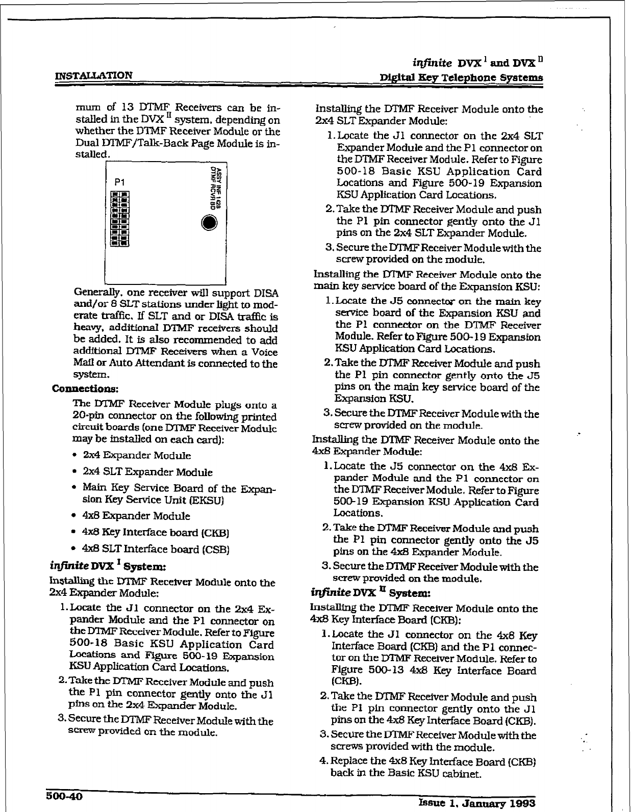
r
INST:AI;[LATION
irzfirrite
DVX ’ and DVX’
DigItal Key
Telephone Systems
mum of 13 DTMF Receivers can be in-
stalled in the DVX ’ system. depending on
whether the DTMF Receiver Module or the
Dual IYTMFjTalk-Back Page Module is in-
Genera@. one receiver will support DISA
and/or 8 SLT stations
under light to
mod-
erate traffic, K SLT and or DISA traf& is
heavy, addiffoional DTMF receivers should
be
added.
It is also recommended to add
additional DTMF Receivers when a Voice
MafI or Auto
Attend-t is connected to the
!syE.tem.
connectfons:
The DIMF Receiver
Module
plugs onto a
20-pin connector on the following printed
circuit boards (one M’MF Receiver Module
may be
instaIled on each card):
l
2x4 Expander Module
l
2x4
SLT Expander Module
l Main
Key Semite Board of the Expan-
sion Key Service Unit (EKSU)
l
4x8 Expander Module
l
4x8
Key Interface board (CKB)
l
4x8 SLT Intetiace board (CSB)
infinite DVX I System
Installing the M’MF Receiver Module onto the
2x4
Expander Module:
1. Locate the Jl
connector on the 2x4 Ex-
pander Modtie and the PI connector on
the DlMF Receiver Module. Refer to Figure
500-18 Basic KSU Application Card
Locations and Figure 500-19 Expansion
KSU Application Card Locations.
2. Take the MMF Receiver Module and push
the Pl pin connector gently onto the 31
pins on the 2x4 Expander Module.
3.
Secure the DTMF Receiver Module with the
screw provided on the module,
Installing the DTMF Receiver Module onto the
2x4 SLT Expander Module:
1. Locate the Jl connector on the 2x4 SLT
Expander Module and the P1 connector on
the DTMF Receiver Module. Refer to Figure
500- 18 Basic KSU Application Card
Locations and Figure 5OO- 19 Expansion
KSU Application Card Locations.
2.
Take the DTMF Receiver Module and push
the PI pin connector gentry onto the Jl
pins on the 2x4 SLT Expander Module.
3. Secure the DTMF Receiver Module with the
screw provided on the module.
hx%albng the IYIMF Receiver Module onto the
main
key service board
of the Expansion KSU:
1. Locate the 55
connect#
on the main key
service board
of
the Expansion KSU
and
the Pl connector
on
the DTMF Receiver
Module. Refer to Figure 500-
19
Expansion
KSU Application
Card Loc&iom.
2. Take the MMF Receiver Module and push
the P1 pin connector gently onto the 55
pins on the main key service board of the
Eqansfon KSU.
3.
Secure the DTMFReceiver Module with the
screw provided on the module.
Installing the DTMF Receiver Module onto the
4x8 Expander
Module:
1. Locate the J5
connector on the 4x8 Ex-
pander
Module and the
Pl connector on
the DTMF Receiver Module. Refer to Figure
500-19 Expansion KSU Application
Card
Locations.
2. Take the Dl’MF Receiver Module and push
the Pl pin connector gently onto the JS
pins on the 4&3 Expander Module.
3. Secure theDTMFRe&verModuiewitb the
screw provided on the module.
ir&i.te DVX a System:
Installing the DTMF Recefver Module onto the
4x8 Key Interface Board (CKB):
l.Locate the Jl connector on the 4x8 Key
Interface Board (CKB)
and the P1 connec-
tor on the DTMF Receiver Module. Refer to
Figure 500-13 4x8 Key Interface Board
(CK01.
2.
Take the DTMF Receiver Module and push
the PI pin connector gently onto the Jl
pins on the 4x8 Key Interface Board (CKB).
3.
Secure the DTIW Receiver Module with the
screws provided with the module.
4.
Replace the 4x8 Key Interface Board (CKB)
back in the Basic KSU cabinet.
50040 Issue 1. JaIulary 1993
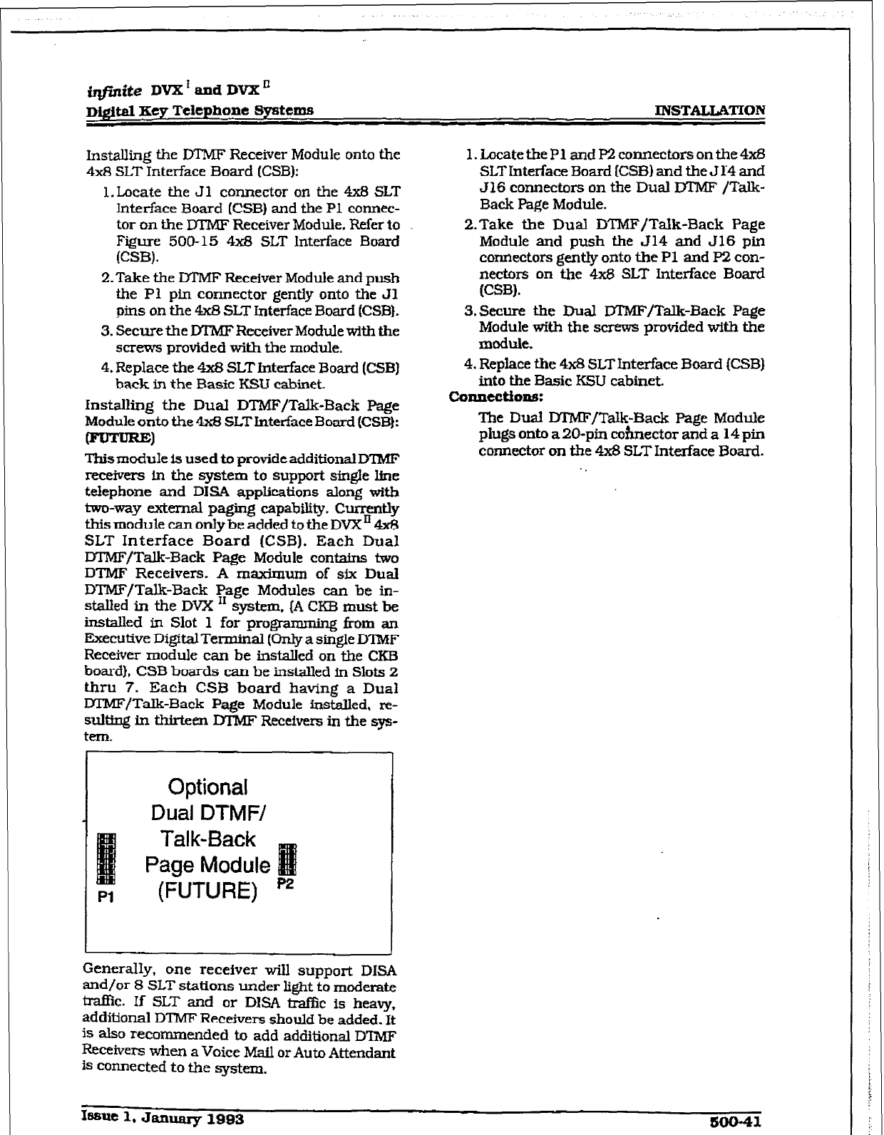
@finite
DVX ’
and D’VX *
D&r&d Key Telephone
Systems
INSTALLATION
hmalling
the DIMF Receiver Module onto the
4x8
SLT Interface Board (CSBl:
1. Locate the Jl connector on the 4x8 SLT
Interface Board
(CSB)
and the Pl connec-
tor on the M’MF Receiver Module. Refer to
Figure 500-15 4x8 SLT Interface Board
(CSB).
Z-Take the DTMF Receiver Module and push
the Pl pin connector gently onto the Jl
pins on the 4x8 SLT Interface Board (CSB).
3.
Secure the DTMF Receiver Modulewith the
screws provided with the module.
4. Replace the 4x8 SLTinteTface Board (CSB)
back in the Basic KSU cabinet.
Installing the DuaI DTMFITalk-Back Page
Module onto the 4x8 SLTInterface Board (CSB):
0
l%ismodule is used to provide additional D?MF
receivers in the system to support single line
tefepbone and DISA applications along with
two-way external paging capability. Cunwtly
this module can only be added to the DVXn 4x8
SLT Interface Board ICSB). Each Dual
m/Talk-Back Page Module contains two
DTMF Receivers. A maximum of six
Dual
DTMF/Talk-Back Page Modules can be in-
stalled in the DVX I1 system, (A CEB must be
installed in Slot 1 for programming f?om an
Executive DigitalTerminal (0nIya single D’IMF
Receiver module can be installed on the CKI3
board}, CSB boards can be installed in Slots 2
thru 7. Each CSB board having a Dual
M’MF/TaIk-Back Page Module installed, re-
sulting in thirteen DTMF Receivers in the sys-
tern.
1. Locatetie Pl and P2 connectors on the 4x8
SLT Interface Board (CSB) and the J 1’4 and
J16 connectors on the Dual MMF
/Talk-
Back Page Module.
P-Take the Dual DTMF/Talk-Back Page
Module and push the J14 and J16 pin
connectors gently onto the Pl and P2 con-
nectors on the 4x8
SLT Interface Board
(CSB).
3.Secure the Dual lXMF/Talk-Back Page
Module with the screws provided with the
module.
4.
Replace the 4x8 SLT Interface Board (CSB)
into the Basic KSU cabinet.
coIulectlons:
The Dual DTNF/Talk-Back Page Module
plugs onto a 20-pin cohnector and a 14 pin
connector on the 4x8 SLT Interface Board.
.
Optional
Dual DTMF/
Talk-Back
Page Module
Pl
(FUTURE) p2
Generally, one receiver will support DISA
and/or 8 SLT stations under light to moderate
tra&. If SLT and or DISA tra& is heavy,
additional DTMF Receivers should be added. It
is aIso recommended to add additional D’IMF
Receivers when a Voice Mzdl or Auto Attendant
IS connected to the system.
Ifume 1.
January 1993 500-41
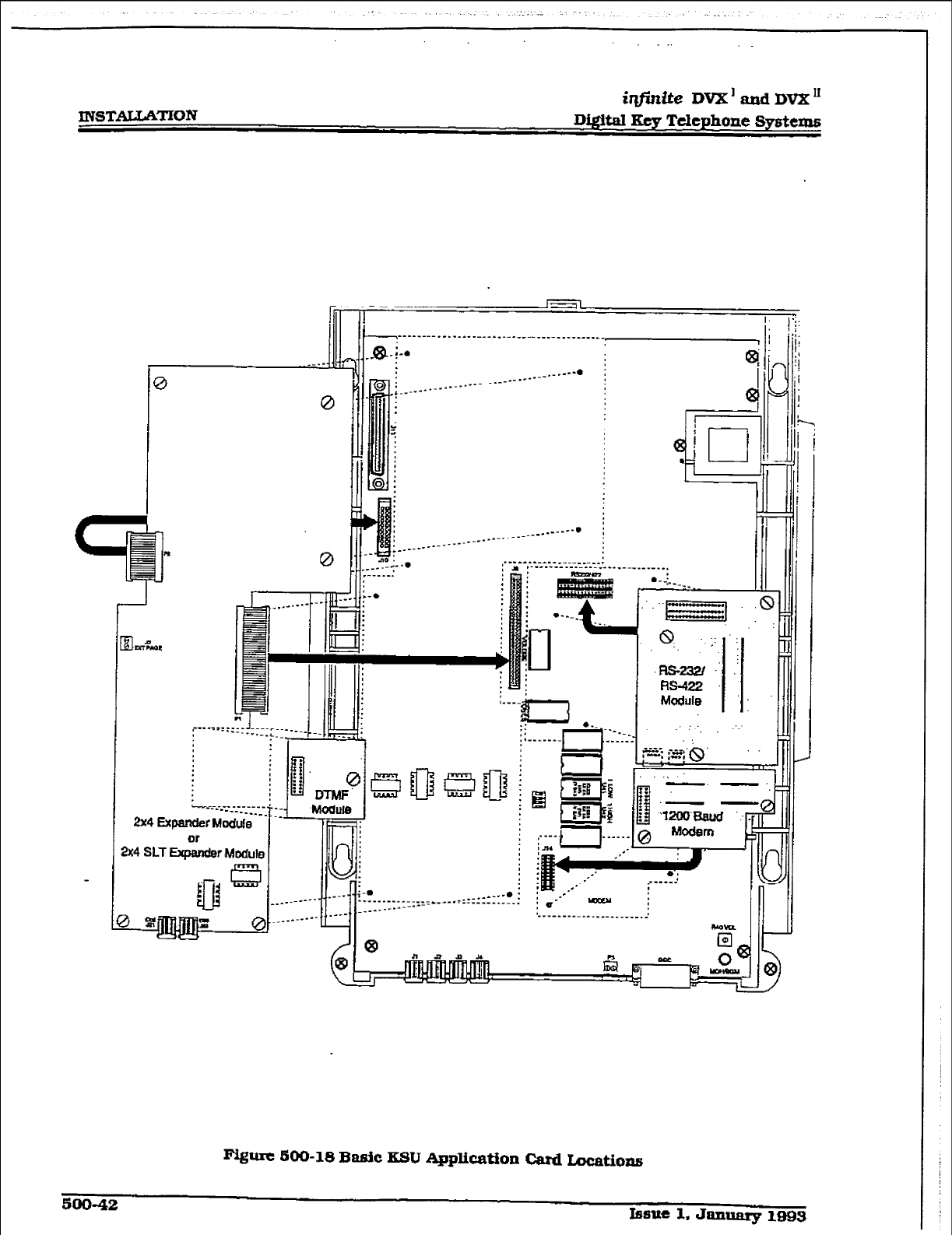
r
XNSTALLATlON iqfinite DVX’ and DV2C’
Digital Key Telephone Systems
/f ----_-----.-----__-- * ---__--__
I_____ ___. -__-__.
,-__.--____-__-_*________
-822
q ..;: .:
wm .’ .I
RS-422
Moclule
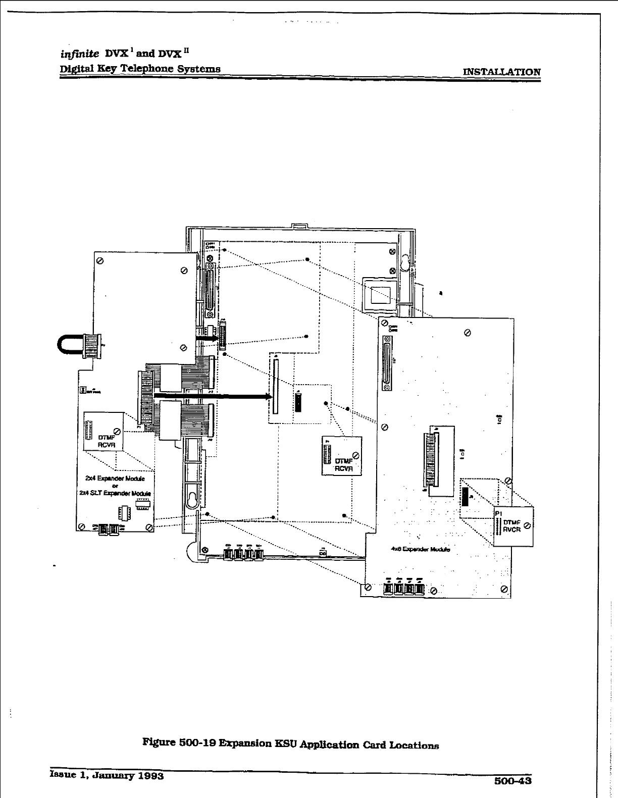
i&.&e mxl and Dvx”
Digital Key
Telephone Symtema
. . .
INST~TION
I”
0 I
-._. I
-.__ . .._.
:‘-....
: l.,
'3. ;
i
.lC “...;.-....--....-.,
.-.. --.
-_
--.__
i . . .
G.. =_, : 1 ; . ..i
! Ii=!1
_ .__.__._ :y.: I Ii
0
hsue 1. Januarg 1993 50043
INSTAUATZON
iq#inite DVX’ and DVX I1
b&&al Key Telephone Spsttms
500.7 DIGITS TERMINALS
A. Digital Terminal Installation:
The Digital Terminals are interfaced with
the DVX ’ Basic KSU or Expansion KSU
main key service board which provides
eight circuits. E&ch of the e@ht clrctits are
interfaced from the Jll connector on the
Basic KSU or Expansion KSU maIn key
service board to the MIX?. The digitaI ter-
minals are interfaced witi the DVX II 4x8
Key Interface Board (CKB) and 4x8 SLT
Interface Board (CSB) which each have
eight circuits per board. Each 4x8 Key
Interface Board interface is extended from
the Basic KSU or the Expansion KSU to the
MDF through the front edge connector on
the CKl3 or CSB board.
At the mF are the terminated distribution
cables that are run from each key tele-
phone location. Each Key Telephone re-
quires two-pair twisted cable wiring to
connect the digital tern&mls to the system
on a “home run” basis. The telephone end
of the cable is terminated on a modular
jack and the MDF end of the cable should
t-k on a punchdown block making
up the MDF. Refer to F’fgure 500-l Digital
Flatpack Mounting Arrangements and
Figure 500-9 Basic KSU Equipment
Cabinet.
Telephones are connected to the station
interfaces via industry-standard twisted,
2-pair. 22 or 24 gauge wire. The station
cable run from the main distriiution frame
to the station wall jack should not exceed
1000 feet.
It
is recommended
that
the sta-
tion cable contain 4 pairs of wires. Refer to
Figure 500-20 Digital Terminal Modular
Block Wiring.
- Station cable is connected to the ?kDF at
one end. and a modular connecting block
at the other end. The modular line cord of
the telephone is then plugged into the con-
necting block.
The system communicates with each
phone using 4 wires. ?plo of the wires are
used to send digital information (voice and
COnId
signals) from the system to the
telephone. and two w&es are used by the
telephone to send digital information to the
Sydem. All 4 wires are necessary for the
telephone to fwnction. Each telephone con-
nected to a station port has
two
&@tal
channels. The primary channel is used for
voice communications only. The second&y
channel is used to provide a secondzuy
path for data switching applications [fu-
mre).
The installer should exercise caution when
connecting a digital terminal while system
power is on. Each digital terminal station
circuit is overload protected by internal
circuitxy on the 4x8 Key Interface Board
(CKE) or 4x8 SLT Interface Board [CSB)).
however the proper polarity of the wired
connections must be maintained for
proper operation.
The standard Single Line Telephone. Sin-
gle Line Telephone Adapter (OPX). and
Dfgital DSS Console arl all considered to
be telephones by the system. These inter-
faces are all wired to digital key station
ports the same as a digital telephone.
B. D&&al DSS Console Installation:
The Digital DSS/DLS Console is assigned
to operate with a digital terminal. Up to
three DSS/DLS Console units can be as-
signed to any one station. There are
a maxi-
mum of 21 DSS/DLS Console that can be
installed in the infinite DVX’ System, and
a m-urn of 42 DSSIDLS Consoles tit
can be installed in the in@nite DVX ’ Sys-
tem. Each unit uses a digital terminti in-
terface circuit and reduces station capacity
on a one-per-one basis.
A two-pair twisted cable is required for
connecting the DSS/DLS Console unit to
the MDF. The cable should be run from the
DSS/DLS Console to the MDF in a “home
run” manner. The DSS/DLS Console end
of the cable is terminated on a three-pair
modular jack and the MDF is “punched
down” on a terminaI block for cross con-
nection to the appropriate station cable.
Refer to Figure 500-20 Digital Terminal
Modular Block Wiring.
Since the system supplies power to the
DSS/DLS Console, no transformer or cx-
tanal power device is required.
C. Wall Mounting the 33-Button Digital
TCrmiaal
To wall mount the &JJ%I& Digital Terminal,
it is necessary to use the X%-Button Wall
Mount bracket and one standard-type jack
assembly designed for normal wall hang-
ing applications.
1. Unplug the line cord from the phone. A
4-foot line cord is provided with the wall
500-44 Issue I, Janwy 1993
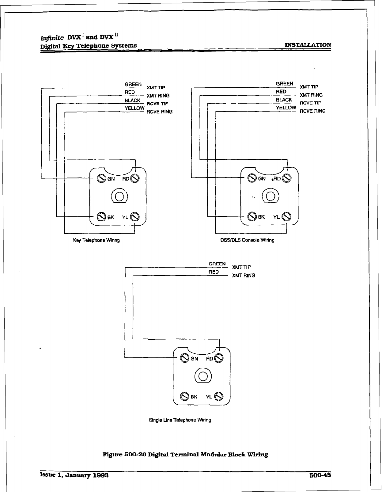
irlfinite DVX’ EUXI DVX”
D&$d Iby Telephone
s~8tCIIlB
INSTALLATION
Key Telephone Wtring DBSIDLB Console Wiring
BK YL
GREEN XMTTIP
RED XMT RING
Single Line Telephone Wiring
Figure 600-20 Digital Terminal Modular Block Wiring
INST&LATION
iqfinite DVX’andDVX”
D&&al Key Telephone Eqstems
bracket.
2.Ltie
up the
hooks at the bottom of the
bracket so that they engage with the slots
cut
in the bottom of the telephone base. Tilt
the telephone back and lock the telephone
into the hooks at the top of the bracket. The
bracket wiIl snap in place.
3. Route the line cord from the wall jack and
plug into the connector on the back of the
telephone. Now match the two key hole
slots on the base plate with the lugs on the
630-A type jack. Align the modular connec-
tor and slide telephone into place. Refer to
Figure 500-21 Digital Terminal Wail
Mounting.
D. Wall Moudting the &Button Df.@ti
TtSHlbd
To wall mount the GI.I. Dig- Terminal.
it is necessary to use the 8-Button Wall
Mount bracket and one standard-type jack
assembly designed for normal wall hang-
ing applications.
1. Unplug the I&e cord from the phone. A
4-foot line cord is supplied with the wall
bracket.
2.Line up the hooks at the bottom of the
bracket so that they engage with the slots
cut in the bottom of the telephone base. Tilt
the telephone back and lock the telephone
into the hooks at the top of the bracket. The
bracket will snap in place.
3. Route the line cord from the wall jack and
plug into the connector on the back of the
telephone. Now match the two key hole
slots on the base plate with the lugs on the
630-Atype jack. Align the modular connec-
tor and slide telephone into place. Refer to
Figure 500-21 Digital Terminal WalI
MOlXlttng.
E. - Single Idne Telephone In~taIlation
Single Line Telephones (SLTs) can be ex-
changed for digital terminals on a groups
of eight or one-for-one basis with an OPX
box.
The 4x8 SLT Interface Board (CSB) can be
pluged
into any designated CKB card slot.
Each 4x8 SLT Interface Board supports
eight standard single line telephones
(standard DTMF Single Line Telephones
ami mwage waiting DTMF SLTs).lt is rec-
ommended that the Tellabs 8101. 30 Hz,
9OVAC Ring Generator be used with this
board.
o#tl&JoneRtigOarnatorisnquindpuI
iIEzzcdkcut-- lzb%xwe&T’
int?lesptcnL I
Either
the singk DTMF Receiver Module or
the Dual DTMF/Talk-Back Page Module
may be installed on each 4x8 SLTinterface
Board installed. The single DTMF Receiver
Module {RM) installs onto either a 4x8 Key
Interface Board [CKB) or 4x8 SLT Interface
Board [CSB) and provides 1 DTMFreceiver.
The Dual m/Talk-Back Page Module
can ONLY be installed onto the 4x8 SLT
Interface Board and provides two DIMF
receivers. M’MF receivers can be added to
the system to support Single Line Tele-
phones. If SLT &afEc is heavy or a Voice
Mail system is being installed, it is recom-
mended that additional DTMF Receiver
Modules be installed in the system.
Each SLT requires one-pair cable. The ca-
ble should be placed from the telephone
location to the MDF in a -home run” man-
ner. The telephone end of the cable run
should be te-rl ’ &ted in a modular jack.
Refer to Figure 500-l Digital Flatpack
Mounting Arrangements and/or Figure
500-9 Basic KSU Equipment Cabinet. The
MDF end should be “punched down” on a
terminal block for cross connection to the
appropriate station cable. Refer to Table
500-9 4x8 SLT interface Board (CSB) for
SLT wiring connections.
F.
SLT Adapter / Off-m
EXkIlSi0n
Moddc (OPX)
This external module provides the inter-
face for one long loop (OPX) singIe line
telephone (2500 type) extension. This mod-
ule requires a separately provided -48V dc
power supply to provide the necessary cur-
rent for long loop applications and to sup-
port ring generation. This module is wired
to and uses a key station port from any
digital key terminal station poti on any
card plugged into the system. The OPX
card meets the requirements of the FCC for
connection to the telephone (‘&lco) net-
work. Telephones must be DTMF only
12500 type). Refer to Figure 500-22 CH-
Premise Extension (OPX) Module
This module also provides for one Power
Fail circuit in the event of an AC power
faiIure.
Buttons aud xm&3:
An LZD located on the back of the unit
indicates correct connection and WIU light
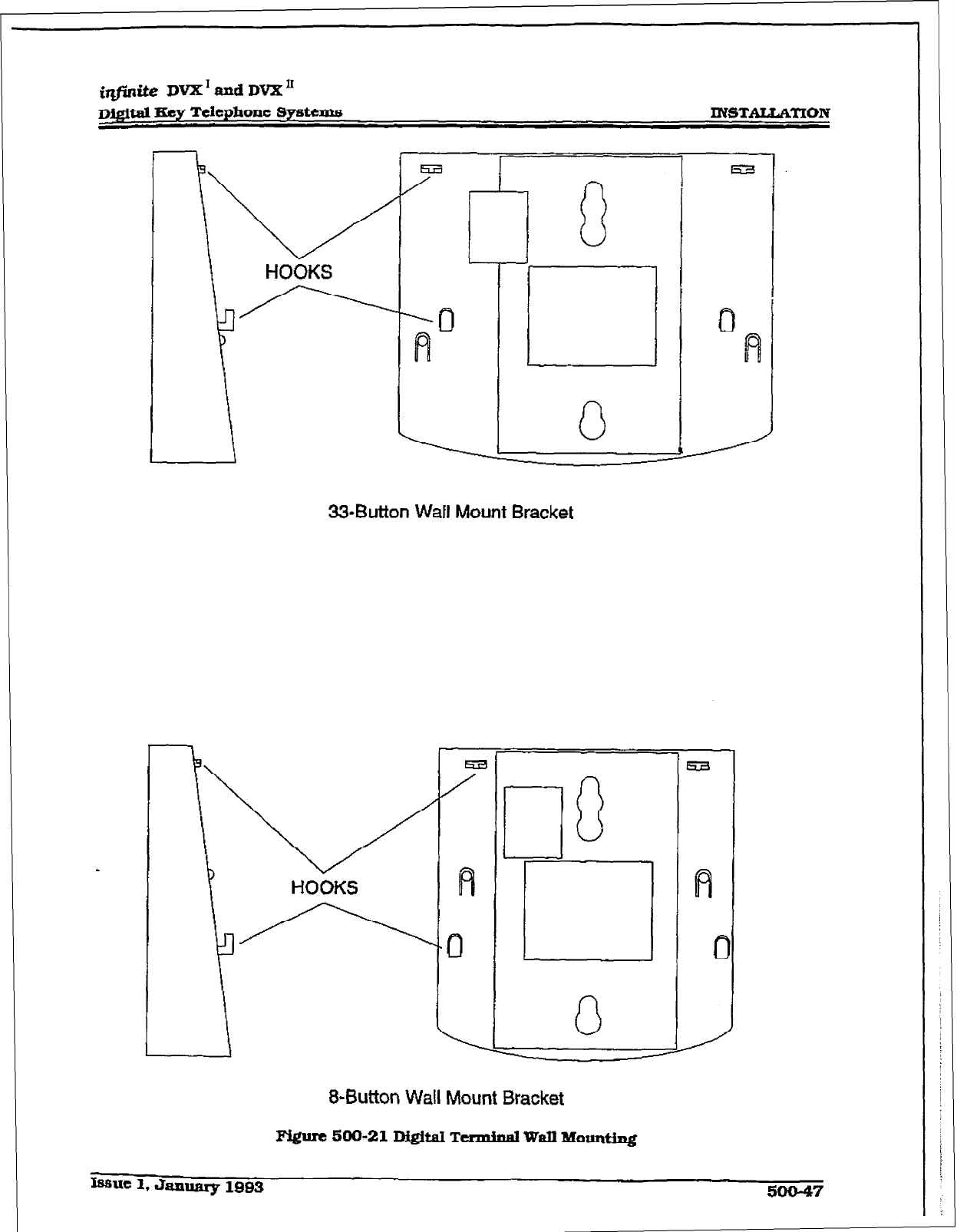
I
33-Button Wafl Mount Bracket
lf3
cl
-
L
c
0
-
-
1
!i3
-
-L c
8-Button Wall Mount Bracket
INSTALWLTXON
iqf?nite
DVX’ and DVX I1
Di@tal Key Telephone Systems
when the SLT station is taken off-hook.
Connections:
AU connections to the SLsi (0PX) adapter
are made on the back of the unit. %o
modular jacks and a two-wire cable are
located on the back of the unit for connec-
tion to the KSU and power supply. The two
wire cable connects to a 48V dc power
suppIy / ring generator. The modular jack
marked KSU is connected to a KSU Digital
terminal station port. This connection re-
quires all four wires and wires the same as
a kqr station. The modular jack marked
OPX is wired to the SLTstation (2500 type].
OPX circuit or SLT device. Additionally, a
CO line may be wired to the second pair of
the SLT modular connector for Power fail
operation.
Cable Imp Limiti:
The maximum loop limit from the KSU to
the SLA (OPX) adapter is 1000 feet.
The mz&num loop limit from the SLA
[OPX) adapter to the connected SLT or
device is 1400 ohms not mciudtng the tele-
phone or device.
500.8 POWER FAILURE TRANSFER
A Relay / Sensor Interface Module
The Relay Sensor interface Module con-
nects to the system using one digital sta-
tion port and provides three relay activated
contacts and three sensing circuits. The
relays provide for applfcations such as
Loud BeJJ Control contacts, CO Line con-
trol contacts, RAN Start contacts, Page Re-
lays, Power FaiI contact and additional
applications as software wIJJ permit. The
sensing circuits wiJl provide for such appli-
cations as Alarm signaHnginput, RAN Stop
* [end of message) and other applications as
developed and allowed by s&ware.
COllUCCti0nS:
All connections
to
the
Relay
Sensor Module
are made on the back of the
unit.
7bo
terminal strips with screw termfnals each
provide connection to the ancillary devices
for relay control or sensing monitoring. The
Modular jack marked KSU is connected to
a KSU Digital terminal station port. This
connection requires all four wires and
*es the same as a key station. Refer to
Figure 500-23 Relay / Sensor Interface
Module for wiring information.
An CX@IXLJ power source may be required
to &iv= equipment connected to the relay
contacts. The contacts are rated at 24Vdc
max at 1 amp.
Cable Loop Lixnitzx
The maxImum loop limit from the KSU to
the relay Sensor Module is 1000 feet.
B. Power Fhihre lkaaefer Unit IpFTU)
This unit provides the relay transfer cir-
cuits for up to 12 CO lines in the event of
a power or processor failure. The unit is
housed in fts own enclosure and mounts
external to the KSU. Activation of the PFIY
relays is contrc&d by a multi-use relay on
any one of the CO/Station Interface boards
that is programmed for PFT. A customer
provided 12 volt DC power supply is re-
quired to operate the un&t. There is a man-
ual switch that activates the PFl%I for
testing purposes.
With loss of power to the system or a failure
of system processing. the PFTU will auto-
matically connect up to twehre CO Jines to
prewired 500/2500 type telephones. When
power is restored. the PFKJ will automat-
i&iy restore the CO &LI.&S and stations
to nonndl operation. ‘These SLTstations do
not have to be used for intercom, but can
be if so desired.
wtrxlg / Pinouts / conxlectiolls:
The PFlW has two 50-pin male amphenol
connectors labeled CONNl and CONNS Jo-
cated on the front of the unit. Each connec-
tor wires six CO lines for power fail
transfer. Refer to Table 500-10 PFI’U Corm
A Connecting Block and Table 500-11
PFTU Corm B Connecting Block for pin-
outs of each of the cqnnectms.
The PFIL7 is connec&d to the KSU via the
modular connector on the side of the unit.
This is connected in series to a customer
provided 12V dc supply. and ta a multi use
relayprognxnmed as a power failure mlay.
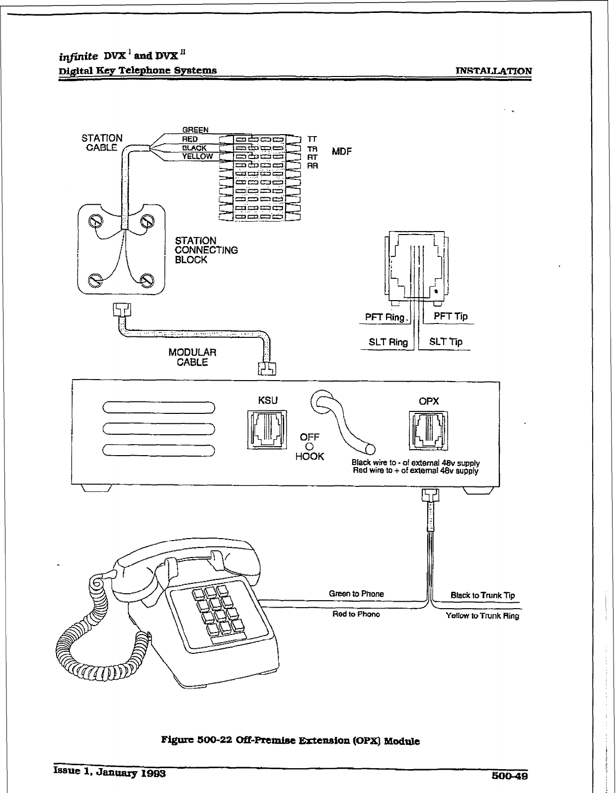
_ GREEN
I I
STATION
i
i
;FtF;CTJNG
MODULAR
CABLE
SLT Tip SLT
Ring 11
Issue 1, Januaxy IBBS 590-49
Black wire to - of external 48~
supply
Red wire to + of external 48~ supply
Yellow to Trunk Ring
FQurc 500-22 OfWremiee Extcnaion (OPIZ) Module
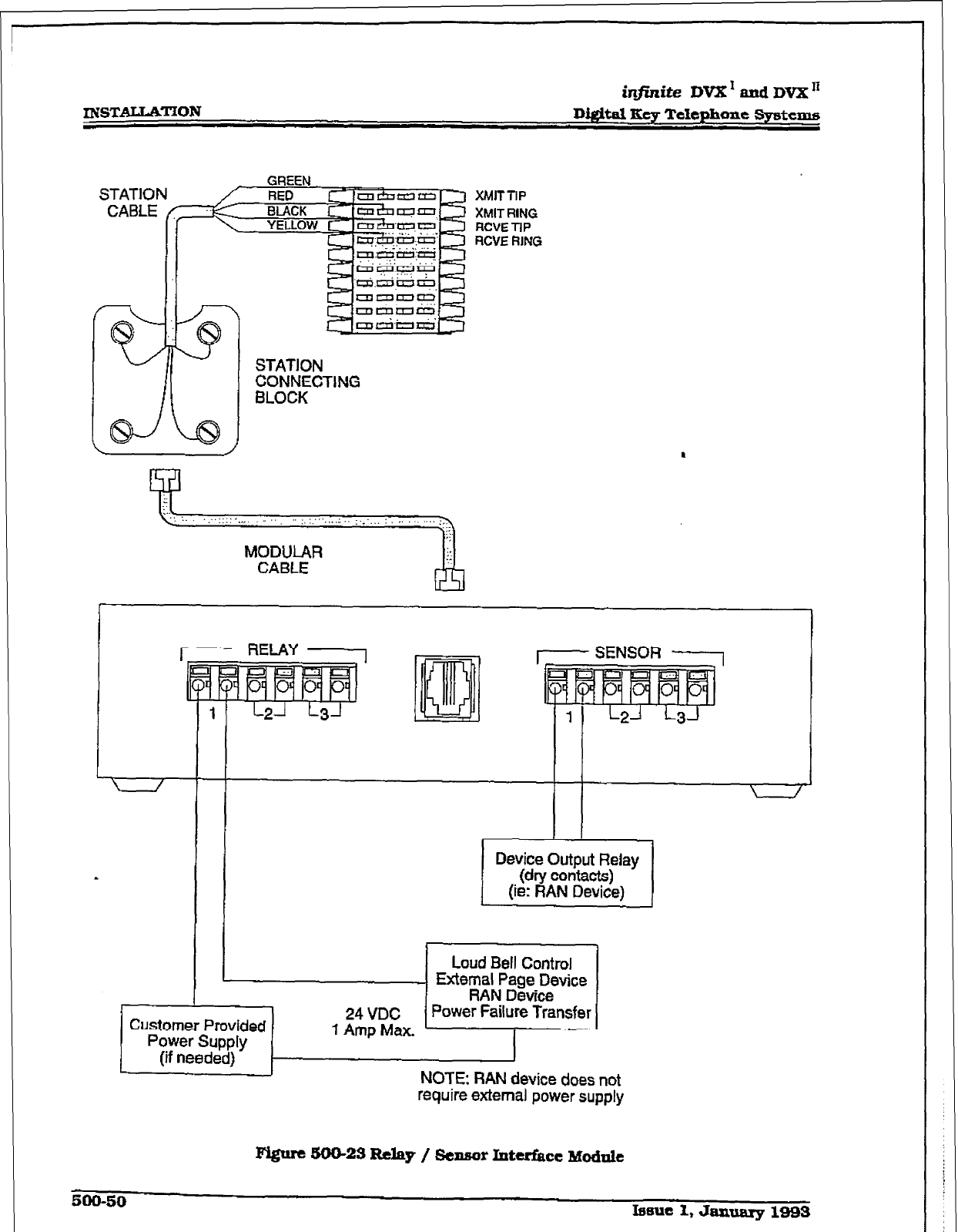
INSTALLATION
GREEN
XMITTIP
XMIT
RING
RCVE TIP
RCVE RING
- SENSOR -
Device Output Relay
I-
Loud Bell Control 1
‘Lip-J:2!i!:E:r,
Customer Provided
Power Supply
(if needed) NOTE: RAN device does not
require external power supply
\ /
500-50 Issue 1, Jsumary 1993
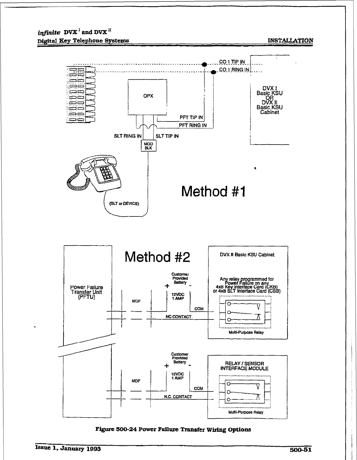
imite DVX’andDVX”
D&itaI Xey Telephone Systems
IN!STALLATlON
OPX
PFT RING IN
SLT RING IN 1 1 SLTTIP IN
I
1
MDF
--
I--
l
Method #I
Method
#2
DVX II Basic KSU Cabinet
Figure 5ioo-24 Power FMlure Transfer Wiring Optiona
k=uc 1, January 19~3 SOUS
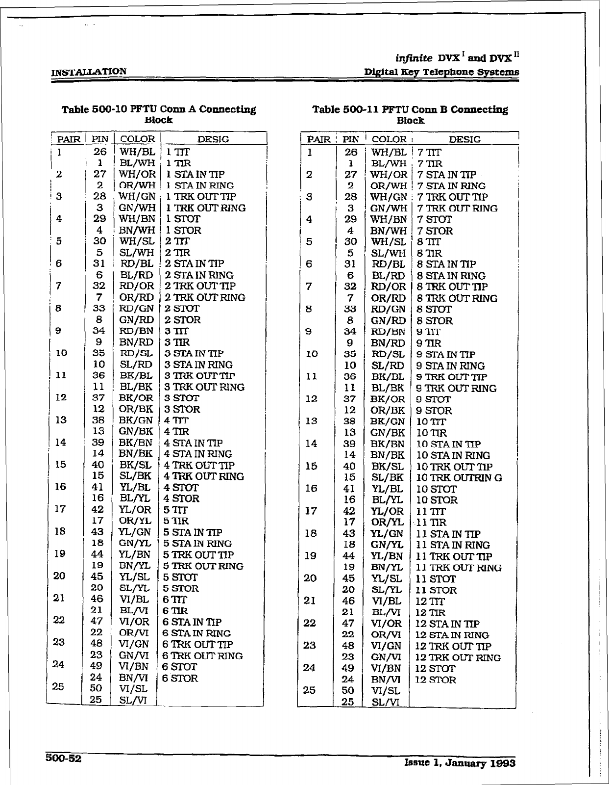
infinite DVX ’ rind DVX I1
D&&al Key Telephone Systems
Table 500-10
PFTU Corm A Connect&g
Table
500-11 PFTU Corm
B Connecting
Block Block
10
11
12
13
14
L5
16
17
18
19
20
21
22
23
24
25
27
2
28
3
29
4
30
5
31
6
32
7
33
8
34
9
35
10
36
11
37
12
38
13
39
14
40
15
41
16
42
17
43
18
44
19
45
20
46
21
47
22
48
23
49
24
50
25
COLOR
WH/BL
BL/wH
W-H/OR
OR/WH
WH/GN
GN/WH
WH/BN
BN/WH
WH/SL
SL/wH
RD/BL
BL/RD
RD/OR
OR/RD
RD/GN
GN/RD
RD/BN
BN/RD
RD/SL
SL/RD
BK/BL
BL/BK
BK/OR
OR/BK
BK/GN
GN/BK
BK/BN
BN/BK
BK/SL
SL/BK
YL/BL
BLrn
YL/OR
ORW
YL/GN
GNrn
YL/BN
BNrn
YL/SL
SLrn
VI/BL
BLM
VI/OR
OR/VI
VI/GN
GNM
VI/BN
BNM
vI/SL
=/VI
DESIG
1nT
1TzR
1 STA1NTiP
1 STAINRING
1TRKouTm
1 TRKOUTRING
1SIQT
1STOR
2llT
2lm
2STAINTiP
2 STA IN RING
2TRKOuTTIP
2TRKOUTRING
B+slnr
2STQR
3m
3m.R
3 STAINTIP
3 STAIN RING
3TRKOuTTIP
3TRi-COUTNNG
3moT
3STOR
3l-n
3nR
BSTAINTIP
3 STA IN RING
QTfcKOuTTiP
3’iRKOTJTRtNG
PsroT
PSl-OR
3TlT
STIR
3STAINTIP
5 STA IN RlNG
jTRKOUTTIP
5TRKOUTRING
ISTOT
ASTOR
j?lT
STIR
6 STAINTIP
GSI’AINRING
6TRxzOuTTIP
B’TIWOUTRING
6sTwr
GSIOR
1
i PAIR t
PIN ’ COLOR I DESIG I
!
I WWBL ! 7 nT 1
I
26
2 I 2:
2
I
3 ! 28
: I
: I
I :
4
5
6
7
8
9
10
11
12
13
14
16
16
17
18
19
20
21
22
23
24
25
3
29
4
30
5
31
6
32
7
33
8
34
9
35
10
36
11
37
12
38
13
39
14
40
15
41
16
42
17
43
18
44
19
45
20
46
21
47
22
48
23
49
24
50
25
BL/wII
WH/OR
OR/wN
WWGN
GNW
WH/BN
BN/wH
WI-ML
swwl
RD/BL
BL/RD
FZD/OR
OR/RD
RD/GN
GN/RD
RD/BN
BN/RD
RDJSL
SL/RD
BK/BL
BL/BK
BK/OK
ORjBK
BK/GN
GN/BK
BK/BN
BN/BK
BK/SL
SL/BK
YL/BL
BLryL
YL/OR
ORfyL
YL/GN
GN/YL
YL/BN
BNrn
YLjSL
=m
Vi/BL
BLM
VI/OR
ORM
Vl/GN
(=/VI
W-BN
BNM
W/SL
SLM
7nR
7STAINTiP
7
ETA IN RING
7TRKOuTTIP
7TRKOUTFlING
7STOT
7STOR
8’llT
8nR
8STAINTIP
8 SJYA IN RING
8 TRK OUTmP
8lRKOuTRwG
8STOT
BSTOR
9nT
9nR
9
STAINTIP
9 STAINRING
9TRKouTmP
9’IRKOUTRING
9Slvr
9sToR
1omT
1OTIR
10 SIAINmP
10STAINRING
1OTRKOuTmP
10TRKOUTRING
1OsToT
10 STOR
1lTiT
1lmR
11 STAINTIP
11 STAINRING
1lTRKOuTrnP
1lTRKOUTFUNG
11STOT
IISTOR
12Trr
12mR
12 STAINTZP
12 STAIN RING
12TRKOuTrnP
12TRKOUTRING
12 STOT
12 STOR
I
500-52 Issue 1, January 1993
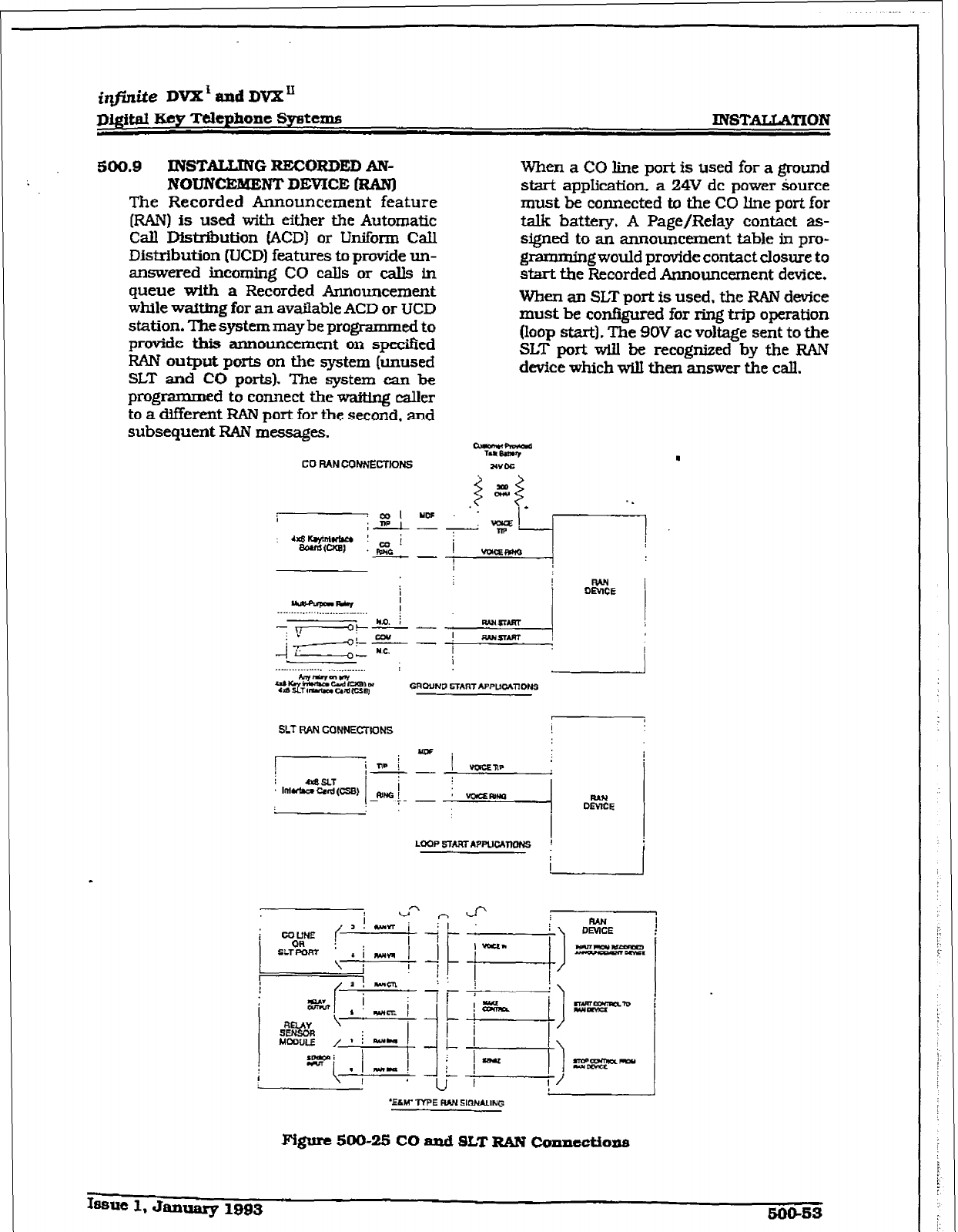
iqfinite
DVX’ and DVX”
D&ital Ecy Tcltphont
Systems INSTAUA’IXON
500.9
INSTALLING RECORDED AN-
NOUN~NTDEVICE (RAN]
The Recorded Announcement feature
(RAN) is used with either the Automatic
Call Dfstrihution fACD) or Uniform CaU
Distribution (UCD) features to
provide un-
answered incoming CO calls or calls in
queue with
a Recorded Announcement
while wafting
for an available ACD or UCD
station. The system may be programmed to
provide this announcement on
specified
RAN output ports on the system [unused
SLT and CO ports). The system can be
programmed to connect the wait&q caller
to a different FUN
port
for the
second, and
subsequent RAN messages.
When a CO line port is used for a
ground
start application. a 24V dc power source
must be connected to the CO line port for
talk battery, A Page/Relay contact as-
signed to an announcement table in pro-
gramming would provide contact closure to
start the Recorded Announcement device.
When an SLT port is used, the RAN
device
must be configured for ring trip operation
(loop start]. The 9OV ac
voltage
sent to the
SLT port will be recognized
by the RAN
device
which will then answer the call.
i
v
%Lw TYPE RAN SIQNAUNG
Fi@m 500-25 CO and SLT RAN @nncctions
Iasuc 1, January 1993 500-m
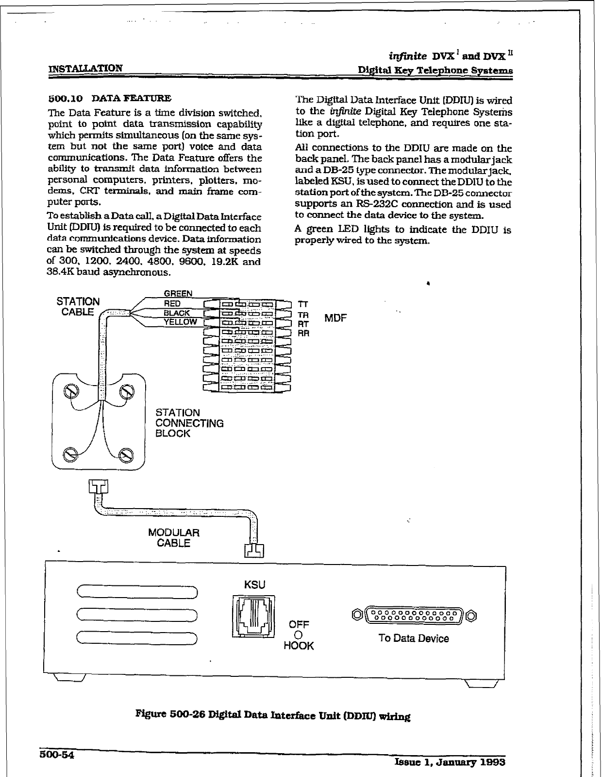
. . .
ir#mite
DVX’ and DVX’
m3TALLATION
500.10 DATA=TURE
The Data Feature is a time division switched,
point to point data transmission capability
which pen-nits simultaneous (on the same sys-
tem but not the same port) voice and data
communications. The Data Feature offers the
abillty to transmit data information between
personal computers. printers, plotters, mo-
dems, CRT terminals. and main frame com-
puter ports.
To establish a Data CalI. a Digftal Data Interface
Unit (DDIU) is required to be connected to each
data communications device.
Data
information
can be switched through the
system at
speeds
of 300, 1200, 2400, 4800. 9600, 19.2K
and
38.4K baud asynchronous.
The Digftal Data lnteriace Unit IDDIU) is wired
to the infinite Digital Key Telephone Systems
like a digital telephone, and requires one sta-
tion port.
All connections to the DDIU are made on the
back panel. The back panel has a modular jack
and a DB-25 type connector. The modularjack.
labeled KSU. is used to connect the DDIU to the
station port ofthe system. The DB-25 connector
supports an RS-232C
connection and is used
to connect the data device to the system.
A green LED Irehts to indicate the DDIU is
prgperly wired ti the
system.
GREEN
STATION
CONNECTlNG
BLOCK
MDF
KSU
8( 0000000000000
000000000000 ]s
“JF
HOOK To Data Device
F@ut SOO-26 Di#tal Data Inttrbt Unit (DDl’W rpiring
=o-s4
Itmlt 1, JannRry 1996
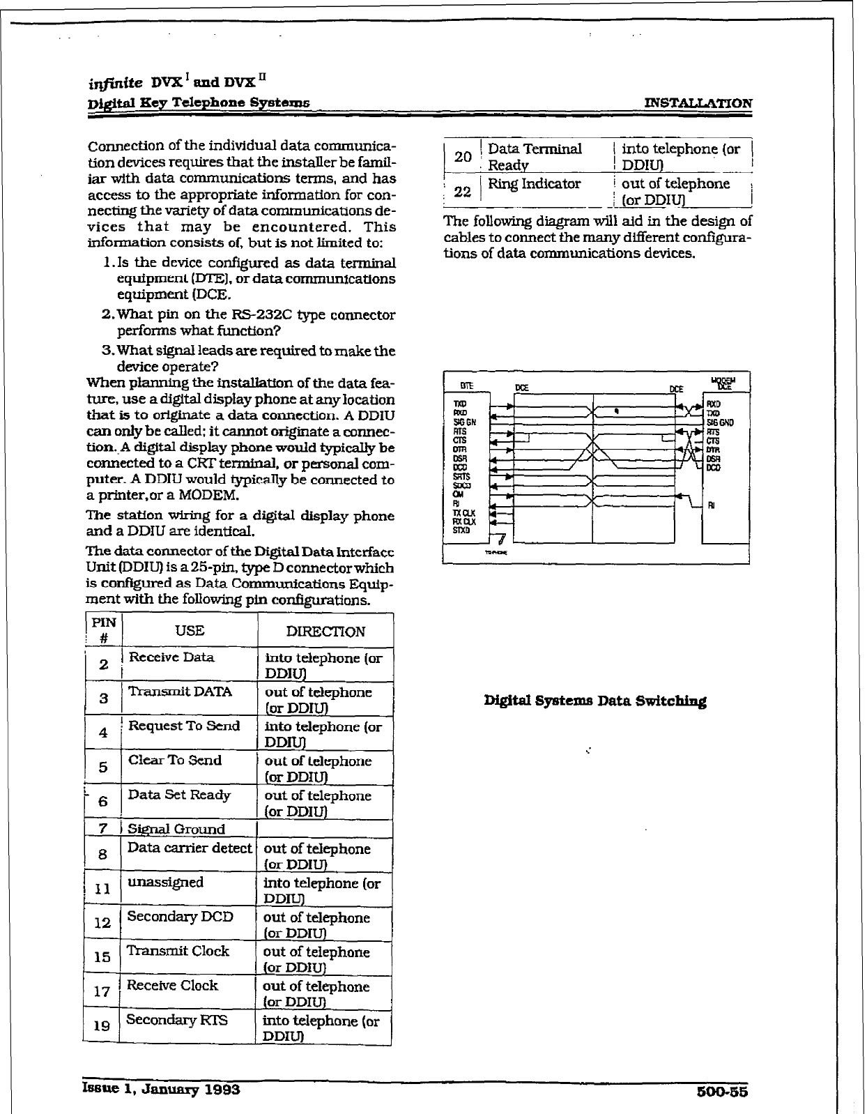
imite DVX * and DVX’
Digital Key Telephone Syetesrs
INSTALLATION
connection of the individual data communica-
tion devices requires that the installer be famil-
iar with data communications terms, and has
access to the appropriate information for con-
necting the variety of data communications de-
vices that may be encountered. This
information consists of, but is not limited to:
1 .Is the device configured as data terminal
equipment (DTEJ. or data communications
equipment (DCE.
2.What pin on the RS232C type connector
performs what function?
3.What signal leads are required to make the
device operate?
When planning the instalkticm of the data fea-
ture, use a digital display phone at any location
that is to originate a data connection. A DDIU
can only be called: it cannot originate a connec-
tion..A digital display phone would typicaUy be
connected to a CRT terminaI, or personal com-
puter. A DDIU would typicaUy be connected to
a prfnter,or a MODEM.
The station wiring for a digital display phone
and a DDIU are identical.
The data connector of the Digital Data Interface
Unit (DD1l-J) is a 25-pin. type D connector which
is configured as Data Communications Equip-
ment with the follow-jng pin configurations.
PIN
1 # USE DtRECTION
’ 2 ! Receive Data into telephone (or
I DDIUJ
3 Transmit DATA out of telephone
(or DDIU’)
4 f Request To Send into telephone (or
DDIU)
5 Clear To Send
I 6 Data Set Ready
7 i SignalGround
out of telephone
(or DDW)
out of telephone
(or DDIU)
8 Data carrier detect out of telephone
(or DDILJ)
t
1 11 unassigned into telephone (or
I DDIUJ
12
Secondary DCD out of telephone
(or DDIU)
15 Transmit Clock out of telephone
(or DDlU)
17 Receive Clock out of telephone
(or DDIU)
1 9 Secondary KIS into telephone (or
DDIU)
2. ( DataTerminal 1 into telephone (or (
Ready ! DDlU) I
I
: 22 ) Ring Indicator i out of telephone
j j
(or DDIUJ !
The following diagram will aid in the design of
cables to connect the many different conf@ra-
tions of data communications devices.
D&itat Systems Data Switching
Issue 1, Jammy 1993 soo-ss
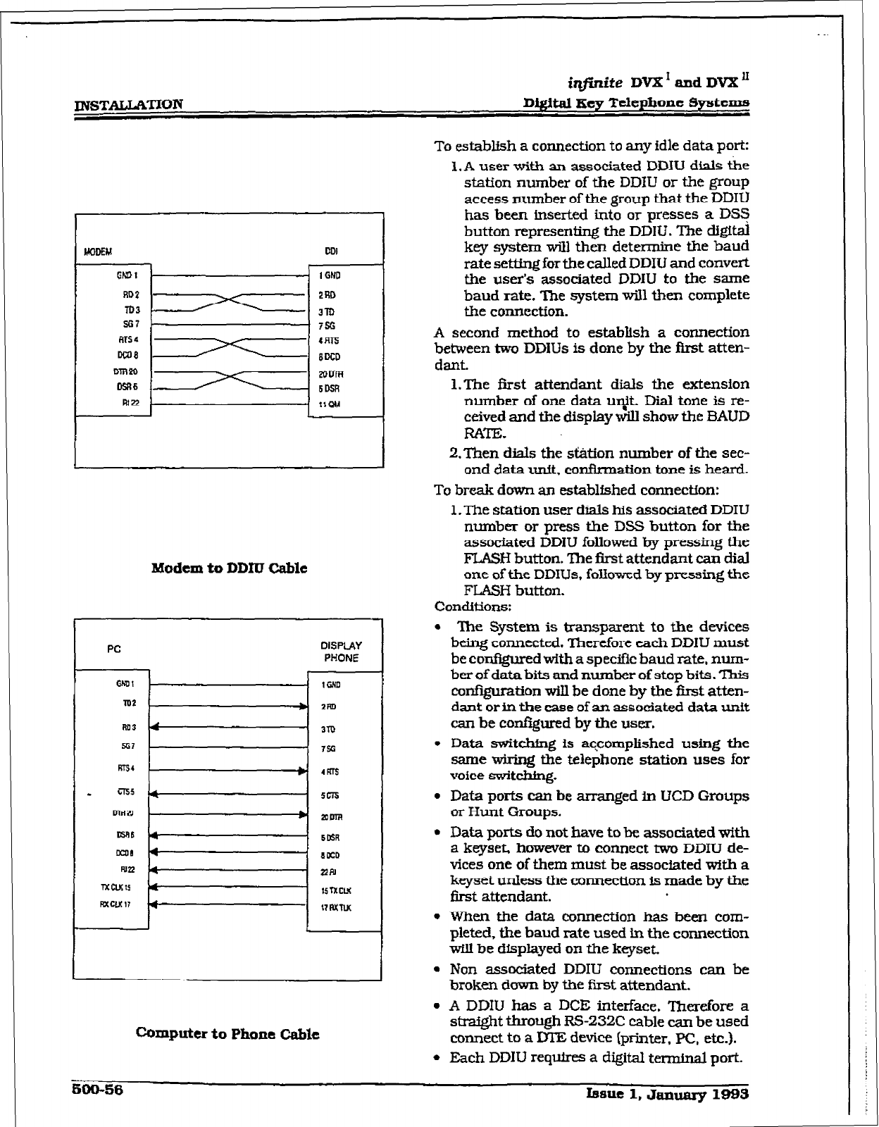
mSTALLKI’ION
irlfinite
DVX * and DVX ’
DigiW Keg Telephone Systems
UODEM
DDI
1 GNO
sG7 II 756
Modem to DDIU Cable
PC
WJl
m2
DISPLAY
PHONE
r
_ 1GNn
* 2Fn
Computer to Phone C&k
To
establish a connection to any idle data port:
l.A user witi an associated DDIU dials the
station number of the DDJU or the group
access number of the group that the
DDIU
has been inserted into or presses a DSZj
button representing the DDIU. The digital
key system will then determine the baud
rate set&g for the called DDIU and convert
the user’s associated DDIU to the same
baud rate. The system will then complete
the connection.
A second method to establish a connection
between two DDlUs is done by the first atten-
dant.
l.Tbe first attendant dials the extension
number of one data u~$t. Dii tone is re-
ceived and the display will show the BAUD
RATE.
2.Then dials the &&ion number of the sec-
ond data unit, confitmation tone is heard.
To break down an establfshed connection:
l.The station user dials his associated DDIU
number or press the DSS button for the
associated DDIU folloftred by pressing the
FLASH button. The first attendant can dial
one of the DDIUs. folfowcd by pressing the
FLASH button.
Conditions:
l
The System is transparent to the devices
being connected. ‘Ikerefore each DDIU must
be configured with a specific baud rate, num-
ber of data bits and number of stop bits. This
configuration wiIl be done by the fkst atten-
dant or in the case of an associated data unit
can be confqxed by the user.
l
Data switc&ng is aqcomplished using the
same wiring the telephone station uses for
voice switching.
. Data ports can be arranged in UCD Groups
or Hunt Groups.
l
Data ports do not have to be associated with
a keyset. however to connect two DDIU de-
vices one of them must be associated with a
keyset unless the connection is made by the
first attendant.
l
when the data connection has been com-
pleted, the baud rate used in the connection
wilI be displayed on the keyset.
l
Non associated DDIU connections can be
broken down by the first attendant.
l
A DDIU has a DCE interface. Therefore a
straight through RS-232C cable can be used
connect to a DTE device (printer. PC, etc.).
l
Each DDIU re@res a digital termhal port-
iqjinite DVX’ and DVXn
D&i&d Key Telephone Systemfi INSTALLATION
Refer to Station Attributes Programming.
730.2. Station ldentifkatlon for programming
the Station ID of the Digital Data Interface Unit
(DDIU). Also refer to Sec. 730.3. Digital Data
Intmface Unit IDDILl) for programming the pa-
rameters of the Digital Data Interkce Unit
(DDIUI.
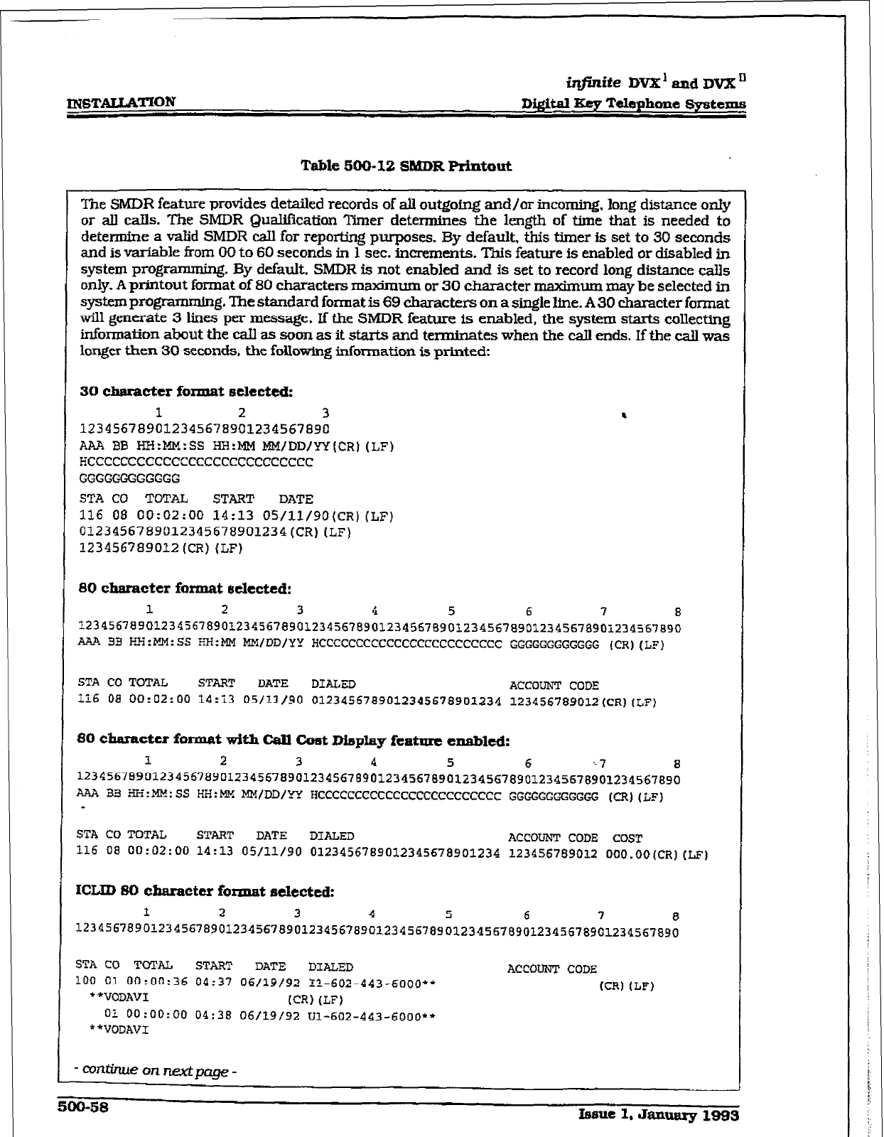
INGTAW*ATfON
iqjinite DVX’ and DVX II
Di@al Key Telephone systems
Table 500-12 SMDR printout
.
The SMDR feature provides detailed records of alI outgotng
and/or incoming.
long distance only
or
all &IS. The SMDR Qualifkation Timer determines the length of time that
is
needed to
determine a valid SMDR call for reporting purposes. By default. this timer is set to 30 seconds
and is variable from 00 to 60 seconds in I sec. increments. This feature is enabled or disabled in
system programming. By defauk SMDR is not enabled and is set to record long distance calls
only.
A
printout format of 80 characters maximum or 30 character maximum may be selected in
system pnagramming. The standard format is 69 characters on a single line. A30 character format
will
generate
3
lines per message, If the SMDR feature Is enabled, the system starts collecting
information
about the caU as soon as it starts and terminates when the call ends. If the call was
longer then 30 seconds. the f&owing information is printed:
30 ch6ractu fcmlat sdtetted:
1
2 3
123456789012345678901234567890
AAA BB HH:MM:SS HH:MM MM/DD/YY(CRj (LF)
HCCCCCCCCCCCCCCCCCCCCCCCCCCC
GGGGGGGGGGGG
STA CD
TOTAL START
DATE
116 08 00:02:00 14:13 05/11/90(CR)(LF)
0123456789012345678901234~CR)(LF)
123456789012(CR)(LF)
80 character format he&cd:
1
2 3 4 5 6
7 8
~23456789012345678901238567890123456?6901234~67%90~234567a90123~567~90i234567~90
AA.?4 33 Ei:i'!M:SS RH:MM MH/DD/YY
HCCCCCCCCCCCCCCCCCCCCCCCC
GGGGGGGGGGGG (CR)(LF)
STA CO TOTAL START DATE DIALED ACCOUNT CODE
116
08
00:02:00
14:X 05/11/90 0123456789012345678901234 123456789012(CR)(LF)
80 character format with CaIl Cost misplay
feature
enabled:
1 2 3 4 5 6 '- 7 8
~234567~901234567890123456789012345678901234567890123456789012345678901234567830
AAA 133 :HE:ME:SS HH:b!X MM/DD/
YY HCCCCCCCCCCCCCCCCCCCCCCCC GGGGGGGGGGGG (CR)(LC)
+
STA CO TOTAL START DATE DIALED ACCOUNT CODE COST
116 08 00:02:00 14:13 05/11/90 0123456789012345678901234 123456789012 OOO.OO(CR)(LF)
KXID 80 character format selected:
1 2 3 4 5 6 7 8
12345678901234567890123456789012345678901~34567830~~~4567~~~~~345~7~~~~~~~~~~~g~
STA CO TOTAL START DATE DIALED ACCOUNT CODE
100 01 00:00:36 04:37
06/19/92
IT-602-443-6000**
(CR) (LF)
l *vomv1 (CR) (L-F)
0: 00:~~:~~ 04:38 &S/19/92 Ul-602-443-6000f'
**VODAVI
-CWUimeonnextpage-
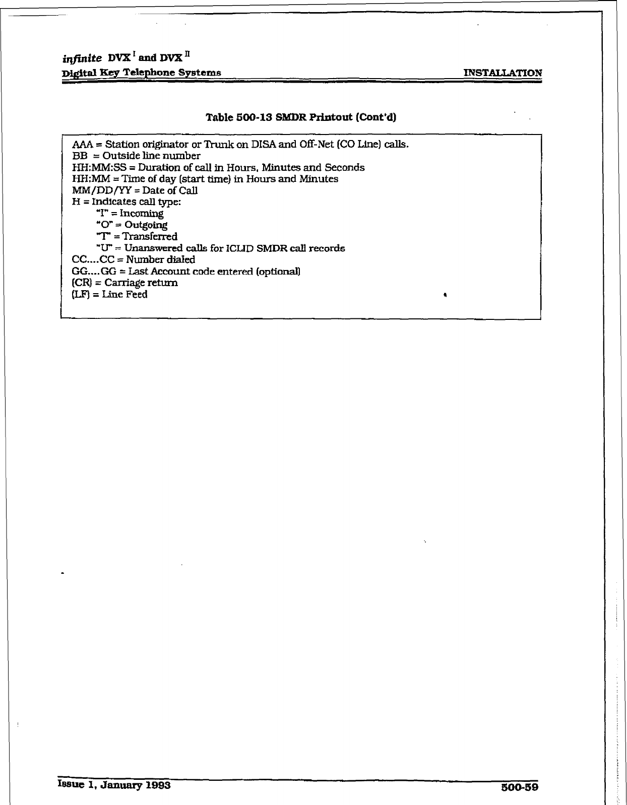
imite
DVX’ and DVX”
Table 500-13 ShfDR printout [C-ont’d)
AAA = Station
originator or Trunk on DISA and Off-Net (CO Line) calls.
BB = Outside line number
HH:MM:SS = Duration of call in Hours, Minutes and Seconds
HH:MM = Time of day (start time) in Hours and Minutes
MM/DD/YY = Date
of Call
H = Indicates call type:
“I” = Incomi.ng
“0” = outgoing
T=Transfcrred
‘7J” = Unanswered c&Us for ICIJD SMDR call records
CC....CC = Number dialed
GG....GG = Last Acmxmt code entered (optional]
(CR) = Carriage
return
(LF) = I&e Feed ,
ku3ue 1, January 1-3
5m-59
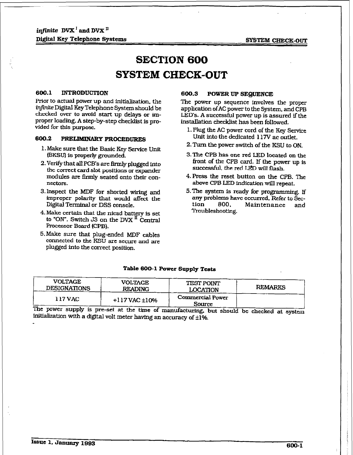
i@nite DVX ’ and
DVX ’
DigiW Key Telephone Sy8tezns spsTEh¶ CBECE-OUT
SECTION 600
SYSTEM CHECK-OUT
600.1
INTRODUCTION
prior to actual power up and initialization. the
infinite Digital Key Telephone System should be
checked over to avoid start up delays or im-
proper loading. A step-by-step checklist is pro-
vided for this purpose.
6cKI.2
PREW PROCEDURES
f . Make sure that the Basic Key service Unit
(BKSU) is properly grounded.
2. Verify that all PCB’s are firmly plugged into
the correct card sfot positions or expander
modules are firmly seated onto their con-
nectors.
3.Inspect the MDF for shorted wiring and
improper polarity that would aEect the
Digital Tertnimil or DSS console.
4.Make certain that the nicad battery is set
to ‘ON”. Switch 53 on the DVx’ Centi
Processor Board (CPB).
5.Make sure that plug-ended MDF cables
connected to the KSU are secure and are
plu@ed into the correct position.
600.3 POWER UP
SEQUENCE
The power up sequence involves the proper
application ofAC power to the System. and CPB
LED’s, A successful power up is assured if the
installation checklist has been followed.
1. Plug the AC power cord of the Key Sexvice
Unit into the dedicated 117V ac outlet.
2.Tum the power switch of the KSU to
ON.
3.The CPB has one red IED located on the
fkont of the CP3 card. If the power up is
succ&. the red LED will flash.
4. Press the reset button OR the CPB. The
above CPB LED indication wiIl repeat.
S-The system is ready for programming. Ii
znproblrO have occurred, Refer to Sec-
Troubkshoot& Maintenance and
Table 600-l Power Supply Tests
i
VOLTAGE ‘POINT
t
1
VOLTAGE TEsf - -I_-
DESIGNATIONS RTMDING LOCATION REMARKS
I
117 VAC +117VAC flO?z! CorllmmaI PO
wer
source
The power supply is pre-set at the time of manufacturing. but she: -----____ -_
uld be checked at svstm
initialization with a dgital volt meter havfng an accuracy of *I%. -, ----
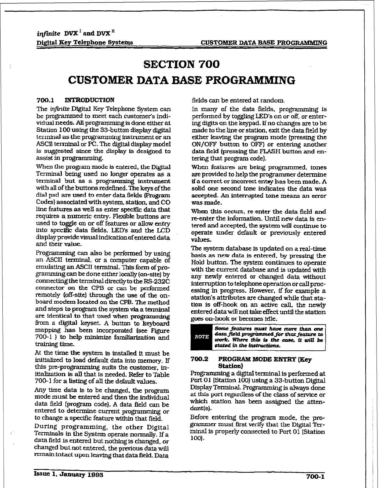
r
1
i&hite DVX’ and DVX’
D&it& Key Telephone Systems CUSTOMER DATA BASE PROGR&MlkDNG
SECTION 700
CUSTOMER DATA BASE PRUG-NG
700.1 INTRODUCTION
The infinite Digital Key Telephone System can
be
programmed to meet each customer’s indi-
vidual
needs. All programming is done either at
Station I00 using the 33-button display digital
terminal as the programming instrument or an
ASCII texminal or PC. The distal display model
is suggested since the display is designed to
assist in programming.
When the program mode is entered, the Digital
TerminaI being used no longer operates as a
terrnird but as a progmmming instrument
with all of the buttons redefined. The keys of the
dial pad are used to enter data fields (program
Codes) associated with system,
station,
and CO
line features as well as enter specific data that
requires a numeric entry. Flexible buttons are
used to toggle on or off features or alIow entry
into speciAc data fields. LED’s and the LCD
display provide visual indication of entered data
and their value.
Programming can also be performed by using
an ASCII terminal. or a computer capable of
emuiamg an ASCII terminal. Thfs form of pro-
gramming can be done either locally (on-site) by
connecting the terminal directly to the FS232C
connector on the CPB or can be performed
remotely (off-site) through the use of the on-
board modem located on the CPB. The method
and steps to progmm the system via a terminal
are identical to that used when programmin%
from a digital keyset. A button to keyboard
mapping has been incorporated (see Figure
700-l ) to help minimix f-on and
training time.
At the time the system is installed it must be
initialized to load default data into memory. If
this pi-e-pro- suits the customer, in-
itialization is all that is needed. Refer to Table
700- 1 for a listing of all the default values.
Any time data is to be changed, the program
mode must be entered and then the individual
data field (program code), A data field can be
entered to determine current prom or
to change a sped& feature witbin that field.
During programming, the other Digital
Timnfnals in the System operate normally. If a
data field is entered but nothing is changed. or
changed
but not entered, the previous data will
i-a-&n intact upon leaving that data field. Data
fields can be entered at random.
In many of the data fields. programming is
performed by toggling LED’s on or off, or enter-
ing digits on the keypad. If no changes are to be
made to the line or station, exft the data field by
either leaving the program mode (pressing the
ON/OFF button to OFF) or entering another
data field (pressing the FLASH button and en-
tering that program code).
When features an being programm ed. tones
are provided to help the programmer determine
if a comect or ticorreet entny has been made. A
solid one second tone indicates the data was
accepted. An interrupted tone means an error
was made.
When this occurs, reenter the data field and
r-e-enter the information. Until new data is en-
tered and accepted, the system will continue to
operate under default or prwiously entered
values.
The system database is updated on a real-time
basis as new data is entered, by pressing the
Hold button. The system continues to operate
with the current database and is updated with
any newly entered or changed data without
interruption to telephone operation or call proc-
essing in progress. However. if for example a
station’s attributes are changed while that sta-
tion is off-hook on an active call, the newly
entered data will not take effect until the station
goes on-hook or becomes fdle.
700.2
PROGRAM MODE ENTRY [Hey
Station)
pro&ramming a digital terminal is performed at
Port Cl 1 (Station 100) using a 33-button Digftal
Display Terminal. Programming is ahvays done
at this Port regardless of the class of service or
which station has been assigned the atten-
dant(s) .
Before entering the program mode, tbe pro-
grammer must ffrst verify that the Digital Ter-
minal isi properly connected to Port 01 [Station
100).
bzmt 1, Jantwy
1993 700-l
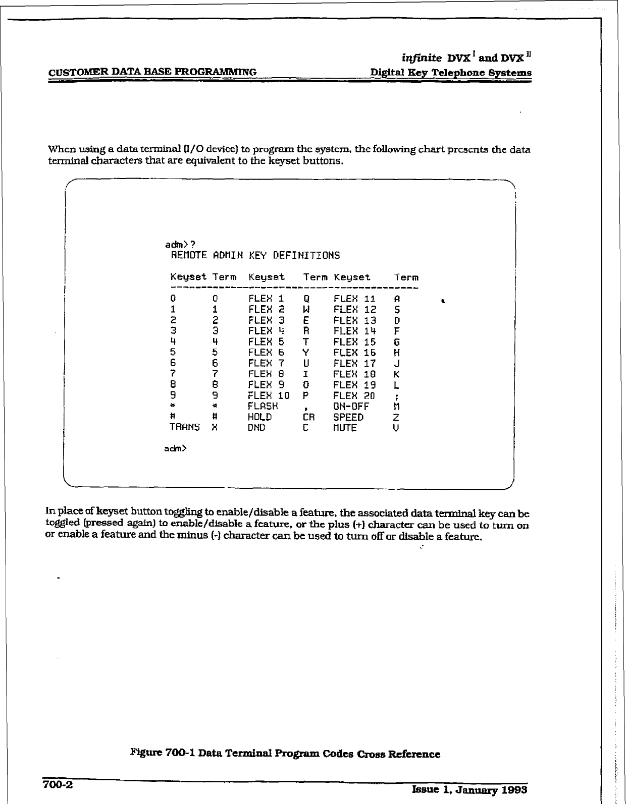
CDSTOMER DATA RASE PROGRAbI&mVG
ir@ite DVX’ and DVX’
Di@taI Key Telephone Systems
When using a data terminal 0/O device) to program the system. the following chart presents the data
terminal characters that are equivalent to the keyset buttons.
adm> ?
REl-tOTE ADtlIN KEY DEFINITIONS
Keyset Term Keyset Term Keyset
Term
---------I-------------------------------
0 0
FLEX i FLEX 11 FI
1
3 : FLEX 2 ; FLEX 12 S
z FLEX FLEX 3 4 E R FLEX FLEX 13 14 F D
2 5” FLEX FLEX 6 5 Y T FLEX FLEX 16 15 6 Ii
; ; FLEX 7 LI FLEX 17 J
FLEX 8 I FLEX 18 K
: 8 9 FLEX FLEX 10 9 P 0 FLEX FLEX 19 20 L
* ii FLRSH ON-OFF A
&FINS X HOLD iR SPEED
DND C IlUTE 6
adm>
.
In place of keyset button to&$ing to enable/disable
a
feature, the associated data terminal key can be
toggled (pressed a&n) to enable/disable a feature,
or the
plus (+I character can be used to turn on
or enable a
feature
and the minus (-1 character can be used to turn off or disable a feature.
a.’
700-2 Issue 1, Jamery lQB3
1
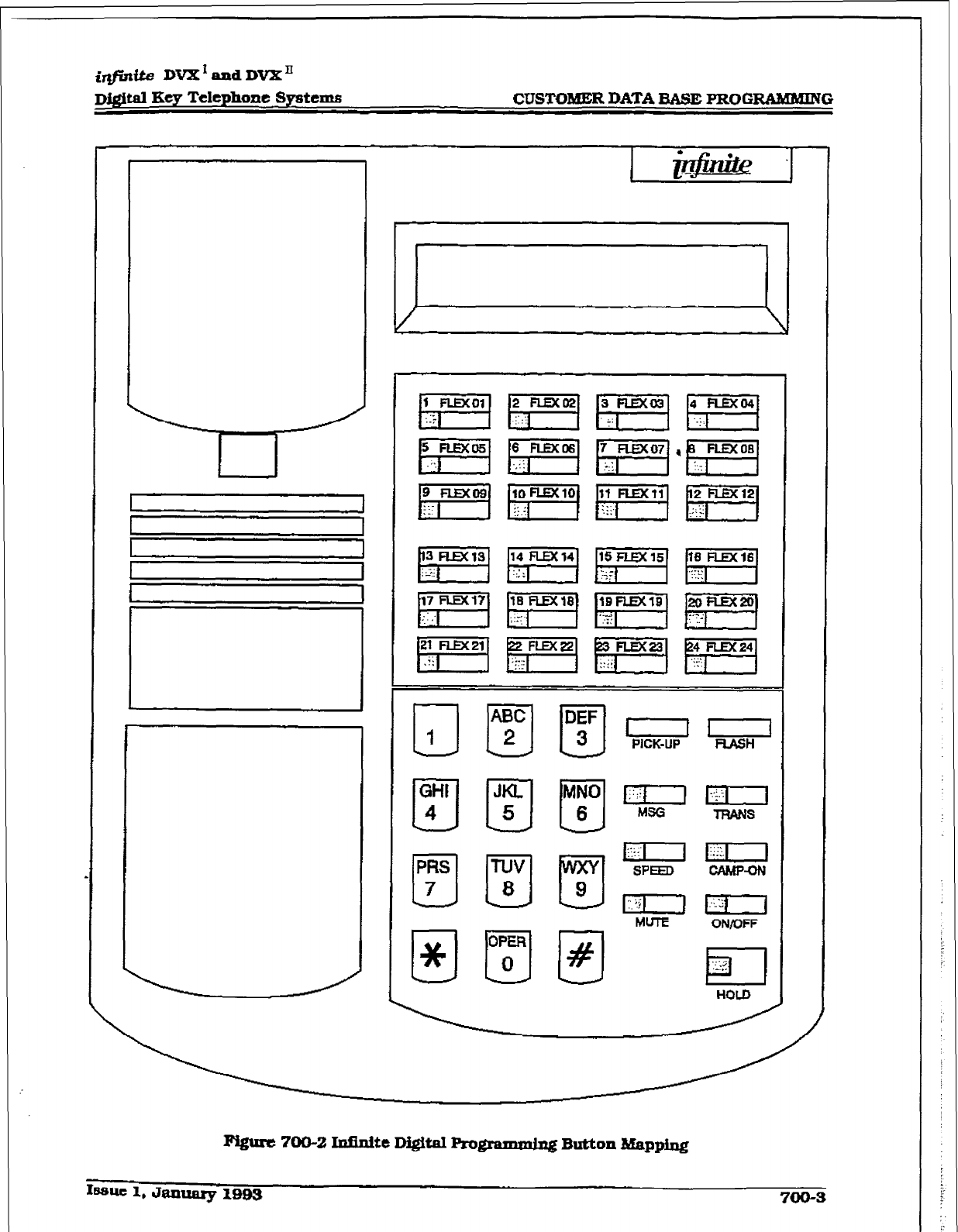
irlfirtf& DVX’mdDVX’I
Dj#ital Key Telephone Systems CUSTOMER DATA BASE PROGRAMMING
If&urr: ?oQ-2 InfidteDigitaIRogramming
Button Mapping
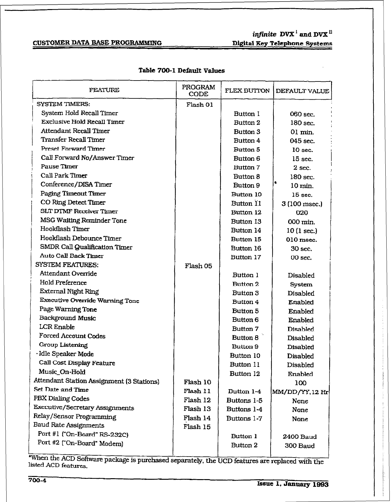
CUSTOMER DATA
aASE
mOGFG
il?jidte DVX’andDVX”
Digital Key Telephone Systems
Table 700-I Defatit
Value5
i SYSTEM T’IMERS:
1
System Hold Recall Timer
Exclusive Hold RecaIl Timer
Attendant Recall Timer
Transfer Recall Timer
Preset Forward Timer
Call Forward No/Answer Timer
Pause Timer
Call Park Timer
Confere.nce/DISA Timer
Paging Tlimeout TJmer
CO Ring DetectTimer
SLT D’I’MF Receiver Timer
MSG Waiting Reminder Tone
Hookflash Tfmer
Hookflash Debounce Tfmer
SMDR Call QuaLiftcaton Timer
Auto Call Back Timer
SYSTEM FEATURES:
Attendant Override
Hold Preference
External Night Ring
Executive
Ckenide Waming
Tone
Page Warn@
Tone
Background Music
LCR Enable
Forced Account Codes
Group Listening
- Idle Speaker Mode
Call Cost Display Feature
Music-On-Hold
Attendant Station Assignment (3 Stations)
Set Date and Time
PBX Dialing Codes
Executlve/SecretaryAssi~ents
Relay/Sensor Programming
Baud Rate Assignments
Port #I (uOn-Board” RS-232C)
Port X2 [‘On-Board” Modem)
PROGRAM
CODE
Flash 01
Flash 05
Flash 10
Flash11
Flash 12
Flash 13
Flash 14
tilash 15
I 1
.- _
‘When the ACD Soi?ware package is purchased separately, the
listed ACD features.
FLEXBUTI’ON
Button I 060 sec.
Button 2 180 sec.
Button 3 01 min.
Button 4 045 sec.
Button 5 10 sec.
Button 6 15 sec.
Button 7 2 sec.
Button 8 180 sec.
Button 9 10 min.
Button 10 15 sec.
Button i’l 3 (100 msec.)
Button 12 020
Button 13 000 min.
Button 14 10 (1 sec.)
Button 15 010 msec.
Button 16 30 sec.
Button 17 00 sec.
Button 1
Button 2
Button 3
Button 4
Button 5
Button 6
Button 7
Button 8 ”
Button 9
Button 10
Button 11
Button 12
Button l-4
Buttons l-5
Buttons l-4
Buttons l-7
Disabled
system
Disabled
Enabled
Enabled
Enabled
Disabled
Disabled
Disabled
Disabled
DisabIed
Enabled
loo
IM/DD,‘YY, 12 HI
None
None
None
Button
1
Button 2
2400 Baud
300 Baud
CD features are replaced with the
700-s
Issue 1, Jammy
1~93
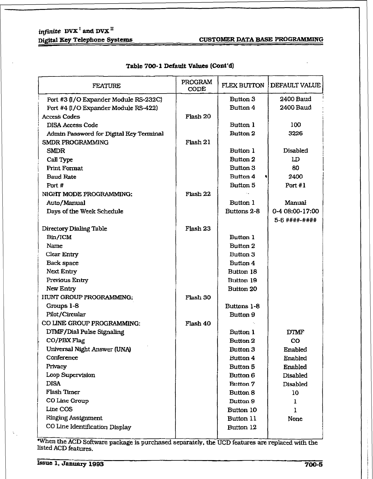
i@inite DVX’andDVX’
D&&d Eey Telephone SyMcrn8 CUSTQMER DATA BASE PROGFMMBUING
Table 700- 1 Default Values (Cant’d)
When the ACD
Software
package is
purchased
listed ACD
features.
FEATURE
/ Port #3 Q/O Expander
Module RS-232C)
Port #4 [I/O
Expander Module R!H22)
Acces& Codes
DISA Access
Code
Acimin password for Digital Key Tw
Sh4DR PROGRAMMlNG
SMDR
Cd?srpe
Print Format
Baud Rate
Polt#
MGHl.
MODE PROGRAMMING:
Auto/Manual
Days
of the Week
!Schedule
Directory Dw Table
Bin/KM
Name
Clear Entry
Back
space
Next Entry
Fbrevious Entry
New Entry
HUNT GROUP PROGRAMMING;
Groups 1-8
PU0t/Circti
CO IDJE GROUP PROG-G:
DTMFDial Pulse Signsling
co/pm Flag
Universal Night Answer (UN.A)
corlfercnee
~==Y
Loop Supervfsion
DISA
Flash ‘lkner
CO Line Group
Line COS
Ringing Assfgnlnmt
CO Line Identification Display
PROGRAM
CODE
Flash 20
Flash21
Flash 22
Flash 23
Flash 30
Ftash 40
eparately. the
FLEXBUTION
Button 3
Button 4
Button 1
Button 2
Button 1
Button 2
Button 3
Button 4
Button 5
._
Button 1
Buttons 2-8
Button 1
Button 2
Button 3
Button 4
Button 18
Button 19
Button 20
Buttons l-8
Button 9
Button 1
Button 2
Button 3
Button 4
Button 5
Button 6
Button 7
Button 8
Button 9
Button 10
Button 11
Button 12
CD fkatures are
’ 1
1
2400Baud !
2400 Baud
loo
3226
Disabled
LD
80
2400
Port #l
MZWld
O-4 08:00- 1790
5-6 ####-####I
co
Enabled
Enabkd
Ellabled
Disabled
Disabled
10
I
1
None
,eplaced with the
hue 1, January 1993 700-s
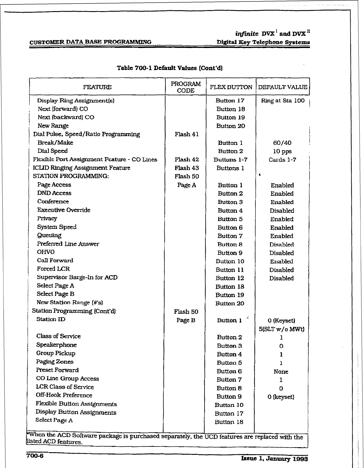
CUSTOMER DATA IBASE PROGRAMMING
iqjinite DvX’aadDVX”
DIgital Key Telephone Systems
Table 700-l Default Values (Cont’d]
1 Display Ring Assigumentb)
; Next [forward) CO
j Next (backward) CO
; NewRange
Dial Puke,
Speed/Ratio programming
Break/Make
Dial speed
Fkxible PortAssignment Feature - CO Lines
ICLID Ringing Assignment Feature
STAnON PROGRAMMING:
Page Access
DND Access
Conference
Executive Override
pnivacy
System Speed
0ueuing
Preferred Line Answer
OWO
Call Forward
Forced LCR
Supervisor Barge-In for ACD
Select Page A
Select Page B
New Station Range (#%I
Station Programming [ConVd)
Station ID
Class of Service
Speakerphone
Group Pickup
Pagingzones
Preset Forward
CO Line Group Access
LCR Class of Service
Off-Hook Preference
Flexible Button Assignments
Display
Button ASSQIUII~~S
Select Page A
PROGRAM
CODE
. . . .
Vhert the ACD Sofkware package is purchased separate&y, me U
;t.ed ACD features. CD features am replaced with the
Flash 41
Flash 42
Flash 43
Flash 50
Page A
Flash 50
Page B
FLEXBUTTON
Button 17
Button 18
Button 19
Button 20
Button 1
Button 2
33uttons l-7
Butkms 1
Button
1
Button 2
Button 3
Button 4
But&on 5
Button 6
Button 7
Button 8
Button 9
Button 10
Button 11
%.&ton 12
Button 18
Button 19
Button 20
Button 1 ’
Button 2
Button 3
Button 4
Button 5
Button 6
Button 7
Button 8
Button 9
Button 10
Button 17
Button 18
““““‘“““1
RillgatSta 100 i
60/40
1OPps
Cards 1-7
Enabled
Enabled
Enabled
Disabled
Enabled
Enabled
Enabled
Disabled
Disabled
Enabled
Disabled
Disabled
0 Wewet)
5(SLT w/o MWti
I
0
1
1
None
1
0
0 R=yJet)
700-6
Issue 1, Janwiry 1993
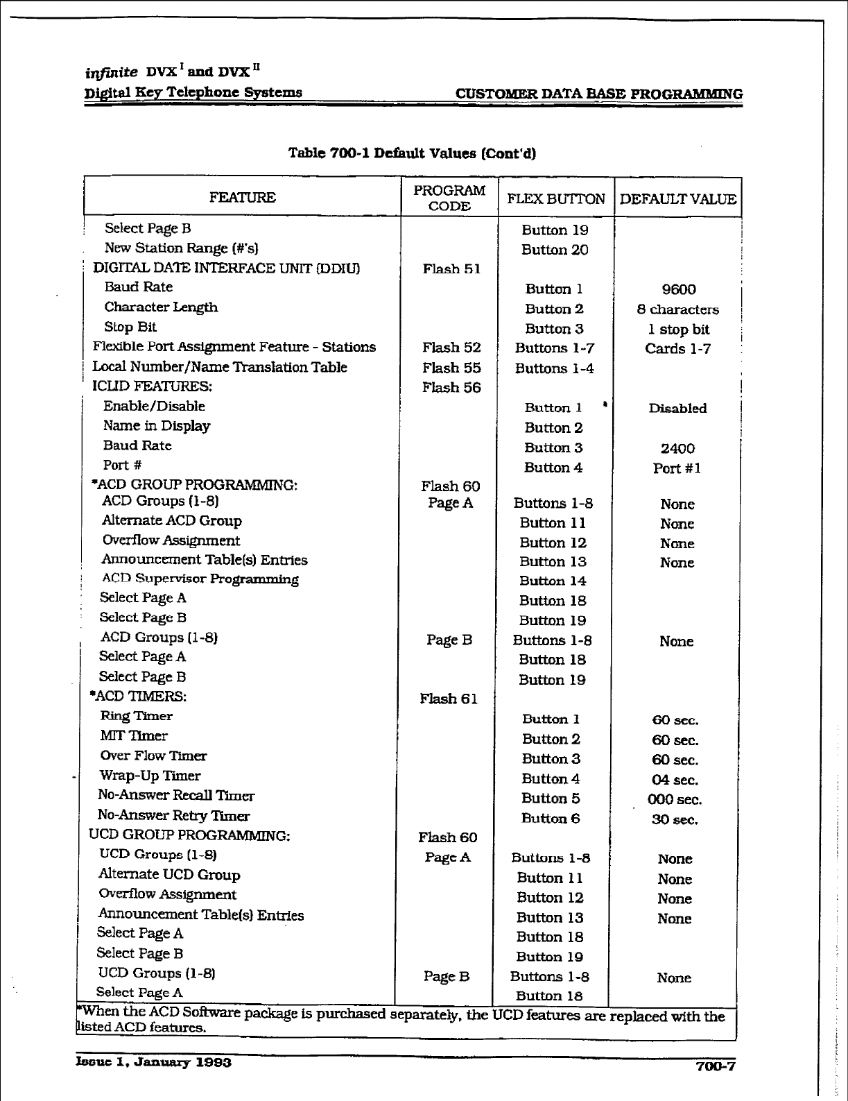
r
i@&te DVX’andDVX’
Dj#d Key Telephone Systems CUSTO- DATA EASE PROGRAMMING
Table 700-l Default Values [Cont‘d)
1 FEATURE
! Select Page B
New Station Range (#&I
DIG-DATE IN~~~RFA~~EuNIT~DDIU)
BaudFtate
Character Length
Stop Bit
Flexible Port Assignment Feature - Stations
Local Number/Name Translation Table
I
ICLID FEATURES:
Enable/Disable
Name in Display
Baud Rate
Pot-t #
*ACD GRCXI-P PROGRAMMING:
ACD Groups (l-8)
Alternate ACD
Group
ovemowAssignment
Announcement Table(s) Entries
; ACD Supervisor Pro-g
: Select Page A
: Select Page B
ACD Groups (l-8)
Select Page A
Select Page B
l ACD ‘TIMERS:
RingTlmer
MIT Timer
Over Flow Timer
Wrap-Up Tier
No-Answer Recall Timer
No-Answer Retry ‘kner
UCD GROUP PROGRAMMING:
UCD Groups (l-8)
Alternate UCD Group
owmow Assignment
Announcement Table(s) Entries
Select Page A
Select Page B
UCD Groups (l-8)
Select Page A
PROGRAM
CODE
Flash 51
Flash 52
Flash 55
Flash 56
Flash 60
Page A
Page B
Flash61
Flash 60
Page A
Page B
When the LCD Soi33vare package is purchased separately, tne LJ
sted
ACD features.
FIXXBU-ITON
Button 19
Button 20
Button 1
Button 2
Button 3
Buttons l-7
3uttJms 1-4
Button 1 ’
Button 2
Button 3
Button 4
Buttons l-8
Button 11
Button 12
Button 13
Button 14
Button 18
Button 19
Buttons l-8
Button 18
Button 19
Button 1
Button 2
Button 3
Button 4
Button 5
Button 6
Buttons l-8
Button 11
Button 12
Button 13
Button 18
Button 19
Buttons l-8
Button 18
9600
8 characters
1 stop bit
Cards l-7
Disabled
2400
Port #l
None
None
None
None
None
CD features are replaced with the
60 sec.
60 sec.
60 sec.
04 sec.
000 sec.
30 sec.
None
None
None
None
None
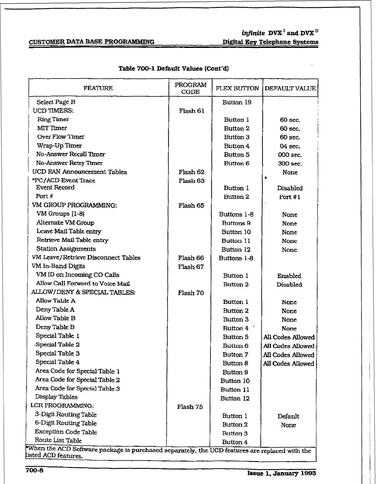
CUSTOMER DATA BASE PROC+RAhWIINCi
ti@.ni.te DVX’ and DVX”
Mgital Key Telephone SJrstems
Table 700-l Default Values (Cont’d)
FEATURE
Select Page B
UCD TIMERS:
Ring Timer
MITmmer
Over Flow Timer
wrap-up Tirne.r
, No-Answer Recall Timer
No-Answer Retry Timer
UCD RAN Am-rouncement Tables
‘PC/ACD Event Trace
Event Record
Port #
. VM GROUPPROGRAMMING:
t VA4 Groups (l-8)
AItcmate VM
Group
Leave Mail
Table entry
E
i
Retrieve Mail Table enny
Station Assignments
VM Leave/Retrieve Disconnect Tables
VM ln-Band Digits
VM ID on Incoming CO CalIs
Allow Call Fomd to Voice Mail
ALLOW/DENY & SPECIALTABLES:
Allow Table A
Deny Table A
Allow Table B
Deny Table B
Special Table 1
Special Table 2
Special Table 3
Special Table 4
Area Code for Special Table 1
Area Code for Special Table 2
Area Code for Special Table 3
Display Tables
LCR PROGRAMMING:
3-Digit
Routing
Table
s-Digit Routing Table
Exception Code Table
Route List Table
Buttons l-8
Buttons 9
Button 10
Button 11
Button 12
Buttons l-8
None
None
None
None
None
FIash 66
Flash 67
Button 1 Enabled
Button 2 Disabled
Flash 70
Button 1
Button 2
Button 3
Button 4 ’
Button 5
Button 6
Button 7
Button 8
Button 9
Button 10
Button 11
Button 12
None
None
None
None
1
ill Codes Allowed
1
ill Codes Allowed
1 ill Codes Avowed
1
ill Codes Allowed
Flash 75
Button 1 Default
Button 2 None
Button 3
Button 4
When the ACD Sofhvare package is
purchased separately. the
UCD features are
replaced with tile
sted
ACD fmtura.
PROGRAM
CODE FLEXBUTTON
Flash61
Flash 62
Flash 63
Flash 65
Button 19
Button 1
Button 2
I
Button 3
Button 4
Button 5
Button 6
Button 1
Button 2
60 sec.
60 sec.
60 sec.
04 sec.
000 sec.
300 sec.
None
L
Disabled
Port#l
700-8 Imme
1. Januarp 1993
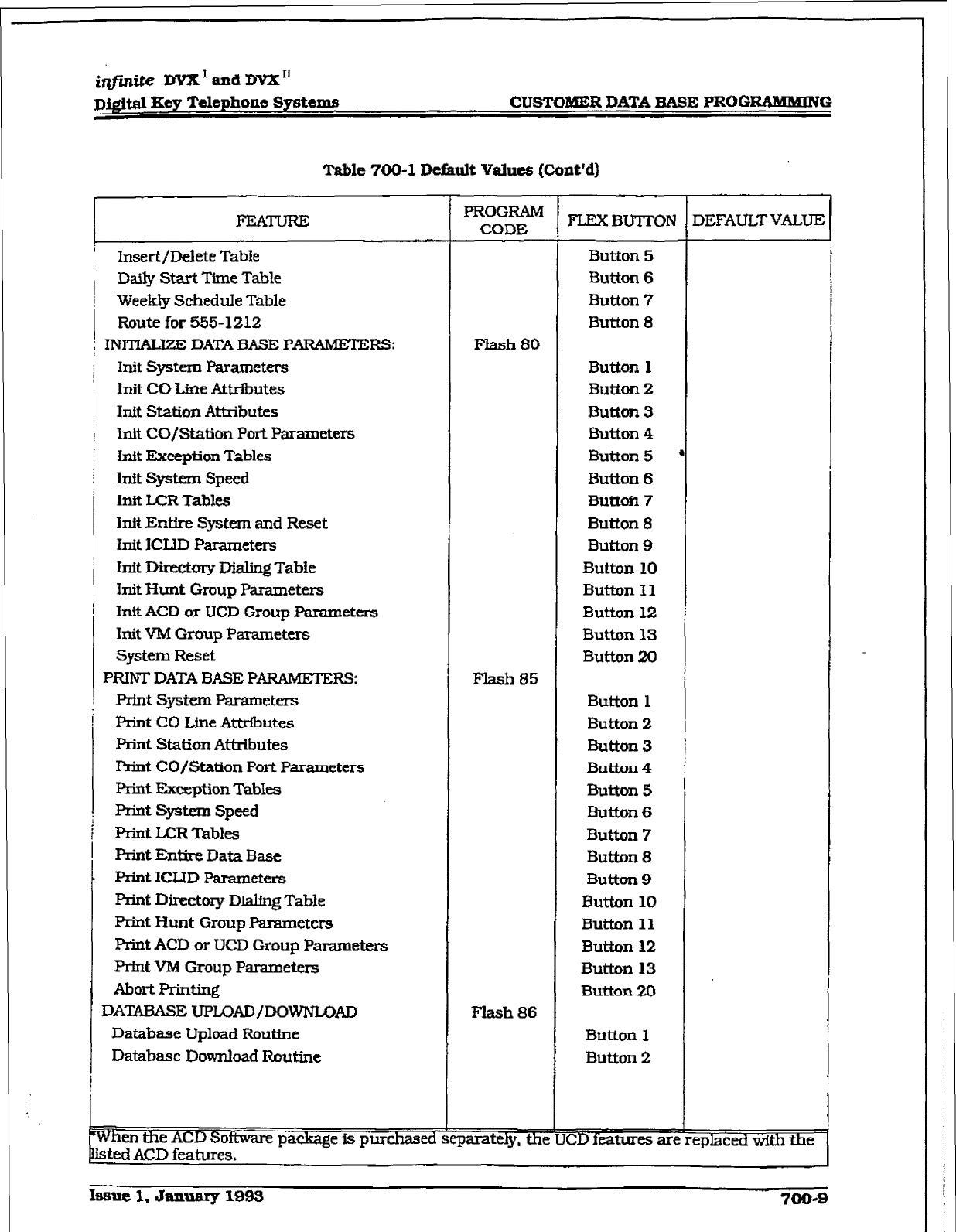
r
irlfinite DVX’ and
DVX’
D@ital Key Telephone Systems
CUSTOMER DATA BASE F’ROGRAlHMlNG
Takrle 700-l Default Values (Cont’d)
FEATURE
Insert/Delete TabIe
Daily Start Time Table
Week@ Schedule Table
Route for 555-1212
; INBMLJZE DATA BASE PARAMETERS:
hit system Parameters
hit CO Line Attributes
Inft
Station
Atkibutes
Init
CO/Station
Port Parameters
Itit Exception Tables
Init System Speed
Inft I.ZR Tables
hit Entire System and Reset
Init ICIID Parameters
Inft Directory Dfaling Tabfe
h-it Hunt Group Parameters
InitACD or UCD Group
Parameters
Init VM Group Parameters
System Reset
PRINT DATA BASE PARAMETERS:
print System Parameters
Print
CO Line Attributes
Fkint Station Athibutes
Print CO/Station Port
Parameters
Prkrt Exception TabI-
Print System Speed
F%int
U=R Tables
print Entire Data Base
Print ICLID Parametets
Print Directory D&hug Table
print Hunt Group Parameters
Print ACD or UCD Group Parameters
Print
VIM Group Parameters
AhcrtI%rlting
DATME 7JPLOAD/DGWNLGAD
Database Upload Routine
Database Download Routine
Nfien the ACD Software package is purchased I
PROGRAM
CODE
Flash 80
Button 1
Button 2
Button 3
Button 4
Button 5
Button 6
Button 7
Button 8
Button 9
Button 10
Button I1
Button 12
Button 13
Button 20
FIash 85
Button
1
Bution 2
Button 3
Button 4
Button 5
Button 6
Button 7
Button 8
Button 9
Button 10
Button 11
Button 12
Button 13
Button 20
Flash 86
Button 1
Button 2
parateiy, the [CD features are
FLEXBUTTON
Button 5
Button 6
Button 7
Button 8
1
f
DEF*uLrTVALuE (
zplaced with the
sted ACD features.
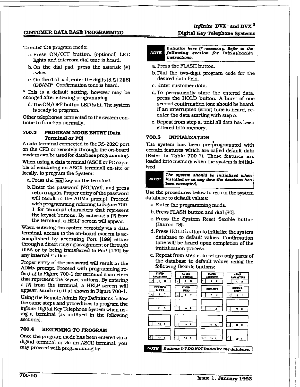
irtfinite DVX I and DV’X I1
CUSTOMER DATA BASE PROGRhMlKING
D&Sal Key Telephone
systems
TO enter the program mode:
a. Press ON/OFF button. (optional) LED
lights and intercom dial tone is heard.
b. On the dial pad, press the asterisk (*I
twice.
C.
On the dial pad. enter the digits
I3lI21[2lISI
(DBAMJ’. Confh-rnation tone is heard.
l
‘This is a default setting, however may be
changed after entering programming.
d. The ON/OFF button LED is lit. The system
is ready to program.
Other telephones connected to the system con-
tinue to function normally.
700.3 PROGRAM MODE ENTRY
(Data
Terminal or PC)
A data terminal connected to the RS-232C port
on the CPB or remotely through the on-board
modem can be used for databaseprogrammiq.
When using a data terminal (ASCU or PC capa-
ble of emulating an ASCII ted) on-site or
locally, to program the System:
aPress them keyonthe terminal.
b.Enter the password (VODAVI], and press
return again. Proper entry of the password
will result in the ADM> prompt. Proceed
with programming referring to Figure 700-
1 for terminal characters that represent
the keyset buttons. By entering a [?I from
the terminal, a HELP screen wili appear.
When entermg the system remotely via a data
terminal. access to the on-board modem is ac-
complished by accessing Port [ 1991 either
through a dfrect ringing assignment or through
DISA or by being transferred to
Port [ 1991 by
anyintemdstation.
Proper entry of the password will result in the
AD& prompt. Proceed with programmin re
ferring to Figure 700-l for terminal cha$&
that represent the keyset buttons. By entering
a I?) from the terminal, a HELP screen will
appear, similar to that shown in Figure 700- 1.
Using the Remote Admix-~ Key DeCniffons follow
the same steps and procedures to program the
rnjinite Digital Key Telephone System when us-
ing a terminal (as outlined in the following
sections).
700.4 BEGINNING TO FROGti
Ck~ce tie program mode has been entered via a
dQW knnina~ or via an ASCII terminal, you
=Y proceed with programming by:
hdtialte hen? # -Qlmr.R&rtothei
foliomtng
ucction
for inittalitatidn ;
a. Press the FLASH button.
b.Dial the two-digit program code for the
desired data field.
c. Enter customer data.
d.To permanently store the entered data,
press the HOLD button. A burst of one
second confirmation tone should he heard.
If an interrupted (error] tone is heard. re-
enter the data starting with step a.
e. Repeat from step a. until all data has been
entered into memory.
700.5 VmON
The system has been pre-$rogrammed with
certain features which are called default data
(Refer to Table 7OP1). These features are
loaded into memory when the system is initial-
ized.
ill6tuiledorataitcrnytime.#l6datalmu6hus
bell &xmuped. 1
Use the procedures below to return the system
database to default values:
a. Enter the pq$amming made.
b. Press FLASH button and dial ISO].
c. Press the System Reset flexible button
(Button #8).
d. Press HOLD button to initiahze the system
database to default values. Con&nation
tone will be heard upon completion of the
initializat.ion process.
e. Repeat from step c. to return only parts of
the database to default values using the
following fJe.xiile buttons:
m
‘r-7
mrul
El mmulu
” 8 E
unTamE5
El
-. T ”
700-10
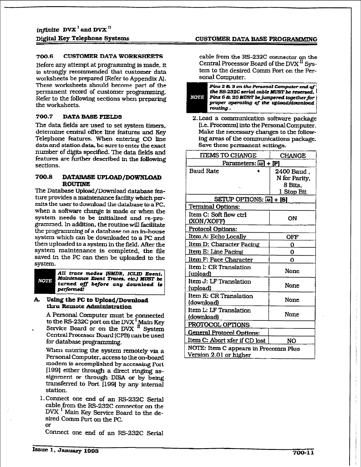
infinite DVX ’ and DVX ’
digital Ety Telephone Systems CUSTOMER DATA EkASE PROG-G
700.6
CUSTOMER DATA WORKSBEETS
Before any attempt at progmmming
is
made. it
is strongly recommended that
customer
data
worksheets be prepared (Refer to Appendix A).
These worksheets should become part of the
permanent record of customer progmmming.
Refer to the following sections when preparing
the worksheets.
700.7 DATA BASE FIELDS
The data fields are used to set system timers,
determine central office line features and Key
Telephone
features. When
entering CO line
data and station data. be sure to enter the exact
number of digits spe&ed. The data fields and
features
are further described in the
folk&q
sections.
700.8 DATABASE UFLUAD/DOWNLCMD
ROUTINE
The Database Upload/Download database fez+
ture provides a maintenance facility which per-
mits the user to download the database to a PC,
when a software change is made or when the
system needs to be Mtialized
and
re-pro-
grammed. In addition, the routine w-ill facilitate
the prog :,rg of a database on au in-house
system which can be downloaded to
a PC
and
then uploaded to
a system in the
field. After the
system maintenance is completed. the Ble
saved in the PC can then be uploaded to the
system.
mmi
A
Using the PC to ‘trpload/Download
thru Rtmote
Adlhli6trdi0n
A Personal Computer must be connected
totheRS-232CportontheDVX’MainKey
* Sewice Board or on the DVX ’ System
Centi Processor Board (CPB) can be used
for database
pragrammkg.
When entering the system remotely via a
Personal Computer. access to the on-board
modem is accomplished by accessing Port
I1991 either through a direct ringing as-
signment or through DISA or by being
transferred to Port 11991 by any internal
station.
1. Connect one end of an RS-232C Serial
dAe from the RS-232C connector on the
DVX I Main Key Service Board to the de-
sk-d Comm Port on the PC.
~n.nect one end of an RS-232C Serial
cable from the RS-232C connector on the
Central Processor Board of the DVX’” Sys-
tem to the desired Comm Port on the Per-
sonal Computer.
2.Load
a communication software package
(i.e. Procomm) into the Personal Computer.
Make the necessary changes to the follow-
ing artas of the communications package.
Save these permanent settings.
lTFMSTOCHANCE 1 CHANGE i
Parameters: /iJ *
Item D: Character Pa&r@ 0
Item E: Line Pa&g ! 0
lsaue 1, Jzuluary 1993 700-11
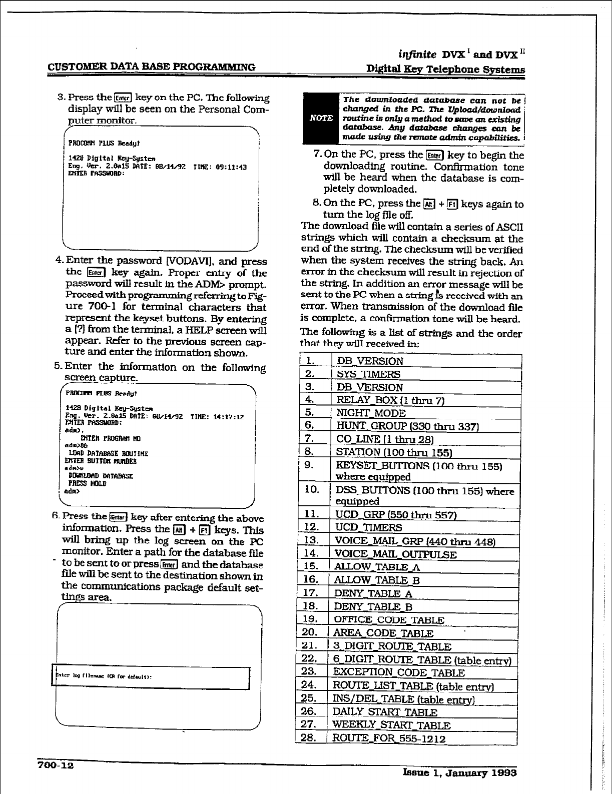
r
CUSTOMER DATA BASE l’R0GRAMXING iqfinite DVX’andDVx”
Wital Key Telephone Systems
3. Press the iEmwl key on the PC. The followhxg
display will be seen on the Personal Com-
puter monitor.
/
PMW PUSReady
,
1428 Digftnl Key-System
Eng. Ucr. 2.8alS MTE: BBAJAZ IIIIE: 89:11:43
Mmi pr3ssuonD:
\
4. Enter the password [VODAVIJ, and press
the m key again. Proper entry of the
password wiIl result in the ADM> prompt.
Proceedwitbprogmmmingzf&ingtoF@-
ure 7061 for terminal characters that
represent the keyset buttons. By entering
a (?I from the terminal, a HELP screen will
appear. Refer to the previous screen cap-
ture
and enter the
information shown.
S-Enter the information on the foIlowing
StlreenCapture.
/ PRDam PLUS rkndy? .
iuB DigItal Key-Sgsta
Erg. Ikr. z.eaf5 DME: e8/14/92 TIME: 1*:17:12
MtER FSSJORD:
6. Press the&J key after entering the above
information. Press the a + m keys. This
wiII bring up the log screen on the PC
monitor. Enter a path for the database fl.le
* to be sent to or press m and the database
file wiIl be sent to the destination shown in
the communications package default set-
7. On the PC, press the m key to begin the
downloading routine. Con&nation tone
will be heard when the database is com-
pletely downloaded.
B.OnthePC,pressthe~+~keysagainto
turn the log fde off.
The download ftie will contain a series of ASCII
strings which will contain a checksum at the
end of the string. The checksum will be verified
when the system receives the string back. An
error in the checksum will result in rejection of
the string. In addition an error message will be
sent to the PC when a sMng fs received with an
error. When transmission of the download file
is complete, a confumation tone will be heard.
The following is a list of strings and the order
that they wilI received in:
700-12
hue 1. January 1893
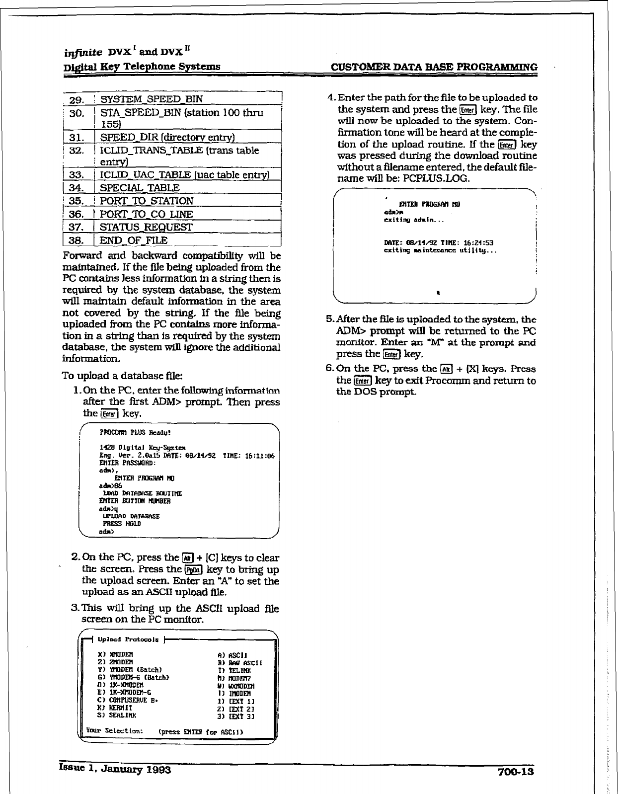
iqfinite DVX’andDVX”
DIgital Eey Telephone Sy~tCrn~ CUSTOIHD~ DATA BASE PROG-G
29. I SYSTEM SPEED BIN 1
;
30.
1 STA-SPEED-BIN (station 100 thru ’
I
I 155)
1 31. 1 SPEED-DIR (directory entrv)
i 32.
1 ICLID_TRANS_TABLE (trans table 1
1 r entrv)
I 33.
i ICLID 7JAC TABLE (uac table entrY)
134. i SPECIAL TABLE
I 35.
i PORT TO STATION
i 36. t POKF l-0 co LINE
i 37.
1 STATUS FUZQUEST
38.
1 END~OFJ’ILE
Forward and backward compatibility will be
maintamed, If the fiIe being uploaded from the
PC contains less information in a string then is
required by the system database, the system
will maintah default information in the area
not covered by the string If the file being
uploaded from the PC contains more informa-
tion in a sW.ng than Is required by the system
database, the system will ignore the additional
information.
To upload a database file:
1. On the PC, enter the fallowing information
after the fbst ADM> rxompt. Then press
f PtEmnll PLllS Ready?
I
I
14zB Digital lky-*ta
Eng. ucr. 2.ealS mm: 88/14&z IIil!c 16:if:Bt
MIEA PRssyofID:
1
i
1
2.
On the PC. press the m + [C 1 keys to clear
the screen, Press the &iiJ key to bring up
the upload screen. Enter an “A” to set the
upload as an ASCII upload Ale.
3.This will bring up the ASCII upload file
screen on the PC monitor.
+ Upload Pmtaols )-
4. Enter the path for the Ale to be uploaded to
the system and press the m key. The file
will now be uploaded to the system. Con-
firmation tone will be beard at the comple-
tion of the upload routine. If the g key
was pressed during the download routine
without a fIlename entered, the default file-
name wiIl be: PCPLWX,OG.
/ , \.
MmlPRDGAfY(tlD
admhl
exiting rdmin. *. t
DfI'lZ: oB/1%CtZ TIRE: 16:24:53 !
uttiag WiintcMn uttlr~. . . I
I
. I
S-After the Ale is uploaded to the system, the
ADIbb prompt wiIl be returned to the PC
monitor. Enter an ‘W at the prompt and
press the m key.
6-k
the PC, press the
q
+ [Xj keys. Press
the s key to exit Procomm and return to
the DOS prompt
Issue 1.
January 1983
700-13
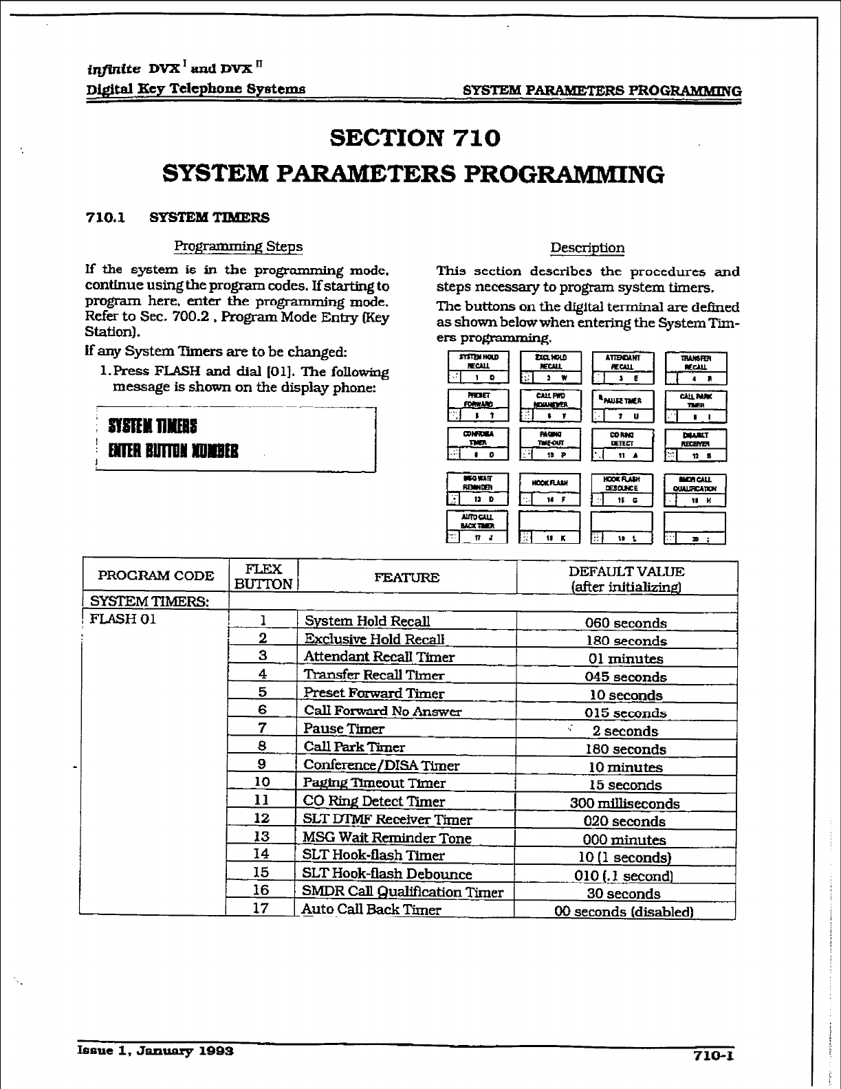
r
&jWfe DVX’andDVXn
Di@.a.l Key Telephone
Systems
SYSTEM PARABEXERS PRCIGRABBMING
SECTION 710
SYSTEM PARAME TERS PROGRAMMING
Profgamdng steps
Description
If the system is in the programming mode,
continue using the program codes. Ifstarting to
program here,
enter
the programming mode.
Refer to Sec. 700.2 , Fk-ogram Mode Entry (Key
Station).
If any System Tpmers are to be changed:
l.I?t-ess FLASH and dial [Ol]. The following
message is shown on tie display phone:
This section describes the procedures and
steps necessary to program system timers.
The buttons on the digital terminal are defined
as shown below when entering the System Tim-
ers progmmmirq.
DEFAULT VALUE
.UIYY.& “VYY BUN 1 r-1 “Jsn (after ix-lltializinp)
I SYSTEM TlMERS:
! FLASH 01 1
I System Hold Recall 060 seconds
2 Exclusive Hold Recall 180 seconds
16 I SMDR Call Qualification Timer 30 seconds
17 1 Auto CaIl Back Timer 00 seconds [disabled)
Issue 1. January
1993
710-l
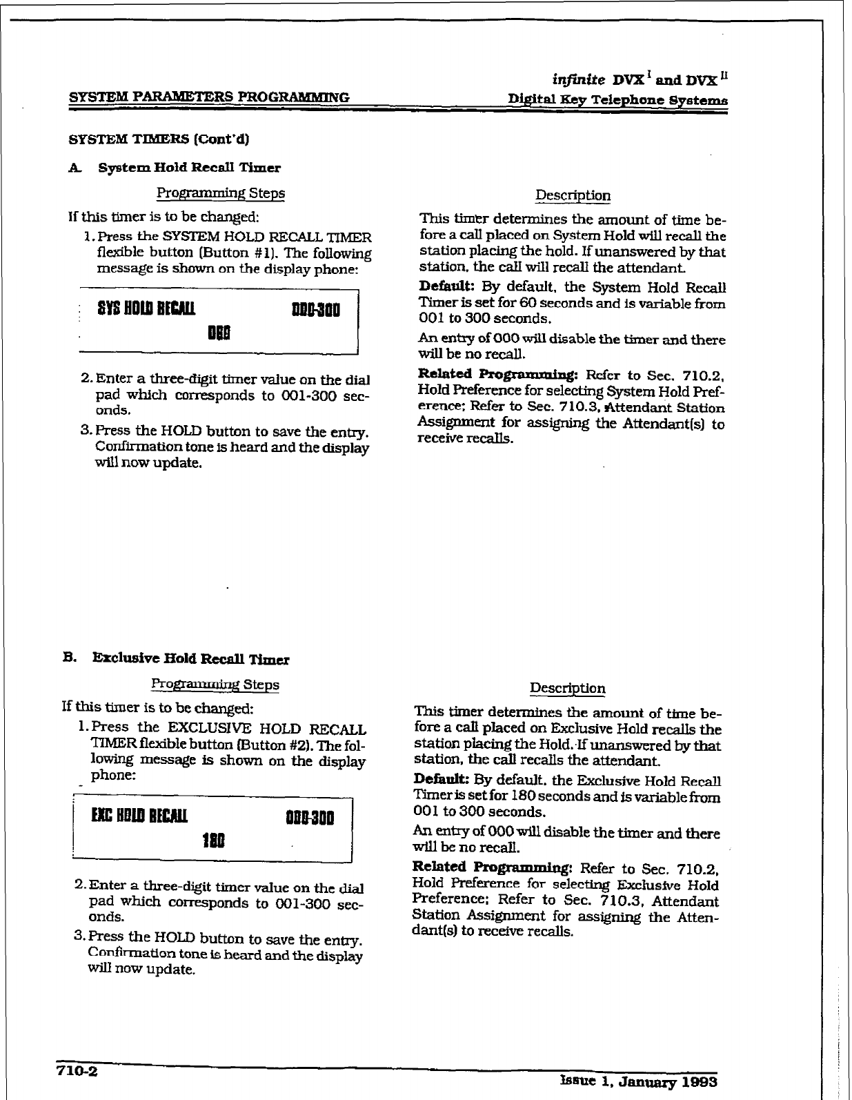
r
in@nite DVX’ and DVX u
D@itaI Key Telephone Systems
SYSTEM TIMERS (Cont’d)
A System Hold Recall Timer
RotTanning Steps
If this timer is to be changed:
1. Press the SYSI’EM HOLD RECALL TIMER
flexible button (Button #I). The following
message is shown on the display phone:
2. Enter a three-digit timer value on tile dial
pad which corresponds to 001-300 sec-
onds.
3. Press the HOLD button to save the entry.
Confirmation tone is heard and the display
will now update.
B. Erclusive Hold Recall Timer
ProgI ’ g steps
If this timer is to be changed:
1. Press the EXCLUSIVE HOLD RECALL
TIMER flexible button (Button #Z). The fol-
lowing message is shown on the display
phone:
2. Enter a three-digit timer value on the dial
pad which corresponds to 001-300 sec-
onds.
3.Press the HOLD button to save the entry.
Confirmation tone is heard and the display
W now update.
Description
This timtzr determines the amount of time be-
fore a call placed on System Hold wilJ recall the
station placrng the hold. If unanswered by that
station. the calI will recall the attendant..
Dcfaulk By default, the System Hold Recall
T’imer is set for 60 seconds and is variable from
001 to 300 seconds.
An entq of000 will disable the timer and there
willbenorecall.
Related Pro-: Refer to Sec. 710.2,
Hold Preference for selecting System Hold Pref-
erence; Refer to Sec. 710.3. Attendant Station
Assignment for assigning the Attendant(s) to
receive recalls.
Description
This timer d&e-es the amount of tfme be-
fore a catf placed on Ekclustve Hold retells the
station piacing the Hold:lfunanswered by that
station, the cd recalls the attendant.
DeEault: E3y default. the Exclusive Hold Recall
Time& setfor 180 seconds and is variable from
00 1 to 300 seconds.
An entry of 000 will disable the timer and there
Willben0X-C!C~.
Related
Progrnlnuniu~: Refer to Sec. 710.2,
Hold Preference for selecting Exclusive Hold
Preference: Refer to Sec. 710.3, Attendant
Station Assignment for assigning the Atten-
dant(s) to receive recalls.
710-Z Lmlt 1. Jan- 1993
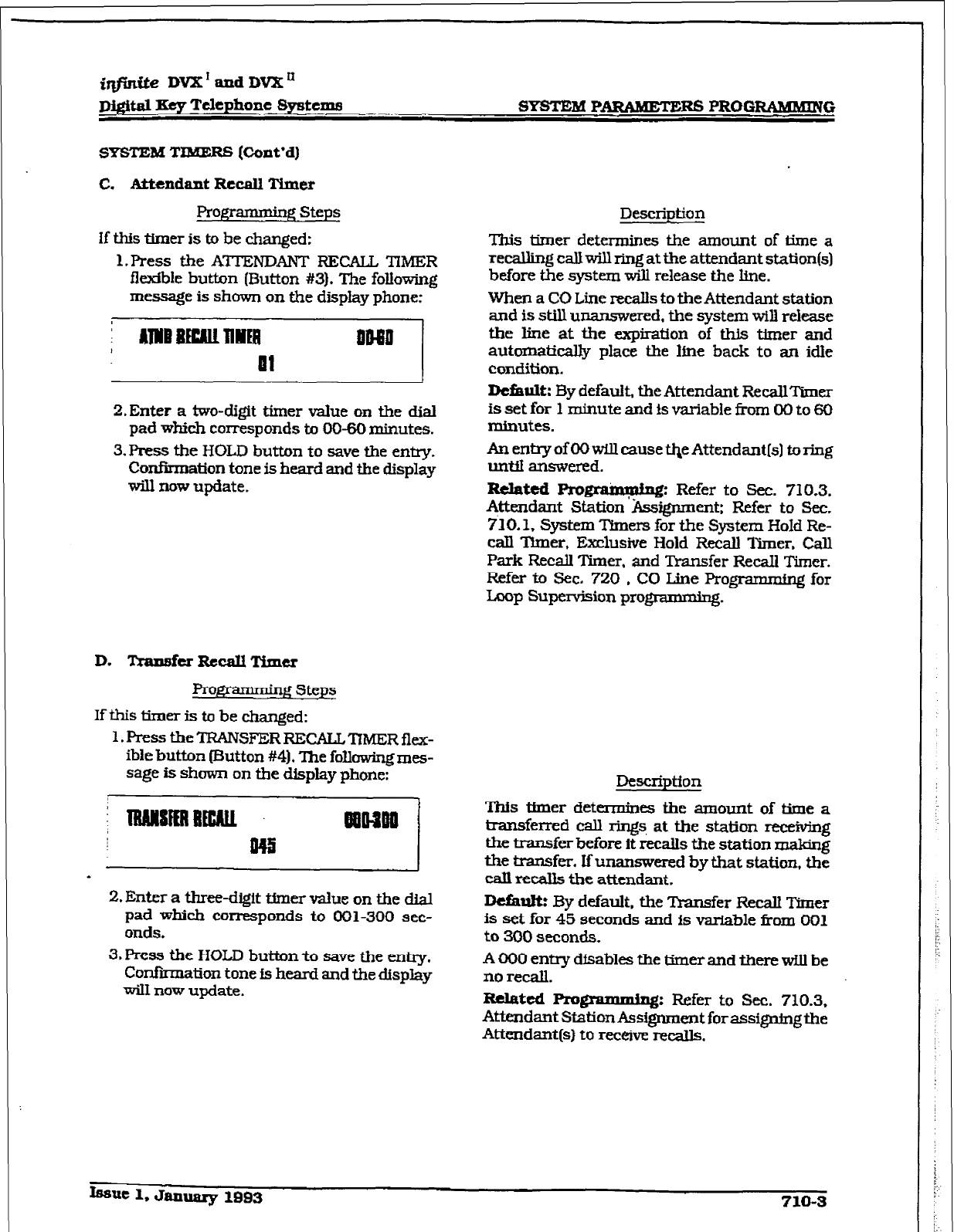
irifinrte VVX’andDVXn
mtal I.&y Telephone
Systems
SYSTEM PARAMEXERS PROGRAMMING
SYSTEM TIMERS [Cont’d)
C. Attendant Recall Timer
Progr-g steps Description
If tMs timer is to be changed:
I. Press the ATTENDANT RECALL TIMER
flexible button (But-ton #3). The following
message is
shown on the display phone:
This timer determines the amount of time a
recalling calJ will ring at the attendant station(s)
before the system will release the hne.
When a CO Line recalls to the Attendant station
andisstillu
mnswered. the
system will release
the line at the expfration of this timer and
automatically place the ltne back to an
idle
CondSon.
i AlWB BEW IllrlEB inaB
Ill
2.Enter a two-digit timer value on the dial
pad which corresponds to 00-60 minutes.
3. Press the HOLD button to save the entry.
Confirmation tone is heard and the display
will now update.
D. lkansfcrRccaUTiu~cr
Prow steps
If this timer is to be changed:
1.FresstbeTFUNSFERRECALL’ITMERflex-
ibfe button (Button #4). The
following mes-
sage is shown on the display
phone:
2. Enter
a
three-dgit tfmer value on the dial
pad which corresponds to 001500 sec-
onds.
3. Press the HOLD button to save the entry.
Conf.&mation tone is heard and the d&play
wiII now update.
Defiault:
By default, the Attendant RecallTimer
is
set
for 1
minute
and is
variable from 00 to 60
minutes.
An entry of 00 will cause qe AttendantIs) to ring
unti answered.
R&ted Prow Refer to Sec. 710.3.
Attendant Station’A&gn.ment: Refer to Sec.
710.1. System ‘Ihers for the System Hold Re-
call
Timer,
Exclusfve Hold Recall Timer. Call
Park Recall Timer. and Transfer Recall Timer.
Refer to Sec. 720 , CO I&e Programming for
Loop Supervision progmmming.
Description
This thner determines the amount of time a
transferred call rings, at the station reteWing
the transfer before it recalls the station making
the transfer. If
unanswered by that station, the
call recalls the attendant.
Default: By default, the Transfer Recall Timer
is set for 45 seconds and is v-a&Me f?om 001
to 300 seconds.
A 000 entry dfsables the timer and there will
be
no recall.
Related
Pmgnunmhg: Refer to Sec. 710.3,
Attendant Station Assfgnmcnt forassignmgthe
Attendant(s) to receive recalls.
Issue 1. January 1993 710-3
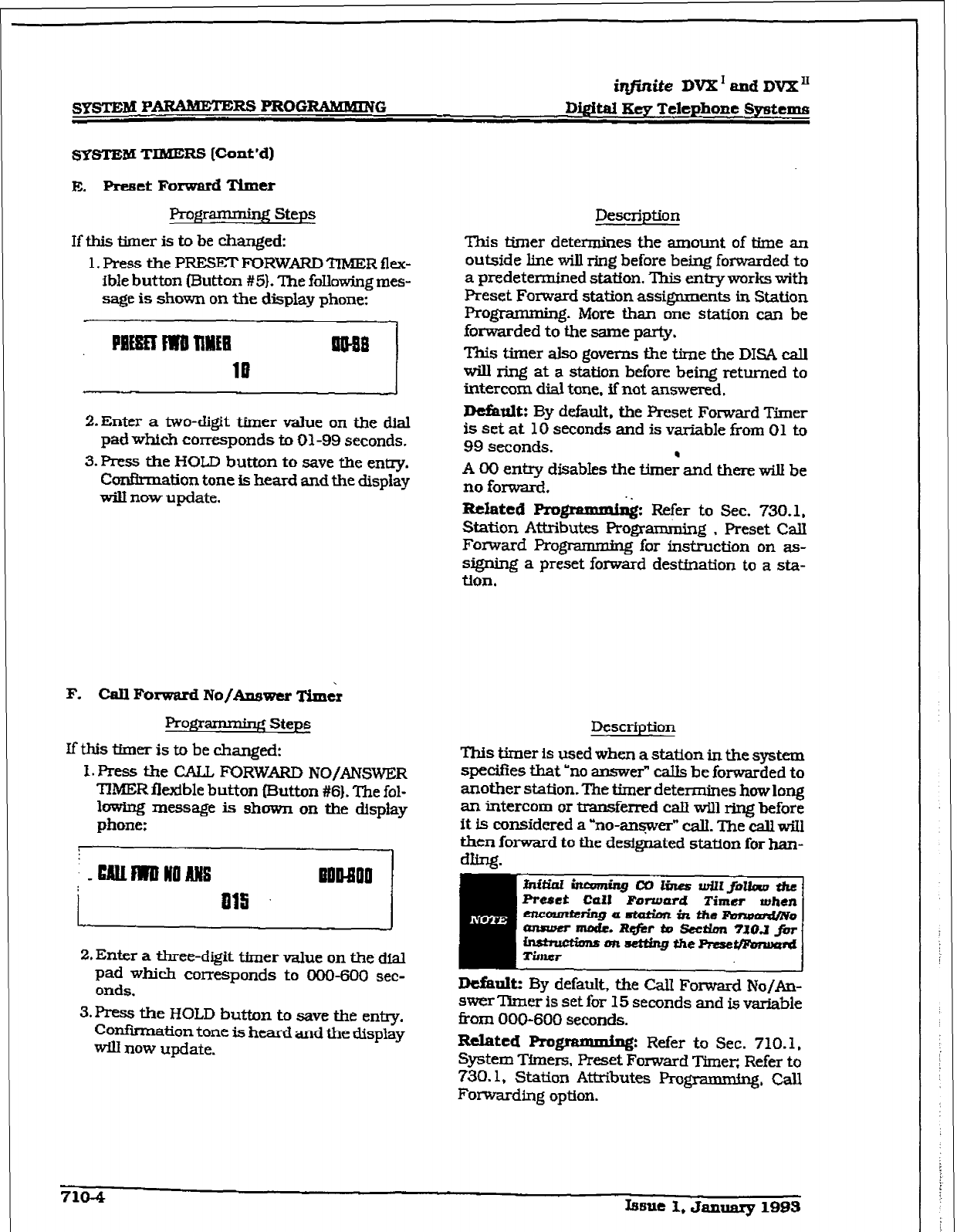
sYSTEM PARMW=E= PROGRAMMiNG
iqftnite DVX’
and
DVX’I:
lM@al Key Telephone Spstcxns
SYSTEM TIMERS [tint ‘dl
E. Preset Forward Timer
Programming Steps
Description
If this timer is to be changed:
1. Press the PRESET FORWARD TIMER flex-
ible button (Button #5}. The following mes-
sage is shown on the
display
phone:
This timer determines the amount of time an
outside line will ring before being forwarded to
a predetermined station. This entry works with
Preset Forward
station
assignments in Station
programming. More than one station can be
forwarded to the same party.
This timer also govms the time the DISA call
will ring at a station before being returned to
intercom dial tone, if nat answered.
DcGult: By default. the Preset Forward Timer
is set at 10 seconds and is
variable
from 01 to
99 seconds.
2.Enter
a two-digit
timer
value
on the dial
pad which corresponds to 01-99 seconds.
3.
Press the HOD button to save the entzy.
Ccmkmation tone is heard and the display
wilt now update.
F. Cdl Forward
No/Answer Timtr
Progmmming Steps
If this tber is to be changed:
1. Press the CALL FORWARD
NO/ANSWER
TlMER flexible
button Button #6). The fol-
IowSng xnessage is shown on the display
phone:
-
2. Enter a three-digit
timer
value
on the
dial
pad which corresponds to 000-600 sec-
onds.
3. Press the HOLD button to save the e&y.
Confirmation tone is
heard and the
display
will now
update.
A 00 entry disabks the time; and there will be
no
forward.
XM.atcd Pro grr&
Refer to Sec. 730.1,
Station Attributes Program&ng , Preset CalI
Forward Progwnming for instruction on as-
signing a preset forward destfnation to a sta-
tion.
Description
This timer is used when a statton in the system
specifies that “no answer” caUs be forwarded to
another station. The timer determines how long
an intercom or
transferred caU will ring
before
it
is considered a “no-ansprer” calI. The call w5II
then
forward
to the designated station
for han-
Default:
By default, the CaU Forward No/An-
swer Tpmer is set
for 15
seconds and is variable
ii-om 000-600 seconds.
Related Prog.mmmi+:
Refer to Sec. 710.1,
System Timers, Preset Forward Timer; Refer to
730.1, Station Attributes Fkgmmming, Call
Forwarding option.
710-4 issue 1, January 1993
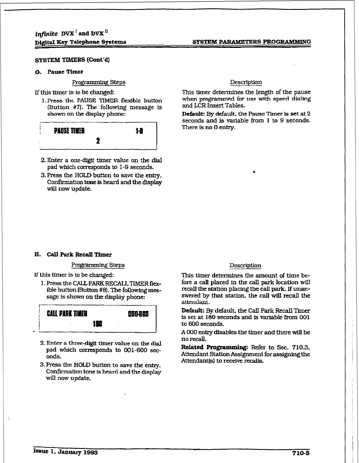
SYsTEM PARAMETERS PROG-G
SYSTEM
TIMERS (cont’d)
Programming Steps
lfthis timer is to be changed:
1 *Press the PAUSE TiMER flexible button
(3utton #I?). The following message is
shown on the display phone:
2.Enter a one-c&it i&ner value on the dM
pad which corresponds to 1-9 seconds.
3.Press the HOLD button to save the entry.
Confirmation tone is heard and the &splay
will now update.
prog;ramminFi Steps
If this timer is to be changed:
l.PresstheCAU.PARKRECALLTIMERfl~-
ible button (EMton #8). The following mes-
sage is shown on the display @one:
2. Enter a three-digit tfmer value on the dial
pad which corresponds to 001-600 sec-
onds.
3. Press the HOLD button to save the entry.
Confirmation tone Is heard and the display
will now update.
Description
This timer determines the length of the pause
when programmed for use with speed dialing
and LCR Insert Tables.
Default:
By default. the Pause Timer is set at 2
seconds and is variable from 1 to 9 seconds.
There is no 0 entry.
Description
This timer determines the amount of time be-
fore a call placed in the CalI park location wiIl
recall the station placing the call park. lfunan-
swered by that statfon. the call wiu recall the
attendant.
DefbIt: By defauk @e Call Park Recall Timer
is set at 180 seconds and fs variable from 001
to 600 seconds.
A 000 entry dfsables the timer and there ti be
no recall.
RelRted
Progmlmmhg: Refer to Sec. 710.3,
Attendant Station Assignment for assigningthe
Attendant(s) to receive recall&
Iwme I, Jammy 1993
710-5
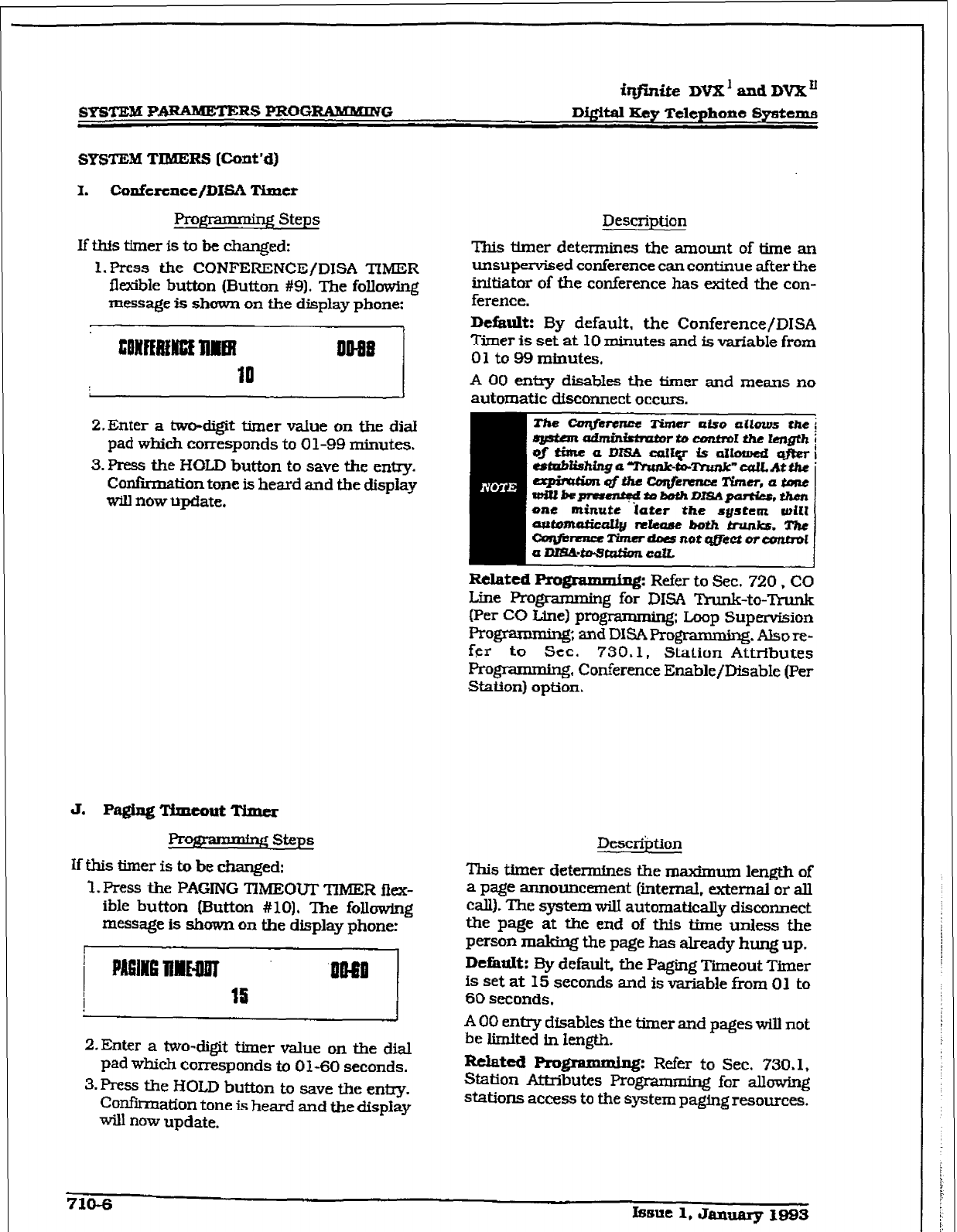
r
SYSTEM PARAMETERS PROGRtXMMRVG
i?finite DVX’ and DVX”
Digital Key Telephone Systems
Prow Steps Description
If this tier is to be changed: This tuner determines the amount of time an
l.Press the CONFERENCE/DISA TIMER unsupervised conference can continue after the
flexible button (Button #9). The following initiator of the conference has &ted the con-
message is shown on the display phone: ference.
J
2.Enter a two-digit timer value on the dial
pad which corresponds to 0 l-99 minutes.
3. Press the HOLD button to save the entry.
Confiition
tone is heard and the display
wiu now Update.
J. Pa&lag’IYxucoutTime~
prolzrammtng steps
If this timer is to be changed:
1. Press the PAGING TIMEOUT TIMER flex-
ible button (Button # 101. The following
message is shown on the display phone:
2,Enter a two-digit timer value on the dial
pad which corresponds to 01-60 seconds.
3. Press the HOLD button to save the entry.
Confirmation tone is heard and the display
will now update.
Default: By default. the Conference/DISA
Timer is set at 10 minutes and is variable from
01 to 99 minutes,
A 00 entxy disables the timer and means no
automatic disconnect occurs.
WiUkprertntbdtDbtdlDISAptlM?S,t?l8Yl
one
minute 'iater
the system dZ1
wltomaiie~~ nluwe both trunks. The
ctn@mlwTimerdDwn0tqgi?ctor-1
Related
Pr0g-J:
Refer to Sec. 720, CO
Line Programming for DISA Trunk-to-Trunk
IPer CO tine) programming; Loop Supervision
Programming; andDISAProgmmn&g.AIsore-
fer to Sec. 730.1, Station Attributes
Progmmming. Conference Enable/Disable (Per
Station) option.
DescriPtion
This timer determines the maxknum length of
a page announcement (internal. external or all
call). The system wil.I automatically disconnect
the page at the end of this time unless the
person making the page has already hung up.
DefaaIt: By default, the Paging Timeout Timer
is set at 15 seconds and is variable from 01 to
60 seconds,
A 00 entry disables the timer and pages will not
be limited in length.
Related
Rogrrg: Refer to Sec. 730.1.
Station Attributes F’rogmmmtng for allow&
stations access to the system paging resources.
710-6 Issue 1, Jalluary 199s
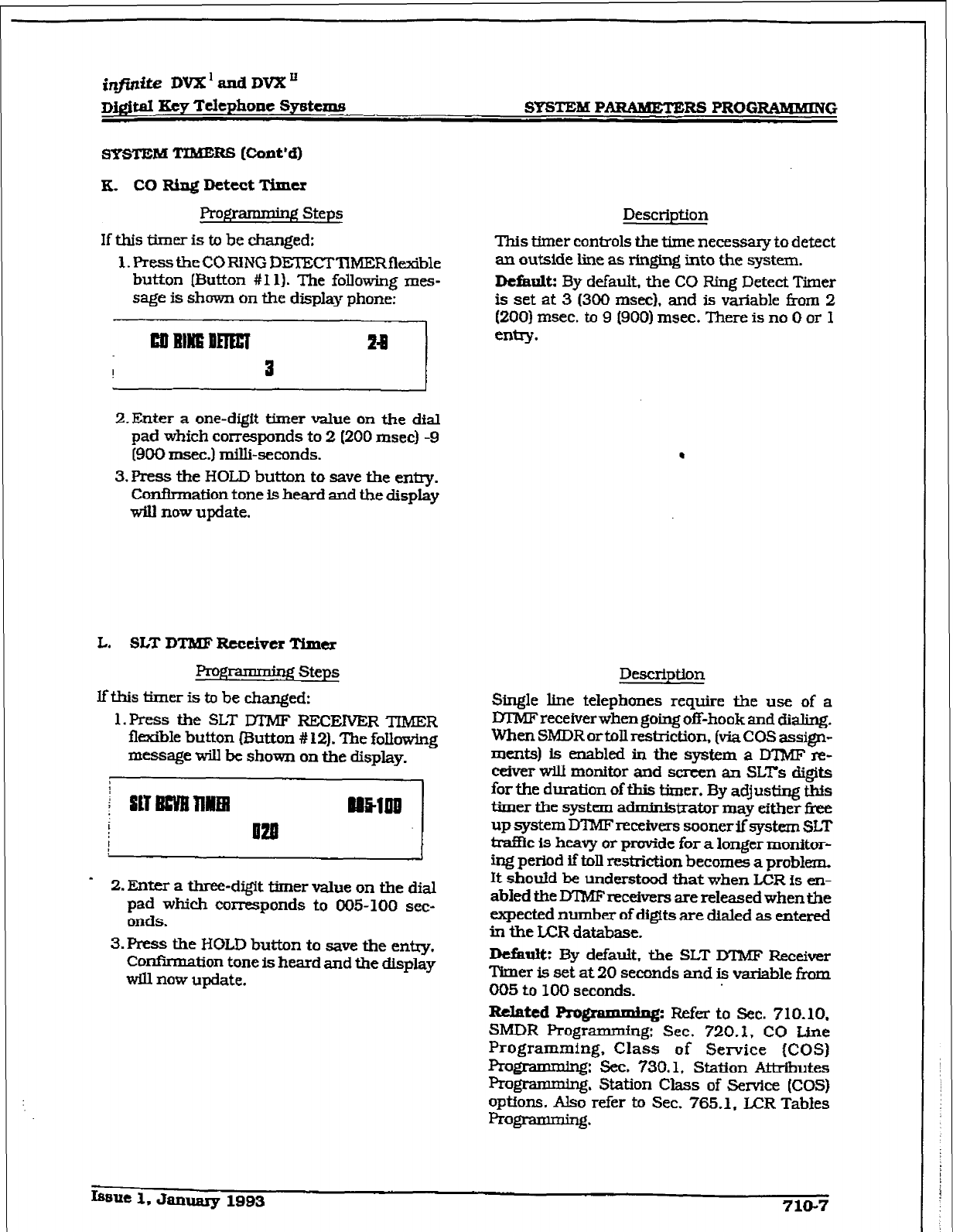
infinite DVX’andDVX”
m&al Eey Telephone Systems SYSTE&I PDRS PROGRAMBUING
SYSTEM TIMERS Eont*a
a- CO Ring Detect Timu
Pro- steps
If this timer is to be changed:
1. Press the CORING DEI’ECTlWIERflexible
button (Button #I 11. The following mes-
sage is shown on the display phone:
2.Enter a one-digit timer value on the dial
pad which corr-ponds to 2 (200 msec) -9
(900 msec.) mill&seconds.
3.
Press the HOLD button to save the entry.
Confirmation tone is heard and the display
will now update.
L. SLT DTMF Receiver Timex
Prog- Steps
lf this timer is to be changed:
l.FYess the SLIT M’MF RJ3CENER TIMER
fludble button (3utton # 12). The following
message will be shown on the display.
2.
Enter a three-dig%
timer
value on the dial
pad which corresponds to 005-100 sec-
onds.
3. Tess the HOLD button to save the entry.
Confirmation tone is heard and the display
will now update.
Description
This timer controls the time necessary to detect
an outside line as ringing into the system.
Default By default, the CO Ring Detect Timer
is set at 3 (300 msec), and is variable &om 2
(200)
msec. to 9 (900) msec. There is no 0 or 1
entry.
.
Description
Single line telephones require the use of a
lYI?vlF receiverwhen going of&hook and dialing.
When SMDR or toll restiction. (via COS assign-
ments) is enabled in the system a D’IMF re-
ceiver will monitor and screen an SLITS digits
for the duration of this timer. By adjusting this
timer the system administrator may either i&e
up system DTMF receivers sooner if system SLT
trafnc is heavy or provide for a longer monitor-
ing period if toll restriction becomes a problem.
It should be understood that when LCR is en-
abled the D’lMFreceivers are released when the
expected number of digits are dialed as entered
in the LCR database.
DeiiuW By default, the SLT DTMF Receiver
T’imer is set at 20 seconds and is variable from
005
to 100 seconds.
Related Programming: Refer to Sec. 710.10.
SMDR Programming: Sec. 720.1, CO Line
Programming, Class of Service (COSI
RogTammhg: Sec. 730.1, Station Attributes
Pro-. Station Class of Service (COS)
options. Also refer to Sec. 765.1. UZR Tables
programming.
Iaeue 1. January
1993 710-7
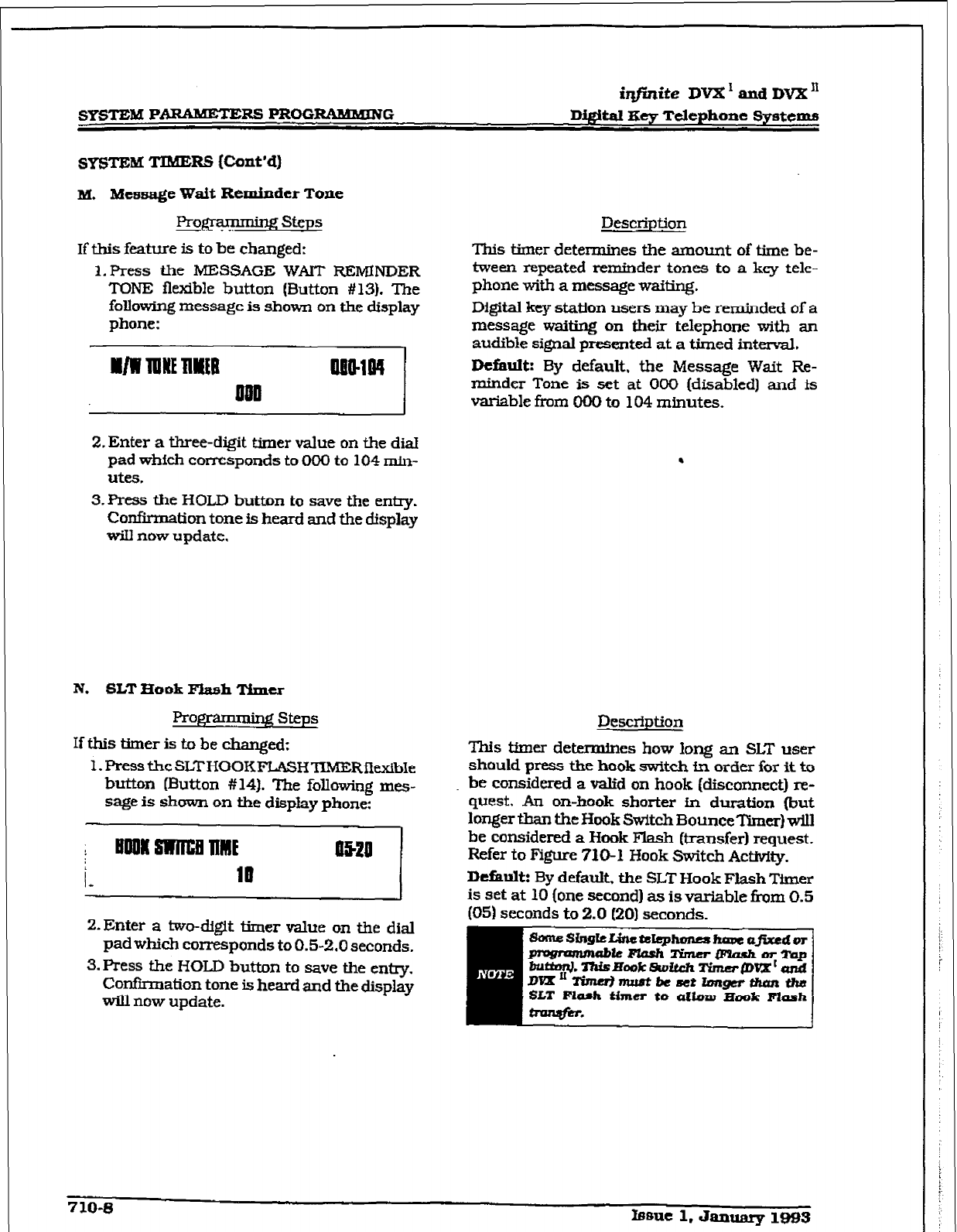
r
iqfhite
DVX ’ and DVX’
SYSTEM PDRS PROGRAMMING Digital Key Telephone Systems
M. Message Wait Reminder Tone
Prow steps
If this feature is to be changed:
l.Press the MESSAGE WAIT REMINDER
TONE flexible button (Button #13). The
foltowing message is shown on the display
phone:
Description
This timer determines the amount of time be-
tween repeated reminder tones to a key tele-
phone with a message waiting.
Digital key station users may be reminded of a
message waiting on their telephone with an
audible signal presented at a timed interval.
Default: By default, the Message Wait Re-
minder Tone is set at 000 [disabled] and is
variable from 000 to 104 minutes.
2. Enter a three-digit timer value on the diaI
pad which corresponds to 000 to 104 min-
utcs.
3.FYess the HOLD button to save the entry.
Confirmation tone is heard and the display
will now update.
N. SLT Book Pktsh Timer
FYognuImrg steps
If this timer is to be changed:
1.PresstheSLTHGOKFTIMERflwdbIe
button (Button #14). The following mes-
sage is shown on the display phone:
2.Enter a two-digit timer value on the dial
pad which corresponds to 0.5-2.0 seconds.
S.I?ress the HOLD button to save the entry.
Con&x-nation tone is heard and the display
will now update.
.
Description
This timer determines how long an SLT user
should press the hook switch fn order for it to
be considered a valid on hook @&connect) re-
quest. An on-book shorter in duration (but
longer than the &ok Switch BounceTimer) will
be considered a Hook Flash &ransferl request.
Refer to Figure 710-l Hook Switch Activity.
Default: By default, the SLT Hook Flash Timer
is set at 10 (one second) as is variable from 0.5
(05) seconds to 2.0 I201 seconds.
710-s mnle 1. Januq? 1993
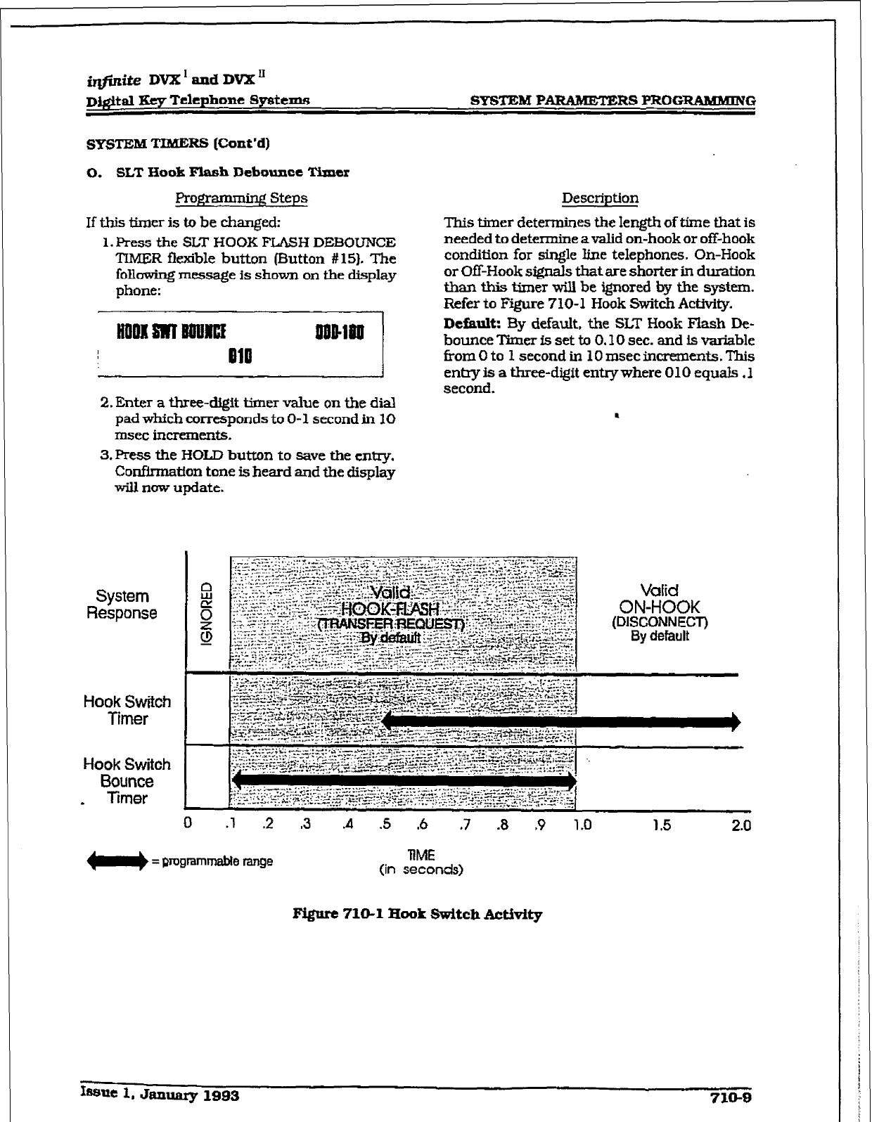
mite DVX’andDvX”
D&$&d I&y Telephone Systtxris
SYSTEM TIMERS [Cont’d)
0.
SLT
Hook
Flash
Debounee Timer
Programming Steps
If this timer is to be changed:
1. Press the SLT HOOK FLASH DEBOUNCE
TIMER fiexible button (Button #15). The
following message is shown on the display
phone:
Description
This timer determines the length of time that is
needed to deWmine a valid on-hook or off-hook
condition for single Iine telephones. On-Hook
or Off-Hook signals that are shorter in duration
than this timer will be ignored by the system.
Refer to Figure 710-l Hook Switch AC&Q.
Default: By default, the SLT Hook Flash De-
bounce ‘Kmer is set to 0.10 sec. and is variable
f?om 0 to 1 second in 10 msec increments. This
entry is a three-digit entry where 010 equals .1
second.
2. Enter a three-t&it timer value on the dial
pad which corresponds to O-l second ti 10
msec increments.
3. Press the HOLD button to save the entry.
ConfMnatfon tone is heard and the display
will nuw update.
1
System
Response
Hook Switch
Timer
Hook
Switch
Bounce
- Timer
-
0
.l 2 .3 A .5 .6 .7 .8 ,9 1.0 1.5 2.0
= programmable range
RME
(in seconds)
Vdid
ON-HOOK
(DISCONNECT)
By default
pigate 710-l Hook Switch Activity
ISaut
1. January 1993 710-8
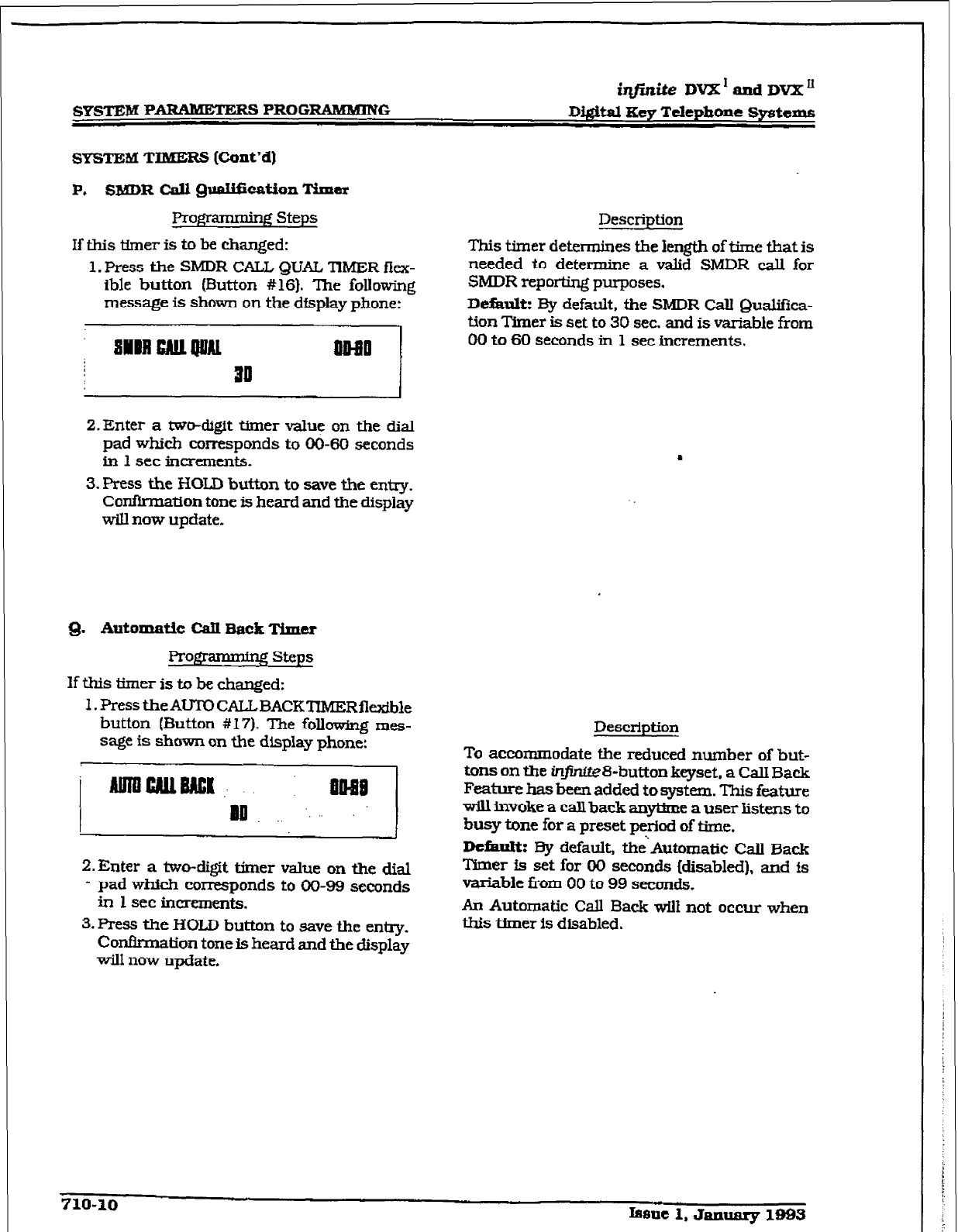
r
SYSTEM PARAlldETERs PROGRAMMING
iq#kite DVX’andDVX”
D&&al Key Telephone Systems
SYS’lZM TIMERS (Cont’d)
P. SMDR CalI 9118lIfication Timer
I?ro*amming Steps
If this tkner is to be changed:
1. Press the SMDR CALL QUAL T’IMER fkx-
ible button (Button #16). The folIowing
message is shown on the display phone:
Description
This timer determines the length of time that is
needed to determine a valid SMDR call for
SMDR reporting purposes.
DeEault: By default, the SMDR call Qualifica-
tion Timer is set to 30 sec. and is variable from
00 to 60
seconds in 1 set increments.
2.
Enter a tw&ligit timer value on the dial
pad which corresponds to 00-80 seconds
in 1 set increments.
3. press the HOLD button to save the entry.
Confirmation tone is heard and the display
will now update.
Q.
Automatic
Cdl Back Timer
ProFframming steps
If this timer is to be changed:
1. Press the AUTO CALLBACKTXMERflexible
button (Button #17). The following mes-
sage is shown on the display phone:
Z.Enter a two-digit timer value on the dial
- pad which corresponds to 00-99 seconds
in 1 set increments.
3. Press the HOLD button to save the entry.
Conflrrnation tone is heard and the display
will now update.
Description
To accommodate the reduced number of but-
tons on the infinfte8-button keyset. a CalI Back
Feature has been added to system. This feature
vdl invoke a call back anytime a user listens to
busy tone for a preset period of time.
Dcfhult: By default, i&Automatic Call Back
Tttner is set for 00 seconds (disabled), and is
variable from 00 to 99 seconds.
An Automatic Call Back WilI not occur when
this timer is disabled.
710-10
Issue 1. Jaxulaly 1993
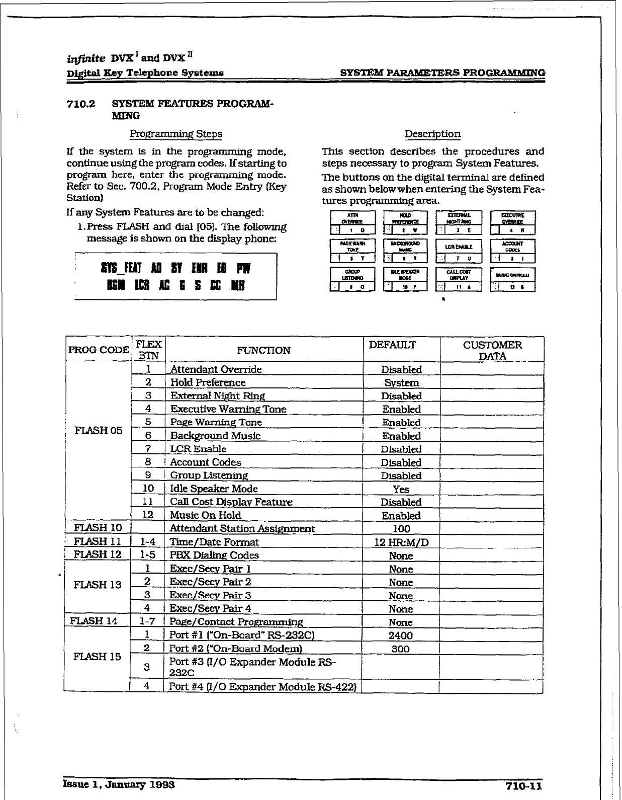
r
i@nite DVX’ aad DVX”
Digital Xey Telephone L3gstexr.u SYsmM P ARAMETERS PROG-G
710.2 SYSTEM FEiATURES PROGRAM-
MMG
Programming Steps
If the system is in the programming mode,
continue using the program codes. Lf starting to
prc@arn here, enter the programming mode.
Refer to Sec. 700.2, Program Mode Entry (Key
Station)
If any System Features are to be changed:
1.W FLASH and dial 1051. The following
message is shown on the display phone:
ST3JEAl All ST ENII Ed IW
Eli ml AC 3 3 33 ml
Description
This section describes the procedures and
steps necessary to program System Features.
The buttons on the digitaI terminal are defmed
as shown below when entering the System Fea-
tures pro@-amming area.
PROGCODE E FUNCi-ION DEFAULT CUSTCIMIER t
DATA
FLASH 14
1-7
1 Page/ Contact Programming None 1
1 I Port #1 (“On-Boa& RS-232C)
2400
2
1
300
FLASH 15 Port #2 (‘On-Board Modem)
I
3 I
Port #3 (I/O Expander Module RS-
232C
4
1 Port #4 II/O Expander Module RS-422) J
hue 1, January 1993 710-11
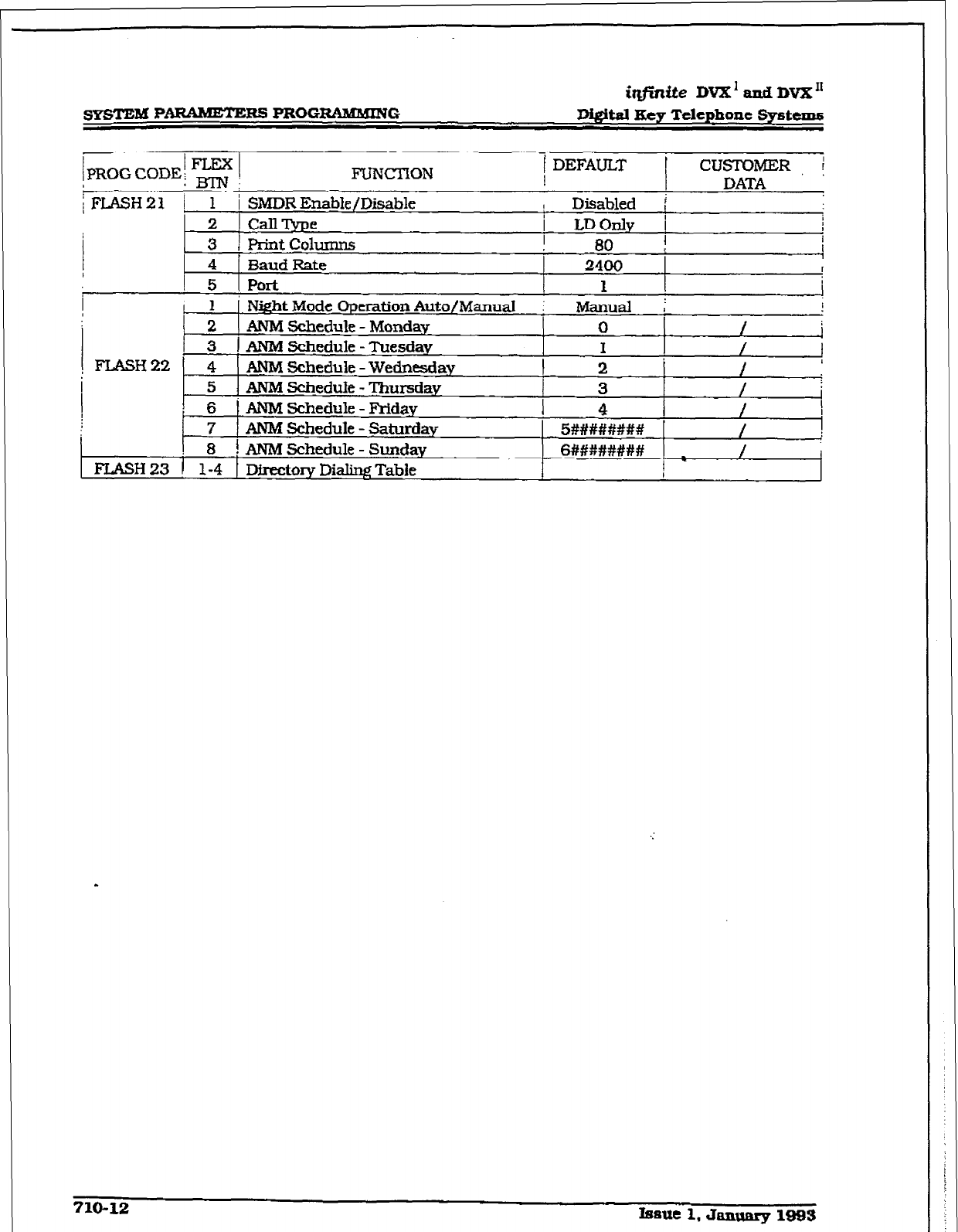
SYSTEM PARAMETERS PRGGRtiMUING
it@aite DVX’~~~DVX~
Di&itd Hey Telephone Systems
IPROG CODE! - I FUNCTION
j DEFAULT
i
CUSTOMER, i
:J=gpj; DATA
;FL&HZl / 1 i SMDR Enable/Disable Disabled f
2 can me
LDOnlv i I
/ 3 4 3aud Print
columns
Rate
2400
80 : I I
1
t
I
I
t
I 5 I
Port
I 1
I 1 I Night Mode Operation Auto/Manual i
Manual i !
2 1 ANMSchedule- Mondav 0
. /
1
3
1 AN&l Schedule - Tuesday /
FLASH22 4
ANM Schedule - Wednesday I :. 1 / I
5
ANM Schedule - Tl-mrsdav
3 /
6
ANM Schedule - F’riday
1 4 /
7
AIVM
Schedule
- Saturday 5########
.
/
8 f ANMSchedule
Sunday
-
6######## / I
FLASH 23 1 1-4 1
Directoq
Dialing Table f
710-12 Issue 1, Januarg 1993
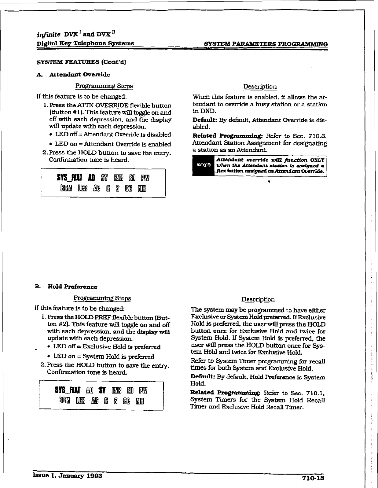
r
irlpnite DVX’ and DVX’
Dj&ital Key Telephone Systems
SYSTEM
FEATURES (Cont’dI
A. Attendant Ovcmide
Prom Steps
if this feature is to be changed:
1. Press the ATIN OVERF$DE flexible button
(Button #I). This feature will toggle on and
off with each depression, and the display
will update with each depression.
l
LED off =Attendant Override
is
disabled
l
LED on = Attendant Override is enabled
2.Press the HOLD button to save the entry.
Confikmation tone is heard.
Description
When this feature is enabled, ft aUows the at-
tendant to override a busy station or a station
in DND.
Default:
By default, Attendant Override is dis-
abled.
Reinted
piognlmdllf~: Refer to Sec. 710.3.
Attendant Station Assignment for designating
a station as an Attendant.
B.
HoId Preference
Pro&& - ig steps
If this future is to be changed:
1. Press the
HOLD
PREIFflexible button (But-
ton #2). This feature will toggle on
and off
with each depression, and the display will
update with each depression.
-
l
IED off = Exclusive Hold is preferred
- LED on = System Hold is preferred
2. Press the HOLD button to save the en*.
Confirmation tone is heard,
Description
The
system
may be programmed to have either
ExciusiveorSystem Hold preferred. IfExclusive
Hold fs preferred, the userwill press the HOLD
button once for Fxclusive Hold and twice for
Systexn Hold. If System Hold is preferred. the
user wiIl press the HOLD button once for Sys-
tan Hold and twice for Exclusive HoId.
Refer to system llmer programming for recall
times for both System and Exclusive Hold.
Ikfimltz By default, Hold preference Is System
Hold.
Related l+ogrrurdng: Refer to Sec. 710.1,
System tiers for the System HoId Recall
Timer and Exclusive Hold Recall Timer.
fB8ue 1, January 1993 710-13
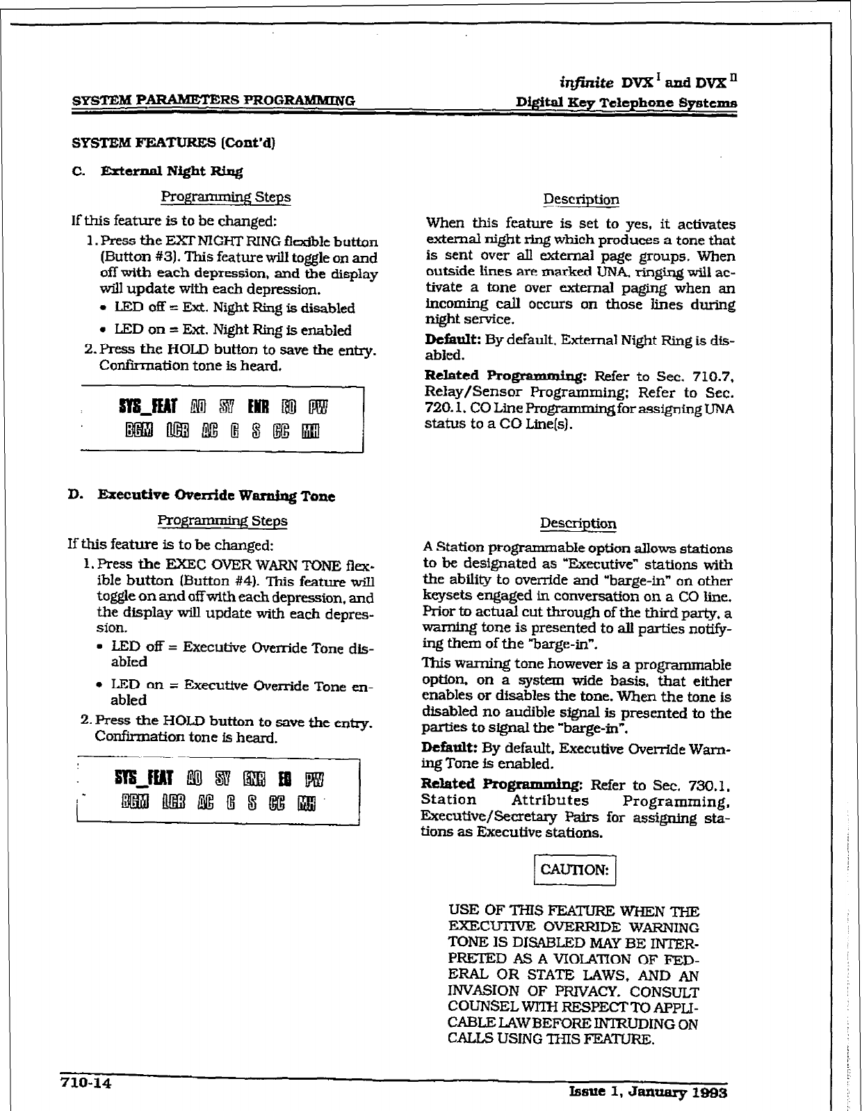
SYSTEM PARAMETERS PROGRAMhUNG Di&al Key Telephone Systems
SYSTEM FEATURES [Cont’dl
C. Erternnl Nfght Rixq
Programming Steps
If this feature is to be changed:
1. Press the FXFNIGHTRING flexible button
(Button #3). This feature will toggle on and
off with each depression, and the display
will update with each depression.
+ LED off = Ext. Night F&g is disabled
l
LEDon= Ext. Night Ring is enabled
2.
Press the HOLD
button to save the entq.
Confi.iation tone is heard.
D. Executive Override Wmdmg Tone
Prog - qq steps
If this feature is to be changed:
1, Press the EXE32 OVER WARN TONE flex-
ible button (Button #4). This feature wiII
toggle on and off with each depression, and
the display w-lb update with each depres-
sion.
l
LED off = Executive Override Tone dis-
abIed
l
LED on = Executive Override Tone en-
abled
2. Press the HOLD button to save the entry.
Confirmation tone is heard.
Description
When this feature is set to yes, it activates
external night ring which produces a tone that
is
sent
over aII external page groups. When
outside lines are marked UNA, ringing will ac-
ttvate a tone over external paging when an
incoming cd occurs on those lines during
night service.
Default:
By defauk. External Night Ring is dis-
abled.
R&&d Programmiq: Refer to Sec. 710.7,
Relay/Sensor Programming; Refer to Sec.
720.1, CO Line Pro gmmmingfor assigning UNA
status to a CO Line(s).
Description
A Station progmmmabIe option allows stations
to be designated as “Executive” stations with
the ability to override and “barge-in” on other
keysets engaged in conversation on a CO line.
Prior to actual cut through of the third party, a
warning tone is presrmted to all parties notify-
ing them of the “barge-in”.
‘Ibis warning tone however is a programmable
option. on a system wide basis. that either
enables or disables the tone. When the tone is
disabled no audible signal is presented to the
parties to signal the “barge-in”.
Dctatrlt:
By default. Executive Override Warn-
ing Tone ia enabled.
-tCd b@IIUlB@J: Refer to Sec. 730.1,
Station Attributes Programming,
Executive/Secretary Pairs for
assigning sta-
tions as Executive stations.
USE OF THIS FEATURE WHEN THE
EXEC’I;ITNE OVERRIDE WARNING
TONE IS DISABLED MAY BE INTER-
PRETED AS A VIOLATION OF FED-
ERAL OR STATE LAWS, AND AN
INVASION OF PRIVACY. CONSULT-
COUNSEL WITH RESPECT l-0 APPLI-
CABLE LAWBEFORE INTRUDlNG ON
CALLS USING THIS FEATURE.
710-14 Issue 1, January 1993
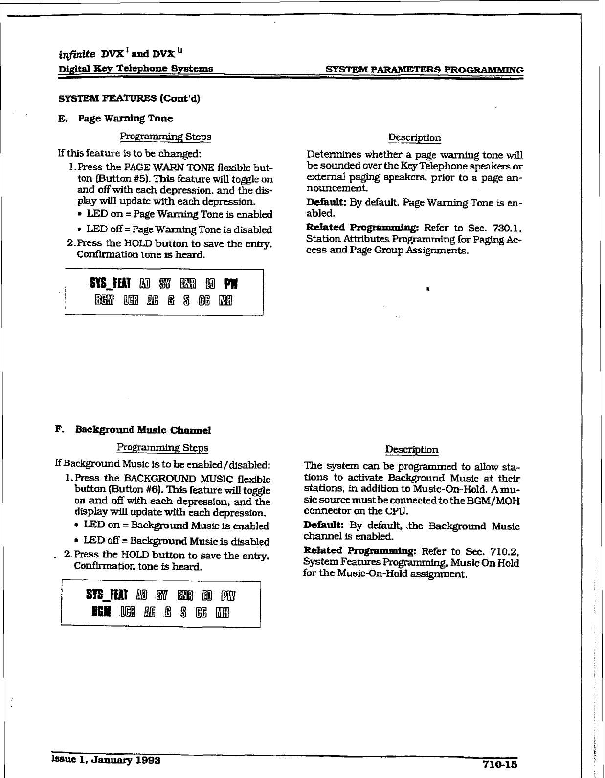
r
iqfini.teDVX1andDVXn
Digital Xey Telephone Sys&n.s Sl’STEM PARULETERS PROGRAMMING
SYSTEMFEATURES(Cont'd)
E. Page Warning
Tone
Progrsmming Steps
If this feature is to be changed:
1, Press the PAGE WARN rONE ilexible but-
ton (Button #51. This feature will toggle on
and off with each depression, and the dis-
play will update with each depression.
. LED on = Page Warning Tone is enabled
l
LED off = Page Warning Tone is disabled
P.Press the HOLD button to save the entry,
Confkmation tone is heard.
DWXipU0Il
Determines whether a page warning tone will
be sounded over the Key Telephone speakers or
external paging speakers, prior to a page an-
nouncement.
Default: By default. Page Warning Tone is M-
abled.
lRelaicd Fvogramminsl Refer to Sec. 730.1,
Station AttrIbutes Prog * 4 for Paging Ac-
cess and Page Group Assignments.
F. Background Music Channel
Prg; - lg steps
IfBackground Music is to be enabled/disabled:
1. Press the BACKGROUND MUSIC flexible
button (Button #6). This feature will toggle
on and off with each depression. and the
display will update with each depression.
l
LED on = Background Music is enabled
l
LED off = Background Music is disabled
- 2,Ress the HOLD button to save the entry.
Confirmation tone is heard.
Description
The system can be programmed to allow sta-
tions to activate Background Music at their
stations, fn addition to Music-On-Hold. A mu-
sic source must be connected to theBGM/MGH
connector on the CPU.
Detault: By default. .&he Background Music
channel is enabled.
lcclatcd Rogrannninn: Refer to Sec. 710.2,
SystemFeatures~~. Music On Hold
for the Music-On-Hold assignment.
Lseuc l,&umary1993 710-1s
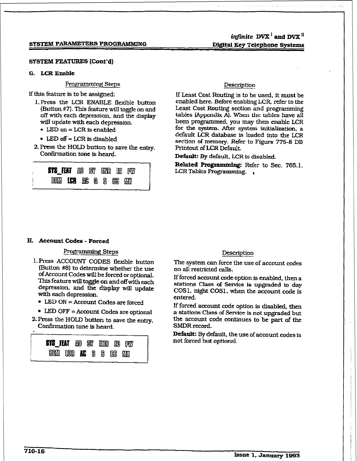
iqfirzite DVX’and DVX”
SYtSTEBB P-RS PROG-G D@itaI Key ‘relcphone systems
SYSTEM FEATURES (ConVd)
G. LCR Enable
Prop- Steps
If this feature is to be assigned:
1. Press the LCR ENABLE flexible button
(Button #7). This feature will toggle on and
off with each depression, and the display
wrll update with each depression.
l
LED on = LCR is enabled
l
LED off = LCR is disabled
2. Press the HOLD button to save the entry.
Conhnation tone is heard.
Description
If Least Cost Routing is to be used, it must be
enabled here. Before enabling LCR refer to the
Least Cost Routing section and programming
tables [Appendix Al. when the tables have alI
been programmed. you may then enable LCR
for the system. After system iuitialization, a
default LA3R database is loaded into the LCR
section of memory. Refer to Figure 775-8 DB
Printout of LCR Default
Default: By default, UZR is disabled.
Related Programmhng:
Refer to Sec. 765.1,
LCR Tables programming. ,
H. Account Codes - Forced
l4lamwg steps
l.Press ACCOUNT CODES flekble button
mutton #8) to determine whether the use
ofAccount Codeswill be forced or optional.
This feature will toggle on and off with each
depression. and the display will update
with each depression.
l
LED ON = Account Codes are forced
l
LED OFF = Account Codes are optional
2. Press tbe HOLD button to save the entry
Confk-matlon tone is heard.
Description
The system can force the use of account codes
on ail restricted caIls.
If forced account code option is enabled, then a
stations Class of Sewice is upgraded to day
COSl, night COSl, when the account code is
entered.
If forced account code option is disabled, then
a stations Class of Semice is not upgraded but
the account code amtiues to be part of the
SMDR record.
Debault: By
default, the use of account codes is
not forced but optional.
710-m lfmue 1, klmuy 1993
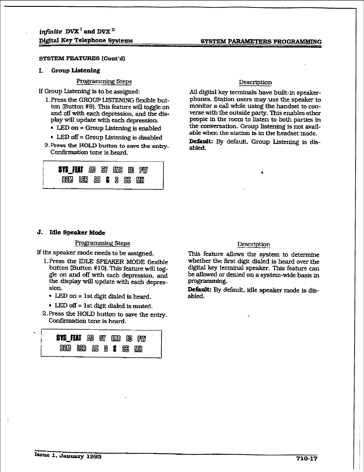
r
irlfintte DVX’ and DVX’
Di@d Eey Telephone Systems SYSTEM PARAMETERS PROG-G
I.
Group Listening
Programmhg Steps
If Group Listening is to be
assigned:
1. Press the GROUP
IB’IENING
flexible but-
ton (Button #9]. This feature win toggle on
and off with each depression, and the dis-
play will update with each depression.
6 LED on = Group List&g is enabled
l
LED
off
=
Group Listening is disabled
2.Prer.s the HOLD button to save the entry.
Conknation tone is heard.
Desctiption
All digital key terminals have built-in speaker-
phones.
Station users
may use the speaker to
monitor a call while using the handset to con-
verse with the outside party. This enables other
people in the room to listen to both parks in
the conversation. Group listening is not avail-
able when the station is in the headset mode.
DcfanIt: By default, Group Listening is dis-
abled.
J. Idle Speaker Mode
profframmin Steps Description
If the speaker mode needs to be assigned.
1. Press the IDLE SPFAKER MODE flexible
button (Button # 10). This feature w-iU tog-
gle on and off with each depression, and
the display wQl update with each
depres-
sion.
v L?ZDon= Istdigitdialedisheard.
* LED off = 1st digit dialed is
muted.
2. Press the HOLD button to save the entry.
Confirmation tone is heard.
This feature atlows the system to determine
whether the first digit dialed is heard over the
digital key terminal speaker. This feature can
be allowed or denied on a system-wide basis In
programming.
Dcfkult: By default, idle
speaker mode is dis-
abled.
but 1,
January 1993 71@17

r
SYSTEM PmRS PROGRAMMING D&itaI
Key Telephone Systems
E, call Cost Display Feature
Prog~ steps
If Call Cost Display Feature is to be enabled:
1 .Press the CALL COST DISPLAY flexible
button (Button # 11). This feature will tog-
gle on and off with each depression, and
the display will update with each depres-
sion.
. LEDon= Call Cost Display is enabled
l
LED
off
= Call Cost Display
is
disabled
2. Press the HOLD button to save the e&y.
Confirmation tone is heard.
L. Music On Hold
If Music On Hold is to be disabled:
1, Press the h4USIC ON HOLD flexible button
‘(Button #12). This feature will toggle on
and off with each depression. and the dis-
play will update with each depression.
l
LED on =
Music
On Hold fs enabled
l
LED off = Music On Hold is disabled
2. Press tile HOLD button to save the entry.
Confk-matton tone is heard.
Description
The Call Cost Display Feature provides a means
for a user to view the approxknate cost of each
caLI made. This approximate cost wizl also be
printed as part of the SMDR record.
The Cdl Cost Display will replace the call du-
ration display when a call is made using LCR.
This display is
enabled in
programming.
The cost information
is
programmable by se-
lecting one of the 16 route list tables and one of
the four time periods. This allows the user to
program four separate costs based on the time
of day for each of 16 routes. The costs entered
in the tables wiIl be a cost for one minute.
however. costs are calculated using a 1 /lOth of
a minute value. These’costs are rounded down
and are based on the start time of the call. even
if the call extends into a dzerent time period.
The SMDR printout w-ill contaM a cost calcu-
lated using a l/ 10th of a minute irxrement
and
the display will update approxhnateiy every 30
seconds. The user must use LCR enabled to get
the call cost display.
Jkfanlt: By default, the Call Cost Display Fea-
ture is disabled.
Related Pro@xmming: Refer
to Sec. 710.2.
System Features Programming, L.CR Enable.
De&&ion
A music source. when connected to the system,
provides music to ail lines on Hold. parked
calls. transferred calis and calls waiting to be
answered by Automatic Call Distribution (ACD)
or Uniform CaU Distribution (LJCD). This fea-
ture can be allowed or denied on a system-wide
basis in prom.
Default: By default. Music On Hold is enabled.
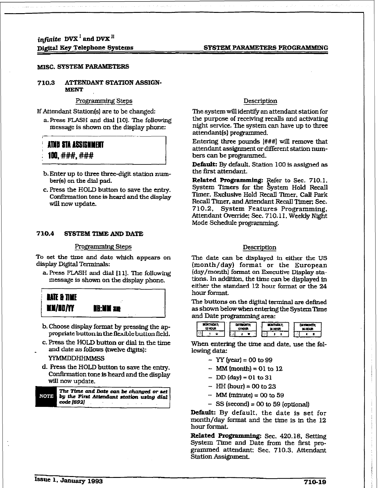
r
f@&e Dvlt’andDVX”
Digital Key Telephone Systems SYSTEM PJ%RAmmERS PROG~G
710.3 A’ITENDAIUT STATION ASSIGN-
BUENT
Prog~ Steps
If Attendant Station(s) are to be changed:
a.Press FLASH and dial [lo]. The following
message is shown on the display phone:
b. Enter up to three three-digit station num-
ber(s)
on
the dial pad.
c. Press the HOJD button to save the entry.
Confirmation
tone is
heard
and the display
will now update.
710.4 SYSTEM TTUHEAND DATE
To
set the time and date which appears on
display Digiti Ten&r&:
a. Press FLASH and dial Ill]. The following
message is shown on the display phone.
b. Choose display format by pressing the ap-
propriate button in the fI&ble button field.
c. Press the HOLD button or dial in the time
and
date as follows (twehre
digits]:
YYMMDDHHMMSS
d. Press the HOLD button to save the entry.
Cordrmation tone is
heard
and the display
will now update.
Dt?scription
The system will identlfy an attendant station for
the purpose of receiving recalls and activating
night service. The system can have up to three
attendant(s) programmed.
Entering three
pounds I###] wii remove
that
attendant a&gnment or different station num-
bers can be
programmed.
Default:
By default, Station 100 fs assigned as
the first attendant.
Related Pro-:
Refer to Sec. 710.1,
System Tfmers for the hystem Hold Rem11
Timer, Exclusfve Hold Recall ‘Drner. Call Park
RecalI
Timer. and Attendant Recall Timer; Sec.
7 10.2,
System
Features Programming,
Attendant Override: Sec. 710.1 I.
Weekly
Night
Mode
Schedule
programming.
Description
The date can
be displayed in either the US
(month/day) format or the European
(day/month) format on Exec&ive Display sta-
tions. In addition. the time can be displayed in
either the standard 12 hour format or the 24
hour format.
The buttons on the digital terminal are defined
asshownbelowwhenenteringt.heSystemTime
and Date programming area:
When entexin~ the time Ad date, use the fol-
lowing data:
- W(year)=0000099
- MM (month) = 01 to 12
- DD(dayI=Ol to31
- HH(hour)=OOto23
- MM(minute)=OOto59
- SS (second) = 00 to 59 (optional)
Default: By default. the date Is set for
month/day format and the time is in the 12
hour format.
Related Progrmg:
Sec. 420.18. Setting
System Time
and
Date from the tist pro-
grammed attendant;
Sec. 710.3, Attendant
Station Assignment.
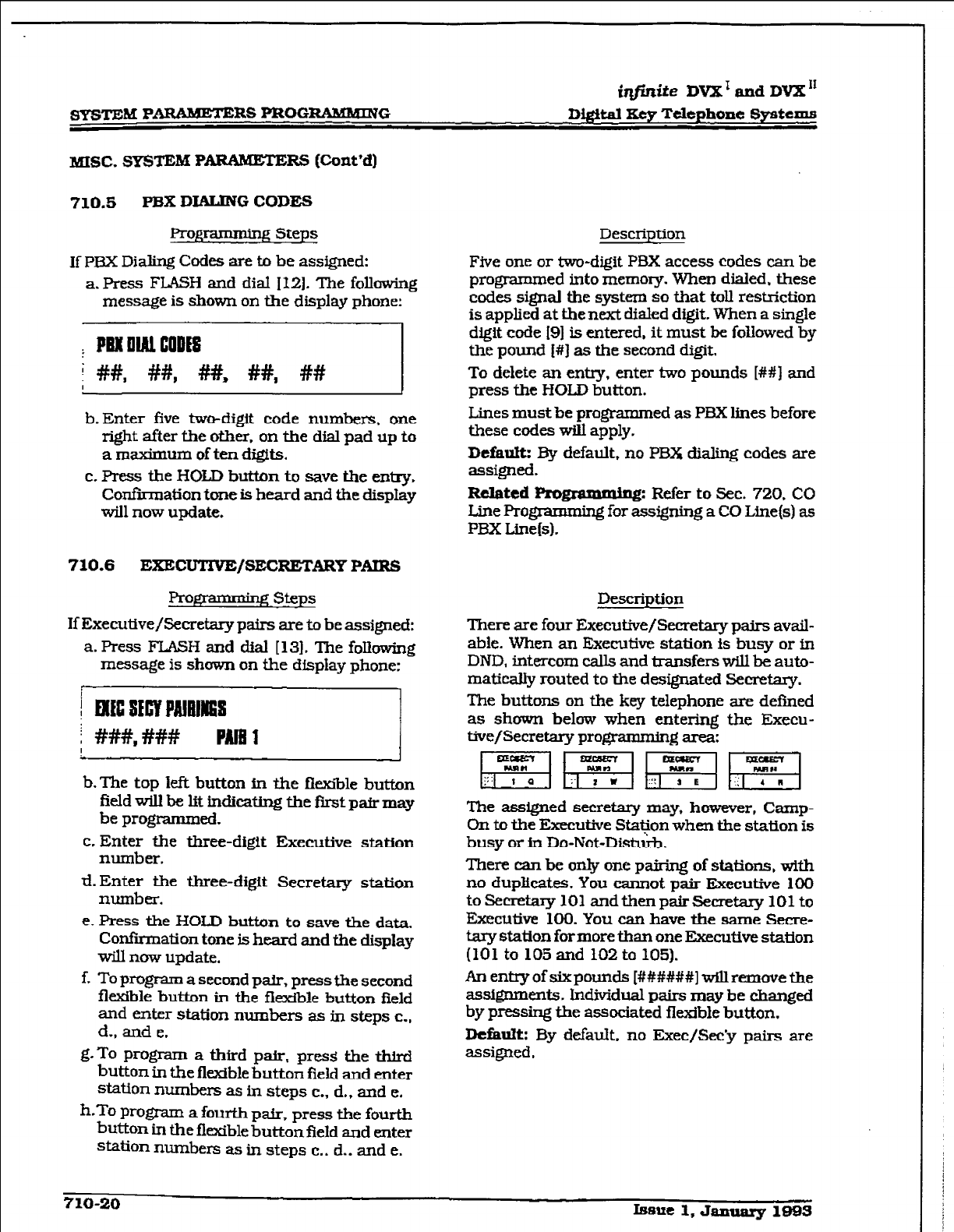
SYSTEM
P
ARAzldETERS PROGRAMlvIlNG
iqfirzite DVX’
and
DVX”
DigItal Xey Telephone Spatems
MISC. SYSTEM PARAnuEm Rs (cont’d)
710.5 PBX DIALING CODES
Programming Steps
If PBX Dialing Codes are to be assigned:
a. Press FLASH and dial 112). The following
message is shown on the display phone:
I PBK DW cm
i #I#, ##, ##, ##, ##
b.Enter five twodigit code numbers, one
right after the other, on the dial pad up to
a maximum of ten digits.
c. Press the HOLD button to save the entry.
Confirmation tone is heard and the display
will now update.
710.6
EXECUTlVE/SECREMRY
PAIRS
If Executive/Secretsry pairs are to be assigned:
a. Press F.TASW and dial [ 131. The following
message is shown on the display phone-
b-The top left button in the fkxiile button
field will be lit indicating the fvstpairmay
be programmed.
c. Enter the three-digit Executive station
number.
d.Enter the three-digit Secretary station
number.
e. Press the HOLD button to save the data.
Confirmation tone is heard and the display
will now update.
f. To program a second pair, press the second
fkible button in the flexible button field
and enter station numbers as in steps c.,
d., and e.
g-To program a third pa&. press the third
button in the flexible button field and enter
station numbers as in steps c., d., and e.
h-To pmgmn a fourth patr, press the fourth
button in the flexible button field and enter
swan numbers as in steps c., d.. and e.
Description
Five one or two-djgit PBX access codes can be
programmed into memory. When dialed. these
codes signal the system so that toll restriction
is applied at the next dialed digit. When a single
digit code 191 is entered, it must be foflowed by
the pound [#] as the second digit.
To delete an entry. enter two pounds [##J and
press the HOLD button.
Lines must
be programmed as PEIX
lines before
these codes will apply.
Default: By default, no PBX dialing codes are
assigned.
EEt T Fef”r to Sec. 720, CO
grammug for assigning a CO Line(s) as
PBX Linels).
Description
There are four Executive/Secretary pairs avail-
able. When an Executive
station is busy
or in
DND, intercom calls and transfers will be auto-
matically routed to the designated Secretary.
The buttons on the key telephone are defmed
as shown below when entering the Execu-
tive/Secretary programming area:
FiRWpgq
The assigned secretzuy may,
h
owever, Camp-
On to the Executive Stapon when the station is
busy or in Do-Not-Disturb.
There- can be only one pairing of stations, with
no duplifcates. You cannot pair Executive
100
toSecretary101andthenpairSenetary101to
Executive 100. You can have the same Secre-
taq station formore than one Executive station
(101 to 105 and 102 to 105).
An entry of six pounds [#I#####] will remove the
assignments. Individual pairs may be changed
by pressing the associated flexible button.
Default: By default. no Exec/See’y pairs are
assigned,
716-20
Issne 1, January 10BS
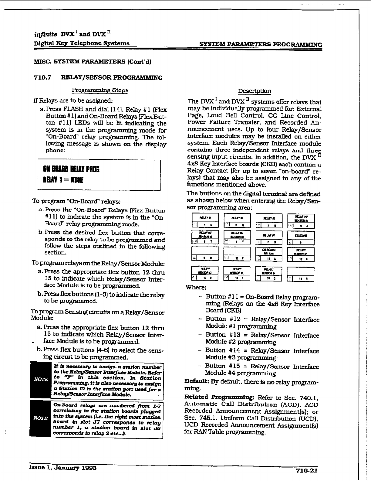
r
irtfinite DVX’tiDVX’
Dig&al Xey Telephone Systems SYSTEM PARAMETERS PRGGRLWMING
MISC. SYSTEM PARAMETE RS (Co&d]
710.7 REUW/SENSOR PROGRAMMING
Programrniqq Steps
If Relays are to be assigned:
a-Press FLASH and dial 1141. Relay #l (Flex
Button # I) and On-Board Relays (FlexBut-
ton #ll] LEDs ti be lit indicating the
system Is in the pro&ramming mode for
“On-Board” relay prom The fol-
lowhg message is shown on tde display
phone:
To program “On-Board” relays:
a. Press the “On-Board” Relays (Fkx Button
#111 to indicate the system is in the ‘On-
Board” relay programming mode.
b.Press the desired flex button that corre-
sponds to the relay to be pwed and
follow the steps outlined in the following
section.
To program relays on the Relay/Sensor Module:
a. Press the appropriate flex button 12 thru
15 to indicate which Relay/Sensor Inter-
face Module is to be programmed.
b. Press flexbuttons (l-3) to indicate the relay
to bc programmed.
To program Sensing circuits on a Relay/Sensor
Module:
a. Press the appropriate flex button 12 thru
15 to indicate which~Relay/Sensor Inter-
* face Mudule is to be programmed.
b. Press flex buttons (4-6) to select the sens-
ing circuit to be prcgmnmed.
Description
The DVX I and DVX ’ systems offer relays that
may be individually programm ed for: External
Page, Loud BeIl Control, CO Line Control.
Power Failure Transfer. and Recorded An-
nouncement uses. Up to four Relay/Sensor
interface modules may be installed on either
system. Each Relay/Sensor Interface module
contains three independent relays and three
sensing input circuits. In addition. the DVX ’
4& Key Interface boards (CKB) each contain a
Relay Contact (for up to seven “on-board” re-
lays) that may also be assigned to any of the
functions mentioned above.
The buttons on the digifal termfnal are deEned
as shown below wlxn entering the Relay/&n-
sor programming area:
MlAY#!
la
RL*YY
Ea
**1AR
:c * ,
E&l
.
_.. , 0
UYR
M
... 1 E
Whtl-t?:
- Button #1 I = On-Board Relay program-
ming (Relays on the 4x8 Key Interface
Board E-1
- Button # 12 = Relay/Sensor Interface
Module # I prqramdng
- Button #13 = Relay/Sensor Interface
Module #2 programming
- Button #14 = Relay/Sensor Interface
Module #3 programming.
- Button #15 = Relay/Sensor Interface
Module #4 pro@ -62
Default:
By default, there is no relay program-
mine-
R&ted Roflammkg: Refer to Sec. 740.1.
Automatic Call Distribution (ACD). ACD
Recorded Announcement Assignment(s); or
Sec. 745.1, Urdfonn Call Distribution (UCD),
UCD Recorded Announcement Assignment(s)
for RAN Table programmhg.
Issue 1, January 1993 71&21
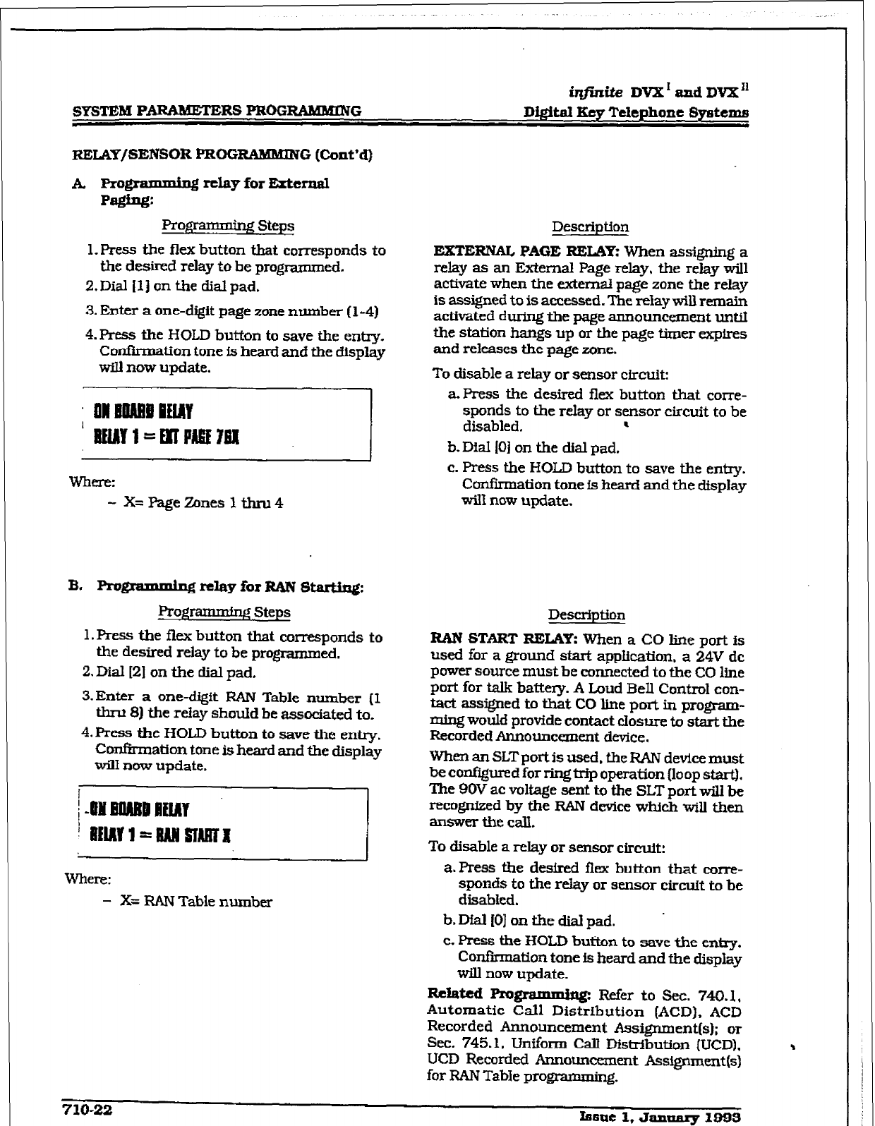
r
irLfini.k DVX I and DVX I1
SYSTEM PARAMETERS PROGRAMMING D&it.& Kcy Tckphone Syi~tems
RELAY/SENSOR PRoGRAMMIlV G (Cont’d)
A Pr&dl relay for External
:
Prog * ASteps
1. Press the flex button that corresponds to
the desired relay to be programmed.
Z&Dial 111 on the dial pad,
3. Enter a one-digit page zone number (l-4)
4. Ress the HOLD button to save the entry.
Confkmation tone is heard and the display
will now update.
Wbm:
- X= Page Zones lthnl4
B. Pl-o*amming relay for RAN sm:
Rog~ Steps
l.Press the fkx button that corresponds to
the desired relay to be programmed.
2.Dia.l[21 on the dial pad.
3. Enter a one-digit RATV Table number (I
thru 8j the relay should be associated to.
4. Press the HOLD button to save the entry.
Ccmfkmation tone is heard and the display
will now update.
Where:
- X= F&IN Table number
Description
EXTERNAL
PAGE RELAY:
When assigning a
relay as an External Page relay, the relay will
activate when the extemaI page zone the relay
is assigned to is accessed. The relay will rem&n
activated during the page announcement until
the station hangs up or the page f&ner expires
and releases the page zone.
To disable a relay or sensor cfrcuit:
a. Press the desired flex button that corre-
sponds to the relay or sensor circuit to be
disabled. .
b,. DiaI 101 on the dial pad.
c. Press the HOLD button to save the entry.
Confirmation tone is heard and the display
will now update.
Description
RAN START RELAY: When a CO line port
is
used for a ground stark application. a 24V dc
power source must be connected to the CO line
port for talk battery. A Loud Bell Control con-
tact assigned to that CO line port in program-
ming would provide contact closure to start the
Recorded Announcanent device.
When an SLT port is used, the RAN device must
be configured for xing trip operation {loop star&
The 9OV ac voltage sent to the SLT port will be
recognized by the RAN device which will then
answer the call.
To disable a relay or sensor circuit:
a.Press the desired flex button that coxre-
spends to the relay or sensor circuit to be
disabled.
b.DIalIOIontbedialpad. .
c. Press the HOLD button to save the e&y.
Conflation tone is heard and the display
will now update.
Rcfated Pragramming Refer to Sec. 740.1.
Automatic Call Di&bution (ACD).
ACD
Recorded Announcement Assignment(s); or
Sec. 745.1, Uniform Call Distribution (UCD),
UCD Recorded Announcement Ass#xnent(s)
for RAN Table programmiq.
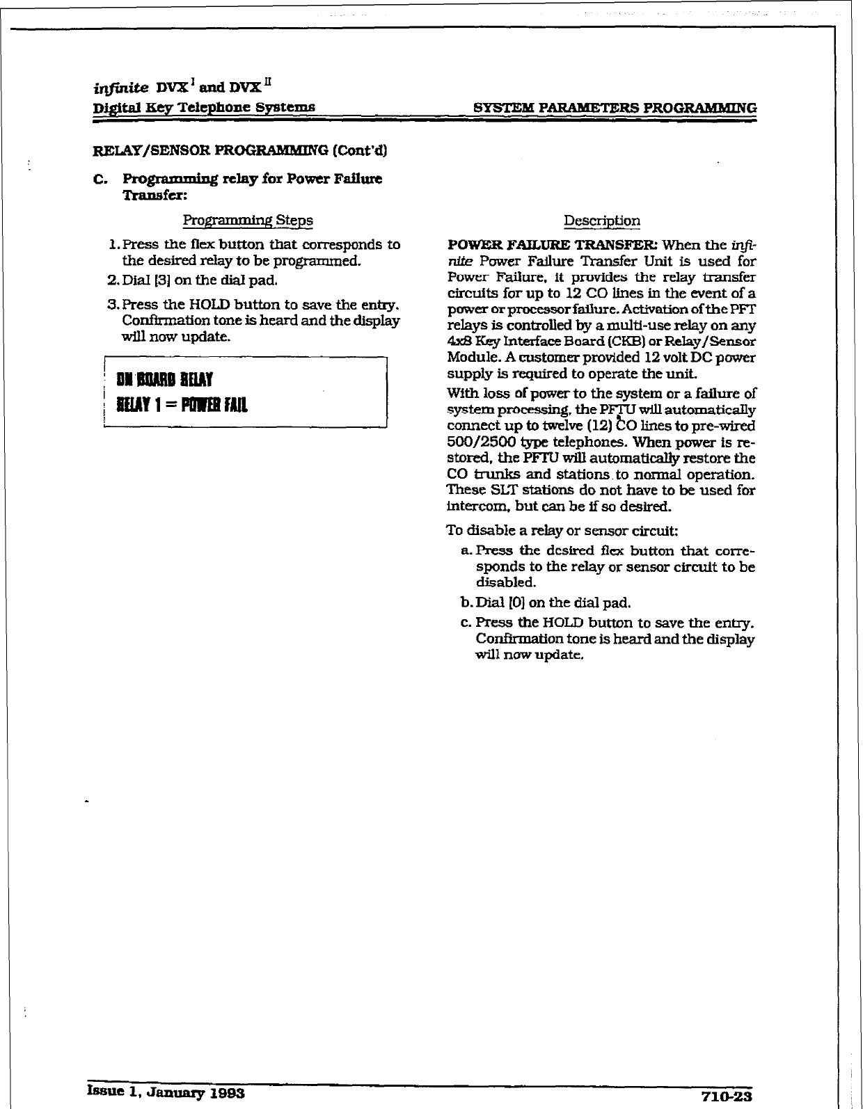
r
Prog * g steps
1. Press the flex button that corresponds to
the desired relay to be programmed.
2. Dial 131 on the dial pad.
3. Press the HOLD button to save the entry.
Confirmation tone is heard and the display
will now update.
!
D&kid Hey Telephone Systems SYSTEM PARAMETERS PROGRAMMING
RELAY/SENSOR PROGWWJkltN G (Cont’d)
c- LY relay for Power Failure
:
Description
POWER FAILURE TRANSFER: When the in@
nite Power Failure Transfer Unit is used for
Power Failure, It provides the relay transfer
circrrits for up to 12 CO Iines in the event of a
power or processo r faGure. Activation of the PFT
relays is controkd by a multi-use relay on any
4x8 Key In&face Board @3SF%] or Relay/Sensor
Module. A customer provided 12 volt DC power
supply is required to operate the unit.
With loss of power to the system or a failure of
system processing, the PFRJ will automaticaJly
connect up to twelve (12) ?33 lines to pre-wired
500/2500 type telephones. When power is re-
stored, the PFFU will automaticayl restore the
CO trunks and stations to normal operation.
These SLT stations do not have to be used for
intercom. but can be if so desired.
To disable a relay or sensor circuit:
a. Press the desired fkx button that corre-
spends to the relay or sensor circuit to be
disabled.
b. Dial 101 on the dial pad.
c. Press the HOLD button to save the entq.
Codirmation tone is heard and the display
will now update.
Ismxc 1, January lSs3 710-23
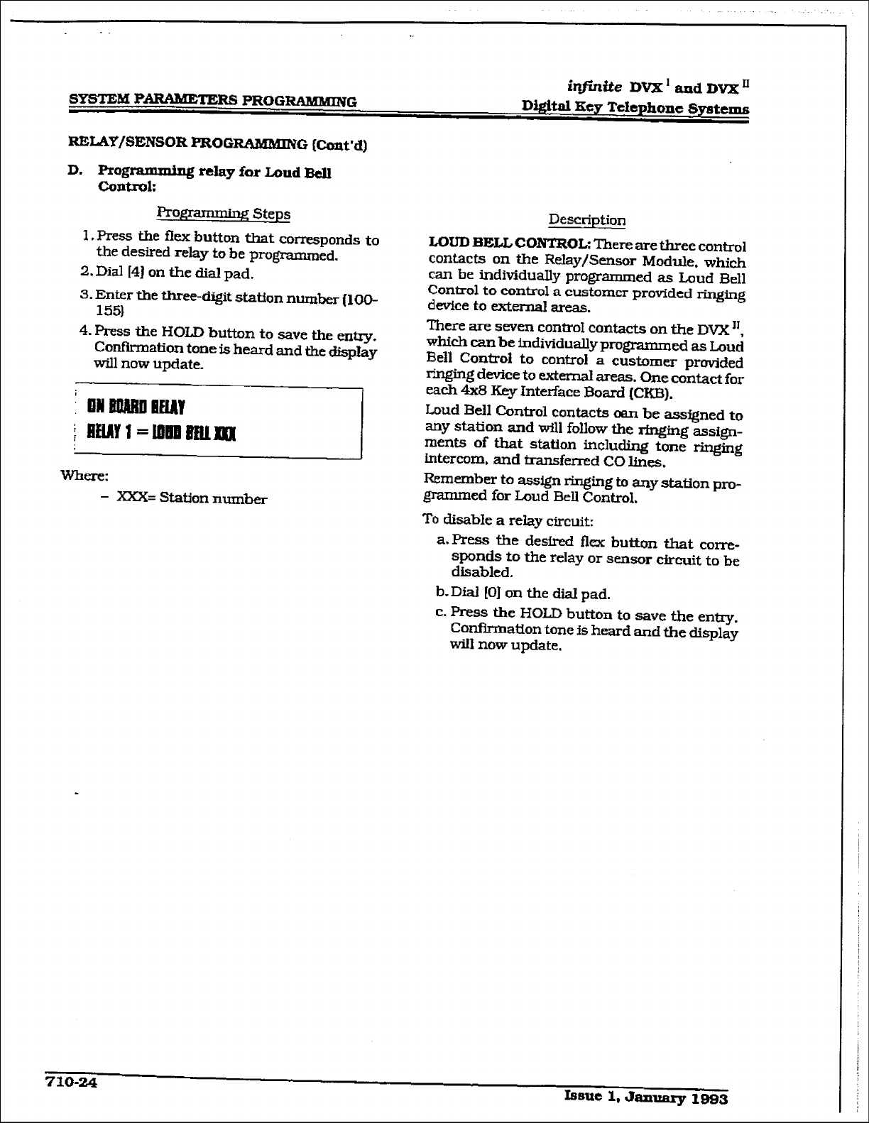
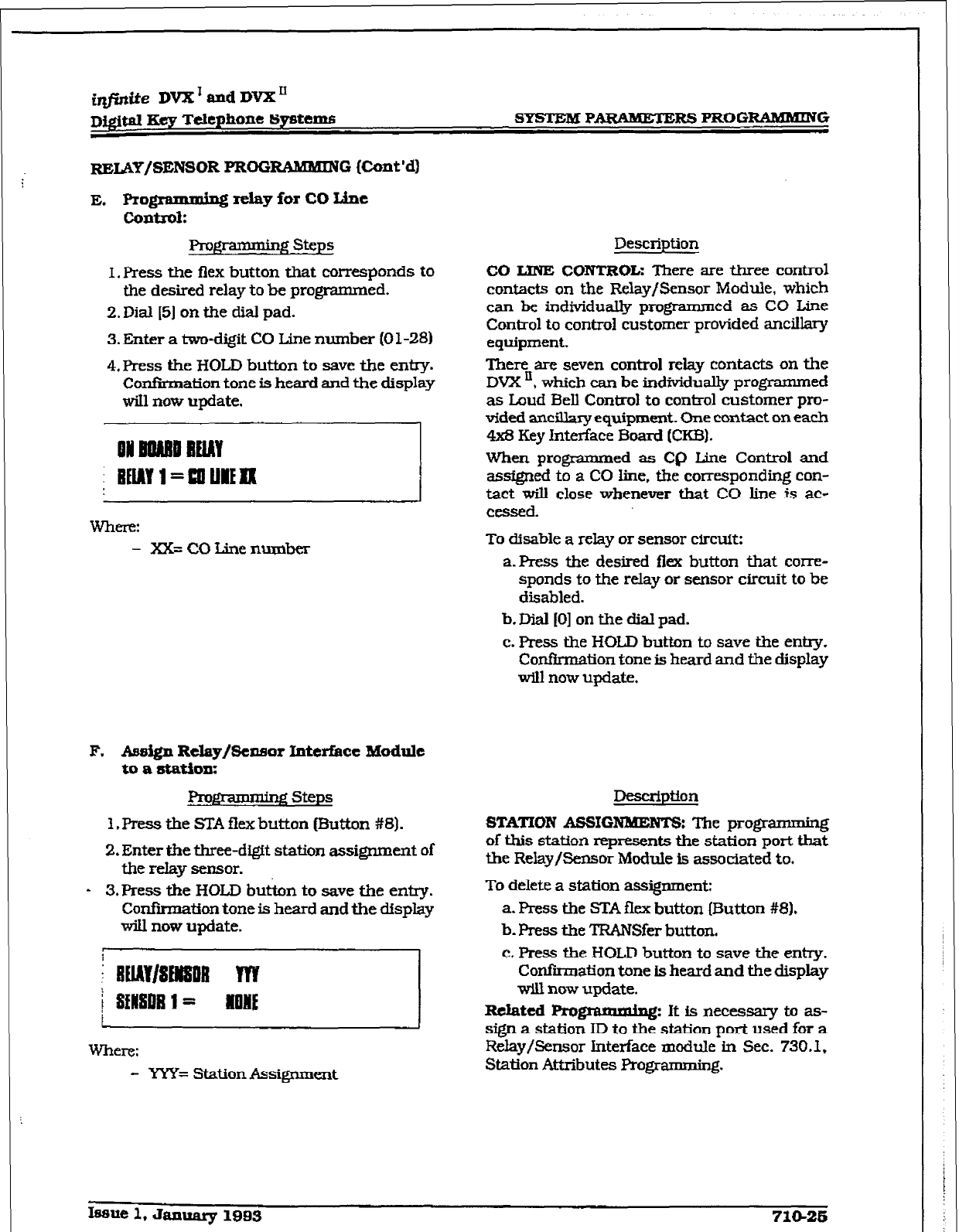
imite DVX’ and DVX’
Dj@m gcS TCrephone
SJ?StCIWi
SYSTEM PAEWWXERS PROGRAMMING
RELAY/SENSOR PROG RtlMMING (Cont’d)
E. f’rogramming rck~y for co tie
COlltIOk
From steps
I. press the flex button that corresponds to
the desired relay to be programmed.
2.Dial [5J on the dial pad.
3. Enter a two-digit CO Line number (0 l-28)
4.
Press the I-lOLD button to save the entry.
ConfIIation tone is heard and the display
will now update.
ON BBNBU BElAY
i BEMY l=WJIEfl(
- xX= CO Line number
P. Aes&n Rclay/&naor Interface Module
to a station:
1. Press the STA flex button (Button #8).
2.
Enter the three-digit station assignment of
the reIay sensor.
- 3,Press
the HOLD but&n to save the entry.
ConfIItion tone is heard and the display
will now update.
i llMY~8MOB
m
j SENSDB 1= BONE
Where:
- YYY= Station Assignment
Description
CO LJNE CONTROL: There are three control
contacts on the Relay/Sensor Module, which
can
be individually programmed as CO Line
Control to control customer provided ancillary
equipment.
There are seven control relay contacts on the
DVX ‘, which can be individually programmed
as Loud Bell Control to control customer pro-
vfckd ancikiry equipment. One contact on each
4x3 Key Interface Board (CKB).
When programmed as CQ Line Control and
assigned to a CO fine. f&e corresponding con-
tact will close whenever that CO line is ac-
cessed.
To disable a relay or sensor circuit:
a-Press the desired flex button that corre-
sponds to the relay or sensor circuit to be
disabled.
b. Dial (01 on the dial pad.
c. Press the HOLD button to save the entry.
Confkmation tone is heard and the display
will now update.
STATION
ASSIGNMENT& The programming
of this station represents the station port that
the Relay/Sensor Module is associated to.
To delete a station assignment:
a. press the STA flex button (Button #8).
b. press the TFWWfer button.
c. Press the HOLD button to save the entry.
Confirmation tone is heard and the display
wiu
now
update.
R&ted Programmhg:
It
is necessary to as-
sign a station ID to the station port used for a
Relay/Sensor Interface module in Sec. 730.1.
Station Attributes Programming.
Issue 1, January lSB3 71@26
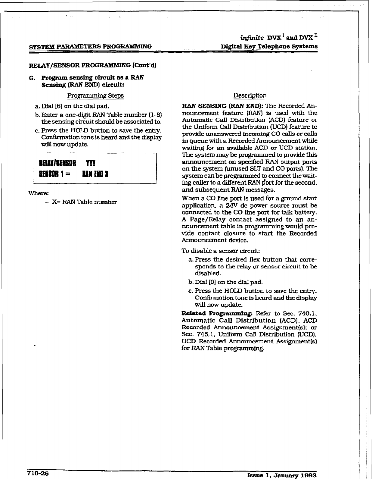
r
SYSTEM PARAMETERS PROG-G
infinite DVX’ and DVXn
DigftaI Key Telephone Systems
R~,~AY/SENSOR PRO0 RAMMING (Ccmt’d]
G. Ptogramsensingch’cuitasa~
Sensiu.~$ (RAN END) circuit:
grammhg Steps
a. MaJ I61 on the dial pad.
b. Enter a one-digit RAN Table number [ 1-8)
the sensing circuit should be associated to.
c. Press the HOLD button to save the entry.
Confirmation tone is heard and the display
d now update.
- X= RAN Table number
Description
RAN SENSING [RAN END): The Recorded An-
nouncement feature (RAN) is used with the
Automatic Call Distribution @CD) feature or
the Uniform Call Distribution (UCD) feature to
provide unanswe red inc0mh.g CO calls or calls
in queue with a Recorded Announcement while
waiting for an available ACD or UCD station.
The system may be programmed to provide this
announcement on specifkd RAN output ports
on the system (unused SLT and CO ports). The.
system can be programmed to connect the wait-
ing caller to a different RAN $ort for the second,
and subsequent RAN messages.
When a CO line port is used for a ground start
application, a 24V dc power source must be
connected to the CO line port for talk battery.
A Page/Relay contact assigned to an an-
nouncement table in programmin g would pro-
vide contact closure to start the Recorded
Announcement device.
To disable a sensor circuit:
a. Press the desired flex button that come-
sponds to the relay or sensor circuit to be
disabled.
b. D&I (01 on the dial pad.
c. Press the HOLD button to save the en-.
Confirmation tone is heard and the display
will now update.
Rebated Pm@ammiq: Refer to Sec. 740. I,
Automatic Call Distribution (ACD). ACD
Recorded Announcement Assigmnentfs): or
Sec. 745.1. Uniform Call Distribution (UCD).
UCD Recorded Announcement Assignment[s)
for RAN Table progmmming.
710-26 hsuel,January 1893
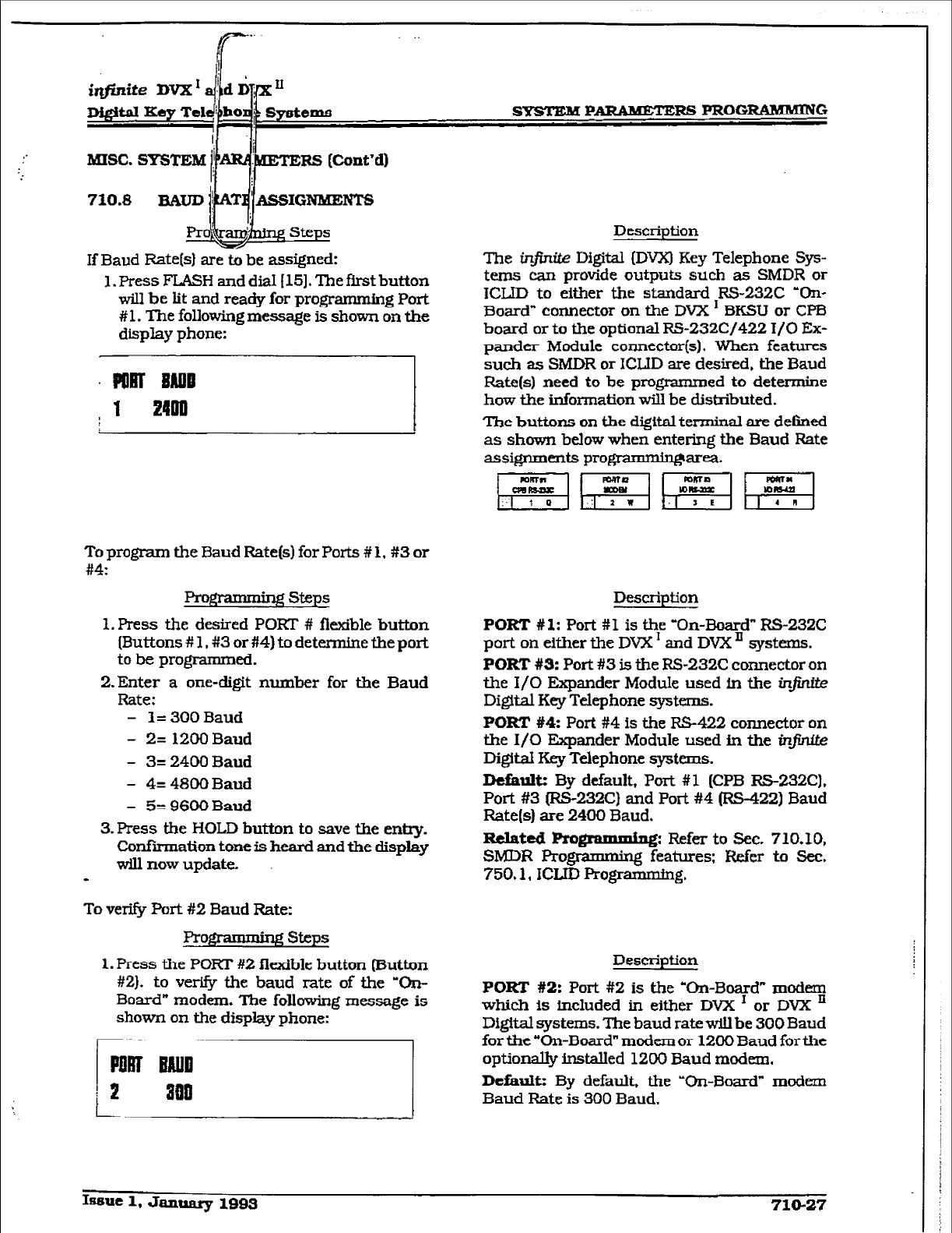
If Baud Rate[sI are to be assigned:
1. Press FLASH and dial [15]. The ftrst button
will be iit and ready for programming Port
# 1. The following message is shown on the
display phone:
Description
The infinite Digital (DVX) Key Telephone Sys-
tems can provide outputs such as SMDR or
ICLID to either the standard RS-232C ‘On-
Board” connector on the DVX I BKSU or CPB
board or to the optional RS-232Cj422 I/O Ex-
pander Module connector(s). When features
such as SMDR or ICWD are desired, the Baud
Rate(s) need to be programmed to determine
how the information will be distributed.
The buttons on the digital terminal are defined
as shown below when entering the Baud Rate
assignments programminffarea.
To program the Baud Rate(s) for Ports # 1, #3 or
#4:
Progra - Agsteps
1. Press the desired PORT # fkxible button
[Buttons # 1, #3 or #4) to determine the port
to be progmnmed.
2.Enter a one-digit number for the Baud
Rate:
- I=
300
Baud
- 2= 1200 Baud
- 3= 2400 Baud
- 4= 4800 Baud
- 5= 9600 Baud
3. Press the HOLD button to save the entry.
Confirmation tone is heard and the display
wiu now update.
-
To vex-i@ Port #2 Baud Rate:
$+-mkng steps
1. Press the PORT #2 flexible button (Button
#2). to verify the baud rate of the ‘On-
Board” modem. The following message is
shown on the display phone:
Description
PORT #
1: Port #I is the ‘On-Board” RS-23X
port on either the DVX I and DVX ’ systems.
PORT #3:
Port #3 is the RS-232C connector on
the I/O Expander Module used in the ir@We
Digital Key Telephone systems.
PORT #t4: Port #4 is the RS-422 connector on
the I/O Expander Module used in the infinite
Digital Key Telephone systems.
Default:
By
default, Port #I [CPB RS-232C).
Port #3 (RS-232C) and Port #4 (RS-422) Baud
Rate(s) are 2400 Baud.
Related
Ro &p7ynhg;a~;sto~; :,‘og*
SMDR Rogranmmg .
’ .
750.1, ICLID Rogmmming.
Description
PORT #2:
Port #2 is the ‘On-Board” modem
which is included in either DVX I or DVX ’
Digital systems. The baud rate will be 300 Baud
for the “On-Board” modem or 1200 Baud for the
optional& installed 1200 Baud modem.
Default: By default, the ‘On-Board” modem
Baud Rate is 300 Baud.
Issue 1, January 1993 71Q-27
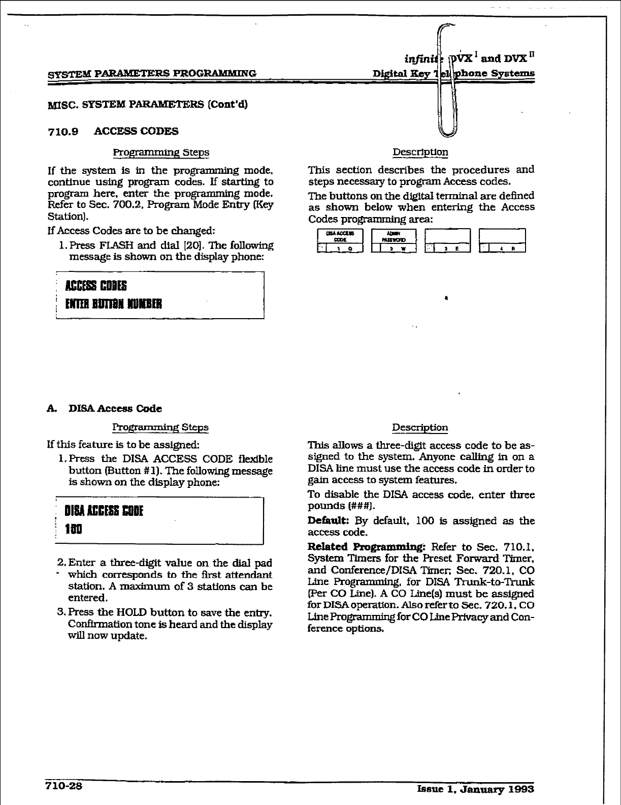
msc. SYSTEM P
AEWMETERS (Cont’d)
710.8 ACCESS CODES
Prm Steps
If the system is in the programnUng mode,
continue using program codes. if starting to
progkun here, enter the programming mode.
Refer to Sec. 700.2. Program Mode En&-y lKey
Station).
If Access Codes are to be changed:
1. Press FLASH and dial [ZO]. The following
message is shown on the display phone:
hone Systems
Description
Tbis section describes the procedures and
steps necessary to program Access codes.
The buttons on the digital terminal are defined
as shown below when entering the Access
Codes progmmming area:
A. DKSAAccessCode
From- steps
If this feature is to be assigned:
X.Press the DISA ACCESS CODE flexible
button Button # 1). The following message
is
shown on the display phone:
2. Enter a three-digit value on the dial pad
- which corresponds to the first attendant
station. A maximum of 3 stations can be
entered.
3. Press the HOLD button to save the entry.
Confirmation tone is heard and the display
will now update.
Description
This allows a three-digit access code to be as-
signed to the system. Anyone calling in on a
DISA line must use the access code in order to
gain access to system features.
To disable the DISA access code, enter three
pounds (###).
Default:
By default, 100 is assigned as the
access code.
Related
pmgmmming: Refer to Sec. 710.1.
System ‘l%ners for tie Preset Forward Timer,
and C!onference/DISA Timer, Sec. 720.1, CO
Line Programming, for DISA TYunk-to-Trunk
(Per CO Line). A CO Line(s) must be assigned
for DISAoperation. Also refer to Sec. 720.1, CO
Line Pro&ramming for CO LJne I+-fvacy and Con-
ferenceoptions.
710-28 lsaue 1. JaInlary 1993
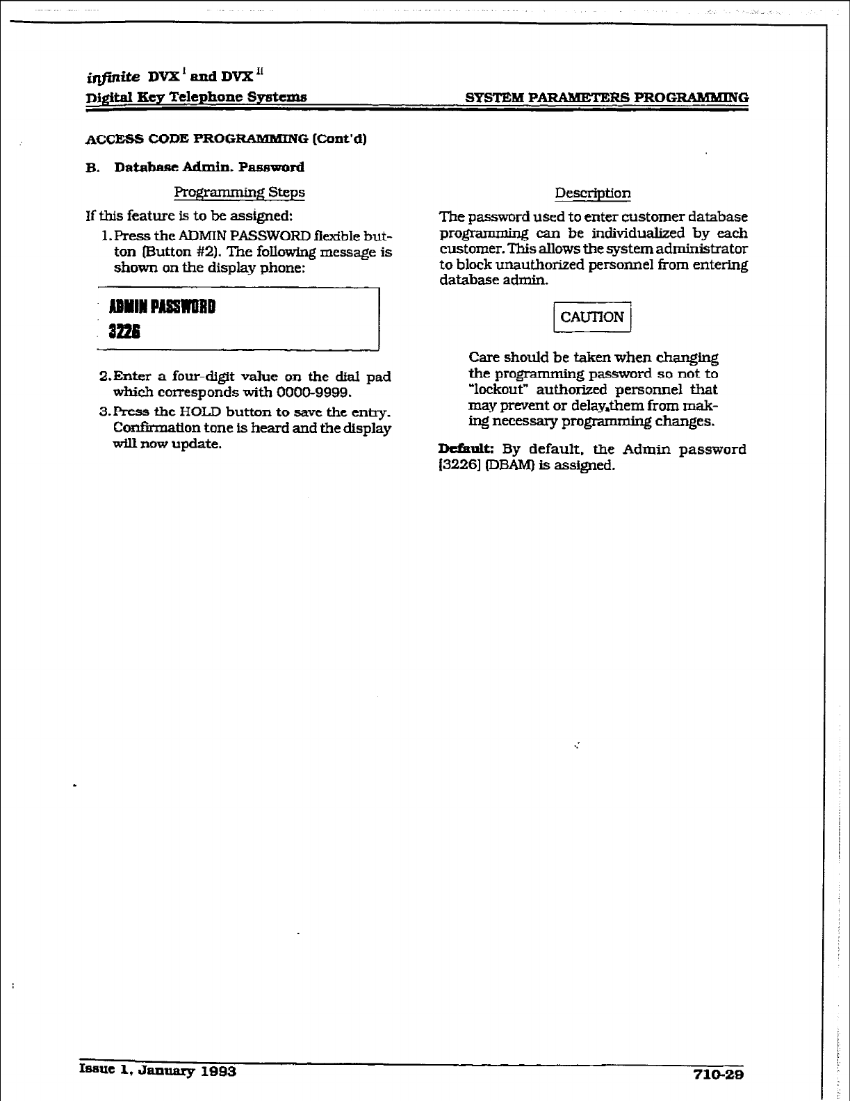
@j+tite DVX’andDvX1l
Digital Key Telephone Systems SYSTEM P- PROGRAMMING
ACC- CODE PROG- G [Cont’d)
B. Database Admin. Password
Programming steps Description
If this feature is to be assigned:
1. Press the ADMIN
PASSWORD
flexible but-
ton [Button #2). The
following message is
1
shown on the display phone: -
DYIIIPAmaBD
8226
-
The
password
used to enter customer database
programmiq can be individualized
by each
customer. This allows tbe system administrator
to block unauthorized personnel from entering
database admin-
-t
Care should
be taken
when changing
Z.Enter a four-di@t value
on
the &al pad
which corresponds with 0000-9999.
3.E’ress the HOLD button to save the entry.
CoxBmatlon tone is heard and the display
will now update.
the programming password so not to
“lockout” autfiorized personnel
that
may prevent or delay&em from mak-
ing necessary programming changes.
Dtfault: By default. the Admin password
f32261
IDBAM) is assigned.
.
Issue 1, January 1993 710-29
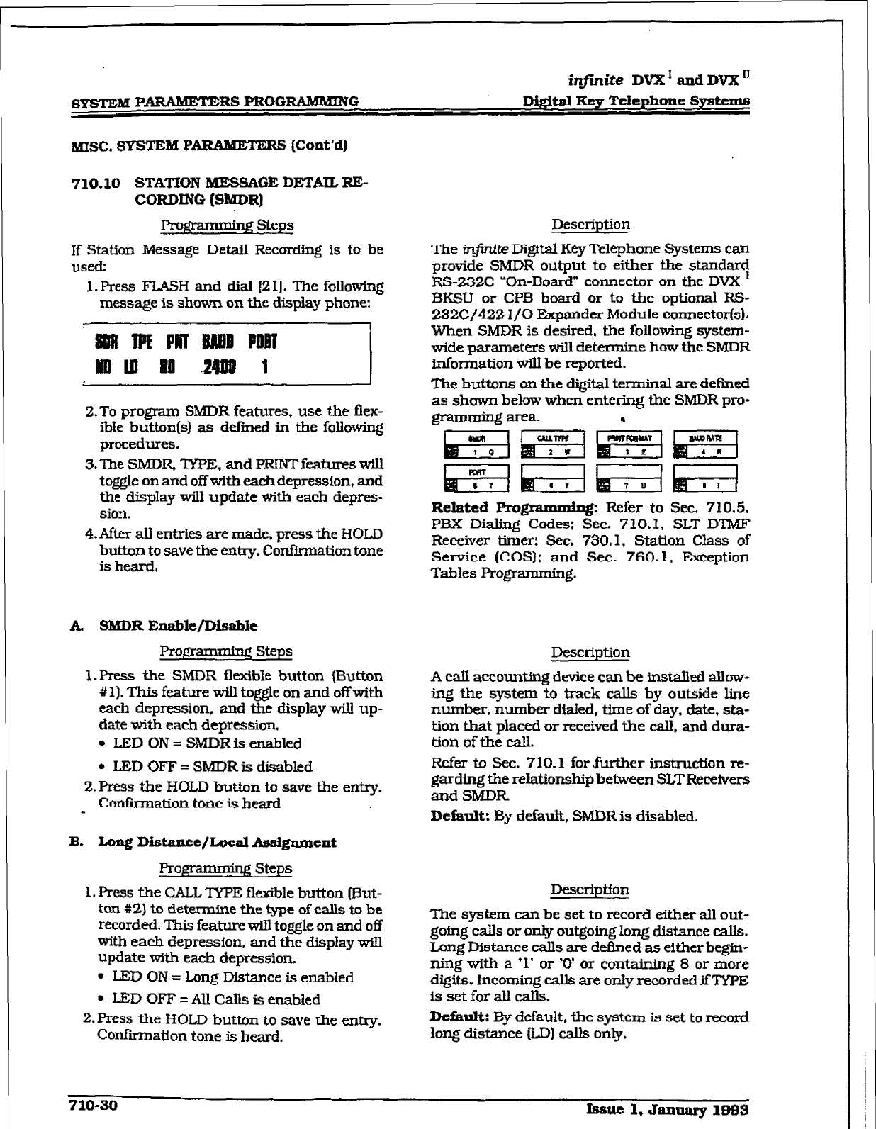
r
~PARtUWlXRSPROGIUMMiNG
infinite DVX’ and DVX’
Digital Key Tcieplxone Systems
MISC. SYSTEM
PARAB6ETERG (Cont’d)
710.10 STATION MESSAGE DETAIL RE-
CORDING
(SMDR)
Progiznmig Steps
If Station Message Detail Recording is to be
used:
1. Press FLASH and dial (2 11. The following
message is shown on the display phone:
::I
2.To program SMDR features, use the flex-
able button(s) as defiied in- the following
procedures.
3.The
SMDR TYPE. and
PRINT features will
t@e on and offwitb eachdepression, and
the display will update with each depres-
sion.
4.After all entries are made, press the HOLD
button to save the entry. Confirmation tone
is heard,
A SMDR Exmble/DisabIe
Programming steps
1. Press the SMDR flexible button (Button
# 1). This feature will toggle on and off with
each depression, and the display wili up-
date with each depression.
l
LED ON = SMDRis enabled
l
LED OFF = SMDR is disabled
2.Press the HOLD button to save the entry.
Confirmation tone is heard
-
B. Long DistaRce/~al kwdgnmeRt
Programdng Steps
1. Press the CALL TYPE flexible button (0ut-
ton #2) to determine the type of calls to be
recorded. This feature will toggle on and off
with each depression. and the display wiIl
update with each depression.
l
LED ON = Long Distance is enabled
l
LED OFF = All Calls is enabled
2.
I’RSS the HOLD button to save the entry.
Confirmation tone is heard.
Description
The inftrite Di#tal Key Telephone Systems can
provide SMDR output to either the standar<
RS-232C -On-Board” connector on the DVX
BKSU or CPB board or to the optional RS-
232C/422 I/O Expander Module connector(s).
When SMDR is desired, the following system-
wide parameters will determine how the SMDR
information will be reported.
The buttons on the digital terminal are defmed
as shown below when entering the SMDR pro-
.
Related pnogrammfng:
Refer to Sec. 710.5.
P3X Dialing Codes: Sec. 7 10.1, SLT D’IMF
Receiver timer, Sec. 730.1. Station Class of
Senrice (COS): and Sec. 760.1, Exception
Tables progtammiug.
Description
A call accounting device can be ir~stalkd allow-
ing the system to track calls by outside line
number. number dialed, time of day, date, sta-
tion that placed or received the call. and dura-
tion of the call.
Refer to Sec. 710.1 for further instruction re-
garding the rezationship between SLTReceivers
and SMDR
Default:
By default, SMDR is disabled.
Description
The system can be set to record either all out-
going calls or only outgoing long distance calls.
Lung Distance calls are def3ned as either begin-
ning with a ‘1’ or ‘0’ or containing 8 or more
digits. incoming calls are only recorded %?YPE
is set for all calls.
Default: By default, the system is set to record
long distance &D) calls only,
no-30
Issue 1. January lSa3
r
SYSTTEM PARAMETERS PROGRAMMING
STA’I’XON MESSAOE DETAIL RECORDmG
[Cont’d)
C. Character Print Assignment
Programmiq Steps Description
1. Press PRINT FORMAT flexible button (But-
ton #3) to determine the print format of
SMDR records. This feature wit1 toggle on
and off with each depression. and the dis-
play will update with each depression.
l
LED ON = 8O-Character is enabled
The system can be prograrmned to prtnt indi-
vidual SMDRrecords in either a l-line 8Gchar-
acter format or a 3-line 30 character format.
Defimlt: By default, the l-line 8O-character
format is selected.
l
LED OFF = 39Character is enabled
2. Press the HOLD button to save the entry.
Confirmation tone is heard.
11. Baud Rate Display
Proglramwq steps
The SMDR Baud Rate is programmed us-
ing Flash 15. Baud Rate Assfgnments. But-
ton #4 will return error tone when pressed.
The LCD displays the current baud rate
based on which Port number is assigned to
the SMDR Port number,
E. SMDR Port Assfgpments
1. Prfss the PORTflexfble button (Button #5)
to determine which port is to be used for
SMDR information.
2.Enter a one-digit number for the SMDR
- Port number:
- 1= Port # 1 (Wn-Board” RS-232C)
- 2= Port #2 (Wn-Board” Modem)
- 3= Port #3 Q/O Expander Module
Rs-232C)
- 4= Port #4 o/O Expander Module
Rs-422)
3.The LCD dispkgs the current baud rate
based on which Port number is assigned to
the SMDR Port number.
4. Press the HOLD button to save the entry.
Confknatlon tone is heard and the display
will now update.
I
Description
The injkite Digital Key Telephone Systems can
provide SMDR output to either the standary
FS232C “On-B0an-l” connector on the DVX
BKSU or DVX * CPB board or to the optional
RS-232C/422 I/O Expander Module connec-
totis), The Baud Rate will be displayed as either
300 baud, 1200 baud, 2400 baud, 4800 baud.
9600 baud.
Related Programmiq: Refer to 710.8, Baud
Rate Assignments for pro@ Elmming SMDR
Baud Rate Assignment.
Description
Poti It1 refm to the standard RS-232C ‘On-
Board” connector on tie DVX* Basic KSU or the
CPB board on the DVXn.
Port #2 refers to the “On-Board” 300 Baud
modem provided wit31 the system.
Port #9 refers to the RS232C connector on the
f/O Expander Module.
Port 114 refers to the RS422 copnector
on
the
same I/O Expander Module installed in either
ihjimf?Digitalsysta.
Dcf&Ak By default, Port #l is used for SMDR
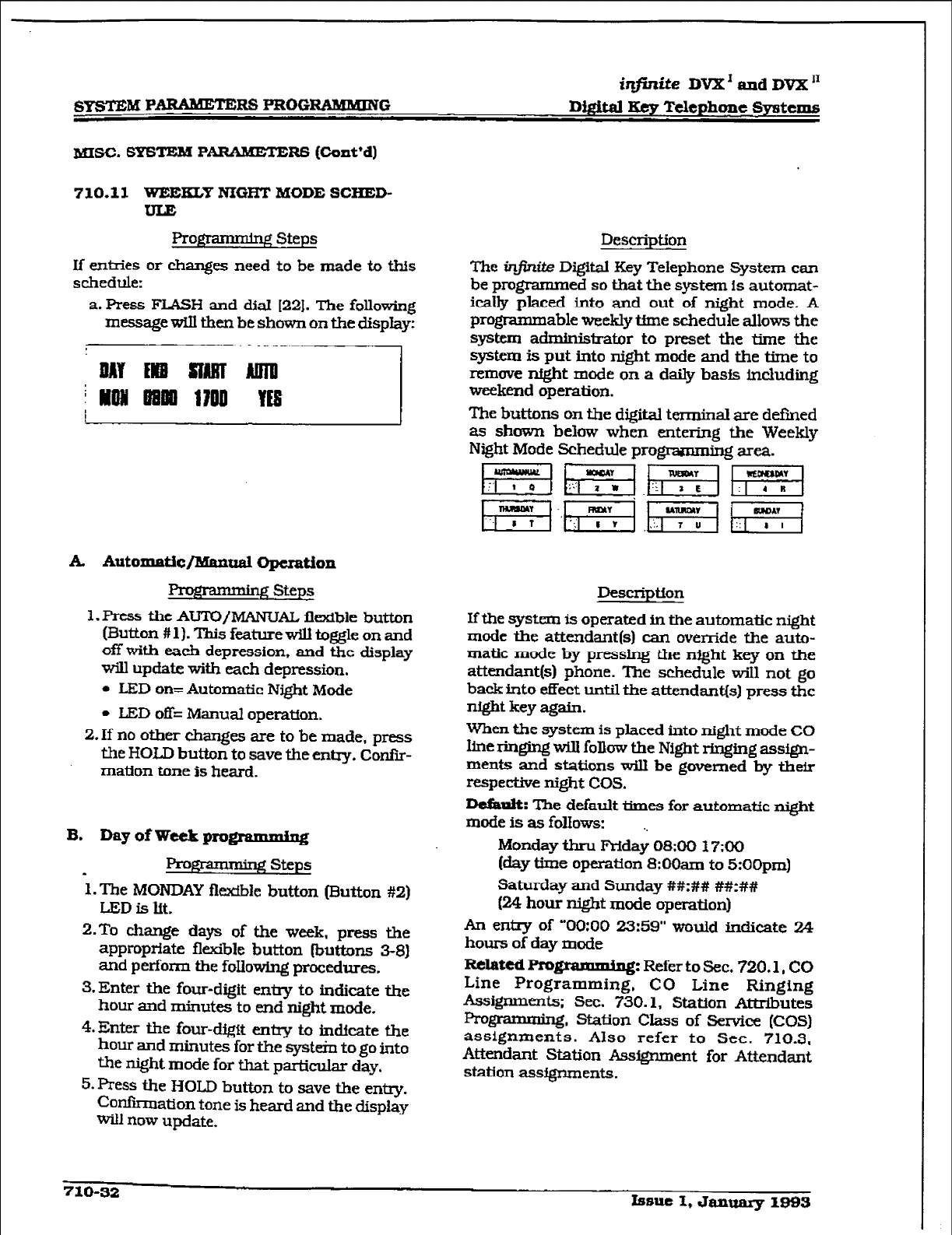
r
GYSTEILZ P
ARAMETERS PROGRAMBEING
iqfinite
DVX’ and DVX’
Digital Keg Telephone Systems
MISC. SYSTEM PARAMETE RS (Co&d)
710.11 WEEKLY NIGFM’ MODE SCHED-
F steps
If entries or changes need to be made to this
schedule:
a. Press FLASH and dial [22]. The following
message will then be shown on the display:
A. Automatic/lYIanual Operation
I3WmmWg Steps
1. FWss the AUTO/MANUAL flexible button
(Button #I 1). This feature wiU toggle on and
off with each depression, and the display
will update witi each depression.
l
LED on= Automatic Night Mode
l
LED off= Manual operatfon.
2. If no other changes are to be made, press
the HOLD button to save the entq. Con&
mation tone is heard.
B. Day of Week programming
Prom steps
1. The MONDAY flexible button (Button #2)
LED is lft.
2.To change days of the week, press the
appropriate flexible button (butk~ns 3-8)
and perform the following procedures.
3.Enter the four-digit entry to indicate the
hour and minutes to end night mode.
4.Enter the four-digit entry to indicate the
hour and minutes for the system to go into
the night mode for that particular day.
5. Press the HOLD button to save the entry.
Confkmation tone is heard and the display
wiil now update.
Description
The infinite Digital Key Telephone System can
be programmed so that the system is automat-
ically placed into and out of night mode. A
programmable weekly time schedule allows the
system administrator to preset the time the
system is put into night mode and the time to
remove nfgbt mode on a daily basis including
weekend operation.
The buttons on the digital terminal are defined
as shown below when entering the Weekly
Night Mode Schedule pro- area.
~~h-“T”;-l~pq
~j..gq m E/
Descriptfon
Ifthe system is operated in the automatic night
mode the attendant(s) can override the auto-
matic mode by pressing the night key on the
attendant[s) phone. The schedule wiI1 not go
back into efFect until the attendant(s) press the
night key again.
When the system is placed into night mode CO
line ringing will follow the Night ringfng assign-
ments and stations will be governed by their
respective night COS.
D&II%: The default ttmes for automatic night
mode is as follows: ,,
Monday tbru Friday OS:00 X7:00
(day time operation 8:0&n to 5:OOpm)
Saturday and Sunday ##:## ##:##
(24 hour night mode operation)
An entry of “0O:OO 23:59” would indicate 24
hours of day mode
RelattdPro gramming: Refer to Sec. 720.1, CO
Line Programming, CO Line Ringing
Assigmnents; Sec. 730.1, Station Attributes
programming station class of Service (COS)
assignment;. Also refer to Sec. 710.3,
Attendant Station Assignment for Attendant
station assfgnments.
710-32 Issue I, dalluary 1993
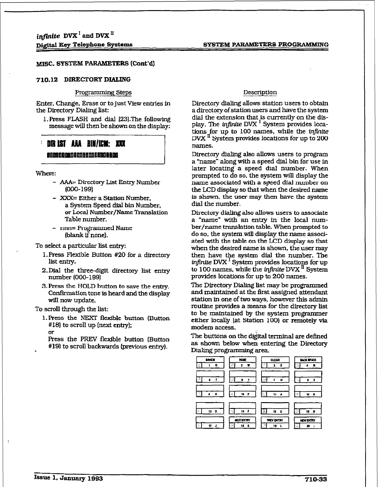
r
i@dte DVX I and DVX’
J-&$&II Key Ttfephone Systems
b!nsc. SYSTEM PARAMETE RS (Cunt’d)
710.12 DIRECTORY DIALING
Pro~amming Steps Description
Enter. Change, Erase or to just View entries in
the Directory Dialing list:
1. Press FLASH and dial I23LThe following
message will then be shown on the display;
Directory dialing allows station users to obtain
a directory of station users and have the system
dial the extension that is currently on the dis-
play. The infinite DVX ’ System provides loca-
tions for up to 100 names, while the infinite
DVX ’ System provides locations for up to 200
names.
WhtTfX
- AAA= Directory List Entry Number
(ooo- 199)
- XXX= Either a Station Number,
a System Speed d&d bin Number,
or Local Number/Name Translation
Table number.
Directory dialing also atlows users to program
a “name” along with a speed dial bin for use in
later locating a speed diaJ number. When
prompted to do so. the system will display the
name associated with a speed dial number on
the LCD display so that when the desired name
is shown, the user may then have the system
dial the number.
- n.nn= Programmed Name
(blank if none).
To select a particular list entry:
I. Press Flexible Button #20 for a directory
list entry.
2-M the three-digit directory list entry
number (000-199)
3. Press the HOLD button to save the entry.
Confirmation tone is heard and the display
will now update.
To scroll through the list:
l.Press the NEXT flex&Ie button (Button
#I81 to scroll up (next e&y);
or
Press the PREV flexMe button (Button
#19) to scroll backwards [previous entry).
-
Directory dialing also allows users to associate
a kame” with an entry in the local num-
ber/name t.ransIaffon table. When prompted to
do so. the system will display the name associ-
ated with the table on the LCD display so that
when the desired name is shown, the user may
then have the system dial the number. The
infinite DVX I System provides locations for up
to 100 names. while the in@r& DVX ’ System
provides locations for up to 200 names.
The Directory Dialing list may be programmed
and maintained at the first assigned attendant
station in one of two ways, howeve rthisadmin
routine prvvides a means for the directory list
to be maintained hy the system programmer
either kally [at Station 100) or remotely via
modem access.
The buttons on the d&al terminal are defined
as shown below when entering the Directory
Dialingprogr . ~area.
pq~pfgF/
m m fEG.E{
IBsue 1. January 1993 710-33
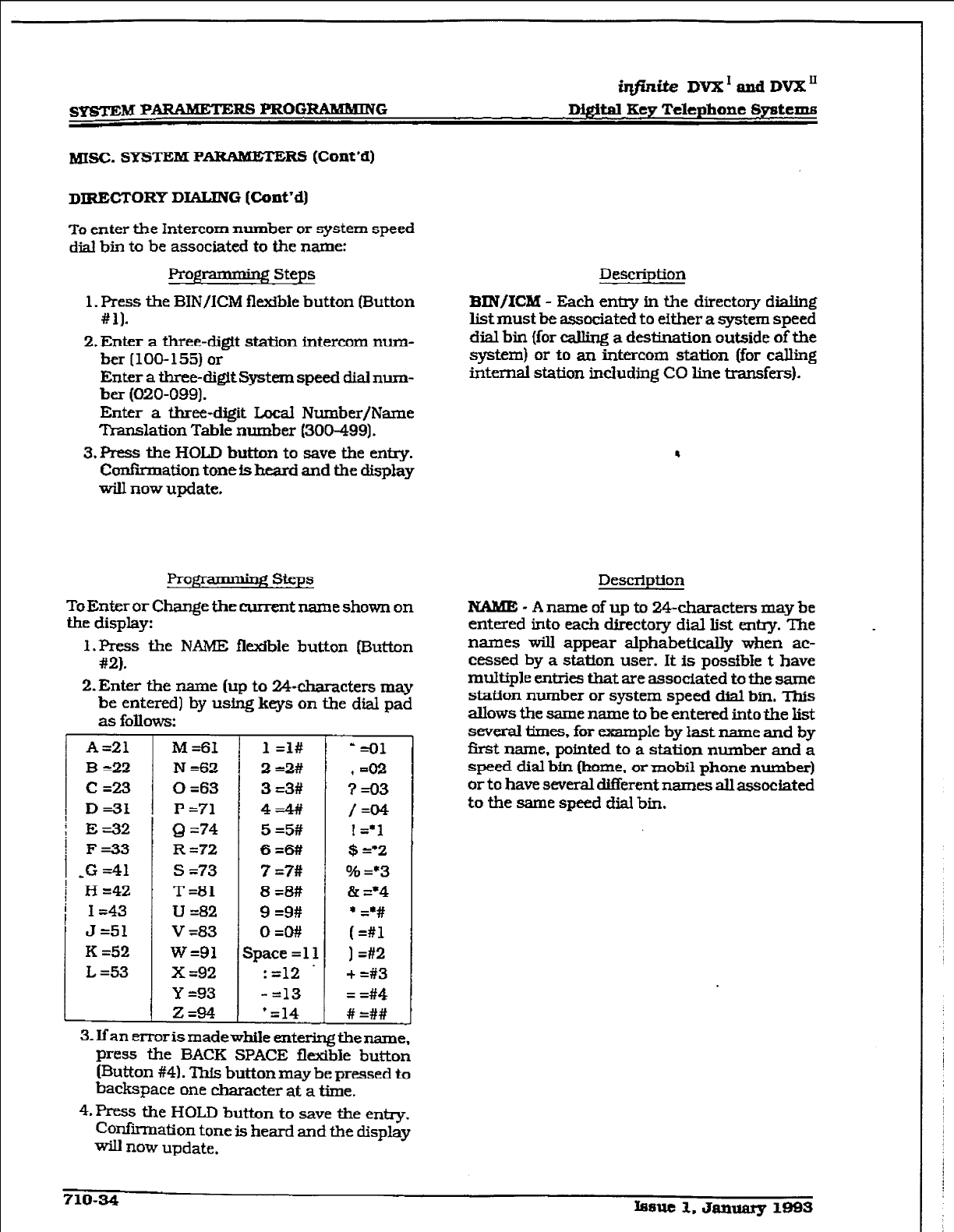
sys~‘~M PARAMETERS PROGRAMMING
@finite DVX’andDVX”
Digital Key
Telepbonc Systems
MISC. SY?xFcM P
ARAMmERs (Cont’d)
DIRECTORY DIALING (tint ‘d)
To enter the Intercom number or system speed
dial bin to be associated to the name:
Projpmming Steps
1. Press the BIN/ICM fl&ble button (Button
#ll.
2. Enter a three-digit station intercom num-
ber (100-155) or
Enter a three-digItSystem speed dial num-
ber (020-099).
Enter a three-dgit Local Number/Name
Translation Table number (300-499).
3.Press the HOLD button to save the entry.
Car&m&ion tone is heard and the display
will now update.
Fro)qammbg steps
ToEnter or Change the eurren t name shown on
the display:
1 .Press the NAME flexible button (Button
#2).
2.Enter the name (up to 24-characters may
be entered) by using keys on the dial pad
as follows:
A=21
B =22
Cd!3
D=31
E-32
F=33
,G =41
H =42
I =43
J=51
K =52
L =53
M ~61
N =62
0 =63
P =71
Q =74
R =72
s =73
T=81
u =82
V =83
w=91
x =92
Y 293
Z&4
1 =l#
2 =2#
3 =3#
4=4#
5 =5#
6=6#
7 =?#
8=8#
9 =9#
0 =O#
Space =ll
:=12 .
- =13
’ =14
‘=ol
* =02
?=03
/=04
! =*1
$ =*2
016 93
& =*4
* &#
( =#l
] =#2
+ =#3
= =#4
# =##
3. Ifan error is made while entering the name,
press the BACK SPACE flexible button
(Button #4). This button may be pressed to
backspace one character at a time.
4.Pre.s~ the HOLD button to save the entry.
Confrrrnation tone is heard and the display
will now update.
Description
BIN/XC&I - Each entry in the directory dialing
list must be associated to either a system speed
dial bin (for calling a destination outside of the
system) or to an intercom station (for calling
idxnal station including CO line transfers).
Description
NAME - A name of up to 24-characters may be
entered
into each
directory dial list entry. The
names will appear alphabetically when ac-
cessed by a station user. It is possible t have
multiple entries that are associated to the same
station number or system speed dial bin. This
allows the same name to be entered
into the
list
several times. for exxnple by last name and by
first name, pointed to a station number and a
speed dial bin [home. or mobil phone number)
or to have several different names all associated
to the same speed dial bin,
710-34 ISa& 1. January 199s
iqjhitt?
DVX’andDVXn
DQm Key Telephone Systems
smnu PAIWMETERS PROGRABUMNQ
MISC. SYSTEM Pm (Cont’d)
DIRECTORY DIALING (Co&d)
To ckar an entry:
Prog -lgsteps
1 -Press the CW flexible button (Button
#3).
2.
Press the HOLD button to save the entry.
Conffrmation
tone is
heard and the display
wiU now update. The em-y will be erased
(both the BIN/ICM assignment and the
programmed name).
Description
CLEAR - Entries in the table may be erased and
cleared from the table allowing another entry to
be
placed into the list. When a system speed
dial bin has been deleted
or changed the
name
associated tc the bin must also be erased. As
multiple table listing may
be
assodated to one
system
speed dial bin it may be necessary to
clear
more than
one entry.
.
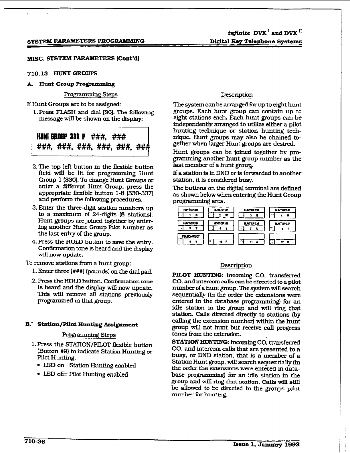
.;
SYSTEM PARAM.EE= PROGRAMMING
&finite DVX’ and DVX’
D&&al Key Telephone Systems
MISC. SYSTEM PARAMETE RS (Cont’d)
710.13 EruNT GROUPS
1f Hunt Groups are to be assigned:
f . Press FLASH and dial f30J. The following
message wiIl be shown on the display:
2.The top left button in the fle&ble button
field will be lit for programming Hunt
Group I @30). To change Hunt Groups or
enter a &f&rent Hunt Group. press the
appropriate flexible button 1-S (330-337)
and perform the following procedures.
3. Enter the three-digit station numbers up
to a maximum of !24-digits (8 stations).
Hunt groups are joined together by enter-
ing another Hunt Group pilot Number as
the last entry of the group.
4. Press the HOLD button to save the entq.
Confxmation tone is heard and the display
will now update.
To remove stations from a hunt group:
1. Enter three I###] ~pounds] on the dial pad.
2. Press the HOLD button. Confirmation tone
is heard and the display will now update.
This will remove all stations previously
programmed in that group,
B-- tW~titxx/~ot Hunting Assignment
Prom Steps
1. Press the STATION/PILMI‘ flexible button
[Button #9) to indicate Station Hunting or
PIlot Hunting.
l
L.ED on= Station Hunting enabled
l
LED off= Pilot Hunting enabled
Description
The system can be arranged for up to eight hunt
groups. Each hunt group can contain up to
eight stations each. Each hunt groups can be
independently arranged to utilize either a pilot
hunting technique or station hunting tech-
nique. Hunt groups may also be chained to-
gether when larger Hunt groups are desired.
Hunt groups can be joined together by pro-
grammjng another hunt group number as the
last member of a hunt grout.
If a station is in DND or is forwarded to another
station. it is conside+ busy.
The buttons on the digital terminal are defined
as shown below when entering the Hunt Group
prog - garea.
Description
PILOT HUNTING: Incoming CO, transferred
CO. and intercom calls can be directed to a ptiot
number of a hunt group. ‘llxe system will search
sequenWy (in the order the extensions were
entered in the database programming) for an
idle station in the group and will ring that
station. Calls directed direct@ to stations (by
calling the extension number) witi the hunt
group will not hunt but receive call progress
tones from the extension.
STATION m 0: Incoming co, transferred
CO, and intercom calls that are presented to a
busy, or DND station, that is a member of a
Station Hunt group, will search sequentially (in
the order the extensions were entered in data-
base programming] for an idle station in the
group and wiU ring that station. calls will st.iSl
be allowed to be directed to the groups pilot
number for hunting.
710-36 Issue 1, January 1993
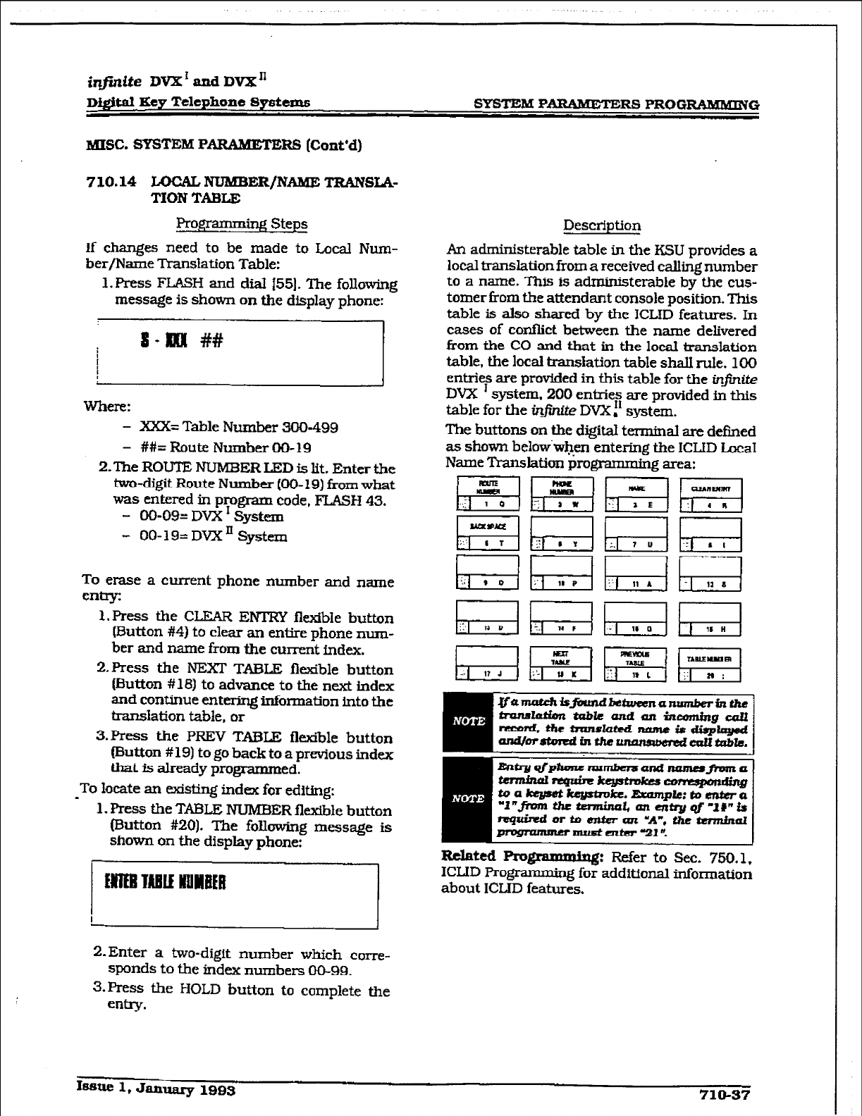
iqfinite DV2C’andDVX”
Di@td Key
Telephone Spstems SYSTEM P-RS PRUGIlAMMING
MISC. SYSTEM PARAMETE RS (Cont’d)
7 10.14 LUCAL NlJMBER/NAME TRANSIA-
TIUN TABLE
Proffrarnrning Steps
lf changes need to be made to Local Num-
ber/Name Translation Table:
1. F’ress FLASH and dial 1551. The following
message is shown
on
the display phone:
]I
mere:
- XXX= Table Number 300-499
- ##= Route Number 00-19
2.The ROUTE NUMBER LED is lit. Enter the
two-digit Route
Numbu (00- 191 frm
what
was entered in program code, FUSH 43.
- 00-09= DVX I
System
- O&19= DVXn System
To erase a current phone number and name
entry:
l.F’ress the CLEAR ENTRY flexible button
(Button #4) to clear an entire phone num-
ber and name from the current index.
2.Press
the NEXT TABLE flexible button
(Button # 16) to advance to the next
index
and continue entering information into the
translation table,
or
3.F’ress
the PREV TmLE flexible button
[Button # 19) to go back to a previous index
that is already programmed.
-
To locate an existing index
for
editing:
1. FYess the TABLE
NUMBER flexible button
(Button
#20).
The following message
is
shown
on the display phone:
,,,.,,
%-Enter a two-digit number which
corn-
spnds to the index numbers 00-99.
3.~ss the HOLD button to complete the
entry.
Description
An administerable table in the KSU provides a
local translation from a received c&ng number
to a name. This is administerable by the cus-
tomer from the attendant console position. This
table is also shared by the ICLlD features. In
cases of conflict between the name delivered
from the CO and that in the locat translation
table. the local translation table shall rule. 100
entries are provided in this table for the infinite
DVX ’ system, 200 entries are provided in this
table for the inj?nUe DVX f ’ system.
Tbe buttons on the digital terminal are
defined
as shown below.w+n entering the 1CLlD l.ccal
Name Translation programming area:
Related Pm
Braqmriae: Refer to Sec. 750.1.
ICLID Programmmg for additional information
about ICLID features.
Issue 1, January 1995 710-57
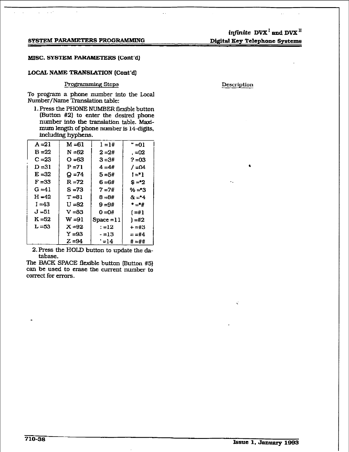
.
@finite DVX’ and DV2X”
8YsTEM PARAMETERS PROGRAMMlNG Di@t.al Ecy Telephone Systems
MISC. SYSTEM PARAMETE
FtS (Cont’d)
LOCAL NAME TRANSLATION [Cont’d)
Pm@ * .,steps
To progmm a phone number into the Local
Number/Name Translation table:
1. Press the PHONE NUMBER flexible button
(E&.&ton #2) to enter the desired phone
number into the translation table. Maxi-
mum length of phone number is I$-digits,
including hyphens.
D =31
E=32
F=33
G =41
H =42
I -43
J =51
K =S2
L =53
M =61
N =62
OS3
P=71
Q =74
R =72
s =73
T=Bl
U =82
v=83
w=91
x =92
Y =93
Z=94
7
1 =I#
2 =2#
3 =3#
4=4#
5 =5#
6 =6#
7 =7#
8 =8#
9 =9#
0 =O#
$.xxe=ll
: =l2
- =13
’ -14
“=ol
,=02
?=Q3
/=04
1=*1
$ =*2
o/s =*3
& =‘4
+ d#
(=#l
] =#2
+ =#3
= =#4
# =##
.
2. Press the HOLD button to update the da-
tabase.
The BACK SPACE flexible button (Button #5)
can be used to erase the current number to
correct for errors.
Description
710-38
Issue 1. January 1993
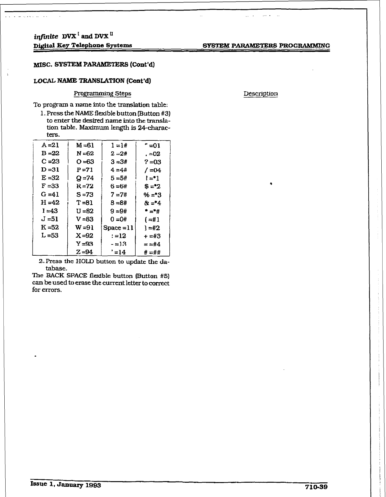
_ _ . .
i@zite DVX’ and DV2C”
D&itd Key Telephone Systema SYSTEM PARAMETERS PROGIUUKMING
MISC. SYsrnM PA,IuMEm RS (Cmt’d)
LOCAL NAME TRANSLATION (Cont’d)
Rogrammiry! Steps
To progam a name into the translation table:
1. Press the PJAME flexible
button
mutton #3)
to enter the
desired name
into the transla-
tion table. Maximum Iergth is 2-+charac-
ters.
A=21 M561
B -22
N -62
C=23 0=63
D=31
f =?l
E =32 Q =?4
F =33
G =41
H =42
I=43
J =51
K =52
L=53
R =72
s =73
T =81
u =82
v=a3
w=91
x=92
Y=93
Z=94
4=# /=04
5 =5# I
I=*1
6 =6# $ =*2
7 =?# % =*3
a =8# & =*4
9 =9#
l G#
cl =O# (=#l
Space
= 11
i
) =#2
: =12 + =#3
- =13
=
=#4
‘=14 # =##
Description
2. Press the HOLD button to update the da-
tabase.
The BACK SPACE flexible button (R.&ton #5)
can be used to erase the current letter to correct
for errors.
.
Isme 1, January 1993 710.39
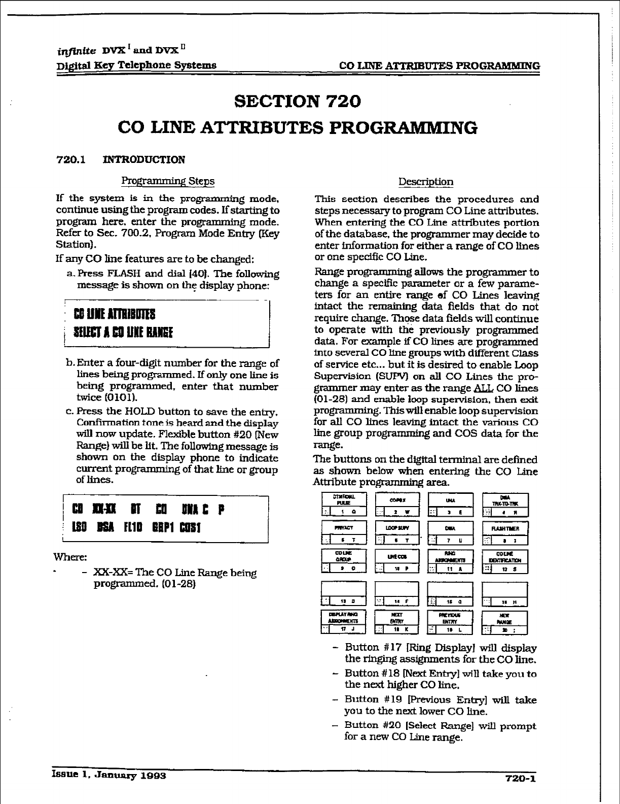
r
in_finite DVX'andDVX'
D~~KeyTclepho~eS~telIlB CO LINE ATITUBUTES PROGRAMMING
SECTION 720
CO LINE ATTlUBUTES PROG-NG
720.1 ~ODUGTION
l?rogramming steps
If the system is in the progr * ’ g mode,
continue using the program codes. IfstarLing to
program here, enter the programming mode.
Refer to See. 700.2, Program Mode Entry (Key
Station).
If any CO line features are to be changed:
a. Press FLASH and dial 1401. The following
message is shown on thgt display phone:
51
b. Enter a four-digit number for the range of
lines being programmed. If only one line is
being programmed, enter that number
twice (0101).
c. Fress the HOLD button to save the entry.
Confirmation tone is heard and the display
will now update. Flexible button #20 [New
Range) will be lit. The following message is
shown on the display phone to indicate
current progmmming of that line or group
of lines.
- XX-XX= The CO Line Range being
programmed. (01-281
Description
This section describes the procedures and
steps necessary to progmm CO Line attributes.
When entfxing the CO Line attributes portion
of the database, the programmer may decide to
enter information for either a range of CO lines
or one spedfic CO Line.
Range pro- allows the programmer to
change a specific parameter or a few parame-
ters for an entire range of CO Lines leaving
intact the remaining data fields that do not
require change. ThFe data fields will continue
to operate with the previously programmed
data. For example ifC0 lines are programmed
into several CO line groups with different Class
of service etc... but it is desired to enable Loop
Supervision (SUPV) on all CO Lines the pro-
grammer may enter as the range BLb, CO lines
(01-28) and enable loop supervision, then wdt
programming. This will enable loop supervision
for all CO lines leaving intact the various CO
line group programming and COS data for the
range*
The buttons on the digital terminal are defined
as shown below when entering the CO L,ine
Attribute progmmming area.
pfq pig &j Fi
p+q~~~
- Button #17 [Ring Display] will display
the ringing assignments for the CO line.
- Button # 18 lrJext Entry] will take you to
the next higher CO line,
- Button #I9 Previous Entry] will take
you to the next lower CO line.
- Button #20 [Select Range] will prompt
for a new CO Line range.
lsa~l,JanuarylQQS 720-l
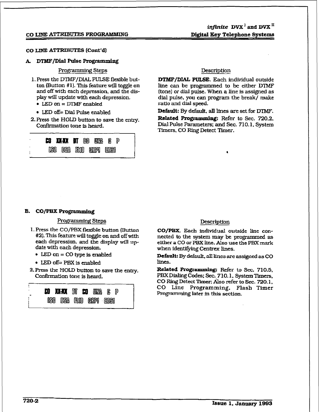
r
CO LINE ATTRIBUTES PROG-G
ir@.nite DVX’ and DVX”
Di@.aI Key Telephone Systems
co LINE A’ITRTBUTES [C-onYd)
A DTMF/Dial P&e Progmz
Profprmming Steps
1. Press the DTMF/DIAL PULSE flexible but-
ton fButton
#l]. This
feature will toggle on
and off with each depression. and the dis-
play will update with each depression.
l
LED on = DTMF enabled
l
IlED off= l&I Pulse enabled
2.Ress
the HOLD button
to save the entry.
B. CO/PBX programming
ROgI
’ lg steps
1. Press the CO/PBX flexible button (Button
#2).
This feature will
toggle
on and off with
each depression, and the display will up-
date with each depression.
l
LBDon= co type is enabled
l
LED off= PBX is enabled
2.Press the HOLD button to save the entry.
Confirmation tone is heard.
Description
m/DIAL
PULSE.
Each individual outside
line can
be
programmed to bc either DTMF
(tone) or dial pulse. When a line is assigned as
dial pulse, you can program the break/ make
ratio and dial speed.
Default:
By default, all lines are set for UKMF.
Related Rogzam&mg:
Refer to Sec. 720.2,
Dial Pulse Parameters; and Sec. 710.1. System
Timers. CO Ring Detect Timer.
Descriptron
CO/PBX. Each in&iduaI
outside line con-
nected to the system may be programmed as
either a CO or PBX line. Also use the PBX mark
when identifying Centrex lines.
Default: By default, alllines are assigned as CO
lines.
Related Progmnming Refer to Sec. 710.5,
PEX Dialing codes; sec. 710.1. systeIIlTimers.
CO Ring Detect l%nec &so refer to Sec. 720.1,
CO Line Programming, Flash Timer
Prog-nmdng later fn this section.
720-2 Ismut 1, Januarg 19Bs
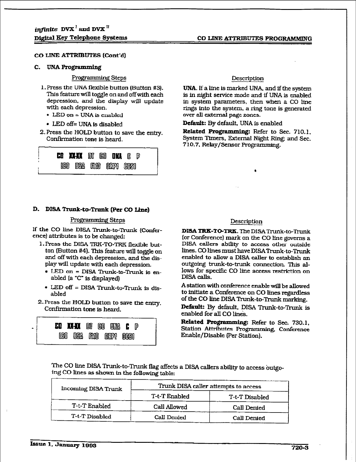
r
iJZFn@e DVX’ and DVX If
digital Key Telephone Systems CO l.JNE ATTRIBUTES PROGIUBKMING
CO LINE ATTRIBUTES (Cont’d)
Pro@krmning Steps Description
1. Press the UNA flexible button Button #3).
This feature will toggle on and off with each
depression, and the display will update
with each depression.
l
LJSD on = UNA is enabled
. LED off= UNA is disabled
2. Press the HOLD button to save the entry.
Confirmation tone is heard.
UNA. If a line is marked UNA, and if the system
is in night setice mode and if UNA is enabled
in system parameters, then when a CO line
rings into the system, a ring tone is generated
over all external page zones.
Defarrlt: By default, UNA is enabled
R&ted Pro-: Refer to Sec. 710.L.
System Timers. External Night Ring; and Sec.
710.7. Relay/Sensor Programming.
.
D. DIM Trunk-to-Tnmk (Per CO Ibnt)
R-c,
’ gsteps
If the CO line DISA Trunk-to-Trunk (Confer-
ence) attributes is to be cfianged:
1. Press the DISA TRIGTO-TRK fltible but-
ton (Button #4). ‘Ihis feature will tog&e on
and off with each depression, and the dis-
play will update with each depression.
l
LEDon = DlsA Trunk-to-rrunk is en-
abled (a ‘C” is displayed)
l
LED off = DISA Trunk-to-Trunk is dis-
abled
2.Press the HOLD button to save the entry.
Confiition tone is heard.
Description
DXSA TRK-TO-TRK The DiSAlYunk-to-Ttunb
(or Conference) mark on the CO line governs a
DISA callers ability to access other outside
lines. CO lines must have D&AR-u&-to-M
enabled to allow a DISA caller to establish an
outgoing bunk-to-trunk connection. This al-
lows for spedik CO line access restriction on
DIM calls.
A station with conference enable will be allowed
to initiate a Conference on CO lines regardless
of the CO iine DISA Trunk-to-‘Punk marking.
Dcfixnik By default, DISA Tkunk-to-Trunk is
enabled for aJ.I CO lintk
Related Progrrq: Refer to Sec. 730.1,
Station Attributes Programming, Conference
Enable/Disable (Per Station).
The CO line DISA Trunk-to-Trunk flag affects a DISA callers ability to access butgo-
it-g CO lines as shown in the following table:
Incoming DISATrunk .
T-t-T Enabled
T-t-T Disabled
Trunk DLSA caller attempts to access
T-t-T Enabled T-t-T Disabled
Cdl Allowed Call Denied
call Denied Call Denied
hue 1. Janq 1993 720-a
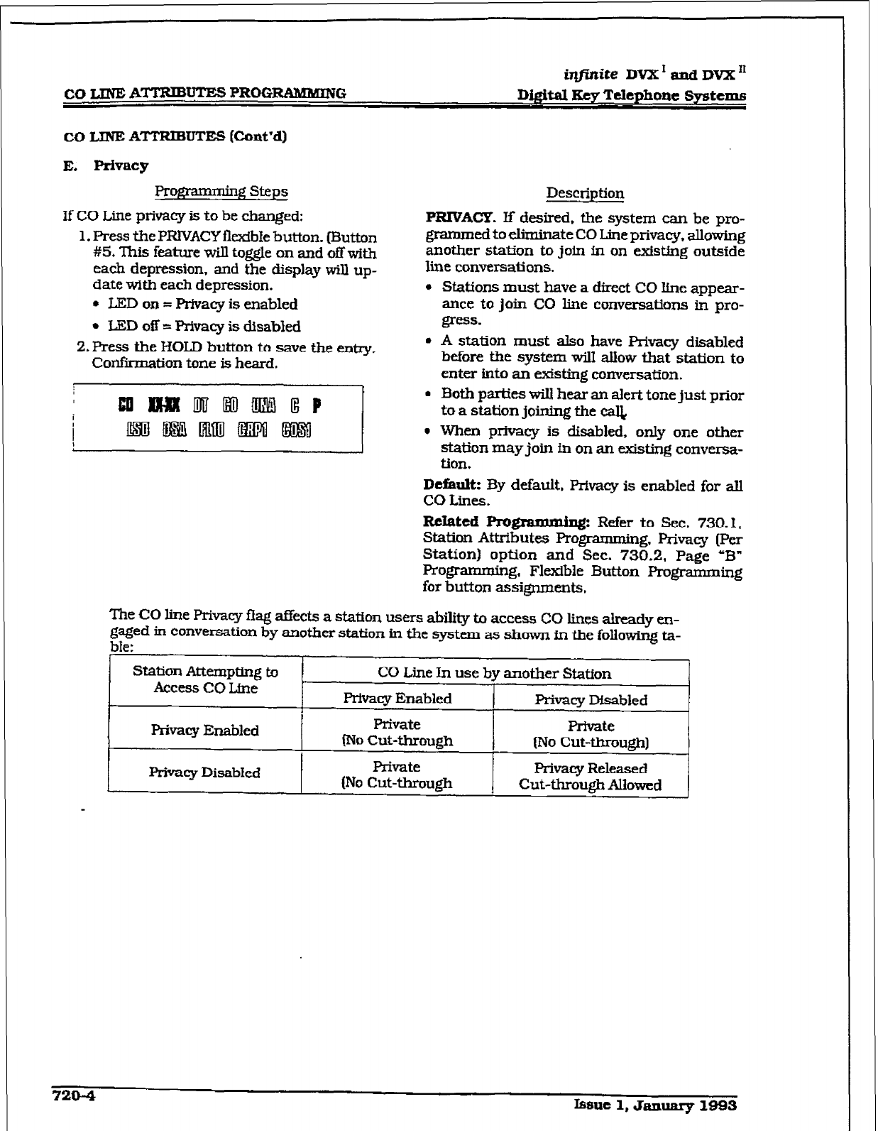
iqj%ite
DVX ’ and DVX I1
co z;LNE AWUTE!j PROGRAMMING Dig&al Key Telephone
Systems
co LINE
ATTRE3UTES
@unt’dI
E. privacy
Pro@ ~‘gsteps
If CO L.ine privacy is to be changed:
1. Press the PRIVACY flexible button. (Button
#5, This feature will toggle on and off with
each depression. and the display will up-
date with each depression.
* IED on = Privacy is enabled
* LED 0s = Privacy is disabled
2. Press the HOLD button to save the entry.
Confirmation tone is heard.
Description
RRIVACY.
If desired. the system can be pro-
gramrned to eliminate CO Line privacy, allowing
another station to join in on existLng outside
line conversations.
l
Stations must have a direct CO Hne appear-
ance to join CO line conversations in pro-
gRSS.
l
A station must also have Privacy disabled
before the system wilI allow
that
station to
enter into an existing conversation.
L/
l
Both parties will hear an alert tone just prior
to a station joining the cal&
l
When privacy is disabled, only one other
station may join tn on an existing conversa-
tion.
D&ulk By default, Privacy is enabled for all
co Lines.
RcIated Rogmmming: Refer to Sec. 730.1,
Statian Attributes Programming, F’rivaq (Per
Station) option and Sec. 730.2, Page ‘B”
Programming, Flexible But-ton Programming
for button assignments.
The CO line. Privacy f.f ag affects a station users ability b access CO lines already en-
gaged in conversation by another station in the system as shown m the following ta-
ble:
Station Attempting to
Access CO Line CO Line In use by another Station
Privacy Enabled Privacy Msabled
1
privacy Enabled
1
Private Private
No Cut-through (No cLlt-through)
1
Privacy Disabkd Private
(No Cut-through I
Privacy Released
Cut-through Allowed
7204 Issue 1, Ja3lualy I.093
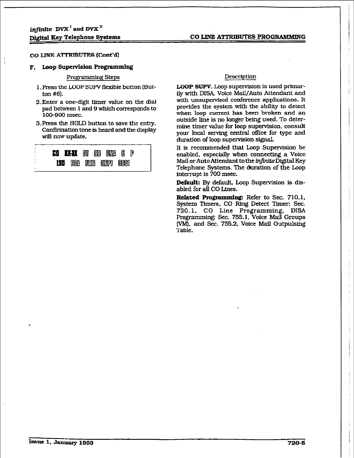
irlfinfte DvX’andDvX”
DQ.$w &y Telephone
Systems
CO
LlNl3A~U’Xl-S
PROG-G
co IJNE ATTRIBUTES (Cont’d)
Pro$!yM steps
1. Press the LOOP SUPV flexible button (But-
ton #61.
2,Enter a one-digit timer value on the dial
pad between 1 and 9 which corresponds to
100-900 msec.
3.Press the HOLD button to save the entry.
Confirmation tone is heard and the display
will now update.
Description
LOOP SUPV. Loop supervision is used primar-
ily with DlSA, Voice MaiI/Auto Attendant and
with unsupervised conference applications. It
provides the system with the ability to detect
when loop current has been broken and an
outside line is no longer being used. To deter-
mine timer value for loop supervision, consult
your local serving central office for type and
duration of loop supervisfon signal.
It is recommended that Loop Supervision be
enabled, especially when connecting a Voice
Mail orAuto Attendant to the infinite Digital Key
Telephone Systems. The duration of the Loop
interrupt is 700 msec.
Default: By default, Loop Supervision is dis-
abled for all CO Lines.
Related
Progl%mldng: Refer to Sec. 710.1,
System Thners. CO Ring Detect Timer; Sec.
720.1, CO Line Programming. DISA
Pro-: Sec. 755.1, Voice Mail Groups
(VI@, and Sec. 755.2, Voice Mall Outpulsing
Table.
h3uel.Jfmuaq1993 720-b
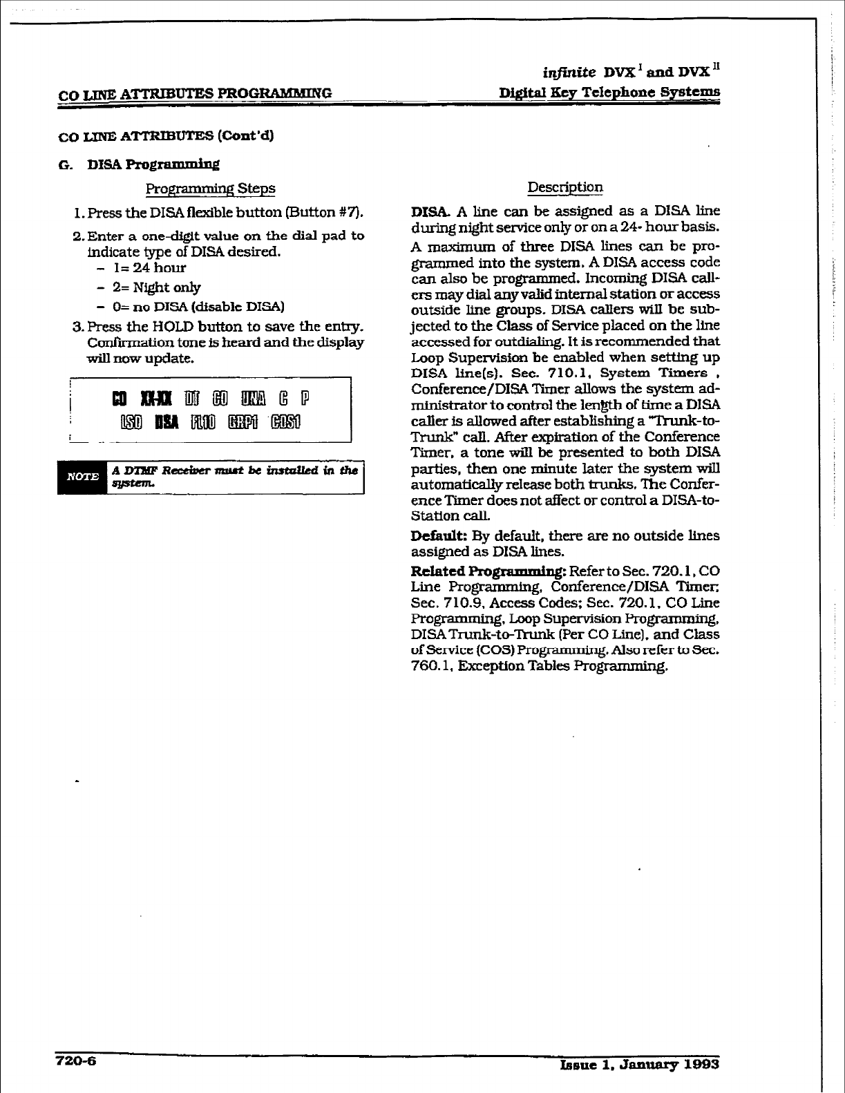
infutite DVX’ and DVX”
Dij@tal Xcy Telephcme Systems
G. Dl!SA Programming
Profframming steps
I. Press the DISA flexible button (Button W).
2. Enter a one-digit value on the dial pad to
Indicate type of DISA desired.
- I= 24hou.r
- 2= Night ordy
- 0= no DISA (disable DISA)
3. Press the HOLD button to save the entry-
Confirmation tone is heard and the display
will ROW update.
Description
DIM. A line can be assigned as a DlSA line
during night service only or on a 24- hour basis.
A maximum of three DISA lines can be pm-
gmmmed into the system. A DISA access code
can also be programmed. Incoming DISA call-
ers may dial any vaIid internal station or access
outside Iine groups. DISA callers WiII be sub-
jected to the Class of Setice placed on the line
accessed for outdiahng. It is recommended that
hop Supervision be enabled when setting up
DISA Iine(s). Sec. 710.1, System Timers ,
Conference/DISA Timer allows the system ad-
ministrator to control the length of time a DISA
caller is allowed after establishing a “lYmk-to-
Tnmk” cdl. After expiration of the Conference
Timer. a tone will be presented to both DISA
parties, then one minute later the system will
automatically release both trunks, ‘Ike Confer-
ence Timer does not affect or control a DISkto-
station CalI.
Default: By default, there are no outside rines
assigned as DEA lines.
F&elated Ro grrg: Refer to Sec. 720.1, CO
Line Programming, Conference/DISA Timer:
Sec. 710.9. Access Codes: Sec. 720.1. CO Line
Pro@ * ig, Loop Supervision ProgmmmUng
DISATrunk-to-Trunk (Per CO Line]. and Class
of Service (COS) Programming. Also refer to Sec.
760.1, Exception Tables Programming.
720-6 Il5sue 1. January 199s
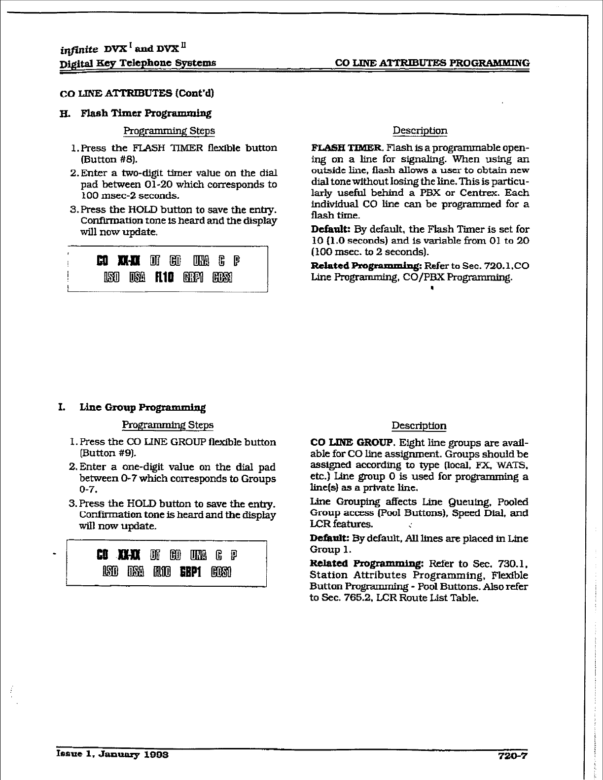
irlfinite DVX’andDVXn
~)@taI zxey Telephone Systems CO LINE ATTRIBIJTES PROGRAMMING
CO LINE ATTRIBUTES (Cont’d)
W. FlashTfmcr Programming
Pr0jpnmm.g Steps
l.Press the FLASH TIMER flexible button
(Button #8).
Z.Enter a two-digit timer value on the dial
pad between 01-20 which corresponds to
100 msec-2 seconds.
3.Press the HOLD button to save the entry.
ConiTirmation tone is heard and the display
will now update.
I.
Line Group Programming
Prw Steps
I. Press the CO LINE GROUP flexible button
[Button #9).
2. Enter a one-digit value on the dial pad
between O-7 which corresponds to Groups
o-7.
3. Press the HOLD button to save the entry.
Confiiation tone is heard and the display
wiIl now update.
Description
FLASH
TIMER.
Flash is a programm able open-
ing on a line for signaling. When using an
outside line. flash allows a user to obtain new
dial tone without Iosing the line. This is particu-
larly useful behind a PBX or Centrex. Each
indivfdual CO line can be programmed for a
flashtime.
Default:
By default, the Flash Timer is set for
10
(1
.O seconds) and is variable
from
01 to 20
(100 msec. to 2 seconds).
Related Pro@ammiq&
Refer to Sec. 720.1 ,CO
Line Progrm, CO/PI% Programming.
.
Description
CO LINE GROUP. Eight line groups are avail-
able for CO line assignment. Groups should be
assigned according to type Ilocal, FX, WATS,
etc.) Line group 0 is used for programming a
line(s) as a private line.
Me Grouping affects Line Queuing, Pooled
Group access (Pool Buttons), Speed Dial, and
LCRfetures. ;
D&tit: By default, AU lines are placed in Line
Group 1.
Related
programmfng: Mer to Sec. 730.1,
Station Attributes Programming, Flexible
Button Prom - Pool Buttons. Also tier
to Sec. 765.2, L.CR Route List Table.
Issue 1. January 1999
720-7
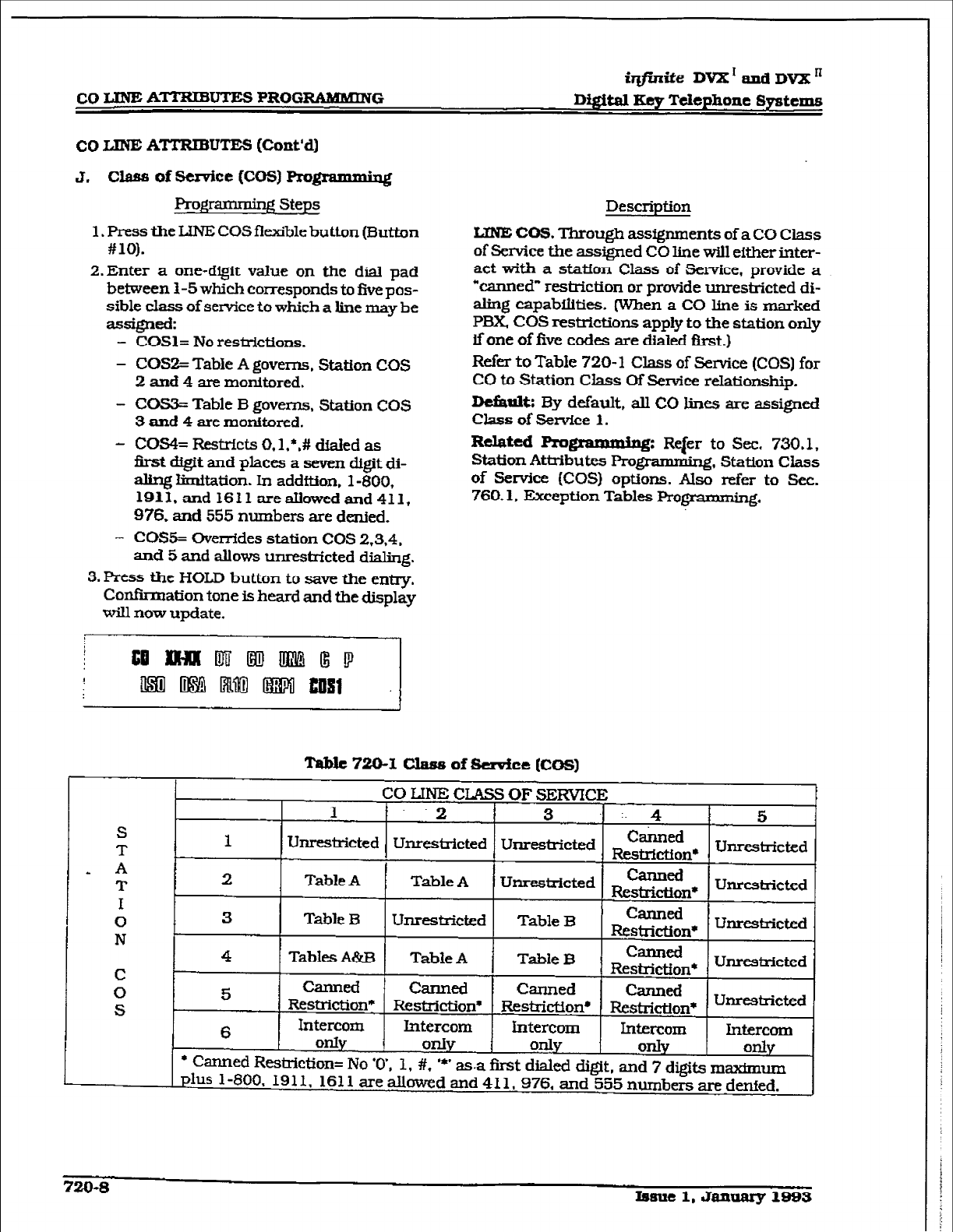
iqfiniie
DVX’andDV2Kn
cOLINEA’M’RIBUTESPRO-G D$$taI Key Telephone Systems
co LJNE ATI’RIBUTES (Co&d)
J. class of Semite (COS) F+ro&
Programming Steps
’ g
1. Press the LINE COS flexible button (Button
#lO).
2.Enter a one-digit value on the dial pad
between 1-5 which corresponds to five pos-
sible class of service to which a line may be
aSsigned:
- COSl= No
res&ictions.
- COS2= Table A governs, Station COS
2 and 4 are monitored.
- COS3= Table B governs. Station COS
3 amI 4
are monitored.
- COS4= Restricts O.l.*,# dialed as
first
digit
and places a seven digit
di-
aling limitation. In addftion. l-800,
1911, and 1611
areahwedand 411,
976. and 555
numbers are denied.
- CO!%= Overrides station COS 2,3,4,
and 5 and allows unrestricted dialing.
3.
Press the HOLD
button
to save the e&y.
Confirmation tone is heard
and
the display
will now update.
Description
LINE CO!& Through assfgmnents
of
a CO Class
of Service the assigned CO line wit1 either inter-
act with a
staffon Class
of Service, provide a
“canned” restriction or provide unrestricted di-
aling capabilities. (when a CO line
is
marked
PBX COS restrictions apply
to the station only
if one of five codes are dialed first.)
Refer to Table 720-l Class of Service (COS) for
CO to Station Class OfService relationship.
De&t& By default. all CO lins are assigned
Class of Service
1.
Related Programming:
Rqer to Sec. 730.1,
Station
Attnibutes Programmhg,
Station Class
of Service (COS)
options. Also refer to Sec.
760.1, Exception Tables Programmiq.
Table 7!2u-1 class of sedce [Cos)
CO LINE CLASS OF SERVICE I
I
.2 f 3 -1-4 5
S
T 1
Unrestricted Unrestricted Unrestricted ~~~~~n~ Unrestricted
- A i
T
2
TableA Table A Unrestricted kzEa$nW
Unrestricted
I
0 3
Table B Unresticted Table B canned
N Restriction* Unrestricted
4
TabIes A&B Table A Table B C-d
Restricti 0l-P Unrestricted
C
0 5 canned canned
Canned Canned
S
Restriction* Restriction* Restriction* Restriction* Unresfricted
6
Intercom Intercom Intercom Intercom Intercom
only
OdV
1 only only
l
Canned Restriction= No ‘0’. 1, #.
l
*’ only
as.a first
dialed digit, and 7 digits maxhnum
plus l-800. 1911, 1611 are allowed and 411,976. and 555
numbers are denied.
720-S Issue 1, January 1999
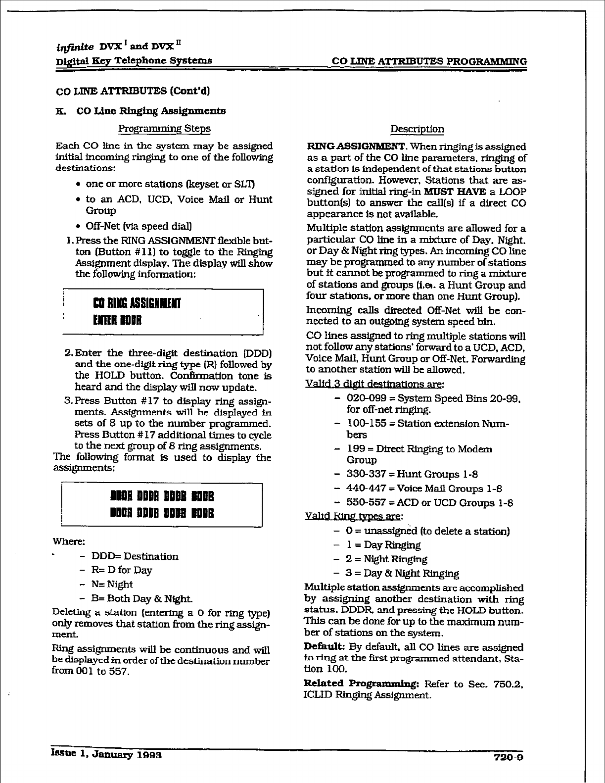
i@ite DVX’ and DVX s
~i@aI Key T&phone Spstema CO LIME ATTRIBUTES PROGlUiMMING
co LINE ATTRIBUTES (Cont’d)
K. CO
Line
Ringing Assignments
Progranxniug Steps
Each CO line in the system may be assigned
initial incoming ringing to one
of
the following
destinations:
a one or more stations (keyset or SLT)
l
to an ACD, UCD. Voice Mail or Hunt
Gl-Wp
. Off-Net (via speed dial)
1. Press the RING ASSIGNMENT fI&ble but-
ton (Button #Xl] to toggle to the Ringing
Assignment display. The display wilI show
the following information:
2.Enter
the three-digit destination (DDD)
and the one-digit ring type (R) followed by
the HOLD button. Confirmation tone Is
heard and the display will now update.
3. Press Button # 17 to display ring assign-
ments. Assfgnments will be displayed in
sets of 8 up to the number programmed.
Press Button # 17 additIonal limes to cycle
to the next group of 8 rkrg assignments.
The following format is used to display the
SSsignm~tS:
Where:
- DDD= Destination
- R= D for Day
- N=Night
- B= Both Day & Night.
Deleting a station (eWerIng a 0 for ring type)
only removes that station from the ring assign-
ment.
Ring assignments will be continuous and will
be displayed in order of the destination number
from 00 1 to 557.
Description
RINGASSIGNMENT
. When ringing is assigned
as a part of the CO line parameters. ringing of
a station is independent of that stations button
configuration. However, Stations that are as-
signed for initial ring-in MIJS’I” HAVE a LCOP
button(s) to answer the cdl(s) if a direct CO
appearance is not avaikble.
Multiple station assignments are allowed for a
particular CO line in a mixture of Day. Night.
or Day 8r Night ring types. An incoming CO line
may be programmed to any number of stations
but it cannot be programmed to ring a mixture
of stations and groups (iem. a Hunt Group and
four stations. or more than one Hunt Group).
Incoming cab directed Off-Net will be con-
nected to an outgoing system speed bin.
CO lines assigned to ring multiple stations will
not follow any stations’ forward to a UCD, ACD,
Voice Mail, Hunt Group or Off-Net. Forwarding
to another station will be allowed.
.
3 mdestfnatlulls &k,.
- 02CW99 = System Speed Bins 20-99,
for off-net ringing.
- 100-l 55 = Station extension Num-
bers
- 199=DirectRingingtoModem
Group
- 330-337 = Hunt Groups l-8
- 440447 = Voice Mail Groups l-8
- 550-557 = ACD or UCD Groups 1-8
- 0 = unassigrkd (to delete a station)
- l=DayF2inging
- 2=Ni&htRir@ng
- 3=Day&NightRinging
Multiple station assignments are accomplished
by assigning another destination with ring
status. DDDR and pressing the HOLD button.
This can be done for up to the maximum nurn-
ber of stations on the system,
Defhlt: By default. all CO lines are assigned
to ring at the first programmed attendant, Sta-
tion 100.
Related Frogrammlng: Refer to Sec. 750.2,
ICLlD Ringing Assignment.
IfumE 1, JaxllxFu-y 1883
720-g
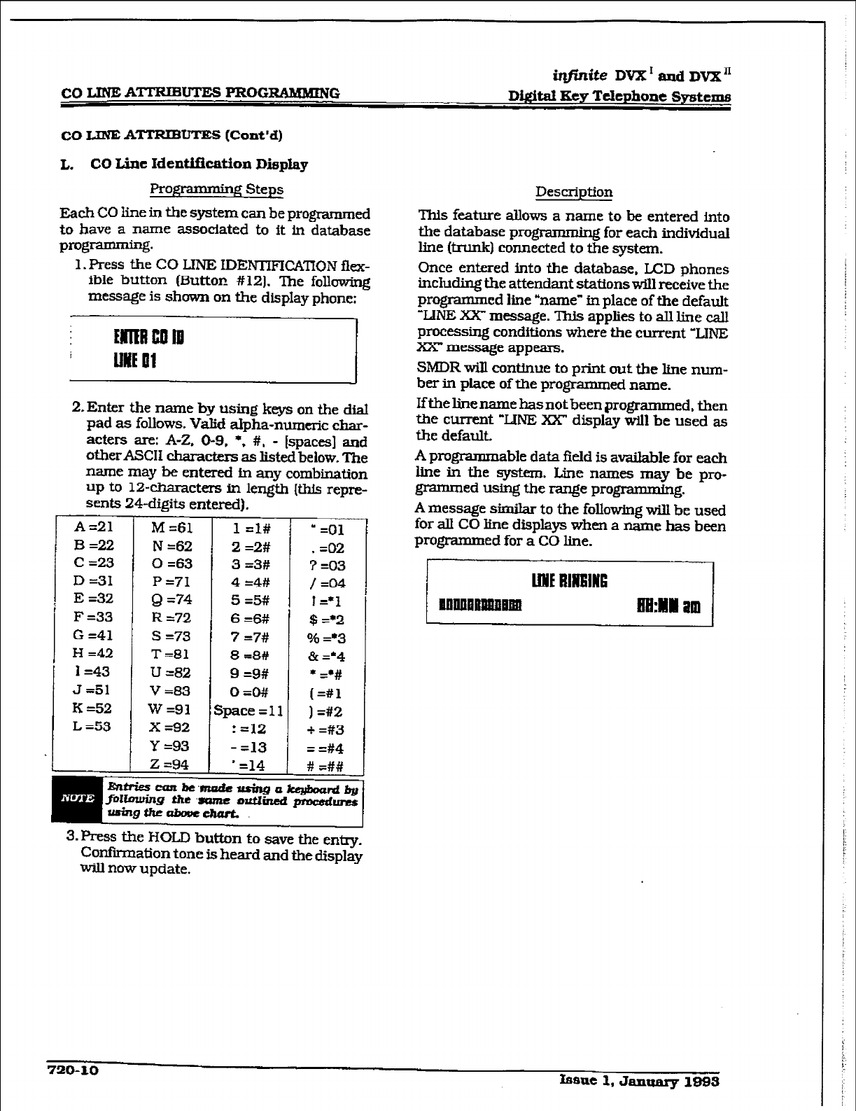
r
CO LINE
ATTRIBUTES
PFtOGRAMMING
iqj?nite DVX’aadDVX”
Di.#aI Key Ttlephone Syratms
co LINE ATTRIBUTE!5 (Cont’d)
L.
CO
Line Identificatfon
Display
pro@-mming
steps
Each CO line in the system can be programmed
to have a name associated to it in database
programming.
1. Press the CO LINE IDEIWIFICATION flex-
ible button (Button #12). The folIowing
message is shown on the display phone:
2. Enter the name by using keys on the dial
pad as follows. Valid alpha-numeric char-
acters are: A-Z. O-9. l , #, - [spaces] and
other ASCII characters as listed below. The
name may be entered in any combination
up to 1%characters in length (this repre-
sents 24-digits entered).
A=21
B=22
C =23
D =31
E =32
F =33
G =41
H =42
I=43
J=51
K =52
L =53
M =61
N
=62
0 =63
P =71
Q =74
R =72
s =73
T=81
U =82
v=83
w=91
x =92
Y =93
T-
!
I
z=94 I
1 =I#
2 =2#
3 =3#
4 =4#
5=5#
6 =6#
7 =7#
8 =8#
9 =9#
OEO#/
jpace ~11
: 112
- =13
’ =14
* =Ol
, =02
7 =03
/ =04
1=*1
$ =+2
0% =*3
& =*4
* =‘#
[=#l
) =#2
+ =#3
= =#4
# =##
3. Press the HOLD button to save the entry.
Confirmation tone is heard and the display
W-III now update.
Description
This feature shows a name to be entered into
the database prog ’ g for each individual
line (trunk) connected to the system.
Once entered into the database, LCD phones
incIuding the attendant staff ons will receive the
programmed line “name” in place of the default
‘LINE XX message. This applies to all line call
processing conditions where the current ‘LINE
Xx message appears.
SMDR will continue to print out the Iine num-
ber in place of the programmed name.
If the line name has not been programmed, then
the current “LINE XX” display will be used as
the default.
A programmable data field is avaiIable for each
he in the system. Line namea may be pro-
grammed using the range programming.
A message similar to the fohowing wiII be used
for aII CO Iine displays when a name has been
programmed for a CO line.
720-10 fsfme 1, Jan- 1895
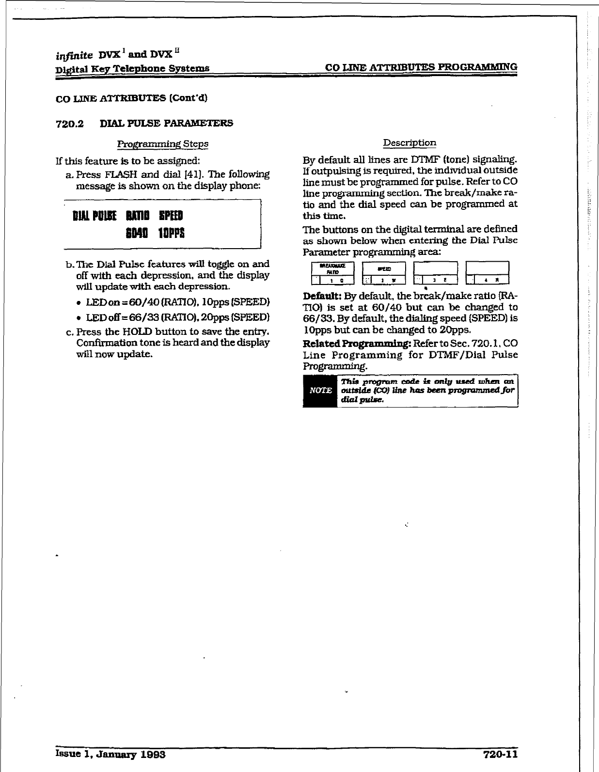
CO LINE A’ITKIBUTE!3 PROGRAMMING
720.2
DIALPULSE
PARAMETERS
gntmmhg Steps
If this feature is to be assigned:
a. Press FLASH and dial 141). The following
message is shown on the display phone:
I._...,.,
ml 10PFs
b.‘Ihe Dial Pulse
features will
toggle on and
off with each depression, and the display
will update with each depression.
. JXDon=60/40(RKTI0). 1OppsW’EED~
. ISDoff = 66/33 (RATIO), 20pps WEED1
c. Press the HOLD button to save the entxy.
Confirmation tone is heard and the display
will now upaate.
Desctiption
By default all lines are DTMF (tone) signaling.
If outpulsing is required, the individual outside
line must be programmed for pulse. Refer to CO
line programming section. The break/make ra-
tio and the dial speed can be programmed at
this time.
The buttons on the digit& terminal are defined
as shown beiow when entening the Dial Pulse
Parameter programming Wea:
D&m&: By default, the b&&/make ratio IRA-
TI0) is set at 60/40 but can be changed to
66/33. By default, the dMng speed [SPEED) is
XOpps but can be changed to 2Opps.
R&edPro~
l
g: Refer to Sec. 720.1, CO
Line Programming for DTMF/Dial Pulse
programming.
Issue 1, January
1983 720-11
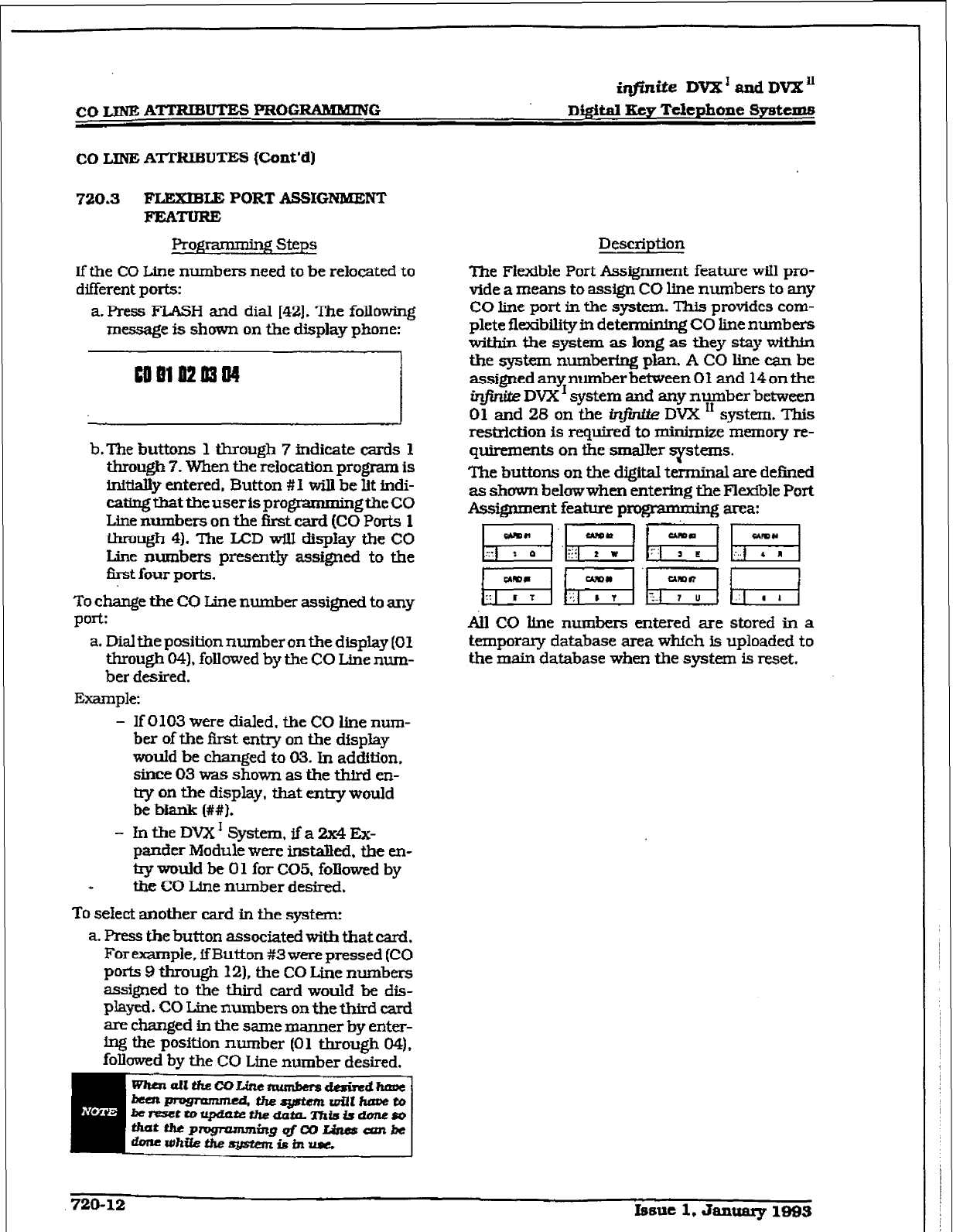
r
CO IJNE A-UTES l’ROGlUMMING
iqfhzite DVX’ and DVX”
D&ital Ecy Telephone Systems
co I~INE ATTRIBUTES (Cont’d)
720.3 FLEXIBLE PORT ASSIGNKENT
FlrATuRE
Programming steps
Description
if the CO Line numbers need to be relocated to
different ports:
a. Press FLASH and dial (421. The following
message is shown on the display phone:
5
b.The buttons 1 through 7 indicate cards 1
through 7. When the relocation program is
initially entered, Button #I will be lit indi-
cating
that
the user is progmzumningthe CO
Line numbers on the
first
card (CO Ports 1
through 4). The LCD wiiI display the CO
Line numbers presently assigned to the
first four ports.
To change the CO Line number assigned to any
port:
a. Dial the position number on the display (01
through 04). folIowed by the CO Line num-
ber desired.
Example:
‘Ike Fltible Port Assignment feature will pro-
vide a means to assign CO line numbers to any
CO line port in the system. This provides com-
plete flexibtily in determinWg CO line numbers
within the system as long as fhey stay witbk
the system numbering plan. A CO line can be
assignedanynumberbetweenO1 and 14ontbe
in@zite DVX’ system and any number between
01 and 28 on the in.. DVX I* system. This
restrktion is required to rninknize memory re-
quirements on the smaller !5pms.
The buttons on the digital terminal are defined
as shown belowwhen entering the Flexible Port
Assiient feature programming arca:
~&Eq gg Fi
[a &ETR h;Ti
All CO line numbers entered are stored in a
temporaq database area which is uploaded to
the main database when the system is reset.
- If 0103 were dialed, the CO line num-
ber of the first enuy on the display
would be changed to 03. In addition,
since 03 was shown as the third cn-
try on the display, that enuy would
be bknk (##I.
- lntheDVX1System,ifa2x4Ex-
pander Module were installed, the en-
by would be 0 1 for CO5. followed by
the CO Line number desired.
To select another card in the system:
a. Press the button associated with that card.
For example, ff Button #3 were pressed (CO
ports 9 through 121, the CO Line numbers
assigned to the third card would be dis-
played. CO Line numbers on the third card
are changed in the same manner by enter-
ing the position number (01 through 04),
folkwed by the CO Line number desired,
720-12 Istrue 1, January 1883
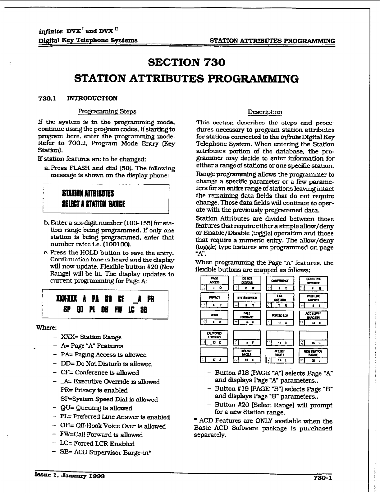
r
infinite DVX’ and DVX’
D&itd Key Telephone SyrMms STATION ATTRIBUTES PROGRAMMING
SECTION 730
STATION ATTRIBUTES PROG~NG
750.1
INTRODUCTION
Pr0g-t
+ng Steps
If the system is in the
programming
mode,
continue using the program codes. If starting
to
program
here,
enter the
programming
mode.
Refer
to
700.2. Program Mode Entry (Key
Staffon).
If station features are to be changed:
a. Press FLASH and dial [50). The following
message is shown
on
the &play phone:
;I
b.
Enter
a six-digit number (1 OO- 155) for sta-
tion range being
programmed. If only one
station is being programmed, enter that
number twice i.e.
(lCH3100).
c. Press the HOLD button to save the entry.
Confirmation tone is heard and the display
tif now update.
Flexible
button #20 (New
Range) will be lit. The display updates to
current programming for Page A:
111
where:
- XXX= Station Range
- - A= Page “A” Features
- PA= paging Access is allowed
- DD= Do
Not Disturb is allowed
- CF= Conference Is
allowed
- -A= Executive Override IS allowed
- PR= privacy is enabled
- SP;=Syatem Speed Dial is allowed
- QU= Queuing is allowed
- PL- Preferred Line Answer is enabled
- OH= Off-Hook Voice Over is allowed
- ~=Cdl Forward is allowed
- LC= Forced LCR Enabled
- SB= ACD Supervisor Barge-in*
Description
This section
describes tbe steps and proce-
dures necessary
to program station attributes
for stations connected to the in_finite
Digital Key
Telephone
System.
When entering the Station
attributes portion of the database, the pm-
grarnmer may decide to enter information for
either a range of stations or one specific station.
Range programming allows the progrannner to
change a spe&c pammeter or a few parame-
ters for an entire range of staff on5 leaving intact
the remaining data fields that do not
require
change. Those data fields will conttnue to oper-
ate with the previously programmed data.
Station Attributes are divided between those
features that require either a simple aflow/deny
or Enable/Dfsable (toggle) operation and those
that require
a numeric entry. The
allow/deny
(toggle) type features are programmed on page
“A”.
When programmmg the Page ‘IA” features. the
flexfble buttons are mapped as follows:
- Button #I18 PAGE “A”] selects Page *A”
and
displays Page “A” parameters..
- Button #19 [PAGE “B-1 selects Page ‘B”
and displays Page “B” parameters..
- Button #20 (Select Range] will prompt
for a
new
Station range.
l
ACD Features are ONLY av&ble when the
Basic ACD Software package Is purchased
separately.
Issue 1, January
1993 730-l
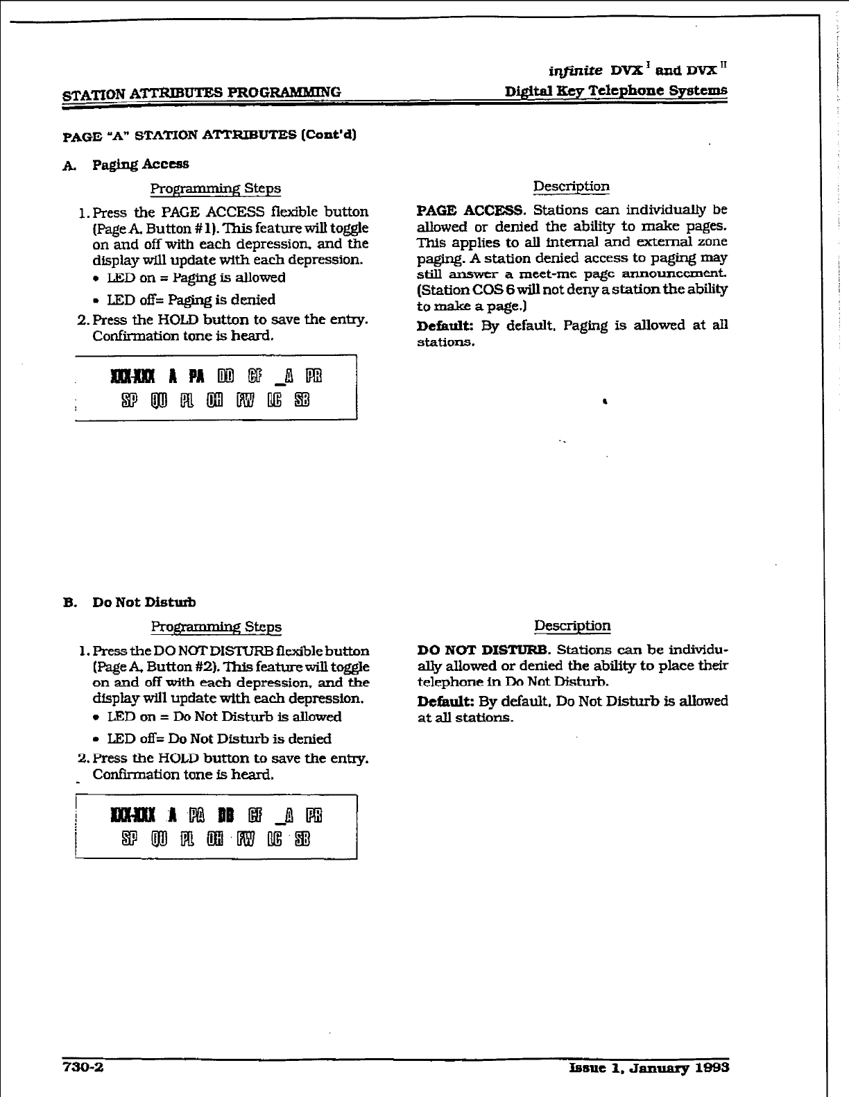
iqfhtite DVX’ aad DVX I1
s’.IXl’ION ATTRIBUTES PROGEUIMMZVG Digital Key Telephone Systems
PAGE
‘A”
STATION ATTRIBUTES [Cont’d)
1. Press the PAGE ACCESS fl&ble button
(Page A, Button #
1). ‘Ihis
feature will to&e
on and off with each depression. and the
display will update with each depression.
l
LED on = Paging is allowed
. IEDoff=Pagirqisdenied
2. Press the HOLD button
to save the entry.
Confirmation tone is heard.
Description
PAGE ACCESS.
Stations can
individua@
be
allowed or
denied the ability to make pages.
This applies
to alI intema.l
and external zone
paging. A station denied access to paging may
still answer a meet-me page announcement.
(Station COS
6 will
not deny a
station the
ability
to make a page.1
Debault:
By default, Paging is allowed at all
stations.
B. Do Not Disturb
ggxmmhg steps
1.
Press the DO NOTDISTURB flexible button
(Page A. Button #2). Tl-&
feature will toggle
on
and off with each depression. and the
display will update with each depression.
l
LED on = Do Not Disturb is a.Uowed
l
LED off= Do Not
Disturb is denied
2. Press the HOLD button
to save the entry.
Confkmation tone is heard. _
Description
DO NOT DISTURB. Stations can be
individu-
ally allowed
or denied the ability to place their
telephone in Do Not
Disturb.
Default:
By defau2t. Do Not Disturb is allowed
at all stations.
730-2 Issue 1. January 1993
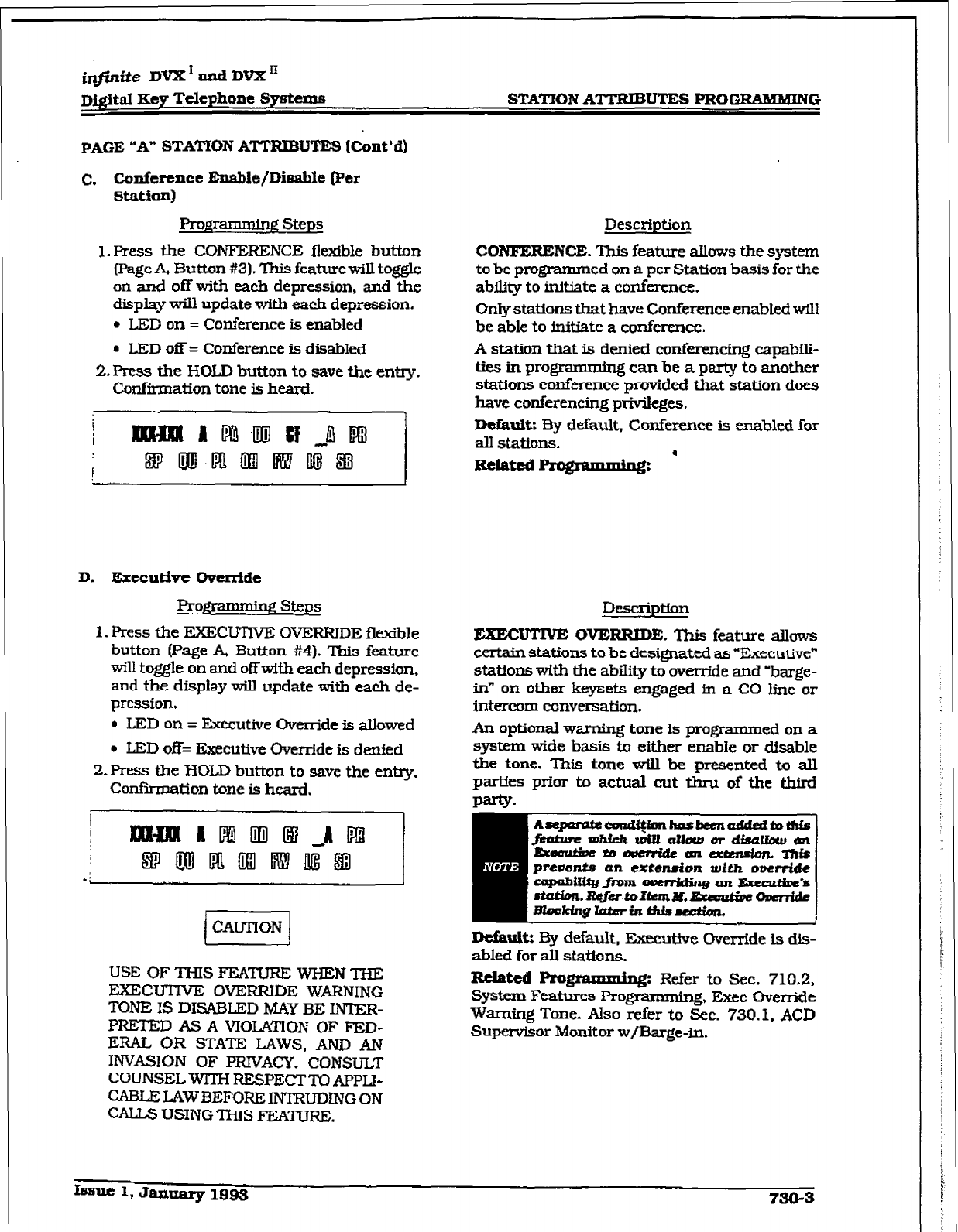
inlfinite DVX I and DVX ’
Dj@tal
Key Telephone Systems
PAGE
“A” STATION
ATTRIBUTES (Cont’d)
C.
Conference Enable/Disable (Per
STATIOIV
ATTRIBUTES PROGRAMhUNG
station)
Programming Steps
l.Press the CONFERENCE flexible button
[Page A, Button #3). This feature will toggle
on and off with each depression, and the
display will update with each depression.
l
LED on = Conference is enabled
l
LED off = Conference is disabled
2.Press the HOLD button to save the entry.
Confirmation tone is heard.
D. Executive Owe&de
pfogx-mmhg steps
1. Press the EXECUTIVE OVERRIDE flerdble
button (Page A, Button #4). This feature
will toggle on and off with each depression,
and the display wiIl update with each de-
l
LED on = &cut&e Override is allowed
l
LED off= Executive Override is denied
2.Pre.s~ the HOLD button to save the entry.
Confknation tone is heard.
pression.
1 CAUTION ]
USE OF THIS FEATURE WHEN THE
EXECUTIVE OVERRlDE WARNING
TONE IS DISABLED MAY BE INTER-
PRETED AS A VIOLATION OF FED-
ERAL OR STATE LAWS, AND AN
INVASION OF PRIVACY. CONSULT
COUNSEL WTIX RESPECTTO APPLJ-
CABLE LAW BEFORE INTRUDiNG ON
CALLS USINGTHIS FEA’IURG.
Description
CONFERENCE. This feature allows the system
to be programmed on a per Station basis for the
ability to initiate a conference.
Only stations tbat have Conference enabled will
be able to initfate a conference.
A station that is denied conferencing capabili-
ties in progranmhg can be a party to another
stations conference provided that station does
have conferencing privileges.
Default: By default, Conference is enabled for
all stations.
Description
EXECUTIVE OVERRIDE. This feature allows
certain stations to be designated as “Executive”
An optional waming tone is programmed on a
stations with the ability
to
override and ‘barge-
in” on other keysets engaged in a CO line or
system wide basis to either enable or disable
the tone. T% tone wiIl be presented to all
parties prior to actual
cut
thru of the third
intercom conversation.
Dciimiltz By default, Executive Override is dis-
abIed for all stations.
Related Pro
Refer to Set 710 2
-A. Exec bvenii;
Systcxu Features Pro
Warning Tone. Also refer to Sec. 730.1, ACD
Supervisor Monitor w/Barge-in.
It=nlt 1, Jauualy 1995
730-3
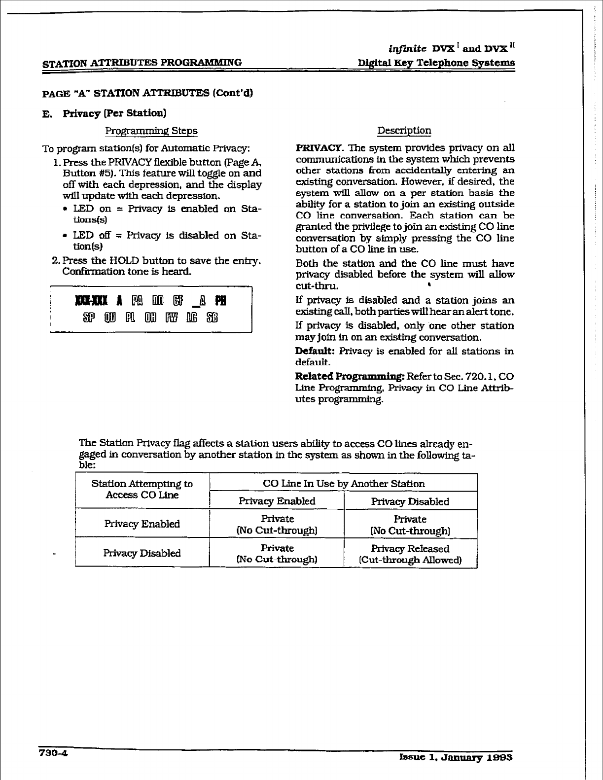
@finite
DVX I and DV2L I1
STATION
A--
PROGRAMMING Digital Key Telephone Systems
PAGE “A” STATION ATTRXBUTES (Co&d)
E. Privacy (Per station)
Profipmmdg Steps
To
program station(s) for Automatic Privacy:
1. Press the PRIVACY flexlble button (Page A,
Button #5). This feature wit1 toggle on and
off with each depression, and the display
will update with each depression.
. LED on = Privacy is enabled on Sta-
tions(s)
. LED off = Privacy is disabled on Sta-
-m
2.Press the I-lOLD button to save the entry.
Confirmatfon tone is heard.
Description
PRIVACY. The system provfdes privacy on all
communications in the system which prevents
other stations from accidentally entering an
existing conversation. However. if desired, the
system will allow on a per station basis the
ability for a station to join an existing outside
CO line conversation. Each station can be
granted the privilege to join an existing CO line
conversation by simply pressing the CO line
button of a CO line in use.
Both the station and the CO line must have
prtMcy disabled before the system will allow
cuHhI-u. 6
If privacy is disabled and a station joins an
existingcalL bothpartieswill hearanalerktone.
If privacy is disabled, only .one other station
may
join
in on an existing conversation.
Default: F’rivacy is enabled for all stations in
default.
Related programming: Refer to Sec. 720.1, CO
Line Programmln g. Privacy in CO Line Attrib-
utes programming.
The Station Privacy flag affects a station users ability to access CO lfnes already en-
gaged in conversation by another station in the system as shown in the folluwing ta-
ble:
Station Attempting to CO Une In Use by Another Station
Access CO Line Privacy Enabled Privacy Disabled
ptfvacy Enabled Private Private
INo Cut-through) , (No Cut-through)
Privacy Msabled Private
* Privacy Released
(No cut-through) [Cut-through Allowed)
730-4 Isue 1, January 190s
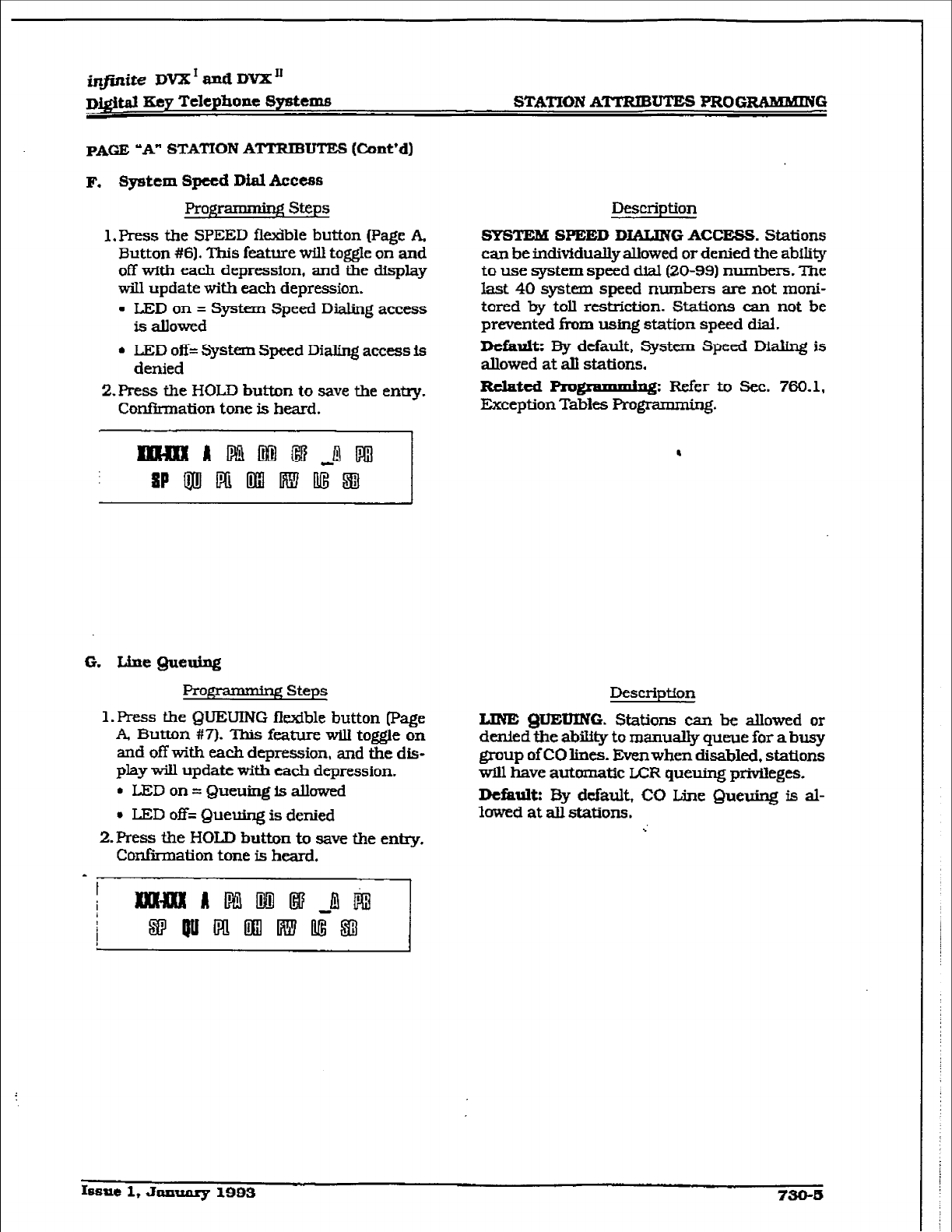
infinite DVX * and DVX’
~&itd Key Telephone Spatems STATION A-UTES PRoGZXAMMING
pA(iE ‘A” STATION ATTRIBUTE-S (Cunt’d)
F.
System Speed Dial Access
Prog~ steps
1, Press the SPEED fieiible button (Page A,
Button #6). This feature will toggle on and
off with each depression, and tie display
will update with each depression.
. LED on = System Speed Dialing access
is allowed
l
LED off= System Speed Dialing access is
denied
2.Pres.s the HOLD button to save the entry.
Confirmation tone is heard.
Description
SYSTEM SPEED DIALING
ACCESS.
Stations
can be individually allowed or denied the ability
to use system speed dial (20-99) numbers. The
last 40 systmn speed numbers are not moni-
tored by toll restriction. Stations can not be
prevented from using station speed dial.
Default: By default, System Speed M&ng is
allowed at alI stations.
Related
Ro gremming: Refer to Sec. 760.1,
Exception Tables Programmmg.
.
G. WneQueuing
Programmiq Steps
1. Press the QUEUING fkdble button Page
A, Button #7). This feature will toggle on
and off with each depression, and the dis-
play will update with each depression.
l
LJ3D on = Queuing is allowed
l
LED off= Queuing is denied
2.Press the HOLD button to save the enky.
Confirmation tone is heard.
Description
LINE @lEUING. Stations caa be allowed or
denied the ability to manually queue for a busy
group of CO lines. Even when disabled. stations
will have automatic IAX queuing privileges.
Default: By default, CO Line Queuing is al-
lowed at all stations.
Issue 1, Jl%nTUiIy 1993 730-6
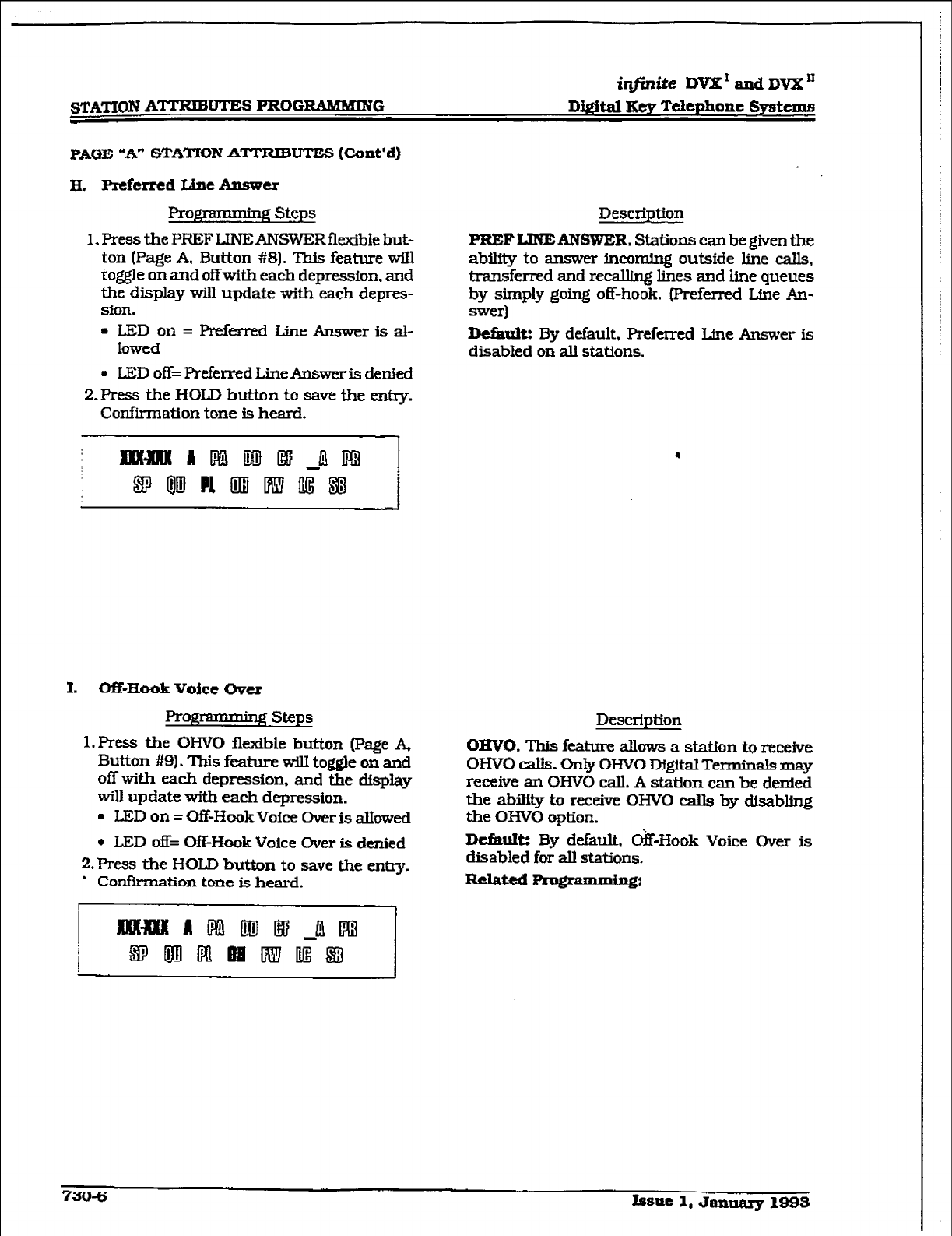
r
STATION ATTRIBUTES PROGRAMMING
imite DVX*andDVXn
Di@t.al Key Telephone Systems
PAGE “A”
STATION ATTRIBUTES (Co&d]
H. Prcfcrrcd Line Answer
ptogrammbg Steps Description
1. Press the PREF LINE ANSWER fl&ble but-
PREF
LINE ANSWER. Stations can be given the
ton [Page A. Button #S]. This feature will ability to answer incoming outside line calls,
toggle on and off with each depression. and transferred and recalling lines and he queues
the display will update with each depres- by simply going off-hook. (Preferred Line An-
sion.
swer)
l
LEDon=hef’kxredLineAnswerisal-
lowed D&auk By default. FVeferred Line Answer
is
disabled on all stations.
l
LED off= Preferred Line Answeris denied
2.FYess the HOLD button to save the entry.
Confirmation tone is heard.
L Off-Hook Voice Over
l?roflpmnkg steps
1. Press the OHVO flexible button (Page A,
Button #9). ‘Ibis feature wilI toggle on and
off with each depression. and the display
will update with each depression.
l
LED
on = Off-Hook Voice Over is aUowed
. LED off= OfFHook Voice Over is denied
2.Press the
HOLD
button to save the enhy.
* Confirmation tone is heard.
Description
OHVO. This feature a&ws a station to receive
OHVO calls. Only OHVO DfgitalTenninals may
receive an OHVO cdl. A station can be denied
the ability to receive OHVO calls by disabling
the OHVO option.
DcfimItz By default. &-Hook Voice Over is
disabled for all stations.
Remed Programming:
730-6 Issue 1, January 1893
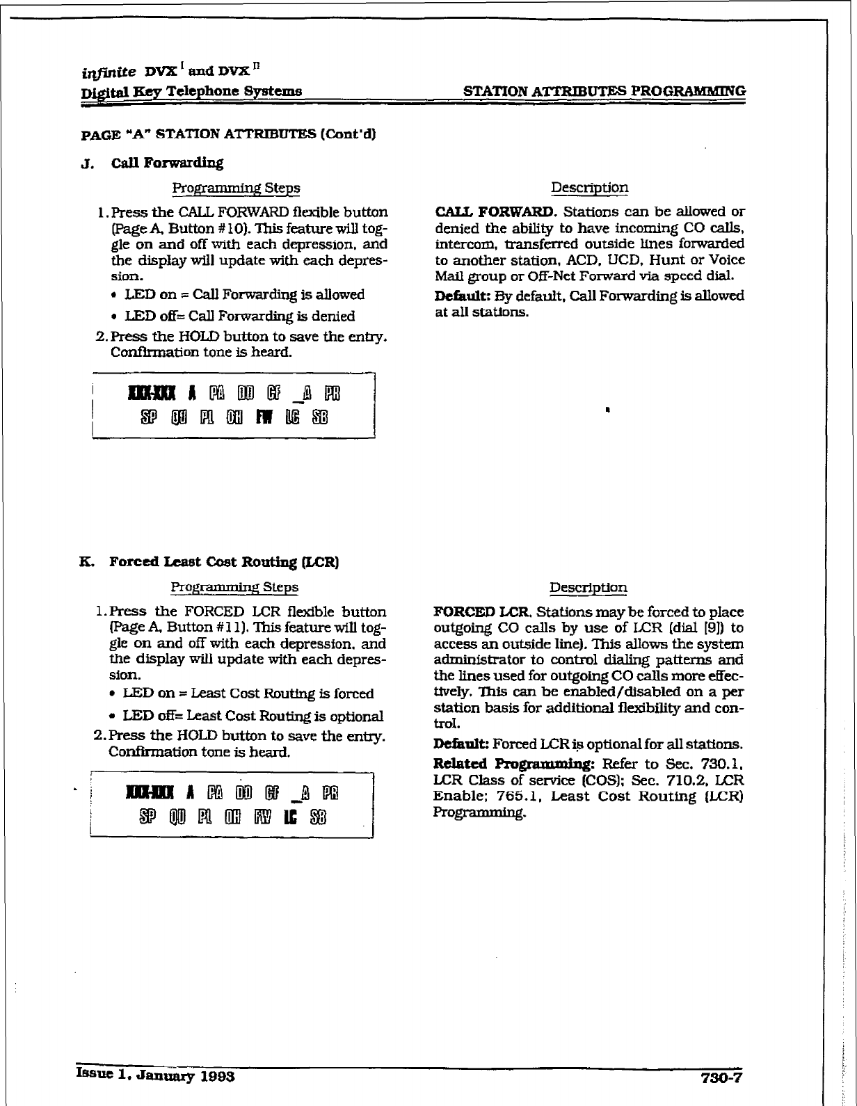
irlfinite DVX * and DVX’
D&$a JXcy Telephone System8 STATION
ATTRlBuTEs
PROGRAMMING
PAGE “A” STATION ATTRIBUTES (Cont’d]
J. CaII Fonvardiq
Prqqramming steps
1. Press the CALL FORWARD flexible button
(Page A, Button # lo]. This feature will tog-
gle on and off with each depression, and
the disp1ay will update with each deptes-
sion.
l
LED on = Call Forwarding is allowed
l
LED off= Call Forwardhg is denied
2.Press
the HOLD button to save the entry.
Confirmation tone is heard.
Description
CALL FORWARD. Stations can be allowed or
denied the ability to have incoming CO calls,
intercom, transferred outside Lines forwarded
to another station, ACD. UCD. Hunt or Voice
Mail group or Off-Net Fomard via speed dial.
Dcfautt:
By defauit. Call Forwarding is allowed
at all stations.
.
a. Forced
Least Cost
Ranting &CR)
Progmmming Steps
1. Press the FORCED LCR flexible button
(PageA, Butt.on#ll).ThisfeaturewiU tog-
gle on and off with each depression. and
the display will update with each depres-
sion.
l
LED on = Least Cost Rmtfng is forced
l
LED off= Least Cost Routing is optional
2.FWss
the HOLD button to save the enm.
Confirmation tone is heard.
Description
FORCED
LCR.
Stations may be forced to place
outgoirqj CO calls by use of LAX [dial [9]) to
access an outside line). This allows the system
administrator to control dialing patterns and
t&e lines used for outgoing CO calls more effec-
tively. This can be enabled/clisabled on a per
station basis for additional flexibility and con-
trd.
Defimk Forced LCR Q optional for all stations.
Itdated prom:
Refer
to
sec. 730.1.
LCR Class of service (COS): Sec. 710.2. LCR
Enable: 765.1, Least Cost Routing (LCR)
programming.
I~sut 1. Januarg 199s
730-7
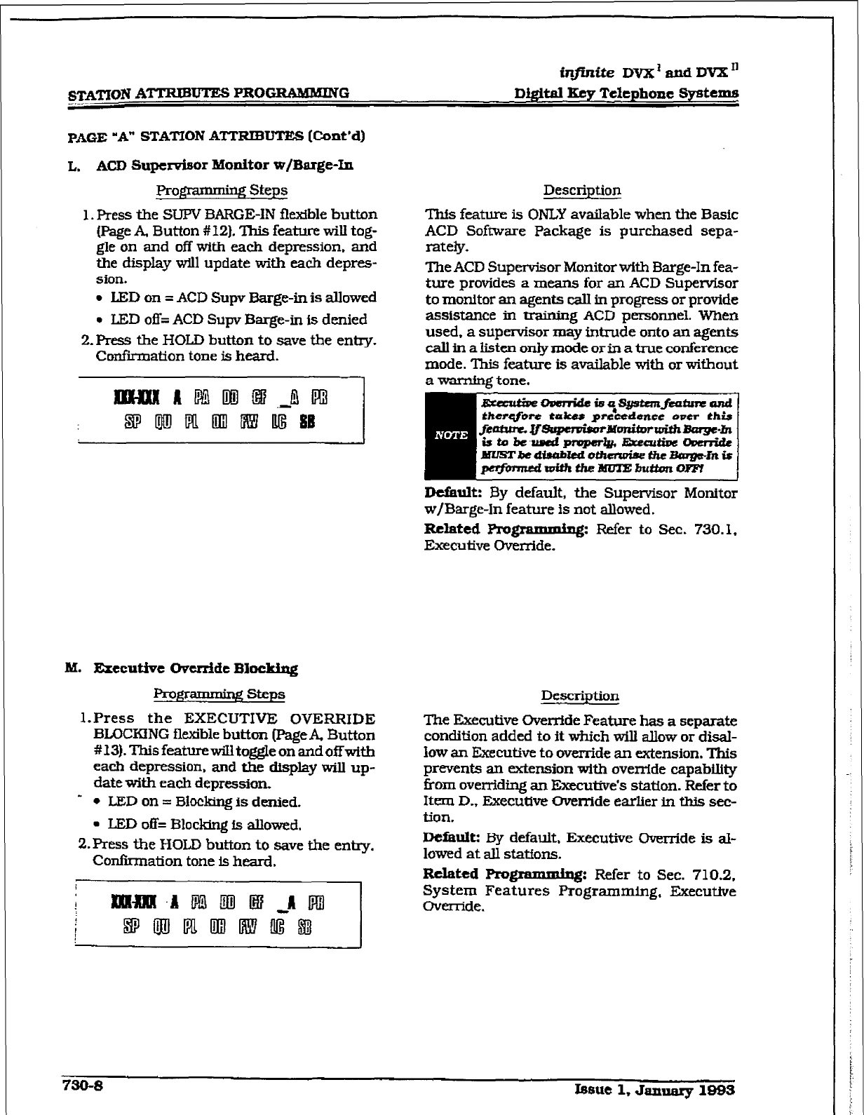
infinite DVX ’ and DVX ’
STATION ATTRIBU'IWS I?ROGRAblILdING Dtgltat Key Telephone
Systems
PAGE “A” STATION ATTRIBUTES [Cont’d)
L. ACD Supe+r Monitor w/Barge-In
Proglxmmhg Steps
1. Press the SUPV 3mGE-IN flexible button
(Page A, Button #12). This feature will tog-
gle on and off with each depression. and
the display will update with each depres-
sion.
l
LED on = ACD Supv Barge-in is alIowed
l
LED off;; ACD Supv Barge-in is denied
2.F%ess the HOLD button to save the entry.
Confiiation tone is heard.
Description
This feature is ONLY available when the Basic
ACD Software Package is purchased sepa-
rately.
The ACD Supervisor Monitor with Barge-In fea-
ture provides a means for an ACD Supenrisor
to monitor an agents calI in progress or provide
assistance in training ACD personnel. When
used, a supervisor may intrude onto an agents
call in a listen only mode of in a true conference
mode. This feature is available with or without
Default: By default, the Supervisor Monitor
w/Barge-In feature is not allowed.
Related Pmgramming: Refer to Sec. 730.1,
Executive Override.
M. Executive Ckwfde BIockiq
1. - gsteps
l.Press the EXECUTIVE OVERRIDE
BLOCKING flexible button (PageA Button
#13).ThisfeaturewiIltoggleonandoffwith
each depression, and the display will up-
date with each depression.
- I, LED on = Blocking is denied.
l
LED off= Blo&q Is allowed,
2.Press the HOLD button to save the entry.
Confiiation tone is heard.
Description
The Executive Override Feature has a separate
condition added to
it
which wili allow or disaI-
Sow an liZxecutive to override an extension. This
prevents an extension with override capability
from overriding an Executive’s station. Reler to
Item D., Executive Override eartier in this sec-
tion.
Dcfautt: E3y default. Executive Override is al-
lowed at all stations.
Related Programmiq: Refer to Sec. 710.2,
System Features Programming, Executive
Override.
730-s Issue 1, Januazy 1993
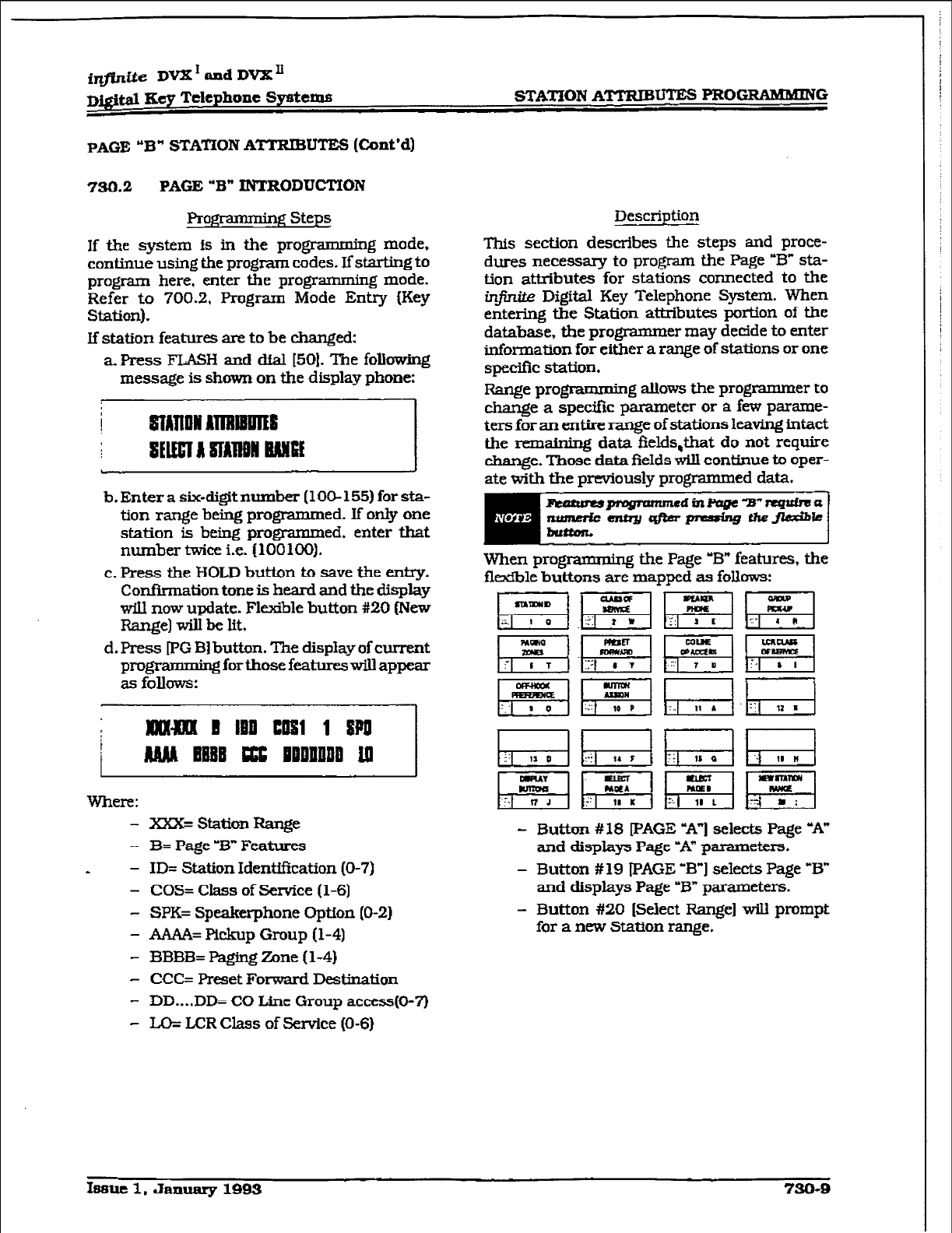
STATION AlTBIB= PROGRAMMING
PAGE “B”
STATTON
ATTRIBUTE8
(Co&d)
730.2 PAGE
“B”
INTRODUCMON
Projg3mmkg Steps
If t&e system is in the programming mode.
continue using the program codes. If starting to
program here, enter the programming mode.
Refer to 700.2, Program Mode Entry (Key
Station).
If station features are to be changed:
a. Press FLASH and dial [50]. The following
message is shown on the display phone:
b.Enterasix-digitnumber(lOO-155)forsta-
tion range being programmed. If only one
station is being programmed, enter that
number twice i.e. (100100).
c. Press the HOLD button to save t.be
entry.
Confirmation
tone is
heard and the display
will now update. Fltible button #20 (New
Range] will be lit.
d. Press FG Bl button. The display of current
programming for those featclreswill appear
as follows:
i EEX3lfll D Ill3 EON 1 8pO
MM EBBE ccc nEDnltPB 10
Where:
- xx=staticmRange
- 3= Page ?3* Features
* - ID= Station Identification (O-7)
- COS= Class of Senrice (1-6)
- SPK= Speakerphone Option (O-2)
- AAAA= Pickup Group (l-4)
- l3BBB= F%ging Zone (l-4)
- CCC= Preset Forward Destination
- DD....DD= CO Line Group access(0-7)
- u);: LCR Class of Service (O-6)
Description
This section describes the steps and proce-
dures necessary to program the Page “B” sta-
tion attributes for stations connected to the
infirrite Digital Key Telephone System. When
entering the Station attributes portion of the
database, the programmer may decide to enter
information for either a range of stations or one
specific station.
Range programming allows the programmer to
change a specific parameter or a few parame-
ters for an entire
range of stations leaving intact
the remaining data flelds,that do not require
change. Those data fields will continue to oper-
ate with the
pnwiously
programmed data.
When programming the Page ‘B”
features, the
flexible buttons are mapped as follows:
RgJh;;alGl
p$q~gqpiq
- Button #18 [PAGE -A”] selects Page -A”
and displays Page -A” parameters.
- Button # 19 PAGE
‘B” 1
selects Page
‘B”
and
displays
Page “B” parameters.
- Button #20 [Select Range] will prompt
for a new Station range.
Issue 1, January 1993 730-Q
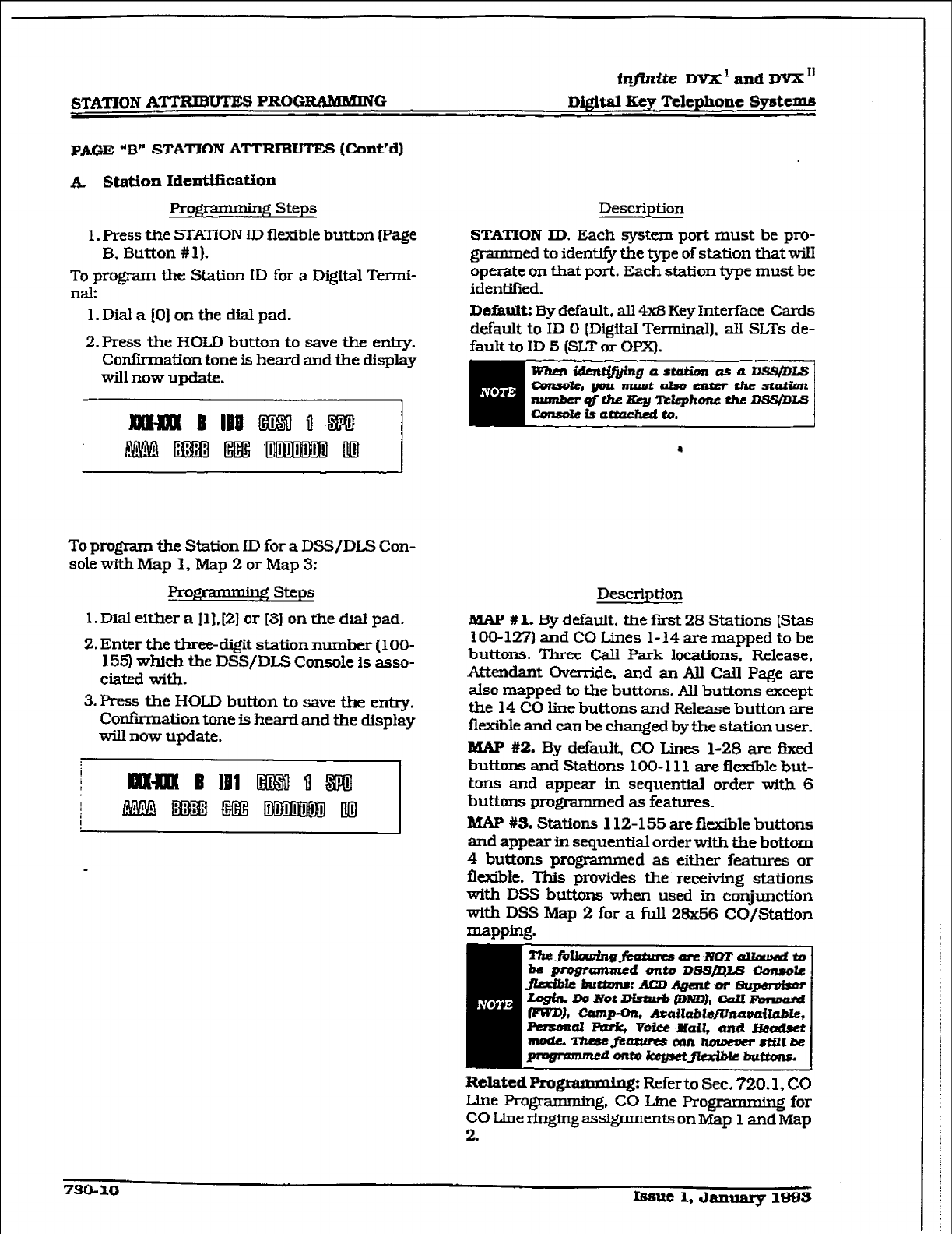
infinite DVX ’ and DVX ‘I
STATION AmUTE! PROGRAMMING D&&al
Kcv Telephone Systems
PAGE
“B”
STATION ATTRIBUTES (Cmt’d)
A Station IdcntJfication
Programming Steps
1. Press the STATiON ID flexible button page
B. Button # 1).
To program the Station ID for a Digital Termi-
nal:
1. Dial a [O] on the dial pad.
2. Press the HOLD
button to save the entry.
Confirmation tone is heard and the display
will now upaate.
To program the Station ID for a DSS/DLS Con-
sole with Map 1, Map 2 or Map 3:
steps
1. Dial either
a
111. [2] or 131 on the diat pad.
2. Enter the three-digit station number (loo-
1551 which the DSS/DLS Console is asso-
ciated with.
3.
Press the HOLD button to save the entry.
Confirmation tone is heard and the display
will now update.
Description
STATION ID. Each system
port must be pro-
grammed to identify tie type of station that wiII
operate on that port. Each station me must be
identiiied.
Dtfhultz
By default, alI 4x8 Key Interface Cards
default to ID 0 [Digital Terminal). all SLTs de-
fault to ID 5 (SLT or OPX).
Description
lWJP
#la
By default, the first 28 Stations (Stas
100-127) and CO Lines 1-14 are mapped to be
buttons. Three Call Park locations,
Release,
Attendant Override, and an AlI Call Page are
also mapped to the buttons. All buttons except
the 14 CO Iine buttons and Release button are
flexible
and can be c.hanged
by the station user.
MAP %2. By default, CO Lines l-28 are fbced
buttons and Stations IOO- 111
are flexMe
but-
tons and appear in sequential order with 6
buttons Programmed as features.
MAP #S. Stations 112-155 are flexible buttons
and appear in sequential order with the bottom
4
buttons programmed as either features or
flwcible. This
provlIdes the receiving stations
with DSS buttons when used in conjunction
with DSS Map 2 for a full 28x56 CO/Station
Related Rugramming:
Refer to Sec. 720.1, CO
Line Programming. CO Line Progrrng for
CO Line ringing assignments onMap 1 and Map
2.
730-10 IBfwe 1, January 1905
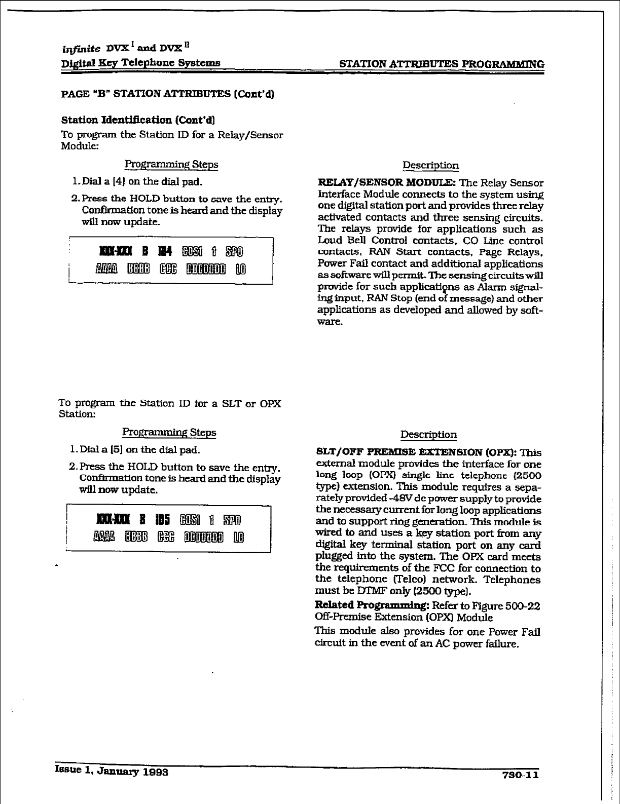
r
irlfinite DVX’andDVX”
Dj@al Key Telephone
Systems
STATION
ATTZUBLITE-S I’ROGEAMMING
PAGE ‘B” STATION ATTRIBUTES (Cont’d)
station Identi&ation (Cont’d)
To program the
Station ID for a Relay/Sensor
Module:
Fro- steps
l.lXd a 14) on the dial pad.
2.Press the HOLD button to save the entry.
Confirmation tone is heard and the display
will
now
update.
To program the Station ID for a SLT or OPX
Station:
Prog$amdng steps
l.Diala151 onthedialpad.
2. Press the HOLD button to save the entry.
ConfltmaUon tone is heard and the display
will now update.
Description
RELAY/SENSOR HODDTX: The
Relay Sensor
Interface Module connects to the system using
one digital station port and provides three relay
activated contacts
and three sensing circuits.
The relays provide for applications such as
Loud
Bell Control contacts, CO Line contro1
contacts, RAN Start
contacts, Page Relays.
Power Fail contact and additional applications
assoftwarewiUpermit.The sensingcircuitswill
provide for such applications as Alarm signal-
ing input, RAN Stop (end of message) and other
applications as developed and allowed by soft-
ware.
Description
SLT/GFF PREmSE EXTENSLGN (Opx): This
external module provides the interface for one
long loop (OPX) single line telephone (2500
type) extension. This
module requires
a sepa-
rately provided -4SV dc power supply to provide
the necessary cument for long loop applications
and to support ring generation. This module is
wiredtoandusesa~statlonport~any
digital key terminal station port on any caml
phgged into the system. The OPX card meets
the requirements of the FCC for connection to
the telephone Uelco) network. Telephones
must be DTMF only (2500 type].
Related I%o@amxr@$
Refer to Figure 500-22
OfT-Premise Extension (OPX) Module
This module also provides for one Power Fail
circuit in the event of an AC power failure.
Issue 1, Janwuy 1993 730-11
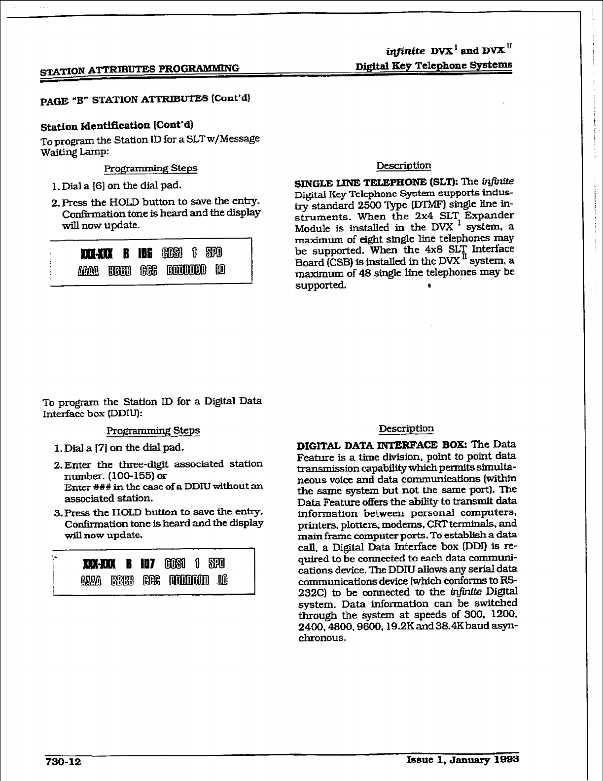
i&s&e
DVX' and DVX”
PAGE “B” STATION ATTRIBUTES (Cunt’d)
station Identification [Cont’d)
To program the Station ID for a SLTw/Message
waiting Lamp:
Pro- Steps
l.Diala[6]onthedialpad.
2. Press the HOLD button to save the entry.
Confirmation tone is heard and the display
will nuw update.
To program the Station ID for a Digital Data
Interface box (DDIIJ):
ProgramminF( steps
l.Di.ala(?]onthedialpad.
2.Enter the three-digit associated station
number. (100-155) or
Enter ### in the case of a DDIU without an
associated station.
3.Pres.5 the HOLD button to Save the entry.
Confirmation tone is heard and the display
will now update.
Description
SINGLE UNE TELEPHONl3 (SLT): The ir$r&
Di@aI Key Telephone System supports indus-
b-y standard 2500 Type (DTMF) single line iu-
struments. When the 2x4 SLT Expander
Module is installed in the DVX I system, a
m&mum of eight single line telephones may
be supported. When the 4x8 SLT Interface
Board [CSB) is installed in the DVX ’ system. a
maximum of 48 single line telephones may be
supported. I
Description
DIGITAL DATA ZNTERFACE BOIS: The Data
Feature is a time division, point to point data
I3 ’ ion capability which permits simulta-
neous voice and data communications [within
the same system but not the same port]. The
Data Feature ofks the ability to transmit data
information between personal computers,
printers, plotters. modems, CRT termink. and
main frame computer ports. To establish a data
call. a Digital Data Interface box (DDI) is re-
quired to be connected to each data communi-
cations device. The DDIU allows any serial data
communications device (which conforms to RS-
232C) to be connected to the in_fintte Digital
system. Data information can be switched
through the system at speeds of 300, 1200,
2400.4800.9600,19.2Kand 38.4Kbaud asyn-
chronous.
730-12 Issue 1, January 1993
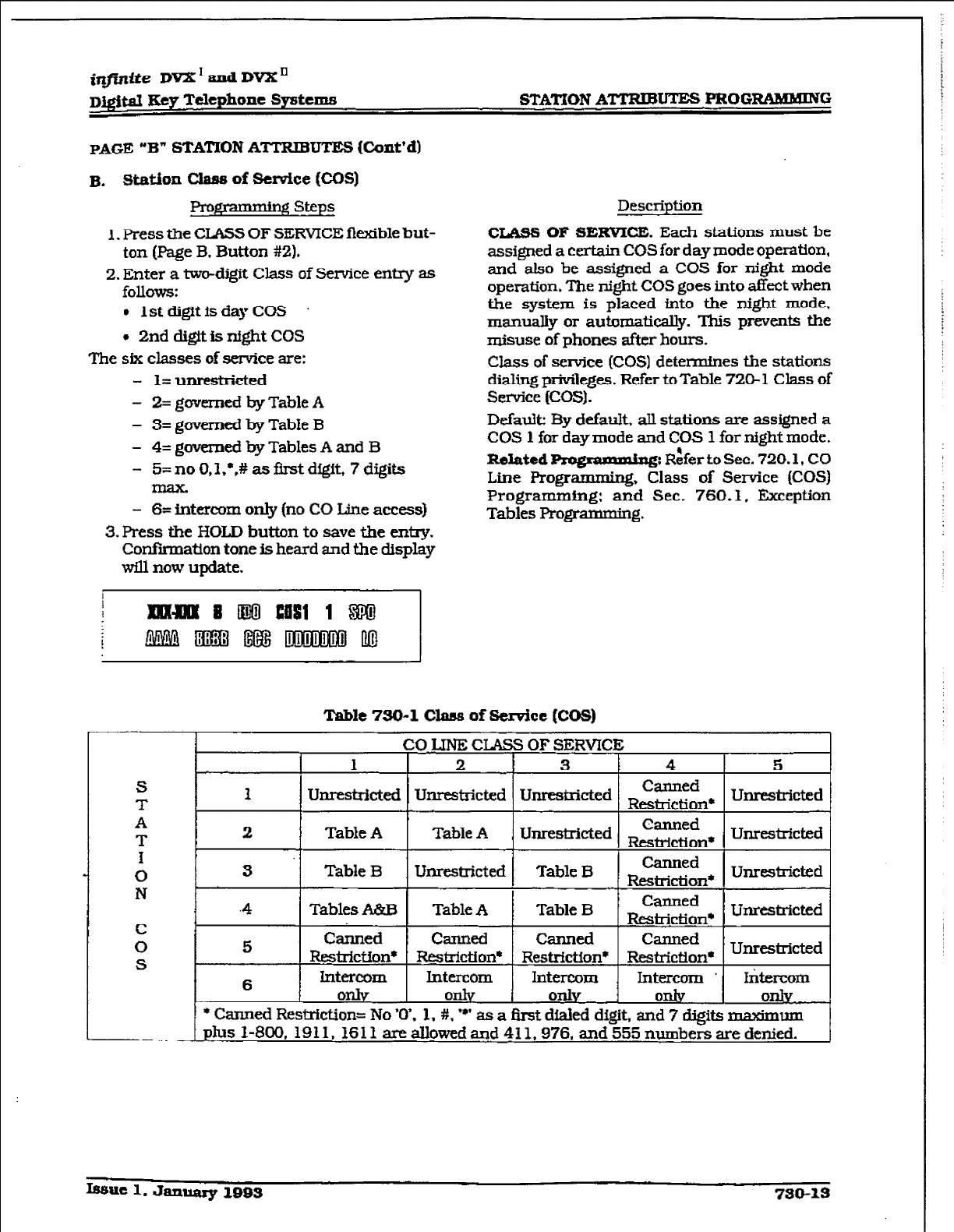
iq#inife DVX’tmdDVXn
D&$&d Key Telephone Systems STATXON A-U== PROGRAMMWG
PAGE
“B” STATION ATTRIBUTES (Cont’d)
B. StEtion class of Service (Cm)
Pro#+?mxmg steps
1. Press the CLASS OF SERVICE fkible but-
ton (Page B. Button #Z).
2. Enter a two-digit Class of Service entq as
follows:
l
1st digit is day COS
+ 2nd digit is night COS
The six classes of service are:
- 1= unrestricted
- 2= governed by Table A
- 3= governed by Table B
- 4= governed by Tables A and B
- 5= no O,I,‘,# as first digit, 7 digits
- 6= intercom only [no CO Line access}
3. Press the HOLD button to save the entry.
Confkmatton tone is heard and the display
will now update.
Description
CLASS OF SERVICE. Each stations must be
assigned a certain COS for day mode operation,
and also be assigned a COS for night mode
operation. The night COS goes into affect when
the system is placed into the night mode.
manually or automatically. This prevents the
misuse of phones after hours.
Class of service (COS] determines the stations
dialing privileges. Refer to Table 720- 1 Class of
Service (COS).
Dcfaulk By default. ail stations are assigned a
COS 1 for day mode and COS 1 for night mode.
Related w: Rifer to Sec. 720.1, CO
Line Progr~J, Class of Service [COS)
Programming: and Sec. 760.1, Exception
Tables Programmtng.
Table 730-l Clam3 of &mice (COS)
CO LlN5 CLASS OF SERVICE
1 2 3 4 5
S
T 1 Unrestricted Unrestricted Unrestricted Rzg;tn* Unrestricted
A
T 2 Table A Table A , Unrestricted R$u$$& Unreskicted
1
0 3 Table B Unrestricted Table B Canned
Restriction* Unrestricted
N .4 Tables A&B Table A Table B Canned
Restriction* Unrestricted
c
0 5 Canned Canned Canned Canned
S ResMction* ResVlction* Restriction* Restriction* Unrestricted
6 Intercom Intercom Intercom Jntercom * h&x-corn
0* OlllV
onlv
OnSy
only
* Canned Restriction= No ‘0’. 1. #, ‘*’ as a iht dialed digit, and 7 digits maximum
phs l-800. 1911.
161 f are allowed and 411,976, and 555 numbers are denied.
Isauc 1. January 1993 730-13
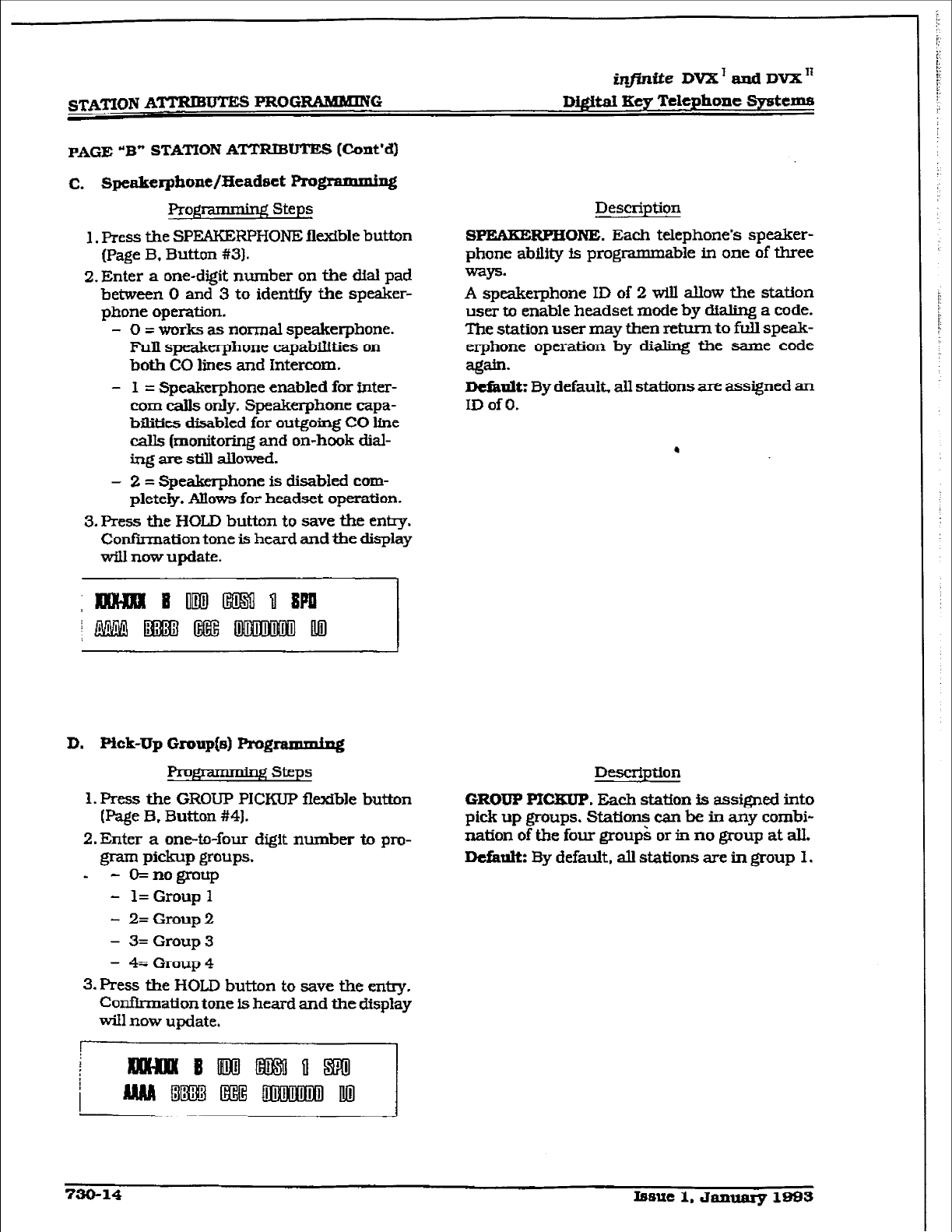
STATlON ATTRIBUTES PROGRNlMlNG
PAGE “B” STATION ATTRJBUTES (Cont’d)
C.
Speakerphont/fXeadact FVog
Progxamming Steps
’ g
1.
Press
the SPEAKERPHONE flexible button
[Page B, Button #31.
2. Enter a one-digit number on the dial pad
between 0 and 3 to identify the speaker-
phone
operation.
- 0 = works as normal
speakerphone.
FUI spezkrphone
capabilities on
both CO lines and Intercom.
- I = Speakerphone
enabled for
inter-
com calls only. Speakerphone capa-
bilities disabled for outgoing CO line
calls (monitoring and on-hook dial-
ing are still auowtd.
- 2 = Speakerphone
is
disabled com-
plete@. Allows for headset operation.
3. Press the HOLD button to save the entry.
Confiiation tone is heard
and the
display
wilI now update.
Descrintion
SPEAKERPHONE. Each telephone’s speaker-
phone ability is programm able in one of three
Ways.
A speakerphone ID of 2 will aUow the station
user to enable headset mode by dialing a code.
The station user may then return to fuIl speak-
erphone operation by di&ng the same code
ag--
Dcf&nlk By default. aU stations are assigned an
ID of 0.
.
D.
Pick-Up
Group[s) programmipg
1. Press the GROUP PICKUP flexible button
(Page
B.
Button #4J.
2. Enter
a one-to-four digit number to pro-
gram Pickup &Foups.
b - o=nogroup
- l=Groupl
- 2=Group2
- 3= Group3
- 4= Group 4
3. Press the HOLD button to save the entry.
Confhmation
tone is heard and the
display
will now update.
[
Description
GROUP PIC3UP. Each station is assigned into
pick up groups. Stations can be in any combi-
nation of the four group& or in no group at alL
D+fault: By default, all stations are in
group 1.
730-14
Issue 1. Jalluaxy 1sss
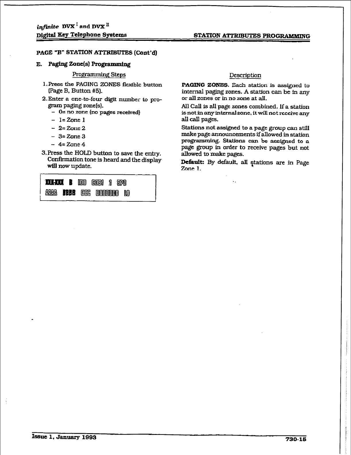
i@ite DVX’ and DVX’
Di@l Key Telephone Systems STATION ATTRIBUTES PROGIMBlMRVG
PAGE “B”
STA’MON ATTRIBUTES (0mt’d)
E. P@ng ant(s) pr0g-g
Prof$Tmmbg steps
l.Press the PAGING ZONES flexible button
(Page B. Button #5).
2.Enter a one-to-four digit number to pro-
gram paging zone(s).
- 0= no zone (no pages received)
- l=Zonel
- 2=Zone2
- 3=Zone3
- 4=Zone4
3.Press the HOLD button to save the entry.
Confbmation tone is heard and the display
wIIl now update.
Description
PAGING ZONES. Each station is assigned to
internal paging zones. A station can be in any
or all zones or in no zone at alI.
All Call is all page zones combined. If a station
is not in any internal zone. itwill not receive any
all call pages.
Stations not assigned to a page group can still
make page announcements ifallowed in station
prog ‘?g. Stations can be assigned to a
page group in order to receive pages but not
akwed to make pages.
Defaultz By default, alI $&ions are in Page
Zone 1.
Ifume 1, January 1993 73&16
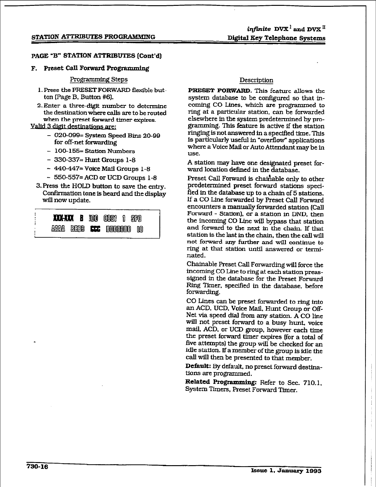
STATION ATTRXBUTES FROGIUWMING
iqfinite DVX'EUI~DVX~
D&&al Key Telephone Systems
PAGE “B” STATION AmU’IE3 (Cont’d)
F. Preset Call Forward Rogrammfn&
Progr~ Steps
1. Press the PRESET FORWARD flexible but-
ton (Page B, Button #6).
2.Enter a three-digit number to determine
the destination where calis are to be routed
when the preset forward timer expires.
.
3 dim
- OZO-099= System Speed Bins 20-99
for off-net forwz&fng
- loo-155= station Numbers
- 330-337= Hunt Groups l-8
- MO-447= Voice Mail Groups 1-8
- 550-5572 ACD or UCD Groups 1-8
3,Press the HOLD button to save the entry.
Confirmation tone is heard and the display
will now update.
Descriution
PlEESET FORWARD. This feature allows the
system database to be configured so that in-
coming CO Lines, which are programmed to
ring at a parttcular station, can be forwarded
elsewhere in the system predetermined by pro-
$2 * g. This feature is actfve if the station
ringing is not answered in a specified time. This
is particularly useful in “overflow” applications
where a Voice Mafl or Auto Attendant may be in
use.
A station may have one designated preset for-
ward location defmed in the database.
Reset Call Forward is ch&able only to other
predetermined preset forward stations speci-
fied in the database up to a chain of 5 stations.
If a CO Line foxwarded by Preset Call Forward
encounters a manually forwarded station (Call
Forward - Station]. or a station in DND. then
the incoming CO Line will bypass that station
and forward to the next in the chain. If that
station is the last in the chain, then the call will
not forward any further and will continue to
ring at that station until answered or termi-
nated.
Chainable Preset Call Forwarding will force the
incoming CO Line to ring at each station preas-
signed in the database for the Preset Forward
Ring Timer. specified in the database, before
fol-Wa&ng.
CO Lines can be preset forwarded to ring into
an ACD, UCD, Voice Mail, Hunt Group or Off-
Net via speed dial from any station. A CO line
will not preset forward to a busy hunt, voice
mail, ACD, or UCD group, however each time
tfie preset forward timer expires [for a toti of
five attempts1 the group will be checked for an
idle station. If a member of the group Is idle the
call will then be presented to that member.
Default:
By default, no preset fomd destina-
tions are programmed.
Related PI-O-: Refer to Sec. 710.1,
System Timers, Preset Forward Timer.
730-16 Iseue 1. Jaauarg 1993
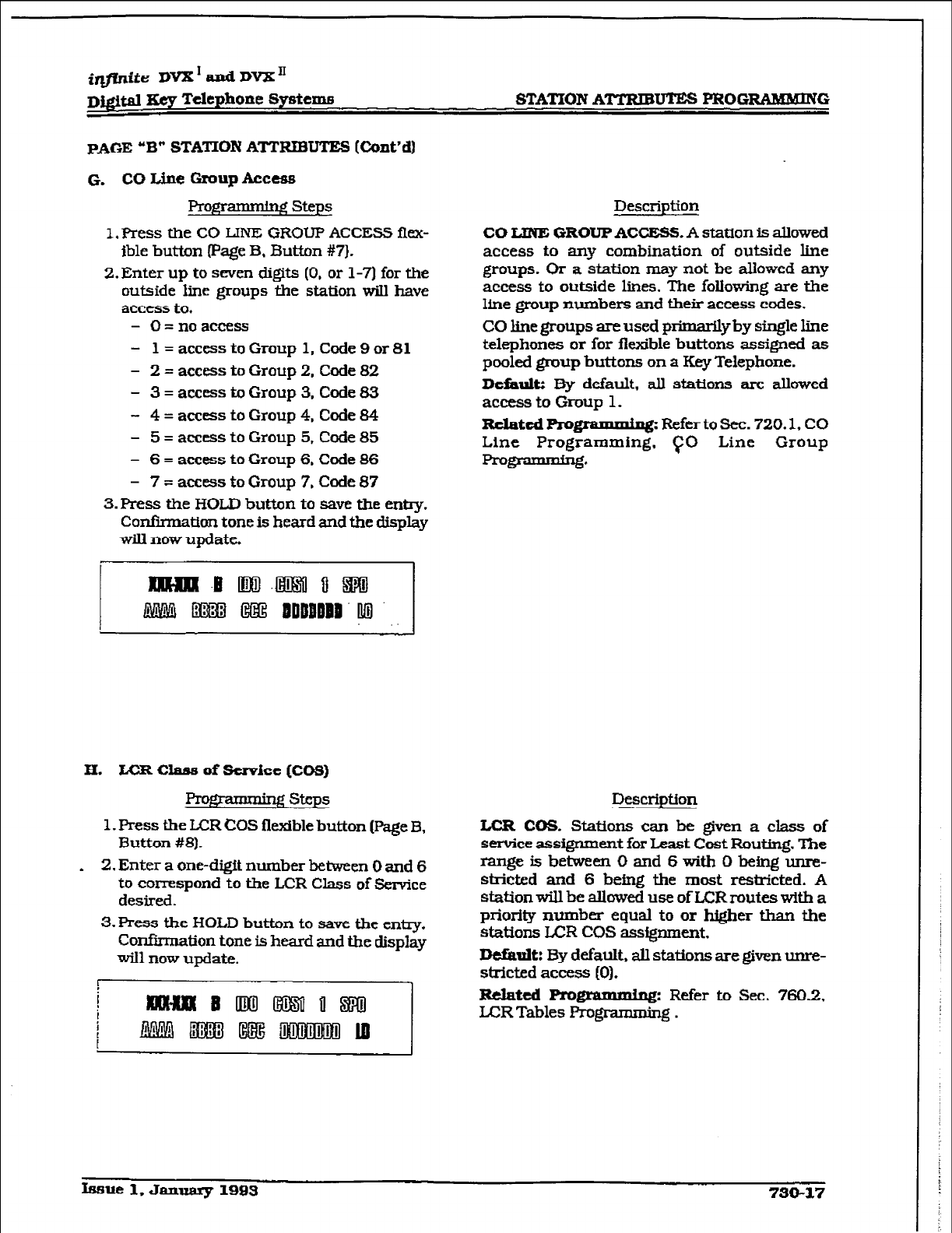
i@ite DVX’aadDVX’
~j#al Xt?y Telephone Systcme
PAGE “B”
STATION ATTRIBUTES
(Cont’d)
G. CO Lbe -Up hm?ss
RoJqmmiTg steps
LPress the CO LIFtI3 GROUP ACCESS flex-
ible button (Page B. Button #7}.
2. Enter
up to seven digits (0, or 1-3 for the
outside line
groups the station wiIl have
access to,
- O=noaceess
- 1 =accesstoGroup 1, Code9or81
- 2 = access to Group 2. Code 82
- 3 = access to Group 3. Code 83
- 4 = access to Group 4, Code 84
- 5 = access to Group 5. Code 85
- 6 = access to Group 6. Code 86
- 7 = access to Group 7. Code 87
3. Press the HOLD button to save the entty.
Confirmation tone is heard and the display
will now update.
Description
CO UNE GROUP ACCESS.
A station is allowed
access to any combination of outside hne
groups. Or a station may not be allowed any
access to outside lines. The following are the
line group numbers and their access codes.
CO line groups are used primarily by single line
telephones or for flexible buttons assigned as
pooled group buttons on a Key Telephone.
Deiidtz By default, all stations are allowed
access to Group 1.
RdmtcdRo~:
Refer to Sec. 720.1,
CO
Line Programming, TO Line Group
--*
H. LCR clans of scmicc [Cos)
v steps
1. Press the LCR COS flexible button (Page B,
Button #8).
b 2. Enter a one-digit number between 0 and 6
to correspond to the LCR Class of Service
desired.
3. Press the HOLD button to save the entry.
Confirmation tone is heard and the display
will now update.
Description
LCR COS. Stations can be given a class of
service assignment
for
Least
Cost Routing. The
rangeisbetweemOand6withObeingunre-
stricted and 6 being the most restricted. A
station will be allowed use of LCR routes with a
priority
rmmbes
equal to or higher than the
stations LCR cos assignment.
Default: By default, all stations are given unre-
stricted access (0).
Related
programming: Refer to See. 760.2,
U=RTables Programming .
Issue 1. January 1993 730-17
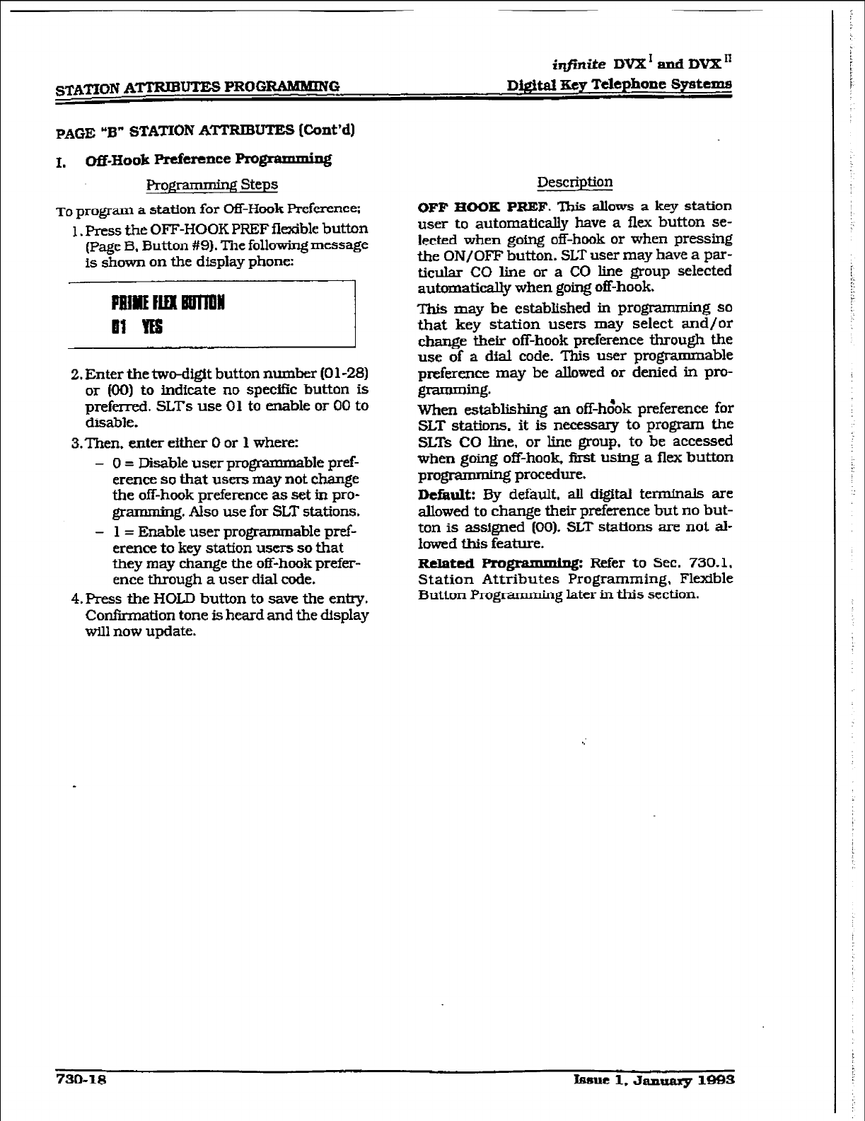
STATION ATTRIBUTES PROGRAMMING
iqfinite DVX' and IWX"
D&it& Key T&phone Syatam~
PAGE “B” STATION
ATTRIBUTES
[Co&d)
1. Off-Hook Preference Prog * g
Programming steps
TO program
a station for OR-Hook Pre.ference;
1. Press the OFF-HOOK PREF flexible button
(Page B. Button #9). The following message
is shown on the display phone:
2. Enter the two-digit button number (0 l-28)
or (00) to indicate no specific button is
preferred. SLTs use 01 to enable or 00 to
disable.
3.Then.
enter either 0 or 1 where:
- 0 = Disable user programmable pref-
erence so that users may not change
the off-hook preference as set in pro-
grammirg. Also use for SLT stations.
- 1 = Enable user programmable pref-
erence to key station users so that
they may change the off-hook prefer-
ence through a user dial code.
4. Press the HOLD button to save the entry.
Con&mation tone is heard and the &splay
will now update.
Description
OFF IIOOK PREF. This allows
a key station
user to automatically have a flex button se-
lected when going off-hook or when pressing
the ON/OFF button. SLT user may have a par-
ticular CO line or a CO line group selected
automatically when going off-hook.
This may be established in programming so
that key station users may select and/or
change their off-hook preference through the
use of a dial code. This user programmable
preference may be allowed or denied in pro-
g-g.
When establishing an off-h&k preference for
SLT stations.
it
is necessary
to program the
SLTs CO Une.
or line group, to be accessed
when going off-hook first using a flex button
pq$2mmQj procedure.
Default: 3y default, all digital terminals are
allowed to change their preference but no but-
ton is assigned (00).
SLT stations are
not al-
lowed this feature.
Related
Progllg: Refer to Sec. 730.1,
Station Attributes Programming, Flexible
Button Programming later in this section.
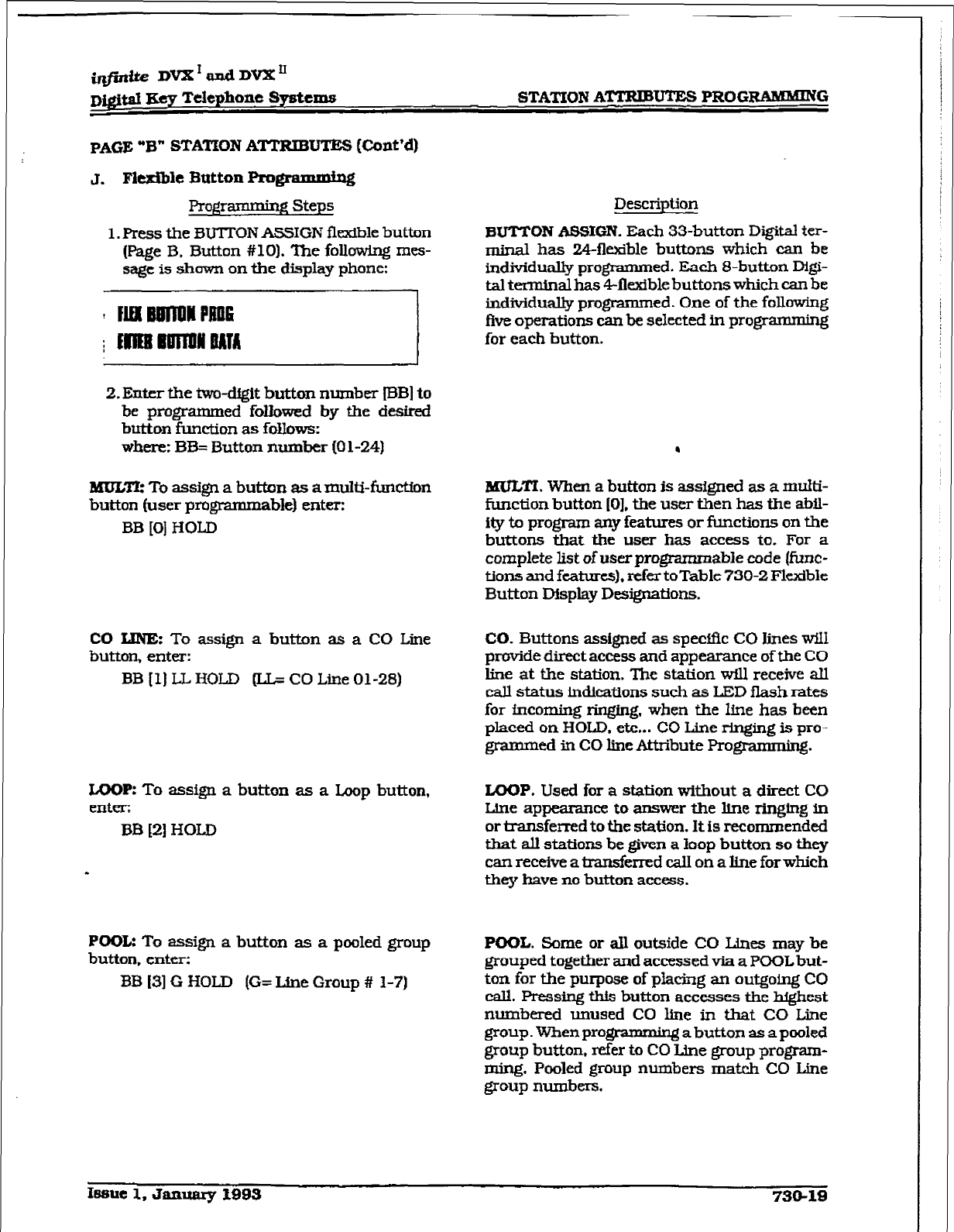
i@ite DVX’andDVX’
~@ta,I gey T&phone Systems STATION A-m PROGRAMHING
PAGE “B” STATION ATTRIBUTES (Cont’d)
Pro@imming Step5
1. Press the BUTION ASSIGN flexible buttnn
(Page B. Button #lo). The following mes-
sage is shown on the display phone:
! MIlwlNMPlin~
c
/ IllimmnoAl~
2. Enter the two-drgit button number IBB] to
be programmed followed by the desired
button function as follows:
where: BB= Button number (0 l-24)
MULTk To assign a button a5 amulti-firnctfon
button tuner programmable) enter:
BB [O] HOLD
CO KJNEz To assign a button as a CO Line
button, enter:
BB (11 IIL HOLD (I& CO Line 01-28)
LOOP: To assign a button as a Loop button,
enter:
BB (21 HOLD
POOL: To assign a button as a pooled group
button, enter:
BB (31 G HOLD (G= Line Group # 1-7)
Description
BUTTON ASSIGN. Each 33-button Digital ter-
minal ha5 24fltible buttons which can be
individually programmed. Each 8-button Mgi-
tal terminal has 4llexible button5 which can be
individually programmed. One of the following
five operations can be selected in programming
for each button.
.
BKKZI. When a button is assigned a5 a multi-
function button IO]. the user then has the a&l-
ity to program any features or function5 on the
buttons that the user has access to. For a
complete list of user programmable code (f&c-
tions and
features),
refer toTable 730-2 Flexible
Button Display Designations.
CO. Buttons assigned a5 spectic CO lines wiI1
provide direct access and appearance of the CO
line at the station. The station wfll receive all
call status indications such as LED flash rates
for incoming ringing, when the line has been
placed on HOLD, etc... CO Line ringing is pro-
grammed in CO line Attribute Progmmming.
LOOP.
Used for a station without a direct CO
Line appearance to answer the line ringing in
or transferred to the station. It is recommended
that alI stations be given a loop button so they
can receive a transferred call on a line for which
they have no button access.
POOL. Some or all outside CO Line5 may be
grouped together and accessed via a POOL but-
ton for the purpose of placing an outgoing CO
call. Pressing this button accesses the highest
nuxnbered unused CO line in that CO Line
group. When programmii a button as a pooled
group button. refer to CO Line group program-
ming. Pooled group numbers mat& CO Line
group numbers.
STATION AmUTES PROGEUMMING
infinite DVX’ and DVX”
Digital Key Telephone Systems
PAGE 93” STATION ATTRIBUTES [Cont’d)
pro-
Steps
7JNASSIGN: To unassign a button, enter:
BB [#I HOLD
If SLT stations are to be programmed for Off-
Hook Refmence, it is necessary to program the
desired CO line. or CO line group, the SLT is to
acce.ss when going off-hook.
To assign a CO Line for a SLT with Off-Hook
Preference. enter:
00 111 LLHOLD (LI= CO Line 01-28)
To assign a CO Line group for an SLT wtth
Off-Hook Preference, enter:
00 (31 G HOLD [G= Line Group # l-7)
Description
UNASSIGN
(looked
out). Specific buttons may
be designated as unused or locked out. When a
button is programmed as unused, the button
may not be programmed by the station user
using flex button programming procedures.
D&a&; By default, Station 100 will ring on a
line. However, if Station 100 is not given button
access to a tie. another station must be pro-
grammed to ring on that line.
Rclstted pro&ramming: When programming a
buttonasaCOLinebutton, refertoScc. 720.1,
CO Line Programming. CO Line Ringing
Assignments: and Sec. 730.1, Station
AtMbutes programming ,Off-Hook Preference
programming.
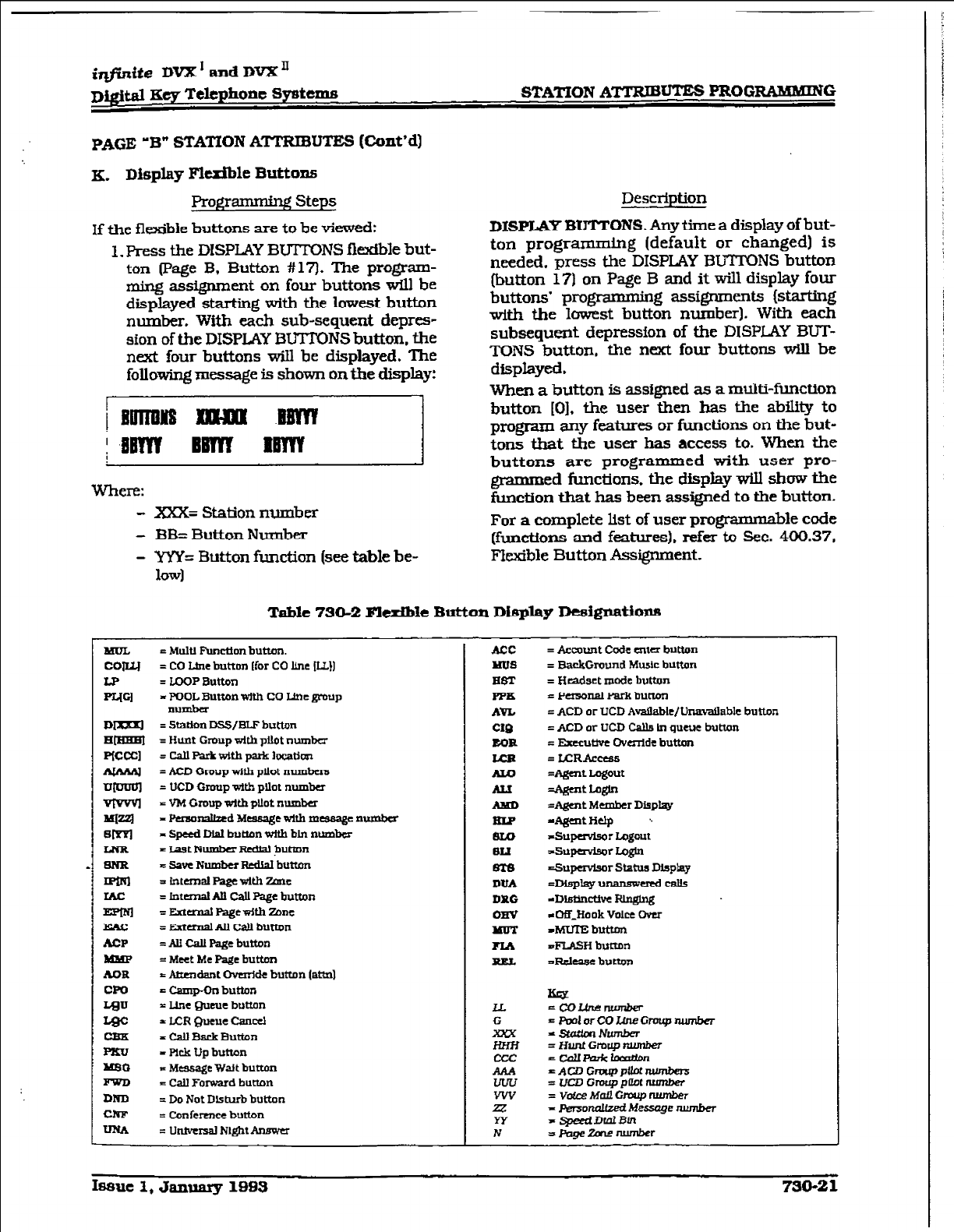
@jWte DVX’ and DVX”
Dw&l Key Telephone Spstcms STATION ATTRJBm PFtOGRMkMIiUG
PAGE ‘B” STATION ATTRIE)UTBS (Ckmt’d]
K. Display Flexible Buttons
Programming Steps
If the flexible buttons are to be viewed:
1. Press the DISPLAY BUTTONS flexible but-
ton (Page B, Button # 17). The program-
xning assignment on four buttons will be
displayed starting with the lowest button
number.
With
each sub-sequent deprcs-
sion of the DISPLAY BUTTONS button, the
next four buttons will be displayed. The
following message is shown on the display:
; ,%BWY BBTYI RBYYY
Where:
- XXX= Station number
- BB=
Button Number
1
Description
DISPLfLY
BUTTONS. Any time
a
display
of
but-
ton programming (default or changed) is
needed, press the DISPLAY BmNS button
(button 17) on Page B and it will display four
buttons’ programming assignments (starting
with the lowest button number). With each
subsequent depression of the DISPLAY BUT-
TONS button, the next four buttons will be
displayed.
When a button is assigned as a multi-function
button [O]. the user then has the ability to
program any features or functions on the but-
tons that the user has access to. When the
buttons are programmed with user pro-
grammed functions. the
display WLll show the
function that has been assigned to the button.
For
a
complete list of user programmable code
~functions and features). refer to Sec. 400.37,
- WY= Button function (see
table be-
Iowl
klexible Button Assignment.
Table 730-2 Flexible Button Diqlay Desl@atiops
t MUIU Fmctlon butmn.
= CO Ltnt button Ifor CO line ILL11
= LOOP Button
= POOL Button with CO MC group
number
= station DSS/ELF button
= Hum Group With p&It number
=CdlRUkWItbptkloEatIOn
= ACD Group titb pilot numbers
= UCD Group with pllot number
= VM Group with pllot number
= Pworralhxd Mcasagc with mcsaagc wmbcr
- speed W button with btn number
= ~~~tNumber~&H buttnn
~savcNumbcrRcdMbut%m
= tntemal Page With zanc
= Internal M call Page button
= Edcrnal Ragcwkb Zone
= aernalW Cd button
=AUCallPagebutton
= Meet Me paBe button
f &r~~~dant Ovcrrlde button (ati]
= Camp-On button
= Line Queue button
= LCR Queue Cancel
= Call Back Button
= pick Up button
p ~cssage Wtit button
= call Forward button
= Do Not Disturb button
= Conhence button
= Untverssl N&lx Answer
ACC
Mu8
= Account Code cntcr button
= BackGround Music button
= Headset mcx5c button
= Pasonal Park button
= ACD or UCD Available/Una-ztillablc button
=ACDorUCDCaU~tnqueucbuttan
= Ekccutlve Ova-tide button
= UIRAccess
=Agent Logout
=Agent wm
=Agcnt Member Display
dgattnelp \
TSupervisor Logout
dhqavbor Logh
=.SupavIsm Status
Display
=-lay”- credcdls
-D&t.incttve RLnglng
c0fiJiook Volcc -
&5UlEbutton
z.FLASH button
=Rcleasc bum
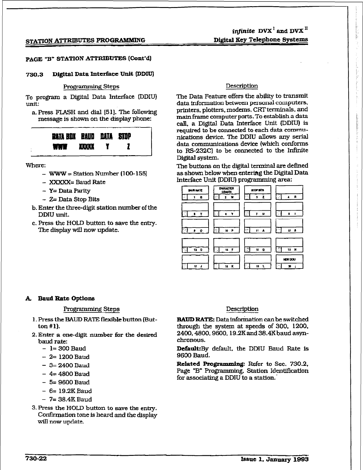
f$lXTION ATTRIBUTES PROGRAMMING
Digital Hey Telephone Systems
PAGE
‘8” STATION ATIWBUTES (Cont’d)
750.3
DIlsftal Data Interface Unit (DDIU)
Prog * 2 steps
To program a DigitaI Data Interface (DDIU)
unit:
a. Press FLASH and dial 1511. The foUowing
message is shown on the display phone:
where: -
?VWW = Station Number (100-155)
- XXXXX= Baud Rate
- Y=DataPariiy
- 2% Data Stop Bits
b. Enter the three-digit station number of the
DDIU unit.
c. Press the HOLD button to save the entry.
The display w-ill now update.
A E%audRatcoptiolu4
Programming steps
1. Press the BAUD RATE ff exible button (But-
ton # 1).
2. Enter a one-digit number for the desired
baud rate:
- 1= 300 Baud
- 2= 1200 Baud
- 3= 2400 Baud
- 4= 4800
Baud
- 5= 9600 Baud
- 6= 19.2KBaud
- 7= 38.4K Baud
3.Fress
the HOLD button to save the entry.
Confkmation tone is heard and the d.lspIay
will now update.
Description
The Data Feature offers the ability to transmit
data information between personal computers,
printers. plotters. modems. CRT terminals, and
main frame computer ports. To estabtish a data
cdl. a Digital Data Interface Unit (DDIUI is
required to be connected to each data cornmu-
nications device. The DDIU allows any seriaJ
data communications device (which conforms
to RS-232C)
to be connected to the Infinite
Digital system.
The buttons on the digital terminal are defined
as shown below when enterihg the Digital Data
Interface Unit (DDIU) programming area:
Description
BAUD RATE: Datainfonnation canbe switched
through the system at speeds of 300, 1200,
2490.4800,9600,19.2K and 38.4K baud asyn-
chronous.
D&ultiBy default, the DDIU Baud Rate is
9600 Baud.
R&ted Prognlmmhg: Refer to See. 730.2,
Page “El” Programming, Station Identification
for associating a DDlU to a station. ’
730-22
Issue 1, January 1-3
STATION
ATTRIBUTES
PROGRMKMiNG
Digital Data Interface Unit DDIU) [Cont’d)
B. cbaracttr Length option
J?rogrammir@ Steps
1. Press the CHARACTER LENGTH flextble
button lsutton #2).
2. Enter a one-digit number for the character
length of the digit string.
- 8= 8 character kngtb
- 9= 9 characterlengtb
3. Press the HOLD button to save the entry.
Confiiation tone is heard and the display
will now update.
Description
CHARACTER =NGTFk Eght bit characters
are typically used. without the need for parity.
The important point is that the character length
settings match those of the attached computer
or terminal. If the computer is set up for 8-bit
data characters with parity, set the printer the
same way. Otherwise, the data may be garbled
due to incompatible formats.
Default: By default, 8-character length is se-
lected.
C, Stop Bit(s) Option
Prow steps
l.Press the STOP BD’S flexible button fBut-
ton #3).
2. Enter a one-digit number for the number
of stop bits desired.
- 1= 1 StopBit
- 2= 2 Stop Bits
Description
STOP BIT@): The stop bit indicates that alI the
data bits have been sent and the transmission
of the character is complete.
Dctiultz By default. 1 stop bit is selected.
3.Press the HOLD button to save the entry.
Con&nation tone is heard and the display
will now update.
Issue 1, January 1993 730-23
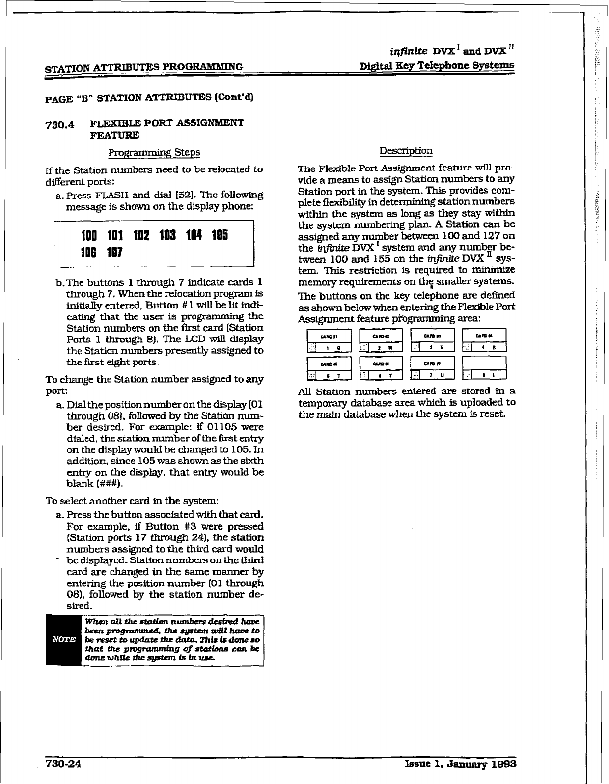
sgXf’ION ATi-RifBm PRGGRAMMIIW
iqfinike DVX’ and DVX’
Dtgttal lgty T&phone
Systems
PAGE “B” STATION ATTRIBUTES
[Cont’dI
730.4 FLExfBLE PORT ASSIGNAUENT
FEATURE
Pl-ogm steps
If the Station numbers need to be relocated to
different ports:
a. Press FLASH and dial [52). The following
message is shown on the display phone:
--::::-,,,.,.,,,j
b.The buttons
1
through 7 indfcate cards
1
through 7. When the relocation
program is
initially entered, Button # 1 will be lit indi-
cating that the user is programming the
Station numbers on tie first card (Station
Ports 1 through 8). The LCD will display
the Station numbers presently assigned
to
the fmt eight ports.
To change the
Station number
assigned to any
port:
a. Dial the position number on the display (01
&rough OS),
follawcd by the
Station num-
ber desired. For example: if 01105 were
dialed. the station number of the first entry
on the display would be changed to 105. In
addition, since 105 was shown as the sixth
entry on the display. that entry would be
blank (###I.
To select another card in the system:
a. Press the button assocfated with that card.
For example. ff Button #3 were
pressed
(Station ports 17 through 24). the station
numbers assigned
to the
third catd would
- be displayed. Station numbers on the third
card are changed in the same manner by
entering the position number (01
through
081, followed by the station number de-
sired.
Description
The Flexible Port Assignment feature WLll pro-
vide
a means to assign Station numbers to any
Station port in the system. This provides com-
plete fiexibility in determining station numbers
wftbin the system as long as they stay within
the system numbcrfng plan. A Station can be
assigned any number between 100 and 127 on
the infinite DVX ’ system
and any number be-
tween 100 and 155 on tbe infintte DVX ’ sys-
tern. This restriction is required to minimize
memory requirements on th: smaller systems.
The buttons on the key telephone are defined
as shown below when entering the Flexible Port
Assignment feature prm area:
p%qy#gq~~
~pic@qh-;-;-l
All Station numbers entered are
stored in
a
temporary database area whtch is uploaded to
the main database when the system is reset.
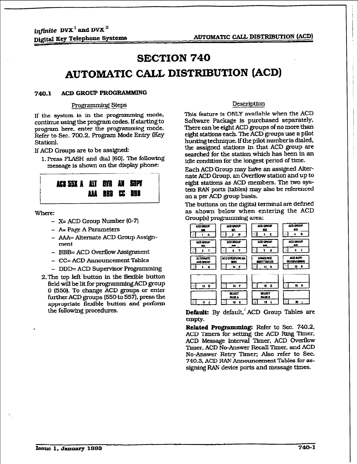
i@ite DVX’ and DVX”
D&&al Key Telephone Systems AuTOM&TIC CALL DISTFUMJTION
(ACD)
SECTION 740
AUTOMATIC CALL DISTRIBUTION (ACD)
740.1 ACD GROUP ??ROGmG
Pro@axnming steps
If the system is in the programming mode,
continue using the program codes. If starting to
program here, enter the programming mode.
Refer to Sec. 700.2, Program Mode Entxy (Key
Station).
lf ACD Groups are to be assigned:
1. Press FLASH and dial [SO]. The fokwlng
message is shown on the display phone:
.~!
WhfflT:
- X= ACD Group Number [O-71
- A= Page A Parameters
- A&k Alternate ACD Group Assign-
ment
- Bl3B= ACD OverflowAssignment
- CC= ACD Announcement Tables
- DDD= ACD Supervisor F’rogramrnmg
2.The top left button in the fl&ble button
field wih be
lit
for programmk# ACD group
0 (5501.
To change
ACD groups or er&r
fu.rtherACD groups (550 to 557). press the
appropriate flexible button and perform
the following procedures.
Descriptton
This feature f.s
ONLY
available when the ACD
Software Package is purchased separately.
There can be eight ACD groups of no more than
eight stations each. The ACD groups use a pilot
hunting technique. Ifthe pilot numberis dialed,
the assigned stations in that ACD group are
searched for the station which has been fn an
idle condition for the longest period of time.
Each ACD Group may have an assigned Alter-
nate ACD Group, an Overflow station and up to
eight stations as
ACD members. The two sys-
tem RAN ports (tables) may also be referenced
on a per ACD group basis.
The buttons on the digital terminal are defined
as shown below when entering the ACD
Group(s) progmmming area:
pzq~.~Lfzj
~~pz&ggcr;-l
Dcfanlt: By default,< ACD Group Tables are
empiy.
Related Rogrsmmiq: Refer to Sec. 740.2.
ACD Timers for setting the ACD Ring Timer,
ACD Message Interval Timer. ACD Overflow
‘Inner. ACD No-Answer Recall Timer, and ACD
No-Answer Retry ‘Dmer: Also refer to
Sec.
740.3. ACD RAN Announcement Tables for as-
signing FUN device ports and message times.
Issue 1, January
1993
740-l
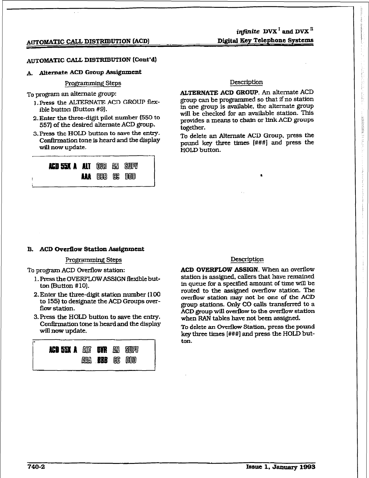
AmOBdAmc CALL DISTRIBUTION (ACD)
i#nite DVX’andDVXn
Digital Key Telephone Systems
AUTOM&I?C CALL. DISTRIBUTION [Cont’d)
A Alternate ACD Group &siggament
Prog-rq steps
To program an alternate group:
1. Press the ALTEXNA~ ACD GROUP flex-
ible button putton #Q).
2. Enter the three-digit pilot number (550 to
557) of the desired alternate ACD group.
3.Press
the HOLD button to save the entry.
Confirmation tone is heard and the display
witl now update.
Description
ALTERNATE ACD GROUP. An alternate ACD
group can be programrued so that if no station
in one group is availabie. the alternate group
will he checked for an available station. This
provides a means to chain or link ACD groups
togetbcr.
To delete an Alternate ACD Group, press the
pound key three times [###I and press the
HOLD button.
B. ACD Overflow Station Assignment
Programmirq! steps
To program ACD Overflow station:
1. Rcss the OVERFLQWASSlGN fltzdblebut-
ton IButton # 10).
2.
Enter the three-digit station nuznber (100
to 155) to designate the
ACD
Groups over-
flow station.
3. Press the HOLD button to save the entry.
Cor&rmation tone is heard and the display
will now update.
Description
ACD OVERFLOW ASSIGN. When an overflow
station is assigned, callers that have remained
in queue for a specffied amount of time will be
routed to the assigned overflow station. The
overflow statfon may not be one of the ACD
group stations. Only CO calls transferred to a
ACD group will overflow to tie overflow station
when RAN tables have not been assigned.
To delete an Overflow Station, press the pound
key three times [###I and press the HOLD but-
ton.
740-2
Jssue 1, Jmuary 1933
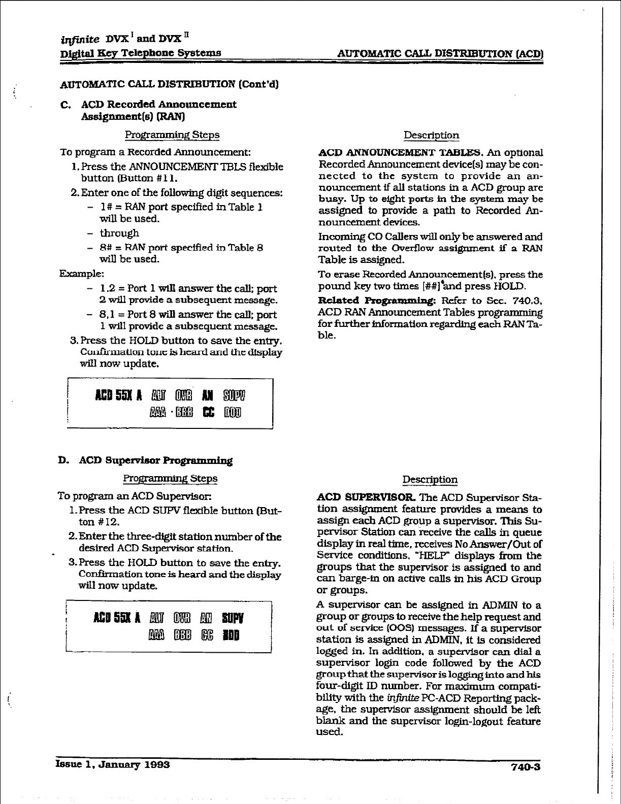
@#i&e
DVX’~dDl%Xn
Di@al Fky Telephone Systems AUTOMATXC CALL DISTRIBUTION (ACD)
AUTOMATfc CALL DISTRIBUTION (Cmt’d)
C.
ACD
Recorded Announcement
Assig--tb) IRAN]
Proprammirlg steps
To program a Recorded Announcement:
1. Press the ANNOUNCEMENT TEKS flexible
button (Button # I 1.
2. Enter one of the following digit sequences:
- 1# = RAN port speciiied in Table I
wiIl be used.
- through
- 8# = RAN port specified in Table 8
will be used.
Example:
- 1.2=Port1wiIIanswert.hecall:port
2 will provide a subsequent message.
- 8.1 =Port8wiIIanswertheeaII:port
1 will provide
a
subsequent message.
3. Press the HOLD button to save the entry.
Confirmation tone is heard and the display
wiIl now update.
D. ACD Supe~r Pro@am~~@
Pr- steps
To program an ACD Supervisor:
1. Press the ACD SUPV flexible button (But-
ton # 12.
2.
Enter the three-dfgit
station number of the
* desired ACD Supervisor station.
3. Press the HOLD
button to save the entry.
Confirmation
tone is heard and the display
will now update.
Description
ACD ANNOlJNCEMENT TABLES. An optional
Recorded Announcement device(s) may be con-
nected to the system to provide an an-
nouncement if alI stations in a ACD group are
busy. Up to eight ports in the system may be
assigned to provide a path to Recorded An-
nouncement devices.
Incoming CO Callers will only be answered and
routed to the Overflow assignment if a RAN
Table is assigned.
To erase Recorded Announcement(s). press the
pound key two times [##)‘and press HOLD.
Related m: Refer to Sec. 740.3.
ACD RAN Announcement Tables programming
for further information regarding each RAN Ta-
ble.
IkscrliptioIl
ACD SUPERVISOR ‘l%e
ACD Supervisor Sta-
tion assignment feature provides a means to
assign each ACD group a supervisor. This Su-
pervisor Station can ‘ixxeive the calls in queue
display in real time, receives No Answer/Out of
Service conditions. ‘HELP” displays from the
groups that the supervisor is assigned to and
can barge-in on active caIls in his ACD Group
or groups.
A supervisor can be assigned in ADMIIU to a
group or groups to receive the help request and
out of service (00s) messages. If a supervisor
station is assigned in ADMIN,
it
is considered
logged in. In addition. a supervisor can dial a
supervisor login code followed by the ACD
group
that
the supervisor is low into and his
four-digit ID number. For maximum compati-
bility with the inj?szi& PC-ACD Reporting pack-
age, the supervisor assignment should be left
blank and the supervisor login-logout feature
used.
Issue
1. January 1QQ3 740-s
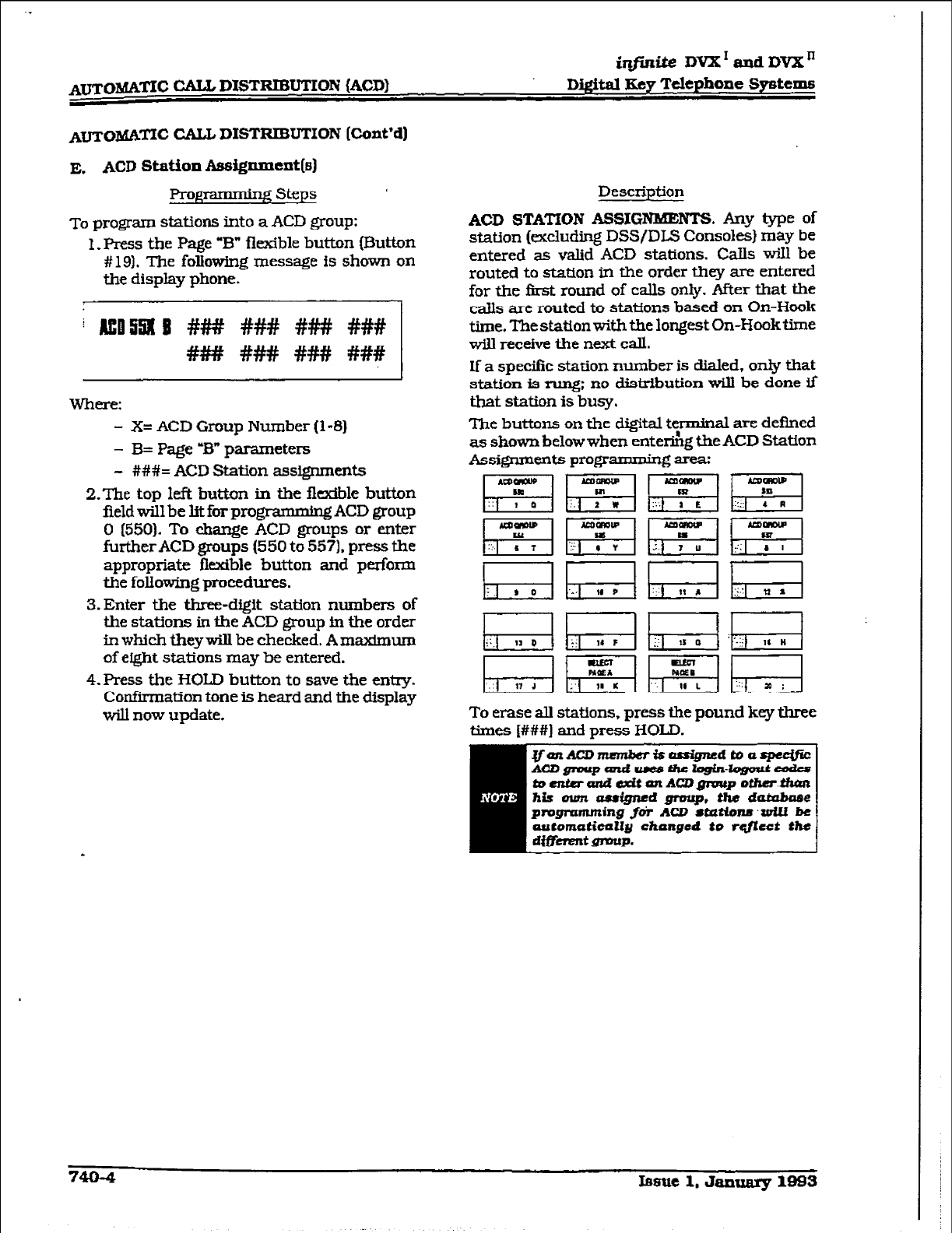
Atomic CALL DISTRIBUTION (ACD)
iqfinite? DVX’andDV2C”
Digital Key Telephone Spetems
Atomic CALL DISTRIBUTION [Cont’d)
E. ACD Station l&d@Imcnt(e]
Prog * g steps ’
To program stations into a ACD group:
I.Press the Page “B” fl&ble button [Button
# 191. The folIowing message is shown on
the display phone.
i EO5533 ### ### ### ###
### ##I## #### ###
Where:
- X= ACD Group Number (l-8)
- B= Page -B” parameters
- ###= ACD Station assignments
2.The top left button in the flexMe button
field will be lit for progmmming ACD group
0 (5501. To change ACD groups or enter
further ACD groups (550 to 557). press the
appropriate flexible button and perform
the following procedures.
3. Enter the three-digit station numbers of
the stations in the ACD group in the order
in which they will be checked, A maximum
of eight stations may be entered,
4.Press the HOLD button to save the entry.
Confirmation tone is heard and the display
will now update.
Description
ACD STATION ASSIGNBUENTS. Any type of
station (exclucbng DSS/DLS Consoles) may be
entered as valid ACD stations. Calls wiIl be
routed to station in the order they are entered
for the first round of calls only. After that the
calls are routed to stations based on On-Hook
time. The station with the longest On-Hook time
will receive the next call.
If a specific station number is dialed, only that
station is rung; no distribution will be done if
that station
is
busy.
The buttons on the digital twminal are de&red
as shown below when enter&g the ACD Station
Assi#lments programming area:
To erase all stations, press the pound key three
times [###I and press HOLD.
~~-J&----s$xJJ$~=
toentmundadtmtAwgmupother.thun
his own awigncd group. the dutubuae
prrrgruming foi AW 8Mtian~~zuill be
automaticully changed
to rqflcct the
dW”:gmrr~.
7404 Iaaue 1, January 1993
.
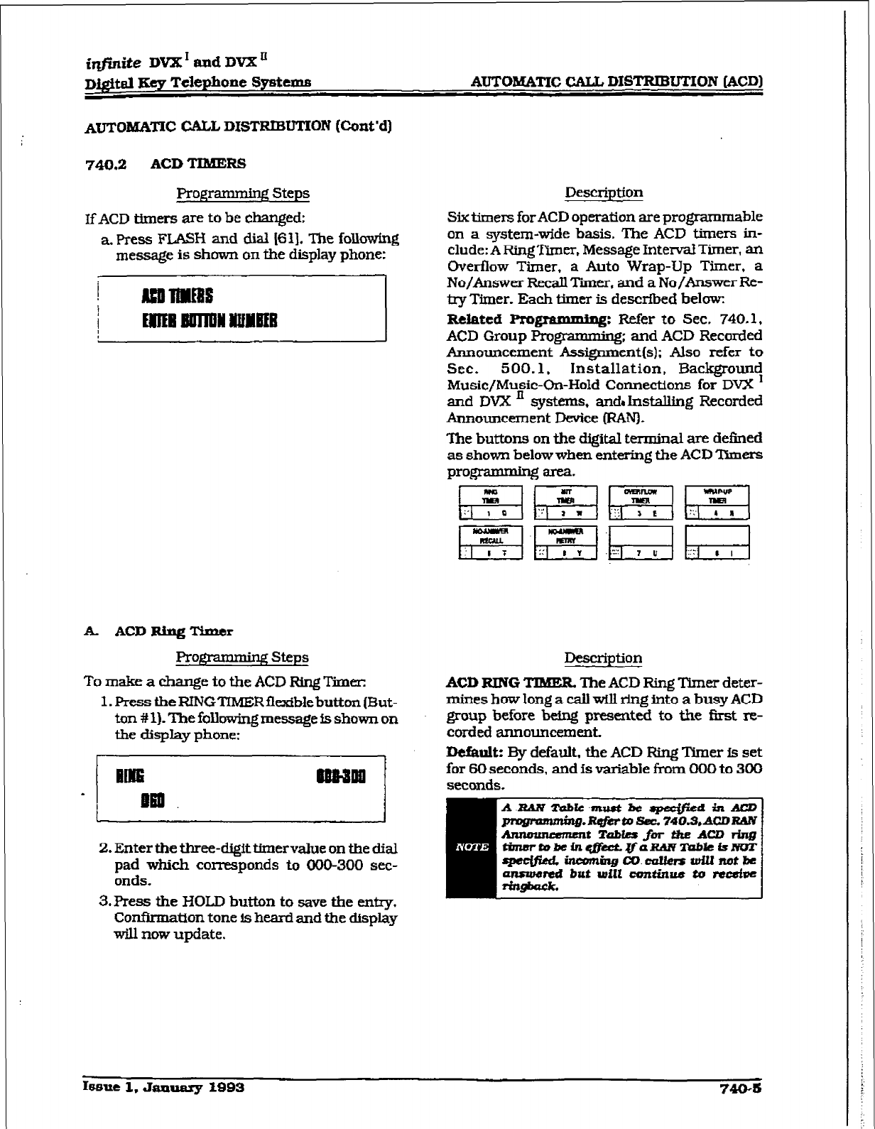
imite
DVX I and DVX u
D@tal FSey Telephone Sy8tems AUTOMATXC CAU DISTRIBUTION [ACD)
AUTOMATIC WL
DXSTRIBUTION
(Cont’d]
740.2
ACD TIMERS
Programming Steps Description
I~ACD thmrs are to
be changed:
a. Press FLASH and dial [6l]. The folkwing
message is shown on the display phone:
Six timers for ACD operation are programmable
on a system-wide basis. The ACD timers in-
clude:
A RingTimer,
Message Interval Tier, an
Overflow Timer, a Auto Wrap-Up Timer, a
No/Answer Recall Tiier. and a No/bwer Re-
tty Timer. Each timer is descrfbed helm
R&ted Rognunming: Refer to Sec. 740.1,
ACD Group Programukg; and ACD Recorded
Announcement Assignment(s): Also refer to
SlX. 500.1~ Installation, Backgrouny
Music/Music-On-Hold Connecttons for DVX
and DVX ’ systems, andJnsfxdling Recorded
Announcement Device (RAN).
The buttons on the digital terminal are defined
as shown below when entering the ACD ‘Ikmrs
programming area.
k ACDRingThner
Prof$Yamag steps
To make a change to the ACD Ring Timer:
1. Press the RINGTlMERflwcible button [But-
ton # 1). The following message is shown on
the display phone:
IME awaw
. II I
2.
Enter the three-digit timervalue on the dial
pad which corresponds to 000-300 sec-
onds.
3.Press the HOLD button to save the entry.
Confkmation tone is heard
and the
display
will now update.
Description
ACD RING TIMER The ACD Ring Timer deter-
mines how long a calI will ring into a busy ACD
group before being presented to the first re-
corded announcement
13tfsult: By default, the ACD Ring Timer is set
for SO seconds, and is variable from 000 to 300
seconds.
I68ue 1. Janutuy 1993
740-b
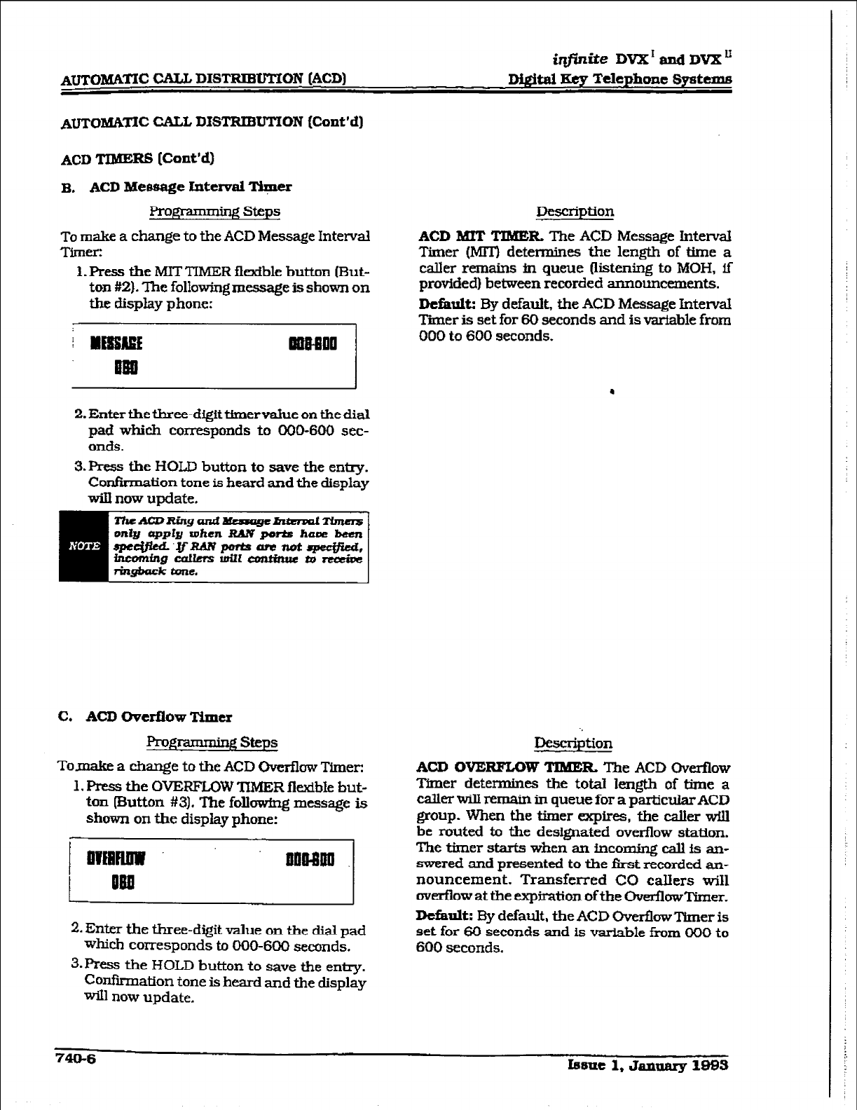
AUTOMATIC CALL DISTRIBUTION (ACD)
iqjinite DVX’andDVX”
Mgital Key Telephone Systems
ACD TIMERS
(Cont’d)
B. ACD Mefaage Interval T+zr
FrogI - gsteps
To make a change to the ACD Message Interval
Timer:
1. Press the MIT TIMER flexible button (But-
ton #2). The following message is shown on
the display phone:
2. Enter the three-digit timervahxe on the dial
pad which corresponds to 000-600 sec-
onds.
3.Press the HOLD button to save the entry.
Confirmation tone is heard and the display
will now update.
Description
ACD MXT
TIMER The
ACD Message interval
Timer (MllJ determines the length of time a
caller remains in queue (‘listening to MOH, if
provided) between recorded announcements.
Dcfhk By default, the ACD Message Interval
Timer is set for 60 seconds and is v&able from
000 to 600 seconds.
.
C. AW tierflow Timer
gramminfS steps
Tomake a change to the ACD Ov&low Timer:
1. Press the OVERFLOW lU4ER fl&bE but-
ton [Button #3]. The followfng message is
shown on the display phone:
pij-Tiy
2. Enter the three-digit value on the dial pad
which corresponds to 000-600 seconds.
3.FRss the HOLD button to save the en-.
Confxmation tone is heard and the display
will now update.
Dfzscr@tion
AW OVERFZOW TIMER The
ACD overflow
Tfmer
determines the tot& kngth of time a
caller will remain in queue for a particular AC0
group. When the timer expires, the dier will
be routed to the designated overflow station.
The timer starts when an incomjng call is an-
swered and presented to the first recorded an-
nouncement. Transferred CO callers will
overflow at the expiration of the Overflow Timer.
Default:
By default, the ACD Ove&wTlmer is
set for 60 seconds and
is
variable fmm 000 to
600 seconds.
740-6
Issue 1, January 1983
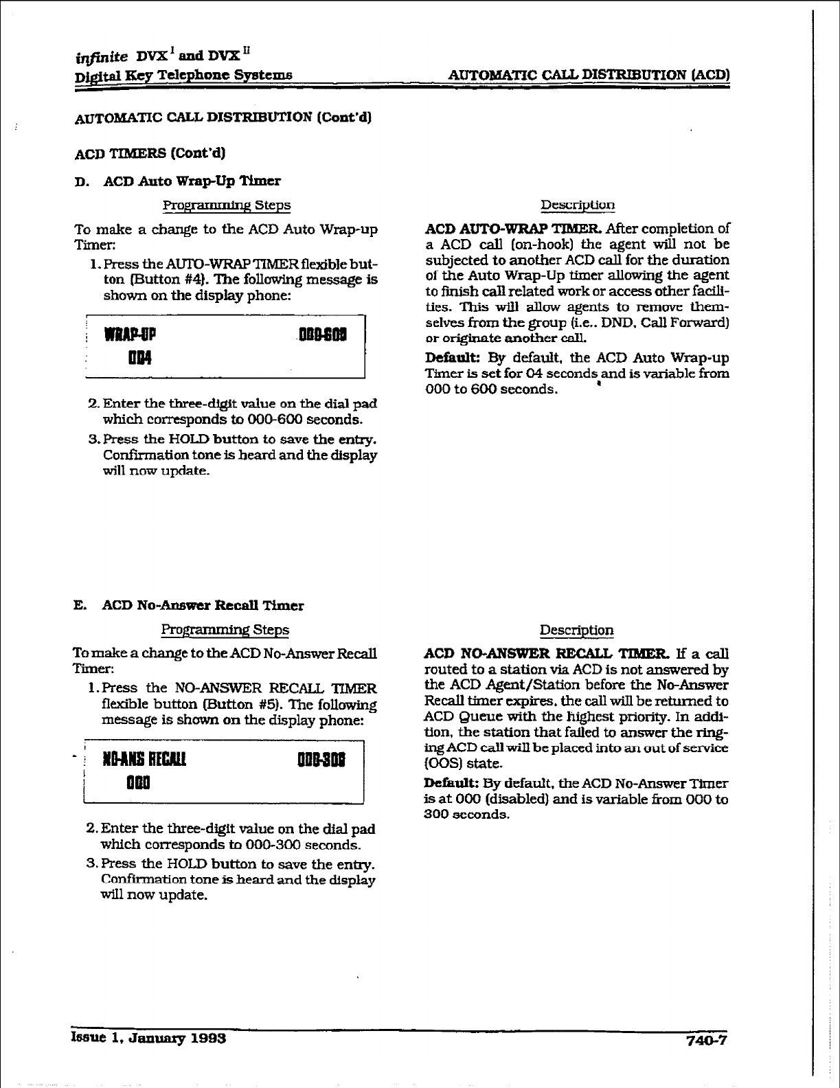
iqfidte DVX’andDVXn
Dj@d Key Telephone System8 A~oI~~~A~I-IC
CAu DISTRIBUTION (ACD)
AUTOIktb%-l’IC CALL DISTRIBUTION (Cmt’d)
ACD TIMERS (Cont’d)
D. ACD
Auto Wrap-Up Timer
Progl ’ n Steps
To make a change to the ACD Auto Wrap-up
Timer:
Description
1. Press the AUTO-WRAP TIMER flexible
but-
ton (Button #4}. The follcMng message is
shown on the display phone:
ACD
AUTO-WRAP
TIME&
After completion of
a ACD call (on-hook) the agent will not be
subjected
to
another ACD call for the duration
of the Auto Wrap-Up timer allowing the agent
to finish call related work or access other facile-
ties. This will allow agents
to remove them-
selves from the group (i.e.. DND. Call Forwatd)
or originate another call.
Default: By default, the ACD Auto Wrap-up
Timer is set for 04 seconds,and
is
variable from
000 to 600 seconds.
2.
Enter the three-digit value on the dial pad
which corresponds to 000-600 scads.
3.F’ress
the HOLD
button
to save the entry.
Confirmation tone is heard and the display
will now update.
E. ACD No-Ar.wwcr Recall Timer
Pro- steps
TomakeachangetotbeACDNo-AnswerRecall
Timer:
l.Press the NO-ANSWER RECALL
TIM33R
flexible button Wutton #5). The following
message is
shown on the
display phone:
2. Enter the three-digit value on the dial pad
which corresponds to 000-300 seconds.
3. Press the HOLD button to save the entq.
Confirmation tone is heard and the display
will now update.
Description
ACD NO-ANSWER RECALL TIMER. lfacall
routed to a station via ACD is not answered by
the ACD Agent/Station before the No-Answer
Recall timer expires, the call will be returned to
ACD Queue with the highest priority. In addi-
tion, the station that failed to answer the ring-
ing ACD call will
be
placed into an out
of service
@OS) state.
Defautt: By default, the ACD No-Answer Timer
is at 000 (disabled) and is variable from 000 to
300
seconds.
Issue 1. January 1993 7443-7
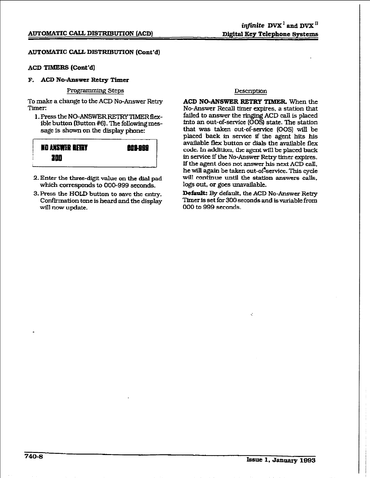
AlJTOMATIC CALL DISTRIBUTION (ACD)
itlfnite
DVX’andDvx”
Digital
3ey Telephone Systems
AUTOB&WIC CALL DISTRIBUTION (Cant’d)
ACD TIMERS @~nt*d]
F.
ACD
No-Answer Retq Timer
F?rogramdng Steps
To make a change to the ACD No-Answer Retry
Timer:
l.PresstheNO-ANSWERREXRYTMERfiex-
ible button mutton #61. The followmg mes-
sage
is
shown on the display phone:
2. Enter the three-digit value on the dial pad
which corresponds to 000-999
seconds.
3.
Press the HOLD button
to save the enn-y.
Confirmation
tone is heard
and the display
will now update.
Description
ACD NO-ANSWER RETRY TIMER. When the
No-Answer Recall timer expires.
a station that
faUed
to answer the ringing
ACD call is placed
fnto an out-of-service (00s) state. The station
that was taken out-of-service (00s) wilI be
placed back in service if the agent hits his
available flex button or dials the availatlle flex
code. In addition, the agent wiIl be placed back
in semice if the No-Answer Reby timer expires.
If the agent does not answer his next ACD calI,
he will again be taken out-of%ervice. This cycle
will continue until the station answers calls,
logs out, or goes unavailable.
Defiaulk Ry default. the ACD No-Answer Retry
Timer Is set for 300 seconds
and is
variable from
000 to 999 seconds.
740-8
Issue 1, Janaarg 1993
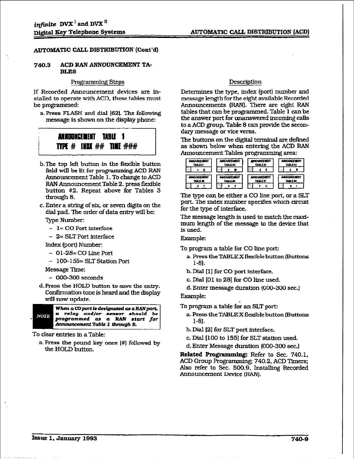
f@&e IWX’andDVXn
D&im IKey Telephone Systems AUTOMATIC
CALL DISTRIBUTION
(ACD]
AuTohfA~c CALL DISTRIB~~N
(Cont’d)
740.3 ACD RAN ANNOUNCEMENT TA-
BLES
If Recorded Announcement devices are in-
stalled to operate with ACD. these tables must
be programmed:
a. Press FLASH and dial (621. The
following
message
is
shown on the display phone:
b-The
top left
button
in the fkible button
field will be
lit for programming ACD RAN
Announcement Table 1. To change to ACD
RAN Announcement Table 2, press fltible
button #2. Repeat above
for
Tables 3
through 8.
c. Enter a string
of
six or seven digits on the
dial pad. The order of data entry will be:
Type Number:
- 1= CO Port interface
- 2=
SLT Port interface
Index (port) Number:
- Ol-28= CO Line Port
- 1 OO- 155= SLT Station Port
Message Time:
- CKIO-300
seconds
d. Press the HOLD button to save the entry.
Confimafion
tone is heard and the display
wilS
mm
update.
WhenaWporti8ddgnatdosuRANpprt,
a relay and/or sensor shorrld be
programmed as a RAN
start
ftw
drurou- Table 1
&hnmgh 8.
To clear entries in a Table:
a. Press the pound key once I#] followed by
the HOLD button.
Description
Determines the type. index (port) number and
message length for the eight available Recorded
Announcements @UN). There are eight RAN
tables that can be programmed. Table
1 can
be
the answer port for
unanswered incoming calls
to
a ACD group. Table 8 can provide the secon-
dary message or vice versa.
The buttons on the digital terminal are
defined
as shown below when entering the ACD RAN
Announcement Tables progmmming area:
m&qqmF]
RWiWF/
The lype can be either a CO line port, or a SLT
port. The index number specifies which circuit
for the type of interface.
The message length is used to match the maxi-
mum leq$h of the message to the device that
is used.
Example:
To program a table for CO line port:
a. Press the TABLEX flexible button (Buttons
l-8).
b. Dial [I ] for CO port inter&we.
c. Dial [Ol to 281
for CO line
used.
d. Enter message duration {OOO-300 sec.)
Example:
:
To program a table for an SLT port:
a. Press the TABLEX flexible button (Buttons
l-81.
b. Dial 121 for SLT port interface.
c. Dial [lo0 to 155) for SLT station used.
d. Enter Message
duration (000-300 sec.)
Related Rognunming: Refer
to Sec. 740.1,
ACD Group Progr
- g; 740.2.
ACD Timem;
Also refer to Sec. 500.9. Installing Recorded
Announcement Device (FUN).
168ue 1. January lBB3 740-B
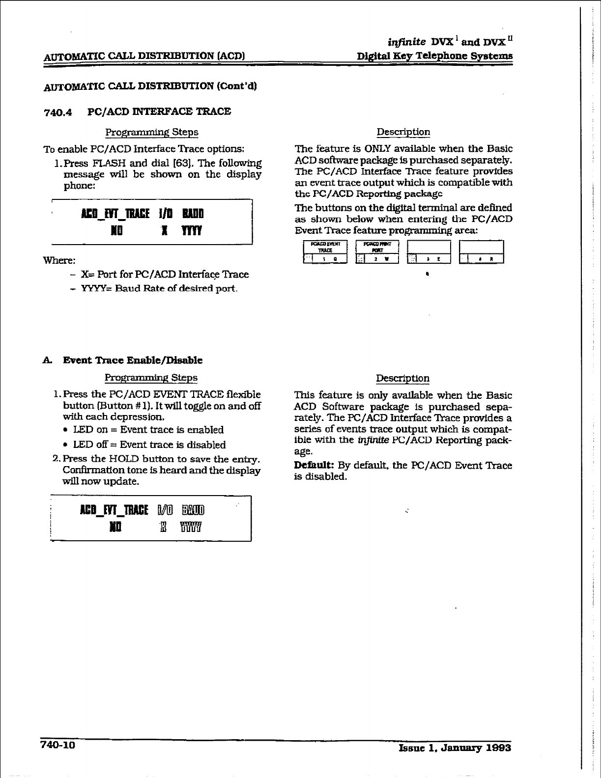
imite DVX’ aad DVX”
Digital Key Telephone Systems
A~o&%i@f’Ic CALL DISTRIBUTION (Cont’d)
740.4 PC/ACD INTERFACE TRACE
Programming Steps
To
enable PWACD Interface Trace options:
1. Press FL4SH and dial 163). The following
message
will be shown on the display
phone:
- X= Port for PC/ACD lnterfaqz ?kace
- YYYY= Baud Rate of
desired
port.
A. Event Trace
En2hlt/Dis2ble
Prop * L-J steps
1. Press the PC/ACD EVENT TRACE flexible
button (l3utton # 1). It will toggle on and off
with each depression.
l
LED
on = Event trace is enabled
l
LED off = Gvent trace is disabled
2.Press the HOLD button to save the entry.
Confxmation tone is
heard
and the display
will now update.
Description
The fature is ONLY available when the Basic
ACD software package is purchased separately.
The PC!/ACD Interface Trace feature provides
an event trace output which is compatible with
the PC/ACD Reporting package
The buttons on the digital terminal are defined
as shown below when entering the PC/ACD
Event
Trace feature
programnkg area:
Description
This feature is only available when the Basic
ACD Software package is purchased sepa-
rately. The PC/ACD Interface mace provides a
series of events trace output which is compat-
ible with the in@-& PC/ACD Reporting pack-
age.
Dthult:
By default, the PC/ACD Event ‘Ikace
is disabled.
740-10 Xssnc 1. Jannarg 1993
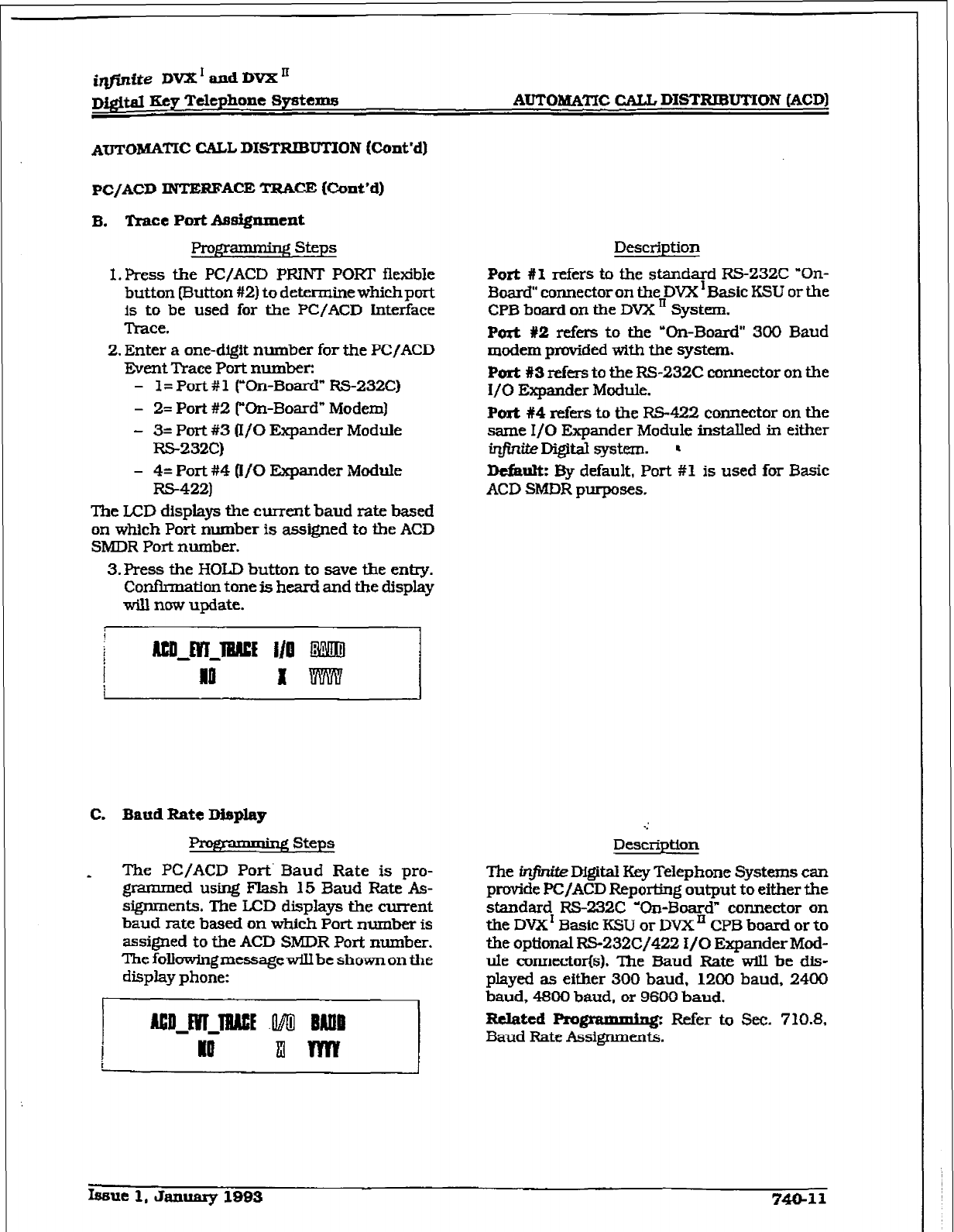
i-&e DVX’andDVX’
Digftal Key Telephone Systems AUTOMATIC CALL DISTRIBUTION (ACDI
Amoh’IAmc CALL DIWFUBUTION (Cont’d]
Pc/ACD INTERFACE TRACE Hhnt’d)
B. T-race Port Assignment.
Prop- Steps
I. Press the PC/ACD PRINT POW flexible
button [Button #2) to determine which port
is to be
used for the PC/ACD interface
Trace.
2. Enter a one-digit number for the PC/ACD
Event Trace Port number:
- 1= Port # 1 (“On-Board” RS-232C)
- 2=
Port
#2 (“On-Board” Modem)
-
3=
Port #3 0/O Expander Module
RS-232C)
- 4= Port #4 (If0
Expander
Module
RS-422)
The LCD displays the current baud rate based
on which Port number is assigned to the ACD
SMDR Port number.
3.Press the HOLD button to save the entry.
Confirmation tone is heard and the display
W-U now update.
Desctiption
Port #I refers to the
standard RS-232C “On-
3oard” connector on the DVX ‘Basic KSU or the
CPB board on the DVX Ii System.
Port #2 refers to the ‘On-Board” 300 Baud
modem
provided with the system.
Port #3 refers
to the RS-232C connector on the
I/O Expander Module.
Port #4 refers to the
FtS-422
connector on the
same I/O Expander Module installed in either
infiniteDigital system. ’
&far& By default, Port #1 is used for Basic
ACD SMDR
purposes.
C. Baud Rate Display
v Steps
The PC/ACD Port’ Baud
Rate
is pro-
grammed using Flash 15 Baud Rate As-
signments. The LCD displays the current
baud
rate
based on which Port number is
assigned
to the ACD SMDR Port number.
ThefoIIawingmessagewiIlbeshownonthe
display phone:
.:
Description
Ihe infinite Digital Key Telephone Systems can
provide PC/ACD Reporting output to either the
standard RS-232C ‘On-Board” connector on
the DVX I Basic KSU or
DVX’
CPB board or to
the optional RS232C/422 i/O
Expander
Mod-
ule connector(s). The Baud Rate wiU be dis-
played as either 300 baud, 1200 baud, 2400
baud, 4600 baud, or 9600 baud.
Related Pro@unmiq- . Refer to Sec. 710.8.
Baud Rate Assignments.
Issue 1, January 1893 740-11
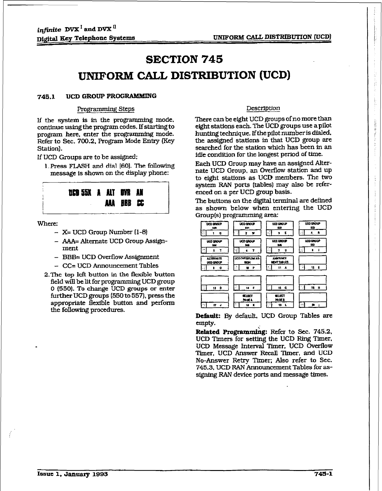
iqfutite DVX I and DVX Ii
Dma Key Telephone
sy8tCIIiS
UNIFORM CAU DIST2ZlBUTIoN (UCD)
SECTION ‘745
UNIFORM CALL DISTRIBUTION (UCD)
745.1 UCD GROUP PROGRAMMING
FYogrixmdng Steps
lf the system is in the programmhg mode,
continue using the program codes. If starting to
program here, enter the programming mode.
Refer to Sec. 700.2, Program Mode Entry (Key
Station).
If UCD Groups are to be assigned:
1. Press FLASH and dial [601. The following
message is shown on the display phone:
Where:
- X= UCD Group Number ll-8)
- A&%= Afternate UCD Group Assign-
ment
- EMS= UCD Overflow Assignment
- CC= UCD Announcement Tables
2.The top kft button in the flexible button
field wizz be Ilt for progranm&g UCD group
0 (550).
To change UCD groups or enter
further UCD groups (550 to 557), press the
appropriate fkxfble button and perform
the fokwing procedures.
.
Description
There can be eight UCD groups of no more than
eight stations each. The UCD groups use a pilot
hunting technique. Iftbe pilot numberis dialed.
the assigned stations in that UCD group are
searched for the station which has been in an
idle condition for the longest period of time.
Each UCD Group may have an assigned Aiter-
nate UCD Group, an Overflow station and up
to eight stations as UCD members. The two
system RAN ports (tables) may also be refer-
emed on a per UCD group basis.
The buttons 011 the digital terminal are defined
as shown below when entering the UCD
Group(s) programming area:
DefkuW EIy default., UCD Group Tables are
empty.
RdattdRo @&W&g: Refer to Sec. 745.2,
UCD Timers for setting the UCD Ring Timer,
UCD
Message Interval Timer, WCD Overflow
Timer, UCD Answer Recall Tkner, and UCD
No-Answer Retry Timer; Also refer to Sec.
745.3. UCD RAN Announcement Tables for as-
signing RAN device ports and message times.
Issue 1, January 1993
745-l
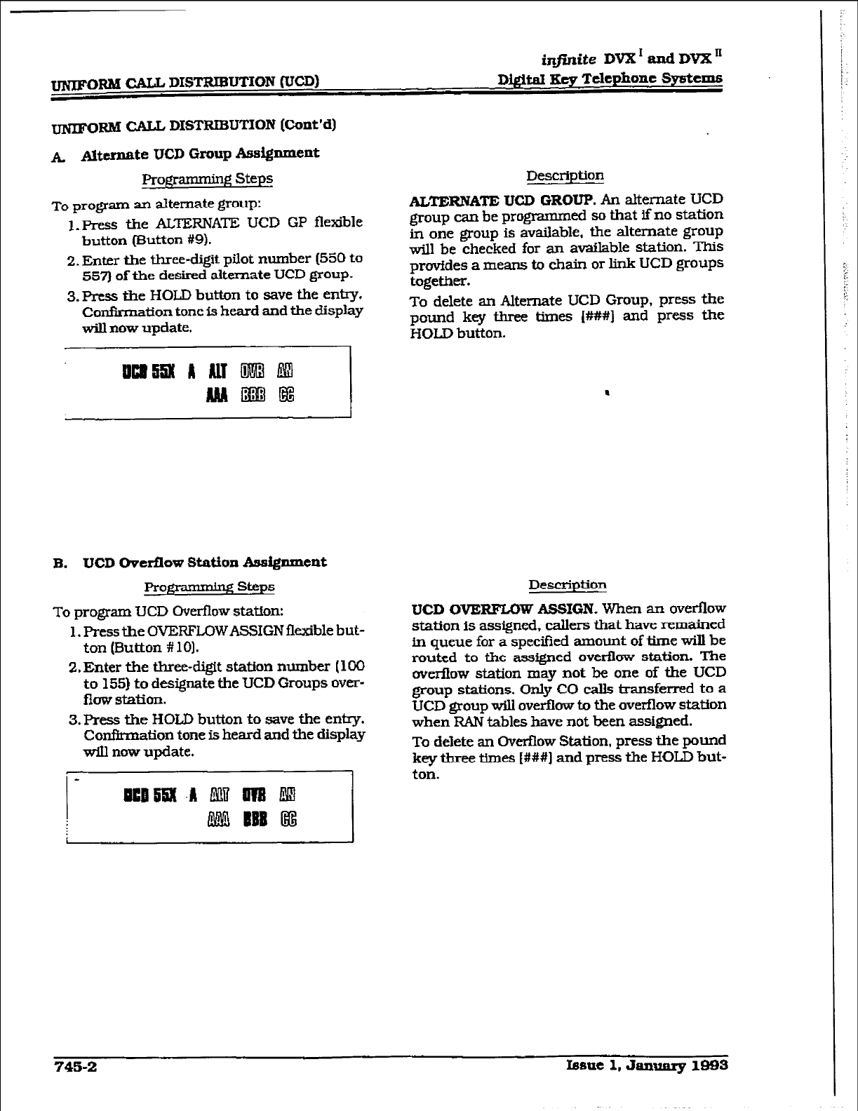
~C3~bl CALL DISTRIBUTION rVCD)
&finite DVX I and DVX II
DigitaI &v Telephone Sy&ems
UNIFORM CALL DISTl3IBU’l’ION (Cmt’d)
A Alttrnnte UCD Group Assignment
Programming Steps
To
program an alternate group:
1. press the ALTERNATE UCD GP flexible
button (Ektton #9).
2. Enter the three-digit pilot number (550 to
557) of the desired alternate UCD group.
3. Press the HOLD button to save the entry.
Confirmation tone is heard and the display
will now update.
Description
ALTERNATE
UCD GROUP. An alternate UCD
group can be programmed so that if no station
in one group is available. the alternate group
will be checked for an available station. This
provides a means to chain or link UCD groups
togetkr.
To delete an Alternate UCD Group, press the
pound key three times [###I and press the
HOLD button.
B. UCD Overflow Station Assignment
Pro)Y$zmag steps
To program UCD Over&w station:
1. Press the OVERFLQWASSIGN flexible but-
ton (Button # 101.
2. Enter the three-digit station number (100
to 155) to designate the UCD Groups over-
flow station.
3. Press the HOLD button to save the en@.
Confirmation tone is heard and the display
will now update.
uulm .A m lm E!5
LWJ EBB @i
Description
UCD OVERFLOW ASSIGN. When an oveflow
station is assigned, callers that have remained
in queue for a specified amount of time will be
routed to the assigned overflow station. The
overflow station may not be one of the UCD
group stations. Only CO calls transferred to a
UCD group will overflow to the overflow station
when RAN tables have not been assigned.
To delete an Overflow Station, press the pound
key three times [###I and press the HOLD but-
ton.
745-2 fsstle 1. Januarg lass
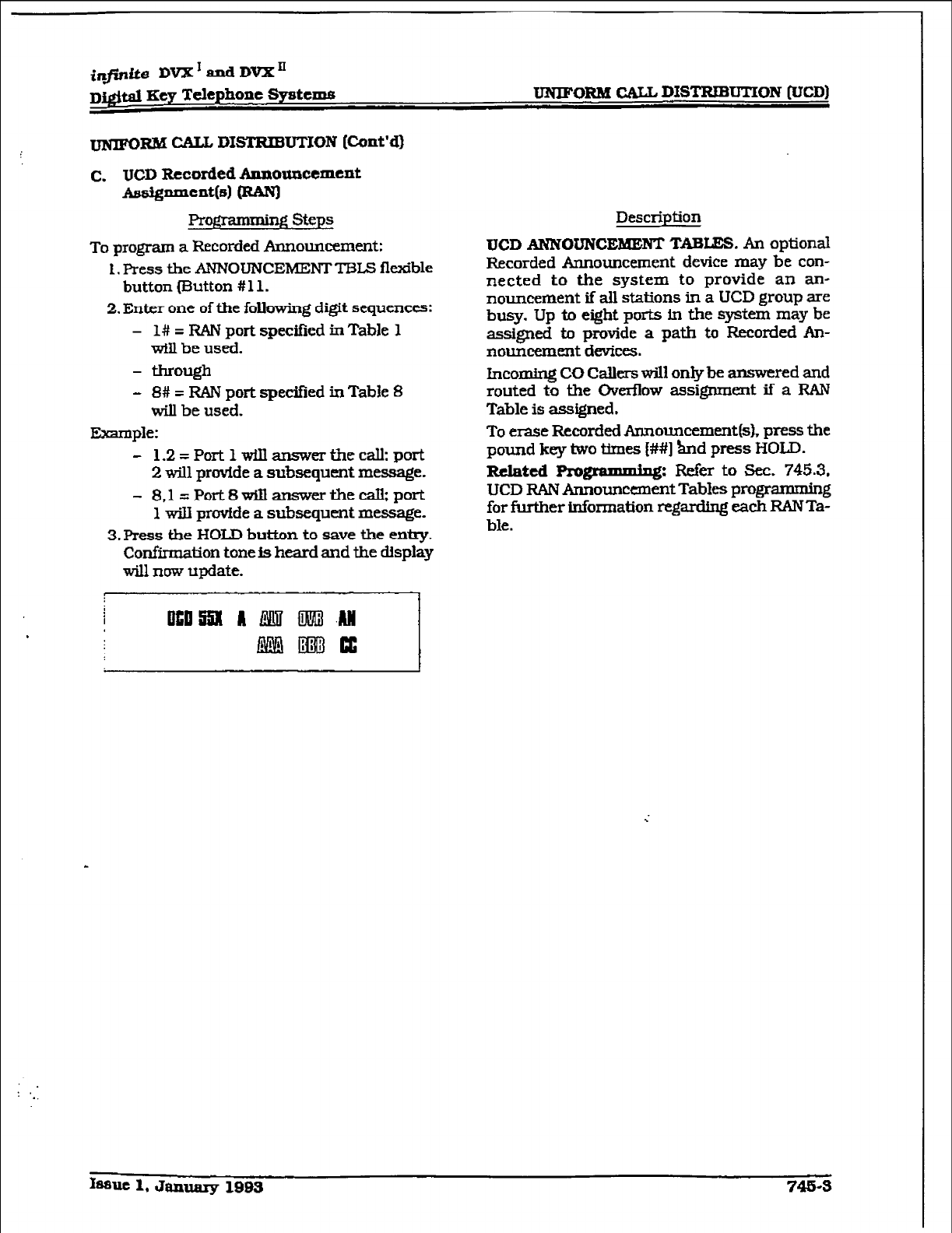
infinite DVX’ and DVX’
D@tal Key Telephone Systems UNIFORM CZ.AIL DISTREKJTION @ED)
ARM CALL DXSTRIBUTION
[Cont’dI
c. UCD Recorded Announcement
~~cntbl mm
Pxgrammir* steps
To program a Recorded Announcement:
1. Press the ANNOUNCEMENTTBLS
flexible
button (Button # 11.
2.
Enter
one of the following digit sequences:
-
l#
= RAN port specified in Table 1
will be used.
- through
- 8# = RAN port specified in Table 8
will be used.
Example:
- 1,2=Port1wiIlanswe.rthecall;port
2 will provide a subsequent message.
- 8.1
=Port8wihanswertheca&port
1 will provfde a subsequent message.
3.
Press the HOLD button to save the entry,
Confirmation tone is heard and the display
will now update.
Description
UCD ANNOUNCEBUENT TABIZS. An
optional
Recorded Announcement device may be con-
nected
to
the system to provide an an-
nouncement if all stations in a UCD group are
busy. Up to eight ports in the system may be
assigned to provide
a
path to Recorded An-
nouncement
devices.
incoming CO Callers will only be
answered and
routed to the Overflow assignment if a RAN
Table is assigned.
To erase Recorded Announcement(s). press the
pound key two Wnes [##I
&nd
press HOLD.
Related Pm~mmm3.q: R&r to sec. 745.3,
UCD RAN Announcement Tables programming
for f&her information regarding each RAN Ta-
ble.
.
‘..
fsauc 1, &mum-y 1983 745-S
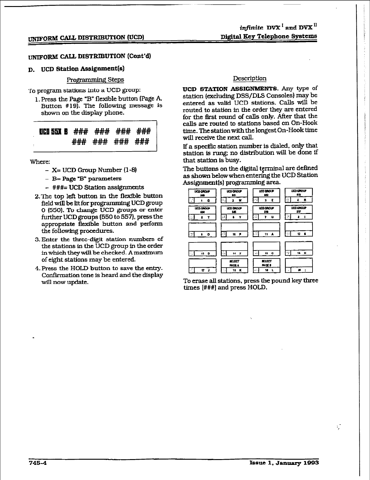
iqjinite DVX ’ and DVX’
WORM CALL DISTRIBUTION (Cont’d)
D. UCD Station Assignment(s)
Pro@ * g Steps
To program stations into a UCD group:
1. Press the Page “B” flexible button (Page A
Button #
19). The
following message is
show-n on the display phone.
ul3l3913 #### #Hi@ #I## #I##
H# ### ### ###
Where:
- X= IJCD Group Number
(l-8)
- B= Page -B” parameters
- ###= UCD Station ass~ents
2.The top l& button in the flsdble button
fieldwillbelitforpro&rammlng UCD group
0 (550). To change UCD
group5 or enter
further UCD groups (550
to 557).
press the
appropriate ffexible button and perform
the following procedures.
3.Enter the three-digit station numbers of
the stations in the LJCD group in the order
inwhicktheywill be checked. Amaximum
of eight stations may be entered,
4.Fress
the HOLD button
to save the entry.
Confirmation tone is heard and the
display
will now
update.
Desctip
tion
UCD STATION AssIGNBUEm. Any type of
station (xcluding DSS/DLS Consoles) may be
entered as valid LJCD
stations.
Calls will be
routed to station in the order they are entered
for the first round of calls only, After that the
calls are routed to stations based on On-Hook
time. The station with the longest On-Hook time
will receive the next call.
If’ a specific station number is dialed, only that
station Is rung: no distribution will be done if
that statin is busy.
The buttons on the digital terminal are defined
as shown below when ente&g the UCD Station
Assignmentfs) programming area.
To erase all stations. press the
pound
key three
times [###I and
press HOLD.
7484 fssue 1, January 1993
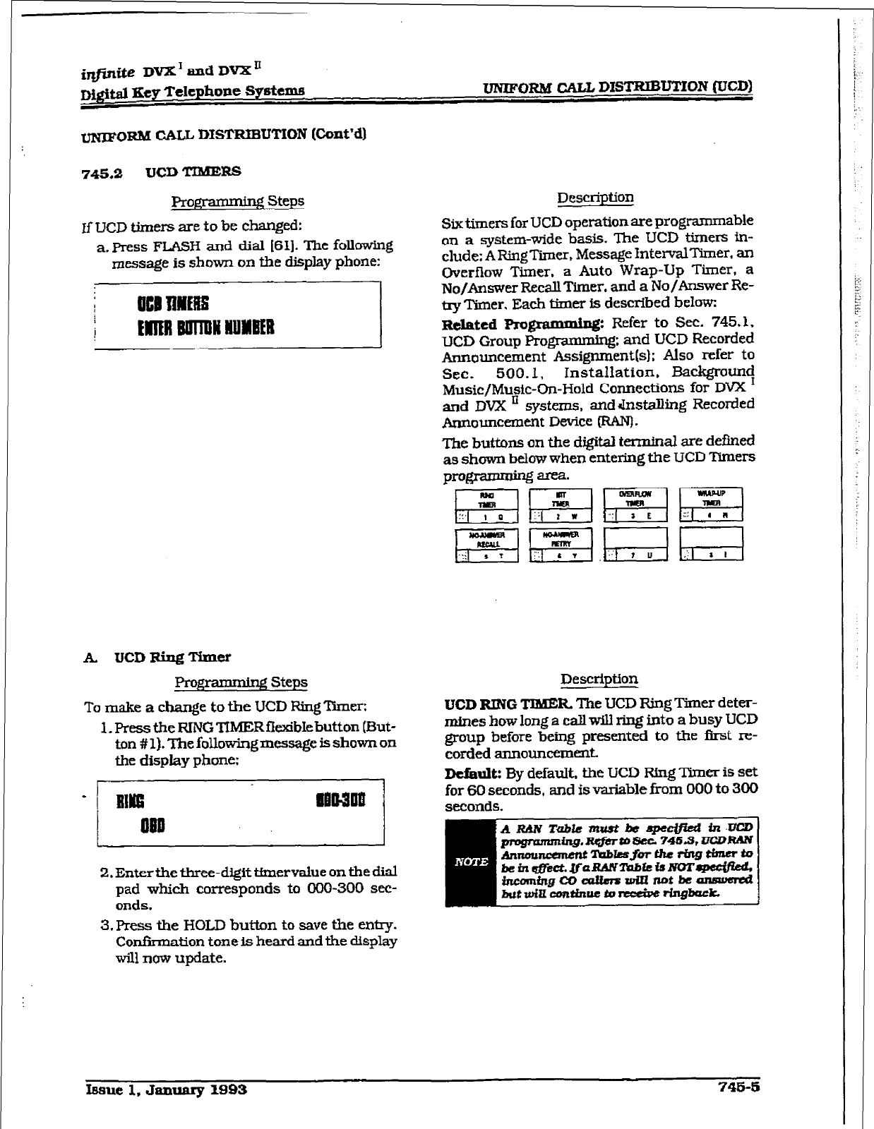
UNJFoRM CALL DISTRIBUTION
(Cont’d)
745.2 UCD TTBBEKS
Programming steps
If UCD timers are to be changed:
a. Press F-H and dial [61]. The follawing
message is shown on the display phone:
A. UCDRiqTimer
B steps
To make
a change to the
UCD Ring ‘Inner:
1. Press the FUNG TIMER
flexible
button (But-
ton #
1). The following message is
shown on
the display phone:
2. Enterthe three-digit tfmervalue on the dial
pad which corresponds to 060-300 see-
onds.
3. Press the
HOLD
button to save the entry.
Con&nation tone is heard and the display
will now update.
Desc
ription
Six timers for UCD operation are programmable
on a system-wide basis. The UCD timers in-
clude: ARingTimer, Message IntervalTimer, an
Overflow
Timer, a Auto
Wrap-Up
Timer, a
No/Answer RecallTimer. and a No/Answer Re-
try Timer.
Each timer is described below:
Related
Pro@ammix@ Refer to Sec. 745.3.
UCD Group Progmmming; and UCD Recorded
Announcement Assignment(s); Also refer to
Sec. 500.1, Installation, Backgrauncj
Music/Music-On-Hold Connections for DVX
and
DVX ’ systems.
andrInstaIhng
Recorded
Announcement Device @AN).
The buttons on the digital tenntnal are defined
as shown
below
when entering the UCD ‘Doers
pmE$i w, Fi
Description
UCD RING TIMER The
UCD Ring Timer deter-
mines how long a call will ring into a busy UCD
group before being presented to the first re-
corded annoullcemmt
Dtfault: By default, the UCD Ring Timer is set
for 60 seconds, and is variable from 000 to 300
seconds.
hue 1,
January
1993 746-5
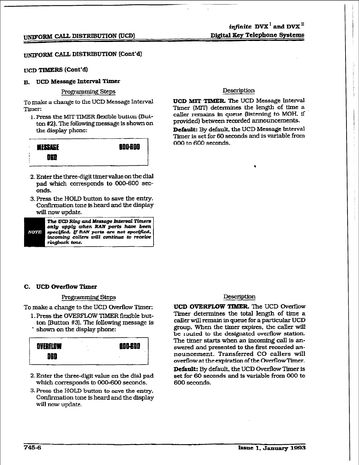
FORM CALL DISTRIBUTION (UCD)
iqfinite
DvX’andDVX”
a&&al Key Telephone Systems
-RM CALL DISTFEIIXJTION
(Cont’d)
UCD TIMERS (Cont’dl
B.
UCD Message httd Timer
FYogEmming steps
To make a change to the UCD Message Interval
Timer:
1. F’ress the MITTIMER flexible button (But-
ton #2). The following message is shown on
the display phone:
2. Enter the three-digit timer value on the dial
pad which corresponds
to
000-600 sec-
onds.
3.Press tie HOLD button
to save the entry.
Confirmation tone is heard and the display
wilI now update.
Description
UCD MIT TIMER The
UCD Message Interval
Timer (MIT) determines the length of time a
caller remains ti queue (listening to MOH. if
provided] between recorded announcements.
Default:
By default, the UCD Message Interval
Timer is set for 60 seconds and is variable from
000 to 600 seconds.
C. UCD Chmflow Timer
Prom steps
To make a change to the UCD Overfiow Timer:
1. Press the OVEFFL0W TIMER flexible but-
ton
Button #3). The following message is
* shown
on the display phone:
2. Enter the three-digit value on the dial pad
which corresponds to 000-600 seconds.
3. Press the HOLJJ button to save the entry.
Coufh-rnation tone is heard and the display
w-ill now
update.
Description
UCD OVERFLOW TIMER The
UCD Overflow
Timer determines the total length of time a
callerwillremain in
queue
for aparticular UCD
group. When the timer expires, the caller will
be routed to the designated overflow station.
The timer starts when an incoming call
is an-
swered and presented
to the first recorded aa
nouncement. Transferred CO callers WiIl
overflow at the expiration of the Overflowtier.
I)tfarift: By defauk the UCD Over&w Timer is
set for 60 seconds and is variable from 000 to
600 seconds.
745-6
fe8Ut
1, th.mu&ry 1993
1’
:.
L
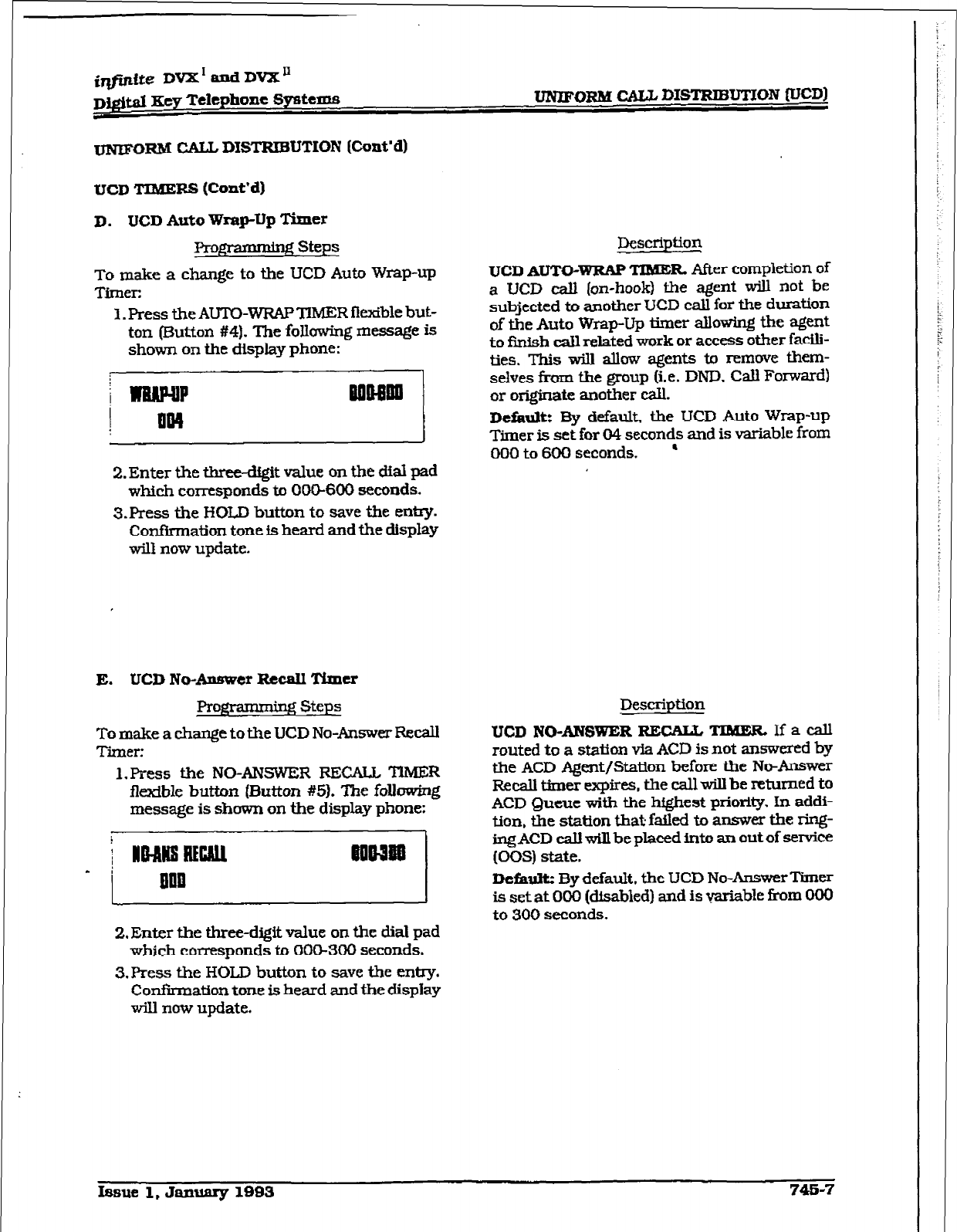
imite DVX’ and DVX”
Dj&d Key Telephone Systems
UNJPORM CAL%
DISTRIBUTXON
(UCD]
UNTF-ORM CALL DISTRIBUTION (Cm&d)
UCD TIBXERS (Cont’d)
D. UCD Auto Wrap-Up
Timer
I?4-ogramdng steps
To make a change to the UCD Auto Wrap-up
Timer:
1. Press the AUTO-WRAP TIMER fiexible but-
ton (EMton #4). The following message is
shown on the display phone:
2. Enter the three-digit value on the dial pad
which corresponds to OCG6OO seconds.
3Jres-s the HOLD button to save the
enhy.
Confirmation tone is heard
and the
display
will now update.
E. UCD No-Answer Recall Timer
Progra * 2 Steps
To make a change to
the UCD No-Answer Recall
Tier:
l.Press the NO-ANSWER RECAP TlMER
flexible
button
[Button #5). The
following
message is
shown
on the display phone:
2. Enter the three-digit value on the dial pad
which corresponds to 00&300 seconds.
3,Press
the HOLD button to save the entry.
Confirmation tone is heard and the display
will now
update.
Description
UCD AUTO-WRAP
TIME& After completion of
a UCD call (on-hook) the agent will not be
subjected to another UCD call for the duration
of the Auto Wrap-Up timer allowing the agent
to fir&h call related work or access other facili-
ties. This will allow agents to remwe them-
selves fimn the group (i.e. DND. Call Forward)
or originate another call.
Default:
By default, the UCD Auto Wrap-up
Timer is set for CM seconds and is variable from
000 to 600 seconds. ’
Description
UCD NO-ANSWER Rl%ZiLL
TQdERIfacall
routed to a station via ACD is not answered by
the ACD Agent/Station before the NW&rower
Recall timer wqires, the call will be
returned to
ACD Queue
with the
highest priority. In
addi-
tion, the station
that failed to answer the ring-
ing ACD ca.U will be placed into an
out of sewice
(00s) state.
Default:
By
default. the LJCD No-Answer Timer
is set at 000 [disabled) and is variable from 000
to 300 seconds.
Issue 1, January 1883 748-7
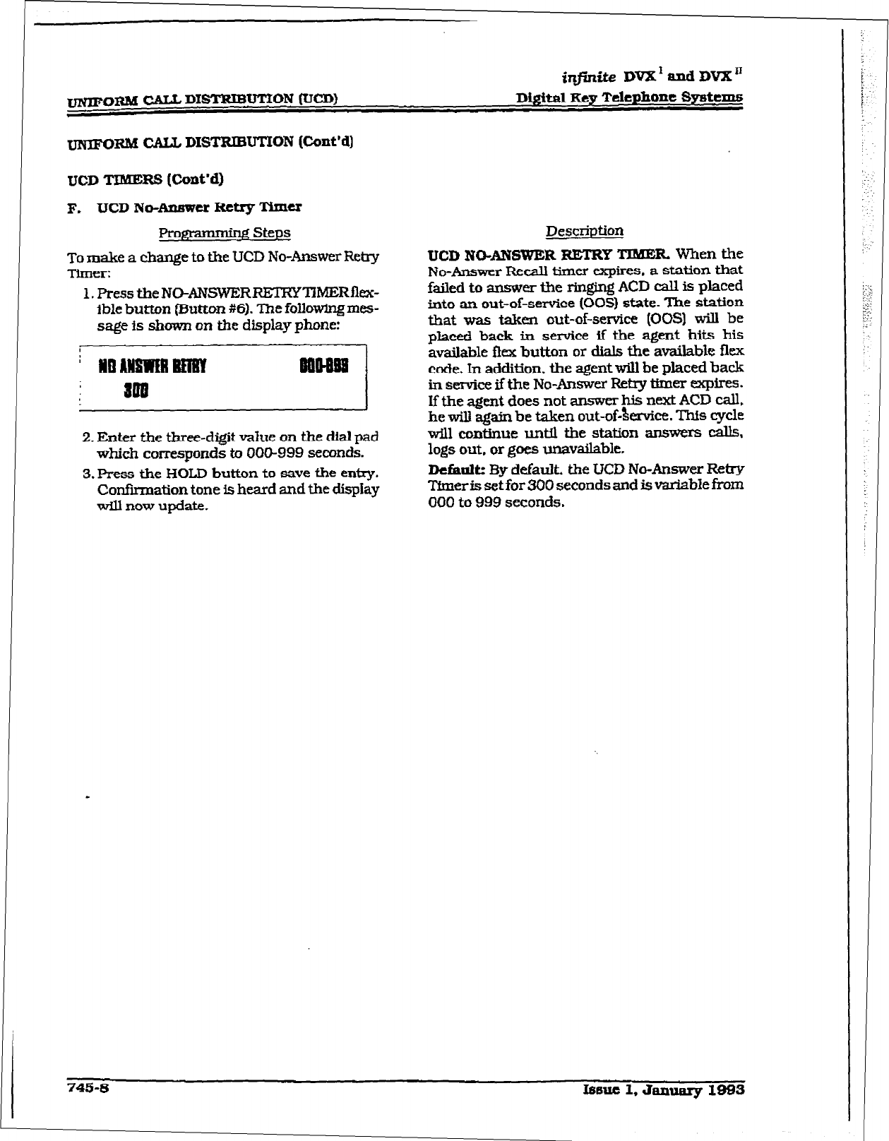
-
irlfinite Dd and DVX”
Di&it&I key Tclephonc Systems
~xlkI CALL DISTRIBUTION (Cont’d)
UCD TIMERS (Cotit’d)
F. UCD No-mer Retry Timer
Pro- Steps
To make a change to the UCD No-Answer Retry
Timer:
1. Press the NO-ANSWERRElR’Y~~Rflcx-
ible button (FJutton #6). The followlngmes-
sage is shown on the display phone:
71
2. Enter the three-digit value on the dial pad
which corresponds to 000-999 seconds.
3. Press the HOLD button to save the entry.
Confhxnation tone is heard and the dispIay
wIll now update.
Description
UCD NO-ANSWER RETRY TIMER. When the
No-Answer Recall timer expires. a station that
failed to amwer tie ringing ACD call is placed
into an out-of-setice (00s) state. The station
that was taken out-of-service (00s) will be
placed back in service if the agent hits his
available flex button or dials the available flex
code. In addition. the agent will be placed back
in service if the No-Answer Retry timer expires.
If the agent does not answer his next ACD call,
he will again be taken out-of&mice. Th% cycle
will eor&inue until the station answers calls,
logs out, or goes unavailable.
Default: By default, the UCD No-Answer Retry
tier is set for 300 seconds and is v&able fi-om
000 to 999 seconds.
745-8 Issue 1. Januruy 1983
:
; :1
I :
.-:
!Z
[I:
:;
I
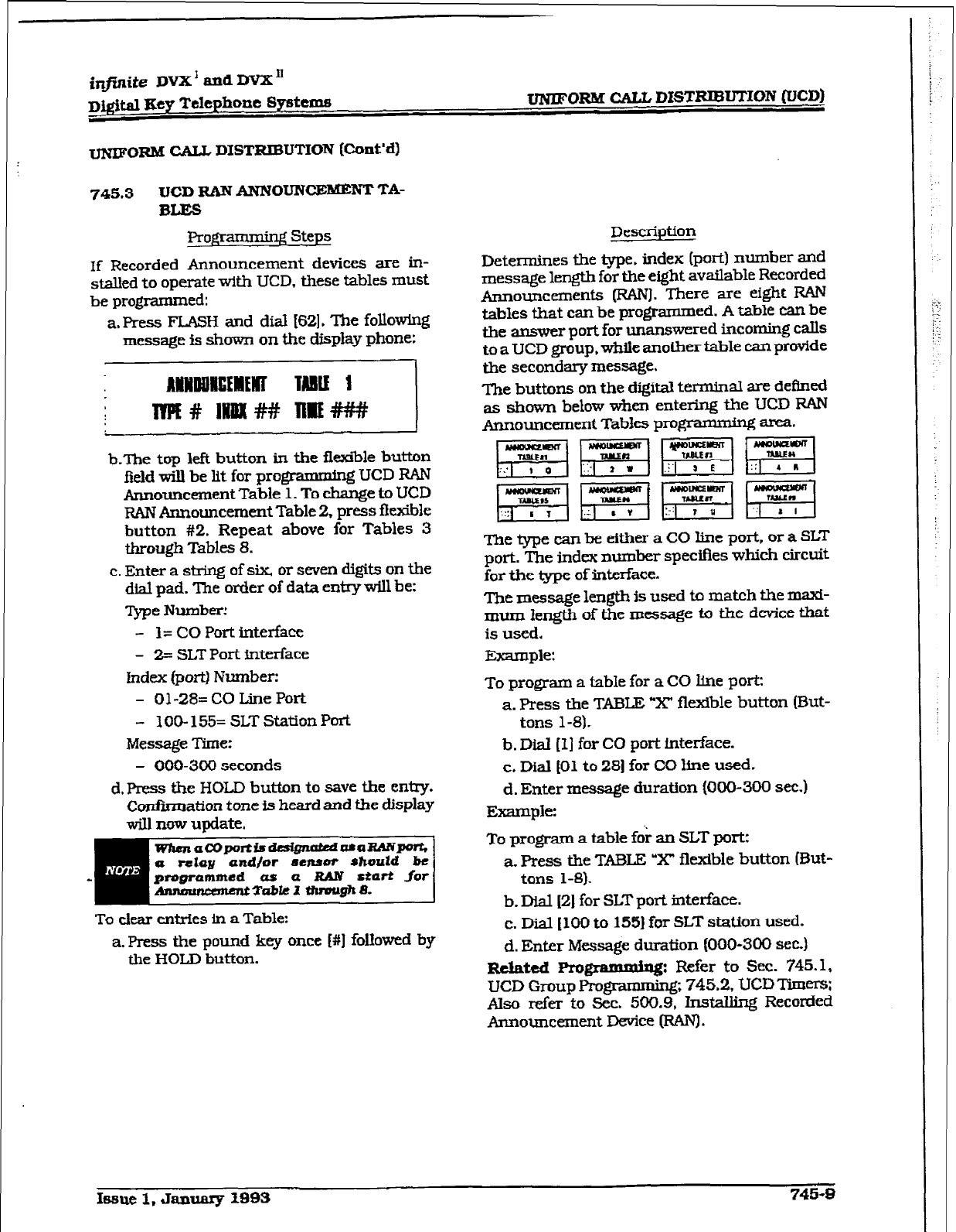
i+ite DVX’ md DVX”
D&i&l Key Telephone Systcme UNJJFORM CALL DISTRIBUTION (UCD)
I~NI~$GN~I CALL DISTRIBUTION (Cont’d)
745.3 UCD RAN ANNOUNCEMENT
TA-
BLES
Rograrmning Steps
lf Recorded Announcement
devices are in-
stalied to operate with UCD. these tables must
be programmed:
a. Press FTASH and dial [62]. The following
message is shown on the display
phone:
-nj
b-The top left button in the flexible button
field will be tit for programmmg UCD RAN
Announcement
Table 1.
To change to
UCD
RAN Announcement Table 2. press flexible
button #2. Repeat above for Tables 3
through Tables 8.
c. Enter a string of six, or seven digits on the
dial pad. ‘Ihe order
of
data entry will be:
ppe Number!
- l= CO
Port interface
- 2s SLT Port interface
Index (port) Number:
- Ol-28=
CO Line Port
- 100- 155= SLT Station Port
Message Time:
- 000-300 seconds
d. Press the HOLD button to save the entry.
Confimation tone is heard
and the display
will now
update.
emmi
To clear entries in a Table:
a. Press the pound key once [#I followed by
the HOLD button.
Description
Determines the type. index (port) number and
message length for the eight available Recorded
Announcements Irwu]. There are
eight RAN
tables that can be programmed. A table can be
the atlswer port for unanswered incoming calls
to
a
UCD
group, while
anotlxer table
can provide
the secondary message.
The buttons on the digital terminal are defined
as shown below when entering the UCD RAN
Announcement Tables program.mW area.
~~gygygq~~
p$qgf+q~{p+q
The type can be either a CO line port, or a
SLT
port. The index number specifies which circuit
for the type of interface.
Tbe message length is used to match the maxi-
mum length of the message to the device that
is used.
Example:
To program a table for a CO line port:
a. Press the TABL;E “X’ flexible button (But-
tons l-8).
b.
Dial (I] for CO port interface.
c. Dial 101 to 281 for CO line used.
d. Enter message duration (000-300 sec.)
Example:
To
program a table fd; an
SLT port:
a.
Press the
TABLE
“X’ flexible button (But-
tons 1-B).
b. Dial [2] for SLT port
interface.
c. Dial [ 100 to 1551
for SLT station used.
d. Enter Message duration (000-300 sec.)
R&tcd Pro l3--yG Refer to sec. 745.1,
UCD
Group Programmmg; 745.2, UCD Timers;
Also refer to Sec. 500.9, Installing Recorded
Announcement Device (RAN).
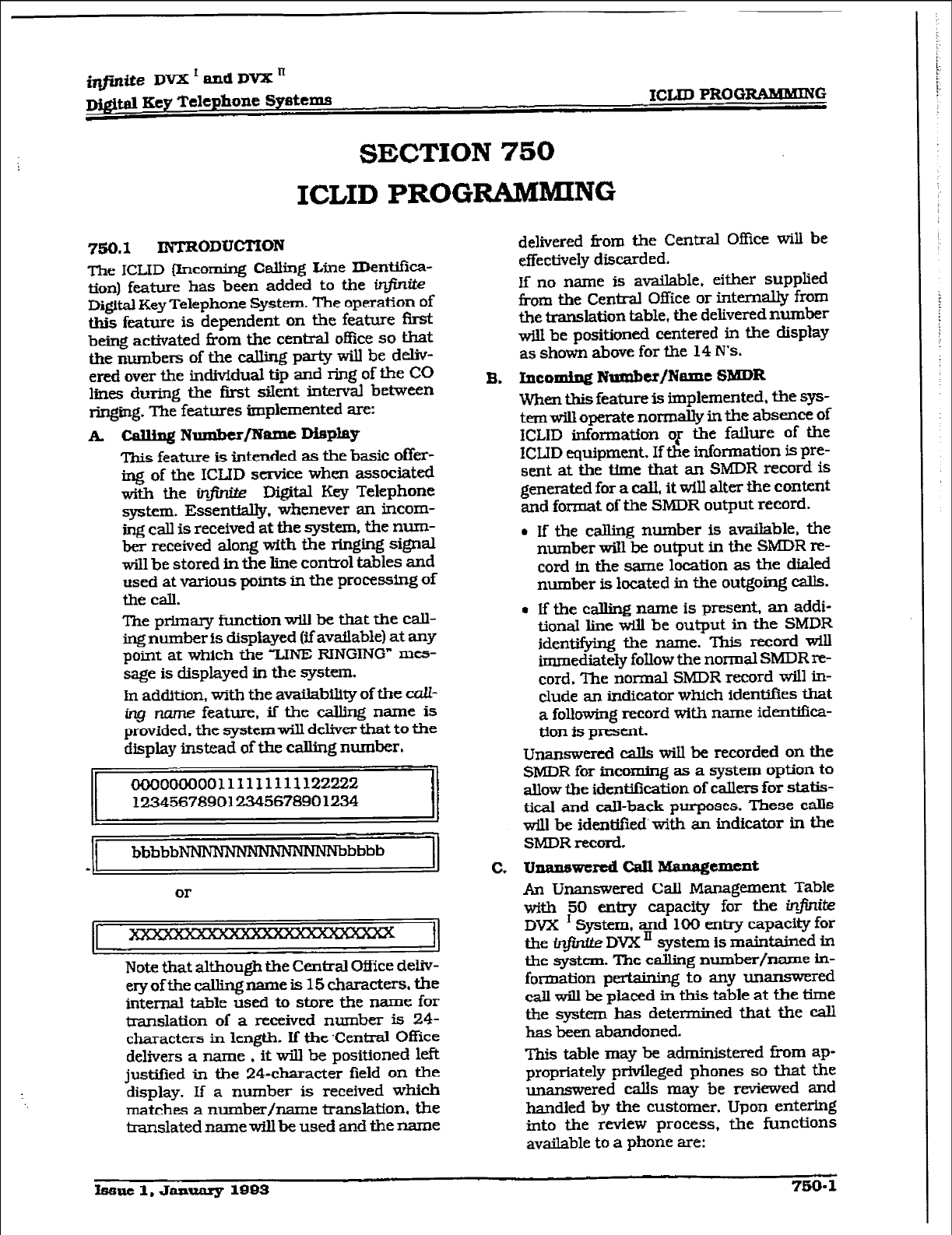
mite DVX’andDVX’
wtfd Key
Telephone
Systems ICIJD PROGRAMMING
SECTION 750
ICLID PROGRAM-G
750.1 INTRODUCTION
The ICLID @ncoming Calling
Line IDentica-
iion) feature has been added to the infinite
DigkaI Key Telephone System. The operation of
this feature is dependent on the feature first
being activated kom the central office so that
the numbers of the calling party will be deliv-
ered over the individuat tip and ring of the CO
Itnes during the first siknt interval between
ringing. The features implemented are:
A. Calling Numhtr/Harne Msplap
This feature is intended as the basic off&
ing of the ICLID service when associated
with the infinite DigitaI Key Telephone
system. Essentially. whenever an incom-
ing call is received at the system, the num-
ber received along with the ringing signal
wiI1 be stored in the line control tables and
used at various points in the processing of
the call.
The primary function will be that the call-
ing number is displayed (if available) at any
point at which the “LINE RINGING” mes-
sage is displayed in the system.
In addition, with the avaikbility of the cu.&
ing name feature. if the calIing name is
provided, the system will deliver that to the
display instead of the calling number.
000000000111111111122222
I23456789012345678901234
II
bbbbbNbbbb II
II II
I’ lj
Note that although the Central Oiiice deliv-
eryofthecallingnameis15characters,the
internal table used to store the name for
translation of a received number is 24-
characters in length. If the Central Office
delivers a name , it will be positioned left
justified in the 24-character field on the
display. If a number is received which
matches a number/name tianslation, the
translated name will be used and the name
delivered fi-om the Central Offke will be
effectively discarded.
E no name is available. either supplied
from the Central Office or internally from
the translation table, the delivered number
will be positioned centered in the display
as shown above for the 14 N’s.
B. Incoming Number/Name SMDR
When this feature is implemented, the sys-
tem will operate normaI@ in the absence of
1CLID information of the failure of the
ICLID equipment. If the information is pre-
sent at the time that an SMDR record is
generated for
a call,
it
will
alter
the
content
and format of the SMDR output record.
l
If the caIIing number is available, the
number will be output in the SMDR re-
cord in the same location as the dialed
number is located in the outgoing calls.
l
If the calling name is present, an addi-
tionaI line will be output in the SMDR
identi@ng the name. This record w-Ill
immcdiateIy follow the normal SMDR re-
cord. The normal SMDR record will in-
clude an indicator which identities that
a foIlowing record with name identifim-
tion is present.
Unanswered caUs will be recorded on the
SMDR for incoming as a system option to
allow the identification of cakrs for statis-
tical and call-back purposes. These calls
will be identified’ with an indicator in the
SMDRrecord.
c. unanswered cdl
Management
An Unanswered Call Management Table
with 50 entry capacity for the infinite
DVX I System, and 100 entry capacity for
the tn. DVX ’ system is maintained in
the system. The calling number/name In-
formation pertaining to any unanswered
call wiU be placed in this table at the time
the system has determined that the call
has been abandoned.
This table may be administered from ap-
propriately privileged phones so that the
unanswered
calls
may be reviewed and
handled by the customer. Upon entering
into the review process, the functions
available to a phone are:
Issue 1. Januarg 1993 7su-1
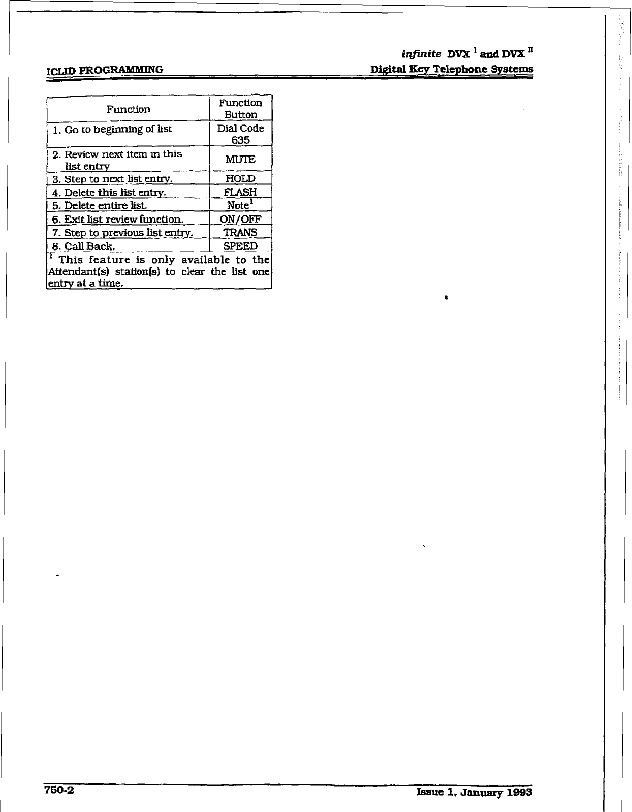
ICLJDPROG-G
iqjinite DVX’andDVXn
D&&al Key Telephone Systems
FUlCtiOIl
Function
3utton
1. GO to be&min~ of list ) DialCode
635
2.
Review next item in this
3.
Step to next list en-. HOLD
4.
Delete this list entry. FLASH
5. Delete entire list. 1 Note’ .
6.
Exit list review function. ON/OFF
7.
Step
to previous list entry, TRANS :
18. Call Back. 1 SPEED 1
’ This feature is only available to the
Attendant(s) st.aUcm[s) to clear the list one
entry at a time.
.
760-2 Issue 1. January 1993
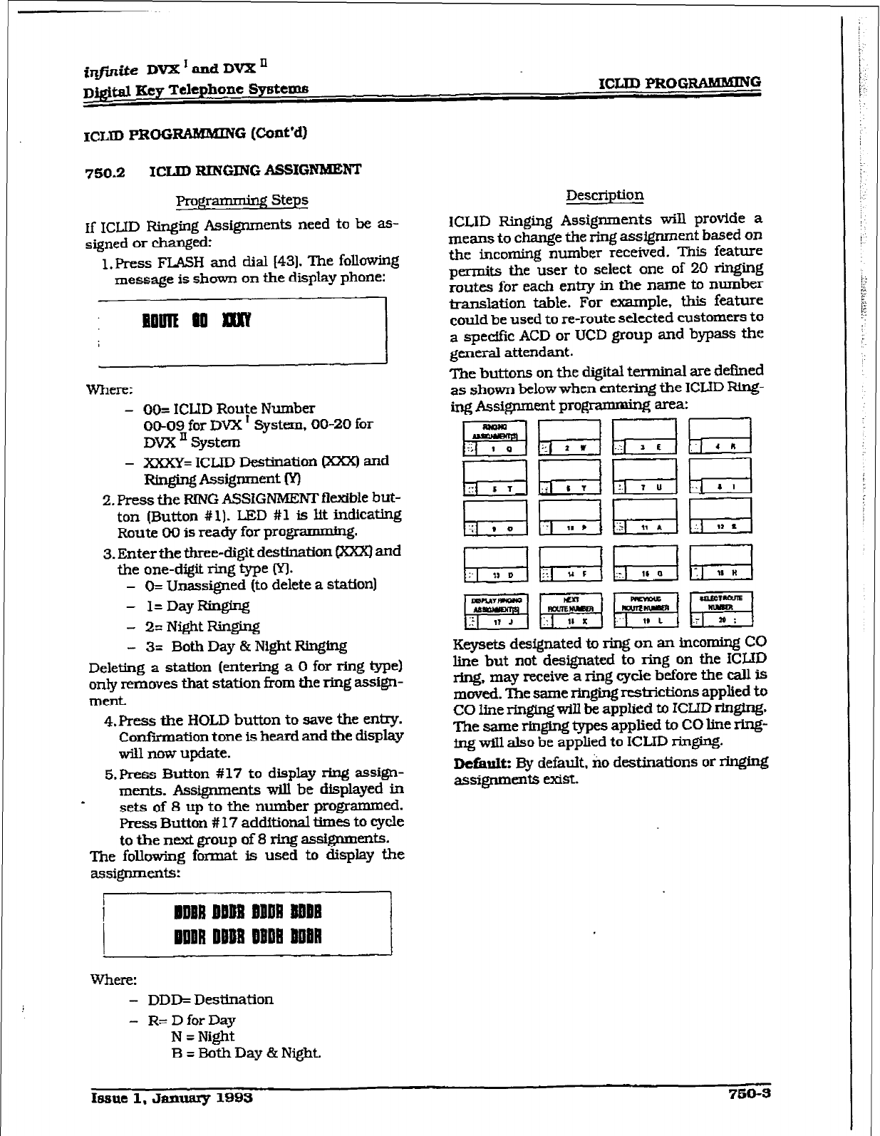
i@i.te DVX’andDVXn
D&&al kzcy Telephone Systems ICLID PROG~G
ICLID PRoG I~AMMING (Cunt’d)
750.2 ICIJD RINGING ASSIGNMENT
If ICIJD Ringing Assignments need to be as-
signed or changed:
1,
press
FLASH and dial [43]. The following
message is shown on the display phone:
where: - OO= ICUD Route Number
00-09 for DVX I System, 00-20
for
DYX ’ System
- XxXY= ICLID De&nation @OR) and
Rixghg Assignment Kl
2. Press the RING ASSiGNMEWT flexible but-
ton (Button # 1). LED #l is
lit
indicating
Route 00 is ready for programming.
3. Enter the three-digit destination clear] and
the one-digit ring Q-pe (YJ.
- O= Unassigned (to delete a station)
- I=DayRinging
- 2= Night Ringing
- 3= BothDay&NightRh@ng
Deleting a station [entering a 0 for ring type)
only removes that station from the ring assign-
ment.
4.Press the HOLD button to save the entry.
Confiiation tone is heard and the display
will now update.
5. Press Button # 17 to display ring assign-
ments. Assignments wiIl be displayed in
sets of 8 up to the number programmed.
Press Button # 17 additional times to cycle
to the next group of 8 ring
assignments.
The foIIowing format is used to display the
assignments:
where:
- DDD= Destination
- R= D for Day
N = Night
B=BothDay&Night.
Description
1CLID Ringing Assignments will provide a
means to change the ring assignment based on
the incoming number received. This feature
permits the user to select one of 20 ringing
routes for each entry in the name to number
transIation table. For example, this feature
could be used to re-route selected customers to
a specffk ACD or UCD group and bypass the
general attendant.
The buttons on the digital terminal are defined
as shown below when entening the ICWD Ring-
ing Assignment pro@amming area:
Rh;;-lhr;-lh;-;-l
jGGsl~~{~j
H Fr;;;i &El GiGI
Keysets designated to ring on an incoming CO
line but not designated to ring on the fCWD
ring, may receive a ring cycle before the call is
moved. The same ringing restrictions applied to
CO line ringing will be applied to ICLJD rIngin&
The same ringing types applied to CO line ring-
ing will also be applied to ICLID ringing.
DcfimItz By default. no destinations or ringing
assignmeRts exist.
Issue 1. JanuaIy 199s 760-S
iqfhtite DVX’andDVXn
Digital Key Telephone
Systems
Propnnning Steps
ping assfgnments witl be continuous and w-ill
be displayed in order of the destination number
f?om 001 to 557.
&Repeat Step 3 to program additional sta-
tions and rIngi.ng ass@ments. A maxi-
mum
of eight stations wilS &splay on the
LCD display. Additionat stations and ring-
ing assignments can be displayed using
Button # 17.
To advance to the next Route:
1. Press the NEXT flexible
button
(Button
#l$) to advance to the next ICLID Route
number,
To go to a previous Route:
1. Press the PREVIOUS flexible button (But-
ton #19] to go to the previous ICLID Route
number.
To select a different Route:
1. Press the SELECT ROUTE NUMBER to
select the
desired route number.
2. Enter the two-digit ICLJD route numba.
- 00-09 for DVX ’ System,
- 00-19 for DVX’ System.
3.Press the HOLD button to change to the
difXerent route
entered. Conflrmatlon tone
willbe heard.
Description
750-4
rssuc 1. January 1993
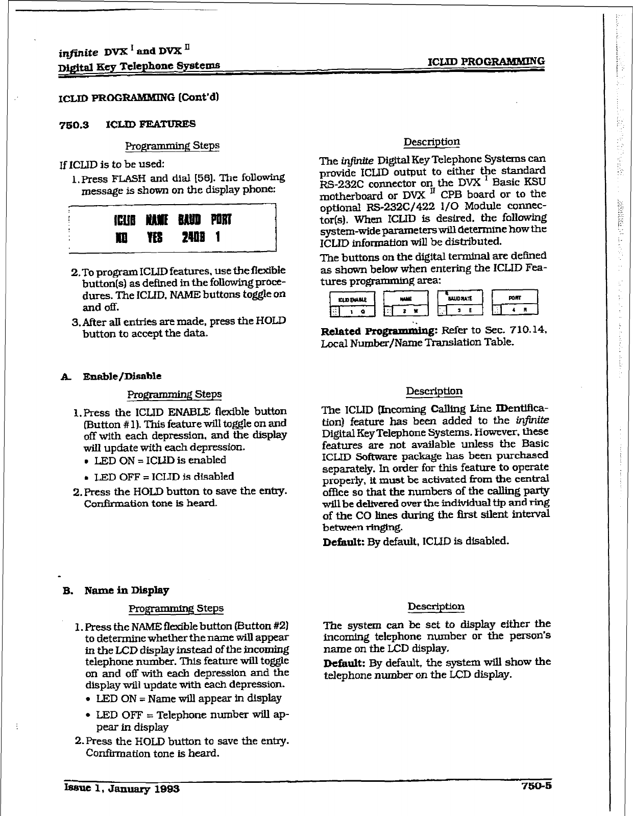
XCLID PRoG
RilNMXNG [Cont’d)
7so.3 ICLID FEkmmEs
Programming
Steps
If ICLID is to be used:
1. Press FLASH and dial [SS]. The following
message is shown on the display phone:
2. To program ICLJD features, use the flexibie
button(s) as defined in the following proce-
dures. The ICLID. NAME buttons toggle on
and off.
3.After all entries are made, press the HOLD
button to accept the data.
Prow steps
1. Press the ICLID ENABLE flexible button
(Button # 1). This feature will toggle on and
off with each depression, and the display
wiU update with each depression.
l
LED ON = ICWD is enabled
l
LED OFF = ICLID is disabled
2.Press the H0I.D button to save the entry.
Confkmation tone is heard.
B. Name in Display
Pro@ - g Steps
1. Press the NAME flexible button [Button #2)
to determine whether the name will appear
In the LCD display instead of the incoming
telephone number. This feature will toggle
on and off with each depression and the
display will update with each depression.
l
LED ON = Name will appear in display
l
LED OFF = Telephone number will ap-
pear in display
2.Press the HOLD button to save the entry.
Confkrnation tone is heard.
Description
The in-@&e Digital Key Telephone Systems can
provide ICLID output to either the standard
Ezs-23% connector on the DVX I Basic KSU
motherboard or DVX II CPB board or to the
optional -2326/422 l/O Module cunnec-
tar(s). When ICIJD is desired. the
following
system-wide parameters w-ill determine how the
ICLID inform&ton will be distibuted.
The buttons on the digital terminal are defined
as shown below when entering the ICLID Fea-
tures programming area:
Related Pro
gWlIY&lg:
Refer to Sec. 710.14,
local Number/Name Translation Table.
Description
The ICLID (Incoming Calling Line IDentifka-
tion) feature has been added to the infinite
DigitalKeyTelepbone Systems. However. these
features are not available unless the Basic
ICIJD Software package has been purchased
separately. In order for this feature to operate
properly, it must be activated kom the central
office
so that the numbers of the calling party
will be delivered over the indMdual tip and ring
of the CO lines during the ik-st silent intenrdl
betweenringing.
D&uIt: By default, ICLID is disabled.
Description
The 5ystem can be set to display either the
ticomlng telephone number or the person’s
name on the LCD display,
Default: By default, the system will show the
telephone number on the LCD display.
Issue 1, January 1893 750-K
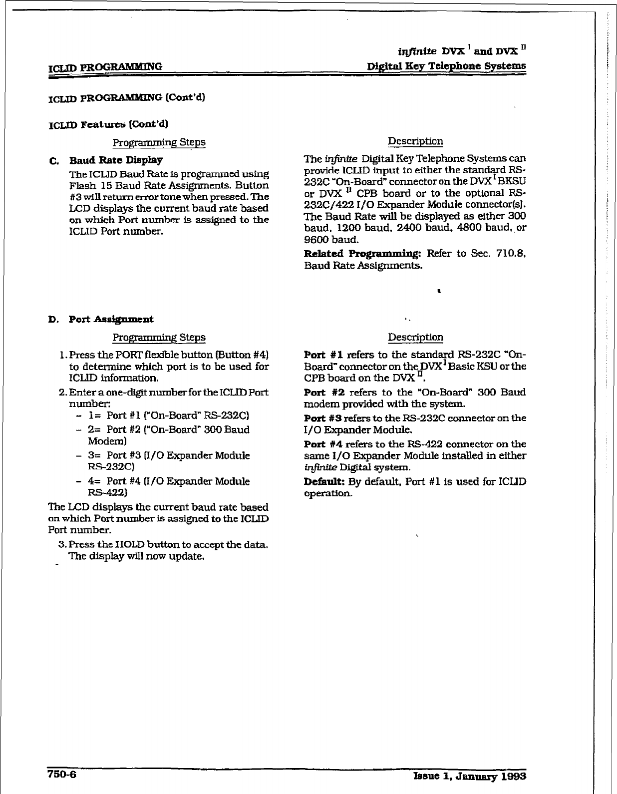
iqfiniie
DvX’andDVX”
DQfiM Key Telephone Systems
ICIJD PROG RABUMING (Ccmt’d)
ICUD Features {Ckmt’dI
prog - g steps
C.
Baud Rate Display
The ICLJD Baud Rate is programmed using
Flash 15 Baud Rate Assignments. Button
#3 will return error tone when pressed. The
LCD displays the current baud rate based
on which Port number is assigned to the
iCLID Port number.
D. Port Atmi@mcnt
prO@3Imliq~ steps
1. Press the PORT flexible button (Button #4)
to determine which port is to be used for
ICLID information.
2. Enter a one-digit number for theICIJD Port
number:
- I= Port #l (“On-Board” RS-232C)
- 2= Port #2 (“On-Board” 300 Baud
Modem)
- 3= Port #3 (I/O Expander Module
RS-232C)
- 4= Port #4 (I/O Ekpander Module
RS-422)
The LCD displays the current baud rate based
on which Port number is assigned to the ICLID
Port number.
3. Press the HOLD button to accept the data.
The display will now update.
Description
The infintte Digital Key Telephone Systems can
provide. ICLID input to either the standard RS-
232C ‘On-Board” connector on the DVX’ 3KSLl
or DVX I1 CPB board or to the optional RS-
232C/422 I/O Expander Module connector(s).
The Baud Bate wU.l be displayed as either 300
baud, 1280 baud. 2400 baud, 4800 baud,, or
9600 baud.
Related
Progmx: Refer to Sec. 710.8,
Baud Bate Assignments.
Description
Port #1 refers to the standard RS-232C “On-
Board- connector on the DVX’ Basic KSU or the
CPB board on the DVX n.
Port
#2 refers to the “On-Board” 300 Baud
modem provided with the system.
Port #S refers to the FS232C connector on the
I/O Expander Module.
Port #4 refers to the RS-422 connector on the
same I/O Expander Module fnstalled in either
infznite Digital system.
Dcfimlt: By default, Port #l is used for ICLlD
operation.
750-B Ismle I, January 1993
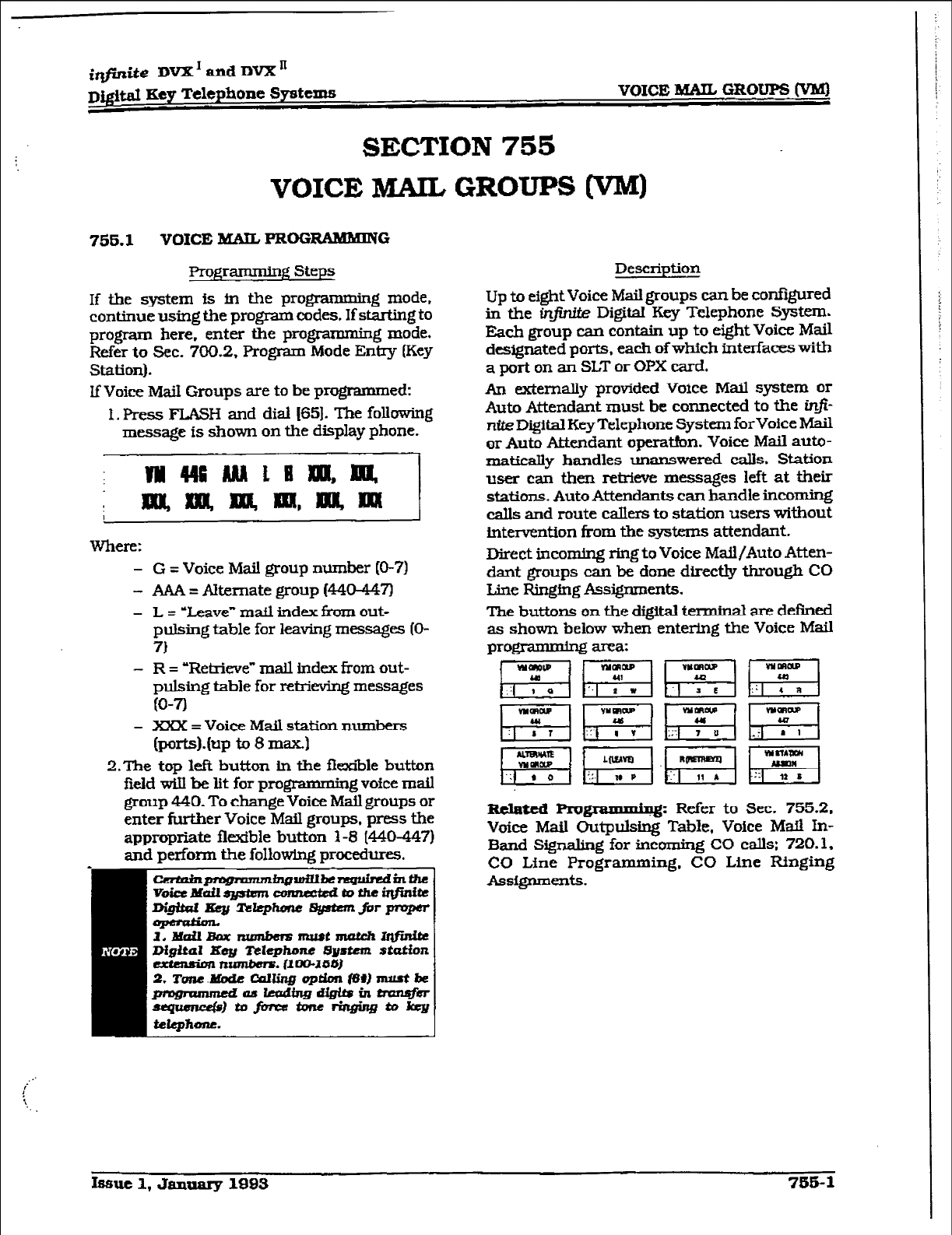
irtfirrite DVX’ and DVX’
DQ$tal Key Telephone Systems VOICE I&AIL GROUPS (VMj
SECTION 755
VOICE MAIL GROUPS m)
755.1
VOICE MAIL. PROGRAM?HING
Pro@ammin~ Steps
If the system is in the programming mode,
continue using the program codes. If starting to
program here, enter the programming mode.
Refer to Sec. 700.2, Program Mode Entry
(Key
Station).
If Voice Mail Groups are to be programmed:
1. Press FLASH and dial (651. The following
message is shown on the display phone.
‘31
W-ha:
- G = Voice Mail group number (O-7)
- AAA = Alternate group W404-47)
- L = ‘Leave” mafl index from out-
pulsing table for leaving messages (O-
71
-
R = ‘Retrieve” maLl index from out-
pulsing table for retrieving messages
(O-7)
- XXX = Voice Mail station numbers
(po*).(up to
8 maI
2.The top lefk button in the flexiile button
field will be lit for programming voice mail
group 440. To change Voice Mail groups or
enter fW-&er Voice Mail groups, press the
appropriate fltrdble button 1-8 (440447)
and perform the following procedures.
t.xeain~tnsrlx~inm
VoictMUil~
ctnzmedtotheirlfinite
~cItp-~mprqpa
Description
Up to eight Voice Mail groups can be confgured
in the in$r&k Digital Key Telephone System.
Each group can contain up to eight Voice Mail
designated ports, each ofwhich interfaces with
a port on an SLT or OPX card.
An externally provided Voice Mail system or
Auto Attendant must be connected to the in&
r&a Digital Key Telephone System forvoice Mail
or Auto Attendant opera&n. Voice Mail auto-
matirdy handles unanswered calls. Station
user can then retrieve messages left at their
stations. Auto Attendants can handle incoming
calls and route callers to station users without
intervention from the systxxns attendant.
Direct incoming ring to Voice Mail/Auto Atten-
dant groups can be done directly through CO
Line Ringfng AssigTlments.
The buttons on the digital terminal are defined
as shown below when entering the Voice Mail
progmmming area:
Izclatcd Plugi
l
.~g: Refer to Sec. 755.2,
Voice Mail Outpulsing Table, Voice Mail In-
Band Signaling for incoming CO calls: 720.1,
CO Line Programming, CO Line Ringing
AsSignmelltS.
Issue 1, January 1SBS 755- 1
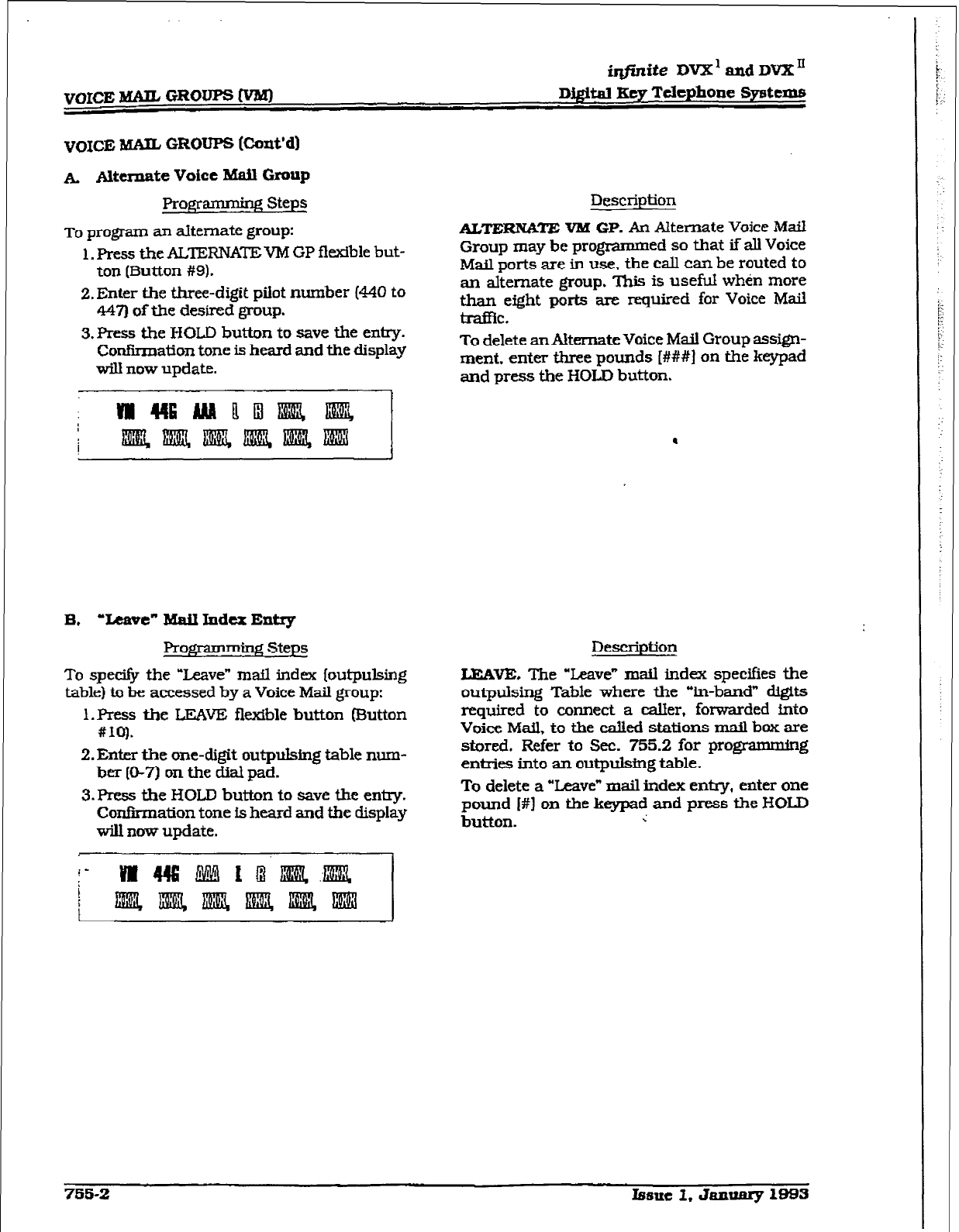
VOICE MAIL GROUPS W
infinite DVX’ and
DVX”
D&~&II Key
Telephone Systems
A ANnnate Voice Mail Group
Profpmming Steps
To
program an alternate group:
1. Press the ALTERNATE VM GP flexible but-
ton (Button #9).
2. Enter the three-digit pilot number (440 to
447) of the desired group.
3. Aess the HOLD button to save the entry.
Con&mat&m tone is heard and the display
will now update.
B. ‘leave” Mail Index Entry
l?rof$ * g steps
To
specitjr the “Leave” mail
index (outpulsing
table) to be accessed by a Voice
Mail
group:
1. Press the LEAVE flexible button (Button
#IQ).
2. Enter the one-digit outpulsing table num-
her [O-7)
on the dial pad.
3.Press the HOLD button to save the en-.
Confmnation tone is heard and the display
will now update.
Description
ALTERNATE VM GP. An
Alternate Voice Mail
Group may be programmed so that if all Voice
Mail ports are in use. the call can be routed to
an alternate
group. This
is useful whin more
than eight ports are required for Voice Mail
tXl.EiC.
To delete an Alternate Voice Mail Group assign-
ment, enter three pounds [###I on the keypad
and press the HOLD button.
Description
LEAVE, The “Leave” mail index specifies the
outpulsing Table where the “in-band” digits
required to connect a caller, forwarded fnto
Voice Mail, to the called stations mail box are
stored. Refer to Sec. 755.2 for programming
enties into an outpulsing table.
To delete a “Leave” mail index entry, enter one
pound I#] on the keypad and press the HOLD
button. ;
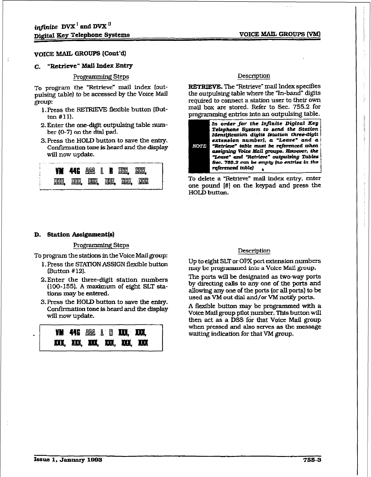
VOICE IYUUL
GROUPS (VB%l
VOICE MAIL GROUPS (Cont’d)
C. “Retrieve” Mail Index Entry
Prom Steps
To program the ‘Retrievti” mail index
[out-
pulsing table) to be accessed by the Voice Mail
group:
1. Press the RETRIEVE flexible button (But-
ton #ill.
2. Enter the one-d&It outpulsing table mnn-
ber (O-7) on the dial pad.
3.Pres.s the HOLD button to save the entry.
Confiiation tone is heard snd the display
will now update.
D. St&ion hsi@mcat@)
prog-mmmbg steps
To program the stations in the Voice Mail group:
1. Press the STATION ASSIGN flexible button
(Button # 121.
2.Enter the three-digit station numbers
(100-155). A m-urn of eight SLT sta-
tions may be entered.
3. Press the HOLD button to save the entry-
Confirmation tone is heard and the dispIay
wiIl now update.
Description
RETRIEVE. The “Retrieve” mail Index spe&es
the outpulsing table where the In-band” digits
required to connect a station user to their own
mail box are stored. Refer to Sec. 755.2 for
prom
entries into an outpulsing table. 1
To delete a “Retrieve” maiI index entry, enter
one pound [#I on the keypad and press the
HOLD button.
Description
Up to eight SLT or OFX port extension numbers
may be programmed into a Voice Mail group.
The ports wilI be designated as two-way ports
by directing &Is to any one of the ports and
alIowing any one of the ports (or all ports) to be
used as VM out dial and/or VM not@ ports.
A flexible button may be programmed with a
Voice MaiI group pilot number. This button will
then act as a DSS for that Voice Mail group
when pressed and also serves as the message
waiting inckation ior that VM group.
IBSUC 1, January 1893
756-3
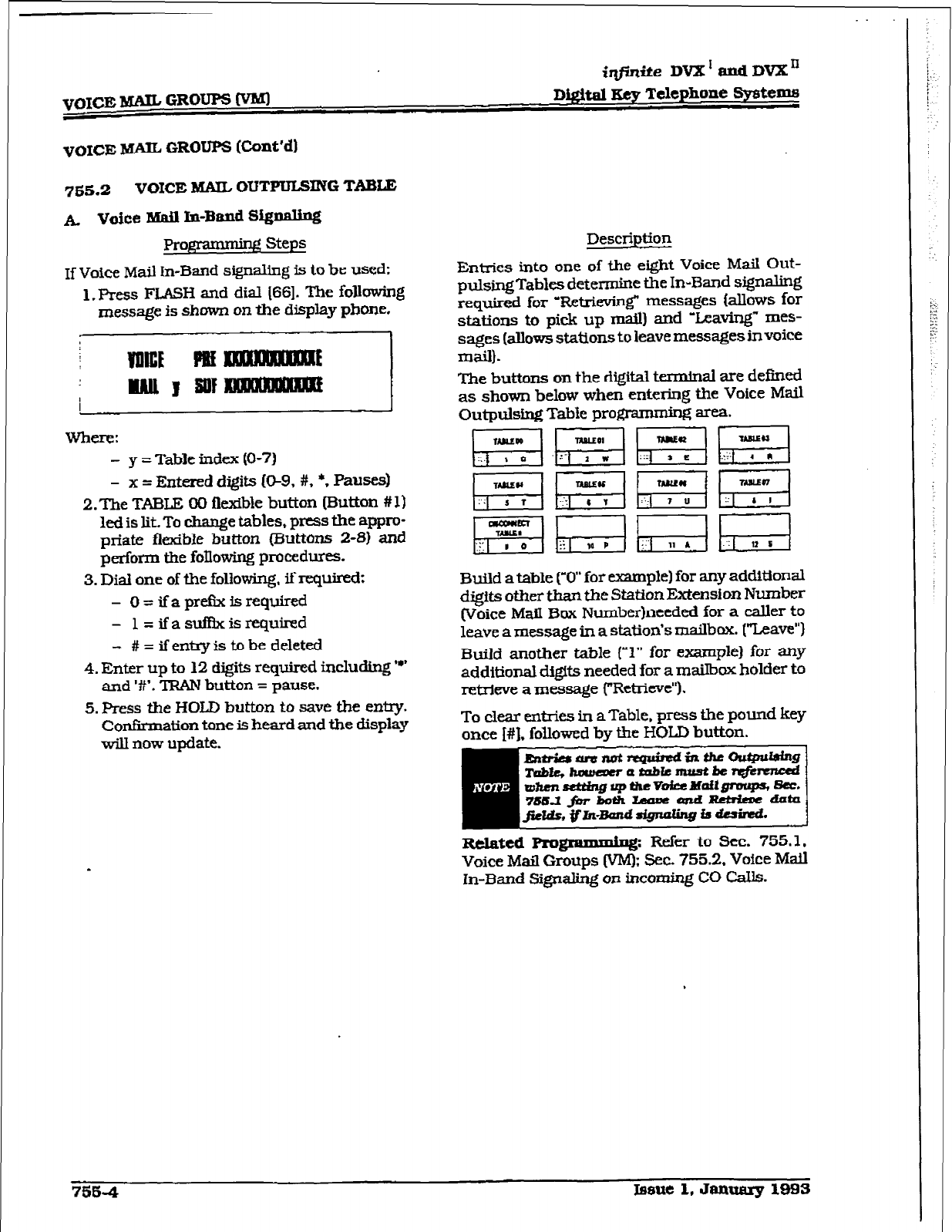
VOICE MA= GROUPS WW
iqjinite DVX’andDVXn
Digital Key Telephone Systems
VOICE hTA= GROUPS Wnt’dl
755.2 VOICE WUL OUTPULSING TAB-
k Voice Mail In-Band SQpa.lbg
ProJip3mdg steps
If
Voice
Mail In-Band signaling is to be used:
1. Press FLASH and dial [66]. The following
message is shown on the display phone.
Li
Where:
- y = Table index (O-7)
- x = Entered digits 09, #, *, F’ausesj
2. The TABLE 00 flexible button (Sutton # 1
led is lit. To change tables, press the appm
- -_
priate flexible button (Buttons 2-W and
perform the following procedues.
3. Dial one of the following. if requited;
- O=ifapretlxisrequired
- l=ifasuf&cisrequired
- #=ifen~istobedeleted
4. Enter up to 12 digits required including y’
and I#‘. TFWN button = pause,
5. Press the HOLD button to save the entry.
Confirmation tone is heard and the display
will now update.
Description
Entries into one of the eight Voice Mail Out-
pulsingTables determine the In-Band signaling
required for “R&-kvin~ messages Iallows for
stations to pick up mail) and ‘Leaving” mes-
sages (allows stations to leave messages in voice
mail].
The buttons on the digital terminal are defined
as shown below when entering the Voice Mail
Outpulsing Table prom area.
pg&gq WI pq
~pqgqpig
p!TxGKJh;;;i
Build a table (‘0” for example) for any additional
digits other than the Station Exknsio~ Number
(Voice Mail Box Numberlneeded for a caller to
leave a message in a station’s mailbox. [“Leave”)
Build another table (‘1” for example) for any
additional digits needed for a mailbox holder to
retrieve a message (“Retrieve”).
To clear enties in aTable. press the pound key
once I#]. followed by the HOLD button.
mm]
Related Rogramming: Refer to Sec. 755.1.
Voice Mail Groups IVM): Sec. 755.2. Voice Mail
In-Band Signaling on incoming CO Calls.
7564 Lesue 1. January 1993
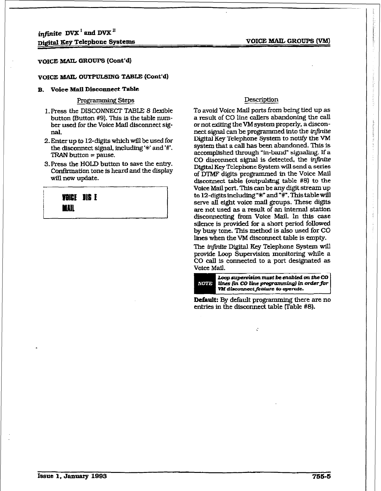
ifiite DVX I and DVX”
~igitd Key Telephone Systems
VOICE MAIL
GROUPS Wont’4
VOICE B5AIL OUTKKSING
TABLE (Cont’dl
B. Voice Mail Dfeco~nect
Table
Prog * :! Steps
1. Press the DISCUNNECT TABLE 8 flexkble
button (Button #9). This is the table num-
ber used for the Voice Mail disconnect sig-
la.
2. Enter up to 12-digits which will be used for
the disconnect sQm.l. i.nclu~ ‘W and W.
TRAN button = pause.
S-Press the HOLD button to save the entry.
Confirmation tone is heard and the display
will now update.
.
Description
To avoid Voice Mail ports from being tied up as
a result of CO line callers abandoning the call
or not exiting the VM system properly, a d&con-
nect signal can be programmed into the infinite
Digital Key Telephone System to noufv the VM
system that a call has been abandoned. This is
accomplished through ‘in-band* signaling. If a
CO disconnect signal is detected, the ir@~f@
Digital Key Telephone System will send a series
of M’MF digits programmed in the Voice Mail
disconnect table (outpuklng table #8) to the
Voice Mail port. This can be any digit stream up
to 12-digW.sinch~Ung”~” and V’. This tablewill
serve all eight voice mail groups. These d@ts
are not used as a result of an internal station
disconnecting fmm Voice h&x& In this case
silence is provided for a short period followed
by busy tone. This method is also used for CO
lines when the VM disconnect table is empty.
The infinittz Digital Key Telephone System will
provide Loop Supervision monitoring while a
CO call is connected to a port designated as
Voice Mail.
Default: l3y default programmtng there are no
entries in the disconnect table mable #8).
,
Issue 1, Janunry 1993
IS&S
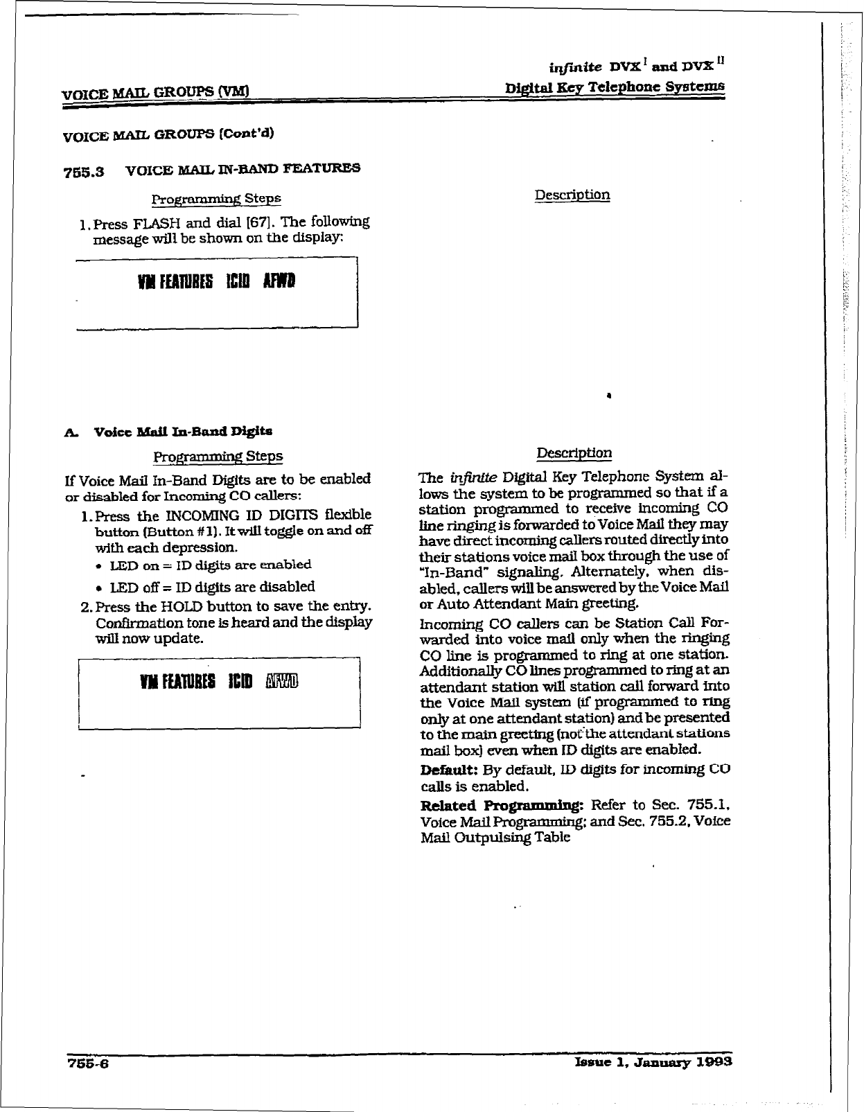
VOXCE MAIL
GLOW
IVM]
iqjhdte DVX’ and DVX”
D&&al Key Telephone Systeme
VOICE MAIL GROUPS (CcM’d)
765.3 VOICE &SAIL IN-BAM)
FEATURES
-
Programming Steps
1. Press FLASH and dial [67]. The following
message will be shown on the display
Description
k voiec Mail In-Band Mgtte
Fframming steps
If Voice Mail In-Band Digits are to be enabled
or disabled for Incoming CO callers;
1. Ffress the INCOMING ID DIGl’IZ
flexible
button (Button # 1).
It
will toggle on and off
with each depression.
. LEDon= ID digits are enabled
l
LED off = ID digits are disabled
2. Press the HOLD button to save the entry.
Confirmation tone is hesrd and the display
will now update.
Description
The infintte
Digital
Key Telephone System al-
lows the system to be programmed so that if a
station programmed to receive incoming CO
line ringing is forwarded to Voice Mail they may
have direct incoming callers muted directly into
their stations voice mail box through the use of
‘In-Band” signaling.
Alternately,
when dis-
abled, callers
willbe answered
by the
Voice
Mail
or Auto
Attendant Main greeting.
Incoming CO callers can be Station Call For-
warded into voice mail only when the ringing
CO line is programmed to ring at one
station.
Additionally CO lines programmed
to ring
at an
attendant station will station call forward into
the Voice Mail. system (if programmed to ring
only at one attendant station) and be presented
to the
main greeting
(noi%be attendant stations
mail box) even when ID digits are
enabled.
Default: By default, ID digits for incoming CO
calls is enabled.
Related Pro
gramming:: F$&-; &755;Z;
VoiceMaill%-ogr -- Ig - *
Mail Cutpulsing Table
mwi
Xsmte 1, Janaarg 1993
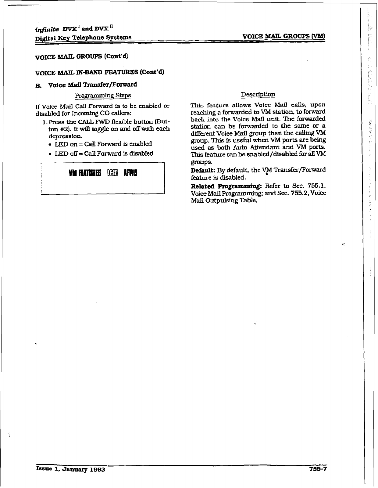
iq@ik DVX’andDVXn
D@taI Eey Telephone System VOKZ MAIL GROUPS (‘VW
VOICE MAIL GROUPS (Cont’d)
VOICE MAIL IN-BAND FEATURES (Cont’d)
Pro&p- - gsteps
Description
If Voice Mafl CalI Forward is to be enabled or
disabled for Incoming CO callers:
1. Press the CALL FWD ff exible button (But-
ton #2]. It will toggle on and off with each
depression.
l
LED on = call Forward is enabled
l
LED off = CaU
Forward
is disabled
This feature allows Voice Mail calls, upon
reaching a forwarded to VM station, to forward
back into fhe Voice Mail unit. The fowarded
station can be foxwarded to the same or a
different Voice
Mail
group thm the calling VM
group. This is usefkl when VM ports are
being
used as
both
Auto Attendant and VM ports.
This feature can be enabled/disabled for allVM
groups.
Default:
By default, the V$‘l ‘I’hnsfer/Fomard
feature is disabled.
hkil Outpulsing Table.
fssue 1, January 1993 7m-7
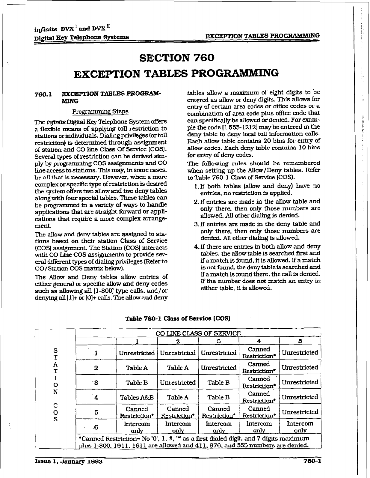
@‘i&e
DVX’ and DVX”
~j&al Key Telephone Systems EXCEPTION TABLES PROGRAMMING
SECTION 760
EXCEPTION TABLES PROCZMMMING
760.1
EXCEFl!lON TABLES pROGR4kC
MING
Fkogrammiry! Steps
The in. DigitaI Key Telephone System offers
a flexible means of applying
toll
restriction
to
stations or Mlividuals. Dialing privileges (or toll
restriction} is determined through assignment
of station and CO line Class Of Sendce (COS).
Several types of restriction can be derived sim-
ply by programming cos assignments and co
line accessto stations. This may, in some cases,
be all that is necessary. However, when a more
complex or spec%ic @pe of restriction is destred
the system offers two allow and two deny tables
along with four special tables. These tables can
be programmed in a variety of way%!? to handle
applications that are stxaight forward or appli-
cations
that
require a more complex an-ange-
ment.
The allow and deny tables are assfgued to sta-
tions based on their station Class of Service
(COS) assignment. The Station (COS) interacts
with CO Une COS assfgnments to p-de sev-
eral different types of dialing privileges (Refer to
CO/Station COS mat& below).
The Albw and Deny tables allow entries of
either general or specific allow and deny codes
such as all&g all [l-800] type calls. and/or
den~anIll+or[O]+calls.?heattowanddeny
tables allow a maximum of eight digits to be
entered as allow or deny digits. This
allows
for
entry of certain area codes or office codes or a
cornbinstion of area code plus office code that
can specifkally be z&wed or denied. For exam-
ple the code [1555-12121 maybe entered in
the
deny table to deny Jocal toil information calls.
Each ahw table contains 20 bins for
entry
of
aIlow codes. Each deny table contains 10 bins
for e&y of deny codes.
The following rules should be remembered
when setting up the Allow/Deny tables. Refer
toTable 760-I Class of Service (COS).
1. If both tables (allow and deny) have no
entrfes, no restriction fs applied.
2. If entries are made in the allow table and
only there, then only those numbers are
allowed. All other dialing is denied.
3. If entries are made in the deny table and
only there. then only those numbers are
denied. All other dialing is allowed.
4.
If there are entries in both allow and deny
tabkss. the aliow table is searched fit and
ifamatchisfound.itisallowed.Ifamatch
is not found, the
deny
table is searched and
ifamatchisfoundthere,thecaIlisdenied.
If the number does not match an entry in
either table, it is allowed.
Tabie 760-l
class of
service
[COSI
Unrestricted
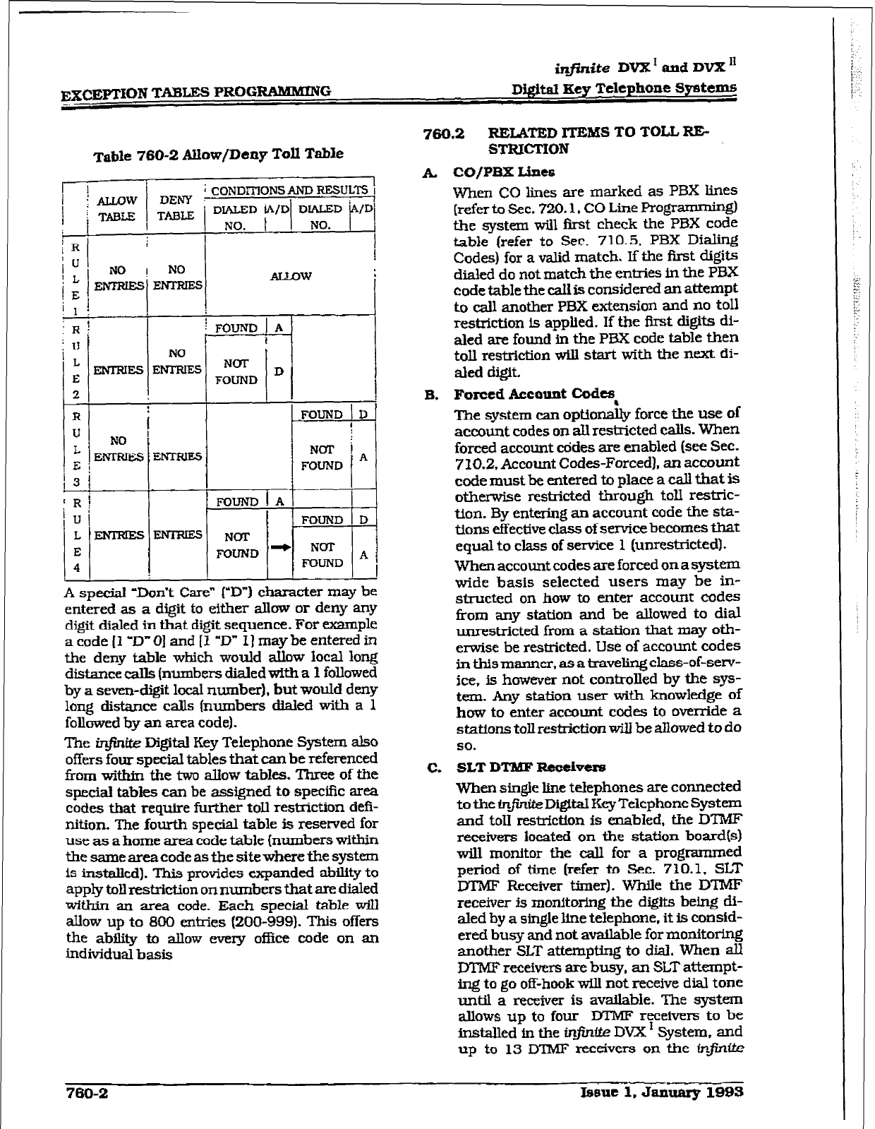
EXCJ@TION TABLES PROGRAMMXNG
infinite
DVX’ and DVX”
Digital Key Telephone Systems
760.2 RELATED ll’EMS TO TOLL RI%
Table 760-2 Allow/Deny Toll Table
I
; CONDITIONS AND RJ.ZSUL7-S I
/D’
2 I I
’
R
f [ FOUND ! D
I
NOT i
FOUND j A
!R! I LFOIJND~AI I
Iuj
FOUND 1 D
I.-- NOT
E FOUND ‘-
l--T-
Nm A
4 FOUND
I I I I I
A special YWYt Care” I’D”) character may be
entered as a digit to either allow or deny any
digit dialed in that digit sequence. For example
a code (1 -D” 01
and [I
“D” I) may be entered in
the deny table which would allow local long
distance calls [numbers dialed with a I followed
by a seven-digit local number), but would deny
long distance calls (numbers dialed with a 1
followed by an area code).
The iTsfinite Digital Key Telephone System also
offers four special tables that can be referenced
from witi the two allow tables. Three of the
special tables can be assigned to specific area
codes that require further toll restriction defi-
nition. The fourth special table is reserved for
use as a home area code table (numbers within
the same area code as the site where the system
is in&&d). This provides expanded &ility to
apply toll restriction on numbers that are dialed
within an area code. Each special table wiIl
allow up to 800 entries (200-999). This offers
the ability to allow every office code on an
individual basis
A.
B.
CO/Pl3x Lines
When CO lines are marked as PBX lines
(refer to Sec. 720.1, CO Line Programming)
the system w-ill first check the PBX code
table [refer to Sec. 710.5. PBX Diahug
Codes) for a valid match. If the frrst digits
dialed do not match the entries in the PBX
code table the call is considered an attempt
to call another PBX extension and no toll
restriction is applied. If the first digits di-
aled are found in the PBX code table then
toll restriction will start with the next di-
a.led digft.
Forced Amount Codes
The system can optto& force the use of
account codes on ah restricted calls. When
forced account codes are enabled (see Sec.
710.2, Account Codes-Forced), an account
code must be entered to place a call that is
otherwise restricted Umn.gh toll restric-
Uon.
By entering an account code the sta-
tions effective class
of service becomes that
equal to class of service 1 (unrestricted).
When account codes are forced on a system
wide basis selected users may be in-
structed on how to enter account codes
from any station and be allowed to dial
unrestricted from a station that may oth-
envise be restricted. Use of account codes
in this manner, as a traveling class-of-sew-
ice, is however not controlled by the sys-
tem. Any station user with lmowledge of
how to enter account codes to override a
stations toll restriction wUi be allowed to do
so.
C.
SLT DTMF Receivm
STRICMON
When single line telephones are connected
to the tnfiniteDi@aI Key Telephone System
and toll restriction is enabled, the DTMF
receivers located on the station board(s)
will monitor the call for a programmed
period of time [refer to Sec. 710.1. SLT
DTMF Receiver timer). WNle the DTMF
receiver is monitoring the digits being di-
aled by a single line telephone. it is consid-
ered busy and not available for monitoring
another SLT attempting to dial. When all
DTMF receivers are busy, an SLT attempt-
ing to go off-hook will not receive dial tone
until a rece.iver is available. The system
allows up to four DTMF receivers to be
installed in the infintte DVX’ System, and
up to 13 DTMF receivers on the ti$nUe
780-2 Iseue 1. January 1993
irlfinite DVX * and DVX ’
D@m fzey Telephone Sy8tcma
DVX ’ System. for monitoring SLT dialing.
lfa system has heavy SLTusage toll restric-
tion may inhibit dialing by SLT stations.
TWO options are available to help alleviate
this problem; 1) shorten the SLT receiver
timer (refer to Sec. 710. I, SLT DTMF
Receiver timer). This will free up DYlMF
receivers faster, however, may not provide
the desired toll restriction for SLT stations;
or 2) Enable LCR and force LCR on SLT
stations. when the LCR database is set up
the 3-d$jlt table allows for entry of the
number of digits to be expected. When a
SLT dials the appropriate number of digits,
LCR will release the D’IMF receiver and
then be av&JaMe for another SLT call.
D. LCR vs. Ton Rc&xiction
LCR is not intended to be an alternaffve to
toll restriction nor is toll resirMion in-
tended to be a alternate to LCR In fact they
both work best when programmed to-
gether. Toll restriction provides the dialing
privileges that stations are allowed and
LCR provides the routing of calis onto the
proper type of lines. LCR can e&ance toil
restriction in that LCR provides a ‘Store
and Forward” operation that allows the
system to analyze the digits befng dialed
before a trunk is seized. This prevents us-
ers from by-passing toll restiction by tak-
ing advantage of the time it takes for a
central office line to provide dial tone. Be-
cause of this it is recommended that LCR
be considered when toll restriction fs de-
sired.
Issue 1. January 1993
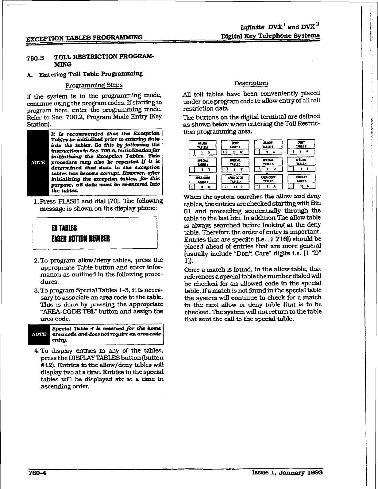
ir@li.t@ D= I and DVX I1
Digit&l Key Telephone
Svsttms
760.3
TOLL RESTRICTION PROGRAM-
MlNG
A.
Entering
Td Table Prom
Projpammhg Steps
If the system is in the programming mode,
continue using the program codes. If starting to
program here, enter the programming mode.
Refer to Sec. 700.2. Program Mode Entry (Key
1. Press FLASH and dial
1701.
The folkxvlng
message is shown on the display phone:
I
2.To
program allow/deny tables, press the
appropriate Table button and enter infor-
mation as outlined in the followSng proce-
dUrC3.
3. To program Special Tabks 1-3. it is neces-
sary to associate an area code to the table.
This is done by pressing the appropriate
“AREA-CODE TBL” button and assign the
area code.
speciaiTobIt4fs -furtheiwme
anzacodeanddoe5notrtQubc~arUiCOdC
entry.
4.To
display entries ln any of the tables.
press the DISPLAY TAELES button (button
# 12).
Entries in the allow/deny tables will
display two at atime. Entries in the special
tables wiIl be displayed six at a time in
ascending order.
760-4
Issue I.January1993
Description
All toll tables have been conveniently placed
under one program code to allow entry of all toll
restriction data.
The buttons on the digital terminal are defined
as shown below when entering the Toll Restric-
tion progmmming area.
When the systtm searches the albw and deny
tables, the entries are checked starling with Bin
01 and proceedfng sequentially through the
table to the last bin. In addttion The allow table
is always searched before looking at the deny
table. Therefore the order of entry is important.
Enties that are specific (i.e. [I 716)) should be
placed ahead of entries that are more general
(usually include “Don’t Care” digits i.e. [l ‘KY
111.
Once a match is found, in the allow table. that
references a special table the number dialed will
be checked for an allowed code in the special
tabIe. If a mat& is not found in the special table
the system will continue to check for a match
in the next alkw or deny table that is to be
checked. The system will not retumto the table
that sent the call to the special table.
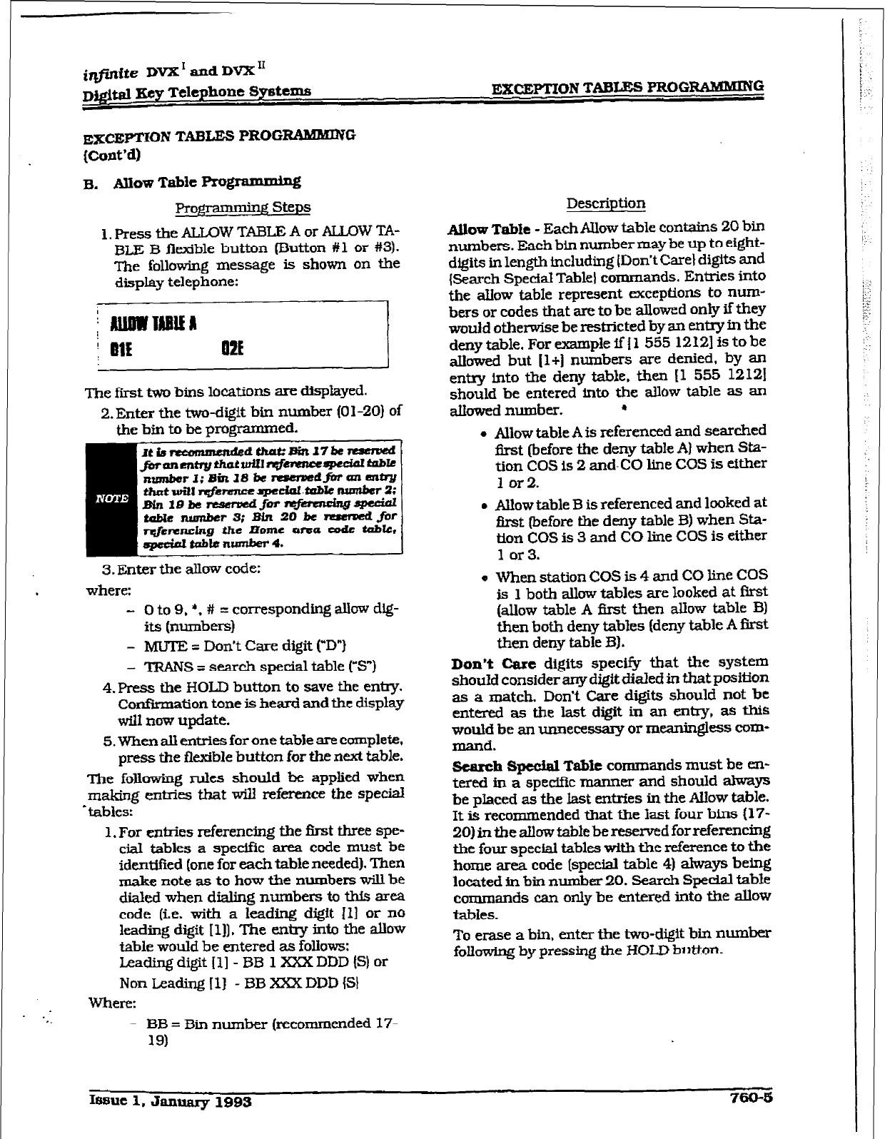
EXCEPTION TABIJW FROG-0
EX~~ION TABLES FROG-G
&ont’d)
FL Allow Table Rogrammj%
1. press the ALlxlW TABLE A or ALLOW TA-
Bl,E B flexible button (Button #l or #3).
The following message is shown on the
display telephone:
The fkst two bins locations are displayed.
2. Enter the two-digit bin number (0 1 -ZO} of
the bin to be programmed.
Ittsrrcanmcndsd~~37knstrcrad f
fbranmkythordIr6snsro# sptdor-k
n-r 3; Bin 38 bc rrsapsdfbrrmantry
thatwarr;fe~spedol.doMenrmrba3;
nstfisafor~qpecirrI
tabb?Yulmbers:Bin20k-~r
the Borne 0-a code tab&,
3. Enter the allow code:
where:
- 0 to 9, l . # = corresponding allow dig-
its (numbers)
- MUTE = Don’t Care digit CD”)
- TRAM = search special table (YY)
4.FVess the HOLD button to save the entry.
Confirmation tone is heard and the display
will now update.
5. When all entries for one table are complete,
press the flexible button for the next table.
The foIlowing rules should be applied when
making entries that will reference the special
-tables:
1. For entries referencing the first three spe-
cial tables a sped& area code must be
identified (one for each table needed). Then
make note as to how the numbers will be
dialed when dialing numbers to this area
code (i.e. with a leading digit II] or no
leading digit [l]] , The entry into the allow
table would be entered as follows:
Leading digit (11 - BB 1 XXX DDD (S) or
Non Leading [l] - BBXXXDDD {S}
WI-El-C
. _
.?. - BB = Bin number (reeomrnended 17-
19)
Descrintion
Allow Table - Each AIIow table
contains
20 bin
numbers. Each bin number may be up to eight-
digits in length including (Don’t Care) digits and
{Search Special Table) commands. Entries into
the azlow table represent exceptions to num-
bers or codes that are to be allowed only if
they
would otherwise be restricted by an entry in the
deny
table. For example if f 1 555 12121 is to be
aIlowed but [ 1+] numbers are denied. by an
entry into the deny table, then 11 555 12121
should be entered into the allow table as an
abwed number. .
l
Allow table A is referenced and searched
first (before the deny table
A)
when Sta-
tion COS is 2 and-CO line COS is either
1 or2.
l
Allow table B is referenced and looked at
first (before the deny table B) when Sta-
tion COS is 3 and CO line COS is either
1 or3.
Q When station COS is 4 and CO line COS
is 1 both allow tables are looked at first
(allow table A first then allow table B)
then both deny tabIes (deny table A &t
then deny table 33)).
Don’t Care digits specify that the system
shoukl consider any digit dialed in that position
as a match. Don’t Care digits should not be
enteredastbelastdigitinanentxy,asthis
would be an unnecessaq or meaningless com-
mand.
scatch Special Table commands must
be en-
tered in a specific manner and should always
be placed as the last enties in the Auow table.
It is recommended that the Iast four bins (17-
20) in the allow table be reserved forreferencing
the four special tables w&b the reference to the
home area code (special table 4) always being
located in bin number 20. Search Spedat table
commands can only be entered into the allow
t&kS.
To erase a bin. enter tie two-digit bin number
fokwing by pressing the HOLD button.
Issue 1, Jallllaly 1993 760-8
injkite DVX ’ and DVX I’
=mlYMON TABLES PROGRAMMING Digital Key Telephone Systems
EXCEPTION TABIS+ FROGIUMBUING
(Cont’d)
Auow Table Pru@unming (Cont’d)
Prog$xmmbg steps
-
XXX = Area code (must match AREA-
X entry)
- DDD = “Don’t Care” dfgit (three en-
Mes, DND button)
- {SI= Search Special Table Command
(TRAM button)
2. For an entq that fs to reference the Home
Area Code table (specfal table 41 the entry
may also be entered to expect or not expect
a leading digit [I]. In fact fn some cases it
may be desirable to enter both of the fol-
lowhg entrks:
Leadfng d@it (11~ BB 1 DDD IS) and/or
Non Leading [l] - BB DDD (S}
Where:
- BB = Bin number (recommended bfn
201
- DDD = uDon’t Care- digit (three en-
t&s, MUTE button)
- IS)= Search Special Table Command
(TR#WS button)
Description
760-6 Isme 1. January 1993
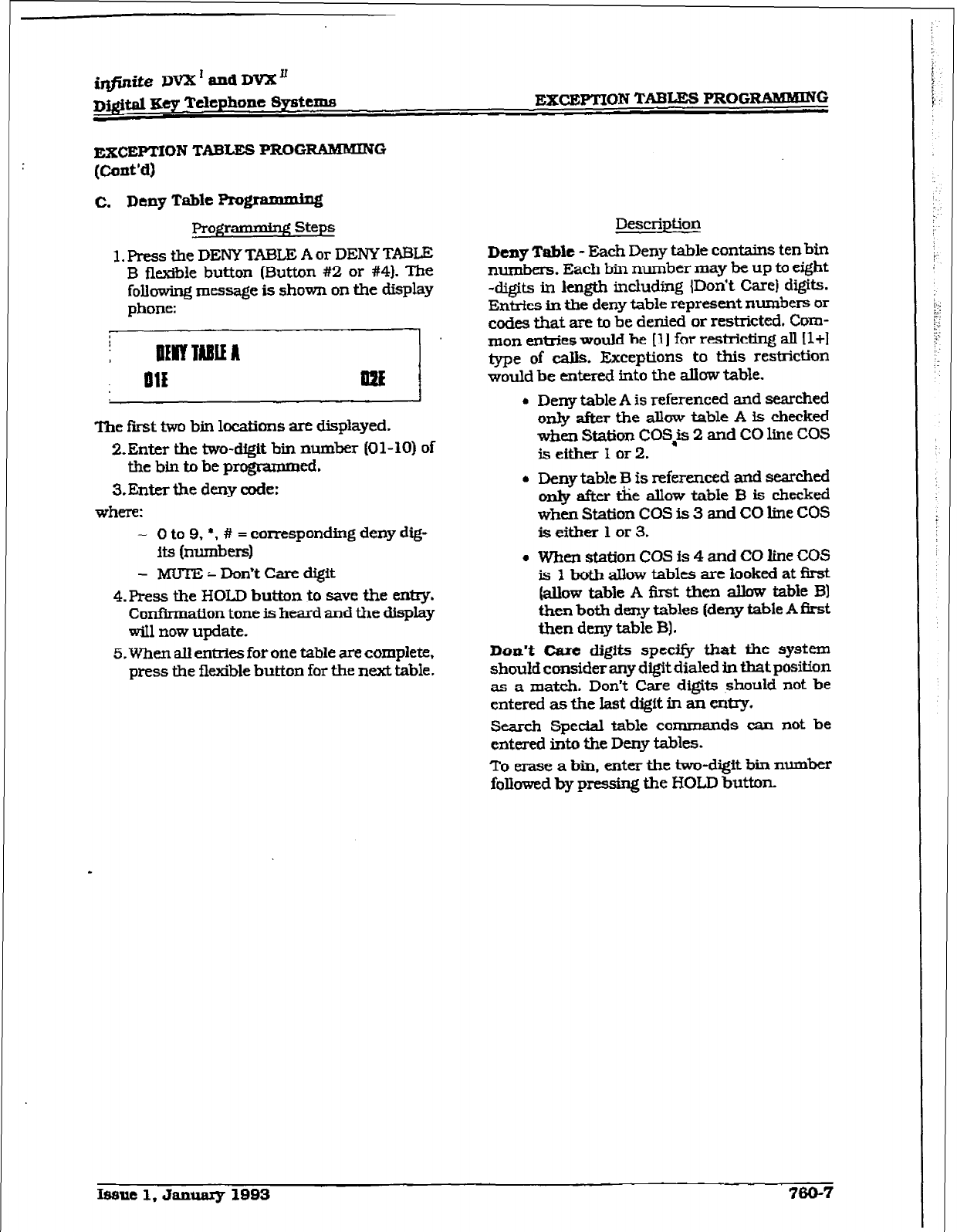
EXCEPTION TABLES I’ROG~G
RxCEPTION TABLE-8 PROGWUDIING
(Cont’d)
c. Deny Table Programmiq!
Pro@mmin.g Steps
1. Press the DENY TABLE A or DENY TABLE
B flexibfe button (Button #2 or #4). The
following message is shown on the display
phone:
The first two bin locations are displayed.
2.Enter the two-digit bin number (01-10) of
the bin to be programmed.
3.Ent.er the deny code:
where:
- 0 to 9, *, # = corresponding deny dig-
its (numbers)
- hRlTi3 = Don’t Care digit
4. Press the HOLD button to save the entry.
Confirmation tone is heard and the display
will now update.
5. When all enlrks for one table are complete.
press the flexible button for the next table e
Description
Deny Table - Each Deny table contains ten bin
numbers. Each bin number may be up to eight
-digits in length including {Don’t Care] digits.
Entries in the deny table represent numbers or
codes that are to be denied or restricted. Com-
mon enties would be [l] for restricting all Il+l
type of calls. Exceptions to this restriction
would be entered into the allow table.
4 Deny table A is referenced and searched
only after the allow table A is checked
when Station COS$2 and CO line COS
is either 1 or 2.
l
Deny table B is referenced and searched
only after die allow table B is checked
when Station COS is 3 and CO Line COS
is either 1 or 3.
a When station COS is 4 and CO line COS
is 1 both allow tables are looked at first
(allow table A Crst then allow table Bl
then both deny tables [deny table A first
then deny table B) .
Don’t Cane digits specify that the system
should consider any d&it dialed in that position
as a match. Don’t Care digits should not be
entered as the last digit in au a&y.
Search Spedal table comma-n ds can not be
entered into the Deny tables.
To erase a bin, enter the two-digit bin number
followed by pressing the HOLD button.
Ifumc 1. Jatnaary 1993 7430-7
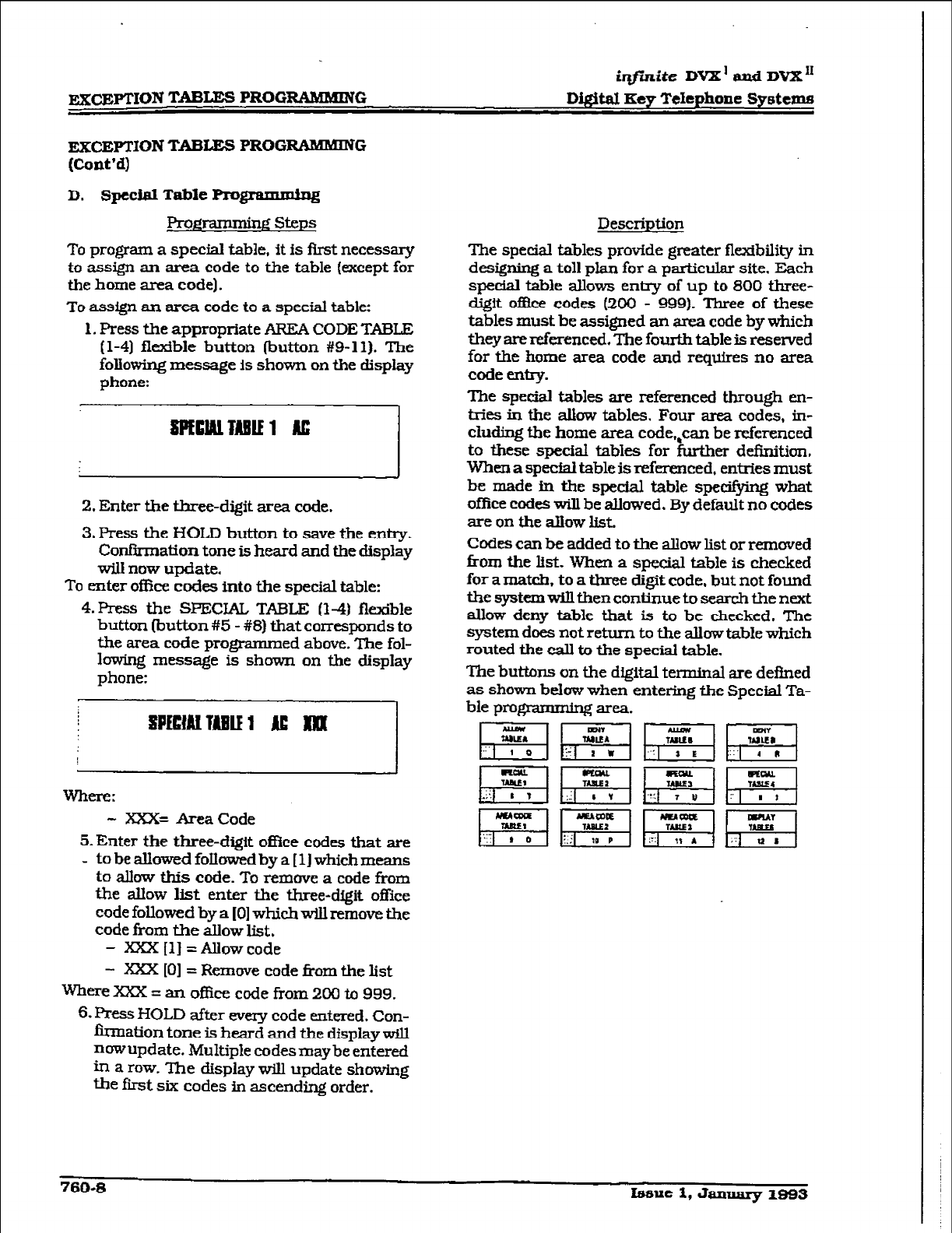
EXCEPTION TAB- PROG-G
,
i@zite DVX’ and DVX”
Digital Key
Telephone
Systems
=CEPTfON TABU3S PROG-G
(Cont’d)
D. Special Table Programminq
F?rog- steps Description
To program a special table, it is first necessary
to assign an area code to the table (except for
the home area code).
To assign an area code to a special table:
1. Press the appropriate AREA CODE TABLE
f 1-4) flexible button (button #9-l 1). The
foliowing message is shown on the display
phone:
The special tables provide greater flezdbility in
designing a toll plan for a particular site. Each
special table allows en&y of up to 800 three-
digit office codes (200 - 999). Three of these
tables must be assigned an area code by which
they are referenced. The four-& table is reserved
for the home area code and requires no area
code entry.
The special tables are referenced through en-
tries in the allow tables. Four area codes, in-
cluding the home area code,,can be referenced
to these special tables for further def%ition,
When a speciai table is referenced, entries must
be made in the spedal table specking what
office codes will be allowed. By default no codes
are on the allow list.
2. Enter the three-digit area code.
3. Press the HOLD button to save the entry.
Confkmation tone is heard and the display
will now update.
To enter ofike codes into the special table:
4.
Press the SPECIAL TABLE (14) fkkble
button (button #5 - #8) that corresponds to
the area code programmed above. The fol-
lowing message is shown on the display
phone:
WhfZlX:
- xXx= Area Code
5.Enter the three-digit of%e codes that are
- to be allowed followed by a [ 11 which means
to allow this code. To remove a code from
the allow list enter the three-digit office
code followed by a [ 01 which wiu remove the
code
from the allow list.
- Xxx Ill = Allow code
- Xxx [O] = Remove
code from the list
Where XXX = an officf2 code from 200 to 999.
6. Press HOLD after every code entered. Con-
bation tone is heard and tbe display will
nowupdate. Multiple codesmay be entered
in a row. The display will update showing
the first six codes ti ascending order.
Codes can be added to the allow list or removed
horn the list. When a special table is checked
for a match, to a three digit code, but not found
thesystemwlllthencontinuetosearchthenext
allow deny table that is to be cl-recked. The
system does not return to the allow table which
routed the call to the special table.
The buttons on the digital terminal are deftned
as shown below when entering the Special Ta-
ble programmmg area.
760-S Issue 1, January 1993
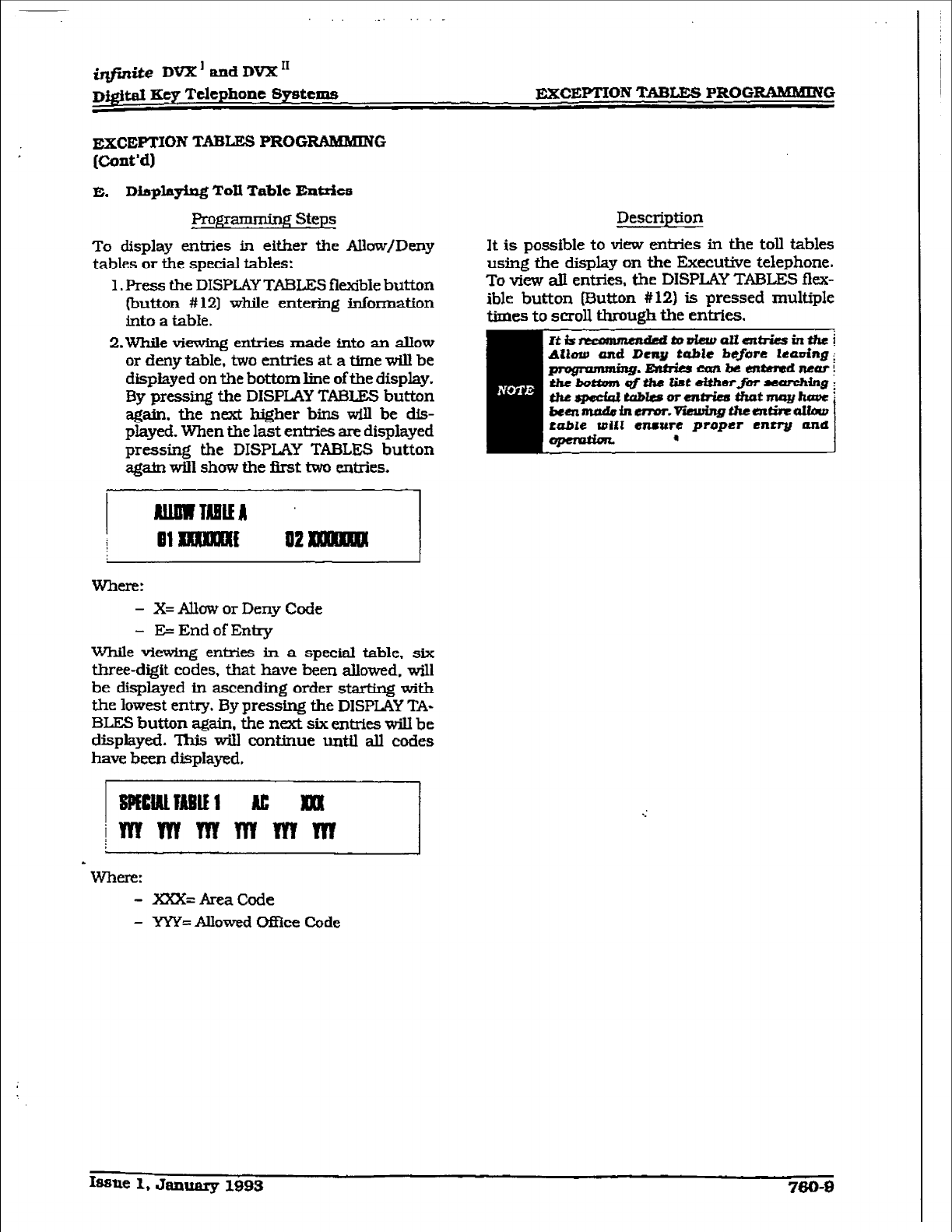
_
iqfmite DVX’ and DVX’
D&id Key Telephone Systems EXCEPTION TABtEs PROGRAMMING
EXCEPTION TABLES PROGRAAlMlNG
[Cont’dl
E. Displfqing Toll Table Entries
Programming Steps
To display entries in either the Allow/Deny
tables or the special tables:
1. Press the DISPLAY TABLES flexible button
button #12) while entering inform&ion
into a table.
2.WhiIe viewing entries made into an allow
or deny table, two entries at a time will be
displayed on the bottom line of the display.
By pressing the DISPLAY TX&ES button
again. the next Mgher bins will be dis-
played. When the last entries are displayed
pressing the DISPLAY TABLES button
agatn will show the fh-st two entries.
mere:
- X= Allow or Deny Code
- E= End of Entry
While viewing entries in a special table. six
three-digit codes, that have been allowed. will
be displayed in ascending order starting with
the lowest entry. By pressing the DISPLAY TA-
BLES button @in, the next six entries will be
displayed. This will continue until all codes
have been displayed.
- m=AreaCode
- YYY= Allowed 0ffice Code
Description
It is possible to view enties in the toll tables
using the display on the Executive telephone.
To view aTi entries, the DISPUXY TABLES flex-
ible button (Button #12) is pressed multiple
times to scroll through the entries.
Issue 1, January 1993
irlfinite DVXrandDVXn
mgital Key Telephone !3pttms LEAST COST RODTING &CR) ~OGRAIKMINE
SECTION 765
LEAST COST ROUTING (LCR) PROGRANLMlNG
785.1 INTRODUCTION
Least Cost Routing &CR) selects the most eco-
nomical programmed route for an outgoing calI.
when a station user dials an outside number,
the LCR feature analyzes the number and then
automatical@ chooses an outside line from the
group that has been programmed as most eco-
nomical. The LCR feature puts the responsibil-
ity
of choosing the least expensive route for
each area code and exchange code on the sys-
tem administrator, not on the station user. In
order to make a routing de&ion, the K!R fea-
ture is programmed in the system database.
The successful operation of this feature 3s com-
pletely dependent on the accuraq of the pro-
gramming.
There are eight different tables which are set up
to monitor the dialing of digits and to select the
best route for the call depending on time of day
and day of week.
‘These tables are:
l
3-Digit Area/Office Code Routing Table
* &Digit Office Code Routing Table
l
Exception Table
l
Route L&t Table
. Insert/Delete Table
l
DaiIy Start Time Table
l
Weekday (Weekly) Schedule
l
Toll Information Table
A. LcRopel-atioll
The system first checks to see if the number
dialed is more than two digits. If it is two digits
or less, the call is processed according to in-
structions in the Exception Table. If the num-
ber is not found in the Exception Table, the call
is denied.
If the number is more than two digits, it goes to
the 3-Digit Table. If the first digit dialed is a * 1”
the leading 1 table will be checked with the
following three digits. If the first digit dialed is
not a ” 1”. then the i?r-st th&e digits are checked
against the Non-Leading 1 3-Digit table. The
lirst three dtgits (either oRice code or area code)
are then checked to see if’ they are in the 3-Digit
Table. If they are not found there. the calI is
denied. If the digits are found in the 3-Digit
Table, the system then checks for an entry to
see if the S-Digit Table must be refenced.
If the 6-Digit column is marked Lyes] inthe three
digit table entry, the number is then checked in
the 6-Digit
Table.
There are 20 6-Digit tables, Each S-Digit table
is programmed and becomes associated to a
specific area code with a selected route. Office
codes are entered into the S-Digit table that wiIl
be routed to a specific route list table. This
allows the system administiator to split area
codes for rou- to different lines connected to
the system. This helps when Foreign Exchange
lfnes (F?I Lines). Banded WATS lines. or ‘Dcdi-
cated” Lines (OPXs fro.m another system) are in
use.
If the office code is not found in the 6-Digit
Table, the call is referred back to the 3-D&$
Table for selecting a route list table. And then
goes through the same procedures as described
below.
Before actually selecting a route list table, the
number is checked against the toll resixiction
tables (station COS). When LCRis enabled, only
station Class of Service is referenced. CO line
Class of Senice is no longer applicable. AU CO
lines are considered Class of Service 1.
Ifthe call is not allowed through the toll restric-
tion tables, the calI is denied. Ifit is allowed. the
caIl then goes to the Route List Table as speci-
fied by either the 3-Digit or 6-Digit table.
The Time of day and Day of week is determined
and the call is presented to the corresponding
&finite DVX1andDVXn
ml” COST ROUTING &CR) PROGRAMMING
Di@td lCey Telephone
Systems
me period route within the specified route
table. ~ch of the 16 Route Tables contain four
me sensitive routes. Routes are determined by
the me of day and day of week as specified in
the Daily Start T3me table and the Weekly
Schedule table.
After the appropriate route is selected, LCR
Class
of Service becomes applicable. A station
can use only those line groups programmed
with a priority number equal to or higher than
the station’s ICR Class of Service.
If a line is not available in the first choice line
group, the system advances to the next choice
line group and search= for a free line. This
process continues until an available he is
found, or the last available line group is
searched ,or unti a line group is reached with
a priority assignment lower than the station’s
LCR Class of Senrice assfgnment.
When a line
is
avaJlable the system will se&
that line and wait for dial tone. Then before
dialing. the system checks the Insert/Delete
table for digits that should be deleted from the
fkont of the number or digits that should be
inserted either before or after the number dt-
aled. Fjnahy the system begins to dial the num-
ber out over the selected line. All of this
analyzing and manipulation of the number
takes only a fraction of a second from the time
the station user begins to dial until the number
is dialed out over the public network lines.
If no lines are available in any of the CO line
groups programmed for that route and allowed
to that station, the cali can be automatically
queued on to the first choice (least mstly) line
group. If the user waits three seconds after
dialing the number, theywfll hear mAinnation
tone which m&c&es that an automatic LCR
Queue Callback has been actfwated on the first
choice line group. When a CO line becomes
available in the fkst choice line group the sys-
tem will ring the calling station. When an-
swered by the station the system will
automatically sefie the line and redial the num-
ber.
.
765-2 tsuc 1, Jrum3ly 1995
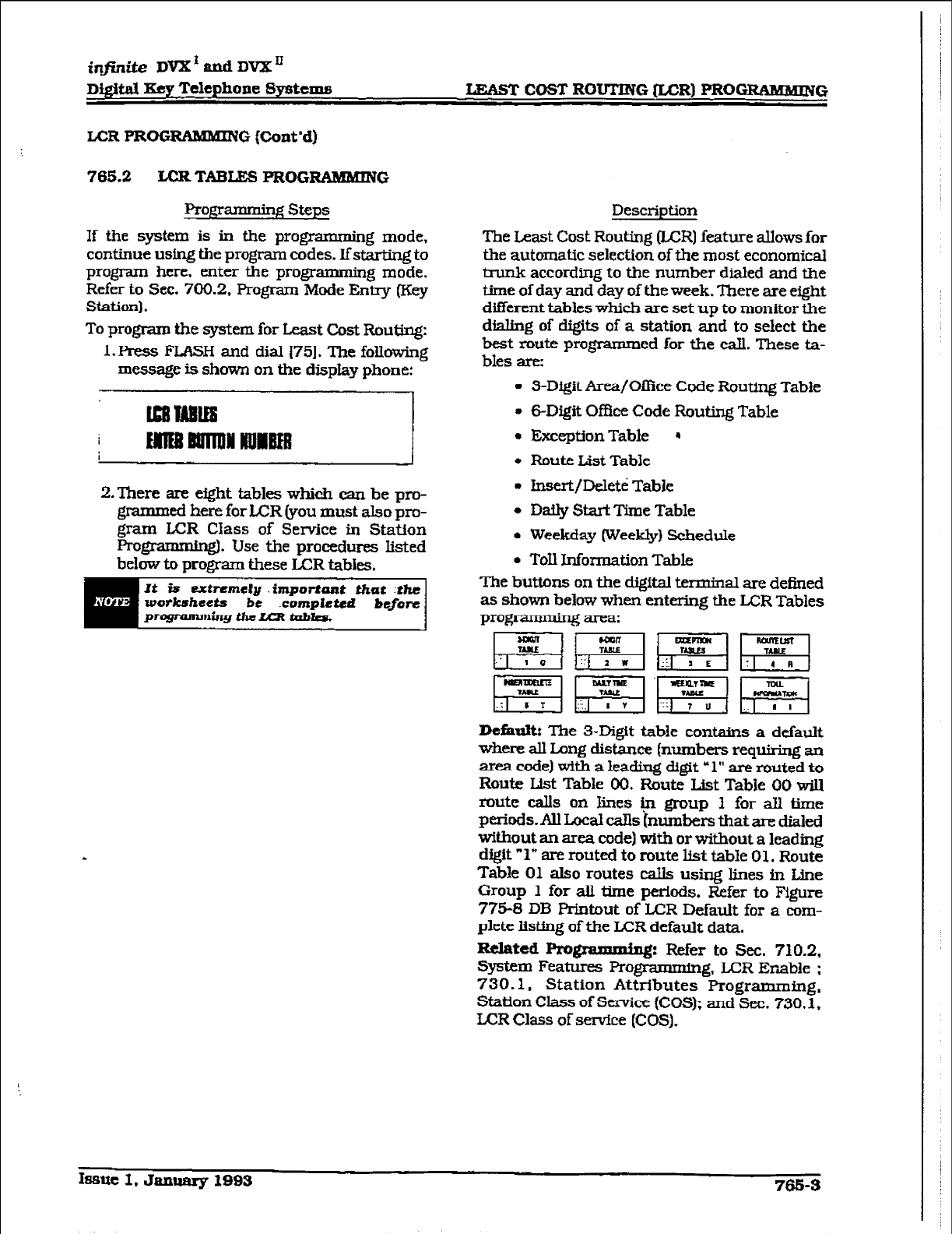
iqjinite
DVX’andDVXn
Digital
Kq Telephone Systems IzLAsT COST ROUTING &CR) PROG~QIMMING
LCR PROGRAMMING (Cont’d)
765.2
LCRTABLE% PROGRAMMING
PfDgr
steps a.rmag
If the system is in the programming mode,
continue using the program codes. Ifstarting to
program here, enter the programming mode.
Refer to Sec. 700.2. Program
Mode
Entry (Key
Station).
To program the system for Least Cost Routing:
1. Press FLASH and dial [75]. The following
message is shown on the display phone:
2.There
are efght tables which can be pro-
grammed here for LCR (you must also pm-
gram L+CR Class of Service in Station
ProgrammingI. Use the procedures Listed
below to program these LCR tables.
It Es
extnmely
.importPnt Urat :the
wirrorkshsetb
be .compXcted b4for-e
pTQfpllM~ihULCRtUbkil.
Description
The Least Cost Routing &CR] feature allows for
the automatic selection of the most economical
trunk according to the number dialed and the
time of day and day of the week. There are eight
different tables which are set up to monitor the
dialing of c&its of a station and to select the
best route programmed for the call. These ta-
bles are:
3-Digit Area/Ofbce Code Routing Table
6-Digit Of&x Code Routing Table
Exception Table *
Route List Table
lnsert/Deleti Table
Daily Start Time Table
Weekday [Weekly) Schedule
Toll Information Table
The buttons on the digital terminal are defined
as shown below when entering the
LCR
Tables
pro- area:
Default: The 3-Digit table conkins a default
where all Long distance (numbers requiring an
area code) with a leading digit ‘1” are muted to
Route List Table 00. Route List Table 00 will
mute calls on lines in group 1 for ah time
periods. AU Local Cans ~numbers that are dialed
without an area code) with or without a leading
digit ” 1” are muted to route hst table 01. Route
Table 01 also routes calls using lines in Line
Group 1 for all time periods. Refer to Figure
775-8 DB Prlntout of ICR Default for a com-
plete listing of the ICR default data.
Related Programm+lg: Refer to Sec. 710.2.
System Features l?ro@mg, LCR Enable :
730.1, Station AttrIbutes Programming.
Station Class of Service {COS); and Sec. 730.1,
LCR Class of service &OS).
Issue I. Jan- 1993
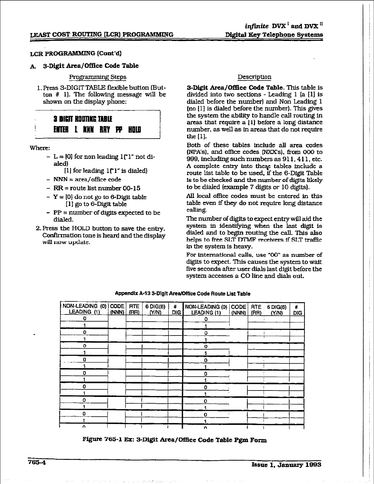
LEAST COST ROUTING &CR) PROGRAWHING
,
iqjinite DVX’ apd DVX I1
Digital Eey Telephone Syetwpe
LCRPROG- G (Cont’d)
A. s-Digit Area/Of&t Code
Table
gpimmhg Steps
1. Press 3-DIGIT TABLE flexible button (But-
ton # 11. The following message will be
shown on the display phone:
- L = 101 for non leading 1 [,l” not di-
aled)
I11 for leading l(“1” is dided)
- NNN = area/office code
- RR-routelistnumberU0-15
- Y = [O) do not
go
to 6-Digit table
[ 11 go
to 6-Digit table
- PP = number of digits expected to be
dialed.
2. Press the HOLD button to save the entry.
Confirmation tone is heard and the display
will
now
update.
Description
s-D&it Area/Of&e Code Table. This table
is
divided into two sections - Leading 1 (a [l] is
dialed before the number) and Non hading 1
(no [l] is dialed before the number). This gives
the system the ability to handle call routing in
areas that require a 111 before a long distance
number, as well as in areas that do not require
the [I].
30th of these tables include all area codes
INpA’s), and oflice
codes (NXXs), 6;-om 000
to
999, including such numbers as 911.4 11, etc.
A complete entry into thqe tables include a
route
List table
to be
used,
if the s-D&it
Table
is to be checked and the number of digits likely
to be
dialed
(example 7 digits
or 10 digits).
AII local oflice codes must be entered in this
table even flthey do not require long distance
calling.
The number of digits to expect entrywill aid the
system in identifying when the last digit is
dialed and to begIn routfng the call. This also
helps to free SLT IXMF receivers if
SLT
traf3c
in the system is heavy.
For international calls, use YW as number of
digits to expect. This causes the. system to wait
five seconds after user dials last digit before the
system accesses a CO line and dials out.
Appendfx A-13 3-Dlglt ArealOttice Code Route List Table
NON-LEADING (0) CODE RTE 6 DIG(6) # #I
LEADING (I) {NNN) (RR) (Y/N) DIG NON-LEADING (0) 1 CODE RTE 6 DICi(6)
LEADING (1) ! (NW) (RR) W/N) DIG
0 0 I
,
1 1
* 0 0
1 I 1 I
0 I 0
1 1 I I
0
1 I I 0 I
1 I
0 t 0 1
1 1
-m--m
0 0 : I
1 1 I
1 I
0 1
0 I
8 1 1 I I
0
1 f 0 I I
i l- t
n I I 1 n 1 I I
Fi@ve 765-l Ex: SD&it Arca/OfEcc Code Table Pgm Farxn
7654
h8ue
1, January 1993
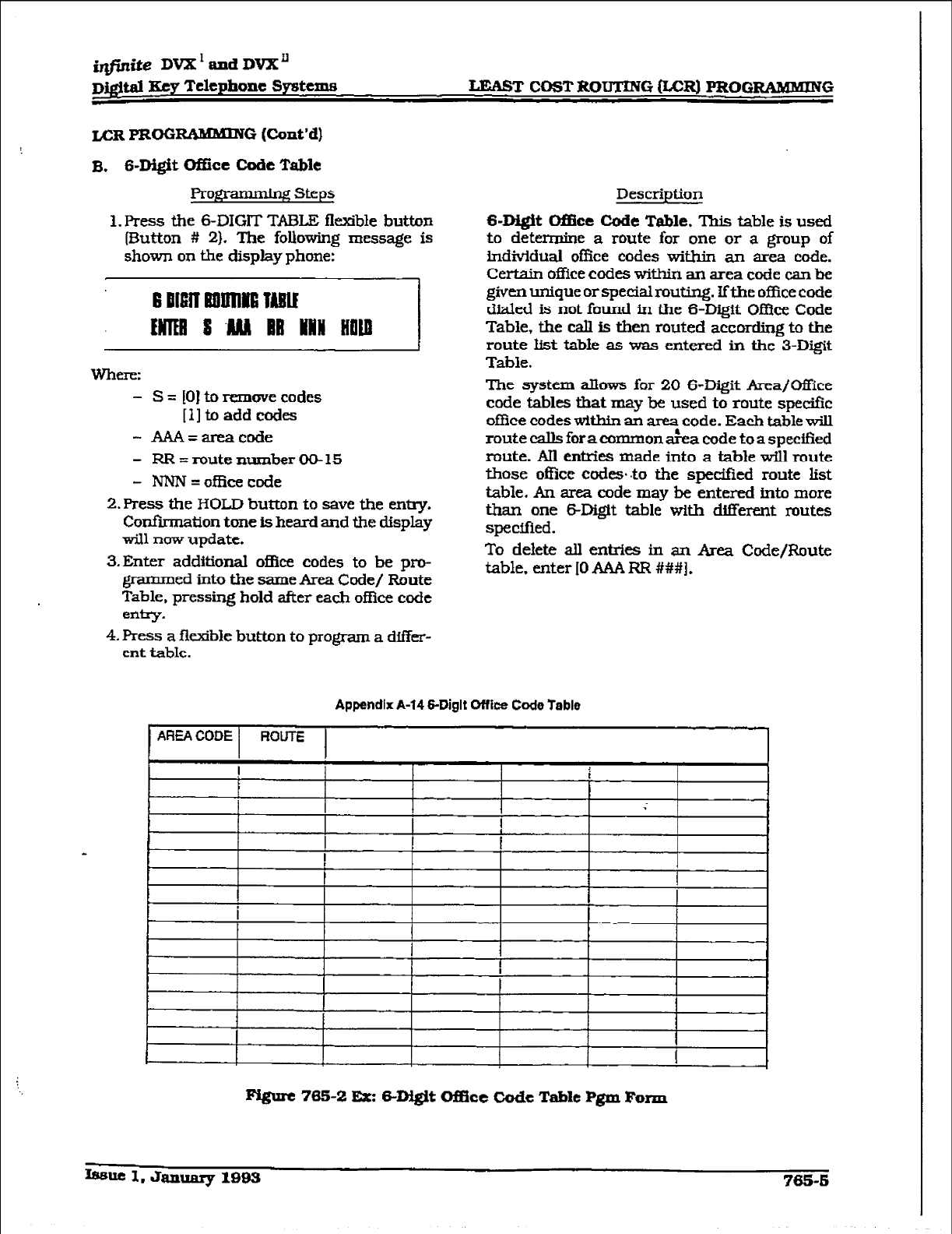
i@ite DVX’ and DV?L’l
Dj@tal Key Telephone systems LE.+ST COST ROUTING &CR) PROGRAMBEING
1. Press the 6-DIGIT TABLE flexible button
(F5utton # 21. The following message is
shown on the display phone:
Whm:
- S = 101 to remwe codes
[lltoaddcodes
- Akw=areacode
- RR=routenumberCMJ-15
- NNN=officecode
2. IVess the HOLD button to save the entry.
Confirmation tone is heard and the display
will now update.
3.Enter additional of&e codes to be pro-
grammed into the same Area Code/ Route
Table, pressing hold after each of&x code
erhy.
4.
Press a flexible button to program a differ-
ent table.
Description
S-Digit Ofike Code Table. This table is used
to determine a route for one or a group of
individual office codes within an area code.
Certain office codes
within an area code can
be
given unique or special routing. Ifthe office code
dialed is not found in the 6-Digit Office Code
Table, the caII is then routed according to the
route list tabIe as was entered in the 3-Digit
Table.
The system aBows for 20 6-Digit Area/Office
code tables that may be used to route speciik
office codes within an area code. Each table will
route calls foracommon a&a code to a specified
route. AII entries made into a table wiU route
those offke ccsdes~ to the sped&d route list
table. An area code may be entered into more
than one MXgit table with Merent routes
specified.
To delete all entrks in an Area Code/Route
table. enter IO AAA RR ###I.
Appendfx A-14 6-Diglt Office Code Table
Fi@rt 765-2
Ex: B-D&it Oiflce Code Table Pgm R.wzn
Issue I. January 1993 785-b
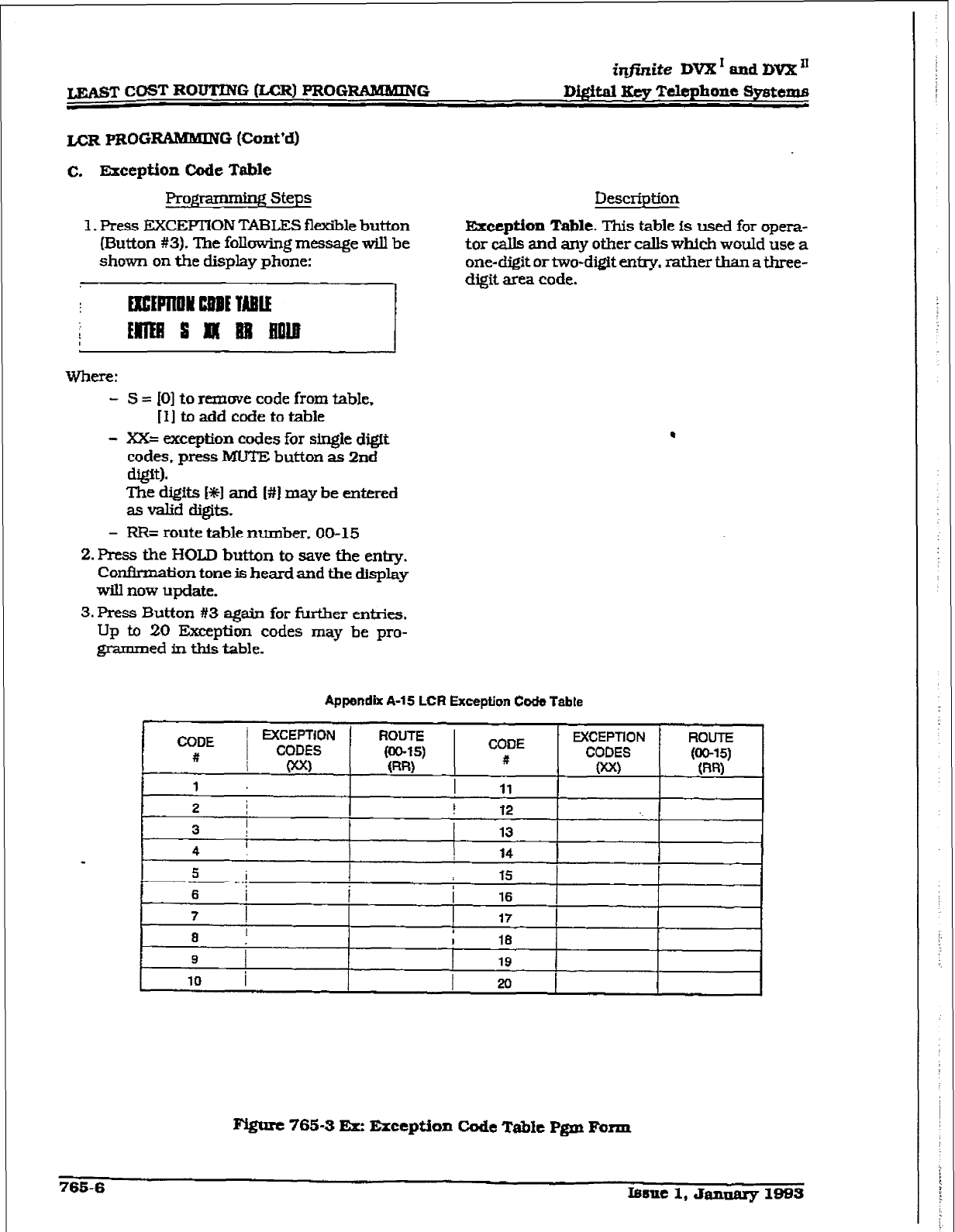
@finite DVX I and DVX ’
LEAST COST ROUTING &CR) PROGRANMING
D&ital Key Telephone Systems
L-CR PROG FtAMMlNG (Cont’d)
c. exception Code
Table
Prog;ramminR steps
1. Press EXCiFlION TABLES flexible button
(Button #3). The following message will be
shown on the display phone:
Where:
- S = IO] to remove code from table,
[I] to add code to table
- XX= exception codes for single
d@.tt
codes,
press MUTE button as 2nd
digit).
The digits [+E] and I#] may be entered
as valid digits.
- RR= route table number. 00-15
2. Fkss the HOLD button to save the entry.
Confirmation tone is heard and the display
will now update.
3.
FIXSS Button #3 again for further entries.
Up to 20 Exeption codes may be pro-
grammed in this table.
Descriution
Exccptiw Table. This table is used
for opera-
tor calls and any other calls which would
use
a
one-digit car
two-digit enfry.
rather than a three-
digit area code.
.
Appendix A-15 LCR
Exception Cock
Table
Pygare 765-3 EXE Exception Code Table Pgm Farm
765-6 I6sue 1, Jannarg 1983
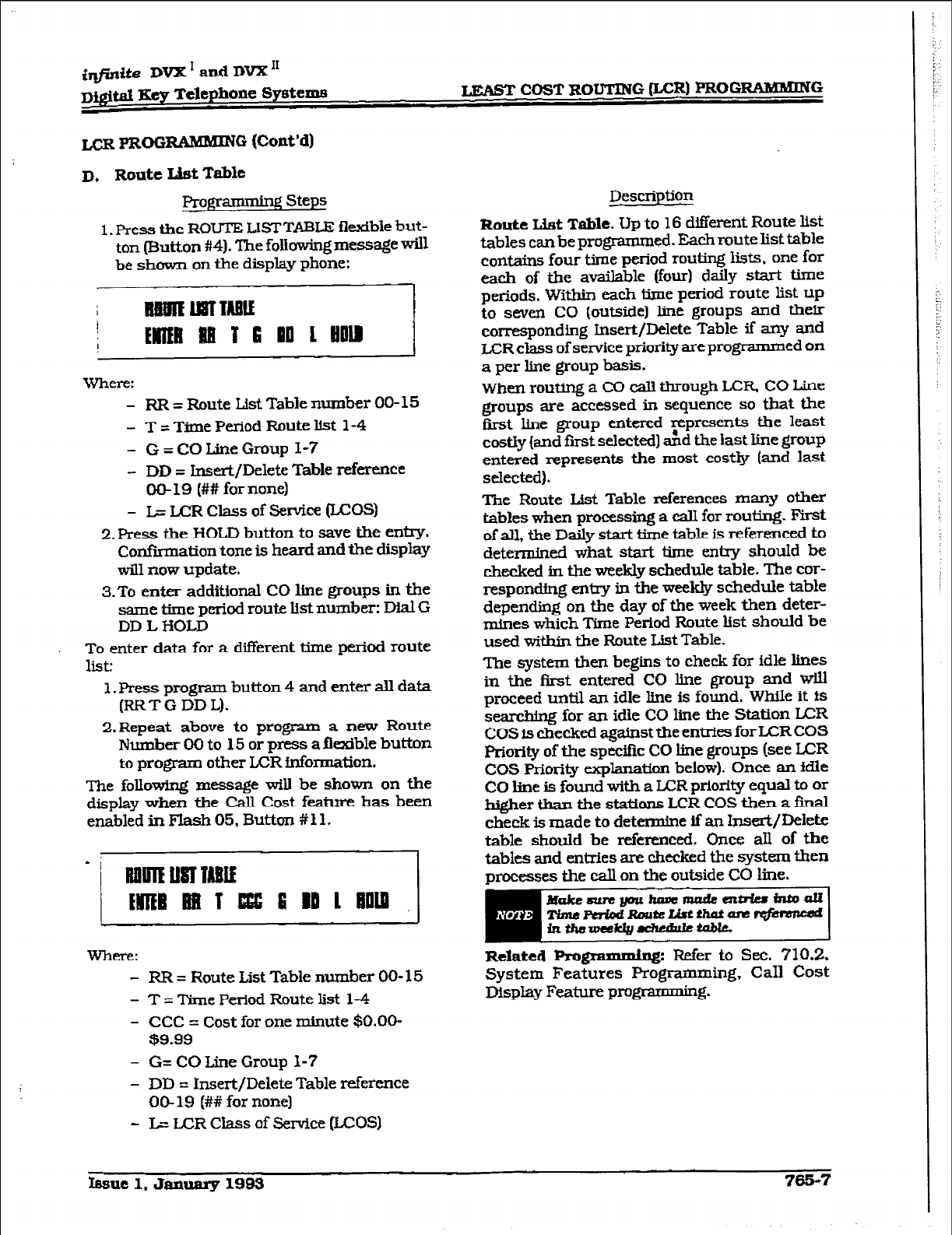
irVfinite DVX ’ and DVX ‘I
Digital Key Telephone Spsteme LEAGT COST ROUTING &CR) PRCIGRAMlywG
LCRPROG
FunWING (Co&d)
D, Route List Table
1. Press the ROUTE LISTTABLE flexible but-
ton (Button #4). The following message will
be shown on the display phone:
Where:
- RR = Route List Table number 00-15
- T = Time Period Route list l-4
- G = CO Line Group l-7
- DD = Insert/Delete Table reference
00-19 (## for none)
- L= LCR Class of service (LCOS)
2.Press the HOLD button to save the entry.
Confkmation tone is heard and the display
will now update.
3.To enter additional CO line groups in the
same time period route kt number: Dial G
DD L HOLD
To enter data for a different time period route
list:
1. Press program button 4 and enter alI data
(RRTGDDL).
2.Repeat above to program a new Route
Number 00 to 15 or press a flexible button
to program other ICR fnfonnation.
The following message will be shown on the
display when the Call Cost feature has been
enabled in Flash 05. Button #Il.
where:
- RR = Route List Table number 00- 15
- T = Time Period Route list l-4
- CCC = Cost for one minute $O.OO-
$9.99
- G= CO Line Group 1-7
- DD = Insert/Delete Table reference
00-19 (## for none)
- L= LCR Class of Service (LCOS)
Description
Route List Table. Up to 16 different Route kt
tables can be programmed. Each route list table
contains four time period routing lists. one for
each of the available (four) daily start time
periods. Within eaoh time period route list up
to seven CO (outside] line groups and their
corresponding Insert/Delete Table if any and
LCR class of setice priority are programmed on
a per line group basis.
When routirrg a CO caIl through LCR CO Line
groups are accessed in sequence so that the
first line group entered Fpresents the least
costly (and fust selected) and the last line group
entered represents the most costly (and
last
selected).
The Route List Table references many other
tables when processing a call for routing.
First
of all, the Daily start time table is referenced to
determined what start time entry shouId be
checked in the weekly schedule table. The cor-
responding entxy in the weekly schedule table
depending on the day of the week then deter-
mines which Time Period Route list should be
used within the Route List Table.
The system then begins to check for idle lines
in the first entered CO hne group and will
proceed until an idle line is found. While it is
searcbhg for an idle CO line the Station LCR
COS fs checked against the entries for ICR COS
Priority of the specific CO line groups (see LCR
COS Priority explanation below). Once an idIe
CO liue is found with a LCR priority equal to or
higher than the stations I.JCR COS then a fti
cheek is made to determine if an Insert/Deiete
table should be referenced. Once all
of the
tables and entries are oheeked the system then
processes the eaIl on the outside CO line.
Related Pr~grammLng: Refer
to Sec. 710.2,
System Features Programming, Call Cost
Display Feature prog * 6.
h3sue 1. January 1993 765-7
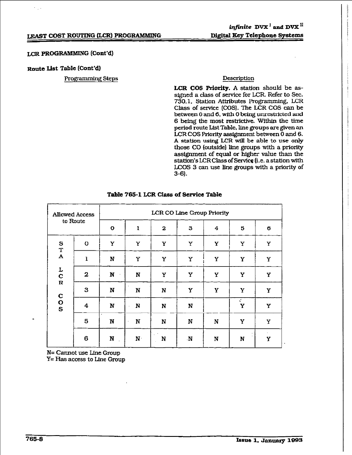
iq.f;nite DVX’ and DVX”
w COST ROUTING &CR) PROGIXAMMRVG
D&itaI Key Telephone Systems
LCRPROG
RAMMING (Cont’d)
Route lht Table (Cont’d)
Pro- steps Description
LCR CO5 Pdority. A station should be as-
signed a class of service for LCR. Refer to Sec.
730.1. Station Attributes Programming. LCR
Class of service (COSI. The LCR COS can be
between 0 and 6. with 0 being unrestricted and
6
being the most restrictive. Within the time
period route List
Table, line groups are given an
LCR COS Priority assfgnment
between 0 and 6,
A
station using LCR witt be able to use only
those CO (outsfde) line groups with a priority
assignment of equal or higher value than the
station’s LCR Class of Servkg (i.e. a station wfth
U=OS 3 can use line groups with a
priority of
3-6).
Table 765-l L.CR Clam of Send&e Table
I
Allowed Access I LX3R CO Line Group Priority
to Route
0 1 2 3 4 5 6
S I
T O[Y Y Y Y Y!Y Y
A 1 N Y Y Y i Y 1 Y 1 Y
I.4
c
R
c
0
S
2 N. N Y Y Y Y Y
3 N -N’N Y Y Y Y
4 N N N N ‘Y Y
5 N N N N N Y Y
6 N N. . . N .N N NY Y
N= Cannot use Line Group
Y= l3as access
to tie
Group
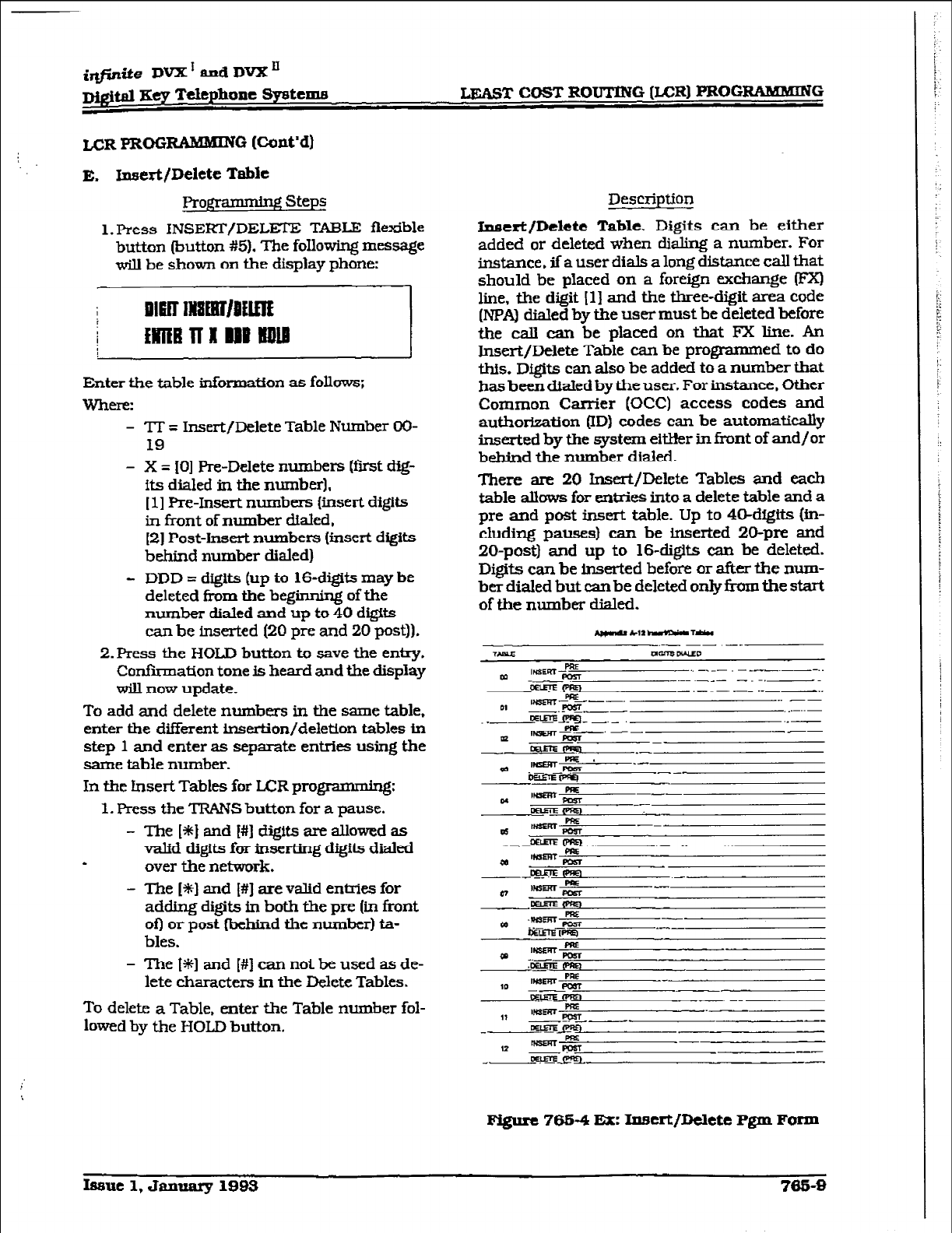
i@i.te DVX’andDVX’
~@tal Key T&phone Systtnm LEAST COST ROUTING (LCR) PROGRAMMING
LCR PRffi RAMMING (Co&d)
E. Insert/Delete Table
programmbg Steps
l.Press INSERT/DELm TABLE flexible
button (button #5). The following message
will be shown on the display phone:
Enter the table information as follows;
Whel-f?:
- ‘IT = Insert/Delete Table Number OO-
19
- X = (01 Pm-Delete numbers (fir;st dig-
its
dialed in the number).
[l] Pre-Insert numbers [insert digits
in front of number dialed,
(21 Post-Insert numbers [insert digits
behind number dialed)
- DDD = d@t.s (up to l&digits may be
deleted fi-om the beginning of the
number dialed and up to 40 digits
can be inserted [ZO pre and 20 post)].
P.Press the HOLD button to save the entry.
Confirmation tone is heard and the display
will now update.
To add and delete numbers in the same table,
enter the different i.nsertion/deletlon tables in
step 1 and enter as separate entries using the
same table number.
In the Insert Tables for LCR programming:
1. Press the TRANS button for a pause.
- The [+k] and [#I digits are allowed as
valid digits for inserting di@.s dialed
e over the network.
- The [S] and [#] are valid entries for
adding digits in both the pre (in front
of) or post (bebind the number) ta-
bles.
- The la] and [#] can not be used as de-
lete characters in the Delete Tables.
To delete a Table, enter the Table number fol-
lowed by the WOLD button.
Descriotion
l.mcrt/Delctc Table. Digits can be either
added or deleted when dialing a number. For
instance, if a user dials a long distance call that
should be placed on a foreign exchange 0?Xl
line, the digit (11 and the three-digit area code
(NPAl dialed by the user must be deleted before
the call can be placed on that FX line. An
Insert/Delete Table can be programmed to do
this. Dfgits can also be added to a number that
has beendialed by the user. For instance. Other
Common Carrier (CCC) access codes and
authorization (ID) codes can be automatically
inserted by the system eftHer in front of and/or
behind the number dialed.
There are 20 Insert/Delete Tables and each
table allows for entries into a delete table and a
pre and post insert table. Up to 4cFdigtts (in-
cluding pauses) can be inserted 20-pre and
20-post) and up to 16-digits can be deleted.
Digits can be inserted before or after the num-
ber dialed but can be deleted only fi-om the start
of the number dialed.
Figure 765-4 Ex: In5crt/r.klete Pgm Form
Issue 1, Jmuary 1993 7659
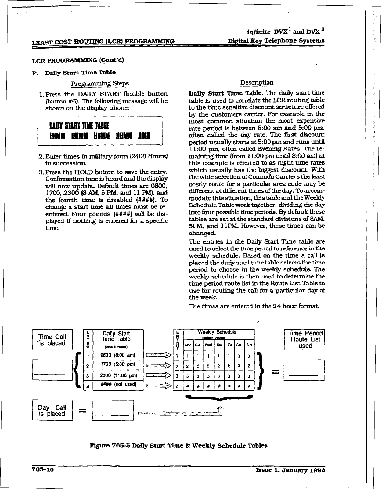
L-CR==
Rt3MMING (@nt’d)
F. ~afly Start Thnc Tabk
Proj+-mmdng Steps
1. press the DAILY E3XFS flexible button
(button #6). The following message wifI be
shown on the display phone:
2. Enter times in military form (2400 Bours)
in succe8sioIL
3.FVess the HOLD button to save the entry.
Confirmation tone is heard and the display
wiil now update. Default times are 0800.
~700,2300(8AM,5PM,and11pM),and
the fourth time is disabled [#I###). To
change a start time all times must be re-
entered. Four Pounds [####I will be dis-
played if nothing is entered for a specific
time.
Description
Daily Stark Time Table. The daily starttime
table is used to correlate the LAX routing table
to the time sensitive discount stnxzture offered
by the customers carrier. For exxnple in the
most common situation the most expensive
rate period is between 8:00 am and 5:00 pm.
often called the day rate. The !Irst discount
period usually starts at 5:00 pm and runs until
1l:OO pm. often called Evening Rates. The re-
maining time (from 11:OO pm until 8:00 am) in
this example is referred to as night time rates
which usually has the biggest discount. With
the wide selection of Commoh Carriers the least
costly route for a particular area code may be
different at different times of the day. To accom-
modate this situation. this table and the Weekly
Schedule Table work together, dividing the day
into four possible time periods. By default these
tables are set at the standard divisions of 8AM.
5PM. and 11PM. However. these times can be
changed.
The enties in the Daily Start Time table are
used to select the time period to reference. in the
weekly schedule. Based on the time a calI is
placed the da@ start time table selects the’ time
period to choose in the weekly schedule. The
weekly schedule is then used to determine the
time period route list in the Route List Table to
use for routing the call for a particular day of
the week.
The times are entered in the 24 hour format.
Fi@rc 765-S Daily Start Time & We&ly Schedule Tables
765-10 Iesue 1, January 1993
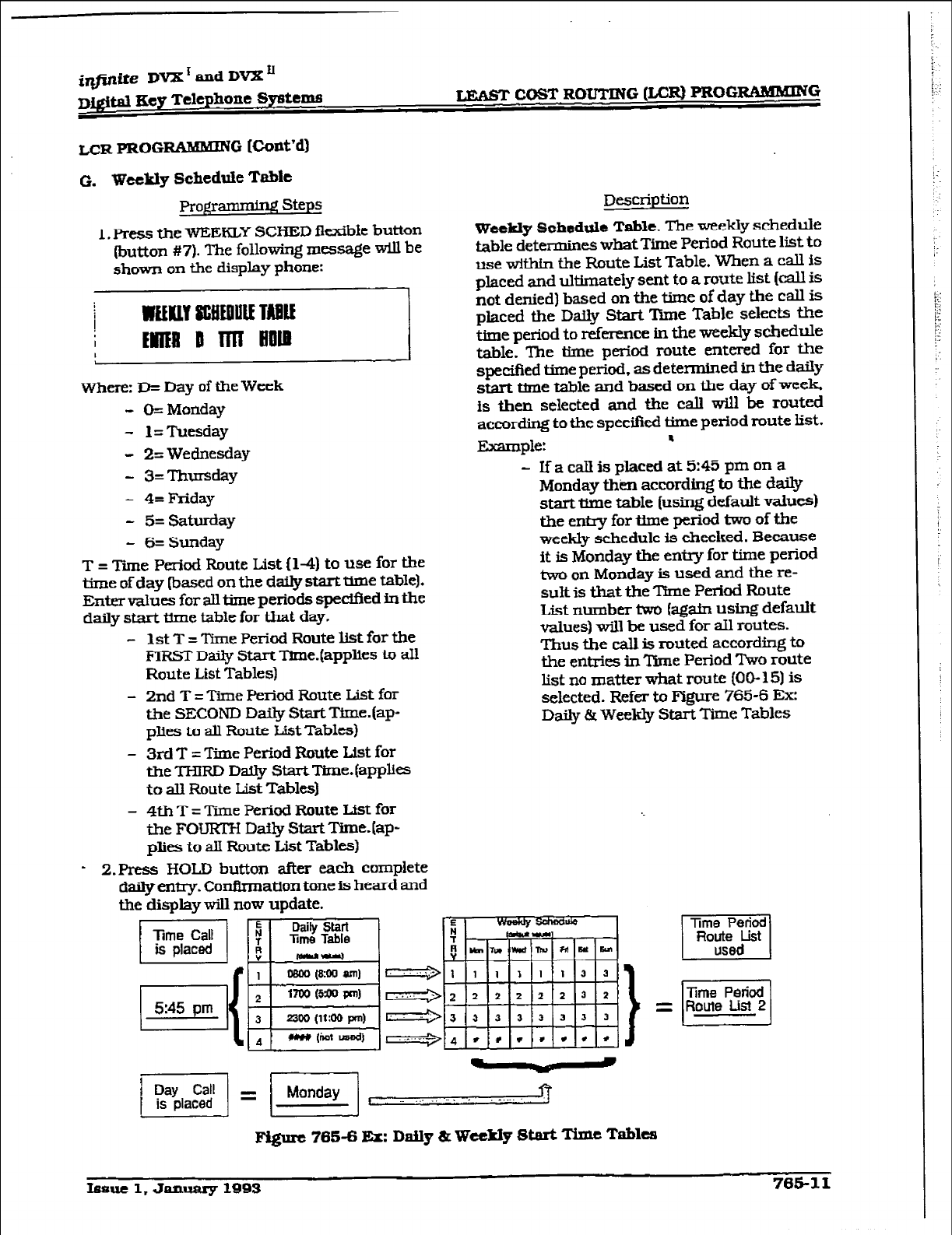
LEdST COST ROUTING (LCR) PROGRAMM]iNG
LCR PROG RAMMlNG (Cont’d)
G. Weekly Schedule T&e
Pro@anunirX Step5
1. Press the WEEKLY SCHED flexible button
(button #7). The following message will be
shown on the display phone:
where: 33~ Day of the Week
- Ck Monday
- 1= Tuesday
- 2= Wednesday
- 3=Thursday
- 4= Friday
- 5= Saturday
- 6= Sunday
T = Time Period Route List (l-4) to use for the
time of day (based on the daily start time table].
Enter values for all time periods spedfied in the
daily start time table for that day.
- 1 st T = Time Period Route list for tbe
FIRST Daily Start TSme.(applies to all
Route List Tables)
- 2nd T = Time Period Route List for
the SECOND Daily Start Time.(ap-
plies to all Route Ust Tables)
- 3rd T = Time Period Route Ust for
the THIRD Daily Start Time.(apphes
to all Route List Tables)
- 4th T = Time Period Route List for
the FOURT?-l Daily Start lBne.(ap-
plies to alI Route List Tab164
- 2.Press HOLD button after eacb complete
daily entry. Confirmation tone is heard and
tbe display will now update.
Description
Weekly Schedrtle Table. The weekly schedule
table determines whatTime Period Route list to
use witbin the Route List Table. When a call is
placed and ultimately sent to a route list (call is
not denied) based on the time of day the call is
placed the Daily Start ‘Dme Table selects the
time period to reference in the weekly schedule
table. The time period route entered for the
specified time period, as determined in the daiIy
start the table and based on the day of week
is then selected and the call will be routed
according to the spec%kd time period route fist.
Example: u
- If a call is placed at 5:45 pm on a
Monday then according to the daily
start time table (using default vaIues1
the entry for time period two of the
weekly schedule is checked. Because
it is Monday tbe entry for time period
two on Monday is used and the re-
sult is that the Time Period Route
List number two (agatn using default
values) will be used for all routes.
Thus the call is routed according to
the entries in Time Period Two route
list no matter what route (OCk 15) is
selected. Refer to FIgure 765-6 Ex:
Daily &Weekly Start Time Tables
Fi@rc 765-6 Er: DaUy 8~
Weekly Start Time
Tables
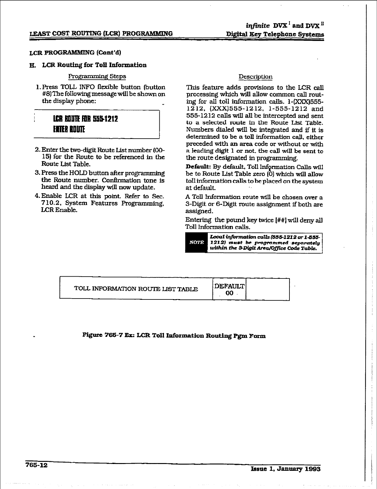
irifinite DVX’ aadDvX”
LEAST COST ROUTING &CR] PROGRAMMING D&ital Key Telephone Systems
LCR PROG RAlHMlNG (Cont’d)
FL LCR Routing for Toll Information
gmmning Steps
1. Press TOLL IWO fl&ble button (button
#8)ThefoIlo~messagewillbeshawnon
the display phone:
2.
Enter the two-digit Route List number (OO-
15) for the Route to be referenced in the
Route List Table.
3.
Press the HOLD button after programming
the Route number. Conknation tone is
heard and the display will now update.
4.Enable ICR at this point. Refer to Sec.
7 10.2, System Features Programming,
LCR Enable.
Description
This feature adds provisions to the LX!R call
processing which will allow common call rout-
ing for all toll information calls. 14XxX)555-
1212, (xXx)555-1212, 1-555-1212 and
555-1212 calls will all be intercepted and sent
to a selected route in the Route List Table.
Numbers dialed will be integx-ated and if it is
determIned to be a toll information call. either
preceded with an area code or without or with
a leadjng digit 1 or not. the call will be sent to
the route designated in programn&g,
Default: By default+ Tot1 lnfqmation Calls will
be to Route List TabIe zero (0) which will allow
toll information calls to be placed on the system
at default
A Toll Information route wfll be chosen over a
3-Digit or S-Digit route assignment if both are
assigned.
Entering the pound key twice [W) will deny all
Toll Information calls.
TOJLL
INFORMATION
ROUTE
LISTTABLE DEFAULT
.oo.
FQure 765-7
Er: LCR Toll Information Routing Pgm Form
765-12
nmle 1, Januaxy mB3

LEA2ST COST ROUTING WR1 PROGRAMMING
CCR PROGRAMKiN
0 [Co&d)
I. Dcfhult LCR Database
pr0g
’ g Steps
Description
In an effort to decrease installation and set up
time, usually associated with LCR, a default
LCR database has been incorporated. The de-
fault LCR database will provide basic routing
for local and long distance dialing. Default en-
tries have been made in the 3-Digit Table for
local offlce codes (lWXs1 and ail area codes
(NPA’s). Tko routes have been established with
the default database for rouling of all caUs
under default. The entire default database is
shoti in Figure 77543 DB Printout of LCR
Default.
The S-D&it tables con&& a default where all
Lm4gdistancebnd3ersrequiringanareacode)
with a leading digit ‘1” are routed to Route table
00. Route Table 00 will route calls on lines in
group Z for all time ptiods. All Local calls
[numbers that are dialed without an area code)
with or without a leading digit ” 1” are routed to
route list table 01. Route fist table 01 also
routes calls using lines in line group 1 for all
time periods.
Issue 1, January 1993 743s13
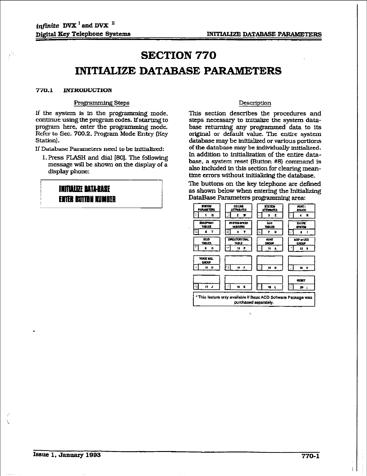
imite DVX I and DVX ’
D&ital Key Telephone Systems - DATABASE PARAMETERS
SECTION 770
INITULIZE DATABASE PARAMETERS
770.1
INTRODUCTI0N
ProgITmmhg steps
If
the system is in the programming mode,
continue usingthe program codes. Ifstarting to
program here, enter the prog - g mode.
Refer to Sec. 700.2. Program Mode Entry (Key
Station).
If Database Parameters need
to be initiafized:
1. Press FLASH and dial [80]. The following
message wU be shown on the display of a
display phone:
Description
This section describes the procedures and
steps necessary to initialize the system data-
base returning any programmed data to its
original or default value. The entire system
database may be initfalized or various portions
of the database may be individuaIly initialized.
In addition to initialization of the entire data-
base,
a system reset
(Button #8)
command is
alsO included in this section for clearing mean-
time errors without initializing the database.
The buttons on the key
telephone are
defined
as shown below when entering the initializing
DataEkse Parameters progmmming area:
p!Fq$!q~~.~
g?qEq~~
.
lfmlc 1, January 1993 770-l
i
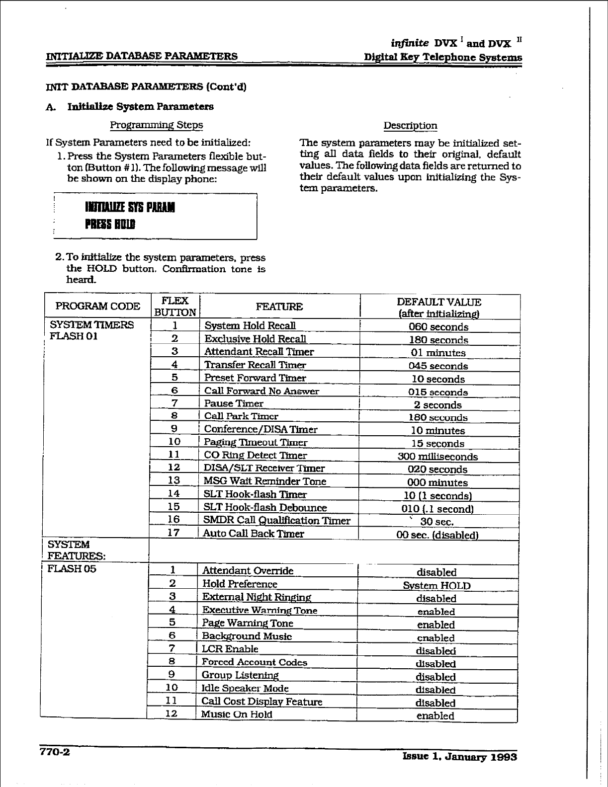
infinite DVX I and DVX I1
nqn%UZE DATABASE PARAMETERS D@IxI Key
Telephone Systems
JNIT DATAWISE PW IZS (Coat’d)
k Initialize System Parameters
Programming Steps
If System Parameters need to he initialized:
1. Press the System Parameters flexible but-
ton
(Button # 11. The
following message will
be shown on the display phone:
Description
The system parameters may be initialized set-
ting all data fields
to
their original. default
values. The following data fields are returned to
their default values upon initializing the Sys-
tem parameters.
2.To W the system
parameters, press
the HOLD button.
Cor&mation tone is
heard,
PROGRAM CODE BEN ’ FEATrum DEFAULTVALUE
(after illitializjn~
SYSTEMTIMEZS 1 System Hold Recall f 060 seconds
I FLASH01
2
I Exclusive Hold Recall 180 seconds
!
SYSTEM
14
SLT Hook-flash ‘I3mer 10 (1 seconds)
_ 15 SLT Hook-flash Debounce
010 (-1 second)
16 SMDR Call QuaUfIcation
Timer
i 3osec.
17
1 Auto Call Back Timer 00 sec. (disabled) I
7
I LCREnabie disabled
8
Forced Account Codes disabled
9 Group Listem disabled
10
Idle Speaker
Mode dimbled
I1 Call Cost Display Feature disabled
12
Music On Hold enabled
770-2 Issue 1. January 1993
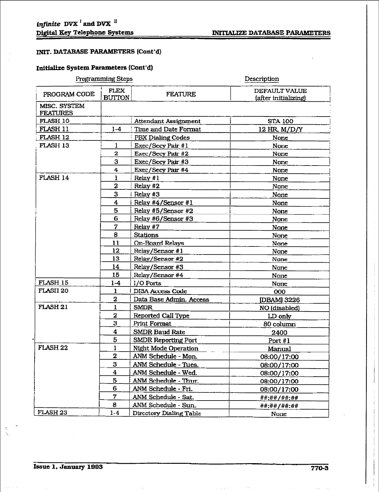
injidte DVX I and DVX ’
D@tal Hey Telephone By&ems INTMUZE DATADASE PAR4MJXER3
INIT. DATABASE PARAMETE RS Whnt’d)
Ini* syf3tcm P
armmeters (C-ont’d)
ProgK3mming steps Description
i PROGRAM CODE iBEN
1 MISC. SYSTEM
FEATURE DEFAULTVALUE
(after initim
i
FEATURES
iFLASH
/FLASH11
IlUSH
j Attendant Assignment I SIA 100 I
1-4 I Time and Date Format 12 HR M/D/Y
j PBX Dialing Codes None
FLASH 13
Issue 1, Jamry lSB3 770-S
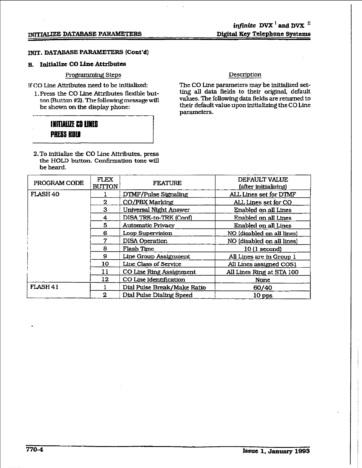
10 DATABASE PARMBEIERS
itIfinike
DVX1andDVXn
Dfgital Key Tckphone Systems
INIT. DATABASE P
ARABEZEFU
(Cont’d)
B. InitiaIizc co Line Attrihutcs
Pro- steps
If CO Line Attributes need to be initialized:
1. Press the CO Line Attributes flexible but-
ton (Button #2). The followingmessagewill
be shown on the display phone:
IllrruLm Ii0 MS f
PEEa tm
Description
The
CO
Lhe parameters may
be
initialized set-
ting all data fields to their original, default
values. The followlng data fields are returned to
their default value upon initializing the CO Line
parameters.
2.To initialize the CO Line Attributes, press
the HOLD button. Confirmation
tone will
be
heard.
PROGRAM CODE - FEATURE DEFAULT VALUE
BU’ITON
(after initializin@
FLASH 40 1 DlMF/PulseS@nalin~ ALL Lines set for DT?MF
2
CO/PF3X
Marking ALL Lhes set for CO
3 UnWersal Ni&t Answer Enabled on alI Lines
4 DK% TFX-to-m (ConfJ Enabled on a.U Lines
5 Automatic Privaq Enabled on all Lines
6 hop Supervision NO (disabled on all lines)
I
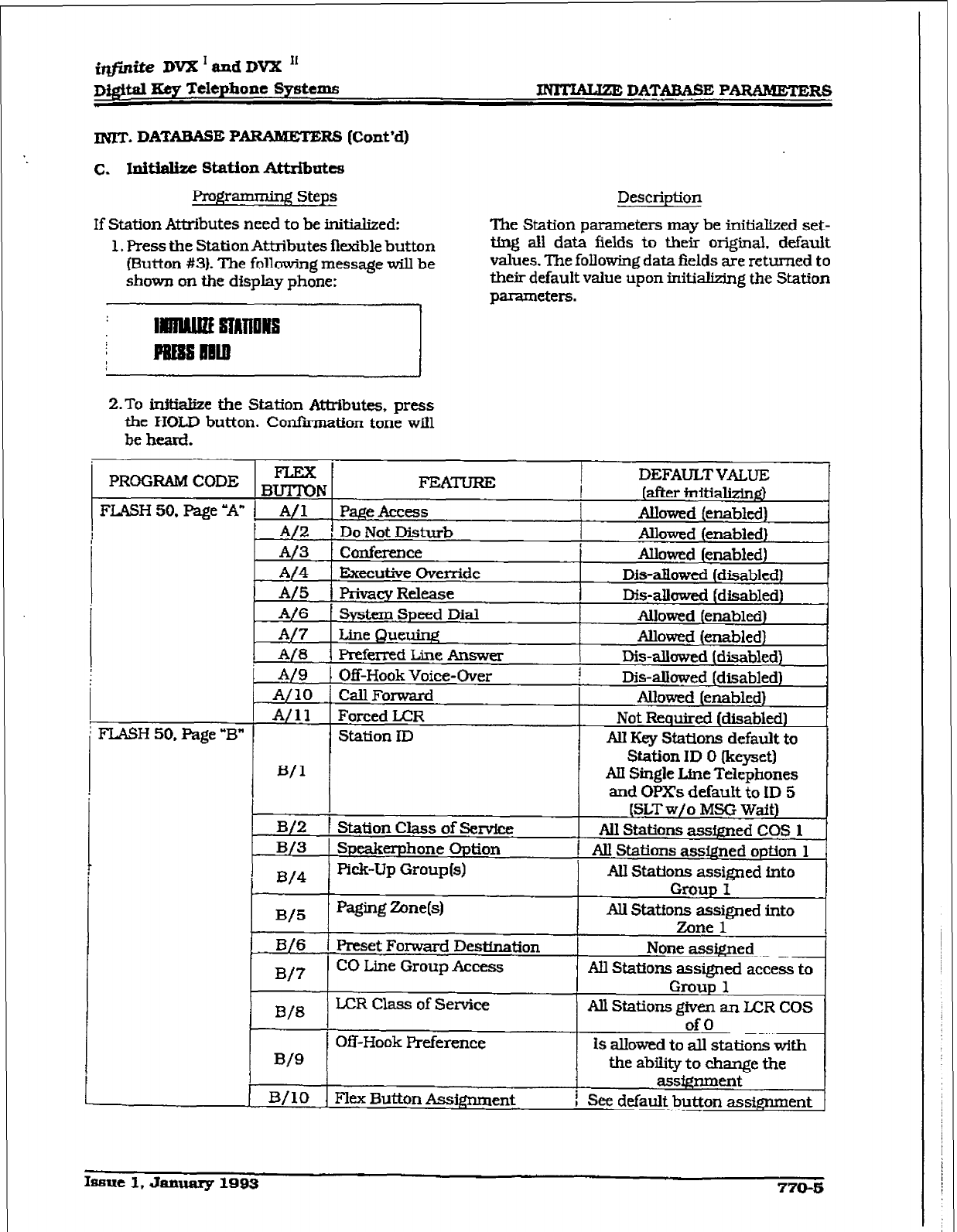
iqfkite DV2I I
md DVX ’
Dilofti Eey Telephone Systems - DATABASE PARAMETERS
INIT. DATAEASE
Pv RS (Co&d)
c. Iui- Station Attributes
Pro@rnming Steps
If Station Attributes need to be initialized:
1. Press the Station Attributes flexible button
(Button #3). The following message will be
shown on the display phone:
Description
The Station parameters may be initialized set-
ting all data fields to their origiial. default
values. The following data fields are returned to
their default value upon initializing the Station
2.To initialize the Station Attributes, press
the HOLD button. Confiition tone will
be heard.
I
i FLASH 50. Page “B”
BUTTON
A/l Page Access
A/Z , Do Not Disturb
A/3 ! Conference
A/4 Executive Override
A/5 privacy Release
A/6 System Speed Dial
A/? Line Queuing
A/8 Preferred Line Answer
A/9 Off-Hook Voice-Over
A/10 Call Forwaxd
A/11 Forced LCR
Station
ID
B/l
DEFAULTVALUE
I [after 3nitializIn~
Allowed (enabled)
Allowed (enabled)
Allowed [enabled)
D&-allowed (disabled)
Dis-allowed (disabled)
Allowed
(enabled)
Ahowed (enabled)
I&-allowed (disabled)
i Disallowed (disabled)
Allowed (enabled)
Not Required (disabled)
AU Key Stations default to
Station
ID 0
(keyset)
Au Single Line Telephones
and OPXs default to ID 5
B/2 1 Station Class of Service
B/3 Speakerphone Option
D/4 pick-up Group(s)
B/5 Paging Zone(s)
B/6 Preset Forward Desttnation
B/7 CO Line Group Access
B/8
LCR Class of Service
Off-Hook Preference
B/9
B/10 Flex Button Assignment
(SLT w/o MSG Wait)
All Stations assfgned COS 1
1 Au Stations assQned option 1
AU Stations assigned into
Group I
Au Stations assigned into
Zone 1
None assigned
All Stations assigned access to
Group 1
All Stations @ven an LCR COS
of0
Is allowed to all stations with
the ability to change the
ZiSS&IYIRCXlt
! See default button assignment
ISSUC 1, January 1B- 770-5
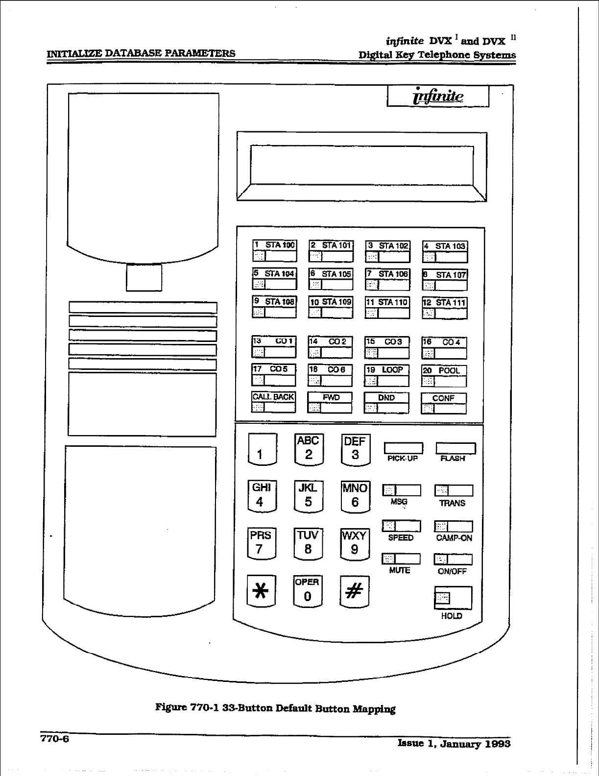
@finite DVX I and DVX I1
Figure 770-l
%-Button Default
Button Mapping
770-6 hnc1,Jantuuy1993
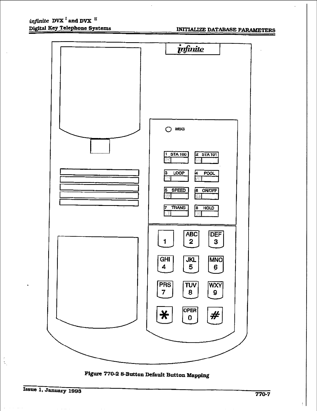
iq#intie DVX’andDVX’
Dlgftal Key Telephone Systems
u-
FQum 770-2 S-Button Default Button Mapping
Issue 1. Januaxy 1993 770-7
w DATAEASE P-RS
INIT. DATABASE PARAlldETE
F& (Cont’d]
D. Idtidize Station a.xLd co Port
~CiCl-S
h@Umdng steps
If Group Parameters need to be initialized:
1. Press the Staff on/CO Port Parameters flex-
fble button lsutton #a)-). The following mes-
sage will be shown on the display phone:
i@inite
DV2C’andDVX’
Di@a3 Xcy Telephone Systems
Description
Station and CO Port parameters may be initial-
ized setting all stations and all CO Lines back
to their original, default
values. The
folIowing
data fields are returned to their default values
2.To tnftialize the Station/CO Port parame-
ters, press the HOLD button. Clmikmation
tonewillbeheard.
770-a bsue
1, Jammy L-3
i@ite DVX’adDVX’
D&$td Key Telephone Systems - DATABASE PARAMETERS
MIT. DATABASE PARAHEWE Fe3 (Cont’d)
E. fnltiake Exception Tables
Proggammhg Steps
If Exception Tables need to be initialized:
1. Press the Exception Tables flexible button
(3utton #5). The following message will be
shown on the display phone:
i lrrrrmmnrMlEs
; lJ3immlm
Description
The Exception Table parameters including the
AIlow/Deny Tables and the Special Tables may
be initialtzed setting all tables to their original.
default values. The fokwing Tables are cleared
returning to their default value upon initializing
the Exception Tables pammeters:
2. To initiake the Exception Tables. press the
HOLD button. Confirmation tone will be
heard.
TABLE DEFAULTVALUE
(after ini-
ALLOWTABLE-A Table Cleared (no entries
DENY TABLE - A Table Cleared (no enties)
ALLOWTABLE-B Table Cleared (no entries)
DENYTiU3LE-B Table Cleared (no entries)
SPECIAL TABLE Table Cleared (no entries allowed,
1 I no area code specified)
SPECIAL TABLE Table Cleared (no entries aIlowed.
2 no area code speclfiedl
SPECIAL, TABLE Table Cleared [no entries aIlowed,
3
1 SPECIAL TABLE no area code specified)
4 Table Cleared (no entries allowed)
tImme area code).
Issue 1, January mQs 770-9
m DATABASE PARAMETERS
iq#inike DvX’andDVX’
Digital Key Telephone Systems
INIT. DATABASE P
ARAMETERS (Cont’d)
F. l.&i&zt System Spttd Numbers
Pragramming Steps
If System Speed bins need to be initialized:
l.FYtss the System Speed flexiile button
(Button #6). The following message will be
shown on the display phone:
Description
Numbers entered into the System Speed dial
Table may be initialized clearing all bins to their
orig-inal, default value [empty). All bins 20
through 99 are cleared returning to their de-
fault value (empty) upon initializing the Speed
Dial Table.
2.To initialize
the.System Speed bins, press
the HOLD button. Confirmation tone will
be heard.
@jWte DK&ndDVXn
Mgltal Ecy Telephone Systcme B DATABASE PARAlWHZRS
INIT. DATARASE P
ARAMETERS (Cont’d)
G. Illi- LcRTablcs
Prog- Steps
If LCR Tables need to be initiaked:
1, Press the LCR Tables flexible button [But-
ton #?I. The following message wiIl be
shown on the display phone:
2.To Mtialize the LCR Tables, press the
HOLD button. Confknation tone will be
heard.
Description
l%e XR Tables may be initialized setting all
tables to their orfgtial, default values. The fol-
lowing tables wiII be reset ta their original de-
fault value a&r inMalimtion of the LCR tables:
l
3-Digit Table
l
6-D&$ Table
l
Exception Table
l
Route List Table
l
Insert/Delete Table
l
Daily Start Time Table
l
Weekly Schedule
l
Toll Information Route
Issue 1, January 1995 770-11
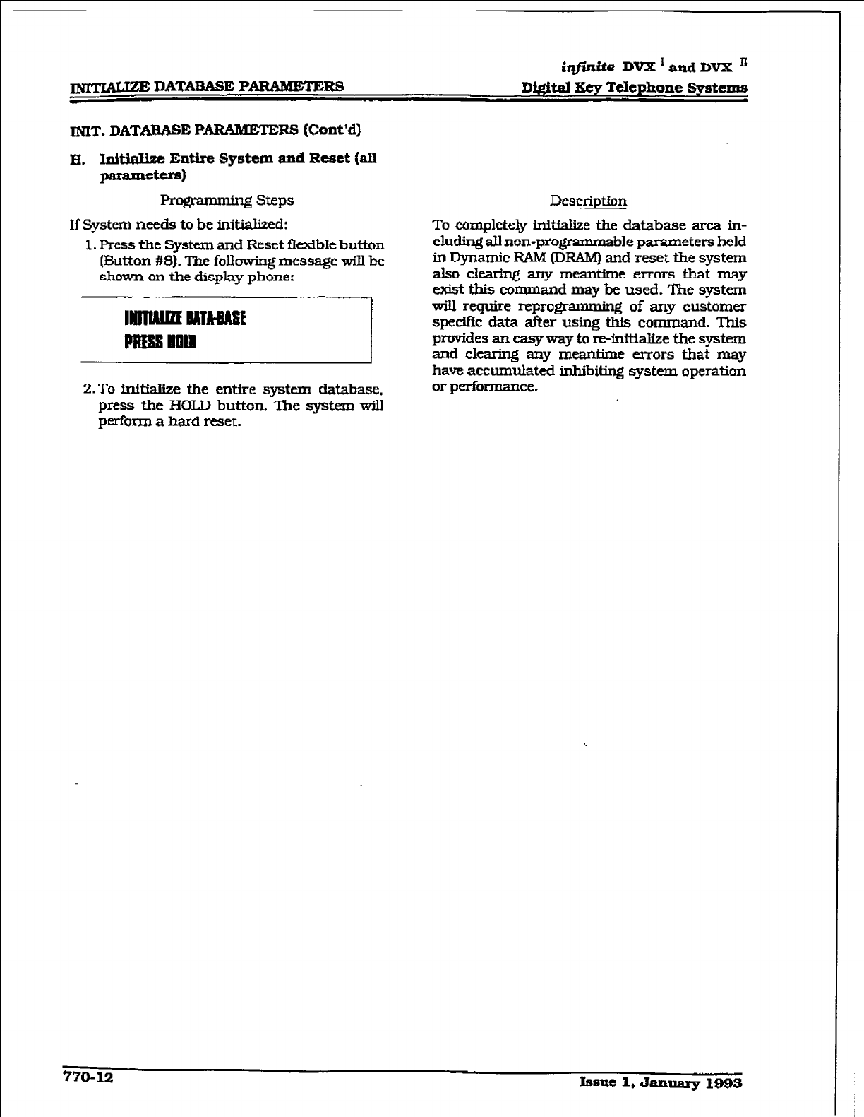
iqfmiie DVX’andDVXn
Digital Eey Telephone Systems
INIT.
DATABASE P
ARAMETEHS [Cont’d)
H. IxMaHze Entire System and Reset (all
paraxn&rs)
steps
IkscIipffon
If
System needs to
be kMaIized:
1. Press the System and Reset flexible button
(&&ton #8). l%e following message will be
shown on the display phone:
2.To
initialize the entire system database.
press the HOLD button. The system will
perform a bard reset.
To completely initial&e the database area in-
cluding all non-programmable
parameters
held
in Dynamic FUM (DRAM) and reset the system
also clearing any meantime errors that may
exist this command may
be
used. The system
will require reprogmmming of any
customer
specific data after using this
command. This
provides an easyway to re-initiake the system
and clearing any meantime errors
that
may
have accumulated inhibiting system operation
or performance.
770-12 fssue 1, January 1993
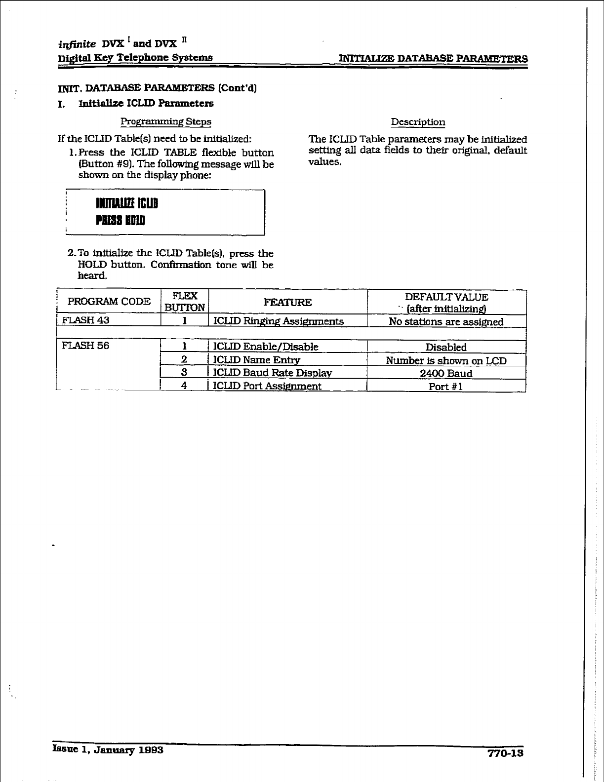
iqjinife DVX I and DVX ’
nrgital SeJr Telephone Systtme -DATAaAsE PARAMETERS
INIT. DATAEASE P- RS (Co&d)
I. Initiallzc ICLID Paranleters
Programmiq steps
If the ICUD Tablets) need to be initialized:
1. Press the ICLID TABLE
fkxlble
button
(Button #9). The following message w.Ul be
shown on the display phone:
Description
The ICLJD Table parameters may be initialized
setting all data fields to their original, default
values.
2.To f.niMke the KWD Table[s). press the
HOLD button. Confirmation tone will be
heard.
i PROGRAMCODE BEN FEATURE DEFAULTVALUE
i FLASH43 .I (after inititid
1 ICLID Rfnm Assi@mm-ks
I No stations are assi@ed
FlASH 56 1 1 ICLID Enable/Disable
2 f ICLJD Name Entry
3 1 ICLID Baud Rate Display
! 4 i ICLID PotiAssi@ment
Disabled
Number is shown on LCD
2400 Baud
Port #l
Issue 1, Japuarg 1993 770-13
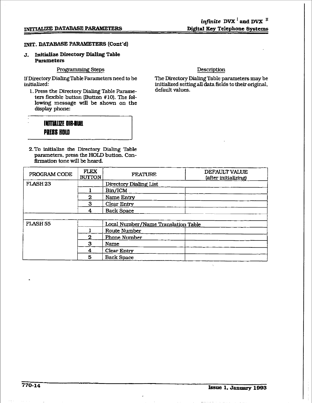
infinite
DVX * and DVX I1
m DATABASE PARAMETERS Dig&al Key Telephone
Systems
INIT. DATABASE P ARAbETERS (Cont’d]
J. IniB Directory Dialing Table
Parameters
ProgImming
steps
If Directory DialingTable Parameters need to be
initialized:
1. Press the Directory Dialing Table Parame-
ters flexible butto~~ (Button #lo). The fol-
lowing message will be shown on the
display phone:
Description
The Directory Dialing Table parameters may be
initialized setting all data fields to their original.
default values.
2.To
initiabe the Directory Dialing Table
parameters, press the HOLD button. Con-
firmation tone will be heard.
PROGRAM CODE BzN FEATUREi DEFAULTVALUE
(after initializind
FLASH 23 Directory Dialing List
1 Bln/ICM 1
2 Name Enixy
3 Clear Entry
4 Back
Space
FLASH 55 1 Local Number/Name Translation Table
1 Route Number
2 Phone Number
3 Name
4 Clear Entw
5 Back Space
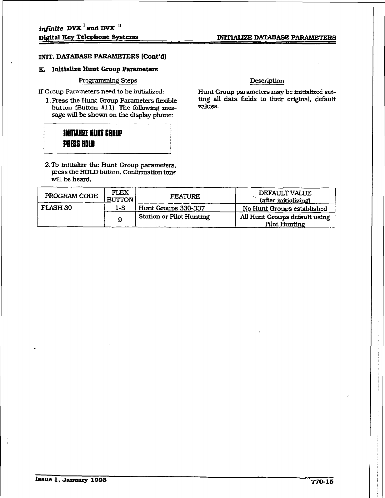
i&.&e DVX ’ and DVX II
~QltaI Key Telephone Systems m DATABASE PAWMETERS
INIT. DATXBASE PARAMETE I@ (Co&d}
K. Initinltzt Hunt Group Parameters
Programming Steps
If Group Parameters need to be inftiaked:
1. Press the Hunt Group Parameters flexible
button (EMton #1 1). The foIIowing mes-
sage will be shown on the display phone:
Description
Hunt Group parameters may be jnitialized set-
ting aII data fieIds to their originaL default
values.
2.To inftia&ze the
Hunt
Group parameters,
press the HOLD button. Confirmation tone
w-31 be heard.
PROGRAM CODE ) $!$& FEATURE . . DEFAULT VALUE
[after iniMk@l
FLASH 30 1-8 Hunt Groups 330-337 No Hunt Groups established
i 9
Station or Pilot Hunting All Hunt Groups default using
Pllot Iiunw
fssue 1, Janumy 1993 770-15
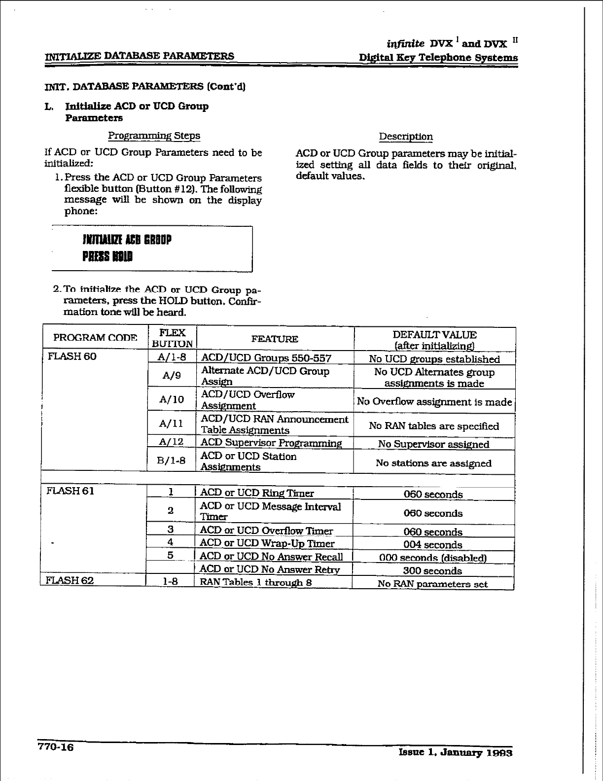
iqf3tite
DVX’andDVX I1
m DATME
P&RAMETERS
D&itd Key
Telephone Systems
INIT. DATABASE PARAMETE
Rs (Co&d)
I,. Lpitialize ACD or UCD Grunp
Paramctcrs
Rogramminf Steps
If ACD or UCD Group Parameters need to be
initialized:
1. Press the ACD or UCD Group Parameters
flexible button (Button # 12). The following
message will be shown on the display
phone:
Description
ACD or UCD Group parameters may be initial-
ized setting all data fields to their original,
default values.
2.To initialize the ACD or UCD Group pa-
rameters, press the HOLD button. Confir-
mation tone will be heard.
PROGRAM CODE DEFAULT
VALUE
. . . . . . .
FLASH 60
FLASH 61
*
FLASH 62
1 1 ACD or UCD R& Timer 060 seconds
2
ACD
or UCD Message Intend
ma 060 seconds
3 ACD or UCD 0verfIow Timer 060 seconds
4 ACD or UCD Wrap-Up Timer 004 seconds
5 ACD or UCD No Answer Recall 000 seconds (disabled)
ACD or UCD No Answer Retrv 300 seconds
1-8 RAN Tables 1 throu& 8 No RAN parameters set
770-16
Iasac
1, Janluuy 1883
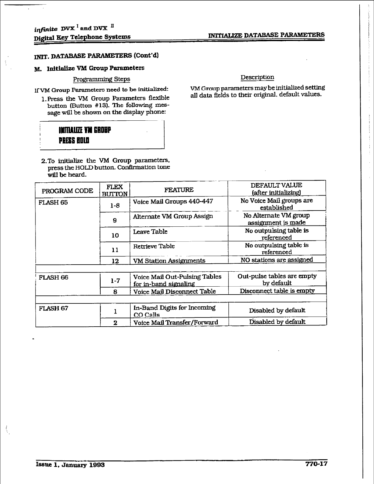
ittfintie DVXTandDVX’
~&&al Key Telephone System6
m. DATABASE P
ARAMETERS (Cont’dl
M. Idtialize VM Group Parameters
Progl -ng steps
ff VM Group Parameters need to be initialized:
1. Press the VM Group Parameters flexible
m DATABASE PARAMETERS
Description
VM Group parameters may be initialized se-g
all data fields to their ori-. default values.
button (Button #13). The following mes-
sage will be shown on the display phone:
;;I
2.To initialize the VM Group parameters.
press the
HOLD button. Conk-nation tone
will be heard.
FLASH 67 1
la-Band Di@s for Incoming
ccl calls Disabled by default
2 Vof ce Mail Transfer/Forward I&abJed by default
Issue 1. Janumy 1993 770-17
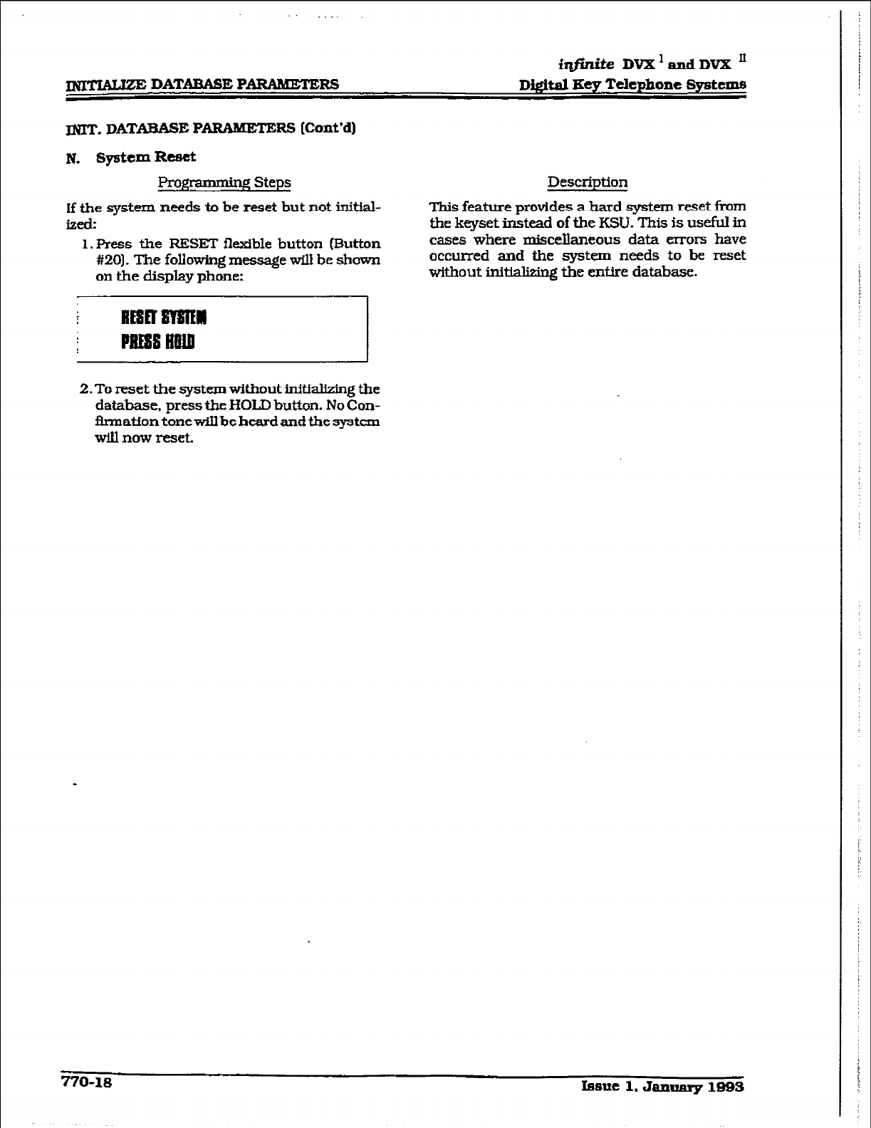
.
METIAtlzE DATABASE PANMETERS
fqfinite DVX ’ and DVX ’
D&&al Eey Telephone Systems
m. DATABASE P
ARAMETERS (Cont’d)
N. SydCm lb~&
gramdng Steps
If the system needs to be reset but not initial-
izd:
l.FWss the FESE3 flexible button (Button
#20]. The following message will be shown
on the display phone:
Description
This feature provides a hard system reset from
the keyset instead of the KSU. This is useful in
cases where miscellaneous data errors have
occurred and the system needs to be reset
without initMizing the entire database.
REsEr ma
PRESS tlfiln
2. To reset the system without initializing the
database, press the I-K&D button. No Con-
flrmation tonewiIlbebeardandthe system
will now reset.
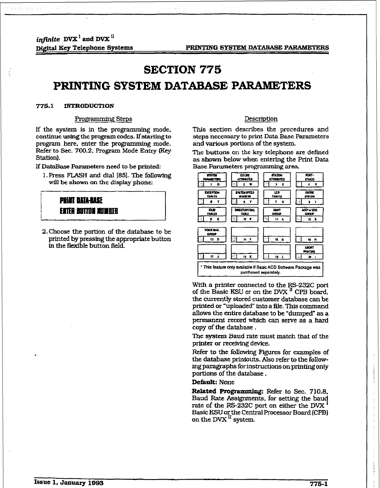
r
i@nite DVX’andDVX’
DJ#t.al Key Telephone Systems PRINTING SYSTEM DATABASE PARAMETERS
SECTION 775
PRINTING SYSTEM DATABASE “AIUMETERS
775.1 INTRODUCTION
Programming Steps Description
If the system is in the programming mode, This section describes the procedures and
continue using the
program codes. If starting to
steps
necessary to print Data Base Parameters
program here, enter the programming mode.
and various portions of the system.
Refer to Sec. 700.2. Program Mode Entry (Key
Station). The buttons on the key telephone are defined
as shown below when entering the Print Data
If DataBase Parameters need to be printed: Base Parameters programmmg area.
1. Press FLASH
and dial WI. The following
will be
shown on
the display phone:
Z-Choose the portion of tie database to be
printed by pressing the approprfate button
in the flexible but-ton field.
* This feature only available If Basic AC0 Software Pac%age was
purdwed sapiuaiely.
With
a
printer connected to the RS-232C port
of the Basic KSU or on the DVX ’ CPB board,
the currently stored customer database can be
printed or ‘uploaded” into a file. This command
allows the entire database to be “dumped” as a
permanent record which can serve as a hard
copy of the database .
The system Baud rate’ must mat& that of the
printer or recefving device.
. Refer to the following Figures for examples of
the database printouts. Also refer to the follow-
ingpamgraphs forinstructionsonprintingonly
portions of the database.
Dchalt: None
Related Programming: Refer to Sec. 710.8.
Baud Rate Assignments, for setting the baud
rate
of the RS232C port on either the DVX ’
Basic KSU or the CentralProcessor Board (CPB)
on the DVX I1 system.
Issue 1. January 199s 776-l
m-G SYSTEM DATABASE PARMBTERS
iqjinite DVX’ and DVX”
D#tal IKeg Telephone Systems
syrctem D~~&%uIc
printouts
[Co&d)
k priptfng System Parameters
Progw Steps
If a printout of all System Parameters
is
desired:
1. Press the SYSTEM PAR#I?3ERS fleldble
button (Button # 1). The following message
will be shown on the display phone:
PllUnslls?AMM
2.To print the system parameter database ,
presstheHOLD button. ThefoIlowingmes-
sage wiU be shown on the
ciispIay
phone:
lwlnNEm PAm.
When the system has finished sending the in-
formation to tie printer, confirmation tone wfll
be heard.
De5ition
of
Tcrme for System
Parameters F’rintout
sy8tem Timers:
SHR=
Syskm
Hold Recall Timer
EHFk Exchsive Hold Recall Timer
ART= Attendarlt Recall Timer
XFR=TransferRedIer
PFT=
Preset
Forward Timer
CF’N= Call Forward No-Answer l-her
FT= Pause Xrner
CPT= Call ParkTimer
CFT= Conference ?Imer
Proz Page Timeout Timer
COT= co Ring Detect mmer
SRT= Single Line Receiver Tfmer
m= Message Wait Reminder Tone
m= Hook Flash ma
HFIJ= Hookswit& Bounce Tfmer
CQT= SMDR Call Qualif+tion Timer
ACB= Auto Call Back Timer
system Features:
AO=Attendant Ovetide
SY= Hold Preference
ENR= External Night Ringing
EO=Exec Override Warn Tone
PW= Page Warning
Tone
BGM= Background Music
LCR= LCR Enable/Disable
A&Forced Account Codes
GL=Group L3steniq
S=IcUe Speaker Mode
CC= Cd Cost Display Feature
MH= Music On Hold
.
775-2 Issue 1, January 1993
Description
With a printer connected to the RS-232C port
of the Basic KSU or on the
DVX ’
CPB board,
the currently stored customer database can be
printed or “uploaded” into a file. This commmd
allows the System Parameters database to be
‘dumped” as a permanent record which can
serve as a hard copy.
The system Baud rate must match that of the
printer or receiving device.
When printing the System Parameters the fol-
bwirg data is print&
l
All System Timers
l
All System wide options (i.e. external
night ringing, Hold preference etc.. .)
l
Attendant programming
l
Other system assignments [i.e. Pa.ge/Re-
lay Assignments, Executive/Secret.aIy.
SMDR etc.. .I
l
Weekly Night Mode schedule
Refer to the following Figure for an wp’le of
the system parameters database print out.
Default: None
Related Pmgrammb@
Refer to Sec. 710.8,
Baud Rate Assignments. for setting tbe bau!
rate of the RS-232C port on either the
DVX
Basic KSU or the Centi Processor Board (CPB)
on the DVX ‘I system .
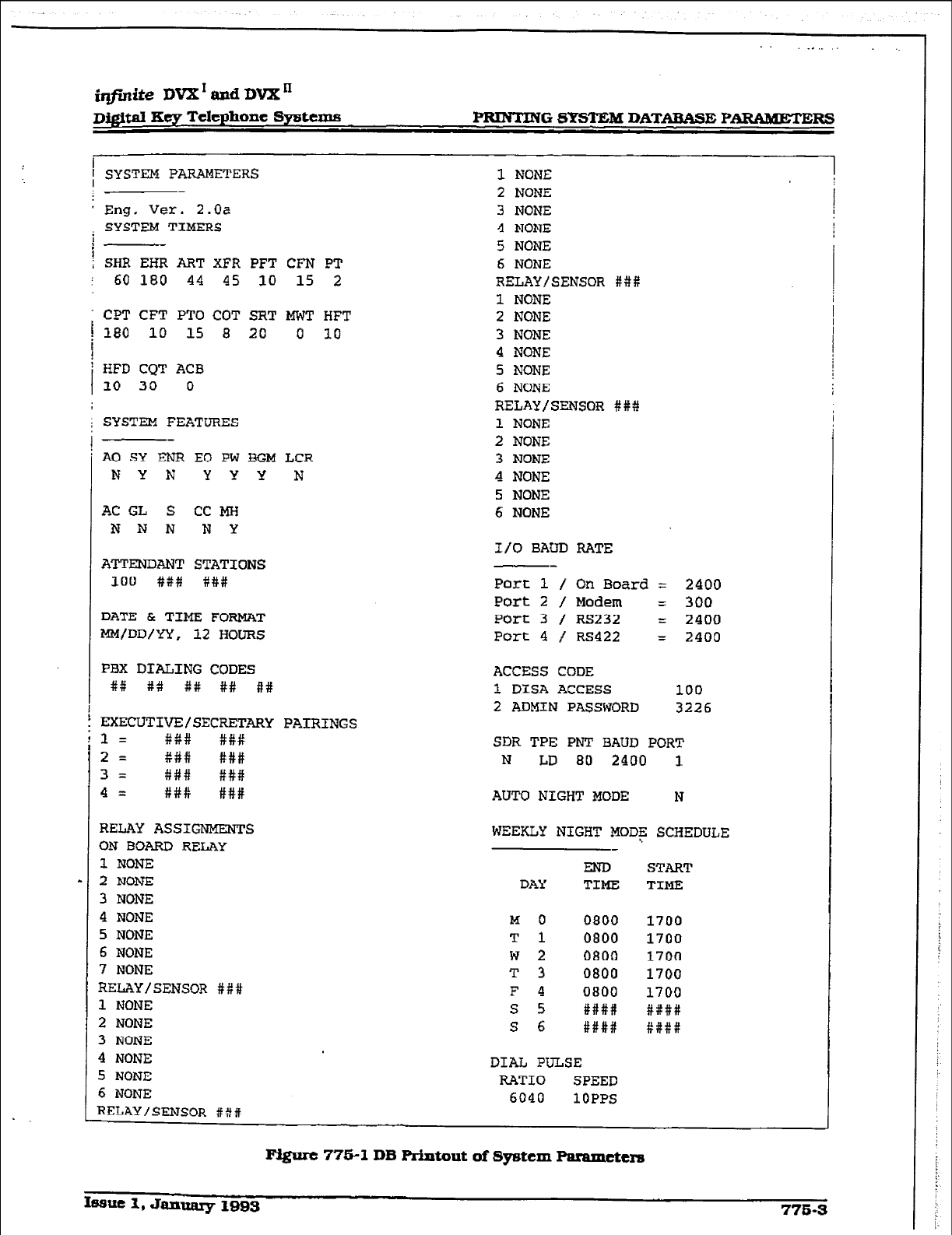
r
iqf&te DVX’ aPd DVX”
DQ.$w Key Telephone Systems PBINTING SYSTEM DATABASE PARAMETERS
1 SYSTEM PARAMETERS
* Eng. Ver. 2.0~
; SYSTEM TIMERS
i--
f SHR EHR ART XFR PFT CFN PT
: 60 180 44 45 10 15 2
CPT CFT PTO COT SRT MWT HFT
i 180 10 15 8 20 0 10
I
'
110 HFD 30 CQT ACB 0
SYSTEM FEATURES
A0 SY ENFI EO PW 3GM LCR
I? Y N YYY N
AC GL S CC MH
NNN NY
ATTENDANT STATIONS
100 ### ###
DATE & TIME FORMAT
MM/DD/YY, 12 HOURS
PBX DIALING CODES
#It ## ## #X ##
?ZXECUTIVE/SECRF.TAFtY PAIRINGS
3 = %## #P#
2 = P## ###
3= ### ###
4 = X## ###
RELAY ASSIGNMENTS
ON BOARD RELAY
1 NONE
2 NONE
3 NONE
4 NONE
5 NONE
6 NONE
7 NONE
RELAY/SENSOR #P#
1 NONE
2 NONE
3 NONE
4 NONE
5 NONE
6 NONE
RELAY/SENSOR #X#
1 NONE
2 NONE
3 NONE
4 NONE
5 NONE
6 NONE
RELAY/SENSOR ##P
1 NONE
2 NONE
3 NONE
4 NONE
5 NONE
6 NONE
RELAY/SENSOR ###
1 NONE
2 NONE
3 NONE
4 NONE
5 NONE
6 NONE
I/O BAUD RATE
Port 1 / On Board = 2400
Port 2 / Modem = 300
Port 3 / RS232 = 2400
Port 4 / RS422 = 2400
ACCESS CODE
1 DISA ACCESS 100
2 ADMIN PASSWORD 3226
SDR TPE PNT BAUD PORT
N LD 80 2400 1
AUTO NIGHT MODE N
WEEKLY NIGHT MODE SCHEDULE
END START
DAY TIME TIME
M 0 0800 1700
T 1 0800 1700
w 2 0800 1700
T 3 0800 1700
F 4 0800 1700
s 5 ####I ####
s 6 I### ##X#
DIAL PULSE
RATIO SPEED
6040 1OPPS
Hgurc 776-I DB printout of System Parametera
J
Isauc 1, JwxaIy 1993 776-S
p~ml%VG SYSTEM DATABASE PARKMETERS
iqjinite
DVX1and~~”
Digital Key Telephone Systems
system DataBase Printouts
(Co&d]
B. Printing Co h Attributes
Pro- steps
If a printout of the Co
Line
AttrIbutes is desired:
1. Press the CO LINE ATI’RIBUTES flexible
button (Button #2). The following message
will be shown on the display phone:
;I
2.To
print the data for ALL CO Lines, press
the HOLD button. To print CO Line data for
a specified CO tine Range enter four digits
to sped@ the CO Line range (two digits for
the&stlinewfthintherangeandtwOdigits
for the last line in the range i.e. [01X5]). If
a print out of only one line is desired enter
that line twice (i.e. [OlOll). Then press the
HOLD
button.
3.
The following message will be shown on the
display phone and the CO Line data will be
printed:
When the system has finished sending the re-
quested information to the printer, confirma-
tion tone will be heard.
Description
With a printer connected to the RS-232C port
of the Basic KSU or on the DVX ’ CPB board,
the currently stored customer database can be
printed or ‘uploaded” into a file. This command
allows either a range of CO Lines or the entire
CO Line database to be “dumped” as a perma-
nent record which can serve as a hard copy of
the CO Line attribute database .
The system Baud rate must match that of the
printer or receiving device.
When prinq the CO Line attributes the fol-
Iowjng data is printed: .
l
All CO Line parameters within the speci-
fied range.
l CO Line ringing assignments within the
specified range.
l
Dial Pulse Ratio and Speed settings
Refer to the following Figure for an example of
the CO Lfne attribute database print out.
Default:
None
Rckted Rogrammbg:
Refer to Sec. 710.8.
Baud Rate Assignments, for setting the baud
rate of the RS-232C port on either the DVX ’
Basic KSU or the Central Processor Board (CPB]
on the DVX ’ system.
Dciinition of Terms for CO Lbus printout
SIGNALP DlMF/Dial Pulse
TYPE= CO/PEuc
UNA= Universal Night Answer
PRI= CO Line F?rivacy
SuPv= Loop supervi!Gon
DISA= Dire& Inward System Access
FKIM= Flash “Inner
GRP= CO Line Group
CO% CO Ltie Class of Service
776-4 Imuc 1, Janwlry 1993
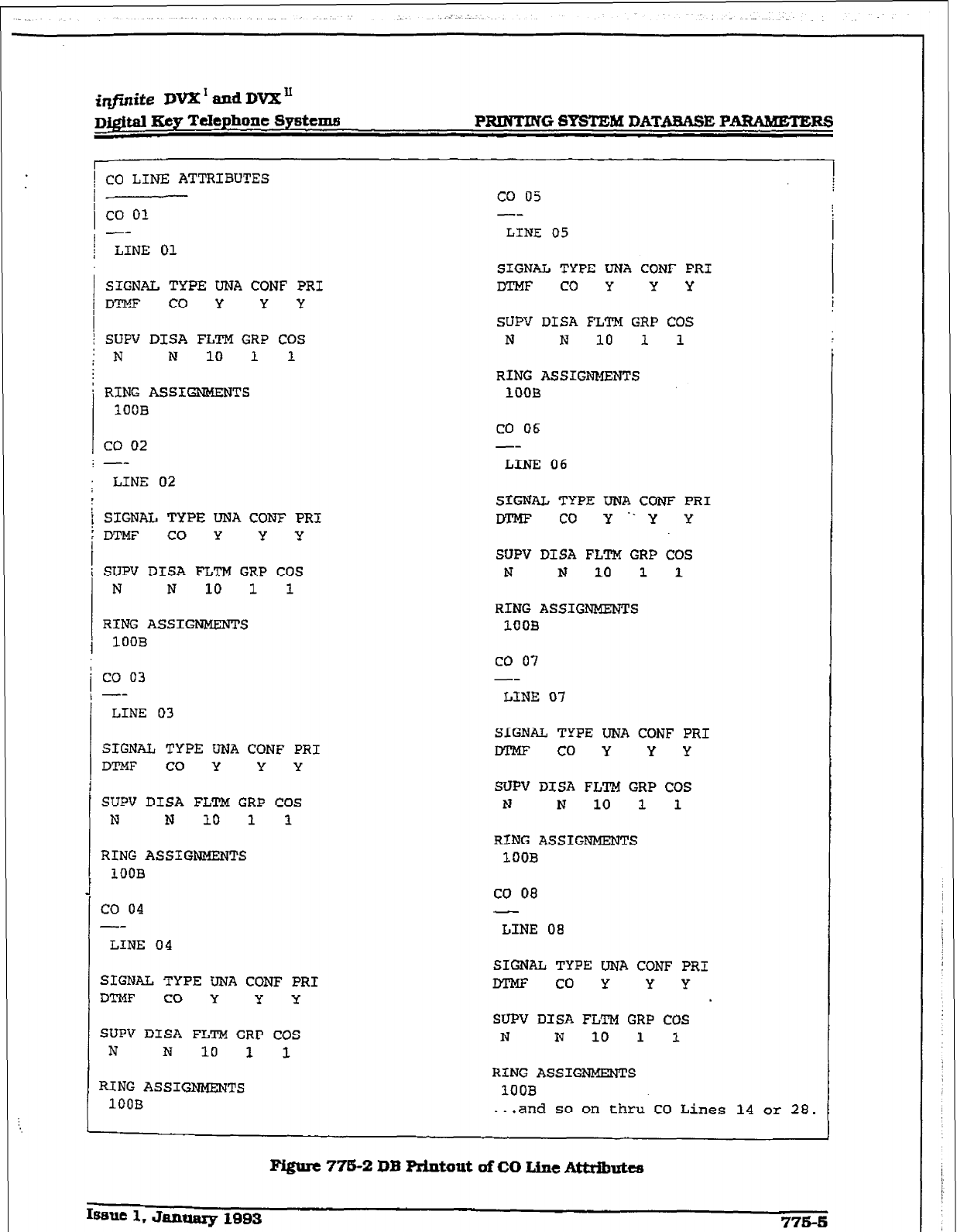
@jinife DVX’ and DVX”
D&$m Ecy Telephone Systems PRINTING SYSTEM DATABASE PARAMETERS
Co LINE ATTRIBUTES CO 05
co 01 --
-- LINE 05
LINE 01
SIGNAL TYPE
UNA CONF
PRI
D'X?F CO Y Y Y
SIGNAL TYPE UNA CONF
PRI
DTMF CO Y Y Y
SUPV DISA
FLTM
GRP COS
1 ; N N
10 1
SUPV DISA FLTM GRP COS
N N 10 1 1
i RING ASSIGNMENTS
100B
co 02
; --
LINE 02
RING
ASSIGNMENTS
lDOB
CO 06
--
LINE 06
SIGNAL TYPE DNA CONF PRI
DTMF CO Y Y Y
SUPV
DISA
F’LTM
GRP CDS
N N 10
1 1
RING
ASSIGNMENTS
10OB
co 03
--
LINE 03
SfGl?AL TYPE UNA COW
PRI
DTMF co Y“Y Y
SUPV DISA FLTM
GRP COS
N N 10 1 1
RING ASSIGNMENTS
1008
co 07
--
LINE 07
SIGNAL TYPE UNA CONF PRI
DTMF CO Y Y Y
SUPV DISA FLTM
GRP COS
N N 10 1 1
RING ASSIGNMENTS
1OOB
co 04
SIGNAL TYPE
UNA
CONF
PRI
DTMF co Y Y Y
SUPV DISA FLTM GRP COS
N N 10 1 1
RING
ASSIGNMENTS
100B
co 08
--
LINE 08
LINE 04
SIGNAL TYPE
UNA CONF PRI
DTMF co Y y y
SUPV DISA FLTM GRP COS
N N 10 1 1
RING ASSIGNMENTS
1OOB
SIGNAL TYPE UNA CONF
PRI
DTMF co Y Y Y
SUFV DISA FLTM GRP COS
N N 10 1 1
RING ASSIGNMENTS
100B
.I.
and
so on thru
CO Lines 14 or 28.
F&urc 778-2
DB *tout uf CO Line AttrIbutes
Ifmlc 1. January 1893
776-5
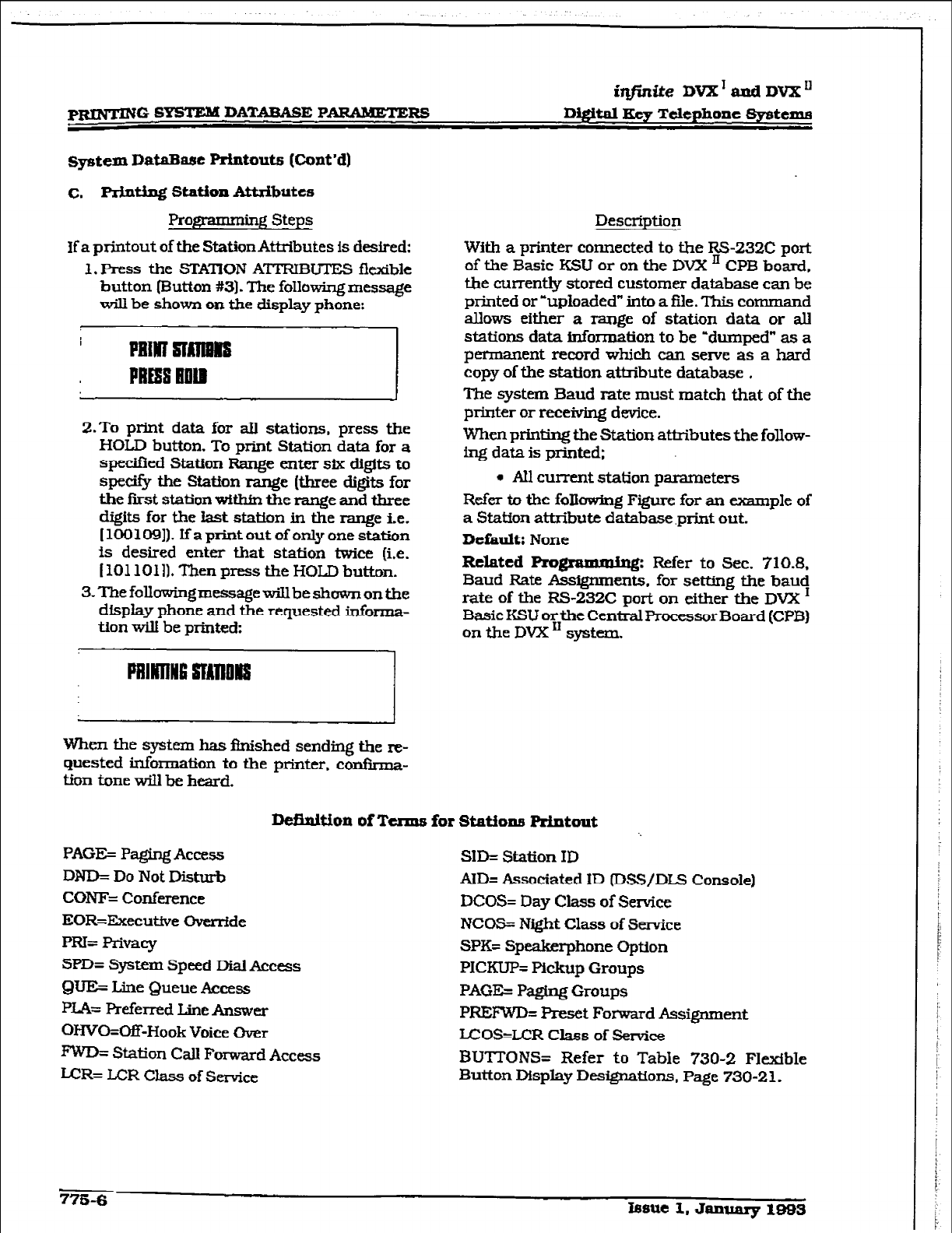
r
PRINTING. SBYI’EM DATABASE PARAMETERS
itlfnite DVXTandDVXI1
D@ital Key Telephone Systema
System DataBase prfatouts (Cont’dl
c. Mt.ing Station Attributes
Progpammbg Steps
If a printout of the Station Attributes is desired:
1. Press the STAnON ATTRIBUTES flexibIe
button putton #3). The following message
will be shown on the display phone:
2.To print data for alI stations, press the
HOLD button. To print Station data for a
specified Station Range enter six digits to
specif$ the Station range (three digits for
the first station within the range and three
digits for the
last
station in the range i.e.
[100109]). Ifap~toutofonlyonestation
is desired enter that station twice. (i.e.
(1011011)+ Thex~ press the HOLD button.
3. The folIowingmessagewiIl be shown on the
dlspIay phone and the requested informa-
tion will be printed:
When the system has &shed sending the re-
quested information to the printer. con&ma-
tion tone will be heard.
Description
With a printer connected to the RS-232C port
of the Basic KSU or on the DVX II CPB
board,
tie currently stored customer database can be
printed or ‘uploaded” into a file. This command
allows either a range of station data
or all
stations data information to be ‘dumped” as a
permanent record which can serve as a hard
copy of the station attribute database .
The system Baud rate must match that of the
printer or receiving device.
When printing the Station attributes the follow-
ing data is printed;
l
AI1 current station parameters
Refer to the
foIIowlng Figure for an mple of
a Station attribute database .ptit out.
Default: None
Related Prognwming:
Refer to Sec. 710.8.
Baud Rate Assignments. for setting the baud
rate
of the RS-232C pork
on
either the
DVX I
Basic KSU or the Central Processor Board (CPB)
on the DVX I1 system.
lkilnit.ion of Terms for Stations
Printout
PAGE= PagingAccess
DND= Do Not Disturb
CONF= Conference
mR=Executive Overrtde
PRl= Rivacy
SPD= System Speed Dial Access
QWS Line Queue Access
PIA= Preferred Line Answer
OHVO=Off-Hook
Voice
Over
IWO= Station CalI Forward Access
LcR= LCR Class of Service
SID= station ID
AID= Associated ID IDSS/DLS Console)
DCOS= Day Class of Service
NCOS= Night Class of Service
SPK= Speakerphone Option
PICKUP= Pickup Groups
PAGE= Paging Groups
PREI%‘D= Preset Forward Assignment
LCOS=LCR CIass of senrice
BUTTONS= Refer to Table 730-Z Flexfble
Button Display Designations. Page 730-2 1.
775-6 Issue
I, January 1993
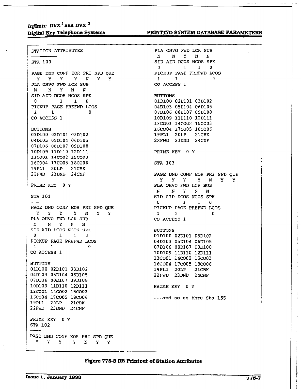
mite DVXrandDVXn
Dj@d Ecy Telephone Systems F’RWI?NG SYSTEM DATAaAsE PARAMETERG
I
1 STATION ATTRIBUTES
!
; STA 100
PLIA owe FWD LCR SUB
N NYNN
SID AID DCOS
NCOS
SPK
PAGE DND CONF EOR
PRI SPD QUZ
YYY YNYY
PLA OHVO FWD
LCR SD3
N NYNN
SID AID DCOS NCOS
SPK
0 1 1 0
PICKUP PAGE PREFWD LCOS
1 1 0
CO ACCESS 1
0 1 1 0
PICKUP PAGE PREFWD LCOS
1 1 0
CO ACCESS 1
BUTTONS
OlDlOO
OZDlOl
03D102
04DlO3 05D104 06Dl05
07DlO6 08D107
09D108
lOD109 110110
12Dlll
13COOl 14coO2 15COO3
16COO4 17c005 18COO6
19PLl 2OLP 21CBK
22FWD 23DND 24CNF
PRIME KEY 0 Y
STA 101
_I-
PAGE
DND
CONF EOR PRI SPD QUE
Y Y Y Y N Y Y
PLA OHVO FWD
LCR SUB
N NYNN
SID AID DCOS NCOS SPX
0 1
1
0
PICKUP PAGE PREFWD
LCOS
1 1 0
CO ACCESS 1
BUTTONS
OlDlOO 02D101 03D102
04D103 05D104 06D105
07~106 08D107 09D108
lODlO9
llDll0 12Dlll
13COOl 14COO2 1X003
16COO4
17COO5 18COO6
19PL1
ZOLP 21CBK
22FWD
23DND 24CNF
PRIME KEY 0 Y
STA 102
PAGE DND CONF EOR PRI SPD QUE
YYY YNYY
BUTTONS
OlDlOO 02D101 03D102
04Dl03 05D104 06DlU5
07Dl06 08D107 09D108
lOD109
1lDlJ.O
12Dlll
13coo1 14coo2 15coo3
16COO4 17coo5
18COO6
19PLl 2OLP 21CBK
22FWD 23DND 24CNF
PRIME KEY 0 Y
STA 103
--
PAGE DND CONF EOR PRI SPD QUE
YYY YNYY
PLA OHVO FWD LCR
SUB
N NYNN
SID AID DCOS NCOS SPK
0 1 1 0
PICKUP PAGE PRE??WD LCOS
1 1 0
CO ACCESS 1
BUTTONS
OlDlOO 02D101 03Dl02
04D103 05D104 06Dl05
07D106 08D107 090108
lOD109 1lDllO 12Dlll
13CoOl 14COO2 15COO3
16CoO4 17~00.5 18c006
19PLl 2OLP 21CBK
22FWD
23DND
24CNF
PRIME KEY 0 Y
..a
and so on thru Sta 155
Figure 775-a DB Rintout of Station Attributes
Itame 1, January 1993 776-7
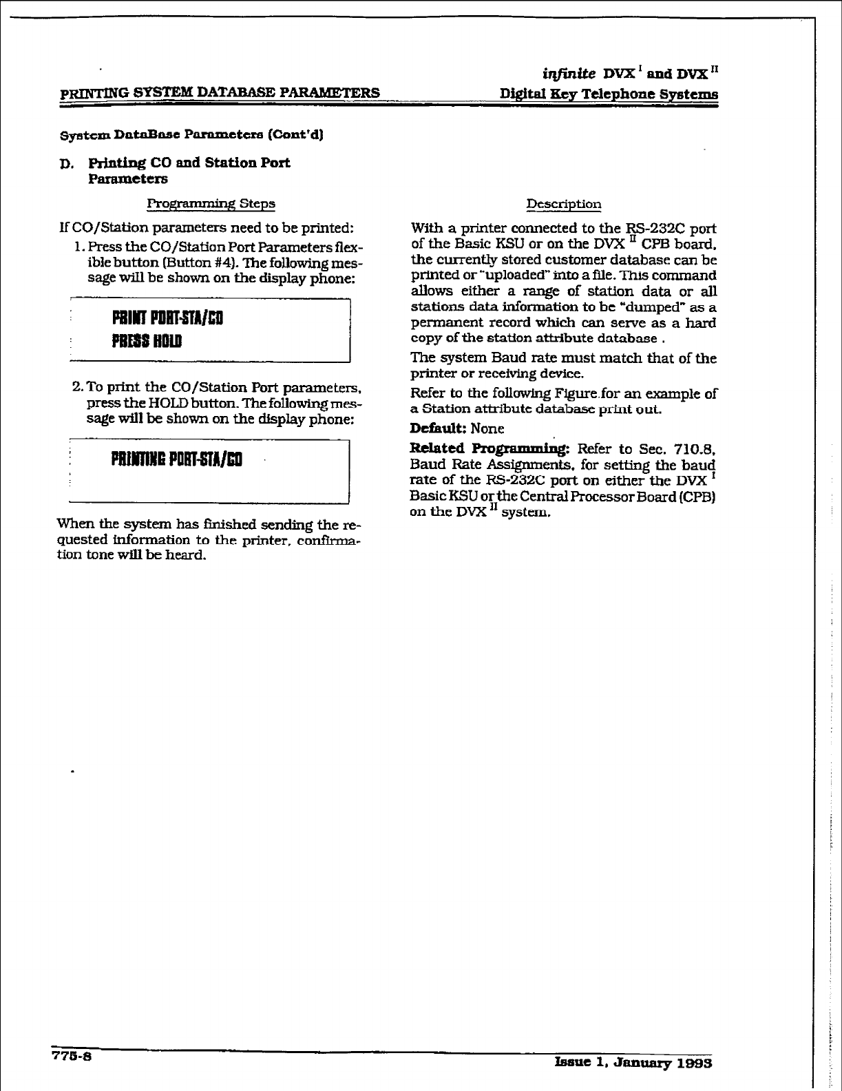
PRINTINGS- DATABASE PARAMETERS
iqfinite DVX I and DVX I1
Dfrriti Key Telephone Systems
sptcm DataBase P arnmetere (Cont’d]
D. prtnting CO and Station port
Panuneters
Prog ’ g Steps
If CO/Station parameters need to be printed:
1. Press the CO/Station Port Parameters flex-
ible button (Button #4). The following mes-
sage will be shown on the display phone:
2. To print the CO/Station Port parameters,
press the HOLD button. The foliowing mes-
sage will be shown on the display phone:
When the system has &YMI~~ sending the re-
quested information to the printer, con&na-
tion tone will be heard.
Description
With a printer connected to the RS-232C port
of the Basic KSU or on the DVX ’ CPB board,
the currently stored customer database can be
printed or “uploaded” into a i3le. This command
allows either a range of station data or all
stations data information to be “dumped” as a
permanent record which can serve as a hard
copy of the station attribute database .
The system Baud rate must match that of the
printer or receiving device.
Refer to the following Figure.for an example of
a Station attribute database print out.
Default;
None
Related Pro glvmd& Refer to Sec. 710.8.
Baud Rate Assignments, for setting the baud
rate of the RS-232C port on either the DVX I
Basic KSU or the Central Processor Board (CPB)
on the DVX I1 system.
776-8 Issue 1. January 1995
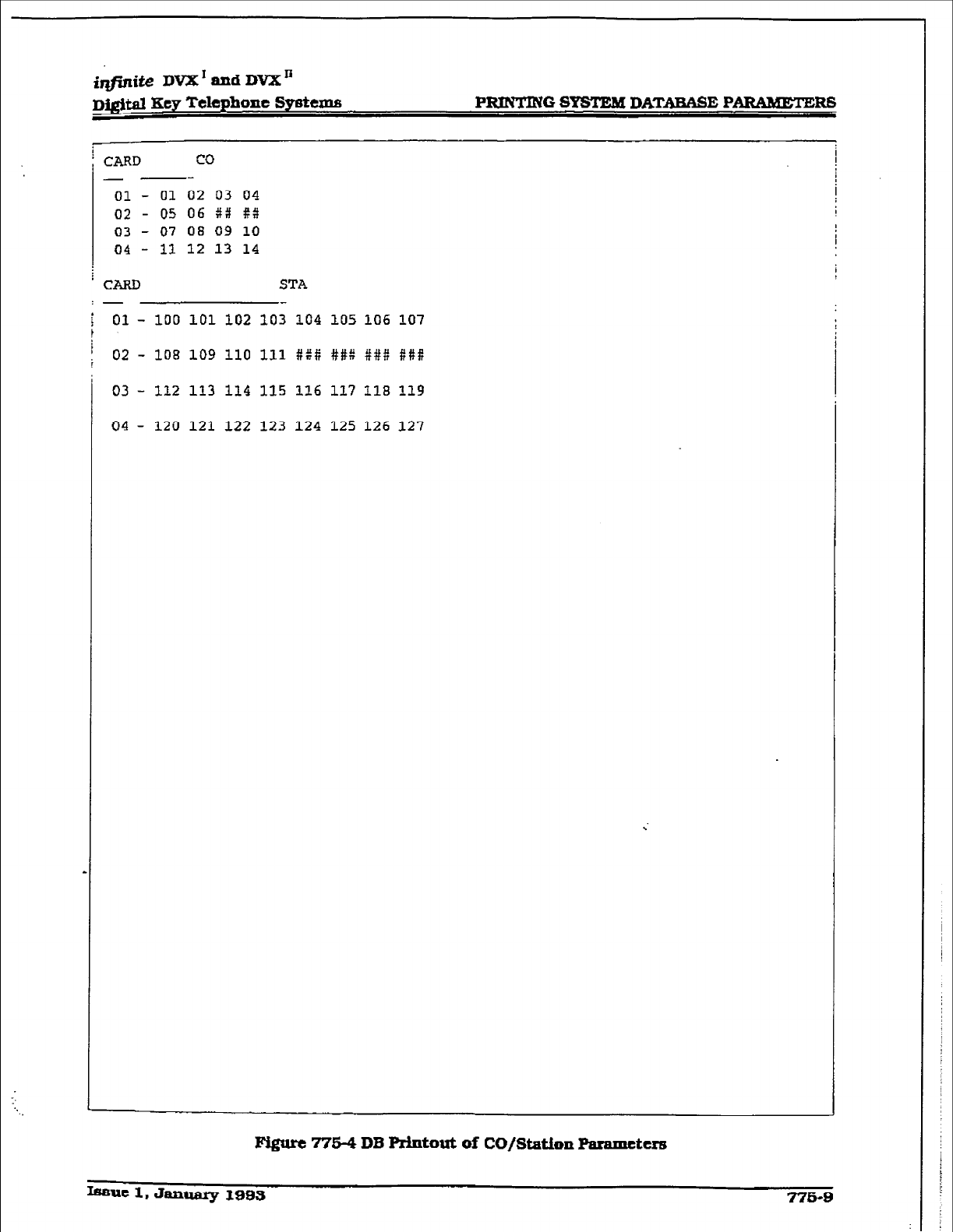
i-i& DVX * lllld DVX ’
DQ@td Key Telephone Sy6tems.i P-0 STEM DATABA8E PARAMETERS
I
; CARD
CO
I
- --
01 -
01 02 03 04 I
02 - 05 06 +I# $3
03 - 07 08 09 10
04 - 11 12 13 14 I
I
* CARD STA
:-
01 - 100 101 102 103 104 105 106 107
02 - 108 109 110 111 ##ii ##:: ### ##if
03 - 112 113 114 115 116 117 118 119
04 - 120 121 122 123 124 125 126 127
F+&urc 7764 DB Printout of CO/Station Paramcttrs
Issue 1. January 3993 ?76-9
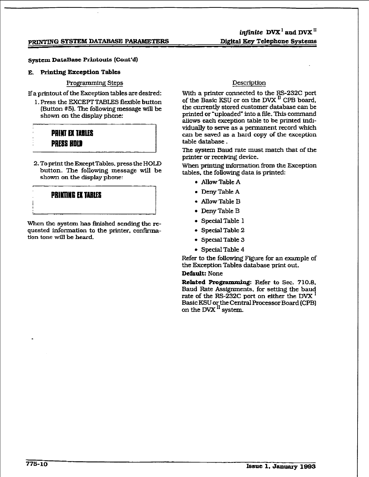
p-Q
SYSTEM DAT-E PARAMETERS
irlfintie DVX’aadDVX”
D&WI Key Telephone Ssgteme
sptem DataBase Printouts (Cont’d)
E. Afntfng Exception Tables
Prong ’ e Steps
If a printout of the Exception tables are desired:
1. Press the EXCEPTTABLES flexible button
(Button #5). The following message will be
shown on the display phone:
2. To prfnt the ExceptTables. press the HOLD
button. The following message will be
shown on the display phone:
When the system has Rnished sending the re-
quested information to the printer, confirma-
tion tone will be heard.
Descripff on
With a printer connected to the RS-232C port
of the Basic KSU or on the DVX ’ CPB board.
the currently stored customer database can be
minted or “uploaded” into a file. This command
allows each exception table to be printed indi-
vidually to serve as a permanent record which
can be saved as a hard copy of the exception
table database.
The system Baud rate must match that of the
printer or receiving device.
When printing information from the Exception
tables, the following data is printed;
l
Allow Table A
l
Deny Table A
l
Allow Table B
l
Deny Table B
l
SpecialTable 1
l
Special Table 2
I Special Table 3
l
Special Table 4
Refer to the following Figure for an example of
the Exception Tables database print out.
Default:
None
Related Pm@ms.uh~: Refer to Sec. 710.8,
Baud Rate Assignments. for setting the bauq
rate of the RS-232C port on either the DVX
Basic KSU or the Central Processor Board (CPB]
on the DVX I1 system.
775-10 Immt 1. Jammy 1993
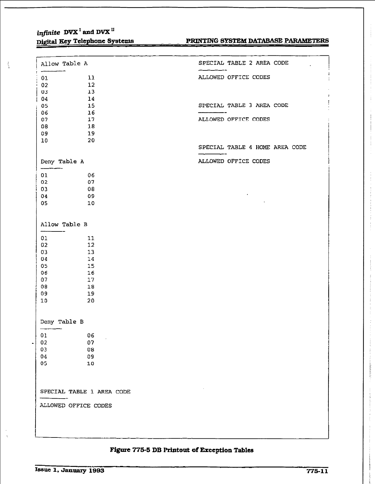
inmite DVX I and DVX ’
D&ital Key Telephone SpstexIS me SYiXt’EM DATABASE PARAMETERS
j
allow
Table A
;-- SPECIAL TABLE 2 AREA CODE
; 01 11 ALLOWED OFFICE CODES
j 02 12
1 03 13
i 04 14
05
06
07
08
09
10
15
16
17
18
19
20
SPECIZLt TABLE 3 AREA CODE
AL&OWED OFFICE CODES
SPECIAL TABLE 4 HOME AREA CODE
Deny Table A ALLOWED OFFICE CODES
01 06
02 07
03 08
04 09
05 10
allow Table B
--
01 11
02 12
03 13
04 14
05 15
06 16
07 17
08 18
09 19
10 20
Deny Table B
01 06
02 07
03 08
04 09
05 10
SPECIAL TABLE 1 AREA CODE
ALLOWED OFFICE CODES
Figure 7755 DB Printout of Exception Tables
i
hwme 1, Jamary 1WS 77511

PRINTING SYSTEM DATABASE PARAMETERS
ix@nite DVX’ and DVX”
Di@.al Key Telephone
Systems
System
DataBase Printouts (Cont’d)
F. Rinting
System Speed Bins
Prof+ammhg Steps
If
a printout
of the System speed dial entries are
desired:
1. Press the SYSTEM SPEED fkxtble. button
(Button #6]. ‘The following message will be
shown on the display phone:
2. To print the System Speed bins, press the
X&D button. The following wiU be shower
on the display phone:
Description
With a printer connected to the RS-232C port
of the Basic KSU or on the DVX ’ CPB board,
the currently stored customer database can be
printed or “uploaded* into a file. This command
allows either a range of system speed dial bins
or alI hi can be ‘dumped” as a permanent
record which oan serve as a hard copy of the
system speed dial database.
The system 3aud rate must match that of the
printer or receiving
device.
Fkfer to the following Figure for an wple of
a System Speed Dial database print out.
Default! None
Related
Rogsmmdng: Refer to Sec. 710.8,
Baud Rate Assignments, for setting the baud
rate of the PS232C port on either the DVX I
Basic K!3U or the Central Processor Board (CPB)
on the DVX I1 system.
When the system has finished sending tie re-
quested information to the printer, confirma-
tion tone will
be heard.
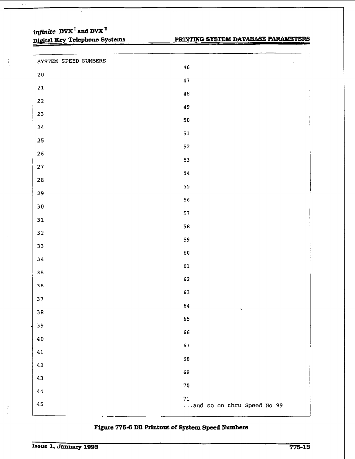
SYSTEM SPEED NUMEiERS 46
20 47
21 48
22 49
23
24
25
26
27
29
32
42
50
51
52
53
54
55
56
57
58
59
60
61
62
63
64
65
66
67
68
69
70
71
. . .
and so on thru Speed No 99
FQurc77’543DB
Printout ofSystcm8peedNumbcrs
IESU~ 1. Janumy 1893 77S-13
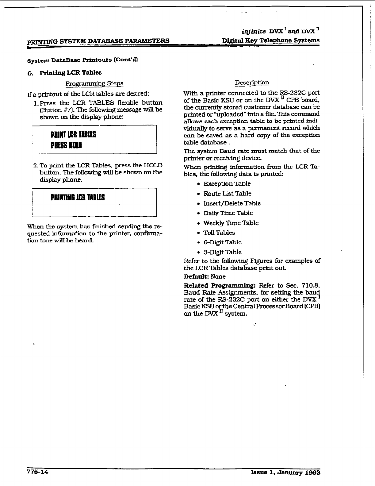
pRIlyTING SYSTEM DATAEA!% PARAMETERS
@r&e DVX’andDVXU
D&.ital Key Telephone Systems
system DataBase Printouts (Cont’d]
0. printing LCR Tables
Progrmming Steps
If a printout of the UIR tables are desired:
1. Press the l.ER TABLES flexible button
(Button #7). ‘Ihe following message will be
shown on the display phone:
PIIIRI ll3l IABIIS
PRESS lml
2. To print the LCR Tables, press the HOLD
button. The following wfll be shown on the
display phone.
When the system has finished sending the re-
quested tiormation to the printer, confirma-
tion tone w-31 be heard.
Description
With a printer connected to the Rs-232C port
of the Basic KSU or on the DVX ’ CPB bo&,
the currently stored customer database can be
printed or “uploaded” into a file. This command
allows each exception table to be printed indi-
viduallytosemeasaperman ent record which
can be saved as a hard copy of the exception
table database.
The system Baud rate must match that of the
printer or receiving device.
when printing information from the LCR Ta-
bles. the foIlowing data is printed:
l
Exception Table
l
Route List Table
l
Insert/Delete Table
l
Dally Tfrne Table
l
Weekly Time Table
l
TollTables
l
6-Dtgit Table
l
S-Digit Table
Refer to the following Figures for examples of
the L+CR Tables database print out.
Default: None
Related Prom: Refer to Sec. 710.8.
Baud Rate Assignments. for setting the baug
rate of the RS-232C port on either the DVX
BasicKSU orthe CentralProcessorBoard (CPB)
on the DVX” system.
775-14 Issue 1,Jan~lBBS
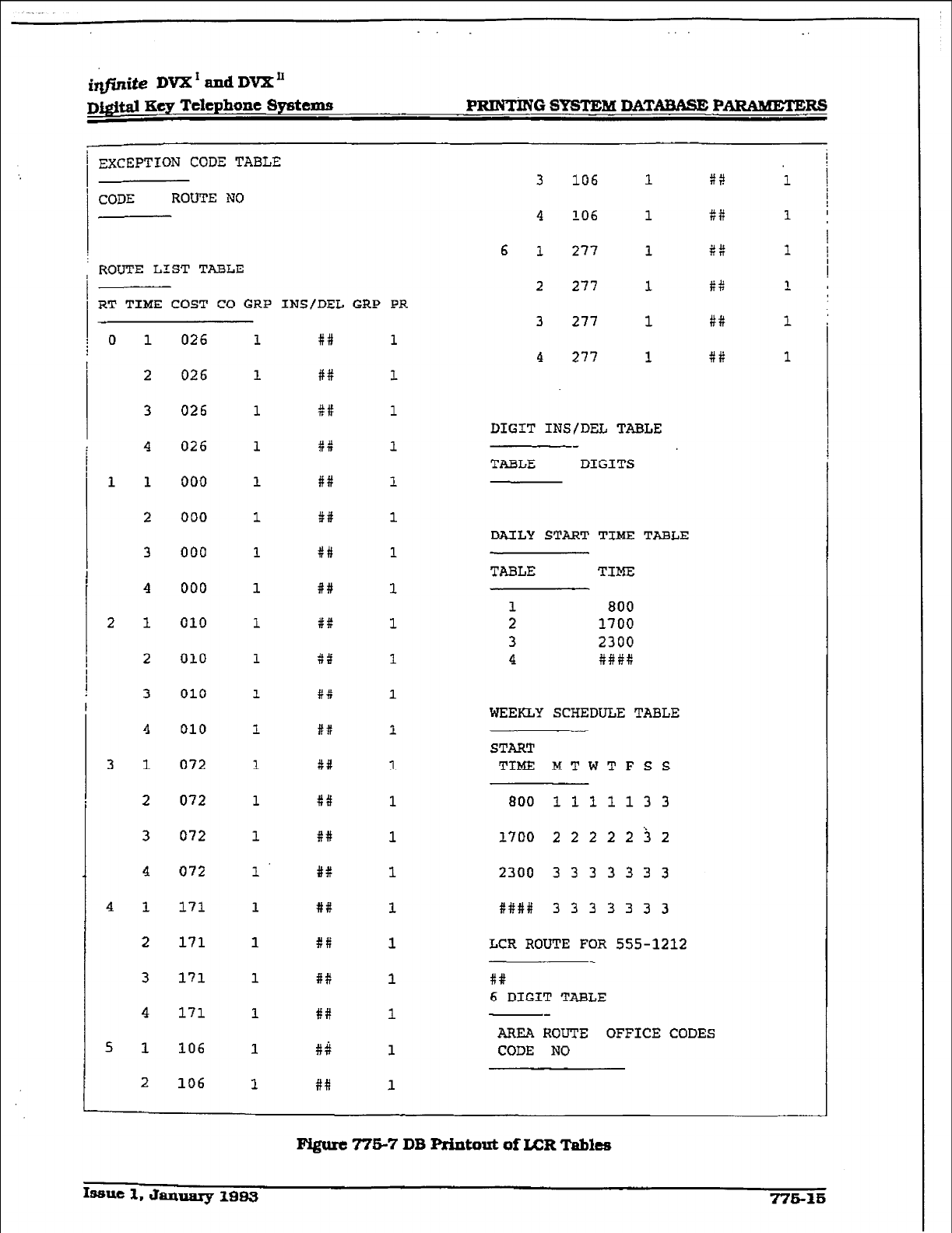
. .
itLfZn&DVX'andDVX'
D&$t.d Key Telephone Systems PRINTiNG SYSTEM DATAWUiE P-KS
EXCEPTION CODE TABLE
CODE ROUTE NO
ROUTE LIST TABLE
RT TIME COST CO GRP INS/DEL GRP PR
0
1
1
2
!
1
2
3
4
1
2
3
4
1
2
3
4
1
2
3
4
1
2
3
4
1
2
026
026
026
026
000
000
000
000
010
010
010
010
072
072
072
072
171
171
171
171
106
106
1
1
1
1
1
1
1
1
1
1
1
1
1
1
1
1
1
1
1
1
1
1
F#
##
St:
x::
#f
##
C#
##
#f
*t
t::
##I
xii
#a
##
#B
##
##
#X
##
#Q
##
1
1
1
1
1
1
1
1
1
1
1
1
1
1
1
1
1
1
1
1
1
1
3 106 1
4 106 1
6 1 277 1
2 277 1
3 277 1
4 277 1
DIGIT INS/DEL TABLE
TABLE DIGITS
DAILY START TIME TABLE
TABLE TIME
1 800
2 1700
3 2300
4 ###X
WEEKLY SCHEDULE TABLE
START
TIME MTWTFSS
800 111113 3
1700 2 2 2 2 2 i 2
2300 3 3 3 3 3 3 3
X### 3 3 3 3 3 3 3
LCR ROUTE FOR 555-1212
tt
6 DIGIT TABLE
iti! I
1 I
8# 1 !
I
#:: l i
8:: 1
AREA ROUTE OFFICE CODES
CODE NO
1# 1
Figure 775-7 DB Printout of LCR Tables
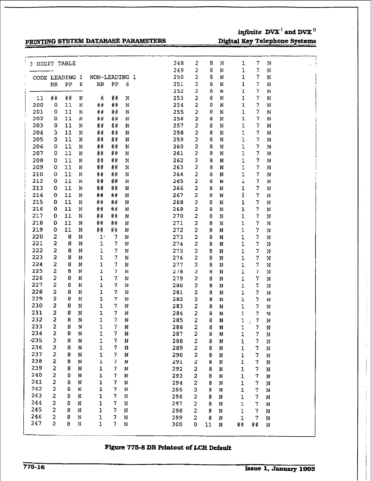
p-0 SYSTEM DATABASE PARAMETEBS
iqjZnite DVX’mdDVX”
Di@al Hey Telephone Systema
! 3 DIGIT TABLE
--
' CODE LEADING !.
RR PP 6
I 11
200
; 201
2D2
203
204
205
206
207
208
209
210
212
213
214
215
216
217
218
219
220
221
222
223
224
225
226
227
228
229
230
231
232
233
234
-235
236
237
238
239
240
241
242
243
244
245
246
247
##
0
0
0
0
3
0
0
0
0
0
0
0
0
0
0
0
0
0
0
2
2
2
2
2
2
2
2
2
2
2
2
2
2
2
2
2
2
2
2
2
2
2
2
2
2
2
2
B# N
11 N
11 N
11 N
11 N
11 N
11
N
11 N
11 N
11 N
11 N
11 N
11 N
11 N
11 N
11 N
11 N
11 N
11 N
11 N
8 N
8 N
8 N
8 N
8 N
8 N
8 N
8 N
a N
8 N
8 N
8 N
8 N
8 N
8 N
a N
8 N
8 N
8 N
8 N
8 N
8 N
8 N
8 N
8 N
8 N
8 N
8 N
248
249
NON-LEADING 1 250
RR PP 6
6
iY#i
6#
#i::
##
tli
#P
#f!
##
##
#i:
##
##
##
tti
P4
##
8::
#+!
##
l-
1
1
1
1
1
1
1
1
1
1
1
1
1
1.
1
1
1
1
1
1
1
1
1
1
1
1
1
## N
## N
## N
8:: N
## N
8:: N
#t N
ft# N
## N
#P N
#if N
if# N
## N
ff: N
a# N
#:: N
#if N
#:: N
## N
## N
7 N
7 N
7 N
7 N
7 N
7 N
7 N
7 N
7 N
7 N
7 N
7 N
7 N
7 N
7 N
7 N
7 N
7 N
7 N
7 N
7 N
7 N
7 N
7 N
7 N
7 N
7 N
7 N
251
252
253
254
255
256
257
258
259
260
261
262
263
264
265
266
267
268
269
270
271
272
273
274
275
276
277
278
279
280
281
282
283
284
285
286
287
288
289
290
291
292
293
294
295
296
297
298
299
300
2
2
2
2
2
2
2
2
2
2
2
2
2
2
2
2
2
2
2
2
2
2
2
2
2
2
2
2
2
2
2
2
2
2
2
2
2
2
2
2
2
2
2
2
2
2
2
2
2
2
2
2
0
8 N
8 N
8 N
8 N
8 N
8 N
a N
8 N
8 N
8 N
8 N
a N
8 N
8 N
8 N
8 N
a N
8 N
8 N
8 N
8 N
8 N
8 N
8 N
8 N
8 N
a N
8 N
8 N
8 N
8 N
8 N
8 N
8 N
8 N
8 N
8 N
8 N
8 N
8 N
8 N
8 I?
8 Ii'
8 N
8 N
8 N
8 N
a N
8 N
8 N
8 N
8 N
11 N
1
1
1
1
1
1
1
1
1
1
1
1
1
1
1
1
1
1
1
i.
1
1
1
1
1
1
1
1
1
1
1
1
1
1
1
1
1
1
1
1
1
1
1
1
1
1
1
1
1
1
1
1
##
7 N
7 N
7 N I
7 N I
7 N
7 N
7 N
7 N
7 N
7 N
7 N
7 N
7 N
7 N
7 N
7 N
7 N
7 N
7 N
7 N
7 N
7 N
7 N
7 N
? N
7 N
7 N
7 N
7 N
7 N
7 N
7 N
7 N
7 N
7 N
7 N
7 N
7 N
7 N
7 N
7 N
7 N
7 N
7 N
7 N
7 N
7 N
7 N
7 N
7 N
7 N
7 N
## N
Pygure 77543 DB Rintout of LCR De&n&
715-36 Isme 1. Jannary 1993
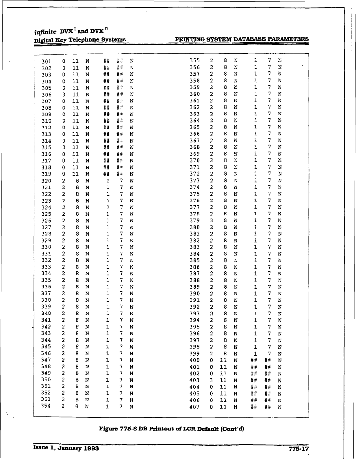
@Wte DVX’ and DVXn
D#a m Telephone SyBttW PRINTING SYSTEM DATABASE PARAMETERS
303
304
305
306
307
308
309
310
312
313
314
315
316
317
318
319
320
321
322
323
324
325
326
327
328
329
330
33'1
332
; 334
I
i
335
336
337
338
339
340
341
342
343
344
345
346
347
348
349
350
351
352
353
354
301
302
: 333
0
0
0
0
0
3
0
0
0
0
0
0
0
0
0
0
0
0
2
2
2
2
2
2
2
2
2
2
2
2
2
2
2
2
2
2
2
2
2
2
2
2
2
2
2
2
2
2
2
2
2
2
2
11 N
11 N
11 N
11 N
11 N
11 N
11 N
11 N
11 N
11 N
11 N
11 N
11 N
11 N
11 N
11 N
11 N
11 N
8 N
6 N
8 N
8 N
8 N
8 N
8 N
a N
a N
a N
8 N
8 N
8 N
8 N
8
N
8 N
a N
a N
8 N
8 N
8 N
8 N
8 N
8 N
8 N
8 N
8 N
8 N
8 N
8 N
8 N
8 N
8 N
8 N
8 N
#Ii
#f
Xt
gg
t#
tt
##
#f
#t
##
##
##
##
##
f#
f#
##
W#
1
1
1
1
1
1
1
1
1
1
1
1
1
1
1
1
1
1
1
1
1
1
1
1
1
1
1
1
1
1
1
1
1
1
1
#:: N
#ii N
88 N
iit: N
81: N
## N
## N
#ii N
#f N
#+I N
## N
#iI N
#+I N
#ii N
I# N
#+I N
#it N
## N
7 N
7 N
7
N
7
N
7
N
7
N
7
N
7
N
7
N
7
N
7
N
7
N
7
N
7 N
7 N
7 N
7 N
7 N
7 N
7 N
7
N
7
N
7
N
7
N
7
N
7 N
7
N
7 N
7 N
7 I?
7 N
7
N
7 N
7 N
7 N
355
356
357
358
359
360
361
362
363
364
365
366
367
368
369
370
371
372
373
374
375
376
377
378
379
380
383.
382
383
384
385
386
387
388
389
390
391
392
393
394
395
396
397
393
399
400
401
402
403
404
405
406
407
2
2
2
2
2
2
2
2
2
2
2
2
2
2
2
2
2
2
2
2
2
2
2
2
2
2
2
2
2
2
2
2
2
2
2
2
2
2
2
2
2
2
2
2
2
0
0
0
3
0
0
0
0
8 N
8
N
8 N
8 N
a N
8 N
8 N
8 N
8 N
8 N
8 N
8 N
8 N
8 N
8 N
8 N
8 N
8 N
8
N
8 N
8 N
8 N
8 N
8 N
a N
8 N
8 N
8 N
8 N
8 N
8 N
8 N
8
N
8 N
8 N
8 N
8 N
8 N
8 N
8 N
8 N
8 N
8 N
8 N
8 N
11 N
11 N
11 N
11 N
11 N
11 N
11 N
11 N
1
1
1
1
1
1
1
1
1
1
1
1
1
1
1
1
1
1
1
1
1
1
1
1
1
1
1
1
1
1
1
1
1
1
1
1
1
1
1
1
1
1
1
1
1
#f:
##
##
##
##
##
I##
#X
7 N
7 hT
7 N
7 N
7 N
7 N
7 N
7 N
7 N
7 N
7 N
7 N
7 N
7 N
7 N
7 N
7 N
7 N
7 N
7 N
7 N
7 N
7 N
7 N
7 N
7 N
7 N
7 N
7 N
7 N
7
N
7
N
7
N
7
N
7 N
7 N
7 N
7 N
7 N
'7 N
7 N
7 N
7
N
7 N
7
N
8# N
#+I N
#i: N
## N
## N
## N
## N
##
N
Fi@rc 776-8 DB ArJntout of L-CR Default (Cont’d)
Issue 1, &lIluarg 1993 77517
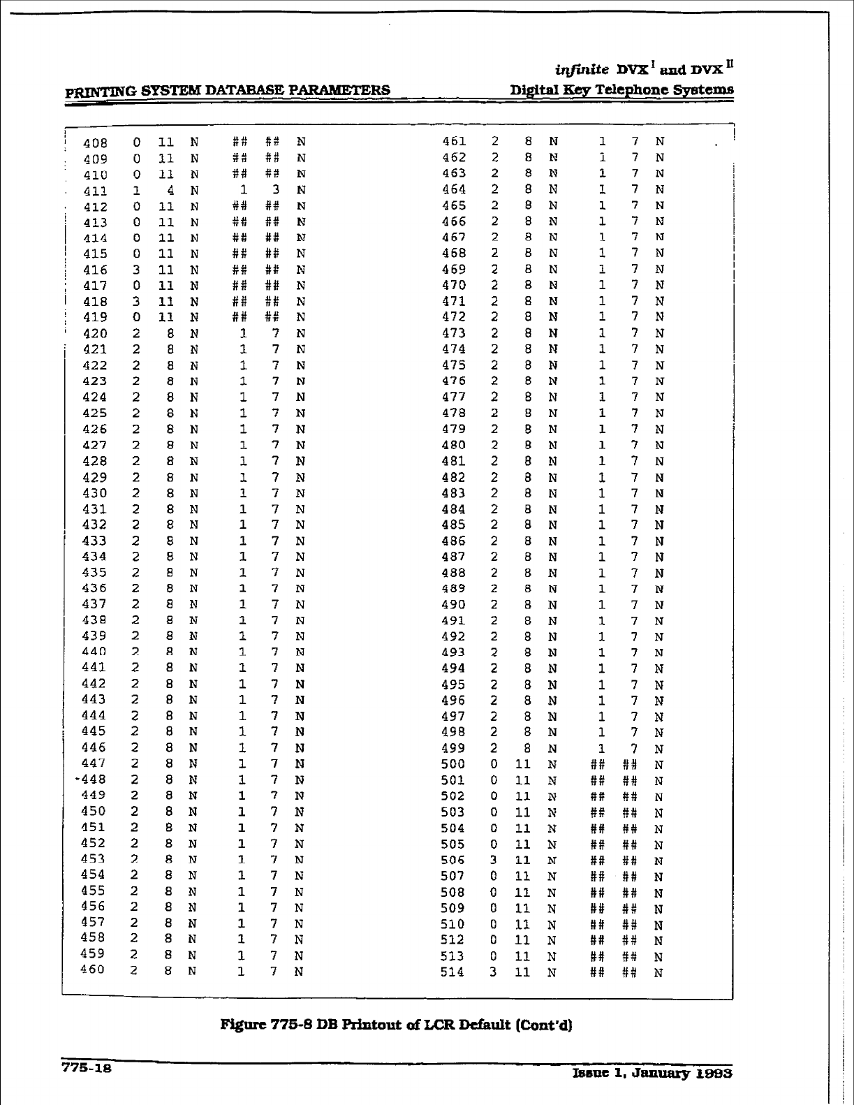
itlfinfte DVX I and DVX I1
p-G SYSTEM DATARASE PARAMETERS Dij$taI Key Telephone Systems
! 408
: 409
410
411
I 412
! 413
414
; 415
j 416
' 417
/ 418
i 419
i 420
421
422
423
424
425
426
427
428
429
430
431
432
433
434
435
436
437
438
439
440
441
442
443
444
445
446
447
-448
449
450
451
452
453
454
455
456
457
458
459
460
0
0
0
1
0
0
0
0
3
0
3
0
2
2
2
2
2
2
2
2
2
2
2
2
2
2
2
2
2
2
2
2
2
2
2
2
2
2
2
2
2
2
2
2
2
2
2
2
2
2
2
2
2
11 N
11 N
11 N
4 N
11 N
11 N
11 N
11 N
11 N
11 N
11 N
11 N
8 N
8 N
8 N
8 N
8 N
8 N
8 N
8 N
8 N
8 N
8 N
8 N
8 N
8 N
8 N
8 N
8 N
8 N
8 N
8 N
8 N
8 N
8 N
8 N
8 N
8 N
8 N
8 N
8 N
8 N
8 N
B N
8 N
8 N
8 N
8 N
8 N
8 N
8 N
8 N
8 N
8::
3::
t3
1
W#
##
##
##
#X
##
##
##
1
I
1
1
1
1
1
1
1
1
1
1
1
1
1
1
1
1
1
1
1
1
1
1
1
1
1
1
1
1
1
1
1
1
1
1
1
1
1
1
1
t4 N
#:: N
f:! N
3 N
#t N
tf: N
#ii N
#t N
tti N
## N
$1: N
8:: N
7 N
7 N
7 N
7 N
7 N
7 N
7 N
7 N
7 N
7 N
7
N
7 N
7 N
7 N
7 N
7 N
7 N
7 N
7
N
7 N
7 N
7 N
7 N
7 N
7 N
7 N
7 N
7 N
7 N
7 I?
7 N
7 N
7 N
7 N
7 N
7 N
7 N
7 N
7 N
7 N
7 N
461
462
463
464
465
466
467
468
469
470
471
472
473
474
475
476
477
478
479
480
481
482
483
484
485
486
487
488
489
490
491
492
493
494
495
496
497
498
499
500
501
502
503
504
505
506
507
508
509
510
512
513
514
2
2
2
2
2
2
2
2
2
2
2
2
2
2
2
2
2
2
2
2
2
2
2
2
2
2
2
2
2
2
2
2
2
2
2
2
2
2
2
0
0
0
0
0
0
3
0
0
0
0
0
0
3
8 N
8 N
8 N
8 N
8 N
8 N
8 N
8 N
a N
a N
8 N
8 N
8 N
8 N
8 N
8 N
8 N
8 N
8 N
8 N
8 N
8 N
8 N
8 N
8 N
8 N
8 N
8 N
a N
a N
8 N
8 N
8 N
8 N
8 N
8 N
8 N
8 N
8 N
11 N
11 N
11 N
11 N
11 N
11 N
11 N
11 N
11 N
11
N
11 N
11 N
11 N
11 N
1
i
1
1
1
1
1
1
1
1
1
1
1
1
1
1
1
1
1
1
1
I
1
1
1
1
1
1
1
1
1
1
1
1
1
1
1
1
1
ti:
##
#t
#P
##
#R
##
##
##
##
##
##
##
#R
7 N
7 N
7 N
7 N
7 N
7 N
7 N
7 N
7 N
7 N
7 N
7 N
7 N
7 N
7 N
7 N
7 N
7 N
7 N
7 N
7 N
7 N
7 N
7 N
7 N
7 N
7 N
7 N
7 N
7 N
7 N
7 N
7 N
7 N
7 N
7 N
7 N
7 N
7 N
## N
## N
## N
## N
## N
## N
## N
## N
#il N
## N
## N
## N
## N
## N
Fi@mc 775-8 DB printout of LCR D&Mt (Cont’d)
775-18 &me 1, January lBBS
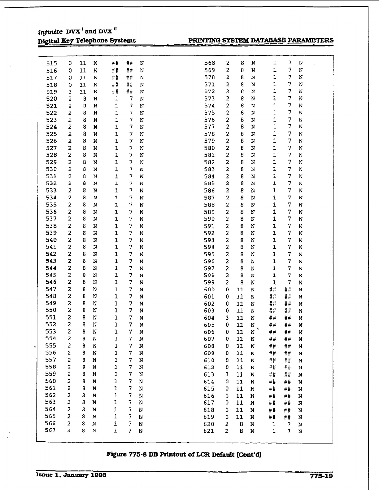
;qfinite DVX I and DVX’
Dj@td Key Telephone Spstemfi PRINTING SYSTEM DATABASE PARAMETERS
515
516
517
518
519
520
521
522
523
524
525
526
527
528
529
530
531
532
533
534
535
536
537
538
539
540
541
542
543
544
545
546
547
548
549
550
551
552
553
554
555
556
557
558
559
560
561
562
563
564
565
566
567
0
0
0
0
3
2
2
2
2
2
2
2
2
2
2
2
2
2
2
2
2
2
2
2
2
2
2
2
2
2
2
2
2
2
2
2
2
2
2
2
2
2
2
2
2
2
2
2
2
2
2
2
2
11 N
11 N
11 N
11 N
11 N
a N
a N
8 N
8 N
a N
8 N
8 N
8 N
8 N
8 N
8 N
8 N
8 N
8 N
8 N
8 N
8 N
8 N
8
N
8 N
8 N
a N
8 N
8 N
8 N
8 N
a N
a N
a N
8 N
8 N
8 N
8 N
a N
8 N
8 N
8 N
a N
8 N
8 N
8 N
a N
8 N
a N
a N
8
N
8 N
8 N
#a
##
##
ax
#I
1
1
1
1
1
1
1
1
1
1
1
1
1
1
1
1
1
1
1
1
1
1
1
1
1
1
1
1
1
1
1
1
1
1
1
1
1
1
1
1
1
1
1
1
1
1
1
1
48 N
$8
N
C:: N
#I N
#t N
7 N
7 N
7 I?
7 N
7 N
7 N
7 N
7 N
7 N
7 N
7 N
7 N
7 N
7 N
7 N
7 N
7 N
7 N
7 N
7 N
7 N
7 N
7 N
7 N
7 N
7 N
7 N
7 N
7 N
7 N
7 N
7 N
7 N
7 N
7 N
7 N
7 N
7 N
7 N
7 N
7 N
7 N
7 N
7 N
7 N
7 N
7 N
7 N
568
569
570
571
572
573
574
575
576
577
578
579
580
581
582
583
584
585
586
587
588
589
590
591
592
593
594
595
596
597
598
599
600
601
602
603
604
605
606
607
608
609
610
612
613
614
615
616
617
618
619
620
621
2
2
2
2
2
2
2
2
2
2
2
2
2
2
2
2
2
2
2
2
2
2
2
2
2
2
2
2
2
2
2
2
0
0
0
0
3
0
0
0
0
0
0
0
3
0
0
0
0
0
0
2
2
8 N
8 N
8 N
8 N
8 N
8 N
8 N
8 N
8 N
8 N
8 N
8 N
8 N
8 N
8 N
8 N
8 N
8 N
8 N
8 N
8 N
8 N
8 N
8 N
8 N
8 N
8 N
8 N
8 N
8 N
8 N
8 N
11 N
11 N
11 N
11 N
11 N
11 N.
11 N"
11 N
11 N
11
N
11 N
11 N
11 N
11 N
11 N
11 N
11 N
11 N
11 N
8 N
B
N
1
1
1
1
1
1
1
1
1
1
1
1
1
1
1
1
1
1
1
1
1
1
1
1
1
1
1
1
1
1
1
1
##
##
X#
##
P#
##
##
##
##
##
##
##
##
##
##
##
#i:
##
##
1
1
7 N
7 N
7 N
7 N
7 N
7 N
7 N
7 N
7 N
7 N
7 N
7 N
7 N
7 N
7 N
7 N
7 N
7 N
7 N
7 N
7 N
7 N
7 N
7 N
7 N
7 N
7
N
7 N
7 N
7 N
7 N
7 N
tf: N
## N
## N
## N
## N
## N
#t N
#if N
#I# N
## N
## N
## N
## N
t# N
fc# N
## N
#t: N
## N
## N
7 N
7
N
Ffgurc 776-8 DB Printout of LCR Default [Cont’d)
Issue 1. Janumy 1993 776-18
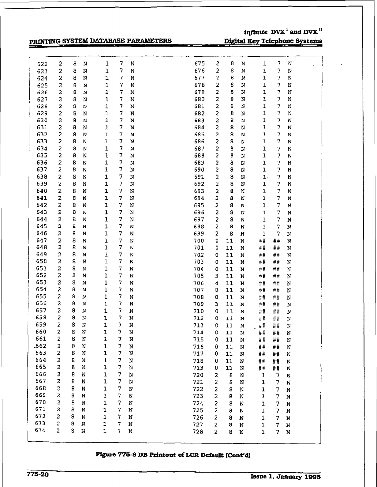
r
p-G SYSTEMDATABASE
PARAMETERS
iqjidfe DVX’audDVX”
DIgital Key Telephone S~rrituns
622
/ 623
1 624
! 625
626
; 627
628
/ 629
630
631
632
633
634
635
636
637
638
639
640
641
642
643
644
645
646
647
648
649
650
651
652
653
654
655
656
657
658
659
660
661
,662
663
664
665
666
667
668
669
670
671
672
673
674
2 8 N
2 8 N
2 8 N
2 8 N
2 8 N
2 8 N
2 8 N
2 8 N
2 8 N
2 a N
2 8 N
2 8 N
2 8 N
2 8 N
2 8 N
2 8 N
2 a N
2 8 N
2 8 N
2 a N
2 8 N
2 8 N
2 8 N
2 8 N
2 8 N
2 8 N
2 8 N
2 8 N
2 8 N
2 8 N
2 8 N
2 8 N
2 8 N
2 8 N
2 8 N
2 8 N
2 8 N
2 8 N
2 8 N
2 8 N
2 8 N
2 8 N
2 8 N
2 8 N
2 8 N
2 8 N
2 8 N
2 8 N
2 8 N
2 8 N
2 8 N
2 8 N
2 8 N
1 7 N
1 7 N
1 7 N
1 7 N
1 7
N
1 7 N
1 7 N
1 7 N
1 7 N
1 7 N
I. 7 N
1 7 N
1 7 N
1 7 N
1 7 N
1 7 N
1 7 N
1 7 N
1 7 N
1 7 N
1 7 N
1 7 N
1 7 N
1 7 N
1 7 N
1 -? N
1 7 N
1 7 N
1 7 N
1 7 N
1 7 N
1 7 N
1 7 N
1 7 N
1 7 N
1 7 N
1 7 N
1 -J N
1 ? N
1 7 N
1 7 N
1 7 N
1 7 N
1 7 N
1 7 N
1 7 N
1 7 N
1 7 N
1 7 N
1 7 N
1 7 N
1 7 N
1 7 N
675 2 8 N
676 2 8 N
677 2 8 N
678 2 a N
679 2 8 N
680 2 8 N
681 2 8 N
682 2 8 N
683 2 8 N
684 2 8 N
685 2 8 N
686 2 8 N
687 2 8 N
688 2 8 N
689 2 8 N
690 2 8 N
691 2 8 N
692 2 8 N
693 2 8 N
694 2 8 N
695 2 8 N
696 2 8 N
697 2 8 N
698 2 8 N
699 2 6 N
700 0 11 N
701 0 11 N
702 0 11 N
703 0 11 N
704 0 11 N
705 3 11 N
706 4 11 N
707 0 11 N
708 0 11 N
709 3 11 N
710 0 11 N
712 0 11 N
713 0 11 N
714 0 11 N
715 0 11 N
716 0 11 N
717 0 11 N
718 0 11 N
719 0 11 N
720 2 8 N
721 2 8 N
722 2 8 N
723 2 8 N
724 2 8 N
725 2 8 N
726 2 8 N
727 2 8 N
728 2 8 N
1
7 N
1
7 N
1 7 N
1 7 N
1 7 N
1 7 N
1 7 N
1 7 N
1 7 N
1 7 N
1 7 N
1 7 N
1 7 N
1 7 N
1 7 N
1 7 N
1 7 N
1 7 N
1 7 N
1 7 N
1 7 N
1 7 N
1 7 N
1 7 N
1 7 N
## ## N
P# ## N
#i# ## N
## ## N
#t ## N
XI #8 N
#I ## N
#t ## N
## ## N
## #it N
##I ## N
#i: ## N
## ## N
#f ## N
## ## N
#I: ## N
## ## N
+I# ## N
#t ## N
1 7 N
1 7 N
1 7 N
1 7 N
1 7 N
1 7 N
1
7 N
1 7 N
1 7 N
Figure 778-S DB printout of LCR DcfauIt (Cimt’d)
77S-20
Issue 1, &Imlaxy 1993
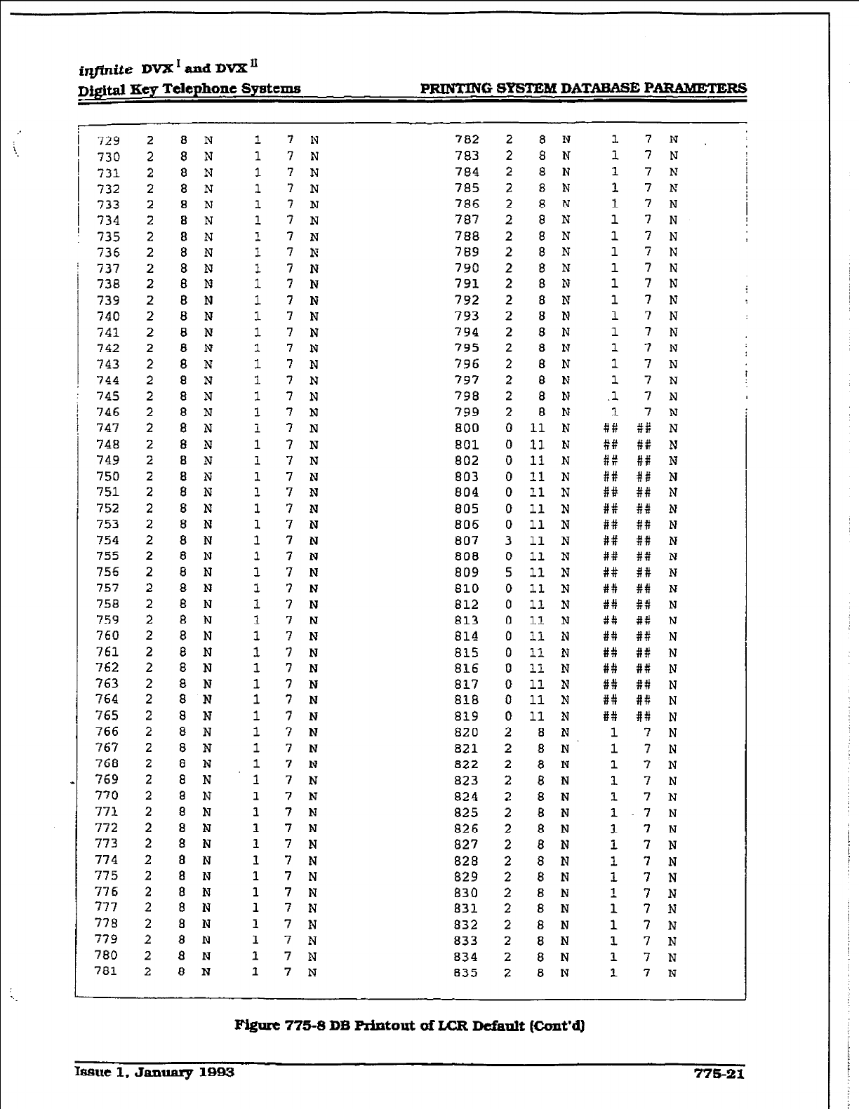
@fjntte DVX’ and DVX”
DQJ~ Key Telephone Systems -G 8YSI’JZM DATABASE PARAMETERS
1
729
730
731
732
a 733
734
: 735
736
737
738
739
740
741
742
743
744
745
746
747
748
749
750
751
752
753
754
755
756
757
758
759
760
761
762
763
764
765
766
767
768
769
770
771
772
773
774
775
776
777
778
779
780
781
2
2
2
2
2
2
2
2
2
2
2
2
2
2
2
2
2
2
2
2
2
2
2
2
2
2
2
2
2
2
2
2
2
2
2
2
2
2
2
2
2
2
2
2
2
2
2
2
2
2
2
2
2
a N
8 N
8 N
8 N
a N
a N
a N
8 N
8 N
8 N
8 N
8 N
8 N
8 N
8 N
8 N
8 N
8 N
8 N
8 N
a N
a N
8 N
8 N
8 N
8 N
8 N
8 N
8 N
8 N
8 N
8 N
8 N
8 N
8 N
a N
8 N
8 N
8 N
8 N
8 N
8 N
8 N
8 N
8 N
8 N
8 N
a N
8 N
8 N
8 N
8 N
8 N
1
1
1
1
1
1
1
I
1
1
1
1
1
1
1
1
1
1
1
1
1
1
1
1
1
1
1
1
1
1
1
1
1
1
1
1
1
1
1
1
1
1
1
1
1
1
1
1
1
1
1
1
1
7 N
7 N
7 N
7 N
7 N
7 N
7 N
7 N
7 N
7 N
7 N
7 N
7 N
7 N
7 N
7 N
7 N
7 N
7 N
7 N
7 N
7 N
7 N
7 N
7 N
7 N
7 N
7 N
7 N
7 N
7 N
7 N
7 N
7 N
7 N
7 N
7 N
? N
7 N
7 N
7 N
7 N
7 N
7 N
7 N
7 N
7 N
7 N
7 N
7 N
7 N
7 N
7 N
782
783
784
785
786
787
788
789
790
791
792
793
794
795
796
797
798
799
a00
801
802
803
804
805
806
807
808
809
810
812
813
814
815
816
81'7
818
819
820
821
822
823
824
825
826
827
828
829
830
831
832
833
834
a35
2 8 N
2 8 N
2 8 N
2 8 N
2 8 N
2 8 N
2 8 N
2 8 N
2 a N
2 a N
2 8 N
2 8 N
2 8 N
2 8 N
2 8 N
2 8 N
2 8 N
2 8 N
0 11 N
0 11 N
0 11 N
0 11 N
0 11 N
0 11 N
0 11 N
3 11 N
0 11 N
5 11 N
0 11 N
0 11 N
0 11 N
0 11 N
0 11 N
0 I1 N
0 11 N
0 11 N
0 11 N
2 8 N
2 8 N
2 8 N
2 8 N
2 8 N
2 8 N
2 a N
2 8 N
2 8 N
2 8 N
2 8 N
2 8 N
2 8 N
2 8 N
2 8 N
2 8 N
1 7 N
1 7 N
1 7 N
1 7 Is
1 7 N
1 7 N
1 7 N
1 7 N
1 7 N
1 7 N
1 7 N
1 7 N
1
7 N
1 7 N
1 7 N
1
7 N
.l 7 N
1 7 N
#X f# N
#f: #i: N
## ## N
I# ## N
#up #I# N
8:: fi:! N
#if 8# N
## ## N
## X# N
#t ## N
## ## N
i## %# N
t# ## N
## ## N
i## ## N
## ## N
## f# N
f# ## N
## ## N
1 7 N
1 7 N
1 7 N
1 7 N
1 7 N
l-7 N
1 7 N
1 7 N
1 7 N
1 7 N
1 7 N
1 7 N
1 7 N
1 7 N
1 7 N
1 7 N
F-&KC 775-8
DB printout uf I&R De&tit (Cont’d)
Issue 1. January 19fW
77621
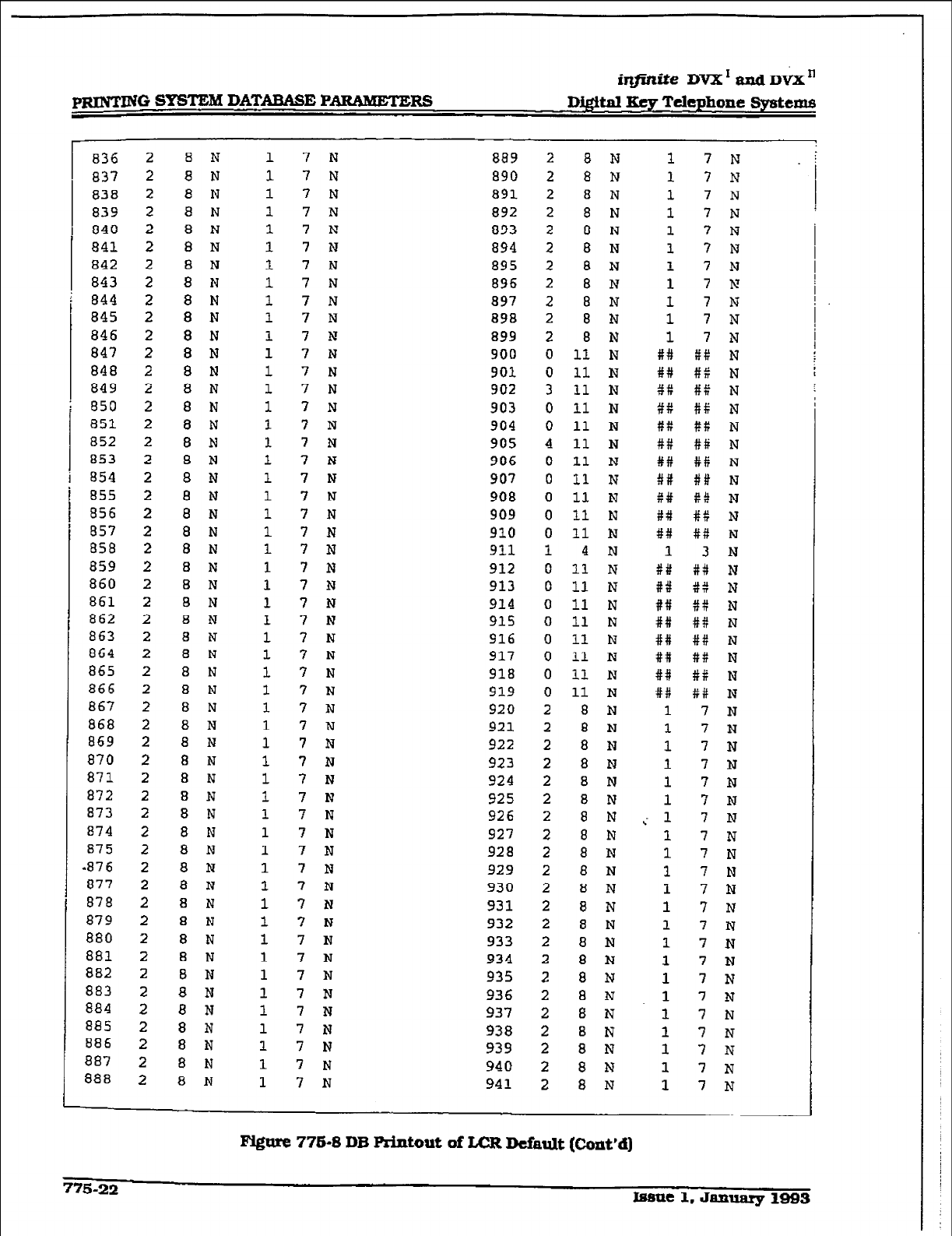
r
pRINTIN SYSTEM DATABASE PARFMETERS
iqf%ite
DVX’andDi’X”
Digital IKey Telephone Systems
036 2 a N
837 2 a N
838 2 8 N
839 2 a N
840 2 8 N
841 2 8 N
842 2 I3 N
843 2 a N
844 2 8 N
845 2 8 N
846 2 8 N
847 2 8 N
848 2 8 N
849 2 8 N
850 2 8 N
851 2 8 N
a52 2 8 N
853 2 8 N
854 2 8 N
855 2 a N
856 2 8 N
857 2 8 N
858 2 8 N
859 2 a N
860 2 a N
861 2 8 N
862 2 8 N
863 2 8 N
864 2
a N
865 2 8 N
866 2 8 N
867 2 8 N
868 2
a N
869 2 a N
870 2 8 N
871 2 8 N
872 2 8 N
873 2 8 N
874 2 8 N
875 2 8 N
-876 2 8 N
877 2 8 N
878 2 a N
879 2 8 N
880 2 8 N
881 2 a N
882 2 a N
883 2 8 N
884 2 8 N
885 2 8 N
886 2 8 N
887 2 8 N
88% 2 8
N
1
7 N
1
7 N
1
7 N
1
7 N
1
7 N
1
7 N
1
7 N
1
7 N
1
7 N
1
7 N
1
7 N
1
7 N
1
7 N
1
7 N
1
? N
1
7 N
1
7 N
I
7 N
1
7 N
1
7 N
1 7 N
1 7 N
1 7 N
1 7 N
1 7 N
1 7 N
1 7 I?
1 7 N
1 7 N
1 7 N
1 ? N
1 7 N
1 7 N
1 7 N
1 7 N
1 ? N
1 7 N
1 7 N
1 7 N
1 7 N
1 7 N
1 7 N
1 7 N
1
? N
1
7 N
1 7 N
1
7 N
1
7 N
1
7 N
1 7 N
1 7 N
1 7 N
1 7 N
889
890
891
892
893
894
a95
896
a97
898
899
900
901
902
903
904
905
906
907
908
909
910
911
912
913
914
915
916
917
918
919
920
921
922
923
924
925
926
927
928
929
930
931
932
933
934
935
936
937
938
939
940
941
8 N
8 N
8 N
8 N
8 N
8 N
8 N
8 N
8 N
8 N
8 N
II N
11 N
11 N
11 N
11 N
11 N
11 N
11 N
11 N
11 N
11 N
4 N
11 N
11 N
11 N
11 N
11
N
11 N
11 N
11 N
8 N
8 N
8 N
8 N
8 N
8 N
8 N
8 N
8 N
8 N
8
N
8 N
8 N
a N
8 N
8 N
8 N
8 N
8 N
a N
8 N
8 N
1 7 N
1 7 N
1 7 N
1
7 N
1 7 N
1 7 N
1 7 N
1 7 M
1
7 N
1
7 N
1
7 N
##
fP N
%#
#$ N
Qf
#% N
+fP
#f N
#f
## N
##
#fi N
##
88 N
##
## N
##
Pi! N
##
## N
##
## N
1
3 N
##
#d N
t'd
8:: N
##
#t: N
##
## N
##
## N
##
## N
##
## N
##
## N
1
7 N
1
7 N
1
7 N
1 7 N
1 7 N
1 '? N
i 1 7 N
1 7 N
1 7 N
1 7 N
1 7 N
1 7 N
1 7 N
1 7 N
1 7 N
1 7 N
1 7 N
1 7 N
1 7 N
1 7 N
1 7 N
1 7 N
Pygurc 776-B
DB printout of LCR Dcfidt (Co&d)
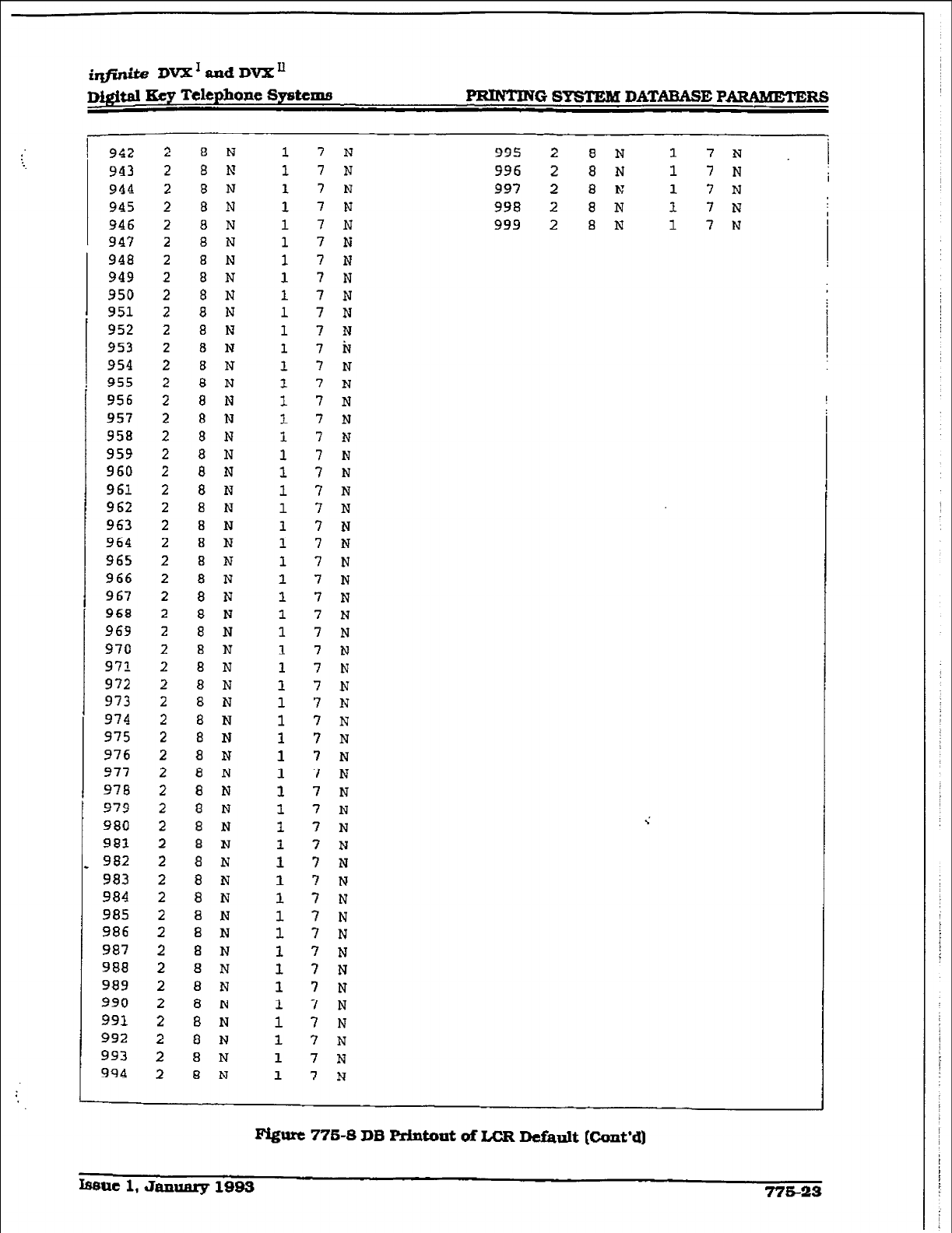
imite DVX1andDVXu
D&&al Key Telephone Systems PRINTING SYSTEM DATABASE PARAMETERS
942
943
944
945
946
947
948
949
950
951
952
953
954
955
956
957
958
959
960
961
962
963
964
965
966
967
968
969
970
971
972
973
974
975
976
977
978
979
980
981
982
983
984
985
986
987
988
989
990
991
992
993
994
2
2
2
2
2
2
2
2
2
2
2
2
2
2
2
2
2
2
2
2
2
2
2
2
2
2
2
2
2
2
2
2
2
2
2
2
2
2
2
2
2
2
2
2
2
2
2
2
2
2
2
2
2
8 N
8 N
8 N
8 N
8 N
8 N
8 N
8 N
8 N
8 N
8 N
8 N
8 N
8 N
8 N
8 N
8 N
8 N
8 N
8 N
8 N
8 N
8 N
8 N
8 N
8 N
8 N
8 N
8 N
8 N
8 N
a N
8 N
8 N
8 N
a N
8 N
8 N
8 N
8 N
8 N
8 N
8 N
8 N
8 N
8 N
8 N
8 N
8 N
8 N
8 N
8 N
8 N
1
1
1
1
1
1
1
1
1
1
1
1
1
1
1
1
1
1
1
1
1
1
1
1
1
1
1
1
1
1
1
1
1
1
1
1
1
1
1
1
1
1
1
1
1
1
1
1
1
1
1
1
1
7 N
995 2 8 N 1 7N I
7 N 996 2 8 N 1 7 N I
7 N 997 2 8 N 1 7 N
7 N 998 2 8 N 1 7 N
7 N 999 2 8 N 1 7 N
7 N
7 N
7 N
7 N
7 N
7 N
7 iv
7 N
7 N
7 N I
7 N
7 N
7 N
7 N
7 N
7 N
7 N
7 N
7 N
7 N
7 N
7 N
7 N
7 N
7 N
7 N
7 N
7 N
? N
7 N
7 N
7 N
7 N
7 N
7 N
7 N
7 N
7 N
7 N
7 N
7 N
7 N
7 N
7 N
7 N
7 N
7 N
7 N
m 776-8 DB Printout ai LCR Default (Cont*cI]
Issue 1, January 1993 776-23
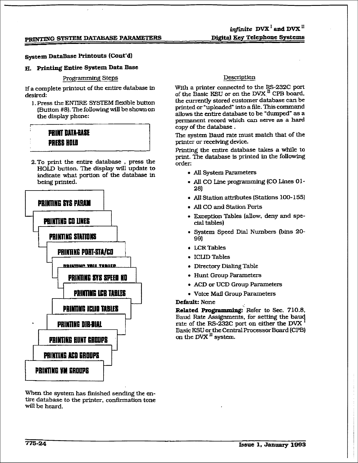
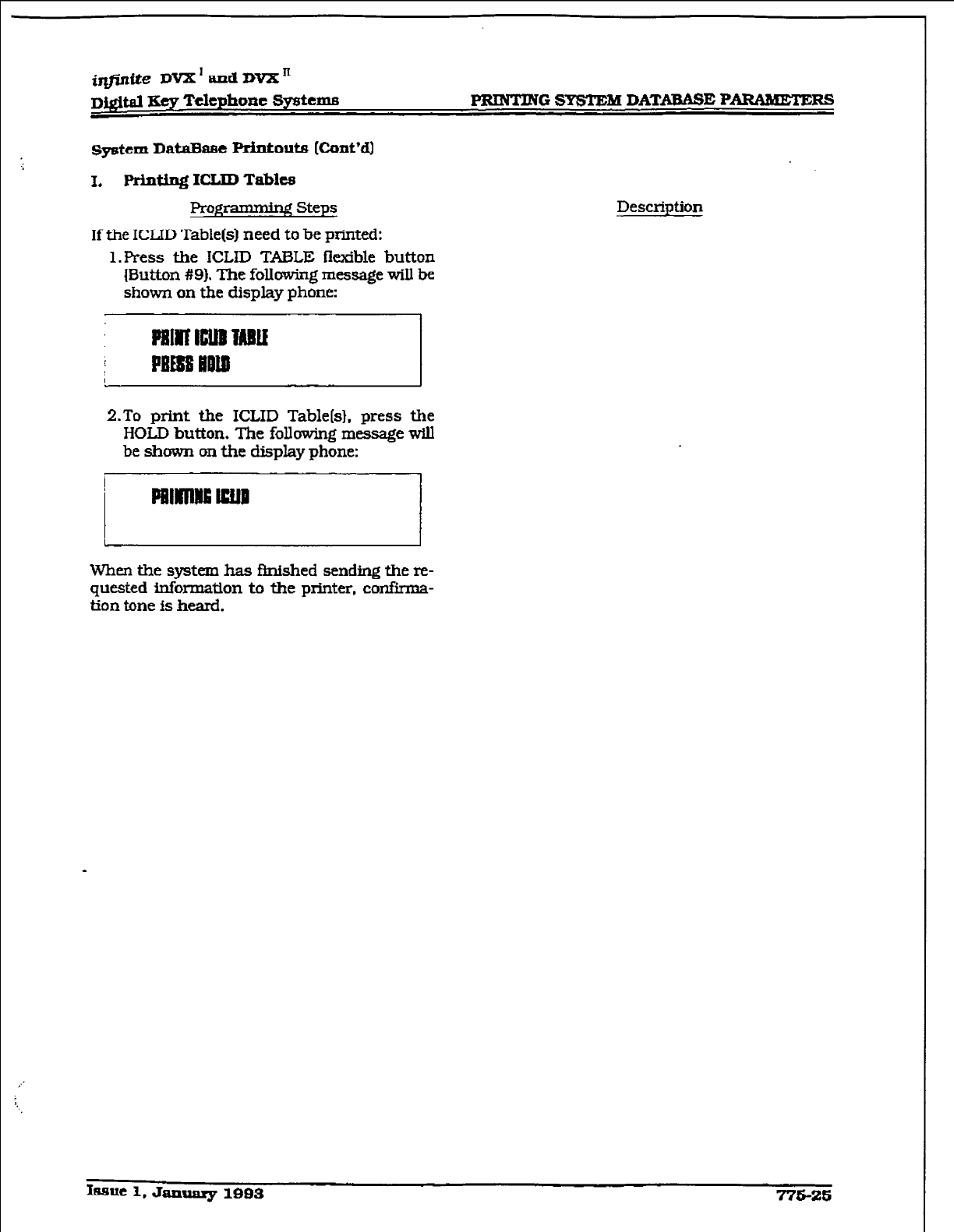
system DaMSiEe
Printouts
[Cont’d)
I.
FWnt.ing ICIJD Tables
Rogm steps
If the ICLJD Table(s) need to be printed:
1. Press the ICLID TMLE kxible button
{Button #9). The following message wiIl be
shown on the display phone:
Description
2.To print the ICLID Table[s}, press the
HOLD button. The following message will
be shown on the display phone:
When the system has finished sending the re-
quested information to the printer, confirma-
tion tone is heard.
k~ue l,JmuaqrlBB3 775-26
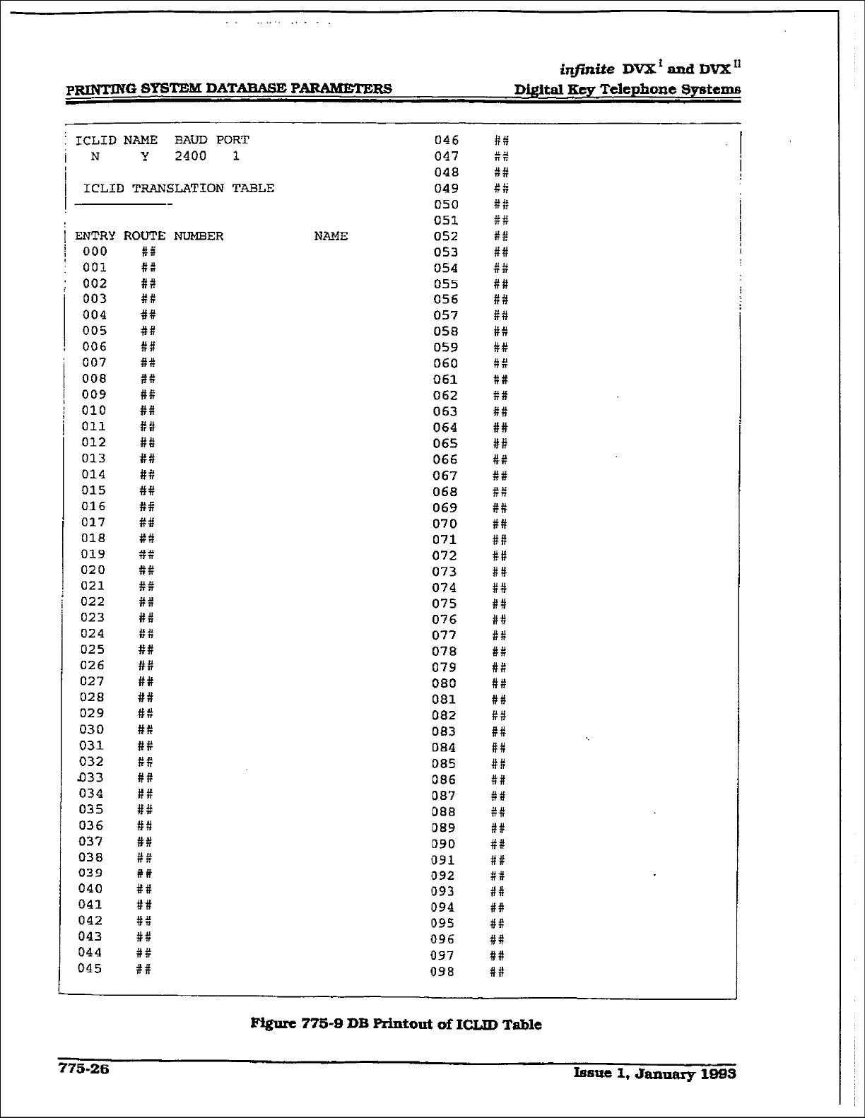
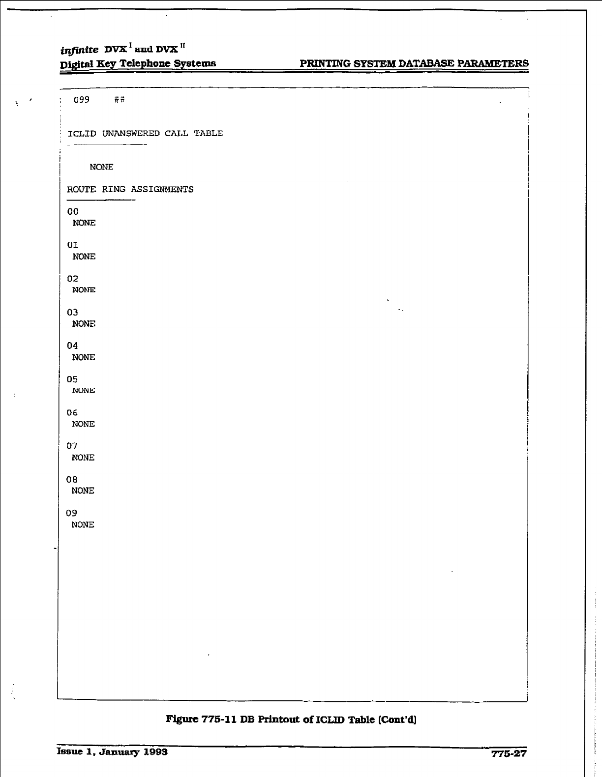
@finite DVX * aud DVX ’
D&$m Key Telephone Sy8teu.w
: 099 ti6
PRINTING SYSTEM DATABME PARMHETEm
I
; ICLID UNANSWERED CALL TABLE
NONE
ROUTE RING ASSIGNMENTS
00
NONE
01
NONE
I32
NONEI
03
NONE
04
NONE
05
NONE
06
NONE
07
NONE
08
NONE
09
NONE
m 775-11 DB Rintout of ICUD Table (Cont’dj
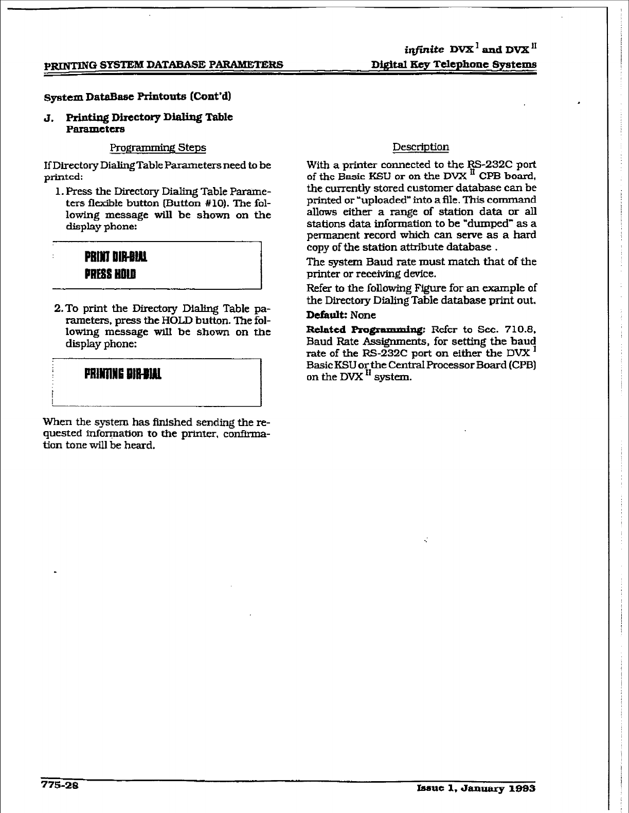
p-G SYSTEM DAT-E PARAMETERS
@@z&e DVX’ and DVX”
Di@al Key Telephone Systems
qrstem ~&a&use Printouts (Cont*dI
J. Prlntiug Directory DiaU.ng Table
P-tCI8
ProgrimmCqq Steps
If Directory DiaIingTable Parameters need to be
pmLteii;
1. Press the Directov Dialing Table Parame-
ters
flexibie button {Button #lo). The fol-
lowing message will be shown on the
clispIay phone:
2.To print the Directory DMfng Table pa-
rameters, press the HOLD button. The fol-
lowing message wIIl be shown on the
dispIay phone:
lmilllfi IMlmL I
,
Description
With a printer connected to the RS-232C port
of tie Basic KSU or on the DVX ’ CPB board,
the cusrently stored customer database can be
printed or ?rploaded” into a file. This command
allows either a range of station data
or all
stations data information to be wdmnpcd” as a
permanent record which can serve as a hard
copy of the station attribute database .
The system Baud rate must match that of the
printer or receiving device.
Refer to the folIowing Figure for an example of
the Directory Dialing TabIe database print out.
Defaultz None
Related Progmmmixq:
Refer to Sec. 7103,
Baud Rate Assignments, for setting the bauy
rate of the RS-232C port on either the DVX
I3asic KSLI or the CentraI Processor Eloard (CPE3]
on the DVX ” system.
1 1
When the system has Mshed
sending
the re-
quested info-ation to the printer, confirma-
tion tone will be heard.
775-28 Issue I. &uuuuy IQ93
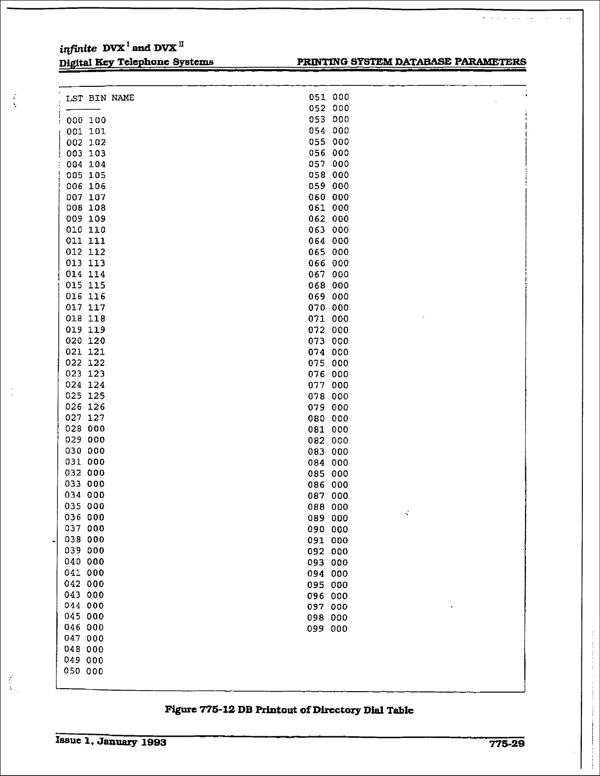
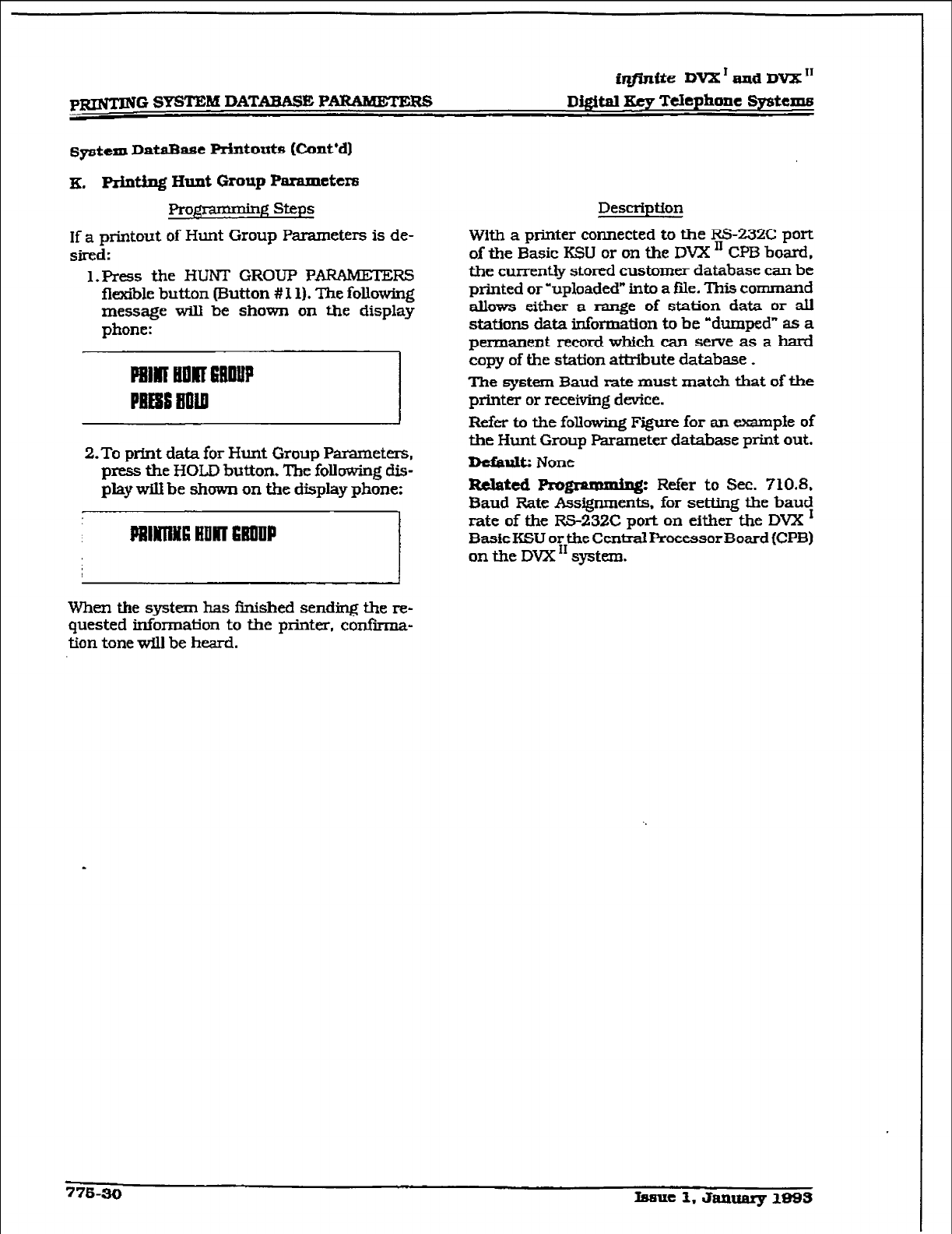
iqtiniie DVX ’ and DVX I1
Di#al Xey Telephone Systems
q&m~ DataBase Printouts (Cont*d)
x, Printing alIlt Group ParaIxlcters
Pro)$amming steps
If a printout of Hunt Group Parameters is de-
sired:
1. Press the
HUNT GROUP PARAMETERS
flexiile button mutton # l 1). The folIowing
message will be shown on the display
phone:
2.To print data for Hunt Group Parameters,
press the HOLD
button. The following dis-
play
wIII
be
shown on the display phone:
When the system has fjnished sending the re-
quested information to the printer, confkma-
tion tone
will
be
hcmi.
Description
With a ptiter connected to the RS-23ZC port
of the Basic KSU or on the DVX ’ CPB board,
the currently stored customer database can be
printed or -uploaded” into a file- This command
allows either a range of station data or all
stations data Morn&ion io be -dumped” as a
permanent record which can seme as a hard
copy of the station attribute database .
The
system
Baud rate must match that of the
printer or receiving device.
Refer to the following Figure for an example of
the Hunt Group Parameter database print out.
Dcfauk None
Related
Rmpuuning Re.Ser to Sec. 710.8,
Baud Rate Assigrments, for setting the bauy
rate of the RS-232C port on
either the DVX
Basic KSU or the Central Processor Board (CPB)
on the DVX I1 system.
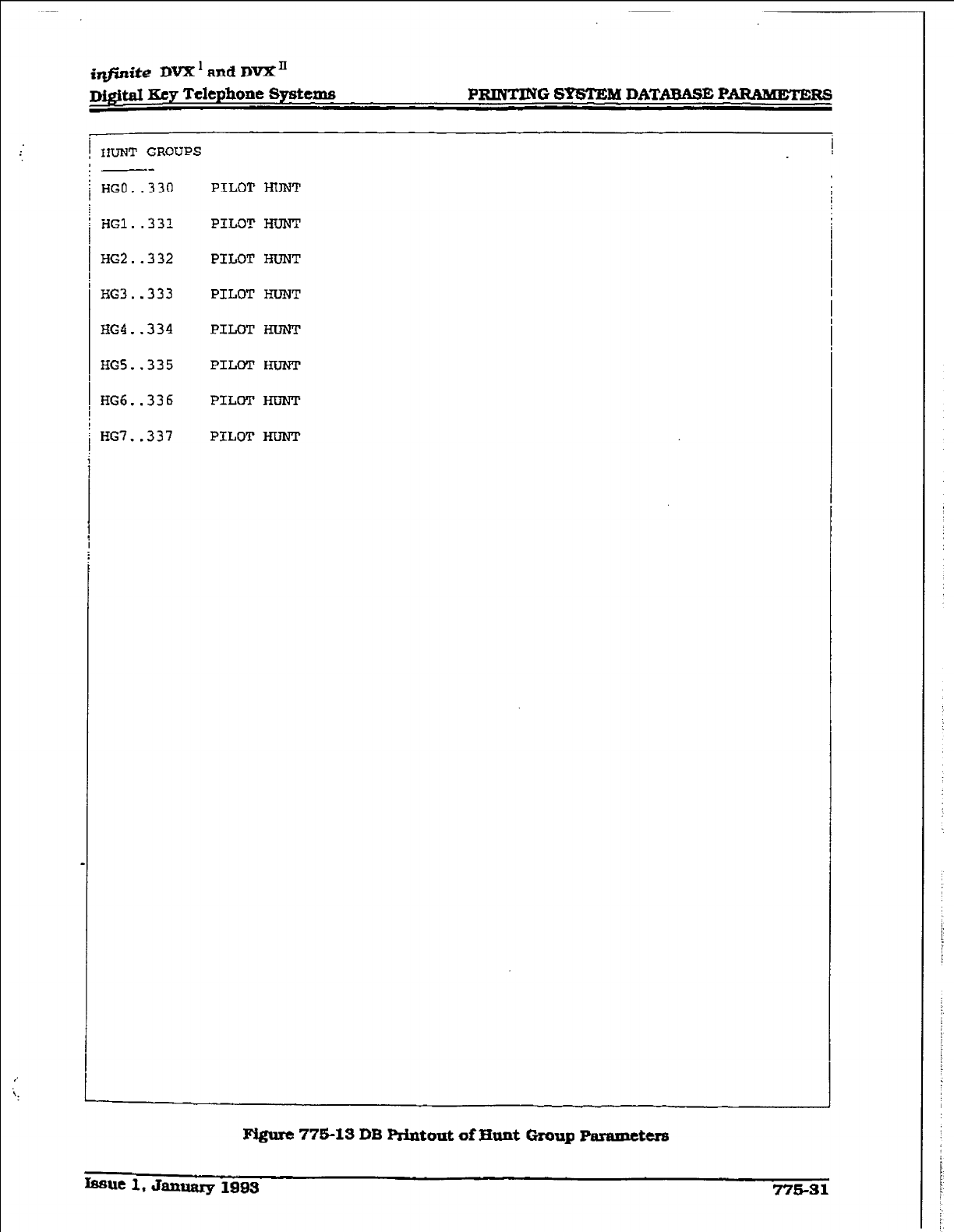
i@nite DVX’ ancl DVX’
D&it&d Key Telephone Systems
i HUNT GROUPS
PRINTING S-M DATABASE PB
!
--
HGO.
.330 PILOT HUNT
HGl..332 PILOT HUNT
HG2..332
HG3..333
EG4..334
HGS.,335
HG6..336
HG7..337
PILOT HUNT
PILOT HUNT
PILOT I3luNT
PILOT lLn,lwr
PILOT HUNT
PILOT HUNT
Figure 7751s DB P&to& of Hunt Group mramcters
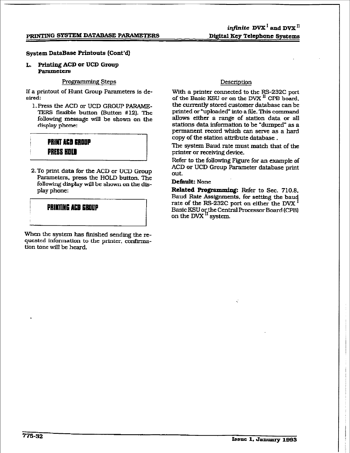
ht,ife DVX ’ and D’VX’
-G SYSTEBI DATABASE P-R!3
System
DataBase
Printouts
(Co&d)
L, Priding ACD
or
UCD Group
Pfuamcter8
Proggamniq Steps
If a printout of Hunt Group Parameters is de-
sired:
1. Press the ACD or UCD GRCXIP PARAME-
TERS flexible button (Button #lZ]. ‘DE
following message will be shown on the
display phone:
2.To print data for the ACD or UCD Group
Parameters, press the I-KXD button. The
following display will be shown on the dis-
play phone:
When the system has finished sending the re-
quested information to the printer, confirma-
tion tone will be heard.
Description
With a printer connected to the KS-232C port
of the Basic KSU or on the DVX ’ CPB board,
the currently stored customer database can be
printed or -uploaded” into a ftie. This commsnd
abws efther a range of station data or all
stattons data information to be -durnpcd” as a
permanent record which can serve as a hard
copy of the station attribute database .
The system Baud rate must match that of the
printer or receiving device.
Refer to the following Figure for an example of
ACD or UCD Group Parameter database print
out.
Default:
None
Related Pro@-d: Refer to Sec. 710.8,
Baud Rate Ass@x~~~~ts, for setting the baud
rate of the RS-232C port on either the DVX ’
Basic KSU or the Central Processor Board (CR31
on the DVX ’ systcrn.
775-32
lsuuc 1, January I%93
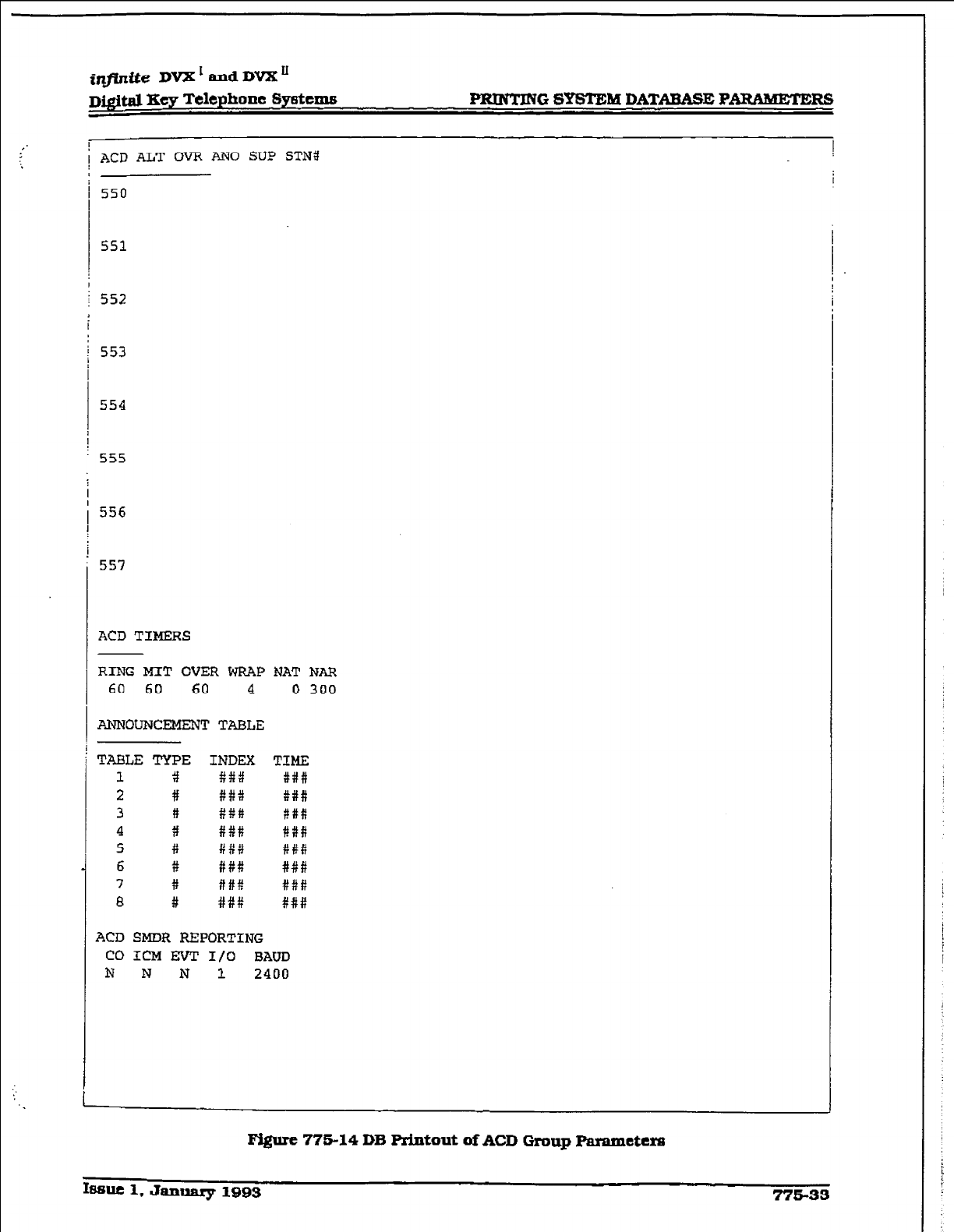
PRINTING SYSTEM DATABASE RARbMEZERS
1 ACD ALT OVR AN0 SU!? STNi!
550
553
554
555
ACD TIMERS
RING MIT OVER WRAP b?AT NAR
60 60
60 4
0
300
ANI?OtmCEMENT TAE%LE
ACD SMDR R?ZPORTING
CO ICM EiVT I/O BAUD
N N N 1
2400
-
Figure 775-14 DB Printout of ACD Group Fmametera
I8sllc 1, Jauuary 1993 775-33
-G SYSTEM DATAEWE PVRS
D.ighl Key Telephone Systems
sptem DataBme Printouts (Cont’d)
M. PAding Voice Mall Group Parameters
Prog-g steps
If
a printout of Voice M&l Group Parameters is
desired:
1. Press the VM GROUF’ PARAMETERS fla-
ible button (Button #13). Tbe following
message will be shown on the display
phone:
2. To print data
for
Voice
Mail
Group Parame-
ters,
press the HOLD button. The following
dispIay will be shown on the display phone:
When the
system
has finished sending the re-
quested information to the printer, coti-
tion tone til be heard.
Description
With a printer connected to the RS-232C bort
of the Basic KSU
or
on the DVX ’ CPB board,
the currently stored customer database can be
prkted or “uploaded” into a ftie. This command
allows either a range of station data or all
stations data infcmnation to be -dumped” as a
pemmnent record which can serve as a hard
copy of the station attribute database .
The system Baud rate must match fiat of the
printer or rece+ving device.
When printing the VM Group Parameters, the
following data is printed:
l
Voice Mail Group Parameters
l
Voice Mafl Outpulsing Table (including
the disconnect table)
l
Voice
MaA
Opttons
Refer to the following Figure for an example of
the VM Group Parameter database print out.
Default: None
Related Pro~@umuin~: Refer to Sec. 710.8,
Baud Rate Assignments. for setting the baud
rate of the RS-232C port on either the DVX ’
Basic KSU or the CenfraI Pxacessor Board (CPB)
on the DVX” system.
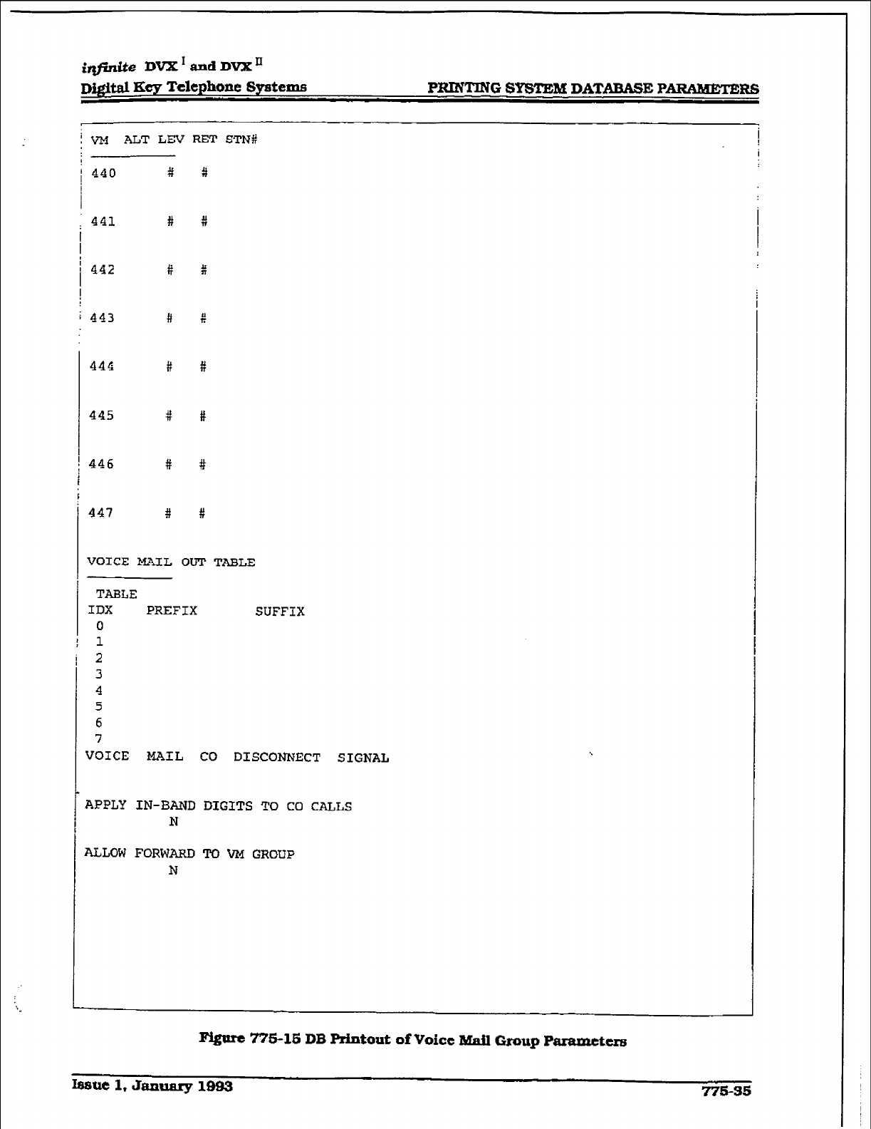
PRINTING 8Y5TJ3M DATARME P-R5
! VM ALT LEV RET STN#
1
,
: 441 #
444 ii
445 #
446 #
447 #
VOICE MAIL OUT TAEkLE
TABLE
IDX PREFIX SUFFIX
0
1
2
3
4
5
6
7
VOICE MAIL CO DISCONhZCT SIGNAL
APPLY IN-BAc?D DIGITS TO CO CALLS
N
ALLOW FORWARD TO VM GROUP
N
F&n-t 775-15 DE Printout of Voict Mail Grout Paramtttrs
bsut
1, January 1993 775-35
WG SYWEM DATAWBE PAWWEl?EW
&finite IW2Crand DVX”
D&&al Xey Telephone !Qmtcmt6
System DataBase Printouts ltint’dl
N. Abort Printing
Pqqmnmbg Steps
If you need to abort a printouk
I. Press tie=mPRImNG flexible button
[Button
#20).
2.
Press the HOLD button. The message cur-
rently on the display phone ti remain
unchanged, however tie
prMQ wiU be
aborted.
Descriptiori
77%36 Issnc 1, Jantuuy 1983
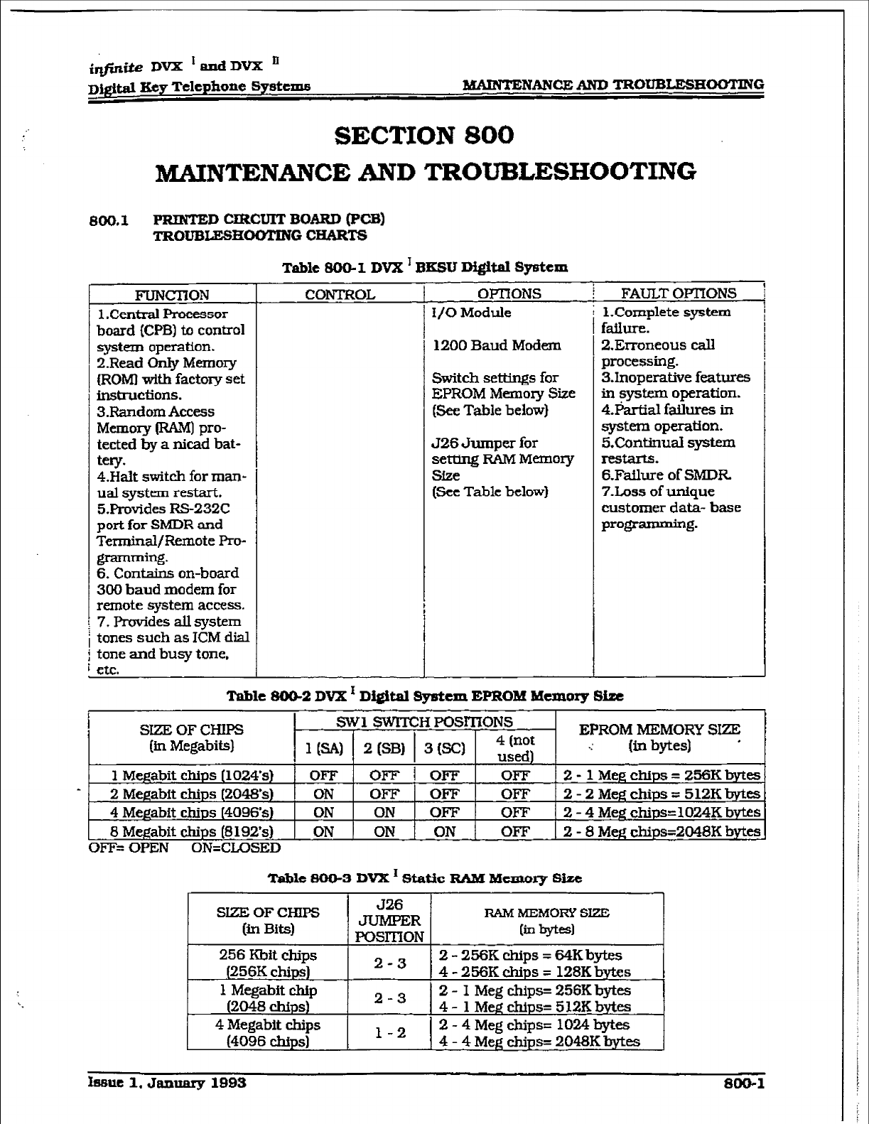
i@a DVX IandDVX’
~&v&d Ecy Telephone System6 MAlNTENANCEAND TROmmHOO’MNG
SECTION 800
MAINTENANCE AND TROUBLESHOOTING
Boo. 1 PRINTED CIRCUIT BOARD (PCB)
Table 80&l DVX ’ BXSU Di#Wl System
CONTROL
FUNmON
1 .Centi Processor
board {CPB) to control
system operation.
Z.Read Only Memow
{ROM) with factory set
hS&UCtiOIlS.
3.Random Access
Memom (RAM) pro-
tected by a nicad bat-
tery.
4.HaIt switch for man-
ual system restcart.
5Irovides RS-235X
port for SMDR and
Terminal/Remote Pro-
OPnONS
I/O Module
1200 Baud Modem
Switch setM.ngs for
EPROM Memoq Size
(See Table below)
J26 Jumper for
setting RAM Memoq
Sfze
(See Table below)
FAULT OFIIONS
1 .Complete system
failure.
2.E1~oneous call
processing.
3.Inoperative features
in system operation.
4.Partial ftiures ti
system operation.
5Lkbim.d syz5tem
restarts.
6.Failure of SMDR
7Loss of unique
customer data- base
PrW * lz-
.
6. Contains on-board
300 baud modem for
remote system access-
7. Provides all system
tones such as ICM dial
j tone and busy tone,
L etc.
Table BOG2 DVX ’ Digital System EPROM Memoxy Size
OFF= OPEN ON=CLOSED
Tabie 8CJfJ-3 DVX ’ Static RAM Menmy Size
SEE OF CHIPS
(in Bits)
256 Kbit chips
(256K chips)
1 Megabit chip
(2048 chips)
4 Megabit chips
(4096 chips)
J26
-R RAM
MEMOFCY
SEX
POSlTiON &II by-w
2-3 2 - 256K chips = 64K bes
4 - 256K chips = 128K bytes
2-3 2 - I Meg chips= 256K bytes
4 - 1 Meg chips= 512K bytes
2 - 4 Meg chips= 1024 bytes
l-2 4 - 4 Meg chips= 2048K bytes
hwuc 1, January lBB3 800-l
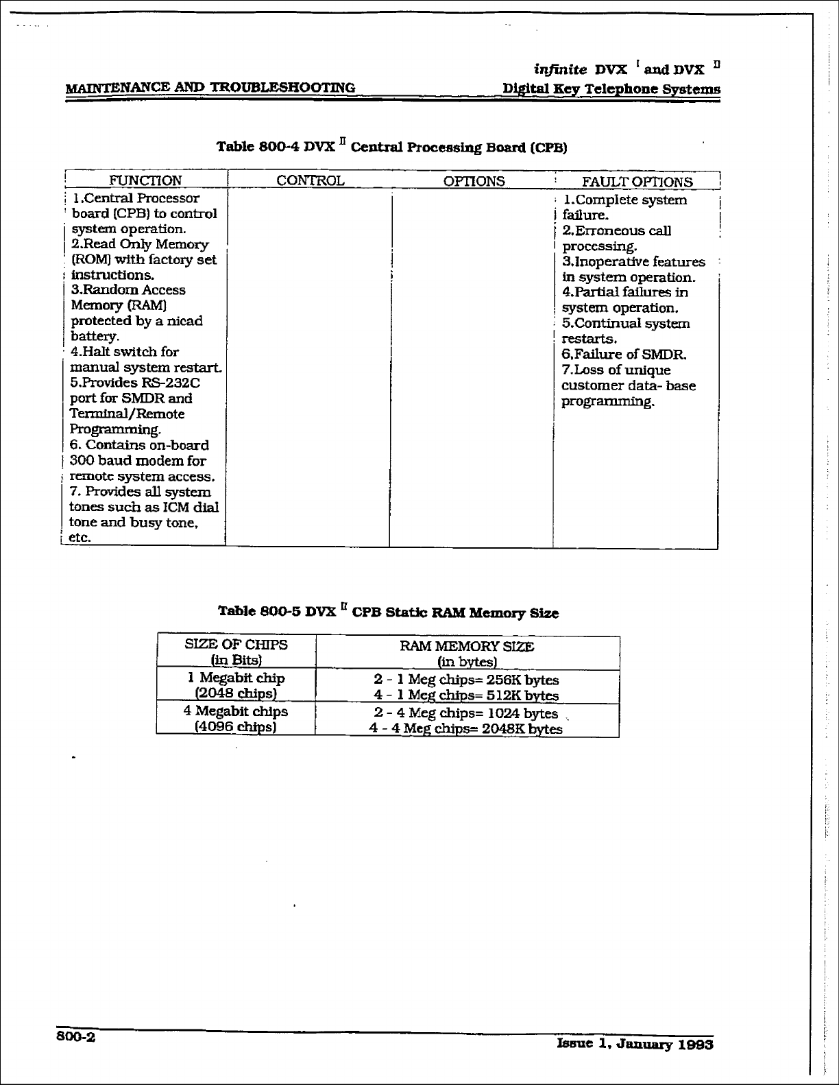
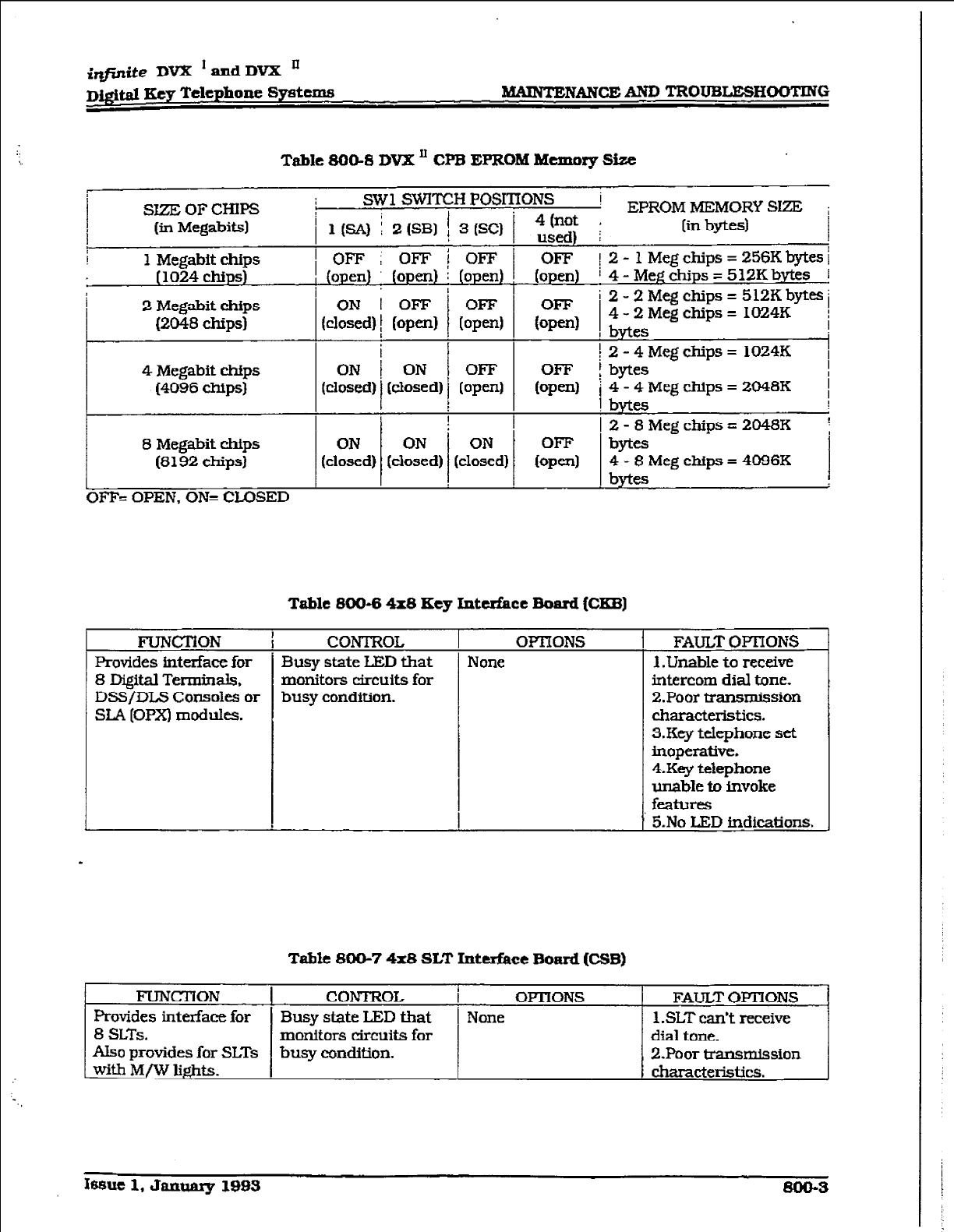
iq@ite DVX ‘=dDVX ’
D&Jd Key Tclephonc
Systems -NANCE AND TROUBLESHOOTING
Table 800-S DVX ’ CPB EPROM Memory Size
I-
SIZEOFCHIF’S SW1 SWITCH POSITIONS ’ EP~OM~MORY So i
(in Megabits] [in bytes) I
I 1 Megabit chips
[ 1024 chips)
2 Megabit chips
(2048 chips)
4 Megabit chips
(4096 chips)
Tuble MO-6 4x6 Key Interface Board (Cm)
8 Di@tal Terminals, monitors circuits for
DSS/DLS Consoles or busy condition.
FUNCTlON i
CONTROL OPTiONS
Provides interface
for 1 Busy
state
LED
that None
A.kzo provides for SLTs
Table BOO-7 4x8 SLT
Inter&e Board (CSB)
T
FAUXT OFI’IONS
1 .LJnable to receive
intercom dial tone.
2.Poor transmission
tAElEKteI-iStiCS.
3.Key telephone set
inaperative.
4.Key telephone
unable to invoke
features
5.No LED indications.
CONTROL
i
OPTIONS
FAUL.T OF’TIONS
Busy state LED that None 1 .SLT can’t meive
monitors circuits for dial tone.
busy condition. 2.Poor transmission
characteristics.
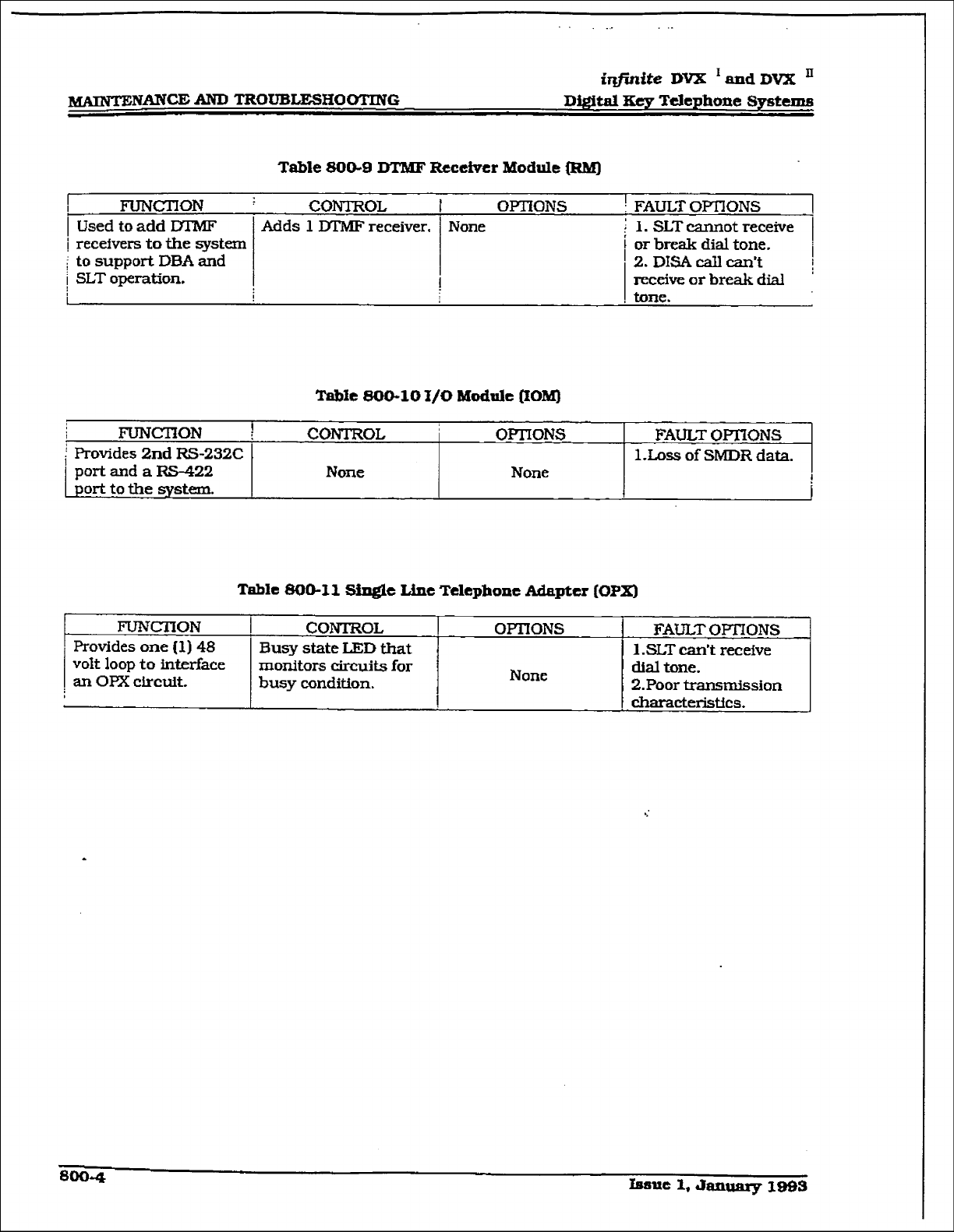
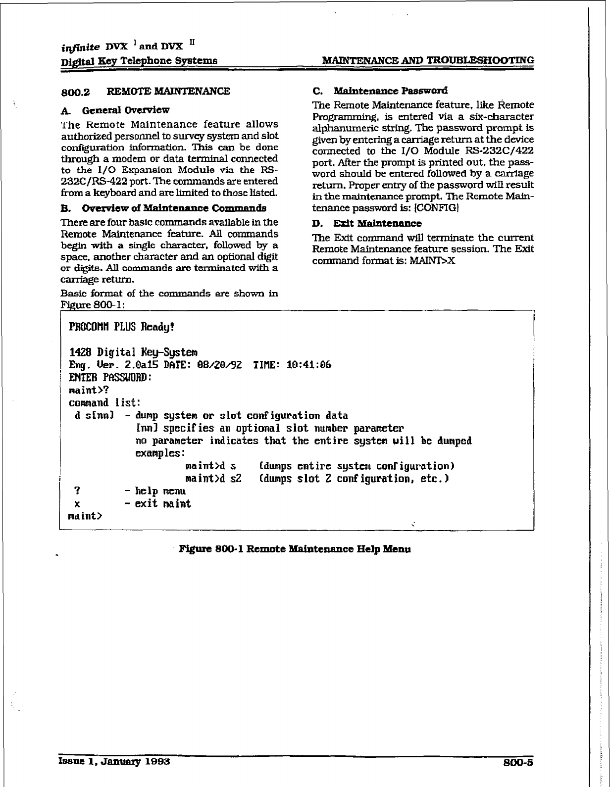
D&tJM Eey Telephone Systems -mCBAND TROT.J5LESHOOTING
800.2 REMOTE MAINTENMCE
A GeneraI ovemh?w
The Remote Maintenance feature
allows
authorized persome to survey system and slot
configuration information. This can be done
through a modem or data terminal connected
to the I/O Expansion Module via the FG-
232C/RS-422 port. The commands are entered
f?om a keyboard and are limited to those listed.
B. Oven&w~Mahtexu~~~~Coznn~~A~
There are four basic
commands available in the
Remote Maintenance feature. All commands
begin with a single character, foIlowed by a
space. another character and an optional digit
or digits. All commands are terzninated with a
carriage return.
Basic format of the comman ds are shown in
C, Mahtaance Passwo~
The Remote Mainknance feature, like Remote
Pro-, is entered via a six-character
alphanumeric string. The password prompt is
given by entering a carriage return at the device
connected to the I/O Module F?S-232C/422
port. Afker the prompt is printed out, the pass-
word shouId be entered folIowed
by
a carriage
return. Proper entry of the password wiU resuk
in the maintenance prompt, The Remote Main-
tenance password is: {CONFIG)
D. EAt B&htc=e
The Exit comman d wiIl terminate the current
Remote Maintenance feature session. The Etit
command format is: MNmX
PRftCOtlH PLUS Ready!
1428 Digital Hey-System
Eng. Uer.
2.0al5 RfiTE: 6H3AW9Z TIIIE: 10:41:06
ENTEN PfBUlJRII:
maint)?
command I ist :
d shnl - dunp system or siot configuration data
h-ml
specifies an optional siot number parameter
no parameter indicates that the entire system will be dumped
examples :
maint>d s (dumps entire system configuration)
maint>d s2 (dumps slot 2 conf igurat ion, etc. 1
? - help
menu
x
- exit maint
ma int> ;
Fi@re 800-l
Remote
Maintenance Hdp Menu
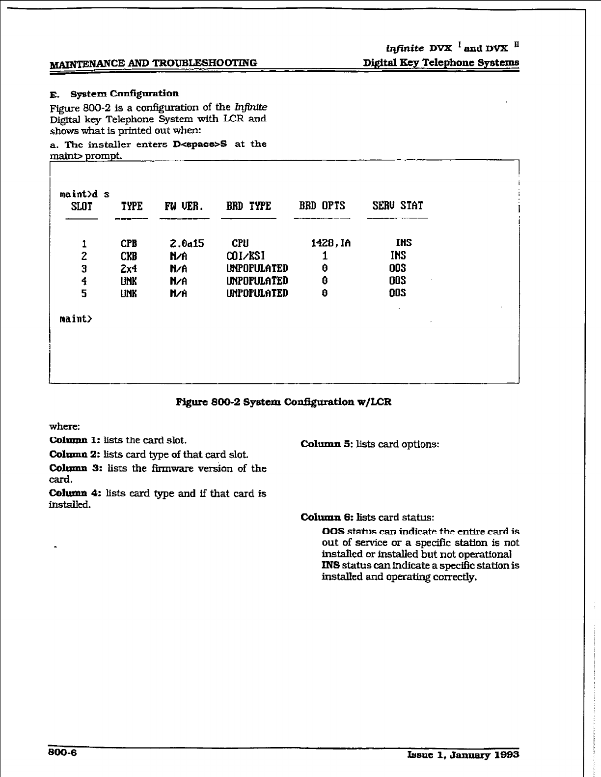
iqjinite DVX ‘andI3VX ’
-NANCE AND TROUBLESHOOTING DigItal Eey Telephone System8
E. Sy5tem CoAgnration
Figure 800-2 is a conf@ration of the Inj%?&?
Digital key Telephone System with LCR and
shows what is printed out when:
a. The installer enters DuspaccsS at the
maint>d s
SLOT TYPE Ia UER. IBID TYPE BBD OPTS SERU STAT i
- --- - ---
1
2
i
5
maint>
CPB
CKB
2x4
U?lK
UiW
CPU
COIAfSI
UNPOPWXED
UNPOFUMTED
UM’lWULfi~ED
1428 F Ih HIS
INS
i 00s
0 00s
0 00s
Figure 800-2 System ConfQunstion w/LCR
where:
Column 1: lists the card slot.
Colnmn 2: lists card me of that card slot.
COlwmn 3: k&s the firmware version of the
card.
Cohmm 5: lists card options:
Column 4: lists card type and if that card is
instaBed. Cohxtn 8: Iists card stabs:
OOS status can indicate the enWe card is
out of service or a specific station is not
installed or irMalIed but not operatfonal
INS status can indicate a spe&c station is
installed and operating correctly.
mo-6
Issue 1, Jannary 1993
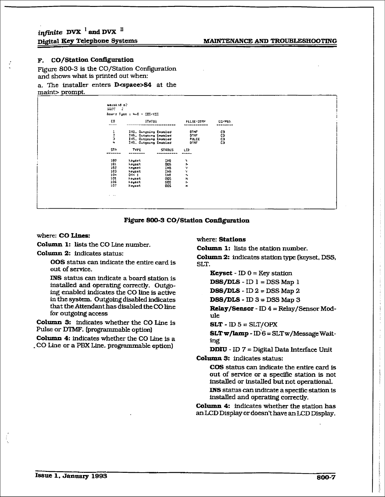
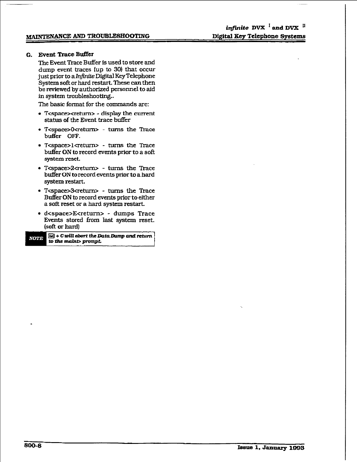
in$iaite DVX *and DVX ’
G. Event ‘h-ace Bdfer
me Eve& Trace Buffer fs used to store and
dump evat traces (up to 30) that
OCCLU
just prior to a 1r11 KXgM Key Telephone
System soft or hard restarL These can then
be reviewed by authorized personnel to aid
fn qstem
troubleshootIx+
The basic format for the commands are:
l
T<spacexretum> - display the current
status of the Event trace
buffer
l
T<space=&returrD - turns the Trace
buffer OFF.
m Tcspace>lcretw - turns the Trace
buffer ON
to
record events
ptior
to a soft
system reset.
l
TGpace>2aetm - turns the Trace
btier ON
to
record events prk to a hard
system restart.
l
T<spae3creturw - tums the R-ace
Buffer ON to record events prior
to
either
a soft reset or a hard system
restart.
l
dcspace>Ecreturn> - dumps Trace
Events stored kom last system reset.
(soft or hard)
800-8 Issue 1, Jamuuy 18533
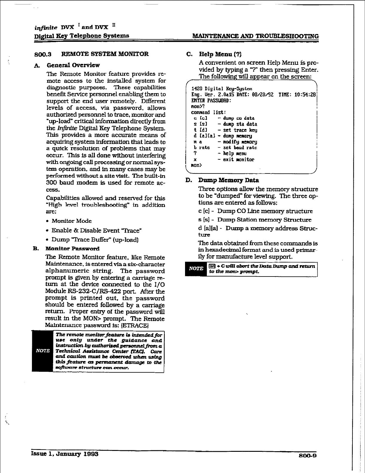
i@dte DVX * andDVX ’
D&$al 3ey Telephone Sycstexns MAINTEluANcBm TR0tJEaEsHoolmG
mo3 IlJmmm SYSTEM MONITOR
A. Gexleml ovemiew
The Remote Monitor feature provides re-
mote access to the in&died system for
diagnostic pqoses. These capabilities
benefit Sen&e persomxl enabling them to
support the end user remotely. Dtierent
levels of access, via password, allows
authorized personnel to trace, monitor and
-up-load” critical information directly f-ram
the h-@&k Digital Key Telephone System.
This provides a more accurate means of
acquiring system infomatfon that leads to
a quick resolution of problems that may
occur. ‘lWs IS all done without interfering
with ongoing call processing or normal sys-
tem operation, and in many cases may be
performed without a site visit. The built-in
300 baud modem is used for remote ac-
CWS.
Capabilities allowed and resewed for this
Vigh level troublesbooting” in addition
SIC?:
l
Monitor Mode
l
Enable & Disable Event 7’race”
. Dump Yl’race Buffer” (up-load]
B. Monitor Password
The Remote Monitor feature, like Remote
h&ntenance, is entered via a six-character
alphanumeric string. The password
prompt is given by entermg a caniage re-
turn at the devfce connected to the I/O
Module RS-232-C/R&$22 port. After the
prompt is printed out, the password
shouId be entered foIlowed by a we
return- F’roper entzy of the password wiII
result in the MOW prompt. The Remote
Maintenance password is: {ETR!XE)
umt
anlg amdur the g&dance and
C. Help Menu (?I
A convenient on screen Help Menu is pro-
vided by Qping a 7” then pressing Enter.
The foIlom will appear on the screen:
,
14Zfl Digital &XJ-S@JXI
Eug.
lkr. Z.&l5 Wfl: 08/Z&32 TIW: 10:59:Z3~
mm FFISNORD:
man>? 1
0
comand 1 i st :
c LA
- dunp ca
data
s ISI - dump sta data
t
Ldl
- set trau!
key
13 Ialra3 - dunp muwwy
Ra - uodify nmoky
b rate - set baud rate
? -~lpluznu
X
- exit monitor
mn>
D. Dump Mexncuy Dais
Three options allow the memov structure
to be -dumped” for Ykwhg. The three op-
tions are entered as fokws:
c [cl - Dump CO Line memoq structure
s [sl- Dump Station memov Structure
d [a1[al - Dump a memory address Struc-
The data obtained from these commands is
in hexadecimal format and is used primar-
ily for mantiacture level support.
Issue 1, Jmmuy 1993 SOiF9
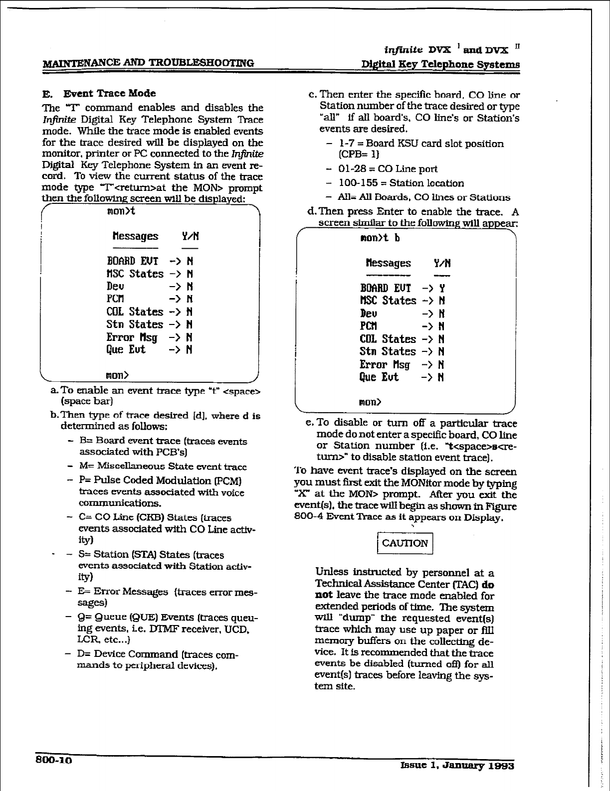
inJini.te DV2I ’ and DVX ’
-NANWAND TRtXl’i3LESHOOTllVG DQitd Key Telephone Systems
E, Event Tmce Mode
me T command enables and disables the
1n.1. Digital Key Telephone
Syskm Trace
mode. Whfle the trace mode is enabled events
for the trace desired will be dispiayed on the
monitor, printer or PC connected to the k@nite
Digital Key Telephone System in an event re-
cord. Totiewthec m-rent status of the trace
mode type T-t-at the MOW prompt
then the following screen will be displayed:
mon>t \
?lessages Y/N
3OABD
EUT ->
N
IISC States -> N
DWJ -> N
PCH -> N
COL States -> N
Stn States -> N
Error tlsg -> N
Que Eut -> N
mm>
a-To cnable an event trace type Y* <space>
bpam bad
b-Then type of trace desired Id], where d is
determined as foIlows:
- B= Board event mce (traces events
associated with PCE3’.s]
- M= Miscellamous State event trace
- P= Pulse
Coded
Modulation (PCM)
traces eve.nts associated with voice
COl7llllUIlf~tiOIlS.
- C= CO Line (CKB) States (kaces
events associated with CO Line
activ-
W
w - S= Station (FXAJ States (traces
events associated with Station activ-
Ql
- E= Error Messages {traces enor mes-
=gf3
- Q= Queue (QUE) Events (&aces queu-
ing events, i.e. DTMF receiver, UCD.
LLR etc...)
- D= Device Command &races com-
mands to peripheral devices),
c. Then enter the spe&c board, CO line or
Station numher of the trace desired or type
“all” ff ail hoard’s, CO lfne’s or Station’s
events are desired.
- l-7 = Board KSU card slot position
[CPB= I)
- 01-28 = CO Line port
- 100-155 = Station location
- All= All Eioards, CO lines or Stations
d. Then press Enter
to
enable the trace. A
screen similar to the folkming will appear:
mon>t
b
kssages Y/N
BUfW EUT -> Y
HSC States -> N
Deu -> ri
PCZI -> N
COI. States -> N
Stm States -> N
Error tlsg -> N
Que Eut -> N
Ron>
e. To disable or turn
05
a particular trace
mode do not enter a specifuz board, CO line
or Station number (i.e. kspacwse-
turn>” to disable station event trace).
To have event trace’s displayed on the screen
you must f&t exit the MONftor
mode b-y @ping
“X” at the MON> prompt. A&r you exit the
event(s), the tice will bep as shown in Fgure
800-4 Event lkace as it appears on
Display,
-.
thless instructed by personnel at a
Technical Assistice
Center (T.AC) do
not leave the trace mode enabled for
extended periods of time. ‘Ihe system
W-III udump” the requested event(s)
trace which may use up paper or filI
memoq
buffers
on the collecw de-
vfce. It fs recommended that the trace
events be disabIed (turned ofI) for all
event(s) traces before leming the sys-
tem sm.
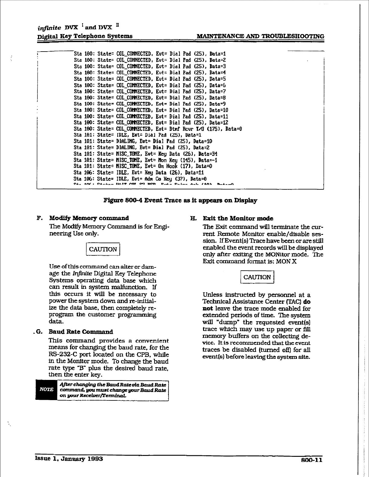
iqjinite Dm ‘andDVX II
~i@fi,l Key Telephone Sy8tema
MAKNTENANW~ TROUB~HOOTING
Sta l&l: State=
COL CilfUiEUED, Eut= Dial Pad G!51, Data=1
Sta 100: State= COLICWNE&TED, Eut= Dial Pad G!5)~ Data=2
Sta 16Q: State= COLJWECTED, Eut= Dial Pad (251, Data=3
Sta 16$: State= COLJOlUIECTED, Eut=
Dial
Pad (251, Data=4
Sta 100: State= COL-mECTED, Eut= Dial Pad GBI, Data=5
Sta
100:
State= COLJXNiHECTED, Eut= Dial Pad (251, Data=6
Sta
le0:
State= COLJXIMIECTED,
Eut=
Dial Pad C7.51, Data=7
Sta
100:
State=
COLJZQMECTED,
Eut= Dial Pad C?SI, Data=8
Sta 1W: State= COLJ3NNEC’IED, Eut= Dial Pad (251, Datu=9
Sta 180: State= COIJWECXD, Eut= Dial Pad GZ51, Datu=l0
Sta 100: St&e= COlJBHNECTED, Eut= Dial Pad (251, Data=11
Sta 180: State= COLJBNFiEC~ED, Eut= Dial Pad CZ51, Data=fZ
Sta 180: State= COLJXlHHECTED, Eut= Dtnf Rcur VO W’!jl, Data=9
St.a Ml: State= ID& Eut= Dial Pad (251, D&.&=1
Sta 101: State= DWLIffi, Eut= Dial Pad (251, Data=113
Sta 191: State=
DWLWG, Eut=
Dial Pad G?!3, Data=2
Sta 101: State= HISCJOKE, Evt= Hay Data (261, Data=34
Sta 181: State= lW3CJlIHE, Eut= Hun Hey (149, Data=-1
Sta 101: State= I!RCJO& Eut= &I Kook (171, Dab=0
Sta lQ6: State= IDLE, Eut= I@ Data (261, Data=11
Sb lQ6: State= IDLE, Eut= Rdm C~I Rey WI, Data=8
vu- .M. r.a-A.“- nb.r* m c-3 Dcen x.-A- “-‘-- A-a. ,.A. TB-L-A
Figure 800-4 Event Trace as it aqpcar8 on Display
F. Modify Memory command E Exit the
Monitor rnodc
The MO&@ Memory Cornmztnd is
for Engi-
neering Use only.
Use of this command can alter or dam-
age the In&&e Digital Key Telephone
Systems
operating data base which
can x-esult in system rrldfunction. If
this occurs it will be necessary to
prxverthe system down and re-iniW-
ize the data base, then completely re-
progmm the customer pro@ * ti
data.
- G. Baud Rate Command
This command provides a convenient
mesns for changing the baud rate, for the
RS-232-C
port hated on the WB, while
ln the Monitor mode, To change the baud
rate Qpe -B” plus the desti baud rate,
then the enter kq.
The Exit co mmand wiI1 terminate the cur-
rent F&mote Monitor enabLe/dlsable se-
sion. IfE%nt(s) Tracx have been or are still
enabled the event records will be displayed
only after ez&ing the MONitor mode. The
Exit command fomt is; MON X
Unless instructed by personnel at a
Technical Assistance Center (TAC) do
not kave the trace
mode enabled for
extended periods of time. ‘Ihe system
will “dump” the requested event(s]
trace which may use up paper or fW
memory buffers on the collecting de-
vice. It is recommended that the event
traces be disabled (turned o@ for all
event(s) before leaving the system site.
800-11
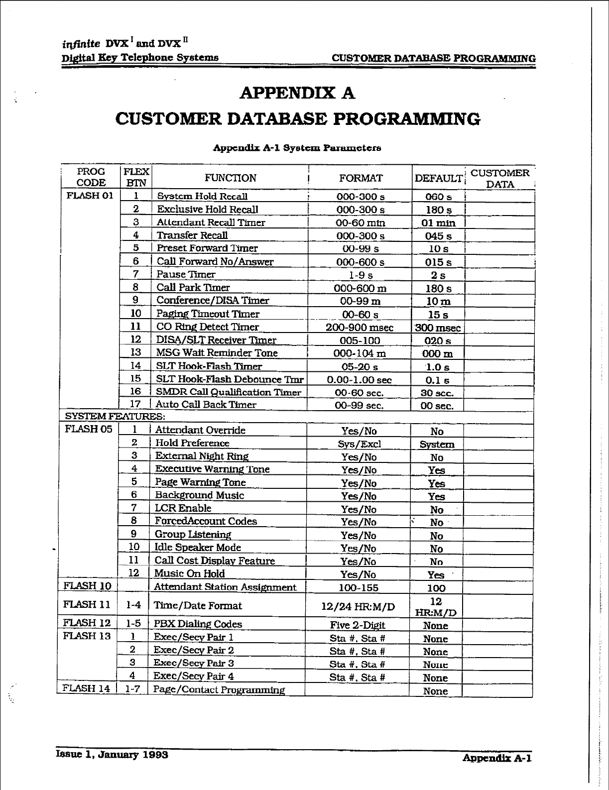
iqfinite DVX ’ aud DVX’
Digital Key Telephone Sy8tenm CUSTO&ER DATABASE PROGW3MMIlVG
APPENDIX A
CUSTOMER DATABASE PROGRAMMING
Appendix A-1 Syvstem Parameters
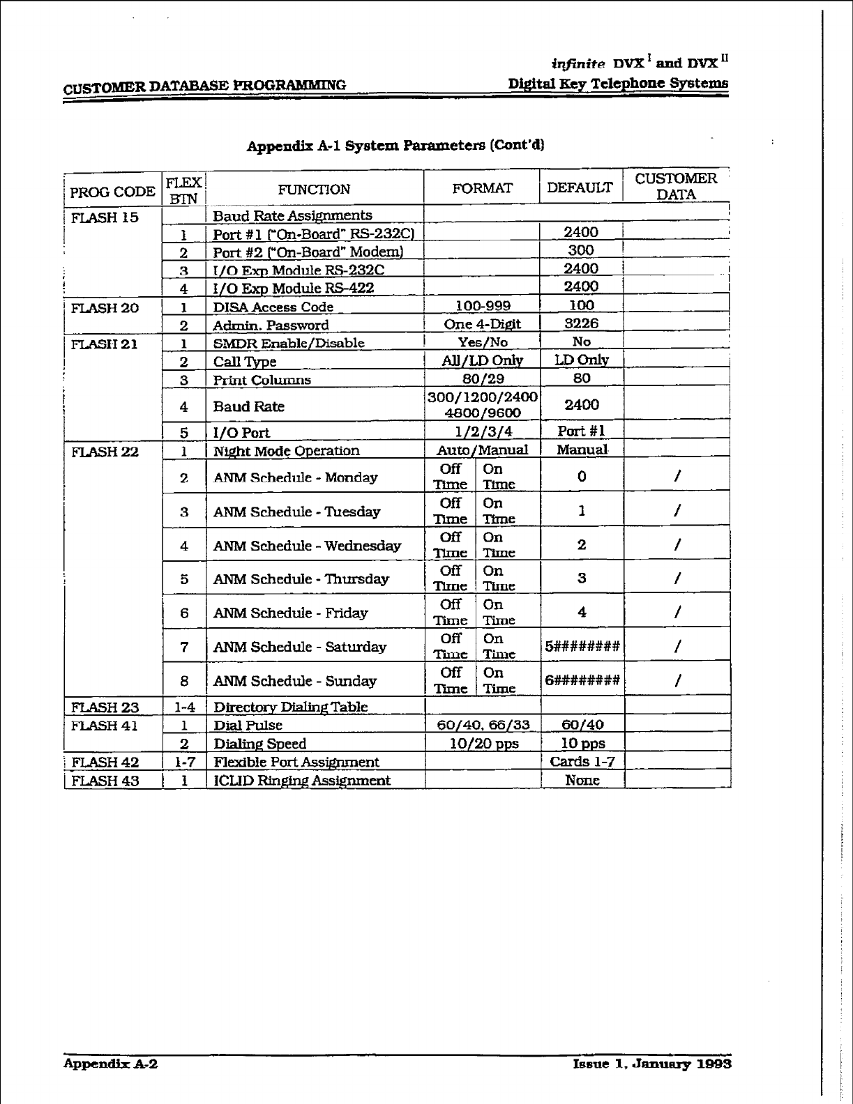
~USTOlNl3R DATABASE FRffiRM56xN~ D&it4 FCcy Telephone Systenxi
Appendix A-l Systexn Parameters (Ccmt’d)
1
PROG CODE
FLEX]
m j FUNCTION FORMAT 1 1 DEFAULT 1 CUSTOMER ’
DATA
iFLASH
I
Baud Rate
Adgnments
! 1
Port # 1 rOn-Board” RS-232C) 2400
i
2 Port #2 (“On-Board” Modem) 300
1
3 I/O Exp Module RS-232C 1 2400
i
i
4 I/O Exp Module RS-422 2400
i
F’LASH20 1 DIM Access Code I 100-999 i loo
2 Admin. Passwmd I Ope4-Digit I 3226
FLASH21 1 SMDR Enable/Disable
2
CallType
3 I Print Columns I 80/29 80
fiNM Schedule - Wednesd
ANM !?&edule - Saturd
i
:FLASH 42 l-7 1 Flexibk Port Assignment Cards l-7
c FLASH 43
Appen& A-2 Isme 1, January 1993
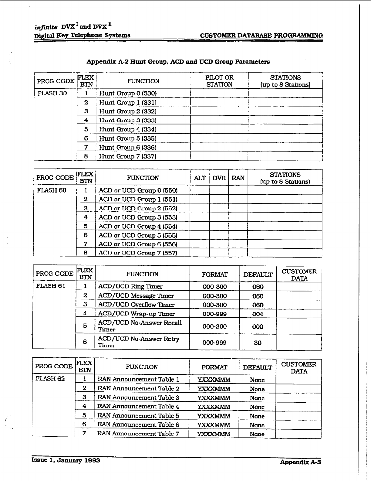
~)-#‘j.nite DVX ’ and
DVX ’
D&itaI Key Telephone Systans CUSTOMER DATABASE PROGRAMMING
Appendix A-2 Hunt
Gmup,
ACD and
TJCD
Gmup Parameters
PRO0 CODE i= 1 FUNCl-ION PIILXOR 1 ZZATlONS ~
STATION ! (up to 8 Stations)
! FLASH30 : 1 ; Hunt Group 0 (330) i I
i 2
i Hunt Group 1 (3311 I
i 3 1 Hunt Group 2 (3321 I ,
4 Hunt Group 3 (333) #
5 Hunt Group 4 (334) I
6 Hunt Group 5 (335)
7 Hunt Group 6 (336) I
I
t3
Hunt Group 7 (337) I
I
1
FLASH 62
TEX FUNCI’ION
F0IUWXT
DEFAULT
CUST0MER
DATA
I RAN Announcement Table 1 Nom
2 FZAN Announc=ent Table 2 None
3 MN ihnquncement Table 3 1 V None
4 RAN Announcement Table 4 1 YXXXMhW None
5 RAN Announcement Table 5 1 YXXXMMM None
6 RANAnnouncexnent TabIe 6 1 KWXMMM None
? RAN Announcenxnt Table 7 1 YXXMMM None
15slIe 1, &ranuary lBBz3 Appendix A-S
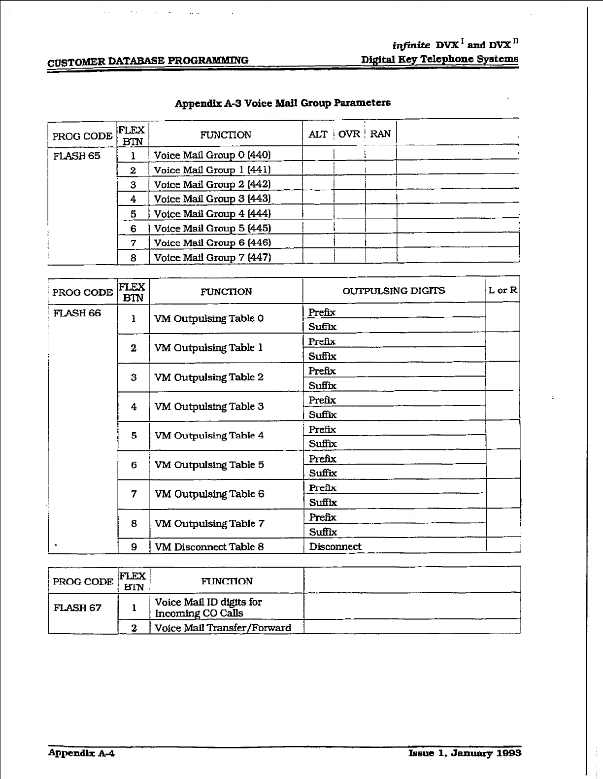
iqfinite DVX1~DVXn
Digital Key Telephone 3y~tem.s
I
L
Appendix A-3 Voice Mail Group Parameter8
PROG CODE E FIJNCTION ALT~OVRhN
1
FLASH 65 1 1 Voice Mail Group 0 PI401
1
1
!
2
Voice Mail Group 1 H-4 11 I
!
i 3 Voice Mail Group 2 (4421 ,
4 Voice M&I Group 3 W-431
I i
i 1
i
5 1 Voice hdaiI Group 4 WA) 1 I ,
I
I
6 1 Voice Mail Group 5 (445)
i ! 1
7 Voice Mail Group 6 (446) 1 1
a Voice Mad Group 7 1447) ,
PROG CORE E FTJNfXlON OUTPmTNG DIGlTS LorR
FIASH66 1 VM Outpulsing Table 0 p-h
I %%lB-ix
2 P&i25
V?d Outpulsing Table 1 SU%k
I
3 VM Outpulsing Table 2 Prefix !
SUfijE 1
!
4
I
I
VM Outpulsing Table 3 SdiiX
5 VM OutpuIsing Table 4 hzfix
Stii
6 VX!? ~tpulsing Table 5 SU!&
7 V-M Ouqmls~Table 6 Prefix
S&
8 VM Outpulsing Table 7 SUfI-ii
1 9 1 V?vl DiscoMect TabIe 8 / Disconnect I
~pt%dIx A4 l8fme 1, &.uluaIy 1993
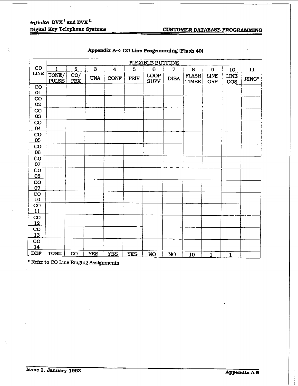
DQ$m Key Telephone systenu CUSTOMER DATABASE PROG-G -a
* 11
co
12 I 1 1 I
co
13
co
14
iDl3F ‘lT3TVlSq CO YES YES YES NO NO 10 1 ! 1
* Refe.r to CO Line Rnging Assignments
knu 1, January 1993 Appendh
A-5
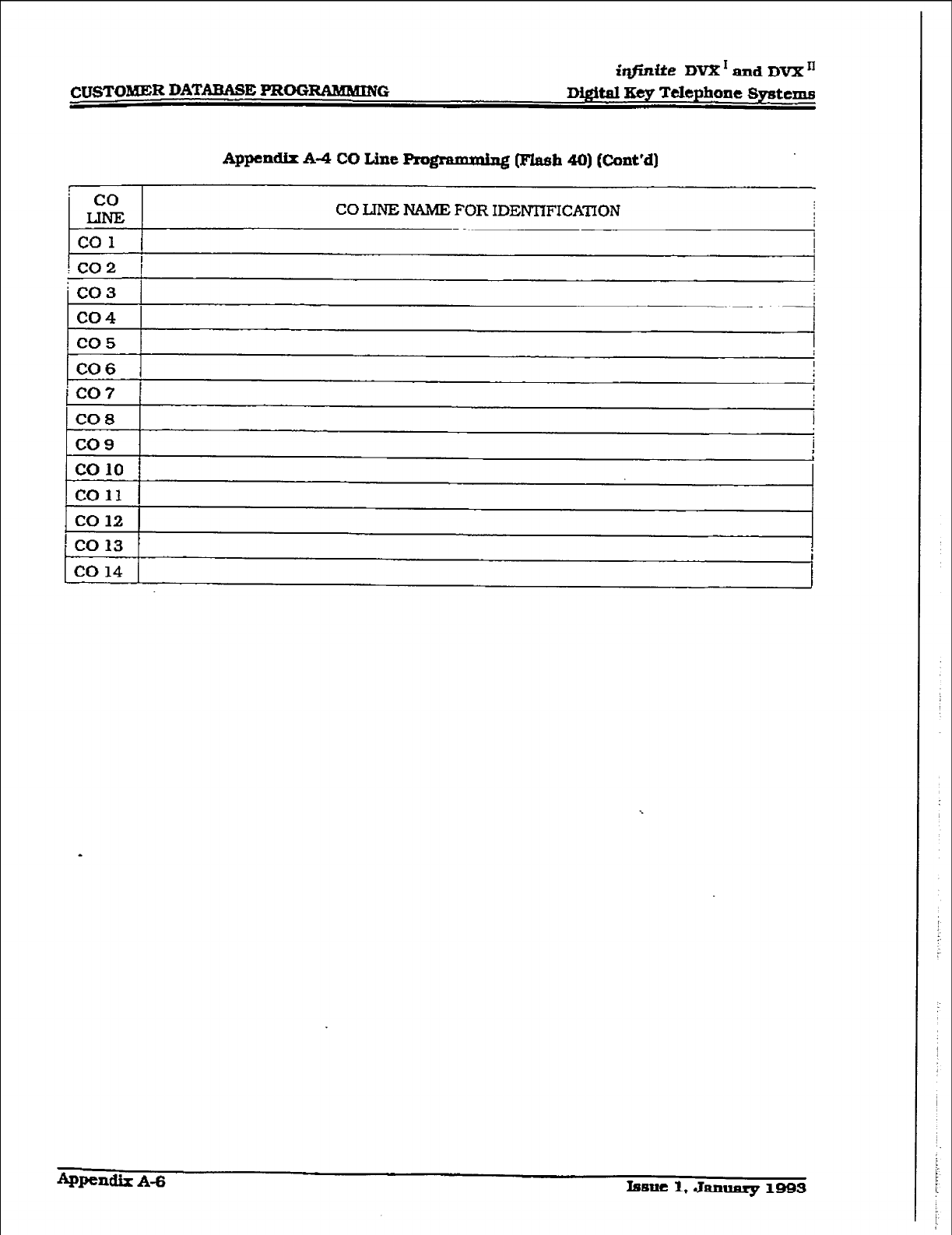
CUSTOMER DATABASE PROGRAlUMUE
- co
LINEZ
co 1
:co2 1
: co3
co4
co5
CO6
‘CO7
CO8
co9
co 10
co11
co 12
‘co13
co 14
Appendix A-4 CO Line Prom (Flash 40) Eunt’dl
CO LINE NAME FOR IDlWl7FICATION
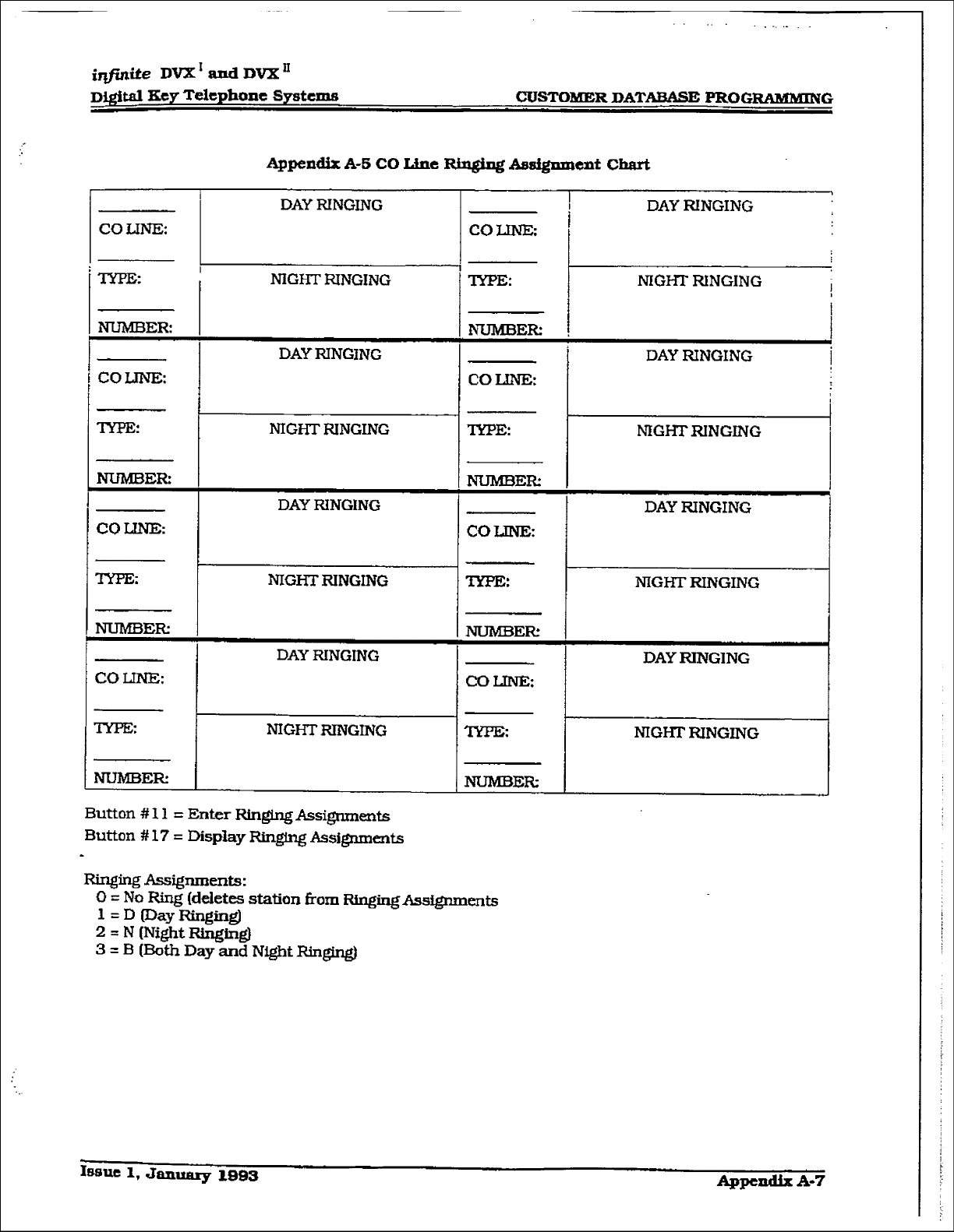
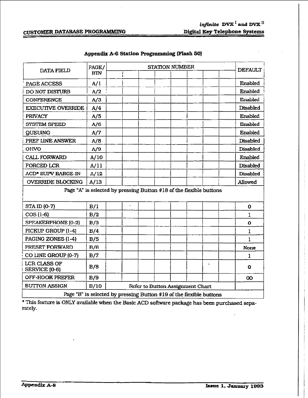
iqfinike DVX1 and DVX”
c~STO?dER DATYWASE PROGRAMMING Digital Key Telephone Sydexns
Appendix A-6 Station Pro@ammixq~ @Iash 50)
PAGING ZONES (l-4)
FRESETF’ORWARD
B/6 I None
! CO LINE GROUP (O-7) W7 1 ..
i LCRCLASSOF .:
i SERVICE (O-6)
w3 0
OFF-HOOK PREFER ! IV9 1 1 00
BUTTON AS!3IGN 1 B/l0 1 Refer to Button Assignment Chart
l%ge -B” is selected by pressing Button #19 of the fitible buttons
* This feature is ONLY avahble when the Basic ACD software package has been purchased sepa-
rately.
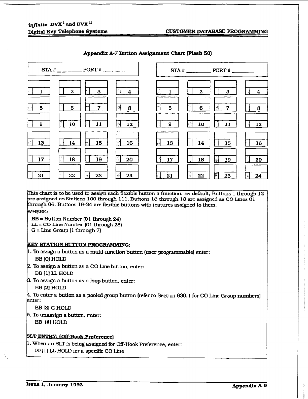
~@.ni~eDVX1adDVXE
~Q$tal Eey Telephone Systems
Appendix A-7 Button Asdgnment Chart (Flash 50)
SI?A# POKr # STA# POKI-#
= Button Number [Ol through 24)
CO Line Number (01 through 28)
G = Line Group (1 through 7)
. To
assign
a button as a CO Line button, enter
BB [l] LL HOLD
. To assign a button as a loop button, enter:
. To enter a button as a pooled group button (refer to Section 630.1
for CO Line
Group numbers)
BB 13) G HOLD
. To unassign a button, enter:
hsue 1, .hnuary
1993 Appendix A-9
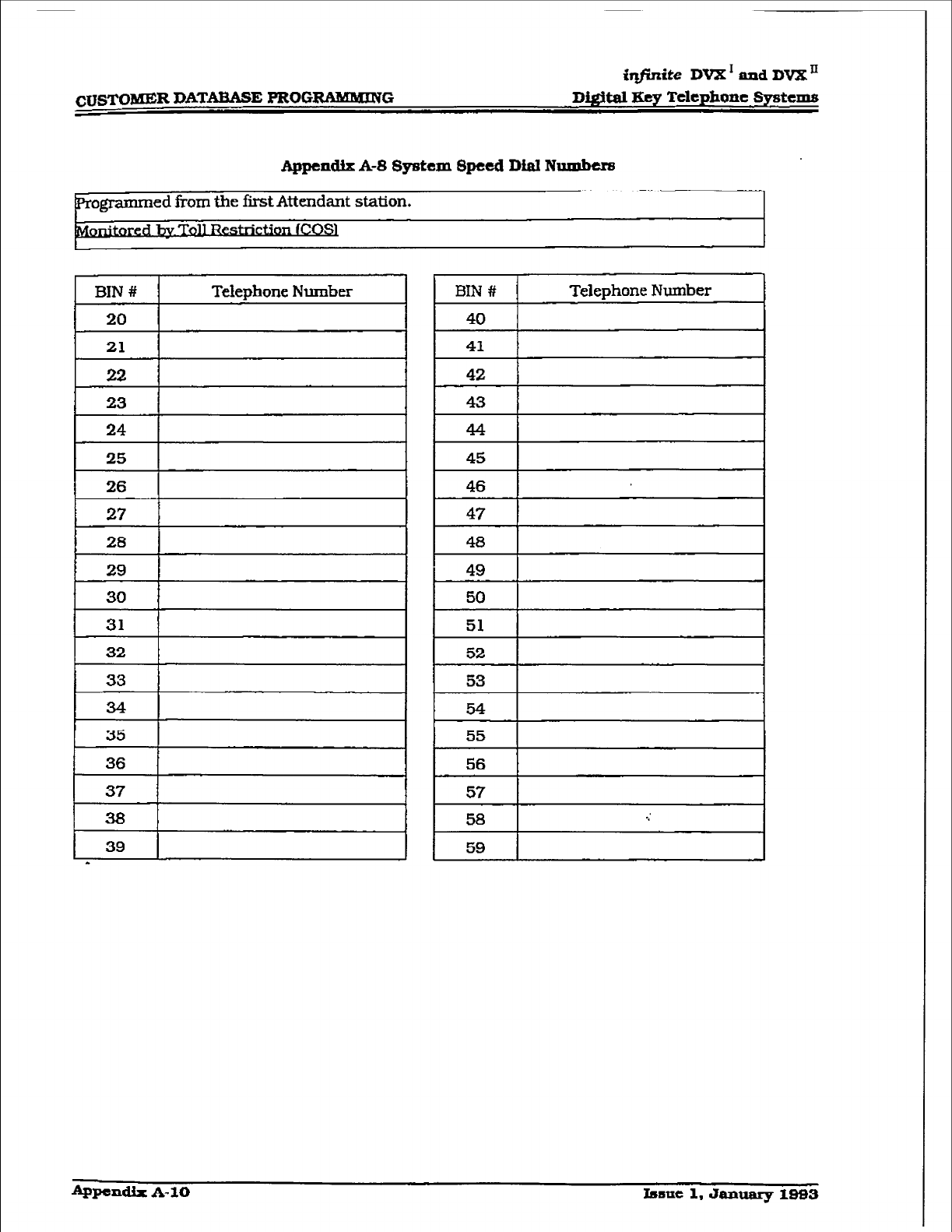
&#~~ite DVX’ and DVXn
cUSTOltU=R DATABASE ~O~RAMMINCG Witd Kq’ Telephone Systems
Appendix A-S f3ystem Speed DinI Numbem
endant
station.
OS1
54
55
56
57
58 .:
59
~pendlx A- 10 hmt 1, January 1993
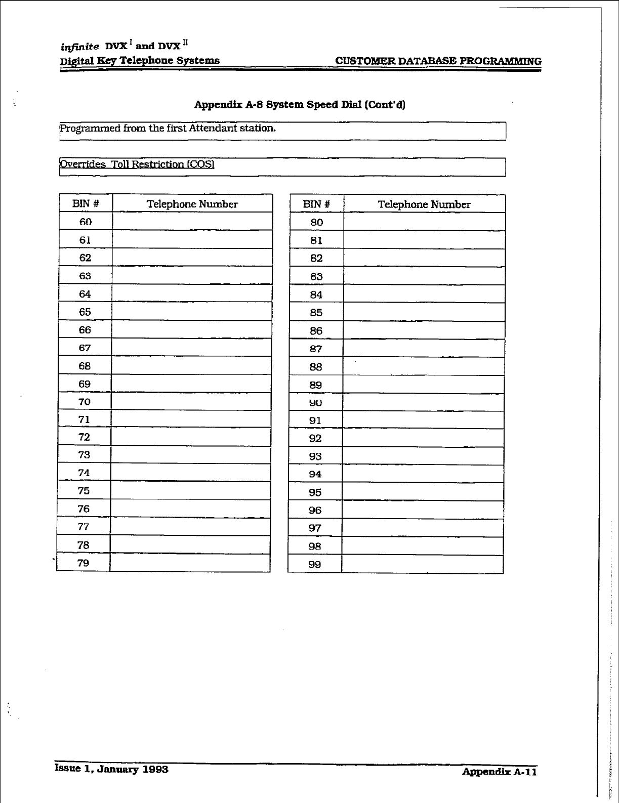
D&iti Key Telephone Sy8tcms CUSTOMER DATABASE PROGRAMMLNG
Appendix A-8 System Speed Dial (Cont’d)
ogrammed from the first Attendant station. I
. .
es Toll B
75
76
77
78
79
Telephone Number
I
82 ,
84
85
86
8?
88
89
90
92
93
94
95
96
97
98
99
hmc 1, January 1993 Appendix A-11
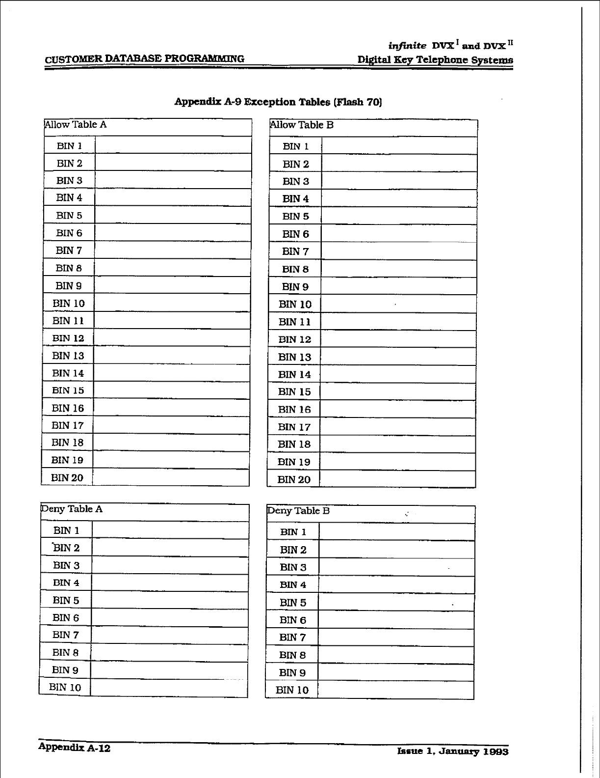
inJini.te DV?Z1 and DVX’
CUSTOMER DATAEASE PRO-G Digital Key Telephone §yster.m
Appcdix A-9 Exception Tables [Flash 70)
plow Table A
3lN 10
BIN 11
eny Table A
BIN1 1
,
BIN3 ’
BIN 4
BIN5
BIN 6
BIN 7
BIN 6
BIN 9
HN 10
+PP-llx A-12 Issue 1, January 3993
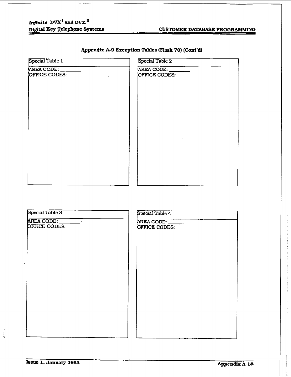
@inite DVX*andDVX’
D@itd 3ey Telephone Sy&crns CUSTOMER DATW PROGRAMMUYG
Appendix A-9 Exception Tables @huxh 70) [Cont’d)
AREA CODE:
3FFlCE CODES:
pecial Table 3
AREA CODE:
OF’F’ICE CODES:
p&al Table 2
CODE:
FFKX CODES
pecial Table 4
AREA CODE:
OF-FICE CODES
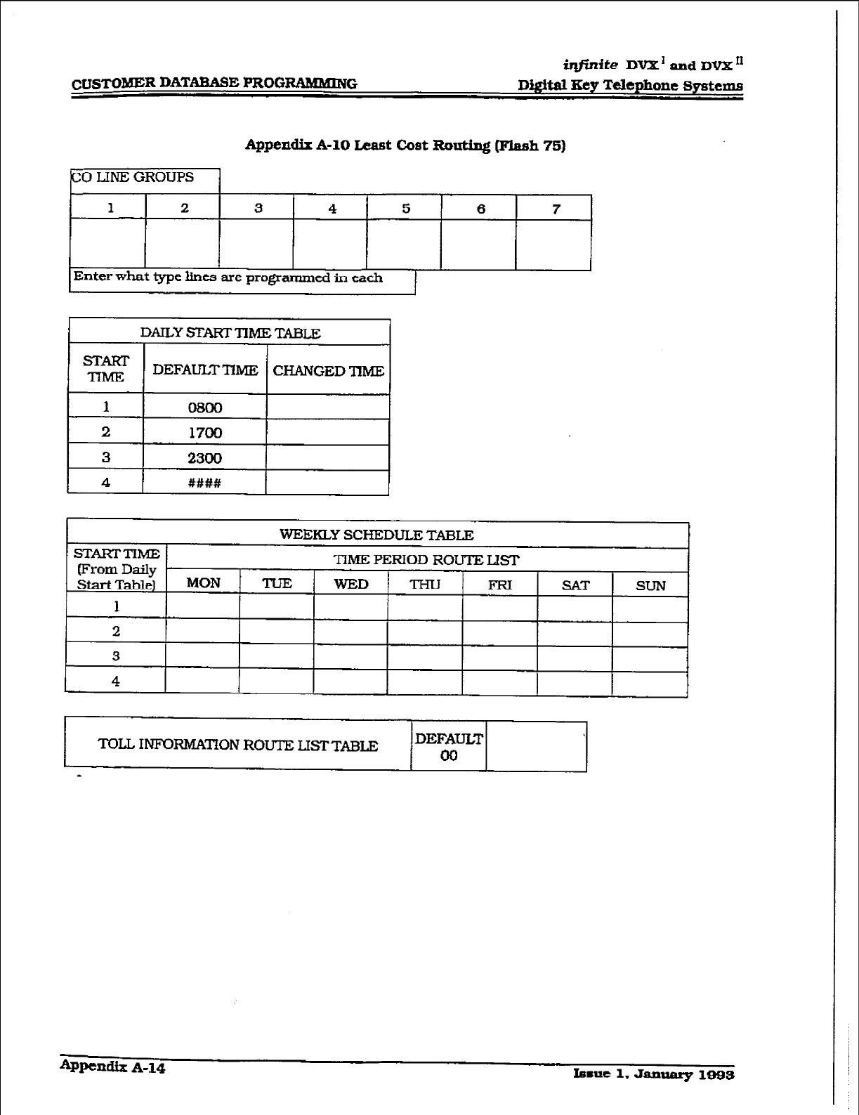
iqfirdte DV2L’ and DVX *I
cuSi’OMER DATARASE m0GmC.G Di.@al Key Telephone
systems
Appendix A-10 Least
Cost
Zkwting (Flnsh 751
PO LJNE GROUPS
1 2 3 4 5 6 7
I 1 I I I
Enter what type lines are progrmed in each
CHANGED ‘IlME
I
TOLL ImWmON ROUTE LISTTABLE DEFATJL.T
00