PDF Vodavi Starplus SPD 1428 2856 Installation
Starplus SPD 1428-2856 Installation Starplus SPD 1428-2856 Installation
User Manual: PDF T E X T F I L E S
Open the PDF directly: View PDF ![]() .
.
Page Count: 560 [warning: Documents this large are best viewed by clicking the View PDF Link!]
- Table of Contents
- Section 100 Introduction
- Section 200 Key Station Feature Descriptions
- Section 300 Station Feature Operation
- Section 400 General Description
- Section 500 Installation
- Section 600 Customer Data Base Programming
- Section 610 System Parameters Programming
- Section 620 CO Line Attributes Programming
- Section 630 Station Attributes Programming
- Section 640 Uniform Call Distrobution (UCD)
- Section 645 Voice Mail Groups (VM)
- Section 650 Exception Tables Programming
- Section 655 Least Cost Routing Programming
- Section 660 Initialize Data Base Parameters
- Section 665 Printing System Data Base Parameters
- Section 700 System Checkout
- Section 800 Maintenance and Troubleshooting
- Appendix A Customer Database Programming
- Appendix B Digital Systems Part Numbers
- Appendix C ICLID General Description
- Technical Fact Notice
- Technical Fact Notice
- Technical Fact Notice
- Technical Fact Notice
- In-Band Integration
STARPLUS"
digital systems
HYBRID KEY TELEPHONE SYSTEMS
.
/ GENERAL DESCRIPTION,
INSTALLATION AND
MAINTENANCE MANUAL
TM
MM
vo3Avl
COMMUNICATIONS
SYSTEMS
STARPLUS@ SPD 1428 & 2858 Digital Key Telephone Systems
SECTION 100
SECTION 200
SECTION 210
SECTION 220
SECTION 300
SECTION 310
SECTION 320
SECTION 400
SECTION 500
SECTION 600
SECTION 610
SECTION 620
SECTION 630
SECTION 640
SECTION 645
SECTION 650
SECTION 655
SECTION 660
SECTION 665
SECTION 700
SECTION 800
APPENDIX A
APPENDIX B
APPENDIX C
QUICK REFERENCE TABLE OF CONTENTS
INTRODUCTION .......................................................................................
108-l
KEY STATION FEATURE DESCRIPTIONS ...................................
200-l
SINGLE LINE TELEPHONE FEATURE DESCRIPTION ............
210-1
ATTENDANT FEATURE DESCRIPTION .........................................
220-l
STATION FEATURE OPERATION ....................................................
300-l
SLT FEATURE OPERATION ...............................................................
31 o-1
AITENDANT FEATURE OPERATION .............................................
320-l
GENERAL DESCRIPTION ....................................................................
400-l
INSTALLATION
........................................................................................ 500-l
CUSTOMER DATA BASE PROGRAMMING
................................. 600-l
SYSTEM PARAMETERS PROGRAMMING ...................................
610-l
CO LINE ATTRIBUTES PROGRAMMING ......................................
620-l
STATION ATTRIBUTES PROGRAMMING .....................................
630-l
UNIFORM CALL DISTRIBUTION (UCD)
......................................... 640-l
VOICE MAIL GROUPS (VM) ................................................................
645-l
EXCEPTION TABLES PROGRAMMING .........................................
650-l
LEAST COST ROUTING PROGRAMMING ....................................
655-l
INITIALIZE DATA BASE PARAMETERS ........................................
680-l
PRINTING SYSTEM DATA BASE PARAMETERS
...................... 665-l
SYSTEM CHECKOUT ............................................................................
700-1
MAINTENANCE AND TROUBLESHOOTING
................................ 800-l
CUSTOMER DATABASE PROGRAMMING .......................................
A-l
DIGITAL SYSTEMS PART NUMBERS ................................................
B-l
ICLID GENERAL DESCRIPTION ...........................................................
C-I
issue 1, November 1991 i
Digital Key Telephone Systems
STARPLUS@
SPD 1428 & 2856
SECTION 100
100.1
100.2
100.3
100.4
SECTION 200
200.1
200.2
200.3
200.4
200.5
200.6
200.7
200.8
200.9
200.10
200.11
200.12
200.13
200.14
200.15
200.16
200.17
200.18
200.19
200.20
TABLE OF CONTENTS
INTRODUCTION .......................................................................................
100-l
PURPOSE ....................................................................................................... 100-l
REGULATORY INFORMATION (USA) .......................................................... 100-l
A. Telephone Company Notification ................................................... 100-l
B. Incidence of Harm .......................................................................... 100-l
C. Changes in Service ........................................................................ 100-l
D. Maintenance Limitations.. ............................................................... 100-l
E. Notice of Compliance ..................................................................... 100-l
F. Hearing Aid Compatibility.. ............................................................. 100-2
G. OPX Circuit .................................................................................... 100-2
REGULATORY INFORMATION (CANADIAN) ............................................... 100-2
A. Notice ............................................................................................. 100-2
B. Explanation of Load Number .......................................................... 100-2
C. Maintenance Limitations.. ............................................................... loo-2
D. Notice of Compliance ..................................................................... 100-2
E. OPX Circuit .................................................................................... 100-3
UUCSA SAFETY COMPLIANCE ................................................................... 100-3
KEY STATION FEATURE DESCRIPTIONS ....................................
200-l
ACCOUNT CODES ........................................................................................ .200-l
ATTENDANT RECALL ................................................................................... .200-l
AUTOMATIC LINE ACCESS ......................................................................... .200-l
AUTOMATIC NIGHT SERVICE ..................................................................... -200-l
AUTOMATIC PAUSE INSERTION WITH SPEED DIAL.. .............................. .200-l
AUTOMATIC PRIVACY ................................................................................. -200-l
AUTOMATIC SELECTION ............................................................................. .200-l
BACKGROUND MUSIC ................................................................................. .200-l
BATTERY BACK-UP (MEMORY). ................................................................. .200-l
BUSY LAMP FIELD (BLF) ............................................................................. .200-l
CALL ANNOUNCE - PRIVACY ...................................................................... 200-l
CALL BACK ............................. ..~
................................................................... .200-l
CALL FORWARD: STATION ......................................................................... .200-l
A. Call Forward . All Calls .................................................................. .200-l
B. Call Forward . Busy ........................................................................ 200-7
C. Call Forward . No Answer ............................................................. .200-7
D. Call Forward . Busy/No Answer .................................................... .200-7
E. Call Forward . Off-Net ................................................................... .200-7
CALL FORWARD: PRESET ........................................................................... 200-7
A. Preset Call Forward . Stations ...................................................... .200-7
B. Preset Call Forward . Hunt Groups ............................................... .200-7
C. Preset Call Forward . UCD Groups.. ............................................. .200-7
D. Preset Call Forward . VM Groups ................................................. .200-7
E. Preset Call Forward . Off-Net.. ............ ........................................... 200-7
CALLING STATION TONE MODE OPTION ................................................. .200-8
CALL PARK .................................................................................................... 200-8
CALL PICK-UP. ................................................................................................ 200-8
A. Group Pick-up ............................................................................... .200-8
B. Directed Call Pick-up .............................................. ..” .................... 200-8
CALL TRANSFER ........................................................................................... 200-8
CAMP-ON ....................................................................................................... 200-8
CAMP-ON RECALL ......................................................................................... 200-8
ii Issue 1, November 1991
Issue 1, November 1991 . . .
III
200.21
200.22
200.23
200.24
200.25
200.26
200.27
200.28
200.29
200.30
200.31
200.32
200.33
200.34
200.35
200.36
200.37
200.38
200.39
200.40
200.41
200.42
200.43
200.44
200.45
200.46
200.47
200.48
200.49
200.50
200.51
200.52
200.53
200.54
200.55
200.56
200.57
200.58
200.59
CANNED TOLL RESTRICTION.. ................................................................... 200-8
CENTREX COMPATIBILITY.. ................................................................ h.. .... 200-8
A. Flex Button Programming .............................................................. 200-8
B. Off-hook Preference ...................................................................... 200-8
C. Private Line appearance.. .............................................................. 200-8
D. Programmable Flash Timer.. ......................................................... 200-8
E. Programming
l
, #, and Hook-Flashes into Speed Dial .................. 200-9
CENTREX/PBX TRANSFER.. ........................................................................ 200-9
CHAINING SPEED BINS ............................................................................... 200-9
CO LINE ACCESS ......................................................................................... 200-9
CO LINE CLASS OF SERVICE.. .................................................................... 200-9
CO LINE CONTROL (CONTACT). ................................................................. 200-9
CO LINE GROUPS.. ....................................................................................... 200-9
CO LINE LOOP SUPERVISION.. ................................................................... 200-9
CO LINE QUEUE ........................................................................................... 200-9
CO LINE INCOMING RINGING ASSIGNMENT.. ........................................... 200-9
CO RING DETECT ......................................................................................... 200-9
CONFERENCE ............................................................................................ 200-l 0
A. Add On Conference ..................................................................... 200-l 0
B. Multi-Line Conference.. ................................................................ 200-l 0
C. Unsupervised Conference ........................................................... 200-l 0
CONFERENCE ENABLE/DISABLE.. ........................................................... 200-10
DATA BASE PRINTOUT (DUMP) ................................................................ 200-l 0
DAY/NIGHT CLASS OF SERVICE (COS) ................................................... 200-10
DEFAULT BUTTON MAPPING.. .................................................................. 200-l 0
DIAL PULSE SENDING ............................................................................... 200-l 0
DIALING PRIVILEGES.. ............................................................................... 200-l 0
DIRECT INWARD SYSTEM ACCESS (DISA) ............................................. 200-10
A. Programmable Access.. ............................................................... 200-l 0
B. CO Line Group Access.. .............................................................. 200-l 0
C. Station Access.. ........................................................................... 200-l 0
D. Trunk-to-Trunk: ............................................................................ 200-l 0
DIRECT STATION SELECTION .................................................................. 200-10
DIRECTED CALL PICKUP.. ......................................................................... 200-12
A. Call Pick-up - Station ................................................................... 200-12
B. Call Pick-up - UCD Groups.. ........................................................ 200-12
DISABLE OUTGOING CO LINE ACCESS.. ................................................. 200-12
DO NOT DISTURB (DND). ........................................................................... 200-12
A. One-Time Do Not Disturb ............................................................ 200-12
DTMF SENDING .......................................................................................... 200-12
EMERGENCY TRANSFER.. ........................................................................ 200-12
END TO END SIGNALLING.. ....................................................................... 200-12
EXCLUSIVE HOLD ..................................................................................... 200-l 2
EXECUTIVE OVERRIDE ............................................................................. 200-l 2
EXECUTIVE/SECRETARY TRANSFER.. .................................................... 200-12
EXTERNAL NIGHT RINGING.. .................................................................... 200-12
FLASH .......................................................................................................... 200-12
FLASH ON INTERCOM ............................................................................... 200-l 3
FLASH WITH SPEED DIAL.. ........................................................................ 200-13
FLEXIBLE ATTENDANT .............................................................................. 200-l 3
FLEXIBLE BUT-TON ASSIGNMENT ............................. A.. ........................... 200-13
FORCED ACCOUNT CODES.. .................................................................... 200-13
FORCED LEAST COST ROUTING (LCR) ................................................... 200-13
GROUP CALL PICK-UP.. ............................................................................. 200-13
Digital Key Telephone Systems
STARPLUS@
SPD 1428 & 2856
200.60
200.61
200.62
200.63
200.64
200.65
200.66
200.67
200.68
200.69
200.70
200.71
200.72
200.73
200.74
200.75
200.76
200.77
200.78
200.79
200.80
200.81
200.82
200.83
200.84
200.85
200.86
200.87
iv Issue 1, November 1991
HEADSET COMPATIBILITY ......................................................................... 200-l 3
HEADSET MODE ......................................................................................... 200-l 3
HEARING AID COMPATIBLE ...................................................................... 200-l 3
HOLD PREFERENCE ................................................................................... 200-l 3
HOLD RECALL ............................................................................................. 200-l 4
HOT LINE/RING DOWN ............................................................................... 200-14
HUNT GROUPS ............................................................................................ 200-l 4
A. Pilot Hunting ................................................................................ .200-14
B. Station Hunting ............................................................................ .200-14
C. Hunt Group Chaining ................................................................... 200-l 4
INCOMING CO LINES OFF-NET FORWARD (VIA SPEED DIAL). ............ .200-14
INTERCOM CALLING .................................................................................. .200-14
INTERCOM SIGNALING SELECT .............................................................. .200-l 4
LAST NUMBER REDIAL (LNR) .................................................................... 200-14
LCD INTERACTIVE DISPLAY ..................................................................... .200-l 4
LEAST COST ROUTING (LCR) ................................................................... .200-l 4
A. LCR 3-Digit Table ......................................................................... 200-l 4
B. LCR 6-Digit Table (Off ice Codes). ............................................... .200-l 5
C. Route List Tables ......................................................................... 200-l 5
D. Insert/Delete Tables ..................................................................... 200-l 5
E. Weekly Time Tables ..................................................................... 200-l 5
F. Daily Start Time Tables ............................................................... .200-l 5
G. Exception Tables .......................................................................... 200-l 5
H. Default LCR Database ................................................................ .200-15
I. LCR Routing for Toll Information ................................................. 200-l 5
LOOP BUTTON CO LINE ACCESS ............................................................. 200-l 5
MEET ME PAGE ........................................................................................... 200-l 5
MESSAGE WAITING .................................................................................... 200-15
MESSAGE WAITING REMINDER TONE ..................................................... 200-l 5
MUSIC ON HOLD ......................................................................................... 200-l 5
MUTE KEY .................................................................................................... 200-l 6
NAME IN LCD DISPLAY ............................................................................... 200-l 6
NIGHT SERVICE .......................................................................................... 200-16
A. Manual Operation ......................................................................... 200-l 6
B. Automatic Night Mode Operation ................................................ .200-16
C. Weekly Night Mode Schedule ...................................................... 200-l 6
D. Night Class of Service (COS). ..................................................... .200-16
E. Universal Night Answer (UNA). ................................................... .200-i 6
F. Night Ringing Assignments ......................................................... .200-l 6
G. External Night Ringing.. ................................................................ 200-l 6
OFF-HOOK PREFERENCE .......................................................................... 200-l 6
A. Auto Line Access ......................................................................... 200-16
B. Auto Feature Access .................................................................... 200-l 6
C. Hot Line/Ring Down ..................................................................... 200-l 6
D. Intercom Access ........................................................................... 200-I 6
E. User Programmable Preference .................................................. 200-l 6
OFF-HOOK SIGNALLING ............................................................................ .200-l 7
OFF-PREMISE EXTENSIONS (OPX) ......................................................... .200-l 7
ON HOOK DIALING ...................................................................................... 200-l 7
ON LINE PROGRAMMING ........................................................................... 200-l 7
PAGE/RELAY CONTROL .......................................................... .
................. .200-l 7
PAGING ....................................................................................................... .200-l 7
A. External Paging ........................................................................... .200-17
B. Internal Paging ............................................................................ . 200-17
STARPLUS@
SPD 1428 & 2856 Digital Key Telephone Systems
200.88
200.89
200.90
200.91
200.92
200.93
200.94
200.95
200.96
200.97
200.98
200.99
200.100
200.101
200.102
200.103
200.104
200.105
200.106
200.107
200.108
200.109
200.110
200.111
200.112
200.113
SECTION 210
210.1
210.2
210.3
210.4
210.5
210.6
C. Paging Access Restriction ........................................................... 200-l 7
PAUSE TIMER ......................................................................................... t ... 200-17
PBX DIALING CODES ................................................................................. 200-17
PERSONALIZED MESSAGES ..................................................................... 200-17
A. Personalized Message Code on a Flex Key.. .............................. 200-17
POOL BUTTON OPERATION ...................................................................... 200-18
PREFERRED LINE ANSWER.. .................................................................... 200-18
PRIVACY RELEASE .................................................................................... 200-l 8
A. Per Station Option ....................................................................... 200-l 8
B. Per CO Line Option ..................................................................... 200-l 8
PRIVATE LINE ............................................................................................. 200-l 8
PULSE-TO-TONE SWITCHOVER ............................................................... 200-l 8
RANGE PROGRAMMING ............................................................................ 200-18
REMOTE ADMINISTRATION ..................................................................... 200-18
REMOTE SYSTEM MONITOR AND MAINTENANCE.. ............................... 200-18
A. Remote System Monitor .............................................................. 200-l 8
B. Remote System Maintenance.. .................................................... 200-l 9
SAVE NUMBER REDIAL (SNR) .................................................................. 200-19
SINGLE LINE TELEPHONE (SLT) COMPATIBILITY.. ................................ 200-19
STATION MESSAGE DETAIL RECORDING (SMDR). ................................ 200-19
SPEAKERPHONE.. .......... ............................................................................ 200-19
STATION CLASS OF SERVICE .................................................................. 200-19
STATION SPEED DIAL ................................................................................ 200-l 9
SYSTEM CAPACITY ................................................................................... 200-l 9
A. Up to 14x28 Configuration: .......................................................... 200-19
B. Up to 28x56 Configuration.. ......................................................... 200-19
SYSTEM HOLD ............................................................................................ 200-l 9
SYSTEM SPEED DIAL ................................................................................. 200-19
TOLL RESTRICTION (TABLE DRIVEN). ..................................................... 200-19
TRANSFER RECALL ................................................................................... 200-20
UNIFORM CALL DISTRIBUTION (UCD) ..................................................... 200-20
A. Alternate UCD Group Assignments.. ........................................... 200-20
B. Overflow Station Assignments.. ................................................... 200-20
C. Incoming CO Direct Ringing ........................................................ 200-20
D. Recorded Announcements (RAN) ............................................... 200-20
E. Number of Calls in Queue Display.. ............................................. 200-20
F. UCD Auto Wrap-Up w/Timer ...................................................... 200-20
G. UCD No-Answer Timer ................................................................ 200-20
H. UCD Available / Unavailable Mode.. ............................................ 200-20
UNIVERSAL NIGHT ANSWER (UNA) ......................................................... 200-20
VOICE MAIL GROUPS (VM). ....................................................................... 200-21
A. VM In-Band Signaling Integration.. .............................................. 200-21
B. VM Message Waiting Indication .................................................. 200-21
C. VM CO Disconnect Signal - Pass Thru.. ...................................... 200-21
D. VM Tone Mode Calling Option.. ................................................... 200-21
VOLUME CONTROLS ................................................................................. 200-21
SINGLE LINE TELEPHONE FEATURE DESCRIPTION.. ..........
210-1
ACCOUNT CODE .......................................................................................... 210-l
AUTOMATIC LINE ACCESS.. ........................................................................ 21 O-l
CALL FORWARD ............................................................ .
.............................. 210-l
CAMP ON ....................................................................................................... 210-l
CONFERENCE .............................................................................................. 210-l
CONFERENCE /WITH PERSONAL PARK.. .................................................. 21 O-l
Issue 1, November 1991
V
Digital Key Telephone Systems
STARPLUS@ SPD 1428 & 2856
210.7
210.8
210.9
210.10
210.11
210.12
210.13
210.14
210.15
210.16
210.17
210.18
210.19
210.20
4
SECTION 220
220.1
220.2
220.3
220.4
220.5
220.6
220.7
220.8
220.9
220.10
220.11
220.12
220.13
SECTION 300
300.1
300.2
300.3
300.4
300.5
300.6
300.7
300.8
300.9
300.10
300.11
300.12
300.13
300.14
DIRECT OUTSIDE LINE ACCESS.. ............................................................. ..210- 1
DIRECT OUTSIDE LINE RINGING ............................................................... .2.10-l
DIRECTED CALL PICK UP ............................................................................ 21 o-1
DO NOT DISTURB ......................................................................................... 210-l
GROUP CALL PICK UP
................................................................................. .21 o-1
INTERCOM CALLING .................................................................................... .210-l
MESSAGE WAITING/CALL BACK.. .............................................................. .21 O-l
NIGHT SERVICE ........................................................................................... .21 o-2
OFF-HOOK PREFERENCE.. ......................................................................... .21 O-2
PERSONAL PARK .......................................................................................... 210-2
QUEUING ....................................................................................................... 21 o-2
STATION SPEED DIAL .................................................................................. 21 o-2
SYSTEM SPEED DIAL .................................................................................. .210-2
TRANSFER .................................................................................................... .21 o-2
AlTENDANT FEATURE DESCRIPTION .........................................
220-I
ATTENDANT DISABLE OUTGOING ACCESS.. ........................................... .220-l
AlTENDANT OVERFLOW ............................................................................. 220-l
All-ENDANT OVERRIDE .............................................................................. .220-l
ATTENDANT POSITION ............................................................................... .220-l
ATTENDANT RECALL ................................................................................... .220-l
AUTOMATIC NIGHT MODE .......................................................................... .220-l
INCOMING CO LINE OFF-NET FORWARD.. ............................................. .0.220-l
TIME AND DATE PROGRAMMING .............................................................. .220-l
ATTENDANT SEARCH.. ................................................................................ .220-2
BUSY LAMP FIELD INDICATORS.. .............................................................. .220-2
DIRECT STATION CALLING ......................................................................... .220-2
MAPPING OPTIONS ..................................................................................... -220-2
RELEASE KEY ............................................................................................... 220-3
STATION FEATURE OPERATION
.................................................. .-.300-l
INTRODUCTION ............................................................................................ .300-l
KEY TELEPHONE STATION FEATURES .................................................... .300-l
ANSWERING AN OUTSIDE CALL ................................................................ .300-4
PLACING AN OUTSIDE CALL ON HOLD ..................................................... .300-4
ANSWERING A RECALL .............................................................................. .300-4
ACCOUNT CODES ........................................................................................ .300-4
DISABLE OUTGOING CO LINE ACCESS.. .................................................. .300-4
PLACING AN OUTSIDE CALL (Automatic Line Selection) ........................... .300-4
BACKGROUND MUSIC (Optional) ................................................................ .300-4
AUTOMATIC SELECTION ............................................................................. .300-4
CALL BACK ................................................................................................... .300-4
CALL FORWARD: STATION ......................................................................... .300-5
A. Call Forward - All Calls.. ................................................................ .300-5
B. Call Forward - No Answer ............................................................. -300-5
C. Call Forward - Busy ....................................................................... .300-5
D. Call Forward - Busy/No Answer .................................................... .300-5
E. Call Forward - Off-Net (via speed dial). ......................................... .300-5
F. Call Forward - UCD Groups .......................................................... .300-6
G. Call Forward - Voice Mail Groups ................................................. .300-6
H. Call Forward - Hunt Groups .................................... I
...................... 300-6
CALL FORWARD: PRESET .......................................................................... .300-6
CALL FORWARD: CO LINES ........................................................................ .300-6
A. Incoming CO Lines Off-Net (via speed dial). ................................. .300-6
vi
Issue
1, November 1991

STARPLUS@
SPD 1428 & 2856 Digital Key Telephone Systems
300.15
300.16
300.17
300.18
300.19
300.20
300.21
300.22
300.23
300.24
300.25
300.26
300.27
300.28
300.29
300.30
300.31
300.32
300.33
300.34
300.35
300.36
300.37
300.38
300.39
300.40
300.41
300.42
300.43
300.44
300.45
300.46
300.47
300.48
300.49
300.50
300.51
300.52
300.53
300.54
300.55
300.56
300.57
300.58
300.59
SECTION 310
310.1
310.2
CALLING STATION TONE MODE OPTION .................................................. 300-7
CALL PARK ............................................................................................ r..
..... 300-7
CALL PICK-UP: GROUP ................................................................................ 300-7
CALL TRANSFER .......................................................................................... 300-7
TRANSFERRING CO CALLS TO A STATION FORWARDED TO VM ........ .300-7
CAMP-ON ....................................................................................................... 300-8
CO LINE ACCESS ......................................................................................... 300-8
QUEUING ....................................................................................................... 300-8
CONFERENCE COMBINATIONS .................................................................. 300-8
DIRECTED CALL PICK-UP ............................................................................ 300-9
DIRECT INWARD SYSTEM ACCESS (DISA) ............................................... 300-9
DO NOT DISTURB ......................................................................................... 300-9
A. One-Time Do Not Disturb .............................................................. 300-9
EXCLUSIVE HOLD ........................................................................................ 300-9
EXECUTIVE OVERRIDE ............................................................................. 300-10
EXECUTIVE/SECRETARY TRANSFER.. .................................................... 300-l 0
FLASH .......................................................................................................... 300-10
FLASH ON INTERCOM ............................................................................... 300-I 0
FLEXIBLE BUITON ASSIGNMENT ............................................................ 300-l 0
HEADSET MODE ......................................................................................... 300-l 1
INTERCOM CALLING .................................................................................. 300-l 1
INTERCOM TRANSFER .............................................................................. 300-12
LAST NUMBER REDIAL .............................................................................. 300-12
LEAST COST ROUTING .............................................................................. 300-12
LCR QUE CANCEL ...................................................................................... 300-12
MEET ME PAGE .......................................................................................... 300-12
MESSAGE WAITING ............. ...................................................................... 300-12
MUTE KEY ................................................................................................... 300-l 3
OFF-HOOK PREFERENCE ......................................................................... 300-l 3
PAGING ........................................................................................................ 300-13
PBX/CENTREX TRANSFER ........................................................................ 300-l 3
PERSONALIZED MESSAGES ..................................................................... 300-13
PERSONALIZED MESSAGE CODE ON A FLEX KEY ............................... 300-l 3
PRIME FLEX BU-ITON PROGRAMMING ................................................... 300-13
PROGRAMMING YOUR NAME INTO THE LCD DISPLAY ......................... .300-14
PULSE TO TONE SWITCHOVER ............................................................... 300-l 4
SAVE NUMBER REDIAL ............................................................................. 300-14
PROGRAMMING PBX/CENTREX CODES ONTO A FLEX BUTTON ......... 300-14
SPEAKERPHONE ........................................................................................ 300-14
STATION SPEED DIAL ................................................................................ 300-15
STORING SPEED NUMBERS ..................................................................... 300-15
SYSTEM SPEED DIAL ................................................................................. 300-15
UNIFORM CALL DISTRIBUTION (UCD) ..................................................... 300-15
A. Number of Calls in Queue Display.. ............................................. 300-15
B. Available/Unavailable Mode ........................................................ 300-15
C. No-Answer Timer ......................................................................... 300-16
UNIVERSAL NIGHT ANSWER (UNA) ......................................................... 300-16
VOICE MAIL OPERATION (VM) .................................................................. 300-16
A. VM Tone Mode Calling Option.. ................................................... 300-l 6
VOLUME CONTROLS ................................................................................. 300-16
SLT FEATURE OPERATION ...............................................................
31 o-l
INTRODUCTION ............................................................................................ 31 o-1
ACCOUNT CODE ......................................................................................... 310-l
Issue 1, November 1991 vii
310.3
310.4
310.5
310.6
310.7
310.8
310.9
310.10
310.11
310.12
310.13
310.14
310.15
310.16
310.17
310.18
310.19
310.20
310.21
310.22
310.23
310.24
310.25
310.26
310.27
310.28
310.29
310.30
310.31
310.32
310.33
SECTION 320
320.1
320.2
320.3
320.4
320.5
320.6
320.7
320.8
320.9
320.10
320.11
320.12
320.13
320.14
320.15
320.16
320.17
320.18
320.19
320.20
320.21
CALL BACK ................................................................................................... .310-l
CALL FORWARDING .................................................................................... .310-l
CALLING STATION TONE MODE OPTION ................................................. .310-l
CAMP-ON ...................................................................................................... .31 O-l
CALL PARK (System) .................................................................................... .310-2
CALL TRANSFER .......................................................................................... .31 O-2
CLEAR CALL FORWARD, DND, PERSONALIZED MESSAGES.. ............... .31 O-3
CO LINE QUEUING ........................................................................................ 31 o-3
CONFERENCE .............................................................................................. -31 o-3
CONFERENCE WITH PERSONAL PARK .................................................... .310-3
DIRECT OUTSIDE LINE ACCESS ................................................................ .31 o-3
DIRECTED CALL PICK-UP ............................................................................ 31 o-3
DO NOT DISTURB ......................................................................................... 310-3
PBX/CENTREX TRANSFER (Flash Command to CO Line) ......................... .31 O-3
GROUP CALL PICK-UP ................................................................................ .31 o-3
PLACING CALLS ON EXCLUSIVE HOLD .................................................... .31 o-4
INTERCOM CALLING .................................................................................... .310-4
LCR QUEUING (Automatic) ........................................................................... -31 o-4
LCR QUE CALL BACK .................................................................................. .310-4
LCR CANCEL ................................................................................................ .310-4
MESSAGE WAITING ..................................................................................... .310-4
OFF-HOOK PREFERENCE ........................................................................... .31 o-4
PERSONALIZED MESSAGES ...................................................................... .310-4
PAGING ......................................................................................................... .310-4
PERSONAL PARK (Flip-Flop) ........................................................................ 31 o-5
PROGRAMMING YOUR NAME INTO THE LCD DISPLAY.. ........................ .310-5
STATION SPEED DIAL .................................................................................. 310-5
STORING STATION SPEED NUMBERS ...................................................... .31 o-5
SYSTEM SPEED DIAL .................................................................................. .31 o-5
UNIVERSAL NIGHT ANSWER (UNA) ........................................................... .31 o-5
UCD AVAILABLE/UNAVAILABLE ................................................................. .31 o-5
AlTENDANT FEATURE OPERATION
............................................ -320-l
INTRODUCTION ............................................................................................ .320-l
A-ITENDANT KEY TELEPHONE STATION FEATURES ............................. ..320- 1
ANSWERING AN OUTSIDE CALL ................................................................ .320-4
PLACING OUTSIDE LINE ON HOLD ............................................................ .320-4
ANSWERING A RECALLING OUTSIDE LINE .............................................. .320-4
ATTENDANT DISABLE OUTGOING ACCESS ............................................. .320-4
ATTENDANT OVERRIDE .............................................................................. .320-4
ATTENDANT RECALL ................................................................................... .320-4
EXECUTIVE OVERRIDE ............................................................................... .320-4
INTERCOM CALLING .................................................................................... .320-4
INCOMING CO LINES OFF-NET (via speed dial) ......................................... .320-5
NIGHT SERVICE ........................................................................................... .320-5
SElTlNG SYSTEM TIME AND DATE ........................................................... .320-5
STORING SYSTEM SPEED NUMBERS ....................................................... .320-5
ATTENDANT TRANSFER SEARCH ............................................................. .320-6
PLACING AN OUTSIDE CALL (Automatic Line Selection) ........................... .320-6
CALL PARK ................................................................................................... .320-6
DO NOT DISTURB INDICATION .............................................. ..‘.................... 320-6
RETRIEVING A PARKED CALL .................................................................... .320-6
CALL TRANSFER ........................................................................................... 320-6
CAMP-ON ................................................................................................... ..-. 320-6
. . .
VIII
Issue 1, November 1991
STARPLUS@
SPD 1428 & 2858 Digital Key Telephone Systems
320.22
320.23
320.24
320.25
330.1
SECTION 400
400.1
400.2
400.3
400.4
400.5
400.6
400.7
400.8
400.9
SECTION 500
500.1
500.2
500.3
500.4
500.5
500.6
FLEXIBLE BUT-l-ON PROGRAMMING .......................................................... 320-6
MEET ME PAGE ............................................................................................ 320-6
PAGING.. ........................................................................................................ 320-7
A. External Paging ............................................................................. 320-7
B. Internal Paging.. ............................................................................. 320-7
C. All Call Paging (Internal/External). ................................................. 320-7
RELEASE BUTTON ....................................................................................... 320-7
LCD DISPLAYS.. ........................................................................................... 330-I
GENERAL DESCRIPTION ....................................................................
400-l
SYSTEM TECHNOLOGY.. ............................................................................. 400-l
SPD 1428 COMMON EQUIPMENT.. ............................................................. 400-2
A. Basic Key Service Unit with Power Supply (BKSU) ....................... 400-2
B. SPD 1428 Expansion KSU with Power Supply (EKSU) ................ 400-4
C. 2x4 CO/Station Expander Module ................................................. 400-6
D. 4x8 CO/Station Expander Module ................................................. 400-7
SPD 2856 SYSTEM COMPONENTS ............................................................. 400-8
A. Equipment Cabinet With Power Supply (KSU) .............................. 400-8
B. Central Processor Board (CPB) ..................................................... 400-8
C. 4 x 8 CO/Station Key Interface Board (CKB). .............................. 400-l 1
D. 4x8 CO/SLT Interface Board (CSB) (Future). .............................. 400-l 2
APPLICATION MODULES ........................................................................... 400-l 3
A. SPD 1428 Expansion I/O Module (IOM). ..................................... 400-13
B. SPD 2856 Expansion I/O Module (IOM). ..................................... 400-13
C. 1200 Baud Modem Module (MM) ................................................ 400-13
D. DTMF Receiver Module (RM) ...................................................... 400-l 3
SPD 1428 & SPD 2856 TERMINALS.. ......................................................... 400-14
A. 34 Button Digital Terminal (Enhanced) ........................................ 400-l 4
B. 34 Button Digital Display Terminal (Executive). ........................... 400-l 6
C. Digital DSS/DLS Console ............................................................ 400-17
SLT ADAPTER / OFF-PREMISE EXTENSION MODULE.. ......................... 400-18
RELAY / SENSOR INTERFACE MODULE.. ................................................ 400-18
POWER FAILURE TRANSFER UNIT (PFTU) ............................................. 400-18
SYSTEM SPECIFICATIONS AND CAPACITY ............................................ 400-19
INSTALLATION ........................................................................................
500-l
SITE PLANNING ............................................................................................ 500-l
A. System Grounding ......................................................................... 500-l
B. Lightning Protection ....................................................................... 500-I
SPD 1428 INSTALLATION PLANNING ......................................................... 500-l
SPD 1428 COMMON EQUIPMENT.. ............................................................. 500-2
A. Basic Key Service Unit with Power Supply (BKSU). ...................... 500-2
B. Expansion KSU with Power Supply (EKSU). ................................. 500-8
C. 2x4 CO/STA Expander Module ................................................... 500-l 0
D. 4x8 CO/STA Expander Module ................................................... 500-l 2
SPD 2856 INSTALLATION PLANNING ....................................................... 500-14
SPD 2856 SYSTEM COMPONENTS.. ......................................................... 500-14
A. Equipment Cabinet With Power Supply (KSU) ............................ 500-l 4
B. Cabinet Installation ...................................................................... 500-l 6
C. Central Processor Board (CPB) ................................................... 500-l 7
D. 4 x 8 CO/Station Key Interface Board (CKB):. ............................. 500-21
E. 4x8 CO/SLT Interface Board (CSB) (Future). .............................. 500-23
APPLICATION MODULE(S) INSTALLATION:. ............................................ 500-26
A. SPD 1428 Expansion I/O Module (IOM). ..................................... 500-26
Issue 1, November 1991 ix
,
Digital Key Telephone Systems
STARPLUS@
SPD 1428 & 2856
500.7
500.8
500.9
SECTION 600
600.1
600.2
600.3
600.4
600.5
600.6
600.7
SECTION 610
610.1
610.2
610.3
610.4
610.5
610.6
610.7
B. SPD 2856 Expansion I/O Module (IOM) ..................................... .500-26
C. 1200 Baud Modem Module (MM). ................................................ 500-26
D. Installing the DTMF Receiver Module (RM) ................................ .500-30
SPD 1428 & SPD 2856 TERMINALS .......................................................... .500-31
A. Digital Terminal Installation: ........................................................ .500-31
B. Digital DSS/DLS Installation ......................................................... 500-31
C. Wall Mounting the Telephone.. .................................................... .500-31
D. Single Line Telephone Installation: (future). ................................ .500&l
E. SLT Adapter / Off-Premise Extension Module ............................ .500-34
POWER FAILURE TRANSFER ................................................................... .500-36
A. Relay / Sensor Interface Module ................................................. .500-36
B. Stat-plus Power Failure Transfer Unit (PFTU) .............................. 500-36
INSTALLING RECORDED ANNOUNCEMENT DEVICE (RAN). ................ .500-40
CUSTOMER DATA BASE PROGRAMMING ..................................
600-l
INTRODUCTION ............................................................................................ .600-l
PROGRAM MODE ENTRY (Key Station). ..................................................... .600-l
PROGRAM MODE ENTRY (Data Terminal or PC) ....................................... .600-8
BEGINNING TO PROGRAM ......................................................................... .600-8
INITIALIZATION ............................................................................................. .600-8
CUSTOMER DATA WORKSHEETS ............................................................. -600-8
DATA BASE FIELDS ..................................................................................... .600-8
SYSTEM PARAMETERS PROGRAMMING
.................................... 61 O-l
SYSTEM TIMERS .......................................................................................... .61 O-l
A. System Hold Recall Timer ............................................................. -61 O-2
B. Exclusive Hold Recall Timer .......................................................... .61 O-2
C. Attendant Recall Timer ................................................................... 610-3
D. Transfer Recall Timer .................................................................... .61 O-3
E. Preset Forward Timer .................................................................... 610-4
F. Call Forward No/Answer Timer ..................................................... .61 O-4
G. Pause Timer .................................................................................. .610-5
H. Call Park Recall Timer ................................................................... .61 O-5
I. Conference/DISA Timer ................................................................ .610-6
J. Paging Timeout Timer.. ................................................................. .61 O-6
K. CO Ring Detect Timer ................................................................... .610-7
L. SLT DTMF Receiver Timer ........................................................... .61 O-7
M. Message Wait Reminder Tone.. .................................................... .610-8
N. SLT Hook Flash Timer .................................................................. .61 O-8
0. SLT Hook Flash Debounce Timer ................................................. .61 O-9
SYSTEM FEATURES PROGRAMMING ..................................................... .610-10
A. Attendant Override ...................................................................... .610-l 1
B. Hold Preference .......................................................................... .610-l 1
C. External Night Ring ..................................................................... .610-12
D. Exec Override Warning Tone.. .................................................... .61 O-12
E. Page Warning Tone .................. i.. ............................................... .610-13
F. Music Channel ............................................................................. 61 O-13
G. LCR Enable ................................................................................. .610-14
H. Account Codes - Forced ............................................................. .61 O-14
ATTENDANT STATION ASSIGNMENT ...................................................... .61 O-15
SEl-fING SYSTEM TIME AND DATE ...................................... I................... 610-15
PBX DIALING CODES ................................................................................. .610-16
EXECUTIVE/SECRETARY PAIRS .............................................................. .610-16
RELAY/SENSOR PROGRAMMING ............................................................ ;610-17
X
Issue 1, November 1991
sTARPLUS@
SPD 1428 & 2856 Digital Key Telephone Systems
610.8
610.9
610.10
610.11
610.12
SECTION 620
620.1
620.2
SECTION 630
630.1
A. Programming relay for External Paging: ...................................... 61 O-1 8
B. Programming relay for RAN Starting: .................................... h.. .. 61 O-1 8
C. Programming relay for Power Failure Transfer:. .......................... 61 O-1 8
D. Programming relay for Loud Bell Control:. ................................... 61 O-1 9
E. Programming relay for CO Line Control: ..................................... 61 O-1 9
F. Assign Relay/Sensor Interface Module to a station: .................... 61 O-20
G. Program sensing ciruit as a RAN Sensing (RAN END) circuit: .... 610-20
BAUD RATE ASSIGNMENTS.. .................................................................... 610-21
ACCESS CODES ......................................................................................... 61 O-22
A. DISA Access Code ...................................................................... 61 O-22
B. Set Data Base Admin. Password.. ............................................... 610-22
STATION MESSAGE DETAIL RECORDING (SMDR). ................................ 610-23
A. SMDR Enable/Disable.. ............................................................... 61 O-23
B. Long Distance/Local Assignment ................................................ 61 O-23
C. Character Print Assignment.. ....................................................... 61 O-24
D. Baud Rate Display.. ..................................................................... 610-24
E. SMDR Port Assignment.. ............................................................. 61 O-24
WEEKLY NIGHT MODE SCHEDULE.. ........................................................ 610-25
A. Automatic/Manual Operation ....................................................... 61 O-25
B. Day of Week programming .......................................................... 61 O-25
HUNT GROUPS ........................................................................................... 61 O-26
A. Hunt Group Programming.. .......................................................... 610-26
B. Station/Pilot Hunting Assignment ................................................ 61 O-26
CO LINE ATTRIBUTES PROGRAMMING ......................................
620-l
INTRODUCTION
............................................................................................ 620-l
A. DTMWDial Pulse Programming.. ................................................... 620-2
B. CO/PBX Programming.. ................................................................. 620-2
C. UNA Programming.. ....................................................................... 620-2
D. DISA Trunk-to-Trunk (Per CO Line) .............................................. 620-3
E. Privacy ........................................................................................... 620-4
F. Loop Supervision Programming .................................................... 620-5
G. DISA Programming.. ...................................................................... 620-5
H. Flash Timer Programming ............................................................. 620-6
I. Line Group Programming .............................................................. 620-6
J. Class of Service (COS) Programming.. ......................................... 620-7
K. CO Line Ringing Assignment.. ....................................................... 620-8
DIAL PULSE PARAMETERS.. ....................................................................... 620-9
STATION AlTRIBUTES PROGRAMMING .....................................
630-l
INTRODUCTION ............................................................................................ 630-l
A. Paging Access.. ............................................................................. 630-2
B. Do Not Disturb ............................................................................... 630-3
C. Conference Enable/Disable (Per Station). ..................................... 630-3
D. Executive Override ........................................................................ 630-4
E. Privacy (Per Station). ..................................................................... 630-5
F. Speed Dialing Access.. .................................................................. 630-6
G. Line Queuing ................................................................................. 630-6
H. Preferred Line Answer.. ................................................................. 630-7
I. Off-Hook Voice Over (Future). ....................................................... 630-7
J. Call Forwarding ............................................. . ................................ 630-8
K. Forced Least Cost Routing ............................................................ 630-8
L. Station Identification .................................................................... 630-10
M. Station Class of Service (COS) ...................................... I.. .......... 630-12
Issue 1, November 1991 xi
SECTION 640 UNIFORM CALL DISTRIBUTION (UCD) . . . . . . . . . . . . . . . . ..-................-......
640-l
N.
Speakerphone Programming ....................................................... 630-13
0.
Pick-Up Group(s) Programming.. ................................................. 630-13
P. Paging Zone(s) Programming ..................................................... .630-l 4
cl. Preset Call Forward Programming.. ............................................ .630-l 5
R. CO Line Group Access
............................................................... .630-16
S. LCR Class of Service.. ................................................................ .630-l 6
T. Off-Hook Preference Programming.. ............................................ 630-17
U. Flexible Button Programming ...................................................... .630-l 8
v. Display Flexible Buttons .............................................................. .630-20
640.1
640.2
640.3
UCD GROUP PROGRAMMING
.................................................................... .640-l
A. Alternate UCD Group Assignment ................................................ .640-l
B. Overflow Station Assignment ........................................................ .640-2
C. UCD Station Assignment(s) .......................................................... .640-2
D. Recorded Announcement Assignment(s) ..................................... .640-2
UCD TIMERS ................................................................................................. .640-3
A. UCD Ring Timer ............................................................................ .640-3
B. UCD Message Interval Timer.. ...................................................... .640-4
C. UCD Overflow Timer ..................................................................... -640-4
D. UCD Auto Wrap-Up Timer ............................................................ .640-4
E. UCD No-Answer Timer ................................................................. .640-5
UCD RAN ANNOUNCEMENT TABLES ........................................................ .640-6
SECTION 645 VOICE MAIL GROUPS (VM) . . . . . . . . . . . . ..~............................*..............-.*...
645-1
645.1
645.2
645.3
SECTION 650
VOICE MAIL PROGRAMMING ...................................................................... .645-l
A. Alternate Voice Mail Group ........................................................... .645-2
B. “Leave” Mail Index Entry ................................................................ 645-2
C. “Retrieve” Mail Index Entry ............................................................ .645-2
D. Station Assignment(s) ................................................................... -645-3
VOICE MAIL OUTPULSING TABLE .............................................................. .645-4
A. Voice Mail In-Band Signaling* ........................................................ .645-4
B. Voice Mail Disconnect Table:. ....................................................... .645-5
VOICE MAIL IN-BAND DIGITS ...................................................................... .645-6
EXCEPTION TABLES PROGRAMMING
.......................................... 650-l
650.1
650.2
650.3
INTRODUCTION ........................................................................................... ..650- 1
RELATED ITEMS TO TOLL RESTRICTION ................................................. .650-2
A. CO/PBX Lines ............................................................................... .650-2
B. Forced Account Codes .................................................................. .650-2
C. SLT DTMF Receivers .................................................................... .650-2
D. LCR VS. Toll Restriction ............................................................... .650-2
TOLL RESTRICTION PROGRAMMING ........................................................ -650-4
A. Entering Toll Table Programming.. ................................................ .650-4
B. Allow Table Programming ............................................................. .650-5
C. Deny Table Programming ............................................................. .650-7
D. Special Table Programming.. ........................................................ .650-8
E. Displaying Toll Table Entries.. ....................................................... .650-g
SECTION 655 LEAST COST ROUTING PROGRAMMING .0...............~......~.~.........
655-l
A.
B.
C.
D.
Introduction .............................................................. :. ................... -655-l
LCR Operation .............................................................................. .655-l
LCR Programming ........................................................................ .655-3
3-Digit Area/Off ice Code Table ....................................................... 655-4
xii Issue 1, November 1991
STARPLUS@
SPD 1428 & 2856 Digital Key Telephone Systems
SECTION 660
SECTION 665 PRINTING SYSTEM DATA BASE PARAMETERS . . . . . . . . . . . . . . . . . ..s..
665-l
SECTION 700
700.1
700.2
700.3
SECTION 800
800.1
800.2
800.3
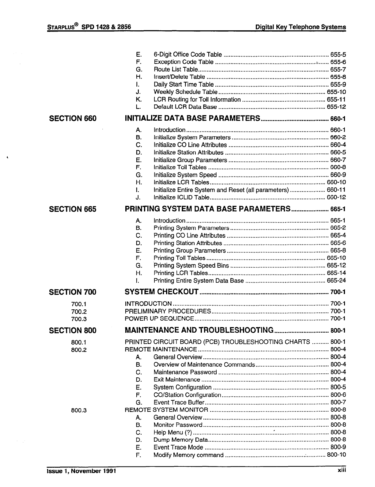
E.
F.
G.
H.
I.
J.
K.
L.
6-Digit Office Code Table .............................................................. 655-5
Exception Code Table -. ............................................................ ...... 655-6
Route List Table.. ........................................................................... 655-7
Insert/Delete Table ........................................................................ 655-8
Daily Start Time Table ................................................................... 655-9
Weekly Schedule Table.. ............................................................. 655-l 0
LCR Routing for Toll Information ................................................. 655-l 1
Default LCR Data Base ............................................................... 655-l 2
INITIALIZE DATA BASE PARAMETERS . . . . . . . . . . . . . . . . . . . . . . . . . . . . . . . . . . . . . . . .
660-l
A.
B.
C.
D.
E.
F.
G.
H.
I.
J.
Introduction.. .................................................................................. 660-i
Initialize System Parameters ......................................................... 660-2
Initialize CO Line Attributes ........................................................... 660-4
Initialize Station Attributes ............................................................. 660-5
Initialize Group Parameters ........................................................... 660-7
Initialize Toil Tables ....................................................................... 660-8
Initialize System Speed ................................................................. 660-9
Initialize LCR Tables.. .................................................................. 660-I 0
Initialize Entire System and Reset (all parameters). .................... 660-l
1
Initialize ICLID Table.. .................................................................. 660-l 2
A. Introduction.. .................................................................................. 665-l
B. Printing System Parameters.. ........................................................ 665-2
C. Printing CO Line Attributes ............................................................ 665-4
D. Printing Station Attributes .............................................................. 665-6
E. Printing Group Parameters.. .......................................................... 665-8
F. Printing Toll Tables ...................................................................... 665-l 0
G. ‘Printing System Speed Bins ........................................................ 665-i 2
H. Printing LCR Tables.. ................................................................... 665-l 4
I. Printing Entire System Data Base ............................................... 665-24
SYSTEM CHECKOUT ............................................................................
700-l
INTRODUCTION ............................................................................................ 700-l
PRELIMINARY PROCEDURES.. ................................................................... 700-l
POWER UP SEQUENCE.. ............................................................................. 700-l
MAINTENANCE AND TROUBLESHOOTING ................................
800-l
PRINTED CIRCUIT BOARD (PCB) TROUBLESHOOTING CHARTS .......... 800-l
REMOTE MAINTENANCE.. ........................................................................... 800-4
A. General Overview .......................................................................... 800-4
B. Overview of Maintenance Commands.. ......................................... 800-4
C. Maintenance Password ................................................................. 800-4
D. Exit Maintenance ........................................................................... 800-4
E. System Configuration .................................................................... 800-5
F. CO/Station Configuration ............................................................... 800-6
G. Event Trace Buffer.. ....................................................................... 800-7
REMOTE SYSTEM MONITOR ...................................................................... 800-8
A. General Overview.. ........................................................................ 800-8
B. Monitor Password .......................................................................... 800-8
C. Help Menu (?) ............................................... .‘................................ 800-8
D. Dump Memory Data.. ..................................................................... 800-8
E. Event Trace Mode ......................................................................... 800-9
F. Modify Memory command ............................................... . ........... 800-l 0
Issue 1, November 1991 .-.
XIII
Digital Key Telephone Systems
STARPLUS@ SPD 1428 & 2856
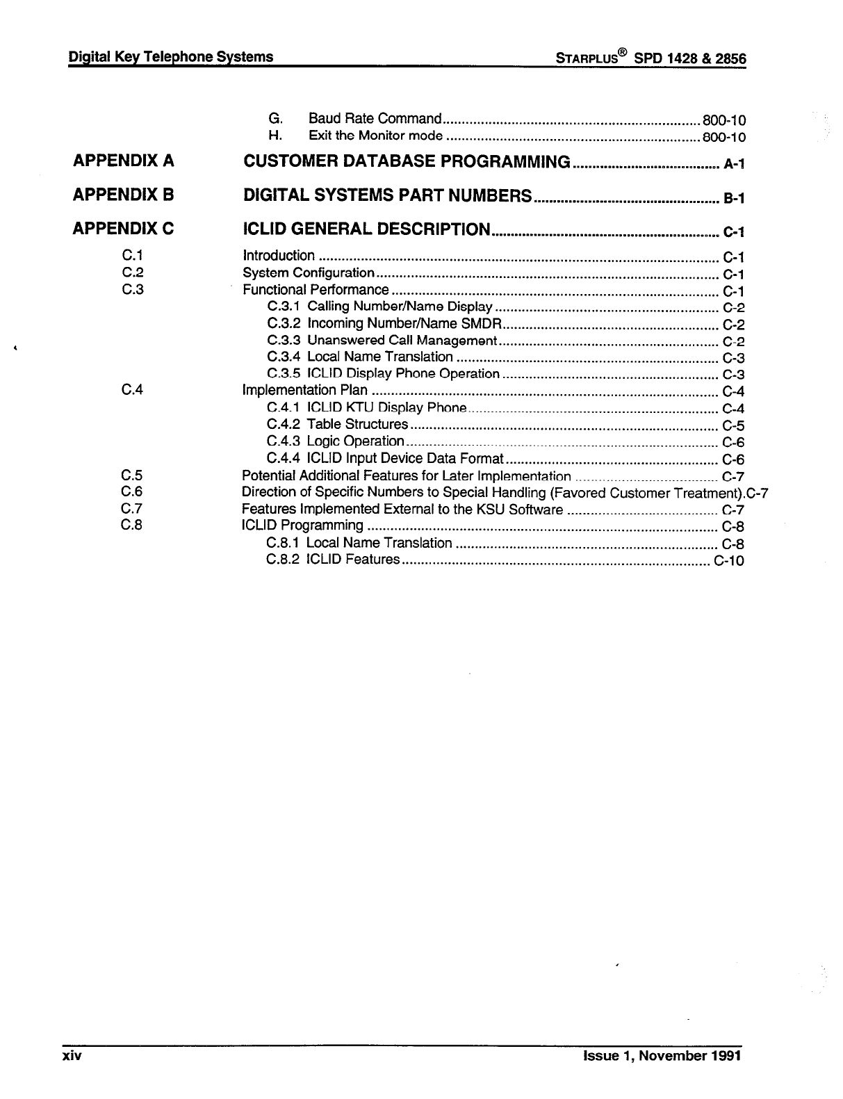
G.
H. Baud Rate Command ................................................................. ..800-10
Exit the Monitor mode .................................................................. 800-l 0
APPENDIX A CUSTOMER DATABASE PROGRAMMING . . . . . . . ..s.........D.m.m..n.m.q..s..m.
A-l
APPENDIX B DIGITAL SYSTEMS PART NUMBERS .*..................m...........................
B-l
APPENDIX C ICLID GENERAL DESCRIPTION . . . . . . . . . . . . . . . . . . . . . . . . . . . . . . ..-..........*...~.....~.~.~~
C-l
c.1
c.2
c.3
c.4
C.5
C.6
c.7
C.8
introduction ........................................................................................................ C-l
System Configuration ......................................................................................... C-l
Functional Performance ..................................................................................... C-l
C.3.1 Calling Number/Name Display.. ........................................................ C-2
C.3.2 Incoming Number/Name SMDR.. ...................................................... C-2
C.3.3 Unanswered Call Management.. ....................................................... C-2
C.3.4 Local Name Translation .................................................................... c-3
C.3.5 ICLID Display Phone Operation ........................................................ C-3
Implementation Plan .......................................................................................... c-4
C.4.1 ICLID KTU Display Phone.. ............................................................... C-4
C.4.2 Table Structures ................................................................................ c-5
C.4.3 Logic Operation ................................................................................. C-6
C.4.4 ICLID Input Device Data Format.. ..................................................... C-6
Potential Additional Features for Later Implementation ..................................... C-7
Direction of Specific Numbers to Special Handling (Favored Customer Treatment).C-7
Features Implemented External to the KSU Software ....................................... C-7
ICLID Programming ........................................................................................... C-8
C.8.1 Local Name Translation .................................................................... C-8
C.8.2 ICLID Features ................................................................................ C-l 0
xiv Issue 1, November 1991
STARPLUS@
SPD 1428 & 2856 Digital Key Telephone Systems
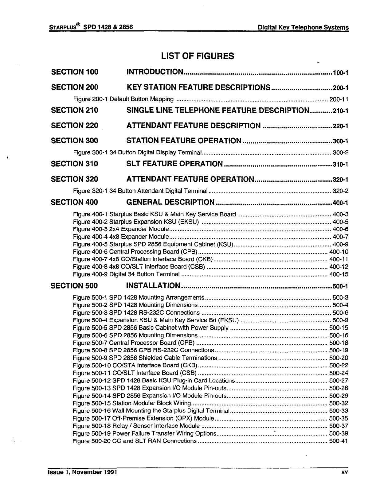
LIST OF FIGURES
SECTION 100 INTRODUCTION . . . . . . . . . . . . . . . . . . . . . . . . . . . . . . . . . . . . . . . . . . . . . . . . . . . . . . . . . . . . . . . . . . . . . . . . .
100-l
SECTION 200 KEY STATION FEATURE DESCRIPTIONS ..............................
200-l
Figure 200-l Default Button Mapping ......................................................................................... 200-l 1
SECTION 210 SINGLE LINE TELEPHONE FEATURE DESCRlPTlON...........210- 1
SECTION 220 All-ENDANT FEATURE DESCRIPTION . . . . . . . . . . . . . . . . . . . . . . . . . . . . . . . . . .
220-l
SECTION 300 STATION FEATURE OPERATION ............................................
300-l
Figure 300-l 34 Button Digital Display Terminal.. .......................................................................... 300-2
SECTION 310 SLT FEATURE OPERATION .....................................................
310-l
SECTION 320 ATTENDANT FEATURE OPERATION ......................................
320-l
Figure 320-l 34 Button Attendant Digital Terminal.. ...................................................................... 320-2
SECTION 400 GENERAL DESCRIPTION .........................................................
400-l
Figure 400-l Starplus Basic KSU & Main Key Service Board ....................................................... 400-3
Figure 400-2 Starplus Expansion KSU (EKSU) ............................................................................ 400-5
Figure 400-3 2x4 Expander Module.. ............................................................................................. 400-6
Figure 400-4 4x8 Expander Module.. ............................................................................................. 400-7
Figure 400-5 Starplus SPD 2856 Equipment Cabinet (KSU). ........................................................ 400-9
Figure 400-6 Central Processing Board
(CPB)
............................................................................ 400-l 0
Figure 400-7 4x8 CO/Station Interface Board
(CKB)
................................................................... 400-l 1
Figure 400-8 4x8 CO/SLT Interface Board (CSB) ....................................................................... 400-l 2
Figure 400-9 Digital 34 Button Terminal ...................................................................................... 400-l 5
SECTION 500 INSTALLATION ..........................................................................
500-l
Figure 500-i SPD 1428 Mounting Arrangements.. ........................................................................ 500-3
Figure 500-2 SPD 1428 Mounting Dimensions.. ............................................................................ 500-4
Figure 500-3 SPD 1428 RS-232C Connections ............................................................................ 500-6
Figure 500-4 Expansion KSU & Main Key Service Bd (EKSU) ..................................................... 500-9
Figure 500-5 SPD 2856 Basic Cabinet with Power Supply ......................................................... 500-15
Figure 500-6 SPD 2856 Mounting Dimensions ............................................................................ 500-l 6
Figure 500-7 Central Processor Board (CPB) ............................................................................. 500-l 8
Figure 500-8 SPD 2856 CPB RS-232C Connections.. ................................................................ 500-I 9
Figure 500-9 SPD 2856 Shielded Cable Terminations ................................................................ 500-20
Figure 500-l 0 CO/STA Interface Board
(CKB)
............................................................................ 500-22
Figure 500-l 1 CO/SLT Interface Board (CSB) ............................................................................ 500-24
Figure 500-12 SPD 1428 Basic KSU Plug-in Card Locations.. .................................................... 500-27
Figure 500-l 3 SPD 1428 Expansion I/O Module Pin-outs.. ......................................................... 500-28
Figure 500-l 4 SPD 2856 Expansion I/O Module Pin-outs.. ......................................................... 500-29
Figure 500-l 5 Station Modular Block Wiring.. .............................................................................. 500-32
Figure 500-16 Wall Mounting the Starplus Digital Terminal.. ....................................................... 500-33
Figure 500-l 7 Off-Premise Extension (OPX) Module.. ................................................................ 500-35
Figure 500-l 8 Relay / Sensor Interface Module .......................................................................... 500-37
Figure 500-i 9 Power Failure Transfer Wiring Options.. ............................... .I .............................. 500-39
Figure 500-20 CO and SLT RAN Connections.. .......................................................................... 500-41
Issue 1, November 1991 xv
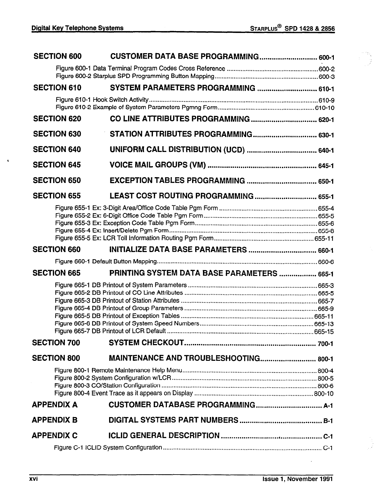
Digital Key Telephone Systems
STARPLUS@
SPD 1428 & 2856
SECTION 600 CUSTOMER DATA BASE PROGRAMMING . ..m.......m.m*D....m.m.m..m
606-l
Figure 600-l Data Terminal Program Codes Cross Reference .................................................... .600-2
Figure 600-2 Starplus SPD Programming Button Mapping ........................................................... .600-3
SECTION 610 SYSTEM PARAMETERS PROGRAMMING .............................
610-l
Figure 61 O-1 Hook Switch Activity ................................................................................................. .610-g
Figure 61 O-2 Example of System Parameters Pgmng Form.. ..................................................... .61 O-l 0
SECTION 620 CO LINE ATTRIBUTES PROGRAMMING ................................
620-l
SECTION 630 STATION AlTRIBUTES PROGRAMMING . . . . . . . . . . . . . . . . . . . ..m.........
630-l
SECTION 640 UNIFORM CALL DISTRIBUTION (UCD) D...........m*n.....m*..e..,.a....
646-l
4
SECTION 645 VOICE MAIL GROUPS (VM) . . . . ..~.......................................~......
645-l
SECTION 650 EXCEPTION TABLES PROGRAMMING . . . . . . . . . . . . ..rn...B........‘......
650-l
SECTION 655 LEAST COST ROUTING PROGRAMMING ..............................
655-l
Figure 655-l Ex: 3-Digit Area/Office Code Table Pgm Form ........................................................ .655-4
Figure 655-2 Ex: 6-Digit Office Code Table Pgm Form ................................................................. .655-5
Figure 655-3 Ex: Exception Code Table Pgm Form ...................................................................... .655-6
Figure 655-4 Ex: Insert/Delete Pgm Form ..................................................................................... .655-8
Figure 655-5 Ex: LCR Toll Information Routing Pgm Form.. ....................................................... .655-l 1
SECTION 660 INITIALIZE DATA BASE PARAMETERS .................................
660-l
Figure 660-l Default Button Mapping ............................................................................................ .660-6
SECTION 665 PRINTING SYSTEM DATA BASE PARAMETERS ..................
665-l
Figure 665-i DB Printout of System Parameters .......................................................................... .665-3
Figure 665-2 DB Printout of CO Line Attributes ............................................................................ .665-5
Figure 665-3 DB Printout of Station Attributes .............................................................................. .665-7
Figure 665-4 DB Printout of Group Parameters ............................................................................ .665-g
Figure 665-5 DB Printout of Exception Tables ............................................................................ .665-l 1
Figure 665-6 DB Printout of System Speed Numbers ................................................................. .665-l 3
Figure 665-7 DB Printout of LCR Default ..................................................................................... 665-l 5
SECTION 700 SYSTEM CHECKOUT ................................................................
700-l
SECTION 800 MAINTENANCE AND TROUBLESHOOTING ...........................
800-l
Figure 800-l Remote Maintenance Help Menu ............................................................................. .800-4
Figure 800-2 System Configuration w/LCR ................................................................................... .800-5
Figure 800-3 CO/Station Configuration .......................................................................................... 800-6
Figure 800-4 Event Trace as it appears on Display .................................................................... .800-l 0
APPENDIX A CUSTOMER DATABASE PROGRAMMING ................................
A-l
APPENDIX B DIGITAL SYSTEMS PART NUMBERS . . . . . . . . . . . . . . . . . . . . ..mm......e......m..
B-l
APPENDIX C ICLID GENERAL DESCRIPTION .................................................
C-l
Figure C-l ICLID System Configuration ............................................................................................ c-i
xvi Issue 1, November 1991
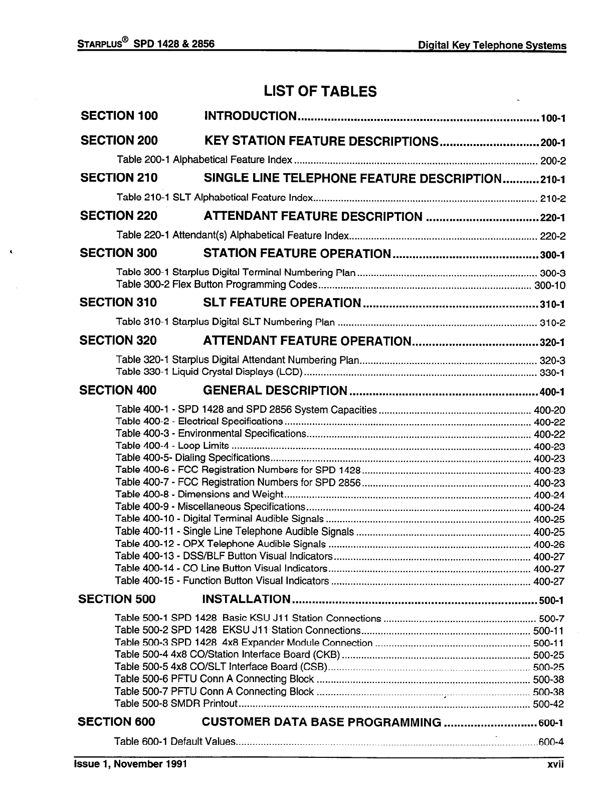
LIST OF TABLES
SECTION 100 INTRODUCTION . . . . . . . . . . . . . . . . . . . . . . . . . . . . . . . . . . . . . . . . . . . . . . . . . . . . . . . . . . . . . . . . . . . . ..~..
100-l
SECTION 200 KEY STATION FEATURE DESCRIPTIONS ..,...........................
200-l
Table 200-l Alphabetical Feature Index ........................................................................................ 200-2
SECTION 210 SINGLE LINE TELEPHONE FEATURE DESCRlPTlON...........21o- I
Table 21 O-l SLT Alphabetical Feature Index.. ............................................................................... 21 O-2
SECTION 220 ATTENDANT FEATURE DESCRIPTION . . . . . . . . . . . . . . . . . . . . . . . . . . . . . . . . . .
220-l
Table 220-l Attendant(s) Alphabetical Feature Index.. .................................................................. 220-2
SECTION 300 STATION FEATURE OPERATION ............................................
300-l
Table 300-l Star-plus Digital Terminal Numbering Plan.. ............................................................... 300-3
Table 300-2 Flex Button Programming Codes.. ........................................................................... 300-10
SECTION 310 SLT FEATURE OPERATION . . . . . . . . . . . . . . . . . . . . . . . . . . . . . . . . . . . . . . . . ..~~.........
310-l
Table 310-l Starplus Digital SLT Numbering Plan ........................................................................ 31 O-2
SECTION 320 A-ITENDANT FEATURE OPERATION ......................................
320-l
Table 320-l Starplus Digital Attendant Numbering Plan.. .............................................................. 320-3
Table 330-l Liquid Crystal Displays (LCD). ................................................................................... 330-l
SECTION 400 GENERAL DESCRIPTION .........................................................
400-l
Table 400-l . SPD 1428 and SPD 2856 System Capacities.. ..................................................... 400-20
Table 400-2 . Electrical Specifications.. ....................................................................................... 400-22
Table 400-3 . Environmental Specifications.. ............................................................................... 400-22
Table 400-4 - Loop Limits ............................................................................................................ 400-23
Table 400-5 Dialing Specifications .............................................................................................. 400-23
Table 400-6 . FCC Registration Numbers for SPD 1428.. ........................................................... 400-23
Table 400-7 . FCC Registration Numbers for SPD 2856.. ........................................................... 400-23
Table 400-8 . Dimensions and Weight .........................................................................................
400-24
Table 400-9 . Miscellaneous Specifications.. ............................................................................... 400-24
Table 400-l 0 . Digital Terminal Audible Signals .......................................................................... 400-25
Table 400-l 1 . Single Line Telephone Audible Signals ............................................................... 400-25
Table 400-12 . OPX Telephone Audible Signals ......................................................................... 400-26
Table 400-l 3 . DSS/BLF Button Visual Indicators.. ..................................................................... 400-27
Table 400-14 . CO Line Button Visual Indicators.. ....................................................................... 400-27
Table 400-l 5 . Function Button Visual Indicators ........................................................................ 400-27
SECTION 500 INSTALLATION ..........................................................................
500-l
Table 500-l SPD 1428 Basic KSU Jl 1 Station Connections ....................................................... 500-7
Table 500-2 SPD 1428 EKSU
Jl 1
Station Connections.. ........................................................... 500-l 1
Table 500-3 SPD 1428 4x8 Expander Module Connection ........................................................ 500-l 1
Table 500-4 4x8 CO/Station Interface Board
(CKB)
.................................................................... 500-25
Table 500-5 4x8 CO/SLT Interface Board (CSB). ........................................................................ 500-25
Table 500-6 PFTU Conn A Connecting Block ............................................................................. 500-38
Table 500-7 PFTU Conn A Connecting Block .............................................. . .............................. 500-38
Table 500-8 SMDR Printout
......................................................................................................... 500-42
SECTION 600 CUSTOMER DATA BASE PROGRAMMING ............................
600-l
Table 600-l Default Values
........................................................................................... ..~...............600- 4
lssuel,November1991 xvii
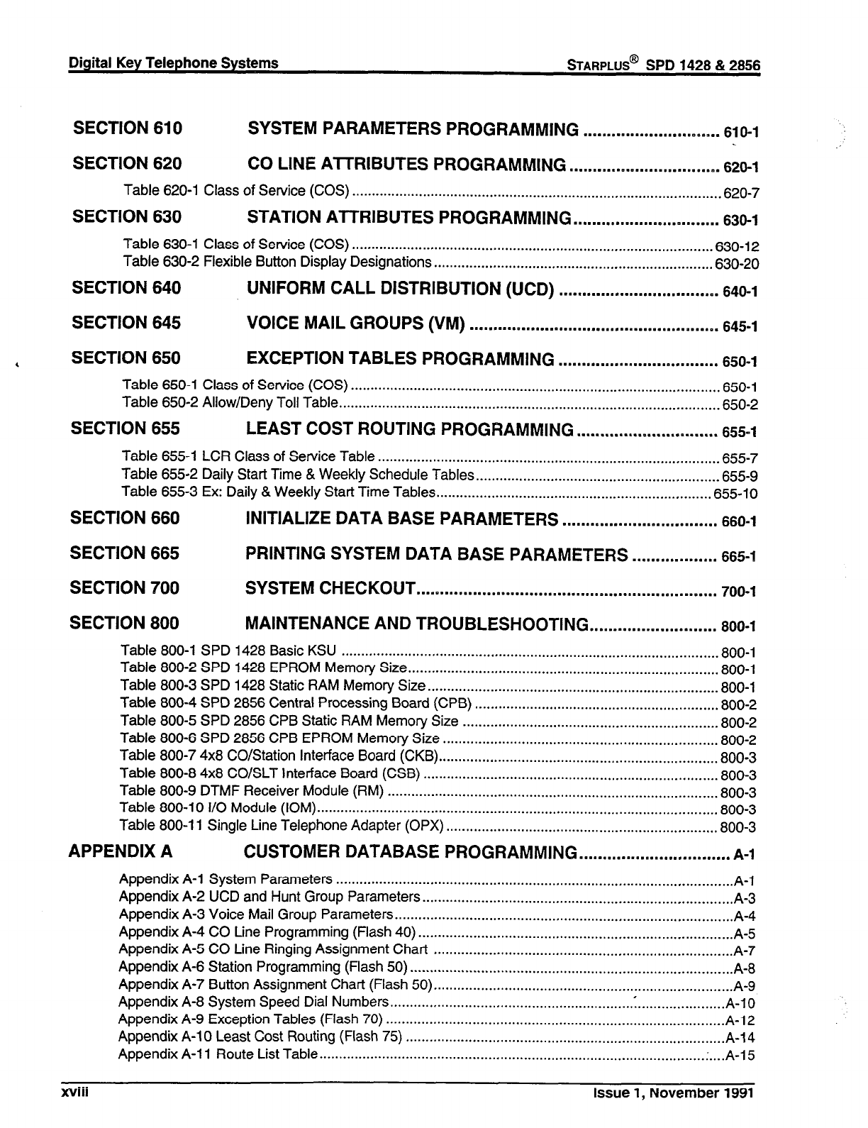
Digital Key Telephone Systems STARPLUS@ SPD 1428 & 2856
SECTION 610 SYSTEM PARAMETERS PROGRAMMING ..m.....m..........*...mmmm..
610-l
SECTION 620 CO LINE AlTRIBUTES PROGRAMMING ................................
628-l
Table 620-l Class of Service (COS) ............................................................................................. .620-7
SECTION 630 STATION ATTRIBUTES PROGRAMMING ...............................
638-l
Table 630-l Class of Service (COS) ........................................................................................... .630-12
Table 630-2 Flexible Button Display Designations ...................................................................... .630-20
SECTION 640 UNIFORM CALL DISTRIBUTION (UCD) ..................................
640-l
SECTION 645 VOICE MAIL GROUPS (VM) .....................................................
645-l
,
SECTION 650 EXCEPTION TABLES PROGRAMMING ..................................
650-l
Table 650-l Class of Service (COS) .............................................................................................. 650-l
Table 650-2 Allow/Deny Toll Table ................................................................................................ .650-2
SECTION 655 LEAST COST ROUTING PROGRAMMING ..............................
655-l
Table 655-l LCR Class of Service Table ...................................................................................... .655-7
Table 655-2 Daily Start Time & Weekly Schedule Tables ............................................................. .655-g
Table 655-3 Ex: Daily & Weekly Start Time Tables ..................................................................... .655-10
SECTION 660 INITIALIZE DATA BASE PARAMETERS .................................
660-l
SECTION 665 PRINTING SYSTEM DATA BASE PARAMETERS ..m . . ..s..........
665-1
SECTION 700 SYSTEM CHECKOUT . . ..~............~.....................~.............~.....~....
700-l
SECTION 800 MAINTENANCE AND TROUBLESHOOTING ...........................
800-l
Table 800-l SPD 1428 Basic KSU ............................................................................................... .800-l
Table 800-2 SPD 1428 EPROM Memory Size .............................................................................. .800-l
Table 800-3 SPD 1428 Static RAM Memory Size ......................................................................... .800-l
Table 800-4 SPD 2856 Central Processing Board (CPB) ............................................................. .800-2
Table 800-5 SPD 2856 CPB Static RAM Memory Size ................................................................ .800-2
Table 800-6 SPD 2856 CPB EPROM Memory Size ..................................................................... .800-2
Table 800-7 4x8 CO/Station Interface Board (CKB). ..................................................................... .800-3
Table 800-8 4x8 CO/SLT Interface Board (CSB) .......................................................................... .800-3
Table 800-9 DTMF Receiver Module (RM) ................................................................................... .800-3
Table 800-10 I/O Module (IOM) ..................................................................................................... .800-3
Table 800-l 1 Single Line Telephone Adapter (OPX) .................................................................... .800-3
APPENDIX A CUSTOMER DATABASE PROGRAMMING ................................
A-l
Appendix A-l System Parameters ..................................................................................................... A-l
Appendix A-2 UCD and Hunt Group Parameters
............................................................................... A-3
Appendix A-3 Voice Mail Group Parameters
...................................................................................... A-4
Appendix A-4 CO tine Programming (Flash 40)
................................................................................ A-5
Appendix A-5 CO Line Ringing Assignment Chart
............................................................................ A-7
Appendix A-6 Station Programming (Flash 50)
.................................................................................. A-8
Appendix A-7 Button Assignment Chart (Flash 50) ............................................................................ A-9
Appendix A-8 System Speed Dial Numbers ..................................................................................... A-10
Appendix A-9 Exception Tables (Flash 70) ...................................................................................... A-12
Appendix A-l 0 Least Cost Routing (Flash 75) ................................................................................. A-14
Appendix A-l 1 Route List Table ................................................................................................. .;. ... A-15
. . .
XVIII
Issue 1, November 1991

Appendix A-12 Insert/Delete Tables ................................................................................................ A-l 9
Appendix A-13 3-Digit Area/Office Code Route List Table .............................................................. A-21
Appendix A-14 6-Digit Office Code Table ........................................................................................ A-22
Appendix A-i 5 LCR Exception Code Table.. ................................................................................... A-23
APPENDIX B DIGITAL SYSTEMS PART NUMBERS ........................................
B-l
Appendix B-l Digital System Component List ................................................................................... B-1
APPENDIX C ICLID GENERAL DESCRIPTION ..................................................
C-l
Issue 1, November 1991 xix
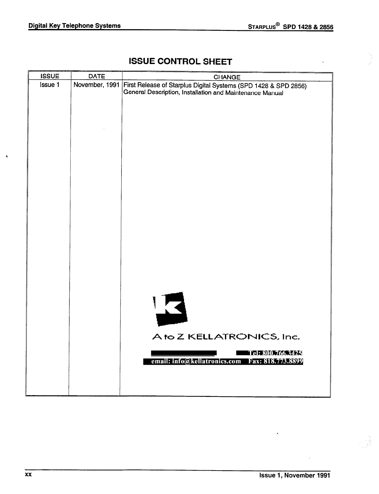
Digital Key Telephone Systems
STARPLUS@
SPD 1428 & 2856
ISSUE CONTROL SHEET
xx issue 1, November 1991
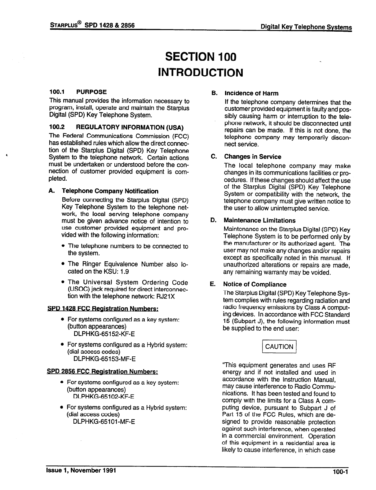
sTARPLUS@
SPD 1428 & 2856
SECTION 100
INTRODUCTION
Digital Key Telephone Systems
100.1 PURPOSE
This manual provides the information necessary to
program, install, operate and maintain the Starplus
Digital (SPD) Key Telephone System.
100.2 REGULATORY INFORMATION (USA)
The Federal Communications Commission (FCC)
has established rules which allow the direct connec-
tion of the Starplus Digital (SPD) Key Telephone
System to the telephone network. Certain actions
must be undertaken or understood before the con-
nection of customer provided equipment is com-
pleted.
A. Telephone Company Notification
Before connecting the Starplus Digital (SPD)
Key Telephone System to the telephone net-
work, the local serving telephone company
must be given advance notice of intention to
use customer provided equipment and pro-
vided with the following information:
l
The telephone numbers to be connected to
the system.
l
The Ringer Equivalence Number also lo-
cated on the KSU: 1.9
l
The Universal System Ordering Code
(USOC) jack required for direct interconnec-
tion with the telephone network: RJ21X
. .
SPD
1428
FCC Realstratlon .
l
For systems configured as a key system:
(button appearances)
DLPHKG-65152-KF-E
l
For systems configured as a Hybrid system:
(dial access codes)
DLPHKG-65153-MF-E
SPD 2856 FCC Reaistration Numbers:
l
For systems configured as a key system:
(button appearances)
DLPHKG-65102-KF-E
l
For systems configured as a Hybrid system:
(dial access codes)
DLPHKG-65101 -MF-E
B. Incidence of Harm
If the telephone company determines that the
customer provided equipment is faulty and pos-
sibly causing harm or interruption to the tele-
phone network, it should be disconnected until
repairs can be made. If this is not done, the
telephone company may temporarily discon-
nect service.
C. Changes in Service
The local telephone company may make
changes in its communications facilities or pro-
cedures. If these changes should affect the use
of the Starplus Digital (SPD) Key Telephone
System or compatibility with the network, the
telephone company must give written notice to
the user to allow uninterrupted service.
D. Maintenance Limitations
Maintenance on the Starplus Digital (SPD) Key
Telephone System is to be performed only by
the manufacturer or its authorized agent. The
user may not make any changes and/or repairs
except as specifically noted in this manual. If
unauthorized alterations or repairs are made,
any remaining warranty may be voided.
E. Notice of Compliance
The Starplus Digital (SPD) Key Telephone Sys-
tem complies with rules regarding radiation and
radio frequency emissions by Class A comput-
ing devices. In accordance with FCC Standard
15 (Subpart J), the following information must
be supplied to the end user:
‘This equipment generates and uses RF
energy and if not installed and used in
accordance with the Instruction Manual,
may cause interference to Radio Commu-
nications. It has been tested and found to
comply with the limits for a Class A com-
puting device, pursuant to Subpart J of
Part 15 of the FCC Rules, which are de-
signed to provide reasonable protection
against such interference, when operated
in a commercial environment. Operation
of this equipment in a residential area is
likely to cause interference, in which case
Issue 1, November 1991 100-l
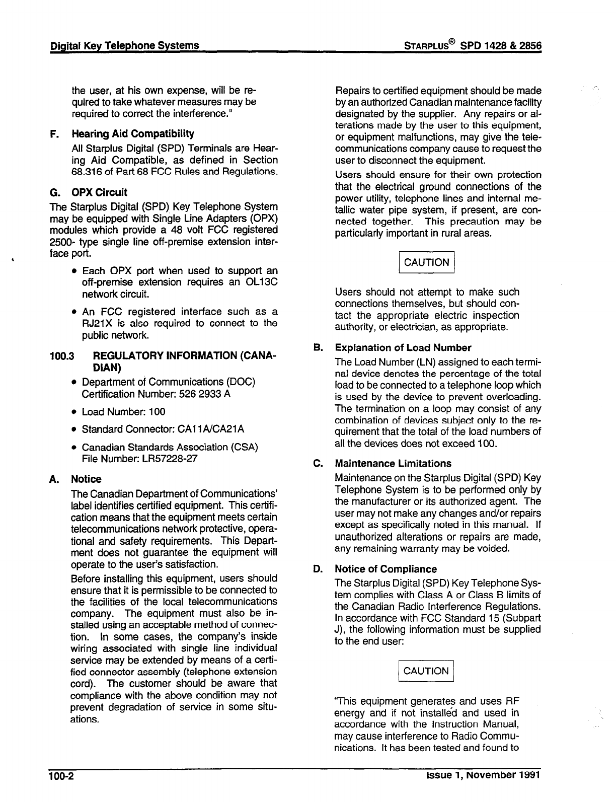
Digital Key Telephone Systems
STARPLUS@
SPD 1428 & 2856
the user, at his own expense, will be re-
quired to take whatever measures may be
required to correct the interference.”
F. Hearing Aid Compatibility
All Starplus Digital (SPD) Terminals are Hear-
ing Aid Compatible, as defined in Section
68.316 of Part 68 FCC Rules and Regulations.
G. OPX Circuit
The Starplus Digital (SPD) Key Telephone System
may be equipped with Single Line Adapters (OPX)
modules which provide a 48 volt FCC registered
2500- type single line off-premise extension inter-
face port.
l
l
100.3
l
Each OPX port when used to support an
off-premise extension requires an OL13C
network circuit.
An FCC registered interface such as a
RJ21X is also required to connect to the
public network.
REGULATORY INFORMATION (CANA-
DIAN)
Department of Communications (DOC)
Certification Number: 526 2933 A
Load Number: 100
Standard Connector: CA1 1 AICA21 A
Canadian Standards Association (CSA)
File Number: LR57228-27
A. Notice
The Canadian Department of Communications’
label identifies certified equipment. This certifi-
cation means that the equipment meets certain
telecommunications network protective, opera-
tional and safety requirements. This Depart-
ment does not guarantee the equipment will
operate to the user’s satisfaction.
Before installing this equipment, users should
ensure that it is permissible to be connected to
the facilities of the local telecommunications
company. The equipment must also be in-
stalled using an acceptable method of connec-
tion. In some cases, the company’s inside
wiring associated with single line individual
service may be extended by means of a certi-
fied connector assembly (telephone extension
cord). The customer should be aware that
compliance with the above condition may not
prevent degradation of service in some situ-
ations.
B.
C.
D.
Repairs to certified equipment should be made
by an authorized Canadian maintenance facility
designated by the supplier. Any repairs or al-
terations made by the user to this equipment,
or equipment malfunctions, may give the tele-
communications company cause to request the
user to disconnect the equipment.
Users should ensure for their own protection
that the electrical ground connections of the
power utility, telephone lines and internal me-
tallic water pipe system, if present, are con-
nected together. This precaution may be
particularly important in rural areas.
Users should not attempt to make such
connections themselves, but should con-
tact the appropriate electric inspection
authority, or electrician, as appropriate.
Explanation of Load Number
The Load Number (LN) assigned to each termi-
nal device denotes the percentage of the total
load to be connected to a telephone loop which
is used by the device to prevent overloading.
The termination on a loop may consist of any
combination of devices subject only to the re-
quirement that the total of the load numbers of
all the devices does not exceed 100.
Maintenance Limitations
Maintenance on the Starplus Digital (SPD) Key
Telephone System is to be performed only by
the manufacturer or its authorized agent. The
user may not make any changes and/or repairs
except as specifically noted in this manual. If
unauthorized alterations or repairs are made,
any remaining warranty may be voided.
Notice of Compliance
The Starplus Digital (SPD) Key Telephone Sys-
tem complies with Class A or Class B limits of
the Canadian Radio Interference Regulations.
In accordance with FCC Standard 15 (Subpart
J), the following information must be supplied
to the end user:
(CAUTION/
“This equipment generates and uses RF
energy and if not installed and used in
accordance with the Instruction Manual,
may cause interference to Radio Commu-
nications. It has been tested and found to
100-2 Issue 1, November 1991
sTARPLUS@
SPD 1428 & 2856 Digital Key Telephone Systems
comply with the limits for a Class A or
Class B computing device, pursuant to
Subpart J or Part 15 of the FCC Rules,
which are designed to provide reasonable
protection against such interference,
when operated in a commercial environ-
ment. Operation of this equipment in a
residential area is likely to cause interfer-
ence, in which case the user, at his own
expense, will be required to take whatever
measures may be required to correct the
interference.”
E. OPX Circuit
The Starplus Digital (SPD) Key Telephone Sys-
tem may be equipped with Single Line Adapters
(OPX) modules which provide a 48 volt FCC
registered 2500- type single line off-premise
extension interface port.
l
A DOC registered interface such as a CA21A
is also required to connect to the public net-
work.
100.4 UUCSA SAFETY COMPLIANCE
The Starplus Digital (SPD) Key Telephone Sys-
tem has met all safety requirements and was
found be in compliance with the Underwriters
Laboratories (UL) 1459 Second Edition and
Canadian Standards Association (CSA) CS-03
Standard. The Starplus Digital (SPD) Key
Telephone System is authorized to bear the UL
and CSA marks.
Issue 1, November 1991 100-3
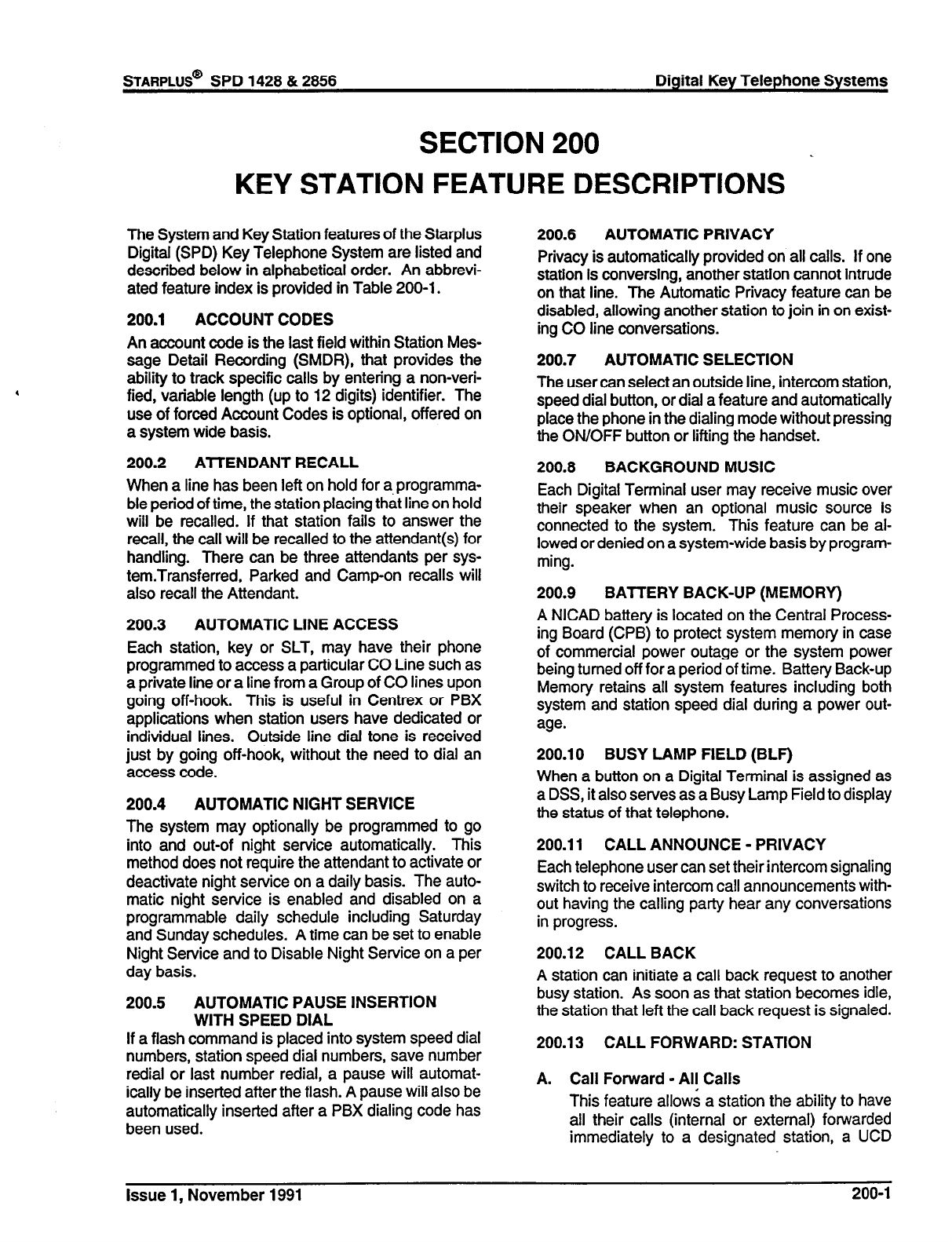
SECTION 200
KEY STATION FEATURE DESCRIPTIONS _
The System and Key Station features of the Starplus
Digital (SPD) Key Telephone System are listed and
described below in alphabetical order. An abbrevi-
ated feature index is provided in Table 200-l.
200.1 ACCOUNT CODES
An account code is the last field within Station Mes-
sage Detail Recording (SMDR), that provides the
ability to track specific calls by entering a non-veri-
fied, variable length (up to 12 digits) identifier. The
use of forced Account Codes is optional, offered on
a system wide basis.
200.2 ATTENDANT RECALL
When a line has been left on hold for a, programma-
ble period of time, the station placing that line on hold
will be recalled. If that station fails to answer the
recall, the call will be recalled to the attendant(s) for
handling. There can be three attendants per sys-
tem.Transferred, Parked and Camp-on recalls will
also recall the Attendant.
200.3 AUTOMATIC LINE ACCESS
Each station, key or SLT, may have their phone
programmed to access a particular CO Line such as
a private line or a line from a Group of CO lines upon
going off-hook. This is useful in Centrex or PBX
applications when station users have dedicated or
individual lines. Outside line dial tone is received
just by going off-hook, without the need to dial an
access code.
200.4 AUTOMATIC NIGHT SERVICE
The system may optionally be programmed to go
into and out-of night service automatically. This
method does not require the attendant to activate or
deactivate night service on a daily basis. The auto-
matic night service is enabled and disabled on a
programmable daily schedule including Saturday
and Sunday schedules. A time can be set to enable
Night Service and to Disable Night Service on a per
day basis.
200.5 AUTOMATIC PAUSE
INSERTION
WITH SPEED DIAL
If a flash command is placed into system speed dial
numbers, station speed dial numbers, save number
redial or last number redial, a pause will automat-
ically be inserted after the flash. A pause will also be
automatically inserted after a PBX dialing code has
been used.
200.6
AUTOMATIC PRIVACY
Privacy is automatically provided on all calls. If one
station is conversing, another station cannot intrude
on that line. The Automatic Privacy feature can be
disabled, allowing another station to join in on exist-
ing CO line conversations.
200.7
AUTOMATIC SELECTION
The user can select an outside line, intercom station,
speed dial button, or dial a feature and automatically
place the phone in the dialing mode without pressing
the ON/OFF button or lifting the handset.
200.8
BACKGROUND MUSIC
Each Digital Terminal user may receive music over
their speaker when an optional music source is
connected to the system. This feature can be al-
lowed or denied on a system-wide basis by program-
ming.
200.9
BATTERY BACK-UP
(MEMORY)
A NICAD battery is located on the Central Process-
ing Board (CPB) to protect system memory in case
of commercial power outage or the system power
being turned off for a period of time. Battery Back-up
Memory retains all system features including both
system and station speed dial during a power out-
age.
200.10 BUSY LAMP FIELD (BLF)
When a button on a Digital Terminal is assigned as
a DSS, it also serves as a Busy Lamp Field to display
the status of that telephone.
200.11 CALL ANNOUNCE - PRIVACY
Each telephone user can set their intercom signaling
switch to receive intercom call announcements with-
out having the calling party hear any conversations
in progress.
200.12 CALL BACK
A station can initiate a call back request to another
busy station. As soon as that station becomes idle,
the station that left the call back request is signaled.
200.13 CALL FORWARD: STATION
A. Call Forward - All Calls
This feature allows a station the ability to have
all their calls (internal or external) forwarded
immediately to a designated station, a UCD
Issue 1, November 1991 200-l
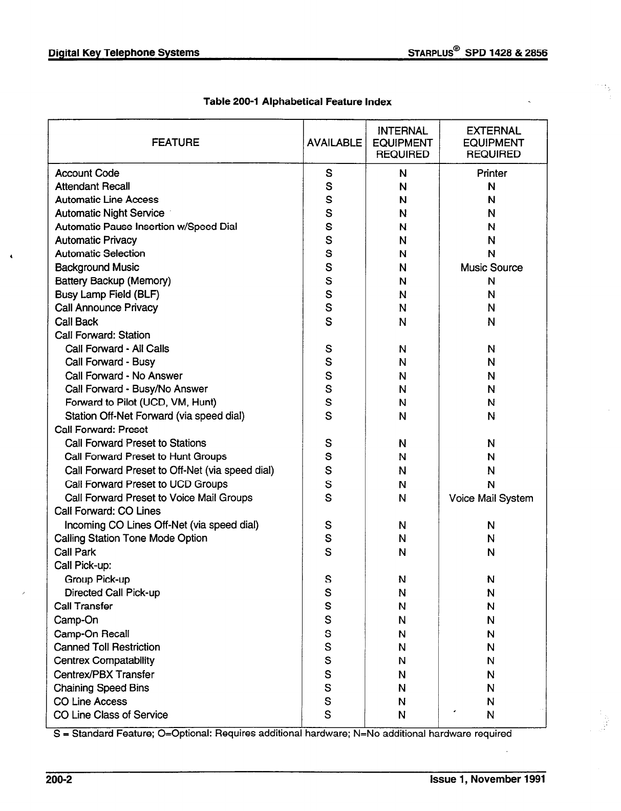
Table 200-l Alphabetical Feature Index
FEATURE AVAILABLE
Account Code
Attendant Recall
Automatic Line Access
Automatic Night Service
Automatic Pause Insertion w/Speed Dial
Automatic Privacy
Automatic Selection
Background Music
Battery Backup (Memory)
Busy Lamp Field (BLF)
Call Announce Privacy
Call Back
Call Forward: Station
Call Forward - All Calls
Call Forward - Busy
Call Forward - No Answer
Call Forward - Busy/No Answer
Forward to Pilot (UCD, VM, Hunt)
Station Off-Net Forward (via speed dial)
Call Forward: Preset
Call Forward Preset to Stations
Call Forward Preset to Hunt Groups
Call Forward Preset to Off-Net (via speed dial)
Call Forward Preset to UCD Groups
Call Forward Preset to Voice Mail Groups
Call Forward: CO Lines
Incoming CO Lines Off-Net (via speed dial)
Calling Station Tone Mode Option
Call Park
Call Pick-up:
Group Pick-up
S
S
S
S
S
S
S
S
S
S
S
S
S
S
S
Directed Call Pick-up
Call Transfer
Camp-On
Camp-On Recall
Canned Toll Restriction
Centrex Compatability
CentrexIPBX Transfer
Chaining Speed Bins
CO Line Access
CO Line Class of Service
S
S
S
S
S
S
S
S
S
S
S
S = Standard Feature; O=Optional: Requires additiona lardware; N:
INTERNAL
EQUIPMENT
REQUIRED
N
N
N
N
N
N
N
N
N
N
N
N
N
N
N
N
N
N
N
N
N
N
N
N
N
N
N
N
N
N
N
N
N
N
N
N
N
EXTERNAL
EQUIPMENT
REQUIRED
Printer
N
N
N
N
N
N
Music Source
N
N
N
N
N
N
N
N
Voice Mail System
N
N
N
N
N
N
N
N
N
N
N
N
N
I N
required
200-2 Issue 1, November 1991

Table 200-l Alphabetical Feature Index (Cont’d)
FEATURE AVAILABLE
CO tine Control (contact)
CO tine Groups
CO Line Loop Supervision
CO Line Queue
CO tine Incoming Ring Assignment:
Assigned Per CO Line
CO Ring Detect
Conference:
Add-on Conference
Multi-Line Conference
Unsupervised Trunk-to-Trunk Conferencing
Conference Enable/Disable
Data Base Printout (dump)
Day/Night Class of Service (COS)
Default Button Mapping
Dial Pulse Sending
Dialing Privileges
Direct CO Line Ringing:
To Stations
To UCD Groups
To Hunt Groups
To Off-Net (via speed dial)
To Voice Mail Groups
Direct Station Selection
Directed Call Pick-up
Direct Inward Station Access (DISA):
Programmable Access
CO Line Group Access
Station Access
Do Not Disturb (DND)
One-Time Do Not Disturb
DTMF Sending
Emergency Transfer
End to End Signalling
Exclusive Hold
Executive Override
Executive/Secretary Transfer
External Night Ringing
‘lash
Rash on Intercom
Rash with Speed Dial
S
S
S
S
S
S
S
S
S
S
S
S
S
0
S
S
S
S
S
S
0
S
S
S
S
S
S
S
S
j = Standard Feature; O=Optional: Requires additiona lardware; N
INTERNAL
EQUIPMENT
REQUIRED
N
N
N
N
N
N
N
N
N
N
N
N
N
DTMF Rcvr
N
N
N
N
N
N
OPx/PFTU
N
N
N
N
N
N
N
N ’
EXTERNAL
EQUIPMENT
REQUIRED
N
N
N
N
N
N
N
N
N
N
Printer
N
N
N
N
N
N
N
N
Voice Mail System
N
N
N
N
N
N
N
N
N
48V Supply or 12V
N
N
N
N
Paging Equip
N
N
N
. .
requrrea
Issue 1, November 1991
200-3
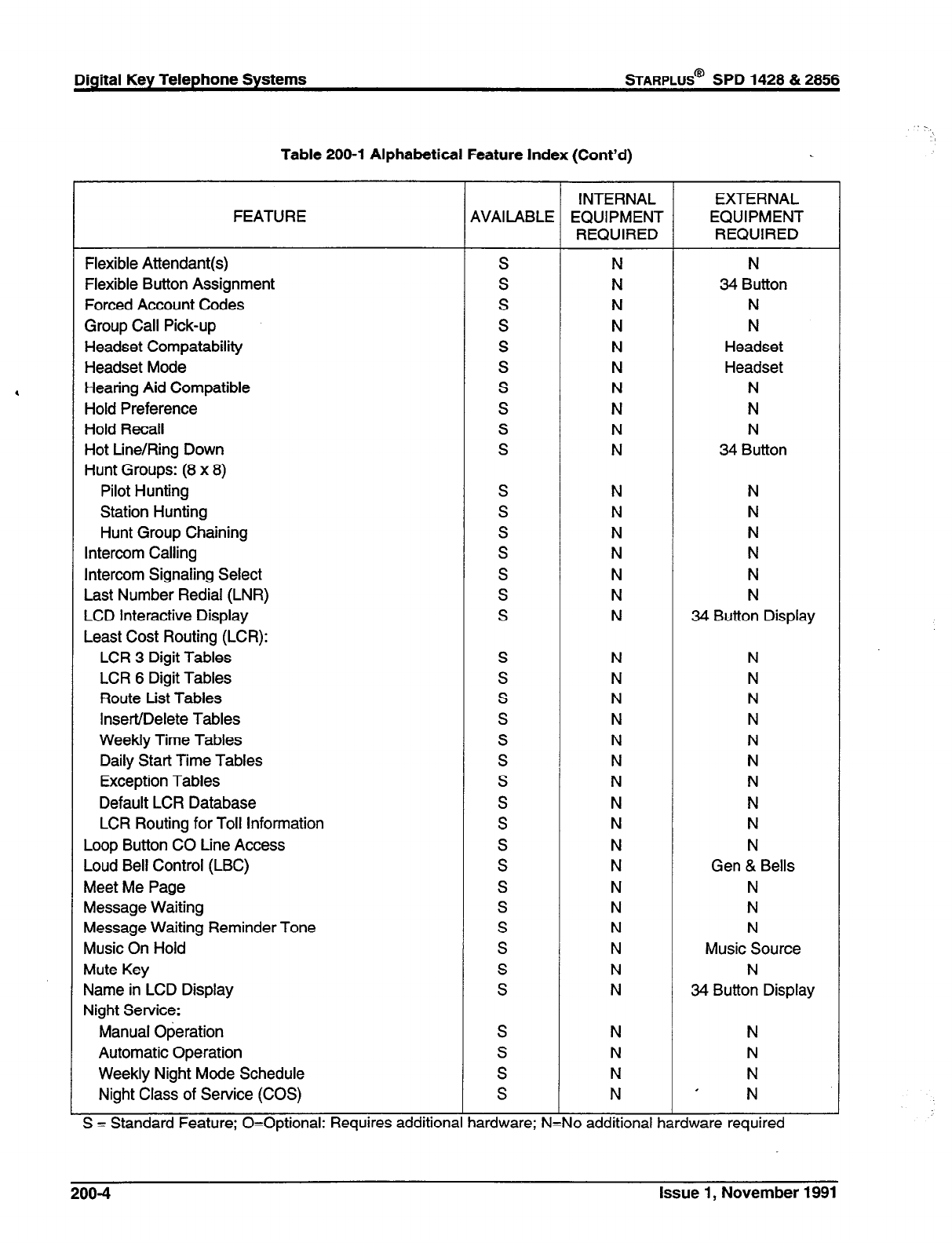
Digital Key Telephone Systems
%ARPLUS@
SPD 1428 & 2856
,
Table 200-l Alphabetical Feature Index (Cont’d)
FEATURE
Flexible Attendant(s)
Flexible Button Assignment
Forced Account Codes
Group Call Pick-up
Headset Compatability
Headset Mode
Hearing Aid Compatible
Hold Preference
Hold Recall
Hot Line/Ring Down
Hunt Groups: (8 x 8)
Pilot Hunting
Station Hunting
Hunt Group Chaining
Intercom Calling
Intercom Signaling Select
Last Number Redial (LNR)
LCD Interactive Display
Least Cost Routing (LCR):
LCR 3 Digit Tables
LCR 6 Digit Tables
Route List Tables
Insert/Delete Tables
Weekly Time Tables
Daily Start Time Tables
Exception Tables
Default LCR Database
LCR Routing for Toll Information
Loop Button CO Line Access
Loud Bell Control (LBC)
Meet Me Page
Message Waiting
Message Waiting Reminder Tone
Music On Hold
Mute Key
Name in LCD Display
Night Service:
Manual Operation
Automatic Operation
Weekly Night Mode Schedule
Night Class of Service (COS)
S = Standard Feature; O=Optional: Requires additiona
4VAI LABLE
S
S
S
S
S
S
S
S
S
S
S
S
S
S
S
S
S
S
S
S
S
S
S
S
S
S
S
S
S
S
S
lardware; N:
INTERNAL
EQUIPMENT
REQUIRED
N
N
N
N
N
N
N
N
N
N
N
N
N
N
N
N
N
N
N
N
N
N
N
N
N
N
N
N
N
N
N
N
N
N
N
N
N
N
EXTERNAL
EQUIPMENT
REQUIRED
N
34 Button
N
N
Headset
Headset
N
N
N
34 Button
N
N
N
N
N
N
34 Button Display
N
N
N
N
N
N
N
N
N
N
Gen & Bells
N
N
N
Music Source
N
34 Button Display
N
N
N
I N
required
200-4
Issue 1, November 1991
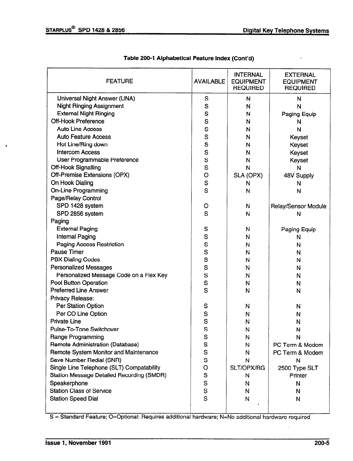
sTARPLUS@
SPD 1428 & 2856 Digital Key Telephone Systems
Table 200-l Alphabetical Feature Index (Cont’d)
FEATURE
Universal Night Answer (UNA)
Night Ringing Assignment
External Night Ringing
Off-Hook Preference
Auto Line Access
Auto Feature Access
Hot tine/Ring down
Intercom Access
User Programmable Preference
Off-Hook Signalling
Off-Premise Extensions (OPX)
On Hook Dialing
On-Line Programming
Page/Relay Control
SPD 1428 system
SPD 2856 system
Paging
External Paging
Internal Paging
Paging Access Restriction
Pause Timer
PBX Dialing Codes
Personalized Messages
Personalized Message Code on a Flex Key
Pool Button Operation
Preferred Line Answer
Privacy Release:
Per Station Option
Per CO Line Option
Private tine
Pulse-To-Tone Switchover
Range Programming
Remote Administration (Database)
Remote System Monitor and Maintenance
Save Number Redial (SNR)
Single Line Telephone (SLT) Compatability
Station Message Detailed Recording (SMDR)
Speakerphone
Station Class of Service
Station Speed Dial
S = Standard Feature; O=Optional: Requires additiona
AVAILABLE INTERNAL
EQUIPMENT
REQUIRED
EXTERNAL
EQUIPMENT
REQUIRED
S
S
S
S
S
S
S
S
S
S
0
S
S
N
N
N
N
N
N
N
N
N
N
SIA (OPX)
N
N
N
N
Paging Equip
N
N
Keyset
Keyset
Keyset
Keyset
N
48V Supply
N
N
0
S
N
N 3elay/Sensor Module
N
Paging Equip
N
N
N
N
N
N
N
N
S
S
S
S
S
S
S
S
0
S
S
S
S
N
N
N
N
N
N
N
N
SLT/OPWRG
N
N
N
N I
N
N
N
N
N
PC Term & Modem
PC Term & Modem
N
2500 Type SLT
Printer
N
N
N
lardware; N: lo additional hardware required
T
Issue 1, November 1991 200-5
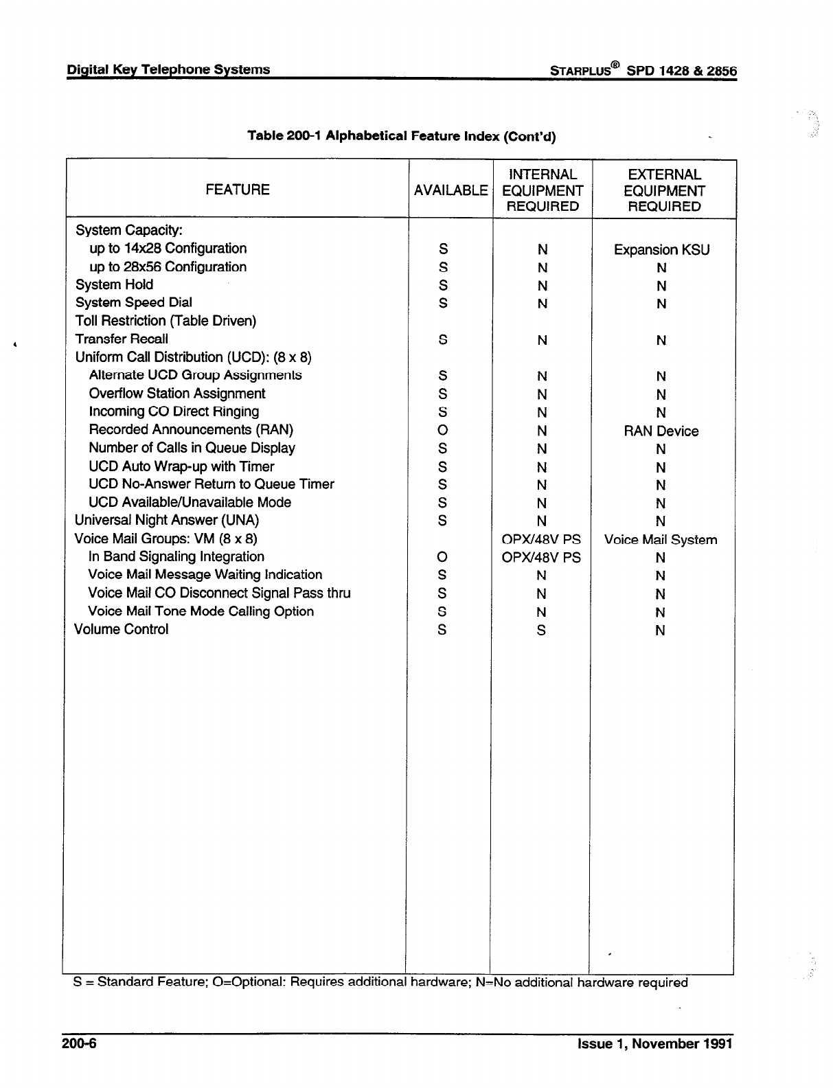
Digital Key Telephone Systems
STARPLUS@
SPD 1428 & 2856
Table 200-l Alphabetical Feature Index (Cont’d)
FEATURE
System Capacity:
up to 14x28 Configuration
up to 28x56 Configuration
System Hold
System Speed Dial
Toll Restriction (Table Driven)
Transfer Recall
Uniform Call Distribution (UCD): (8 x 8)
Alternate UCD Group Assignments
Overflow Station Assignment
Incoming CO Direct Ringing
Recorded Announcements (RAN)
Number of Calls in Queue Display
UCD Auto Wrap-up with Timer
UCD No-Answer Return to Queue Timer
UCD Available/Unavailable Mode
Universal Night Answer (UNA)
Voice Mail Groups: VM (8 x 8)
In Band Signaling Integration
Voice Mail Message Waiting Indication
Voice Mail CO Disconnect Signal Pass thru
Voice Mail Tone Mode Calling Option
Volume Control
S = Standard Feature; O=Optional: Requires additions
4VAI LABLE
S
S
S
S
S
S
S
S
0
S
S
S
S
S
0
S
S
S
S
lardware; N
INTERNAL
EQUIPMENT
REQUIRED
N
N
N
N
N
N
N
N
N
N
N
N
N
N
OPx148V PS
OPIU48V PS
N
N
N
S
EXTERNAL
EQUIPMENT
REQUIRED
Expansion KSU
N
N
N
N
N
N
N
RAN Device
N
N
N
N
N
Voice Mail System
N
N
N
N
N
. .
requrrea
206-6 Issue 1, November 1991
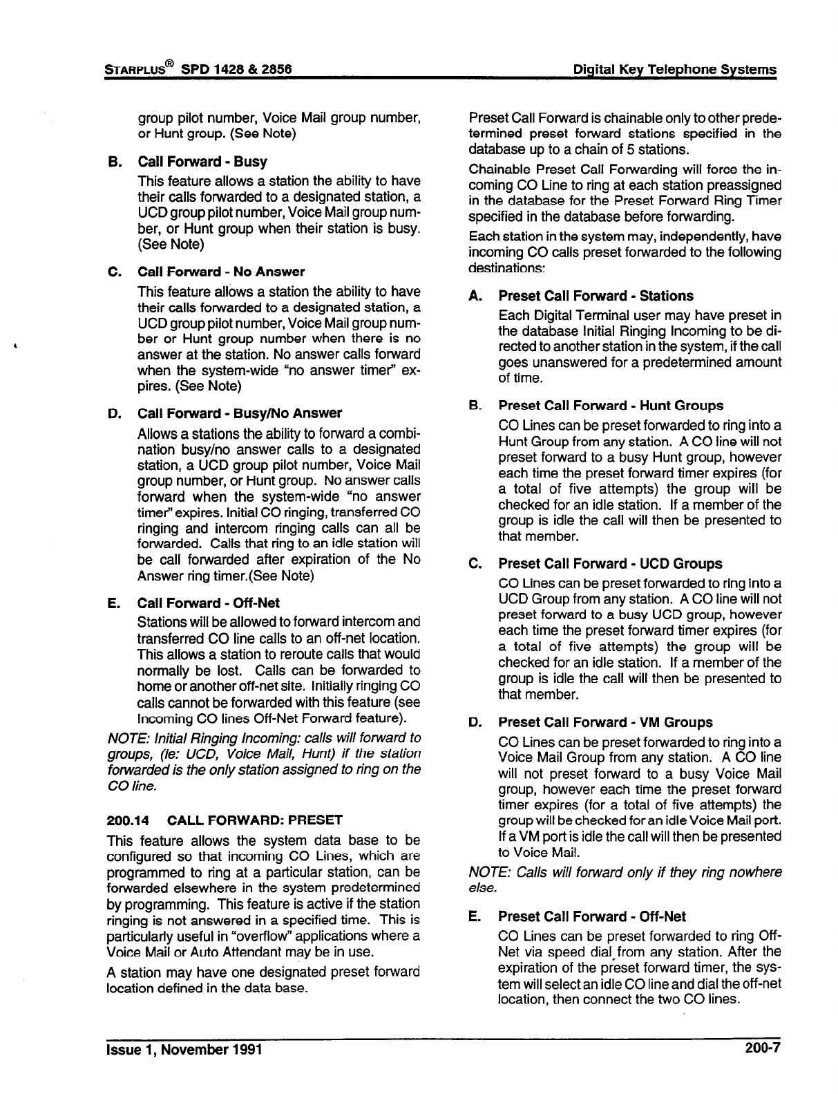
B.
C.
D.
E.
group pilot number, Voice Mail group number,
or Hunt group. (See Note)
Call Forward - Busy
This feature allows a station the ability to have
their calls fonnrarded to a designated station, a
UCD group pilot number, Voice Mail group num-
ber, or Hunt group when their station is busy.
(See Note)
Call Forward - No Answer
This feature allows a station the ability to have
their calls forwarded to a designated station, a
UCD group pilot number, Voice Mail group num-
ber or Hunt group number when there is no
answer at the station. No answer calls forward
when the system-wide “no answer timer” ex-
pires. (See Note)
Call Forward - Busy/No Answer
Allows a stations the ability to forward a combi-
nation busy/no answer calls to a designated
station, a UCD group pilot number, Voice Mail
group number, or Hunt group. No answer calls
forward when the system-wide “no answer
timer” expires. Initial CO ringing, transferred CO
ringing and intercom ringing calls can all be
forwarded. Calls that ring to an idle station will
be call forwarded after expiration of the No
Answer ring timer.(See Note)
Call Forward - Off-Net
Stations will be allowed to forward intercom and
transferred CO line calls to an off-net location.
This allows a station to reroute calls that would
normally be lost. Calls can be forwarded to
home or another off-net site. Initially ringing CO
calls cannot be forwarded with this feature (see
Incoming CO lines Off-Net Forward feature).
NOTE: Initial Ringing Incoming: calls will forward to
groups, (ie: UCD, Voice Mail, Hunt) if the station
forwarded is the only station assigned to ring on the
CO line.
200.14 CALL FORWARD: PRESET
This feature allows the system data base to be
configured so that incoming CO Lines, which are
programmed to ring at a particular station, can be
forwarded elsewhere in the system predetermined
by programming. This feature is active if the station
ringing is not answered in a specified time. This is
particularly useful in “overflow” applications where a
Voice Mail or Auto Attendant may be in use.
A station may have one designated preset forward
location defined in the data base.
STARPLUS@
SPD 1428 & 2858 Digital Key Telephone Systems
Preset Call Forward is chainable only to other prede-
termined preset forward stations specified in the
database up to a chain of 5 stations.
Chainable Preset Call Forwarding will force the in-
coming CO Line to ring at each station preassigned
in the database for the Preset Forward Ring Timer
specified in the database before forwarding.
Each station in the system may, independently, have
incoming CO calls preset forwarded to the following
destinations:
A. Preset Call Forward - Stations
Each Digital Terminal user may have preset in
the database Initial Ringing Incoming to be di-
rected to another station in the system, if the call
goes unanswered for a predetermined amount
of time.
B. Preset Call Forward - Hunt Groups
CO Lines can be preset forwarded to ring into a
Hunt Group from any station. A CO line will not
preset forward to a busy Hunt group, however
each time the preset forward timer expires (for
a total of five attempts) the group will be
checked for an idle station. If a member of the
group is idle the call will then be presented to
that member.
C. Preset Call Forward - UCD Groups
CO Lines can be preset forwarded to ring into a
UCD Group from any station. A CO line will not
preset forward to a busy UCD group, however
each time the preset forward timer expires (for
a total of five attempts) the group will be
checked for an idle station. If a member of the
group is idle the call will then be presented to
that member.
D. Preset Call Forward - VM Groups
CO Lines can be preset forwarded to ring into a
Voice Mail Group from any station. A CO line
will not preset forward to a busy Voice Mail
group, however each time the preset forward
timer expires (for a total of five attempts) the
group will be checked for an idle Voice Mail port.
If a VM port is idle the call will then be presented
to Voice Mail.
NOTE: Calls will forward only if they ring nowhere
else.
E. Preset Call Forward - Off-Net
CO Lines can be preset forwarded to ring Off-
Net via speed dial,from any station. After the
expiration of the preset forward timer, the sys-
tem will select an idle CO line and dial the off-net
location, then connect the two CO lines.
Issue 1, November 1991 200-7
Digital Key Telephone Systems
STARPLUS@
SPD 1428 & 2856
200.15 CALLING STATION TONE MODE OP-
TION
This feature will provide an easy means for a Calling
station to override a desired stations H (handsfree)
or P (call announce) intercom switch setting. A dial
code has been added that is dialed in front of the
extension number to force the tone ringing.
200.16 CALL PARK
An outside line can be placed into one of eight (8)
parking locations and can be retrieved by any station
that has a direct line appearance or an available loop
button. Parked calls have their own recall timer and
will recall the originating station and if still unan-
swered, the attendant(s).
200.17 CALL PICK-UP:
A. Group Pick-up
Stations can be placed in one or more of four
pick-up groups. Stations within a group can
pick up tone ringing intercom calls, transferred,
incoming, or recalling outside line calls for an-
other station in that group.
B. Directed Call Pick-up
A station can pick up an intercom call, trans-
ferred, incoming, or recalling outside line call to
a specific unattended station. The call must be
a tone ringing call.
200.18 CALL TRANSFER
An outside CO line can be transferred from one
keyset to another. By using the TRANS button,
screened (announced) or unscreened transfers can
be made. The line being transferred rings on the
keyset and provides Exclusive Hold flashing indica-
tion to the receiving party’s keyset. Any number of
attempts can be made to locate someone by calling
different keysets without losing the call. If a line is
transferred to a busy station, it will receive muted
ringing.
200.19 CAMP-ON
A station may alert a busy party that an outside line
is on hold and waiting for them by using the CAMP-
ON button. To camp on a call, press the TRANS
button to transfer the call to the desired busy station,
then press the CAMP ON button. The busy party
will receive a muted ring over the keyset speaker,
and a visual flashing CAMP ON LED. By pressing
the CAMP ON button, the person called places his
existing outside call on hold and is connected to the
person placing the Camp On. He can then pick up
the call on the appropriate line. Calls cannot be
camped on when a station is in DND or in Confer-
ence.
200.20 CAMP-ON RECALL
When a station does not answer a Camp On, that
call will recall the person placing the Camp On, and
if unanswered by them, will recall the attendant(s).
200.21 CANNED TOLL RESTRICTION
The system provides an easy means of applying the
most common form of toll restriction where 1-e and
0+ along with 976, 555, and 411 type of calls are
restricted with all local calls and l-800, 911, l-91 1,
and l-61 1 type of calls are allowed. This canned toll
restriction is applied through the use of a single
pre-built Class-of-Service and can be assigned to
stations using range programming.
200.22 CENTREX COMPATIBILITY
The Starplus Digital (SPD) Key Telephone System
provides features that are Centrex compatible so
that Centrex users can utilize the Starplus Digital
(SPD) Key Telephone System to enhance their Cen-
trex capabilities. The system actually simplifies and
provides easier access to many Centrex features by
offering the following features:
A.
B.
C.
D.
Flex Button Programming
Flexible button programming allows Centrex
users to program complex Centrex dial codes
onto a key set button for easy one touch access
to Centrex features.
Off-hook Preference
Both Digital Terminals and Single line tele-
phones may be programmed to have their per-
sonal Centrex line accessed automatically just
by lifting the handset or pressing the ON/ OFF
button. Internal features to the Starplus Digital
(SPD) Key Telephone System are still made
available to Digital Terminals by accessing in-
tercom before going off-hook.
Private Line appearance
The Starplus Digital (SPD) Key Telephone Sys-
tem allows for private line assignment on an
unlimited bases. Each station may have sole
access to a particular outside line if desired and
may also be assigned to receive incoming ring-
ing on that line.
Programmable Flash Timer
CO line flash is a momentary opening on a CO
line used for signaling. When using the Star-
plus Digital (SPD) Key Telephone System in a
Centrex environment the CO line flash is to
signal the intention to transfer a caller using
Centrex transfer. The CO line flash timer is
programmable on a per CO line bases to facili-
206-8 Issue 1, November 1991
tate a mixture of Centrex and CO lines within
the same system.
E. Programming
l
, #, and Hook-Flashes into
Speed Dial
Many Centrex codes utilize a hook-flash fol-
lowed by in many cases the digit [*I and or [#I.
The Starplus Digital (SPD) Key Telephone Sys-
tem allows these codes to be programmed as a
part of system or station speed dial sequences.
200.23 CENTREWPBX TRANSFER
When Centrex or PBX lines are connected to the
Starplus Digital (SPD) Key Telephone System, users
may, by using the Flash button, transfer callers to
other Centrex or PBX extensions. Additionally, the
Flash command may be included within a Speed Bin
and programmed onto a flex button for one button
transfer.
200.24 CHAINING SPEED BINS
Speed dial bins may be chained together by simply
pressing one speed bin, then another and another
as required.
This is helpful for accessing Long Distant carriers or
banking services when Account Codes may be re-
quired.
200.25 CO LINE ACCESS
Through programming, telephones are allowed or
denied access to particular outside lines or line
groups.
200.26 CO LINE CLASS OF SERVICE
Each CO Line may be programmed with a Class-of-
Service to provide dialing privileges. The Starplus
Digital (SPD) Key Telephone System uses an array
between CO Line Class-of-Service and Station
Class-Of-Service to offer a wide variety of dialing
privilege possibilities.
200.27 CO LINE CONTROL (CONTACT)
There are seven control contacts which may be
individually programmed as either CO Line Control
(to control ancillary equipment) or Loud Bell Control
to control a customer provided ringing device to
external areas. When programmed as CO Line Con-
trol and assigned to a CO line, the corresponding
contact will close whenever that CO line is accessed
by a station. (One contact for each 4x8 port card)
200.28 CO LINE GROUPS
Outside lines can be placed in one of eight groups if
the customer’s business requires such grouping.
Stations are then individually assigned access to
these lines and given the ability to dial on particular
lines.
200.29 CO LINE LOOP SUPERVISION
The Starplus Digital (SPD) Key Telephone System
can be programmed to monitor CO lines while on-
hold or connected to RAN devices or Voice Mail
systems or in Trunk-to-Trunk connections for discon-
nect signal provided by the Telco.
After a disconnect signal is detected, the Starplus
Digital (SPD) Key Telephone System will release the
CO lines and automatically place them back in serv-
ice.
200.30 CO LINE QUEUE
When all the outside lines in a group are busy,
stations can be placed in queue awaiting a line in the
same group to become available. If a station doesn’t
answer the queue signal within 15 seconds, that
station is dropped from the queue.
200.31 CO LINE INCOMING RINGING AS-
SIGNMENT
Each CO line may be programmed (in data base
admin) so that incoming ringing on the specified CO
line(s) may be assigned initial ringing to one of the
following destinations:
l
one or more stations (Keyset or SLT)
l
To a UCD, Voice Mail or Hunt Group
l
Off-Net (via Speed Dial)
The ring-in will follow Day Ring assignments unless
Night Service mode is active, in which case all incom-
ing CO calls will follow Night Ring assignments.
When ringing is assigned to a keyset, a direct line
appearance or an idle Loop button must be available
to receive the call. Station call forwarding of initial
ringing CO call is possible and can be directed to
other keysets with an available Loop button or direct
appearance.
If the initially ringing CO call cannot ring at the
destination assigned, it will ring at the first Attendant
station.
NOTE: You cannot Station Call Forward an initially
ringing CO call to UCD, Voice Mail, or Hunt groups
if the line is assigned to ring at more than one station.
200.32 CO RING DETECT
The duration of the ringing signal from the CO or the
PBX is matched with ringing detection circuitry in the
KSU. The ring detect can range from 200 to 900
msec, programmed in 100 msec increments. This
timer helps prevent false ringing.
200.33 CONFERENCE
There are three different types of conferencing:
sTARPLUS@
SPD 1428 & 2856 Digital Key Telephone Systems
Issue 1, November 1991 200-g

A.
B.
C.
Add On Conference
Up to five internal parties can engage in a
conference, or four internal parties with a limit
of one external party.
Multi-Line Conference
One internal station can engage in a confer-
ence with two outside parties.
Unsupervised Conference
The conference initiator can exit a conference
with two outside parties and leave them in an
unsupervised conference. The initiator can re-
enter the conference at any time. The Starplus
Digital (SPD) Key Telephone System can auto-
matically terminate the call when both parties
hang up, when Loop Supervision is provided by
the telco and enabled in the data base.
A programmable conference timer will discon-
nect the unsupervised conference if the initiator
does not re-enter.
200.34 CONFERENCE ENABLE/DISABLE
This feature will allow the system to be administered
on a per station basis for the ability of a station to
initiate a conference.
200.35 DATA BASE PRINTOUT (DUMP)
Through a system programming command, either
portions of or a complete data base dump can be
printed using the RS232C connector located on the
Starplus Digital (SPD) Key Telephone System Cen-
tral Processing Board (CPB).
200.36 DAY/NIGHT CLASS OF SERVICE
WS)
This feature allows stations that are a certain COS
during the day, to be assigned a different COS when
the system is put in the night mode. The night COS
goes into affect when the system is placed into the
night mode, manually or automatically. This pre-
vents the misuse of phones after hours.
200.37 DEFAULT BUlTON MAPPING
The Starplus Digital (SPD)
Key
Telephone System
allows for 28 flexible buttons on each Enhanced or
Executive Digital Terminals to be flexibly assigned
to CO/PBX lines, DSS buttons, Speed Dial or Fea-
ture buttons. However the system will power up with
a default button mapping as shown in Figure 200-l.
200.36 DIAL PULSE SENDING
Each CO interface circuit for outside lines can be
programmed to send dial pulse or DTMF signals.
Dialing speed and break/make ratios are program-
mable.
200.39 DIALING PRIVILEGES
The system provides a flexible means of providing
toll or dialing restriction. Through the assignment of
class of service (both station and outside line) many
combinations of allow and deny numbers can be set.
Both area and office codes can be screened for
allow/deny privileges.
200.40 DIRECT INWARD SYSTEM ACCESS
(DISA)
Allows as many as three simultaneous outside line
calls to be programmed to provide direct access to
the system and the use of features such as WATS
lines, intercom dial tone or the ability to dial out on
outgoing trunks without going through the attendant.
The duration of a Trunk to Trunk DISA call can be
set by the system administrator.
A.
B.
C.
D.
Programmable Access
A 3-digit security code can be assigned in the
system database to restrict unwanted use of
the DISA circuits. Each DISA line can be pro-
grammed independently for 24 hour DISA use
or night DISA use only.
CO Line Group Access
Incoming DISA callers may access all line
groups such as FX or WATS lines or other
outgoing services from home or while away
from the office.
Station Access
DISA callers may dial any station directly with-
out going thru the attendant.
If a DISA caller attempts to call a station that is
busy or does not answer the system will return
ICM dial tone at the end of a programmable
timer (Preset Forward Timer). This will allow
the DISA caller to try another station without
having to dial into the system again.
Trunk-to-Trunk:
The DISA Trunk-to-Trunk (or Conference)
mark on the CO line governs a DISA callers
ability to access other outside lines. CO lines
must have DISA Trunk-to-Trunk enabled to
allow a DISA caller to establish an outgoing
trunk-to-trunk connection. This allows for spe-
cific CO line access restriction on DISA calls.
200.41 DIRECT STATION SELECTION
The user with DSS buttons assigned at their Digital
Terminal can call an intercom station by simply
pressing the appropriate DSS button. The called
station is automatically signaled.
200-l 0 Issue 1, November 1991
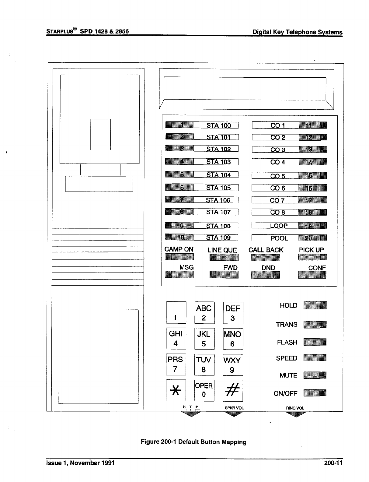
STARPLUS@
SPD 1428 & 2858 Digital Key Telephone Systems
HTP
-7 7 SPKRVOL RN3 VOL
Figure 200-l Default Button Mapping
issue 1, November 1991 200-l 1
200.42 DIRECTED CALL PICKUP
A. Call Pick-up - Station
A station can pick up an intercom call, trans-
ferred, incoming, or recalling outside line call to
a specific unattended station. The call must be
a tone ringing call.
B. Call Pick-up - UCD Groups
200.48 DISABLE OUTGOING CO LINE AC-
CESS
Stations outside of a UCD group can pick up an
intercom call, transferred, incoming, or recall-
ing outside line call ringing to a specific UCD
station. The call must be a tone ringing call.
This feature allows the first Attendant station to dial
a code and disable a CO line from outgoing CO calls.
This applies to all station(s) that have access to that
line. Incoming status is not affected. This feature is
a part of the “Maintenance” package.
200.44 DO NOT DISTURB (DND)
Placing a keyset in DND will eliminate incoming
outside line ringing, intercom calls, transfers and
paging announcements. A ringing station may go
into DND to silence ringing. The attendant can
override a station in DND. The station in DND can
use the telephone to make normal outgoing calls. A
station can be denied this feature through program-
ming.
A. One-Time Do Not Disturb
Allows a station user to turn off muted ringing
that occurs while off hook (handset or ON/OFF)
on another call. Useful when having an impor-
tant conversation and do not wish to be dis-
turbed by ringing. The station, while off hook,
(ON/OFF or handset) depresses the DND but-
ton which eliminates muted ringing. When the
station goes on-hook the DND button is extin-
guished and DND is canceled.
200.45 DTMF SENDING
Each CO interface circuit for outside lines can be
individually programmed to send DTMF (tone) or
dial pulse signals.
200.46 EMERGENCY TRANSFER
Each OPX box will provide power transfer to speci-
fied customer provided SLT’s.
200.47 END TO END SIGNALLING
This feature indicates the capability of the system to
accept DTMF tones from stations, send them
through the public network and have them received
at the distant end for computer access, or a variety
Digital Key Telephone Systems
STARPLUS@
SPD 1428 & 2866
of control functions or inward call completion at a
distant switching system.
200.48 EXCLUSIVE HOLD
When a line is placed on Exclusive Hold, no other
station in the system can retrieve this call. Hold may
be programmed to be activated on the first or second
depression of the Hold button. CO Lines while in a
transfer hold are always placed in an Exclusive Hold
condition.
200.49 EXECUTIVE OVERRIDE
This feature allows certain stations to be designated
as executive stations with the ability to override and
“Barge in” on other keysets engaged in conversation
on a CO line. Stations engaged in intercom conver-
sations can be overridden, however, the intercom
call will be dropped when the override occurs.
In addition to the station programmable option a
system programmable option will enable or disable
a warning tone when the station marked as an
executive is cut into the conversation. This is useful
for UCD agent supervisor or training personnel who
require a service observing option.
NOTE: A decrease in volume may occur on the CO
line after the barge-in occurs and each user will
receive a conference display message on their
keysets.
I
CAUTION: USE OF THIS FEATURE WHEN THE
EXECUTIVE OVERRIDE WARNING TONE IS DIS-
ABLED MAY BE INTERPRETED AS A VIOLATION
OF FEDERAL OR STATE LAWS, AND AN INVA-
SION OF PRIVACY. CONSULT COUNSEL WITH
RESPECT TO APPLICABLE LAW BEFORE IN-
TRUDING ON CALLS USING THIS FEATURE.
200.50 EXECUTIVE/SECRETARY TRANSFER
There are four sets of Executive/ Secretary pairings
available. When the Executive station is busy or in
DND, the Secretary station will receive intercom
calls and transfers. The Secretary station can signal
the Executive in DND by using the Camp On feature.
200.51 EXTERNAL NIGHT RINGING
The system can be programmed so that CO lines
marked for UNA will provide ringing out the external
page ports when the system is placed into Night
mode.
200.52 FLASH
Provides telephone users with the ability to termi-
nate an outside call or transfer a call behind a PBX
or Centrex and restore dial tone without hanging up
the handset. A FLASH button is located on each
Digital Terminal.
200-l 2 Issue 1, November 1991
200.53 FLASH ON INTERCOM
This feature enables key station users to utilize the
Flash Key to terminate pages and intercom calls.
While connected to a page zone or another internal
station pressing the Flash key will terminate the call
and return intercom dial tone.
200.54 FLASH WITH SPEED DIAL
A flash can be programmed within a speed dial
number. When this is done, a pause will automat-
ically be inserted before the remaining speed dial
digits are sent.
200.55 FLEXIBLE AlTENDANT
Any three Digital Terminals in the system can be
assigned as attendant stations. These stations will
receive recalls and can place the system into Night
Service. The attendant stations must be either En-
hanced or Executive stations.
200.56 FLEXIBLE BUlTON ASSIGNMENT
Each Digital Terminal has 28 flexible buttons which
can be individually programmed. One of the follow-
ing seven operations can be selected for each but-
ton: Also refer to Sec. 200.22.
Outside line. Automatically accesses assigned
line. (Assigned in database)
DSS/BLF. Automatically signal assigned sta-
tion and provides BLF for off-hook and DND.
(User programmable)
Feature. Any feature with a dialing code (ie:
Personalized Messages, Paging, Account
Code, Call Park, Music, etc.) can be assigned
to a flexible button. (User programmable)
Group Access. (ie: UCD, Hunt, Voice Mail
group pilot numbers) (User programmable)
Speed dial. Automatically dials a Speed num-
ber. (System, Station, Saved Number Redial,
Last Number Redial) (User programmable)
Pooled group access. Some or all outside lines
can be grouped; pressing this button accesses
the highest numbered unused CO line in that
group. (Assigned in database)
Loop. Used to answer a transferred call on a
line for which a user does not have a button
assigned. (Assigned in database)
200.57 FORCED ACCOUNT CODES
The Starplus Digital (SPD) Key Telephone System
allows the system to be arranged so that station
users must enter an account code before placing an
outside call. Account codes can also be used as a
Traveling Class-of-Service to upgrade a restricted
stations class-of-service for unrestricted dialing. Ac-
Issue 1, November 1991 200-l 3
count codes must be entered before the call when
forced.
200.58 FORCED LEAST COST ROUTING
(LCW
The Starplus Digital (SPD) Key Telephone System
may be programmed on a per station basis to force
the use of LCR for outgoing accessed. This allows
the system administrator to maintain greater control
over dialing patterns and the lines used for placing
outgoing CO calls.
200.59 GROUP CALL PICK-UP
Stations can be placed in one or more of four pick-up
groups. Stations within a group can pick up tone
ringing intercom calls, recalling outside line ringing,
or transferred outside line calls for another station in
that group.
200.60 HEADSET COMPATIBILITY
The electronic Digital Terminals are designed to
allow the connection of an industry standard, electret
mic compatible, modular headset. The user con-
nects the modular headset to the handset jack on the
telephone leaving the handset in place. The
ON/OFF button on the Digital Terminal is then used
to activate the headset.
200.61 HEADSET MODE
Each Electronic Digital Terminal can be individually
programmed for headset operation. When pro-
grammed, an industry standard Headset with it’s
adapter box may be connected to a Digital Terminal
for headset use. This allows handset or headset
operation by switching the selector switch on the
adapter box. Speakerphone operation and call an-
nounce on intercom are disabled while a station has
enabled headset mode.
Once programmed in station programming the user
may then select between headset mode or normal
handseffspeakerphone mode by simply dialing a
code or pressing a user programmable flex button.
200.62 HEARING AID COMPATIBLE
All Electronic Digital Terminals and Single Line Tele-
phones are hearing aid compatible in compliance
with the FCC Part 15, section 68.316. This allows
the telephone to be used in conjunction with users
wearing hearing aids.
200.63 HOLD PREFERENCE
This allows either Exclusive or System hold as the
primary hold on the first depression of the HOLD
button, depending on programming.
Digital Key Telephone Systems
sTARPLUS@
SPD 1428 & 2856
200.64 HOLD RECALL
When an outside call has been on Hold for a pro-
grammable length of time, recall ringing tone is sent
to the station placing the call on Hold. If this station
does not answer the recall, a recall tone is sent to
the attendant(s).
200.65 HOT LINE/RING DOWN
Electronic Digital Terminals may be programmed to
immediately call or ring down a particular station or
outside number upon going off hook. This is per-
formed by programming the stations Off-Hook pref-
erence to activate a DSS or Speed dial feature key.
200.66 HUNT GROUPS
The system can be arranged for up to eight (8) Hunt
groups. Each Hunt group can contain up to eight
stations each. Each Hunt group is independently
arranged to utilize either a pilot hunting technique or
station hunting technique.
A. Pilot Hunting
Incoming CO, transferred CO, and intercom
calls can be directed toa pilot extension number
of a Hunt group. The system will search se-
quentially (in the order the extensions were
entered in the data base programming) for an
idle station in the group and will ring that station.
Calls directed directly to stations (by calling the
extension number) within the hunt group will not
hunt but receive call progress tones of the
extension dialed.
B. Station Hunting
Incoming CO, transferred CO, and intercom
calls that are presented to a busy, or DND
station, that is a member of a Station Hunt
group, will search sequentially (in the order the
extensions were entered in data base program-
ming) for an idle station in the group and will ring
that station. Calls can also be directed to the
groups pilot number for hunting.
C. Hunt Group Chaining
Hunt Groups can be chained or joined together
forming larger Hunt Groups. This is accom-
plished by assigning a pilot hunt group number
as the last member of a group.
200.67 INCOMING CO LINES OFF-NET FOR-
WARD (VIA SPEED DIAL)
Allows the first attendant to forward incoming CO
calls to an off-net location. The attendant can for-
ward a group of CO lines or all CO lines to a off-net
location. The attendant must have a direct appear-
ance of the CO line(s) to be forwarded. Off-net
forwarding is accomplished via use of a speed dial
bin.
200.68 INTERCOM CALLING
The System’s architecture allows non-blocking of
intercom calls. A station is reached on intercom by
dialing the associated three-digit number.
200.69 INTERCOM SIGNALING SELECT
Users can control the method by which they receive
intercom calls and signals. A convenient intercom
signal switch is located on each Digital Terminal for
easy selection. The choices are:
Handsfree (H)(left position). The station user,
upon hearing a tone burst and voice an-
nouncement over the speaker, can reply
handsf ree.
Tone Ringing (T)(center position). A standard
tone ring notifies the party of an incoming inter-
com call. The called party answers by lifting
the handset or moving the switch to the
handsfree (H) position or pressing the ON/OFF
button.
Privacy (P)(right position). The station user
receives a burst of tone and a voice an-
nouncement over his/her speaker. The micro-
phone is deactivated for privacy. The called
party must lift the handset or press the MUTE
button to answer the call.
200.70 LAST NUMBER REDIAL (LNR)
Permits the automatic redialing of the last telephone
number dialed on an outside line. Up to 32 digits can
be stored. Outside line selection of the same line
used is automatic.
200.71 LCD INTERACTIVE DISPLAY
The 34 button Executive Digital Terminal provides
the user with visual indication of call status, Calls to
and from other extensions, number dialed, line used
and camp-on are some of the features displayed.
200.72 LEAST COST ROUTING (LCR)
Allows the system to automatically select the least
costly route available according to the number di-
aled, the time of day/day of week, the class of service
(COS) assigned to the station/trunk group priority
level assigned.
A. LCR SDigit Table
This table is divided into 2 sections: “Leading 1’
(“1” is dialed before the number) and “Non
Leading 1” (no “1” is dialed before the number).
This gives the system the ability to handle call
routing in areas that require a “1” before a long
200-l 4 Issue 1, November 1991
B.
C.
D.
E.
F.
G.
H.
distance number as well as in areas that do not
require the “1”.
LCR 6-Digit Table (Office Codes)
The 6-Digit Table can include 20 office code
maps. Each map can be programmed to route
up to 800 off ice codes to one of the 16 possible
route lists. Each map must be associated with
a specific area code in the 3-Digit Table. Sev-
eral different off ice code maps can be used with
the same area code to provide additional rout-
ing flexibility.
Route List Tables
Up to 16 different routes can be programmed.
Each route can contain up to 4 route lists - one
for each of the 4 time periods. Up to 7 CO line
groups (routing choices) and their correspond-
ing Insert/Delete Tables may be programmed
within each route list.
Insert/Delete Tables
There are 20 Insert/Delete Tables. Up to 20
digits, including pauses, can be inserted and up
to 16 digits deleted. Digits can be inserted
before or after the number dialed, but can be
deleted only from the beginning of a number
dialed.
Weekly Time Tables
The least costly route for a particular dialed
number may be different at different times of the
day and on different days of the week. To
accommodate this situation, there are 2 Time-
of-Day tables - Daily Start Time Table and
Weekly Schedule Table.
The Weekly Time table determines which one
of the 4 Routes LCR should use based on the
Time-of-Day and Day-of-the-Week.
Daily Start Time Tables
The Daily Start Time tables allow the user to
match the Time Periods discount structure to
the carriers rate schedule.
Exception Tables
This table is used to route operator assisted
calls and any other calls which would use a l-
or 2-digit number rather than a 3-digit area
code.
Default LCR Database
In an effort to decrease installation and set up
time usually associated with LCR a default LCR
data base has been incorporated. The default
LCR data base will provide basic routing for all
local and long distance dialing.
%ARPLUS@
SPD 1428 & 2856 Digital Key Telephone Systems
I. LCR Routing for Toll Information
This feature adds provisions to the LCR call
processing which will allow common call routing
for all toll information calls.
l-(XxX)555-1212, (XxX)555-1212, l-555-
1212 and 555-l 212 calls will all be intercepted
and sent to a selected route in the Route List
Table. Numbers dialed will be integrated and if
it is determined to be a toll information call,
either preceded with an area code or without or
with a leading digit 1 or not, the call will be sent
to the route designated in programming.
200.73 LOOP BUTTON CO LINE ACCESS
A station not having a direct appearance for a CO
line will receive incoming CO calls and transferred
CO calls under the loop button. Only one call at a
time can be connected to a keyset on the loop button.
If more than one loop button is on a key set, the loop
buttons may be conferenced together. If all pro-
grammed Loop buttons on a keyset are busy or have
a CO call on hold, the party attempting to transfer a
CO line to that station will receive busy tone and
cannot transfer the call to that station. If a transfer
is attempted, the CO line will recall the initiator
immediately.
CO lines are also presented to a Loop when dialing
out using LCR or when using speed dial to dial out
and the line chosen does not appear on the key
station.
200.74 MEET ME PAGE
Users may answer a page call from any phone in the
system by dialing a special code. The parly who
initiated the page must remain off-hook.
200.75 MESSAGE WAITING
Stations that are busy, unattended, or in DND can
be left a message indication by other stations in the
system. Up to five messages can be left at one
keyset. Updn return to the station, the user can
press the flashing MSG WAIT button to ring each
party in sequential order.
200.76 MESSAGE WAITING REMINDER TONE
A key station with a message waiting can be re-
minded at a timed interval with a tone.
200.77 MUSIC ON HOLD
A music source, when connected to the system,
provides music to all lines on Hold, parked calls,
transferred calls and calls waiting to be answered by
Uniform Call Distribution, (UCD).
200.78 MUTE KEY
Pressing the MUTE button while in the speaker-
phone mode or using the handset-will disable the
Issue 1, November 1991 200-l 5
Digital Key Telephone Systems
STARPLUS@
SPD 1428 & 2858
microphone but not affect the speech coming over
the speaker or handset. Pressing the illuminated
MUTE button again will reactivate the microphone.
200.79 NAME IN LCD DISPLAY
This feature allows every extension (Key or SLT) the
capability to program the users name, for that sta-
tion, so that people using display telephones will see
the name instead of the station number on their
display. The name is programmed at each station
by the user and may be up to seven (7) letters in
length.
200.80 NIGHT SERVICE
4
A.
B.
C.
D.
E.
Manual Operation
The Attendant(s) can control the use of Night
Mode manually by pressing the NIGHT (DND)
button. An LED will indicate when the system is
in Night Mode operation.
Automatic Night Mode Operation
The Starplus Digital (SPD) Key Telephone Sys-
tem can be programmed so that the system is
automatically placed into night mode. A pro-
grammable weekly time schedule allows the
system administrator to preset the time the
system is placed into night mode and removed
from night mode on a daily basis including
weekend operation.
The Attendant(s) can override the Automatic
Night mode schedule simply by pressing the
NIGHT (DND) button.
Weekly Night Mode Schedule
A programmable weekly night mode schedule
provides for 24 hour, 7 day a week automatic
night mode operation. The system can be put
into and out of night mode automatically on a
daily basis.
Night Class of Service (COS)
The system allows each station to be assigned
a different COS for night operation. The night
COS goes into effect when the system is put
into night mode manually or via the automatic
schedule. Prevents the misuse of phones after
hours.
Universal Night Answer (UNA)
Incoming CO lines can be programmed for
Universal Night Answer (UNA). Stations which
do not have access to a line during the day can
answer that line while the System is in the Night
Mode by dialing a UNA code.
F. Night Ringing Assignments
Each CO line may be individually programmed
for Night ringing to other stations, to Hunt
groups, UCD groups, Voice Mail groups, or
off-net via speed dial. When the system is
placed into night mode, manually or automat-
ically, ringing will follow the night ringing assign-
ments for each CO line.
G. External Night Ringing
The system can be programmed so that CO
lines marked for UNA will ring on the external
page speakers.
200.81 OFF-HOOK PREFERENCE
A.
B.
C.
D.
E.
Auto Line Access
Each station, key or SLT, may have their phone
programmed to access a particular CO Line
such as a private line or a line from a Group of
CO lines upon going off-hook. This is useful in
Centrex or PBX applications when station users
have dedicated lines. Outside line dial tone is
received just by going off-hook, without the
need to dial an access code.
Auto Feature Access
In addition to auto line access Digital Terminals
have the ability to have their off-hook prefer-
ence select a DSS or feature button upon going
off-hook or pressing the ON/OFF button.
Hot Line/Ring Down
Electronic Digital Terminals may be pro-
grammed to immediately call or ring down a
particular station or outside number upon going
off hook. This is performed by programming the
stations Off-Hook preference to activate a DSS
or Speed dial feature key.
Intercom Access
When off-hook preference is enabled, at a key
station, that station may still obtain intercom dial
tone for accessing internal stations or other
system features. This is done either by press-
ing an intercom button or dialing their own
intercom station number prior to going off-hook.
User Programmable Preference
Based on a station programmable option Digital
Terminals may be given the ability to enable,
disable or change their off-hook preference by
dialing a code. This option can be denied in
station programming on a per key station basis.
200-l 8 Issue 1, November 1991
200.82 OFF-HOOK SIGNALLING
If a station has been programmed to receive direct
outside line ringing and is busy on another call, that
station will receive muted ring to indicate another call
is ringing in. Additionally CO calls may be “camped-
on” to a busy station and receive muted ringing.
200.83 OFF-PREMISE EXTENSIONS (OPX)
The Off-Premises Extension Box (OPX) provides 1
FCC registered 2500~type single line interface ports.
This enables the use of 1 off-premise 2500 tele-
phone sets. A precise tone plan is provided to OPX
stations. A 48 volt power supply is required when
installing an OPX Box.
200.84 ON HOOK DIALING
The Digital Terminal user can place calls without
lifting the handset. If the speakerphone is disabled,
the handset must be lifted to converse.
200.85 ON LINE PROGRAMMING
Changes to the system data base can be made
without interrupting normal system operation. Pro-
gramming may be performed using a key station
terminal connected to the system (Sta 100) or via a
external terminal either on-site or remotely.
200.86 PAGE/RELAY CONTROL
The SPD 1428 and SPD 2856 systems offer relays
that may be individually programmed for: External
Page, Loud Bell Control, CO Line Control, Power
Failure Transfer, and Recorded Announcement
uses. Up to four Relay/Sensor interface modules
may be installed on either system. Each relay/sensor
interface module contains three (3) independent re-
lays and three (3) sensing input circuits. In addition,
each 4x8 CO/Station Interface card of the SPD 2856
system contains a Relay Contact (for up to seven (7)
“on-board” relays) that may also be assigned to any
of the functions mentioned above.
200.87 PAGING
A. External Paging
There are four (4) external paging zones avail-
able in the SPD 1428 and seven (7) available
in the SPD 2856 systems. External Paging
requires a three-digit dialing code. External
paging requires an externally provided amplifier
and paging system. One (1) make and one (1)
break contact are provided with the page zone
on the 4x8 CO/Station board. Since no “on-
board” relay contacts are available on the SPD
1428 for external paging, the Relay/Sensor In-
terface module is used for this purpose.
STARPLUS@
SPD 1428 & 2856 Digital Key Telephone Systems
B. Internal Paging
There are four internal paging zones available
in the Starplus Digital (SPD) Key Telephone
Systems. A station can be in any or all zones or
in no zone at all. Stations not assigned to a page
group can still make page announcements, if
allowed in station programming. Stations can
be assigned to a page group in order to receive
pages but not allowed to make page an-
nouncements. Since no “on-board” relay con-
tacts are available on the SPD 1428 for internal
paging, the Relay/Sensor Interface module is
used for this purpose.
C. Paging Access Restriction
Programming on a per-station basis, can deny
any station the ability to make any type of page.
200.88 PAUSE TIMER
When dialing a speed number, a timed pause be-
tween digit sending can be placed in the number.
The length of this pause can be programmed in the
system database.
200.89 PBX DIALING CODES
The System will allow five one or two-digit access
codes to be entered into memory. When one of
these codes is dialed, this signals the KSU that toll
restriction is to be applied at the next dialed digits
after the code. If one of these codes is not dialed,
toll restriction does not apply. This allows the dialing
of PBX extensions 100,110,111, etc. This functions
on lines marked as PBX type lines in programming.
200.90 PERSONALIZED MESSAGES
Each station (Key and SLT) can select a pre-as-
signed message to be displayed on the LCD of the
Digital Terminal calling that station. There are ten
possible messages which can be displayed:
- VACATION
- RETURN MORNING
- RETURN AFTERNOON
- RETURN TOMORROW
- RETURN NEXT WEEK
- BUSINESS TRIP
- MEETING
- HOME
- ON BREAK
- LUNCH
A. Personalized Message Code on a Flex Key
This feature allows’s key station user to pro-
gram the pre-selected message code [633] un-
der a Flex key. This speeds access of the
preselected messages.
Issue’ 1, November 1991 200-l 7
200.91 POOL BUTTON OPERATION
The Pool Group Key is used primarily to access CO
lines that do not appear on a station so that outgoing
calls may be made. Pooled group keys are associ-
ated to CO line groups and may be programmed for
use on any of the flexible line buttons. CO lines are
accessed in descending order of priority starting with
the highest numbered available (not busy) CO line
in a CO line group.
Stations may have as many POOL buttons as their
are CO line groups (7). Multiple POOL buttons for
the same group are also allowed.
200.92 PREFERRED LINE ANSWER
A station with Preferred Line Answer can answer any
assigned outside, transferred, or recalling line, or
queue callbacks by lifting the handset or pressing the
ON/OFF button.
200.93 PRIVACY RELEASE
Privacy is insured on all communications in the sys-
tem. If desired, the customer may elect to disable
the Automatic Privacy feature. Thus allowing an-
other station to join in on existing CO Line conversa-
tions.
A. Per Station Option
Each station may be programmed to give the
station the capability to join an existing conver-
sation simply by pressing the CO line button
that is in use. A warning tone is presented to
all parties when the station enters the conver-
sation. The CO line must also have privacy
disabled to allow the cut-thru.
B. Per CO Line Option
This feature allows each CO line to be individu-
ally programmed for privacy. This feature is
useful for maintaining security on such lines as
Data lines, Private lines, or special circuits re-
quiring privacy. If privacy is disabled on a CO
line then, while in use, another station may
enter the conversation simply by pressing the
CO line button. A warning tone is presented to
all parties prior to actual cut-thru. The station
attempting to enter the conversation must also
have privacy disabled.
200.94 PRIVATE LINE
Private line programming allows certain lines to ring
at a specific station only. When placed on Hold,
these lines are active at the programmed station
only. A private line can be transferred to other
stations.
Digital Key Telephone Systems
STARPLUS@
SPD 1428 & 2856
200.95 PULSE-TO-TONE SWITCHOVER
When commanded, the system will change thesig-
naling on an outside line from dial pulse to DTMF
(tone), allowing the use of common carriers behind
a dial pulse outside line. This can be done manually
when dialing, or can be stored within a speed dial
number.
200.96 RANGE PROGRAMMING
The Starplus Digital (SPD) Key Telephone System
allows for range programming when programming
Co lines and Stations. Range programming allows
you to program all parameters alike for the entire
range or you can change or modify a few items that
will be copied to all members in the range.
200.97 REMOTE ADMINISTRATION
The Remote Administration feature allows author-
ized personnel to access the administration pro-
gramming via a terminal device (portable terminal
device or personal computer with communications
software package).
The feature permits the review and entry of the
customer database in the same manner as via the
telephone at “admin” extension 100. The terminal
device can be connected directly to the RS232 con-
nector on the CPB board, or can be accessed by a
telephone modem linking the CPB’s RS232 connec-
tor (via a CO line) to a remote location.
200.98 REMOTE SYSTEM MONITOR AND
MAINTENANCE
A. Remote System Monitor
The Remote Monitor feature provides remote
access to the installed system for diagnostic
purposes. These capabilities benefit Service
personnel enabling them to support the end
user remotely. Different levels of access, via
password, allows authorized personnel to
trace, monitor and “up-load” critical information
directly from the Starplus Digital (SPD) Key
Telephone System. This provides a more ac-
curate means of acquiring system information
that leads to a quick resolution of problems that
may occur. This is all done without interfering
with ongoing call processing or normal system
operation, and in many cases may be per-
formed without a site visit.
Capabilities allowed and reserved for this “High
level troubleshooting” in addition are:
l
Monitor Mode
l
Enable & Disable Event “Trace”
l
Dump “Trace Buffer” (up-load)
200-l 8 Issue 1, November 1991
B. Remote System Maintenance
The Remote Maintenance feature allows the
interconnects’ technical staff to review the sys-
tems configuration data and individual card slot
configuration data. This can be done “on site”
using a data terminal or remotely using modem
to modem access to a remote data terminal.
200.99 SAVE NUMBER REDIAL (SNR)
Any number dialed on an outside line can be saved
permanently to be used at any time. This number is
saved until a new number is stored.
200.100 SINGLE LINE TELEPHONE (SLT)
COMPATIBILITY
The Starplus Digital (SPD) Key Telephone System
supports industry standard 2500 Type (DTMF) sin-
gle line instruments. A maximum of 55 single line
telephones may be installed and operate on the SPD
2856 Digital Terminal System. OPX Boxes are re-
quired.
200.101 STATION MESSAGE DETAIL RE-
CORDING (SMDR)
The Starplus Digital (SPD) Key Telephone System
provides one industry standard RS-232C port for
dual purpose use and a second port is optional for
SMDR output, each allowing connection to an exter-
nal printer or call accounting device. The system
provides details on both incoming and outgoing calls.
This feature is programmable to allow all calls or just
outgoing long distance calls to be recorded. The
system tracks calls by outside line, number dialed,
time of day, date, station that placed the call and
duration of call. Account codes may also be entered
and recorded.
200.102 SPEAKERPHONE
Both Enhanced and Executive Digital Terminals are
equipped with a speakerphone. However, the
speakerphone can be programmed to work in one of
three ways:
. Normal speakerphone operation.
. Disabled for outgoing and incoming CO calls
but handsfree on intercom allowed.
. Headset operation allowed.
200.103 STATION CLASS OF SERVICE
Each station is assigned a Class of Service which
governs that stations dialing privileges. Day Class
of Service and Night Class of Service assignments
to stations provide the system administrator addi-
tional control over station dialing, preventing misuse
of phones after hours. Six uniquely defined Classes
of Service are available for assignment to stations
on a per station basis and all six are available for day
and night assignment. Station Class of Service
works in conjunction with CO line Classof Service
to provide the most flexible means for offering cus-
tom toll restriction. As a part of the Dialing privilege
assignment through Class of Service the system
offers two programmable Allow and Deny tables for
additional customization of a toll restriction plan for
a particular customer. In addition, each station can
reference up to 4 special area code
tables.
200.104 STATION SPEED DIAL
Each station user can program up to 20 frequently
dialed numbers of up to 24 digits in length. Pauses,
flash commands, pulse-to-tone switchover, and NO-
DISPLAY characters take up digit spaces. There
are a total of 1120 speed locations to be divided
among all telephones.
Numbers are dialed by use of the SPEED button and
a two-digit code. This feature can additionally be
assigned to any of the 28 buttons in the flexible
button field on each keyset for one-button activation.
200.105 SYSTEM CAPACITY
A. Up to 14x28 Configuration:
The SPD 1428 system will support a maximum
of 14 outside CO circuits and 28 station circuits.
B. Up to 28x56 Configuration
The SPD 2856 system will support a maximum
of 28 outside CO circuits and 56 station circuits.
200.106 SYSTEM HOLD
When a line is placed on System Hold, any station
in the system with access to that line can retrieve the
call.
200.107 SYSTEM SPEED DIAL
Up to 80 commonly dialed numbers can be pro-
grammed into System Speed Dial for use by stations
allowed this feature. These numbers can be up to
24 digits including pauses, flash commands, pulse-
to-tone switchover, and no-display characters. The
last 40 numbers will not be monitored by toll restric-
tion.
200.108 TOLL RESTRICTION (TABLE DRIVEN)
The system provides a flexible means of providing
toll restriction to internal stations of the Starplus
Digital (SPD) Key Telephone System. Each station
is assigned a Class of Service for day mode opera-
tion and one for night mode operation these station
COS’s work in conjunction with a CO line Class of
service to allow for customized toll restriction. Two
(2) Allow and Deny tables along with four (4) special
tables afford the system administrator to devise a
Issue 1, November 1991 200-l 9
Digital Key Telephone Systems
STARPLUS@ SPD 1428 & 2856
variety of complex toll restriction or dialing privilege
schemes.
200.109 TRANSFER RECALL
Screened and unscreened transfers will recall the
initiating party if unanswered for a programmable
length of time, and then if unanswered, will recall the
attendant.
200.110 UNIFORM CALL DISTRIBUTION (UCD)
Eight Uniform Call Distribution (UCD) groups can be
programmed, each containing up to eight 3-Digit
station numbers. Each group is assigned a pilot
number. When this number is dialed, the first avail-
able agent in that group is rung. Calls are routed to
the station that has been on-hook for the longest
period of time.
A.
B.
C.
D.
E.
Alternate UCD Group Assignments
An alternate UCD group can be programmed
so that if stations in one group are busy, the
alternate group will be checked for an available
station.
Overflow Station Assignments
An overflow station may be assigned to route
callers in queue to a designated station after a
specified time. The overflow station may not be
one of the UCD group stations.
Incoming CO Direct Ringing
CO Lines can be programmed to ring directly
into a UCD group. When all agents are busy
and RAN is enabled, the system will answer the
caller and present the 1st RAN announcement
automatically.
Recorded Announcements (RAN)
Recorded announcement devices can be as-
signed to provide up to two different messages,
if all stations in a UCD group are busy. The two
messages are available to all eight (8) UCD
groups in different configurations. A RAN de-
vice can provide an announcement to one caller
at a time. Subsequent callers will be queued
onto the message on a first-in basis.
Number of Calls in Queue Display
There are two methods of viewing UCD Group
call queue status.
1. In-service UCD agents and the assigned
overflow station will see the quantity of calls in
queue on the LCD of their station for the UCD
group of which they are a member. If every
member of a UCD group is busy and calls are
in queue, the “XX CALLS IN QUEUE” display
will be seen at all UCD members of that group.
NOTE: If a UCD member is taken out of the group
(ie. DND, Call Forward,Unavailable etc.) they wilLnot
receive calls in queue information.
F.
G.
H.
2. Any station not assigned in a UCD group can
view the number of calls in queue for any given
UCD Group. To view the number of calls in
queue the station user dials the Calls In Queue
code (or presses a programmed FLEX button
with this code) then enters the UCD group
desired. The LCD will display, on a real time
basis, the number of calls in queue for that
group.
UCD Auto Wrap-Up w/Timer
After completion of a UCD call (on-hook) the
agent will not be subjected to another UCD call
for the duration of the Auto Wrap-Up timer
(regardless of the number of calls in queue),
allowing the agent to finish call related work or
access other facilities. This will allow agents to
remove themselves from the group (ie. DND,
Unavailable, Call Forward or originate another
call). The auto wrap-up timer is programmed
as part of the UCD data base. (System-wide)
UCD No-Answer Timer
If a call routed to a station via UCD is not
answered by the UCD Agent/Station before the
No-Answer timer expires, the call will be re-
turned to UCD Queue with the highest priority.
In addition, the station that failed to answer the
ringing UCD call will be placed into an unavail-
able state.
UCD Available / Unavailable Mode
Stations programmed into a UCD group may
log off and on to their assigned UCD group by
dialing an Available/Unavailable code. When
an agent is in the Available mode that agent will
receive UCD calls in the normal manner. When
an agent is in the Unavailable mode that agent
will no longer receive UCD type calls, however
may receive non-UCD calls. Agents that have
logged off by going Unavailable will receive a
visual reminder that they are logged off with a
flashing LED and or a LCD display message.
200.111 UNIVERSAL NIGHT ANSWER (UNA)
Incoming CO lines can be programmed for Universal
Night Answer (UNA). Stations which do not have
access to a line during the day can answer that line
while the System in the Night Mode by dialing a UNA
code. In order to utilize this feature, a loop button
must be present on the station. I
200-20 Issue 1, November 1991

sTARPLUS@
SPD 1428 & 2856 Digital Key Telephone Systems
200.112 VOICE MAIL GROUPS (VM)
The Voice Mail feature automatically handles unan-
swered calls. Stations may forward calls to a voice
mail group (for leaving mail) or may call the voice
mail group directly (to retrieve mail) with no assis-
tance from the attendant. Up to eight (8) voice mail
groups can be configured in the system. Each group
can contain up to eight voice mail stations, each of
which interfaces with a port on an OPX box. Each
voice mail “station” can be shared by a number of
actual users. An OPX Box and a 48 vdc power supply
are required when utilizing the Starplus Digital (SPD)
Key Telephone System Voice Mail “In-Band” integra-
tion.
200.113 VOLUME CONTROLS
Both speaker and tone ringing volume can be sepa-
rately adjusted by utilizing the two slide switches on
the right side of the keyset.
A. VM In-Band Signaling Integration
The Starplus Digital (SPD) Key Telephone Sys-
tem integrates with a wide range of Voice Mail
systems through the use of “In-Band” signaling.
B. VM Message Waiting Indication
When Voice Mail has received a voice message
for a user who has a station on the Starplus
Digital (SPD) Key Telephone System, the VM
connected to the system will leave a message
waiting indication at the VM users station. When
the station user retrieves their mail, the VM
system will cancel the message waiting indica-
tion left at a station via a VM port.
The message waiting indication will appear on
the programmed Voice Mail (group) button. If
such a button has not been programmed, a
voice mail message waiting indication will ap-
pear on the MSG WAIT button as a normal
message waiting signal.
C. VM CO Disconnect Signal - Pass Thru
To avoid Voice Mail ports from being tied up, as
a result of CO line callers abandoning the call
or not exiting the VM system properly, a discon-
nect signal has been provided to notify the VM
system that a CO caller has abandon. “Silence”
is provided to the VM port followed by “busy
tone” to aid the VM system to recognize that an
intercom caller has abandoned the call.
Disconnect digits may also be programmed.
D. VM Tone Mode Calling Option
Voice mail systems and/or Automated Atten-
dants can utilize the Calling Station Tone Mode
option. This is useful when using supervised
transfer or call screening options on voice mail
or auto attendant(s) requiring ringback tone for
proper call handling.
Issue 1, November 1991 200-21

sTARPLUS@
SPD 1428 & 2856
SECTION 210
Digital Key Telephone Systems
SINGLE LINE TELEPHONE FEATURE DESCRlPTiON
Single Line telephones have access to most of the
system and station features listed in the previous
section, however, the additional features listed be-
low are unique to Single Line Telephones. (An OPX
Box and 48 vdc power supply must be installed in
the system for proper SLT operation) An abbreviated
feature index is provided in Table 21 O-l.
210.1 ACCOUNT CODE
SLT stations may enter an account code, up to 12
digits in length, to identify calls for billing/tracking
purposes. The account code may be entered either
before the call or during the call (the outside caller is
placed on hold while the account code is entered if
during the call.). The account code is recorded on
the SMDR printout. Account codes are non-verified
and can vary in length from 1 to 12 digits.
210.2 AUTOMATIC LINE ACCESS
SLT’s may have their station programmed to access
a particular CO Line such as a private line or a line
from a Group of CO lines upon going off-hook. This
is useful in Centrex or PBX applications when station
users have dedicated or individual lines. Outside
line dial tone is received just by going off-hook,
without the need to dial access codes.
210.3 CALL FORWARD
Single line telephones may direct intercom calls and
transferred CO lines to be forwarded to another
station. SLTs have access to all forwarding options
that Key station users have:
Call Forward - All Calls
Call Forward - No Answer j7]
Call Forward - Busy [8]
Call Forward - Busy/No Answer [9]
Call Forward - Off-Net [‘I
Preset Call Forward
CAMP ON
A busy station can be notified that an outside line is
on hold and waiting for them. The busy station is
notified of this by a beep tone. Single line telephones
can receive a camp on indication or initiate one by
using an access code.
210.5 CONFERENCE
An SLT user can initiate a conference with an outside
line and one other internal station.
210.6 CONFERENCE /WITH PERSONAL
PARK
Single Line Telephones (SLT) can initiate a confer-
ence between two outside (CO) calls. The Personal
Park feature is used in conjunction with the SLT
conference code to make this possible. A combina-
tion of features are derived from these dial codes
(Personal Park, Flip/Flop, and Multi-line Confer-
ence).
210.7 DIRECT OUTSIDE LINE ACCESS
Single line telephones can access outside lines by
dialing CO line group access codes 9 or 81-87.
210.8 DIRECT OUTSIDE LINE RINGING
Single line telephones can be set up to receive direct
outside line ringing. SLTs may be programmed to
receive incoming CO Ringing on more than one CO
line. However, an SLT can answer only ONE call at
a time. If a SLT is busy when a CO call rings in,
camp-on tone will be given to that SLT station.
210.9 DIRECTED CALL PICK UP
Tone ringing intercom calls, Initial Ringing CO calls
and transferred outside line calls to specific stations
can be picked up by single line telephones. For this
type of pickup, the stations do not have to be in the
same pickup group.
210.10 DO NOT DISTURB
Each telephone user can be allowed to place their
phone in Do No Disturb. The user will receive error
tone if they are not allowed this feature. They will
also receive a confidence tone when lifting the hand-
set to remind them they are in Do Not Disturb. The
attendant can override a station in DND.
210.11 GROUP CALL PICK UP
Tone ringing intercom calls, transferred outside line
calls, and initially ringing calls can be picked up by
single line telephones by dialing a special pickup
code. The telephones must be in the same pickup
group.
210.12 INTERCOM CALLING
Single line telephones can make and receive inter-
com calls.
210.13 MESSAGE WAITING/CALL BACK
Single Line Telephones calling a station that is busy,
idle, or in Do Not Disturb can leave a message
waiting indication to signal the station to call back.
Issue 1, November 1991 21 o-l
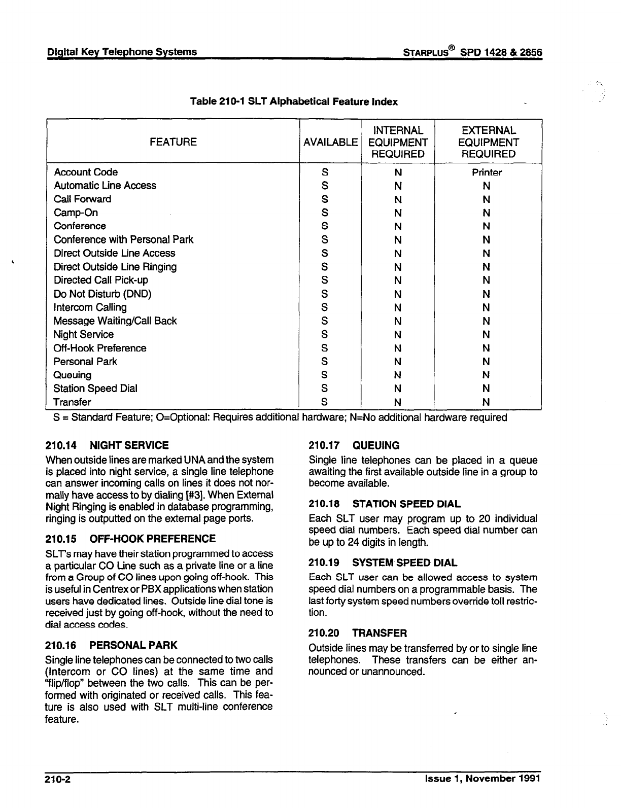
Digital Key Telephone Systems
sTARPLUS@
SPD 1428 & 2858
Table 21 O-l SLT Alphabetical Feature Index
INTERNAL EXTERNAL
FEATURE AVAILABLE EQUIPMENT EQUIPMENT
REQUIRED REQUIRED
Account Code S N Printer
Automatic Line Access S N N
Call Forward S N N
Camp-On S N N
Conference S N N
Conference with Personal Park S N N
Direct Outside Line Access S N N
Direct Outside Line Ringing S N N
Directed Call Pick-up S N N
Do Not Disturb (DND) S N N
Intercom Calling S N N
Message Waiting/Call Back S N N
Night Service S N N
Off-Hook Preference S N N
Personal Park S N N
Queuing S N N
Station Speed Dial S N N
Transfer S N N
S = Standard Feature; O=Optional: Requires additional hardware; N=No additional hardware required
210.14 NIGHT SERVICE
When outside lines are marked UNA and the system
is placed into night service, a single line telephone
can answer incoming calls on lines it does not nor-
mally have access to by dialing [#3]. When External
Night Ringing is enabled in database programming,
ringing is outputted on the external page ports.
210.15 OFF-HOOK PREFERENCE
SLT’s may have their station programmed to access
a particular CO Line such as a private line or a line
from a Group of CO lines upon going off-hook. This
is useful in Centrex or PBX applications when station
users have dedicated lines. Outside line dial tone is
received just by going off-hook, without the need to
dial access codes.
210.18 PERSONAL PARK
Single line telephones can be connected to two calls
(Intercom or CO lines) at the same time and
“flip/flop” between the two calls. This can be per-
fom-red with originated or received calls. This fea-
ture is also used with SLT multi-line conference
feature.
210.17 QUEUING
Single line telephones can be placed in a queue
awaiting the first available outside line in a group to
become available.
210.18 STATION SPEED DIAL
Each SLT user may program up to 20 individual
speed dial numbers. Each speed dial number can
be up to 24 digits in length.
210.19 SYSTEM, SPEED DIAL
Each SLT user can be allowed access to system
speed dial numbers on a programmable basis. The
last forty system speed numbers override toll restric-
tion.
210.20 TRANSFER
Outside lines may be transferred by or to single line
telephones. These transfers can be either an-
nounced or unannounced.
210-2 Issue 1, November 1991
sTARPLUS@
SPD 1428 & 2856 Digital Key Telephone Systems
SECTION 220
. AITENDANT FEATURE DESCRIPTION
The Attendant and Attendant(s) with DSS/DLS fea-
tures of the Starplus Digital (SPD) Key Telephone
System are listed and described below in alphabeti-
cal order. An abbreviated feature index is provided
in Table 220-l.
220.1 AlTENDANT DISABLE OUTGOING
ACCESS
The first attendant can disable CO lines, preventing
outgoing access to those lines. This is useful for
removing a faulty line from service, or for reserving
CO lines for important use. All stations that can
normally make calls on the lines are affected, but
incoming calls are not affected. A CO line may be
disabled while it is being used; when the trunk be-
comes idle, further outgoing access will be pre-
vented.
220.2 AlTENDANT OVERFLOW
System programming allows the attendant station to
be programmed so that if the attendant is busy or not
there, the call will be automatically forwarded to
another predetermined station, VM Group, Hunt
Group or UCD group after a programmed period of
time. (Refer to Call Forward, Station and Preset)
220.3 AlTENDANT OVERRIDE
Attendant stations may override a busy station or
ring a station in DND. While busy, pressing the
override key provides override tone and a five sec-
ond delay before voice cut-through to the called party
occurs, automatically placing any outside line call on
Hold. The Attendant Override function may be pro-
grammed on to a flex button and can be enabled or
disabled in programming.
220.4 AlTENDANT POSITION
The system identifies a maximum of three program-
mable stations as attendants for line recalls and
attendant features. The first programmed attendant
can enter system date and time information as well
as System Speed numbers from this position without
entering the programming mode. The Starplus Digi-
tal (SPD) Key Telephone System is placed in Night
Service by any programmed attendant pressing the
NIGHT (DND) button or dialing the NIGHT code.
220.5 AlTENDANT RECALL
A held CO call left unattended by a station will recall
the attendant(s) after a programmable period of time
has elapsed. A recalling CO line flashes at a distinc-
tive rate that identifies the originating station of the
unanswered call.
220.6 AUTOMATIC NIGHT MODE
In addition to the attendants capability to place the
system into and out of night mode manually, by
pressing the Night key, an automatic night mode
schedule has been added to the system. The auto-
matic schedule is set in data base programming on
a week day basis, including Saturday and Sunday.
The Attendant can override the automatic schedule
by pressing the NIGHT (DND) button.
220.7 INCOMING CO LINE OFF-NET FOR-
WARD
Allows the first attendant to forward incoming CO
calls to an Off-Net location. The attendant must
have a direct appearance of the CO line to be
forwarded. Forwarding can be established on a per
CO line group basis, or all CO lines may be simulta-
neously forwarded to an off-net location.
220.8 TIME AND DATE PROGRAMMING
This feature allows the first programmed attendant
to set the time and date without entering the pro-
gramming mode.
Issue 1, November 1991 220-l
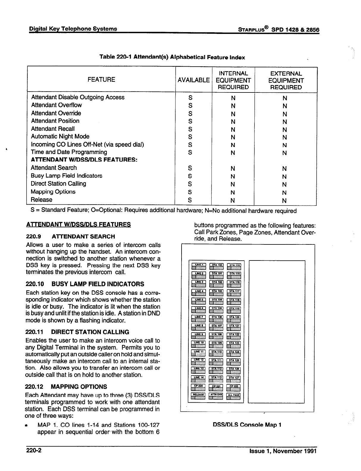
Digital Key Telephone Systems
=ARPLUS@
SPD 1428 & 2866
Table 220-l Attendant(s) Alphabetical Feature Index
INTERNAL EXTERNAL
FEATURE AVAILABLE EQUIPMENT EQUIPMENT
REQUIRED REQUIRED
Attendant Disable Outgoing Access s N N
Attendant Overflow S N N
Attendant Override S N N
Attendant Position S N N
Attendant Recall, S N N
Automatic Night Mode S N N
Incoming CO Lines Off-Net (via speed dial) S N N
Time and Date Programming S N N
AlTENDANT W/DSS.‘DLS FEATURES:
Attendant Search S N N
Busy Lamp Field Indicators S N N
Direct Station Calling S N N
Mapping Options S N N
Release S N N
S = Standard Feature; O=Optional: Requires additional hardware; N=No additional hardware required
ATTENDANT WIDSSIDLS FEATURES
220.9 AlTENDANT SEARCH
Allows a user to make a series of intercom calls
without hanging up the handset. An intercom con-
nection is switched to another station whenever a
DSS key is pressed. Pressing the next DSS key
terminates the previous intercom call.
220.10 BUSY LAMP FIELD INDICATORS
Each station key on the DSS console has a corre-
sponding indicator which shows whether the station
is idle or busy. The indicator is lit when the station
is busy and unlit if the station is idle. A station in DND
mode is shown by a flashing indicator.
220.11 DIRECT STATION CALLING
Enables the user to make an intercom voice call to
any Digital Terminal in the system. Permits you to
automatically put an outside caller on hold and simul-
taneously make an intercom call to an internal sta-
tion. Also allows you to transfer an intercom call or
outside call that is on hold to another station.
220.12 MAPPING OPTIONS
Each Attendant may have up to three (3) DSWDLS
terminals programmed to work with one attendant
station. Each DSS terminal can be programmed in
one of three ways:
. MAP 1. CO lines 1-14 and Stations loo-127
appear in sequential order with the bottom 6
buttons programmed as the following features:
Call Park Zones, Page Zones, Attendant Over-
ride, and Release.
DSS/DLS Console Map 1
220-2
Issue 1, November 1991
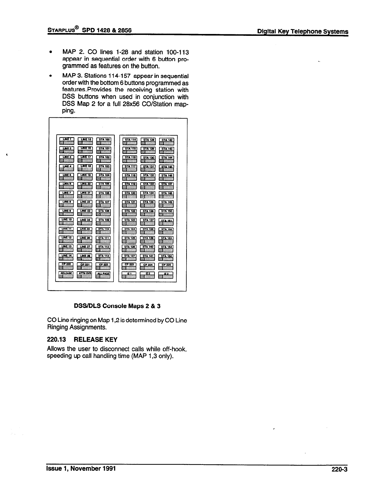
.
MAP 2. CO lines 1-28 and station 100-l 13
appear in sequential order with 6 button pro-
grammed as features on the button.
b MAP 3. Stations 114-l 57 appear in sequential
order with the bottom 6 buttons programmed as
features.Provides the receiving station with
DSS buttons when used in conjunction with
DSS Map 2 for a full 28x56 CO/Station map-
ping.
DSWDLS Console Maps 2 & 3
CO Line ringing on Map 1,2 is determined by CO Line
Ringing Assignments.
220.13 RELEASE KEY
Allows the user to disconnect calls while off-hook,
speeding up call handling time (MAP I,3 only).
issue 1, November 1991 220-3
sTARPLUS@
SPD 1428 & 2856 Digital Key Telephone Systems
SECTION 300
-
STATION FEATURE OPERATION
300.1 INTRODUCTION
The Starplus Digital (SPD) Key Telephone System
has a wide variety of features and flexible program-
ming, allowing each telephone user to program
his/her telephone to meet his/her own individual
needs.
This section of the manual contains the operating
instructions for key telephone and Single Line users
and includes an illustration of the key telephone used
in the Starplus Digital (SPD) Key Telephone System
and description of the keys on the telephones and
their functions. It is designed to provide step-by-step
instructions for operating the Digital Terminals and
Single Line telephones in the system. Visual and
audible cues which accompany the various steps in
the operation of the features are also include
Literature similar to these operating instructions has
been prepared for use by the customer in the form
of Station, SLT, and Attendant Users Guides.
300.2 KEY TELEPHONE STATION FEA-
TURES
Each Starplus Digital (SPD) Key Telephone System
provides the following keys, indicators and features:
HANDSET AND SPEAKER
are located at the left
side of the front panel. A handset is provided to allow
confidential conversation when desired. Lifting the
handset from its cradle (going off-hook) disengages
the station’s built-in speaker.
The speaker is located directly below the center
portion of the handset. The station may be operated
with the handset on-hook. When this occurs, audio
is transmitted to the station user through the station’s
speaker.
HOLD
button enables you to place an outside caller
on hold.
TRANSFER (TRANS)
button is used to transfer an
outside call from one station to another.
FLASH
button is used to terminate an outside call
and restore dial tone without having to hang up the
handset. It is also used to transfer calls behind a PBX
or Centrex within those systems.
SPEED
button provides you with access to speed
dialing, save number redial and last number redial.
This button is also used to access speed dial and flex
button programming.
MUTE
button allows you to switch the built-in micro-
phone on or off when using the speakerphone, or the
handset microphone when using the handset. A flex
button must be assigned to use this feature.
ON/OFF
button enables you to make a telephone
call without lifting the handset. It turns the telephone
on and off when using the speakerphone.
FLEXIBLE BUTTONS
are used to access idle out-
side lines, provide DSS/BLF for internal stations,
access speed dial number and activate features.
These buttons are programmed by the individual
station user. The default flex feature buttons are
described below:
CAMP-ON
(flex) button enables you to alert a
busy party that an outside line is on hold and
waiting for them. A flex button must be as-
signed to use this feature.
LINE QUEUE
(flex) button allows you to queue
onto an outside line when all lines in a group are
busy. Your station is placed in queue awaiting
a line in the same group to become available.
A flex button must be assigned to use this
feature.
CALL BACK
(flex) button allows you to initiate
an automatic call back request to another busy
station. As soon as that station becomes idle,
the station that left the call back request is
signalled. A flex button must be assigned to
use this feature.
PICK UP
(flex) button allows you to pickup a
tone ringing intercom call, transferred, incom-
ing, or recalling outside line call to a specific
unattended station either by group or directed
call pick-up.
MESSAGE WAIT (MSG WAIT)
(flex) button
allows you to initiate a message waiting indica-
tion at stations that are busy, unattended, or in
Do Not Disturb. Message Waiting Callback
request left at your station will indicated by a
flashing Msg Wait LED.
CALL FWD
(flex) button allows you to forward
your calls to another station.
DO NOT DISTURB (DND)
(flex) button allows
the user to place his/her telephone into a Do
Not Disturb mode to eliminate incoming outside
line ringing, intercom calls, transfers and paging
announcements. The station in DND can use
the telephone to make normal outgoing calls.
On Attendant stations, this button becomes the
system Night Mode button. A flex button must
be assigned to use fhis feature.
CONFERENCE (CONF)
(flex) button is used to
establish and build conference calls.
Issue 1, November 1991 300-l
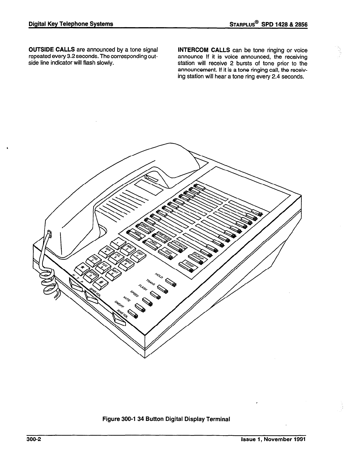
Digital Key Telephone Systems
sTARPLUS@
SPD 1428 & 2856
OUTSIDE CALLS are announced by a tone signal
repeated every 3.2 seconds. The corresponding out-
side line indicator will flash slowly.
INTERCOM CALLS can be tone ringing or voice
announce If it is voice announced, the receiving
station will receive 2 bursts of tone prior to the
announcement. If it is a tone ringing call, the receiv-
ing station will hear a tone ring every 2.4 seconds.
Figure 300-l 34 Button Digital Display Terminal
300-2 Issue 1, November i991
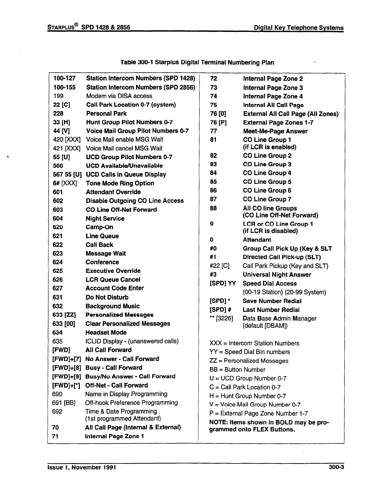
Table 366-l Starplus Digital Terminal Numbering Plan
loo-127 Station Intercom Numbers (SPD 1428)
108-155 Station Intercom Numbers (SPD 2856)
199 Modem via DISA access
22 tc1
Call Park Location 6-7 (system)
228 Personal Park
33 WI
Hunt Group Pilot Numbers O-7
MM
Voice Mail Group Pilot Numbers 6-7
420 goo<l Voice Mail enable MSG Wait
421 Dooc] Voice Mail cancel MSG Wait
55
FJI
UCD Group Pilot Numbers O-7
566 UCD Available/Unavailable
567 55 [U] UCD Calls in Queue Display
6# [xxx] Tone Mode Ring Option
601 Attendant Override
602 Disable Outgoing CO Line Access
603 CO Line Off-Net Forward
604 Night Service
620 Camp-On
621 Line Queue
622 Call Back
623 Message Wait
624 Conference
625 Executive Override
626 LCR Queue Cancel
627 Account Code Enter
631 Do Not Disturb
632 Background Music
633 [ul Personalized Messages
633 [OO] Clear Personalized Messages
634 Headset Mode
635
ICLID Display - (unanswered calls)
F-W
All Call Forward
[FWD]+[71 No Answer - Call Forward
[FWD]+[8] Busy - Call Forward
[FWD]+[9] Busy/No Answer - Call Forward
[FWD]+[*] Off-Net - Call Forward
690
Name in Display Programming
691 [BB] Off-hook Preference Programming
692 Time & Date Programming
(1 st programmed Attendant)
70 All Call Page (Internal & External)
71 Internal Page Zone 1
72
73
74
75
76
PI
76
PI
77
81
82
83
84
85
86
Internal Page Zone 2
Internal Page Zone 3
Internal Page Zone 4
Internal All Call Page
External All Call Page (All Zones)
External Page Zones l-7
Meet-Me-Page Answer
CO Line Group 1
(if LCR is enabled)
CO Line Group 2
CO Line Group 3
CO Line Group 4
CO Line Group 5
CO Line Group 6
87 CO Line Group 7
88 All CO line Groups
(CO Line Off-Net Forward)
9 LCR or CO Line Group 1
(if LCR is disabled)
0 Attendant
#O Group Call Pick Up (Key & SLT
#l Directed Call Pick-up (SLT)
#22 [C]
Call Park Pickup (Key and SLT)
#3 Universal Night Answer
[SPD] YY Speed Dial Access
(00-l 9 Station) (20-99 System)
[SPD] * Save Number Redial
[SPD] # Last Number Redial
** [3226]
Data Base Admin Manager
(default [DBAM])
XXX = Intercom Station Numbers
YY = Speed Dial Bin numbers
ZZ = Personalized Messages
BB = Button Number
U = UCD Group Number O-7
C = Call Park Location O-7
H = Hunt Group Number O-7
V = Voice Mail Group Number O-7
P = External Page Zone Number 1-7
NOTE: Items shown in BOLD may be pro-
grammed onto FLEX Buttons.
Issue 1, November 1991 300-3
Digital Key Telephone Systems
STARPLUS@
SPD 1428 & 2856
300.3 ANSWERING AN OUTSIDE CALL
a.
b.
Lift handset.
Press slow flashing outside line button, or Loop
button. (If your telephone is programmed with
Preferred Line Answer, you may answer an
outside line by lifting the handset.)
300.4 PLACING AN OUTSIDE CALL ON
HOLD
a. If your system is programmed for Exclusive
Hold Preference, press HOLD button once for
Exclusive Hold and twice for System Hold.
b. If your system is programmed for System Hold
Preference, press HOLD button once for Sys-
tem Hold and twice for Exclusive Hold.
300.5 ANSWERING A RECALL
When an outside line has remained on hold for an
extended period of time, you will be reminded with a
recalling ring. (If Preferred Line Answer is enable,
skip Step A.)
a. Press outside line, Loop or Pool button flashing
at very fast rate.
b. Lift handset to converse.
300.6 ACCOUNT CODES
When connected to an outside line call:
a.
b.
C.
d.
Press pre-programmed* ACCOUNT CODE
button.
Dial account code up to 12 digits. (The other
party will not hear the digits being dialed).
If account code is less than 12 digits, an [*I must
be entered to return to the call.
If account codes are forced the account code
must be entered prior to dialing the outside
number.
*Refer to Flexible Button programming
300.7 DISABLE OUTGOING CO LINE AC-
CESS
The First Attendant station can disable CO lines,
preventing outgoing CO calls.
a. Lift handset or press ON/OFF button.
b. Dial [602]. Confirmation tone is heard
c. Depress the line button(s) of the CO Line(s) to
be disable Confirmation tone is heard and the
CO Line Button LED is flashing.
To re-activate the CO Line(s), repeat the steps fol-
lowed to disable it.
300.8 PLACING AN OUTSIDE CALL (Auto-
a.
b.
C.
matic Line Selection)
Press outside line or Pool button. ON/OFF but-
ton LED will light and dial tone will be heard.
Dial desired party.
When called party answers, lift handset to con-
verse or use speakerphone.
Station user may also dial the individual trunk group
access code to access an outside line.
300.9
BACKGROUND MUSIC (Optional)
a. Dial [632] on the dial pad, or press the pre-pro-
grammed* flexible button. (music is heard)
b. Dial [632], or press the pre-programmed* flex-
ible button again, and music is discontinue.
c. When you pick up the handset or press the
ON/OFF button, music is discontinued auto-
matically.
*Refer to Flexible Button programming
300.10 AUTOMATIC SELECTION
Pressing an outside line button, Loop or Pool button;
a Speed button; a Station button; or dialing a number
in the Starplus Digital (SPD) Key Telephone System
Numbering Plan will automatically activate the
speakerphone and light the ON/OFF button, if your
keyset is programmed as a speakerphone.
300.11 CALL BACK
If you dial a telephone that is busy or in DND and
want to activate Call Back:
a.
b.
C.
d.
Press the pre-programmed* CALL BACK but-
ton.
Hang up.
When busy station hangs up, you will be sig-
naled.
Answer call; station you called will then be
signaled. (If your station is busy when signaled,
an automatic MSG will be left at your phone.)
Only one Call Back request can be left at a station;
the second request will be converted to a message
wait call back request.
*A flex button must be programmed for this feature
to operate. Refer to Flexible Button programming
300-4 Issue 1, November 1991
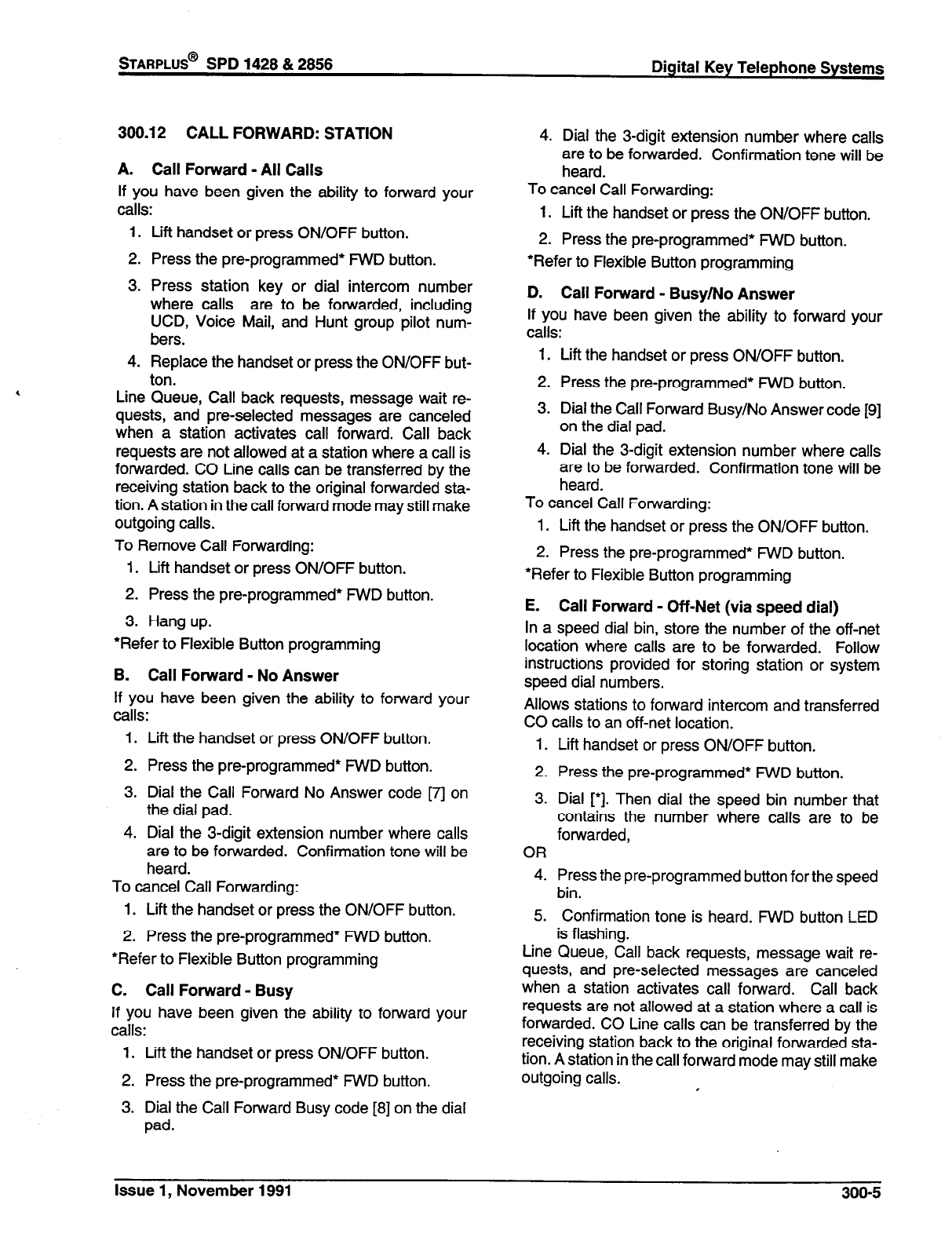
STARPLUS@
SPD 1428 & 2858 Digital Key Telephone Systems
300.12 CALL FORWARD: STATION
A. Call Forward - All Calls
If you have been given the ability to forward your
calls:
1. Lift handset or press ON/OFF button.
2. Press the pre-programmed* FWD button.
3. Press station key or dial intercom number
where calls are to be forwarded, including
UCD, Voice Mail, and Hunt group pilot num-
bers.
4. Replace the handset or press the ON/OFF but-
ton.
Line Queue, Call back requests, message wait re-
quests, and preselected messages are canceled
when a station activates call forward. Call back
requests are not allowed at a station where a call is
forwarded. CO Line calls can be transferred by the
receiving station back to the original forwarded sta-
tion. A station in the call forward mode may still make
outgoing calls.
To Remove Call Forwarding:
1. Lift handset or press ON/OFF button.
2. Press the pre-programmed* FWD button.
3. Hang up.
*Refer to Flexible Button programming
B. Call Forward - No Answer
If you have been given the ability to forward your
calls:
1. Lift the handset or press ON/OFF button.
2. Press the pm-programmed* FWD button.
3. Dial the Call Forward No Answer code [7j on
the dial pad.
4. Dial the 3-digit extension number where calls
are to be forwarded. Confirmation tone will be
heard.
To cancel Call Forwarding:
1. Lift the handset or press the ON/OFF button.
2. Press the pre-programmed* FWD button.
*Refer to Flexible Button programming
C. Call Forward - Busy
If you have been given the ability to forward your
calls:
1. Lift the handset or press ON/OFF button.
2. Press the pre-programmed* FWD button.
3. Dial the Call Forward Busy code [8] on the dial
pad.
4. Dial the 3-digit extension number where calls
are to be forwarded. Confirmation tone will be
heard.
To cancel Call Forwarding:
1. Lift the handset or press the ON/OFF button.
2. Press the pre-programmed’ FWD button.
*Refer to Flexible Button programming
D. Call Forward - Busy/No Answer
If you have been given the ability to forward your
calls:
1.
2.
3.
4.
Lift the handset or press ON/OFF button.
Press the pre-programmed’ WD button.
Dial the Call Forward Busy/No Answer code [9]
on the dial pad.
Dial the 3-digit extension number where calls
are to be forwarded. Confirmation tone will be
heard.
To cancel Call Forwarding:
1. Lift the handset or press the ON/OFF button.
2. Press the pre-programmed* FWD button.
*Refer to Flexible Button programming
E. Call Forward - Off-Net (via speed dial)
In a speed dial bin, store the number of the off-net
location where calls are to be forwarded. Follow
instructions provided for storing station or system
speed dial numbers.
Allows stations to forward intercom and transferred
CO calls to an off-net location.
1.
2.
3.
OR
4.
5.
Line
Lift handset or press ON/OFF button.
Press the pre-programmed* FWD button.
Dial [‘I. Then dial the speed bin number that
contains the number where calls are to be
forwarded,
Press the pre-programmed button for the speed
bin.
Confirmation tone is heard. FWD button LED
is flashing.
Queue, Call back requests, message wait re-
quests, and preselected messages are canceled
when a station activates call forward. Call back
requests are not allowed at a station where a call is
forwarded. CO Line calls can be transferred by the
receiving station back to the original forwarded sta-
tion. A station in the call forward mode may still make
outgoing calls. I
Issue 1, November 1991 300-5
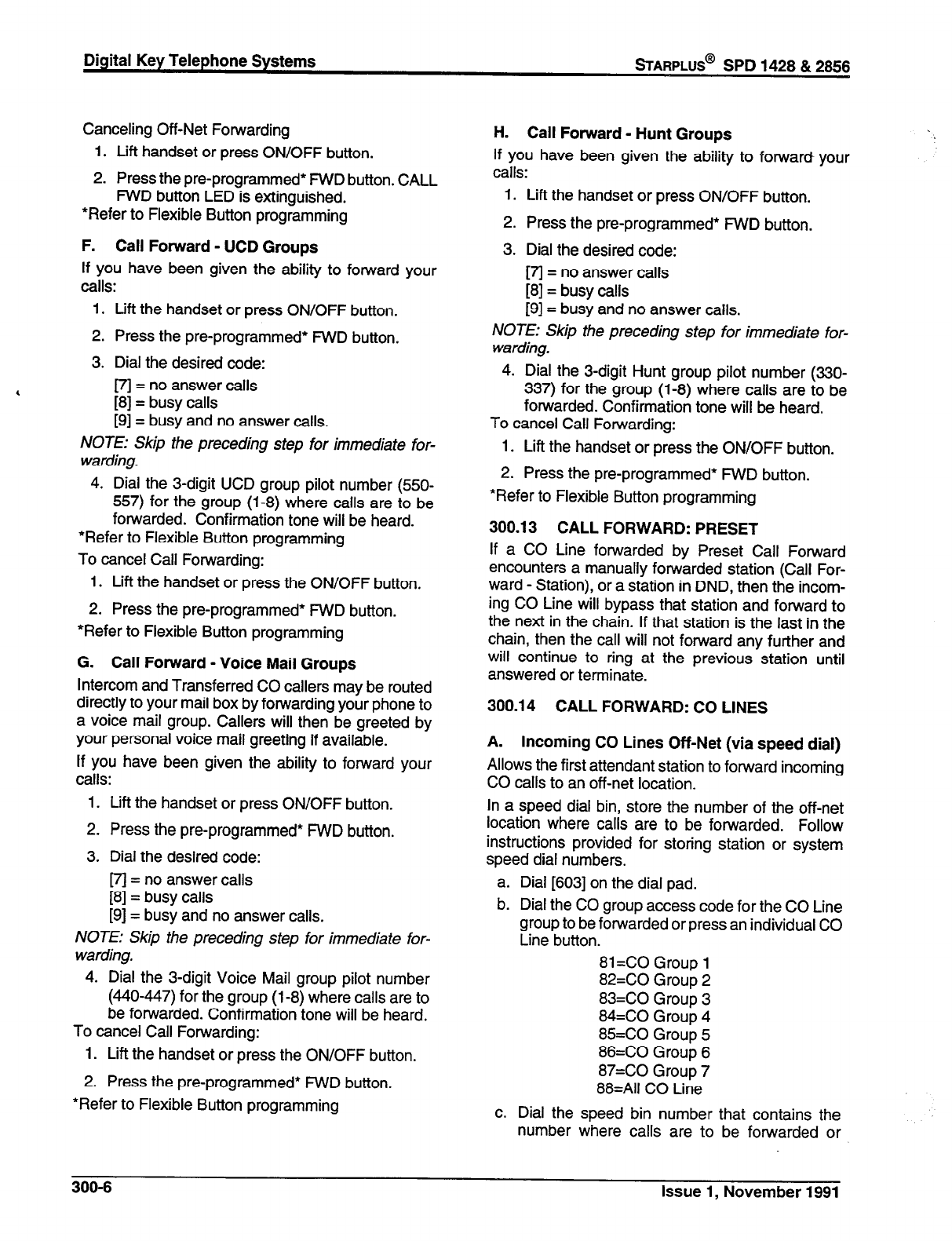
Canceling Off-Net Forwarding
1. Lift handset or press ON/OFF button.
2. Press the pre-programmed* FWD button. CALL
FWD button LED is extinguished.
*Refer to Flexible Button programming
F. Call Forward - UCD Groups
If you have been given the ability to forward your
calls:
1. Lift the handset or press ON/OFF button.
2. Press the pre-programmed* FWD button.
3. Dial the desired code:
m = no answer calls
[8] = busy calls
[9] = busy and no answer calls.
NOTE: Skip the preceding step for immediate for-
warding.
4. Dial the 3-digit UCD group pilot number (550-
557) for the group (l-8) where calls are to be
forwarded. Confirmation tone will be heard.
*Refer to Flexible Button programming
To cancel Call Forwarding:
1. Lift the handset or press the ON/OFF button.
2. Press the pre-programmed* FWD button.
*Refer to Flexible Button programming
G. Call Forward - Voice Mail Groups
Intercom and Transferred CO callers may be routed
directly to your mail box by forwarding your phone to
a voice mail group. Callers will then be greeted by
your personal voice mail greeting if available.
If you have been given the ability to forward your
calls:
1. Lift the handset or press ON/OFF button.
2. Press the pre-programmed* FWD button.
3. Dial the desired code:
m = no answer calls
[8] = busy calls
[9] = busy and no answer calls.
NOTE: Skip the preceding step for immediate for-
warding.
4. Dial the 3-digit Voice Mail group pilot number
(440447) for the group (l-8) where calls are to
be forwarded. Confirmation tone will be heard.
To cancel Call Forwarding:
1. Lift the handset or press the ON/OFF button.
2. Press the pre-programmed* FWD button.
*Refer to Flexible Button programming
Digital Key Telephone Systems
sTARPLUS@
SPD 1428 & 2856
H. Call Forward - Hunt Groups
If you have been given the ability to forward your
calls:
1. Lift the handset or press ON/OFF button.
2. Press the pre-programmed* WD button.
3. Dial the desired code:
[7j = no answer calls
[8] = busy calls
[9] = busy and no answer calls.
NOTE: Skip the preceding step for immediate for-
warding.
4. Dial the 3-digit Hunt group pilot number (330-
337) for the group (l-8) where calls are to be
forwarded. Confimation tone will be heard.
To cancel Call Forwarding:
1. Lift the handset or press the ON/OFF button.
2. Press the pre-programmed* FWD button.
*Refer to Flexible Button programming
300.13 CALL FORWARD: PRESET
If a CO Line forwarded by Preset Call Forward
encounters a manually forwarded station (Call For-
ward - Station), or a station in DND, then the incom-
ing CO Line will bypass that station and forward to
the next in the chain. If that station is the last in the
chain, then the call will not forward any further and
will continue to ring at the previous station until
answered or terminate.
300.14 CALL FORWARD: CO LINES
A. Incoming CO Lines Off-Net (via speed dial)
Allows the first attendant station to forward incoming
CO calls to an off-net location.
In a speed dial bin, store the number of the off-net
location where calls are to be forwarded. Follow
instructions provided for storing station or system
speed dial numbers.
a. Dial [603] on the dial pad.
b. Dial the CO group access code for the CO Line
group to be forwarded or press an individual CO
Line button.
81 =CO Group 1
82=CO Group 2
83=CO Group 3
84=CO Group 4
85=CO Group 5
86=CO Group 6
87=CO Group 7
88=All CO Line
c. Dial the speed bin number that contains the
number where calls are to be forwarded or
300-6 issue 1, November 1991
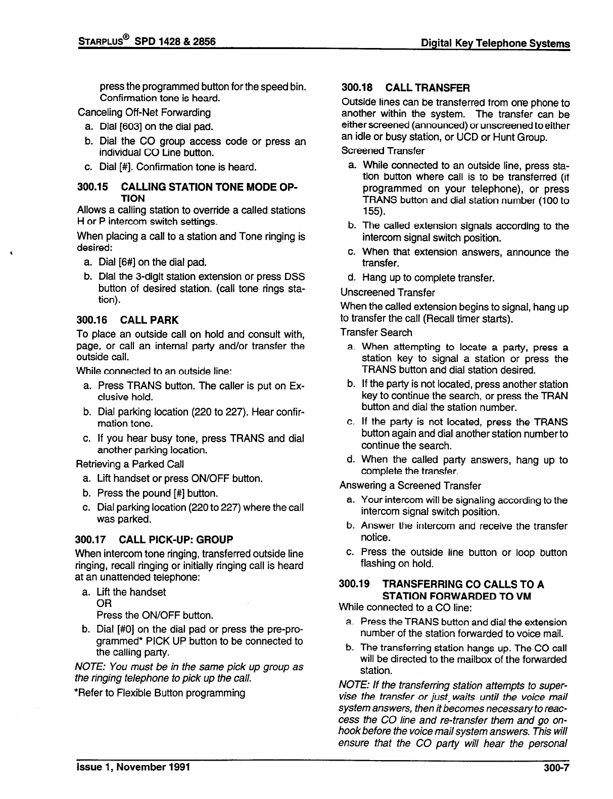
press the programmed button for the speed bin.
Confirmation tone is heard.
Canceling Off-Net Forwarding
a. Dial [603] on the dial pad.
b. Dial the CO group access code or press an
individual CO Line button.
c. Dial [#I. Confirmation tone is heard.
300.15 CALLING STATION TONE MODE OP-
TION
Allows a calling station to override a calted stations
H or P intercom switch settings.
When placing a call to a station and Tone ringing is
desired:
a. Dial [6#] on the dial pad.
b. Dial the 3-digit station extension or press DSS
button of desired station. (call tone rings sta-
tion).
300.16 CALL PARK
To place an outside call on hold and consult with,
page, or call an internal party and/or transfer the
outside call.
While connected to an outside line:
a. Press TRANS button. The caller is put on Ex-
clusive hold.
b. Dial parking location (220 to 227). Hear confir-
mation tone.
c. If you hear busy tone, press TRANS and dial
another parking location.
Retrieving a Parked Call
a. Lift handset or press ON/OFF button.
b. Press the pound [#] button.
c. Dial parking location (220 to 227) where the call
was parked.
300.17 CALL PICK-UP: GROUP
When intercom tone ringing, transferred outside line
ringing, recall ringing or initially ringing call is heard
at an unattended telephone:
a. Lift the handset
OR
Press the ON/OFF button.
b. Dial [#0] on the dial pad or press the pre-pro-
grammed* PICK UP button to be connected to
the calling party.
NOTE: You must be in the same pick up group as
the ringing telephone to pick up the call.
*Refer to Flexible Button programming
STARPLUS@
SPD 1428 & 2856 Digital Key Telephone Systems
300.18 CALL TRANSFER
Outside lines can be transferred from one phone to
another within the system. The transfer can be
either screened (announced) or unscreened toeither
an idle or busy station, or UCD or Hunt Group.
Screened Transfer
a. While connected to an outside line, press sta-
tion button where call is to be transferred (if
programmed on your teiephone), or press
TRANS button and dial station number (100 to
155).
b. The called extension signals according to the
intercom signal switch position.
c. When that extension answers, announce the
transfer.
d. Hang up to complete transfer.
Unscreened Transfer
When the called extension begins to signal, hang up
to transfer the call (Recall timer starts).
Transfer Search
a. When attempting to locate a party, press a
station key to signal a station or press the
TRANS button and dial station desired.
b. If the party is not located, press another station
key to continue the search, or press the TRAN
button and dial the station number.
c. If the party is not located, press the TRANS
button again and dial another station number to
continue the search.
d. When the called patty answers, hang up to
complete the transfer.
Answering a Screened Transfer
a. Your intercom will be signaling according to the
intercom signal switch position.
b. Answer the intercom and receive the transfer
notice.
c. Press the outside line button or loop button
flashing on hold.
300.19 TRANSFERRING CO CALLS TO A
STATION FORWARDED TO VIM
While connected to a CO line:
a. Press the TRANS button and dial the extension
number of the station forwarded to voice mail.
b. The transferring station hangs up. The CO call
will be directed to the mailbox of the forwarded
station.
NOTE: If the transferring station attempts to super-
vise the transfer or just, waits until the voice mail
system answers, then it becomes necessary to reac-
cess the CO line and re-transfer them and go on-
hook before the voice mail system answers. This will
ensure that the CO party will hear the personal
Issue 1, November 1991 300-7
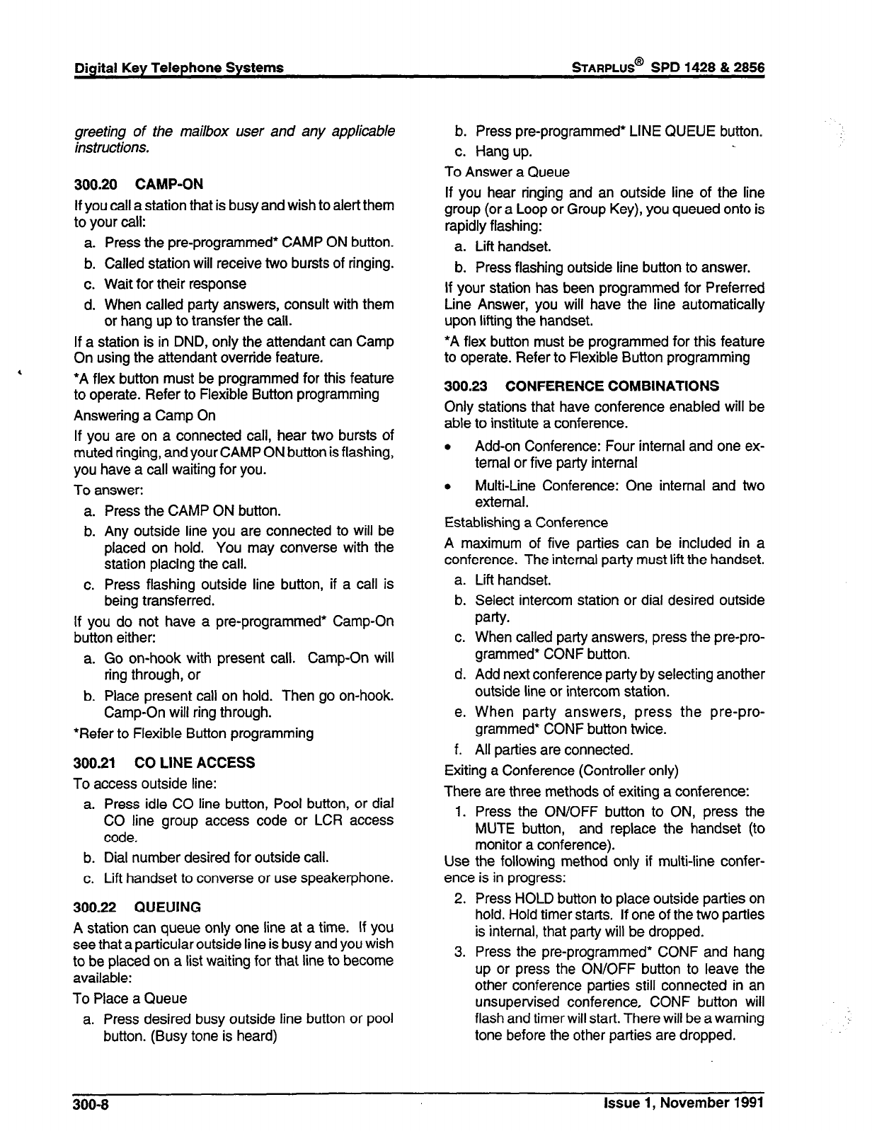
Digital Key Telephone Systems
sTARPLUS@
SPD 1428 & 2856
greeting of the mailbox user and any applicable
instructions.
300.20
CAMP-ON
If you call a station that is busy and wish to alert them
to your call:
a. Press the pre-programmed’ CAMP ON button.
b. Called station will receive two bursts of ringing.
c. Wait for their response
d. When called party answers, consult with them
or hang up to transfer the call.
If a station is in DND, only the attendant can Camp
On using the attendant override feature.
, ‘A flex button must be programmed for this feature
to operate. Refer to Flexible Button programming
Answering a Camp On
If you are on a connected call, hear two bursts of
muted ringing, and your CAMP ON
button
is flashing,
you have a call waiting for you.
To answer:
a. Press the CAMP ON button.
b. Any outside line you are connected to will be
placed on hold. You may converse with the
station placing the call.
c. Press flashing outside line button, if a call is
being transferred.
If you do not have a pre-programmed* Camp-On
button either:
a. Go on-hook with present call. Camp-On will
ring through, or
b. Place present call on hold. Then go on-hook.
Camp-On will ring through.
*Refer to Flexible Button programming
300.21 CO LINE ACCESS
To access outside line:
a. Press idle CO line button, Pool button, or dial
CO line group access code or LCR access
code.
b. Dial number desired for outside call.
c. Lift handset to converse or use speakerphone.
300.22 QUEUING
A station can queue only one line at a time. If you
see that a particular outside line is busy and you wish
to be placed on a list waiting for that line to become
available:
To Place a Queue
a. Press desired busy outside line button or pool
button. (Busy tone is heard)
b. Press pre-programmed* LINE QUEUE button
c. Hang up.
To Answer a Queue
If you hear ringing and an outside line of the line
group (or a Loop or Group Key), you queued onto is
rapidly flashing:
a. Lift handset.
b. Press flashing outside line button to answer.
If your station has been programmed for Preferred
Line Answer, you will have the line automatically
upon lifting the handset.
*A flex button must be programmed for this feature
to operate. Refer to Flexible Button programming
300.23 CONFERENCE COMBINATIONS
Only stations that have conference enabled will be
able to institute a conference.
.
Add-on Conference: Four internal and one ex-
ternal or five party internal
. Multi-Line Conference: One internal and two
external.
Establishing a Conference
A maximum of five parties can be included in a
conference. The internal party must lift the handset.
a.
b.
C.
d.
e.
f.
Lift handset.
Select intercom station or dial desired outside
party.
When called party answers, press the pre-pro-
grammed* CONF button.
Add next conference party by selecting another
outside line or intercom station.
When party answers, press the pre-pro-
grammed’ CONF button twice.
All parties are connected.
Exiting a Conference (Controller only)
There are three methods of exiting a conference:
1. Press the ON/OFF button to ON, press the
MUTE button, and replace the handset (to
monitor a conference).
Use the following method only if multi-line confer-
ence is in progress:
2. Press HOLD button to place outside parties on
hold. Hold timer starts. If one of the two parties
is internal, that party will be dropped.
3. Press the pre-programmed* CONF and hang
up or press the ON/OFF button to leave the
other conference parties still connected in an
unsupervised conference, CONF button will
flash and timer will start. There will be a warning
tone before the other parties are dropped.
300-6
Issue 1, November 1991
300.24 DIRECTED CALL PICK-UP
When incoming, transferred, or recalling outside line
ringing, intercom ringing, or Camp On ringing is
heard at an unattended telephone:
a. Dial the station number of the known ringing
telephone.
b. Receive ringback tone, or call announce tone.
C.
Press the pre-programmed* PICK UP button to
answer the call.
Re-entering a Conference
When the controller re-enters the conference, the
disconnect timer is reset.
a. Lift handset to re-enter a monitored conference.
b. To re-enter a conference placed on hold, repeat
steps for establishing a conference.
c. To re-enter an unsupervised conference, lift
handset and press flashing pre-programmed*
CONF button. The CONF button lights steady
and confirmation tone will be heard.
Terminating a Conference
To terminate a conference the conference initiator
who is actively in the conference replaces handset
or push ON/OFF button to OFF. To terminate an
unsupervised conference, press the flashing pre-
programmed* CONF button while on hook, all parties
will be dropped.
*Refer to Flexible Button programming
User must have access to the specific outside line
or a Loop key to do a directed call pickup.
* A flex button must be programmed for this feature
to operate. Refer to Flexible Button programming
300.25 DIRECT INWARD SYSTEM ACCESS
(DISA)
a. Call the phone number the system administra-
tor specified as the DISA line.
b. The system answers and returns intercom dial
tone.
c. Enter the DISA access code also specified by
the system administrator, if applicable.
d. Dial tone is returned.
To place an outgoing call:
a. Dial a group access code: 9,81 - 87.
b. CO Dial tone is returned.
c. Dial the desired telephone number.
NOTE: LCR cannot be accessed from DISA. If LCR
is enabled, DISA users may dial 81 to access lines
in trunkgroup 1.
STARPLUS@
SPD 1428 & 2856 Digital Key Telephone Systems
NOTE: The conference timer (Refer to Sec. 610.1)
will monitor a DISA “trunk- to- trunk” call and release
the lines one (1) minute after the time expires.
To reach an internal station:
a. Dial the 3-digit station number. Ringback tone
will be heard.
b. Converse when party answers.
NOTE: If the station dialed is unattended, busy or in
DND, intercom dial tone will be returned. (after the
Preset Call Forward Timer expires) Refer to Sec.
610.1.
300.26 DO NOT DISTURB
Activating Do Not Disturb:
a. If you have been given the ability to place your
phone in Do Not Disturb, press the pre-pro-
grammed* DND button.
b. DND button lights steady.
The DND button can be pressed while the phone is
ringing to stop the ringing. (Refer to One-Time Do
Not Disturb below.)
Removing Do Not Disturb
a. Press the pre-programmed* DND button.
b. The button LED extinguishes and DND is can-
celed. A flex button must be programmed for
this feature to operate.
*Refer to Flexible Button programming
A. One-Time Do Not Disturb
Allows you to prevent calls from ringing at your
station while you’re on a call. The One-Time DND
condition will automatically cancel when you end
your call.
a. Press the pre-programmed* DND button while
you’re off-hook and connected to a CO line or
intercom call. The DND button LED lights and
off-hook tones at your station are canceled.
To cancel:
a. Replace handset. The DND button LED extin-
guishes and DND is canceled.
*A flex button must be programmed for this feature
to operate. Refer to Flexible Button programming
300.27 EXCLUSIVE HOLD
When a line is placed on Exclusive Hold, no other
station in the system can retrieve this call. Exclusive
Hold may be programmed to be activated on the first
or second depression of the Hold button. CO Lines
while in a transfer hold are always placed in an
Exclusive Hold condition.’
Issue 1, November 1991 300-g
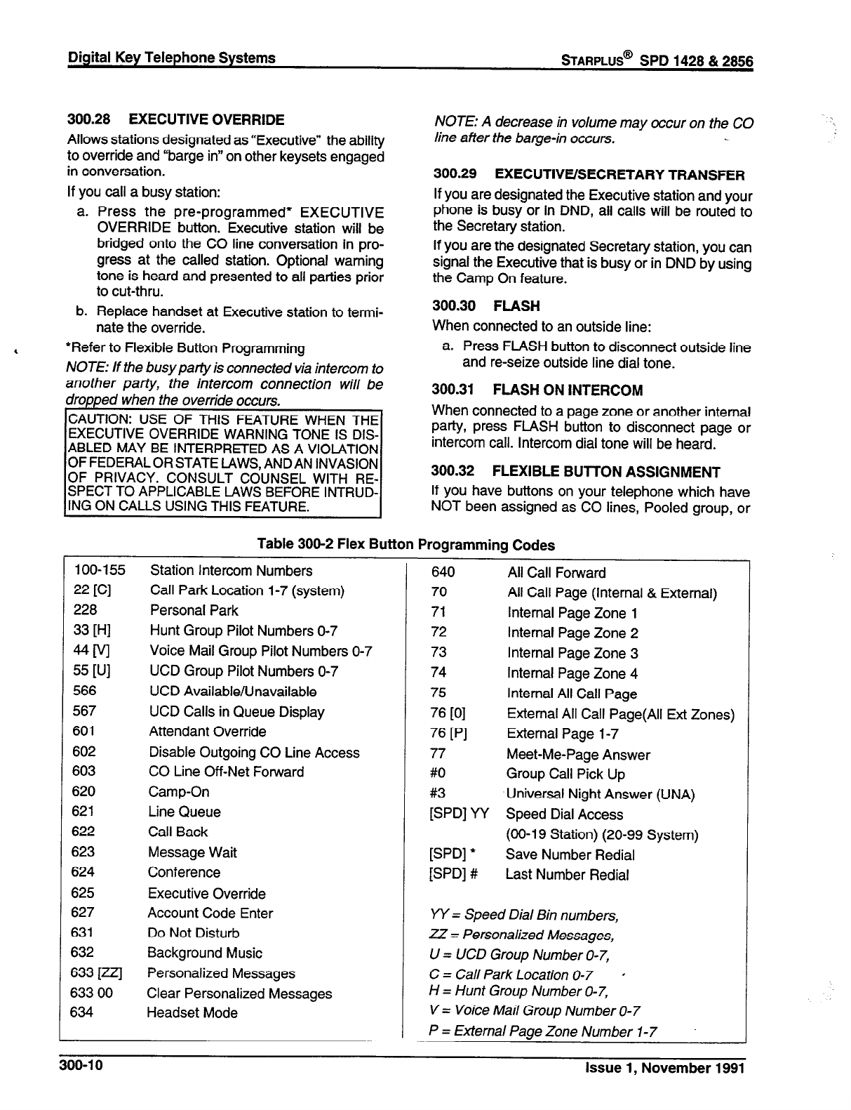
Digital Key Telephone Systems
sTARPLUS@
SPD 1428 & 2856
300.28 EXECUTIVE OVERRIDE
Allows stations designated as “Executive” the ability
to override and “barge in” on other keysets engaged
in conversation.
If you call a busy station:
a. Press the pre-programmed* EXECUTIVE
OVERRIDE button. Executive station will be
bridged onto the CO line conversation in pro-
gress at the called station. Optional warning
tone is heard and presented to all parties prior
to cut-thru.
b. Replace handset at Executive station to termi-
nate the override.
, *Refer to Flexible Button Programming
NOTE: If the busy party is connected via intercom to
another party, the intercom connection will be
dropped when the override occurs.
CAUTION: USE OF THIS FEATURE WHEN THE
EXECUTIVE OVERRIDE WARNING TONE IS DIS-
ABLED MAY BE INTERPRETED AS A VIOLATION
OF FEDERAL OR STATE LAWS, ANDAN INVASION
OF PRIVACY. CONSULT COUNSEL WITH RE-
SPECT TO APPLICABLE LAWS BEFORE INTRUD-
ING ON CALLS USING THIS FEATURE.
NOTE: A decrease in volume may occur on the CO
line after the barge-in occurs.
300.29 EXECUTIVE/SECRETARY TRANSFER
If you are designated the Executive station and your
phone is busy or in DND, all calls will be routed to
the Secretary station.
If you are the designated Secretary station, you can
signal the Executive that is busy or in DND by using
the Camp On feature.
300.30
FLASH
When connected to an outside line:
a. Press FLASH button to disconnect outside line
and re-seize outside line dial tone.
300.31 FLASH ON INTERCOM
When connected to a page zone or another internal
party, press FLASH button to disconnect page or
intercom call. Intercom dial tone will be heard.
300.32 FLEXIBLE BUTTON ASSIGNMENT
If you have buttons on your telephone which have
NOT been assigned as CO lines, Pooled group, or
Table 300-2 Flex Button Programming Codes
100-155 Station Intercom Numbers 640 All Call Forward
22
PI
Call Park Location 1-7 (system) 70 All Call Page (Internal & External)
228 Personal Park 71 Internal Page Zone 1
33
WI
Hunt Group Pilot Numbers O-7 72 Internal Page Zone 2
MM
Voice Mail Group Pilot Numbers O-7 73 Internal Page Zone 3
55 WI
UCD Group Pilot Numbers O-7 74 Internal Page Zone 4
566 UCD Available/Unavailable 75 Internal All Call Page
567 UCD Calls in Queue Display 76
PI
External All Call Page(All Ext Zones)
601 Attendant Override 76
PI
External Page l-7
602 Disable Outgoing CO Line Access 77 Meet-Me-Page Answer
603 CO Line Off-Net Forward #O Group Call Pick Up
620 Camp-On #3 Universal Night Answer (UNA)
621 Line Queue [SPD] YY Speed Dial Access
622 Call Back (00-l 9 Station) (20-99 System)
623 Message Wait [SPD]
l
Save Number Redial
624 Conference [SPD] # Last Number Redial
625 Executive Override
627 Account Code Enter YY = Speed Dial Bin numbers,
631 Do Not Disturb ZZ = Personalized Messages,
632 Background Music U = UCD Group Number O-7,
633 L=l
Personalized Messages C = Call Park Location O-7 *
633 00 Clear Personalized Messages H = Hunt Group Number O-7,
634 Headset Mode V = Voice Mail Group Number O-7
P = External Page Zone Number 1-7
300-l 0
Issue 1, November 1991
Loop buttons, you may program them to suit your
own individual needs. There are five possible func-
tions you may assign to these buttons:
DSS/BLF: This button, when pressed, will automat-
ically signal the assigned intercom station.
DSS/BLF buttons are programmed by the station
user.
. FEATURES: This button can be programmed
so that when pressed it will activate a particular
feature, thus eliminating the need for dialing the
feature code. Some features require a flex
button to be programmed for that feature to be
accessible to the station user. Where this is the
case it is so designated in this Feature Opera-
tion Section and user guide. Feature buttons
are programmed by the station user. Refer to
Table 300-2 for a complete listing of code/fea-
tures that may be programmed onto a flexible
button.
. SPEED DIAL: This button can be programmed
to automatically access a speed number loca-
tion for one-step operation. PBX and Centrex
codes can be programmed into a speed dial bin
and accessed by one button depression.
. POOLED GROUP ACCESS: A group of out-
side lines can be placed under one button.
When this button is pressed, the system will
select an available line from this group for the
user to place a call on. Pool buttons are as-
signed in data base administration.
. LOOP: This button will act as the direct appear-
ing button for outside lines that do not appear
on the user’s individual telephone. Any phone
that doesn’t have all lines appear on it must
have a loop key. There is NO limit to the number
of LOOP buttons a station may have. Loop
buttons are assigned in data base administra-
tion.
To program flexible buttons:
a. Press SPEED button twice.
b. Press the assigned button to be programmed
(it must be programmed in data base as a
multi-function button).
c. Dial desired code (Refer to Button Program-
ming Codes).
To erase a flexible button:
a. Press SPEED button twice.
b. Press the button to be erase
c. Press FLASH button.
d. Replace handset or press ON/OFF button.
STARPLUS@ SPD 1428 & 2856 Digital Key Telephone Systems
300.33 HEADSET MODE
If you wish to use a headset and have been given
the ability to do so in programming.
To activate Headset Mode:
a. Dial 16341 on the dial pad or press pre-pro-
grammed’ HEADSET MODE button.
b. LED will light steady.
While Headset mode is active, the ON/OFF button
will activate the headset and disable speakerphone
and intercom call announce operation at your sta-
tion.
To de-activate Headset Mode:
a. Dial [634] on the dial pad or press the pre-pro-
grammed* HEADSET MODE button.
b. LED will extinguish.
*Refer to Flexible Button programming
300.34 INTERCOM CALLING
Placing an Intercom Call
a. Press station key of party to be called (if pro-
grammed at your phone); or dial station number
(loo to 155).
NOTE: Dialing a number in the numbering plan
activates the telephone automatically.
b. You will hear ringing if called station is in the ‘T
answering mode; or two bursts of tone if called
station is in the “H” or “P” position.
c. Lift handset or use speakerphone, after the two
tone bursts stop.
d. Hang up to end call.
Answering an Intercom Call
With your intercom signal switch in the T (center)
mode, you will hear repeated bursts of intercom tone
ringing and the HOLD button will slow flash.
a. Lift handset or press ON/OFF button to answer,
or move the intercom signal switch to the “H”
mode to reply.
b. Hang up to end call.
In the “P” mode, you will hear two bursts of tone and
one-way announcement. The HOLD button will slow
flash and the calling party cannot hear conversations
in progress.
a. Lift handset or press ON/OFF button to answer,
or move the intercom signal switch to the “H”
mode to reply.
In the ‘7-l” mode, you will hear two bursts of tone and
an announcement. Reply handsfree or lift handset
for privacy.
Issue 1, November 1991 300-l 1
Digital Key Telephone Systems
STARPLUS@
SPD 1428 & 2866
300.35 INTERCOM TRANSFER
Intercom transfer without DSS buttons:
a. Receive or make an intercom call.
b. Press the TRANS button. Intercom dial tone is
heard.
c. Dial the station where the call is to be trans-
ferred.
d. When 2nd station answers, you are in a super-
vised transfer mode (1st station is staged for
transfer).
e. Hang up (station 1 and 2 are connected).
Intercom transfer using DSS buttons:
a. Receive or make an intercom call using a DSS
button.
b. Press the TRANS button. Intercom dial tone is
heard.
c. Press DSS button where call is to be trans-
ferred.
d. Hang up (station 1 and 2 are connected).
300.36 LAST NUMBER REDIAL
a. Press SPEED button.
b. Press pound [#] key.
c. The last number dialed over an outside line will
be automatically re-dialed.
-
-
-
-
300.37
The system will automatically select the
original line used to place the call and redial
the number.
If that line is busy, the system will automat-
ically select another line from the same
group and redial the number.
If no lines are available in the same group,
station will receive busy tone and can
queue for a line.
If the station user preselects a line before
activating LNR, the preselection will over-
ride the line which was used originally.
LEAST COST ROUTING
To place an outside call when LCR has been enabled
in the system:
a. Dial [9] on the dial pad.
b. Dial the desired 7 digit telephone number (ie:
1+ area code+7-digit number).
c. Wait for answer. Lift handset or use speaker-
phone to converse.
If all lines available to you are busy, remain off-hook
for four (4) seconds to automatically be queued onto
LCR for an available line.
LCR Que Callback
If an LCR Queue Callback has been activated:-
a. When telephone is signalled, answer the call.
b. Desired telephone number will automatically be
re-dialed.
NOTE: Only one LCt? Queue Call Back request may
be initiated by a station. When a second request is
made, the first request will be canceled.
300.38 LCR QUE CANCEL
a. Dial the LCR Queue Cancel code, [626].
b. Replace handset or press ON/OFF button.
300.39 MEET ME PAGE
To request another party to meet you on a page:
a. Dial the desired two-or three-digit paging code
or press pre-programmed* PAGING button
b. Request that party meet you on the page.
c. Do not hang up; wait for the requested party to
answer. As soon as the paged party answers
and is connected to you, the page circuit is
released.
Answering a Meet Me Page
a. Go to the nearest Telephone and dial [77] or
press the pre-programmed* MEET ME PAGE
ANSWER button.
b. You will be connected to the party that paged
you.
*Refer to Flexible Button programming
300.40 MESSAGE WAITING
Leaving a Message Waiting Indication
Up to five messages can be left at any Station. If
you dial a station that is busy, unattended, or in DND,
you can leave a message waiting indication.
a. Press the pre-programmed* MSG button.
b. Called party’s MSG button will slow flash.
c. Hang up.
Answering a Message Waiting Indication
If your MSG WAIT button is flashing at a slow rate,
you have a message waiting for you. The first mes-
sage left will be the first one called.
a. Press flashing pre-programmed* MSG button.
b. Station that left message will be signaled with
tone ringing.
c. If called station does not answer, press MSG
button once to leave message.
*Refer to Flexible Button programming
300-l 2 Issue 1, November 1991
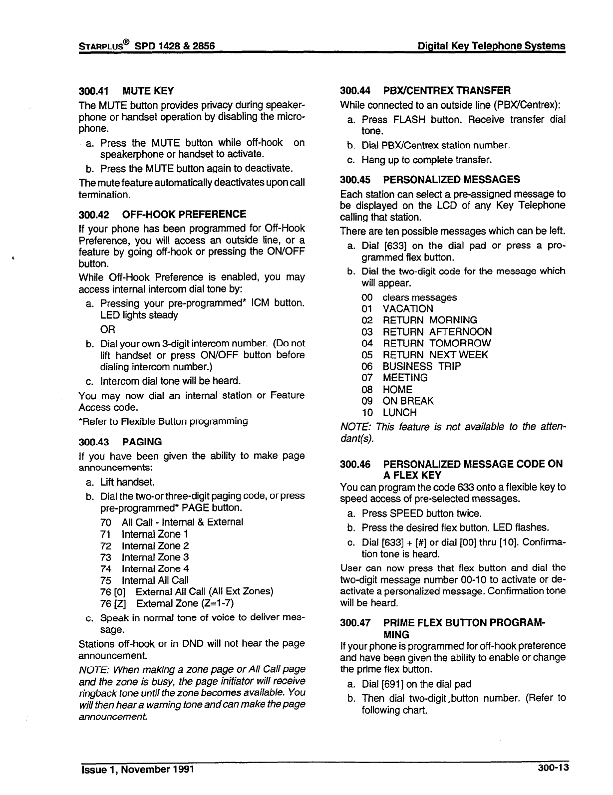
STARPLUS@
SPD 1428 & 2856 Digital Key Telephone Systems
300.41 MUTE KEY
The MUTE button provides privacy during speaker-
phone or handset operation by disabling the micro-
phone.
a. Press the MUTE button while off-hook on
speakerphone or handset to activate.
b. Press the MUTE button again to deactivate.
The mute feature automatically deactivates upon call
termination.
300.42 OFF-HOOK PREFERENCE
If your phone has been programmed for Off-Hook
Preference, you will access an outside line, or a
feature by going off-hook or pressing the ON/OFF
button.
While Off-Hook Preference is enabled, you may
access internal intercom dial tone by:
a.
b.
C.
You
Pressing your pre-programmed’ ICM button.
LED lights steady
OR
Dial your
own
3-digit intercom number. (Do not
lit? handset or press ON/OFF button before
dialing intercom number.)
Intercom dial tone will be heard.
may now dial an internal station or Feature
Access code.
*Refer to Flexible Button programming
300.43
PAGING
If you have been given the ability to make page
announcements:
a. Lift handset.
b. Dial the two-or three-digit paging code, or press
pre-programmed* PAGE button.
70 All Call - Internal & External
71 Internal Zone 1
72 Internal Zone 2
73 Internal Zone 3
74 Internal Zone 4
75 Internal All Call
76 [0] External All Call (All Ext Zones)
76 [z] External Zone (Z=l-7)
c. Speak in normal tone of voice to deliver mes-
sage.
Stations off-hook or in DND will not hear the page
announcement.
NOTE: When making a zone page or All Call page
and fhe zone is busy, the page initiator will receive
ringback
tone until
the zone becomes available. You
will then hear a warning tone and can make the page
announcement.
300.44 PBX/CENTREX TRANSFER
While connected to an outside line (PBWCentrex):
a. Press FLASH button. Receive transfer dial
tone.
b. Dial PBX/Centrex station number.
c. Hang up to complete transfer.
300.45 PERSONALIZED MESSAGES
Each station can select a pre-assigned message to
be displayed on the LCD of any Key Telephone
calling that station.
There are ten possible messages which can be left.
a.
b.
Dial [633] on the dial pad or press a pro-
grammed flex button.
Dial the two-digit code for the message which
will appear.
00
01
02
03
04
05
06
07
08
09
10
clears messages
VACATION
RETURN MORNING
RETURN AFTERNOON
RETURN TOMORROW
RETURN NEXT WEEK
BUSINESS TRIP
MEETING
HOME
ON BREAK
LUNCH
NOTE: This feature is not available to the atten-
dan t(s).
300.46 PERSONALIZED MESSAGE CODE ON
A FLEX KEY
You can program the code 633 onto a flexible key to
speed access of pre-selected messages.
a. Press SPEED button twice.
b. Press the desired flex button. LED flashes.
c. Dial [633] + [#] or dial [00] thru [lo]. Confirma-
tion tone is heard.
User can now press that flex button and dial the
two-digit message number 00-10 to activate or de-
activate a personalized message. Confirmation tone
will be heard.
300.47 PRIME FLEX BUTTON PROGRAM-
MING
If your phone is programmed for off-hook preference
and have been given the ability to enable or change
the prime flex button.
a. Dial [691] on the dial pad
b. Then dial two-digit,button number. (Refer to
following chart.
Issue 1, November 1991
300-l 3

Digital Key Telephone Systems STARPLUS@ SPD 1428 & 2866
To disable Off-Hook Preference:
a. Dial [691] on the dial pad.
b. Dial [00] on the dial pad.
300.48 PROGRAMMING YOUR NAME INTO
THE LCD DISPLAY
Every extension (key and SLT) has the capability to
program the users name so that people using display
telephones will see the name instead of the station
number.
a. Dial [690] on the dial pad.
b. Enter your name (up to 7 letters) using the
:
c. Press S
pattern
A=21
B=22
C=23
D=31
E=32
F=33
G=41
H=42
I=43
J=51
K=52
L=53
M=61
7own belov
N=62
0=63
P=71
Q=74
R=72
s=73
T=81
U=82
V=83
w=91
x=92
Y=93
z=94
EED buttor
l=l#
2=2#
3=3#
4=4#
5=5#
6=6#
7=7#
8=8#
9=9#
O=O#
Space=1 1
:=12
-=13
‘=14
0 complete
“Zol
,=02
?=03
I=04
I=‘1
$=*2
&=*4
;I$
)=#2
+=#3
==#4
#=##
ie program-
ming process.
To erase your name:
a. Dial [690] on the dial pad.
b. Press SPEED button.
,300.49 PULSE TO TONE SWITCHOVER
The signaling on an outside line can be changed
from dial pulse to tone (DTMF) manually while dialing
out.
To perform the change-over
a. Dial an [‘I on the dial pad.
b. Remaining digit(s) will be sent using DTMF.
The Pulse to Tone Switchover command may also
be included into a speed dial bin. Refer to speed dial
programming.
300.50 SAVE NUMBER REDIAL
If you wish to save the last number you dialed for use
later:
a. After placing an outside call, keep handset off-
hook.
b. Press SPEED button twice.
To Dial a number that was saved using the steps
above:
a. Press SPEED button.
b. Dial the asterisk [*I key.
- System will automatically select the original
line used to place the call and redial the
number.
- If that line is busy, the system will automat-
ically select another line from the same
group and redial the number.
- If no lines are available in the same group,
station will receive busy tone and can
queue for a line.
- If the station user preselects a line before
activating SNR, the preselection will over-
ride the line which was used originally.
300.51 PROGRAMMING PBWCENTREX
CODES ONTO A FLEX BUlTON
For easy one-button access to Centrex or PBX fea-
tures, perform the following steps:
a. Program the Centrex or PBX code into a station
or system speed dial bin, including hook-flash
(flash key), [*I, and [#I] commands. (Refer to
station or system speed dial programming)
b. Program that speed bin onto a flexible* button.
*Refer to Flexible Button programming
300.52 SPEAKERPHONE
a. Press ON/OFF button to “ON”. Intercom dial
tone will be heard.
b. Press station key of desired party, or press
available outside line button and dial number.
Speakerphone is activated.
c. Press ON/OFF button to “OFF’ to end call.
NOTE: For further references in this section where
“lift handset” is specified, you may also use the
method of pressing the “ON/OFF’button, if the tele-
phone is programmed to be a true two-way speak-
erphone.
300-l 4
Issue 1, November 1991
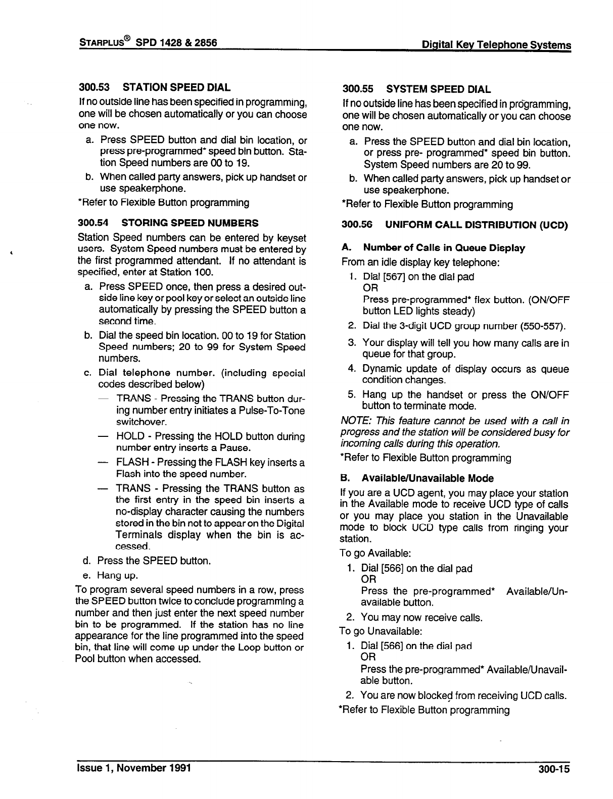
STARPLUS@
SPD 1428 & 2856 Digital Key Telephone Systems
300.53 STATION SPEED DIAL
If no outside line has been specified in programming,
one will be chosen automatically or you can choose
one now.
a. Press SPEED button and dial bin location, or
press pre-programmed* speed bin button. Sta-
tion Speed numbers are 00 to 19.
b. When called party answers, pick up handset or
use speakerphone.
*Refer to Flexible Button programming
300.54 STORING SPEED NUMBERS
Station Speed numbers can be entered by keyset
users. System Speed numbers must be entered by
the first programmed attendant. If no attendant is
specified, enter at Station 100.
a.
b.
C.
d.
e.
Press SPEED once, then press a desired out-
side line key or pool key or select an outside line
automatically by pressing the SPEED button a
second time.
Dial the speed bin location. 00 to 19 for Station
Speed numbers; 20 to 99 for System Speed
numbers.
Dial telephone number. (including special
codes described below)
- TRANS - Pressing the TRANS button dur-
ing number entry initiates a Pulse-To-Tone
switchover.
- HOLD - Pressing the HOLD button during
number entry inserts a Pause.
- FLASH - Pressing the FLASH key inserts a
Flash into the speed number.
- TRANS - Pressing the TRANS button as
the first entry in the speed bin inserts a
no-display character causing the numbers
stored in the bin not to appear on the Digital
Terminals display when the bin is ac-
cessed.
Press the SPEED button.
Hang up.
To program several speed numbers in a row, press
the SPEED button twice to conclude programming a
number and then just enter the next speed number
bin to be programmed. If the station has no line
appearance for the line programmed into the speed
bin, that line will come up under the Loop button or
Pool button when accessed.
*Refer to Flexible Button programming
300.56 UNIFORM CALL DISTRIBUTION (UCD)
A. Number of Calls in Queue Display
From an idle display key telephone:
1.
2.
3.
4.
5.
Dial [5671 on the dial pad
OR
Press pre-programmed* flex button. (ON/OFF
button LED lights steady)
Dial the 3-digit UCD group number (550557).
Your display will tell you how many calls are in
queue for that group.
Dynamic update of display occurs as queue
condition changes.
Hang up the handset or press the ON/OFF
button to terminate mode.
300.55 SYSTEM SPEED DIAL
If no outside line has been specified in prdgramming,
one will be chosen automatically or you can choose
one now.
a. Press the SPEED button and dial bin location,
or press pre- programmed* speed bin button.
System Speed numbers are 20 to 99.
b. When called party answers, pick up handset or
use speakerphone.
NOTE: This feature cannot be used with a call in
progress and the station will be considered busy for
incoming calls during this operation.
*Refer to Flexible Button programming
B. Available/Unavailable Mode
If you are a UCD agent, you may place your station
in the Available mode to receive UCD type of calls
or you may place you station in the Unavailable
mode to block UCD type calls from ringing your
station.
To go Available:
1. Dial [566] on the dial pad
OR
Press the pre-programmed* Available/Un-
available button.
2. You may now receive calls.
To go Unavailable:
1. Dial [566] on the dial pad
OR
Press the pre-programmed* Available/Unavail-
able button.
2. You are now blocked from receiving UCD calls.
*Refer to Flexible Button programming
Issue 1, November 1991 300-l 5

Digital Key Telephone Systems
C. No-Answer Timer
After a UCD call rings into an agent, the No-Answer
timer takes effect. if the agent does not answer the
call before this timer expires, then that agent is set
to “UCD Unavailable” and the call is routed back to
the UCD group for another available agent or queue.
In order to continue receiving UCD calls, the agent
then needs to press their UCD Available button.
300.57 UNIVERSAL NIGHT ANSWER (UNA)
If you hear outside line ringing at another station and
wish to answer it, dial [#3] on the dial pad. The
connected outside line can be transferred or discon-
nected. Each telephone utilizing Universal Night
4 Answer must have a loop button appearance if the
ringing outside line does not appear at their phone.
300.58 VOICE MAIL OPERATION (VM)
Forward Callers to your Mail box
Intercom and Transferred CO callers may be routed
directly to your mail box by forwarding your phone to
a voice mail group. Callers will then be greeted by
your personal voice mail greeting if available (Refer
to Call Forward - Voice Mail Operation)
Retrieving Voice Messages
If your Message Waiting key or programmed Voice
Mail group key is flashing, you may have a voice
message waiting for you. To enter the voice mail
system to check for mail:
a. Dial the Voice Mail group number or press the
pre-programmed* voice mail group key or
flashing Message Wait key.
b. You will immediately be prompted to enter your
password for your mail box.
Receiving a Voice Mail Message Wait
To receive a message waiting indication that a voice
message has been taken for you, the Voice Mail
system must be programmed to provide such an
indication.
After the voice mail system receives a voice mes-
sage for a station user:
a. The voice mail must go off-hook and dial the
voice mail message wait code [420].
b. Then dial the 3-digit extension number of the
station user who received a voice message.
Turning the Message Waiting Lamp Off
When a station user retrieves the voice messages
from the voice mail system, the voice mail system
must:
a. Be programmed to go off-hook and dial the
message cancel code 14211.
b. Then dial the 3-digit extension number of the
station user who retrieved the voice message.
306-l 6
STARPLUS@
SPD 1428 & 2856
*Refer to Flexible Button programming
A. VM Tone Mode Calling Option
Allows the Voice Mail system to override a called
stations H or P intercom switch settings.
When placing a call to a station and Tone ringing is
desire (the Voice Mail system MUST be pro-
grammed to:
a. Dial [6#].
b. Then dial 3-digit station extension (call tone
rings station).
300.59 VOLUME CONTROLS
There are two volume control slide switches on the
front of the Key Telephone. Sliding the switch to the
left decreases the volume. The left slide switch is for
voice, background music, and speakerphone vol-
ume. The right slide switch is for tone ringing vol-
ume.
Issue 1, November 1991
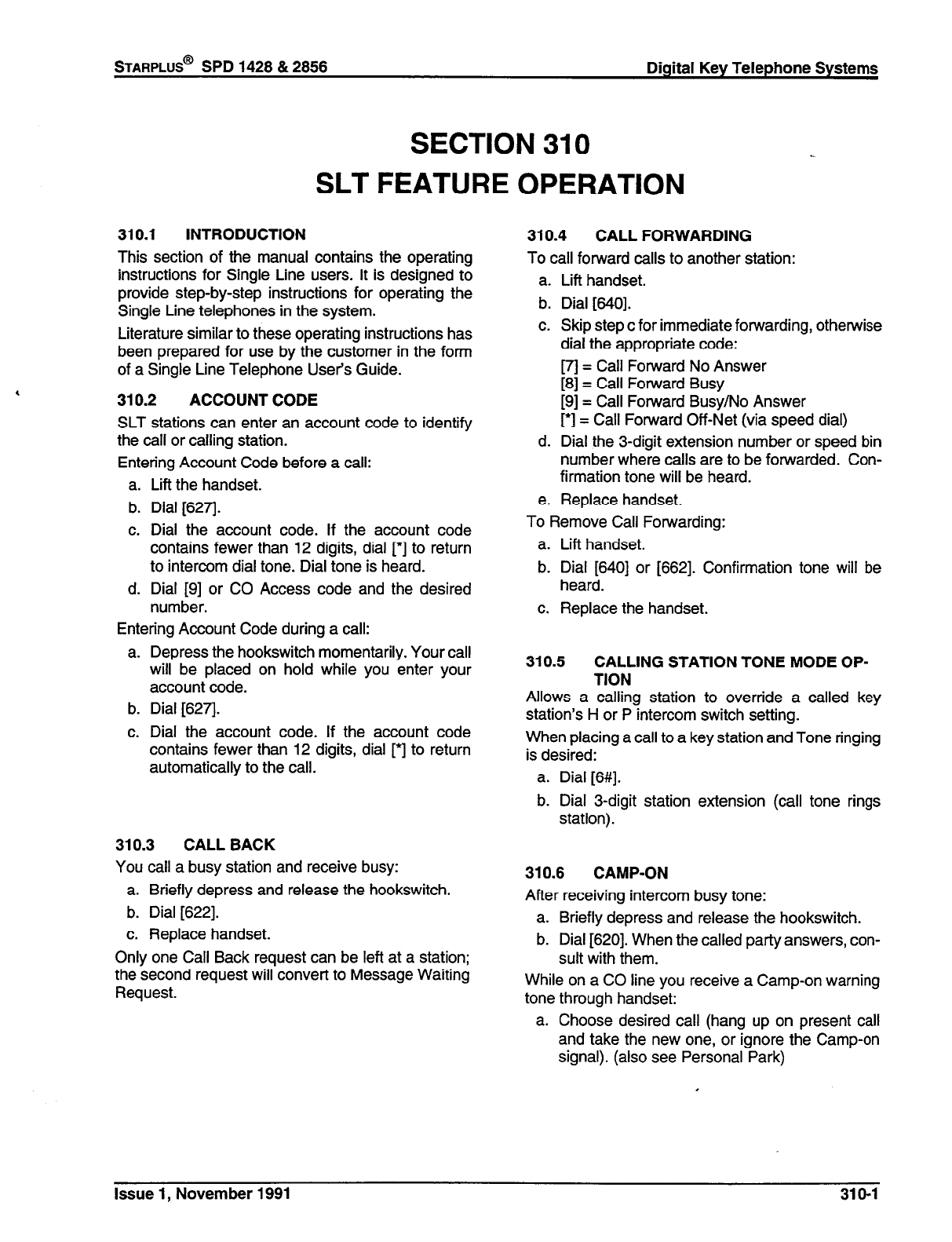
STARPLUS@
SPD 1428 & 2856 Digital Key Telephone Systems
310.1 INTRODUCTION
This section of the manual
SECTION 310
SLT FEATURE
contains the operating
instructions for Single Line users. It is designed to
provide step-by-step instructions for operating the
Single Line telephones in the system.
Literature similar to these operating instructions has
been prepared for use by the customer in the form
of a Single Line Telephone User’s Guide.
310.2 ACCOUNT CODE
SLT stations can enter an account code to identify
the call or calling station.
Entering Account Code before a call:
a. Lift the handset.
b. Dial [627].
c. Dial the account code. If the account code
contains fewer than 12 digits, dial [*I to return
to intercom dial tone. Dial tone is heard.
d. Dial [9] or CO Access code and the desired
number.
Entering Account Code during a call:
Depress the hookswitch momentarily. Your call
will be placed on hold while you enter your
account code.
Dial [627].
Dial the account code. If the account code
contains fewer than 12 digits, dial [*I to return
automatically to the call.
310.3 CALL BACK
You call a busy station and receive busy:
a. Briefly depress and release the hookswitch.
b. Dial [622].
c. Replace handset.
Only one Call Back request can be left at a station;
the second request will convert to Message Waiting
Request.
OPERATION
310.4 CALL FORWARDING
To call forward calls to another station:
a. Lift handset.
b. Dial [640].
c. Skip step c for immediate forwarding, otherwise
dial the appropriate code:
m = Call Forward No Answer
[8] = Call Forward Busy
[9] = Call Forward Busy/No Answer
[‘I = Call Forward Off-Net (via speed dial)
d. Dial the 3-digit extension number or speed bin
number where calls are to be forwarded. Con-
firmation tone will be heard.
e. Replace handset.
To Remove Call Forwarding:
a. Lift handset.
b. Dial [640] or [662]. Confirmation tone will be
heard.
c. Replace the handset.
310.5 CALLING STATION TONE MODE OP-
TION
Allows a calling station to override a called key
station’s H or P intercom switch setting.
When placing a call to a key station and Tone ringing
is desired:
a. Dial [6#].
b. Dial 3-digit station extension (call tone rings
station).
310.6 CAMP-ON
After receiving intercom busy tone:
a. Briefly depress and release the hookswitch.
b. Dial [620]. When the called party answers, con-
sult with them.
While on a CO line you receive a Camp-on warning
tone through handset:
a. Choose desired call (hang up on present call
and take the new one, or ignore the Camp-on
signal). (also see Personal Park)
Issue 1, November 1991 310-l
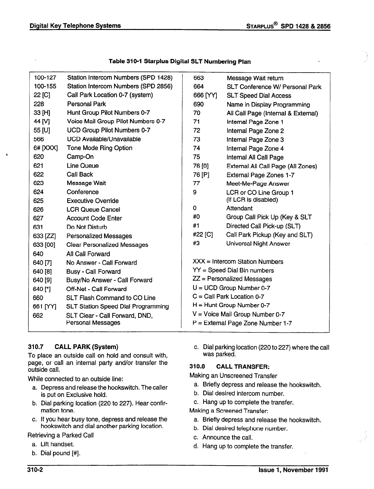
fable 31 O-1 Starplus Digital SLT Numbering Plan
loo-127 Station Intercom Numbers (SPD 1428) 663 Message Wait return
100-l 55 Station Intercom Numbers (SPD 2856) 664 SLT Conference W/ Personal Park
22
[Cl
Call Park Location O-7 (system) 666 [WI SLT Speed Dial Access
228 Personal Park 690 Name in Display Programming
33
WI
Hunt Group Pilot Numbers O-7 70 All Call Page (Internal & External)
UM
Voice Mail Group Pilot Numbers O-7 71 Internal Page Zone 1
55
WI
UCD Group Pilot Numbers O-7 72 Internal Page Zone 2
566 UCD Available/Unavailable 73 Internal Page Zone 3
6# [XXX] Tone Mode Ring Option 74 Internal Page Zone 4
620 Camp-On 75 Internal All Call Page
621 Line Queue 76
PI
External All Call Page (All Zones)
622 Call Back 76
PI
External Page Zones l-7
623 Message Wait 77 Meet-Me-Page Answer
624 Conference 9 LCR or CO Line Group 1
625 Executive Override (if LCR is disabled)
626 LCR Queue Cancel 0 Attendant
627 Account Code Enter #O Group Call Pick Up (Key & SLT
631 Do Not Disturb #l Directed Call Pick-up (SLT)
633
1721 Personalized Messages #22 [C] Call Park Pickup (Key and SLT)
633 [00] Clear Personalized Messages #3 Universal Night Answer
640 All Call Forward
640
I?1
No Answer - Call Forward XXX = Intercom Station Numbers
640 [8] Busy - Call Forward W = Speed Dial Bin numbers
640 [9] Busy/No Answer - Call Forward ZZ = Personalized Messages
640 [*I Off-Net - Call Forward U = UCD Group Number O-7
660 SLT Flash Command to CO Line C = Call Park Location O-7
661 [WI SLT Station Speed Dial Programming H = Hunt Group Number O-7
662 SLT Clear - Call Forward, DND, V = Voice Mail Group Number O-7
Personal Messages P = External Page Zone Number l-7
310.7 CALL PARK (System)
To place an outside call on hold and consult with,
page, or call an internal party and/or transfer the
outside call.
While connected to an outside line:
a. Depress and release the hookswitch. The caller
is put on Exclusive hold.
b. Dial parking location (220 to 227). Hear confir-
mation tone.
c. If you hear busy tone, depress and release the
hookswitch and dial another parking location.
Retrieving a Parked Call
a. Lift handset.
b. Dial pound [#I.
c. Dial parking location (220 to 227) where the call
was parked.
310.8
CALL TRANSFER:
Making an Unscreened Transfer
a. Briefly depress and release the hookswitch.
b. Dial desired intercom number.
c. Hang up to complete the transfer.
Making a Screened Transfer:
a. Briefly depress and release the hookswitch.
b. Dial desired telephone number.
c. Announce the call.
d. Hang up to complete the transfer.
31 o-2 Issue 1, November 1991
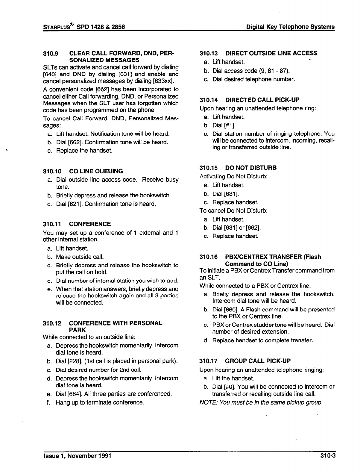
STARPLUS@
SPD 1428 & 2858 Digital Key Telephone Systems
310.9 CLEAR CALL FORWARD, DND, PER-
SONALIZED MESSAGES
SLTs can activate and cancel call forward by dialing
[640] and DND by dialing [631] and enable and
cancel personalized messages by dialing [633xx].
A convenient code [662] has been incorporated to
cancel either Call forwarding, DND, or Personalized
Messages when the SLT user has forgotten which
code has been programmed on the phone
To cancel Call Forward, DND, Personalized Mes-
sages:
a. Lift handset. Notification tone will be heard.
b. Dial [662]. Confirmation tone will be heard.
c. Replace the handset.
310.10 CO LINE QUEUING
a. Dial outside line access code. Receive busy
tone.
b. Briefly depress and release the hookswitch.
c. Dial [621]. Confirmation tone is heard.
310.11 CONFERENCE
You may set up a conference of 1 external and 1
other internal station.
a.
b.
C.
d.
e.
Lift handset.
Make outside call.
Briefly depress and release the hookswitch to
put the call on hold.
Dial number of internal station you wish to add.
When that station answers, briefly depress and
release the hookswitch again and all 3 parties
will be connected.
310.12 CONFERENCE WITH PERSONAL
PARK
While connected to an outside line:
a. Depress the hookswitch momentarily. Intercom
dial tone is heard.
b. Dial [228]. (1st call is placed in personal park).
c. Dial desired number for 2nd call.
d. Depress the hookswitch momentarily. Intercom
dial tone is heard.
e. Dial [664]. All three parties are conferenced.
f. Hang up to terminate conference.
310.13 DIRECT OUTSIDE LINE ACCESS
a. Lift handset.
b. Dial access code (9, 81 - 87).
c. Dial desired telephone number.
310.14 DIRECTED CALL PICK-UP
Upon hearing an unattended telephone ring:
a. Lift handset.
b. Dial [#l].
c. Dial station number of ringing telephone. You
will be connected to intercom, incoming, recall-
ing or transferred outside line.
310.15 DO NOT DISTURB
Activating Do Not Disturb:
a. Lift handset.
b. Dial [631].
c. Replace handset.
To cancel Do Not Disturb:
a. Lift handset.
b. Dial [631] or [662].
c. Replace handset.
310.16 PBWCENTREX TRANSFER (Flash
Command to CO Line)
To initiate a PBX or Centrex Transfer command from
an SLT.
While connected to a PBX or Centrex line:
Briefly depress and release the hookswitch.
Intercom dial tone will be heard.
Dial [660]. A Flash command will be presented
to the PBX or Centrex line.
PBX or Centrex studder tone will be heard. Dial
number of desired extension.
Replace handset to complete transfer.
310.17 GROUP CALL PICK-UP
Upon hearing an unattended telephone ringing:
a. Lift the handset.
b. Dial [#O]. You will be connected to intercom or
transferred or recalling outside line call.
NOTE: You musf be in the same pickup group.
Issue 1, November 1991 31 o-3
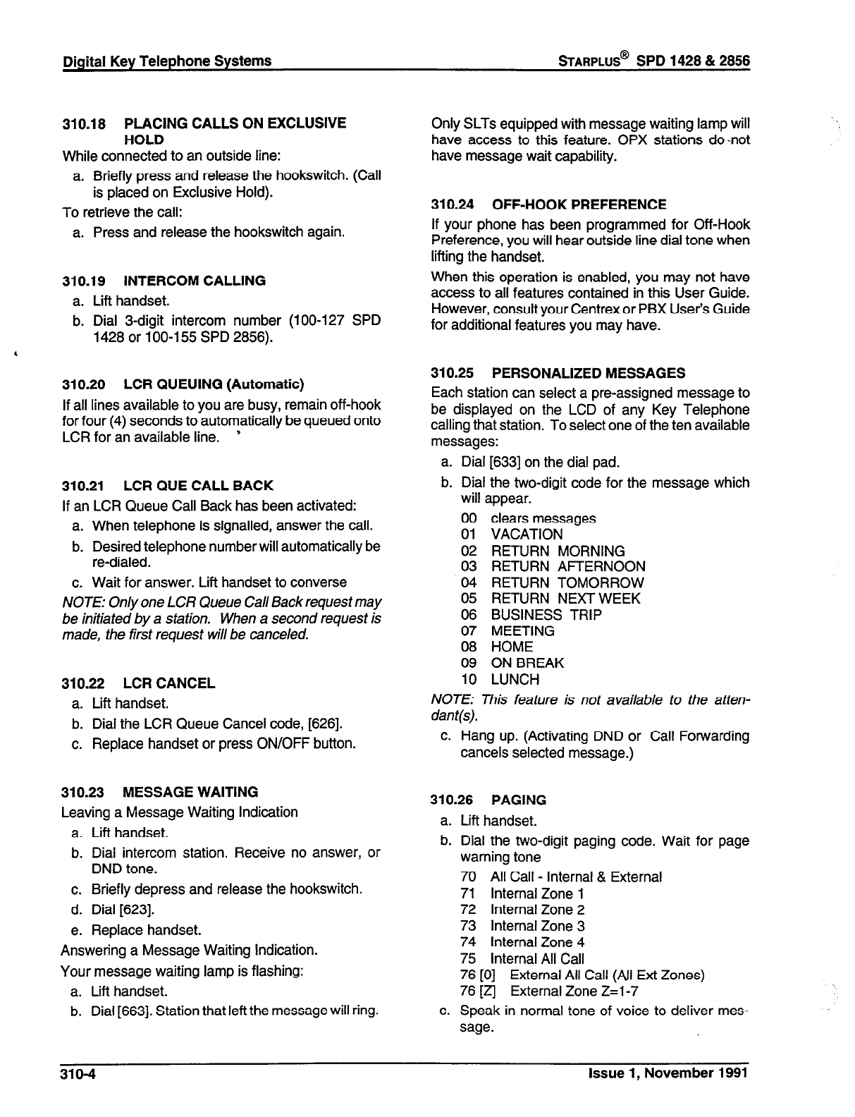
Digital Key Telephone Systems
sTARPLUS@
SPD 1428 & 2858
310.18 PLACING CALLS ON EXCLUSIVE
HOLD
While connected to an outside line:
a. Briefly press and release the hookswitch. (Call
is placed on Exclusive Hold).
To retrieve the call:
a. Press and release the hookswitch again.
310.19 INTERCOM CALLING
a. Lift handset.
b. Dial 3-digit intercom number (loo-127 SPD
1428 or 100-l 55 SPD 2856).
4
310.20 LCR QUEUING (Automatic)
If all lines available to you are busy, remain off-hook
for four (4) seconds to automatically be queued onto
LCR for an available line. ’
310.21 LCR QUE CALL BACK
If an LCR Queue Call Back has been activated:
a. When telephone
is
signalled, answer the call.
b. Desired telephone number will automatically be
re-dialed.
c. Wait for answer. Lift handset to converse
NOTE: Only one LCR Queue Call Back request may
be initiated by a station. When a second request is
made, the first request will be canceled.
310.22 LCR CANCEL
a. Lift handset.
b. Dial the LCR Queue Cancel code, [626].
c. Replace handset or press ON/OFF button.
310.23 MESSAGE WAITING
Leaving a Message Waiting Indication
a. Lift handset.
b. Dial intercom station. Receive no answer, or
DND tone.
c. Briefly depress and release the hookswitch.
d. Dial [623].
e. Replace handset.
Answering a Message Waiting Indication.
Your message waiting lamp is flashing:
a. Lift handset.
b. Dial [663]. Station that left the message will ring.
Only SLTs equipped with message waiting lamp will
have access to this feature. OPX stations do-not
have message wait capability.
310.24 OFF-HOOK PREFERENCE
If your phone has been programmed for Off-Hook
Preference, you will hear outside line dial tone when
lifting the handset.
When this operation is enabled, you may not have
access to all features contained in this User Guide.
However, consult your Centrex or PBX User’s Guide
for additional features you may have.
310.25 PERSONALIZED MESSAGES
Each station can select a pre-assigned message to
be displayed on the LCD of any
Key
Telephone
calling that station. To select one of the ten available
messages:
a. Dial [633] on the dial pad.
b. Dial the two-digit code for the message which
will appear.
00 clears messages
01 VACATION
02 RETURN MORNING
03 RETURN AFTERNOON
04 RETURN TOMORROW
05 RETURN NEXTWEEK
06 BUSINESS TRIP
07 MEETING
08 HOME
09 ON BREAK
10 LUNCH
NOTE: This feature is not available to the atten-
dan t(s).
c. Hang up. (Activating DND or Call Forwarding
cancels selected message.)
310.26 PAGING
a. Lift handset.
b. Dial the two-digit paging code. Wait for page
warning tone
70 All Call - Internal & External
71 Internal Zone 1
72 Internal Zone 2
73 Internal Zone 3
74 Internal Zone 4
75 Internal All Call
76 [0] External All Call (All Ext Zones)
76 [z] External Zone Z=l-7
c. Speak in normal tone of voice to deliver mes-
sage.
318-4
Issue 1, November 1991
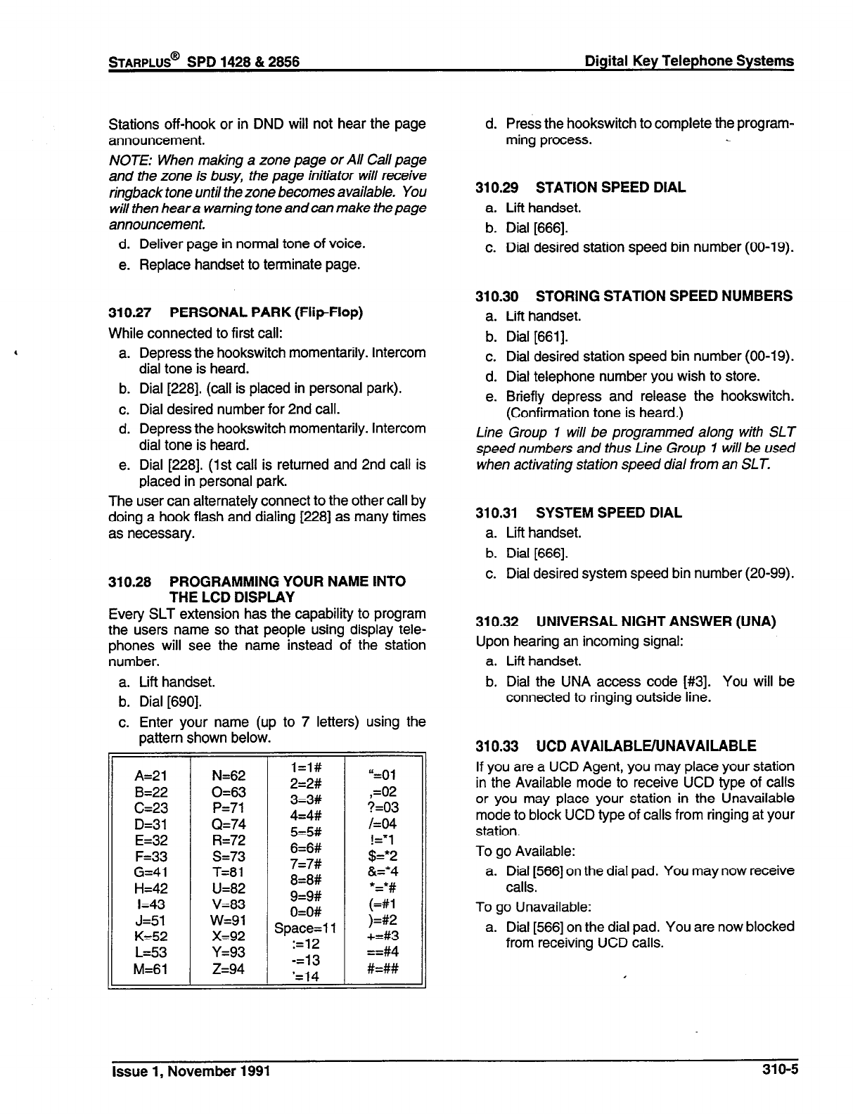
Digital Key Telephone Systems
Stations off-hook or in DND will not hear the page d. Press the hookswitch to complete the program-
announcement. ming process.
NOTE: When making a zone page or All Call page
and the zone is busy, the page initiator will receive
ringback tone until the zone becomes available. You
will then hear a warning tone and can make the page
announcement.
d. Deliver page in normal tone of voice.
e. Replace handset to terminate page.
310.29 STATION SPEED DIAL
a. Lift handset.
b. Dial [666].
c. Dial desired station speed bin number (00-l 9).
310.27 PERSONAL PARK (Flip-Flop)
While connected to first call:
a. Depress the hookswitch momentarily. Intercom
dial tone is heard.
b. Dial [228]. (call is placed in personal park).
c. Dial desired number for 2nd call.
d. Depress the hookswitch momentarily. Intercom
dial tone is heard.
e. Dial [228]. (1st call is returned and 2nd call is
placed in personal park.
The user can alternately connect to the other call by
doing a hook flash and dialing [228] as many times
as necessary.
310.28 PROGRAMMING YOUR NAME INTO
THE LCD DISPLAY
Every SLT extension has the capability to program
the users name so that people using display tele-
phones will see the name instead of the station
number.
310.30 STORING STATION SPEED NUMBERS
a. Lift handset.
b. Dial [661].
c. Dial desired station speed bin number (00-19).
d. Dial telephone number you wish to store.
e. Briefly depress and release the hookswitch.
(Confirmation tone is heard.)
Line Group 1 will be programmed along with SLT
speed numbers and thus Line Group 1 will be used
when activating station speed dial from an SLT.
310.31 SYSTEM SPEED DIAL
a. Lift handset.
b. Dial [666].
c. Dial desired system speed bin number (20-99).
310.32 UNIVERSAL NIGHT ANSWER (UNA)
Upon hearing an incoming signal:
a. Lift handset.
a. Lift handset.
b. Dial [690].
c. Enter your name (up to 7 letters) using the
b. Dial the UNA access code [#3]. You will be
connected to ringing outside line.
pattern shown below.
N=62 l=l#
0=63 2=2# “=Ol “=Ol
3=3# ,=02 ,=02
P=71 4=4# +=03 ?=03
Q=74 HF /=04 /=04
R=72 5=5# j#
s=73 6=6# 3 !=*I !=*I
,u !§=*2 !§=*2
T=81 7=7# a=*4 a=*4
U=82 8=8#
V=83 ;;;
9=9#
w=91 O=O# I# ;;; ;;;
x=92 Space=1 1 ?=l 1 )=#2 )=#2
t-9
:=12 +=#3 +=#3
Y=93 ==#4
z=94 -=13
‘=14 #=##
==#4
#=##
A=21
B=22
C=23
D=31
E=32
F=33
G=41
H=42
I=43
J=51
K=52
L=53
M=61
310.33 UCD AVAILABLE/UNAVAILABLE
If you are a UCD Agent, you may place your station
in the Available mode to receive UCD type of calls
or you may place your station in the Unavailable
mode to block UCD type of calls from ringing at your
station.
To go Available:
a. Dial [566] on the dial pad. You may now receive
calls.
To go Unavailable:
a. Dial [566] on the dial pad. You are now blocked
from receiving UCD calls.
Issue 1, November 1991 31 O-5
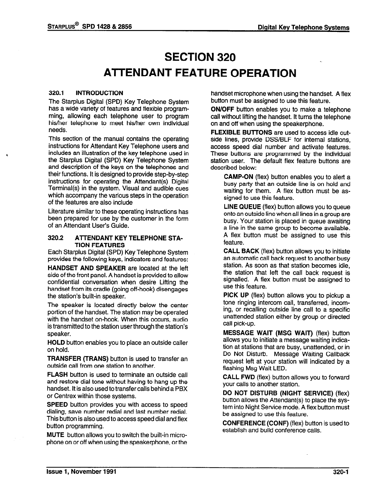
STARPLUS@
SPD 1428 & 2856 Digital Key Telephone Systems
SECTION 320
ATTENDANT FEATURE OPERATION
320.1 INTRODUCTION
The Starplus Digital (SPD) Key Telephone System
has a wide variety of features and flexible program-
ming, allowing each telephone user to program
his/her telephone to meet his/her own individual
needs.
This section of the manual contains the operating
instructions for Attendant Key Telephone users and
includes an illustration of the key telephone used in
the Starplus Digital (SPD)
Key
Telephone System
and description of the keys on the telephones and
their functions. It is designed to provide step-by-step
instructions for operating the Attendant(s) Digital
Terminal(s) in the system. Visual and audible cues
which accompany the various steps in the operation
of the features are also include
Literature similar to these operating instructions has
been prepared for use by the customer in the form
of an Attendant User’s Guide.
320.2 ATTENDANT KEY TELEPHONE STA-
TION FEATURES
Each Starplus Digital (SPD)
Key
Telephone System
provides the following keys, indicators and features:
HANDSET AND SPEAKER
are located at the left
side of the front panel. A handset is provided to allow
confidential conversation when desire Lifting the
handset from its cradle (going off-hook) disengages
the station’s built-in speaker.
The speaker is located directly below the center
portion of the handset. The station may be operated
with the handset on-hook. When this occurs, audio
is transmitted to the station user through the station’s
speaker.
HOLD
button enables you to place an outside caller
on hold.
TRANSFER (TRANS)
button is used to transfer an
outside call from one station to another.
FLASH
button is used to terminate an outside call
and restore dial tone without having to hang up the
handset. It is also used to transfer calls behind a PBX
or Centrex within those systems.
SPEED
button provides you with access to speed
dialing, save number redial and last number redial.
This button is also used to access speed dial and flex
button programming.
MUTE
button allows you to switch the built-in micro-
phone on or off when using the speakerphone, or the
handset microphone when using the handset. A flex
button must be assigned to use this feature.
ON/OFF
button enables you to make a telephone
call without lifting the handset. It turns the telephone
on and off when using the speakerphone.
FLEXIBLE BUllONS
are used to access idle out-
side lines, provide DSS/BLF for internal stations,
access speed dial number and activate features.
These buttons are programmed by the individual
station user. The default flex feature buttons are
described below:
CAMP-ON
(flex) button enables you to alert a
busy party that an outside line is on hold and
waiting for them. A flex button must be as-
signed to use this feature.
LINE QUEUE
(flex) button allows you to queue
onto an outside line when all lines in a group are
busy. Your station is placed in queue awaiting
a line in the same group to become available.
A flex button must be assigned to use this
feature.
CALL BACK
(flex) button allows you to initiate
an automatic call back request to another busy
station. As soon as that station becomes idle,
the station that left the call back request is
signalled. A flex button must be assigned to
use this feature.
PICK UP
(flex) button allows you to pickup a
tone ringing intercom call, transferred, incom-
ing, or recalling outside line call to a specific
unattended station either by group or directed
call pick-up.
MESSAGE WAIT
(MSG
WAIT)
(flex) button
allows you to initiate a message waiting indica-
tion at stations that are busy, unattended, or in
Do Not Disturb. Message Waiting Callback
request left at your station will indicated by a
flashing Msg Wait LED.
CALL FWD
(flex) button allows you to forward
your calls to another station.
DO NOT DISTURB (NIGHT SERVICE)
(flex)
button allows the Attendant(s) to place the sys-
tem into Night Service mode. A flex button must
be assigned to use this feature.
CONFERENCE (CONF)
(flex) button is used to
establish and build conference calls.
Issue 1, November 1991 320-l
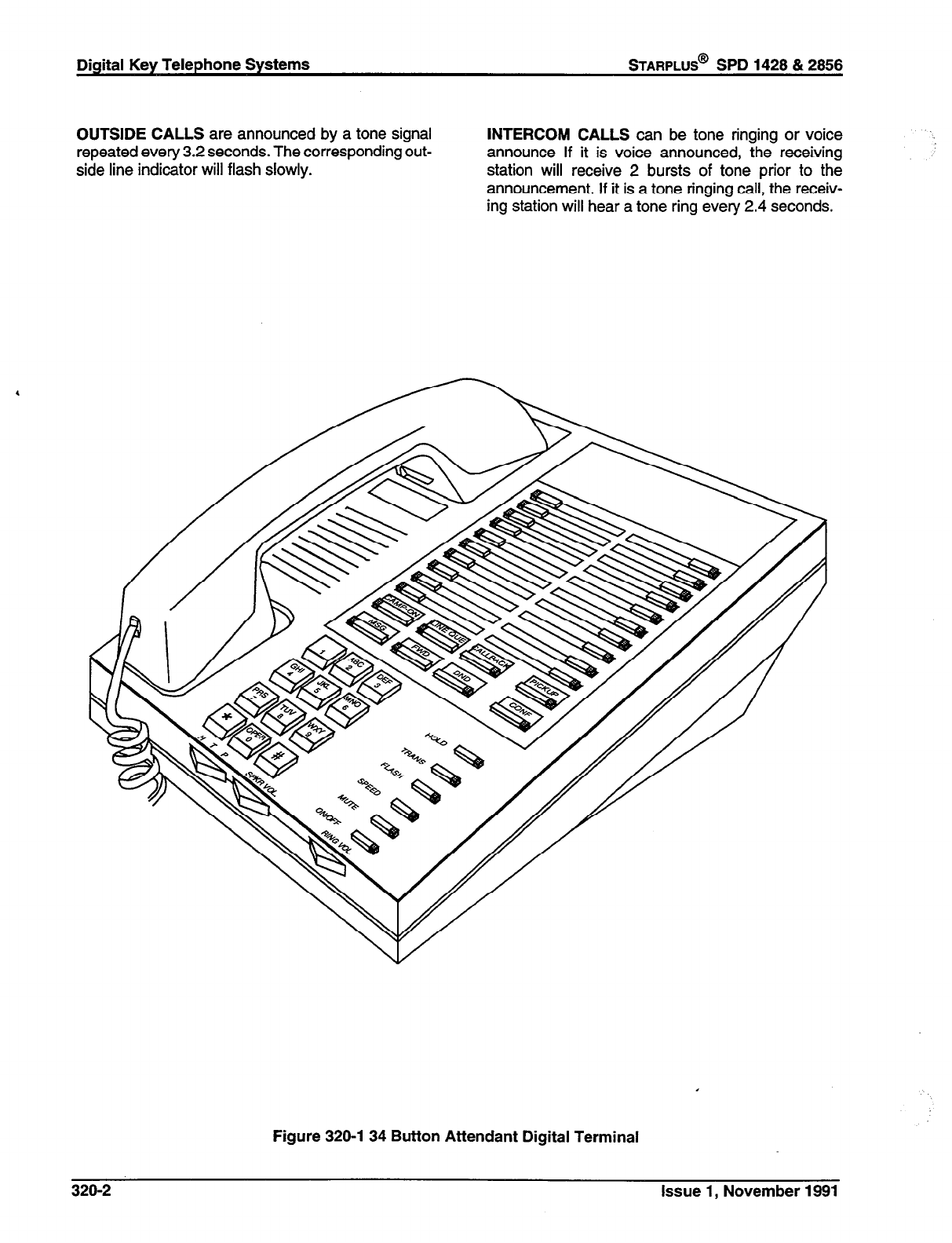
Digital Key Telephone Systems
STARPLUS@
SPD 1428 & 2856
OUTSIDE CALLS
are announced by a tone signal
repeated every 3.2 seconds. The corresponding out-
side line indicator will flash slowly.
INTERCOM CALLS
can be tone ringing or voice
announce If it is voice announced, the receiving
station will receive 2 bursts of tone prior to the
announcement. If it is a tone ringing call, the receiv-
ing station will hear a tone ring every 2.4 seconds.
Figure 320-l 34 Button Attendant Digital Terminal
320-2 Issue 1, November 1991
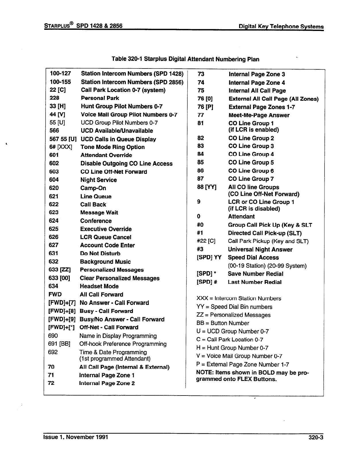
sTARPLUS@
SPD 1428 & 2858 Digital Key Telephone Systems
Table 328-l Starplus Digital Attendant Numbering Plan
108-l 27 Station Intercom Numbers (SPD 1428)
108-155 Station Intercom Numbers (SPD 2858)
22 [Cl
Call Park Location 8-7 (system)
228 Personal Park
= WI
Hunt Group Pilot Numbers 6-7
MM
Voice Mail Group Pilot Numbers 8-7
55
WI
UCD Group Pilot Numbers O-7
588 UCD AvailableNnavailable
567 55 [U] UCD Calls in Queue Display
6# Dooc] Tone Mode Ring Option
601 Attendant Override
602 Disable Outgoing CO Line Access
603 CO Line Off-Net Forward
604 Night Service
620 Camp-On
621 Line Queue
622 Call Back
623 Message Wait
624 Conference
625 Executive Override
626 LCR Queue Cancel
627 Account Code Enter
631 Do Not Disturb
632 Background Music
633[zzl Personalized Messages
633 [00] Clear Personalized Messages
634 Headset Mode
FWD All Call Forward
[FWD]+[71 No Answer - Call Forward
[FWD]+[8] Busy - Call Forward
[FWD]+[S] Busy/No Answer - Call Forward
[FWD]+[*] Off-Net - Call Forward
690 Name in Display Programming
691 [BB] Off-hook Preference Programming
692 Time & Date Programming
(1st programmed Attendant)
70 All Call Page (Internal & External)
71 Internal Page Zone 1
72 Internal Page Zone 2
73
74
75
76
PI
76
PI
Internal Page Zone 3
Internal Page Zone 4
Internal All Call Page
External All Call Page (All Zones)
External Page Zones 1-7
77
81
82
83
84
85
86
87
~[wl
9
0
#O
#l
#22 [C]
Meet-Me-Page Answer
CO Line Group 1
(if LCR is enabled)
CO Line Group 2
CO Line Group 3
CO Line Group 4
CO Line Group 5
CO Line Group 6
CO Line Group 7
All CO line Groups
(CO Line Off-Net Forward)
LCR or CO Line Group 1
(if LCR is disabled)
Attendant
Group Call Pick Up (Key & SLT
Directed Call Pick-up (SLT)
Call Park Pickup (Key and SLT)
#3 Universal Night Answer
[SPD] YY Speed Dial Access
(00-l 9 Station) (20-99 System)
[SPD] * Save Number Redial
[SPD] # Last Number Redial
XXX = Intercom Station Numbers
YY = Speed Dial Bin numbers
ZZ = Personalized Messages
BB = Button Number
U = UCD Group Number O-7
C = Call Park Location O-7
H = Hunt Group Number O-7
V = Voice Mail Group Number O-7
P = External Page Zone Number 1-7
NOTE: Items shown in BOLD may be pro-
grammed onto FLEX Buttons.
.
Issue 1, November 1991 320-3
320.3 ANSWERING AN OUTSIDE CALL
a. Lift handset.
b. Press slow flashing outside line button. (If your
telephone is programmed with Preferred Line
Answer, you may answer an outside line by
lifting the handset.)
320.4 PLACING OUTSIDE LINE ON HOLD
a. If your system is programmed for Exclusive
Hold Preference, press HOLD button once for
Exclusive Hold and twice for System Hold.
b. If your system is programmed for System Hold
Preference, press HOLD button once for Sys-
tem Hold and twice for Exclusive Hold.
4
320.5 ANSWERING A RECALLING OUT-
SIDE LINE
When an outside line has remained on hold for an
extended period of time, you will be reminded with a
recalling ring.
a. Press outside line button flashing at very fast
rate.
b. Lift handset to converse.
320.6 AlTENDANT DISABLE OUTGOING
ACCESS
The attendant station can disable CO lines, prevent-
ing outgoing CO calls.
a. Lift handset or press ON/OFF button.
b. Dial [602]. Confirmation tone is hear
c. Depress the line button(s) of the CO Line(s) to
be disable Confirmation tone is heard and the
CO tine Button(s) LED is flashing.
d. To re-activate the CO Line(s), repeat the steps
followed to disable it.
320.7 ATTENDANT OVERRIDE
If Attendant Override is allowed, Attendant(s) sta-
tions may override or call stations that are either busy
or in Do Not Disturb.
If the Attendant calls a station that is busy on a CO
call and wishes to alert them of a waiting call:
a. Press the pre-programmed* AlTN OVERRIDE
button. Three short tone bursts will be pre-
sented to the called party.
b. After five (5) seconds, the station’s CO line will
automatically be placed on hold and the Atten-
dant will be cut-thru.
If the Attendant calls a station that is in Do Not
Disturb mode and wishes to alert them of a call;
a. Press the pre-programmed* AlTN OVERRIDE
button. The station will be signalled with a
Camp-on tone.
‘Refer to flexible button programming
320.8 ATTENDANT RECALL
When an outside line has remained on hold for an
extended period of time, you will be reminded with a
recalling ring.
a. Press outside line button flashing at a very fast
rate.
b. Lift handset to converse.
320.9
EXECUTIVE OVERRIDE
Allows stations designated as “Executive” the ability
to override and “barge in” on other keysets engaged
in conversation.
If you call a busy station:
a. Press pre-programmed* EXECUTIVE OVER-
RIDE button. Executive station will be bridged
onto the CO conversation in progress at the
called station. Optional warning tone is heard
and presented to all parties prior to cut-thru.
b. Replace handset at Executive station to termi-
nate the override.
*Refer to Flexible Button Programming
NOTE: If the busy party is connected via intercom to
another party, the intercom connection will be
dropped when the override occurs.
CAUTION: USE OF THIS FEATURE WHEN THE
EXECUTIVE OVERRIDE WARNING TONE IS DIS-
ABLED MAY BE INTERPRETED AS A VIOLATION
OF FEDERAL OR STATE LAWS, AND AN INVASION
OF PRIVACY. CONSULT COUNSEL WITH RE-
SPECT TO APPLICABLE LAWS BEFORE INTRUD-
ING ON CALLS USING THIS FEATURE.
NOTE: A decrease in volume may occur on the CO
line after the barge-in occurs.
320.10 INTERCOM CALLING
Placing an Intercom Call
a. Press station key of party to be called (if pro-
grammed at your phone); or dial station number
(100 to 155).
b. You will hear ringing if called station is in the ‘7”
answering mode; or two bursts of tone if called
station is in the “l-l” or “P” position.
c. Lift handset or use speaker-phone, when tone
bursts stop.
d. Hang up to end call.
Answering an Intercom Call
With your intercom signal switch in the T mode, you
will hear repeated bursts of intercom tone ringing and
the HOLD button will slow flash.
a. Lift handset or press ON/OFF button to an-
swer.
b. Hang up to end call.
320-4 Issue 1, November 1991
In the P mode, you will hear two bursts of tone and
one-way announcement. The HOLD button will slow
flash and the calling party cannot hear conversations
in progress.
In the H mode, you will hear two bursts of tone and
an announcement. Reply handsfree or lift handset
for privacy.
320.11 INCOMING CO LINES OFF-NET (via
speed dial)
Allows the first attendant station to forward incoming
CO calls to an off-net location.
In a speed dial bin, store the number of the off-net
location where calls are to be forwarded. Follow
instructions provided for storing station or system
speed dial numbers.
a. Dial [603] on the dial pad or press pre-pro-
grammed* CO Off-Net Forward button.
b. Dial the CO group access code of the group to
be forwarded or press the CO Line button for
an individual CO Line for Off-Net forward.
81=CO Group 1
82=CO Group 2
83=CO Group 3
84=CO Group 4
85=CO Group 5
86=CO Group 6
87=CO Group 7
88=All CO Lines
c. Dial the speed bin number that contains the
number where calls are to be forwarded or
press the pre-programmed* button for the
speed bin. Confirmation tone is heard.
*Refer to flexible button programming
Canceling Off-Net Forwarding
a. Dial [603] on the dial pad or press pre-pro-
grammed* CO Off-Net Forward button.
b. Dial the CO group access code or press the CO
Line button.
c. Dial [#]. Confirmation tone is heard.
320.12 NIGHT SERVICE
a. Any designated attendant can place the system
into Night Service by pressing the pre-pro-
grammed Night Service button (DND) or by
dialing [604].
b. Pressing the pre-programmed Night Service
button again removes the system from Night
Service.
320.13 SElTING SYSTEM TIME AND DATE
Must be set by the first programmed attendant.
a. Dial [692] on the dial pad. Confirmation tone is
heard.
b. Enter date and time as follows:
YYMMDDHHMM
W = year 00-99
MM = month 01-12
DD = day 01-31
HH = hour 00-23
MM=minute 00-59
When the correct number of digits are entered, con-
firmation tone will be heard and the display will
update.
320.14 STORING SYSTEM SPEED NUMBERS
System Speed numbers must be entered by the first
programmed attendant. If no attendant is specified,
enter at Station 100.
a. Press SPEED once, then press a desired out-
side line key or select an outside line automat-
ically by pressing the SPEED button a second
time.
b. Dial the System speed bin location (20 to 99).
C.
Dial telephone number.
d. Press the SPEED button.
e. Hang up.
- Pressing the TRANS button during number
entry initiates a Pulse-To-Tone switchover.
Pressing the HOLD button during number
entry inserts a Pause. Pressing the FLASH
key inserts a Flash into the speed number.
- Pressing the TRANS button as the first
entry in the speed bin inserts a no-display
character causing the numbers stored in
the bin not to appear on the Digital Termi-
nals display when the bin is accessed.
Speed Bin numbers 60-99 are NOT monitored by
Toll Restriction.
Issue 1, November 1991
320-5
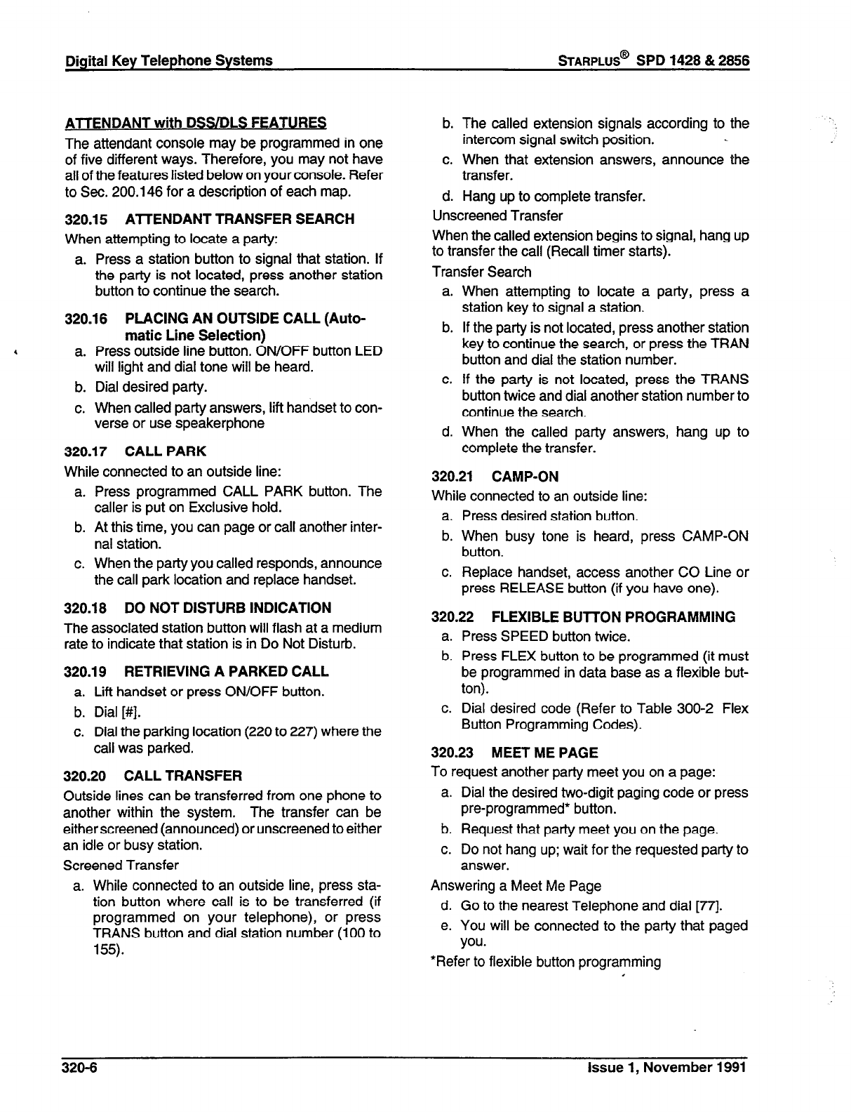
Digital Key Telephone Systems
STARPLUS@
SPD 1428 & 2856
ATTENDANT with DSS/DLS FEATURES
The attendant console may be programmed in one
of five different ways. Therefore, you may not have
all of the features listed below on your console. Refer
to Sec. 200.146 for a description of each map.
320.15 A7TENDANT TRANSFER SEARCH
When attempting to locate a party:
a. Press a station button to signal that station. If
the party is not located, press another station
button to continue the search.
320.16 PLACING AN OUTSIDE CALL (Auto-
a.
b.
C.
matic Line Selection)
Press outside line button. ON/OFF button LED
will light and dial tone will be heard.
Dial desired party.
When called party answers, lift handset to con-
verse or use speakerphone
320.17 CALL PARK
While connected to an outside line:
a. Press programmed CALL PARK button. The
caller is put on Exclusive hold.
b. At this time, you can page or call another inter-
nal station.
c. When the party you called responds, announce
the call park location and replace handset.
320.18 DO NOT DISTURB INDICATION
The associated station button will flash at a medium
rate to indicate that station is in Do Not Disturb.
320.19 RETRIEVING A PARKED CALL
a. Lift handset or press ON/OFF button.
b. Dial [#I.
c. Dial the parking location (220 to 227) where the
call was parked.
320.20 CALL TRANSFER
Outside lines can be transferred from one phone to
another within the system. The transfer can be
either screened (announced) or unscreened to either
an idle or busy station.
Screened Transfer
a. While connected to an outside line, press sta-
tion button where call is to be transferred (if
programmed on your telephone), or press
TRANS button and dial station number (100 to
155).
b. The called extension signals according to the
intercom signal switch position.
6. When that extension answers, announce the
transfer.
d. Hang up to complete transfer.
Unscreened Transfer
When the called extension begins to signal, hang up
to transfer the call (Recall timer starts).
Transfer Search
a.
b.
C.
d.
When attempting to locate a party, press a
station key to signal a station.
If the party is not located, press another station
key to continue the search, or press the TRAN
button and dial the station number.
If the party is not located, press the TRANS
button twice and dial another station number to
continue the search.
When the called party answers, hang up to
complete the transfer.
320.21 CAMP-ON
While connected to an outside line:
a. Press desired station button.
b. When busy tone is heard, press CAMP-ON
button.
c. Replace handset, access another CO Line or
press RELEASE button (if you have one).
320.22 FLEXIBLE BUTTON PROGRAMMING
a. Press SPEED button twice.
b. Press FLEX button to be programmed (it must
be programmed in data base as a flexible but-
ton).
c. Dial desired code (Refer to Table 300-2 Flex
Button Programming Codes).
320.23 MEET ME PAGE
To request another party meet you on a page:
a. Dial the desired two-digit paging code or press
pre-programmed* button.
b. Request that party meet you on the page.
c. Do not hang up; wait for the requested party to
answer.
Answering a Meet Me Page
d. Go to the nearest Telephone and dial [77].
e. You will be connected to the party that paged
you.
*Refer to flexible button programming
I
320-6
issue 1, November 1991
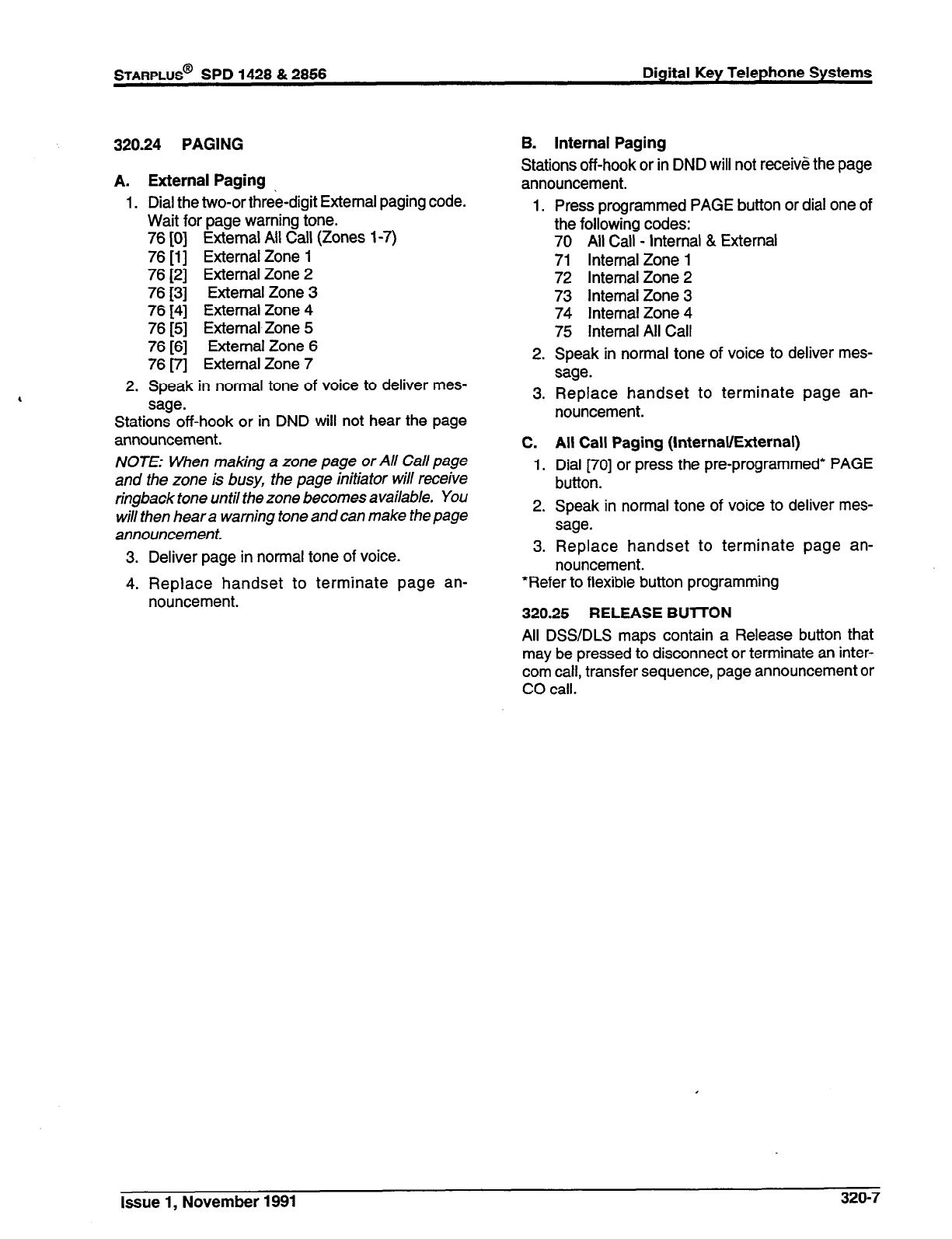
STARPLUS@
SPD 1428 & 2856 Digital Key Telephone Systems
320.24 PAGING
A. External Paging
1. Dial the two-or three-digit External paging code.
Wait for page warning tone.
76 [0] External All Call (Zones 1-7)
76 [l] External Zone 1
76 [2] External Zone 2
76 [3] External Zone 3
76 [4] External Zone 4
76 [5] External Zone 5
76 [6] External Zone 6
76 m External Zone 7
2. Speak in normal tone of voice to deliver mes-
sage.
Stations off-hook or in DND will not hear the page
announcement.
NOTE: When making a zone page or All Call page
and the zone is busy, the page initiator will receive
ringback tone until the zone becomes available. You
will then hear a warning tone and can make the page
announcement.
3. Deliver page in normal tone of voice.
4. Replace handset to terminate page an-
nouncement.
B. Internal Paging
Stations off-hook or in DND will not receive the page
announcement.
1.
2.
3.
C.
1.
2.
3.
Press programmed PAGE button or dial one of
the following codes:
70 All Call - Internal & External
71 Internal Zone 1
72 Internal Zone 2
73 Internal Zone 3
74 Internal Zone 4
75 Internal All Call
Speak in normal tone of voice to deliver mes-
sage.
Replace handset to terminate page an-
nouncement.
All Call Paging (Internal/External)
Dial [70] or press the pre-programmed* PAGE
button.
Speak in normal tone of voice to deliver mes-
sage.
Replace handset to terminate page an-
nouncement.
*Refer to flexible button programming
320.25 RELEASE BUlTON
All DSS/DLS maps contain a Release button that
may be pressed to disconnect or terminate an inter-
com call, transfer sequence, page announcement or
CO call.
Issue 1, November 1991 320-7
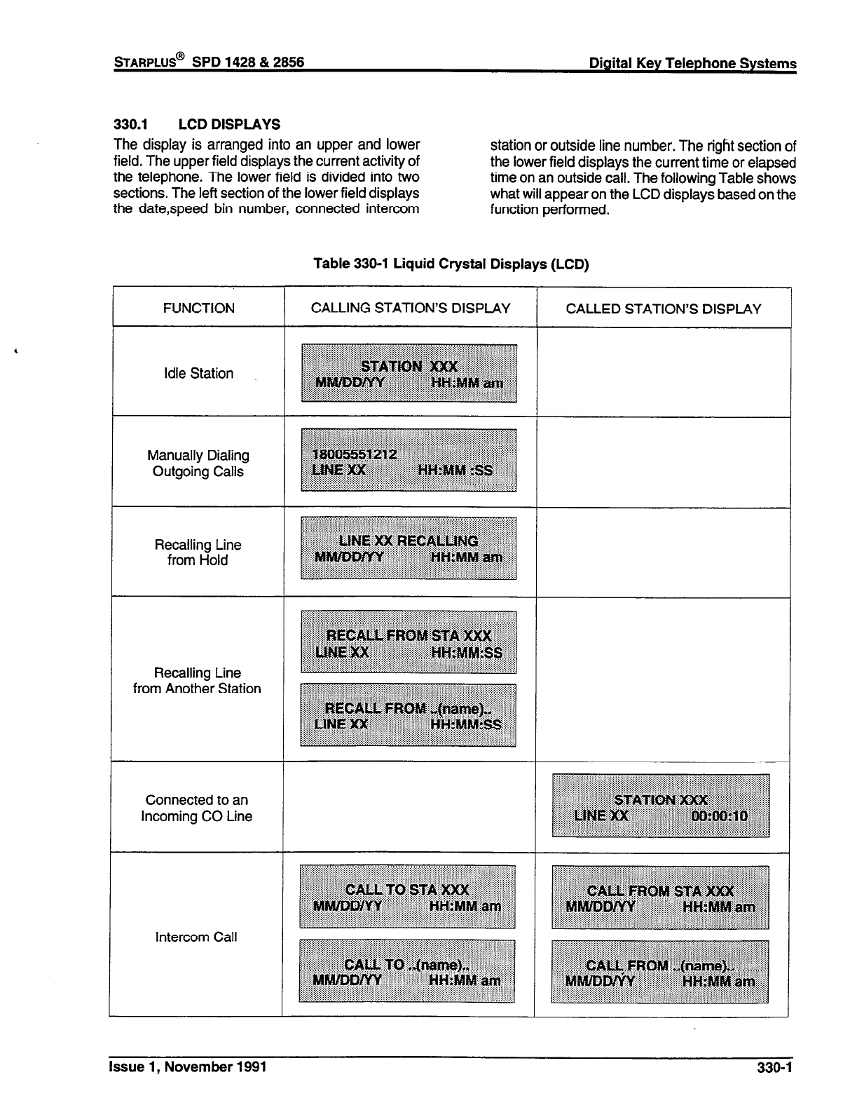
STARPLUS@
SPD 1428 & 2858 Digital Key Telephone Systems
330.1 LCD DISPLAYS
The display is arranged into an upper and lower
field. The upper field displays the current activity of
the telephone. The lower field is divided into two
sections. The left section of the lower field displays
the datespeed bin number, connected intercom
station or outside line number. The right section of
the lower field displays the current time or elapsed
time on an outside call. The following Table shows
what will appear on the LCD displays based on the
function performed.
Table 330-l Liquid Crystal Displays (LCD)
FUNCTION
Idle Station
Manually Dialing
Outgoing Calls
Recalling Line
from Hold
Recalling Line
from Another Station
Connected to an
Incoming CO Line
Intercom Call
CALLING STATION’S DISPLAY
T
CALLED STATION’S DISPLAY
Issue 1, November 1991
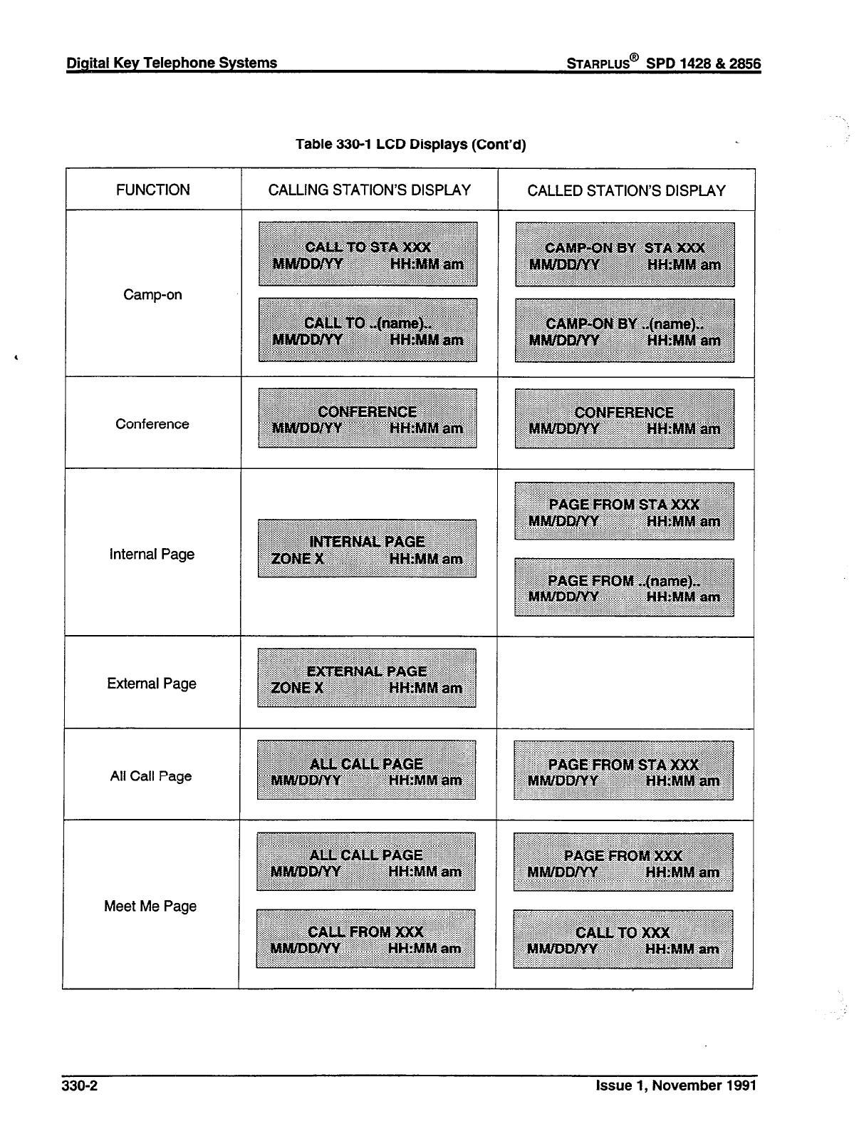
Table 330-l LCD Displays (Cont’d)
,
FUNCTION
Camp-on
Conference
internal Page
External Page
All Call Page
Meet Me Page
CALLING STATION’S DISPLAY CALLED STATION’S DISPLAY
330-2
Issue 1, November 1991
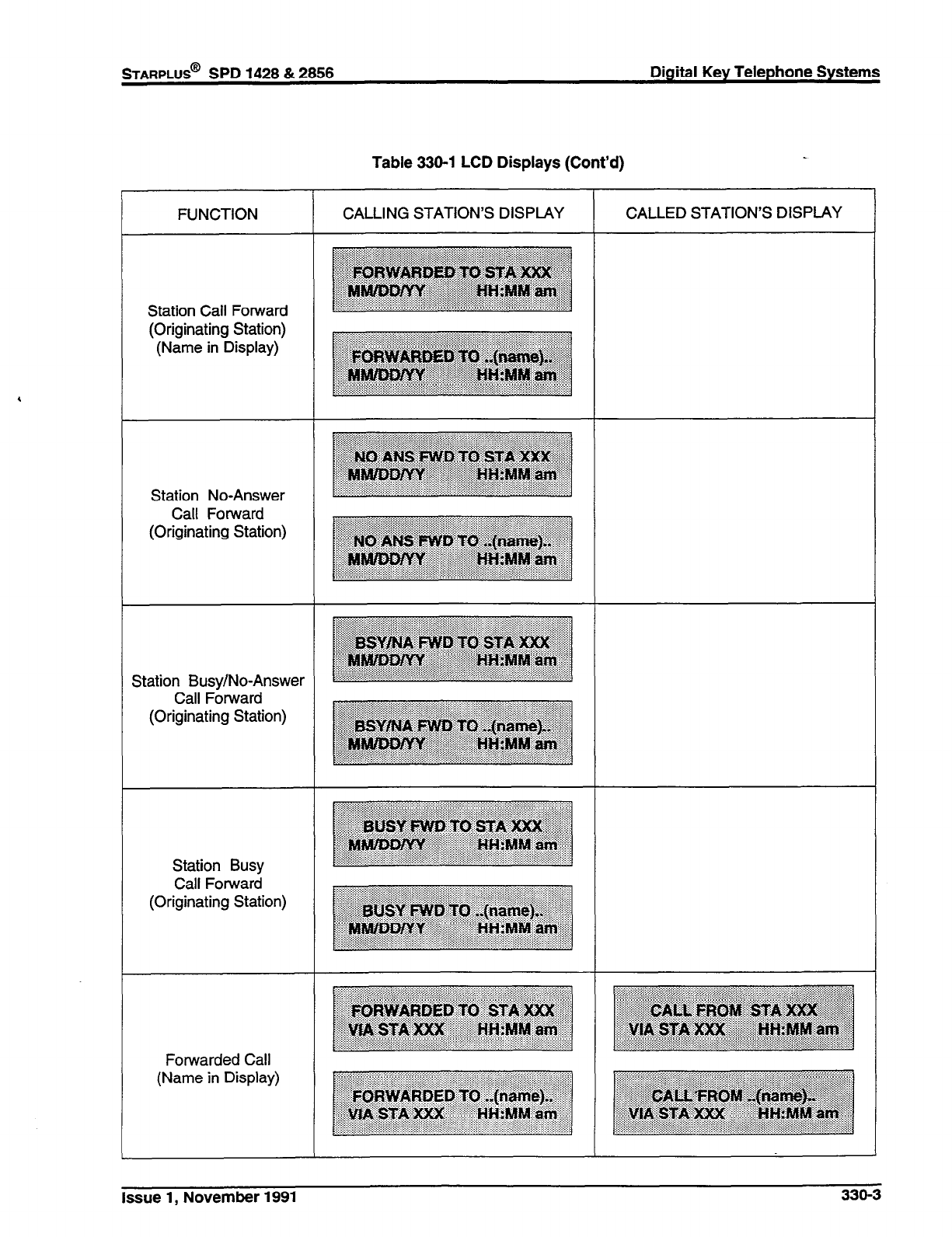
STARPLUS@
SPD 1428 & 2856 Digital Key Telephone Systems
Table 330-l LCD Displays (Cont’d)
FUNCTION CALLING STATION’S DISPLAY CALLED STATION’S DISPLAY
Station Call Forward
(Originating Station)
(Name in Display)
Station No-Answer
Call Forward
(Originating Station)
Station Busy/No-Answer
Call Forward
(Originating Station)
Station Busy
Call Forward
(Originating Station)
Forwarded Call
(Name in Display)
Issue 1, November 1991
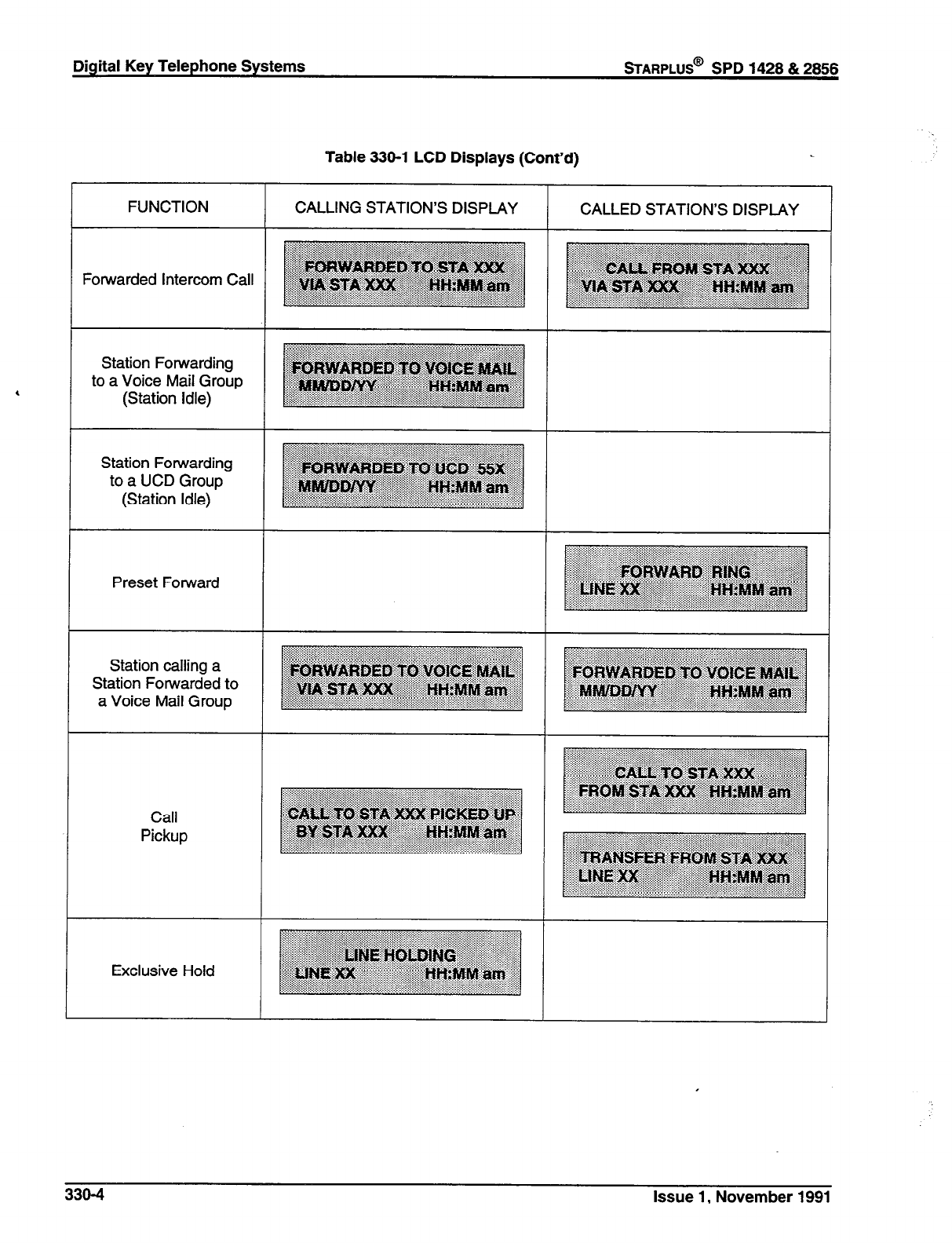
Digital Key Telephone Systems
sTARPLUS@
SPD 1428 & 2856
Table 330-l LCD Displays (Cont’d)
FUNCTION CALLING STATION’S DISPLAY CALLED STATION’S DISPLAY
Forwarded Intercom Call
Station Forwarding
to a Voice Mail Group
(Station Idle)
Station Forwarding
to a UCD Group
(Station Idle)
Preset Forward
Station calling a
Station Forwarded to
a Voice Mail Group
Call
Pickup
Exclusive Hold
330-4
Issue 1, November 1991

Table 330-l LCD Displays (Cont’d)
Call Back
FUNCTION CALLING STATION’S DISPLAY CALLED STATION’S DISPLAY
Do Not Disturb
Outside Line
Transfer
Message Waiting
Reply to a
Message Waiting
issue 1, November 1991 330-5
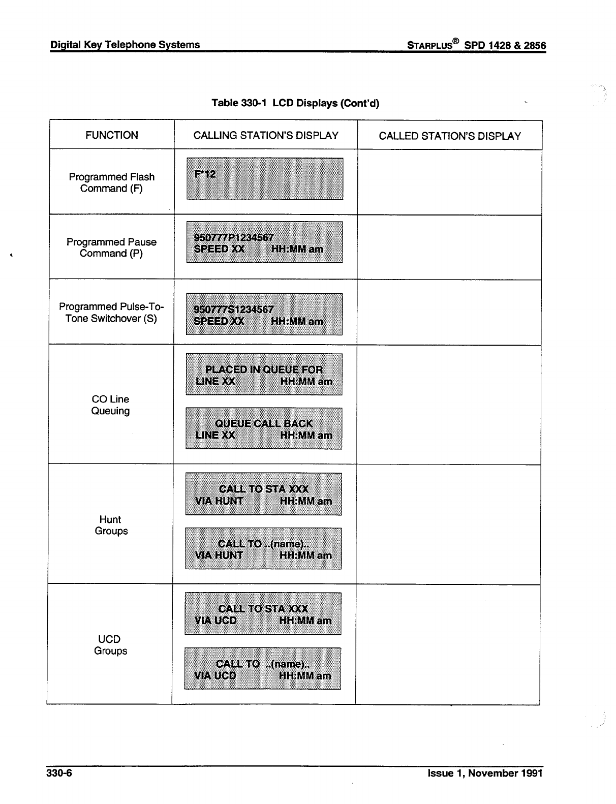

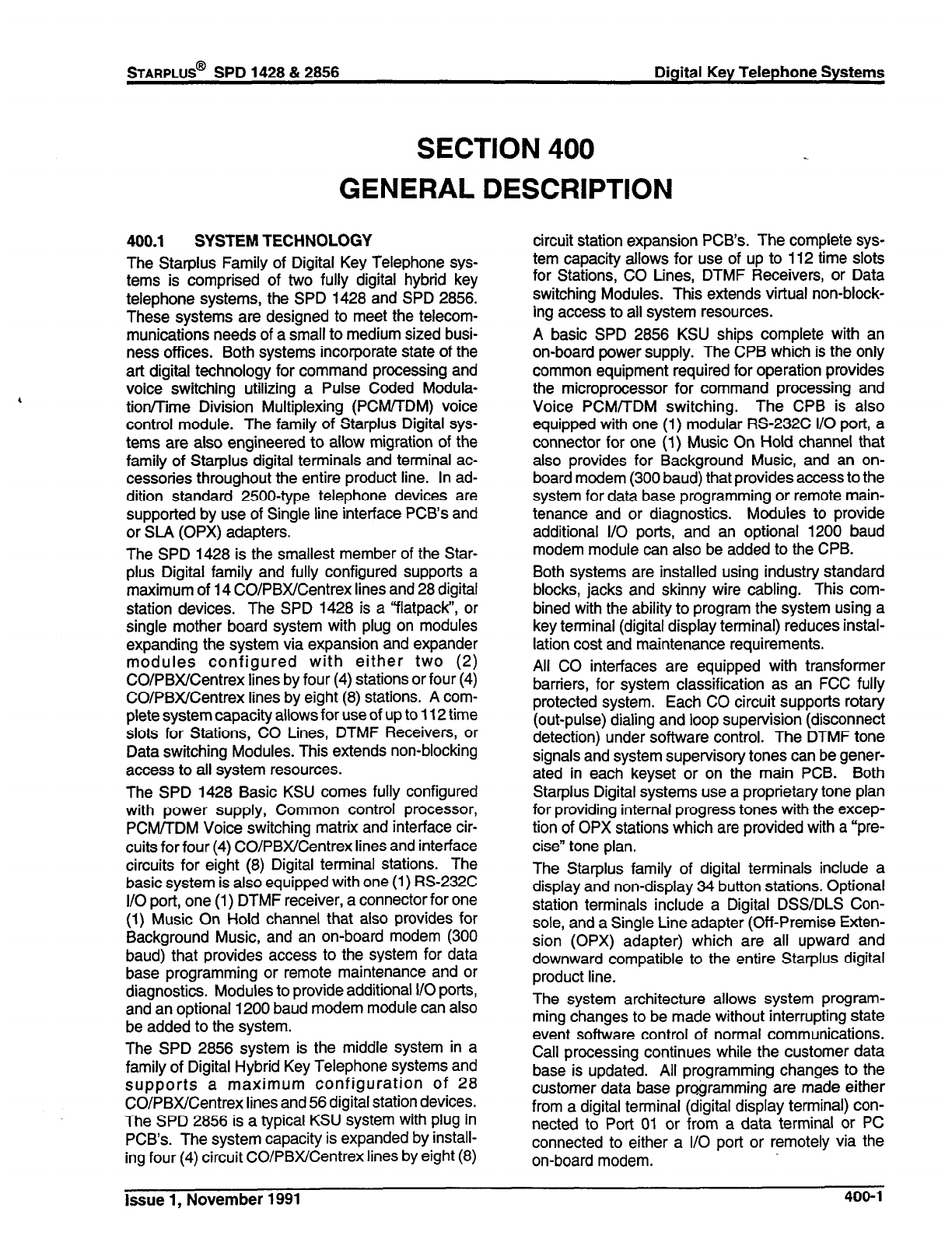
STARPLUS@
SPD 1428 & 2856 Digital Key Telephone Systems
SECTION 400
GENERAL
400.1 SYSTEM TECHNOLOGY
The Starplus Family of Digital Key Telephone sys-
tems is comprised of two fully digital hybrid key
telephone systems, the SPD 1428 and SPD 2856.
These systems are designed to meet the telecom-
munications needs of a small to medium sized busi-
ness offices. Both systems incorporate state of the
art digital technology for command processing and
voice switching utilizing a Pulse Coded Modula-
tion/Time Division Multiplexing (PCM/TDM) voice
control module. The family of Starplus Digital sys-
tems are also engineered to allow migration of the
family of Starplus digital terminals and teminal ac-
cessories throughout the entire product line. In ad-
dition standard 2500-type telephone devices are
supported by use of Single line interface PCB’s and
or SLA (OPX) adapters.
The SPD 1428 is the smallest member of the Star-
plus Digital family and fully configured supports a
maximum of 14 CO/PBX/Centrex lines and 28 digital
station devices. The SPD 1428 is a “flatpack”, or
single mother board system with plug on modules
expanding the system via expansion and expander
modules configured with either two (2)
CO/PBX/Centrex lines by four (4) stations or four (4)
COIPBXICentrex lines by eight (8) stations. A com-
plete system capacity allows for use of up to 112 time
slots for Stations, CO Lines, DTMF Receivers, or
Data switching Modules. This extends non-blocking
access to all system resources.
The SPD 1428 Basic KSU comes fully configured
with power supply, Common control processor,
PCM/TDM Voice switching matrix and interface cir-
cuits for four (4) CO/PBWCentrex lines and interface
circuits for eight (8) Digital terminal stations. The
basic system is also equipped with one (1) RS-232C
I/O port, one (1) DTMF receiver, a connector for one
(1) Music On Hold channel that also provides for
Background Music, and an on-board modem (300
baud) that provides access to the system for data
base programming or remote maintenance and or
diagnostics. Modules to provide additional I/O ports,
and an optional 1200 baud modem module can also
be added to the system.
The SPD 2856 system is the middle system in a
family of Digital Hybrid Key Telephone systems and
supports a maximum configuration of 28
CO/PBX/Centrex lines and 56 digital station devices.
The SPD 2856 is a typical KSU system with plug in
PCB’s. The system capacity is expanded by install-
ing four (4) circuit CO/PBX/Centrex lines by eight (8)
DESCRIPTION
circuit station expansion PCB’s. The complete sys-
tem capacity allows for use of up to 112 time slots
for Stations, CO Lines, DTMF Receivers, or Data
switching Modules. This extends virtual non-block-
ing access to all system resources.
A basic SPD 2856 KSU ships complete with an
on-board power supply. The CPB which is the only
common equipment required for operation provides
the microprocessor for command processing and
Voice PCM/TDM switching. The CPB is also
equipped with one (1) modular RS-232C l/O port, a
connector for one (1) Music On Hold channel that
also provides for Background Music, and an on-
board modem (300 baud) that provides access to the
system for data base programming or remote main-
tenance and or diagnostics. Modules to provide
additional I/O ports, and an optional 1200 baud
modem module can also be added to the CPB.
Both systems are installed using industry standard
blocks, jacks and skinny wire cabling. This com-
bined with the ability to program the system using a
key terminal (digital display terminal) reduces instal-
lation cost and maintenance requirements.
All CO interfaces are equipped with transformer
barriers, for system classification as an FCC fully
protected system. Each CO circuit supports rotary
(out-pulse) dialing and loop supervision (disconnect
detection) under software control. The DTMF tone
signals and system supervisory tones can be gener-
ated in each keyset or on the main PCB. Both
Starplus Digital systems use a proprietary tone plan
for providing internal progress tones with the excep-
tion of OPX stations which are provided with a “pre-
cise” tone plan.
The Stat-plus family of digital terminals include a
display and non-display 34 button stations. Optional
station terminals include a Digital DSWDLS Con-
sole, and a Single Line adapter (Off-Premise Exten-
sion (OPX) adapter) which are all upward and
downward compatible to the entire Star-plus digital
product line.
The system architecture allows system program-
ming changes to be made without interrupting state
event software control of normal communications.
Call processing continues while the customer data
base is updated. All programming changes to the
customer data base programming are made either
from a digital terminal (digital display terminal) con-
nected to Port 01 or from a data terminal or PC
connected to either a I/O port or remotely via the
on-board modem.
Issue 1, November 1991 400-l
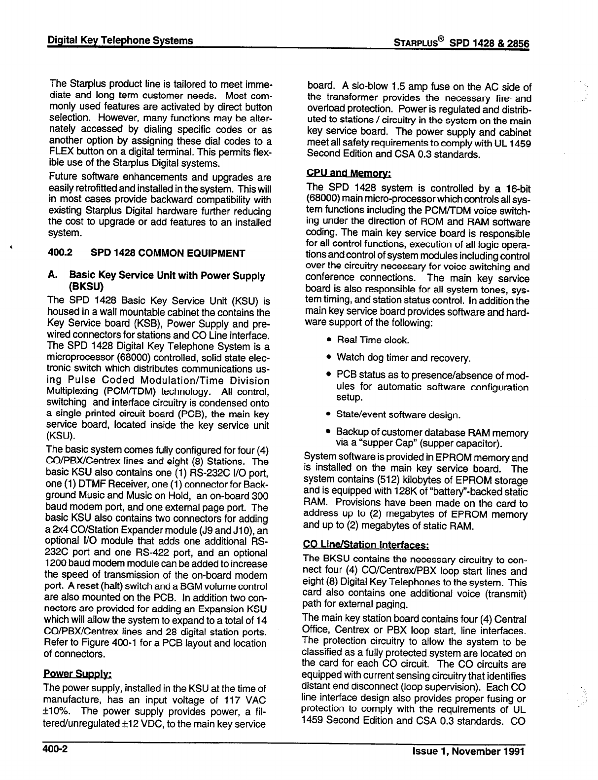
Digital Key Telephone Systems
STARPLUS@
SPD 1428 & 2856
,
The Starplus product line is tailored to meet imme-
diate and long term customer needs. Most com-
monly used features are activated by direct button
selection. However, many functions may be alter-
nately accessed by dialing specific codes or as
another option by assigning these dial codes to a
FLEX button on a digital terminal. This permits flex-
ible use of the Starplus Digital systems.
Future software enhancements and upgrades are
easily retrofitted and installed in the system. This will
in most cases provide backward compatibility with
existing Starplus Digital hardware further reducing
the cost to upgrade or add features to an installed
system.
400.2
SPD 1428 COMMON EQUIPMENT
A. Basic Key Service Unit with Power Supply
(BKSU)
The SPD 1428 Basic Key Service Unit (KSU) is
housed in a wall mountable cabinet the contains the
Key Service board (KSB), Power Supply and pre-
wired connectors for stations and CO Line interface.
The SPD 1428 Digital Key Telephone System is a
microprocessor (68000) controlled, solid state elec-
tronic switch which distributes communications us-
ing Pulse Coded Modulation/Time Division
Multiplexing (PCM/TDM) technology. All control,
switching and interface circuitry is condensed onto
a single printed circuit board (PCB), the main key
service board, located inside the key service unit
(KSU).
The basic system comes fully configured for four (4)
CO/PBX/Centrex lines and eight (8) Stations. The
basic KSU also contains one (1) RS-232C I/O port,
one (1) DTMF Receiver, one (1) connector for Back-
ground Music and Music on Hold, an on-board 300
baud modem port, and one external page port. The
basic KSU also contains two connectors for adding
a 2x4 CO/Station Expander module (J9 and Jl 0), an
optional I/O module that adds one additional RS-
232C port and one RS-422 port, and an optional
1200 baud modem module can be added to increase
the speed of transmission of the on-board modem
port. A reset (halt) switch and a BGM volume control
are also mounted on the PCB. In addition two con-
nectors are provided for adding an Expansion KSU
which will allow the system to expand to a total of 14
CO/PBX/Centrex lines and 28 digital station ports.
Refer to Figure 400-l for a PCB layout and location
of connectors.
.
Power Sup&~
The power supply, installed in the KSU at the time of
manufacture, has an input voltage of 117 VAC
*lo%. The power supply provides power, a fil-
tered/unregulated +12 VDC, to the main key service
board. A slo-blow 1.5 amp fuse on the AC side of
the transformer provides the necessary fire and
overload protection. Power is regulated and distrib-
uted to stations / circuitry in the system on the main
key service board. The power supply and cabinet
meet all safety requirements to comply with UL
1459
Second Edition and CSA 0.3 standards.
The SPD 1428 system is controlled by a 16-bit
(68000) main micro-processor which controls all sys-
tem functions including the PCMnDM voice switch-
ing under the direction of ROM and RAM software
coding. The main key service board is responsible
for all control functions, execution of all logic opera-
tions and control of system modules including control
over the circuitry necessary for voice switching and
conference connections. The main key service
board is also responsible for all system tones, sys-
tem timing, and station status control. In addition the
main key service board provides software and hard-
ware support of the following:
Real Time clock.
Watch dog timer and recovery.
PCB status as to presence/absence of mod-
ules for automatic software configuration
setup.
State/event software design.
Backup of customer database RAM memory
via a “supper Cap” (supper capacitor).
System software is provided in EPROM memory and
is installed on the main key service board. The
system contains (512) kilobytes of EPROM storage
and is equipped with 128K of “battery”-backed static
RAM. Provisions have been made on the card to
address up to (2) megabytes of EPROM memory
and up to (2) megabytes of static RAM.
CO Line/Station Interfaces:
The BKSU contains the necessary circuitry to con-
nect four (4) CO/Centrex/PBX loop start lines and
eight (8) Digital Key Telephones to the system. This
card also contains one additional voice (transmit)
path for external paging.
The main key station board contains four (4) Central
Office, Centrex or PBX loop start, line interfaces.
The protection circuitry to allow the system to be
classified as a fully protected system are located on
the card for each CO circuit. The CO circuits are
equipped with current sensing circuitry that identifies
distant end disconnect (loop supervision). Each CO
line interface design also provides proper fusing or
protection to comply with the requirements of UL
1459 Second Edition and CSA 0.3 standards. CO
400-2
Issue 1, November 1991
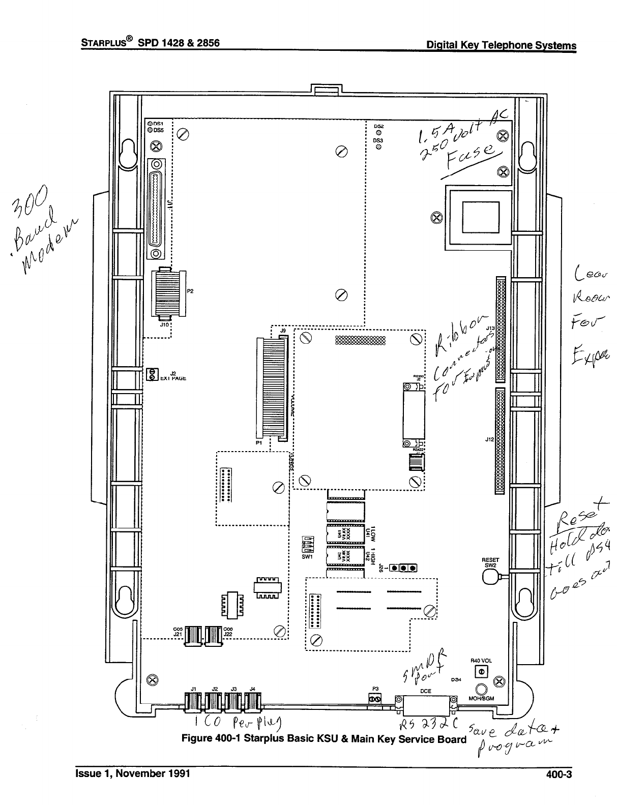
STARPLUS@
SPD 1428 & 2856 Digital Key Telephone Systems
Figure 400-l Starplus Basic KSU & Main Key Service Board
Issue 1, November 1991 400-3
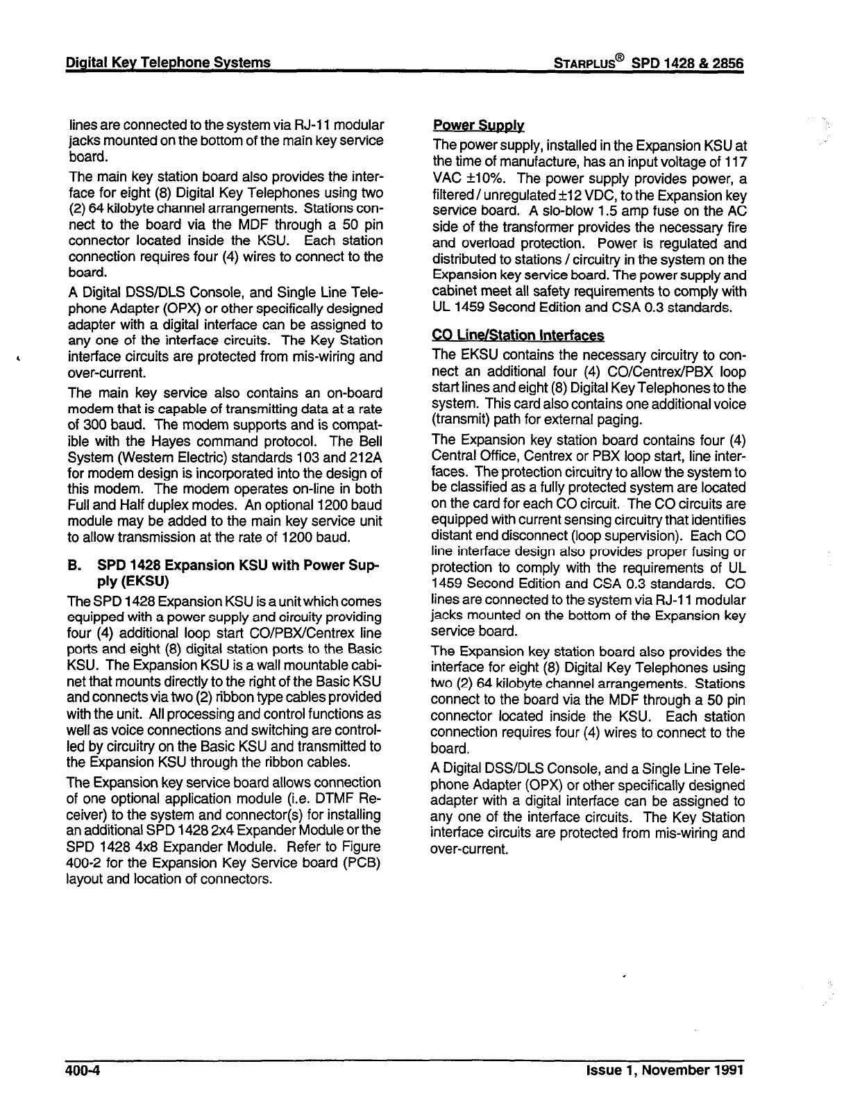
Digital Key Telephone Systems
STARPLUS@
SPD 1428 & 2856
lines are connected to the system via RJ-11 modular
jacks mounted on the bottom of the main key service
board.
The main key station board also provides the inter-
face for eight (8) Digital Key Telephones using two
(2) 64 kilobyte channel arrangements. Stations con-
nect to the board via the MDF through a 50 pin
connector located inside the KSU. Each station
connection requires four (4) wires to connect to the
board.
A Digital DSS/DLS Console, and Single Line Tele-
phone Adapter (OPX) or other specifically designed
adapter with a digital interface can be assigned to
any one of the interface circuits. The Key Station
interface circuits are protected from mis-wiring and
over-current.
The main key service also contains an on-board
modem that is capable of transmitting data at a rate
of 300 baud. The modem supports and is compat-
ible with the Hayes command protocol. The Bell
System (Western Electric) standards 103 and 212A
for modem design is incorporated into the design of
this modem. The modem operates on-line in both
Full and Half duplex modes. An optional 1200 baud
module may be added to the main key service unit
to allow transmission at the rate of 1200 baud.
B. SPD 1428 Expansion KSU with Power Sup
PRY (EKSU)
The SPD 1428 Expansion KSU is a unit which comes
equipped with a power supply and circuity providing
four (4) additional loop start CO/PBX/Centrex line
ports and eight (8) digital station ports to the Basic
KSU. The Expansion KSU is a wall mountable cabi-
net that mounts directly to the right of the Basic KSU
and connects via two (2) ribbon type cables provided
with the unit. All processing and control functions as
well as voice connections and switching are control-
led by circuitry on the Basic KSU and transmitted to
the Expansion KSU through the ribbon cables.
The Expansion key service board allows connection
of one optional application module (i.e. DTMF Re-
ceiver) to the system and connector(s) for installing
an additional SPD 1428 2x4 Expander Module or the
SPD 1428 4x8 Expander Module. Refer to Figure
400-2 for the Expansion Key Service board (PCB)
layout and location of connectors.
Power SUDS&
The power supply, installed in the Expansion KSU at
the time of manufacture, has an input voltage of 117
VAC flO%. The power supply provides power, a
filtered / unregulated +12 VDC, to the Expansion key
service board. A slo-blow 1.5 amp fuse on the AC
side of the transformer provides the necessary fire
and overload protection. Power is regulated and
distributed to stations /circuitry in the system on the
Expansion key service board. The power supply and
cabinet meet all safety requirements to comply with
UL 1459 Second Edition and CSA 0.3 standards.
CO Line/Station Interfaces
The EKSU contains the necessary circuitry to con-
nect an additional four (4) COICentrexlPBX loop
start lines and eight (8) Digital Key Telephones to the
system. This card also contains one additional voice
(transmit) path for external paging.
The Expansion key station board contains four (4)
Central Office, Centrex or PBX loop start, line inter-
faces. The protection circuitry to allow the system to
be classified as a fully protected system are located
on the card for each CO circuit. The CO circuits are
equipped with current sensing circuitry that identifies
distant end disconnect (loop supervision). Each CO
line interface design also provides proper fusing or
protection to comply with the requirements of UL
1459 Second Edition and CSA 0.3 standards. CO
lines are connected to the system via RJ-11 modular
jacks mounted on the bottom of the Expansion key
service board.
The Expansion key station board also provides the
interface for eight (8) Digital Key Telephones using
two (2) 64 kilobyte channel arrangements. Stations
connect to the board via the MDF through a 50 pin
connector located inside the KSU. Each station
connection requires four (4) wires to connect to the
board.
A Digital DSS/DLS Console, and a Single Line Tele-
phone Adapter (OPX) or other specifically designed
adapter with a digital interface can be assigned to
any one of the interface circuits. The Key Station
interface circuits are protected from mis-wiring and
over-current.
406-4 Issue 1, November 1991
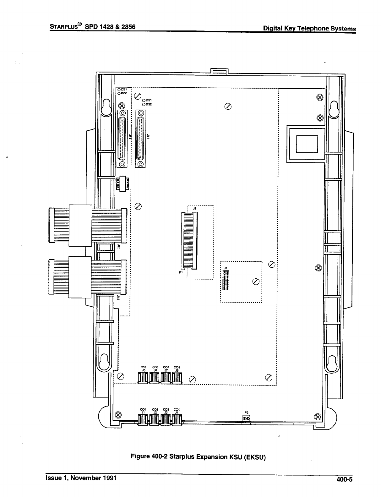
STARPLUS@ SPD 1428 & 2856 Digital Key Telephone Systems
,--------
’ 23
__
0
Figure 400-2 Starplus Expansion KSU (EKSU)
Issue 1, November 1991 400-S
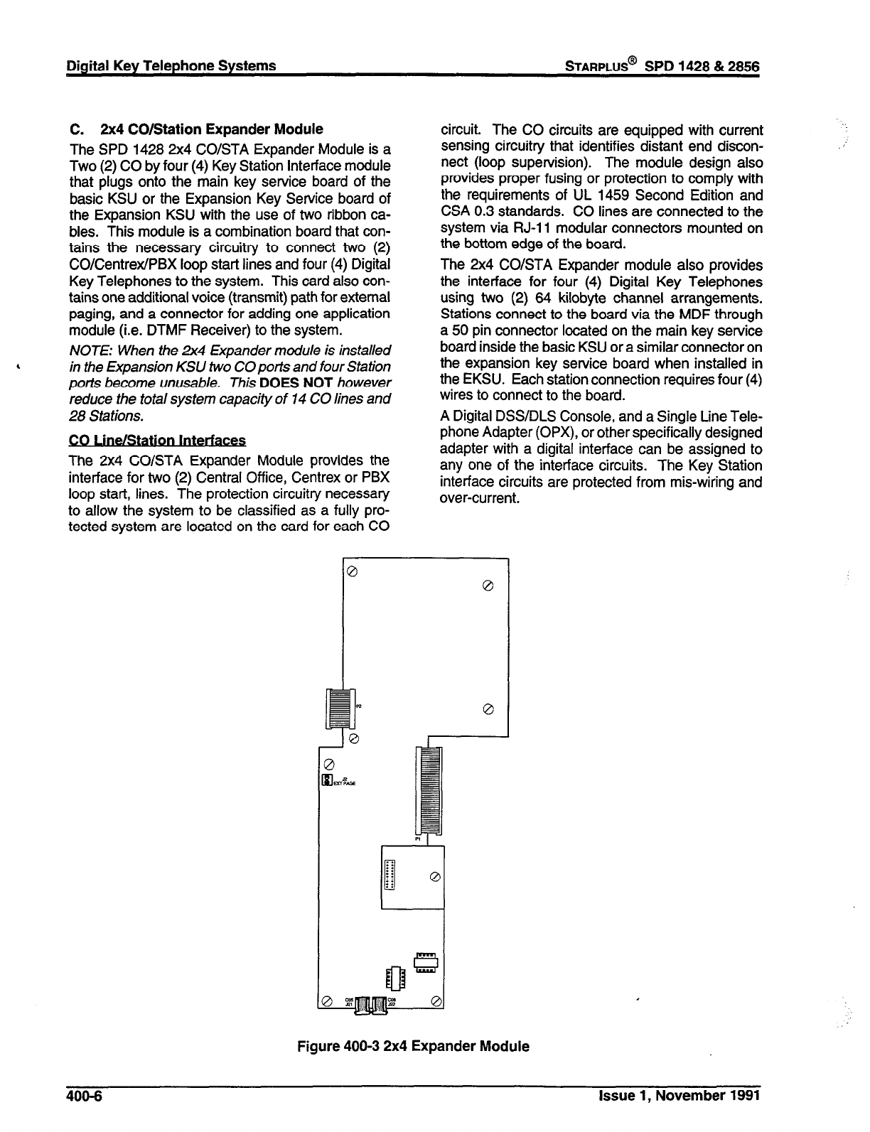
C. 2x4 CO/Station Expander Module
The SPD 1428 2x4 CO/STA Expander Module is a
Two (2) CO by four (4) Key Station interface module
that plugs onto the main key service board of the
basic KSU or the Expansion Key Service board of
the Expansion KSU with the use of two ribbon ca-
bles. This module is a combination board that con-
tains the necessary circuitry to connect two (2)
CO/Centrex/PBX loop start lines and four (4) Digital
Key Telephones to the system. This card also con-
tains one additional voice (transmit) path for external
paging, and a connector for adding one application
module (i.e. DTMF Receiver) to the system.
NOTE: When the 2x4 Expander module is installed
, in the Expansion KSU two CO ports and four Station
ports become unusable. This DOES NOT however
reduce the total system capacity of 14 CO lines and
28 Stations.
The 2x4 CO/STA Expander Module provides the
interface for two (2) Central Office, Centrex or PBX
loop start, lines. The protection circuitry necessary
to allow the system to be classified as a fully pro-
tected system are located on the card for each CO
Digital Key Telephone Systems
STARPLUS@
SPD 1428 & 2856
circuit. The CO circuits are equipped with current
sensing circuitry that identifies distant end discon-
nect (loop supervision). The module design also
provides proper fusing or protection to comply with
the requirements of UL 1459 Second Edition and
CSA 0.3 standards. CO lines are connected to the
system via RJ-11 modular connectors mounted on
the bottom edge of the board.
The 2x4 CO/STA Expander module also provides
the interface for four (4) Digital Key Telephones
using two (2) 84 kilobyte channel arrangements.
Stations connect to the board via the MDF through
a 50 pin connector located on the main key service
board inside the basic KSU or a similar connector on
the expansion key service board when installed in
the EKSU. Each station connection requires four (4)
wires to connect to the board.
A Digital DSS/DLS Console, and a Single Line Tele-
phone Adapter (OPX), or other specifically designed
adapter with a digital interface can be assigned to
any one of the interface circuits. The Key Station
interface circuits are protected from mis-wiring and
over-current.
Figure 400-3 2x4 Expander Module
400-6 Issue 1, November 1991
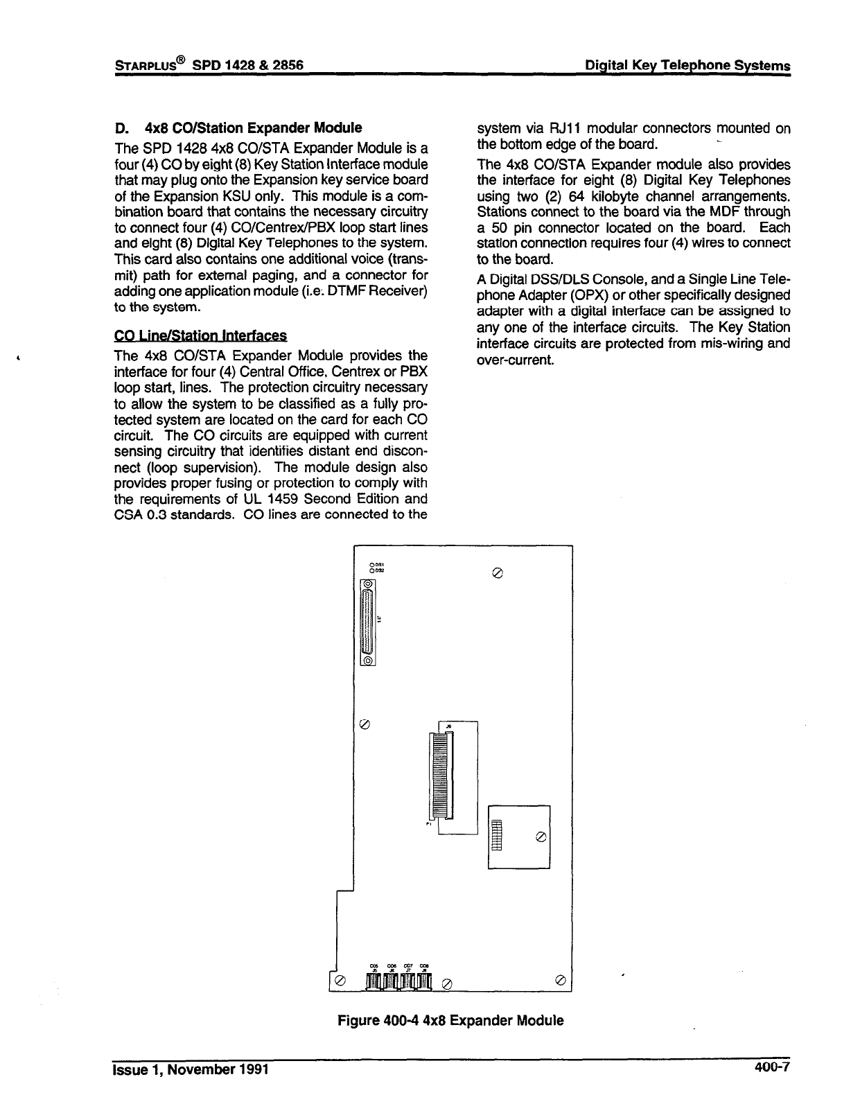
sTARPLUS@
SPD 1428 & 2856 Digital Key Telephone Systems
D. 4x8 CO/Station Expander Module
The SPD 1428 4x8 CO/STA Expander Module is a
four (4) CO by eight (8) Key Station Interface module
that may plug onto the Expansion key service board
of the Expansion KSU only. This module is a com-
bination board that contains the necessary circuitry
to connect four (4) CO/Centrex/PBX loop start lines
and eight (8) Digital Key Telephones to the system.
This card also contains one additional voice (trans-
mit) path for external paging, and a connector for
adding one application module (i.e: DTMF Receiver)
to the system.
The 4x8 COISTA Expander Module provides the
interface for four (4) Central Office, Centrex or PBX
loop start, lines. The protection circuitry necessary
to allow the system to
be
classified as a fully pro-
tected system are located on the card for each CO
circuit. The CO circuits are equipped with current
sensing circuitry that identifies distant end discon-
nect (loop supervision). The module design also
provides proper fusing or protection to comply with
the requirements of UL 1459 Second Edition and
CSA 0.3 standards. CO lines are connected to the
system via RJll modular connectors mounted on
the bottom edge of the board.
The 4x8 CO/STA Expander module also provides
the interface for eight (8) Digital Key Telephones
using two (2) 84 kilobyte channel arrangements.
Stations connect to the board via the MDF through
a 50 pin connector located on the
board.
Each
station connection requires four (4) wires to connect
to the board.
A Digital DSS/DLS Console, and a Single Line Tele-
phone Adapter (OPX) or other specifically designed
adapter with a digital interface can be assigned to
any one of the interface circuits. The Key Station
interface circuits are protected from mis-wiring and
over-current.
1
0
0
0
cg cg3 cLL7 m
Figure 400-4 4x8 Expander Module
Issue 1, November 1991
400-7

400.3 SPD 2856 SYSTEM COMPONENTS
The following components are necessary to operate
the SPD 2856 Digital Key Telephone System: (Refer
to Appendix B for a complete Starplus Digital (SPD)
Key Telephone System component list with Part #‘s)
. Equipment Cabinet w/Power Supply (KSU)
. Central Processing Board (CPB)
. 4x8 CO/Digital Interface Board (CKB)
0 4x8 CO/SLT Interface Board (CSB) (Future)
A. Equipment Cabinet With Power Supply
WW
The SPD 2856 system main cabinet contains the
power supply and mother board to support a fully
configured system of 28 CO Lines and 56 Stations.
The mother board has eight (8) card slots. Card Slot
J8 (the right most card slot) is used for the Central
Processor Board (CPB) PCB. Card slots Jl through
J7 each support a four (4) CO line by eight (8) station
PCB’s. Cable exits through the bottom of the KSU
through a cable exit raceway near the back of the
KSU. Refer to Figure 400-5 for printed circuit board
layout and location of connectors.
Power SUJS&
The power supply is installed in the KSU at the time
of manufacture and ships with the KSU. The power
supply input voltage is
117 VAC +l 0%. The power
supply provides power distribution of filtered / un-
regulated 12 VDC and a regulated -5 VDC to the
backplane bus. An ON/OFF switch is located on the
front of the power supply along with a slo-blow 5 amp
fuse on the AC side of the transformer. The power
supply provides an input for a 48 VDC source for
future use. Power is regulated and distributed to
stations/circuitry in the system on each PCB. Three
fuses located inside the power supply protect the
system from over-current situations. The power
supply and cabinet meet all safety requirements to
comply with UL 1459 Second Edition and CSA 0.3
standards.
B. Central Processor Board (CPB)
This plug-in card is the only common equipment card
required to make the system operational and con-
trols all system activity. The CPB contains the main
micro-processor a 16-bit (68000) and a real time
clock which controls all system functions including
the PCM/TDM voice switching under direction of
ROM and RAM software coding. The CPB is re-
sponsible for all control functions, execution of all
logic operations and control of system modules in-
cluding control over circuitry necessary for voice
switching and conference connections. The CPB is
also responsible for all system tones, system timing,
and station status control. In addition the CPB also
400-8
Issue
1,
November 1991
provides software and hardware support to ensure
the following:
l
Watch dog timer and recovery.
l
PCB status as to presence/absence of cards
for automatic software configuration setup.
l
Interpret an ID code from each PCB so that
card type can be determined automatically.
l
State/event software design.
l
Battery backup of customer database RAM
memory.
The CPB contains the circuitry and connection (RCA
type) for background music/music on hold, and the
standard 300 Baud Modem. An optional 1200 Baud
Modem can be installed on the CPB to allow the
on-board modem to transmit at a 1200 baud rate. In
addition there is one RS-232 (modular connector)
input/output port on the CPB and a connector to
support the use of an optional l/O expansion module.
The I/O expansion module adds (1) RS-232 I/O port
and (1) RS-422 I/O port to the system for a system
total of three (3) I/O ports. A reset (halt) push button
switch and a BGM/MOH volume control pot is lo-
cated on the front of the PCB. Refer to Figure 400-6
for the location of the Central Processing Board
connectors.
System software is provided in EPROM memory and
is installed on the CPB. The CPB contains (512)
kilobytes of EPROM storage and is equipped with
256K of battery-backed static RAM. Provisions
have been made on the card to address up to (4)
megabytes of EPROM memory and up to (2) mega-
bytes of static RAM.
Modem Interface
The CPB contains an on-board modem that is capa-
ble of transmitting data at a rate of 300 baud. The
modem supports and is compatible with the Hayes
command protocol. The Bell System (Western Elec-
tric) standards 103 and 212A for modem design is
incorporated into the design of this modem. The
modem operates on-line in both Full and Half duplex
modes. An optional 1200 baud module may be
added to the CPB to allow transmission at the rate
of 1200 baud.
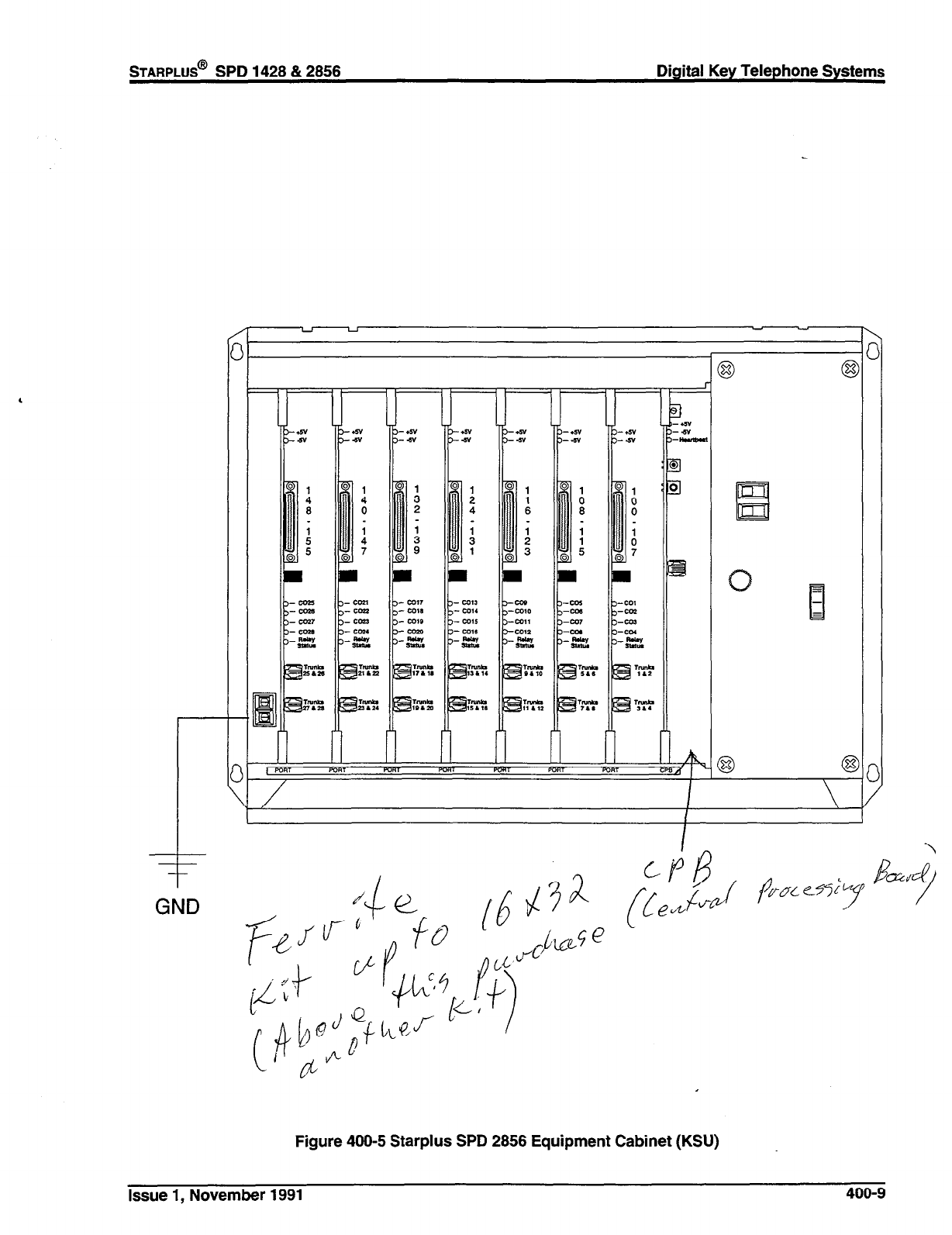
STARPLUS@ SPD 1428 & 2858 Digital Key Telephone Systems
GND
El
3
B
-
Figure 400-5 Starplus SPD 2856 Equipment Cabinet (KSU)
Issue 1, November 1991 400-9
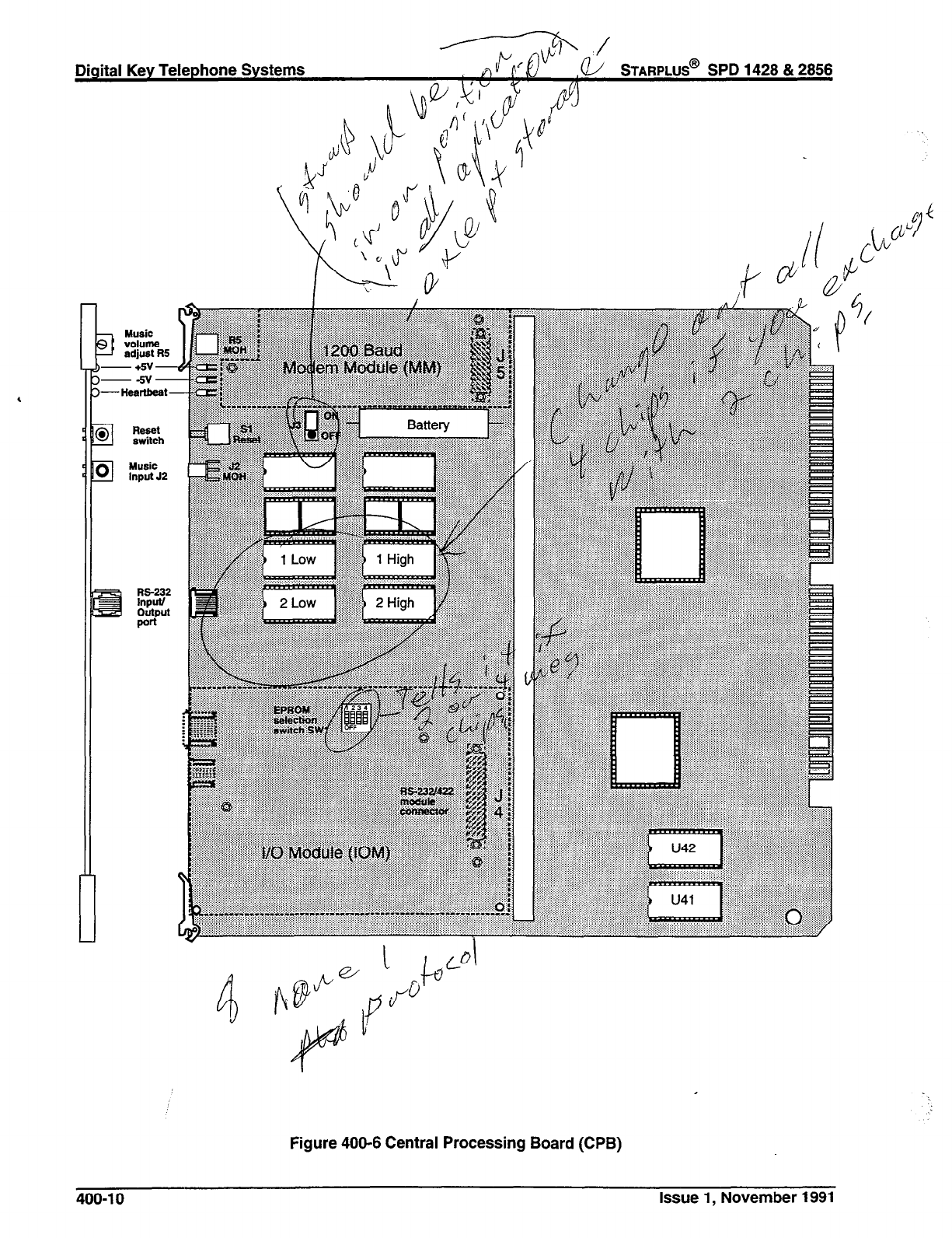
Digital Key Telephone Systems
TARPLUS@
SPD 1428 & 2856
Figure 400-6 Central Processing Board (CPB)
400-l 0 Issue 1, November 1991
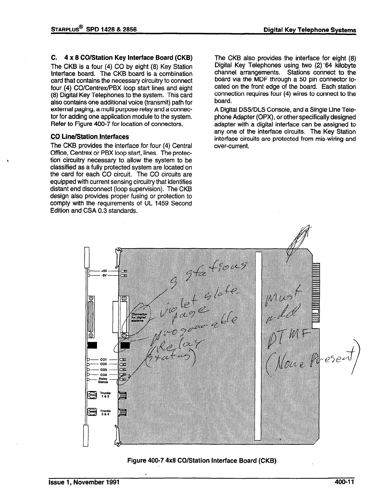
STARPLUS@
SPD 1428 & 2856 Digital Key Telephone Systems
C. 4 x 8 CO/Station Key Interface Board (CKB)
The CKB is a four (4) CO by eight (8) Key Station
interface board. The CKB board is a combination
card that contains the necessary circuitry to connect
four (4) CO/Centrex/PBX loop start lines and eight
(8) Digital Key Telephones to the system. This card
also contains one additional voice (transmit) path for
external paging, a multi purpose relay and a connec-
tor for adding one application module to the system.
Refer to Figure 400-7 for location of connectors.
CO Line/Station Interfaces
The CKB provides the interface for four (4) Central
Office, Centrex or PBX loop start, lines. The protec-
tion circuitry necessary to allow the system to be
classified as a fully protected system are located on
the card for each CO circuit. The CO circuits are
equipped with current sensing circuitry that identifies
distant end disconnect (loop supervision). The CKB
design also provides proper fusing or protection to
comply with the requirements of UL 1459 Second
Edition and CSA 0.3 standards.
The CKB also provides the interface for eight (8)
Digital Key Telephones using two (2) -64 kilobyte
channel arrangements. Stations connect to the
board via the MDF through a 50 pin connector lo-
cated on the front edge of the board. Each station
connection requires four (4) wires to connect to the
board.
A Digital DSS/DLS Console, and a Single Line Tele-
phone Adapter (OPX), or other specifically designed
adapter with a digital interface can be assigned to
any one of the interface circuits. The Key Station
interface circuits are protected from mis-wiring and
over-current.
Figure 400-7 4x8 CO/Station Interface Board (CKB)
Issue 1, November 1991
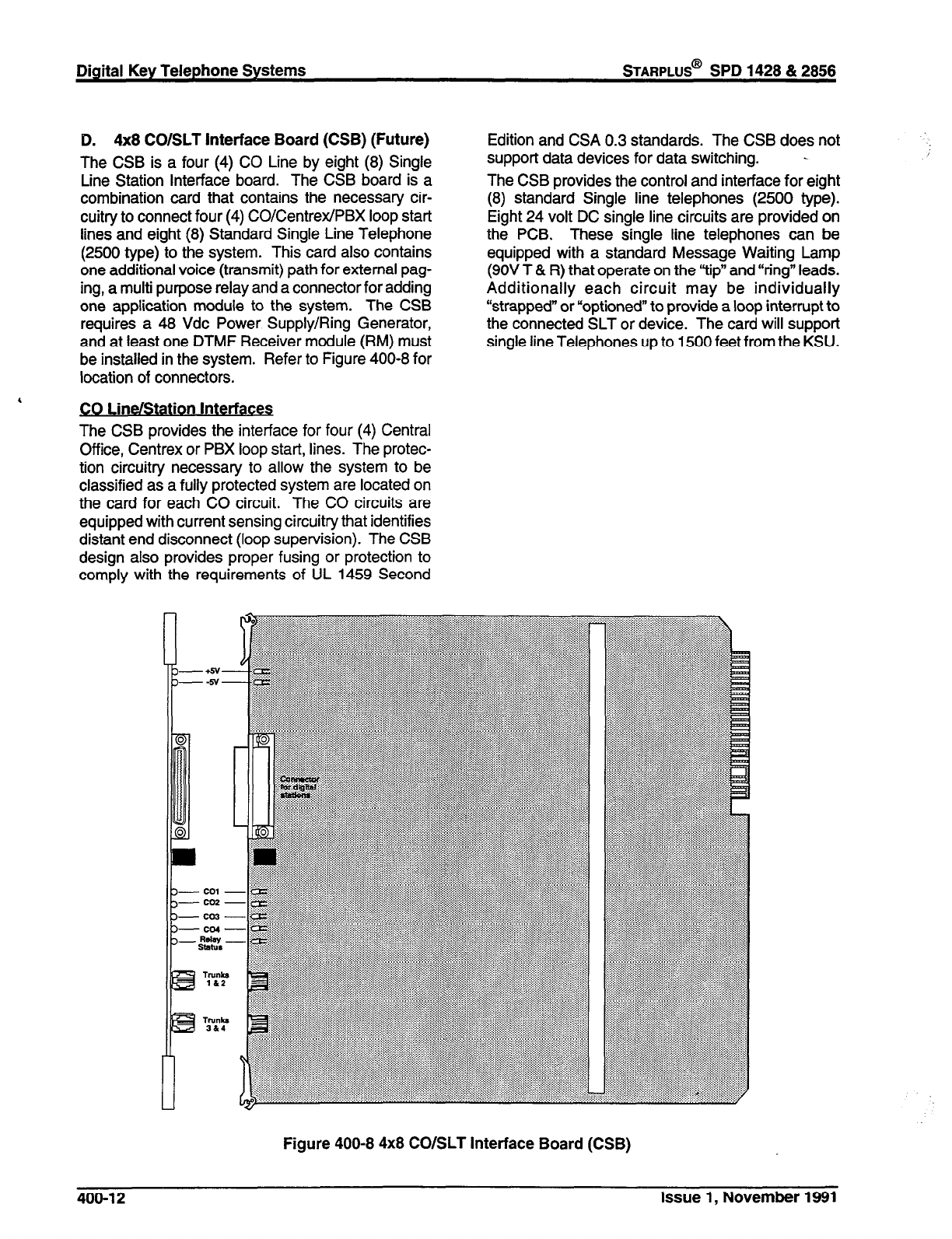
Digital Key Telephone Systems
STARPLUS@
SPD 1428 & 2856
D. 4x8 CO/SLT Interface Board (CSB) (Future)
The CSB is a four (4) CO Line by eight (8) Single
Line Station Interface board. The CSB board is a
combination card that contains the necessary cir-
cuitry to connect four (4) CO/Centrex/PBX loop start
lines and eight (8) Standard Single Line Telephone
(2500 type) to the system. This card also contains
one additional voice (transmit) path for external pag-
ing, a multi purpose relay and a connector for adding
one application module to the system. The CSB
requires a 48 Vdc Power Supply/Ring Generator,
and at least one DTMF Receiver module (RM) must
be installed in the system. Refer to Figure 400-8 for
location of connectors.
4
CO Line/Station Interfaces
The CSB provides the interface for four (4) Central
Office, Centrex or PBX loop start, lines. The protec-
tion circuitry necessary to allow the system to be
classified as a fully protected system are located on
the card for each CO circuit. The CO circuits are
equipped with current sensing circuitry that identifies
distant end disconnect (loop supervision). The CSB
design also provides proper fusing or protection to
comply with the requirements of UL 1459 Second
Edition and CSA 0.3 standards. The CSB does not
support data devices for data switching. -
The CSB provides the control and interface for eight
(8) standard Single line telephones (2500 type).
Eight 24 volt DC single line circuits are provided on
the PCB. These single line telephones can be
equipped with a standard Message Waiting Lamp
(9OV T & R) that operate on the “tip” and “ring” leads.
Additionally each circuit may be individually
“strapped” or “optioned” to provide a loop interrupt to
the connected SLT or device. The card will support
single line Telephones up to 1500 feet from the KSU.
Figure 400-8 4x8 CO/SLT Interface Board (CSB)
400-f 2 Issue 1, November 1991
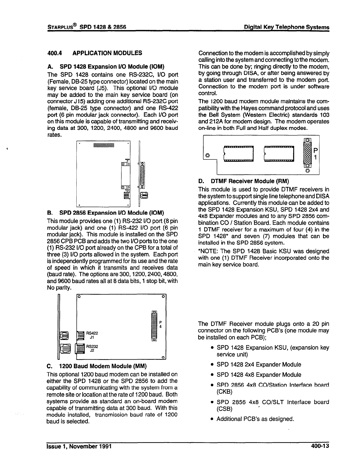
400.4 APPLICATION MODULES
A. SPD 1428 Expansion l/O Module (IOM)
The SPD 1428 contains one RS-232C, I/O port
(Female, DB-25 type connector) located on the main
key service board (J5). This optional i/O module
may be added to the main key service board (on
connector Ji 5) adding one additional RS-232C port
(female, DB-25 type connector) and one RS-422
port (6 pin modular jack connector). Each I/O port
on this module is capable of transmitting and receiv-
ing data at 300, 1200, 2400, 4800 and 9600 baud
rates.
. .
I u
B. SPD 2866 Expansion l/O Module (IOM)
This module provides one (1) RS-232 I/O port (8 pin
modular jack) and one (1) RS-422 I/O port (6 pin
modular jack). This module is installed on the SPD
2856 CPB PCB and adds the two I/O ports to the one
(1) RS-232 l/O port already on the CPB for a total of
three (3) I/O ports allowed in the system. Each port
is independently programmed for its use and the rate
of speed in which it transmits and receives data
(baud rate). The options are 300,1200,2400,4800,
and 9600 baud rates all at 8 data bits, 1 stop bit, with
No parity.
0
C. 1200 Baud Modem Module (MM)
This optional 1200 baud modem can be installed on
either the SPD 1428 or the SPD 2856 to add the
capability of communicating with the system from a
remote site or location at the rate of 1200 baud. Both
systems provide as standard an on-board modem
capable of transmitting data at 300 baud. With this
module installed, transmission baud rate of 1200
baud is selected.
Connection to the modem is accomplished by simply
calling into the system and connecting to-the modem.
This can be done by; ringing directly to the modem,
by going through DISA, or after being answered by
a station user and transferred to the modem port.
Connection to the modem port is under software
control.
The 1200 baud modem module maintains the com-
patibility with the Hayes command protocol and uses
the Bell System (Western Electric) standards 103
and 212A for modem design. The modem operates
on-line in both Full and Half duplex modes.
i
P
0 1
L 4
D. DTMF Receiver Module (RM)
This module is used to provide DTMF receivers in
the system to support single line telephone and DISA
applications. Currently this module can be added to
the SPD 1428 Expansion KSU, SPD 1428 2x4 and
4x8 Expander modules and to any SPD 2856 com-
bination CO / Station Board. Each module contains
1 DTMF receiver for a maximum of four (4) in the
SPD 1428’ and seven (7) modules that can be
installed in the SPD 2856 system.
*NOTE: The SPD 1428 Basic KSU was designed
with one (1) DTMF Receiver incorporated onto the
main key service board.
The DTMF Receiver module plugs onto a 20 pin
connector on the following PCB’s (one module may
be installed on each PCB);
l
SPD 1428 Expansion KSU, (expansion key
service unit)
l
SPD 1428 2x4 Expander Module
l
SPD 1428 4x8 Expander Module
l
SPD 2856 4x8 CO/Station Interface board
(CKB)
l
SPD 2856 4x8 CO/SLT Interface board
(CSB) ’
l
Additional PCB’s as designed.
Issue 1, November 1991 400-l 3
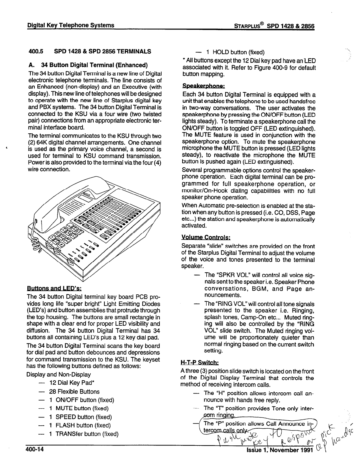
Digital Key Telephone Systems
sTARPLUS@
SPD 1428 & 2856
400.5
SPD 1428 & SPD 2856 TERMINALS
A. 34 Button Digital Terminal (Enhanced)
The 34 button Digital Terminal is a new line of Digital
electronic telephone terminals. The line consists of
an Enhanced (non-display) and an Executive (with
display). This new line of telephones will be designed
to operate with the new line of Starplus digital key
and PBX systems. The 34 button Digital Terminal is
connected to the KSU via a four wire (two twisted
pair) connections from an appropriate electronic ter-
minal interface board.
The terminal communicates to the KSU through two
(2) 64K digital channel arrangements. One channel
is used as the primary voice channel, a second is
used for terminal to KSU command transmission.
Power is also provided to the terminal via the four (4)
wire connection.
The 34 button Digital terminal key board PCB pro-
vides long life “super bright” Light Emitting Diodes
(LED’s) and button assemblies that protrude through
the top housing. The buttons are small rectangle in
shape with a clear end for proper LED visibility and
diffusion. The 34 button Digital Terminal has 34
buttons all containing LED’s plus a 12 key dial pad.
The 34 button Digital Terminal scans the key board
for dial pad and button debounces and depressions
for command transmission to the KSU. The keyset
has the following buttons defined as follows:
Display and Non-Display
- 12 Dial Key Pad*
- 28 Flexible Buttons
- 1 ON/OFF button
(fixed)
- 1 MUTE button
(fixed)
- 1 SPEED button
(fixed)
- 1 FLASH button
(fixed)
- 1 TRANSfer button
(fixed)
- 1 HOLD button (fixed)
l
All buttons except the 12 Dial key pad have an LED
associated with it. Refer to Figure 400-9 for default
button mapping.
Each 34 button Digital Terminal is equipped with a
unit that enables the telephone to be used handsfree
in two-way conversations. The user activates the
speakerphone by pressing the ON/OFF button (LED
lights steady). To terminate a speakerphone call the
ON/OFF button is toggled OFF (LED extinguished).
The MUTE feature is used in conjunction with the
speakerphone option. To mute.the speakerphone
microphone the MUTE button is pressed (LED lights
steady), to reactivate the microphone the MUTE
button is pushed again (LED extinguished).
Several programmable options control the speaker-
phone operation. Each digital terminal can be pro-
grammed for full speakerphone operation, or
monitor/On-Hook dialing capabilities with no full
speaker phone operation.
When Automatic pre-selection is enabled at the sta-
tion when any button is pressed (i.e. CO, DSS, Page
etc...) the station and speakerphone is automatically
activated.
Separate “slide” switches are provided on the front
of the Starplus Digital Terminal to adjust the volume
of the voice and tones presented to the terminal
speaker.
- The “SPKR VOL” will control all voice sig-
nals sent to the speaker i.e. Speaker Phone
conversations, BGM, and Page an-
nouncements.
- The “RING VOL” will control all tone signals
presented to the speaker i.e. Ringing,
splash tones, Camp-On etc... Muted ring-
ing will also be controlled by the “RING
VOL” slide switch. The Muted ringing vol-
ume will be proportionately quieter than
normal tinging based on the current switch
setting.
H-T-P Switch:
A three (3) position slide switch is located on the front
of the Digital Display Terminal that controls the
method of receiving intercom calls.
- The “H” position allows intercom call an-
nounce with hands free reply.
- The ‘T’ position provides Tone only inter-
ringina. -
- The ‘P” position allows Call Announ
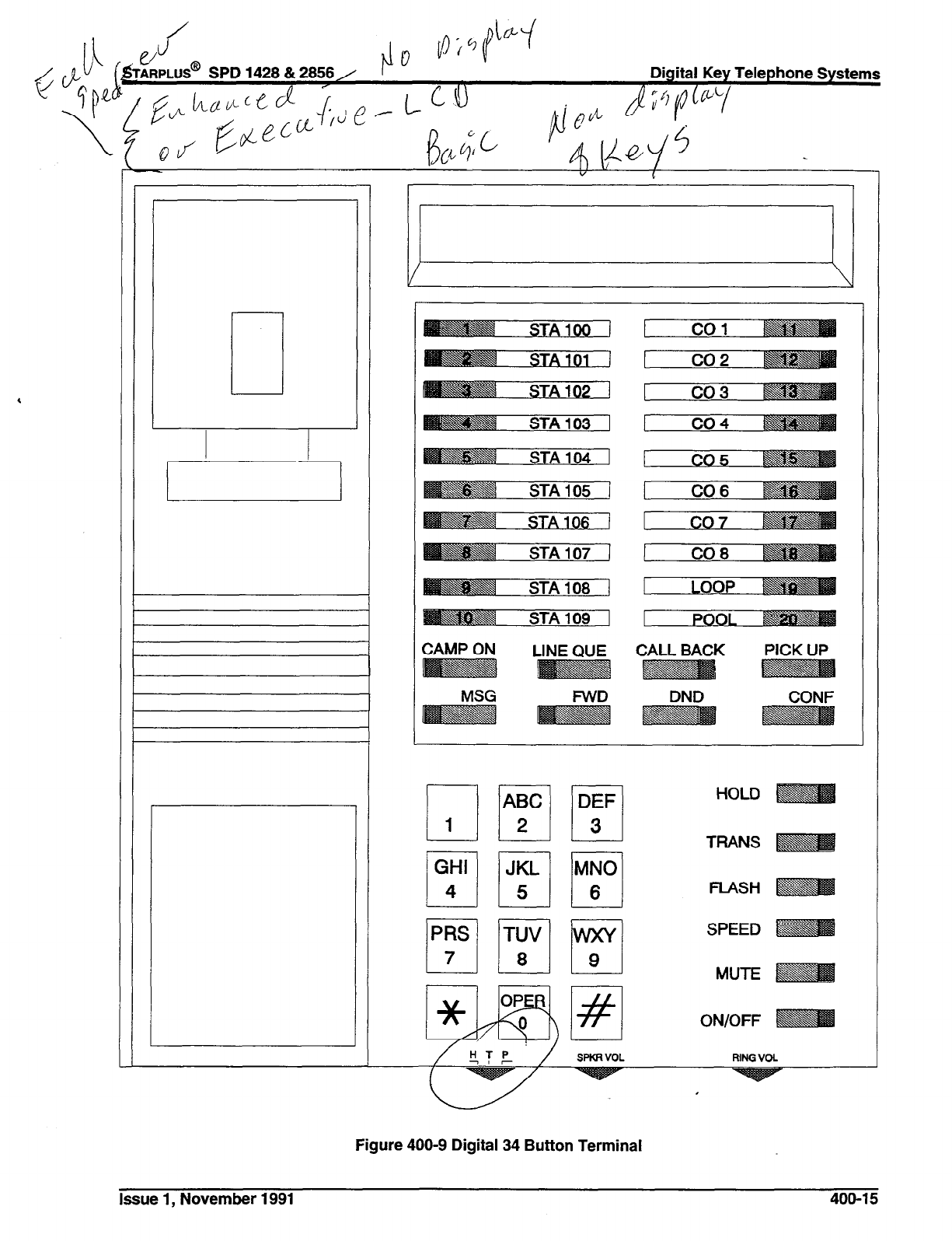
SPD 1428 & 2856/
CALL BACK
MSG
FWD
Figure 400-9 Digital 34 Button Terminal
Issue 1, November 1991 400-l 5
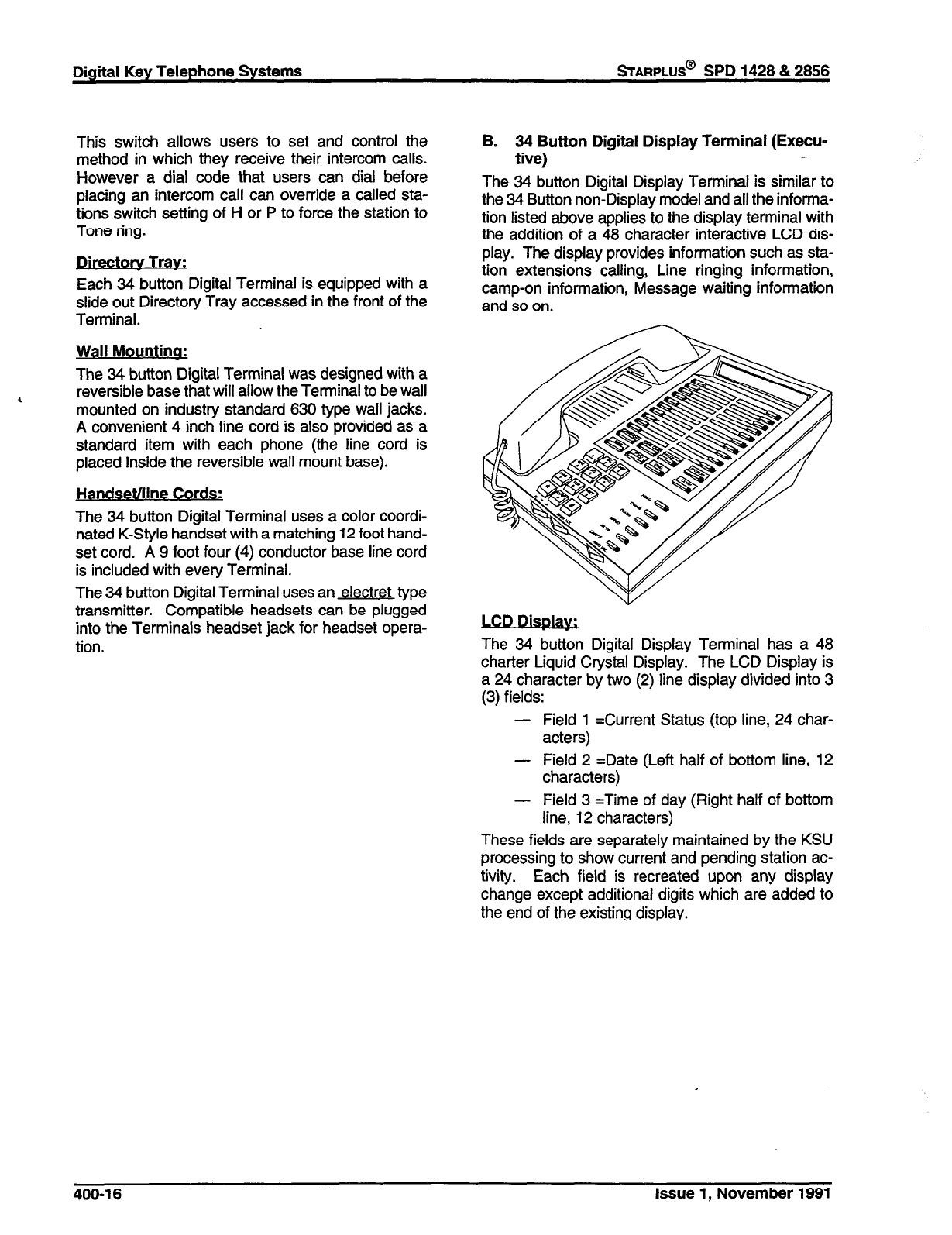
Digital Key Telephone Systems
STARPLUS@
SPD 1428 & 2856
This switch allows users to set and control the
method in which they receive their intercom calls.
However a dial code that users can dial before
placing an intercom call can override a called sta-
tions switch setting of H or P to force the station to
Tone ring.
.
Directorv Tray,
Each 34 button Digital Terminal is equipped with a
slide out Directory Tray accessed in the front of the
Terminal.
Wall Mountina:
The 34 button Digital Terminal was designed with a
6 reversible base that will allow the Terminal to be wall
mounted on industry standard 630 type wall jacks.
A convenient 4 inch line cord is also provided as a
standard item with each phone (the line cord is
placed inside the reversible wall mount base).
Handsetnine Cords:
The 34 button Digital Terminal uses a color coordi-
nated K-Style handset with a matching 12 foot hand-
set cord. A 9 foot four (4) conductor base line cord
is included with every Terminal.
The 34 button Digital Terminal uses an electret type
transmitter. Compatible headsets can be plugged
into the Terminals headset jack for headset opera-
tion.
B. 34 Button Digital Display Terminal (Execu-
tive)
The 34 button Digital Display Terminal is similar to
the 34 Button non-Display model and all the informa-
tion listed above applies to the display terminal with
the addition of a 48 character interactive LCD dis-
play. The display provides information such as sta-
tion extensions calling, Line ringing information,
camp-on information, Message waiting information
and so on.
.
LCn D-ki.p&a
The 34 button Digital Display Terminal has a 48
charter Liquid Crystal Display. The LCD Display is
a 24 character by two (2) line display divided into 3
(3) fields:
- Field 1 =Current Status (top line, 24 char-
acters)
- Field 2 =Date (Left half of bottom line, 12
characters)
- Field 3 =Time of day (Right half of bottom
line, 12 characters)
These fields are separately maintained by the KSU
processing to show current and pending station ac-
tivity. Each field is recreated upon any display
change except additional digits which are added to
the end of the existing display.
400-l 6 Issue 1, November 1991
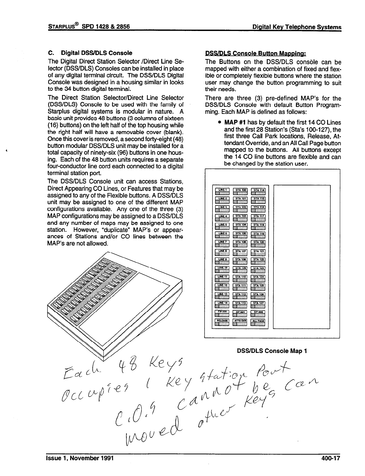
STARPLUS@
SPD 1428 & 2856 Digital Key Telephone Systems
C. Digital DSS/DLS Console
The Digital Direct Station Selector /Direct Line Se-
lector (DSS/DLS) Consoles can be installed in place
of any digital terminal circuit. The DSWDLS Digital
Console was designed in a housing similar in looks
to the 34 button digital terminal.
The Direct Station Selector/Direct Line Selector
(DSWDLS) Console to be used with the family of
Starplus digital systems is modular in nature. A
basic unit provides 48 buttons (3 columns of sixteen
(16) buttons) on the.left half of the top housing while
the right half will have a removable cover (blank).
Once this cover is removed, a second forty-eight (48)
button modular DSS/DLS unit may be installed for a
total capacity of ninety-six (96) buttons in one hous-
ing. Each of the 48 button units requires a separate
four-conductor line cord each connected to a digital
terminal station port.
The DSS/DLS Console unit can access Stations,
Direct Appearing CO Lines, or Features that may be
assigned to any of the Flexible buttons. A DSS/DLS
unit may be assigned to one of the different MAP
configurations available. Any one of the three (3)
MAP configurations may be assigned to a DSS/DLS
and any number of maps may be assigned to one
station. However, “duplicate” MAP’s or appear-
ances of Stations and/or CO lines between the
MAP’s are not allowed.
DSSiDLS Console Button Mappina:
The Buttons on the DSWDLS console can be
mapped with either a combination of fixed and flex-
ible or completely flexible buttons where the station
user may change the button programming to suit
their needs.
There are three (3) pre-defined MAP’s for the
DSWDLS Console with default Button Program-
ming. Each MAP is defined as follows:
l
MAP #l has by default the first 14 CO Lines
and the first 28 Station’s (Sta’s lOO-127), the
first three Call Park locations, Release, At-
tendant Override, and an All Call Page button
mapped to the buttons. All buttons except
the 14 CO line buttons are flexible and can
be changed by the station user.
DSS/DLS Console Map 1
Issue 1, November 1991

l
MAP
##2 has by default all 28 CO lines the
first 14 Stations (Sta’s 100-l 13) the first
three Call Park locations, Release, Attendant
Override, and an All Call Page button
mapped to the buttons. All buttons except
the 28 CO line buttons are flexible and can
be changed by the station user.
l
MAP
#3 by default is intended to be used with
MAP # 2 on an SPD 2856, in that it has the
remaining stations (Sta’s 114-l 55) to provide
a full CO tine by Station mapping. Addition-
ally, Call Park locations 223-225 along with
Internal Page Ports 1,2, and 3 appear. All of
the buttons on MAP #3 are flexible and can
be changed by the user.
DSS/DLS Console Maps 2 & 3
Wall Mountincl;
The DSS/DLS Console was designed with a revers-
ible base that will allow the Terminal to be wall
mounted on industry standard 630 type wall jacks.
A convenient 4 inch line cord is also provided as a
standard item with each DSS/DLS Console (the line
cord is placed inside the reversible wall mount base).
Expansion Module:
The DSS/DLS console allows one DSS/DLS expan-
sion module to be installed into the right half of the
basic unit. The expansion unit provides an addi-
tional 48 buttons with LED’s for a total of 96 buttons
and LED’s in one base housing.
The Expansion Modules may also be assigned as
any one of the three (3) pre-defined MAPS.
400.6
SLT ADAPTER / OFF-PREMISE EX-
TENSION MODULE
This external module provides the interface for one
long loop (OPX) single line telephone (2500 type)
extension. This module requires a separately pro-
vided -48 VDC power supply to provide the neces-
sary current for long loop applications and to support
ring generation. This module is wired to and inter-
faces with a digital terminal (key station) port from
either the SPD 1428 or SPD 2856 systems. The OPX
card meets the requirements of the FCC for connec-
tion to the telephone (Telco) network. Telephones
connected to the OPX must be DTMF only (2500
type).
This module also provides for one Power Fail circuit
in the event of an AC power failure.
400.7
RELAY/SENSOR INTERFACE MOD-
ULE
The Relay Sensor Interface Module connects to
either the SPD 1428 or SPD 2856 systems using one
digital station port and provides three relay activated
contacts and three sensing circuits. The relays pro-
vide for applications such as Loud Bell Control con-
tacts, CO Line control contacts, RAN Start contacts,
Page Relays, Power Fail contact and additional ap-
plications as software will permit. The sensing cir-
cuits provide for such applications as RAN Stop (end
of message) and other applications as developed
and allowed by software.
An external power source is required to drive equip-
ment connected to the relay contacts. The contacts
are rated at 24Vdc max at 1 amp.
400.8
POWER FAILURE TRANSFER UNIT
(PFTU)
This unit provides the relay transfer circuits for up to
12 CO lines in the event of a power or processor
failure. The unit is housed in its own enclosure and
mounts external to the KSU. Activation of the PFT
relays is controlled by a multi-use relay on any one
of the CO / Station Interface boards that is pro-
grammed for PFT. A customer provided 12 volt DC
power supply is required to operate the unit. There
is a manual switch that activates the PFTU for testing
purposes.
With loss of power to the system or a failure of
system processing, the PFTU will automatically con-
nect up to twelve CO lines to pre’wired 500/2500 type
telephones. When power is restored, the PFTU will
automatically restore the CO trunks and stations to
400-l 8 Issue 1, November 1991
STARPLUS@
SPD 1428 & 2856 Digital Key Telephone Systems
normal operation. These SLT stations do not have
to be used for intercom, but can be if so desired.
400.9 SYSTEM SPECIFICATIONS AND CA-
PACITY
The SPD 1428 Basic KSU is housed in a wall-mount-
able cabinet that contains the system power supply
and the motherboard for stations and CO lines. This
Basic KSU supports a loaded capacity of 6 CO lines
and 12 stations. DSS/DLS’s can be installed in place
of any Digital Key terminal. Standard single line
telephones (2500 type) can be installed by using
Single Line Telephone Adapters (OPX) boxes.
The SPD 2856 Basic KSU is housed in a wall-mount-
able cabinet that contains the system power supply
and the backplane for station and CO line boards.
This Basic KSU supports a loaded capacity of 28 CO
lines and 56 stations. DSWDLS’s can be installed in
place of any Digital Key terminal. Standard single
line telephones (2500 type) can be installed by ex-
changing Digital key terminal interface boards.
Eight single line telephones can replace eight Digital
Display Terminals for each board exchanged. An
ON/OFF switch is located on the front of the power
supply.
The system capacities are listed in Table 400-I.
Electrical specifications, environmental specifica-
tions, and Loop limits are listed in Tables 400-2,
400-3 and 400-4. Dialing specifications are listed in
Table 400-5. FCC Registrations Numbers for SPD
1428 and SPD 2858 are listed in Tables 400-6 and
400-7. Dimensions and weight are listed in Table
400-8. Miscellaneous Specifications are listed in Ta-
ble 400-9. Key telephone, Single Line Telephone
and OPX Audible Indications are listed in Tables
400-l 0, 400-l 1 and 400-12. Key Telephone Visual
Indications are listed in Tables 400-l 3, 400-l 4, and
400-l 5.
Issue 1, November 1991 400-l 9
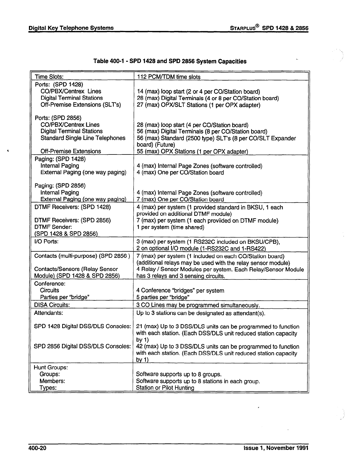
Digital Key Telephone Systems
STARPLUS@
SPD 1428 & 2856
Table 400-l - SPD 1428 and SPD 2856 System Capacities
Time Slots: 112 PCM/TDM time slots
Ports: (SPD 1428)
CO/PBX/Centrex tines 14 (max) loop start (2 or 4 per CO/Station board)
Digital Terminal Stations 28 (max) Digital Terminals (4 or 8 per CO/Station board)
Off-Premise Extensions (SLT’s) 27 (max) OPX/SLT Stations (1 per OPX adapter)
Ports: (SPD 2856)
CO/PBX/Centrex Lines 28 (max) loop start (4 per CO/Station board)
Digital Terminal Stations 56 (max) Digital Terminals (8 per CO/Station board)
Standard Single Line Telephones 56 (max) Standard (2500 type) SLT’s (8 per CO/SLT Expander
board) (Future)
Off-Premise Extensions 55 (max) OPX Stations (1 per OPX adapter)
Paging: (SPD 1428)
Internal Paging 4 (max) Internal Page Zones (software controlled)
External Paging (one way paging) 4 (max) One per CO/Station board
Paging: (SPD 2856)
Internal Paging 4 (max) Internal Page Zones (software controlled)
External Paging (one way paging) 7 (max) One per CO/Station board
DTMF Receivers: (SPD 1428) 4 (max) per system (1 provided standard in BKSU, 1 each
provided on additional DTMF module)
DTMF Receivers: (SPD 2856) 7 (max) per system (1 each proviided on DTMF module)
DTMF Sender: 1 per system (time shared)
(SPD 1428 & SPD 2856)
I/O Potts: 3 (max) per system (1 RS232C included on BKSWCPB),
2 on optional I/O module (1 RS232C and 1 -RS422)
Contacts (multi-purpose) (SPD 2856 ) 7 (max) per system (1 included on each CO/Station board)
(additional relays may be used with the relay sensor module)
Contacts/Sensors (Relay Sensor 4 Relay / Sensor Modules per system. Each Relay/Sensor Module
Module) (SPD 1428 & SPD 2856) has 3 relays and 3 sensing circuits.
Conference:
Circuits 4 Conference “bridges” per system
Parties per “bridge” 5 parties per “bridge”
DISA Circuits: 3 CO Lines may be programmed simultaneously.
Attendants: Up to 3 stations can be designated as attendant(s).
SPD 1428 Digital DSS/DLS Consoles: 21 (max) Up to 3 DSS/DLS units can be programmed to function
with each station. (Each DSS/DLS unit reduced station capacity
by11
SPD 2856 Digital DSWDLS Consoles: 42 (max) Up to 3 DSS/DLS units can be programmed to function
with each station. (Each DSS/DLS unit reduced station capacity
byl)
Hunt Groups:
Groups: Software supports up to 8 groups.
Members: Software supports up to 8 stations in each group.
Types: Station or Pilot Hunting
400-20 Issue 1, November 1991
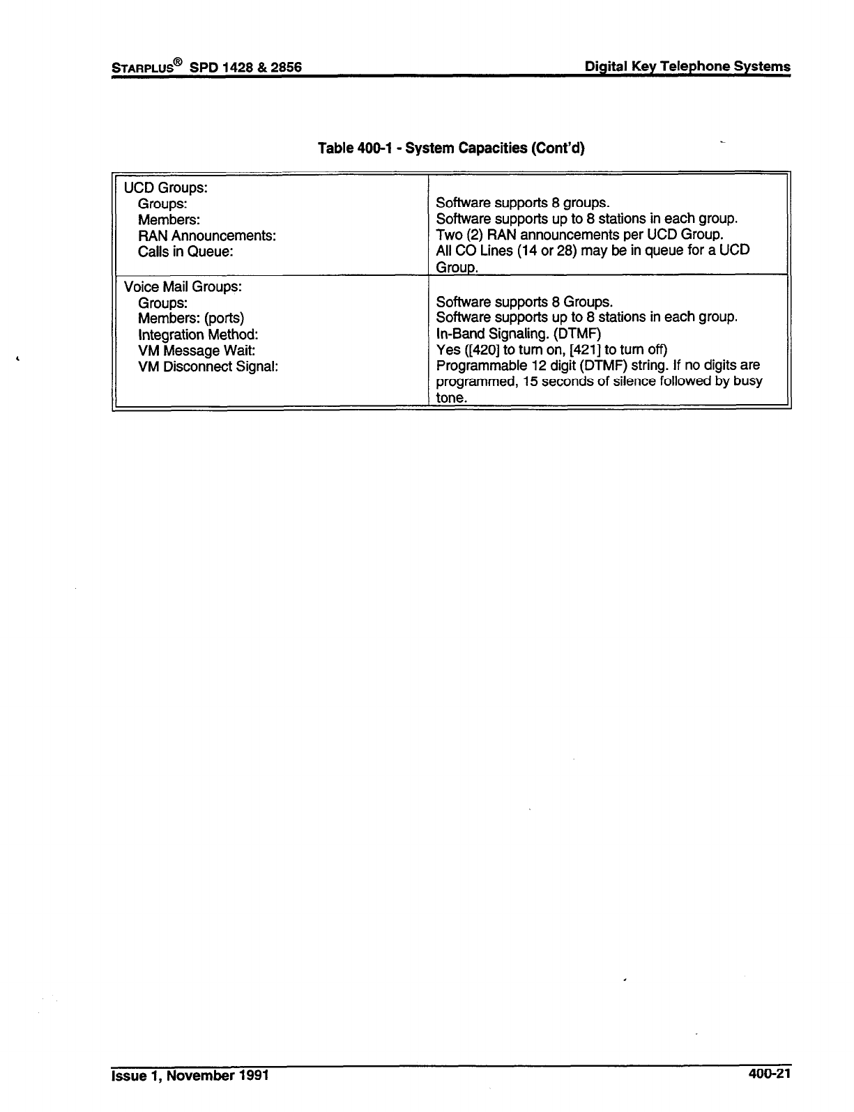
STARPLUS@
SPD 1428 & 2856 Digital Key Telephone Systems
Table 400-l - System Capacities (Cont’d)
UCD Groups:
Groups:
Members:
RAN Announcements:
Calls in Queue:
Software supports 8 groups.
Software supports up to 8 stations in each group.
Two (2) RAN announcements per UCD Group.
All CO Lines (14 or 28) may be in queue for a UCD
Voice Mail Groups:
Groups:
Members: (ports)
Integration Method:
VM Message Wait:
VM Disconnect Signal:
Software supports 8 Groups.
Software supports up to 8 stations in each group.
In-Band Signaling. (DTMF)
Yes ([420] to turn on, [421] to turn off)
Programmable 12 digit (DTMF) string. If no digits are
programmed, 15 seconds of silence followed by busy
tone.
Issue 1, November 1991 400-21
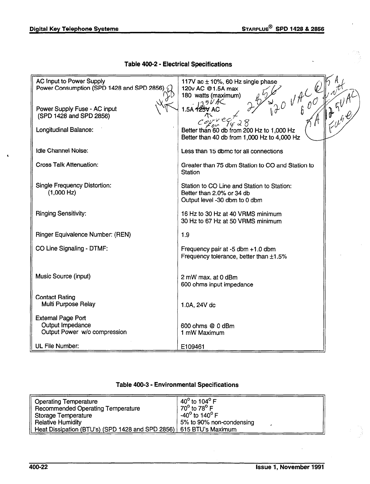
Digital Key Telephone Systems
STARPLUS@ SPD 1428 & 2856
Table 400-2 - Electrical Specifications
AC Input to Power Supply 117V ac + lo%, 60 Hz single phase
Power Consumption (SPD 1428 and SPD 2856) 120vAC @1.5A max
Power Supply Fuse - AC input
(SPD 1428 and SPD 2856)
Longitudinal Balance: Better than 40 db from 1,000 Hz to 4,000 Hz
Idle Channel Noise: Less than 15 dbmc for all connections
Cross Talk Attenuation: Greater than 75 dbm Station to CO and Station to
Station
Single Frequency Distortion:
(1,000 Hz)
Ringing Sensitivity:
Ringer Equivalence Number: (REN)
CO Line Signaling - DTMF:
Music Source (input)
Contact Rating
Multi Purpose Relay
External Page Port
Output Impedance
Output Power w/o compression
Station to CO Line and Station to Station:
Better than 2.0% or 34 db
Output level -30 dbm to 0 dbm
16 Hz to 30 Hz at 40 VRMS minimum
30 Hz to 67 Hz at 50 VRMS minimum
1.9
Frequency pair at -5 dbm +1 .O dbm
Frequency tolerance, better than +1.5%
2 mW max. at 0 dBm
600 ohms input impedance
1 .OA. 24V dc
600 ohms 8 0 dBm
1 mW Maximum
UL File Number: El 09461
Table 400-3 - Environmental Specifications
Operating Temperature 40’ to 104’ F
Recommended Operating Temperature 70’ to 78’ F
Storage Temperature -40’ to 140’ F
Relative Humidity 5% to 90% non-condensing ,
Heat Dissipation (BTU’s) (SPD 1428 and SPD 2856) 615 BTU’s Maximum
400-22 Issue 1, November 1991
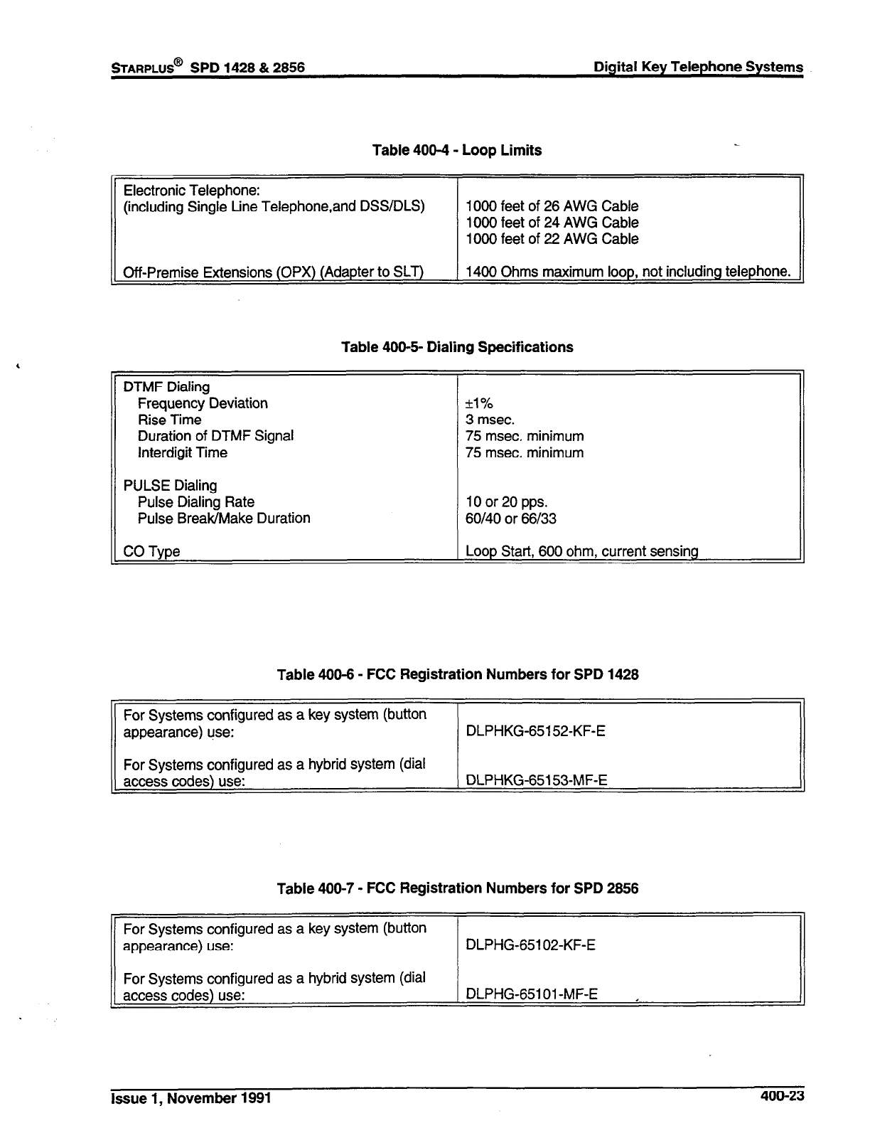
STARPLUS@
SPD 1428 & 2856 Digital Key Telephone Systems
Table 400-4 - Loop Limits
Electronic Telephone:
(including Single Line Telephone,and DSS/DLS) 1000 feet of 26 AWG Cable
1000 feet of 24 AWG Cable
1000 feet of 22 AWG Cable
1 Off-Premise Extensions (OPX) (Adapter to SLT) 1 1400 Ohms maximum loop, not including telephone. 1
Table 400-5- Dialing Specifications
DTMF Dialing
Frequency Deviation
Rise Time
Duration of DTMF Signal
Interdigit Time
PULSE Dialing
Pulse Dialing Rate
Pulse Break/Make Duration
1 CO Type
*l %
3 msec.
75 msec. minimum
75 msec. minimum
10 or 20 pps.
60/40 or 66/33
Loop Start, 600 ohm, current sensing
Table 400-6 - FCC Registration Numbers for SPD 1428
For Systems configured as a key system (button
appearance) use:
For Systems configured as a hybrid system (dial
access codes) use:
DLPHKG-65152-KF-E
DLPHKG-65153-MF-E
Table 400-7 - FCC Registration Numbers for SPD 2856
For Systems configured as a key system (button
appearance) use:
For Systems configured as a hybrid system (dial
access codes) use:
DLPHG-65102-KF-E
DLPHG-65101 -MF-E ,
Issue 1, November 1991 400-23
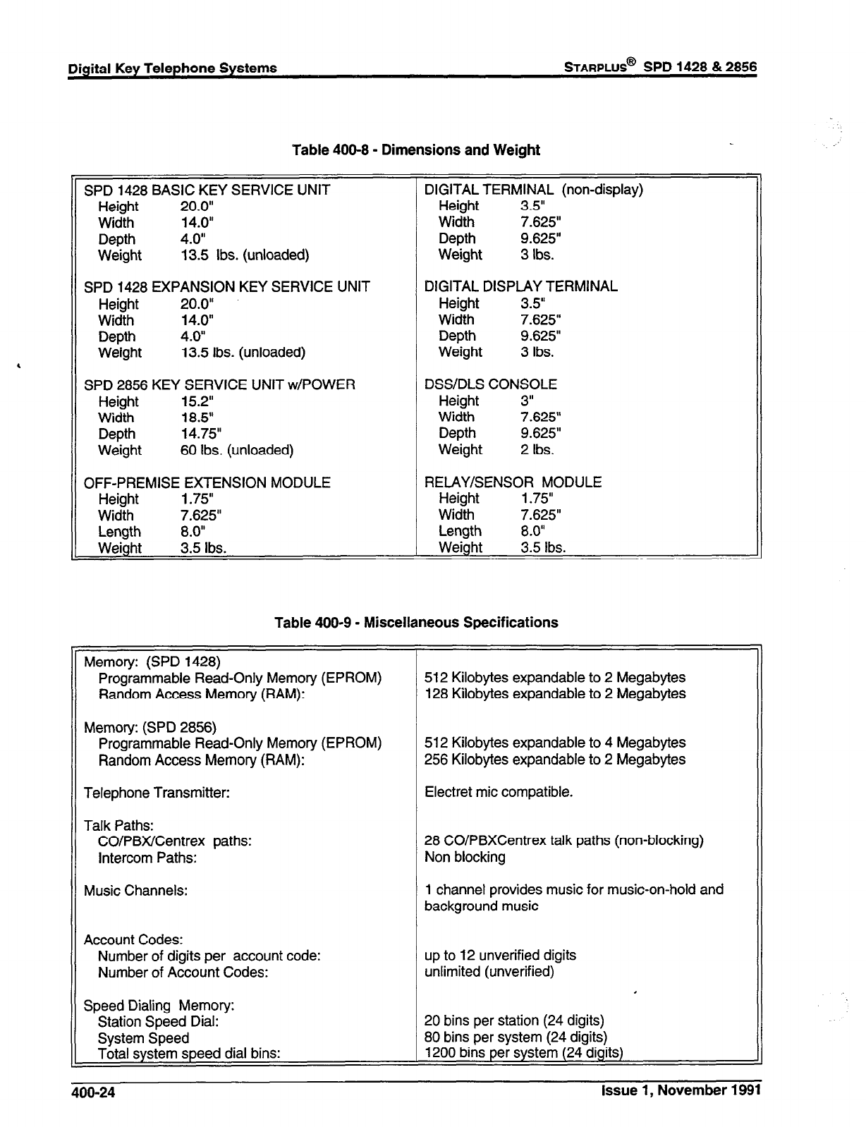
Digital Key Telephone Systems
STARPLUS*
SPD 1428 & 2856
,
Table 400-8 - Dimensions and Weight
SPD 1428 BASIC KEY SERVICE UNIT
Height 20.0”
Width 14.0”
Depth 4.0”
Weight 13.5 Ibs. (unloaded)
SPD 1428 EXPANSION KEY SERVICE UNIT
Height 20.0”
Width 14.0”
Depth 4.0”
Weight 13.5 Ibs. (unloaded)
SPD 2856 KEY SERVICE UNIT w/POWER
Height 15.2”
Width 18.5”
Depth 14.75”
Weight 60 Ibs. (unloaded)
OFF-PREMISE EXTENSION MODULE
Height 1.75”
Width 7.625”
Length 8.0”
Weight 3.5 Ibs.
DIGITAL TERMINAL (non-display)
Height 3.5”
Width 7.625”
Depth 9.625”
Weight 3 Ibs.
DIGITAL DISPLAY TERMINAL
Height 3.5”
Width 7.625”
Depth 9.625”
Weight 3 Ibs.
DSS/DLS CONSOLE
Height 3”
Width 7.625”
Depth 9.625”
Weight 2 Ibs.
RELAY/SENSOR MODULE
Height 1.75”
Width 7.625”
Length 8.0”
Weight 3.5 Ibs.
Table 400-9 - Miscellaneous Specifications
Memory: (SPD 1428)
Programmable Read-Only Memory (EPROM)
Random Access Memory (RAM):
Memory: (SPD 2856)
512 Kilobytes expandable to 2 Megabytes
128 Kilobytes expandable to 2 Megabytes
Programmable Read-Only Memory (EPROM)
Random Access Memory (RAM):
Telephone Transmitter:
Talk Paths:
CO/PBX/Centrex paths:
Intercom Paths:
Music Channels:
512 Kilobytes expandable to 4 Megabytes
256 Kilobytes expandable to 2 Megabytes
Electret mic compatible.
28 CO/PBXCentrex talk paths (non-blocking)
Non blocking
1 channel provides music for music-on-hold and
background music
Account Codes:
Number of digits per account code:
Number of Account Codes:
Speed Dialing Memory:
Station Speed Dial:
System Speed
Total system speed dial bins:
up to 12 unverified digits
unlimited (unverified) .
20 bins per station (24 digits)
80 bins per system (24 digits)
1200 bins per system (24 digits)
406-24 Issue 1, November 1991
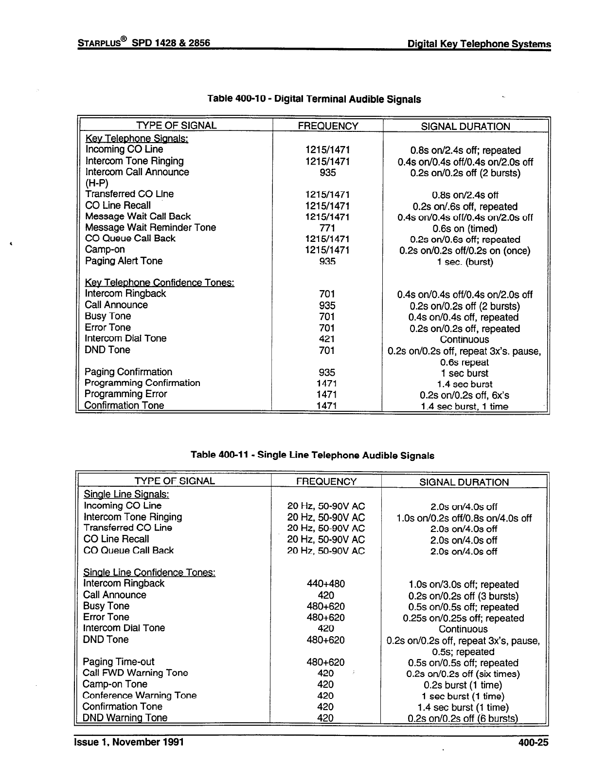
STARPLUS@
SPD 1428 & 2856 Digital Key Telephone Systems
Table 400-10 - Digital Terminal Audible Signals
TYPE OF SIGNAL
Key Telephone Signals:
Incoming CO Line
Intercom Tone Ringing
Intercom Call Announce
W-P)
Transferred CO Line
CO Line Recall
Message Wait Call Back
Message Wait Reminder Tone
CO Queue Call Back
Camp-on
Paging Alert Tone
Key Telephone Confidence Tones:
Intercom Ringback
Call Announce
Busy Tone
Error Tone
Intercom Dial Tone
DND Tone
Paging Confirmation
Programming Confirmation
Programming Error
Confirmation Tone
FREQUENCY SIGNAL DURATION
1215/1471 0.8s on/2.4s off; repeated
1215/1471 0.4s on/o.4s off/o.4s on/2.os off
935 0.2s on/O.2s off (2 bursts)
1215/1471
1215/1471
121511471
771
1215/1471
1215/1471
935
701
935
701
701
421
701
935
1471
1471
1471
0.8s orV2.4~ off
0.2s on/.6s off, repeated
0.4s orl/o.4s off/o.4s otl/2.os off
0.6s on (timed)
0.2s 011/0.6s off; repeated
0.2s otVO.2~ ofVO.2~
on (once)
1 sec. (burst)
0.4s on/o.4s ofVo.4s on/2.os off
0.2s on/O.2s off (2 bursts)
0.4s on/O.4s off, repeated
0.2s on/O.2s off, repeated
Continuous
0.2s orVO.2s
off, repeat 3~‘s. pause,
0.6s repeat
1 set burst
1.4 set burst
0.2s orVO.2~ off, 6x’s
1.4 set burst, 1 time
Table 409-l 1 - Single Line Telephone Audible Signals
TYPE OF SIGNAL
Sinale Line Sianals:
Incoming CO Line
Intercom Tone Ringing
Transferred CO Line
CO Line Recall
CO Queue Call Back
Sinale Line Confidence Tones:
Intercom Ringback
Call Announce
Busy Tone
Error Tone
Intercom Dial Tone
DND Tone
Paging Time-out
Call FWD Warning Tone
Camp-on Tone
Conference Warning Tone
Confirmation Tone
DND Warning Tone
FREQUENCY
20
Hz, 50-9OV AC
20 Hz, 50-9OV AC
20 Hz, 50-9OV AC
20 Hz, 50-9OV AC
20
Hz, 50-9OV AC
440+480
420
480+620
480+620
420
480+620
480+620
420 ’
420
420
420
420
SIGNAL DURATION
2.0s on/4.os off
1 .Os on/O.2s off/O.8s on/4.Os off
2.0s oll/4.os off
2.0s oll/4.os off
2.0s on/4.os off
1 .Os on/3.Os off; repeated
0.2s orVO.2~
off (3 bursts)
0.5s orVO.5~
off; repeated
0.25s o1V0.25~
off; repeated
Continuous
0.2s orVO.2~
off, repeat 3x’s, pause,
0.5s; repeated
0.5s otVO.5~
off; repeated
0.2s on/O.2s
off (six times)
0.2s
burst (1 time)
1 set burst (1 time)
1.4 set burst (1 time)
0.2s on/0.2s off (6 bursts)
Issue 1, November 1991 400-25
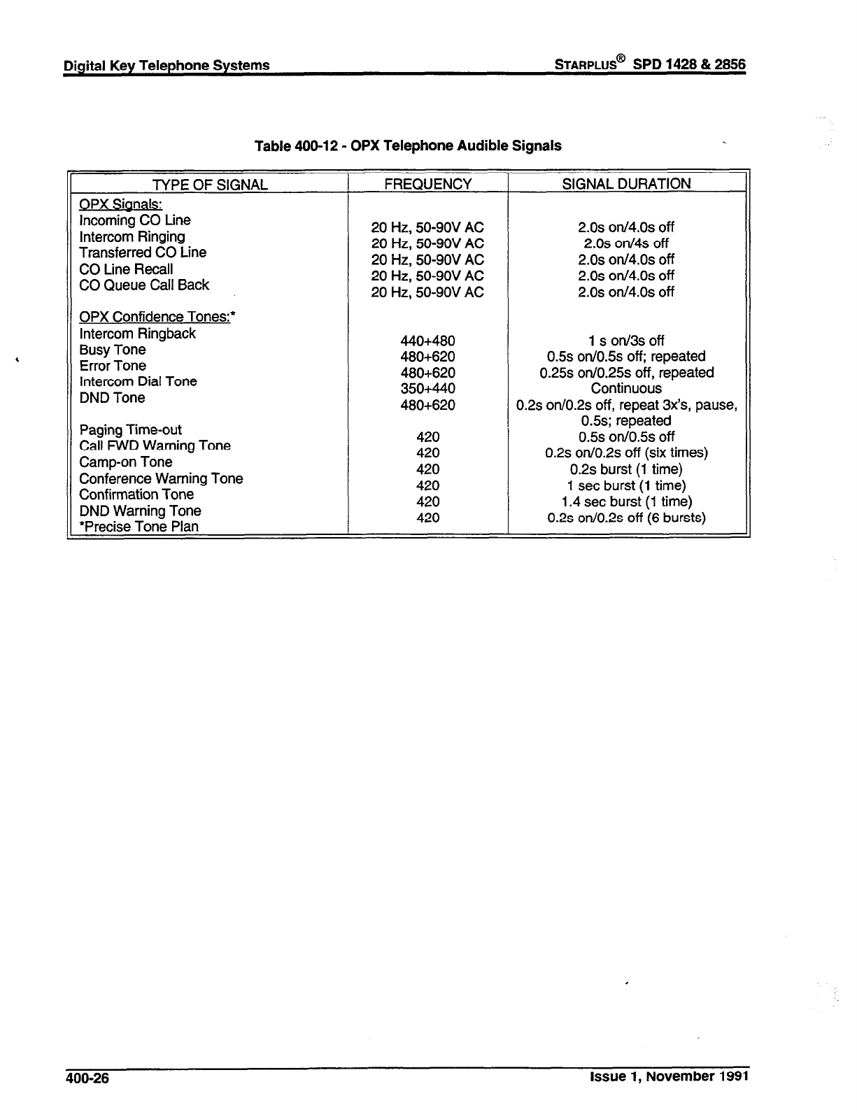
Digital Key Telephone Systems
STARPLUS@
SPD 1428 & 2856
Table 400-12 - OPX Telephone Audible Signals
TYPE OF SIGNAL
OPX Sianals:
Incoming CO Line
Intercom Ringing
Transferred CO Line
CO Line Recall
CO Queue Call Back
OPX Confidence Tones:*
Intercom Ringback
Busy Tone
Error Tone
Intercom Dial Tone
DND Tone
Paging Time-out
Call FWD Warning Tone
Camp-on Tone
Conference Warning Tone
Confirmation Tone
DND Warning Tone
*Precise Tone Plan
FREQUENCY SIGNAL DURATION
20 Hz, 50-9OV AC 2.0s otl/4.os off
20 Hz, 50-9OV AC 2.0s on/4s off
20 Hz, 50-9OV AC 2.0s on/4.os off
20 Hz, 50-9OV AC 2.0s otl/4.os off
20 Hz, 50-9OV AC 2.0s orv4.os off
440+480
480+620
480+620
350+440
480+620
420
420
420
420
420
420
-
1 s on/3s off
0.5s onlO.5~ off; repeated
0.25s on/O.25s off, repeated
Continuous
0.2s on/O.2s off, repeat 3x’s, pause,
0.5s; repeated
0.5s 0n/0.% off
0.2s on.IO.2~ off (six times)
0.2s burst (1 time)
1 set burst (1 time)
1.4 set burst (1 time)
0.2s on/O.2s off (6 bursts)
400-26 Issue 1, November 1991
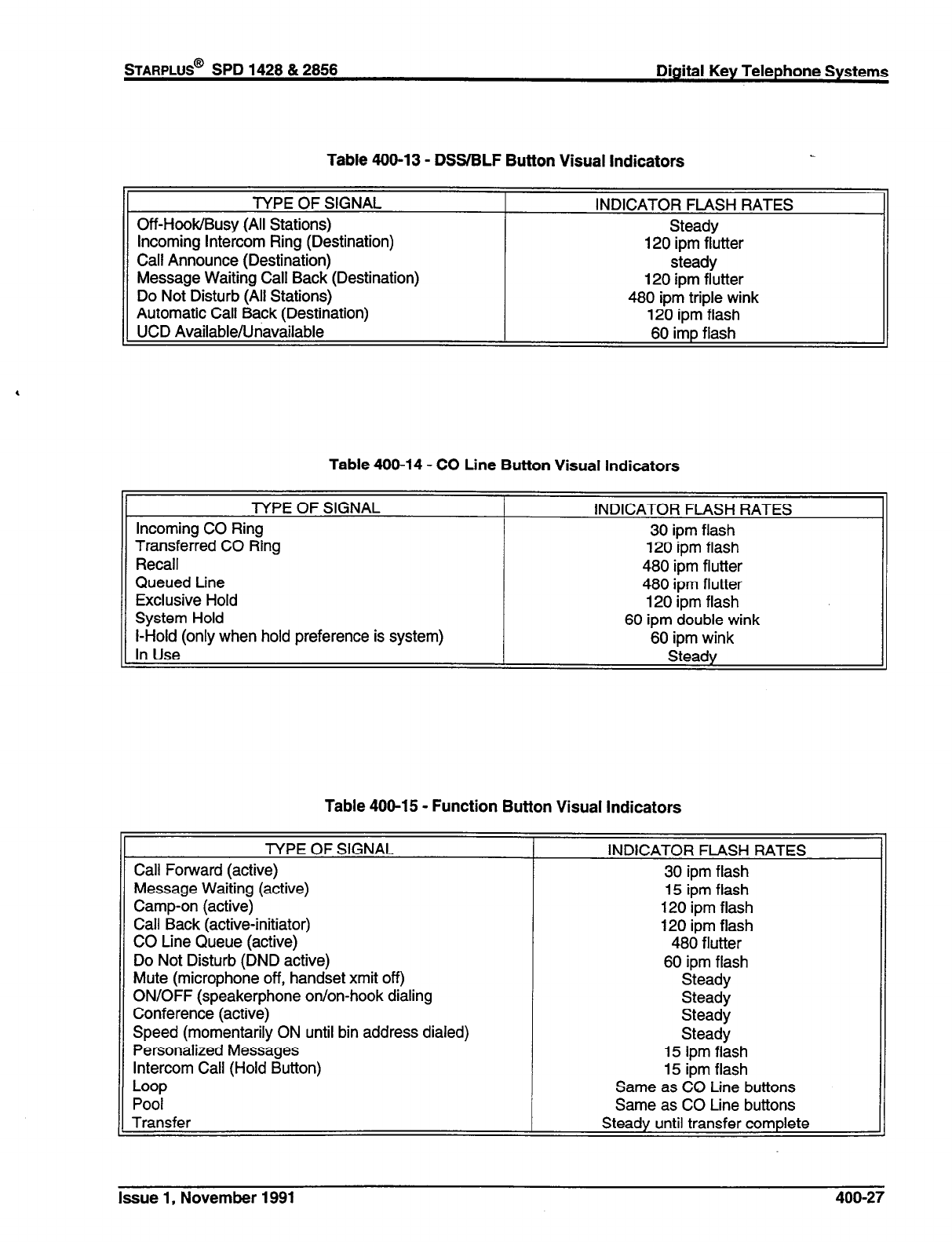
STARPLUS@
SPD 1428 & 2858 Digital Key Telephone Systems
Table 400-13 - DSS/BLF Button Visual Indicators
TYPE OF SIGNAL
Off-Hook/Busy (All Stations)
Incoming Intercom Ring (Destination)
Call Announce (Destination)
Message Waiting Call Back (Destination)
Do Not Disturb (All Stations)
Automatic Call Back (Destination)
UCD Available/Unavailable
INDICATOR FLASH RATES
Steady
120 ipm flutter
steady
120 ipm flutter
480 ipm triple wink
120 ipm flash
60 imp flash
Table 400-14 - CO Line Button Visual Indicators
TYPE OF SIGNAL
Incoming CO Ring
Transferred CO Ring
Recall
Queued Line
Exclusive Hold
System Hold
I-Hold (only when hold preference is system)
r
INDICATOR FLASH RATES
30 ipm flash
120 ipm flash
480 ipm flutter
480 ipm flutter
120 ipm flash
60 ipm double wink
60 ipm wink
Steady In Use
Table 400-15 - Function Button Visual Indicators
TYPE OF SIGNAL
Call Forward (active)
Message Waiting (active)
Camp-on (active)
Call Back (active-initiator)
CO Line Queue (active)
Do Not Disturb (DND active)
Mute (microphone off, handset xmit off)
ON/OFF (speakerphone on/on-hook dialing
Conference (active)
Speed (momentarily ON until bin address dialed)
Personalized Messages
Intercom Call (Hold Button)
Loop
Pool
Transfer
INDICATOR FLASH RATES
30 ipm flash
15 ipm flash
120 ipm flash
120 ipm flash
480 flutter
60 ipm flash
Steady
Steady
Steady
Steady
15 ipm flash
15 ipm flash
Same as CO Line buttons
Same as CO Line buttons
Steady until transfer complete
Issue 1, November 1991 400-27
STARPLUS@
SPD 1428 & 2856
SECTION 500
INSTALLATION
Digital Key Telephone Systems
500.1
SITE PLANNING
Selection of a suitable location is the most basic, yet
most critical consideration in the installation of a
telephone system. The following should be consid-
ered when choosing an appropriate location for
equipment installation:
Ample space must be allowed to remove the
KSU cover, to access assemblies and cards
within the cabinet and allow space for the MDF
(Main Distribution Frame).
Location of CO/PBX line terminations must be
considered when selecting a location for the
KSU. In the case of telephone company line,
FCC approved connectors supplied by the tele-
phone company, should be within 5 feet (1.5
meters) of the cabinet/main distribution frame.
To minimize the length of cable runs between
the stations and the system KSU, the location
of the majority of the telephone sets (stations)
should be taken into consideration when select-
ing a location for the cabinet.
A well ventilated, and well lighted area having
an optimum temperature range of 60 degrees
to 80 degrees F and a relative humidity range
of 5 to 90% (non-condensing) must be pro-
vided.
Area lighting should be adequate for installation
and maintenance of the system. Hazardous or
flammable materials should be removed from
the vicinity. The immediate area must not be
subject to flooding or excess moisture. The
KSU should be isolated from areas of moving
machinery or equipment. It is also recom-
mended that static electricity-producing carpets
not be installed in this area.
A separately fused, dedicated 117 volts AC, +
lo%, 15 Amp., 60 Hz, single phase, 3-wire
(parallel blade with ground) power outlet should
be located within 5 feet (1.5 meters) of the
system power supply.
The KSU and main distribution frame should be
placed in an electrically noise free environment,
isolated and shielded from equipment that
causes electromagnetic interference (EMI) or
radio frequency interference (RFI). Examples
of electrical noise are rotating electrical machin-
ery and arc welding equipment, refrigerators,
copy machines, etc. Floor coverings that gen-
erate static electricity should also be avoided.
.
The system KSU should not be installed close
to any equipment which may produce RFI (Ra-
dio Frequency Interference) such as a radio
frequency transmitter.
. If the system is to be installed in a location prone
to lightning strikes, provide lightning protection
on the power line, any station cable runs outside
the building, and CO lines.
A. System Grounding
To ensure that the system will operate properly, a
good earth ground is required. Use of the Telco
ground (source not demark) or a metallic COLD
water pipe usually provides a reliable ground path.
Carefully check that the pipe does not contain insul-
ated joints that could isolate the ground. In the
absence of the COLD water pipe, a ground rod or
other source may be used. A no.12 AWG copper
wire should be used between the ground source and
the KSU (25 feet maximum). The farther from the
ground source, the larger the ground wire used
should be. The wire should be kept as short as
possible and can be connected to the ground lug
provided on the lower left side of the backplane on
the KSU with the cover off.
B. Lightning Protection
The Starplus Digital (SPD) Key Telephone System
should have Central Office lines and OPX stations
protected with proper lightning surge arresters. This
will provide protection from damaging surges on
sensitive cabling by non-direct lightning strikes.
The protection should contain a compliment of three-
element gas-discharged tubes to ground high poten-
tial surges, and associated circuits to absorb and
filter lower level surges. This type of lightning pro-
tection is available through telephone equipment
supply houses. Care should be taken to ensure that
such protection devices are installed in accordance
with the manufacturers instructions and to ensure
that no more than one set of protectors be installed
on central office lines at the installation premises.
Improper installation can be a serious safety hazard.
Failure to provide the proper lightning protection will
increase maintenance expense and require more
available spare parts.
500.2
SPD 1428 INSTALLATION PLANNING
Prior planning of the installation will aid in a smooth
cut-over and a satisfied customer. Select a suitable
location for the system. Determine -the number of
Issue 1, November 1991 500-l
telephones of each type, and the number of CO/Sta-
tion ports from the sales contract and discussions
with the customer.
NOTE: On/y
one sfafion set is allowed
per digital
extension number. If is not possible to bridge digifal
station ports so that an extension number may ap-
pear in more than one location.
.
0
4 .
.
*
Programming information should also be gath-
ered from the customer at this time so that the
system may be programmed either before, or
while the system is being installed.
Determine the location and type of each tele-
phone, and mark floor plans accordingly.
Determine the location for the operator stations,
and mark the floor plans.
Arrange for power cabling (if necessary) and
station cabling of the site.
If the system is to be installed in an area subject
to frequent lightning storms, consideration
should be given to providing additional lightning
protection on the CO lines beyond what is
provided by the local telephone operating com-
pany.
NOTE: Installers should be trained and thoroughly
familiar with the basic components of the SPD 1428
before attempting installation of this product.
500.3 SPD 1428 COMMON EQUIPMENT
A. Basic Key Service Unit with Power Supply
(BKSU)
The SPD 1428 Basic Key Service Unit is a system
which comes fully configured for four (4)
CO/PBX/Centrex lines and eight (8) Stations. The
basic KSU also contains one (1) RS-232C l/O port,
one (1) DTMF Receiver, one (1) connector for Back-
ground Music and Music on Hold, an on-board 300
baud modem port, and one external page port. The
basic KSU also contains two connectors for adding
a 2X4 CO/Station Expander module (J9 and JlO),
an optional I/O module that adds one additional
RS-232C port and one RS-422 port, and an optional
1200 baud modem module can be added to increase
the speed of transmission of the on-board modem
port. A reset (halt) switch and a BGM volume control
are also mounted on the PCB. In addition two con-
nectors are provided for adding an Expansion KSU
which will allow the system to expand to a total of 14
COIPBWCentrex lines and 28 digital station ports.
Refer to Figure 500-l for a PCB layout and location
of connectors.
Power Sut3pl~
The power supply, installed in the KSU at the time of
manufacture, has an input voltage of 117 VAC
+lO%. The power supply provides power, a fil-
tered/unregulated 512 VDC, to the main key service
board. A slo-blow 1.5 amp fuse on the AC side of
the transformer provides the necessary fire and
overload protection. Power is regulated and distrib-
uted to stations / circuitry in the system on the main
key service board. The power supply and cabinet
meet all safety requirements to comply with UL 1459
Second Edition and CSA 0.3 standards.
.
S&In- .
Four green LED’s are located on the main key station
board along the top of the PCB. Two of the LED’s
(DS2 & DS3) indicate the presence of +5 & -5 volts.
LED’s DSl and DS5 indicate the presence of +12
VDC used to supply power to the key stations (one
LED per four stations). An extinguished LED indi-
cates the absences of the associated voltage.
A red LED (DS4) located in the lower right portion of
the PCB provides a system “heart beat” indication.
SPD 1428 BKSU Mountina:
The SPD 1428 Basic Key Service Unit (BKSU) is
housed in a wall mountable cabinet which contains
the Key Service board (KSB), Power Supply and
pre-wired connectors for stations and CO Line inter-
face. Once the area for the telephone equipment has
been selected, mount a plywood back board to the
wall. The back board size will vary depending upon
the size of the MDF. The entire system and frame
can be mounted on a 4’ x 6’ x 3/4” plywood. If
mounting the KSU alone, the minimum back board
size is 25” x 17” x 3/4”. A fully loaded KSU can weigh
approximately 15 Ibs. Make certain proper mounting
procedures are followed.
NOTE: Check local building and electrical codes
before mounting the system. For example, certain
areas may require a flame retardant plywood back
board.
Mount the cabinet to the plywood using 3/4” #12
pan-head sheet metal screws such that the top of the
KSU is approximately three feet (1 meter) from the
ceiling, and bottom is four feet (1.2 meters) from the
floor.
Use the mounting template supplied with the cabinet
to locate the mounting holes. Refer to Figure 500-2.
Drill the holes and mount the KSU.
Groundinq
A No. 12 AGW copper wire should be used to
connect a ground between the ground source and
the KSU (25 feet maximum). A two position terminal
strip P3 is located along the bottom edge of the main
key service unit and is accessible through the bottom
of the KSU. One terminal position can be used to
connect the ground wire from a ground source and
500-2 Issue 1, November 1991
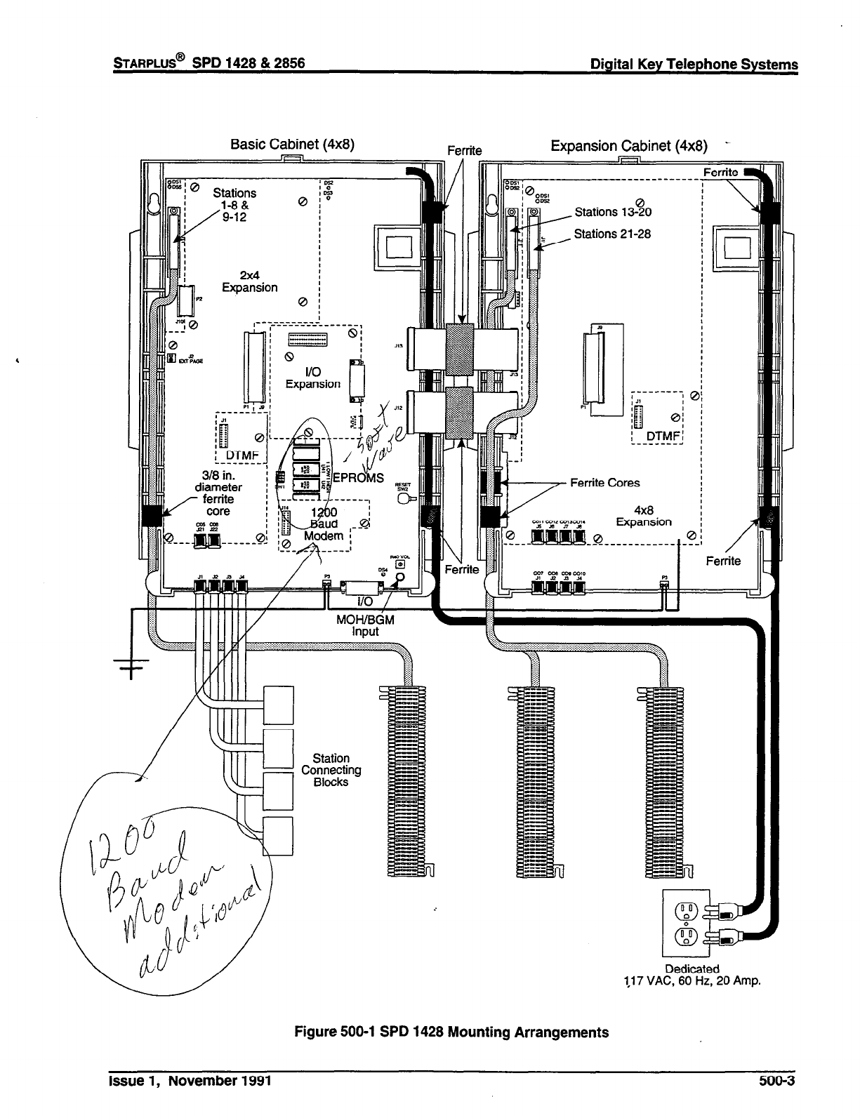
STARPLUS@
SPD 1428 & 2856 Digital Key Telephone Systems
Basic Cabinet (4x8)
Ferrite
Expansion Cabinet (4x8) .
II II i Expansion I I _
, Stations 13-50
Stations 21-28
---- -----
; 21 IQ
: DTMF:
__-____-a
Ferrite Cores
Expansion : ;
~~~~ ,. :.::::.:::::“:::.:::::::::::::::::::::::::.::::,::.:‘::: ,:: :: :: :.: :.: ..:.: ..:.:.:.:.:,:.:.:.:.:.:...: :
Statio?
Co~~~nnllg
I I
Dedicated
1.17 VAC, 60 Hz, 20 Amp.
Figure 500-l SPD 1428 Mounting Arrangements
Issue 1, November 1991 500-3

Digital Key Telephone Systems
sTARPLUS@
SPD 1428 & 2858
0 :
______
S‘- _____,
8:
x
a
n,
13.00"-b
-
II I
0
Figure 500-2 SPD 1428 Mounting Dimensions
500-4 issue 1, November 1991
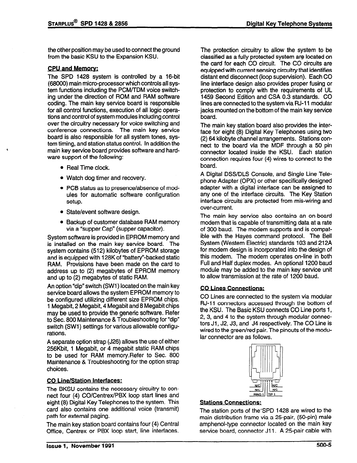
the other position may be used to connect the ground
from the basic KSU to the Expansion KSU.
.
CPU and Me-
The SPD 1428 system is controlled by a 16-bit
(68000) main micro-processor which controls all sys-
tem functions including the PCMflDM voice switch-
ing under the direction of ROM and RAM software
coding. The main key service board is responsible
for all control functions, execution of all logic opera-
tions and control of system modules including control
over the circuitry necessary for voice switching and
conference connections. The main key service
board is also responsible for all system tones, sys-
tem timing, and station status control. In addition the
main key service board provides software and hard-
ware support of the following:
Real Time clock.
Watch dog timer and recovery.
PCB status as to presence/absence of mod-
ules for automatic software configuration
setup.
State/event software design.
Backup of customer database RAM memory
via a “supper Cap” (supper capacitor).
System software is provided in EPROM memory and
is installed on the main key service board. The
system contains (512) kilobytes of EPROM storage
and is equipped with 128K of “battery’-backed static
RAM. Provisions have been made on the card to
address up to (2) megabytes of EPROM memory
and up to (2) megabytes of static RAM.
An option “dip” switch (SWl) located on the main key
service board allows the system EPROM memory to
be configured utilizing different size EPROM chips.
1 Megabit, 2 Megabit, 4 Megabit and 8 Megabit chips
may be used to provide the generic software. Refer
to Sec. 800 Maintenance &Troubleshooting for “dip”
switch (SWl) settings for various allowable configu-
rations.
A separate option strap (J26) allows the use of either
256Kbit, 1 Megabit, or 4 megabit static RAM chips
to be used for RAM memory.Refer to Sec. 800
Maintenance & Troubleshooting for the option strap
choices.
CO Line/Station Interfaces:
The BKSU contains the necessary circuitry to con-
nect four (4) CO/Centrex/PBX loop start lines and
eight (8) Digital Key Telephones to the system. This
card also contains one additional voice (transmit)
path for external paging.
The main key station board contains four (4) Central
Office, Centrex or PBX loop start, line interfaces.
The protection circuitry to allow the system to be
classified as a fully protected system are located on
the card for each CO circuit. The CO circuits are
equipped with current sensing circuitry that identifies
distant end disconnect (loop supervision). Each CO
line interface design also provides proper fusing or
protection to comply with the requirements of UL
1459 Second Edition and CSA 0.3 standards. CO
lines are connected to the system via RJ-11 modular
jacks mounted on the bottom of the main key service
board.
The main key station board also provides the inter-
face for eight (8) Digital Key Telephones using two
(2) 64 kilobyte channel arrangements. Stations con-
nect to the board via the MDF through a 50 pin
connector located inside the KSU. Each station
connection requires four (4) wires to connect to the
board.
A Digital DSS/DLS Console, and Single Line Tele-
phone Adapter (OPX) or other specifically designed
adapter with a digital interface can be assigned to
any one of the interface circuits. The Key Station
interface circuits are protected from mis-wiring and
over-current.
The main key service also contains an on-board
modem that is capable of transmitting data at a rate
of 300 baud. The modem supports and is compat-
ible with the Hayes command protocol. The Bell
System (Western Electric) standards 103 and 212A
for modem design is incorporated into the design of
this modem. The modem operates on-line in both
Full and Half duplex modes. An optional 1200 baud
module may be added to the main key service unit
to allow transmission at the rate of 1200 baud.
- .
s co-
CO Lines are connected to the system via modular
RJ-11 connectors accessed through the bottom of
the KSU. The Basic KSU connects CO Line ports 1,
2, 3, and 4 to the system through modular connec-
tors Jl , J2, J3, and J4 respectively. The CO Line is
wired to the green/red pair. The pinouts of the modu-
lar connector are as follows.
Stations Connections:
The station ports of the’SPD 1428 are wired to the
main distribution frame via a 25-pair, @O-pin) male
amphenol-type connector located on the main key
service board, connector Ji 1. A 25-pair cable with
STARPLUS@
SPD 1428 & 2856 Digital Key Telephone Systems
Issue 1, November 1991 500-5
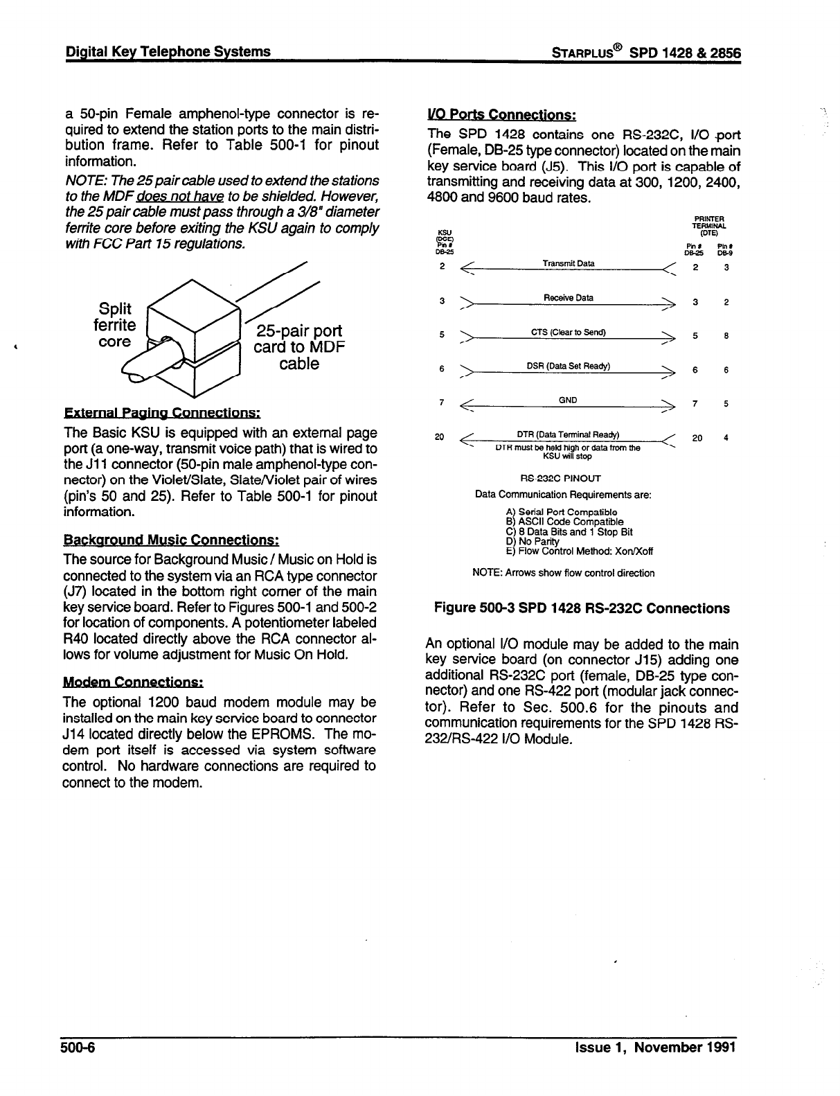
Digital Key Telephone Systems
STARPLUS@
SPD 1428 % 2856
a 50-pin Female amphenol-type connector is re-
quired to extend the station ports to the main distri-
bution frame. Refer to Table 500-l for pinout
information.
NOTE: The 25pair cable used to extend the stations
to the MDFdoes not have to be shielded. However,
the 25 pair cable must pass through a 3/8” diameter
ferrite core before exiting the KSU again to comply
with FCC Part 15 regulations.
Split
ferrite OQ
core B 25pair port
card to MDF
cable
The Basic KSU is equipped with an external page
port (a one-way, transmit voice path) that is wired to
the Jl 1 connector (50-pin male amphenol-type con-
nector) on the Violet/Slate, Slate/Violet pair of wires
(pin’s 50 and 25). Refer to Table 500-l for pinout
information.
Backaround Music Connections:
The source for Background Music/ Music on Hold is
connected to the system via an RCA type connector
(J7) located in the bottom right comer of the main
key service board. Refer to Figures 500-l and 500-2
for location of components. A potentiometer labeled
R40 located directly above the RCA connector al-
lows for volume adjustment for Music On Hold.
The optional 1200 baud modem module may be
installed on the main key service board to connector
J14 located directly below the EPROMS. The mo-
dem port itself is accessed via system software
control. No hardware connections are required to
connect to the modem.
l/O Ports Connections:
The SPD 1428 contains one RS232C, I/O port
(Female, DB-25 type connector) located on the main
key service board (J5). This I/O port is capable of
transmitting and receiving data at 300, 1200, 2400,
4800 and 9600 baud rates.
PRNTER
TERMlW
2 (DTO
pin t Pin,
DEZ De-9
2 Transmit Data 2 3
3 Receive Data 3 2
5 CTS (Clear to Send) 5 6
6 \ DSR (Data Set Ready) 6 6
7 GND 7 5
20 DTR (Data Terminal Ready)
DTR must be held high or data from the
KSU will stop
20 4
RS-232C PINOUT
Data Communication Requirements are:
$ ~J!!~~~2i~,
D) No Parity
E) Flow Control Method: XotVXofl
NOTE: Arrows show flow control direction
Figure 500-3 SPD 1428 RS-232C Connections
An optional I/O module may be added to the main
key service board (on connector 515) adding one
additional RS-232C port (female, DB-25 type con-
nector) and one RS-422 port (modular jack connec-
tor). Refer to Sec. 500.6 for the pinouts and
communication requirements for the SPD 1428 RS-
232/RS-422 I/O Module.
508-6 Issue 1, November 1881
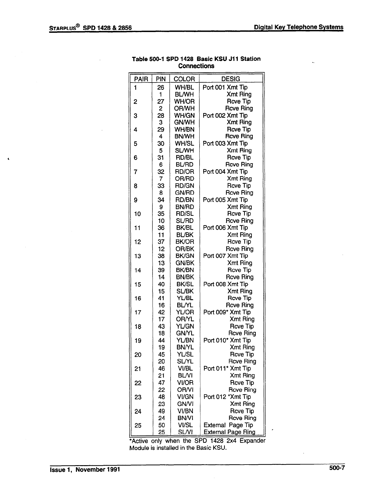
sTARPLUS@
SPD 1428 & 2858 Digital Key Telephone Systems
Table 500-l SPD 1428 Basic KSU Jll Station
Connections
--
--
PAIR PIN
--
1 26
1
2 27
2
3 28
3
4 29
4
5 30
5
6 31
6
7 32
7
8 33
8
9 34
9
10 35
10
11 36
11
12 37
12
13 38
13
14 39
14
15 40
15
16 41
16
17 42
17
18 43
18
19 44
19
20 45
20
21 46
21
22 47
22
23 48
23
24 49
24
25 50
25
--
--
active only v
-
COLOR
WH/BL
BLA’VH
WH/OR
OR/WH
WH/GN
GNNVH
WH/BN
BN/WH
WH/SL
SINVH
RD/BL
BURD
RDlOR
OWRD
RD/GN
GN/RD
RD/BN
BN/RD
RD/SL
SURD
BWBL
BUBK
BWOR
OWBK
BWGN
GN/BK
BWBN
BN/BK
BWSL
SUBK
YUBL
BLIYL
YUOR
OWYL
YUGN
GNNL
YUBN
BNNL
YUSL
SLIYL
VI/BL
BUVI
VI/OR
ORNI
VI/GN
GNNI
VI/BN
BNNI
VIISL
SWI
sn the I
DESIG
Port 001 Xmt Tip
Xmt Ring
Rcve Tip
Rcve Ring
Port 002 Xmt Tip
Xmt Ring
Rcve Tip
Rcve Ring
Port 003 Xmt Tip
Xmt Ring
Rcve Tip
Rcve Ring
Port 004 Xmt Tip
Xmt Ring
Rcve Tip
Rcve Ring
Port 005 Xmt Tip
Xmt Ring
Rcve Tip
Rcve Ring
Port 006 Xmt Tip
Xmt Ring
Rcve Tip
Rcve Ring
Port 007 Xmt Tip
Xmt Ring
Rcve Tip
Rcve Ring
Port 008 Xmt Tip
Xmt Ring
Rcve Tip
Rcve Ring
Port 009* Xmt Tip
Xmt Ring
Rcve Tip
Rcve Ring
Port 010* Xmt Tip
Xmt Ring
Rcve Tip
Rcve Ring
Port 011
l
Xmt Tip
Xmt Ring
Rcve Tip
Rcve Ring
Port 012 *Xmt Tip
Xmt Ring
Rcve Tip
Rcve Ring
External Page Tip
Module is installed in the Basic KSU.
Issue 1, November 1991
500-7

B. Expansion KSU with Power Supply (EKSU)
The SPD 1428 Expansion KSU is a unit which comes
equipped with a power supply and circuity providing
four (4) additional loop start CO/PBWCentrex line
ports and eight (8) digital station ports to the Basic
KSU. All processing and control functions as well as
voice connections and switching are controlled by
circuitry on the Basic KSU and transmitted to the
Expansion KSU through the ribbon cables.
The Expansion key service board allows connection
of one optional application. module (i.e. DTMF Re-
ceiver) to the system and connector(s) for installing
an additional SPD 1428 2X4 Expander Module or the
SPD 1428 4X8 Expander Module. Refer to Figure
500-4 for an expansion key service board (PCB)
layout and location of connectors.
Power Sum
The power supply, installed in the Expansion KSU at
the time of manufacture, has an input voltage of 117
VAC 510%. The power supply provides power, a
filtered / unregulated +12 VDC, to the Expansion key
service board. A slo-blow 1.5 amp fuse on the AC
side of the transformer provides the necessary fire
and overload protection. Power is regulated and
distributed to stations / circuitry in the system on the
Expansion key service board. The power supply and
cabinet meet all safety requirements to comply with
UL 1459 Second Edition and CSA 0.3 standards.
,
s & Indicators
Four green LED’s are located on the expansion key
station board. Two of the LED’s (DS2 & DS3) indi-
cate the presence of +5 & -5 volts. LED’s DSl and
DS5 indicate the presence of +12 VDC used to
supply power to the key stations (one LED for every
four stations). An extinguished LED indicates the
absences of the associated voltage.
ExDansion KSU Mountina:
The SPD 1428 Expansion KSU (EKSU) is housed in
a wall mountable cabinet which contains the Expan-
sion Key Service board (EKSB), Power Supply and
pre-wired connectors for station and CO Line inter-
faces. The Expansion KSU is mounted directly to the
right of the Basic KSU and connects via two (2)
ribbon type cables provided with the unit. Once the
area for the telephone equipment has been selected,
mount a plywood back board to the wall. The back
board size will vary depending upon the size of the
MDF. The entire system and frame can be mounted
on a 4’ x 8’ x 3/4” plywood. If mounting the KSU
alone, the minimum back board size is 25” x 17” x
3/4”. A fully loaded KSU can weigh approximately
15 Ibs. Make certain proper mounting procedures
are followed.
Digital Key Telephone Systems
sTARPLUS@
SPD 1428 812866
NOTE: Check local building and electrical codes
before mounting the system. For example, certain
areas may require a flame retardant plywood back
board.
Mount the cabinet to the plywood using 3/4” #12
pan-head sheet metal screws such that the top of the
KSU is approximately three feet (1 meter) from the
ceiling, and bottom is four feet (1.2 meters) from the
floor.
Use the mounting template supplied with the cabinet
to locate the mounting holes. Refer to Figure 500-2.
Drill the holes and mount the KSU.
A No. 12 AWG copper wire should be used to
connect a ground between the Basic KSU and the
Expansion KSU. A two position terminal strip (P3)
is located along the bottom edge of the main key
service unit and is accessible through the bottom of
the BKSU. A similar two position terminal strip (P3)
is located along the bottom edge of the expansion
key service board and is accessible through the
bottom of the EKSU. One terminal position on each
P3 connector can be used to connect the ground
wire from the basic KSU to the Expansion KSU.
CO Line/Station interfaces:
The EKSU contains the necessary circuitry to con-
nect an additional four (4) CO/Centrex/PBX loop
start lines and eight (8) Digital Key Telephones to the
system. This card also contains one additional voice
(transmit) path for external paging.
The Expansion key station board contains four (4)
Central Office, Centrex or PBX loop start, line inter-
faces. The protection circuitry to allow the system to
be classified as a fully protected system are located
on the card for each CO circuit. The CO circuits are
equipped with current sensing circuitry that identifies
distant end disconnect (loop supervision). Each CO
line interface design also provides proper fusing or
protection to comply with the requirements of UL
1459 Second Edition and CSA 0.3 standards. CO
lines are connected to the system via RJ-11 modular
jacks mounted on the bottom of the Expansion key
service board.
The Expansion key station board also provides the
interface for eight (8) Digital Key Telephones using
two (2) 64 kilobyte channel arrangements. Stations
connect to the board via the MDF through a 50 pin
connector located inside the KSU. Each station
connection requires four (4) wires to connect to the
board.
A Digital DSS/DLS Console, and a Single Line Tele-
phone Adapter (OPX) or other specifically designed
adapter with a digital interface can be assigned to
any one of the interface circuits. The Key Station
500-8 Issue 1, November 1881
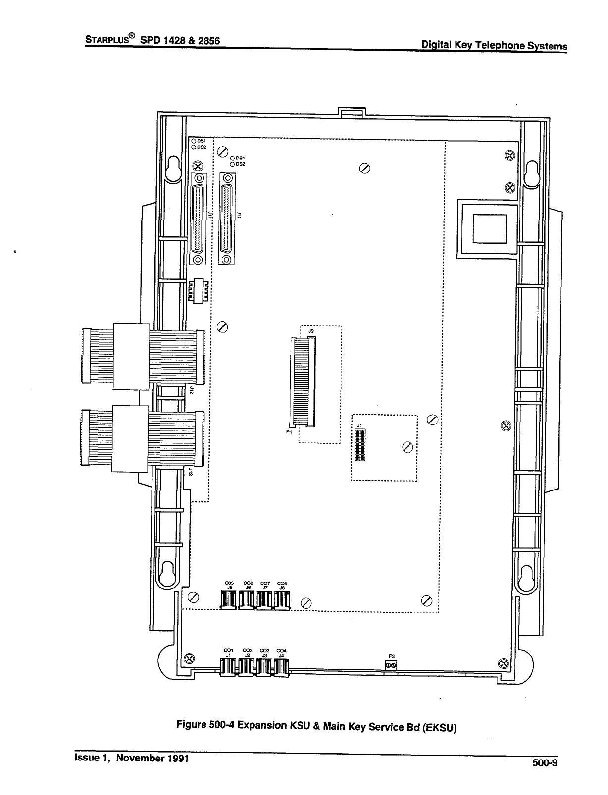
STARPLUS@ SPD 1428 & 2856
Digital Key Telephone Systems
_ - - _ _ _
.i¶
~
. _ _ _ _. .
___.
,-__
. . . ..--.-............1
Figure 500-4 Expansion KSU & Main Key Service Bd (EKSU)
Issue 1, November 1991 500-9
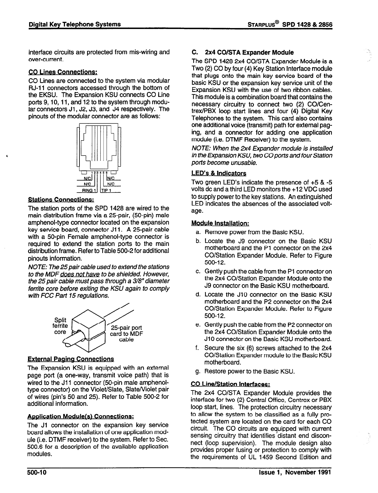
Digital Key Telephone Systems
STARPLUS@
SPD 1428 & 2856
interface circuits are protected from mis-wiring and
over-current.
.
mes Connections:
CO Lines are connected to the system via modular
RJ-11 connectors accessed through the bottom of
the EKSU. The Expansion KSU connects CO Line
ports 9,10, 11, and 12 to the system through modu-
lar connectors Jl , J2, J3, and J4 respectively. The
pinouts of the modular connector are as follows:
%!I ITF
Stations Connections:
The station ports of the SPD 1428 are wired to the
main distribution frame via a 25pair, @O-pin) male
amphenol-type connector located on the expansion
key service board, connector Jl 1. A 25pair cable
with a 50-pin Female amphenol-type connector is
required to extend the station ports to the main
distribution frame. Refer to Table 500-2 for additional
pinouts information.
NOTE: The 25 pair cable used to extend the stations
to the MDFdoes not have to be shielded. However,
the 25 pair cable must pass through a 318” diameter
ferrite core before exiting the KSlJ again to comply
with FCC Part 15 regulations.
s
25pair port
card to MDF
cable
External Paaina Connections
The Expansion KSU is equipped with an external
page port (a one-way, transmit voice path) that is
wired to the Jl 1 connector @O-pin male amphenol-
type connector) on the Violet/Slate, Slate/Violet pair
of wires (pin’s 50 and 25). Refer to Table 500-2 for
additional information.
Awlication Modulefs) Connections:
The Jl connector on the expansion key service
board allows the installation of one application mod-
ule (i.e. DTMF receiver) to the system. Refer to Sec.
500.6 for a description of the available application
modules.
C. 2x4 CO/STA Expander Module
The SPD 1428 2x4 CO/STA Expander Module& a
Two (2) CO by four (4) Key Station Interface module
that plugs onto the main key service board of the
basic KSU or the expansion key service unit of the
Expansion KSU with the use of two ribbon cables.
This module is a combination board that contains the
necessary circuitry to connect two (2) CO/Cen-
trex/PBX loop start lines and four (4) Digital Key
Telephones to the system. This card also contains
one additional voice (transmit) path for external pag-
ing, and a connector for adding one application
module (i.e. DTMF Receiver) to the system.
NOTE: When the 2x4 Expander module is installed
in the Expansion KSU, two CO ports and four Station
ports become unusable.
LED’s & Indicators
Two green LED’s indicate the presence of +5 & -5
volts dc and a third LED monitors the +12 VDC used
to supply power to the key stations. An extinguished
LED indicates the absences of the associated volt-
age.
Module Installation:
a.
b.
C.
d.
e.
f.
g-
Remove power from the Basic KSU.
Locate the J9 connector on the Basic KSU
motherboard and the Pl connector on the 2x4
CO/Station Expander Module. Refer to Figure
500-l 2.
Gently push the cable from the Pl connector on
the 2x4 CO/Station Expander Module onto the
J9 connector on the Basic KSU motherboard.
Locate the JlO connector on the Basic KSU
motherboard and the P2 connector on the 2x4
CO/Station Expander Module. Refer to Figure
500-l 2.
Gently push the cable from the P2 connector on
the 2x4 CO/Station Expander Module onto the
JlO connector on the Basic KSU motherboard.
Secure the six (6) screws attached to the 2x4
CO/Station Expander module to the Basic KSU
motherboard.
Restore power to the Basic KSU.
CO Line/Station Interfaces:
The 2x4 CO/STA Expander Module provides the
interface for two (2) Central Office, Centrex or PBX
loop start, lines. The protection circuitry necessary
to allow the system to be classified as a fully pro-
tected system are located on the card for each CO
circuit. The CO circuits are equipped with current
sensing circuitry that identifies’distant end discon-
nect (loop supervision). The module design also
provides proper fusing or protection to comply with
the requirements of UL 1459 Second Edition and
500-l 0 Issue 1, November 1991
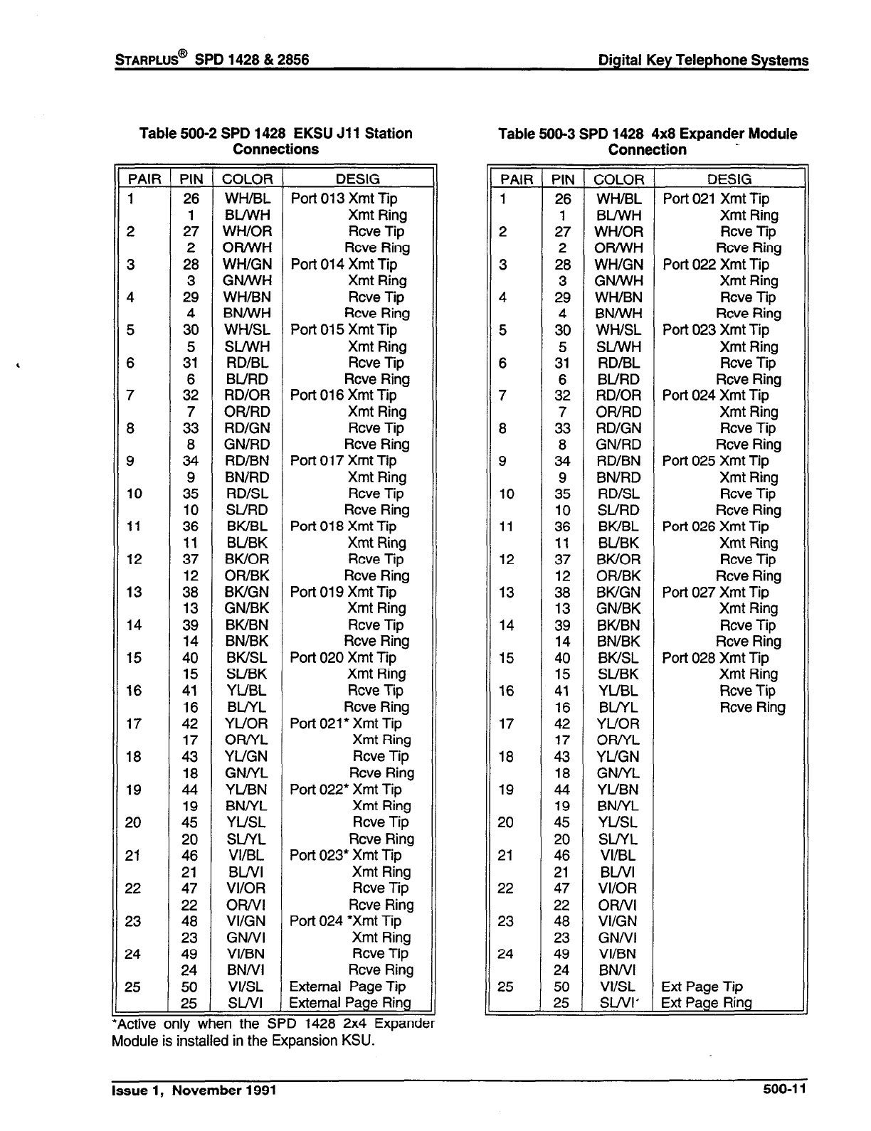
sTARPLUS@
SPD 1428 & 2858 Digital Key Telephone Systems
Table 500-2 SPD 1428 EKSU Jll Station
Connections Table 500-3 SPD 1428 4x8 Expander Module
Connection .
PAIR PIN COLOR DESIG
1 26 WH/BL Port 013 Xmt Tip
1 BUWH Xmt Ring
2 27 WH/OR Rcve Tip
2 OR/WH Rcve Ring
3 28 WWGN Port 014 Xmt Tip
3 GNIWH Xmt Ring
4 29 WH/BN Rcve Tip
4 BN/WH Rcve Ring
5 30 WWSL Port 015 Xmt Tip
5 SUWH Xmt Ring
6 31 RD/BL Rcve Tip
6 BURD Rcve Ring
7 32 RD/OR Port 016 Xmt Tip
7 OWRD Xmt Ring
8 33 RD/GN Rcve Tip
8 GN/RD Rcve Ring
9 34 RD/BN Port 017 Xmt Tip
9 BN/RD Xmt Ring
10 35 RD/SL Rcve Tip
10 SURD Rcve Ring
11 36 BWBL Port 018 Xmt Tip
11 BUBK Xmt Ring
12 37 BWOR Rcve Tip
12 OR/BK Rcve Ring
13 38 BWGN Port 019 Xmt Tip
13 GN/BK Xmt Ring
14 39 BWBN Rcve Tip
14 BN/BK Rcve Ring
15 40 BWSL Port 020 Xmt Tip
15 SUBK Xmt Ring
16 41 YUBL Rcve Tip
16 BUYL Rcve Ring
17 42 YUOR Port 021* Xmt Tip
17 OR/YL Xmt Ring
18 43 YUGN Rcve Tip
18 GNNL Rcve Ring
19 44 YUBN Port 022’ Xmt Tip
19 BNNL Xmt Ring
20 45 YUSL Rcve Tip
20 SLiYL Rcve Ring
21 46 VI/BL Port 023* Xmt Tip
21 BWl Xmt Ring
22 47 VI/OR Rcve Tip
22 OR/VI Rcve Ring
23 48 VI/GN Port 024 ‘Xmt Tip
23 GNNI Xmt Ring
24 49 VI/BN Rcve Tip
24 BNNI Rcve Ring
25 50 VIISL External Page Tip
25 SWI External Page Ring
.ctive only when the SPD 1428 2x4 Expander
Module is installed in the Expansion KSU.
PAIR
1
2
3
4
5
6
7
8
9
10
11
12
13
14
15
16
17
18
19
20
21
22
23
24
25
-
-
PIN
COLOR
26 WWBL
1 BUWH
27 WWOR
2 ORiWH
28 WWGN
3 GN/WH
29 WH/BN
4 BN/WH
30 WWSL
5 SVWH
31 RD/BL
6 BURD
32 RD/OR
7 OR/RD
33 RD/GN
8 GN/RD
34 RD/BN
9 BN/RD
35 RD/SL
10 SURD
36 BWBL
11 BUBK
37 BWOR
12 OWBK
36 BWGN
13 GN/BK
39 BWBN
14 BN/BK
40 BKISL
15 SUBK
41 YUBL
16 BUYL
42 YUOR
17 ORIYL
43 YUGN
18 GNNL
44 YUBN
19 BNNL
45 YUSL
20 SUYL
46 VI/BL
21 BWI
47 VI/OR
22 OR/VI
48 VI/GN
23 GNNI
49 VI/BN
24 BNNI
50 VIISL
25 SWI’
-
-
DESIG
Port 021 Xmt Tip
Xmt Ring
Rcve Tip
Rcve Ring
Port 022 Xmt Tip
Xmt Ring
Rcve Tip
Rcve Ring
Port 023 Xmt Tip
Xmt Ring
Rcve Tip
Rcve Ring
Port 024 Xmt Tip
Xmt Ring
Rcve Tip
Rcve Ring
Port 025 Xmt Tip
Xmt Ring
Rcve Tip
Rcve Ring
Port 026 Xmt Tip
Xmt Ring
Rcve Tip
Rcve Ring
Port 027 Xmt Tip
Xmt Ring
Rcve Tip
Rcve Ring
Port 028 Xmt Tip
Xmt Ring
Rcve Tip
Rcve Ring
Ext Page Tip
Ext Page Ring
Issue 1, November 1991 500-l 1
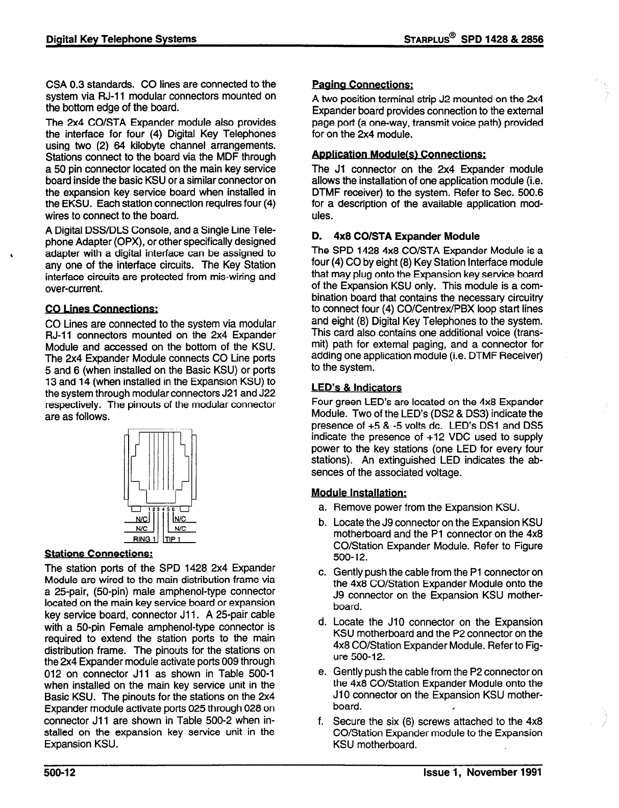
Digital Key Telephone Systems
sTARPLUS@
SPD 1428 & 2858
CSA 0.3 standards. CO lines are connected to the
system via RJ-11 modular connectors mounted on
the bottom edge of the board.
The 2x4 CO/STA Expander module also provides
the interface for four (4) Digital Key Telephones
using two (2) 64 kilobyte channel arrangements.
Stations connect to the board via the MDF through
a 50 pin connector located on the main key service
board inside the basic KSU or a similar connector on
the expansion key service board when installed in
the EKSU. Each station connection requires four (4)
wires to connect to the board.
A Digital DSWDLS Console, and a Single Line Tele-
phone Adapter (OPX), or other specifically designed
4 adapter with a digital interface can be assigned to
any one of the interface circuits. The Key Station
interface circuits are protected from mis-wiring and
over-current.
CO Lines are connected to the system via modular
RJ-11 connectors mounted on the 2x4 Expander
Module and accessed on the bottom of the KSU.
The 2x4 Expander Module connects CO Line ports
5 and 6 (when installed on the Basic KSU) or ports
13 and 14 (when installed in the Expansion KSU) to
the system through modular connectors J21 and J22
respectively. The pinouts of the modular connector
are as follows.
sy ppF
RIN 1
Stations Connections:
The station ports of the SPD 1428 2x4 Expander
Module are wired to the main distribution frame via
a 25pair, @O-pin) male amphenol-type connector
located on the main key service board or expansion
key service board, connector Jl 1. A 25-pair cable
with a 50-pin Female amphenol-type connector is
required to extend the station ports to the main
distribution frame. The pinouts for the stations on
the 2x4 Expander module activate ports 009 through
012 on connector Jl 1 as shown in Table 500-l
when installed on the main key service unit in the
Basic KSU. The pinouts for the stations on the 2x4
Expander module activate ports 025 through 028 on
connector Jll are shown in Table 500-2 when in-
stalled on the expansion key service unit in the
Expansion KSU.
Paaina Connections:
A two position terminal strip J2 mounted on the 2x4
Expander board provides connection to the external
page port (a one-way, transmit voice path) provided
for on the 2x4 module.
. .
9,
The Jl connector on the 2x4 Expander module
allows the installation of one application module (i.e.
DTMF receiver) to the system. Refer to Sec. 500.6
for a description of the available application mod-
ules.
D. 4x8 CO/STA Expander Module
The SPD 1428 4x8 CO/STA Expander Module is a
four (4) CO by eight (8) Key Station Interface module
that may plug onto the Expansion key service board
of the Expansion KSU only. This module is a com-
bination board that contains the necessary circuitry
to connect four (4) COICentrexlPBX loop start lines
and eight (8) Digital Key Telephones to the system.
This card also contains one additional voice (trans-
mit) path for external paging, and a connector for
adding one application module (i.e. DTMF Receiver)
to the system.
LED’s 81 Indicators
Four green LED’s are located on the 4x8 Expander
Module. Two of the LED’s (DS2 & DS3) indicate the
presence of +5 & -5 volts dc. LED’s DSl and DS5
indicate the presence of +12 VDC used to supply
power to the key stations (one LED for every four
stations). An extinguished LED indicates the ab-
sences of the associated voltage.
Module Installation:
a. Remove power from the Expansion KSU.
b. Locate the J9 connector on the Expansion KSU
motherboard and the Pl connector on the 4x8
CO/Station Expander Module. Refer to Figure
500-l 2.
c. Gently push the cable from the Pl connector on
the 4x8 CO/Station Expander Module onto the
J9 connector on the Expansion KSU mother-
board.
d. Locate the JlO connector on the Expansion
KSU motherboard and the P2 connector on the
4x8 CO/Station Expander Module. Refer to Fig-
ure 500-l 2.
e. Gently push the cable from the P2 connector on
the 4x8 CO/Station Expander Module onto the
JlO connector on the Expansion KSU mother-
board. I
f. Secure the six (6) screws attached to the 4x8
CO/Station Expander module to the Expansion
KSU motherboard.
500-l 2 Issue 1, November 1991
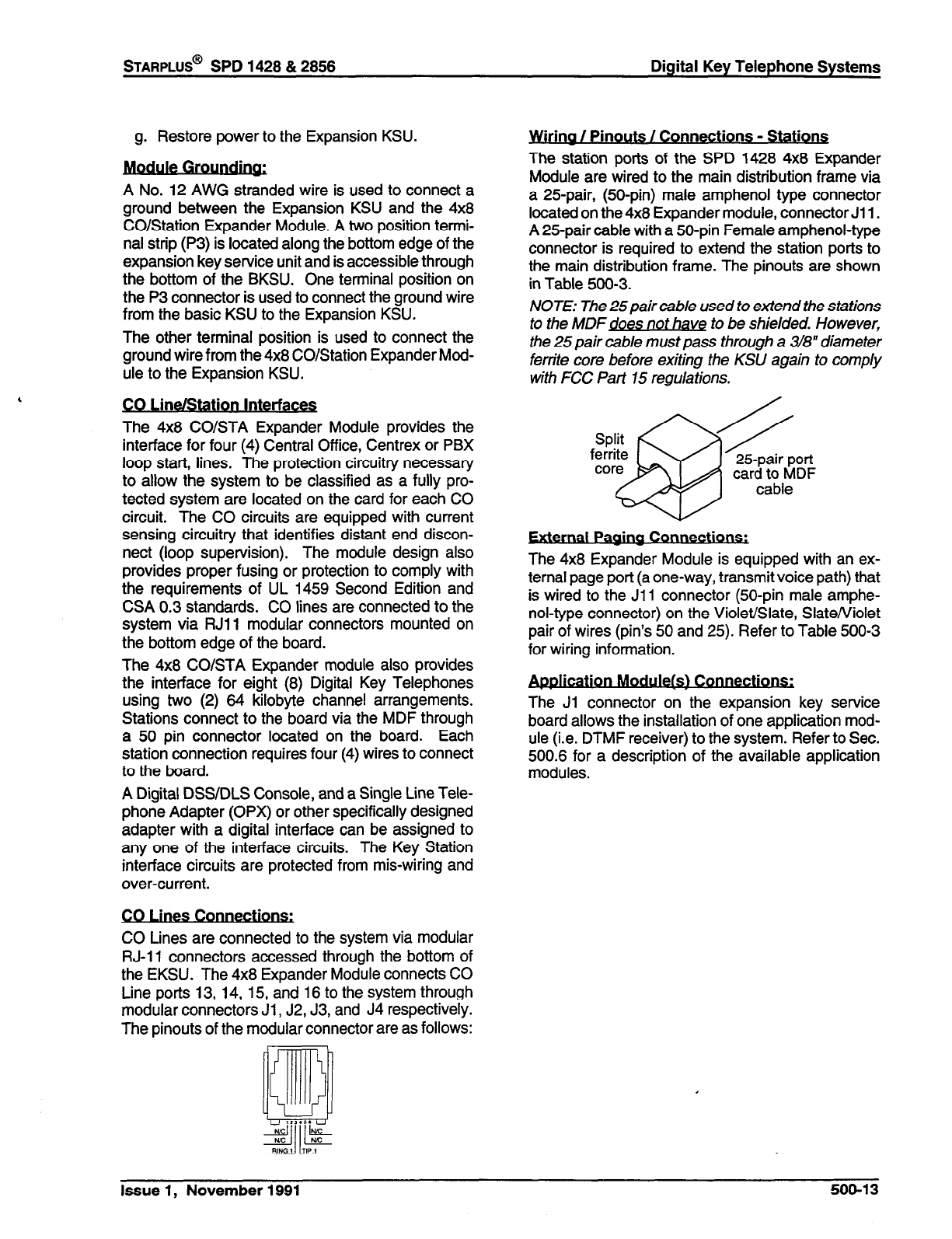
g. Restore power to the Expansion KSU.
A No. 12 AWG stranded wire is used to connect a
ground between the Expansion KSU and the 4x8
CO/Station Expander Module. A two position termi-
nal strip (P3) is located along the bottom edge of the
expansion key service unit and is accessible through
the bottom of the BKSU. One terminal position on
the P3 connector is used to connect the ground wire
from the basic KSU to the Expansion KSU.
The other terminal position is used to connect the
ground wire from the 4x8 CO/Station Expander Mod-
ule to the Expansion KSU.
CO Line/Station Interfaces
The 4x8 CO/STA Expander Module provides the
interface for four (4) Central Office, Centrex or PBX
loop start, lines. The protection circuitry necessary
to allow the system to be classified as a fully pro-
tected system are located on the card for each CO
circuit. The CO circuits are equipped with current
sensing circuitry that identifies distant end discon-
nect (loop supervision). The module design also
provides proper fusing or protection to comply with
the requirements of UL 1459 Second Edition and
CSA 0.3 standards. CO lines are connected to the
system via RJll modular connectors mounted on
the bottom edge of the board.
The 4x8 CO/STA Expander module also provides
the interface for eight (8) Digital Key Telephones
using two (2) 64 kilobyte channel arrangements.
Stations connect to the board via the MDF through
a 50 pin connector located on the board. Each
station connection requires four (4) wires to connect
to the board.
A Digital DSS/DLS Console, and a Single Line Tele-
phone Adapter (OPX) or other specifically designed
adapter with a digital interface can be assigned to
any one of the interface circuits. The Key Station
interface circuits are protected from mis-wiring and
over-current.
.
s Connections.
CO Lines are connected to the system via modular
RJ-11 connectors accessed through the bottom of
the EKSU. The 4x8 Expander Module connects CO
Line ports 13, 14, 15, and 16 to the system through
modular connectors Jl , J2, J3, and J4 respectively.
The pinouts of the modular connector are as follows:
. .
Irma / Pmouts / Connections - Stations
The station ports of the SPD 1428 4x8 Expander
Module are wired to the main distribution frame via
a 25pair, @O-pin) male amphenol type connector
located on the 4x8 Expander module, connector Jl 1.
A 25-pair cable with a 50-pin Female amphenol-type
connector is required to extend the station ports to
the main distribution frame. The pinouts are shown
in Table 500-3.
NOTE: The 25pair cable used to extend the stations
to the MDFdoes not have to be shielded. However,
the 25 pair cable must pass through a 3/8” diameter
ferrite core before exiting the KSU again to comply
with FCC Part 75 regulations.
I 25-pair port
card to MDF
cable
.
nal Pv
The 4x8 Expander Module is equipped with an ex-
ternal page port (a one-way, transmit voice path) that
is wired to the Jll connector (50-pin male amphe-
nol-type connector) on the Violet/Slate, Slate/Violet
pair of wires (pin’s 50 and 25). Refer to Table 500-3
for wiring information.
- .
Con-
The Ji connector on the expansion key service
board allows the installation of one application mod-
ule (i.e. DTMF receiver) to the system. Refer to Sec.
500.6 for a description of the available application
modules.
Issue 1, November 1991 500-13
500.4
SPD 2656 INSTALLATION PLANNING
Prior planning of the installation will aid in a smooth
cut-over and a satisfied customer. Select a suitable
location for the system. Determine the number of
telephones of each type, and the number of 4x8
CO/Station cards from the sales contract and discus-
sions with the customer.
NOTE: Only one station set is allowed per digital
extension number. It is not possible to bridge digital
station ports so that an extension number may ap-
pear in more than one location.
.
4
.
e
.
.
Programming information should also be gath-
ered from the customer at this time so that the
system may be programmed either before, or
while the system is being installed. I_
Determine the location and type of each tele-
phone, and mark floor plans accordingly.
Determine the location for the operator stations,
and mark the floor plans.
Arrange for power cabling (if necessary) and
station cabling of the site.
If the system is to be installed in an area subject
to frequent lightning storms, consideration
should be given to providing additional lightning
protection on the CO lines beyond what is
provided by the local telephone operating com-
pany.
NOTE: Installers should be trained and thoroughly
familiar with the basic components of the SPD 2856
before attempting installation of this product,
500.5
SPD 2656 SYSTEM COMPONENTS
A. Equipment Cabinet With Power Supply
WW
The SPD 2856 system main cabinet contains the
power supply and mother board to support a fully
configured system of 28 CO Lines and 56 Stations.
The mother board has eight (8) card slots. Card Slot
J8 (the right most card slot) is used for the Central
Processor Board (CPB) PCB. Card slots Jl through
J7 each support a four (4) CO line by eight (8) station
PCB’s. Cable exits through the bottom of the KSU
through a cable exit raceway near the back of the
KSU. Refer to Figure 500-5 for PCB layout and
location of connectors.
Power Sup&
The power supply is installed in the KSU at the time
of manufacture and ships with the KSU. The power
supply input voltage is 117 VAC flO%. The power
supply provides power distribution of filtered / un-
regulated 12 VDC and a regulated -5 VDC to the
backplane bus. An ON/OFF switch is located on the
front of the power supply along with a slo-blow 5 amp
fuse on the AC side of the transformer. The power
supply provides an input for a 48 VDC source for
future use. Power is regulated and distributed to
stations/circuitry in the system on each PCB. Three
fuses located inside the power supply protect the
system from over-current situations. The power
supply and cabinet meet all safety requirements to
comply with UL 1459 Second Edition and CSA 0.3
standards.
The power supply is installed inside the system
cabinet, on the right side, in the first card slot (J9).
The power supply is designed to be an integral,
structural part of the system. Do not attempt to install
the system, or interface cards unless the power
supply is installed with all four screws securely in
place. The cabinet, includes the power supply al-
ready installed. The power supply is recognized
under the Component Program of Underwriters
Laboratories Inc.
NOTE: Make certain a l/2 inch diameter ferrite core
is in place on the power cord at a point as close to
the power supply as possible. If this core is not in
place, it is shipped with the cabinet and must be
installed before operating the system. Refer to fig-
ure 500-6 for the proper location. Keep the ferrite
core from sliding down the cable by installing a cab/e
tie on the power cordjust below the ferrite cord.
The power supply is unique in that the transformer
is not present on the power supply card and its
enclosure. The transformer is mounted inside the
cabinet next to the bottom right of the backplane.
When the power supply card is installed, the trans-
former is totally enclosed by the power supply card’s
“L” shaped enclosure, and the right side of the cabi-
net. This creates a totally enclosed, operational,
power supply. Since the transformer is installed in
the cabinet, and the power supply card is removable
from the cabinet, the AC connections are made
directly to the system backplane.
1
WARNING 1
Since hazardous voltages are always pre-
sent on the backplane while the system
AC power cord is plugged in, AT NO TIME
SHOULD THE POWER SUPPLY CARD
BE REMOVED WHILE THE SYSTEM AC
POWER CORD IS PLUGGED IN. THE
POWER SUPPLY BOARD AND ITS “L
SHAPED METAL ENCLOSURE PRO-
VIDE THE ONLY PROTECTION FROM
SHOCK HAZARD WHILE THE AC
POWER CORD IS PLUGGED IN. There
are very few instances when the power
500-l 4 Issue 1, November 1991
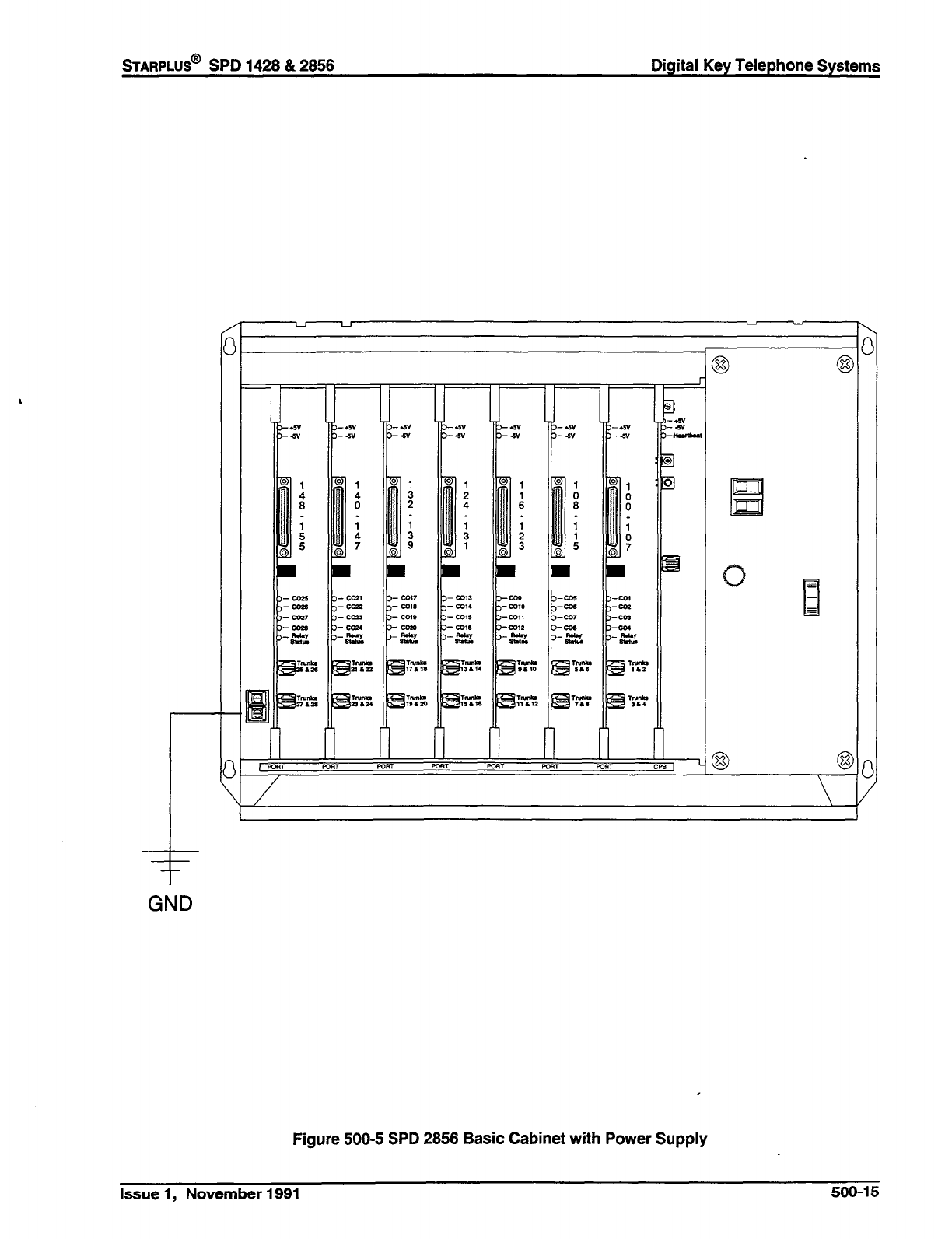
sTARPLUS@
SPD 1428 & 2856 Digital Key Telephone Systems
GND
Figure 500-5 SPD 2856 Basic Cabinet with Power Supply
Issue 1, November 1991 500-15
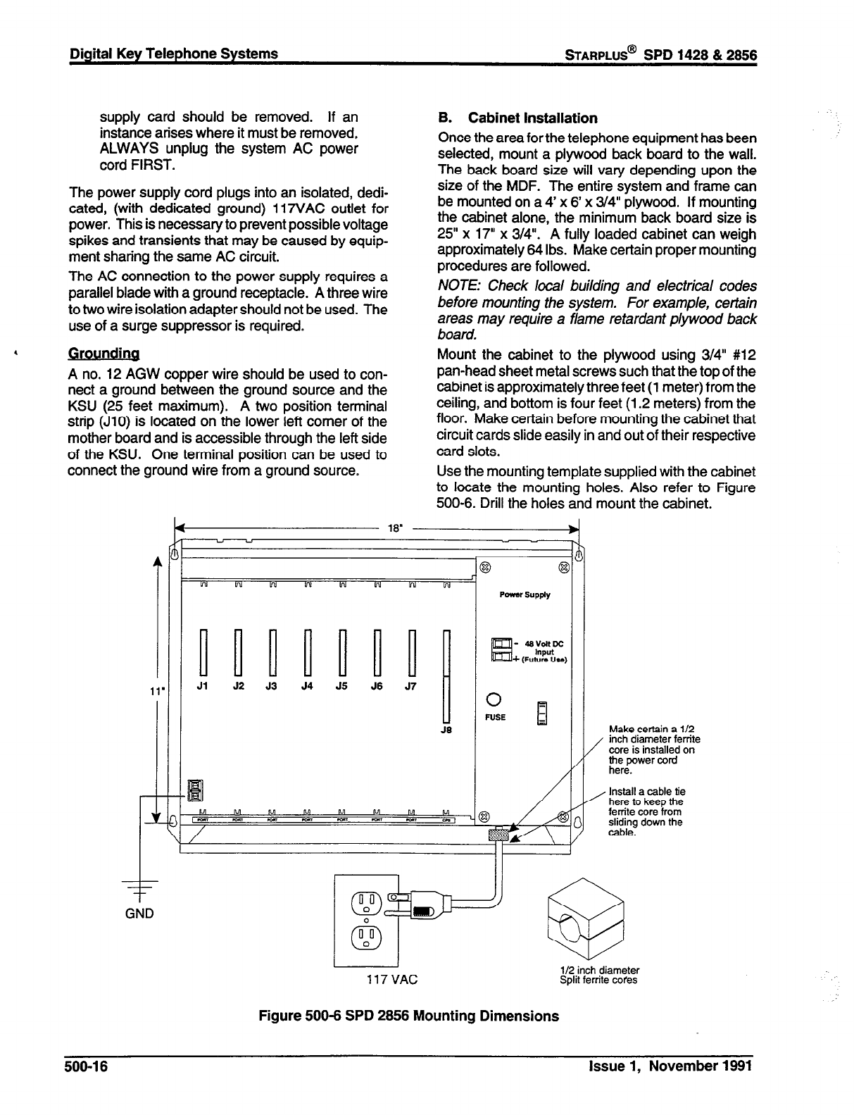
Digital Key Telephone Systems
STARPLUS@
SPD 1428 & 2858
supply card should be removed. If an
instance arises where it must be removed,
ALWAYS unplug the system AC power
cord FIRST.
The power supply cord plugs into an isolated, dedi-
cated, (with dedicated ground) 117VAC outlet for
power. This is necessary to prevent possible voltage
spikes and transients that may be caused by equip-
ment sharing the same AC circuit.
The AC connection to the power supply requires a
parallel blade with a ground receptacle. A three wire
to two wire isolation adapter should not be used. The
use of a surge suppressor is required.
. Grounding
A no. 12 AGW copper wire should be used to con-
nect a ground between the ground source and the
KSU (25 feet maximum). A two position terminal
strip (JlO) is located on the lower left comer of the
mother board and is accessible through the left side
of the KSU. One terminal position can be used to
connect the ground wire from a ground source.
I
- -
GND
4
18”
B. Cabinet Installation
Once the area for the telephone equipment has been
selected, mount a plywood back board to the wall.
The back board size will vary depending upon the
size of the MDF. The entire system and frame can
be mounted on a 4’ x 6’ x 3/4” plywood. If mounting
the cabinet alone, the minimum back board size is
25” x 17” x 3/4”. A fully loaded cabinet can weigh
approximately 64 Ibs. Make certain proper mounting
procedures are followed.
NOTE: Check local building and electrical codes
before mounting the system. For example, certain
areas may require a flame retardant plywood back
board.
Mount the cabinet to the plywood using 3/4” #12
pan-head sheet metal screws such that the top of the
cabinet is approximately three feet (1 meter) from the
ceiling, and bottom is four feet (1.2 meters) from the
floor. Make certain before mounting the cabinet that
circuit cards slide easily in and out of their respective
card slots.
Use the mounting template supplied with the cabinet
to locate the mounting holes. Also refer to Figure
500-6. Drill the holes and mount the cabinet.
- - - -
w w bu !rd vd w w w
Poww supply
UWU~~
Jl 52 J3 54 55 56 57
d
J6
6
:
0 -
PUS-E 1
n
/
Make certain a l/2
/ inch diameter ferrite
core is installed on
the power cord
here.
/’
/ Install a cable tie
here to keep the
ferrite core from
sliding down the
cable.
/
I I
I I II
r iig
117VAC
Split ferrite cores
Figure 500-6 SPD 2856 Mounting Dimensions
500-l 6 Issue 1, November 1891

STARPLUS@
SPD 1428 & 2856 Digital Key Telephone Systems
C. Central Processor Board (CPB)
This plug-in card is the only common equipment card
required to make the system operational and con-
trols all system activity. The CPB contains the main
micro-processor a 16-bit (68000) and a real time
clock which controls all system functions including
the PCM/TDM voice switching under direction of
ROM and RAM software coding. The CPB is re-
sponsible for all control functions, execution of all
logic operations and control of system modules in-
cluding control over circuitry necessary for voice
switching and conference connections. The CPB is
also responsible for all system tones, system timing,
and station status control. In addition the CPB also
provides software and hardware support to ensure
the following:
Watch dog timer and recovery.
PCB status as to presence/absence of cards
for automatic software configuration setup.
Interpret an ID code from each PCB so that
card type can be determined automatically.
State/event software design.
Battery backup of customer database RAM
memory.
The CPB contains the circuitry and connection (RCA
type) for background music/music on hold, and the
standard 300 Baud Modem. An optional 1200 Baud
Modem can be installed on the CPB to allow the
on-board modem to transmit at a 1200 baud rate. In
addition there is one RS-232 (modular connector)
input/output port on the CPB and a connector to
support the use of an optional I/O expansion module.
The I/O expansion module adds (1) RS-232 l/O port
and (1) RS-422 l/O port to the system for a system
total of three (3) I/O ports. A reset (halt) push button
switch and a BGM/MOH volume control pot is lo-
cated on the front of the PCB. Refer to Figure 500-5
for CPB layout and location of connectors.
System software is provided in EPROM memory and
is installed on the CPB. The CPB contains (512)
kilobytes of EPROM storage and is equipped with
256K of battery-backed static RAM. Provisions
have been made on the card to address up to (4)
megabytes of EPROM memory and up to (2) mega-
bytes of static RAM.
An option “dip” switch located on the CPB allows the
system EPROM memory to be configured utilizing
different size EPROM chips. 1 Megabit, 2 Megabit,
4 Megabit and 8 Megabit chips may be used to
provide the generic software.Refer to Sec. 800 Main-
tenance & Troubleshooting for “dip” switch settings
for various allowable configurations.
The CPB allows the use of either 1 Megabit or 4
megabit static RAM chips to be used for RAM mem-
ory. The size and type of memory usedjs automat-
ically determined and set by the system.
The battery backup strap must be placed
in the “ON” position to activate memory
battery backup (J3). Do this prior to insert-
ing the CPB into the KSU (Refer to Figure
500-5). If the optional 1200 baud modem
module or expansion I/O module are to be
installed, do this now prior to inserting the
CPB. The CPB board is inserted into the
J8 slot with components on the card facing
the right. This board must NOT be in-
stalled with the power on. The edge con-
nector on the CPB is offset to prevent it
from being installed in an incorrect slot.
Do not force the card into another slot.
One CPB is required per system.
LED’s 81 Indicators
Two green LED’s located along the front edge of the
CPB provide an indication of the presence of +5 VDC
& -5 VDC to the PCB. A third red LED located just
below the two green LED’s provides a system “heart
beat” indication.
Modem Interface
The CPB contains an on-board modem that is capa-
ble of transmitting data at a rate of 300 baud. The
modem supports and is compatible with the Hayes
command protocol. The Bell System (Western Elec-
tric) standards 103 and 212A for modem design is
incorporated into the design of this modem. The
modem operates on-line in both Full and Half duplex
modes. An optional 1200 baud module may be
added to the CPB to allow transmission at the rate
of 1200 baud.
VO Port(s) Connections:
The SPD 2856 CPB contains one RS232C, I/O port
(8 pin modular jack type connector) located near the
front edge of the PCB. This I/O port is capable of
transmitting and receiving data at 300, 1200, 2400,
4800, and 9600 baud rates. The pinouts and com-
munication requirements are shown in Figure 500-8.
Issue 1, November 1991 500-l 7
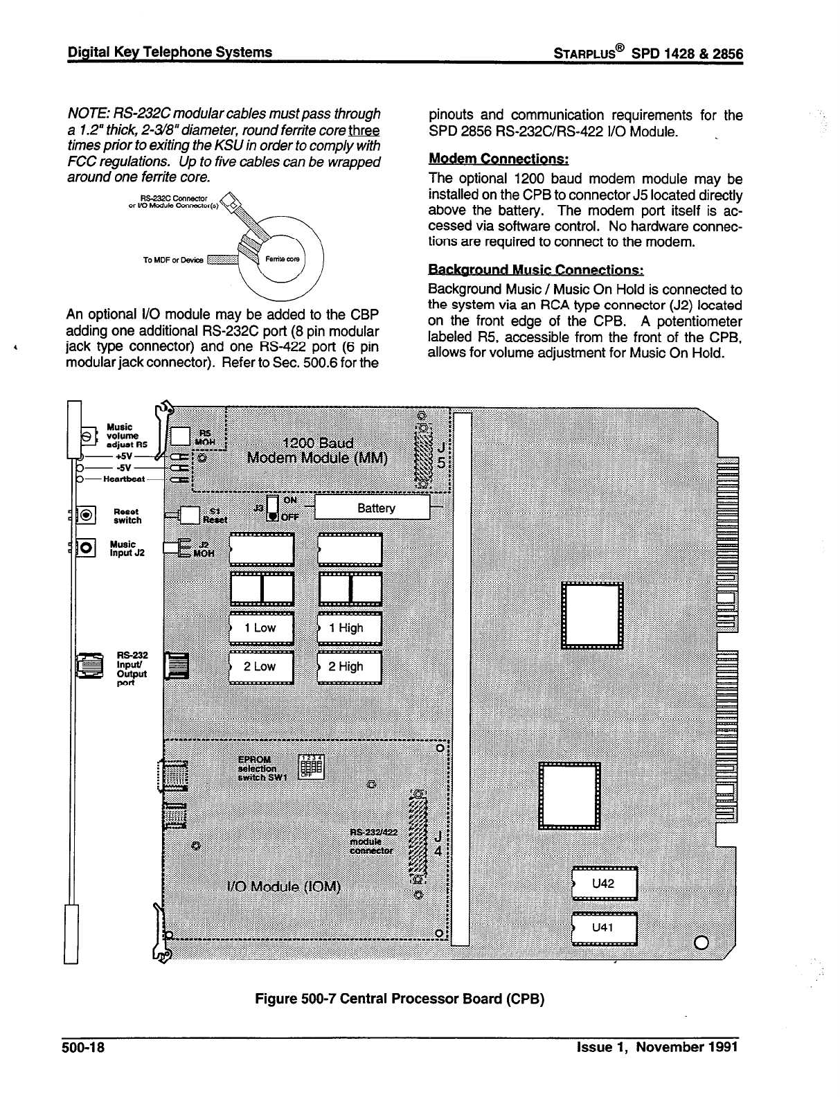
Digital Key Telephone Systems
STARPLUS@
SPD 1428 & 2858
NOTE: RS-232C modular cables must pass through
a 1.2” thick, 2-348” diameter, round ferrite core three
times prior to exiting the KSU in order to comply with
FCC regulations. Up to five cables can be wrapped
around one ferrite core.
An optional I/O module may be added to the CBP
adding one additional RS-232C port (8 pin modular
4 jack type connector) and one RS-422 port (6 pin
modular jack connector). Refer to Sec. 500.6 for the
pinouts and communication requirements for the
SPD 2856 RS-232C/RS-422 I/O Module. _
Modem Connections:
The optional 1200 baud modem module may be
installed on the CPB to connector J5 located directly
above the battery. The modem port itself is ac-
cessed via software control. No hardware connec-
tions are required to connect to the modem.
.
Backaround MUSIC Co nnections:
Background Music / Music On Hold is connected to
the system via an RCA type connector (J2) located
on the front edge of the CPB. A potentiometer
labeled R5, accessible from the front of the CPB,
allows for volume adjustment for Music On Hold.
b-+!5V-
b--w-
~-Heartbeat -
Reset
switch
El
Music
Input JZ
El
us-222
lnputl
Output
Figure 500-7 Central Processor Board (CPB)
500-l 8 Issue 1, November 1991
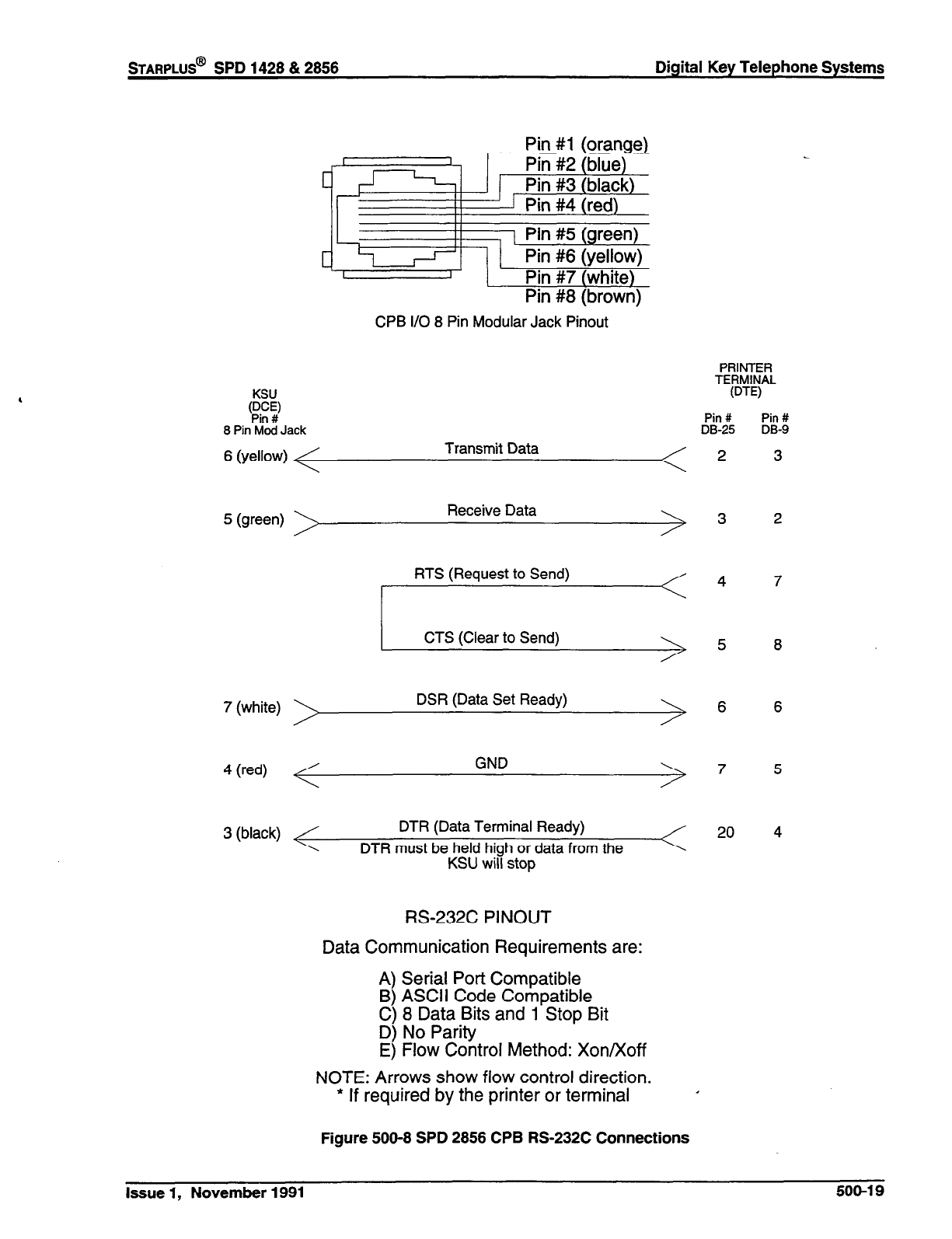
,
STARPLUS@ SPD 1428 & 2856 Digital Key Telephone Systems
Pin #I (orange)
C
Pin #8 (brown)
CPB I/O 8 Pin Modular Jack Pinout
KSU
p..y
8 Pin Mod Jack
6 (yellow) Transmit Data
5 (green) Receive Data
7 (white) DSR (Data Set Ready)
4 (red) GND
3 (black) DTR (Data Terminal Ready)
DTR must be held high or data from the
KSU will stop
RS-232C PINOUT
Data Communication Requirements are:
A) Serial Port Compatible
B) ASCII Code Compatible
C) 8 Data Bits and 1 Stop Bit
D) No Parity
E) Flow Control Method: Xon/Xoff
NOTE: Arrows show flow control direction.
._ . . . . .
* If required
by the
printer or terminal ’
Figure 500-8 SPD 2856 CPB RS-232C Connections
PRINTER
TERMINAL
WE)
Pin # Pin #
DB-25 DB-9
2 3
3 2
4 7
5 8
6 6
7
20
Issue 1, November 1991 500-l 9
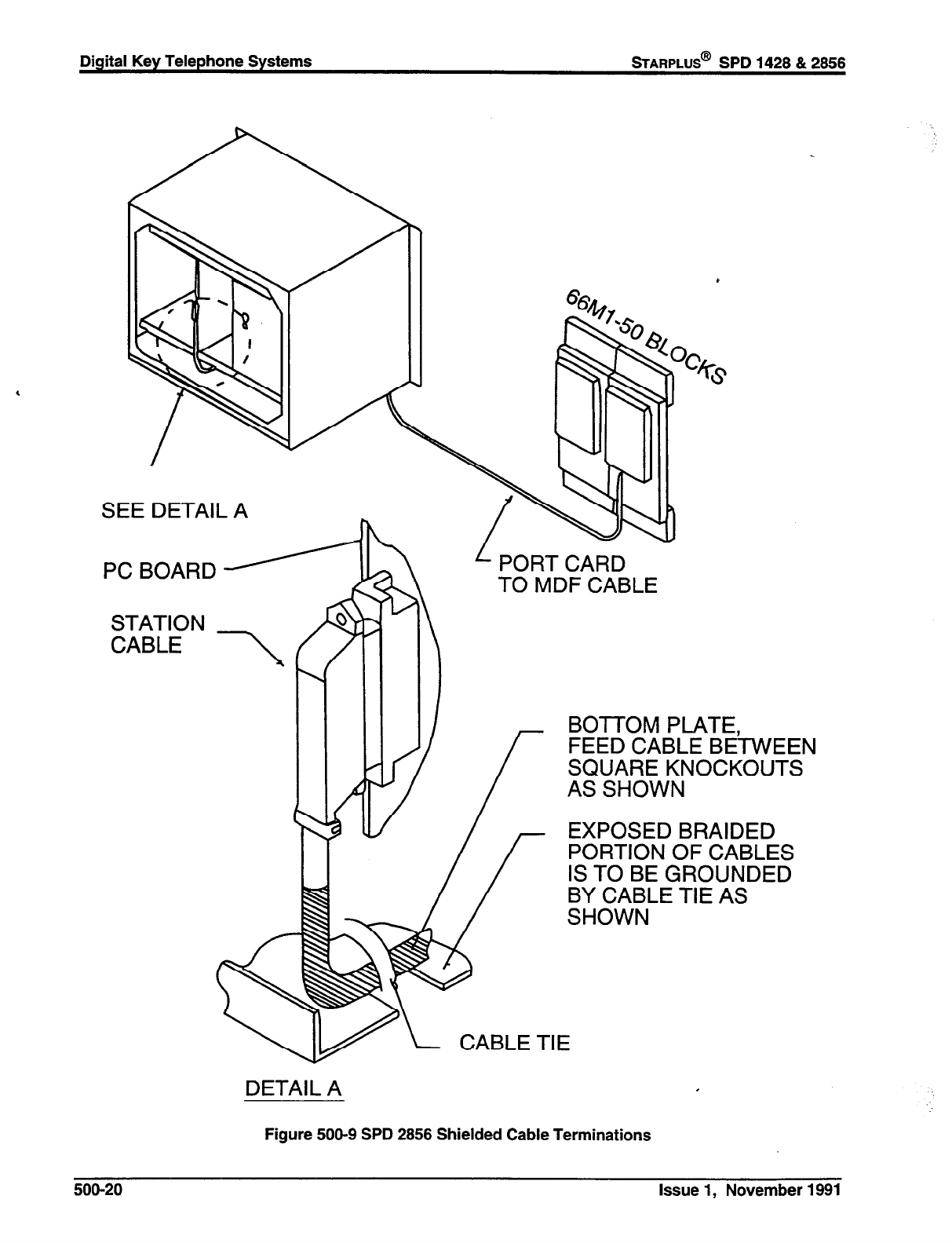
Digital Key Telephone Systems
BARPLUS@
SPD 1428 & 2858
SEE DETAIL A
STATION
CABLE \ I
PORT CARD
TO MDF CABLE
DETAIL A
Figure 500-9 SPD 2856 Shielded Cable Terminations
BOTTOM PLATE,
FEED CABLE BETWEEN
SQUARE KNOCKOUTS
AS SHOWN
EXPOSED BRAIDED
PORTION OF CABLES
IS TO BE GROUNDED
BY CABLE TIE AS
SHOWN
500-20 Issue 1, November 1991
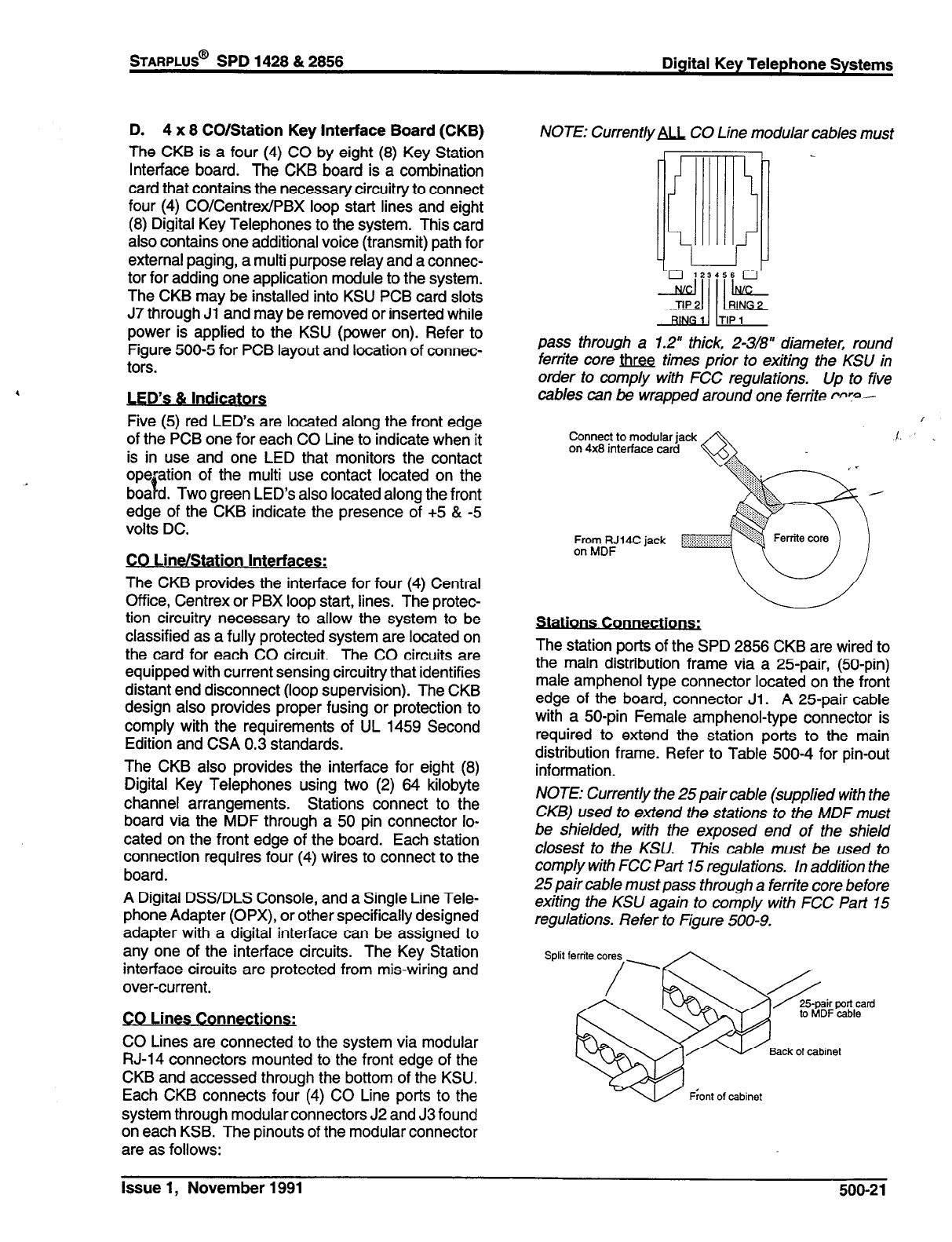
STARPLUS@
SPD 1428 & 2858 Digital Key Telephone Systems
D. 4 x 8 CO/Station Key Interface Board (CKB)
The CKB is a four (4) CO by eight (8) Key Station
Interface board. The CKB board is a combination
card that contains the necessary circuitry to connect
four (4) CO/Centrex/PBX loop start lines and eight
(8) Digital Key Telephones to the system. This card
also contains one additional voice (transmit) path for
external paging, a multi purpose relay and a connec-
tor for adding one application module to the system.
The CKB may be installed into KSU PCB card slots
J7 through Jl and may be removed or inserted while
power is applied to the KSU (power on). Refer to
Figure 500-5 for PCB layout and location of connec-
tors.
,
s & Indicators
Five (5) red LED’s are located along the front edge
of the PCB one for each CO Line to indicate when it
is in use and one LED that monitors the contact
operation of the multi use contact located on the
boa%d. Two green LED’s also located along the front
edge of the CKB indicate the presence of +5 & -5
volts DC.
CO Line/Station Interfaces:
The CKB provides the interface for four (4) Central
Office, Centrex or PBX loop start, lines. The protec-
tion circuitry necessary to allow the system to be
classified as a fully protected system are located on
the card for each CO circuit. The CO circuits are
equipped with current sensing circuitry that identifies
distant end disconnect (loop supervision). The CKB
design also provides proper fusing or protection to
comply with the requirements of UL 1459 Second
Edition and CSA 0.3 standards.
The CKB also provides the interface for eight (8)
Digital Key Telephones using two (2) 64 kilobyte
channel arrangements. Stations connect to the
board via the MDF through a 50 pin connector lo-
cated on the front edge of the board. Each station
connection requires four (4) wires to connect to the
board.
A Digital DSWDLS Console, and a Single Line Tele-
phone Adapter (OPX), or other specifically designed
adapter with a digital interface can be assigned to
any one of the interface circuits. The Key Station
interface circuits are protected from mis-wiring and
over-current.
CO Lines Connections:
CO Lines are connected to the system via modular
RJ-14 connectors mounted to the front edge of the
CKB and accessed through the bottom of the KSU.
Each CKB connects four (4) CO Line ports to the
system through modular connectors J2 and J3 found
on each KSB. The pinouts of the modular connector
are as follows:
NOTE: Current/y U CO Line modular cables must
pass through a 1.2” thick, 2-3/8” diameter, round
ferrite core ti times prior to exiting the KSU in
order to comply with FCC regulations. Up to five
cables can be wrapped around one ferrite PW--
Connect to modular jack
on 4x8 interface card
From RJ14C jack
on MDF
ons Connectlorls.
- .
The station ports of the SPD 2856 CKB are wired to
the main distribution frame via a 25-pair, (50-pin)
male amphenol type connector located on the front
edge of the board, connector Jl. A 25-pair cable
with a 50-pin Female amphenol-type connector is
required to extend the station ports to the main
distribution frame. Refer to Table 500-4 for pin-out
information.
NOTE: Currently the 25 pair cable (suppled with the
CKB) used to extend the stations to the MDF must
be shielded, with the exposed end of the shield
closest to the KSU. This cable must be used to
comply with FCC Part 15 regulations. In addition the
25 pair cable must pass through a ferrite core before
exiting the KSU again to comply with FCC Pan 15
regulations. Refer to Figure 500-9.
Issue 1, November 1991 500-21
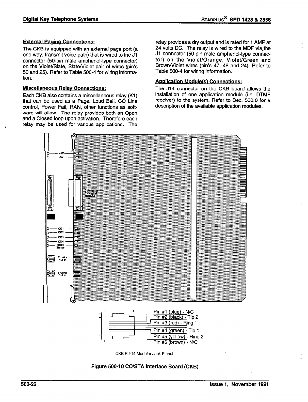
ernal Pagjna Connections:
The CKB is equipped with an external page port (a
one-way, transmit voice path) that is wired to the Jl
connector @O-pin male amphenol-type connector)
on the Violet/Slate, SlateNiolet pair of wires (pin’s
50 and 25). Refer to Table 500-4 for wiring informa-
tion.
Miscellaneous Relay Connections:
Each CKB also contains a miscellaneous relay (Kl)
that can be used as a Page, Loud Bell, CO Line
control, Power Fail, PAN, other functions as soft-
ware will allow. The relay provides both an Open
and a Closed loop upon activation. Therefore each
relay provides a dry output and is rated for 1 AMP at
24 volts DC. The relay is wired to the MDF viathe
Jl connector @O-pin male amphenol-type connec-
tor) on the Violet/Orange, Violet/Green and
Brown/Violet wires (pin’s 47, 46 and 24). Refer to
Table 500-4 for wiring information.
pi cat on Module(s) Connections: A Ii i
The J14 connector on the CKB board allows the
installation of one application module (i.e. DTMF
receiver) to the system. Refer to Sec. 500.6 for a
description of the available application modules.
a relay may be used for various applications. The
CKB RJ-14 Modular Jack Pinout
Figure 500-l 0 CO/STA Interface Board (CKB)
500-22 Issue 1, November 1991

STARPLUS@ SPD 1428 & 2856 Digital Key Telephone Systems
E. 4x8 CO/SLT Interface Board (CSB) (Future)
The CSB is a four (4) CO Line by eight (8) Single
Line Station interface board. The CSB board is a
combination card that contains the necessary cir-
cuitry to connect four (4) CO/Centrex/PBX loop start
lines and eight (8) Standard Single Line Telephone
(2500 type) to the system. This card also contains
one additional voice (transmit) path for external pag-
ing, a multi purpose relay and a connector for adding
one application module to the system. The CSB
requires a 9OVdc Power Supply/Ring Generator,
and at least one DTMF Receiver module (RM) must
be installed in the system. This board can be re-
moved or inserted with power on the KSU. Refer to
Figure 500-5 for a PCB layout and location of con-
nectors.
LED’s & Indicators
Five (5) red LED’s are located along the front edge
of the PCB one for each CO Line to indicate when it
is in use and one LED that monitors the contact
operation of the multi use relay located on the board.
Two green LED’s also located along the front edge
of the CKB indicate the presence of +5 & -5 volts DC.
CO Line/Station Interfaces:
The CSB provides the interface for four (4) Central
Office, Centrex or PBX loop start, lines. The protec-
tion circuitry necessary to allow the system to be
classified as a fully protected system are located on
the card for each CO circuit. The CO circuits are
equipped with current sensing circuitry that identifies
distant end disconnect (loop supervision). The CSB
design also provides proper fusing or protection to
comply with the requirements of UL 1459 Second
Edition and CSA 0.3 standards. The CSB does not
support data devices for data switching.
The CSB provides the control and interface for eight
(8) standard Single line telephones (2500 type).
Eight 24 volt DC single line circuits are provided on
the PCB. These single line telephones can be
equipped with a standard Message Waiting Lamp
(90V T & R) that operate on the “tip” and “ring” leads.
Additionally each circuit may be individually
“strapped” or “optioned” to provide a loop interrupt to
the connected SLT or device. The card will support
single line Telephones up to 1500 feet from the KSU.
CO Lines Connections:
CO Lines are connected to the system via modular
RJ-14 connectors mounted to the front edge of the
CSB and accessed through the bottom of the KSU.
Each CSB connects four (4) CO Line ports to the
system through modular connectors J2 and J3 found
on each CSB. The pinouts of the modular connector
are as follows:
NOTE: Current/yU CO Line modular cables must
CSB RJ-14 Modular Jack Pinout
pass through a 1.2” thick, 2-3/g” diameter, round
ferrite core m times prior to exiting the KSU in
order to comply with FCC regulations. Up to five
cables can be wrapped around one ferrite core.
Connect to modular jack
on 4x8 interface card
From RJ1 4c jack
on MDF
Stations Connections:
The SLT station ports of the SPD 2856 CSB are
wired to the main distribution frame via a 25-pair,
(50-pin) male amphenol type connector located on
the front edge of the board, connector Jl. A 25-pair
cable with a 50-pin Female amphenol-type connec-
tor is required to extend the station ports to the main
distribution frame. The pinouts are shown in Table
500-5.
NOTE: Current/y the 25pair cable (supplied with the
CSB) used to extend the stations to the MDF must
be shielded, with the exposed end of the shield
closest to the KSLJ. This cable must be used to
comply with FCC Part 15 regulations. In addition the
25 pair cab/e must pass through a ferrite core before
exiting the KSU again to comply with FCC Part 15
regulations. Refer to Figure 500-9.
Front of cabinet
Issue 1, November 1991 500-23
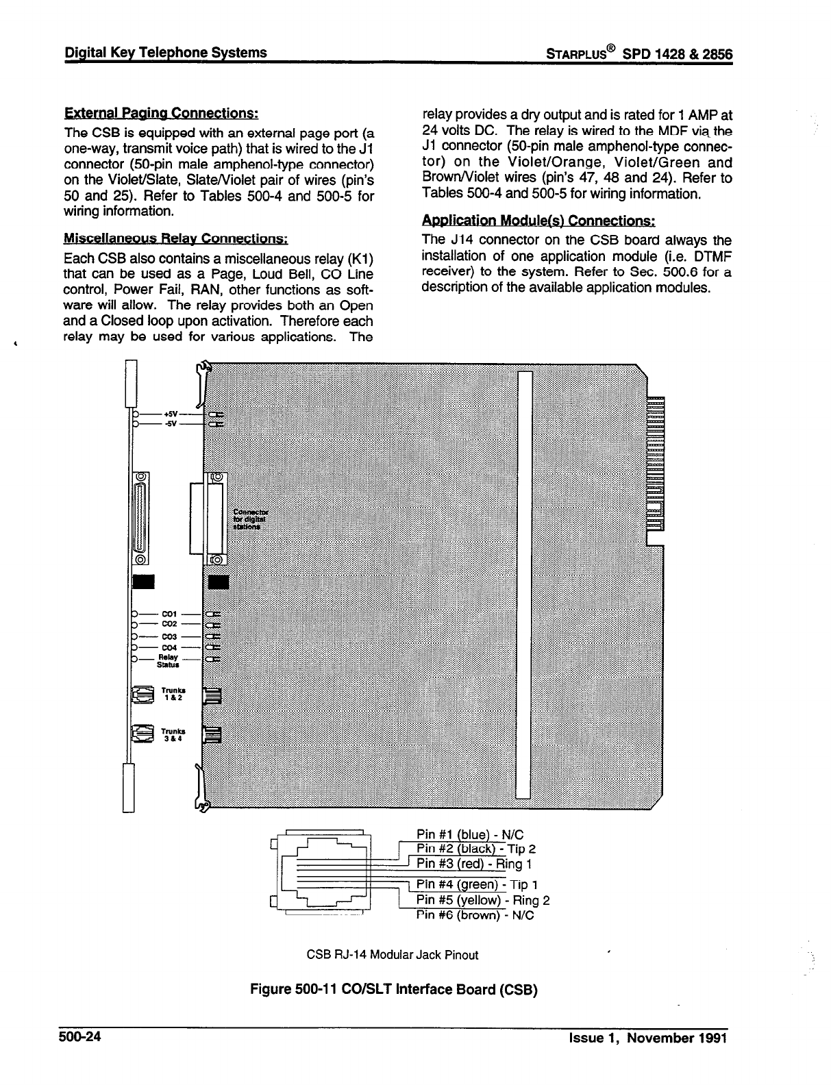
Digital Key Telephone Systems
sTARPLUS@
SPD 1428 & 2856
External Paaina Connections:
The CSB is equipped with an external page port (a
one-way, transmit voice path) that is wired to the Jl
connector @O-pin male amphenol-type connector)
on the Violet/Slate, Slate/Violet pair of wires (pin’s
50 and 25). Refer to Tables 500-4 and 500-5 for
wiring information.
Miscellaneous Relay Connections:
Each CSB also contains a miscellaneous relay (Kl)
that can be used as a Page, Loud Bell, CO Line
control, Power Fail, RAN, other functions as soft-
ware will allow. The relay provides both an Open
and a Closed loop upon activation. Therefore each
, relay may be used for various applications. The
relay provides a dry output and is rated for 1 AMP at
24 volts DC. The relay is wired to the MDF via the
Ji connector (50-pin male amphenol-type connec-
tor) on the Violet/Orange, Violet/Green and
Brown/Violet wires (pin’s 47, 46 and 24). Refer to
Tables 500-4 and 500-5 for wiring information.
. .
IcatIon Module!& Connections:
The J14 connector on the CSB board always the
installation of one application module (i.e. DTMF
receiver) to the system. Refer to Sec. 500.6 for a
description of the available application modules.
CSB RJ-14 Modular Jack Pinout
Figure 500-l 1 CO/SLT Interface Board (CSB)
500-24 Issue 1, November 1991
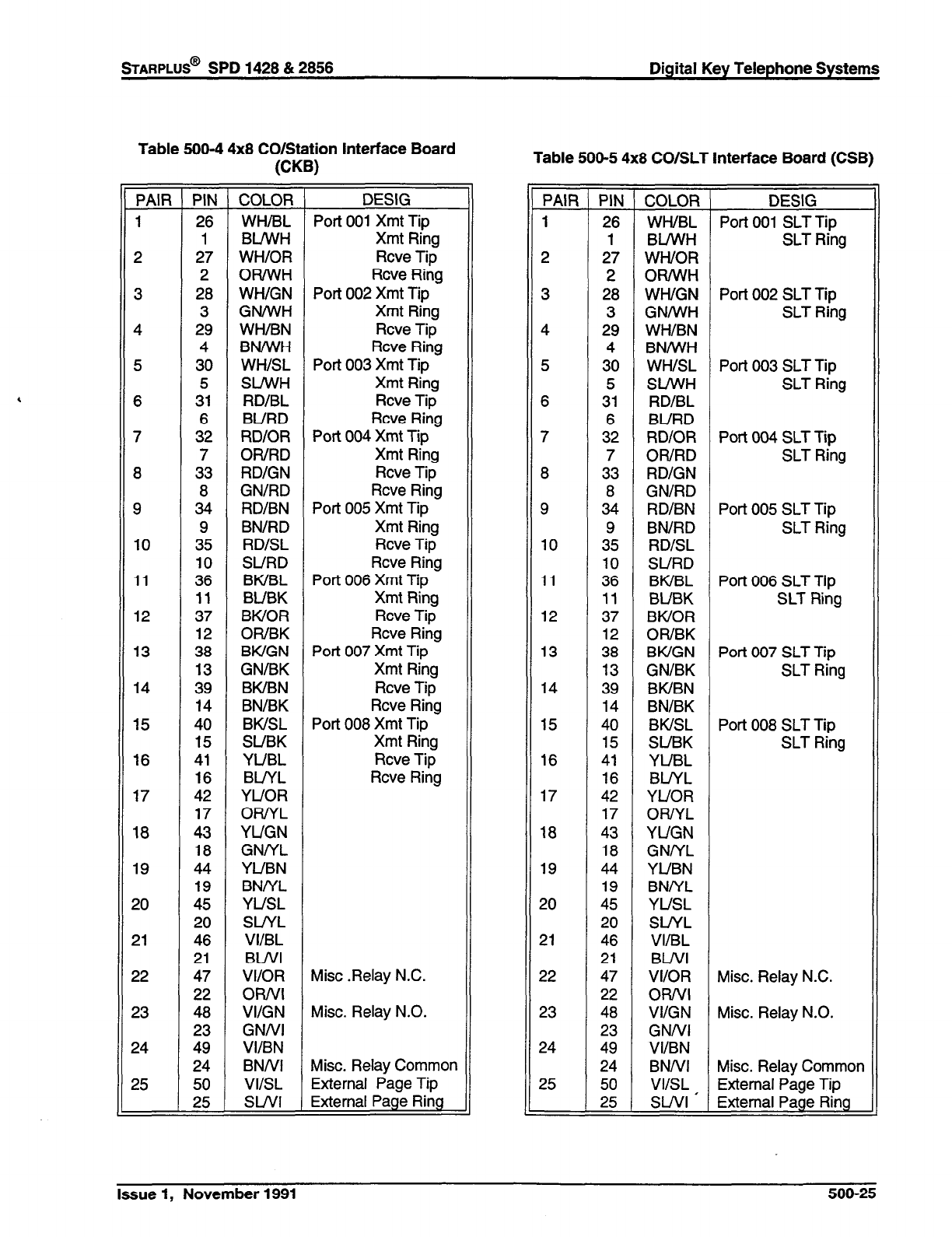
STARPLUS@
SPD 1428 & 2856 Digital Key Telephone Systems
Table 500-4 4x8 CO/Station Interface Board
WB)
PAIR
1
2
3
4
5
6
7
8
9
10
11
12
13
14
15
16
17
18
19
20
21
22
23
24
25
-PI&
COLOR
26 WH/BL
1 BLIWH
27 WH/OR
2 OR/WH
28 WH/GN
3 GNNVH
29 WH/BN
4 BN/WH
30 WHISL
5 SlfWH
31 RD/BL
6 BURD
32 RD/OR
7 OR/RD
33 RD/GN
8 GN/RD
34 RD/BN
9 BN/RD
35 RD/SL
10 SURD
36 BWBL
11 BUBK
37 BWOR
12 OWBK
38 BWGN
13 GN/BK
39 BK/BN
14 BN/BK
40 BWSL
15 SUBK
41 YUBL
16 BL/YL
42 YUOR
17 ORiYL
43 YUGN
18 GNNL
44 YUBN
19 BNNL
45 YUSL
20 SUYL
46 VI/BL
21 BWI
47 VI/OR
22 OR/VI
48 VI/GN
23 GNNI
49 VI/BN
24 BNNI
50 VI/SL
25 SWI
-
-
DESIG
Port 001 Xmt Tip
Xmt Ring
Rcve Tip
Rcve Ring
Port 002 Xmt Tip
Xmt Ring
Rcve Tip
Rcve Ring
Port 003 Xmt Tip
Xmt Ring
Rcve Tip
Rcve Ring
Port 004 Xmt Tip
Xmt Ring
Rcve Tip
Rcve Ring
Port 005 Xmt Tip
Xmt Ring
Rcve Tip
Rcve Ring
Port 006 Xmt Tip
Xmt Ring
Rcve Tip
Rcve Ring
Port 007 Xmt Tip
Xmt Ring
Rcve Tip
Rcve Ring
Port 008 Xmt Tip
Xmt Ring
Rcve Tip
Rcve Ring
Mist .Relay N.C.
Misc. Relay N.O.
Misc. Relay Common
External Page Tip
External Page Ring
Table 500-5 4x8 CO/SLT Interface Board (CSB)
-
PAIR
1
2
3
4
5
6
7
8
9
10
11
12
13
14
15
16
17
18
19
20
21
22
23
24
25
7
y
26
1
27
2
28
3
29
4
30
5
31
6
32
7
33
8
34
9
35
10
36
11
37
12
38
13
39
14
40
15
41
16
42
17
43
18
44
19
45
20
46
21
47
22
48
23
49
24
50
25
COLOR
WH/BL
BUVVH
WWOR
OR/V/H
WH/GN
GNNVH
WH/BN
BN/WH
WH/SL
SLbA’H
RD/BL
BURD
RD/OR
OWRD
RD/GN
GN/RD
RD/BN
BN/RD
RD/SL
SURD
BWBL
BUBK
BWOR
OR/BK
BWGN
GN/BK
BWBN
BN/BK
BWSL
SUBK
YUBL
BINL
YUOR
ORNL
YUGN
GNNL
YUBN
BNNL
YUSL
SUYL
VIIBL
BWI
VI/OR
ORNI
VI/GN
GNNI
VI/BN
BNNI
VIISL
SWI ’
DESIG
Port 001 SLT Tip
SLT Ring
Port 002 SLT Tip
SLT Ring
Port 003 SLT Tip
SLT Ring
Port 004 SLT Tip
SLT Ring
Port 005 SLT Tip
SLT Ring
Port 006 SLT Tip
SLT Ring
Port 007 SLT Tip
SLT Ring
Port 008 SLT Tip
SLT Ring
Misc. Relay N.C.
Misc. Relay N.O.
Misc. Relay Common
External Page Tip
External Page Ring
-
Issue 1, November 1991
500-25
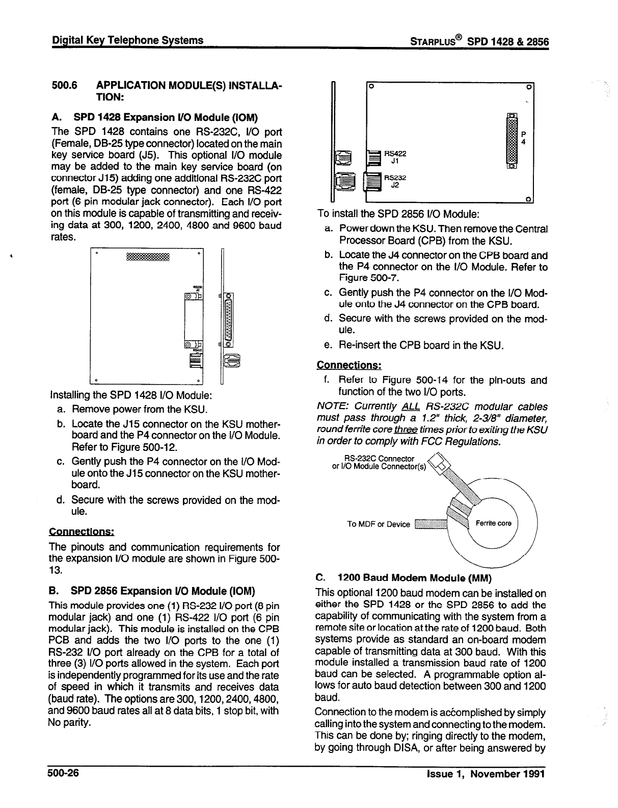
Digital Key Telephone Systems
wARPLUS@
SPD 1428 & 2858
500.6 APPLICATION MODULE(S) INSTALLA-
TION:
A. SPD 1428 Expansion l/O Module (IOM)
The SPD 1428 contains one RS-232C, I/O port
(Female, DB-25 type connector) located on the main
key service board (J5). This optional I/O module
may be added to the main key service board (on
connector J15) adding one additional RS-232C port
(female, DB-25 type connector) and one RS-422
port (6 pin modular jack connector). Each I/O port
on this module is capable of transmitting and receiv-
ing data at 300, 1200, 2400, 4800 and 9600 baud
rates.
I:
D
Installing the SPD 1428 I/O Module:
a. Remove power from the KSU.
b. Locate the J15 connector on the KSU mother-
board and the P4 connector on the I/O Module.
Refer to Figure 500-12.
c. Gently push the P4 connector on the I/O Mod-
ule onto the J15 connector on the KSU mother-
board.
d. Secure with the screws provided on the mod-
ule.
The pinouts and communication requirements for
the expansion I/O module are shown in Figure 500-
13.
B. SPD 2856 Expansion l/O Module (IOM)
This module provides one (1) RS-232 I/O port (8 pin
modular jack) and one (1) RS-422 l/O port (6 pin
modular jack). This module is installed on the CPB
PCB and adds the two I/O ports to the one (1)
RS-232 I/O port already on the CPB for a total of
three (3) I/O ports allowed in the system. Each port
is independently programmed for its use and the rate
of speed in which it transmits and receives data
(baud rate). The options are 300,1200,2400,4800,
and 9600 baud rates all at 8 data bits, 1 stop bit, with
No parity.
Is422
Jl
RS232
J2
u 1
To install the SPD 2856 I/O Module:
0
a. Power down the KSU. Then remove the Central
Processor Board (CPB) from the KSU.
b. Locate the J4 connector on the CPB board and
the P4 connector on the l/O Module. Refer to
Figure 500-7.
c. Gently push the P4 connector on the I/O Mod-
ule onto the J4 connector on the CPB board.
d. Secure with the screws provided on the mod-
ule.
e. Re-insert the CPB board in the KSU.
Connections:
f. Refer to Figure 500-14 for the pin-outs and
function of the two I/O ports.
NOTE: Currently ALL RS-232C modular cables
must pass through a 1.2” thick, 2-3/8” diameter,
round ferrite core three times prior to exiting the KSU
in order to comply with FCC Regulations.
RS-232C Connector
or I/O Module Connector(s)
C. 1200 Baud Modem Module (MM)
This optional 1200 baud modem can be installed on
either the SPD 1428 or the SPD 2856 to add the
capability of communicating with the system from a
remote site or location at the rate of 1200 baud. Both
systems provide as standard an on-board modem
capable of transmitting data at 300 baud. With this
module installed a transmission baud rate of 1200
baud can be selected. A programmable option al-
lows for auto baud detection between 300 and 1200
baud.
Connection to the modem is accomplished by simply
calling into the system and connecting to the modem.
This can be done by; ringing directly to the modem,
by going through DISA, or after being answered by
500-26 Issue 1, November 1891
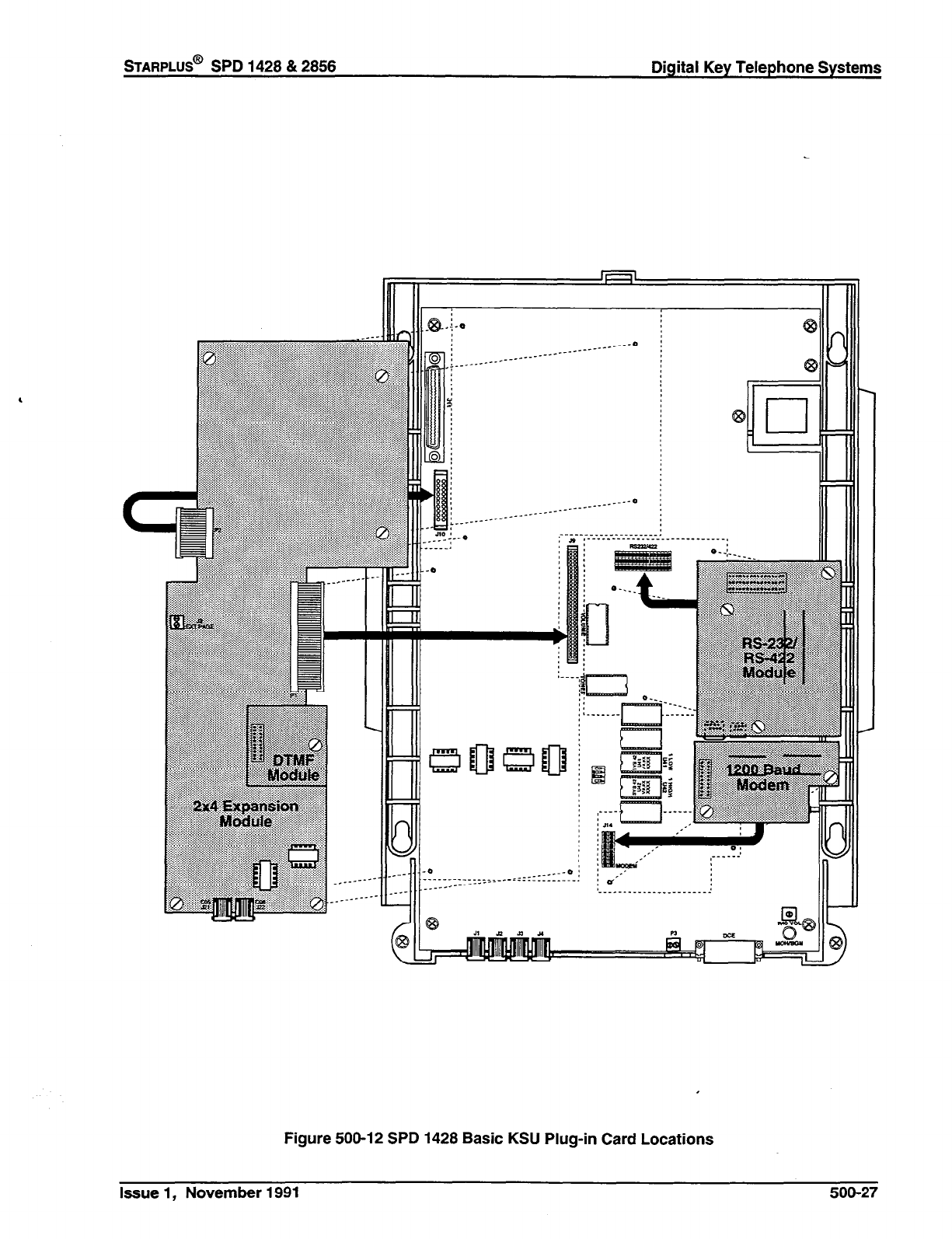
%ARPLUS@
SPD 1428 & 2856 Digital Key Telephone Systems
,
..j::::
9 101
iI P
::$
:j:j/j//
:iiii:::i ---- _._____ -..
R II
Figure 500-12 SPD 1428 Basic KSU Plug-in Card Locations
Issue 1, November 1991 500-27
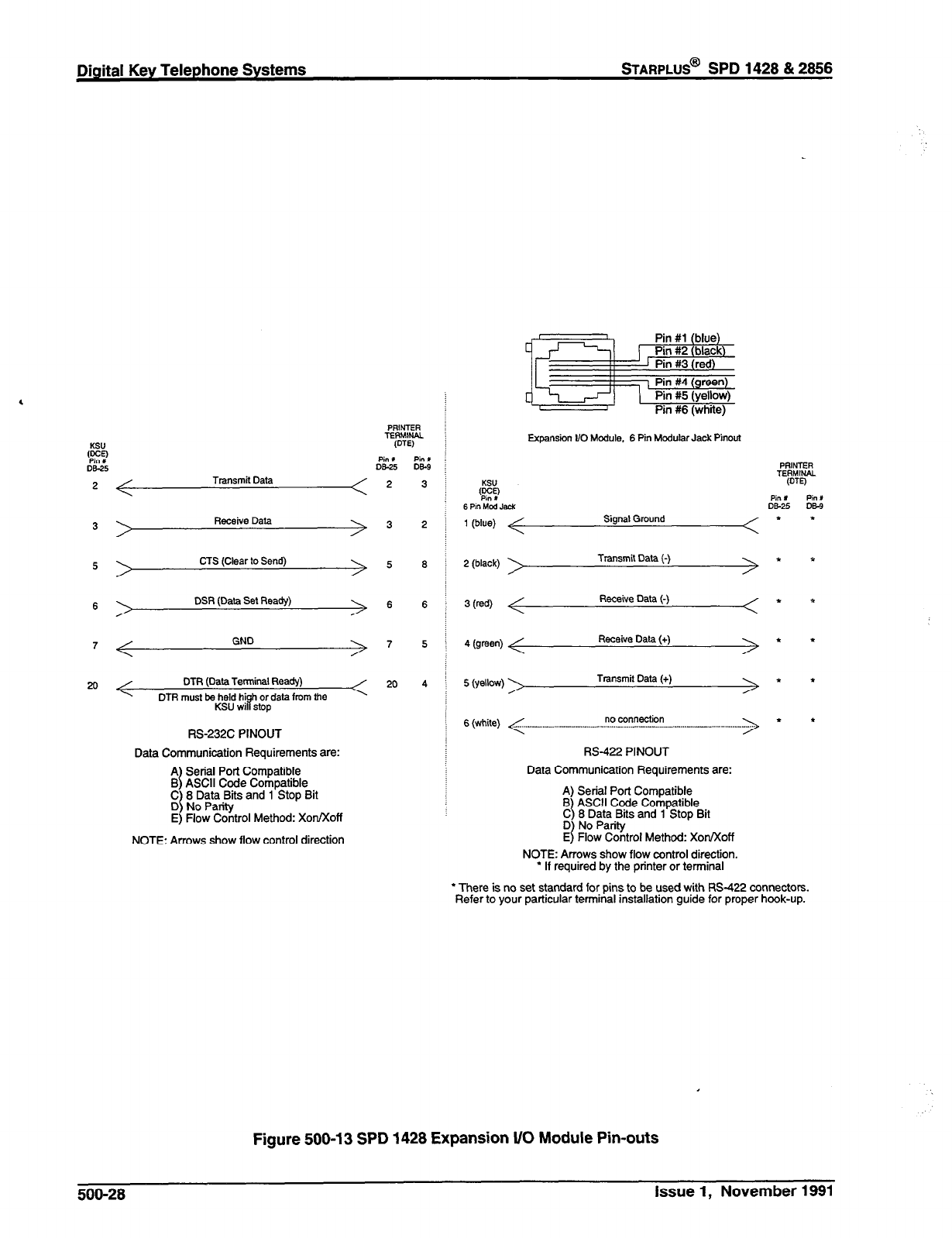
Digital Key Telephone Systems
BARPLUS@
SPD 1428 & 2856
KSU
‘E?
Ds-25
<
Transmit Data <
>
Receive Data >
>
CTS (Clear to Send) >
>
DSR (Data Sat Ready)
>
<
GND
>
DTR (Data Terminal Ready)
DTR must be held hi P
h or data from the
KSU wi stop
RS-232C PINOUT
Data Communication Requirements are:
A
B 1 Serial Port Compatible
g 1
ASCII Code Compatible .
;;;EnB$ and 1 Stop Brt
E) Flow Control Method: Xon/Xoff
NOTE: Arrows show flow control direction
Pint
DS-9
3
2
6
6
Expansion VO Module. 6 Pin Modular Jack Pinaut
R’? Pin X
6 Pin Mod W DS-25
1 (blue) Signal Ground t
2 (black) Transmit Data (-) t
3 WI Receive Data (-) t
4 (emen) Receive Data (+) *
5 (yellow) \ Transmit Data (+) t
6 (white) <
.____.__ - .__...._.__________.......~~ ?!.-!!?!?!tio! ..__ - ______._ - .__....________...
> *
W-422 PINOUT
Data Communication Requirements are:
A) Serial Port Compatible
B 1
C ASCII Code Compatible
8 Data .Bits and 1 Stop Bit
$ t%%%rol Method: XorVXoff
NOTE: Arrows show flow control direction.
l
If required by the printer or terminal
l
There is no set standard for pins to be used with RS-422 connectors.
Refer to your particular terminal installation guide for proper hook-up.
Figure 500-13 SPD 1428 Expansion l/O Module Pin-outs
Pin L
DE!3
t
500-28 Issue 1, November 1991
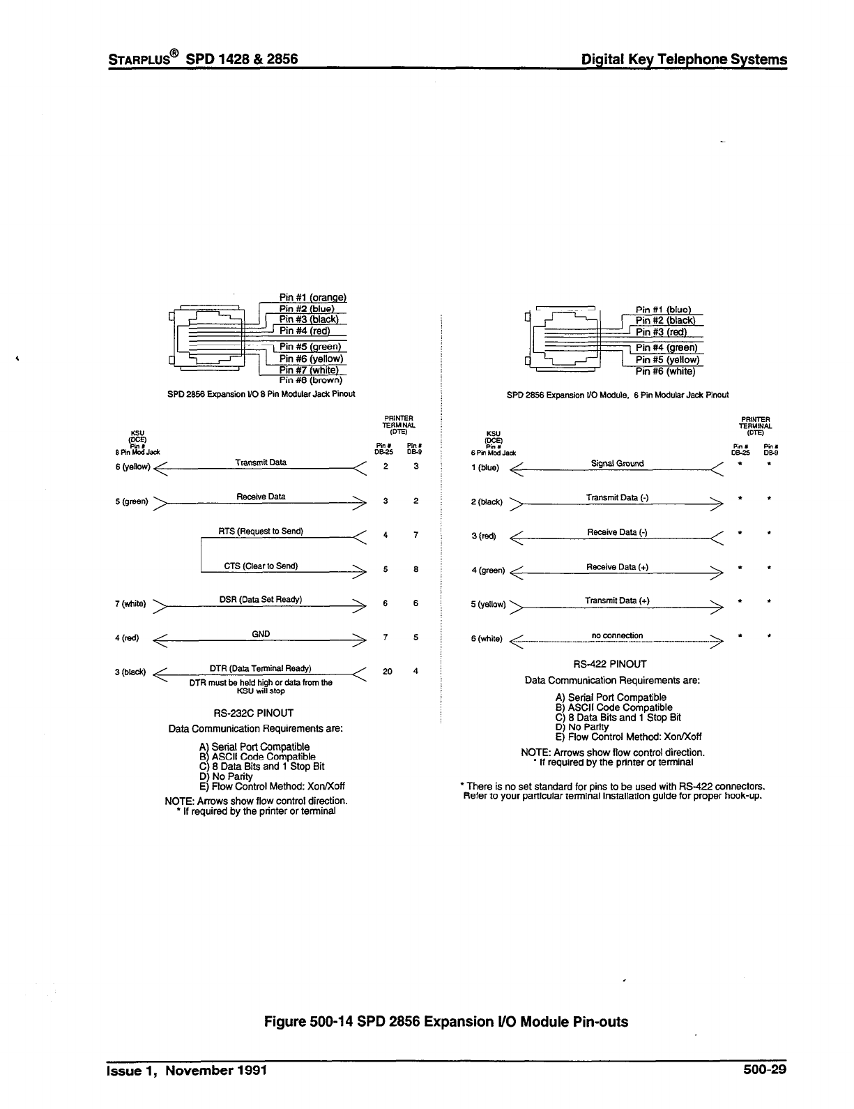
STARPLUS@ SPD 1428 & 2856 Digital Key Telephone Systems
SPD 26.56 Expansion UO 8 Pin Modular Jack Pinout
6 wiow)
Transmit Data <
5 (emen) Receive Data
>
c
7 (tiite) DSR (Data Set Ready)
>
4 (red) GND >
3 (black) DTR (Data Terminal Ready)
DTR must be held high of data from lhe
Ksu win stop
RS-232C PINOUT
Data Communication Requirements are:
A
B
I Serial Port Compatible
ASCII Code Compatible
C) 8 Data Bits and 1 Stop Bit
D) No Panty
E) Flow Control Method: XonKoff
NOTE: Arrows show flow control direction.
l
If required by the printer or terminal
<
2
7
8
6
SPD 2656 Expansion VO Module. 6 Pin Modular Jack Pinout
(K?
6 Pin Mod .I*&
1 (blue)
Signal Ground
Pin I
W-25
l
2 (black) Transmit Data (-) t
3 @a Receive Data (-)
l
4 mm Receive Data (+)
l
5 (yellow) Transmit Data (+) *
6 (white) <
._.-_._- .._ - __.......___..__.__ ZZ!!!!!??!!~? ___. -._-_._- _.__ -_..-_-.
> *
M-422 PINOUT
Data Communication Requirements are:
A) Serial Port Compatible
B) ASCII Code Compatible
C) 8 Data Bits and 1 Stop Bit
D) No Parity
E) Flow Control Method: XotVXoff
NOTE: Arrows show ffow control direction.
* If required by the printer or terminal
l
There is no set standard for pins to be used with RS-422 connectors.
Refer to your particular terminal installation guide for proper hook-up.
Figure 500-l 4 SPD 2856 Expansion i/O Module Pin-outs
Issue 1, November 1991 500-29
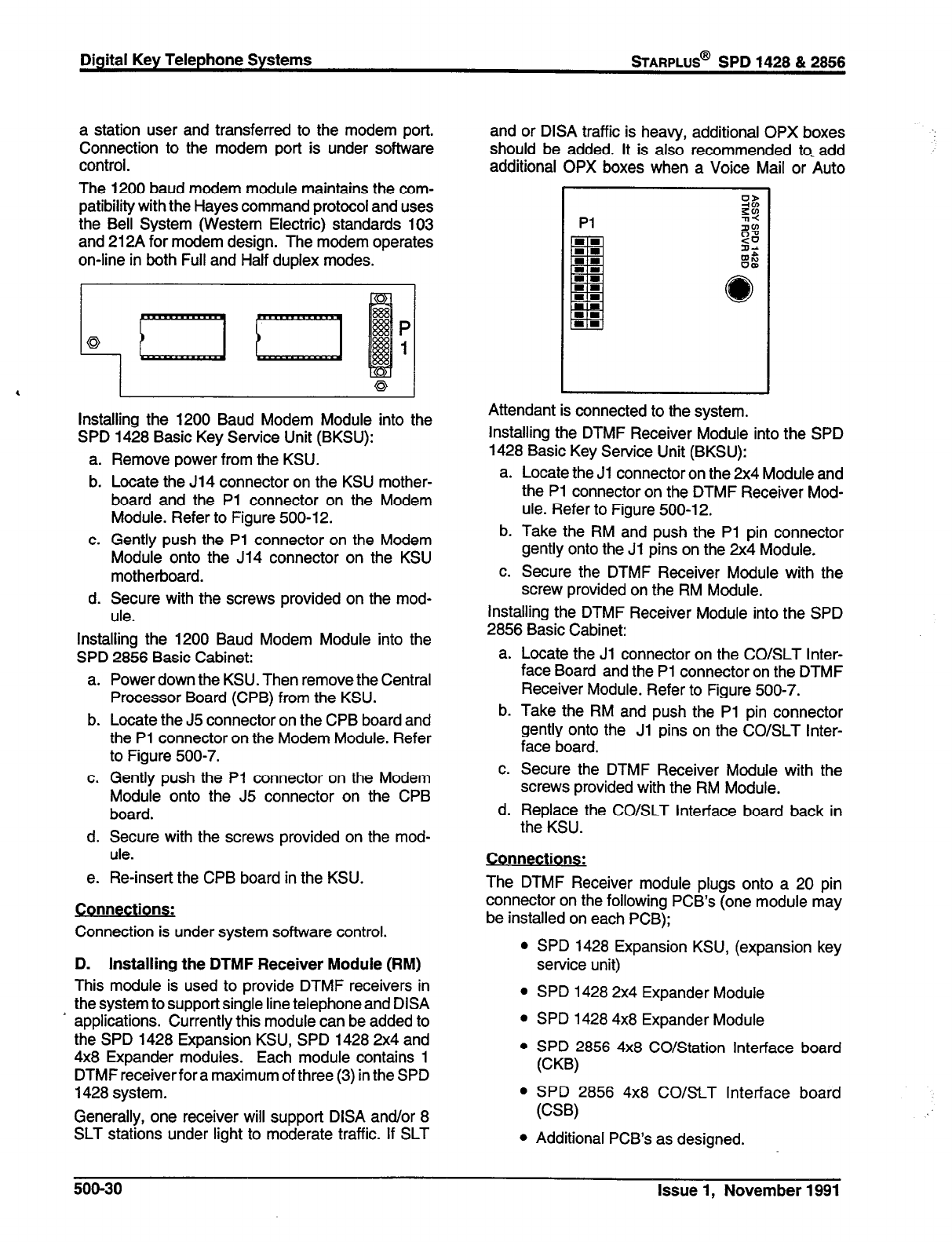
Digital Key Telephone Systems
STARPLUS@
SPD 1428 & 2856
a station user and transferred to the modem port.
Connection to the modem port is under software
control.
The 1200 baud modem module maintains the com-
patibility with the Hayes command protocol and uses
the Bell System (Western Electric) standards 103
and 212A for modem design. The modem operates
on-line in both Full and Half duplex modes.
4
P
Q 1
6 I I
Installing the 1200 Baud Modem Module into the
SPD 1428 Basic Key Service Unit (BKSU):
a. Remove power from the KSU.
b. Locate the J14 connector on the KSU mother-
board and the Pl connector on the Modem
Module. Refer to Figure 500-12.
c. Gently push the Pl connector on the Modem
Module onto the J14 connector on the KSU
motherboard.
d. Secure with the screws provided on the mod-
ule.
Installing the 1200 Baud Modem Module into the
SPD 2856 Basic Cabinet:
a. Power down the KSU. Then remove the Central
Processor Board (CPB) from the KSU.
b. Locate the J5 connector on the CPB board and
the Pl connector on the Modem Module. Refer
to Figure 500-7.
c. Gently push the Pl connector on the Modem
Module onto the J5 connector on the CPB
board.
d. Secure with the screws provided on the mod-
ule.
e. Re-insert the CPB board in the KSU.
Connections:
Connection is under system software control.
D. Installing the DTMF Receiver Module (RM)
This module is used to provide DTMF receivers in
the system to support single line telephone and DISA
* applications. Currently this module can be added to
the SPD 1428 Expansion KSU, SPD 1428 2x4 and
4x8 Expander modules. Each module contains 1
DTMF receiver for a maximum of three (3) in the SPD
1428
system.
Generally, one receiver will support DISA and/or 8
SLT stations under light to moderate traffic. If SLT
and or DISA traffic is heavy, additional OPX boxes
should be added. It is also recommended to- add
additional OPX boxes when a Voice Mail or Auto
Pl
Attendant is connected to the system.
Installing the DTMF Receiver Module into the SPD
1428 Basic Key Service Unit (BKSU):
a. Locate the Jl connector on the 2x4 Module and
the Pl connector on the DTMF Receiver Mod-
ule. Refer to Figure 500-l 2.
b. Take the RM and push the Pl pin connector
gently onto the Jl pins on the 2x4 Module.
c. Secure the DTMF Receiver Module with the
screw provided on the RM Module.
Installing the DTMF Receiver Module into the SPD
2856 Basic Cabinet:
a. Locate the Jl connector on the CO/SLT Inter-
face Board and the Pl connector on the DTMF
Receiver Module. Refer to Figure 500-7.
b. Take the RM and push the Pl pin connector
gently onto the Jl pins on the CO/SLT Inter-
face board.
c. Secure the DTMF Receiver Module with the
screws provided with the RM Module.
d. Replace the CO/SLT Interface board back in
the KSU.
Connections:
The DTMF Receiver module plugs onto a 20 pin
connector on the following PCB’s (one module may
be installed on each PCB);
l
SPD 1428 Expansion KSU, (expansion key
service unit)
l
SPD 1428 2x4 Expander Module
l
SPD 1428 4x8 Expander Module
l
SPD 2856 4x8 CO/Station Interface board
WB)
l
SPD 2856 4x8 CO/SLT Interface board
WY
l
Additional PCB’s as designed.
500-30
Issue 1, November 1991
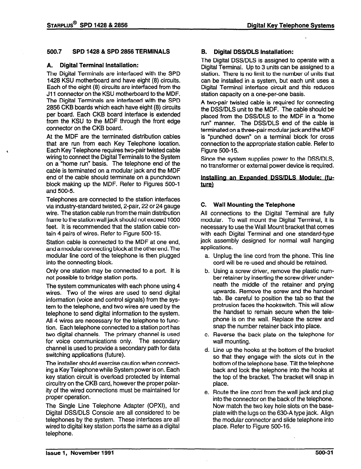
500.7
SPD 1428 & SPD 2856 TERMINALS
A. Digital Terminal Installation:
The Digital Terminals are interfaced with the SPD
1428 KSU motherboard and have eight (8) circuits.
Each of the eight (8) circuits are interfaced from the
Ji 1 connector on the KSU motherboard to the MDF.
The Digital Terminals are interfaced with the SPD
2856 CKB boards which each have eight (8) circuits
per board. Each CKB board interface is extended
from the KSU to the MDF through the front edge
connector on the CKB board.
At the MDF are the terminated distribution cables
that are run from each Key Telephone location.
Each Key Telephone requires two-pair twisted cable
wiring to connect the Digital Terminals to the System
on a “home run” basis. The telephone end of the
cable is terminated on a modular jack and the MDF
end of the cable should terminate on a punchdown
block making up the MDF. Refer to Figures 500-l
and 500-5.
Telephones are connected to the station interfaces
via industry-standard twisted, 2-pair, 22 or 24 gauge
wire. The station cable run from the main distribution
frame to the station wall jack should not exceed 1000
feet. It is recommended that the station cable con-
tain 4 pairs of wires. Refer to Figure 500-15.
Station cable is connected to the MDF at one end,
and a modular connecting blockat the other end. The
modular line cord of the telephone is then plugged
into the connecting block.
Only one station may be connected to a port. It is
not possible to bridge station ports.
The system communicates with each phone using 4
wires. Two of the wires are used to send digital
information (voice and control signals) from the sys-
tem to the telephone, and two wires are used by the
telephone to send digital information to the system.
All 4 wires are necessary for the telephone to func-
tion. Each telephone connected to a station port has
two digital channels. The primary channel is used
for voice communications only. The secondary
channel is used to provide a secondary path for data
switching applications (future).
The installer should exercise caution when connect-
ing a Key Telephone while System power is on. Each
key station circuit is overload protected by internal
circuitry on the CKB card, however the proper polar-
ity of the wired connections must be maintained for
proper operation.
The Single Line Telephone Adapter (OPXI), and
Digital DSS/DLS Console are all considered to be
telephones by the system. These interfaces are all
wired to digital key station ports the same as a digital
telephone.
B. Digital DSS/DLS Installation:
The Digital DSS/DLS is assigned to operate with a
Digital Terminal. Up to 3 units can be assigned to a
station. There is no limit to the number of units that
can be installed in a system, but each unit uses a
Digital Terminal interface circuit and this reduces
station capacity on a one-per-one basis.
A two-pair twisted cable is required for connecting
the DSS/DLS unit to the MDF. The cable should be
placed from the DSS/DLS to the MDF in a “home
run” manner. The DSS/DLS end of the cable is
terminated on a three-pair modular jack and the MDF
is “punched down” on a terminal block for cross
connection to the appropriate station cable. Refer to
Figure 500-l 5.
Since the system supplies power to the DSSIDLS,
no transformer or external power device is required.
an wded DSS/DLS Mod&,&,~
- -
C. Wall Mounting the Telephone
All connections to the Digital Terminal are fully
modular. To wall mount the Digital Terminal, it is
necessary to use the Wall Mount bracket that comes
with each Digital Terminal and one standard-type
jack assembly designed for normal wall hanging
applications.
a.
b.
c.
d.
e.
Unplug the line cord from the phone. This line
cord will be re-used and should be retained.
Using a screw driver, remove the plastic num-
ber retainer by inserting the screw driver under-
neath the middle of the retainer and prying
upwards. Remove the screw and the handset
tab. Be careful to position
the tab
so that the
protrusion faces the hookswitch. This will allow
the handset to remain secure when the tele-
phone is on the wall. Replace the screw and
snap the number retainer
back
into place.
Reverse the back plate on the telephone for
wall mounting.
Line up the hooks at the bottom of the bracket
so that they engage with the slots cut in the
bottom of the telephone base. Tilt the telephone
back and lock the telephone into the hooks at
the top of the bracket. The bracket will snap in
place.
Route the line cord from the wall jack and plug
into the connector on the back of the telephone.
Now match the two
key
hole slots on the base-
plate with the lugs on the 630-A type jack. Align
the modular connector and slide telephone into
place. Refer to Figure 500-l 6.
Issue 1, November 1991 500-31
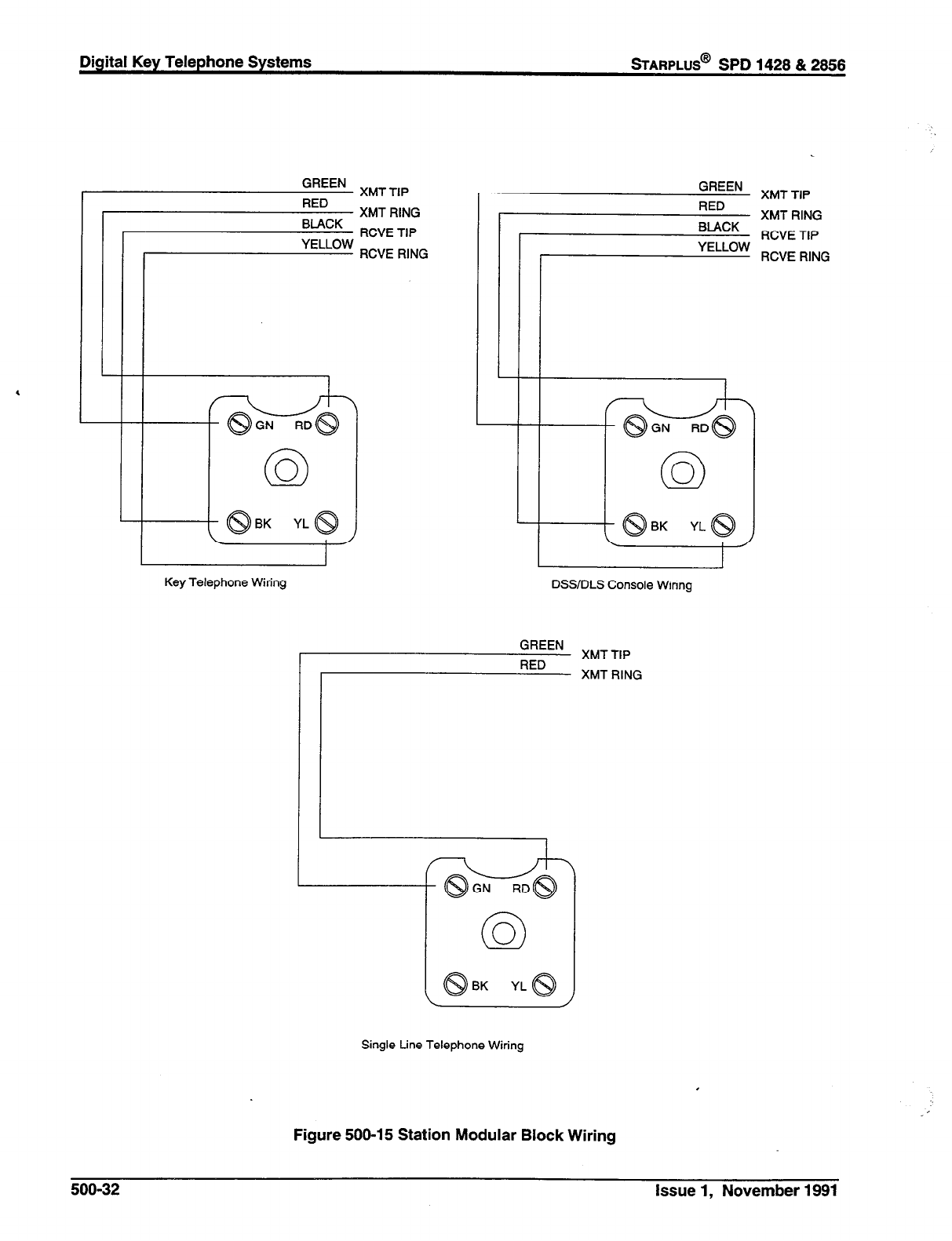
GREEN XMT TIP
RED XMT RING
BLACK RCVE TIP
YELLOW
: RCVER’NG
II
L
i
I
GREEN XMT TIP
RED XMT RING
BLACK
- RCVE TIP
YELLOW
~ RCVERING
Key Telephone Wiring DSS/DLS Console Wiring
GREEN XMT TIP
RED XMT RING
Single Line Telephone Wiring
Figure 500-l 5 Station Modular Block Wiring
500-32 Issue 1, November 1991
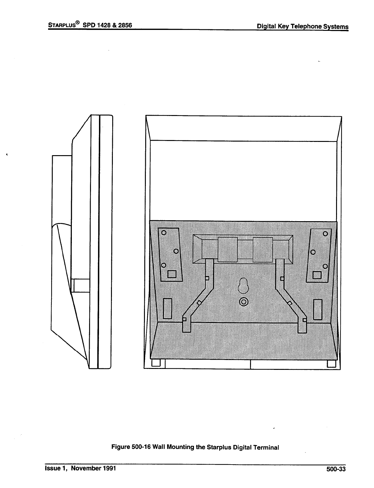
STARPLUS@
SPD 1428 & 2856 Digital Key Telephone Systems
Figure 500-l 6 Wall Mounting the Starplus Digital Terminal
Issue 1, November 1991 500-33
Digital Key Telephone Systems
wARPLUS@
SPD 1428 & 2856
D. Single Line Telephone Installation: (future)
Single Line Telephones (SLT’s) can be exchanged
for Digital Terminals on an one-for-one basis. The
following items are required for a system installing
SLTs:
E. SLT Adapter / Off-Premise Extension Mod-
ule
l
4x8 CO/SLT Interface Board (CSB)
l
DTMF Receiver Module (RM)
The CSB plugged into any designated CKB card slot.
Each CSB board supports eight telephones (stand-
ard DTMF Single Line Telephones and message
waiting DTMF SLT’s). A 48V Power Supply Unit
must be installed in the system to provide power for
ringing and message waiting for SLT’s. Refer to
Figure 500-17. The DTMF Receiver Module should
be installed for each CSB installed. The DTMF
Receiver Module (RM) installs onto either a 4x8
CO/Station Interface cards or 4x8 CO/SLT Interface
cards and provides 1 DTMF receiver. DTMF receiv-
ers can be added to the system to support Single
Line Telephones. If SLT traffic is heavy or a Voice
Mail system is being installed, it is recommended
that additional DTMF Receiver Modules be installed
in the system.
This external module provides the interface for one
long loop (OPX) single line telephone (2500 type)
extension. This module requires a separately pro-
vided -48 VDC power supply to provide the neces-
sary current for long loop applications and to support
ring generation. This module is wired to and uses a
key station port from any digital key terminal station
port on any card plugged into the system. The OPX
card meets the requirements of the FCC for connec-
tion to the telephone (Telco) network. Telephones
must be DTMF only (2500 type).
This module also provides for one Power Fail circuit
in the event of an AC power failure.
Buttons and LED’s:
An LED located on the back of the unit indicates
correct connection and will light when the SLT station
is taken off-hook.
Connections:
Each SLT requires one-pair cable. The cable should
be placed from the telephone location to the MDF in
a “home run” manner. The telephone end of the
cable run should be terminated in a modular jack.
Refer to Figures 500-l and/or 500-5. The MDF end
should be “punched down” on a terminal block for
cross connection to the appropriate station cable.
Refer to Table 500-5 for SLT wiring connections.
All connections to the SLA (OPX) adapter are made
on the back of the unit. Two modular jacks and a
two wire cable are located on the back of the unit for
connection to the KSU and power supply. The two
wire cable connects to a 48V dc power supply / ring
generator. The Modular jack marked KSU is con-
nected to a KSU Digital terminal station port. This
connection requires all fourwires and wires the same
as a key station. The modular jack marked OPX is
wired to the SLT station (2500 type), OPX circuit or
SLT device. Additionally a CO line may be wired to
the second pair of the SLT modular connecter for
Power fail operation.
Cable Loop Limits:
The maximum loop limit from the KSU to the SLA
(OPX) adapter is 1000 feet.
The maximum loop limit from the SLA (OPX) adapter
to the connected SLT or device is 1400 ohms not
including the telephone or device.
500-34 Issue 1, November 1991

STARPLUS@
SPD 1428 & 2856 Digital Key Telephone Systems
STATION
CONNECTING
MODULAR
CABLE
MDF
Red wire to 48 volts
‘. ...:.::::::g:;:giii;i)I
::::::::.::.... . . . . . .
3;::
R -
$;$
$$
$2;
9;;
Figure 500-17 Off-Premise Extension (OPX) Module
Issue 1, November 1991 500-35
Digital Key Telephone Systems
%ARPLUS@
SPD 1428 & 2856
500.8 POWER FAILURE TRANSFER
A. Relay / Sensor Interface Module
The Relay Sensor Interface Module connects to the
system using one digital station port and provides
three relay activated contacts and three sensing
circuits. The relays provide for applications such as
Loud Bell Control contacts, CO Line control contacts,
RAN Start contacts, Page Relays, Power Fail con-
tact and additional applications as software will per-
mit. The sensing circuits will provide for such
applications as Alarm signaling input, RAN Stop (end
of message) and other applications as developed
and allowed by software.
power fail transfer. Refer to Tables 500-6 and 500-7
for pin-outs of each of the connectors. _
The PFTU is connected to the KSU via the modular
connector on the side of the unit. This is connected
in series to a customer provided 12 dc supply. and
to a multi use relay programmed as a power failure
relay.
4 Connections:
All connections to the Relay Sensor Module are
made on the back of the unit. Two terminal strips
with screw terminals each provide connection to the
ancillary devices for relay control or sensing moni-
toring. The Modular jack marked KSU is connected
to a KSU Digital terminal station port. This connec-
tion requires all four wires and wires the same as a
key station. Refer to Figure 500-18 for wiring infor-
mation.
An external power source may be required to drive
equipment connected to the relay contacts. The
contacts are rated at 24Vdc max at 1 amp.
Cable Loop Limits:
The maximum loop limit from the KSU to the relay
Sensor Module is 1000 feet.
6. Starplus Power Failure Transfer Unit
(Pm0
This unit provides the relay transfer circuits for up to
12 CO lines in the event of a power or processor
failure. The unit is housed in its own enclosure and
mounts external to the KSU. Activation of the PFT
relays is controlled by a multi-use relay on any one
of the CO / Station Interface boards that is pro-
grammed for PFT. A customer provided 12 volt DC
power supply is required to operate the unit. There
is a manual switch that activates the PFTM for testing
purposes.
With loss of power to the system or a failure of
system processing, the PFRJ will automatically con-
nect up to twelve CO lines to prewired 500/2500 type
telephones. When power is restored, the PFTU will
automatically restore the CO trunks and stations to
normal operation. These SLT stations do not have
to be used for intercom. but can be if so desired.
Wirina I Pinouts I Connections
The PFTU has two 50-pin male amphenol connec-
tors labeled CONNl and CONN2 located on the front
of the unit. Each connector wires 8 CO lines for
500-36 Issue 1, November 1991
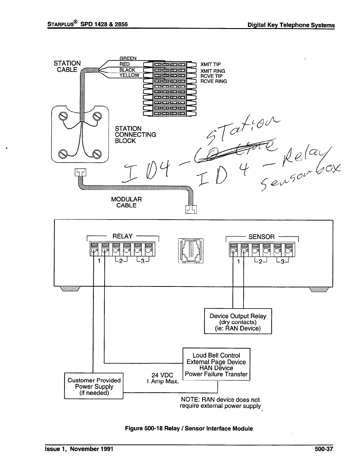
STARPLUS@
SPD 1428 & 2858 Digital Key Telephone Systems
GREEN
--.-.-. XMIT TIP
XMIT RING
RCVE TIP
RCVE RING
CONNECTING
MODULAR
CABLE
Device Output Relay
(dry contacts)
(ie: RAN Device)
+pjiiiJJ
Customer Provided
Power Supply
(if needed) NOTE: RAN device does not
require external power supply I
Figure 500-18 Relay / Sensor Interface Module
Issue 1, November 1991
500-37
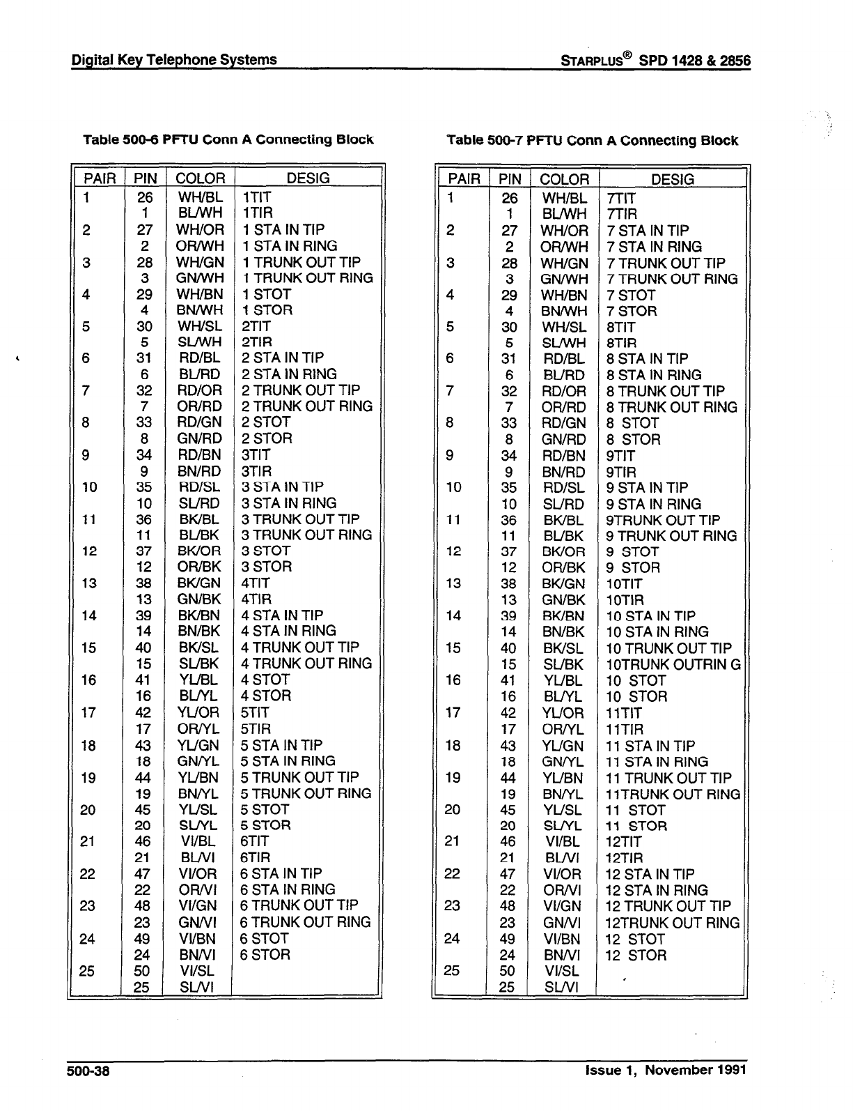
Digital Key Telephone Systems
STARPLUS@
SPD 1428 & 2856
Table 500-6 PFTU Conn A Connecting Block
PAIR PIN COLOR DESIG
1 26 WWBL 1TIT
1 BLIWH 1TIR
2 27 WWOR 1 STA IN TIP
2 OR/WH 1 STA IN RING
3 28 WWGN 1 TRUNK OUT TIP
3 GN/WH 1 TRUNK OUT RING
4 29 WH/BN 1 STOT
4 BN/WH 1 STOR
5 30 WWSL 2TIT
5 SL/WH 2TIR
6 31 RD/BL 2 STA IN TIP
6 BURD 2 STA IN RING
7 32 RD/OR 2 TRUNK OUT TIP
7 OWRD 2 TRUNK OUT RING
8 33 RD/GN 2 STOT
8 GN/RD 2 STOR
9 34 RD/BN 3TIT
9 BN/RD 3TIR
10 35 RD/SL 3 STA IN TIP
10 SURD 3 STA IN RING
11 36 BWBL 3 TRUNK OUT TIP
11 BUBK 3 TRUNK OUT RING
12 37 BWOR 3 STOT
12 OWBK 3 STOR
13 38 BWGN 4TIT
13 GN/BK 4TIR
14 39 BWBN 4 STA IN TIP
14 BN/BK 4 STA IN RING
15 40 BWSL 4 TRUNK OUT TIP
15 SUBK 4 TRUNK OUT RING
16 41 YUBL 4STOT
16 BL/YL 4STOR
17 42 YUOR 5TIT
17 ORNL 5TIR
18 43 YUGN 5 STA IN TIP
18 GNNL 5 STA IN RING
19 44 YUBN 5 TRUNK OUT TIP
19 BNNL 5 TRUNK OUT RING
20 45 YUSL 5 STOT
20 SUYL 5 STOR
21 46 VIIBL 6TIT
21 BWI 6TlR
22 47 VI/OR 6 STA IN TIP
22 OR/VI 6 STA IN RING
23 48 VI/GN 6 TRUNK OUT TIP
23 GNNI 6 TRUNK OUT RING
24 49 VI/BN 6 STOT
24 BNNI 6 STOR
25 50 VIISL
25 SWI
Table 500-7 PFTU Conn A Connecting Block
PAIR
1
2
3
4
5
6
7
8
9
10
11
12
13
14
15
16
17
18
19
20
21
22
23
24
25
-PlJ
COLOR
26 WHIBL
1 BLhVH
27 Wl-UOR
2 OR/WH
28 WWGN
3 GN/WH
29 WWBN
4 BNh’iH
30 WHISL
5 SLM’H
31 RD/BL
6 BURD
32 RD/OR
7 OR/RD
33 RD/GN
a GN/RD
34 RD/BN
9 BN/RD
35 RD/SL
10 SURD
36 BWBL
11 BUBK
37 BWOR
12 OWBK
38 BWGN
13 GN/BK
39 BWBN
14 BN/BK
40 BWSL
15 SUBK
41 YUBL
16 BLNL
42 YUOR
17 OR/YL
43 YUGN
18 GNNL
44 YUBN
19 BNNL
45 YUSL
20 SUYL
46 VI/BL
21 BWI
47 VI/OR
22 ORNI
48 VI/GN
23 GNNI
49 VI/BN
24 BNNI
50 VIISL
25 SWI
-
-
DESIG
7TlT
7TlR
7 STA IN TIP
7 STA IN RING
7 TRUNK OUT TIP
7 TRUNK OUT RING
7 STOT
7 STOR
8TIT
8TIR
8 STA IN TIP
8 STA IN RING
8 TRUNK OUT TIP
8 TRUNK OUT RING
8 STOT
8 STOR
9TIT
9TIR
9 STA IN TIP
9 STA IN RING
STRUNK OUT TIP
9 TRUNK OUT RING
9 STOT
9 STOR
1 OTIT
1OTlR
10 STA IN TIP
10 STA IN RING
10 TRUNK OUT TIP
1 OTRUNK OUTRIN G
10 STOT
10 STOR
11TIT
1lTlR
11 STA IN TIP
11 STA IN RING
11 TRUNK OUT TIP
11TRUNK OUT RING
11 STOT
11 STOR
12TIT
12TIR
12 STA IN TIP
12 STA IN RING
12 TRUNK OUT TIP
12TRUNK OUT RING
12 STOT
12 STOR
I
.:
500-38
Issue 1, November 1991

OPX
PFT TIP IN
PFT RING IN
. _ _ _ _. .
.____._
;PD 1428 BKSU
SPD 2% KSU
Method #l
Starplus
Power Failure
Transfer Unit
PflU)
Customer
Provided
Battery
+
SPD 2856 KSU
:................................:
Multi-Purpose Relay
Method #2
Figure 500-19 Power Failure Transfer Wiring Options
Issue 1, November 1991 500-39
Digital Key Telephone Systems
STARPLUS@
SPD 1428 & 2856
500.9 INSTALLING RECORDED AN-
NOUNCEMENT DEVICE (RAN)
,
The Recorded Announcement feature (RAN) is used
with the Uniform Call Distribution feature (UCD) to
provide unanswered incoming CO calls or calls in
queue with a Recorded Announcement while wait-
ing for an available UCD station. The system may
be programmed to provide this announcement on
specified RAN output ports on the system (unused
SLT and CO ports). The system can be programmed
to connect the waiting caller to a different RAN port
for the second, and subsequent RAN messages.
When a CO line port is used for a ground start
application, a 24V dc power source must be con-
nected to the CO line port for talk battery. A
Page/Relay contact assigned to an announcement
table in programming would provide contact closure
to start the Recorded Announcement device.
When an SLT port is used, the RAN device must be
configured for ring trip operation (loop start). The
9OV ac voltage sent to the SLT port will be recog-
nized by the RAN device which will then answer the
call. Refer to Figure 500-20.
509-40 Issue 1, November 1991
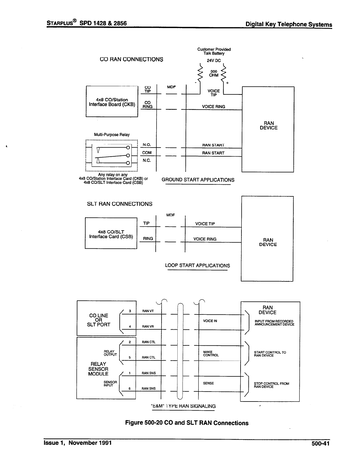
STARPLUS@ SPD 1428 & 2856 Digital Key Telephone Systems
CO RAN CONNECTIONS
VOICE RtNG
4x8 CO/Station
interface Board (CKB)
‘................................i I
T
Any relay on any
Multi-Purpose Relay
,------..--.---------------------I
I
I
RAN START
RAN START
4x8 CO/Station Interface Card (MS)
or
4x8 CO/SLT Interface Card (CSB)
GROUND START APPLICATIONS
Customer Provided
Talk Battety
24V DC
RAN
DEVICE
SLT RAN CONNECTIONS
4x8 COISLT
Interface Card (CSB)
LOOP START APPLICATIONS
I
SLT?;RT I I 4
RAN VR
I
I \-
f
2 RAN CTL
RELAY
OUTPUT
RELAY
SENSOR
MODULE
SENSOR
INPLlT
“E&M” -I YPE RAN SIGNALING
VOICE IN
E&O,
1
SENSE
Figure 500-20 CO and SLT RAN Connections
INPUT FROM RECORDED
ANNOUNCEMENT DEVICE
SGR;&yCTROL TO
SGPOC$FOL FROM
Issue 1, November 1991 500-41

,
Digital Key Telephone Systems
sTARPLUS@
SPD 1428 & 2858
Table 500-8 SMDR Printout
The SMDR feature provides detailed records of all outgoing and/or incoming, long distance only or all calls
exceeding 30 seconds. This feature is enabled or disabled in system programming. By default, SMDR is
not enabled and is set to record long distance calls only. A printout format of 80 characters maximum or 30
character maximum may be selected in system programming. The standard format is 69 characters on a
single line. A 30 character format will generate 3 lines per message. If the SMDR feature is enabled, the
system starts collecting information about the call as soon as it starts and terminates when the call ends. If
the call was longer then 30 seconds, the following information is printed:
30 character format selected
123456789~123456789ik23456789~
116 08 00:02:00 14:13 05/U/90
0123456789012345678901234
123456789012
123456789~123456789~123456789;
AAA BB HH:MM:SS HH:MM MM/DD/W (CR) (CR) (LF)
HCCCCCCCCCCCCCCCCCCCCCCCCCCC (CR) (CR) (LF)
- (CR) (CR) (LF)
80 character format selected
123456789~123456789~123456789~123456789~1234~6789~1234~6789~1234~6789~1234~6789~
STA CO TOTAL START DATE DIALED ACCOUNT CODE
116 08 00:02:00 14:13 05/n/90 0123456789012345678901234 123456789012
AAA BB HH:MM:SS HH:MM MM/DD/W HCCCCCCCCCCCCCCCCCCCCCCCC - (CR) (CR) (LF)
AAA = Station originator or Trunk on DISA and Off-Net (CO Line) calls.
BB = Outside line number
HH:MM:SS = Duration of call in Hours, Minutes and Seconds
HH:MM = Time of day (start time) in Hours and Minutes
MM/DD/YY = Date of Call
H = Indicates call type
“I, = Incoming
“0” = Outgoing
‘T’ = Transferred
CC....CC = Number dialed
GG....GG = Last Account code entered (optional)
(CR) = Carriage return
(LF) = Line Feed
508-42 Issue 1, November 1991
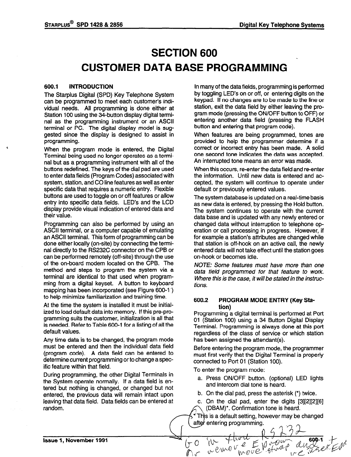
STARPLUS@
SPD 1428 & 2856 Digital Key Telephone Systems
SECTION 600
CUSTOMER DATA BASE PROGRAMMING
600.1 INTRODUCTION
The Starplus Digital (SPD) Key Telephone System
can be programmed to meet each customer’s indi-
vidual needs. All programming is done either at
Station 100 using the
34-button
display digital termi-
nal as the programming instrument or an ASCII
terminal or PC. The digital display model is sug-
gested since the display is designed to assist in
programming.
When the program mode is entered, the Digital
Terminal being used no longer operates as a termi-
nal but as a programming instrument with all of the
buttons redefined. The keys of the dial pad are used
to enter data fields (Program Codes) associated with
system, station, and CO line features as well as enter
specific data that requires a numeric entry. Flexible
buttons are used to toggle on or off features or allow
entry into specific data fields. LED’s and the LCD
display provide visual indication of entered data and
their value.
Programming can also be performed by using an
ASCII terminal, or a computer capable of emulating
an ASCII terminal. This form of programming can be
done either locally (on-site) by connecting the termi-
nal directly to the RS232C connector on the CPB or
can be performed remotely (off-site) through the use
of the on-board modem located on the CPB. The
method and steps to program the system via a
terminal are identical to that used when program-
ming from a digital keyset. A button to keyboard
mapping has been incorporated (see Figure 600-l ‘)
to help minimize familiarization and training time.
At the time the system is installed it must be initial-
ized to load default data into memory. If this pre-pro-
gramming suits the customer, initialization is all that
is needed. Refer to Table 600-l for a listing of all the
default values.
Any time data is to be changed, the program mode
must be entered and then the individual data field
(program code). A data field can be entered to
determine current programming or to change a spec-
ific feature within that field.
During programming, the other Digital Terminals in
the System operate normally. If a data field is en-
tered but nothing is changed, or changed but not
entered, the previous data will remain intact upon
leaving that data field. Data fields can be entered at
random.
In many of the data fields, programming is performed
by toggling LED’s on or off, or entering digits on the
keypad. If no changes are to be made to the line or
station, exit the data field by either leaving the pro-
gram mode (pressing the ON/OFF button to OFF) or
entering another data field (pressing the FLASH
button and entering that program code).
When features are being programmed, tones are
provided to help the programmer determine if a
correct or incorrect entry has been made. A solid
one second tone indicates the data was accepted.
An interrupted tone means an error was made.
When this occurs, re-enter the data field and reenter
the information. Until new data is entered and ac-
cepted, the system will continue to operate under
default or previously entered values.
The system database is updated on a real-time basis
as new data is entered, by pressing the Hold button.
The system continues to operate with the current
data base and is updated with any newly entered or
changed data without interruption to telephone op-
eration or call processing in progress. However, if
for example a station’s attributes are changed while
that station is off-hook on an active call, the newly
entered data will not take effect until the station goes
on-hook or becomes idle.
NOTE: Some features must have more than one
data field programmed for that feature to work.
Where this is the case, it will be stated in the instruc-
tions.
600.2 PROGRAM MODE ENTRY (Key Sta-
tion)
Programming a digital terminal is performed at Port
01 (Station 100) using a 34 Button Digital Display
Terminal. Programming is always done at this port
regardless of the class of service or which station
has been assigned the attendant(s).
Before entering the program mode, the programmer
must first verify that the Digital Terminal is properly
connected to Port 01 (Station 100).
To enter the program mode:
a. Press ON/OFF button. (optional) LED lights
and intercom dial tone is heard.
b. On the dial pad, press the asterisk (‘) twice.
c. On the dial pad, enter the digits [3][2][2][6]
(DBAM)‘. Confirmation tone is heard.
s is a default setting, however may be changed
entering programming.
Issue 1, November 1991
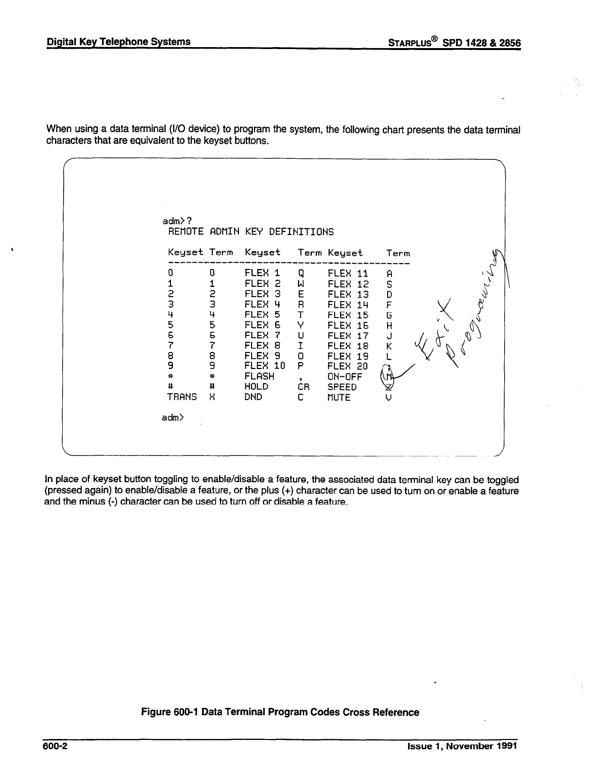
Digital Key Telephone Systems
wARPLUS@
SPD 1428 & 2858
When using a data terminal (I/O device) to program the system, the following chart presents the data terminal
characters that are equivalent to the keyset buttons.
adm> ?
REIAOTE RDflIN KEY DEFINITIONS
Keyset Term Keyset Term Keyset Term
-----------------------------------------
0 0 FLEX 1 Q FLEX 11 A
1 1 FLEX 2 W FLEX 12 S
2 2 FLEX 3 E FLEX 13 D
3 3 FLEX 4 R FLEX 14 F
4 4 FLEX 5 T FLEX 15 G
5 5 FLEX 6 ‘f FLEX 16 H
6 6 FLEX 7 U FLEX 17 J
7 7 FLEX 8 I FLEX 18 K
: 8 FLEX 2 0 FLEX 19 L
2 FLEX 10 P FLEX 20
* * FLASH ON-OFF
# # HOLD iR SPEED
TRANS X DND C MUTE v
adm>
In place of keyset button toggling to enable/disable a feature, the associated data terminal key can be toggled
(pressed again) to enable/disable a feature, or the plus (+) character can be used to turn on or enable a feature
and the minus (-) character can be used to turn off or disable a feature.
Figure 600-l Data Terminal Program Codes Cross Reference
600-2
Issue 1, November 1991

STARPLUS@
SPD 1428 & 2858 Digital Key Telephone Systems
SPKR VOL RING VOL
Figure 600-2 Starplus SPD Programming Button Mapping
Issue 1, November 1991 600-3
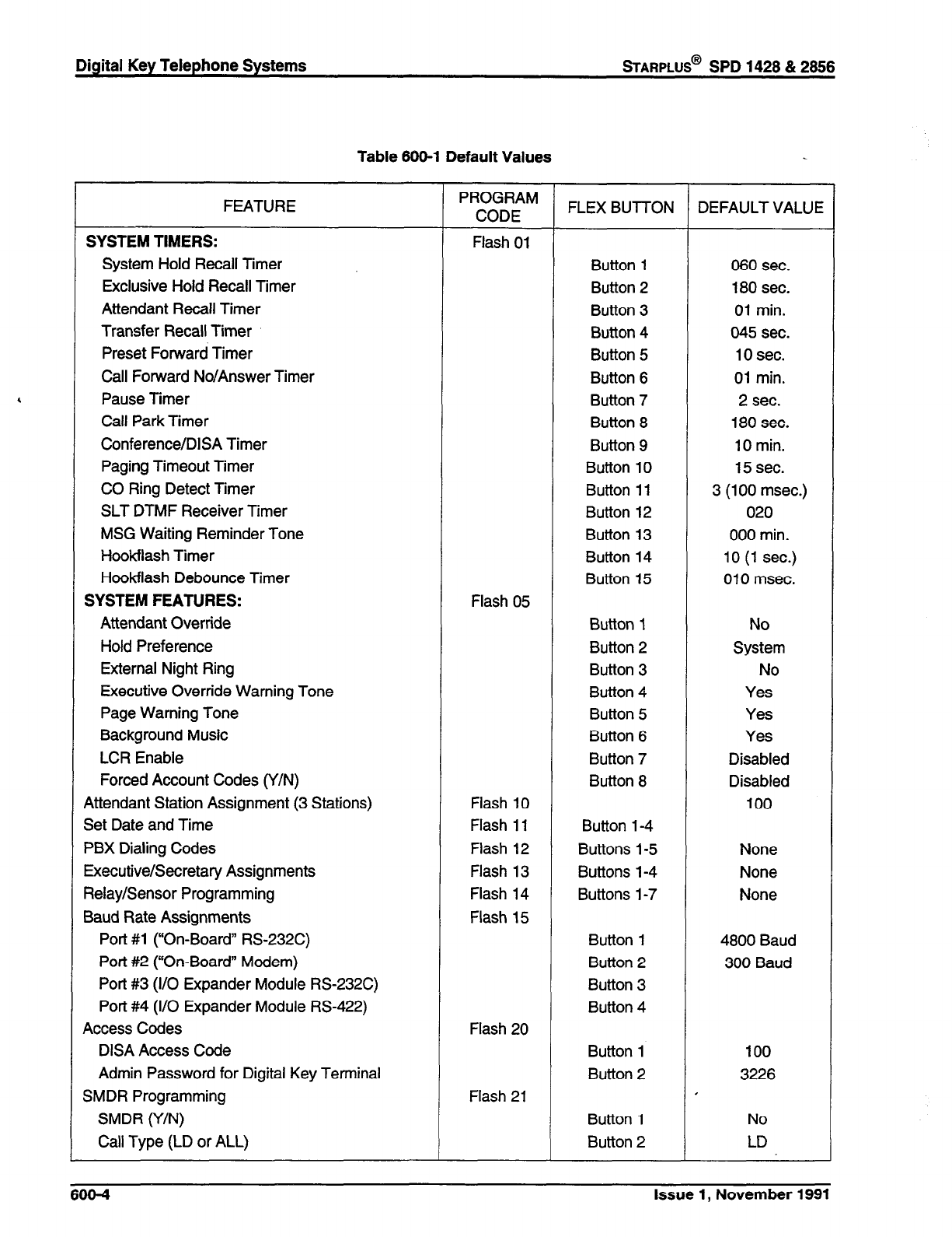
Digital Key Telephone Systems
BARPLUS@
SPD 1428 & 2856
Table 600-l Default Values
FEATURE
SYSTEM TIMERS:
System Hold Recall Timer
Exclusive Hold Recall Timer
Attendant Recall Timer
Transfer Recall Timer
Preset Forward Timer
Call Forward No/Answer Timer
Pause Timer
Call Park Timer
Conference/DISA Timer
Paging Timeout Timer
CO Ring Detect Timer
SLT DTMF Receiver Timer
MSG Waiting Reminder Tone
Hookflash Timer
Hookflash Debounce Timer
SYSTEM FEATURES:
Attendant Override
Hold Preference
External Night Ring
Executive Override Warning Tone
Page Warning Tone
Background Music
LCR Enable
Forced Account Codes (Y/N)
Attendant Station Assignment (3 Stations)
Set Date and Time
PBX Dialing Codes
Executive/Secretary Assignments
Relay/Sensor Programming
Baud Rate Assignments
Port #l (“On-Board” RS232C)
Port #2 (“On-Board” Modem)
Port #3 (I/O Expander Module RS232C)
Port #4 (I/O Expander Module RS-422)
Access Codes
DISA Access Code
Admin Password for Digital Key Terminal
SMDR Programming
SMDR (Y/N)
Call Type (LD or ALL)
PROGRAM
CODE FLEX BUT-TON DEFAULT VALUE
Flash 01
Button 1 060 sec.
Button 2 180 sec.
Button 3 01 min.
Button 4 045 sec.
Button 5 10 sec.
Button 6 01 min.
Button 7 2 sec.
Button 8 180 sec.
Button 9 10 min.
Button 10 15 sec.
Button 11 3 (100 msec.)
Button 12 020
Button 13 000 min.
Button 14 10 (1 sec.)
Button 15 010 msec.
Flash 05
Button 1 No
Button 2 System
Button 3 No
Button 4 Yes
Button 5 Yes
Button 6 Yes
Button 7 Disabled
Button 8 Disabled
Flash 10 100
Flash 11 Button l-4
Flash 12 Buttons 1-5 None
Flash 13 Buttons 1-4 None
Flash 14 Buttons l-7 None
Flash 15
Button 1 4800 Baud
Button 2 300 Baud
Button 3
Button 4
Flash 20
Button 1 100
Button 2 3226
Flash 21 I
Button 1 No
Button 2 LD
666-4 Issue 1, November 1991
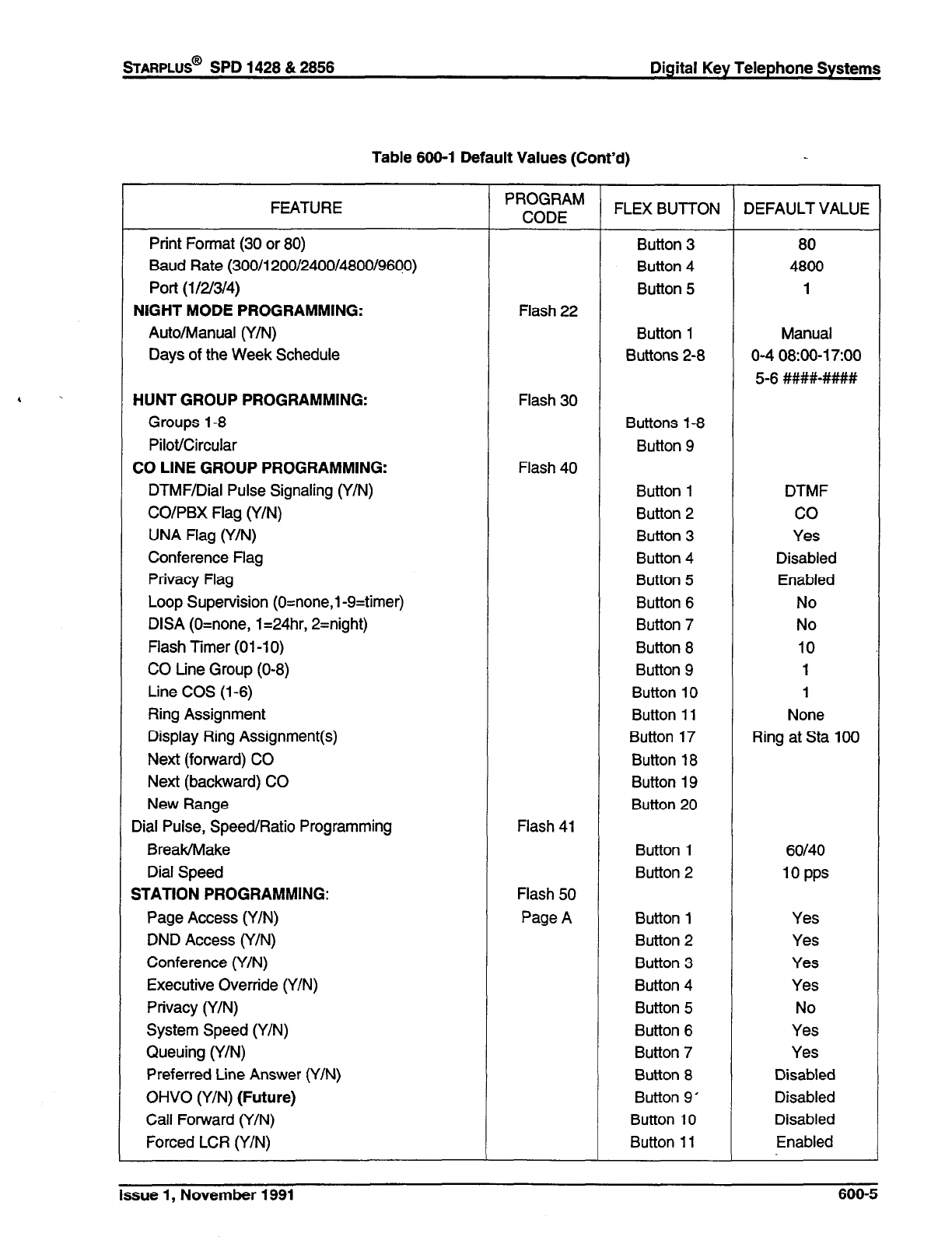
STARPLUS@
SPD 1428 & 2858 Digital Key Telephone Systems
Table 800-l Default Values (Cont’d)
FEATURE
Print Format (30 or 80)
Baud Rate (300/l 200/2400/4800/9660)
Port (l/2/3/4)
NIGHT MODE PROGRAMMING:
Auto/Manual (Y/N)
Days of the Week Schedule
HUNT GROUP PROGRAMMING:
Groups l-8
Pilot/Circular
CO LINE GROUP PROGRAMMING:
DTMF/Dial Pulse Signaling (Y/N)
CO/PBX Flag (Y/N)
UNA Flag (Y/N)
Conference Flag
Privacy Flag
Loop Supervision (O=none,l-9=timer)
DISA (O=none, 1=24hr, 2=night)
Flash Timer (01-l 0)
CO
tine Group (O-8)
Line COS (l-6)
Ring Assignment
Display Ring Assignment(s)
Next (forward) CO
Next (backward) CO
New Range
Dial Pulse, Speed/Ratio Programming
Break/Make
Dial Speed
STATION PROGRAMMING:
Page Access (Y/N)
DND Access (Y/N)
Conference (Y/N)
Executive Override (Y/N)
Privacy (Y/N)
System Speed (Y/N)
Queuing (Y/N)
Preferred Line Answer (Y/N)
OHVO
(Y/N) (Future)
Call Forward (Y/N)
Forced LCR (Y/N)
PROGRAM
CODE FLEX BUT-I-ON DEFAULT VALUE
Button 3 80
Button 4 4800
Button 5
1
Flash 22
Button 1 Manual
Buttons 2-8 O-4 08:00-l TOO
5-6 ####-####
Flash 30
Buttons 1-8
Button 9
Flash 40
Button 1 DTMF
Button 2 co
Button 3 Yes
Button 4 Disabled
Button 5 Enabled
Button 6 No
Button 7 No
Button 8 10
Button 9 1
Button 10 1
Button 11 None
Button 17 Ring at Sta 100
Button 18
Button 19
Button 20
Flash 41
Button 1 60140
Button 2 10 PPS
Flash 50
Page A Button 1 Yes
Button 2 Yes
Button 3 Yes
Button 4 Yes
Button 5 No
Button 6 Yes
Button 7 Yes
Button 8 Disabled
Button 9’ Disabled
Button 10 Disabled
Button 11 Enabled
Issue 1, November 1991
600-5
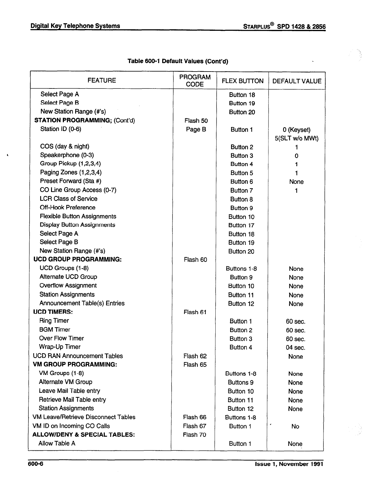
Table 600-l Default Values (Cont’d)
FEATURE
Select Page A
Select Page B
New Station Range (#Is)
STATION PROGRAMMING;
(Cont’d)
Station ID (O-6)
COS (day & night)
Speakerphone (O-3)
Group Pickup (1,2,3,4)
Paging
Zones
(1,2,3,4)
Preset Forward (Sta #)
CO tine Group Access (O-7)
LCR Class of Service
Off-Hook Preference
Flexible Button Assignments
Display Button Assignments
Select Page A
Select Page B
New Station Range (#I’s)
UCD GROUP PROGRAMMING:
UCD Groups (l-8)
Alternate UCD Group
Overflow Assignment
Station Assignments
Announcement Table(s) Entries
UCD TIMERS:
Ring Timer
BGM Timer
Over Flow Timer
Wrap-Up Timer
UCD RAN Announcement Tables
VM GROUP PROGRAMMING:
VM Groups (l-8)
Alternate VM Group
Leave Mail Table entry
Retrieve Mail Table entry
Station Assignments
VM Leave/Retrieve Disconnect Tables
VM ID on Incoming CO Calls
ALLOW/DENY & SPECIAL TABLES:
Allow Table A
PROGRAM
CODE FLEX BUTTON DEFAULT VALUE
Button 18
Button 19
Button 20
Flash 50
Page B Button 1 0 (Keyset)
5(SLT w/o MWt)
Button 2 1
Button 3 0
Button 4 1
Button 5 1
Button 6 None
Button 7 1
Button 8
Button 9
Button 10
Button 17
Button 18
Button 19
Button 20
Flash 60
Buttons 1-8 None
Button 9 None
Button 10 None
Button 11 None
Button 12 None
Flash 61
Button 1 60 sec.
Button 2 60 sec.
Button 3 60 sec.
Button 4 04 sec.
Flash 62 None
Flash 65
Buttons l-8 None
Buttons 9 None
Button 10 None
Button 11 None
Button 12 None
Flash 66 Buttons l-8
Flash 67 Button 1 ’ No
Flash 70
Button 1 None
606-6
Issue 1, November 1991
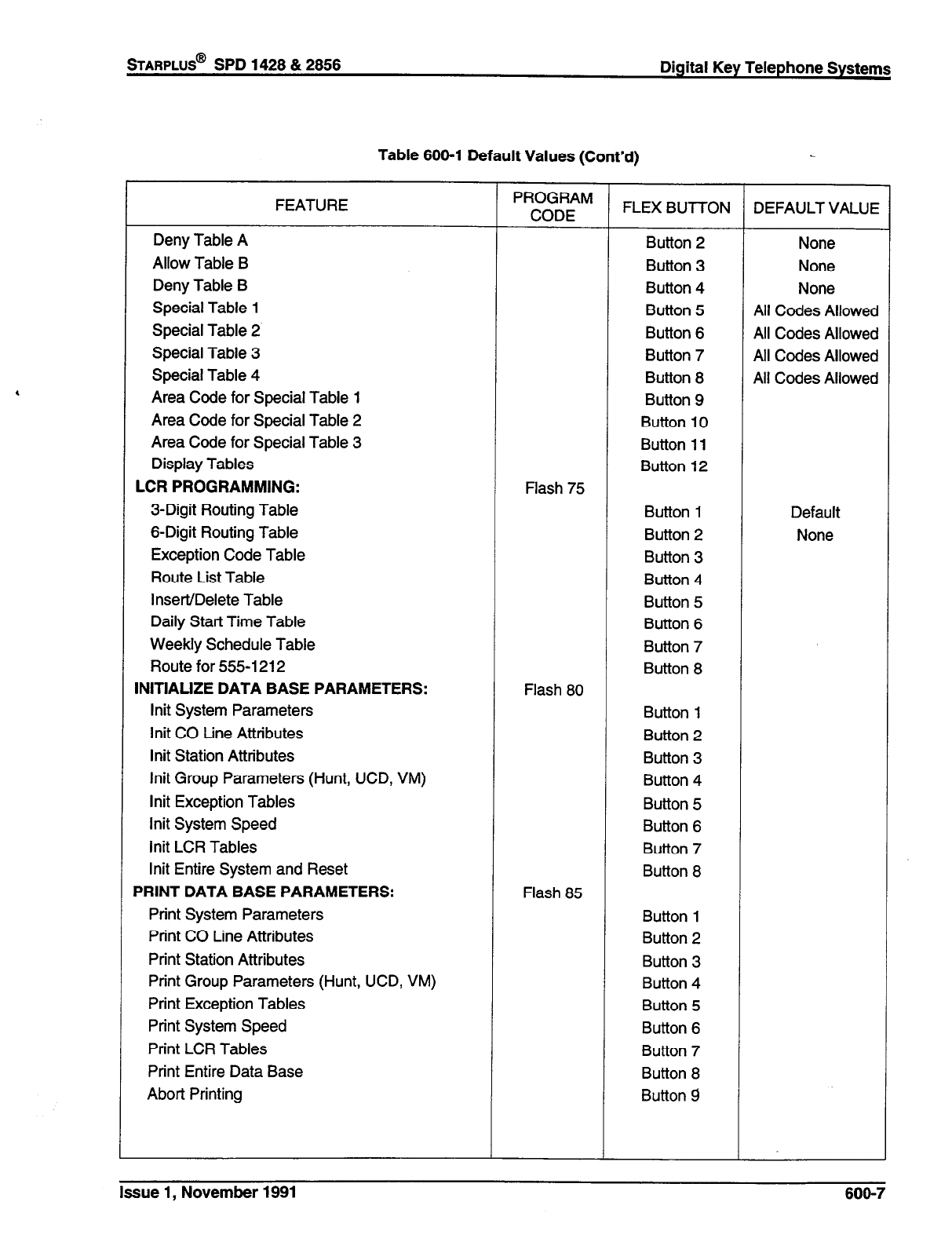
Table 600-l Default Values (Cont’d)
FEATURE
Deny Table A
Allow Table B
Deny Table B
Special Table 1
Special Table 2
Special Table 3
Special Table 4
Area Code for Special Table 1
Area Code for Special Table 2
Area Code for Special Table 3
Display Tables
LCR PROGRAMMING:
3-Digit Routing Table
6-Digit Routing Table
Exception Code Table
Route List Table
Insert/Delete Table
Daily Start Time Table
Weekly Schedule Table
Route for 555-l 212
INITIALIZE DATA BASE PARAMETERS:
lnit System Parameters
lnit CO tine Attributes
lnit Station Attributes
lnit Group Parameters (Hunt, UCD, VM)
lnit Exception Tables
lnit System Speed
lnit LCR Tables
lnit Entire System and Reset
PRINT DATA BASE PARAMETERS:
Print System Parameters
Print CO Line Attributes
Print Station Attributes
Print Group Parameters (Hunt, UCD, VM)
Print Exception Tables
Print System Speed
Print LCR Tables
Print Entire Data Base
Abort Printing
PROGRAM
CODE
Flash 75
Flash 80
Flash 85
FLEX BUT-l-ON DEFAULT VALUE
Button 2 None
Button 3 None
Button 4 None
Button 5 All Codes Allowed
Button 6 All Codes Allowed
Button 7 All Codes Allowed
Button 8 All Codes Allowed
Button 9
Button 10
Button 11
Button 12
Button 1 Default
Button 2 None
Button 3
Button 4
Button 5
Button 6
Button 7
Button 8
Button 1
Button 2
Button 3
Button 4
Button 5
Button 6
Button 7
Button 8
Button 1
Button 2
Button 3
Button 4
Button 5
Button 6
Button 7
Button 8
Button 9
Issue 1, November 1991
600-7
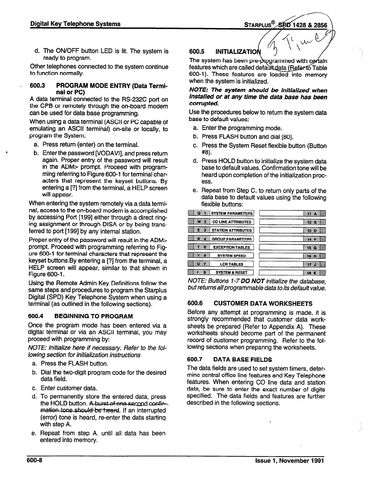
d. The ON/OFF button LED is lit. The system is
ready to program.
Other telephones connected to the system continue
to function normally.
. 600.3
PROGRAM MODE ENTRY (Data Termi-
nal or PC)
A data terminal connected to the RS-232C port on
the CPB or remotely through the on-board modem
can be used for data base programming.
When using a data terminal (ASCII or PC capable of
emulating an ASCII terminal) on-site or locally, to
program the System:
a. Press return (enter) on the terminal.
b. Enter the password [VODAVI], and press return
again. Proper entry of the password will result
in the ADM> prompt. Proceed with program-
ming referring to Figure 600-l for terminal char-
acters that represent the keyset buttons. By
entering a [?] from the terminal, a HELP screen
will appear.
When entering the system remotely via a data termi-
nal, access to the on-board modem is accomplished
by accessing Port [199] either through a direct ring-
ing assignment or through DISA or by being trans-
ferred to port [I 991 by any internal station.
Proper entry of the password will result in the ADM>
prompt. Proceed with programming referring to Fig-
ure 600-l for terminal characters that represent the
keyset buttons.By entering a [?] from the terminal, a
HELP screen will appear, similar to that shown in
Figure 600-l.
Using the Remote Admin Key Definitions follow the
same steps and procedures to program the Starplus
Digital (SPD) Key Telephone System when using a
terminal (as outlined in the following sections).
600.4
BEGINNING TO PROGRAM
Once the program mode has been entered via a
digital terminal or via an ASCII terminal, you may
proceed with programming by:
NOTE: initialize here if necessary. Refer to the fol-
lowing section for initialization instructions
a. Press the FLASH button.
b. Dial the two-digit program code for the desired
data field.
c. Enter customer data.
d. To permanently store the entered data, press
the HOLD button. ,bbllrC)
p If an interrupted
(error) tone is heard, re-enter the data starting
with step A.
e. Repeat from step A. until all data has been
entered into memory.
The system has been pre-
600-l). These features are loaded into memory
when the system is initialized.
NOTE: The system should be initialized when
installed or at any time the data base has been
corrupted.
Use the procedures below to return the system data
base to default values:
a. Enter the programming mode.
b. Press FLASH button and dial [80].
c. Press the System Reset flexible button (Button
#8).
d. Press HOLD button to initialize the system data
base to default values. Confirmation tone will be
heard upon completion of the initialization proc-
ess.
e. Repeat from Step C. to return only parts of the
data base to default
flexible buttons: values using-the following
[>igggg
2;;: . . . . . . . ::::..:..y.$ ,<,
tiiii~~~
:p+.:.:. ..::..: . . . . . . :, ,,
~~:~$~~
NOTE: Buttons I-7 DO NOT initialize the database,
but returns allprogrammable data to its default value.
600.6
CUSTOMER DATA WORKSHEETS
Before any attempt at programming is made, it is
strongly recommended that customer data work-
sheets be prepared (Refer to Appendix A). These
worksheets should become part of the permanent
record of customer programming. Refer to the fol-
lowing sections when preparing the worksheets.
600.7
DATA BASE FIELDS
The data fields are used to set system timers, deter-
mine central office line features and Key Telephone
features. When entering CO line data and station
data, be sure to enter the exact number of digits
specified. The data fields and features are further
described in the following sections.
600-8 Issue
1, November 1991
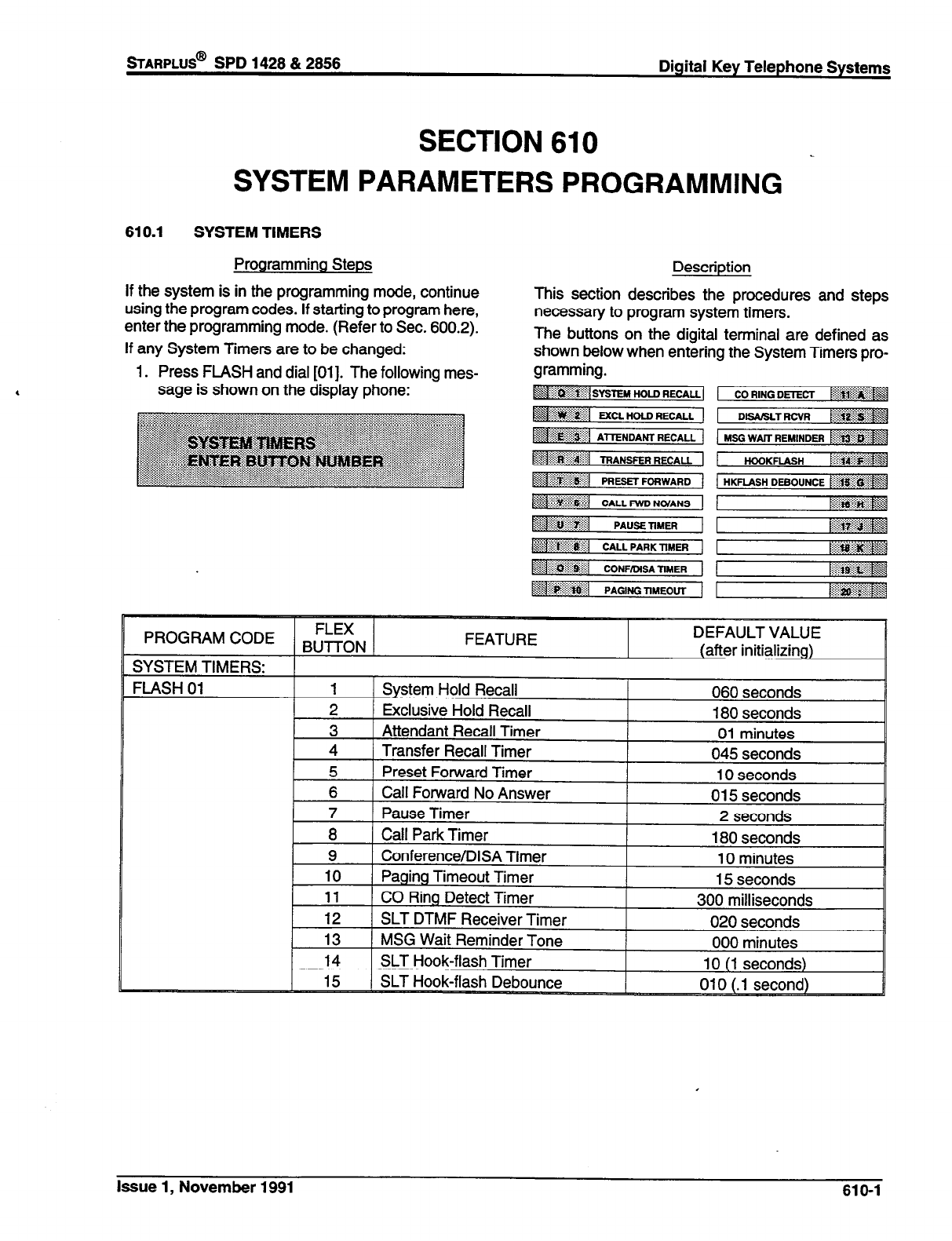
sTARPLUS@
SPD 1428 812856 Digital Key Telephone Systems
SECTION 610
SYSTEM PARAMETERS PROGRAMMING
610.1 SYSTEM TIMERS
Programming Steps
If the system is in the programming mode, continue
using the program codes. If starting to program here,
enter the programming mode. (Refer to Sec. 600.2).
If any System Timers are to be changed:
Description
This section describes the procedures and steps
necessary to program system timers.
The buttons on the digital terminal are defined as
shown below when entering the System Timers pro-
1. Press FLASH and dial [Ol]. The following mes-
sage is shown on the display phone:
PROGRAM CODE
Issue 1, November 1991 610-l
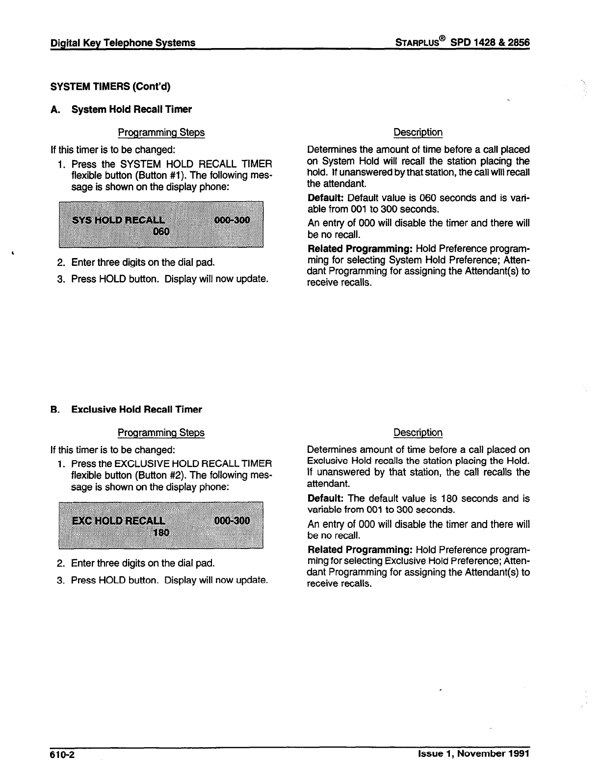
Digital Key Telephone Systems
sTARPLUS@
SPD 1428 & 2656
SYSTEM TIMERS (Cont’d)
A. System Hold Recall Timer
Programming Steps
If this timer is to be changed:
1. Press the SYSTEM HOLD RECALL TIMER
flexible button (Button #l). The following mes-
sage is shown on the display phone:
,
2. Enter three digits on the dial pad.
3. Press HOLD button. Display will now update.
B. Exclusive Hold Recall Timer
Programming Steps
If this timer is to be changed:
1. Press the EXCLUSIVE HOLD RECALL TIMER
flexible button (Button #2). The following mes-
sage is shown on the display phone:
2. Enter three digits on the dial pad.
3. Press HOLD button. Display will now update.
Description
Determines the amount of time before a call placed
on System Hold will recall the station placing the
hold. If unanswered by that station, the call will recall
the attendant.
Default: Default value is 060 seconds and is vari-
able from 001 to 300 seconds.
An entry of 000 will disable the timer and there will
be no recall.
Related Programming: Hold Preference program-
ming for selecting System Hold Preference; Atten-
dant Programming for assigning the Attendant(s) to
receive recalls.
Description
Determines amount of time before a call placed on
Exclusive Hold recalls the station placing the Hold.
If unanswered by that station, the call recalls the
attendant.
Default: The default value is 180 seconds and is
variable from 001 to 300 seconds.
An entry of 000 will disable the timer and there will
be no recall.
Related Programming: Hold Preference program-
ming for selecting Exclusive Hold Preference; Atten-
dant Programming for assigning the Attendant(s) to
receive recalls.
610-2 Issue 1, November 1991
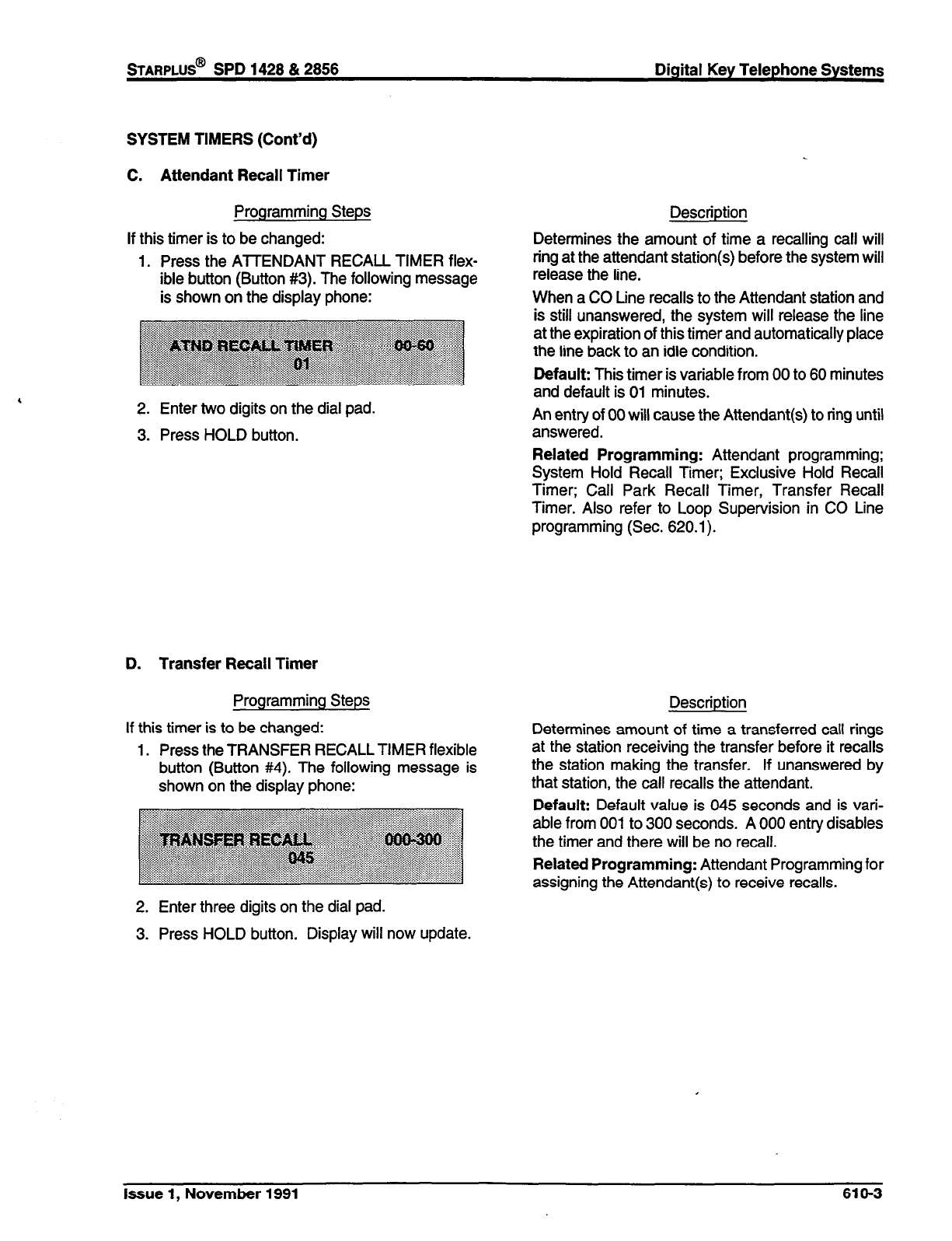
STARPLUS@
SPD 1428 & 2858 Digital Key Telephone Systems
SYSTEM TIMERS (Cont’d)
C. Attendant Recall Timer
Programming Steps
If this timer is to be changed:
1. Press the ATTENDANT RECALL TIMER flex-
ible button (Button #3). The following message
is shown on the display phone:
2. Enter two digits on the dial pad.
3. Press HOLD button.
D. Transfer Recall Timer
Programming Steps
If this timer is to be changed:
1. Press the TRANSFER RECALL TIMER flexible
button (Button #4). The following message is
shown on the display phone:
2. Enter three digits on the dial pad.
3. Press HOLD button. Display will now update.
Description
Determines the amount of time a recalling call will
ring at the attendant station(s) before the system will
release the line.
When a CO Line recalls to the Attendant station and
is still unanswered, the system will release the line
at the expiration of this timer and automatically place
the line back to an idle condition.
Default: This timer is variable from 00 to 60 minutes
and default is 01 minutes.
An entry of 00 will cause the Attendant(s) to ring until
answered.
Related Programming: Attendant programming;
System Hold Recall Timer; Exclusive Hold Recall
Timer; Call Park Recall Timer, Transfer Recall
Timer. Also refer to Loop Supervision in CO Line
programming (Sec. 620.1).
Description
Determines amount of time a transferred call rings
at the station receiving the transfer before it recalls
the station making the transfer. If unanswered by
that station, the call recalls the attendant.
Default: Default value is 045 seconds and is vari-
able from 001 to 300 seconds. A 000 entry disables
the timer and there will be no recall.
Related Programming: Attendant Programming for
assigning the Attendant(s) to receive recalls.
Issue 1, November 1991 610-3
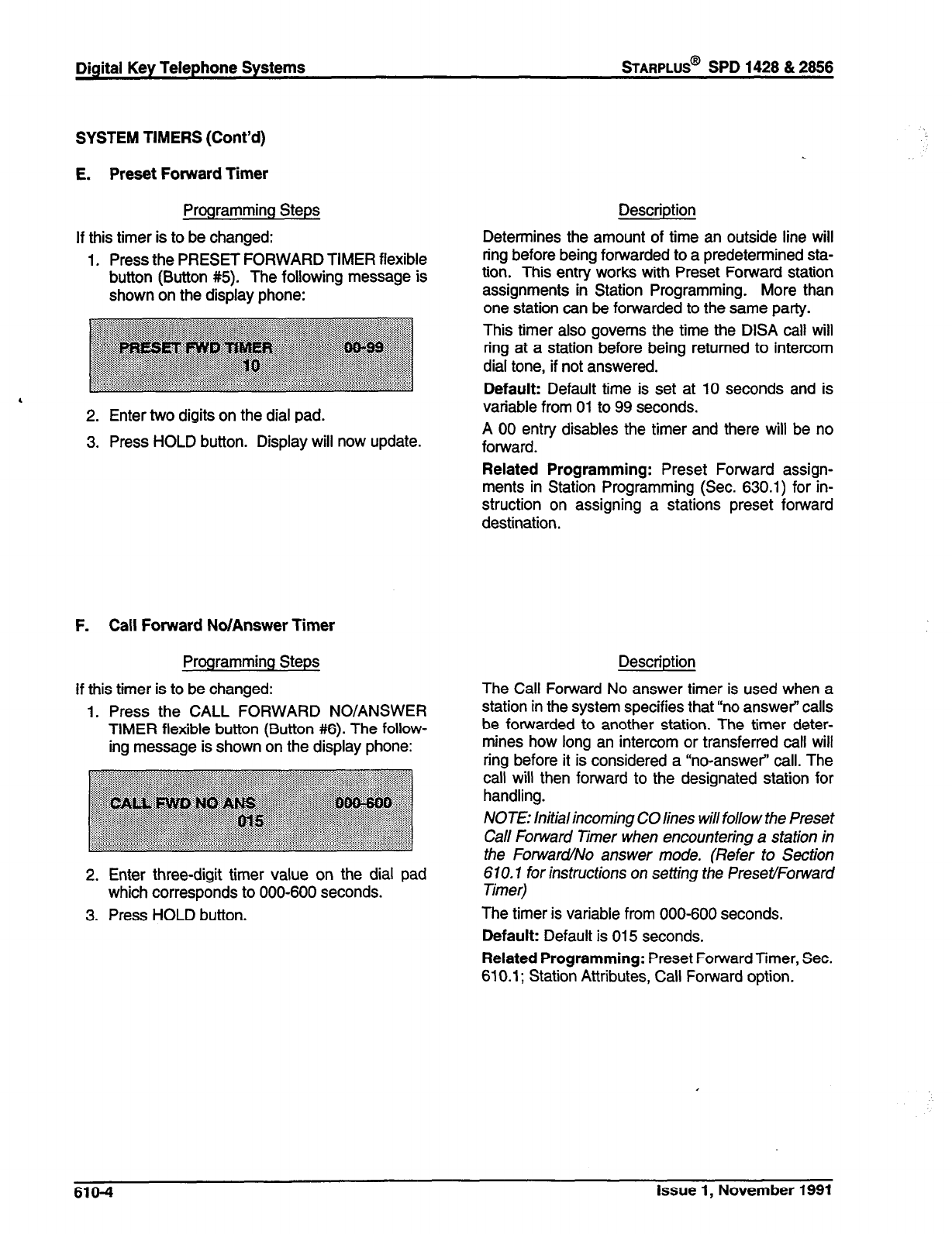
Digital Key Telephone Systems
%ARPLUS@
SPD 1428 & 2866
SYSTEM TIMERS (Cont’d)
E. Preset Forward Timer
Programming Steps
If this timer is to be changed:
1. Press the PRESET FORWARD TIMER flexible
button (Button #5). The following message is
shown on the display phone:
2. Enter two digits on the dial pad.
3. Press HOLD button. Display will now update.
F. Call Forward No/Answer Timer
Programming Steps
If this timer is to be changed:
1. Press the CALL FORWARD NO/ANSWER
TIMER flexible button (Button #6). The follow-
ing message is shown on the display phone:
2. Enter three-digit timer value on the dial pad
which corresponds to 000-600 seconds.
3. Press HOLD button.
Description
Determines the amount of time an outside line will
ring before being forwarded to a predetermined sta-
tion. This entry works with Preset Forward station
assignments in Station Programming. More than
one station can be forwarded to the same party.
This timer also governs the time the DISA call will
ring at a station before being returned to intercom
dial tone, if not answered.
Default: Default time is set at IO seconds and is
variable from 01 to 99 seconds.
A 00 entry disables the timer and there will be no
forward.
Related Programming: Preset Forward assign-
ments in Station Programming (Sec. 630.1) for in-
struction on assigning a stations preset forward
destination.
Description
The Call Forward No answer timer is used when a
station in the system specifies that “no answer” calls
be forwarded to another station. The timer deter-
mines how long an intercom or transferred call will
ring before it is considered a “no-answer” call. The
call will then forward to the designated station for
handling.
NOTE: Initial incoming CO lines will follow the Preset
Call Forward Timer when encountering a station in
the Forward/No answer mode. (Refer to Section
670.7 for instructions on setting the Preset/Forward
Timer)
The timer is variable from 000-600 seconds.
Default: Default is 015 seconds.
Related Programming: Preset Forward Timer, Sec.
610.1; Station Attributes, Call Forward option.
610-4 Issue 1, November 1991
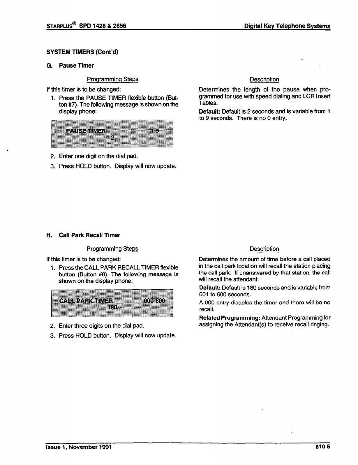
STARPLUS@
SPD 1428 & 2858 Digital Key Telephone Systems
SYSTEM TIMERS (Cont’d)
G. Pause Timer
Programming Steps
If this timer is to be changed:
1. Press the PAUSE TIMER flexible button (But-
ton #7). The following message is shown on the
display phone:
2. Enter one digit on the dial pad.
3. Press HOLD button. Display will now update.
H. Call Park Recall Timer
Programming Steps
If this timer is to be changed:
1. Press the CALL PARK RECALLTIMER flexible
button (Button #8). The following message is
shown on the display phone:
2. Enter three digits on the dial pad.
3. Press HOLD button. Display will now update.
Description
Determines the length of the pause when pro-
grammed for use with speed dialing and LCR Insert
Tables.
Default: Default is 2 seconds and is variable from 1
to 9 seconds. There is no 0 entry.
Description
Determines the amount of time before a call placed
in the call park location will recall the station placing
the call park. If unanswered by that station, the call
will recall the attendant.
Default: Default is 180 seconds and is variable from
001 to 600 seconds.
A 000 entry disables the timer and there will be no
recall.
Related Programming: Attendant Programming for
assigning the Attendant(s) to receive recall ringing.
Issue 1, November 1991 61 O-5
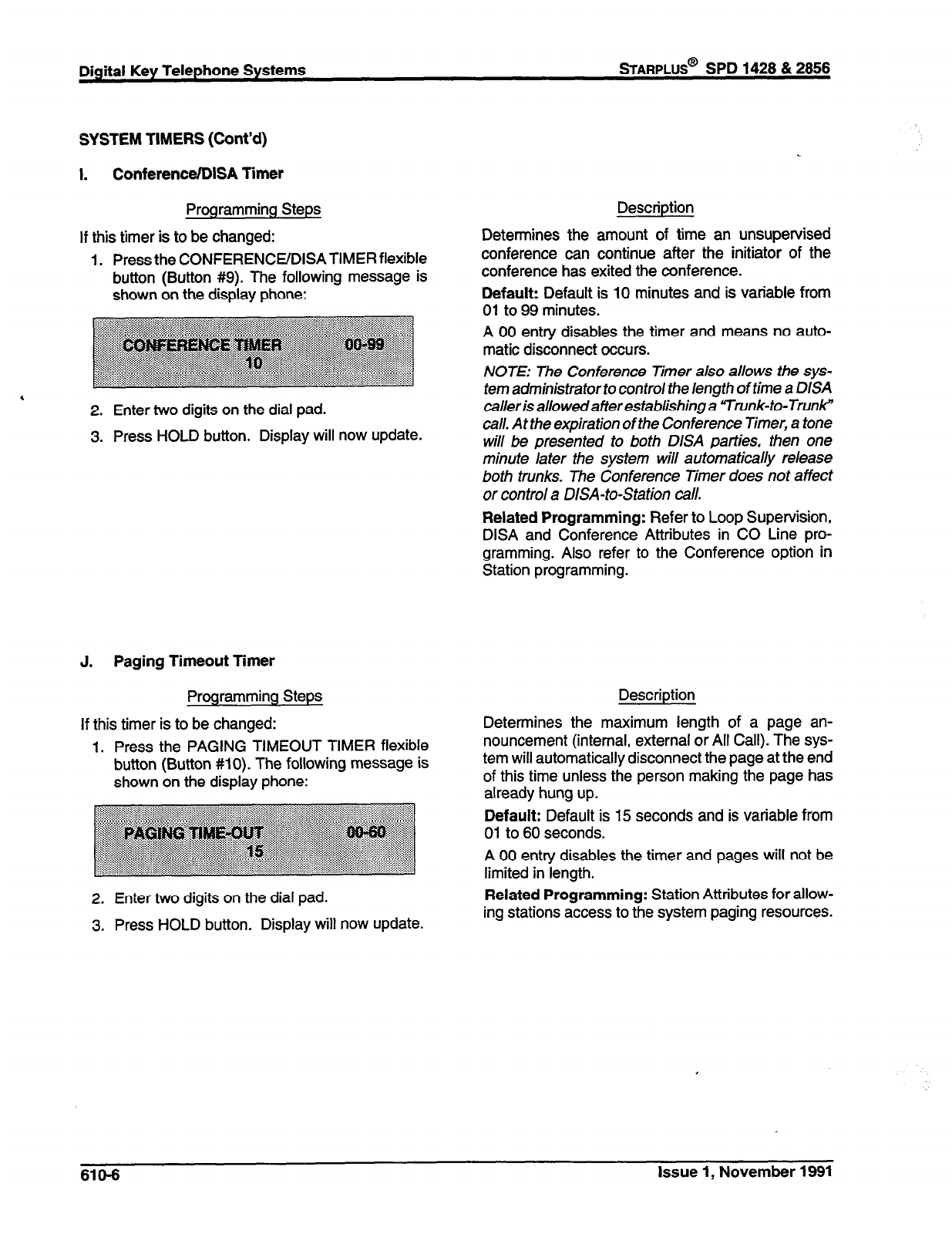
Digital Key Telephone Systems STARPLUS@ SPD 1428 & 2858
SYSTEM TIMERS (Cont’d)
I. ConferenceIDISA Timer
Programming Steps
If this timer is to be changed: Determines the
Description
amount of time an unsupervised
continue after the initiator of the
1. Press the CONFERENCEIDISATIMER flexible conterence can
button (Button #9). The following message is conference has exited the conference.
shown on the display phone: Default: Default is 10 minutes and is variable from
01 to 99 minutes.
A 00 entry disables the timer and means no auto-
matic disconnect occurs.
NOTE: The Conference Timer also
allOWS
the
Sp-
tern administrator to control the length of time a DISA
caller is allowedafter establishing a “Trunk-to-Trunk”
call. At the expiration of the Conference Timer, a tone
will be presented to both DISA parties, then one
minufe later the system will automatically release
both trunks. The Conference Timer does not affect
or control a DISA-to-Station call.
Related Programming: Refer to Loop Supervision,
DISA and Conference Attributes in CO Line pro-
gramming. Also refer to the Conference option in
Station programming.
.
2. Enter two digits on the dial pad.
3. Press HOLD button. Display will now update.
J. Paging Timeout Timer
Programming Steps
If this timer is to be changed:
1. Press the PAGING TIMEOUT TIMER flexible
button (Button #lo). The following message is
shown on the display phone:
2. Enter two digits on the dial pad.
3. Press HOLD button. Display will now update.
Description
Determines the maximum length of a page an-
nouncement (internal, external or All Call). The sys-
tem will automatically disconnect the page at the end
of this time unless the person making the page has
already hung up.
Default: Default is 15 seconds and is variable from
01 to 60 seconds.
A 00 entry disables the timer and pages will not be
limited in length.
Related Programming: Station Attributes for allow-
ing stations access to the system paging resources.
610-6 Issue 1, November 1991
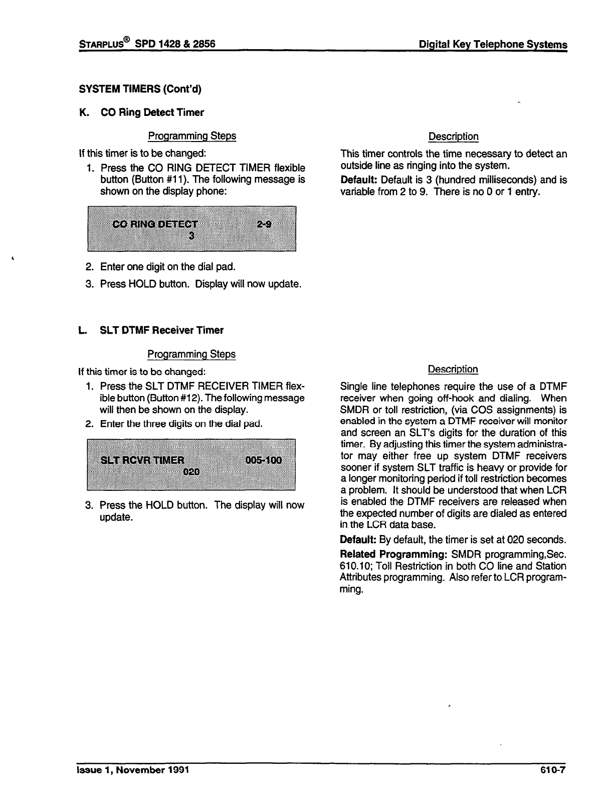
STARPLUS@
SPD 1428 & 2856 Digital Key Telephone Systems
SYSTEM TIMERS (Cont’d)
K. CO Ring Detect Timer
Programming Steps
If this timer is to be changed:
1. Press the CO RING DETECT TIMER flexible
button (Button #ii). The following message is
shown on the display phone:
2. Enter one digit on the dial pad.
3. Press HOLD button. Display will now update.
L. SLT DTMF Receiver Timer
Programming Steps
If this timer is to be changed:
1. Press the SLT DTMF RECEIVER TIMER flex-
ible button (Button #12). The following message
will then be shown on the display.
2. Enter the three digits on the dial pad.
3. Press the HOLD button. The display will now
update.
Description
This timer controls the time necessary to detect an
outside line as ringing into the system.
Default: Default is 3 (hundred milliseconds) and is
variable from 2 to 9. There is no 0 or 1 entry.
Description
Single line telephones require the use of a DTMF
receiver when going off-hook and dialing. When
SMDR or toll restriction, (via COS assignments) is
enabled in the system a DTMF receiver will monitor
and screen an SLT’s digits for the duration of this
timer. By adjusting this timer the system administra-
tor may either free up system DTMF receivers
sooner if system SLT traffic is heavy or provide for
a longer monitoring period if toll restriction becomes
a problem. It should be understood that when LCR
is enabled the DTMF receivers are released when
the expected number of digits are dialed as entered
in the LCR data base.
Default: By default, the timer is set at 020 seconds.
Related Programming: SMDR programming,Sec.
610.10; Toll Restriction in both CO line and Station
Attributes programming. Also refer to LCR program-
ming.
Issue 1, November 1991 616-7
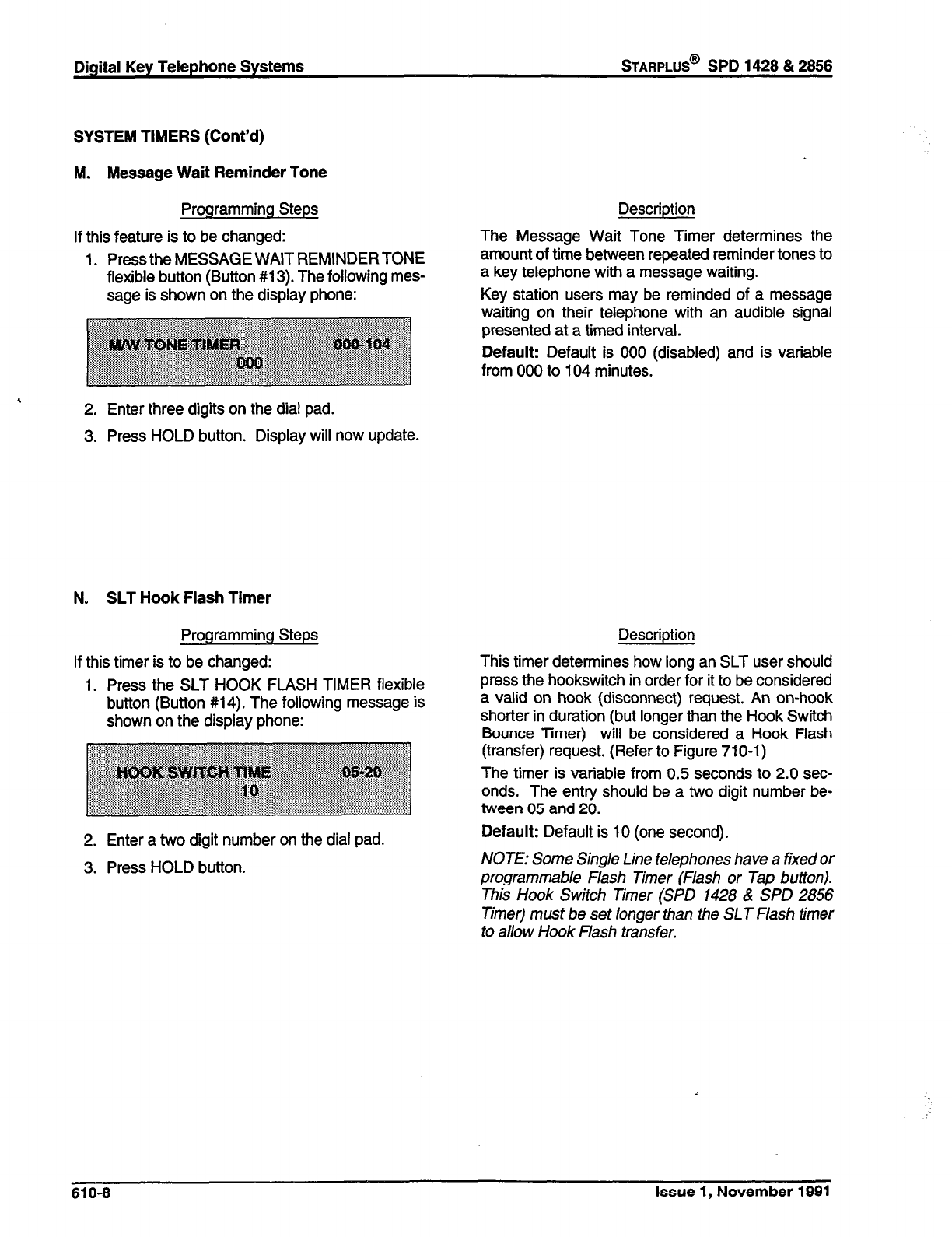
Digital Key Telephone Systems
STARPLUS@
SPD 1428 & 2866
SYSTEM TIMERS (Cont’d)
M. Message Wait Reminder Tone
Programming Steps
If this feature is to be changed:
1. Press the MESSAGE WAIT REMINDERTONE
flexible button (Button #13). The following mes-
sage is shown on the display phone:
2. Enter three digits on the dial pad.
3. Press HOLD button. Display will now update.
N. SLT Hook Flash Timer
Programming Steps
If this timer is to be changed:
1. Press the SLT HOOK FLASH TIMER flexible
button (Button #14). The following message is
shown on the display phone:
2. Enter a two digit number on the dial pad.
3. Press HOLD button.
Description
The Message Wait Tone Timer determines the
amount of time between repeated reminder tones to
a key telephone with a message waiting.
Key station users may be reminded of a message
waiting on their telephone with an audible signal
presented at a timed interval.
Default: Default is 000 (disabled) and is variable
from 000 to 104 minutes.
Description
This timer determines how long an SLT user should
press the hookswitch in order for it to be considered
a valid on hook (disconnect) request. An on-hook
shorter in duration (but longer than the Hook Switch
Bounce Timer) will be considered a Hook Flash
(transfer) request. (Refer to Figure 710-l)
The timer is variable from 0.5 seconds to 2.0 sec-
onds. The entry should be a two digit number be-
tween 05 and 20.
Default: Default is 10 (one second).
NOTE: Some Single Line telephones have a fixed or
programmable Flash Timer (Flash or Tap button).
This Hook Switch Timer (SPD 1428 & SPD 2856
Timer) must be set longer than the SLT Flash timer
to allow Hook Flash transfer.
610-6 Issue 1, November 1991
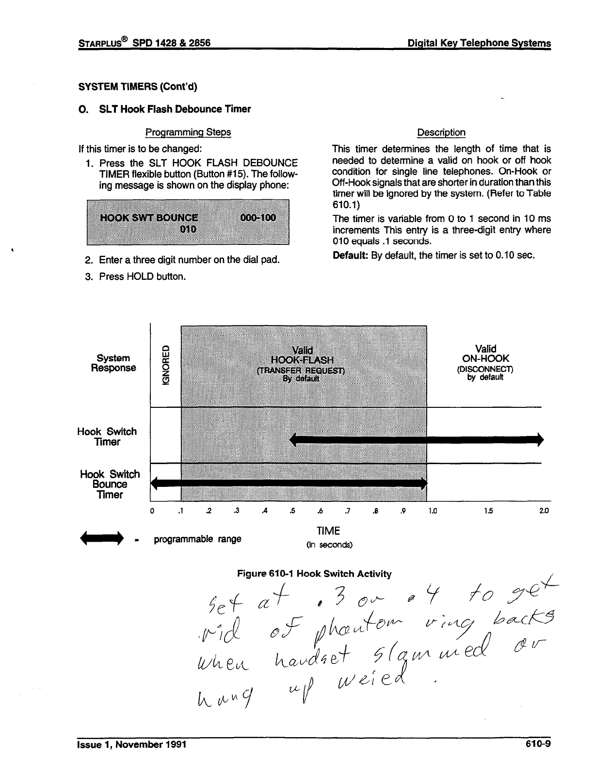
STARPLUS@
SPD 1428 & 2856 Digital Key Telephone Systems
SYSTEM TIMERS (Cont’d)
0. SLT Hook Flash Debounce Timer
Programming Steps
If this timer is to be changed:
1. Press the SLT HOOK FLASH DEBOUNCE
TIMER flexible button (Button #15). The follow-
ing message is shown on the display phone:
2. Enter a three digit number on the dial pad.
3. Press HOLD button.
Description
This timer determines the length of time that is
needed to determine a valid on hook or off hook
condition for single line telephones. On-Hook or
Off-Hook signals that are shorter in duration than this
timer will be ignored by the system. [Refer to Table
610.1)
The timer is variable from 0 to 1 second in 10 ms
increments This entry is a three-digit entry where
010 equals .l seconds.
Default: By default, the timer is set to 0.10 sec.
System
Response
Hook Switch
Timer
Ho;:&Stch
Timer
0 .1 .2 .3 A .s .6 .7
.a
.9 1.0 1.5 2.0
w=
programmable range
TIME
(In seconds)
Figure 610-l Hook Switch Activity
Issue 1, November 1991 610-9
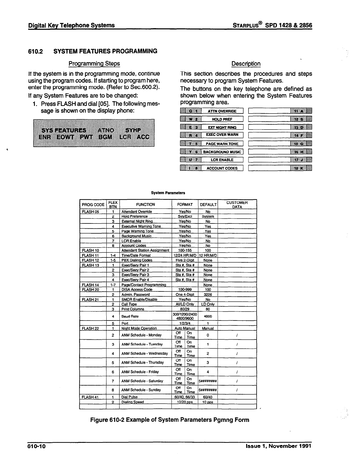
Digital Key Telephone Systems
STARPLUS@
SPD 1428 & 2866
610.2 SYSTEM FEATURES PROGRAMMING
Programming Steps
If the system is in the programming mode, continue
using the program codes. If starting to program here,
enter the programming mode. (Refer to Sec.600.2).
If any System Features are to be changed:
1. Press FLASH and dial [05]. The following mes-
sage is shown on the display phone:
Descriotion
This section describes the procedures and steps
necessary to program System Features.
The buttons on the key telephone are defined as
shown below when entering the System Features
System Parameters
Figure 61 O-2 Example of System Parameters Pgmng Form
610-10 Issue 1, November 1991
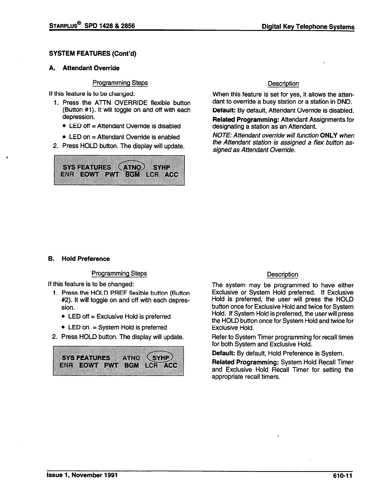
STARPLUS@
SPD 1428 & 2856 Digital Key Telephone Systems
SYSTEM FEATURES (Cont’d)
A. Attendant Override
Programming Steps
If this feature is to be changed:
1. Press the AlTN OVERRIDE flexible button
(Button #l). It will toggle on and off with each
depression.
l
LED off = Attendant Override is disabled
l
LED on = Attendant Override is enabled
2. Press HOLD button. The display will update.
B. Hold Preference
Programming Steps
If this feature is to be changed:
1. Press the HOLD PREF flexible button (Button
#2). It will toggle on and off with each depres-
sion.
l
LED off = Exclusive Hold is preferred
l
LED on = System Hold is preferred
2. Press HOLD button. The display will update.
Description
When this feature is set for yes, it allows the atten-
dant to override a busy station or a station in DND.
Default: By default, Attendant Override is disabled.
Related Programming: Attendant Assignments for
designating a station as an Attendant.
NOTE: Attendant override will function ONLY when
the Attendant station is assigned a flex button as-
signed as Attendant Override.
Description
The system may be programmed to have either
Exclusive or System Hold preferred. If Exclusive
Hold is preferred, the user will press the HOLD
button once for Exclusive Hold and twice for System
Hold. If System Hold is preferred, the user will press
the HOLD button once for System Hold and twice for
Exclusive Hold.
Refer to System Timer programming for recall times
for both System and Exclusive Hold.
Default: By default, Hold Preference is System.
Related Programming: System Hold Recall Timer
and Exclusive Hold Recall Timer for setting the
appropriate recall timers.
Issue 1, November 1991 610-11
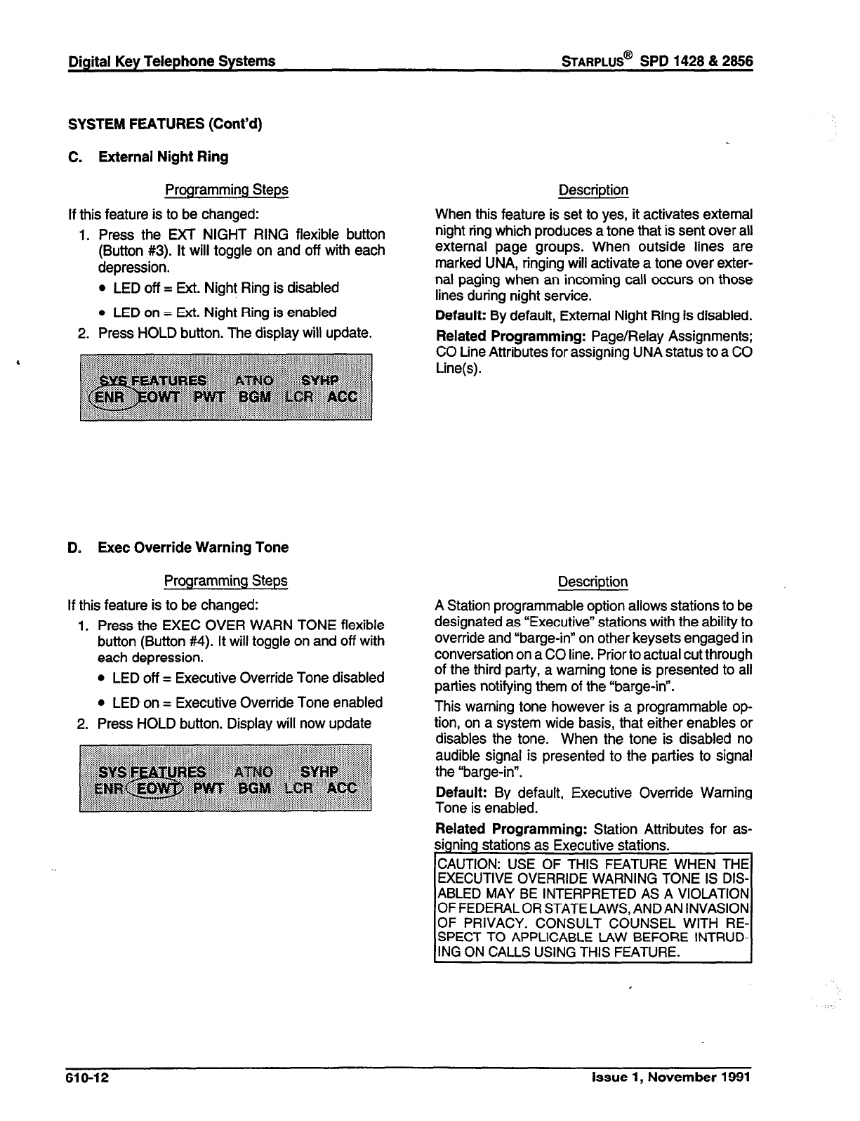
Digital Key Telephone Systems
sTARPLUS@
SPD 1428 & 2866
SYSTEM FEATURES (Cont’d)
C. External Night Ring
Programming Steps
If this feature is to be changed:
1. Press the EXT NIGHT RING flexible button
(Button #3). It will toggle on and off with each
depression.
l
LED off = Ext. Night Ring is disabled
l
LED on = Ext. Night Ring is enabled
2. Press HOLD button. The display will update.
D. Exec Override Warning Tone
Programming Steps
If this feature is to be changed:
1. Press the EXEC OVER WARN TONE flexible
button (Button #4). It will toggle on and off with
each depression.
l
LED off = Executive Override Tone disabled
l
LED on = Executive Override Tone enabled
2. Press HOLD button. Display will now update
Description
When this feature is set to yes, it activates external
night ring which produces a tone that is sent over all
external page groups. When outside lines are
marked UNA, ringing will activate a tone over exter-
nal paging when an incoming call occurs on those
lines during night service.
Default: By default, External Night Ring is disabled.
Related Programming: Page/Relay Assignments;
CO Line Attributes for assigning UNA status to a CO
Line(s).
Description
A Station programmable option allows stations to be
designated as “Executive” stations with the ability to
override and “barge-in” on other keysets engaged in
conversation on a CO line. Prior to actual cut through
of the third party, a warning tone is presented to all
parties notifying them of the “barge-in”.
This warning tone however is a programmable op-
tion, on a system wide basis, that either enables or
disables the tone. When the tone is disabled no
audible signal is presented to the parties to signal
the “barge-in”.
Default: By default, Executive Override Warning
Tone is enabled.
Related Programming: Station Attributes for as-
signing stations as Executive stations.
CAUTION: USE OF THIS FEATURE WHEN THE
EXECUTIVE OVERRIDE WARNING TONE IS DIS-
ABLED MAY BE INTERPRETED AS A VIOLATION
OF FEDERAL OR STATE LAWS, AND AN INVASION
OF PRIVACY. CONSULT COUNSEL WITH RE-
SPECT TO APPLICABLE LAW BEFORE INTRUD-
ING ON CALLS USING THIS FEATURE.
610-12 Issue 1, November 1991

STARPLUS@ SPD 1428 & 2856 Digital Key Telephone Systems
SYSTEM FEATURES (Cont’d)
E. Page Warning Tone
Programming Steps
If this feature is to be changed:
1. Press the PAGE WARN TONE flexible button
(Button #5). It will toggle on and off with each
depression.
l
LED on = Page Warning Tone is enabled
l
LED off = Page Warning Tone is disabled
2. Press HOLD button. Display will now update.
Description
Determines whether a page warning tone will be
sounded over the Key Telephone speakers or exter-
nal paging speakers, prior to a page announcement.
Default: By default, Page Warning Tone is enabled.
Related Programming: Station Attributes, Sec.
630.1; Page Access and Page Group Assignments.
F. Music Channel
Programming Steps
If Background Music is to be enabled/disabled:
1. Press the BACKGROUND MUSIC flexible but-
ton (Button #6). It will toggle on and off with
each depression.
l
LED on = Background Music is enabled
l
LED off = Background Music is disabled
2. Press HOLD button. Display will now update.
Description
The system can be programmed to allow stations to
activate Background Music at their stations, in addi-
tion to Music-On-Hold. A music source must be
connected to the BGM/MOH connector on the CPU.
Default: By default, the Background Music channel
is enabled.
Related Programming:
Issue 1, November 1991 610-13
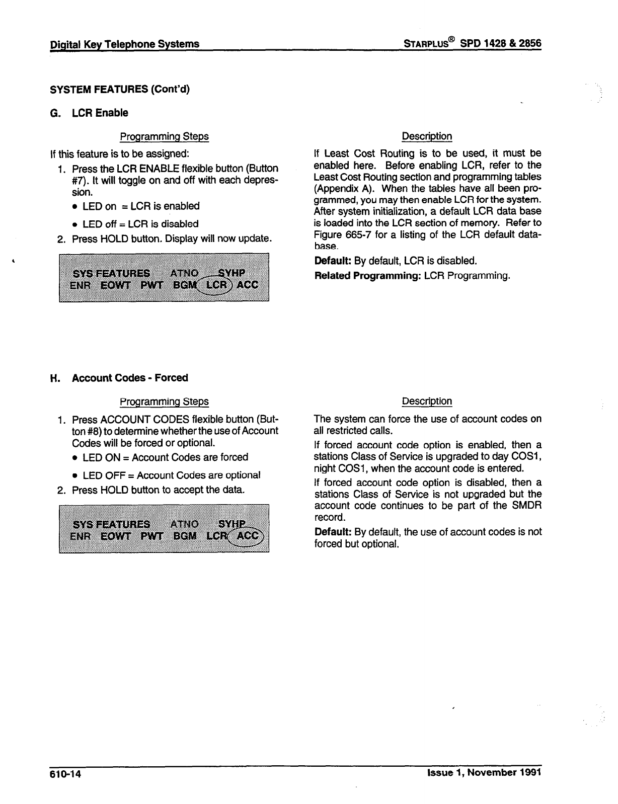
Digital Key Telephone Systems
sTARPLUS@
SPD 1428 & 2666
SYSTEM FEATURES (Cont’d)
G. LCR Enable
Programming Steps
If this feature is to be assigned:
Description
If Least Cost Routing is to be
1.
2.
Press the LCR ENABLE flexible button (Button
#7). It will toggle on and off with each depres-
sion.
* LED on = LCR is enabled
l
LED off = LCR is disabled
Press HOLD button, Display will now update.
enabled here. Before enabling
. . - _ _. ,. .
used, it must be
LCR, refer to the
Least Cost t-routing sectron ana programming tables
(Appendix A). When the tables have all been pro-
grammed, you may then enable LCR for the system.
After system initialization, a default LCR data base
is loaded into the LCR section of memory. Refer to
Figure 665-7 for a listing of the LCR default data-
base.
Default: By default, LCR is disabled.
Related Programming: LCR Programming.
H. Account Codes - Forced
Programming Steps
1. Press ACCOUNT CODES flexible button (But-
ton #8) to detem7ine whetherthe use of Account
Codes will be forced or optional.
0 LED ON = Account Codes are forced
l
LED OFF = Account Codes are optional
2. Press HOLD button to accept the data.
Description
The system can force the use of account codes on
all restricted calls.
If forced account code option is enabled, then a
stations Class of Service is upgraded to day COSI ,
night COSl, when the account code is entered.
If forced account code option is disabled, then a
stations Class of Service is not upgraded but the
account code continues to be part of the SMDR
record.
Default: By default, the use of account codes is not
forced but optional.
610-14 Issue 1, November 1991
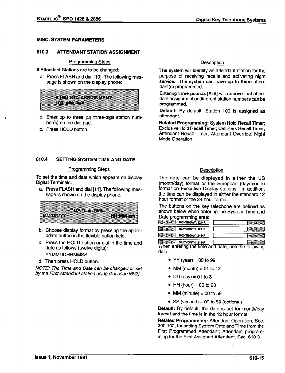
STARPLUS@
SPD 1426 & 2656
MISC. SYSTEM PARAMETERS
610.3 AlTENDANT STATION ASSIGNMENT
Programming Steps
If Attendant Stations are to be changed:
a. Press FLASH and dial [lo]. The following mes-
sage is shown on the display phone:
b. Enter up to three (3) three-digit station num-
ber(s) on the dial pad.
c. Press HOLD button.
610.4 SElTING SYSTEM TIME AND DATE
Programming Steps
To set the time and date which appears on display
Digital Terminals:
a. Press FLASH and dial [i 11. The following mes-
sage is shown on the display phone.
b. Choose display format by pressing the appro-
priate button in the flexible button field.
c. Press the HOLD button or dial in the time and
date as follows (twelve digits):
YYMMDDHHMMSS
d. Then press HOLD button.
NOTE: The Time and Date can be changed or set
by the First Attendant station using dial code [692]
Digital Key Telephone Systems
Description
The system will identify an attendant station for the
purpose of receiving recalls and activating night
service. The system can have up to three atten-
dant(s) programmed.
Entering three pounds [###I will remove that atten-
dant assignment or different station numbers can be
programmed.
Default: By default, Station 100 is assigned as
attendant.
Related Programming: System Hold Recall Timer;
Exclusive Hold Recall Timer; Call Park Recall Timer;
Attendant Recall Timer; Attendant Override; Night
Mode Operation.
The date can be displayed in either the US
(month/day) format or the European (day/month)
format on Executive Display stations. In addition,
the time can be displayed in either the standard 12
hour format or the 24 hour format.
Description
The buttons on the key telephone are defined as
shown below when entering the System Time and
Date programming area:
~T@&$ ..:i:ji:
8.j MONTH!DAt 12HR 1
$1 DAYMOW 24HR ( 1 @g?@qq
. . . . .:.:.:.: :.
When entering the time and date, use the following
data:
l
W (year) = 00 to 99
l
MM (month) = 01 to 12
l
DD (day) = 01 to 31
l
HH (hour) = 00 to 23
l
MM (minute) = 00 to 59
l
SS (second) = 00 to 59 (optional)
Default: By default, the date is set for month/day
format and the time is in the 12 hour format.
Related Programming: Attendant Operation, Sec.
300.102, for setting System Date and Time from the
First Programmed Attendant; Attendant program-
ming for the First Assigned Attendant, Sec. 610.3.
Issue 1, November 1991 610-15
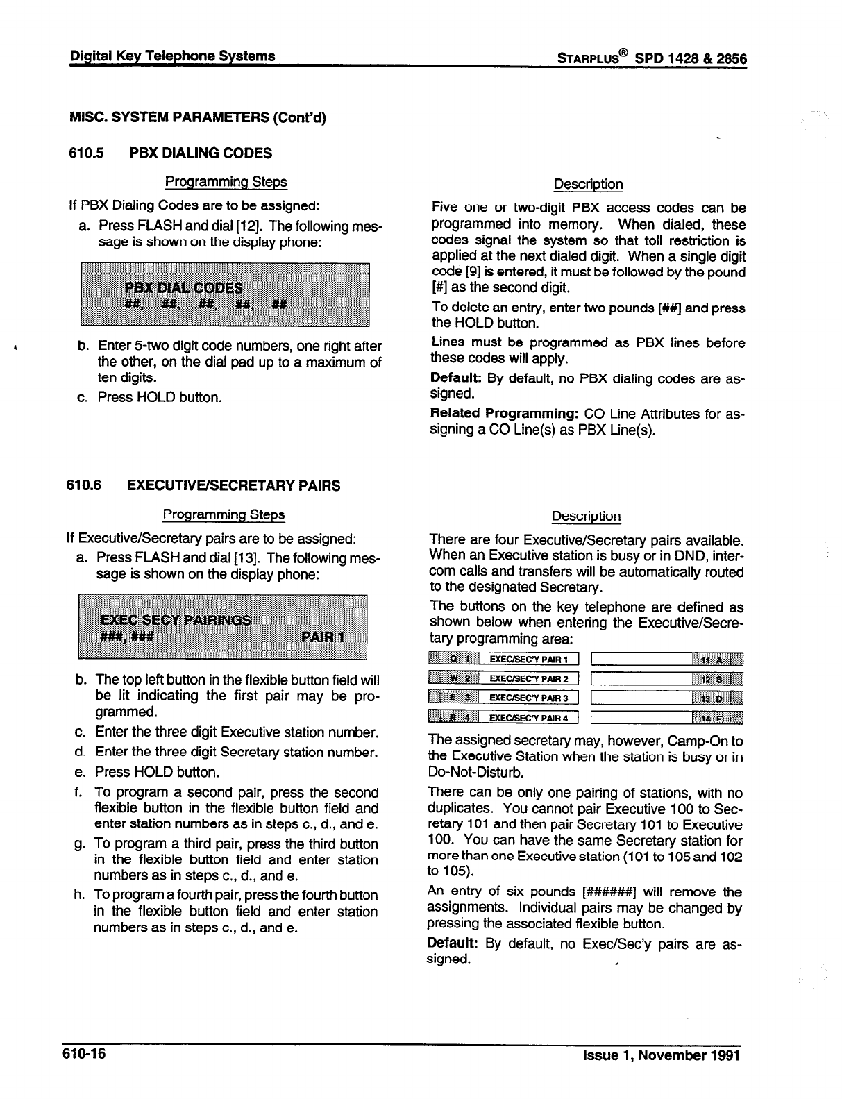
Digital Key Telephone Systems
sTARPLUS@
SPD 1428 & 2856
MISC. SYSTEM PARAMETERS (Cont’d)
610.5 PBX DIALING CODES
Programming Steps
If PBX Dialing Codes are to be assigned:
a. Press FLASH and dial [12]. The following mes-
sage is shown on the display phone:
b. Enter 54.~0 digit code numbers, one right after
the other, on the dial pad up to a maximum of
ten digits.
c. Press HOLD button.
610.6 EXECUTIVE/SECRETARY PAIRS
Programming Steps
If Executive/Secretary pairs are to be assigned:
a. Press FLASH and dial [13]. The following mes-
sage is shown on the display phone:
b. The top left button in the flexible button field will
be lit indicating the first pair may be pro-
grammed.
c. Enter the three digit Executive station number.
d. Enter the three digit Secretary station number.
e. Press HOLD button.
f. To program a second pair, press the second
flexible button in the flexible button field and
enter station numbers as in steps c., d., and e.
g. To program a third pair, press the third button
in the flexible button field and enter station
numbers as in steps c., d., and e.
h. To program a fourth pair, press the fourth button
in the flexible button field and enter station
numbers as in steps c., d., and e.
Description
Five one or two-digit PBX access codes can be
programmed into memory. When dialed, these
codes signal the system so that toll restriction is
applied at the next dialed digit. When a single digit
code [9] is entered, it must be followed by the pound
[#I as the second digit.
To delete an entry, enter two pounds [#I#] and press
the HOLD button.
Lines must be programmed as PBX lines before
these codes will apply.
Default: By default, no PBX dialing codes are as-
signed.
Related Programming: CO Line Attributes for as-
signing a CO Line(s) as PBX Line(s).
Description
There are four Executive/Secretary pairs available.
When an Executive station is busy or in DND, inter-
com calls and transfers will be automatically routed
to the designated Secretary.
The buttons on the key telephone are defined as
shown below when entering the Executive/Secre-
tary programming area:
~rciii.~~~j w-c’y pmR,
~~~~~~~I U[EC/SECY PAIR * ~~~~~
~$$$gy.-
5 .:3i&g.j ExEC(SECY PNR
3
.:.:::...:...: . . . . . :.:,:,. <
~;jug&g&~
,<
U(EeSECy PNR 4 ~~~~~~~~
The assigned secretary may, however, Camp-On to
the Executive Station when the station is busy or in
Do-Not-Disturb.
There can be only one pairing of stations, with no
duplicates. You cannot pair Executive 100 to Sec-
retary 101 and then pair Secretary 101 to Executive
100. You can have the same Secretary station for
more than one Executive station (101 to 105 and 102
to 105).
An entry of six pounds [######I] will remove the
assignments. Individual pairs may be changed by
pressing the associated flexible button.
Default: By default, no Exec/Sec’y pairs are as-
signed. I
610-16 Issue 1, November 1891
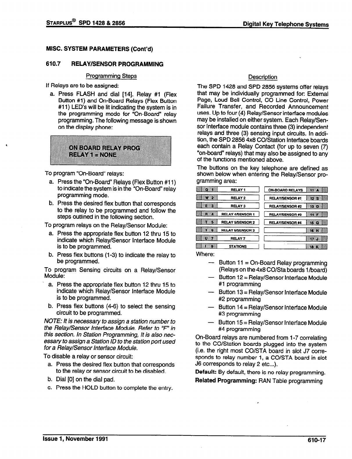
sTARPLUS@
SPD 1428 & 2856 Digital Key Telephone Systems
MISC. SYSTEM PARAMETERS (Cont’d)
610.7 RELAY/SENSOR PROGRAMMING
Programming Steps
If Relays are to be assigned:
a. Press FLASH and dial [14]. Relay #l (Flex
Button #l) and On-Board Relays (Flex Button
#1 1) LED’s will be lit indicating the system is in
the programming mode for “On-Board” relay
programming. The following message is shown
on the display phone:
To program “On-Board” relays:
a. Press the “On-Board” Relays (Flex Button #1 1)
to indicate the system is in the “On-Board” relay
programming mode.
b. Press the desired flex button that corresponds
to the relay to be programmed and follow the
steps outlined in the following section.
To program relays on the Relay/Sensor Module:
a. Press the appropriate flex button 12 thru 15 to
indicate which Relay/Sensor Interface Module
is to be programmed.
b. Press flex buttons (l-3) to indicate the relay to
be programmed.
To program Sensing circuits on a Relay/Sensor
Module:
a. Press the appropriate flex button 12 thru 15 to
indicate which Relay/Sensor Interface Module
is to be programmed.
b. Press flex buttons (4-6) to select the sensing
circuit to be programmed.
NOTE: /t is necessary to assign a station number to
the Relay/Sensor Interface Module. Refer to “% in
this section. In Station Programming, It is also nec-
essary to assign a Station ID to the station port used
for a Relay/Sensor Interface Module.
To disable a relay or sensor circuit:
a. Press the desired flex button that corresponds
to the relay or sensor circuit to be disabled.
b. Dial [0] on the dial pad.
c. Press the HOLD button to complete the entry.
Description
The SPD 1428 and SPD 2856 systems offer relays
that may be individually programmed for: External
Page, Loud Bell Control, CO Line Control, Power
Failure Transfer, and Recorded Announcement
uses. Up to four (4) Relay/Sensor interface modules
may be installed on either system. Each Relay/Sen-
sor Interface module contains three (3) independent
relays and three (3) sensing input circuits. In addi-
tion, the SPD 2856 4x8 CO/Station Interface boards
each contain a Relay Contact (for up to seven (7)
“on-board” relays) that may also be assigned to any
of the functions mentioned above.
The buttons on the key telephone are defined as
shown below when entering the Relay/Sensor pro-
Where:
-
-
-
-
-
Button 11 = On-Board Relay programming
(Relays on the 4x8 CO/Sta boards l/board)
Button 12 = Relay/Sensor Interface Module
#l programming
Button 13 = Relay/Sensor Interface Module
#2 programming
Button 14 = Relay/Sensor Interface Module
#3 programming
Button 15 = Relay/Sensor Interface Module
#4 programming
On-Board relays are numbered from l-7 correlating
to the CO/Station boards plugged into the system
(i.e. the right most CO/STA board in slot J7 corre-
sponds to relay number 1, a CO/STA board in slot
J6 corresponds to relay 2 etc...).
Default: By default, there is no relay programming.
Related Programming: RAN Table programming
.
Issue 1, November 1991 610-17
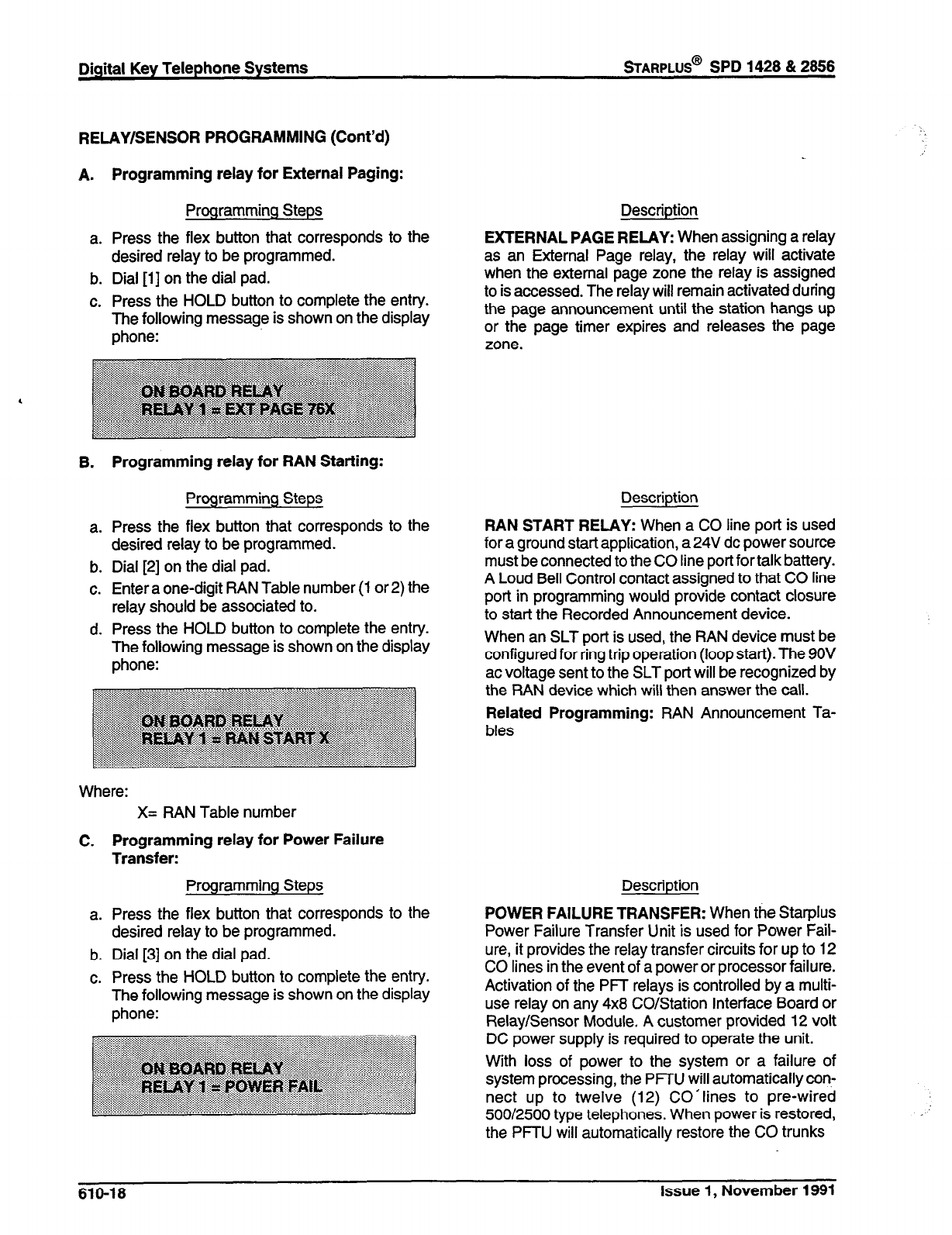
RELAY/SENSOR PROGRAMMING (Cont’d)
A.
a.
b.
c.
Programming relay for External Paging:
Programming Steps
Press the flex button that corresponds to the
desired relay to be programmed.
Dial [i] on the dial pad.
Press the HOLD button to complete the entry.
The following message is shown on the display
phone:
B.
a.
b.
C.
d.
Programming relay for RAN Starting:
Programming Steps
Press the flex button that corresponds to the
desired relay to be programmed.
Dial [2] on the dial pad.
Enter a one-digit RAN Table number (1 or 2) the
relay should be associated to.
Press the HOLD button to complete the entry.
The following message is shown on the display
phone:
Where:
C.
a.
b.
c.
X= RAN Table number
Programming relay for Power Failure
Transfer:
Programming Steps
Press the flex button that corresponds to the
desired relay to be programmed.
Dial [3] on the dial pad.
Press the HOLD button to complete the entry.
The following message is shown on the display
phone:
Digital Key Telephone Systems
sTARPLUS@
SPD 1428 & 2866
Description
EXTERNAL PAGE RELAY: When assigning a relay
as an External Page relay, the relay will activate
when the external page zone the relay is assigned
to is accessed. The relay will remain activated during
the page announcement until the station hangs up
or the page timer expires and releases the page
zone.
Description
RAN START RELAY: When a CO line port is used
for a ground start application, a24V dc power source
must be connected to the CO line port for talk battery.
A Loud Bell Control contact assigned to that CO line
port in programming would provide contact closure
to start the Recorded Announcement device.
When an SLT port is used, the RAN device must be
configured for ring trip operation (loop start). The 9OV
ac voltage sent to the SLT port will be recognized by
the RAN device which will then answer the call.
Related Programming: RAN Announcement Ta-
bles
Description
POWER FAILURE TRANSFER: When the Starplus
Power Failure Transfer Unit is used for Power Fail-
ure, it provides the relay transfer circuits for up to 12
CO lines in the event of a power or processor failure.
Activation of the PFf relays is controlled by a multi-
use relay on any 4x8 CO/Station Interface Board or
Relay/Sensor Module. A customer provided 12 volt
DC power supply is required to operate the unit.
With loss of power to the system or a failure of
system processing, the PFTU will automatically con-
nect up to twelve (12) CO’lines to pre-wired
500/2500 type telephones. When power is restored,
the PFRJ will automatically restore the CO trunks
610-18 Issue 1, November 1991
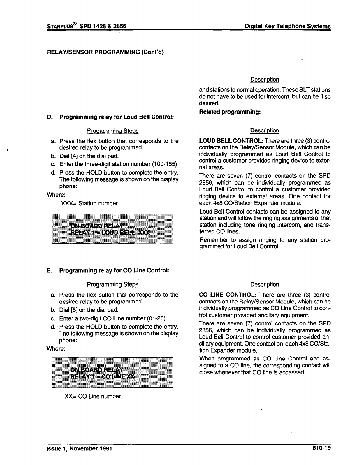
RELAY/SENSOR PROGRAMMING (Cont’d)
Description
D. Programming relay for Loud Bell Control:
Programming Steps
a.
b.
C.
d.
Press the flex button that corresponds to the
desired relay to be programmed.
Dial [4] on the dial pad.
Enter the three-digit station number (100-l 55)
Press the HOLD button to complete the entry.
The following message is shown on the display
phone:
Where:
XXX= Station number
E. Programming relay for CO Line Control:
Programming Steps
a. Press the flex button that corresponds to the
desired relay to be programmed.
b. Dial [5] on the dial pad.
c. Enter a two-digit CO Line number (01-28)
d. Press the HOLD button to complete the entry.
The following message is shown on the display
phone:
Where:
XX= CO tine number
and stations to normal operation. These SLT stations
do not have to be used for intercom, but can be if so
desired.
Related programming:
Description
LOUD BELL CONTROL: There are three (3) control
contacts on the Relay/Sensor Module, which can be
individually programmed as Loud Bell Control to
control a customer provided ringing device to exter-
nal areas.
There are seven (7) control contacts on the SPD
2856, which can be individually programmed as
Loud Bell Control to control a customer provided
ringing device to external areas. One contact for
each 4x8 CO/Station Expander module.
Loud Bell Control contacts can be assigned to any
station and will follow the ringing assignments of that
station including tone ringing intercom, and trans-
ferred CO lines.
Remember to assign ringing to any station pro-
grammed for Loud Bell Control.
Description
CO LINE CONTROL: There are three (3) control
contacts on the Relay/Sensor Module, which can be
individually programmed as CO Line Control to con-
trol customer provided ancillary equipment.
There are seven (7) control contacts on the SPD
2856, which can be individually programmed as
Loud Bell Control to control customer provided an-
cillary equipment. One contact on each 4x8 CO/Sta-
tion Expander module.
When programmed as CO Line Control and as-
signed to a CO line, the corresponding contact will
close whenever that CO line is accessed.
Issue 1, November 1991 610-19
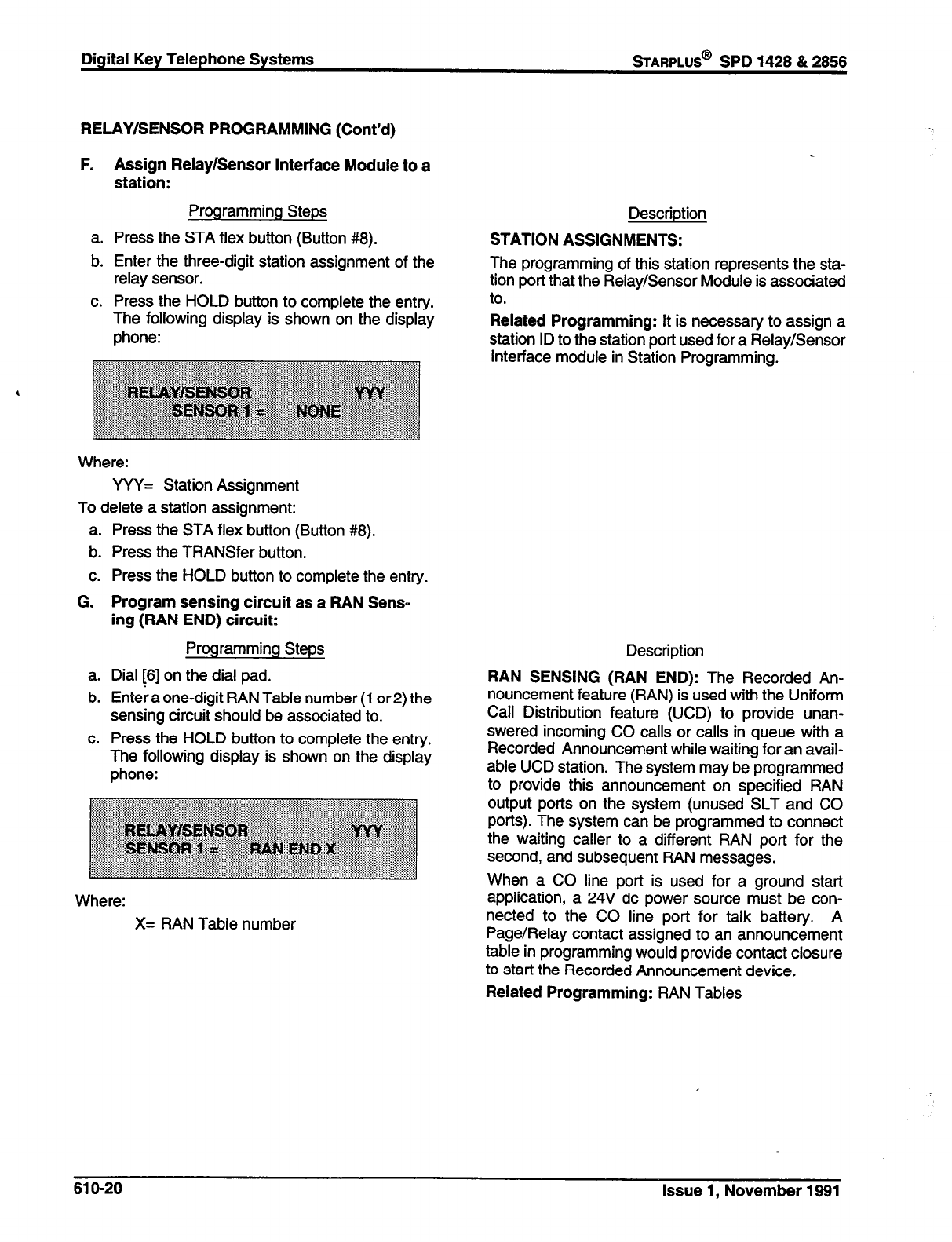
Digital Key Telephone Systems
sTARPLUS@
SPD 1426 & 2666
RELAY/SENSOR PROGRAMMING (Cont’d)
F. Assign Relay/Sensor Interface Module to a
station:
Programming Steps
a. Press the STA flex button (Button #8).
b. Enter the three-digit station assignment of the
relay sensor.
c. Press the HOLD button to complete the entry.
The following display is shown on the display
phone:
Where:
YYY= Station Assignment
To delete a station assignment:
a. Press the STA flex button (Button #8).
b. Press the TRANSfer button.
c. Press the HOLD button to complete the entry.
G. Program sensing circuit as a RAN Sens-
ing (RAN END) circuit:
Programming Steps
a. Dial [6] on the dial pad.
b. Entee; a one-digit RAN Table number (1 or 2) the
sensing circuit should be associated to.
c. Press the HOLD button to complete the entry.
The following display is shown on the display
phone:
Where:
X= RAN Table number
Description
STATION ASSIGNMENTS:
The programming of this station represents the sta-
tion port that the Relay/Sensor Module is associated
to.
Related Programming: It is necessary to assign a
station ID to the station port used for a Relay/Sensor
Interface module in Station Programming.
Description
RAN SENSING (RAN END): The Recorded An-
nouncement feature (RAN) is used with the Uniform
Call Distribution feature (UCD) to provide unan-
swered incoming CO calls or calls in queue with a
Recorded Announcement while waiting for an avail-
able UCD station. The system may be programmed
to provide this announcement on specified RAN
output ports on the system (unused SLT and CO
ports). The system can be programmed to connect
the waiting caller to a different RAN port for the
second, and subsequent RAN messages.
When a CO line port is used for a ground start
application, a 24V dc power source must be con-
nected to the CO line port for talk battery. A
Page/Relay contact assigned to an announcement
table in programming would provide contact closure
to start the Recorded Announcement device.
Related Programming: RAN Tables
61 O-20 Issue 1, November 1991
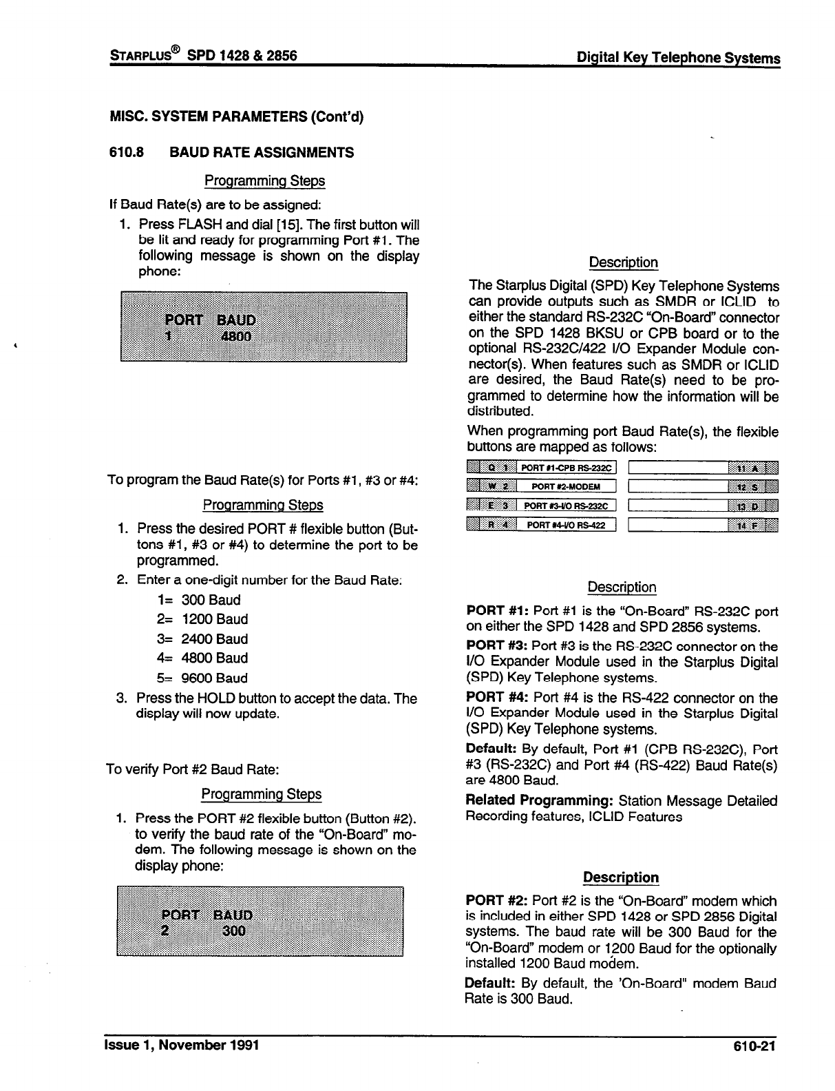
sTARPLUS@
SPD 1428 & 2856 Digital Key Telephone Systems
MISC. SYSTEM PARAMETERS (Cont’d)
610.8 BAUD RATE ASSIGNMENTS
Programming Steps
If Baud Rate(s) are to be assigned:
1. Press FLASH and dial [15]. The first button will
be lit and ready for programming Port #1. The
following message is shown on the display
phone:
To program the Baud Rate(s) for Ports #l , #3 or #4:
Programming Steps
1. Press the desired PORT # flexible button (But-
tons #l, #3 or #4) to determine the port to be
programmed.
2. Enter a one-digit number for the Baud Rate:
l= 300 Baud
2= 1200 Baud
3= 2400 Baud
4= 4800 Baud
5= 9600 Baud
3. Press the HOLD button to accept the data. The
display will now update.
To verify Port #2 Baud Rate:
Programming Steps
1. Press the PORT #2 flexible button (Button #2).
to verify the baud rate of the “On-Board” mo-
dem. The following message is shown on the
display phone:
Description
The Statplus Digital (SPD) Key Telephone Systems
can provide outputs such as SMDR or ICLID to
either the standard RS-232C “On-Board” connector
on the SPD 1428 BKSU or CPB board or to the
optional RS232C/422 I/O Expander Module con-
nector(s). When features such as SMDR or ICLID
are desired, the Baud Rate(s) need to be pro-
grammed to determine how the information will be
distributed.
When programming port Baud Rate(s), the flexible
buttons are mapped as follows:
Description
PORT #l: Port #l is the “On-Board” RS-232C port
on either the SPD 1428 and SPD 2856 systems.
PORT #3: Port #3 is the RS-232C connector on the
I/O Expander Module used in the Starplus Digital
(SPD) Key Telephone systems.
PORT #4: Port #4 is the RS-422 connector on the
I/O Expander Module used in the Starplus Digital
(SPD) Key Telephone systems.
Default: By default, Port #l (CPB RS232C), Port
#3 (RS232C) and Port #4 (RS-422) Baud Rate(s)
are 4800 Baud.
Related Programming: Station Message Detailed
Recording features, ICLID Features
Description
PORT #2: Port #2 is the “On-Board” modem which
is included in either SPD 1428 or SPD 2856 Digital
systems. The baud rate will be 300 Baud for the
“On-Board” modem or 1200 Baud for the optionally
installed 1200 Baud modem.
Default: By default, the ‘On-Board” modem Baud
Rate is 300 Baud.
Issue 1, November 1991 61 O-21
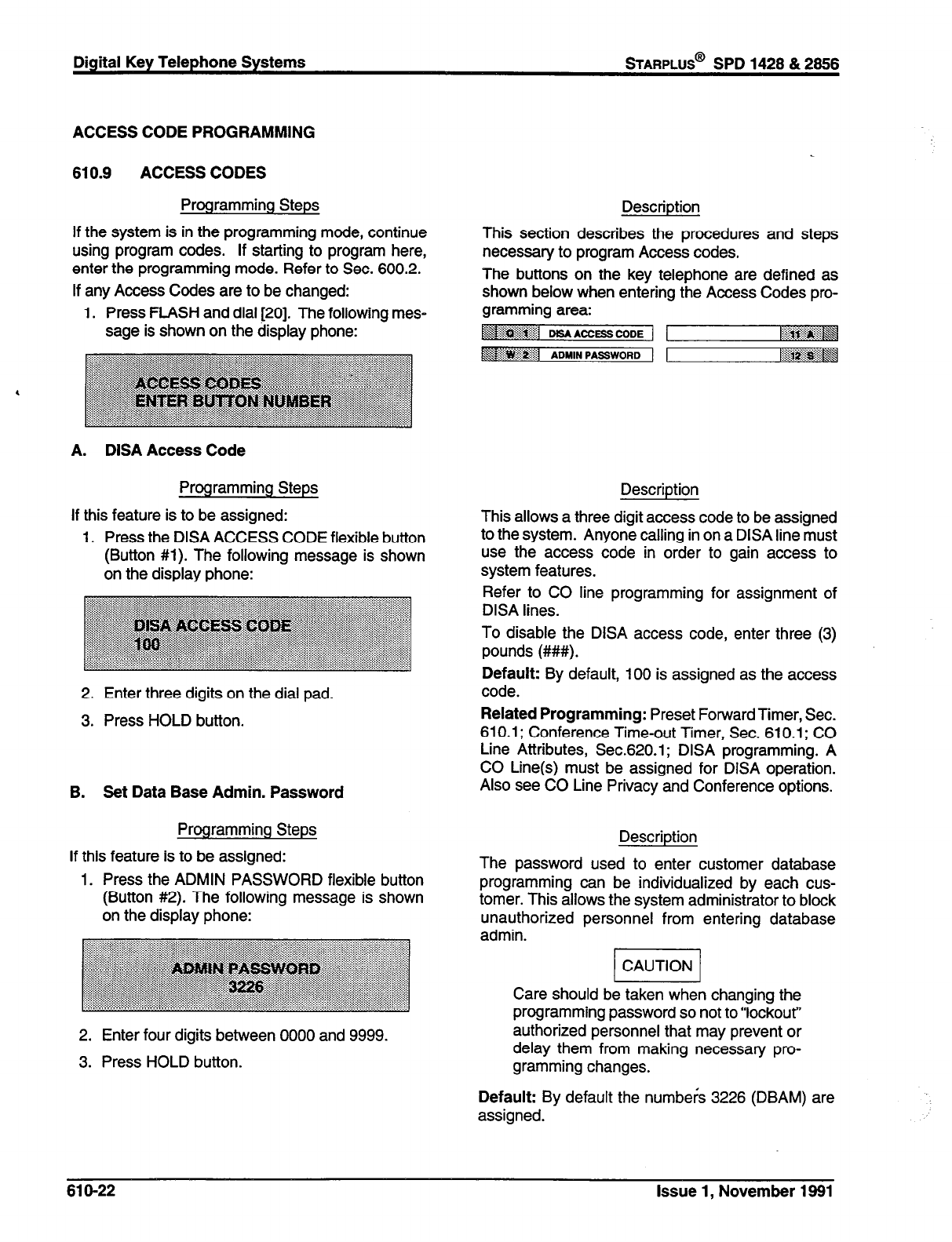
Digital Key Telephone Systems
sTARPLUS@
SPD 1428 & 2666
ACCESS CODE PROGRAMMING
610.9 ACCESS CODES
Programming Steps
If the system is in the programming mode, continue
using program codes. If starting to program here,
enter the programming mode. Refer to Sec. 600.2.
If any Access Codes are to be changed:
1. Press FLASH and dial [20]. The following mes-
sage is shown on the display phone:
A. DISA Access Code
Programming Steps
If this feature is to be assigned:
1. Press the DISA ACCESS CODE flexible button
(Button #l). The following message is shown
on the display phone:
2. Enter three digits on the dial pad.
3. Press HOLD button.
B. Set Data Base Admin. Password
Programming Steps
If this feature is to be assigned:
1. Press the ADMIN PASSWORD flexible button
(Button #2). The following message is shown
on the display phone:
2. Enter four digits between 0000 and 9999.
3. Press HOLD button.
Description
This section describes the procedures and steps
necessary to program Access codes.
The buttons on the key telephone are defined as
shown below when entering the Access Codes pro-
gramming area:
~~~rln~~~ MS*AcpBcoDE j 1 :z::.‘: . . . . . :;: . . . . . :.:. A \
[i:&i&J@
Description
This allows a three digit access code to be assigned
to the system. Anyone calling in on a DISA line must
use the access code in order to gain access to
system features.
Refer to CO line programming for assignment of
DISA lines.
To disable the DISA access code, enter three (3)
pounds (##I#).
Default: By default, 100 is assigned as the access
code.
Related Programming: Preset Forward Timer, Sec.
610.1; Conference Time-out Timer, Sec. 610.1; CO
Line Attributes, Sec.620.1; DISA programming. A
CO Line(s) must be assigned for DISA operation.
Also see CO Line Privacy and Conference options.
Description
The password used to enter customer database
programming can be individualized by each cus-
tomer. This allows the system administrator to block
unauthorized personnel from entering database
admin.
/I
Care should be taken when changing the
programming password so not to “lockout”
authorized personnel that may prevent or
delay them from making necessary pro-
gramming changes.
Default: By default the numbers 3226 (DBAM) are
assigned.
61 O-22 Issue 1, November 1991
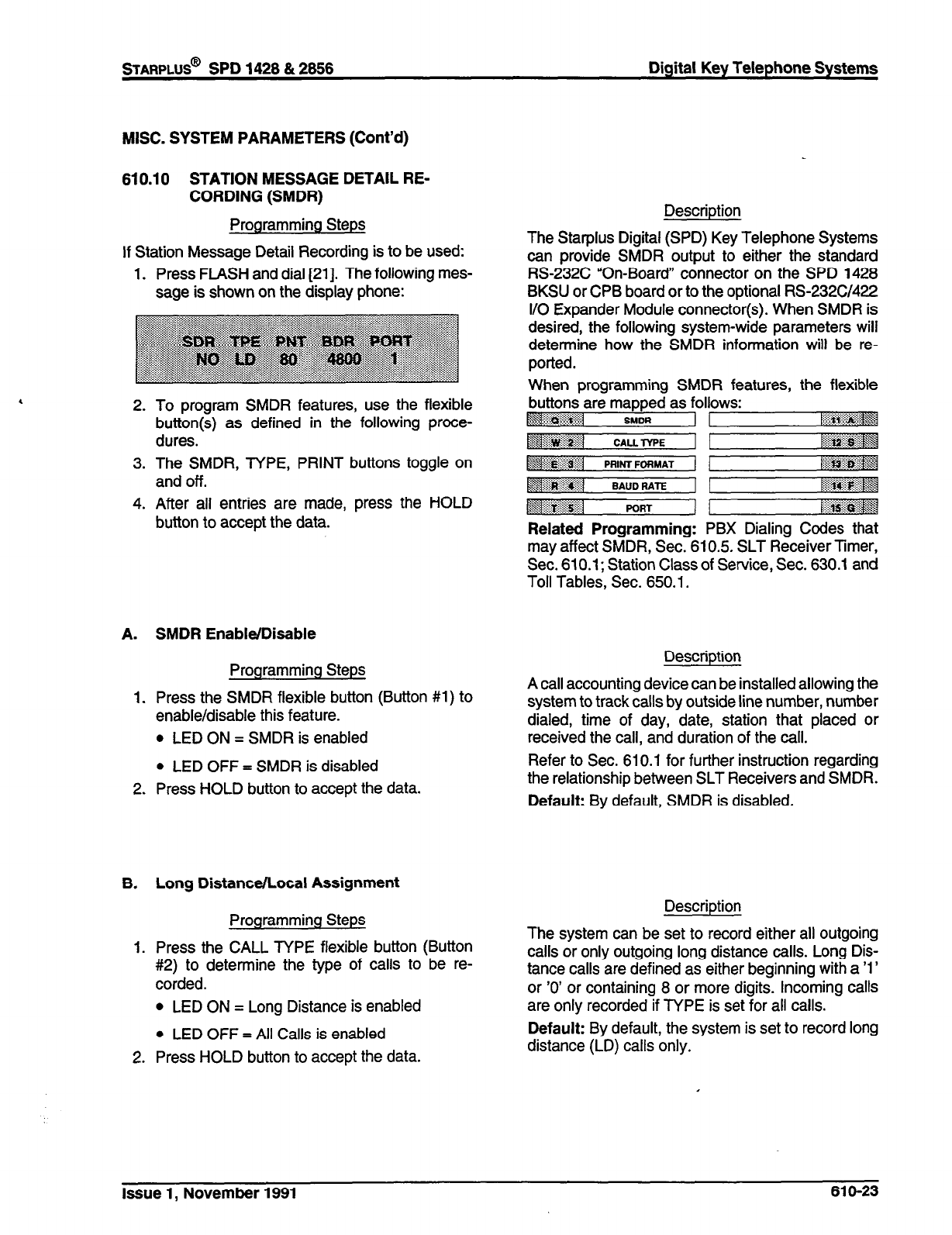
STARPLUS@
SPD 1428 & 2858 Digital Key Telephone Systems
MISC. SYSTEM PARAMETERS (Cont’d)
610.10 STATION MESSAGE DETAIL RE-
CORDING (SMDR)
Programming Steps
If Station Message Detail Recording is to be used:
1. Press FLASH and dial [21]. The following mes-
sage is shown on the display phone:
2. To program SMDR features, use the flexible
button(s) as defined in the following proce-
dures.
3. The SMDR, TYPE, PRINT buttons toggle on
and off.
4. After all entries are made, press the HOLD
button to accept the data.
A. SMDR Enable/Disable
Programming Steps
1. Press the SMDR flexible button (Button #l) to
enable/disable this feature.
l
LED ON = SMDR is enabled
l
LED OFF = SMDR is disabled
2. Press HOLD button to accept the data.
B. Long Distance/Local Assignment
Programming Steps
1. Press the CALL TYPE flexible button (Button
#2) to determine the type of calls to be re-
corded.
l
LED ON = Long Distance is enabled
l
LED OFF = All Calls is enabled
2. Press HOLD button to accept the data.
Description
The Starplus Digital (SPD) Key Telephone Systems
can provide SMDR output to either the standard
RS-232C “On-Board” connector on the SPD 1428
BKSU or CPB board or to the optional RS232C/422
I/O Expander Module connector(s). When SMDR is
desired, the following system-wide parameters will
determine how the SMDR information will be re-
ported.
When programming SMDR features, the flexible
buttons are mapped as follows:
~<#$$@g$ SMDR ,.... . ..:
M+]
‘$.. . . . . . . . :.::: . . . . . 2;; PORT [:&gig&J
:::::: :.. :.: . . . . . ::>;: :$$;
Related Programming: PBX Dialing Codes that
may affect SMDR, Sec. 610.5. SLT Receiver Timer,
Sec. 610.1; Station Class of Service, Sec. 630.1 and
Toll Tables, Sec. 650.1.
Description
A call accounting device can be installed allowing the
system to track calls by outside line number, number
dialed, time of day, date, station that placed or
received the call, and duration of the call.
Refer to Sec. 610.1 for further instruction regarding
the relationship between SLT Receivers and SMDR.
Default: By default, SMDR is disabled.
Description
The system can be set to record either all outgoing
calls or only outgoing long distance calls. Long Dis-
tance calls are defined as either beginning with a ‘1’
or ‘0’ or containing 8 or more digits. Incoming calls
are only recorded if TYPE is set for all calls.
Default: By default, the system is set to record long
distance (LD) calls only.
Issue 1, November 1991 61 O-23

STATION MESSAGE DETAIL RECORDING
(Cont’d)
C. Character Print Assignment
Programming Steps Description
1. Press PRINT FORMAT flexible button (Button
#3) to determine the print format of SMDR
records.
l
LED ON = 80 Character is enabled
l
LED OFF = 30 Character is enabled
2. Press HOLD button to accept the data.
D. Baud Rate Display
Programming Steps
The SMDR Baud Rate is programmed using
Flash 15 Baud Rate Assignments. Button #4
will return error tone when pressed. The LCD
displays the current baud rate based on which
Port number is assigned to the SMDR Port
number.
E. SMDR Port Assignment
Programming Steps
1. Press the PORT flexible button (Button #5) to
determine which port is to be used for SMDR
information.
2. Enter a one-digit number for the SMDR Port
number:
1= Port #1 (“On-Board” RS232C)
2= Port #2 (“On-Board” Modem)
3= Port #3 (I/O Expander Module RS232C)
4= Port #4 (I/O Expander Module RS-422)
3. Press HOLD button to accept the data.
The system can be programmed to print individual
SMDR records in either a l-line 80 character format
or a 3-line 30 character format.
Default: By default, the 1 -line 80 character format is
selected.
Description
The Starplus Digital (SPD) Key Telephone Systems
can provide SMDR output to either the standard
RS-232C “On-Board” connector on the SPD 1428
BKSU or SPD 2856 CPB board or to the optional
RS232C/422 I/O Expander Module connector(s).
The Baud Rate will be displayed as either 300 baud,
1200 baud, 2400 baud, 4800 baud, 9600 baud.
Related Programming: Baud Rate Assignments
Description
Port #l refers to the standard RS-232C “On-Board
connector on the SPD 1428 Basic KSU or the CPB
board on the SPD 2856.
Port #2 refers to the “On-Board 300 Baud modem
provided with the system.
Port #3 refers to the RS-232C connector on the I/O
Expander Module.
Port #4 refers to the RS-422 connector on the same
I/O Expander Module installed in either Starplus
Digital system.
Default: By default, Port #1 is used for SMDR.
61 O-24 Issue 1, November 1991

STARPLUS@
SPD 1428 & 2856 Digital Key Telephone Systems
MISC. SYSTEM PARAMETERS (Cont’d)
610.11 WEEKLY NIGHT MODE SCHEDULE
Programming Steps
If entries or changes need to be made to this sched-
ule:
a. Press FLASH and dial [22]. The following mes-
sage will then be shown on the display:
A.
1.
B.
1.
2.
3.
4.
Automatic/Manual Operation
Programming Steps
The AUTO/MANUAL flexible button (Button #l)
LED is lit.
l
LED on= Automatic Night Mode
l
LED off= Manual operation.
Day of Week programming
Programming Steps
The MONDAY flexible button (Button #2) LED
is lit.
To change days of the week, press the appro-
priate flexible button (buttons 3-8) and perform
the following procedures.
Enter the four digits to indicate the hour and
minutes to end night mode.
Enter the four digits to indicate the hour and
minutes for the system to go into the night mode
for that particular day.
Description
The Starplus Digital (SPD) Key Telephone System
can be programmed so that the system is automat-
ically placed into and out of night mode. A program-
mable weekly time schedule allows the system
administrator to preset the time the system is put into
night mode and the time to remove night mode on a
daily basis including weekend operation.
When programming Night Mode Schedule, the flex-
Description
If the system is operated in the automatic night mode
the attendant(s) can override the automatic mode by
pressing the night key on the attendant(s) phone.
The schedule will not go back into effect until the
attendant(s) press the night key again.
When the system is placed into night mode CO line
ringing will follow the Night ringing assignments and
stations will be governed by their respective night
cos.
Default: The default times for automatic night mode
is as follows:
Monday thru Friday 08:OO 17:OO
(day time operation 8:OOam to 5:OOpm)
Saturday and Sunday ##:## ##:##
(24 hour night mode operation)
An entry of “0O:OO 2359” would indicate 24 hours of
day mode
Related Programming: Ringing Assignments;
Night Class of Service (COS) assignments; Atten-
dant station assignments.
Issue 1, November 1991 61 O-25
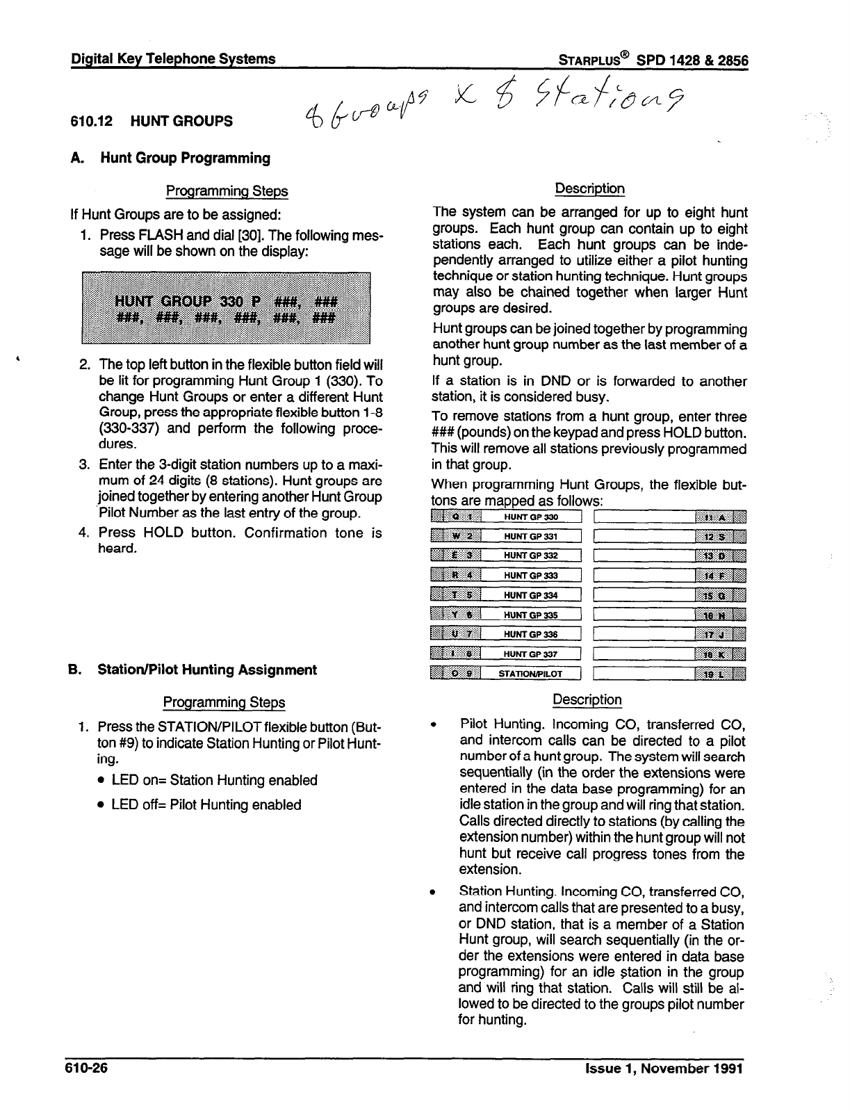
Digital Key Telephone Systems
sTARPLUS@
SPD 1428 & 2868
810.12 HUNT GROUPS
A. Hunt Group Programming
Programming Steps
If Hunt Groups are to be assigned:
1. Press FLASH and dial [30]. The following mes-
sage will be shown on the display:
2. The top left button in the flexible button field will
be lit for programming Hunt Group 1 (330). To
change Hunt Groups or enter a different Hunt
Group, press the appropriate flexible button 1-8
(330-337) and
perform the following proce-
dures.
3. Enter the 3-digit station numbers up to a maxi-
mum of 24 digits (8 stations). Hunt groups are
joined together by entering another Hunt Group
‘Pilot Number as the last entry of the group.
4. Press HOLD button. Confirmation tone is
heard.
B. Station/Pilot Hunting Assignment
Programming Steps
1. Press the STATION/PILOT flexible button (But-
ton #9) to indicate Station Hunting or Pilot Hunt-
ing.
l
LED on= Station Hunting enabled
l
LED off= Pilot Hunting enabled
Description
The system can be arranged for up to eight hunt
groups. Each hunt group can contain up to eight
stations each. Each hunt groups can be inde-
pendently arranged to utilize either a pilot hunting
technique or station hunting technique. Hunt groups
may also be chained together when larger Hunt
groups are desired.
Hunt groups can be joined together by programming
another hunt group number as the last member of a
hunt group.
If a station is in DND or is forwarded to another
station, it is considered busy.
To remove stations from a hunt group, enter three
### (pounds) on the keypad and press HOLD button.
This will remove all stations previously programmed
in that group.
When programming Hunt Groups, the flexible but-
tons are mapped as follows:
&$ ‘li$$::.: :i:.:q
j ..:&ji:
HUHTGP330 1 tiii%~~i~~~~~~
$1 HuMGP33, 1
Description
. Pilot Hunting. Incoming CO, transferred CO,
and intercom calls can be directed to a pilot
number of a hunt group. The system will search
sequentially (in the order the extensions were
entered in the data base programming) for an
idle station in the group and will ring that station.
Calls directed directly to stations (by calling the
extension number) within the hunt group will not
hunt but receive call progress tones from the
extension.
. Station Hunting. Incoming CO, transferred CO,
and intercom calls that are presented to a busy,
or DND station, that is a member of a Station
Hunt group, will search sequentially (in the or-
der the extensions were entered in data base
programming) for an idle station in the group
and will ring that station. Calls will still be al-
lowed to be directed to the groups pilot number
for hunting.
61 O-26 Issue 1, November 1991

sTARPLUS@
SPD 1428 & 2856 Digital Key Telephone Systems
-
620.1 INTRODUCTION
Programming Steps
If the system is in the programming mode, continue
using the program codes. If starting to program here,
enter the programming mode. (Refer to Sec. 600.2).
If any CO line features are to be changed:
a. Press FLASH and dial [40]. The following mes-
sage is shown on the display phone:
b. Enter a four digit number for the range of lines
being programmed. If only one line is being
programmed, enter that number twice (0101).
c. Press HOLD button. Program button #20 (New
Range) will be lit. The following message is
shown on the display phone to indicate current
programming of that line or group of lines.
Where:
XX-XX= The CO tine Range being program-
med. (01-28)
Description
This section describes the procedures and steps
necessary to program CO Line attributes. When
entering the CO Line attributes portion of the data
base the programmer may decide to enter informa-
tion for either a range of CO lines or one specific CO
Line.
Range programming allows the programmer to
change a specific parameter or a few parameters for
an entire range of CO Lines leaving intact the re-
maining data fields that do not require change.
Those data fields will continue to operate with the
previously programmed data. For example if CO
lines are programmed into several CO line groups
with different Class of service etc... but it is desired
to enable Loop Supervision (SUPV) on all CO Lines
the programmer may enter as the range 9Lh CO
lines (01-28) and enable loop supervision, then exit
programming. This will enable loop supervision for
all CO lines leaving intact the various CO line group
programming and COS data for the range.
The buttons on the key telephone are defined as
shown below when entering the CO Line Attribute
programming.
‘y& . ...::.. ;:;:I:: .y*
‘i@&&~&~$~ DTMF,D,AL PULSE :.... . . . . . . . . . .._ . . . <.;,
R,K ASSIGNMENTS ~<$j$$&$$$j
~~~~1 co/Psx
~1~~~1 UNA ,:.::::..:...:.:.: _.... ::::;
$&$‘& -..:
y
~~Pi~~$iil
LOOP SUPV :::::.:.:...::::: _....... > +.\.
~iiii*rig@@$g
tliilri~iiii~~f DISA 1 DBPLAY R1NG AwGN ~s~~~:
~~~~il :.: FLASH TIMER NW (FORWARD) ~;$p$g$$j
&$&gp&X]
::. ::i:i: CO LINE GROUP NOCT (BACKWARD)
$3 :$g$jiijiii’r UNE COS NEWRANGE 1
.::/::: . . . . . . . . . . . . . . .
$g.$$gj :<q
- Button #17 [Ring Display] will display the
ringing assignments for the CO line.
- Button #18 [Next Forward] will take you to
the next higher CO line.
- Button #19 [Next Backward] will take you to
the next lower CO line.
- Button #20 [Select Range] will prompt for a
new CO Line range.
I
Issue 1, November 1991 620-l
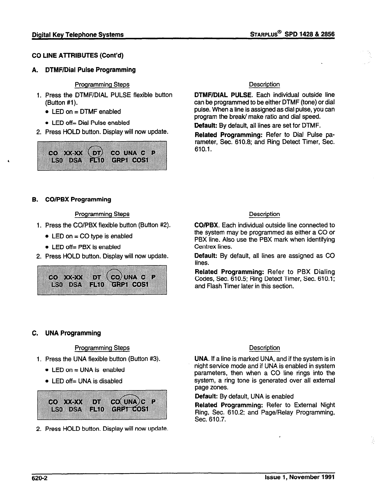
Digital Key Telephone Systems
BARPLUS@
SPD 1428 & 2866
CO LINE AlTRIBUTES (Cont’d)
A. DTMF/Dial Pulse Programming
Programming Steps
1. Press the DTMWDIAL PULSE
(Button #l).
l
LED on = DTMF enabled
l
LED off= Dial Pulse enabled
flexible button
2. Press HOLD button. Display will now update.
Description
DTMF/DIAL PULSE. Each individual outside line
can be programmed to be either DTMF (tone) or dial
pulse. When a line is assigned as dial pulse, you can
program the break/ make ratio and dial speed.
Default: By default, all lines are set for DTMF.
Related Programming: Refer to Dial Pulse pa-
rameter, Sec~610.8; and Ring Detect Timer, sec.
B. CO/PBX Programming
Programming Steps
1. Press the CO/PBX flexible button (Button #2).
l
LED on = CO type is enabled
l
LED off= PBX is enabled
2. Press HOLD button. Display will now update.
Description
CO/PBX. Each individual outside line connected to
the system may be programmed as either a CO or
PBX line. Also use the PBX mark when identifying
Centrex lines.
Default: By default, all lines are assigned as CO
lines.
Related Programming: Refer to PBX Dialing
Codes, Sec. 610.5; Ring Detect Timer, Sec. 610.1;
and Flash Timer later in this section.
C. UNA Programming
Programming Steps
1. Press the UNA flexible button (Button #3).
0 LED on = UNA is enabled
l
LED off= UNA is disabled
Description
UNA. If a line is marked UNA, and if the system is in
night service mode and if UNA is enabled in system
parameters, then when a CO line rings into the
system, a ring tone is generated over all external
page zones.
Default: By default, UNA is enabled
Related Programming: Refer to External Night
610.2; and Page/Relay Programming,
2. Press HOLD button. Display will now update.
626-2 Issue 1, November 1991
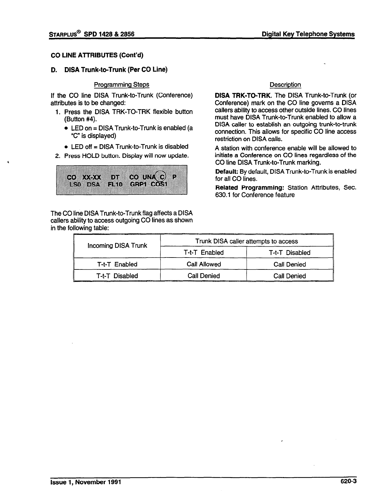
STARPLUS@
SPD 1428 & 2856 Digital Key Telephone Systems
CO LINE ATTRIBUTES (Cont’d)
D. DISA Trunk-to-Trunk (Per CO Line)
Programming Steps
if the CO line DISA Trunk-to-Trunk (Conference)
attributes is to be changed:
1. Press the DISA TRK-TO-TRK flexible button
(Button #4).
l
LED on = DISA Trunk-to-Trunk is enabled (a
“C” is displayed)
l
LED off = DISA Trunk-to-Trunk is disabled
2. Press HOLD button. Display will now update.
Description
DISA TRK-TO-TRK. The DISA Trunk-to-Trunk (or
Conference) mark on the CO line governs a DISA
callers ability to access other outside lines. CO lines
must have DISA Trunk-to-Trunk enabled to allow a
DISA caller to establish an outgoing trunk-to-trunk
connection. This allows for specific CO line access
restriction on DISA calls.
A station with conference enable will be allowed to
initiate a Conference on CO lines regardless of the
CO line DISA Trunk-to-Trunk marking.
Default: By default, DISA Trunk-to-Trunk is enabled
for all CO lines.
Related Programming: Station Attributes, Sec.
630.1 for Conference feature
The CO line DlSATrunk-to-Trunk flag affects a DISA
callers ability to access outgoing CO lines as shown
in the following table:
I
Incoming DISA Trunk Trunk DISA caller attempts to access
T-t-T Enabled T-t-T Disabled
Issue 1, November 1991 626-3
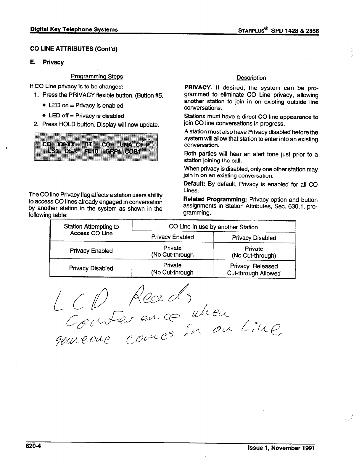
Digital Key Telephone Systems
%ARPLUS@
SPD 1428 & 2888
CO LINE ATTRIBUTES (Cont’d)
E. Privacy
Programming Steps
If CO tine privacy is to be changed:
1. Press the PRIVACY flexible button. (Button #5.
l
LED on = Privacy is enabled
l
LED off = Privacy is disabled
2. Press HOLD button. Display will now update.
Description
PRIVACY. If desired, the system can be pro-
grammed to eliminate CO Line privacy, allowing
another station to join in on existing outside line
conversations.
Stations must have a direct CO line appearance to
join CO line conversations in progress.
A station must also have Privacy disabled before the
system will allow that station to enter into an existing
conversation.
Both parties will hear an alert tone just prior to a
station joining the call.
When privacy is disabled, only one other station may
join in on an existing conversation.
Default: By default, Privacy is enabled for all CO
The CO line Privacy flag affects a station users ability
to access CO lines already engaged in conversation
by another station in the system as shown in the
followina table:
Lines.
Related Programming: Privacy option and button
assignments in Station Attributes, Sec. 630.1, pro-
gramming.
Privacy Enabled
Privacy Disabled
Private
(No Cut-through
Private
(No Cut-through
Private
(No Cut-through)
Privacy Released
Cut-through Allowed
820-4 Issue 1, November 1991
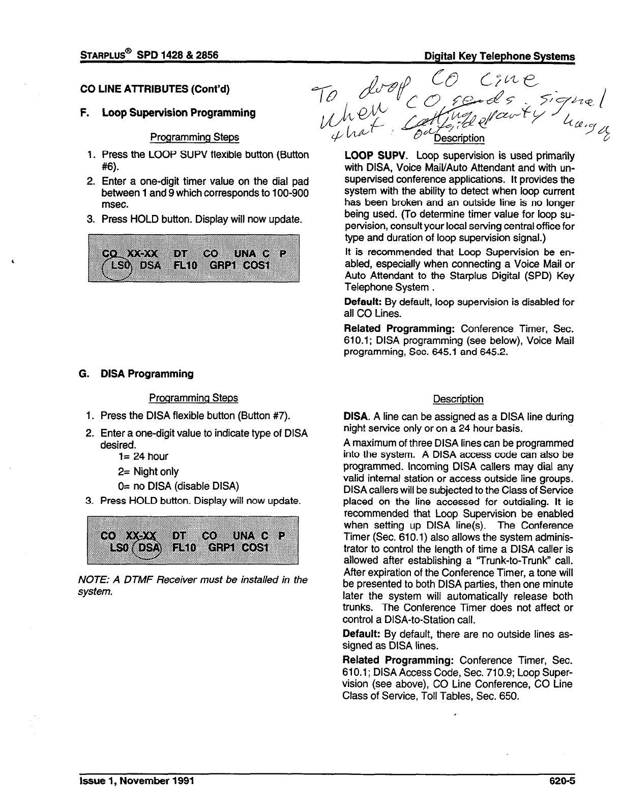
STARPLUS@
SPD 1428 & 2858 Digital Key Telephone Systems
CO LINE AlTRIBUTES (Cont’d)
F. Loop Supervision Programming
Programming Steps
1. Press the LOOP SUPV flexible button (Button
w-
2. Enter a one-digit timer value on the dial pad
between 1 and 9 which corresponds to 100-900
msec.
3. Press HOLD button. Display will now update.
G. DISA Programming
Programming Steps
1. Press the DISA flexible button (Button #7).
2. Enter a one-digit value to indicate type of DISA
desired.
I= 24 hour
2= Night only
O= no DISA (disable DISA)
3. Press HOLD button. Display will now update.
NOTE: A DTMF Receiver must be installed in the
system.
LOOP SUPV. Loop supervision is used primarily
with DISA, Voice Mail/Auto Attendant and with un-
supervised conference applications. It provides the
system with the ability to detect when loop current
has been broken and an outside line is no longer
being used. (To determine timer value for loop su-
pervision, consult your local serving central office for
type and duration of loop supervision signal.)
It is recommended that Loop Supervision be en-
abled, especially when connecting a Voice Mail or
Auto Attendant to the Starplus Digital (SPD) Key
Telephone System .
Default: By default, loop supervision is disabled for
all CO Lines.
Related Programming: Conference Timer, Sec.
610.1; DISA programming (see below), Voice Mail
programming, Sec. 645.1 and 645.2.
Description
DISA. A line can be assigned as a DISA line during
night service only or on a 24 hour basis.
A maximum of three DISA lines can be programmed
into the system. A DISA access code can also be
programmed. Incoming DISA callers may dial any
valid internal station or access outside line groups.
DISA callers will be subjected to the Class of Service
placed on the line accessed for outdialing. It is
recommended that Loop Supervision be enabled
when setting up DISA line(s). The Conference
Timer (Sec. 610.1) also allows the system adminis-
trator to control the length of time a DISA caller is
allowed after establishing a ‘Trunk-to-Trunk” call.
After expiration of the Conference Timer, a tone will
be presented to both DISA parties, then one minute
later the system will automatically release both
trunks. The Conference Timer does not affect or
control a DISA-to-Station call.
Default: By default, there are no outside lines as-
signed as DISA lines.
Related Programming: Conference Timer, Sec.
610.1; DISA Access Code, Sec. 710.9; Loop Super-
vision (see above), CO Line Conference, CO Line
Class of Service, Toll Tables, Sec. 650.
issue 1, November 1991 620-5
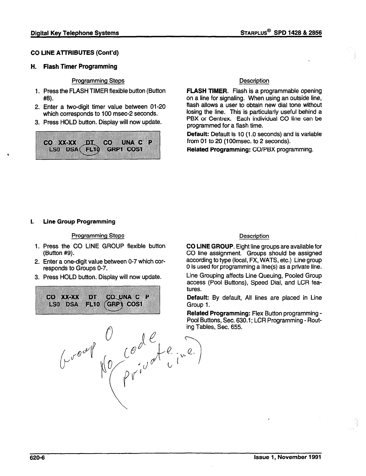
Digital Key Telephone Systems
sTARPLUS@
SPD 1428 & 2866
CO LlNE AlTRIBUTES (Cont’d)
H. Flash Timer Programming
Programming Steps
1. Press the FLASH TIMER flexible button (Button
#8).
2. Enter a two-digit timer value between 01-20
which corresponds to 100 msec-2 seconds.
3. Press HOLD button. Display will now update.
Description
FLASH TIMER. Flash is a programmable opening
on a line for signaling. When using an outside line,
flash allows a user to obtain new dial tone without
losing the line. This is particularly useful behind a
PBX or Centrex. Each individual CO line can be
programmed for a flash time.
Default: Default is 10 (1 .O seconds) and is variable
from 01 to 20 (100msec. to 2 seconds).
Related Programming: COIPBX programming.
I. Line Group Programming
Programming Steps
1. Press the CO LINE GROUP flexible button
(Button #9).
2. Enter a one-digit value between O-7 which cor-
responds to Groups O-7.
3. Press HOLD button. Display will now update.
Description
CO LINE GROUP. Eight line groups are available for
CO line assignment. Groups should be assigned
according to type (local, FX, WATS, etc.) Line group
0 is used for programming a line(s) as a private line.
Line Grouping affects Line Queuing, Pooled Group
access (Pool Buttons), Speed Dial, and LCR fea-
By default, All lines are placed in Line
Related Programming: Flex Button programming -
Pool Buttons, Sec. 630.1; LCR Programming - Rout-
ing Tables, Sec. 655.
628-6 Issue 1, November 1991
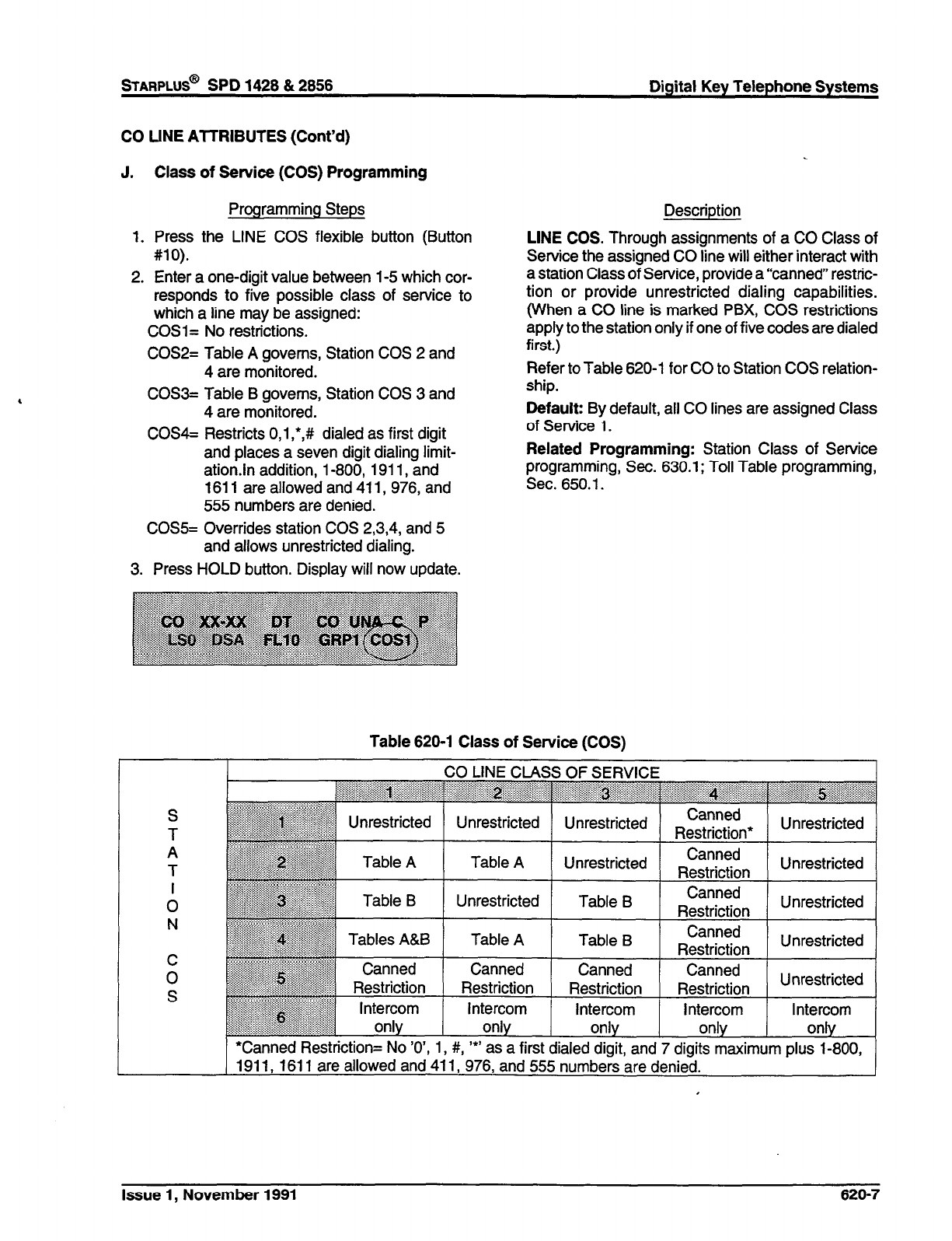
STARPLUS@ SPD 1428 & 2856 Digital Key Telephone Systems
CO UNE ATTRIBUTES (Cont’d)
J. Class of Service (COS) Programming
Programming Steps
1. Press the LINE COS flexible button (Button
#lO).
2. Enter a one-digit value between l-5 which cor-
responds to five possible class of service to
which a line may be assigned:
COSi= No restrictions.
COS2= Table A governs, Station COS 2 and
4 are monitored.
COS3= Table B governs, Station COS 3 and
4 are monitored.
COS4= Restricts O,l,*,# dialed as first digit
and places a seven digit dialing limit-
ation.ln addition, l-800, 1911, and
1611 are allowed and 411,976, and
555 numbers are denied.
CO%= Overrides station COS 2,3,4, and 5
and allows unrestricted dialing.
3. Press HOLD button. Display will now update.
Description
LINE COS. Through assignments of a CO Class of
Service the assigned CO line will either interact with
a station Class of Service, provide a “canned” restric-
tion or provide unrestricted dialing capabilities.
(When a CO line is marked PBX, COS restrictions
apply to the station only if one of five codes are dialed
first.)
Refer to Table 620-l for CO to Station COS relation-
ship.
Default: By default, all CO lines are assigned Class
of Service 1.
Related Programming: Station Class of Service
programming, Sec. 630.1; Toll Table programming,
Sec. 650.1.
Table 620-l Class of Service (COS)
S
T
A
T
I
0
N
C
0
S
CO LINE CLASS OF SERVICE
~~~~~~~~~~~~~~~~~~~~~~~~~~~~~
. . . ..,.... “” . . . . . . . . . . ,.,. . . . . . . . . .
.~e~~~~~~~~:~~~~~~~~~~~~~~~:~~~~~~~:~~~~
. . . . . . ..i...
““‘+.‘.‘.. .
. ...: ..,.,.,: .?,.: .::, I I A- - - -I
y.-: .
.
.
.
.
. .
. .
.
‘:::Q:::::::::>.::::: l.,.,:,,,
.
:.:.:::::::::::
. . . . . . .._...... bannea
::~~~:~:‘::~:~:::: :(.:,_)
::::~::~:i:~::::::i:::::a:~,:~i(
~~
Unrestricted
i.:~~:~:::::-i:~:.~;i~:::.::::.: Unrestricted Unrestricted c
,.,.
x?!:!:.:::::.::::::::~:~ .:.:.: ~:~lf~~~~i:I:.::,~~:::.::~~:: Restriction’ Unrestricted
Table A
“‘A . . . . . . . . . . . .
~.Lw.:.:.::.: :.:.::,:,
. . . . . . . . .
,,,,
~i2~~~:~~~~~~~~~li~~
,,,,
~~~ Table B
::::::::::::u:i~~:~ii:~~~.~~
::::ww.<<:::~.:;:: :::::
;-..
““-.:....:.i
. . . . . . . . . . . . ..>....i:
“s::::~:i:~:~i’~8ipii~~~~~~~
. . . .
~~~~ii~~:a:::
. . . . . . . . . . . . . . .._..~.
] Canned
~~~~ Restriction
.,
~~~~~ Intercom
:~:~:~:i:~:i:~:i::::I:.:~::il ::::::
.‘:‘::::::,i;i~~iii:lilili
. . . . . . . . . . . . . . . . . . . . . . . . only
Table A Unrestricted Canned
Restriction Unrestricted
I
Unrestricted Table B Canned
Restriction Unrestricted
Table A Table B Canned
Restriction Unrestricted
Canned Canned Canned
Restriction
Intercom
only
Restriction
Intercom
only
Restriction
Intercom
only
Unrestricted
*Canned Restriction= No ‘0’, 1, #, ‘*’ as a first dialed digit, and 7 digits maximum plus l-800,
1911, 1611 are allowed and 411, 976, and 555 numbers are denied.
Issue 1, November 1991 626-7
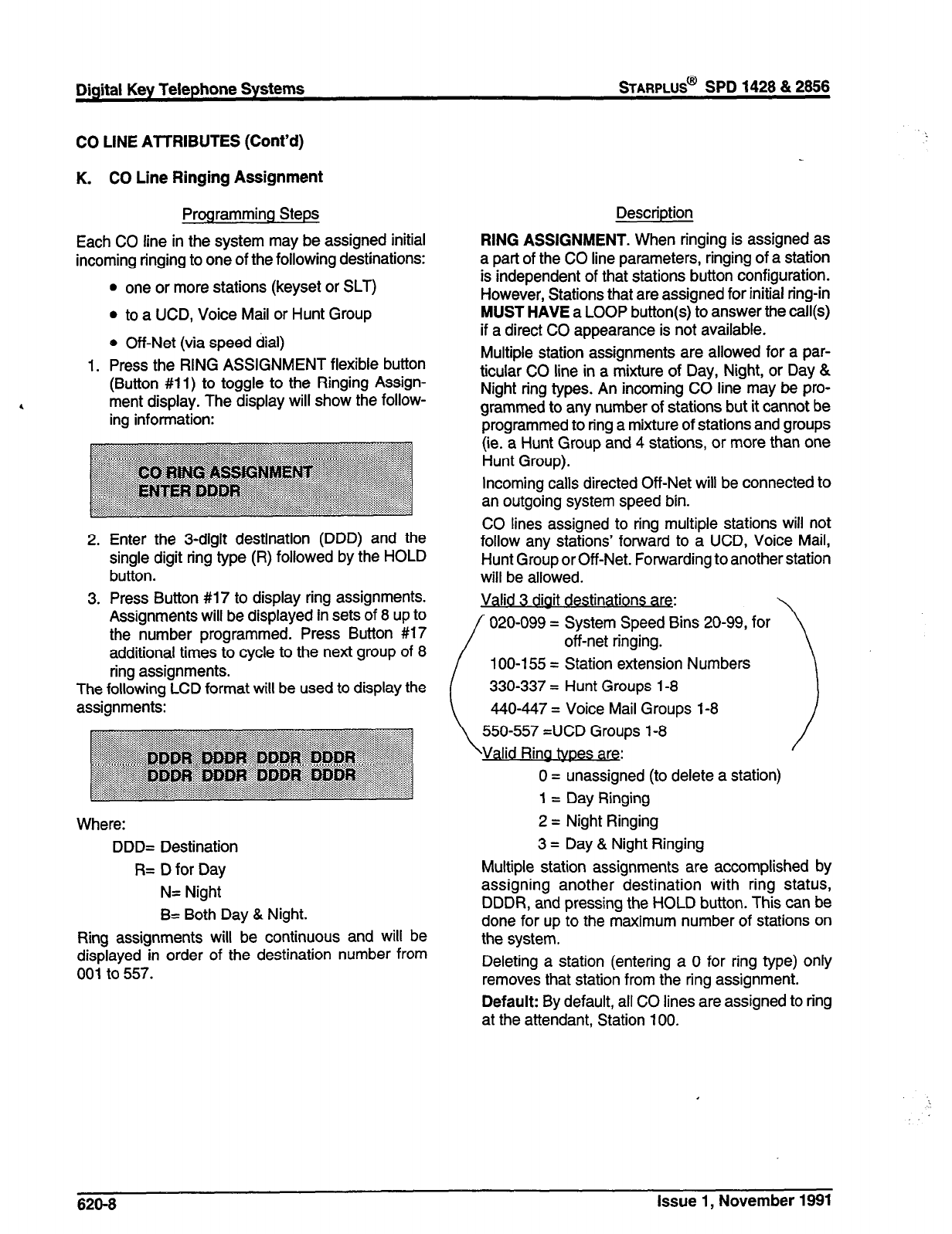
Digital Key Telephone Systems
sTARPLUS@
SPD 1428 & 2866
CO LINE ATTRIBUTES (Cont’d)
K. CO Line Ringing Assignment
Programming Steps
Each CO line in the system may be assigned initial
incoming ringing to one of the following destinations:
l
one or more stations (keyset or SLT)
l
to a UCD, Voice Mail or Hunt Group
e Off-Net (via speed dial)
1. Press the RING ASSIGNMENT flexible button
(Button #ll) to toggle to the Ringing Assign-
ment display. The display will show the follow-
ing information:
Enter the 3-digit destination (DDD) and the
single digit ring type (R) followed by the HOLD
button.
Press Button #17 to display ring assignments.
Assignments will be displayed in sets of 8 up to
the number programmed. Press Button #17
additional times to cycle to the next group of 8
ring assignments.
The following LCD format will be used to display the
assignments:
Where:
DDD= Destination
R= D for Day
N= Night
B= Both Day & Night.
Ring assignments will be continuous and will be
displayed in order of the destination number from
001 to 557.
Description
RING ASSIGNMENT. When ringing is assigned as
a part of the CO line parameters, ringing of a station
is independent of that stations button configuration.
However, Stations that are assigned for initial ring-in
MUST HAVE a LOOP button(s) to answer the call(s)
if a direct CO appearance is not available.
Multiple station assignments are allowed for a par-
ticular CO line in a mixture of Day, Night, or Day &
Night ring types. An incoming CO line may be pro-
grammed to any number of stations but it cannot be
programmed to ring a mixture of stations and groups
(ie. a Hunt Group and 4 stations, or more than one
Hunt Group).
Incoming calls directed Off-Net will be connected to
an outgoing system speed bin.
CO lines assigned to ring multiple stations will not
follow any stations’ forward to a UCD, Voice Mail,
Hunt Group or Off-Net. Forwarding to another station
will be allowed.
020-099 = System Speed Bins 20-99, for
100-l 55 = Station extension Numbers
~~~~ps l-8
ad atypesae.
)
0 = unassigned (to delete a station)
1 = Day Ringing
2 = Night Ringing
3 = Day & Night Ringing
Multiple station assignments are accomplished by
assigning another destination with ring status,
DDDR, and pressing the HOLD button. This can be
done for up to the maximum number of stations on
the system.
Deleting a station (entering a 0 for ring type) only
removes that station from the ring assignment.
Default: By default, all CO lines are assigned to ring
at the attendant, Station 100.
I
626-8 Issue 1, November 1981
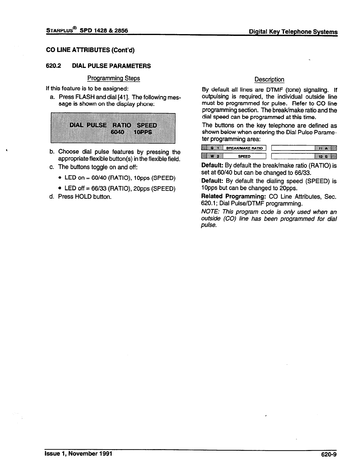
STARPLUS@
SPD 1428 & 2858 Digital Key Telephone Systems
CO LINE ATTRIBUTES (Cont’d)
620.2 DIAL PULSE PARAMETERS
Programming Steps
If this feature is to be assigned:
a. Press FLASH and dial [41]. The following mes-
sage is shown on the display phone:
b. Choose dial pulse features by pressing the
appropriate flexible button(s) in the flexible field.
c. The buttons toggle on and off:
0 LED on = 60/40 (RATIO), 1Opps (SPEED)
l
LED off = 66133 (RATIO), 2Opps (SPEED)
d. Press HOLD button.
Description
By default all lines are DTMF (tone) signaling. If
outpulsing is required, the individual outside line
must be programmed for pulse. Refer to CO line
programming section. The break/make ratio and the
dial speed can be programmed at this time.
The buttons on the key telephone are defined as
shown below when entering the Dial Pulse Parame-
ter programming area: . . . . . . . . . . . . . :*:...:.:.:: ,x
y- ~~.&:~ <k
Default: By default the break/make ratio (RATIO) is
set at 60140 but can be changed to 66/33.
Default: By default the dialing speed (SPEED) is
1Opps but can be changed to 2Opps.
Related Programming: CO Line Attributes, Sec.
620.1; Dial Pulse/DTMF programming.
NOTE: This program code is only used when an
outside (CO) line has been programmed for dial
pulse.
Issue 1, November 1991 620-9
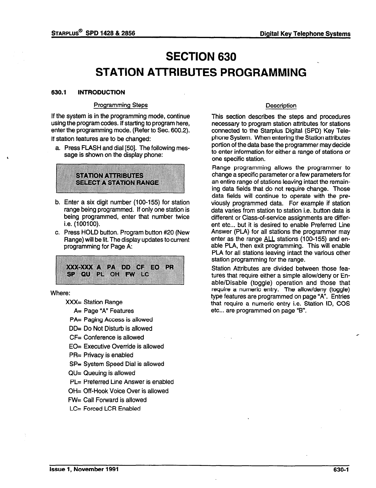
SECTION 630
STATION AlTRIBUTES PROGRAMMING
630.1 INTRODUCTION
Programming Steps Description
If the system is in the programming mode, continue
using the program codes. If starting to program here,
enter the programming mode. (Refer to Sec. 600.2).
If station features are to be changed:
a. Press FLASH and dial [50]. The following mes-
sage is shown on the display phone:
b.
C.
Enter a six digit number (100-155) for station
range being programmed. If only one station is
being programmed, enter that number twice
i.e. (100100).
Press HOLD button. Program button #20 (New
Range) will be lit. The display updates to
current
programming for Page A:
Where:
XXX= Station Range
A= Page “A” Features
PA= Paging Access is allowed
DD= Do Not Disturb is allowed
CF= Conference is allowed
EO= Executive Override is allowed
PR= Privacy is enabled
SP= System Speed Dial is allowed
QU= Queuing is allowed
PL= Preferred Line Answer is enabled
OH= Off-Hook Voice Over is allowed
FW= Call Forward is allowed
LC= Forced LCR Enabled
This section describes the steps and procedures
necessary to program station attributes for stations
connected to the Starplus Digital (SPD) Key Tele-
phone System. When entering the Station attributes
portion of the data base the programmer may decide
to enter information for either a range of stations or
one specific station.
Range programming allows the programmer to
change a specific parameter or a few parameters for
an entire range of stations leaving intact the remain-
ing data fields that do not require change. Those
data fields will continue to operate with the pre-
viously programmed data. For example if station
data varies from station to station i.e. button data is
different or Class-of-service assignments are differ-
ent etc... but it is desired to enable Preferred Line
Answer (PLA) for all stations the programmer may
enter as the range 9cL stations (100-155) and en-
able PL4, then exit programming. This will enable
PLA for all stations leaving intact the various other
station programming for the range.
Station Attributes are divided between those fea-
tures that require either a simple allow/deny or En-
able/Disable (toggle) operation and those that
require a numeric entry. The allow/deny (toggle)
type features are programmed on page “A”. Entries
that require a numeric entry i.e. Station ID, COS
etc... are programmed on page “B”.
r
Issue
1, November 1991 630-l
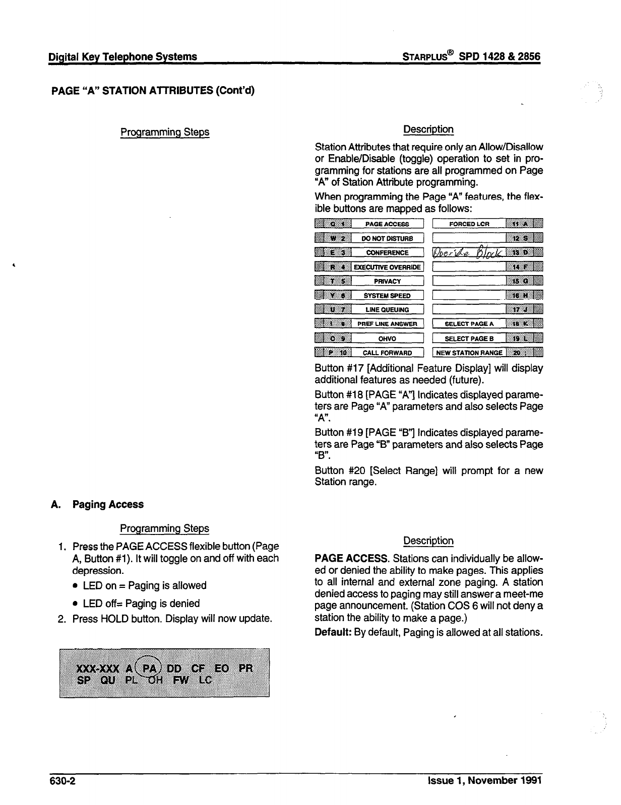
Digital Key Telephone Systems
STARPLUS@
SPD 1428 & 2856
PAGE “A” STATION AlTRIBUTES (Cont’d)
Programming Steps
Paging Access
Programming Steps
Press the PAGE ACCESS flexible button (Page
A, Button #l). It will toggle on and off with each
depression.
l
LED on = Paging is allowed
l
LED off= Paging is denied
Press HOLD button. Display will now update.
Description
Station Attributes that require only an Allow/Disallow
or Enable/Disable (toggle) operation to set in pro-
gramming for stations are all programmed on Page
“A” of Station Attribute programming.
When programming the Page “‘A” features, the flex-
ible buttons are mapped as follows:
Button #17 [Additional Feature Display] will display
additional features as needed (future).
Button #18 [PAGE “A”‘j Indicates displayed parame-
ters are Page “A” parameters and also selects Page
“A”.
Button #19 [PAGE “B”] Indicates displayed parame-
ters are Page “B” parameters and also selects Page
“B”.
Button #20 [Select Range] will prompt for a new
Station range.
Description
PAGE ACCESS. Stations can individually be allow-
ed or denied the ability to make pages. This applies
to all internal and external zone paging. A station
denied access to paging may still answer a meet-me
page announcement. (Station COS 6 will not deny a
station the ability to make a page.)
Default: By default, Paging is allowed at all stations.
630-2 Issue 1, November 1991
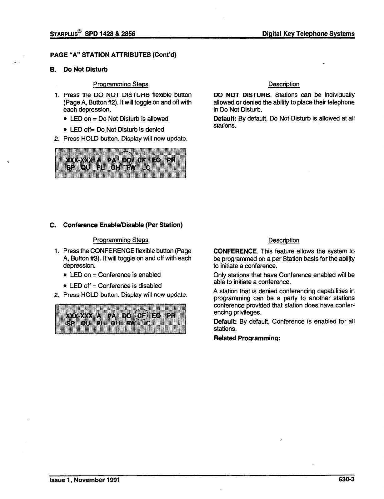
PAGE “A” STATION ATTRIBUTES (Cont’d)
B. Do Not Disturb
Programming Steps Description
1. Press the DO NOT DISTURB flexible button DO NOT DISTURB. Stations can be individually
(Page A, Button #2). It will toggle on and off with allowed or denied the ability to place their telephone
each depression. in Do Not Disturb.
Default: By default, Do Not Disturb is allowed at all
stations.
l
LED on = Do Not Disturb is allowed
l
LED off= Do-Not Disturb is denied
2. Press HOLD button. Display will now update.
C. Conference Enable/Disable (Per Station)
Programming Steps
1. Press the CONFERENCE flexible button (Page
A, Button #3). It will toggle on and off with each
depression.
l
LED on = Conference is enabled
l
LED off = Conference is disabled
2.
Press HOLD button. Display will now update.
Description
CONFERENCE. This feature allows the system to
be programmed on a per Station basis for the abil#y
to initiate a conference.
Only stations that have Conference enabled will be
able to initiate a conference.
A station that is denied conferencing capabilities in
programming can be a party to another stations
conference provided that station does have confer-
encing privileges.
Default: By default, Conference is enabled for all
stations.
Related Programming:
Issue 1, November 1991 636-3
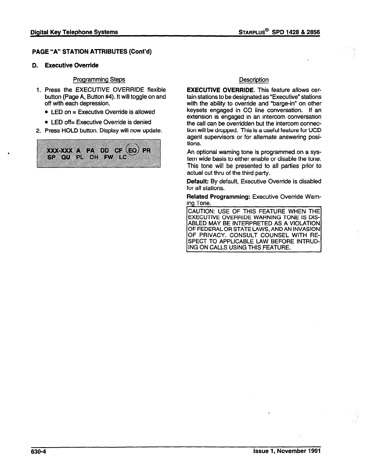
Digital Key Telephone Systems STARPLUS@ SPD 1428 & 2856
PAGE “A” STATION ATTRIBUTES (Cont’d)
Executive Override
Programming Steps Description
Press the EXECUTIVE OVERRIDE flexible
button (Page A, Button #4). It will toggle on and
off with each depression.
l
LED on = Executive Override is allowed
l
LED off= Executive Override is denied
Press HOLD button. Display will now update.
EXECUTIVE OVERRIDE. This feature allows cer-
tain stations to be designated as “Executive” stations
with the ability to override and “barge-in” on other
keysets engaged in CO line conversation. If an
extension is engaged in an intercom conversation
the call can be overridden but the intercom connec-
tion will be dropped. This is a useful feature for UCD
agent supervisors or for alternate answering posi-
tions.
An optional warning tone is programmed on a sys-
teqn wide basis to either enable or disable the tone.
This tone will be presented to all parties prior to
actual cut thru of the third party.
Default: By default, Executive Override is disabled
for all stations.
Related Programming: Executive Override Wam-
ina Tone.
CAUTION: USE OF THIS FEATURE WHEN THE
EXECUTIVE OVERRIDE WARNING TONE IS DIS-
ABLED MAY BE INTERPRETED AS A VIOLATION
OF FEDERALOR STATE LAWS, AND AN INVASION
OF PRIVACY. CONSULT COUNSEL WITH RE-
SPECT TO APPLICABLE LAW BEFORE INTRUD-
ING ON CALLS USING THIS FEATURE.
630-4 Issue 1, November 1991

sTARPLUS@
SPD 1428 & 2858 Digital Key Telephone Systems
PAGE “A” STATION AlTRIBUTES (Cont’d)
E. Privacy (Per Station)
Programming Steps
To program station(s) for Automatic Privacy:
1. Press the PRIVACY flexible button (Page A,
Button #5). It will toggle on and off with each
depression.
l
LED on = Privacy is enabled on Stations(s)
l
LED off = Privacy is disabled on Station(s)
2. Press HOLD button. Display will now update.
Description
PRIVACY. The system provides privacy on all com-
munications in the system which prevents other
stations from accidently entering an existing conver-
sation. However, if desired, the system will allow on
a per station basis the ability for a station to join an
existing outside CO line conversation. Each station
can be granted the privilege to join an existing CO
line conversation by simply pressing the CO line
button of a CO line in use.
Both the station and the CO line must have privacy
disabled before the system will allow cut-thru.
If privacy is disabled and a station joins an existing
call, both parties will hear an alert tone.
If privacy is disabled, only one other station may join
in on an existing conversation.
The Station Privacy flag affects a station users ability
to access CO lines already engaged in conversation
by another station in the system as shown in the
following table:
Default: Privacy is enabled for all stations in default.
Related Programming: CO Line Attributes, Sec.
620.1, programming: Privacy feature.
Privacy Enabled
Privacy Disabled
Private
(No Cut-through)
Private
(No Cut-throuah)
Private
(No Cut-through)
Privacy Released
KM-throuoh Allnwad\
Issue 1, November 1991 630-5
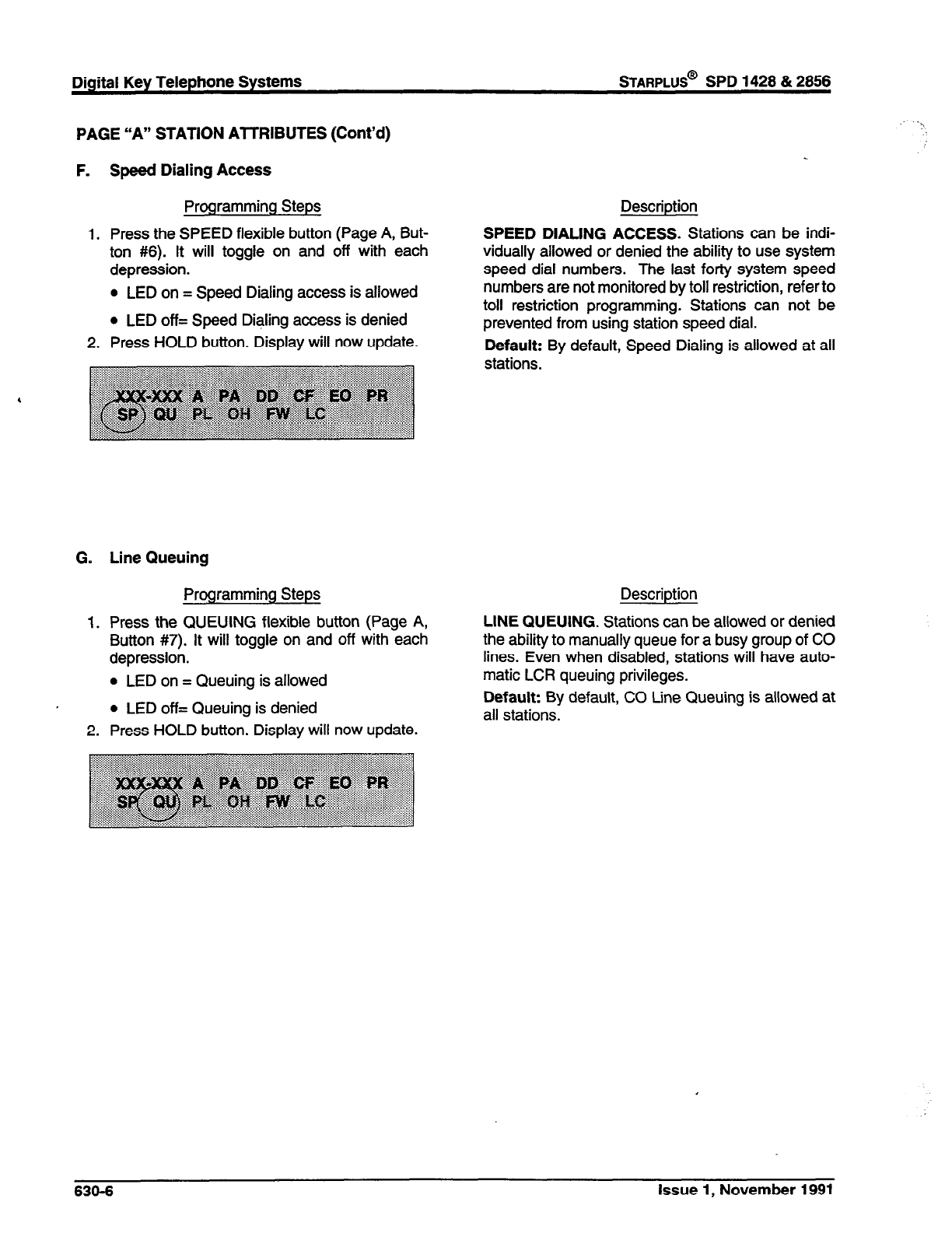
PAGE ‘VI” STATION AlTRIBUTES (Cont’d)
F. Speed Dialing Access
Programming Steps
1. Press the SPEED flexible button (Page A, But-
ton #6). It will toggle on and off with each
depression.
0 LED on = Speed Dialing access is allowed
l
LED off= Speed Dialing access is denied
2. Press HOLD button. Display will now update.
G. Line Queuing
Programming Steps Description
1. Press the QUEUING flexible button (Page A,
Button #7). It will toggle on and off with each
depression.
l
LED on = Queuing is allowed
l
LED off= Queuing is denied
2. Press HOLD button. Display will now update.
LINE QUEUING. Stations can be allowed or denied
the ability to manually queue for a busy group of CO
lines. Even when disabled, stations will have auto-
matic LCR queuing privileges.
Default: By default, CO Line Queuing is allowed at
all stations.
Descriotion
SPEED DIALING ACCESS. Stations can be indi-
vidually allowed or denied the ability to use system
speed dial numbers. The last forty system speed
numbers are not monitored by toll restriction, refer to
toll restriction programming. Stations can not be
prevented from using station speed dial.
Default: By default, Speed Dialing is allowed at all
stations.
636-6 Issue 1, November 1991
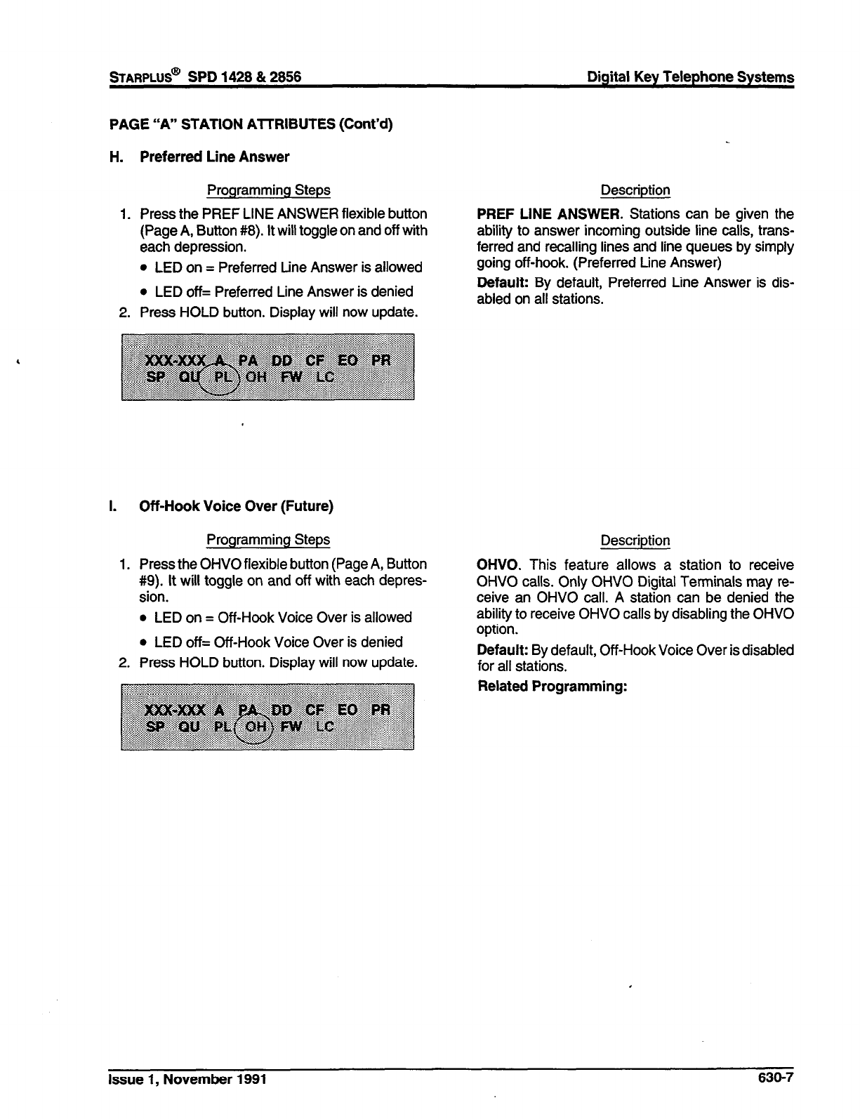
STARPLUS@ SPD 1428 & 2858 Digital Key Telephone Systems
PAGE “A” STATION AlTRIBUTES (Cont’d)
H.
1.
2.
Preferred Line Answer
Programming Steps
Press the PREF LINE ANSWER flexible button
(Page A, Button #8). It will toggle on and off with
each depression.
l
LED on = Preferred Line Answer is allowed
Description
PREF LINE ANSWER. Stations can be given the
ability to answer incoming outside line calls, trans-
ferred and recalling lines and line queues by simply
going off-hook. (Preferred tine Answer)
l
LED off= Preferred Line Answer is denied
Press HOLD button. Display will now update.
Default: By default, Preferred Line Answer is dis-
abled on all stations.
I. Off-Hook Voice Over (Future)
Programming Steps
1. Press the OHVO flexible button (Page A, Button
#9). It will toggle on and off with each depres-
sion.
l
LED on = Off-Hook Voice Over is allowed
l
LED off= Off-Hook Voice Over is denied
2. Press HOLD button. Display will now update.
Description
OHVO. This feature allows a station to receive
OHVO calls. Only OHVO Digital Terminals may re-
ceive an OHVO call. A station can be denied the
ability to receive OHVO calls by disabling the OHVO
option.
Default: By default, Off-Hook Voice Over is disabled
for all stations.
Related Programming:
Issue 1, November 1991 630-7

Digital Key Telephone Systems
STARPLUS@
SPD 1428 & 2666
PAGE “A” STATION AnRlBUTES (Cont’d)
J. Call Forwarding
Programming Steps
1. Press the CALL FORWARD flexible button
(Page A, Button #lo). It will toggle on and off
with each depression.
l
LED on = Call Forwarding is allowed
l
LED off= Call Forwarding is denied
2. Press HOLD button. Display will now update.
K. Forced Least Cost Routing
Programming Steps
1. Press the FORCED LCR flexible button (Page
A, Button #l 1). It will toggle on and off with each
depression.
l
LED on = Least Cost Routing is forced
l
LED off= Least Cost Routing is optional
2. Press HOLD button. Display will now update.
Description
CALL FORWARD. Stations can be allowed or de-
nied the ability to have incoming CO calls, intercom,
transferred outside lines forwarded to another sta-
tion, UCD, Hunt or Voice Mail group or Off-Net
Forward via speed dial.
Default: By default, Call Forwarding is allowed at all
stations.
Description
FORCED LCR. Stations may be forced to place
outgoing CO calls by use of LCR (dial [9]) to access
an outside line). This allows the system administrator
to control dialing patterns and the lines used for
outgoing CO calls more effectively. This can be
enabled/disabled on a per station basis for additional
flexibility and control,
Default: Forced LCR is optional for all stations.
Related Programming: LCR Class of Service, LCR
Enable/Disable, Sec. 610.2; LCR programming,
Sec. 655.
630-6 Issue 1, November 1991

sTARPLUS@
SPD 1428 & 2866 Digital Key Telephone Systems
PAGE “B” STATION PROGRAMMING
Programming Steps
The remaining station features are located and pro-
grammed on Page B.
a. Press [PG B] button. The display of current
programming for those features will appear as
follows:
Where:
XXX= Station Range
B= Page “B” Features
ID= Station Identification (O-5
COS= Class of Service (l-6)
SPK= Speakerphone Option (O-2)
A= Pickup Group (l-4)
B= Paging Zone (l-4)
CC= Preset Forward Destination
DD= CO tine Group access
LO= LCR Class of Service
Description
When programming Page B features, the flexible
buttons are mapped as follows:
LCR COS SELECT PAGE A m
~~~~~~1 oFF-HwKpREF 1 sELEm PAGE B ~~~~~~~~~~
SVFTONASSlGN 1 NEWSTATlON RANGE [
NOTE: Features programmed in Page “B” require a
numeric entry after pressing the flexible button.
Issue 1, November 1991 630-9
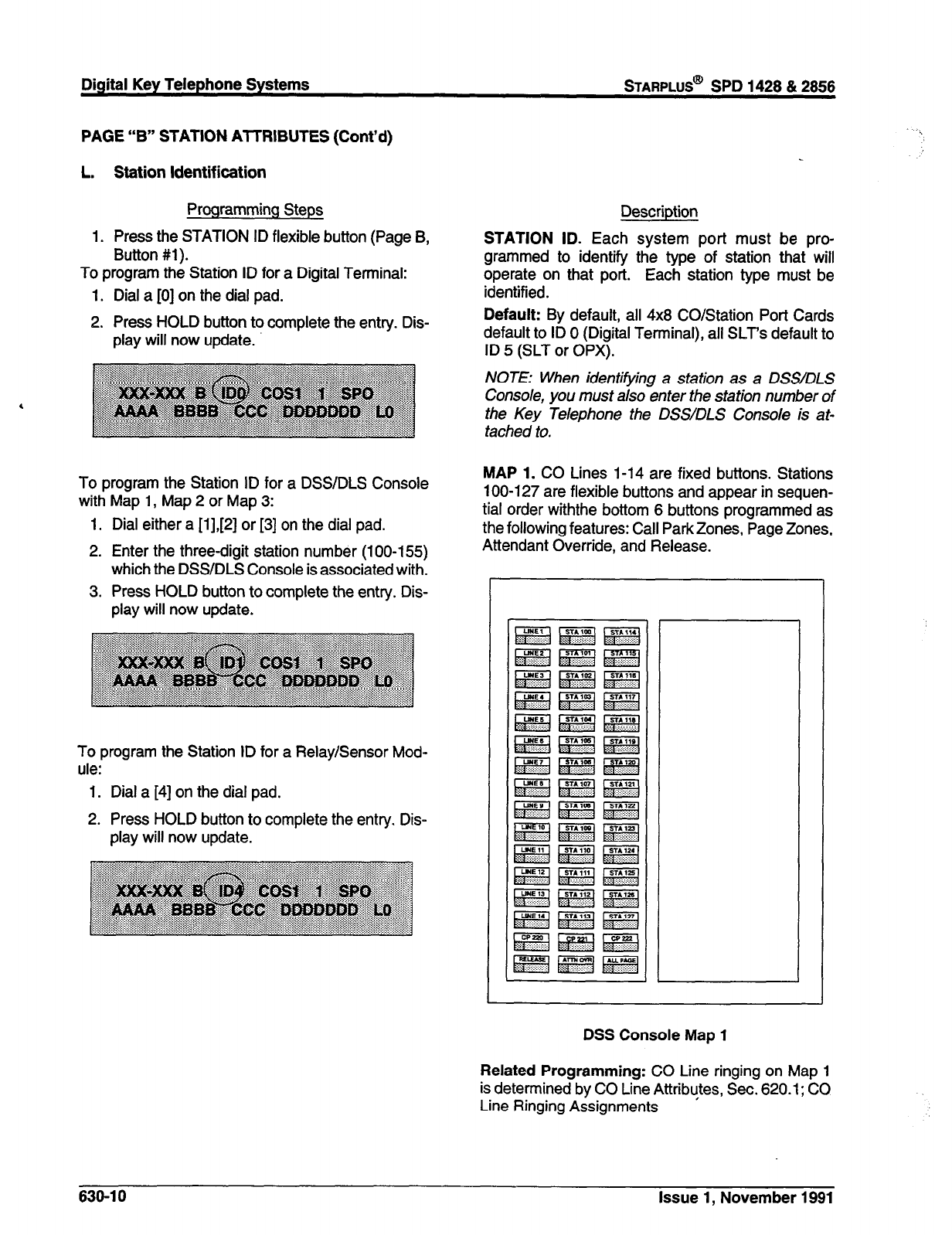
PAGE “B” STATION AlTRIBUTES (Cont’d)
L. Station ldentif ication
Programming Steps
1. Press the STATION ID flexible button (Page B,
Button #l).
To program the Station ID for a Digital Terminal:
1. Dial a [0] on the dial pad.
2. Press HOLD button to complete the entry. Dis-
play will now update.
To program the Station ID for a DSS/DLS Console
with Map 1, Map 2 or Map 3:
1. Dial either a [1],[2] or [3] on the dial pad.
2. Enter the three-digit station number (100-155)
which the DSWDLS Console is associated with.
3. Press HOLD button to complete the entry. Dis-
play will now update.
To program the Station ID for a Relay/Sensor Mod-
ule:
1. Dial a [4] on the dial pad.
2. Press HOLD button to complete the entry. Dis-
play will now update.
Description
STATION ID. Each system port must be pro-
grammed to identify the type of station that will
operate on that port. Each station type must be
identified.
Default: By default, all 4x8 CO/Station Port Cards
default to ID 0 (Digital Terminal), all SLT’s default to
ID 5 (SLT or OPX).
NOTE: When identifying a station as a DSS/DLS
Console, you must also enter the station number of
the Key Telephone the DSSIDLS Console is at-
tached to.
MAP 1. CO Lines l-14 are fixed buttons. Stations
100-l 27 are flexible buttons and appear in sequen-
tial order withthe bottom 6 buttons programmed as
the following features: Call Park Zones, Page Zones,
Attendant Override, and Release.
DSS Console Map 1
Related Programming: CO Line ringing on Map 1
is determined by CO Line Attributes, Sec. 620.1; CO
Line Ringing Assignments
638-l 0 Issue 1, November 1991
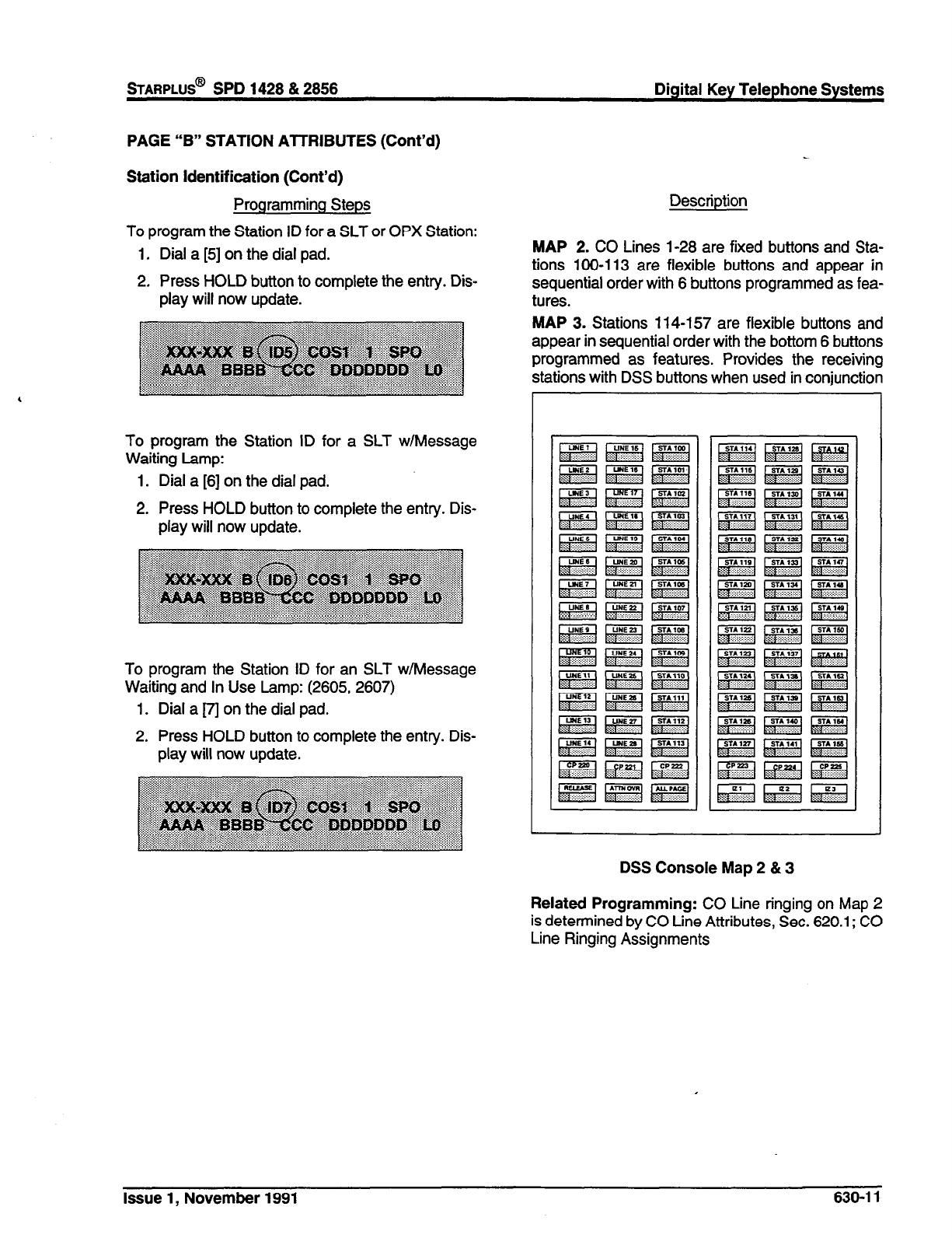
wARPLUS@
SPD 1428 & 2858 Digital Key Telephone Systems
PAGE “B” STATION ATMBUTES (Cont’d)
Station Identification (Cont’d)
Programming Steps
To program the Station ID for a SLT or OPX Station:
1. Dial a [5] on the dial pad.
2, Press HOLD button to complete the entry. Dis-
play will now update.
To program the Station ID for a SLT w/Message
Waiting Lamp:
1. Dial a [S] on the dial pad.
2. Press HOLD button to complete the entry. Dis-
play will now update.
To program the Station ID for an SLT w/Message
Waiting and In Use Lamp: (2605, 2607)
1. Dial a j7’l on the dial pad.
2. Press HOLD button to complete the entry. Dis-
play will now update.
Description
MAP 2. CO Lines 1-28 are fixed buttons and Sta-
tions 100-l 13 are flexible buttons and appear in
sequential order with 6 buttons programmed as fea-
tures.
MAP 3. Stations 114-157 are flexible buttons and
appear in sequential order with the bottom 6 buttons
programmed as features. Provides the receiving
stations with DSS buttons when used in conjunction
L
-
DSS Console Map 2 & 3
Related Programming: CO Line ringing on Map 2
is determined by CO Line Attributes, Sec. 620.1; CO
Line Ringing Assignments
Issue 1, November 1991 630-l 1
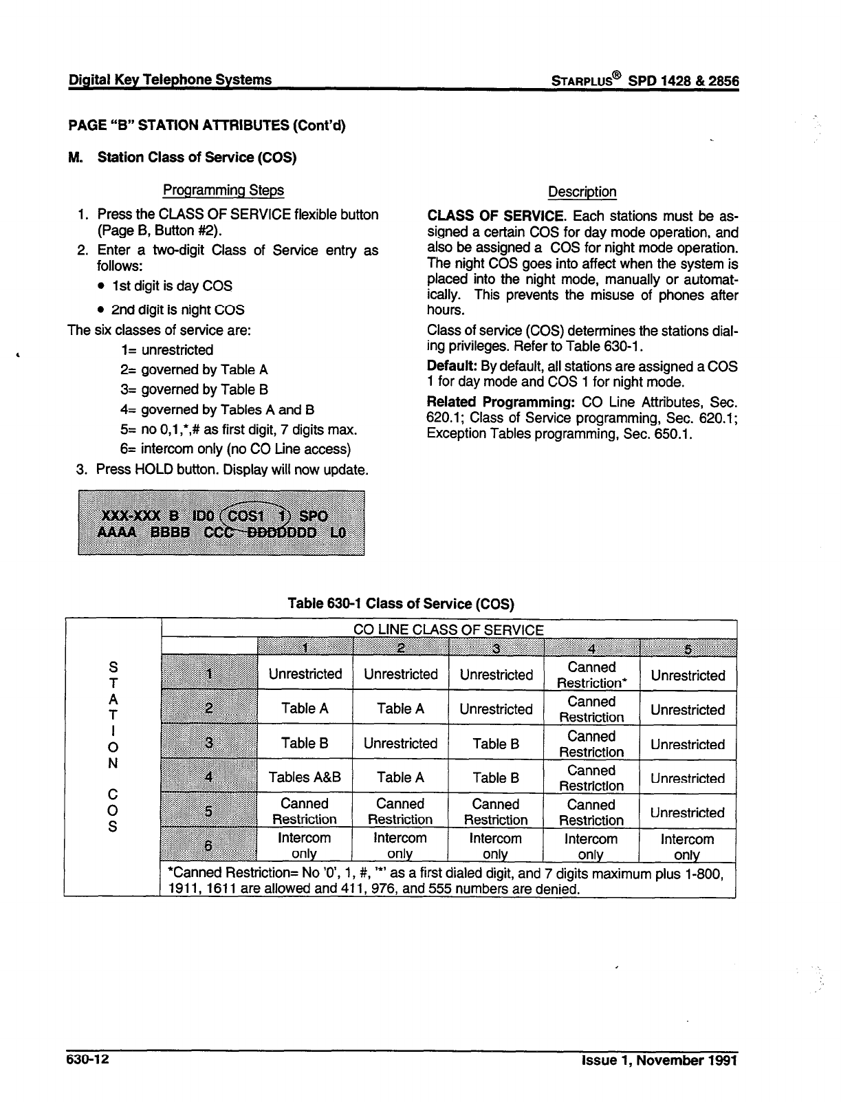
Digital Key Telephone Systems
sTARPLUS@
SPD 1428 & 2856
PAGE “B” STATION AlTRIBUTES (Cont’d)
M.
1.
2.
Station Class of Service (COS)
Programming Steps
Press the CLASS OF SERVICE flexible button
(Page B, Button #2).
Enter a two-digit Class of Service entry as
follows:
l
1st digit is day COS
l
2nd digit is night COS
Description
CLASS OF SERVICE. Each stations must be as-
signed a certain COS for day mode operation, and
also be assigned a COS for night mode operation.
The night COS goes into affect when the system is
placed into the night mode, manually or automat-
ically. This prevents the misuse of phones after
hours.
The six classes of service are:
1= unrestricted
2= governed by Table A
3= governed by Table B
4= governed by Tables A and B
5= no 0,l ,*,#I as first digit, 7 digits max.
6= intercom only (no CO Line access)
3. Press HOLD button. Display will now update.
Class of service (COS) determines the stations dial-
ing privileges. Refer to Table 630-l.
Default: By default, all stations are assigned a COS
1 for day mode and COS 1 for night mode.
Related Programming: CO Line Attributes, Sec.
620.1; Class of Service programming, Sec. 620.1;
Exception Tables programming, Sec. 650.1.
Table 630-l Class of Service (COS)
S
T
A
T
I
0
N
i
Unrestricted Unrestricted Restriction* Unrestricted
Table A Unrestricted Canned
Restriction Unrestricted
Unrestricted Table B Canned
Restriction Unrestricted
Table A Table B Canned
Restriction Unrestricted
Canned Canned Canned
Restriction Restriction Restriction Unrestricted
Intercom Intercom Intercom Intercom
only only only only
*Canned Restriction= No ‘O’, 1, #, ‘*’ as a first dialed digit, and 7 digits maximum plus l-800,
1911, 1611 are allowed and 411, 976, and 555 numbers are denied.
I
630-l 2 Issue 1, November 1991
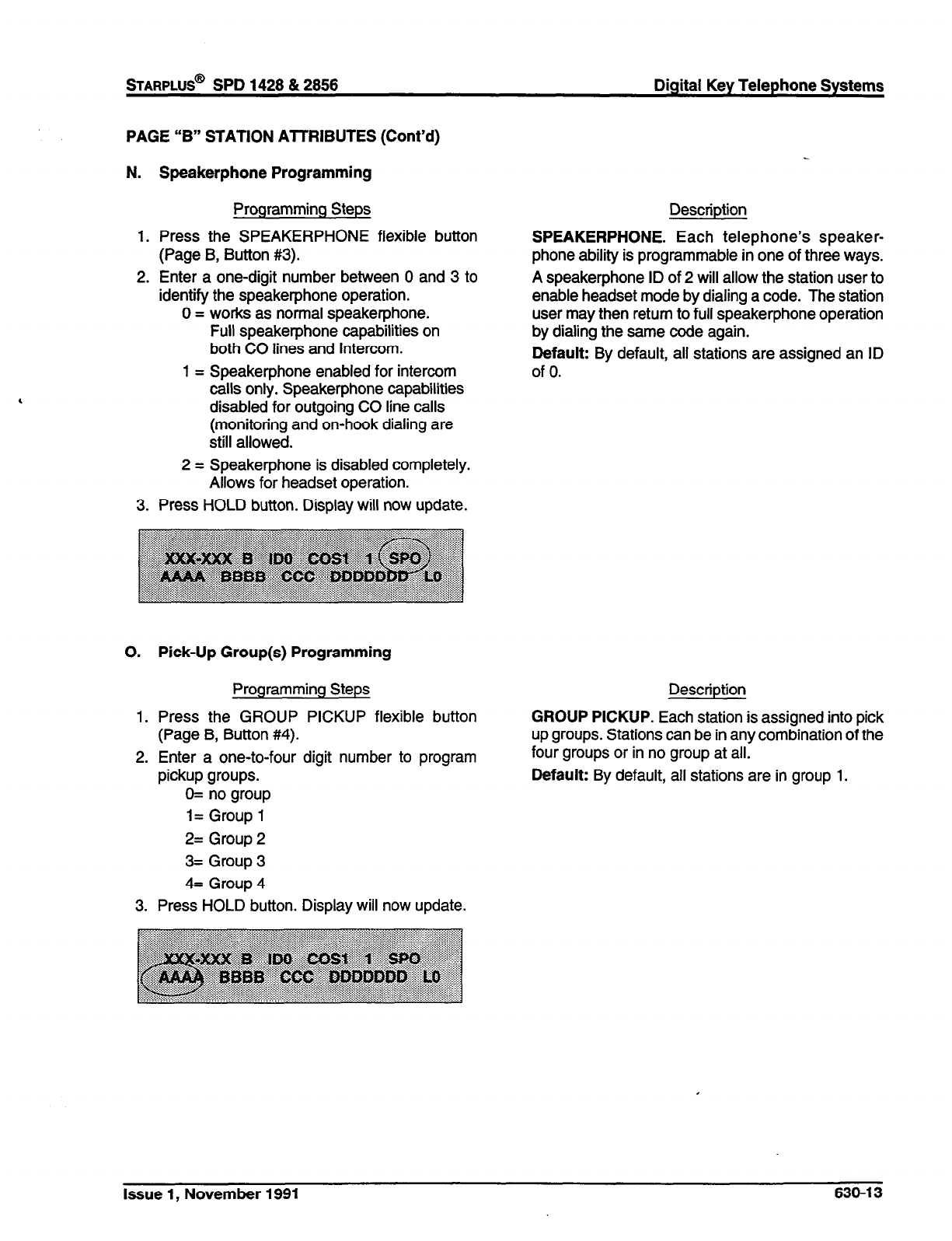
sTARPLUS@ SPD 1428 & 2856 Digital Key Telephone Systems
PAGE “B” STATION ATTRIBUTES (Cont’d)
N. Speakerphone Programming
Programming Steps
1. Press the SPEAKERPHONE flexible button
(Page B, Button #3).
2. Enter a one-digit number between 0 and 3 to
identify the speakerphone operation.
0 = works as normal speakerphone.
Full speakerphone capabilities on
both CO lines and Intercom.
1 = Speakerphone enabled for intercom
calls only. Speakerphone capabilities
disabled for outgoing CO line calls
(monitoring and on-hook dialing are
still allowed.
2 = Speakerphone is disabled completely.
Allows for headset operation.
3. Press HOLD button. Display will now update.
0. Pick-Up Group(s) Programming
Programming Steps
1. Press the GROUP PICKUP flexible button
(Page B, Button #4).
2. Enter a one-to-four digit number to program
pickup groups.
0= no group
l= Group 1
2= Group 2
3= Group 3
4= Group 4
3. Press HOLD button. Display will now update.
Description
SPEAKERPHONE. Each telephone’s speaker-
phone ability is programmable in one of three ways.
A speakerphone ID of 2 will allow the station user to
enable headset mode by dialing a code. The station
user may then return to full speakerphone operation
by dialing the same code again.
Default: By default, all stations are assigned an ID
of 0.
Description
GROUP PICKUP. Each station is assigned into pick
up groups. Stations can be in any combination of the
four groups or in no group at all.
Default: By default, all stations are in group 1.
Issue 1, November 1991 630-l 3
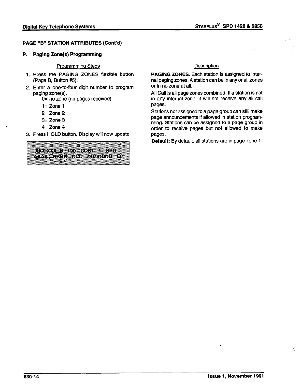
PAGE “B” STATION AnRlBUTES
(Cont’d)
P. Paging Zone(s) Programming
Programming Steps
1. Press the PAGING ZONES flexible button
(Page B, Button #5).
2. Enter a one-to-four digit number to program
paging zone(s).
,
0= no zone (no pages received)
l= Zone 1
2= Zone 2
3= Zone 3
4= Zone 4
3. Press HOLD button. Display will now update.
Description
PAGING ZONES. Each station is assigned to inter-
nal paging zones. A station can be in any or all zones
or in no zone at all.
All Call is all page zones combined. If a station is not
in any internal zone, it will not receive any all call
pages.
Stations not assigned to a page group can still make
page announcements if allowed in station program-
ming. Stations can be assigned to a page group in
order to receive pages but not allowed to make
pages.
Default:
By default, all stations are in page zone 1 e
636-14 Issue 1, November 1991
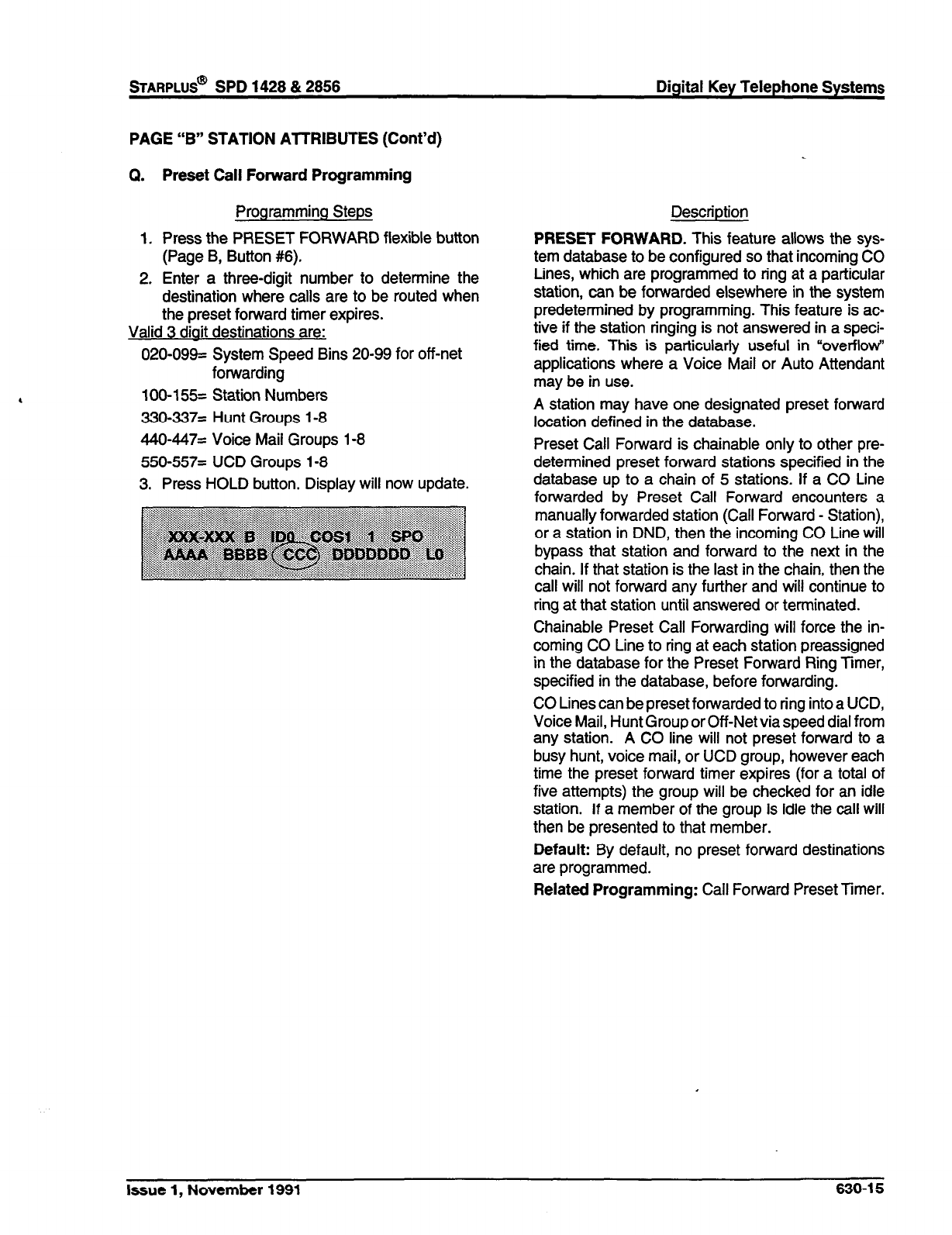
sTARPLUS@
SPD 1428 & 2858 Digital Key Telephone Systems
PAGE “B” STATION ATTRIBUTES (Cont’d)
Q. Preset Call Forward Programming
Programming Steps
1. Press the PRESET FORWARD flexible button
(Page B, Button #6).
2. Enter a three-digit number to determine the
destination where calls are to be routed when
the preset forward timer expires.
Valid 3 diait destinations are:
020-099= System Speed Bins 20-99 for off-net
forwarding
100-155= Station Numbers
330~337= Hunt Groups l-8
440~447= Voice Mail Groups 1-8
550-557= UCD Groups I-8
3. Press HOLD button. Display will now update.
Description
PRESET FORWARD. This feature allows the sys-
tem database to be configured so that incoming CO
Lines, which are programmed to ring at a particular
station, can be forwarded elsewhere in the system
predetermined by programming. This feature is ac-
tive if the station ringing is not answered in a speci-
fied time. This is particularly useful in “overflow
applications where a Voice Mail or Auto Attendant
may be in use.
A station may have one designated preset forward
location defined in the database.
Preset Call Forward is chainable only to other pre-
determined preset forward stations specified in the
database up to a chain of 5 stations. If a CO Line
forwarded by Preset Call Forward encounters a
manually forwarded station (Call Forward - Station),
or a station in DND, then the incoming CO Line will
bypass that station and forward to the next in the
chain. If that station is the last in the chain, then the
call will not forward any further and will continue to
ring at that station until answered or terminated.
Chainable Preset Call Forwarding will force the in-
coming CO Line to ring at each station preassigned
in the database for the Preset Forward Ring Timer,
specified in the database, before forwarding.
CO Lines can be preset forwarded to ring into a UCD,
Voice Mail, Hunt Group or Off-Net via speed dial from
any station. A CO line will not preset forward to a
busy hunt, voice mail, or UCD group, however each
time the preset forward timer expires (for a total of
five attempts) the group will be checked for an idle
station. If a member of the group is idle the call will
then be presented to that member.
Default: By default, no preset forward destinations
are programmed.
Related Programming: Call Forward Preset Timer.
Issue 1, November 1991 638-l 5
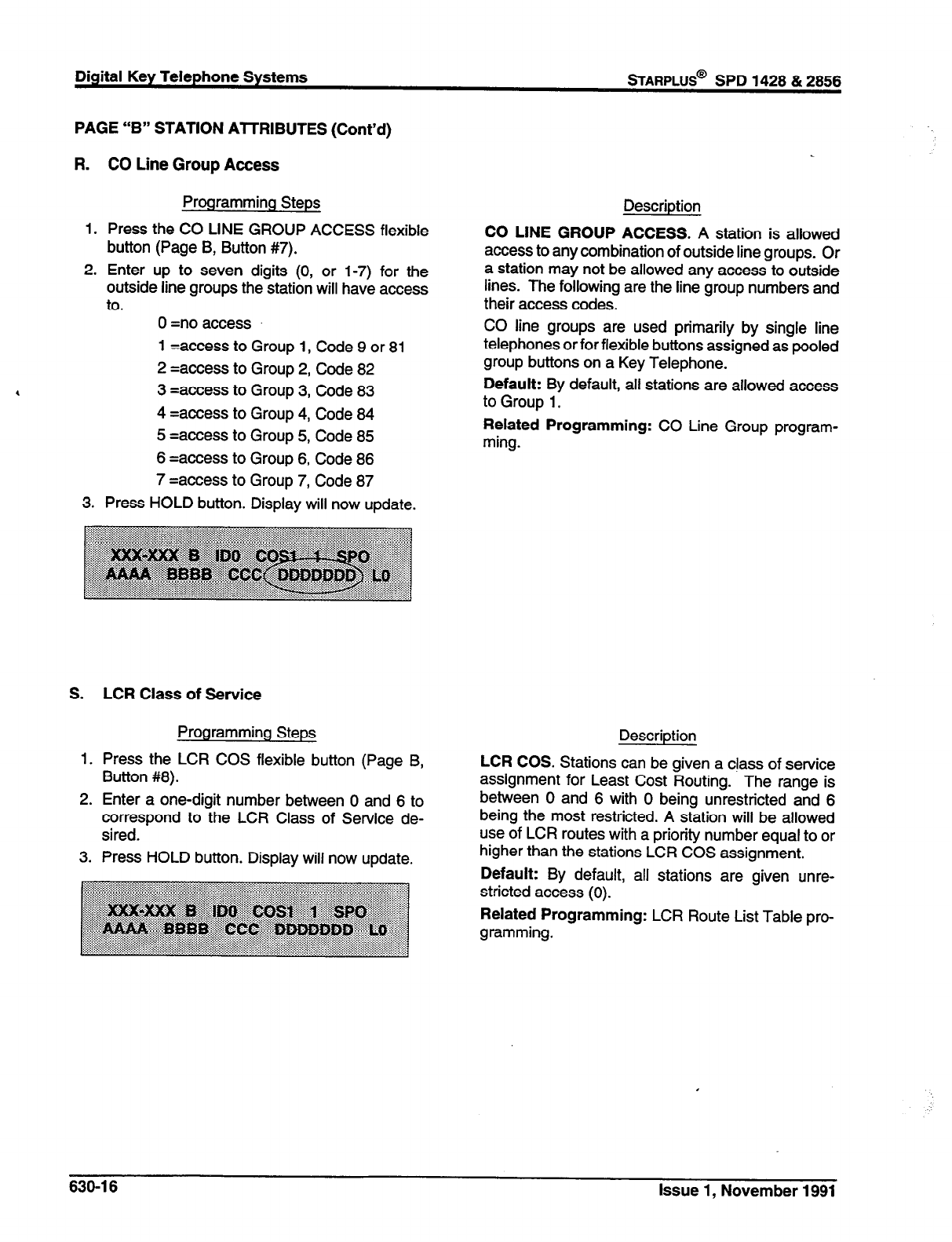
Digital Key Telephone Systems
sTARPLUS@
SPD 1428 & 2856
PAGE “B” STATION AlTRIBUTES (Cont’d)
R. CO Line Group Access
Programming Steps
1. Press the CO LINE GROUP ACCESS flexible
button (Page B, Button #7).
2. Enter up to seven digits (0, or 1-7) for the
outside line groups the station will have access
to. 0 =no access
1 =access to Group 1, Code 9 or 81
2 =access to Group 2, Code 82
3 =access to Group 3, Code 83
4 =access to Group 4, Code 84
5 =access to Group 5, Code 85
6 =access to Group 6, Code 86
7 =access to Group 7, Code 87
3. Press HOLD button. Display will now update.
S. LCR Class of Service
Programming Steps
1. Press the LCR COS flexible button (Page B,
Button #8).
2. Enter a one-digit number between 0 and 6 to
correspond to the LCR Class of Service de-
sired.
3. Press HOLD button. Display will now update.
Description
CO LINE GROUP ACCESS. A station is allowed
access to any combination of outside line groups. Or
a station may not be allowed any access to outside
lines. The following are the line group numbers and
their access codes.
CO line groups are used primarily by single line
telephones or for flexible buttons assigned as pooled
group buttons on a Key Telephone.
Default: By default, all stations are allowed access
to Group 1.
Related Programming: CO Line Group program-
ming.
Description
LCR COS. Stations can be given a ctass of service
assignment for Least Cost Routing. The range is
between 0 and 6 with 0 being unrestricted and 6
being the most restricted. A station will be allowed
use of LCR routes with a priority number equal to or
higher than the stations LCR COS assignment.
Default: By default, all stations are given unre-
stricted access (0).
Related Programming: LCR Route List Table pro-
gramming.
630-l 6 Issue 1, November 1991
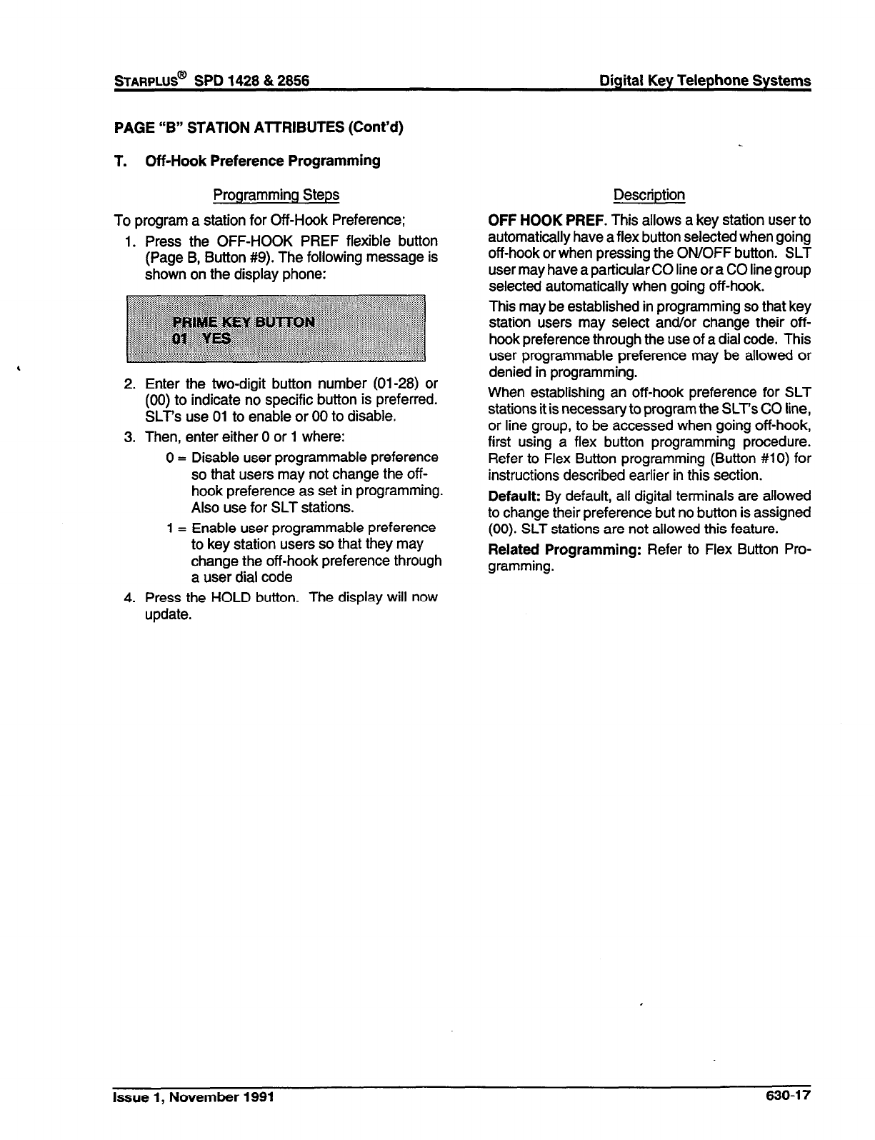
PAGE “B” STATION AmRlBUTES (Cont’d)
T. Off-Hook Preference Programming
Programming Steps
To program a station for Off-Hook Preference;
1. Press the OFF-HOOK PREF flexible button
(Page B, Button #9). The following message is
shown on the display phone:
2. Enter the two-digit button number (01-28) or
(00) to indicate no specific button is preferred.
SLT’s use 01 to enable or 00 to disable.
3. Then, enter either 0 or 1 where:
0 = Disable user programmable preference
so that users may not change the off-
hook preference as set in programming.
Also use for SLT stations.
1 = Enable user programmable preference
to key station users so that they may
change the off-hook preference through
a user dial code
4. Press the HOLD button. The display will now
update.
Description
OFF HOOK PREF. This allows a key station user to
automatically have a flex button selected when going
off-hook or when pressing the ON/OFF button. SLT
user may have a particular CO line or a CO line group
selected automatically when going off-hook.
This may be established in programming so that key
station users may select and/or change their off-
hook preference through the use of a dial code. This
user programmable preference may be allowed or
denied in programming.
When establishing an off-hook preference for SLT
stations it is necessary to program the SLT’s CO line,
or line group, to be accessed when going off-hook,
first using a flex button programming procedure.
Refer to Flex Button programming (Button MO) for
instructions descn’bed earlier in this section.
Default: By default, all digital terminals are allowed
to change their preference but no button is assigned
(00). SLT stations are not allowed this feature.
Related Programming: Refer to Flex Button Pro-
gramming.
Issue 1, November 1991 630-l 7
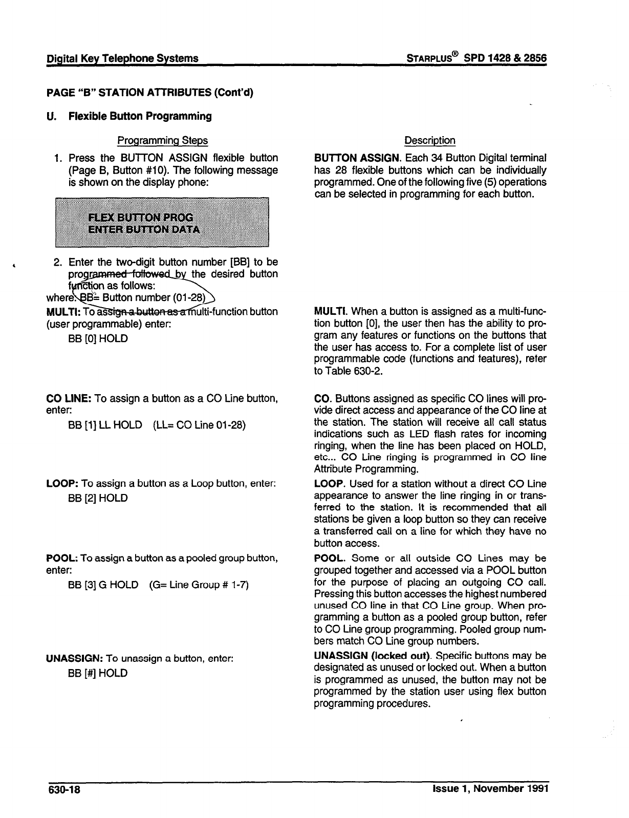
Digital Key Telephone Systems
STARPLUS@
SPD 1428 & 2856
PAGE “B” STATION ATTRIBUTES (Cont’d)
U. Flexible Button Programming
Programming Steps
1. Press the BUTTON ASSIGN flexible button
(Page B, Button #lo). The following message
is shown on the display phone:
Description
BUTTON ASSIGN.
Each 34 Button Digital terminal
has 28 flexible buttons which can be individually
programmed. One of the following five (5) operations
can be selected in programming for each button.
,
2. Enter the two-digit button number [BB] to be
desired button
(user programmable) enter:
BB [0] HOLD
unction button
CO LINE:
To assign a button as a CO Line button,
enter:
BB [l] LL HOLD (LL= CO Line 01-28)
LOOP:
To assign a button as a Loop button, enter:
BB [2] HOLD
POOL:
To assign a button as a pooled group
button,
enter:
BB [3] G HOLD (G= Line Group # 1-7)
UNASSIGN:
To unassign a button, enter:
BB [#] HOLD
MULTI.
When a button is assigned as a multi-func-
tion button [0], the user then has the ability to pro-
gram any features or functions on the buttons that
the user has access to. For a complete list of user
programmable code (functions and features), refer
to Table 630-2.
CO. Buttons assigned as specific CO lines will pro-
vide direct access and appearance of the CO line at
the station. The station will receive all call status
indications such as LED flash rates for incoming
ringing, when the line has been placed on HOLD,
etc... CO Line ringing is programmed in CO
line
Attribute Programming.
LOOP.
Used for a station without a direct CO Line
appearance to answer the line ringing in or trans-
ferred to the station. It is recommended that all
stations be given a loop button so they can receive
a transferred call on a line for which they have no
button access.
POOL.
Some or all outside CO Lines may be
grouped together and accessed via a POOL button
for the purpose of placing an outgoing CO call.
Pressing this button accesses the highest numbered
unused CO line in that CO Line group. When pro-
gramming a button as a pooled group button, refer
to CO Line group programming. Pooled group num-
bers match CO Line group numbers.
UNASSIGN (locked out).
Specific buttons may be
designated as unused or locked out. When a button
is programmed as unused, the button may not be
programmed by the station user using flex button
programming procedures.
630-l 8 Issue 1, November 1991
STARPLUS@ SPD 1428 & 2856 Digital Key Telephone Systems
PAGE “B” STATlON ATTRIBUTES (Cont’d)
Flexible Button Programming (Cont’d)
Programming Steps
If SLT stations are to be programmed for Off-Hook
Preference, it is necessary to program the desired
CO line, or CO line group, the SLT is to access when
going off-hook.
To assign a CO Line for a SLT with Off-Hook Pref-
erence, enter:
00 [l] LL HOLD (LL= CO Line 01-28)
To assign a CO Line group for an SLT with Off-Hook
Preference, enter:
00 [3] G HOLD (G= Line Group # 1-7)
Description
Default: By default, Station 100 will ring on a line.
However, if Station 100 is not given button access to
a line, another station must be programmed to ring
on that line.
Related Programming: When programming a but-
ton as a CO Line button, refer to CO tine Attributes
for assigning CO Line Ringing, Sec. 620.1; Off-Hook
Preference.
Issue 1, November 1991 630-19
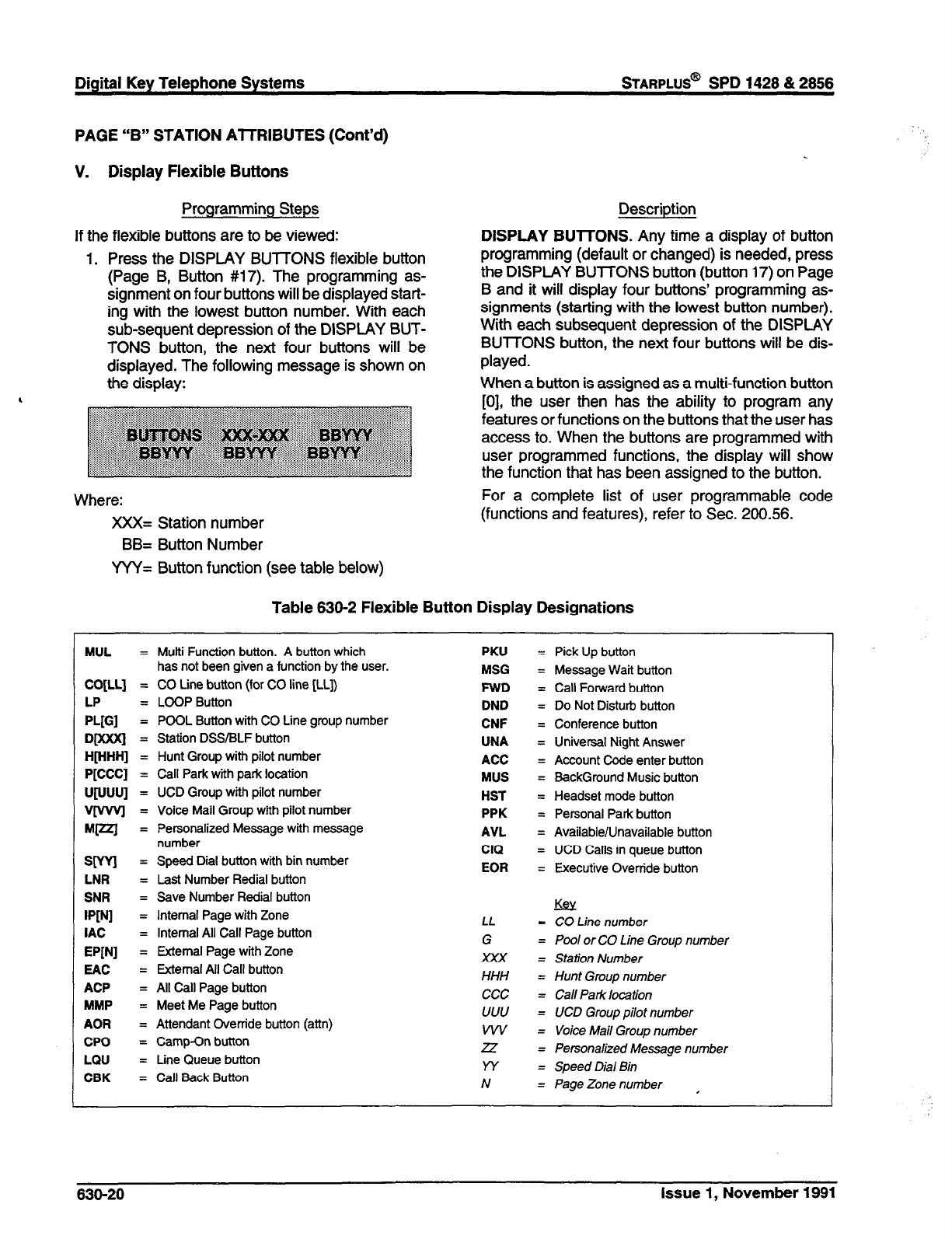
Digital Key Telephone Systems
sTARPLUS@
SPD 1428 & 2856
PAGE “B” STATION AlTRIBUTES (Cont’d)
V. Display Flexible Buttons
Programming Steps
If the flexible buttons are to be viewed:
1. Press the DISPLAY BUTTONS flexible button
(Page B, Button #17). The programming as-
signment on four buttons will be displayed start-
ing with the lowest button number. With each
sub-sequent depression of the DISPLAY BUT-
TONS button, the next four buttons will be
displayed. The following message is shown on
the display:
Descriotion
DISPLAY BUTTONS. Any time a display of button
programming (default or changed) is needed, press
the DISPLAY BUTTONS button (button 17) on Page
B and it will display four buttons’ programming as-
signments (starting with the lowest button number).
With each subsequent depression of the DISPLAY
BUTTONS button, the next four buttons will be dis-
played.
When a button is assigned as a multi-function button
[0], the user then has the ability to program any
features or functions on the buttons that the user has
access to. When the buttons are programmed with
user programmed functions, the display will show
the function that has been assigned to the button.
For a complete list of user programmable code
(functions and features), refer to Sec. 200.56.
Where:
XXX= Station number
BB= Button Number
YYY= Button function (see table below)
Table 830-2 Flexible Button Display Designations
MUL = Multi Function button. A button which
has not been given a function by the user.
CO[LL] = CO Line button (for CO line [LL])
LP = LOOP Button
PL[Gl
= POOL Button with CO Line group number
D@(XXj = Station DSS/BLF button
H@-lHH] = Hunt Group with pilot number
P[CCC] = Call Park with park location
U[vUU] = UCD Group with pilot number
V[wvl = Voice Mail Group with pilot number
w?l = Personalized Message with message
number
WV = Speed Dial button with bin number
LNR = Last Number &dial button
SNR = Save Number F&dial button
rpPJ1
= Internal Page with Zone
IAC = Internal All Call Page button
WNI
= External Page with Zone
EAC
= External All Call button
ACP
= All Call Page button
YMP
= Meet Me Page button
AOR = Attendant Override button (ann)
CPO
= Camp-On button
LQU
= Line Queue button
CBK
= Call Back Button
PKU = Pick Up button
MSG = Message Wait button
FWD = Call Forward button
DND = Do Not Disturb button
CNF = Conference button
UNA = Universal Night Answer
ACC = Account Code enter button
YUS = BackGround Music button
HST = Headset mode button
PPK = Personal Park button
AVL = Available/Unavailable button
CIQ = UCD Calls in queue button
EOR = Executive Override button
Es!
LL
= CO Line number
G
= Pool or CO Line Group number
XXX = Station Number
HHH = Hunt Group number
ccc = Call Park location
LJULJ
= LJCD Group pilot number
WV = Voice Mail Group number
25 = Personalized Message number
w = Speed Dial Bin
N = Page Zone number ,
830-20 Issue 1, November 1991
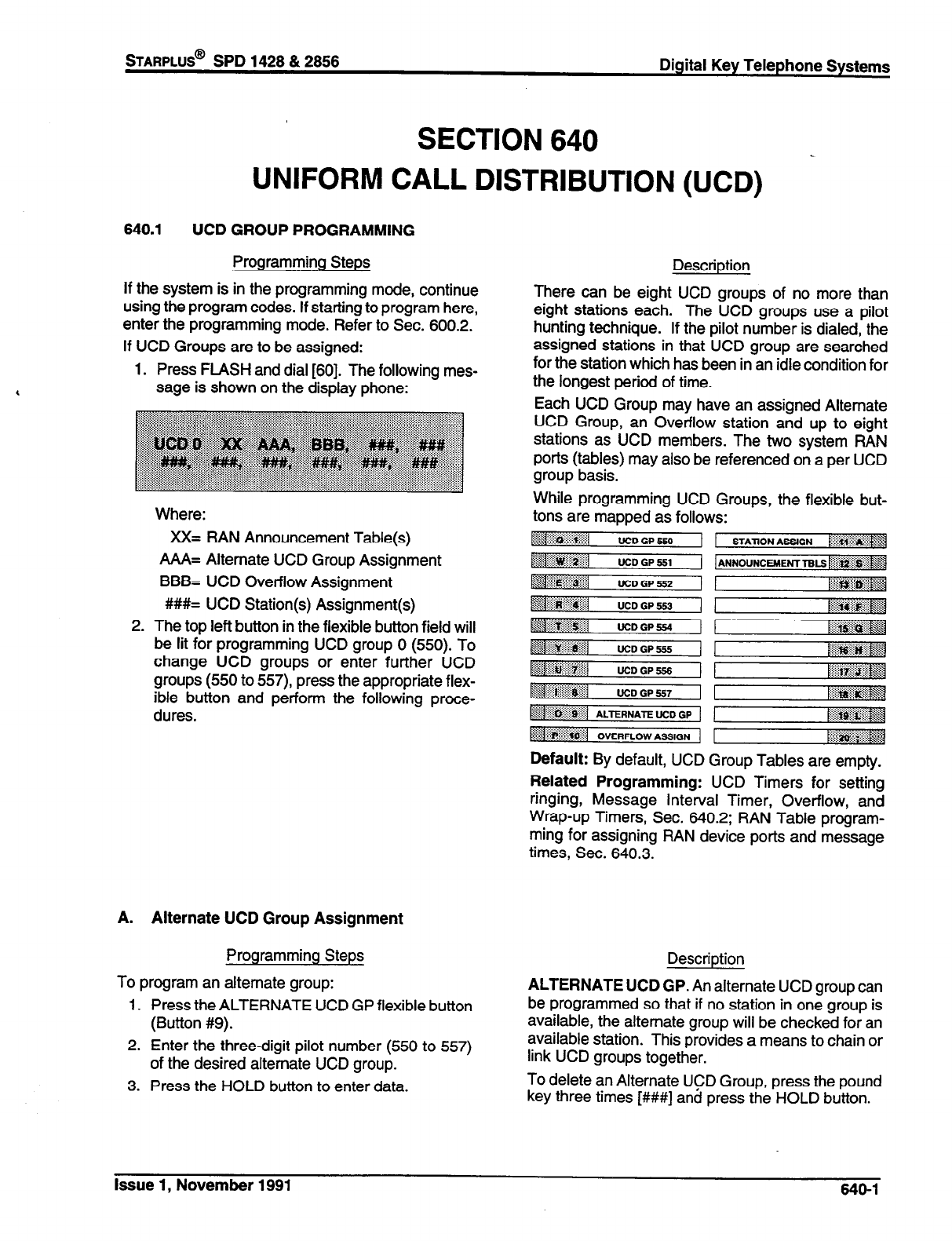
STARPLUS@
SPD 1428 & 2856 Digital Key Telephone Systems
SECTION 640
DISTRIBUTION (UCD)
UNIFORM CALL
640.1 UCD GROUP PROGRAMMING
Programming Steps
If the system is in the programming mode, continue
using the program codes. If starting to program here,
enter the programming mode. Refer to Sec. 600.2.
If UCD Groups are to be assigned:
1. Press FLASH and dial [60]. The following mes-
sage is shown on the display phone:
Where:
XX= RAN Announcement Table(s)
A/VI= Alternate UCD Group Assignment
BBB= UCD Overflow Assignment
#I##= UCD Station(s) Assignment(s)
2. The top left button in the flexible button field will
be lit for programming UCD group 0 (550). To
change UCD groups or enter further UCD
groups (550 to 557) press the appropriate flex-
ible button and perform the following proce-
dures.
A. Alternate UCD Group Assignment
Programming Steps
To program an alternate group:
1. Press the ALTERNATE UCD GP flexible button
(Button #9).
2. Enter the three-digit pilot number (550 to 557)
of the desired alternate UCD group.
3. Press the HOLD button to enter data.
Description
There can be eight UCD groups of no more than
eight stations each. The UCD groups use a pilot
hunting technique. If the pilot number is dialed, the
assigned stations in that UCD group are searched
for the station which has been in an idle condition for
the longest period of time.
Each UCD Group may have an assigned Alternate
UCD Group, an Overflow station and up to eight
stations as UCD members. The two system RAN
ports (tables) may also be referenced on a per UCD
group basis.
While programming UCD Groups, the flexible but-
tons are mapped as follows:
~~1
UCDGPS50
UCD GP 551 1 ANND”NCUOEHT TBLs ~~~~~~~
~~i:;iiii~l UCD GP 552 r;iaiiii~~~
-7 .: .::g@ UCD GP 553
UCDGP5S.l
~1~~~~1 UCDGP555 i$q@~~ pz+
:::..- ::: :., .a
basil UCDGP556
&j ~~~~~1 UCD GP 557 [A
.iiii##y...- \\
~~~~~~iil ALTERN*E wD GP I&*;i&$,+Jj
:if::...“.:f:>:f’;. :8”
~:~l D”ERpLDW ASS,GN rli~~~
Default: By default, UCD Group Tables are empty.
Related Programming: UCD Timers for setting
ringing, Message Interval Timer, Overflow, and
Wrap-up Timers, Sec. 640.2; RAN Table program-
ming for assigning RAN device ports and message
times, Sec. 640.3.
Description
ALTERNATE UCD GP. An alternate UCD group can
be programmed so that if no station in one group is
available, the alternate group will be checked for an
available station. This provides a means to chain or
link UCD groups together.
To delete an Alternate UCD Group, press the pound
key three times [###I and press the HOLD button.
Issue 1, November 1991 640-l
Digital Key Telephone Systems
sTARPLUS@
SPD 1428 & 2888
UNIFORM CALL DISTRIBUTION (Cont’d)
6. Overflow Station Assignment
Programming Steps
To program UCD Overflow station:
1. Press the OVERFLOW ASSIGN flexible button
(Button #lo).
2. Enter the three-digit station number (100 to
155) to designate the UCD Groups overflow
station.
3. Press the HOLD button to enter the data.
,
C. UCD Station Assignment(s)
Programming Steps
To program stations into a UCD group:
1. Press the STATION ASSIGN flexible button
(Button #il).
2. Enter the three digit station numbers of the
stations in the UCD group in the order in which
they will be checked. A maximum of eight sta-
tions may be entered.
3. Press HOLD button.
D. Recorded Announcement Assignment(s)
Programming Steps
To program a Recorded Announcement:
1. Press the ANNOUNCEMENT TBLS flexible
button (Button #12).
2. Enter one of the following digit sequences:
l# = RAN port specified in Table 1
will be used.
2# = RAN port specified in Table 2
will be used.
1,2 = Port 1 will answer the call; port 2
will provide a subsequent message.
2,l = Port 2 will answer the call; port 1
will provide a subsequent message.
Description
OVERFLOW ASSIGN. When an overflow station is
assigned, callers that have remained in queue for a
specified amount of time will be routed to the as-
signed overflow station. The overflow station may
not be one of the UCD group stations. Only CO calls
transferred to a UCD group will overflow to the
overflow station when RAN tables have not been
assigned.
To delete an Overflow Station, press the pound key
three times [###I and press the HOLD button.
Description
STATION ASSIGN. Any type of station (excluding
DSS/DLS Consoles) may be entered as valid UCD
stations. Calls will be routed to station in the order
they are entered for the first round of calls only. After
that the calls are routed to stations based on On-
Hook time. The station with the longest On-Hook
time will receive the next call.
If a specific station number is dialed, only that station
is rung; no distribution will be done if that station is
busy.
To erase all stations, press the pound key three
times [###I and press HOLD.
Description
ANNOUNCEMENT TBLS. An optional Recorded
Announcement device may be connected to the
system to provide an announcement if all stations in
a UCD group are busy. Two ports in the system may
be assigned to provide a path to a Recorded An-
nouncement device.
Incoming CO Callers will only be answered and
routed to the Overflow assignment if a RAN Table is
assigned.
To erase Recorded Announcement(s), press the
pound key two times [##I and press HOLD.
Refer to RAN Announcement Table programming
(Sec. 640.3) for further information regarding each
RAN Table.
640-2 Issue 1, November 1991
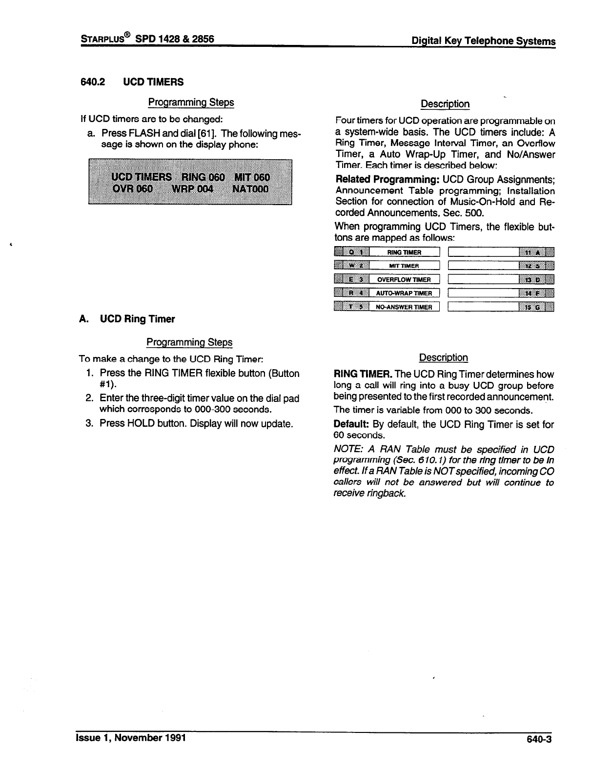
sTARPLUS@
SPD 1428 & 2858 Digital Key Telephone Systems
840.2
UCD TIMERS
Programming Steps
If UCD timers are to be changed:
a. Press FLASH and dial [Sl]. The following mes-
sage is shown on the display phone:
Description _
Four timers for UCD operation are programmable on
a system-wide basis. The UCD timers include: A
Ring Timer, Message Interval Timer, an Overflow
Timer, a Auto Wrap-Up Timer, and No/Answer
Timer. Each timer is described below:
Related Programming: UCD Group Assignments;
Announcement Table programming; Installation
Section for connection of Music-On-Hold and Re-
corded Announcements, Sec. 500.
When programming UCD Timers, the flexible but-
tons are mapped as follows:
~~~~~~1
RINK mm4 :i::: ..::.::i:::c .: : ‘CqX
[&&&&$$
A. UCD Ring Timer
Programming Steps
To make a change to the UCD Ring Timer:
1. Press the RING TIMER flexible button (Button
#l).
2. Enter the three-digit timer value on the dial pad
which corresponds to 000-300 seconds.
3. Press HOLD button. Display will now update.
Description
RING TIMER. The UCD Ring Timer determines how
long a call will ring into a busy UCD group before
being presented to the first recorded announcement.
The timer is variable from 000 to 300 seconds.
Default: By default, the UCD Ring Timer is set for
60
seconds.
NOTE: A RAN Table must be specified in UCD
programming (Sec. 670.1) for the ring timer to be in
effect. If a RAN Table is NOTspecified, incoming CO
callers will not be answered but will continue to
receive ringback.
Issue 1, November 1991
840-3
Digital Key Telephone Systems
sTARPLUS@
SPD 1428 & 2666
UCD TIMERS (Cont’d)
B. UCD Message Interval Timer
Programming Steps
To make a change to the UCD Message Interval
Timer:
1. Press the MIT TIMER flexible button (Button
w.
2. Enter the three-digit timer value on the dial pad
which corresponds to.OOO-600 seconds.
Press HOLD button. Display will now update.
NOTE: The UCD Ring and Message Interval Timers
4 only apply when RAN ports have been specified. If
RAN ports are not specified, incoming callers will
continue to receive ringback tone.
C. UCD Overflow Timer
Programming Steps
To make a change to the UCD Overflow Timer:
1. Press the OVERFLOW TIMER flexible button
(Button #3).
2. Enter the three-digit value on the dial pad which
corresponds to 000-600 seconds.
3. Press HOLD button. Display will now update.
D. UCD Auto Wrap-Up Timer
Programming Steps
To make a change to the UCD Auto Wrap-up Timer:
1. Press the AUTO-WRAP TIMER flexible button
(Button #4).
2. Enter the three-digit value on the dial pad which
corresponds to 000-600 seconds.
3. Press HOLD button. Display will now update.
640-4
Description
MIT TIMER. The UCD Message Interval Timer (MIT)
determines the length of time a caller remains in
queue (listening to MOH, if provided) between re-
corded announcements.
The timer is variable from 000 to 600 seconds.
Default: By default, the UCD Message Interval
Timer is set for 60 seconds.
Description
OVERFLOW TIMER. The UCD Overflow Timer de-
termines the total length of time a caller will remain
in queue for a particular UCD group. When the timer
expires, the caller will be routed to the designated
overflow station. The timer starts when an incoming
call is answered and presented to the first recorded
announcement. Transferred CO callers will overflow
at the expiration of the Overflow Timer.
The timer is variable from 000 to 600 seconds.
Default: By default, the UCD Overflow Timer is set
for 60 seconds.
Description
AUTO-WRAP TIMER. After completion of a UCD
call (on-hook) the agent will not be subjected to
another UCD call for the duration of the Auto Wrap-
Up timer allowing the agent to finish call related work
or access other facilities. This will allow agents to
remove themselves from the group (ie. DND, Call
Forward) or originate another call.
This timer is variable from 000-600 seconds.
Default: By default, the UCD Auto Wrap-up Timer
is set for 04 seconds. .
Issue 1, November 1991
UCD TIMERS (Cont’d)
E. UCD No-Answer Timer
Programming Steps Description
To make a change to the UCD No-Answer Timer:
1. Press the NO-ANSWER TIMER flexible button
(Button #5).
2. Enter the three-digit value on the dial pad which
corresponds to 000-300 seconds.
3. Press HOLD button. Display will now update.
NO-ANSWER TIMER. After a UCD call rings to an
agent, this timer takes effect. If the agent does not
answer the call before this timer expires, then that
agent is set to “UCD Unavailable” and the call is
routed back to the UCD group for another available
agent or queue.
The timer is variable from 000-300 seconds.
Default: By default, the UCD No-Answer Timer is
disabled with an entry of 000.
Issue 1, November 1991 646-S
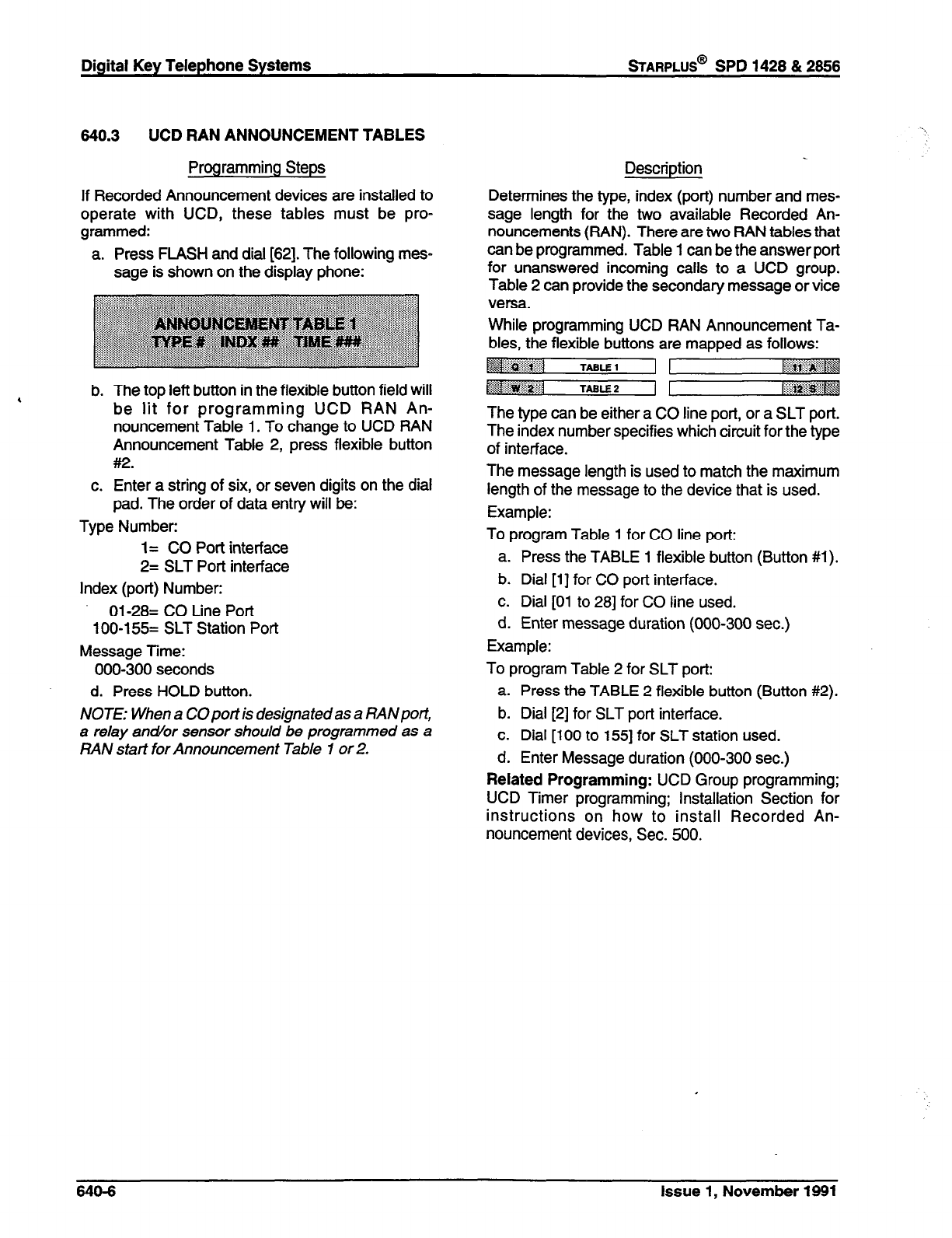
Digital Key Telephone Systems
sTARPLUS@
SPD 1428 & 2866
640.3 UCD RAN ANNOUNCEMENT TABLES
Programming Steps
If Recorded Announcement devices are installed to
operate with UCD, these tables must be pro-
grammed:
a. Press FLASH and dial [62]. The following mes-
sage is shown on the display phone:
, b. The top left button in the flexible button field will
be lit for programming UCD RAN An-
nouncement Table 1. To change to UCD RAN
Announcement Table 2, press flexible button
#2.
c. Enter a string of six, or seven digits on the dial
pad. The order of data entry will be:
Type Number:
1= CO Port interface
2= SLT Port interface
Index (port) Number:
Ol-28= CO Line Port
100-l 55= SLT Station Port
Message Time:
000-300 seconds
d. Press HOLD button.
NOTE: When a COportis designatedas a RANport,
a relay antior sensor should be programmed as a
RAN start for Announcement Table 1 or 2.
Description
Determines the type, index (port) number and mes-
sage length for the two available Recorded An-
nouncements (RAN). There are two RAN tables that
can be programmed. Table 1 can be the answer port
for unanswered incoming calls to a UCD group.
Table 2 can provide the secondary message or vice
versa.
While programming UCD RAN Announcement Ta-
bles, the flexible buttons are mapped as follows:
~g$%.-:::.j
.:$&g;:i:
TABLE 1 ~~~
~~~~~~~ TABLE 2
The type can be either a CO line port, or a SLT port.
The index number specifies which circuit for the type
of interface.
The message length is used to match the maximum
length of the message to the device that is used.
Example:
To program Table 1 for CO line port:
a. Press the TABLE 1 flexible button (Button #l).
b. Dial [l] for CO port interface.
c. Dial [Ol to 281 for CO line used.
d. Enter message duration (000-300 sec.)
Example:
To program Table 2 for SLT port:
a. Press the TABLE 2 flexible button (Button #2).
b. Dial [2] for SLT port interface.
c. Dial [lo0 to 1551 for SLT station used.
d. Enter Message duration (000-300 sec.)
Related Programming: UCD Group programming;
UCD Timer programming; Installation Section for
instructions on how to install Recorded An-
nouncement devices, Sec. 500.
640-6 Issue 1, November 1881
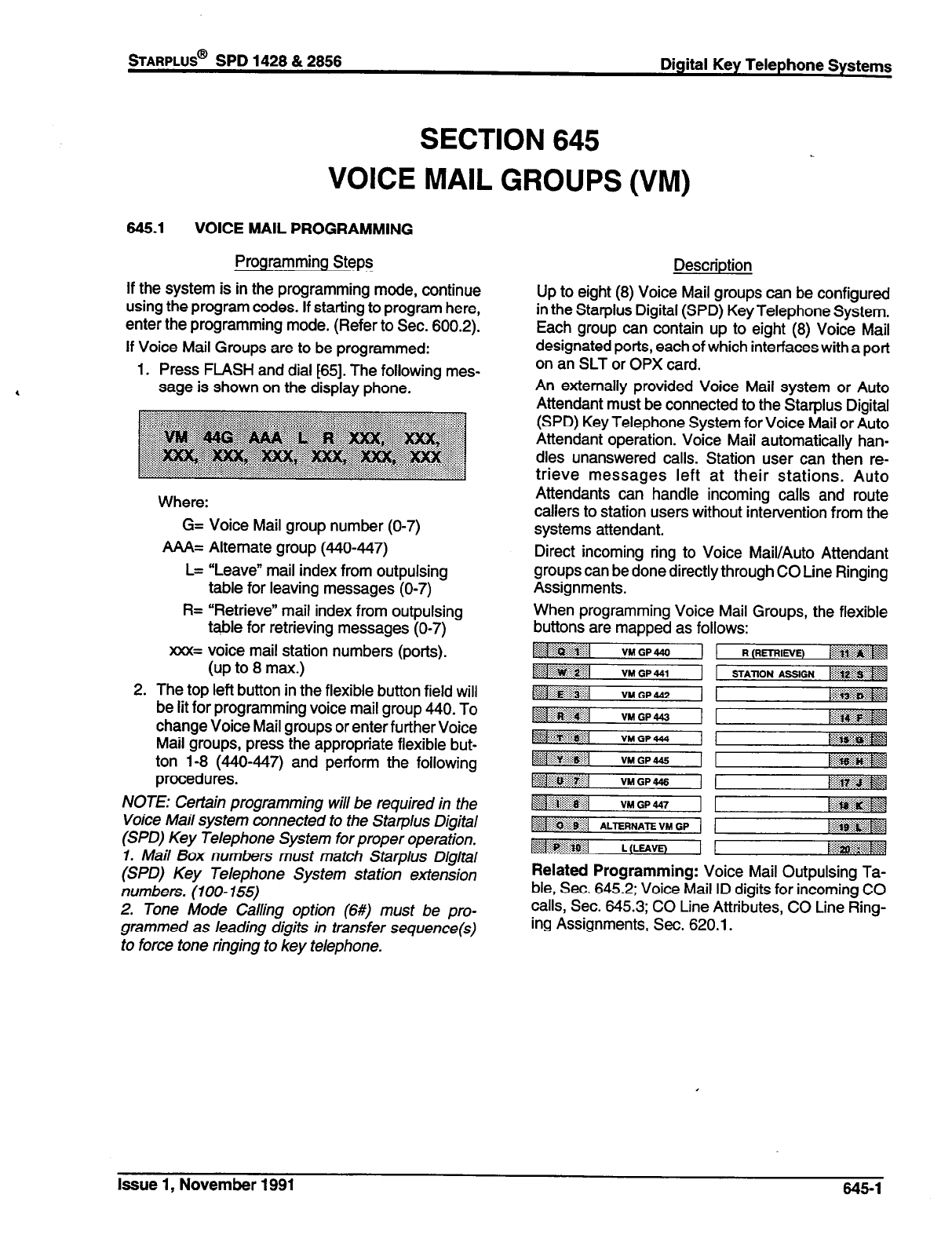
mARPLUS@
SPD 1428 & 2856 Digital Key Telephone Systems
SECTION 645
VOICE MAIL GROUPS (VM)
645.1 VOICE MAIL PROGRAMMING
Programming Steps
If the system is in the programming mode, continue
using the program codes. If starting to program here,
enter the programming mode. (Refer to Sec. 600.2).
If Voice Mail Groups are to be programmed:
1. Press FLASH and dial t65]. The following mes-
sage is shown on the display phone.
2.
Where:
G= Voice Mail group number (O-7)
AAA= Alternate group (440447)
L= “Leave” mail index from outpulsing
table for leaving messages (O-7)
R= “Retrieve” mail index from outpulsing
table for retrieving messages (O-7)
xxx= voice mail station numbers (ports).
(up to 8 max.)
The top left button in the flexible button field will
be lit for programming voice mail group 440. To
change Voice Mail groups or enter further Voice
Mail groups, press the appropriate flexible but-
ton l-8 (440447) and perform the following
procedures.
NOTE: Certain programming will be required in the
Voice Mail system connected to the Starplus Digital
(SPD) Key Telephone System for proper operation.
1. Mail Box numbers must match Starplus Digital
(SPD) Key Telephone System station extension
numbers. (IOO- 155)
2. Tone Mode Calling option (649 must be pro-
grammed as leading digits in transfer sequence(s)
to force tone ringing to key telephone.
Description
Up to eight (8) Voice Mail groups can be configured
in the Starplus Digital (SPD) Key Telephone System.
Each group can contain up to eight (8) Voice Mail
designated ports, each of which interfaces with a port
on an SLT or OPX card.
An externally provided Voice Mail system or Auto
Attendant must be connected to the Starplus Digital
(SPD) Key Telephone System for Voice Mail or Auto
Attendant operation. Voice Mail automatically han-
dles unanswered calls. Station user can then re-
trieve messages left at their stations. Auto
Attendants can handle incoming calls and route
callers to station users without intervention from the
systems attendant.
Direct incoming ring to Voice Mail/Auto Attendant
groups can be done directly through CO Line Ringing
Assignments.
When programming Voice Mail Groups, the flexible
buttons are mapped as follows:
Related Programming: Voice Mail Outpulsing Ta-
ble, Sec. 645.2; Voice Mail ID digits for incoming CO
calls, Sec. 645.3; CO Line Attributes, CO Line Ring-
ing Assignments, Sec. 620.1.
Issue 1, November 1991 645-l

Digital Key Telephone Systems
sTARPLUS@
SPD 1428 & 2866
VOICE MAIL GROUPS (Cont’d)
A. Alternate Voice Mail Group
Programming Steps
To program an alternate group:
1. Press the ALTERNATE VM GP flexible button
(Button #9).
2. Enter the three-digit pilot number (440 to 447)
of the desired group.
3. Press the HOLD button to enter data.
B. “Leave” Mail Index Entry
Programming Steps
To specify the “Leave” mail index (outpulsing table)
to be accessed by a Voice Mail group:
1. Press the LEAVE flexible button (Button #lo).
2. Enter the one-digit outpulsing table number (O-
7) on the dial pad.
3. Press the HOLD button to enter the data.
C. “Retrieve” Mail Index Entry
Programming Steps
To program the “Retrieve” mail index (outpulsing
table) to be accessed by the Voice Mail group:
1. Press the RETRIEVE flexible button (Button
#ll).
2. Enter the one-digit outpulsing table number (O-
7) on the dial pad.
3. Press the HOLD button to enter the data.
Description
ALTERNATE VM GP. An Alternate Voice Mail
Group may be programmed so that if all Voice Mail
ports are in use, the call can be routed to an alternate
group. This is useful when more than eight ports are
required for Voice Mail traffic.
To delete an Alternate Voice Mail Group assignment,
enter three pounds [#I##] on the keypad and press
the HOLD button.
Description
LEAVE. The “Leave” mail index specifies the out-
pulsing Table where the “in-band” digits required to
connect a caller, forwarded into Voice Mail, to the
called stations mail box are stored. Refer to Sec.
645.2 for programming entries into an outpulsing
table.
To delete a “Leave” mail index entry, enter one
pound [#] on the keypad and press the HOLD button.
Description
RETRIEVE. The “Retrieve” mail Index specifies the
outpulsing table where the “In-band” digits required
to connect a station user to their own mail box are
stored. Refer to Sec. 645.2 for programming entries
into an outpulsing table.
NOTE: In order for the Starplus Digital (SPD) Key
Telephone System to send the Station Identification
digits (station three-digit extension number), a
Seave” and a “Retrieve” table must be referenced
when assigning Voice Mail groups. However, the
“Leave” and “Retrieve” outpulsing Tables (Sec.
645.2) can be empty (no entries in the referenced
table).
To delete a “Retrieve” mail
index
entry, enter one
pound [#J on the keypad and press the HOLD button.
645-2
Issue 1, November 1991
STARPLUS@
SPD 1428 & 2858 Digital Key Telephone Systems
VOICE MAIL GROUPS (Cont’d)
D. Station Assignment(s)
Programming Steps
To program the stations in the Voice Mail group:
1. Press the STATION ASSIGN flexible button
(Button #12).
2. Enter the three digit station numbers. A maxi-
mum of eight SLT stations may be entered.
3. Press the HOLD button to enter the data.
Description
Up to eight (8) SLT or OPX port extension numbers
may be programmed into a Voice Mail group.
The ports will be designated as two-way ports by
directing calls to any one of the ports and allowing
any one of the ports (or all ports) to be used as VM
out dial and/or VM notify ports.
A flexible button may be programmed with a Voice
Mail group pilot number. This button will then act as
a DSS for that Voice Mail group when pressed and
also serves as the message waiting indication for
that VM group.
Issue 1, November 1991 845-3
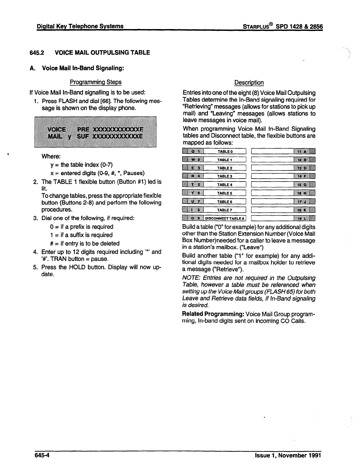
Digital Key Telephone Systems
mARPLUS@
SPD 1428 & 2666
848.2 VOICE MAIL OUTPULSING TABLE
A. Voice Mail In-Band Signaling:
Programming Steps
If Voice Mail In-Band signalling is to be used:
1. Press FLASH and dial [88]. The following mes-
sage is shown on the display phone.
Where:
y = the table index (O-7)
x = entered digits (O-9, #,
l
, Pauses)
2. The TABLE 1 flexible button (Button #l) led is
lit.
To change tables, press the appropriate flexible
button (Buttons 2-8) and perform the following
procedures.
3. Dial one of the following, if required:
0 = if a prefix is required
1 = if a suffix is required
# = if entry is to be deleted
4. Enter up to 12 digits required including ‘*’ and
‘#‘. TRAN button = pause.
5. Press the HOLD button. Display will now up-
date.
Description
Entries into one of the eight (8) Voice Mail Outpulsing
Tables determine the In-Band signaling required for
“Retrieving” messages (allows for stations to pick up
mail) and “Leaving” messages (allows stations to
leave messages in voice mail).
When programming Voice Mail In-Band Signaling
tables and Disconnect table, the flexible buttons are
mapped as follows:
~$&@$$#~] as@.,,,Em TABLE 6
y; ,?.:: . . . . . . . . . . . . [ ~~~~~~
Build a table (“0” for example) for any additional digits
other than the Station Extension Number (Voice Mail
Box Number)needed for a caller to leave a message
in a station’s mailbox. (“Leave”)
Build another table (“1” for example) for any addi-
tional digits needed for a mailbox holder to retrieve
a message (“Retrieve”).
NOTE: Entries are not required in the Outpulsing
Tab/e, however a table must be referenced when
setting up the Voice Mailgroups (FLASH 65) forboth
Leave and Retrieve data fields, if /n-Band signaling
is desired,
Related Programming: Voice Mail Group program-
ming, In-band digits sent on incoming CO Calls.
645-4 Issue 1, November 1991

sTARPLUS@
SPD 1428 & 2856 Digital Key Telephone Systems
VOICE MAIL OUTPULSING TABLE (Cont’d)
B.
1.
2.
3.
Voice Mail Disconnect Table:
Programming Steps
Press the DISCONNECT TABLE 8 flexible but-
ton (Button #$I) . This is the table number used
for the Voice Mail disconnect signal.
Enter up to 12 digits which will be used for the
disconnect signal, including ‘*’ and ‘Y. TRAN
button = pause.
Press the HOLD button. Display will now up-
date.
Description
To avoid Voice Mail ports from being tied up as a
result of CO line callers abandoning the call or not
exiting the VM system properly, a disconnect signal
can be programmed into the Starplus Digital (SPD)
Key Telephone System to notify the VM system that
a call has been abandoned. This is accomplished
through “in-band” signaling. If a CO disconnect sig-
nal is detected, the Starplus Digital (SPD) Key Tele-
phone System will send a series of DTMF digits
programmed in the Voice Mail disconnect table (out-
pulsing table eight (8)) to the Voice Mail port. This
can be any digit stream up to 12 digits including =*’
and “#“. This table will serve all eight voice mail
groups. These digits are not used as a result of an
internal station disconnecting from Voice Mail. In
this case silence is provided for a short period fol-
lowed by busy tone. This method is also used for
CO lines when the VM disconnect table is empty.
The Starplus Digital (SPD) Key Telephone System
will provide Loop Supervision monitoring while a CO
call is connected to a port designated as Voice Mail.
Default: By default programming there are no en-
tries in the disconnect table (table eight (8)).
NOTE: Loop supervision must be enabled on the CO
lines (in CO line programming) in order for VM dis-
connect feature to operate.
issue 1, November 1991
545-5
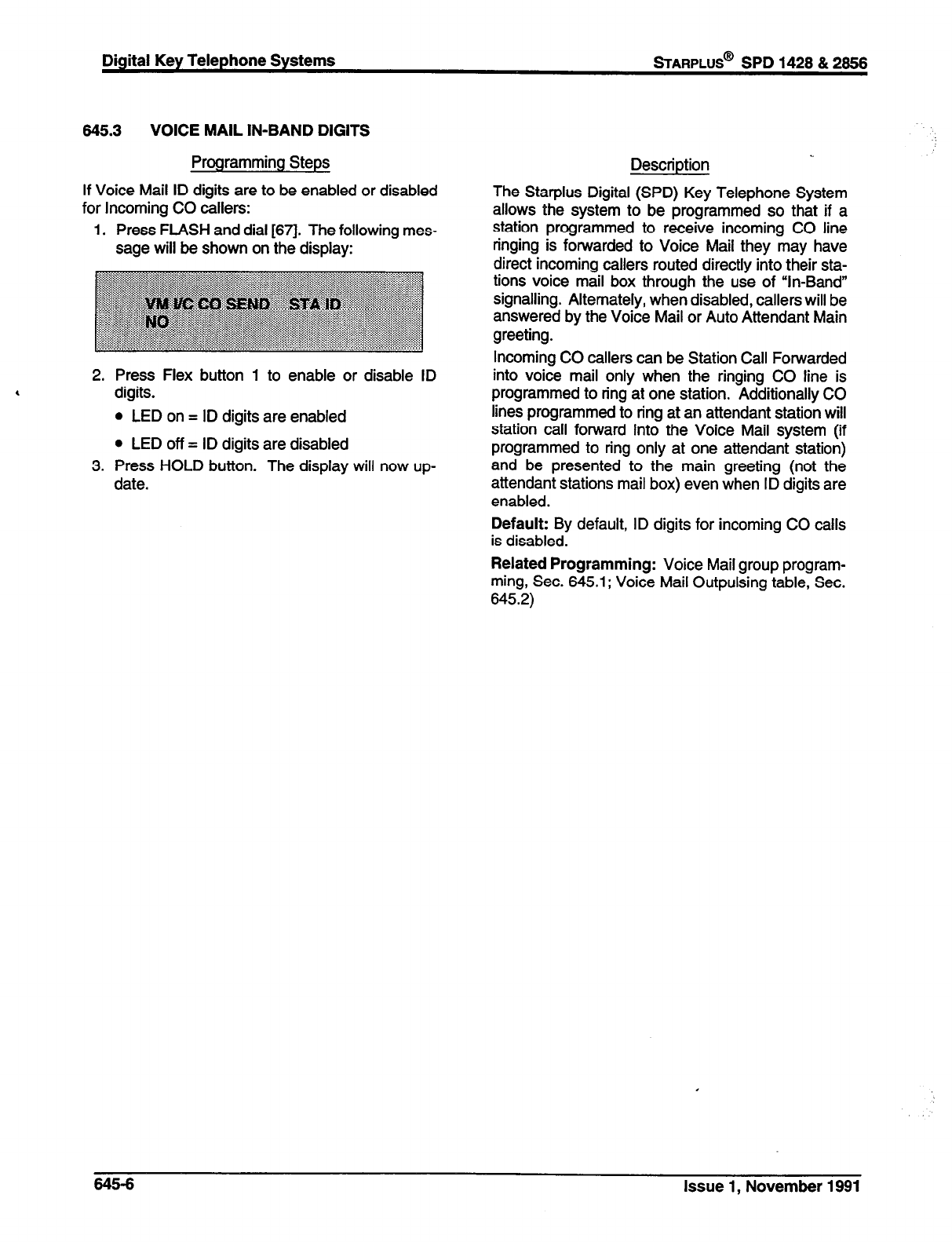
Digital Key Telephone Systems
645.3 VOICE MAIL IN-BAND DIGITS
Programming Steps Description
If Voice Mail ID digits are to be enabled or disabled
for Incoming CO callers:
1. Press FLASH and dial [671. The following mes-
sage will be shown on the display:
The Starplus Digital (SPD) Key Telephone System
allows the system to be programmed so that if a
station programmed to receive incoming CO line
ringing is forwarded to Voice Mail they may have
direct incoming callers routed directly into their sta-
tions voice mail box through the use of “In-Band
signalling. Alternately, when disabled, callers will be
answered by the Voice Mail or Auto Attendant Main
greeting.
2. Press Flex button 1 to enable or disable ID
digits.
l
LED on = ID digits are enabled
l
LED off = ID digits are disabled
3. Press HOLD button. The display will now up-
date.
Incoming CO callers can be Station Call Forwarded
into voice mail only when the ringing CO line is
programmed to ring at one station. Additionally CO
lines programmed to ring at an attendant station will
station call forward into the Voice Mail system (if
programmed to ring only at one attendant station)
and be presented to the main greeting (not the
attendant stations mail box) even when ID digits are
enabled.
Default: By default, ID digits for incoming CO calls
is disabled.
Related Programming: Voice Mail group program-
ming, Sec. 645.1; Voice Mail Outpulsing table, Sec.
645.2)
645-6 Issue 1, November 1991
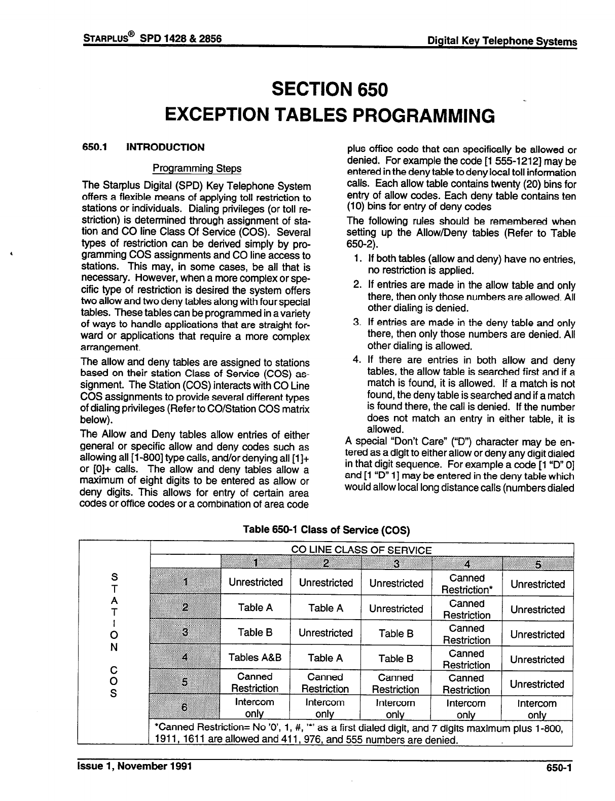
STARPLUS@
SPD 1428 & 2858 Digital Key Telephone Systems
SECTION 650
-
EXCEPTION TABLES PROGRAMMING
650.1 INTRODUCTION
Programming Steps
The Starplus Digital (SPD) Key Telephone System
offers a flexible means of applying toll restriction to
stations or individuals. Dialing privileges (or toll re-
striction) is determined through assignment of sta-
tion and CO line Class Of Service (COS). Several
types of restriction can be derived simply by pro-
gramming COS assignments and CO line access to
stations. This may, in some cases, be all that is
necessary. However, when a more complex or spe-
cific type of restriction is desired the system offers
two allow and two deny tables along with four special
tables. These tables can be programmed in a variety
of ways to handle applications that are straight for-
ward or applications that require a more complex
arrangement.
The allow and deny tables are assigned to stations
based on their station Class of Service (COS) as-
signment. The Station (COS) interacts with CO Line
COS assignments to provide several different types
of dialing privileges (Refer to CO/Station COS matrix
below).
The Allow and Deny tables allow entries of either
general or specific allow and deny codes such as
allowing all [I -8001 type calls, and/or denying all [I]+
or [0]+ calls. The allow and deny tables allow a
maximum of eight digits to be entered as allow or
deny digits. This allows for entry of certain area
codes or office codes or a combination of area code
plus office code that can specifically be allowed or
denied. For example the code [I 555-l 2121 may be
entered in the deny table to deny local toll information
calls. Each allow table contains twenty (20) bins for
entry of allow codes. Each deny table contains ten
(10) bins for entry of deny codes
The following rules should be remembered when
setting up the Allow/Deny tables (Refer to Table
650-2).
1.
2.
3.
4.
If both tables (allow and deny) have no entries,
no restriction is applied.
If entries are made in the allow table and only
there, then only those numbers are allowed. All
other dialing is denied.
If entries are made in the deny table and only
there, then only those numbers are denied. All
other dialing is allowed.
If there are entries in both allow and deny
tables, the allow table is searched first and if a
match is found, it is allowed. If a match is not
found, the deny table is searched and if a match
is found there, the call is denied. If the number
does not match an entry in either table, it is
allowed.
A special “Don’t Care” (‘II”) character may be en-
tered as a digit to either allow or deny any digit dialed
in that digit sequence. For example a code [I “D” 0]
and [I ‘ID” I] may be entered in the deny table which
would allow local long distance calls (numbers dialed
Table 650-l Class of Service (CCXl
S
T
A
T
I
0
N
CO LINE CLASS OF SERVICE . . . . . . . . . . . . . . . . .
~~~~~~~~~~~~~~~~~~~~~~~~~~~~~
i:i:$i::ii.iiFy:i:i::::::.:.:.; . . . ,. . . . . . . . . . . . . . . ,.
Unrestricted Unrestricted Canned
Restriction* Unrestricted
Table A Canned
Unrestricted Restriction Unrestricted
Unrestricted Table B Canned
Restriction Unrestricted
Table A Table B Canned
C Restriction Unrestricted
0 Canned Canned Canned Unrestricted
S Restriction Restriction Restriction
Intercom Intercom Intercom Intercom
only only only only
*Canned Restriction= No ‘O’, 1, #, I*’ as a first dialed digit, and 7 digits maximum plus I-800,
1911, 1611 are allowed and 41 I, 976, and 555 numbers are denied.
Issue 1, November 1991 650-l
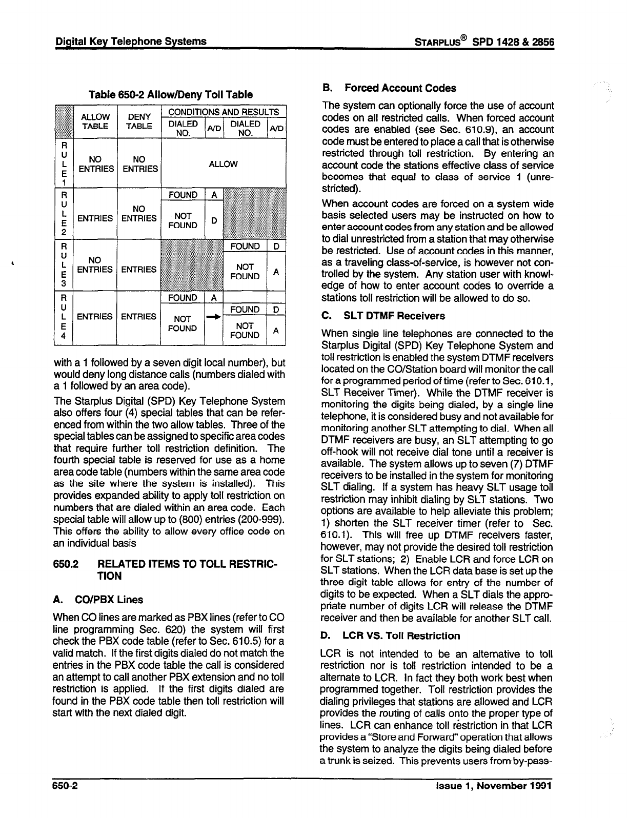
Digital Key Telephone Systems
sTARPLUS@
SPD 1428 & 2856
,
Table 650-2 Allow/Deny Toll Table
NO
ENTRIES ALLOW
FOUND ( A
El FOUND D-
with a 1 followed by a seven digit local number), but
would deny long distance calls (numbers dialed with
a 1 followed by an area code).
The Starplus Digital (SPD) Key Telephone System
also offers four (4) special tables that can be refer-
enced from within the two allow tables. Three of the
special tables can be assigned to specific area codes
that require further toll restriction definition. The
fourth special table is reserved for use as a home
area code table (numbers within the same area code
as the site where the system is installed). This
provides expanded ability to apply toll restriction on
numbers that are dialed within an area code. Each
special table will allow up to (800) entries (200-999).
This offers the ability to allow every office code on
an individual basis
650.2 RELATED ITEMS TO TOLL RESTRIC-
TION
A. CO/PBX Lines
When CO lines are marked as PBX lines (refer to CO
line programming Sec. 620) the system will first
check the PBX code table (refer to Sec. 610.5) for a
valid match. If the first digits dialed do not match the
entries in the PBX code table the call is considered
an attempt to call another PBX extension and no toll
restriction is applied. If the first digits dialed are
found in the PBX code table then toll restriction will
start with the next dialed digit.
B. Forced Account Codes
The system can optionally force the use of account
codes on all restricted calls. When forced account
codes are enabled (see Sec. 610.9), an account
code must be entered to place a call that is otherwise
restricted through toll restriction. By entering an
account code the stations effective class of service
becomes that equal to class of service 1 (unre-
stricted).
When account codes are forced on a system wide
basis selected users may be instructed on how to
enter account codes from any station and be allowed
to dial unrestricted from a station that may otherwise
be restricted. Use of account codes in this manner,
as a traveling class-of-service, is however not con-
trolled by the system. Any station user with knowl-
edge of how to enter account codes to override a
stations toll restriction will be allowed to do so.
C. SLT DTMF Receivers
When single line telephones are connected to the
Starplus Digital (SPD) Key Telephone System and
toll restriction is enabled the system DTMF receivers
located on the CO/Station board will monitor the call
for a programmed period of time (refer to Sec. 610.1,
SLT Receiver Timer). While the DTMF receiver is
monitoring the digits being dialed, by a single line
telephone, it is considered busy and not available for
monitoring another SLT attempting to dial. When all
DTMF receivers are busy, an SLT attempting to go
off-hook will not receive dial tone until a receiver is
available. The system allows up to seven (7) DTMF
receivers to be installed in the system for monitoring
SLT dialing. If a system has heavy SLT usage toll
restriction may inhibit dialing by SLT stations. Two
options are available to help alleviate this problem;
1) shorten the SLT receiver timer (refer to Sec.
610.1). This will free up DTMF receivers faster,
however, may not provide the desired toll restriction
for SLT stations; 2) Enable LCR and force LCR on
SLT stations. When the LCR data base is set up the
three digit table allows for entry of the number of
digits to be expected. When a SLT dials the appro-
priate number of digits LCR will release the DTMF
receiver and then be available for another SLT call.
D. LCR VS. Toll Restriction
LCR is not intended to be an alternative to toll
restriction nor is toll restriction intended to be a
alternate to LCR. In fact they both work best when
programmed together. Toll restriction provides the
dialing privileges that stations are allowed and LCR
provides the routing of calls onto the proper type of
lines. LCR can enhance toll restriction in that LCR
provides a “Store and Forward” operation that allows
the system to analyze the digits being dialed before
a trunk is seized. This prevents users from by-pass-
650-2 Issue 1, November 1991
*AFtPLUS@
SPD 1428 & 2858 Digital Key Telephone Systems
ing toll restriction by taking advantage of the time it
takes for a central office line to provide dial tone.
Because of this it is recommended that LCR be
considered when toll restriction is desired.
Issue 1, November 1991 650-3
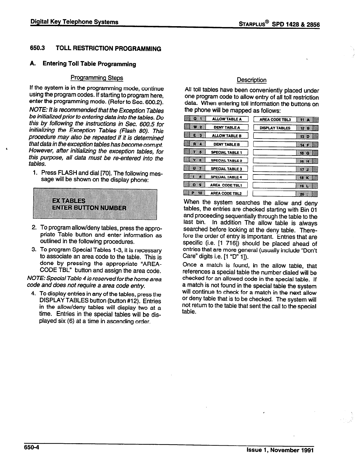
Digital Key Telephone Systems
sTARPLUS@
SPD 1428 & 2868
850.3 TOLL RESTRICTION PROGRAMMING
A. Entering Toll Table Programming
Programming Steps
If the system is in the programming mode, continue
using the program codes. If starting to program here,
enter the programming mode. (Refer to Sec. 600.2).
NOTE: It is recommended that the Exception Tables
be initializedprior to entering data into the tables. Do
this by following the instructions in Sec. 600.5 for
initializing the Exception Tables (Flash 80). This
procedure may also be repeated if it is determined
4 that data in the exception tables has become corrupt.
However, after initializing the exception tab/es, for
this purpose, all data must be re-entered into the
tables.
1. Press FLASH and dial [70]. The following mes-
sage will be shown on the display phone:
2. To program allow/deny tables, press the appro-
priate Table button and enter information as
outlined in the following procedures.
3. To program Special Tables 1-3, it is necessary
to associate an area code to the table. This is
done by pressing the appropriate “AREA-
CODE TBL” button and assign the area code.
NOTE: Special Table 4 is reserved for the home area
code and does not require a area code entry.
4. To display entries in any of the tables, press the
DISPLAY TABLES button (button #12). Entries
in the allow/deny tables will display two at a
time. Entries in the special tables will be dis-
played six (6) at a time in ascending order.
Description
All toll tables have been conveniently placed under
one program code to allow entry of all toll restriction
data. When entering toll information the buttons on
the phone will be mapped as follows:
::::/:: . . . . . . . . . ::.:.:::,,, , ,
~ii:i$g$&@
/i:i:i:*i$$:p:::&f
Bi:ll”‘:i:::::;:,:iii .p
When the system searches the allow and deny
tables, the entries are checked starting with Bin 01
and proceeding sequentially through the table to the
last bin. In addition The allow table is always
searched before looking at the deny table. There-
fore the order of entry is important. Entries that are
specific (i.e. [l 7161) should be placed ahead of
entries that are more general (usually include “Don’t
Care” digits i.e. [l “D” 11).
Once a match is found, in the allow table, that
references a special table the number dialed will be
checked for an allowed code in the special table. If
a match is not found in the special table the system
will continue to check for a match in the next allow
or deny table that is to be checked. The system will
not return to the table that sent the call to the special
table.
:.
650-4 Issue 1, November 1991
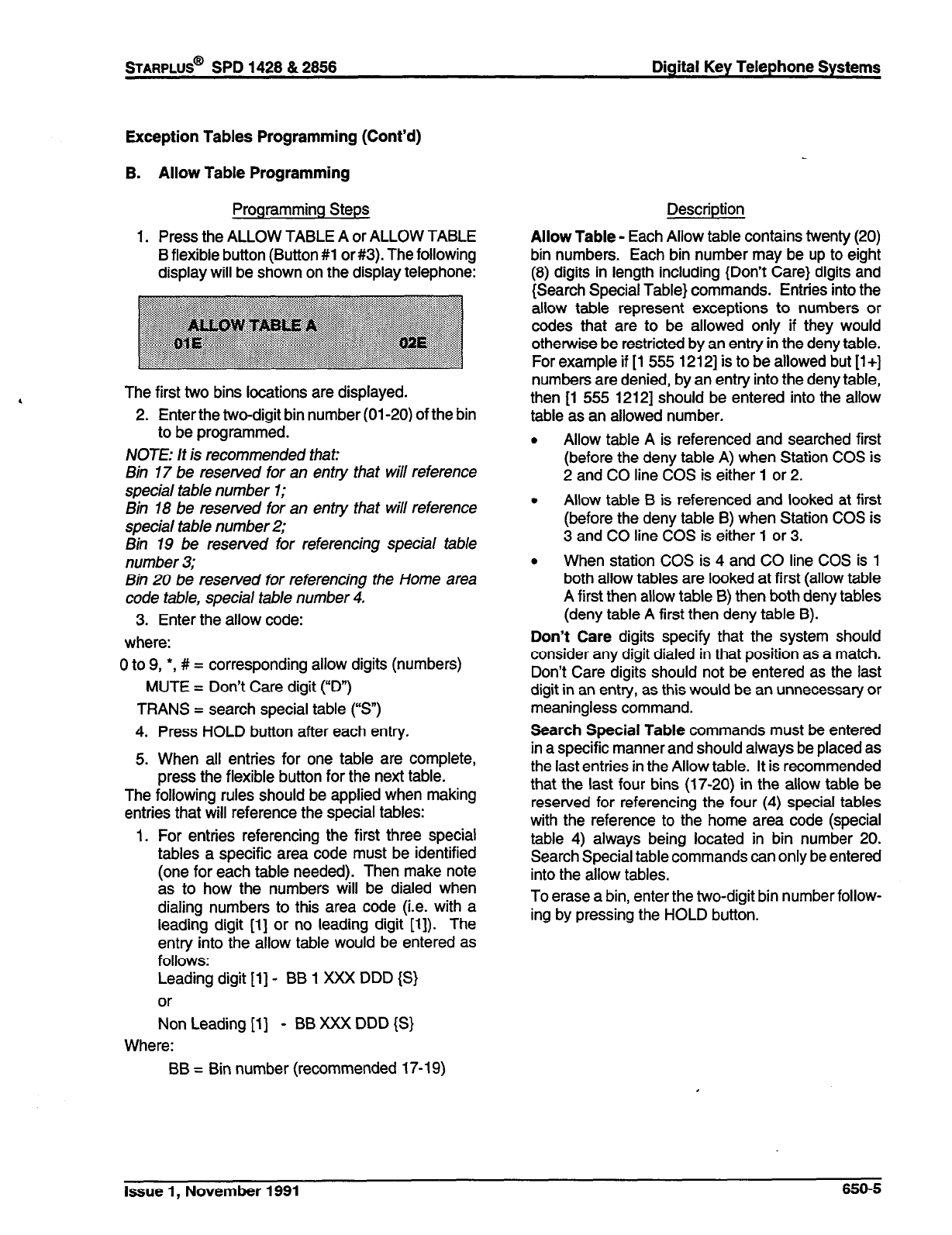
STARPLUS@
SPD 1428 & 2858 Digital Key Telephone Systems
Exception Tables Programming (Cont’d)
B.
1.
Allow Table Programming
Programming Steps
Press the ALLOW TABLE A or ALLOW TABLE
B flexible button (Button #l or #3). The following
display will be shown on the display telephone:
The first two bins locations are displayed.
2. Enter the two-digit bin number (01-20) of the bin
to be programmed.
NOTE: It is recommended that:
Bin 17 be reserved for an entry that will reference
special table number 1;
Bin 18 be reserved for an entry that will reference
special tab/e number 2;
Bin 19 be reserved for referencing special table
number 3;
Bin 20 be reserved for referencing the Home area
code table, special table number 4.
3. Enter the allow code:
where:
0 to 9, *, # = corresponding allow digits (numbers)
MUTE = Don’t Care digit (“D”)
TRANS = search special table (“S”)
4. Press HOLD button after each entry.
5. When all entries for one table are complete,
press the flexible button for the next table.
The following rules should be applied when making
entries that will reference the special tables:
1. For entries referencing the first three special
tables a specific area code must be identified
(one for each table needed). Then make note
as to how the numbers will be dialed when
dialing numbers to this area code (i.e. with a
leading digit [l] or no leading digit [l]). The
entry into the allow table would be entered as
follows:
Leading digit [l] - BB 1 XXX DDD {S}
or
Non Leading [l] - BB XXX DDD {S}
Where:
BB = Bin number (recommended 17-l 9)
Description
Allow Table - Each Allow table contains twenty (20)
bin numbers. Each bin number may be up to eight
(8) digits in length including {Don’t Care} digits and
{Search Special Table} commands. Entries into the
allow table represent exceptions to numbers or
codes that are to be allowed only if they would
otherwise be restricted by an entry in the deny table.
For example if [ 1 555 12121 is to be allowed but [ l+]
numbers are denied, by an entry into the deny table,
then [l 555 12121 should be entered into the allow
table as an allowed number.
. Allow table A is referenced and searched first
(before the deny table A) when Station COS is
2 and CO line COS is either 1 or 2.
l
Allow table B is referenced and looked at first
(before the deny table B) when Station COS is
3 and CO line COS is either 1 or 3.
. When station COS is 4 and CO line COS is 1
both allow tables are looked at first (allow table
A first then allow table B) then both deny tables
(deny table A first then deny table B).
Don’t Care digits specify that the system should
consider any digit dialed in that position as a match.
Don’t Care digits should not be entered as the last
digit in an entry, as this would be an unnecessary or
meaningless command.
Search Special Table commands must be entered
in a specific manner and should always be placed as
the last entries in the Allow table. It is recommended
that the last four bins (17-20) in the allow table be
reserved for referencing the four (4) special tables
with the reference to the home area code (special
table 4) always being located in bin number 20.
Search Special table commands can only be entered
into the allow tables.
To erase a bin, enter the two-digit bin number follow-
ing by pressing the HOLD button.
Issue 1, November 1991 650-S
Digital Key Telephone Systems
sTARPLUS@
SPD 1428 & 2866
Exception Tables Programming (Cont’d)
Allow Table Programming (Cont’d)
Programming Steps
XXX = Area code (must match AREA-X entry)
DDD = “Don’t Care” digit (three entries,
DND button)
{S}= Search Special Table Command
(TRANS button)
2. For an entry that is to reference the Home Area
Code table (special table 4) the entry may also
be entered to expect or not expect a leading
digit [il. In fact in some cases it may be desir-
able to enter both of the following entries;
Leading digit [I] - BB 1 DDD {S}
and/or
Non Leading [l] - BB DDD {S}
Where:
BB = Bin number (recommended bin 20)
DDD = “Don’t Care” digit (three entries,
MUTE button)
{S}= Search Special Table Command
(TRANS button)
NOTE: If both leading digit [1] and non-leading digit
[I] entries are made to reference the same table it is
necessaty to place the leading digit [1] entry ahead
of the non-leading digit [I] entry in the allow table.
Description
650-6 Issue 1, November 1991
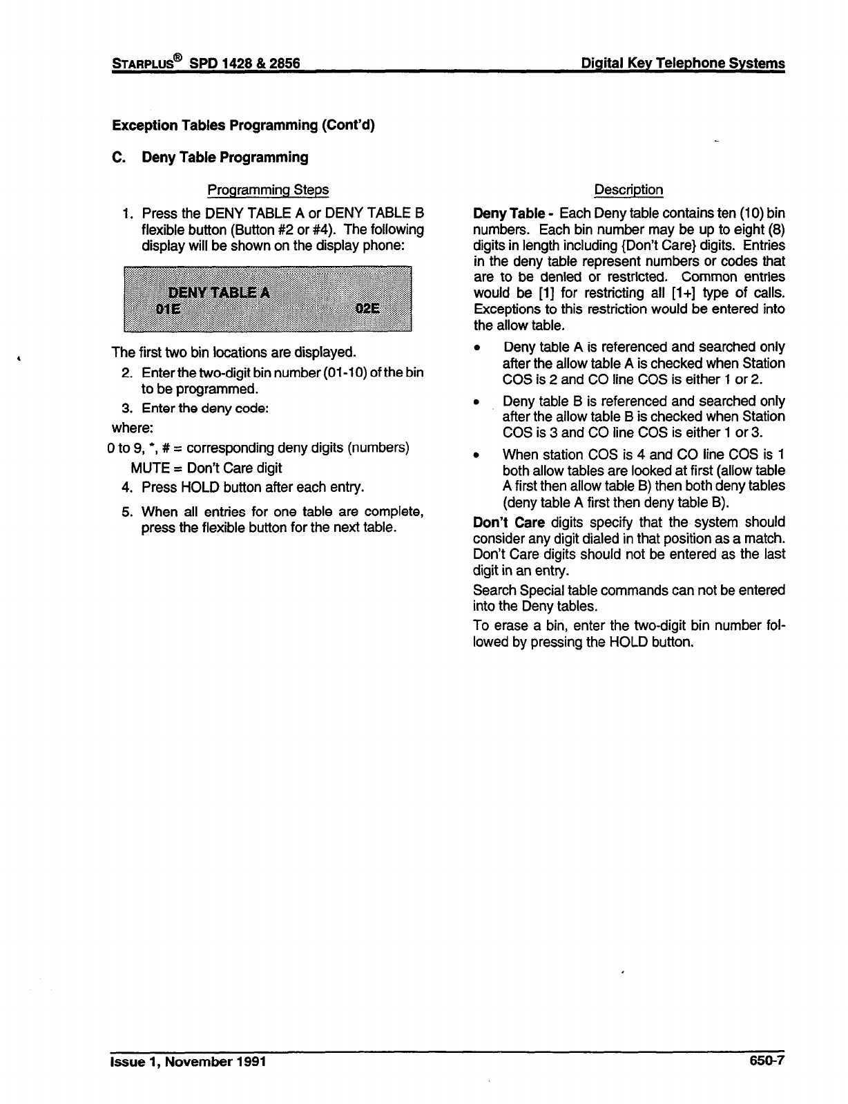
STARPLUS@ SPD 1428 & 2858 Digital Key Telephone Systems
Exception Tables Programming (Cont’d)
C. Deny Table Programming
Programming Steps
1. Press the DENY TABLE A or DENY TABLE B
flexible button (Button #2 or #4). The following
display will be shown on the display phone:
The first two bin locations are displayed.
2. Enter the two-digit bin number (01-10) of the bin
to be programmed.
3. Enter the deny code:
where:
0 to 9,
l
, # = corresponding deny digits (numbers)
MUTE = Don’t Care digit
4. Press HOLD button after each entry.
5. When all entries for one table are complete,
press the flexible button for the next table.
Description
Deny Table - Each Deny table contains ten (10) bin
numbers. Each bin number may be up to eight (8)
digits in length including {Don’t Care} digits. Entries
in the deny table represent numbers or codes that
are to be denied or restricted. Common entries
would be [i] for restricting all [l+] type of calls.
Exceptions to this restriction would be entered into
the allow table.
. Deny table A is referenced and searched only
after the allow table A is checked when Station
COS is 2 and CO line COS is either 1 or 2.
. Deny table B is referenced and searched only
after the allow table B is checked when Station
COS is 3 and CO line COS is either 1 or 3.
. When station COS is 4 and CO line COS is 1
both allow tables are looked at first (allow table
A first then allow table B) then both deny tables
(deny table A first then deny table B).
Don’t Care digits specify that the system should
consider any digit dialed in that position as a match.
Don’t Care digits should not be entered as the last
digit in an entry.
Search Special table commands can not be entered
into the Deny tables.
To erase a bin, enter the two-digit bin number fol-
lowed by pressing the HOLD button.
Issue 1, November 1991 650-7

Digital Key Telephone Systems
sTARPLUS@
SPD 1428 & 2856
Exception Tables Programming (Cont’d)
D. Special Table Programming
Programming Steps
To program a special table, it is first necessary to
assign an area code to the table (except for the home
area code).
To assign an area code to a special table:
1. Press the appropriate AREA CODE TABLE
(i-4) flexible button (button #9-l 1). The follow-
ing display will be shown on the display phone:
2. Enter the three (3) digit area code.
3. Press the HOLD button. The display will now
update.
To enter office codes into the special table:
4. Press the SPECIAL TABLE (l-4) flexible
button
(button #5 - #8) that corresponds to the area
code programmed above. The following display
will be shown on the display phone:
Where:
XXX= Area Code
5. Enter the three (3) digit office codes that are to
be allowed followed by a [l] which means to
allow this code. To remove a code from the
allow list enter the three (3) digit office code
followed by a [0] which will remove the code
from the allow list.
XXX [I] = Allow code
XXX [0] = Remove code from the list
Where XXX = an office code from 200 to 999.
6. Press HOLD after every code entered. Multiple
codes may be entered in a row. The display will
update showing the first six codes in ascending
order.
Desctiotion
The special tables provide greater flexibility in de-
signing a toll plan for a particular site. Each special
table allows entry of up to 800 three digit office codes
(200 - 999). Three of these tables must be assigned
an area code by which they are referenced. the
fourth table is reserved for the home area code and
requires no area code entry.
The special tables are referenced through entries in
the allow tables. Four area codes, including the
home area code, can be referenced to these special
tables for further definition. When a special table is
referenced, entries must be made in the special
table specifying what office codes will be allowed.
By default no codes are on the allow list.
Codes can be added to the allow list or removed from
the list. When a special table is checked for a match,
to a three digit code, but not found the system will
then continue to search the next allow deny table that
is to be checked. The system does not return to the
allow table which routed the call to the special table.
650-8 Issue 1, November 1991
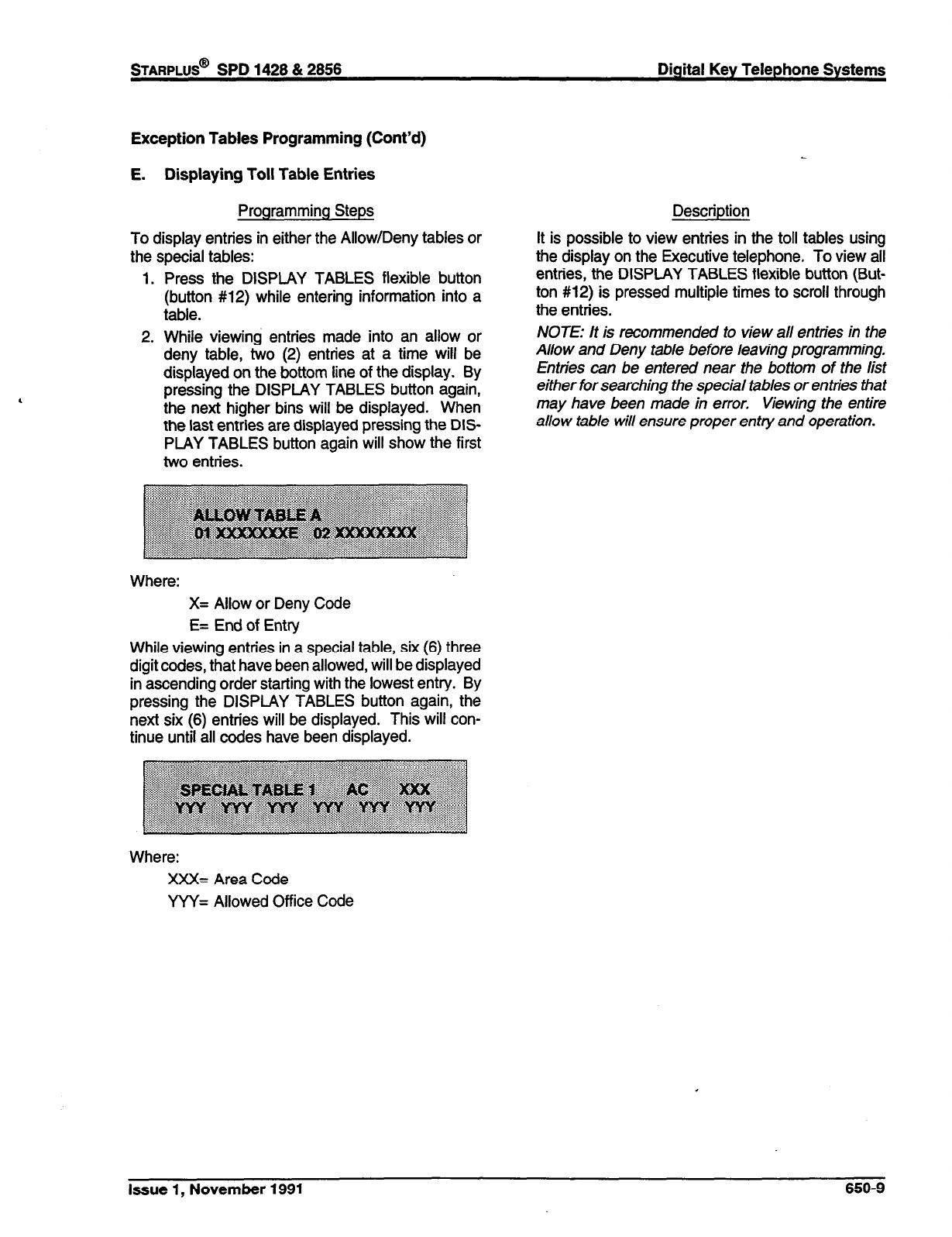
Exception Tables Programming (Cont’d)
E. Displaying Toll Table Entries
Programming Steps
To display entries in either the Allow/Deny tables or
the soecial tables:
Description
It is possible to view entries in the toll tables using
the disDlav on the Executive teleDhone. To view all
1.
2.
Press the DISPLAY TABLES flexible button entries: the DISPLAY TABLES flexible button (But-
(button #12) while entering information into a ton #12) is pressed multiple times to scroll through
table. the entries.
While viewing entries made into an allow or
deny table, two (2) entries at a time will be
displayed on the bottom line of the display. By
pressing the DISPLAY TABLES button again,
the next higher bins will be displayed. When
the last entries are displayed pressing the DIS-
PLAY TABLES button again will show the first
two entries.
NOTE: It is recommended to view all entries in the
Allow and Deny table before leaving programming.
Entries can be entered near the bottom of the list
either for searching the special tab/es or entries Bat
may have been made in error. Viewing the entire
allow table will ensure proper entry and operation.
Where:
X= Allow or Deny Code
E= End of Entry
While viewing entries in a special table, six (6) three
digit codes, that have been allowed, will be displayed
in ascending order starting with the lowest entry. By
pressing the DISPLAY TABLES button again, the
next six (6) entries will be displayed. This will con-
tinue until all codes have been displayed.
Where:
XXX= Area Code
YYY= Allowed Office Code
Issue 1, November 1991 650-9
sTARPLUS@
SPD 1428 & 2888 Digital Key Telephone Systems
SECTION 655
. LEAST COST ROUTING PROGRAMMING
A. Introduction
Least Cost Routing (LCR) selects the most economi-
cal programmed route for an outgoing call. When a
station user dials an outside number, the LCR fea-
ture analyzes the number and then automatically
chooses an outside line from the group that has been
programmed as most economical. The LCR feature
puts the responsibility of choosing the least expen-
sive route for each area code and exchange code on
the system administrator, not on the station user. In
order to make a routing decision, the LCR feature is
programmed in the system database. The success-
ful operation of this feature is completely dependent
on the accuracy of the programming.
There are eight (8) different tables which are set up
to monitor the dialing of digits and to select the best
route for the call depending on time of day and day
of week.
tables are:
Three (3) Digit Area/Office Code Routing
Table
Six (6) Digit Office Code Routing Table
Exception Table
Route List Table
Insert/Delete Table
Daily Start Time Table
Weekday (Weekly) Schedule
Toll Information Table
B. LCR Operation
The system first checks to see if the number dialed
is more than two digits. If it is two digits or less, the
call is processed according to instructions in the
Exception Table. If the number is not found in the
Exception Table, the call is denied.
If the number is more than two digits, it goes to the
3 Digit Table. If the first digit dialed is a “1” the
leading 1 table will be checked with the following
three digits. if the first digit dialed is not a “1” then
the first three digits are checked against the Non-
Leading 1 three digit table. The first three digits
(either office code or area code) are then checked to
see if they are in the 3 Digit Table. If they are not
found there, the call is denied. If the digits are found
in the 3 Digit Table, the system then checks for an
entry to see if the 6 Digit Table must be referenced.
If the 6 Digit column is marked [yes] in the three digit
table entry, the number is then checked in the 6 Digit
Table.
There are twenty (20) six digit tables. Each six digit
table is programmed and becomes associated to a
specific area code with a selected route. Office
codes are entered into the six (6) digit table that will
be routed to a specific route list table. This allows
the system administrator to split area codes for
routing to different lines connected to the system.
This helps when Foreign Exchange lines (FX Lines),
Banded WATS lines, or “Dedicated” Lines (OPX’s
from another system) are in use.
If the office code is not found in the 6 Digit Table, the
call is referred back to the 3 Digit Table for selecting
a route list table. And then goes through the same
procedures as described below.
Before actually selecting a route list table, the num-
ber is checked against the toll restriction tables (sta-
tion COS). When LCR is enabled, only station Class
of Service is referenced. CO line Class of Service is
no longer applicable. All CO lines are considered
Class of Service 1.
If the call is not allowed through the toll restriction
tables, the call is denied. If it is allowed, the call then
goes to the Route List Table as specified by either
the three (3) digit or six (6) digit table.
The Time of day and Day of week is determined and
the call is presented to the corresponding time period
route within the specified route table. Each of the
sixteen (16) Route Tables contain four time sensitive
Issue 1, November 1991 655-l
Digital Key Telephone Systems
sTARPLUS@
SPD 1428 & 2866
routes. Routes are determined by the time of day
and day of week as specified in the Daily Start Time
table and the Weekly Schedule table.
After the appropriate route is selected, LCR Class of
Service becomes applicable. A station can use only
those line groups programmed with a priority number
equal to or higher than the station’s LCR Class of
Service.
If a line is not available in the first choice line group,
the system advances to the next choice line group
and searches for a free line. This process continues
until an available line is found, or the last available
line group is searched ,or until a line group is reached
with a priority assignment lower than the station’s
4 LCR Class of Service assignment.
When a line is available the system will seize that
line and wait for dial tone. Then before dialing, the
system checks the Insert/Delete table for digits that
should be deleted from the front of the number or
digits that should be inserted either before or after
the number dialed. Finally the system begins to dial
the number out over the selected line. All of this
analyzing and manipulation of the number takes only
a fraction of a second from the time the station user
begins to dial until the number is dialed out over the
public network lines.
If no lines are available in any of the CO line groups
programmed for that route and allowed to that sta-
tion, the call can be automatically queued on to the
first choice (least costly) line group. If the user waits
three seconds after dialing the number, they will hear
confirmation tone which indicates that an automatic
LCR Queue Callback has been activated on the first
choice line group. When a CO line becomes avail-
able in the first choice line group the system will ring
the calling station. When answered by the station
the system will automatically seize the line and redial
the number.
655-2
Issue 1, November 1991
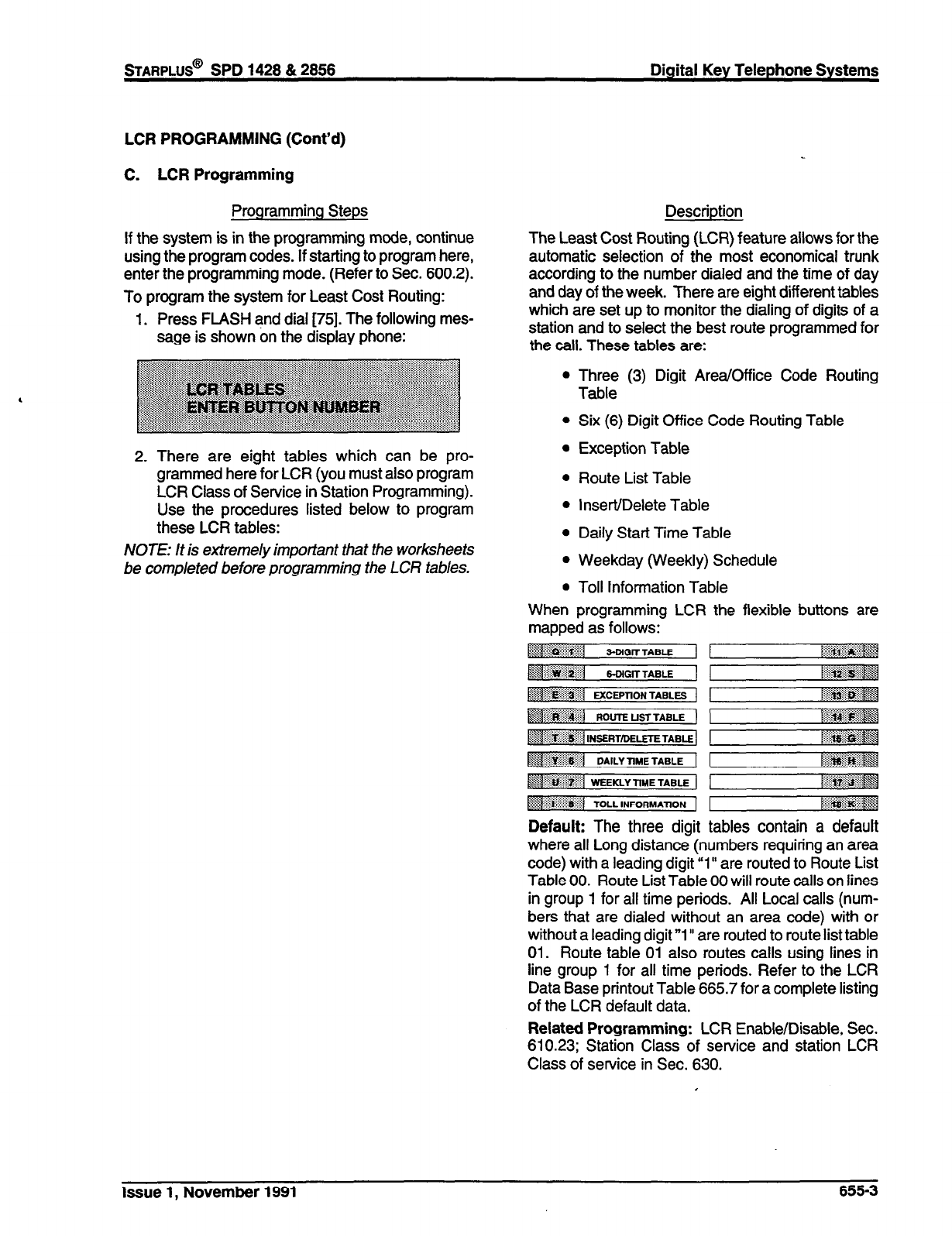
STARPLUS@
SPD 1428 & 2858 Digital Key Telephone Systems
LCR PROGRAMMING (Cont’d)
C. LCR Programming
Programming Steps
If the system is in the programming mode, continue
using the program codes. If starting to program here,
enter the programming mode. (Refer to Sec. 600.2).
To program the system for Least Cost Routing:
1. Press FLASH and dial [75]. The following mes-
sage is shown on the display phone:
2. There are eight tables which can be pro-
grammed here for LCR (you must also program
LCR Class of Service in Station Programming).
Use the procedures listed below to program
these LCR tables:
NOTE: It is extremely important that the worksheets
be completed before programming the LCR tables.
Description
The Least Cost Routing (LCR) feature allows for the
automatic selection of the most economical trunk
according to the number dialed and the time of day
and day of the week. There are eight different tables
which are set up to monitor the dialing of digits of a
station and to select the best route programmed for
the call. These tables are:
l
l
l
l
l
l
l
l
When
Three (3) Digit Area/Office Code Routing
Table
Six (6) Digit Office Code Routing Table
Exception Table
Route List Table
Insert/Delete Table
Daily Start Time Table
Weekday (Weekly) Schedule
Toll Information Table
programming LCR the flexible buttons are
-..
mapped as follows:
~~~~j 3-DIGIT TABLE l~~~~ai~~
,~~~~~~~~~i~] 6-DIGm T*BE
~~~1 MCEPnON T*BLEs
..>$. j:j:: $$gjg@q
:::+..%:.. ,. ..) ., y
‘)<< :2:.....‘:.:::~,:~~
fg.&g&:i::g+j WlJ-rE DSTTABLE 1 $qg$#$$ <
:.:.:..
:.: . . . . . . . . .
~~~~Laidii:f ,NSERTIMLm T*BE ]
.:>. :..... ., .:.: ~j;~~
~1 DA,lYTIMETABLE 1 p@##@gj
~~~ffiaij -KLYTIMETABE 1 /:!&r:&&g
:pi:?Y...::$$x”:~ *
TOLL ,pJFORMAJJON 1 ~~~~
Default: The three digit tables contain a default
where all Long distance (numbers requiring an area
code) with a leading digit “1 It are routed to Route List
Table 00. Route List Table 00 will route calls on lines
in group 1 for all time periods. All Local calls (num-
bers that are dialed without an area code) with or
without a leading digit “1” are routed to route list table
01. Route table 01 also routes calls using lines in
line group 1 for all time periods. Refer to the LCR
Data Base printout Table 665.7 for a complete listing
of the LCR default data.
Related Programming: LCR Enable/Disable, Sec.
610.23; Station Class of service and station LCR
Class of service in Sec. 630.
Issue 1, November 1991 655-3
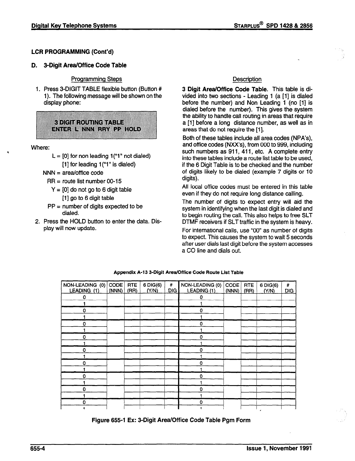
Digital Key Telephone Systems
sTARPLUS@
SPD 1428 & 2656
LCR PROGRAMMING (Cont’d)
D. 3-Digit Area/Office Code Table
Programming Steps
1. Press 3-DIGIT TABLE flexible button (Button #
1). The following message will be shown on the
display phone:
, Where:
L = [0] for non leading 1 (“1” not dialed)
[l] for leading l(y1’ is dialed)
NNN = area/office code
RR = route list number 00-15
Y = [0] do not go to 6 digit table
[l] go to 6 digit table
PP = number of digits expected to be
dialed.
2. Press the HOLD button to enter the data. Dis-
play will now update.
Description
3 Digit Area/Office Code Table. This table is di-
vided into two sections - Leading 1 (a [l] is dialed
before the number) and Non Leading 1 (no [l] is
dialed before the number). This gives the system
the ability to handle call routing in areas that require
a [l] before a long distance number, as well as in
areas that do not require the [l].
Both of these tables include all area codes (NPA’s),
and office codes (NXX’s), from 000 to 999, including
such numbers as 911, 411, etc. A complete entry
into these tables include a route list table to be used,
if the 6 Digit Table is to be checked and the number
of digits likely to be dialed (example 7 digits or 10
digits).
All local office codes must be entered in this table
even if they do not require long distance calling.
The number of digits to expect entry will aid the
system in identifying when the last digit is dialed and
to begin routing the call. This also helps to free SLT
DTMF receivers if SLT traffic in the system is heavy.
For international calls, use “00” as number of digits
to expect. This causes the system to wait 5 seconds
after user dials last digit before the system accesses
a CO line and dials out.
Appendix A-l 3 3-Digit Area/Office Code Route List Table
NON-LEADING (0) CODE RTE 6 DIG(6) # NON-LEADING (0) CODE RTE 6 DIG(6) #
LEADING (1) (NNN) (RR) (Y/N) DIG LEADING (1) (NNN) (RR) (Y/N) DIG _
0 0
i I
II 0 I
0
I1 0 1 !
0
0 0 I
1 1
0 0
i i
w I I
0
I I 3 I 1 I I
I
Figure 655-l Ex: 3-Digit Area/Off ice Code Table Pgm Form
655-4
Issue 1, November 1991
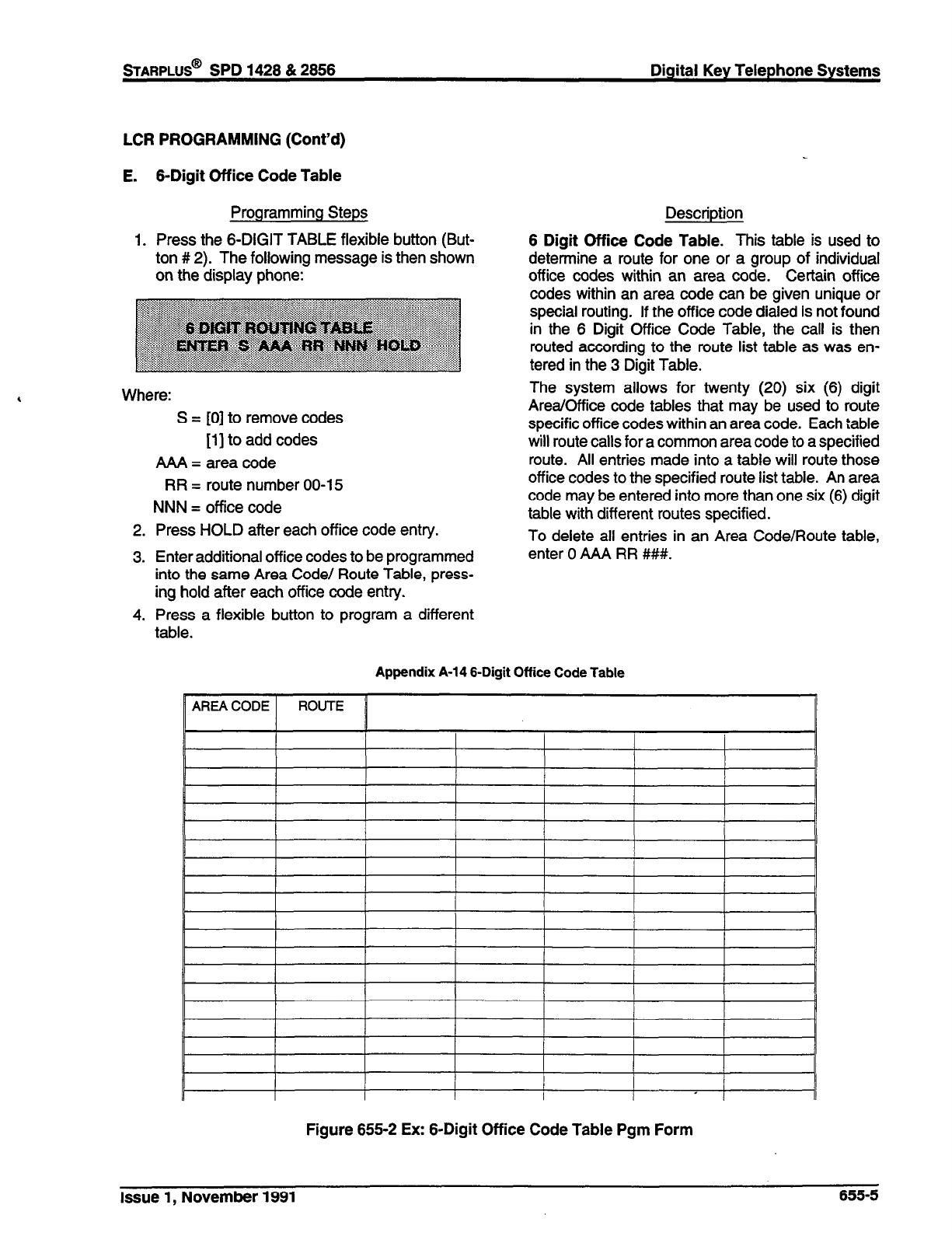
sTARPLUS@
SPD 1428 & 2858 Digital Key Telephone Systems
LCR PROGRAMMING (Cont’d)
E. 6-Digit Office Code Table
Programming Steps
1. Press the 6-DIGIT TABLE flexible button (But-
ton # 2). The following message is then shown
on the display phone:
Where:
S = [0] to remove codes
[l] to add codes
AAA = area code
RR = route number 00-15
NNN = office code
2. Press HOLD after each office code entry.
3. Enter additional office codes to be programmed
into the same Area Code/ Route Table, press-
ing hold after each office code entry.
4. Press a flexible button to program a different
table.
Description
6 Digit Office Code Table. This table is used to
determine a route for one or a group of individual
off ice codes within an area code. Certain office
codes within an area code can be given unique or
special routing. If the office code dialed is not found
in the 6 Digit Office Code Table, the call is then
routed according to the route list table as was en-
tered in the 3 Digit Table.
The system allows for twenty (20) six (6) digit
Area/Office code tables that may be used to route
specific office codes within an area code. Each iable
will route calls for a common area code to a specified
route. All entries made into a table will route those
office codes to the specified route list table. An area
code may be entered into more than one six (6) digit
table with different routes specified.
To delete all entries in an Area Code/Route table,
enter 0 IMA RR ###.
Appendix A-14 6-Digit Office Code Table
Figure 655-2 Ex: 6-Digit Office Code Table Pgm Form
Issue 1, November 1991 655-5
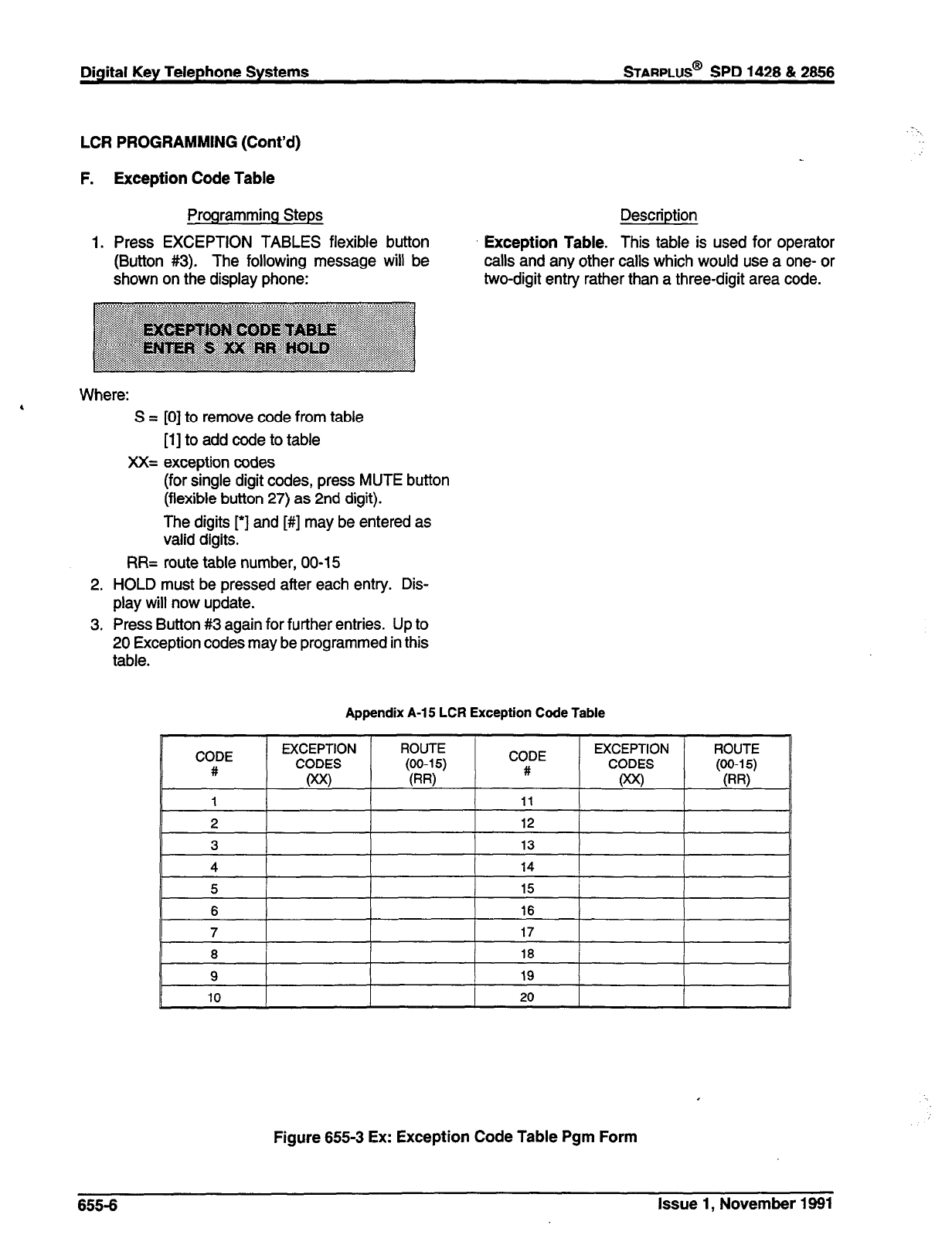
Diqital Key Telephone Systems
sTARPLUS@
SPD 1428 8c 2656
LCR PROGRAMMING (Cont’d)
F.
1.
Exception Code Table
Programming Steps
Press EXCEPTION TABLES flexible button
(Button #3). The following message will be
shown on the display phone:
Description
Exception Table. This table is used for operator
calls and any other calls which would use a one- or
two-digit entry rather than a three-digit area code.
Where:
4 S = [0] to remove code from table
[l] to add code to table
XX= exception codes
(for single digit codes, press MUTE button
(flexible button 27) as 2nd digit).
The digits [‘I and [#] may be entered as
valid digits.
RR= route table number, 00-15
2. HOLD must be pressed after each entry. Dis-
play will now update.
3. Press Button #3 again for further entries. Up to
20 Exception codes may be programmed in this
table.
Appendix A-15 LCR Exception Code Table
CODE
#
EXCEPTION
CODES
Wo
ROUTE CODE
#
EXCEPTION
CODES
oo<)
ROUTE
9
19
IO 20
Figure 655-3 Ex: Exception Code Table Pgm Form
- .,
655-6 Issue 1, November 1991
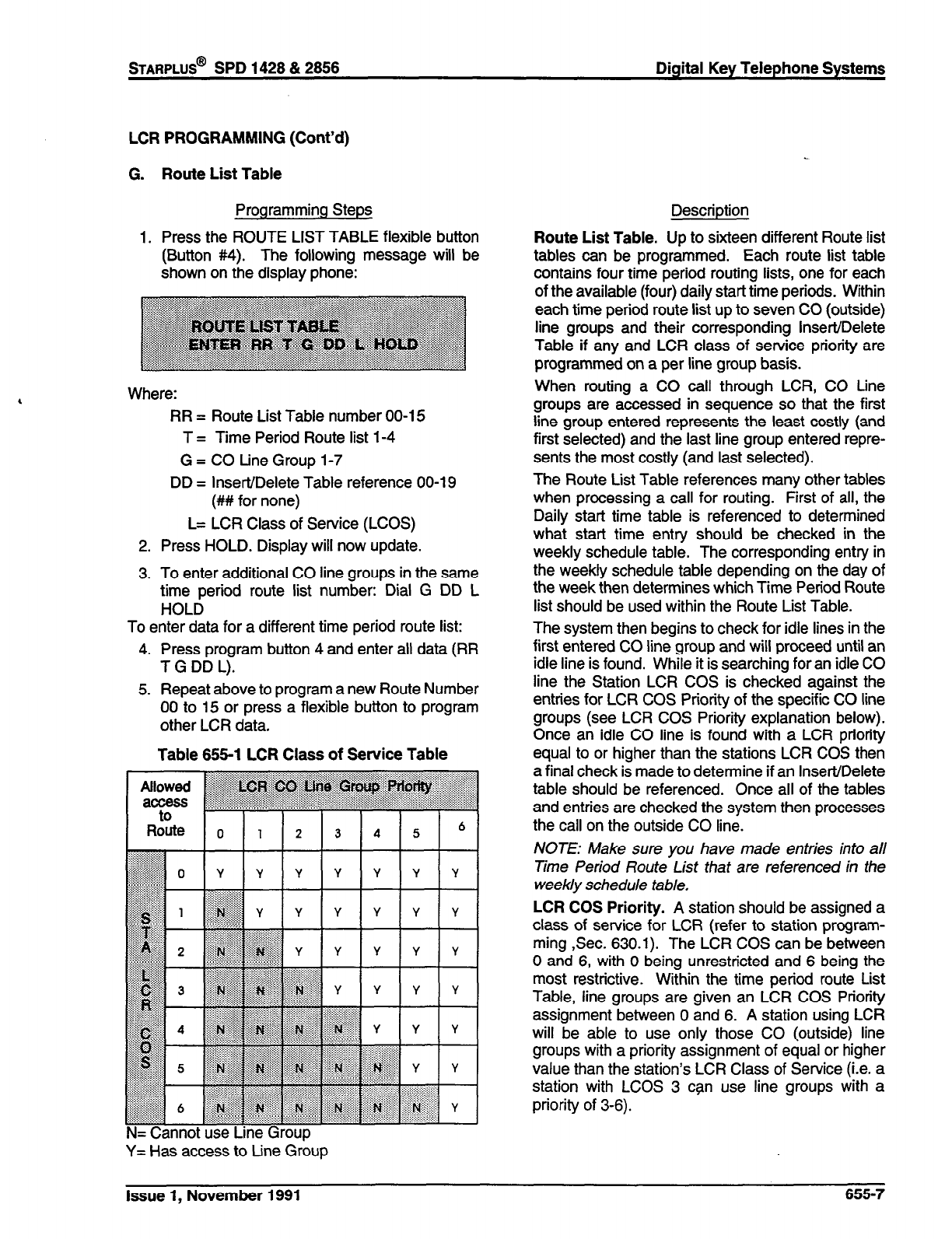
STARPLUS@
SPD 1428 & 2856 Digital Key Telephone Systems
LCR PROGRAMMING (Cont’d)
G.
1.
Route List Table
Programming Steps
Press the ROUTE LIST TABLE flexible button
(Button #4). The following message will be
shown on the display phone:
Where:
RR = Route List Table number 00-l 5
T = Time Period Route list 1-4
G = CO tine Group 1-7
DD = Insert/Delete Table reference 00-l 9
(## for none)
L= LCR Class of Service (LCOS)
2. Press HOLD. Display will now update.
3. To enter additional CO line groups in the same
time period route list number: Dial G DD L
HOLD
To enter data for a different time period route list:
4. Press program button 4 and enter all data (RR
T G DD L).
5. Repeat above to program a new Route Number
00 to 15 or press a flexible button to program
other LCR data.
Table 666-l LCR Class of Service Table
Y= Has access to Line Group
Description
Route List Table. Up to sixteen different Route list
tables can be programmed. Each route list table
contains four time period routing lists, one for each
of the available (four) daily start time periods. Within
each time period route list up to seven CO (outside)
line groups and their corresponding Insert/Delete
Table if any and LCR class of service priority are
programmed on a per line group basis.
When routing a CO call through LCR, CO Line
groups are accessed in sequence so that the first
line group entered represents the least costly (and
first selected) and the last line group entered repre-
sents the most costly (and last selected).
The Route List Table references many other tables
when processing a call for routing. First of all, the
Daily start time table is referenced to determined
what start time entry should be checked in the
weekly schedule table. The corresponding entry in
the weekly schedule table depending on the day of
the week then determines which Time Period Route
list should be used within the Route List Table.
The system then begins to check for idle lines in the
first entered CO line group and will proceed until an
idle line is found. While it is searching for an idle CO
line the Station LCR COS is checked against the
entries for LCR COS Priority of the specific CO line
groups (see LCR COS Priority explanation below).
Once an idle CO line is found with a LCR priority
equal to or higher than the stations LCR COS then
a final check is made to determine if an Insert/Delete
table should be referenced. Once all of the tables
and entries are checked the system then processes
the call on the outside CO line.
NOTE: Make sure you have made entries into all
Time Period Route List that are referenced in the
week/y schedule table.
LCR COS Priority. A station should be assigned a
class of service for LCR (refer to station program-
ming Sec. 630.1). The LCR COS can be between
0 and 6, with 0 being unrestricted and 6 being the
most restrictive. Within the time period route List
Table, line groups are given an LCR COS Priority
assignment between 0 and 6. A station using LCR
will be able to use only those CO (outside) line
groups with a priority assignment of equal or higher
value than the station’s LCR Class of Service (i.e. a
station with LCOS 3 can use line groups with a
priority of 3-6).
Issue 1, November 1991 655-7
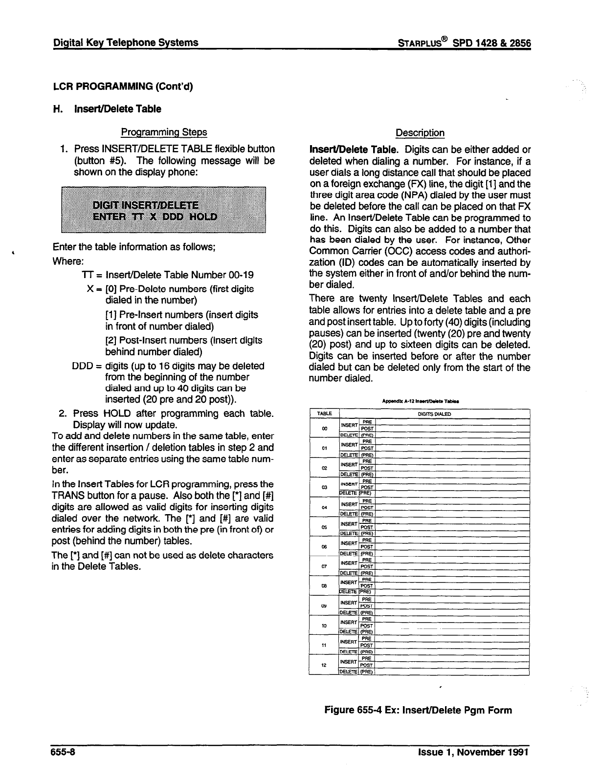
Digital Key Telephone Systems
sTARPLUS@
SPD 1428 & 2856
LCR PROGRAMMING (Cont’d)
H. Insert/Delete Table
Programming Steps
1. Press INSERT/DELETE TABLE flexible button
(button #5). The following message will be
shown on the display phone:
Enter the table information as follows;
Where:
lT = Insert/Delete Table Number 00-I 9
X = [0] Pre-Delete numbers (first digits
dialed in the number)
[l] Pre-Insert numbers (insert digits
in front of number dialed)
[2] Post-Insert numbers (insert digits
behind number dialed)
DDD = digits (up to 16 digits may be deleted
from the beginning of the number
dialed and up to 40 digits can be
inserted (20 pre and 20 post)).
2. Press HOLD after programming each table.
Display will now update.
To add and delete numbers in the same table, enter
the different insertion / deletion tables in step 2 and
enter as separate entries using the same table num-
ber.
In the Insert Tables for LCR programming, press the
TRANS button for a pause. Also both the [*I and [#]
digits are allowed as valid digits for inserting digits
dialed over the network. The r] and [#] are valid
entries for adding digits in both the pre (in front of) or
post (behind the number) tables.
The r] and [#] can not be used as delete characters
in the Delete Tables.
Description
Insert/Delete Table. Digits can be either added or
deleted when dialing a number. For instance, if a
user dials a long distance call that should be placed
on a foreign exchange (FX) line, the digit [l] and the
three digit area code (NPA) dialed by the user must
be deleted before the call can be placed on that FX
line. An Insert/Delete Table can be programmed to
do this. Digits can also be added to a number that
has been dialed by the user. For instance, Other
Common Carrier (OCC) access codes and authori-
zation (ID) codes can be automatically inserted by
the system either in front of and/or behind the num-
ber dialed.
There are twenty Insert/Delete Tables and each
table allows for entries into a delete table and a pre
and post insert table. Up to forty (40) digits (including
pauses) can be inserted (twenty (20) pre and twenty
(20) post) and up to sixteen digits can be deleted.
Digits can be inserted before or after the number
dialed but can be deleted only from the start of the
number dialed.
Figure 655-4 Ex: Insert/Delete Pgm Form
655-6 issue 1, November 1991
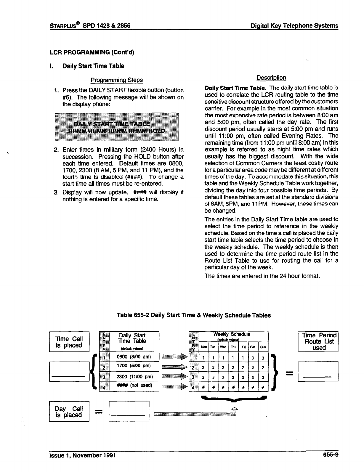
%ARPLUS@
SPD 1428 & 2858 Digital Key Telephone Systems
I. Daily Start Time Table
Programming Steps Description
1. Press the DAILY START flexible button (button Daily Start Time Table. The daily start time table is
#6). The following message will be shown on used to correlate the LCR routing table to the time
the display phone: sensitive discount structure offered by the customers
carrier. For example in the most common situation
the most expensive rate period is between 8:00 am
and 500 pm, often called the day rate. The first
discount period usually starts at 500 pm and runs
until 11:OO pm, often called Evening Rates. The
remaining time (from 11:OO pm until 890 am) in this
2.
3.
Enter times in military form (2400 Hours) in
succession. Pressing the HOLD button after
each time entered. Default times are 0800,
1700,230O (8 AM, 5 PM, and 11 PM), and the
fourth time is disabled (####). To change a
start time all times must be re-entered.
Display will now update. ###I# will display if
nothing is entered for a specific time.
example is referred to as night time rates which
usually has the biggest discount. With the wide
selection of Common Carriers the least costly route
for a particular area code may be different at different
times of the day. To accommodate this situation, this
table and the Weekly Schedule Table work together,
dividing the day into four possible time periods. By
default these tables are set at the standard divisions
of 8AM, SPM, and 11 PM. However, these times can
be changed.
The entries in the Daily Start Time table are used to
select the time period to reference in the weekly
schedule. Based on the time a call is placed the daily
start time table selects the time period to choose in
the weekly schedule. The weekly schedule is then
used to determine the time period route list in the
Route List Table to use for routing the call for a
particular day of the week.
The times are entered in the 24 hour fom-rat.
LCR PROGRAMMING (Cont’d)
Table 655-2 Daily Start Time & Weekly Schedule Tables
$$#::
j&f& Daily Start
:i$e’$$ Time Table
:...
jL++$ (d@IadI -1
0800 (800 am) e
1700 (5roo pm) e
2300 (ilroo pm) kW$p
#I## (not used) e
Time Period
I
R”EicList
Issue 1, November 1991 655-9
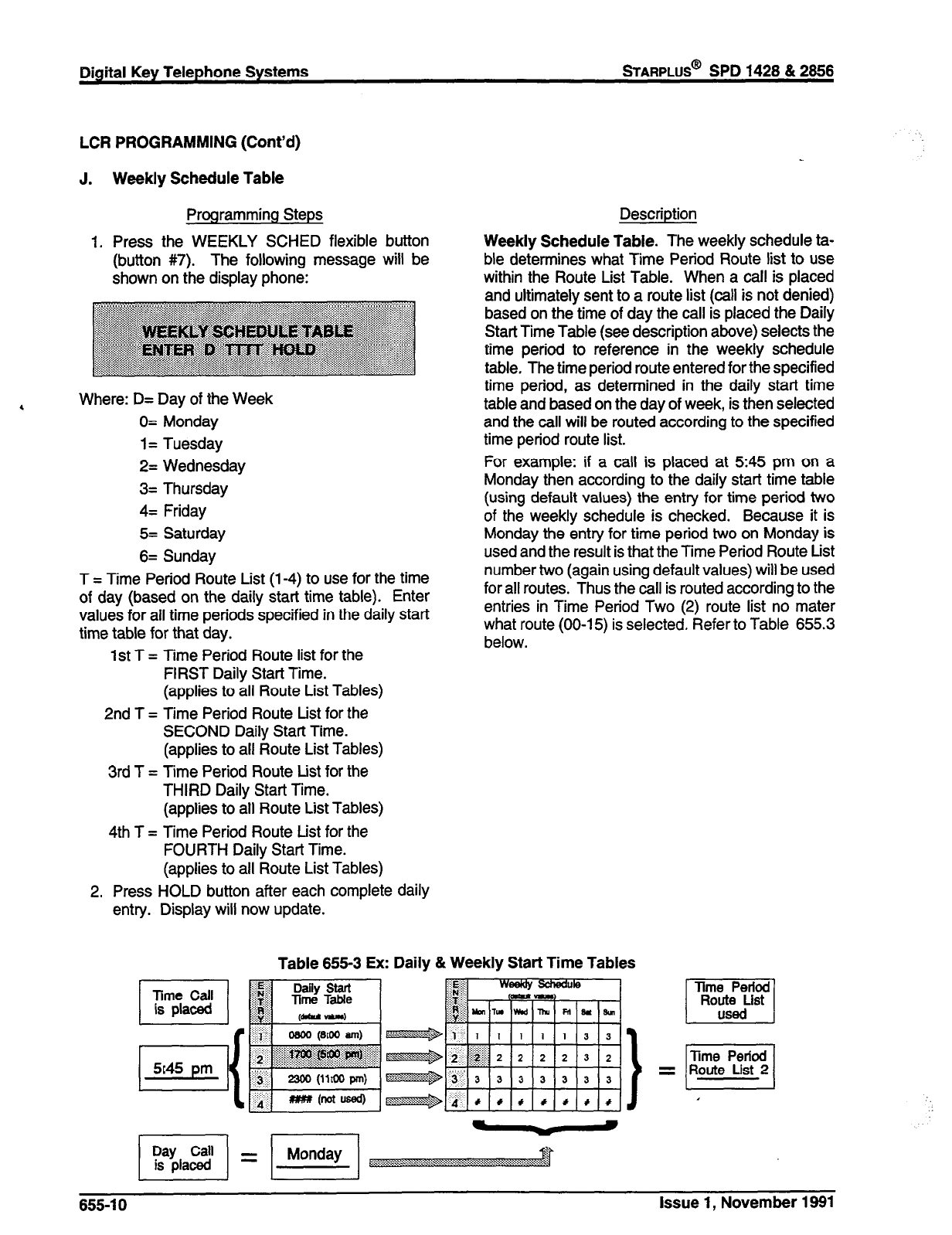
Digital Key Telephone Systems
%ARPLUS@
SPD 1428 & 2656
LCR PROGRAMMING (Cont’d)
J.
1.
Weekly Schedule Table
Programming Steps
Press the WEEKLY SCHED flexible button
(button #7). The following message will be
shown on the display phone:
4
Where: D= Day of the Week
0= Monday
1= Tuesday
2= Wednesday
3= Thursday
4= Friday
5= Saturday
6= Sunday
T = Time Period Route List (l-4) to use for the time
of day (based on the daily start time table). Enter
values for all time periods specified in the daily start
time table for that day.
1st T = Time Period Route list for the
FIRST Daily Start Time.
(applies to all Route List Tables)
2nd T = Time Period Route List for the
SECOND Daily Start Time.
(applies to all Route List Tables)
3rd T = Time Period Route List for the
THIRD Daily Start Time.
(applies to all Route List Tables)
4th T = Time Period Route List for the
FOURTH Daily Start Time.
(applies to all Route List Tables)
2. Press HOLD button after each complete daily
entry. Display will now update.
Description
Weekly Schedule Table. The weekly schedule ta-
ble determines what Time Period Route list to use
within the Route List Table. When a call is placed
and ultimately sent to a route list (call is not denied)
based on the time of day the call is placed the Daily
Start Time Table (see description above) selects the
time period to reference in the weekly schedule
table, The time period route entered for the specified
time period, as determined in the daily start time
table and based on the day of week, is then selected
and the call will be routed according to the specified
time period route list.
For example: if a call is placed at 5:45 pm on a
Monday then according to the daily start time table
(using default values) the entry for time period two
of the weekly schedule is checked. Because it is
Monday the entry for time period two on Monday is
used and the result is that the Time Period Route List
number two (again using default values) will be used
for all routes. Thus the call is routed according to the
entries in Time Period Two (2) route list no mater
what route (00-l 5) is selected. Refer to Table 655.3
below.
Table 655-3 Ex: Daily & Weekly Start Time Tables
655-l 0 Issue 1, November 1991
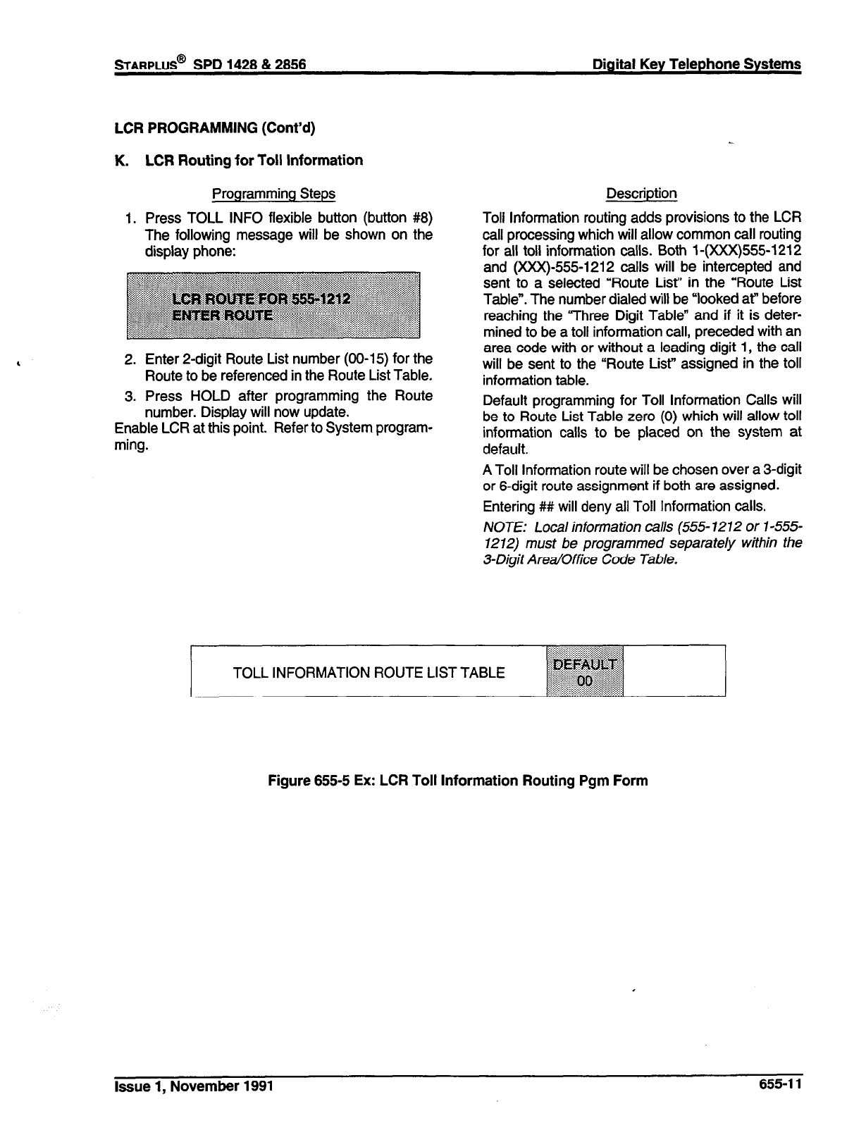
sTARPLUS@
SPD 1428 & 2856 Digital Key Telephone Systems
LCR PROGRAMMING (Cont’d)
K. LCR Routing for Toll Information
Programming Steps
1. Press TOLL INFO flexible button (button #8)
The following message will be shown on the
display phone:
2. Enter P-digit Route List number (00-15) for the
Route to be referenced in the Route List Table.
3. Press HOLD after programming the Route
number. Display will now update.
Enable LCR at this point. Refer to System program-
ming.
Description
Toll Information routing adds provisions to the LCR
call processing which will allow common call routing
for all toll information calls. Both l-(XXX)555-1212
and 0(xX)-555-1212 calls will be intercepted and
sent to a selected “Route List” in the “Route List
Table”. The number dialed will be “looked at” before
reaching the “Three Digit Table” and if it is deter-
mined to be a toll information call, preceded with an
area code with or without a leading digit 1, the call
will be sent to the “Route List” assigned in the toll
information table.
Default programming for Toll Information Calls will
be to Route List Table zero (0) which will allow toll
information calls to be placed on the system at
default.
A Toll Information route will be chosen over a 3-digit
or 6-digit route assignment if both are assigned.
Entering ## will deny all Toll Information calls.
NOTE: Local information calls (555- 7212 or l-555-
7272) must be programmed separately within the
3-Digit Area/Office Code Table.
. .
‘-+:B : .: . . . . . :...
::::::::::::::: ::.::::::,:.:.:.::::::::~~~ .:.:,,.,.,:,,
. . . . . . . . . . . . . . . . . . . . . ..+.~g~..$#
.: . . . ..(...~....:,,,,,,:
TOLL INFORMATION ROUTE LIST TABLE ~~~~~~~~
~~~~~~~~~~
““~‘.:.~:A :.‘.>. . . .,.:.::::::aril:i:i:,:
::~:::::~::::::~:i::i:
~‘iiiili!iiir:i~~~riiii:i:i:::: .:.:,,.,.,.,.
Figure 655-5 Ex: LCR Toll Information Routing Pgm Form
Issue 1, November 1991 655-l 1
LCR PROGRAMMING (Cont’d)
L. Default LCR Data Base
Programming Steps Description
In an effort to decrease installation and set up time,
usually associated with LCR, a default LCR data
base has been incorporated. The default LCR data
base will provide basic routing for local and long
distance dialing. Default entries have been made in
the Three Digit Table for local office codes (NNX’s)
and all area codes (NPA’s). Two routes have been
established with the default data base for routing of
all calls under default. The entire default data base
is shown in Table 665.7.
The three digit tables contain a default where all
Long distance (numbers requiring an area code) with
a leading digit “1” are routed to Route table 00.
Route Table 00 will route calls on lines in group 1 for
all time periods. All Local calls (numbers that are
dialed without an area code) with or without a leading
digit “1’ are routed to route list table 01. Route list
table 01 also routes calls using lines in line group 1
for all time periods.
655-l 2 Issue 1, November 1991
sTARPLUS@
SPD 1428 & 2856 Digital Key Telephone Systems
SECTION 660
- INITIALIZE DATA BASE PARAMETERS
A. Introduction
Programming Steps
If the system is in the programming mode, continue
using the program codes. If starting to program here,
enter the programming mode. (Refer to Sec. 600.2).
If Data Base Parameters need to be initialized:
1. Press FLASH and dial [80]. The following mes-
sage will be shown on the display of a display
phone:
Description
This section describes the procedures and steps
necessary to initialize the system data base retum-
ing any programmed data to its original or default
value. The entire system data base may be initial-
ized or various portions of the data base may be
individually initialized. In addition to initialization of
the entire data base, a system reset (Button 8)
command is also included in this section for clearing
meantime errors.
The buttons on the programming terminal are de-
fined as shown below when initializing or resetting
the system data base.
Issue 1, November 1991 660-l
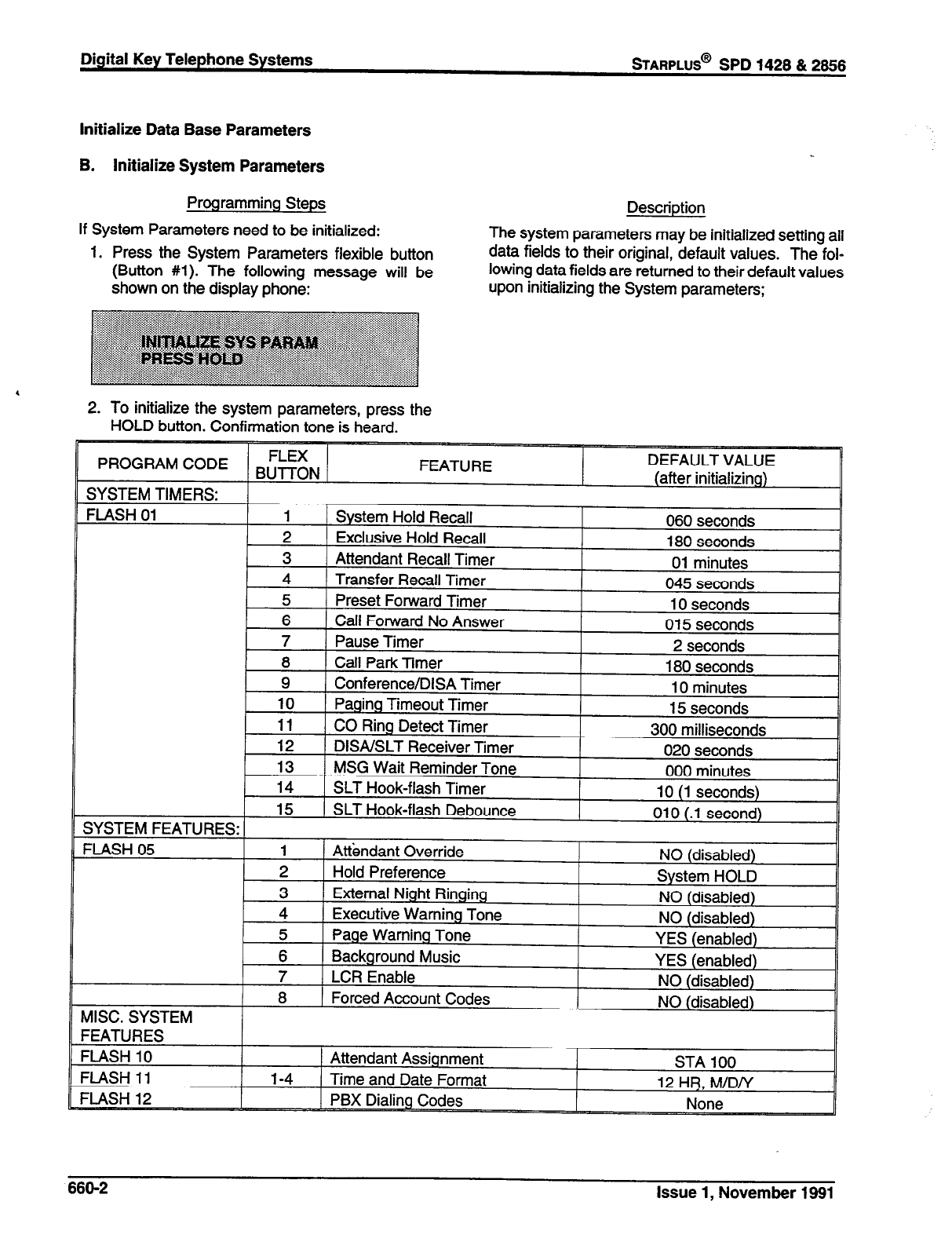
Digital Key Telephone Systems
sTARPLUS@
SPD 1428 & 2866
Initialize Data Base Parameters
B. Initialize System Parameters
Programming Steps
If System Parameters need to be initialized:
1. Press the System Parameters flexible button
(Button #l). The following message will be
shown on the display phone:
Description
The system parameters may be initialized setting all
data fields to their original, default values. The fol-
lowing data fields are returned to their default values
upon initializing the System parameters;
2. To initialize the system parameters, press the
HOLD button. Confirmation tone is heard.
666-2 Issue 1, November 1991
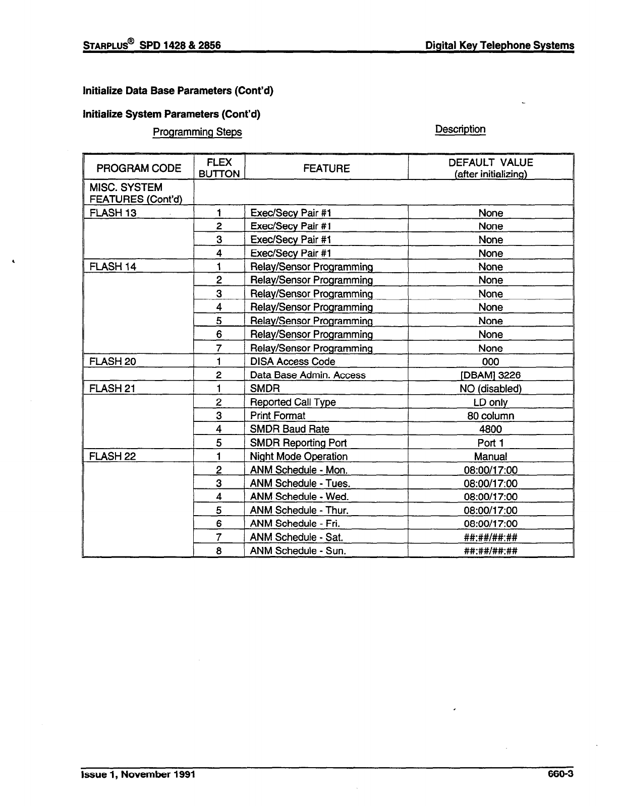
Initialize Data Base Parameters (Cont’d)
Initialize System Parameters (Cont’d)
,
Programming Steps Description
Issue 1, November 1991 660-3
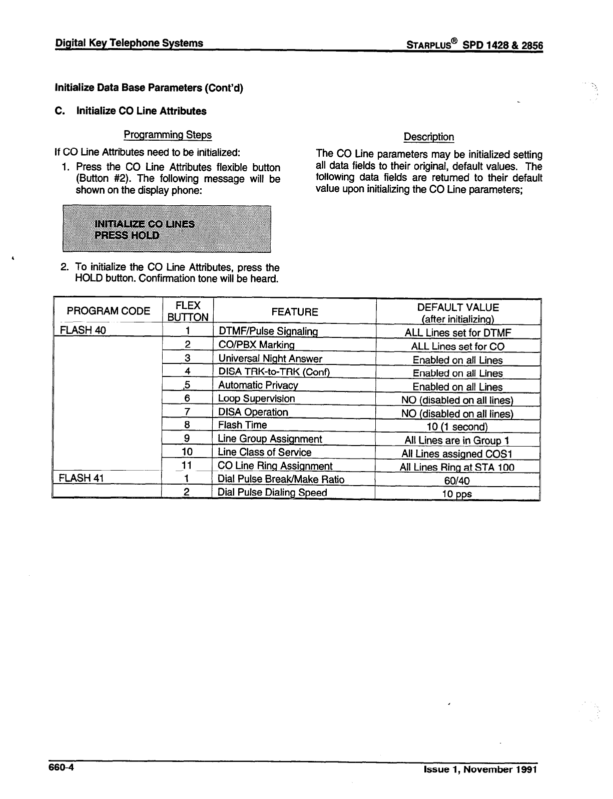
Digital Key Telephone Systems
sTARPLUS@
SPD 1428 & 2656
Initialize Data Base Parameters (Cont’d)
C. initialize CO Line Attributes
Programming Steps
If CO tine Attributes need to be initialized:
1. Press the CO Line Attributes flexible button
(Button #2). The following message will be
shown on the display phone:
Description
The CO Line parameters may be initialized setting
all data fields to their original, default values. The
following data fields are returned to their default
value upon initializing the CO Line parameters;
2. To initialize the CO Line Attributes, press the
HOLD button. Confirmation tone will be heard.
DEFAULT VALUE
660-4 Issue 1, November 1991

sTARPLUS@
SPD 1428 & 2858 Digital Key Telephone Systems
Initialize Data Base Parameters (Cont’d)
D. Initialize Station Attributes
Programming Steps
If Station Attributes need to be initialized:
1. Press the Station Attributes flexible button (But-
ton #3). The following message will be shown
on the display phone:
Description
The Station parameters may be initialized setting all
data fields to their original, default values. The fol-
lowing data fields are returned to their default value
upon initializing the Station parameters;
2. To initialize the Station Attributes, press the
HOLD button. Confirmation tone will be heard.
Off-Hook Preference
Issue 1, November 1991 660-5
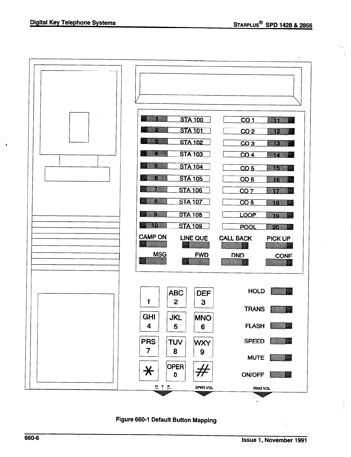
Digital Key Telephone Systems
sTARPLUS@
SPD 1428 & 2868
1
ZAMP ON
DND CONF
HTP
7, r SPKRVOL FUNGVOL
Figure 660-l Default Button Mapping
660-6 Issue 1, November 1991

Initialize Data Base Parameters (Cont’d)
E. Initialize Group Parameters
Programming Steps
If Group Parameters need to be initialized:
1. Press the Group Parameters flexible button
(Button #4). The following message will be
shown on the display phone:
Description
Hunt, UCD and Voice Mail Group parameters may
be initialized setting all data fields to their original,
default values. The following data fields are returned
to their default value upon initializing Group parame-
ters:
2. To initialize the Group parameters, press the
HOLD button. Confirmation tone will be heard.
PROGRAMCODE FLEX
BUT-TON FEATURE DEFAULT VALUE
(after initializing)
FLASH 30 l-8 Hunt Groups 330337 No Hunt Groups established
9 Station or Pilot Hunting All Hunt Groups default using Pilot
Hunting
FLASH 60 1-8 UCD Groups 550-557 No UCD groups established
9 Alternate UCD Group Assign No UCD Alternates group
assignments is made
10 I Overflow Assignment 1 No Overflow assignment is made
11 1 UCD Station Assignments No stations are assigned
12 Announcement Table Assign No RAN tables are specified
1 UCD Ring Timer 060seconds
2 UCD Message Interval Timer 060 seconds
3 UCD Overflow Timer 060seconds
4 UCD Wrap-Up Timer 004seconds
5 UCD No Answer Timer 000 seconds (disabled)
1-2 RAN Tables 1 and 2 No RAN parameters set
FLASH 61
FLASH 62
FLASH 65 1-8 Voice Mail Groups 440447 No Voice Mail groups are
established
9 Alternate VM Group Assign No Alternate VM group assignmeni
is made
10 Leave Table No outpulsing table is
referenced
FLASH 66
11 Retrieve Table No outpulsing table is
referenced
12 VM Station Assignments NO stations are assigned
l-7 Voice Mail Out-Pulsing Tables Out-pulse tables are empty
for in-band signaling by default
8 Voice Mail Disconnect Table Disconnect table is empty
FLASH 67 1 In-Band Digits for Incoming
CO Calls Disabled by default
I
Issue 1, November 1991 660-7
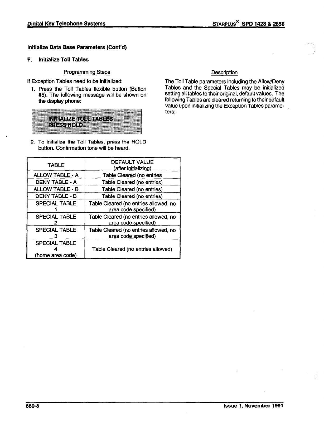
Initialize Data Base Parameters (Cont’d)
F. Initialize Toll Tables
Programming Steps
If Exception Tables need to be initialized:
1. Press the Toll Tables flexible button (Button
#5). The following message will be shown on
the display phone:
Description
The Toll Table parameters including the Allow/Deny
Tables and the Special Tables may be initialized
setting all tables to their original, default values. The
following Tables are cleared returning to their default
value upon initializing the Exception Tables parame-
, 2. To initialize the Toll Tables, press the HOLD
button. Confirmation tone will be heard.
TABLE DEFAULT VALUE
(after initializing)
ALLOW TABLE - A Table Cleared (no entries
DENY TABLE - A Table Cleared (no entries)
ALLOW TABLE - B Table Cleared (no entries)
DENY TABLE - B Table Cleared (no entries)
SPECIAL TABLE Table Cleared (no entries allowed, no
1 area code specified)
SPECIAL TABLE Table Cleared (no entries allowed, no
2 area code specified)
SPECIAL TABLE Table Cleared (no entries allowed, no
3 area code specified)
SPECIAL TABLE
4 Table Cleared (no entries allowed)
666-6 Issue 1, November 1991

STARPLUS@ SPD
1428 & 2856 Digital Key Telephone Systems
Initialize Data Base Parameters (Cont’d)
G. Initialize System Speed
Programming Steps Description
If System Speed bins need to be initialized:
1. Press the System Speed flexible button (Button
#6). The following message will be shown on
the display phone:
2. To initialize the System Speed bins, press the
HOLD button. Confirmation tone will be heard.
Numbers entered into the System Speed dial Table
may be initialized clearing all bins to their original,
default value (empty). All bins 20 through 99 are
cleared returning to their default value (empty) upon
initializing the Speed Dial Table.
Issue 1, November 1991 660-9
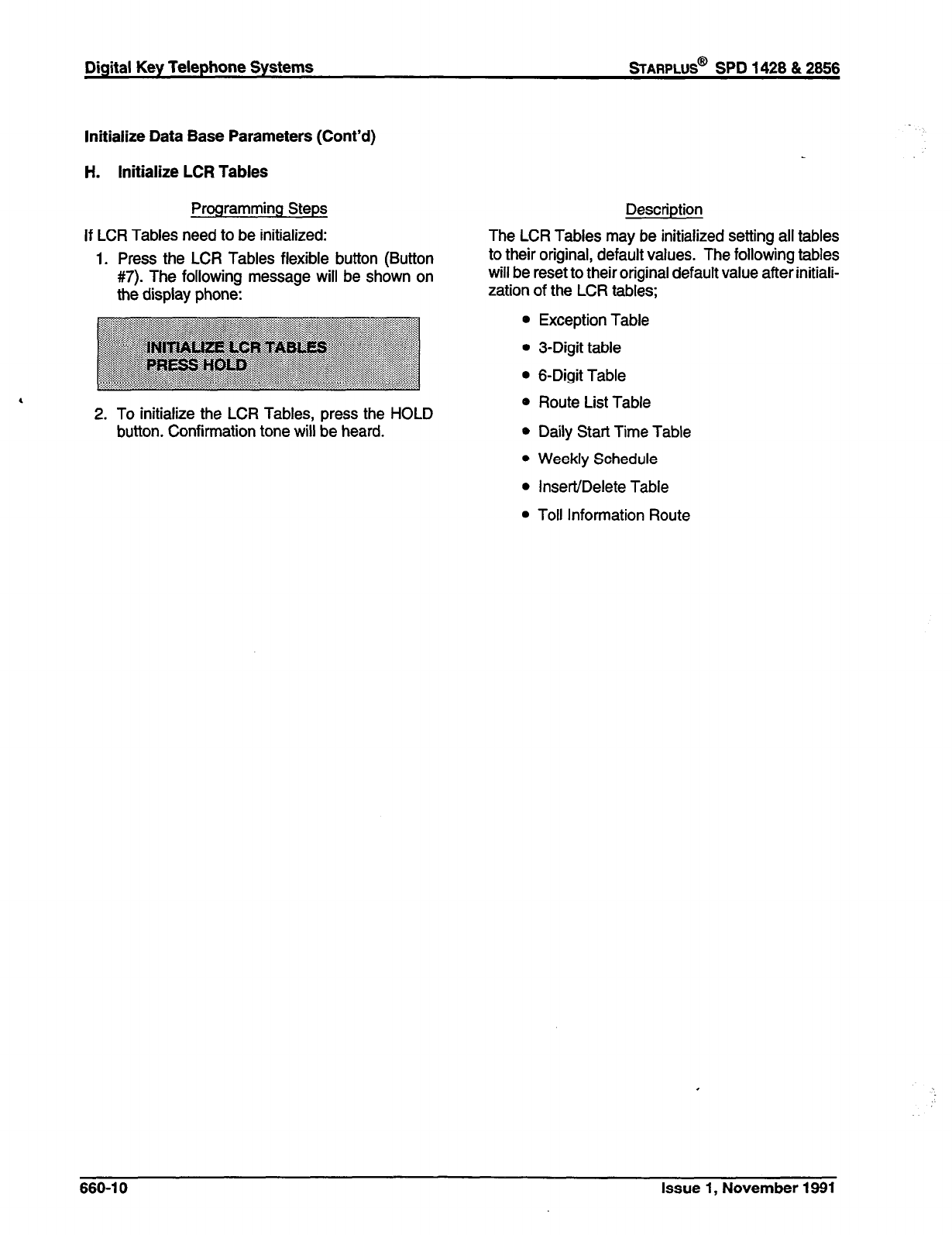
Digital Key Telephone Systems
sTARPLUS@
SPD 1428 & 2856
Initialize Data Base Parameters (Cont’d)
H. Initialize LCR Tables
Programming Steps
If LCR Tables need to be initialized:
1. Press the LCR Tables flexible button (Button
#7). The following message will be shown on
the display phone:
2. To initialize the LCR Tables, press the HOLD
button. Confirmation tone will be heard.
Description
The LCR Tables may be initialized setting all tables
to their original, default values. The following tables
will be reset to their original default value after initiali-
zation of the LCR tables;
0 Exception Table
l
3-Digit table
l
6-Digit Table
0 Route List Table
* Daily Start Time Table
l
Weekly Schedule
l
Insert/Delete Table
l
Toll Information Route
660-l 0 Issue 1, November 1891
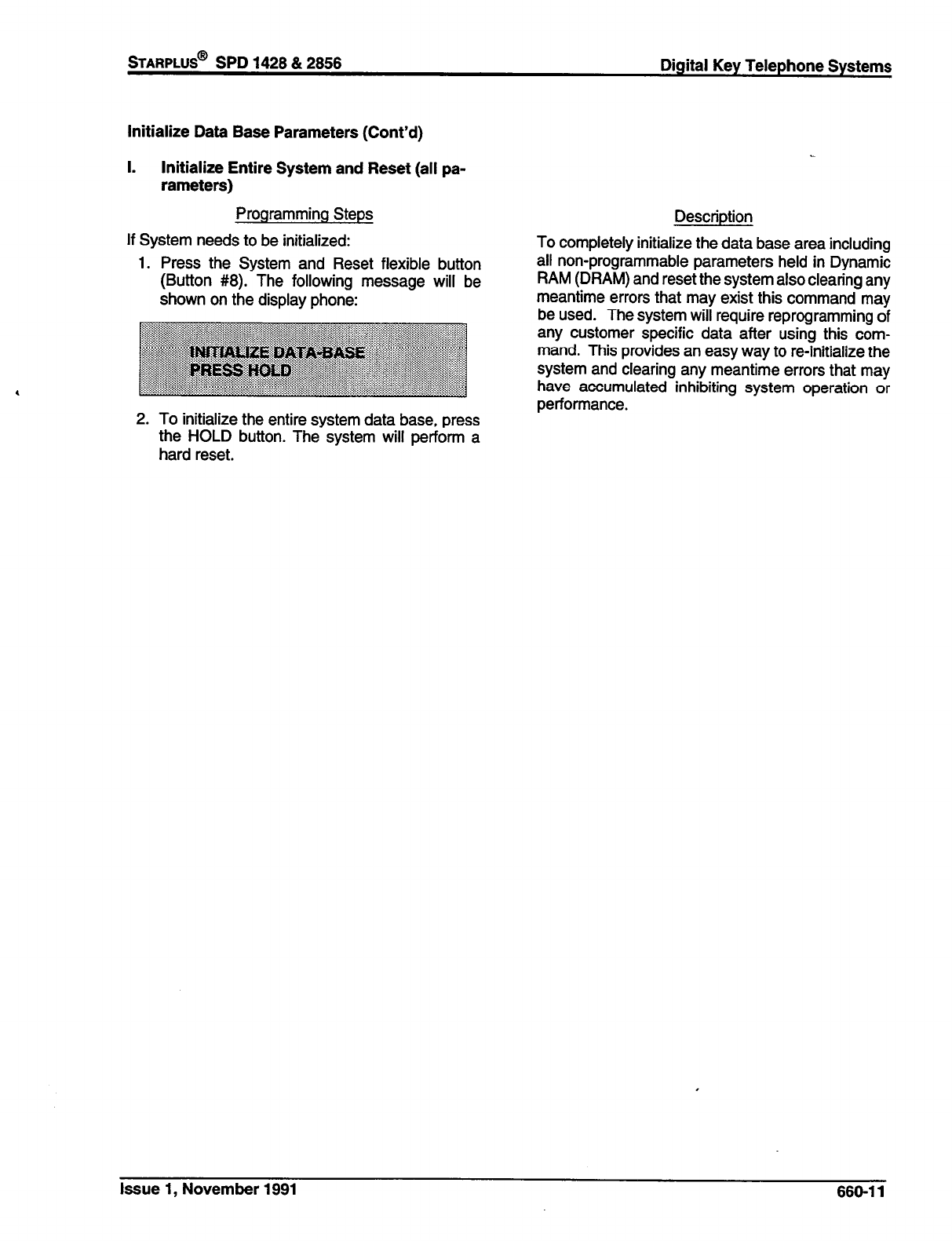
STARPLUS@
SPD 1428 & 2858 Digital Key Telephone Systems
Initialize Data Base Parameters (Cont’d)
I. Initialize Entire System and Reset (all pa-
rameters)
Programming Steps
If System needs to be initialized:
1. Press the System and Reset flexible button
(Button #8). The following message will be
shown on the display phone:
2. To initialize the entire system data base, press
the HOLD button. The system will perform a
hard reset.
Description
To completely initialize the data base area including
all non-programmable parameters held in Dynamic
RAM (DRAM) and reset the system also clearing any
meantime errors that may exist this command may
be used. The system will require reprogramming of
any customer specific data after using this com-
mand. This provides an easy way to re-initialize the
system and clearing any meantime errors that may
have accumulated inhibiting system operation or
performance.
Issue 1, November 1991 660-l 1
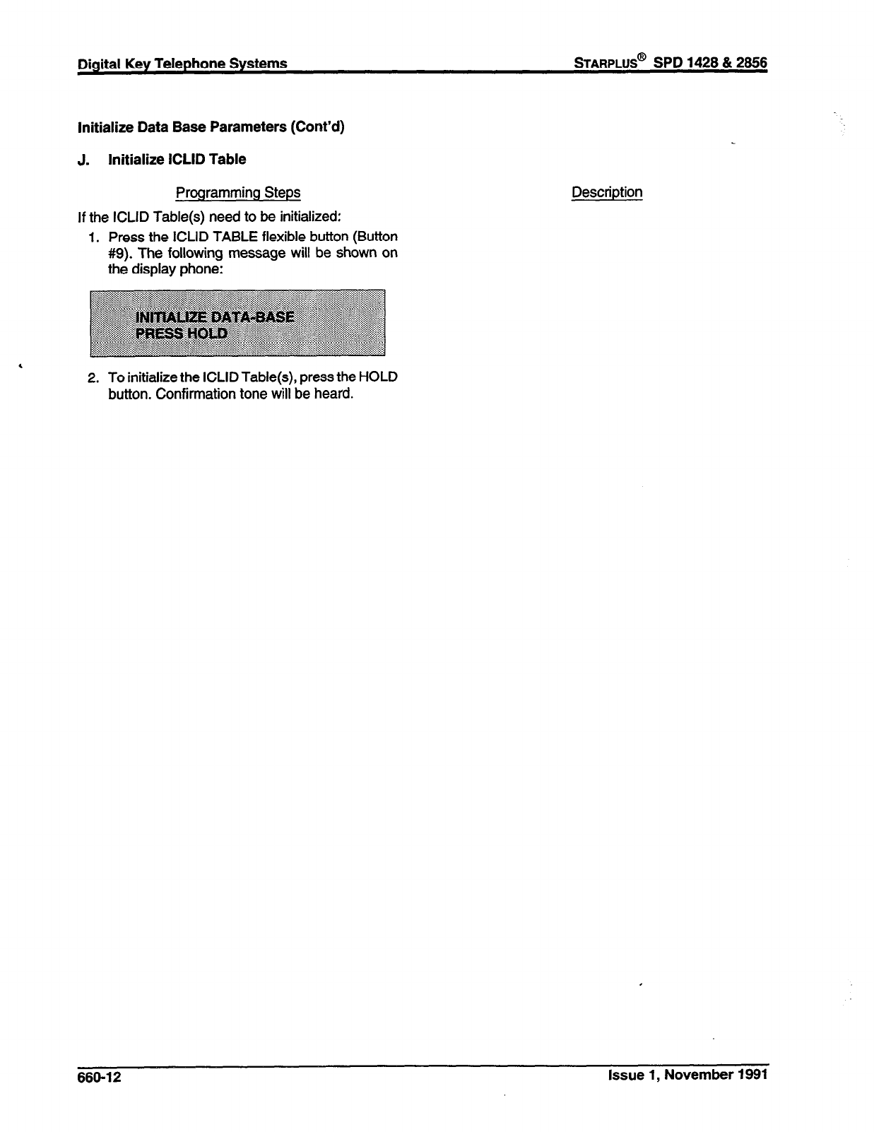
Digital Key Telephone Systems
sTARPLUS@
SPD 1428 & 2866
Initialize Data Base Parameters (Cont’d)
J. Initialize ICLID Table
Programming Steps
If the ICLID Table(s) need to be initialized:
1. Press the ICLID TABLE flexible button (Button
#9). The following message will be shown on
the display phone:
2. To initialize the ICLID Table(s), press the HOLD
button. Confirmation tone will be heard.
Description
660-12 Issue 1, November 1891
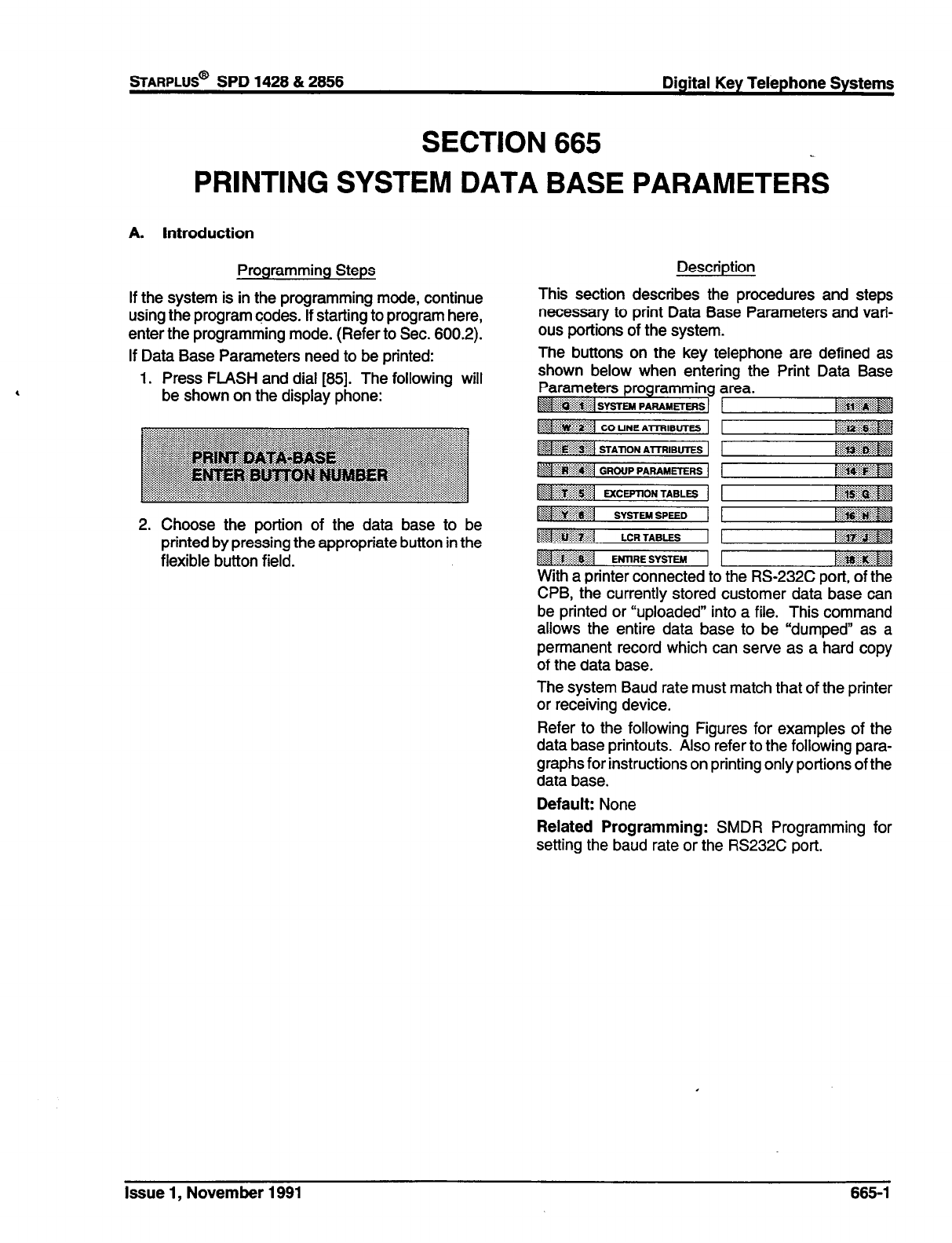
sTARPLUS@
SPD 1428 & 2856 Digital Key Telephone Systems
SECTION 665
PRINTING SYSTEM DATA BASE PARAMETERS
A. Introduction
Programming Steps
If the system is in the programming mode, continue
using the program codes. If starting to program here,
enter the programming mode. (Refer to Sec. 600.2).
If Data Base Parameters need to be printed:
1. Press FLASH and dial [85]. The following will
be shown on the display phone:
Description
This section describes the procedures and steps
necessary to print Data Base Parameters and vari-
ous portions of the system.
The buttons on the key telephone are defined as
shown below when entering the Print Data Base
Parameters programming area.
~$q~:~:$&g$:~j SYSI-EM PARAMETEfqS 1
;, :::~:~:..:..:~:+:~:* 1 ~~~~~~~~~
2. Choose the portion of the data base to be
printed by pressing the appropriate button in the
flexible button field. With a printer connected to the RS-232C port, of the
CPB, the currently stored customer data base can
be printed or “uploaded” into a file. This command
allows the entire data base to be “dumped” as a
permanent record which can serve as a hard copy
of the data base.
The system Baud rate must match that of the printer
or receiving device.
Refer to the following Figures for examples of the
data base printouts. Also refer to the following para-
graphs for instructions on printing only portions of the
data base.
Default: None
Related Programming: SMDR Programming for
setting the baud rate or the RS232C port.
Issue 1, November 1991 665-l
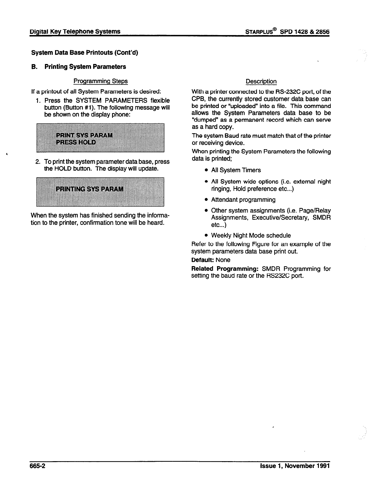
Digital Key Telephone Systems
sTARPLUS@
SPD 1428 & 2856
System Data Base Printouts (Cont’d)
B. Printing System Parameters
Programming Steps
If a printout of all System Parameters is desired:
1. Press the SYSTEM PARAMETERS flexible
button (Button #I). The following message will
be shown on the display phone:
2. To print the system parameter data base, press
the HOLD button. The display will update.
When the system has finished sending the informa-
tion to the printer, confirmation tone will be heard.
Description
With a printer connected to the RS-232C port, of the
CPB, the currently stored customer data base can
be printed or “uploaded” into a file. This command
allows the System Parameters data base to be
“dumped” as a permanent record which can serve
as a hard copy.
The system Baud rate must match that of the printer
or receiving device.
When printing the System Parameters the following
data is printed;
l
All System Timers
l
All System wide options (i.e. external night
ringing, Hold preference etc...)
l
Attendant programming
l
Other system assignments (i.e. Page/Relay
Assignments, Executive/Secretary, SMDR
etc...)
l
Weekly Night Mode schedule
Refer to the following Figure for an example of the
system parameters data base print out.
Default: None
Related Programming: SMDR Programming for
setting the baud rate or the RS232C port.
665-2 Issue 1, November 1991
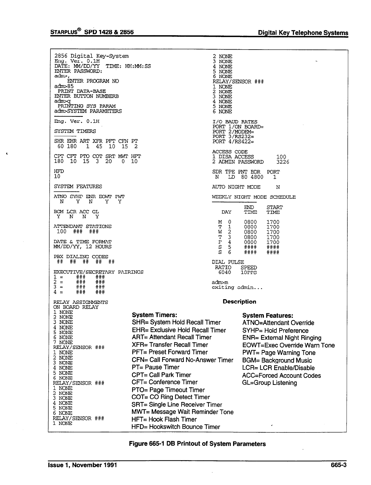
STARPLUS@
SPb 1428 & 2856 Digital Key Telephone Systems
2856 Digital Key-System
Eng. Ver. O.lH
DATE: MM/DD/YY TIME: HH:MM:SS
ZF pAsswom:
kNTER PROGRAM NO
2
NONE
3
NONE
4
NONE
5
NONE
6
NONE
RELAY/SENSOR ###
a-85
PRINT DATA-BASE
EWI'ERBU'MONNUMBERB
adm>q
PRINTING SYS PARAM
adm%YSTEMPARAM.ErERS
1 NONE
2
NONE
3
NONE
4
NONE
2 E-i-E
Eng. Ver. O.lH
SYSTEM TIMERS
SHREHRARTXFRPFTCFN F'I'
60 180
1 45 10 15 2
I/O BAUD RATES
PORT l/ON BOARD=
FORT 2/MODEM=
FORT 3/RS232=
PORT 4/RS422=
CPTCFT P'KICOT SRTMWI'H??T
180 10 15 3 20 0 10
ACCESS CODE
1 DISA ACCESS 100
2
ADMIN PASSWORD
3226
HFD
10
SDR TPE PNT BDR PORT
N
LD 80 4800 1
SYSTEM FEATURES AUTO NIGHT MODE N
A'INO SYHPENR MlwT PWT
N YN YY WEEKLY NIGHT MODE SCHEDULE
BGM LCR ACC GL
Y N N Y
ATTENDANT STATIONS
100 ### ###
DATE&TIME FORMAT
MM/DD/YY, 12 HOURS
PBX DIALING CODES
+I# ## ## ## ##
EXECUT~~SEC$ARY PAIRINGS
1=
2=
3= ift: Et
4= ### ###
RELAY ASSIGNMENTS
ON BOARD RELAY
1 NONE
2
NONE
3
NONE
4
NONE
5
NONE
6
NON-E
7
NONE
RELAY/SENSOR ###
1 NONE
2
NONE
ii EE
5
NONE
6
NONE
RELAY/SENSOR ###
1 NONE
z :z-i!I
4
NONE
5
N&E
6
NONE
RELAY/SENSOR ###
1 NONE
START
DAY ?i% TIME
M 0
0800
Tl
0800
w2 0800
T 3
0800
F 4
E 2 ZIK:
####
DIAL PULSE
%% SPEED
1OPPS
ahm
exiting admin...
Description
1700
1700
1700
1700
1700
####
####
System Timers:
SHR= System Hold Recall Timer
EHR= Exclusive Hold Recall Timer
ART= Attendant Recall Timer
XFR= Transfer Recall Timer
PFT= Preset Forward Timer
CFN= Call Forward No-Answer Timer
PT= Pause Timer
CPT= Call Park Timer
CFf= Conference Timer
PTO= Page Timeout Timer
COT= CO Ring Detect Timer
SRT= Single Line Receiver Timer
MWT= Message Wait Reminder Tone
HFT= Hook Flash Timer
HFD= Hookswitch Bounce Timer
System Features:
ATNO=Attendant Override
SYHP= Hold Preference
ENR= External Night Ringing
EOWT=Exec Override Warn Tone
PWT= Page Warning Tone
BGM= Background Music
LCR= LCR Enable/Disable
ACC=Forced Account Codes
GL=Group Listening
Figure 665-l DB Printout of System Parameters
Issue 1, November 1991
665-3
Digital Key Telephone Systems
sTARPLUS@
SPD 1428 & 2856
System Data Base Printouts (Cont’d)
C. Printing CO Line Attributes
Programming Steps
If a printout of the CO tine Attributes is desired:
1. Press the CO LINE ATTRIBUTES flexible but-
ton (Button #2). The following message will be
shown on the display phone:
2. To print the data for ALL CO Lines, press the
HOLD button. To print CO Line data for a
specified CO Line Range enter four digits to
specify the CO Line range (two digits for the first
line within the range and two digits for the last
line in the range i.e. [0115]). If a print out of only
one line is desired enter that line twice (i.e.
[OlOi]). Then press the HOLD button.
3. The following display will be shown on the
display phone and the CO Line data will be
printed:
When the system has finished sending the re-
quested information to the printer, confirmation tone
will be heard.
Description
With a printer connected to the RS-232C port, of the
CPB, the currently stored customer data base can
be printed or “uploaded” into a file. This command
allows either a range of CO Lines or the entire CO
Line data base to be “dumped” as a permanent
record which can serve as a hard copy of the CO
Line attribute data base.
The system Baud rate must match that of the printer
or receiving device.
When printing the CO Line attributes the following
data is printed;
0 All CO Line parameters within the specified
range.
l
CO Line ringing assignments within the
specified range.
l
Dial Pulse Ratio and Speed settings
Refer to the following Figure for an example of the
CO Line attribute data base print out.
Default: None
Related Programming: SMDR Programming for
setting the baud rate or the RS232C port.
665-4 Issue 1, November 1981
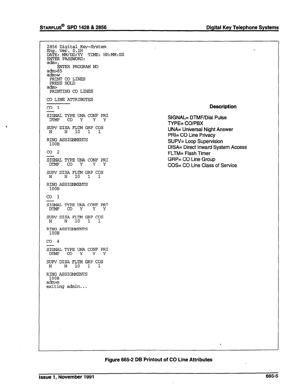
STARPLUS@
SPD 1428 & 2856 Digital Key Telephone Systems
2856 Digital Key-System
Eng. Ver. O.lH
DATE: MM/DD/YY TIME: HH:MM:SS
ENrERPAbwORD:
ati, ENTER PROGRAM NO
:zt5
PRINT CO LINES
PRESS HOLD
adrrv
PRINTINGCO LINES
CO LINE ATTRIBUTES
co 1
Description
SI@?ATJ TYPE UNA CONF PRI
m co Y Y Y
SUPV DISA FLY GRP COS
N N 1 1
RING ASSIGNMENTS
100B
co 2
SIG&L TYPE UNA CONF PRI
co Y Y Y
SUPV DISA FLTM GRP COS
N N 10 1 1
RING ASSIGNMENTS
100B
co 3
SIGNAL TYPEUNACONF PRI
m co Y Y Y
SUPV DISA FL%f Gy CYS
N N
SXNAL TYPE UNA CONF PRI
JnPE? co Y Y Y
SUPV DISA FLTM GRP CYS
N N 10 1
RING ASSIGNMENTS
1OOB
adrwm
exiting admin...
SIGNAL= DTMF/Dial Pulse
TYPE= CO/PBX
UNA= Universal Night Answer
PRI= CO Line Privacy
SUPV= Loop Supervision
DISA= Direct Inward System Access
FLTM= Flash Timer
GFlP= CO Line Group
COS= CO Line Class of Service
Figure 665-2 DB Printout of CO Line Attributes
Issue 1, November 1991 665-5
Digital Key Telephone Systems
STARPLUS@
SPD 1428 & 2858
System Data Base Printouts (Cont’d)
D. Printing Station Attributes
Programming Steps
If a printout of the Station Attributes is desired:
1. Press the STATION ATTRIBUTES flexible but-
ton (Button #3). The following message will be
shown on the display phone:
2. To print data for all stations, press the HOLD
button. To print Station data for a specified
Station Range enter six digits to specify the
Station range (three digits for the first station
within the range and three digits for the last
station in the range i.e. [100109]). If a print out
of only one station is desired enter that station
twice (i.e. [101101]). Then press the HOLD
button.
3. The following display will be shown on the
display phone and the requested information
will be printed:
Description
With a printer connected to the RS-232C port, of the
CPB, the currently stored customer data base can
be printed or “uploaded” into a file. This command
allows either a range of station data or all stations
data information to be “dumped” as a permanent
record which can serve as a hard copy of the station
attribute data base.
The system Baud rate must match that of the printer
or receiving device.
When printing the Station attributes the following
data is printed;
@ All current station parameters
l
Current Flex Button assignments
Refer to the following Figure for an example of a
Station attribute data base print out.
Default: None
Related Programming: SMDR Programming for
setting the baud rate or the RS232C port.
When the system has finished sending the re-
quested information to the printer, confirmation tone
will be heard.
.
6666 Issue 1, November 1991
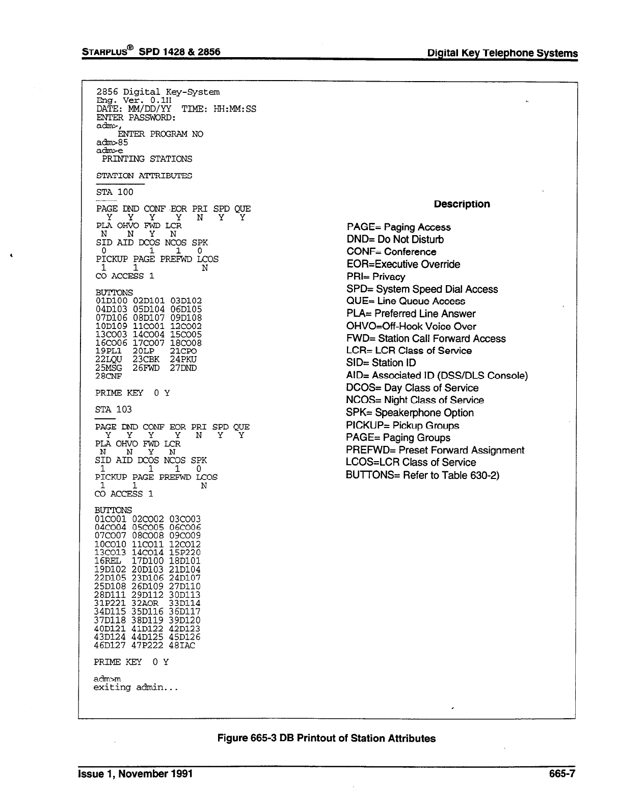
2856 Digital Key-System
Em. Ver. O.lH
DA+E: MM/DD/YY TIME: HH:MM:SS
ENTER PASSvxxxD:
a*,
ENTER PROGRAM NO
ad85
afhnx
PRINTING STATIONS
STATION ATTRIBUTES
STA 100
PAGE DND COW-EOR PRI SPD QUE
PL3:O~OFzDLc:: N Y Y
S:D AI: IX& N:OS SPK
0 1 0
PICKUP PAGE PREhD LCOS
1 1 N
CO ACCESS 1
BUTION
OlDlOO
04D103
07D106
z%
16COO6
19PLl
22LQu
%E
S
02DlOl 03D102
05D104 06D105
08D107 09D108
11c001 12coo2
14coo4 15coo5
17coo7 18COO8
2OLP 21cJ?o
23CBK 24PKU
26FWD 27DND
PRIME KEY 0 Y
STA 103
PAGE DND CONF EOR PRI SPD QUE
YYY YNYY
PLAOHVO EWD LCR
S:D AI: IX& N:OS SPK
1 1 10
PICKUP PAGE PREFWD LCOS
- . __
CA ACCEbS 1
N
BUTTONS
01c001 02coo2 03coo3
04coo4 05coo5 06COO6
07coo7 08COO8 09coo9
Description
PAGE= Paging Access
DND= Do Not Disturb
CONF= Conference
EOR=Executive Override
PRI= Privacy
SPD= System Speed Dial Access
QUE= Line Queue Access
PLA= Preferred Line Answer
OHVO=Off-Hook Voice Over
MID= Station Call Forward Access
LCR= LCR Class of Service
SID= Station ID
AID= Associated ID (DSS/DLS Console)
DCOS= Day Class of Service
NCOS= Night Class of Service
SPK= Speakerphone Option
PICKUP= Pickup Groups
PAGE= Paging Groups
PREFWD= Preset Forward Assignment
LCOS=LCR Class of Service
BUTTONS= Refer to Table 630-2)
40D121 41D122 42D123
43D124 44D125 45D126
46D127 47P222 481AC
PRIMEKEY OY
atim
exiting admin...
Figure 665-3 DB Printout of Station Attributes
Issue 1, November 1991 665-7
System Data Base Printouts (Cont’d)
E. Printing Group Parameters
Programming Steps
If a printout of the Group Parameters is desired:
1. Press the GROUP PARAMETERS flexible but-
ton (Button #4). The following message will be
shown on the display phone:
,
2. To print data for all Group Parameters, press
the HOLD button. The following display will be
shown on the display phone:
When the system has finished sending the re-
quested information to the printer, confirmation tone
will be heard.
Description
With a printer connected to the RS-232C port, of the
CPB, the currently stored customer data base can
be printed or “uploaded” into a file. This command
allows either a range of station data or all stations
data information to be “dumped” as a permanent
record which can serve as a hard copy of the station
attribute data base.
The system Baud rate must match that of the printer
or receiving device.
When printing the Group Parameters, the following
data is printed;
l
Hunt Group Parameters
l
UCD Group Parameters
l
UCD Timers
l
RAN Announcement Tables
l
Voice Mail Group Parameters
e Voice Mail Outpulsing Table (including the
disconnect table)
l
Voice Mail Options
Refer to the following Figure for an example of a
Group Parameter data base print out.
Default: None
Related Programming: SMDR Programming for
setting the baud rate or the RS232C port.
6658 Issue 1, November 1991
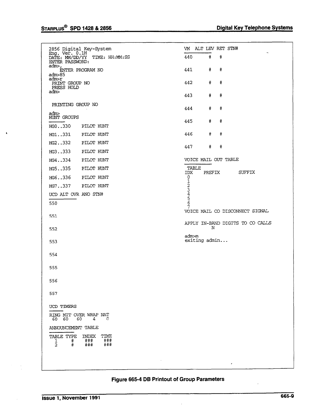
*AFtPLUS@
SPD 1428 & 2856 Digital Key Telephone Systems
2856 Digital Key-System
mg. Ver. O.lH
SAT Mk&D&g TIME: HH:MM:SS
:
PRINTING GROUP NO
E GROUPS
HGO..330 PILOT HUNT
HG1..331 PILOT HUNT
HG2..332 PILMT HUNT
HG3..333 PILOT HUNT
HG4..334 PILOT HUNT
VM ALTLEVRET STN#
440 # #
441 # #
442 # #
443 # #
444 # #
445 # #
446 # #
447 # #
VOICE MAIL OUT TABLE
HG5..335 PILOT HUNT
HG6..336 PILOT HUNT
HG7..337 PILOT HUNT
UCDALTOVRANO STN#
550
551
552
553
554
555
556
557
UCD TIMERS
TABLE
IDX PREFIX SUFFIX
:
z
4
2
7
VOICE MAIL CO DISCONNECT SIGNAL
APPLY IN-BAND DIGITS TO CO CALLS
N
a&m
exiting achin...
ANNOUNCEMENT TABLE
TABLE YE
t # %F
### TE
###
Figure 666-4 DB Printout of Group Parameters
Issue 1, November 1991 665-9
Digital Key Telephone Systems
sTARPLUS@
SPD 1428 & 2856
System Data Base Printouts (Cont’d)
F. Printing Toll Tables
Programming Steps
If a printout of the Toll tables are desired:
1. Press the TOLL TABLES flexible button (Button
#5). The following message will be shown on
the display phone:
2. To print the Toll Tables, press the HOLD button.
When the system has finished sending the re-
quested information to the printer, confirmation tone
will be heard.
l
Allow Table A
l
Deny Table A
0 Allow Table B
l
Deny Table B
l
Special Table 1
l
Special Table 2
l
Special Table 3
l
Special Table 4
Refer to the following Figure for an example of the
Toll Tables data base print out.
Default: None
Related Programming: SMDR Programming for
setting the baud rate or the RS232C port.
Description
With a printer connected to the RS-232C port, of the
CPB, the currently stored customer data base can
be printed or “uploaded” into a file. This command
allows each exception table to be printed individually
to serve as a permanent record which can be saved
as a hard copy of the exception table data base.
The system Baud rate must match that of the printer
or receiving device.
When printing information from the Toll tables, the
following data is printed:
665-l 0 Issue 1, November 1991
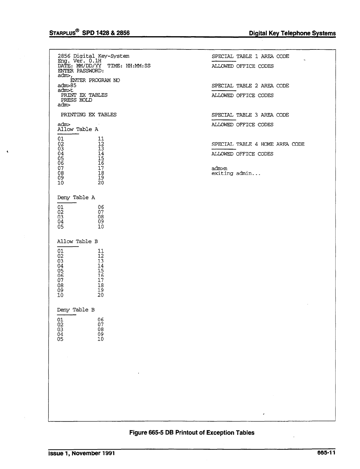
STARPLUS@
SPD 1428 & 2858 Digital Key Telephone Systems
2856 Digital Key-System
Eng. Ver. O.lH
D$&yEksg TIME: HH:MM:SS
ati, ENTER PROGRAM NO
:E:5
PRINTEXTABLES
PRESS HOLD
SPECIAL TABLE 1 AREA CODE
ALLOWED OFFICE CODES
SPECIAL TABLE 2 AREA CODE
ALLCWED OFFICE CODES
PRINTING EX TABLES SPECIAL TABLE 3 AREA CODE
a&w
Allow Table A ALLOWED OFFICE CODES
SPECIAL TABLE 4 HOME AREA CODE
ALLOWED OFFICE CODES
a&m
exiting admin...
Deny TableA
Allow Table B
Deny Table B
Figure 865-5 DB Printout of Exception Tables
Issue 1, November 1991 665-l 1
Digital Key Telephone Systems
STARPLUS@
SPD 1428 812856
System Data Base Printouts (Cont’d)
G. Printing System Speed Bins
Programming Steps
If a printout of the System speed dial entries are
desired:
1. Press the SYSTEM SPEED flexible button
(Button #6). The following message will be
shown on the display phone:
2. To print the System Speed bins, press the
HOLD button. The following will be shown on
the display phone:
When the system has finished sending the re-
quested information to the printer, confirmation tone
will be heard.
Description
With a printer connected to the RS-232C port, of the
CPB, the currently stored customer data base can
be printed or “uploaded” into a file. This command
allows either a range of system speed dial bins or all
bins can be “dumped” as a permanent record which
can serve as a hard copy of the system speed dial
data base.
The system Baud rate must match that of the printer
or receiving device.
Refer to the following Figure for an example of a
System Speed Dial data base print out.
Default: None
Related Programming: SMDR Programming for
setting the baud rate or the RS232C port.
665-l 2 Issue 1, November 1891
sTARPLUS@
SPD 1428 & 2856 Digital Key Telephone Systems
2856 Digital Key-System
mg. Ver. O.lH
Ds MMdMDzg TIME: HK:MM:SS
ati, ENTER PROGRAM NO
a-85
a-y
PRINT SYS SPEEDNO
PRESS HOLD
PRINTING SYS SPEED NO
SYSTEM SPEED NUMBERS
20
21
22
23
24
25
26
27
28
29
30
31
32
33
34
35
36
37
38
39
40
41
42
43
44
45
46
47
48
49
50
51
52
53
54
55
56
57
58
59
60
61
62
63
64
65
66
67
68
69
70
71
72
73
74
75
76
77
78
79
80
a&m
exiting admin...
Figure 665-6 DB Printout of System Speed Numbers
Issue 1, November 1991 665-l 3
Digital Key Telephone Systems
STARPLUS@
SPD 1428 & 2858
System Data Base Printouts (Cont’d)
H. Printing LCR Tables
Programming Steps
If a printout of the LCR tables are desired:
1. Press the LCR TABLES flexible button (Button
#7). The following message will be shown on
the display phone:
2. To print the LCR Tables, press the HOLD but-
ton. The following will be shown on the display
phone.
~g&, < ..::..;:.:.:.: . . . . . .
‘...:.:.::::w:b.
~ . . . ..~..~~rJl~~~~~~~~~~~~~~~~~~
“:::::i::::: ):.:.,.,.. . ,
When the system has finished sending the re-
quested information to the printer, confirmation tone
will be heard.
Description
With a printer connected to the RS-232C port, of the
CPB, the currently stored customer data base can
be printed or “uploaded” into a file. This command
allows each exception table to be printed individually
to serve as a permanent record which can be saved
as a hard copy of the exception table data base.
The system Baud rate must match that of the printer
or receiving device.
When printing information from the LCR Tables, the
following data is printed:
3-Digit Table
6-Digit Table
Exception Table
Route List Table
Insert/Delete Table
Daily Time Table
Weekly Time Table
Toll Tables
Refer to the following Figures for examples of the
LCR Tables data base print out.
Default: None
Related Programming: SMDR Programming for
setting the baud rate or the RS232C port.
665-l 4 Issue 1, November 1991
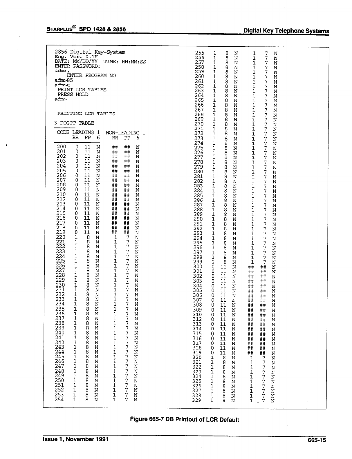
STARPLUS@ SPD 1428 & 2856 Digital Key Telephone Systems
2856 Digital Key-System
Eng. Ver. 0.1H
DATE: MM/DD/YY TIME: HH:MM:SS
ENTER PASSWORD:
ah=-,
ENTER PROGRAM NO
:Et"
PRINT LCR TABLES
PRESS HOLD
a&m
PRINTINGLCRTABLES
3 DIGIT TABLE
CODE LEADING 1 NON-LEADING 1
RR PP 6 RR PP 6
255
264
$662
267
%
%
272
273
274
275
276
277
278
~~;
281
282
283
284
285
286
287
288
289
%!f
292
293
294
295
296
297
298
299
300
301
304
305
306
307
308
309
310
312
313
314
E
317
318
319
320
321
322
323
324
%Z
327
328
329
7 N
1 8 N 1 .7 il
Figure 665-7 DB Printout of LCF? Default
Issue 1, November 1991 665-l 5
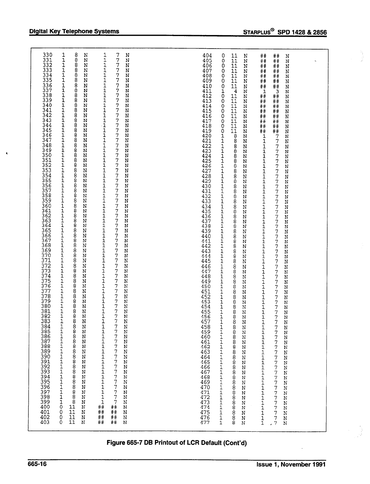
Digital Key Telephone Systems
STARPLUS@ SPD 1428 & 2856
340
z2'
343
E
346
347
348
349
350
351
352
353
EZ
356
357
$2:
360
361
362
363
364
~~~
E
z76:
371
z;:
z;t
376
377
378
379
380
381
382
383
E
386
387
388
389
390
391
z;:
394
ZE
~~~
ii%
401
402
403
Figure 665-7 DB Printout of LCR Default (Cont’d)
665-l 6 Issue 1, November 1991
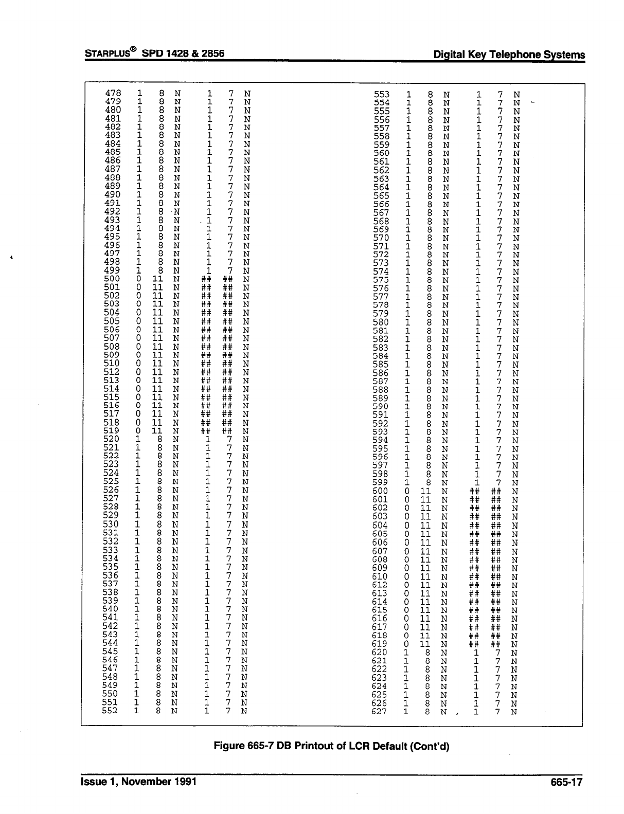
STARPLUS@
SPD 1428 & 2856 Digital Key Telephone Systems
478
%Z
481
:E
484
485
486
487
488
489
490
491
492
493
494
495
496
497
498
499
500
501
1 8 N 1 7 N 553
554
z55:
557
558
559
z!
562
566
zi
569
570
571
572
573
574
575
576
577
578
579
580
2:;
583
584
1
8N 7 N
: 7N
I -.
## I+;: ii
514
51.5
516
517
i i ; /
599
1 8 N : 7N
600 0 11 N ## ## N
601 : 1; ii ## ## N
## ## N
0 11 N ## ## N
ti
N ti
N
N
N N
N
N
609
:
N
616
612
i
613
0
538
539
540
541
542
543
544
545
546
547
548
549
550
551
N
614 0 11 N
615 0 11 N
616 0 11 N ## ## N
617 0 11 N ## ## N
618 0 11 N ## ## N
619 0 11 N ## ## N
620 621
1 i ii i :: ii
622
Zfi 1 iii ii i :: 1
625
t E NN : :: :
626 627
: : :, : :: :
552
Figure 665-7 DB Printout of LCR Default (Cont’d)
Issue 1, November 1991 665-17
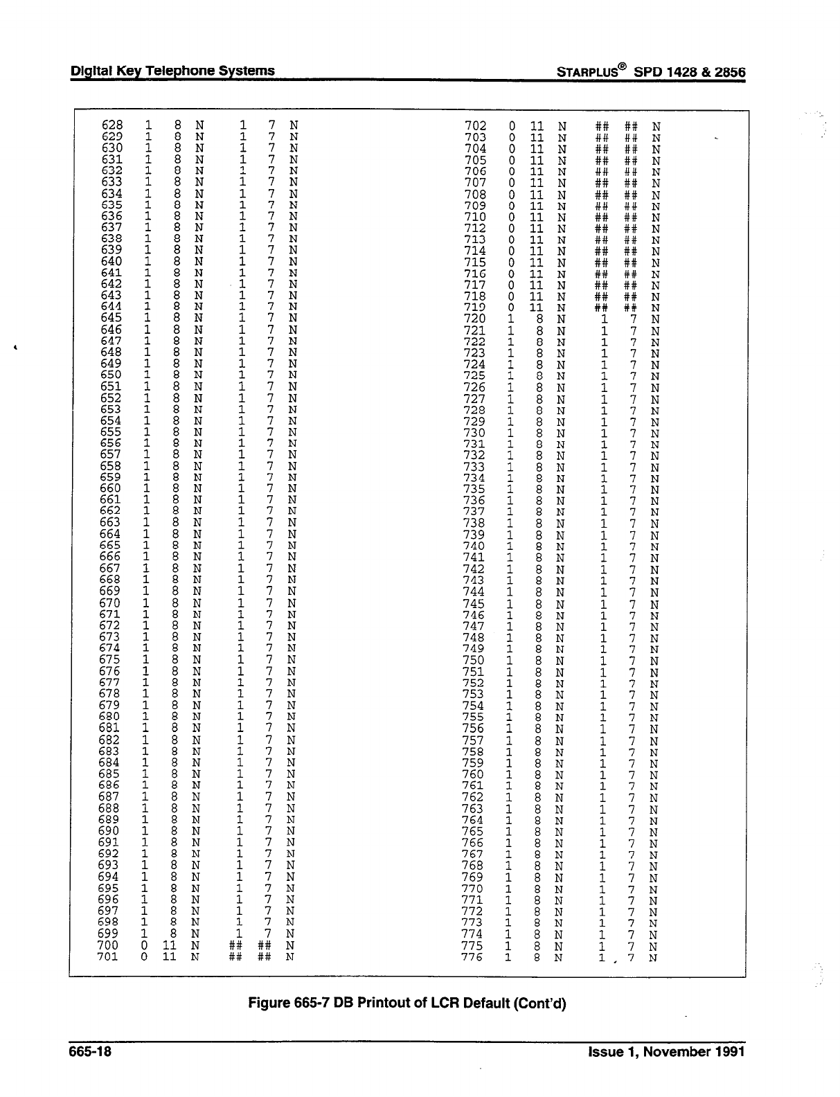
Digital Key Telephone Systems STARPLUS@ SPD 1428 & 2858
702 0 11 N
703
%i Cl 11 N
706
707 i ti Ei
708 0 11 N
709 0 11 N
710
712 i 1: i
713 0 11 N
714 715 i 11 ?J
716 0 11 N
717 0 11 N
718
2: i 1: ii
721 : : ii
722
723 t i ii
724
725 i : ii
726
727
728
729
738
739 1 i ii t :: ii
740 1 8 N 1 7 N
a
1 N
1 i ii
1 8
E
670
671
672
673
674
1 a N 1 7 N
692
693
694
695
696
:;i
Figure 665-7 DB Printout of LCR Default (Cont’d)
665-l 8 Issue 1, November 1991
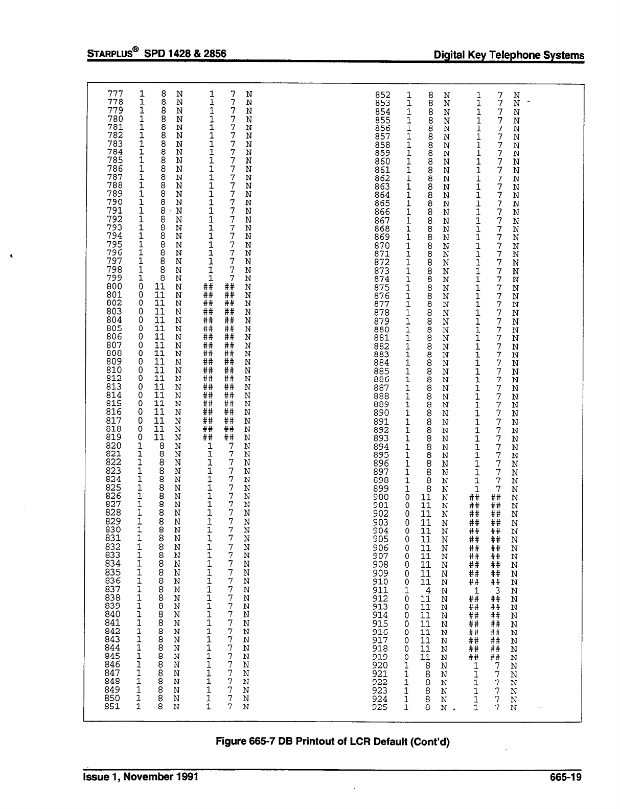
777
778 1 i : + :: ii
779 1 8 N 1 7 N
852 1 8 N 1 7 N
879
880
881
EZ
8:
886
N
i 5
8 N
898
899
900
901
911
E5
914
915
916
917
918
0 11 N
0 11 N
0 11 N
0 11 N
0 11 N
0 11 N
0 11 N
0 11 N
0 11 N
0 11 N
0 11 N
A 1: iti
0 11 N
0 11 N
0 11 N
0 11 N
: t: ii
t 7N
## +I;: i.i
## ## N
## ## N
## ## N
## ## N
## ## N
## ## N
## ## N
## ## N
iii iii ii
## ##
N
## ## N
## ## N
## ## N
## ## N
919 0 11 N ## ## N
920 921 t : ii 1 :: i
922 923 t : z : :: ii
924
925 11 1 :: ii
Figure 665-7 DB Printout of LCR Default (Cont’d)
&sue 1, November 1991 665-l 9
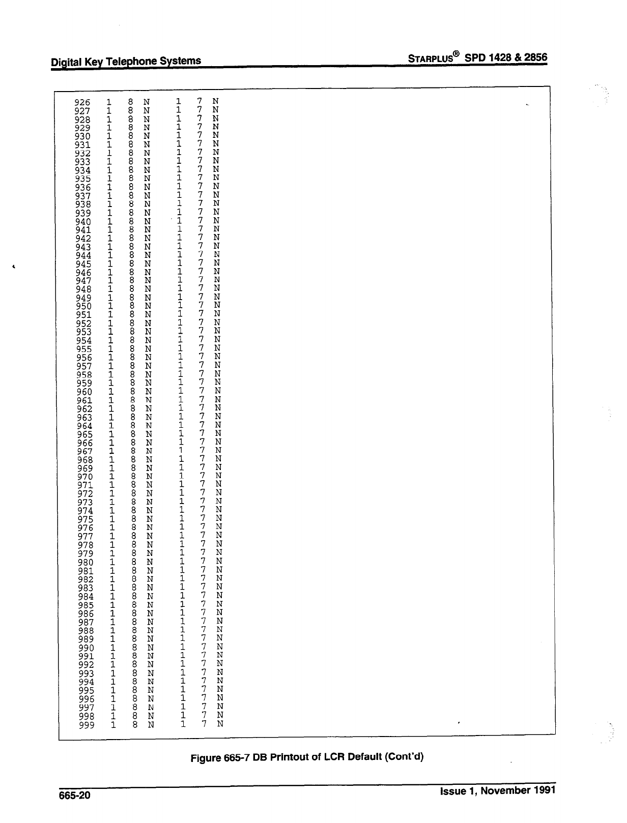
,
Digital Key Telephone Systems
STARPLUS@
SPD 1428 & 2858
:: :
7
N
7
N
7
N
:: ii
7
N
7
N
:: ii
7
N
7
N
I N
; iti
7 N I
Figure 665-7 DB Printout of LCR Default (Cont’d)
665-20 Issue 1, November 1991
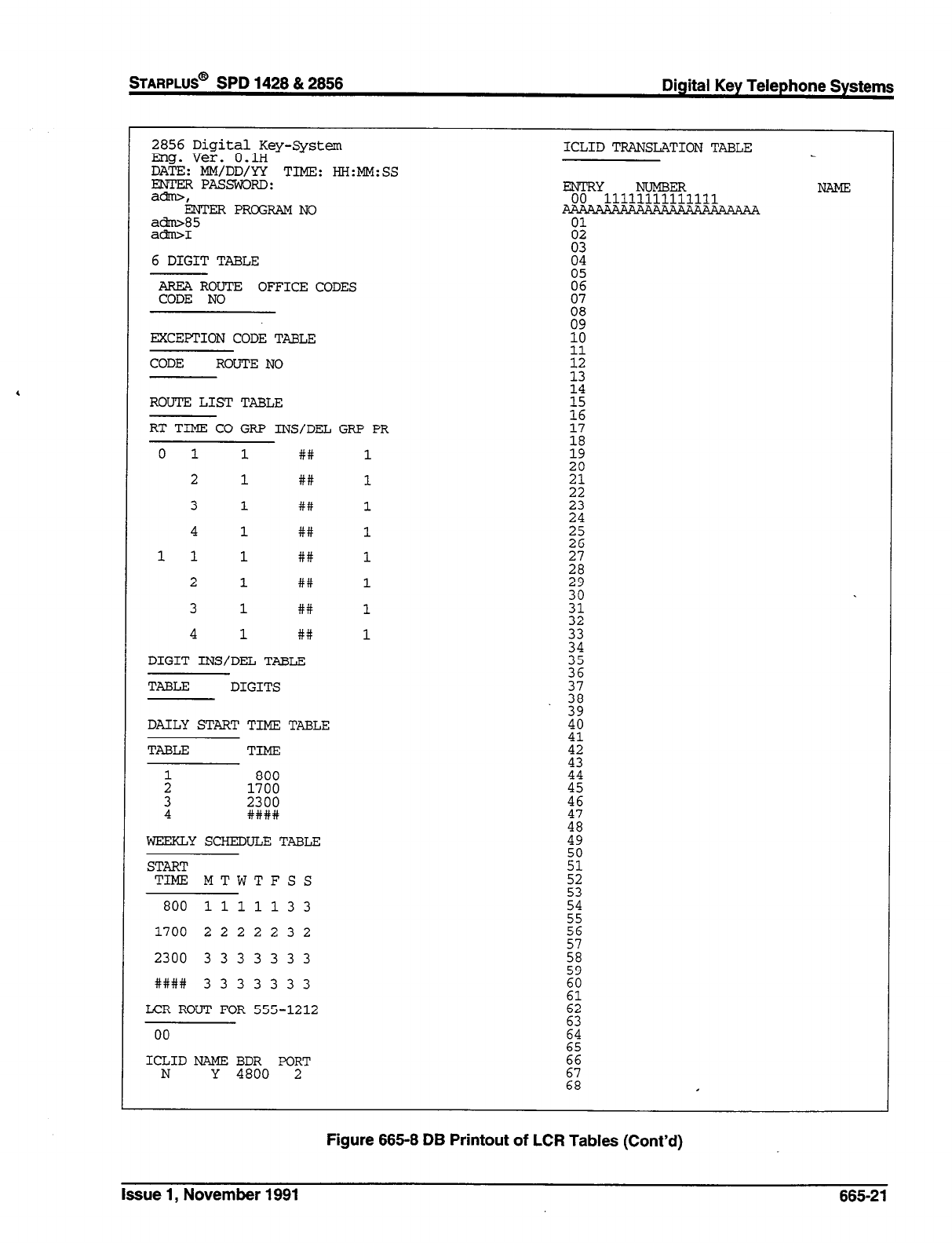
STARPLUS@
SPD 1428 & 2856 Digital Key Telephone Systems
2856 Digital Key-System
Eng. Ver. O.lH
DATE: MM/DD/Y!t TIME: HH:MM:SS
EzF pAssw0RD:
i3J'l?ER PROGRAM NO
a-85
ah1
6 DIGIT TABLE
AREA ROUTE OFFICE CODES
CODE NO
EXCEPTION CODE TABLE
CODE ROUTE NO
ROUTE! LIST TABLE
RT TIME CO GRP INS/DEL GRP PR
0 1 1 ## 1
2 1 ## 1
3
1 ## 1
4
1 ## 1
11 1 ## 1
2
1 ## 1
3 1 ##
1
4
1 ## 1
DIGIT INS/DEL TABLE
TABLE DIGITS
DAILY STARTTIME TABLE
TABLE TIME
21 1700 800
i 2#3#::
WEEKLYSCHEDULETABLE
START
TIME MTWTFSS
800
1111133
1700 2 2 2 2 2 3 2
2300 3 3 3 3 3 3 3
#### 3 3 3 3 3 3 3
LCR ROUT FOR 555-1212
00
ICLID NAME BDR PORT
N
Y 4800 2
Figure 665-8 DB Printout of LCR Tables (Cont’d)
Issue 1, November 1991 665-21
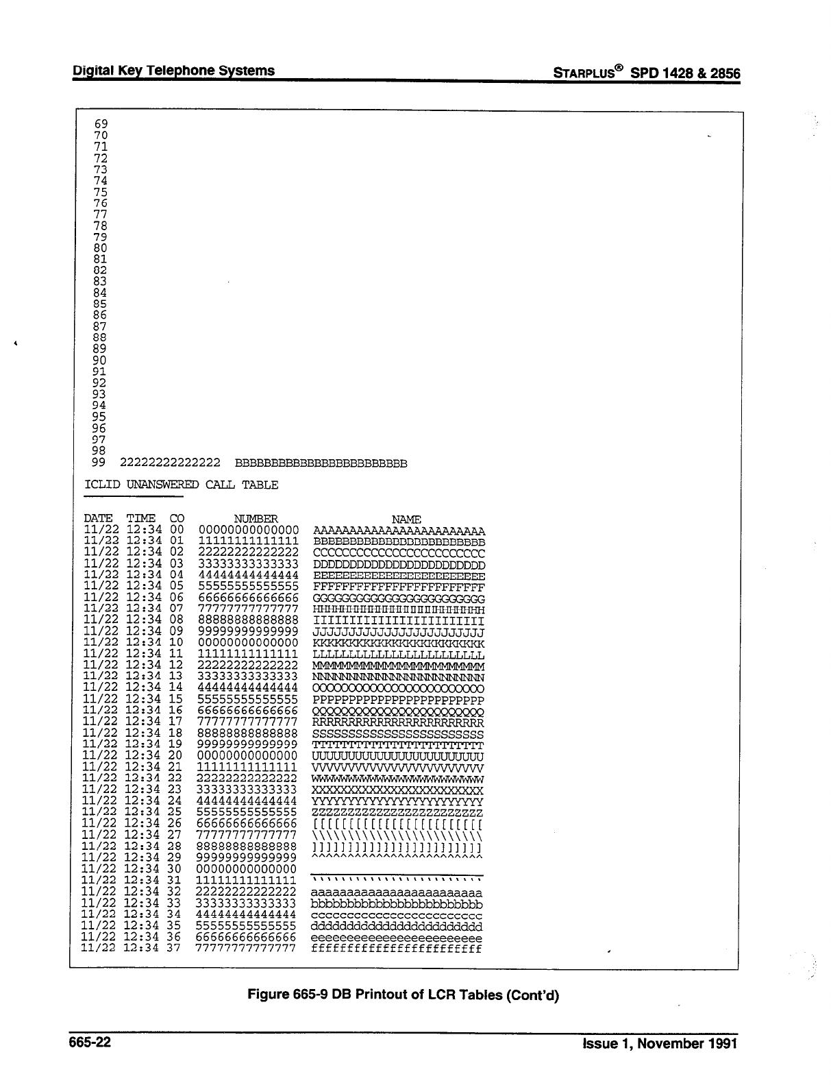
Digital Key Telephone Systems
sTARPLUS@
SPD 1428 & 2856
69
z!
2
74
2
;78
79
::
E
E
i76
E
;:
;z
;:
;76
;: 22222222222222 BBBBBBBBBBBBBBBBBBBBBBBB
ICLID UNANSWERED
CALL TABLE
TIME
12:34
12:34
12:34
12:34
12:34
12:34
12:34
12:34
12:34
12:34
12:34
12:34
12:34
Et
12i34
12:34
12:34
12:34
12:34
12:34
12:34
12:34
12:34
12:34
12:34
12:34
12:34
12:34
12:34
12:34
12:34
ooooo%zooo
11111111111111
22222222222222
33333333333333
44444444444444
55555555555555
66666666666666
77777777777777
88888888888888
99999999999999
00000000000000
11111111111111
22222222222222
33333333333333
44444444444444
55555555555555
66666666666666
77777777777777
88888888888888
99999999999999
00000000000000
11111111111111
22222222222222
33333333333333
44444444444444
55555555555555
66666666666666
77777777777777
88888888888888
99999999999999
00000000000000
11111111111111
BBBBBBBBBBBBBBBBBBBBBBBB
cccccccccccccccccccccccc
DDDDDDDDDDDDDDDDDDDDDDDD
EEXEEEEEEEEBEEEEEEEEEEEE
FFFFFFFFFFFFFFFFFFFFFFFF
111111111111111111111111
JJJJJJJJJJJJJJJJJJJJJJJJ
LLLLLLLLLLLLLLLLLLLLLLLL
PPPPPPPPPPPPPPPPPPPPPPPP
ssssssssssssssssssssssss
zzzzzzzzzzzzzzzzzzzzzzzz
[[[[[[[[[[[[[E[[[[[[[[[[
\\\\\\\\\\\\\\\\\\\\\\\\
111111111111111111111111
hhhhhhhh*hhhhhhhh~*~~~~~
11/22 12:34 32 22222222222222 aaaaaaaaaaaaaaaaaaaaaaaa
11/22 12:34 33 33333333333333
bbbbbbbbbbbbbbbbbbbbbbbb
11/22 12:34 34 44444444444444 cccccccccccccccccccccccc
11/22 12:34 35 55555555555555 dddddddddddddddddddddddd
11/22 12:34 36 66666666666666 eeeeeeeeeeeeeeeeeeeeeeee
11/22 12:34 37 77777777777777 ffffffffffffffffffffffff
Figure 665-9 DB Printout of LCR Tables (Cont’d)
66522
Issue 1, November 1991

sTARPLUS@
SPD 1428 & 2856 Digital Key Telephone Systems
11/22 12:34 38 88888888888888 gggggggggggggggggggggggg
11/22 12:34 39 99999999999999 -
11/22 12:34 40 00000000000000 iiiiiiiiiiiiiiiiiiiiiiii
11/22 12:34 41 11111111111111 jjjjjjjjjjjjjjjjjjjjjjjj
11/22 12:34 42 22222222222222 kWddckkkkkkkkWdddddd
11/22 12:34 43 33333333333333 111111111111111111111111
11/22 12:34 44 44444444444444 mmmmmmmmmmmmmmmmmmmm
11/22 12:34 45 55555555555555
11/22 12:34 46 66666666666666 oooooooooooooooooooooooo
11/22 12:34 47 77777777777777 PPPPPPPPPPPPPPPPPPPPPPPP
11/22 12:34 48 88888888888888 9
11/22 12:34 49 99999999999999 rrrrrrrrrrrrrrrrrrrrrrrr
admz-m
exiting admin..-.
Figure 665-10 DB Printout of LCR Tables (Cont’d)
Issue 1, November 1991 665-23

Digital Key Telephone Systems STARPLUS@ SPD 1428 & 2856
System Data Base Printouts (Cont’d)
1. Printing Entire System Data Base
Programming Steps
If a complete printout of the entire data base in
desired:
1. Press the ENTIRE SYSTEM flexible button
(Button #8). The following will be shown on the
display phone:
2. To print the entire data base, press the HOLD
button. The display will update to indicate what
portion of the data base in being printed.
Description
With a printer connected to the RS-232C port, of the
CPB, the currently stored customer data base can
be printed or “uploaded” into a file. This command
allows the entire data base to be “dumped” as a
permanent record which can serve as a hard copy
of the data base.
The system Baud rate must match that of the printer
or receiving device.
Printing the entire data base takes a while to print.
The data base is printed in the following order:
l
All System Parameters
0 All CO Line programming (CO Lines 01-28)
0 All Station attributes (Stations 100-l 55)
l
All Group No (UCD, Hunt, VM)
* Toll Tables (allow, deny and special tables)
l
System Speed Dial Numbers (bins 20-99)
l
LCR Tables
Default: None
Related Programming: SMDR Programming for
setting the baud rate or the RS232C port.
When the system has finished sending the entire
data base to the printer, confirmation tone will be
heard.
665-24 Issue 1, November 1991

STARPLUS@
SPD 1428 & 2858 Digital Key Telephone Systems
SECTION 700
SYSTEM CHECKOUT
700.1 INTRODUCTION 700.3 POWER UP SEQUENCE
Prior to actual power up and initialization, the Star- The power up sequence involves the proper applica-
plus Digital (SPD) Key Telephone System should be tion of AC power to the System, and CPB LED’s. A
checked over to avoid start up delays or improper successful power up is assured if the installation
loading. A step-by-step checklist is provided for this checklist has been followed.
purpose. 1.
700.2 PREUMINARY PROCEDURES
1.
2.
3.
4.
5.
2.
Make sure that the Basic Key Service Unit
(KSU) is properly grounded.
Verify that all PCB’s are firmly plugged into the
correct card slot positions or expander modules
are firmly seated onto their connectors.
Inspect the MDF for shorted wiring and im-
proper polarity that would affect the Digital Ter-
minal or DSS console.
3.
4.
5.
Make certain that the nicad battery is set to
“ON”. (SPD 2856 only)
Make sure that plug-ended MDF cables con-
nected to the KSU are secure and are plugged
into the correct position.
Plug the AC power cord of the Key Service Unit
into the dedicated 117V ac outlet.
Turn the power switch of the KSU to ON.
The CPB has one (1) red LED located on the
front of the CPB card. If the power up is suc-
cessful, the red LED will flash.
Press the reset button on the CPB. The above
CPB LED indication will repeat.
The system is ready for programming. If any
problems have occurred, Refer to Section 800,
Maintenance and Troubleshooting.
Table 700-l Power Supply Tests
VOLTAGE VOLTAGE TEST POINT
DESIGNATIONS READING LOCATION REMARKS
117VAC +117 VAC fl 0% Commercial Power
Source
7he power supply is preset at the time of manufacturing, but should be checked at system initialization with a
digital volt meter having an accuracy of +l%.
ONICS,, lnc:.
Issue 1, November 1991 700-l
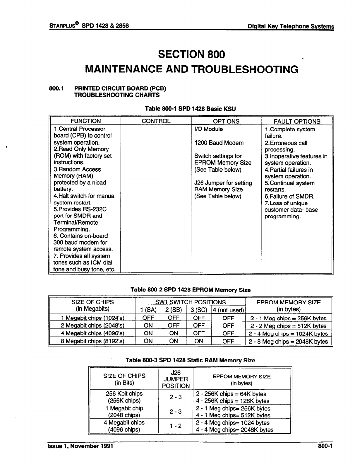
SECTION 800
MAINTENANCE AND TROUBLESHOOTING
800.1 PRINTED CIRCUIT BOARD (PCB)
TROUBLESHOOTING CHARTS
Table 800-l SPD 1428 Basic KSU
FUNCTION
1 .Central Processor
board (CPB) to control
system operation.
2.Read Only Memory
(ROM) with factory set
instructions.
3.Random Access
Memory (RAM)
protected by a nicad
battery.
4.Halt switch for manual
system restart.
5. Provides RS-232C
port for SMDR and
Terminal/Remote
Programming.
6. Contains on-board
300 baud modem for
remote system access.
7. Provides all system
tones such as ICM dial
tone and busy tone, etc.
CONTROL OPTIONS
I/O Module
1200 Baud Modem
Switch settings for
EPROM Memory Size
(See Table below)
J26 Jumper for setting
RAM Memory Size
(See Table below)
FAULT OPTIONS
1 .Complete system
failure.
2.Erroneous call
processing.
3.lnoperative features in
system operation.
4.Paftial failures in
system operation.
5Continual system
restarts.
6,Failure of SMDR.
7.Loss of unique
customer data- base
programming.
Table 800-2 SPD 1428 EPROM Memory Size
SIZE OF CHIPS EPROM MEMORY SIZE
Table 800-3 SPD 1428 Static RAM Memory Size
SIZE OF CHIPS
(in Bits)
256 Kbit chips
(256K chips)
1 Megabit chip
(2048 chips)
4 Megabit chips
(4096 chips)
J26
JUMPER
EPROM MEMORY SIZE
POSITION (in bytes)
2-3 2
- 256K chips = 64K bytes
4 - 256K chips = 128K bytes
2-3 2
- 1 Meg chips= 256K bytes
4 - 1 Meg chips= 512K bytes
2 - 4 Meg chips= 1024 bytes
l-2 4 - 4 Meg chips= 2048K bytes
Issue 1, November 1991 800-l
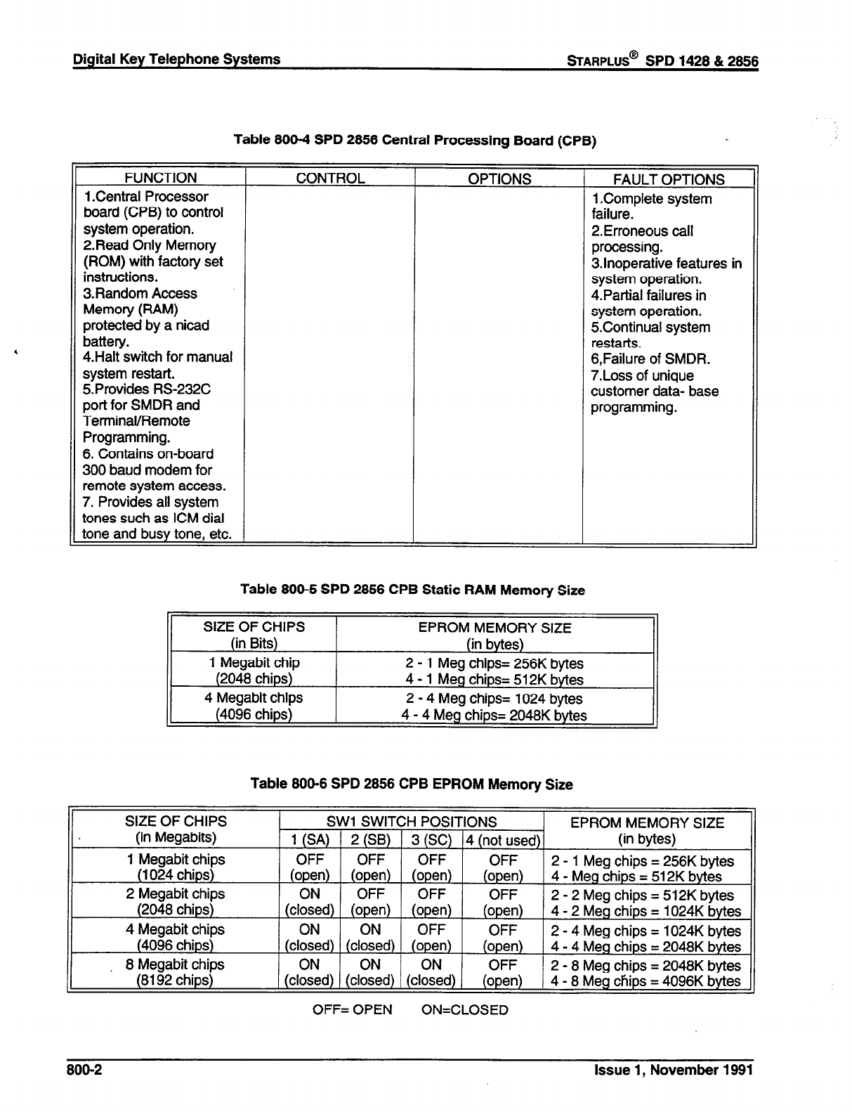
Digital Key Telephone Systems
%ARPLUS@
SPD 1428 & 2856
Table 800-4 SPD 2856 Central Processing Board (CPB)
FUNCTION
1 .Central Processor
board (CPB) to control
system operation.
2Read Only Memory
(ROM) with factory set
instructions.
3Random Access
Memory (RAM)
protected by a nicad
battery.
4.Halt switch for manual
system restart.
S.Provides RS-232C
port for SMDR and
Tem-rinaVRemote
Programming.
6. Contains on-board
300 baud modem for
remote system access.
7. Provides all system
tones such as ICM dial
tone and busy tone, etc.
CONTROL OPTIONS FAULT OPTIONS
1 .Complete system
failure.
2.Erroneous call
processing.
3.lnoperative features in
system operation.
4.Partial failures in
system operation.
5Continual system
restarts.
6,Failure of SMDR.
7.Loss of unique
customer data- base
programming.
Table
800-5 SPD 2856 CPB Static RAM Memory Size
SIZE OF CHIPS
(in Bits)
1 Megabit chip
(2048 chips)
4 Megabit chips
(4096 chips)
EPROM MEMORY SIZE
(in bytes)
2 - 1 Meg chips= 256K bytes
4 - 1 Meg chips= 512K bytes
2 - 4 Meg chips= 1024 bytes
4 - 4 Meg chips= 2048K bytes
Table 800-6 SPD 2656 CPB EPROM Memory Size
SIZE OF CHIPS
(in Megabits)
1 Megabit chips
(1024 chips)
2 Megabit chips
(2048 chips)
4 Megabit chips
(4096 chips)
8 Megabit chips
(8192 chips)
SW1 SWITCH POSITIONS
1 (SA) ( 2 (SB) 1 3 (SC) 14 (not used)
OFF OFF OFF OFF
(open) (open) (open) (open)
ON OFF OFF OFF
(closed) (open) (open) (open)
ON ON OFF OFF
(closed) (closed) (open) (open)
ON ON ON OFF
(closed) (closed) (closed) (open)
OFF= OPEN ON=CLOSED
EPROM MEMORY SIZE
(in bytes)
2 - 1 Meg chips = 256K bytes
4 - Meg chips = 512K bytes
2 - 2 Meg chips = 512K bytes
4 - 2 Meg chips = 1024K bytes
2 - 4 Meg chips = 1024K bytes
4 - 4 Meg chips = 2048K bvtes
2 - 8 Meg chips = 2048K bytes
4 - 8
Meg chips = 4096K bytes
800-2
Issue 1, November 1981

sTARPLUS@
SPD 1428 & 2858 Digital Key Telephone Systems
Table 800-7 4x8 CO/Station Interface Board (CKB)
FUNCTION CONTROL OPTIONS FAULT OPTIONS
Provides interface for 8 Busy state LED that 1 Unable to receive
Digital Terminals, monitors circuits for intercom dial tone.
DSWDLS Consoles or busy condition. 2.Poor transmission
SIA (OPX) modules. characteristics.
None 3.Key telephone set
inoperative.
4.Key telephone unable
to invoke features
5.No LED indications.
Table 800-8 4x8 CO/SLT Interface Board (CSB)
FUNCTION
Provides interface for 8
SLTs.
Also provides for SLTs
with MAW lights.
CONTROL
Busy state LED that
monitors circuits for
busy condition.
OPTIONS FAULT OPTIONS
None 1 .SLT can’t receive dial
tone.
2.Poor transmission
characteristics.
Table 800-9 DTMF Receiver Module (RM)
FUNCTION CONTROL OPTIONS FAULT OPTIONS
Used to add DTMF Adds 1 DTMF receiver. None 1. SLT cannot receive or
receivers to the system break dial tone.
to support DBA and SLT 2. DISA call can’t
operation. receive or break dial
Table 800-10 l/O Module (IOM)
FUNCTION
Provides 2nd RS232C
port and a RS422 port to
the system.
CONTROL
None
OPTIONS
None
FAULT OPTIONS
1 .Loss of SMDR data.
Table 800-l 1 Single Line Telephone Adapter (OPX)
FUNCTION CONTROL OPTIONS FAULT OPTIONS
Provides one (1) 48 volt Busy state LED that , 1 .SLT can’t receive dial
loop to interface an monitors circuits for None tone.
OPX circuit. busy condition. 2.Poor transmission
characteristics.
Issue 1, November 1991 808-3
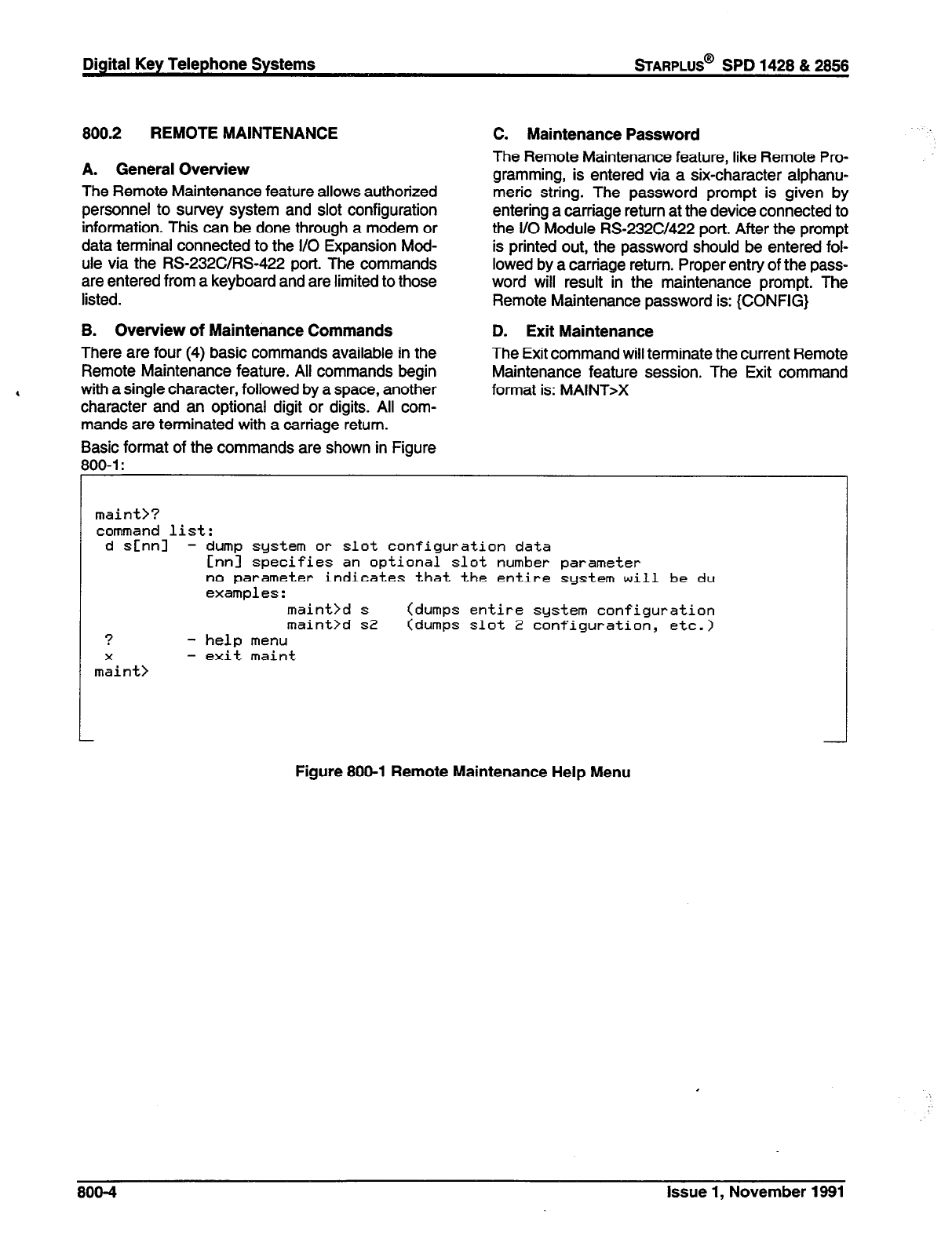
Digital Key Telephone Systems
wARPLUS@
SPD 1428 & 2686
800.2 REMOTE MAINTENANCE
A. General Overview
The Remote Maintenance feature allows authorized
personnel to survey system and slot configuration
information. This can be done through a modem or
data terminal connected to the I/O Expansion Mod-
ule via the RS-232C/RS-422 port. The commands
are entered from a keyboard and are limited to those
listed.
B. Overview of Maintenance Commands
There are four (4) basic commands available in the
Remote Maintenance feature. All commands begin
with a single character, followed by a space, another
character and an optional digit or digits. All com-
mands are terminated with a carriage return.
Basic format of the commands are shown in Figure
100-l :
C. Maintenance Password
The Remote Maintenance feature, like Remote Pro-
gramming, is entered via a six-character alphanu-
meric string. The password prompt is given by
entering a carriage return at the device connected to
the l/O Module RS232CY422 port. After the prompt
is printed out, the password should be entered fol-
lowed by a carriage return. Proper entry of the pass-
word will result in the maintenance prompt. The
Remote Maintenance password is: {CONFIG}
D. Exit Maintenance
The Exit command will terminate the current Remote
Maintenance feature session. The Exit command
,
format is: MAINT>X
L
maint>?
command list:
d s[nn] - dump system or slot configuration data
Cnnl specifies an optional slot number parameter
no parameter indicates that the entire system will be du
examples :
maint>d s (dumps entire system configuration
maint>d s2 (dumps slot 2 configuration, etc.)
?
- help
menu
X
-
exit
maint
maint>
Figure 800-l Remote Maintenance Help Menu
800-4 Issue 1, November 1981
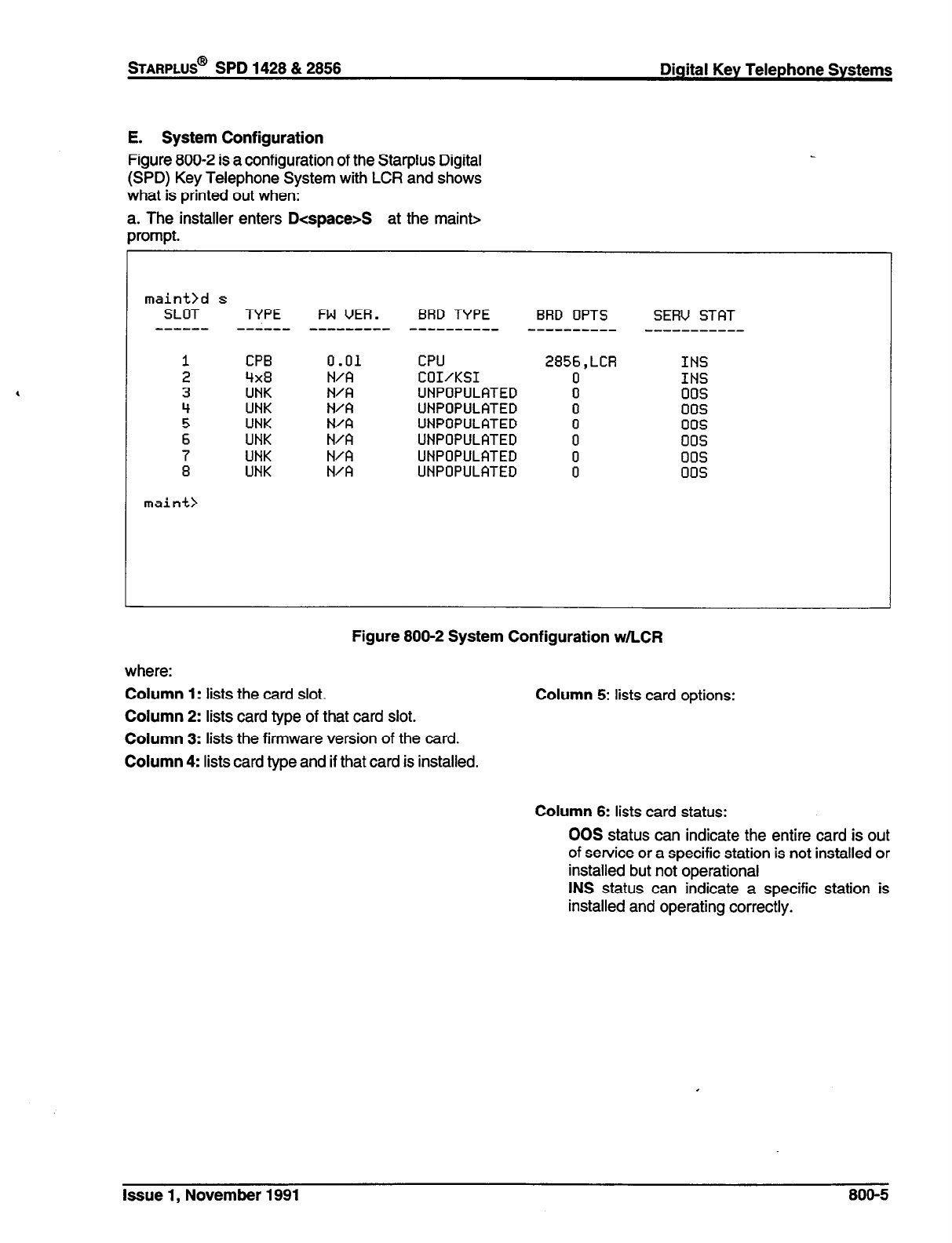
sTARPLUS@
SPD 1428 & 2856 Digital Key Telephone Systems
E. System Configuration
Figure 800-2 is a configuration of the Starplus Digital
(SPD) Key Telephone System with LCR and shows
what is printed out when:
a. The installer enters D<space>S at the maint>
prompt.
maint>d s
SLOT TYPE
------ --i---
CPB 0.01 CPU 2856,LCR INS
Qx8 N/A COI/KSI 0 INS
UNK N&l UNPOPULATED 0 00s
UNK N/A UNPOPULATED 0 00s
UNK N/A UNPOPULATED 0 00s
UNK N/A UNPOPULATED 0 00s
UNK N/A UNPOPULATED 0 00s
UNK N/A UNPOPULATED 0 00s
maint>
FW UER. BRD TYPE BRD OPTS
-----e-s-- ---------- - SERU STAT
Figure 800-2 System Configuration w/LCR
where:
Column 1: lists the card slot.
Column 2: lists card type of that card slot.
Column 3: lists the firmware version of the card.
Column 4: lists card type and if that card is installed.
Column 5: lists card options:
Column 6: lists card status:
00s status can indicate the entire card is out
of service or a specific station is not installed or
installed but not operational
INS status can indicate a specific station is
installed and operating correctly.
Issue 1, November 1991
800-5
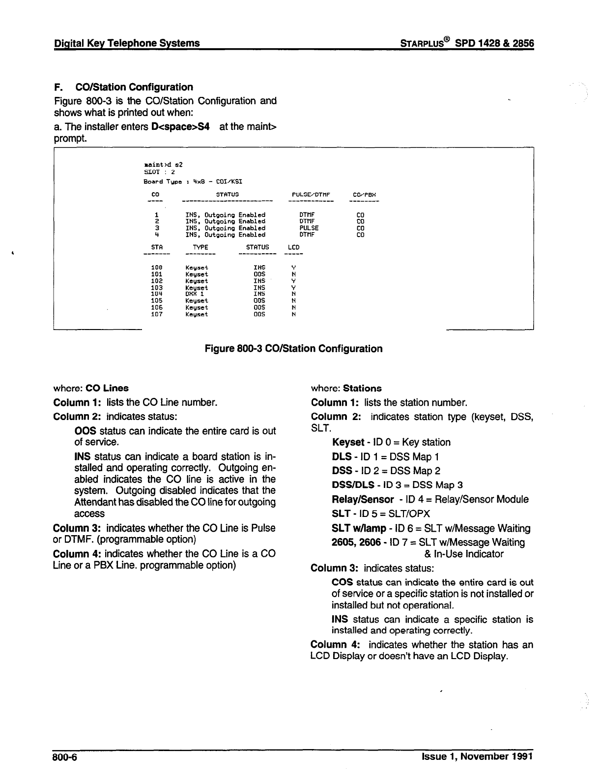
Digital Key Telephone Systems
wARPLUS@
SPD 1428 & 2858
F. CO/Station Configuration
Figure 800-3 is the CO/Station Configuration and
shows what is printed out when:
a. The installer enters D<space>S4 at the mainb=
prompt.
raint>d s2
SLOT : 2
Board Tupe : ‘+xB - COVKSI
co STATUS PULSEfDTHF CWPBX
---- _----_-____------------- --_-----____ ________
:
3
II
STFI
100
101
102
103
104
105
106
107
INS, Outgoing Enabled
INS. Outgoing Enabled
INS,
Outgoing
Enabled
INS, Outgoing Enabled
TYPE STATUS
-------- ---__ _ ---
Keyset
INS
Kcyset 00s
Keuset INS
Keuset INS
DXX 1 INS
Keys& 00s
Kegset 00s
Keyset 005
DTtlF
DTtlF
PULSE
DTtlF
LCD
.- -----
co
co
co
co
,
Figure 800-3 CO/Station Configuration
where: CO Lines
Column 1: lists the CO Line number.
Column 2: indicates status:
00s status
can indicate the entire card is out
of servfce.
INS status can indicate a board station is in-
stalled and operating correctly. Outgoing en-
abled indicates the CO line is active in the
system. Outgoing disabled indicates that the
Attendant has disabled the CO line for outgoing
access
where: Stations
Column 1: lists the station number.
Column 2: indicates station type (keyset, DSS,
SLT.
Keyset - ID 0 = Key station
DLS-ID1 =DSSMapl
DSS-ID2=DSSMap2
DSS/DLS - ID 3 = DSS Map 3
Relay/Sensor - ID 4 = Relay/Sensor Module
SLT - ID 5 = SLT/OPX
SLT w/lamp - ID 6 = SLT w/Message Waiting
2605,2666 - ID 7 = SLT w/Message Waiting
Column 3: indicates whether the CO Line is Pulse
or DTMF. (programmable option)
Column 4: indicates whether the CO Line is a CO
Line or a PBX Line. programmable option) & In-Use Indicator
Column 3: indicates status:
COS status can indicate the entire card is out
of service or a specific station is not installed or
installed but not operational.
INS status can indicate a specific station is
installed and operating correctly.
Column 4: indicates whether the station has an
LCD Display or doesn’t have an LCD Display.
800-6 Issue 1, November 1991
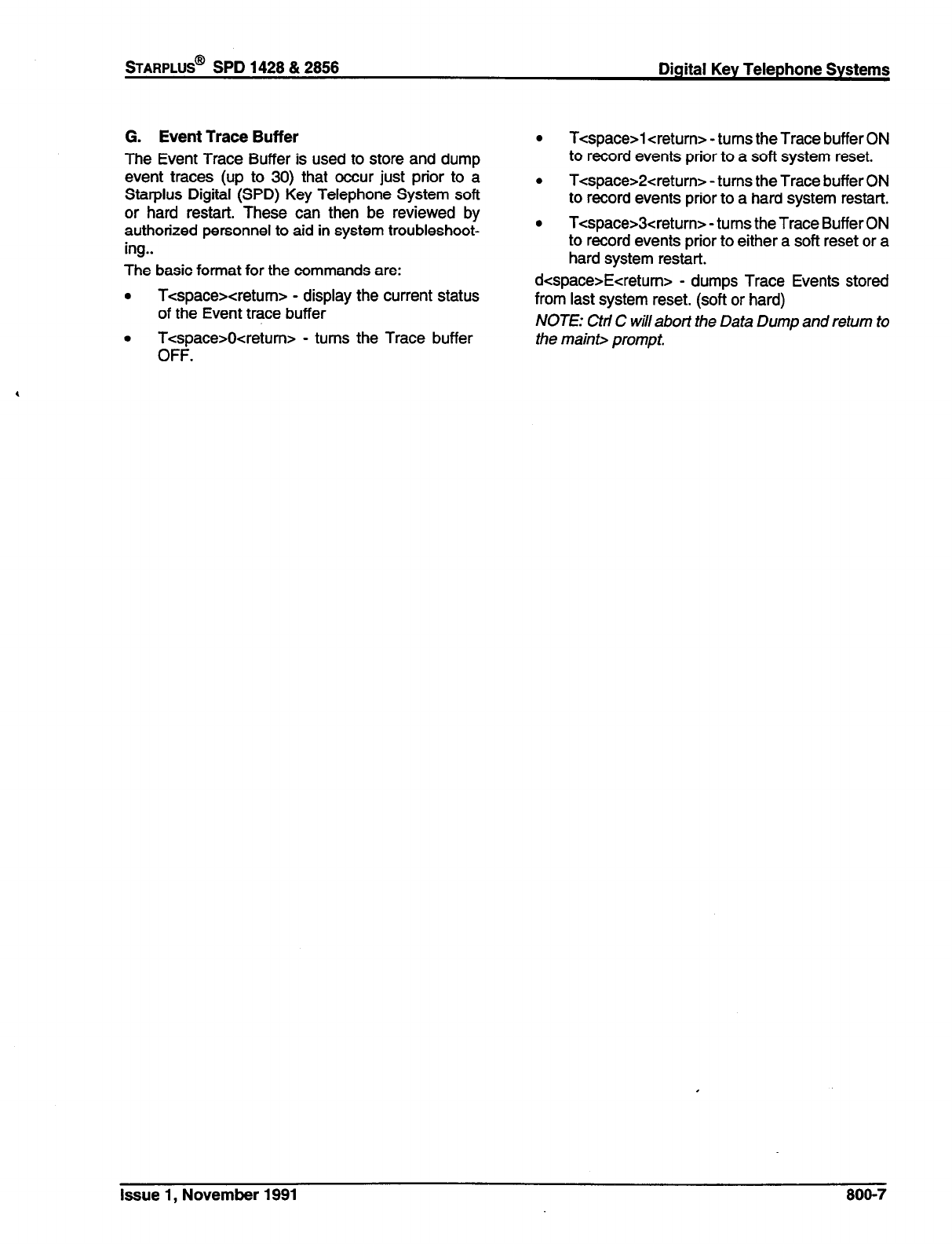
%ARPLUS@
SPD 1428 & 2856 Digital Key Telephone Systems
G. Event Trace Buffer
The Event Trace Buffer is used to store and dump
event traces (up to 30) that occur just prior to a
Stat-plus Digital (SPD) Key Telephone System soft
or hard restart. These can then be reviewed by
authorized personnel to aid in system troubleshoot-
ing..
The basic format for the commands are:
. T-cspacexretumz- - display the current status
of the Event trace buffer
. Tespace>Ocretum> - turns the Trace buffer
OFF.
.
T<space>l <return> - turns the Trace buffer ON
to record events prior to a soft system reset.
. T<space>2<return> -turns the Trace buffer ON
to record events prior to a hard system restart.
0 T<space>3creturn> - turns the Trace Buffer ON
to record events prior to either a soft reset or a
hard system restart.
dcspace>Eeretum> - dumps Trace Events stored
from last system reset. (soft or hard)
NOTE: Ctri C will abort the Data Dump and return to
the maint> prompt.
issue 1, November 1991 800-7
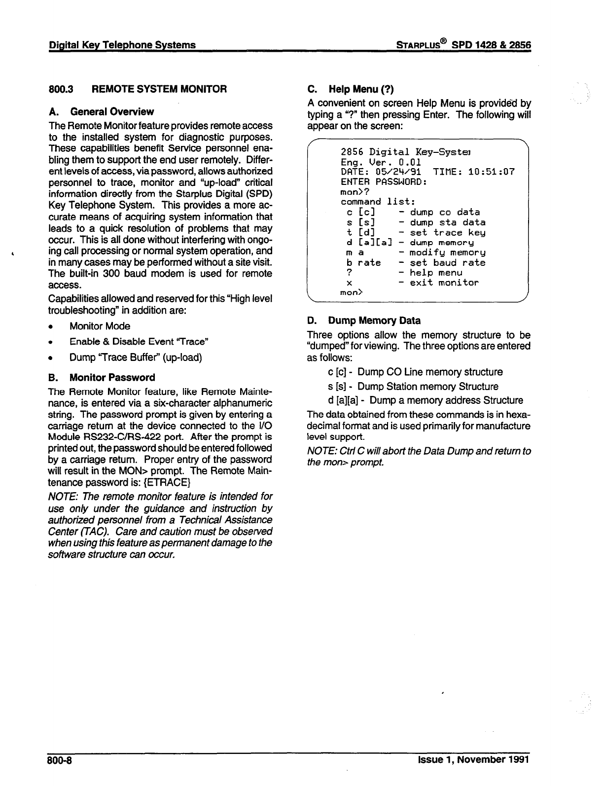
Digital Key Telephone Systems
sTARPLUS@
SPD 1428 & 2866
800.3 REMOTE SYSTEM MONITOR
A. General Overview
The Remote Monitor feature provides remote access
to the installed system for diagnostic purposes.
These capabilities benefit Service personnel ena-
bling them to support the end user remotely. Differ-
ent levels of access, via password, allows authorized
personnel to trace, monitor and “up-load” critical
information directly from the Starplus Digital (SPD)
Key Telephone System. This provides a more ac-
curate means of acquiring system information that
leads to a quick resolution of problems that may
occur. This is all done without interfering with ongo-
4 ing call processing or normal system operation, and
in many cases may be performed without a site visit.
The built-in 300 baud modem is used for remote
access.
Capabilities allowed and reserved for this “High level
troubleshooting” in addition are:
. Monitor Mode
0 Enable & Disable Event “Trace”
. Dump ‘Trace Buffer” (up-load)
B. Monitor Password
The Remote Monitor feature, like Remote Mainte-
nance, is entered via a six-character alphanumeric
string. The password prompt is given by entering a
carriage return at the device connected to the I/O
Module RS232-C/R&422 port. After the prompt is
printed out, the password should be entered followed
by a carriage return. Proper entry of the password
will result in the MON> prompt. The Remote Main-
tenance password is: {ETRACE}
NOTE: The remote monitor feature is intended for
use only under the guidance and instruction by
authorized personnel from a Technical Assistance
Center (TAC). Care and caution must be observed
when using this feature as permanent damage to the
software structure can occur.
C. Help Menu (?)
A convenient on screen Help Menu is provided by
typing a “?” then pressing Enter. The following will
appear on the screen:
Y
2856 Digital Key-System
Eng. Uer. 0.01
DQTE: 05/24/91 TIME: 10:51:07
ENTER PFISSWORD:
man>?
command
list:
c EC1
- dump co data
s Csl
- dump sta data
t Cdl
- set trace key
d CalLal - dump memory
ma - modify memory
b rate - set baud rate
?
- help
menu
X
- exit monitor
mot-0
\
I
D. Dump Memory Data
Three options allow the memory structure to be
“dumped” for viewing. The three options are entered
as follows:
c [c] - Dump CO Line memory structure
s [s] - Dump Station memory Structure
d [a][a] - Dump a memory address Structure
The data obtained from these commands is in hexa-
decimal format and is used primarily for manufacture
level support.
NOTE: Ctti C will abort the Data Dump and return to
the man> prompt.
800-8
Issue 1, November 1991

STARPLUS@
SPD 1428 & 2866 Digital Key Telephone Systems
E. Event Trace Mode
The ‘T’ command enables and disables the Starplus
Digital (SPD) Key Telephone System Trace mode.
While the trace mode is enabled events for the trace
desired will be displayed on the monitor, printer or
PC connected to the Starplus Digital (SPD) Key
Telephone System in an event record. To view the
current status of the trace mode type “T”<retum>at
the MON> prompt then the following screen will be
displayed:
mon> t
Messages Y/N
-------- ---
BOARD E’JT -> N
MSC States -> N
Deu -> N
PCH -> N
COL States -> N
Stn States -> N
Error kg -> N
Que Eut -> N
mon>
a. To enable an event trace type ‘Y’ <space>
(space bar)
b. Then type of trace desired [d], where d is deter-
mined as follows:
B= Board event trace (traces events assoc-
iated with PCB’s)
M= Miscellaneous State event trace
P= Pulse Coded Modulation (PCM) traces
events associated with voice comm-
unications.
C= CO tine (CKB) States (traces events
associated with CO Line activity)
S= Station (STA) States (traces events
associated with Station activity)
E= Error Messages (traces error messages)
Q= Queue (QUE) Events (traces queuing
events, i.e.
DTMF
receiver, UCD, LCR,
etc...)
D= Device Command (traces commands to
peripheral devices).
c. Then enter the specific board, CO line or Station
number of the trace desired or type “all” if all
board’s, CO line’s or Station’s events are de-
sired.
l-7 = Board KSU card slot position (CPB= 1)
01-28 = CO Line port
100-l 55 = Station location
All= All Boards, CO lines or Stations
d. Then press Enter to enable the trace. A screen
similar to the following will appear:
mon>t b
tlessages Y/N
-------- ---
BOFlRD E’JT -> Y
HSC States -> N
Dev -> N
PCrl -> N
COL States -> N
Stn States -> N
Error kg -> N
Que Eut -> N
mon>
\
e. To disable or turn off a particular trace mode do
not enter a specific board, CO line or Station
number (i.e. “t<space>screturn>” to disable
station event trace).
To have event trace’s displayed on the screen you
must first exit the MONitor mode by typing “X” at the
MON> prompt. After you exit the event(s), the trace
will begin as shown in Table 800-6.
1 CAUTION /
Unless instructed by personnel at a Tech-
nical Assistance Center (TAC) do not
leave the trace mode enabled for ex-
tended periods of time. The system will
“dump” the requested event(s) trace which
may use up paper or fill memory buffers on
the collecting device. It is recommended
that the trace events be disabled (turned
off) for all event(s) traces before leaving
the system site.
Issue 1, November 1991 800-9
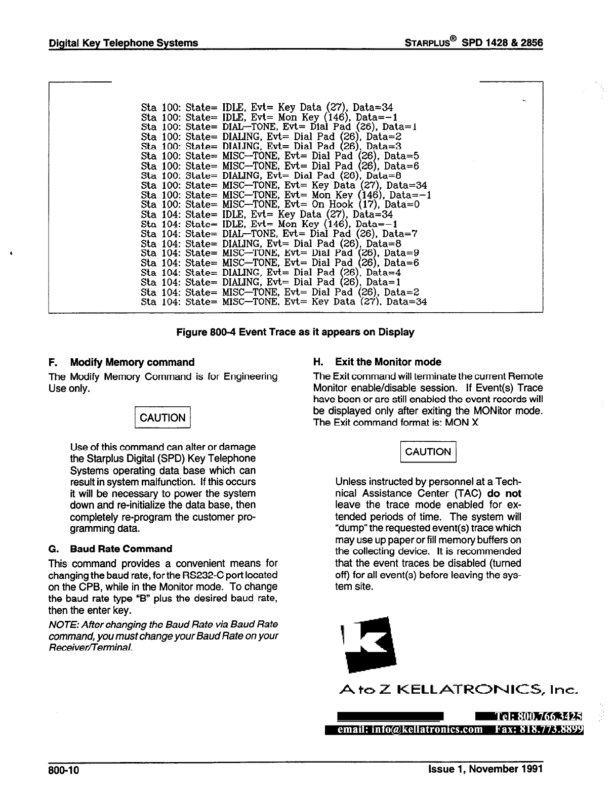
Digital Key Telephone Systems
sTARPLUS@
SPD 1428 & 2866
Sta 100: State= IDLE, Evt= Key Data (27), Data=34
Sta 100: State= IDLE, Evt= Mon Key (146), Data=-1
Sta 100: State= DIAL-TONE, Evt= Dial
Sta 100: State= DIALING, Evt= Dial
Sta 100: State= DIALING, Evt= Dial
Sta 100: State= MISC-TONE, Evt=
Sta 100: State= MISC-TONE, Evt=
Sta 100: State= DIALING, Evt= Dial Pad (26), Data=8
Sta 100: State= MISC-TONE, Evt= Key Data
Sta 100: State= MISC-TONE, Evt= Mon Key
Sta 100: State= MISC-TONE, Evt= On Hook
Sta 104: State= IDLE, Evt= Key Data (27), Data=34
Sta 104: State= IDLE, Evt= Mon Key (146), Data=-1
Sta 104: State= DIAL-TONE, Evt= Dial Pad (26). Data=7
Sta 104: State= DIALING, Evt= Dial Pad (26), Data=8
Sta 104: State= MISC-TONE, Evt=
Sta 104: State= MISC-TONE, Evt=
Sta 104: State= DIALING, Evt= Dial
Sta 104: State= DIALING, Evt= Dial
Sta 104: State= MISC-TONE, Evt= Dial Pad
Sta 104: State= MLSC-TONE. Evt=
Figure 800-4 Event Trace as it appears on Display
F. Modify Memory command
The Modify Memory Command is for Engineering
Use only.
Use of this command can alter or damage
the Starplus Digital (SPD) Key Telephone
Systems operating data base which can
result in system malfunction. If this occurs
it will be necessary to power the system
down and re-initialize the data base, then
completely re-program the customer pro-
gramming data.
G. Baud Rate Command
This command provides a convenient means for
changing the baud rate, for the RS232-C port located
on the CPB, while in the Monitor mode. To change
the baud rate type “B” plus the desired baud rate,
then the enter key.
NOTE: After changing the Baud Rate via Baud Rate
command, you must change your Baud Rate on your
ReceiverfTemMal.
H. Exit the Monitor mode
The Exit command will terminate the current Remote
Monitor enable/disable session. If Event(s) Trace
have been or are still enabled the event records will
be displayed only after exiting the MONitor mode.
The Exit command format is: MON X
Unless instructed by personnel at a Tech-
nical Assistance Center (TAC) do not
leave the trace mode enabled for ex-
tended periods of time. The system will
“dump” the requested event(s) trace which
may use up paper or fill memory buffers on
the collecting device. It is recommended
that the event traces be disabled (turned
off) for all event(s) before leaving the sys-
tem site.
808-l 0 Issue 1, November 1991
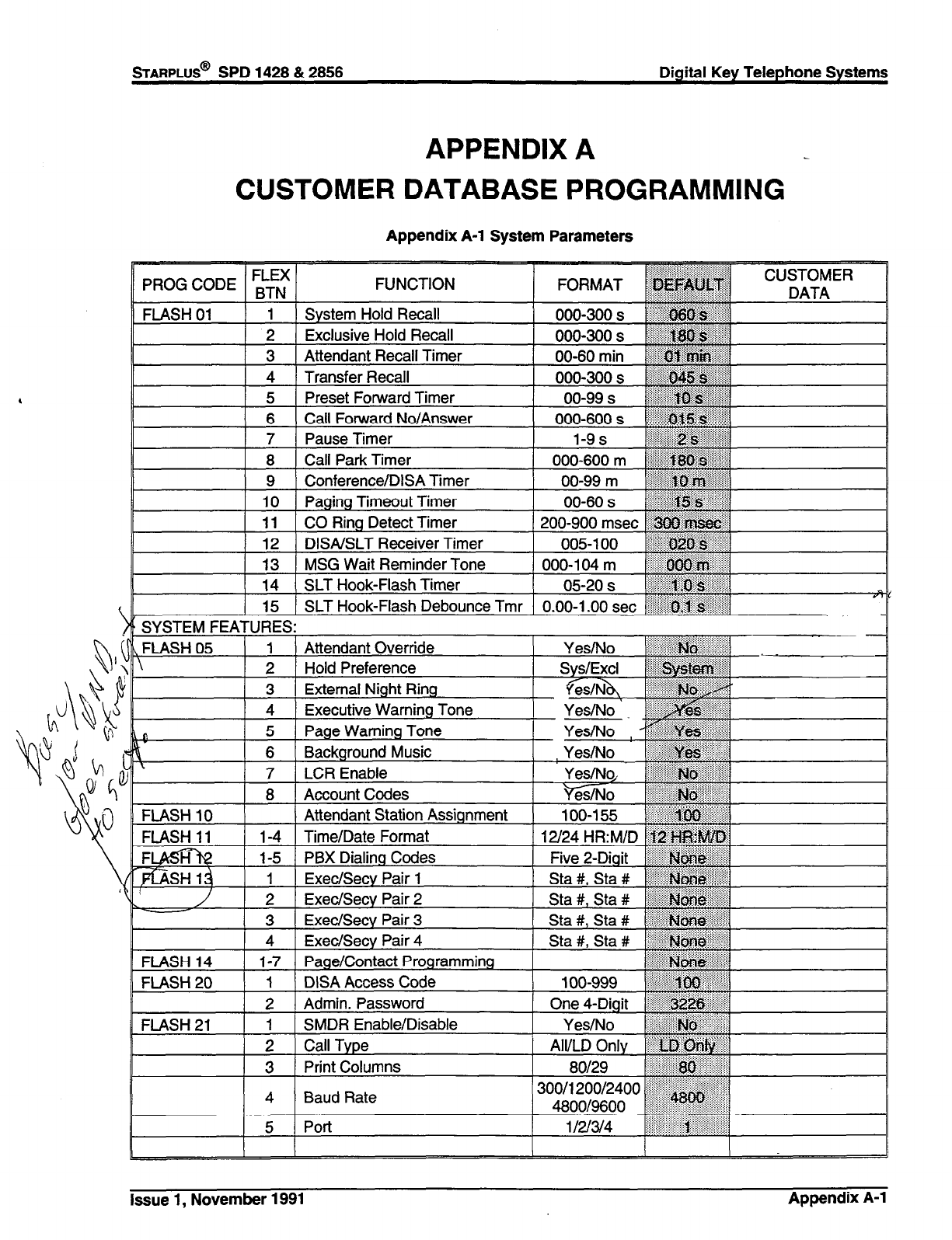
STARPLUS@ SPD 1428 & 2858 Digital Key Telephone Systems
APPENDIX A
CUSTOMER DATABASE PROGRAMMING
Appendix A-l System Parameters
Issue 1, November 1991 Appendix A-l
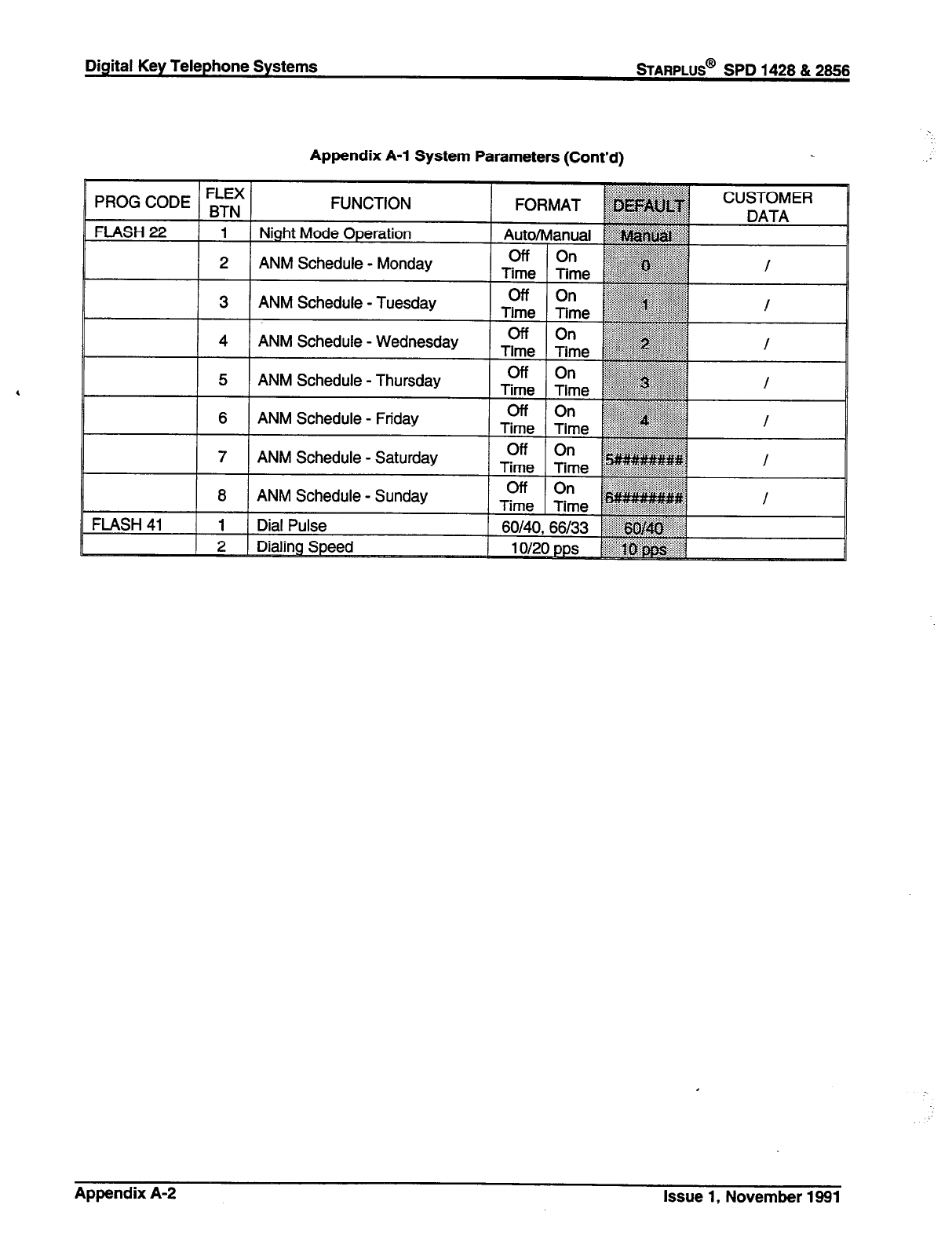
Digital Key Telephone Systems
sTARPLUS@
SPD 1428 & 2866
Appendix A-l System Parameters (Cont’d)
/ PROG CODE / ;;f / FUNC TION
FLASH22 ) --.- ( 1 Night Mode Operation
I I
2 ANM Schedule - ‘*--_I-.-
Monaay
I - I ALI.‘ a?.-L-A..,- -#-..--A-..
3 MIYIVI 3~i1euu1e - I uesaay
FORMA,- 1
;;::
*
Auto/Manual &
Time Time ~~
‘-:p:‘:::::::.:.: . . . . . . :<.:.:::: :.:.: . .
,, ,,,,,
off On ~~~
~:;~~ig+y%..w.
CUSTOMER
4 ANM Schedule - Wednesday
A hlh 1 cI..L-A. .I- 7-b.. .--A-. .
PWYIYI 3u ItNuIe - I I lulauay
6 ANM Schedule - Friday H
Appendix A-2 Issue 1, November 1991
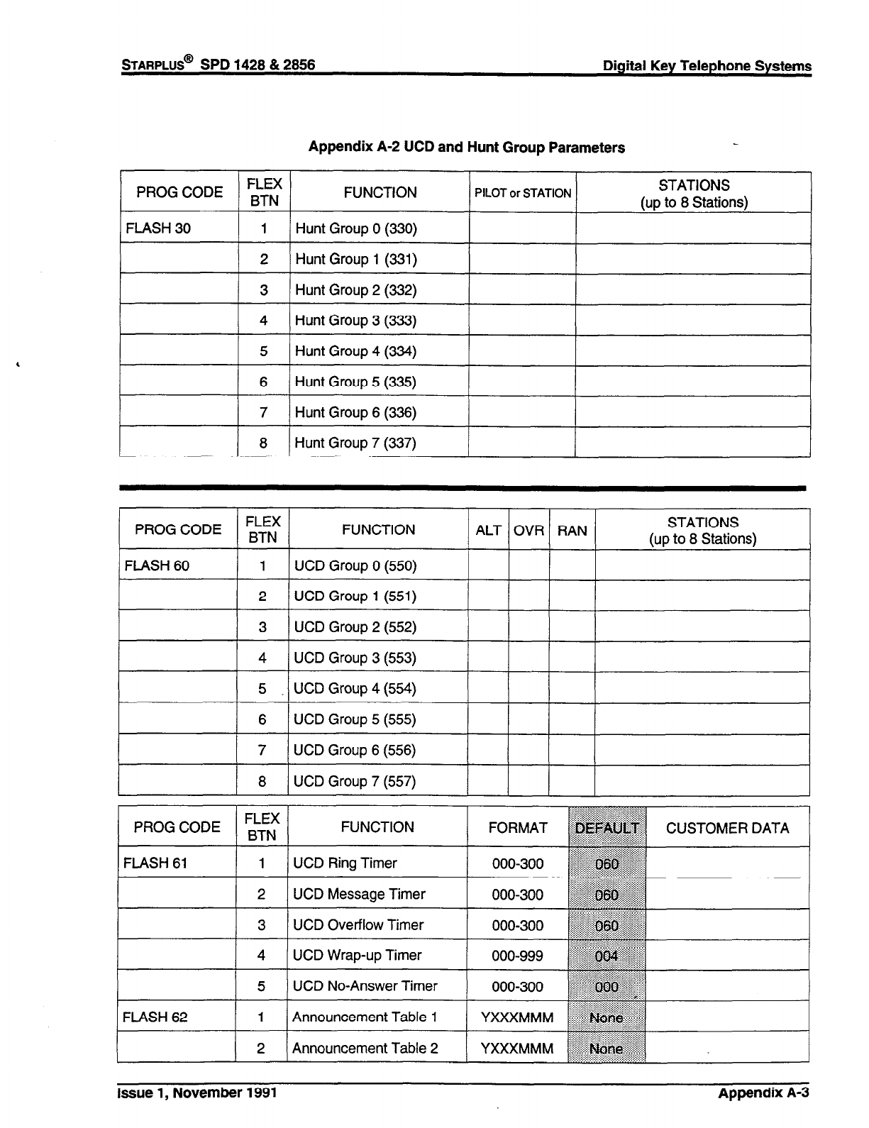
STARPLUS@
SPD 1428 & 2856 Digital Key Telephone Systems
Appendix A-2 UCD and Hunt Group Parameters
7 Hunt Group 6 (336)
8 Hunt Group 7 (337)
PROG CODE FLEX
BTN FUNCTION ALT OVR RAN STATIONS
(up to 8 Stations)
FLASH 60 1 UCD Group 0 (550)
I 2 I
UCD Group 1 (551)
3 UCD Group 2 (552)
4 UCD Group 3 (553)
5 UCD 4 Group (554)
6 UCD Group 5 (555)
7 UCD Group 6 (556)
I 8 I
UCD Group 7 (557)
I I I
l----t+
FUNCTION CUSTOMER DATA
UCD Ring Timer
UCD Message Timer
::::;.::::i:;:;
‘i:i:$i::$.:
000-300 ,iiilll,,,,,,,~~:,:
UCD Overflow Timer
UCD Wrap-up Timer
UCD No-Answer Timer
Announcement Table 1
Announcement Table 2
Issue 1, November 1991 Appendix A-3
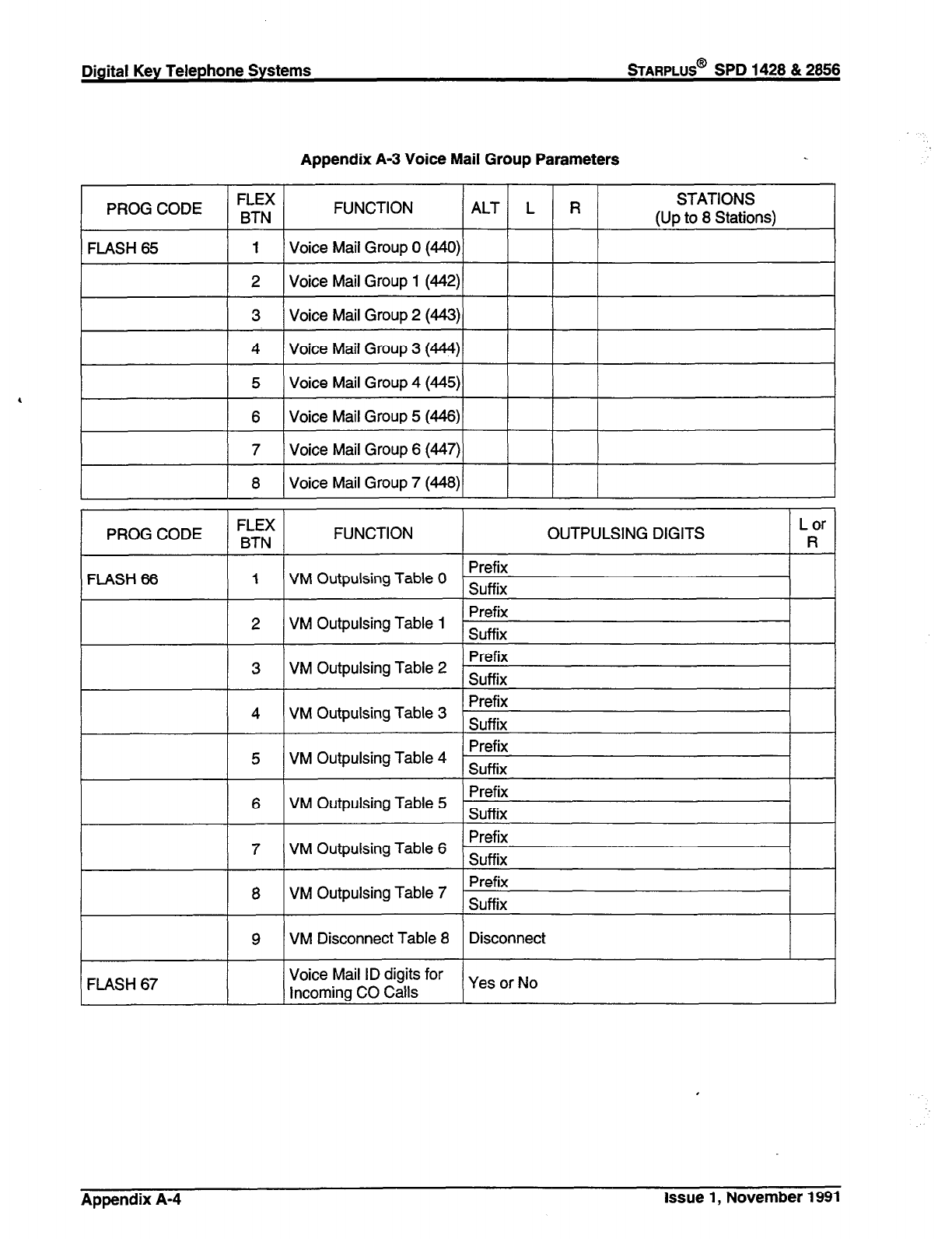
Digital Key Telephone Systems
sTARPLUS@
SPD 1428 & 2866
Appendix A-3 Voice Mail Group Parameters
PROG CODE FLEX FUNCTION ALT L R STATIONS
BTN (Up to 8 Stations)
FLASH 65 1 Voice Mail Group 0 (440)
2 Voice Mail Group 1 (442)
3 Voice Mail Group 2 (443)
4 Voice Mail Group 3 (444)
1 5 ) Voice Mail Group 4 (445)/ I I I
1 6 I Voice Mail Group 5 (446)/
I I I I
I 7 1 Voice Mail Group 6 (4.47))
I I I
/ 8 I Voice Mail Group 7 (448)/
I I I I
Prefix
5 VM Outpulsing Table 4 Suffix
Prefix
6 VM Outpulsing Table 5 Suffix
Prefix
7 VM Outpulsing Table 6 Suffix
FLASH 67
8 VM Outpulsing Table 7 Prefix
Suffix
9 VM Disconnect Table 8 Disconnect
Voice Mail ID digits for
Incoming CO Calls Yes or No
Appendix A-4 Issue 1, November 1991

Appendix A-4 CO Line Programming (Flash 40)
FLEX BTN 1 2 3 4 5 6 7 8 9 10 11
LINE
TONE/ co/ DISA AUTO LOOP
NO PULSE PBX UNA Trk-Trk PRIVACY SUPV D,SA FLASH LINE LINE
TIME GRP COS RING’ REMARKS
Refer to CO Line Ringing Assignments
Isgwe 1, November 1991 Appendix A-5
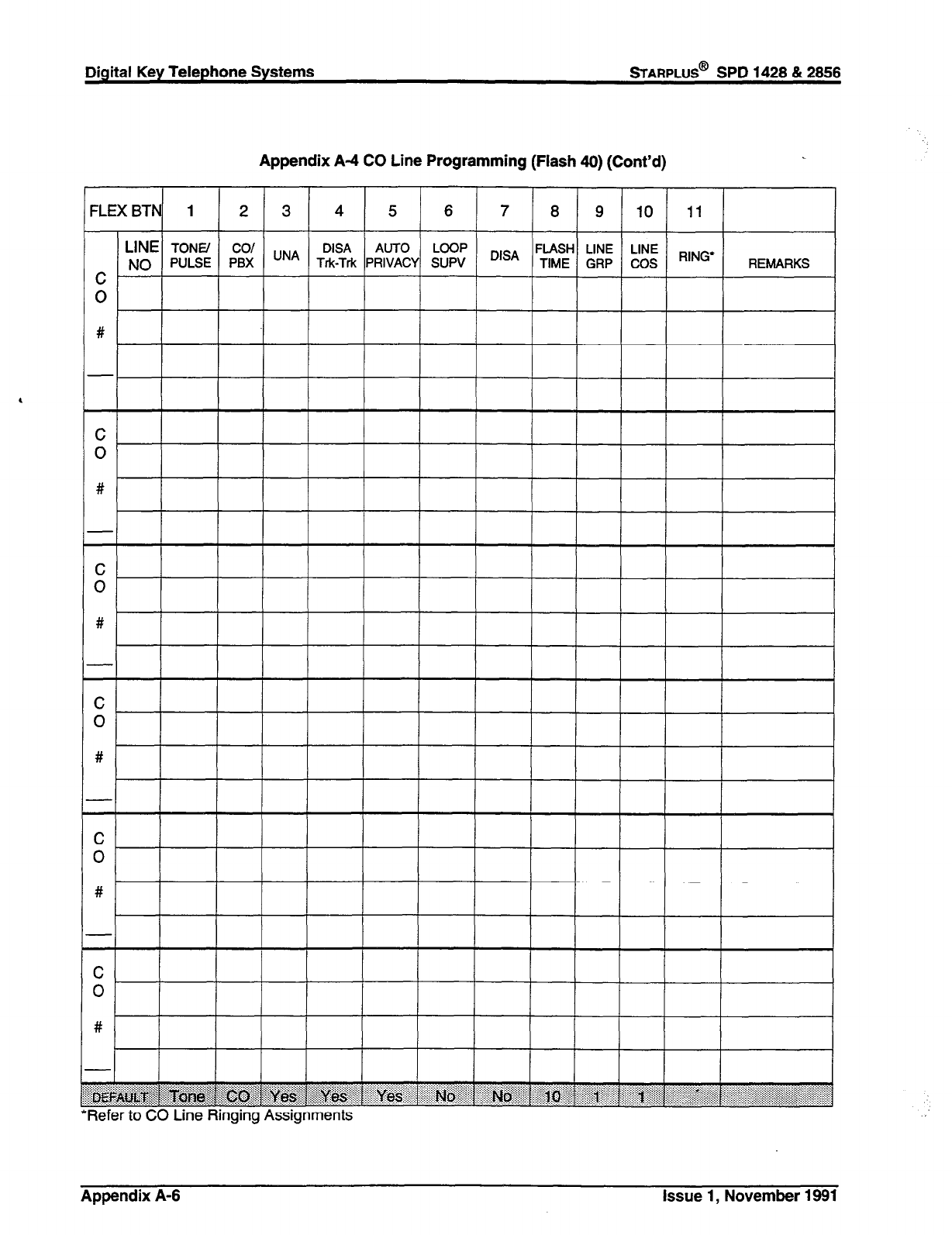
Digital Key Telephone Systems
sTARPLUS@
SPD 1428 & 2866
Appendix A-4 CO Line Programming (Flash 40) (Cont’d)
=LEXBTN 1 2 3 4 5 6 7 8 9 10 11
-
:
#
-
-
C
0
#
-
-
:
#
-
-
C
0
#
-
-
C
0
#
-
-
C
0
#
-
LINE
TONE/ co/ DISA AUTO LOOP
NO PULSE PBX UNA Trk-Trk PRIVACY SUPV D,SA FLASH LINE LINE
TIME GRP COS RING’ REMARKS
fj@
-
qefer to c;U une Hinging Assignments
Appendix A-6 Issue 1, November 1991
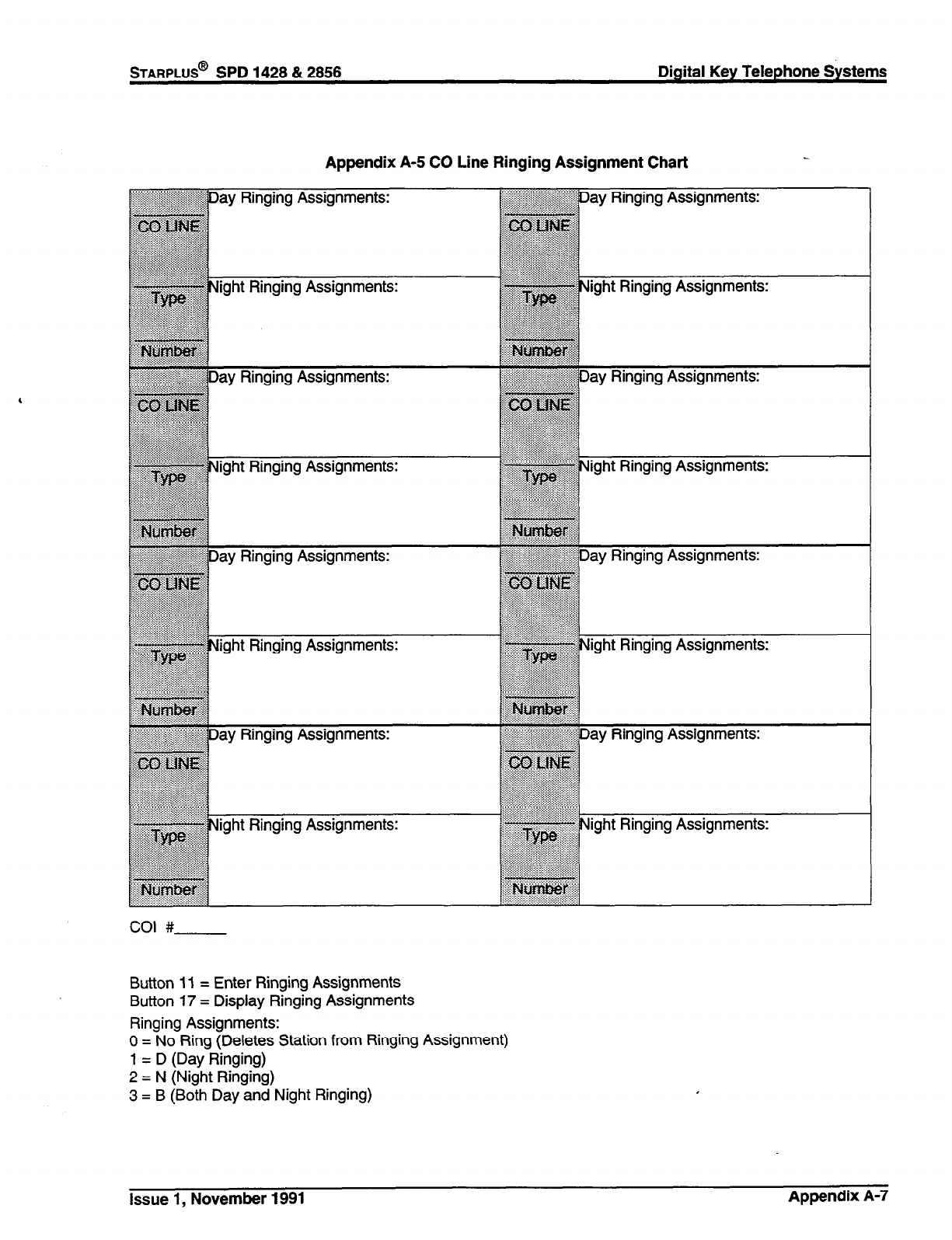
STARPLUS@
SPD 1428 & 2858 Digital Key Telephone Systems
Appendix A-5 CO Line Ringing Assignment Chart
Ili~~~~ay Ringing Assignments:
ay Ringing Assignments:
ight Ringing Assignments:
Uight Ringing Assignments:
Ringing Assignments:
ight Ringing Assignments:
ight Ringing Assignments:
Ringing Assignments: $!$JNight Ringing Assignments:
Button 11 = Enter Ringing Assignments
Button 17 = Display Ringing Assignments
Ringing Assignments:
0 = No Ring (Deletes Station from Ringing Assignment)
1 = D (Day Ringing)
2 = N (Night Ringing)
3 = B (Both Day and Night Ringing)
issue 1, November 1991 Appendix A-7
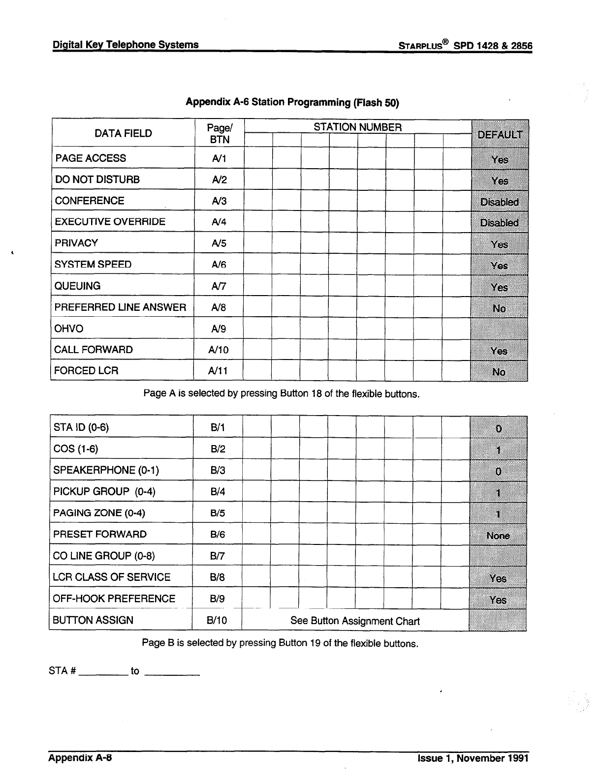
Digital Key Telephone Systems
sTARPLUS@
SPD 1428 & 2866
Appendix A-6 Station Programming (Flash 50)
Page/
RTN t
STATION NUMBER
DO NOT DISTURB Al2
1 CONFERENCE
1 STA ID (O-6)
Page A is selected by pressing Button 18 of the flexible buttons.
1 B/l t 1 1 1
COS (l-6)
SPEAKERPHONE (O-1)
PICKUP GROUP (O-4)
PAGING ZONE (O-4)
PRESET FORWARD
CO LINE GROUP (O-8)
B/2
B/3
B/4 ~ ““5 ::
iiii:~:::.::ji::;.:.:.::::::.:
a::::::.:::...:: . . . . . ....i,,,,,:::;;.:
. . . . .
B/5 .:.::::::>g:::i;;:
B/6 E:;,;;F
:;:;qgg$,
::::: :.,,:.,.,., j
“~“‘:‘y~
““:‘.‘.:....:.~.:.: . . . .
.,.:x.x . . ..‘..:.:...::::ri:i:iirii)i:
. . . .
::::::::y.-: . . . .
:i.:
B/7 .:... :.:.::::::i,i
. . . . .,., ,, ,:,: :^‘:::,
,:,::,,,:
:::::::.::t::::i:::::.? .: .:.:.:..:.: .,:..,,,,,:,:,,,,,
. . . . :I.:.::.:.:~ ::,:,::,:,),:,
q$::::::::::$- . ..^..........
LCR CLASS OF SERVICE
OFF-HOOK PREFERENCE
BUTTON ASSIGN
818
B/9
B/l 0 See Button Assignment Chart
Page B is selected by pressing Button 19 of the flexible buttons,
STA # to
Appendix A-8 Issue 1, November 1991

STARPLUS@
SPD 1428 & 2856 Digital Key Telephone Systems
Appendix A-7 Button Assignment Chart (Flash 60)
This chart is to be used to assign each flexible button a function. By default, Buttons 1 through 10 are as-
signed as Stations 100 through 109, Buttons 11 through 20 are assigned as CO Lines 01 through 10.
WHERE:
BB = Button Number (01 through 28)
LL = CO Line Number (01 through 28)
G = Line Group (1 through 7)
KEY STATION BUITON PROGRAMMING:
1. To assign a button as a multi-function button (user programmable) enter:
BB [0] HOLD
2. To assign a button as a CO Line button, enter:
BB [l] LL HOLD
3. To assign a button as a loop button, enter:
BB [2] HOLD
4. To enter a button as a pooled group button (refer to Section 630.1 for CO Line Group numbers) enter:
BB [3] G HOLD
5. To unassign a button, enter:
BB [#] HOLD
SLT HlTRY. (Off
- -
Hook PrW
6. When an SLT is being assigned for Off-Hook Preference, enter:
00 [l] LL HOLD for a specific CO Line
or
00[3] G HOLD for CO Group Access.
Issue 1, November 1991 Appendix A-9
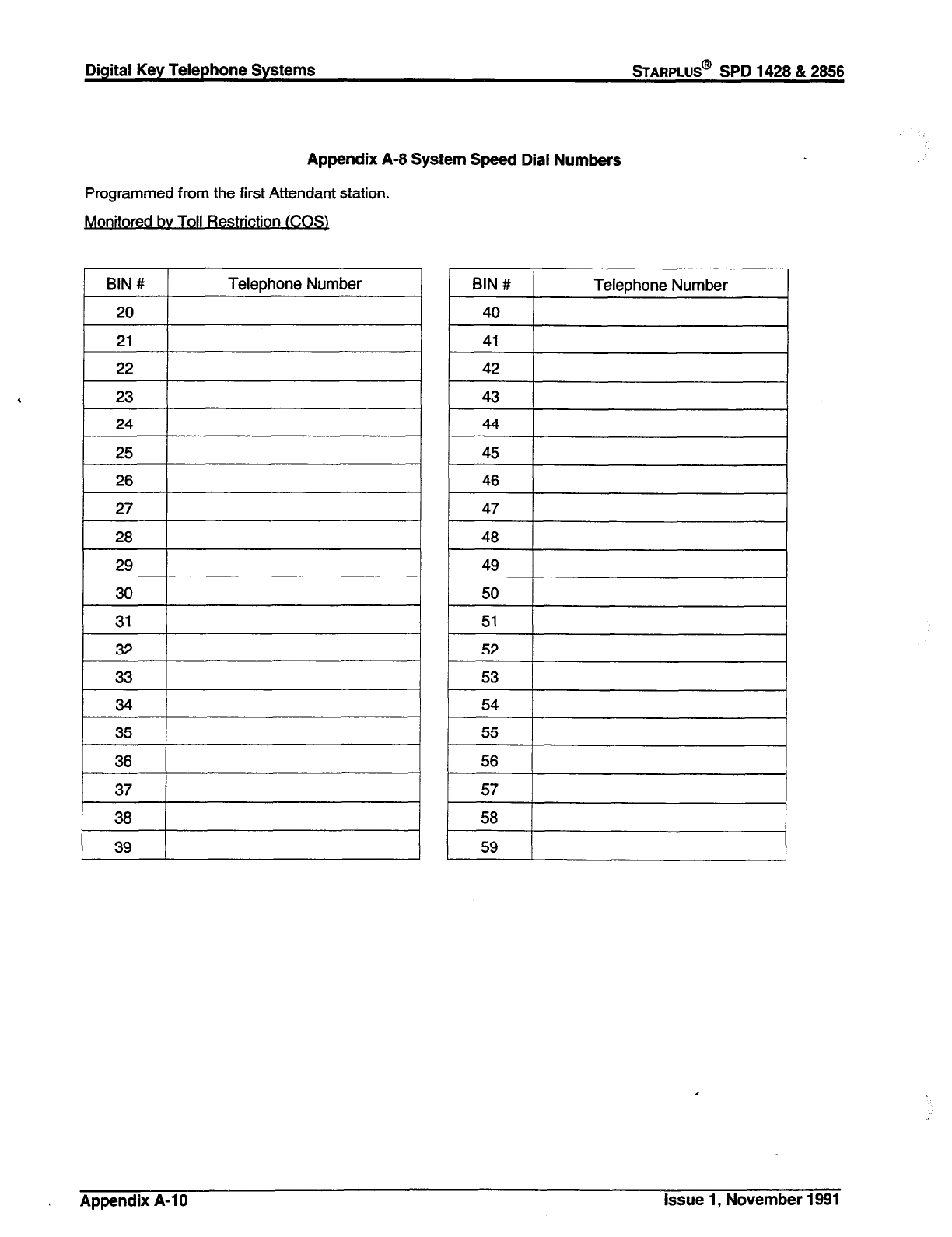
Digital Key Telephone Systems
%ARPLUS@
SPD 1428 & 2866
Appendix A-8 System Speed Dial Numbers
Programmed from the first Attendant station.
. .
Monitored by Toll Restnctlo nl .COS)
54
55
56
57
56
59
Appendix A-l 0 Issue 1, November 1991
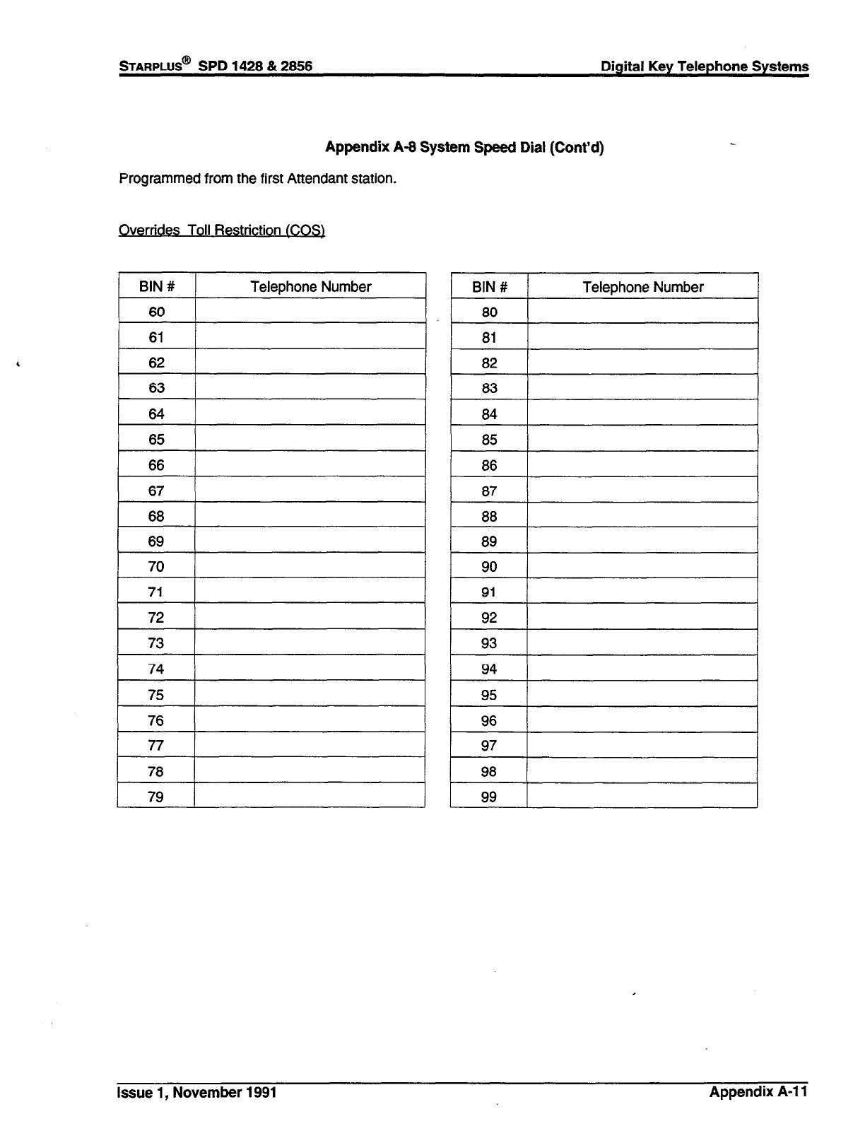
Appendix A-8 System Speed Dial (Cont’d)
Programmed from the first Attendant station.
Overrides Toll Restriction tCOS)
74
75
76
77
76
79
Issue 1, November 1991 Appendix A-l 1

Digital Key Telephone Systems
%ARPLUS@
SPD 1428 & 2866
Allow Table A
Appendix A-9 Exception Tables (Flash 70)
1 BIN 1 1
1 BIN2 1
1 BIN3 1
1 BIN4 (
1 BIN5 I
BIN 13
BIN 14
1 BIN 15 1
1 BIN 19 I
[ BIN 20 [
Deny Table A
BIN 1
BIN 2
BIN 3
BIN 4
BIN 5
BIN 6
BIN 7
1 BIN8 I
BIN 9
BIN 10
Allow Table B
Deny Table B
Appendix A-12 Issue 1, November 1991
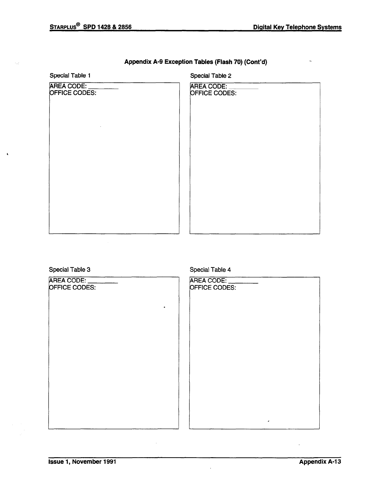
Special Table 1
Appendix A-9 Exception Tables (Flash 70) (Cont’d)
MEA CODE:
IFFICE CODES:
Special Table 3
P
C
LREA CODE:
IFFICE CODES:
Special Table 2
,REA CODE:
IFFICE CODES:
Special Table 4
GIEA CODE:
IFFICE CODES:
Issue 1, November 1991 Appendix A-l 3
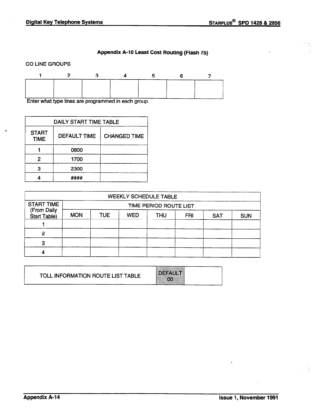
Digital Key Telephone Systems
sTARPLUS@
SPD 1428 & 2858
Appendix A-10 Least Cost Routing (Flash 75)
CO LINE GROUPS
2 7
Enter what type lines are programmed in each group.
DAILY START TIME TABLE
I I
DEFAULT TIME CHANGED TIME
1 0800 I
2 1700
3 2300
I 4 I
. . . . . . .
TOLL INFORMATION ROUTE LIST TABLE ~~~~~~~~
fll~~~
: :...:,:, ,_,,, . . . . . . . . . ..“‘ii~~(i.....
Appendix A-l 4 Issue 1, November 1991
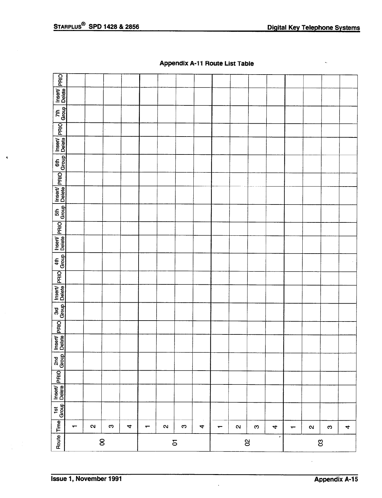
sTARPLUS@
SPD 1428 & 2856 Digital Key Telephone Systems
Appendix A-l 1 Route List Table
Issue 1, November 1991 Appendix A-l 5
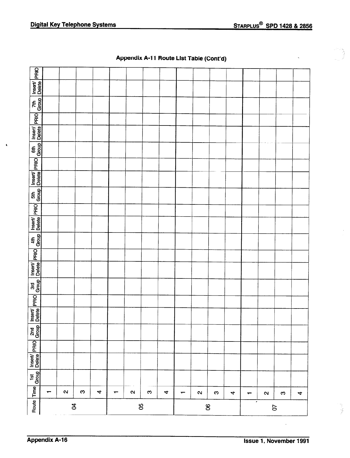
Digital Key Telephone Systems
STARPLUS@
SPD 1428 & 2866
Appendix A-l 1 Route List Table (Cont’d)
Appendix A-l 6 Issue 1, November 1991
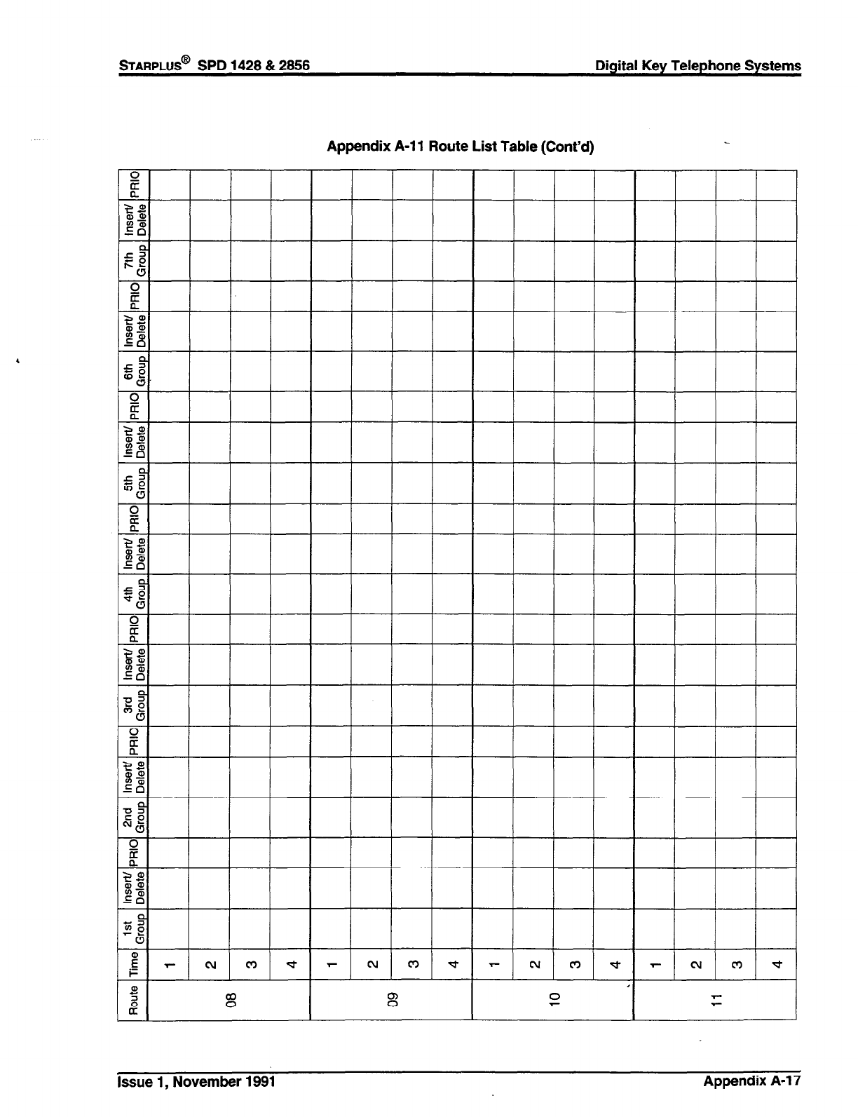
Appendix A-l 1 Route List Table (Cont’d)
Issue 1, November 1991 Appendix A-l 7

Digital Key Telephone Systems
sTARPLUS@
SPD 1428 812856
Appendix A-l 1 Route List Table (Cont’d)
Appendix A-18 Issue 1, November 1991
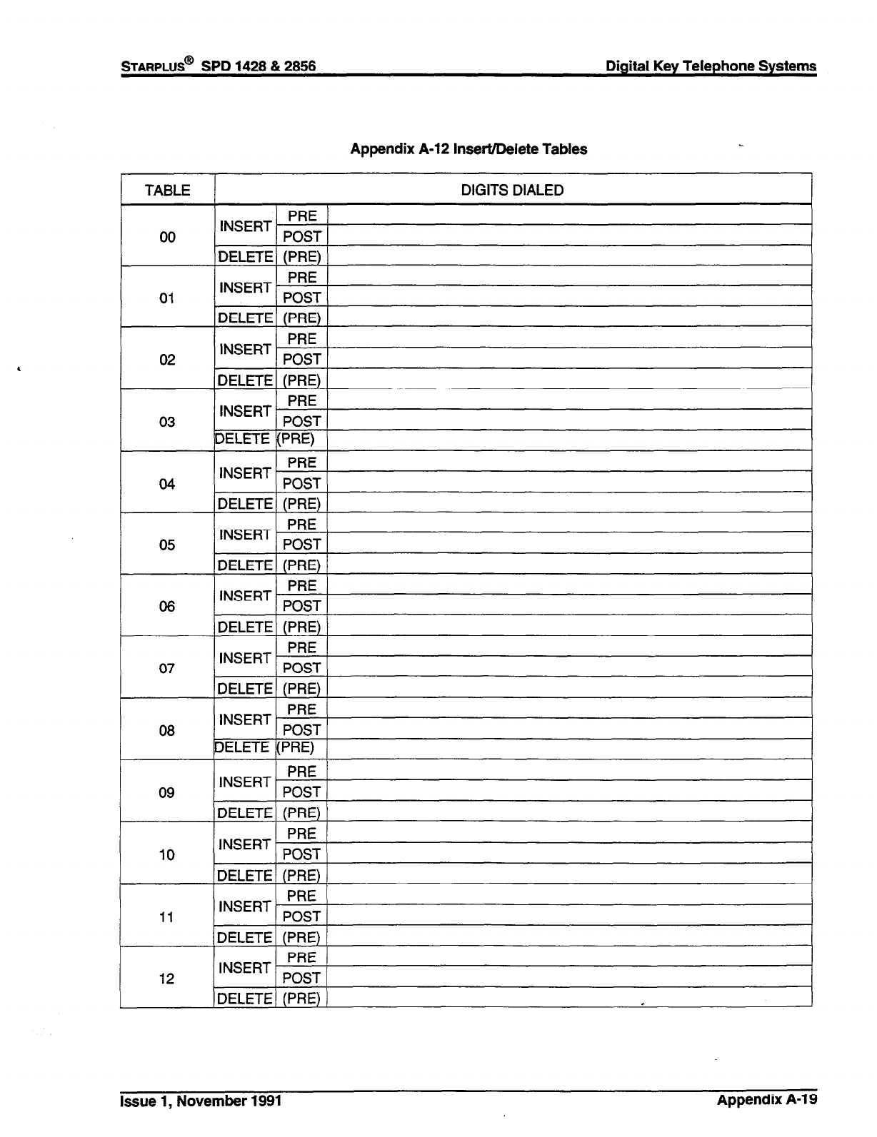
STARPLUS@
SPD 1428 812858 Digital Key Telephone Systems
,
Appendix A-12 Insert/Delete Tables
TABLE DIGITS DIALED
00 INSERT PRE
POST
IDELETE\ (PRE) )
01 INSERT PRE
POST
1 DELETE 1 (PRE) 1
02 INSERT ;:!jT
DELETE (PRE)
03 INSERT. PRE
POST
DELETE (PRE)
INSERT PRE
04 POST
nlZl C-I-C IDPI=\
05 INSERT ;:iT
DELETE (PRE)
INSERT PRE
08 POST
11 INSERT PRE
POST
DELETE (PRE)
12 INSERT PRE
POST
1
) DELETE] (PRE) 1 I
Issue 1, November 1991 Appendix A-l 9
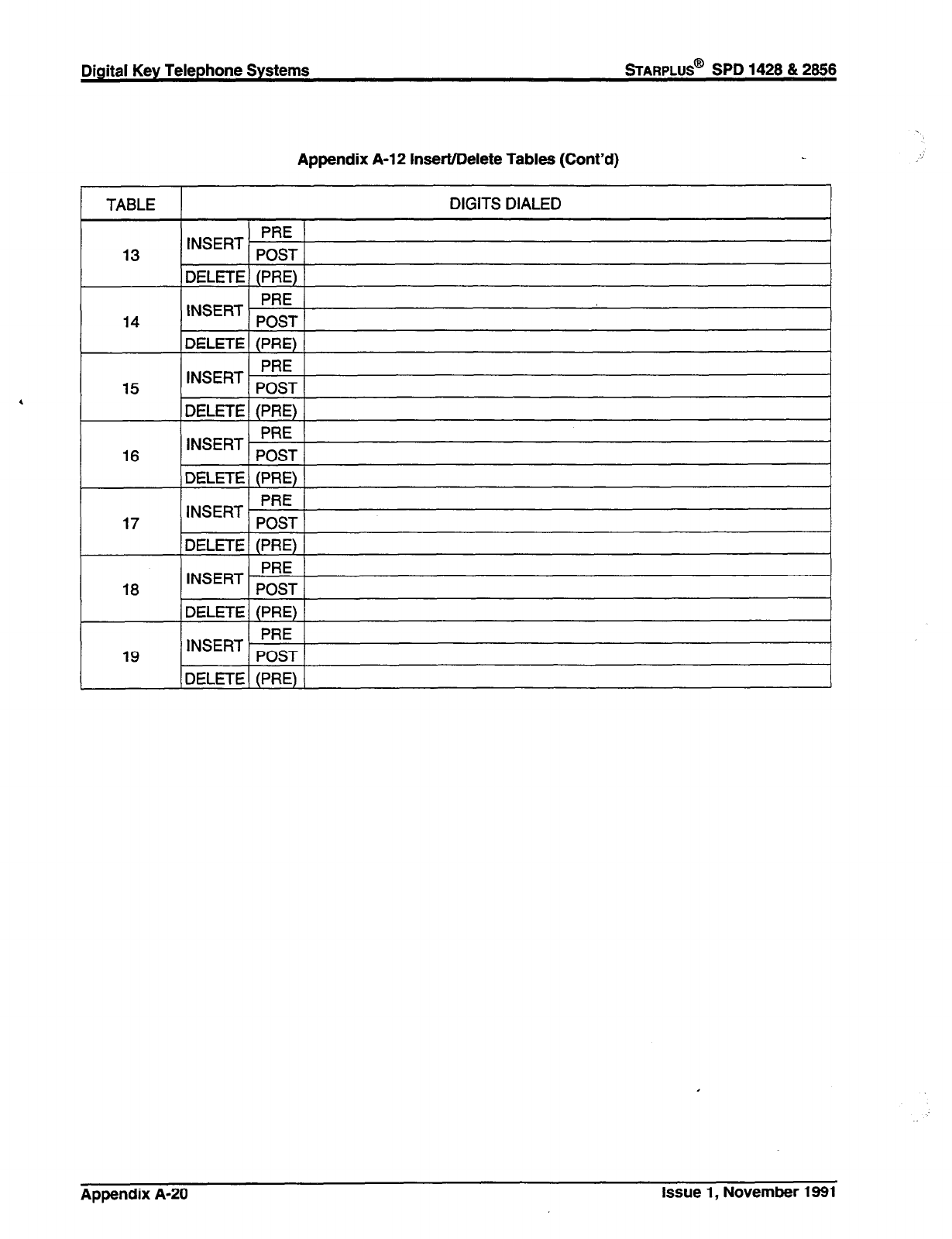
Digital Key Telephone Systems
STARPLUS@
SPD 1428 & 2866
Appendix A-l 2 Insert/Delete Tables (Cont’d)
1 TABLE ) DIGITS DIALED
13 INSERT PRE
POST
DELETE (PRE)
14 INSERT PRE
POST
DELETE (PRE)
15 INSERT p;;T
DELETE (PRE)
16 INSERT PRE
POST
DELETE (PRE)
17 INSERT PRE
POST
DELETE (PRE)
18 INSERT ;;iT
L
(DELETEI (PRE) 1 I
Appendix A-20 Issue 1, November 1991
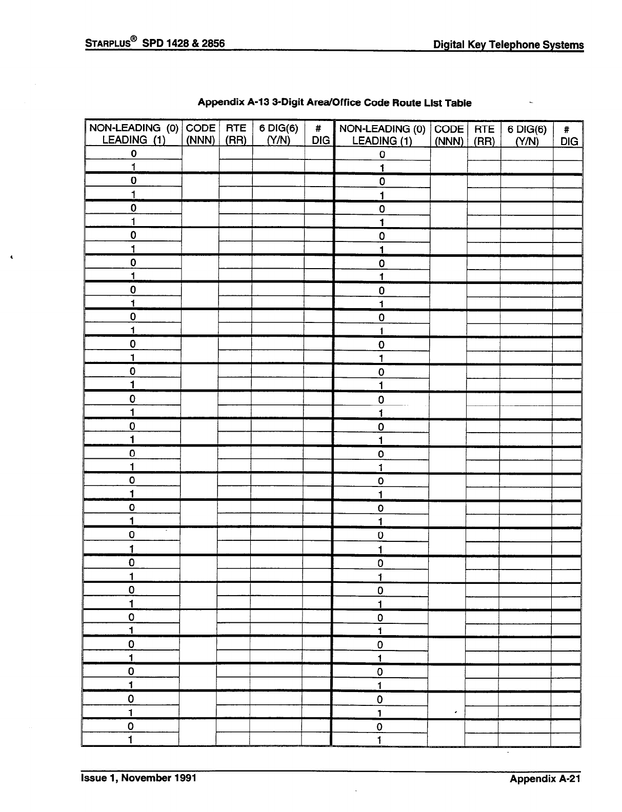
STARPLUS@ SPD 1428 & 2856 Digital Key Telephone Systems
Appendix A-13 3-Digit Area/Office Code Route List Table
Issue 1, November 1991 Appendix A-21
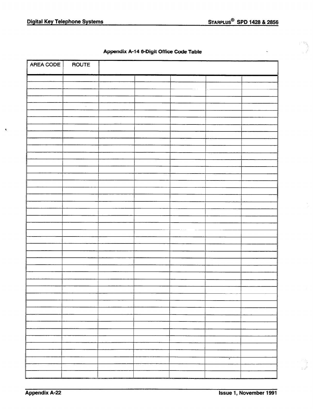
Appendix A-14 6-Digit Office Code Table
Appendix A-22
Issue
1, November 1991
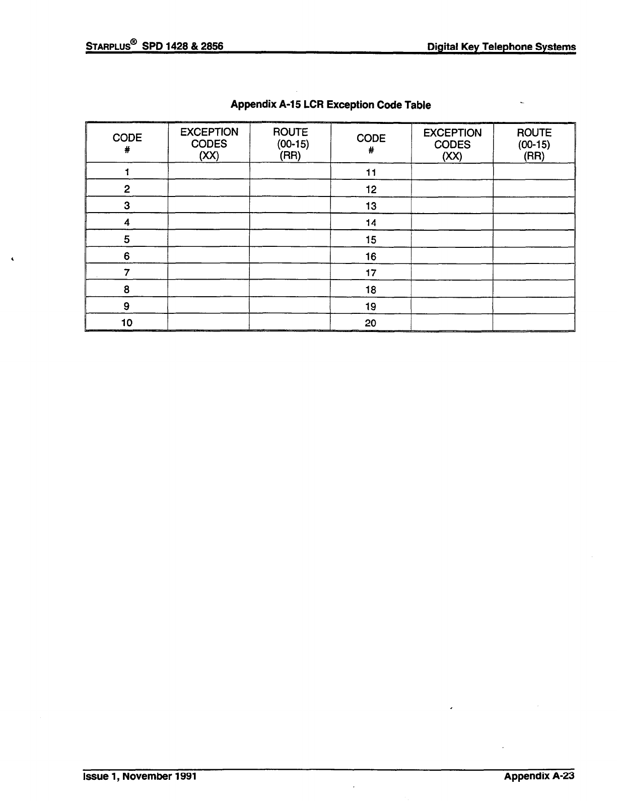
STARPLUS@
SPD 1428 & 2858 Digital Key Telephone Systems
Appendix A-l 5 LCR Exception Code Table
Issue 1, November 1991 Appendix A-23
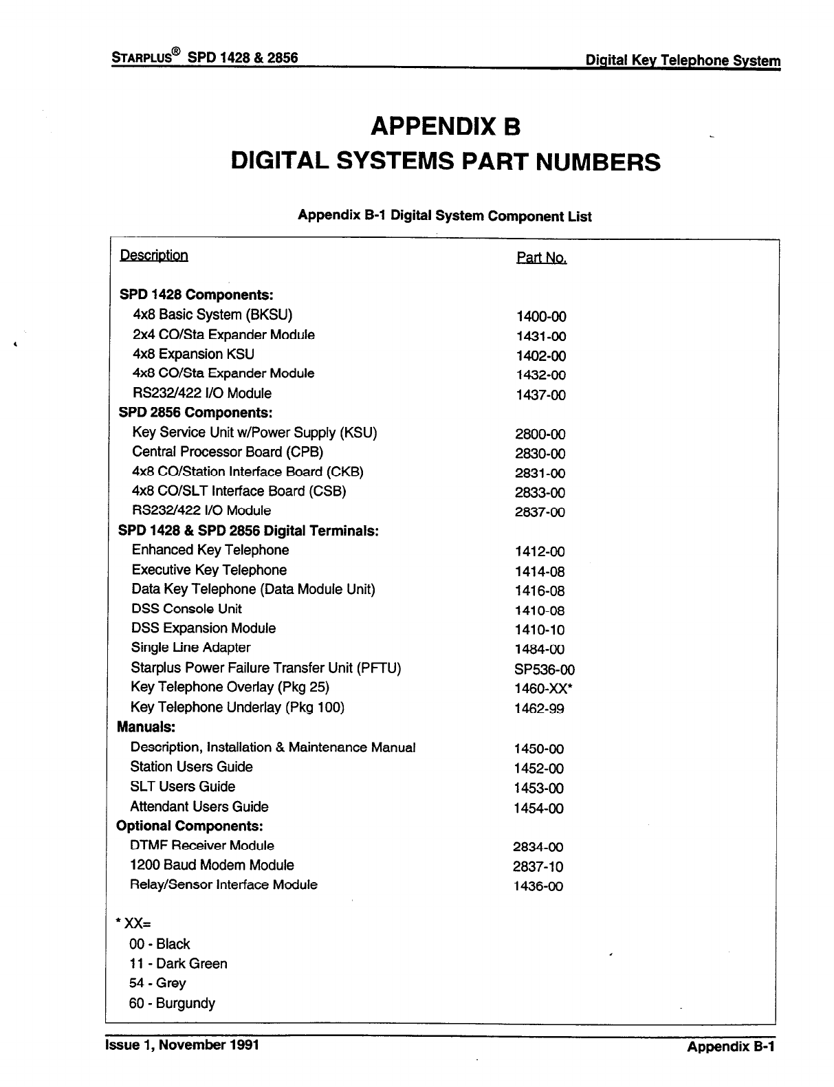
sTARPLUS@
SPD 1428 & 2856 Digital Key Telephone System
APPENDIX B
DIGITAL SYSTEMS PART NUMBERS
Appendix B-l Digital System Component List
. .
Pescnptw Part No,
SPD 1428 Components:
4x8 Basic System (BKSU)
2x4 CO/Sta Expander Module
4x8 Expansion KSU
4x8 CO/Sta Expander Module
RS232/422 I/O Module
SPD 2856 Components:
Key Service Unit w/Power Supply (KSU)
Central Processor Board (CPB)
4x8 CO/Station Interface Board (CKB)
4x8 CO/SLT Interface Board (CSB)
RS232/422 I/O Module
SPD 1428 & SPD 2856 Digital Terminals:
Enhanced Key Telephone
Executive Key Telephone
Data Key Telephone (Data Module Unit)
DSS Console Unit
DSS Expansion Module
Single Line Adapter
Starplus Power Failure Transfer Unit (PFTU)
Key Telephone Overlay (Pkg 25)
Key Telephone Underlay (Pkg 100)
Manuals:
Description, Installation & Maintenance Manual
Station Users Guide
SLT Users Guide
Attendant Users Guide
Optional Components:
DTMF Receiver Module
1200 Baud Modem Module
Relay/Sensor Interface Module
*xX=
00 - Black
11 - Dark Green
54 - Grey
60 - Burgundy
1400-00
1431-00
1402-00
1432-00
1437-00
2800-00
2830-00
2831-00
2833-00
2837-00
1412-00
1414-08
1416-08
1410-08
1410-10
1484-00
SP536-00
1460-xX*
1462-99
1450-00
1452-00
1453-00
1454-00
2834-00
2837- 10
1436-00
Issue 1, November 1991 Appendix B-l
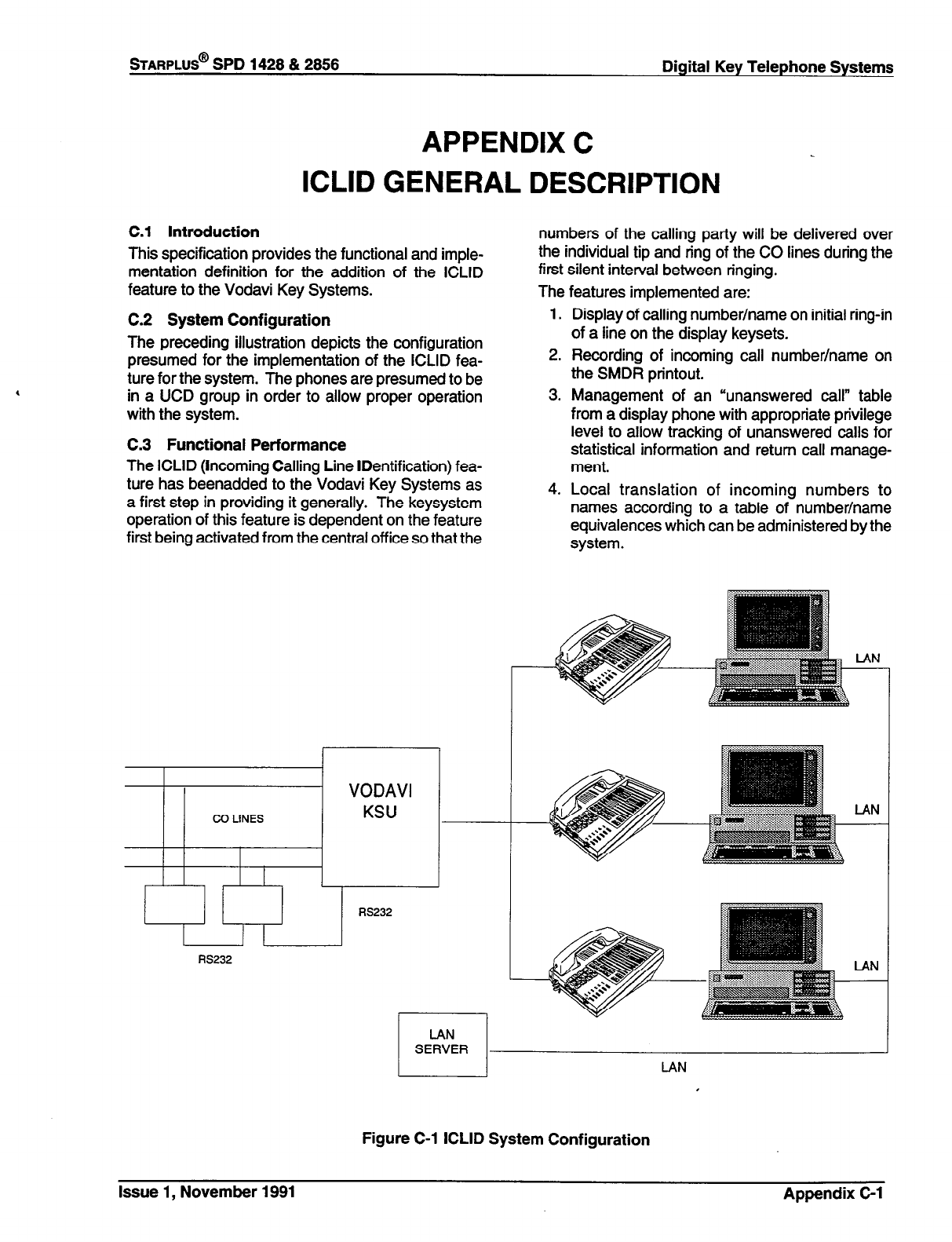
STARPLUS@
SPD 1428 & 2856 Digital Key Telephone Systems
APPENDIX C
ICLID GENERAL DESCRIPTION
C.l Introduction
This specification provides the functional and imple-
mentation definition for the addition of the ICLID
feature to the Vodavi Key Systems.
numbers of the calling party will be delivered over
the individual tip and ring of the CO lines during the
first silent interval between ringing.
The features implemented are:
C.2 System Configuration
The preceding illustration depicts the configuration
presumed for the implementation of the ICLID fea-
ture for the system. The phones are presumed to be
in a UCD group in order to allow proper operation
with the system.
C.3 Functional Performance
The ICLID (Incoming Calling Line IDentification) fea-
ture has beenadded to the Vodavi Key Systems as
a first step in providing it generally. The keysystem
operation of this feature is dependent on the feature
first being activated from the central off ice so that the
I-
RS232
1. Display of calling number/name on initial ring-in
of a line on the display keysets.
2. Recording of incoming call number/name on
the SMDR printout.
3. Management of an “unanswered call” table
from a display phone with appropriate privilege
level to allow tracking of unanswered calls for
statistical information and return call manage-
ment.
4. Local translation of incoming numbers to
names according to a table of number/name
equivalences which can be administered by the
system.
LAN
Figure C-l ICLID System Configuration
Issue 1, November 1991 Appendix C-l
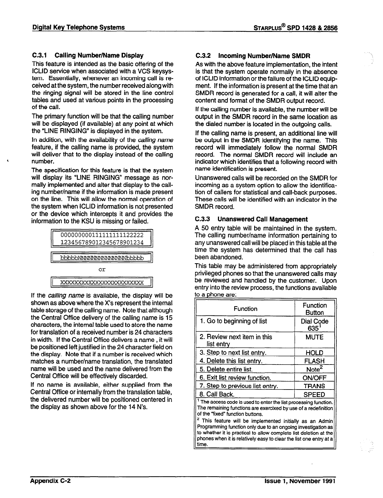
C-3.1 Calling Number/Name Display
This feature is intended as the basic offering of the
ICLID service when associated with a VCS keysys-
tern. Essentially, whenever an incoming call is re-
ceived at the system, the number received along with
the ringing signal will be stored in the line control
tables and used at various points in the processing
of the call.
The primary function will be that the calling number
will be displayed (if available) at any point at which
the “LINE RINGING” is displayed in the system.
In addition, with the availability of the calling name
feature, if the calling name is provided, the system
will deliver that to the display instead of the calling
4 number.
The specification for this feature is that the system
will display its “LINE RINGING” message as nor-
mally implemented and alter that display to the call-
ing number/name if the information is made present
on the line. This will allow the normal operation of
the system when ICLID information is not presented
or the device which intercepts it and provides the
information to the KSU is missing or failed.
1 bbbbb-bbbb 1
000000000111111111122222
123456789012345678901234
If the calling name is available, the display will be
shown as above where the X’s represent the internal
table storage of the calling name. Note that although
the Central Office delivery of the calling name is 15
characters, the internal table used to store the name
for translation of a received number is 24 characters
in width. If the Central Office delivers a name , it will
be positioned left justified in the 24 character field on
the display. Note that if a number is received which
matches a number/name translation, the translated
name will be used and the name delivered from the
Central Office will be effectively discarded.
If no name is available, either supplied from the
Central Office or internally from the translation table,
the delivered number will be positioned centered in
the display as shown above for the 14 N’s.
Digital Key Telephone Systems
sTARPLUS@
SPD 1428 & 2866
C.3.2 Incoming Number/Name SMDR
As with the above feature implementation, the intent
is that the system operate normally in the absence
of ICLID information or the failure of the ICLID equip-
ment. If the information is present at the time that an
SMDR record is generated for a call, it will alter the
content and format of the SMDR output record.
If the calling number is available, the number will be
output in the SMDR record in the same location as
the dialed number is located in the outgoing calls.
If the calling name is present, an additional line will
be output in the SMDR identifying the name. This
record will immediately follow the normal SMDR
record. The normal SMDR record will include an
indicator which identifies that a following record with
name identification is present.
Unanswered calls will be recorded on the SMDR for
incoming as a system option to allow the identifica-
tion of callers for statistical and call-back purposes.
These calls will be identified with an indicator in the
SMDR record.
C.3.3 Unanswered Call Management
A 50 entry table will be maintained in the system.
The calling number/name information pertaining to
any unanswered call will be placed in this table at the
time the system has determined that the call has
been abandoned.
This table may be administered from appropriately
privileged phones so that the unanswered calls may
be reviewed and handled by the customer. Upon
entry into the review process, the functions available
to a phone are: I
Function Function
Button ,
1. Go to beginning of list Dial Code
635’
2. Review next item in this MUTE
list entry
3. Step to next list entry. HOLD
4. Delete this list entry. FLASH
5. Delete entire list. Note*
6. Exit list review function. ON/OFF
7. Step to previous list entry. TRANS
8. Call Back. SPEED
’ The access code is used to enter the list orocessina function.
The remaining functions are exercixed by’use of a redefinition
’ This feature will be implemented initially as an Admin
[;zVxey.Y function buttons.
ProgrammIng function only due to an ongoing mvestrgabon as
. . . 1
to whether it is practical to allow complete list deletion at the
phones when it is relatively easy to clear the list one entry at a
:.
Appendix C-2 Issue 1, November 1991
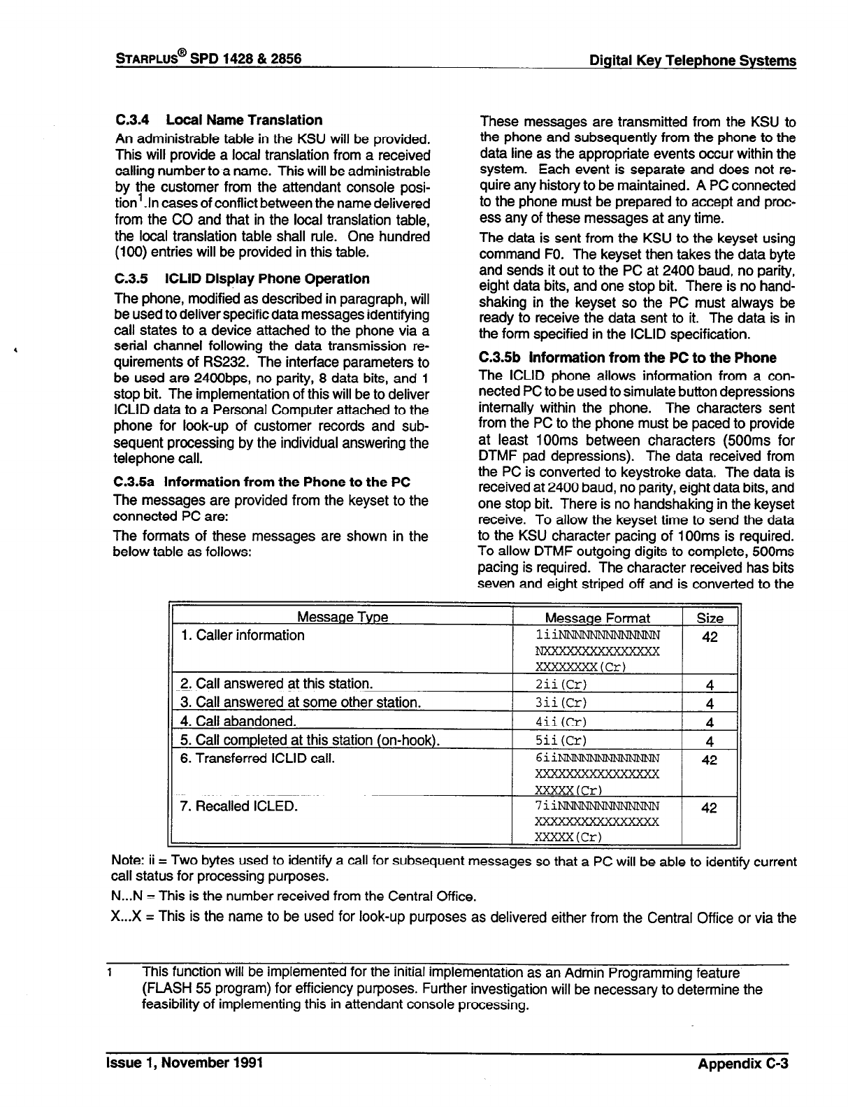
STARPLUS@
SPD 1428 & 2856 Digital Key Telephone Systems
C.3.4 Local Name Translation
An administrable table in the KSU will be provided.
This will provide a local translation from a received
calling number to a name. This will be administrable
by the customer from the attendant console posi-
tion’.ln cases of conflict between the name delivered
from the CO and that in the local translation table,
the local translation table shall rule. One hundred
(100) entries will be provided in this table.
C.3.5 ICLID Display Phone Operation
The phone, modified as described in paragraph, will
be used to deliver specific data messages identifying
call states to a device attached to the phone via a
serial channel following the data transmission re-
quirements of RS232. The interface parameters to
be used are 24OObps, no parity, 8 data bits, and 1
stop bit. The implementation of this will be to deliver
ICLID data to a Personal Computer attached to the
phone for look-up of customer records and sub-
sequent processing by the individual answering the
telephone call.
C.3.5a Information from the Phone to the PC
The messages are provided from the keyset to the
connected PC are:
The formats of these messages are shown in the
below table as follows:
These messages are transmitted from the KSU to
the phone and subsequently from the phone to the
data line as the appropriate events occur within the
system. Each event is separate and does not re-
quire any history to be maintained. A PC connected
to the phone must be prepared to accept and proc-
ess any of these messages at any time.
The data is sent from the KSU to the keyset using
command FO. The keyset then takes the data byte
and sends it out to the PC at 2400 baud, no parity,
eight data bits, and one stop bit. There is no hand-
shaking in the keyset so the PC must always be
ready to receive the data sent to it. The data is in
the form specified in the ICLID specification.
C.3.5b information from the PC to the Phone
The ICLID phone allows information from a con-
nected PC to be used to simulate button depressions
internally within the phone. The characters sent
from the PC to the phone must be paced to provide
at least 1OOms between characters (500ms for
DTMF pad depressions). The data received from
the PC is converted to keystroke data. The data is
received at 2400 baud, no parity, eight data bits, and
one stop bit. There is no handshaking in the keyset
receive. To allow the keyset time to send the data
to the KSU character pacing of 100ms is required.
To allow DTMF outgoing digits to complete, 500ms
pacing is required. The character received has bits
seven and eight striped off and is converted to the
Note: ii = Two bytes used to identify a call for subsequent messages so that a PC will be able to identify current
call status for processing purposes.
N...N = This is the number received from the Central Office.
X...X = This is the name to be used for look-up purposes as delivered either from the Central Office or via the
1
This function will be implemented for the initial implementation as an Admin Programming feature
(FLASH 55 program) for efficiency purposes. Further investigation will be necessary to determine the
feasibility of implementing this in attendant console processing.
Issue 1, November 1991 Appendix C-3
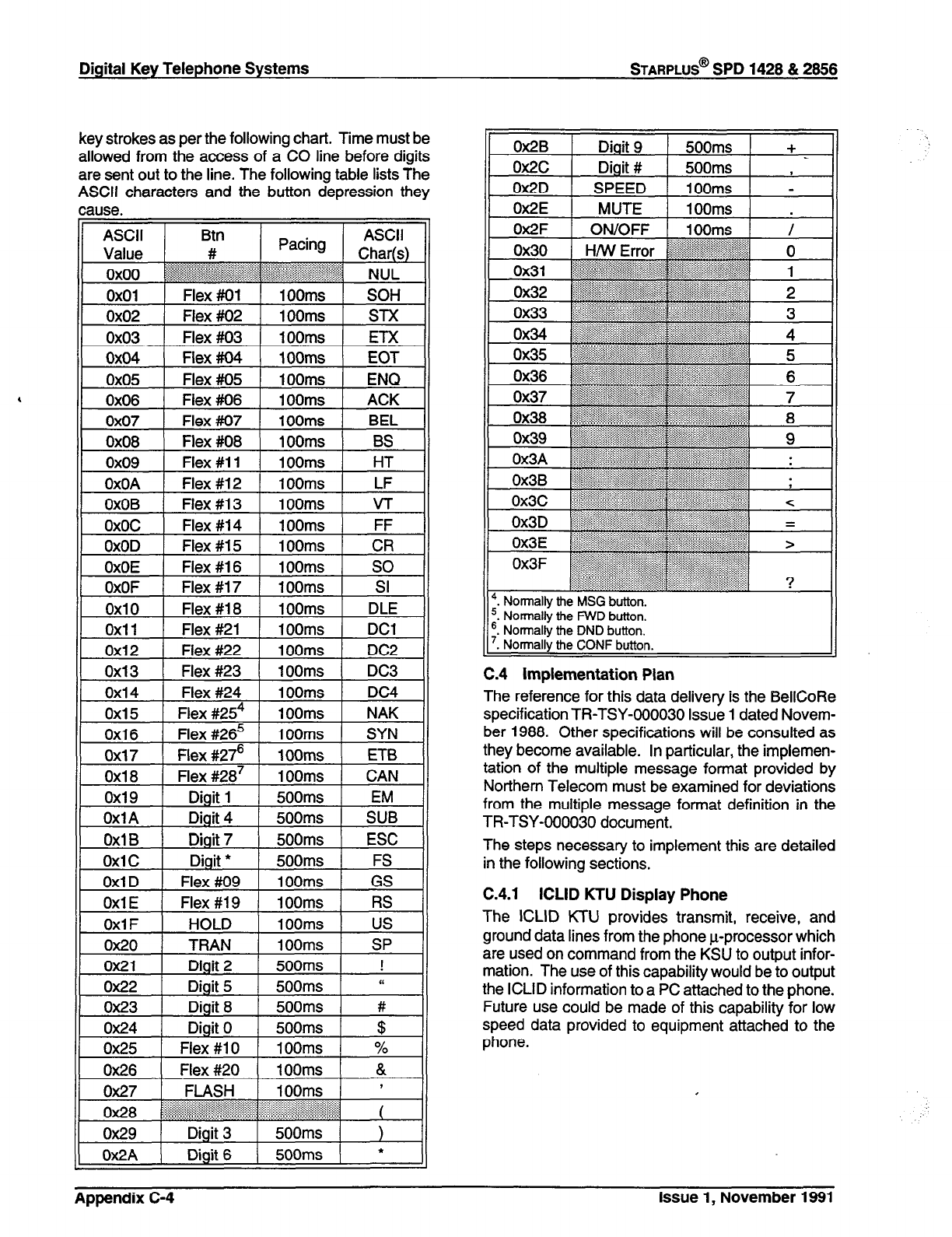
Digital Key Telephone Systems
STARPLUS@
SPD 1428 & 2866
key strokes as per the following chart. Time must be
allowed from the access of a CO line before digits
are sent out to the line. The following table lists The
ASCII characters and the button depression they
cause.
ASCII Btn ASCII
Value # Pacing Char(s)
oxoo .:::.:.~::i~~~~~~~~~ ~~~~~
~,~~~.~,~.~.~.~.~.~~:~.~.~.~:~,~.:~:.~ .:...... .
“‘r’:‘.‘....:.:..:.:~~::~~:~:~:.: . . . . . . :r::::.:i
:)‘:::. ~ ,:::::: ~ ,,:,:,: : : : : : : : : : :
: NUL
,
0x27 FLASH 1 100ms 1 ’
,‘? I’. ‘...“.
ox28 ~~~li’:‘jal
‘.“(‘:-::::.:.:....?.: . . . . . . . . . . . . . . . . . . . .
:.... . . . . . . . . . . . . . . ...*).._.,,,,,,,,,,,,:,,,,,,,,,,,
(
0x29 Digit 3 500ms )
Ox2A Digit 6 500ms *
C.4 implementation Plan
The reference for this data delivery is the BellCoRe
specification TR-TSY-000030 Issue 1 dated Novem-
ber 1988. Other specifications will be consulted as
they become available. In particular, the implemen-
tation of the multiple message format provided by
Northern Telecom must be examined for deviations
from the multiple message format definition in the
TR-TSY-000030 document.
The steps necessary to implement this are detailed
in the following sections.
C.4.1 ICLID KTU Display Phone
The ICLID KTU provides transmit, receive, and
ground data lines from the phone u-processor which
are used on command from the KSU to output infor-
mation. The use of this capability would be to output
the ICLID information to a PC attached to the phone.
Future use could be made of this capability for low
speed data provided to equipment attached to the
phone.
:.
Appendix C-4
issue
1, November 1991
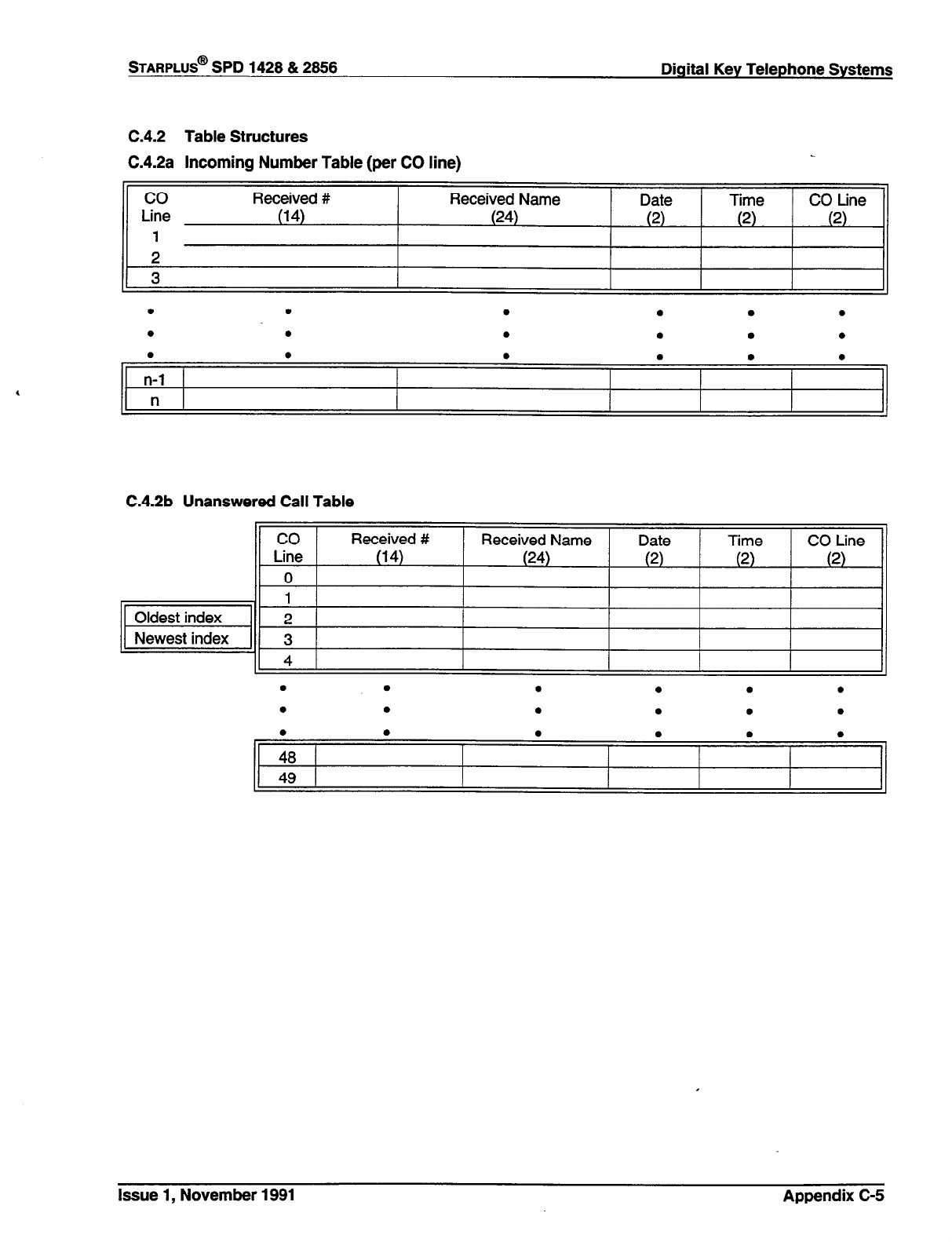
STARPLUS@
SPD 1428 & 2856 Digital Key Telephone Systems
C.4.2 Table Structures
C.4.2a Incoming Number Table (per CO line)
co
Line
1
2
3
Received #
(14) Received Name
(24) Date
(2) Time
(2) CO tine
(2)
. . . . . .
l . . . . .
. . . . . .
n-l
n
C.4.2b Unanswered Call Table
.
l . . . .
. . . . . 0
. . . . . .
48
49
Issue 1, November 1991 Appendix C-5
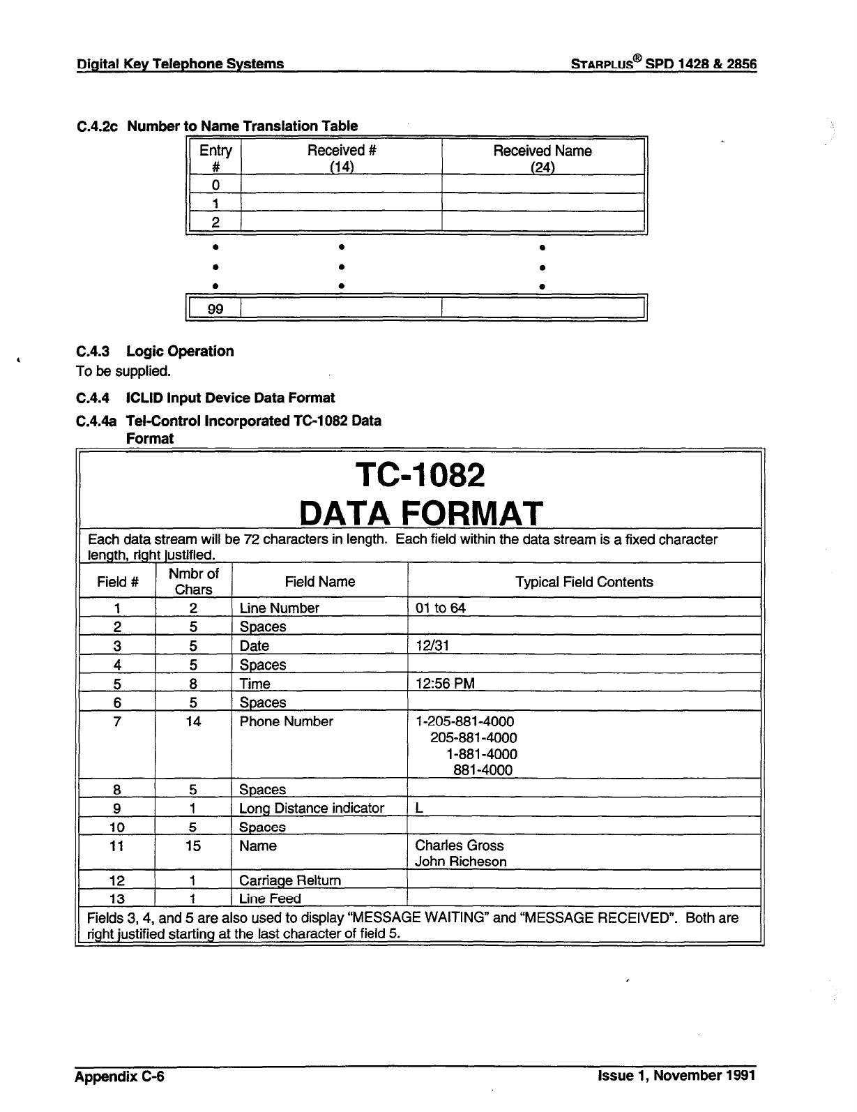
Digital Key Telephone Systems
STARPLUS@
SPD 1428 & 2866
,
C.4.2~ Number to Name Translation Table
<I
. . e
. 0 0
.
l .
1 99 I
C.4.3 Logic Operation
To be supplied.
C.4.4 ICLID Input Device Data Format
C.4.4a Tel-Control Incorporated TC-1082 Data
Format
TWO82
DATA FORMAT
Each data stream will be 72 characters in length. Each field within the data stream is a fixed character
length, right justified.
Field # Nmbr of
Chars Field Name Typical Field Contents
1 2 Line Number 01 to64
3 5 1 Date / 12/31
5 8 1 Time 1 12:56 PM
7 14 Phone Number l-205-881 -4000
205-881-4000
l-881 -4000
881-4000
8 5 Spaces
9 1 Long Distance indicator L
10 5 Spaces
11 15 Name Charles Gross
John Richeson
12 1 Carriage Reltum
13 1 Line Feed
Fields 3,4, and 5 are also used to display “MESSAGE WAITING” and “MESSAGE RECEIVED”. Both are
right justified starting at the last character of field 5.
Appendix C-6 Issue 1, November 1991
STARPLUS@
SPD 1428 & 2856 Digital Key Telephone Systems
C.5 Potential Additional Features for Later Im-
plementation
(Features to be included in the Keysystem Software)
Advantage System integration. This should be gen-
eralized to the point where the data currently pro-
vided to the special ICLID KTU would be instead
tagged with a phone number and sent via an
RS23ZYRS422 processor port from the KSU to a host
computer. The concept in this case is that the host
computer handles multiple terminals associated with
the telephones. As a telephone is identified as re-
ceiving ICLID data, the host computer would provide
the appropriate data to the terminal associated with
the message.
C.6 Direction of Specific Numbers to Special
Handling (Favored Customer Treatment).
l
e.g.Calling Number Blocking
l
Favored Customer UCD Group Selection
l
Favored Customer Off-net Forwarding
l
Special UCD Recording Selection
l
Accumulate multiple counts of the same
number incoming, rather than entering the
same number into the unanswered number
table again.
C.7 Features Implemented External to the
KSU Software
l
Customer name/address look-up based on
the incoming number. This would be a data
base program which would be indexed on
the customer name and number.
Issue 1, November 1991 Appendix C-7
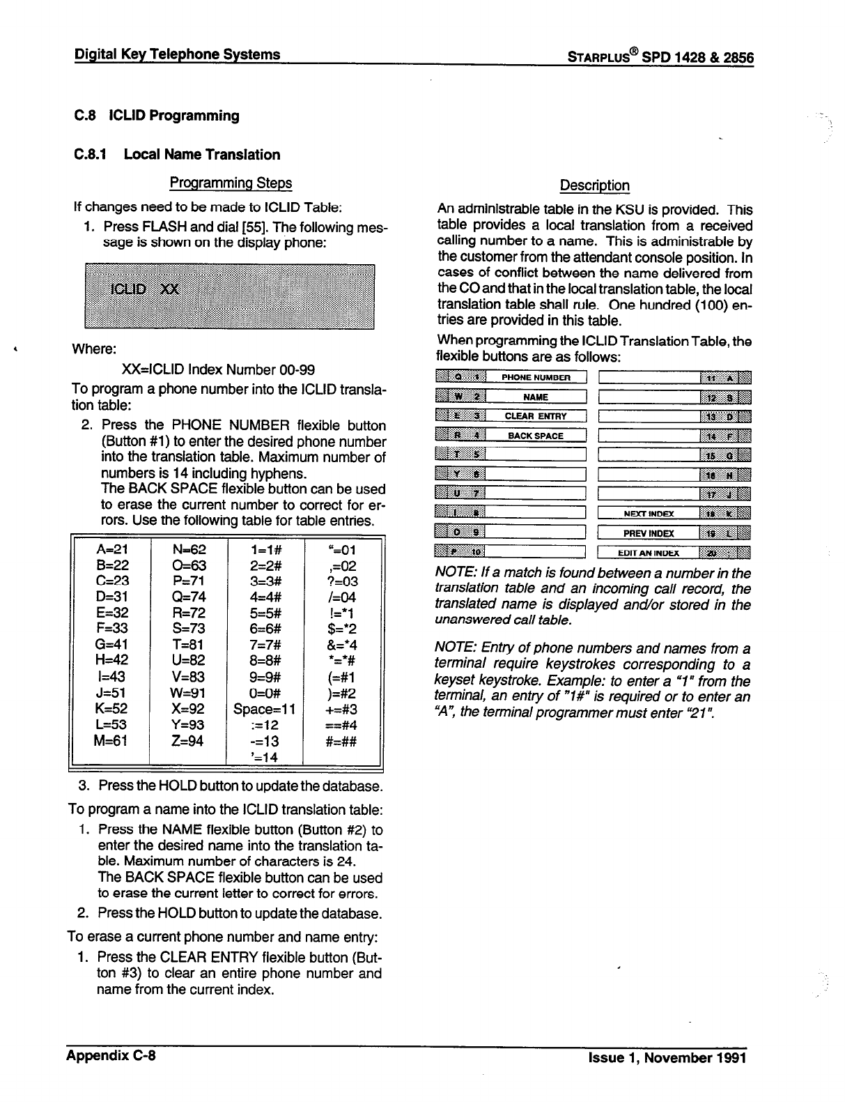
Digital Key Telephone Systems
STARPLUS@
SPD 1428 & 2866
C.8 ICLID Programming
C.8.1 Local Name Translation
Programming Steps
If changes need to be made to ICLID Table:
1. Press FLASH and dial [55]. The following mes-
sage is shown on the display phone:
,
Where:
XX=ICLID Index Number 00-99
To program a phone number into the ICLID transla-
tion table:
2. Press the PHONE NUMBER flexible button
(Button #l) to enter the desired phone number
into the translation table. Maximum number of
numbers is 14 including hyphens.
The BACK SPACE flexible button can be used
to erase the current number to correct for er-
rors. Use the following table for table entries.
A=21
B=22
C=23
D=31
E=32
F=33
G=41
H=42
I=43
J=Sl
K=52
L=53
M=61
N=62
0=63
P=71
Q=74
R=72
s=73
T=81
U=82
v=83
w=91
x=92
Y=93
if=94
=F
l=l#
2=2#
3=3#
4=4#
5=5#
6=6#
7=7#
8=8#
9=9#
O=O#
Space=1 1
:=12
-=I3
‘=14
“=Oi
,=02
?=03
/=04
;I:;
&=*4
;I;
)=#2
+=#3
==#4
#=##
ii
3. Press the HOLD button to update the database.
To program a name into the ICLID translation table:
1. Press the NAME flexible button (Button #2) to
enter the desired name into the translation ta-
ble. Maximum number of characters is 24.
The BACK SPACE flexible button can be used
to erase the current letter to correct for errors.
2. Press the HOLD button to update the database.
To erase a current phone number and name entry:
1. Press the CLEAR ENTRY flexible button (But-
ton #3) to clear an entire phone number and
name from the current index.
Description
An administrable table in the KSU is provided. This
table provides a local translation from a received
calling number to a name. This is administrable by
the customer from the attendant console position. In
cases of conflict between the name delivered from
the CO and that in the local translation table, the local
translation table shall rule. One hundred (100) en-
tries are provided in this table.
When programming the ICLID Translation Table, the
flexible buttons are as follows:
-4 .~$:&~:
PHONE NUMBER (
~I . . . . . . . ::: CLEAR ENTRY liii~~~~~
~~1 BACK SPACE T-- Ili~~~~~ y&:
D .r: x....
;g ;::...?p::::::g
A>> :j:/ ::::::::::::
$$$I ~g@@?&j
~~~~~ ~$g$g@g
~~
NDCTINOEX 1
g$p- . . . . . . . . XL
.::+::$&q
~~~,3~~4 PREV ,NoM. ,1;g$$$m:: 1‘8
.::&&g
Basil -j!$j$ EDIT AN INW[ .:.:.“‘.‘:::::$qg w
NOTE: If a match is found between a number in the
translation table and an incoming call record, the
translated name is displayed ancl/or stored in the
unanswered call table.
NOTE: Entry of phone numbers and names from a
terminal require keystrokes corresponding to a
keyset keystroke. Example: to enter a “I” from the
terminal, an entry of “W is required or to enter an
“A”, the terminal programmer must enter “21”.
Appendix C-8 Issue 1, November 1991
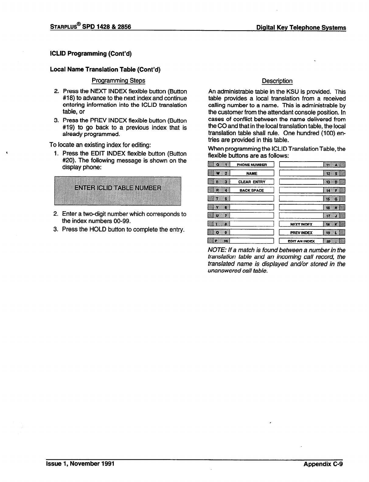
STARPLUS@
SPD 1428 & 2856 Digital Key Telephone Systems
ICLID Programming (Cont’d)
Local Name Translation Table (Cont’d)
Programming Steps
2. Press the NEXT INDEX flexible button (Button
#18) to advance to the next index and continue
entering information into the ICLID translation
table, or
3. Press the PREV INDEX flexible button (Button
#19) to go back to a previous index that is
already programmed.
To locate an existing index for editing:
1. Press the EDIT INDEX flexible button (Button
#20). The following message is shown on the
display phone:
2. Enter a two-digit number which corresponds to
the index numbers 00-99.
3. Press the HOLD button to complete the entry.
Description
An administrable table in the KSU is provided. This
table provides a local translation from a received
calling number to a name. This is administrable by
the customer from the attendant console position. In
cases of conflict between the name delivered from
the CO and that in the local translation table, the local
translation table shall rule. One hundred (100) en-
tries are provided in this table.
When programming the ICLID Translation Table, the
flexible buttons are as follows:
p:j ..::;:;:::*:;
PHONE NUMBER /$yfi~
:::. :..:.:.I :.: ..A
snivel . . . .
NAME ~~~~
~~~~~1 CLEAR EmY ~~~~ai~~ \
NOTE: If a match is found between a number in the
translation table and an incoming call record, the
translated name is displayed and/or stored in the
unanswered call table.
Issue 1, November 1991 Appendix C-9
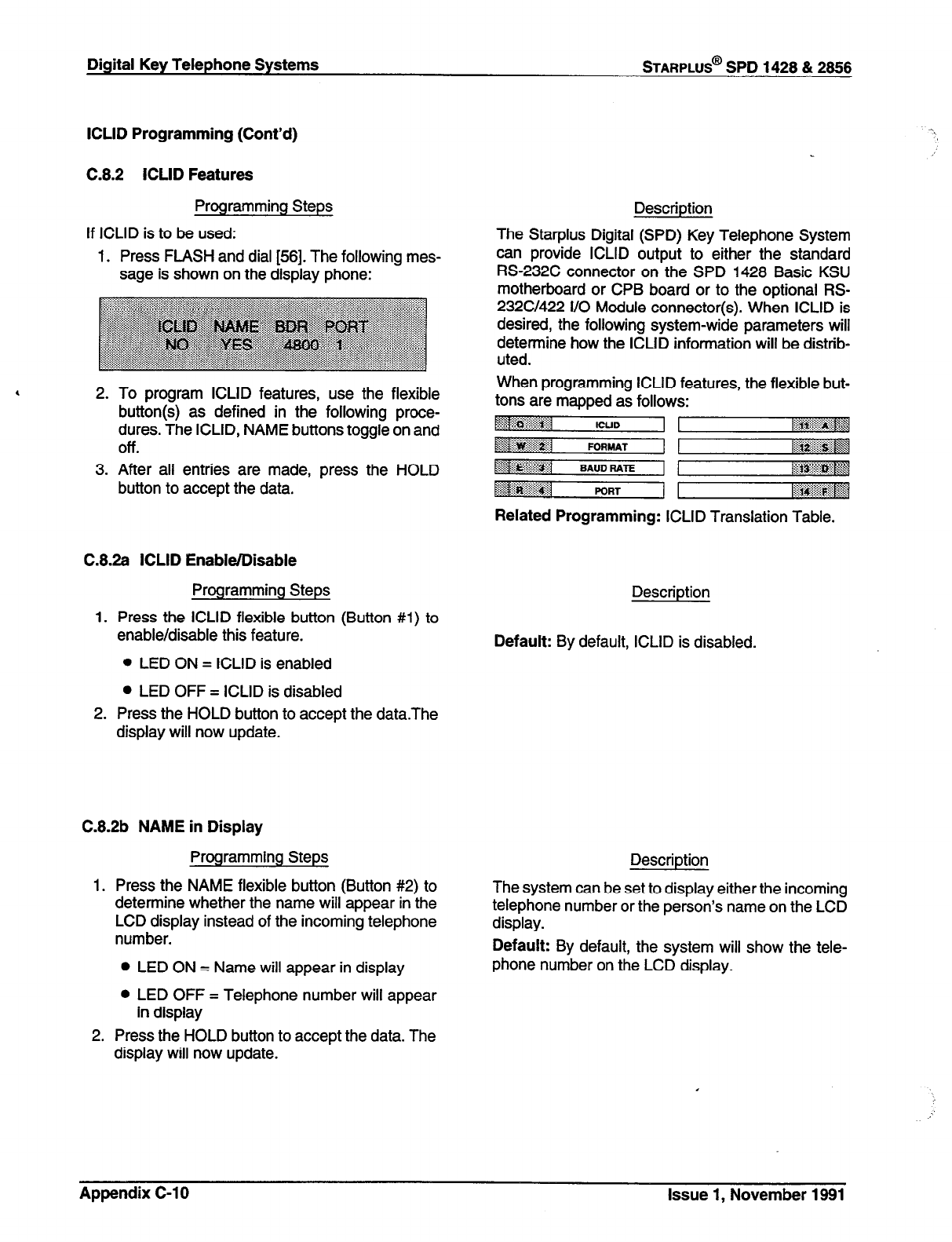
Digital Key Telephone Systems
STARPLUS@
SPD 1428 & 2866
ICLID Programming (Cont’d)
C.8.2 ICLID Features
Programming Steps
If ICLID is to be used:
1. Press FLASH and dial [56]. The following mes-
sage is shown on the display phone:
2. To program ICLID features, use the flexible
button(s) as defined in the following proce-
dures. The ICLID, NAME buttons toggle on and
Off.
3. After all entries are made, press the HOLD
button to accept the data.
C.8.2a ICLID Enable/Disable
Programming Steps
1. Press the ICLID flexible button (Button #l) to
enable/disable this feature.
l
LED ON = ICLID is enabled
l
LED OFF = ICLID is disabled
2. Press the HOLD button to accept the data.The
display will now update.
Description
The Starplus Digital (SPD) Key Telephone System
can provide ICLID output to either the standard
RS-232C connector on the SPD 1428 Basic KSU
motherboard or CPB board or to the optional RS-
232C/422 l/O Module connector(s). When ICLID is
desired, the following system-wide parameters will
determine how the ICLID information will be distrib-
uted.
When programming ICLID features, the flexible but-
tons are mapped as follows:
~~~
ICUD
~~~~~~l FORMAT 1 pJ@$$@#
Related Programming: ICLID Translation Table.
Description
Default: By default, ICLID is disabled.
C.8.2b NAME in Display
Programming Steps
1. Press the NAME flexible button (Button #2) to
determine whether the name will appear in the
LCD display instead of the incoming telephone
number.
Description
The system can be set to display either the incoming
telephone number or the person’s name on the LCD
display.
Default: By default, the system will show the tele-
l
LED ON = Name will appear in display phone number on the LCD display.
l
LED OFF = Telephone number will appear
in display
2. Press the HOLD button to accept the data. The
display will now update.
Appendix C-10 Issue 1, November 1991
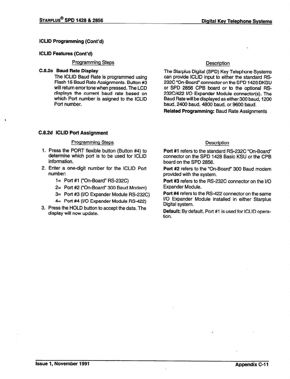
STARPLUS@
SPD 1428 & 2888 Digital Key Telephone Systems
ICLID Programming (Cont’d)
ICLID Features (Cont’d)
Programming Steps
C.8.2~ Baud Rate Display
The ICLID Baud Rate is programmed using
Flash 15 Baud Rate Assignments. Button #3
will return error tone when pressed. The LCD
displays the current baud rate based on
which Port number is asigned to the ICLID
Port number.
C.8.2d ICLID Port Assignment
1.
2.
3.
Programming Steps
Press the PORT flexible button (Button #4) to
determine which port is to be used for ICLID
information.
Enter a one-digit number for the ICLID Port
number:
1 = Port #1 (“On-Board” RS232C)
2= Port #2 (“On-Board” 300 Baud Modem)
3= Port #3 (I/O Expander Module RS232C)
4= Port #4 (I/O Expander Module RS-422)
Press the HOLD button to accept the data. The
display will now update.
Description
The Stat-plus Digital (SPD) Key Telephone Systems
can provide ICLID input to either the standard RS-
232C “On-Board” connector on the SPD 1428 BKSU
or SPD 2856 CPB board or to the optional RS-
232C/422 I/O Expander Module connector(s). The
Baud Rate will be displayed as either 300 baud, 1200
baud, 2400 baud, 4800 baud, or 8600 baud.
Related Programming: Baud Rate Assignments
Description
Port #1 refers to the standard RS-232C “On-Board”
connector on the SPD 1428 Basic KSU or the CPB
board on the SPD 2856.
Port #2 refers to the “On-Board” 300 Baud modem
provided with the system.
Port #3 refers to the RS-232C connector on the I/O
Expander Module.
Port #4 refers to the RS-422 connector on the same
I/O Expander Module installed in either Starplus
Digital system.
Default: By default, Port #l is used for ICLID opera-
tion.
Issue 1, November 1991 Appendix C-l 1
TECHNICAL FACT NOTICE
Stsrplus Digital Telephone
fF NO: 27a
1 o/23/92
ADDITIONAL FEATURES - STARPLUS DIGITAL SYSTEMS
ISSUE 1, NOVEMBER 1991
The following list of features are available with software version 2.OD, or higher and IRS Level C, m firmware
version 1 .OF or higher. (The IRS Level is located in the lower left comer of the label on the bottom of the phone.)
SYSTEM FEATURES SECTION
Dial by Name
Directory Dialing Internal/External
Local Number/Name Translation Table
Off Hook Voice Over
Messages Canned
Messages Date and Time
Message Custom
Text Messaging (Silent Response)
Distinctive Ringing
Group Listening
Flex Button Programming
Idle Speaker Mode
Music On Hold
Automatic Call Back Timer
Executive Override
UCD FEATURES
Enhanced Calls in Queue Display
No-Answer Retry Timer
Expansion of Recorded Announcements to 8
VOICE MAIL FEATURES
Voice Mail Transfer with ID
LCD ENHANCEMENT SECTION
CO Line Identification Display
PROGRAMMING FEATURES SECTION
Station Relocation
Flexible Station and CO Port Assignments
HARDWARE FEATURES SECTION
Digital Data Interface Unit (DDIU)
Keyset Self Test
Page 1 of 72 TF NO. 27a
Vodavi Communications Systems 6300 E. Raintree Drive Scottsdale, AZ 66260 (602) 443-6000
STARPLUS TECHNICAL FACT NOTICE STARPLUS DIGITAL TELEPHONE
TF NO: 27a
SYSTEM FEATURES
Dial By Name
Directory Dialing Internal/External
Local Number/Name Translation Table
Off Hook Voice Over
Messages Canned
Messages Date &Time
Message Custom
Text Messaging (Silent Response)
Distinctive Ringing
4 Group Listening
Flex Button Programming
Idle Speaker Mode
Music On Hold
Automatic Call Back Timer
Executive Override
Page 2 of 72
6300 E. Raintree Drive
TF NO. 27a
i602) 443-6000 Scottsdale, AZ 66260
Vodavi Communications SYSttJmS
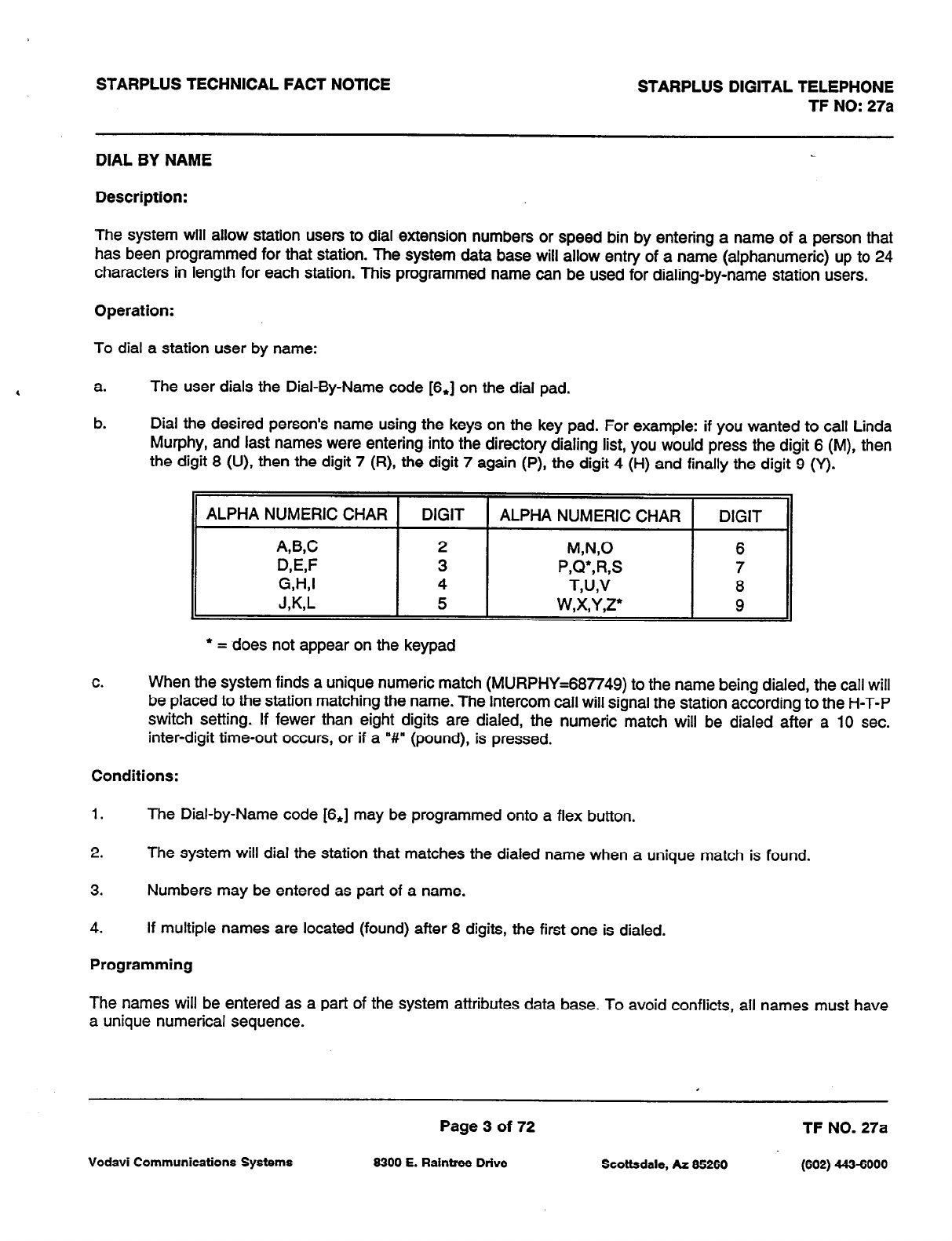
STARPLUS TECHNICAL FACT NOTICE STARPLUS DIGITAL TELEPHONE
TF NO: 27a
DIAL BY NAME
Description:
The system will allow station users to dial extension numbers or speed bin by entering a name of a person that
has been programmed for that station. The system data base will allow entry of a name (alphanumeric) up to 24
characters in length for each station. This programmed name can be used for dialing-by-name station users.
Operation:
To dial a station user by name:
a. The user dials the Dial-By-Name code [6,] on the dial pad.
b. Dial the desired person’s name using the keys on the key pad. For example: if you wanted to call Linda
Murphy, and last names were entering into the directory dialing list, you would press the digit 6 (M), then
the digit 6 (U), then the digit 7 (R), the digit 7 again (P), the digit 4 (H) and finally the digit 9 (Y).
ALPHA NUMERIC CHAR DIGIT ALPHA NUMERIC CHAR DIGIT
A,B,C 2 W’J,O 6
QW 3 P,Q*,R,S 7
G,H,I 4 T,U,V 8
J&L
5 w,x,y,z* 9
l
= does not appear on the keypad
C.
When the system finds a unique numeric match (MURPHY=687749) to the name being dialed, the call will
be placed to the station matching the name. The intercom call will signal the station according to the H-T-P
switch setting. If fewer than eight digits are dialed, the numeric match will be dialed after a 10 sec.
inter-digit time-out occurs, or if a “#I” (pound), is pressed.
Conditions:
1. The Dial-by-Name code [S,] may be programmed onto a flex button.
2. The system will dial the station that matches the dialed name when a unique match is found.
3. Numbers may be entered as part of a name.
4. If multiple names are located (found) after 8 digits, the first one is dialed.
Programming
The names will be entered as a part of the system attributes data base. To avoid conflicts, all names must have
a unique numerical sequence.
Page 3 of 72 TF NO. 27a
Vodavi Communications Systems 6300 E. Raintree Drive Scottsdale, AZ 66260 (602) 443-6000
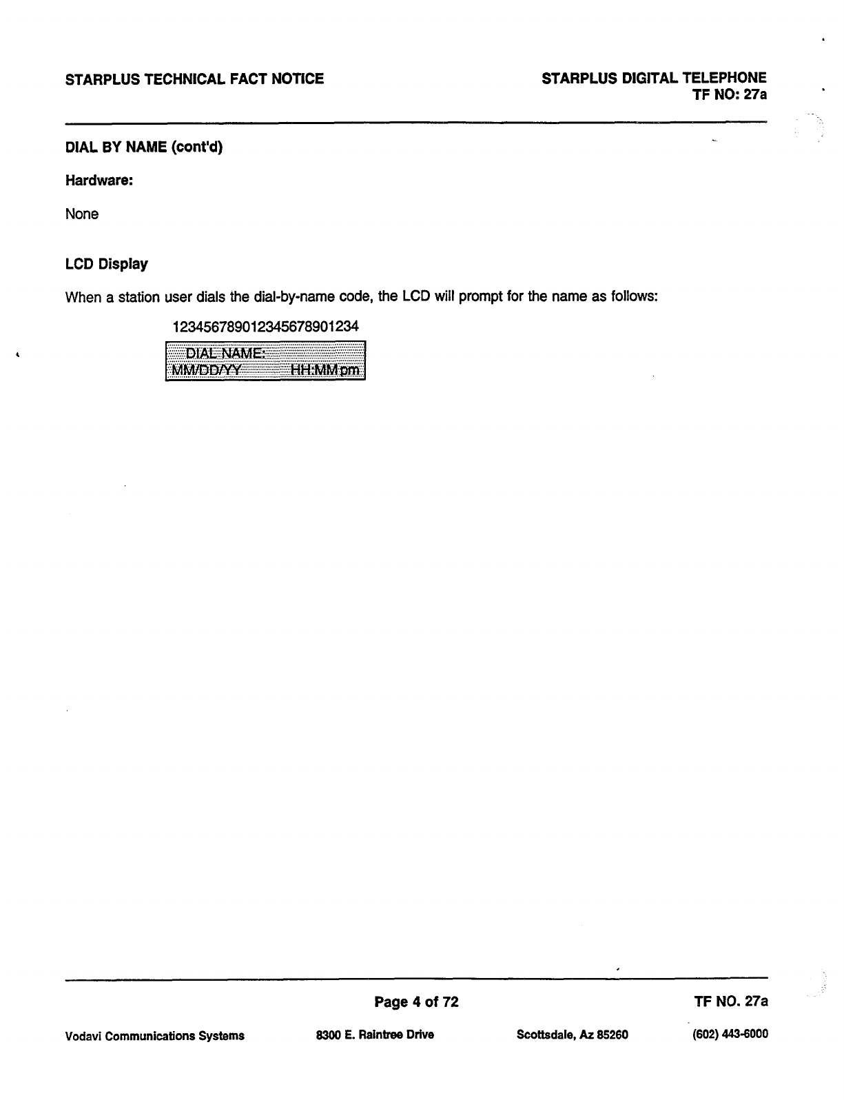
,
STARPLUS TECHNICAL FACT NOTICE STARPLUS DIGITAL TELEPHONE
TF NO: 27a
DIAL BY NAME (cont’d)
Hardware:
None
LCD Display
When a station user dials the dial-by-name code, the LCD will prompt for the name as follows:
123456789012345678901234
Page 4 of 72 TF NO. 27a
Vodavi Communications Systems 6300 E. Raintree Drive Scottsdale, AZ 66260 (602) 443-6000

STARPLUS TECHNICAL FACT NOTlCE STARPLUS DlGlTAL TELEPHONE
TF NO: 27a
DIRECTORY DIALING - Station
Description:
Station users with Executive Display telephones may view a list, of up to 200 names, from the system directory on
the station’s LCD display, then automatically dial the station or speed dial bin or entry in the Local Number/Name
Translation Table by pressing a single key. Names placed in the directory list may be associated to intercom
numbers, system speed dial bins, or entries in the Local Number/Name Translation Table. Users may view the
directory list beginning with any letter of the alphabet, then scroll through the list either forward or backwards. When
the desired name is displayed on the LCD display, pressing the SPEED button will automatically place a call to that
destination. Directory dialing may also be used to transfer a call from one station to another.
Operation:
a. Dial the Directory List dial code [680], or press the pre-programmed flex button programmed as
a directory dialing button.
b. Press a button on the key pad, once, twice or three times, to represent the letter of the alphabet,
to begin viewing the list of names. (i.e. the first depression of the digit 2 produces the names
beginning with an “A”. The second depression of the digit 2 produces the names beginning with
a ‘B’, while the third depression of the digit 2 produces the names beginning with a “C”.) The
letters of the alphabet are represented on the key pad as follows:
ALPHA NUMERIC CHAR DIGIT ALPHA NUMERIC CHAR DIGIT
ARC 2 MN0 6
Wf 3 P,Q’,R,S 7
GA-U 4 T,U,V 8
J&L
5 W,X,Y,Z’ 9
* = does not appear on the keypad
C.
Names beginning with the letter chosen will appear on the LCD display.
If there are no names in the Directory List beginning with the desired letter, a name with the next higher letter will
be shown on the LCD display.
d. Dial [J to scroll up (next entry) through the list,
or
Dial [#] to scroll down (previous entry) through the list,
or
Press another key to view the list for a different letter of the alphabet.
Page 5 of 72 TF NO. 27a
Vodavi Communications Systems 6300 E. Raintree Drive Scottsdale, AZ 66260 (602) 443-6000

STARPLUS TECHNICAL FACT NOTlCE STARPLUS DIGITAL TELEPHONE
TF NO: 27a
DIRECTORY DIALING - Station (cont’d)
e. When the desired name is shown in the LCD display, pressing the SPEED button will automatically
dial the destination station or outside phone number (via speed dial).
.
If the desired party is an intercom station, that station will be signaled according to that
station’s intercom selector switch (SLT stations will tone ring).
.
If the desired party is associated to a speed dial bin, the system will select a CO line and
dial the number programmed into the speed dial bin. Call progress tones will then be
heard.
.
If the desired party is associated to an entry in the Local Number/Name Translation Table,
the system will and dial the number programmed into the translation table. Call progress
tones will then be heard.
To Transfer a Call using Directory Dialing:
While on a call:
a. Press the TFlANSfer button.
b. Dial the Directory Dial Code [680] on the dial pad,
or
Press a pre-programmed flex button programmed for directory dialing.
C.
Press the SPEED button to automatically dial the destination station.
d. Hang up to complete the transfer.
Note: Calls may only be transferred to internal stations only. An attempt to transfer a call off-net (via a Speed dial
bin) will result in the call recalling upon going on-hook.
Programming
None
Vodavi Communications Systems
Page 6 of 72
8300 E. Raintrea Drive Scottsdale, AZ 65260
TF NO. 27a
(602) 443-6000
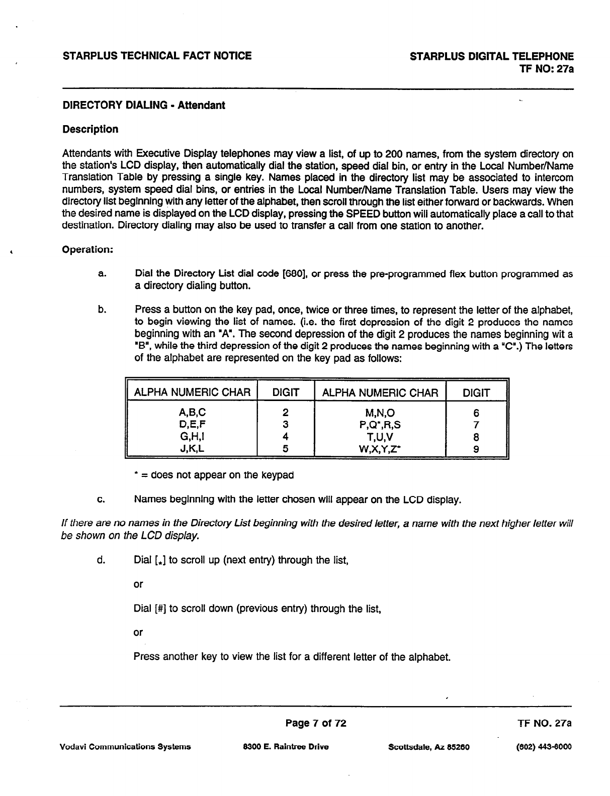
STARPLUS TECHNICAL FACT NOTlCE STARPLUS DlGlTAL TELEPHONE
TF NO: 27a
DIRECTORY DIALING - Attendant
Description
Attendants with Executive Display telephones may view a list, of up to 200 names, from the system directory on
the station’s LCD display, then automatically dial the station, speed dial bin, or entry in the Local Number/Name
Translation Table by pressing a single key. Names placed in the directory list may be associated to intercom
numbers, system speed dial bins, or entries in the Local Number/Name Translation Table. Users may view the
directory list beginning with any letter of the alphabet, then scroll through the list either forward or backwards. When
the desired name is displayed on the LCD display, pressing the SPEED button will automatically place a call to that
destination. Directory dialing may also be used to transfer a call from one station to another.
Operation:
a. Dial the Directory List dial code [680], or press the pre-programmed flex button programmed as
a directory dialing button.
b. Press a button on the key pad, once, twice or three times, to represent the letter of the alphabet,
to begin viewing the list of names. (i.e. the first depression of the digit 2 produces the names
beginning with an “A”. The second depression of the digit 2 produces the names beginning wit a
‘B”, while the third depression of the digit 2 produces the names beginning with a “C”.) The letters
of the alphabet are represented on the key pad as follows:
ALPHA NUMERIC CHAR DIGIT ALPHA NUMERIC CHAR DIGIT
A&C 2 MNO 6
D,E,F 3 P,Q*,R,S 7
W-L1 4 T,U,V
a
J,KS
5 w,x,y,z* 9
* = does not appear on the keypad
C.
Names beginning with the letter chosen will appear on the LCD display.
If there are no names in the Directory List beginning with the desired letter, a name with the next higher letter will
be shown on the LCD display.
d. Dial [J to scroll up (next entry) through the list,
or
Dial [#] to scroll down (previous entry) through the list,
or
Press another key to view the list for a different letter of the alphabet.
Page 7 of 72 TF NO. 27a
Vodavi Communications Systems 6300 E. Raintree Drive Scottsdale, AZ 66260 (602) 44-S-6000

STARPLUS TECHNICAL FACT NOTlCE STARPLUS DIGITAL TELEPHONE
TF NO: 27a
DIRECTORY DIALING - AlTENDANT (cont’d)
e. When the desired name is shown in the LCD display, pressing the SPEED button will automatically
dial the destination station or outside phone number (via speed dial).
0
If the desired party is an intercom station, that station will be signaled according to that
station’s intercom selector switch (SLT stations will tone ring).
4
If the desired party is associated to a speed dial bin, the system will select a CO line and
diai the number programmed into the speed dial bin. Call progress tones will then be
heard.
d
If the desired party is associated to an entry in the local number/name translation table,
the system will dial the number programmed into the translation table. Call progress tones
will then be heard.
To Transfer a Call using Directory Dialing:
While on a call;
a. Press the TRANSfer button.
b. Dial the Directory Dial Code [680] on the dial pad,
or
Press a pre-programmed flex button programmed for directory dialing.
C.
Press the SPEED button to automatically dial the destination station.
d. Hang up to complete the transfer.
Note: Cal/s may only be transferred to internal stations only. An attempt to transfer a call off-net (via a Speed dial
bin) will result in the call recalling upon going on-hook.
Page 8 of 72 TF NO. 27a
Vodavi Communications Systems 8300 E. Raintree Drive Scottsdale, AZ 85280 (802) 443-8000
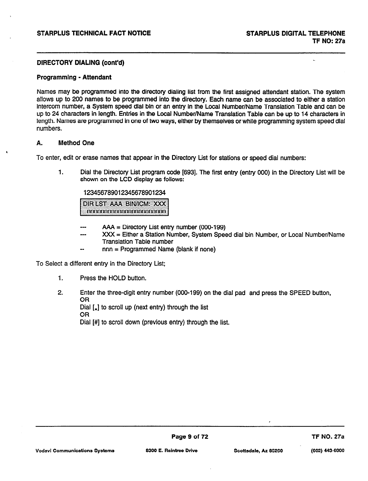
STARPLUS TECHNICAL FACT NOTICE STARPLUS DIGITAL TELEPHONE
TF NO: 27a
DIRECTORY DIALING (cont’d)
Programming - Attendant
Names may be programmed into the directory dialing list from the first assigned attendant station. The system
allows up to 200 names to be programmed into the directory. Each name can be associated to either a station
intercom number, a System speed dial bin or an entry in the Local Number/Name Translation Table and can be
up to 24 characters in length. Entries in the Local Number/Name Translation Table can be up to 14 characters in
length. Names are programmed in one of two ways, either by themselves or while programming system speed dial
numbers.
A. Method One
To enter, edit or erase names that appear in the Directory List for stations or speed dial numbers:
1. Dial the Directory List program code 16931. The first entry (entry 000) in the Directory List will be
shown on the LCD display as follows:
123456789012345678901234
AAA = Directory List entry number (000-199)
XXX = Either a Station Number, System Speed dial bin Number, or Local Number/Name
Translation Table number
nnn = Programmed Name (blank if none)
To Select a different entry in the Directory List;
1. Press the HOLD button.
2. Enter the three-digit entry number (000-199) on the dial pad and press the SPEED button,
OR
Dial [J to scroll up (next entry) through the list
OR
Dial [#] to scroll down (previous entry) through the list.
Page 9 of 72 TF NO. 27a
Vodavi Communications Systems 6300 E. Raintree Drive Scottsdale, AZ 66260 (602) 443-6000
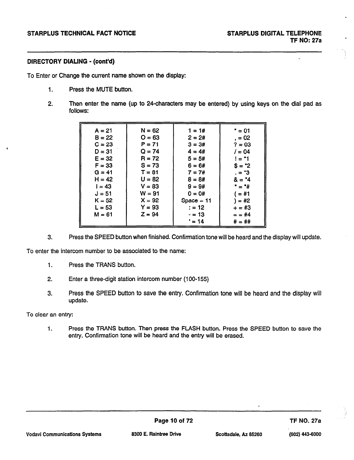
STARPLUS TECHNICAL FACT NOTlCE STARPLUS DIGITAL TELEPHONE
TF NO: 27a
DIRECTORY DIALING - (cont’d)
To Enter or Change the current name shown on the display:
1. Press the MUTE button.
2. Then enter the name (up to 24-characters may be entered) by using keys on the dial pad as
follows:
A = 21 N = 62 1 =l# = = 01
B=22 0 = 63 2 = 2# , = 02
C = 23 P = 71 3 = 3# ? = 03
D=31 Q = 74 4=# /=04
E = 32 R = 72 5 = 5#
F = 33 s = 73 6 = 6# ;yl;
G = 41 T=61 7 = 7# .= ‘3
H = 42 U = 82 8 = 8# & = l 4
I = 43 V = 83 9 = 9#
J = 51 w = 91 0 = O# ;I;
K = 52 x = 92 Space = 11 ) = #2
L = 53 Y = 93 : = 12 + = #3
M = 61 z = 94 -= 13 = = #4
‘= 14 # = ##
3. Press the SPEED button when finished. Confirmation tone will be heard and the display will update.
To enter the intercom number to be associated to the name:
1. Press the TFWNS button.
2. Enter a three-digit station intercom number (100-155)
3. Press the SPEED button to save the entry. Confirmation tone will be heard and the display will
update.
To clear an entry:
1. Press the TRANS button. Then press the FLASH button. Press the SPEED button to save the
entry. Confirmation tone will be heard and the entry will be erased.
Page 10 of 72 TF NO. 27a
Vodavi Communications Systems 6300 E. Raintree Drive Scottsdale, AZ 66260 (602) 443-6000

STARPLUS TECHNICAL FACT NOTICE STARPLUS DIGITAL TELEPHONE
TF NO: 27a
DIRECTORY DIALING (cont’d)
C. Method Two:
This method may be used to enter names that will be associated to the Local Number/Name Translation
Table only.
To enter a name along with a local number/name translation table number:
I. Press the TRANS button.
2. Dial the three-digit local number/name translation table number (300-499) that represents the
desired telephone number.
To Enter or Change the current name shown on the display:
I. Press the MUTE button.
2. Then enter the name (up to 24characters may be entered) by using keys on the dial pad as
follows: The display will update as the name is entered.
A = 21
B=22
C = 23
D = 31
E = 32
F = 33
G = 41
H = 42
I = 43
J = 51
K = 52
L = 53
M = 61
N = 62
0 = 63
P = 71
Q = 74
R = 72
s = 73
T = 81
U = 82
V = 83
w = 91
x = 92
Y = 93
z = 94
1 =I#
2 = 2#
3 = 3#
4=4#/
5 = 5#
6 = 6#
7 = 7#
8 = 8#
9 = 9#
0 = O#
Space = 11
: = 12
-= 13
‘= 14
* = 01
, = 02
? = 03
/ = 04
! = ‘I
$ = ‘2
.= “3
& = l 4
;I:
) = #2
+ = #3
= = #4
# = ##
3. Press the SPEED button when finished. Confirmation tone will be heard.
NOTE: The Local Number/Name Translation Table can be used to enter additional speed dial numbers
which can be used for directory dial or dial by name. The name entered into the local number/name
translation table is not relevant when used with directory dialing and dial by name. In addition, it should be
noted that the numbers entered into this table are limited to 14-digits and will be covered by toll restriction
rules.
Page 11 of 72 TF NO. 27a
Vodavi Communications Systems 8300 E. Raintree Drive Scottsdale, AZ 85260 (602) 4436000
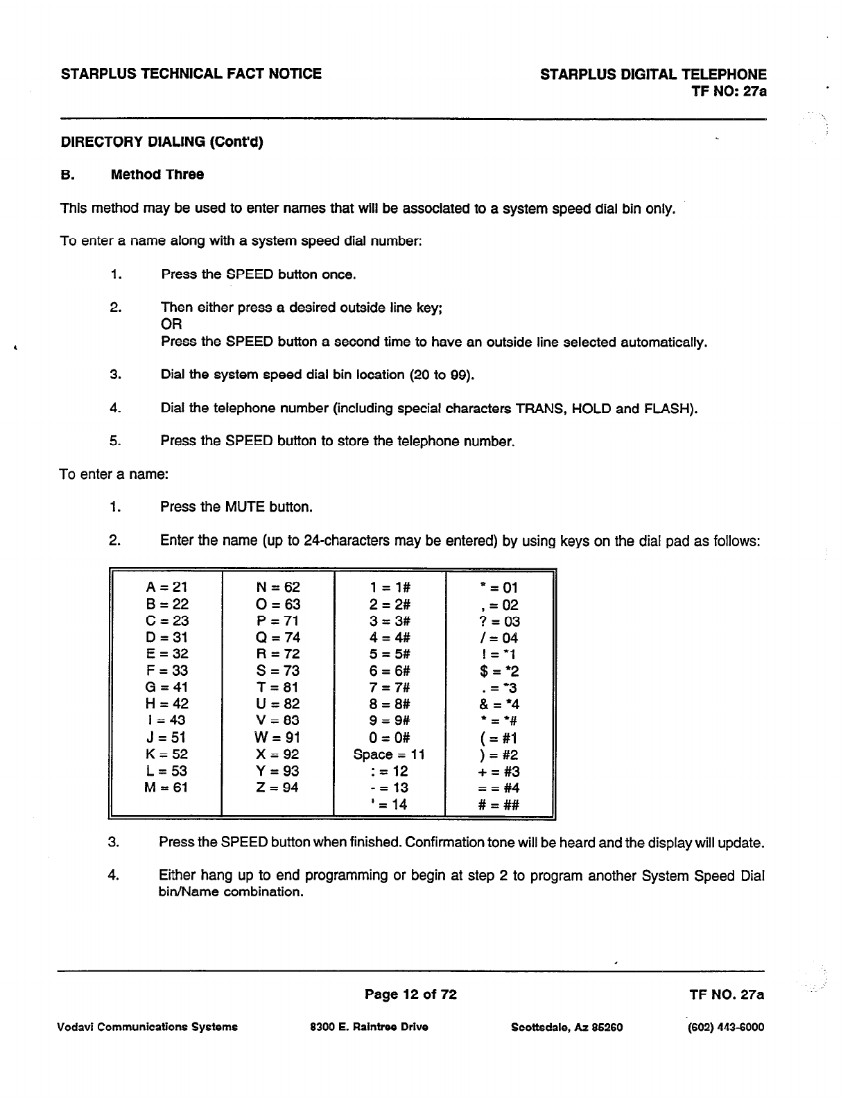
STARPLUS TECHNICAL FACT NOTICE
DIRECTORY DIALING (Cont’d)
STARPLUS DIGITAL TELEPHONE
TF NO: 27a
B. Method Three
This method may be used to enter names that will be associated to a system speed dial bin only.
To enter a name along with a system speed dial number:
1. Press the SPEED button once.
2. Then either press a desired outside line key;
OR
Press the SPEED button a second time to have an outside line selected automatically.
3. Dial the system speed dial bin location (20 to 99).
4. Dial the telephone number (including special characters TRANS, HOLD and FLASH).
5. Press the SPEED button to store the telephone number.
To enter a name:
1. Press the MUTE button.
Enter the name (up to 24characters may be entered) by using keys on the dial pad as follows:
Press the SPEED button when finished. Confirmation tone will be heard and the display will update.
Either hang up to end programming or begin at step 2 to program another System Speed Dial
bin/Name combination.
Page 12 of 72 TF NO. 27a
Vodavi Communications Systems 6300 E. Raintree Drive Scottsdale, AZ 66260 (602) 443-6000
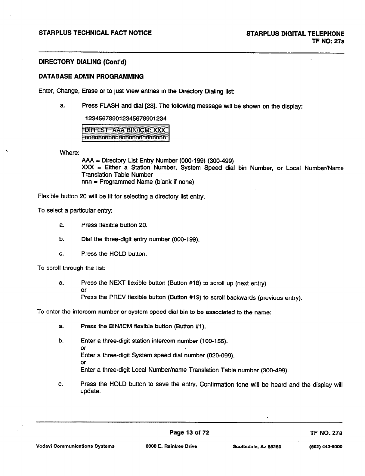
STARPLUS TECHNICAL FACT NOTICE STARPLUS DIGITAL TELEPHONE
TF NO: 27a
DIRECTORY DIALING (Cont’d)
DATABASE ADMIN PROGRAMMING
Enter, Change, Erase or to just View entries in the Directory Dialing list:
a. Press FLASH and dial [23]. The following message will be shown on the display:
123456789012345678901234
Where: AAA = Directory List Entry Number (000-199) (300-499)
XXX = Either a Station Number, System Speed dial bin Number, or Local Number/Name
Translation Table Number
nnn = Programmed Name (blank if none)
Flexible button 20 will be lit for selecting a directory list entry.
To select a particular entry:
a. Press flexible button 20.
b. Dial the three-digit entry number (000-199).
C.
Press the HOLD button.
To scroll through the list:
a. Press the NEXT flexible button (Button #18) to scroll up (next entry)
or
Press the PREV flexible button (Button #19) to scroll backwards (previous entry).
To enter the intercom number or system speed dial bin to be associated to the name:
a. Press the BIN/ICM flexible button (Button #l).
b. Enter a three-digit station intercom number (100-155).
or
Enter a three-digit System speed dial number (020-099).
or
Enter a three-digit Local Number/name Translation Table number (300-499).
C.
Press the HOLD button to save the entry. Confirmation tone will be heard and the display will
update.
Page 13 of 72 TF NO. 27a
Vodavi Communications Systems 6300 E. Raintree Drive Scottsdale, AZ 66260 (602) 4434000
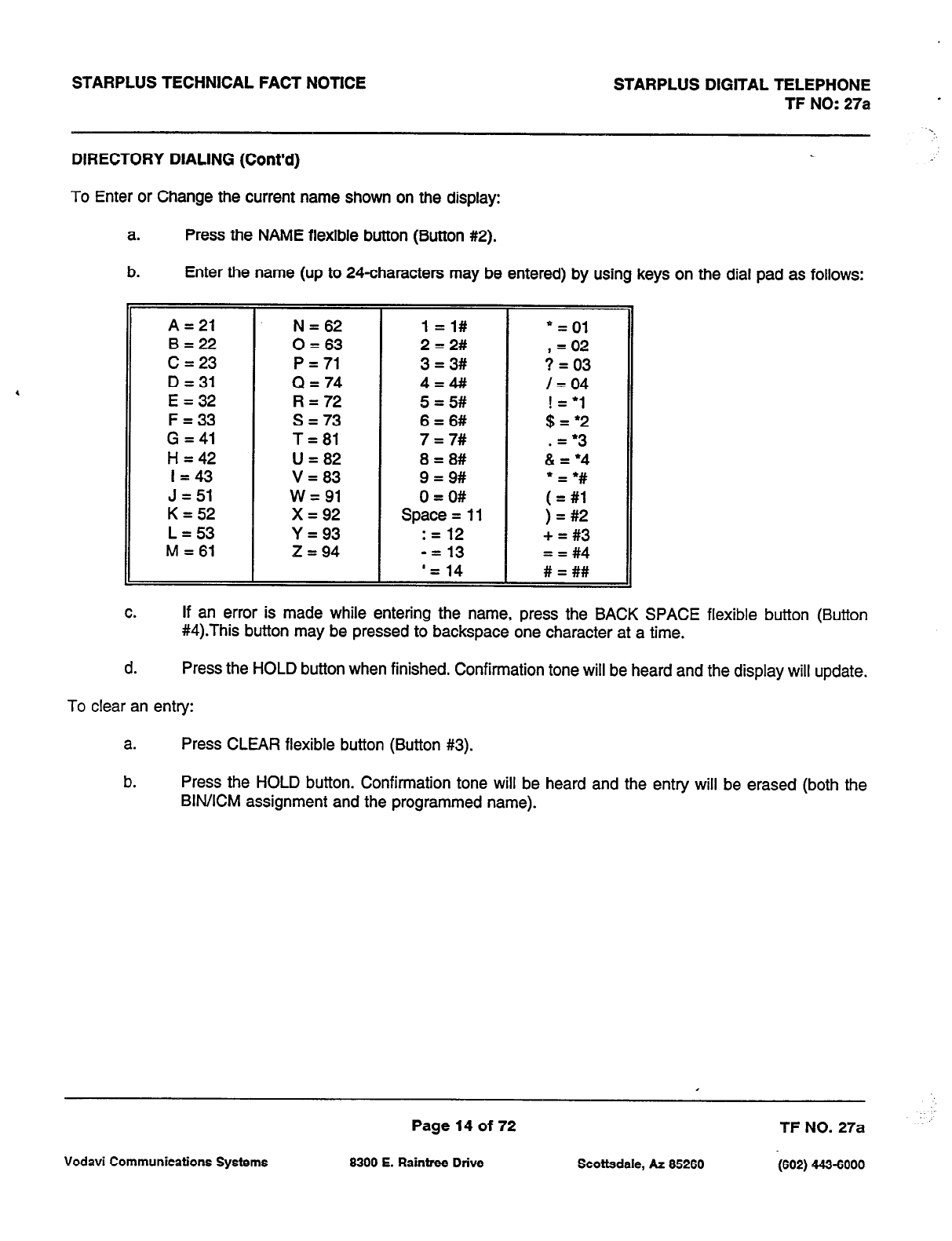
STARPLUS TECHNICAL FACT NOTICE STARPLUS DIGITAL TELEPHONE
TF NO: 27a *
DIRECTORY DIALING (Cont’d)
To Enter or Change the current name shown on the display:
a. Press the NAME flexible button (Button #2).
b. Enter the name (up to 24characters may be entered) by using keys on the dial pad as follows:
A=21 N = 62 1 =l# * = 01
B=22 0 = 63 2 = 2# , = 02
C = 23 P = 71 3 = 3# 3 = 03
D = 31 Q = 74 4=# /=04
E = 32 R = 72 5 = 5#
F = 33 s = 73 6 = 6# ;I;;
G = 41 T= 81 7 = 7# .= l 3
H = 42 U = 82 8 = 8# & = *4
I = 43 V = 83 9 = 9#
l
= l #
J = 51 w= 91 0 = O# ( = #l
K = 52 x = 92 Space= 11 ) = #2
L = 53 Y=93 : = 12 + = #3
M = 61 .z = 94 -= 13 = = #4
‘= 14 # = ##
C.
If an error is made while entering the name, press the BACK SPACE flexible button (Button
#4).This button may be pressed to backspace one character at a time.
d. Press the HOLD button when finished. Confirmation tone will be heard and the display will update.
To clear an entry:
a. Press CLEAR flexible button (Button #3).
b. Press the HOLD button. Confirmation tone will be heard and the entry will be erased (both the
BIN/ICM assignment and the programmed name).
Page 14 of 72 TF NO. 27a
Vodavi Communications Systems 6300 E. Raintree Drive Scottsdale, AZ 85260 (602) 443-6000
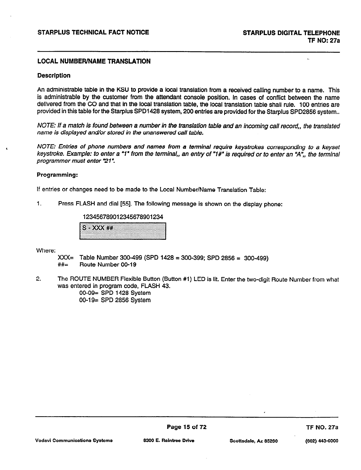
STARPLUS TECHNICAL FACT NOTICE STARPLUS DIGITAL TELEPHONE
TF NO: 27a
LOCAL NUMBER/NAME TRANSLATION
Description
An administrable table in the KSU to provide a local translation from a received calling number to a name. This
is administrable by the customer from the attendant console position. In cases of conflict between the name
delivered from the CO and that in the local translation table, the local translation table shall rule. 100 entries are
provided in this table for the Starplus SPD1428 system, 200 entries are provided for the Starplus SPD2856 system..
NOTE: If a match is fotind between a number in the translation table and an incoming call record,, the translated
name is displayed andor stored in the unanswered call table.
NOTE: Entries of phone numbers and names from a terminal require keystrokes corresponding to a keyset
keystroke. Example: to enter a ‘1’ from the terminal,, an entry of “I#’ is required or to enter an “A”,, the terminal
programmer must enter 21’.
Programming:
If entries or changes need to be made to the Local Number/Name Translation Table:
1. Press FLASH and dial [55]. The following message is shown on the display phone:
123456789012345678901234
Where: XXX= Table Number 300-499 (SPD 1428 = 300-399; SPD 2856 = 300-499)
##= Route Number 00-l 9
2. The ROUTE NUMBER Flexible Button (Button #l) LED is lit. Enter the two-digit Route Number from what
was entered in program code, FLASH 43.
00-09= SPD 1428 System
00-19= SPD 2856 System
Page 15 of 72 TF NO. 27a
Vodavi Communications Systems 8300 E. Raintrw Drive Scottsdale, AZ 85260 (602) 443-6000
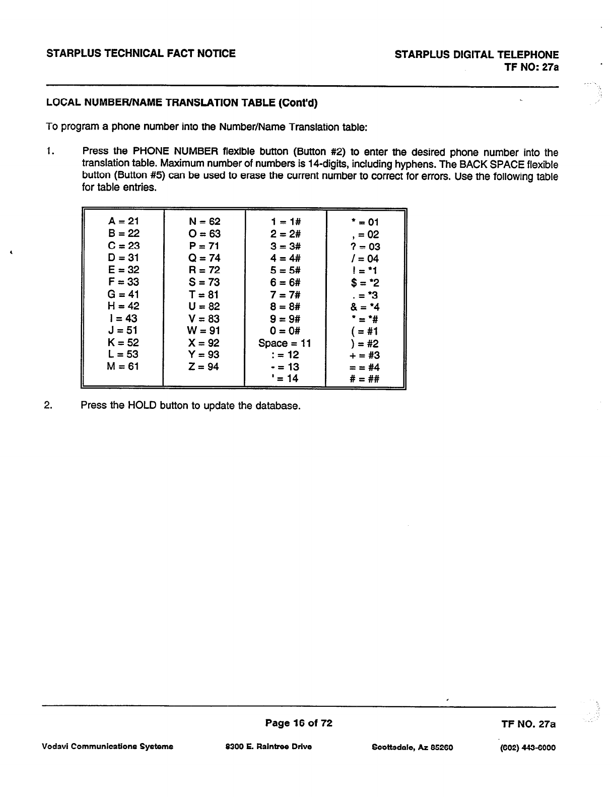
STARPLUS TECHNICAL FACT NOTICE STARPLUS DIGITAL TELEPHONE
TF NO: 27a .
LOCAL NUMBER/NAME TRANSLATION TABLE (Cont’d)
To program a phone number into the Number/Name Translation table:
1. Press the PHONE NUMBER flexible button (Button #2) to enter the desired phone number into the
translation table. Maximum number of numbers is ICdigits, including hyphens. The BACK SPACE flexible
button (Button #5) can be used to erase the current number to correct for errors. Use the following table
for table entries.
A = 21
B=22
C = 23
D =31
E = 32
F = 33
G = 41
H = 42
I = 43
J = 51
K=52
L = 53
M = 61
N = 62
0 = 63
P = 71
0 = 74
R = 72
s = 73
T = 81
U = 82
V = 83
W=91
x = 92
Y = 93
z = 94
1 =l#
2 = 2#
3 = 3#
4=4#/
5 = 5#
6 = 6#
7 = 7#
8 = 8#
9 = 9#
0 = O#
Space = 11
:= 12
-= 13
‘= 14
l
= 01
, = 02
? = 03
I=04
11:;
.= l 3
& = l 4
;I;
) = #2
+ = #3
= = #4
# = ##
2. Press the HOLD button to update the database.
Page 16 of 72 TF NO. 27a
Vodavi Communications Systems 6300 E. Raintree Drive Scottsdale, AZ 66260 (602) 443-6000
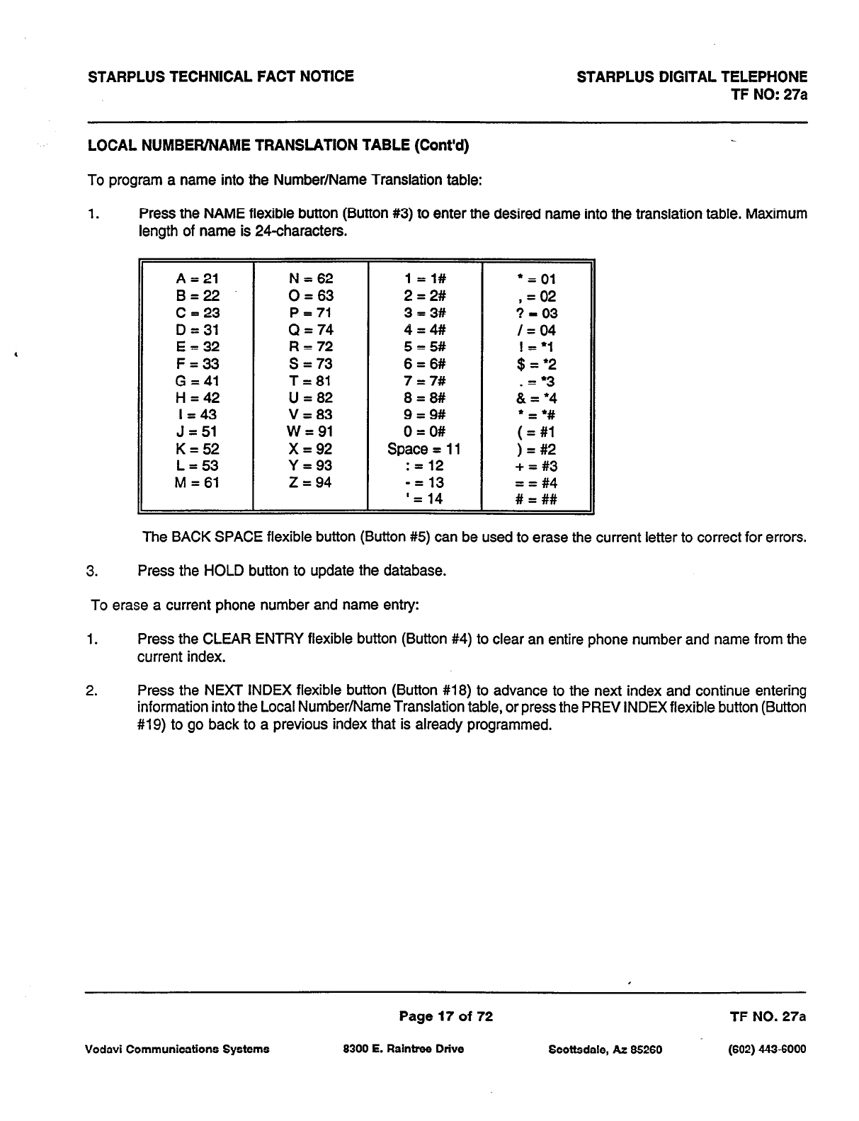
STARPLUS TECHNICAL FACT NOTICE STARPLUS DIGITAL TELEPHONE
TF NO: 27a
LOCAL NUMBER/NAME TRANSLATION TABLE (Cont’d)
To program a name into the Number/Name Translation table:
1. Press the NAME flexible button (Button #3) to enter the desired name into the translation table. Maximum
length of name is 24characters.
A = 21 N = 62 l=i#
l
= 01
B=22 0 = 63 2 = 2# , = 02
C = 23 P = 71 3=3# 3 = 03
D = 31 cl = 74 4 = 4# /=04
E = 32 R = 72 5 = 5#
F = 33 s = 73 6 = 6# ;z:;
G = 41 T=81 7 = 7# .= 3
H = 42 U = 82 8 = 8# & = *4
I=43 V = 83 9 = 9#
J = 51 w = 91 0 = O# ;I;
K = 52 x = 92 Space = 11 ) = #2
L = 53 Y = 93 : = 12 + = #3
M = 61 z = 94 -= 13 = = #4
‘= 14 # = ##
The BACK SPACE flexible button (Button #5) can be used to erase the current letter to correct for errors.
3. Press the HOLD button to update the database.
To erase a current phone number and name entry:
1. Press the CLEAR ENTRY flexible button (Button #4) to clear an entire phone number and name from the
current index.
2. Press the NEXT INDEX flexible button (Button #18) to advance to the next index and continue entering
information into the Local Number/Name Translation table, or press the PREV INDEX flexible button (Button
#19) to go back to a previous index that is already programmed.
Page 17 of 72 TF NO. 27a
Vodavi Communications Systems 6300 E. Raintree Drive Scottsdale, AZ 85260
(602)
4436000
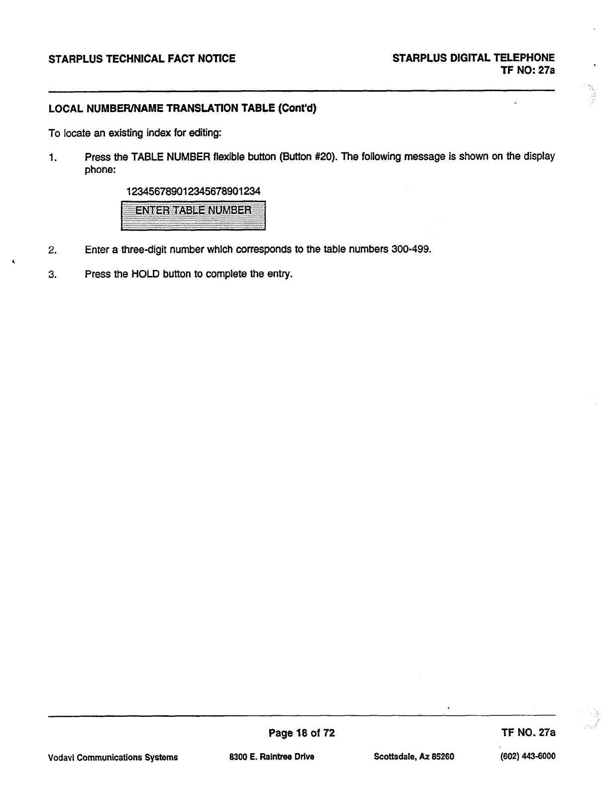
STARPLUS TECHNICAL FACT NOTICE STARPLUS DIGITAL TELEPHONE
TF NO: 27a
LOCAL NUMBEWNAME TRANSLATION TABLE (Cont’d)
To locate an existing index for editing:
1. Press the TABLE NUMBER flexible button (Button #20). The following message is shown on the display
phone:
123456789012345678901234
2. Enter a three-digit number which corresponds to the table numbers 300-499.
4
3. Press the HOLD button to complete the entry.
Page 18 of 72 TF NO. 27a
8300 E. Raintree Drive Scottsdale, hz 05260 <602) 443-6000
Vodavi Communications Systems

STARPLUS TECHNICAL FACT NOTICE STARPLUS DIGITAL TELEPHONE
TF NO: 27a
OFF HOOK VOICE OVER (OHVO)
Description
This feature allows users, off-hook on a call (CO or Intercom), to receive a voice announcement through the
handset receiver without interrupting the existing call. The Voice Over is muted so as not to “override” or “drown”
out the existing conversation. The overridden party may then respond to the calling party using CAMP-ON
procedures to talk to the calling party or may use Silent Text Messaging to respond to the calling party via LCD
Displays.
Operation
.
Placing an Off-Hook Voice Over (OHVO):
When a station (Sta A) calls a busy keyset (Sta B), and busy tone is received, the calling station (Sta A)
may dial the OHVO dial code 16281, or press a pre-programmed flex button to initiate an OHVO
announcement. The HOLD button LED will flash at the called OHVO station.
Both stations (Sta A AND Sta B) will receive a one beep warning tone, the calling party may then begin
the voice announcement to the called party (Sta B). The called station’s (Sta B) existing conversation will
not be interrupted and the voice-over announcement will not “drowned” out the existing conversation. The
calling station (Sta A) will not be able to hear the called station’s (Sta B) conversation (the connection will
only allow Sta A to transmit to Sta B).
e
Responding to an Off-Hook Voice Over:
After receiving an OHVO announcement, two options are available to the called party to respond to the
calling party:
1. The called station (Sta B) may respond to the calling station (Sta A) by using the Camp-On feature.
The called station (Sta B) presses the flashing HOLD button to consult with the calling station (Sta
A). The called station’s (Sta B) existing CO call goes on Exclusive Hold automatically. This method
then follows CAMP-ON procedures and operation.
2. The called station (Sta B) may respond to the calling station (Sta A) by using the Silent Text
Messaging. This feature is only available to digital key terminals, and the calling station (Sta A)
must be a Digital Display Terminal.) The calling station (Sta B) may press pre-programmed
Message buttons to respond to the voice-over announcement without being released from the
current call, (i.e. by pressing a flex button pre-programmed for the message “IN MEETING”), the
calling station (Sta A) will then receive this message on the calling station’s LCD display.
Conditions
1. The station receiving the OHVO call MUST be off-hook and in the “H” mode.
2. The calling (originating) station and receiving station (Sta B) must be a Digital terminal.
3. When the dialed station responds via the CAMP-ON feature, all conditions and options available to CAMP-
ON apply.
I
Page 19 of 72 TF NO. 27a
Vodavi Communications Systems 6300 E. Raintrtw Drive Scottsdale, AZ 66260 (602) 443-6000
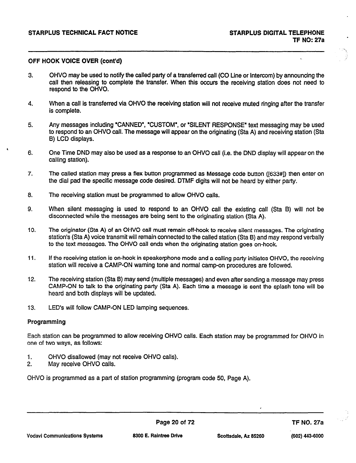
STARPLUS TECHNICAL FACT NOTICE STARPLUS DIGITAL TELEPHONE
TF NO:27a *
OFF HOOK VOICE OVER (cont’d)
3.
4.
5.
, 6.
7.
8.
9.
IO.
11.
12.
13.
OHVO may be used to notify the called party of a transferred call (CO Line or Intercom) by announcing the
call then releasing to complete the transfer. When this occurs the receiving station does not need to
respond to the OHVO.
When a call is transferred via OHVO the receiving station will not receive muted ringing after the transfer
is complete.
Any messages including “CANNED’, “CUSTOM’, or ‘SILENT RESPONSE” text messaging may be used
to respond to an OHVO call. The message will appear on the originating (Sta A) and receiving station (Sta
B) LCD displays.
One Time DND may also be used as a response to an OHVO call (i.e. the DND display will appear on the
calling station).
The called station may press a flex button programmed as Message code button ([633#]) then enter on
the dial pad the specific message code desired. DTMF digits will not be heard by either party.
The receiving station must be programmed to allow OHVO calls.
When silent messaging is used to respond to an OHVO call the existing call (Sta B) will not be
disconnected while the messages are being sent to the originating station (Sta A).
The originator (Sta A) of an OHVO call must remain off-hook to receive silent messages. The originating
station’s (Sta A) voice transmit will remain connected to the called station (Sta B) and may respond verbally
to the text messages. The OHVO call ends when the originating station goes on-hook.
If the receiving station is on-hook in speakerphone mode and a calling party initiates OHVO, the receiving
station will receive a CAMP-ON warning tone and normal camp-on procedures are followed.
The receiving station (Sta B) may send (multiple messages) and even after sending a message may press
CAMP-ON to talk to the originating party (Sta A). Each time a message is sent the splash tone will be
heard and both displays will be updated.
LED’s will follow CAMP-ON LED lamping sequences.
Programming
Each station can be programmed to allow receiving OHVO calls. Each station may be programmed for OHVO in
one of two ways, as follows:
1. OHVO disallowed (may not receive OHVO calls).
2. May receive OHVO calls.
OHVO is programmed as a part of station programming (program code 50, Page A).
Page 20 of 72 TF NO. 27a
Vodavi Communications Systems 8300 E. Raintree Drive Scottsdale, At 85280 (602) 443-6000
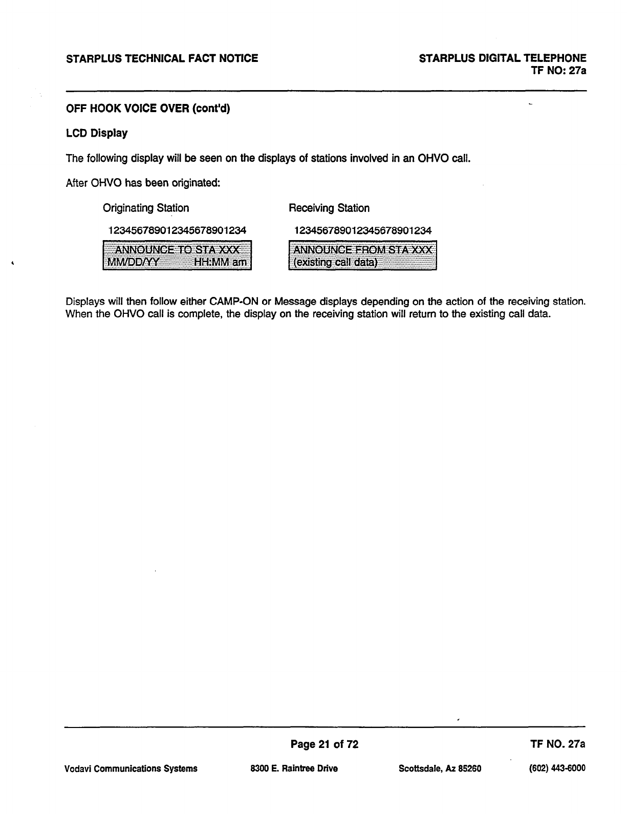
STARPLUS TECHNICAL FACT NOTICE STARPLUS DIGITAL TELEPHONE
TF NO: 27a
OFF HOOK VOICE OVER (cont’d)
LCD Display
The following display will be seen on the displays of stations involved in an OHVO call.
After OHVO has been originated:
Originating Station Receiving Station
123456769012345678901234 123456789012345678901234
Displays will then follow either CAMP-ON or Message displays depending on the action of the receiving station.
When the OHVO call is complete, the display on the receiving station will return to the existing call data.
Page 21 of 72 TF NO. 27a
Vodavi Communications Systems 8300 E. Raintree Drive Scottsdale, AZ 85280 (802) 443-8000
STARPLUS TECHNICAL FACT NOTICE STARPLUS DIGITAL TELEPHONE
TF NO: 27a
MESSAGES - CANNED
Description
A station user may select a pre-assigned message from a list of ‘canned’ messages in the system to be displayed
on the LCD of a telephone that calls that station.
Operation
A station wishing to select a message, dials the Message Access Code [633], or presses the flexible button
programmed for Message Access, then dials the two digit message code and hangs up. Example: m+ [Ol]
means that a telephone calling the station will receive the message ‘VACATION”.
The individual canned message codes are as follows:
00
Clear Messages
01
ON VACATION
02 RETURN AM
03 RETURN PM
04 RETURN TOMORROW
05 RETURN NEXT WEEK
06 ON TRIP
07 IN MEETING
08 AT HOME
09 ON BREAK
10 AT LUNCH
To cancel the message, the station dials the Code [633] + fOO] and hangs up.
Conditions:
1. The telephone receiving the message must be a display telephone.
2. Both key telephones and SLT can leave the message. SLTs are notified that they have left a message with
a warning tone when going off-hook.
3. Incoming and outgoing calls are not inhibited in any way with a message displayed.
4. When a message is displayed by a key telephone, the DND button LED flashes at 15 ipm.
5. When DND is invoked on the telephone the message is canceled.
6. Message Access (with a desired message) may be assigned to a flex button.
7. Messages may be entered while off-hook on a call and an intercom call has camped-on to the station. This
will cause the station calling to see the message.
8.
Messages are retained in battery protected area of memory in the event of power failure or system reset.
Page 22 of 72 TF NO. 27a
Vodavi Communications Systems 6300 E. Raintree Drive Scottsdale, AZ 66260 (602) 443-6000
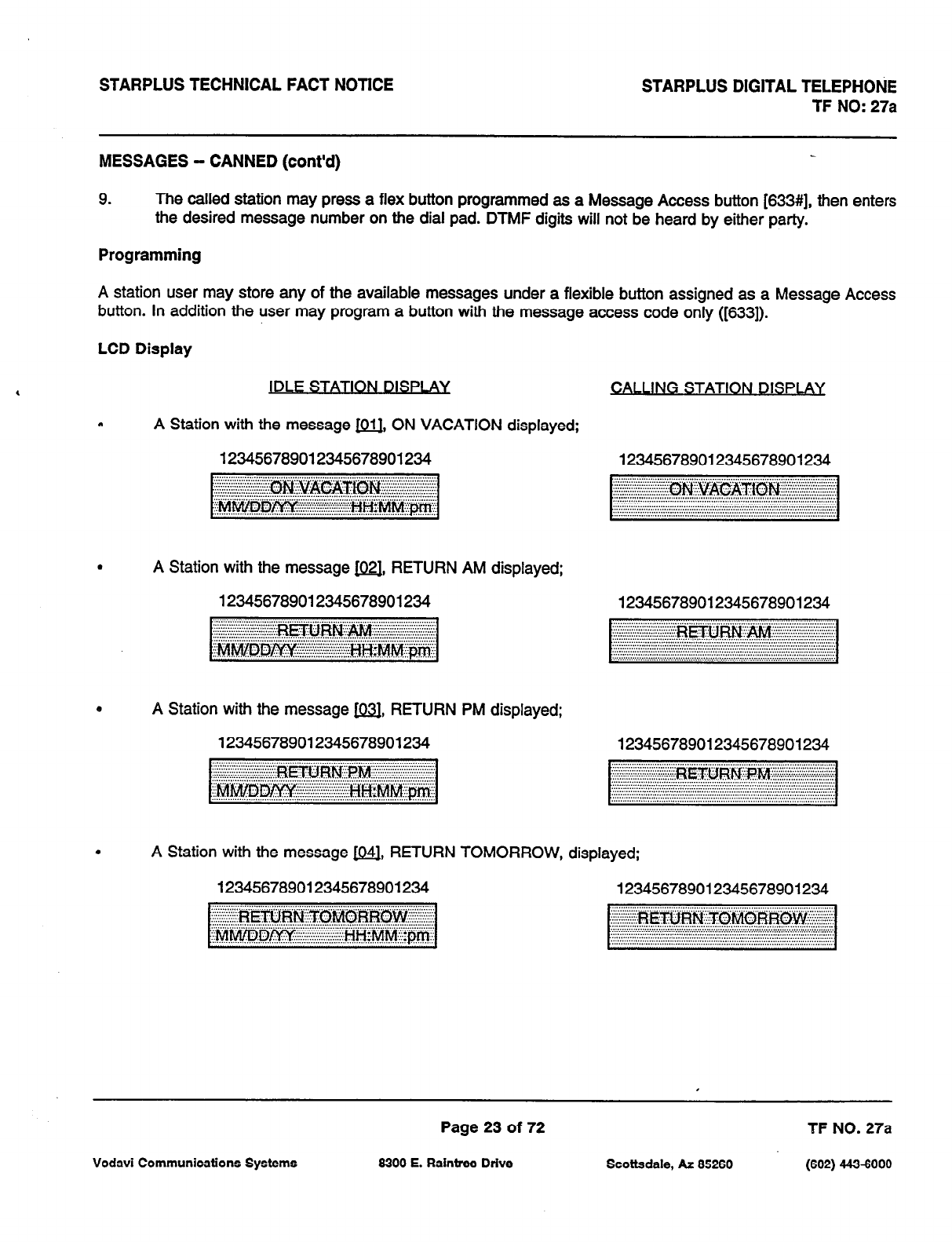
STARPLUS TECHNICAL FACT NOTICE STARPLUS DIGITAL TELEPHONE
TF NO: 27a
MESSAGES - CANNED (cont’d)
9. The called station may press a flex button programmed as a Message Access button [633#], then enters
the desired message number on the dial pad. DTfvlF digits will not be heard by either party.
Programming
A station user may store any of the available messages under a flexible button assigned as a Message Access
button. In addition the user may program a button with the message access code only ([633]).
LCD Display
JDLE STATION DlSf’LAY
NG STATION DISPI AY
a A Station with the message 1011. ON VACATION displayed;
123456789012345678901234 123456789012345678901234
.
A Station with the message &QJ, RETURN AM displayed;
123456789012345678901234 123456789012345678901234
e
A Station with the message &j3J, RETURN PM displayed;
123456789012345678901234 123456789012345678901234
.
A Station with the message 1041, RETURN TOMORROW, displayed;
123456789012345678901234 123456789012345678901234
Page 23 of 72 TF NO. 27a
Vodavi Communications Systems 8300 E. Raintree Drive Scottsdale, AZ 85260 (602) 4434000

STARPLUS TECHNICAL FACT NOTICE STARPLUS DIGITAL TELEPHONE
TF NO: 27a
MESSAGES - CANNED (cont’d)
. A Station with the message w, RETURN
123456789012345678901234
NEXT WEEK, displayed;
*
A Station with the message m, ON TRIP, displayed;
123456789012345678901234
.
A Station with the message m, IN MEETING, displayed;
123456789012345678901234
b
A Station with the message m, AT HOME, displayed;
123456789012345678901234
.
A Station with the message [es3, ON BREAK, displayed;
123456789012345678901234
e
A Station with the message (.l.Ql, AT LUNCH, displayed;
123456789012345678901234
123456789012345678901234
...............................................................................................................................
..................................................................................................
..................................................................................................
..................................................................................................
..................................................................................................
..................................................................................................
.................................................................................................
..................................................................................................
123456789012345678901234
123456789012345678901234
123456789012345678901234
123456789012345678901234
Page 24 of 72
6300 E. Raintree Drive
TF NO. 27a
-(602) 4436000 Scottsdale, AZ 66260 Vodavi Communications Systems
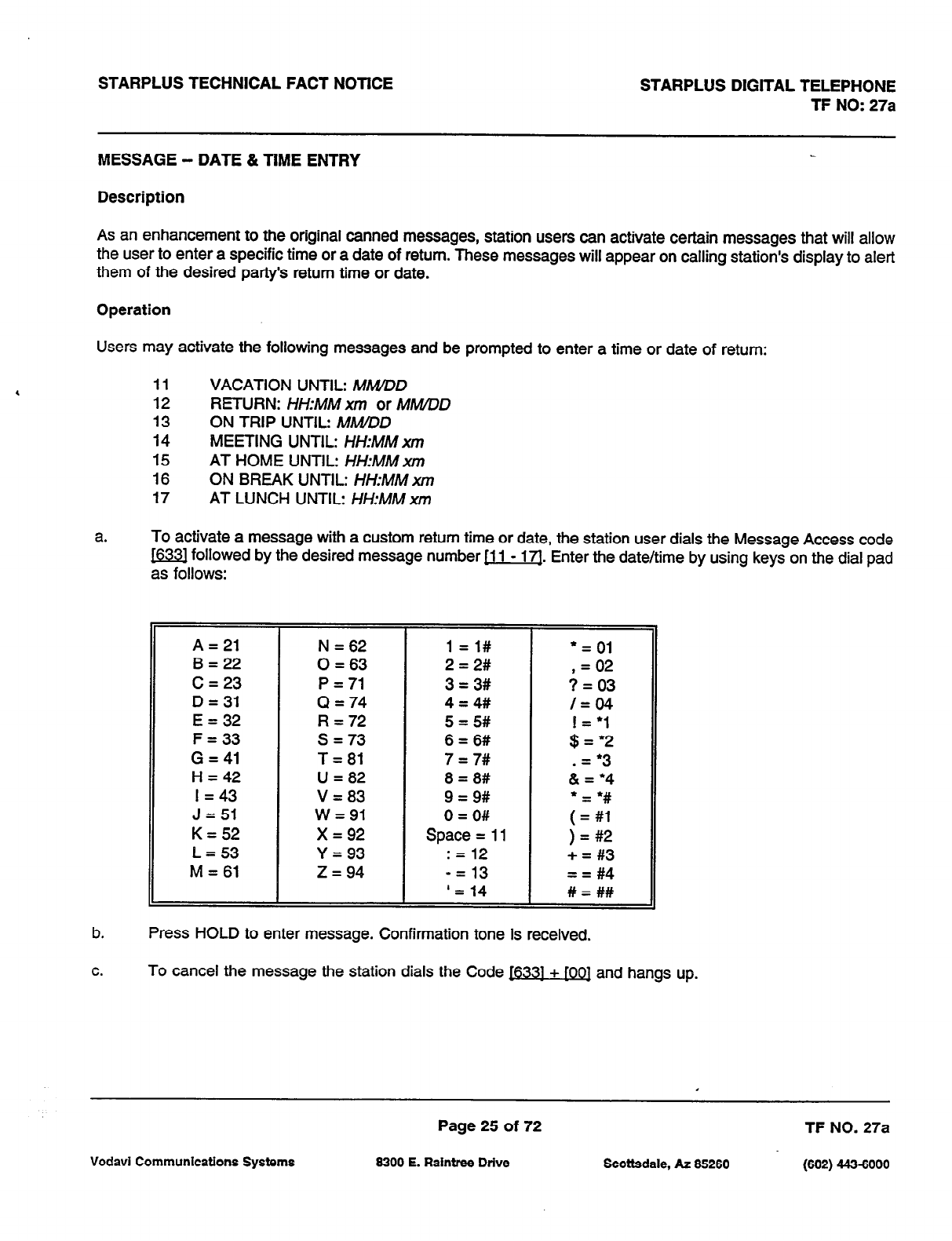
STARPLUS TECHNICAL FACT NOTICE STARPLUS DIGITAL TELEPHONE
TF NO: 27a
MESSAGE - DATE & TIME ENTRY
Description
As an enhancement to the original canned messages, station users can activate certain messages that will allow
the user to enter a specific time or a date of return. These messages will appear on calling station’s display to alert
them of the desired party’s return time or date.
Operation
Users may activate the following messages and be prompted to enter a time or date of return:
11 VACATION UNTIL: MMZDD
12 RETURN: HHMMxm or MMVDD
13 ON TRIP UNTIL: MWDD
14 MEETING UNTIL: HHMM xm
15 AT HOME UNTIL: HH:MM xm
16 ON BREAK UNTIL: H/-L-MM xm
17 AT LUNCH UNTIL: HH:MM x/n
a. To activate a message with a custom return time or date, the station user dials the Message Access code
m followed by the desired message number [l 1 - 171. Enter the date/time by using keys on the dial pad
as follows:
b. Press HOLD to enter message. Confirmation tone is received.
A = 21
B=22
C = 23
D = 31
E = 32
F = 33
G = 41
H = 42
I = 43
J = 51
K = 52
L=53
M = 61
N = 62
0 = 63
P = 71
Q = 74
R = 72
s = 73
T= 81
U = 82
V = 83
W=91
x = 92
Y=93
z = 94
1 =l#
2 = 2#
3 = 3#
4 = 4#
5 = 5#
6 = 6#
7 = 7#
8 = 8#
9 = 9#
0 = O#
Space = 11
: = 12
-= 13
‘= 14
l
= 01
, 02 =
? = 03
/=04
;z:;
- l 3
&4
;I;
) = #2
+ = #3
== #4
# = ##
C.
To cancel the message the station dials the Code I6331 + fOOl and hangs up.
Page 25 of 72 TF NO. 27a
Vodavi Communications Systems 6300 E. Raintree Drive Scottsdale, AZ 66260 (602) 4436000
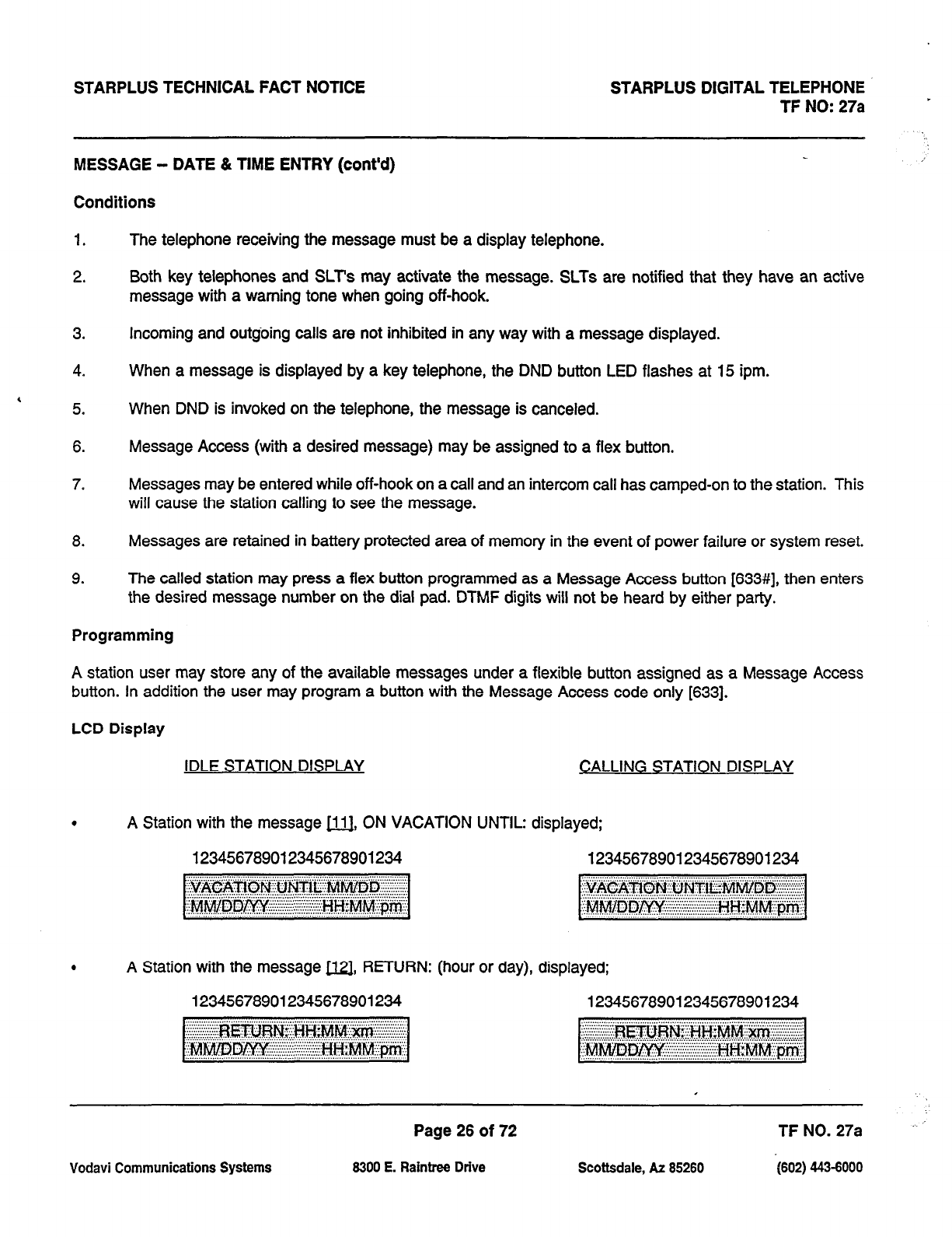
STARPLUS TECHNICAL FACT NOTICE STARPLUS DIGITAL TELEPHONE
TF NO: 27a
MESSAGE - DATE & TIME ENTRY (cont’d)
Conditions
,’
1.
2.
3.
4.
, 5.
6.
7.
The telephone receiving the message must be a display telephone.
Both key telephones and SLT’s may activate the message. SLTs are notified that they have an active
message with a warning tone when going off-hook.
Incoming and outgoing calls are not inhibited in any way with a message displayed.
When a message is displayed by a key telephone, the DND button LED flashes at 15 ipm.
When DND is invoked on the telephone, the message is canceled.
Message Access (with a desired message) may be assigned to a flex button.
Messages may be entered while off-hook on a call and an intercom call has camped-on to the station. This
will cause the station calling to see the message.
8. Messages are retained in battery protected area of memory in the event of power failure or system reset.
9. The called station may press a flex button programmed as a Message Access button [633#], then enters
the desired message number on the dial pad. DTMF digits will not be heard by either party.
Programming
A station user may store any of the available messages under a flexible button assigned as a Message Access
button. In addition the user may program a button with the Message Access code only [633].
LCD Display
IDLE STATION DISPLAY CALLING STATION DISPLAY
.
A Station with the message 1111, ON VACATION UNTIL: displayed;
123456789012345678901234 123456789012345678901234
.
A Station with the message m, RETURN: (hour or day), displayed;
123456789012345678901234 123456789012345678901234
Page 26 of 72 TF NO. 27a
Vodavi Communications Systems 8300 E. Raintree Drive Scottsdale, AZ 85260 -1602) 443-8000
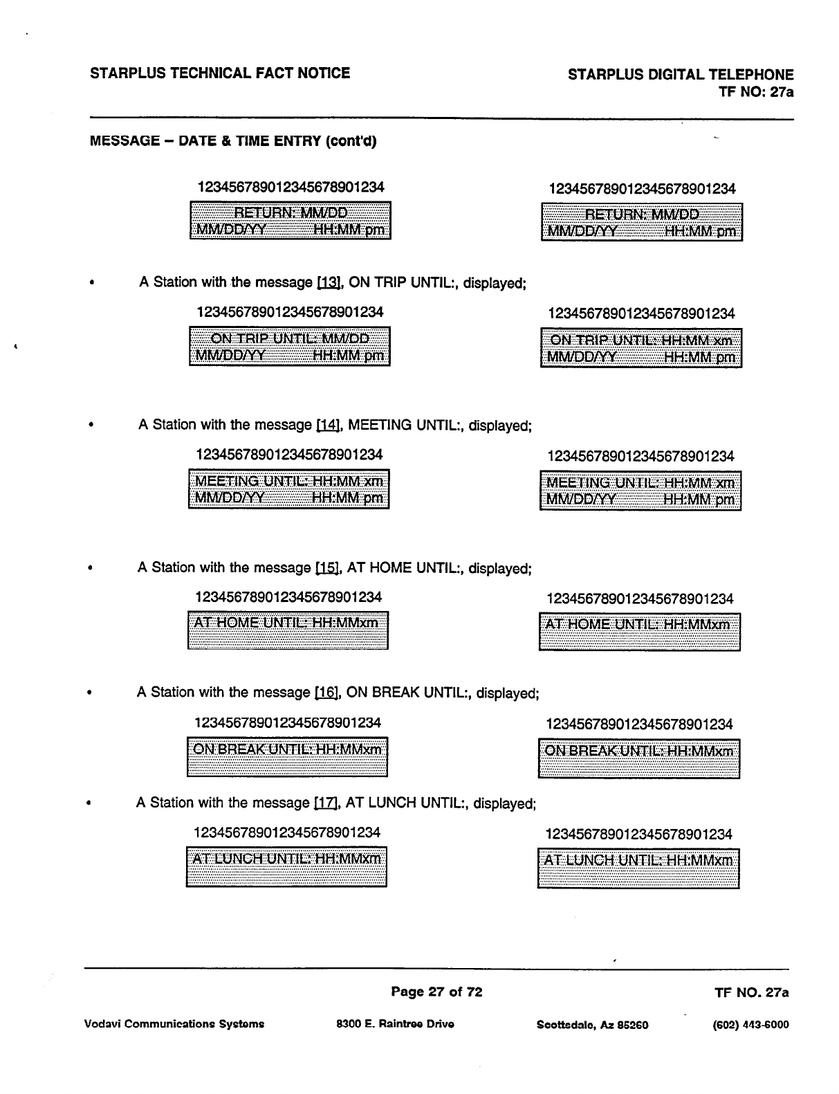
STARPLUS TECHNICAL FACT NOTICE STARPLUS DIGITAL TELEPHONE
TF NO: 27a
MESSAGE - DATE 81 TIME ENTRY (cont’d)
123456789012345678901234 123456789012345678901234
l
A Station with -the message m, ON TRIP UNTIL:, displayed;
123456789012345678901234
.
A Station with the message 11, MEETING UNTIL:, displayed;
123456789012345678901234
e
A Station with the message u, AT HOME UNTIL:, displayed;
123456789012345678901234
123456789012345678901234
123456789012345678901234
123456789012345678901234
.
A Station with the message m, ON BREAK UNTIL:, displayed;
123456789012345678901234 123456789012345678901234
.
A Station with the message 1171, AT LUNCH UNTIL:, displayed;
123456789012345678901234 123456789012345678901234
Page 27 of 72 TF NO. 27a
Vodavi Communications Systems 8300 E. Raintree Drive Scottsdale, AZ 85260 (602) 443-6000
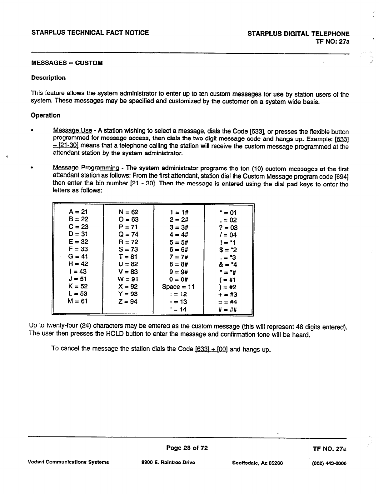
STARPLUS TECHNICAL FACT NOTICE STARPLUS DIGITAL TELEPHONE
TF NO: 27a ’
MESSAGES - CUSTOM ,,’
Description
This feature allows the system administrator to enter up to ten custom messages for use by station users of the
system. These messages may be specified and customized by the customer on a system wide basis.
Operation
,
.
fvlessaoe Use - A station wishing to select a message, dials the Code 16331, or presses the flexible button
programmed for message access, then dials the two digit message code and hangs up. Example: m
+ f21-301 means that a telephone calling the station will receive the custom message programmed at the
attendant station by the system administrator.
.
Messaae f’rOQramminQ - The system administrator programs the ten (10) custom
messages
at the first
attendant station as follows: From the first attendant, station dial the Custom Message program code [694]
then enter the bin number [21 - 301. Then the message is entered using the dial pad keys to enter the
letters as follows:
Up to twenty-four (24) characters may be entered as the custom message (this will represent 48 digits entered).
The user then presses the HOLD button to enter the message and confirmation tone will be heard.
To cancel the message the station dials the Code 16331 + [OO] and hangs up.
Page 28 of 72 TF NO. 27a
Vodavi Communications Systems 6300 E. Raintree Drive Scottsdale, At 66260 (602) 443-6000
STARPLUS TECHNICAL FACT NOTICE STARPLUS DIGITAL TELEPHONE
TF NO: 27a
MESSAGES - CUSTOM (cont’d)
Conditions
1.
2.
3.
4.
5.
6.
7.
8.
9.
10.
11.
The actual Alpha-Numeric characters will be displayed as the digits are being entered while programming
the messages.
The attendant must go idle after programming a message before another message may be programmed.
The telephone .receiving the message must be a display telephone.
Both key telephones and SLT can leave the message. SLT’s are notified that they have left a message with
a warning tone when going off-hook.
Incoming and outgoing calls are not inhibited in any way with a message displayed.
When a message is displayed by a key telephone, the DND button LED flashes at the 15 ipm rate.
When DND is invoked on the telephone, the message is canceled.
Message Access (with a desired message) may be assigned to a flex button.
Messages may be entered while off-hook on a call and an intercom call has camped-on to the station. This
will cause the station calling to see the message.
Message status is stored in battery protected area of memory for retention across a power failure or system
reset (soft or hard).
The called station may press a flex button programmed as a message Access button [633#], then enter
the desired message number on the dial pad. DTMF digits will not be heard by either party.
Programming
1. The first programmed attendant is the only station that may program these custom messages.
2. The function of Message Access is assigned to a station flexible button in database admin.
3. A station user may store any of the available messages under a flexible button assigned as a Message
Access button.
Page 29 of 72 TF NO. 27a
Vodavi Communications Systems 8300 E. Raintree Drive Scottsdale, Ar 85260 (602) 443-6000
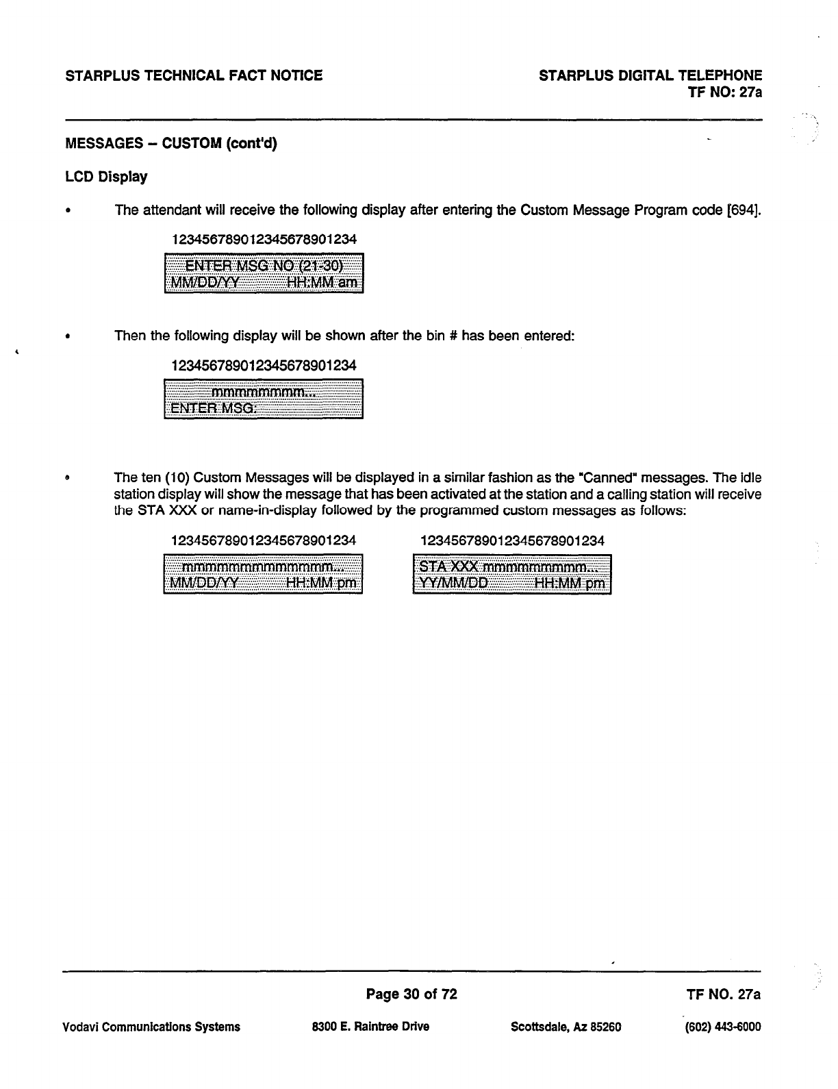
STARPLUS TECHNICAL FACT NOTICE STARPLUS DIGITAL TELEPHONE
TF NO: 27a
MESSAGES - CUSTOM (cont’d)
LCD Display
.
The attendant will receive the following display after entering the Custom Message Program code [694].
123456789012345678901234
.
Then the following display will be shown
123456789012345678901234
after the bin # has been entered:
e
The ten (10) Custom Messages will be displayed in a similar fashion as the “Canned” messages. The idle
station display will show the message that has been activated at the station and a calling station will receive
the STA XXX or name-in-display followed by the programmed custom messages as follows:
123456789012345678901234 123456789012345678901234
Page 30 of 72 TFNO. 27a
Vodavi Communications Systems 6300 E. Raintree Drive Scottsdale, AZ 85260 -(602) 443-6000
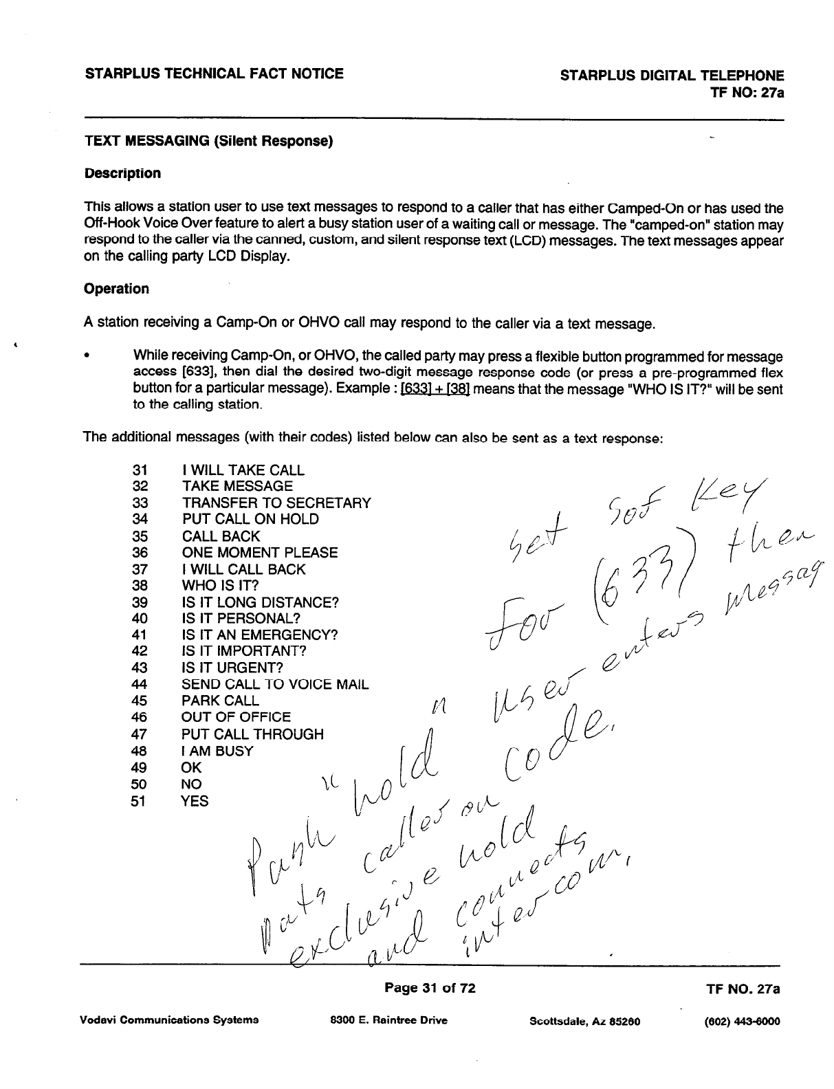
STARPLUS TECHNICAL FACT NOTICE STARPLUS DIGITAL TELEPHONE
TF NO: 27a
TEXT MESSAGING (Silent Response)
Description
This allows a station user to use text messages to respond to a caller that has either Camped-On or has used the
Off-Hook Voice Over feature to alert a busy station user of a waiting call or message. The “camped-on” station may
respond to the caller via the canned, custom, and silent response text (LCD) messages. The text messages appear
on the calling party LCD Display.
Operation
A station receiving a Camp-On or OHVO call may respond to the caller via a text message.
, . While receiving Camp-On, or OHVO, the called party may press a flexible button programmed for message
access [633], then dial the desired two-digit message response code (or press a pre-programmed flex
button for a particular message). Example : 1633]+ [38] means that the message “WHO IS IT?” will be sent
to the calling station.
The additional messages (with their codes) listed below can also be sent as a text response:
31
32
33
34
35
36
37
38
39
40
41
42
43
44
45
46
47
48
49
50
51
I WILL TAKE CALL
TAKE MESSAGE
TRANSFERTOSECRETARY
PUT CALL ON HOLD
CALL BACK
ONE MOMENT PLEASE
I WILL CALL BACK
WHO IS IT?
IS IT LONG DISTANCE?
IS IT PERSONAL?
IS IT AN EMERGENCY?
IS IT IMPORTANT?
IS IT URGENT?
SEND CALL TO VOICE MAIL
PARK CALL
OUT OF OFFICE
PUT CALL THROUGH
I AM BUSY
OK
NO
YES
Page 31
of 72
TF NO. 27a
Vodavi Communications Systems 8300 E. Raintree Drive Scottsdale, AZ 85280 (802) 443-8000
STARPLUS TECHNICAL FACT NOTICE STARPLUS DIGITAL TELEPHONE
TF NO:27a ’
TEXT MESSAGING (cont’d)
e
If the station receiving the text message response was doing a Camp-on, he will first receive a short burst
of tone on the speaker, then the display will show the message that has been activated by the called
station.
.
If the station receiving the text message response is on an OHVO call, no tone will be received.
Conditions
1. All canned and custom messages may be used to respond to a calling party.
2.
4 Text response messages will automatically clear when the calling station (station receiving the messages)
goes on-hook.
3. A station can receive only one message at a time.
4. Text messages may be chained (i.e. multiple messages sent to one caller).
5. Text message responses may only be activated by key stations and the receiving station must be a Digital
Display telephone.
6. The text message responses will appear on both the calling station and the called station (station activating)
text responses) LCD displays.
7. One Time DND may also be used as a response to a call (i.e. the DND display will appear on the calling
station).
8. The called station may press a flex button programmed as Message Access button ([633#]), then enter the
desired message on the dial pad. DTMF digits will not be heard by either party.
9. When silent messaging is used to respond to a call, the existing call of the called station will not be
disconnected while the messages are being sent to the calling station.
10. If the called station responds with a text message, the text message will appear on the LCD.
11. LED’s will follow that of the CAMP-ON or OHVO.
12. Each individual message may be programmed onto a flexible button including a flex button on a DSS/BLF
console.
Programming
None
Hardware
The calling station must be a digital display telephone and the called station must be a keyset.
Page 32 of 72 TF NO. 27a
Vodavi Communications Systems 8300 E. Raintree Drive Scottsdale, AZ 85280 (802) 4436000
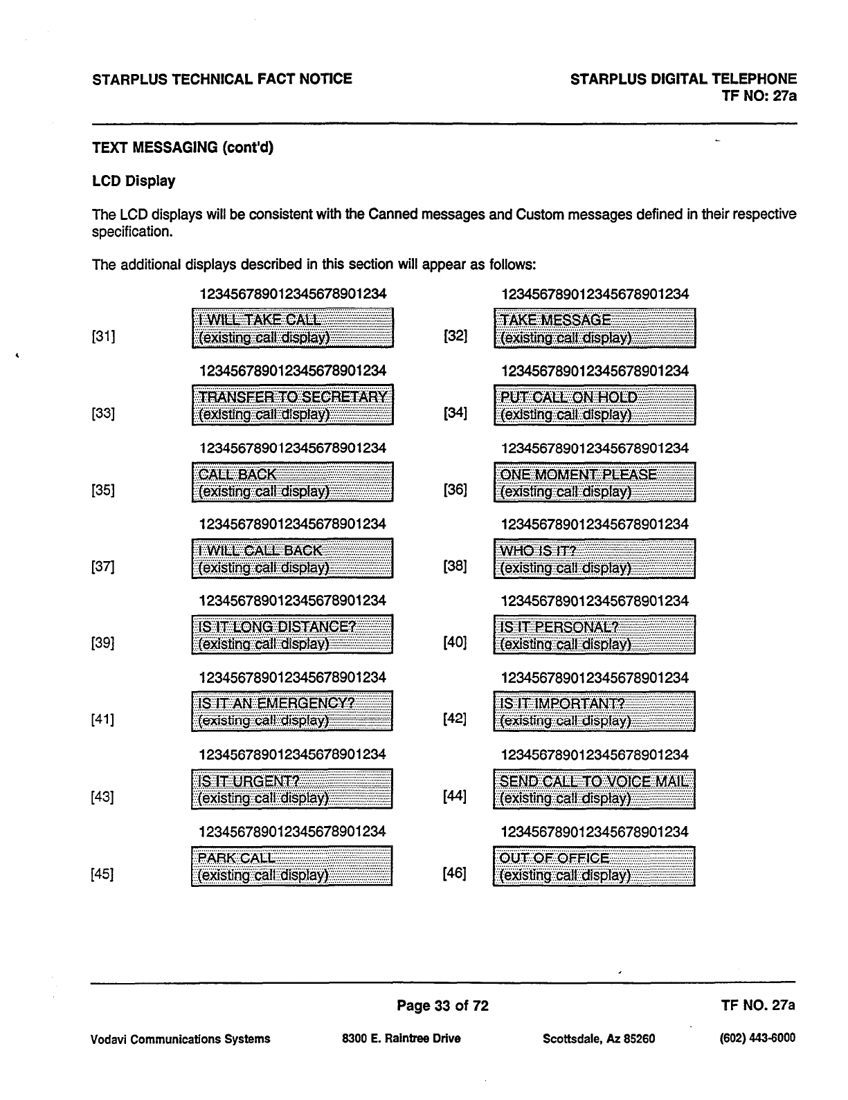
STARPLUS TECHNICAL FACT NOTICE STARPLUS DIGITAL TELEPHONE
TF NO: 27a
TEXT MESSAGJNG (cont’d)
LCD Display
The LCD displays will be consistent with the Canned messages and Custom messages defined in their respective
specification.
The additional displays described in this section will appear as follows:
1311
4
[331
I351
1371
[391
[411
[431
i451
123456789012345678901234 123456789012345678901234
i321
123456789012345678901234 123456789012345678901234
WI
123456789012345678901234 123456789012345678901234
. . . . . . . . . .,............,,,,.,,,,...........,....,.........,,,......,,,,. ..,.......
~
~~~~~~~~~~~~~~~~~
123456789012345678901234
123456789012345678901234
123456789012345678901234
123456789012345678901234
123456789012345678901234
123456789012345678901234
1361
[381
1401
[421
WI
[461
123456789012345678901234
123456789012345678901234
123456789012345678901234
123456789012345678901234
Page 33 of 72 TF NO. 27a
Vodavi Communications Systems 8300 E. Raintree Drive Scottsdale, AZ 85260 (602) 44343000
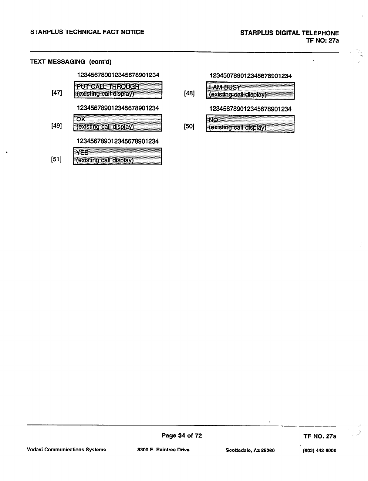
STARPLUS TECHNICAL FACT NOTICE
TEXT MESSAGING (cont’d)
STARPLUS DIGITAL TELEPHONE
TF NO: 27a
1471
WI
1511
123456769012345676901234 123456789012345678901234
123456769012345676901234 123456789012345678901234
123456789012345678901234
Page 34 of 72 TF NO. 27a
Vodavi Communications Systems 6300 E. Raintree Drive Scottsdale, AZ 66260 (602) 443-6000
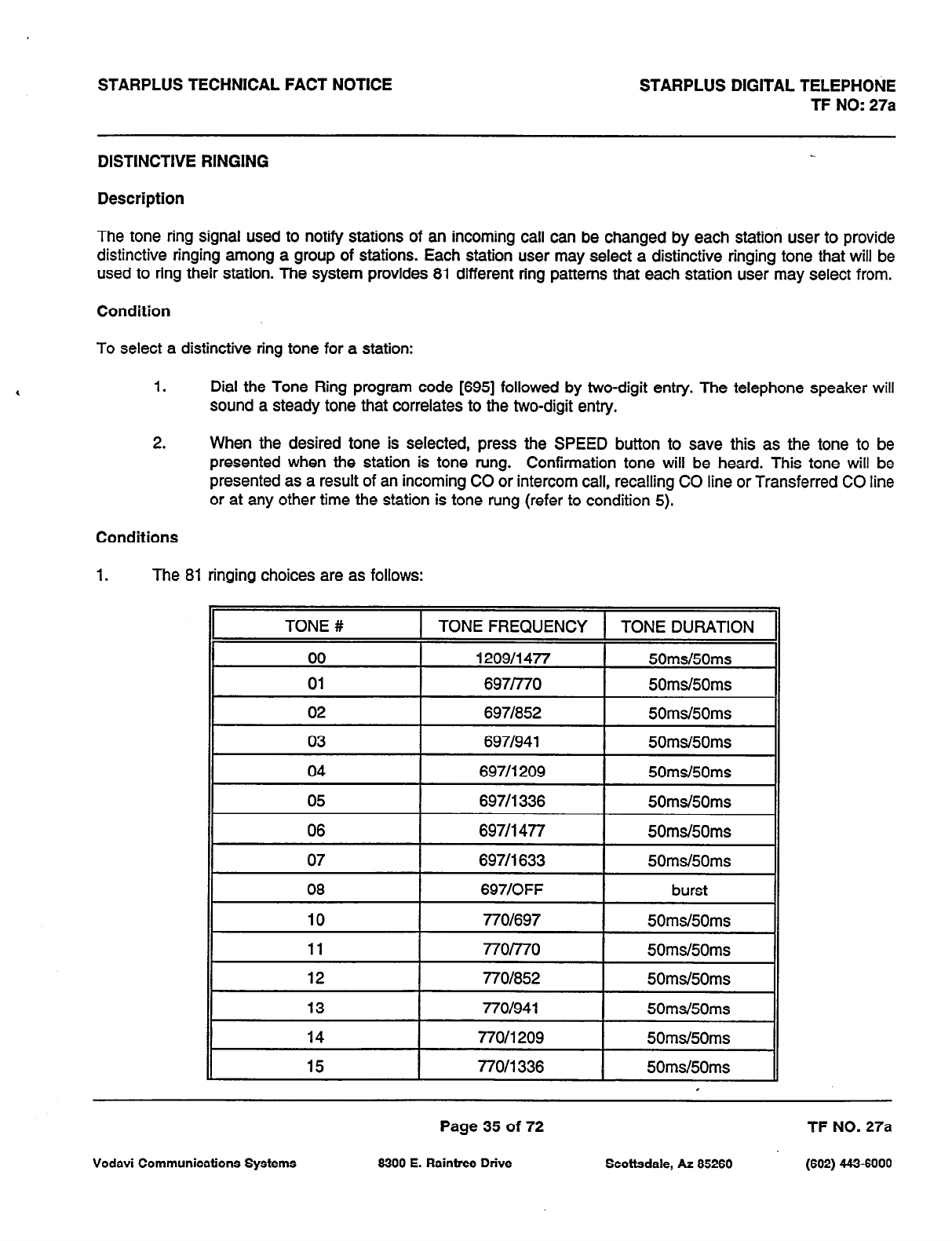
STARPLUS TECHNICAL FACT NOTICE STARPLUS DIGITAL TELEPHONE
TF NO: 27a
DISTINCTIVE RINGING
Description
The tone ring signal used to notify stations of an incoming call can be changed by each station user to provide
distinctive ringing among a group of stations. Each station user may select a distinctive ringing tone that will be
used to ring their station. The system provides 81 different ring patterns that each station user may select from.
Condition
To select a distinctive ring tone for a station:
1. Dial the Tone Ring program code [695] followed by two-digit entry. The telephone speaker will
sound a steady tone that correlates to the two-digit entry.
2. When the desired tone is selected, press the SPEED button to save this as the tone to be
presented when the station is tone rung. Confirmation tone will be heard. This tone will be
presented as a result of an incoming CO or intercom call, recalling CO line or Transferred CO line
or at any other time the station is tone rung (refer to condition 5).
Conditions
1. The 81 ringing choices are as follows:
Page 35 of 72 TF NO. 27a
Vodavi Communications Systems 6300 E. Raintree Drive Scottsdale, AZ 85260 (602) 443-6000
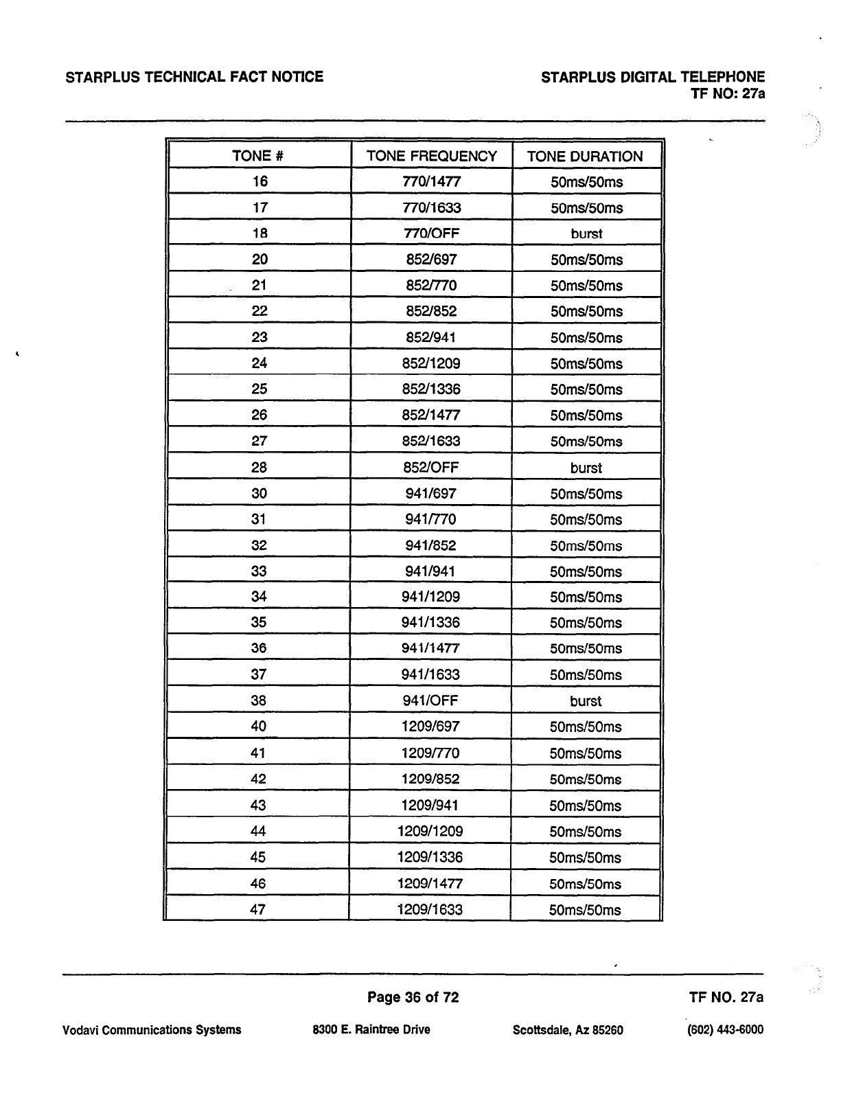
STARPLUS TECHNICAL FACT NOTICE STARPLUS DIGITAL TELEPHONE
TF NO: 27a
TONE # TONE FREQUENCY TONE DURATION
II
16 770/i 477 50ms/50ms
17
16
77011633
77OiOFF
50msI50ms
burst
II
20 I 852f697 I 50ms/50ms
21 8521770 50ms/50ms
22 852l852 50md50ms
23 852/941 50ms/50ms
II
24 852/l 209 I 50ms/50ms
25 852/l 336 50ms/50ms
26 852/l 477 50ms/50ms
27 8520 633 50md50ms
28 852fOFF burst
30 9411697 50ms/50ms
31 941l770 50md50ms
32 9411852 50msi50ms
33 9411941 50ms/50ms
34 941/l 209 50ms/50ms
35 941/l 336 50ms/50ms
II
36 941 I1 477 50md50ms
37
38
40
41
94111633
941/OFF
12091697
1209/770
50ms/50ms
burst
50ms/50ms
50ms/50ms
II
42 12091852 50ms/50ms
I
43 1209/941 50ms/50ms
44 1209/l 209 50ms/50ms
45 1209/l 336 50ms/50ms
46 120911477 50ms/50ms
II
47 120911633 50ms/50ms
Vodavi Communications Systems
Page 36 of 72
8300 E. Raintree Drive Scottsdale, AZ 85260
TFNO. 27a ’
-(602) 443-6000
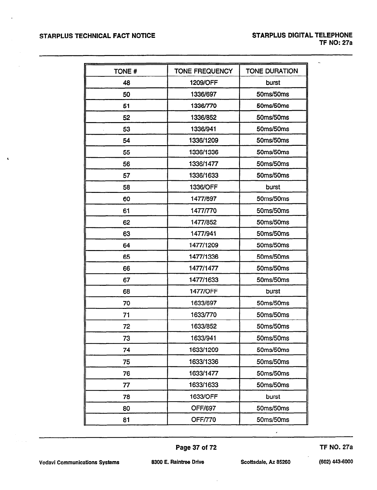
STARPLUS TECHNICAL FACT NOTICE STARPLUS DIGITAL TELEPHONE
TF NO: 27a
Page 37 of 72 TF NO. 27a
Vodavi Communications Systems 8300 E. Raintree Drive Scottsdale, AZ 65260 (602) 443-6000
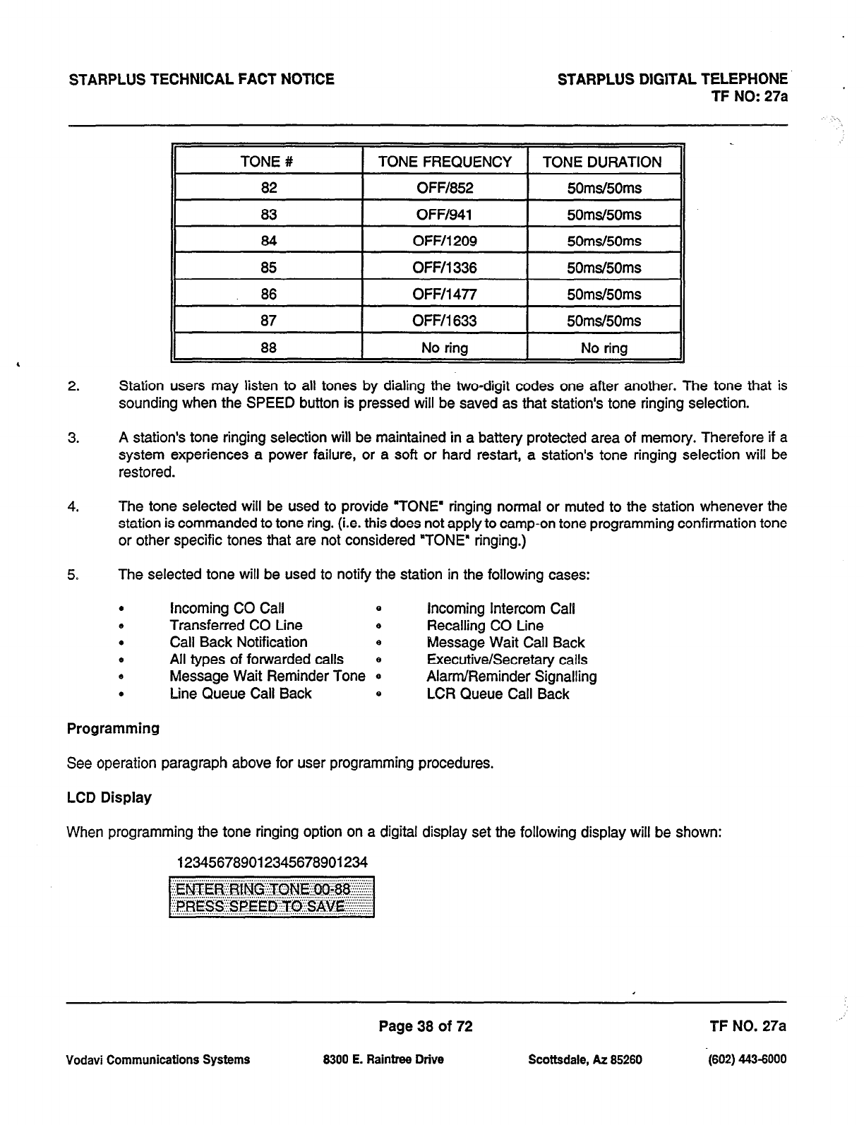
STARPLUS TECHNICAL FACT NOTICE STARPLUS DlGlTAL TELEPHONE
TF NO: 27a
2. Station users may listen to all tones by dialing the two-digit codes one after another. The tone that is
sounding when the SPEED button is pressed will be saved as that station’s tone ringing selection.
3. A station’s tone ringing selection will be maintained in a battery protected area of memory. Therefore if a
system experiences a power failure, or a soft or hard restart, a station’s tone ringing selection will be
restored.
4. The tone selected will be used to provide ‘TONE’ ringing normal or muted to the station whenever the
station is commanded to tone ring. (i.e. this does not apply to camp-on tone programming confirmation tone
or other specific tones that are not considered “TONE” ringing.)
5. The selected tone will be used to notify the station in the following cases:
.
Incoming CO Call 0 incoming Intercom Call
* Transferred CO Line B Recalling CO Line
. Call Back Notification e Message Wait Call Back
0 All types of forwarded calls e Executive/Secretary calls
* Message Wait Reminder Tone 0 Alarm/Reminder Signalling
. Line Queue Call Back 0 LCR Queue Call Back
Programming
See operation paragraph above for user programming procedures.
LCD Display
When programming the tone ringing option on a digital display set the following display will be shown:
123456789012345678901234
Vodavi Communications Systems
Page 38 of 72
6300 E. Raintree Drive Scottsdale, AZ 65260
TF NO. 27a
-(602) 443-6000
STARPLUS TECHNICAL FACT NOTICE STARPLUS DIGITAL TELEPHONE
TF NO: 27a
GROUP LISTENING
Description
All digital key stations have built in speakerphones. Station users may use the speaker to monitor a call while using
the handset to converse with the outside party. This enables other people in the room to listen to both parties in
the conversation.
Operation
While conversing,
on
the handset, press the ON/OFF button. Both parties of the conversation can then be heard
on the digital station’s speaker. The speakerphone microphone will be muted while the handset is off-hook.
To deactivate Group Listening while off-hook, the ON/OFF button must be depressed.
Conditions
1. While talking using the speaker phone, then lifting the handset will turn off of the speakerphone. To activate
group listening, the ON/OFF button must be pressed (to ON) while the handset is off-hook.
2. While in group listening mode, pressing the MUTE button will cause the transmit from the handset to be
muted (the speakerphone microphone is already muted). However the distant end can still be heard over
both the handset receiver and the station speaker.
3. If full speakerphone operation is desired while in group listening mode, simply set the handset on-hook.
4. Group listening is not available when the station is in headset mode.
5. When placing the handset on-hook to go to full speakerphone operation, it is normal for a “squeal” caused
by audio feedback to be heard.
Programming
By default, Group listening is disabled. To enable, System Attributes, Flash 05, Button 9.
Page 39 of 72 TF NO. 27a
Vodavi Communication5 Systems 6300 E. Raintree Drive Scottsdale, AZ 66260 (602) 443-6000
STARPLUS TECHNICAL FACT NOTICE STARPLUS DIGITAL TELEPHONE
TF NO: 27a
. .
FLEX BUTTON PROGRAMMING
Description
If you have buttons on your telephone which have NOT been assigned as CO lines, Pooled Group, or Loop buttons,
you may program them to suit your own individual needs. There are five functions you may assign to these buttons:
DSS/BLF, FEATURES, SPEED DIAL, POOLED GROUP ACCESS, and LOOP.
As an added feature, LCR may now be added to a flex button.
In earlier versions of software, the Do Not Disturb (DND), Call Forward (MID), Camp-On, Available/Unavailable,
Personal Park, Voice Mail, Headset Mode features were able to be programmed onto DSS Console Flexible
4 buttons. however, the LED associated with those features did not light or flash. Therefore, in this version of
software, the above mentioned features are not allowed to be programmed onto DSS Console flexible buttons.
These features can however, still be programmed onto keyset flexible buttons.
Page 40 of 72 TF NO. 27a
Vodavi Communications Systems 6300 E. Rainbw Drive Scottsdale, AZ 85260 (602) 443-6000
STARPLUS TECHNICAL FACT NOTICE STARPLUS DIGITAL TELEPHONE
TF NO: 27a
IDLE SPEAKER MODE
Description
This feature allows the system to determine whether the first digit dialed is heard over the digital key terminal
speaker. This feature can be allowed or denied on a system-wide basis in programming.
Programming
Idle Speaker Mode is programmed as part of System Features, Flash 05, Button #lo. By default, Idle Speaker
Mode is disabled.
Page 41 of 72 TF NO. 27a
Vodavi Communications Systems 6300 E. Raintree Drive Scottsdale, AZ 66260 (602) 443-6000
STARPLUS TECHNICAL FACT NOTICE STARPLUS DIGITAL TELEPHONE ’ TF NO: 27a
MUSIC ON HOLD
Description
A music source, when connected to the system, provides music to all lines on hold, parked calls, transferred calls
and calls waiting to be answered by Uniform Call Distribution (UCD). This feature can be allowed or denied on a
system-wide basis in programming.
Programming
Music On Hold is programmed as part of System Features, Flash 05, Button #12. By default, Music On Hold is
enabled for all CO lines.
Vodavi Communications Systems 8300 E. Raintree Drive
Page 42 of 72
Scottsdale, AZ 85260
TF NO. 27a
(602) 443-6000
.’
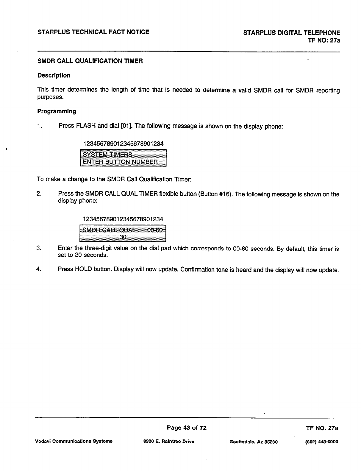
STARPLUS TECHNICAL FACT NOTICE STARPLUS DIGITAL TELEPHONE
TF NO: 27a
SMDR CALL QUALIFICATION TIMER
Description
This timer determines the length of time that is needed to determine a valid SMDR call for SMDR reporting
purposes.
Programming
1. Press FLASH and dial [Oil. The following message is shown on the display phone:
123456789012345678901234
To make a change to the SMDR Call Qualification Timer:
2. Press the SMDR CALL QUAL TIMER flexible button (Button #16). The following message is shown on the
display phone:
123456789012345678901234
3. Enter the three-digit value on the dial pad which corresponds to 00-60 seconds. By default, this timer is
set to 30 seconds.
4.
Press HOLD button. Display will now update. Confirmation tone is heard and the display will now update.
Page 43 of 72 TF NO.
27a
Vodavi Communications Systems 6300 E. Raintree Drive Scottsdale, AZ 66260 (602) 443-6000
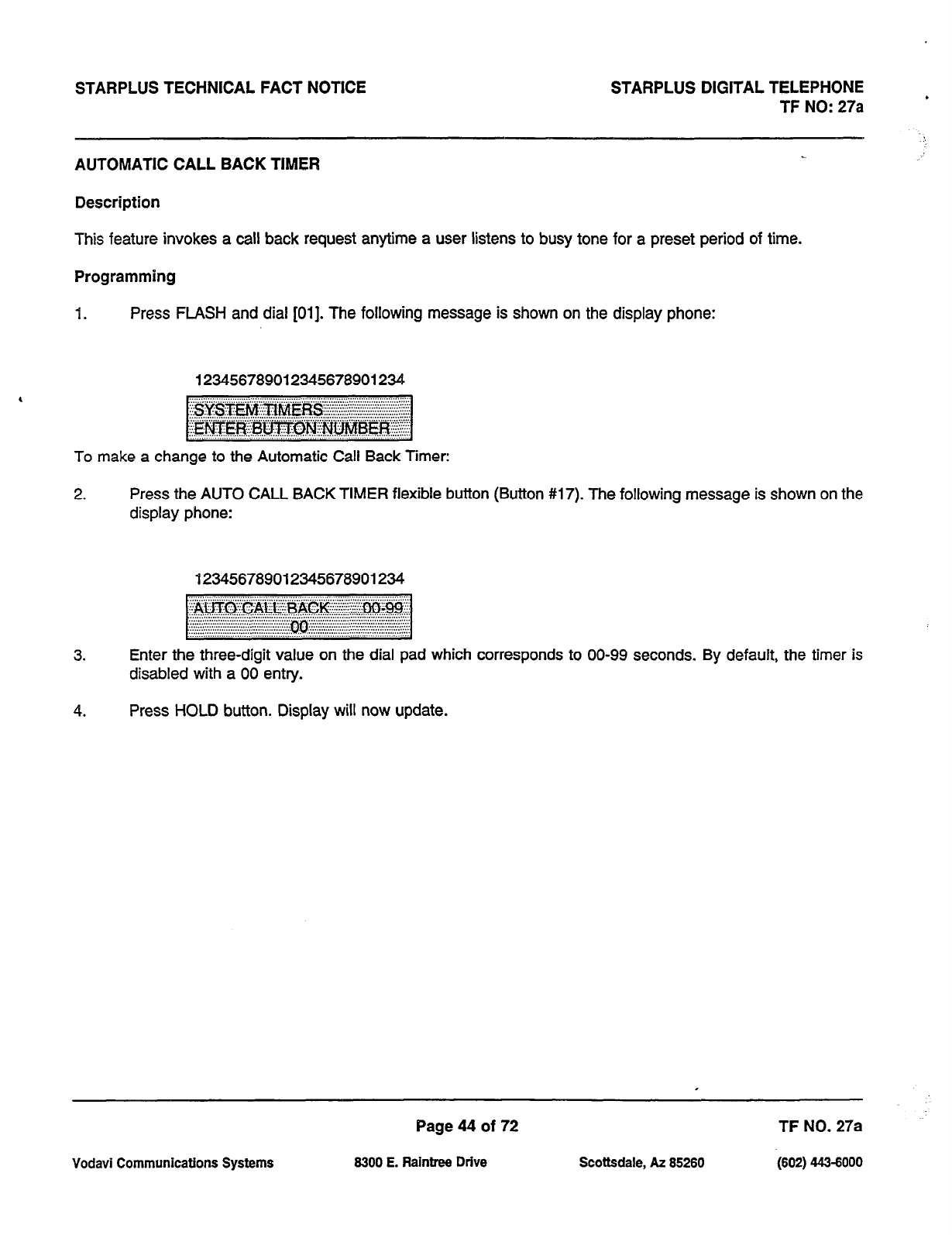
STARPLUS TECHNICAL FACT NOTICE STARPLUS DIGITAL TELEPHONE
TF NO: 27a
AUTOMATIC CALL BACK TIMER
Description
This feature invokes a call back request anytime a user listens to busy tone for a preset period of time.
Programming
1. Press FLASH and dial [Ol]. The following message is shown on the display phone:
123456789012345678901234
To make a change to the Automatic Call Back Timer:
2. Press the AUTO CALL BACK TIMER flexible button (Button #17). The following message is shown on the
display phone:
123456789012345678901234
3. Enter the three-digit value on the dial pad which corresponds to 00-99 seconds. By default, the timer is
disabled with a 00 entry.
4. Press HOLD button. Display will now update.
Vodavi Communications Systems
Page 44 of 72
8300 E. Raintree Drive Scottsdale, AZ 85280 -1802) 4434000
TF NO. 27a
STARPLUS TECHNICAL FACT NOTICE STARPLUS DIGITAL TELEPHONE
TF NO: 27a
EXECUTIVE OVERRIDE
Description:
Allows stations designated as ‘Executive’ the ability to override and “barge-in” on other keysets engaged in
conversation
Operation:
If you call a busy station:
a. Press the pre-programmed EXECUTIVE OVERRIDE button. Executive station will be bridged onto the CO
line conversation in progress at the called station. Optional warning tone is heard and presented to all
parties prior to cut-thru.
b. Replace handset at Executive station to terminate the override.
NOTE: A change in volume may occur on the CO line or intercom call after the barge-in occurs.
Conditions:
1.
An error tone will occur:
- if the called party is in a conference
- if the called party is already on an OHVO call.
- if the called party already has a Camp-On at his station.
2. If the Executive joins a call and one of the members does a hook-flash or depresses his transfer button,
the Executive will be dropped.
3. If the Executive does a hook-flash or depresses his transfer button, it will be ignored.
4. When the Executive jumps in on an intercom call or CO call and the Executive is not in a mute condition,
and any member of the party hangs up, the call will be converted to a two-party conversation.
5.
When the Executive jumps in on an intercom call or CO call and the Executive is in the mute condition and
either of the two parties in the intercom call hang up, the call will be dropped. If the Executive hangs up,
the call will remain as a two-party conversation.
Programming:
A separate condition has been added to Station programmi hi& will allow or
disallow an Executive to override an extension. Station displ s been changed
from blank or EO to A or D, or EA or ED; where A= allow override, D= disallow override, E= Enable
override capability.
Page 45 of 72 TF NO. 27a
Vociavi Communications Systems 6300 E. Raintree Drive Scottsdale, AZ 85260 (602) 443-6000
STARPLUS TECHNICAL FACT NOTICE STARPLUS DIGITAL TELEPHONE ,
TF NO: 27a
UCD FEATURE SECTION
Eight Uniform Call Distribution (UCD) groups can be programmed, each containing up to eight three-digit station
numbers. Each group is assigned a pilot number. When this number is dialed, the first available agent in that group
is rung. Calls are routed to the station that has been on-hook for the longest period of time.
Enhanced Calls in Queue Display
No-Answer Retry Timer
Expansion of Recorded Announcements to 8
Page 46 of 72 TF NO. 27a
Vodavi Communications Systems 8300 E. Raintrw Drive Scottsdale, AZ 85280 (602) 443-6000
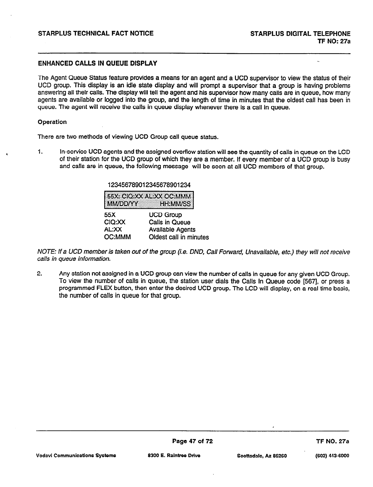
STARPLUS TECHNICAL FACT NOTICE STARPLUS DIGITAL TELEPHONE
TF NO: 27a
ENHANCED CALLS IN QUEUE DISPLAY
The Agent Queue Status feature provides a means for an agent and a UCD supervisor to view the status of their
UCD group. This display is an idle state display and will prompt a supervisor that a group is having problems
answering all their calls. The display will tell the agent and his supervisor how many calls are in queue, how many
agents are available or logged into the group, and the length of time in minutes that the oldest call has been in
queue. The agent will receive the calls in queue display whenever there is a call in queue.
Operation
There are two methods of viewing UCD Group call queue status.
1. In-service UCD agents and the assigned overflow station will see the quantity of calls in queue on the LCD
of their station for the UCD group of which they are a member. If every member of a UCD group is busy
and calls are in queue, the following message will be seen at all UCD members of that group.
123456789012345678901234
55X UCD Group
CIQ:XX Calls in Queue
AL:XX Available Agents
0C:MMM Oldest call in minutes
NOTE: If a UCD member is taken out of the group (i.e. DND, Call Forward, Unavailable, etc.) they will not receive
calls in queue information.
2. Any station not assigned in a UCD group can view the number of calls in queue for any given UCD Group.
To view the number of calls in queue, the station user dials the Calls In Queue code [567], or press a
programmed FLEX button, then enter the desired UCD group. The LCD will display, on a real time basis,
the number of calls in queue for that group.
Page 47 of 72 TF NO. 27a
Vodavi Communications Systems 8300 E. Raintree Drive Scottsdale, AZ 85260 (602) 443-6000
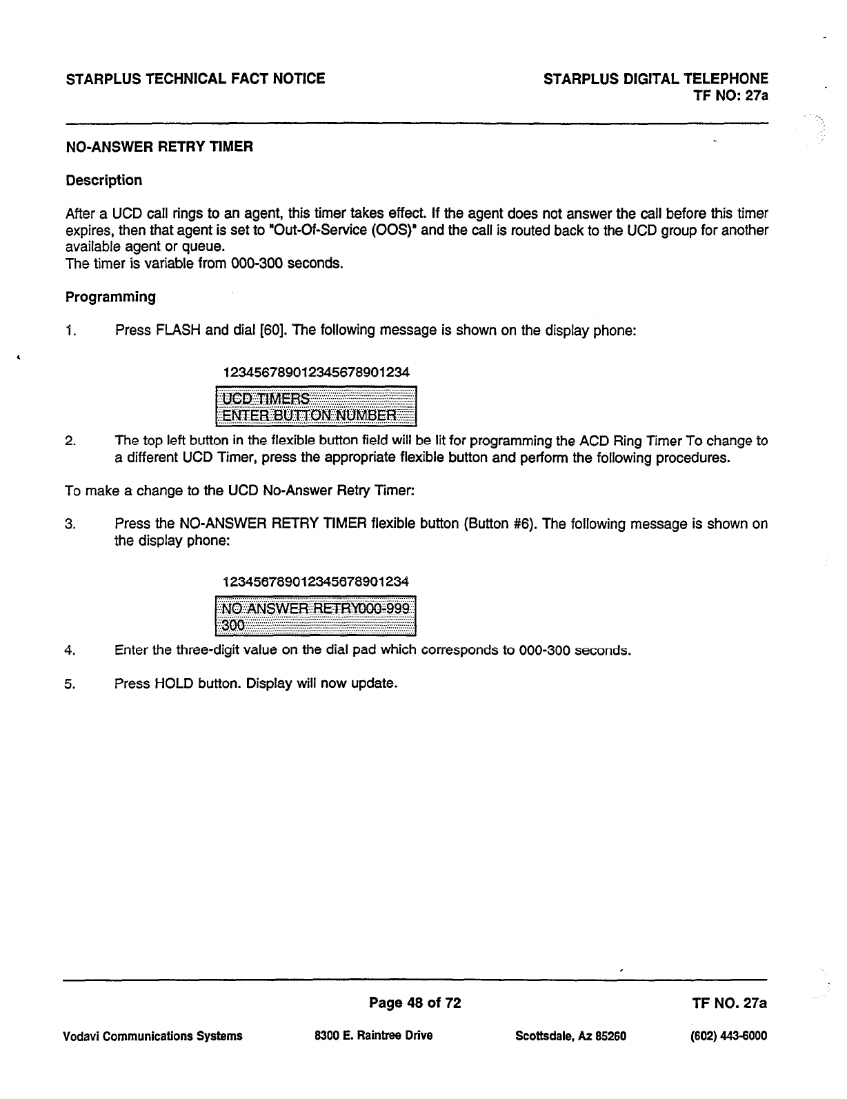
STARPLUS TECHNICAL FACT NOTICE STARPLUS DIGITAL TELEPHONE
TF NO: 27a
NO-ANSWER RETRY TIMER
Description
After a UCD call rings to an agent, this timer takes effect. If the agent does not answer the call before this timer
expires, then that agent is set to “Out-Of-Service (00s)” and the call is routed back to the UCD group for another
available agent or queue.
The timer is variable from 000-300 seconds.
Programming
1. Press FLASH and dial [60]. The following message is shown on the display phone:
123456789012345678901234
2. The top left button in the flexible button field will be lit for programming the ACD Ring Timer To change to
a different UCD Timer, press the appropriate flexible button and perform the following procedures.
To make a change to the UCD No-Answer Retry Timer:
3. Press the NO-ANSWER RETRY TIMER flexible button (Button #6). The following message is shown on
the display phone:
123456789012345678901234
4. Enter the three-digit value on the dial pad which corresponds to 000-300 seconds.
5. Press HOLD button. Display will now update.
Page 48 of 72 TF NO. 27a
Vodavi Communications Systems 6300 E. Raintree Drive Scottsdale, AZ 66260 (602) 4434000
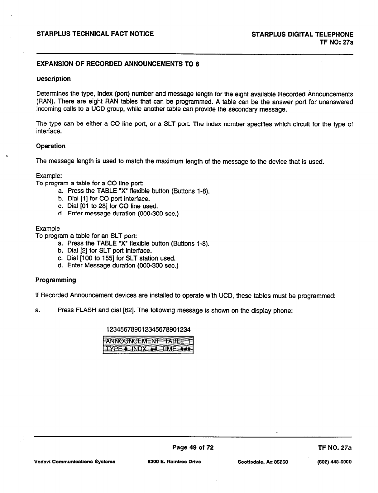
STARPLUS TECHNICAL FACT NOTICE STARPLUS DIGITAL TELEPHONE
TF NO: 27a
EXPANSION OF RECORDED ANNOUNCEMENTS TO 8
Description
Determines the type, index (port) number and message length for the eight available Recorded Announcements
(PAN). There are eight HAN tables that can be programmed. A table can be the answer port for unanswered
incoming calls to a UCD group, while another table can provide the secondary message.
The type can be either a CO line port, or a SLT port. The index number specifies which circuit for the type of
interface.
Operation
The message length is used to match the maximum length of the message to the device that is used.
Example:
To program a table for a CO line port:
a. Press the TABLE “x’ flexible button (Buttons i-8).
b. Dial [l] for CO port interface.
c. Dial [Oi to 281 for CO line used.
d. Enter message duration (000-300 sec.)
Example
To program a table for an SLT port:
a. Press the TABLE ‘x’ flexible button (Buttons l-8).
b. Dial [2] for SLT port interface.
c. Dial [lo0 to 1551 for SLT station used.
d. Enter Message duration (000-300 sec.)
Programming
If Recorded Announcement devices are installed to operate with UCD, these tables must be programmed:
a. Press FLASH and dial [62]. The following message is shown on the display phone:
123456789012345678901234
Page 49 of 72 TF NO. 27a
Vodavi Communications Systems 6300 E. Raintree Drive Scottsdale, AZ 66260 (602) 443-6000
STARPLUS TECHNICAL FACT NOTICE STARPLUS DIGITAL TELEPHONE
TF NO: 27a .
EXPANSION OF RECORDED ANNOUNCEMENTS TO 8 (cont’d) ,:
b. The top left button in the flexible button field will be lit for programming UCD RAN Announcement Table
1. To change to UCD RAN Announcement Table 2, press flexible button #2. Repeat above for Tables 3
through Tables 8.
C.
Enter a string of six, or seven digits on the dial pad. The order of data entry will be:
Type number:
1 = CO Port interface
2 = SLT Port interface
Index (port) Number:
01 - 28 = CO Line Port
loo-155 = SLT Station Port
Message Time:
000-300
seconds
d. Press HOLD button.
NOTE When a CO port is designated as a RAN port, a relay andor sensor should be programmed as a RAN start
for Announcement Table 1 through 8.
Vodavi Communications Systems
Page 50 of 72
8300 E. Raintme Drive Scottsdale, AZ 85280 (602) 443-6000
TF NO. 27a
STARPLUS TECHNICAL FACT NOTICE STARPLUS DIGITAL TELEPHONE
TF NO: 27a
VOICE MAIL
Voice Mail Transfer with ID
Page 51 of 72 TF NO.
27a
Vodavi Communications Systems 8300 E. Raintres Drive Scottsdale, AZ 85280 (802) 443-5000
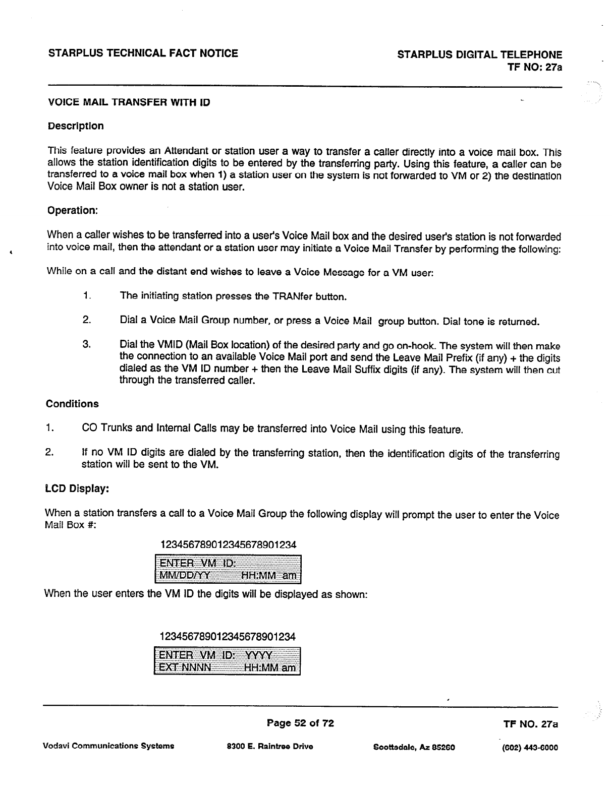
STARPLUS TECHNICAL FACT NOTICE STARPLUS DIGITAL TELEPHONE
TF NO: 27a
VOICE MAIL TRANSFER WITH ID
Description
This feature provides an Attendant or station user a way to transfer a caller directly into a voice mail box. This
allows the station identification digits to be entered by the transferring party. Using this feature, a caller can be
transferred to a voice mail box when 1) a station user on the system is not forwarded to VM or 2) the destination
Voice Mail Box owner is not a station user.
Operation:
When a caller wishes to be transferred into a user’s Voice Mail box and the desired user’s station is not forwarded
I into voice mail, then the attendant or a station user may initiate a Voice Mail Transfer by performing the following:
While on a call and the distant end wishes to leave a Voice Message for a VM user:
1.
The initiating station presses the TRANfer button.
2. Dial a Voice Mail Group number, or press a Voice Mail group button. Dial tone is returned.
3. Dial the VMID (Mail Box location) of the desired party and go on-hook. The system will then make
the connection to an available Voice Mail port and send the Leave Mail Prefix (if any) + the digits
dialed as the VM ID number + then the Leave Mail Suffix digits (if any). The system will then cut
through the transferred caller.
Conditions
1. CO Trunks and Internal Calls may be transferred into Voice Mail using this feature.
2. If no VM ID digits are dialed by the transferring station, then the identification digits of the transferring
station will be sent to the VM.
LCD Display:
When a station transfers a call to a Voice Mail Group the following display will prompt the user to enter the Voice
Mail Box #:
123456789012345678901234
When the user enters the VM ID the digits will be displayed as shown:
123456789012345678901234
.
Page 52 of 72 TF NO. 27a
Vodavi Communications Systems 6300 E. Raintree Drive Scottsdale, AZ 66260 (602) 443-6000
STARPLUS TECHNICAL FACT NOTICE STARPLUS DIGITAL TELEPHONE
TF NO: 27a
LCD ENHANCEMENT SECTION
CO Line Identification Display
Page 53 of 72 TF NO. 27a
Vodavi Communications Systems 8300 E. Raintree Drive Scottsdale, AZ 85280 (602) 443-6000
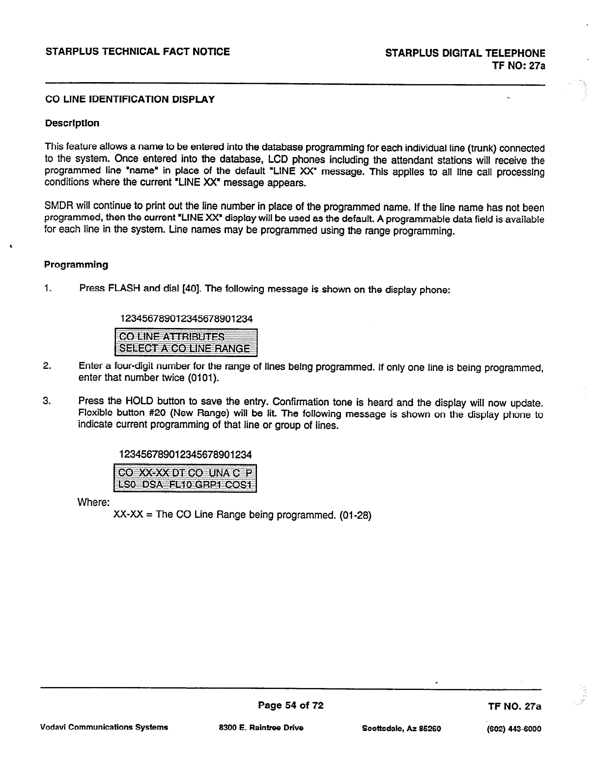
STARPLUS TECHNICAL FACT NOTICE STARPLUS DIGITAL TELEPHONE
TF NO:
27a
CO LINE IDENTIFICATION DISPLAY
Description
This feature allows a name to be entered into the database programming for each individual line (trunk) connected
to the system. Once entered into the database, LCD phones including the attendant stations will receive the
programmed line “name” in place of the default ‘LINE XX” message. This applies to all line call processing
conditions where the current ‘LINE XX” message appears.
SMDR will continue to print out the line number in place of the programmed name. If the line name has not been
programmed, then the current “LINE XX” display will be used as the default. A programmable data field is available
for each line in the system. Line names may be programmed using the range programming.
Programming
1.
Press FLASH and dial [40]. The following message is shown on the display phone:
123456789012345678901234
2. Enter a four-digit number for the range of lines being programmed. If only one line is being programmed,
enter that number twice (0101).
3. Press the HOLD button to save the entry. Confirmation tone is heard and the display will now update.
Flexible button #20 (New Range) will be lit. The following message is shown on the display phone to
indicate current programming of that line or group of lines.
123456789012345678901234
Where: XX-XX = The CO Line Range being programmed. (01-28)
Page 54 of 72 TF NO. 27a
Vodavi Communications Systems 6300 E. Raintree Drive Scottsdale, AZ 66260 (602) 443-6000
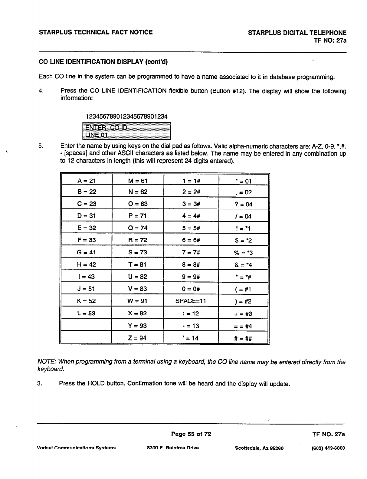
STARPLUS TECHNICAL FACT NOTICE STARPLUS DIGITAL TELEPHONE
TF NO: 27a
CO LINE IDENTIFICATION DISPLAY
(cont’d)
Each CO line in the system can be programmed to have a name associated to it in database programming.
4. Press the CO LINE IDENTIFICATION flexible button (Button #12). The display will show the following
information:
123456789012345678901234
5. Enter the name by using keys on the dial pad as follows. Valid alpha-numeric characters are: A-Z, O-9, *,#,
- [spaces] and other ASCII characters as listed below. The name may be entered in any combination up
to 12 characters in length (this will represent 24 digits entered).
A=21 M = 61 1=1#
n = 01
B=22 N = 62 2 = 2# , = 02
C = 23 0 = 63 3 = 3# ? = 04
D = 31 P = 71 4=4## I = 04
E = 32 Q = 74 5 = 5# ! = ‘1
F = 33 R = 72 6 = 6# $ = ‘2
G = 41 s = 73 7 = 7# % = l 3
H = 42 T = 81 8 = 8# & = ‘4
I = 43 U = 82 9 = 9#
l
= l #
J = 51 V = 83
K=52 w = 91
0 = O#
SPACE=1 1
( = #I
) = #2
L = 53 x = 92 : = 12 + = #3
Y = 93 -= 13 = = #4
z = 94 ‘= 14 # = ##
NOTE: When programming from a terminal using a keyboard, the CO line name may be entered direct/y from the
keyboard.
3. Press the HOLD button. Confirmation tone will be heard and the display will update.
Page 55 of 72 TF NO. 27a
Vodavi Communications Systems 6300 E. Raintree Drive Scottsdale, AZ 66260 (602) 4436000
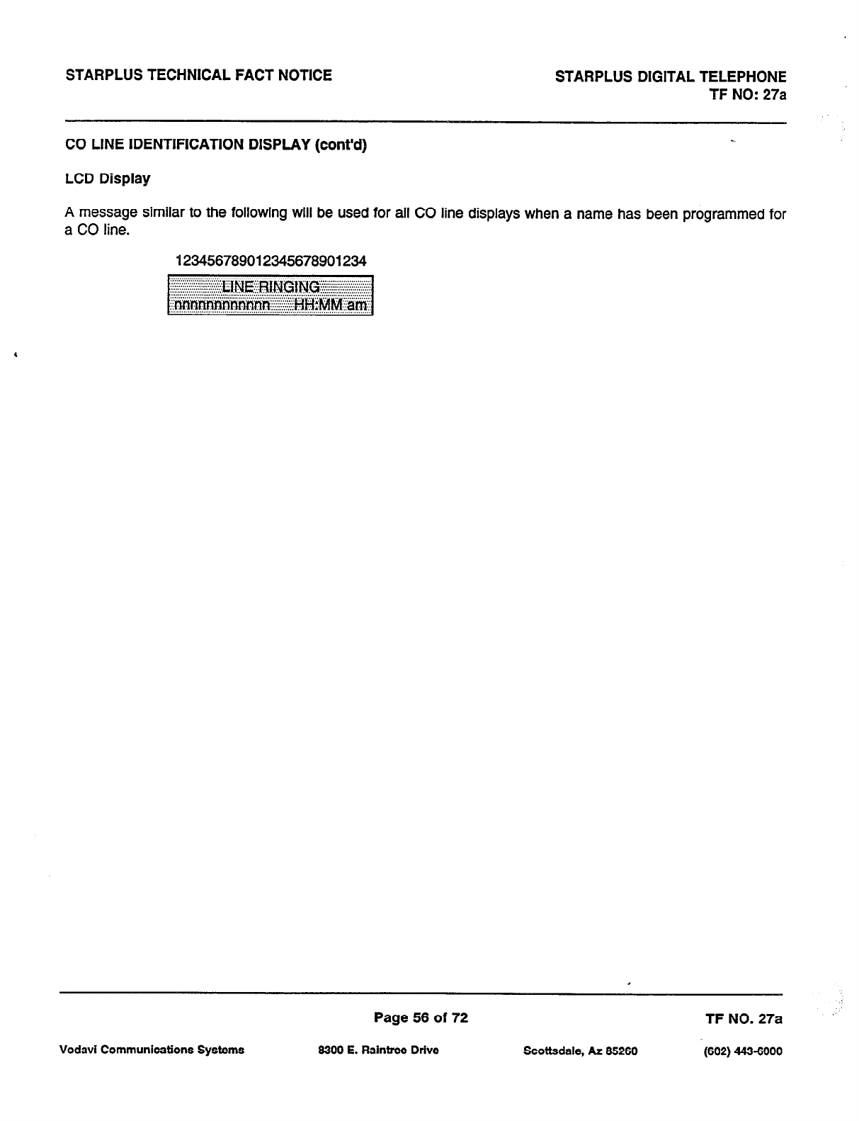
STARPLUS TECHNICAL FACT NOTICE STARPLUS DIGITAL TELEPHONE
TF NO: 27a
CO LINE IDENTIFICATION DISPLAY (cont’d)
LCD Display
A message similar to the following will be used for all CO line displays when a name has been programmed for
a CO line.
423456789012345678901234
Page 56 of 72 TF NO. 27a
Vodavi Communications Systems 6300 E. Raintree Drive Scottsdale, AZ 65260 (602) 443-6000
STARPLUS TECHNICAL FACT NOTICE STARPLUS DIGITAL TELEPHONE
TF NO: 27a
PROGRAMMING FEATURES
Station Relocation
Flexible Station and CO Port Assignments
Page 57 of 72 TF NO. 27a
Vodavi Communications Systems 6300 E. Raintree Drive Scottsdale, AZ 65260 (602) 443-6000
STARPLUS TECHNICAL FACT NOTICE STARPLUS DIGITAL TELEPHONE
TF NO: 27a
‘\
./
STATION RELOCATION FEATURE
Description
The Station Relocation Feature will provide a means to allow a user to unplug their station and plug it in at another
location. Then by dialing a simple code followed by his old station number, bring all the station attributes including
extension number, button mapping, speed dial, and class of service to the new location.
Operation
A station can be relocated by unplugging it and then plugging it in at a new location. Then dial [636] followed by
the extension number of the station being relocated. Once this is done, all station attributes are copied to the
current station.
4
NOTE: If a station is assigned to a specific port and that user unplugs their station and plugs it in at another
location, the database administration programming will be updated to reflect the new port change.
Conditions
I. The station number that is dialed as the relocated station must be currently out of service.
2. The relocated station will be given the station attributes of the station doing the relocating. The two stations
have traded station numbers and station attributes.
3. If a keyset is plugged into the relocated position it will have all the station attributes of the relocating station.
4. This feature only is applicable to keysets.
5. If a call is on hold at the relocating station or the relocated station is in service, error tone will be received.
Vodavi Communications Systems
Page 58 of 72
6300 E. Raintree Drive Scottsdale, AZ 66260 /602) 443-6000
TF NO. 27a
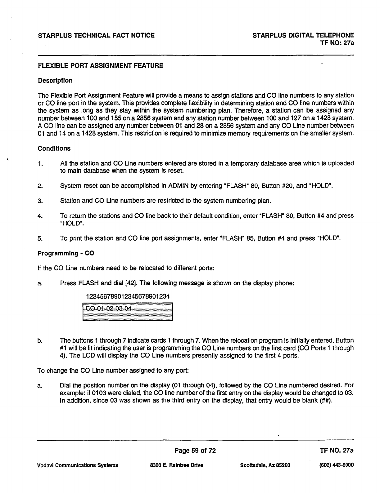
STARPLUS TECHNICAL FACT NOTICE STARPLUS DIGITAL TELEPHONE
TF NO: 27a
FLEXIBLE PORT ASSIGNMENT FEATURE
Description
The Flexible Port Assignment Feature will provide a means to assign stations and CO line numbers to any station
or CO line port in the system. This provides complete flexibility in determining station and CO line numbers within
the system as long as they stay within the system numbering plan. Therefore, a station can be assigned any
number between 100 and 155 on a 2856 system and any station number between 100 and 127 on a 1428 system.
A CO line can be assigned any number between 01 and 28 on a 2856 system and any CO Line number between
01 and 14 on a 1428 system. This restriction is required to minimize memory requirements on the smaller system.
Conditions
1. All the station and CO Line numbers entered are stored in a temporary database area which is uploaded
to main database when the system is reset.
2. System reset can be accomplished in ADMIN by entering “FLASH” 80, Button #20, and ‘HOLD”.
3. Station and CO Line numbers are restricted to the system numbering plan.
4. To return the stations and CO line back to their default condition, enter ‘FLASH” 80, Button #4 and press
“HOLD”.
5. To print the station and CO line port assignments, enter ‘FLASH” 85, Button #4 and press “HOLD”.
Programming - CO
If the CO Line numbers need to be relocated to different ports:
a. Press FLASH and dial [42]. The following message is shown on the display phone:
123456789012345678901234
b. The buttons 1 through 7 indicate cards 1 through 7. When the relocation program is initially entered, Button
#l will be lit indicating the user is programming the CO Line numbers on the first card (CO Ports 1 through
4). The LCD will display the CO Line numbers presently assigned to the first 4 ports.
To change the CO Line number assigned to any port:
a. Dial the position number on the display (01 through 04), followed by the CO Line numbered desired. For
example: if 0103 were dialed, the CO line number of the first entry on the display would be changed to 03.
In addition, since 03 was shown as the third entry on the display, that entry would be blank (##).
Page 59 of 72 TF NO. 27a
Vodavi Communications Systems 8300 E. Raintree Drive Scottsdale, AZ 85260 (602) 443-6000
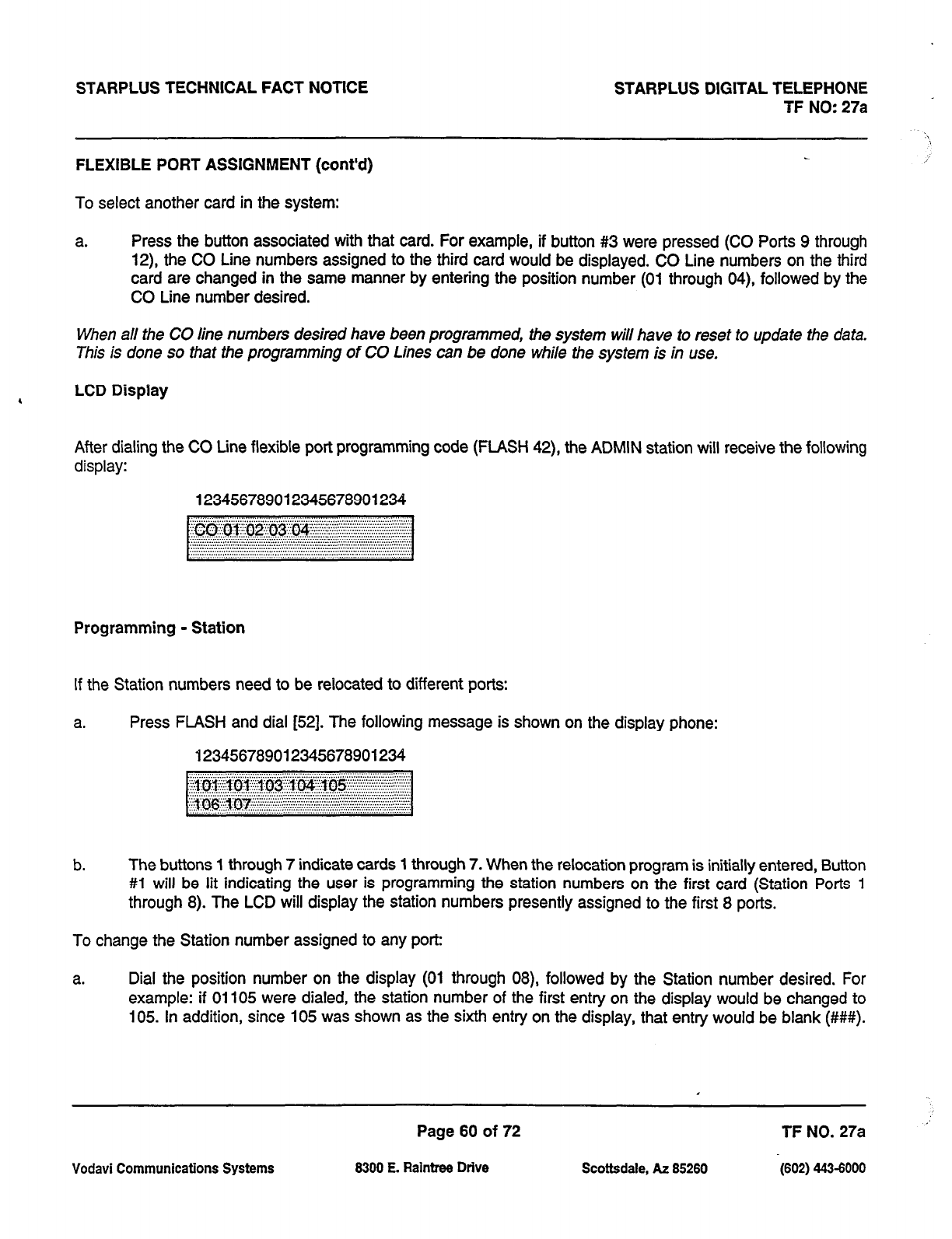
STARPLUS TECHNICAL FACT NOTICE STARPLUS DIGITAL TELEPHONE
TF NO: 27a
FLEXIBLE PORT ASSIGNMENT (cont’d)
To select another card in the system:
a. Press the button associated with that card. For example, if button #3 were pressed (CO Ports 9 through
12) the CO Line numbers assigned to the third card would be displayed. CO Line numbers on the third
card are changed in the same manner by entering the position number (01 through 04), followed by the
CO Line number desired.
When all the CO line numbers desired have been programmed, the system will have to reset to update the data.
This is done so that the programming of CO Lines can be done while the system is in use.
4 LCD Display
After dialing the CO Line flexible port programming code (FLASH 42), the ADMIN station will receive the following
display:
123456789012345678901234
Programming
- Station
If the Station numbers need to be relocated to different ports:
a. Press FLASH and dial [52]. The following message is shown on the display phone:
423456789012345678901234
b. The buttons 1 through 7 indicate cards 1 through 7. When the relocation program is initially entered, Button
#l will be lit indicating the user is programming the station numbers on the first card (Station Ports 1
through 8). The LCD will display the station numbers presently assigned to the first 8 ports.
To change the Station number assigned to any port:
a. Dial the position number on the display (01 through 08), followed by the Station number desired. For
example: if 01105 were dialed, the station number of the first entry on the display would be changed to
105. In addition, since 105 was shown as the sixth entry on the display, that entry would be blank (###).
Page 60 of 72 TF NO.
27a ”
Vodavi Communications Systems
6300 E.
Raintree Drive Scottsdale, AZ
66260 (602) 443-6000
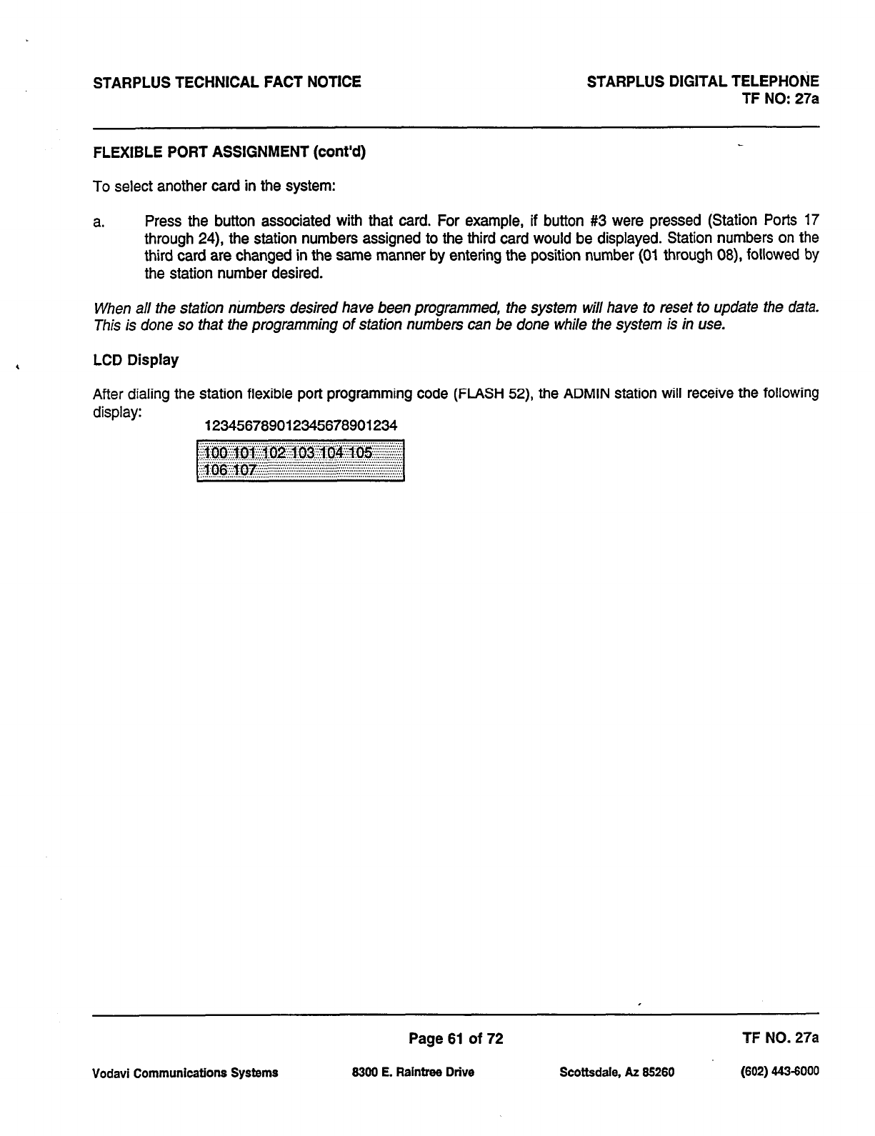
STARPLUS TECHNICAL FACT NOTICE STARPLUS DIGITAL TELEPHONE
TF NO: 27%
FLEXIBLE PORT ASSIGNMENT (cont’d)
To select another card in the system:
a. Press the button associated with that card. For example, if button #3 were pressed (Station Ports 17
through 24) the station numbers assigned to the third card would be displayed. Station numbers on the
third card are changed in the same manner by entering the position number (01 through 08) followed by
the station number desired.
When all the station ntimbers desired have been programmed, the system will have to reset to update the data.
This is done so that the programming of station numbers can be done while the system is in use.
LCD Display
After dialing the station flexible port programming code (FLASH 52), the ADMIN station will receive the following
display: 123456789012345678901234
Page 61 of 72 TF NO. 27a
Vodavi Communications Systems 8300 E. Raintree Drive Scottsdale, AZ 66260 (602) 443-6000
STARPLUS TECHNICAL FACT NOTICE STARPLUS DIGITAL TELEPHONE
TF NO: 27a
,
HARDWARE FEATURES
Digital Data Interface Unit (DDIU)
Keyset Self Test
Page 62 of 72 TF NO. 27a
Vodavi Communications Systems 8300 E. Raintrw Drive Scottsdale, AZ 85260 (602) 443-6000
STARPLUS TECHNICAL FACT NOTICE STARPLUS DIGITAL TELEPHONE
TF NO: 27a
DIGITAL DATA INTERFACE UNIT (DDIU)
Description
The Data Feature is a time division switched, point to point data transmission capability which permits simultaneous
voice and data communications (same system but not same port). The Data Feature offers the ability to transmit
data information between personal computers, printers, plotters, modems, CRT terminals, and main frame computer
ports. To establish a Data call a Digital Data Interface Unit (DDIU) is required to be connected to each data
communications device. Data information can be switched through the system at speeds of 300, 1200,2400,4800,
9600, 19.2K and 38.4K baud asynchronous.
Installation
The Digital Data Interface Unit (DDIU) is wired to the Stat-plus 1428 and Starplus 2856 like a digital telephone, and
requires one station port.
All connections to the DDIU are made on the back panel. The back panel has a modular jack and a DB-25 type
connector. The modular jack, labeled KSU, is used to connect the DDIU to the station port of the system. The DB-
25 connector supports an W-232 connection and is used to connect the data device to the system.
A green LED lights to indicate the DDIU is properly wired to the system.
Page 63 of 72 TF NO. 27a
Vodavi
Communications Systems 6300 E. Raintrw Drive Scottsdale, AZ 66260 (602) 443-6000
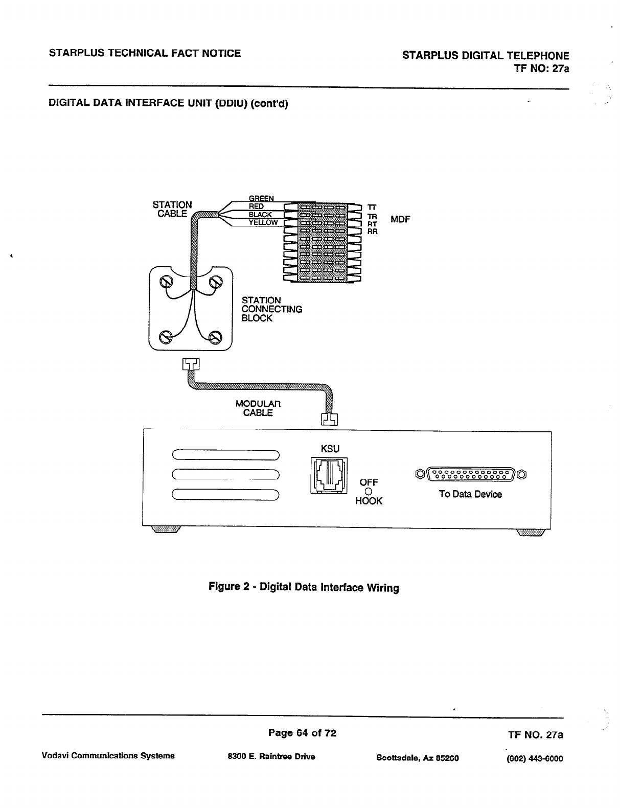
STARPLUS TECHNICAL FACT NOTICE STARPLUS DIGITAL TELEPHONE -
TF NO: 27a
DIGITAL DATA INTERFACE UNIT (DDIU) (cont’d) .a’
l-r
g MDF
RR
STATION
~~CW&CTING
1
KSU
Figure 2 - Digital Data Interface Wiring
Page 64 of 72 TF NO. 27a
Vodavi Communications Systems 8300 E. Raintree Drive Scottsdale, AZ 85260 (602) 443-6000
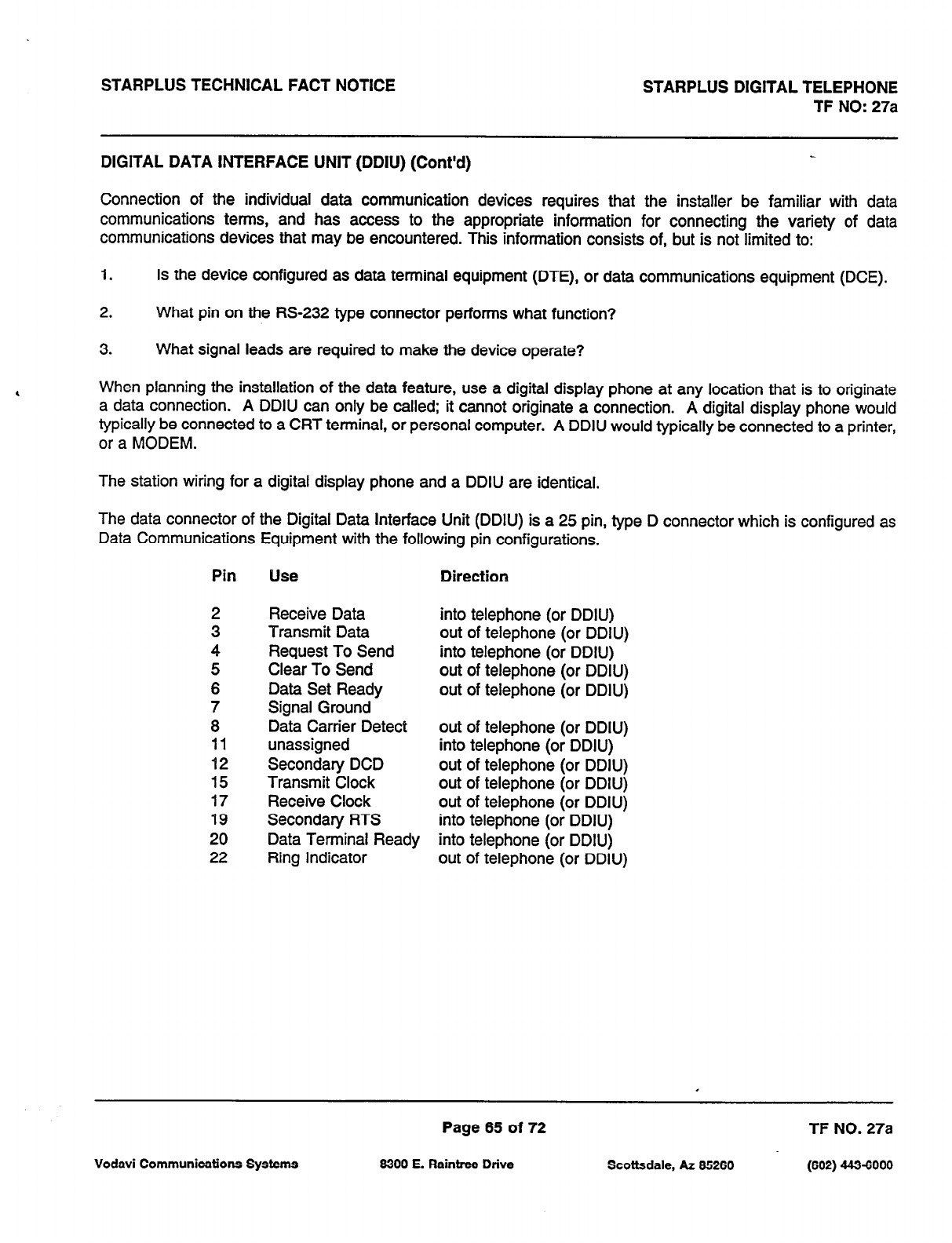
STARPLUS TECHNICAL FACT NOTICE STARPLUS DIGITAL TELEPHONE
TF NO: 27a
DIGITAL DATA INTERFACE UNIT (DDIU) (Cont’d)
Connection of the individual data communication devices requires that the installer be familiar with
data
communications terms, and has access to the appropriate information for connecting the variety of data
communications devices that may be encountered. This information consists of, but is not limited to:
1. Is the device configured as data terminal equipment (DTE), or data communications equipment (DCE).
2. What pin on the RS-232 type connector performs what function?
3. What signal leads are required to make the device operate?
When planning the installation of the data feature, use a digital display phone at any location that is to originate
a data connection. A DDIU can only be called; it cannot originate a connection. A digital display phone would
typically be connected to a CRT terminal, or personal computer. A DDIU would typically be connected to a printer,
or a MODEM.
The station wiring for a digital display phone and a DDIU are identical.
The data connector of the Digital Data Interface Unit (DDIU) is a 25 pin, type D connector which is configured as
Data Communications Equipment with the following pin configurations.
Pin Use
2 Receive Data
3 Transmit Data
4 Request To Send
5 Clear To Send
6 Data Set Ready
7 Signal Ground
8 Data Carrier Detect
11 unassigned
92 Secondary DCD
15 Transmit Clock
17 Receive Clock
19 Secondary RTS
20 Data Terminal Ready
22 Ring Indicator
Direction
into telephone (or DDIU)
out of telephone (or DDIU)
into telephone (or DDIU)
out of telephone (or DDIU)
out of telephone (or DDIU)
out of telephone (or DDIU)
into telephone (or DDIU)
out of telephone (or DDIU)
out of telephone (or DDIU)
out of telephone (or DDIU)
into telephone (or DDIU)
into telephone (or DDIU)
out of telephone (or DDIU)
Page 65 of 72 TF NO. 27a
Vodavi Communications Systems 6300 E. Raintree Drive Scottsdale, AZ 66260 (602) 443-6000

STARPLUS TECHNICAL FACT NOTICE STARPLUS DIGITAL TELEPHONE _
TF NO: 27a
DIGITAL DATA INTERFACE UNIT (DDIU) (cont’d)
The following diagram will aid in the design of cables to connect the many different configurations of data
communications devices.
DCE DCE
I I
lxD
RXD
SIG ON
RTS
D-m
DSFI
DCD
surs
SDCD
QM
RI
lxcu
RXCLK
slxl
3xD
IXD
SIG GND
TTS
3s
l-m
XR
ICD
Figure
3 - STARPLUS 1428 AND 2856 Data Switching
Page 66 of 72 TF NO. 27a
Vodavi Communications Systems 8300 E. Raintree Drive Scottsdale, AZ 85280 (602) 443-6000
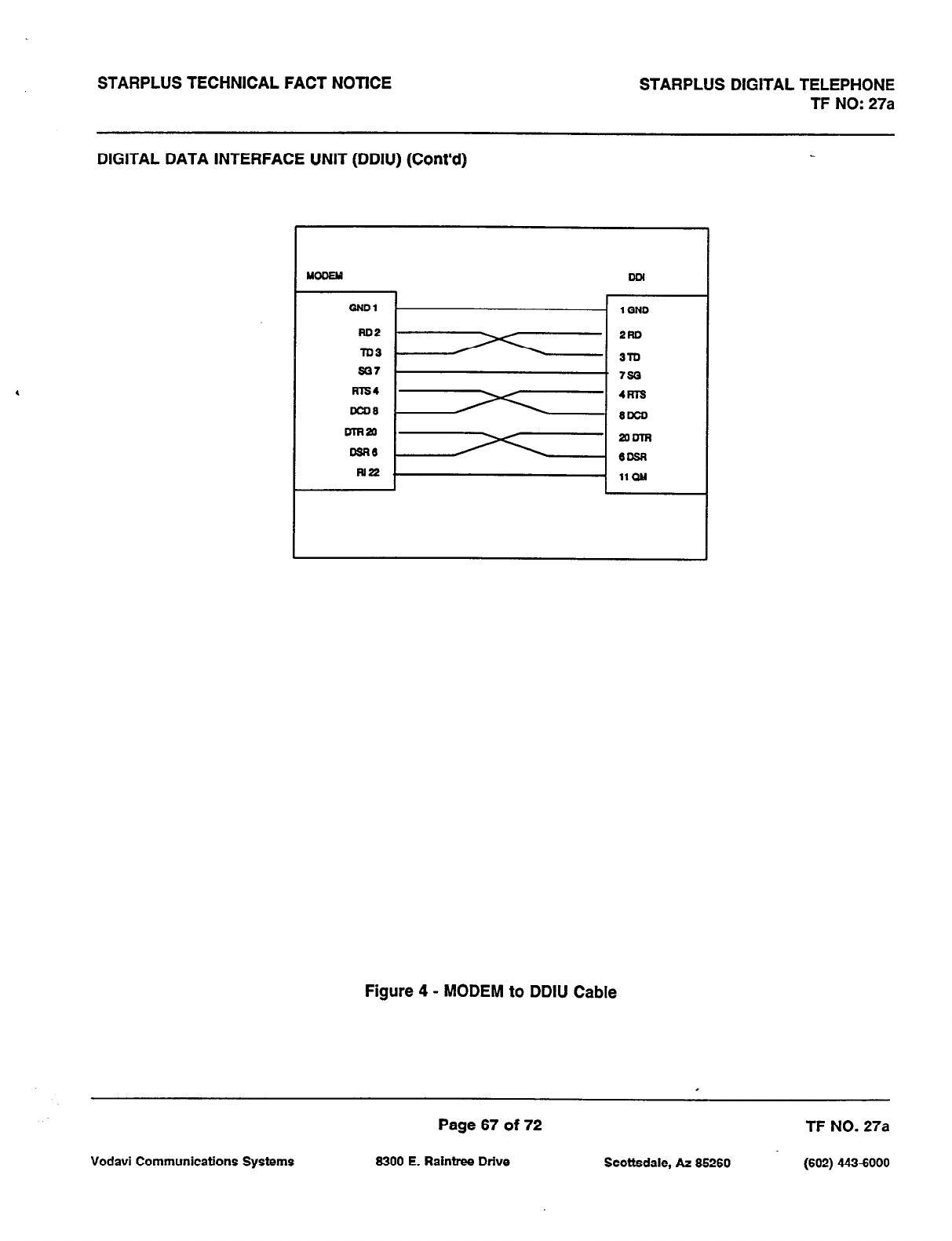
STARPLUS TECHNICAL FACT NOTlCE STARPLUS DIGITAL TELEPHONE
TF NO: 27a
DIGITAL DATA INTERFACE UNIT (DDIU) (Cont’d)
QNDI 1 QND
2Ro
3lu
sQ7 . 72Q
ms4 4RT2
mJ3 BLlco
DlR2a 2olnw
me (IOSR
iuP 11 QM
Figure 4 - MODEM to DDIU Cable
Page 67 of 72 TF NO. 27a
Vodavi Communications Systems 8300 E. Raintree Drive Scottsdale, AZ 85260 (602) 4436000
STARPLUS TECHNICAL FACT NOTICE STARPLUS DIGITAL TELEPHONE
TF NO: 27a
DIGITAL DATA INTERFACE UNIT (DDIU) (cont’d)
Operation
To establish a connection to any idle data port, a user with an associated DDIU dials the station number of the
DDIU or the group access number of the groups that the DDIU has been inserted into or depresses a DSS button
representing the DDIU. The key system will then determine the baud rate setting for the called DDIU and convert
the users associated DDIU to the same baud rate. The system will then complete the connection.
A second method to establish a connection between two DDIU is done by the first attendant. The first attendant
dials the extension number of one data unit. Dial tone is received and the display will show the BAUD RATE. Then
the first attendant dials the station number of the second data unit, confirmation tone is heard. This connection will
, be maintained until the first attendant dials the station number of one DDIU followed by pressing the FLASH button.
To break down an established connection the user should dial his associated DDIU number or depress the DSS
button for the associated DDIU followed by depressing the ‘FLASH” button.
A station user can configure his associated DDIU by:
1. The station user dials the DDIU access code [63T] on the dial pad.
2. Enter the three-digit extension number of the DDIU. The display will show the BAUD rate setting,
the data length (8 or 9), and the number of stop bits (1 or 2).
To change the baud rate:
1. Press the “HOLD” button. Then enter the one-digit baud rate desired. Press the ‘SPEED’ button
to save any changes made.
1 = 300
2 = 1200
3 = 2400
4 = 4800
5 = 9600
6 = 19.2K
7 = 38.4K
To change the character length:
1. Press the “TFlAN’ button. Then enter the one-digit character length desired, either 8 or 9. Press
the ‘SPEED’ button to save any changes made.
To change the number of stop bits:
1. Press the “MUTE” button. Then enter the one-digit stop bit desired. Press the ‘SPEED button save
any changes made.
Page 68 of 72 TF NO. 27a
Vodavi Communications Systems 6300 E. Raintree Drive Scottsdale, AZ 66260 (602) 4436000
STARPLUS TECHNICAL FACT NOTlCE STARPLUS DIGITAL TELEPHONE
TF NO: 27a
DIGITAL DATA INTERFACE UNIT (DDIU) (Cont’d)
Programming
In ADMIN, enter station programming (Flash 50) Page B, Button #l and enter an ID of 7 followed by the associated
station number or [##I#] in the case of a DDIU without an associated station.
The Digital Data Interface Units (DDIU) in the system can be configured in ADMIN by:
1. Press the FLASH button and dial (511 on the dial pad.
2. Enter the three-digit extension number of the DDIU and depress the ‘HOLD” button. The display
will show the present settings for the DDIU.
To change the BAUD rate:
1. Press the BAUD HATE flexible button (Button #I).
2. Enter the one-digit baud rate desired.
1 = 300
2 = 1200
3 = 2400
4 = 4800
5 = 9600
6 = 19.2K
7 = 38.4K
3. Press the ‘HOLD’ button to save any changes made.
To change the character length.
1. Press the CHARACTER LENGTH flexible button (Button #2).
2. Enter the one-digit character length desired, either 8 or 9.
3. Press the ‘HOLD’ button to save any changes made.
To change the stop bits:
1. Press the STOP BIT flexible button (Button #3).
2. Enter the one-digit stop bit desired.
3. Press the HOLD button save any changes made.
To select a different Data unit press button #20 and enter a new data unit station number.
Page 69 of 72 TF NO. 27a
Vodavi Communications Systems 6300 E. Raintree Drive Scottsdale, AZ 66260 (602) 443-6000

STARPLUS TECHNICAL FACT NOTICE STARPLUS DIGITAL TELEPHONE
TF NO: 27a
DIGITAL DATA INTERFACE UNIT (DDIU) (Cont’d)
Conditions
1. The System is transparent to the devices being connected. Therefore each DDIU must be configured with
a specific baud rate, number of data bits and number of stop bits. This configuration will be done by the
first attendant or in the case of an associated data unit can be configured by the user.
2. Data switching is accomplished using the same wiring the telephone station uses for voice switching.
3. Data ports can be arranged in UCD Groups or Hunt Groups.
4.
I Data ports do not have to be associated with a keyset, however to connect two DDlU devices one of them
must be associated with a keyset unless the connection is made by the first attendant.
5. When the data connection has been completed, the baud rate used in the connection will be displayed on
the keyset.
6. Non associated DDIU connections can be broken down by the first attendant.
7. A DDIU has a DCE interface. Therefore a straight through RS232 cable can be used connect to a DTE
device (printer, PC, etc.).
8. Each DDIU requires a digital terminal port.
LCD Display
A station after dialing an associated DDIU will receive the following display:
123456789012345678901234
A station after dialing the programming code will receive the following display:
123456789012345678901234
Page 70 of 72 TF NO. 27a
Vodavi
Communications Systems 6300 E. Raintree Drive
Scottsdale, AZ 66260
(602) 443-6000
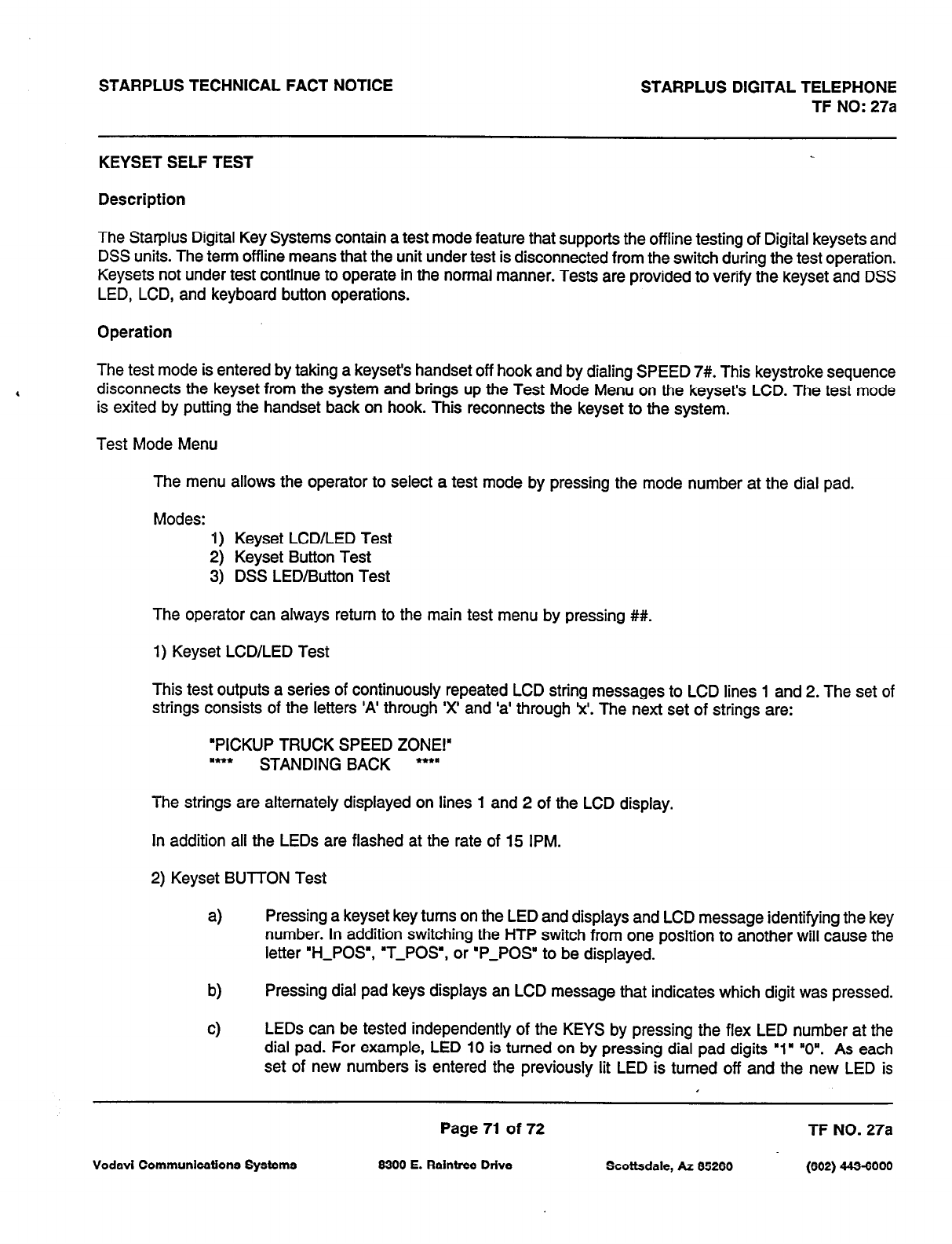
STARPLUS TECHNICAL FACT NOTICE STARPLUS DIGITAL TELEPHONE
TF NO: 27a
KEYSETSELFTEST
Description
The Star-plus Digital Key Systems contain a test mode feature that supports the offline testing of Digital keysets and
DSS units. The term offline means that the unit under test is disconnected from the switch during the test operation.
Keysets not under test continue to operate in the normal manner. Tests are provided to verify the keyset and DSS
LED, LCD, and keyboard button operations.
Operation
The test mode is entered by taking a keyset’s handset off hook and by dialing SPEED 7#. This keystroke sequence
disconnects the keyset from the system and brings up the Test Mode Menu on the keyset’s LCD. The test mode
is exited by putting the handset back on hook. This reconnects the keyset to the system.
Test Mode Menu
The menu allows the operator to select a test mode by pressing the mode number at the dial pad.
Modes: 1) Keyset LCD/LED Test
2) Keyset Button Test
3) DSS LED/Button Test
The operator can always return to the main test menu by pressing ##.
1) Keyset LCD/LED Test
This test outputs a series of continuously repeated LCD string messages to LCD lines 1 and 2. The set of
strings consists of the letters ‘A’ through ‘x’ and ‘a’ through ‘x’. The
next
set of strings are:
‘PICKUP TRUCK SPEED ZONE!”
I*** STANDING BACK ***”
The strings are alternately displayed on lines 1 and 2 of the LCD display.
In addition all the LEDs are flashed at the rate of 15 IPM.
2) Keyset BUTTON Test
a)
Pressing a keyset key turns on the LED and displays and LCD message identifying the key
number. In addition switching the HTP switch from one position to another will cause the
letter ‘H-POS’, ‘T-POS”, or ‘P-POS” to be displayed.
b) Pressing dial pad keys displays an LCD message that indicates which digit was pressed.
cl
LEDs can be tested independently of the KEYS by pressing the flex LED number at the
dial pad. For example, LED 10 is turned on by pressing dial pad digits ‘1” “0”. As each
set of new numbers is entered the previously lit LED is turned off and the new LED is
Page 71 of 72 TF NO.
27a
Vodavi Communications Systems 6300 E. Raintree Drive Scottsdale, AZ 85260 (602) 443-6000

STARPLUS TECHNICAL FACT NOTICE STARPLUS DIGITAL TELEPHONE .,
TF NO: 27a
turned on. Invalid flex values (ex. 00,99) turn off currently lit LED.
3) DSS LED/BUTTON Test
When the DSS test is selected and a DSS test is invoked ALL DSSs associated with the keyset running
the test are placed in test mode. If no DSS unit is associated wit the keyset, the keyset display will indicate
“NO DSS’. The DSS LED test will cause all the LEDs to flash at a 15 IPM rate. Once started the DSS LED
test will continue until a DSS flex button is depressed. Pressing a DSS flex button turns on the flex key LED
and displays an LCD message on the associated keyset identifying the flex key number (01 to 48). In
addition, it turns off the previously selected flex LED.
Conditions
4
1. Test mode disrupts the normal operation of a keyset or DSS.
LCD Display:
The Main Test
mode menu
is as follows:
123456789012345678901234
The Keyset BUTTON Test mode menu is as follows:
123456789012345678901234
The DSS BUTTON Test mode menu is as follows:
123456789012345678901234
Page 72 of 72 TF NO. 27a
Vodavi Communications SyStemS 8300 E. Raintree Drive Scottsdale, AZ 85260 (602) 443-6000

TECHNICAL FACT NOTICE
sTARPLUS
D@ftal Systems
TF NO: 43
2/17&I
ADDITIONAL FEATURES -
STARPLUS@
SPD 1428/2856 Digital Systems
Issue 1, November 1991
A Key Station Features matrix is included in this techfact to identify the new software packages for the Stat-plus
Digital Systems. The following list of new features are available with software version 2.3 or higher. The SPD 1428
KSU must have IRS level “S” or later, and the SPD 2858 CPB board must have IRS level “H” or later in order for
these features to operate properly.
CUSTOMER DATABASE PROGRAMMING
Upload/Download Routine
SYSTEM TIMERS
Reminder Ring Timer (Button 18)
Release Guard Timer (Button 19)
NbEX!$
II-ICE=.
SYSTEM FEATURES
Call Cost Display (Button 11)
Handset Volume Adjustment (Button 13)
Call Qualifier Tone (Button 14)
Privacy Release Tone Option (Flash 06, Button 1)
Flash Rates (Programmable) (Flash 07, Buttons 1-4)
CO L:NE Al-TRIBUTES
DISA Programming Options (Button 7)
Trunk Direction (Button 13)
Ring Delay Timer (Button 14)
STATION ATTRIBUTES
CO Line Ringing Options (Reminder Ring) (Button 13)
ICLID FEATURES (Features available with optional software)
Caller Entered ICLID digits
Expanded ICLID Ringing Assignments (Flash 43, Button 1)
ACD FEATURES (Features available with optional software)
ACD Group Expansion to 16 Groups/l6 Members (Flash 60, Flash 64)
Guaranteed Message Announcement (Flash 60, Button 11)
ACD Event Trace (Flash 63, Buttons 1 812)
UCD FEATURES
UCD Station Assignments (Flash 60, Page B, Buttons 1 thru 8)
VOICE MAIL FEATURES (Features available with optional software)
Enhanced Voice Mail Integration (Flash 65)
Vodavi Communications Systems
Page 1 of56 TF NO. 43
8300 E. Raintrw Drive Scottsdale, AZ 85260 (@a 443aooo
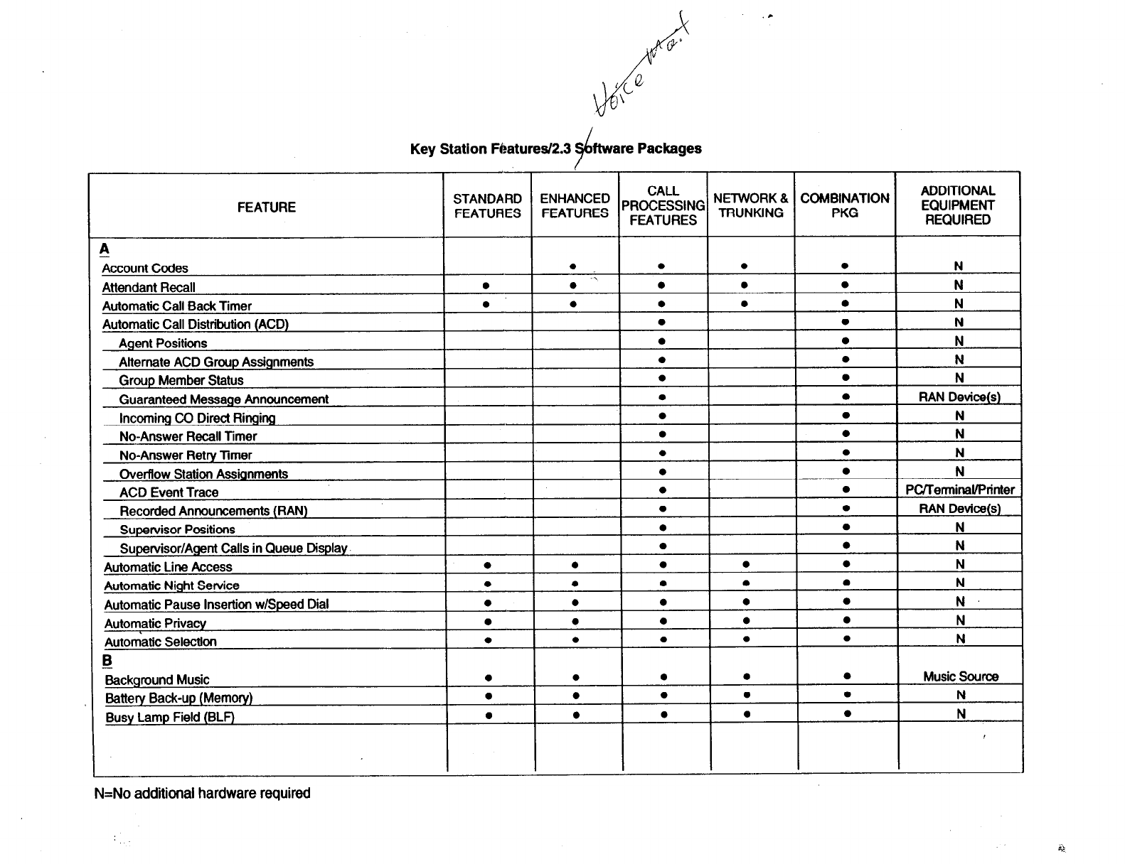
Key Station Nraturesl2.3
FEATURE CALL ADDITIONAL
TA!$;;; YE;;;;;: PROCESSING NETWORK & COMBINATION EQUIPMENT
FEATURES TRUNKING PKG REQUIRED
tccount
Codes
Attendant Recall
Automatic Call Bad< Timer
Automatic Call Distribution (ACD)
Agent Positions
Alternate ACD Group Assignments
Group Member Status
Guaranteed Message Announcement
Incoming CO Direct Ringing
No-Answer Recall Timer
No-Answer Retry Timer
OverRow Station Assignments
ACD Event Trace
Recorded Announcements (RAN)
l
0
0
l 0 l N
.,
l 0 l 0 N
0
l l l N
l 0 N
l l N
l l N
l l N
l 0
RAN Device(s)
0 0 N
l 0 N
l a N
l 0 N
0 a PCrrerminaUPrinter
0
l
RAN Device(s)
k&ground Music
Battery Back-up (Memory)
Busy Lamp Field (BLF)
N=No additional hardware required
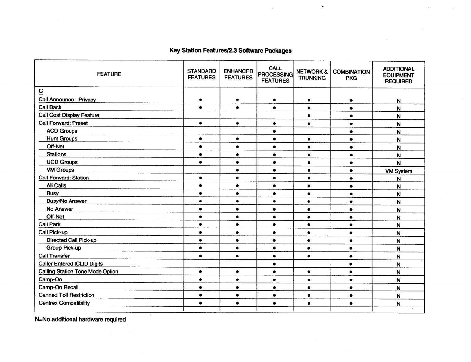
Key Station Featb
FEATURE
STANDARD
FEATURES
Eall Announce - Privacy
Call Back
Call Cost Display Feature
Call Forward: Preset
ACD Groups
Hunt Groups
Off-Net
Stations
UCD Groups
VM Groups
Call Forward: Station
All Calls
Busy
Busy/No Answer
No Answer
Off-Net
Call Park
Call Pick-up
Directed Call Pick-up
Group Pick-up
Call Transfer
Caller Eotered ICLID Digits
Calling Station Tone Mode Option
CampOn
Camp-On Recall
Canned Toil Restriction
Centrex Compatibility
‘es/2.3 Software Packages
I I I I
CALL NETWORK & COMBINATION
FE;;;;:: PROCESSING TRUNKING PKG
FEATURES
ADDITIONAL
EQUIPMENT
REQUIRED
l I. 1. IO I
N
N=No additional hardware
required
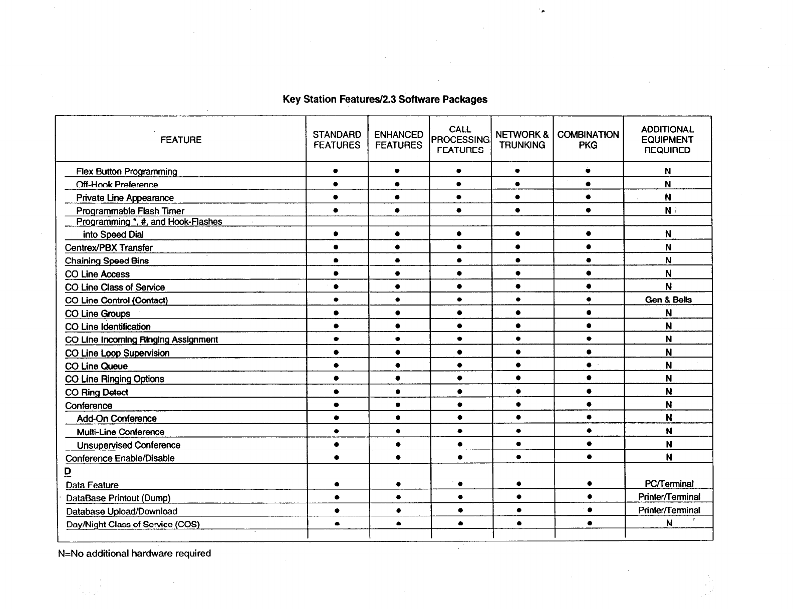
c
Key Station Features/P.3 Software Packages
FEATURE COMBINATION
PKG
ADDITIONAL
EQUIPMENT
REQUIRED
l N
l NI
l I N
l I N
l I N
l I N
l I N
l N
l
PC/Terminal
l
Printerfletminal
l
Printer/Terminal
l N ’
I
N=No additional hardware required
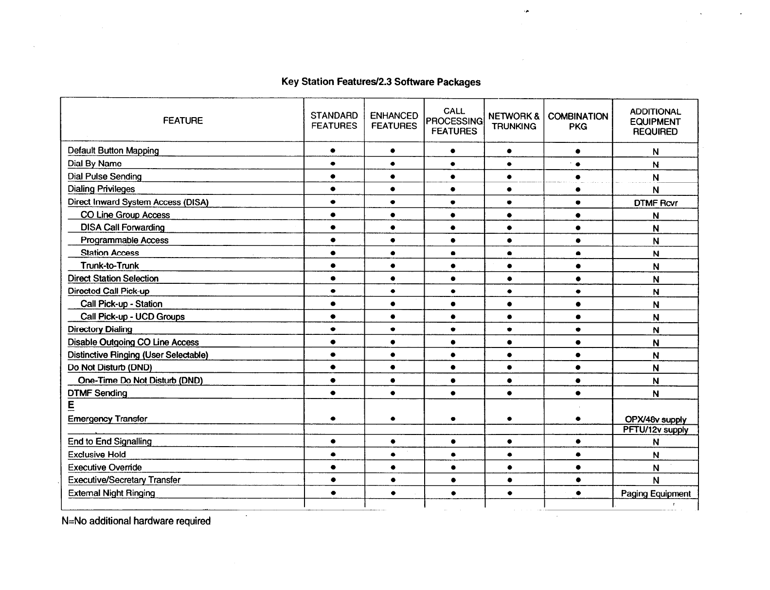
Key Station Featuresl2.3 Software Packages
DISA Call Forwardin
COMBINATION
PKG
ADDITIONAL
EQUIPMENT
REQUIRED
0Pxmv supply
PFw12v supply
N
N
N
l
I
N
l 1 Paging Equipment
I ,
N=No
additional
hardware required
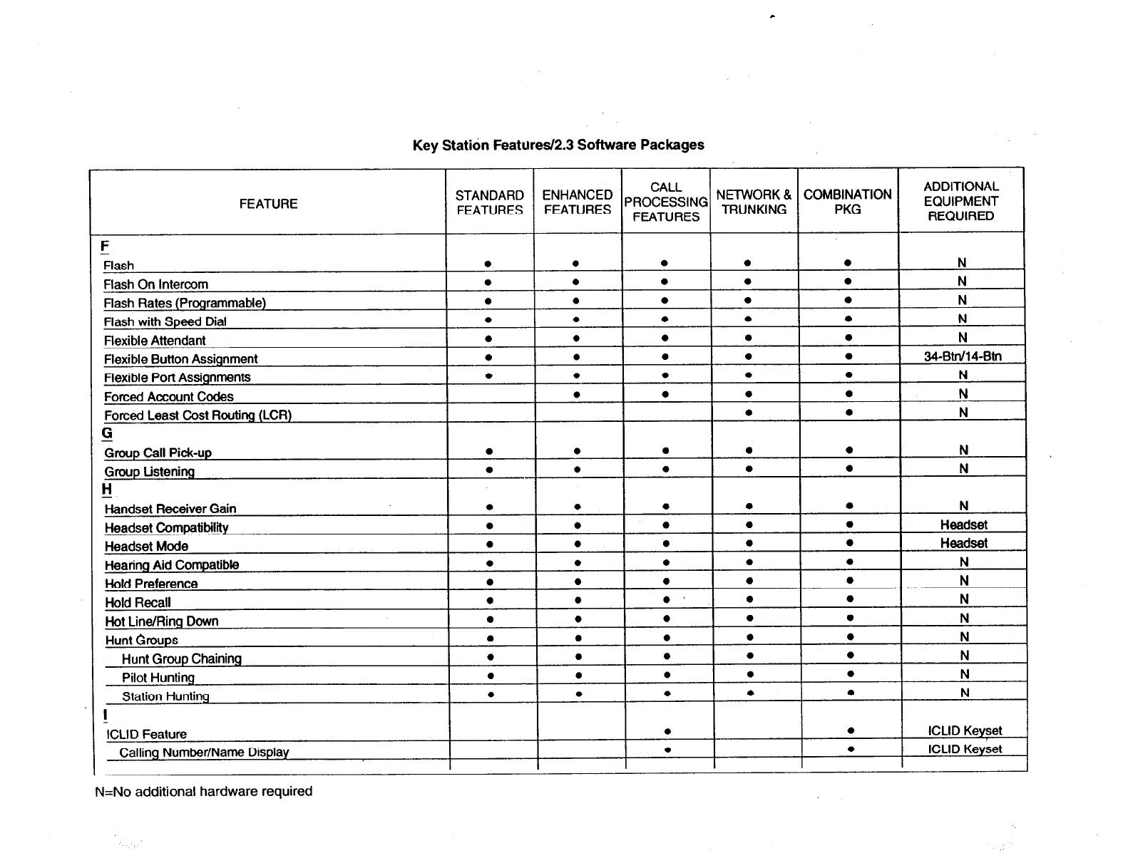
Key Statidn Feattired2.3 Software Packages
FEATURE
l N
l N
0 N
l N
0
34-BW14-ml
l N
0 N
0 N
0 N
0 N
a N
0 N
a N
l N
0 N
l N
N=No additional hardware required

c
Key Station Featutes/2.3 Software Packages
CALL
FEATURE NETWORK 8, COMBINATION
sFI”A”Tu”$s” “F”E;;;;E’s” PROCESSING TRUNKING
ADDITIONAL
PKG EQUIPMENT
FEATURES REQUIRED
incoming Number/Name for SMDR Records
l l
ICLID Keyset
Unanswered Call Management
l .e
ICLID Keyset
Idle Speaker Mode
l l l l l N
Incoming CO Lines Off-Net Forward via Speed Dial
l l l l l N
Intercom Calling
l e l l l N
Intercom Signaling Select
l l l l l N
K
keyset Self
Test
l l l l l
34-Btn keyset
I:
Last Number Redial (LNR)
l l l l l N
LCD Interactive Display
l l l l l
Exec Keyset
Least Cost Routing (LCR)
l . N
6-Digit
Table
l l N
Daily Start Time Tables
l l N
Default LCR Data Base
l l N
Exception Tables
l l N
InserVDelete Tables
l l N
LCR Routing for Toll Information
l l N
Route List Tables
l l N
Weekly Time Tables
l l N
3-Digit Table
l l N
Local Number/Name Translation Table
l l l l l N
Loop Bqtton CO Line Access
l l l l l N
:eet Me Page
l l l l l N
Message Waiting
l l l l l N
Message Waiting Reminder Tone
l l l l l N
Messages - Personalized
l l l l l N
N=No additional hardware required
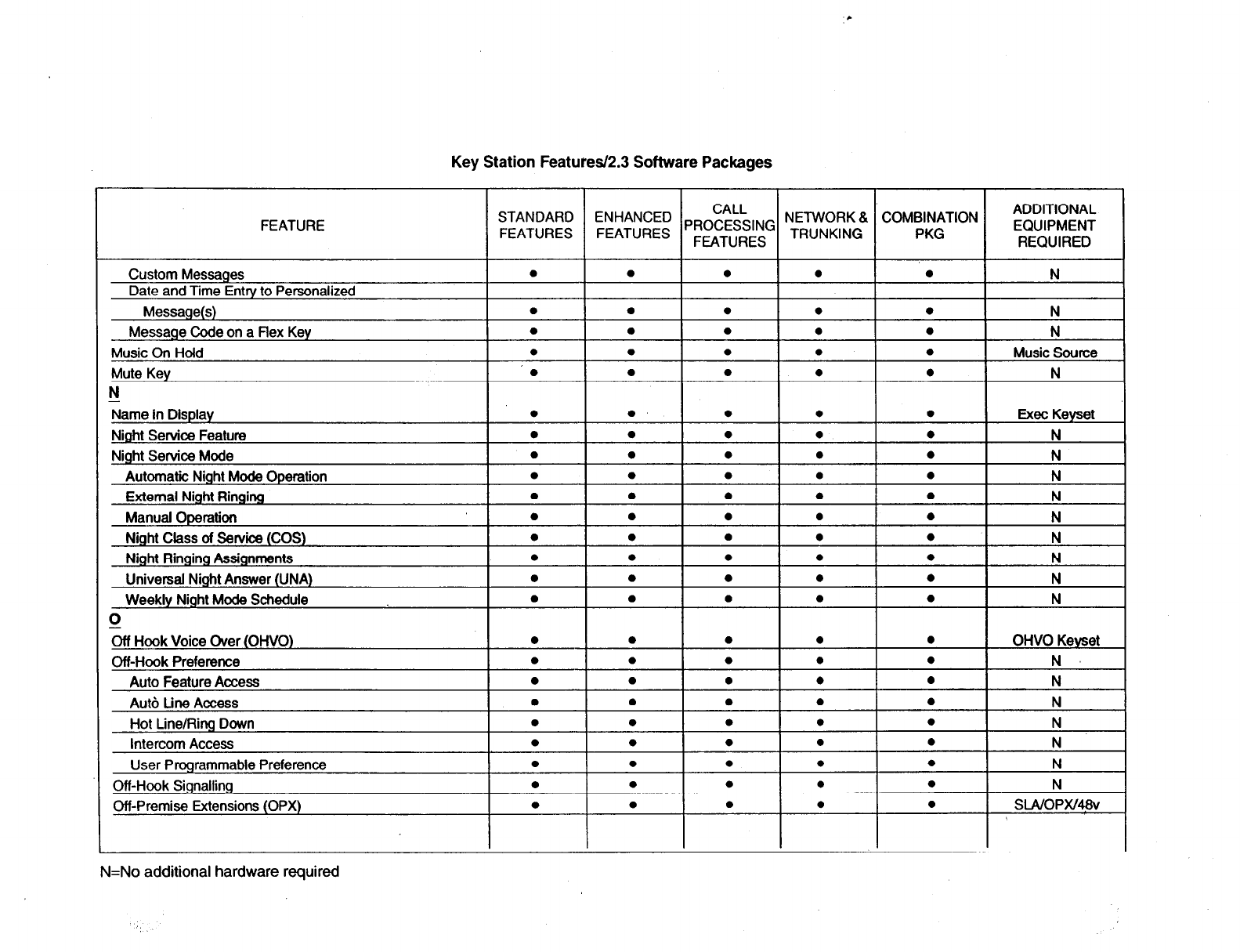
c
Key Station Features/2.3 Software Packages
FEATURE STANDARD
FEATURES
Custom Messages
Date and Time Entry to Personalized
CALL NETWORK 8 COMBINATION
;;;;;;Ei PROCESSING TRUNKING
FEATURES PKG
ADDITIONAL
EQUIPMENT
REQUIRED
l l l l N
l
l
l
l
l
l
l
l
N
N
l
l
l l l
I Music Source
l I l l I N
l
l
l
l
l
l
l
l
l
l
Exec Keyset
l
N
l N
l
Ie Ie I
l
I
N
l l l l
N
l l l l
N
l l l l
N
l l l l N
i
l
Ie Ie I
l
I
N
l
l
l
l
l
l
l
l
l
l
0
l
OHVO Keyset
N
N
N=No additional hardware required
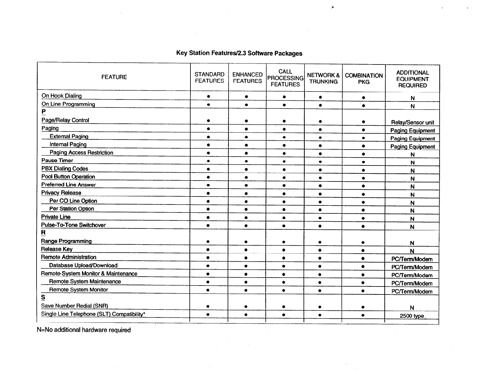
Key Station Featdres/2.3 Software Packages
FEATURE
Pause Timer
N=No additional hardware required
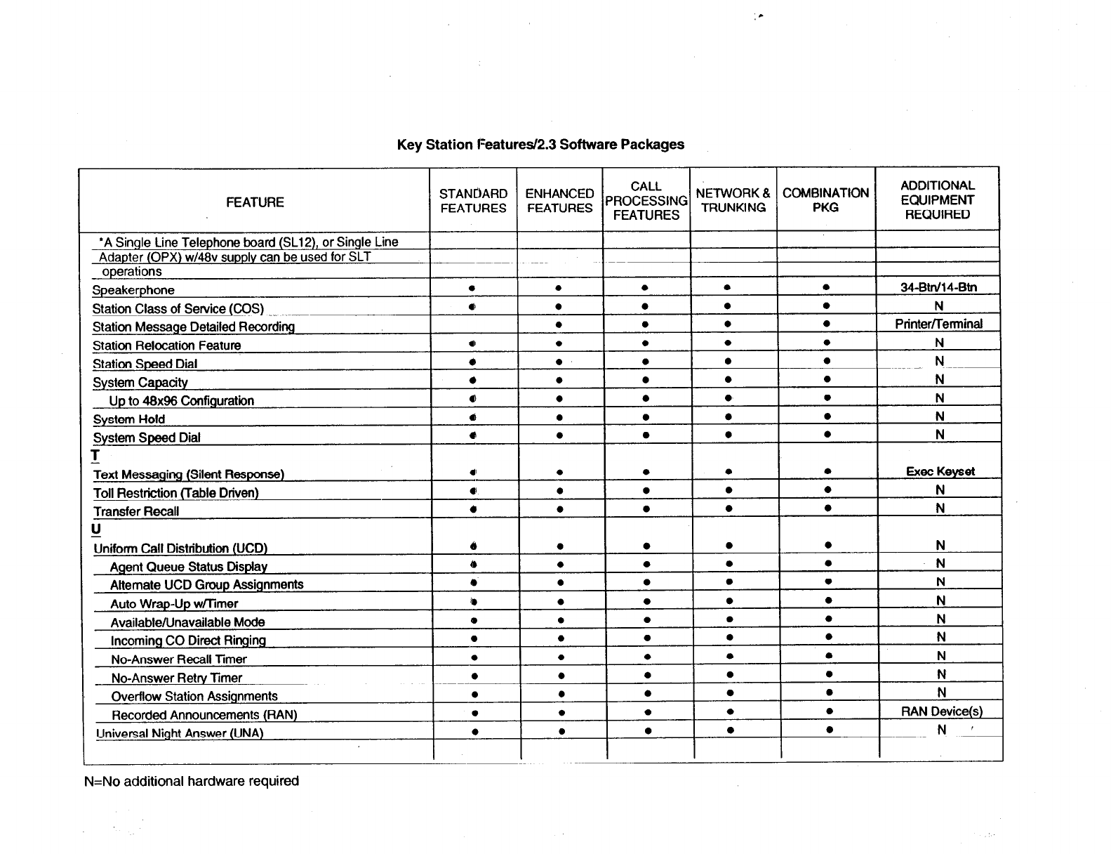
c
Key Station Features/2.3 Software Packages
FEATURE
N=No additional hardware required
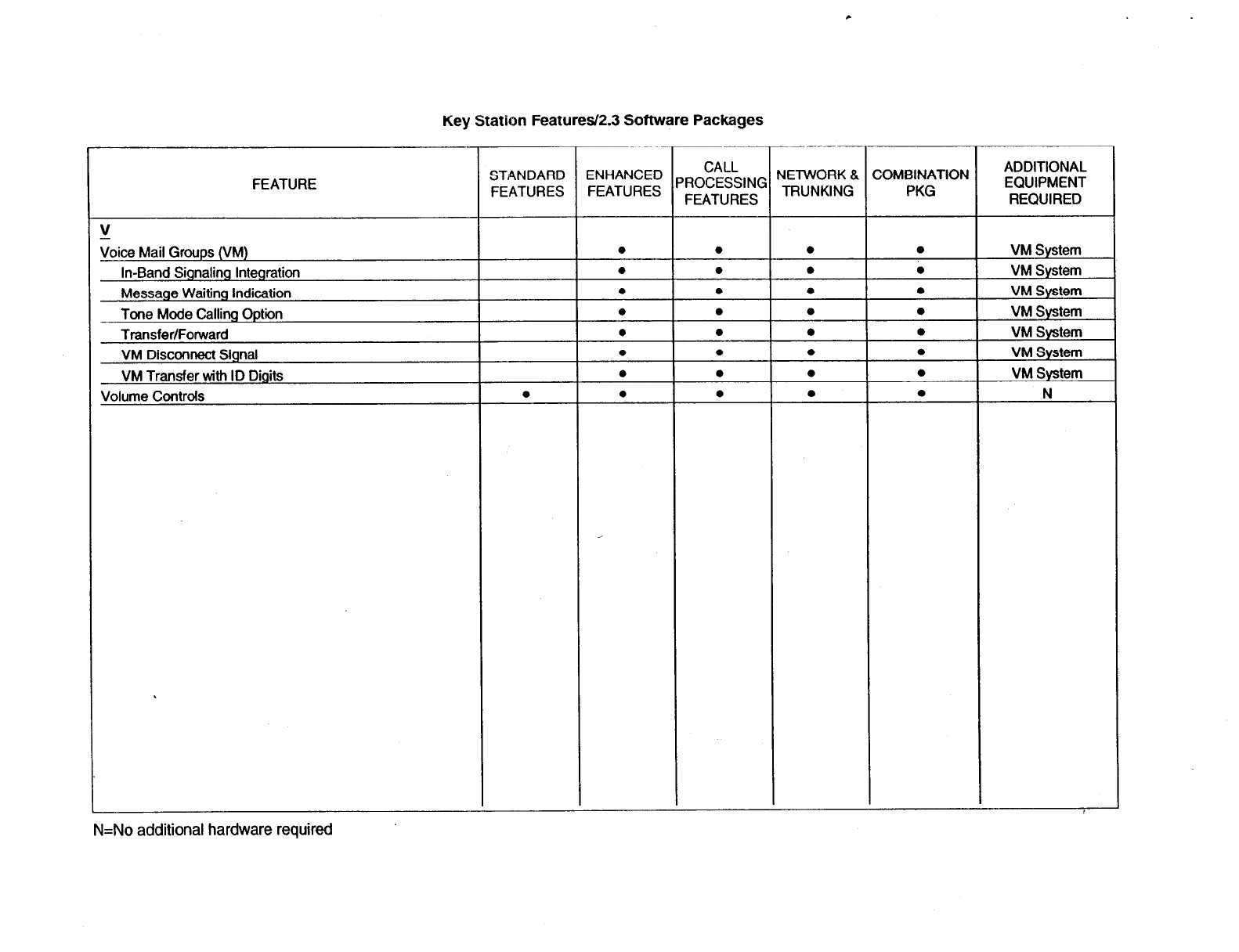
Key Station Features/2.3 Software Packages
FEATURE STANDARD CALL ADDITIONAL
Et;;;:: PROCESSING NETWORK & COMBINATION
FEATURES EQUIPMENT
FEATURES TRUNKING PKG REQUIRED
zoice Mail Groups (VM)
In-Band Signaling Integration
Message Waiting Indication
Tone Mode Calling Option
Transfer/Forward
VM Disconnect Signal
VM Transfer with ID Digits
Volume Controls
l
VM System
VM System
VM System
VM System
VM System
VM System
VM System
N
N=No additional hardware required
STARPLUS’ Digiil Systems TF NO: 43
CUSTOMER DATABASE PROGRAMMING
Upload/Download Routine
Page2of56 TF NO. 43
Vodavi Communications Systems 8300 E. Raintree Drive Scottsdale, AZ 85260
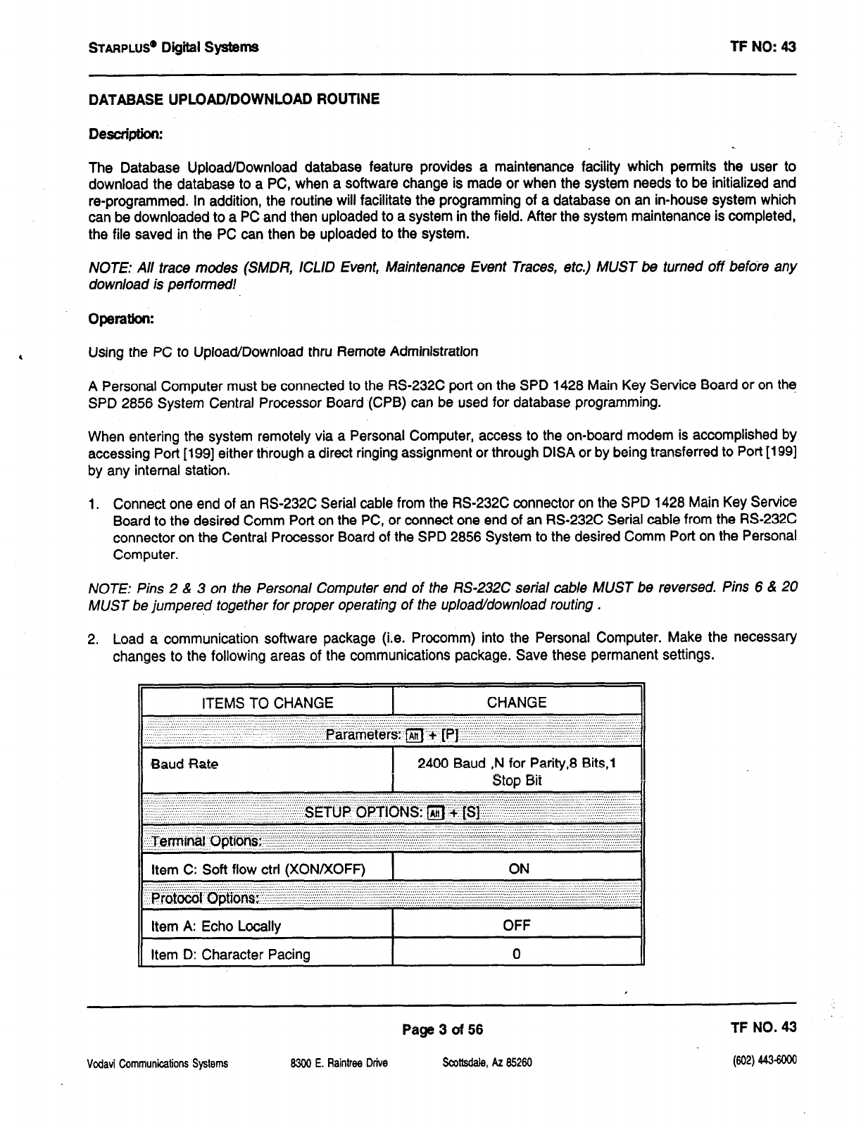
STARPLUS@
Digiil Systems TF NO: 43
DATABASE UPLOAD/DOWNLOAD ROUTINE
Desctim:
The Database Upload/Download database feature provides a maintenance facility which permits the user to
download the database to a PC, when a software change is made or when the system needs to be initialized and
re-programmed. In addition, the routine will facilitate the programming of a database on an in-house system which
can be downloaded to a PC and then uploaded to a system in the field. After the system maintenance is completed,
the file saved in the PC can then be uploaded to the system.
NOTE: All trace modes (SMDR, ICLID Event, Maintenance Event Traces, etc.) MUST be turned off befdre any
download is performed!
Using the PC to Upload/Download thru Remote Administration
A Personal Computer must be connected to the RS-232C port on the SPD 1428 Main Key Service Board or on the
SPD 2856 System Central Processor Board (CPB) can be used for database programming.
When entering the system remotely via a Personal Computer, access to the on-board modem is accomplished by
accessing Port [199] either through a direct ringing assignment or through DISA or by being transferred to Port [199]
by any internal station.
1. Connect one end of an RS-232C Serial cable from the RS-232C connector on the SPD 1428 Main Key Service
Board to the desired Comm Port on the PC, or connect one end of an RS-232C Serial cable from the RS-232C
connector on the Central Processor Board of the SPD 2856 System to the desired Comm Port on the Personal
Computer.
NOTE: Pins 2 & 3 on the Persona/ Computer end of the RS-232C serial cable MUST be reversed. Pins 6 & 20
MUST be jumpered together for proper operating of the upload/download routing .
2. Load a communication software package (i.e. Procomm) into the Personal Computer. Make the necessary
changes to the following areas of the communications package. Save these permanent settings.
ITEMS TO CHANGE CHANGE
..,,,, .:.. L. .‘. : .7: . . ...’ ‘.I .,.,. 1::: :, ......
.:: ......
., .; .,. .; .;
,.. ,, ,.::...” ‘..“.’
.’ .,; ““‘, ; ,,,. .“. ’ .“““” ‘.‘I ?f5&-~~efersy m + -rpj--:l(::‘:“il:~~~~~~~‘:::~.,:~:,~:::1.;:,._1:1 ,:1:,.,:1:::.1,.,~~~~::~:.:~, : 1
..’ ” I
II
Baud Rate I 2400 Baud ,N for Parity,8 Bits,1
1 Stop Bit II
II
“”
:. ..‘.... “. .:::::.i ‘..‘.‘.‘, ‘.:::. :::. ::.A:: : ,,........
,., ;, ‘,. .;; ., ,,, ;, .. ‘-:’ :~.~.‘.‘.~.‘..~..~.~..~.~.‘.~.‘.’.,.’.: .y.:: .;, ;; ., .,.,.,
‘I:;.:: ,’ “‘, “~..~.‘,“.,’ ,, ... ,,, ,,.,.... :::‘;.:‘.:‘.
j. .‘. ,,,,:,: ” ,.,.
., ( .,. ::. : ., ( “( ‘, ,‘, .;:.: ( :: Sg’T(j p .qyTI(-JNS: ~~~~si_‘j~:~~~::~~.:~.~:~~:~~’ :
I
11 Item C: Soft flow ctrl (XONIXOFR 1 ON II
Item A: Echo Locally
Item D: Character Pacing
OFF
0
Vcdavi Communications Systems
Page3of56 TF NO. 43
8300 E. Raintree Drive
Scottsdale, AZ 85260 (602) 443-6oca
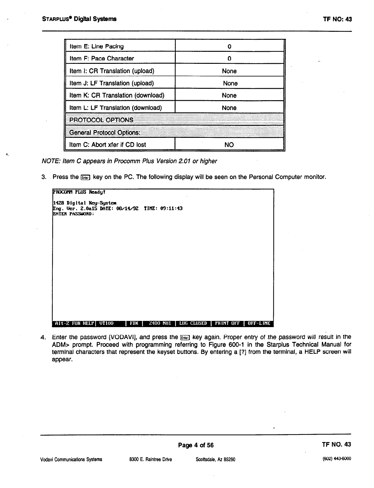
STARPWS@ Digiil Systems TF NO: 43
Item E: Line Pacing 0
item F: Pace Character 0
Item I: CR Translation (upload) None
Item J: LF Translation (upload) None
Item K: CR Translation (download) None
Item L: LF Translation (download) None
:, :. ,’ ‘7. :::. .‘.‘.‘.‘.‘,‘.~.~.‘.’ ‘.‘.‘,~.~. ‘7. ..‘,‘. :. 1. :;:. .~.~.‘.‘.‘.‘.‘.‘.‘.‘.‘.‘.‘.‘.‘.‘.’.~.’.’.7.’:.’.‘.‘.~.‘. .~.‘.::‘.‘.‘..‘.:‘.‘.‘.‘.‘. .‘.‘.‘.‘.‘.‘.‘.‘.‘.‘.‘.‘.‘.‘.‘. ,.. . . ...
,::~,~,~~~~~~~~~~~~:~:~:~:~:~~~~:~:~~~~~~:~~~~:~.~.~~~:~~~~~~
‘...‘.‘:. :;:. ::: . . ..:::; .‘L’,‘,,..... ,,,..._,........... ,, ..., ..,.. ,...., ...,_..,..,,
:.. :.. .,’ :.: . . . . . . . . ...’ ‘. . . ...’ ..:. . . . . ‘... : ‘.. ~~.~.... .:,. ,.,,’ ,’ .:.. ..:.:.. “’ ”
~
?$+&g~~ ~~~~~~~~~optl6ns~~~~~~~~~~~::~~:~~~~~~~~~~~~:~~~:::~~~~~~~ :iii~~si~~~~~~:.~~
., ; ., ; ;; . . . . . . . . .,. . . . . . . . ,. .; . . . .,. ; ., . . . .,. . . . . . . . . . . . . . . . . . . . .,., ., .,.,.,.,...,. .,“..,.....,.,...,.,........... . . . . . . . . . . . .,. .,.,. ., . . . . . . . . . . . . . ; ; .. ,.,. .,..., ., ..:‘: ., . . . .’ .-.
Item C: Abort xfer if CD lost I NO
NOTE: Item C appears in Procomm Plus Version 2.01 or higher
3. Press the IEnrs;l key on the PC. The following display will be seen on the Personal Computer monitor.
1428 Digital ltey-System
Eng. Uer. Z.&l5
DATE:
08/14/92 IIHE: 89:11:43
ENTER PASSUOAD:
4. Enter the pasword p,/OD.Wl], and press t.he M key again. Proper entry of the passurord will result in the
ADM> prompt. Proceed with programming referring to Figure 600-l in the Starplus Technical Manual for
terminal characters that represent the keyset buttons. By entering a [?] from the terminal, a HELP screen will
appear.
Page4of56 TF NO. 43
Vodavi Communications Systems 8300 E. Raintrw Drive SadMale, AZ 85260
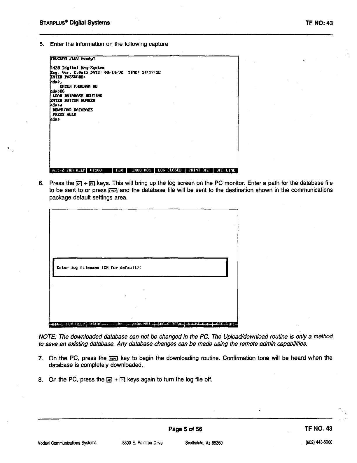
STARPLUS@ Digiil Systems TF NO: 43
5. Enter the information on the following capture
JloaItMPLusbdy?
423 DIgItal Hey-Sgstm
&
ng. ucr. t.eal!i DME: ee/14/92 11m: 14:17:lz
ml PtlssmnD:
6. Press the @ +
q
keys. This will bring up the log screen on the PC monitor. Enter a path for the database file
to be sent to or press m and the database file will be sent to the destination shown in the communications
package default settings area.
Enter Iql filename (CR for default):
NOTE: The downloaded database can not be changed in the PC. The Upload/download routine is only a method
to save an existing database. Any database changes can be made using the remote admin capabilities.
7. On the PC, press the m key to begin the downloading routine. Confirmation tone will be heard when the
database is completely downloaded.
6. On the PC, press the
q
+
q
keys again to turn the log file off.
Vodavi Communications Sysb7I.S
Page5of56 TF NO. 43
8300 E. Raintree Drive Scottsdale, AZ 85260
W2) 443-6m
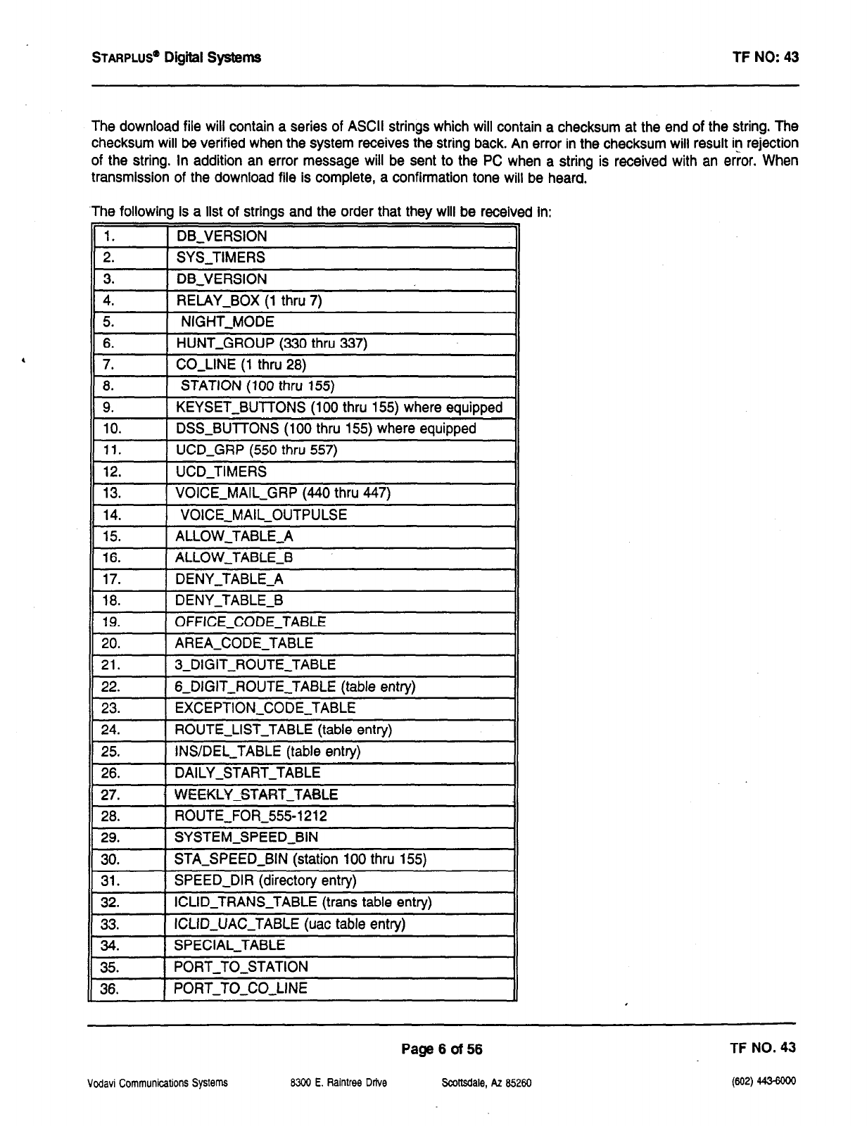
STARPLUS”
Digital systems l-F NO: 43
The download file will contain a series of ASCII strings which will contain a checksum at the end of the string. The
checksum will be verified when the system receives the string back. An error in the checksum will result in rejection
of the string. In addition an error message will be sent to the PC when a string is received with an error. When
transmission of the download file is complete, a confirmation tone will be heard.
.The following is a list of strings and the order that they will be received in:
1. DB-VERSION
2. SYS-TIMERS
,
3. DB-VERSION
4. RELAY-BOX (1 thru 7)
5. NIGHT-MODE
6. HUNT-GROUP (330 thru 337)
7. CO-LINE (1 thru 28)
8. STATION (100 thru 155)
9. KEYSET-BUTTONS (100 thru 155) where equipped
10. DSS-BUTTONS (100 thru 155) where equipped
II 1’.
j UCD-GRP (550 thru 557) II
12. UCD-TIMERS
13. VOICE-MAIL-GRP (440 thru 447)
-
14. VOICE-MAIL-OUTPULSE
15. ALLOW-TABLE-A
I
16. ALLOW-TABLE-B
17. DENY-TABLE-A -I
I
18. DENY-TABLE-B
19. OFFICE-CODE-TABLE I
20. AREA-CODE-TABLE
21. 3sDIGIT-ROUTE-TABLE
22. 6~DiGIJ~ROUJE~JABLE (table entry)
23. EXCEPTION-CODE-TABLE
24. ROUTE-LIST-TABLE (table entry)
25. INS/DEL_TABLE (table entry)
26. DAILY-START-TABLE
27. WEEKLYSTART-TA%LE
28. ROUTE-FOR-555-1212
II I
29.
j SYSTEM-SPEED-BIN
Ii 30. I
1 SJA-SPEED-BIN (station 100 thru 155) II
31. SPEED-DIR (directory entry)
32. ICLIDJRANS-TABLE (trans table entry)
33. ICLID-UAC-TABLE (uac table entry)
34. SPECIAL-JABLE
II 35. I
1 PORT-TO-STATION II
11 36. I
j PORT-TO-CO-LINE II
Vodavi Communications Systems
Page6of56 TF NO. 43
MOO E. Raintree Drive Scottsdale, AZ 85260
VW 443-Mao
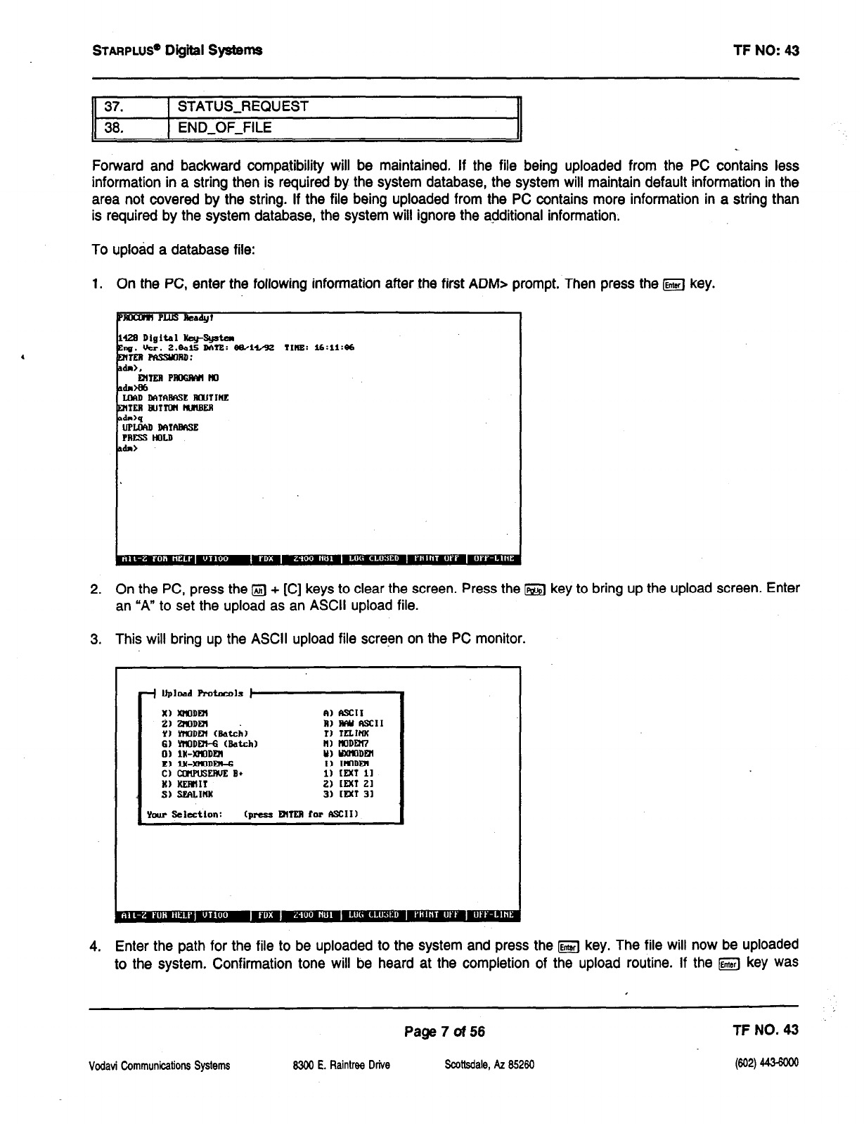
STARPLUS@ Digiil systems
TF NO: 43
37. STATUS-REQUEST
38. END-OF-FILE
Forward and backward compatibility will be maintained. If the file being uploaded from the PC contains less
information in a string then is required by the system database, the system will maintain default information in the
area not covered by the string. If the file being uploaded from the PC contains more information in a string than
is required by the system database, the system will ignore the additional information.
To upload a database file:
1. On the PC, enter the following information after the first ADM> prompt. Then press the GJ key.
1426 Digital I@--~
%
ng. tkr. z.eals DATE: ewl4/32 TIHEE: l6:11:86
m -aD:
2. On the PC, press the IZJ + [C] keys to clear the screen. Press the m key to bring up the upload screen. Enter
an “A” to set the upload as an ASCII upload file.
3. This will bring up the ASCII upload file screen on the PC monitor.
Xl XrloDDI iI1 fscl1
il mDm
1) YtlODBl Mch) RI mu n3cll
r) m.lNx
6)YllODDC6U&ch) Ill KlD)DE)CI
0) Ill-XtXlDF2l Y) WJ’lODtYl
El lX-XiQDRl-6 II IWDDl
Cl aImPusEIIvE B+ 1) mx1 11
II) KmlIl 2) [MT 21
Sl SmLImx 31 [FM 31
Yau Selection: (press DImI ror ASCII)
4. Enter the path for the file to be uploaded to the system and press the fKJ key. The file will now be uploaded
to the system. Confirmation tone will be heard at the completion of the upload routine. If the m key was
Page 7of56 TF NO. 43
Vodavi Communications Systems 8300 E. Raintree Drive Scottsdale, AZ 85260
WJa
44.3-mo
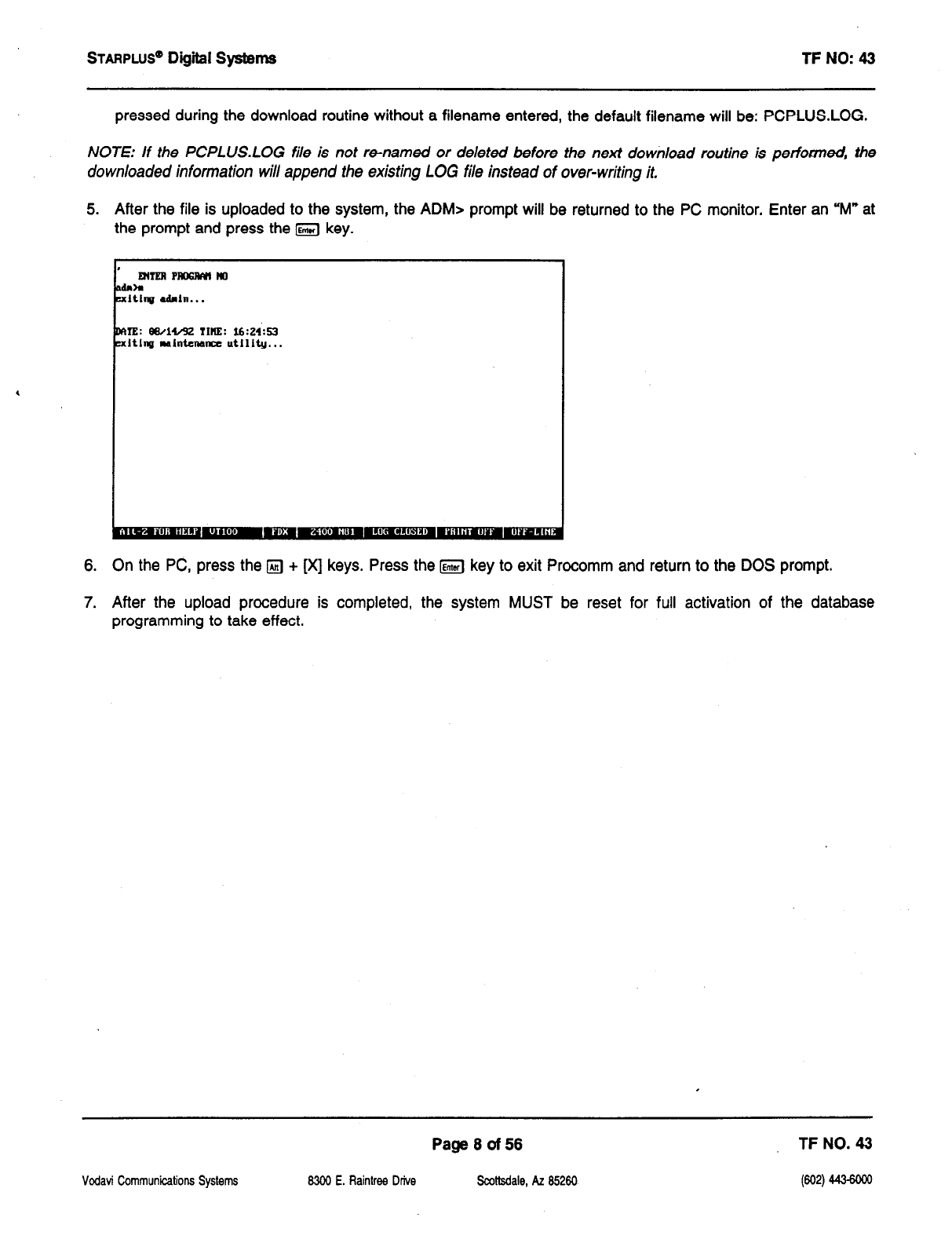
STARPLUS” Digiil Systems TF NO: 43
pressed during the download routine without a filename entered, the default filename will be: PCPLUS.LOG.
NOTE: If the PCPLUSLOG file is not re-named or deleted before the next download routine is performed, the
downloaded information will append the existing LOG file instead of over-writing it.
5. After the file is uploaded to the system, the ADM> prompt will be returned to the PC monitor. Enter an “M” at
the prompt and press the IGJ key.
,
,
MIERPlBXMiI40
adaa
EdtinfJ admln...
DME: eeAiA2 TIME: lfm:s3
uit1ng mlnteMnr utility...
6. On the PC, press the IZJ + [X] keys. Press the [Entsrl key to exit Procomm and return to the DOS prompt.
7. After the upload procedure is completed, the system MUST be reset for full activation of the database
programming to take effect.
Vodavi Communications Systems
Page8of56 TF NO. 43
8303 E. Raintree Drive !ScoHsdale, AZ 85260
bw 44wooo
STARPLUS@ Digital Systems TF NO: 43
SYSTEM TIMERS
Reminder Ring Timer
Release Guard Timer
Page9of56 TF NO. 43
Vodavi Communications Systems 6300 E. Raintree Drive Scottsdale, AZ 85260
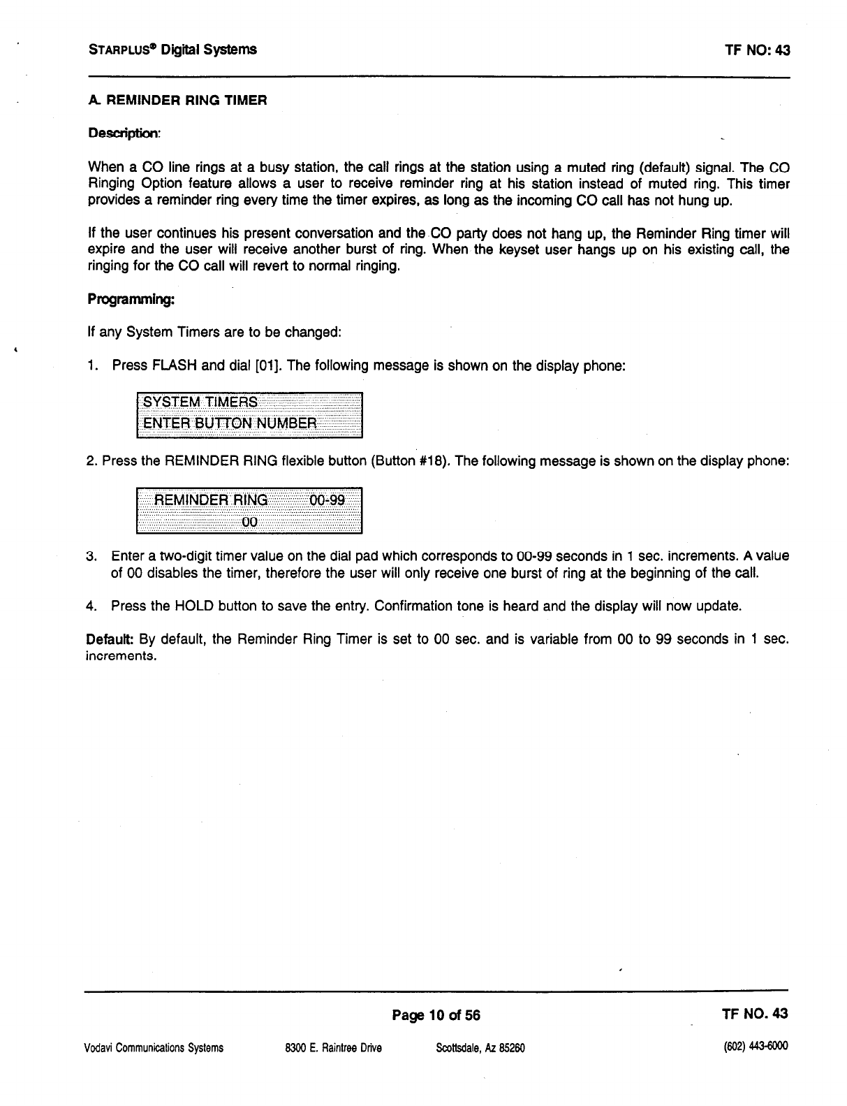
STARPLUS”
Dfgiil Systems TF NO: 43
A
REMINDER RING TIMER
Description:
When a CO line rings at a busy station, the call rings at the station using a muted ring (default) signal. The CO
Ringing Option feature allows a user to receive reminder ring at his station instead of muted ring. This timer
provides a reminder ring every time the timer expires, as long as the incoming CO call has not hung up.
If the user continues his present conversation and the CO party does not hang up, the Reminder Ring timer will
expire and the user will receive another burst of ring. When the keyset user hangs up on his existing call, the
ringing for the CO call will revert to normal ringing.
Programming:
If any System Timers are to be changed:
1. Press FLASH and dial [Ol]. The following message is shown on the display phone:
2. Press the REMINDER RING flexible button (Button #la). The following message is shown on the display phone:
3. Enter a two-digit timer value on the dial pad which corresponds to 00-99 seconds in 1 sec. increments. A value
of 00 disables the timer, therefore the user will only receive one burst of ring at the beginning of the call.
4. Press the HOLD button to save the entry. Confirmation tone is heard and the display will now update.
Default By default, the Reminder Ring Timer is set to 00 sec. and is variable from 00 to 99 seconds in 1 sec.
increments.
Vodavi Communicalions Systems
Page 10 of56 TF NO. 43
8300 E. Raintree Drive Scoltsdale, AZ 85260
W2)
443-6m
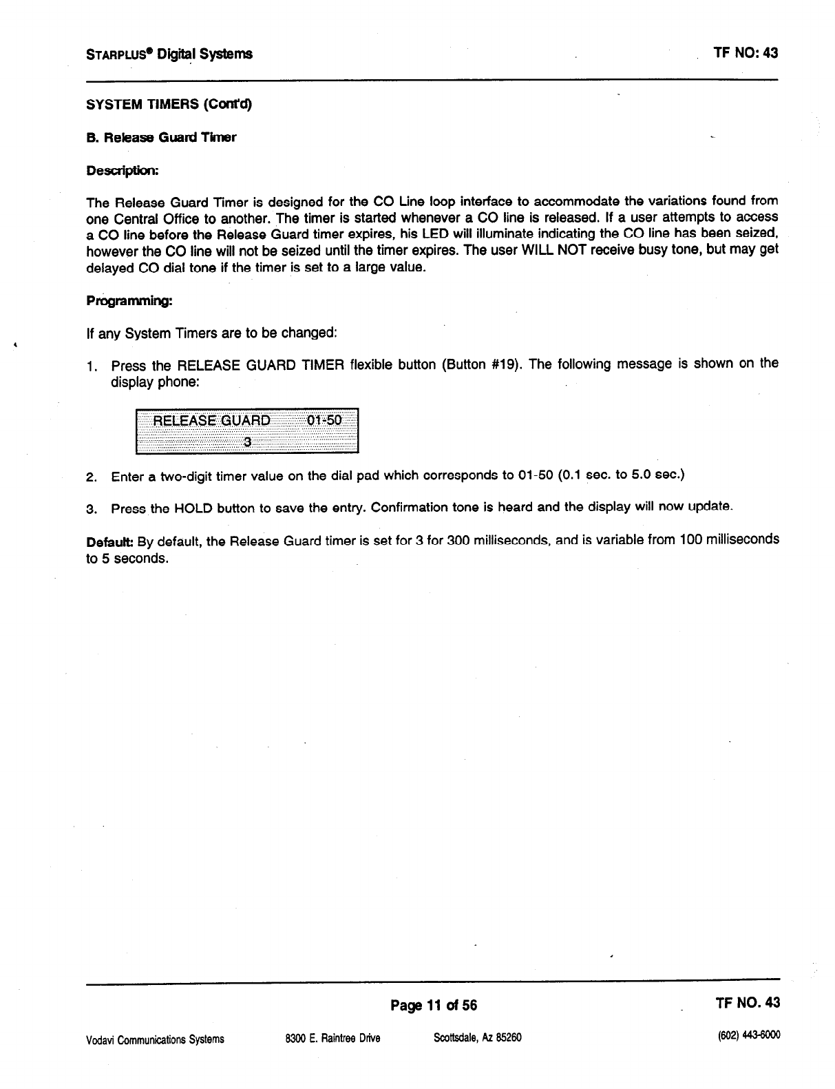
STARPLUS@
Digi@ Systems TF NO: 43
SYSTEM TIMERS (Ccmt’d)
B. Release Guard Timer
Description:
The Release Guard Timer is designed for the CO tine loop interface to accommodate the variations found from
one Central Office to another. The timer is started whenever a CO line is released. If a user attempts to access
a CO line before the Release Guard timer expires, his LED will illuminate indicating the CO line has been seized,
however the CO line will not be seized until the timer expires. The user WILL NOT receive busy tone, but may get
delayed CO dial tone if the timer is set to a large value.
PrOgramming:
If any System Timers are to be changed:
1. Press the RELEASE GUARD TIMER flexible button (Button #19). The following message is shown on the
display phone:
2. Enter a two-digit timer value on the dial pad which corresponds to 01-50 (0.1 sec. to 5.0 sec.)
3. Press the HOLD button to save the entry. Confirmation tone is heard and the display will now update.
Defaut By default, the Release Guard timer is set for 3 for 300 milliseconds, and is variable from 100 milliseconds
to 5 seconds.
Page 11 of56 TF NO. 43
Vdavi Communications Systems 83&l E. Raintree Drive Scottsdale, AZ 85260

STARPLUS’ Digiil Systems TF NO: 43
SYSTEM FEATURES
Call Cost Display (Available with optional software)
Handset Volume Adjustment
Call Qualifier Tone
Privacy Release Tone Option
Flash Rates (Programmable)
Vodavi Communications Systems
Page 12 of 56 TF NO. 43
8300 E. Raintree Drive Scottsdale, AZ 85260 (602) 443-6ooo
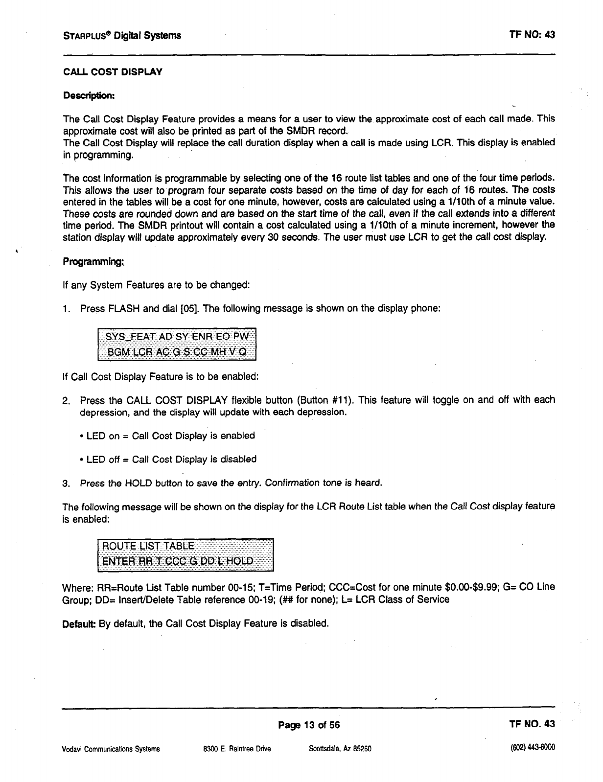
STARPLUS” Digital systems
TP NO: 43
CALL COST DISPLAY
Desaiptfon:
The Call Cost Display Feature provides a means for a user to view the approximate cost of each call made. This
approximate cost will also be printed as part of the SMDR record.
The Call Cost Display will replace the call duration display when a call is made using LCR. This display is enabled
in programming.
,
The cost information is programmable by selecting one of the 16 route list tables and one of the four time periods.
This allows the user to program four separate costs based on the time of day for each of 16 routes. The costs
entered in the tables will be a cost for one minute, however, costs are calculated using a l/lOth of a minute value.
These costs are rounded down and are based on the start time of the call, even if the call extends into a different
time period. The SMDR printout will contain a cost calculated using a l/lOth of a minute increment, however the
station display will update approximately every 30 seconds. The user must use LCR to get the call cost display.
Programming:,
If any System Features are to be changed:
1. Press FLASH and dial [05]. The following message is shown on the display phone:
If Call Cost Display Feature is to be enabled:
2. Press the CALL COST DISPLAY flexible button (Button #ll). This feature will toggle on and off with each
depression, and the display will update with each depression.
l
LED on = Call Cost Display is enabled
l
LED off = Call Cost Display is disabled
3. Press the HOLD button to save the entry. Confirmation tone is heard.
The following message will be shown on the display for the LCR Route List table when the Call Cost display feature
is enabled:
ROXJTE LiST TABLE’ ‘.
.::... : : :::,, X: . . . . . . ,$’ ii.
‘.’ ‘. :.:, ::: ‘. :;. .‘.‘.‘.‘.‘.‘.‘.‘.~.~.~::‘.‘.‘.’ ‘. : ‘. :: .; ,,‘.,,‘, .,‘,‘,,., ,.,‘,“.. : :,:
‘. ‘,‘,’ .’ : : . ..”
1,E~TER;RR~~~~.CCC’~~..DD’~L:-I~WO~.~~.i:~
: ; :. : ‘.‘.’ :.
,.. ..““. ., ,. ,, ‘. ” .: ‘,‘I ‘.
Where: RR=Route List Table number 00-15; T=Time Period; CC&Cost for one minute $O.OO-$9.99; G= CO Line
Group; DD= Insert/Delete Table reference 00-19; (## for none); L= LCR Class of Service
Defautb By default, the Call Cost Display Feature is disabled.
Vodavi Communications Systems
Page 13 of 56 TF NO. 43
@300 E. Raintrw Drive Scottsdale, AZ 85260
Pm
4434ooo
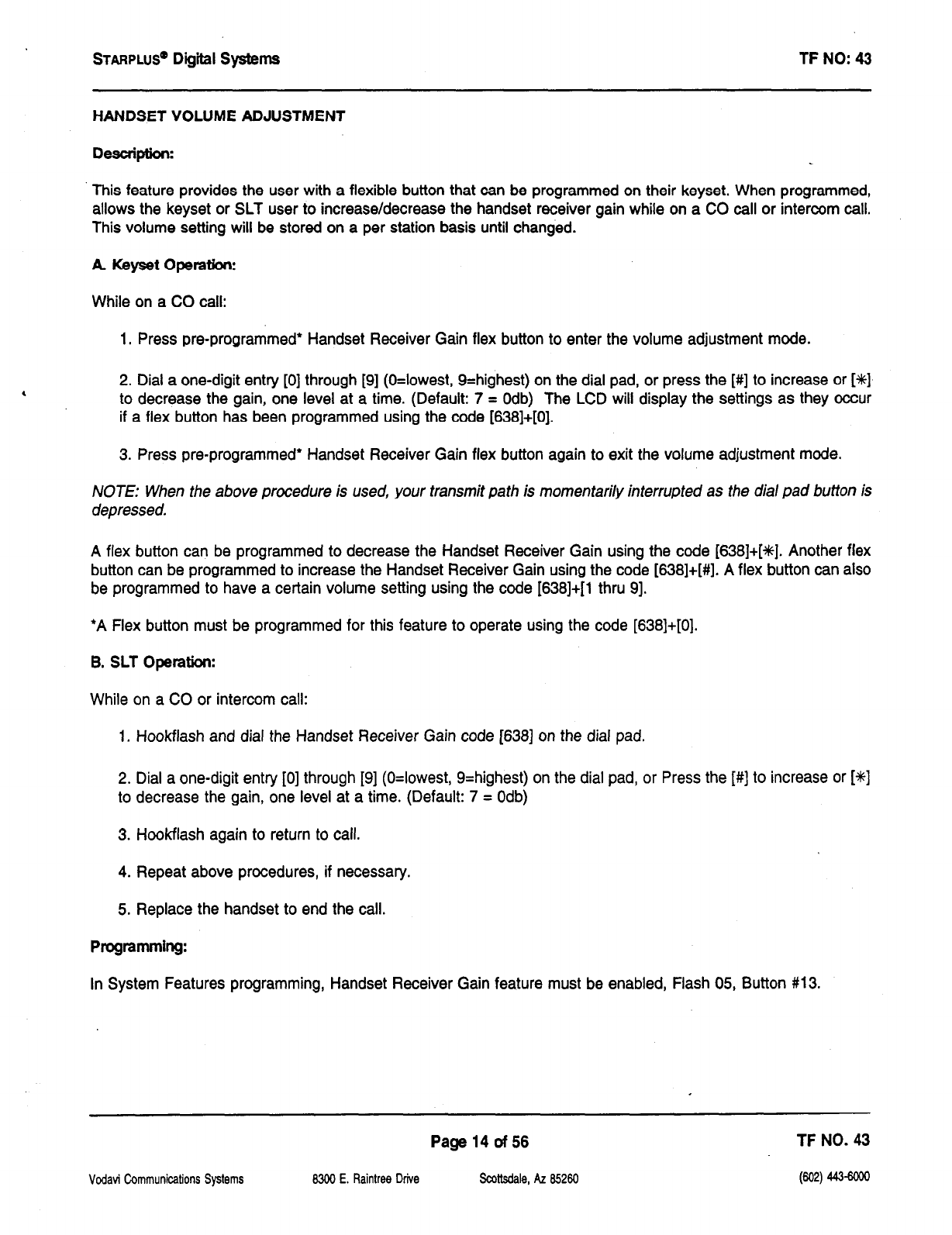
STARPLUS~
Digiil Systems TF NO: 43
HANDSET VOLUME ADJUSTMENT
Description:
This feature provides the user with a flexible button that can be programmed on their keyset. When programmed,
allows the keyset or SLT user to increase/decrease the handset receiver gain while on a CO call or intercom call.
This volume setting will be stored on a per station basis until changed.
A. Keyset OperatIoni
While on a CO call:
1. Press pre-programmed* Handset Receiver Gain flex button to enter the volume adjustment mode.
, 2. Dial a one-digit entry [0] through [9] (O=lowest, 9=highest) on the dial pad, or press the [#] to increase or [%]
to decrease the gain, one level at a time. (Default: 7 = Odb) The LCD will display the settings as they occur
if a flex button has been programmed using the code [638]+[0].
3. Press pre-programmed* Handset Receiver Gain flex button again to exit the volume adjustment mode.
NOTE: When the above procedure is used, your transmit path is momentarily interrupted as the dial pad button is
depressed.
A flex button can be programmed to decrease the Handset Receiver Gain using the code [638]+[+#]. Another flex
button can be programmed to increase the Handset Receiver Gain using the code [638]+[#]. A flex button can also
be programmed to have a certain volume setting using the code [638]+[1 thru 91.
*A Flex button must be programmed for this feature to operate using the code [638]+[0].
B. SLT Operation:
While on a CO or intercom call:
1. Hookflash and dial the Handset Receiver Gain code [SSS] on the dial pad.
2. Dial a one-digit entry [0] through [9] (O=lowest, 9=highest) on the dial pad, or Press the [#] to increase or [+I+]
to decrease the gain, one level at a time. (Default: 7 = Odb)
3. Hookflash again to return to call.
4. Repeat above procedures, if necessary.
5. Replace the handset to end the call.
Programming:
In System Features programming, Handset Receiver Gain feature must be enabled, Flash 05, Button #13.
Vodavi Communications Systems
Page 14 of 56 TF NO. 43
8300 E. Raintrw Drive scatsdale, AZ 85260 (602) 443-6cm
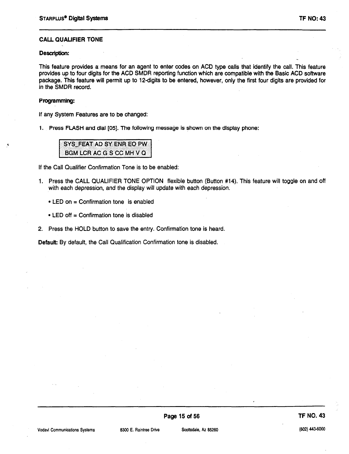
sTARPLUS@
Digital Systems TF NO: 43
CALL QUALIFIER TONE
Description:
This feature provides a means for an agent to enter codes on ACD type calls that identify the call. This feature
provides up to four digits for the ACD SMDR reporting function which are compatible with the Basic ACD software
package. This feature will permit up to 12-digits to be entered, however, only the first four digits are provided for
in the SMDR record.
Programming:
If any System Features are to be changed:
1. Press FLASH and dial [05]. The following message is shown on the display phone:
If the Call Qualifier Confirmation Tone is to be enabled:
1. Press the CALL QUALIFIER TONE OPTION flexible button (Button #14). This feature will toggle on and off
with each depression, and the display will update with each depression.
l
LED on = Confirmation tone is enabled
l
LED off = Confirmation tone is disabled
2. Press the HOLD button to save the entry. Confirmation tone is heard.
Default By default, the Call Qualification Confirmation tone is disabled.
Page 15 of 56 TF NO. 43
Vodavi Communications Systems 15300 E. Raintree Drive Scottsdale, AZ 85260
t3w
443-6om
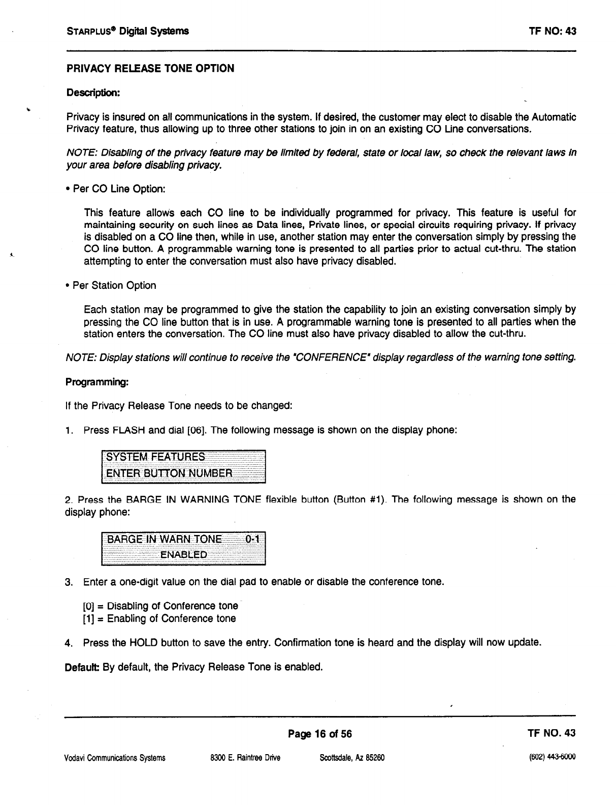
STARPLUS’
Digiil systems TF NO: 43
PRIVACY RELEASE TONE OPTION
Description:
Privacy is insured on all communications in the system. If desired, the customer may elect to disable the Automatic
Privacy feature, thus allowing up to three other stations to join in on an existing CO Line conversations.
NOTE: Disabling of the privacy feature may be limited by federal, state or local law, so check the relevant laws in
your area before disabling privacy.
l
Per CO Line Option:
This feature allows each CO line to be individually programmed for privacy. This feature is useful for
maintaining security on such lines as Data lines, Private lines, or special circuits requiring privacy. If privacy
is disabled on
a
CO line then, while in use, another station may enter the conversation simply by pressing the
CO line button. A programmable warning tone is presented to all parties prior to actual cut-thru. The station
attempting to enter the conversation must also have privacy disabled.
l
Per Station Option
Each station may be programmed to give the station the capability to join an existing conversation simply by
pressing the CO line button that is in use. A programmable warning tone is presented to all parties when the
station enters the conversation. The CO line must also have privacy disabled to allow the cut-thru.
NOTE: Display stations will continue to receive the *CONFERENCE” display regardless of the warning tone setting.
Programming:
If the Privacy Release Tone needs to be changed:
1. Press FLASH and dial [06]. The following message is shown on the display phone:
2. Press the BARGE IN WARNING TONE flexible button (Button #l). The following message is shown on the
display phone:
3. Enter a one-digit value on the dial pad to enable or disable the conference tone.
[0] = Disabling of Conference tone
[1] = Enabling of Conference tone
4. Press the HOLD button to save the entry. Confirmation tone is heard and the display will now update.
Default
By default, the Privacy Release Tone is enabled.
Page 16 of 56 TF NO. 43
Vodavi Ckmmunicalions Systems 8300 E. Raintree Drive !k.dtsdale, AZ 85260
@@)
44s6ooo
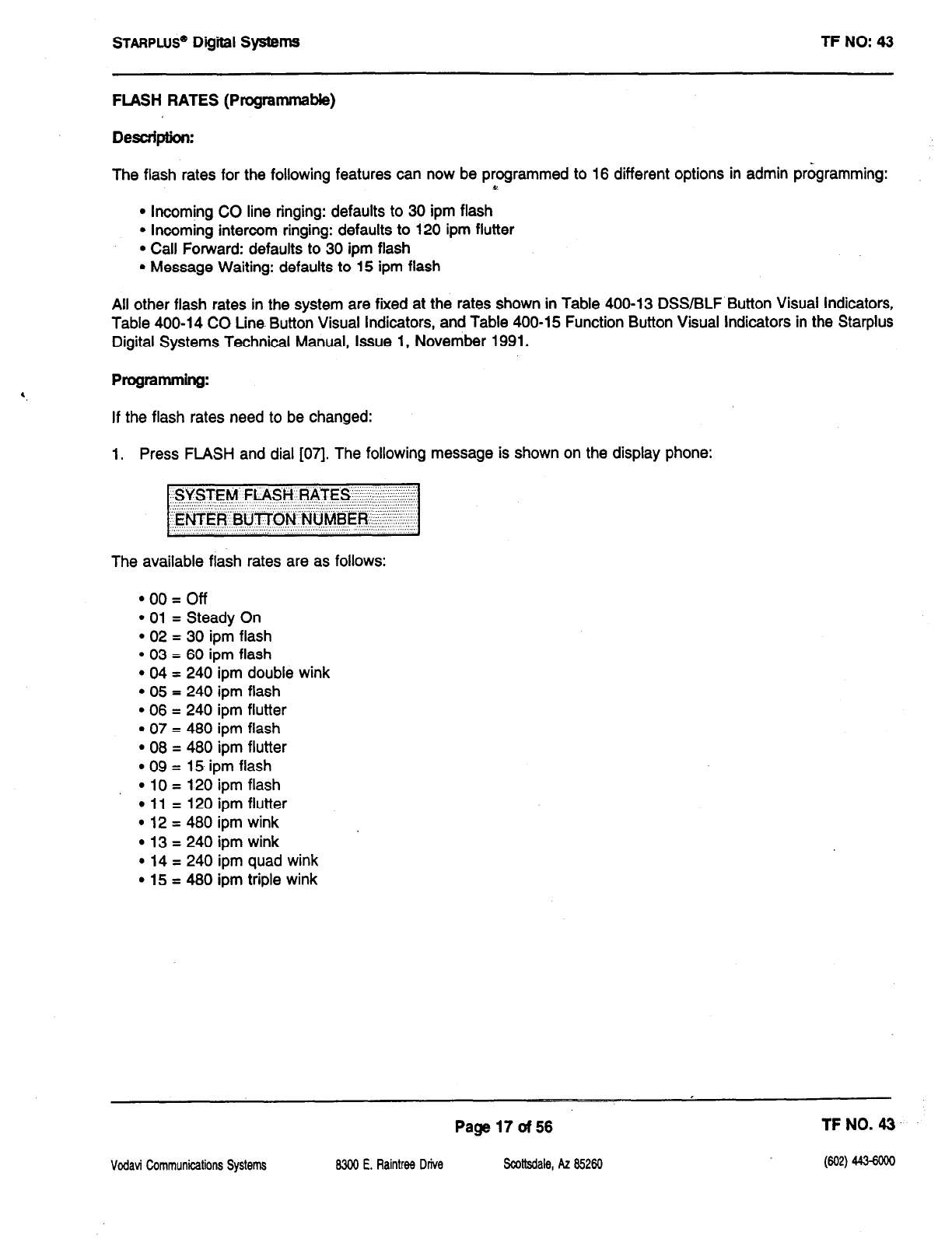
STARPLUS”
Digiil SystemS TF NO: 43
FLASH RATES (Programmable)
Description:
The flash rates for the following features can now be programmed to 16 different options in admin programming:
47
l
Incoming CO line ringing: defaults to 30 ipm flash
l
Incoming intercom ringing: defaults to 120 ipm flutter
l
Call Forward: defaults to 30 ipm flash
l
Message Waiting: defaults to 15 ipm flash
All other flash rates in the system are fixed at the rates shown in Table 400-13 DSS/BLF Button Visual Indicators,
Table 400-14 CO Line. Button Visual Indicators, and Table 400-15 Function Button Visual Indicators in the Starplus
Digital Systems Technical Manual, Issue
1,
November 1991.
Programming:
If the flash rates need to be changed:
1. Press FLASH and dial [07]. The following message is shown on the display phone:
The available flash rates are as follows:
l oo=off
l
01 = Steady On
l
02 = 30 ipm flash
l
03 = 60 ipm flash
l
04 = 240 ipm double wink
l
05 = 240 ipm flash
l
06 = 240 ipm flutter
l
07 = 460 ipm flash
l
08 = 480 ipm flutter
l
09 = 15 ipm flash
l
10 = 120 ipm flash
l
11 = 120 ipm flutter
l
12 = 480 ipm wink
l
13 = 240 ipm wink
l
14 = 240 ipm quad wink
l
15 = 480 ipm triple wink
Vcdavi Communifzations Systems
Page 17 of 56 TFNO. 43
8300 E. Ftaintree Drive Scottsdale, AZ 85260
(602) 443-6ow
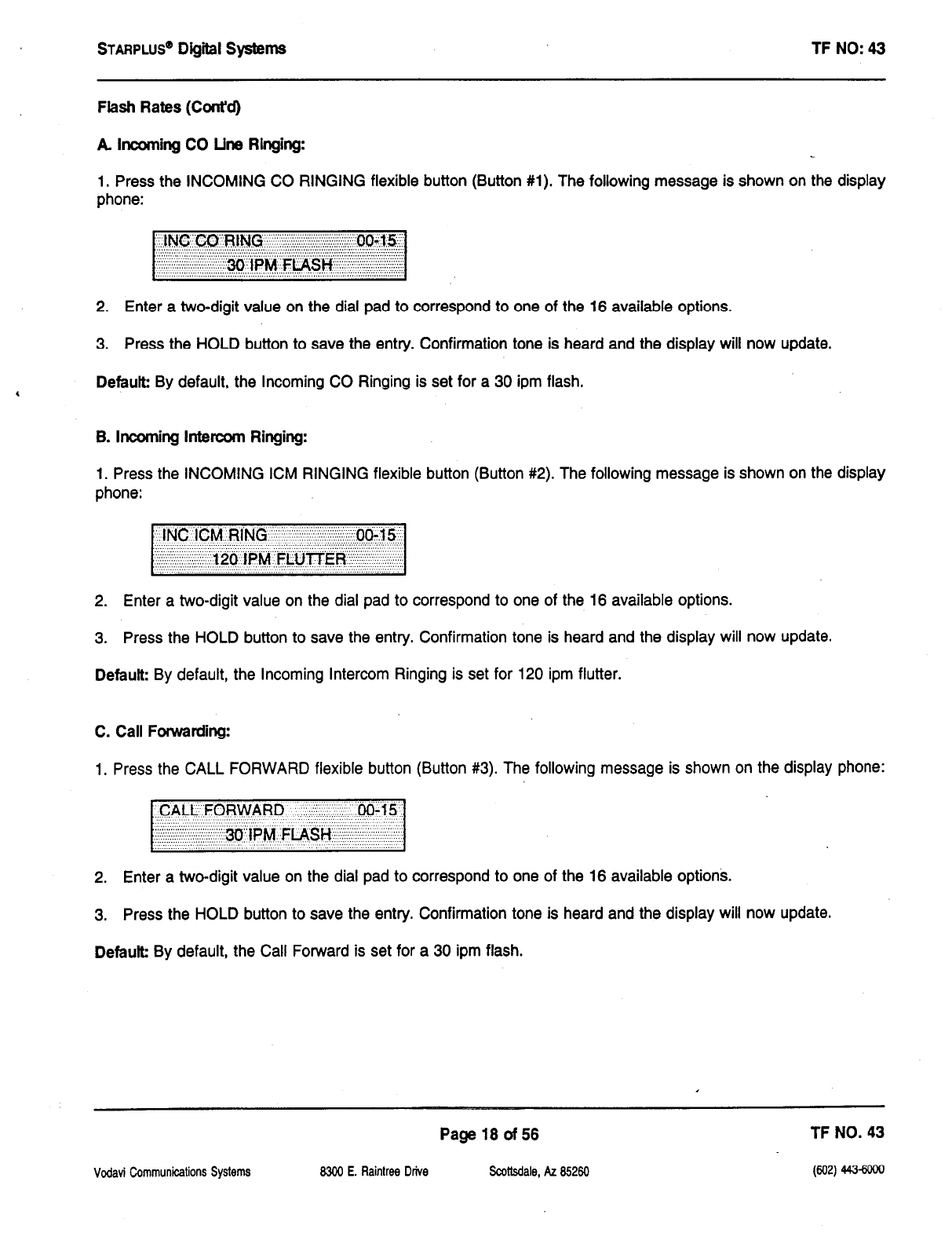
STARPLUS@
Digiii systems TF NO: 43
Flash Rates (Cont’d)
A banning CO Line Ringing:
1, Press the INCOMING CO RINGING flexible button (Button #l). The following message is shown on the display
phone:
2. Enter a two-digit value on the dial pad to correspond to one of the 16 available options.
3. Press the HOLD button to save the entry. Confirmation tone is heard and the display will now update.
Default By default, the Incoming CO Ringing is set for a 30 ipm flash.
B. incoming intercom Ringing:
1. Press the INCOMING ICM RINGING flexible button (Button #2). The following message is shown on the display
phone:
2. Enter a two-digit value on the dial pad to correspond to one of the 16 available options.
3. Press the HOLD button to save the entry. Confirmation tone is heard and the display will now update.
Default By default, the Incoming Intercom Ringing is set for 120 ipm flutter.
C. Call Fonvarding:
1. Press the CALL FORWARD flexible button (Button #3). The following message is shown on the display phone:
2. Enter a two-digit value on the dial pad to correspond to one of the 16 available options.
3. Press the HOLD button to save the entry. Confirmation tone is heard and the display will now update.
Defauk By default, the Call Forward is set for a 30 ipm flash.
Page 18 of 56 TF NO. 43
Vodavi Communications Systems 83&l E. Raintree Drive Scottsdale, AZ 65260
032)
443-woe
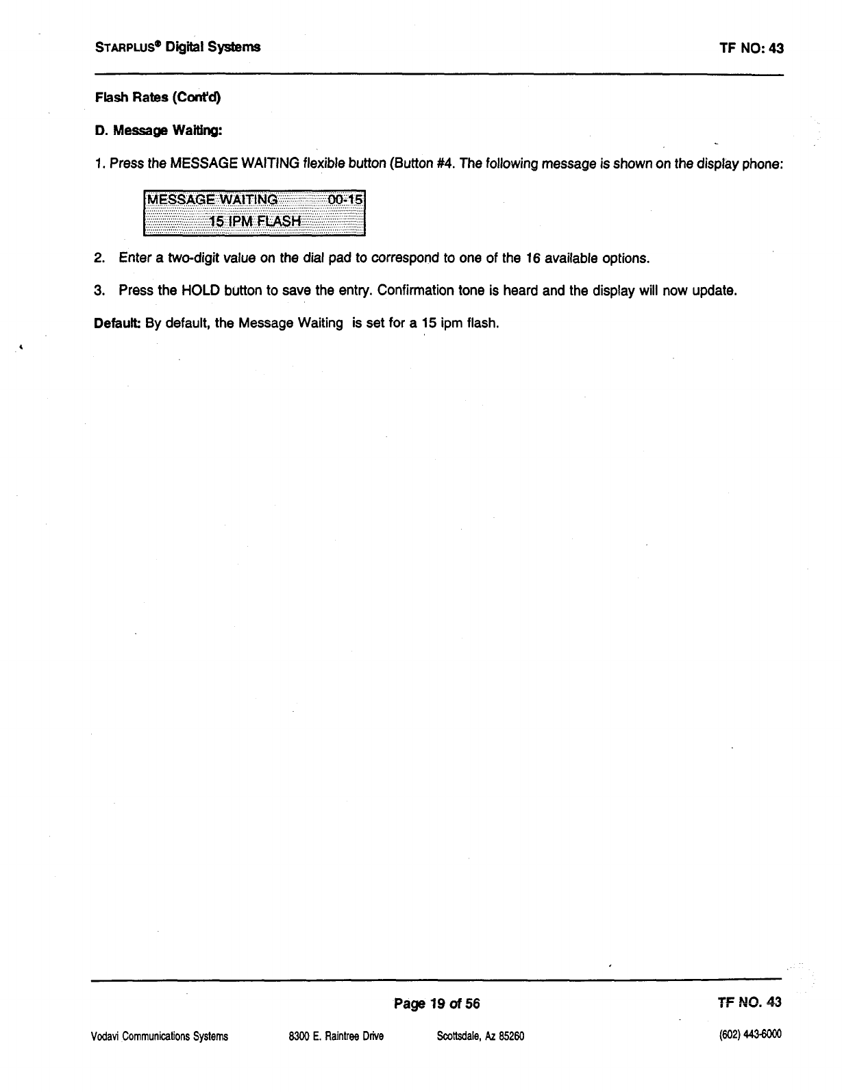
STARPLUS@
Digiil Systems TF NO: 43
Flash Rates (Cont’d)
D. Message Waiting:
1. Press the MESSAGE WAITING flexible button (Button #4. The following message is shown on the display phone:
2. Enter a two-digit value on the dial pad to correspond to one of the 16 available options.
3. Press the HOLD button to save the entry. Confirmation tone is heard and the display will now update.
Default: By default, the Message Waiting is set for a 15 ipm flash.
Vodavi Communications Systems
Page 19 of56 ?F NO. $3
WI E. Raintree Drive Scottsdale, AZ 85260
w
44cwNJ
STARPLUS”
Dig&d systems TF NO: 43
CO LINE AlTRIBUTES
DISA Programming Options (Button #7)
Trunk Direction (Button #13)
Ring Delay Timer (Button #14)
Vodavi Communications Systems 8300 E. Raintrw Drive
Page 20 of 56
Scottsdale, AZ 85260
TF NO. 43
(602) 443aoo
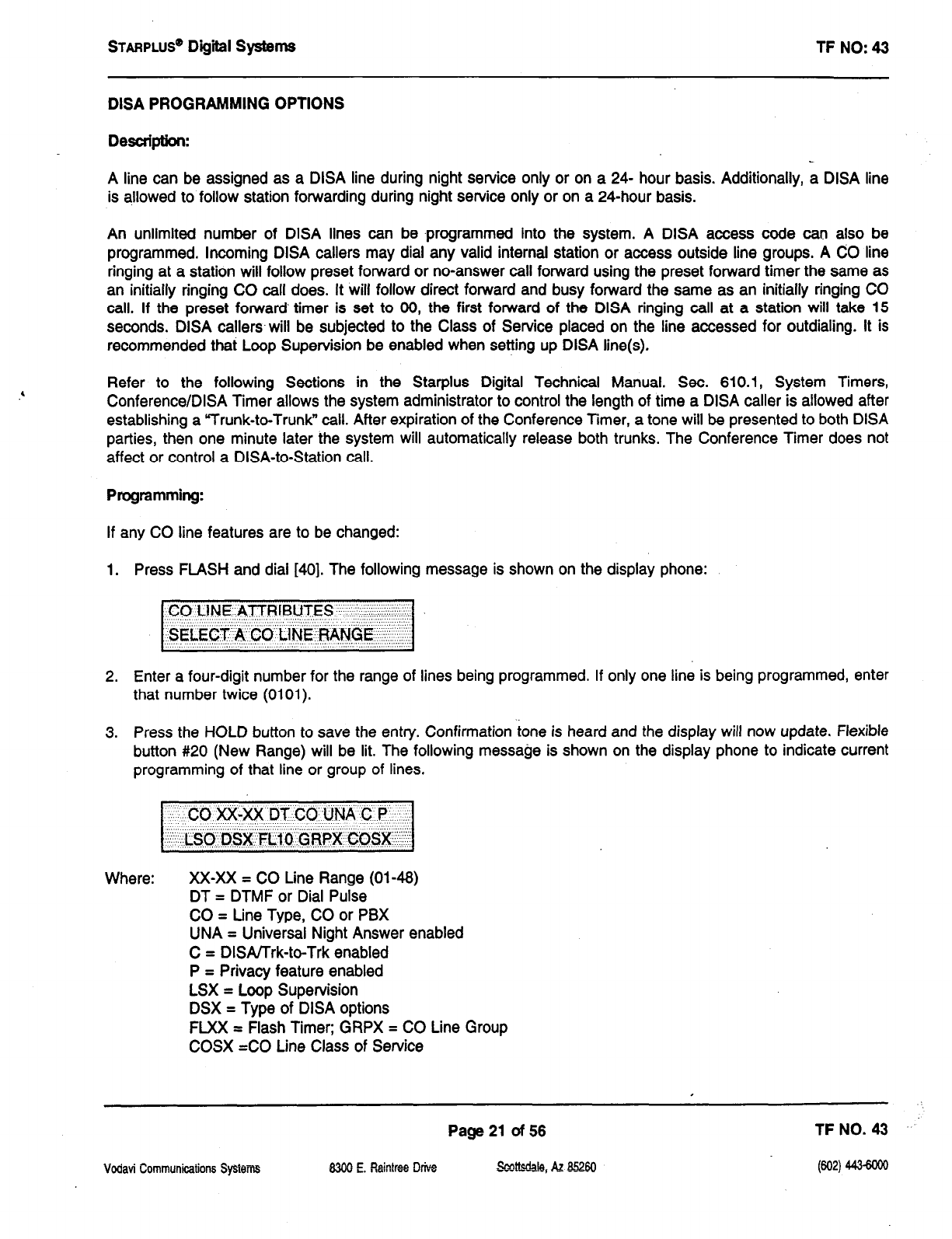
STARPLUS” Digital
Systems
TF NO: 43
DISA PROGRAMMING OPTIONS
Description:
A line can be assigned as a DISA line during night service only or on a 24- hour basis. Additionally, a DISA line
is allowed to follow station forwarding during night service only or on a 24-hour basis.
An unlimited number of DISA lines can be .programmed into the system. A DISA access code can also be
programmed. Incoming DISA callers may dial any valid internal station or access outside line groups. A CO line
ringing at a station will follow preset forward or no-answer call forward using the preset forward timer the same as
an initially ringing CO call does. It will follow direct forward and busy forward the same as an initially ringing CO
call. If the preset forward timer is set to 06, the first forward of the DISA ringing call at
a
station will take 15
seconds. DISA callers-will be subjected to the Class of Service placed on the line accessed for outdialing. It is
recommended that Loop Supervision be enabled when setting up DISA line(s).
Refer to the following Sections in the Starplus Digital Technical Manual. Sec. 610.1, System Timers,
Conference/DISA Timer allows the system administrator to control the length of time a DISA caller is allowed after
establishing a “Trunk-to-Trunk” call. After expiration of the Conference Timer, a tone will be presented to both DISA
parties, then one minute later the system will automatically release both trunks. The Conference Timer does not
affect or control a DISA-to-Station call.
Programming:
If any CO line features are to be changed:
1. Press FLASH and dial [40]. The following message is shown on the display phone:
~~SELECT’A’~CO”UNE’RANGE ?:. ,.::‘:.
2. Enter a four-digit number for the range of lines being programmed. If only one line is being programmed, enter
that number twice (0101).
3. Press the HOLD button to save the entry. Confirmation tone is heard and the display will now update. Flexible
button #20 (New Range) will be lit. The following message is shown on the display phone to indicate current
programming of that line or group of lines.
Where: XX-XX = CO Line Range (01-46)
DT = DTMF or Dial Pulse
CO = Line Type, CO or PBX
UNA = Universal Night Answer enabled
C = DISAJTrk-to-Trk enabled
P = Privacy feature enabled
LSX = Loop Supervision
DSX = Type of DISA options
FLXX t Flash Timer; GRPX = CO Line Group
COSX =CO Line Class of Service
Vodavi Communications Spiwms
Page 21 of 56 TF NO. 43
83&l E. Rainlrse Drive ,sLcdtaa, A.2 Bmo (602) 443-6ooo
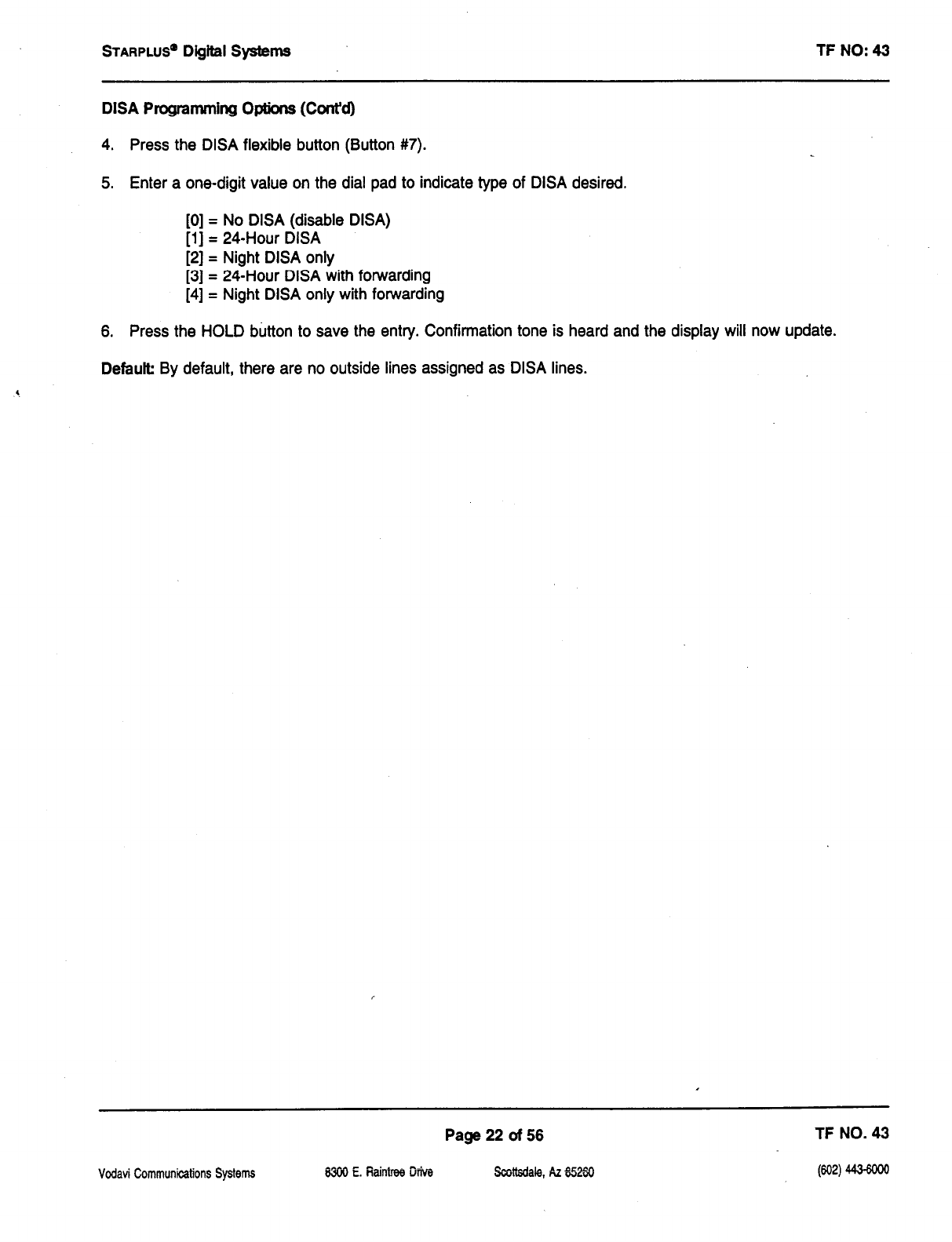
STARPLUS’
Digital Systems TF NO: 43
DISA Programming Options (Cont’d)
4. Press the DISA flexible button (Button #7).
5. Enter a one-digit value on the dial pad to indicate type of DISA desired.
[0] = No DISA (disable DISA)
[l] = 24-Hour DISA
[2] = Night DISA only
[3] = 24-Hour DISA with forwarding
[4] = Night DISA only with forwarding
6. Press the HOLD button to save the entry. Confirmation tone is heard and the display will now update.
Default By default, there are no outside lines assigned as DISA lines.
Page 22 of 56 TF NO. 43
Vodavi Communications Systems WO E. iiaintree Diva §izYdale, k 6250
WQ)
4434ooo
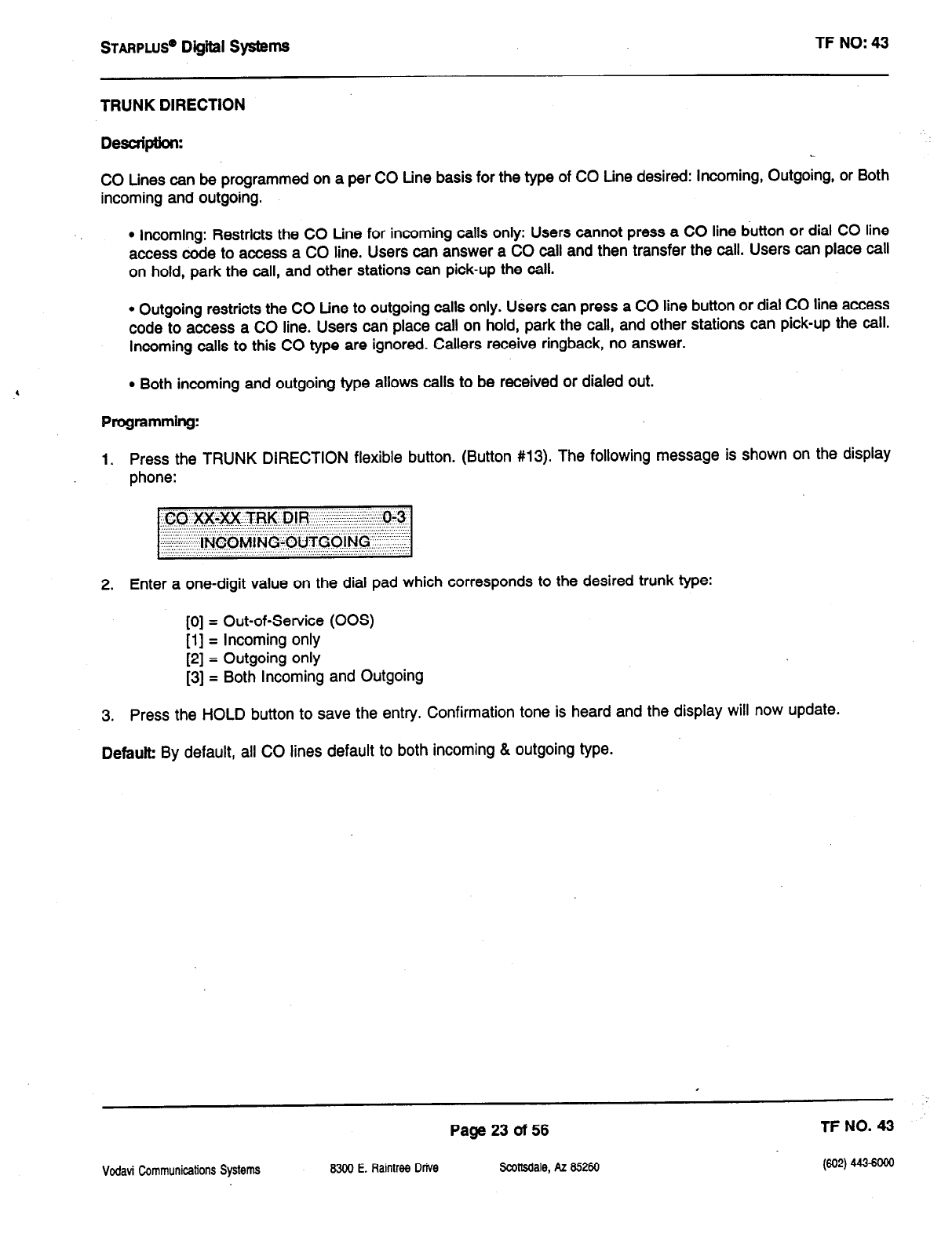
STARPLUS’
Digiil SyStemS TF NO: 43
TRUNK DIRECTION
Descriphkn:
CO Lines can be programmed on a per CO tine basis for the type of CO Line desired: Incoming, Outgoing, or Both
incoming and outgoing.
l
Incoming: Restricts the CO Line for incoming calls only: Users cannot press a CO line button or dial CO line
access code to access a CO line. Users can answer a CO call and then transfer the call. Users can place call
on hold, park the call, and other stations can pick-up the call.
l
Outgoing restricts the CO tine to outgoing calls only. Users can press a CO line button or dial CO line access
code to access a CO line. Users can place call on hold, park the call, and other stations can pick-up the call.
Incoming calls to this CO type are ignored. Callers receive ringback, no answer.
l
Both incoming and outgoing type allows calls to be received or dialed out.
Programming:
1. Press the TRUNK DIRECTION flexible button. (Button #13). The following message is shown on the display
phone:
2. Enter a one-digit value on the dial pad which corresponds to the desired trunk type:
[0] = Out-of-Service (00s)
[l] = Incoming only
[2] = Outgoing only
[3] = Both Incoming and Outgoing
3. Press the HOLD button to save the entry. Confirmation tone is heard and the display will now update.
Default By default, all CO lines default to both incoming & outgoing type.
Page 23 of 56 TF NO. 43
Vodavi Communications Systems 8300 E. Raintree Drive Sadtsdale, AZ 85260
w4
443-woe
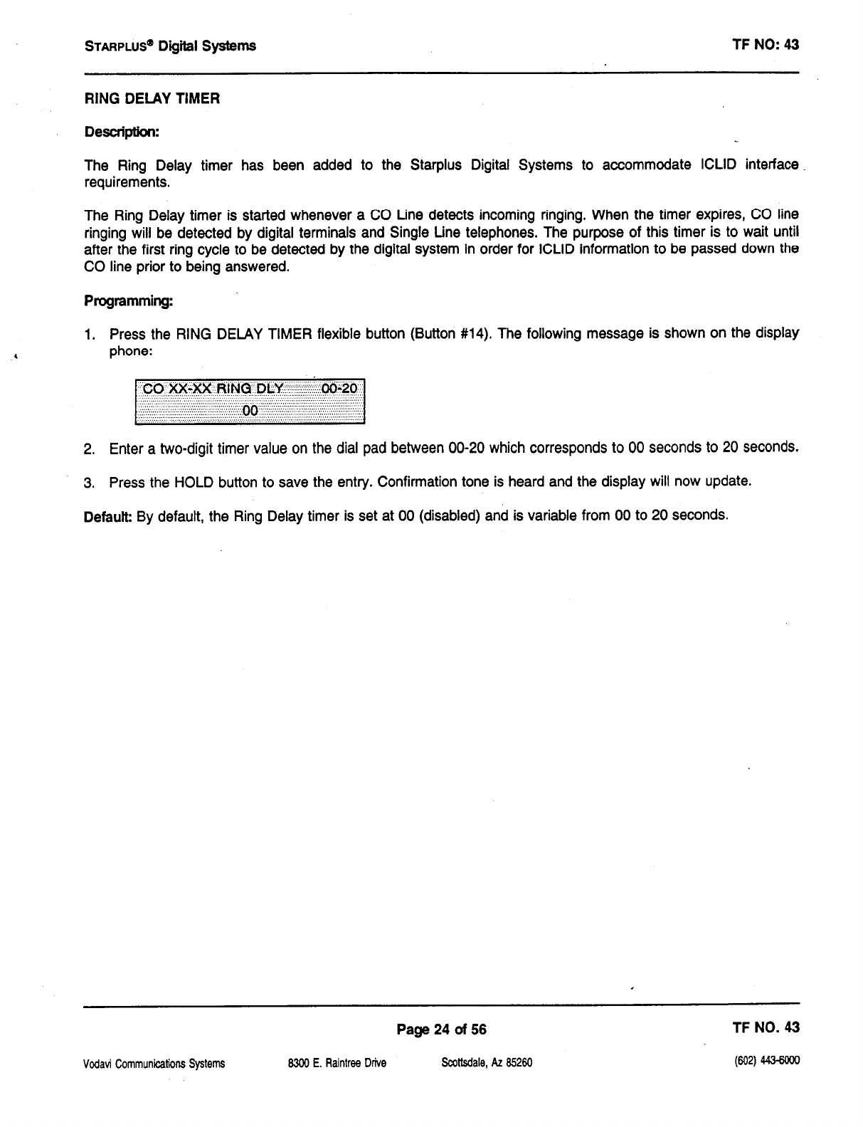
STARPLUS”
Dig&al Systems TF NO: 43
RING DELAY TIMER
Desuipth:
The Ring Delay timer has been added to the Starplus Digital Systems to accommodate ICLID interface
requirements.
The Ring Delay timer is started whenever a CO Line detects incoming ringing. When the timer expires, CO line
ringing will be detected by digital terminals and Single Line telephones. The purpose of this timer is to wait until
after the first ring cycle to be detected by the digital system in order for ICLID information to be passed down the
CO line prior to being answered.
Programming:
1. Press the RING DELAY TIMER flexible button (Button #14). The following message is shown on the display
phone:
2. Enter a two-digit timer value on the dial pad between 00-20 which corresponds to 00 seconds to 20 seconds.
3. Press the HOLD button to save the entry. Confirmation tone is heard and the display will now update.
Default By default, the Ring Delay timer is set at 00 (disabled) and is variable from 00 to 20 seconds.
Page 24 of 56 TF NO. 43
Vodavi Communications Systems 8300 E. Raintree Drive Scottsdale, AZ 85260
STARPLUS” Digiil
Systems
TF NO: 43
STATION ATTRIBUTES
CO Line Ringing Options
,
Vodavi Communications SystertIS
Page 25 of 56 TF NO. 43
8300 E. Raintrw Drive Scoltsdale, AZ 85260 W) 443-ml
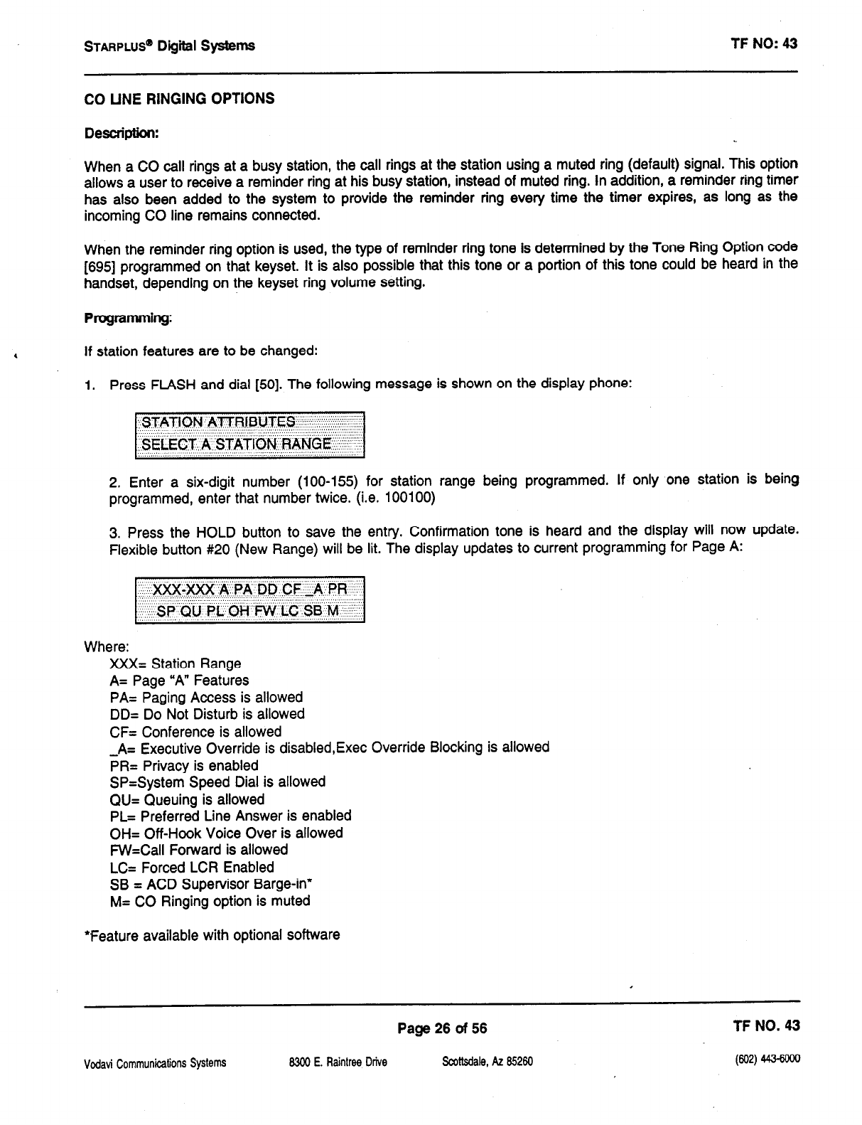
STARPLUS”
Dig&al Systems TF NO: 43
CO UNE RINGING OPTIONS
Desuiption:
When a CO call rings at a busy station, the call rings at the station using a muted ring (default) signal. This option
allows a user to receive a reminder ring at his busy station, instead of muted ring. In addition, a reminder ring timer
has also been added to the system to provide the reminder ring every time the timer expires, as long as the
incoming CO line remains connected.
When the reminder ring option is used, the type of reminder ring tone is determined by the Tone Ring Option code
[695] programmed on that keyset. It is also possible that this tone or a portion of this tone could be heard in the
handset, depending on the keyset ring volume setting.
Programming:
,
If station features are to be changed:
1. Press FLASH and dial [50]. The following message is shown on the display phone:
2. Enter a six-digit number (100-155) for station range being programmed. If only one station is being
programmed, enter that number twice. (i.e. 100100)
3. Press the HOLD button to save the entry. Confirmation tone is heard and the display will now update.
Flexible button #20 (New Range) will be lit. The display updates to current programming for Page A:
Where:
XXX= Station Range
A= Page “A” Features
PA= Paging Access is allowed
DD= Do Not Disturb is allowed
CF= Conference is allowed
-A= Executive Override is disabled,Exec Override Blocking is allowed
PR= Privacy is enabled
SP=System Speed Dial is allowed
QU= Queuing is allowed
PL= Preferred Line Answer is enabled
OH= Off-Hook Voice Over is allowed
FW=Call Forward is allowed
LC= Forced LCR Enabled
SB = ACD Supervisor Barge-in*
M= CO Ringing option is muted
‘Feature available with optional software
Page 26 of 56 TF NO. 43
Vodavi Commutcalions Systems 6300 E. Raintree Drive
Scottsdale, AZ
85260
PQ)
443-6mo
STAFIPLUS’ D@iil Systems TF NO: 43
Stathi Features -
(Ccmt'd)
CO LINE RINGING OPTIONS (Co&d)
4. Press the RINGING OPTIONS flexible button (Page A, Button #14). This feature will toggle on and off with each
depression, and the display will update with each depression.
l
LED on = Reminder Ring is allowed
l
LED off= Muted Ringing is allowed
5. Press the HOLD button to save the entry. Confirmation tone is heard.
Defauk By default,
Muted
Ringing is allowed at all stations.
Related Programming: Refer to Reminder Ring Timer, Flash 01, Button #18.
Vodavi Communications Systems
Page 27 of 56 TF NO. 43
8300 E. Raintree Drive Scottsdale, AZ 85260
km
4434ooo
sTARPLUS@
Digiil systems TF NO: 43
ICUD FEATURES (Optional Software)
Caller Entered ICLID Digits (Guaranteed Message announcement) (Flash 60, Button #ll)
Expanded ICLID Ringing Assignments (Flash 43, Button #l)
Page 28 of 56 TF NO. 43
Vcdavi Communications Systems 8300 E. Raintrw Drive Scottsdale, AZ 85260 (602) 443-6ooo
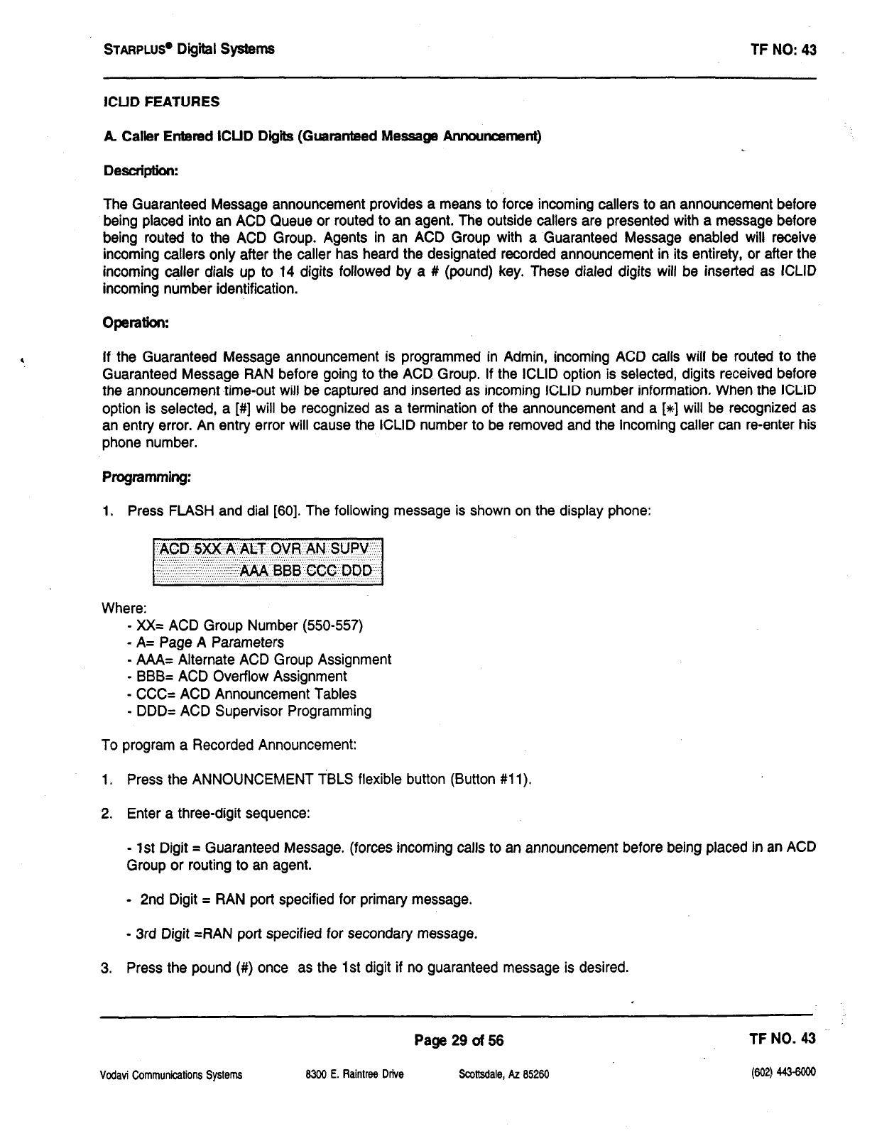
STARPLU~
Digiil Systems TF NO: 43
ICUD FEATURES
A Caller Entered ICUD Digii (Guaranteed Message Announcement)
Description:
The Guaranteed Message announcement provides a means to force incoming callers to an announcement before
being placed into an ACD Queue or routed to an agent. The outside callers are presented with a message before
being routed to the ACD Group. Agents in an ACD Group with a Guaranteed
Message
enabled will receive
incoming callers only after the caller has heard the designated recorded announcement in its entirety, or after the
incoming caller dials up to 14 digits followed by a # (pound) key. These dialed digits will be inserted as ICLID
incoming number identification.
If the Guaranteed Message announcement is programmed in Admin, incoming ACD calls will be routed to the
Guaranteed Message RAN before going to the ACD Group. If the ICLID option is selected, digits received before
the announcement time-out will be captured and inserted as incoming ICLID number information, When the ICLID
option is selected, a [#] will be recognized as a termination of the announcement and a [%I will be recognized as
an entry error. An entry error will cause the ICLID number to be removed and the incoming caller can re-enter his
phone number.
Programming:
1. Press FLASH and dial [60]. The following message is shown on the display phone:
,,;,:::::,:j+#/& BBB”CCC DDQ
‘.” ‘,, ‘.‘.‘.L :::. .., ‘I.. L. ..“‘.‘. ““’ “‘...
Where:
= XX= ACD Group Number (550-557)
= A= Page A Parameters
= AAA= Alternate ACD Group Assignment
= BBB= ACD Overflow Assignment
= CCC= ACD Announcement Tables
= DDD= ACD Supervisor Programming
To program a Recorded Announcement:
1. Press the ANNOUNCEMENT TBLS flexible button (Button #ll).
2. Enter a three-digit sequence:
=
1st Digit = Guaranteed Message. (forces incoming calls to an announcement before being placed in an ACD
Group or routing to an agent.
= 2nd Digit = RAN port specified for primary message.
= 3rd Digit =RAN port specified for secondary message.
3. Press the pound (#) once as the 1st digit if no guaranteed message is desired.
Vodavi Communications Systems
Page 29 of 56 TFNO. 43
8300 E. Raintree Drive Scottsdale, AZ 85260 (602) 443-swo
STARPLUS’
Digiil systems TF NO: 43
Example:
l
an entry of #,2,3 = No Guaranteed Message will be heard, Port 2 will provide a primary message and Port
3 will provide a secondary message.
l
an entry of 1,2,3 = Port 1 will provide the Guaranteed Message upon initially answering the call, Port 2 will
provide a primary message and Port 3 will provide a secondary message.
l
an entry of 8,1,2 = Port 8 will provide the Guaranteed Message upon initially answering the call, Port 1 will
provide a primary message and Port 2 will provide a secondary message.
4. Press the HOLD button to save the entry. Confirmation tone is heard and the display will now update.
To erase Recorded Announcement(s), press the pound key three times [##I#] and press HOLD.
Related Programming: Refer to Guaranteed Message timer, Flash 61, Button #7, Page 40 of this techfact. Refer
to Techfact Notice #31, dated 5/26/93 for further programming information regarding each RAN Table. Also refer
to Techfact Notice #30, dated 5/26/93 to enable the ICLID features.
l
A Guaranteed Message may be specified for each ACD Group.
l
When a caller is routed to a recorded announcement that is programmed as a Guaranteed Message, the caller
will not be pulled from the message if an agent becomes available. The caller will be allowed to listen to the
announcement in its entirety.
l
The RAN timers will control the length of the announcement.
.
A Guaranteed Message timer is used to specify the delay time before the guaranteed message RAN will
answer the incoming call. This timer is defaulted to 5 seconds.
l
Enabling ICLID will permit incoming callers to enter digits during the Guaranteed Message RAN announcement.
If a caller enters digits, the ICLID information received will be replaced with the caller inserted information.
.
If a caller enters digits while in the Guaranteed Message announcement, an interdigit time-out is set. This
interdigit time-out defaults to 10 seconds. An entry of a [#] or an interdigit time-out will terminate the Guaranteed
Message announcement and route the call.
.
Incoming ACD calls without ICLID enabled will route to the Guaranteed Message first. From there, they will be
routed to the ACD Group that the call rang into. If the group is busy, the call will be routed per normal routing
procedures.
l
Incoming ACD calls with ICLID enabled are checked against the ICLID route first and routed per the ICLID
number. If a number is not found in the ICLID route table, the call will be sent to the Guaranteed Message first.
If ICLID digits are entered while in the Guaranteed Message, those digits will be compared with the ICLID route
tables. If the digits entered are found, the call will be routed per the ICLID route table. If no match is found, the
call will be routed per the normal ACD routing procedures.
l
Calls will only be routed to the Guaranteed Message one time.
Vodavi Communications System5 8300 E. Raintree Drive
Page 30 of 56 TF NO. 43
Scottsdale, AZ 65260 (602) 4434ooo
STARPLUS’
Digital systems TF NO: 43
l
Transferred calls to the group will not be routed to a Guaranteed Message.
l
The telephone number in the Local Number/Name translation table must be programmed with dashes included
if it is a 10 or 11 digit ICLID number. (i.e.: l-802-998-2200) This is not necessary for ICLID digits entered during
the Guaranteed Message announcement.
Vodavi Communications Systems
Page 31 of 56 TF NO. 43
8300 E. Raintree Drive SadMale, AZ 85260
(602) 443ma
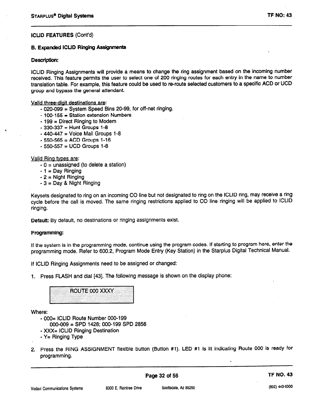
STARPLUS”
Dtgffl Systems TF NO: 43
ICUD FEATURES (Cont’d)
B. Expanded ICUD Ringing Ass@unents
Description:
ICLID Ringing Assignments will provide a means to change the ring assignment based on the incoming number
received. This feature permits the user to select one of 200 ringing routes for each entry in the name to number
translation table. For example, this feature could be used to re-route selected customers to a specific ACD or UCD
group and bypass the general attendant.
Valid three-diait destinations are:
- 020-099 = System Speed Bins 20-99, for off-net ringing.
- loo-155 = Station extension Numbers
- 199 = Direct Ringing to Modem
- 330337 = Hunt Groups 1-8
- 440-447 = Voice Mail Groups l-8
- 550-565 = ACD Groups l-16
- 550-557 = UCD Groups 1-8
Valid Rina tvoes are:
- 0 = unassigned (to delete a station)
- 1 = Day Ringing
- 2 = Night Ringing
- 3 = Day & Night Ringing
Keysets designated to ring on an incoming CO line but not designated to ring on the ICLID ring, may receive a ring
cycle before the call is moved. The same ringing restrictions applied to CO line ringing will be applied to ICLID
ringing.
Defauk By default, no destinations or ringing assignments exist.
Programming:
If the system is in the programming mode, continue using the program codes. If starting to program here, enter the
programming mode. Refer to 600.2, Program Mode Entry (Key Station) in the Starplus Digital Technical Manual.
If ICLID Ringing Assignments need to be assigned or changed:
1, Press FLASH and dial [43]. The following message is shown on the display phone:
Where:
- 000= ICLID Route Number 000-199
000-009 = SPD 1428; 000-199 SPD 2856
- XXX= ICLID Ringing Destination
- Y= Ringing Type
2. Press the RING ASSIGNMENT flexible button (Button #l). LED #l is lit indicating Route 000 is ready
for
programming. I
Page 32 of 56 TF NO. 43
Vodavi Communications Systems 8300 E. Ftaintree Drive Scottsdale, AZ 65260 (602) 443-6ooo
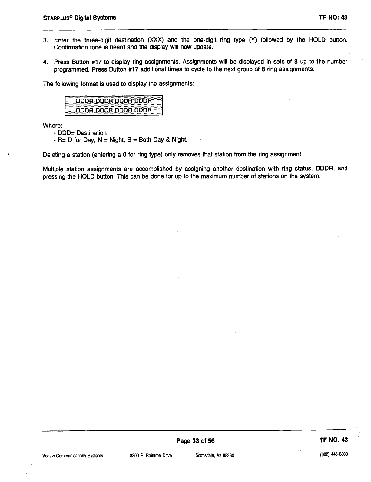
STARPLUS’ Digiil Systems TF NO: 43
3. Enter the three-digit destination (XXX) and the one-digit ring type (Y) followed by the HOLD button,
Confirmation tone is heard and the display will now update.
4. Press Button #17 to display ring assignments. Assignments will be displayed in sets of 8 up to-the number
programmed. Press Button #17 additional times to cycle to the next group of 8 ring assignments.
The following format is used to display the assignments:
Where:
- DDD= Destination
- R= D for Day, N = Night, B = Both Day & Night.
Deleting a station (entering a 0 for ring type) only removes that station from the ring assignment.
Multiple station assignments are accomplished by assigning another destination with ring status, DDDR, and
pressing the HOLD button. This can be done for up to the maximum number of stations on the system.
Vodavi Communications Systems
Page 33 of 56 TF NO. 43
8300 E. Raintree Drive Scottsdale, AZ 85260 (602) 4436ooo
STARPLUS@
Digiil SystemS TF NO: 43
ACD FEATURES (Optional Software)
ACD Group Expansion to 16 Groups/l6 Members (Flash 60, Flash 64)
Guaranteed Message Announcement (Flash 60, Button #Ill)
ACD Event Trace (Flash 63, Buttons 1 & 2)
Vodavi Communications Systems 8300 E. Raintree Drive
Page 34 of 56 TF NO. 43
Scottsdale, AZ 85260

STARPLUS’
Dtgffl Systems TF NO: 43
AUTOMATIC CALL DISTRIBUTION
ACD Group Expensktn - Groups 550-557
Description:
This feature is available with optional software. There can be 16 ACD groups of no more than 16 stations each (up
to the system station maximum). The ACD groups use a pilot hunting technique. If the pilot number is dialed, the
assigned stations in that ACD group are searched for the station which has been in an idle condition for the longest
period of time.
Each ACD Group may have an assigned Alternate ACD Group, an Overflow station and up to 16 stations as ACD
members. The eight system RAN ports (tables) may also be referenced on a per ACD group basis.
The buttons on the digital terminal are defined as shown below when entering the ACD Group(s) programming area:
PrograIl ming:
1. Press FLASH and dial [60]. The following message is shown on the display phone:
:.~,:~~:.<,:‘&ji&
Where:
- XX= ACD Group Number (550557)
- A= Page A Parameters
- AAA= Alternate ACD Group Assignment
- BBB= ACD Overflow Assignment
- CCC= ACD Announcement Tables
- DDD= ACD Supervisor Programming
Vodavi Communications Systems
Page 35 of 56 TF NO. 43
8300 E. Raintrw Drive Scottsdale, AZ 85260
WI
~
STARPLUS”
Digiil Systems TF NO: 43
AUTOMATIC CALL DISTRIBUTION (Cont’d)
2. The top left button in the flexible button field will be lit for programming ACD group 1 (550). To change ACD
groups or enter additional ACD groups (550 to 557) press the appropriate flexible button and perform the
following procedures for ACD Recorded Announcement Assignments (RAN) and Guaranteed Message Timer.
Defautt By default, ACD Group Tables are empty.
Related Programming: Refer to Techfact Notice #31, dated 5/26/93 for programming the ACD Ring Timer, ACD
Message Interval Timer, ACD Overflow Timer, ACD No-Answer Recall Timer, ACD No-Answer Retry Timer; Also
refer to the same Techfact Notice for assigning RAN device ports and message times.
Page 36 of 56 TF NO. 43
Vcdavi Communkations Systems 8300 E. Raintree Drive Scottsdale, AZ 85260 (602) 443-woe
STARPLUS@
Digiil Systems TF NO: 43
AUTOMATIC CALL DISTRIBUTION (Cont’d)
A
ACD Recorded Announcement &sQnment(s) (RAN)
Desaiption:
Optional Recorded Announcement device(s) may be connected to the system to provide an announcement if all
stations in an ACD group are busy; Up to eight ports in the system may be assigned to provide a path to Recorded
Announcement devices.
incoming
CO
Callers will only be answered and rOUt8d to the Overflow assignment if a RAN Table is assigned.
The Guaranteed Message announcement provides a means to force incoming callers to an announcement befOr
being placed into an ACD Queue or routed to an agent. The outside callers are presented with a message before
being routed to the ACD Group. Agents in an ACD Group with
a
Guaranteed Message enabled will receive
incoming callers only after the caller has heard the designated recorded announcement in its entirety, or after the
incoming caller dials up to 14 digits followed by
a
[#] pound. These dialed digits can be inserted as ICLID incoming
number identification.
If th8 Guaranteed Message announcement is programmed in Admin, incoming ACD calls will be routed to the
Guaranteed Message RAN before going to the ACD Group. If the ICLID option is Selected, digits received before
the announcement time-out will be captured and inserted as incoming ICLID number information. When the ICLID
option is selected, a [#] will be recognized as a termination of the announcement and a [*] will be recognized as
an entry error. An entry error will cause the ICLID number to b8 removed and the incoming caller can re-enter his
phOn8 number.
Programming:
To program a Recorded Announcement:
1. Press the ANNOUNCEMENT TBLS flexible button (Button #ll).
2. Enter a three-digit sequence:
- 1st Digit = Guaranteed Message. (forces incoming calls to an announcement before being placed in an ACD
Group or routing to an agent)
- 2nd Digit = RAN port specified for primary message.
- 3rd Digit =RAN port specified for secondary message.
3. If no guaranteed message is desired, press the pound (#) key once as the 1st digit.
EXampl8:
l
an entry of #,2,3 = No Guaranteed Message will be heard. Port 2 will provide
a
primary message and Port
3 will provide
a
secondary message.
l
an entry of 1,2,3 = Port 1 will provide the Guaranteed Message upon initially answering the call. Port 2 Will
Vodavi Communications Systems
Page 37 of 56 TF NO. 43
8300 E. Raintree Drive
Scottsdale, AZ 85260 t3M
443-6m
STARPLUS”
Digiil SystemS TF NO: 43
provide a primary message and Port 3 will provide a secondary message.
l
an entry of 8,1,2 = Port 8 will provide the Guaranteed Message upon initially answering the call. Port 1 will
provide a primary message and Port 2 will provide a secondary message.
4. Press the HOLD button to save the entry. Confirmation tone is heard and the display will now update.
To erase Recorded Announcement(s), press the pound key three times [###I and press HOLD.
COfldii
l
A Guaranteed Message may be specified for each ACD Group.
l
When a caller is routed to a recorded announcement that is programmed as a Guaranteed Message, the caller
will not be pulled from the message if an agent becomes available. The caller will be allowed to listen to the
announcement in its entirety.
l
The RAN timers will control the length of the announcement.
l
A Guaranteed Message timer is used to specify the delay time before the guaranteed message RAN will
answer the incoming call. This timer is defaulted to 5 seconds.
.
Enabling ICLID will permit incoming callers to enter digits during the Guaranteed Message RAN announcement.
If a caller enters digits, the ICLID information received will be replaced with the caller inserted information.
. If a caller enters digits while in the Guaranteed Message announcement, an interdigit time-out is set. This
interdigit time-out defaults to 10 seconds. An entry of a [#] or an interdigit time-out will terminate the Guaranteed
Message announcement and route the call.
.
Incoming ACD calls without ICLID enabled will route to the Guaranteed Message first. From there, they will be
routed to the ACD Group that the call rang into. If the group is busy, the call will be routed per normal routing
procedures.
l
Incoming ACD calls with ICLID enabled are checked against the ICLID route first and routed per the ICLID
number. If a number is not found in the ICLID route table, the call will be sent to the Guaranteed Message first.
If ICLID digits are entered while in the Guaranteed Message, those digits will be compared with the ICLID route
tables. If the digits entered are found, the call will be routed per the ICLID route table. If no match is found, the
call will be routed per the normal ACD routing procedures.
l
Calls will only be routed to the Guaranteed Message one time.
l
Transferred calls will not be routed to a Guaranteed Message.
Related Programming:
Refer to Guaranteed Message timer, Flash 61, Button #7. Refer to Techfact Notice #31,
dated 5/26/93 for further information regarding each RAN Table.
Page 38 of 56
Scottsdale, A2 85260
TF NO. 43
(602) 443-6ooa
Vodati Communications Systems MOO E. Raintree Drive
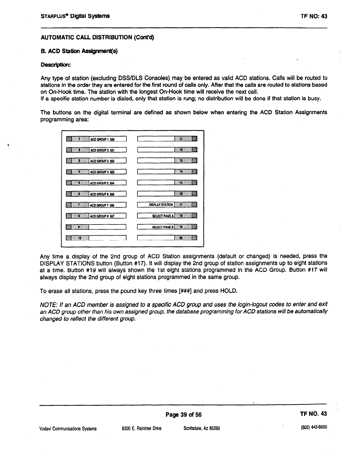
STARPLUS@
Di@tal Systems TF NO: 43
AUTOMATIC CALL DISTRIBUTION (CcWd)
B. ACD Station Ass@menl(s)
Description:
Any type of station (excluding DSWDLS Consoles) may be entered as valid ACD stations. Calls will be routed to
stations in the order they are entered for the first round of calls only. After that the calls are routed to stations based
on On-Hook time. The station with the longest On-Hook time will receive the next call.
If a specific station number is dialed, only that station is rung; no distribution will be done if that station is busy.
The buttons on the digital terminal are defined as shown below when entering the ACD Station Assignments
programming area:
Any time .a display of the 2nd group of ACD Station assignments (default or changed) is needed, press the
DISPLAY STATIONS button (Button #17). It will display the 2nd group of station assignments up to eight stations
at a time. Button #19 will always shown the 1st eight stations programmed in the ACD Group. Button #17 will
always display the 2nd group of eight stations programmed in the same group.
To erase all stations, press the pound key three times [###I and press HOLD.
NOTE: If an AC0 member is assigned to a specific ACD group and uses the login-logout codes to enter and exit
an ACD group other fhan his own assigned group, the database programming for ACD sfations will be automatically
changed to reflect the different group.
Page 39 of 56
Vodavi t%mmunications Systems 8300 E. Raintree Drive Scottsdale, AZ &260
TFN0.43
(602) 4436030
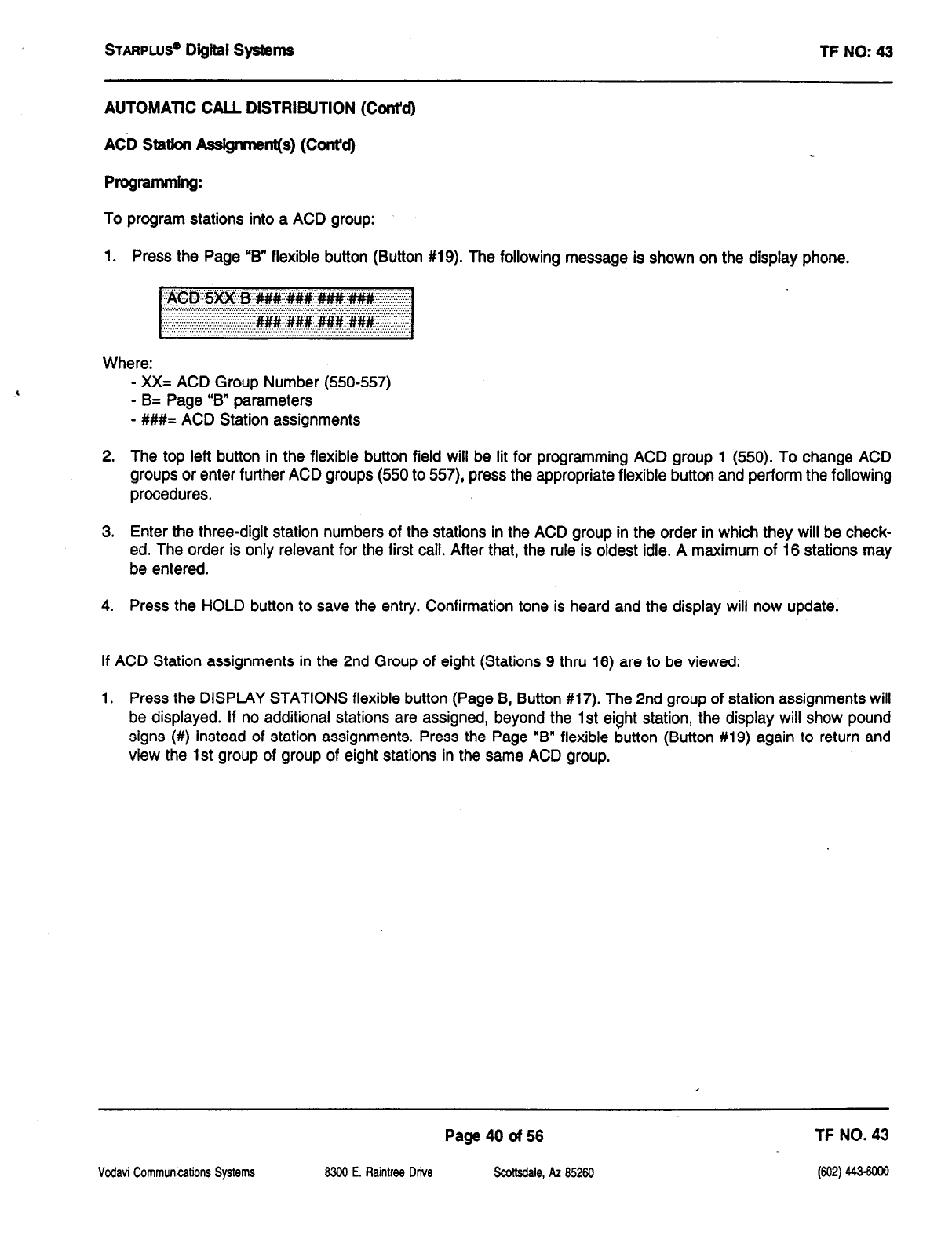
STARPLUS’
Digital Systems TF NO: 43
AUTOMATIC CALL DISTRIBUTION (Cont’d)
ACD Station Assigrmnt(s) (Cont’d)
ProgrammIng:
To program stations into a ACD group:
1. Press the Page ‘B” flexible button (Button #19). The following message is shown on the display phone.
Where:
- XX= ACD Group Number (550-557)
- B= Page “B” parameters
- ###= ACD Station assignments
2. The top left button in the flexible button field will be lit for programming ACD group 1 (550). To change ACD
groups or enter further ACD groups (550 to 557) press the appropriate flexible button and perform the following
procedures.
3. Enter the three-digit station numbers of the stations in the ACD group in the order in which they will be check-
ed. The order is only relevant for the first call. After that, the rule is oldest idle. A maximum of 16 stations may
be entered.
4. Press the HOLD button to save the entry. Confirmation tone is heard and the display will now update.
If ACD Station assignments in the 2nd Group of eight (Stations 9 thru 16) are to be viewed:
1. Press the DISPLAY STATIONS flexible button (Page B, Button #17). The 2nd group of station assignments will
be displayed. If no additional stations are assigned, beyond the 1st eight station, the display will show pound
signs (#) instead of station assignments. Press the Page “B” flexible button (Button #19) again to return and
view the 1st group of group of eight stations in the same ACD group.
Page4Oof56 TF NO. 43
Vodavi G3mmunications Systems 8300 E. Raintree Drive SaAbdale, AZ 85260
(602) 443-6ooo
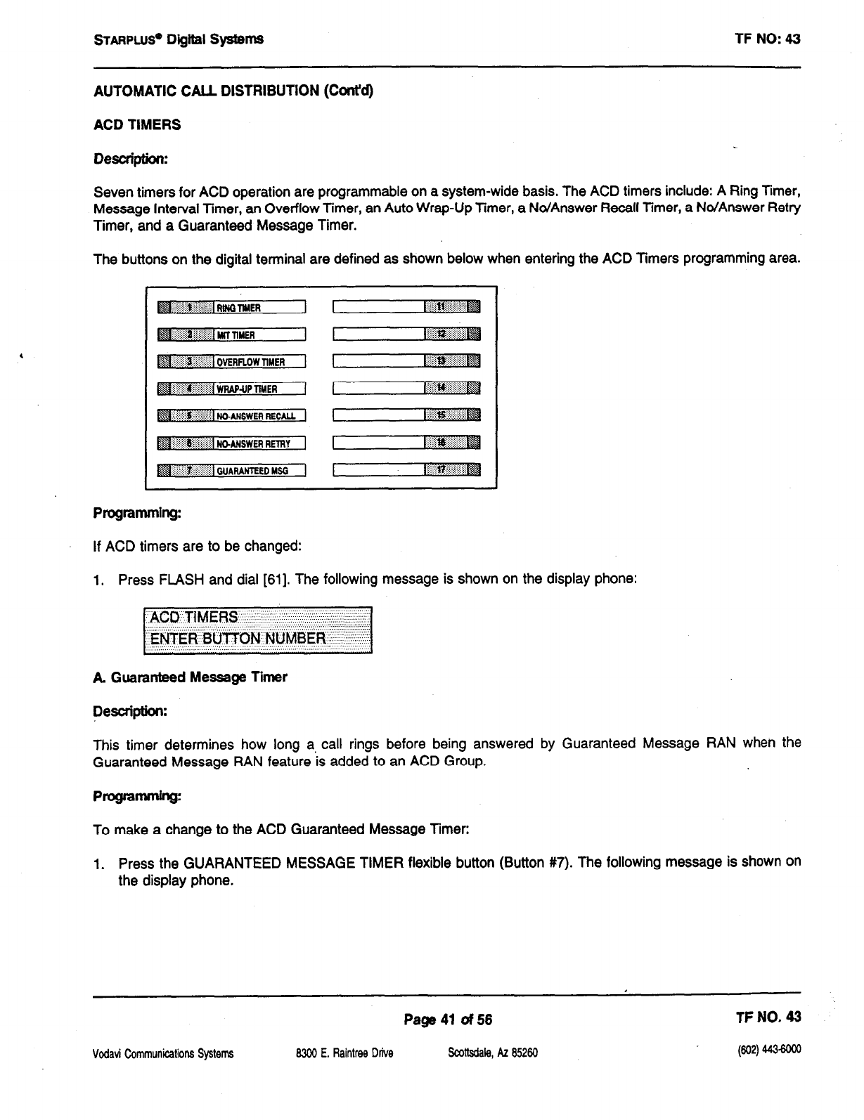
STARPLUS~
Digital Systems
AUTOMATIC CALL DISTRIBUTION (Cont’d)
ACD TIMERS
Desuiption:
TF NO: 43
Seven timers for ACD operation are programmable on a system-wide basis. The ACD timers include: A Ring Timer,
Message Interval Timer, an Overflow Timer, an Auto Wrap-Up Timer, a No/Answer Recall Timer, a No/Answer Retry
Timer, and a Guaranteed Message Timer.
The buttons on the digital terminal are defined as shown below when entering the ACD Timers programming area.
Programming:
If ACD timers are to be changed:
1, Press FLASH and dial [61]. The following message is shown on the display phone:
A Guaranteed Message Timer
Description:
This timer determines how long a call rings before being answered by Guaranteed Message RAN when the
Guaranteed Message RAN feature ‘is added to an ACD Group.
programming:
To make a change to the ACD Guaranteed Message Timer:
1. Press the GUARANTEED MESSAGE TIMER flexible button (Button #7). The following message is shown on
the display phone.
Page 41 of 66 TF NO. 43
Vcdavi Communications Systems 8300 E. Raintrw Drive Scottsdale, AZ 85260 (602) 443-sooO
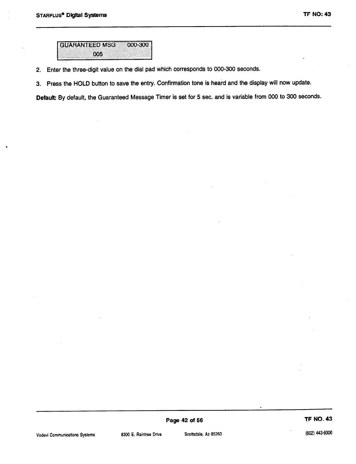
STARPLUS” Digiil Systems TF NO: 43
2. Enter the three-digit value on the dial pad which corresponds to 000-300 seconds.
3. Press the HOLD button to save the entry. Confirmation tone is heard and the display will now update.
Default
By default, the Guaranteed Message Timer is set for 5 sec. and is variable from 000 to 300 s6conds.
Page 42 of 56 TF NO. 43
Vcdavi Communications
Systems
8300 E. Raintree Drive Scottsdale, AZ 85260 (602) 443-6ooo
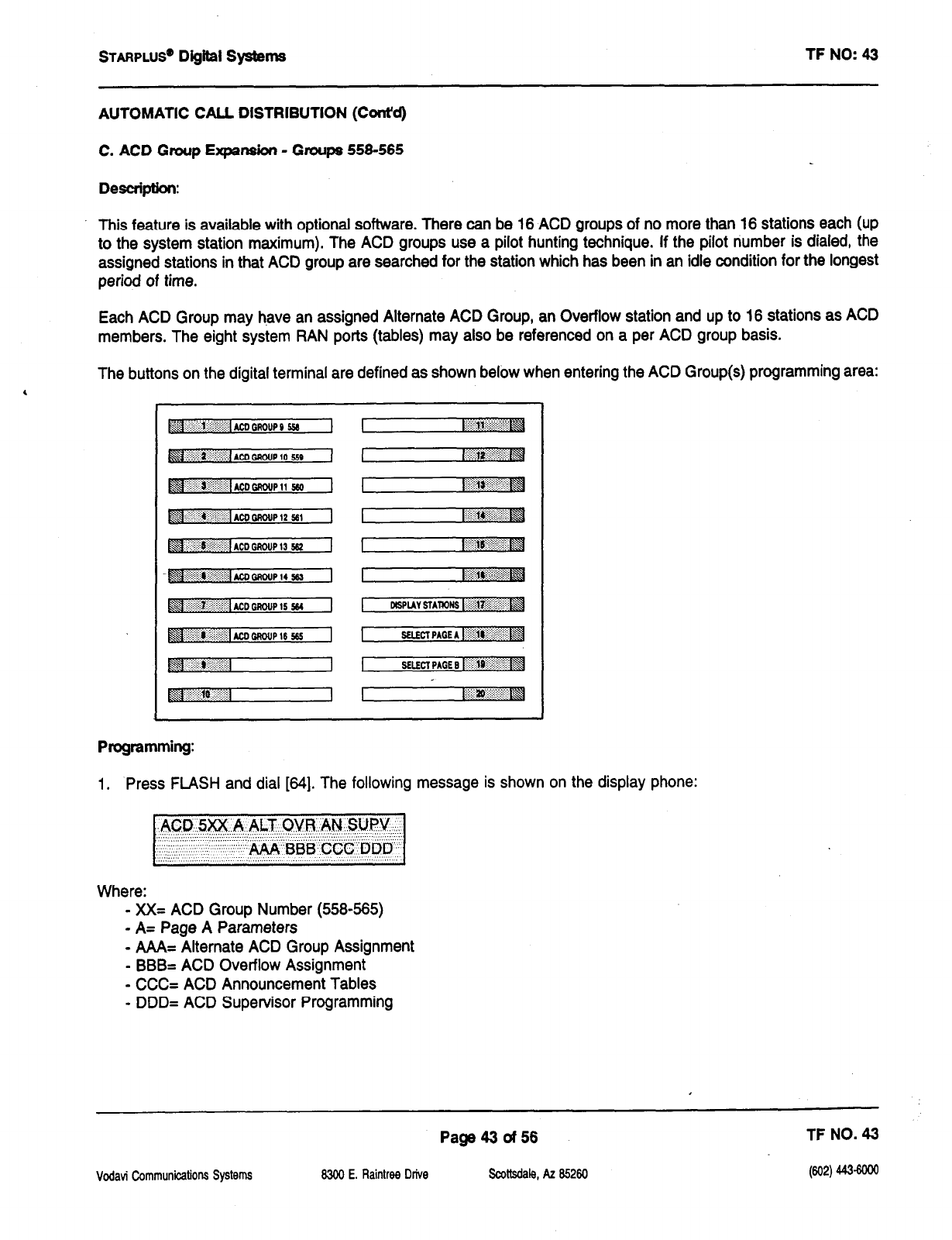
STARPLUS”
Digital Systems TF NO: 43
AUTOMATIC CALL DISTRIBUTION (Cont’d)
C. ACD Group Expansion - Groups 556-565
Description:
This feature is available with optional software. There can be 16 ACD groups of no more than 16 stations each (up
to the system station maximum). The ACD groups use a pilot hunting technique. If the pilot number is dialed, the
assigned stations in that ACD group are searched for the station which has been in an idle condition for the longest
period of time.
Each ACD Group may have an assigned Alternate ACD Group, an Overflow station and up to 16 stations as ACD
members. The eight system RAN ports (tables) may also be referenced on a per ACD group basis.
The buttons on the digital terminal are defined as shown below when entering the ACD Group(s) programming area:
Programming:
1. Press FLASH and dial [84]. The following message is shown on the display phone:
Where:
- xX= ACD Group Number (5584585)
- A= Page A Parameters
- AAA= Alternate ACD Group Assignment
- BBB= ACD Overflow Assignment
- CCC= ACD Announcement Tables
- DDD= ACD Supervisor Programming
Page43of56 TF NO. 43
Vodavi Communications Systems 83W E. Raintree Drive Scottsdale, AZ 85260 (602) 443-woe
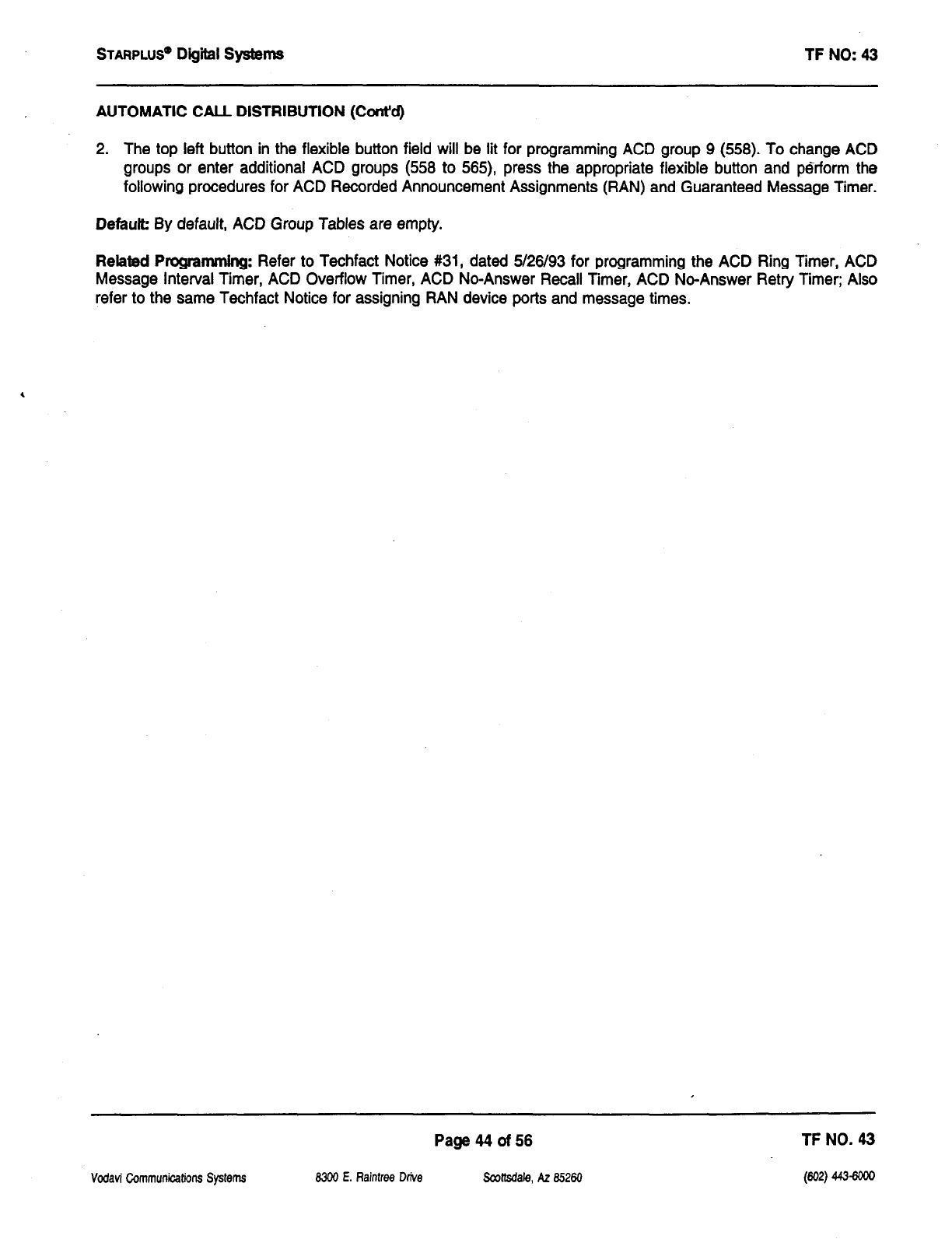
STARPLUS’
Digiil Systems TF NO: 43
AUTOMATIC CALL DISTRIBUTION (Cont’d)
2. The top left button in the flexible button field will be lit for programming ACD group 9 (558). To change ACD
groups or enter additional ACD groups (558 to 565), press the appropriate flexible button and perform the
following procedures for ACD Recorded Announcement Assignments (RAN) and Guaranteed Message Timer.
Defauk By default, ACD Group Tables are empty.
Related Programming: Refer to Techfact Notice #31, dated 5/26/93 for programming the ACD Ring Timer, ACD
Message Interval Timer, ACD Overflow Timer, ACD No-Answer Recall Timer, ACD No-Answer Retry Timer; Also
refer to the same Techfact Notice for assigning RAN device ports and message times.
Vodavi Communicafions Systems
Page44of56 TF NO. 43
8300 E. Raintree Drive Scottsdale, AZ 85260 (602) 443-6ooo

STARPLUS@
Digiil Systems TF NO: 43
AUTOMATIC CALL DISTRIBUTION (Ctid)
B. ACD Station Ass@nment(s)
Description:
Any type of station (excluding DSS/DLS Consoles) may be entered as valid ACD stations. Calls will be routed to
stations in the order they are entered for the first round of calls only. After that the calls are routed to stations based
on On-Hook time. The station with the longest On-Hook time will receive the next call.
If a specific station number is dialed, only that station is rung; no distribution will be done if that station is busy.
The buttons on the digital terminal are defined as shown below when entering the ACD Station Assignments
programming area:
I
Any time a display of the 2nd group of ACD Station assignments (default or changed) is needed, press the
DISPLAY STATIONS button (Button #17). It will display the 2nd group of station assignments up to eight stations
at a time. Button #I 9 will always shown the 1st eight stations programmed in the ACD Group. Button #17 will
always display the 2nd group of eight stations programmed in the same group.
To erase all stations, press the pound key three times [###I and press HOLD.
NOTE: If an ACD member is assigned to a specific ACD group and uses the login-logout codes to enter and exit
an ACD group other than his own assigned group, the database programming for ACD stations will be automatically
changed to reflect the different group.
Vodavi Communications Systems
Page 45 of 56 TF NO. 43
8300 E. Aaintree Drive Scottsdale, AZ 65260
wa
442-6w
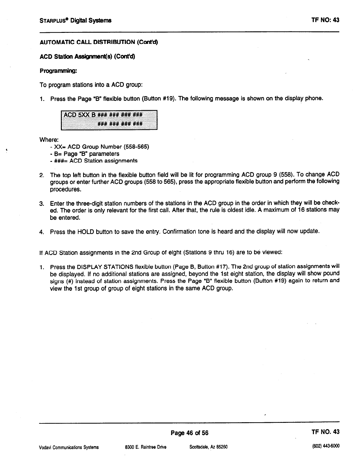
STARPLUS’
Digiil Systems TF NO: 43
AUTOMATIC CALL DISTRIBUTION (Cont’d)
ACD Station
ASS@WIS~~(S)
(C~f~t’d)
Programming:
To program stations into a ACD group:
1. Press the Page ‘B” flexible button (Button #19). The following message is shown on the display phone.
Where:
- XX= ACD Group Number (558-565)
- B= Page ‘B” parameters
- ###= ACD Station assignments
2. The top left button in the flexible button field will be lit for programming ACD group 9 (558). To change ACD
groups or enter further ACD groups (558 to 565), press the appropriate flexible button and perform the following
procedures.
3. Enter the three-digit station numbers of the stations in the ACD group in the order in which they will be check-
ed. The order is only relevant for the first call. After that, the rule is oldest idle. A maximum of 16 stations may
be entered.
4. Press the HOLD button to save the entry. Confirmation tone is heard and the display will now update.
If ACD Station assignments in the 2nd Group of eight (Stations 9 thru 16) are to be viewed:
1. Press the DISPLAY STATIONS flexible button (Page B, Button #17). The 2nd group of station assignments will
be displayed. If no additional stations are assigned, beyond the 1st eight station, the display will show pound
signs (#) instead of station assignments. Press the Page “B” flexible button (Button #19) again to return and
view the 1st group of group of eight stations in the same ACD group.
Vodavi Communications Systems
Page 46 of 56 TF NO. 43
8300 E. Raintrw Drive Scottsdale, AZ 65260
Pw 443-6ow
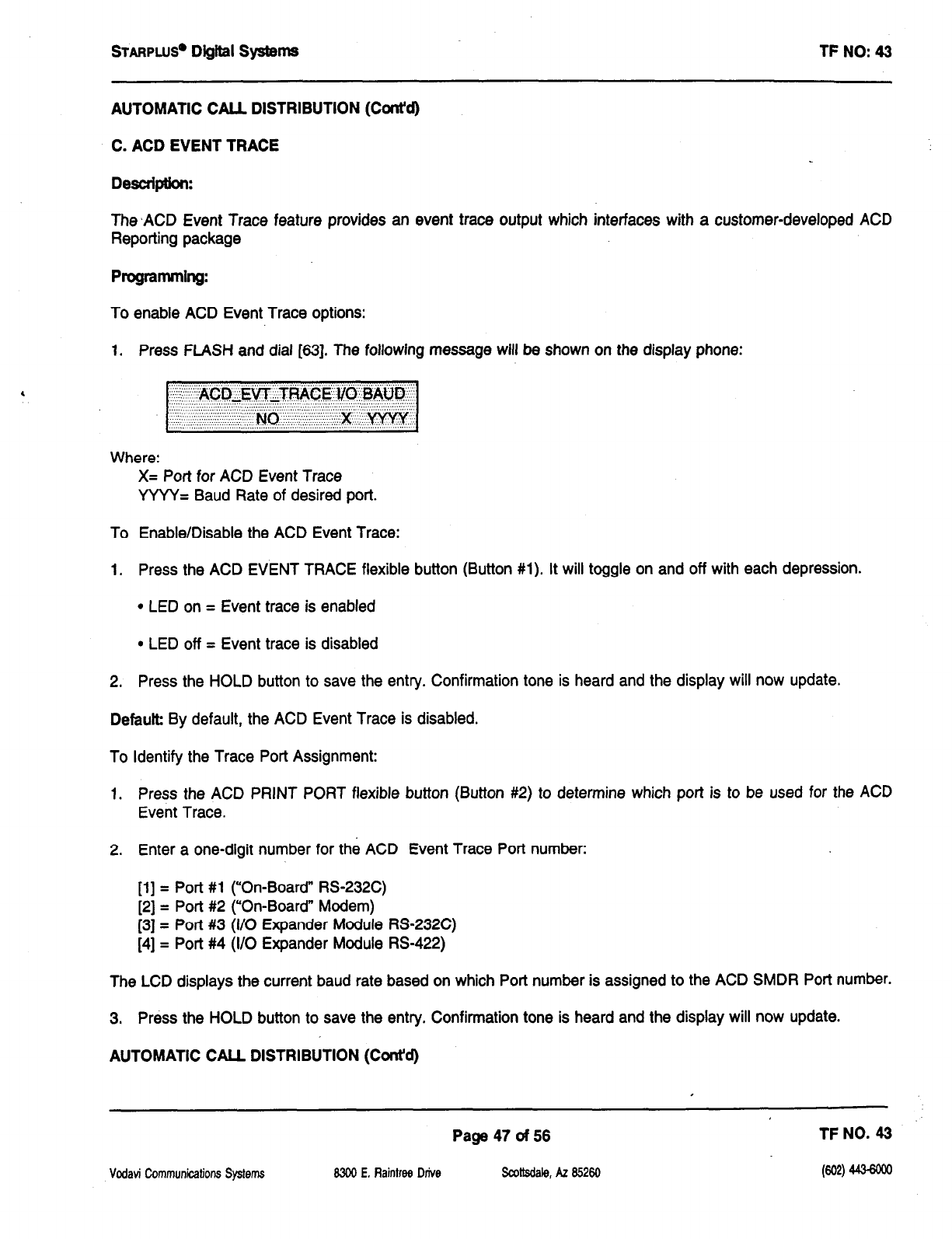
sTARPLus* Digital systems
TF NO: 43
AUTOMATIC CALL DISTRIBUTION (Cont’d)
C. ACD EVENT TRACE
Desuiptkm:
The ,ACD Event Trace feature provides an event trace output which interfaces with a customer-developed ACD
Reporting package
Pmgrmming:
To enable ACD Event Trace options:
1. Press FLASH and dial [63]. The following message will be shown on the display phone:
Where:
X= Port for ACD Event Trace
YYYY= Baud Rate of desired port.
To Enable/Disable the ACD Event Trace:
1. Press the ACD EVENT TRACE flexible button (Button #I). It will toggle on and off with each depression.
l
LED on = Event trace is enabled
l
LED off = Event trace is disabled
2. Press the HOLD button to save the entry. Confirmation tone is heard and the display will now update.
Defautb By default, the ACD Event Trace is disabled.
To Identify the Trace Port Assignment:
1. Press the ACD PRINT PORT flexible button (Button #2) to determine which port is to be used for the ACD
Event Trace.
2. Enter a one-digit number for the ACD Event Trace Port number:
[l] = Port #l (“On-Board” RS-232C)
[2] = Port #2 (“On-Board” Modem)
[3] = Port #3 (I/O Expander Module RS-232C)
[4] = Port #4 (I/O Expander Module RS-422)
The LCD displays the current baud rate based on which Port number is assigned to the ACD SMDR Port number.
3. Press the HOLD button to save the entry. Confirmation tone is heard and the display will now update.
AUTOMATIC CALL DISTRIBUTION (Cmt’d)
Vodati Communications Systems
Page 47 of 56 TF NO. 43
8300 E. Raintrw Dtive
.wtsdale, AZ 85260 Pa 443-6oM

STARPLuS* Digiil SptEms
I-F NO: 43
ACD EVENT TRACE (Cont’d)
To determine the Baud Rate:
The ACD Port Baud Rate is programmed using Flash 15 Baud Rate Assignments. The LCD displays the current
baud rate based on which Port number is assigned to the ACD SMDR Port number.
Vcdavi Communications Systems
Page46of56 TF NO. 43
8300 E. Raintree Drive Scottsdale, AZ 85260
Pm
443-6m
STARPLUS@ Digital Systems TF NO: 43
UCD FEATURES
UCD Station Assignments
Vodavi Communications Systems
Page 49 of 56
6309 E. Raintree Drive !Scottsdaie, AZ 85260
TF NO. 43
Pw
443-6m
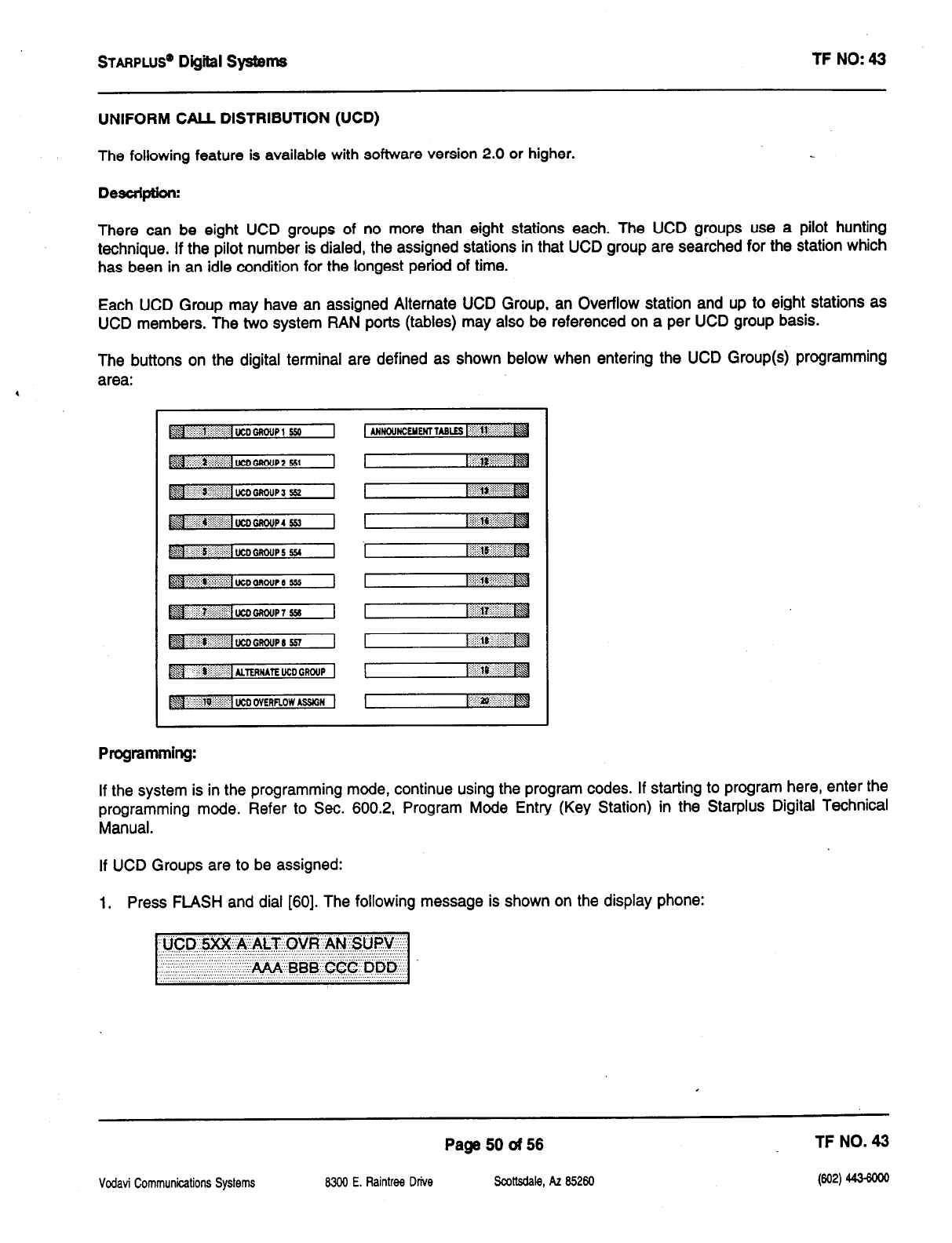
sTARPLUS@
Digiil Systems TF NO: 43
UNIFORM CALL DISTRIBUTION (UCD)
The following feature is available with software version 2.0 or higher.
Description:
There can be eight UCD groups of no more than eight stations each. The UCD groups use a pilot hunting
technique. If the pilot number is dialed, the assigned stations in that UCD group are searched for the station which
has been in an idle condition for the longest period of time.
Each UCD Group may have an assigned Alternate UCD Group, an Overflow station and up to eight stations as
UCD members. The two system RAN ports (tables) may also be referenced on a per UCD group basis.
The buttons on the digital terminal are defined as shown below when entering the UCD Group(s) programming
area:
If the system is in the programming mode, continue using the program codes. If starting to program here, enter the
programming mode. Refer to Sec. 600.2, Program Mode Entry (Key Station) in the Starplus Digital Technical
Manual.
If UCD Groups are to be assigned:
1. Press FLASH and dial [60]. The following message is shown on the display phone:
Vodati Communications Systems
Page 50 of 56 TF NO. 43
8300 E. Raintree Drive
Scottsdale, AZ 85260 W) 4434ooo
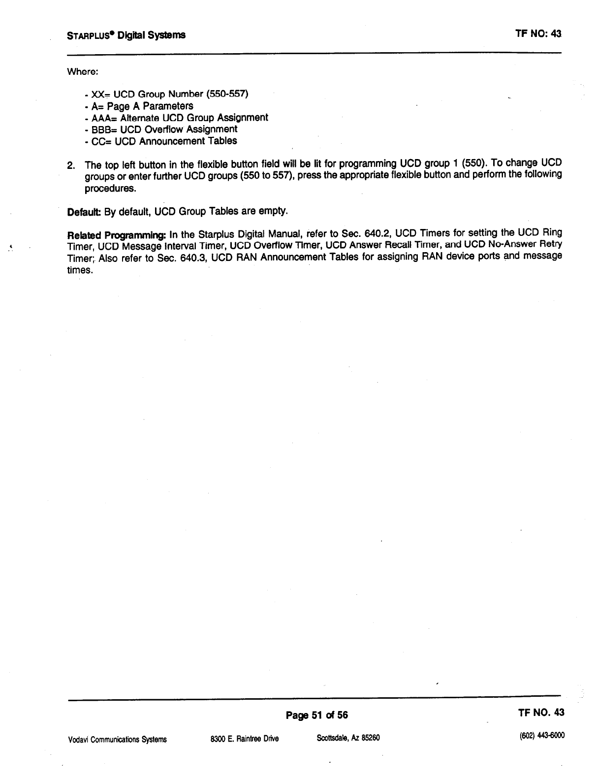
STARPLUS@
Digttl Systems TF NO: 43
Where:
- xX= UCD Group Number (550-557)
- A= Page A Parameters
- AAA= Alternate UCD Group Assignment
- BBB= UCD Overflow Assignment
- CC= UCD Announcement Tables
2. The top left button in the flexible button field will be lit for programming UCD group 1 (550). To change UCD
groups or enter further UCD groups (550 to 557) press the appropriate flexible button and perform the following
procedures.
Defauk By default, UCD Group Tables are empty.
Rebted Programming: In the Starplus Digital Manual, refer to Sec. 640.2, UCD Timers for setting the UCD Ring
Timer, UCD Message Interval Timer, UCD Overflow Timer, UCD Answer Recall Timer, and UCD No-Answer Retry
Timer;. Also refer to Sec. 640.3, UCD RAN Announcement Tables for assigning RAN device ports and message
times.
Vodavi Communications Systems
Page 51 of 56 TF NO. 43
8300 E. Raintrw Drive .scottadale, AZ a5260 wa 443-6ow
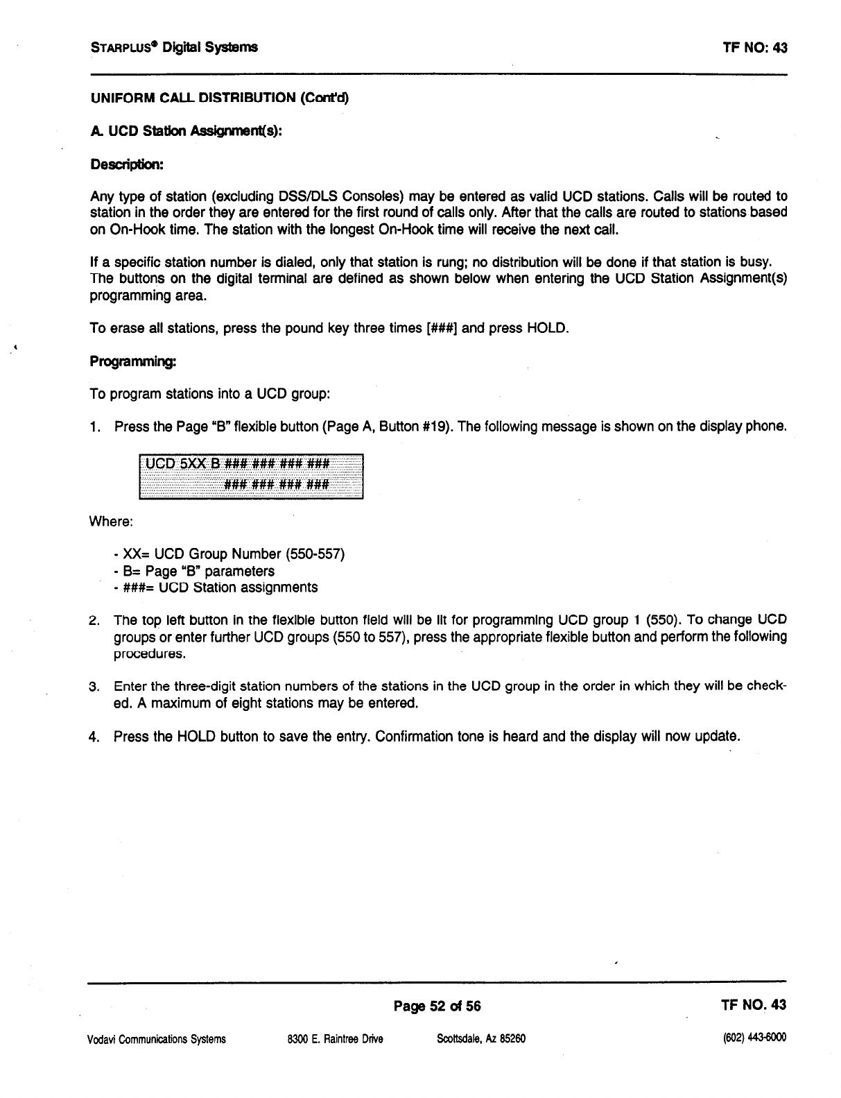
STARPWS’
Digital Systems TF NO: 43
UNIFORM CALL DISTRIBUTION (Cont’d)
A
UCD Ststbn A@nment(s):
Desuipthn:
Any type of station (excluding DSS/DLS Consoles) may be entered as valid UCD stations. Calls will be routed to
station in the order they are entered for the first round of calls only. After that the calls are routed to stations based
on On-Hook time. The station with the longest On-Hook time will receive the next call.
If a specific station number is dialed, only that station is rung: no distribution will be done if that station is busy.
The buttons on the digital terminal are defined as shown below when entering the UCD Station Assignment(s)
programming area.
To erase all stations, press the pound key three times [###I] and press HOLD.
Progrsmmirg:
To program stations into a UCD group:
1. Press the Page “B” flexible button (Page A, Button #19). The following message is shown on the display phone.
Where:
- XX= UCD Group Number (550557)
- B= Page “6” parameters
- ##I#= UCD Station assignments
2. The top left button in the flexible button field will be lit for programming UCD group 1 (550). To change UCD
groups or enter further UCD groups (550 to 557), press the appropriate flexible button and perform the following
procedures.
3. Enter the three-digit station numbers of the stations in the UCD group in the order in which they will be check-
ed. A maximum of eight stations may be entered.
4. Press the HOLD button to save the entry. Confirmation tone is heard and the display will now update.
Vodati Communications Systems
Page 52 of 56 TF NO. 43
8300 E. Raintrw Drive Scottsdale, AZ 85260
W2) 4436oGu
STARPLUS@
Digital Systems TF NO: 43
VOICE MAIL (Optional Software)
Enhanced Voice Mail Integration
Page 53 of 56 TF NO. 43
Vcdavi Communications Systems 8300 E. Raintree Drive sootkdale, AZ 85260
w4
443-6m

STARPLUS”
Digital Systems TF NO: 43
VOICE MAfL GROUPS
Enhanced Voice Mail lntegratiofl
Description:
To better accommodate Voice Mail systems, a Busy/No-Answer feature has been added to the system software.
This feature provides a busy or no/answer message from the voice mail system when a device is fonnrarded to voice
mail via a keyset or single line which has a busy, no-answer or a busy/no-answer forward to voice mail. This is
accomplished via additional leave table entries per voice mail group. These tables control what “in-band” information
is sent to the voice mail system under a busy or no-answer condition.
An externally provided Voice Mail system or Auto Attendant must be connected to the Starplus Digital Key
Telephone System for Voice Mail or Auto Attendant operation. Voice Mail automatically handles unanswered calls.
Station users can then retrieve messages left at their stations. Auto Attendants can handle incoming calls and route
callers to station users without intervention from the systems attendant.
Direct incoming ring to Voice Mail/Auto Attendant groups can be done directly through CO Line Ringing
Assignments.
The buttons on the digital terminal are defined as shown below when entering the Voice Mail programming area:
NOTE: By default, all Voice Mail stations are placed into Pickup Group 7. You may need to change the default
setting.
operation:
If a user forwards his extension busy, no-answer, or busy/no-answer to voice mail and a call rings at the busy
extension, the call will be forwarded to voice mail with the digits programmed in the busy leave table. With the
additional digits, the voice mail system can provide a busy greeting to the caller. If a call rings at the user extension
and he does not answer, the call will be forwarded to voice mail with the digits programmed in the No-Answer leave
table. With the additional digits, the voice mail system can provide a no-answer greeting to the caller.
In addition, to support voice mail systems that do not have supervised transfer, a recall from a station that was
transferred from a voice mail port will recall to the attendant.
Page54of56 TF NO. 43
Vodavi Communications Systems 6300 E. Raintree Drive Scottsdale, AZ 85260
kw
443-6m
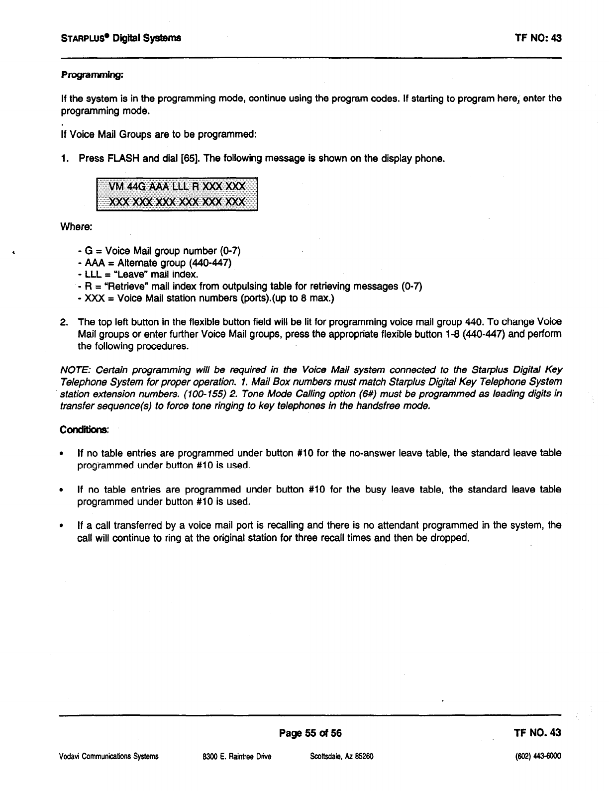
STARPLW
Digital S@ms TF NO: 43
PKgramm@:
If the system is in the programming mode, continue using the program codes. If starting to program herei enter the
programming mode.
If Voice Mail Groups are to be programmed:
1. Press FLASH and dial [8!5]. The following message is shown on the display phone.
Where:
- G = Voice Mail group number (O-7)
- AAA = Alternate group (440447)
- LLL = “Leave” mail index.
-R= “Retrieve” mail index from outpulsing table for retrieving messages (O-7)
- XXX = Voice Mail station numbers (ports).(up to 8 max.)
2. The top left button in the flexible button field will be lit for programming voice mail group 440. To change Voice
Mail groups or enter further Voice Mail groups, press the appropriate flexible button i-8 (440447) and perform
the following procedures.
NOTE: Certain programming will be required in the Voice Mail system connected to the Starplus Digital Key
Telephone System for proper operation. 1. Mail Box numbers must match Statplus Digital Key Telephone System
station extension numbers. (100-155) 2. Tone Mode Calling option (6#) must be programmed as leading digits in
transfer sequence(s) to force tone ringing to key telephones in the handsfree mode.
.
If no table entries are programmed under button #lO for the no-answer leave table, the standard leave table
programmed under button #lO is used.
l
If no table entries are programmed under button #lO for the busy leave table, the standard leave table
programmed under button #lO is used.
.
If a call transferred by a voice mail port is recalling and there is no attendant programmed in the system, the
call will continue to ring at the original station for three recall times and then be dropped.
Vcdati Communications Systems
Page 55 of 56 TF NO. 43
6300 E. Raintree Drive
scolisdale, AZ 85260
(@m
443-6ow
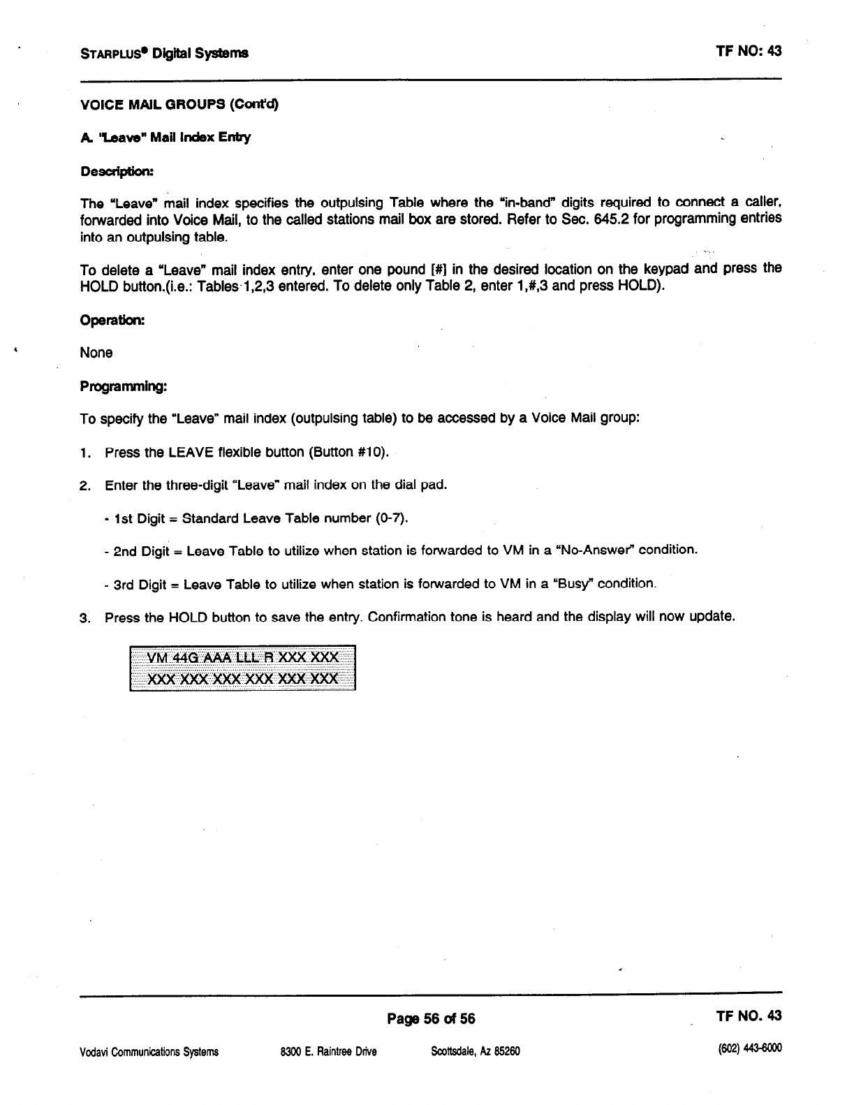
STAFIPLUS~
Digital Systems TF NO: 43
VOICE MAIL GROUPS (Cont’d)
A
Uave” Mall Index Entry
Desaiptbm
The “Leave” mail index specifies the outpulsing Table where the ‘in-band” digits required to connect a caller,
forwarded into Voice Mall, to the called stations mail box are stored. Refer to Sec. 645.2 for programming entries
into an outpulsing table. .._
To delete a ‘Leave” mail index entry, enter one pound [#] in the desired location on the keypad and press the
HOLD button.(i.e.: Tables-l ,2,3 entered. To delete only Table 2, enter 1,#,3 and press HOLD).
OpeIMOIX
None
Programming:
To specify the “Leave” mail index (outpulsing table) to be accessed by a Voice Mail group:
1. Press the LEAVE flexible button (Button #lo).
2. Enter the three-digit “Leave” mail index on the dial pad.
- 1st Digit = Standard Leave Table number (O-7).
- 2nd Digit = Leave Table to utilize when station is forwarded to VM in a “No-Answer” condition.
- 3rd Digit = Leave Table to utilize when station is forwarded to VM in a “Busy” condition.
3. Press the HOLD button to save the entry. Confirmation tone is heard and the display will now update.
Vodavi Communicalions Systems
Page 56 d 56 TF NO. 43
8300 E. Raintree Drive
swttedaie, AZ 85260 (@a 443-6m
TECHNICAL FACT NOTICE
Starplus Dlgltal Systems
-TF NO: 33
2/l/93
2x4 SLT Expander Module
Description:
The 2x4 SLT Expander Module is a two CO by four single line telephone Interface module that plugs onto the main
key service board of the Basic KSU or the main key service board of the Expansion KSU through the use of two
ribbon cables. This module is a combination board that contains the necessary circuitry to connect two
CO/Centrex/PBX loop start lines and four single line telephones to the system. This card also contains a connector
for adding one application module (i.e. DTMF Receiver) to the system.
Message Waiting capability comes installed on the 2x4 SLT Expander Module. This circuitry provides message
waiting voltage to single line telephones equipped with message waiting lamps, and supports up to four single line
telephones message waiting lamps at 9OV dc typically across tip and ring.
LEDs & Indicators: Two green LEDs indicate the presence of +5V & -5V dc. An extinguished LED indicates the
absence of the associated voltage.
CO Llne/Statlon Interfaces: The 2x4 SLT Expander Module provides the interface for two Central Office, Centrex
or PBX loop start, lines. The protection circuitry necessary to allow the system to be classified as a fully protected
system are located on the card for each CO circuit. The CO circuits are equipped with current sensing circuitry that
identifies distant end disconnect (loop supervision). The module design also provides proper fusing or protection
to comply with the requirements of UL 1459 Second Edition and CSA C22.2 No. 225 standards. CO lines are
connected to the system via RJ-11 modular connectors mounted on the bottom edge of the board.
The 2x4 SLT Expander module also provides the interface for four standard on-premise single line telephones
(2500 type). Four 36V dc single line circuits are provided on the printed circuit board. These single line telephones
can be equipped with a standard message waiting lamp (9OV T&R) that operate on the “tip” and “ring” leads.
Additionally, each circuit may be individually optioned (software controlled) to provide a loop interrupt
to the
connected SLT or device. The card will support single line telephones up to 2000 feet from the Basic KSU.
On-premise single line telephones should present a load to the port totaling a maximum ringer equivalence of 2.5.
A molex connector (J4) is located on the 2x4 SLT Expander Module to provide ring generator capabilities. It is
recommended that the Tellabs 8101, 30 Hz, SOVAC Ring Generator be used with this board.
Vodavi Communications Systems
Page1 of 11
6300 E.
Raintree Drive Scottsdale, AZ 85260
TF NO. 33
(602) 443-6000
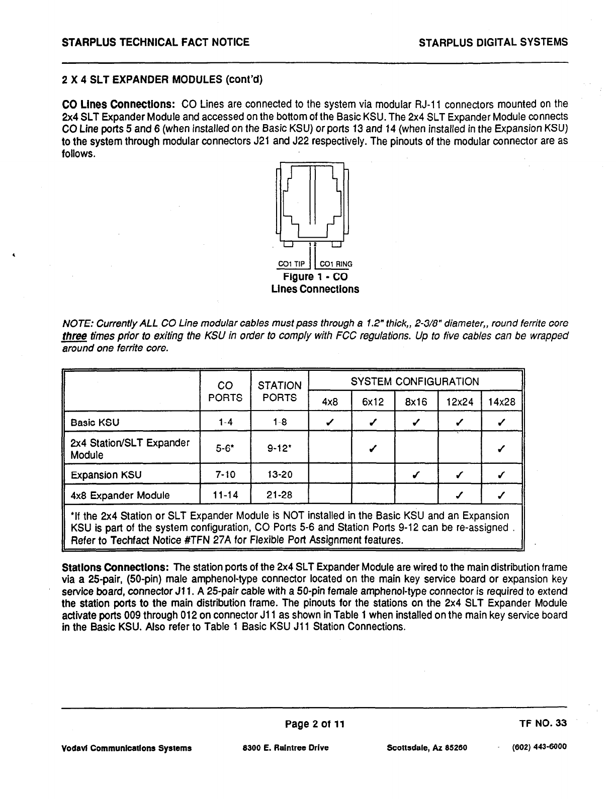
STARPLUS TECHNICAL FACT NOTICE
STARPLUS DIGITAL
SYSTEMS
2 X 4 SLT EXPANDER MODULES (cont’d)
CO Lines Connections:
CO Lines are connected to the system via modular RJ-11 connectors mounted on the
2x4 SLT Expander Module and accessed on the bottom of the Basic KSU. The 2x4 SLT Expander Module connects
CO Line ports 5 and 6 (when installed on the Basic KSU) or ports 13 and 74 (when installed in the Expansion KSU)
to the system through modular connectors J21 and J22 respectively. The pinouts of the modular connector are as
follows.
CO1 TIP 1 1 CO1 RING
Figure 1 - CO
Lines Connectlons
NOTE: Currently ALL CO Line modular cables must pass through a 1.2” thick,, 2-3/a” diameter,, round ferrite core
fhree times prior to exiting the KSU in order to comply with FCC regulations. Up to five cables can be wrapped
Gd one ferrite core.
*If the 2x4 Station or SLT Expander Module is NOT installed in the Basic KSU and an Expansion
KSU is part of the system configuration, CO Ports 5-6 and Station Ports 9-12 can be re-assigned
Refer to Techfact Notice #TFN 27A for Flexible Port Assignment features.
Statlons Connectlons:
The station ports of the 2x4 SLT Expander Module are wired to the main distribution frame
via a 25pair, (50-pin) male amphenol-type connector located on the main key service board or expansion key
service board, connector Jl 1. A 25-pair cable with a 50-pin female amphenol-type connector is required to extend
the station ports to the main distribution frame. The pinouts for the stations on the 2x4 SLT Expander Module
activate ports 009 through 012 on connector Jl 1 as shown in Table 1 when installed on the main key service board
in the Basic KSU. Also refer to Table 1 Basic KSU Jl 1 Station Connections.
Page 2 of 11 TF NO. 33
Vodavi Communications Systems 8300 E. Raintree Drive Scottsdale, AZ 65260 (602) 443-6000
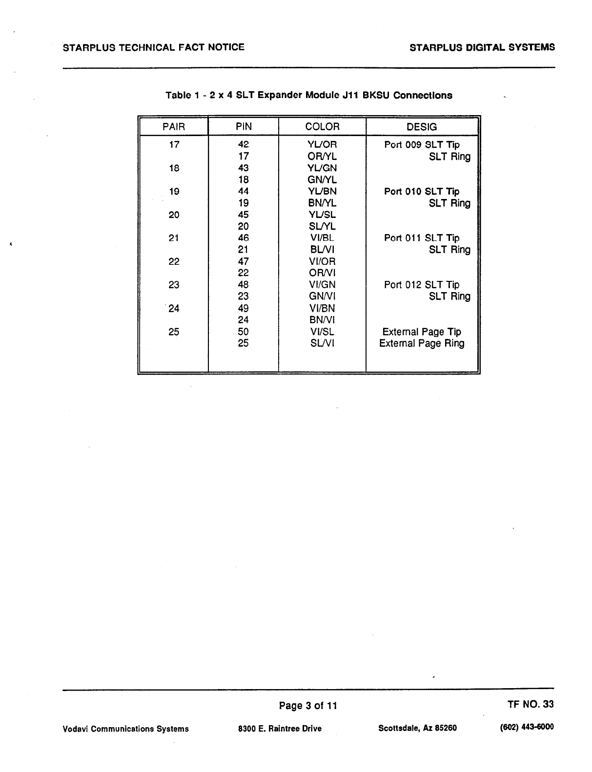
STARPLUS TECHNICAL FACT NOTICE STARPLUS DIGITAL SYSTEMS
Table 1 - 2 x 4 SLT Expander Module Jll BKSU Connections
PAIR
17
18
19
20
21
22
23
.24
25
PIN COLOR
42 YUOR
17 OFvfL
43 YIJGN
18 GNNL
44 YUBN
19 BNNL
45 YUSL
20 SINL
46 VI/BL
21 BWI
47 VI/OR
22 OFVVI
48 VI/GN
23 GNNI
49 VI/BN
24 BNNI
50 VIISL
25 SWI
DESIG
Port 009 SLT Tip
SLT Ring
Port 010 SLT Tip
SLT Ring
Port 011 SLT Tip
SLT Ring
Port 012 SLT Tip
SLT Ring
External Page Tip
External Page Ring
Page3of 11 TF NO. 33
Vodavi Communications Systems 8300 E. Raintree Drive Scottsdale, AZ 86260 (602) 443-6000
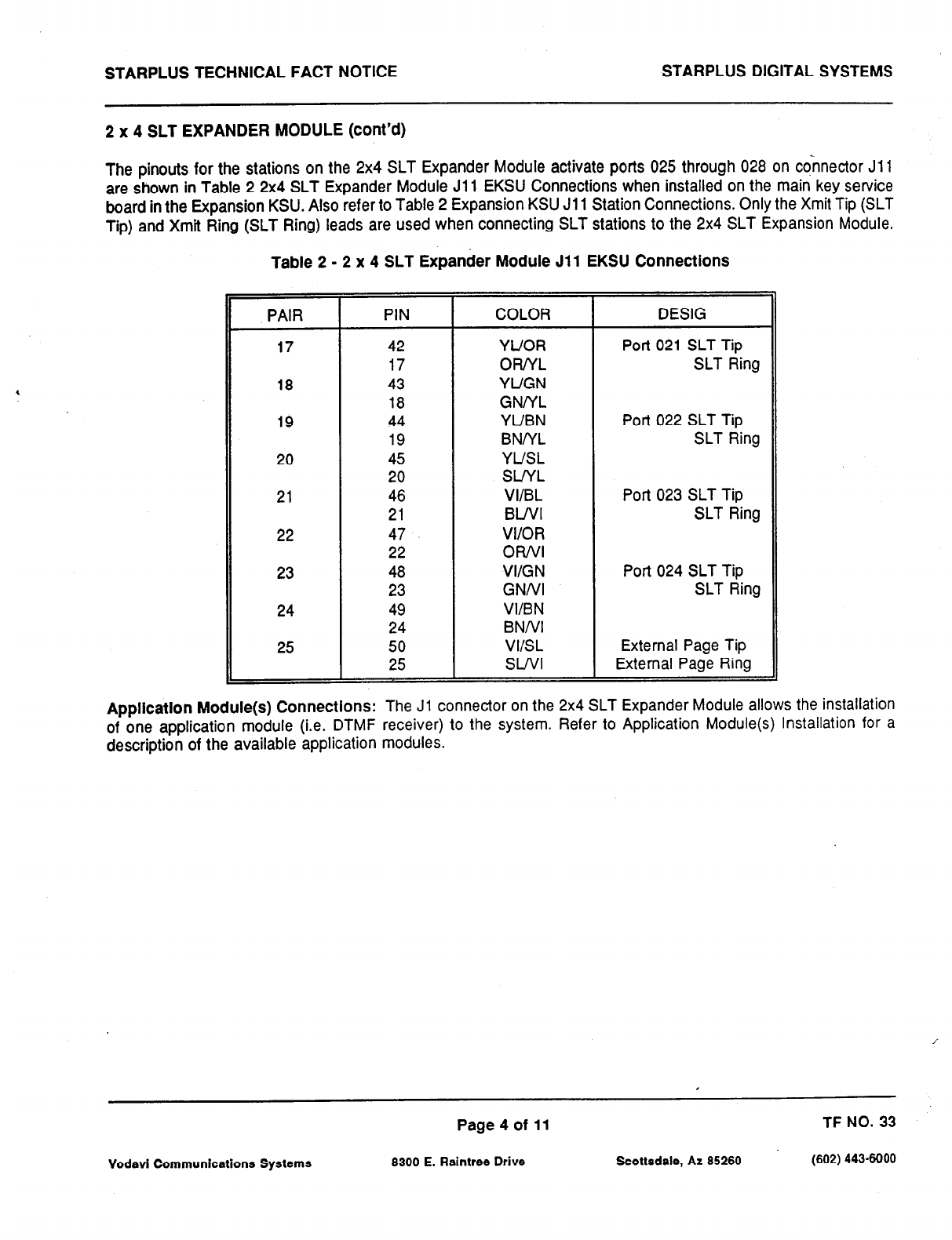
STARPLUS TECHNICAL FACT NOTICE STARPLUS DIGITAL SYSTEMS
2 x 4 SLT EXPANDER MODULE (cont’d)
The pinouts for the stations on the 2x4 SLT Expander Module activate ports 025 through 028 on connector Jl 1
are shown in Table 2 2x4 SLT Expander Module Jl 1 EKSU Connections when installed on the main key service
board in the Expansion KSU. Also refer to Table 2 Expansion KSU Jll Station Connections. Only the Xmit Tip (SLT
Tip) and Xmit Ring (SLT Ring) leads are used when connecting SLT stations to the 2x4 SLT Expansion Module.
Table 2 - 2 x 4 SLT Expander Module Jll EKSU Connections
PAIR I PIN I COLOR I DESIG
17
18
19
20
21
22
23
24
25
42
17
43
18
44
19
45
20
46
21
47
22
48
23
49
24
50
25
YUOR
OR/YL
YUGN
GNNL
YUBN
BNNL
YUSL
SlNL
VIn3L
BWI
O&l
VI/GN
GNNI
VI/BN
BNNI
VIISL
SWI
Port 021 SLT Tip
SLT Ring
Port 022 SLT Tip
SLT Ring
Port 023 SLT Tip
SLT Ring
Port 024 SLT Tip
SLT Ring
External Page Tip
External Page Ring
Appllcatlon Module(s) Connections: The Ji connector on the 2x4 SLT Expander Module allows the installation
of one application module (i.e. DTMF receiver) to the system. Refer to Application Module(s) Installation for a
description of the available application modules.
Vodavi Communications Systems
Page4of 11
8300 E. Raintree Drive Scottsdale, AZ 85260
TF NO. 33
(602) 443-6000
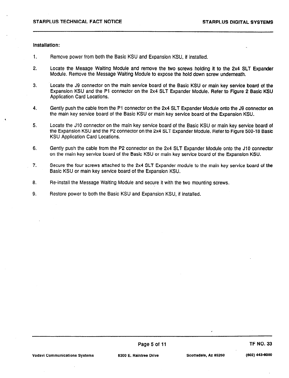
STARPLUS TECHNICAL FACT NOTICE STARPLUS DIGITAL SYSTEMS
Installation:
1.
2.
Remove power from both the Basic KSU and Expansion KSU, if installed.
Locate the Meaage Waiting Module and remove the two screws holding it to the 2x4 SLT Expander
Module. Remove the Message Wafting Module to expose the hold down screw underneath.
3. Locate the J9 connector on the main service board of the Basic KSU or main key service board of the
Expansion KSU and the Pl connector on the 2x4 SLT Expander Module. Refer to Figure 2 Basic KSU
Application Card Locations.
4. Gently push the cable from the Pl connector on the 2x4 SLT Expander Module onto the J9 connector on
the main key service board of the Basic KSU or main key service board of the Expansion KSU.
5. Locate the JlO connector on the main key service board of the Basic KSU or main key service board of
the Expansion KSU and the P2 connector on the 2x4 SLT Expander Module. Refer to Figure 500-18 Basic
KSU Application Card Locations.
6. Gently push the cable from the P2 connector on the 2x4 SLT Expander Module onto the JlO connector
on the main key service board of the Basic KSU or main key service board of the Expansion KSU.
7. Secure the four screws attached to the 2x4 SLT Expander module to the main key service board of the
Basic KSU or main key service board of the Expansion KSU.
8. Re-install the Message Waiting Module and secure it with the two mounting screws.
9. Restore power to both the Basic KSU and Expansion KSU, if installed.
Page5of 11 TF NO. 33
Vodavi Communications Systems 8300 E. Raintree Drive Scottsdale, AZ 85260 (602) 443-6000
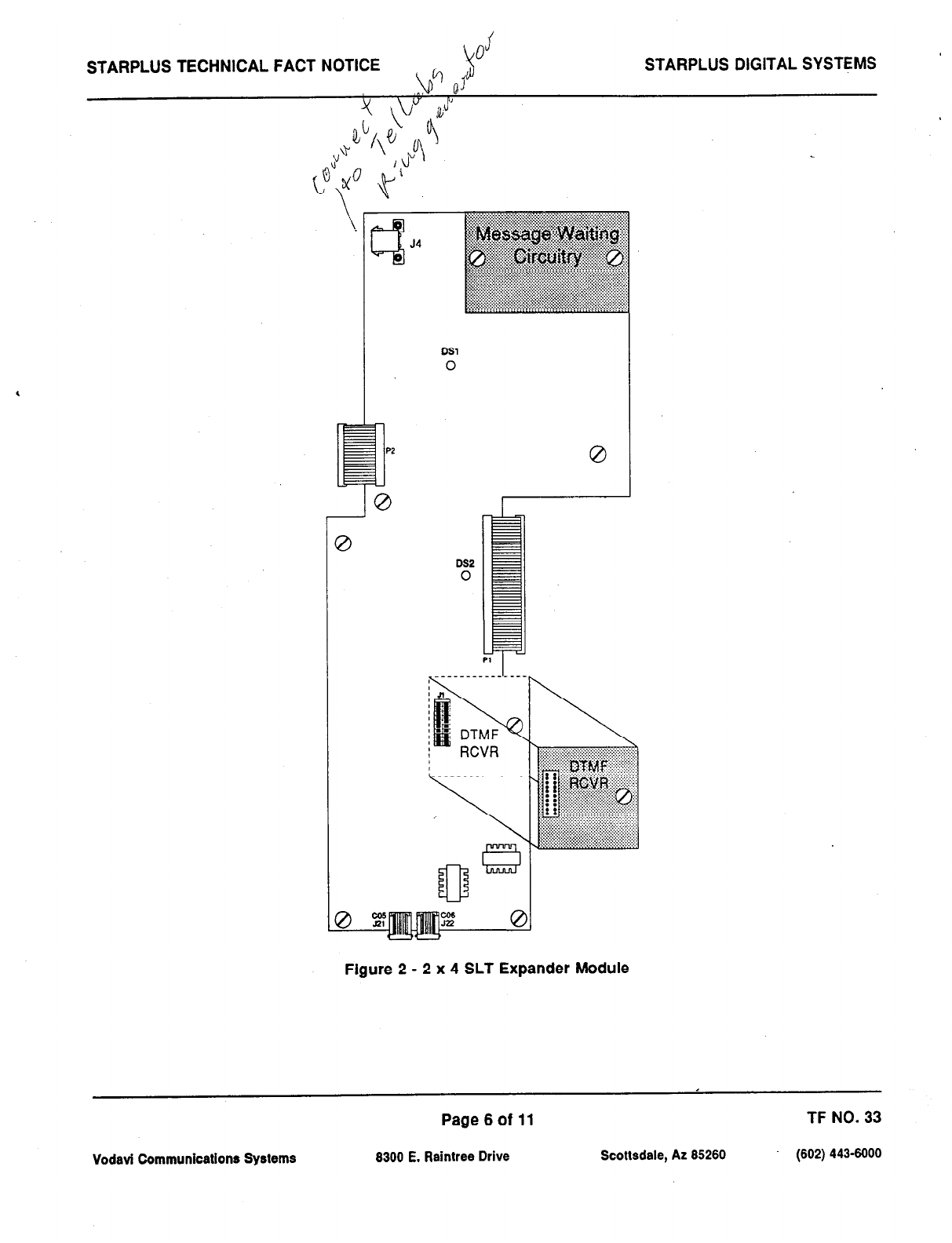
J
’
STARPLUS TECHNICAL FACT NOTICE STARPLUS DIGITAL SYSTEMS
DSI
0
DS2
0
0 1
Pl
_ _ _ _ _ _ - - - _ -
Figure 2 - 2 x 4 SLT Expander Module
Page6of 11 TF NO. 33
Vodavi Communications Systems 8300 E. Raintree Drive Scottsdale, AZ 85260 (602) 443-6000

STARPLUS TECHNICAL FACT NOTICE STARPLUS DIGITAL SYSTEMS
4x8 SLT Interface Board (CSB)
Description:
The 4x8 SLT Interface Board (CSB) is a four CO Line by eight single line telephone interface board. The card is
a combination card that contains the necessary circuitry to connect four CO/Centrex/PBX loop start lines and eight
standard on-premise single line telephones (2500 type) to the system. This card also contains one additional voice
(transmit) path for external paging and a connector for adding one application module (i.e. DTMF Receiver or Dual
DTMF/Taik-Back Page Module) to the system. The 4x8 SLT interface Board can be removed or inserted with power
on the KSU. Refer to Figure 5 Basic KSU Equipment Cabinet for component layout and location of connectors.
A moiex connector is located on the 4x8 SLT Interface Board (CSB) to provide ring generator capabilities. It is
recommended that the Teiiabs 8101, 30 Hz, SOVAC Ring Generator be used with this board.
NOTE: Only one Ring Generator is required per system. At least one DTMF Receiver MUST be installed in the
system.
Message Waiting capability is installed onto the 4x8 SLT interface Board. This circuitry provides message waiting
lamps to single line telephones equipped with message waiting lamps, and supports up to eight single line
telephone Message Waiting lamps at 9OV ac typically across tip and ring.
LEDs & indicators: Five red LEDs are located along the front edge of the 4x8 SLT interface Board, one for each
CO Line to indicate when it is in use and one LED that monitors the contact operation of the multi use relay located
on the board. Two green LEDs also located along the front edge of the 4x8 SLT Interface Board (CSB) indicate
the presence of +5V & -5V dc.
CO Line/Station Interfaces: The 4x8 SLT interface Board (CSB) provides the interface for four Central Office,
Centrex or PBX loop start,, lines. The protection circuitry necessary to allow the system to be classified as a fully
protected system are located on the card for each CO circuit. The CO circuits are equipped with current sensing
circuitry that identifies distant end disconnect (loop supervision). The card also provides proper fusing or protection
to comply with the requirements of UL 1459 Second Edition and CSA C22.2 No. 225 standards. The 4x8 SLT
interface Board does not support data devices for data switching.
The 4x8 SLT Interface Board (CSB) provides the control and interface for eight standard single line telephones
(2500 type). Eight 36V dc single line circuits are provided on the printed circuit board. These single line telephones
can be equipped with a standard Message Waiting Lamp (9OV T & R) that operate on the “tip” and “ring” leads.
Additionally each circuit may be individually “optioned” (software controlled) to provide a loop interrupt to the
connected SLT or device. The card will support single line telephones up to 2000 feet from the Basic KSU cabinet.
On-premise single line telephones should present a load to the port totaling a maximum ringer equivalence of 2.5.
Page7of 11 TF NO. 33
Vodavi Communications Systems 6300 E. Raintree Drive Scottsdale, AZ 65260 (602) 443-6000
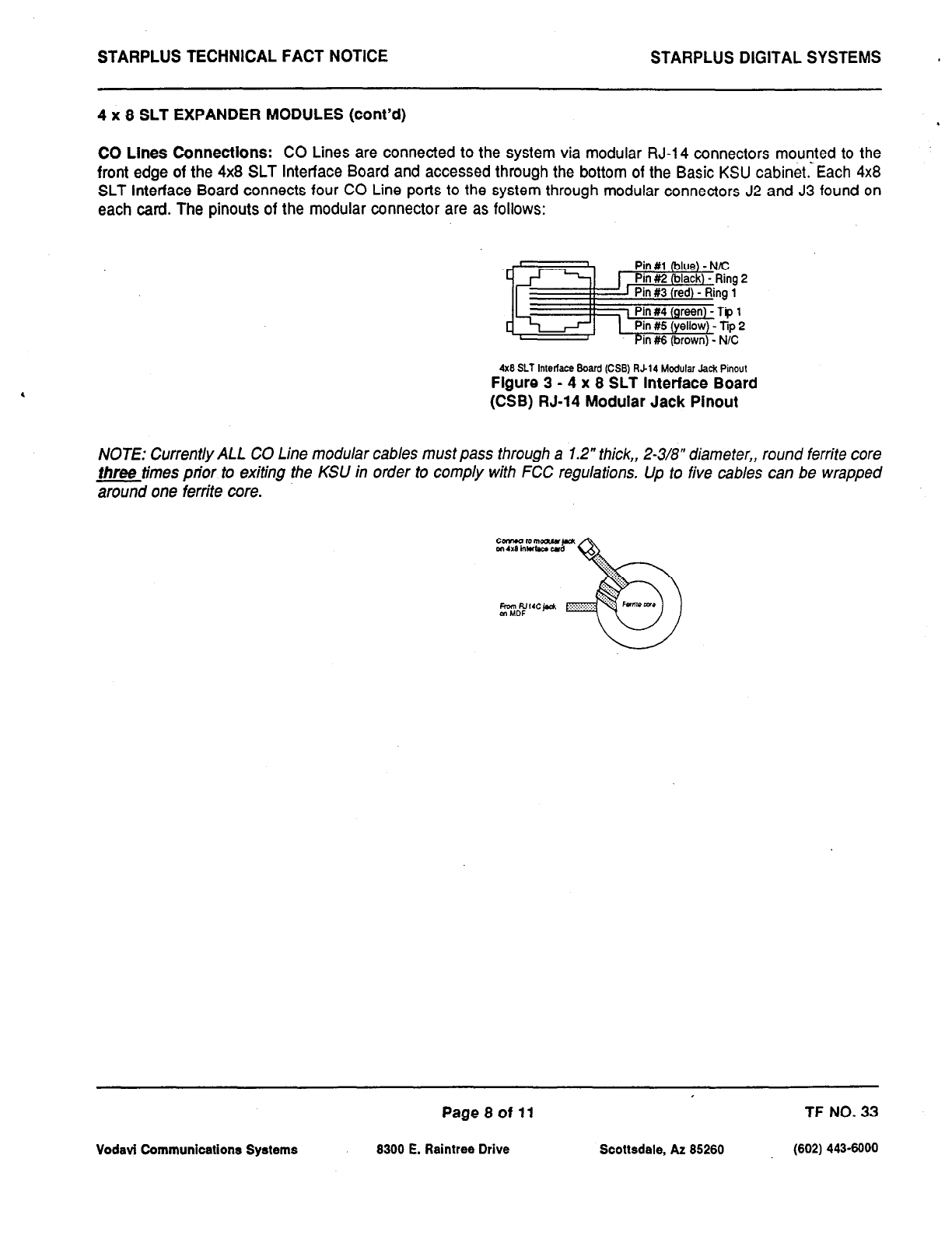
STARPLUS TECHNICAL FACT NOTICE STARPLUS DIGITAL SYSTEMS a
4 x 8 SLT EXPANDER MODULES (cont’d) .
CO Lines Connections: CO Lines are connected to the system via modular RJ-14 connectors mounted to the
front edge of the 4x8 SLT Interface Board and accessed through the bottom of the Basic KSU cabinet. Each 4x8
SLT Interface Board connects four CO Line ports to the system through modular connectors J2 and J3 found on
each card. The pinouts of the modular connector are as follows:
4x8 SLT Interlace Board (CSS) W-14 Modular Jack Pinout
Flgure 3 - 4 x 8 SLT Interface Board
(CSB) RJ-14 Modular Jack Plnout
NOTE: Currently ALL CO Line modular cables must pass through a 1.2” thick,, 2-3/8” diameter,, round ferrite core
three
times prior to exiting the KSU in order to comply with FCC regulations, Up to five cables can be wrapped
around one ferrite core.
c-tomour~
m 4X8 in- cd
‘Q::..
“:::;;
..:::.,
.: . ...:,, ‘7.
b
..,:,, ‘..
hull RJ,,cj& .:.:.: .:...:,:,:., “‘” k”r*m~
m MOF
Vodavi Communications Systems
Page8of 11
8300 E. Raintree Drive Scottsdale, AZ 85260
TF NO. 33
(602) 443-6000
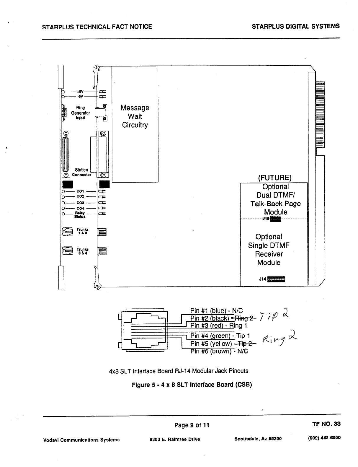
STARPLUS TECHNICAL FACT NOTICE STARPLUS DIGITAL SYSTEMS
0
$
Station
0 Connects
Message
Wait
Circuitry
(FUTURE)
Optional-
Dual DTMF/
Talk-Back Page
Module
_------- Jqg# -----------
Optional
Single DTMF
Receiver
Module
514
I I
CJJ Pin #1 (blue) - N/C
1 Pin #2 (black) +f?i~@-
1
I 1 Pin #3 (red) - Ring I
I
I
I
C-5
1 Pin #4 (green) - Tip 1
Pin #5 (yellow) Gp-%
I Pin #6 (brown) - N/C
4x8 SLT Interface Board RJ-14 Modular Jack Pinouts
Figure 5 - 4 x 8 SLT Interface Board (CSB)
Page 9 of 11 TF NO. 33
Vodavi Communications Systems 8300 E. Raintree Drive Scottsdale, AZ 65260 (662) 443-6000
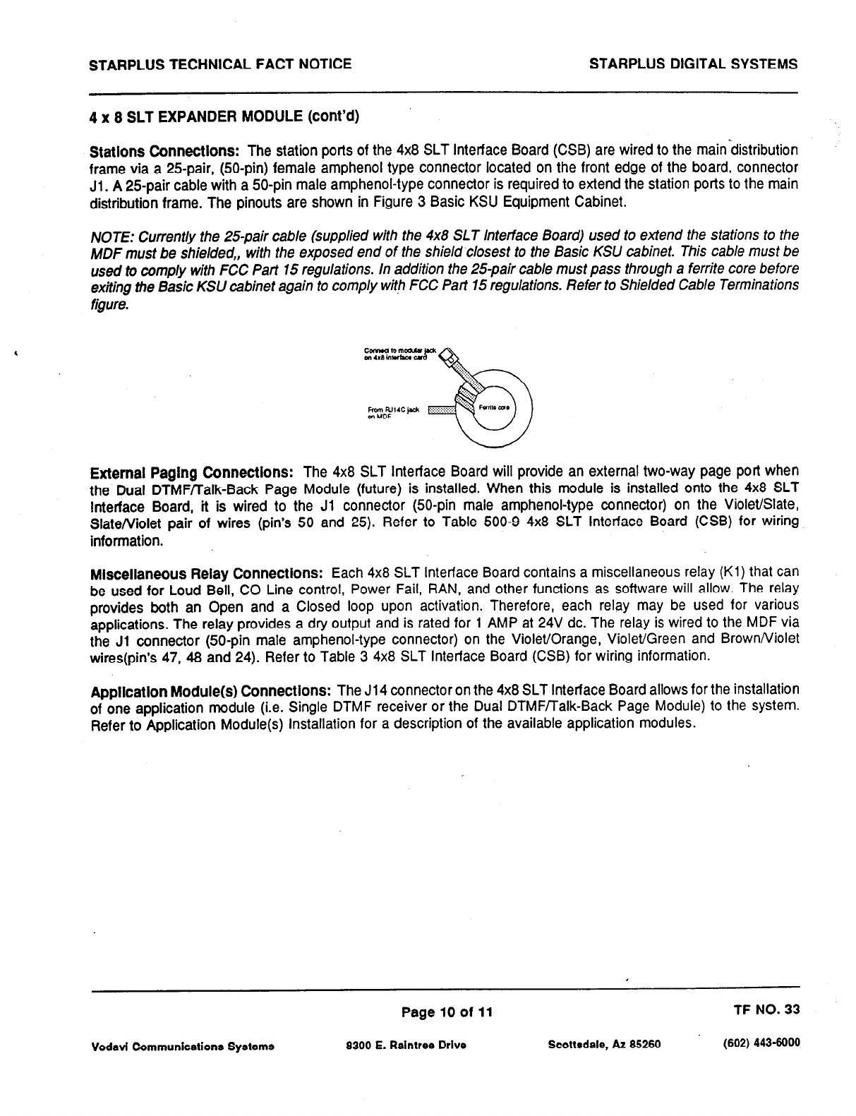
STARPLUS TECHNICAL FACT NOTICE STARPLUS DIGITAL SYSTEMS
4 x 8 SLT EXPANDER MODULE (cont’d)
Statlons Connectlons:
The station ports of the 4x8 SLT Interface Board (CSB) are wired to the mainbistribution
frame via a 25pair, (50-pin) female amphenol type connector located on the front edge of the board, connector
Jl.
A
25pair cable with a 50-pin male amphenol-type connector is required to extend the station ports to the main
distribution frame. The pinouts are shown in Figure 3 Basic KSU Equipment Cabinet.
NOTE: Currently the 25pair cable (supplied with the 4x8 SLT Interface Board) used to extend the stations to the
MDF must be shielded,, with the exposed end of the shield closest to the Basic KSU cabinet. This cable must be
used to comply with FCC Part 15 regulations. In addition the 25-pair cable must pass through a ferrite core before
exiting the Basic KSU cabinet again to comply with FCC Part 15 regulations. Refer to Shielded Cable Terminations
figure.
External Paging Connections:
The 4x8 SLT Interface Board will provide an external two-way page port when
the Dual DTMF/Talk-Back Page Module (future) is installed. When this module is installed onto the 4x8 SLT
Interface Board, it is wired to the Jl connector @O-pin male amphenol-type connector) on the Violet/Slate,
Slate/violet pair of wires (pin’s 50 and 25). Refer to Table 500-9 4x8 SLT Interface Board (CSB) for wiring
information.
Miscellaneous Relay Connections:
Each 4x8 SLT Interface Board contains a miscellaneous relay (Kl) that can
be used for Loud Bell, CO Line control, Power Fail, RAN, and other functions as software will allow. The relay
provides both an Open and a Closed loop upon activation. Therefore, each relay may be used for various
applications. The relay provides a dry output and is rated for 1 AMP at 24V dc. The relay is wired to the MDF via
the Jl connector (50-pin male amphenol-type connector) on the Violet/Orange, Violet/Green and Brown/Violet
wires(pin’s 47, 48 and 24). Refer to Table 3 4x8 SLT Interface Board (CSB) for wiring information.
Application Module(s) Connections:
The J14 connector on the 4x8 SLT Interface Board allows for the installation
of one application module (i.e. Single DTMF receiver or the Dual DTMF/Talk-Back Page Module) to the system.
Refer to Application Module(s) Installation for a description of the available application modules.
Page 10 of 11 TF NO. 33
Vodavi Communications Systems 8300 E. Raintree Drive Scottsdale, AZ 85260 (602) 4436000
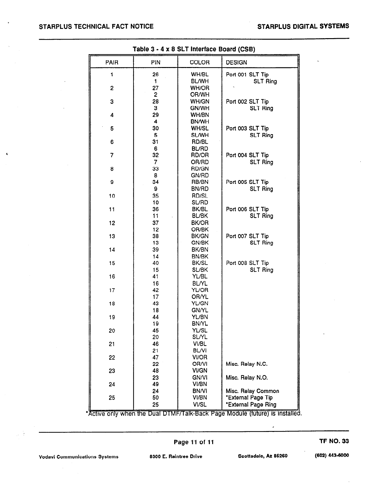
STARPLUS TECHNICAL FACT NOTICE STARPLUS DIGITAL SYSTEMS
PAIR
1
2
3
4
5
6
7
8
9
10
11
12
13
14
15
16
17
18
19
20
21
22
23
24
25
We only whe
Table 3 - 4 x 8 SLT Interface Board (CSB)
PIN COLOR DESIGN
26
1
27
2
28
3
29
4
30
5
31
6
32
7
33
8
34
9
35
10
36
11
37
12
38
13
39
14
40
15
41
16
42
17
43
18
44
19
45
20
46
21
47
22
48
23
49
24
50
25
fhe Dualulfvf
WHiBL
BLfWH
WH/OR
ORIWH
WH/GN
GNIWH
WH/BN
BNWH
WHISL
SLIWH
RDIBL
BURD
RD/OR
OR/RD
RDlGN
GN/RD
RBIBN
BN/RD
RD/SL
SURD
BWBL
BUBK
BWOR
ORIBK
BWGN
GN/BK
BWBN
BNlBK
BWSL
SUBK
YUBL
BLNL
YUOR
ORNL
YUGN
GNNL
YUBN
BNNL
YUSL
SUYL
VIiBL
BWl
VI/OR
OR/VI
VI/GN
GNNI
VIIBN
BNNI
VIIBN
VIISL
i lalk-Back Pa!
Port 001 SLT Tip
SLT Ring
Port 002 SLT Tip
SLT Ring
Port 003 SLT Tip
SLT Ring
Port 004 SLT Tip
SLT Ring
Port 005 SLT Tip
SLT Ring
Port 006 SLT Tip
SLT Ring
Port 007 SLT Tip
SLT Ring
Port 008 SLT Tip
SLT Ring
Misc. Relay N.C.
Misc. Relay N.O.
Misc. Relay Common
‘External Page Tip
*External Page Ring
Module (tuture) IS mstalle
Page 11 of 11 TF NO. 33
Vodavi Communications Systems 8300 E. Reintree Drive Scottsdale, AZ 85260
(602)443-6000
TECHNICAL FACT NOTICE
Starplus Digital Systems
TF NO: 31
5126193
AUTOMATIC CALL DISTRIBUTION (ACD)
Description:
The Basic ACD Software package is an optional software package available for the Starplus Digital Systems. When
purchased, Uniform Call Distribution (UCD) is not used and is replaced by the ACD functions identified in the
following. Eight Automatic Call Distribution (ACD) groups can be programmed, each containing up to eight
three-digit station numbers. Each group is assigned a pilot number. When this number is dialed, the first available
agent in that group is rung. Calls are routed to the station that has been on-hook for the longest period of time.
1. Agent Posltlons
A. Agent LoginfLogout w/Agent ID Feature
B. Agent Available/Unavailable Mode
C. Agent Help Request
D. Agent Call Qualification
E. Group Member Status
2. SupervIsor Posltlons
A. Supervisor LogirVLogout Feature
B. Supervisor Help Request and Station Assignment Feature
C. Supervisor Monitor w/Barge-In Feature
D. Supervisor/Agent Calls in Queue Display
3. ACD Programmlng
4. ACD Timers
5. ACD RAN Announcement Tables
6. Modlfled
SMDR
Output for ACD Reporting
Vodavi Communications Systems
Page 1 of 28 TF NO. 31
8300 E. Raintree Drive Scottsdale, AZ 85260 (602) 4436000
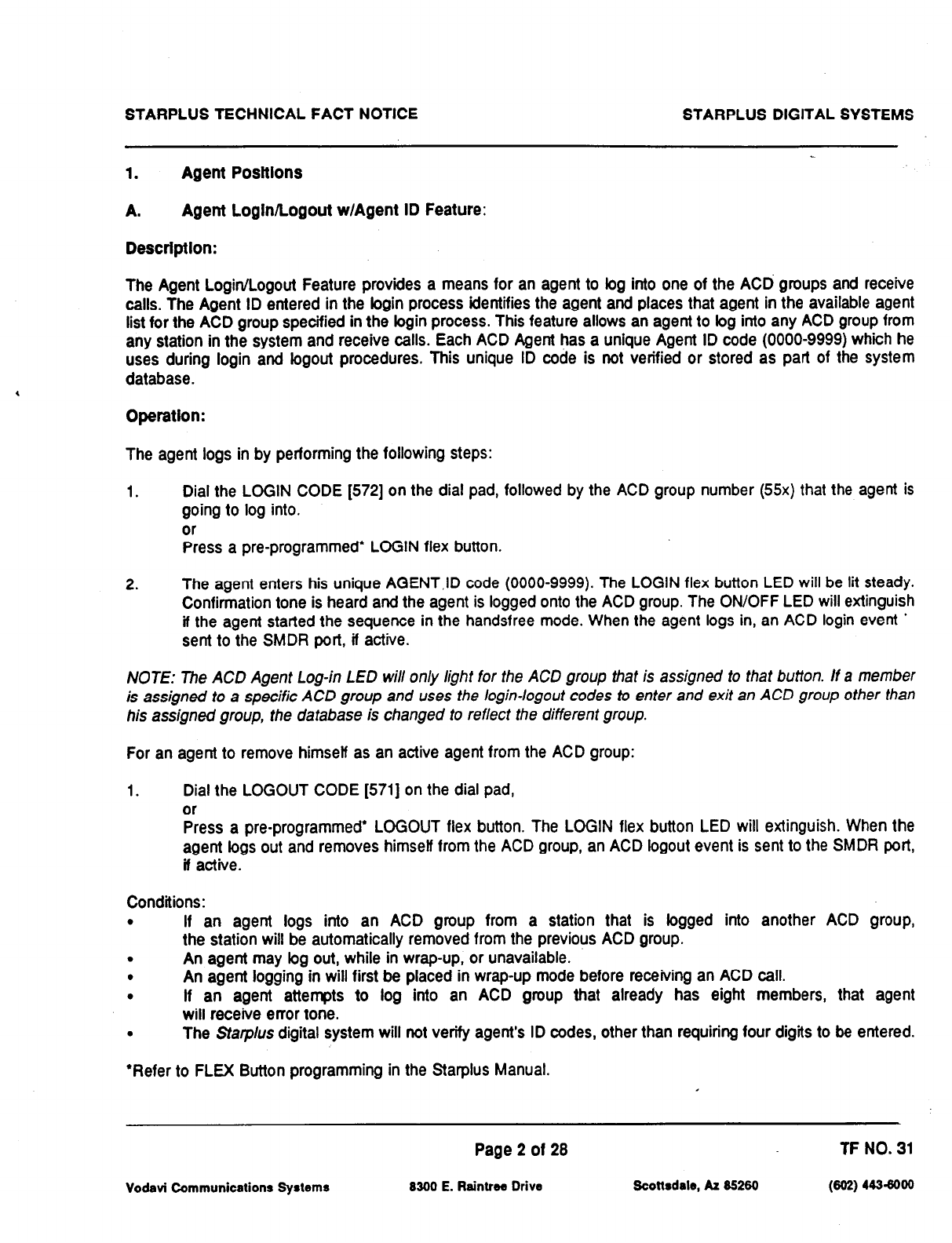
STARPLUS TECHNICAL FACT NOTICE STARPLUS DIGITAL SYSTEMS
1. Agent Posltlons
A.
Agent LoglnlLogout w/Agent ID Feature:
Desctlptlon:
The Agent LoginlLogout Feature provides a means for an agent to bg into one of the ACD groups and receive
calls. The Agent ID entered in the bgin process identifies the agent and places that agent in the available agent
list for the ACD group specified in the bgin process. This feature allows an agent to bg into any ACD group from
any station in the system and receive calls. Each ACD Agent has a unique Agent ID code (0000-9999) which he
uses during login and bgout procedures. This unique ID code is not verified or stored as part of the system
database.
Operation:
The agent logs in by performing the following steps:
1. Dial the LOGIN CODE [572] on the dial pad, followed by the ACD group number (55x) that the agent is
going to log into.
or
Press a pre-programmed* LOGIN flex button.
2. The agent enters his unique AGENT,ID code (0000-9999). The LOGIN flex button LED will be lit steady.
Confirmation tone is heard and the agent is logged onto the ACD group. The ON/OFF LED will extinguish
if the agent started the sequence in the handsfree mode. When the agent logs in, an ACD login event *
sent to the SMDR port, if active.
NOTE: The ACD Agent Log-in LED will only light for the ACD group that is assigned to that button. If a member
is assigned to a specific ACD group and uses the login-logout codes to enter and exit an ACD group other than
his assigned group, the database is changed to reflect the different group.
For an agent to remove himself as an active agent from the ACD group:
1. Dial the LOGOUT CODE [571] on the dial pad,
or
Press a pre-programmed’ LOGOUT flex button. The LOGIN flex button LED will extinguish. When the
agent logs out and removes himself from the ACD group, an ACD logout event is sent to the SMDR port,
II active.
Conditions:
. If an agent logs into an ACD group from a station that is logged into another ACD group,
the station will be automatically removed from the previous ACD group.
. An agent may bg out, while in wrap-up, or unavailable.
. An agent logging in will first be placed in wrap-up mode before receiving an ACD call.
. If an agent attempts to log into an ACD group that already has eight members, that agent
will receive error tone.
. The Starplus digital system will not verify agent’s ID codes, other than requiring four digits to be entered.
*Refer to FLEX Button programming in the Starplus Manual.
Page 2 of 28 TF NO. 31
Vodavi Communications Sy8temr 8300 E. Raintrw Drive Scottsdale, AZ 85260 (802) 4436000
STARPLUS TECHNICAL FACT NOTICE STARPLUS DIGITAL SYSTEMS
Agent Posltlons (cont’d)
B. Agent Avallable / Unavallable Mode:
Description:
Stations programmed into a ACD group may log off and on to their assigned ACD group by dialing an
Available/Unavailable code. When an agent is in the Available mode, that agent will receive ACD calls in
the
normal
manner. When an agent is in the Unavailable mode, that agent will no longer receive ACD type calls. However, the
agent may
receive
non-ACD calls. Agents that have logged off by going Unavailable will receive a visual reminder
that they are logged off with a flashing LED and/or an LCD display message.
Operatlon: .
To go Available:
1. Dial [566] on the dial pad,
or
Press the pre-programmed* Available/Unavailable button. You may now receive calls.
To go Unavailable:
1. Dial (5661 on the dial pad
or
Press the pre-programmed’ Available/Unavailable button. You are now blocked from receiving ACD calls.
*Refer to FLEX Button programming in the Stat-plus Manual.
Page 3 of 28 TF NO. 31
Vodavi Communications Systems 8300 E. Raintree Drive Scottsdale, AZ 85260 (602) 443-6000
STARPLUS TECHNICAL FACT NOTICE STARPLUS DIGITAL SYSTEMS
Agent Posttlons (cont’d)
C. Agent Help Request:
Description:
This feature provides a means for an ACD agent to signal his assigned supervisor for assistance. While on a call,
the agent can press the HELP button to signal the assigned supervisor. The supervisor may then respond by using
his HELP button and his ACD Barge-In feature.
Operation:
While on a call in progress, the agent:
1. Presses his pre-programmed’ HELP flex button. Confirmation tone will be heard by the agent. The agent
will see his HELP button illuminate if a supervisor is logged into his ACD group. ff no supervisor is logged
in, the agent will receive a burst of error tone and his help button will not illuminate.The ACD supervisor
station receives a “HELP” message if a member of one of the ACD groups he is assigned to. The help
function also sends a Camp-On tone to the speaker of the supervisors keyset. The help message takes
precedence over any other message and can be cleared by the supervisor by pressing his help button. At
the time the supervisor receives a help request, he can press his help flex button followed by his override
feature button to bridge onto the ACD group members call. The help button will place an intercom call to
the station requesting help. The help message will be cleared after the supervisors help button is
depressed. In add&on, the HELP message will be cleared if the agent was on a call and went back on
hook before the supervisor could respond. In this case, the HELP message will be converted to a messar-
wait indication. The agent can also clear the HELP request by hitting his HELP button a second time.
Conditions:
. Up to five messages can be left at any supervisor station.
. The supervisor can cancel the HELP request signal by depressing his flashing HELP button. In addition,
a call will be placed to the agent requesting HELP. If the agent is on a call, the supervisor can press his
Barge-In button to monitor the call or give assistance on the call.
. The HELP feature access code will permit a single line telephone to access the HELP feature. While on
a call, the SLT after doing a hook-flash can dial the HELP code 15741 to leave the HELP message. After
the code is dialed, the SLT will be returned to his call.
NOTE: Only digital terminals can activate this feature.
‘Refer to FLEX Button programming in the Starplus Manual.
Vodavi Communications System8
Page 4
of 28 TF NO. 31
8300 E. Raintree Drive Scottsdale, AZ 85260 (802) 443-8000
STARPLUS TECHNICAL FACT NOTICE STARPLUS DlGlTAL SYSTEMS
Agent Positions (cont’d)
D. Agent Call Quallflcatlon:
Description:
This feature provides a means for an Agent to enter codes on ACD type calls that identify the call. This feature
permits up to lo-digits to be entered, however only the first four digits are provided for in the SMDR record.
Operatlon:
While on a call, the agent:
1. Press the pre-programmed* CALL QUALIFY flex button, followed by the four-digit qualify code. Enter a r]
to complete the sequence.
The QUALIFY button is programmed using flex code [570#]. If the agent wishes to enter his qualify code in a speed
bin, he can do so using the standard speed bin programming sequence. Then when he programs his flex button,
he can enter 570 followed by the bin number. This will provide an agent with a series of buttons with qualify codes
under them.
Conditions:
.
Only digital key stations can operate this feature as it requires a flex button programmed as a qualify
button.
. The outside party will not hear the (qualify code) account code being entered.
. The qualify code uses the first 4-digits of the account code. Therefore the account code record in the
SMDR will contain the qualify code in the first 4-digits.
. The qualify code must be entered during CO talk state.
. A # can be entered in the qualify code, however it will not be recognized by the ACD reporting package.
. Speed dial entries can contain all digits including the
l
, which will terminate the entry and return the UCD
agent to his CO party.
‘Refer to FLEX Button programming in the Starplus Manual.
Page 5 of 28 TF NO. 31
Vodavi Communications Systems 8300 E. Raintree Drive Scottsdale, AZ 85260 (602) 443-6000
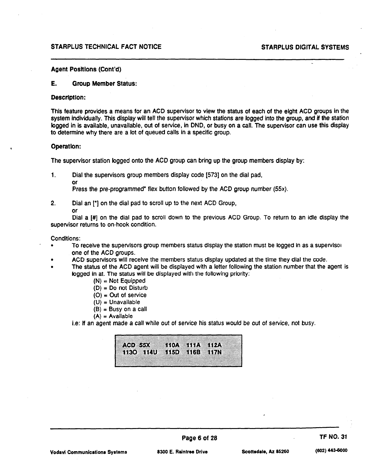
STARPLUS TECHNICAL FACT NOTICE STARPLUS DIGITAL SYSTEMS
Agent Po&ions (Cont’d)
E. Group Member Status:
Description:
This feature
provides a means for an ACD supervisor to view the status of each of the eight ACD groups in the
system individually.
This display will tell the supervisor which stations are logged into the group, and if
the
station
logged in is available, unavailable, out of service, in DND, or busy on
a
call. The supervisor can use this display
to determine why there are a lot of queued calls in a specific group.
Operatlon:
The supervisor station logged onto the ACD group can bring up the group members display by:
1.
Dial the supervisors group members display code (5731 on the dial pad,
or
Press the pre-programmed* flex button followed by the ACD group number (55x).
2. Dial an [‘I on the dial pad to scroll up to the next ACD Group,
or
Dial a [##I on the dial pad to scroll down to the previous ACD Group. To return to an idle display the
supervisor returns to on-hook condition.
Conditions:
_ . To receive the supervisors group members status display the station must be logged in as a supervisor
one of the ACD groups.
. ACD supervisors will receive the members status display updated at the time they dial the code.
. The status of the ACD agent will be displayed with a letter following the station number that the agent is
logged in at. The status will
be
displayed with the following priority:
(N) = Not Equipped
(D) = Do not Disturb
(0) = Out of service
(U) = Unavailable
(8) = Busy on a call
(A) = Available
i.e: lf an agent made a call while out of service his status would be out of service, not busy.
Vodavi Communications Systems
Page 6 of 28
8300 E. Raintree Drive Scottsdale, AZ 85260
TF NO. 31
(602) 443GoOO
STARPLUS TECHNICAL FACT NOTICE STARPLUS DIGITAL SYSTEMS
2. Supervisor
Positions
A.
Supervisor LogWLogout Feature:
Description:
This feature provides a means for
a
supervisor to tog into one of the ACD groups. The Supervisor ID entered
in
the bgin
process
identifies the supervisor for the specific ACD group he is assigned to. This feature allows a
supervisor to bg into any ACD group from any station in the system. However, to have the Supervisor Monitor
w/Barge-In feature, the supervisor must bg in at a station with monitor barge-in capability. Each ACD Supervisor
has a unique Supervisor ID code (0000-9999) which he uses during bgin and logout procedures. This unique ID
code is not verified or stored as part of the system database.
Operatlon:
The supervisor logs in by performing the following steps:
1. Dial the LOGIN CODE (5761 on the dial pad, followed by the ACD group number (55x) that the agent is
going to log into
or
Press a pre-programmed’ LOGIN flex button. (Flex button must have 576+55x programmed onto it.)
2.
The supervisor enters his unique SUPERVISOR ID code (0000-9999). The LOGIN flex button LED will be
lit steady. Confirmation tone is heard and the agent is logged onto the ACD group. The ON/OFF LED will
extinguish if the supervisor started the sequence in the handsfree mode. When the supervisor logs in, an
ACD login event is sent to the SMDR port, if active.
For a supervisor to remove himself as an active supervisor from the ACD group:
1. Dial the LOGOUT CODE (5751 on the dial pad,
or
Press a pre-programmed* LOGOUT flex button. The LOGIN flex button LED will extinguish. When the
supervisor logs out and removes himself from the ACD group, an ACD logout event is sent to the SMDR
port, It active.
Conditions:
. If a supervisor logs into an ACD group from a station that is logged into another ACD group, the station
will be automatically removed from the previous ACD group.
. A supervisor may log out, while in wrap-up, or unavailable.
. A supervisor logging in will first be placed in wrap-up mode before receiving an ACD call.
. If a supervisor attempts to bg into an ACD group that already has a members, that supervisor will
receive error tone.
. The Starplus digital system will not verify supervisors ID codes, other than requiring four digits
to be
entered.
‘Refer to FLEX Button programming in the Starplus Manual.
Vodavi Communications Systems
Page 7
of 28 TF NO. 31
8300 E. Raintree Drive Scottsdale, AZ 85260 (602) 4436000
STARPLUS TECHNICAL FACT NOTICE STARPLUS DIGITAL SYSTEMS
SupervIsor Posltlons (cont’d)
B. Supervlsor Help Request and Station Asslgnment:
Descrlptlon:
The HELP
feature provides a means for an ACD agent to signal his assigned supervisor for assistance. The agent
while on a call can press the HELP button to signal the assigned supervisor. The supervisor may
respond by
use
of his HELP button and his ACD Barge-In feature. The ACD Supervisor Station Assignment feature provides a
means to assign a supervisor
to
each ACD group. This supervisor station can receive the calls in queue display
in real time, rece’ves No Answer/Out of Service,
receives
‘HELP” displays from the groups that the supervisor is
assigned to and can barge in on active calls in his ACD group or groups.
Opemtlon:
The ACD supervisor’s station logged in can receive the calls in queue display from any group he desires by:
1.
Dial the calls in queue code [577) on the dial pad,
or
Press the pre-programmed* CALLS IN QUEUE flex button, followed by the ACD group number (55x) that
the supervisor is going to monitor.
The ACD supervisor station logged in will also receive a station out of service (00s) message for any member of
the ACD group that does not answer a call directed to his station by the ACD group. This message is displayed
in real time and can be removed by reactivating the calls in queue display.
In addition, the ACD supervisor station will receive a “HELP” message if a member of one of the AC0 groups he
is assigned to presses his programmable help button. The help function will also send an announce tone to the
speaker of the supervisors keyset. The help message will take precedence over any other message and can only
be cleared by the supervisor pressing his HELP flex button. At the time the supervisor receives a help request, he
can press his help flex button followed by his barge-in feature button to bridge onto the ACD group members call.
The help button will place an intercom call to the station requesting help. The barge-in feature is activated by
pressing the help response button or dialing the station number of the ACD member requesting help and hitting
the barge-in button. The help message will be cleared affer the help button is depressed. When the supervisor
barges in his mute button will be lii indicating that the parties he is monitoring can not hear him. lf the supervisor
wishes to talk he must hit his mute button.
*Refer to FLEX Button programming in the Starplus Manual.
Vodavi Communication* Systems
Page 8 of 28 TF NO. 31
8300 E. Raintrw Drive scottsdele, AZ 85280 (802) 443-6000
STARPLUS TECHNICAL FACT NOTICE STARPLUS DIGITAL SYSTEMS
Supervisor Positions (cont’d)
B. Supenrlsor Help Request and Statlon Asslgnment (cont’d)
Conditions:
.
.
.
.
A supervisor can be assigned in ADMIN to a group or groups to receive the help request and out of service
(00s) message. tf a supervisor station is assigned in
ADMIN,
tt is considered logged in. In addition, a
supervisor can dial a supervisor bgin code (576) followed by the ACD group that the supervisor is logging
into and his four-digit ID number.
A supervisor can only barge into a call from a member of one of the groups
to which he
is logged into.
Out of Service (00s) and Help displays will take priority over normal call processing displays. However,
Help displays will be the highest priority.
An agent requesting help will receive confirmation tone if a supervisor is logged in at a station. He will
receive programming error tone if there isn’t any supervisor logged in.
Up to five
HELP
messages can be left at any supervisor station.
A supervisor may be logged on to more than one group at a time.
A station does not receive ACD calls when programmed as a supervisor, however a supervisor can bg on
as a ACD agent and receive ACD calls.
Only one supervisor is permitted per ACD group.
To remove the warning tone from barge-in, use the yes/no option for Executive warning tone
(FLASH 05,
button 4).
Vodavi Communications Systems
Page 9 of 28 TF NO. 31
8300 E. Raintree Drive Scottsdale, AZ 85260 (802) 443-8000
STARPLUS TECHNICAL FACT NOTICE STARPLUS DlGlTAL SYSTEMS
Supervlsor Positions (cont’d)
C. Supervlsor Monltor w/Bargeln Feature:
Descrlptlon:
The Supervisor Monitor with Barge-In feature provides a means for an ACD supervisor to monitor an agent’s call
in
progress
or provide assistance in training ACD personnel. When used,
a
supervisor may intrude onto an agents
call in a listen only mode or in a true conference mode. This feature is available with or without a warning tone.
Operation:
The ACD supervisor can intrude on an agent’s call in the listen only mode by:
1.
Dial the three-digit station number of the agent’s station. Upon hearing busy tone, press the
pre-programmed* Barge-In flex button. The Executive Over-ride Code [625] is used to program Supv
Monitor with barge-in feature onto a flex button. The conversation in progress will be heard by the
supervisor on the handset receiver and the supervisor’s Mute LED will be lit indicating that the supervisor’s
transmit is muted.
2. If the supervisor wishes to participate in the conversation in a true conference mode, he can depress his
Mute button which removes mute.
NOTE: The use of silent monitor and barge-in is limited by federal law and may also be limited or prohibited by
stare or local law, so check the relevant laws in your area before employing these features.
Conditions:
.
Supervisors are granted the barge-in option if they log in at a station with the Supervisor Barge-In flag
enabled.
. Supervisors can only barge-in on calls of members of the ACD that they are logged into.
. Warning tone is enabled and disabled using the Executive Override warning tone option (FLASH 05, button
4).
. A digital key or SLT may be intruded using this feature.
. Supewisor stations must be digital keysets.
*Refer to FLEX Button programming in the Starplus Manual.
Page 10 of 28 TF NO. 31
Vodavi Communications Systems 8300 E. Reintree Drive Scottsdale, AZ 85260 (scl2) 443-6000
STARPLUS TECHNICAL FACT NOTICE STARPLUS DIGITAL SYSTEMS
SupervIsor Posltlons (cont’d)
D. Supervisor Queue Status Dlsplay
Descrlptlon:
This feature provides a means for an agent and ACD supervisor to view the status of their ACD group. This display
is an idle state display and will prompt a supervisor that his agents in the group are having problems answering
all their calls. The display will tell the agent and his supervisor how many calls are in queue, how many agents are
togged into the ACD group, and the length of time in minutes that the oldest call has been in queue.
The supervisor station logged onto the ACD group can obtain the calls in queue display by:
1. Dial the CALLS IN QUEUE code [57T] on the dial pad,
or
Press the pre-programmed* CALLS IN QUEUE flex button, followed by the ACD group number the
supervisor wants to observe (55x).
If the supervisor wants to change the display to a different group:
1. Dials the CALLS IN QUEUE code [577) on the dial pad,
or
Presses the pre-programmed* CALLS IN QUEUE flex button followed by the ACD group that he wishes
to display.
Conditions:
.
To receive the Supervisor’s Queue Status Display, the station must be logged in as a supervisor and diaf
the flex code for the appropriate group.
. ACD supervisors will receive the Queue Status Display in real time.
. The Queue Status Display is only given when the ACD group member or supervisors station is not
receiving a higher priority display, such as help or out of service, or other applicable off hook events are
taking place at the station.
. The supervisors Queue Status Display is saved in battery backed memory.
. When a supervisor logs out of the group he is presently displaying, he must enter a new request for Queue
Status Display.
. The Supervisor’s Queue Status Display can be updated by dialing the flex code followed by the group
being observed. Dialing a different group will change the Queue Status Display to a different group.
. The Queue Status Display will give the following information:
55Y = ACD Group (550-557)
CIQ:xx = Calls in queue
AL:xx = Agents logged in
0C:mmm = Oldest call in minutes
*Refer to FLEX Button programming in the Statplus Manual.
Page 11 of 28 TF NO. 31
Vodavi Communications Systems 8300 E. Raintrw Drive soottsdsls, AZ 85280 (802) 4436000
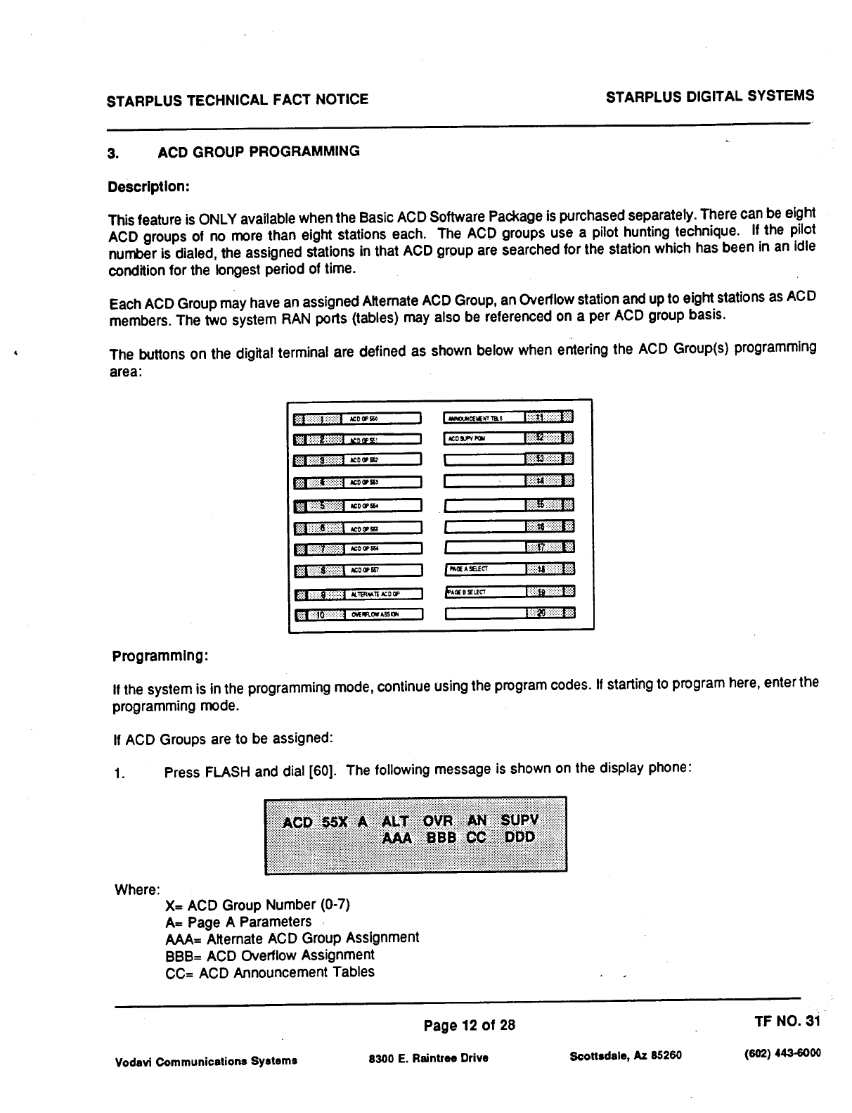
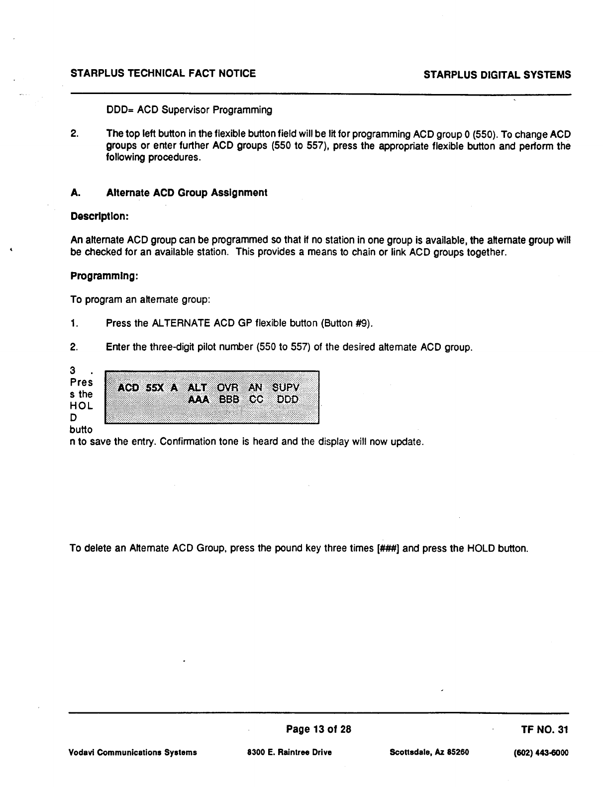
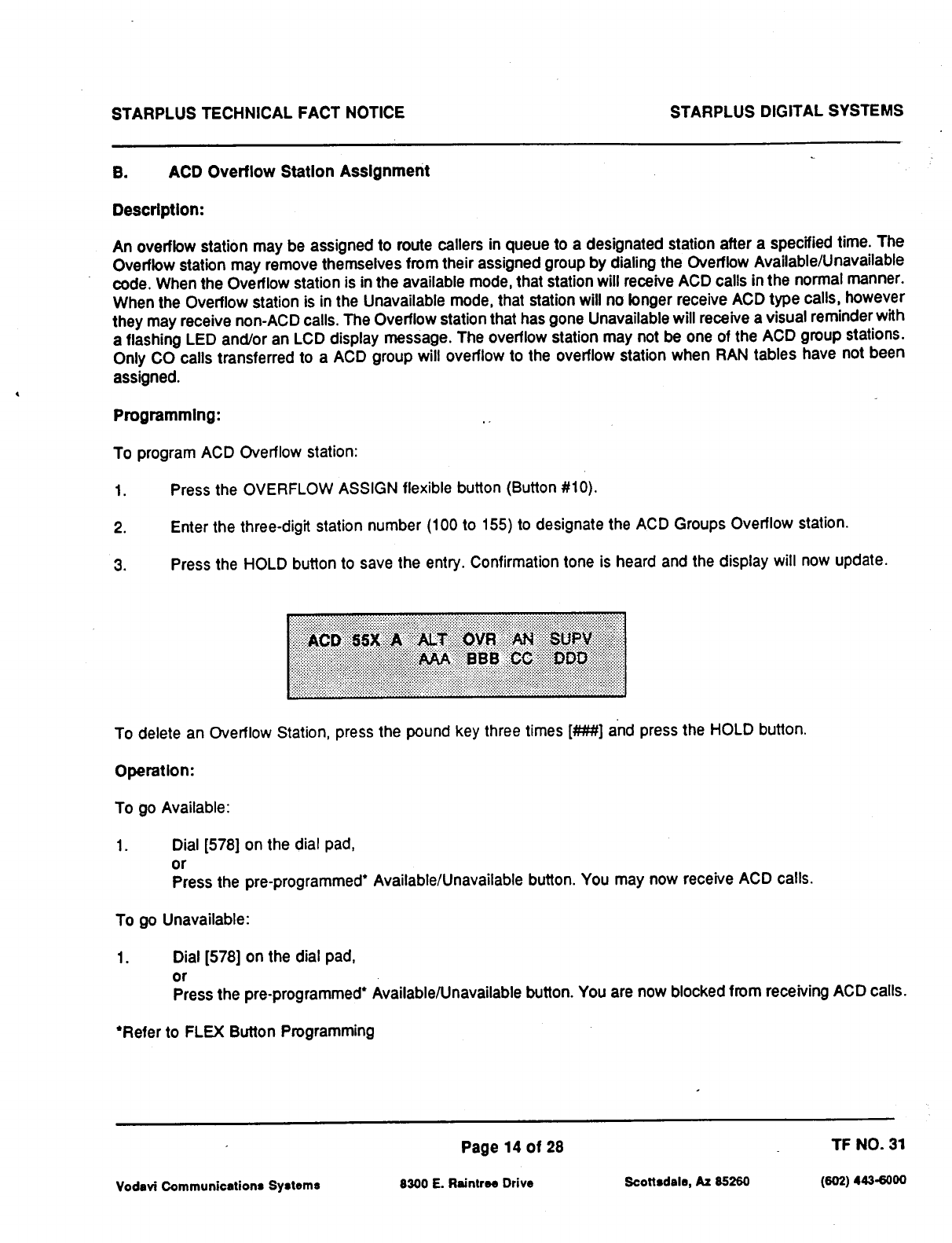
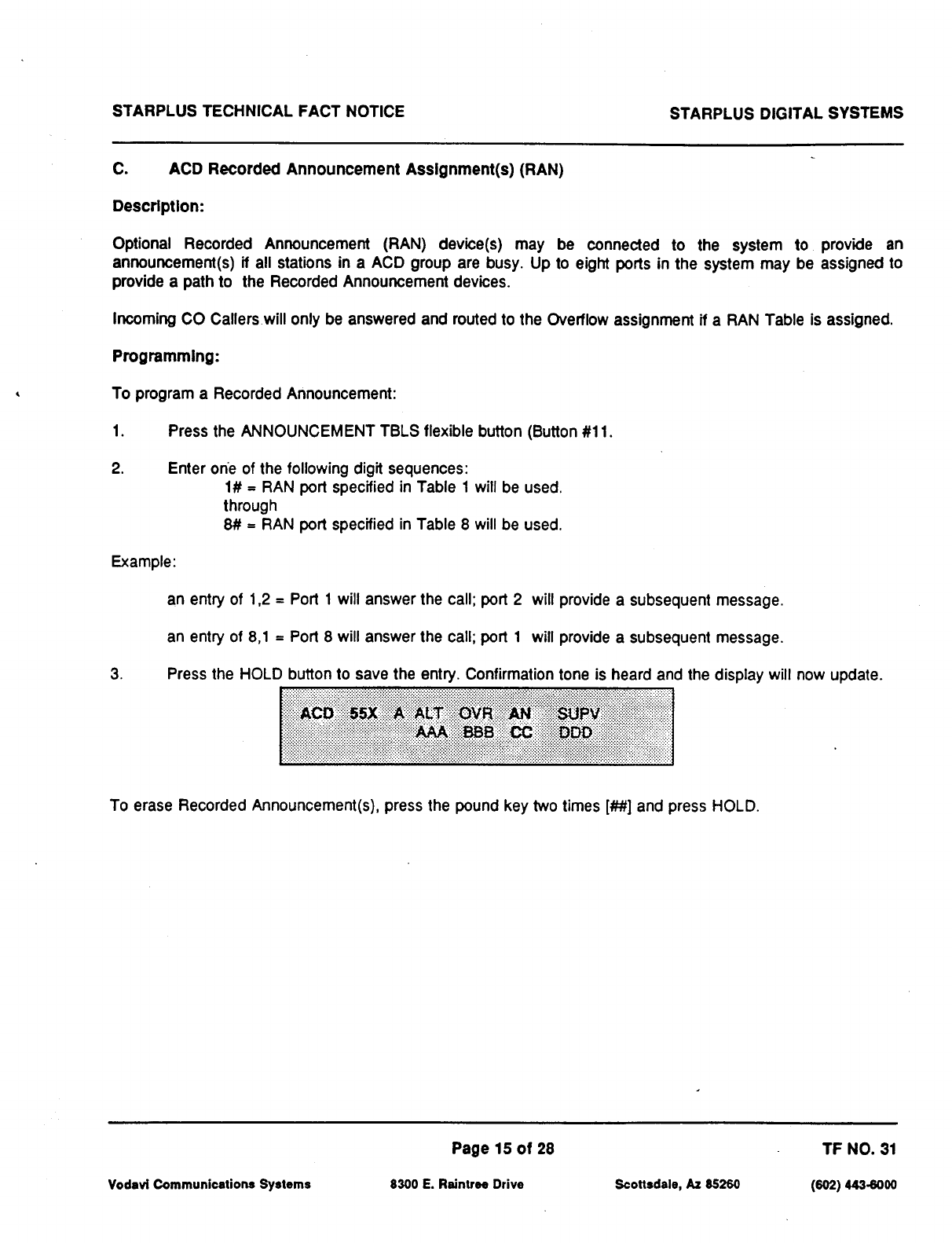
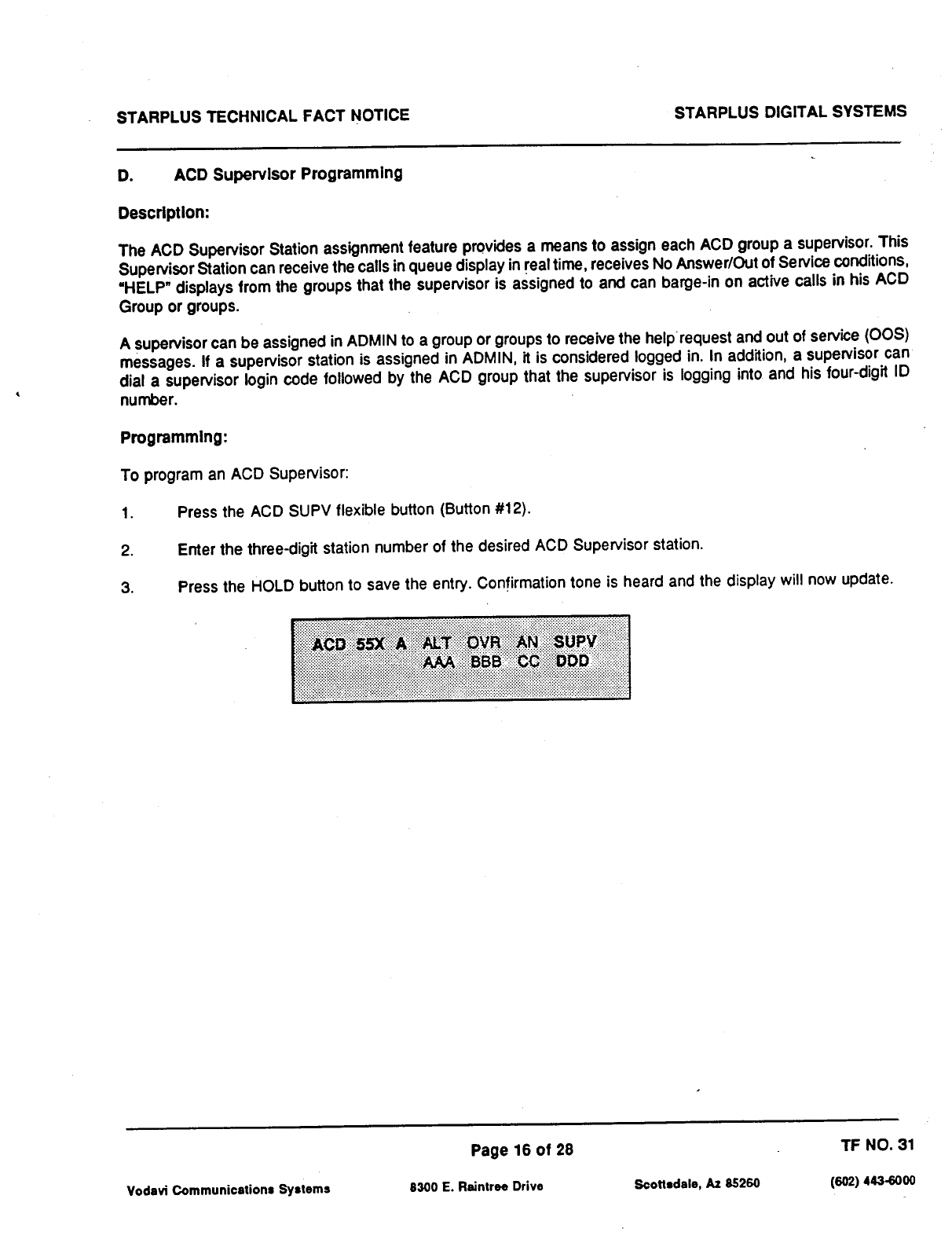
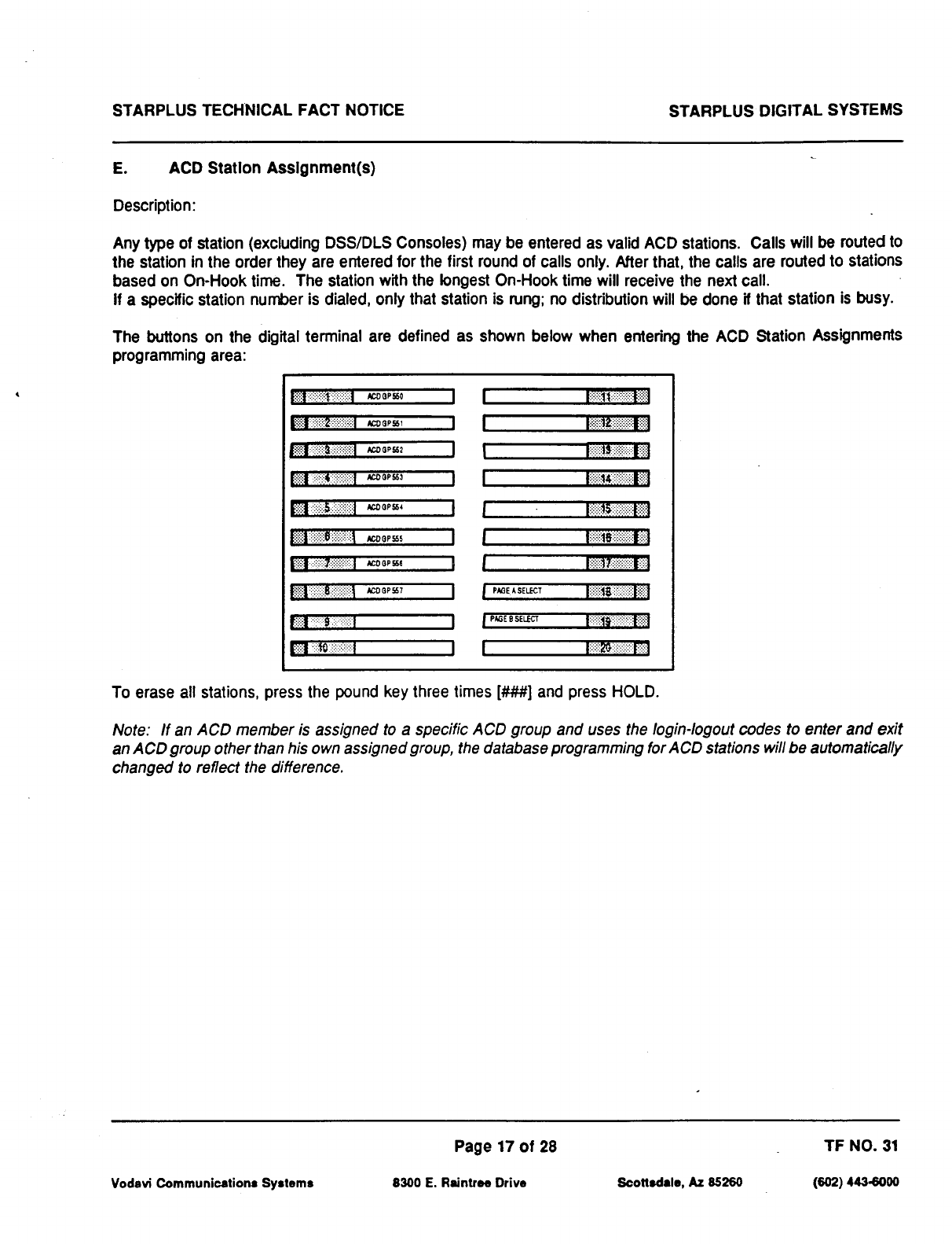
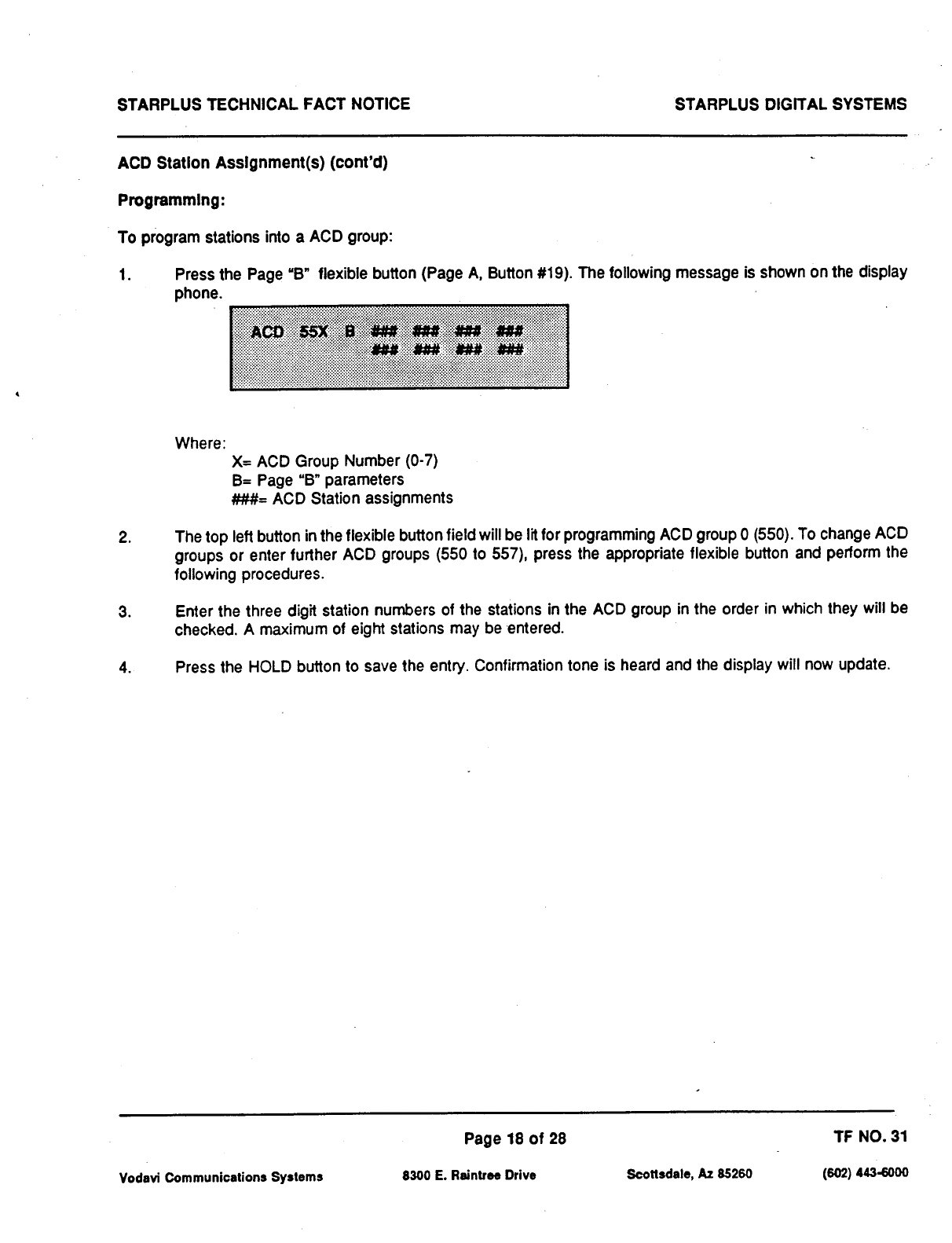
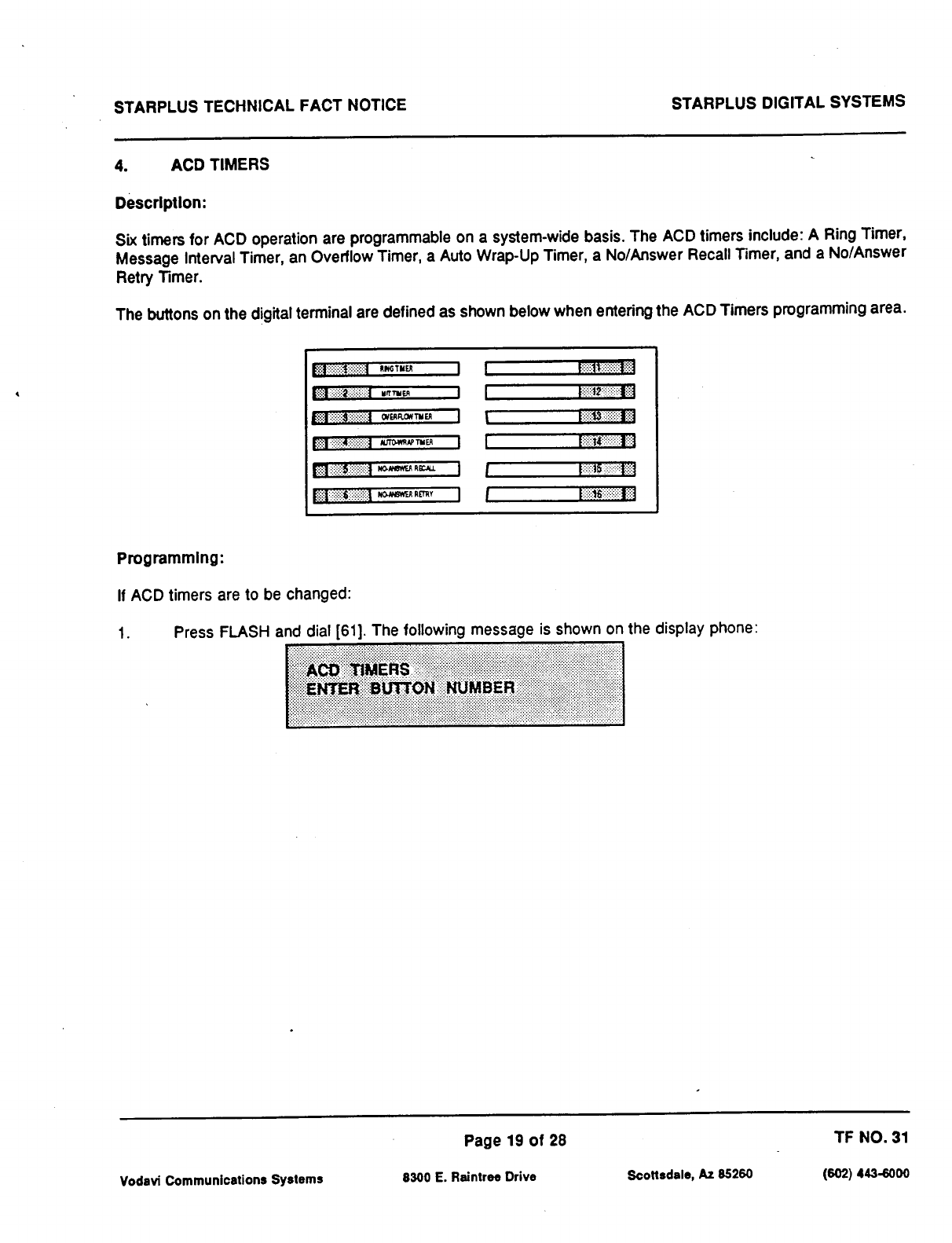

STARPLUS TECHNICAL FACT NOTICE STARPLUS DIGITAL SYSTEMS
A. ACD Ring Timer
Descrlptlon:
The ACD Ring Timer determines how long a call will ring into a busy ACD group before being presented to the first
recorded announcement.
NOTE: A RAN Table must be specified in ACD programming for the ring timer to be in effect If a RAN Table is
NOT specified, incoming CO callers will not be answered but will continue to receive ringback
Programming:
To make a change to the ACD Ring Timer:
1. Press the RING TIMER flexible button (Button #I). The following message is shown on the display phone:
2. Enter the three-digit timer value on the dial pad which corresponds to 000300 seconds.
3. Press the HOLD button to save the entry. Confirmation tone is heard and the display will now update.
Default: By default, the ACD Ring Timer is set for 60 seconds, and is variable from 000 to 300 seconds.
Vodavi Communications Systems
Page 20 of 28 TF NO. 31
8300 E. Raintree Drive Scottsdale, AZ 85260 (w2) 4436000
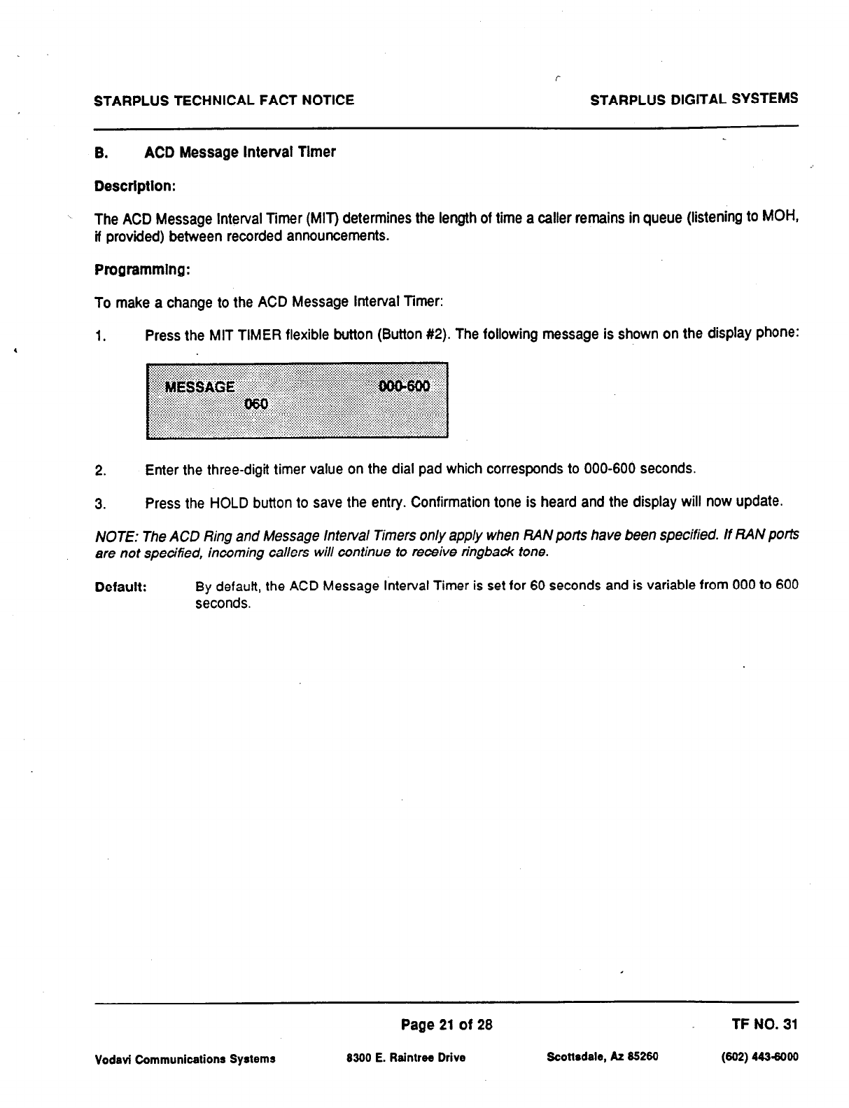
STARPLUS TECHNICAL FACT NOTICE STARPLUS DIGITAL SYSTEMS
8. ACD Message Interval Tlmer
Descrlptlon:
The ACD Message Interval Timer (MIT) determines the length of time a caller remains in queue (listening to
MOH,
if provided) between recorded announcements.
Programmlng:
To make a change to the ACD Message Interval Timer:
1. Press the MIT TIMER flexible button (Button #2). The following message is shown on the display phone:
2. Enter the three-digit timer value on the dial pad which corresponds to 000-600 seconds.
3. Press the HOLD button to save the entry. Confirmation tone is heard and the display will now update.
NOTE: The ACD Ring and Message lntetval Timers only apply when RAN ports have been specified. If RAN ports
are not specified, incoming callers will continue to receive ringbadc tone.
Default: By defautt, the ACD Message Interval Timer is set for 60 seconds and is variable from 000 to 600
seconds.
Page 21 of 28 TF NO. 31
Vodavi Communications Systems 8300 E. Raintree Drive Scottsdale, AZ 85260 (602) 443-6000
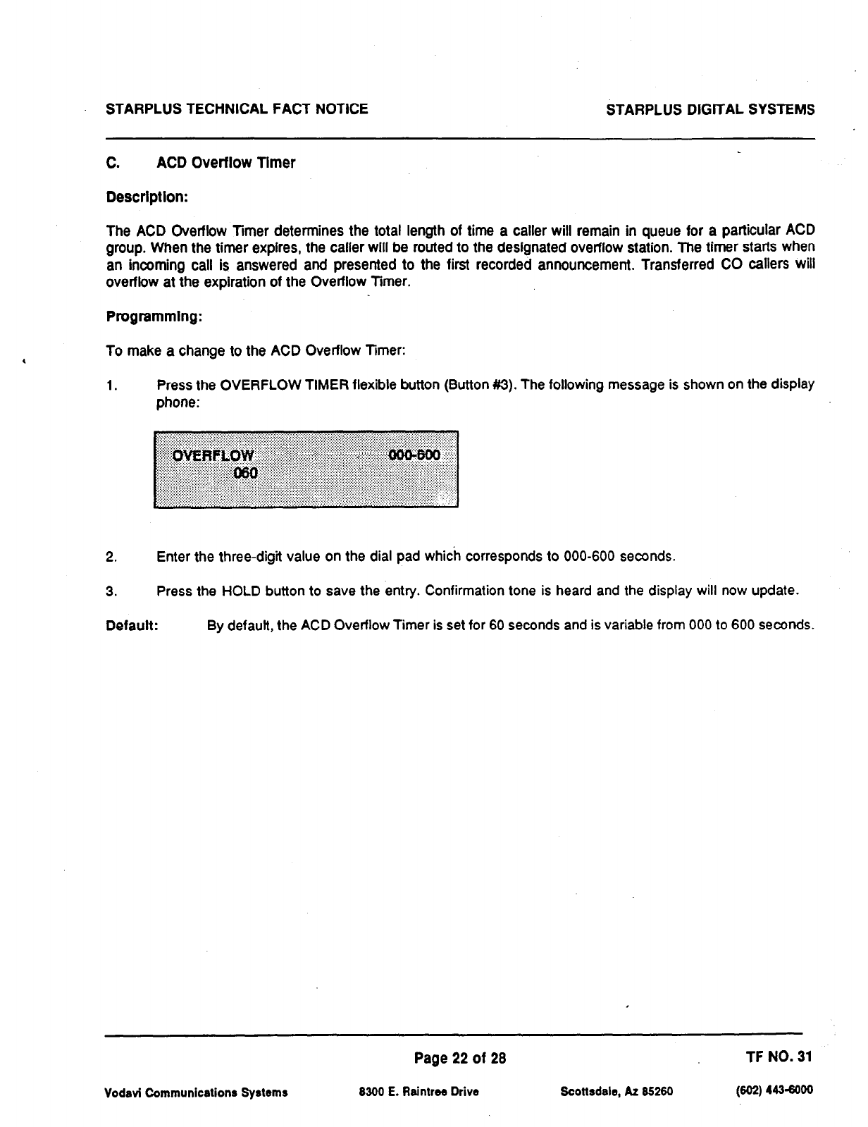
STARPLUS TECHNICAL FACT NOTICE STARPLUS DIGlTAL SYSTEMS
C. ACD Overflow Tlmer
Descrlptlon:
The ACD Overflow Timer determines the total length of time a caller will remain in queue for a particular ACD
group. When the timer expires, the caller will be routed to the designated overflow station. The timer starts when
an incoming call is answered and presented to the first recorded announcement. Transferred CO callers will
overflow at the expiration of the Overflow Timer.
Programmlng:
To make a change to the ACD Overflow Timer:
1. Press the OVERFLOW TIMER flexible button (Button #3). The following message is shown on the display
phone:
2. Enter the three-digit value on the dial pad which corresponds to 000-600 seconds.
3. Press the HOLD button to save the entry. Confirmation tone is heard and the display will now update.
Default: By defautf, the ACD Overflow Timer is set for 60 seconds and is variable from 000 to 600 seconds.
Vodavi Communications Systems
Page 22 of 28 TF NO. 31
8300 E. Raintree Drive Scottsdale, AZ 85260 (602) 443-6000
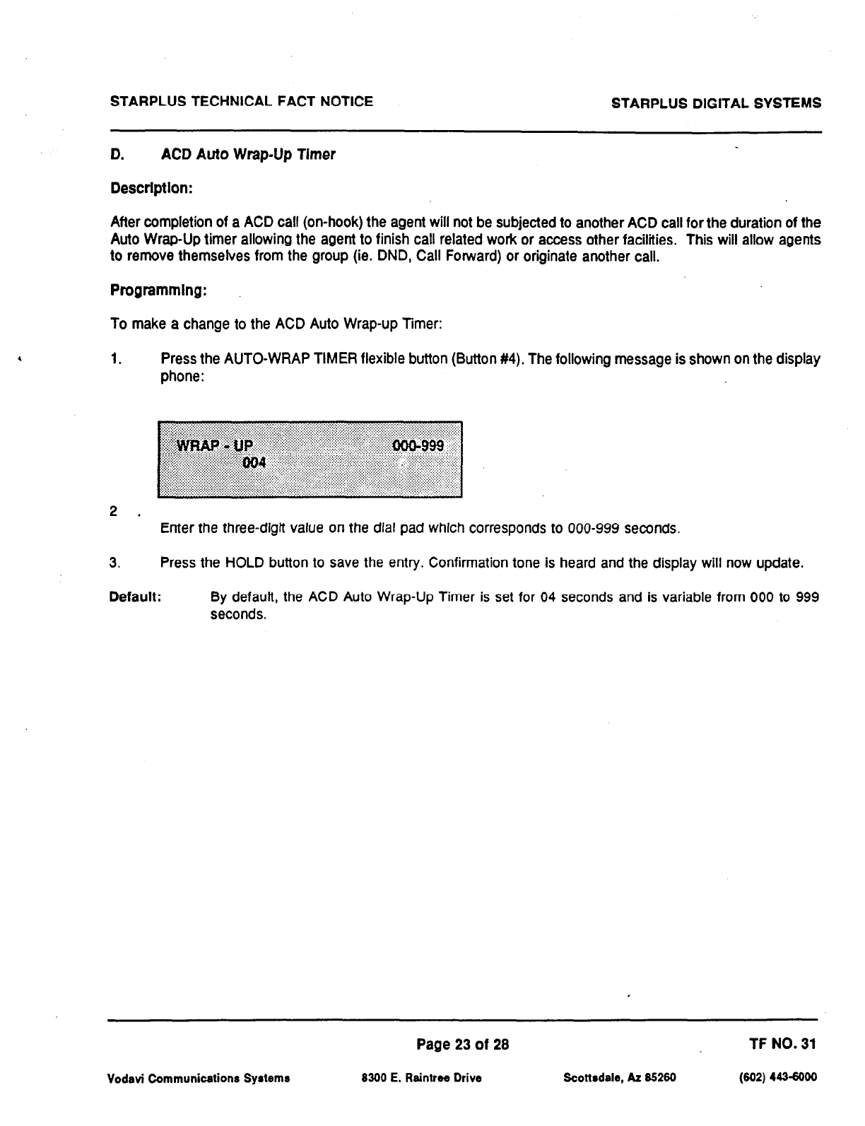
STARPLUS TECHNICAL FACT NOTICE STARPLUS DIGITAL SYSTEMS
D. ACD Auto Wrap-Up Timer
Description:
After completion of a ACD call (on-hook) the agent will not be subjected to another ACD call for the duration of the
Auto Wrap-Up timer allowing the agent to finish call related work or access other facilities. This will allow agents
to remove themselves from the group (ie. DND, Call Forward) or originate another call.
Programmlng:
To make a change to the ACD Auto Wrap-up Timer:
1. Press the AUTO-WRAP TIMER flexible button (Button #4). The following message is shown on the display
phone:
2 . Enter the three-digit value on the dial pad which corresponds to 000-999 seconds.
3. Press the HOLD button to save the entry. Confirmation tone is heard and the display will now update.
Default: By defautt, the ACD Auto Wrap-Up Timer is set for 04 seconds and is variable from 000 to 999
seconds.
Vodavi Communications Systems
Page 23 of 28 TF NO. 31
8300 E. Raintree Drive Scottsdale, AZ 85260 (602) 4434000
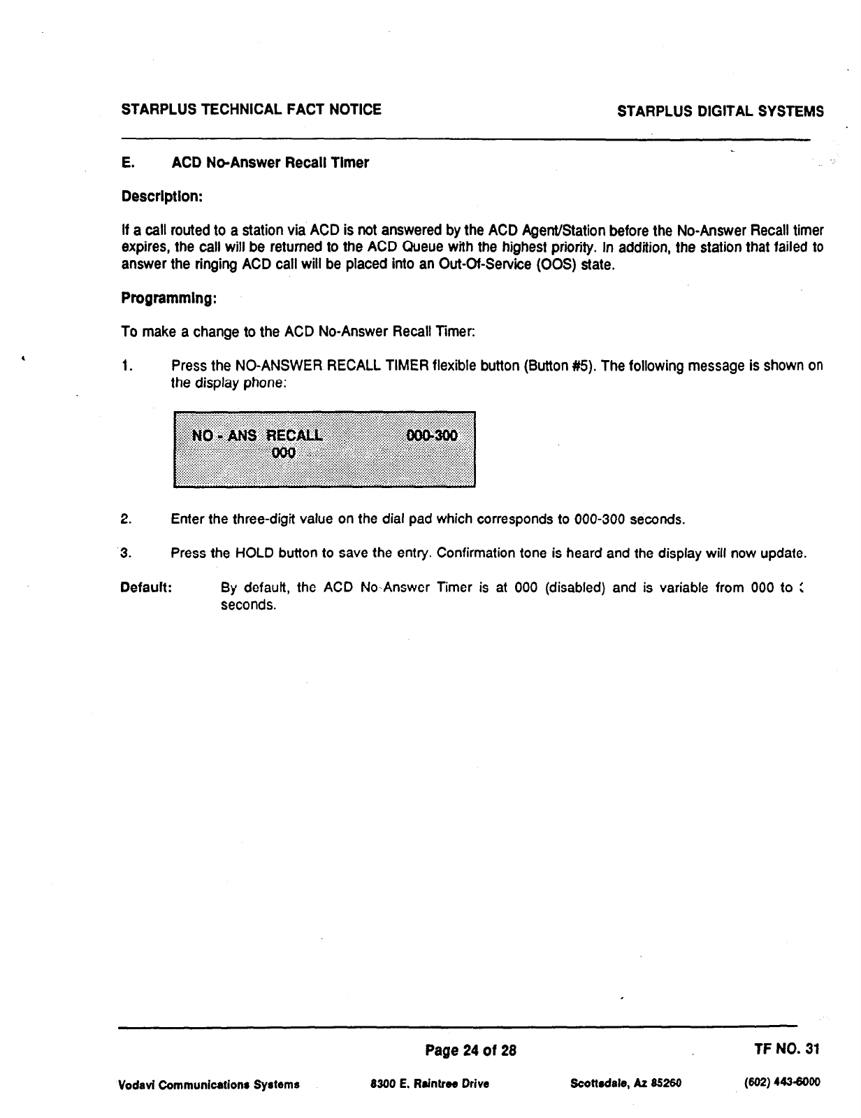
STARPLUS TECHNICAL FACT NOTICE STARPLUS DIGITAL SYSTEMS
E. ACD NeAnswer Recall Timer
Descrlptlon:
If a call routed to a station via ACD is not answered by the ACD AgenVStation before the No-Answer Recall timer
expires, the call will be returned to the ACD Queue with the highest priority. In addition, the station that failed to
answer the ringing ACD call will be placed into an Out-Cf-Service (00s) state.
Programmlng:
To make a change to the ACD No-Answer Recall Timer:
1. Press the NO-ANSWER RECALL TIMER flexible button (Button #5). The following message is shown on
the display phone:
2. Enter the three-digit value on the dial pad which corresponds to 000-300 seconds.
3. Press the HOLD button to save the entry. Confirmation tone is heard and the display will now update.
Default: By defauff, the ACD No-Answer Timer is at 000 (disabled) and is variable from 000 to :
seconds.
Vodavi Communications Systems
Page 24 of 28 TF NO. 31
8300 E. Raintree Drive Soottsdale, A2 85260 (602) 4436000
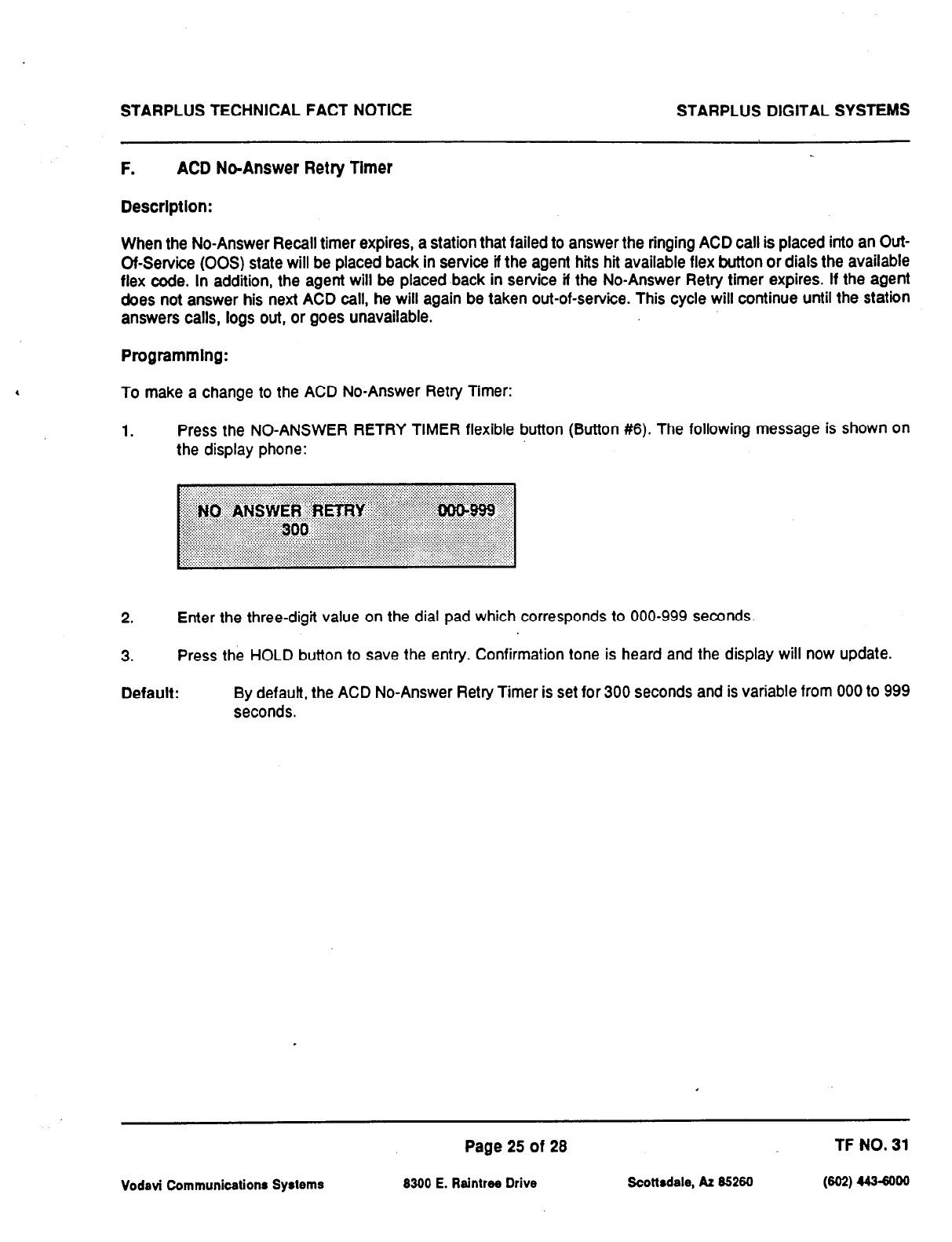
STARPLUS TECHNICAL FACT NOTICE STARPLUS DIGITAL SYSTEMS
F. ACD No-Answer Retry Timer
Description:
When the No-Answer Recall timer expires, a station that failed to answer the ringing ACD call is placed into an Out-
Of-Service (00s) state will be placed back in service if the agent hits hi available flex button or dials the available
flex code. In addition, the agent will be placed back in service if the No-Answer Retry timer expires. If the agent
does not answer his next ACD call, he will again be taken out-of-service. This cycle will continue until the station
answers calls, logs out, or goes unavailable.
Programmlng:
To make a change to the ACD No-Answer Retry Timer:
1. Press the NO-ANSWER RETRY TIMER flexible button (Button #6). The following message is shown on
the display phone:
2. Enter the three-digit value on the dial pad which corresponds to 000-999 seconds.
3. Press the HOLD button to save the entry. Confirmation tone is heard and the display will now update.
Default: By default, the ACD No-Answer Retry Timer is set for 300 seconds and is variable from 000 to 999
seconds.
Vodavi Communications
Systems
Page 25 of 28 TF NO. 31
8300 E. Raintree Drive Scottsdale, At 85260 @w 448-8000
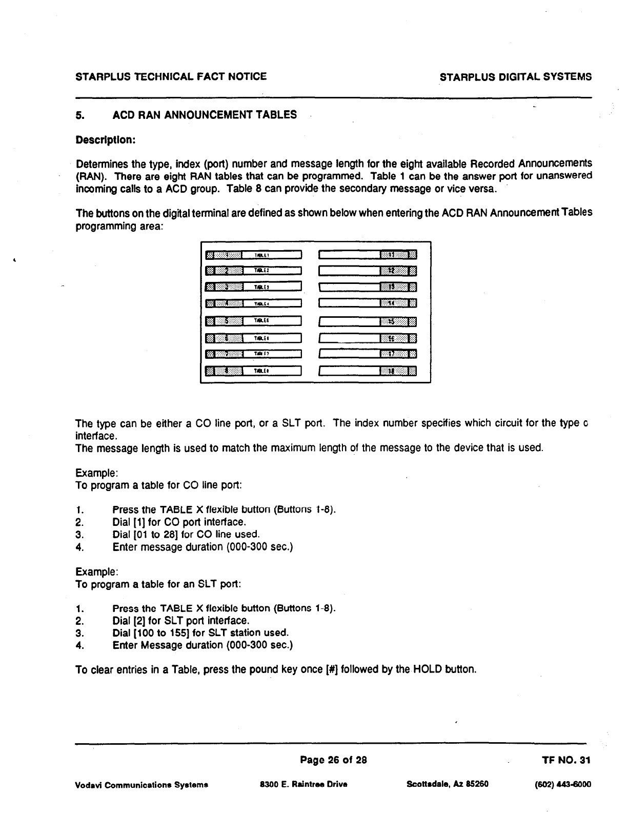
STARPLUS TECHNICAL FACT NOTICE STARPLUS DlGtTAL SYSTEMS
5.
ACD RAN ANNOUNCEMENT TABLES
Desctlptlon:
Determines the type, index (port) number and message length for the eight available Recorded Announcements
(RAN). There are eight RAN tables that can be programmed. Table 1 can be the answer port for unanswered
incoming calls to a ACD group. Table 8 can provide the secondary message or vice versa.
The buttons on the digital terminal are defined as shown below when entering the ACD RAN Announcement Tables
programming area:
,
The type can be either a CO line port, or a SLT port. The index number specifies which circuit for the type G
interface.
The message length is used to match the maximum length of the message to the device that is used.
Example:
To program a table for CO line port:
1. Press the TABLE X flexible button (Buttons l-8).
2. Dial (11 for CO port interface.
3. Dial [Ol to 281 for CO line used.
4. Enter message duration (000-300 sec.)
Example:
To program a table for an SLT port:
1. Press the TABLE X flexible button (Buttons l-8).
2. Dial [2] for SLT port interface.
3. Dial [lo0 to 1551 for SLT station used.
4. Enter Message duration (000-300 sec.)
To clear entries in a Table, press the pound key once [#] followed by the HOLD button.
Page 26 of 28 TF NO. 31
Vodavi Communications Systems 8300 E. Raintree Drive Scottsdale, A2 85260 (602) 4434000
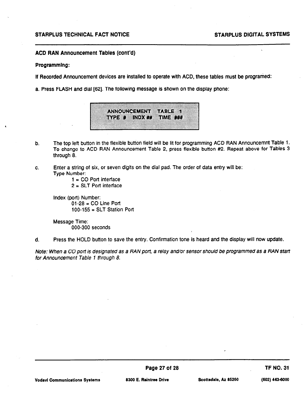
STARPLUS TECHNICAL FACT NOTICE STARPLUS DIGITAL SYSTEMS
ACD RAN Announcement Tables (cont’d)
Programming:
If Recorded Announcement devices are installed to operate with
ACD,
these tables must be programed:
a. Press
FLASH and dial [62]. The following
message is
shown on the display phone:
b.
The top left button in the flexible button field will be lit for programming ACD RAN Announcemnt Table I.
To change to ACD RAN Announcement Table 2, press flexible button #2. Repeat above for Tables 3
through 8.
C.
Enter a string of six, or seven digits on the dial pad. The order of data entry will be:
Type Number:
1 = CO Port interface
2 = SLT Port interface
Index (port) Number:
01-28 = CO Line Port
loo-155 = SLT Station Port
Message Time:
000-300 seconds
d. Press the HOLD button to save the entry. Confirmation tone is heard and the display will now update.
Note: When a CO port is designated as a RAN port, a relay and/or sensor should be programmed as a RAN start
for Announcement Table 1 through 8.
Vodavi Communications Systems
Page 27 of 28 TF NO. 31
8300 E. Raintree Drive Scottsdale, AZ 85260 (802) 443-6000
STARPLUS TECHNICAL FACT NOTICE STARPLUS DlGlTAL SYSTEMS
6. SMDR ENHANCEMENTS
Description:
The SMDR output has been enhanced to replace the “I” (incoming) and 7” (transferred) call types with an “A”
designation to capture ACD call records. This modified SMDR output is only available with the ACD System
software.
Vodavi Communications Systems
Page 28 of 28 TF NO. 31
8300 E. Raintree Drive Scottsdale, AZ 85260 (802) 4436000
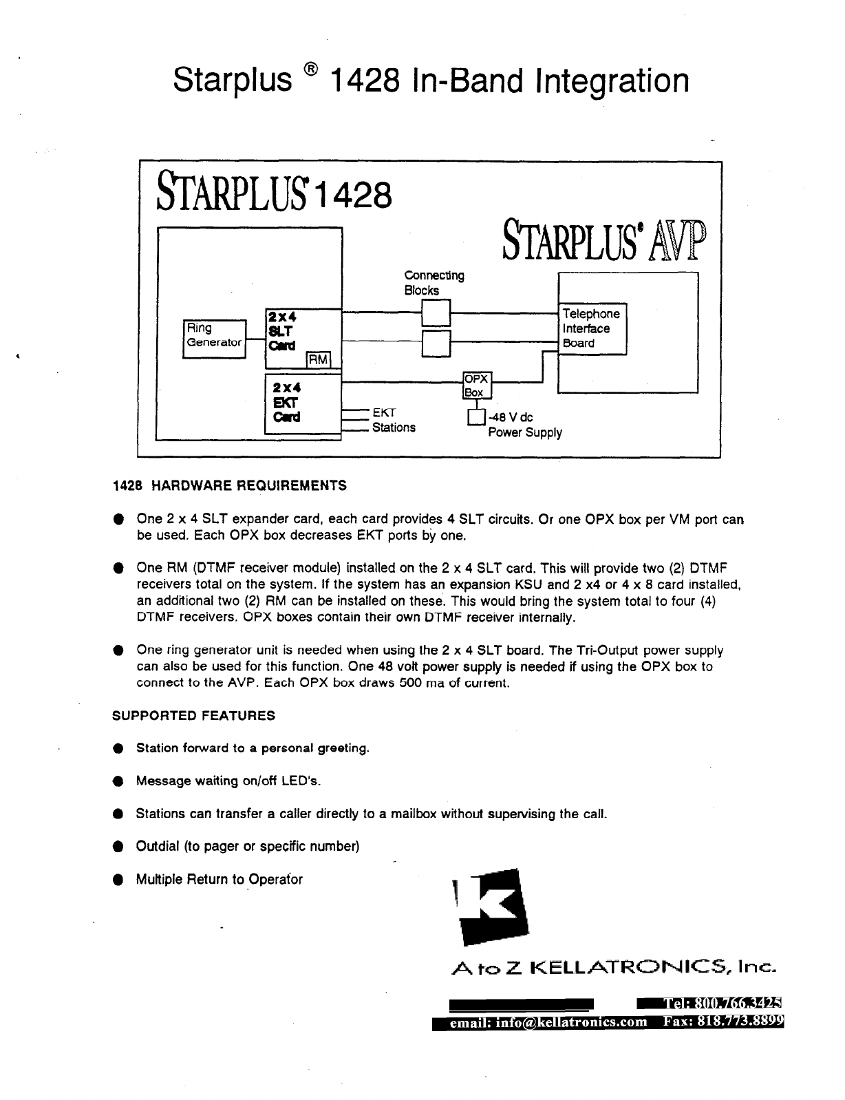
Starplus ’ 1428 In-Band Integration
I J Connecting
Blocks I
12x4 I
Ring SLl-
r
I
I
n-*-1 _-
Generator - m
pq
I
1428 HARDWARE REQUIREMENTS
0 One 2 x 4 SLT expander card, each card provides 4 SLT circuits. Or one OPX box per VM port can
be used. Each OPX box decreases EKT ports by one.
0 One RM (DTMF receiver module) installed on the 2 x 4 SLT card. This will provide two (2) DTMF
receivers total on the system. If the system has an expansion KSU and 2 x4 or 4 x 8 card installed,
an additional two (2) RM can be installed on these. This would bring the system total to four (4)
DTMF receivers. OPX boxes contain their own DTMF receiver internally.
l
One ring generator unit is needed when using the 2 x 4 SLT board. The Tri-Output power supply
can also be used for this function. One 48 volt power supply is needed if using the OPX box to
connect to the AVP. Each OPX box draws 500 ma of current.
SUPPORTEDFEATURES
0 Station forward to a personal greeting.
l
Message waiting on/off LED’s
0 Stations can transfer a caller directly to a mailbox without supervising the call.
0 Outdial (to pager or specific number)
l
Multiple Return to Operator
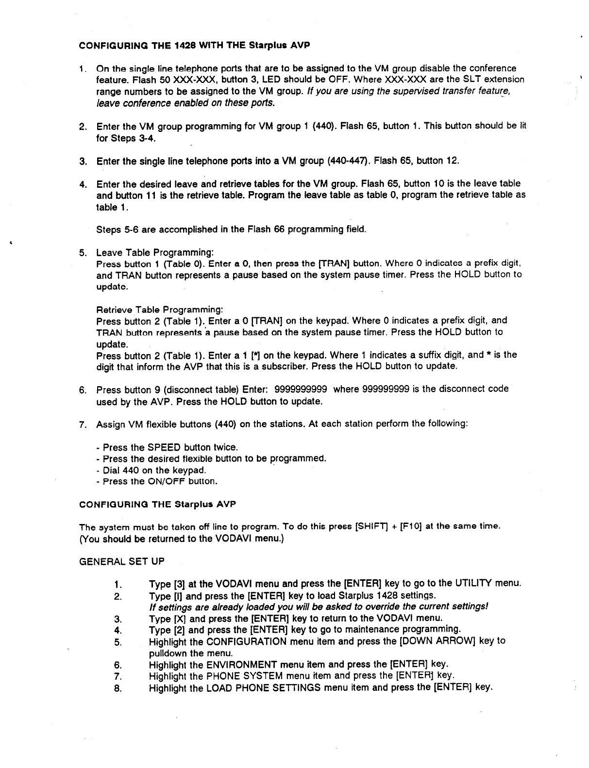
CONFIGURING THE 1428 WITH THE Starplus AVP
1. On the single line telephone ports that are to be assigned to the VM group disable the conference
feature. Flash 50 XXX-XXX, button 3, LED should be OFF. Where XXX-XXX are the SLT extension
range numbers to be assigned to the VM group. If you are using the supervised transfer feature,
leave conference enabled on these ports.
2. Enter the VM group programming for VM group 1 (440). Flash 65, button 1. This button should be lit
for Steps 3-4.
3. Enter the single line telephone ports into a VM group (440447). Flash 65, button 12.
4. Enter the desired leave and retrieve tables for the VM group. Flash 65, button 10 is the leave table
and button 11 is the retrieve table. Program the leave table as table 0, program the retrieve table as
table 1.
Steps 5-6 are accomplished in the Flash 66 programming field.
5. Leave Table Programming:
Press button 1 (Table 0). Enter a 0, then press the FRAN] button. Where 0 indicates a prefix digit,
and TRAN button represents a pause based on the system pause timer. Press the HOLD button to
update.
Retrieve Table Programming:
Press button 2 (Table 1). Enter a 0 [TRAN] on the keypad. Where 0 indicates a prefix digit, and
TRAN button represents a pause based on the system pause timer. Press the HOLD button to
update.
Press button 2 (Table 1). Enter a 1 [q on the keypad. Where 1 indicates a suffix digit, and * is the
digit that inform the AVP that this is a subscriber. Press the HOLD button to update.
6. Press button 9 (disconnect table) Enter: 9999999999 where 999999999 is the disconnect code
used by the AVP. Press the HOLD button to update.
7. Assign VM flexible buttons (440) on the stations. At each station perform the following:
- Press the SPEED button twice.
- Press the desired flexible button to be programmed.
- Dial 440 on the keypad.
- Press the ON/OFF button.
CONFIGURING THE Starplus AVP
The system must be taken off line to program. To do this press [SHIFT] t [FlO] at the same time.
(You should be returned to the VODAVI menu.)
GENERAL SET UP
1.
2. Type [3] at the VODAVI menu and press the [ENTER] key to go to the UTILITY menu.
Type [I] and press the [ENTER] key to load Starplus 1428 settings.
If settings are already loaded you will be asked to override the current settings!
3.
4.
5.
Type [X] and press the [ENTER] key to return to the VODAVI menu.
Type [2] and press the [ENTER] key to go to maintenance programming.
Highlight the CONFIGURATION menu item and press the [DOWN ARROW key to
pulldown the menu.
6. Highlight the ENVIRONMENT menu item and press the [ENTER] key.
7. Highlight the PHONE SYSTEM menu item and press the [ENTER] key.
8. Highlight the LOAD PHONE SETTINGS menu item and press the [ENTER] key.
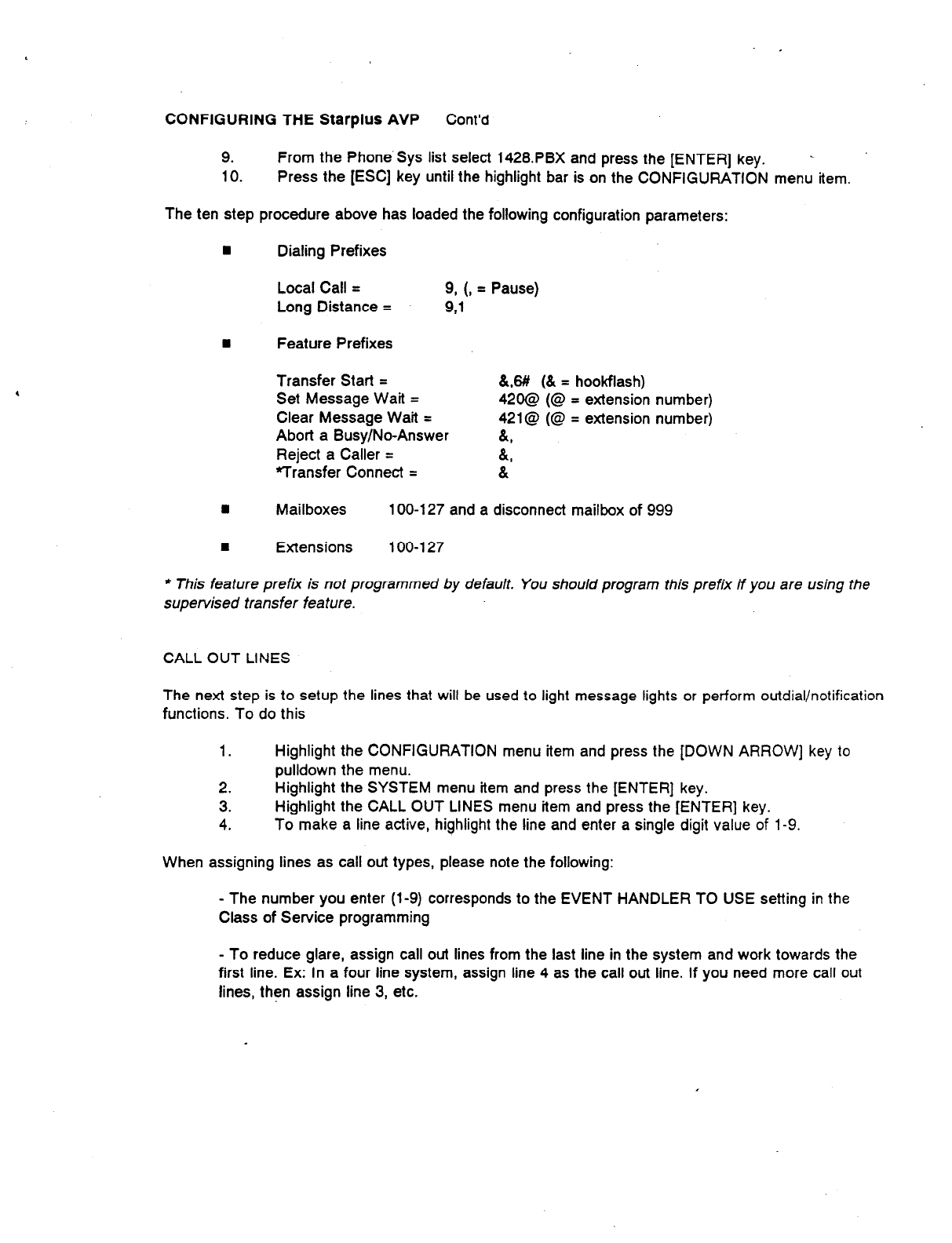
CONFIGURING THE Starplus AVP Cont’d
9. From the Phone.Sys list select 1428.PBX and press the [ENTER] key. L
10. Press the [ESC] key until the highlight bar is on the CONFIGURATION menu item.
The ten step procedure above has loaded the following configuration parameters:
n
Dialing Prefixes
Local Call =
Long Distance = 9, (, = Pause)
9,1
8 Feature Prefixes
Transfer Start =
Set Message Wait =
Clear Message Wait =
Abort a Busy/No-Answer
Reject a Caller =
Transfer Connect =
&,8# (& = hookflash)
420@ (@ = extension number)
421@ (@ = extension number)
a,
A,
&
n
Mailboxes 100-l 27 and a disconnect mailbox of 999
1
Extensions 100-l 27
* This feature prefk is not programmed by default. You should program this prefix if you are using the
supervised transfer feature.
CALL OUT LINES
The next step is to setup the lines that will be used to light message lights or perform outdial/notification
functions. To do this
1. Highlight the CONFIGURATION menu item and press the [DOWN ARROW] key to
pulldown the menu.
2. Highlight the SYSTEM menu item and press the [ENTER] key.
3. Highlight the CALL OUT LINES menu item and press the [ENTER] key.
4. To make a line active, highlight the line and enter a single digit value of 1-9.
When assigning lines as call out types, please note the following:
- The number you enter (l-9) corresponds to the EVENT HANDLER TO USE setting in the
Class of Service programming
- To reduce glare, assign call out lines from the last line in the system and work towards the
first line. Ex: In a four line system, assign line 4 as the call out line. If you need more call out
lines, then assign line 3, etc.
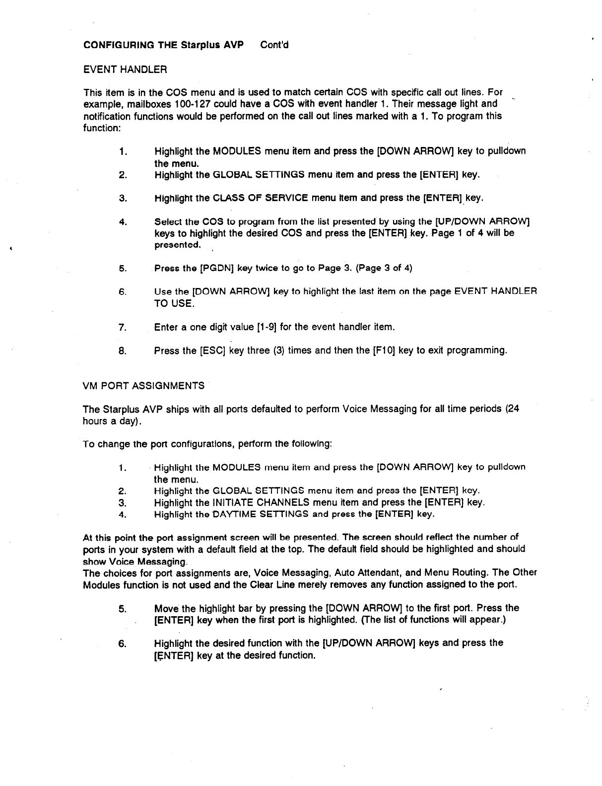
CONFIGURING THE Starplus AVP Cont’d
EVENT HANDLER
This item is in the COS menu and is used to match certain COS with specific call out lines. For
example, mailboxes 100-l 27 could have a COS with event handler 1. Their message light and _
notification functions would be performed on the call out lines marked with a 1. To program this
function:
1.
2.
Highlight the MODULES menu item and press the [DOWN ARROW] key to pulldown
the menu,
Highlight the GLOBAL SETTINGS menu item and press the [ENTER] key.
3. Highlight the CLASS OF SERVICE menu item and press the [ENTER],key.
4. Select the COS to program from the list presented by using the [UP/DOWN ARROW]
keys to highlight the desired COS and press the [ENTER] key. Page 1 of 4 will be
presented. ,
5. Press the [PGDN] key twice to go to Page 3. (Page 3 of 4)
6. Use the [DOWN ARROW] key to highlight the last item on the page EVENT HANDLER
TO USE.
7. Enter a one digit value [l-9] for the event handler item.
8. Press the [ESC] key three (3) times and then the [FlO] key to exit programming.
VM PORT ASSIGNMENTS
The Starplus AVP ships with all ports defautted to perform Voice Messaging for all time periods (24
hours a day).
To change the port configurations, perform the following:
1. Highlight the MODULES menu item and press the [DOWN ARROW] key to pulldown
the menu.
2. Highlight the GLOBAL SETTINGS menu item and press the [ENTER] key.
3. Highlight the INITIATE CHANNELS menu item and press the [ENTER] key.
4. Highlight the’DAYTIME SElTlNGS and press the [ENTER] key.
At this point the port assignment screen will be presented. The screen should reflect the number of
ports in your system with a default field at the top. The default field should be highlighted and should
show Voice Messaging.
The choices for port assignments are, Voice Messaging, Auto Attendant, and Menu Routing. The Other
Modules function is not used and the Clear Line merely removes any function assigned to the port.
5. Move the highlight bar by pressing the [DOWN ARROW] to the first port. Press the
[ENTER] key when the first port is highlighted. (The list of functions will appear.)
6. Highlight the desired function with the [UP/DOWN ARROW] keys and press the
[ENTER] key at the desired function.

For a detailed description of each function please refer to the Starplus AVP manual, The appropriate
sections are:
Voice Messaging Page 620-l 2
Auto Attendant Page 620-34
Menu Routing Page 620-56
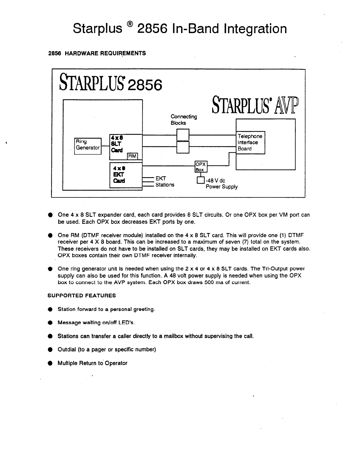
Starplus @ 2856 In-Band Integration
2856 HARDWARE REQUIREMENTS
/
u ml’
Connecting
Blocks
L I
Ring
4x8
* Telephone
SLT - Interface
, Generator - oud - Board
pj -
4x8
cl
-40 V dc
_
Power Z
jUPPlY
4=
EKT
Stations
0 One 4 x 8 SLT expander card, each card provides 8 SLT circuits. Or one OPX box per VM port can
be used. Each OPX box decreases EKT ports by one.
0 One RM (DTMF receiver module) installed on the 4 x 8 SLT card. This will provide one (1) DTMF
receiver per 4 X 8 board. This can be increased to a maximum of seven (7) total on the system.
These receivers do not have to be installed on SLT cards, they may be installed on EKT cards also.
OPX boxes contain their own DTMF receiver internally.
0 One ring generator unit is needed when using the 2 x 4 or 4 x 8 SLT cards. The Tri-Output power
supply can also be used for this function. A 48 volt power supply is needed when using the OPX
box to connect to the AVP system. Each OPX box draws 500 ma of current.
SUPPORTEDFEATURES
0 Station forward to a personal greeting.
0 Message waiting on/off LED’s.
0 Stations can transfer a caller directly to a mailbox without supervising the call.
0 Outdial (to a pager or specific number)
0 Multiple Return to Operator
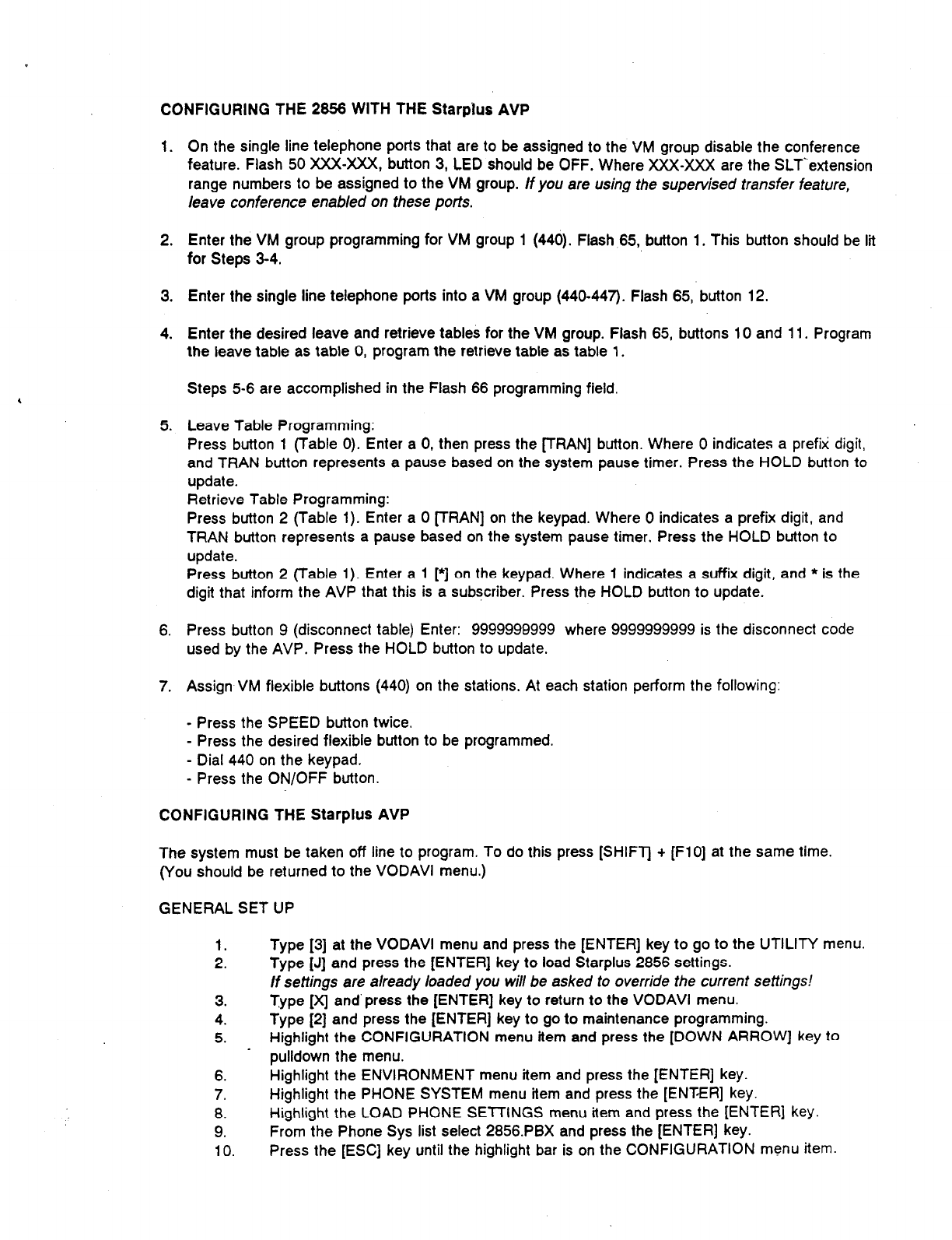
CONFIGURING THE 2856 WITH THE Starplus AVP
1. On the single line telephone ports that are to be assigned to the VM group disable the conference
feature. Flash 50 XXX-XXX, button 3, LED should be OFF. Where XXX-XXX are the SLTLextension
range numbers to be assigned to the VM group. If you are using the supervised transfer feature,
leave conference enabled on these ports.
2. Enter the VM group programming for VM group 1 (440). Flash 65, button 1. This button should be lit
for Steps 3-4.
3.
4.
Enter the single line telephone ports into a VM group (440-447’). Flash 65, button 12.
Enter the desired leave and retrieve tables for the VM group. Flash 65, buttons 10 and 11. Program
the leave table as table 0, program the retrieve table as table 1.
Steps 5-6 are accomplished in the Flash 66 programming field.
5. Leave Table Programming:
Press button 1 (Table 0). Enter a 0, then press the FRAN] button. Where 0 indicates a prefix digit,
and TRAN button represents a pause based on the system pause timer. Press the HOLD button to
update.
Retrieve Table Programming:
Press button 2 (Table 1). Enter a 0 [TRAN] on the keypad. Where 0 indicates a prefix digit, and
TRAN button represents a pause based on the system pause timer. Press the HOLD button to
update.
Press button 2 (Table 1). Enter a 1 [*] on the keypad. Where 1 indicates a suffix digit, and * is the
digit that inform the AVP that this is a subscriber. Press the HOLD button to update.
6. Press button 9 (disconnect table) Enter: 9999999999 where 9999999999 is the disconnect code
used by the AVP. Press the HOLD button to update.
7. Assign VM flexible buttons (440) on the stations. At each station perform the following:
- Press the SPEED button twice.
- Press the desired flexible button to be programmed.
- Dial 440 on the keypad.
- Press the ON/OFF button.
CONFIGURING THE Starplus AVP
The system must be taken off line to program. To do this press [SHIFT + (FlO] at the same time.
(You should be returned to the VODAVI menu.)
GENERAL SET UP
1.
2.
3.
4.
5.
Type [S] at the VODAVI menu and press the [ENTER] key to go to the UTILITY menu.
Type [J] and press the [ENTER] key to load Starplus 2856 settings.
If settings are already loaded you will be asked to override the current settings!
Type [x] and’press the [ENTER] key to return to the VODAVI menu.
Type [2] and press the [ENTER] key to go to maintenance programming.
Highlight the CONFIGURATION menu item and press the [DOWN ARROW] key to
pulldown the menu.
6. Highlight the ENVIRONMENT menu item and press the [ENTER] key.
7. Highlight the PHONE SYSTEM menu item and press the [ENTER] key.
8. Highlight the LOAD PHONE SElTlNGS menu item and press the [ENTER] key.
9. From the Phone Sys list select 2856.PBX and press the [ENTER] key.
10. Press the [ESC] key until the highlight bar is on the CONFIGURATION menu item.
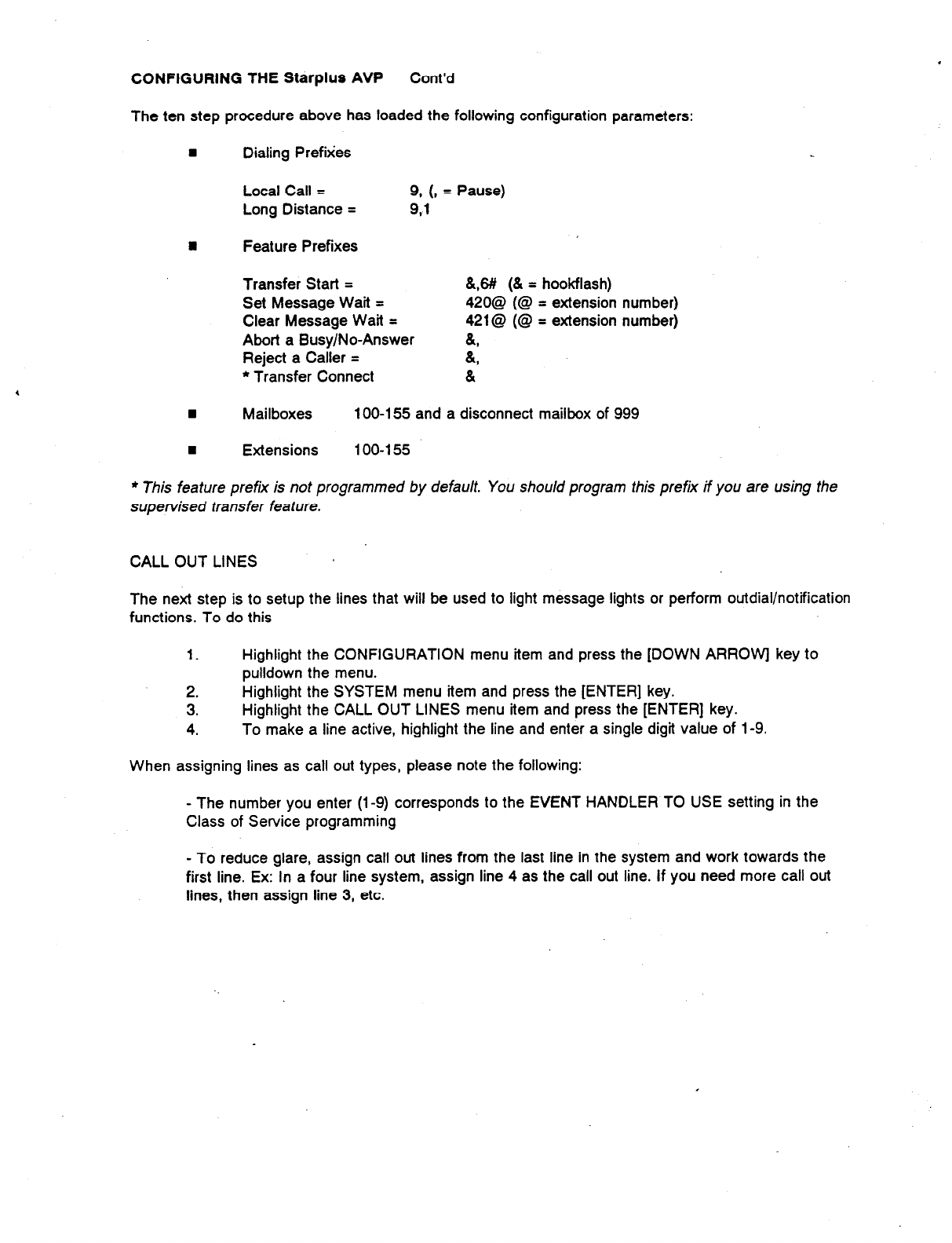
CONFIGURING THE Starplus AVP Cont’d
The ten step procedure above has loaded the following configuration parameters:
n
Dialing Prefixes
Local Call = 9. (8 = Pause)
Long Distance = 9.1
n
Feature Prefixes
Transfer Start =
Set Message Wait =
Clear Message Wait =
Abort a Busy/No-Answer
Reject a Caller =
* Transfer Connect
&,6# (& = hookflash)
420@ (@ = extension number)
421@ (@ = extension number)
(L,
&
&
8 Mailboxes 100-l 55 and a disconnect mailbox of 999
n
Extensions 100-l 55
l
This feature prefix is not programmed by default. You should program this prefix if you are using the
supervised transfer feature.
CALL OUT LINES
The next step is to setup the lines that will be used to light message lights or perform outdial/notification
functions. To do this
1. Highlight the CONFIGURATION menu item and press the [DOWN ARROWI key to
pulldown the menu.
2. Highlight the SYSTEM menu item and press the [ENTER] key.
3. Highlight the CALL OUT LINES menu item and press the [ENTER] key.
4. To make a line active, highlight the line and enter a single digit value of 1-9.
When assigning lines as call out types, please note the following:
- The number you enter (l-9) corresponds to the EVENT HANDLER TO USE setting in the
Class of Service programming
- To reduce glare, assign call out lines from the last line in the system and work towards the
first line. Ex: In a four line system, assign line 4 as the call out line. If you need more call out
lines, then assign line 3, etc.
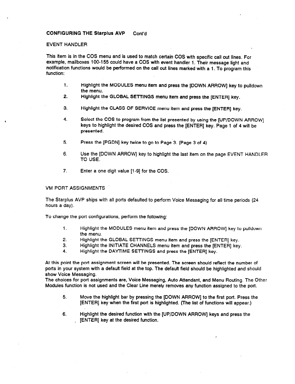
CONFIGURING THE Starplus AVP Cont’d
EVENT HANDLER
This item is in the COS menu and is used to match certain COS with specific call out lines. For
example, mailboxes 100-l 55 could have a COS with event handier 1. Their message light and
notification functions would be performed on the call out lines marked with a 1. To program this
function:
1.
2.
Highlight the MODULES menu item and press the [DOWN ARROW] key to pulldown
the menu.
Highlight the GLOBAL SETTINGS menu item and press the [ENTER] key.
3. Highlight the CLASS OF SERVICE menu item and press the [ENTER] key.
4. Select the COS to program from the list presented by using the [UP/DOWN ARROW)
keys to highlight the desired COS and press the [ENTER] key. Page 1 of 4 will be
presented.
5. Press the [PGDN] key twice to go to Page.3. (Page 3 of 4)
6. Use the [DOWN ARROW] key to highlight the last item on the page EVENT HANDLER
TO USE.
7. Enter a one digit value [l-9] for the COS.
VM PORT ASSIGNMENTS
The Starplus AVP ships with all ports defaulted to perform Voice Messaging for all time periods (24
hours a day).
To change the port configurations, perform the following:
1. Highlight the MODULES menu item and press the [DOWN ARROW] key to pulldown
the menu.
2. Highlight the GLOBAL SETTINGS menu item and press the [ENTER] key.
3. Highlight the INITIATE CHANNELS menu item and press the [ENTER] key.
4. Highlight the DAYTIME SETTINGS and press the [ENTER] key.
At this point the port assignment screen will be presented. The screen should reflect the number of
ports in your system with a defautt field at the top. The defautt field should be highlighted and should
show Voice Messaging.
The choices for port assignments are, Voice Messaging, Auto Attendant, and Menu Routing. The Other
Modules function is not used and the Clear Line merely removes any function assigned to the port.
5. Move the highlight bar by pressing the [DOWN ARROW] to the first port. Press the
[ENTER] key when the first port is highlighted. (The list of functions will appear.)
6. Highlight the desired function with the [UP/DOWN ARROW] keys and press the
_ [ENTER] key at the desired function.

For a detailed descriptiqn of each function please refer to the Starpius AVP manual. The appropriate
sections are:
Voice Messaging Page 620-l 2
Auto Attendant Page 620-34
Menu Routing Page 620-56
STARPLUS Digital Systems Technical Training .
I. Class Schedule
1. We start at 8:00 am and end at approximately 5:00 pm.
2. One 15 minute break in the morning, one in the afternoon.
3. One hour for lunch.
II. Objective
To introduce the student to the hardware components, system installation, and
programming maintenance of the Starplus Digital 1428 and 2856 Key Telephone Systems.
III.Introduce the Manual
1. Quick Reference Table of Content
2. List of Figures
3. List of Tables
4. Issue Control Sheet
5. Section 100 - Introduction
6. Section 200 - Key Station Feature Description*
7. Section 210 - Single Line Telephone Feature Description*
8. Section 220 - Attendant Feature Description*
9. Section 300 - Station Feature Operation*
10. Section 3 10 - SLT Feature Operation*
11. Section 320 - Attendant Feature Operation*
12. Section 330 - LCD Displays*
13. Section 400 - General Description
14. Section 500 - Installation
15. Section 600 - Customer Database Programming
16. Section 610 - System Parameters Programming
17. Section 620 - CO Lines Attributes Programming
18. Section 630 - Station Attributes Programming
Page 1
19. Section 640 - Uniform Call Distribution (UCD)
20. Section 750
- ICLID Programming
21. Section 645 - Voice Mail Programming
22. Section 650 - Exception Tables Programming
23. Section
665 - Least Cost Routing (LCR) Programming
24. Section 660
- Initialize Database Parameters
25. Section 665 - Printing System Database Parameters
26. Section 700 - System Checkout
27. Section 800 - Maintenance and Troubleshooting
28. Customer Database Programming Worksheets
29. Digital Systems Part Numbers
30. ICLID General Descriptions
*Feature and feature operation questions may be addressed to the trainer, as time permits, prior
to class, during breaks, and after class.
This will help to insure the objective of the class is met:
IV. Section 100 Introduction
1. Regulatory Information
A. Telephone Company Notification
B. Ringer Equivalence Number (1.9 )
C. Universal System Ordering Code (USOC) RJ21X
D. FCC Registration Numbers 1428
a. Key System ( direct button appearances ) DLPHKG-65 152~KF-E
b. Hybrid ( dial access codes ) DLPI-IKG-65 153~MF-E
E. FCC Registration Numbers 2856
a. Key System ( direct button appearances) DLPI-IKG-65 102~KF-E
b. Hybrid ( dial access codes) DLPHKG-65 lOI-MF-E
F. Incidence of Harm
a. If the telephone company determines that the customer provided equipment is
causing harm to the telephone network, the equipment must be removed from the
network until repairs are made.
G. Changes in Service.
Page 2
a. The local telephone company must notify the user of system affecting changes in
service.
H. Maintenance Limitations.
a. Warranty will be voided if field repairs are attempted.
I. Notice of Compliance.
a. Class A Computing Device which complies with FCC part 15.
b. Caution Statement
1) Equipment generates RF energy.
2) Any interference corrections are the users responsibility.
J. Hearing Aid Compatibility.
a. All Keysets designed to operate on the system are hearing aid compatible.
K. OPX Circuit.
a. OL13C network circuit and RJl lC/W interface.
L. Canadian Regulatory Information.
M. UL/CSA Safety Compliance
V. General Description
1. The STARPLUS Family of Digital Key Telephone Systems
A. The 1428 - Flat Pack Design
a. Satisfies configurations from 4x8 to 14x28.
B. The 2856 - Card Cage
a. Satisfies configurations from 4x8 to 28x56.
C. BOTH use the same terminal devices (Keysets, Relay Sensor Module, Digital Data
Interface Unit, and SLA/OPX Module).
D. BOTH may use standard 2500~type telephones.
E. BOTH Utilize PCM/TDM Digital Switching Technique.
a. Non-blocking systems
b. Tie Slots
F. CO interfaces
a. ALL CO interfaces are transform protected, classified as fully protected.
G. On-line programming changes, no interruptions of communications (exceptions:
flexible port assignment).
a. Call processing continues as database is updated.
Page 3

b. Programming changes may be made from PORT 01 using a Keyset or from a I/O
Port using a PC.
c. Progr amming Changes may be made from On-board 300 Baud Modem.
VI.Common Equipment for the 1428.
1. Basic KSU with Power Supply.
A. Wall Mountable “Flat Pack” Cabinet.
B. Contains Key Service Board.
a. 68000 Microprocessor.
b. Controls all PCM/TDM circuitry.
c. All control, switching, and interface circuitry are contained on KSB.
C. Capable of supporting 4 CO/PBX/Centrex Lines and 8 Digital Key Terminals ( 4x8
system in the basic configuration ).
D. Reset Halt Switch.
E. Grounding Lug ( P3 ).
F. Provides One DTMF Receiver.
G. Provides One RS-232C I/O Port @B-25)
H. Provides One Input Channel for Background Music and Music On Hold with volume
adjustment.
I. Provides an On-Board 300 Baud Modem.
J. One External Page Path ( all Page paths are one-way in the DVX family ).
K. Contains additional interface connections for:
a. Optional 1200 Baud Modem Module.
b. 2x4 Expander Module or 2x4 SLT Expander Module.
c. Optional I/O Expander Module ( ONE - RS-232C DB25, and ONE RS-422
RJ-14 ).
d. Expansion KSU Interface Connections.
L. Power Supply.
a. Requires 117V ac f 10% input voltage.
b. Requires a Dedicated AC Circuit!
c. Provides a filtered and regulated +12V dc and - 12V dc to the main Key Service
Board.
d. Protected by a 1.5 Amp Slow-blo fuse.
e. Complies with UL 1459 Second Edition.
Page 4
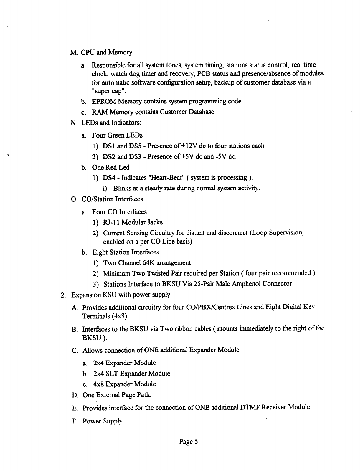
M. CPU and Memory.
a. Responsible for all system tones, system timing, stations status control, real time
clock, watch dog timer and recovery, PCB status and presence/absence of modules
for automatic software configuration setup, backup of customer database via a
“super cap”.
b. EPROM Memory contains system programming code.
c. RAM Memory contains Customer Database.
N. LEDs and Indicators:
a. Four Green LEDs.
1) DSl and DS5 - Presence of +12V dc to four stations each.
2) DS2 and DS3 - Presence of +5V dc and -5V dc.
b. One Red Led
1) DS4 - Indicates “Heart-Beat” ( system is processing ).
i) Blinks at a steady rate during normal system activity.
0. CO/Station Interfaces
a. Four CO Interfaces
1) RJ-11 Modular Jacks
2) Current Sensing Circuitry for distant end disconnect (Loop Supervision,
enabled on a per CO Line basis)
b. Eight Station Interfaces
1) Two Channel 64K arrangement
2) Minimum Two Twisted Pair required per Station ( four pair recommended ).
3) Stations Interface to BKSU Via 25-Pair Male Amphenol Connector.
2. Expansion KSU with power supply.
A. Provides additional circuitry for four CO/PBX/Centrex Lines and Eight Digital Key
Terminals (4x8).
B. Interfaces to the BKSU via Two ribbon cables ( mounts immediately to the right of the
BKSU ).
C. Allows connection of ONE additional Expander Module.
a. 2x4 Expander Module
b. 2x4 SLT Expander Module.
c. 4x8 Expander Module.
D. One External Page Path.
E. Provides interface for the connection of ONE additional DTMF Receiver Module.
F. Power Supply
Page 5
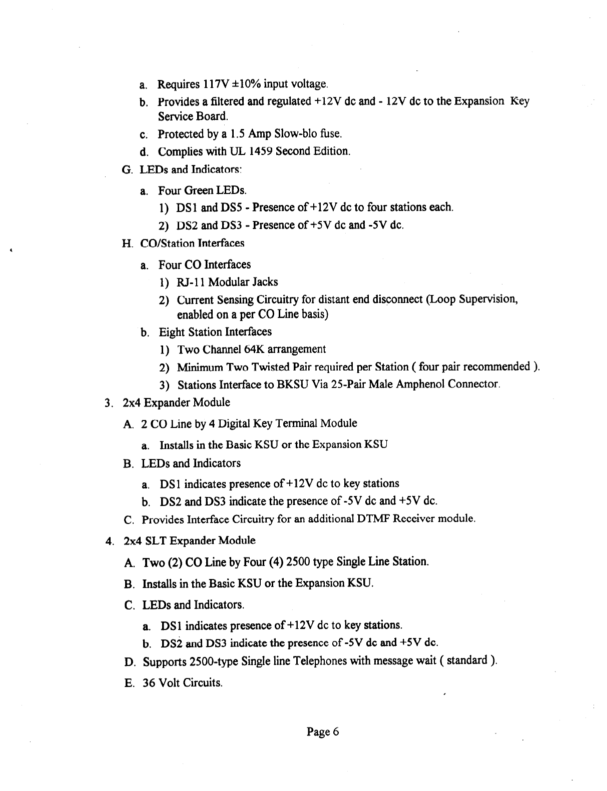
a. Requires 117V *lOoh input voltage.
b. Provides a filtered and regulated +12V dc and - 12V dc to the Expansion Key
Service Board.
c. Protected by a 1.5 Amp Slow-blo fuse.
d. Complies with UL 1459 Second Edition.
G. LEDs and Indicators:
a. Four Green LEDs.
1) DSl and DSS - Presence of +12V dc to four stations each.
2) DS2 and DS3 - Presence of +5V dc and -5V dc.
H. CO/Station Interfaces
a. Four CO Interfaces
1) RJ-11 Modular Jacks
2) Current Sensing Circuitry for distant end disconnect (Loop Supervision,
enabled on a per CO Line basis)
b. Eight Station Interfaces
1) Two Channel 64K arrangement
2) Minimum Two Twisted Pair required per Station ( four pair recommended ).
3) Stations Interface to BKSU Via 25Pair Male Amphenol Connector.
3. 2x4 Expander Module
A. 2 CO Line by 4 Digital Key Terminal Module
a. Installs in the Basic KSU or the Expansion KSU
B. LEDs and Indicators
a. DSl indicates presence of +12V dc to key stations
b. DS2 and DS3 indicate the presence of -5V dc and +5V dc.
C. Provides Interface Circuitry for an additional DTMF Receiver module.
4. 2x4 SLT Expander Module
A. Two (2) CO Line by Four (4) 2500 type Single Line Station.
B. Installs in the Basic KSU or the Expansion KSU.
C. LEDs and Indicators.
a. DSl indicates presence of +12V dc to key stations.
b. DS2 and DS3 indicate the presence of -5V dc and +5V dc.
D. Supports 2500~type Single line Telephones with message wait ( standard ).
E. 36 Volt Circuits.
Page 6
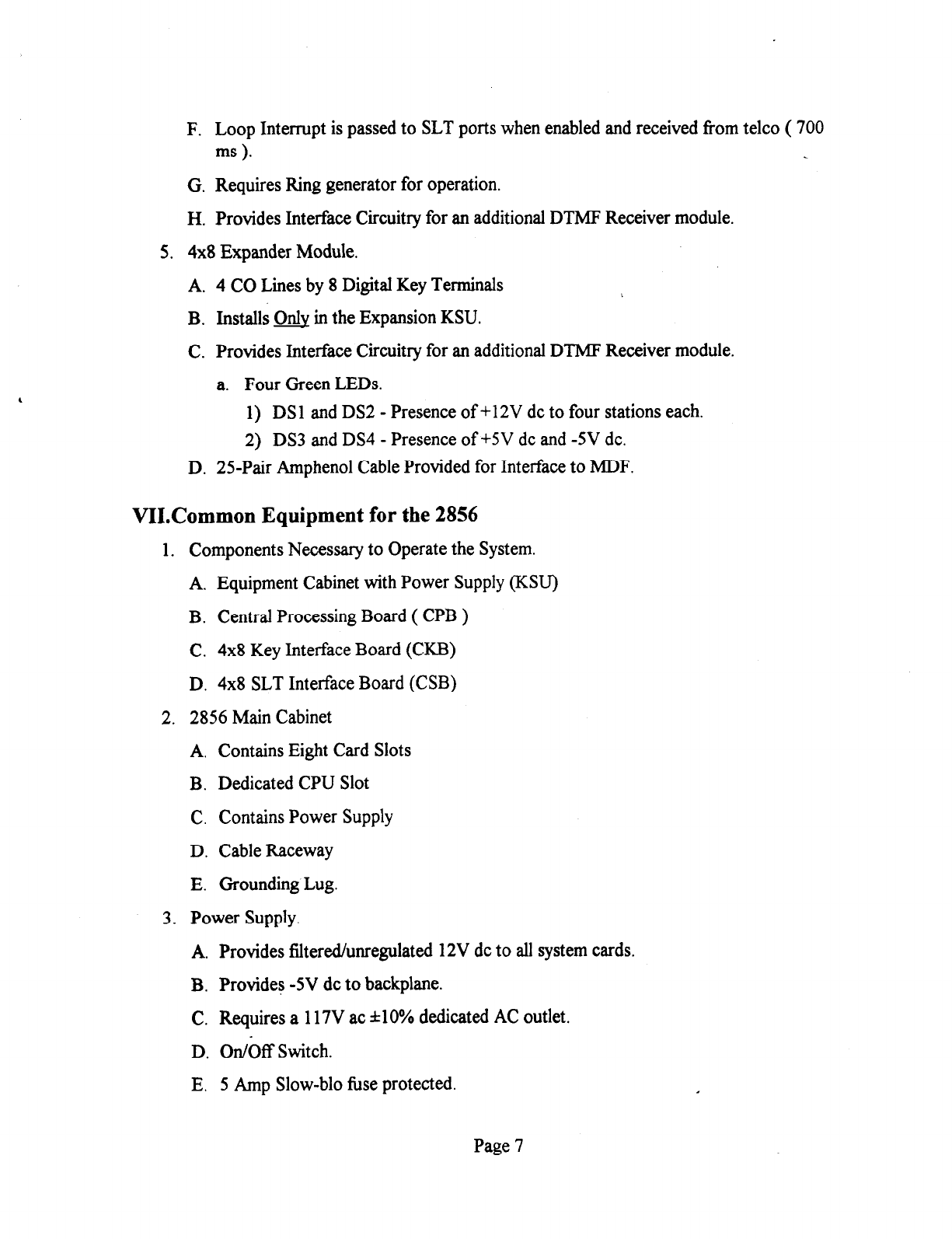
F. Loop Interrupt is passed to SLT ports when enabled and received from telco ( 700
ms ).
G. Requires Ring generator for operation.
H. Provides Interface Circuitry for an additional DTMF Receiver module.
5. 4x8 Expander Module.
A. 4 CO Lines by 8 Digital Key Terminals
B. Installs m in the Expansion KSU.
C. Provides Interface Circuitry for an additional DTMF Receiver module.
a. Four Green LEDs.
1) DSl and DS2 - Presence of +12V dc to four stations each.
2) DS3 and DS4 - Presence of +SV dc and -5V dc.
D. 25-Pair Amphenol Cable Provided for Interface to MDF.
VII.Common Equipment for the 2856
1. Components Necessary to Operate the System.
A. Equipment Cabinet with Power Supply (KSU)
B. Central Processing Board ( CPB )
C. 4x8 Key Interface Board (CKB)
D. 4x8 SLT Interface Board (CSB)
2. 2856 Main Cabinet
A. Contains Eight Card Slots
B. Dedicated CPU Slot
C. Contains Power Supply
D. Cable Raceway
E. Grounding Lug.
3. Power Supply.
A. Provides filtered/unregulated 12V dc to all system cards.
B. Provides -5V dc to backplane.
C. Requires a 117V ac &lo% dedicated AC outlet.
D. On/Off Switch.
E. 5 Amp Slow-blo fuse protected.
Page 7
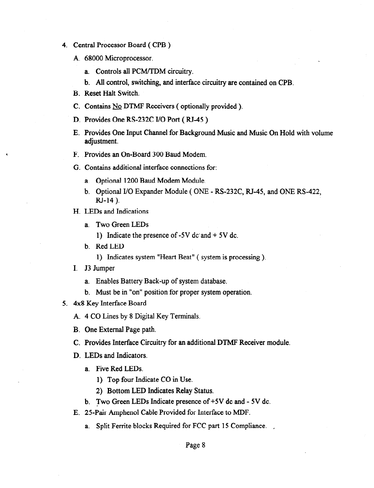
4. Central Processor Board ( CPB )
A. 68000 Microprocessor.
a. Controls all PCM/TDM circuitry.
b. All control, switching, and interface circuitry are contained on CPB.
B. Reset Halt Switch.
C. Contains & DTMF Receivers ( optionally provided ).
D. Provides One RS-232C I/O Port ( RJ-45 )
E. Provides One Input Channel for Background Music and Music On Hold with volume
adjustment.
F. Provides an On-Board 300 Baud Modem.
G. Contains additional interface connections for:
a. Optional 1200 Baud Modem Module.
b. Optional I/O Expander Module ( ONE - RS-232C, RJ-45, and ONE RS-422,
RJ-14 ).
H. LEDs and Indications
a. Two Green LEDs
1) Indicate the presence of -5V dcand + 5V dc.
b. Red LED
1) Indicates system “Heart Beat” ( system is processing ).
I. J3 Jumper
a. Enables Battery Back-up of system database.
b. Must be in “on” position for proper system operation.
5. 4x8 Key Interface Board
A. 4 CO Lines by 8 Digital Key Terminals.
B. One External Page path.
C. Provides Interface Circuitry for an additional DTMF Receiver module.
D. LEDs and Indicators.
a. Five Red LEDs.
1) Top four Indicate CO in Use.
2) Bottom LED Indicates Relay Status.
b. Two Green LEDs Indicate presence of +5V dc and - 5V dc.
E. 25-Pair Amphenol Cable Provided for Interface to MDF.
a. Split Ferrite blocks Required for FCC part 15 Compliance. ,
Page 8
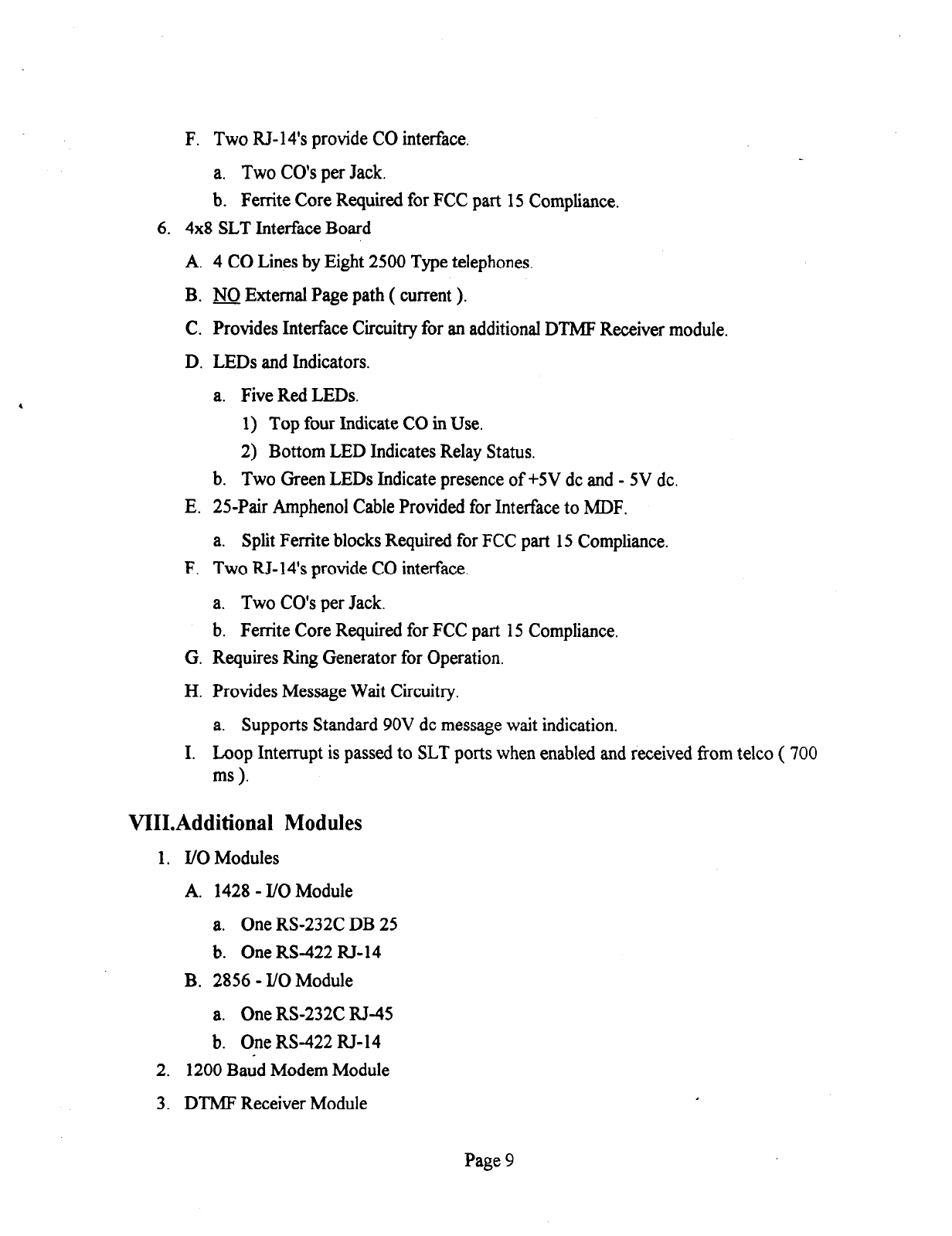
F. Two RJ-14’s provide CO interface.
a. Two CO’s per Jack.
b. Ferrite Core Required for FCC part 15 Compliance.
6. 4x8 SLT Interface Board
A. 4 CO Lines by Eight 2500 Type telephones.
B. m External Page path ( current ).
C. Provides Interface Circuitry for an additional DTMF Receiver module.
D. LEDs and Indicators.
a. Five Red LEDs.
1) Top four Indicate CO in Use.
2) Bottom LED Indicates Relay Status.
b. Two Green LEDs Indicate presence of +5V dc and - 5V dc.
E. 2%Pair Amphenol Cable Provided for Interface to MDF.
a. Split Ferrite blocks Required for FCC part 15 Compliance.
F. Two R&14’s provide CO interface.
a. Two CO’s per Jack.
b. Ferrite Core Required for FCC part 15 Compliance.
G. Requires Ring Generator for Operation.
H. Provides Message Wait Circuitry.
a. Supports Standard 9OV dc message wait indication.
I. Loop Interrupt is passed to SLT ports when enabled and received from telco ( 700
ms ).
VIII.Additional Modules
1. I/O Modules
A. 1428 - I/O Module
a. One RS-232C DB 25
b. One RS-422 RJ-14
B. 2856 - I/O Module
a. One RS-232C RJ-45
b. One RS-422 RJ-14
2. 1200 Baud Modem Module
3. DTMF Receiver Module
Page 9

IX.Digital Terminal Description
1. 34-Button Terminal
A. Three Different Models
a. 34-Button Executive Terminal has a 48 Character LCD display
b. 34-Button Enhanced Terminal has NO display.
c. 34-button Executive/PC Terminal has a 48 Character LCD Display and a RS-232
Output for ICLID information interface to a Personal Computer.
B. Digital Terminals Require Two-pair to operate.
C. The LCD Display is Divided into Three Fields.
a. Field One - Current Status (top line, 24 characters).
b. Field Two - Date (left half of bottom line, 12 characters).
c. Field Three - Time of Day (right half of bottom line, twelve characters).
D. Buttons and LEDs
a. Super-Bright LEDs on all keys, except the Dial Pad,
b. Button Definitions
1) 12 Dial Key Pad
2) 28 Flexible Buttons
3) On/Off button (fixed)
4) Mute button (fixed)
5) Speed button (fixed)
6) Flash button (fixed)
7) Transfer button (fixed)
8) Hold button (fixed)
E. Speakerphone Description
a. Handsfree two way conversation.
b. Mute.
c. Terminate call with the On/Off button.
d. Automatic Pre-selection allows the speakerphone to be enabled by pressing a
button (i.e.. DSS, CO Line, Page . . . . . etc..)
e. Programmable options allow for full speakerphone or monitor/on-hook dialing
capabilities and no speakerphone operation.
F. Volume controls.
a. Slide switches provide the ability to adjust the ring volume and the speaker
volume.
Page 10

1) Speaker volume adjusts all voice signals sent to the speaker (i.e..
Speakerphone Conversations, Background Music, Page announcements)
2) Ring Volume adjusts all tone signals sent to the speaker.
i) Muted ringing will be proportionately quieter than normal ringing based on
the volume setting.
G. H-T-P Switch - Three position slide switch which controls the method of receiving
intercom calls.
a. Hand&e (I-I) Position - Upon hearing a tone burst and voice announcement over
the speaker the User can reply handsfiee.
b. Privacy (P) Position - The station user receives a tone burst and a vice
announcement over the speaker. the microphone is deactivated for privacy, the
user must either go off-hook or press the Mute key to reply.
c. Tone (T) Position - Standard tone ring notifies of an incoming call and the user
answers by going off-hook or pressing the On/Off button for speakerphone
operation.
d. Switch selection may be overridden by use of the Forced Tone Ring option.
H. Directory Tray
I. Wall Mountable
2. 34-Button Digital Terminal (Enhanced)
A. Information About Executive Terminal Applies Except No LCD Display.
3. 34-Button Executive/PC Interface Terminal (ICLID)
A. Information About Executive Terminal Applies.
B. Equipped with RS232C I/O channel.
a. 2400bps, No-Parity, 8 Data Bits, 1 Stop Bit.
C. A Personal Computer May Be Interfaced with the Terminal To Receive ICLID
information, via Vodavi Call Tracker Software.
D. A program which runs on a PC may control key actions on the terminal and also
receive ICLID information. Would Require Software Development By Independent
Programmer.
4. 14-Button Digital Terminal
A. Digital Terminals Require Two-pair to operate.
B. Buttons and LEDs
a. Super-Bright LEDs on all keys except the Dial Pad.
b. Button Definitions
1) 12 Dial Key Pad
2) 8 Flexible Buttons
Page 11
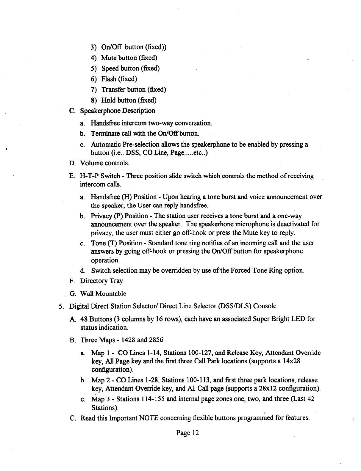
3) On/Off button (fixed))
4) Mute button (fixed)
5) Speed button (fixed)
6) Flash (fixed)
7) Transfer button (fixed)
8) Hold button (fixed)
C. Speakerphone Description
a. Hand&x intercom two-way conversation.
b. Terminate call with the On/Off button.
c. Automatic Pre-selection allows the speakerphone to be enabled by pressing a
button (i.e.. DSS, CO Line, Page . . . . . etc..)
D. Volume controls.
E. H-T-P Switch - Three position slide switch which controls the method of receiving
intercom calls.
a. Handsfree (H) Position - Upon hearing a tone burst and voice announcement over
the speaker, the User can reply handsfree.
b. Privacy (P) Position - The station user receives a tone burst and a one-way
announcement over the speaker. The speakerhone microphone is deactivated for
privacy, the user must either go off-hook or press the Mute key to reply.
c. Tone (T) Position - Standard tone ring notifies of an incoming call and the user
answers by going off-hook or pressing the On/Off button for speakerphone
operation.
d. Switch selection may be overridden by use of the Forced Tone Ring option.
F. Directory Tray
G. Wall Mountable
5. Digital Direct Station Selector/ Direct Line Selector @SS/DLS) Console
A. 48 Buttons (3 columns by 16 rows), each have an associated Super Bright LED for
status indication.
B. Three Maps - 1428 and 2856
a. Map 1 - CO Lines 1-14, Stations 100-127, and Release Key, Attendant Override
key, All Page key and the first three Call Park locations (supports a 14x28
configuration).
b. Map 2 - CO Lines l-28, Stations 100-l 13, and first three park locations, release
key, Attendant Override key, and All Call page (supports a 28x12 configuration).
c. Map 3 - Stations 114-l 55 and internal page zones one, two, and three (Last 42
Stations).
C. Read this Important NOTE concerning flexible buttons programmed for features.
Page 12
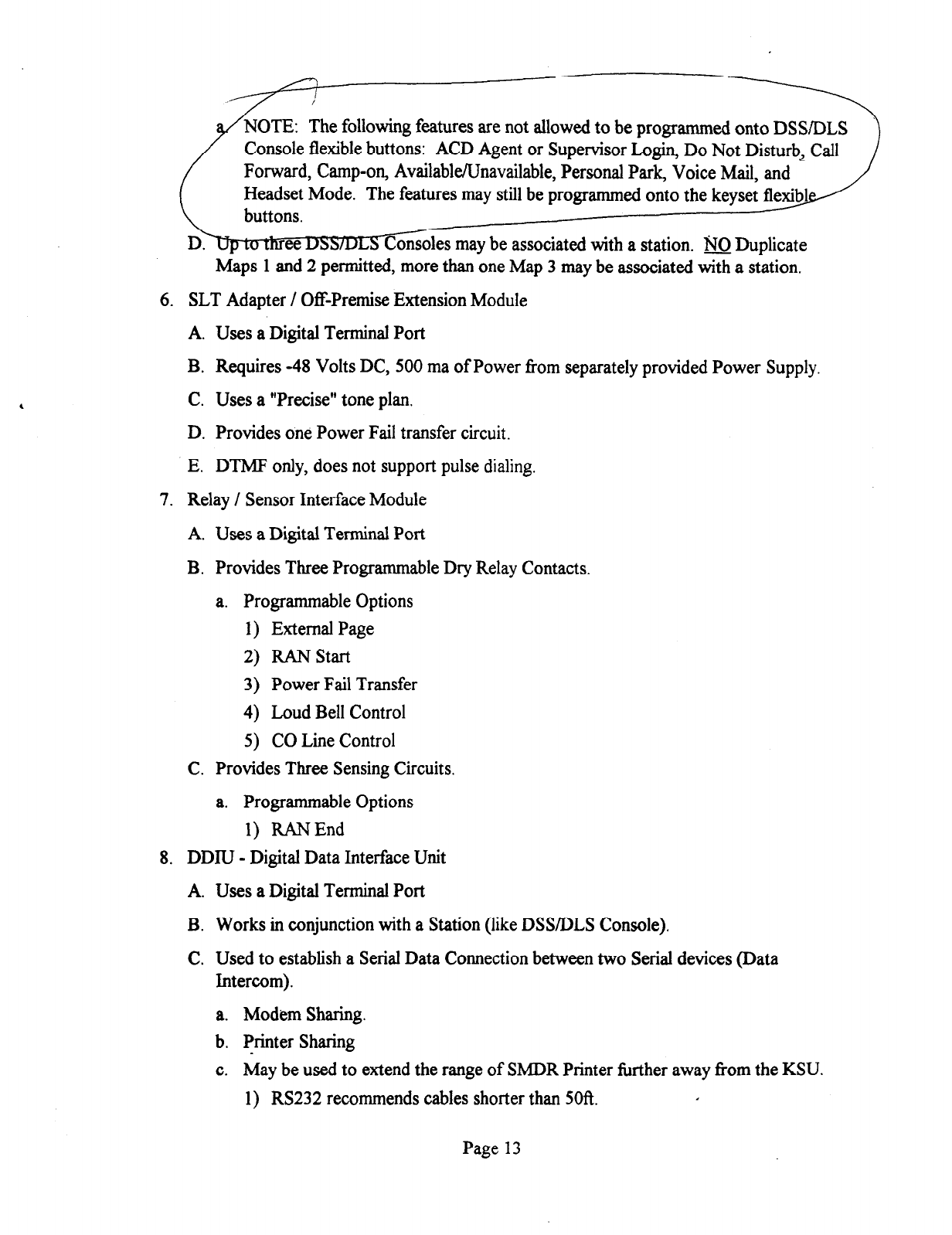
: The following features are not allowed to be programmed onto DSSIDLS
Console flexible buttons: ACD Agent or Supervisor Login, Do Not Disturb, Call
Forward, Camp-on, Available/Unavailable, Personal Park, Voice Mail, and
Headset Mode. The features may still be programmed onto the keyset fl
Consoles may be associated with a station. No Duplicate
Maps 1 and 2 permitted, more than one Map 3 may be associated with a station.
6. SLT Adapter / Off-Premise Extension Module
A. Uses a Digital Terminal Port
B. Requires -48 Volts DC, 500 ma of Power from separately provided Power Supply.
C. Uses a “Precise” tone plan.
D. Provides one Power Fail transfer circuit.
E. DTMF only, does not support pulse dialing.
7. Relay / Sensor Interface Module
A. Uses a Digital Terminal Port
B. Provides Three Programmable Dry Relay Contacts.
a. Programmable Options
1) External Page
2) RAN start
3) Power Fail Transfer
4) Loud Bell Control
5) CO Line Control
C. Provides Three Sensing Circuits.
a. Programmable Options
1) RANEnd
8. DDIU - Digital Data Interface Unit
A. Uses a Digital Terminal Port
B. Works in conjunction with a Station (like DSS/DLS Console).
C. Used to establish a Serial Data Connection between two Serial devices (Data
Intercom).
a. Modem Sharing.
b. Printer Sharing
c. May be used to extend the range of SMDR Printer further away from the KSU.
1) RS232 recommends cables shorter than 5Ofi.
Page 13
9, PFTU - Power Fail Transfer Unit
A. Provides the relay transfer circuits for up to 12 CO Lines in the event of a Power
Failure.
B. Controlled by a Relay Sensor Module Programmed for Power Fail Transfer.
C. A customer provided 12 Volt DC Power Supply is required to operate the unit.
Page 14
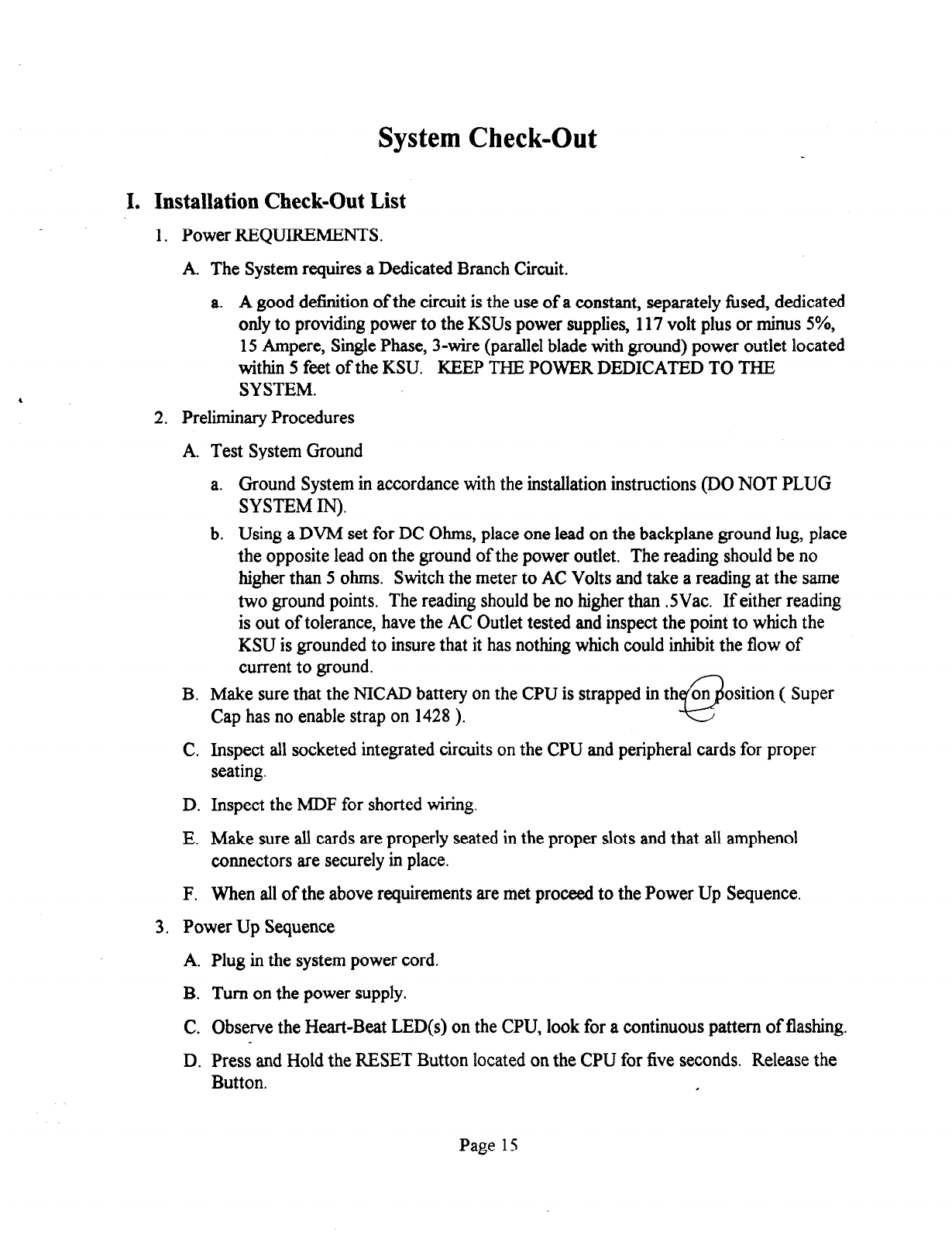
System Check-Out
I. Installation Check-Out List
1. Power REQUIREMENTS.
A. The System requires a Dedicated Branch Circuit.
a. A good definition of the circuit is the use of a constant, separately fused, dedicated
only to providing power to the KSUs power supplies, 117 volt plus or minus 5%,
15 Ampere, Single Phase, 3-wire (parallel blade with ground) power outlet located
within 5 feet of the KSU. KEEP THE POWER DEDICATED TO THE
SYSTEM.
2. Preliminary Procedures
A. Test System Ground
a. Ground System in accordance with the installation instructions (DO NOT PLUG
SYSTEM IN).
b. Using a DVM set for DC Ohms, place one lead on the backplane ground lug, place
the opposite lead on the ground of the power outlet. The reading should be no
higher than 5 ohms. Switch the meter to AC Volts and take a reading at the same
two ground points. The reading should be no higher than .SVac. If either reading
is out of tolerance, have the AC Outlet tested and inspect the point to which the
KSU is grounded to insure that it has nothing which could inhibit the flow of
current to ground.
B. Make sure that the NICAD battery on the CPU is strapped in th
Q
on osition ( Super
Cap has no enable strap on 1428 ).
C. Inspect all socketed integrated circuits on the CPU and peripheral cards for proper
seating.
D. Inspect the MDF for shorted wiring.
E. Make sure all cards are properly seated in the proper slots and that all amphenol
connectors are securely in place.
F. When all of the above requirements are met proceed to the Power Up Sequence.
3. Power Up Sequence
A.
B.
C.
D.
Plug in the system power cord.
Turn on the power supply.
Observe the Heart-Beat LED(s) on the CPU, look for a continuous pattern of flashing.
Press and Hold the RESET Button located on the CPU for five seconds. Release the
Button.
Page 15
E. After the LEDs return to their pattern, enter the programming mode either from
Station 100 or via the RS232 communications port on the CPU and INITIALIZE the
DATABASE (Flash 80, button 8, Hold).
F. The System is now ready for programming.
Page 16

Customer Database Programming
I. Introduction
1. Flexible Programming allows the system to be tailored to the customers needs.
2. No interruptions in call processing while programming the database.
A. Exception is flexible port assignment. Requires a reset so system can assign time slots.
3. Methods of Programming.
A. From Station 100 (port 01) using a Executive Display Terminal.
a. Enter the programming mode by dialing **3226.
b. The On/Off Key on the terminal is lit.
c. The System is ready to program.
d. Refer to Figure 600-3 Programming Button Mapping for Terminal layout while in
programming mode.
B. From an ASCII terminal.
a. May be either on-site via direct connection to the RS-232C port on the CPB
(RS232C may be configured for 300, 1200,2400, or 4800 Baud) or Remotely via
the on-board 300 baud modem (1200 Baud if the optional 1200 Baud Modem
Module is installed).
b. Terminal Device must be configured for Selected Baud Rate, 8 data bits, 1 stop
bit, and no parity ( xxxx,8,N,l).
c. When purchasing a cable, buy one with pins that are not fixed but can be
configured.
d. Program Mode Entry.
1) Once connected to the system hit the Return Key.
2) Prompt will appear.
i) The Prompt shows the System time and date, and the Software Version.
This is the best way to find out the software version without interrupting
service.
3) Enter the password.
4) The System is ready to program.
5) Refer to Figure 600-l - Data Terminal Codes Cross Reference, the table
provides a one to one cross reference of keystrokes, allowing digital terminal
programming to be emulated on the ASCII terminal.
- i) Plus (+) and Minus (-) proceeding the terminal entry may be used to
toggle on/off enable/disable features.
Page 17
ii) While in programming entering a question mark (?) will return the Remote
Administration Key Definitions.
4. Data Base Programming Structure and Indications
A. Once the database is entered programming of attributes is facilitated using Data Field
(FLASH or Program Codes) codes.
a. Data Fields are used as a method of Dividing the Database into Sections of Related
Attributes, much like drawers within a file cabinet. Related items are grouped
together and then an individual item is changed by making the proper program
entry, much like accessing a file within the drawer and mod@ing some of the
information within the file.
B. The Hold Key on the terminal is used to save programming entries.
a. Pressing hold writes information to the database and saves it. You have accessed
your file in the cabinet, changed the data in the tile, and now you are returning the
file to its location in the cabinet and closing the drawer. The data is saved at that
location until it is ready to be modified again.
b. Ifan error is made in data entry, do not press the Hold Key, simply re-enter the
Data Field code or press the On/Off key or hang the terminal up.
C. Confirmations Tone
a. Confirmation tone is issued when a valid entry is made in the database
programming mode.
b. Confirmation Tone has a frequency of 1471 Hertz and lasts a duration of 1.4
seconds, sounding only once.
D. Error Tone
a. Programming Error Tone is provided when an invalid entry is made while in the
programming mode.
b. Programming Error Tone has a frequency of 1471 Hertz and a cadence of 0.2
seconds on / 0.2 seconds off repeated six times.
5. Beginning to Program.
A. Once the program mode has been entered.
a. Press the Flash button.
b. Enter the two-digit field number.
c. Enter customer Data.
d. Press hold and listen for either conformation tone or error tone.
e. Repeat the steps until all data is entered.
6. Initialization.
A. SYSTEM DATABASE MUST BE INITIALIZED WHEN THE SYSTEM IS
INSTALLED OR WHEN THE DATABASE HAS BEEN CORRUPTED.
Page 18
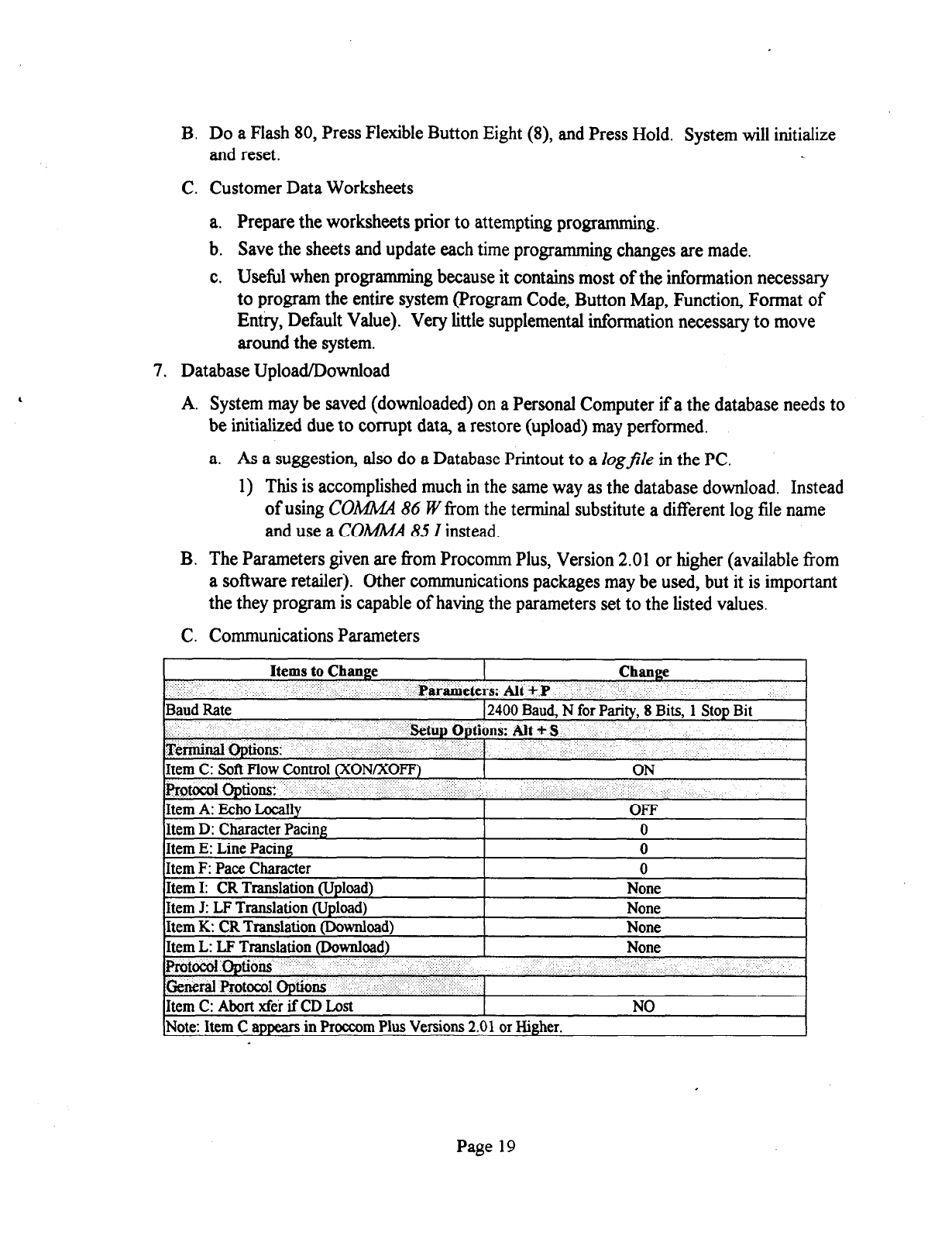
B. Do
a Flash 80, Press Flexible Button Eight (8), and Press Hold.
System
will
initialize
and reset.
C. Customer Data Worksheets
a. Prepare the worksheets prior to attempting programming.
b. Save the sheets and update each time programming changes are made.
c. Useful when programming because it contains most of the information necessary
to program the entire system (Program Code, Button Map, Function, Format of
Entry, Default Value). Very little supplemental information necessary to move
around the system.
7. Database Upload/Download
A. System may be saved (downloaded) on a Personal Computer if a the database needs to
be initialized due to corrupt data, a restore (upload) may performed.
a. As a suggestion, also do a Database Printout to a Zogfile in the PC.
1) This is accomplished much in the same way as the database download. Instead
of using COM 86 ?I’from the terminal substitute a different log file name
and use a CO&M4 85 I instead.
B. The Parameters given are from Procomm Plus, Version 2.01 or higher (available from
a software retailer). Other communications packages may be used, but it is important
the they program is capable of having the parameters set to the listed values.
C. Communications Parameters
Items to Change Change
: .:, ‘, Parameters: AM +.P ..
Baud Rate 12400 Baud, N for Parity, 8 Bits, 1 Stop Bit
. . . . . . ‘EMup Options: Alt +$.
T&imii@l optins:
Item C: Soft Flow Control &ON/xOFF)
.,:
ON
protocDl uptious: “.. ...
Item A: Echo Locally .: ,’ . . .
OFF
Item D: Character Pacing 0
Item E: Line Pacing 0
Item F: Pace Character 0
ktem I: CR Translation (U&ad)
IItem J: LF Translation (Upload)
It- em K: CR Translation IDownload~ I
Item L: LF Translation (Download)
EJIemroptions ..‘:
;Ge,d fiot@.&l opb& ,’ .:. :. ,’
;,::q ... . . y,:::r.. 1
Item C: Abort xfe’ei if CD Lost
None
None
None
NO
I
. .
INote: Item C appears in Proccom Plus Versions 2.01 or Higher.
Page 19
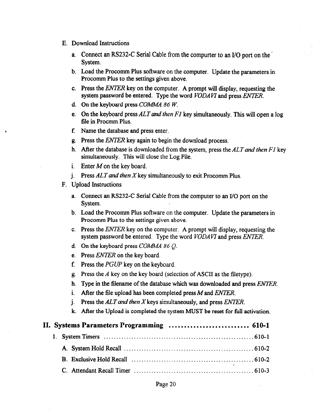
E. Download Instructions
a.
b.
C.
d.
e.
E
8.
h.
i.
i
Connect an RS232-C Serial Cable from the compurter to an I/O port on the -
System.
Load the Procomm Plus software on the computer.
Update the parameters in
Procomm Plus to the settings given above.
Press the EN7ER key on the computer. A prompt will display, requesting the
system password be entered. Type the word VODA Ki’ and press IW7IX
On the keyboard press CGA444 86 W.
On the keyboard press ALT and then FI key simultaneously. This will open a log
file in Procmm Plus.
Name the database and press enter.
Press the ENK?ZR key again to begin the download process.
After the database is downloaded from the system, press the ALTand then FI key
simultaneously. This will close the Log File.
Enter A4 on the key board.
Press ALT and then X key simultaneously to exit Procomm Plus.
F. Upload Instructions
a. Connect an RS232-C Serial Cable from the computer to an I/O port on the
System.
b. Load the Procomm Plus software on the computer. Update the parameters in
Procomm Plus to the settings given above.
c. Press the IWZ7% key on the computer. A prompt will display, requesting the
system password be entered. Type the word F’ODAF7 and press ENTER.
d. On the keyboard press COMMA 86 Q.
e. Press EiVTH on the key board.
f Press the PGUP key on the keyboard.
g. Press the A key on the key board (selection of ASCII as the filetype).
h. Type in the filename of the database which was downloaded and press EhVER.
i. After the file upload has been completed press M and EiViZK
j. Press the ALT and then X keys simultaneously, and press ENi’ER.
k. After the Upload is completed the system MUST be reset for full activation.
II. Systems Parameters Programming .......................... 610-l
1. System Timers ............................................................ 610-l
A. System Hold Recall ................................................... .610-2
B. Exclusive Hold Recall ................................................ .610-2
C. Attendant Recall Timer ............................................... .6 1 O-3
Page 20
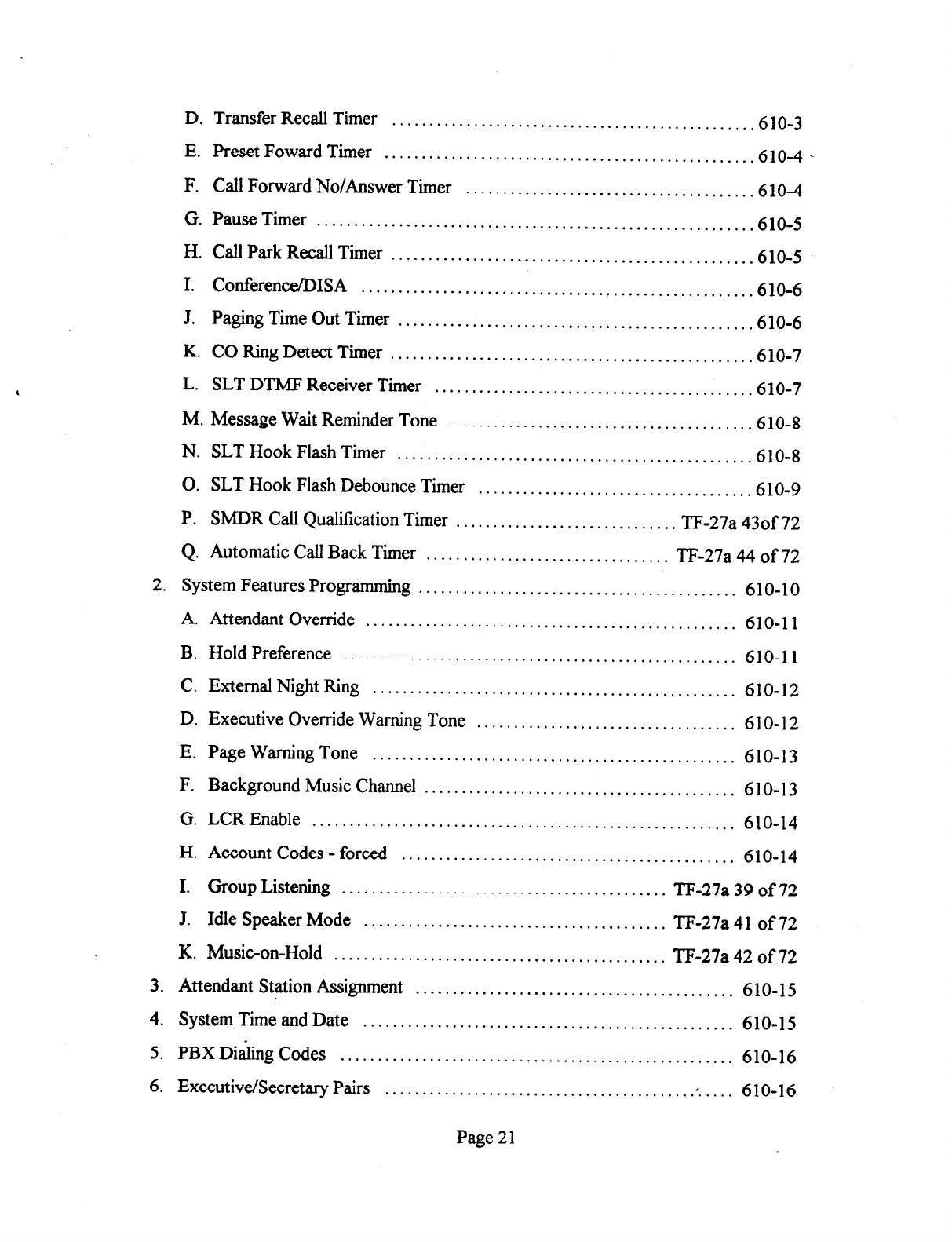
D. Transfer Recall Timer ................................................ .6 1 O-3
E. Preset Foward Timer ................................................. .610-4
F. Call Forward No/Answer Timer ...................................... .610-4
G. Pause Timer .......................................................... .610-5
H. CallParkRecallTimer ................................................ .610-5
I. ConferenceDISA .................................................... .6 1 O-6
J. Paging Time Out Timer ............................................... .610-6
K. CO Ring Detect Timer ................................................ .610-7
L. SLT DTMF Receiver Timer .......................................... .610-7
M. Message Wait Reminder Tone ........................................ .610-8
N. SLT Hook Flash Timer ............................................... .610-8
0. SLT Hook Flash Debounce Timer .................................... .610-9
P. SMDR Call Qualification Timer .............................. TF-27a 430f 72
Q. Automatic Call Back Timer ................................. TF-27a 44 of 72
2. System Features Programming ........................................... 610-10
A. Attendant Override .................................................. 61 O-l 1
B. HoldPreference ..................................................... 610-11
C. External Night Ring ................................................. 610-12
D. Executive Override Warning Tone ................................... 610-12
E. Page Warning Tone ................................................. 610-13
F. Background Music Channel .......................................... 610-13
G. LCREnable ......................................................... 610-14
H. Account Codes - forced ............................................. 610-14
I. Group Listening ............................................ TF-27a 39 of 72
J. Idle Speaker Mode ......................................... TF-27a 41 of 72
K. Music-on-Hold ............................................. TF-27a 42 of 72
3. Attendant Station Assignment ........................................... 6 lo- 15
4. System Time and Date .................................................. 610-15
5. PBX Dialing Codes ..................................................... 610-16
6. Executive/Secretary Pairs ......................................... .: .... 6 lo- 16
Page 21
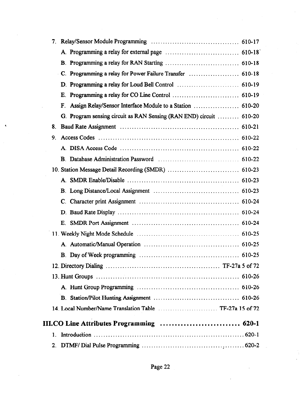
7. Relay/Sensor Module Programming ..................................... 6 lo- 17
A. Programming a relay for external page ............................... 610-18-
B. Programming a relay for RAN Starting
............................... 610-18
C. Progr amming
a relay for Power Failure Transfer ..................... 610-18
D. Programming a relay for Loud Bell Control .......................... 610-19
E. Programming a relay for CO Line Control ............................ 610-19
F. Assign Relay/Sensor Interface Module to a Station ................... 610-20
G. Program sensing circuit as RAN Sensing (RAN END) circuit ......... 610-20
8. Baud Rate Assignment .................................................. 610-21
9. Access Codes ........................................................... 6 1 O-22
A. DISA Access Code .................................................. 6 1 O-22
B. Database Administration Password .................................. 6 1 O-22
10. Station Message Detail Recording (SMDR) .............................. 6 1 O-23
A. SMDR Enable/Disable ............................................... 6 1 O-23
B. Long Distance/Local Assignment .................................... 610-23
C. Character print Assignment .......................................... 6 1 O-24
D. Baud Rate Display ................................................... 61 O-24
E. SMDR Port Assignment ............................................. 6 1 O-24
11. Weekly Night Mode Schedule ........................................... 610-25
A. Automatic/Manual Operation ........................................ 6 1 O-25
B. Day of Week programming
.......................................... 610-25
12. Directory Dialing ................................................ TF-27a 5 of 72
13. Hunt Groups ............................................................ 610-26
A. Hunt Group Programming ........................................... 610-26
B. Station/Pilot Hunting Assignment .................................... 610-26
14. Local Number/Name Translation Table ......................... TF-27a 15 of 72
III.CO Line Attributes Programming ........................... 620-l
1. Introduction .............................................................. .620-l
2. DTMF/ Dial Pulse Programming
.................................. : ....... .620-2
Page 22
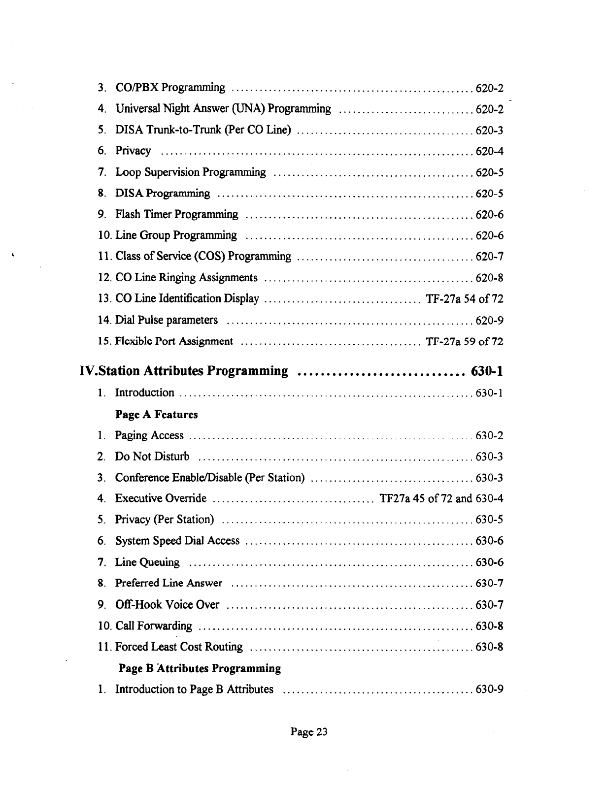
3.
CO/PBX Programming . . . . . . . . . . . . . . . . . . . . . . . . . . . . . . . . . . . . . . . . . . . . . . . . . . . .620-2
,
4. Universal Night Answer
(UNA)
Programming ............................ .620-2
5. DISA Trunk-to-Trunk (Per CO Line) ..................................... .620-3
6.
Privacy .................................................................. .620-4
7. Loop Supervision Programming ...........................................
620-5
8.
DISA Programming ...................................................... -620-5
9. Flash Timer Progr
amming ............................................... ..620- 6
10. Line Group Programming ................................................ .620-6
11. Class of Service (COS) Programming
..................................... .620-7
12. CO Line Ringing Assignments ............................................ .620-8
13. CO Line Identification Display .................................. TF-27a 54 of 72
14. Dial Pulse parameters .................................................... .620-9
15. Flexible Port Assignment ....................................... TF-27a 59 of 72
IV.Station Attributes Programming .............................
630-l
1. Introduction .............................................................. .630-l
Page A Features
1. Paging Access
........................................................... ..630- 2
2. Do Not Disturb ........................................................... 630-3
3. Conference Enable/Disable (Per Station) .................................. .630-3
4. Executive Override ................................... TF27a 45 of 72 and 630-4
5. Privacy (Per Station) ..................................................... .630-5
6.
System Speed Dial Access
................................................ .630-6
7.
Line
Queuing ............................................................ .630-6
8. Preferred Line Answer ................................................... .630-7
9. Off-Hook Voice Over .................................................... -630-7
10. Call Forwarding .......................................................... .630-8
11. Forced Least Cost Routing ................................................
630-8
Page B Attributes Programming
1. Introduction to Page B Attributes ........................................ .630-g
Page 23
1.
2.
3.
4.
5.
6.
7.
8.
9.
Page B Feature Programming
Station Identification ....... : ............................................ 630- 10 _
Station Class of Service ................................................. 630-12
Speakerphone/Headset Progr amming .................................... 630-13
Pick-up Group (s) Programming ......................................... 630-13
Paging Zone (s) Progr amrning ........................................... 630-14
Preset Call Forward Programming ....................................... 630-15
CO Line Group Access .................................................. 630-16
Off-Hook Preference
Progr amming ...................................... 630-17
Flexible Button Programming
............................................ 630- 18
10. Display Flexible Buttons Programming . . . . . . . . . . . . . . . . . . . . . . . . . . . . . . . . . . 630-20
ll.DigitalDataInterfaceUnit@DIU) . . . . . . . . . . . . . . . . . . . . . . . . . . . . . TF-27a63 of72
12. Flexible Port Assignment Feature . . . . . . . . . . . . . . . . . . . . . . . . . . . . . . . TF-27a 60 of 72
VIII.Automatic Call Distribution (ACD) . . . . . . . . . . . . . . . . . . . . . . . . TF-31
1. ACD Programming
A. Alternate ACD Group Assignment
B. ACD Overflow Station Assignment
C. ACD Recorded Announcement Assignment (s) (RAN)
D. ACD Supervisor Programming
E. ACD Station Assignment (s)
2. ACD Timers
A. ACD Ring Timer
B. ACD Message Interval Timer
C. ACD Overflow Timer
D. ACD Auto Wrap-Up Timer
E. ACD No-Answer Recall Timer
F. ACD NoAnswer Retry Timer
G. ACDRAN Announcement Tables
IX.Uniform Call Distribution (UCD) . . . . . . . . . . . . . . . . . . . . . ..a.....
640- 1
Page 24
1. UCD Programming . . . . . . . . . . . . . . . . . . . . . . . . . . . . . . . . . . . . , . . . . . . . . . . . . . . . . . . .640-l
A. Alternate UCD Group Assignment
................................... .640-l .
B. UCD Overflow Station Assignment
................................... .640-2
C. UCD Recorded Announcement Assignment (s) (RAN) ................ .640-2
D. UCD Station Assignment (s) .......................................... .640-2
UCD Timers ............................................................. .640-3
A. UCD Ring Timer ..................................................... .640-3
B. UCD Message Interval Timer ......................................... .640-4
C. UCD Overflow Timer ................................................ .640-4
D. UCDAuto Wrap-Up Timer .......................................... ..640 -4
E. UCD No-Answer Timer .............................................. .640-4
UCD RAN Announcement Tables ........................................ .640-g
X. Voice Mail Groups (VM) ..................................... 645-l
1. Voice Mail Programming ................................................. .645-l
A. Alternate Voice Mail Group .......................................... .645-2
B. “Leave” Mail Index Entry ............................................. .645-2
C. “Retrieve” Mail Index Entry .......................................... .645-2
D. Station Assignment (s) ................................................ .645-3
2. Voice Mail Outpulsing Table .............................................. 645-4
A. Voice mail In-Band Signaling ......................................... .645-4
B. Voice Mail Disconnect Table ......................................... .645-5
3. Voice Mail In-Band Signalmg ............................................ .645-6
A. Voice Mail In-Band Digits ............................................ .645-6
B. Voice Mail Transfer/Forward ............................... TF-27a 52 of 72
XI.Exception Tables Programming .............................. 650-l
1. Exception Tables Programming ........................................... .650- 1
2. Related Items To Toll Restriction
......................................... .650-2
A. CO/r;BX Lines ....................................................... .650-2
B. Forced Account Codes ........................................ :. ..... .650-2
Page 25
C. SLT DTMF Receivers ...........................................
D. LCR vs. Toll Restriction .........................................
3. Toll Restriction Programming
.......................................
A. Entering Toll Table Progr amming ................................
B. Allow Table Programming
.......................................
C. Deny Table Progr amming ........................................
D. Special Table Progr amming ......................................
E. Displaying Toll Table Entries ....................................
. . . . .
650-2
. . . . . 650-3 _
. . . . .650-4
. . . . .650-4
. . . . . 650-5
. . . . . 650-7
. . . . . 650-8
. . . . . 650-9
XII.Least Cost Routing (LCR) ................................. .
1. Introduction .............................................................
A. LCR Operation ......................................................
2. LCR Tables Programming ...............................................
A. 3-Digit Area/Office Code Table ......................................
B. 6-Digit Office Code Table ...........................................
C. Exception Code Table ...........
D. Route List Table .................
E. Insert Delete Table ..............
F. Daily Start Time Table ...........
G. Weekly Schedule Table ..........
H. LCR Routing for Toll Information
I. Default LCR Database ...........
. . . .
. . . .
. . . ,
. . . .
. . . .
. . .
. . . .
. . . . . . .
655-l
.655-l
.655-l
,655-3
1655-4
.655-5
. .
.655-6
. .
.655-7
. . .
655-8
. . .655-g
. 655-10
. 655-11
. 655-12
XIII.Initialize Database Parameters ............................. 660-l
1. Introduction .............................................................. .660-l
A. Initialize System Parameters
.......................................... .660-2
B. Initialize CO Line Attributes .......................................... .660-4
C. Initialize Station Attributes ........................................... .660-5
D. Initialize Group Parameters . . . . . . . . . . . . . . . . . . . . . . . . . . . . . . . . . . . . . . . . . . . .660-7
E. Initialize Exception Tables . . . . . . .
F. Initialize System Speed Numbers
. . . . . . . . . . . . . . . . . . . . . . . . . ..‘......
.660-g
.660-8
Page 26

G. Initialize LCR Tables ................................................ 660-l 0
H. Initialize System Database and Reset (All Parameters) 660-l 1 .
................
I. Initialiie ICLlD Parameters
.......................................... 660- 12
J. Initialize Directory Dialing Table Parameters ......................... 660-14
K. Initialize Hunt Group Parameters
.................................... 660-l 5
L. Initialize ACD or UCD Group Parameters ........................... 660-l 6
M. Initialize VM Group Parameters
..................................... 660-l 7
N. System Reset ........................................................ 660- 18
XIV.Printing System Database Parameters ...................... 665-l
1. Introduction .............................................................. ,665-l
2. Printing System Parameters ............................................... .665-2
3. Printing CO Line Attributes .............................................. .665-4
4. Printing Station Attributes ................................................. 665-6
5. Printing Group Parameters ............................................... .665-8
6. Printing Exception Tables ............................................... 665-10
7. Printing System Speed Bins ............................................. 665-12
8. Printing LCR Tables ..................................................... 665-14
9. Printing Entire System Database ......................................... 665-24
XV.System Checkout . . . . . . . . . . . . . . . . . . . . . . . . . . . . . . . . . . . . . . . . . . . 700-l
XVI.Maintenance and Troubleshooting .......................... 800-l
1. Printed Circuit Board Troubleshooting Charts ............................. 800-I
A. 1428 BKSU Troubleshooting Table ................................... .800-l
B. 1428 EPROM Memory Size ........................................... 800-l
C. 1428 Static Memory Size ............................................. .800-l
D. 2856 CPB Troubleshooting Table ...................................... 800-2
E. 2856 CPB Static RAM Memory Size .................................. 800-2
F. 2856 CPB EPROM Memory Size ...................................... 800-3
G. 4x8 Key Interface Board Troubleshooting Table ....................... 800-3
Page 27
H. 4x8 SLT Interface Board Troubleshooting Table ...................... .800-3
I. DTMF Receiver Module .............................................. .800-3 -
J. I/O Module ........................................................... .800-3
K. Single Line Telephone Adapter (OPX) ................................ .800-3
XVII.Customer Database Programming . . . . . . . . . . . . . . . . . . . Appendix A
XVIII.Digital Systems Part Numbers . . . . . . . . . . . . . . . . . . . . . . Appendix B
XKICLID General Descriptions ......................... Appendix C
1. ICLID General Descriptions
................................................. C-l
A. Introduction ............................................................. C-l
B. System Configuration
.................................................... C-l
C. Calling Name/Number Display ........................................... C-2
D. Incoming Number/Name SMDR ......................................... C-2
E. Unanswered Call Management ........................................... C-2
F. Local Name Translation ................................................. C-2
G. ICLID Display Phone Operation ......................................... C-2
H. Implementation Plan ..................................................... C-4
Page 28
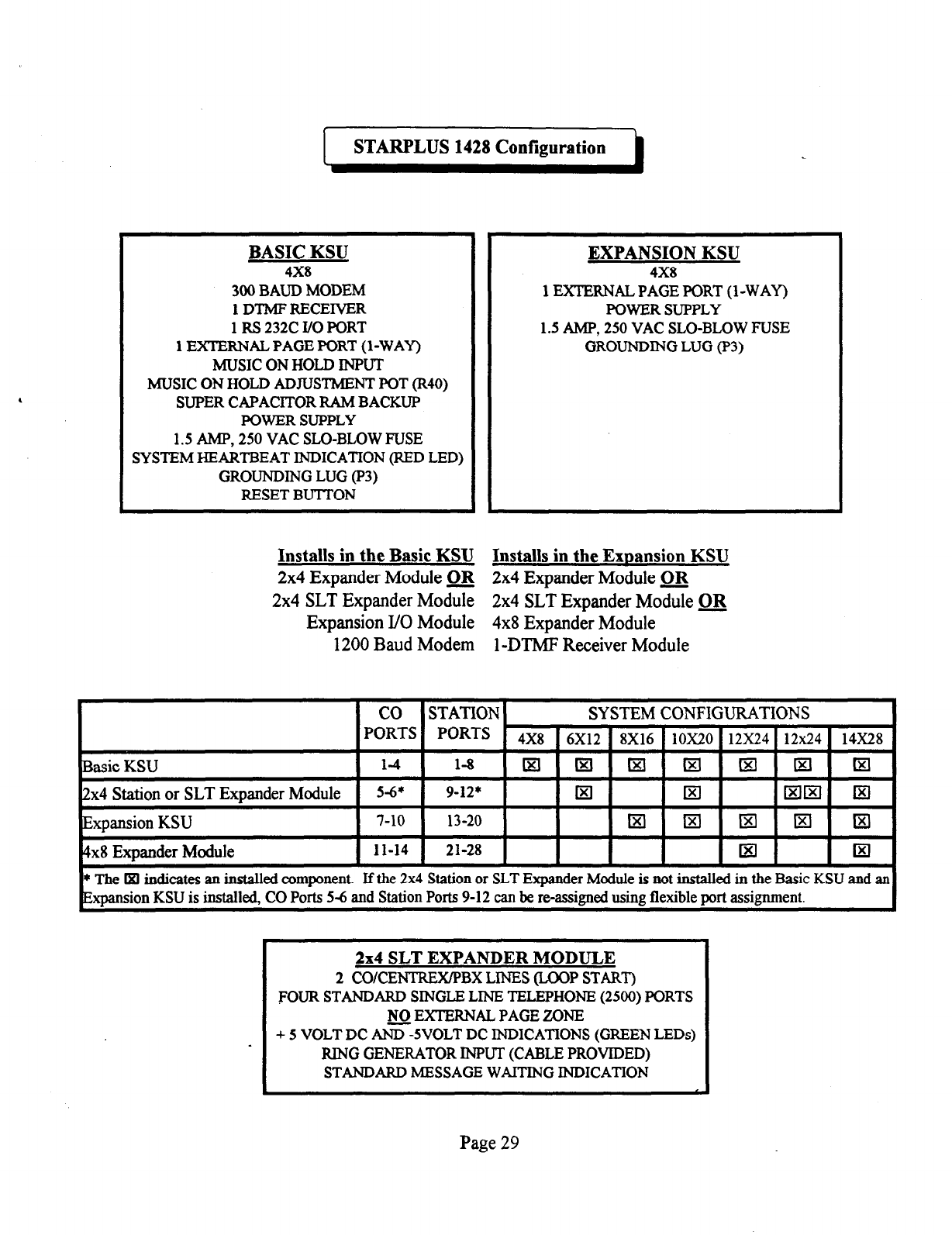
I
STARPLUS 1428 Configuration
BASIC KSU
4X8
300 BAUD MODEM
1 DTMF RECEIVER
1 RS 232C I/O PORT
1 EXTERNAL PAGE PORT (1 -WAY)
MUSIC ON HOLD INPUT
MUSIC ON HOLD ADJUSTMENT POT (R40)
SUPER CAPACITOR RAM BACKUP
POWER SUPPLY
1.5 AMP, 250 VAC SLO-BLOW RUSE
SYSTEM HEARTBEAT INDICATION (RED LED)
GROUNDING LUG (P3)
RESET BUTTON
EXPANSION KSU
4X8
1 EXTERNAL PAGE PORT (1 -WAY)
POWER SUPPLY
1.5 AMP, 250 VAC SLO-BLOW FUSE
GROUNDING LUG (P3)
Installs in the Basic KSU Installs in the ExDansion KSU
2x4 Expander Module Q& 2x4 Expander Module m
2x4 SLT Expander Module 2x4 SLT Expander Module m
Expansion I/O Module 4x8 Expander Module
1200 Baud Modem
1
-DTMF Receiver Module
4x8 Expander Module
* The •i indicates an installed component. Jf the 2x4 Station or SLT Expander Module is not installed in the Basic KSU and an
Exoansion KSU is installed. CO Ports 5-6 and Station Ports 9-12 can be re-assimed usine flexible mrt assimment.
2x4 SLT EXPANDER MODULE
2 CO/CENTRBX/PBX LINES (LOOP START)
FOUR STANDARD SINGLE LINE TELBPHON-E (2500) PORTS
NO EXTBRNAL PAGE ZONE
+ 5 VOLT DC E5VOLT DC INDICATIONS (GREEN LED@
RING GENERATOR INPUT (CABLE PROVIDED)
STANDARD MESSAGE WAITING INDICATION ‘
Page 29
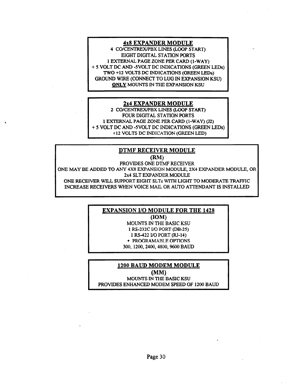
4x8 EXPANDER MODULE
4 CO/CENTREX/PBX LINES (LOOP START)
EIGHT DIGITAL STATION PORTS
1 EXTERNAL PAGE ZONE PER CARD (I-WAY)
+ 5 VOLT DC AND -5VOLT DC INDICATIONS (GREEN LEDs)
TWO +12 VOLTS DC INDICATIONS (GREEN LEDs)
GROUND WIRE (CONNECT TO LUG IN EXPANSION KSU)
ONLY MOUNTS IN THE EXPANSION KSU
2x4 EXPANDER MODULE
2 CO/CENTREX/PBX LINES (LOOP START)
FOUR DIGITAL STATION PORTS .
1 EXTERNAL PAGE ZONE PER CARD (I-WAY) (J2)
+ 5 VOLT DC AND -5VOLT DC INDICATIONS (GREEN LEDs)
+12 VOLTS DC INDICATION (GREEN LED)
DTMF RECEIVER MODULE
mw
PROVIDES ONE DTMF RECEIVER
ONE MAY BE ADDED TO ANY 4X8 EXPANSION MODULE, 2X4 EXPANDER MODULE, OR
2x4 SLT EXPANDER MODULE
ONE RECEIVER WILL SUPPORT EIGHT SLTs WlTH LIGHT TO MODERATE TRAFFIC
INCREASE RECEIVERS WHEN VOICE MAIL OR AUTO ATTENDANT IS INSTALLED
EXPANSION I/O MODULE FOR THE 1428
OOM)
MOUNTS IN THE BASIC KSU
1 RS-232C I/O PORT @B-25)
1 RS-422 I/O PORT (RJ-14)
l
PROGRAMABLE OPTIONS
300, 1200,2400,4800, !WO BAUD
1200 BAUD MODEM MODULE
I (MM)
MOUNTS IN THE BASIC KSU
PROVIDES ENHANCED MODEM SPEED OF 1200 BAUD
Page 30
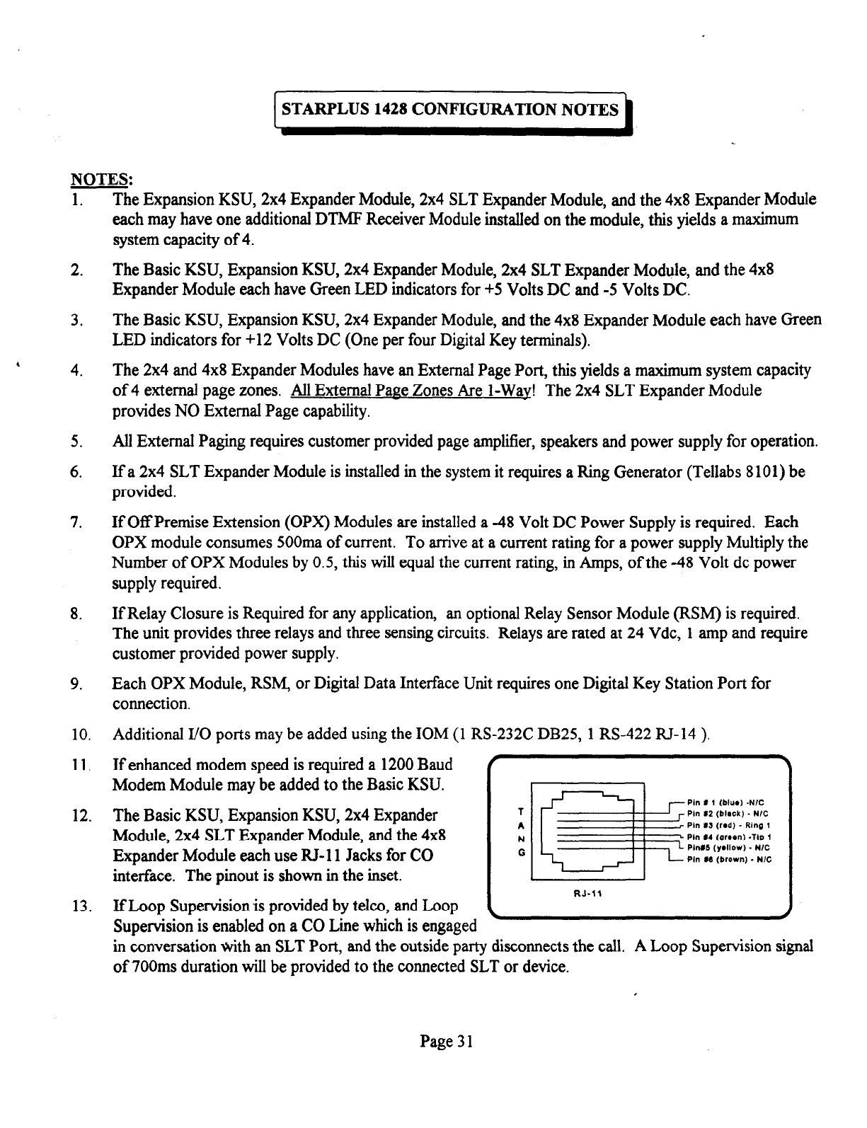
TARPLUS 1428 CONFIGURATION NOTES
NOTES:
1.
2.
3.
, 4.
5.
6.
7.
8.
9.
10.
11.
12.
13.
The Expansion KSU, 2x4 Expander Module, 2x4 SLT Expander Module, and the 4x8 Expander Module
each may have one additional DTMP Receiver Module installed on the module, this yields a maximum
system capacity of 4.
The Basic KSU, Expansion KSU, 2x4 Expander Module, 2x4 SLT Expander Module, and the 4x8
Expander Module each have Green LED indicators for +5 Volts DC and -5 Volts DC.
The Basic KSU, Expansion KSU, 2x4 Expander Module, and the 4x8 Expander Module each have Green
LED indicators for +12 Volts DC (One per four Digital Key terminals).
The 2x4 and 4x8 Expander Modules have an External Page Port, this yields a maximum system capacity
of 4 external page zones. All External Page Zones Are I-Wav! The 2x4 SLT Expander Module
provides NO External Page capability.
All External Paging requires customer provided page amplifier, speakers and power supply for operation.
If a 2x4 SLT Expander Module is installed in the system it requires a Ring Generator (Tellabs 8 101) be
provided.
If Off Premise Extension (OPX) Modules are installed a -48 Volt DC Power Supply is required. Each
OPX module consumes 500ma of current. To arrive at a current rating for a power supply Multiply the
Number of OPX Modules by 0.5, this will equal the current rating, in Amps, of the -48 Volt de power
supply required.
If Relay Closure is Required for any application,
an optional Relay Sensor Module (RSM) is required.
The unit provides three relays and three sensing circuits. Relays are rated at 24 Vdc, 1 amp and require
customer provided power supply.
Each OPX Module, RSM, or Digital Data Interface Unit requires one Digital Key Station Port for
connection.
Additional l/O ports may be added using the IOM (1 RS-232C DB25, 1 RS-422 RJ-14 ),
If enhanced modem speed is required a 1200 Baud I .
Modem Module may be added to the Basic KSU.
The Basic KSU, Expansion KSU, 2x4 Expander
Module, 2x4 SLT Expander Module, and the 4x8
Expander Module each use RJ-11 Jacks for CO
interface. The pinout is shown in the inset.
1
A
N
liie!e
Pin 8 1 (bhm) -N/C
Pin 12 (b&k) . N/C
Pin #S (rad) _ Ring 1
Ph L4 (Qrren) -Tap (
G
Pln#S (yallow) - N/C
Pln M (brown) - N/C
RJ-11
If Loop Supervision is provided by telco, and Loop
Supervision is enabled on a CO Line which is engaged ’ *
in conversation with an SLT Port, and the outside party disconnects the call. A Loop Supervision signal
of 700ms duration will be provided to the connected SLT or device.
Page 3 1
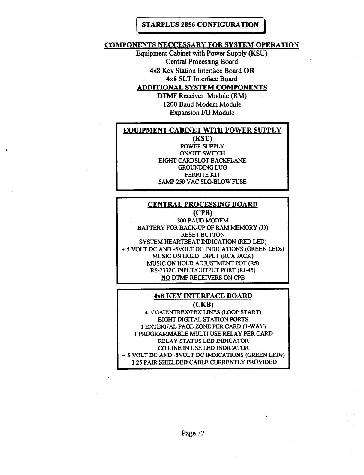
STARPLUS 2856 CONFIGURATION
COMPONENTS NECCESSARY FOR SYSTEM OPERATION
Equipment Cabinet with Power Supply (KSU)
Central Processing Board
4x8
Key Station Interface Board QlJ
4x8
SLT Interface Board
ADDITIONAL SYSTEM COMPONENTS
DTMF Receiver Module (RMJ
1200 Baud Modem Module
Expansion I/O Module
EOUIPMENT CABINET WITH POWER SUPPLY
ww
POWER SUPPLY
ON/OFF SWITCH
EIGHT CARDSLOT BACKPLANE
GROUNDING LUG
FERRITEKIT
5AMP 250 VAC SLO-BLOW FUSE
CENTRAL PROCESSING BOARD
PW
300 BAUD MODEM
BATTERY FOR BACK-UP OF RAM MEMORY (J3)
RESET BUTTON
SYSTEM HEARTBEAT INDICATION (RED LED)
+ 5 VOLT DC AND -5VOLT DC INDICATIONS (GREEN LED@
MUSIC ON HOLD INPUT (RCA JACK)
MUSIC ON HOLD ADJUSTMENT POT (R5)
RS-2332C INPUT/OUTPUT PORT (RJ-45)
NO DTMF RECEIVERS ON CPB
-
4x8 KEY INTERFACE BOARD
(CW
4 CO/CENTREX@BX LINES (LOOP START)
EIGHT DIGITAL STATION PORTS
1 EXTERNAL PAGE ZONE PER CARD (l-WAY)
1 PROGRAMMABLE MULTI USE RELAY PER CARD
RELAY STATUS LED INDICATOR
CO LINE IN USE LED INDICATOR
+ 5 VOLT DC AND -5VOLT DC INDICATIONS (GREEN LEDs)
125 PAIR SHIELDED CABLE CURRENTLY PROVIDED
Page 32
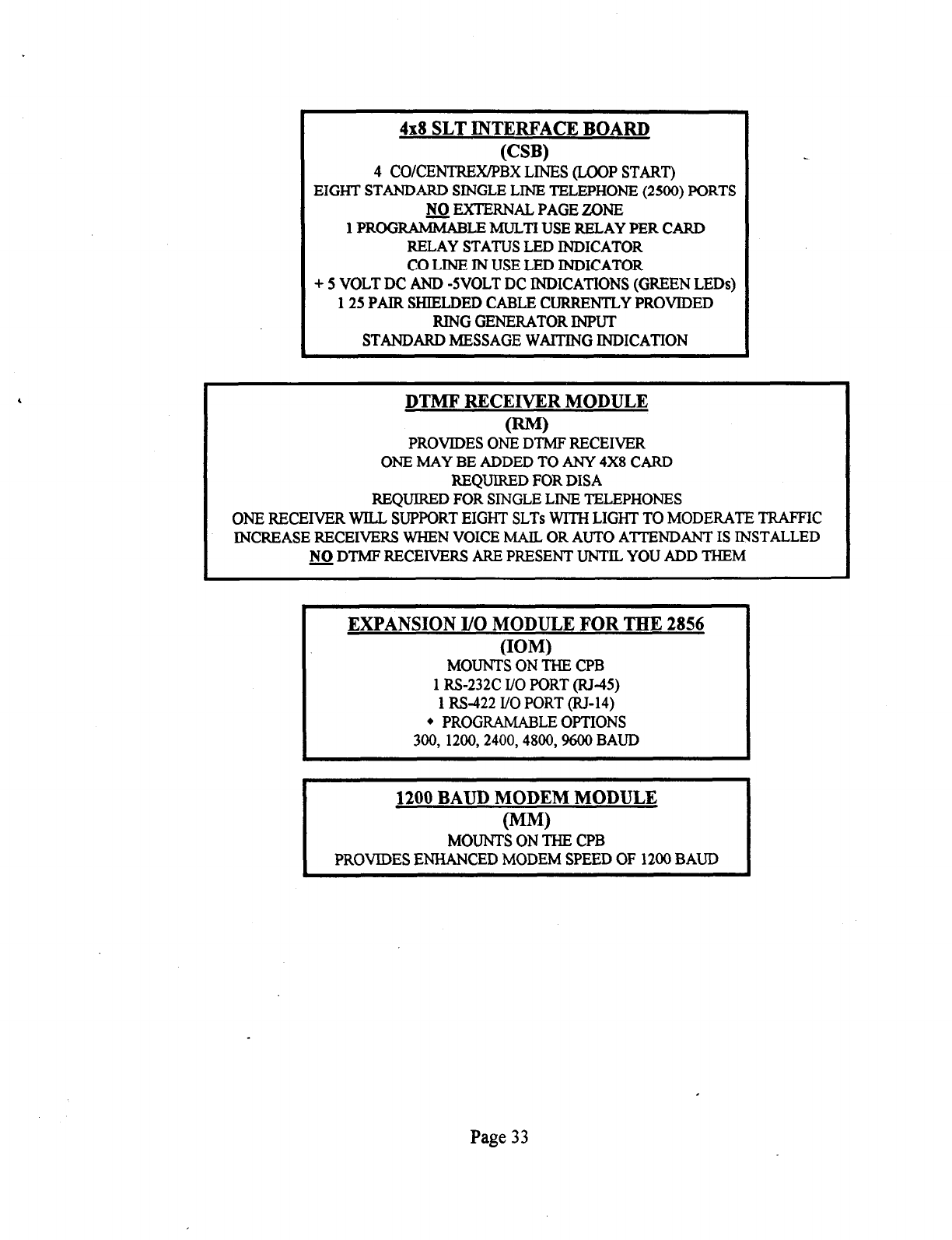
4x8 SLT INTERFACE BOARD
(CW
4
COICENTREXIPBX LINES (LOOP START)
EIGHT STANDARD SINGLE LINE TELEPHONE (2500) PORTS
w EXTERNAL PAGE ZONE
1 PROGRAMMABLE MULTI USE RELAY PER CARD
RELAY STATUS LED INDICATOR
CO LINE IN USE LED INDICATOR
+ 5 VOLT DC AND -5VOLT DC INDICATIONS (GREEN LEDs)
125 PAIR SHIELDED CABLE CURRENTLY PROVIDED
RING GENERATOR INPUT
STANDARD MESSAGE WAlTING INDICATION
DTMF RECEIVER MODULE
uw
PROVIDES ONE DTMF RECEIVER
ONE MAY BE ADDED TO ANY 4X8 CARD
REQUIRED FOR DISA
REQUIRED FOR SINGLE LINE TELEPHONES
ONE RECEIVER WILL SUPPORT EIGHT SLTs WITH LIGHT TO MODERATE TRAFFIC
INCREASE RECEIVERS WHEN VOICE MAIL OR AUTO ATTENDANT IS INSTALLED
NO DTMF RECEIVERS ARE PRESENT UNTIL YOU ADD THEM
-
EXPANSION I/O MODULE FOR THE 2856
(IOW
MOUNTS ON THE CPB
1 RS-232C I/O PORT (RJ-45)
1 RS-422 I/O PORT (RI-14)
l
PROGRAMABLE OPTIONS
300, 1200,2400,4800,9600 BAUD
1200 BAUD MODEM MODULE
(MM)
MOUNTS ON THE CPB
PROVIDES ENHANCED MODEM SPEED OF 1200 BAUD
Page 33
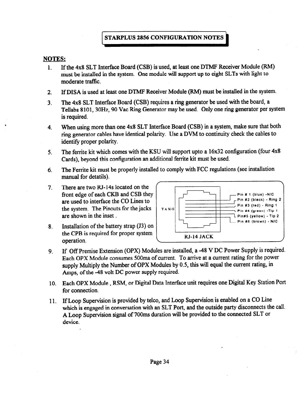
TARPLUS 2856 CONFIGURATION NOTES
NOTES:
1.
2.
3.
4
4.
5.
6.
7.
-8.
If the 4x8 SLT Interface Board (CSB) is used, at least one DTMF Receiver Module (RM)
must be installed in the system. One module will support up to eight SLTs with light to
moderate trafhc.
If DISA is used at least one DTMF Receiver Module (RM) must be installed in the system.
The 4x8 SLT Interface Board (CSB) requires a ring generator be used with the board, a
Tellabs 8101,3OHz, 90 Vat Ring Generator may be used. Only one ring generator per system
is required.
When using more than one 4x8 SLT Interface Board (CSB) in a system, make sure that both
ring generator cables have identical polarity. Use a DVM to continuity check the cables to
identity proper polarity.
The ferrite kit which comes with the KSU will support upto a 16x32 configuration (four 4x8
Cards), beyond this configuration an additional ferrite kit must be used.
The Ferrite kit must be properly installed to comply with FCC regulations (see installation
manual for detatils).
There are two RJ-14s located on the ’
front edge of each CKB and CSB they
Pin # 1 (blue) -N/C
are used to interface the CO Lines to
the system. The Pinouts for the jacks
Pin #3 (red) - Ring 1
TANG Pin #4 (green) -Tip 1
are shown in the inset .
Installation of the battery strap (J3) on
\ FPin #2 (black) -Ring i
L
Ping6 (yellow) - Tip 2
-
Pin 116 (brown) - N/C
the CPB is required for proper system
operation. \
RJ-14
JACK
9.
10.
11.
If Off Premise Extension (OPX) Modules are installed, a -48 V DC Power Supply is required.
Each OPX Module consumes 500ma of current. To arrive at a current rating for the power
supply Multiply the Number of OPX Modules by 0.5, this will equal the current rating, in
Amps, of the -48 volt DC power supply required.
Each OPX Module, RSM, or Digital Data Interface unit requires one Digital Key Station Port
for connection.
IfLoop Supervision is provided by telco, and Loop Supervision is enabled on a CO Line
which is engaged in conversation with an SLT Port, and the outside party disconnects the call.
A Loop Supervision signal of 7OOms duration will be provided to the connected SLT or
device.
Page 34
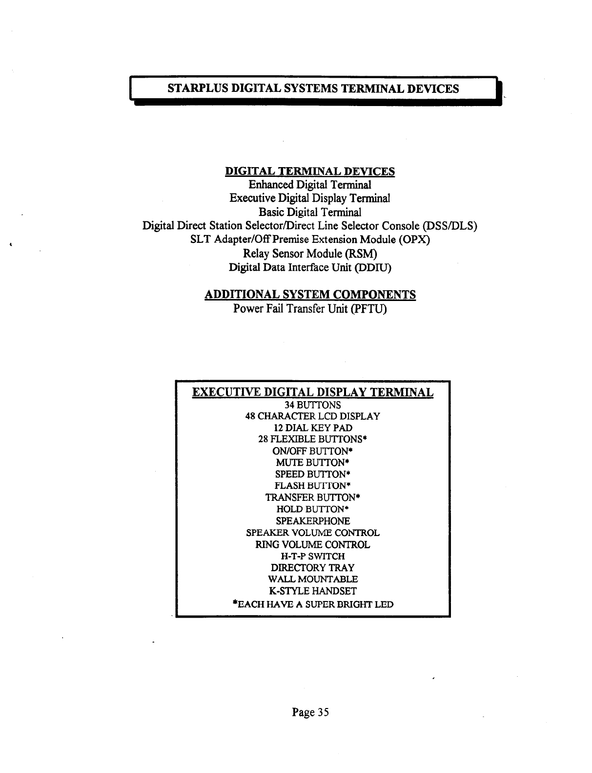
STARPLUS DIGITAL SYSTEMS TERMINAL DEVICES
DIGITAL TERMINAL DEVICES
Enhanced Digital Terminal
Executive Digital Display Terminal
Basic Digital Terminal
Digital Direct Station Selector/Direct Line Selector Console @SS/DLS)
SLT Adapter/Off Premise Extension Module (OPX)
Relay Sensor Module (RSM)
Digital Data Interface Unit (DDIU)
ADDITIONAL SYSTEM COMPONENTS
Power Fail Transfer Unit (PFTU)
EXECUTIVE DIGITAL DISPLAY TERMINAL
34 BUTTONS
48 CHARACTER LCD DISPLAY
12 DIAL KEY PAD
28 FLEXIBLE BUTTONS*
ON/OFF BUTTON*
MUTE BUTTON*
SPEED BUTl-ON*
FLASH BUlTON*
TRANSFER BUTTON*
HOLD BUTTON*
SPEAKERPHONE
SPEAKER VOLUME CONTROL
RING VOLUME CONTROL
H-T-P SWITCH
DIRECTORY TRAY
WALLMOUNTABLE
K-STYLE HANDSET
*EACH HAVE A SUPER BRIGHT LED
Page 35
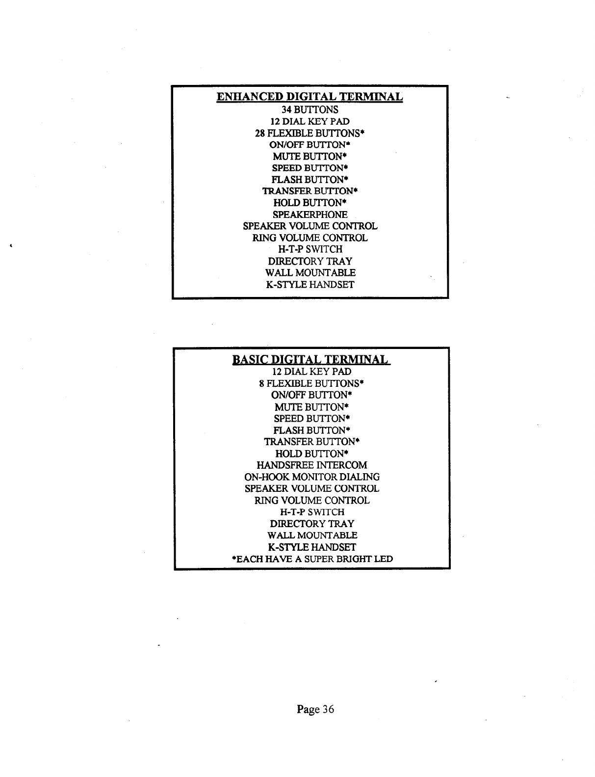
ENHANCED DIGITAL TERMINAL
34
BUTTONS
12 DIAL KEY PAD
28
FLEXIBLE BUlTONS*
ON/OFF BUTTON*
MUTE BUTTON*
SPEED BUTTON*
FLASH BUlTON*
TRANSFER BU’ITON*
HOLD
BU’lTON*
SPEAKERPHONE
SPEAKER VOLUME CONTROL
RING VOLUME CONTROL
H-T-P SWITCH
DIRECTORY TRAY
WALL MOUNTABLE
K-STYLE HANDSET
BASIC DIGITAL TERMINAL
12 DIAL KEY PAD
8 FLEXIBLE BUTTONS*
ON/OFF BUlTON*
MUTE BUlTON*
SPEED BUTTON*
FLASH BU+lTON*
TRANSFER BUTTON*
HOLD BU-ITON*
HANDSFREE INTERCOM
ON-HOOK MONITOR DIALING
SPEAKER VOLUME CONTROL
RING VOLUME CONTROL
H-T-P SWITCH
DIRECTORY TRAY
WALLMOUNTABLE
K-STYLE HANDSET
*EACH HAVE A SUPER BRIGHT LED
Page 36
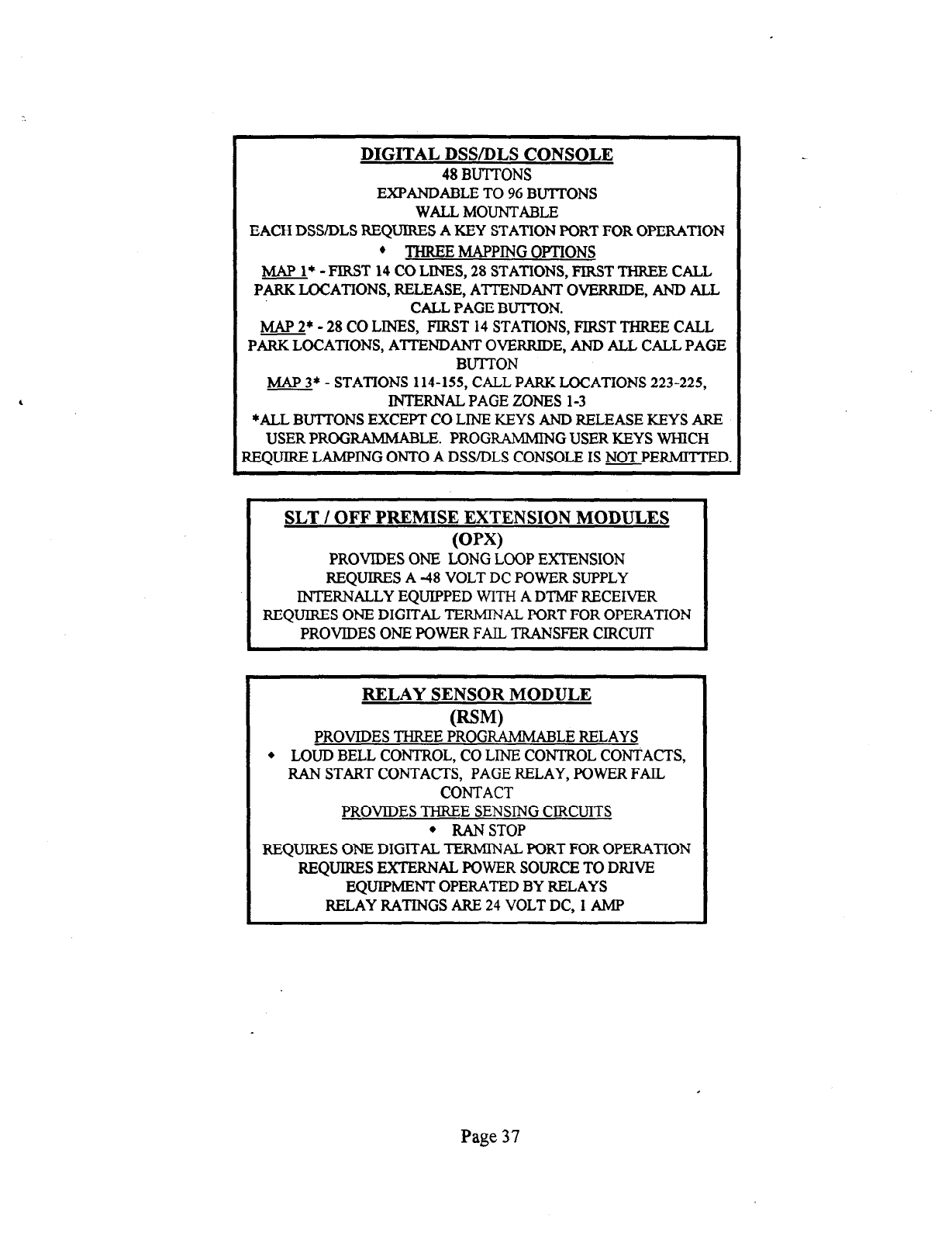
DIGITAL DSWDLS CONSOLE
48 BUTTONS
EXPANDABLE TO 96 BUTTONS
WALLMOUNTABLE
EACH DSS/DLS REQUIRES A KEY STATION PORT FOR OPERATION
’ THREE MAPPING OPTIONS
MAP l* - FIRST 14 CO LINES, 28 STATIONS, FIRST THREE CALL
PARR LOCATIONS, RELEASE, ATTENDANT OVERRIDE, AND ALL
CALL PAGE BUTTON.
MAP 2* - 28 CO LINES, FIRST 14 STATIONS, FIRST THREE CALL
PARK LOCATIONS, ATTENDANT OVERRIDE, AND ALL CALL PAGE
BUTTON
MAP 3* - STATIONS 114-155, CALL PARR LOCATIONS 223-225,
INTERNAL PAGE ZONES l-3
*ALL BUTTONS EXCEPT CO LINE KEYS AND RELEASE KEYS ARE
USER PRQG RAMMABLE. PROGRAMMTN G USER KEYS WHICH
REQUIRE LAMFING ONTO A DSS/DLS CONSOLE IS NOTPERMITTED.
SLT / OFF PREMISE EXTENSION MODULES
Pw
PROVIDES ONE LONG LOOP EXTENSION
REQUIRES A -48 VOLT DC POWER SUPPLY
INTERNALLY EQUIF’PED WITH A DTMF RECEIVER
REQUIRES ONE DIGITAL TERMINAL PORT FOR OPERATION
PROVIDES ONE POWER FAIL TRANSFER CIRCUIT
RELAY SENSOR MODULE
PROVIDES THREE Pt$.? R4MMABLE RELAYS
l
LOUD BELL CONTROL, CO LINE CONTROL CONTACTS,
RAN START CONTACTS, PAGE RELAY, POWER FAIL
CONTACT
PROVIDES THREE SENSING CIRCUITS
l
RANSTOP
REQUIRES ONE DIGITAL TERMINAL PORT FOR OPERATION
REQUIRES EXTERNAL POWER SOURCE TO DRIVE
I EQUIPMENT OPERATED BY RELAYS
RELAY RATINGS ARE 24 VOLT DC, 1 AMP
Page 37
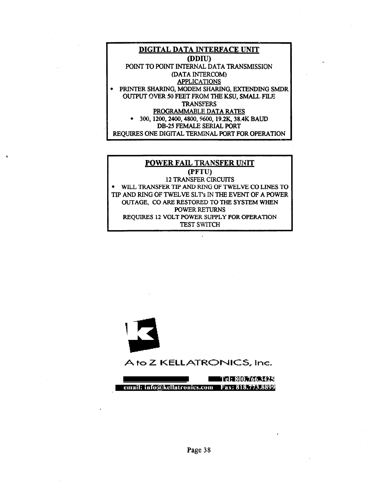
DIGITAL DATA INTERFACE UNIT
@DW
POINT TO POINT INTERNAL DATA TRANSMISSION
(DATA INTERCOM)
APPLICATIONS
l
PRIWI’ER SHARING, MODEM SHARING, EXTENDING SMDR
OUTPUT OVER 50 FEET FROM THE KSU, SMALL FILE
TRANSFERS
PROGRAMMABLE DATA RATES
l
300,1200,2400,4800,9600,19.2K, 38.4K BAUD
DB-25 FEMALE SERIAL PORT
REQUIRES ONE DIGITAL TERMINAL PORT FOR OPERATION
POWER FAIL TRANSFER UNIT
(PFTU)
12 TRANSFER CIRCUITS
. WILL TRANSFER TIP AND RING OF TWELVE CO LINES TO
TIP AND RING OF TWELVE SLT’s IN THE EVENT OF A POWER
OUTAGE, CO ARE RESTORED TO THE SYSTEM WHEN
POWERRETURNS
REQUIRES 12 VOLT POWER SUPPLY FOR OPERATION
TEST SWITCH
Page 38
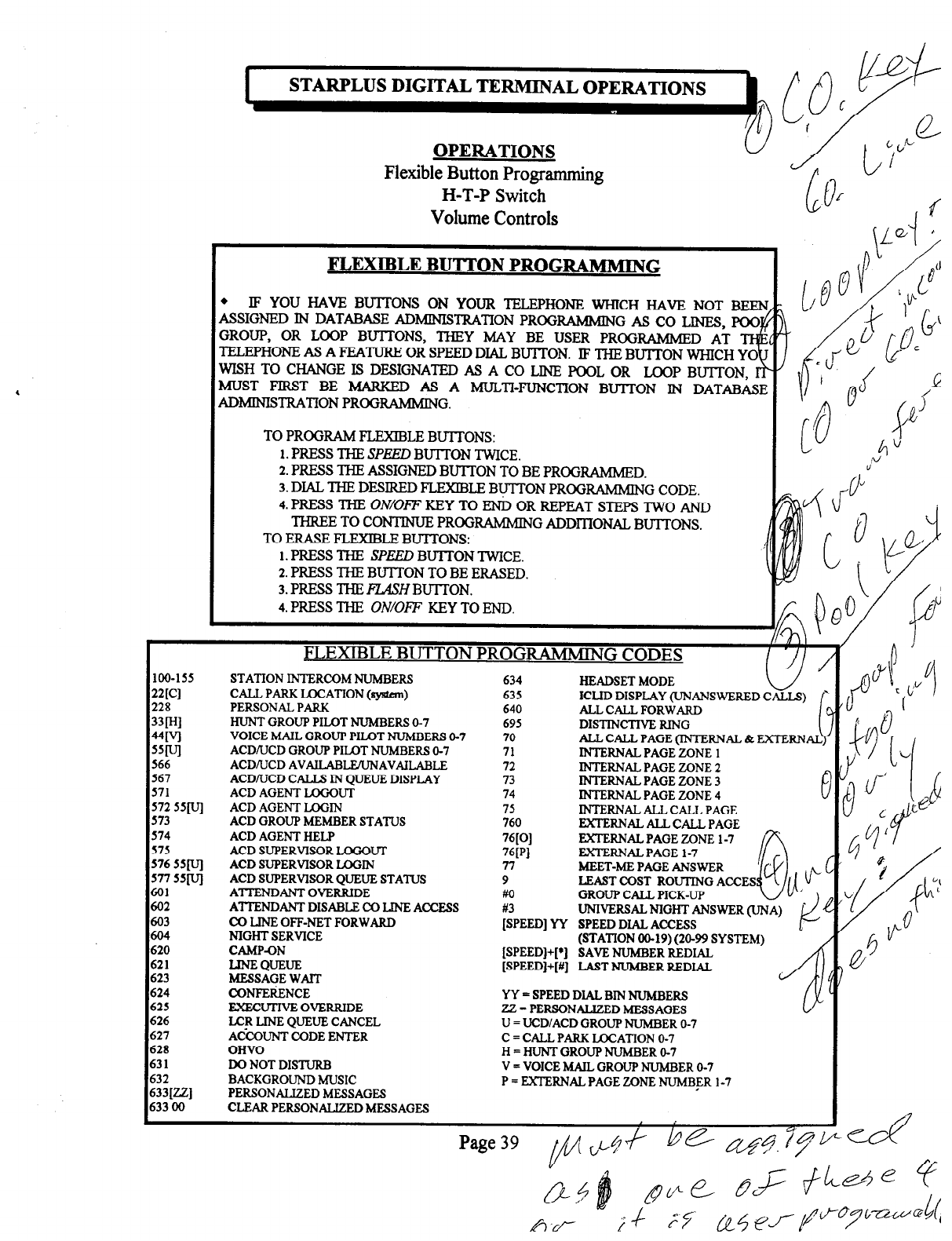
STARPLUS DIGITAL TERMINAL OPERATIONS
OPERATIONS
Flexible Button Programming
H-T-P Switch
Volume Controls
FLEXIBLE BUTTON PROGRAMMING
l
IF YOU HAVE BU?TONS ON YOUR TELEPHONE WHICH HAVE NOT BEEN
ASSIGNED IN DATABASE ADMINISTRATION PROGRAMMIN GASCOLINES,POO
GROUP, OR LOOP BUTI-ONS, THEY MAY BE USER PROGRAMMED AT
4
TELEPHONE AS A FEATURE OR SPEED DIAL BUTTON. IF THE BU-ITON WHICH YO
WISH TO CHANGE IS DESIGNATED AS A CO LINE POOL OR LOOP BUlTON,
MUST FIRST BE IMARKED AS A MULTI-FUNCTION Bu?TON IN DATABASE
IUMINISTRATION PROGRAMMING.
TO PROGRAM FLEXIBLE BUlTONS:
1. PRESS THE SPEED BUTrON TWICE.
2.
PRESS THE ASSIGNED BUTTON TO BE PROGRAMMED.
3.
DIAL THE DESIRED FLEXIBLE By-TON PROGFWMMING CODE.
4.
PRESS THE ON/OFF KEY TO END OR REPEAT STEPS TWO AND
THREE TO CONTINUE PROGRAMMIN G ADDITIONAL BUTT’ONS.
TO ERASE FLEXlBLE BUTI’ONS:
I. PRESS THE SPEED BUTrON TWICE.
2.
PRESS THE BU-ITON TO BE ERASED.
3.
PRESS THE RASH BUITON.
4.
PRESS THE ON/OFF KEY TO END.
I
FLEXIBLE BUTTON PROG
RAMMING CODES I
loo-155
2Wl
228
33lw
4wl
55wl
566
567
571
572 55[vl
573
574
575
576 55[vl
577 55[vl
601
602
603
604
620
621
623
624
625
626
627
628
631
632
633[22]
633 00
STATION INTERCOM NUMBERS
CALL PARK LOCATION (sy&m)
PERSONAL PARK
HUNT GROUP PILOT NUMBERS O-7
VOICE MAIL GROUP PILOT NUhiBERS O-7
ACDNCD GROUP PILOT NUMBERS O-7
ACD/‘UCD AVAILABLE’UNAVAILABLE
ACDAJCD CALLS IN QUEUE DISPLAY
ACD AGENT LOGGUT
ACD AGENT LOGIN
ACD GROUP MEMBER STATUS
ACD AGENT HELP
ACD SUPERVISOR LOGOUT
ACD SUPERVISOR UJGIN
ACD SUPERVISOR QUEUE STATUS
ATIXNDANT OVERRIDE
ATTENDANT DISABLE CO LINE ACCESS
CO LINE OFF-NET FORWARD
NIGHT SERVICE
CAMP43N
LINE QUEUE
MESSAGE WAIT
CONFEIiENCE
FXECUTIVE OVERRIDE
LC!t LINE QUEUE CANCEL
ACCOUNT CODE ENTER
OHVO
DO NOT DISTURB
BACKGROUND MUSIC
PERSONALIZED MESSAGES
CLEAR PERSONALIZED MESSAGES
634
635
640
695
70
71
72
73
74
75
760
76[01
76iPl
77
9
Ml
HEADSET MODE k-l
ICLID DISPLAY (UNANSWERED CALLS)
ALL CALL FORWARD
DISTINCTIVE RING i
ALL CALL PAGE (INTERNAL & EXTERNAL
INTERNAL PAGE ZONE 1
INTERNAL PAGE ZONE 2
INTERNAL PAGE ZONE 3
INTERNAL PAGE ZONE 4
INTERNAL ALL CALL PAGE
EXTERNAL ALL CALL PAGE
EXTERNAL PAGE ZONE 1-7 ’
EXTERNAL PAGE 1-7
MEET-ME PAGE ANSWER
LEAST COST ROUTING ACCES
GROUP CALL PICK-UP 0
$ 1/1 (i”
;iPEEDl YY UNIVERSAL NIGHT ANSWER (UNA) .
SPEED DIAL ACCESS l+
(STATION 00-19) (20-99 SYSTEM)
[SPEED]+[*] SAVE NUh4BER REDIAL
[SPEED]+[#] LAST NUMBER REDIAL
YY = SPEED DIAL BIN NUMBERS
ZZ = PERSONALIZED MESSAGES
U = UCD/ACD GROUP NUMBER O-7
C = CALL PARK LAXATION O-7
H = HUNT GROUP NUMBER O-7
V = VOICE MAIL GROUP NUMBER O-7
P = EXTERNAL PAGE ZONE NUMBER 1-7
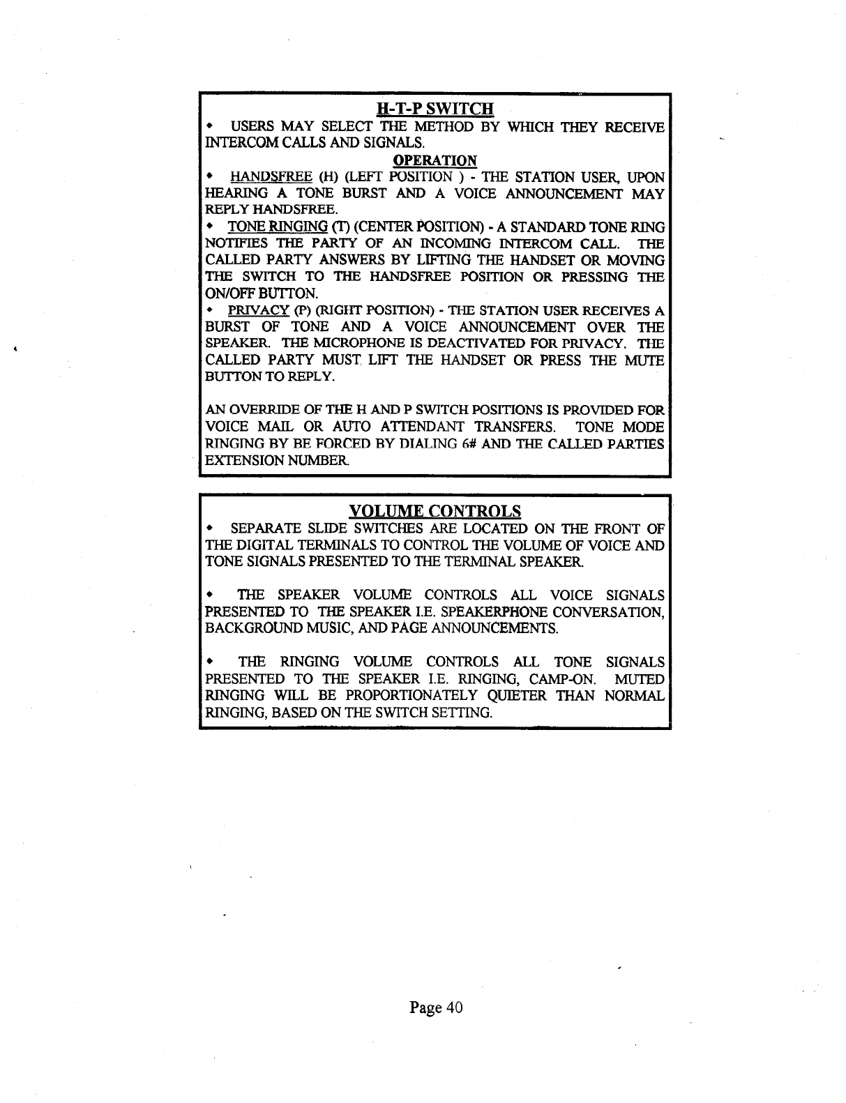
H-T-P SWITCH
l
USERS MAY SELECT THE METHOD BY WHICH THEY RECEIVE
INTERCOM CALLS AND SIGNALS.
OPERATION
l
HANDSFREE (H) (LEFT POSITION ) - THE STATION USER, UPON
HEARING A TONE BURST AND A VOICE ANNOUNCEMENT MAY
REPLY HANDSFREE.
l
TONE RINGING (T) (CENTER l%XITION) - A STANDARD TONE RING
NOTIFIES THE PARTY OF AN INCOMING INTERCOM CALL. THE
CALLED PARTY ANSWERS BY LIFTING THE HANDSET OR MOVING
THE SWITCH TO THE HANDSFREE PQSITION OR PRESSING THE
ON/OFF BUTTON.
l
PRIVACY (P) (RIGHT POSITION) - THE STATION USER RECEIVES A
BURST OF TONE AND A VOICE ANNOUNCEMENT OVER THE
SPEAKER THE MICROPHONE IS DEACTIVATED FOR PRIVACY. THE
CALLED PARTY MUST LIFT THE HANDSET OR PRESS THE MUTE
BUTTON TO REPLY.
I
AN OVERRIDE OF THE H AND P SWITCH POSITIONS IS PROVIDED FOR
VOICE MAIL OR AUTO ATTENDANT TRANSFERS. TONE MODE
RINGING BY BE FORCED BY DIALING 6# AND THE CALLED PARTIES
EXTENSION NUMBER
VOLUME CONTROLS
l
SEPARATE SLIDE SWITCHES ARE LOCATED ON THE FRONT OF
THE DIGITAL TERMINALS TO CONTROL THE VOLUME OF VOICE AND
TONE SIGNALS PRESENTED TO THE TERMINAL SPEAKER
l
THE SPEAKER VOLUME CONTROLS ALL VOICE SIGNALS
PRESENTED TO THE SPEAKER I.E. SPEAKERPHONE CONVERSATION,
BACKGRGUND MUSIC, AND PAGE ANNOUNCEMENTS.
l
THE RINGING VOLUME CONTROLS ALL TONE SIGNALS
PRESENTED TO THE SPEAKER I.E. RINGING, CAMP-ON. MUTED
RINGING WILL BE PROPORTIONATELY QUIETER THAN NORMAL
RINGING, BASED ON THE SWITCH SETTING.
Page 40
