PDF Vodavi Triad S Description Install & Program
Starplus Triad-S Desc Install & Program Starplus Triad-S Desc Install & Program
User Manual: PDF T E X T F I L E S
Open the PDF directly: View PDF ![]() .
.
Page Count: 710 [warning: Documents this large are best viewed by clicking the View PDF Link!]

Product Description Manual
Issue 1
December 1998
Part Number:
5050-11

LIFE SUPPORT APPLICATIONS POLICY
VODAVI Communications Systems products are not authorized for and should not be
used within Life Support applications. Life Support systems are equipment intended
to support or sustain life and whose failure to perform when properly used in accor-
dance with instructions provided can be reasonably expected to result in significant
personal injury or death.
VODAVI Communications Systems warranty is limited to replacement of defective
components and does not cover injury to persons or property or other consequential
damages.
Copyright
0
1998 VODAVI Communications Systems, Inc.
All Rights Reserved
This material is copyrighted by VODAVI Communications Systems. Any unauthorized repro-
ductions, use or disclosure of this material, or any part thereof, is strictly prohibited and is a
violation of the Copyright Laws of the United States (17 U.S.C. Section 101 et. seq.).
VODAVI reserves the right to make changes in specifications at any time and without
notice. The information furnished by VODAVI in this material is believed to be accurate and
reliable, but is not warranted to be true in all cases.
STARPLUV
is a Registered trademark of VODAVI Communications Systems, Inc.
Triad-9’”
is a Registered trademark of VODAVI Communications Systems, Inc.

1 INTRODUCTION
PURPOSE
..............................................................................................................................
l-l
REGULATORY INFORMATION (U.S.A.) ..................................................................................
l-l
Telephone Company Notification
...................................................................................
l-l
Incidence of Harm
.........................................................................................................
l-l
Changes in Service
......................................................................................................... 1-2
Maintenance Limitations
...............................................................................................
l-2
Hearing Aid Compatibility
..............................................................................................
l-2
UL/CSA
Safety Compliance
.............................................................................................
l-2
Notice of Compliance
.....................................................................................................
l-2
Toll Fraud and DISA Disclaimer
...........................................................................................
l-3
2 KEY STATION FEATURES
Account Codes
......................................................................................................................
2-l
Account Codes
-
Forced
.......................................................................................................
.2-l
Account Codes
-
Traveling COS (Verified)
............................................................................
.2-l
Answering Machine Emulation
.............................................................................................
2-l
Attendant Assignment
........................................................................................................... 2-2
Attendant Recall
.................................................................................................................... 2-2
Automatic Call Back Timer
.................................................................................................. .2-2
Automatic Call Distribution (ACD)
........................................................................................ 2-2
Agent Positions
.............................................................................................................. 2-2
Alternate ACD Group Assignments
................................................................................. 2-3
ACD Group Member Status ............................................................................................ 2-3
Guaranteed Message Announcement
............................................................................. 2-3
Incoming CO Direct Ringing
......................................................................................... ,2-4
No-Answer Recall Timer ................................................................................................. 2-4
No-Answer Retry Timer ................................................................................................. .2-4
Overflow Station Assignments
....................................................................................... .2-4
Overflow Station Forwarding
.......................................................................................... 2-4
PC/ACD
Interface Trace
.................................................................................................. 2-5
Recorded Announcements (RAN)
.................................................................................. 2-5
Supervisor/Agent Calls in Queue Status Display
............................................................ .2-6
Wrap-Up Timer Per ACD Group ..................................................................................... 2-7
Automatic Line Access
.......................................................................................................... 2-7
Automatic Night Service
........................................................................................................ 2-7
STARPLUS
Triad-S Product Description Manual
ii
Automatic Pause Insertion With Speed Dial
......................................................................... 2-7
Automatic Privacy .................................................................................................................
2-7
Automatic Selection ..............................................................................................................
2-8
Background Music ................................................................................................................
2-8
Battery Back-Up (Memory)
..................................................................................................
2-8
Busy
Lamp Field
(BLF)
........................................................................................................
2-8
Call Announce
-
Privacy
....................................................................................................... 2-8
Call Back
..............................................................................................................................
2-8
Call Cost Display Feature ...................................................................................................... 2-8
Call Coverage Feature
...........................................................................................................
2-9
Call Forward
-
Preset
............................................................................................................
2-9
Preset Call Forward
-
ACD Groups
................................................................................
2-10
Preset Call Forward
-
Hunt Groups
...............................................................................
2-10
Preset Call Forward
-
Off-Net ........................................................................................ 2-10
Preset Call Forward
-
Per CO Line ................................................................................ 2-10
Preset Call Forward
-
Stations
..........
.
............................................................................ 2-11
Preset Call Forward
-
UCD Groups ................................................................................ 2-11
Preset Call Forward
-
VM Groups .................................................................................. 2-11
Call Forward: Station
............................................................................................................ 2-11
Call Forward
-
Ab
Calls
................................................................................................. 2-11
Call Forward
-
Busy
......................................................................................................
2-11
Call Forward
-
Busy/No Answer .................................................................................... 2-11
Call Forward
-
Follow-Me
..............................................................................................
2-12
Call Forward
-
No Answer ............................................................................................. 2-12
Call Forward
-
Off-Net ................................................................................................... 2-12
Call Park
...............................................................................................................................
2-12
Call Pick-Up
..........................................................................................................................
2-12
ACD/LJCD
Groups
...........................................................................................................
2-12
Directed .........................................................................................................................
2-13
Group
............................................................................................................................
2-13
Station ........................................................................................................................... 2-13
Call Transfer .........................................................................................................................
2-13
Calling Station Tone Mode Option
........................................................................................ 2-13
Camp-on .............................................................................................................................. 2-14
Camp-on Recall
.................................................................................................................... 2-14
Centrex Compatibility ...........................................................................................................
2-14
Flex Button Programming
............................................................................................. 2-14
Off-Hook Preference ...................................................................................................... 2-14
Issue
1
-
December 1998
STARPLUS
Triad-S ProductDescriptionManual
ii1
Private Line Appearance
............................................................................................... ,2-14
Programmable Flash Timer
........................................................................................... 2-15
Programming
S,
#,
and Hook-Flashes into Speed Dial
.................................................. 2-15
Centrex/PBX
Transfer
........................................................................................................... 2-15
Class Of Service (COS) Station .............................................................................................. 2-15
CO Line
-
Access ................................................................................................................... 2-15
CO Line
-
Class Of Service (COS) ..........................................................................................
2-16
CO Line
-
Control (Contact)
.................................................................................................. 2-16
CO Line
-
Distinctive Ring
..................................................................................................... 2-16
CO Line
-
Groups .................................................................................................................. 2-16
CO Line
-
Identification
......................................................................................................... 2-16
CO Line
-
Incoming Ringing Assignment
.............................................................................. 2-17
CO Line
-
Loop Button
.......................................................................................................... 2-17
CO Line
-
Loop Supervision
.................................................................................................. 2-18
CO Line
-
Pool Button Operation
.......................................................................................... 2-18
CO Line
-
Queuing
................................................................................................................ 2-18
CO Line
-
Ringing Options
.................................................................................................... 2-18
CO Ring Detect ...................................................................................................................... 2-18
Conference
............................................................................................................................
2-19
Multi-Party Conference
..................................................................................................
2-19
Unsupervised Conference
..............................................................................................
2-19
Conference Enable/Disable
............................................................................................
2-15)
Database Printout (Dump)
...................................................................................................
2-19
Database Upload/Download
..................................................................................................
2-19
Class Of Service (COS) Day/night .......................................................................................... 2-20
Dial By Name ........................................................................................................................ 2-20
Dial Pulse Sending
................................................................................................................ 2-20
Dialing Privileges
.................................................................................................................. 2-21
Direct Inward System Access (DISA) .....................................................................................
2-23
Group Access ................................................................................................................. 2-23
DISA Call Forwarding ..................................................................................................... 2-23
Programmable Access
.......................................... ..; ....................................................... 2-23
Station Access ................................................................................................................ 2-23
Trunk-to-Trunk
............................................................................................................. 2-23
Direct Station Selection (DDS)
............................................................................................. 2-24
Direct Transfer Mode
............................................................................................................
2-24
Directory Dialing
...................................................................................................................
2-24
Disable Outgoing CO Line Access .......................................................................................... 2-24
STARPLUS
Triad-S Product Description Manual
lssoe
I- December 1998
iv
Distinctive Ringing (User Selectable)
.................................................................................... 2-24
D
O
Not
Disturb (DND) .......................................................................................................... 2-25
One-Time Do Not Disturb
.............................................................................................. 2-25
DTMF Sending
......................................................................................................................
2-25
End-to-End Signaling
............................................................................................................ 2-25
Executive Override ................................................................................................................
2-25
Executive/Secretary Pairing ..................................................................................................
2-26
External Night Ringing
.......................................................................................................... 2-26
Flash .....................................................................................................................................
2-26
Flash On Intercom
............................................................................................................... 2-26
Flash Rates (Programmable)
............................................................................................... 2-27
Flexible Button Assignment
.................................................................................................. 2-27
Forced Least Cost Routing (LCR) .......................................................................................... 2-30
Forward Override
...........................................................................................................
2-30
Group Listening ....................................................................................................................
2-30
Headset Compatibility ...........................................................................................................
2-30
Headset Mode
.......................................................................................................................
2-30
Hearing Aid Compatible ........................................................................................................
2-31
Hold
-
Exclusive ....................................................................................................................
2-31
Hold
-
Preference .................................................................................................................
2-31
Hold
-
Recall .........................................................................................................................
2-31
Hold
-
System .......................................................................................................................
2-31
Hot Keypad Feature
..............................................................................................................
2-31
Hot Line/Ring Down
............................................................................................................. 2-31
Hunt Groups .........................................................................................................................
2-32
Chaining
........................................................................................................................ 2-32
Pilot Hunting .................................................................................................................
2-32
Station Hunting
............................................................................................................. 2-32
ICLID/Caller
ID Features
......................................................................................................
2-32
Caller-Entered ICLID
Digits
........................................................................................... 2-33
Caller ID Name/Number Option
....................................................................................
2-33
Calling Number/Name Display
......................................................................................
2-33
Incoming Number/Name for SMDR Records
.................................................................
2-33
Unanswered Call Management Table
............................................................................. 2-34
Idle Speaker Mode
................................................................................................................
2-34
Incoming CO Call Transfer
................................................................................................... 2-34
Intercom Button(S) ..............................................................................................................
2-34
Intercom Calling
...................................................................................................................
2-35
Issue I- December 1998
STARPLUS
Triad-S Product Description Manual
V
Intercom Signaling Select
..................................................................................................... 2-35
Inter-Digit Timeout
...............................................................................................................
2-35
Keyset
Mode (Digital KTU Only)
............................................................................................
2-36
Keyset
Self Test
.....................................................................................................................
2-36
Last Number Redial (LNR) ...................................................................................................
2-36
LCD Interactive Display ........................................................................................................ ,2-36
Least Cost Routing (LCR) ......................................................................................................
2-36
3-Digit Table ..................................................................................................................
2-36
6-Digit Table (Office Codes) ...........................................................................................
2-37
Daily Start Time Tables
..................................................................................................
2-37
Default LCR Database ....................................................................................................
2-37
Exception Tables
............................................................................................................
2-37
Insert/Delete Tables
.......................................................................................................
2-37
LCR Routing for Toll Information
..................................................................................
2-37
Route List Tables
...........................................................................................................
2-38
Weekly Time Tables .......................................................................................................
2-38
Local Number/Name Translation Table
................................................................................
2-38
Mailbox Button(S)
................................................................................................................
2-38
Meet Me Page ........................................................................................................................
2-39
Message Waiting ....................................................................................................................
2-39
Message Waiting Reminder Tone
..........................................................................................
2-39
Music-On-Hold .....................................................................................................................
2-39
Mute Key ...............................................................................................................................
2-39
Name In Display ...................................................................................................................
2-39
Name/Number Display At Idle
.............................................................................................. Z-40
Night Service Feature
............................................................................................................ Z-40
Night Service Mode ............................................................................................................... Z-40
Automatic Night Mode Operation
...................................................................................
Z-40
External Night Ringing
...................................................................................................
Z-40
Manual Operation
..........................................................................................................
Z-40
Night Class of Service (COS) ..........................................................................................
Z-40
Night Ringing Assignments
............................................................................................ 2-41
Universal Night Answer (UNA) ...................................................................................... .2-41
Weekly Night Mode Schedule ......................................................................................... 2-41
Off-Hook Preference ............................................................................................................. 2-41
Auto Feature Access ....................................................................................................... 2-41
Auto Line Access ........................................................................................................... ,2-41
Hot Line/Ring Down
...................................................................................................... 2-41
STARPLUS
Triad-S Product Description Manual Issue I- December 1998

vi
Intercom Access
............................................................................................................ 2-42
User Programmable Preference
.................................................................................... 2-42
Off-Hook Signaling
............................................................................................................... 2-42
Off-Hook Voice Over (OHVO) ................................................................................................ 2-42
On-Hook Dialing...................................................................................................................
2-43
Online Programming
............................................................................................................ 2-43
One-Touch Recording
........................................................................................................... 2-43
Page/Relay Control
............................................................................................................... 2-43
Paging ...................................................................................................................................
2-43
Access Restriction
.......................................................................................................... 2-43
External .........................................................................................................................
2-43
Internal .........................................................................................................................
2-44
Park Personal .......................................................................................................................
2-44
Pause Timer .........................................................................................................................
2-44
PBX Dialing Codes
................................................................................................................
2-44
Personalized Messages
......................................................................................................... 2-44
Custom ..........................................................................................................................
2-45
Date and Time Entry to Personalized Message(s)
......................................................... 2-45
Personalized Message Code on a Flex Key ..................................................................... 2-45
Scrollable Canned Messages
.......................................................................................... 2-46
Preferred Line Answer
.......................................................................................................... 2-46
Privacy Release ..................................................................................................................... 2-46
Per CO Line Option
........................................................................................................
2-47
Per Station Option
......................................................................................................... 2-47
Private Line ..........................................................................................................................
2-47
Pulse-to-Tone Switchover .....................................................................................................
2-47
Range Programming
............................................................................................................. 2-47
Remote Administration
........................................................................................................ 2-48
Database Upload/Download
........................................................................................... 2-48
Remote System Monitor And Maintenance
........................................................................... 2-48
Maintenance
.................................................................................................................. 2-48
Monitor ..........................................................................................................................
2-48
Repeat Redial
........................................................................................................................ 2-49
Save Number Redial (SNR) ................................................................................................... 2-49
Single Line Telephone (SLT) Compatibility
.......................................................................... 2-49
Speakerphone
...................................................................................................................... 2-49
Speed Bins/Chaining
............................................................................................................ 2-50
Speed Dial
-
Flash .................................................................................................................
2-50
,.
:.-
--
-
,.,
Issue 1
-
December 1998
STARPLUS
Triad-S Product Description Manual
vii
Speed Dial
-
Station ..............................................................................................................
2-50
Speed Dial
-
System ..............................................................................................................
2-50
Station ID Lock ..................................................................................................................... 2-50
Station Message Detail Recording (SMDR)
.......................................................................... .2-51
Station Relocation Feature
.................................................................................................... 2-51
Text Messaging (Silent Response)
........................................................................................ .2-51
Toll Restriction (Table Driven)
............................................................................................. 2-51
Canned Toll Restriction
................................................................................................ .2-52
Transfer Recall
...................................................................................................................... 2-52
Uniform Call Distribution (UCD)
.......................................................................................... 2-52
Agent Queue Status Display
.......................................................................................... .2-52
Alternate UCD Group Assignments
................................................................................. 2-53
Auto Wrap-Up with Timer ..............................................................................................
2-53
Available/Unavailable Mode
...........................................................................................
2-53
Incoming CO Direct Ringing
..........................................................................................
2-53
No-Answer Recall Timer .................................................................................................
2-53
No-Answer Retry Timer .................................................................................................. 2-54
Overflow Station Forwarding Assignments
..................................................................... 2-54
Recorded Announcements (RAN)
................................................................................. .2-54
Universal Day/Night Answer
(UDA/UNA) ............................................................................... 2-54
Voice Mail Groups
(VM) ....................................................................................................... .2-54
Disconnect Signal
..........................................................................................................
2-55
In-Band Signaling Integration
........................................................................................
2-55
LCD Message(s) Indication
............................................................................................
2-55
Message Waiting Indication
............................................................................................
2-56
Tone Mode Calling Option
.............................................................................................
2-56
Transfer/Forward
...........................................................................................................
2-56
Transfer with ID Digits
................................................................................................... 2-56
Volume Control Bar
..............................................................................................................
2-57
3 SINGLE LINE TELEPHONE FEATURES
Account Codes
. . . . . . . . . . . . . . .
..I....................................................................................,,.....,.,,.,,,.
3-l
1
Verified/Traveling COS
. . . . . . . . . . . . . . . . . . . . . . . . . . . . . . . . . . . . . . . . . . . . . . . . . . . . . . . . . . . . . . . . . . . . . . . . . . . . . . . . . . . . . . . . . . . . . . . . . . .
&
-
3-l
,.2‘;;:
2
:‘:.:: Automatic Call Distribution/Uniform Call Distribution
(ACD/UCD)
. . . . . . . . . . . . . . . . . . . . . . . . . . . . . . . . . . . . . . 3-l
-.w
Automatic Line Access
. . . . . . . . . . . . . . . . . . . . . . . . . . . . . . . . . . . . . . . . . . . . . . . . . . . . . . . . . . . . . . . . . . . . . . . . . . . . . . . . . . . . . . . . . . . . . . . . . . . . . . . . . .
3-l
Call Brokering
Call Forward
..:::::::::::::::::::::::::::::::::::::::::::::::::::::::::::::::::::::::::::::::::::::::::::::::::::::::::::::::::::::::
;1;
Call Pick-Up Directed
. . . . . . . . . . . . . . . . . . . . . . . . . . . . . . . . . . . . . . . . . . . . . . . . . . . . . . . . . . . . . . . . . . . . . . . . . . . . . . . . . . . . . . . . . . . . . . . . . . . . . . . . . . . .
3-2
STARPLUS
Triad-S Product Description Manual
Issue I
-
December 1998
Call Pick-Up Group
...............................................................................................................
3-2
Camp-On
..............................................................................................................................
3-2
CO Line Queuing
..................................................................................................................
3-3
Conference
...........................................................................................................................
3-3
Conference With Personal Park
............................................................................................
3-3
Direct Outside Line Group Access
........................................................................................
3-3
Direct Outside Line Ringing
..................................................................................................
3-3
D
O
Not Disturb (DND)
..........................................................................................................
3-3
Handset Receiver Gain
..........................................................................................................
3-3
Intercom Calling
...................................................................................................................
3-4
Loop Interrupt Option
..........................................................................................................
3-4
Message Waiting/Call Back
...................................................................................................
3-4
Messages
..............................................................................................................................
3-4
Personalized
..................................................................................................................
3-4
Custom ..........................................................................................................................
3-5
Off-Hook Preference
.............................................................................................................
3-5
Personal Park
.......................................................................................................................
3-5
Speed Dial
-
Station
..............................................................................................................
3-5
Speed Dial
-
System
..............................................................................................................
3-5
Toll Restriction (Table Driven)
.............................................................................................
3-5
Canned Toll Restriction
Transfer
.............................
..::::::::::::::::::::::::::::::::::::::::::::::::::::::::::::::::::::::::::::::::::::::::::::::::
:
::E
Transfer Recall
.....................................................................................................................
3-6
Universal Day/Night Answer
(UDA/UNA) ...............................................................................
3-6
Voice Mail Groups (VM) ........................................................................................................
3-6
Message Waiting Indication
...........................................................................................
3-6
4 ATTENDANT FEATURES
Attendant Features
...............................................................................................................
4-l
Alternate Position
..........................................................................................................
4-1
Automatic Night Mode
...................................................................................................
4-l
Direct Station Selector
-
DSS Console
............................................................................
4-l
Disable Outgoing Access
................................................................................................
4-l
Display
...........................................
I..
...........................................................................
.,4-l
Night Service Feature
..................................................................................................... 4-2
Off-Net Forward
-
Incoming CO Lines
.......................................................................... 4-2
Overflow (Via Preset Forward) ....................................................................................... 4-2
Override
.........................................................................................................................
4-2
Issue
1
-
December 1998
S TARPL US Triad-S Product Description Manual
IX
Position ..........................................................................................................................
4-2
Recall .............................................................................................................................
4-3
Special Ring Mode ..........................................................................................................
4-3
Time And Date Programming
........................................................................................
4-3
DSS/DLS
Features
.................................................................................................................
4-3
Attendant Transfer Search
.............................................................................................
4-3
Busy Lamp Field Indicators
...........................................................................................
4-3
Direct Station Calling
.....................................................................................................
4-3
Messages
-
Custom
...................................................................................................... ,4-4
Release Key ....................................................................................................................
4-4
Volume Control Bar (DKT) ........................................................................................... .4-4
5 DIGITAL STATION OPERATION
Introduction
.........................................................................................................................
5-1
Digital Terminal Station Features
.........................................................................................
5-l
Handset and Speaker
.....................................................................................................
5-l
Flexible Buttons
.............................................................................................................
5-l
Fixed Feature Buttons
....................................................................................................
5-2
Outside Calls
..................................................................................................................
5-2
Intercom Calls
...............................................................................................................
5-3
Account Codes ......................................................................................................................
5-5
Account Codes/Traveling COS (Verified) ...............................................................................
5-5
Answering a Recall
................................................................................................................
5-6
Answering Machine Emulation
.............................................................................................
5-6
Automatic Call Distribution (ACD)
........................................................................................ 5-8
ACD Agent HELP Feature ............................................................................................... 5-8
Agent Login/Logout Feature
...........................................................................................
5-9
ACD Agent Queue Status Display .................................................................................... 5-10
ACD Available/Unavailable Mode .................................................................................... 5-11
ACD Call Qualification ................................................................................................... .5-12
ACD Group Member Status ............................................................................................ 5-12
ACD Overflow Station
-
Available/Unavailable Mode ..................................................... .5-13
ACD Overflow Station
-
Forwarding ............................................................................... 5-14
Supervisor Login/Logout Feature
................................................................................... 5-15
Supervisor Monitor With Barge-In
................................................................................ .5-16
Supervisor Queue Status Display
................................................................................... 5-16
Automatic Selection
............................................................................................................. ,5-18
Background Music (Optional)
.............................................................................................. 5-18
STARPLUS
Triad-S Product Description Manual Issue I- December 1998
X
Call Back
. . . . . . . . . . . . . . . . . . . . . . . . . . . . . . . . . . . . . . . . . . . . . . . . . . . . . . . . . . . . . . . . . . . . . . . . . . . . . . . . . . . . . . . . . . . . . . . . . . . . . . . . . . . . . . . . . . . . . . . .
...... 5-18
Call Coverage Feature
Cali
Forward
. . . . . . . . . . . . .
.:::::::::::::::::::::::::::::::::::::::::::::::::::::::::::::::::::::::::::
:
1::::::::::::::::::::::::::::::
::;i
All Calls . . . . . . . . . . . . . . . . . . . . . . . . . . ..~.............................................................................................
5-20
BUSY
.............................................................................................................................. 5-22
Busy/No Answer
.............................................................................................................
5-22
Follow-Me
......................................................................................................................
No Answer ......................................................................................................................
:I;:
Off-Net (via speed dial) ..................................................................................................
5-25
Station ...........................................................................................................................
5-26
Caller ID Name/Number Option
........................................................................................... 5-26
Calling Station Tone Mode Option ........................................................................................
5-27
Call Park ...............................................................................................................................
5-27
Call Pick-Up
..........................................................................................................................
5-27
Directed .........................................................................................................................
5-27
Group
............................................................................................................................
5-28
Call Transfer .........................................................................................................................
5-28
Camp-On
..............................................................................................................................
5-29
CO Line Access .....................................................................................................................
5-30
CO Line Queuing
..................................................................................................................
5-30
Conference Combinations
.................................................................................................... 5-31
Dial By Name
........................................................................................................................
5-32
Directory Dialing
-
Stations..
................................................................................................ 5-33
Direct Inward System Access (DISA) ....................................................................................
5-36
Distinctive Ringing ................................................................................................................
5-36
Do Not Disturb (DND) ..........................................................................................................
5-39
One-Time Do Not Disturb
..............................................................................................
5-40
Executive Override ................................................................................................................
5-40
Executive/Secretary Pairing ..................................................................................................
5-41
FLASH
...................................................................................................................................
5-41
Flash On Intercom
...............................................................................................................
5-42
Flexible Button Assignment..
................................................................................................ 5-42
Forward Override ..................................................................................................................
5-45
Group Listening ....................................................................................................................
5-45
Headset Mode
.......................................................................................................................
5-46
Hold
-
Exclusive ....................................................................................................................
5-46
Hot Keypad Feature
..............................................................................................................
5-46
ICLID Unanswered Call Management Table
..........................................................................
5-47
issue
I-
December 1998
STARPLUS
Triad-S Product Description Manual
xi
Incoming CO
Call
Transfer ..................................................................................................
.5-48
Intercom Buttons
................................................................................................................. 5-48
Intercom Calling
................................................................................................................... 5-50
Intercom Transfer
................................................................................................................ 5-51
Keyset
Mode ..........................................................................................................................
5-51
Last Number Redial (LNR) ................................................................................................... 5-52
LCD Display
-
Contrast .......................................................................................................... 5-53
Least Cost Routing (LCR) ...................................................................................................... 5-53
Mailbox Buttons
....................................................................................................................
5-54
Meet Me Page ........................................................................................................................
5-55
Message Waiting ....................................................................................................................
5-55
Mute Key ...............................................................................................................................
5-56
Night Service Feature
............................................................................................................
5-56
Off-Hook Preference ............................................................................................................ .5-56
Off-Hook Voice Over (OHVO) ................................................................................................
5-57
One-Touch Recording
...........................................................................................................
5-59
Outside Call
-
Answer...........................................................................................................
,5-60
Outside Call
-
Place
............................................................................................................... 5-61
Outside Call
-
Place on Hold
................................................................................................
,561
Paging ...................................................................................................................................
5-61
Park
-
Personal
.....................................................................................................................
5-62
PBX/Centrex
Transfer
...........................................................................................................
5-63
Personalized Messages
..........................................................................................................
5-63
Messages
-
Custom
.......................................................................................................
5-64
Date and Time Entry on Personalized Message
.............................................................
5-64
Personalized Message Code on a Flex Button
............................................................... .5-65
Scrollable Canned Messages
..........................................................................................
5-66
Prime Flex Button Programming
..........................................................................................
5-67
Programming
PBX/Centrex
Codes Onto Flex Button
.............................................................
5-68
Programming Your Name Into The LCD Display
..................................................................
5-68
Pulse-to-Tone Switchover
.....................................................................................................
5-68
Repeat Redial
........................................................................................................................
5-69
Save Number Redial (SNR) ...................................................................................................
5-70
Speakerphone .......................................................................................................................
5-70
Station Relocation Feature
.................................................................................................... 5-71
Speed Dial
-
Station
.............................................................................................................. 5-71
Speed Dial
-
Storing Numbers
...............................................................................................
5-72
Speed Dial
-
System ..............................................................................................................
5-73
STARPLUS
Triad-S Product Description Manual
Issue
7
-
December 1998
I
xii
Text Messaging (Silent Response)
........................................................................................
5-73
Uniform Call Distribution (UCD)
..........................................................................................
5-75
UCD Calls In Queue Display
..........................................................................................
5-75
UCD Available/Unavailable Mode ...................................................................................
5-75
UCD Overflow Station
-
Forwarding Assignments
.........................................................
5-76
Universal Day/night Answer
(UDA/uNA) ...............................................................................
5-77
Voice Mail Groups (VM)
........................................................................................................
5-78
VM Transfer with ID Digits
.............................................................................................
5-79
VM Tone Mode Calling Option .......................................................................................
5-79
Volume Control Bar (DKT) ...................................................................................................
5-80
6
SINGLE LINE TELEPHONE OPERATION
Introduction .........................................................................................................................
6-1
Account Codes ......................................................................................................................
6-1
Automatic Call Distribution (ACD)
.......................................................................................
6-1
Agent Login/Logout Feature
...........................................................................................
6-2
ACD Agent HELP Feature ...............................................................................................
6-8
ACD/tJCD
Available/Unavailable Mode
...........................................................................
6-8
Automatic Line Access
..........................................................................................................
6-9
Call Back
..............................................................................................................................
6-9
Call Brokering ......................................................................................................................
6-9
Call Forward
.........................................................................................................................
6-9
Call Forward
-
Follow-Me..............................................................................................
6-10
Calling Station Tone Mode Option
....................................................................................... .6-11
Camp-On
..............................................................................................................................
6-1
I
Call Park
-
Personal..............................................................................................................
6-12
Call Park (System) ................................................................................................................
6-12
Call Transfer.........................................................................................................................
6-12
Clear Call Forward, DND, Personalized Messages .................................................................
6-13
CO Line Queuing ..................................................................................................................
6-13
Conference
...........................................................................................................................
6-13
Conference With Personal Park
............................................................................................
6-14
Direct Outside Line Access
...................................................................................................
6-14
Call Pick-up Directed
............................................................................................................
6-14
Call Pick-Up Group ...............................................................................................................
6-14
Do Not Disturb (DND) ..........................................................................................................
6-15
PBX/Centrex
Transfer (Flash Command to CO Line)
...........................................................
6-15
Handset Receiver Gain
..........................................................................................................
6-15
Issue 1
-
December 1998 S TARPL US Triad-S Product Description Manual
. . .
XIII
Intercom Calling
.................................................................................................................. ,6-16
Least Cost Routing (LCR)
..................................................................................................... .6-16
Message Waiting
....................................................................................................................
6-17
Off-Hook Preference .............................................................................................................
6-17
Personalized Messages
..........................................................................................................
6-17
Paging ................................................................................................................................... 6-1s
Meet Me Page
.......................................................................................................................
,6-19
Programming Names
-
LCD Display
..................................................................................... 6-19
Speed Dial
-
Station
.............................................................................................................. 6-19
Speed Dial
-
Storing Station Numbers
................................................................................... 6-19
Speed Dial
-
System ..............................................................................................................
6-20
Universal Day/Night Answer
(UDA/UNA) ............................................................................... 6-20
7 DIGITAL ATTENDANT OPERATIONS
Introduction
.........................................................................................................................
7-l
Attendant Digital Key Telephone Station Features
.................................................................
7-l
Attendant Unavailable (Alternate Position)
........................................................................... 7-5
Call Hold
...............................................................................................................................
7-5
Call Park
............................................................................................................................... 7-6
CO Lines Off-Net Forward
-
Incoming (via Speed Dial)
....................................................... ,7-6
Day/Night/Special Mode ........................................................................................................ 7-7
Directory Dialing
................................................................................................................... 7-7
Programming
.................................................................................................................
7-9
ICLID Unanswered Call Management Table
......................................................................... .7-13
Messages
-
Custom
.............................................................................................................. 7-13
Outgoing Access
-
Attendant Disable
.................................................................................... ,7-15
Override
................................................................................................................................
7-15
Outside Call
-
Answer
........................................................................................................... ,7-15
Outside Call
-
Place
............................................................................................................... 7-15
Recall
.................................................................................................................................... 7-16
Release Button
..................................................................................................................... ,7-16
Ring Mode
.............................................................................................................................
7-16
Setting System Time and Date
............................................................................................. ,7-16
Software Version Display ....................................................................................................... 7-17
Speed Dial
-
System Storing
.................................................................................................. 7-17
8 LIQUID CRYSTAL DISPLAYS
Introduction
. . . . . . . . . . . . . . . . . . . . . . . . . . . . . . . . . . . . . . . . . . . . . . . . . . . . . . . . . . . . . . . . . . . . . . . . . . . . . . . . . . . . . . . . . . . . . . . . . . . . . . . . . . . . . . . . . . . . . . . .
.
8-1
STARPLUS
Triad-S Product Description Manual issue
7
-
December 1998
xiv
:
:i:.:
:
_
-.
::
.:..
9 SYSTEM CONFIGURATION
General Description .............................................................................................................. 9-l
Basic Key Service Unit (BKSU)
.............................................................................................. 9-l
Expansion Key Service Unit (EKSU)
......................................................................................
9-2
Peripheral Boards
................................................................................................................
9-2
Three 8 CO Line and Eight Digital Station Board (CKIB)
...............................................
9-2
Three 8 CO Line and 8 Single Line Station Board (CSIB)
..............................................
9-3
Optional Boards
...................................................................................................................
9-3
Miscellaneous Service Unit (MISU)
...............................................................................
9-3
Modem Unit
(MOD@
....................................................................................................
9-3
Message Wait Unit (MSGU)
........................................................................................... .9-3
DTMF Receiver Unit (DTMF-A)
......................................................................................
9-3
Digital Station Instruments
.................................................................................................
.9-14
S-Button Enhanced Digital Terminal
............................................................................. 9-14
12-Button Executive Digital Terminals
.......................................................................... 9-15
24-Button Executive/Enhanced Digital Terminals..
.......................................................
9-16
Digital
DSS/DLS
Console
................................................................................................ 9-17
A
ICLID
GENERAL DESCRIPTION
Introduction
......................................................................................................................... A-l
System Configuration ...........................................................................................................
A-l
Functional Performance .......................................................................................................
A-2
Calling Number/Name Display
......................................................................................
A-2
Incoming Number/Name SMDR
....................................................................................
A-3
Unanswered Call Management
......................................................................................
A-3
Local Name Translation
................................................................................................. A-4
B PART NUMBERS
C CUSTOMER DATABASE PROGRAMMING
Issue
I-
December 1998 STARPLUS
Triad-S Product Description Manual
I
xv
Digital Enhanced (S-Button) Terminal
........................................................................................ 2-21
Digital Executive
(12-Btn)
Terminal
........................................................................................... .2-22
Digital Executive (24-Button) Terminal
...................................................................................... .2-22
DSS Console Map
#
1 ..................................................................................................................
4-5
Key Pad
-
Dial By Name ...............................................................................................................
5-33
Key Pad
-
Directory Dialing
.......................................................................................................... 5-34
ICLID Unanswered Call Management
.......................................................................................... 5-47
2500 Series SLT Telephones
........................................................................................................
6-3
2600
Series SLT Telephones .......................................................................................................
6-5
Attendant Digital Display Terminal
..............................................................................................
7-3
Starplus Triad-S System
............................................................................................................... 9-4
Starplus Enhanced (S-Button) Digital Terminal
......................................................................... 9-14
Triad-S Executive (12-Button) Digital Terminal
..........................................................................
9-15
Triad-S Executive (24Button) Digital Terminal
..........................................................................
9-16
Triad-S Digital
DSS/DLS
Console
.................................................................................................
9-17
CT1
System Configuration
............................................................................................................ A-l
STARPLUS
Triad-S Product Description Manual
issue 1
-
December 1998
xvi
Flex Button Programming Codes
................................................................................................ 2-29
Key Station Features/Software Packages .................................................................................... 2-58
SLT Features/Software Packages ................................................................................................ 3-7
Attendant Features/Software Packages
......................................................................................
4-6
Digital Terminal Numbering Plan
..............................................................................................
5-4
Ringing Choices ..........................................................................................................................
5-38
Flex Button Programming Codes
................................................................................................
5-44
Other Key Pad Codes ..................................................................................................................
-
SLT Numbering Plan
..................................................................................................................
i-f’
Digital Attendant Numbering Plan
..............................................................................................
7-4
ICLID Unanswered Call Management
......................................................................................... 7-13
Liquid Crystal Displays (LCD) .................................................................................................... 8-1
Digital System Capacity
...............................................................................................................
9-4
Electrical Specifications ..............................................................................................................
9-5
Environmental Specifications
.....................................................................................................
9-6
Loop Limits ................................................................................................................................
9-7
Dialing Specifications .................................................................................................................
9-7
Trunk Ordering Information: Public Network Lines
...................................................................
9-7
Physical Dimensions and Weight
...............................................................................................
9-7
Miscellaneous Specifications
.......................................................................................................
9-8
Single Line Audible Signals
.........................................................................................................
9-9
Digital Station Visual Signals
-
CO Line Buttons
......................................................................... 9-10
Digital Station Visual Signals
-
DSS
/
BLF Buttons
...................................................................... 9-10
Digital Station Visual Signals
-
Feature
/
Function Buttons
........................................................ 9-l 1
Signals to Called Stations (Digital Station)
.................................................................................. 9-12
Signals to Calling Station (Digital Station)
..................................................................................
9-12
Voice Mail Confidence Tones
......................................................................................................
9-13
Starplus Triad-S Part Numbers .................................................................................................. B-l
System Parameters ....................................................................................................................
C-l
Directory Dialing Defaults (FLASH 23)
...................................................................................... C-8
Hunt Group Parameters (FLASH 30)
.......................................................................................... c-12
Verified Account Codes (FLASH 3 1) ........................................................................................... c-12
CO Line Programming (
FL
AS
H
40)
............................................................................................
c-19
Miscellaneous CO Parameters
&
Timers (FLASH 41)
.................................................................
c-20
CO Line Ringing Assignments (FLASH 40) ................................................................................. c-21
DID/ICLID
Default Ringing Assignments (FLASH 43)
...............................................................
c-22
Issue I- December 1998
STARPLUS
Triad-S Product Description Manual
xvii
Station Programming (FLAS
H
50)
..............................................................................................
c-30
Button Assignments (FLASH 50)
................................................................................................ c-31
System Speed Dial Numbers
......................................................................................................
c-33
ACD Group Parameters
..............................................................................................................
c-35
UCD Group Parameters
..............................................................................................................
C-38
Voice Mail Group Parameters
.....................................................................................................
c-39
Mailboxes (FLASH 68) ............................................................................................................... c-41
Exceptions (
FLASH
70) ...............................................................................................................
c-49
Exceptions (
FLASH
70) ...............................................................................................................
c-50
Least
cost
Routing (
FLASH
75) ................................................................................................... c-51
Daily Start Time ..........................................................................................................................
c-51
Weekly
Schedule
......................................................................................................................... c-51
Route List
................................................................................................................................
...~-5
2
Insert/Delete
...............................................................................................................................
c-55
3-Digit
Area/Office Code Route List
.............................................................................................
C-58
6-Digit
Area Code/Routing
.......................................................................................................... c-60
6-Digit
Office Code
...................................................................................................................... c-61
STARPLUS
Triad-S Product Description Manual Issue I- December 1998
*..
XVIII
Issue
1
-
December 1998
STARPLUS
Triad-S
Product Description Manual
Purpose
This manual provides the information necessary to program, install, operate and maintain the
STARPLUS
Triad-S’Lhf
system.
Regulatory Information (U.S.A.)
The Federal Communications Commission (FCC) established rules to allow the direct connection of the
Triad-S systems to a telephone network. Certain actions must be undertaken or understood before the
connection of customer provided equipment is completed.
Telephone Company Notif ication
Before connecting the Triad-S system to the telephone network, the local serving telephone company must
be given advance notice of intention to use customer provided equipment, and must be provided with the
following information:
+
The telephone numbers to be connected to the system.
Triad-S System Information:
+
The Ringer Equivalence Number also located on the KSU:
1.3B
+
The USOC jack required for direct interconnection with the telephone network:
RJllC
FCC Registration Numbers:
oFor systems configured as a key system: (button appearances)
DLPKOR-24039~KF-E
oFor systems configured as a Hybrid system: (dial access codes)
DLPKOR-24026-MF-E
Incidence of Harm
If the telephone company determines that the customer provided equipment is faulty and possibly causing
harm or interruption to the telephone network, it should be disconnected until repairs can be made. If this is
not done, the telephone company may temporarily disconnect service.
Issue
I-
December 1998
STARPLUS
Triad-S Product Description
Manual
Il-2 INTRODUCTION
REGULATORY INFORMATION (U.S.A.)
Changes in Service
The local telephone company may make changes in its communications facilities or procedures. If these
changes affect the use of the Triad-S system or compatibility with the network, the telephone company
must give written notice to the user to allow uninterrupted service.
Maintenance Limitations
Maintenance on the Triad-S system must be performed only by the manufacturer or its authorized agent.
The user may not make any changes and/or repairs except as specifically noted in this manual. If
unauthorized alterations or repairs are made, any remaining warranty and the software license for the
system will be voided.
Hearing Aid Compatibility
Ail Triad-S Digital Terminals are Hearing Aid Compatible, as defined in Section
68.316
of Part
68
FCC Rules
and Regulations.
UL/CSA
Safety Compliance
The Triad-S system has met all safety requirements and was found in compliance with the Underwriters
Laboratories (UL)
1459.
This system is authorized to bear the
“NRTL/C”
marking.
Notice of Compliance
The Triad-S system complies with rules regarding radiation and radio frequency emissions by Class A
computing devices. In accordance with FCC Standard 15 (Subpart J), the following information must be
supplied to the end user:
‘This equipment generates and uses RF energy and if not installed and
used in accordance with the Instruction Manual, may cause interference
to Radio Communications. It has been tested and found to comply with the
limits for a Class A computing device, pursuant to Subpart J of Part 75 of
the FCC Rules, which are designed to provide reasonable protection
against such interference, when operated in a commercial environment.
Operation of this equipment in a residential area is likely to cause in
terfer-
ence, in which case the user, at his own expense, will be required to take
whatever measures may be required to correct the interference.”
Issue I
-
December 7998 STARPLUS
Triad-S Product Description Manual
INTRODUCTION
Toll Fraud and
DISA
Disclaimer
Toll Fraud and
DISA
Disclaimer
“While this device is designed to be reasonably secure against intrusions from fraudulent callers, it is by no
means invulnerable to fraud. Therefore, no express or implied warranty is made against such fraud
including interconnection to the long distance network.”
“While this device is designed to be reasonably secure against invasion of privacy, it is by no means
invulnerable to such invasions. Therefore, no express or implied warranty is made against unlawful or
unauthorized utilization which results in the invasion of one’s right of privacy.”
Vodavi has made every reasonable effort to ensure that this product works in most business environments.
However, there may be some environments
(RF1
and EFI) in which this product may not work properly. In
such cases, it is the responsibility of the installer to take the necessary actions to correct the situation.
This product is tested and found to be Year 2000 compliant. Vodavi shows 00 as the year in SMDR output and
on LCD displays.
STARPLUS
Triad-S Product Description Manual Issue I- December 1998
l-4 INTRODUCTION
Toll Fraud and
DISA
Disclaimer
h.
.L.
.:
,
I..._
^,
,..-
. .
.._
..;..y.;.
Issue
‘I
-
December 1998
S
JARPLUS
Triad-S Product Description Manual
g;3;
The System and Key Station features of the
STARPLUS
Triad-??‘“I are listed and described below in
%:-; alphabetical order. An abbreviated feature index is provided in
Table 2-2:Key Station
Features/Sojware
Packages
on page 2-58.
Account Codes
An account code is the last field within Station Message Detail Recording (SMDR), that provides tracking
capabilities for specific calls by entering a non-verified, variable length (up to 12 digits) identifier. The use of
forced Account Codes is optional, offered on a system-wide basis. SMDR must be enabled to use account
codes.
Account Codes
-
Forced
The Triad-S system allows arranging of the system so that station users must enter an account code before
placing an outside call. Account codes can also be used as a Traveling Class-of-Service to upgrade a restricted
stations class-of-service for unrestricted dialing. Account codes must be entered before the call when forced.
Account Codes
-
Traveling COS (Verified)
The Verified Account Code/Traveling Class of Service (COS) feature provides the ability to track specific calls
by entering a verified, variable length (up to 12 digits) identifier. Each account code can be assigned a day
and night Class-of-Service for determining the dialing privileges allowed by that account code. This provides a
means for users to override a restricted station. If the dialed account code matches the Verified Account code
table, an intercom dial tone is returned, otherwise an error tone is presented. The use of forced Account
Codes is optional, offered on a system-wide basis. SMDR must be enabled for the account code to print as
part of the SMDR record. The Triad-S system allows up to 250 la-digit account codes.
,..-=
Answering Machine Emulation
When a call is sent to a voice mailbox, the station associated with that mailbox can press a pre-programmed
button to listen to the caller leaving the voice mail message. If the mailbox owner decides to speak with the
caller, they can press the pre-programmed button and connect to the caller. Two methods of notification are
issue
I-
December 1998
STARPLUS
Triad-S Product Description Manual
KEY STATION FEATURES
Attendant Assignment
available, a ring mode or a speaker mode. These methods are controlled by the type of flexible button
assigned on the telephone.
Attendant
Any three Digital Terminals in the system can be assigned as attendant stations. These stations receive
recalls and can place the system into Night Service. The attendant stations must be either Enhanced or
Executive stations.
Attendant Recall
When a line is left on hold for a programmable time period, the station placing that line on hold is recalled.
If that station fails to answer the recall, the call is recalled to the attendant(s) for handling. There can be
three attendants per system. Transferred, Parked and Camp-on recalls also recall the attendant.
Automatic Call Back Timer
This feature invokes a call back anytime a user places an intercom call and listens to a busy tone for a
preset time period. By default, this timer is disabled and is variable from 00 to
99
seconds.
Automatic Call Distribution (ACD)
Thisfeature is available
with
optional
so@zuare.
When purchased, Uniform Call Distribution (UCD) is not
used and is replaced by the ACD functions identified below. Sixteen Automatic Call Distribution (ACD)
groups can be programmed, each containing up to
16
station numbers (up to the system station
maximum). Each group is assigned a pilot number. When this number is dialed, the first available agent in
that group is rung. Calls are routed to the station that has been on-hook for the longest time period.
Agent Positions
+
Agent Login/Logout with Agent ID Feature: The Agent Login/Logout Feature provides a means for an
agent to log into one of the ACD groups and receive calls. The Agent ID entered in the login process
identifies the agent and places that agent in the available agent list for the ACD group specified in
the login process. This feature allows an agent to log into any ACD group from any station in the
system and receive calls.
Issue
1
-
December 1998 S
JARPLUS
Triad-S Product Description
Mat-ml
KEY STATION FEATURES
Automatic Call Distribution (ACD)
2-3
+z+
Agent Identification:
Each ACD Agent has a unique Agent ID
(0000-9999)
for use during login and logout procedures. This
unique ID is not verified or stored in the system database.
$4
Agent Available/Unavailable Mode:
Stations programmed into an ACD group may remove themselves from their assigned ACD group by
dialing the Available/Unavailable code. When an agent is in the Available mode, that agent receives
ACD calls in the normal manner. When an agent is in the Unavailable mode, that agent no longer
receives ACD calls, however the agent may receive non-ACD calls. Agents that have gone Unavailable
receive a visual reminder with a flashing LED/LCD message.
+ze
Agent Help Request:
The HELP feature provides a means for an ACD agent to signal the assigned supervisor for assistance.
While on a call, the agent can press the HELP button to signal the assigned supervisor. The
supervisor may respond by using the HELP button and the ACD Barge-In feature.
+
Agent Call Qualification:
This feature provides a means for an agent on ACD calls to enter codes that identify the call. This
feature permits entering up to 12 digits to print in the SMDR record. A programmable confirmation
tone option was added to the Agent Call Qualification feature on a system-wide basis.
6
Agent ACD Transfer Display:
This feature changes the LCD message to indicate to what ACD group the call was transferred. The
LCD indicates if the call was transferred to a station number or a pilot group number.
Alternate ACD Group Assignments
An alternate ACD group can be programmed so if stations in one group are busy, the alternate group is
checked for an available station.
ACD Group Member Status
The Supervisors Group Member Status feature provides a means for an ACD supervisor to view the status of
the
16
ACD groups in the system, individually. This display tells the supervisor which stations are logged into
the group, and if the station logged in is available, unavailable, out-of-service, in DND, or busy on a call. The
supervisor can use this display to determine why there are a lot of queued calls in a specific group.
C‘
‘$:j$
Guaranteed Message Announcement
This feature provides a means to force incoming callers to an announcement before being placed into an
ACD Queue or routed to an agent. The outside callers are presented with the entire message before being
STARPLUS
Triad-S Product Description Manual Issue I- December 1998
I2-4 KEY STATION FEATURES
Automatic Call Distribution (ACD)
routed to the ACD Group. Agents in an ACD Group with a Guaranteed Message enabled receive incoming
callers only after the caller has heard the designated recorded announcement in its entirety.
Incoming CO Direct Ringing
CO Lines can be programmed to ring directly into an ACD group. When all agents are busy and RAN is
enabled, the system answers the caller and presents the first RAN announcement automatically.
No-Answer Recall Timer
If a call routed to a station via ACD is not answered by the ACD Agent/Station before the No-Answer Recall
timer expires, the call is returned to ACD Queue with the highest priority. Additionally, the station that failed
to answer the ringing ACD call is placed into an out-of-service (00s) state.
No-Answer Retry Timer
When the No-Answer Retry timer expires, a station that failed to answer the ringing ACD call is placed into
an out-of-service (OOS) state. The station that was taken out-of-service (00s) is placed back in service if the
agent presses his available flex button or dials the available flex code. Additionally, the agent is placed back
in service if the No-Answer Retry timer expires. If the agent does not answer his next ACD call, he is again
taken out-of-service. This cycle continues until the station answers calls, logs out, or goes unavailable.
Overflow Station Assignments
An overflow station may be assigned to route callers in queue to a designated station after a specified time.
The Overflow station may remove themselves from their assigned group by dialing the Overflow
Available/Unavailable code. When the Overflow station is in the available mode, that station receives ACD
calls in the normal manner. When the Overflow station is in the Unavailable mode, that station no longer
receives ACD calls, however they may receive non-ACD calls. The Overflow station that went Unavailable
receives a visual reminder with a flashing LED. The overflow station may NOT be one of the ACD group
stations.
Overflow Station Forwarding
This feature allows ACD calls reaching the ACD Overflow Station to call forward to another station, This is
allowed or denied on a system-wide basis. Once enabled in programming, an ACD Overflow station can
Busy/No-Answer forward to Voice Mail Groups, ACD Groups, Hunt Groups and stations. If the ACD Overflow
/sue
7
-
December 7998
STARPLUS Triad-S Product Description Manual
I
KEY STATION FEATURES
Automatic Call Distribution (ACD)
2-5
station is busy or does not answer before the no-answer call timer expires, the ACD call forwards to Voice
Mail.
If
no stations are logged into the ACD Group, ACD calls route to the
attendant station.
PC/ACD
lnterf ace Trace
This feature is available with optional software. The
PC/ACD
Interface Trace provides a series of events trace
output that can be used for ACD reporting packages from third parties.
Recorded Announcements (RAN)
Recorded announcement devices can be assigned to provide up to eight different messages per system, if all
stations in an ACD group are busy. The eight messages are available to all
16
ACD groups in different
configurations. Each group can have a Guaranteed RAN and two other
RANs,
a primary and a secondary. A
RAN device can provide an announcement to one caller at a time. Subsequent callers are queued onto the
message on a first-in basis.
Each RAN Announcement Table can be directed to a Hunt Group, therefore each primary and secondary RAN
Table can have eight announcements. RAN Hunt Group numbers can be chained together by placing the RAN
Group Number
(458-461)
as the last member in the desired group. RAN Groups are pilot type only.
Callers may dial a RAN directly via their station number. This allows users to change RAN recordings by
calling the RAN device, providing DTMF instructions, then voice recording. This affects Guaranteed Message
Announcements and RAN Announcements.
0.0.1 Supervisor Positions
9Supervisor Login/Logout Feature:
The Supervisor Login/Logout Feature provides a means for a supervisor to log into one of the ACD
groups, The Supervisor ID entered in the login process identifies the supervisor for the specific ACD
group to which he is assigned. A supervisor can log into any ACD group from any station in the
system. However, to let the supervisor monitor with barge-in feature, the supervisor must log in at a
station with monitor barge-in capability.
Supervisor Identification:
Each ACD Supervisor has a unique Supervisor ID
(0000-9999)
that is used during login and logout
procedures. This unique ID is not verified or stored in the system database.
STARPLUS
Triad-S Product Description Manual
issue
7
-
December 1998
KEY STATION FEATURES
Automatic Call Distribution (ACD)
$3
Supervisor Help Request:
The HELP feature provides a means for an ACD agent to signal his assigned supervisor for
assistance. While on a call the agent can press the HELP button to signal the assigned supervisor.
The supervisor may respond by using the HELP button and the ACD Barge-In feature.
+z+
Supervisor Monitor with Barge-In Feature:
The ACD Supervisor Monitor with Barge-In feature provides a means for an ACD supervisor to
monitor an agent’s call in progress to coach sales techniques or customer relations skills. When
used, a supervisor may intrude onto an agents call in a listen only mode or in a true conference
mode. This feature is available with or without a warning tone.
The use of Supervisor Monitor with Barge-in is limited by federal law and
may also be limited or prohibited by state or local law, so check the relevant
laws in your area before employing these features.
A change in volume may occur on the CO line or intercom call after the
barge-in occurs.
o
Supervisor Station Assignment Feature:
The ACD Supervisor Station Assignment feature provides a means to assign each ACD group a
supervisor. This supervisor station can:
+
Receive calls in queue display in real time.
o
Receives No Answer/out-of-service.
+z+
Receives HELP displays from the groups to which the supervisor is assigned.
+z+
Can barge in on active calls in his ACD group or groups.
Supervisor/Agent Calls in Queue Status Display
This feature provides a means for an agent and ACD supervisor to view the status of their ACD group. This
display is an idle state display and prompts a supervisor that agents in the group are having problems
answering all their calls. The display tells the agent and his supervisor how many calls are in queue, how
many agents are logged into the ACD group, and the length
of
time that the oldest call has been in queue.
This feature displays the oldest call in queue duration in hours, minutes and seconds. When an ACD agent
is on a CO call, the LCD displays the trunk name and call duration of the present call in the lower half of the
display.
This feature allows an ACD station
(12/24
button executive only) to assign multiple buttons that display the
calls in queue information for a particular group on the LCD. Additionally, the button LED indicates the
number of calls in queue.
issue
7
-
December 1998
STARPLUS
Triad-S Product Description Manual
KEY STATION FEATURES
Automatic Line Access
2-7
Wrap-Up Timer Per ACD Group
This feature provides can be programmed on a per group basis instead of on a system-wide basis.
Automatic Line Access
Each station, key or SLT, may have their phone programmed to access a particular CO Line, such as a private
line or a line from a Group of CO lines upon going off-hook. This is useful in Centrex or PBX applications
when station users have dedicated or individual lines. An outside line dial tone is received just by going
off-
hook, without dialing an access code.
Automatic Night Service
The system may optionally be programmed to go in and out of night service automatically. This method does
not require the attendant to activate or deactivate night service on a daily basis. The automatic night service is
enabled and disabled on a programmable daily schedule including Saturday and Sunday. A time can be set to
enable Night Service and to Disable Night Service on a per day basis.
Automatic Pause Insertion With Speed Dial
If a flash command is placed into system speed dial numbers or station speed dial numbers, a pause is
automatically inserted after the flash. A pause is also automatically inserted after a PBX dialing code is used.
Manually dialing a flash during a call causes only those numbers dialed after the flash to be redialed for a
Last Number redialed number or for a Save Number redialed number.
Automatic Privacy
Privacy is automatically provided on all calls. If one station is conversing, another station cannot intrude on
that line. The Automatic Privacy feature can be disabled, allowing up to seven other stations to join in on
existing CO line conversations.
Disabling of the privacy feature may be limited by federal, state or local
law, so check the relevant laws in your area before disabling privacy.
STARPLUS
Triad-S Product Description Manual
issue
I
-
December 1998

_
2-8 KEY STATION FEATURES
Automatic Selection
Automatic Selection
The user can select an outside line, intercom station, speed dial button, or dial a feature and automatically
place the phone in the dialing mode without pressing the ON/OFF button or lifting the handset,
I-:-
\
I‘
:.
::,,
--;-
,‘!
_
:-
‘C..;,
Background Music
Each Digital Terminal user may receive music over their speaker when an optional music source is
connected to the system. This feature can be allowed or denied on a system-wide basis by programming.
Battery Back-Up (Memory)
A Lithium battery is located on the Master Processor Board (MPB) of the Triad-S system to protect system
memory in case of commercial power outage or the system power being turned off for a time period.
Battery Back-up Memory retains all system features including system and station speed dial during a power
outage.
Busy Lamp Field (BLF)
When a button on an Digital Terminal is assigned as a DSS, it also serves as a Busy Lamp Field to display the
status of that telephone.
Call Announce
-
Privacy
Each telephone user can set their intercom signaling switch or HPT button (Digital Terminals) to receive
intercom call announcements without having the calling party hear any conversations in progress.
Call Back
A station can initiate a call back request to another busy station. Once that station becomes idle, the station
that left the call back request is signaled.
Call Cost Display Feature
.,
.
The Call Cost Display Feature allows a user to view the approximate cost of each call made, This
approximate cost is also printed as part of the SMDR record.
Issue 1
-
December 7998
STARPLUS
Triad-S Product Description Manual
KEY STATION FEATURES
Call Coverage Feature
The Call Cost Display replaces the call duration display when a call is made using LCR. This display is enabled
in programming.
The cost information is programmable by selecting one of the
16
route list tables and one of the four time
-:
.,‘i
-+:*
c
.
_.;
?
1
.c,
.A;
;;.
periods. This allows the user to program four separate costs based on the time of day for each of the
16
routes. The costs entered in the tables is a cost for one minute, however, costs are calculated using a
l/l&h
of a minute value. These costs are rounded down and are based on the start time of the call, even if the call
extends into a different time period. The SMDR printout contains a cost calculated using a
l/lOth
of a minute
increment and the display updates approximately every
30
seconds. The user must have LCR enabled to get
the call cost display.
Call Coverage Feature
This feature provides the functionality for stations to answer calls for other stations by utilizing call coverage
buttons. Visual and Audible status of ringing stations to an assigned coverage station are provided. Multiple
coverage stations can have the same remote ringing station(s) programmed on their stations. Once a
coverage station answers the call, other stations attempting to answer the call receives busy tone and the call
coverage button extinguishes on all appearances of that button. This feature can cover SLT extensions,
however an SLT cannot perform the call coverage function. The SLT extension need not be physically
installed, only the SLT card must be installed.
Direct CO calls have ring and LCD priority over call coverage calls. The call coverage station must have a
direct CO appearance or Loop button in order to pick up an external call. If the call coverage station is in
DND, no audible ringing is heard, however visual and LCD information is presented.
This feature can be programmed by the station user or through admin programming. By default, no call
coverage buttons are assigned.
Call Forward
-
Preset
This feature allows the system database to be configured so that incoming CO Lines, which are programmed
to ring at a particular station, can be forwarded elsewhere in the system predetermined by programming.
This feature is active if the station ringing is not answered in a specified time, and is particularly useful in
overflow applications in which a Voice Mail or Auto Attendant may be in use.
et4
A station may have one designated preset forward location defined in the database.
0Preset Call Forward is chainable only to other predetermined preset forward stations specified in the
database up to a chain of 5 stations.
STARPLUS
Triad-S Product Description Manual
Issue 1
-
December 1998
I
..
.
.
..
:.
:
2-10 KEY STATION FEATURES
Call Forward
-
Preset
+
Chainable Preset Call Forwarding forces the incoming CO Line to ring at each station preassigned in
the database for the Preset Forward Ring Timer specified in the database before forwarding.
+
Each station in the system may, independently, have incoming CO calls preset forwarded to the
following destinations:
Preset Call Forward
-
ACD Groups
..:
-,
. . . .
+>;.>\
/
I
.
_
--
.,
‘:-:1-T’
.z_
CO Lines can be preset forwarded to ring into an ACD Group from any station. A CO line does not preset
forward to a busy ACD group, however each time the preset forward timer expires (for a total of five
attempts) the group is checked for an idle station. If a member of the group is idle the call is then presented
to that member.
Preset Call Forward
-
Hunt Groups
CO Lines can be preset forwarded to ring into a Hunt Group from any station. A CO line does not preset
forward to a busy Hunt group, however each time the preset forward timer expires (for a total of five
attempts) the group is checked for an idle station, If a member of the group is idle the call is then presented
to that member.
Preset Call Forward
-
Off-Net
CO Lines can be preset forwarded to ring Off-Net via speed dial from any station, After the expiration of the
preset forward timer, the system selects an idle CO line and dial the off-net location, then connect the two
CO lines.
Preset Call Forward
-
Per CO Line
This feature allows each CO line to be preset call forwarded on a per CO line basis. This allows a CO line to
initially ring at multiple stations and forward to a predetermined destination. The destination can be a
station or Hunt Group. Each CO line has a preset forward timer. Additionally, each CO line has a VMID field
to allow specific VM digits to be sent when a CO line forwards to a VM group.
This feature applies to initial CO ringing lines only. If a forward destination is programmed in the CO line
field, the CO call forwards to that destination after the CO Preset Forward timer expires, This forward occurs
regardless of how many or how few stations the line is ringing on. Once the CO line is answered and
transferred, station call forwarding rules are in effect. Calls still follow all call or busy forwards, however, CO
preset forward forwards the call if the first forward destination has not answered the call, VMID digits per
CO line override station VMID. Calls ringing into ACD, UCD or VM Groups continue to ring the group. The
CO call does not forward when ringing one of these types of groups.
Issue
1
-
December 1998 STARPLUS
Triad-S Product Description Manual
KEY STATION FEATURES
Call Forward: Station
Preset Call Forward
-
Stations
Each Digital Terminal user may have preset in the database Initial Ringing Incoming directed to another
.r:.
_.
pc& station in the system, if the call goes unanswered for a predetermined amount of time.
.;.:-S.
Preset Call Forward
-
UCD Groups
CO Lines can be preset forwarded to ring into a UCD Group from any station, A CO line does not preset
forward to a busy UCD group, however each time the preset forward timer expires (for a total of five attempts)
the group is checked for an idle station. If a member of the group is idle the call is then presented to that
member.
Preset Call Forward
-
VM Groups
This feature is available with optional software. CO Lines can be preset forwarded to ring into aVoice Mail
Group from any station. A CO line does not preset forward to a busy Voice Mail group, however each time the
preset forward timer expires (for a total of five attempts) the group is checked for an idle Voice Mail port. If a
VM port is idle the call is then presented to Voice Mail.
Call Forward: Station
When any type of station call forwarding is invoked, the LCD display normally indicates the call forwarding
mode at all times. This feature has modified the LCD forwarding display to make the call forwarding mode
display optional. This feature is enabled/disabled in admin programming on a system-wide basis.
Call Forward
-
All Calls
This feature allows a station the ability to have all their calls (internal or external) forwarded immediately to
a designated station, an ACD or UCD group pilot number, Voice Mail group number, or Hunt group.
Call Forward
-
Busy
This feature allows a station the ability to have their calls forwarded to a designated station, an ACD or UCD
group pilot number, Voice Mail group number, or Hunt group when their station is busy.
.-z-k
.
.:-
c
.
.-.
..<
-:--A-
‘-‘I”
Call Forward
-
Busy/No Answer
Allows a station the ability to forward a combination busy/no answer calls to a designated station, an ACD or
UCD group pilot number, Voice Mail group number, or Hunt group. No answer calls forward when the
system-wide no answer timer expires. Initial CO ringing, transferred CO ringing and intercom ringing calls
STARPLUS
Triad-S Product Description Manual
Issue
I-
December 1998
KEY STATION FEATURES
Call Park
can all be forwarded. Calls that ring to an idle station is call forwarded after expiration of the No Answer
Ring Timer.
Call Forward
-
Follow-Me
This feature allows a user who is away from their station, to activate/deactivate call forwarding from another
station in the system. This enables the user to have their calls forwarded to their current location or
forwarded into Voice Mail,
ACDRJCD,
Hunt Groups, or to any other station in the system, When this call
forward is activated, all calls presented to the forwarded station forward to the destination station
immediately. This feature also provides the capability for DISA and TIE callers to activate/deactivate call
forwarding from a remote location. Both internal and external calls forward to the designated station, The
call forward status is stored in
a battery
protected area of memory.
Call Forward
-
No Answer
This feature allows a station the ability to have their calls forwarded to a designated station, an ACD or UCD
group pilot number, Voice Mail group number or Hunt group number when there is no answer at the
station. No answer calls forward when the system-wide no answer timer expires.
Call Forward
-
Off-Net
Stations are allowed to forward intercom and transferred CO line calls to an off-net location, This allows a
station to reroute calls that would normally be lost. Calls can be forwarded to home or another off-net site.
Initially ringing CO calls cannot be forwarded with this feature (see Incoming CO lines Off-Net Forward
feature).
Call Park
An outside line can be placed into one of eight parking locations and can be retrieved by any station that has
a direct line appearance or an available loop button. Parked calls have their own recall timer and recall the
originating station and, if still unanswered, the attendant(s).
Call Pick-Up
ACD/UCD
Groups
Stations outside of an ACD or UCD group can pick up a tone-ringing intercom call, transferred, incoming, or
recalling outside line call ringing to a specific UCD station. The call must be a tone ringing call.
Issue 1
-
December 7998
STARPLUS
Triad-S Product Description Manual
KEY STATION FEATURES
Call Transfer
2-13
Directed
A station can pick up an intercom call, transferred, incoming, or recalling outside line call to a specific
&:j~ unattended station. The call must be a tone ringing call.
ye&;
Group
Stations can be placed in one or more of four pick-up groups. Stations within a group can pick up tone
ringing intercom calls, transferred, incoming, or recalling outside line calls for another station in that
group.
By
default,
04 Voice Mail
stations
are placed in Pick-Up Group 1. You may
need to
chuge
this default setting.
Station
A station can pick up a tone-ringing intercom call, transferred, incoming, or recalling outside line call to a
specific unattended station. The call must be a tone ringing call.
Call Transfer
An outside CO line can be transferred from one
keyset
to another. By using the TRANS button, screened
(announced) or unscreened transfers can be made. The line being transferred rings on the
keyset
and
provides Exclusive Hold flashing indication to the receiving party’s
keyset.
Any number of attempts can be
made to locate someone by calling different
keysets
without losing the call. If a line is transferred to a busy
station, it receives muted ringing.
The Direct Transfer Mode allows transferring of an outside CO line directly to the key station handset, if
enabled in programming.
An system-wide database parameter can select music on hold or ringback tone to the CO caller when CO calls
are transferred in the system.
c-m-
..:.;z,
:‘
_
p:
Calling Station Tone Mode Option
_
-,:
.;G-
This feature provides an easy means for a Calling station to override a desired stations H (handsfree) or P
(call announce) intercom setting. A dial code has been added that is dialed in front of the extension number
to force the tone ringing.
STARPLUS
Triad-S Product Description Manual Issue I- December 1998
2-14 KEY STATION FEATURES
Camp-on
Camp-on
A station may alert a busy party that an outside line is on hold and waiting for them by using the CAMP-ON
button. To camp on a call, press the
TBANS
button to transfer the call to the desired busy station, then press
the CAMP ON button. The busy party receives a muted ring over the
keyset
speaker, and a visual flashing
CAMP ON LED. By pressing the CAMP ON button, the person called places his existing outside call on hold
and is connected to the person placing the Camp On. He can then pick up the call on the appropriate line.
Calls cannot be camped on when a station is in DND or in Conference.
Camp-on Recall
When a station does not answer a Camp-On, that call recalls the person placing the Camp-On, and if
unanswered by them, recalls the attendant(s).
Centrex Compatibility
The Triad-S system provide features that are Centrex compatible so that Centrex users can utilize the
Triad-
S system to enhance their Centrex capabilities. The system actually simplifies and provides easier access to
many Centrex features by offering the following features:
Flex Button Programming
Flexible button programming allows Centrex users to program complex Centrex dial codes onto a
keyset
button for easy one touch access to Centrex features.
Off -Hook Preference
Digital Terminals and Single line telephones may be programmed to have their personal Centrex line
accessed automatically just by lifting the handset or pressing the ON/ OFF button, Internal features to the
Triad-S system are still made available to Digital Terminals by accessing intercom before going off-hook.
Private Line Appearance
The Triad-S system allow for private line assignment on an unlimited basis. Each station may have sole
access to a particular outside line if desired and may also be assigned to receive incoming ringing on that
line.
Issue I- December 1998
STARPLUS
Triad-S Product Description Manual
I
:
KEY STATION FEATURES
CentrexlPBX
Transfer
2-15
Programmable Flash Timer
CO line flash is a momentary opening on a CO line used for signaling. When using the Triad-S system in a
@$
Centrex environment, the CO line flash is to signal the intention to transfer a caller using
Centrex
transfer.
. .
,.
The CO line flash timer is programmable on a per CO line bases to facilitate a mixture of
Centrex
and CO
. . . . .
lines within the same system.
Programming
g,
#, and Hook-Flashes into Speed Dial
Many Centrex codes utilize a hook-flash followed by, in many cases, the digit [
*]
and or
[#I.
The Triad-S
system allow programming of these codes as a part of system or station speed dial sequences.
Centrex/PBX Transfer
When Centrex or PBX lines are connected to the Triad-S system, users may, by using the Flash button,
transfer callers to other
Centrex
or PBX extensions. Additionally, the Flash command may be included within
a Speed Bin and programmed onto a flex button for one button transfer.
Class Of Service (COS) Station
Each station is assigned a Class of Service which governs that stations dialing privileges. Day Class of Service
and Night Class of Service assignments to stations provide the system administrator additional control over
station dialing, preventing misuse of phones after hours. Six uniquely defined Classes of Service are available
for assignment to stations on a per station basis and all six are available for day and night assignment. Station
Class of Service works in conjunction with CO line Class of Service to provide the most flexible means for
offering custom toll restriction. As a part of the Dialing privilege assignment through Class of Service the
system offers two programmable Allow and Deny tables for additional customization of a toll restriction plan
for a particular customer. Additionally, each station can reference up to four special area code tables.
CO Line
-
Access
Through programming, telephones are allowed or denied access to particular outside lines or line groups.
STARPLUS
Triad-S Product Description Manual
issue
I
-
December 1998
2-16 KEY STATION FEATURES
CO Line
-
Class Of Service (COS)
CO Line
-
Class Of Service (COS)
Each CO Line may be programmed with a Class-of-Service to provide dialing privileges. The Triad-S system
use an array between CO Line Class-of-Service and Station Class-Of-Service to offer a wide variety of dialing
privilege possibilities.
CO Line
-
Control (Contact)
On the Triad-S system, there are two (2) control contacts which may be individually programmed as either
CO Line Control (to control ancillary equipment) or Loud Bell Control to control a customer provided
ringing device to external areas. When programmed as CO Line Control and assigned to a CO line, the
corresponding contact closes whenever that CO line is accessed by a station.
CO Line
-
Distinctive Ring
The tone ring signal used to notify stations of an incoming call can be changed in administrative
programming to provide distinctive ringing on a per CO line basis. A distinctive ring tone can be
programmed for each CO line that is used to ring each station. The system provides
36
different ring
patterns that can be selected for each CO line in the system. CO line distinctive ringing overrides station
distinctive ringing.
CO Line
-
Groups
Outside lines can be placed in one of eight groups if the customer’s business requires such grouping.
Stations are then individually assigned access to these groups and given the ability to dial on particular
lines.
CO Line
-
Identification
This feature allows entering a name into the database for each individual line (trunk) connected to the
system. The name may be entered in any combination up to 12-characters in length (this represents 24
digits entered). Once entered, LCD Digital Terminals including the attendant station(s) receives the
programmed line name in place of the default LINE XXX message. This applies to all line call processing
conditions where the current LINE XXX message appears.
issue I- December 7998
STARPLUS Triad-S Product Description Manual
KEY STATION FEATURES
CO Line
-
Incoming Ringing Assignment 2-17
SMDR always print the line number in place of the programmed name. A programmable data field is
available for each line in the system.
This feature is for LCD Display appearance
only!
CO Line
-
Incoming Ringing Assignment
Each CO line may be programmed (in database admin) so that incoming ringing on the specified CO line(s)
may be assigned initial ringing to one of the following destinations:
9One or more stations
(Keyset
or SLT)
+To an ACD, UCD, Voice Mail or Hunt Group
+Off-Net (via Speed Dial)
The ring-in follows Day Ring assignments unless Night Service mode is active, in which case all incoming CO
calls follow Night Ring assignments.
When ringing is assigned to a
keyset,
a direct line appearance or an idle Loop button must be available to
receive the call. Station call forwarding of initial ringing CO call is possible and can be directed to other
keysets
with an available Loop button or direct appearance.
If the initially ringing CO call cannot ring at the destination assigned, it rings at the first attendant station.
CO Line
-
Loop Button
A station not having a direct appearance for a CO line receives incoming CO calls and transferred CO calls
under the loop button. Only one call at a time can be connected to a
keyset
on the loop button. If more than
one loop button is on a key set, the loop buttons may be conferenced together. If all programmed Loop
buttons on a
keyset
are busy or have a CO call on hold, the party attempting to transfer a CO line to that
station
receives busy tone and cannot transfer the call to that station. If a transfer is attempted, the CO line
recalls the initiator immediately.
CO lines are also presented to a Loop when dialing out using LCR or when using speed dial to dial out and the
line chosen does not appear on the key station.
S
TARPLUS
Triad-S Product Descrip fion Manual issue I
-
December 1998
2-18 KEY STATION FEATURES
CO Line
-
Loop Supervision
CO Line
-
Loop Supervision
The Triad-S system can be programmed to monitor CO lines while on-hold or connected to RAN devices or
Voice Mail systems, or in Trunk-to-Trunk connections for disconnect signal provided by the
Telco.
After a disconnect signal is detected, the Triad-S system releases the CO lines and automatically place them
back in service.
CO Line
-
Pool Button Operation
The Pool Group Key is used primarily to access CO lines that do not appear on a station so that outgoing
calls may be made. Pooled group keys are associated to CO line groups and may be programmed for use on
any of the flexible line buttons. CO lines are accessed in descending order of priority starting with the
highest numbered available (not busy) CO line in a CO line group. Stations may have as many POOL
buttons as there are CO line groups. Multiple POOL buttons for the same group are also allowed.
CO Line
-
Queuing
When all the outside lines in a group are busy, stations can be placed in queue awaiting a line in the same
group to become available. If a station doesn’t answer the queue signal within 15 seconds, that station is
dropped from the queue.
CO Line
-
Ringing Options
When a CO call rings at a busy station, the call rings at the station using a muted ring signal. This option
allows a user to receive a reminder ring at his busy station, instead of muted ringing. Additionally, a
reminder ring timer is available to provide the reminder ring every time the timer expires, as long as the
incoming CO line remains connected. The system defaults this option to muted ringing.
CO Ring Detect
The duration of the ringing signal from the CO or the PBX is matched with ringing detection circuitry in the
Triad-S. The ring detect can range from 200 to
900
ms programmed in 100 ms increments. This timer
helps prevent false ringing.
issue 1
-
December 1998
STARPLUS
Triad-S Product Description Manual
KEY STATION FEATURES
Conference
Conference
There are two different types of conferencing.
Multi-Party Conference
Up to eight parties can engage in a conference. A maximum of five external parties can be conferenced.
Unsupervised Conference
The conference initiator can exit a conference with two outside parties and leave them in an unsupervised
conference. The initiator can re-enter the conference at any time. The Triad-S system can automatically
terminate the call when both parties hang up, when Loop Supervision is provided by the
Telco
and enabled in
the database.
A programmable conference timer disconnects the unsupervised conference if the initiator does not re-enter.
Conference Enable/Disable
This feature allows administering of the system conference feature on a per station basis for the ability of a
station to initiate a conference.
Database Printout (Dump)
Through a system programming command, either portions of or a complete database dump can be printed
using the RS-23X connector located on the optional Miscellaneous Service Unit (MISU) board on the
Triad-
S system.
Database Upload/Download
DataBase
Upload/Download feature provides a maintenance facility which has been added to the Remote
Administration routine. This routine permits downloading of the database to a PC, when a software change is
made or when the system must be initialized and re-programmed. Additionally, the routine facilitates the
programming of a database on an in-house system which can be downloaded to a PC and then uploaded to a
system in the field. After the system maintenance is completed, the file saved in the PC can then be uploaded
to the system.
STARPLUS
Triad-S
Producf
Description Manual
issue
I-
December 1998

KEY STATION FEATURES
Class Of Service (COS) Day/night
Class Of Service (COS) Day/night
This feature allows stations that are a certain COS during the day, to be assigned a different COS when the
system is put in the night mode. The night COS goes into affect when the system is placed into the night
mode, manually or automatically. This prevents the misuse of phones after hours.
Dial By Name
The system allows station users to dial extension numbers, or speed bins by entering the name of a person
that has been programmed for that station. The system database allows entry of a name (alphanumeric) up
to 24 digits in length for each station. The programmed name can be used for dial-by-name station users
and in directory dialing. This feature should not be confused with the Name In Display feature.
Dial Pulse Sending
Each CO interface circuit for outside lines can be programmed to send dial pulse or DTMF signals, Dialing
speed and break/make ratios are programmable.
Issue 1
-
December 1998 STARPLUS
Triad-S Product Description Manual
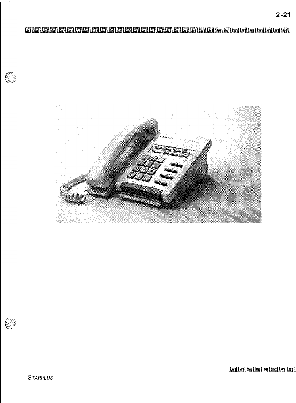
KEY STATION FEATURES
Dialing Privileges
Dialing Privileges
The system provides a flexible means of providing toll or dialing restriction. Through the assignment of class
of service (both station and outside line) many combinations of allow and deny numbers can be set. Both
area and office codes can be screened for allow/deny privileges.
Figure 2-1: Digital Enhanced (8-Button) Terminal
STARPLUS
Triad-S Product Description Manual Issue I- December 1998
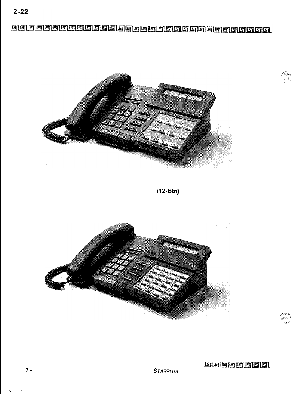
KEY STATION FEATURES
Dialing Privileges
Figure 2-2: Digital Executive
(IP-Btn)
Terminal
Figure 2-3: Digital Executive (24-Button) Terminal
Issue
I-
December 1998 STARPLUS
Triad-S Product Description Manual
KEY STATION FEATURES 2-23
Direct Inward System Access (DISA)
Direct Inward System Access (DISA)
The Triad-S system allows programming of an unlimited number of outside line calls to provide direct access
to the system and use of features such as WATS lines, intercom dial tone or the ability to dial out on outgoing
trunks without going through the attendant. The duration of a Trunk-to-Trunk DISA call can be set by the
system administrator. DISA callers may also access LCR, All Internal/External paging, All Call paging, Call
Park pick-up, and Meet-Me paging. A DTMF receiver must be available for DISA operation.
Vodavi has taken precautions to prevent fraud by requiring a security code
for this feature. However, it is may still be vulnerable to fraud.
Group Access
Incoming DISA callers may access all line groups such as FX or WATS lines or other outgoing services while
away from the office.
DISA
Call Forwarding
Four options are available for a DISA line:
1)
24-hour, 2) night, 3) 24-hour with forwarding, 4) or night with
forwarding. The CO line ringing at a station follows preset forward or no-answer call forward using the preset
forward timer the same as an initially ringing CO line does. It follows direct forward and busy forward the
same as an initially ringing CO line. If the preset forward timer is set to 00 (disabled) the first forward of the
DISA ringing call at a station takes 15 seconds.
Programmable Access
A three-digit security code can be assigned in the system database to restrict unwanted use of the DISA
circuits. Each DISA line can be programmed independently for each option.
Station Access
DISA callers may dial any station directly without going through the attendant.
Trunk-to-Trunk
The DISA Trunk-to-Trunk (or Conference) option on the CO line governs a DISA callers ability to access other
outside lines, CO lines must have DISA Trunk-to-Trunk enabled to allow a DISA caller to establish an
outgoing trunk-to-trunk connection. This allows for specific CO line access restriction on DISA calls.
STARPLUS
Triad-S Product Description Manual Issue I- December 1998
2-24 KEY STATION FEATURES
Direct Station Selection (DDS)
Direct Station Selection (
A user with DSS buttons assigned at their Key Station can call an intercom station or transfer a CO call by
simply pressing the appropriate DSS button.
Direct Transfer Mode
An outside CO line can be transferred from one
keyset
to another. By using the TRANS button, a screened
(announced) transfer can be transferred directly to the handset on any key station. Any number of attempts
can be made to locate someone by calling different
keysets
without losing the call. If a line is transferred to
a busy station, it receives muted ringing.
This feature is programmable on a system-wide basis in admin programming.
Directory Dialing
Directory dialing allows station users to obtain a directory of station users and have the system dial the
extension that is currently on the display. The Triad-S system provide locations for up to
200
names.
Directory dialing also allows users to program a name along with a speed dial bin for use in later locating a
speed dial number. When prompted to do so, the system displays the name associated with a speed dial
number on the LCD display so that when the desired name is shown, the user may then have the system
dial the number.
Directory dialing also allows users to associate a name with an entry in the local number/name translation
table. When prompted to do so, the system displays the name associated with the table on the LCD display
so that when the desired name is shown, the user may then have the system dial the number.
Disable Outgoing CO Line Access
This feature allows the first attendant station to dial a code and disable a CO line from outgoing CO calls,
This applies to all station(s) that have access to that line. Incoming status is not affected.
Distinctive Ringing (User Selectable)
The tone ring signal used to notify stations of an incoming call can be changed by each station user to
provide distinctive ringing among a group of stations. Each station user may select a distinctive ringing tone
Issue I
-
December 1998 STARPLUS
Triad-S Product Description Manual
. .
‘.
:
KEY STATION FEATURES
2-25
Do Not Disturb
(DND)
that is used to ring their station. The system provides
36
different ring patterns that the station users may
select from.
Do Not Disturb (DND)
Placing a
keyset
in DND eliminates incoming outside line ringing, intercom calls, transfers and paging
announcements. A ringing station may go into DND to silence ringing. The attendant can override a station in
DND. The station in DND can use the telephone to make normal outgoing calls. A station can be denied this
feature through programming. DND does not apply to the first attendant station.
One-Time Do Not Disturb
Allows a station user to turn off muted ringing that occurs while off hook (handset or ON/OFF) on another
call. Useful when having an important conversation and do not wish to be disturbed by ringing. The station,
while off hook, (ON/OFF or handset) depresses the DND button which eliminates muted ringing. When the
station goes on-hook the DND button is extinguished and DND is cancelled.
DTMF Sending
Each CO interface circuit for outside lines can be individually programmed to send DTMF (tone) or dial pulse
signals.
End-to-End Signaling
This feature enables station users to communicate with external devices such as answering machines and
IVR
devices.
Executive Override
This feature allows designation of certain stations as executive stations with the ability to override and Barge
in on other
keysets
engaged in conversation on a CO line or intercom call.
In addition to the station programmable option, a system programmable option enables or disables a
warning tone when the station marked as an executive is cut-thru to the conversation. This is useful for an
ACD agent supervisors or training personnel who require a service observing option.
A separate condition has been added to this feature which allows or disallow an Executive to override an
extension. This prevents an extension with override capability from overriding an Executive’s station,
STARPLUS
Triad-S Product Description Manual
Issue
I-
December 1998
2-26 KEY STATION FEATURES
Executive/Secretary Pairing
Use of this feature when the exec tive override warning tone is disabled
may be interpreted as a violation of
federal
or state laws.
A change in volume may occur on the CO line or intercom call after the
barge-in occurs.
Executive/Secretary Pairing
There are four sets of Executive/Secretary pairings available. When the Executive station is busy or in DND,
the Secretary station receives intercom calls and transfers. The Secretary station can signal the Executive in
DND by using the Camp-On feature.
External Night Ringing
The system can be programmed so that CO lines marked for UNA provides ringing out the external page
ports when the system is placed into Night mode.
Flash
Provides telephone users with the ability to terminate an outside call or transfer a call behind a PBX or
Centrex and restore dial tone without hanging up the handset. A FLASH button is located on each Digital
Terminal.
Flash On Intercom
This feature enables key station users to utilize the Flash Key to terminate pages and intercom calls. While
connected to a page zone or another internal station pressing the Flash key terminates the call and return
intercom dial tone.
Issue I- December 1998
STARPLUS
Triad-S Product Description Manual
KEY STATION FEATURES
Flash Rates (Programmable)
2-27
Flash Rates (Programmable)
Fixed and flexible button flash rates can be programmed. There are programmable flash rates for 19
features/functions that can now be programmed to up to 15 different red flash rate options and 14 different
green flash rate options. These are set-up in admin programming.
All other flash rates in the system are fixed (defaulted) at the rates for the Triad-S system.
Flexible Button Assignment
The Triad-S system has the following flexible button assignment features:
+
Enhanced or Executive Digital Terminals
(24-Btn/12-Btn)
with 11 fixed feature buttons and
24/12
flexible buttons. The system powers up with a default button mapping as shown inFigure 2-I: Digital
Enhanced @-Button) Terminal and Figwe 2-2: D@tal Executive (12-B&) Terminal. Each flexible
button can be assigned as a
CO/PBX
line, DSS button, Speed Dial or Feature button. Refer to Table 2-
I:Flex Button Programming Codes.
Q
Enhanced Digital Terminals
(8-Btn)
with 5 fixed feature buttons and 8 flexible buttons. The system
powers up with a default button mapping as shown in F&we 2-2:
Dz@tal
Executive (12-B&)
Terminal. Each flexible button can be assigned as a
COIPBX
line, DSS button, Speed Dial or Feature
button. Refer to Table 2-1:Flex Button Programming Codes.
This feature enables programming of flexible buttons from a remote location (off-site). Range programming
can also be used to assign these buttons to multiple stations.
Outside Line: Automatically accesses assigned line. (Assigned in database)
DSSBLF:
Automatically signal assigned station and provides BLF for off-hook and DND. (User
programmable)
Feature: Any feature with a dialing code (i.e., Personalized Messages, Paging, Account Code, Call Park,
Music, etc.) can be assigned to a flexible button. (User programmable)
Group Access: (Le., ACD, UCD, Hunt, Voice Mail group pilot numbers) (User programmable).
Speed Dial: Automatically dials Speed number. (System, Station, Saved Number Redial, Last Number
Redial) (User programmable)
Pooled Group Access: Some or all outside lines can be grouped; pressing this button accesses the
highest numbered unused CO line in that group. (Assigned in database)
loop: Used to answer a transferred call on a line for which a user does not have a button assigned.
(Assigned in database)
STARPLUS
Triad-S Product Description Manual
Issue
I-
December 7998
2-28 KEY STATION FEATURES
Flexible Button Assignment
+
Unassign (Locked-Out): Specific buttons may be designated as unused or locked out. When a
button is programmed as unused, the button may not be programmed by the station user using
flex button programming procedures.
Issue
I-
December 1998
STARPLUS
Triad-S Product Description Manual
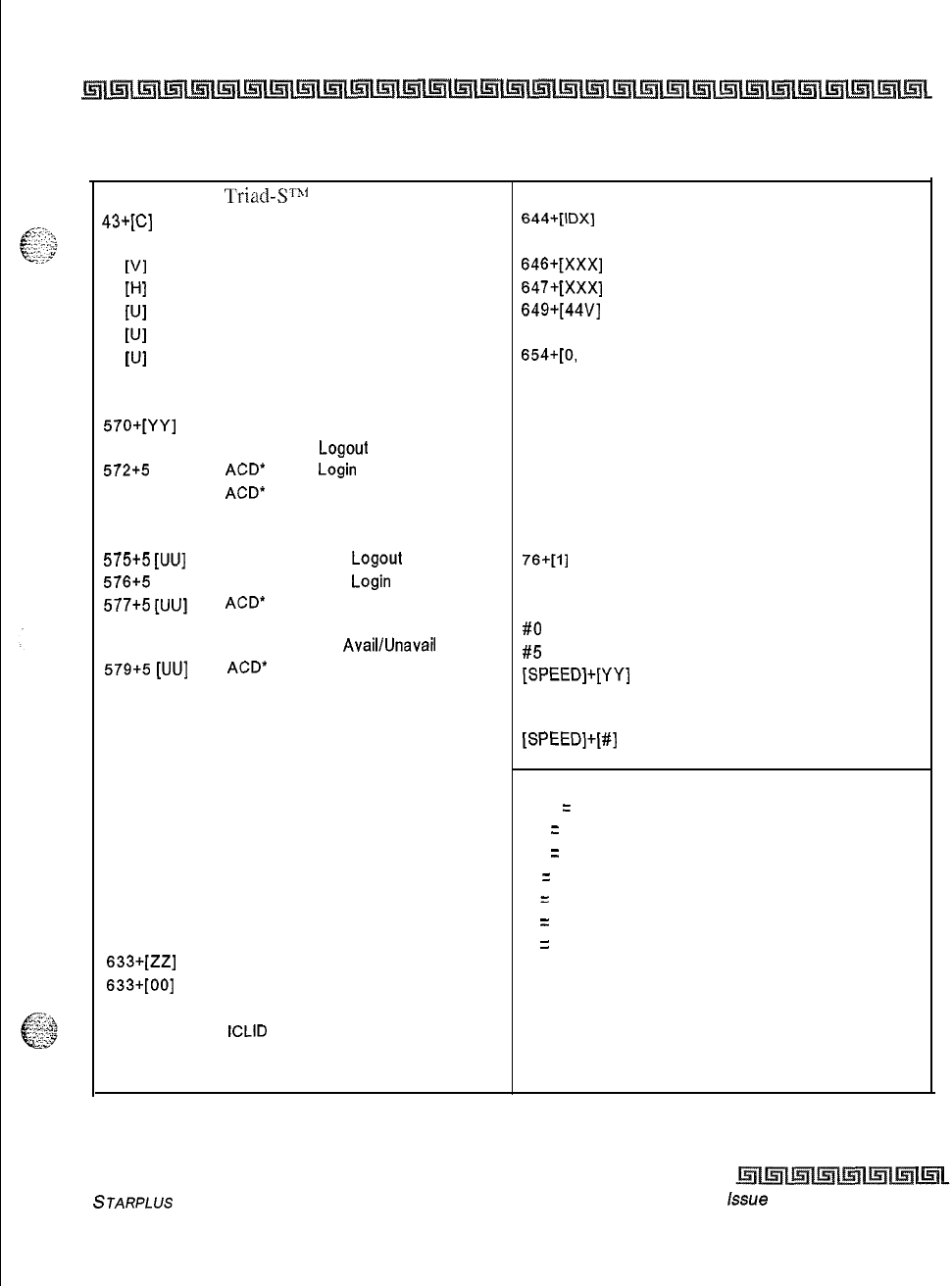
KEY STATION FEATURES
Flexible Button Assignment
2-29
100-131
43+tq
438
44
VI
45
P-d
55
PJI
55
PJI
56
WI
566
567
57o+[YY]
571
572+5
[UU]
573
574
575+5
[UU]
576+5
[UU]
577+5
[UU]
578
579+5
[UU]
601
603
604
621
622
625
626
627
628
631
632
633+[ZZ]
633+[00]
634
635
639
641
‘l‘riact-S’t’31
Ext. Numbers
Call Park Location l-7 (System)
Personal Park
Voice Mail Group Pilot Numbers O-7
Hunt Group Pilot Numbers O-7
ACD* Group Pilot Numbers O-9
UCD Group Pilot Numbers O-7
ACD* Group Pilot Numbers 1 O-15
ACD*/UCD Available/Unavailable
ACD*/UCD Calls in Queue Display
ACD* Call Qualifier Code
ACD* Agent
Logout
ACD’
Agent
Login
ACD*
Group Member Status
Display
ACD* Agent Help
ACD* Supervisor
Logout
ACD* Supervisor
Login
ACD*
Supervisor Queue Status
Display
ACD* Overflow
Avail/Unavail
ACD*
Calls in Queue Display buttons
Attendant Override
CO Line Off-Net Forward
Night Service
Line Queue
Call Back
Executive Override/
Monitor Barge-In
LCR Queue Cancel
Account Code Enter
OHVO Enable
Do Not Disturb
Background Music
Personalized Messages
Clear Personalized Messages
Headset Mode
ICLID
Display (unanswered calls
Incoming CO Call Transfer
Release button
643
Repeat Redial
644+[IDX]
Mailbox button
645 Intercom button(s)
646+1XxX]
Call Coverage (Ringing Type)
647+[XXX]
Call Coverage (Non-Ringing Type)
649+[44V]
One-Touch Recording
653
Caller ID Name/Number Toggle
654+[0,
I]
Answering Machine Emulation mode
680 Dial Speed Directory
695
Distinctive Ringing
70
All Call Page (Internal and External)
71 Internal Page Zone 1
72
Internal Page Zone 2
73
Internal Page Zone 3
74
Internal Page Zone 4
75 Internal All Call Page
76+[1]
External Page Zones
77
Meet-Me-Page Answer
9
Least Cost Routing (LCR) Access
#O
Group Call Pick Up
#5
Universal Day/Night Answer
[SPEED]+[YY]
Speed Dial Access
(00-19 Station) (20-99 System)
[SPEED]+[S] Save Number Redial
[SPEED]+[#]
Last Number Redial
XXX
=
Station Extension Numbers
YY
=
Speed Dial Bin Numbers
ZZ
=
Personalized Messages
U
=
ACD* (O-15) or UCD (O-7) Group Number
C
=
Call Park Location O-7
H
=
Hunt Group Number O-7
V
=
Voice Mail Group Number O-7
IDX = 001-255
l Features available with optional software.
Table 2-1: Flex Button Programming Codes
STARPLUS
Triad-S Product Description Manual
issue
I- December 7998
2-30 KEY STATION FEATURES
Forced Least Cost Routing (LCR)
Forced Least Cost Routing (LCR)
The Triad-S system may be programmed on a per station basis to force the use of LCR for outgoing
accessed. This allows the system administrator to maintain greater control over dialing patterns and the
lines used for placing outgoing CO calls.
Forward Override
This feature allows a user to reach a busy station that is busy forward, no answer forward or all call
forwarded. This allows the calling station to call to a forwarded station, OHVO, Executive Override, Monitor,
Message Wait, Camp-On, or Call Back at that station rather than forwarding to the busy destination.
Group Listening
All digital key stations have built-in speakerphones. Station users may use the speaker to monitor a call
while using the handset to converse with the outside party. This enables other people in the room to listen
to both parties in the conversation.
This feature is not available when the station is in headset mode.
Headset Compatibility
The Triad-S Digital Terminals are designed to allow the connection of an industry standard, electret mic
compatible, modular headset. The user connects the modular headset to the handset jack on the telephone
leaving the handset in place. The ON/OFF button on the Digital Terminal is then used to activate the
headset.
Headset Mode
Each digital terminal can be individually programmed for headset operation. When programmed, an
industry standard headset with it’s adapter box may be connected to a digital terminal for headset use. This
allows handset or headset operation by switching the selector switch on the adapter box. Speakerphone
operation and call announce on intercom are disabled while a station has enabled headset mode.
Once programmed in station programming, the user may then select between headset mode or normal
handset/speakerphone mode by simply dialing a code or pressing a user programmable flex button,
Issue I
-
December 1998
STARPLUS
Triad-S Product Description Manual

KEY STATION FEATURES 2-31
Hearing Aid Compatible
Hearing Aid Compatible
All Digital Terminals and Single Line Telephones are hearing aid compatible in compliance with the FCC Part
68,
Section
68.316.
This allows using the telephone in conjunction with users wearing hearing aids.
Hold
-
Exclusive
When a line is placed on Exclusive Hold, no other station in the system can retrieve this call. Exclusive Hold
may be programmed and activated on the first or second depression of the Hold button, CO Lines while in a
transfer hold are always placed in an Exclusive Hold condition.
Hold
-
Preference
This allows either System or Exclusive hold as the primary hold on the first depression of the HOLD button,
depending upon programming. A second depression invokes the second hold preference.
Hold
-
Recall
When an outside call has been on Hold for a programmable length of time, recall ringing tone is sent to the
station placing the call on Hold. If this station does not answer the recall, a recall tone is sent to the
attendant(s).
Hold
-
System
When a line is placed on System Hold, any station in the system with an appearance of that line can retrieve
the call.
Hot Keypad Feature
This feature enables a station user to activate the telephone by dialing digits without going off hook.
Hot Line/Ring Down
Digital key stations may be programmed to immediately call or ring down a particular station or outside
number upon going off hook. This is done by programming the stations Off-Hook preference to activate a
STARPLUS Triad-S Product Description Manual
Issue I- December 1998
I
-‘.-..
2-32 KEY STATION FEATURES
Hunt Groups
DSS or Speed dial feature key. This feature can be overridden if the station user selects a CO line first when
going off-hook.
Hunt Groups
The system can be arranged for up to eight Hunt groups. Each Hunt group can contain up to eight stations
each. Each Hunt group is independently arranged to utilize either a pilot hunting technique or station
hunting technique.
Chaining
Hunt Groups can be chained or joined together forming larger Hunt Groups. This is accomplished by
assigning a pilot hunt group number as the last member of a group.
Pilot Hunting
Incoming CO, transferred CO, and intercom calls can be directed to a pilot extension number
of
a Hunt
group. The system searches sequentially (in the order the extensions were entered in the database
programming) for an idle station in the group and rings that station. Calls directed to stations (by calling
the extension number) within the hunt group do not hunt but receive call progress tones of the extension
dialed.
Station Hunting
Transferred CO calls and intercom calls that are presented to a busy, or DND station, who is a member of a
station Hunt group, searches sequentially (in the order the extensions were entered in database
programming) for an idle station in the group and rings that station. Direct ringing CO Line calls to the
station number rings at the station. If station hunting is desired on a direct ringing call, program the station
hunting pilot number in the CO Line ring assignment list. This allows the member of the hunt group to
receive private calls and hunt group calls.
ICLID/Caller
ID Features
The ICLID (Incoming Calling Line IDentification) feature has been added to the Triad-S system. However, in
order for this feature to operate properly, it must be activated from the Central Office so that the numbers
of the calling party is delivered over the individual tip and ring of the CO lines during the first silent interval
between ringing. The following features have been implemented.
Issue I- December 1998
STARPLUS
Triad-S Product Description Manual
KEY STATION FEATURES
ICLID/Caller
ID Features
2-33
Caller-Entered ICLID Digits
This feature is available with optional software. The Guaranteed Message announcement feature provides a
means to force incoming callers to an announcement before being placed into an ACD Queue or routed to an
agent, The outside callers are presented with the entire message before being routed to the ACD Group.
Agents in an ACD Group with a Guaranteed Message enabled receives incoming callers only after the caller
has heard the designated recorded announcement in its entirety.
Additionally, the Guaranteed Message feature provides an option to capture digits dialed by the incoming
caller which can be inserted as ICLID incoming number identification.
If the Guaranteed Message announcement is programmed in Admin, incoming ACD calls is routed to the
Guaranteed Message RAN before going to the ACD Group. If the ICLID option is selected, digits received before
the announcement time-out is captured and inserted as incoming ICLID number information. When the
ICLID option is selected, a
[#I
is recognized as a termination of the announcement and a
[*I
is recognized
as an entry error. An entry error removes the ICLID number and the incoming caller can re-enter his phone
number.
Caller ID Name/Number Option
This feature allows a station user to program a flexible button to view both the number and name on the LCD
when receiving a Caller ID CO call. The top line of the LCD displays the number of the caller and the bottom
line of the LCD displays the name.
Calling Number/Name Display
This feature is intended as the basic offering of the ICLID service when associated with the Triad-S system.
Whenever an incoming call is received at the system, the number received along with the ringing signal is
stored in the line control tables and used at various points in the processing of the call,
$4
The primary function is that the calling number is displayed (if available) at any point at which the
LINE RINGING is displayed in the system.
+
Additionally, with the availability of the calling name feature, if the calling name is provided, the
system delivers that to the display instead of the calling number,
Incoming Number/Name for SMDR Records
This feature operates normally in the absence of ICLID information or the failure of the ICLID equipment, If
the information is present at the time that an SMDR record is generated for a call, it alters the content and
format of the SMDR output record.
STARPLUS
Triad-S Product Description Manual
Issue
I
-
December 1998
2-34 KEY STATION FEATURES
Idle Speaker Mode
If the calling number is available, the number is output in the SMDR record in the same location as the
dialed number is located in the outgoing calls.
If the calling name is present, an additional line is output in the SMDR record identifying the name. This
record immediately follows the normal SMDR record. The normal SMDR record includes an indicator
which identifies that a following record with name identification is present.
Unanswered calls is recorded in the SMDR record for incoming with an indicator to allow the identification
of callers for statistical and call-back purposes.
Unanswered Call Management Table
An Unanswered Call Management Table with 100 entry capacity is maintained in the system database. The
calling number/name information pertaining to any unanswered call is placed in this table at the time the
system has determined that the call has been abandoned.
This table may be accessed from any display telephone to review unanswered calls . Only an attendant
station(s) can delete an entry from this table.
Idle Speaker Mode
This feature allows the system to determine whether the first digit dialed is heard over the digital terminal
speaker. This feature is allowed or denied on a system-wide basis in programming.
Incoming CO Call Transfer
This feature provides station users the ability to transfer a call that is currently ringing at their station
without answering it. Only Incoming and Transferred calls can be forced. This feature only operates when
the station is in an idle mode and is not available to Single Line Telephone users. Calls may be forwarded to
any available station,
ACD/LJCD
group, VM Group. Destination station must have an direct appearance for
that CO Line or Loop button and not in DND or error tone is presented to the originator and the call
remains ringing at his station. If the station is busy, the current call must be placed on hold, the ringing
transfer initiated, and then the station can return to his original call.
Intercom Button(S)
This feature provides station users the function of ringing a busy station via the intercom without using the
Camp-On or Executive Override features. This also allows stations to place intercom calls on hold. If calls
Issue I- December 1998
STARPLUS
Triad-S Product Description Manual
,-...
,
..-,
c.::;; .$:-,
. . .
.
,.<.
..I
L_
d..
..-.d
.
,.l.-.
.T..,
“2.
::
:”
KEY STATION FEATURES
Intercom Calling
2-35
are ringing on intercom buttons and a Handsfree call is received, the Handsfree call is allowed and the calls
ringing continue with muted ringing. Multiple intercom path buttons can be assigned to a single station,
however up to five internal parties can be placed on hold per station. Music-On-Hold is provided to intercom
callers on hold.
This feature can be programmed on any key station or DSS Console with an available flexible button. If there
is an available intercom button, a station calling that station cannot OHVO, Camp-On or Override that station.
Depending on the key station programming, intercom ringing is muted or reminder ringing. If all intercom
buttons are in use, then the station may utilize the Camp-On or Executive Override features. By default, no
intercom buttons are assigned to any key stations.
Intercom Calling
The system’s architecture allows non-blocking of intercom calls. A station is reached on intercom by dialing
the associated three-digit number.
Intercom Signaling Select
Users can control the method by which they receive intercom calls and signals. A convenient intercom signal
switch(es) or HPT button (Digital Terminals) is located on each Terminal for easy selection, The choices are:
oHandsfree (H): The station user, upon hearing a tone burst and voice announcement over the
speaker, can reply handsfree.
*s
Privacy (P): The station user receives a burst of tone and a voice announcement over their speaker.
The microphone is deactivated for privacy, The called party must lift the handset or press the MUTE
button to answer the call.
$4
Tone Ringing (T): A standard tone ring notifies the party of an incoming intercom call. The called
party answers by lifting the handset or moving the switch to the handsfree (H) position or pressing
the ON/OFF button.
Inter-Digit Timeout
This feature allows programming of the inter-digit time-out on a system-wide basis. This feature applies to
intercom and LCR calls,
DISA
inter-digit time-out remains unaffected by this timer.
STARPLUS
Triad-S Product Description Manual
Issue
I-
December 7998
2-36 KEY STATION FEATURES
Keyset
Mode (Digital KTU Only)
Keyset Mode (Digital KTU Only)
This feature allows the station user to determine the mode in which the Digital Terminal with
CT1
Box
(optional) operates. The five (5) modes are: Inactive mode, PC Phone mode, ATD Command mode, ATH
Command mode and CKTU mode. Through the use of a dial code, the station user can also determine the
baud rate for each mode selected. This setting is stored in back-up memory in the event of a power outage
or system reset.
Keyset
Self Test
The Triad-S system contains a test mode feature that supports the off-line testing of Digital Terminals and
DSS consoles. The term off-line means that the unit under test is disconnected from the system during the
test operation. Digital Terminals not under test continue to operate in the normal manner. Tests are
provided to verify the
keyset
and DSS LED, LCD, and keypad button operations.
Last Number Redial (LNR)
Permits the automatic redialing of the last telephone number dialed on an outside line. Up to 24-digits can
be stored. Outside line selection of the same line used is automatic.
LCD Interactive Display
The Executive Digital Terminal provides the user with visual indication of call status, Calls to and from other
extensions, number dialed, line used and camp-on are some of the features displayed.
Least Cost Routing (LCR)
Allows the system to automatically select the least costly route available according to the number dialed, the
time of day/day of week, the class of service (COS) assigned to the station/trunk group priority level
assigned.
3-Digit Table
This table is divided into two sections: Leading
1
(1 is dialed before the number) and Non-Leading 1 (no 1
is dialed before the number). This gives the system the ability to handle call routing in areas that require a
1 before a long distance number as well as in areas that do not require the 1.
.
.-.
Issue
I-
December 1998 STARPLUS
Triad-S Product Description Manual
KEY STATION FEATURES
Least Cost Routing (LCR) 2-37
6-Digit Table (Office Codes)
The
6-Digit
Table can include 20 office code maps. Each map can be programmed to route up to 800 office
g$$
codes to one of the
16
possible route lists. Each map must be associated with a specific area code in the
3-
-r’ Digit Table. Several different office code maps can be used with the same area code to provide additional
routing flexibility.
Daily Start Time Tables
The Daily Start Time tables allow the user to match the Time Periods discount structure to the carriers rate
schedule.
Default LCR Database
In an effort to decrease installation and set-up time usually associated with LCR a default LCR database has
been incorporated. The default LCR database provides basic routing for all local and long distance dialing.
Exception Tables
This table is used to route operator assisted calls and any other calls which would use a one or two-digit
number rather than a three-digit area code.
Insert/Delete Tables
There are 20 Insert/Delete Tables. Up to 20-digits, including pauses, can be inserted and up to
16-digits
deleted. Digits can be inserted before or after the number dialed, but can be deleted only from the beginning
of a number dialed. To insure that a pause is inserted in LCR at default, the database programming has been
changed to add a pause in each of the 20 LCR insert and delete tables and insert table 0 in each of the route
tables.
LCR Routing for Toll Information
This feature adds provisions to the LCR call processing which allows common call routing for all toll
information calls.
-..\
i
:...
r.
_
&is::
l-(xXx)555-1212,
(XxX)555-1212,
1-555-1212 and 555-1212 calls are intercepted and sent to a selected
7
route
in the Route List Table. Numbers dialed is integrated and if it is a toll information call, either preceded
with an area code or without or with a leading digit 1 or not, the call is sent to the route designated in
programming.
STARPLUS
Triad-S Product Description Manual
Issue I
-
December 1998

2-38 KEY STATION FEATURES
Local Number/Name Translation Table
Route List Tables
Up to
16
different routes can be programmed. Each route can contain up to four route lists
-
one for each
of the four time periods. Up to seven CO line groups (routing choices) and their corresponding
Insert/Delete Tables may be programmed within each route list.
Weekly Time Tables
The least costly route for a particular dialed number may be different at different times of the day and on
different days of the week. To accommodate this situation, there are two Time-of-Day tables: a Daily Start
Time Table and a Weekly Schedule Table.
The Weekly Time table determines which one of the four Routes LCR to use based on the Time-of-Day and
Day-of-the-Week.
Local Number/Name Translation Table
An administrable table provides a local translation from a received calling number to a name. This table
can be administered by the customer from the attendant console location. This table is also shared by the
ICLID features. In cases of conflict between the name delivered from the CO and that in the local translation
table, the local translation table shall rule. 200 entries are provided for the Triad-S system.
Mailbox Button(S)
This feature provides station users to program specific mailbox index numbers onto flexible button at their
station or DSS Console. Users can then transfer internal/external callers to specific Voice Mail Groups or
Mailbox numbers. These Voice Mail Groups or Mailbox numbers are programmed in admin programming.
A total of 255 mailbox buttons are allowed per system.
This feature can be programmed on any key station or DSS Console with an available flexible button. If a
station is an OHVO, Camp-On or Executive Override initiator, they may not use the mailbox button feature.
Stations engaged in a conference cannot use this feature.
If no station(s) are programmed in the Voice Mail Group, the user receives an error tone. By default, no
mailbox buttons are assigned to any key stations.
Issue I
-
December 1998 STARPLUS
Triad-S Product Description Manual
KEY STATION FEATURES
Meet Me Page
Meet Me Page
Users may answer a page call from any phone in the system by dialing a special code. The party who initiated
p;
the page must remain off-hook.
Message Waiting
Stations that are busy, unattended, or in DND can be left a message indication by other stations in the
system. Up to five messages can be left at one
keyset.
Upon return to the station, the user can press the
flashing MSG WALT button to ring each party in sequential order.
Message Waiting Reminder Tone
A key station with a message waiting can be reminded at a programmed timed interval with a tone.
Music-On-Hold
A music source, when connected to the system, provides music to all lines on Hold, parked calls, transferred
calls and calls waiting to be answered by Automatic Call Distribution (ACD) or Uniform Call Distribution
(UCD). This feature can be allowed or denied on a system-wide basis in database programming. This feature
can also allow or deny Music-On-Hold heard on each CO line and is programmable on a per CO line basis.
I
This feature also allows the system to assign CO line circuits as additional music inputs, This increases the
j
capacity of music channels beyond the two available on this system. A total of eight channels is available for
;
use on the system.
Mute Key
Pressing the MUTE button while in the speakerphone mode or using the handset disables the microphone
but not affect the speech coming over the speaker or handset. Pressing the illuminated MUTE button again
reactivates the microphone.
I
.
(i$j
Name
In
Display
i
This feature allows every extension (Key or SLT) the capability to program the users name, for that station, so
that people using display telephones see the name instead of the station number on their display. The name
:
is programmed at each station by the user and may be up to seven letters in length.
STARPLUS
Triad-S Product Description Manual
Issue
7
-
December 1998
.
.
.
.-
2-40 KEY STATION FEATURES
Name/Number Display At Idle
Name/Number Display At Idle
This feature allows the programmed seven-digit name and station number to display together. This option
is programmable on a per station basis, however the feature must be enabled/disabled in admin
programming. If a station has this feature enabled but has not programmed a name, the name portion of
the LCD is blank, The priority of the idle display is
UCD/ACD,
Hunt, Station/Name, or Station alone.
Night Service Feature
The Night Service feature provides a means to put the system in night mode from any
keyset
or remove the
system from night mode from any
keyset
as long as the system was put in night mode by the night service
feature flex button. If the system was placed in night mode by the attendant using the DND button or if the
system was placed in night mode by the automatic schedule, the night service flex button can not remove
the system from night mode.
Night Service Mode
Automatic Night Mode Operation
The Triad-S system can be programmed in database administration to place the system into automatic
night mode. The attendant(s) can override the Automatic Night mode schedule simply by pressing the
NIGHT
(DND)
button.
External Night Ringing
The system can be programmed so that CO lines marked for UNA rings on the external page speakers.
Manual Operation
The attendant(s) can control the use of Night Mode manually by pressing the NIGHT (DND) button. An LED
indicates when the system is in Night Mode operation.
Night Class of Service (COS)
The system allows each station to be assigned a different COS for night operation. The night COS goes into
effect when the system is put into night mode manually or via the automatic schedule. Prevents the misuse
of phones after hours.
Issue 1
-
December 1998 STARPLUS
Triad-S Product Description
Mm.ml
,“,/
:>
-.
._..

KEY STATION FEATURES
Off-Hook Preference
2-41
Night Ringing Assignments.
Each CO line may be individually programmed for Night ringing to other stations, to Hunt groups, ACD
groups, UCD groups, Voice Mail groups, or off-net via speed dial. When the system is placed into night mode,
manually or automatically, ringing follows the night ringing assignments for each CO line.
Universal Night Answer (UNA)
Incoming CO lines can be programmed for Universal Night Answer (UNA). Stations which do not have access
to a line during the day can answer that line while the System is in the Night Mode by dialing a UNA code.
Weekly Night Mode Schedule
A programmable weekly night mode schedule provides for
24
hour, 7 day a week automatic night mode
operation. The system can be put into and out of night mode automatically on a daily basis,
Off -Hook Preference
Auto Feature Access
In addition to auto line access Digital Terminals have the ability to have their off-hook preference select a
DSS or feature button upon going off-hook or pressing the ON/OFF button.
Auto Line Access
Each station, key or SLT, may have their phone programmed to access a particular CO Line such as a private
line or a line from a Group of CO lines upon going off-hook. This is useful in Centrex or PBX applications
when station users have dedicated lines. Outside line dial tone is received just by going off-hook, without the
need to dial an access code.
Hot Line/Ring Down
Digital Terminals may be programmed to immediately call or ring down a particular station or outside
number upon going off hook. This is done by programming the stations Off-Hook preference to activate a
DSS or Speed dial feature key. This feature can be overridden if the station user selects a CO line first when
going off-hook.
STARPLUS
Triad-S Product Description Manual
Issue 1
-
December 1998
.
2-42 KEY STATION FEATURES
Off -Hook Signaling
Intercom Access
When off-hook preference is enabled, at a key station, that station may still obtain intercom dial tone for
accessing internal stations or other system features. This is done either by pressing an DSS button or dialing
their own intercom station number prior to going off-hook.
User Programmable Preference
Based on a station programmable option Digital Terminals may be given the ability to enable, disable or
change their off-hook preference by dialing a code. This option can be denied in station programming on a
per key station basis.
Off -Hook Signaling
If a station has been programmed to receive direct outside line ringing and is busy on another call, the call
rings at the station using a muted ring signal. This option allows a user to receive a reminder ring at his
busy station, instead of muted ringing. Additionally, a reminder ring timer has been added to the system to
provide the reminder ring every time the timer expires, as long as the incoming CO line remains connected.
The system defaults this option to muted ringing. Additionally CO calls may be camped-on to a busy station
and receive muted ringing.
Off -Hook Voice Over (OHVO)
This feature allows Digital terminal users, off-hook on a call (CO or Intercom), to receive a voice
announcement through the handset receiver without interrupting the existing call, The Voice Over is muted
so as not to override or drown out the existing conversation. The overridden party may then respond
to
the
calling party using CAMP-ON procedures to talk to the calling party or use Silent Text Messaging to respond
to the calling party via LCD displays. The calling (originating) station and receiving station MUST be a digital
terminal. The receiving station MUST also be programmed to receive OHVO calls.
A third method provides for the receiving station to respond to an OHVO announcement utilizing the MUTE
feature button. This button is pressed to carry on a two-way conversation with the OHVO initiator while still
listening to the original call.
The calling station is placed in a one-time DND mode upon initiating the
Voice-Over. One- Time DND cannot be toggled during the OHVO call. The
station receiving the OHVO call must be off-hook and in the H mode.
Issue
1
-
December 1998
STARPLUS
Triad-S Product Description Manual
KEY STATION FEATURES
On-Hook Dialing
2-43
On-Hook Dialing
The Digital Terminal user can place calls without lifting the handset. If the speakerphone is disabled, the
..:
1.
6::
handset must be lifted to converse.
..,
.-..
_.._.L
s...
. .
Online Programming
Changes to the system database can be made without interrupting normal system operation. Programming
may be performed using a key station terminal connected to the system (Station 100) or via an external PC
either on-site or remotely.
One-Touch Recording
This feature allows the station user while on an internal/external call to press a button and have the system
record the conversation in the station users mailbox. It has been designed to work with the Triad-S Dispatch
Voice Mail system via in-band signaling.
Use of this feature may be interpreted as a violation of federal or state
laws and an invasion of privacy. Check applicable laws in your area before
recording calls using this feature.
Page/Relay Control
On the Triad-S system, there are two dry relays that may be individually programmed for: External Page,
Loud Bell Control, CO Line Control and Recorded Announcement uses.
Paging
Access Restriction
Programming on a per-station basis, can deny any station the ability to make any type of page.
(ii;
External
There is one external paging zone available on the
Triad-f!P1
system. External Paging requires a three-digit
dialing code. External paging requires an externally provided amplifier and paging system. The zone can have
a relay contact associated to it.
STARPLUS
Triad-S Product Description Manual
issue
I-
December 1998
2-44 KEY STATION FEATURES
Park Personal
Internal
There are four internal paging zones available in the Triad-S system. A station can be in any or all zones or
in no zone at all. Stations not assigned to a page group can still make page announcements, if allowed in
station programming. Stations can be assigned to a page group in order to receive pages but not allowed to
make page announcements.
,(-:.
:,,
I_._
, .
.
,,
%,..
.
..-.,
;?.’
Park Personal
Each digital terminal in the system can place a call into a personal park location and then later retrieve that
call from the originating station. Intercom calls and CO line calls can be placed into the stations’ personal
park location. Calls parked in a personal park location are subject to the system call park recall timer. A
station retrieving a personal parked CO call must have either a direct CO line appearance or an available
loop button to retrieve the parked call.
Only one call can be parked in a Personal Call Park location at one time.
When dialing the Personal Park location and the location is already occu-
pied, the initiating station receives the previously parked call and the
second call is then parked.
Pause Timer
When dialing a speed number, a timed pause between digit sending can be placed in the number. The
length of this pause can be programmed in the system database.
PBX Dialing Codes
Five one or two-digit access codes can be entered into memory. When one of these codes is dialed, it signals
the KSU that the user is dialing a PBX access code, not dialing directly over an outside CO line, and to apply
toll restriction to the next dialed digits after the code. Therefore, toll restriction is not applied to the station
unless one of these five PBX codes is dialed first. This allows dialing of PBX extensions 100, 110, 111, etc.
and functions on lines marked as PBX lines in programming.
Personalized Messages
Each station (Key and SLT) can select a pre-assigned message to display on the LCD of the digital key
terminal calling that station. There are ten possible messages whkh can be displayed:
issue
I- December 1998
STARPLUS
Triad-S Product Description Manual
KEY STATION FEATURES
Personalized Messages
2-45
00 = Clears Messages
01 = ON VACATION
02 = RETURN AM
03 = RETURN PM
04 = RETURN TOMORROW
05 = RETURN NEXT WEEK
06 = ON TRIP
07
=
IN MEETING
08 = AT HOME
09 = ON BREAK
10
= AT LUNCH
Custom
This feature allows the system administrator to enter up to ten custom messages for use by station users of
the system. These messages may be specified and customized by the customer on a system-wide basis,
Date and Time Entry to Personalized Message(s)
This feature allows the station users to activate certain messages that allow the user to enter a specific time or
a date of return. These messages display on calling stations to alert them of the desired party’s return time or
date.
11 = ON VACATION UNTIL: MM/DD
12 = RETURN: HH:MM xm or
MM/DD
13
= ON TRIP UNTIL:
MM/DD
14 = MEETING UNTIL: HH:MM xm
15 = AT HOME UNTIL: HH:MM xm
16
= ON BREAK UNTIL: HH:MM xm
17 = AT LUNCH UNTIL: HH:MM xm
,.?::.
c
Personalized Message Code on a Flex Key
.‘_
.::..
2’:
::-:
T
y-
This feature allows a key station user to program the personalized message code
[633#]
onto a flex button,
This speeds access of the pre-selected messages.
STARPLUS
Triad-S
Product Description Manual Issue
7
-
December 1998
:
;.
:
2-46 KEY STATION FEATURES
Preferred Line Answer
Scrollable Canned Messages
This feature allows the user to use a single digit
[#I
or [*I to scroll through the canned messages and
select one. When the desired message is displayed, pressing the hold button places that message on the
station LCD. This feature operates when the phone is in the idle mode only. This feature cannot be activated
if the station is in the Call Forward or DND mode(s). This feature is not available to attendant stations. The
messages is scrolled in the following order:
Q
Clears Message
o AT HOME
+
AT LUNCH
+
IN MEETING
+
ON BREAK
+
ONTRIP
Q
ON VACATION
+
RETURN AM
+z+
RETURN EM.
+RETURN NEXT WEEK
+ RETURN TOMORROW
Preferred Line Answer
A station with Preferred Line Answer can answer any assigned outside, transferred, or recalling line, or
queue callbacks by lifting the handset or pressing the ON/OFF button. The station MUST be physically
ringing, to function properly.
Privacy Release
Privacy is insured on all communications in the system. If desired, the customer may elect to disable the
Automatic Privacy feature, thus allowing up to three other stations to join in on an existing CO Line
conversations.
Disabling of the privacy feature may be limited by federal, state or local
law, so check the relevant laws in your area before disabling privacy.
Issue 1
-
December 1998 STARPLUS
Triad-S Product Description Manual

KEY STATION FEATURES
Private Line
2-47
Per CO Line Option
This feature allows programming of each CO line individually for privacy. This feature is useful for
maintaining security on such lines as Data lines, Private lines, or special circuits requiring privacy. If privacy
is disabled on a CO line then, while in use, another station may enter the conversation simply by pressing the
CO line button, A programmable warning tone is presented to all parties prior to actual cut-thru. The station
attempting to enter the conversation must also have privacy disabled.
Per Station Option
Each station may be programmed to give the station the capability to join an existing conversation simply by
pressing the CO line button that is in use. A programmable warning tone is presented to all parties when the
station enters the conversation. The CO line must also have privacy disabled to allow the cut-through.
Privacy per station on SLT type stations allows/denies camp-on to the SLT. This is useful for data
applications.
Private Line
Private line programming allows certain lines to ring at a specific station only. When placed on Hold, these
lines are active at the programmed station only. A private line can be transferred to other stations, provided
the station receiving the call has a loop button or direct appearance of that CO line.
Pulse-to-Tone Switchover
When commanded, the system changes the signaling on an outside line from dial pulse to DTMF (tone),
allowing the use of common carriers behind a dial pulse outside line. This can be done manually when
dialing, or can be stored within a speed dial number.
Range Programming
The Triad-S system allow for range programming when programming CO lines and Stations. Range
programming allows you to program all parameters alike for the entire range or you can change or modify a
few items for all members in the range.
STARPLUS
Triad-S Product Description Manual
issue
I- December 1998
2-48 KEY STATION FEATURES
Remote Administration
Remote Administration
The Remote Administration feature allows authorized personnel to access the administration programming
via a terminal device (portable terminal device or personal computer with communications software
package).
The feature permits the review and entry of the customer database in the same manner as via the digital
terminal at
ADMIN
Station 100. The terminal device can be connected directly to the RS-23X connector on
the Miscellaneous Service Unit
(MISLJ)
on the Triad-S system, or can be accessed by a telephone modem
linking the RS-23X connector (via a CO line) to a remote location. When entering the system remotely via
a terminal device, access to the On-Board 9600 baud modem is accomplished by accessing Port
499
either
through a direct ringing assignment or through DISA or by being transferred to Port
499
by any internal
station.
Database Upload/Download
Database Upload/Download provides a maintenance facility which is added to the Remote Administration
routine. This routine permits downloading of the database to a PC, when a software change is made or
when the system must be initialized and reprogrammed. Additionally, the routine facilitates the
programming of a database on an in-house system which can be downloaded to a PC and then uploaded to
a system in the field. After the system maintenance is completed, the file saved in the PC can then be
uploaded to the system.
Remote System Monitor And Maintenance
Maintenance
The Remote Maintenance feature allows the Interconnects’ technical staff to review the system
configuration data and individual card slot configuration data. This can be done on-site using a data
terminal or remotely using a modem to access a remote data terminal. When entering the system remotely
via a terminal device, access to the optional
9600
baud modem is accomplished by accessing Port
499
either through a direct ringing assignment or through DISA or by being transferred to Port
499
by any
internal station.
Monitor
The Remote Monitor feature provides remote access to the installed system for diagnostic purposes, These
capabilities benefit Service personnel enabling them to support the end user remotely. Different levels of
Issue I- December 1998
STARPLUS
Triad-S Product Description Manual
KEY STATION FEATURES
Repeat Redial
access, via password, allows authorized personnel to trace, monitor and up-load critical information directly
from the Triad-S system. This provides a more accurate means of acquiring system information that leads to
a quick resolution of problems that may occur. This is all done without interfering with ongoing call
b,
__ .--
c::‘-
processing or normal system operation, and in many cases may be performed without a site visit,
-_-
.:
..;’
:;. 5
--
Capabilities allowed and reserved for this High level troubleshooting additionally are:
$0
Monitor Mode
+:b
Enable and Disable Event Trace
oDump Trace Buffer (Up-Load)
Repeat Redial
The feature allows a digital key station to press a flexible button or dial a code and redial a busy or no-answer
number at specific intervals. The user is signaled via a queue callback indication. The Repeat Redial flexible
button flashes at the callback rate of 120 ipm for 15 seconds. If the station doesn’t answer within the 15
seconds, the callback is canceled. The system retains the last call the user made. If the station is busy on an
internal/external call when the Repeat Redial queue callback occurs, the callback does not occur until the
user goes on-hook. The user must enter a Redial timer value when invoking this feature. This value is from
006-999
which represents seconds. A 2-minute interval would be entered as 120. Default value is 1 minute
(60).
Save Number Redial (SNR)
Any number dialed on an outside line can be saved permanently and used at any time. This number is saved
until a new number is stored.
Single Line Telephone (SLT) Compatibility
The Triad-S system support industry standard 2500 Type (DTMF) single line instruments. When the
CO
Line/Single Line Interface Board
(CSIB)
is installed in the
Triad-ST”’
system up to 24 single line telephones
can be supported.
Both Enhanced and Executive Digital Terminals are equipped with a speakerphone. However, the
speakerphone can be programmed to work in one of three ways:
STARPLUS
Triad-S Product Description Manual
Issue
I-
December 1998
:
2-50
KEY STATION FEATURES
Speed Bins/Chaining
oNormal speakerphone operation.
+
Disabled for outgoing and incoming CO calls but handsfree on intercom allowed.
+s
Headset operation allowed.
Speed Bins/Chaining
Speed dial bins may be chained together by simply pressing one speed bin, then another and another as
required. This is helpful for accessing Long Distance carriers or banking services when account codes may
be required.
Speed Dial
-
Flash
A flash can be programmed within a speed dial number. When this is done, a pause is automatically
inserted before the remaining speed dial digits are sent.
Speed Dial
-
Station
Each station user can program up to 20 frequently dialed numbers of up to 24-digits in length. Pauses,
flash commands, pulse-to-tone switchover, and NO-DISPLAY characters take up digit spaces. There are a
total of 2000 speed locations in the Triad-S system for dividing among all telephones.
Numbers are dialed by use of the SPEED button and a two-digit code. This feature can additionally be
assigned to any of the buttons in the flexible button field on each
keyset
for one-button activation,
Speed Dial
-
System
Up to
80
commonly dialed numbers can be programmed into System Speed Dial for use by stations allowed
this feature. These numbers can be up to 24-digits including pauses, flash commands, pulse-to-tone
switchover, and no-display characters. The last 40 numbers are not monitored by toll restriction.
Station ID Lock
This feature provides a means for the installer/programmer to lock the station Id of all stations in the
system. Once locked, attempts to plug unlike devices (Le., a DSS into a 24-button port) results in the device
not working.
Issue
7
-
December 1998 STARPLUS
Triad-S Product Description Manual
KEY STATION FEATURES
Station Message Detail Recording (SMDR)
This feature is designed to prevent the loss of station programming that results when a different station type
is plugged into a port already designated as another station type.
‘T;=---
Station Message Detail Recording (SMDR)
The Triad-S system provides details on both incoming and outgoing calls. This feature is programmable to
allow recording of all calls or just outgoing long distance calls. The system tracks calls by outside line,
number dialed, time-of-day, date, station that placed the call and duration of call. Account codes may also be
entered and recorded. The optional MISU is required.
Station Relocation Feature
The Station Relocation feature provides a means to allow a user to unplug their station and plug it in at
another location. Then by dialing a code followed by the old station number, all station attributes, including
extension number, button mapping, speed dial, and class of service are transferred to the new location.
/f
a station is assigned to a specific port and that station user unplugs their
station and plugs it in at another location, the database administration
programming is updated to reflect the new port change. Station lock may
prevent this feature from working correct/y.
Text Messaging (Silent Response)
This feature allows a station user to use text messages to respond to a caller that has either Camped-On or
has used the Off-Hook Voice Over (OHVO) feature to alert a busy station of a waiting call or message. The
camped-on station may respond to the caller via the personalized, custom, and response text (LCD)
messages. The text messages appear on the calling party LCD display. The calling (originating) station and
receiving station MUST be a digital terminal. The receiving station MUST also be programmed to allow OHVO
calls.
Toll Restriction (Table Driven)
The system provides a flexible means of providing toll restriction to internal stations of the Triad-S system.
Each station is assigned a Class of Service for day mode operation and one for night mode operation these
station
COS’s
work in conjunction with a CO line Class of Service to allow for customized toll restriction. Two
Allow and Deny tables along with four special tables afford the system administrator to devise a variety of
complex toll restriction or dialing privilege schemes.
STARPLUS
Triad-S Product Description Manual
Issue
I-
December 1998
.:
KEY STATION FEATURES
Transfer Recall
Canned Toll Restriction
The system provides an easy means of applying the most common form of toll restriction where 1 + and
0+ along with
976,
555,
and 411 type of calls are denied and l-800, 1-888, 911, l-911, and
1-611
type of
calls are allowed. This canned toll restriction is applied through the use of a single pre-built Class-of-Service
and can be assigned to stations using range programming.
Transfer Recall
Screened and unscreened transfers recalls the initiating party if unanswered for a programmable length of
time, and then if unanswered, recalls the attendant.
Uniform Call Distribution (UCD)
Eight Uniform Call Distribution (UCD) groups can be programmed, each containing up to eight three-digit
station numbers. Each group is assigned a pilot number. When this number is dialed, the first available
agent in that group is rung. Calls are routed to the station that has been on-hook for the longest period of
time.
Agent Queue Status Display
The Agent Queue Status feature provides a means for an agent and UCD supervisor to view the status of
their UCD group. This display is an idle state display and prompts a supervisor that Agents in a group are
having problems answering all their calls. The display tells the agent and his supervisor how many calls are
in queue, how many agents are available or logged into the group, and the length of time in minutes that
the oldest call has been in queue. The agent receives the calls in queue display whenever there is a call in
queue.
There are two methods of viewing UCD Group call queue status,
1
In-service UCD agents and the assigned overflow station sees the quantity of calls in
queue on the LCD of their station for the UCD group of which they are a member. If
every member of a UCD group is busy and calls are in queue, the Supervisor/Agent
Queue Status display is seen at all UCD members of that group.
._...
-.-_
If
a
UC0
member is token out of the group
(Le..
DND, All
Call
Forward,
Unavailable. etc.) they do not receive calls in queue information.
issue
1
-
December 1998
STARPLUS
Triad-S Product Description Manual
.
.
.
KEY STATION FEATURES
Uniform Call Distribution (UCD)
2-53
2
Any station not assigned in a UCD group can view the number of calls in queue for any
given UCD Group. To view the number of calls in queue the station user dials the Calls In
Queue code (or presses a programmed FLEX button with this code) then enters the UCD
group desired. The LCD displays, on a real time basis, the number of calls in queue for
that group.
Alternate UCD Group Assignments
An alternate UCD group can be programmed so that if stations in one group are busy, the alternate group is
checked for an available station.
Auto Wrap-Up with Timer
After completion of a UCD call (on-hook) the agent is not subjected to another UCD call for the duration of
the Auto Wrap-Up Timer (regardless of the number of calls in queue), allowing the agent to finish call related
work or access other facilities. This allows agents to remove themselves from the group (i.e., DND,
Unavailable, Call Forward or originate another call). The Auto Wrap-Up Timer is programmed as part of the
UCD database. (System-wide)
Available/Unavailable Mode
Stations programmed into a UCD group may log off and on to their assigned UCD group by dialing an
Available/Unavailable code. When an agent is in the Available mode that agent receives UCD calls in the
normal manner. When an agent is in the Unavailable mode that agent no longer receives UCD type calls,
however may receive non-UCD calls. Agents that have logged off by going Unavailable receives a visual
reminder that they are logged off with a flashing LED and or a LCD display message.
Incoming CO Direct Ringing
CO Lines can be programmed to ring directly into a UCD group. When all agents are busy and RAN is enabled,
the system answers the caller and present the 1st RAN announcement automatically.
No-Answer Recall Timer
If a call routed to a station via UCD is not answered by the UCD Agent/Station before the No-Answer Recall
. .
-.
j,;
r
:=
“-1
-::-’
=_;jr
timer expires, the call is returned to UCD Queue with the highest priority. Additionally, the station that failed
to answer the ringing UCD call is placed into an Out-Of-Service (00s) state.
STARPLUS
Triad-S Product Description Manual
Issue
I-
December 1998
I2-54 KEY STATION FEATURES
Universal Day/Night Answer (UDAIUNA)
No-Answer Retry Timer
When the No-Answer Recall timer expires, a station that failed to answer the ringing UCD call is placed into
an out-of-service (00s) state. The station that was taken out-of-service (00s) is placed back in service if the
agent
hits his available flex button or dials the available flex code. Additionally, the agent is placed back in
service if the No-Answer Retry timer expires. If the agent does not answer his next UCD call, he is again
taken out-of-service. This cycle continues until the station answers calls, logs out, or goes unavailable.
Overflow Station Forwarding Assignments
An overflow station may be assigned to route callers in queue to a designated station after a specified time.
The overflow station may not be one of the UCD group stations.
This feature allows UCD calls reaching the UCD Overflow Station to call forward to another station. This is
allowed or denied on a system-wide basis. Once enabled in programming, a UCD Overflow station can
Busy/No-Answer forward to Voice Mail Groups, Hunt Groups and stations. If the UCD Overflow station is
busy
or does not answer before the no-answer call timer expires, the UCD call forwards to Voice Mail.
Recorded Announcements (RAN)
Recorded announcement devices can be assigned to provide up to eight different messages, if all stations in
a UCD group are busy. The eight messages are available to all eight UCD groups in different configurations.
A RAN table can be the answer port for unanswered incoming calls to a UCD group, while another table can
provide the secondary message. Each RAN device can provide an announcement to one caller at a time.
Subsequent callers is queued onto the message on a first-in basis.
Universal Day/Night Answer
(UDA/UNA)
Incoming CO lines can be programmed for Universal Day Answer (UDA) or Universal Night Answer (UNA).
UDA/UNA
assigned CO lines can also signal over the external page port(s). External Day ringing is
programmed on a system-wide basis in admin programming. Stations which do not have access to a line
during the day can answer that line while the System is in the Night Mode by dialing a UNA code. In order to
utilize this feature, a Loop button or an appearance of the trunk must be present on the station.
Voice Mail Groups (VM)
The Voice Mail feature automatically handles unanswered calls. Stations may forward calls to a voice mail
group (for leaving mail) or may call the voice mail group directly (to retrieve mail) with no assistance from
Issue 1
-
December 1998 STARPLUS
Triad-S Product Description Manual
KEY STATION FEATURES
Voice Mail Groups (VM)
2-55
the attendant. Up to eight voice mail groups containing up to eight Voice Mail stations can be configured in
the system. Each station interfaces with a port on the Single Line Interface Board
(SLIB).
Each voice mail
station can be shared by a number of actual users. A CO Line/Single Line Interface Board (CSIB) is required
when utilizing the Triad-S system Voice Mail In-Band integration,
Additionally, calls that are transferred from aVoice Mail group do NOT recall to the VM group. Instead, the
call recall to the attendant station. If no attendant station is programmed in the system, the call continues to
recall this station. This is useful for Voice Mail systems that only provide unsupervised transfer capability.
By default, all Voice Mail stations are placed into Pick-Up Group
1.
You
may need to change the default setting.
Disconnect Signal
To avoid Voice Mail ports from being unavailable as a result of CO line callers abandoning the call or not
exiting the VM system properly, a disconnect signal is provided to notify the VM system that a CO or intercom
caller hung up or abandoned the call. Silence is provided to the VM port followed by busy tone to aid the VM
system to recognize that an intercom caller has abandoned the call.
In-Band Signaling Integration
The Triad-S system allow programming so that if a station programmed to receive incoming CO line ringing
is forwarded to Voice Mail, they may have incoming callers routed directly into their stations voice mail box
through the use of In-Band signaling. Alternately, incoming CO lines can be programmed to ring directly into
the Voice Mail system. In this case, callers are answered by the Voice Mail or Auto Attendant Main greeting.
Incoming CO callers can be call forwarded into Voice Mail automatically, if a Preset Forward Destination is
programmed for that CO line and the same CO line programmed to ring at one station. Additionally, CO lines
programmed to ring at an attendant station call forward into the Voice Mail system (if programmed to ring at
one attendant station) and presented to the main greeting (not the attendant stations mail box) even when
ID digits are enabled.
~~~~
LCD Message(s) Indication
t
-
:..
~:‘~,:
‘1
iS:i
This feature presents the number of new Voice Messages to users on their LCD display. The new VM LCD
message on the
keyset
takes priority over Forward, DND, Messages, and idle displays. Ringing, Recalling,
Outgoing Calls, and current call operation displays override the VM message display for the duration of the
call or operation.
STARPLUS
Triad-S Product
Description
Manual Issue
1
-
December 1998
KEY STATION FEATURES
Voice Mail Groups (VM)
Message Waiting Indication
When Voice Mail receives a voice message for a user who has a station on the Triad-S system, the VM
connected to the system can leave a message indication at the VM users station. When the station retrieves
their mail, the VM system can cancel the message waiting indication left at a station via a VM port.
The message waiting indication displays on the programmed Voice Mail (group) button, If such a button
was not programmed, a voice mail message waiting indication displays on the MSG WAIT button as a
normal message waiting signal.
Tone Mode Calling Option
Voice mails systems and/or Automated Attendants can utilize the Calling Station Tone Mode option, This is
useful when using supervised transfer or call screening options on voice mail or auto attendant(s)
requiring ring back tone for proper call handling.
Transf et-/Forward
This feature allows Voice Mail calls, upon reaching a forwarded to VM station, to forward back into the Voice
Mail unit. This is useful when VM ports are used as Auto Attendant and VM ports. This feature can be
enabled/disabled for all VM groups.
Transfer with ID Digits
This feature provides an attendant or station user a way to transfer a caller directly into a voice mail box.
This allows the station identification digits to be entered by the transferring party. Using this feature, a caller
can be transferred to a voice mail box when
1)
a station user on the system is not forwarded to VM, or 2)
the destination voice mail box owner is not a station user. CO trunks and internal calls may be transferred
into voice mail using this feature. If no voice mail ID digits are dialed by the transferring station, the
identification digits of the transferring station are sent to the voice mail.
This feature allows dialing of digits 0000-9999 when using the VM with ID feature. This allows, on a per
station basis, the ID number that is sent to Voice Mail to be flexible. By default, the station number is sent
to the Voice Mail system. In database programming, there is a field to insert a 4-digit entry (0000-9999)
that can be sent to the Voice Mail system instead of the station number. This is useful when a station user
manually transfers a caller to a mailbox.
issue
I- December 1998
STARPLUS
Triad-S Product Description Manual

KEY STATION FEATURES
Volume Control Bar
2-57
Volume Control Bar
The volume control bar on the Digital Key Terminal is located below the keypad. It controls ringing, handset,
F-:
and speakerphone volumes.
. .
4.
.--I
STARPLUS
Triad-S Product Description Manual issue
I
-
December 1998
.
.
2-58 KEY STATION FEATURES
Volume Control Bar
FEATURE
iCOUNT
CODES
VERIFIED ACCOUNT CODES
ANSWERING MACHINE EMULATION
ATTENDANT RECALL
AUTOMATIC CALL BACK TIMER
AUTOMATIC CALL DISTRIBUTION (ACD)
Agent Positions
Alternate ACD Group Assignment
ACD Group Member Status
Guaranteed Message Announcement
Incoming CO Direct Ringing
No-Answer Recall Timer
No-Answer Retry Timer
Overflow Station Assignments
Overflow Station Forwarding
PC/ACD
Interface Trace
Recorded Announcements (RAN)
Supervisor Positions
Supervisor/Agent Calls in Queue Display
Wrap-Up Timer Per ACD Group
AUTOMATIC LINE ACCESS
AUTOMATIC NIGHT SERVICE
AUTOMATIC PAUSE INSERTION
AUTOMATIC PRIVACY
AUTOMATIC SELECTION
EACKGROUND
MUSIC
BATTERY BACK-UP (Memory)
BUSY LAMP FIELD (BLF)
N = No Additional Equipment Required
STD ACD ADDITIONAL
PKG PKG EQUIPMENT
. .
N
..
N
.
.
VM System
.
.
N
..
N
.
N
.
N
.N
.N
.
N
.
N
.
N
.
N
.
N
.
N
.
N
.
N
.
N
.
N
..N
..
N
..
N
.
.
N
..
N
.
.
Music Source
. .
N
.
.N
Table 2-2: Key Station Features/Software Packages
Issue
7
-
December 1998
STARPLUS
Triad-S Product Descrjption Manual
KEY STATION FEATURES
Volume Control Bar
FEATURE
:ALL
ANNOUNCE
-
PRIVACY
CALL BACK
CALL COST DISPLAY FEATURE
CALL COVERAGE FEATURE
CALL FORWARD: PRESET
ACD Groups
Hunt Groups
Off-Net
Per CO Line
Stations
UCD Groups
VM Groups
CALL FORWARD: STATION
All Calls
Busy
Busy/No Answer
Follow-Me
No Answer
Off-Net
CALL PARK
CALL PICKUP
Directed Call Pick-Up
Group Pick-Up
CALL TRANSFER
CALLER ENTERED
ICLID
DIGITS
CALLER ID NAME/NUMBER OPTION
CALLING STATION TONE MODE OPTION
CAMP-ON
CAMP-ON RECALL
CANNED TOLL RESTRICTION
N = No Additional Equipment Required
STD ACD ADDITIONAL
PKG
PKG
EQUIPMENT
. . N
.
.
N
.
.
N
.
.
N
.N
..N
. . N
. .
N
.
.
N
.
.
N
.
VM System
.
.N
.
.
N
.
.
N
.
.
N
.
.N
..N
.
.N
..N
.
.
N
.
.
N
.N
.
.N
.
.N
.
.
N
.
.
N
.
.N
Table 2-2: Key Station Features/Software Packages (Continued)
STARPLUS
Triad-S Product Description Manual
Lssue
I- December 1998
I
-...
_-
-.
2-60 KEY STATION FEATURES
Volume Control Bar
FEATURE STD ACD ADDITIONAL
PKG PKG EQUIPMENT
CENTREX
COMPATIBILITY
Flex Button Programming
.
.
N
Off-Hook Preference
. . N
Private Line Appearance .
.N
Programmable Flash Timer . .
N
Programming
‘%“,
‘I#“,
and Hook-Flashes into
Speed Dial
. .
N
CENTREWPBX TRANSFER l
.
N
CHAINING SPEED BINS . .
N
CO LINE ACCESS
. .
N
CO LINE CLASS OF SERVICE
. .
N
CO LINE CONTROL (Contact) ..
Ancillary Relay
CO LINE GROUPS
..
N
CO LINE IDENTIFICATION
.
.
N
CO LINE INCOMING RINGING ASSIGNMENT l
.
N
CO LINE LOOP SUPERVISION
. . N
CO LINE QUEUING . .
N
CO LINE RINGING OPTIONS . .
N
CO RING DETECT
. . N
CONFERENCE
Multi-Party Conference
.
.N
Unsupervised Conference
.
.
N
CONFERENCE ENABLE/DISABLE
. .
N
:ATABASE
PRINTOUT (Dump)
..
PCfierminaVMlSU
DATABASE UPLOAD/DOWNLOAD
. .
Printer/Terminal/MEA
DAY/NIGHT CLASS OF SERVICE (COS)
..
Printer/Terminal
DEFAULT BUTTON MAPPING
..
N
DIAL BY NAME
.
.
N
DIAL PULSE SENDING
..
N
DIALING PRIVILEGES ..
N
hl
=
hln
Arlr(itinn~l
Fmhvnnnt
Rnnlh-d
I.
-
I.”
r\““ILI”IIUS
byuymIIL.mm.
m.“ywl””
J
Table 2-2: Key Station Features/Software Packages (Continued)
Issue
1
-
December 1998
STARPLUS
Triad-S Product Description Manual
KEY STATION FEATURES
Volume Control Bar
2-61
FEATURE
FEATURE
DIRECT INWARD SYSTEM ACCESS (DISA)
CO Line Group Access
DISA
Call Forwarding
Programmable Access
Station Access
Trunk-to-Trunk
DIRECT STATION SELECTION
DIRECT TRANSFER MODE
DIRECTED CALL PICK-UP
ACD/UCD Groups
Station
DIRECTORY DIALING
DISABLE OUTGOING CO LINE ACCESS
DISTINCTIVE RINGING (User Selectable)
DISTINCTIVE RINGING ON CO LINES
DO NOT DISTURB
One-Time Do Not Disturb
DTMF SENDING
EMERGENCY TRANSFER
END-TO-END SIGNALING
EXCLUSIVE HOLD
EXECUTIVE OVERRIDE
EXECUTIVE/SECRETARY TRANSFER
EXTERNAL
NlGliT
RINGING
E
FLASH
FLASH ON INTERCOM
FLASH RATES (Programmable)
FLASH WITH SPEED DIAL
N = No Additional Equipment Required
STD ACD ADDITIONAL
PKG
PKG
EQUIPMENT
. .
DTMF Rcvr
.
.N
. . N
.
.
N
.
.
N
..
N
.
.N
.
.
N
.
.N
.
.N
.
.
N
.
.
N
..N
.
.N
.
.
N
..N
..
PFTlJh
2v
.
.
N
. . N
.
.N
.
.
N
. .
Paging Equip.
.
.
N
. . N
. .
N
.
.
N
Table 2-2: Key Station Features/Software Packages (Continued)
STARPLUS
Triad-S Product Description Manual
Issue
I
-
December 1998
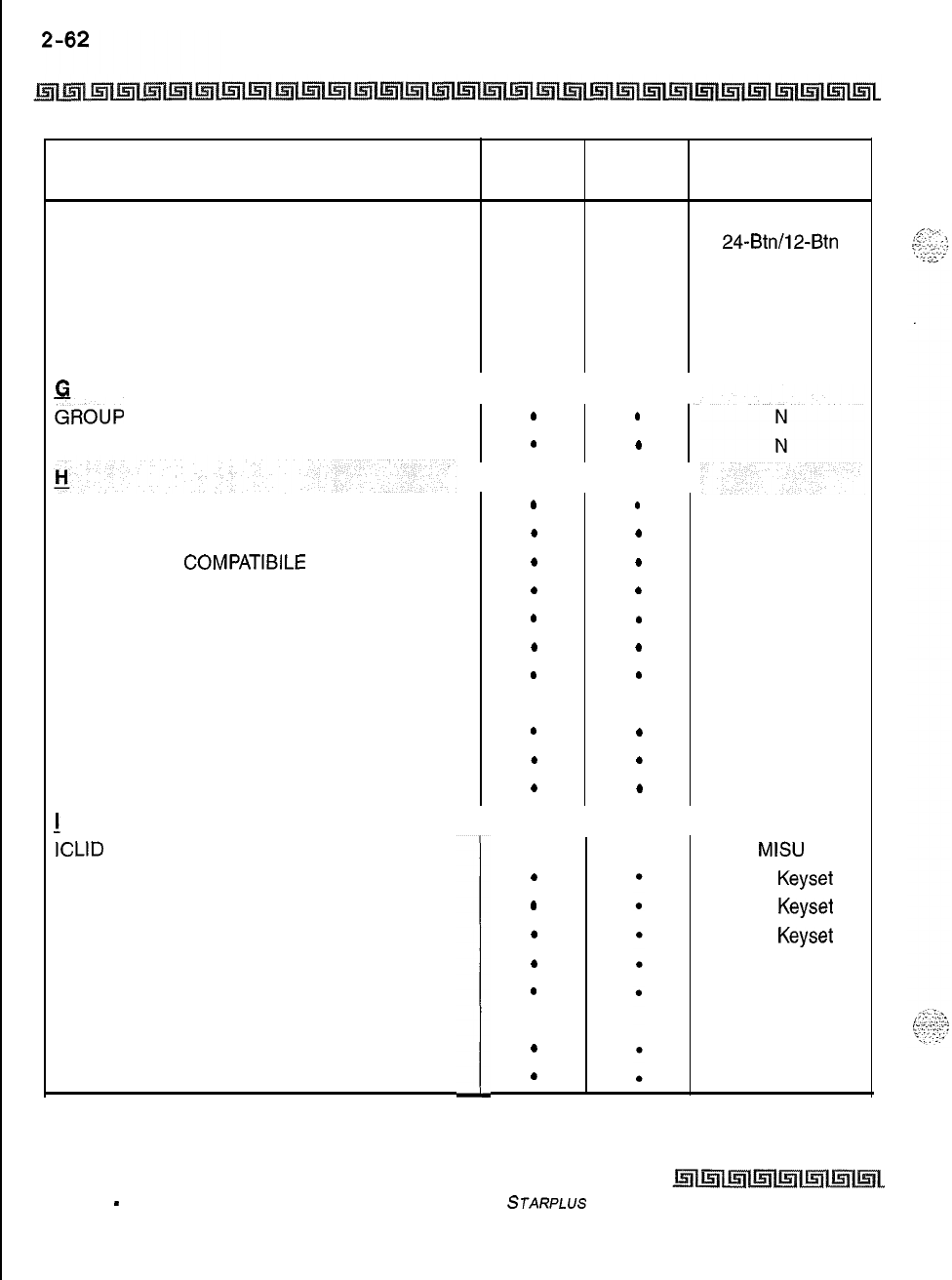
KEY STATION FEATURES
Volume Control Bar
FEATURE
FLEXIBLE ATTENDANT
FLEXIBLE BUTTON ASSIGNMENT
FLEXIBLE INTER-DIGIT TIMEOUT
FORCED ACCOUNT CODES
FORCED LEAST COST ROUTING (LCR)
FORWARD OVERRIDE
c
u
GROUP
CALL PICK-UP
GROUP LISTENING
STD ACD ADDITIONAL
PKG PKG EQUIPMENT
.
.
N
.
.
24-Btn/l2-Btn
. .
N
..
N
. .
N
..N
HEADSET COMPATIBILITY
HEADSET MODE
HEARING AID
COMPATIBILE
HOLD PREFERENCE
HOLD RECALL
HOT KEYPAD FEATURE
HOT LINE/RING DOWN
HUNT GROUPS
Hunt Group Chaining
Pilot Hunting
Station Hunting
Headset
N
N
N
N
N
N
N
N
N
!
.
.
.
.
.
.
.
.
.
.
.
.
.
.
.
.
.
.
.
.
.
.
.
.
.
.
.
.
.
.
.
ICLID
FEATURE
Calling Number/Name Display
Incoming Number/Name for SMDR Records
Unanswered Call Management
IDLE SPEAKER MODE
INCOMING CO CALL TRANSFER
INCOMING CO LINES OFF-NET FORWARD
(via Speed Dial)
INTERCOM BUTTONS
N = No Additional Equipment Required
1
MISU
Exec Keyset
Exec Keyset
Exec Keyset
N
N
N
N
Table 2-2: Key Station Features/Software’Packages (Continued)
issue 1
-
December 1998 STARPLUS
Triad-S Product Description Manual
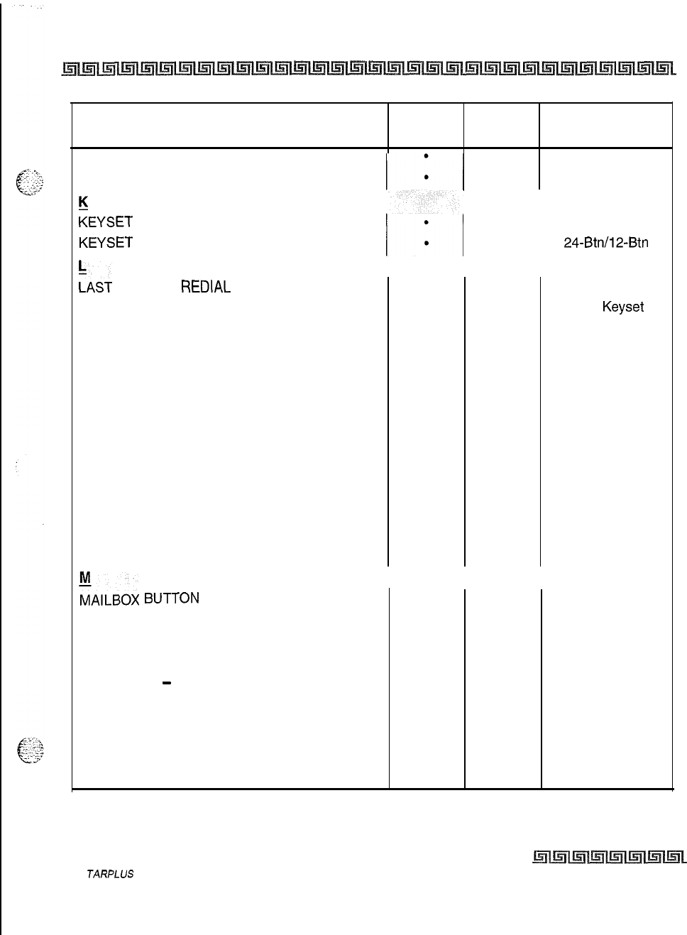
KEY STATION FEATURES
Volume Control Bar
2 -63
FEATURE STD ACD ADDITIONAL
PKG
PKG
EQUIPMENT
INTERCOM CALLING
.N
INTERCOM SIGNALING SELECT
. . N
K
KEYSET MODE
I*,
I
.
.
CTI Box
KEYSET
SELF TEST ..
24-Btn/l2-Btn
:AST
NUMBER
REDIAL
(LNR) .
.N
LCD INTERACTIVE DISPLAY
..
Exec Keyset
LEAST COST ROUTING (LCR)
3-Digit Table
.
.
N
6-Digit Table (Office Codes)
.
.
N
Daily Start Time Tables
.
.
N
Default LCR Database
.
.
N
Exception Tables
.
.N
Insert/Delete Tables
.
.N
LCR Routing for Toll Information .
.N
Route List Tables
.
.N
Weekly Time Tables
.
.
N
LOCAL NUMBER/NAME TRANSLATION TABLE
l
.
N
LOOP BUTTON CO LINE ACCESS
.
.
N
MAILBOX
f3unoN
.
.N
MEET ME PAGE
. .
N
MESSAGE WAITING
.
.
N
MESSAGE WAITING REMINDER TONE
. . N
MESSAGES
-
PERSONALIZED
Custom Messages
. .
N
Date and Time Entry to Personalized
.
Messages
.
N
Personalized Message Code on a Flex Key
.
.
N
Scrollable Canned Messages
.
.
Music Source
N = No Additional Equipment Required
Table 2-2: Key Station Features/Software Packages (Continued)
S
JARPLUS
Triad-S Product Description Manual
Issue I- December 1998
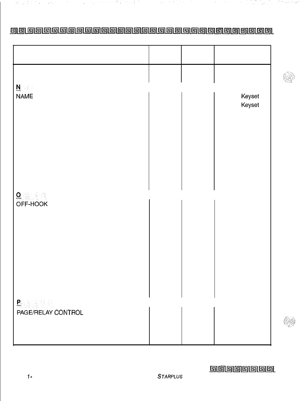
2-64 KEY STATION FEATURES
Volume Control Bar
FEATURE
MUSIC ON HOLD
MUTE KEY
:AME
IN DISPLAY
NAME/NUMBER DISPLAY AT IDLE
NIGHT SERVICE FEATURE
NIGHT SERVICE MODE
Automatic Night Mode Operation
External Night Ringing
Manual Operation
Night Class of Service (COS)
Night Ringing Assignments
Universal Night Answer (UNA)
Weekly Night Mode Schedule
%FF-HOOK PREFERENCE
Auto Feature Access
Auto Line Access
Hot Line/Ring Down
Intercom Access
User Programmable Preference
OFF-HOOK SIGNALING
OFF-HOOK VOICE OVER (OHVO)
ONE-TOUCH RECORDING
ON-HOOK DIALING
ON-LINE PROGRAMMING
FAGEIRELAY
corrrRoL
PAGING
External Paging
Internal Paging
N = No Additional Equipment Required
STD ACD ADDITIONAL
PKG PKG EQUIPMENT
. .
N
.
.
N
..
Exec Keyset
.
.
Exec Keyset
.
.
N
.
.N
.
.
N
..
N
. .
N
l
.
N
. . N
. .
N
.
.
N
. . N
..
N
.
.
N
..
N
. .
N
.
.N
..
N
. .
N
..
N
..
.
.
Paging Equip
..
Table 2-2: Key Station Features/Software Packages (Continued)
lssue
1
-
December 1998
STARPLUS
Triad-S Product
Description
Manual
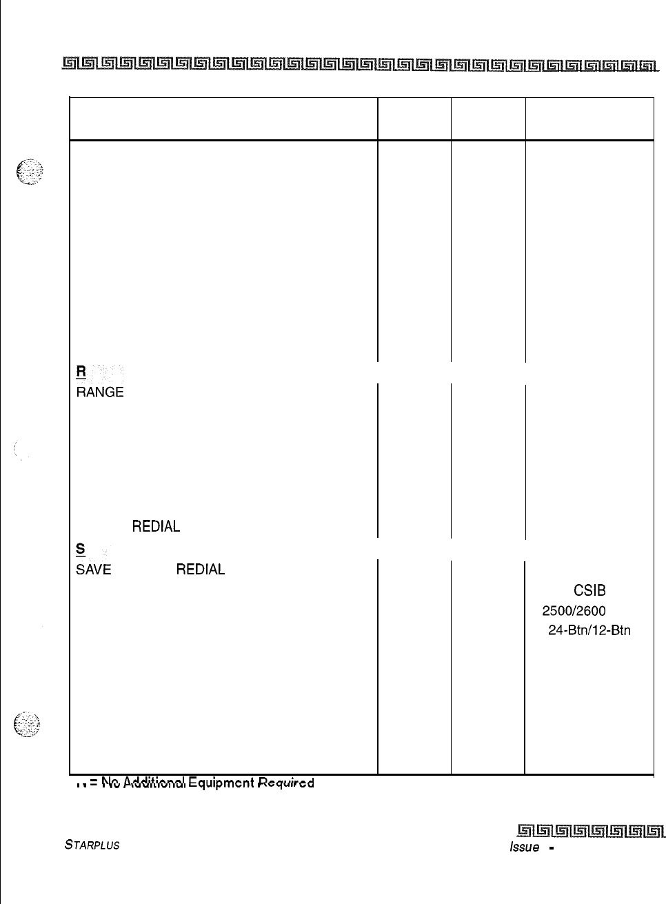
KEY STATION FEATURES
Volume Control Bar
2-65
FEATURE STD ACD ADDITIONAL
PKG
PKG
EQUIPMENT
Paging Access Restriction
. .
N
PAUSE TIMER
.
. .
N
PBX DIALING CODES
. . N
PERSONAL PARK
.
.
N
POOL BUTTON OPERATION
.
.N
PREFERRED LINE ANSWER
.
.N
PRIVACY RELEASE
Per CO Line Option
.
.
N
Per Station Option
.
.
N
PRIVATE LINE
..
N
PULSE-TO-TONE SWITCHOVER
. . N
:ANGE
PROGRAMMING .
.N
REMOTE ADMINISTRATION
Database Upload/Download
.
.
PC/Term/Modem
REMOTE SYSTEM MONITOR AND
MAINTENANCE
Remote System Maintenance
.
.
PC/Term/Modem
Remote System Monitor
.
.
PC/Term/Modem
REPEAT REDIAL
.
.
N
HAVE
NUMBER
REDIAL
(SNR) .
.N
SINGLE LINE TELEPHONE (SLT) CSIB
COMPATIBILITY
.
.
2500/2600
Type
SPEAKERPHONE
.
.
24-Btn/l2-Btn
STATION CLASS OF SERVICE
.
.N
STATION ID LOCK
.
.N
STATION MESSAGE DETAIL RECORDING .
(SMDR)
.
Printer/Terminal
STATION RELOCATION FEATURE
.
.N
STATION SPEED DIAL
. .
N
SYSTEM CAPACITY
.
.
N
N
=
Nn
Artrlitinnsl
Fmlinmnnt
Rnn~~irnrl
I.
I
.”
,
,““I~I”IIUI
Lt,jUq#IIIUIIk
I
\ryull
G”
Table 2-2: Key Station Features/Software Packages (Continued)
STARPLUS
Triad-S Product Description Manual
issue
I
-
December 1998
2-66 KEY STATION FEATURES
Volume Control Bar
FEATURE
SYSTEM HOLD
SYSTEM SPEED DIAL
L
TEXT MESSAGING (Silent Response)
TOLL RESTRICTION (Table Driven)
TRANSFER RECALL
u
UNIFORM CALL
DiSTRlBUTlON
(UCD)
Agent Queue Status Display
Alternate UCD Group Assignments
Auto Wrap-Up with Timer
Available/Unavailable Mode
Incoming CO Direct Ringing
No-Answer Recall Timer
No-Answer Retry Timer
Overflow Station Assignments
Recorded Announcements (RAN)
UNIVERSAL DAY/NIGHT ANSWER
(UDA/UNA)
:OfCE
MAIL GROUPS (VM)
VM Disconnect Signal
-
Pass Through
VM In-Band Signaling Integration
VM LCD Message(s) Indication1
VM Message Waiting Indication
VM Tone Mode Calling Option
VM Transfer/Forward
VM Transfer with ID Digits
VOLUME CONTROL BAR (DKT)
N
=
No Additional Equipment Required
STD ACD ADDITIONAL
PKG PKG EQUIPMENT
..
N
.
.
N
..
Exec Keyset
..
N
. .
N
.
.
N
..
N
. . N
..N
.
.
N
..
N
.
.
N
.
.
N
..
RAN Devices
. .
N
. .
VM System
.
.
VM System
.
.
VM System
..
VM System
. .
VM System
..
VM System
.
.
VM System
.
.N
Table 2-2: Key Station Features/Software Packages (Continued)
IIssue I- December 1998
STARPLUS
Triad-S Product Description Manual
Single Line telephones have access to most system and station features listed in the previous section;
-x
. .
.J,.’
-..
L
.::;;?
. . . . . . .
however, the features listed below are common to CO Line/Single Line Interface Board (CSIB) and are
_.
.
required in the
STARPLUS
Triad-S
TM
System for proper SLT operation. An abbreviated feature index is
provided in Table
3-1:SLT
FeatureslSoflware Packages.
Account Codes
SLT stations may enter an account code to identify calls for billing/tracking purposes, The account code may
be entered before the call or during the call (the outside caller is placed on hold while the account code is
entered if during the call). The account code is recorded on the SMDR printout, Account codes are not
verified and can vary in length from 1-12 digits.
Verified/Traveling COS
The Verified Account Code/Traveling Class of Service (COS) feature provides tracking of specific calls by
entering a verified, variable length identifier (up to 12 digits). Each account code can be assigned a day and
night Class of Service for determining the dialing privileges allowed by that account code. This provides a
means for users to override a restricted station. If the dialed account code matches the Verified Account code
table, an intercom dial tone is returned, otherwise an error tone is returned. The use of forced Account Codes
is optional, offered on a system-wide basis. SMDR must be enabled for the account code to print as part of
the SMDR record. The Triad-S system allows up to 250 12-digit account codes for verification purposes.
Automatic Call DistributionNnif orm Call Distribution
(ACDIUCD)
A single line telephone (SLT) may be an agent in an ACD group.
Automatic Line Access
SLTs
may have their station programmed to access a particular CO Line, such as a private line or a line from
a Group of CO lines, upon going off-hook. This is useful in Centrex or PBX applications when station users
have dedicated or individual lines. Outside line dial tone is received just by going off-hook, without dialing
access codes.
Issue
I-
December 7998
STARPLUS
Triad-S Product Description Manual
3-2 SINGLE LINE TELEPHONE FEATURES
Call Brokering
Call Brokering
Enables SLT user on a CO call to Hook-Flash and make another CO call. Once this other call is established,
the SLT user can Hook-Flash to move back and forth between parties.
Call Forward
^
.y...
,
-2
2
,
-.,.
_.._
.
.._
,....
._
Single line telephones may direct intercom calls and transferred CO lines for forwarding to another station.
SLTs
have access to all forwarding options that Key station users have:
8
Call Forward
-
All Calls
+
Call Forward
-
No Answer
[7]
+
Call Forward
-
Busy
[S]
Q
Call Forward
-
Busy/No Answer
[9]
+
Call Forward
-
Off-Net
[++I
+>
Preset Call Forward
Call Pick-Up Directed
Tone ringing intercom calls, Initial Ringing CO calls and transferred outside line calls to specific stations
can be picked up by single line telephones. For this type of pickup, the stations need not be in the same
pickup group.
Call Pick-Up Group
Tone ringing intercom calls, transferred outside line calls, and initially ringing calls can be picked up by
single line telephones by dialing a special pickup code. The telephones must be in the same pickup group,
Camp-On
A busy station can be notified that an outside line is on hold and waiting for them. The busy station is
notified of this by a beep tone. Single line telephones can receive a camp on indication or initiate one by
using an access code.
Issue
7
-
December 1998
STARPLUS
Triad-S Product Description Manual
SINGLE LINE TELEPHONE FEATURES
CO Line Queuing
CO Line Queuing
Single line telephones can be placed in a queue awaiting the first available outside line in a group to become
available.
Conference
An SLT user can initiate a conference with an outside line and one other internal station,
Conference With Personal Park
Single Line Telephones (SLT) can initiate a conference between two outside (CO) calls. The personal park
feature is used in conjunction with the SLT conference code to make this possible..
Direct Outside Line Group Access
Single line telephones can access outside lines by dialing CO line group access codes
9
or
81-87.
Direct Outside Line Ringing
Single line telephones can receive direct outside line ringing.
SLTs
may be programmed to receive incoming
CO Hinging on more than one CO line. However, an SLT can answer only ONE call at a time. If an SLT is busy
when a CO call rings in, camp-on tone is given to that SLT station.
Do Not Disturb (DND)
Each telephone user can place their phone in Do Not Disturb. The user receives an error tone if they are not
allowed this feature. They also receive a stuttered dial tone when lifting the handset to remind them they are
in Do Not Disturb. The attendant can override a station in DND.
Handset Receiver Gain
This feature allows an SLT user, while on a
CO/KM
call, to hookflash and dial a code to increase/decrease the
handset volume.
STARPLUS
Triad-S Product Description Manual
Lssue
I- December 1998
SINGLE LINE TELEPHONE FEATURES
Intercom Calling
Intercom Calling
Single line telephones can make and receive intercom calls.
Loop
Interrupt Option
This feature enables single line telephone ports to provide a loop disconnect signal to any devices connected
to an SLT port. This is an inherent operation, no programming is necessary.
J*
Signal is provided when a CO Line, marked with loop supervision, connected to an SLT port receives
loop supervision from the Central Office.
$
Upon termination of an internal call to an SLT, the SLT provides the loop interrupt signal,
+
Loop interrupt signal consists of an open for 700 ms with less than
5
mA.
Message Waiting/Call Back
Single Line Telephones calling a station that is busy, idle, or in Do Not Disturb can leave a message waiting
indication to signal the station to call back.
Messages
Personalized
Each SLT station can select a pre-assigned message to display on the LCD of the Digital Terminal receiving
that message, There are ten possible messages that can be displayed:
OO=
Clears Messages
01~
ON VACATION
02=
RETURN AM
03=
RETURN PM
04=
RETURN TOMORROW
05=
RETURN NEXT WEEK
06=
ON TRIP
07=
IN MEETING
08=
AT HOME
09= ON BREAK
1
O=
AT LUNCH
Issue
I-
December 1998
S
JARPLUS
Triad-S Product Description Manual
SINGLE LINE TELEPHONE FEATURES
Off -Hook Preference
Custom
This feature allows the system administrator to enter up to ten custom messages for use by system station
@;
users, These messages may be specified and customized by the customer on a system-wide basis.
Lr
Off -Hook Preference
SLTs
may access a particular CO Line such as a private line or a line from a Group of CO lines upon going
off-
hook. This is useful in Centrex or PBX applications when station users have dedicated lines. Outside line dial
tone is received just by going off-hook, without the need to dial access codes.
Personal Park
Single line telephones can be connected to two calls (Intercom or CO lines) at the same time and toggle
between the two calls. This can be performed with originated or received calls. This feature is also used with
the SLT multi-line conference feature.
Speed Dial
-
Station
An SLT user may program up to 20 speed dial numbers. Each speed dial number can be up to 24-digits in
length.
Speed Dial
-
System
Each SLT user can access system speed dial numbers on a programmable basis. The last forty system speed
numbers override toll restriction.
Toll Restriction (Table Driven)
The system provides a flexible means of providing toll restriction to internal stations of the Triad-S system.
Each station is assigned a Class of Service for day mode operation and one for night mode operation these
.r2
:.
d
station
COS’s
work in conjunction with a CO line Class of Service to allow for customized toll restriction. Two
‘ii2 Allow and Deny tables along with four special tables afford the system administrator to devise a variety of
complex toll restriction or dialing privilege schemes.
STARPLUS
Triad-S Product Description Manual Issue I- December 7998
SINGLE LINE TELEPHONE FEATURES
Transfer
Canned Toll Restriction
The system provides an easy means of applying the most common form of toll restriction where 1
+
and
Of alongwith
976,
555,
and 411 type of calls are denied and l-800, l-888,911, l-911, and
l-611
type of
calls are allowed. This canned toll restriction is applied through the use of a single pre-built Class-of-Service
and can be assigned to stations using range programming.
Transfer
Outside lines may be transferred by or to single line telephones. These transfers can be announced or
unannounced.
Transfer Recall
Screened and unscreened transfers recalls the initiating party if unanswered for a programmable length of
time, and then if unanswered, recalls the attendant.
Universal Day/Night Answer (UDA/UNA)
Incoming CO lines can be programmed for Universal Day Answer (UDA) or Universal Night Answer (UNA).
UDA/UNA
assigned CO lines can also signal over the external page port(s). External Day ringing is
programmed on a system-wide basis in admin programming. Stations which do not have access to a line
during the day can answer that line while the System is in the Night Mode by dialing a UNA code. In order to
utilize this feature, a Loop button or an appearance of the trunk must be present on the station.
Voice Mail Groups (VM)
The Voice Mail feature automatically handles unanswered calls. Stations may forward calls to a voice mail
group (for leaving mail) or may call the voice mail group directly (to retrieve mail) with no assistance from
the attendant.
Message Waiting Indication
When Voice Mail receives a voice message for a user who has a station on the Triad-S system, the VM
connected to the system can leave a message indication at the VM users station. When the station retrieves
their mail, the VM system can cancel the message waiting indication left at a station via a VM port.
Issue
1
-
December 1998 STARPLUS
Triad-S Product Description
Manual
SINGLE LINE TELEPHONE FEATURES
Voice Mail Groups (VM)
FEATURE STD
PKG ACD
PKG ADDITIONAL
EQUIPMENT
II I
%CO”NT
CODES
Il I*1
N
VERIFIED ACCOUNT CODES/
TRAVELING COS
AUTOMATIC LINE ACCESS
.
.
.N
.
N
BROKER CALL
I l
CONFERENCE
CONFERENCE WITH PERSONAL PARK
CALL FORWARD
CAMP-ON
CO LINE QUEUING
DIRECT OUTSIDE LINE RINGING
DIRECTED CALL PICK-UP
DO NOT DISTURB (DND)
:ROUP
CALL PICK-UP
DIRECT OUTSIDE LINE GROUP ACCESS
:ANDSET
RECEIVER
GAIN
INTERCOM
CALLING
FOOP
INTERRUPT OPTION
I
I
.
I
.
I
N
I
.
I
.
I
N
I*I*l
N
:ESSAGE
WAITING/CALL
BACK . .
N
MESSAGES
-
PERSONALIZED
Table 3-l: SLT
FeaturedSof
tware Packages
STARPLUS
Triad-S Product Description Manual
issue
I-
December 1998
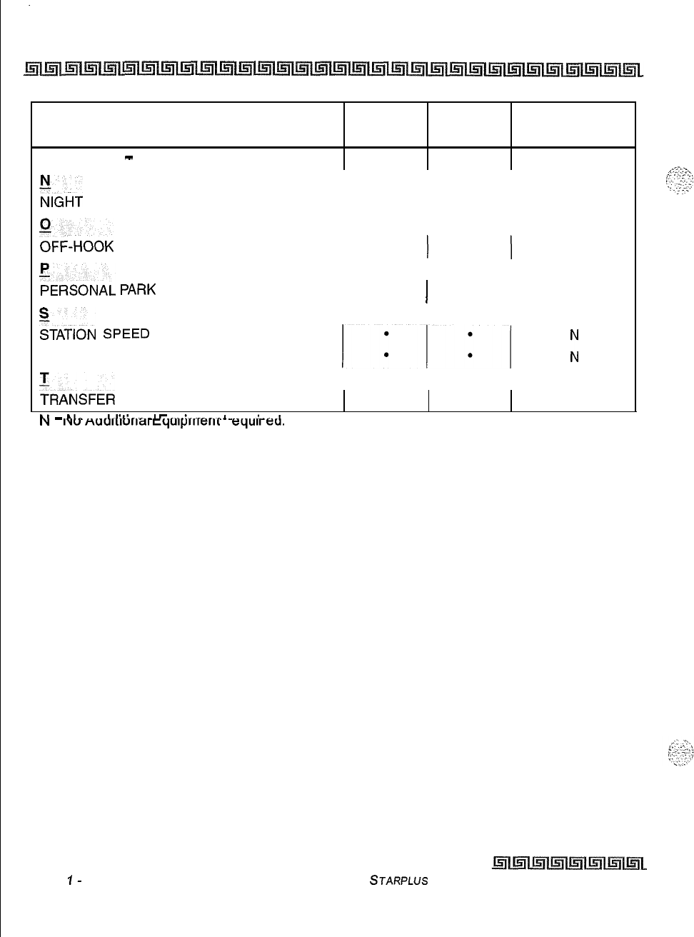
.
.
3-8 SINGLE LINE TELEPHONE FEATURES
Voice Mail Groups (VM)
FEATURE STD ACD ADDITIONAL
PKG PKG EQUIPMENT
Messages
-
Custom
. .
N
:IGHT
SERVICE
I
.
I
.
I
N
%FF-HOOK PREFERENCE
I
.
I
l
I
N
FERSCNAL
PARK
I
.
I
.
I
N
ETATICN
SPEED
DIAL
SYSTEM SPEED DIAL
1:I:i
i
TRANSFER
.
.N
LI
-
LI-
A -1-1:1:---1
h--..:----z
---..:..--I
IY
=
NW
nUUlllullal
cqulplllelll
I
equll
eu.
Table 3-1: SLT Features/Software Packages (Continued)
Issue
I-
December 7998
STARPLUS
Triad-S Product Description Manual
*,>;::3,
+f
The Attendant and Attendant(s) with
DSS/DLS
Features of the
STARPLUS
Triad-S’“f
system are listed and
.$3 described below in alphabetical order. An abbreviated feature table is provided in Table 4-l:Atiendant
Feature.s/Sojware Packages.
Attendant Features
Alternate Position
This feature allows Attendant stations to program a flexible button to place their station in an unavailable
mode. When the station is in unavailable mode, the next attendant station (second) receives incoming and 0
calls. All other available attendants receive recalls. This feature is based on the system having three Attendant
stations. If all Attendants are unavailable, no attendants are available for internal/external calls.
Automatic Night Mode
In addition to the attendants capability to place the system into and out of night mode manually, by pressing
the Night key, an automatic night mode schedule is added to the system. The automatic schedule is
determined in database programming on a weekly basis, including Saturday and Sunday. The Attendant can
override the automatic schedule by pressing the NIGHT (DND) button,
Direct Station Selector
-
DSS Console
An optional DSS console is available which may be associated with an atendant station to provide additional
buttons for
DSS/DLS
features.
Disable Outgoing Access
The first attendant can disable CO lines, preventing outgoing access to those lines. This is useful for removing
a faulty line from service, or for reserving CO lines for important use.
Ah
stations that normally make calls on
the lines are affected, but incoming calls are unaffected. A CO line may be disabled while it is being used.
c
<g-j+
.&
When the trunk becomes idle, further outgoing access is prevented.
Display
The Attendant display timer changes the way in which multiple calls ringing at the attendant station are
displayed. If two calls are ringing at an attendant station, when the station goes off hook, the first call is
Issue
1
-
December 7998
STARPLUS
Triad-S Product Description Manual
I4-2 ATTENDANTFEATURES
Attendant Features
answered. The LCD display then updates to show the second call that is ringing which sometimes does not
allow the station to view the current calls’ LCD information. This programmed timer keeps the current
calls’ information on the LCD for a programmable time period before showing any other calls ringing in at
the time.
Night Service Feature
The Night Service feature provides a means to put the system in night mode from any
keyset
or remove the
system from night mode from any
keyset,
providing the system was put in night mode by the night service
feature flex button.
If
the system was placed in night mode by the attendant using the DND button or if the
system was placed in night mode by the automatic schedule, the night service flex button cannot remove
the system from night mode.
Off -Net Forward
-
Incoming CO Lines
Allows the first attendant to forward incoming CO calls to an Off-Net location. The attendant must have a
direct appearance of the CO line to be forwarded. Forwarding can be established on a per CO line group
basis, all CO lines, or an individual CO line may be simultaneously forwarded to an off-net location,
Overflow (Via Preset Forward)
System programming allows programming of the attendant station so if the attendant is busy or not there,
the call is automatically forwarded to another predetermined station, VM Group, Hunt Group, ACD or UCD
group after a programmed time period. (Refer to Call Forward, Station and Preset.)
Override
Attendant stations may override a busy station or ring a station in DND. While busy, pressing the override
key provides override tone and a five second delay before voice cut-through to the called party occurs,
automatically placing any outside line call on Hold. The Attendant Override function must be programmed
onto a flex button and can be enabled or disabled.
Position
The system identifies three maximum programmable stations as attendants for line recalls and attendant
features. The first programmed attendant can enter system date and time information and System Speed
numbers from this position without entering the programming mode. The
STARPLUS
Digital Hybrid
Telephone System is placed in Night Service by any programmed attendant pressing the NIGHT (DND)
button or dialing the NIGHT code.
Issue 1
-
December 1998
STARPLUS
Triad-S Product Description Manual
ATTENDANT FEATURES
DSWDLS Features
Recall
A held CO call left unattended by a station recalls the attendant(s) after a programmable time period
elapses. A recalling CO line flashes at a distinctive rate and has an LCD display that identifies the originating
station of the unanswered call.
Special Ring Mode
This feature provides an additional ring mode that is manually invoked by the Attendant. This mode provides
a third ring list so that the system has a day ring mode, a night ring mode, and a special ring mode. Each CO
line can have a special mode ring assignment associated to it. Up to ten stations per CO line may ring in the
special mode. By default, no stations are programmed to ring in the special ring mode.
Time And Date Programming
This feature allows the first programmed attendant to set the time and date without entering the
programming mode.
DSWDLS
Features
Attendant Transfer Search
Aflows
a user to make a series of intercom calls without hanging up the handset. An intercom connection is
switched to another station whenever a DSS key is pressed. Pressing the next DSS key terminates the previous
intercom call.
Busy Lamp Field Indicators
Each station key on the DSS console has a corresponding indicator that shows whether the station is idle or
busy. The indicator is lit when the station is busy and unlit if the station is idle, A station in
DND mode is
shown by a flashing indicator.
Direct Station Calling
Enables the user to make an intercom voice call to any Digital Terminal in the system. Lets you automatically
put an outside caller on hold and simultaneously make an intercom call to an internal station. Also lets you
transfer an intercom call or outside call that is on hold to another station.
STARPLUS
Triad-S Product Description Manual
lssoe
7
-
December 1998
I4-4 ATTENDANTFEATURES
DSSIDLS
Features
Messages
-
Custom
This feature allows the first programmed attendant (system administrator) to enter up to ten custom
messages for use by station users of the system. Up to 24 characters may be entered as the custom message
(this represent 48 digits entered). A station user may store any of the available messages under a flexible
button assigned as a Message Access button. These messages may be specified and customized by the
customer on a system-wide basis. Message status is stored in battery protected area of memory for retention
in the event of a power failure or system reset (soft or hard).
Release Key
Allows the user to disconnect calls while off-hook, speeding up call handling time.
Volume Control Bar (DKT)
On the Digital Key Terminals
(DKT),
there is a volume control bar below the keypad to control the ringing,
handset, and speakerphone volumes.
Issue I- December 1998
STARPLUS
Triad-S Product Description Manual
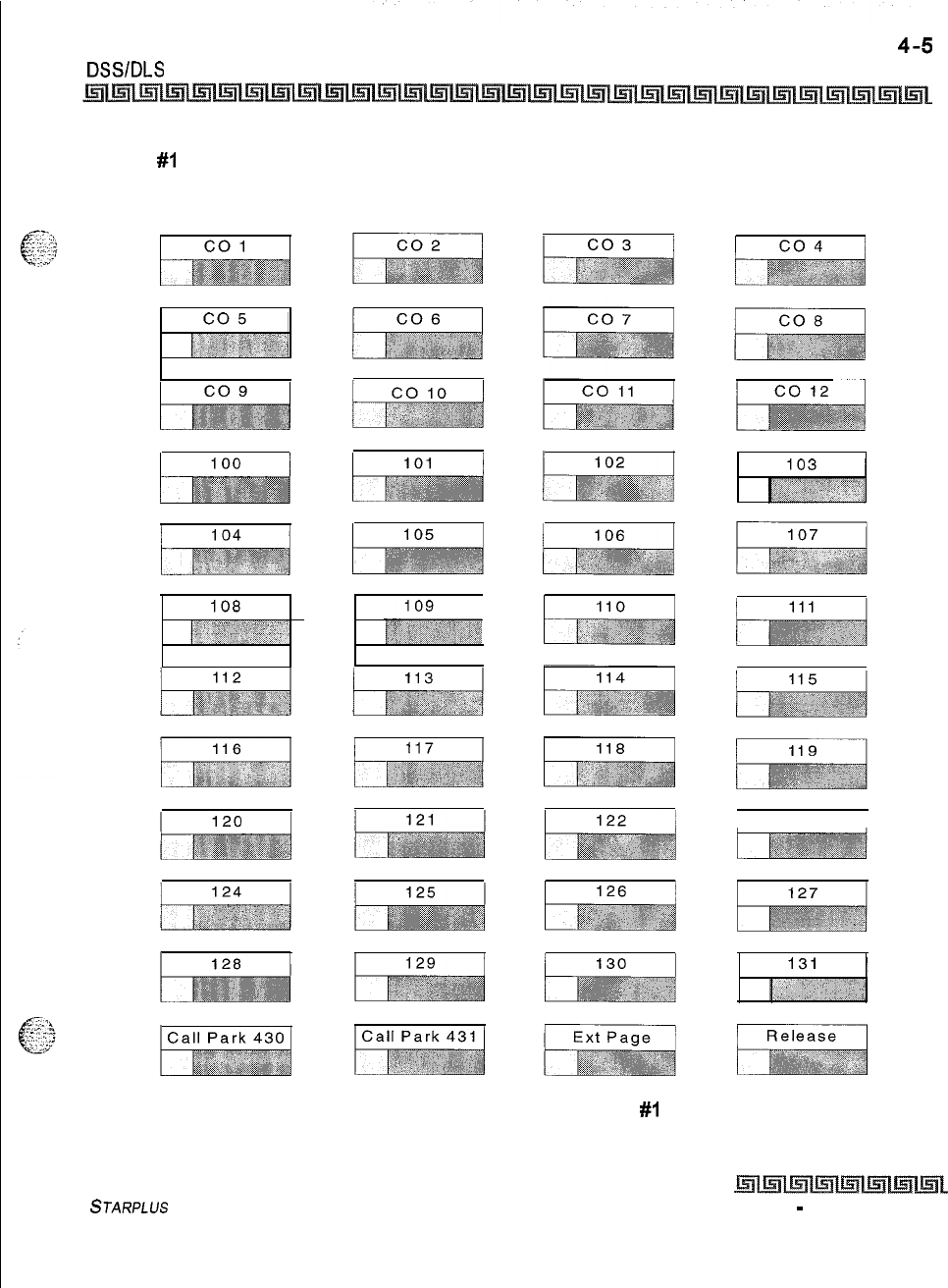
ATTENDANT FEATURES
DSSIDLS Features
MAP
#l
has 12 CO Lines and the 32 Stations, 100-131. This provides a default layout of a
12x32 configuration.
I123 I
Figure 4-1: DSS Console Map
#I
STARPLUS
Triad-S Product Description Manual
Issue 1
-
December 1998
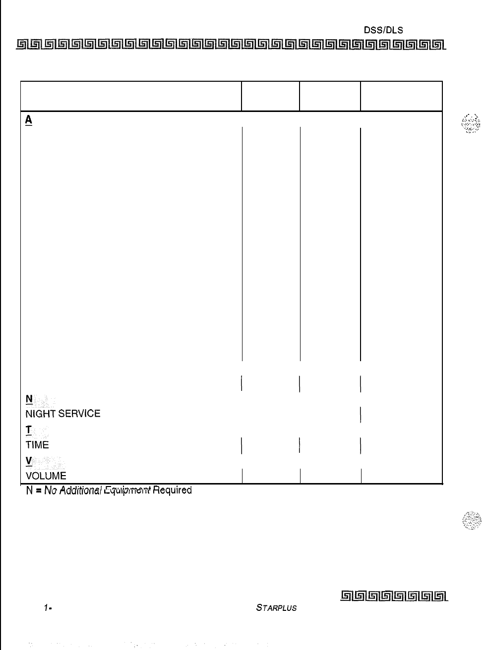
4-6 ATTENDANTFEATURES
DSSIDLS Features
FEATURES STD PKG ACD PKG
ADDITIONAL
EQUIPMENT
A
ATTENDANT ALTERNATE POSITION
ATTENDANT DISABLE OUTGOING ACCESS
ATTENDANT DISPLAY
ATTENDANT OVERFLOW
ATTENDANT OVERRIDE
ATTENDANT POSITION
ATTENDANT RECALL
ATTENDANT SPECIAL RING MODE
ATTENDANT with DSS/DLS FEATURES:
. . N
. .
N
.
.
N
.
.N
.
.
N
.
.N
. . N
. .
N
ATTENDANT SEARCH
.
.N
BUSY LAMP FIELD INDICATORS
.
.
N
DIRECT STATION CALLING .
.N
MAPPING OPTIONS
. . N
MESSAGES-CUSTOM .
.N
RELEASE KEY
..N
AUTOMATIC NIGHT MODE .
.N
!
INCOMING CO LINE OFF-NET FORWARD
I
.
I
.
I
N
ZIGHT
SERVICE
FEATURE
I
.
I
.
I
N
:IME
AND DATE PROGRAMMING
I
.
I
.
I
N
:OL”ME
CONTROL BAR (DKT) ..
N
hl
-
hlrr
Arlrlitinn~l
lzn,,inmnnt
nnnllirdrl
I”
-
IY”
l-iUU,I,“IIcl.,
LqUlfJll1w11
I
IcqlullmA
Table 4-l: Attendant Features/Software Packages
Issue
1
-
December 1998
STARPLUS
Triad-S Product Description Manual
I-
.
,‘.
..:
. .
:.
:’
‘:~.:
I
:;:
I.:
.:
_.
.~.~..
..;
Introduction
The
STARPLUS
Triad-SrAf
system has a variety of features and flexible programming, allowing each
telephone user to program the telephone to meet their individual needs.
This section contains the operating instructions for the digital terminal and an illustration of the telephone
used in the Triad-S System and the telephone key descriptions and their functions. Visual and audible cues that
accompany the various steps in the operation of the features are also included.
A Station User’s Guide is also available that provides detailed operating instructions,
Digital Terminal Station Features
Each Triad-S system provides the following keys, indicators and features:
Handset and Speaker
Handset and speaker are located at the left side of the front panel. A handset is provided to allow confidential
conversation when desired. Lifting the handset from its cradle (going off-hook) disengages the station’s built-
in speaker.
The speaker is located directly below the center portion of the handset. The station may be operated with the
handset on-hook. When this occurs, audio is transmitted to the station user through the station’s speaker.
Flexible Buttons
Flexible buttons provide access to idle outside lines,
DSVJ3LF
for internal stations, access speed dial
numbers and activate features. These buttons can be programmed by the individual station user. The default
flex feature buttons are described below.
+:+
CALL BACK
button lets you initiate a call back request to another busy station. As soon as that station
becomes idle, the station that left the call back request is automatically signaled. A flex button must
be assigned to use this feature.
e+
PICK-UP
button lets you pick up a tone ringing intercom call, transferred, incoming, or recalling
outside line call to a specific unattended station, either by group or directed call pick-up.
Issue I- December 7998
STARPLUS
Triad-S Product Description Manual

DIGITAL STATION OPERATION
Digital Terminal Station Features
+
DND (DO NOT DISTURB)
button lets the user place their telephone into Do Not Disturb mode to
eliminate incoming outside line ringing, intercom calls, transfers and paging announcements. The
station in DND can use the telephone to make normal outgoing calls. On Attendant stations, this
button becomes the system Night Mode button. A flex button must be assigned to use this feature.
9
LINE QUEUE
button lets you queue onto an outside line when all lines in a group are busy. Your
station is placed in queue, awaiting a line in the same group to become available.
Fixed Feature Buttons
VOLUME BAR
lets the user adjust ringer, speakerphone and handset volume.
H-P-T
lets the user select the ICM Signaling Mode, handsfree tone, or privacy.
FLASH
button terminates an outside call and restores dial tone without hanging up the handset. It
also transfers calls behind a PBX or Centrex within those systems.
CAMP-ON
button enables you to alert a busy party that an outside line is on hold and waiting for
them.
MSG (MESSAGE WAIT)
button lets you initiate a message waiting indication at stations that are
busy, unattended, or in Do Not Disturb. Message Waiting Callback request left at your station is
indicated by a flashing MSG WAIT LED.
SPEED
button provides access to speed dialing, save number redial and last number redial. This
button also accesses flex button programming.
TRANS (TRANSFER)
button transfers an outside call from one station to another.
CONF (CONFERENCE)
button establishes and builds conference calls.
FORWARD (FWD)
button lets you forward your calls to another station.
ON/OFF
button enables you to make a telephone call without lifting the handset. It turns the
telephone on and off when using the speakerphone.
MUTE
button lets you toggle the built-in microphone on or off when using the speakerphone, or
the handset microphone when using the handset.
HOLD
button enables you to place an outside caller on hold.
Outside Calls
Outside calls are announced by a tone signal repeated every 3.2 seconds. The corresponding outside line
indicator flashes slowly.
Issue I- December 1998
STARPLUS
Triad-S Product Description Manual
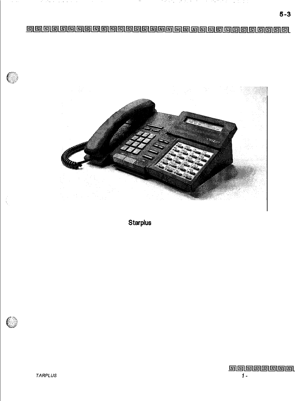
DIGITAL STATION OPERATION
Digital Terminal Station Features
Intercom Calls
Intercom calls can be tone ringing or voice announce. If voice announced, the receiving station receives three
tone bursts prior to the announcement. If a tone ringing call, the receiving station hears a tone ring every 2.4
seconds.
Figure 5-1: Starplus Executive Digital Terminal
S
JARPLUS
Triad-S Product Description Manual Issue
I-
December 7998
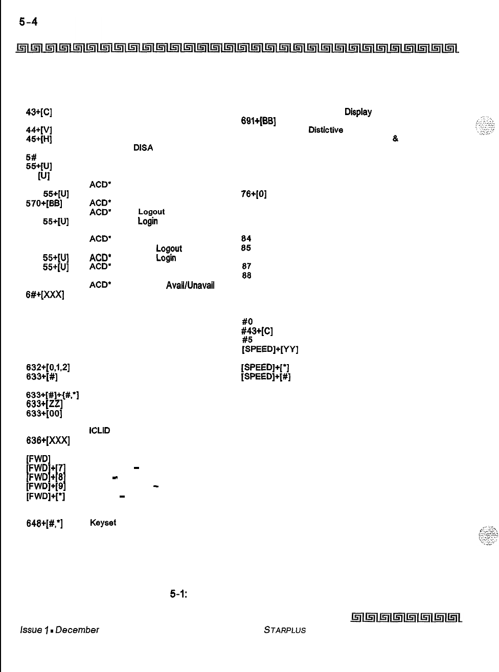
DIGITAL STATION OPERATION
Digital Terminal Station Features
100-131
43+[c]
438
44+[v]
45+[H]
499
5#
55+[u]
55
WI
568
567
55+[U]
57O+[BB]
571
572
55+[U]
573
574
575
578
55+[u]
577
55+[u]
578
8#+[XXX]
6’
623
825
828
628
831
832+[0,1.2]
833+[#]
633+[#]+{#.‘]
833+[zz]
833+[00]
834
835
836+[XXX]
839
W’DI
W’Dl+Vl
W’Dl+Pl
i;;;;:;?;
842
843
848+[#;]
862
Triad-S TM Ext Numbers
Call Park Location O-7 (System)
Personal Park
Voice Mail’ Group Pilot Numbers O-7
Hunt Group Pilot Numbers O-7
Modem via
DISA
Access or Transfer
Forward Overide
ACD’ Group Pilot Numbers O-9
UCD Group Pilot Numbers O-7
ACD’
or UDC Available/Unavailable
ACD’ or UCD Calls in Queue Display
ACD”
Call Qualifier
ACD’
Agent
Logout
ACD’ Agent
Login
ACD’ Group Member Status
ACD’
Agent Help
ACD’ Supervisor
Logout
ACD”
Supervisor Login
ACD’
Supervisor Queue
Status Display
ACD*
Overflow Sta
AvaillUnavail
Tone Mode Ring Option
Dial By Name
Message Wait
Executive Override/ ACD”
Supervisor Monitor Barge-in
LCR Queue Cancel
OHVO Enable
Do Not Disturb
Background Music
Personalized Message
on Flex Button
Scroll Canned Messages
Personalized Messages
Clear Personalized Messages
Headset Mode
ICLID
Display (unanswered calls)
Station Relocate
Incoming CO Call Transfer
All Call Forward
No Answer
-
Call Forward
Busy
-
Call Forward
Busy/No Answer
-
Call Forward
Off-Net
-
Call Forward
Follow-Me Forward
Repeat Redial
Keyset
Mode
Clear Call Forward, DND,
Personalized Messages
680
690
69l+(BB]
695
70
71
72
73
74
75
76+[0]
77
81
82
63
z5”
86
5:
9
0
#O
#43+[c]
~PEEDI+~~vI
[SPEED]+(*]
[SPEED]+[#]
Speed Dial Directory
Name in Display Programming
Off -Hook Preference Programming
Distictive Ringing
All Call Page (Internal
8.
External)
Internal Page Zone 1
Internal Page Zone 2
Internal Page Zone 3
Internal Page Zone 4
Internal All Call Page
External Page
Meet-Me-Page Answer
CO line Group 1 (if LCR is enabled)
CO Line Group 2
CO Line Group 3
CO Line Group 4
CO Line Group 5
CO Line Group 6
CO Line Group 7
All CO Line Groups
(CO Line Off -Net Forward)
LCR or CO Line Group 1
(if LCR is disabled)
Attendant
Group Call Pick Up (Key and SLT)
Call Park Pickup (Key and SLT)
Universal Day /Night Answer
Speed Dial Access
(00-19 Station) (20-99 System)
Save Number Redial
Last Number Saved
XXX Intercom Station
YY
Speed Dial Bin numbers
zz
Personalized Messages
BB
Button Number
U
ACD’ (O-15)
C
H
V
or UCD (O-7) Group Number
Call Park Locaiton O-7
Hunt Group Number O-7
Voice Mail’ Group Number O-7
l
Features available with optional software
Table 5-1: Digital Terminal Numbering Plan
lSSU8
1
-
DeC8I?Iber
1998
STARPLUS
Triad-S Product
Description Manual
I
DIGITAL STATION OPERATION
Account Codes
Account Codes
When connected to an outside line call:
e:-
02.::
:
_
,_ . .
C.”
1
Press the pre-programmed* ACCOUNT CODE button.
2
Dial account code up to 12-digits. (The other party will not hear the digits being dialed).
oIf account code is less than 12-digits, an
[*]
must be entered to return to the call,
+
If account codes are forced, the account code must be entered prior to dialing the outside
number.
SMDR
must be enabled for the Account Code feature to operate. Also,
SMDR must be enabled for the account code to become part of the SMDR
record.
*A Flex Button must be programmed for this feature to operate. Refer to
Table
5-3;FZex
Button
programming Codes.
Account Codes/Traveling COS (Verified)
The Verified Account Code/Traveling Class of Service (COS) feature provides the ability to track specific calls
by entering a verified, variable length (up to 12 digits) identifier. Each account code can be assigned a day
and night Class of Service for determining the dialing privileges allowed by that account code. This provides a
means for users to override a restricted station. If the dialed account code matches the Verified Account code
table, an intercom dial tone is returned, otherwise an error tone is presented. Using forced Account Codes is
optional, available on a system-wide basis. SMDR must be enabled for the account code to print as part of the
SMDR record. The Triad-S system allows up to 250 12-digit account codes for verification purposes.
To enter an account code prior to a CO call:
1
Press pre-programmed* ACCOUNT CODE button before accessing a CO line.
2
Dial the account code up to 12-digits. If the account code matches a verified account
code, intercom dial tone is returned. Otherwise error tone is presented.
If
account code is
less
than
12 digits, an
[*J
asterisk
must be entered to return to the
call.
3
Access the outside CO line or dial the LCR code and dial the desired number.
SMDR must be enabled for the Account Code feature to operate. Also,
SMDR must be enabled for the account code to become part of the SMDR
record.
Conditions:
STARPLUS
Triad-S Product Description Manual issue I- December 1998
5-6 DIGITAL STATION OPERATION
Answering a Recall
+
Verified Account Codes allow use of an account code as a traveling Class of Service.
oIf LCR is activated in the system and verified account codes are forced, the user must enter the
account code before dialing the LCR code.
+
When verified account codes are forced, station MUST enter an account code to dial a number that
is restricted through station COS and toll restriction. An account code is not required for calls that
are unrestricted through station COS and toll restriction,
Q
When verified account codes are not forced, a station user may place a call without entering an
account code. In this case, the station user’s COS is based on their station COS. In this case, a user
can enter a verified account code to upgrade their COS.
+
The Redial feature does not support Verified Account Codes.
*A
Flex Button must be programmed for this feature to operate. Refer to Table
5-3;FZex
Button
Psogmnming Codes.
__
:
::
I’.
i
:-:.ry
.I..
-..
..A....
Answering a Recall
When an outside line remains on hold for an extended time period, a recalling ring reminder is sent. (If
Preferred Line Answer is enabled, skip step
1.)
1
Press outside line, Loop or Pool button flashing at very fast rate.
2
Lift handset or press ON/OFF button to converse.
Answering Machine Emulation
When a call is sent to a voice mailbox, the station associated with that can press a pre-programmed button
to listen to the caller leaving the voice mail message. If the mailbox owner decides to speak with the caller,
they can press the pre-programmed button to be connected to the caller. Two methods of notification are
available, a ring mode or a speaker mode. These methods are controlled by the type of flexible button
assigned on the telephone.
Q
Station A places their phone in the answering machine mode by pressing the flexible button
programmed on the telephone. The button lights solid red.
The pre-programmed* button type (654+ O=Ring mode, 654 +
1
= Spkr Mode) defines the feature
operation mode. ,
,_
_
-.
*
=_.-.>
_-
An incoming CO call rings at a station and forwards (except busy type) to the station’s voice mailbox. In the:
+-
RING MODE:
The pre-programmed answering machine flex button flashes at 480 ipm red while
the caller is in the owners mailbox. The mailbox owner presses the pre-programmed flashing
Issue I- December 1998
STARPLUS
Triad-S Product Description Manual
DIGITAL STATION OPERATION
Answering Machine Emulation
button and the audio is broadcast over the
keyset
speaker. The mute key is enabled on the
keyset
at
this point. The LED lights solid green.
9
SPKR MODE:
The voice mail message is broadcast over the speaker. The mute key is enabled on the
keyset
at this point. The LED lights solid green.
Below are the mailbox owners options at this point:
1
To leave the caller in the voice mail and stop the speaker broadcast, the mailbox owner
presses the ON/OFF button. The mailbox owner can continue to listen to the message
without taking action at their
keyset.
When the caller disconnects after leaving the voice
mail message, the button returns to solid red and the
keyset
returns to idle.
2
The station can press the MUTE key to talk to the party leaving the message. The
station is still in the CONF mode at this point and the caller can hear the VM and the
station user.
3
The station can pick up the call by pressing the flexible button. When the mailbox owner
picks up the call, the voice mail system disconnects from the call, and the voice mail port
returns to the idle (waiting) state.
4
The caller is in a normal talk state with the CO caller.
Conditions:
+
The user must have an Electronic or Digital
Keyset.
+
The
keyset
must have a pre-programmed ANSWER MACHINE flex button.
+
After the in-band digits are sent to the voice mail, the station’s flexible button status is checked.
Then, the feature is executed based on this check. The result of the check is as follows:
*P
Inactive = no feature operation executed
+
Active = feature executed as per button function (ring mode or speaker mode)
Q
An idle station can press the flexible button to go to the inactive mode. The LED extinguishes and no
answer machine calls are presented to the station.
+
Once the button is programmed at the station, it is in the inactive mode (LED extinguished),
oIf the station user answers the call, the normal CO line LCD window displays, The call timer shows
the elapsed time including the time the caller was in VM. The call timer does not start at 0 in this
case.
‘.
-2,,;-,:
,.,
cc.
When the call is ringing the station in the ring mode, the display shows:
.-.
..I
1
;-:
..:’
VM SCREENING RING
MM/DD/YY HH:MMam
STARPLUS
Triad-S Product Description Manual
issue
I-
December 1998
I5-8 DIGITAL STATION OPERATION
Automatic Call Distribution (ACD)
When the station is monitoring the caller in VM, the display shows:
VM SCREENING
MM/DD/YY HH:MMam
*A
Flex
Button must be programmed for this feature to operate. Refer to
Table 53:FZe.x Button
Programming Codes.
Automatic Call Distribution (ACD)
Thisfeature
is
avulluble with option& software.
When purchased, Uniform Call Distribution (UCD) is not
used and is replaced by the ACD functions identified below. Sixteen Automatic Call Distribution (ACD)
groups can be programmed, each containing up to sixteen 3-digit station numbers.
ACD Agent HELP Feature
The ACD Agent HELP feature provides a means for an ACD agent to signal his assigned supervisor for
assistance. A flex button must be programmed for this feature. Refer to
Table
53:FZm
Button
Progmnming
Codes.
While on a call in progress, the agent:
1
Presses his pre-programmed* HELP flex button. A confirmation tone is heard by the
agent. The agent’s HELP button illuminates if a supervisor is logged into his ACD group.
If no supervisor is logged in, the agent receives a burst of error tone and the HELP
button does not illuminate.
2
The ACD supervisor station receives a HELP message if an ACD group member he is
assigned to initiates a HELP request. The HELP function also sends a Camp-On tone to
the speaker of the supervisors
keyset.
The HELP message takes precedence over any
other message and can be cleared by the supervisor by pressing his HELP button.
3
At the time the supervisor receives a HELP request, he can press his HELP flex button
followed by the override feature button to bridge onto the ACD group member’s call.
The HELP button places an intercom call to the station requesting HELP. The HELP
message is cleared after the supervisor’s HELP button is pressed. Additionally, the
HELP message is cleared if the agent was on a call and went back on hook before the
supervisor could respond. In this case, the HELP message is converted to a message
wait indication. The agent can also clear the HELP request by pressing his HELP button
a second time.
Conditions:
+
Up to five messages can be left at any supervisor station. .
Issue
7
-
December 1998 STARPLUS
Triad-S Product Description Manual
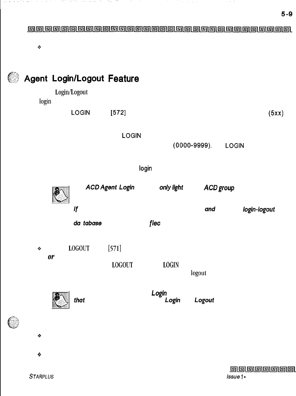
DIGITAL STATION OPERATION
Automatic Call Distribution (ACD)
Q
The supervisor can cancel a HELP request signal by pressing his flashing HELP button. Additionally, a
call is placed to the agent requesting HELP If the agent is on a call, the supervisor can press the
barge-in button to monitor the call or give assistance.
.?.
c
i?$
Agent
Login/Logout
Feature
-I;,.“.
The Agent Login/Logout feature lets an agent log into one of the ACD groups and receive calls. An agent must
first login to be placed into an active ACD state. The agent logs in by:
1
Dial the
LOGIN
CODE
[572]
on the dial pad, followed by the ACD group number
(5xx)
into which the agent is going to log.
or
Press a pre-programmed*
LOGIN
flex button.
2The agent enters his unique AGENT ID code
(0000-9999).
The
LOGIN
flex button LED
is lit steady. Confirmation tone is heard and the agent is logged onto the ACD group. The
ON/OFF LED extinguishes if the agent started the sequence in the handsfree mode.
When the agent logs in, an ACD
login
event is sent to the ACD Events Trace port, if
active.
The
ACDAgent
Login LED will only/ight for the
ACDgroup
that is assigned
to that button.
If
a member is assigned to a specific ACD group and uses the login-logout
codes to enter and exit an ACD group, other than his assigned group, the
da tabuse is changed to re
flee
t the different group.
For an agent to remove himself from the ACD group as an active agent:
+:+
Dial the
LOGOUT
CODE
[571]
on the dial pad,
Or
Press a pre-programmed*
LOGOUT
flex button.
LOGIN
flex button LED extinguishes. When the agent
logs out and removes himself from the ACD group, an ACD logout event is sent to the ACD Events
Trace port, if active.
When an ACD agent has a Login flex button programmed onto his station,
thut
flex button can be used to
Login
and
Logout
of the assigned ACD
group.
@
Conditions:
44
If an agent logs into an ACD group from a station that is logged into another ACD group, the station is
automatically removed from the previous ACD group.
oAn agent may log out while in wrap-up, or unavailable.
STARPLUS
Triad-S Product Description Manual
hue
7
-
December 1998
5-10
DIGITAL STATION OPERATION
Automatic Call Distribution
(ACD)
(0
An agent logging in is placed in wrap-up mode before receiving an ACD call.
+
If an agent attempts to log into an ACD group that already has
16
members, that agent receives
error tone.
,-:-
The Triad-S Digital System does not verify agent’s ID codes, other than requiring entry of four digits.
I
. .
,.
Q
$?.-;-
_
.-.
-
*A Flex Button must be programmed for this feature to operate. Table
5.JMZex
Button Programming
Codes.
ACD Agent Queue Status Display
From an idle key telephone:
I
Dial
[567]
on the dial pad,
or
Press pre-programmed* flex button.
2
Dial the 3-digit ACD group number
(5xx).
ON/OFF button LED lights steady.
The Agent Queue Status display shows the following information:
ACDSxx
00 CALLS IN QUEUE
MMM DD YY HH:MMam
I
Where:
5xx
= ACD Group
(550-565).
The above display is an idle state display and tells the agent and/or his supervisor how many calls are in
queue.
*z.
Replace the handset or press the ON/OFF button to terminate the display.
This feature cannot be used with a call in progress. The station is consid-
ered busy for incoming calls during this operation. Each time this feature
is
used,
wrap-up is started.
The agent automatically receives an enhanced Calls in Queue display whenever there is a call in queue.
The display shows the following information:
5xx:
CIQ: xx AGENT(S): xx
oc: HH:MM:SS
Where:
$3
= ACD Group
(550-565)
issue
1
-
December 1998
STARPLUS
Triad-S Product Description Manual
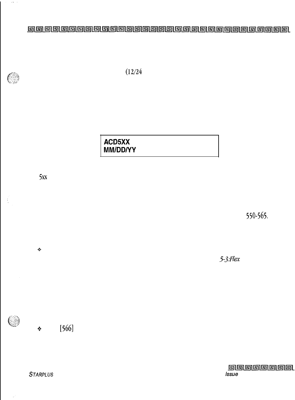
DIGITAL STATION OPERATION
5-11
Automatic Call Distribution (ACD)
CIQ: xx = Calls in queue
AGENT(S): xx = Agents logged in
OC: hh:mm:ss = Oldest call in hours, minutes and seconds
This feature also allows an ACD station
(12/24
button executive only) to assign multiple buttons that display
the calls in queue for a particular group on the LCD. Additionally, the button LED indicates the number of
calls in queue, determined in programming.
From an idle key telephone:
1
The pre-programmed* flex button for the ACD group being monitored is flashing at 240
ipm indicating there are calls in queue. Press the pre-programmed flex button. The Agent
Queue Status display shows the following:
ACDSXX
00 CALLS IN QUEUE
MM/DD/YY HH:MMam
Where:
5xx
= ACD Group (550-565)
The above display is an idle state display and tells the agent and/or his supervisor how many calls are in
queue.
2Replace the handset or press the ON/OFF button to terminate the display.
The user assigns a flexible button by dialing 579 XXX. Where XXX is the ACD group number
550-565.
The user sees the following LED indications:
Conditions:
+:*
Any ACD station can have a button assigned to view the calls in queue for any ACD group.
*A Flex Button must be programmed for this feature to operate. Refer to Table
5-3:FZe.x
Button
Programming Codes.
ACD Available/Unavailable Mode
If you are an ACD agent, you may place your station in the Available mode to receive ACD calls, or you may
place your station in the Unavailable mode to block ACD calls from ringing your station.
To go Available:
43
Dial
[566]
on the dial pad,
or
Press the pre-programmed* AVAILABLE/UNAVAILABLE button. You may now receive ACD calls.
To go Unavailable:
STARPLUS
Triad-S Product Description Manual
issue
I- December 1998
:
DIGITAL STATION OPERATION
Automatic Call Distribution (ACD)
Q
Dial
[566]
on the dial pad,
Or
Press the pre-programmed* AVAILABLE/UNAVAILABLE button. You are now blocked from receiving
ACD calls.
*A Flex Button must be programmed for this feature to operate. Refer to
Table 5-3:Flex Button
Programnilzg Codes.
ACD Call Qualification
The CALL QUALIFICATION feature provides a means for an Agent on ACD calls to enter call identification
codes. This feature provides up to four digits for the ACD SMDR reporting function. Up to
12
digits can be
entered, however only the first four digits are used in the SMDR record.
oThe QUALIFY button is programmed using flex code
[570].
*A Flex Button must
be
programmed for this feature to operate. Refer to
Table53;FZexButton Prog~amm’ng
Codes.
While on a call, the agent:
0%
Presses the pre-programmed CALL QUALIFY flex button, followed by the 4-digit qualify code. Enter
an
[*]
to complete the sequence. A short burst of confirmation tone is heard through the
keyset
speaker, if programmed.
Conditions:
+
The outside party does not hear the (qualify code) account code being entered,
oThe qualify code is the first four digits of the account code. Therefore, the account code record in
the SMDR contains the qualify code in the first four digits.
*z+
The qualify code must be entered during CO
talk state.
ACD Group Member Status
The ACD Group Member Status feature provides a means for an ACD Supervisor/Agent to view the status of
the eight ACD groups in the system. This display tells the Supervisor/Agent which stations are logged into
the group, and if the stations logged in are Available/Unavailable, Out-of-Service, in DND, or busy on a call.
The Supervisor/Agent can use this display to determine why there are many queued calls in a specific
group.
Any station (Supervisor or Agent) logged onto the ACD group view the group members display by:
Issue
7
-
December 1998
STARPLUS
Triad-S Product
Description Manual
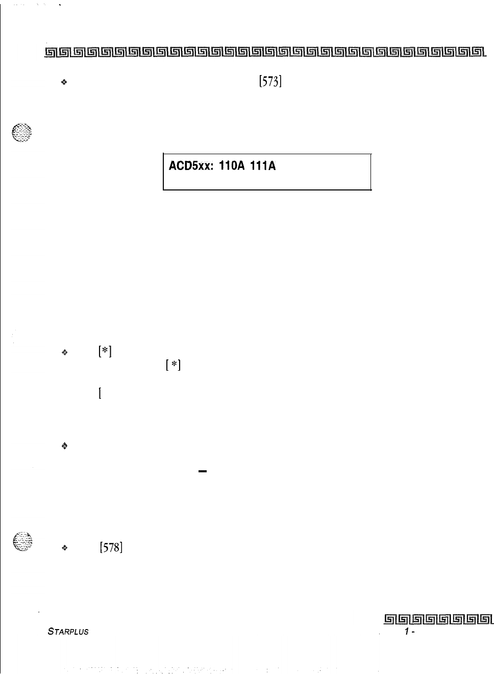
Issue
I-
December 7998
.
DIGITAL STATION OPERATION
Automatic Call Distribution (ACD)
5-13
+
Dialing the ACD Group Member Status code
[573]
on the dial pad,
or
Pressing the pre-programmed* flex button. The display now shows ACD Group 550.
The status of the ACD agents is displayed with a letter following the station number where the agent is logged
in.
ACDSxx:
110A
111A
112A
1130 114U 115D 116B 117N
The status is displayed with the following priority:
Where:
(N) = Not Equipped
(D) = Do not Disturb
(0) = Out of service
(U) = Unavailable
(B) = Busy on a call
(A) = Available
(If an agent made a call while out of service, the status would be out of service, not busy.)
+zo
Dial [*I on the dial pad to scroll up to the next ACD Group. If more than eight members are in the
ACD group, pressing
[
*]
displays the additional members,
or
Dial
[
#] on the dial pad to scroll down to the previous ACD Group. To return to an idle display, the
Supervisor/Agent station returns to on-hook condition.
Conditions:
+fr
The ACD Group Members Status display is updated at the time the code is dialed.
ACD Overflow Station
-
Available/Unavailable Mode
If you are an ACD Overflow station, you may place your station in the Available mode to receive ACD calls, or
you may place your station in the Unavailable mode to block ACD calls from ringing your station.
To go Available:
+z+
Dial
(5781
on the dial pad,
or
Press the pre-programmed* AVAILABLE/UNAVAILABLE button. You may now receive ACD calls.
To go Unavailable:
STARPLUS
Triad-S Product Description Manual
DIGITAL STATION OPERATION
Automatic Call Distribution (ACD)
+
Dial
[578]
on the dial pad,
or
Press the pre-programmed* AVAILABLE/UNAVAILABLE button. You are now blocked from receiving
ACD calls.
If no stations are logged
into the ACD Group, ACD calls are routed to the
Attendant station.
*A FlexButton must be programmed for this feature to operate. Refer to Table53:FZexButton Programming
Codes.
ACD Overflow Station
-
Forwarding
This feature allows ACD calls reaching the ACD Overflow Station to follow the call forward of the overflow
station.
1
Lift the handset or press ON/OFF button.
2Press the FWD button.
3Dial the desired code:
[7]
= No Answer Calls
[8]
= Busy Calls
[9]
= Busy and No Answer Calls
Skip the preceding step for immedic te
forwarding.
4Dial the 3-digit destination number where calls are to be forwarded (Station, Voice Mail,
ACD groups, or Hunt group). Confirmation tone is heard.
5
Replace handset or press ON/OFF button.
To remove Call Forwarding:
1
Lift handset or press ON/OFF button.
2
Press the FWD button. Confirmation tone is heard and the FWD LED is extinguished.
The overflow station follows the following rules:
IIt forwards on the no answer timer if the forward is set to NO ANSWER or BUSY NO
ANSWER.
2
It forwards immediately if the station is set to any other forward type.
Issue
1
-
December 1998
STARPLUS
Triad-S Product Description Manual
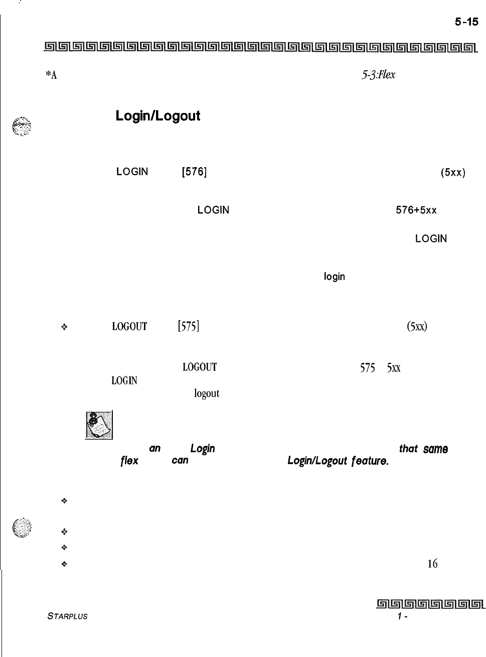
I
--
DIGITAL STATION OPERATION
Automatic Call Distribution (ACD)
*A
Flex Button must be programmed for this feature to operate. Refer to Table
5-3:FZex
Button
Programming Codes.
GT2
Supervisor
Login/Logout
Feature
E::
y.:;>
y’
.”
--.
The Supervisor Login/Logout feature provides a means for a supervisor to log into one of the ACD groups and
monitor calls.
1
Dial the
LOGIN
CODE
[576]
on the dial pad, followed by the ACD group number
(5xx)
that the supervisor is going to log into,
or
Press a pre-programmed*
LOGIN
flex button. (Flex button must have
576+5xx
programmed onto it.)
2The supervisor enters a unique SUPERVISOR ID code (0000-9999). The
LOGIN
flex
button LED is lit steady. Confirmation tone is heard and the supervisor is logged onto the
ACD group. The ON/OFF LED extinguishes if the supervisor started the sequence in the
handsfree mode. When the supervisor logs in, an ACD
login
event is sent to the ACD
Events Trace port, if active.
For a supervisor to remove himself from the ACD group as an active supervisor:
+:+
Dial the
LOGOUT
CODE
[575]
on the dial pad, followed by the ACD group number
(5xx)
that the
supervisor is going to log out of,
or
Press a pre-programmed*
LOGOUT
flex button. (Flex button must have
575
+
5xx
programmed onto
it), The
LOGIN
flex button LED extinguishes. When the supervisor logs out and removes himself
from the ACD group, an ACD logout event is sent to the ACD Events Trace port, if active.
The ACD
Supervisor
Log-in
LED
will only light for the ACD group that is
assigned
to that button.
When
cm
ACD Login flex button is programmed in the system, thut same
f/ex button can
be used
to toggle
the
Login/Logout feuture.
Conditions:
9If a supervisor logs into an ACD group from a station that is logged into another ACD group, the
station remains in the previous ACD group.
oA supervisor may log out while in wrap-up, or unavailable.
+
A supervisor logging in is first placed in wrap-up mode before receiving an ACD call.
+
If a supervisor attempts to log into an ACD group as an agent and that group already has
16
members, the supervisor receives error tone.
STARPLUS
Triad-S Product Description Manual
Issue
I-
December 1998
DIGITAL STATION OPERATION
Automatic Call Distribution (ACD)
+
The Triad-S Digital System does not verify the supervisor’s ID codes, other than requiring that four
digits are entered.
*A Flex Button must be programmed for this feature to operate. Refer to Table 5-3:Hex Button
Programming Codes.
Supervisor Monitor With Barge-In
The Supervisor Monitor with Barge-In feature provides a means for an ACD supervisor to monitor an
agent’s call in progress, to coach sales techniques or customer relations skills. When used, a supervisor
may intrude onto an agent’s call in a listen-only mode or in a true conference mode by use of the barge-in
feature. This feature is available with or without a warning tone.
The use of Supervisor Monitor with Barge-in is limited by federal law and
may also be limitedorprohibitedby state
orlocallaw,
so check the relevant
laws in your area before employing these features.
A change in volume may occur on the CO line or intercom call after the
barge-in occurs.
The ACD supervisor can intrude on an agent’s call in the listen only mode by:
+
Dialing the agent’s
3-digit
station number. Upon hearing busy tone, press the pre-programmed*
Barge-In flex button. The conversation in progress is heard by the Supervisor on the handset
receiver and the Supervisor’s MUTE button LED is lit indicating that the Supervisor’s transmit is
muted. If the Supervisor wishes to participate in the conversation in a true conference mode, he
can press the MUTE button which removes mute.
The Executive Override Code,
[625]
programs Supv Monitor with Barge-
/n feature onto a flex button.
Conditions:
+Supervisors are granted the Barge-In option if they log in at a station with the Supervisor
Barge-
In/Executive Override enabled in programming.
9Supervisors can only Barge-In on calls of ACD group(s) members into which they are logged.
Supervisor Queue Status Display
The Supervisor Queue Status feature provides a means for an ACD supervisor to view the status of their ACD
group. This display is an idle state display and prompts a Supervisor when a group is having problems
Issue
7
-
December 1998 STARPLUS
Triad-S Product Description Manual
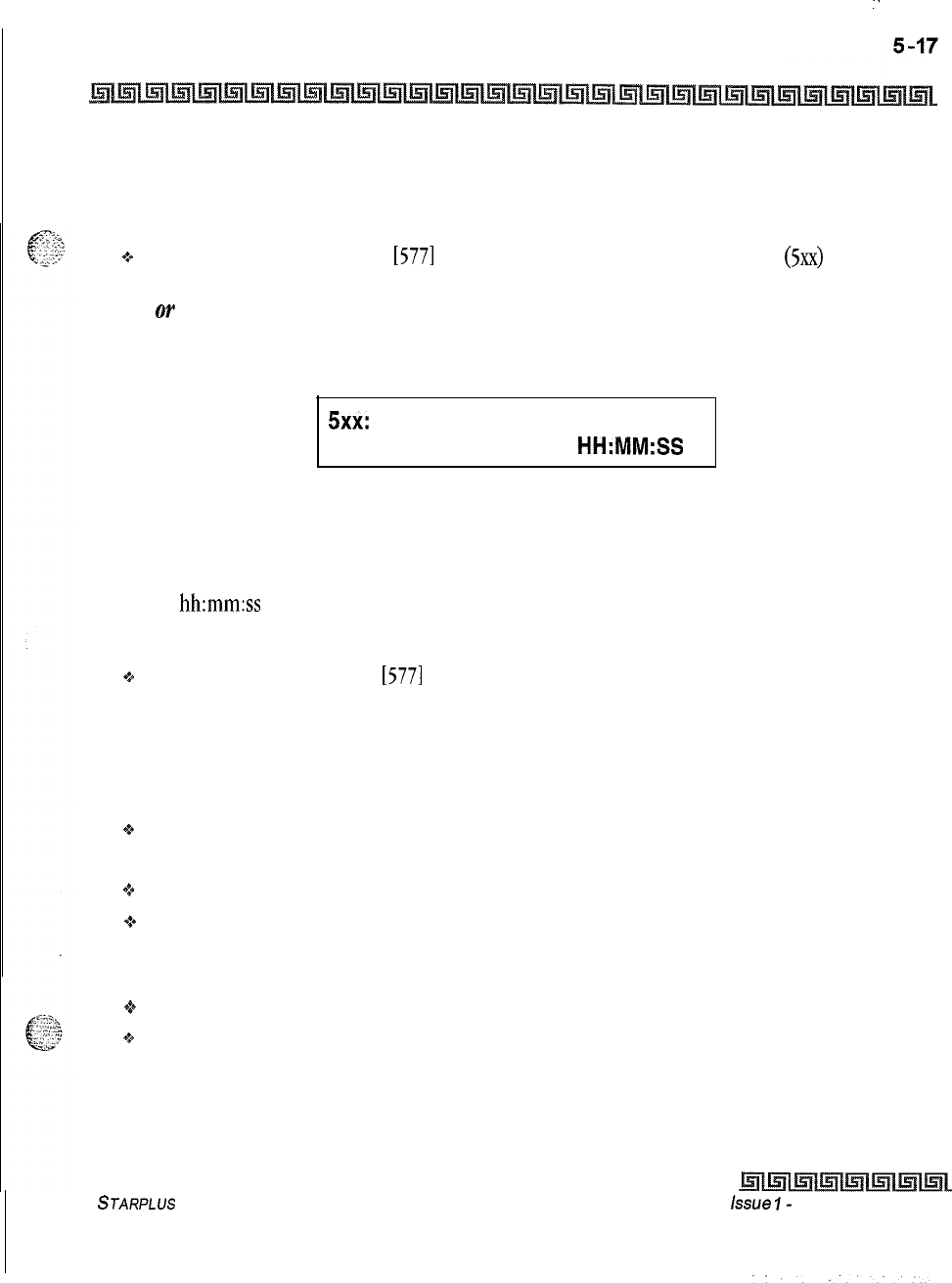
I
:
DIGITAL STATION OPERATION
Automatic Call Distribution (ACD)
answering their calls. The display tells the supervisor how many calls are in queue, how many agents are
logged into the ACD group, and the length of time, in minutes, that the oldest call is in queue.
The supervisor station logged onto the ACD group can obtain the Queue Status display by:
+t+
Dialing the Queue Status code
[577]
on the dial pad, followed by the ACD group
(5xx)
the supervisor
wants to observe,
Or
Press the pre-programmed* flex button.
The Queue Status display shows the following information:
5xx:
CIQ: xx AGENTS: xx
oc:
HH:MM:SS
Where:
5xx = ACD Group (550-565)
CIQ: xx = Calls in queue
AGENT(S) : xx = Agents logged in
OC:
hh:mm:ss
= Oldest call in hours, minutes and seconds
If the supervisor wants to change the display to a different group:
+
Dials the Queue Status code
[577]
on the dial pad, followed by the ACD group that the supervisor
wishes to observe,
or
Presses the pre-programmed* flex button.
Conditions:
oTo receive the Supervisor’s Queue Status display, the station must be logged in as a Supervisor and
dial the flex code for the appropriate group.
Q
ACD Supervisors receive the Queue Status display in real time.
$4
The Queue Status display is only given when the ACD group member or Supervisor’s station is not
receiving a higher priority display, such as HELP or Out-Of-Service, or other applicable off-hook
events are taking place at the station.
oThe Supervisor’s Queue Status display is saved in battery backed memory.
+
When a Supervisor logs out of the group presently displayed, he must enter a new request for Queue
Status display.
STARPLUS
Triad-S Product Description Manual
issue
I-
December 1998
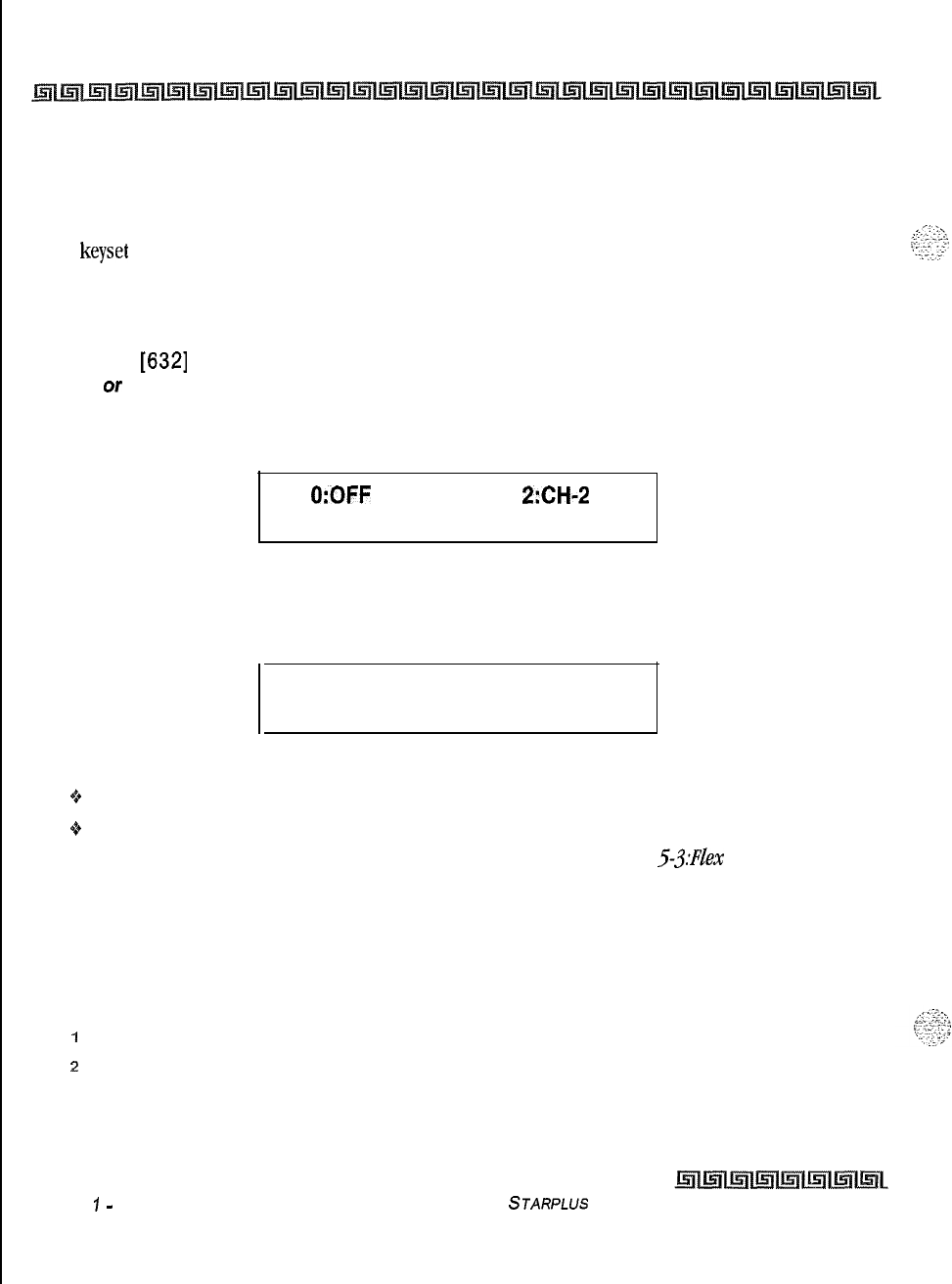
5-18 DIGITAL STATION OPERATION
Automatic Selection
Automatic Selection
Pressing an outside line button, or pool button; a speed button; a station button; or dialing a number in the
Triad-S system numbering plan, automatically activates the speakerphone and lights the ON/OFF button, if
your
keyset
is programmed as a speakerphone.
Background Music (Optional)
1
Dial
[632]
on the dial pad,
Or
Press the pre-programmed* flexible button.
The LCD display shows the following:
0:OFF 1 :CH-1
2:CH-2
MMIDDNY
HH:MM
2
Enter the desired channel on the dial pad. Confirmation tone is heard. Music is now
heard through the speaker.
3
Press the Volume Bar to change the volume. The following message is shown on the
display phone:
SPEAKER BGM
[#########I
MMM DD YY
HH:MM am
Conditions
+
When you pick up the handset or press the ON/OFF button, music is discontinued automatically
9Once the headset is enabled, BGM is discontinued.
*A Flex Button must be programmed for this feature to operate. Refer to Table 5.$Hex Button
Programming Codes.
Call Back
If you dial a telephone that is busy and want to activate Call Back:
1
Press the CALL BACK button.
2
Hang up.
3
When the busy station hangs up, you are signaled.
Issue
1
-
December 1998 STARPLUS
Triad-S Product Description Manual
I
DIGITAL STATION OPERATION
Call Coverage
Feature
4Answer the call; station you called is then signaled. (If your station is busy when signaled,
an automatic MSG is left at your phone).
When the Automatic Cull Back Timer is enabled, a call back request will
automatically be invoked unytime a user listens to intercom busy tone for
a preset period of time.
Only one Call Back request can be
left
at a station; the second request is
converted to a message wuit call back request.
*A
Flex
Button must be programmed for this feature to operate. Refer to Table 53:Fle.x Buttm Prog~zlmzing
Codes.
Call Coverage Feature
This feature lets stations answer calls for other stations by utilizing enhanced DSS buttons, AVisual and
Audible status of ringing stations to an assigned coverage station are provided.
To program a flexible button for call coverage at a station:
1
Press the SPEED button twice.
2
Press the desired flexible button to program.
3Dial
[646XxX]
(Ringing Type) or
[647XxX]
(Non-Ringing Type) on the dial pad where
XXX is the extension number to cover. Confirmation tone is heard. If an error was made
during entry, error tone is presented.
Once the button is assigned on the station and a call rings in:
1
The coverage station hears ringing for the coverage station after a five second
delay.The ring tone is the internal ring tone cadence. The LCD of the coverage station
identifies the ringing station as:
CALL FOR STA XXX
MMM DD YY HH:MM
2The Coverage station then presses their flashing Coverage flexible button,
or
Presses the ON/OFF button,
or
Lifts the handset if PLA is enabled. The flash rate is the same as the incoming CO line
ringing rate. The call is answered and ceases to ring at any other stations that may have
STARPLUS
Triad-S Product Description Manual
issue
I- December 1998
DIGITAL STATION OPERATION
Call Forward
the same coverage appearance. The following message is displayed after the call is
answered:
CALL TO STATION XXX
FROM STA YYY
HH:MM:SS
By default, no call coverage buttons are assigned.
Conditions:
Multiple coverage stations can have the same remote ringing station(s) programmed on their
stations.
Once a coverage station answers the call, other stations attempting to answer the call receive a
busy tone and the call coverage button extinguishes on all appearances of that button,
This feature can cover SLT extensions, however an SLT cannot perform the call coverage function.
The SLT extension need not be physically installed, only the SLT card must be installed.
Direct CO calls have ring and LCD priority over call coverage calls. The call coverage station must
have a direct CO appearance or Loop button to pick up an external call. If the call coverage station is
in DND, no audible ringing is heard, however visual and LCD information is presented.
This feature can be programmed on any key station or DSS Console with an available flexible
button. If the DSS with a call coverage button assigned is unplugged or moved, the station
associated with that DSS stops ringing until the DSS is plugged in again.
Camp-On or Override drops any internal callers to which a station is talking.
Only one button type
(646
or 647) per covered station can be assigned on a
keyset.
*A Flex Button must be programmed for this feature to operate. Refer to TabZe53:HexButton Programming
Codes.
Call Forward
All Calls
If you were given the ability to forward your calls:
1
Lift handset or press ON/OFF button.
2
Press the FWD button or dial
[640].
3
Press DSS button of desired station,
or
Dial the 3-digit extension number where to forward calls, including ACD or UCD, Voice
Mail, Hunt Group pilot numbers and Speed Dial bins for off -net forwarding.
issue 1
-
December 1998 S
JARPLUS
Triad-S Product Description Manual
DIGITAL STATION OPERATION
Call Forward
4
Replace handset or press ON/OFF button.
Conditions:
Call Forward remains engaged until manually released. When released, the station number is
returned to the LCD.
Calls cannot be forwarded to a station in the DND mode. An error tone is received when this is
attempted. It cannot be forwarded to a busy station, the caller receives busy tone in this case,
CO Line queues, a Message Waiting request, and pre-selected messages are canceled when a station
is placed in the Forward mode.
A forwarded call signals to the forwarded station in the Tone mode, regardless of the Intercom
Signaling Switch Mode selection.
A station in the Forward mode can make outgoing calls.
A Camp-On signal is allowed at the forwarded station if that station is busy.
A station denied the use of Call Forwarding receives an error tone when pressing the Call Forward
button.
A forwarded CO Line call can be transferred back to the original forwarding station, effectively
overriding the forward. Also, a station receiving the Call Forward can call the original forwarding
station.
If a CO Line rings into a station with manual Call Forward, the line sequences to the last station of the
chain. If the last station is in DND mode or does not have a Direct appearance for the CO Line or a
Loop button, the call reverts back to the first station.
If a CO Line rings into a station with both Manual and Preset Call Forwarding, Manual Call
Forwarding takes precedence. Once the Manual Forward determines the station to be rung as per
above, preset Call Forward may then apply at the new station.
An unlimited number of stations can be set up in a Manual Call Forward chain. However, a station
cannot forward to a station that is already a member of his chain.
If the last number of the Manual Call Forward chain is in DND mode, the internal caller gets a DND
response.
Calls to a station in both Manual Call Forward and DND mode follow the forward.
If a private line rings into a station with Manual Call Forward the CO Line forwards, providing the
forwarded station has a direct CO Line appearance or an available Loop button.
When a forwarded SLT goes off-hook, a Call Forward warning tone is heard by the user to inform the
user the phone is forwarded.
SLTs
may use Call Forward in the same manner as digital terminals.
S
TARPLUS
Triad-S Product Description Manual Issue I- December 1998
5-22 DIGITAL STATION OPERATION
Call Forward
+
A station’s Call Forward status is stored in a battery protected area of memory, A station’s Call
Forward status is returned after a power failure or system reset occurs.
+
Idle
Keyset
in hands-free mode will not follow no answer/busy-no-answer forwarding.
To remove Call Forwarding:
1
Lift handset or press ON/OFF button.
2Press the FWD flex button. Confirmation tone is heard and the FWD LED is
extinguished.
Busy
If you were given the ability to forward your calls:
1
Lift the handset or press ON/OFF button.
2
Press the FWD button or dial
[640].
3
Dial the Call Forward Busy code
[8]
on the dial pad.
4
Dial the 3-digit destination number to forward calls. Confirmation tone is heard.
5
Replace handset.
To remove Call Forwarding:
1
Lift the handset or press ON/OFF button.
2
Press the FWD button. Confirmation tone is heard and the FWD LED is extinguished.
Busy/No Answer
If you were given the ability to forward your calls:
1
Lift the handset or press ON/OFF button.
2Press the FWD button or dial
[640].
3
Dial the Call Forward Busy/No Answer code
[9]
on the dial pad.
4
Dial the 3-digit destination number to forward calls. Confirmation tone is heard.
s
Replace handset.
To remove Call Forwarding:
ILift the handset or press ON/OFF button.
2Press the FWD button. Confirmation tone is heard and the FWD LED is extinguished.
Conditions:
oThe user cancels the feature by dialing the Call Forward Code or pressing the Call Forward button
again.
issue
I-
December 1998
STARPLUS
Triad-S Product Description Manual
_
_
.:
_
._
_
DIGITAL STATION OPERATION
Call Forward
5-23
+
For Call Forward No Answer, the number of rings before the call is forwarded is determined by the
Call Forward No Answer timer.
+z+
Stations Call Forwarded/No Answer forward incoming CO calls according to the Preset Forward Ring
Timer.
8
CO Line transfers to a station forwarded to a ACD, UCD or VM group receives BGM until a member of
the group becomes available.
$6
KM
calls forwarded to a VM group receive ringback until a member of the VM group becomes
available.
oIf a station is denied Station Call Forwarding, then Off-Net Forwarding is not allowed.
+
A station’s Call Forward status is stored in a battery protected area of memory. A station’s Call
Forward
status
is returned after a power failure occurs.
The Call Forward condition Codes are as follows:
NONE
Unconditional forward (all calls forwarded)
[71
Forward after the No Answer time (programmable)
[81
Forward only when station is busy
[91
Forward if station is busy or after the No Answer time expires
Follow-Me
This feature lets a user who is away from their station, activate/deactivate call forwarding from another
station in the system. This lets the user forward their calls to their current location or into Voice Mail,
ACD/UCD,
Hunt Groups, or to any other station in the system. When this call forward is activated, all calls
presented to the forwarded station forward to the destination station immediately.
If you were given the ability to forward your calls:
J
Lift the handset or press ON/OFF button.
2
Dial the Follow-Me Forward code
[642
YYY XXX] on the dial pad, where YYY=station
forwarding from and XXX is station forwarding to.
3 Replace handset.
To remove Follow-Me Forwarding:
1
Lift the handset or press ON/OFF button.
2
Dial the Follow-Me Forward code
[642
YYY YYY] on the dial pad, where Y=station
forwarded from.
To establish Follow-Me Forwarding from an off-site location:
1
Dial into the system on a
DISA
or TIE trunk. Enter the
DISA
access code, if applicable.
STARPLUS
Triad-S Product Description Manual
/ssue
I- December 1998
5-24 DIGITAL STATION OPERATION
Call Forward
2
Dial the Follow-Me Forward code
[642
YYY XXX] on the dial pad, where YYY=station
forwarding from and XXX=station forwarding to.
To remove Follow-Me Forwarding from an off-site location:
1
Dial into the system on a
DISA
or TIE trunk. Enter the
DISA
access code, if applicable.
2
Dial the Follow-Me Forward code
[642
YYY YYY] on the dial pad, where Y=station
forwarded from.
Conditions:
+
If a Call Forward mode is currently active at the station where forwarding is desired, the new
forward becomes active and cancels the previous forward.
+
Both internal and external calls to the affected station forward to the designated location,
+:*
Call forwarding must be allowed in programming for the affected station.
Q
When remote forward is activated the forwarding is immediate.
+
A station’s Call Forward status is stored in a battery protected area of memory. A stations Call
Forward status is returned after a power failure or system reset occurs.
Q
When a key telephone is forwarded remotely, the key stations forward button lights. The station
user may cancel the forwarding at their station by pressing ON/OFF, then the FWD button, SLT users
can cancel their forwarding by going off hook and dialing the forward code.
+z+
DISA callers entering the code and making a mistake are given error tone for
3
seconds, silence for
2 seconds, then the dial tone is returned.
No Answer
If you were given the ability to forward your calls:
ILift the handset or press ON/OFF button.
2
Press the FWD button or dial
[640].
3
Dial the Call Forward No-Answer code
[i’]
on the dial pad.
4
Dial the 3-digit extension number where calls are to be forwarded. Confirmation tone is
heard.
5
Replace handset or press ON/OFF button.
To remove Call Forwarding:
1
Lift the handset or press ON/OFF button.
2
Press the FWD button or dial
[640].
Confirmation tone is heard and the FWD LED is
extinguished.
Issue I- December 1998
STARPLUS
Triad-S Product Description Manual
DIGITAL STATION OPERATION
Call Forward
5-25
Off -Net (via speed dial)
This feature allows stations to forward intercom and transferred CO calls to an off-net location,
g=3
~
In a speed dial bin, store the number of the off-net location where to forward calls. Follow instructions provided
-Z’S
U,? for storing station or system speed dial numbers.
1
Lift handset or press ON/OFF button,
2Press the FWD button or dial
[640].
3Dial
[*]
on the dial pad. Dial the 2-digit speed bin number (00-19, 20-99) that contains the
number where to forward calls. Confirmation tone is heard. FWD button LED flashes.
4Replace handset or press ON/OFF button.
Conditions:
Q
The user cancels forwarding by going off-hook and pressing Call Forward button.
6Forwarding is unconditional and occurs immediately when a station calls an Off-Net forwarded
station.
*a
The call to a station is not answered until the outgoing CO Line is seized and the digits are
out-
pulsed, The calling Station receives ICM ringback until answered. Upon answer the Station receives
whatever CO progress tones apply (i.e., Ringback, Busy, Error, Announcement, etc.).
Q
If a station is denied Station Call Forwarding, Off-Net forwarding is not allowed.
Q
Toll Restriction is based on the forwarding station’s COS and the outgoing CO Line COS.
oThe calling station must have an appearance (Direct, Loop) for the outgoing (Off-Net) line. The call is
not forwarded if a Direct Appearance or Loop key is unavailable.
+
SMDR printout reflects transferred and outgoing calls like a DISA call record.
+
Station users may use Station or System Speed Dial as the Speed Dial Bin used for Station Off-Net
Forward.
+
A station’s Call Forward status is stored in a battery protected area of memory, A station’s Call
Forward status is returned after a power failure or system reset occurs.
+
Call must be an intercom or transferred CO call.
To remove Off-Net Forwarding
1
Lift the handset or press ON/OFF button.
^‘:>.
..-_
.
t32
2
Press the FWD button. Confirmation tone is heard and the FWD button LED is
_..__
-v
extinguished.
STARPLUS
Triad-S Product
Descripfion
Manual
issue
I- December 1998
5-26 DIGITAL STATION OPERATION
Caller ID Name/Number Option
Station
When any type of station call forwarding is invoked, the LCD display normally indicates the call forwarding
mode at all times. This feature changes the LCD forwarding display to make the call forwarding mode
display optional. This feature is enabled/disabled in admin programming on a system-wide basis.
Caller ID Name/Number Option
This feature lets a station user program a flexible button to view the number and name on the LCD when
receiving a Caller ID CO call.
If the feature is enabled, the flex button LED is lit solid, the name and number is displayed. During the call,
the user can press the flexible button to view the normal call information.
The top line of the LCD displays the number of the caller and the bottom line of the LCD displays the name.
Conditions:
0When enabled, this display overrides transfer call LCD messages, ACD Ring messages, Call Pickup
messages, and Answer messages. If the user wishes to view the Line Number/Call Timer and the
standard call information, they can press the flexible button to toggle between the name/number
and normal mode.
+
By default, no button is assigned on telephones.
*A Flex Button must be programmed for this feature to operate. Refer to
TabZe53;FlexBzrtton
Programming
Codes.
,:y;.:<-
,_-1.-.
I..-.
.:
_
.
.
.
.
:.
,..
.
.._
Issue I- December 1998
STARPLUS
Triad-S
Producf
Description Manual
:
DIGITAL STATION OPERATION
Calling Station Tone Mode Option
5-27
Calling Station Tone Mode Option
Enables a calling station to override a called station’s H or P intercom settings,
When placing a call to a station and Tone ringing is desired:
1
Dial
[6#]
on the dial pad.
2
Dial the 3-digit extension number,
or
Press DSS button of desired station (call tone rings station).
Call Park
To place an outside call in park and consult with, page, or call an internal party:
While connected to an outside line:
1
Press TRANS button. The caller is put on hold.
2
Dial parking location (430 to 437). Confirmation tone is heard.
s
If you hear busy tone, press TRANS twice and dial another parking location.
Retrieving a Parked Call:
1
Lift handset or press ON/OFF button.
2
Press the [#] button.
3
Dial parking location (430 to 437) where the call was parked.
Call Pick-Up
_-,,
=.;
:
;?
4-
,_;
;-
.’
.2x?
Directed
A station can pick up a tone ringing intercom call, transferred, incoming or recalling outside line to a specific
unattended station. The call must be a tone ringing call:
1
Dial the station number of the known ringing telephone. Receive
ringback
tone or call
announce tone depending on the intercom selector switch setting.
2
Press the pre-programmed* PICK UP button to answer the call.
*A
Flex Button must be programmed for this feature to operate. Refer to Table53:FZex Button Programming
Codes.
Conditions:
+:+
User must have access to the specific outside line or a Loop button to do a directed call pick up.
STARPLUS
Triad-S Product Description Manual
Issue I
-
December 1998
I
--...
5-28 DIGITAL STATION OPERATION
Call Transfer
Group
When intercom tone ringing, transferred outside line ringing, recall ringing or initially ringing call is heard
at an unattended telephone:
1
Lift handset or press ON/OFF button.
2
Dial [#0] on the dial pad,
Of
Press the pre-programmed* PICK UP button to connect to the calling party.
You must be in the some pick up group
OS
the ringing telephone to pick up
the call.
*A Flex Button must be programmed for this feature to operate. Refer to
TabZe5-3:FZexButton
Programming
Codes.
Conditions:
a+
User must have access to the specific outside line or loop button to do a group call pick up.
Call Transfer
Outside lines can be transferred from one phone to another within the system. The transfer can be
screened (announced) or unscreened to an idle or busy station, ACD or UCD Group, or Hunt Group.
Screened Transfer
While connected to an outside line:
1
Press DSS button where to transfer call (if programmed on your telephone),
or
Press TRANS button and dial 3-digit station number.
2
The called extension signals according to the intercom position.
3
When that extension answers, announce the transfer.
4
Hang up to complete transfer.
If
Direct Transfer Mode is enabled in admin programming, the supervised
tronsfer is transferred directly to the key
stution
handset.
Issue 1
-
December 1998
STARPLUS
Triad-S Product Description Monuol
I-
-.
.-
. . .
DIGITAL STATION OPERATION 5-29
Camp-On
Answering a Screened Transfer
Your intercom signals according to the intercom position.
1
Answer the intercom and receive the transfer notice.
7”
gi;
2
2,
Press the outside line button or loop button flashing on hold.
Transfer Search
When attempting to locate a party:
1
Press a station button to signal the desired station.
If the party is not located:
21
Press another station button to continue the search.
3When the called party answers, hang up to complete the transfer.
Unscreened Transfer
When the called extension begins to signal, hang up to transfer the call (Recall timer starts).
Camp-On
If you call a station that is busy and wish to alert them to your call:
1
Press the CAMP-ON button. Called station receives one-burst of ringing. Wait for their
response.
2
When called party answers, consult with them or hang up to transfer the call.
If
a station is in
DND,
only
the attendant can
Camp
On using
the
attendant
override feature. Cump-On or Override
wi/l
drop any internal callers to
which that
station
is talking.
Answering a Camp-On
If you are on a connected call, hear one burst of muted ringing, and your CAMP-ON button is flashing, you
have a call waiting.
To answer:
. .
:
.I
-.-
:.
.__.l
f
’
1
.z.:
-
Press the CAMP-ON button. Any outside line you are connected to is placed on hold.
.s2:
You may converse with the station placing the call.
:!
Press flashing outside line button if a call is being transferred
S
TARPLUS
Triad-S Product Description Manual Issue
I
-
December 1998
DIGITAL STATION OPERATION
CO Line Access
If you do not have a Camp-On button:
0Go on-hook with present call. Camp-On rings through,
or
Place present call on hold, then go on-hook. Camp-On rings through.
CO Line Access
To access outside line:
1
Press idle CO line button, Pool button,
or
Dial CO line group access code or LCR access code.
2
Dial desired number for outside call.
3
Lift handset to converse or use speakerphone.
CO Line Queuing
A station can queue only one line at a time. If you see that a particular outside line is busy and you wish to
be placed on a list waiting for that line to become available:
To Place a Queue:
1
Press desired busy outside line button,
or
Pool button. (Busy tone is heard.)
2
Press pre-programmed* LINE QUEUE button.
3
Replace handset or press ON/OFF button.
To Answer a Queue:
If you hear ringing and an outside line of the line group or a Loop button you queued onto is rapidly
flashing:
ILift handset or press ON/OFF button.
2
Press flashing outside line button or Loop button to answer.
If
your station has been programmed for Preferred Line Answer, you will
have the line automatically upon /if ting the handset.
Issue
I-
December 1998
STARPLUS Triad-S Product
Description Manual
DIGITAL STATION OPERATION
Conference Combinations
Conditions:
9A Loop button or direct appearance of the queued line is required.
*A Flex Button must be programmed for this feature to operate. Refer to
Table53;FZe.x
Button Programming
Codes.
Conference Combinations
Only stations that have conference enabled can institute a conference,
oAdd-On Conference:
Up to eight internal parties can engage in a conference, or seven internal
parties with one external party A maximum of five g-party conferences (five external parties
maximum) can be established.
oMulti-Line Conference:
One internal station can engage in a conference with up to four outside
parties.
A maximum of eight parties can be included in a
conference.
Establishing a Conference:
1
Lift handset.
2
Select intercom station or dial desired outside party.
3
When called party answers, press the CONF button.
4
Add next conference party by selecting another outside line or intercom station.
5
If the next conference party is an outside line and a busy or wrong number is
encountered, press one of the conference parties on hold. This drops the busy or wrong
number party. Press the conference button again and repeat step 4.
6
When party answers, press the CONF button twice.
7
All parties are connected.
Exiting a Conference (Controller only).
There are three methods of exiting a conference:
1
Press the ON/OFF button to ON, press the MUTE button, and replace the handset (to
monitor a conference).
Use the following method only
if
multi-line conference is in progress.
2
Press HOLD button to place outside parties on hold. Hold timer starts. If one of the two
parties is internal, that party is dropped.
STARPLUS
Triad-S Product Description Manual
issue
I-
December 7998
5-32 DIGITAL STATION OPERATION
Dial By Name
3
Press CONF and hang up or press the ON/OFF button to leave the other conference
parties still connected in an unsupervised conference. CONF button flashes and timer
starts. There is a warning tone before the other parties are dropped.
Re-entering a Conference:
When the controller re-enters the conference, the disconnect timer is reset.
1
Lift handset to re-enter a monitored conference.
2
To re-enter a conference placed on hold, repeat steps for establishing a conference.
3
To re-enter an unsupervised conference, lift handset and press flashing CONF button.
The CONF button lights steady and confirmation tone is heard.
Terminating a Conference:
To terminate a conference, the conference initiator who is actively in the conference:
+
Replaces handset or pushes
ON/OFF
button to OFF.
To terminate an unsupervised conference:
G
Pressing the flashing CONF button while on hook, all parties are dropped.
Dial By Name
The system lets station users dial extension numbers by entering the name of a person programmed for
that station. The system database allows entry of a name (alphanumeric) up to 24 characters for each
station. This programmed name can be used for dialing-by-name station users and displays on LCD
displays.
To dial a station user by name:
1
Dial the Dial-By-Name code
[6*]
on the dial pad,
01
Press the pre-programmed* DIAL-BY-NAME flex button.
Issue 1
-
December 1998
STARPLUS
Triad-S Product Description Manual
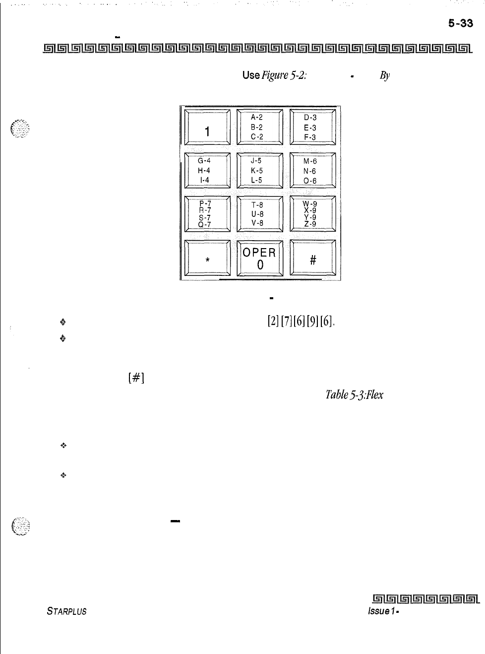
DIGITAL STATION OPERATION
Directory Dialing
-
Stations
2
Dial person’s last name on the keypad.
UseP@re5-2:
Key Pad
-
Dial
By
Name
below:
Figure 5-2: Key Pad
-
Dial By Name
+
Example: searching for the name BROWN, press
[Z]
[7]
[6]
[9]
[6].
0%
When the system finds a unique numeric match to the name being dialed, the call is placed to the
station matching the name. The intercom call signals the station according to the H-P-T button. If
fewer than 8 digits are dialed, the numeric match is dialed after a 10 second interdigit time-out
occurs, or if
[#]
is pressed.
*A Flex Button must be programmed for this feature to operate. Refer to
TaBZe5-j:FZex
Button Programming
Codes.
Conditions:
+
The system dials the station that matches the dialed name when a unique match is found. If multiple
names are located (found) after eight digits, the first one is dialed.
+
Names are entered as part of the system attributes database. Numbers may be entered as part of a
name. To avoid conflicts, all names must have a unique numerical sequence.
Directory Dialing
-
Stations
Directory dialing lets station users obtain a directory of station users and automatically dial the extension
currently displayed. The Triad-S System provides locations for up to 200 names.
STARPLUS
Triad-S Product Description Manual
issue
I
-
December 1998
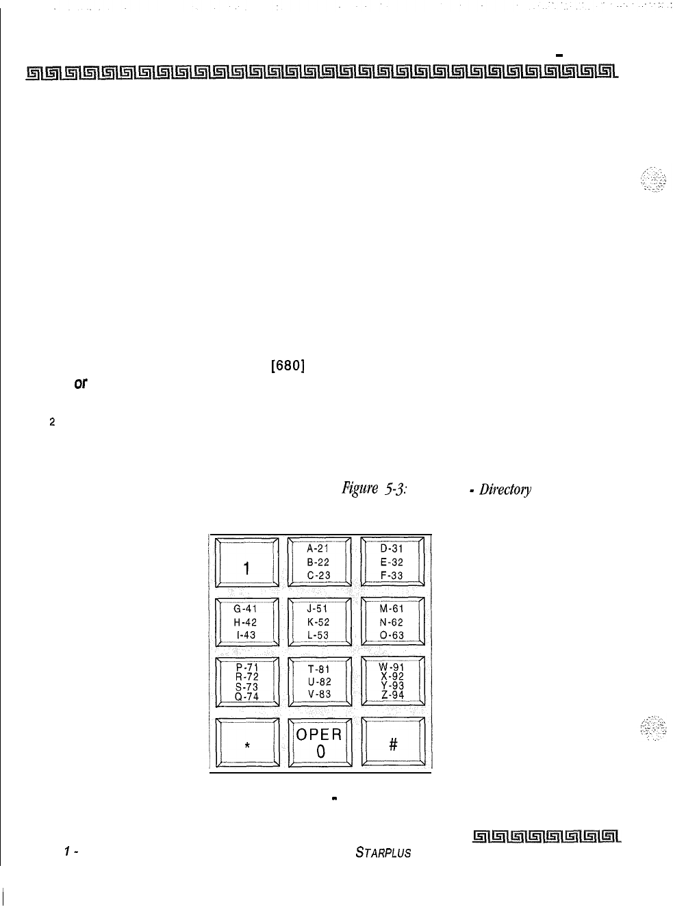
5-34 DIGITAL STATION OPERATION
Directory Dialing
-
Stations
Directory dialing also lets users program a name along with a speed dial bin for later locating a speed dial
number. When prompted, the system displays the name associated with a speed dial number on the LCD
display. When the desired name is shown, the user may have the system dial the number.
Directory dialing lets users associate a name with an entry in the local number/name translation table.
When prompted, the system display the name associated with the table on the LCD display. When the
desired name is shown, the user may have the system dial the number.
The Directory Dialing list may be programmed and maintained at the first assigned attendant station in one
of two ways. However this admin routine provides a means for maintaining the directory by the system
programmer either locally (at Station 100) or remotely, via modem access,
Directory dialing may also be used to transfer a call from one station to another.
To view the directory list:
1
Dial the Directory List dial code
[680]
on the dial pad,
Ol-
Press the pre-programmed* flex button programmed as a directory dialing button.
z
Press a button on the key pad once, twice or three times to represent the letter of the
alphabet to begin viewing the list of names (i.e., pressing 2 produces the names
beginning with A. Pressing 2 again produces the names beginning with B. Pressing 2 a
third time produces the names beginning with C). The letters of the alphabet are
represented on the key pad as shown below in
Figure
5-3:
Key Pad
-
Directory
Dialing.
Figure 5-3: Key Pad
-
Directory Dialing
Issue
I-
December 1998
STARPLUS
Triad-S Product Description Manual
DIGITAL STATION OPERATION
Directory Dialing
-
Stations
3
Names beginning with the letter chosen display on the LCD display.
/f
there are no names in the Directory List beginning with the desired letter,
a name with the next higher letter shows on the LCD
disp/ay
4
Dial [*] on the dial pad to scroll up (next entry) through the list,
or
Dial [#] on the dial pad to scroll down (previous entry) through the list,
or
Press another button to view the list for a different letter of the alphabet.
5
When the desired name is shown on the LCD display, press the SPEED button to
automatically dial the destination station or outside phone number (via speed dial).
Conditions:
+
If the desired party is an intercom station, that station is signaled according to it’s H-P-T switch (SLT
stations tone ring).
+
If the desired party is associated to a speed dial bin, the system selects a CO line and dials the
number programmed into the speed dial bin. Call progress tones are then heard.
a”
If a station is in the Directory Dialing mode and a CO or intercom call rings in, the station must exit
the Directory Dialing mode to answer the call.
To Transfer a call using Directory Dialing while on a call:
1
Press the TRANS button.
2
Dial the Directory Dial Code
[680]
on the dial pad,
or
Press a pre-programmed* flex button programmed for directory dialing.
3
Press the digit associated with the person’s name and when it displays, press the SPEED
button to automatically dial the destination station.
4
Hang up to complete the transfer.
Calls may be transferred to internal stations on/y, An attempt to transfer
a call
off
-net (via a speed dial bin)
result
in the call recalling upon going on-
hook.
*A
Flex Button must be programmed for this feature to operate. Refer to Table53:Fiex Button Programming
Codes.
STARPLUS
Triad-S Product Description Manual
issue
I- December 1998

1..
5-36 DIGITAL STATION OPERATION
Direct Inward System Access (DISA)
Direct Inward System Access (DISA)
1
Call the phone number the system administrator specified as the
DISA
line. The system
answers and returns internal dial tone.
--,..
2
Enter the
DISA
access code specified by the system administrator, if applicable. Dial
!.<:-‘$
.:
:.
-:
tone returns.
To place an outgoing call:
IDial a group access code: 9, 81-87. CO Dial tone returns.
z
Dial the desired telephone number.
The conference timer
will
monitor a DISA ‘trunk- to- trunk” call and release
the lines one (7) minute of ter the time expires.
3
To reach an internal station:
rl
Dial the
3-digit
station number.
Ringback
tone is heard.
5
Converse when party answers.
If
the station dialed is unattended, busy or in DND, intercom dial tone
returns, (after the Preset Call Forward Timer expires).
WARNING: Toll fraud can occur if DISA is not properly implemented.
Distinctive Ringing
The tone ring signal that notifies stations of an incoming call can be changed by each station user to provide
distinctive ringing among a group of stations. Each station user may select a distinctive ringing tone
used to
ring their station. The system provides
36
different ring patterns that station users may select from.
To select a distinctive ring tone for a station:
1
Dial the Tone Ring program code
(6951
on the dial pad. The following message is shown
on the display phone:
ENTER RING TONES
00-36
XX PRESS SPEED TO SAVE
issue
7
-
December 1998
STARPLUS
Triad-S Product Description Manual
DIGITAL STATION OPERATION
Distinctive Ringing
2
Enter the 2-digit tone number. The telephone speaker sounds a steady tone that
correlates to the 2-digit entry.
3
When the desired tone is selected (default ringing code is set to
00)
press the SPEED
button to save it as the tone to present when the station is tone rung. Confirmation tone
is heard. This tone is presented as a result of an incoming CO or intercom call, recalling
CO line or Transferred CO line or at any other time the station is tone rung. The 2-digit
tone number displays in the lower left corner of the LCD display.
The ringing choices are as follows:
STARPLUS
Triad-S Product Description Manual Issue I- December 1998
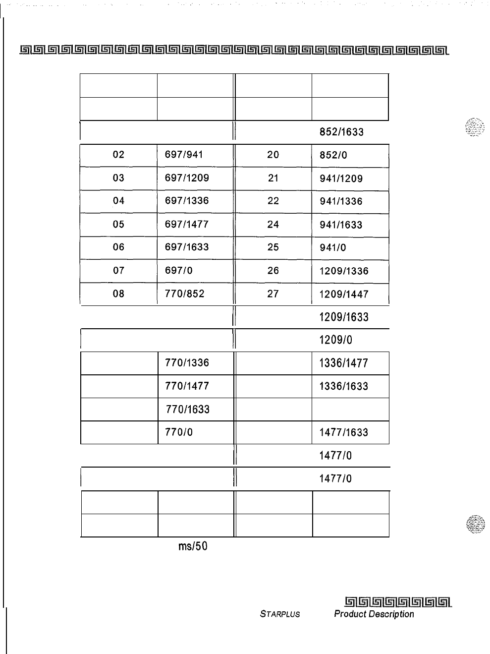
5-38 DIGITAL STATION OPERATION
Distinctive Ringing
TONE #FREQ TONE #FREQ
00
6971770
18
85211477
I
01
6971852
II
19
852/1633
I
I
09
7701941
/I
28 1209/1633
I
I
10
77011209
II
29 1209/O
1
11
770/1336 30 1336/1477
12
770/1477
31
1336/1633
13
770/1633 32
133610
14
770/O 33 1477/1633
I
15 8521941
/I
34
1477/o
I
I
16
85211209
II
35
1477/o
I
17
85211336 36
Off
23 94111477
Tone Duration = 50
ms150
ms
Table 5-2: Ringing Choices
lssue I- December 1998
STARPLUS
Triad-S
ProductDescription
Manual
DIGITAL STATION OPERATION
Do Not Disturb (DND)
Conditions:
+
Station users may listen to all tones by dialing the 2-digit codes one after another. The tone that is
sounding when the SPEED button is pressed is saved as that station’s tone ringing selection.
*:a
A station’s tone ringing selection is maintained in a battery protected area of memory, Therefore, if a
system experiences a power failure or a soft or hard restart, the tone ringing selection is restored.
+
The tone selected provides TONE ringing normal or muted to the station whenever the station is
commanded to tone ring (i.e., this excludes camp-on tone programming confirmation tones or
other specific tones not considered TONE ringing).
~4
The selected tone is used to notify the station in the following cases:
Incoming CO Call
Incoming Intercom Call
Transferred CO Line
Recalling CO Line
Call Back Notification
Message Wait Call Back
All types of forwarded calls
Executive/Secretary calls
Line Queue Call Back
LCR Queue Call Back
oCO distinctive ringing supersedes station distinctive ringing.
Do Not Disturb (DND)
DND blocks incoming paging and ringing, and provides visual status indication to other telephones with DSS
appearance. The DND code is
[631].
*Press the pre-programmed* DND button. DND button lights steady,
The DND button can be pressed while the phone is ringing to stop the ringing. (Refer to One-Time Do Not
Disturb below.)
Removing Do Not Disturb:
.:+
Press the pre-programmed* DND button or dial
[631],
The button LED extinguishes and DND
cancels.
Conditions:
oCalling stations will receive DND audible tone.
4th
The first programmed attendant does not have DND capability,
STARPLUS
Triad-S Product Description Manual
issue
I-
December 1998
I5-40 DIGITAL STATION OPERATION
Executive Override
Q
DND cpability is programmable on a per-station basis.
One-Time Do Not Disturb
Prevents calls from ringing at your station while you are on a call. The One-Time DND condition
automatically cancels when you end your call.
Q
Press the pre-programmed* DND button while you are off-hook and connected to a CO line or intercom call.
TheDND
button LED lights and off-hook tones at your station cancel.
To cancel:
+
Replace handset. The DND button LED extinguishes and DND cancels.
*A Flex Button must be programmed for this feature to operate. Refer to
Table5.?:FZex
Button Programming
Codes.
Executive Override
This feature enables Executive designated stations the ability to override and barge-in on other
keysets
engaged in conversation. Code is
16251.
If you call a busy station:
t
Press the pre-programmed* EXECUTIVE OVERRIDE button. Executive station is
bridged onto the CO line conversation in progress at the called station. Optional
warning tone is heard and presented to all parties prior to cut-through.
z
Replace handset at Executive station to terminate the override.
Conditions:
3An error tone occurs:
-
If the called party is in a conference.
-
If the called party is already on an OHVO call.
-
If the called party has
a Camp-On at
his
station.
+
If the Executive joins a call and one of the members does a hook-flash or presses his transfer
button, the Executive is dropped.
+
If the Executive does a hook-flash or presses his transfer button, it is ignored.
I”
When the Executive joins an intercom call or CO call and the Executive is not in a mute state, and
any member of the party hangs up, the call is converted to a two-party conversation.
Issue I
-
December 1998 STARPLUS
Triad-S Product Description Manual
DIGITAL STATION OPERATION
Executive/Secretary Pairing
+
When the Executive joins an intercom call or CO call and the Executive is in the mute state, and
either of the two parties in the intercom call hang up, the call is dropped. If the Executive hangs up,
the call remains a two-party conversation.
+
Certain forwarding types affect override operation.
+
Intercom button will disallow Executive Override.
*A
Flex Button must be programmed for this feature to operate. Refer to Table
5-.j:FZe.xButton
P~ogmmming
Codes.
Use of this feature when the Executive Override warning tone is disabled may be interpreted
as a violation of federal, state or local laws, and an invasion of privacy. Check applicable
laws in your area before intruding on calls using this feature.
A change in volume may occur on the CO line or intercom call after the
barge-in occurs.
Executive/Secretary Pairing
There are four sets of Executive/Secretary pairings available. When the Executive station is busy or in DND,
the Secretary station receives intercom calls and transfers. The Secretary station can signal the Executive in
DND by using the Camp-On feature.
Conditions:
If
you are designated the Executive station and your phone is busy or in DND, all calls are routed to
the Secretary station.
$If you are the designated Secretary station, you can signal the Executive that is busy or in DND by
using the Camp On feature.
Flash
When connected to an outside line:
‘_
2
-::.
c:--
“‘,;.
‘ii
‘:Y,*
oPress FLASH to disconnect outside line and reseize outside line dial tone.
STARPLUS
Triad-S Product Description Manual
issue
I- December 7998
5-42 DIGITAL STATION OPERATION
Flash On Intercom
Flash On Intercom
When connected to a page zone or another internal party, press FLASH to disconnect page or intercom call.
Intercom dial tone is heard.
Flexible Button Assignment
If you have buttons on your telephone that have NOT been assigned as CO lines, Pooled group, or Loop
buttons, you may program them to suit your own needs. This feature was enhanced in database
programming to allow programming of flexible buttons from a remote location (off-site). Range
programming can also assign these buttons to multiple stations. There are five possible functions you may
assign to these buttons:
DSS/BLF:
When this button is pressed, it automatically signals the assigned intercom station.
DSS/BLF
buttons are programmed by the station user.
FEATURES:
When this button is pressed, it activates a particular feature, thus eliminating the
need for dialing the feature code. Some features require a programmed flex button for that feature
to be accessible to the station user. In the case, it is designated in this Feature Operation Section
and user guide. Feature buttons are programmed by the station user. Refer to
Table
5-3:
Hex
Button Programming Codes
for a complete listing of code/features that may be programmed onto
a flexible button.
SPEED DIAL:
This button can automatically access a speed number location for one-step
operation. PBX and
Centrex
codes can be programmed into a speed dial bin and accessed by
pressing one button.
POOLED GROUP ACCESS:
A group of outside lines can be placed under one button. When this
button is pressed, the system selects an available line from this group on which the user may place
a call. Pool buttons are assigned in database administration.
LOOP:
This button appears as the direct button for outside lines that do not appear on the user’s
telephone. Any phone that does not have all lines appearing on it must have a loop button. There is
NO limit to the number of LOOP buttons a station may have. Loop buttons are assigned in database
administration.
UNASSIGN (Locked Out):
Specific buttons may be designated as locked out or unused. When a
button is unused, the button may not be programmed using flex button programming procedures.
To program flexible buttons:
1
Press the SPEED button twice.
2
Press the assigned button to program (it must be programmed in the database as a
multi-function button).
issue
7
-
December 7998
STARPLUS
Triad-S Product Description Manual
I
DIGITAL STATION OPERATION
Flexible Button Assignment
gg.3
w..;
3
Dial the desired code. Refer
toTable
5-.?:Flex
Butfou
Progmnzming
Codes.
To
erase a flexible button:
1
Press the SPEED button twice.
2
Press the button to erase.
3
Press the FLASH button. Confirmation tone is heard.
4
Replace handset or press ON/OFF button.
STARPLUS
Triad-S Product Description Manual
issue
I-
December 1998
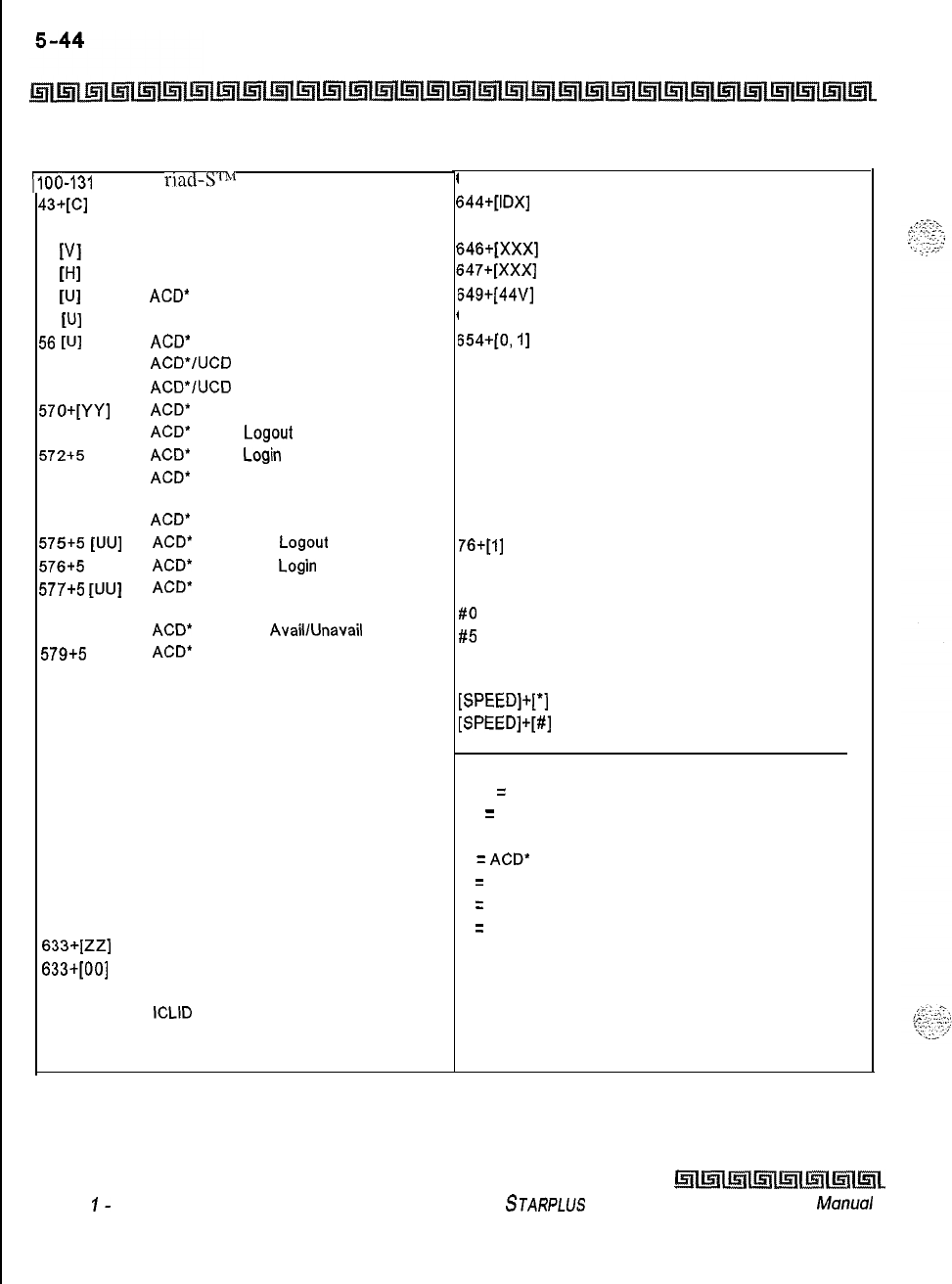
DIGITAL STATION OPERATION
Flexible Button Assignment
~100-131
‘I
riad-Sr”t
Ext. Numbers
43*[c]
438
44
[VI
45
WI
55
WI
55
WI
56
WI
566
567
57o+[YY]
571
572+5
[UU]
573
574
575+5
[UU]
576+5
[UU]
577+5
[UU]
578
579+5
[VU]
601
603
604
621
622
625
626
627
628
631
632
633*[ZZ]
633+[00]
634
635
639
641
Call Park Location l-7 (System)
Personal Park
Voice Mail Group Pilot Numbers O-7
Hunt Group Pilot Numbers O-7
ACD*
Group Pilot Numbers O-9
UCD Group Pilot Numbers O-7
ACD’
Group Pilot Numbers IO-15
ACD*/UCD
Available/Unavailable
ACD*/UCD
Calls in Queue Display
ACD*
Call Qualifier Code
ACD*
Agent
Logout
ACD*
Agent
Login
ACD*
Group Member Status
Display
ACD*
Agent Help
ACD*
Supervisor
Logout
ACD*
Supervisor
Login
ACD*
Supervisor Queue Status
Display
ACD*
Overflow
AvaillUnavail
ACD*
Calls in Queue Display buttons
Attendant Override
CO Line Off -Net Forward
Night Service
Line Queue
Call Back
Executive Override/
Monitor Barge-In
LCR Queue Cancel
Account Code Enter
OHVO Enable
Do Not Disturb
Background Music
Personalized Messages
Clear Personalized Messages
Headset Mode
ICLID
Display (unanswered calls
Incoming CO Call Transfer
Release button
I
I
I
I
I
I
I
I
I
I
,
I
I
I
643 Repeat Redial
544+[IDX]
645
646+[XXX]
647+[xxx]
649+[44v]
653
654+[0,
I]
680
695
70
71
72
73
74
75
76+[1]
77
9
#O
#5
[SPEED]+[YY]
[SPEED]+[*]
[SPEED]+[#]
Mailbox button
Intercom button(s)
Call Coverage (Ringing Type)
Call Coverage (Non-Ringing Type)
One-Touch Recording
Caller ID Name/Number Toggle
Answering Machine Emulation mode
Dial Speed Directory
Distinctive Ringing
All Call Page (Internal and External)
Internal Page Zone 1
Internal Page Zone 2
Internal Page Zone 3
Internal Page Zone 4
Internal All Call Page
External Page Zones
Meet-Me-Page Answer
Least Cost Routing (LCR) Access
Group Call Pick Up
Universal Day/Night Answer
Speed Dial Access
(00-19 Station) (20-99 System)
Save Number Redial
Last Number Redial
XXX
=
Station Extension Numbers
YY
=
Speed Dial Bin Numbers
ZZ = Personalized Messages
U
=
ACD*
(O-15) or UCD (O-7) Group Number
C
=
Call Park Location O-7
H
=
Hunt Group Number O-7
V
=
Voice Mail Group Number O-7
IDX = 001-255
l Features available with optional software.
Table 5-3: Flex Button Programming Codes
Issue
I-
December 1998
~~~~~~
STARPLUS
Triad-S Product Description
Manual
DIGITAL STATION OPERATION
Forward Override
Forward Override
This feature lets a user reach a busy station that is busy forward, no answer forward or all call forwarded.
This allows the calling station to call a forwarded station, OHVO, Executive Override, Monitor, Message Wait,
Camp On, or Call Back at that station rather than forwarding to the busy destination.
++
Dial [
5#
XXX] on the dial pad where XXX is the desired station extension,
Group Listening
All digital key stations have a built-in speakerphone. Station users may use the speaker to monitor a call
while using the handset to converse with the outside party. This enables other people in the room to listen to
both parties in the conversation.
$4
While conversing on the handset, press the ON/OFF button. Both parties can then be heard on the
digital station’s speaker. The speakerphone microphone is muted while the handset is off-hook.
To deactivate Group Listening while off-hook, press the ON/OFF button.
Conditions:
.;*
While using the speakerphone, lifting the handset turns off the speakerphone. To activate group
listening, press the ON/OFF button (to ON) while the handset is off-hook.
+
While in group listening mode, pressing the MUTE button causes the transmit from the handset to be
muted (the speakerphone microphone is already muted). However, the distant end is still heard over
the handset receiver and the station speaker.
+s
If full speakerphone operation is desired while in group listening mode, simply set the handset
on-
hook.
Q
Group listening is unavailable when the station is in headset mode.
+
When placing the handset on-hook to full speakerphone operation, it is normal for a to hear a squeal
caused by audio feedback. To eliminate this noise, press MUTE prior to initiating speakerphone
operation.
oMust be enabled in Station Programming.
STARPLUS
Triad-S Product Description Manual
Issue
I-
December 7998
DIGITAL STATION OPERATION
Headset Mode
Headset Mode
To activate Headset Mode:
+
Dial
[634]
on the dial pad,
or
Press pre-programmed* HEADSET MODE button. LED lights steady
While Headset mode is active, the ON/OFF button activates the headset
and disables speakerphone and intercom call announce operation at your
station.
NOTE: To install the headset, see the Installation Manual.
To deactivate Headset Mode:
*Dial
[634]
on the dial pad,
or
Press the pre-programmed* HEADSET MODE button. LED extinguishes.
Station must be programmed in database programming for headset oper-
ation before flex button can be programmed.
*A
Flex Button must be programmed for this feature to operate. Refer to Table53: FlexButton Programming
Codes.
Hold
-
Exclusive
When a line is placed on Exclusive Hold, no other station in the system can retrieve the call. Exclusive Hold
may be programmed for activation when the Hold button is pressed once or twice. CO Lines, while in a
transfer hold, are always placed in an Exclusive Hold condition.
Hot Keypad Feature
This feature enables a station user to activate the telephone by dialing digits without going off hook.
issue
I- December 1998
STARPLUS
Triad-S Product Description Manual
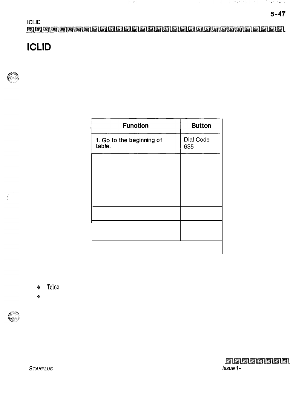
DIGITAL STATION OPERATION
ICLID Unanswered Call Management Table
ICLID Unanswered Call Management Table
An Unanswered Call Management Table with 100 entry capacity for the Triad-S System is maintained in the
system. The calling number/name information pertaining to any unanswered call is placed in this table at
the time the system determines the call was abandoned.
This table may be accessed from any user station display phone so the unanswered calls may be reviewed and handled
by the end user. Any Attendant station(s) can delete a table entry, one entry at a time. Upon entry into the review
process, the functions available to a phone are:
2. Review next item in table
entry.
MUTE
3. Step to next table entry.
HOLD
4. Delete this table entry.
(attendant only)
FLASH
5. Exit table review function.
ON/OFF
6. Step to previous table
entry. TRANSFER
7. Call Back. SPEED
Table 5-4: ICLID Unanswered Call Management
Conditions:
o
Telco
must activate Caller ID service.
+P
Auto Attendant calls are considered answered.
STARPLUS
Triad-S Product Description Manual
issue
7
-
December 7998
I5-48 DIGITAL STATION OPERATION
Incoming CO Call Transfer
Incoming CO Call Transfer
This feature lets station users transfer a call that is currently ringing at their station without answering it.
This feature is unavailable to Single Line Telephone users.
While station is idle:
1
Call rings in at idle station.
2
Press the pre-programmed* INC CO XSFR flexible button,
Of
Dial the Incoming CO call transfer code
[639]
on the dial pad.
3
Press a DSS, Group button or dial the 3-digit station number or group number. Call is
automatically transferred to that destination.
While on an internal/external call and an incoming or transferred CO call is ringing at your station:
1
Place the current call on hold.
z
Press the pre-programmed* INC CO XSFR flexible button,
or
Dial the Incoming CO call transfer code
[639]
on the dial pad.
3
Press a DSS, Group button or dial the 3-digit station number or group number. Call is
automatically transferred to that destination. The incoming transferred CO call
receives Music-On-Hold during the transfer state.
4
Station user can return to call placed on hold.
*AFlex
Button must be programmed for this feature to operate. Refer to
TabZe5-3:FZexButton
Programming
Codes.
Conditions:
+
Calls may be forwarded to any available station,
ACD/UCD
group, Hunt Group or VM Group.
+
Destination station must have a direct appearance for that CO Line or Loop button, and not in DND,
or error tone is presented to the originator and the call remains ringing at his station.
+
Attendant stations do not send ID digits.
o
ACD agents are not allowed to transfer ACD calls using this feature.
Intercom Buttons
This feature enables station users the ring a busy station via the intercom without using the Camp-On or
Executive Override features. This allows stations to place intercom calls on hold.
Issue I
-
December 1998 STARPLUS
Triad-S Product Description Manual
. .
DIGITAL STATION OPERATION
Intercom Buttons
5-49
To program a flexible button as an intercom button:
1
Press the SPEED button twice.
2
Press the desired flexible button to program.
3
Dial
[645]
on the dial pad. Confirmation tone is heard. If an error was made during entry,
error tone is heard.
You place an intercom call to a busy station that has an intercom button:
1
The calling station receives
ringback
tone instead of busy tone. The called station hears
muted or reminder ring and their intercom button LED starts flashing at the incoming CO
line rate. This indicates an incoming intercom call.
z
The called station can place the current CO call on hold by pressing the HOLD button,
Of
Place the current intercom call on hold by pressing the HOLD button. The intercom call is
placed on hold on the available intercom button.
3
The called station then presses the flashing intercom button to answer the incoming
intercom call. Once the call is answered, the following message displays on the called
station LCD:
CALL FROM STA XXX
MMM DD YY HH:MM:SS
Sta
Xxx
can be a programmed station name.
By default, no intercom buttons are assigned to key stations
Conditions:
oIf calls are ringing on intercom buttons and a Handsfree call is received, the Handsfree call is allowed
and the calls ringing continue with muted ringing.
Q
Multiple intercom path buttons can be assigned to a single station, however up to five internal parties
can be placed on hold per station. Music-On-Hold is provided to the intercom caller on hold.
+
Once an intercom button is set up on the
keyset,
callers dialing that station will always receive
ringback tone as long as an available intercom button is idle. If all intercom buttons are in use, the
station may utilize the camp-on or executive override features to reach the station. Internal callers
are dropped after the camp-on is answered.
oThis feature can be programmed on any key station or DSS Console with an available flexible button.
If there is an available intercom button, the following actions cannot be performed: Executive
Override, ACD Supervisor Barge-In, OHVO, Camp-On or Override.
+
A call ringing to a station on an intercom button rings muted or reminder ringing, depending on the
stations tone ringing cadence.
STARPLUS
Triad-S Product Description Manual Issue I- December 1998
5-50 DIGITAL STATION OPERATION
intercom Calling
Q
Up to five internal parties can be placed on hold. No recall timers apply to Intercom buttons.
Internal callers can be placed and removed from hold when they appear on an Intercom button.
0%
To utilize the capability of intercom buttons, busy forward cannot be active at the station.
“P
A call ringing to a station on an intercom button and the DND button is pressed, returns DND tone
to the caller and the call is dropped.
*A Flex Button must be programmed for this feature to operate. Refer to
TubZeS-3:FZexButton
Progrumming
Codes.
Intercom Calling
Placing an Intercom Call:
1
Press the DSS button of the party to be called (if programmed at your phone),
or
Dial the 3-digit extension number.
Dialing a number in the numbering plan activates the telephone automati-
cally.
2
You hear ringing if the called station is in the T answering mode; or three bursts of tone
if called station is in the H or P position.
3
Lift the handset or use the speakerphone after the three tone bursts stop.
4
Hang up to end the call.
Answering an Intercom Call:
With your H-P-T button in the T mode (LED On), you hear repeated bursts of intercom tone ringing and the
HOLD button slow flashes.
1
Lift the handset or press the ON/OFF button to answer,
or
Press the H-P-T button to the H mode (No LED) to reply.
2
Replace the handset to end the call.
In the P mode (LED flashes at
30
ipm), you hear three bursts of tone and one-way announcement, The
calling party cannot hear conversations in progress.
+
Lift the handset or press the ON/OFF button to answer,
01
Press the H-P-T button to the H mode to reply
issue
I- December 1998
STARPLUS
Triad-S Product Description Manual
DIGITAL STATION OPERATION
Intercom Transfer
In the H mode (No LED), you hear two bursts of tone and an announcement, Reply handsfree or lift the handset
for privacy.
6
zg2
Intercom Transfer
‘2...=t
. .
Intercom transfer without DSS buttons:
1
Receive or make an intercom call.
2
Press the TRANS button. Intercom dial tone is heard.
s
Dial the station.
4
When the second station answers, you are in a supervised transfer mode (first station is
staged for transfer).
5
Hang up (stations 1 and 2 are connected).
Intercom transfer using DSS buttons:
1
Receive or make an intercom call using a DSS button.
2
Press the TRANS button. Intercom dial tone is heard.
s
Press the DSS button where to transfer the call.
*1
Hang up (stations 1 and 2 are connected).
Keyset Mode
This feature lets a station user determine the mode and baud rate of the optional
CT1
Module connected to
their phone. This setting is stored in back-up memory in the event of a power outage or system reset.
At an idle station:
1
Dial the
Keyset
Mode code
[648]
on the dial pad,
Or
Press the pre-programmed*
KEYSET
MODE button. The display shows the following
information:
INACTIVE
MODE=%
SAVE=HOLD
BAUD=#
2
Press
[*]
to scroll through the
keyset
modes. The available modes are: Inactive, PC
Phone, ATD Command, ATH Comm and CKTU.
s
Press [#] to scroll through the baud rates. Available baud rates are: 1200, 2400, and
4800.
4
Press the HOLD button to save the desired entries.
STARPLUS
Triad-S Product Description Manual Issue I- December 1998

5-52 DIGITAL STATION OPERATION
Last Number Redial (LNR)
When the telephone is set to the AT command mode, the following AT commands are supported:
+s
ATD:
This is the modem dialing command. The telephone recognizes the ATD and accepts digits
after the command.
-e
ATH
or
ATHX:
Where X = 0 or 1. This is the modem on hook/off hook command. ATH or
ATHO
forces the telephone to the on hook state from it’s current state.
ATHl
forces the telephone to the
off hook state from it’s current state.
If the handset is off hook
(/if
ted), these commands are discarded and no
action is taken by the telephone.
+z+
AT or ATW:
Where X = 0 or 1. This is the modem reset/initialize command. Whenever these
commands are sent to the
keyset,
the
keyset
returns OK in ASCII format.
o
CKTU:
This mode is used when the optional Wanderer (cordless key telephone unit) is connected
to the station. Refer to the Wanderer User Guide for additional information.
Conditions:
9*
The telephone must be in the AT command mode to process AT commands.
oAll
CT1
information is still sent out the RS232 port in the AT command mode.
+
These access codes are assigned to available flexible buttons for feature activation.
-z+
The ATD command is always accepted by the telephone while it is in the AT command mode. ATHX
is accepted only if enabled.
+z+
AT2
is always enabled if the station is in the AT command mode.
+
ATD accepts W to indicate a pause command.
+
ATH or
ATHO
causes an on hook event.
ATHl
must be specified to go off hook.
+z+
Default mode is inactive.
*AFlex
Button must be programmed for this feature to operate. Refer to Table53:FZexButton Programming
Codes.
Last Number Redial (LNR)
1
Press the SPEED button.
2Press
[#I,
The last number dialed over an outside line is automatically redialed.
+
The system automatically selects the original line used to place the call and redials the
number.
Issue I- December 1998
STARPLUS
Triad-S Product Description Manual
DIGITAL STATION OPERATION
LCD Display
-
Contrast
+
If that line is busy, the system automatically selects another line from the same group and
redials the number.
+S
If no lines are available in the same group, the station receives busy tone and can queue for a
line.
9If the station user preselects a line before activating LNR, the preselection overrides the line that
was used originally.
LCD Display
-
Contrast
There are four contrast adjustments available to the user to adjust the LCD for different lighting levels, At idle
phone:
1
Press volume bar up or down for desired effect.
Conditions:
+
BGM must be inactive.
oHandset must be in cradle.
Q
ON/OFF button must be set to OFF.
Least Cost Routing (LCR)
To place an outside call when LCR is enabled in the system:
1
Dial
[9]
on the dial pad.
2Dial the desired telephone number.
3Wait for an answer. Lift handset or use the speakerphone to converse.
If all available lines are busy, remain off-hook for four seconds to automatically be queued onto LCR for an
available line, then hang up.
If an LCR Queue Callback is activated:
1
When telephone is signaled, answer the call.
2Desired telephone number is automatically redialed.
Only one
LCR
Queue Call
Back
request may
be initiated by
a
station.
When
a second request is made, the
first
request is cancelled.
STARPLUS
Triad-S Product Description Manual
issue 1
-
December 1998
5-54 DIGITAL STATION OPERATION
Mailbox Buttons
If an LCR Queue Callback is activated and you wish to cancel that callback request:
IDial the LCR Queue Cancel code,
[626]
on the dial pad.
2
Replace handset or press ON/OFF button.
Mailbox Buttons
This feature lets station users program specific mailbox index numbers onto flexible buttons at their station
or DSS Console. Users can then transfer internal/external callers to specific Voice Mail Groups or Mailbox
numbers.
These Voice Mail Groups or Mailbox numbers are programmed in admin programming. Up to
255
mailbox buttons per system are allowed.
To program a flexible button for a mailbox button at a station:
1
Press the SPEED button twice.
2
Press the desired flexible button to program.
3
Dial
[644]
on the dial pad followed by the 3-digit VM Index number (001-255).
Confirmation tone is heard. If an error was made during entry, error tone is heard.
To use your mailbox button while on an internal/external call:
+z+
The called station presses the Mailbox flexible button and goes on-hook. The call is then transferred
to the VM port by the telephone system.
By default, no mailbox buttons are assigned to key stations.
Conditions:
G
This feature can be programmed on any key station or DSS Console with an available flexible
button. If a station is an
OHVO,
Camp-on or Executive Override initiator, they may not use the
mailbox button feature.
-+
Stations engaged in a conference cannot use this feature.
*:.
If no station(s) are programmed in the Voice Mail Group, the user receives error tone.
+
Mailbox buttons interact with the station VMID feature as follows:
-
VM transfer with ID (manually enter digits) = No station VMID.
-
VM transfer with ID (press DSS button) = Use station VMID.
-
Mailbox button feature
=
No station
VMID.
*A Flex Button must be programmed for this feature to operate. Refer to Table53;FlexButton Programming
Codes.
i...
>.<
/
.--
.!
&
,.,:
-*.
.
,_
.
--
..,
,....,.
Is,
.,_
Issue I- December 1998
STARPLUS
Triad-S Product Description Manual
I
DIGITAL STATION OPERATION
Meet Me Page
Meet Me Page
To request another party to meet you on a page:
1
Dial the desired 2-digit or 3-digit paging code,
or
Press pre-programmed* PAGING button.
2Request that party meet you on the page.
3Do not hang up, wait for the requested party to answer. As soon as the paged party
answers and is connected to you, the page circuit releases.
Answering a Meet Me Page
+
Go to the nearest telephone and dial
[77]
on the dial pad,
or
Press the pre-programmed* MEET ME PAGE ANSWER button. You are connected to the paging party
*A Flex Button must be programmed for this feature to operate. Refer to
Table j-3:FZex
Button Programming
Codes.
Message Waiting
Leaving a Message Waiting Indication:
If you dial a station that is busy, unattended, or in DND, you can leave a message waiting indication.
1
Lift handset or press ON/OFF button.
2Dial the desired intercom station.
3
Press the MSG button. Confirmation tone is heard. Called party’s MSG button slow
flashes.
4Replace the handset or press the ON/OFF button to end the call.
Up to five messages can
be
left at any Station.
Answering a Message Waiting Indication:
If your MSG button is lit, you have a message waiting for you. The first message left is the first one called.
1
Press the MSG button. Station that left message is signaled with tone ringing.
2If called station does not answer, press MSG button once to leave message.
STARPLUS
Triad-S Product Description Manual Issue I- December 1998
I
...
5-56
..
..:.
DIGITAL STATION OPERATION
Mute Key
Mute Key
The MUTE button provides privacy during speakerphone or handset operation by disabling the microphone.
1
Press the MUTE button while off-hook on speakerphone or handset to activate.
2
Press the MUTE button again to deactivate.
The mute feature automatically deactivates upon call termination.
Night Service Feature
The Night Service feature
[604]
will provide a means to put the system in night mode from any
keyset
or
remove
the system from night mode from any
keyset
as long as the system was put in night mode by the
Night Service feature flex button. If the system was placed in night mode by the attendant using the Night
Service (DND) button or if the system was placed in night mode by the automatic schedule, the Night
Service flex button can not remove the system from night mode.
From an idle station:
oPress the pre-programmed* Night Service flex button. The system is now in the Night Service Mode.
To remove the Night Service Mode:
+
Press the pre-programmed* Night Service flex button again. The system is now removed from the
Night Service Mode.
*A Flex Button must be programmed for this feature to operate. Refer to TabZe53:Hex Button Programming
Codes.
Off -Hook Preference
If your phone has been programmed for Off-Hook Preference, you will access an outside line, or a feature
by going off-hook or pressing the ON/OFF button. It simulates the depression of a specific button and can
be programed by a station user or a database administration programmer. Code
[691]
+ Button Number.
While Off-Hook Preference is enabled, you may access internal intercom dial tone by:
1
Pressing the pre-programmed* ICM button,
_
.-..
i’
‘:
.:,
or
I.
. . , ,
1
,...
..-. I
Dial your 3-digit intercom number. (Do not lift handset or press ON/OFF button before
.
.a:.-.
dialing intercom number.) LED lights steady and intercom dial tone is heard.
z
You may now dial an internal station or Feature Access code.
Issue I
-
December 1998 STARPLUS
Triad-S Product Description Manual
DIGITAL STATION OPERATION
Off -Hook Voice Over (OHVO)
*A Flex Button must be programmed for this feature to operate. Refer to Table53;FZex
Button
Progwnming
Codes.
F-T
..
1::
Off -Hook Voice Over (OHVO)
.y:>;.
This feature enables users, off-hook on a call (CO or Intercom), receive a voice announcement through the
handset receiver without interrupting the existing call. The Voice Over is muted so it does not override or
drown out the existing conversation. The overridden party may then talk to the calling party, using CAMP-ON
procedures, or use Silent Text Messaging to respond to the calling party via LCD Displays,
Placing an Off-Hook Voice Over (OHVO) call:
When an OHVO station calls a busy OHVO station, and busy tone is received:
1
The calling OHVO station dials the OHVO code
[628]
on the dial pad,
or
Presses a pre-programmed* OHVO button to initiate an OHVO announcement, The
HOLD button LED flashes at the called OHVO station.
2
The OHVO receiving station receives a one-beep warning tone. The station receiving
the OHVO call must be off-hook and in H mode, then the calling OHVO party may begin
the voice announcement to the called OHVO party. The called OHVO station’s existing
conversation is uninterrupted and the voice over announcement does not drown out the
existing conversation. The calling OHVO station is not connected to or otherwise able to
hear the called station’s conversation (the connection only allows the calling station to
transmit to the called station).
The ca/ling station is placed in a one-time
ON0
mode upon initiating the
Voice Over. One-Time DND cannot be toggled during the OHVO call. The
station receiving the OHVO call must be off-hook and in H mode.
Responding to an Off-Hook Voice Over
(OHVO):
After receiving an OHVO announcement, three options are available to respond to the calling party:
Option 1:
This method lets the receiving station respond to an OHVO announcement utilizing the
MUTE feature button. This button is pressed to carry on a two-way conversation with the OHVO
initiator while still listening to the original call.
Option 2:
The OHVO receiving station may respond to the calling station by using the Silent Text
Messaging (this feature is only available to digital key terminals, and the calling station must be a
digital display terminal.) The
OHVO
receiving station may press a pre-programmed Message button
STARPLUS
Triad-S Product Description Manual
issue
I-
December 1998
I
5-58
DIGITAL STATION OPERATION
Off -Hook Voice Over (OHVO)
to respond to the voice over announcement without being released from the current call, (i.e. by
pressing a flex button pre-programmed for the message IN MEETING), the calling station receives
this message on the LCD display
Option
3: The OHVO receiving station may respond to the calling OHVO station by using the Camp-
On feature. The OHVO receiving station presses the flashing HOLD button to consult with the calling
station, The existing call (CO line) goes on Exclusive Hold automatically. This method then follows
Camp-On procedures and operation.
Conditions:
+
The station receiving the OHVO call MUST be off-hook and in H mode.
+z+
The receiving station must have OHVO enabled.
.a
When the dialed station responds via Camp-On, all conditions and options available to Camp-On
apply (refer to the feature description for Camp-On).
+
OHVO may be used to notify the called party of a transferred call (CO Line or Intercom) by
announcing the call, then releasing to complete the transfer. When this occurs, the receiving station
need not respond to the
OHVO.
o
When a call is transferred via OHVO, the receiving station receives muted ringing after the transfer
is complete.
Q
Any messages including CANNED, CUSTOM, or SILENT RESPONSE text messaging may be used to
respond to an OHVO call. The message appears on the calling station and called station LCD
displays.
0%
If the calling station is a non-LCD terminal, the called station receives error tone when responding
via text messaging.
+
The called station may press a flex button programmed as a Text Message button,
[633
+
#],
Press
this flex button and dial the 2-digit message number
(31-51)
to respond to the calling station.
DTMF digits are not heard by either party
oThe receiving station must be programmed to allow OHVO calls.
+
When silent messaging is used to respond to an OHVO call, the existing call on the called station is
not disconnected while the messages are being sent to the calling station,
Q
The calling station of an OHVO call must remain off-hook to receive silent messages. The calling
station’s voice transmit remains connected to the called station and may respond verbally to the
text messages. The OHVO call ends when the calling station goes on-hook.
Q
If the receiving station is on-hook in speakerphone mode and a calling party initiates OHVO, the
receiving station receives a Camp-On warning tone and normal Camp-On procedures are followed.
Issue
I-
December 1998
STARPLUS
Triad-S Product Description Manual
,
.
:-
DIGITAL STATION OPERATION
One-Touch Recording
g*
The called station may send a message, and then press MUTE to talk to the calling station. Each time
a message is sent, the splash tone is heard and both displays are updated.
9
LEDs
follow Camp-On LED lamp sequences.
Q
OHVO will not function if the busy station is in the Group Listening Mode.
One-Touch Recording
This feature lets the station user, while on an internal/external call, press a button to have the system record
the conversation into the station users mailbox. Code
[649 44X],
where X= O-7 for desired VM group.
Use of this feature when the One-Touch Warning Tone is disabled may
be interpreted as a violation of federal, state or locallaws, and an invasion
of privacy. Check applicable laws in your area before recording calls using
this feature.
While on an internal/external call:
In.
The LED flutters red
1
Station user presses the pre-programmed* VM RECORD
butta
at 240 ipm during the set up and the following message displays:
RECORDING SETUP
MMM DD YY
oo:oo:oo
2
Once the system connects to the station, the user’s mailbox, the flexible button LED
lights solid green and the LCD displays:
RECORDING
MMM DD YY
oo:oo:oo
3
When the user finishes recording, press the pre-programmed* VM RECORD button. The
LED extinguishes and the normal LCD call information displays.
Conditions:
Q
If the user hangs up without terminating the record function, the system performs the exit
procedure as described in step
3
above.
+If the user presses the TRANS, CAMP-ON, MSG, or FWD buttons during recording, pressing the button
is ignored.
0%
During the recording setup, pressing the CONF button is ignored.
STARPLUS
Triad-S Product Description Manual Issue I- December 1998
5-60 DIGITAL STATION OPERATION
Outside Call
-
Answer
If no VM port is available when the station user wants to record, the user receives the following
display (lasts six seconds):
RECORDING UNAVAILABLE
MMM DD YY
oo:oo:oo
The user may retry after the display extinguishes.
In the recording mode, pressing the CONF button lets the user add members to the recording
(conference). Normal conference operation/conditions apply.
If an internal station is being recorded, the internal station receives a CONFERENCE LCD message
and the CONF LED lights.
If the FLASH or HOLD button is pressed during the recording, the recording is terminated.
If a station user presses the record button while in a two-party conference, the conference is
recorded. If the button is pressed a second time, the conference ends and the call is returned to a
two-way conversation.
Only one active recording per station is allowed.
If a recording is done to another internal station, the station being recorded cannot invoke the
record feature.
If a conference is being recorded and the conference master exits, the recording stays active. The
recording stops if the initiator re-enters the conference and ends it, removes the record function, or
the conference ends on it’s own.
Only the initiator of a conference can invoke/remove the record function during a conference.
Conference Warning Tone is not given to the conference members, if the initiator is recording the
conference and the record tone is disabled.
Recording is not allowed for a station that is barged in, Executive Overridden, or on an active OHVO
call.
An unsupervised conference call can be recorded.
*AFlex
Button must be programmed for this feature to operate. Refer to Table53;FlexButton Progmmning
Codes.
Outside Call
-
Answ
1
Lift handset or press ON/OFF button.
2
Press slow flashing outside line button or Loop button. (If your telephone is
programmed with Preferred Line Answer, you may answer an outside line by lifting the
handset, or pressing the ON/OFF button.)
Issue
I-
December 1998 STARPLUS
Triad-S Product Description Manual
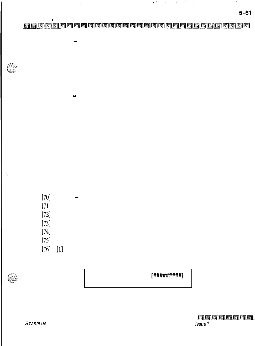
DIGITAL STATION OPERATION
Outside Call
-
Place
Outside Call
-
Place
1
Press outside line or Pool button. ON/OFF button LED lights and dial tone is heard.
2
Dial the desired party.
3
When called party answers, lift handset to converse or use speakerphone.
Station user may also dial the individual trunk group access code to access an outside line.
Outside Call
-
Place on Hold
1
If your system is programmed for Exclusive Hold Preference, press HOLD button once
for Exclusive Hold and twice for System Hold.
2
If your system is programmed for System Hold Preference, press HOLD button once for
System Hold and twice for Exclusive Hold.
Paging
If you were given the ability to make page announcements:
1
Lift handset or press ON/OFF button.
2
Dial the 2-digit or 3-digit paging code,
or
Press pre-programmed* PAGE button.
[70]
= All Call
-
Internal and External
[71]
= Internal Zone
1
[72]
= Internal Zone 2
[73]
= Internal Zone 3
[74]
= Internal Zone 4
[75]
= Internal All Call
[76]
+
[l]
= External Page
3
Stations receiving a Page Announcement can press the Volume Bar to change the
paging volume. The following message is shown on the display phone:
SPEAKER PAGE
MMM DD YY
[#########J
HH:MM am
STARPLUS
Triad-S Product Description Manual
issue
I-
December 1998
I
..
..-.
5-62 DIGITAL STATION OPERATION
Park
-
Personal
Stations
off
-book or in DAD
do
not hear the internal page announcement.
When making a zone page or
All
Call page and the zone is busy, the page
initiator receives ring back tone until the zone becomes available. You then
hear a warning tone and can make the page announcement.
External paging requires op
tiond
hardware.
*AFlexButton must be programmed for this feature to operate. Refer to Table53:FZexButton Programming
Codes.
Park
-
Personal
Each station in the system can place a call to a personal park location and later retrieve that call from the
originating station.
While connected to an outside line:
1
Press the TRANS button. The caller is put on Exclusive Hold.
2
Dial the Personal Park location
[438]
on the dial pad,
or
Press the pre-programmed* PERSONAL PARK button. Dial tone is heard.
When dialing the personal park location and it is already occupied, the
initiating station receives the previously parked call and the second call is
parked.
Retrieving a Parked Call:
I*
Dial the Personal Call Park location code
14381
on the dial pad,
or
Press the pre-programmed* PERSONAL PARK button. A talk path is established between the two
parties.
Conditions:
+
Intercom calls and CO line calls can be placed into the station’s personal park location.
Q
Calls parked in a personal park location are subject to the system call park recall timer.
*a
A CO call parked in a personal call park location recalls to the station that parked the call, when the
call park recall timer expires. The CO call rings to this station until the system hold timer expires.
The CO call then recalls the attendant(s) (at this point, the attendant station and the initiating
Issue 1
-
December 1998 STARPLUS
Triad-S Product Description Manual
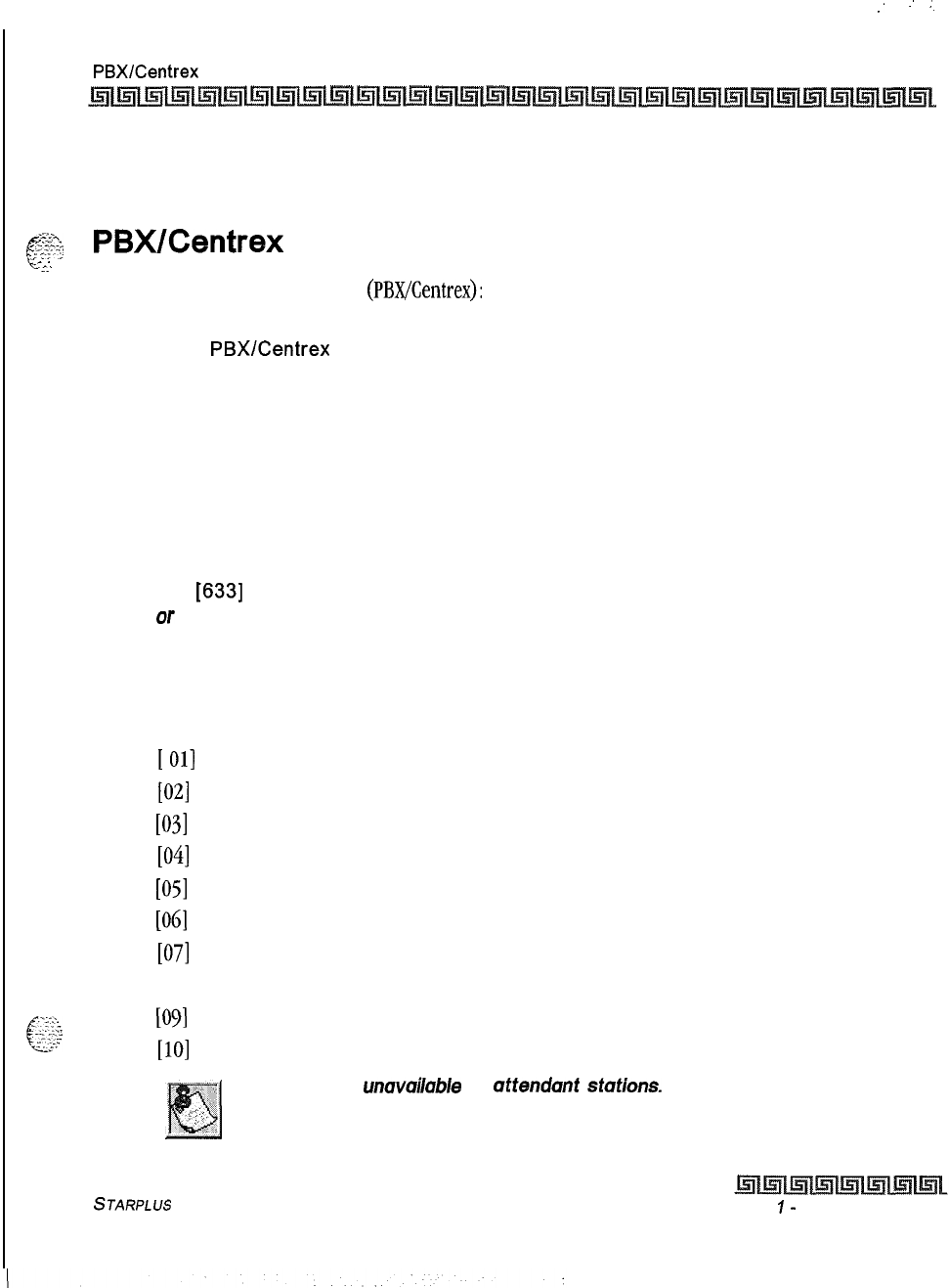
I
:
:
:.
DIGITAL STATION OPERATION
PBX/Centrex
Transfer 5-63
station are ringing), and the attendant recall timer is initiated. When the attendant recall timer
expires, the CO call is disconnected.
.-w-.
c
;~s:
PBX/Centrex
Transfer
-<I.
,
While connected to an outside line
(PBX/Centrex):
1
Press the FLASH button. Receive transfer dial tone.
2
Dial a
PBX/Centrex
station number.
3
Hang up to complete the transfer.
Personalized Messages
Each station can select a pre-assigned message to display on the LCD of any key telephone calling that
station.
There are ten possible messages that can be left.
1
Dial
[633]
on the dial pad,
Of
Press a pre-programmed* MSG button.
2
Dial the 2-digit code for the message that displays. Confirmation tone is heard and the
DND button LED flashes.
[00] = clear messages
[
011 = ON VACATION
[02]
= RETURN AM
[03]
= RETURN PM
[04] = RETURN TOMORROW
[05] = RETURN NEXT WEEK
[ob]
= ON TRIP
[07]
= IN MEETING
[OS] = AT HOME
.._~
._..
_
.._
k&G
[09]
= ON BREAK
. . .
[lo]
= AT LUNCH
This feature is unavuiloble at uftendunt stutions.
STARPLUS
Triad-S Product Description Manual Issue
I-
December 1998
5-64 DIGITAL STATION OPERATION
Personalized Messages
Messages
-
Custom
Each station can select from ten possible custom messages to display on the LCD of a key telephone calling
that station. These messages are programmed from the first attendant station.
1
Dial
[633]
on the dial pad,
Of
Press a pre-programmed* MSG button.
2
Dial the 2-digit code (21-30) for the desired custom message. The first attendant
should provide a list of messages to each station user.
Conditions:
9This feature is not available to attendant stations.
Date and Time Entry on Personalized Message
Station users can activate certain messages that let users enter a specific time or return date. These
messages appear on the calling station’s display to alert them of the desired party’s return time or date.
To activate a message with a custom return time or date, the station user:
IDials the Message Access code
[633]
on the dial pad.
2
Then dial the desired message number [II
-
171.
Users may activate the following messages and be prompted to enter a return time or date:
[ll]
=
VACATION UNTIL:
MWDD
[12]
=
RETURN:
HH:MMxm
or
MM/DO
[13]
= ON TRIP UNTIL:
MM/DD
[14]=
MEETING UNTIL: HH:MM xm
[15]
=
AT HOME UNTIL:
/-//-/:MM
xm
[16]
=
ON BREAK UNTIL: HH:MM xm
[17]
=
AT LUNCH UNTIL:
HH:MMxm
s
Enter the date/time using buttons on the dial pad as shown in
TnbZe5-5:0&r
Key
Pad
Codes.
Issue I- December 1998
STARPLUS
Triad-S Product Description Manual
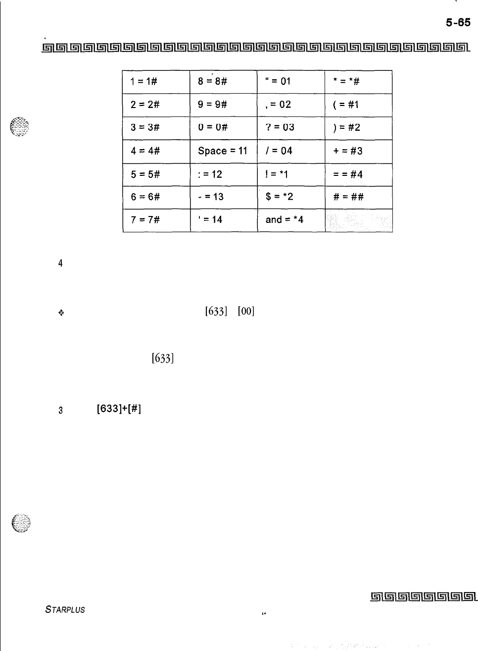
.
DIGITAL STATION OPERATION
Personalized Messages
Table 5-5: Other Key Pad Codes
4
Press HOLD to enter message. Confirmation tone is received and DND button LED
flashes.
To cancel the message:
.:+
Dials the Message Access Code
[633]
+
[OO]
and replaces handset. DND button LED extinguishes.
Personalized Message Code on a Flex Button
You can program the code
[633]
onto a flexible button to speed access of pre-selected messages.
1
Press the SPEED button twice.
2Press the desired flex button. LED flashes.
s
Dial
[633]+[#]
on the dial pad. Confirmation tone is heard. The user can now press that
flex button and dial the 2-digit message number (00-IO), or the 2-digit custom message
number (21-30) to activate the message. Confirmation tone is heard and DND button
LED flashes.
STARPLUS
Triad-S Product Description Manual
._
Issue I- December 1998
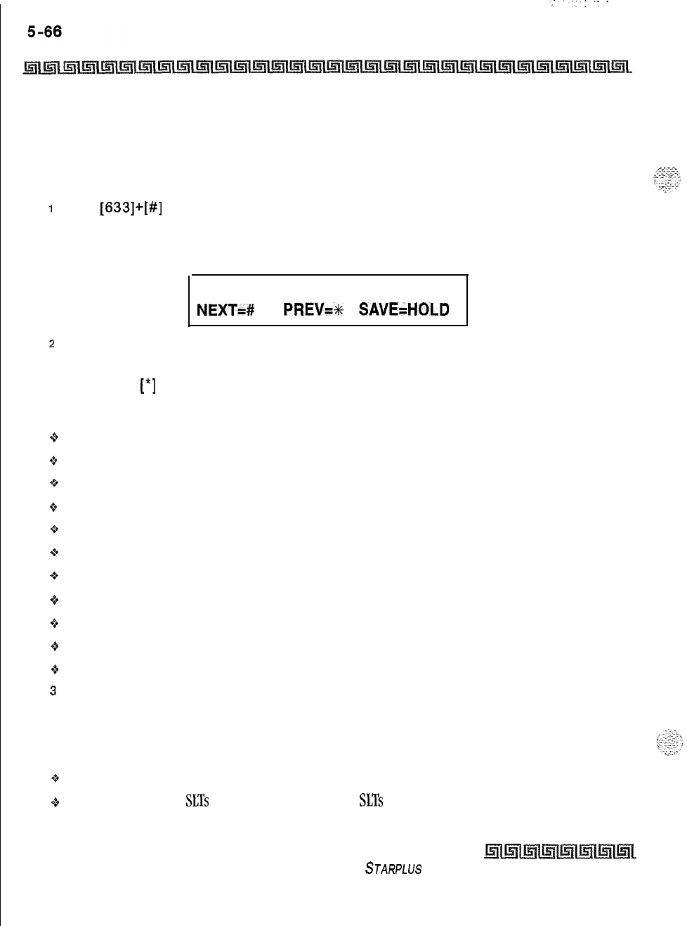
DIGITAL STATION OPERATION
Personalized Messages
Scrollable Canned Messages
This feature lets the user use a single digit to scroll through the messages and select one. This feature
operates when the phone is in idle mode only and cannot be activated if the station is in Call Forward or
DND mode(s). This feature is unavailable at attendant stations.
1
Dial
[633]+[#]
on the dial pad,
or
Press the MSG button. Clear Messages is always first. The following message displays
on the LCD phone:
CLEAR MESSAGES
NEXT=# PREV=x
SAVE=HOLD
2
Press [#] to scroll through the messages,
or
Press
[*]
to scroll backward through the list.
Scroll forward through the messages in the following order. The scroll is a rolodex type scroll.
+ CLEAR MESSAGES
o
AT HOME
8 AT LUNCH
+:+
IN MEETING
+t+
ON BREAK
9*
ON TRIP
“*
ON VACATION
<+
RETURN AM
Q
RETURN PM
oRETURN NEXT WEEK
+ RETURN TOMORROW
3
When the desired message is shown on the LCD display, pressing the HOLD button
activates that message on your station. Confirmation tone is heard and the DND button
LED flashes.
Conditions:
+
The telephone receiving the message must be a display telephone.
Q
Key telephones and
SLTs
may activate the message.
SLTs
are notified that they have an active
message with a warning tone when going off-hook.
Issue I- December 1998
STARPLUS
Triad-S Product Description Manual
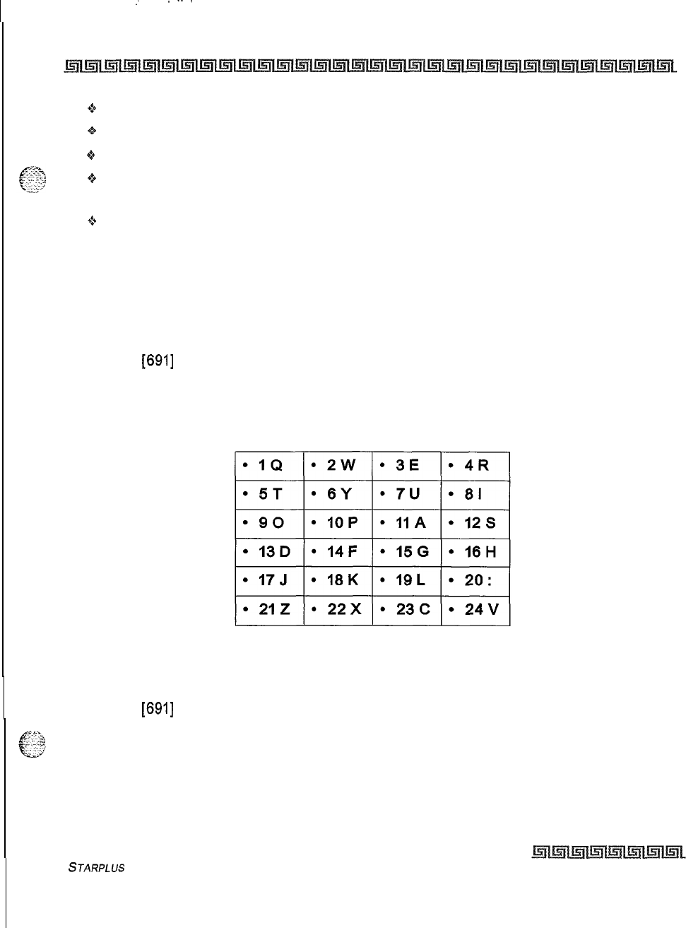
:
---.
DIGITAL STATION OPERATION
Prime Flex Button Programming
5-67
*:a
When a message displays by a key telephone, the DND button LED flashes at
15
ipm.
oWhen DND is invoked on the telephone the message cancels.
oMessage Access (with a desired message) may be assigned to a flex button.
+
Messages may be entered while off-hook on a call if an intercom call is camped onto the station. This
causes the station calling to see the message.
+S
Messages are retained in battery protected area of memory in the event of power failure or system
reset.
Prime Flex Button Programming
If your phone is programmed for Off-Hook Preference and were given the ability to enable or change the prime
flex button.
1
Dial
[691]
on the dial pad
2
Dial the 2-digit button number. Refer to the following chart.
To disable Off-Hook Preference:
1
Dial
[691]
on the dial pad.
2
Dial [00] on the dial pad.
STARPLUS
Triad-S Product Description Manual Issue I- December 1998
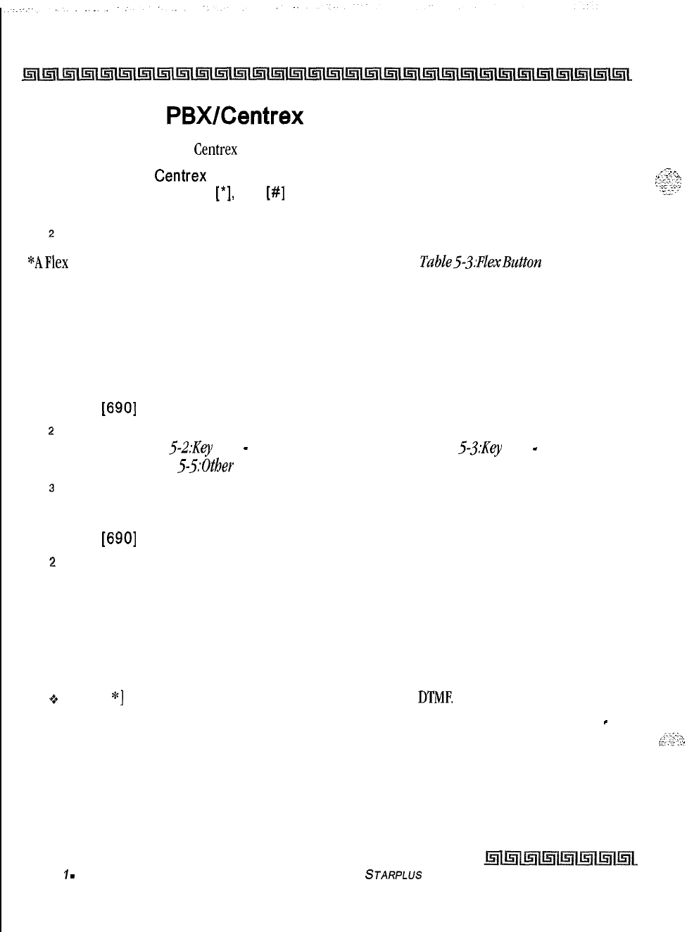
5-66 DIGITAL STATION OPERATION
Programming PBX/Centrex Codes Onto Flex Button
Programming
PBX/Centrex
Codes Onto Flex Button
For easy one-button access to Centrex or PBX features, perform the following steps:
1
Program the
Centrex
or PBX code into a station or system speed dial bin, including
,.-Tl<..
,.
. . . . . . .
-.
hook-flash (flash key),
[*I,
and
[#]
commands. Refer to station or system speed dial
;:;-r:;‘..‘T.:
Ye
programming.
2
Program that speed bin onto a flexible* button.
*AFlex
Button must be programmed for this feature to operate. Refer to Table53:FZexButh.m Programming
Codes.
Programming Your Name Into The LCD Display
Every extension (key and SLT) allow users to program their name so that people using display telephones
see the name instead of the station number.
IDial
[690]
on the dial pad.
2
Enter the name (up to 7 characters may be entered) by using keys on the dial pad as
shown in
Figure
S-2:Key
Pad
-
Dial By Name.
Also refer to
Figure
5-3:Key
Pad
-
Directory
Dialing
and
Table 5-5:Other Key Pad Codes.
3
Press the SPEED button to complete the programming process.
To erase your name:
1
Dial
[690]
on the dial pad.
2
Press the SPEED button to complete the erasing process.
Pulse-to-Tone Switchover
Signaling on an outside line can be changed from dial pulse to tone (DTMF) manually while dialing out.
To perform the change-over:
9Dial [
*]
on the dial pad. The remaining digit(s) is sent using
DTME
The Pulse-To-Tone Switchover command may also be included in a speed dial bin. Refer to “Speed Dial
-
Storing Numbers” on page 5 -72 for speed dial programming.
Issue
1
-
December 1998
STARPLUS
Triad-S Product Description Manual
.:-
DIGITAL STATION OPERATION
Repeat Redial
5-69
Repeat Redial
The feature lets a digital key station redial a busy or no-answer number at specific intervals. The user is
signaled via a queue callback indication. The Redial flexible button flashes at the callback rate of 120 ipm for
15 seconds. If the station does not answer within 15 seconds, the callback cancels, The system retains the
last call the user made. If the station is busy on an internal/external call when the Redial queue callback
occurs, the callback does not occur until the user goes on-hook. The user must enter a Redial timer value
(006-999
that represents seconds) when invoking this feature. A two minute interval is entered as 120.
Default value is 1 minute
(60).
A
keyset
station user places a CO call and receives a busy or no answer:
1
Press the pre-programmed* RREPEAT
REDIAL
flexible button
[643].
The LCD prompts
the user for a timer value.
ENTER RPT
REDIAL
TIMER:
xxx
006-999
2
Enter a 3-digit timer value (006-999 seconds) for the Repeat Redial timer. Default value
is 060 (one minute). Confirmation tone is heard and the station user goes on-hook. The
flexible button LED lights steady.
When the timer expires, the station is signaled via a CO line queue indication on the Repeat Redial flexible
button. During the queue callback, the LCD display indicates this is a Redial Callback. Once the line queue is
answered, the LCD indicates an outgoing CO line display.
*:*
Press the pre-programmed*
REDL4L
flexible button,
Or
Press the ON/OFF button,
or
Lift the handset. The line is seized and the number is dialed. If the user receives a busy/no answer,
they may repeat the step to activate another redial.
To cancel the operation:
$0
Press the pre-programmed*
REDL4L
flexible button. Confirmation tone is heard and the Auto Redial
function is cancelled.
Conditions:
$4
Once the user presses the pre-programmed* flexible button, there is no timer applied until the user
enters a digit. After a digit is entered, the inter-digit timer applies between the digits.
S
JARPLUS
Triad-S Product Description Manual Issue I
-
December 1998
I5-70 DIGITAL STATION OPERATION
Save Number Redial (SNR)
*A FlexButton must be programmed for this feature to operate. Refer to
TabZeS-3:FLexButton
Progmmning
Codes.
Save Number Redial (SNR)
If you wish to save the last number you dialed for use later:
1
After placing an outside call, keep handset off-hook.
z
Press the SPEED button twice.
To Dial a number that was saved using the steps above:
1
Press the SPEED button.
2
Dial the
[*]
button.
9*
System automatically selects the original line used to place the call and redials the number,
+
If that line is
busy,
the system automatically selects another line from the same group and redials
the number.
6If no lines are available in the same group, the station receives busy tone and can queue for a line.
-3
If the station user preselects a line before activating SNR, the preselection overrides the line
originally used.
Speakerphone
1
Press ON/OFF button to ON. Intercom dial tone is heard. Press the Volume Bar to
change the tone volume. The following message displays on the display phone:
SPEAKER TONE
[#########]
MMM DD YY
HH:MM am
2
Press the party’s DSS button, or press an available outside line button and dial the
number. Speakerphone is activated.
3
Press ON/OFF button to OFF to end the call.
For further references in this
set
tion where lift handset is specified, you
may also press the ON/OFF button, if the telephone is programmed as a
two-way speakerphone.
Issue
7
-
December 1998 STARPLUS
Triad-S Product Description Manual

DIGITAL STATION OPERATION
Station Relocation Feature
Station Relocation Feature
The Station Relocation Feature lets a user unplug their station and plug it into another location. Then, by
dialing a code followed by the old station number, bring all the station attributes including extension
number, button mapping, speed dial, and class of service to the new location.
i
A station can be relocated by unplugging it, then plugging it into a new location.
2
Dial
[636]
on the dial pad. Then, dial the extension number of the station being relocated.
Once this is done, all station attributes are copied to the current station.
If a station is assigned to a specific port and the user unplugs his station
and plugs it in to another location, database administration programming is
updated to reflect the
newport
change.
Conditions:
.:.
The station number that is dialed as the relocated station must be currently out of service.
*s
The relocated station is given the station attributes of the station doing the relocating. The two
stations trade station numbers and station attributes.
*p
If a
keyset
is plugged into the relocated position it has all station attributes of the relocating station.
.:.
This feature is only applicable to
keysets.
+
If the relocated station is in service, error tone is received.
oDigital stations must be relocated to another digital port. If a digital user moves his station number to
an analog port, the buttons are initialized and must be reprogrammed.
*s
Station lock will disable this feature.
Speed Dial
-
Station
If
no outside line was specified in programming, one can be selected now or the system will assign the line.
1
Press SPEED button and dial bin location,
Or
2
Press the pre-programmed* speed bin button. Station Speed numbers are 00 to 19.
3
When the called party answers, pick up the handset or use the speakerphone to
converse.
*A Flex Button must be programmed for this feature to operate. Refer to Table53:FlexButton
Progr+amnzitzg
Codes.
STARPLUS
Triad-S Product Description Manual
Issue I- December 1998
5-72 DIGITAL STATION OPERATION
Speed Dial
-
Storing Numbers
Speed Dial
-
Storing Numbers
Station Speed numbers can be entered by
keyset
users. System Speed numbers must be entered by the first
programmed attendant. If no attendant is specified, enter at Station 100.
1
1..
1
2
10
11
Press the SPEED button once.
Press an outside line button or pool button.
or
Automatically select an outside line by pressing the SPEED button again.
Dial the speed bin location.
00 to 19 = Station Speed numbers; 20 to 99
=
System Speed numbers.
Dial the desired telephone number (including special codes described below).
TRANS: Pressing the TRANS button during number entry initiates a Pulse-To-Tone
switchover.
HOLD: Pressing the HOLD button during number entry inserts a Pause.
FLASH: Pressing the FLASH button inserts a Flash into the speed number.
TRANS: Pressing the TRANS button as the first entry in the speed bin inserts a
no-
display character causing the numbers stored in the bin to not appear on the Digital
Terminals display when the bin is accessed.
Press the SPEED button.
Replace the handset to end the speed bin programming.
To program several speed numbers, press the SPEED button twice to conclude programming a number,
then just enter the next speed number bin to program. If the station has no line appearance for the line
programmed into the speed bin, that line comes up under the Loop button or Pool button when accessed.
To erase an existing speed bin:
I
Press the SPEED button twice.
z
Dial the speed bin location:
00 to 19 = Station Speed numbers
20
to
99
= System Speed numbers
3
Press the SPEED button again. Confirmation tone is heard.
Issue I- December 1998
STARPLUS
Triad-S Product Description Manual
DIGITAL STATION OPERATION
Speed Dial
-
System
Speed Dial
-
System
If no outside line was specified in programming, one can be selected now or the system will assign the line.
1
Press the SPEED button.
z
Dial the speed bin location,
or
Press the pre-programmed* speed bin button.
3
20 to 99 = System Speed numbers.
4
When the called party answers, pick up the handset or use the speakerphone to
converse.
*A Flex Button must be programmed for this feature to operate. Refer to Table53:FlexBz&m Programming
Codes.
Text Messaging (Silent Response)
This feature lets a station user use text messages in response to a caller that has Camped-On or used the
Off-
HookVoice
Over feature to alert a busy station user of a waiting call or message. The camped-on station may
respond to the caller via the canned, custom, or silent response text (LCD) messages. Text messages display
on the calling party LCD Display.
While receiving a Camp-On, or OHVO call:
oThe called party may press a pre-programmed* Text Message button with a specific message
[633+xx]. Example:
[633]
+
[38]
means a telephone calling the station receives the message WHO
IS IT ?
Additional messages (with their codes listed below) can also be sent as a text response:
[31] = I WILL TAKE CALL
[32] = TAKE MESSAGE
[
331 = TRANSFER TO SECRETARY
[34]
= PUT CALL ON HOLD
[35]
= CALL BACK
[361
= ONE MOMENT PLEASE
[37]
= I WILL CALL BACK
[38]
= WHO IS IT?
[39]
= IS IT LONG DISTANCE?
STARPLUS
Triad-S Product Description Manual
Issue
I-
December 1998
5-74
.,
.
.
.
.
DIGITAL STATION OPERATION
Text Messaging (Silent Response)
[40] = IS IT PERSONAL?
[41]
= IS IT AN EMERGENCY?
[42] = IS IT IMPORTANT?
[43]
= IS IT URGENT?
[44] = SEND CALL TO VOICE MAIL
[45]
=
PARKCALL
[46] = OUT OF OFFICE
[47] = PUT CALL THROUGH
1481
= I AM BUSY
[49]
= O.K.
[50]
= NO
[51]
= YES
Conditions:
If the station receiving the text message response was doing a camp-on, it receives a short burst of
tone on the speaker, then the display shows the message that was activated by the called station.
If the station receiving the text message response is on an OHVO call, no tone is received.
All
canned and custom messages may be used to respond to a calling party,
Text response messages automatically clear when the calling station (station receiving the
messages) goes on-hook.
A station can receive only one message at a time.
Text messages may be chained (i.e., multiple messages sent to one caller).
Text message responses appear on the calling station and the called station (station activating text
responses) LCD displays.
If the calling station is a non-LCD terminal, the called station receives error tone when responding
via text messaging.
The called station may press a flex button programmed as a Text Message button,
[633
+
#].
Press
this flex button and dial the 2-digit message number (31-51) to respond to the calling station.
DTMF digits are not heard by either party.
When silent messaging is used to respond to a call, the existing call of the called station is not
disconnected while the messages are sent to the calling station.
The calling station must remain off-hook to receive silent messages.
If the called station responds with a text message, the text message displays on the LCD.
Issue 1
-
December 1998
STARPLUS
Triad-S Product Description Manual
I
.
-.
..
--....
.-.
.-.
DIGITAL STATION OPERATION
Uniform Call Distribution (UCD)
Q
LEDs follow the CAMP-ON or OHVO.
9Each message may be programmed onto a flexible button, including a flex button on a
DSS/BLF
console.
The calling station must be a display telephone and the called station must
be a keyse
t.
Uniform Call Distribution (UCD)
Eight Uniform Call Distribution (UCD) groups can be programmed, each containing up to eight s-digit station
numbers. Each group is assigned a pilot number. When this number is dialed, the first available agent in that
group is rung. Calls are routed to the station that has been on-hook for the longest period of time.
UCD Calls In Queue Display
From an idle display key telephone:
t
Dial
[567]
on the dial pad, followed by the 3-digit UCD group number (55x),
or
Press pre-programmed* flex button. ON/OFF button LED lights steady.
This display is an idle state display and prompts a Supervisor that a group is having
problems answering their calls. The display tells the agent and his supervisor how many
calls are in queue, how many agents are available or logged into the group, and the
time
(in minutes) that the oldest call has been in queue. The agent automatically receives the
calls in queue display whenever there is a call in queue.
2
Hang up the handset or press ON/OFF button to terminate the display.
This feature cannot be used with a call in progress. The station is consid-
ered busy
for
incoming calls during this operation.
*A
Flex Button must be programmed for this feature to operate. Refer to Table
53:FZex
Button
Programming Codes.
-.
gi;>
UCD Available/Unavailable Mode
If you are an UCD agent, you may place your station in Available mode to receive UCD calls, or you may place
your station in Unavailable mode to block UCD calls from ringing your station.
STARPLUS
Triad-S Product Description Manual Issue I- December 1998
.
5-76 DIGITAL STATION OPERATION
Uniform Call Distribution (UCD)
To go Available:
$3
Dial
[566]
on the dial pad,
Or
Press the pre-programmed* AVAILABLE/UNAVAILABLE button. You may now receive UCD calls.
To go Unavailable:
+
Dial
[566]
on the dial pad,
Or
Press the pre-programmed* AVAILABLE/UNAVAILABLE button. You are now blocked from receiving
UCD calls.
*A Flex Button must be programmed for this feature to operate. Refer to Table53:lexButton Programming
Codes.
UCD Overflow Station
-
Forwarding Assignments
This feature enables UCD calls reaching an Overflow Station to be forwarded.
1
Lift the handset or press ON/OFF button.
2
Press the pre-programmed* FWD button.
3
Dial the desired code:
[7]
= No Answer Calls
[8]
= Busy Calls
[9]
= Busy and No Answer Calls
Skip the preceding step for immediate forwarding.
4
Dial the 3-digit destination number where to forward calls (Station, Voice Mail, UCD
groups, or Hunt group). Confirmation tone is heard.
5
Replace handset or press ON/OFF button.
To remove Call Forwarding:
I
Lift handset or press ON/OFF button.
z
Press the pre-programmed* FWD button. Confirmation tone is heard and the FWD LED
extinguishes.
Issue
I-
December 1998
STARPLUS
Triad-S Product
Description
Manual
DIGITAL STATION OPERATION
Universal Day/Night Answer (UDA/UNA)
Conditions:
oAn overflow station may be assigned to route callers in queue to a designated station after a specified
time. A queued call is one that has been answered by a recorded announcement device or
transferred into the group.
*A Flex Button must be programmed for this feature to operate. Refer to Table53:Flex Button Programming
Codes.
Universal Day/Night Answer
(UDA/UNA)
Incoming CO lines can be programmed for Universal Day Answer (UDA) or Universal Night Answer
(UNA).
UDA/UNA
assigned CO lines can also signal over the external page port(s). If External Day programming is
enabled and the system is in the day mode, the assigned external page port(s) present a ringing signal.
UDA/UNA
is established on a per CO line basis in admin programming.
When the system is in Day or Night mode and you hear an outside line ringing at another station, and wish to
answer it:
+
Dial [#5] on the dial pad. The connected outside line can be transferred or disconnected.
Each telephone utilizing Universal Day/Night Answer must have a loop
button appearance
if
the ringing outside line does not display at theirphone.
Conditions:
+z+
During the Day mode, all common CO lines programmed for UDA ringing will ring.
$3
CO lines not programmed for UDA ringing do not participate in common audible ringing.
4~
If External Day ring is disabled, or the system is not in the day mode, external page ringing is
disabled.
oRinging CO lines not assigned CO line group access for a particular SLT may be answered in a UDA
service. Dialing privileges are unavailable on CO lines to which an SLT does not have access. CO lines
without UDA status may not be answered or accessed via UDA procedures,
oIf two single-line telephones attempt to retrieve one ringing CO line simultaneously, one user is
connected to the incoming CO line and the other user receives intercom busy tone.
+
The special ring mode is treated as day mode.
STARPLUS
Triad-S Product Description Manual
Issue
7
-
December 1998
5-78 DIGITAL STATION OPERATION
Voice Mail Groups
(VM)
Voice Mail Groups (VM)
Forward Callers to your Mail box:
Intercom and Transferred CO callers may be routed directly to your mail box by forwarding your phone to a
voice mail group. Callers are then greeted by your personal voice mail greeting, if available. (Refer to Call
Forward -Voice Mail Operation.)
Retrieving Voice Messages:
If your Message Waiting button or programmed Voice Mail Group button is flashing, you may have a voice
message waiting.
To enter the voice mail system to check for mail:
1
Dial the Voice Mail Group number
[440-4471,
or
Press the pre-programmed* Voice Mail group button or flashing Message Wait button.
2
When prompted, enter the mailbox password.
Receiving a Voice Mail Message Wait:
To receive a message waiting indication that a voice message is waiting, the Voice Mail system must be
programmed to provide the indication.
After the voice mail system receives a voice message for a station user:
I
The voice mail must go off -hook and dial the voice mail message wait code
[420]
on
the dial pad.
2
Dial the 3-digit extension number of the station user who received a voice message.
Turning the Message Waiting Lamp
Off:
When a station user retrieves the voice messages from the voice mail system, the voice mail system must:
1
Be programmed to go off -hook and dial the message cancel code
[421]
on the dial pad.
2
Dial the 3-digit extension number of the station user who received a voice message.
Conditions:
oOnly VM extensions are allowed to turn ON/OFF VM message wait indications.
*A Flex Button must be programmed for this feature to operate. Refer to
Table53:FZexButton Programming
Codes.
lssue
I-
December 7998
STARPLUS
Triad-S Product Description Manual
DIGITAL STATION OPERATION 5-79
Voice Mail Groups (VM)
VM Transfer with ID Digits
This feature lets an Attendant or station user transfer a caller directly into a voice mail box. This allows entry
-
F.,
of the station identification digits by the transferring party. A caller using this feature can transfer to a voice
_..Y”
L-.
.~.,
‘,O
.,a
mail box when: 1) a station user on the system is not forwarded to VM, or 2) the destination Voice Mail Box
i.
5
owner is not a station user.
When a caller wishes to be transferred into a user’s Voice Mail box and that user’s station is not forwarded
into voice mail, the attendant or a station user may initiate a Voice Mail Transfer.
When the caller wishes to leave a Voice Message for a VM user:
1
The initiating station presses the TRANS button.
2
Dial the Voice Mail Group number,
or
Press the pre-programmed* VM group button.
3
Dial the desired party’s
VMID
(Mail Box location) and go on-hook. The system makes the
connection to an available Voice Mail port and sends the Leave Mail Prefix (if any) plus
the digits dialed as the
VMID
number, then the Leave Mail Suffix digits (if any). The
system then cuts through the transferred caller.
The
VMID
(mail
box location) can be any number between 000 through
999.
If
4-digit
VMID
(Flash 09) is enabled, the range is between 0000
through 9999.
OR
1
The initiating system presses the Voice Mail button.
2
Press DSS button to transfer desired party’s Voice Mail ID.
Conditions:
$*
CO Trunks and Internal Calls may be transferred into Voice Mail using this feature.
oIf no
VMID
digits are dialed by the transferring station, the identification digits of the transferring
station are sent to VM.
VM Tone Mode Calling Option
--;-zi
c
<:
>>.A
*
..;-...;J
-,.
d
Lets the Voice Mail system override a called station’s H or P intercom settings.
When placing a call to a station and Tone ringing is desired, the Voice Mail system MUST be programmed to:
7
Dial
[6#]
on the dial pad.
2
Dial the 3-digit station extension (call tone rings station).
STARPLUS
Triad-S Product Description Manual Issue I- December 1998
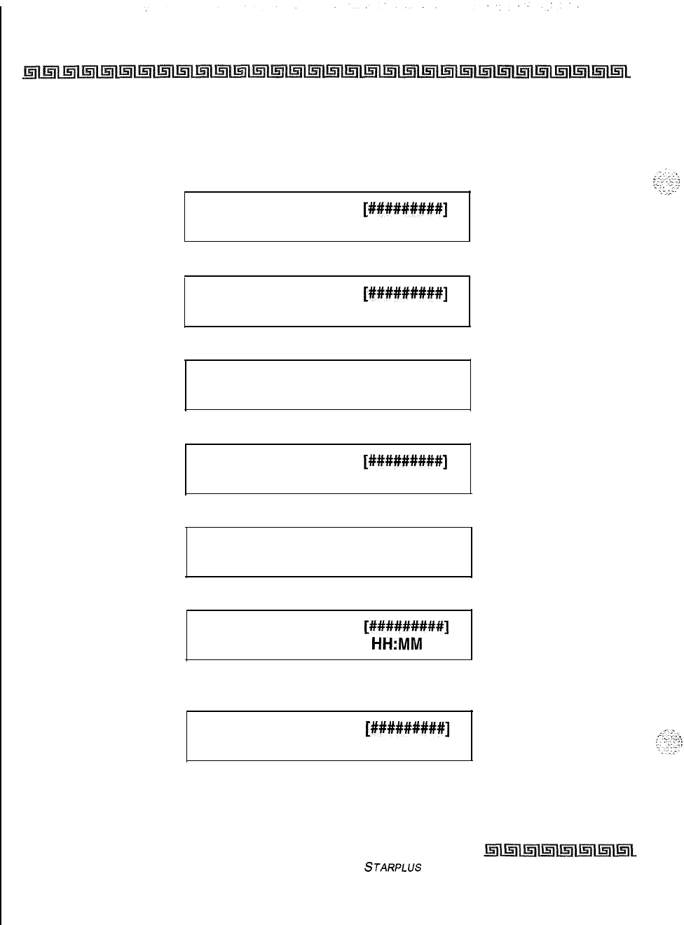
5-80 DIGITAL STATION OPERATION
Volume Control Bar (DKT)
Volume Control Bar (DKT)
There is a volume control bar below the keypad to control the ringing, handset, and speakerphone volumes.
The following message is shown on the display phone, while listening to Background Music:
SPEAKER BGM
[#########]
MMM DD YY
HH:MM am
The following message is shown on the display phone, while using the speakerphone on a Intercom call:
SPEAKER CALL
MMM DD YY
[#########]
HH:MM am
The following message is shown on the display phone, while using the handset on a Intercom call:
HANDSET ICM
[#I########]
MMM DD YY
HH:MM am
The following message is shown on the display phone, while using the speakerphone on a CO call:
SPEAKER CALL
[#I########]
MMM DD YY
HH:MM am
The following message is shown on the display phone, while using the handset on a CO call:
HANDSET CO
[######I###]
MMM DD YY
HH:MM am
The following message is shown on the display phone, while receiving a page announcement:
SPEAKER PAGE
MMM DD YY
[#########]
HH:MM
am
The following message is shown on the display phone, while receiving an incoming tone ringing Intercom or
CO call:
SPEAKER RING
[#########]
MMM DD YY
HH:MM am
issue I- December 1998
STARPLUS
Triad-S Product Description Manual
.
Introduction
This section of the manual contains the operating instructions for Single Line users. It is designed to provide
step-by-step instructions for operating the Single Line telephones in the system.
Literature similar to these operating instructions was prepared for use by the customer in the form of a
Single Line Telephone User’s Guide.
Account Codes
SLT stations can enter an account code to identify the call or calling station,
Entering Account Code before a call
1
Lift the handset.
2
Dial
[627]
on the dial pad.
3
Dial the account code.
If the account code contains fewer than 12 digits, dial
[S]
to return to intercom dial tone.
Dial tone is heard.
4
Dial
[9]
or CO Access code and the desired number.
Entering Account Code during a call
1
Press the hookswitch momentarily. Your call is placed on hold while you enter your
account code.
2
Dial
[627]
on the dial pad.
3
Dial the account code.
If the account code contains fewer than 12 digits, dial
[+I+]
to return automatically to the call.
Automatic Call Distribution (ACD)
Thisfeature is available with optional soJware. When purchased, Uniform Call Distribution (UCD) is not
used and is replaced by the ACD functions identified in the following. Sixteen Automatic Call Distribution
(ACD)
groups can be programmed, each containing up to sixteen 3-digit station numbers.
Issue 1
-
December 1998
STARPLUS
Triad-S Product Description Manual
SINGLE LINE TELEPHONE OPERATION
Automatic Call Distribution (ACD)
Agent
Login/Logout
Feature
The Agent Login/Logout feature provides a means for an agent to log into one of the ACD groups and receive
calls, For an agent to be placed into an active ACD state, the agent must first login.
IDial the
LOGIN
CODE
[572]
on the dial pad, followed by the ACD group number
(5xx)
into which the agent is going to log.
2
The agent enters his unique AGENT ID code (0000-9999). Confirmation tone is heard
and the agent is logged onto the ACD group. When the agent logs in, an ACD
login
event is sent to the SMDR port, if active.
If
u member is assigned to a specific
AC0
group and uses the login-logout
codes to enter and exit an
AC0
group other than his assigned group,
the
database is changed to reflect the different group.
For an agent to remove himself from the ACD group as an active agent
o
Dial the
LOGOUT
CODE
15711
on the dial pad. When the agent logs out and removes himself from
the ACD group, an ACD logout event is sent to the SMDR port, if active.
Conditions:
*
If an agent logs into an ACD group from a station that is logged into another ACD group, the station
is automatically removed from the previous ACD group.
+z+
An agent may log out while in wrap-up, or unavailable.
3
An agent logging in is placed in wrap-up mode before receiving an ACD call,
c,
If an agent attempts to log into an ACD group that already has I6 members, that agent receives
error tone.
Issue
I-
December 1998
STARPLUS
Triad-S Product Description Manual
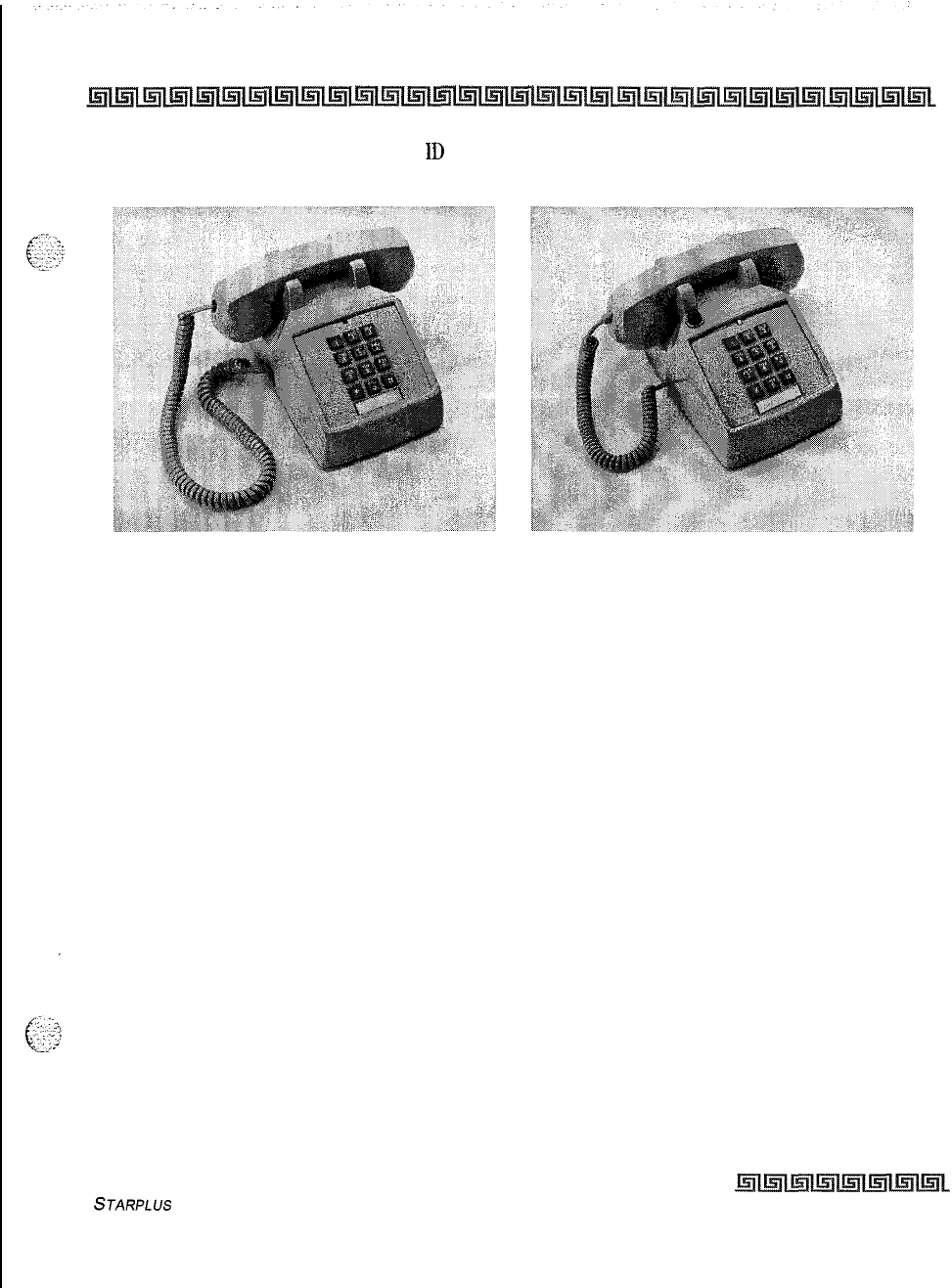
SINGLE LINE TELEPHONE OPERATION
Automatic Call Distribution (ACD)
6-3
The Triad-S system does not verify agents
ID
codes, other than requiring entry of four digits.
2500
Type 2500 Type with Message Waiting Lamp on Top
Figure 6-1: 2500 Series SLT Telephones
STARPLUS
Triad-S Product Description Manual Issue I- December 7998
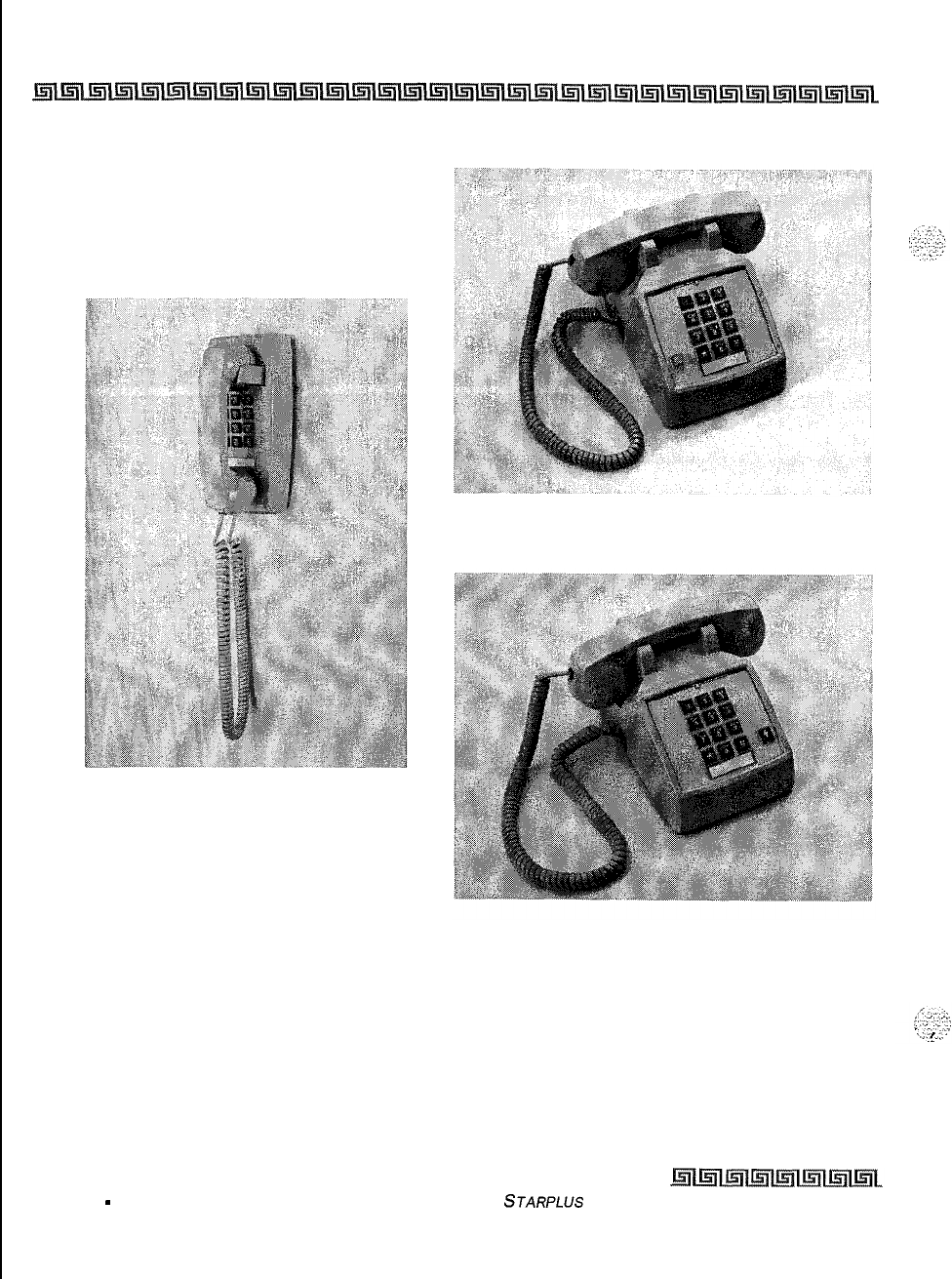
6-4 SINGLE LINE TELEPHONE OPERATION
Automatic Call Distribution (ACD)
2500 Type with Message Waiting Lamp
2500 Type Wall Phone 2500 Type with Flash Key
Figure 6-l: 2500 Series SLT Telephones
issue I
-
December 1998 STARPLUS
Triad-S Product Description Manual
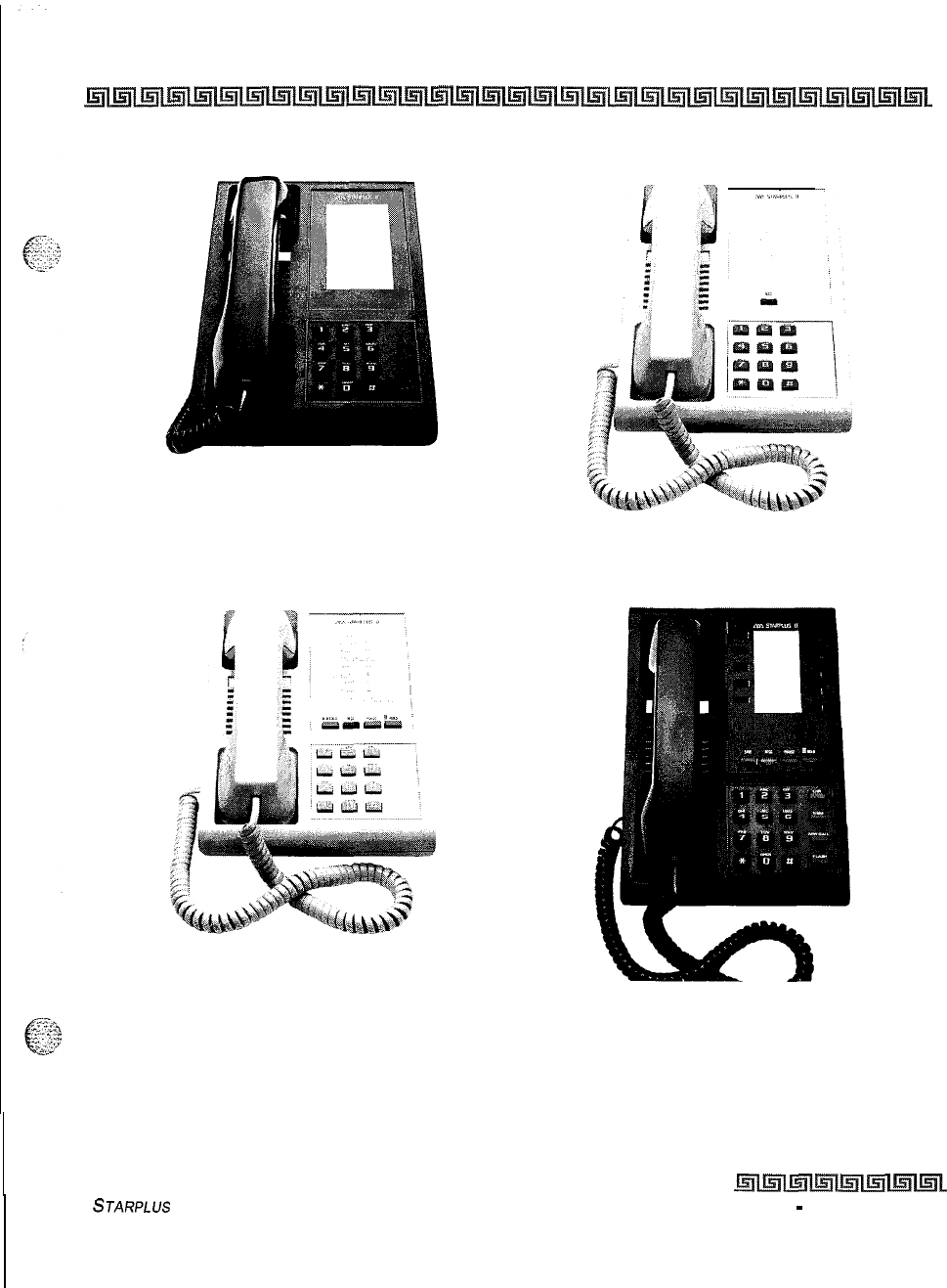
SINGLE LINE TELEPHONE OPERATION
Automatic Call Distribution (ACD)
6-5
Model 2601 Feature Telephone Model 2602 Feature Telephone
Model 2603 Feature Telephone Model 2603E Feature Telephone
Figure 6-2: 2600 Series SLT Telephones
STARPLUS
Triad-S Product Description Manual
Issue 1
-
December 1998
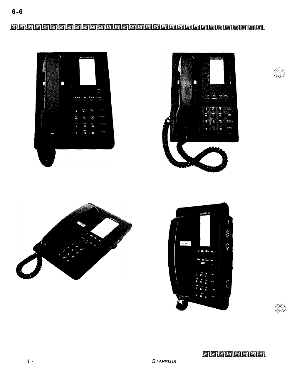
SINGLE LINE TELEPHONE OPERATION
Automatic Call Distribution (ACD)
Model 2604 Feature Telephone Model 2604E Feature Telephone
Model 2605 Feature Telephone Model 2606 Feature Telephone
Figure 6-2: 2600 Series SLT Telephones (Continued)
Issue
I-
December 1998 STARPLUS
Triad-S Product Description Manual
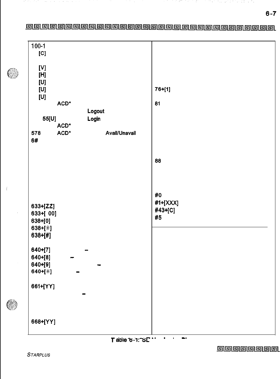
SINGLE LINE TELEPHONE OPERATION
Automatic Call Distribution (ACD)
TOO-1 71 Triad-S Ext. Numbers
43
PI
Call Park Location O-7 (System)
438 Personal Park
44
WI
Voice Mail’ Group Pilot Numbers O-7
45
[HI
Hunt Group Pilot Numbers O-7
55
WI
ACD* Group Pilot Numbers O-9
55
SJI
UCD Group Pilot Numbers O-7
56
WI
ACD* Group Pilot Numbers 1 O-l 5
566
ACD”
or UCD Available/Unavailable
571
ACD” Agent
Logout
572
55[U]
ACD” Agent
Login
574
ACD”
Agent Help
578
ACD*
Overflow Sta
AvaillUnavail
6#
[XXX] Tone Mode Ring Option
620
Camp-On
621 Line Queue
622 Call Back
623 Message Wait
625 Executive Override
626 LCR Queue Cancel
627 Account Code Enter
631 Do Not Disturb
633+[2Z]
Personalized Messages
633+[
001
Clear Personalized Messages
636+[0] Handset Receiver Gain
636+[3]
Handset Receiver Gain Decrease
636+[#]
Handset Receiver Gain Increase
640
All Call Forward
640+[7] No Answer
-
Call Forward
640+[6] Busy
-
Call Forward
640+[9] Busy/No Answer
-
Call Forward
640+[%]
Off-Net
-
Call Forward
660
SLT Flash Command To CO Line
661+[YY]
SLT Station Speed Dial Programming
662
SLT Clear
-
Call Forward, DND,
Personalized Messages
663 Message Wait Return
664
SLT Conference w/Personal Park
666+[YY]
SLT Speed Dial Access
690 Name in Display Programming
70
71
72
73
74
75
76+[1]
77
ai
a2
a3
a4
a5
86
67
88
9
0
#O
#l+[XXX]
#43+[c]
#5
All Call Page (Internal and External)
Internal Page Zone 1
Internal Page Zone 2
Internal Page Zone 3
Internal Page Zone 4
Internal All Call Page
External Page Zones
Meet-Me-Page Answer
CO Line Group 1
(if LCR is enabled)
CO Line Group 2
CO Line Group 3
CO Line Group 4
CO Line Group 5
CO Line Group 6
CO Line Group 7
All CO Line Groups
(CO Line Off-Net Forward)
LCR or CO Line Group 1
(if LCR is disabled)
Attendant
Group Call Pick Up (Key and SLT)
Directed Call Pick Up (SLT)
Call Park Pickup (Key
and
SLT)
Universal Day/Night Answer
XXX = Intercom Station Numbers
YY = Speed Dial Bin numbers
ZZ = Personalized Messages
BB = button Number
U = ACD” (O-15) or UCD (O-7) Group Number
C = Call Park Location O-7
H = Hunt Group Number O-7
V = Voice Mail* Group Number O-7
P = External Page Zone Number (l-2)
* Features available with optional software.
I
-..
.
.
-_
I
aDte
0-l:
SL I Numbering
Plan
STARPLUS
Triad-S Product Description Manual
Issue I- December 1998
I
‘.
6-8 SINGLE LINE TELEPHONE OPERATION
Automatic Call Distribution (ACD)
ACD Agent HELP Feature
The ACD Agent HELP feature provides a means for an ACD agent to signal his assigned supervisor for
assistance.
While on a call-in-progress, the agent:
1
After hook-flashing, dials the HELP code
[574]
on the dial pad. The agent must
hook-
flash again to return to his call after the code is dialed. If no supervisor is logged in, the
agent receives one-burst of error tone.
2
The ACD supervisor station receives a HELP message if a member of one of the ACD
groups he is assigned to initiates a HELP request. The HELP function also sends a
Camp-On tone to the speaker of the supervisors
keyset.
The HELP message takes
precedence over any other message and can be cleared by the supervisor by pressing
his HELP button.
3
At the time the supervisor receives a HELP request, he can press the HELP flex button
followed by the override feature button to bridge onto the ACD group members call.
The HELP button places an intercom call to the station requesting HELP. The HELP
message is cleared after the supervisor’s HELP button is pressed. Additionally, the
HELP message is cleared if the agent was on a call and went back on hook before the
supervisor could respond. In this case, the HELP message is converted to a message
wait indication for the station.
Conditions:
+
Up to five messages can be left at any supervisor station.
+
The supervisor can cancel the HELP request signal by pressing the flashing HELP button.
Additionally, a call is placed to the agent requesting
HELP
If the agent is on a call, the supervisor can
press his barge-in button to monitor the call or give assistance on the call.
ACDNCD
Available/Unavailable Mode
If you are an ACD agent, you may place your station in the Available mode to receive ACD calls or you may
place your station in the Unavailable mode to block ACD calls from ringing your station.
To go Available:
Q
Dial
[566]
on the dial pad. Confirmation tone is heard through the handset. You may now receive
ACD calls.
To go Unavailable:
Q
Dial
[566]
on the dial pad. Confirmation tone is heard through the handset. You are now blocked
from receiving ACD calls.
Issue 1
-
December 7998
S
JARPLUS
Triad-S Product Description Manual
SINGLE LINE TELEPHONE OPERATION
Automatic Line Access
Conditions:
e
Single line telephones receive a stuttered dial tone when unavailable.
&$$
Automatic
Line
Access
SLTs
may have their station programmed to access a particular CO Line, such as a private line or a line from
a Group of CO lines, upon going off-hook. This is useful in Centrex or PBX applications when station users
have dedicated or individual lines. Outside line dial tone is received just by going off-hook, without dialing
access codes.
Call Back
You call a busy station and receive busy:
1
Briefly press and release the hookswitch.
2
Dial
[622]
on the dial pad.
3 Replace handset.
Only one
Cull
Back request can be
/ef
t
ot
a station; the second request
converts to Message Waiting Request.
Call Brokering
Enables SLT user on a CO call to Hook-Flash and make another CO call. Once this other call is established,
the SLT user can Hook-Flash to move back and forth between parties. Hoof-Flash timer may require
adjustment for proper operation.
Call Forward
To Call Forward calls to another station:
1
Lift handset.
F.
:.>
2
E
”
:*
Dial
[640]
on the dial pad.
g+&$
3
Skip this step for immediate forwarding. Otherwise, dial the appropriate code:
[7]
= Call Forward No Answer
[S] = Call Forward Busy
[9]
= Call Forward Busy/No Answer
STARPLUS
Triad-S Product Description Manual
Issue
I-
December 1998
I
--.
6-10
SINGLE LINE TELEPHONE OPERATION
Call Forward
[x] = Call Forward Off-Net (via speed dial)
4
Dial the 3-digit extension number or speed bin number where calls are to be forwarded.
Confirmation tone is heard.
5
Replace handset.
To Remove Call Forwarding:
ILift handset, stuttered dial tone is heard.
z
Dial
[640]
on the dial pad or
[662]
on the dial pad. Confirmation tone is heard.
3 Replace the handset.
Call Forward
-
Follow-Me
This feature enables a user who is away from their station, activate/deactivate call forwarding from another
station in the system. This lets the user forward their calls to their current location or into Voice Mail,
ACD/UCD,
Hunt Groups, or to any other station in the system. When this call forward is activated, all calls
presented to the forwarded station forward to the destination station immediately.
If you were given the ability to forward your calls:
1
Lift the handset or press ON/OFF button.
2
Dial the Follow-Me Forward code
[642
YYY XXX] on the dial pad, where YYY=station
forwarding from and XXX is station forwarding to.
3 Replace handset.
To remove Follow-Me Forwarding:
i
Lift the handset or press ON/OFF button.
2
Dial the Follow-Me Forward code
[642
YYY YYY] on the dial pad, where Y=station
forwarded from.
To establish Follow-Me Forwarding from an off-site location:
I
Dial into the system on a
DISA
or TIE trunk. Enter the
DISA
access code, if applicable.
2
Dial the Follow-Me Forward code
[642
YYY XXX] on the dial pad, where YYY=station
forwarding from and XXX=station forwarding to.
To remove Follow-Me Forwarding from an off-site location:
1
Dial into the system on a
DISA
or TIE trunk. Enter the
DISA
access code, if applicable.
2
Dial the Follow-Me Forward code
[642
YYY YYY] on the dial pad, where Y=station
forwarded from.
Issue I- December 1998
STARPLUS
Triad-S Product Description Manual
SINGLE LINE TELEPHONE OPERATION
Calling Station
Tone Mode
Option
6-11
Conditions:
oIf a Call Forward mode is currently active at the station where forwarding is desired, the new forward
becomes active and cancels the previous forward.
+
Both internal and external calls to the affected station forward to the designated location.
+
Call forwarding must be allowed in programming for the affected station.
+
When remote forward is activated the forwarding is immediate.
+ze
A station’s Call Forward status is stored in a battery protected area of memory. A stations Call Forward
status is returned after a power failure or system reset occurs.
When a key telephone is forwarded remotely, the key stations forward button lights, The station user
may cancel the forwarding at their station by pressing ON/OFF, then the FWD button, SLT users can
cancel their forwarding by going off hook and dialing the forward code.
+
DISA callers entering the code and making a mistake are given error tone for
3
seconds, silence for 2
seconds, then the dial tone is returned.
Calling Station Tone Mode Option
This feature enables a calling station to override a called station’s H or P intercom
settings.
Use
from
VM
port.
When placing a call to a station and Tone ringing is desired:
iDial
[6#]
on the dial pad.
2
Dial the 3-digit extension number,
or
Press DSS button of desired station (call tone rings station).
Camp-On
After receiving intercom busy tone:
1
Briefly press and release the hookswitch.
2
Dial
16201
on the dial pad. When the called party answers, consult with them.
While on a CO line you receive a Camp-on warning tone through handset:
++
Choose desired call (hang up present call and take the new one, or ignore the Camp-on signal). (Also
see Personal Park)
STARPLUS
Triad-S Product Description Manual
Issue
7
-
December 1998
I6-12 SINGLE LINE TELEPHONE OPERATION
Call Park
-
Personal
Call Park
-
Personal
While connected to first call:
1
Press the hookswitch momentarily. Intercom dial tone is heard.
z
Dial
[438]
on the dial pad (call is placed in personal park).
3
Dial desired number for second call.
4
Press the hookswitch momentarily. Intercom dial tone is heard.
5
Dial
[438]
on the dial pad (first call is returned and second call is placed in Personal
Park).
The user can alternately connect to the other call by doing a hook-flash
and dialing
[438]
as many times as necessary.
Call Park (System)
This feature enables an outside call to be placed on hold and consult with, page, or call an internal party
prior to transfer.
While connected to an outside line:
t
Press and release the hookswitch. The caller is put on Exclusive hold.
2
Dial parking location (430 to 437) on the dial pad. Confirmation tone is heard.
3
If you hear busy tone, press and release the hookswitch to re-establish contact with the
called station, and press and release the hookswitch again prior to dialing another
parking location.
Retrieving a Parked Call
1
Lift handset.
2
Dial
[#]
on the dial pad.
3
Dial parking location (430 to 437) where the call was parked.
Call Transfer
Making an Unscreened Transfer
1
Briefly press and release the hookswitch.
2
Dial desired intercom number.
3
Hang up to complete the transfer.
Issue
1
-
December 1998 STARPLUS
Triad-S Product Description Manual
SINGLE LINE TELEPHONE OPERATION
Clear Call Forward, DND, Personalized Messages
6-13
Making a Screened Transfer
1
Briefly press and release the hookswitch.
z
Dial desired telephone number. Announce the call.
g&
s
Hang up to complete the transfer.
. . ;a:
Clear Call Forward, DND, Personalized Messages
SLTs
can activate and cancel call forward by dialing
[640]
on the dial pad and DND by dialing
[631].
SLTs
can
enable and cancel personalized messages by dialing
[633xx].
A convenient code
[662]
is incorporated to cancel either Call forwarding, DND, or Personalized Messages
when the SLT user forgets which code was programmed on the phone
To cancel Call Forward, DND, Personalized Messages:
1
Lift handset. Notification tone is heard.
2
Dial
[662]
on the dial pad. Confirmation tone is heard.
s
Replace the handset.
CO Line Queuing
1
Dial outside line access code. Receive busy tone.
2Briefly press and release the hookswitch.
3Dial
[621]
on the dial pad. Confirmation tone is heard.
Conference
You may set up a conference of one external and one other internal station.
1
Lift handset.
2 Make outside call.
s
Briefly press and release the hookswitch to put the call on hold.
4Dial number of internal station to add.
f%$
5
When that station answers, briefly press and release the hookswitch again and all three
-->’
parties are connected.
STARPLUS
Triad-S Product Description Manual
Issue
I-
December 1998
.
.
6-14 SINGLE LINE TELEPHONE OPERATION
Conference With Personal Park
Conference With Personal Park
While connected to an outside line:
1
Press the hookswitch momentarily. Intercom dial tone is heard.
2
Dial
[438]
on the dial pad (first call is placed in personal park).
3
Dial desired number for second call.
4
Press the hookswitch momentarily. Intercom dial tone is heard.
5
Dial
[664]
on the dial pad. All three parties are
conf
erenced.
6
Hang up to terminate conference.
Direct Outside Line Access
1
Lift handset.
2
Dial access code (9, 81-87) on dial pad.
3
Dial desired telephone number.
Call Pick-up Directed
Upon hearing an unattended telephone ring:
1
Lift handset.
2
Dial
[#I]
on the dial pad.
3
Dial station number of ringing telephone. You are connected to intercom, incoming,
recalling or transferred outside line.
Call Pick-Up Group
Upon hearing an unattended telephone ringing:
1
Lift the handset.
2
Dial [#0] on the dial pad. You are connected to intercom, transferred or recalling
outside line call.
You must be in
the
same
pickup group.
Issue
I
-
December 1998 STARPLUS Triad-S Product Description Manual
SINGLE LINE TELEPHONE OPERATION
Do Not Disturb (DND)
6-15
Do Not Disturb
Activating Do Not Disturb
1
Lift handset.
._-
:-*
-
.
_.:_
c:.:>
I
,_
‘..d
-.
,...j
2
Dial
[631]
on the dial pad.
3 Replace handset.
To cancel Do Not Disturb
1
Lift handset.
2
Dial
[631]
on the dial pad or
[662]
on the dial pad.
s
Replace handset.
PBX/Centrex
Transfer (Flash Command to CO Line)
To initiate a PBX or
Centrex
Transfer command from an SLT.
While connected to a PBX or Centrex line:
1
Briefly press and release the hookswitch. Intercom dial tone is heard.
2
Dial
[660]
on the dial pad. A Flash command is presented to the PBX or
Centrex
line.
s
PBX or
Centrex
stutter tone is heard. Dial number of desired extension.
4
Replace handset to complete
transfEr.
Handset Receiver Gain
This feature allows an SLT user to increase/decrease the handset volume while on a CO or intercom call.
While on a CO or intercom call:
1
Hookflash and dial the Handset Receiver Gain code
[638]
on the dial pad.
2
Dial a l-digit entry [0] through
[9]
(O=lowest,
9=highest)
on the dial pad,
Of
Press [#] to increase or
[a]
to decrease the gain, one level at a time.
3
Hookflash again to return to call.
4
Repeat above procedures, if necessary.
5
Replace the handset to end the call.
STARPLUS
Triad-S Product Description Manual
Issue
I-
December 1998
6-16 SINGLE LINE TELEPHONE OPERATION
Intercom Calling
Intercom Calling
Ringing is heard if called station is in T answering mode; or two bursts of tone if called station is in the H or
P position. To place an intercom call:
1
Lift the handset.
2
Dial the 3-digit intercom number.
3
Converse after the two tone bursts stop.
4
Replace the handset to end the call.
Answering an Intercom Call
1
Lift handset to converse.
2
Replace handset to end call
Conditions:
+
Off-Hook Preference may affect this feature. See “Off-Hook Preference” on page
6-17
Least Cost Routing (LCR)
To place an outside call when LCR is enabled in the system:
1
Lift the handset.
z
Dial [g] on the dial pad.
s
Dial the desired telephone number.
4
Wait for an answer, then converse.
If all lines available are busy, remain off-hook for four seconds to automatically be queued onto LCR for an
available line.
If an LCR Queue Callback is activated:
1
When telephone is signaled, answer the call.
2
Desired telephone number is automatically redialed.
Only one L CR Queue Call Back request may be initiated by a station. When
a second request is made, the first request is cancelled.
To cancel an LCR Queue Callback:
1
Dial the LCR Queue Cancel code,
[626]
on the dial pad.
2
Replace the handset.
Issue
7
-
December 1998 STARPLUS
Triad-S Product Description Manual
SINGLE LINE TELEPHONE OPERATION
Message Waiting
6-17
Message Waiting
Leaving a Message Waiting Indication
1
Lift handset.
2
Dial the desired intercom station. Receive no answer, or DND tone.
3
Briefly press and release the hookswitch.
4
Dial
[623]
on the dial pad.
5 Replace handset.
Answering a Message Waiting Indication (message waiting lamp is flashing) :
1
Lift handset.
2
Dial
[663]
on the dial pad. Station that left the message rings.
Only
SLTs
equipped with a message waiting /amp have access to
this
feature.
Off -Hook Preference
If your phone was programmed for Off-Hook Preference, an outside line dial tone is heard when lifting the
handset.
When this operation is enabled, you may not have access to all features described in this document.
However, consult your
Centrex
or PBX User’s Guide for additional features you may have.
Personalized Messages
Each station can select a pre-assigned message to display on the LCD of any Key Telephone calling that
station. To select one of the ten available messages:
1
Dial
[633]
on the dial pad.
2
Dial the 2-digit code for the message.
[00] = clears message
[Ol] = ONVACATION
[02]
= RETURN AM
[03]
= RETURN PM
[04]
= RETURN TOMORROW
STARPLUS
Triad-S Product Description Manual Issue I- December 1998
.
. . .
.
6-18 SINGLE LINE TELEPHONE OPERATION
Paging
[05]
= RETURN NEXT WEEK
[ob]
= ON TRIP
[07] = IN MEETING
[08] = AT HOME
[09]
= ON BREAK
[
103
= AT LUNCH
This feature is unavailable to the attendant(s).
3
Replace the handset. (Activating DND or Call Forwarding cancels selected message.)
Paging
1
Lift handset.
2
Dial the
Z-
or 3-digit paging code. Wait for page warning tone.
[70]
= All Call
-
Internal and External
[71]
= Internal Zone
1
[72]
= Internal Zone 2
[73]
= Internal Zone 3
[74]
= Internal Zone 4
[75]
= Internal All Call
(All Ext. Zones)
[76]
+
[l]
= External Zone
1
J
Deliver message.
Stations off-hook or in DND do not hear the internal page announcement.
When making a Zone Page or All Call Page and the zone is busy, the page
initiator receives ringback tone until the zone becomes available. You then
hear a warning tone and can make the page announcement.
4
Use Flash, depress hookswitch or replace handset to terminate page.
STARPLUS
Triad-S Product Description Manual
SINGLE LINE TELEPHONE OPERATION
Meet Me Page
6-19
Meet Me Page
To request another party to meet you on a page:
1
Dial the desired
Z-
or 3-digit paging code.
2Request that party meet you on the page.
3Do not hang up; wait for the requested party to answer. As soon as the paged party
answers and is connected to you, the page circuit is released.
Answering a Meet Me Page
e4
Go to the nearest telephone and dial
[77]
on the dial pad. You are connected to the party that paged
you.
Programming Names
-
LCD Display
Every SLT extension has the capability to program the users name so that people using display telephones see
the name instead of the station number.
1
Lift handset.
2Dial
[690]
on the dial pad.
3
Enter the name (up to 7 characters may be entered) by using keys on the dial pad as
shown in
Figure 5-2:
Kq
Pad
-
Dial
By
Name, Chapter 5, page 5-33.
Also refer to
Figure 5-3:
Key Pad
-
Directory
Dialing, Cbapter5, page 5-34
and
Table 5-5:Other Key Pad Codes, Chapter5,
page
545.
4Press the hookswitch to complete the programming process.
Speed Dial
-
Station
I
Lift handset.
2Dial
[668]
on the dial pad.
3Dial desired station speed bin number (00-19).
Speed Dial
-
Storing Station Numbers
.-.
&Gs;:x
,
e;?
Lift handset.
2Dial
[661]
on the dial pad.
3
Dial desired station speed bin number (00-19).
4Dial telephone number to store.
STARPLUS
Triad-S Product Description Manual
issue
I-
December 1998
SINGLE LINE TELEPHONE OPERATION
Speed Dial
-
System
5
Briefly press and release the hookswitch (Confirmation tone is heard.)
Line Group
1
is programmed along with SL T speed numbers and thus, Line
Group
I
is used when activating station speed dial from an SL T.
Speed Dial
-
System
I
Lift handset.
z
Dial
[668]
on the dial pad.
3
Dial desired system speed bin number
(20-99).
Universal Day/Night Answer (UDABJNA)
Upon hearing an incoming signal:
1
Lift handset.
z
Dial the
UDAlUNA
access code
[#5]
on the dial pad. You are connected to ringing
outside line.
Issue
1
-
December 1998 STARPLUS
Triad-S Product Description Manual
ff?$
Introduction
The
STARPLUS
Triad-Srhl
system has a wide variety of features and flexible programming, allowing each
telephone user to program their telephone to meet their individual needs.
This section contains the operating instructions for Attendant Digital Key Terminal user(s) and includes an
illustration of the digital key telephone used in the Triad-S system. It also includes a description of the
telephone keys and their functions. This section is intended for use in conjunction with the Station Operation
section to provide step-by-step instructions for operating the Attendant(s) Digital Terminal(s) in the system.
Visual and audible cues that accompany the various feature operation steps are also included.
Digital Attendant features are an addition to digital station features. An Attendant User’s Guide is also
available that provides detailed operating instructions.
Attendant Digital Key Telephone Station Features
Each Triad-S system provide the following keys, indicators and features:
HANDSET AND SPEAKER
are located at the left side of the front panel. A handset is provided to allow
confidential conversation when desired. Lifting the handset from its cradle (going off-hook) disengages the
station’s built-in speaker.
The speaker is located directly below the center portion of the handset. The station may be operated with the
handset on-hook. When this occurs, audio is transmitted to the station user through the station’s speaker.
FLEXIBLE BUTTONS
access idle outside lines, provide
DSVBLF
for internal stations, access speed dial
numbers and activate features. These buttons can be programmed by the individual station user.
The default flex feature buttons are described below:
+a
CALL BACK
button lets you initiate a call back request to another busy station, As soon as that station
becomes idle, the station that left the call back request is automatically signaled. A flex button must
be assigned to use this feature.
.:.
PICK-UP
button lets you pickup a tone ringing intercom call, transferred, incoming, or recalling
outside line call to a specific unattended station by group or directed call pick-up.
e.
DND (DO NOT DISTURB)
button. On Attendant stations, this button becomes the system Night
Mode button. A flex button must be assigned to use this feature.
Issue
I-
December 7998 STARPLUS Triad-S Product Description Manual
7-2 DIGITAL ATTENDANT OPERATIONS
Attendant Digital Key Telephone Station Features
+z+
LINE QUEUE
button lets you queue onto an outside line when all lines in a group are busy, Your
station is placed in queue awaiting a line in the same group to become available.
FIXEDFEATUREBUTTONS:
VOLUME BAR
lets the user adjust ringer, speakerphone and handset volume.
H-T-P
lets the user select the
KM
Signaling Mode, handsfree tone, or privacy.
FLASH
button terminates an outside call and restores dial tone without hanging up the handset. It
also transfers calls behind a PBX or Centrex within those systems,
CAMP-ON
button lets you alert a busy party that an outside line is on hold and waiting for them.
MSG (MESSAGE WAIT)
button lets you initiate a message waiting indication at stations that are
busy, unattended, or in Do Not Disturb. Message Waiting Callback request left at your station is
indicated by a flashing MSG WAIT LED.
SPEED
button gives you access to speed dialing, save number redial and last number redial. This
button also accesses flex button programming.
TRANS (TRANSFER)
button transfers an outside call from one station to another.
CONF (CONFERENCE)
button establishes and builds conference calls.
FORWARD
(FWD) button lets you forward your calls to another station.
ON/OFF
button lets you make a telephone call without lifting the handset. It turns the telephone on
and off when using the speakerphone.
MUTE
button lets you switch the built-in microphone on or off when using the speakerphone, or
the handset microphone when using the handset.
HOLD
button lets you place an outside caller on hold.
OUTSIDE CALLS
are announced by a tone signal repeated every 3.2 seconds. The corresponding outside
line indicator flashes slowly.
INTERCOM CALLS
can be tone ringing or voice announce. If it is voice announced, the receiving station
receives two bursts of tone prior to the announcement. If it is a tone ringing call, the receiving station hears
a tone ring every 2.4 seconds.
Issue I
-
December 1998 STARPLUS
Triad-S Product Description Manual
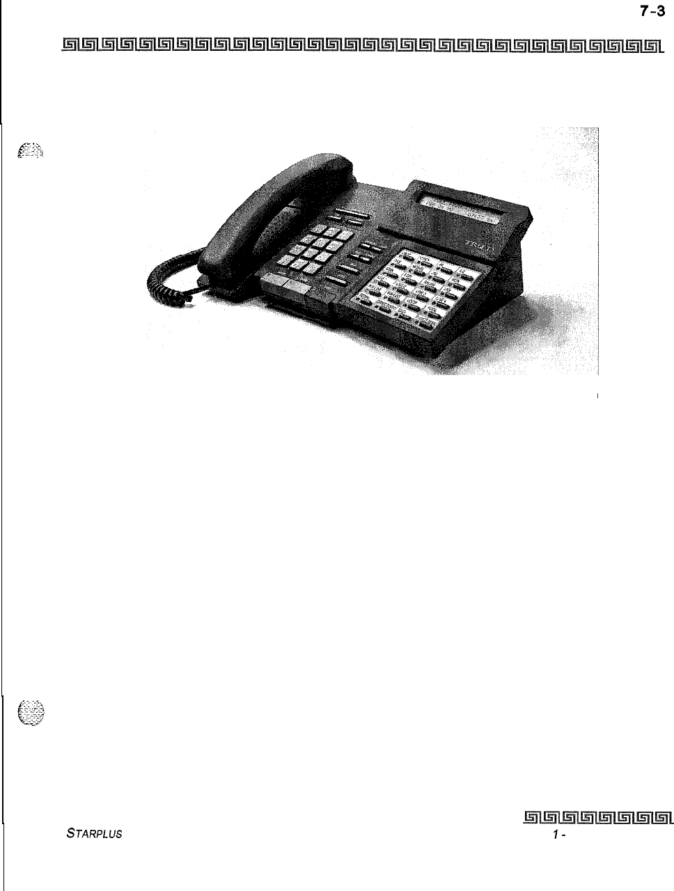
DIGITAL ATTENDANT OPERATIONS
Attendant Digital Key Telephone Station Features
Figure 7-l: Attendant Digital Display Terminal
STARPLUS
Triad-S Product Description Manual
Issue
I-
December 1998
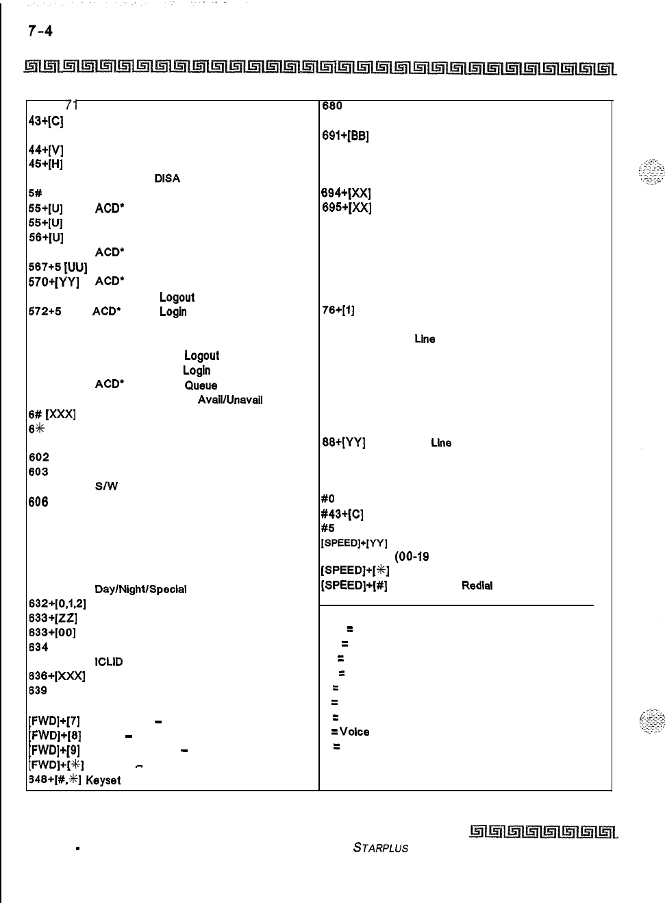
DIGITAL ATTENDANT OPERATIONS
Attendant Digital Key Telephone Station Features
100-l
/l
Triad-S Ext. Numbers
080
Speed Dial Directory
43qc1
Call Park Location O-7 (System) 690
Name in Display Programming
438
Personal Park
BQl+[BB]
Off -Hook Preference Programming
44+[v]
Voice Mail* Group Pilot Numbers O-7
692
Time and Date Programming
45+[H]
Hunt Group Pilot Numbers O-7
(first programmed Attendant)
499 Modem via
DISA
Access or Transfer 893 Directory List Program Code
5#
Forward Override
694+[XX]
Custom Message(s) Program Code
55+[u] ACD”
Group Pilot Numbers O-9
695+[XX]
Distinctive Ringing
55+[u]
UCD Group Pilot Numbers O-7 70 All Call Page (Internal and External)
56+[U]
ACD” Group Pilot Numbers IO-15
71
Internal Page Zone 1
566
ACD”
or UCD Available/Unavailable 72 Internal Page Zone 2
587+5
[VU]
ACD’ or UCD Calls In Queue Display 73 Internal Page Zone 3
57O+(YY] ACD”
Call Qualifier 74
Internal Page Zone 4
571
ACD’ Agent
Logout
75 Internal All Call Page
572+5
[UU]
ACD”
Agent
Login
76+[1]
External Page
573 ACD’ Group Member Status 77 Meet-Me-Page Answer
574 ACD” Agent Help
81
CO
Line
Group 1 (if LCR is enabled)
575 ACD’ Supervisor
Logout
82
CO Line Group 2
576 ACD’ Supervisor
Login 83
CO Line Group 3
577
ACD*
Supervisor Gueue Status Dlsplay
84 CO Line Group 4
578 ACD’ Overflow Sta
AvaibUnavail
85 CO Line Group 5
6#
W=l
Tone Mode Ring Optlon
86
CO Llne Group 6
8%
Dial By Name 87
CO Line Group 7
601
Attendant Override
88+[YY]
All CO
Line
Groups
602
Disable Outgoing CO Line Access
(CO Line Off-Net Fwd)
603
CO Line Off -Net Forward
9
LCR or CO Line Group 1 (if LCR disabled)
605
SIW
Version Display 0
Attendant
606
Clears T-l alarms
#O
Group Call Pick Up (Key and SLT)
607 Attendant Unavailable (Alternate Position)
#43+[c]
Call Park Pickup (Key and SLT)
823
Message Walt
#5
Universal Day/Night Answer
625
Executive Override/Monitor Barge-In
[SPEED]+[W]
Speed Dial Access
626 LCR Queue Cancel
(09-19
Station) (20-99 System)
628
OHVO Enable
[SPEED]+[f]
Save Number Redial
631
DaylNightISpeclal
(Attendant only)
[SPEED]+(#]
Last Number
Redlal
632+[0.1,2]
Background Music
633+[zz]
Personalized Messages
633+[00]
Clear Personalized Messages
XXX
=
Intercom Station Numbers
634
Headset Mode
YY = Speed Dial Bin numbers
635
ICLID
Unanswered Calls Display
ZZ
=
Personalized Messages
636+[XXX]
Station Relocate BB
=
button Number
639
Incoming CO Call Transfer U
=
ACD” (O-15) or UCD (O-7) Group Number
FWD
All Call Forward
C
=
Call Park Location O-7
[FWD]+[7]
No Answer
-
Call Forward
H
=
Hunt Group Number O-7
[FWD]+[B]
Busy
-
Call Forward
V
=
Voice
Mall* Group Number O-7
[FWD]+[Q]
Busy/No Answer
-
Call Forward
P
=
External Page Zone Number (l-2)
;FWD]+[%]
Off -Net
-
Call Forward
348+[#.%]
Keyset
Mode
l
Features available with optional software.
Table 7-l: Digital Attendant Numbering Plan
Issue 1
-
December 1998 STARPLUS
Triad-S Product Description Manual
:
DIGITAL ATTENDANT OPERATIONS
Attendant Unavailable (Alternate Position)
Attendant Unavailable (Alternate Position)
This feature lets attendant stations have a button that places their station in an unavailable mode. When the
gg+: station is in the unavailable mode, the next attendant station receives incoming and dial 0 calls. All other
.
..;
-
.-
_
available attendants receive recalls. This feature is based on the three programmed attendant stations.
1
The first programmed Attendant presses the pre-programmed* Unavailable flexible
button,
or
Dials the Attendant Unavailable code
[607]
on the dial pad. The LED on the flexible
button lights solid, if programmed. Recalls and dial 0 calls that were ringing at the first
Attendant station now ring at the second. If the second Attendant places their phone in
unavailable, the third Attendant takes recall and dial 0 calls.
2
When the first Attendant presses the pre-programmed* Unavailable flexible button
again,
or
Dials the Attendant Unavailable code
[607]
on the dial pad again. The LED on the flexible
button, if programmed, extinguishes. The first Attendant resumes normal operation and
the second Attendant does not receive recalls or dial 0 calls.
Conditions:
+
This feature lets the programmed attendant stations receive attendant recalls and dial 0 calls only. No
other attendant type functions are given to this station when the station is in the attendant mode.
oIf Attendant A (first programmed) is available, incoming, recalls, and dial 0 calls are directed to this
station regardless of other attendant stations status.
oThe special ring mode can be set so the alternate attendant does not receive an incoming CO ring
until the main attendant places their phone in special and unavailable modes.
+
If all attendants in the system are unavailable, no attendants are available for internal/external
callers.
oRecalls are directed to all programmed available attendants.
o
If
only one attendant is programmed in the system, and that attendant is unavailable, users dialing
zero hear an error tone.
1If your system is programmed for System Hold Preference, press HOLD button once for
System Hold and twice for Exclusive Hold.
z
If your system is programmed for Exclusive Hold Preference, press HOLD button once
for Exclusive Hold and twice for System Hold.
STARPLUS
Triad-S Product Description Manual
issue 1
-
December 1998
7-6 DIGITAL ATTENDANT OPERATIONS
Call Park
Call Park
To
place an outside call in park and consult with, page, or call an internal party:
While connected to an outside line:
1
Press TRANS button. The caller is put on hold.
2
Dial
parkin,g
location (430 to 437). Confirmation tone is heard.
3
If you hear busy tone, press TRANS twice and dial another parking location.
Retrieving a Parked Call:
1
Lift handset or press ON/OFF button.
2
Press the
[#I
button.
3
Dial parking location (430 to 437) where the call was parked.
CO Lines Off -Net Forward
-
Incoming (via Speed Dial)
Lets the first attendant station forward incoming CO calls to an off-net location.
In a speed dial bin, store the number of the off-net location where calls are to forward. Follow instructions
provided for storing station or system speed dial numbers.
IDial
[603]
on the dial pad,
or
Press pre-programmed* CO Off -Net Forward button.
2
Dial the CO group access code of the group to be forwarded,
or
Press the CO Line button for an individual CO Line for Off-Net forward.
[81]
= CO Group
1
[82]
= CO Group 2
[83]
= CO Group
3
[84]
= CO Group
4
[SS]
= CO Group 5
[Sb]
= CO Group 6
[87]
= CO Group 7
[88]
= All CO Line
3
Dial the speed bin number that contains the number where calls are to forward.
Confirmation tone is heard.
issue
I-
December 1998
STARPLUS
Triad-S Product Description Manual
,-.c_..._
,._..__
.
.,
_
.._
.
.
I
.-’
--
..
DIGITAL ATTENDANT OPERATIONS
Day/Night/Special Mode
Canceling Off-Net Forwarding
I
Dial
[603]
on the dial pad,
or
Press pre-programmed* CO Off -Net Forward button,
2Dial the CO group access code,
or
Press the CO Line button.
3Dial
[#]
on the dial pad. Confirmation tone is heard.
Conditions:
+
When CO lines are off-net forwarded, these lines will display unique flash rates at the attendant
station.
*A
Flex Button must be programmed for this feature to operate. Refer to Table
5-3:Fle.x
Button Programming
Codes, Chapter
5,
page 5-44.
Day/Night/Special Mode
Any designated attendant can place the system into Night Service by:
1
Pressing the pre-programmed Night Service button (DND by default) once, activates the
night mode (LED solid). Pressing the DND button again, activates the special mode (LED
flashes
@
240 ipm).
2
The DND button (by default) acts as a toggle in this manner, starting in the day mode,
night mode, and special mode.
Directory Dialing
Directory dialing allows station users to obtain a directory of station users and have the system dial the
extension that is currently displayed. The Triad-S system provides locations for up to
200
names.
Directory dialing also lets users program a name with a speed dial bin for later locating a speed dial number,
When prompted, the system displays the name associated with a speed dial number on the LCD display. The
user may then have the system dial the number.
$4
Directory dialing enables users to associate a name with an entry in the local number/name translation table.
‘?$
When prompted, the system displays the name associated with the table on the LCD display. The user may
then have the system dial the number.
STARPLUS
Triad-S Product Description Manual
Issue
I
-
December 1998
:
.
..-
7-8 DIGITAL ATTENDANT OPERATIONS
Directory Dialing
The Directory Dialing list may be programmed and maintained at the first assigned attendant station.
However, this admin routine lets the system programmer maintain the list locally (at Attendant) or
remotely via modem access.
Directory dialing may also be used to transfer a call from one station to another.
To view the directory list:
IDial the Directory List dial code
[680]
on the dial pad,
or
Press the pre-programmed* flex button programmed as a directory dialing button.
2
Press a button on the key pad, once, twice or three times, that represents the letter of
the alphabet to begin viewing the list of names (i.e., when 2 is first pressed, it produces
names beginning with A. When 2 is pressed a second time, it produces names beginning
with
6.
Pressing 2 a third time produces the names beginning with C). The alphabet is
represented on the key pad as shown in
Figwe52:Key
Ptid
-
DialBy Name, Cbapter5, page
5-33.
Also refer to
Figures-3:Key Pad
-
Directory Dialing Cbapter5j page 5-34
3
Names beginning with the letter chosen display on the LCD display.
If
there are no names in the Directory List beginning with the desired letter,
a name with the next higher letter displays on the LCD display.
4
Dial
[4+]
to scroll up (next entry) through the list,
or
Dial [#] to scroll down (previous entry) through the list,
or
Press another key to view the list for a different letter of the alphabet.
5
When the desired name displays on the LCD, press the SPEED button to automatically
dial the destination station or outside phone number (via speed dial).
Conditions:
+
If the desired party is an intercom station, that station is signaled according to their intercom
selector switch (SLT stations tone ring).
+z+
If the desired party is associated to a speed dial bin, the system selects a CO line and dials the
number programmed into the speed dial bin. Call progress tones are then heard.
To Transfer a Call using Directory Dialing:
While on a call:
1
Press the TRANS button.
IIssue I- December 1998
STARPLUS
Triad-S Product Description Manual
I
:
DIGITAL ATTENDANT OPERATIONS
Directory Dialing
7-Q
2
Dial the Directory Dial Code
[680]
on the dial pad,
or
Press a pre-programmed* flex button programmed for directory dialing,
3
Press the SPEED button to automatically dial the destination station.
4
Hang up to complete the transfer.
Culls
may be transferred to
inter&
stations on/y. An otternpt to trunsfer
u
cull
of f-net
(via
u
Speed
dial
bin) results in the
cull recalling
upon going
on-hook.
Programming
Directory dialing allows station users to obtain a station users directory and have the system dial the
extension currently displayed. The Triad-S system provides locations for up to 200 names.
Directory dialing also lets users program a name with a speed dial bin for later locating a speed dial number.
When prompted, the system displays the name associated with a speed dial number on the LCD. The user
may then have the system dial the number.
Directory dialing enables users to associate a name with an entry in the local number/name translation table.
When prompted, the system displays the name associated with the table on the LCD. The user may then have
the system dial the number.
The Directory Dialing list may be programmed and maintained at the first assigned attendant station.
Directory dialing may also be used to transfer a call from one station to another.
Method One:
To enter, edit or erase names that appear in the Directory List for stations or speed dial numbers:
8Dial the Directory List program code
[693]
on the dial pad. The HOLD button is lit. The first entry
(000) in the Directory List displays on the phone as follows:
DIR LST AAA
BIN/KM:
XXX
nnnnnnnnnnnnnnnnnnnnnnnn
AAA = Directory List entry number
(000-199)
XXX = Station Number, System Speed Dial bin Number, or Local Number/Name Translation
Table
number
nnn = Programmed Name (blank if none)
STARPLUS
Triad-S Product Description Manual
Issue
I-
December 1998
DIGITAL ATTENDANT OPERATIONS
Directory Dialing
To Select a different entry in the Directory List:
1
Enter the 3-digit (000-199) entry number on the dial pad,
Of
Dial
[%]
to scroll up (next entry) through the list,
Of
Dial [#] to scroll down (previous entry) through the list.
2
Press the TRANS button to select the entry.
To Enter or Change the current name shown on the display:
1
Press the MUTE button.
2
Enter the name (up to 24-characters) by using keys on the dial pad as shown
inFi,we5-
2:Kq
Pud
-
Dial By
Name,
Chpter
5,
puge
5-33
and using the key pad codes listed in Table
5-5:Other Key Pad Codes, Chapter 5, page 5-65.
3
Press the SPEED button when finished. Confirmation tone is heard and the display
updates.
4
Press HOLD, use
[%]
or
[#]
to scroll to next entry.
To enter the intercom number to associate with the name:
1
Press the TRANS button.
2
Enter the 3-digit station intercom number.
3
Press the SPEED button to save the entry. Confirmation tone is heard and the display
updates.
4
Press HOLD, use
[X]
or [#] to scroll to next entry.
To clear an entry:
I
Select the desired entry using the Method One procedure.
2
Press the FLASH button to erase the entry.
3
Press the SPEED button. Confirmation tone is heard and the entry is erased.
Method Two:
This method may be used to enter names associated with the Local Number/Name Translation Table only.
et*
Dial the Directory List program code
[693]
on the dial pad. The HOLD button is lit. The first entry
(000) in the Directory List displays on the phone as follows:
DIR LST AAA
BIN/ICM:
XXX
nnnnnnnnnnnnnnnnnnnnnnnn
AAA = Directory List entry number (000-199)
Issue
7
-
December 1998 S
JARPLUS
Triad-S Product Description Manual
DIGITAL ATTENDANT OPERATIONS
Directory Dialing
XXX = Station Number, System Speed Dial bin Number, or Local Number/Name Translation Table
number
nnn = Programmed Name (blank if none)
a=..
,T
.‘Z.
\
6.
I...
-.
fy
;-
,
y,-
To Select a different entry in the Directory List:
1
Enter the 3-digit (000-199) entry number on the dial pad,
or
Dial
[+K]
to scroll up (next entry) through the list,
or
Dial [#] to scroll down (previous entry) through the list.
2Press the TRANS button to select the entry.
To enter a name along with a local number/name translation table number:
1
Press the TRANS button.
2
Dial the 3-digit local number/name translation table number (600-799) that represents
the telephone number.
3
Press the SPEED button. Confirmation tone is heard and the entry is stored.
4
Press HOLD, use
[+!+I
or
[#]
to scroll to next entry
To Enter or Change the current name shown on the display:
1
Press the MUTE button.
2Then enter the name (up to 24-characters may be entered) by using keys on the dial pad
as shown in
Figure52:Key Pad
-
Dial By Name, Chapter5,
page533
and using the key pad
codes listed in
Table 5-5:Other Key Pad Codes, Chapter5,
page565.
The display updates as
the name is entered.
s
Press the SPEED button when finished. Confirmation tone is heard.
4Press HOLD, use
[%]
or [#] to scroll to next entry.
The Local Number/Name Translation Table can be used to enter additiond
speed dial numbers used for directory dial or dial by name. The name
entered into the local number/name translation table is irrelevant when
used with directory dialing and dial by name. Note that the numbers entered
into this table are limited to 14 digits and are covered by to// restriction
rules.
STARPLUS
Triad-S Product Description Manual
Issue
I- December 1998
;.
7-12
DIGITAL ATTENDANT OPERATIONS
Directory Dialing
Method Three:
This method may be used to enter names associated to a system speed dial bin only.
oDial the Directory List program code
[693]
on the dial pad. The HOLD button is lit. The first entry
(entry 000) in the Directory List then displays on the phone as follows:
DIR LST AAA
BIN/ICM:
XXX
nnnnnnnnnnnnnnnnnnnnnnnn
AAA = Directory List entry number (000-199)
XXX = Station Number, System Speed Dial bin Number, or Local Number/Name Translation Table
number
nnn = Programmed Name (blank if none)
To Select a different entry in the Directory List:
1
Enter the 3-digit (000-199) entry number on the dial pad,
or
Dial
[+I+]
to scroll up (next entry) through the list,
or
Dial [#] to scroll down (previous entry) through the list.
2
Press the TRANS button to select the entry.
To enter a name with a system speed dial bin:
1
Select the desired entry using Method Three procedure.
2
Dial the system speed dial bin location (20-99).
3
Press the SPEED button. Confirmation tone is heard and the entry is saved.
4
Press HOLD, use
[X]
or
[#]
to scroll to next entry.
To enter or change the current name shown in the display at this point:
1
Press the MUTE button.
2
Enter the name (up to 24 characters may be entered) by using keys on the dial pad as
shown in
Figure5-2:Key Pad- DialBy Name, Chapter5,page5-J.jd
and using the key pad
codes listed in
Table5-5:Other Key PadCodes, Chapter5,page5-65.
3
Press the SPEED button when finished. Confirmation tone is heard and the display
updates.
4
Press HOLD, use
[+I+]
or [#] to scroll to next entry.
Issue
1
-
December 1998 STARPLUS
Triad-S Product Description Manual
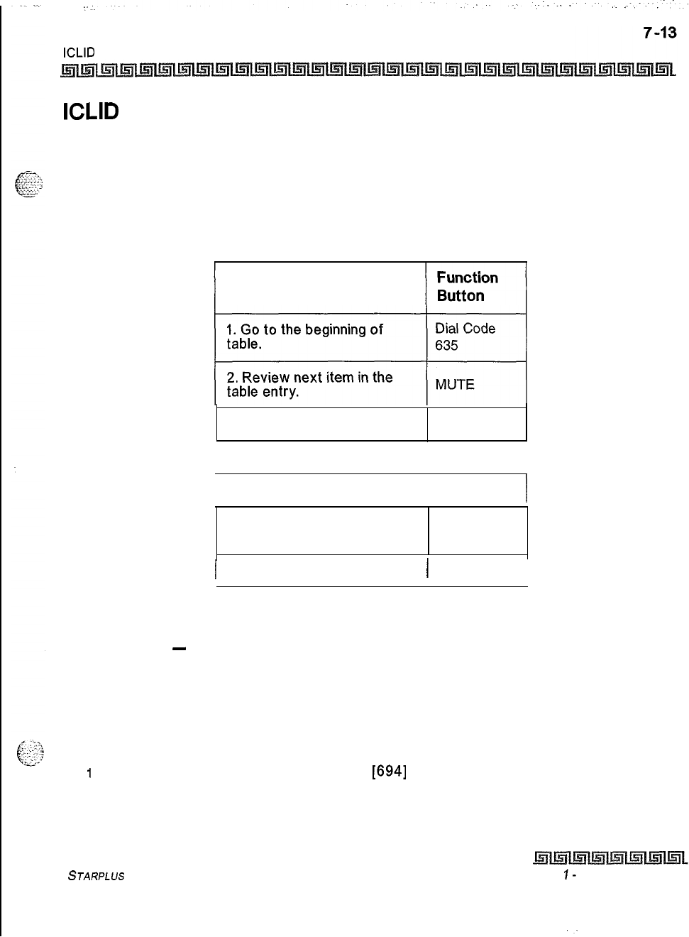
DIGITAL ATTENDANT OPERATIONS
ICLID Unanswered Call Management Table
ICLID Unanswered Call Management Table
An Unanswered Call Management Table with 100 entry capacity for the Triad-S system is maintained. The
calling number/name information pertaining to any unanswered call is placed in this table at the time the
system determines the call was abandoned.
This table may be accessed from any station display phone so that the unanswered calls may be reviewed and
handled by the end user. Upon entry into the review process, the functions available to a phone are:
Function
3. Step to next table entry. HOLD
4. Delete this table entry. FLASH I
5. Exit table review function.
ON/OFF
I
6. Step to previous table
entry. TRANSFER
1 7. Call Back. 1 SPEED I
Table 7-2: ICLID Unanswered Call Management
Messages
-
Custom
This feature lets the system administrator enter up to ten custom messages for use by system station users.
These messages may be specified and customized by the customer on a system-wide basis.
The system administrator (Station 100) programs the ten custom messages at the first attendant station as
follows:
1
Dial the Custom Message program code
[694]
on the dial pad.
STARPLUS
Triad-S Product Description Manual
Issue
I-
December 1998
‘-
.I.
DIGITAL ATTENDANT OPERATIONS
Messages
-
Custom
The following message is shown on the display phone:
ENTER MSG NO
MMM DD YY HH:MM
am
i
2
Enter the Z-digit message bin number
[21-301.
Then the following display is shown after the bin # has been selected.
mmmmmmmmmm...
ENTER MSG:
3
Enter the custom message using the dial pad keys to enter the letters as shown
inFigure
5-2:Key
Pad
-
Dial
l?y
Name, Chapter 5, page 5-33.
For key pad codes, refer to Table
5-
5:Otber Key Pad Codes, Chapteci, page 5-65.
Up to
24
alphanumeric characters may be entered for the custom message (this represents 48 digits
entered).The actual characters display as the digits are being entered while programming the messages.
The attendant must go idle after programming a message before another message may be programmed.
oThe user then presses the HOLD button to enter the message and confirmation tone is heard.
Conditions:
The telephone receiving the message or programming must be a display telephone.
Key telephones and
SLTs
can leave a message.
SLTs
are notified that they left a message with a
warning tone when going off-hook.
Incoming and outgoing calls are not inhibited with a message displayed.
When a message is displayed by a key telephone, the DND button LED flashes at the
15
ipm rate.
When DND is invoked on the telephone, the message is canceled.
Message Access (with a desired message) may be assigned to a flex button.
Message status is stored in a battery protected memory area for retention across a power failure or
system reset (soft or hard).
The Message Access function is assigned to a station flex button in database administration.
A station user may store any of the available messages under a flex button assigned as a Message
Access button.
The ten Custom Messages display in a similar fashion as Canned messages. The idle station display
shows the message that was activated at the station and a calling station receives the STA XXX or
name-in-display followed by the programmed custom messages.
This feature is not available for use at attendant stations.
ksue
I-
December
IQ98 STARPLUS
Triad-S Product Description Manual
I
~.
DIGITAL ATTENDANT OPERATIONS 7-15
Outgoing Access
-
Attendant Disable
Outgoing Access
-
Attendant Disable
The attendant station can disable CO lines, preventing outgoing CO calls,
1
Lift handset or press ON/OFF button.
2
Dial
16021
on the dial pad. Confirmation tone is heard.
3
Press the line button(s) of the CO Line(s) to disable. Confirmation tone is heard and the
CO Line button(s) LED is flashing.
4
To reactivate the CO Line(s), repeat the steps to disable it.
Override
If Attendant Override is allowed, Attendant(s) stations may override or call stations that are busy or in Do Not
Disturb.
If the Attendant calls a station that is busy on a CO call and wishes to alert them of a waiting call:
1
Press the pre-programmed* ATTN OVERRIDE button
[601].
Three short tone bursts are
presented to the called party.
2
After five (5) seconds, the station’s CO line is automatically placed on hold and the
Attendant is cut-through.
If the Attendant calls a station that is in Do Not Disturb mode and wishes to alert them of a call:
oPress the pre-programmed* ATTN OVERRIDE button. The station is signaled with a Camp-On tone.
*A Flex Button must be programmed for this feature to operate. Refer to Table 5-3:Flex Button Programming
Codes,
Clya#
ter
5,
page 5-44..
Outside Call
-
1
Lift handset.
2
Press slow flashing outside line button. (If your telephone is programmed with Preferred
Line Answer, you may answer an outside line by lifting the handset.)
Outside Call
-
Place
1
Press outside line button. ON/OFF button LED lights and dial tone is heard.
2
Dial desired party.
3
When called party answers, lift handset to converse or use speakerphone
STARPLUS
Triad-S Product Description
Manual
Issue I- December 1998
7-16 DIGITAL ATTENDANT OPERATIONS
Recall
Recall
When an outside line remains on hold for an extended time period, a
real1
ring is heard.
1
Press outside line button flashing at a very fast rate.
2
Lift handset to converse.
Conditions:
$.
Recall does not apply to intercom calls placed on hold.
Release Button
Lets the station user disconnect calls while off-hook (on handset, not speakerphone), speeding up call
handling time.
While off-hook (on handset, not speakerphone) on an intercom call, transfer sequence, page
announcement or CO call:
9Press the pre-programmed* RELEASE button to terminate intercom call, transfer sequence, page
announcement or CO call.
*AFlex
Button must be programmed for this feature to operate. Refer to
Tuble5-3:FZexButton Programming
Codes, Chapter
5, page 5-44.
Ring Mode
Conditions:
+
The three attendant stations can invoke or remove this mode. When one attendant station activates
this mode, other attendant stations have their DND button lit accordingly.
*$
Each CO line has a special mode ring assignment associated with it. Up to 10 stations per CO line
may ring in the special mode.
$3
This feature overrides the day/night scheduler feature.
Setting System Time and Date
Must be set by the first programmed attendant.
1
Dial
[692]
on the dial pad. Confirmation tone is heard.
2
Enter date and time as follows:
YYMMDDHHMM
issue 1
-
December 1998 STARPLUS
Triad-S Product Description Manual
“.,
-:_
;:--..;..::
‘i
:F---
DIGITAL ATTENDANT OPERATIONS
Software
Version Display
IY
= year 00-99
MM =
menthol-12
DD = day 01-31
(?&
HH = hour 00-23
MM = minute 00-59
When the correct number of digits are entered, confirmation tone is heard. Pressing the ON/OFF button to
OFF updates the display.
Software Version Display
The current system software can be viewed by the first programmed Attendant. This display shows the
version number and the level of software in english.
At the first Attendant station:
+z+
Dial the S/W Display code
[605]
on the dial pad. The top line of the LCD continues to show the same
data as it currently displays, while the bottom line of the LCD shows the following in place of the
time/date information:
STARPLUS
BASIC
STARPLUS VOICE MALL
STARPLUS
ACD
Conditions:
*:a
The station must be an LCD type to view the information,
Speed Dial
-
System Storing
System Speed numbers must be entered by the first programmed attendant. If no attendant is specified,
enter at Station 100.
1
Press SPEED once, then press a desired outside line key or select an outside line
automatically by pressing the SPEED button a second time.
2
Dial the System Speed bin location (20-99).
3 Dial telephone number.
4
Press the SPEED button.
5
Hang up.
STARPLUS
Triad-S Product Description Manual
Lss~~e
I-
December 1998
:
7-18 DIGITAL ATTENDANT OPERATIONS
Speed Dial
-
System Storing
a.
Pressing the TRANS button during number entry initiates a Pulse-To-Tone switcho-
ver. Pressing the HOLD button during number entry inserts a Pause. Pressing the
FLASH key inserts a Flash into the speed number.
b. Pressing the TRANS button as the first entry in the speed bin inserts a no-display
character causing the numbers stored in the bin not to display on the Digital Terminals
when the bin is accessed.
Speed Bin numbers
60-99
are not monitored by Toll Restriction.
issue
I-
December 1998 STARPLUS
Triad-S Product Description Manual
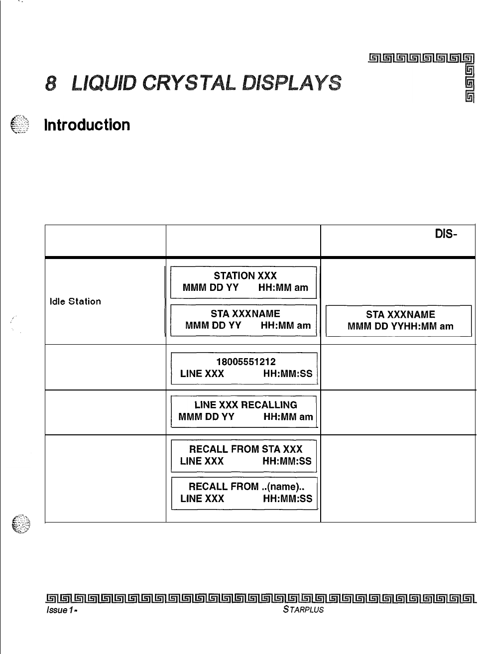
The display is arranged into an upper and lower field. The upper field displays the current activity of the
telephone. The lower field is divided into two sections. The left section of the lower field displays the date,
speed bin number, connected intercom station or outside line number. The right section of the lower field
displays the current time or elapsed time on an outside call. The following table shows what displays on the
LCD
displays based on the function performed.
FUNCTION CALLING STATION CALLED STATION
DIS-
DISPLAY PLAY
Manually dialing
outgoing calls
]I
Recalling line
from Hold
]]
Recalling line
ppyq
from another station
]I
* Features available with optional software
Table 8-l: Liquid Crystal Displays (LCD)
issue
7
-
November 1998
STARPLUS
Triad-S Product Description Manual
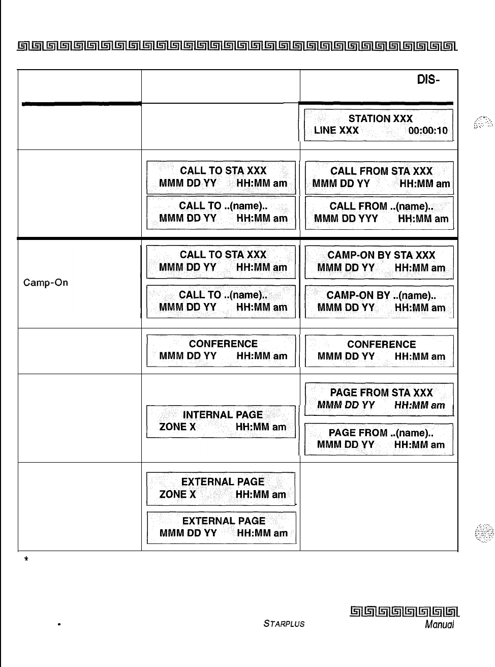
8-2 LIQUID CRYSTAL DISPLAYS
INTRODUCTION
FUNCTION
Connected to an
incoming CO line
CALLING STATION CALLED STATION
DIS-
DISPLAY PLAY
-1
Intercom Call
~lil
)I/1
Conference
4111
Internal Page
11
~~1
External Zone Page
and
pi-z=zq
External All Call Page
11
*
Features available with optional software
Table 8-l: Liquid Crystal Displays (LCD)
issue 1
-
November 1998 STARPLUS Triad-S Product
Description
Manual
,,<<
-
1:.
::‘A
,:
,...
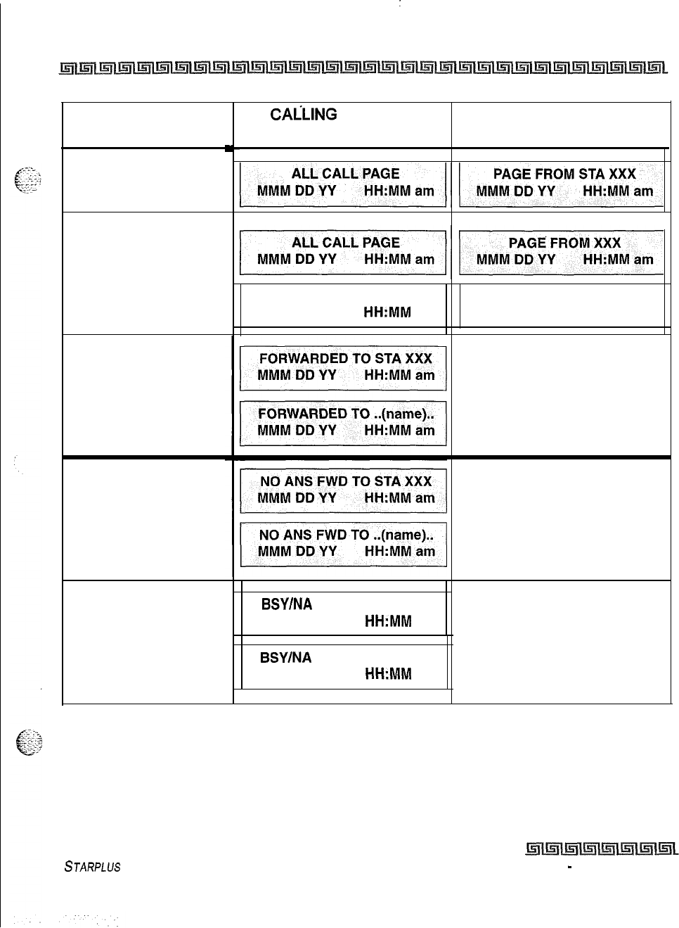
:
LIQUID CRYSTAL DISPLAYS 8-3
INTRODUCTION
FUNCTION
All Call Page
Meet Me Page
Station Call Forward
(Originating Station)
(Name in Display)
Station No-Answer
Call Forward
(Originating Station)
Station Busy/No-
Answer Call Forward
(Originating Station)
CALLING
STATION
DISPLAY
CALL FROM XXX
MMM DD YY
HH:MM
am
BSY/NA FWD TO STA XXX
MMM DD YY HH:MM
am
BSY/NA FWD TO
..(name)..
MMM
DD YY
HH:MM
am
CALLED STATION DIS-
PLAY
CALL TO XXX
MMM DD YY HH:MM am
* Features available with optional software
Table 8-1: Liquid Crystal Displays (LCD)
STARPLUS
Triad-S Product Description Manual
Issue I
-
November 1998
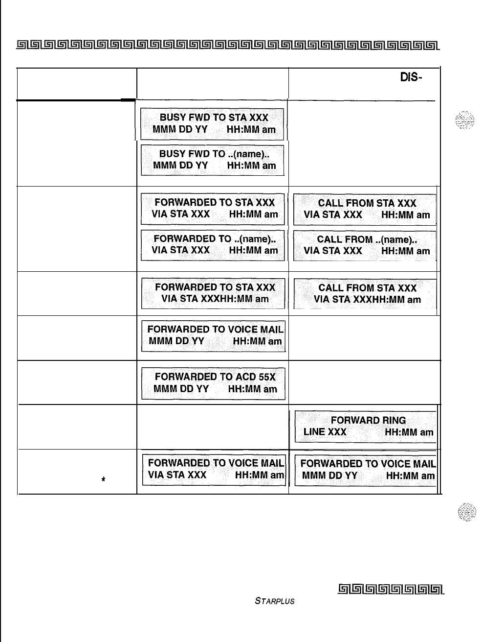
8-4 LIQUID CRYSTAL DISPLAYS
INTRODUCTION
FUNCTION CALLING STATION CALLED STATION
DIS-
DISPLAY PLAY
Station Busy
Call Forward
-cc
(Originating Station)
1
Forwarded Call
44
(Name in Display)
pg-G&-q/
Forwarded Intercom
Call
y/
Station Forward to
Voice Mail Group
(Station Idle)
51
Station Forward to
ACD* or UCD Group
(Station Idle)
41
Preset Forward
Station call to
Station Forwarded to a
Voice Mail Group
*
* Features available with optional software
Table 8-l: Liquid Crystal Displays (LCD)
Issue I- November 7998
STARPLUS
Triad-S Product Description Manual
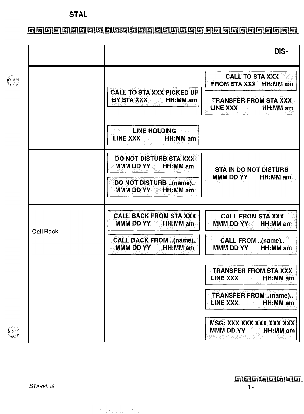
LIQUID CRY
S-I-AL
DISPLAYS 8-5
INTRODUCTION
FUNCTION CALLING STATION CALLED STATION
DIS-
DISPLAY PLAY
Call Pick Up
(1
pi5zzTq\
Exclusive Hold
41
Do Not Disturb
~~~
MMM
DD YY HH:MM am
Outside Line Transfer
Message Waiting
4
* Features available with optional software
Table 8-l: Liquid Crystal Displays (LCD)
STARPLUS
Triad-S Product Description Manual
Issue
I-
November 1998
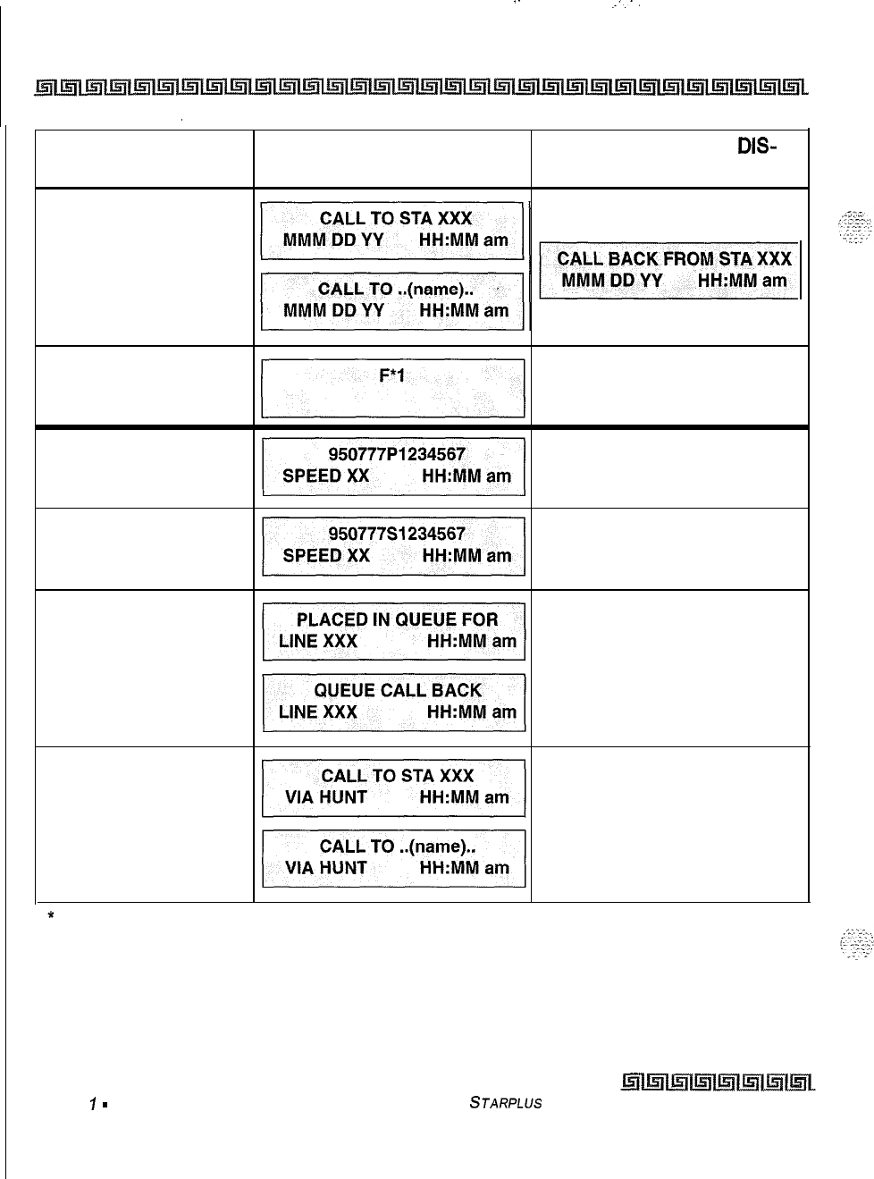
.-
.._-.
8-6 LIQUID CRYSTAL DISPLAYS
INTRODUCTION
FUNCTION CALLING STATION CALLED STATION
DIS-
DISPLAY PLAY
Reply to a
Message Waiting
Programmed Flash
Command (F)
Programmed Pause
Command (P)
Programmed
Pulse-To-Tone
Switchover (S)
CO Line Queuing
Hunt Groups
*
Features available with optional software
Table 8-1: Liquid Crystal Displays (LCD)
Issue
1
-
November 7998 STARPLUS
Triad-S Product Description Manual
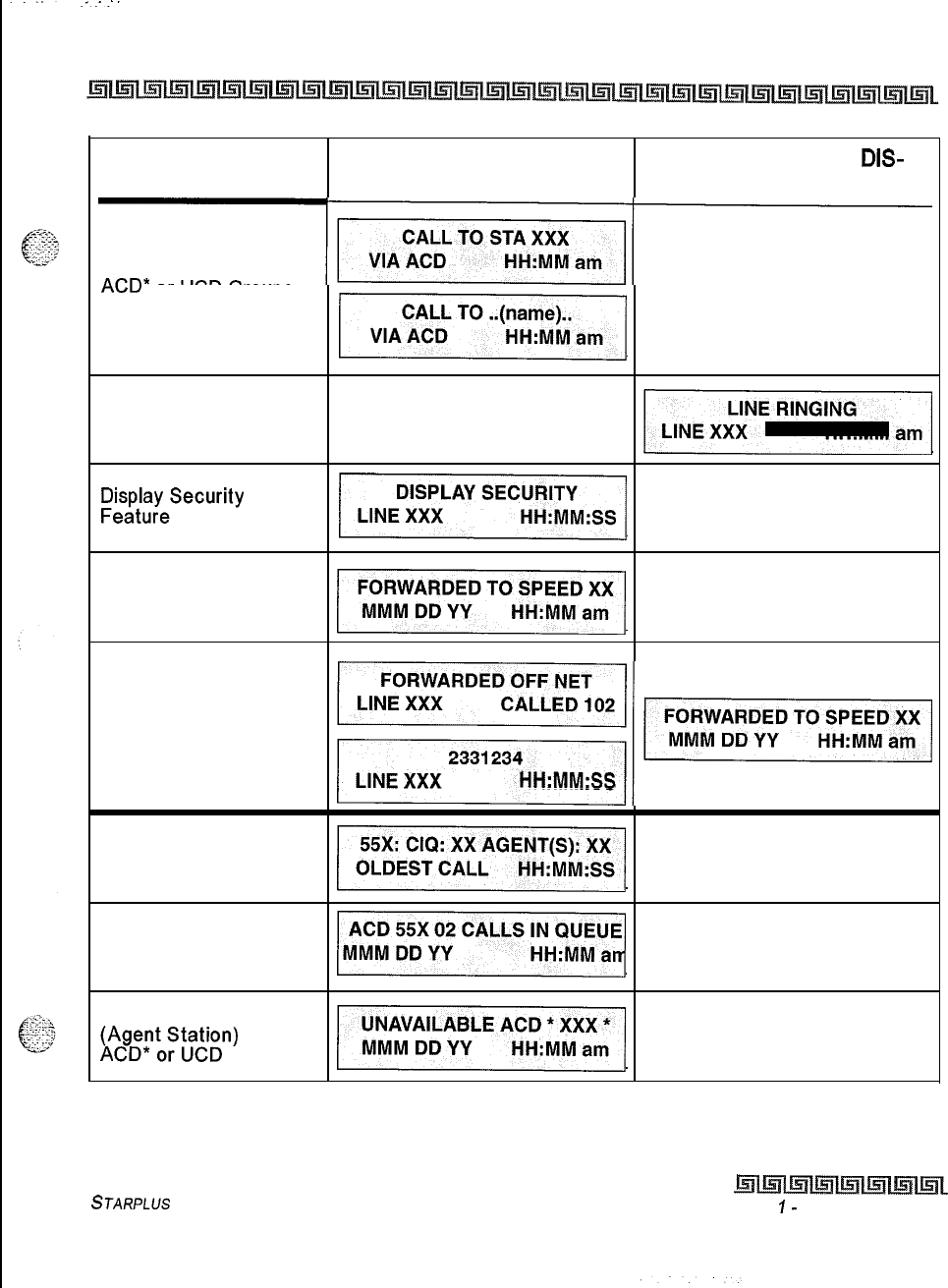
LIQUID CRYSTAL DISPLAYS 8-7
INTRODUCTION
FUNCTION CALLING STATION CALLED STATION
DIS-
DISPLAY PLAY
-j7iisEq~
ACD*
or UCD Groups
-1
Ringing CO Lines
FFitl;ayeSecurity
y
Station Forwarding
Off-Net
11
Call to Station
Forwarded Off -Net
(before and after a call
is answered)
~~
LINE XXX HH:MM:SS
Calls in Queue
(Supervisor)
~
Calls in Queue
(Using Dial Code)
ACD* or UCD
5
Unavailable Mode
~~;p~;~)
qi
* Features available with optional software
Table 8-l: Liquid Crystal Displays (LCD)
STARPLUS
Triad-S Product Description Manual
Issue
I-
November 1998
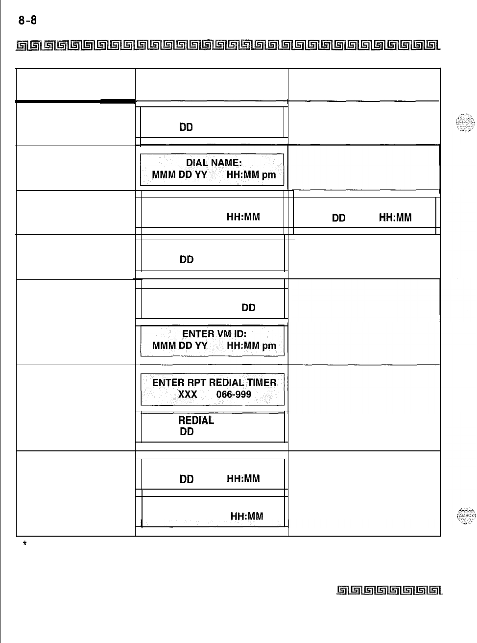
8-8
LIQUID CRYSTAL DISPLAYS
INTRODUCTION
FUNCTION
Station call to
Voice Mail Group
Pilot Number
Dial By Name
Off-Hook Voice Over
(OHVO)
Executive Override
Voice Mail* Transfer
with ID Digits
Repeat Redial
Call Coverage Station
After call is answered
at coverage station.
CALLING STATION
DISPLAY
CALL TO VOICE MAIL
MMM
DD
YY
HH:MM am
ANNOUNCE TO STA XXX
MMM DD YY HH:MM am
MONITORING STA XXX
MMM
DD
YY
HH:MM am
CALL TO VOICE MAIL
VIA XXX
MMM
DD
YY
RPT
REDIAL
CALLBACK:
MMM
DD
YY
HH:MM pm
CALL TO STA XX
MMM
DD
YY
HH:MM am
CALL TO STATION XXX
FROM STA YYY HH:MM am
CALLED STATION DIS-
PLAY
ANNOUNCE FROM STA XXX
MMM
DD
YY
HH:MM am
*
Features available with optional software
Table 8-l: Liquid Crystal Displays (LCD)
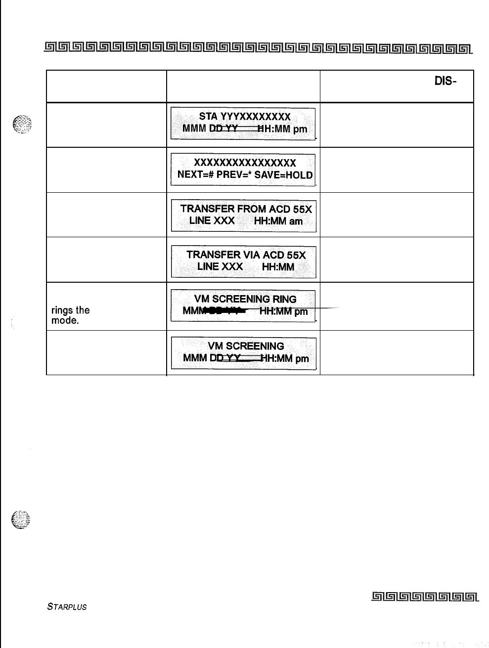
LIQUID CRYSTAL DISPLAYS 8-9
INTRODUCTION
FUNCTION CALLING STATION CALLED STATION
DIS-
DISPLAY PLAY
Name/Number Display
at Idle
Scrollable Canned
Messages
~
ACD* Transfer Display
u
ACD* Overflow Station
receives an Overflow
Call
/I
Answering Machine
Emulation: When a call
rinogiethe
station in ring
Answering Machine
Emulation: When station
monitors caller in VM.
* Features available with optional software
Table 8-l: Liquid Crystal Displays (LCD)
STARPLUS
Triad-S Product Description Manual Issue I- November 7998
I
-.-
..
.
.
.
.
.-...
8-10 LIQUID CRYSTAL DISPLAYS
INTRODUCTION
Issue
I
-
November 1998
STARPLUS
Triad-S Product Description Manual
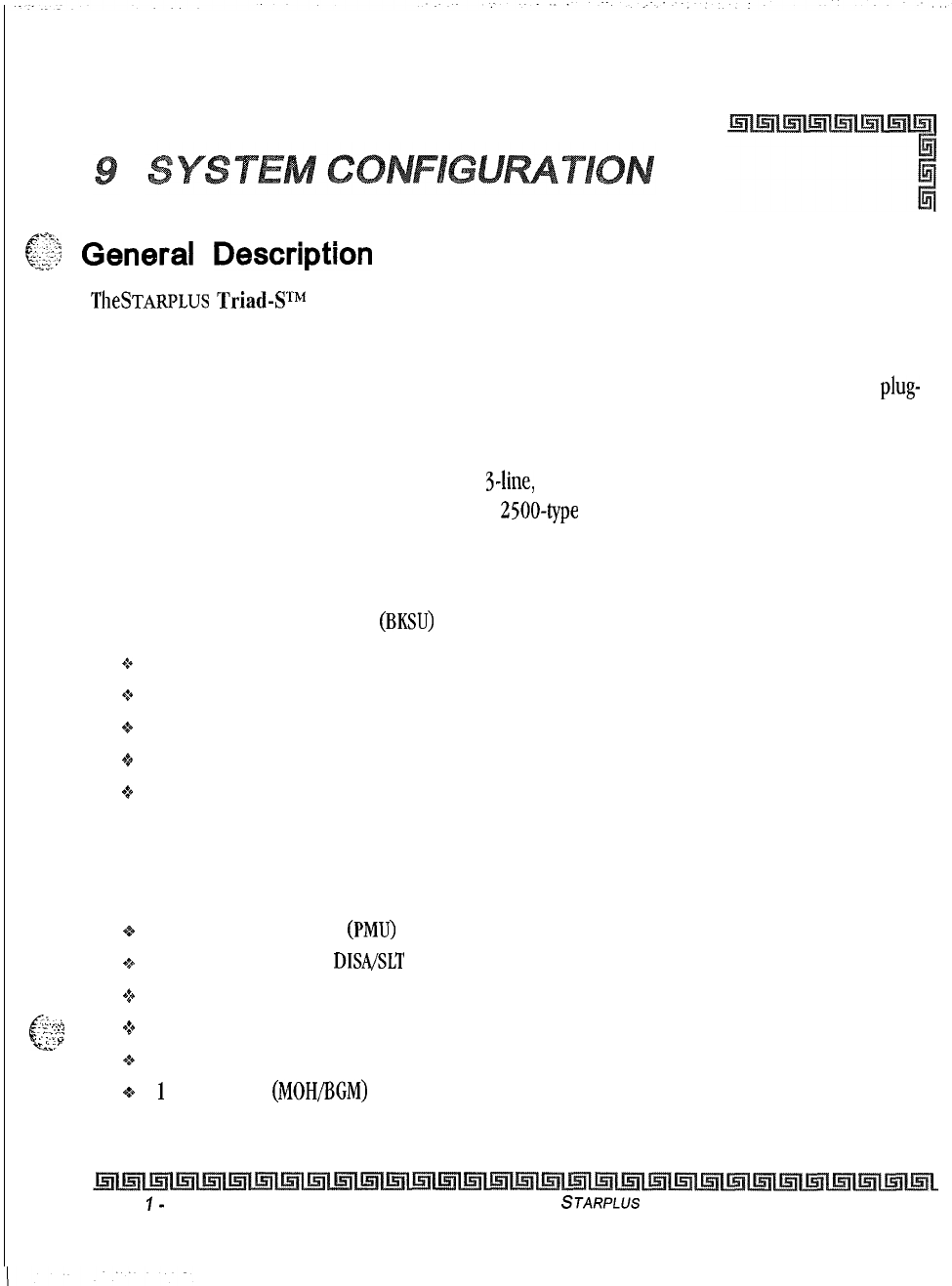
c$$
General
Description
TheSTARPLUs
Triad4Pf
is a digital telephone system designed to meet the needs of small size business
offices, The system incorporates state-of-the-art digital technology for command and voice switching utilizing
a Pulse Code Modulation/Time Division Multiplexing switching matrix. The system achieves flexibility by
employing a universal card slot architecture with Basic and Expansion cabinets. These cabinets house plug-
in circuit boards that support different types of telephone instruments.
The system begins at a 3-line, g-station capacity and can expand to a maximum configuration of a 12-line,
32-station capacity. Expansion is accomplished in 3-line, S-station increments. The system supports
proprietary digital terminals or standard touch tone
2500-type
terminals.
Basic Key Service Unit (BKSU)
The
Triad-S
Basic Key Service Unit
(BKSU)
is a wall mountable cabinet that houses the following:
+
Main CPU board
+
System ROM
0 System RAM
+z+
Power supply
+
Circuitry to support two 3x8 boards and the expansion cabinet with two 3x8 boards
Thus, the maximum capacity of the BKSU is 6 CO lines and 16 stations (8 digital and 8 digital or SLT). Every
BKSU supports three loop start CO lines and eight standard digital station interfaces from the factory.
The BKSU also has these standard features:
e
1 Program Module Unit
(PMU)
that provides system software (sold separately)
Q
1 DTMF Receiver (for
DIWSLT
applications)
+
2 Programmable relays with dry contacts rated at 24V DC, 1 amp
.,
. .
.,..
-6
-_
.._,
c
Y-y’;;
+1 External Page Port
1..
.-
-
::’
+:b
Battery Backup for System Database
0
i
Music Input
(MOHBCM)
The BKSU main board can accept the following modules:
Issue
I-
December 1998 STARPLUS
Triad-S Product Description Manual
Q-2
SYSTEM CONFIGURATION
Expansion Key Service Unit (EKSU)
.:.
1 Miscellaneous Service Unit
(MIS@
that provides two
RS232C/9
pin ports and second music
source circuitry
91 Modem Unit (MODU, 9600 baud modem) for remote administration
+1 4 Circuit DTMF Receiver (DTMF-A) provides 4 DTMF receivers
61 3x8 CKIB or
3x8
CSIB
(one CKIB installed in every BKSU standard)
A number 12 AWG copper wire should be used to ground between the ground source and the BKSU (25 feet
maximum). Attach this wire to the ground lug on the lower right side of the BKSU.
Expansion Key Service Unit (EKSU)
The Triad-S Expansion Key Service (EKSU) is a wall-mountable cabinet that houses the circuitry to support
two 3x8 boards. The EKSU mounts directly above the BKSU. The EKSU has cables that connect power and
digital communications form the EKSU to the BKSU.
The EKSU can provide six additional CO lines and sixteen station growth that takes the system to it’s
maximum configuration of twelve CO lines and 32 stations.
The EKSU contains one expansion interface board (EIB) which includes power supply and connector
interface buses. A number 12 AWG copper wire should be used to ground between the ground source and
the BKSU (25 feet maximum). Attach this wire to the ground lug on the right side of the EKSU.
Peripheral Boards
Three 8 CO Line and Eight Digital Station Board (CKIB)
This board provides three loop start CO line interfaces and eight Digital Key Telephone interfaces. This
board can be installed in the BKSU or EKSU. If all CKIB boards are installed in the BKSU and EKSU, the
system capacity is 12 CO lines and 32 digital stations.
The CO line interfaces are brought out on the right side of the
BKSU/EKSU
utilizing
RJll
connectors. The
digital station interfaces are brought out utilizing a 50-pin amphenol connector on the left side of the
BKSU/EKSU.
The station interface for stations loo-107 also provides the wiring interface for the additional features that
require input/output connections. These features are music sources, relay connections, and external page
connections.
Issue
1
-
December 1998
STARPLUS
Triad-S Product Description Manual
SYSTEM CONFIGURATION
Optional Boards
Three 8 CO Line and 8 Single Line Station Board (CSIB)
This board provides three loop start CO line interfaces and eight Single Line Telephone interfaces. These
interfaces support 2500 touch tone telephone instruments and/or voice mail interfaces. This board can be
installed in the BKSU or EKSU. A maximum of three
CSIBs
may be installed between the
BKSU/EKSU
to
provide a maximum of 24 single line interfaces.
The CO line interfaces are brought out on the right side of the
BKSU/EKSU
utilizing
RJll
connectors. The
digital station interfaces are brought out utilizing a 50-pin amphenol connector on the left side of the
BKSU/EKSU.
The CSIB can accept the optional Message Wait Unit (MSGU) to provide message wait lamp capability to the
eight instruments attached.
Optional Boards
Miscellaneous Service Unit (MISU)
This board provides two
RS232C
interfaces for system programming, caller ID, and SMDR applications. The
board also contains a second music source to increase the music channels in the system from one to two.
The board installs in the BKSU.
Modem Unit (MODU)
This board provides a 9600 baud modem for remote system programming. The modem is accessed by
dialing station
499.
Message Wait Unit (MSGU)
This board provides message wait lamp capability to the eight attached SLT instruments. This board is
installed on the CSIB. Each CSIB may have one MSGU installed.
DTMF Receiver Unit (DTMF-A)
This board provides four DTMF receivers for CSIB use and should be installed any time a CSIB board is
installed in the system. The BKSU supports one DTMF-A unit.
STARPLUS
Triad-S Product Description Manual Issue I- December 1998
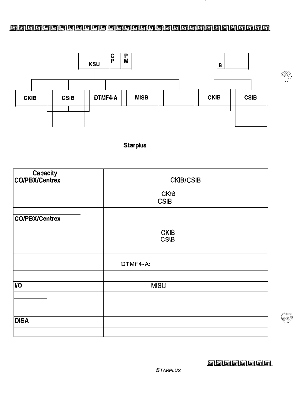
:
Q-4
SYSTEM CONFIGURATION
Optional Boards
Basic
$
p
KSU
u u
E
I EKSU
B
g,:.;?;
‘,
I..::
. . . . .
;:
I--.
CKIB CSIB
DTMF4-A
MISB
MODU
CKIB CSIB
I
MSGU MSGU
Figure 9-1: Starplus Triad-S System
BKSU
Caoacity
CO/PBWCentrex Lines:
Station:
Digital Terminal:
Single Line Telephone:
BKSU + EKSU Capacity
COlPBWCentrex Lines:
Station:
Digital Terminal:
Single line Telephone:
DTMF Receiver
6 lines maximum (3 per
CKIBESIB
board)
16 maximum (8 per
CKIB
board)
8 maximum (8 per
CSIB
board)
12 lines maximum
32 maximum (8 per
CKIB
board)
24 maximum (8 per
CSIB
board) (
(System max: 12 lines, 8 digital telephones, 24 SLT)
Basic: 1 each
With
DTMF4-A:
5 (Provides 4 additional services)
DTMF Sender
l/O
Ports
Conference
Circuit:
Parties:
DISA
Circuit
Attendants
Unlimited
2 maximum with
MISU
5 conference per system
8 parties per conference (5 of the 8 can be external)
12 CO lines may be programmed simultaneously
Up to 3 stations can be designated as attendants
Table 9-l: Digital System Capacity
Issue I- December 1998
STARPLUS
Triad-S Product Description Manual
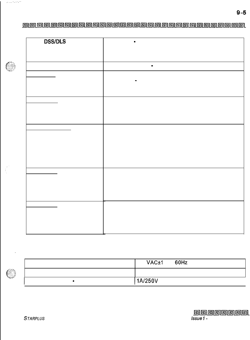
SYSTEM CONFIGURATION
Optional Boards
Digital
DSS/DLS
Units
Loop Supervision Disconnect
Paae Zones
Internal Paging:
External Paging:
(One/Two Way)
Hunt Groups
Groups:
Members:
Types:
Voice Mail Groups
Groups:
Members (Ports):
Integrated Method:
VM Message Wait:
VM Disconnect Signal:
ACD Groups
Groups:
Members:
RAN Announcements:
Calls in Queue:
UCD Groups
Groups:
Members:
RAN Announcements:
Calls in Queue:
8 maximum
-
each DSWDLS unit requires 1 station port
and reduces station capacity by 1. DSWDLS maps may not
be duplicated at a station. One station may have up to
three DSWDLS units associated with it.
700 msec. duration
-
CO or Internal Call to SLT
4 maximum
-
software controlled
1 maximum
Software supports up to 8 groups
Software supports up to 8 stations in each group
Station or Pilot Hunting
Software supports up to 8 groups
Software supports up to 8 stations
In-band signalling (DTMF)
Programmable 12-digit (DTMF) string
If no digits are programmed, 15 seconds of silence
followed by busy tone
Software supports up to 16 groups
Software supports up to 16 stations in each group
Eight RAN Announcements per system, 3 per ACD group
All CO lines may be queued for an ACD group
Software supports up to 8 groups
Software supports up to 8 stations in each group
Eight RAN Announcements per system, 3 per UCD group
All CO lines may be queued for a UCD group
Table 9-l: Digital System Capacity
AC Input to Power Supply
Power Consumption
117
VACkl
0%,
60Hz
single phase
74 watts
1
Power Supply Fuse
-
AC Input
1
lA/250V
I
Table 9-2: Electrical Specifications
STARPLUS
Triad-S Product Description Manual
issue
I-
December 1998
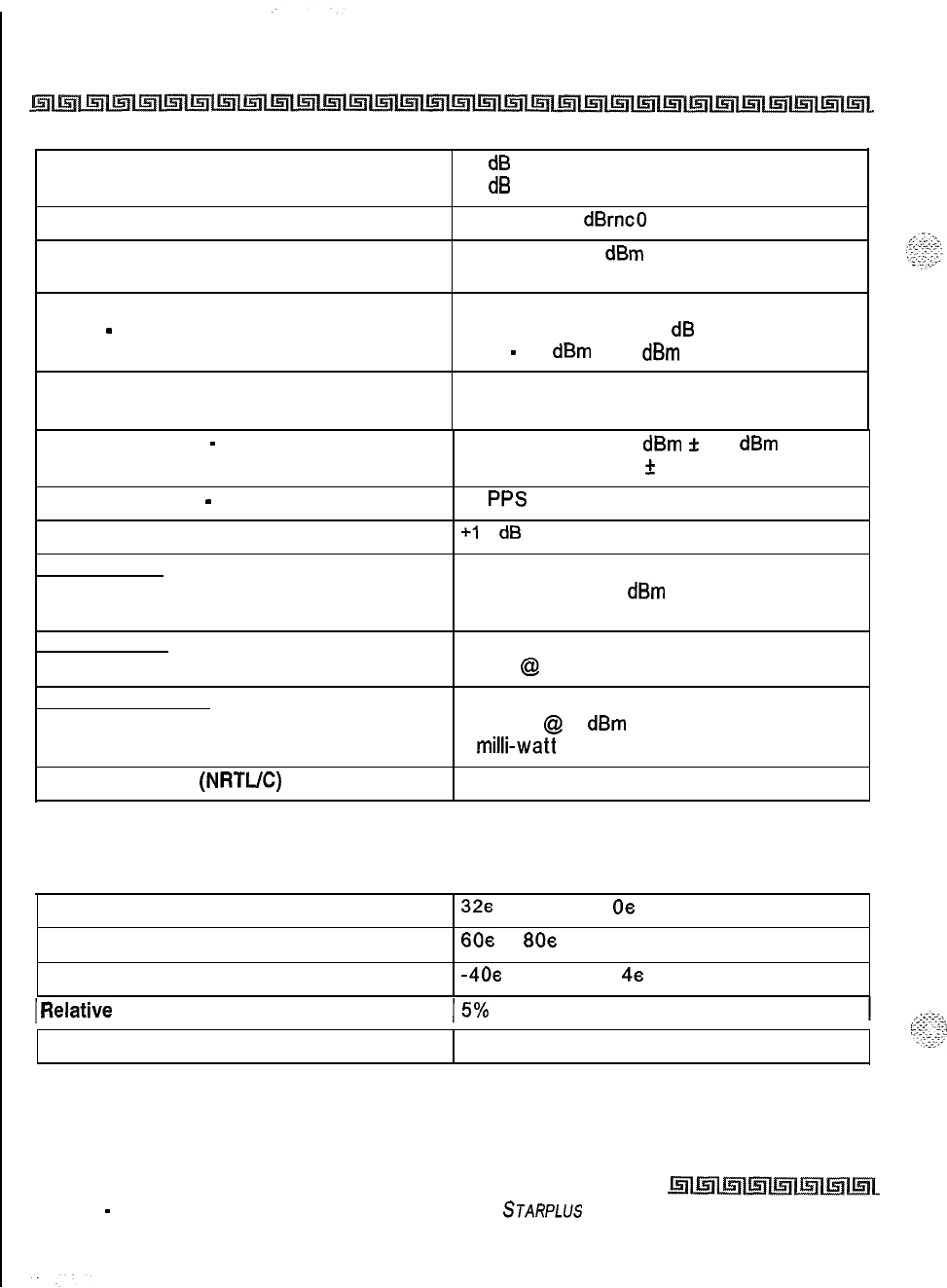
Q-6
SYSTEM CONFIGURATION
Optional Boards
Longitudinal Balance
Idle Channel Noise
Cross Talk Attenuation
60
dB
from 200 Hz to 1,000 Hz
40
dB
from 1.000 Hz to 40,000 Hz
Less than 15
dBrnc0
for all connections
Greater than 80 dBm Station to CO and
Station to Station
Single Frequency Distortion
300
Hz
-
3,400 Hz
Station to CO and Station to Station:
Better than 2.0% or 34
dB
for an output
Level
-
30
dBm
to 0
dBm
Ringing Sensitivity
16 Hz to 30 Hz at 40 Vrms minimum
03 Hz to 67 Hz at 50 Vrms minimum
CO Line Signaling
-
DTMF
Frequency pair at -5
dBm
f
0.5
dBm
Frequency tolerance
f
1.5%
CO Line Signaling
-
Dial Pulse
Input Level
Music Source
10
PPS
+I
0
dB
maximum
Music on Hold/Background Music Input
600 ohm input at 0
dBm
maximum from music
source
Contact Rating
Multipurpose Relay
1 amp
@
24 V DC (two on MBU board)
External Paae Port
Output Impedance
600 ohm
@
0
dBm
Output Power without Compression
5
milli-watt
maximum
CSA File Number
(NRTUC)
LR85633
Table 9-2: Electrical Specifications
Operating Temperature
328
to 104s F
0s
to 40s C
Optimum Temperature
60~
to
80s
F 15s to 26s C
Storage Temperature
-4Oe
to 140e F
4s
to 60e C
IRelative
Humidity
15%
to 90% non-condensing
Heat Dissipation (BTU)
1481 BTU/Hour
Table 9-3: Environmental Specifications
Issue 1
-
December 1998
STARPLUS
Triad-S Product Description Manual
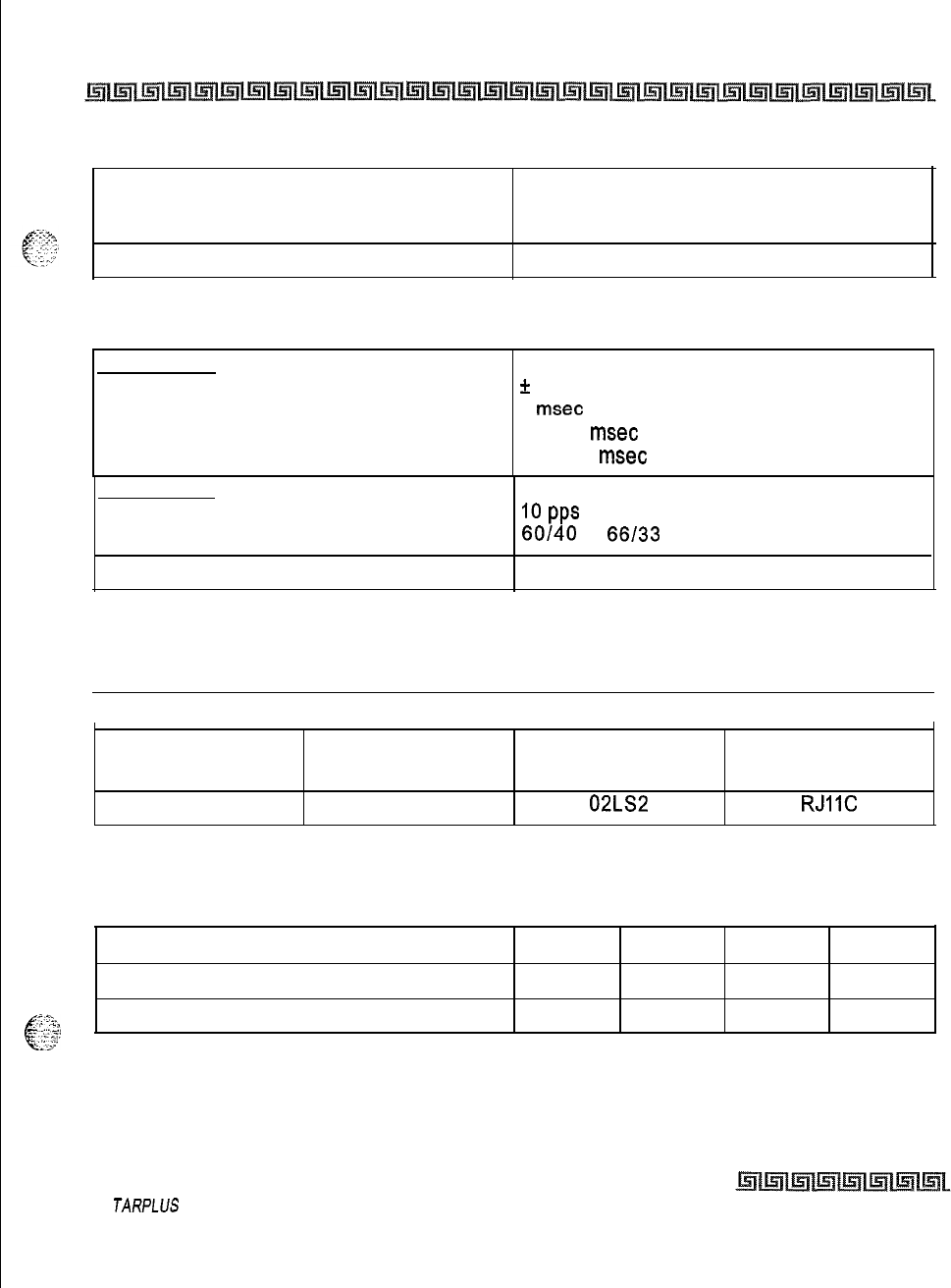
SYSTEM CONFIGURATION
Optional Boards
Q-7
Digital Terminals
Single Line Telephones
Maximum length of station loop:
1,000 feet of 24 AWG (2 wire, inside wiring,
twisted cable)
2,000 feet of 24 AWG
Table Q-4: Loop Limits
DTMF Dialinq
Frequency Deviation
Rise Time
Duration of DTMF Signal
Interdigit Time
*
1.5%
5
msec
70-100
msec
100-130
msec
Pulse Dialing
Pulse Dialing Rate
Pulse Break/Make Duration
10
PPS
60140
or
66133
CO Type
I
Loop start, 600 ohm, current sensing
II
Table Q-5: Dialing Specifications
I
System Port Specification, Facility Interface and Service Order Codes
I
lnterf ace Card Ringer Equivalent
Number (REN) Facility Line
lnterf ace
Jack Type
III
Loop start
1.3 B
02LS2
RJIIC
Table Q-6: Trunk Ordering Information: Public Network Lines
Item Height Width Depth Weight
Triad-S
Basic Key Service Unit
13.6 in 10.85 in 4.9 in
5.3 Kg
6Iii
Triad-S
Expansion Key Service Unit
13.6 in
10.85 in
4.9 in
&P..”
4.6 Kg
Table Q-7: Physical Dimensions and Weight
S
TARPLUS
Triad-S Product Description Manual
Issue I- December 7998
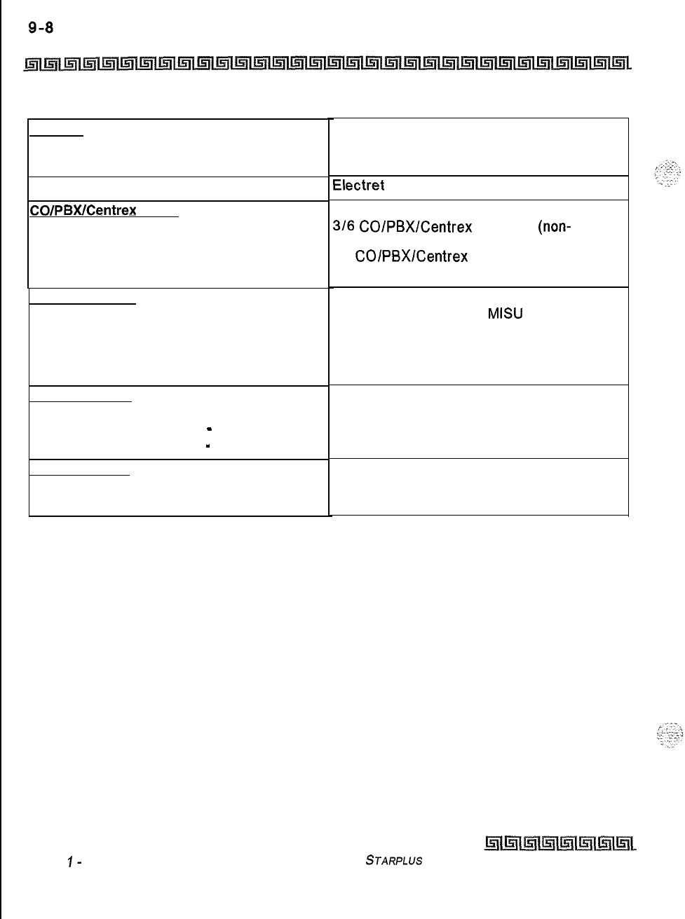
SYSTEM CONFIGURATION
Optional Boards
Memory
Programmable Read-Only Memory (EPROM)
Random Access Memory (RAM)
Telephone Transmitter
CO/PBWCentrex
Paths
Basic KSU
Basic KSU + Expansion KSU
Intercom Paths
Music Channels
Music On-Hold/Background Music
Account Codes
Number of Digits Per Account Code
Number of Account Codes
-
Unverified
Number of Account Codes
-
Verified
Dialina Memory
Station Speed Dialing
System Speed Dialing
Issue
I-
December
1998
1 Megabyte
384 K expandable to 640 K
Electret
mic compatible
316
CO/PBX/Centrex
talkpaths
(non-
blocking)
12
COlPBXlCentrex
talkpaths (non-blocking)
Non-blocking
2 channels with optional
MISU
per system (1
MOH, 1 BGM [different sources])
Additional music channels available through
CO lines. Connections up to 8 maximum
optional. Talk battery required.
Up to 12 unverified digits
Unlimited
250 account codes
20 bins per station (24 digits)
80 bins per system (24 digits)
Table Q-8: Miscellaneous Specifications
STARPLUS
Triad-S Product Description Manual
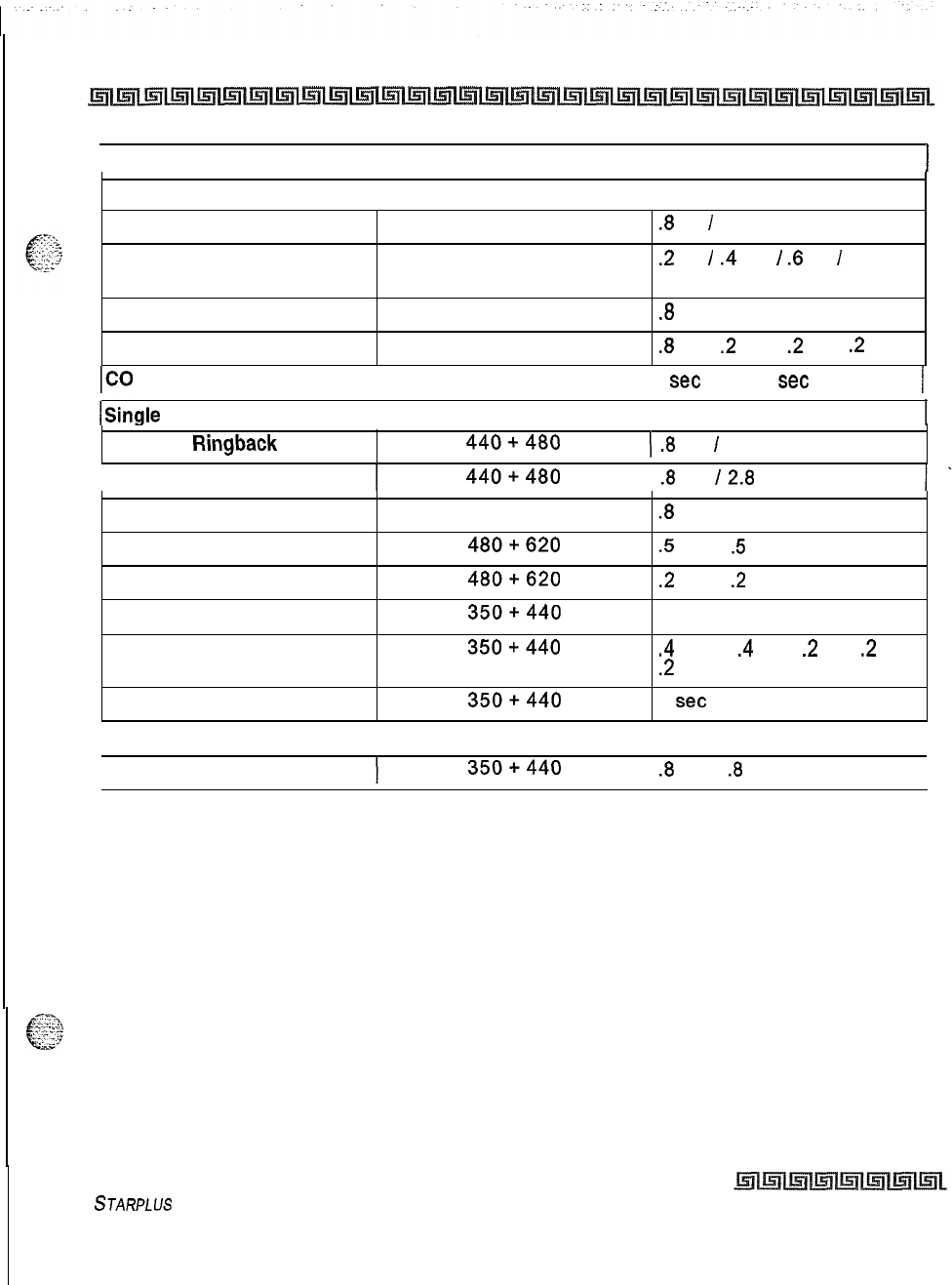
SYSTEM CONFIGURATION
Optional Boards
Q-Q
I
Type of Signal
I
Frequency
I
Signal Duration
)
Single Line Signals:
Incoming CO Line
Intercom Tone Ringing
II
20
Hz
90 VAC
.8 on I
2.8 off
repeated
20
Hz
90 VAC
.2
on
I
.4
off
I
.6
on
I
3.0 off
repeated
Transferred CO Line
20
Hz
90 VAC
.8
on
I2.8 off repeated
CO Line Recall
20
Hz
90 VAC
.8
on
I
.2
off
I
.2
on
I
.2
off
ICO Queue Call Back
I
20
Hz 90 VAC
I I
set
on I 2
set
off repeated
I
/Single Line Confidence Tones:
Intercom Ringback
440+480
(
.8
on
I
2.8 off repeated
Transferred CO Line
440+480
I
.8
on
12.8
off repeated
Call Announce
Busy
Tone
Error Tone
Intercom Dial Tone
440
480+620
480+620
350+440
.8
on I 2.8 off repeated
.5
on I
5
off repeated
.2
on I
.2
off repeated
Steady
DND Tone
Paging Confirmation Tone
350+440
350+440
.4
on I
.4
off I
.2
on I
.2
off I
.2
on repeated
1
set
on
(Conference Time-out Tone
I
440
I Programmable Steady Tone I
Confirmation Tone
350+440
.8
on I
.8
off 3 bursts
I
Table 9-9: Single Line Audible Signals
STARPLUS
Triad-S Product Description Manual Issue I- December 1998
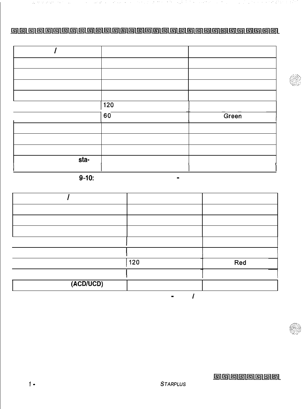
Q-IO
SYSTEM CONFIGURATION
Optional Boards
Feature
/
Function
Incoming CO Ringing
Transferred CO Ringing
CO Line Recalling
Flash Rates
30 ipm flash
120 ipm flash
480 ipm flutter
LED Color
Red
Red
Red
System Hold
60 ipm double wink Red
1
Exclusive Hold (I-Hold)
II20
ipm flash Green
1 I-Hold (system)
I60
ipm wink
1
CO Line Queue Call Back
480 ipm flutter Red
CO Line in Use
On steady Red
CO Line Idle
Off Off
Exclusive Hold (other
sta-
On steady Red
)
tions)
Table
9-10:
Digital Station Visual Signals
-
CO Line Buttons
Feature
/
Function
Off-Hook (busy)
Incoming Intercom Ring
Call Announce (H or P mode)
Flash Rates
On steady
120 ipm flutter
Steady
LED Color
Red
Red
Red
I
Message Waiting Call Back
)
120 ipm flutter Red
(Station in Do Not Disturb
(
60 ipm double flash Red
I
Camp On (by station)
II20
ipm flutter
(Automatic Call Back
(
120 ipm flash Red
Station Unavailable (ACDAJCD)
60 ipm flash Red
Table 9-11: Digital Station Visual Signals
-
DSS
/
BLF Buttons
Issue
1
-
December 7998 STARPLUS Triad-S Product Description Manual

SYSTEM CONFIGURATION
Optional Boards
Feature
/
Function Flash Rates LED Color
Call Forward (active)
Message Wait (active)
Camp On (active)
Call Back (active
-
initiator)
CO Line Queue (active)
30 ipm flash
Steady
120 ipm flash
120 ipm flash
480 ipm flutter
Red
Red
Red
Red
Red
1
DND (active)
( Steady Red
1
Mute
1 Steady Red
(On/Off I Steady Red
Conference
Speed (moment on until bin address di-
Steady
I
Red
aled)
I
Personalized Messages
Tone Intercom Call (hold button)
Loop
Pool
Transfer
I
(
15 ipm flash
I
Red
15 ipm flash
same as CO
same as CO
None
Red
Green
/
Red
Green
/
Red
None
Table 9-12: Digital Station Visual Signals
-
Feature
/
Function Buttons
STARPLUS
Triad-S Product
Description
Manual issue
I-
December 1998
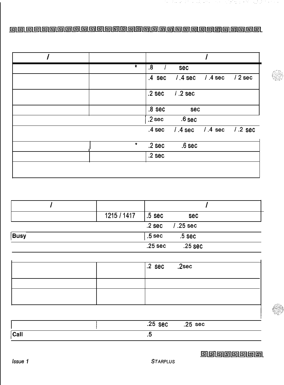
9-12 SYSTEM CONFIGURATION
Optional Boards
Feature
/
Indication
incoming CO Line
Intercom Tone Ringing
Sound in HZ
User selectable
*
User selectable *
Occurrence
/
Cadence
.8
on
I
2.4
set
off repeated
.4
set
on
I
.4
set
off
I
.4
set
on
I2
set
off repeated
Intercom Call Announce (H 935
.2
set
on
/
.2
set
off 2 bursts
and P)
Transferred CO Line User selectable *
.8
set
on 12.4
set
off repeated
CO Line Recall 1 User selectable *
/
.2
set
on I
.6
set
off repeated I
Message Waiting Call Back User selectable *
.4sec
on
l.4sec
off
I.4
set
on
I.2
set
off repeated
I I
Queued CO Line Call Back 1 User selectable
*
1
.2
set
on I
.6
set
off repeated
I
I
Camp On 935
.2
set
burst
* Only one tone can be selected by a station at a time. This tone is used for all signaling that
uses the User Selectable tone.
Table 9-13: Signals to Called Stations (Digital Station)
Feature
/
Indication
Incoming Ring Back Tone
Sound in Hz Occurrence
/
Cadence
1215l1417
5
set
on I 2.5
set
off repeated
I
Intercom Call Announce
I
935
.2
set
on
/
.25
set
off 3 times I
(busy
Tone
I
701
(
.5
set
on I
.5
set
off repeated
I
Error Tone
I
701
I
.25
set
on I
.25
set
off repeated I
Intercom Dial Tone
I
420
I
Continuous I
DND Tone
Paging Confirmation Tone
Conference Time-out Warning
Tone
701
935
420
.2
set
on
I
.2
set
off
3times,
repeated
pause,
1 second burst
1 second
burst
Programming Confirmation
Tone
1471
1 second burst
I
Programmed Error Tone
I
1471
.25
set
on
I
.25
set
off 6 times
I
/Call Waiting
I
735
.5
second burst I
Table 9-14: Signals to Calling Station (Digital Station)
issue
1
-December1998
STARPLUS
Triad-S Product Description Manual
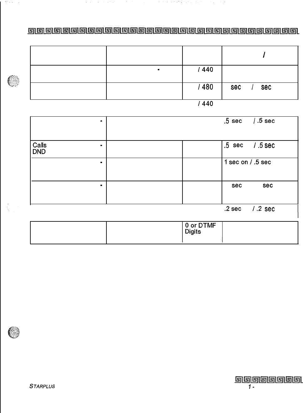
SYSTEM CONFIGURATION
Optional Boards
9-13
VM Condition Action Tone Received Sound in
Hz
Occurrence
/
Cadence
Off Hook Internal dial tone
-
no
stutter tone 350
I440
Continuous
Calls an Internal Station Ring back tone 440
I480
1
set
on
I
3
set
off
(idle) repeated
Initiate a Transfer (hook- Internal dial tone (no
flash) stutter tone) 350
I440
Continuous
I
Calls an Internal Station
-
Busy tone
4801620
I I
.5
set
on
I
.5
set
off
busy
repeated
Call back not allowed
;Zlk
an Internal Station
-
Busy tone 4801620
.5
set
on
I
.5
set
off
repeated
Calls an Internal Station
-
Busy tone 4801620
lsecon
l.5sec
off
programmed
I
not
equipped repeated
Calls an Internal Station
-
Reorder tone 4801620
1
set
on
1.2
set
off
not programmed
I
not
equipped repeated
Dials Invalid Digit
I
FA
Reorder tone 4801620
.2sec
on
I.2
set
off
Code
I
station
repeated
I
Calling Party Silence or disconnect Continuous or as
Disconnects (internal or
digits
programmed
external call)
Table 9-15: Voice Mail Confidence Tones
STARPLUS
Triad-S Product Description Manual
Issue
I-
December 1998
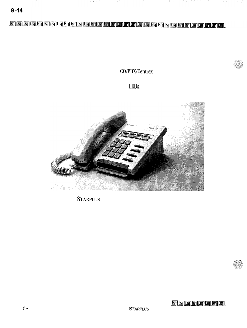
SYSTEM CONFIGURATION
Digital Station Instruments
Digital Station Instruments
8-Button Enhanced Digital Terminal
The Triad-S Enhanced 8-Button Digital Terminals are fully modular instruments with five fixed feature
buttons and eight buttons that can be flexibly assigned as
CO/PBX/Centrex
lines, Station
DSS,
or
feature/function buttons. This telephone also features an integrated speakerphone, call announce with
handsfree intercom, a volume control button, and long life
LEDs.
Figure 9-2:
STARPLUS
Enhanced (8-Button) Digital Terminal
Issue
1
-
December 1998 STARPLUS
Triad-S Product Description Manual
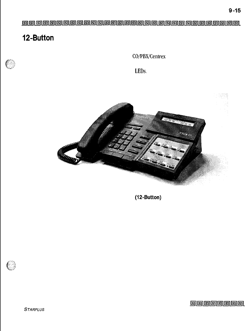
SYSTEM CONFIGURATION
Digital Station Instruments
12-Button Executive Digital Terminals
The Triad-S Executive 12-Button Digital Terminals are fully modular instruments with 11 fixed feature
buttons and 12 buttons that can be flexibly assigned as
CO/PBX/Centrex
lines, Station DSS, or
feature/function buttons. This telephone also features an integrated speakerphone, call announce with
handsfree intercom, a volume control bar, and long life
LEDs.
Figure 9-3: Triad-S Executive
(la-Button)
Digital Terminal
STARPLUS
Triad-S Product Description Manual Issue I- December 1998
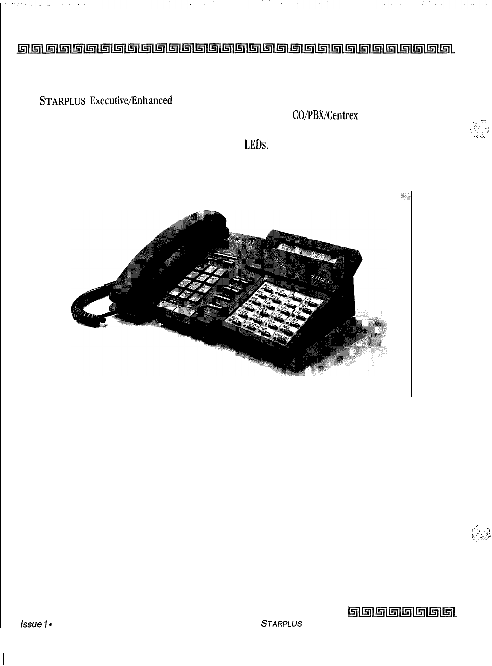
9-16 SYSTEM CONFIGURATION
Digital Station instruments
24-Button Executive/Enhanced Digital Terminals
The
STARPLUS
ExecutivelEnhanced 24-Button Digital Terminals are fully modular instruments with 11
fixed feature buttons and 24 buttons that can be flexibly assigned as
CO/PBX/Centrex
lines, Station DSS, or
feature/function buttons. This telephone also features an integrated speakerphone, call announce with
handsfree intercom, a volume control bar, and long life
LEDs.
,
7
:
;
(
.
.‘:
‘.
;
:
:
.
.
.-:.
Figure 9-4: Triad-S Executive (24-Button) Digital Terminal
,i
.
.
!
.;
r-i
I.
._:;
I:.
,..L1,
.i
issue
7
-
December 1998
~l~i~l~l~l~~~
STARPLUS
Triad-S Product Description Manual
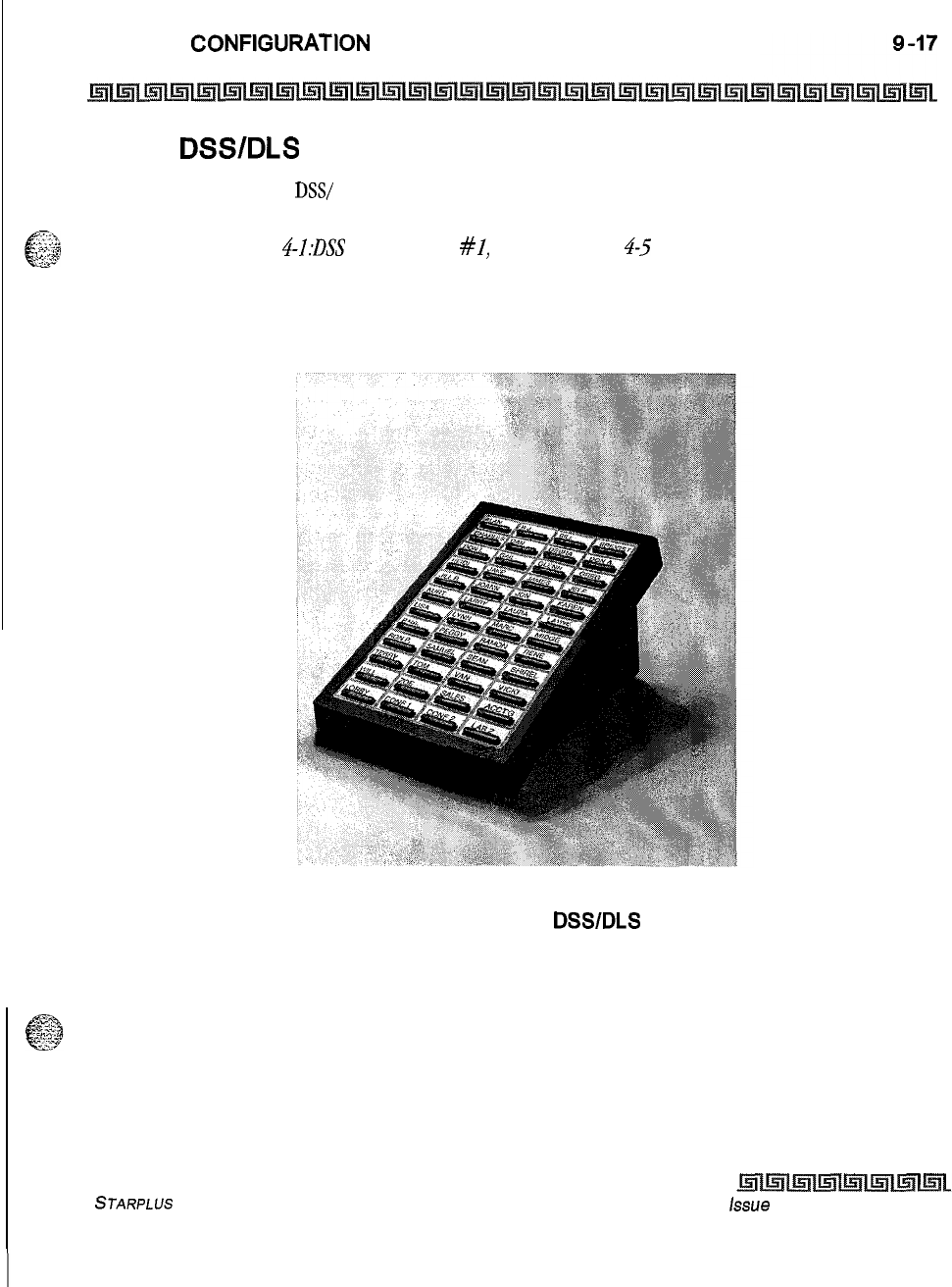
SYSTEM CONFlGUFtATlON
Digital Station Instruments
Digital
DSWDLS
Console
The station port used for a
DSS/
DLS Console can be assigned as a Direct Station Select or Direct Line Select
depending on customer need. All forty-eight (48) buttons on the unit can be assigned as DSS, or flexible
.
.‘I
..I
e
_
:.;;.&3
&>”
buttons. Refer to Figure
4--I:DSS
Console Map
#I,
Chapter 4, page
4-5
for an explanation of the mapping
options.
Figure 9-5: Triad-S Digital
DSWDLS
Console
STARPLUS
Triad-S Product Description Manual
issue
I- December 1998
9-18 SYSTEM CONFIGURATION
Digital Station Instruments
Issue
I
-
December 1998 STARPLUS Triad-S Product Description Manual
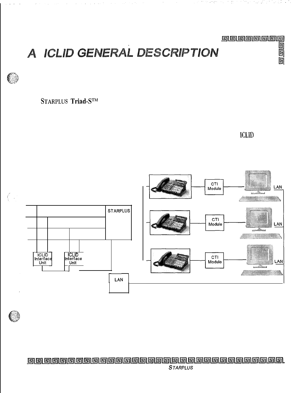
Introduction
This specification provides the functional and implementation definition for the addition of the ICLID feature
to the
STARPLUS
Triad-SThf
Digital Key Telephone System.
System Configuration
The following illustration depicts the configuration presumed for the implementation of the
ICLlD
feature for
the system. The phones are presumed to be in an ACD or UCD group in order to allow proper operation with
the system.
STARPLUS
KSU
CO LINES
RS232
ICLID ICLID
‘nt&?c Int;xf;ce
1
I
RS232
SERVER LAN
Figure A-l: CTI System Configuration
Issue I- December 7998
STARPLUS
Triad-S Product Description Manual
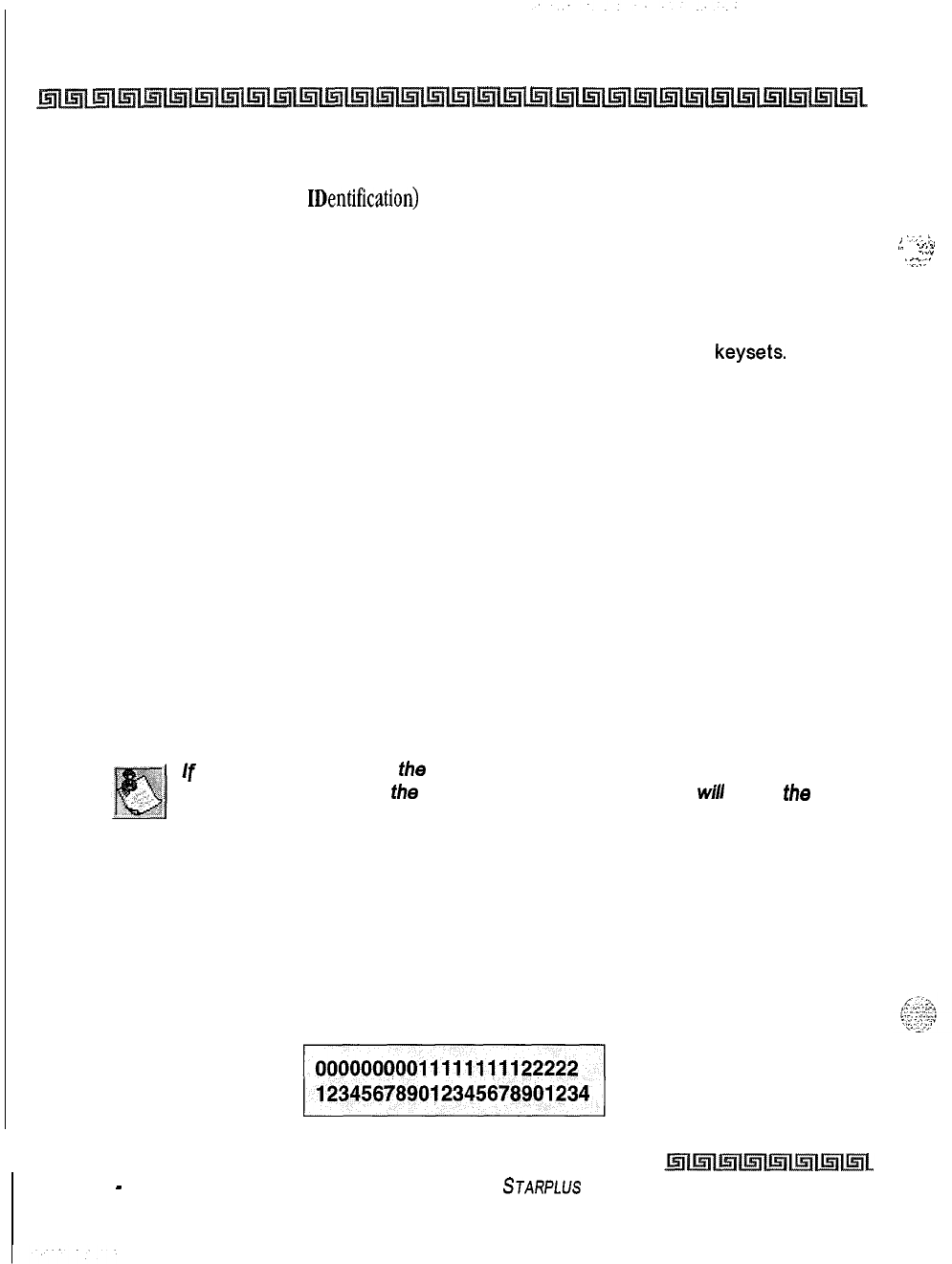
A-2 ICLID GENERAL DESCRIPTION
Functional Performance
Functional Performance
The ICLID (Incoming Calling Line IDentification) feature has been added to the Triad-S system as a first
step in providing it generally. The key system operation of this feature is dependent on the feature first
being activated from the central office so that the numbers of the calling party will be delivered over the
individual tip and ring of the CO lines during the first silent interval between ringing.
The features implemented are:
1
Display of calling number/name on initial ring-in of a line on the display
keysets.
2
Recording of incoming call number/name on the SMDR printout.
3
Management of an “unanswered call” table from a display phone with appropriate
privilege level to allow tracking of unanswered calls for statistical information and
return call management.
4
Local translation of incoming numbers to names according to a table of number/name
equivalences which can be administered by the system.
Calling Number/Name Display
This feature is intended as the basic offering of the ICLID service when associated with the Triad-S system.
Essentially, whenever an incoming call is received at the system, the number received along with the
ringing signal will be stored in the line control tables and used at various points in the processing of the call.
The primary function will be that the calling number will be displayed (if available) at any point at which
the “LINE RINGING” is displayed in the system.
If
2 lines are ringing in at the same time, the display will show the oldest line
information. After 1 of
the
lines is answered, the display
will
show
the
information on the unanswered line.
In addition, with the availability of the calling name feature, if the calling name is provided, the system will
deliver that to the display instead of the calling number.
The specification for this feature is that the system will display its “LINE RINGING” message as normally
implemented and alter that display to the calling number/name if the information is made present on the
line. This will allow the normal operation of the system when ICLID information is not presented or the
device which intercepts it and provides the information to the KSU is missing or failed.
,
‘7,:
:.
, .
.
.
.
.
_,
.-
..,_.
. . . .
...”
‘<.>-c’
Issue 1
-
December 7998
STARPLUS
Triad-S Product Description Manual
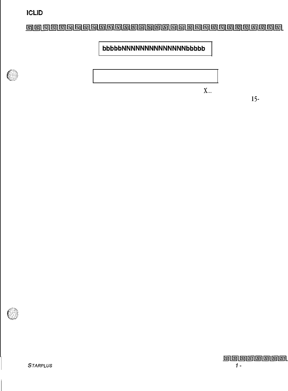
ICLID
GENERAL DESCRIPTION
Functional Performance
A-3
bbbbbNNNNNNNNNNNNNNbbbbb
OR
xxxxxxxxxxxxxxxxxxxxxxxxxxx
If the culling name is available, the display will be shown as above where
X...
represents the internal table
storage of the calling name. Note that although the Central Office delivery of the calling name is
15-
characters, the internal table used to store the name for translation of a received number is 24-characters in
width. If the Central Office delivers a name, it will be positioned left justified in the 24-character field on the
display. Note that if a number is received which matches a number/name translation, the translated name
will be used and the name delivered from the Central Office will be effectively discarded.
If no name is available from the Central Office or a translation table the delivered number will be displayed
as the repeated character N (14 characters).
Incoming Number/Name SMDR
As with the above feature implementation, the intent is that the system operate normally in the absence of
ICLID information or the failure of the ICLID equipment. If the information is present at the time that an
SMDR record is generated for a call, it will alter the content and format of the SMDR output record.
If the calling number is available, the number will be output in the SMDR record in the same location as the
dialed number is located in the outgoing calls.
If the calling name is present, an additional line will be output in the SMDR identifying the name. This record
will immediately follow the normal SMDR record. The normal SMDR record will include an indicator which
identifies that a following record with name identification is present.
Unanswered calls will be recorded on the SMDR as a system option to allow the identification of callers for
statistical and call-back purposes. These calls will be identified with an indicator in the SMDR record.
Unanswered Call Management
An Unanswered Call Management Table with 50 entry capacity for the Triad-D systems are maintained in the
iC,$<
$,
:;..:; system, The calling number/name information pertaining to any unanswered call will be placed in this table
:‘,>
at the time the system has determined that the call has been abandoned. This table may be accessed from
any station display phone so that the unanswered calls may be reviewed and handled by the end user.
STARPLUS
Triad-S Product Description Manual
Issue
I-
December 1998

A-4
ICLID
GENERAL DESCRIPTION
Functional Performance
Local Name Translation
An administrable table provides a local translation from a received calling number to a name. This table
can be administered by the customer from the attendant console location, In cases of conflict between the
name delivered from the CO and that in the local translation table, the local translation table shall rule,
200
entries are provided for the Triad-S systems.
,.-:
.
.
I
,‘Y:
L:-.
\
I
.-.-
--.
:.;
.:
:
‘-r.
I
..:,
Issue
I-
December 1998
STARPLUS
Triad-S Product Description Manual
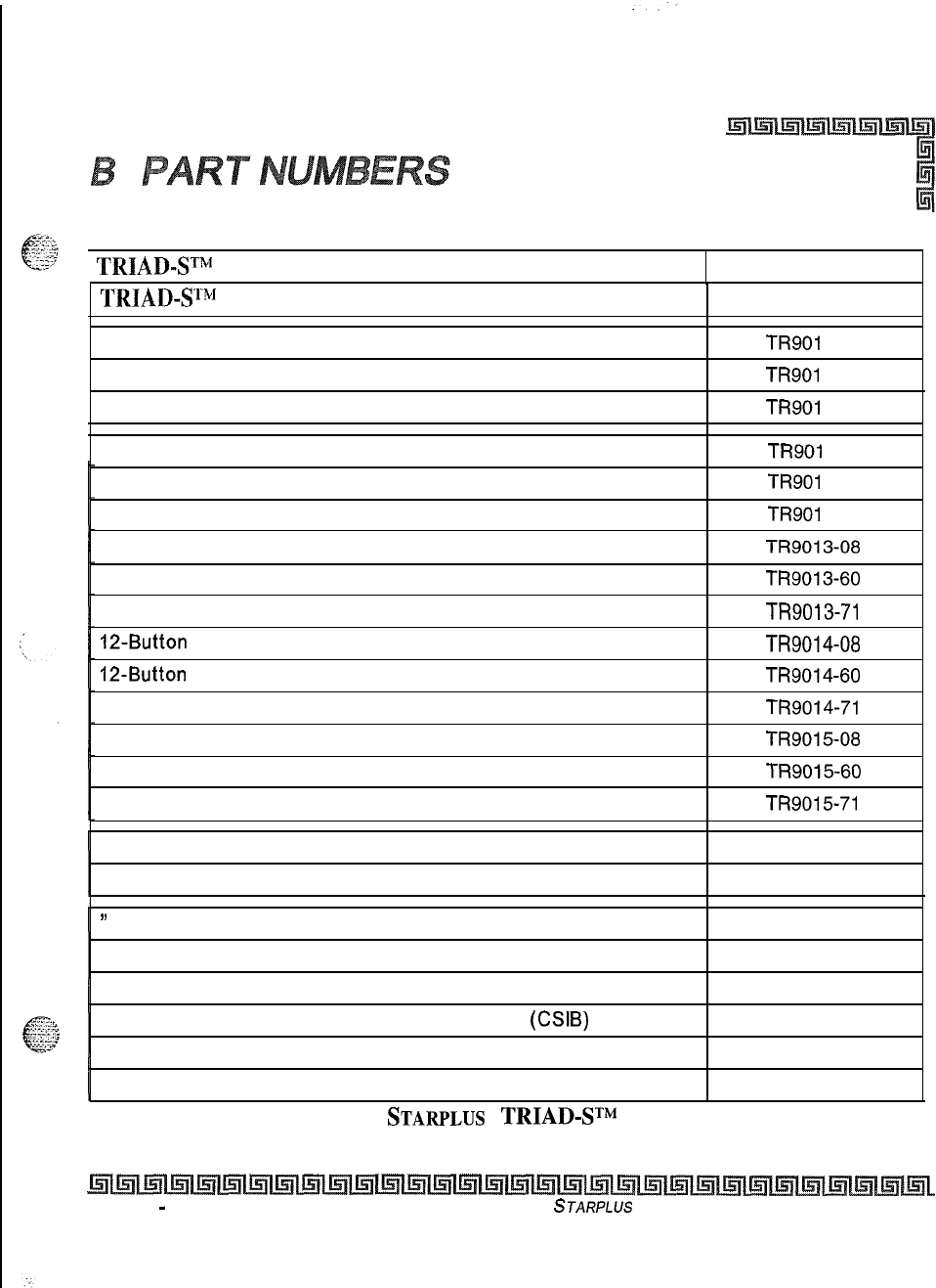
1
TRIAD-ST”
Basic KSU (BKSU) 5000-00
TRIADWgl
Expansion KSU (EKSU)
DSS Console (Off-White)
5002-01
TR901 O-08
DSS Console (Burgundy)
TR901 O-60
DSS Console (Charcoal)
TR901 O-71
8-Button Basic (Off -White)
TR901
l-08
8-Button Basic (Burgundy)
TR901
l-60
8-Button Basic (Charcoal)
TR901
l-71
24-Button Enhanced (Off-White)
TR9013-08
24-Button Enhanced (Burgundy)
TR9013-60
24-Button Enhanced (Charcoal)
TR9013-71
12-Button
Executive (Off-White)
TR9014-08
12-Button
Executive (Burgundy)
TR9014-60
12-Button Executive (Charcoal)
TR9014-71
24-Button Executive (Off-White)
TR901508
24-Button Executive (Burgundy)
TR9015-60
24-Button Executive (Charcoal)
TR9015-71
CTI Connector Box 9020-00
Caller Identification Interface Unit (TCI) 1480-00
’
9600 Baud Modem (MODU) 5030-30
4-circuit DTMF Receiver Unit (DTMF-A) 9033-l 0
3 CO line x 8 Circuit Digital Telephone Interface Board (CKIB) 5032-00
3 CO line x 8 Circuit Single Line Interface Board
(CSIB)
5033-00
Message Wait Unit (MSGU) 5033-l 0
Miscellaneous Interface Service Unit (MISU) 5035-00
Table B-l
:
STARPLUS
TRIAD-STM
Part Numbers
Issue 1
-
November 1998 STARPLUS
Triad-S Product Description Manual
B-2
PART NUMBERS
Issue
7
-
November 1998 STARPLUS
Triad-S Product Description Manual
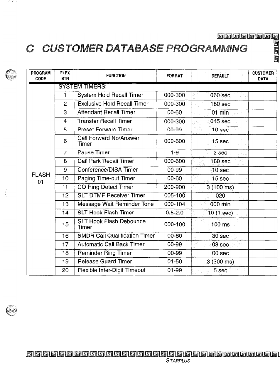
Table C-l : System Parameters
Issue I- November 1998
STARPLUS
Triad-S Product Description Manual
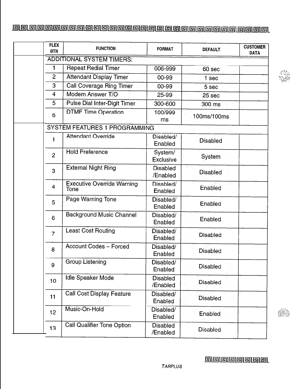
c-2 CUSTOMER DATABASE PROGRAMMING
PROGRAM
CODE
FLASH
02
FLASH
05
_-.
.5
..-.-,
I
-.._,-
,.-.
.
..-_
_-.
,.,.
I._.
,.,
,.-,_
Table C-l : System Parameters (Continued)
Issue I- November 7998 S
JARPLUS
Triad-S Product Description Manual
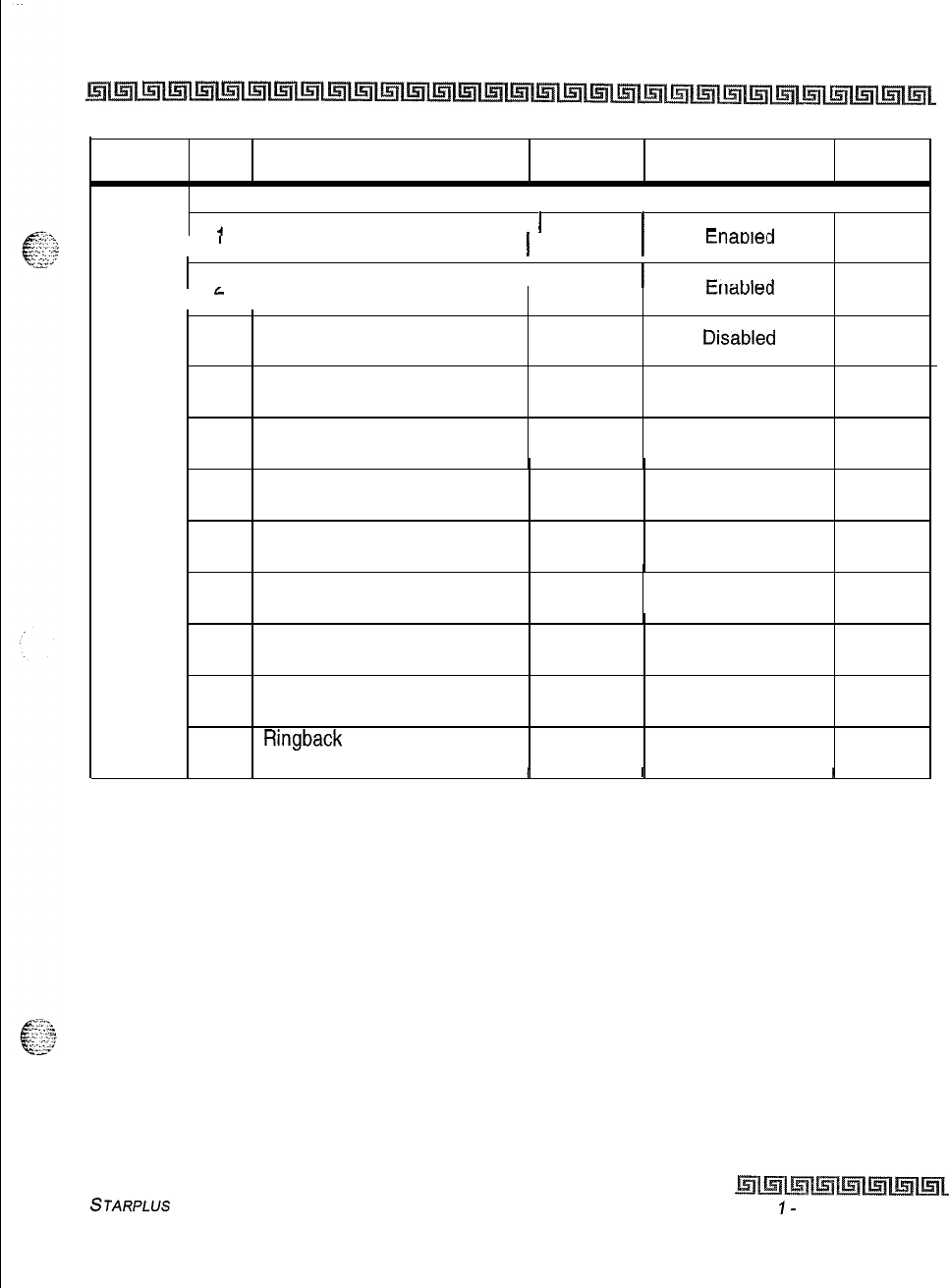
CUSTOMER DATABASE PROGRAMMING c-3
PROGRAM FLEX
CODE
BTN
FUNCTION FORMAT DEFAULT CUSTOMER
DATA
SYSTEM FEATURES 2 PROGRAMMING
FLASH
06
I
’
I
4
1 Privacy Release Tone Option 1 Disabled/ 1
1 Enabled 1
tnaotec
_
, ,
j
II
I
3
1 Distinctive CO Ringing I Disabled
)
l---L,-
Ll
I
G
I
/Enabled
tllaulel
3
Verified Account Code Disabled/
Enabled Disablea
4
Call Forward Display Disabled/
Enabled Enabled
5
External Day Ring Disabled/
Enabled Disabled
6
Overflow Station Forward
Disabled/
Enabled Disabled
7
Direct Transfer Mode Disabled/
Enabled Enabled
8
Station ID Lock Disabled/
Enabled Disabled
9LCR Call Progress Disabled/
Enabled Enabled
10 One-Touch Recording Disabled/
Warning Tone Enabled Enabled
11
Ringback
on Transfer
Disabled/
Enabled Disabled
I I
I I I
I
Table C-l : System Parameters (Continued)
STARPLUS
Triad-S Product Description Manual Issue
I-
November 1998
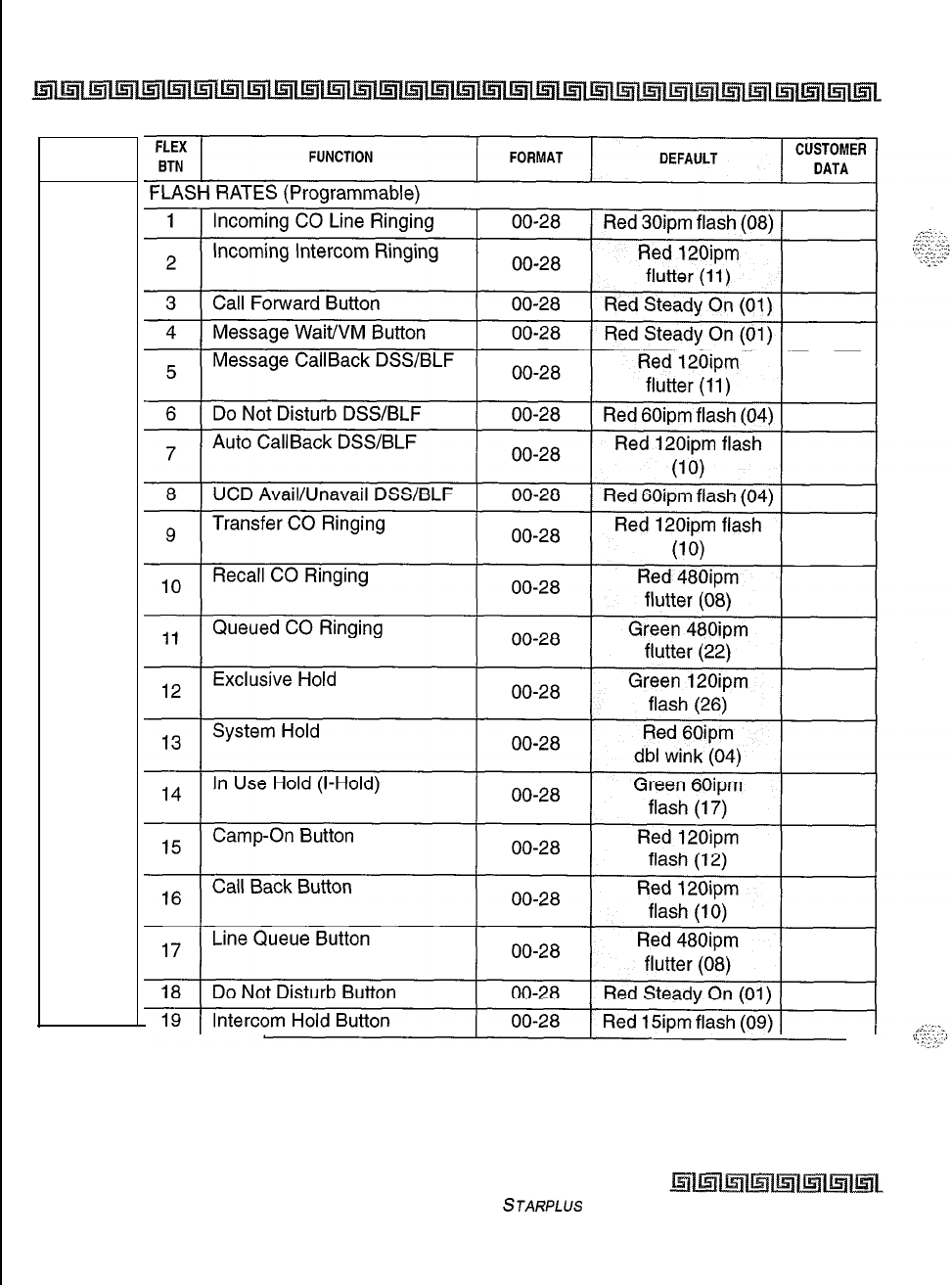
c-4 CUSTOMER DATABASE PROGRAMMING
PROGRAM
CODE
FLASH
07
Table C-l : System Parameters (Continued)
Issue I- November 1998
STARPLUS
Triad-S Product Description Manual
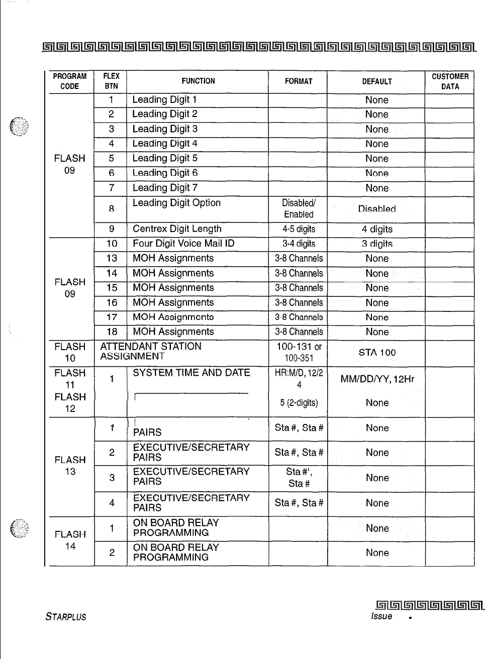
CUSTOMER DATABASE PROGRAMMING c-5
PBX DIALING CODES
EXECUTIVE/SECRETARY
Table C-l : System Parameters (Continued)
STARPLUS
Triad-S Product Description Manual
issue 1
-
November 1998
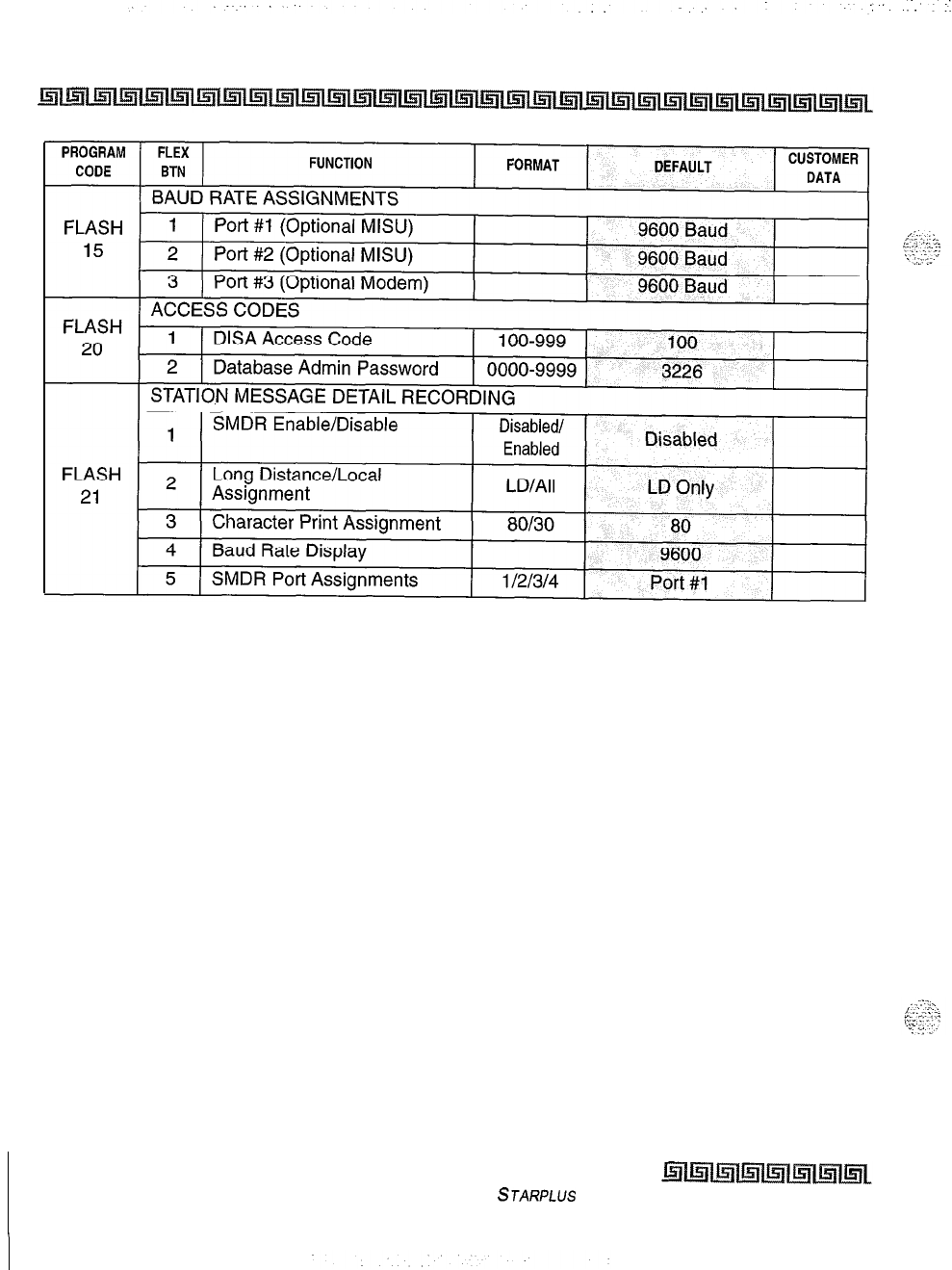
C-6 CUSTOMER DATABASE PROGRAMMING
Table C-l : System Parameters (Continued)
Issue I- November 1998
STARPLUS
Triad-S Product Description Manual
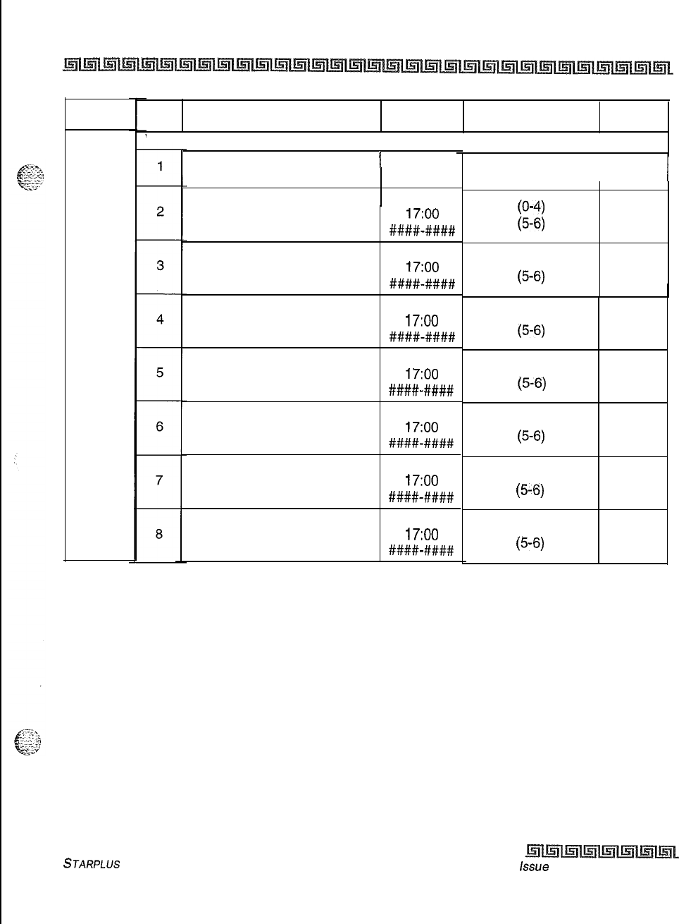
CUSTOMER DATABASE PROGRAMMING c-7
PROGRAM
CODE
FLASH
22
FLEX
BTN
FUNCTION FORMAT DEFAULT CUSTOMER
DATA
WEEKLY NIGHT MODE SCHEDULE
Automatic/Manual Operation 1 Auto/Man-
Day of Week Programming
Day of Week Programming
Day of Week Programming
Day of Week Programming
Day of Week Programming
Day of Week Programming
Day of Week Programming
ual
08:00-
17:oo
A+##-####
08:00-
17:oo
####-####
08:00-
17:oo
####-####
08:00-
17:oo
##I##-####
08:00-
17:oo
####-####
08:00-
17:oo
#I###-####
08:00-
17:oo
#I###-####
Manual
I
(O-4)
(5-6)
(O-4)
(5-6)
(O-4)
(5-6)
(O-4)
(5-6)
(O-4)
F-6)
(O-4)
(5-6)
(O-4)
(5-6)
Table C-l : System Parameters (Continued)
STARPLUS
Triad-S Product Description Manual
issue
I- November 1998
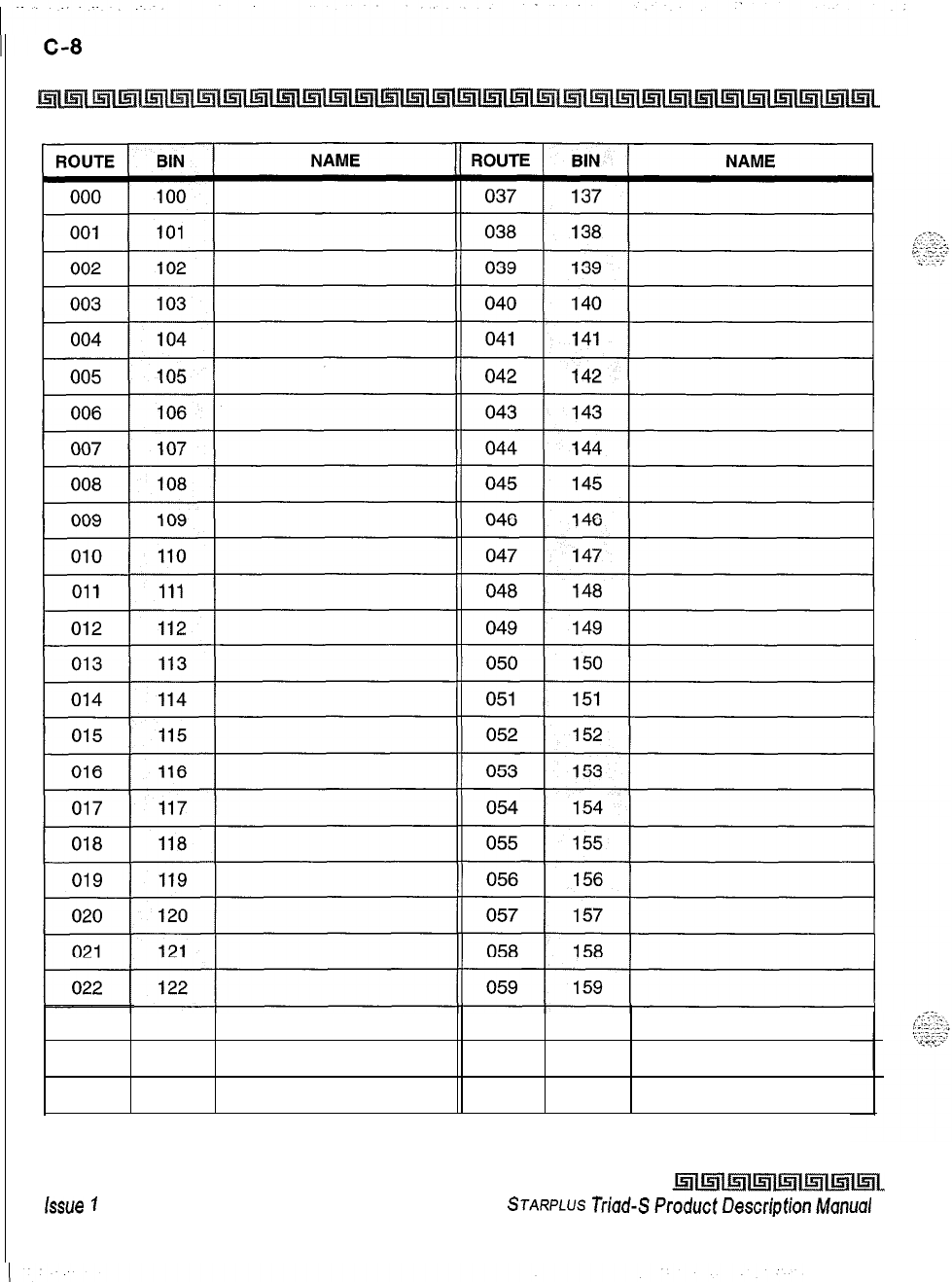
CUSTOMER DATABASE PROGRAMMING
023 123
024
124
025 125
060 160
061
161
062 162
Table C-2: Directory Dialing Defaults (FLASH 23)
issue
7
-November 1998
STARPLUS
triad-SProductDescriptionManuol
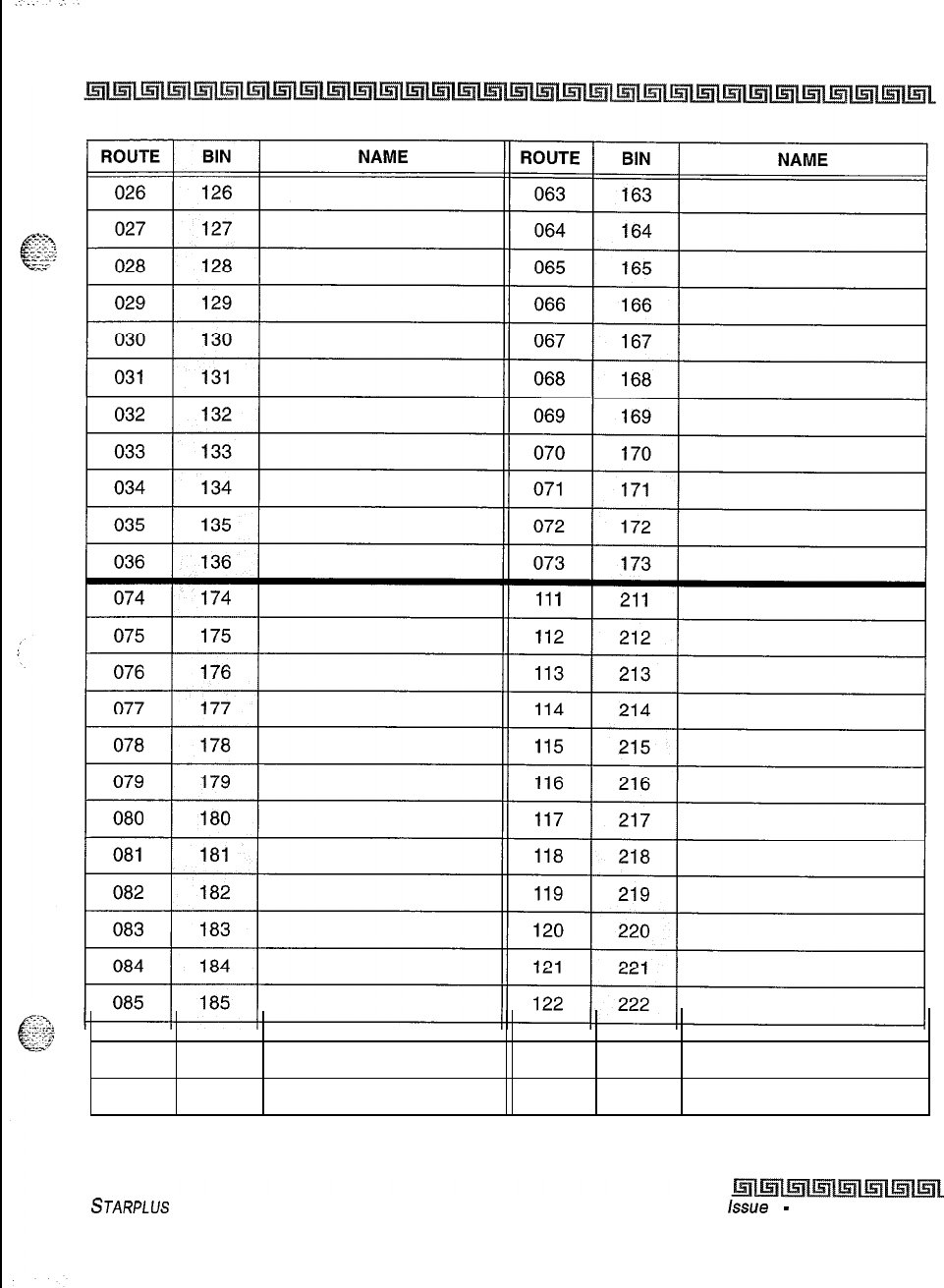
CUSTOMER DATABASE PROGRAMMING C-Q
086
087
088
186 123
223
187 124
224
188 125
225
Table C-2: Directory Dialing Defaults (FLASH 23) (Continued)
STARPLUS
Triad-S Product Description Manual
issue
I
-
November 1998
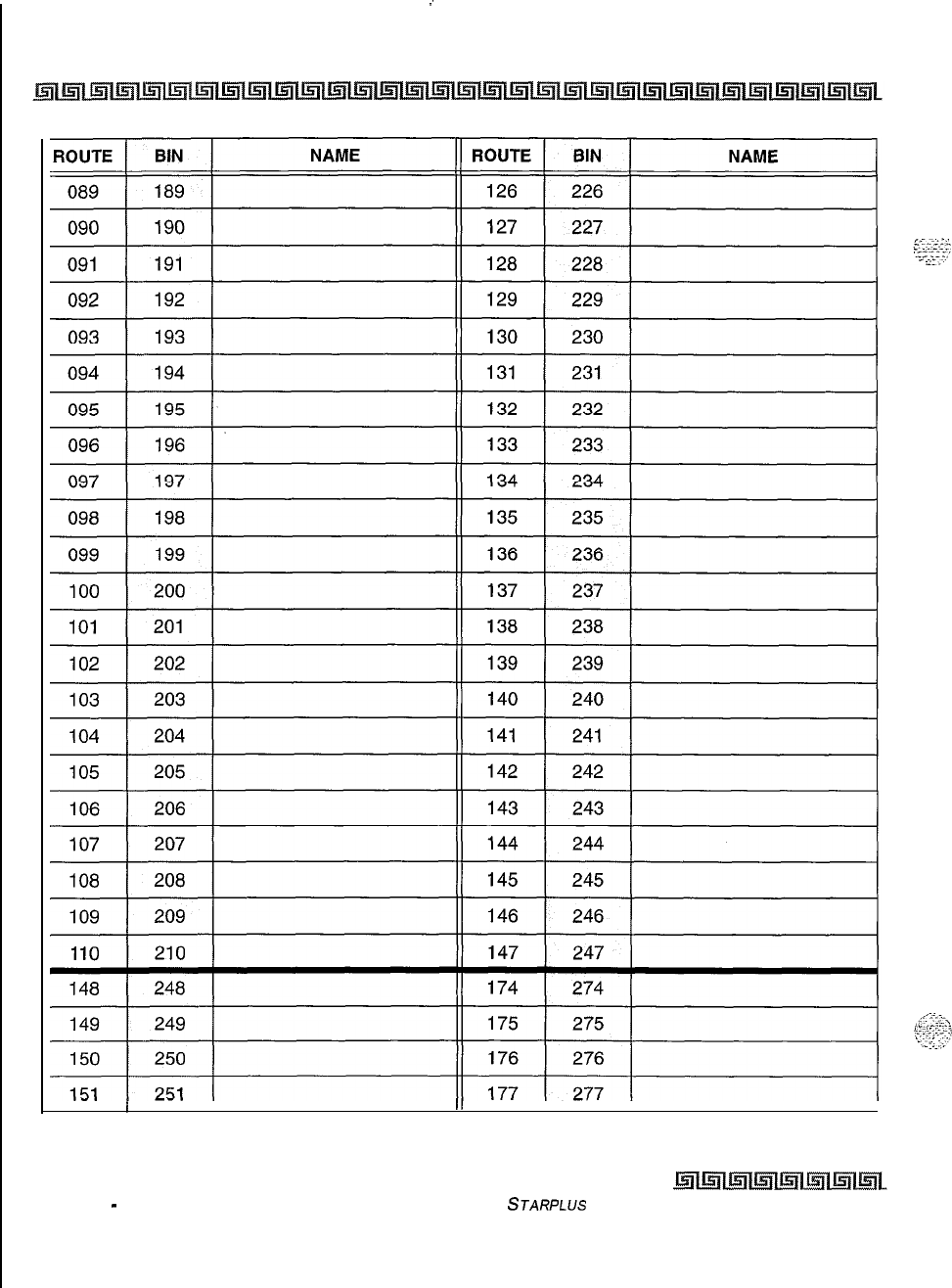
:
c-10 CUSTOMER DATABASE PROGRAMMING
I
I
II
III
Table C-2: Directory Dialing Defaults (FLASH 23) (Continued)
Issue 1
-
November 1998
STARPLUS
Triad-S Product Description Manual
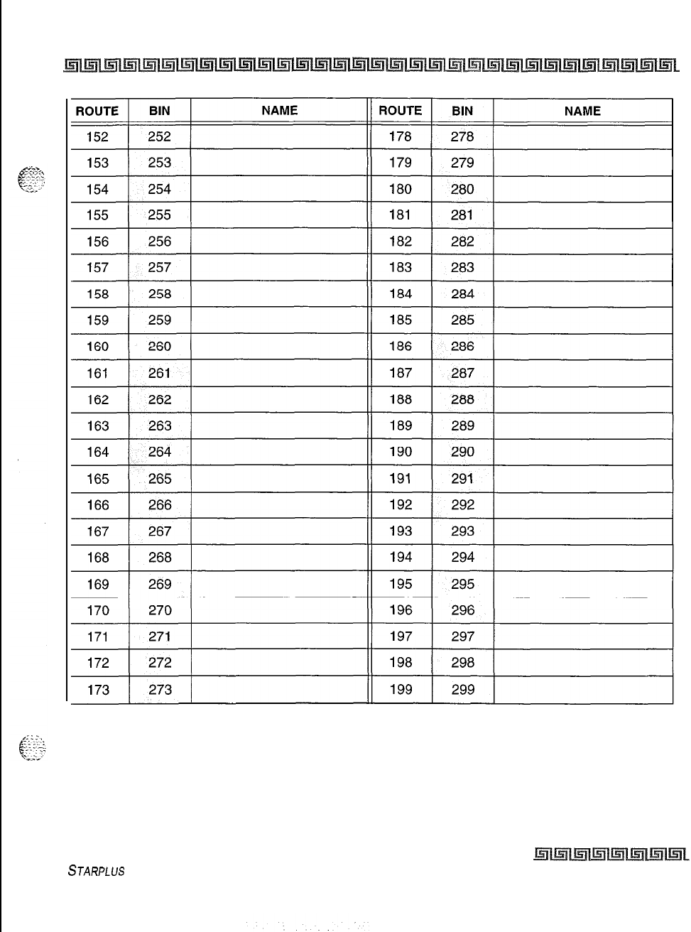
CUSTOMER DATABASE PROGRAMMING C-II
Table C-2: Directory Dialing Defaults (FLASH 23) (Continued)
STARPLUS
Triad-S Product Description Manual Issue I- November 1998
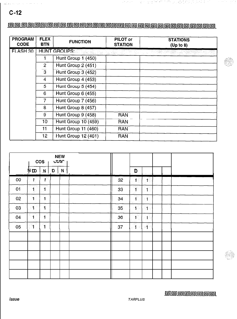
CUSTOMER DATABASE PROGRAMMING
Table C-3: Hunt Group Parameters (FLASH 30)
DEFAULT
I
!z!
I
DEFAULT NEW
/
INDEX
/
D
,
N
;
;rN
1 DIGITS (12 MAX.) INDEX
N
$“,
DIGITS (12 MAX.)
D
“”
01
02
E
03
04
05
06 1 138 1 1
07 1 139 1 1
08 1 140 1 1
09 1 141 1 1
10 1 142 1 1
Table C-4: Verified Account Codes (FLASH 31)
issue
I- November 1998
S
TARPLUS
Triad-S Product Description Manual
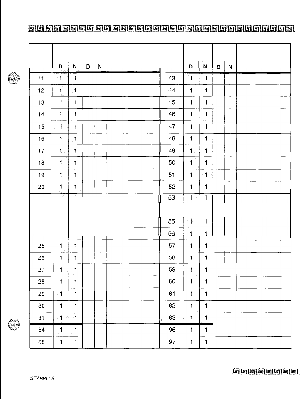
CUSTOMER DATABASE PROGRAMMING C-13
DEFAULT NEW DEFAULT NEW
INDEX
cos DIGITS (12 MAX.)
INDEX
cos DIGITS (12 MAX.)
D/N
DIN
DIN
DIN
21 1 1
22 1 154 1 1
23 1 1
24 1 1
Table C-4: Verified Account Codes (FLASH 31) (Continued)
STARPLUS
Triad-S
Product Description Manual
Issue I- November 1998
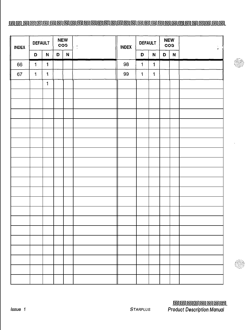
c-14 CUSTOMER DATABASE PROGRAMMING
DIGITS (12 MAX.) DIGITS
(12 MAX.)
68 1
1
100 1 1
69 1 1101 1 1
70 1 1102 1 1
71 1 1103 1 1
72 1 1104 1 1
73 1 1105 1 1
74 1 1106 1 1
75 1 1107 1 1
76 1 1108 1 1
77 1 1109 1 1
78 1 1110 1 1
79 1 1111 1 1
80 1 1112 1 1
81 1 1113 1 1
82 1 1114 1 1
83 1 1115 1 1
84 1 1116 1 1
85 1 1117 1 1
86 1 1118 1 1
87 1 1119 1 1
88 1 1120 1 1
Table C-4: Verified Account Codes (FLASH 31) (Continued)
Issue
1
-November 1998 STARPLUS Triad-S ProductDescripfionManual
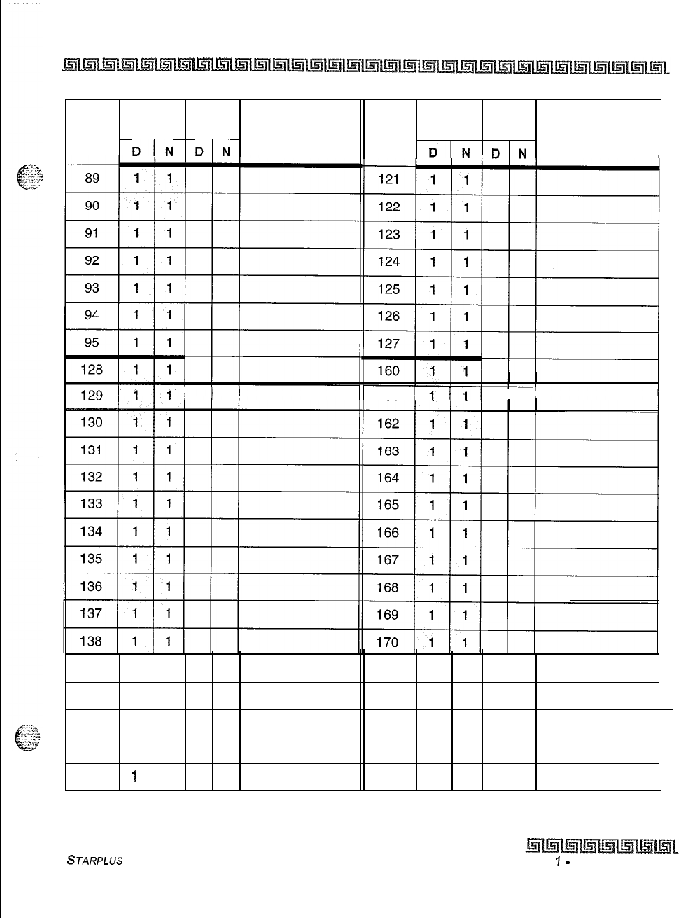
CUSTOMER DATABASE PROGRAMMING C-15
DEFAULT NEW DEFAULT NEW
INDEX
cos DIGITS (12 MAX.)
INDEX
cos
DIN
DIN
DIGITS (12 MAX.)
DIN
DIN
11
161 I I
I I
139 1 1171 1 1
140 1 1172 1 1
141 1 1173 1 1
142 1 1174 1 1
143
1
1 175 1 1
Table C-4: Verified Account Codes (FLASH 31) (Continued)
STARPLUS
Triad-S Product Description Manual
Issue
7
-
November 1998
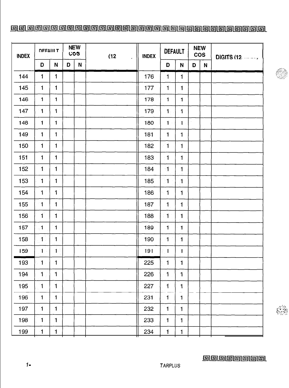
C-16 CUSTOMER DATABASE PROGRAMMING
EW
I
-^
DIGITS (12 MAX.)
/
DEFAULT
1
”
DlGlTS(12
MAX.1
/
Table C-4: Verified Account Codes (FLASH 31) (Continued)
Issue
1
-
November 1998
S
JARPLUS
Triad-S Product Description Manual
;t
‘:-Z.
.
.
;-.
h
. .
..-.,
.,-_.
./
‘;
--:,:
.,.,
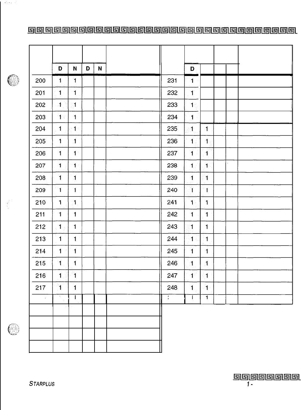
CUSTOMER DATABASE PROGRAMMING c-17
218 1 1249 1
I I I I
219 1 1
220 1 1
221 1 1
222 1 1
N
D N
1
1
1
1
DEFAULT
NEW
cos
DEFAULT
NEW
INDEX
DIGITS (12 MAX.)
INDEX
cos
DIGITS (12 MAX.)
. .
Table C-4: Verified Account Codes (FLASH 31) (Continued)
STARPLUS
Triad-S Product Description Manual
Issue
I-
November 1998
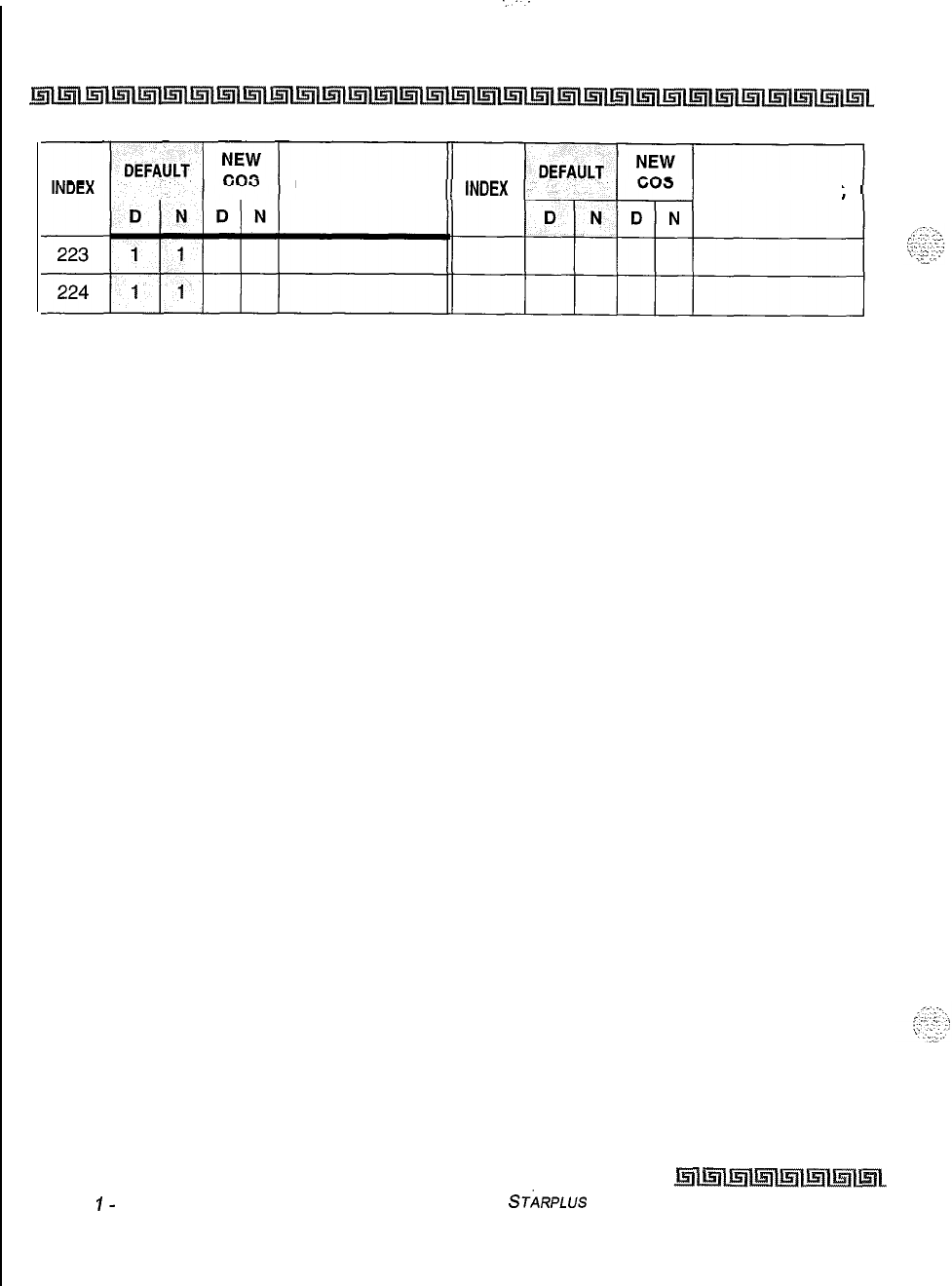
..‘..
C-18 CUSTOMER DATABASE PROGRAMMING
DIGITS
(12 MAX.) DIGITS (12 MAX.)
Table C-4: Verified Account Codes (FLASH 31) (Continued)
Issue
I-
November 1998 ST~RPLUS
Triad-S Product Description Manual
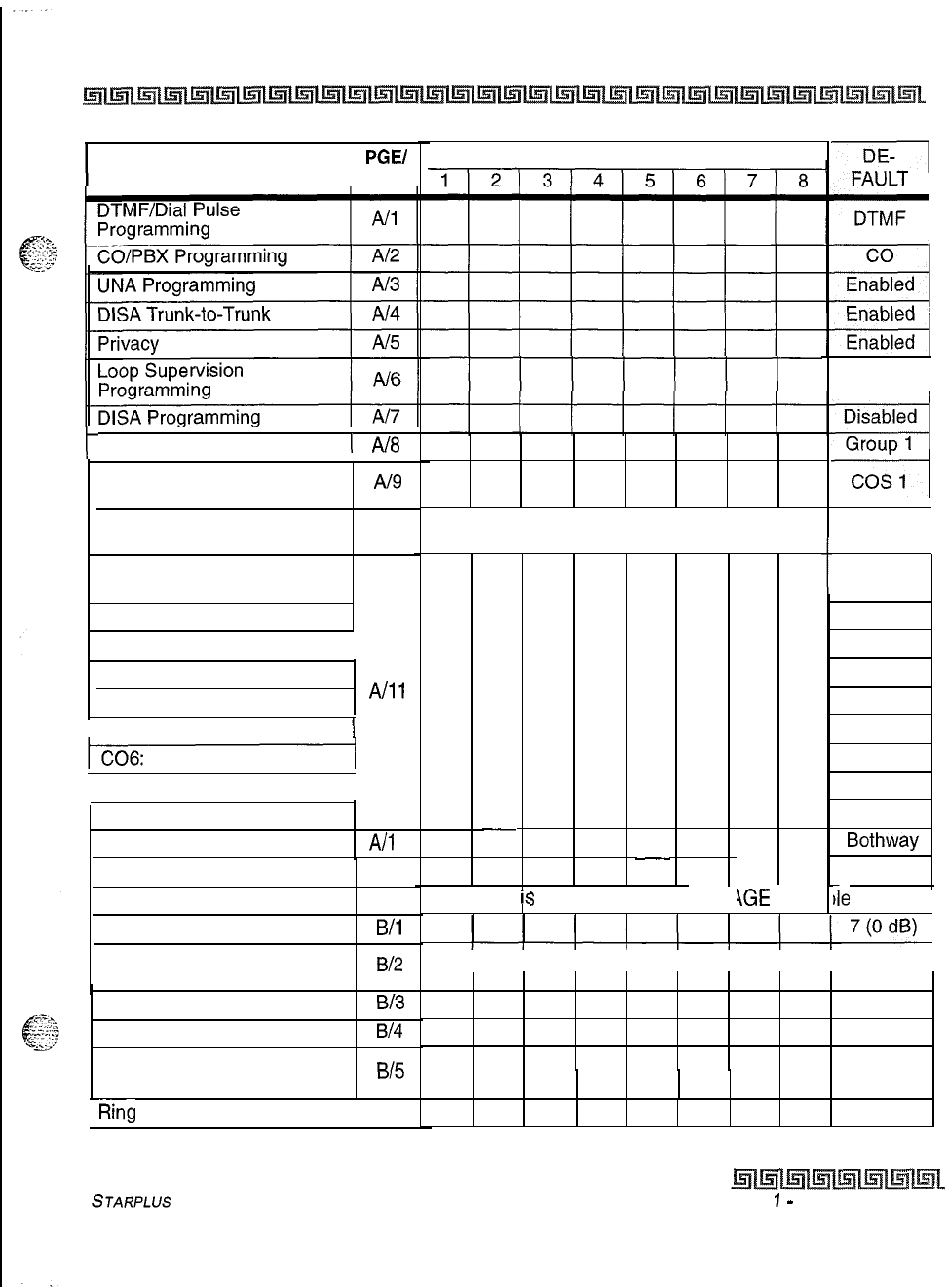
CUSTOMER DATABASE PROGRAMMING c-19
DATA FIELD
PGEI
BTN
CO LINE PORT NUMBER
400 ms
t
Line Grouo Proarammina
1
Ah3
Class of Service
Programming
CO Line Ringing
Assignments
CO Line Identification
Display
co1 :
Al9
All 0 Sta 100
Refer to CO Line Ringing Assignments
t
Line XX
Line XX
Line XX
Line XX
Line XX
Line XX
Line XX
Line XX
Line XX
Bothway
DTMF
I co2: I
co3:
co4:
A/11
I co5:
I
I co7: I
C08:
Trunk Direction
Display Ring Assignments
PAGE A
Transmit Volume Option
Preset Call Forward
Destination
Preset Forward Voice Mail
Universal Day Answer
Music-On-Hold
A/l
2
All3
19
B/i
B/2
B/3
B/4
B/5
Page “A”
i:
;
selected by pressing I \GE flex
it
ie
button. 1
I I I I I I I I None I
None
Disabled
Channel
1
Ring
Tone 1 B/6
00
Table C-5: CO Line Programming (FLASH 40)
STARPLUS
Triad-S Product
Description Manual
Issue
7
-
November 7998
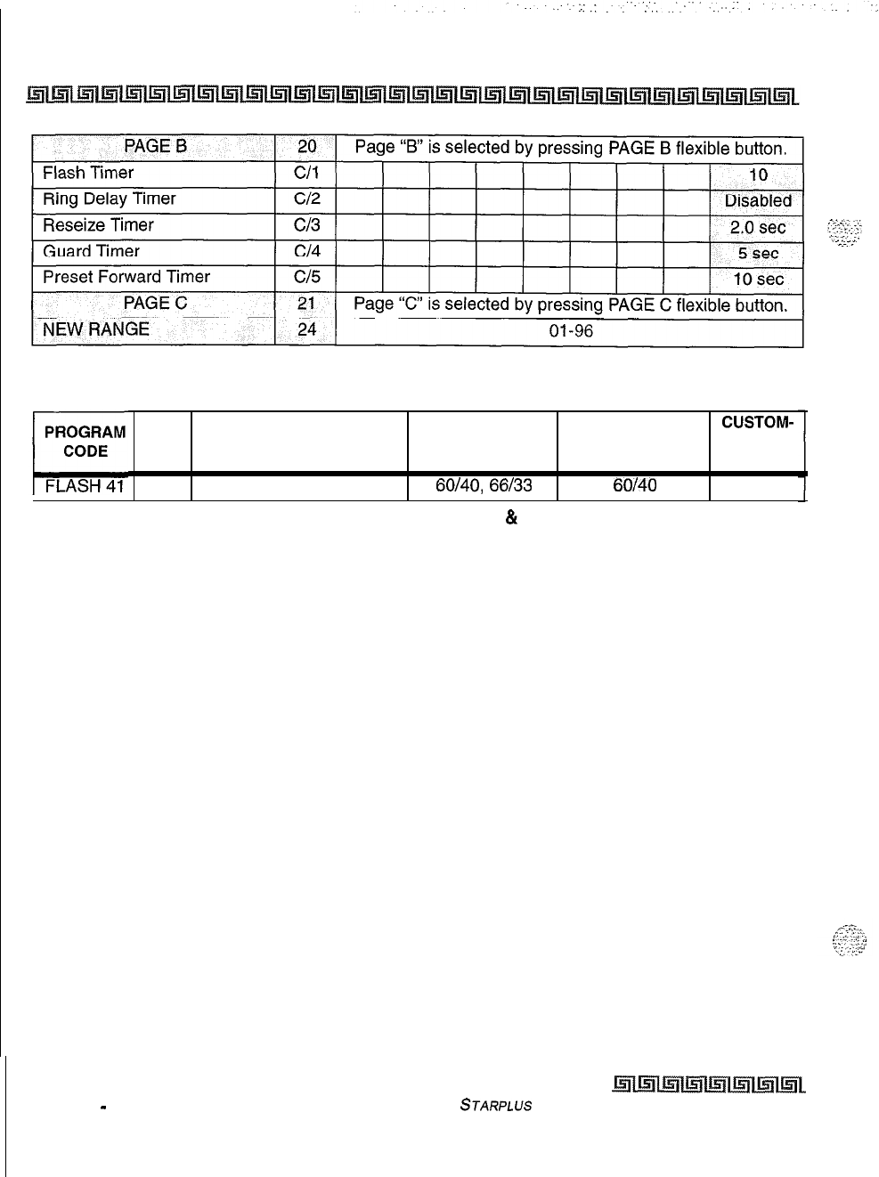
c-20 CUSTOMER DATABASE PROGRAMMING
Table C-5: CO Line Programming (FLASH 40)
FLEX
CUSTOM-
BTN
FUNCTION FORMAT DEFAULT ER
DATA
1
Dial Pulse Parameters
60140,
66133
60/40
Table C-6: Miscellaneous CO Parameters & Timers (FLASH 41)
Issue 1
-
November 1998
STARPLUS
Triad-S Product Description Manual
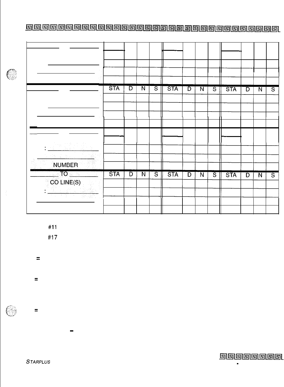
CUSTOMER DATABASE PROGRAMMING c-21
TO
STA
D N SSTA D N S
STA
D N S
CO LINE(S)
TYPE:
NUMBER
TO
CO LINE(S)
TYPE:
NUMBER
TOSTA D N S
STA
D N SSTA D N S
CO LINE(S)
TYPE:
TYPE:
NUMBER
Button
#ll
= Enter Ringing Assignments
Button #17 = Display Ringing Assignments
Ringing Assignments:
0 = No Ringing (unassigned/to delete a station)
1 = Day Ringing (D)
2
=
Night Ringing (N)
3 = Day/Night Ringing (DN)
4 = Special Only (S)
5
=
Day/Special (DS)
6 = Night/Special (NS)
7 = All Modes
-
Day/Night/Special
(A)
Table C-7: CO Line Ringing Assignments (FLASH
40)
STARPLUS
Triad-S Product Description Manual
Issue I
-
November 1998
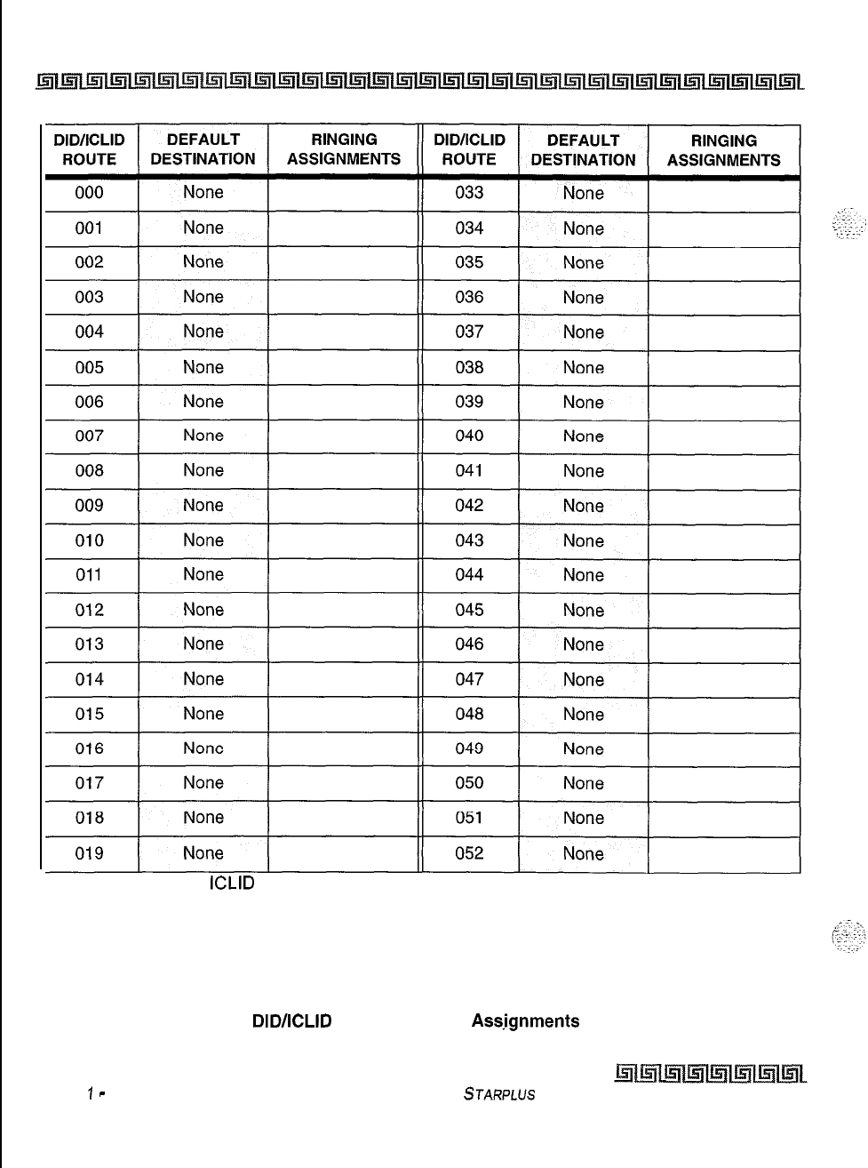
c-22 CUSTOMER DATABASE PROGRAMMING
1. Route 000 in the
ICLID
Ringing Assignment Table is used as the intercept route. Calls to
numbers not contained in the DID table will follow Route 000. If Route 000 is defaulted to
“none”, the call will follow Route 001.
2. Route 001 in the ICLID Ringing Assignment Table is used for Busy calls. If Route 001 is
defaulted to “none”, the caller is given a busy tone. Calls to busy stations (i.e., without an
available Loop or CO button) will follow Route 001.
Table C-8:
DIDACLID
Default Ringing
Assjgnments
(FLASH 43)
Issue
1
-
November 1998 STARPLUS Triad-S Product Description Manual
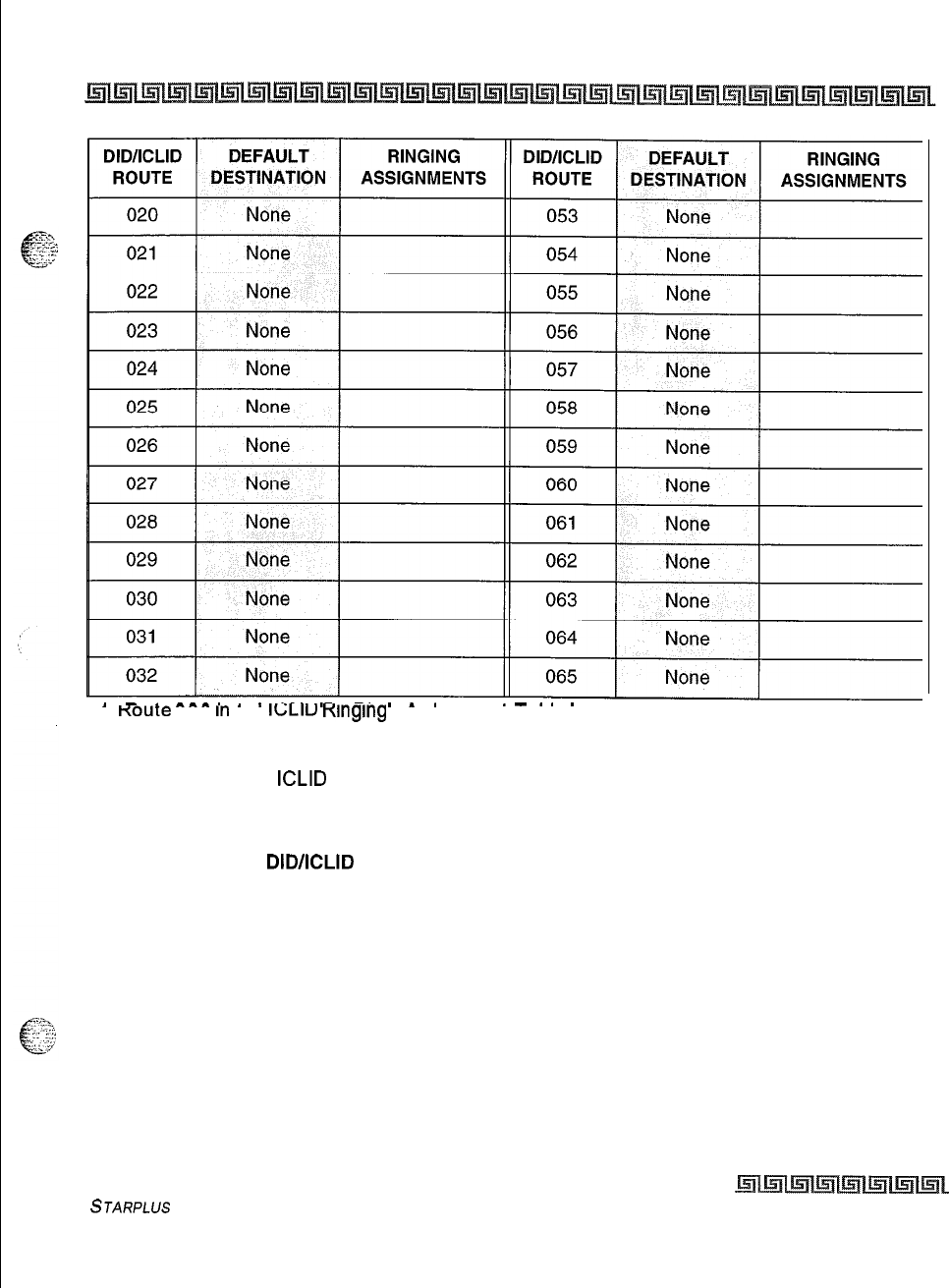
CUSTOMER DATABASE PROGRAMMING C-23
>
-
.
^^^.
.
.
.^.
.-
-.
.
*
.
.-..
.
I.
Koute
uuu
In
tne
IGLIU
Klnglng
Hsslgnment I able IS used as the intercept route. Calls to
numbers not contained in the DID table will follow Route 000. If Route 000 is defaulted to
“none”, the call will follow Route 001.
2. Route 001 in the
ICLID
Ringing Assignment Table is used for Busy calls. If Route 001 is
defaulted to “none”, the caller is given a busy tone. Calls to busy stations (i.e., without an
available Loop or CO button) will follow Route 001.
Table C-8:
DID/ICLID
Default Ringing Assignments (FLASH 43) (Continued)
STARPLUS
Triad-S Product Description Manual Issue I- November 1998
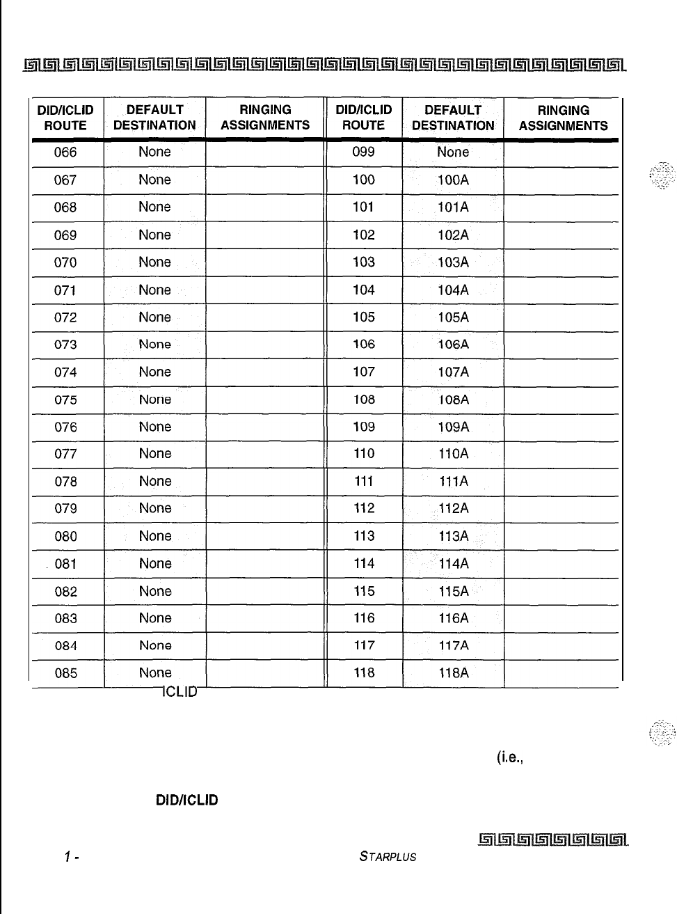
C-24 CUSTOMER DATABASE PROGRAMMING
1. Route 000 in the
ICLID
Ringing Assignment Table is used as the intercept route. Calls to
numbers not contained in the DID table will follow Route 000. If Route 000 is defaulted to
“none”, the call will follow Route 001.
2. Route 001 in the ICLID Ringing Assignment Table is used for Busy calls. If Route 001 is
defaulted to “none”, the caller is given a busy tone. Calls to busy stations
(i.e.,
without an
available Loop or CO button) will follow Route 001.
Table C-8:
DID/ICLID
Default Ringing Assignments (FLASH 43) (Continued)
Issue
I-
November 1998 STARPLUS
Triad-S Product Description Manual
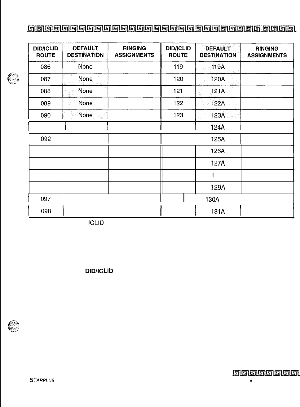
CUSTOMER DATABASE PROGRAMMING C-25
II I
I
I
I
09
1 1 None 1
II
124 1
124A
1
I
092
I
None
I
I/
125
I
125A
I
093
None 126 126A
094 None 127 127A
095 None 128
-I
28A
096 None 129 129A
I
097
I
None
I
11
1
13OA
1
130
I
098
I
None
I
II
131
I
13lA
I
1. Route 000 in the
ICLID
Ringing Assignment Table is used as the intercept route. Calls to
numbers not contained in the DID table will follow Route 000. If Route 000 is defaulted to
“none”, the call will follow Route 001.
2. Route 001 in the ICLID Ringing Assignment Table is used for Busy calls. If Route 001 is
defaulted to “none”, the caller is given a busy tone. Calls to busy stations (i.e., without an
available Loop or CO button) will follow Route 001.
Table C-8:
DID/ICLID
Default Ringing Assignments (FLASH 43) (Continued)
STARPLUS Triad-S Product Description Manual
issue I
-
November 1998
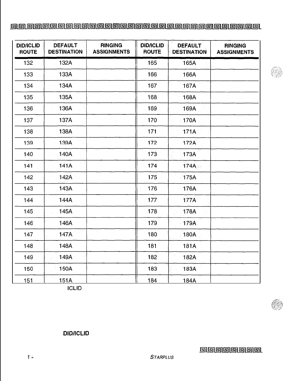
C-26 CUSTOMER DATABASE PROGRAMMING
I
I
II
I
I
1. Route 000 in the
ICLID
Ringing Assignment Table is used as the intercept route. Calls to
numbers not contained in the DID table will follow Route 000. If Route 000 is defaulted to
“none”, the call will follow Route 001.
2. Route 001 in the ICLID Ringing Assignment Table is used for Busy calls. If Route 001 is
defaulted to “none”, the caller is given a busy tone. Calls to busy stations (i.e., without an
available Loop or CO button) will follow Route 001.
Table C-8:
DID/ICLID
Default Ringing Assignments (FLASH 43) (Continued)
Issue
1
L
November 1998
STARPLUS
Triad-S Product Description Manual
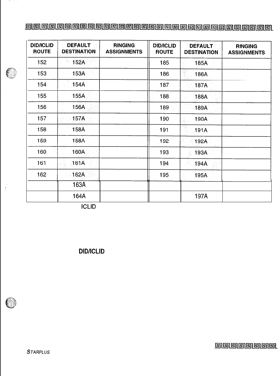
CUSTOMER DATABASE PROGRAMMING
C-27
163 163A 196 196A
164 164A 197 197A
1. Route 000 in the
ICLID
Ringing Assignment Table is used as the intercept route. Calls to
numbers not contained in the DID table will follow Route 000. If Route 000 is defaulted to
“none”, the call will follow Route 001.
2. Route 001 in the ICLID Ringing Assignment Table is used for Busy calls. If Route 001 is
defaulted to “none”, the caller is given a busy tone. Calls to busy stations (i.e., without an
available Loop or CO button) will follow Route 001.
Table C-8:
DIDIICLID
Default Ringing Assignments (FLASH 43) (Continued)
STARPLUS
Triad-S Product Description Manual Issue I- November 1998
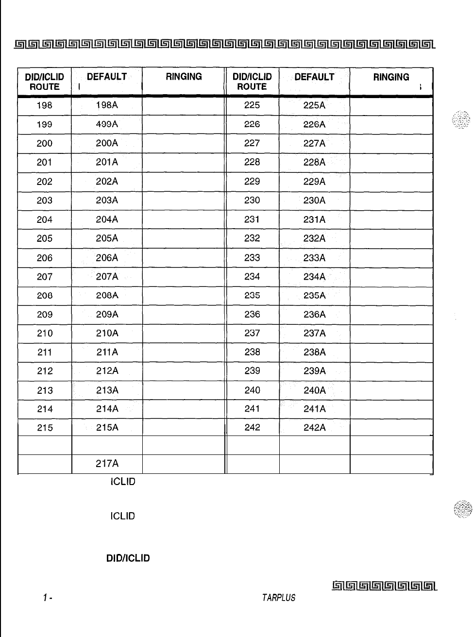
C-28 CUSTOMER DATABASE PROGRAMMING
DESTINATION ASSIGNMENTS DESTINATION ASSIGNMENTS
216
216A
243
243A
217 217A
244
244A
1. Route 000 in the
ICLID
Ringing Assignment Table is used as the intercept route. Calls to
numbers not contained in the DID table will follow Route 000. If Route 000 is defaulted to
“none”, the call will follow Route 001.
2. Route 001 in the
ICLID
Ringing Assignment Table is used for Busy calls. If Route 001 is
defaulted to “none”, the caller is given a busy tone. Calls to busy stations (i.e., without an
available Loop or CO button) will follow Route 001.
Table C-8:
DID/ICLID
Default Ringing Assignments (FLASH 43) (Continued)
Issue
I-
November 1998 S
TARPLUS
Triad-S Product Description Manual
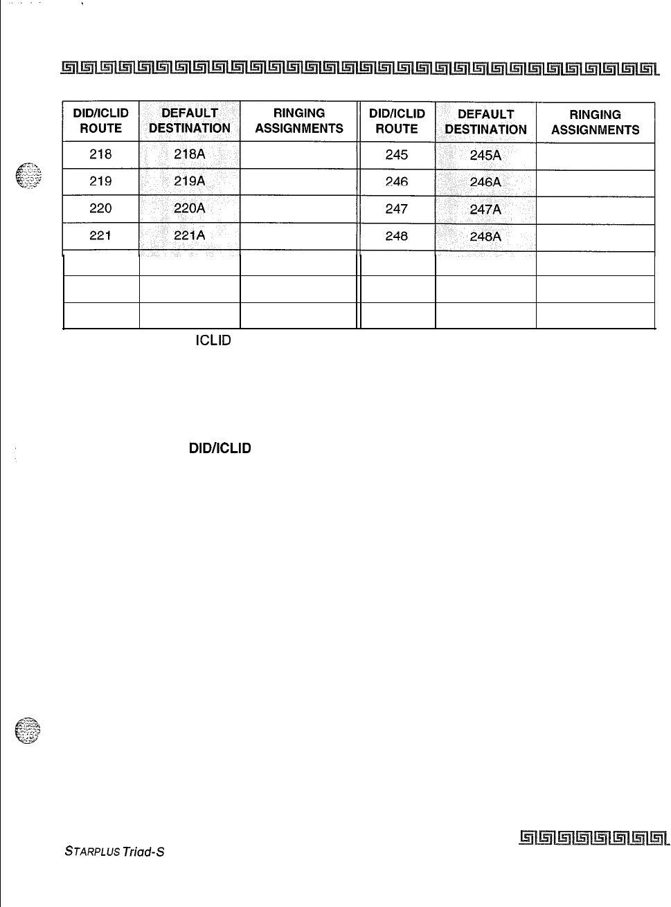
.
CUSTOMER DATABASE PROGRAMMING c-29
222
222A
249
249A
223
223A 250
250A
224 224A 251 251A
1. Route 000 in the
ICLID
Ringing Assignment Table is used as the intercept route. Calls to
numbers not contained in the DID table will follow Route 000. If Route 000 is defaulted to
“none”, the call will follow Route 001.
2. Route 001 in the ICLID Ringing Assignment Table is used for Busy calls. If Route 001 is
defaulted to “none”, the caller is given a busy tone. Calls to busy stations (i.e., without an
available Loop or CO button) will follow Route 001.
Table C-8:
DID/ICLID
Default Ringing Assignments (FLASH 43) (Continued)
STARPLUS
Triad-S
Product Description Manual Issue I- November 1998
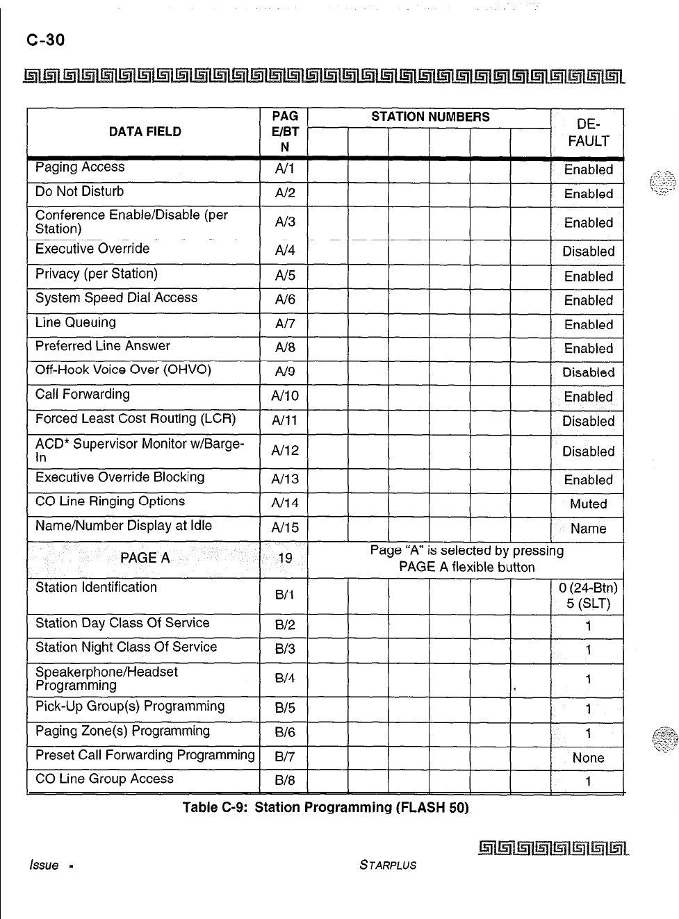
CUSTOMER DATABASE PROGRAMMING
Issue
I
-
November 1998
STARPLUS
Triad-S Product Description Manual
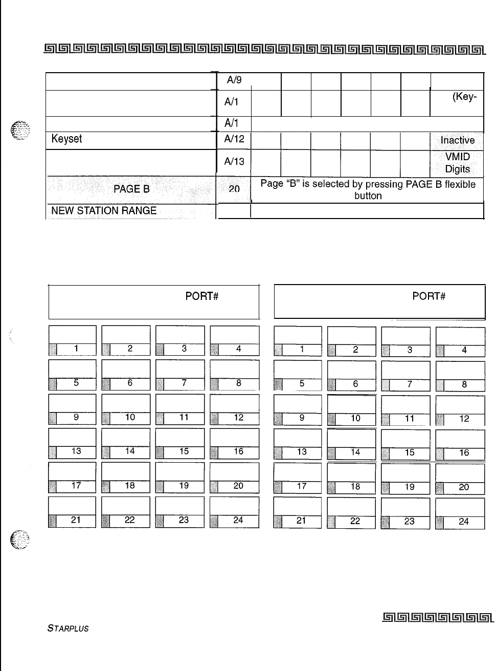
CUSTOMER DATABASE PROGRAMMING c-31
LCR Class of Service (COS)
Off-Hook Preference Programming
Flexible Button Programming
Keyset Mode
Voice Mail ID Translation
Al9
1
0
All
0
All
1
00
(Key-
set)
Refer to Flexible Button Proarammina Chart
E%~
Page “B” is selected by pressing PAGE B flexible
~
*Features available with optional software.
#
24 1
700-131
Table C-9: Station Programming (FLASH 50)
STA# PORT# STA# PORT#
Table C-10: Button Assignments (FLASH 50)
STARPLUS Triad-S
Product
Description Manual
Issue I- November 1998
C-32 CUSTOMER DATABASE PROGRAMMING
Refer to
Table C-10: Button Assignments (FLASH
50) to assign a function to each flexible button.
Defaults:
Q
Buttons 1 thru
12
are assigned as Stations 100 thru 111,
*Buttons 13 thru 18 are assigned as CO Lines 01 thru 06,
+
Buttons 19 is assigned as a Loop button,
+z+
Button 20 is assigned as a Pool Group button,
oButtons 21 thru 24 are flexible buttons with features assigned to them.
Where:BB = Button Number (01-24)
9LLL = CO Line Number (001-012)
3G = Line Group (l-7)
KEY STATION BUTTON PROGRAMMING:
1
To assign a button as a Flexible button (user programmable) enter:
BB [0] HOLD
z
To assign a button as a CO Line button, enter:
BB [I] LLL HOLD
3To assign a button as a Loop button, enter:
BB
[2]
HOLD
4
To enter a button as a Pooled Group button, enter:
BB
[3]
G HOLD
5
To enter a button as a Feature button,
enter:
BB
[4]
[XXX] HOLD
6
To unassign a button, enter:
BB
[#]
HOLD
SLT ENTRY: (Off-Hook Preference)
oWhen an SLT is being assigned for Off-Hook Preference, enter:
01
[
1)
LLL HOLD for a specific CO Line,
+3
or
01 [3]
G
HOLD for a CO Group Access.
Table C-l 0: Button Assignments (FLASH 50)
Issue
1
-
November 1998
~l~l~l~l~l~i~l~~
S
JARPLUS
Triad-S
Product Description Manual
.‘,
_
1
.
.._
,
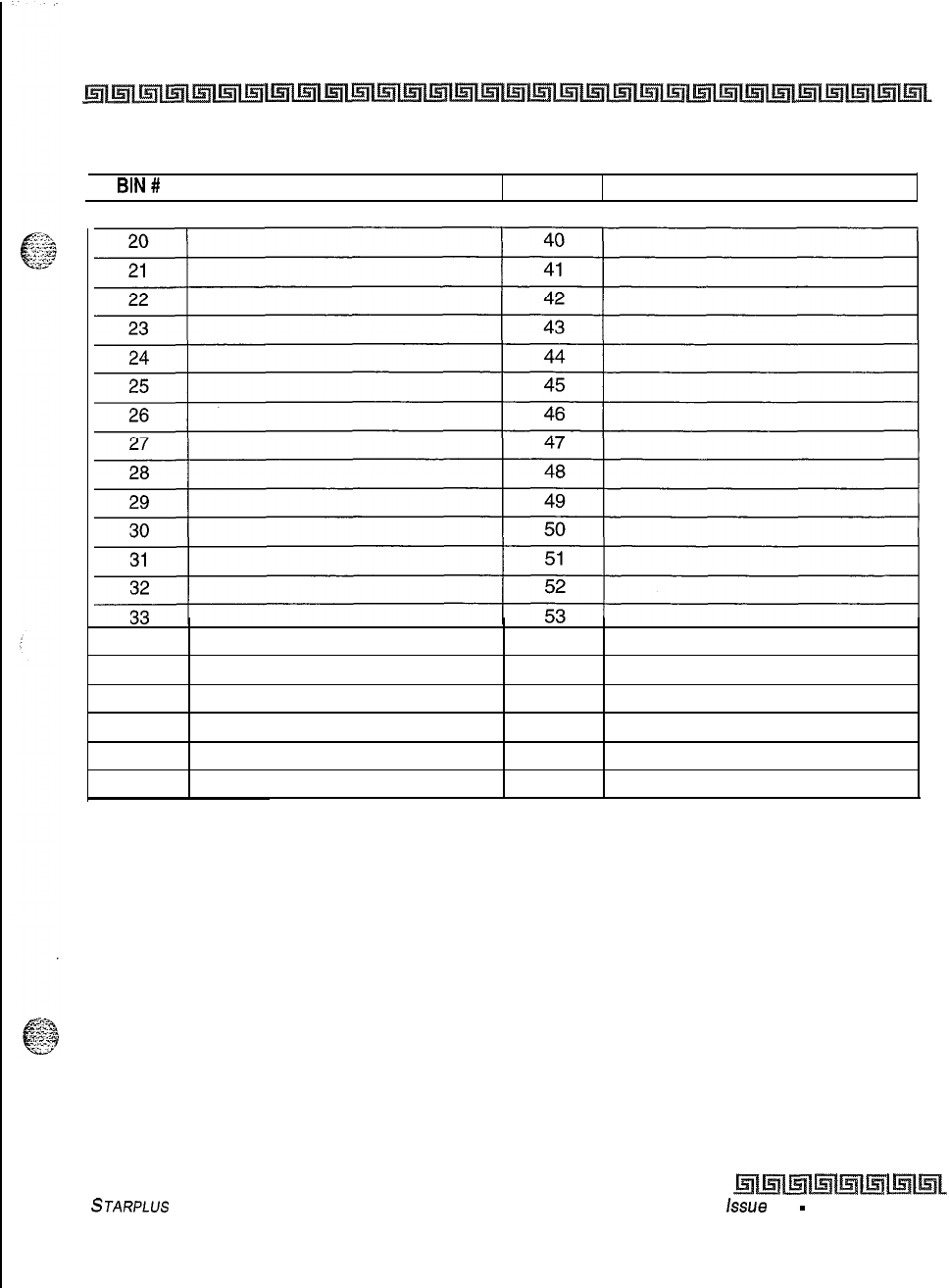
34 54
35 55
36 56
37 57
38 58
39 59
CUSTOMER DATABASE PROGRAMMING
c-33
Programmed from the first Attendant Station.
BIN#
1TELEPHONE NUMBER
BIN #
TELEPHONE NUMBER
Monitored by Toll Restriction (COS)
Table C-l 1: System Speed Dial Numbers
STARPLUS
Triad-S Product Description Manual
issue 1
-
November 1998
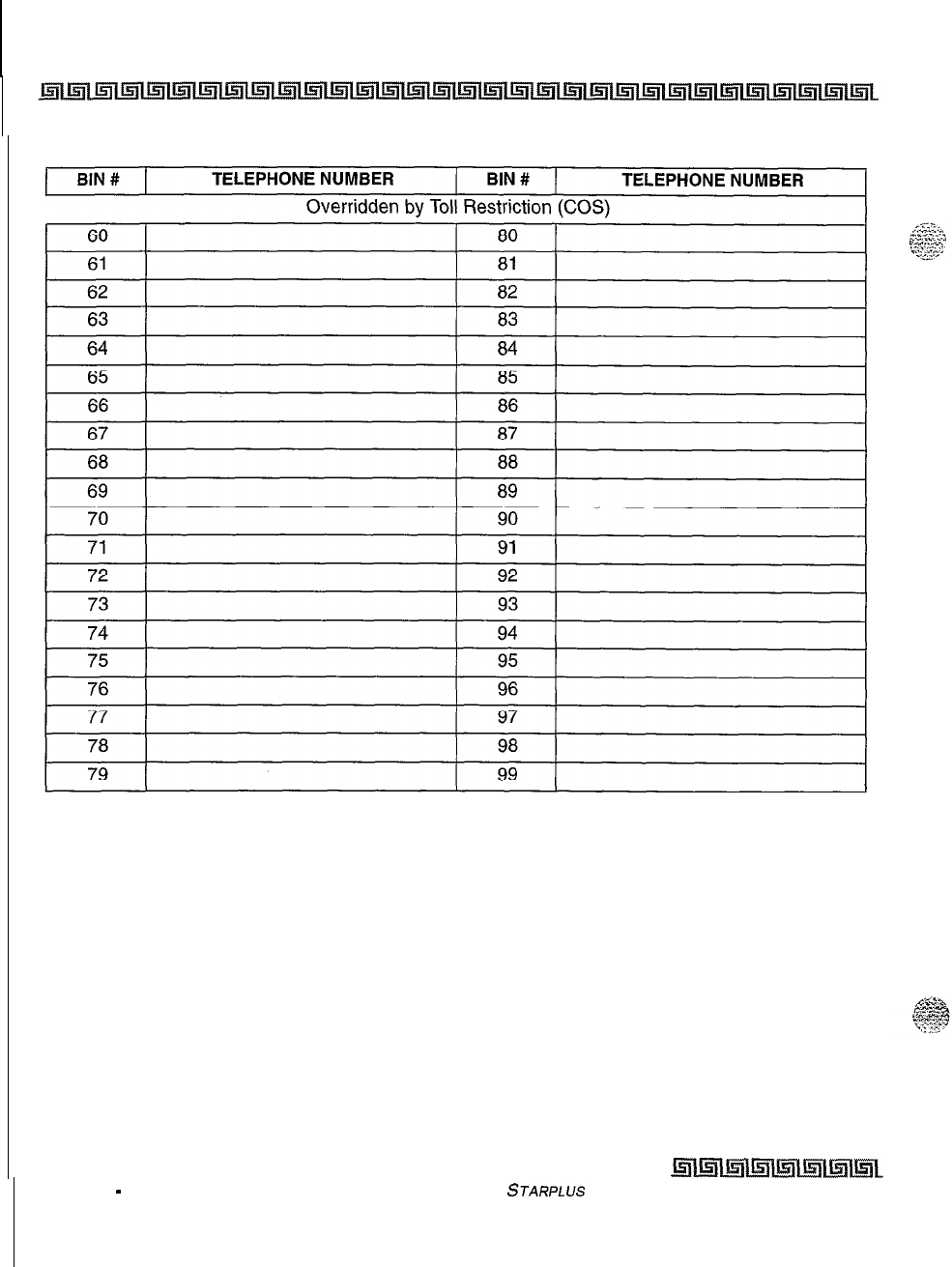
c-34 CUSTOMER DATABASE PROGRAMMING
Programmed from the first Attendant Station.
Issue 1
-
November 1998
Table C-l 1: System Speed Dial Numbers (Continued)
STARPLUS
Triad-S Product Description Manual
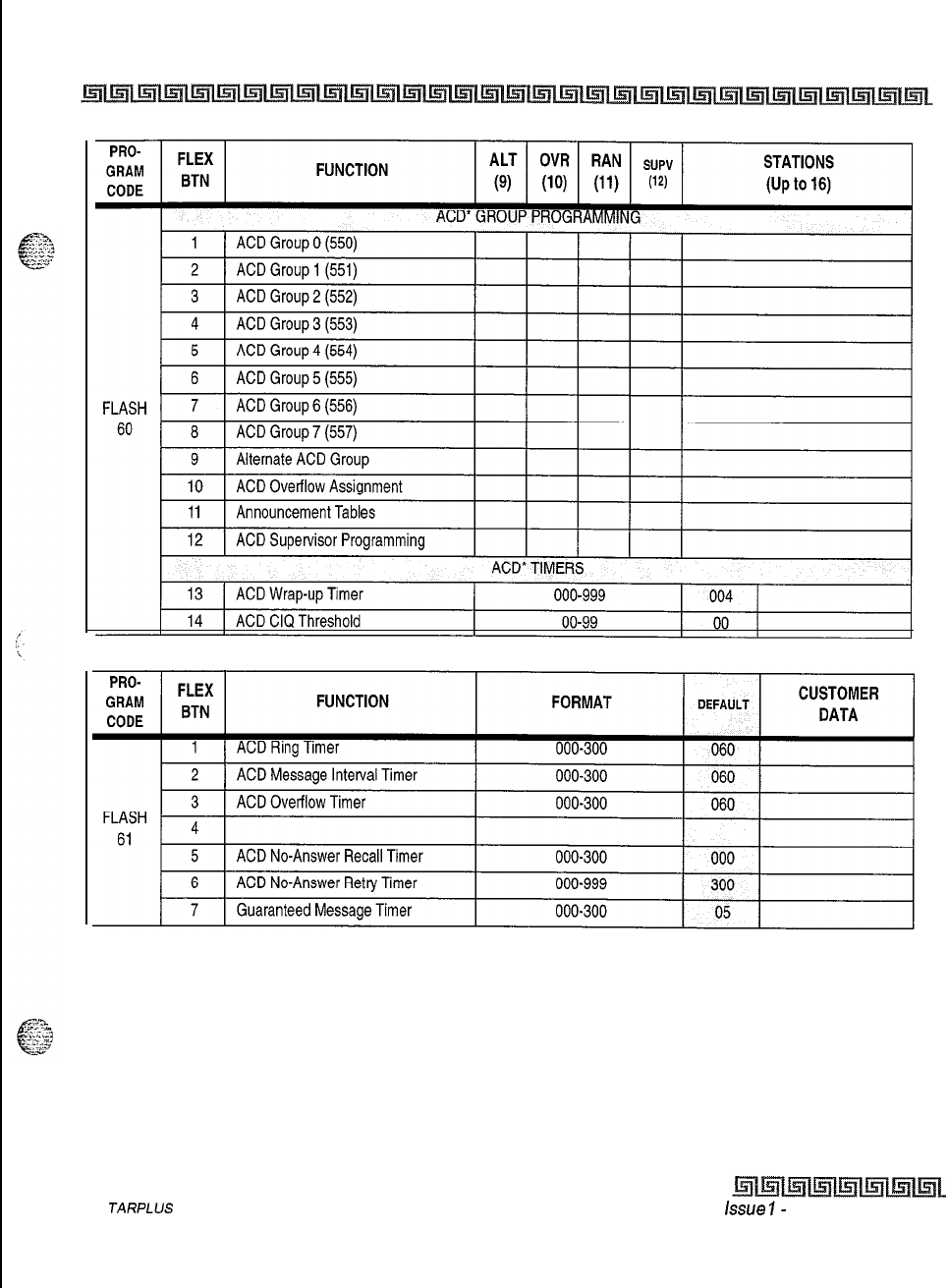
CUSTOMER DATABASE PROGRAMMING c-35
Table C-12: ACD Group Parameters
S
TARPLUS
Triad-S Product Description Manual issue
I-
November 1998
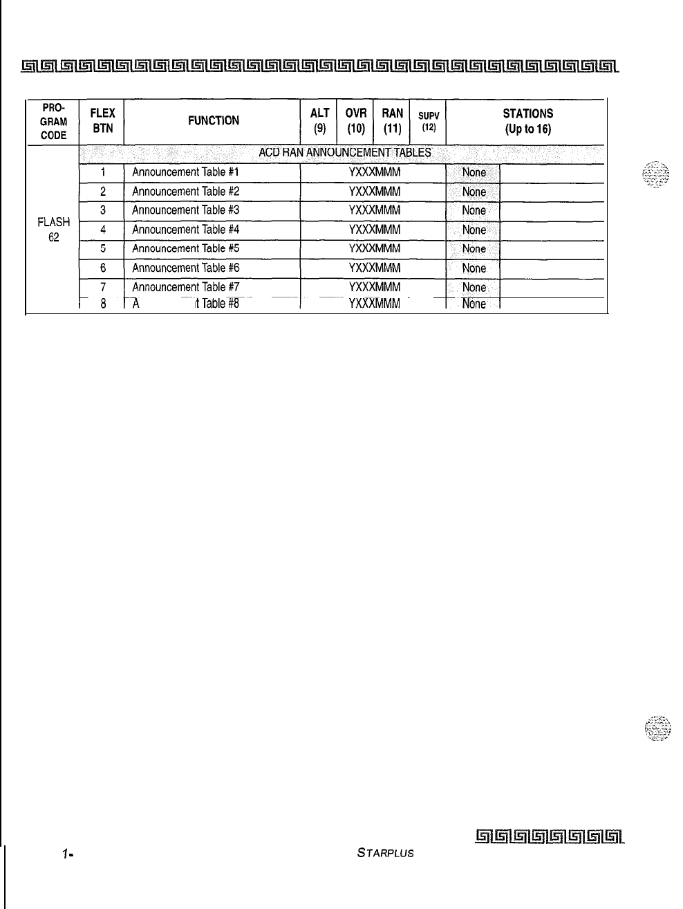
C-36 CUSTOMER DATABASE PROGRAMMING
nnouncemen
*Features available with optional software.
Table C-l 2: ACD Group Parameters (Continued)
Issue
1
-
November 1998
STARPLUS
Triad-S Product Description Manual
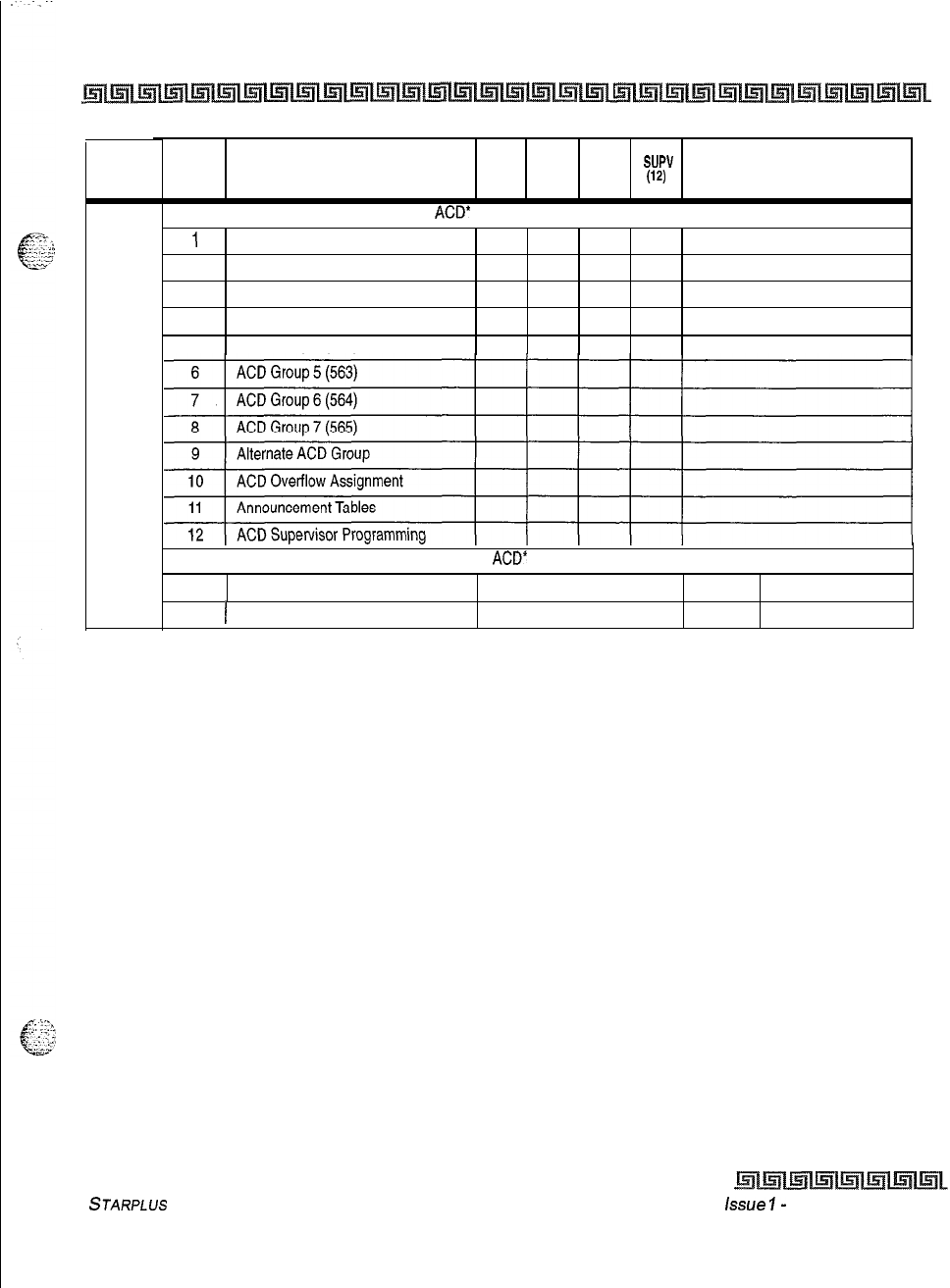
CUSTOMER DATABASE PROGRAMMING c-37
PRO-
GRAM
CODE
FLASH
64
FLEX FUNCTION
ALT OVR RAN
sup” STATIONS
BTN
(9) (10) (11)
(14 (Up to 16)
ACD* GROUP PROGRAMMING
1
ACD Group 0 (558)
2
ACD Group 1 (559)
3
ACD Group 2 (560)
4
ACD Group 3 (561)
5
ACD Group 4
(562)
ACD* TIMERS
13
ACD
Wrap-up Timer 000-999 004
14
(
ACD CIQ Threshold
00-99 00
*Features available with optional software.
Table C-12: ACD Group Parameters (Continued)
STARPLUS
Triad-S Product Description Manual
issue
I-
November 1998
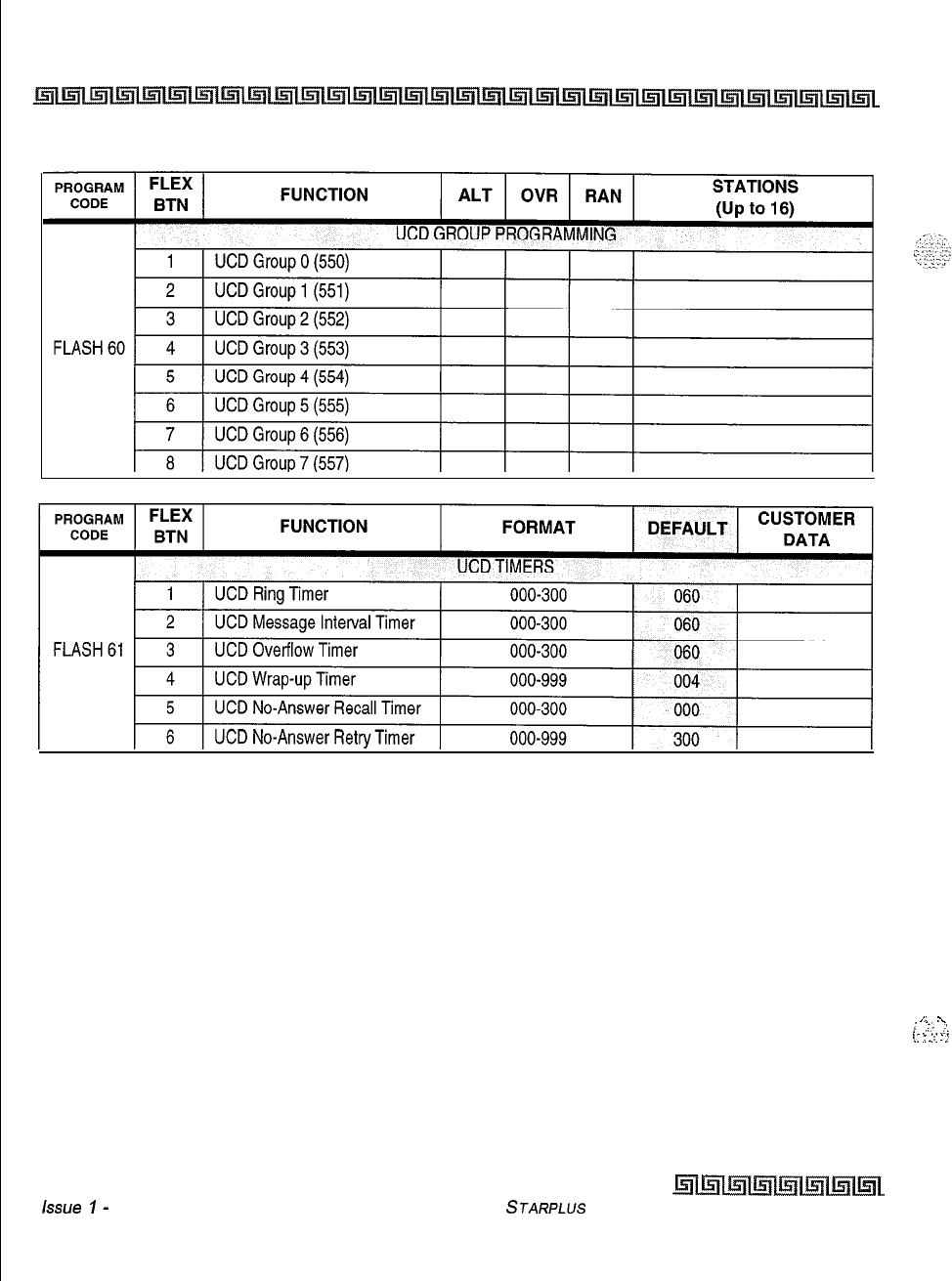
C-38 CUSTOMER DATABASE PROGRAMMING
issue
I-
November 1998
Table C-13: UCD Group Parameters
/
.
.
;
“.
:,
,
:-
.-.
!I
‘.
.:::
:
.:
STARPLUS
Triad-S Product Description Manual
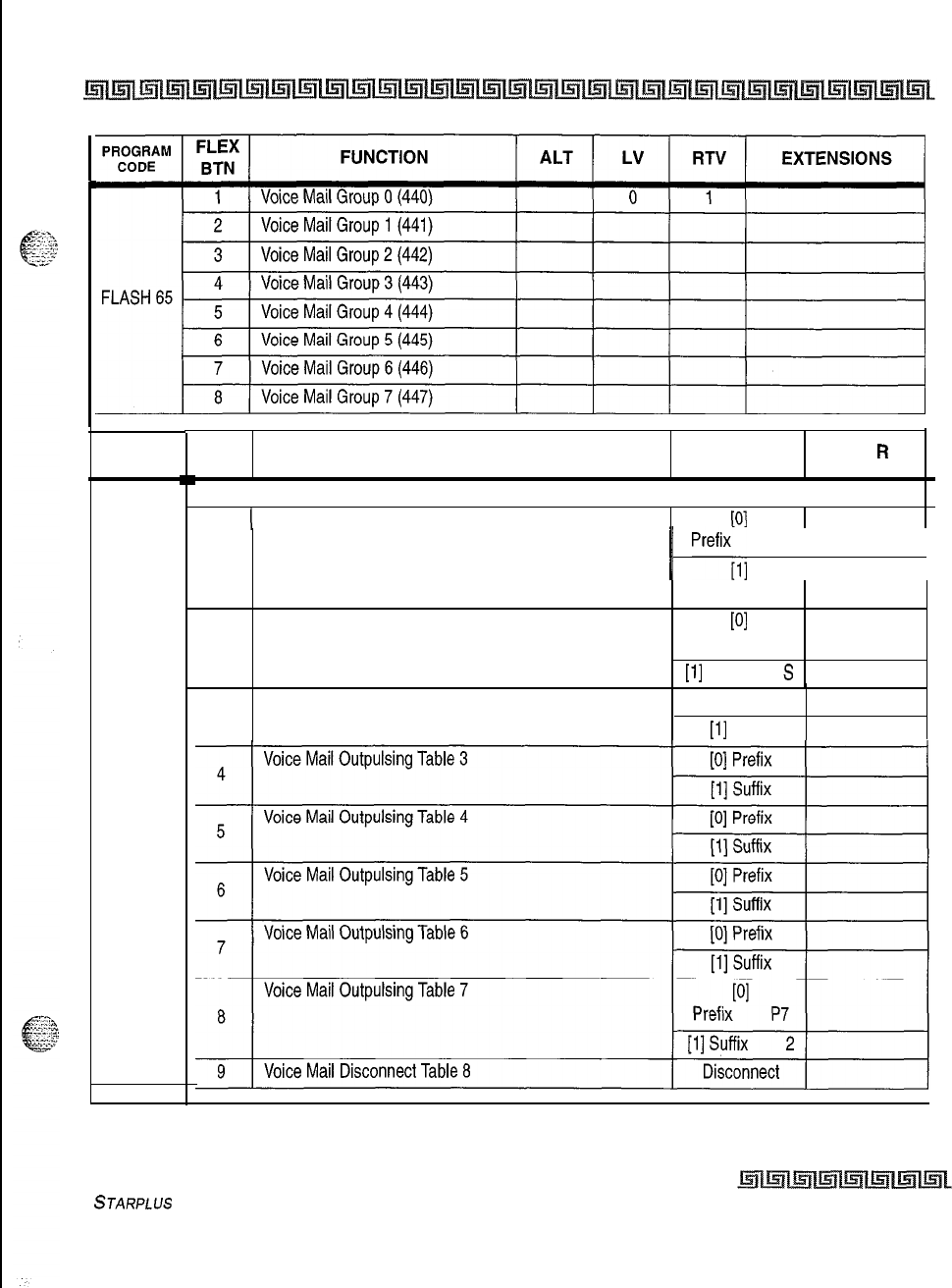
CUSTOMER DATABASE PROGRAMMING c-39
.
PROGRAM
CODE
FLASH 66
FLEX FUNCTION
BTN
VOICE MAIL IN-BAND SIGNALING
(
Voice Mail Outpulsing Table 0
OUTPULSING
DIGITS
PI
L or
R
1
1
Prefix;,;
P7 1
j
Suffix
None
Voice Mail Outpulsing Table 1
PI
2
Prefix P7
[l]
Suffix
S
3Voice Mail Outpulsing Table 2 [0] Prefix
[l]
Suffix
Table C-l
4: Voice Mail Group Parameters
STARPLUS
Triad-S Product Description Manual Issue I- November 1998
c-40 CUSTOMER DATABASE PROGRAMMING
PROGRAM FLEX
CODE
BTN FUNCTION ALT LV
RTV
PROGRAM FLEX
CODE BTN FUNCTION
VOICE MAIL IN-BAND FEATURES
1
FLASH 67
-
2
Voice Mail In-Band Digits
Voice Mail Transfer/Forward
3
VM Broker
Table C-l 4: Voice Mail Group Parameters
EXTENSIONS
DEFAULT
Enabled
Enabled
Enabled
Issue
1
-
November 1998 STARPLUS
Triad-S Product Description Manual
CUSTOMER DATABASE PROGRAMMING c-41
Table C-15: Mailboxes (FLASH 68)
STARPLUS
Triad-S Product Description Manual
issue 1
-
November 1998
_..
C-42 CUSTOMER DATABASE PROGRAMMING
.
30
I
440
I
I 440
I
31
440
64
440
32
440
65
440
Issue
I-
November 1998
STARPLUS
Triad-S Product Description Manual
Table C-15: Mailboxes (FLASH 68) (Continued)
CUSTOMER DATABASE PROGRAMMING c-43
90
440 123
440
Table C-15: Mailboxes (FLASH 68) (Continued)
STARPLUS
Triad-S Product Description Manual
issue
7
-
November 1998
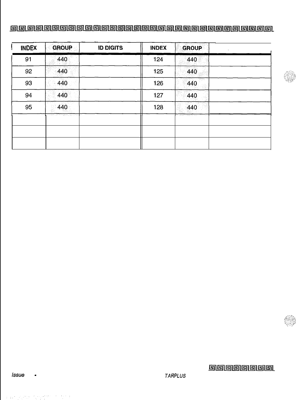
c-44 CUSTOMER DATABASE PROGRAMMING
1
INDE ID DIGITS
I
96
440
129
440
97
440
130
440
98
440
131
440
Issue 1
-
November 1998
Table C-15: Mailboxes (FLASH 68) (Continued)
S
JARPLUS
Triad-S Product Description Manual
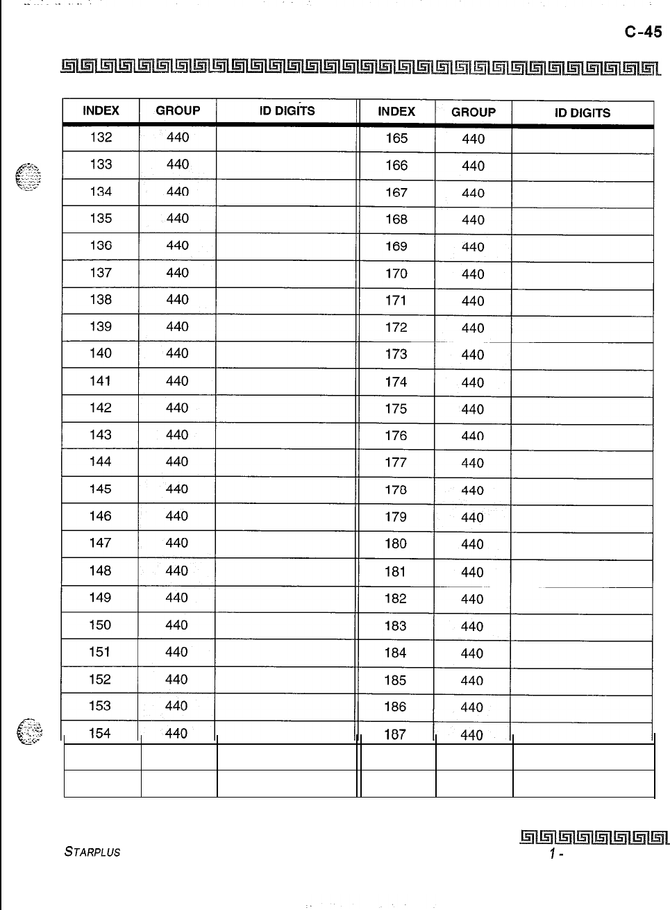
CUSTOMER DATABASE PROGRAMMING
?
.
..2.’
t
~;
-:i
.
.
yyy
&L.
155
440
188
440
156
440
189
440
Table C-15: Mailboxes (FLASH 68) (Continued)
STARPLUS
Triad-S Product Description Manual
Issue
I-
November 1998
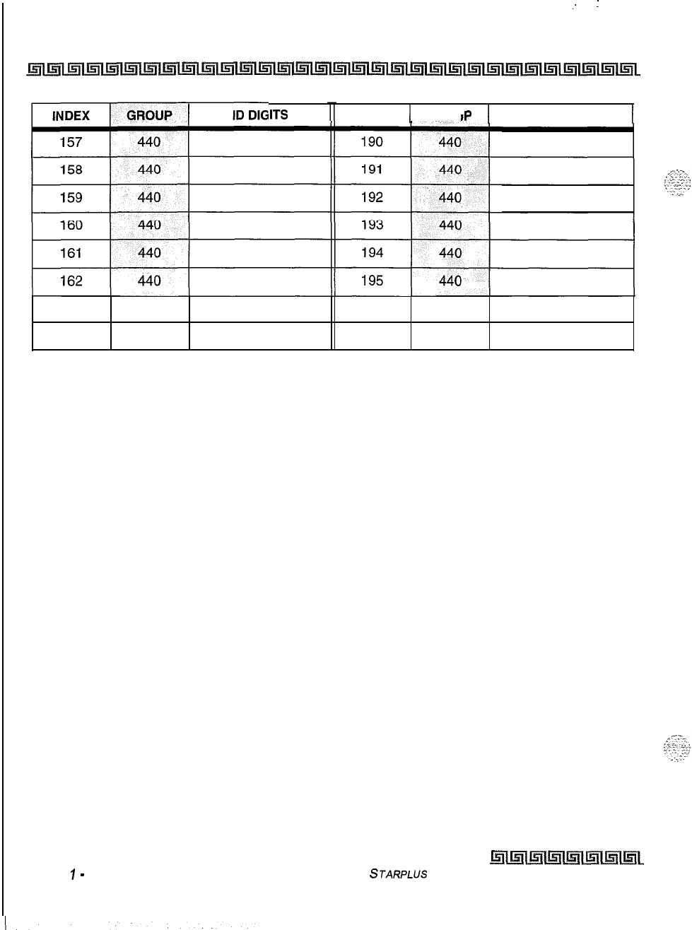
._
:
C-46 CUSTOMER DATABASE PROGRAMMING
Issue
1
-
November 1998 STARPLUS
Triad-S Product Description Manual
IITS
INDEX 1 GROU
p
I
ID DIGITS
I
163
440
196
440
164
440
197
440
Table C-15: Mailboxes (FLASH 68) (Continued)
CUSTOMER DATABASE PROGRAMMING c-47
INDEX ) GROUP 1ID DIGITS INDEX 1 GROUP 1ID DIGITS I
I I
227
440198 1440 1
199
I440 I
228
440
229
440
200
I440
I
1
230 1 440
1
201 440
202 440
203 440
204 440
I
231
I440 I I
I
232
I
440 I I
I
233
I440
I
I
I
234 440
205
I
440
I
206
I440 II
235
I
440
I
207
I
440
II I
440
I
236
208
I
440
I
237
440
238
440
209
I
440
I
210
I440 I
239
440
240
440
241
440
211
I440 I
212
I
440
II I
440
I
242213 440
214 440
215
440
216
440
I I
440
I
243
I
I I
440
I
244
I
I
245
I440 II
217
I
440
I
246
440
218 440
219 440
220
440
221 440
222 440
I I
440
I
250
I
J
251
440
Table C-15: Mailboxes (FLASH 68) (Continued)
STARPLUS
Triad-S Product Description Manual
Issue I
-
November 7998
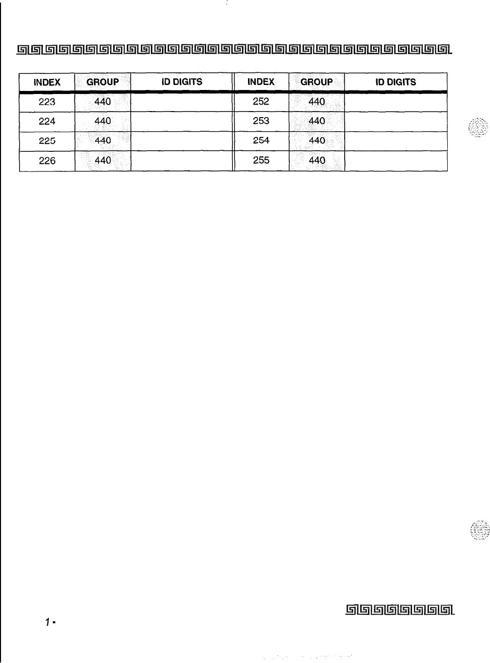
I
C-48 CUSTOMER DATABASE PROGRAMMING
Table C-15: Mailboxes (FLASH 68) (Continued)
Issue
7
-
November 7998
S
JARPLLJS
Triad-S Product Description
Manual
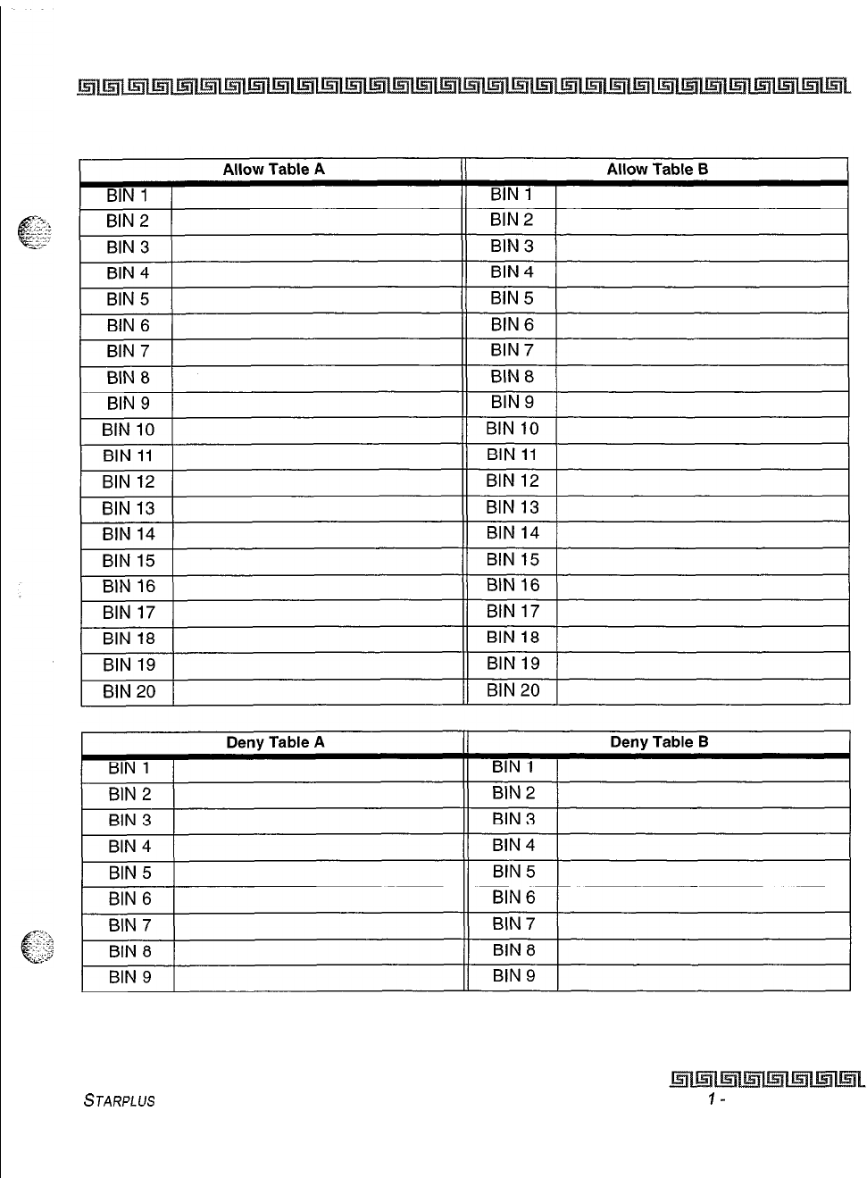
CUSTOMER DATABASE PROGRAMMING c-49
Table C-16: Exceptions (FLASH 70)
STARPLUS
Triad-S Product Description Manual
Issue
I-
November 1998
c-50
:
CUSTOMER DATABASE PROGRAMMING
Special Table 1
Area Code:
Special Table 2
Area Code:
mice
c;oaes
II
OFFILE
CODES
I
Special Table
3
Area Code:
Special Table 4
Home Area Code:
Off ice Codes
II
OFFICE
CODES-I
Table C-l 7: Exceptions (FLASH 70)
Issue 1
-
November 1998
STARPLUS
Triad-S Product Description Manual
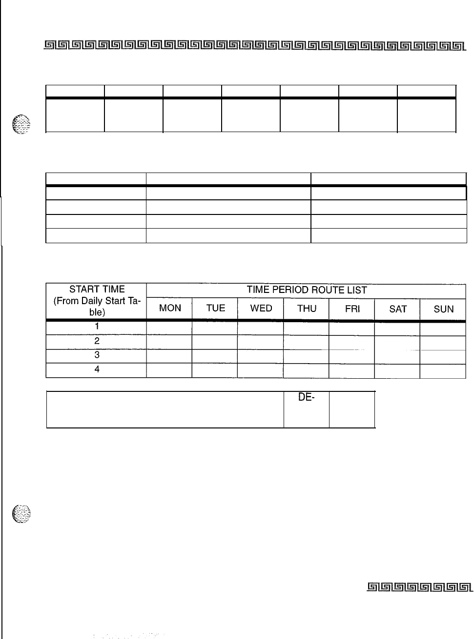
CUSTOMER DATABASE PROGRAMMING c-51
COLINEGROUPS
1
2 3
4
5 6
7
Table C-l 8: Least Cost Routing (FLASH 75)
START TIME DEFAULT TIME CHANGED TIME
1
0800
21700
3
2300
4 ####
Table C-l 9: Daily Start Time
DE-
TOLL INFORMATION ROUTE LIST TABLE
FAULT
00
Table C-20: Weekly Schedule
STARPLLJS Triad-S Product Description Manual Issue I- November 7998
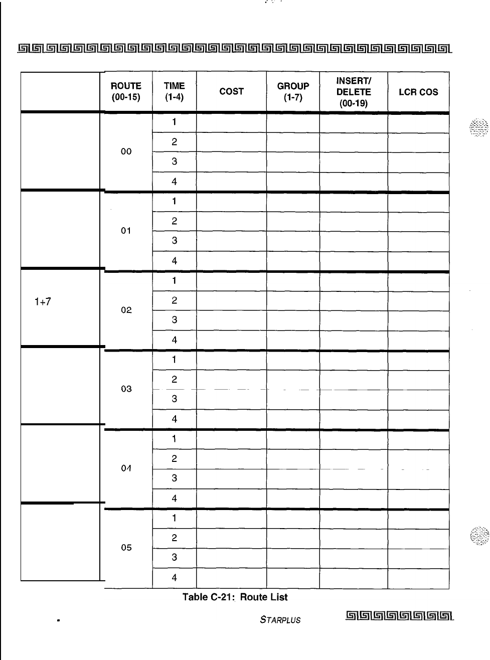
c-52 CUSTOMER DATABASE PROGRAMMING
1 + 10 DIGITS
LD TOLL
ROUTE
7 DIGIT
LOCAL
ROUTE
1+7
DIGITS
TOLL ROUTE
DEFINED BY
DEFAULT
DEFINED BY
DEFAULT
DEFINED BY
DEFAULT
Issue 1
-
November 7998 STARPLUS
Triad-S Product Description Manual
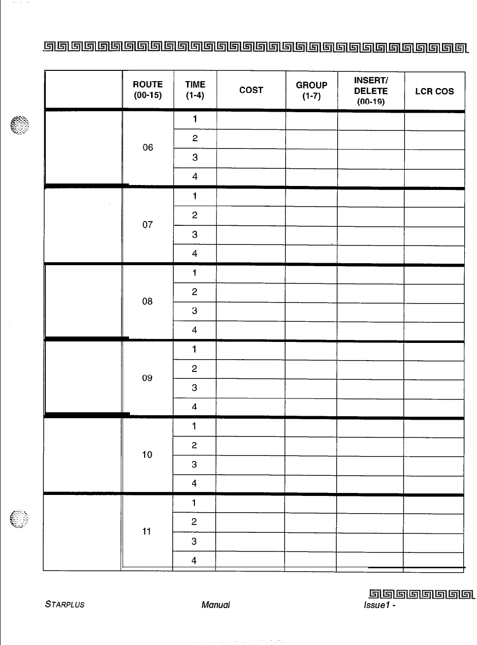
CUSTOMER DATABASE PROGRAMMING c-53
Table C-21 : Route List
STARPLUS
Triad-S Product Description
Manua/ Lssoe
I-
November 1998
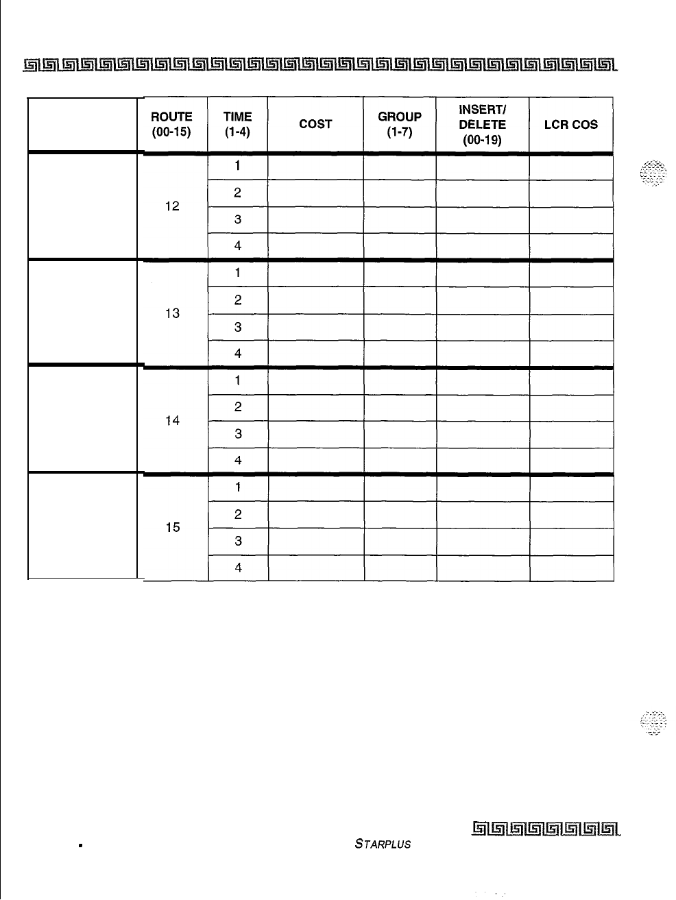
c-54 CUSTOMER DATABASE PROGRAMMING
Table C-21 : Route List
Issue 1
-
November 1998 STARPLUS
Triad-S Product Description Manual
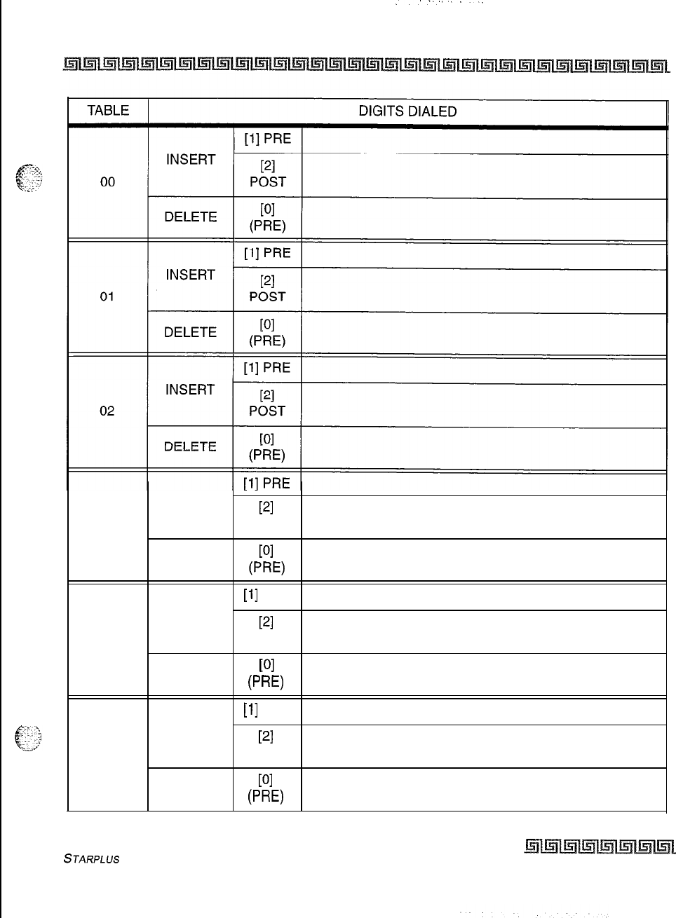
CUSTOMER DATABASE PROGRAMMING c-55
03
INSERT
DELETE
PI
POST
PI
(PW
04
[l]
PRE
INSERT
PI
POST
DELETE
PI
0’
W
05
INSERT
[l]
PRE
PI
POST
DELETE
WI
PW
Table C-22: Insert/Delete
STARPLUS
Triad-S Product Description Manual Issue I- November 1998
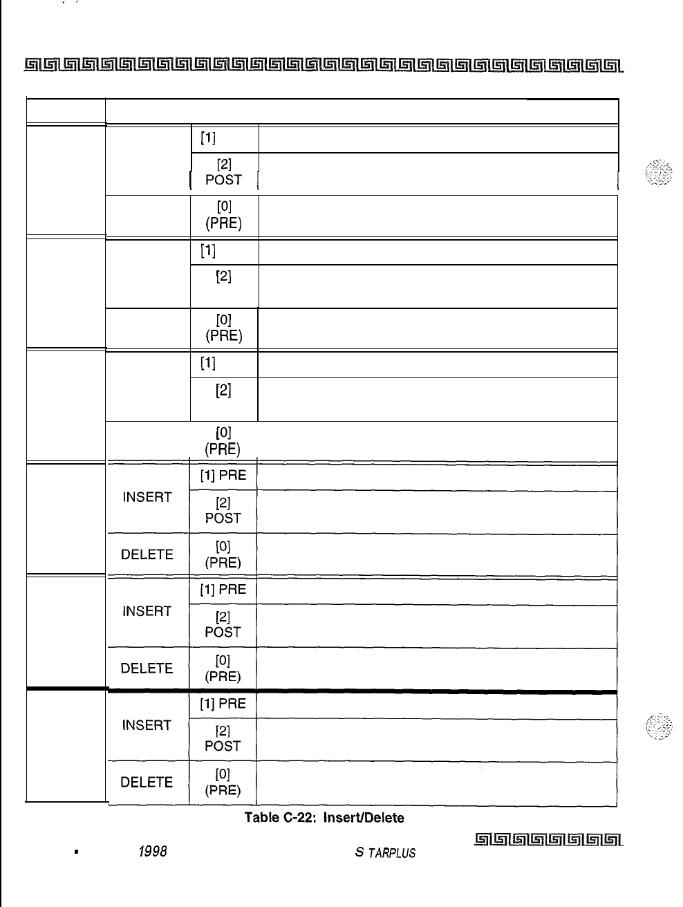
C-56 CUSTOMER DATABASE PROGRAMMING
TABLE
DIGITS DIALED
06
07
08
09
10
11
[l]
PRE
INSERT
PI
1
P&T
1
DELETE
WI
0-E)
[l]
PRE
INSERT
PI
POST
DELETE
PI
PW
[l]
PRE
INSERT
PI
POST
DELETE
PI
I I
0-E)
Issue 1
-
November 1998
S
JARPLUS
Triad-S Product Description Manual
:
CUSTOMER DATABASE PROGRAMMING c-57
TABLE
T
12
13
14
15
16
17
[l]
PRE 1
DIGITS DIALED
INSERT
PI
POST
DELETE
PI
PW
[l]
PRE
INSERT
PI
POST
DELETE
PI
6-3
[l]
PRE
INSERT
PI
POST
DELETE
PI
0’
W
[l]
PRE
INSERT
PI
POST
DELETE
WI
PW
[l]
PRE
INSERT
PI
POST
DELETE
PI
P
W
INSERT
DELETE
[l]
PRE
PI
POST
PI
PW
Table C-22: Insert/Delete
STARPLUS Triad-S Product Description Manual /ssue
I
-
November 7998
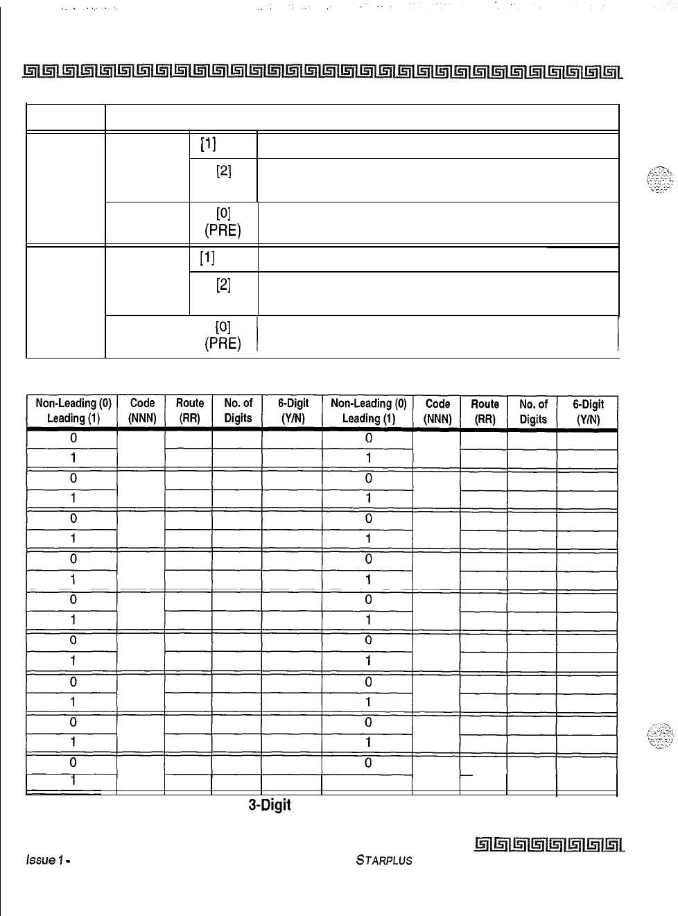
C-58 CUSTOMER DATABASE PROGRAMMING
TABLE
18
INSERT
[l]
PRE
PI
POST
DIGITS DIALED
DELETE
PI
0-E)
19
[l]
PRE
INSERT
PI
POST
DELETE
I
I
PI
VW
Table C-22: Insert/Delete
1
Table C-23: 3-Digit Area/Office Code Route List
issue
1
-
November 1998
STARPLUS
Triad-S
Product Description Manual
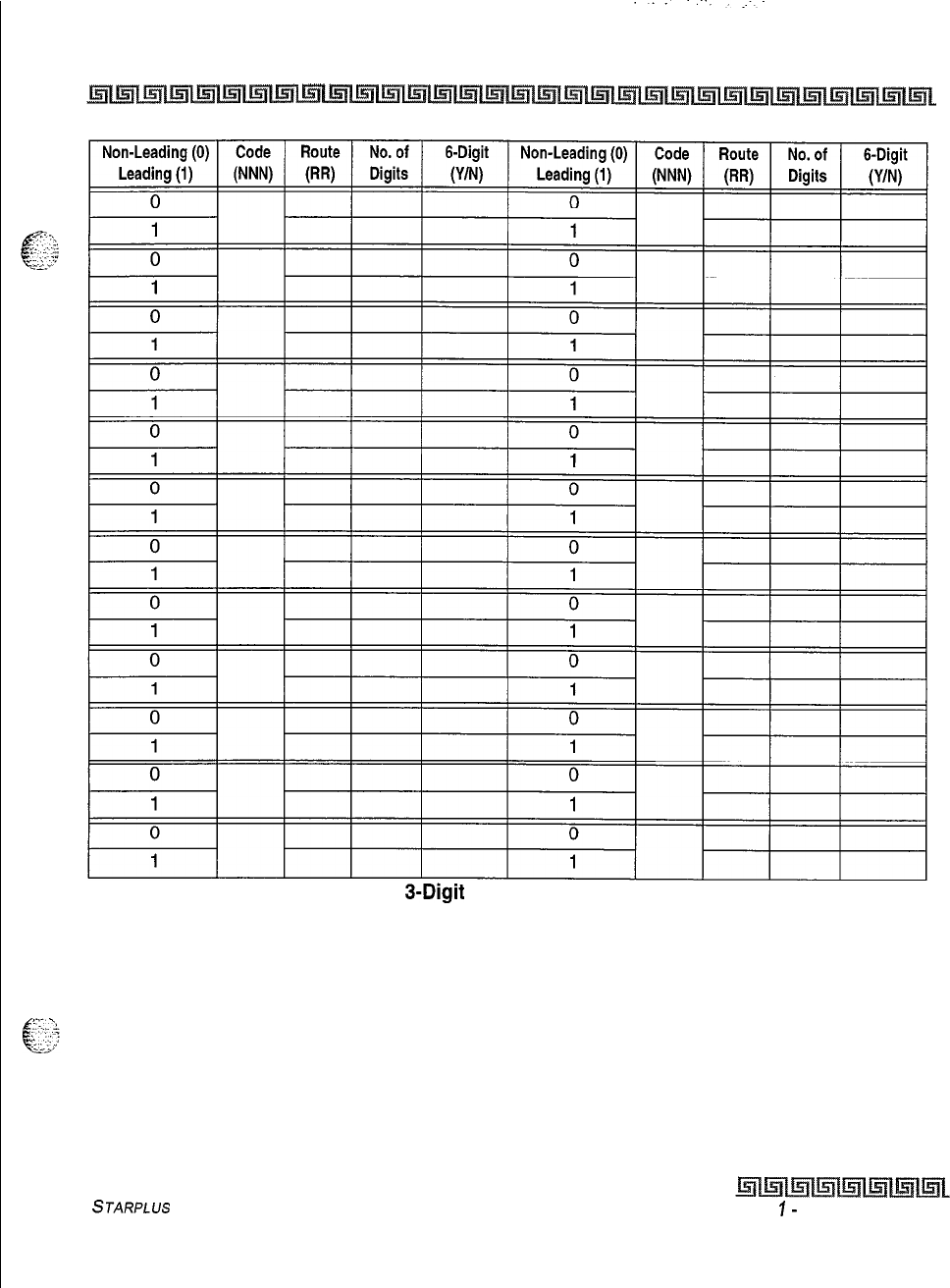
CUSTOMER DATABASE PROGRAMMING c-59
Table C-23: 3-Digit Area/Office Code Route List
STARPLUS
Triad-S Product Description Manual
Issue
I-
November 1998
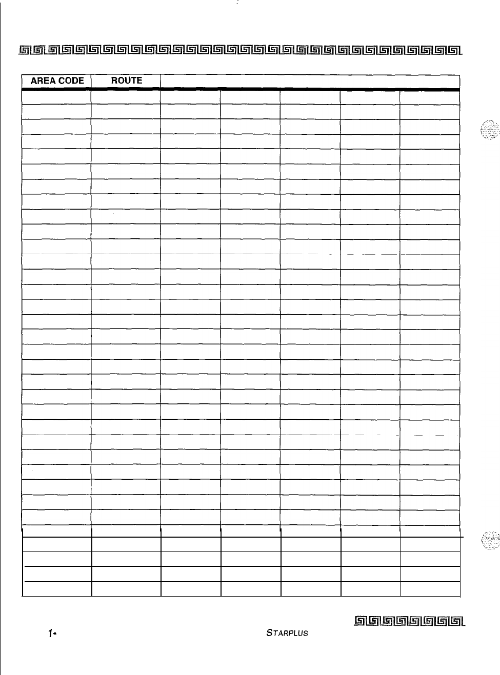
C-60
I
CUSTOMER DATABASE PROGRAMMING
Table C-24: B-Digit Area Code/Routing
Issue
1
-
November 7998
STARPLUS Triad-S Product Description Manual
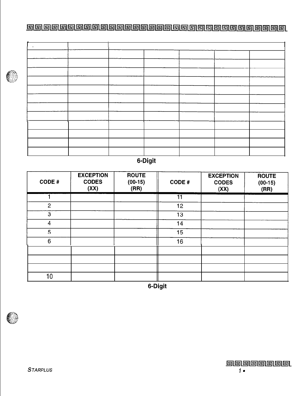
CUSTOMER DATABASE PROGRAMMING C-61
AREA CODE ROUTE 1
Table C-24:
6-Digit
Area Code/Routing
7 17
818
9
19
IO 20
Table C-25:
6-Digit
Office Code
STARPLUS
Triad-S Product Description Manual
Issue
I
-
November 1998
C-62 CUSTOMER DATABASE PROGRAMMING
Issue
1
-
November 1998
STARPLUS
Triad-S
Product Description Manual

Installation Manual
Issue 1
December 1998
Part Number: 5050-12

LIFE SUPPORT APPLICATIONS POLICY
VODAVI Communications Systems products are not authorized for and should not be
used within Life Support applications. Life Support systems are equipment intended
to support or sustain life and whose failure to perform when properly used in accor-
dance with instructions provided can be reasonably expected to result in significant
personal injury or death.
VODAVI Communications Systems warranty is limited to replacement of defective
components and does not cover injury to persons or property or other consequential
damages.
Copyright
0
1998 VODAVI Communications Systems, Inc.
All Rights Reserved
This material is copyrighted by VODAVI Communications Systems. Any unauthorized repro-
ductions, use or disclosure of this material, or any part thereof, is strictly prohibited and is a
violation of the Copyright Laws of the United States (17 U.S.C. Section 101 et. seq.).
VODAVI reserves the right to make changes in specifications at any time and without
notice. The information furnished by VODAVI in this material is believed to be accurate and
reliable, but is not warranted to be true in all cases.
STARPLUS
TRIAIXP
is a registered trademark of VODAVI Communications Systems, Inc.
TRIADTM
is a Registered trademark of VODAVI Communications Systems, Inc.

i.
..:.:;.;.:
Table of Contents
Introduction
Purpose..
........................
Regulatory Information (U.S.A.)
.......
Telephone Company Notification ,
Incidence of Harm
............
Changes in Service
............
Maintenance Limitations
.......
Hearing Aid Compatibility
.......
UWCSA
Safety Compliance
......
Notice of Compliance
..........
Toll Fraud and DISA Disclaimer
.......
.
.
.
.
2 Installation
Introduction . . . . . . . . . . . . . . . . . . . . . . . . . . . . . . . . . . . . . . . . . . . . . . . . . . . . . . . . . . . . ...2-1
/
Site Preparation . . . . . . . . . . . . . . . . . . .
General Site Considerations , , , , ,
Backboard Installation . . . . . . . . .
Verify On-Site Equipment . . . . . . .
KSU Installation . . . . . . . . . . . . . . . . . . . .
Mounting the Basic KSU . . . . . . . ,
Mounting the Expansion KSU (EKSU) . . .
Battery Charging Unit (BCU) Installation
KSU Grounding . . . . . . . . . . . . . . . . . . , ,
.
.*
..
* *
.
.
.
.
.
.
.
.
.
*
.
.
.2-l
.
.2-l
.
.2-2
,
.2-2
.
.2-3
.
.2-3
.
.2-5
.
.2-8
.
.2-8
.
.
.
*
.
.
.
.
.
.
.
.
.
..
.
.
.
.
.
.
.
.
.*
. .
.
Power Line Surge Protection . . . . . . . . . . , . . . . . .
Lightning Protection , . , , , , , , , , . . . , , , , .
KSU AC Power Plug . . . . . . , , . . . . , , , . . , ,
PCB Installation . . . . . . . . , . , . , , , . , , , , . . , . , .
PCB Handling and General Installation
, , .
BKSU and Main Board Assembly . . . . . , , . . , . . . ,
Modem Unit
(MOD@
. . . . . . . . . . . . . . . . . . . . . .
Miscellaneous Interface Unit (MISU) Installation ,
DTMF4-A
Unit . . . . . . , . . . . . . . . . . . . . . . . . , . , .
Message Wait Unit
(MSGU)
. . . . . . . . . . . . . . , , , .
CKIB/CSIB
Installation . . . , . . . . . . . . . . . , , , , , .
.
..
.2-9
.
.2-q
.
-2-q
.
.2-9
.
.2-9
.2-10
.2-10
.2-12
.2-14
.2-15
.2-16
.
.
.
*
.
.
*
.
.
.
.
.
.
.
I
.
.
.
.
.
.
.
CKIB/CSIB
Wiring
.........................
Station Wiring
.................................
Digital
Keyset
............................
Single Line Telephone
.....................
Wall Mounting the Digital Key Telephone
............
Headset Installation
............................
Caller ID Interface Unit Installation
................
Switch Settings
...........................
Programming Caller ID
....................
ICLID Enable
........................
I/OPorts
............................
CO Lines
............................
SMDR
.......................................
.
*
.
.
.
..
*
.
,
.2-17
*
2-20
-2-20
-2-20
.2-21
-2-23
.2-23
-2-24
.2-24
-2-24
.2-24
.2-24
.2-25
3 System Check-Out
Introduction
.............................................................
..3- 1
Preliminary Procedures
.....................................................
.3-l
PowerUpSequence
.......................................................
..3-
1
4 Maintenance and Troubleshooting
Introduction
..........................................................
System Programming and Verification
......................................
Telephone and Terminal Troubleshooting
...................................
KeysetSelfTest
........................................................
Keyset
LCD/LED Test
..............................................
Keyset
Button Test
................................................
DSSLED/ButtonTest
..............................................
Key Telephones/Terminals
..........................................
SingleLineTelephones
............................................
DSS/DLS
Console
.................................................
COLineCardFunctions
.................................................
SystemFunctions
......................................................
Remote Maintenance
...................................................
GeneralOverview
.................................................
Overview of Maintenance Commands
.................................
Maintenance Password
.............................................
ExitMaintenance
.................................................
*
.
9
.
4-1
. . .
*
4-l
. . . . 4-2
. . . . 4-2
. .
*
.
4-2
. . . . 4-3
. . . . 4-3
. .
*
. 4-4
.
*
. ,
4-5
. .
*
.
4-5
. . . .
4-6
. . . . 4-6
. . . .
4-7
. . .
*
4-7
. . . . 4-7
. . , .
4-7
. . . , 4-8
Issue
I-
December 7998
hllnlmll5lll5lll5lll5ll~~
STARPLUS
Triad-S
hstallation
Manual
System Configuration
............................
Station Configuration
............................
Event Trace Buffer
..............................
DTMF Receiver Trace
............................
Remote System Monitor
...............................
GeneralOverview
...............................
Monitor Password
...............................
Help Menu
(?)
.................................
Dump Memory Data
.............................
Event Trace Mode
...............................
Modify Memory Command
........................
Exit the Monitor Mode
...........................
STARPLUS
Triad-S
/nsta//afion
Manual
.
*
.
.
.
.
.
.
.
.
.
.
.
.
.
.
.
*
*
.
.
.
.
.
.
.
.
.
.
.
.
*
.
.
*
*
.
.
.
.
. .4-9
.4-10
.4-11
.4-11
.4-12
-4-12
-4-12
.4-13
.4-13
.4-14
.4-16
-4-16
Lslllrrllmlmlmll5llml~L
Issue
I-
December 1998
iV
List
of Figures
BasicKSU.......................................................................2-
4
Basic KSU Mounting Holes and Installation
............................................
.2-5
ExpansionKSU
.................................................................
..2- 6
BKSU and EKSU Mounting Holes and Installation
.......................................
.2-7
BKSUDipSwitches..
...........................................................
..2-10
Modem Unit
(MOD@
............................................................
.2-11
Miscellaneous Interface Unit
(MN)
................................................
.2-13
DTMF4A
.....................................................................
.2-14
MessageWaitUnit(MSGU).
.......................................................
.2-15
CKIBBoard.....................................................................2-1
6
CSIB Board with MSGU Mounted
...................................................
.2-17
Digital Station Jack Wiring
........................................................
.2-20
Single Line Telephone Wiring
......................................................
-2-20
Digital Key Telephone Wail Mounting
................................................
.2-22
Caller ID Cable Connections
.......................................................
.2-23
Maintenance Help Menu
..........................................................
-4-S
System Configuration
.............................................................
.4-9
CO
/
Station Configuration
........................................................
.4-10
HelpMenu
..................................................................
.,.4-l
3
Trace Mode Status
..............................................................
.4-14
EnableEventTrace...............................................................4-1
5
EventTrace.....................................................................4-1
6
x.-.
.
.
i:<:
\
:...-
:.;v,.
:
,..
.
.
.
:.
”
i’-..;-.
Issue I- December 1998
l!Lmm5llrnlmlmil5ll~~
STARPLUS
Triad-S
hstallafian
Manual
List
of Tables
MISU Dip Switches
............................
CKIB/CSIB
Wiring
.............................
SMDR Printout.
...............................
Power Supply Tests
............................
Flash Rates
..................................
Key Telephones/Terminals
.....................
Single Line Telephones
........................
DSS/DLS
Console
.............................
CO Line Loop Start Board
(CKIB/CSIB
Board)
.......
System Functions
.............................
STARPLUS
Triad-S Installation Manual
.
*
.
.
.
.
.
.
.
.
.
.
.
.
.
.
.
.
.
.
.
.
.
*
.
*
.
.
.
.
.
*
.
.
*
.
*
*
.
.
.
.
.
.
*
.
.
*
.
.
.
.
.
.
.....................
2-12
.....................
2-18
.....................
2-26
......................
3-2
......................
4-3
......................
4-4
......................
4-5
......................
4-5
......................
4-6
......................
4-6
l5m5llmlml~lml~l~L
Issue
7
-
December
1998
issue
I- December 1998
l5lll5lll5lll5lils;rll5llGil~
STARPLUS
Triad-S Installation Manual
Purpose
This manual provides the information necessary to program, install, operate and maintain the
STARPLUS
Triad-S””
systems.
Regulatory Information (U.S.A.)
The Federal Communications Commission (FCC) has established rules that allow the direct connection of
the
STARPLUS
Triad-S systems to the telephone network. Certain actions must be undertaken or
understood before the connection of customer provided equipment is completed.
Telephone Company Notif ication
Before connecting the
STARPLUS
Triad-S system to the telephone network, the local serving telephone
company must be given advance notice of intention to use customer provided equipment, and must be
provided with the following information:
Q
The telephone numbers to be connected to the system.
-+
Triad-S system information:
oThe Ringer Equivalence Number also located on the KSU:
1.3B
8The USOC jack required for direct interconnection with the telephone network: RJl
1C
FCC Registration Numbers:
+
For systems configured as a key system: (button appearances)
DLPKOR-24039~KF-E
oFor systems configured as a hybrid system: (dial access codes)
DLPKOR-24026-MF-E
Incidence of Harm
If the telephone company determines that the customer provided equipment is faulty and possibly causing
harm or interruption to the telephone network, it should be disconnected until repairs can be made. If this is
not done, the telephone company may temporarily disconnect service.
l-2
Introduction
Regulatory Information (U.S.A.)
~l~l~l~l~~l~ltRI1Ei(lLi;lllsll~llr?ll~l~l~l~l~lIsll~l~l~llsrlll+lilsll~l~l~lLnlIs;ll~l~L
Changes in Service
The local telephone company may make changes in its communications facilities or procedures. If these
changes affect the use of the
STARPLUS
Triad-S system or compatibility with the network, the telephone
company must give written notice to the user to allow uninterrupted service.
Maintenance Limitations
Maintenance on the
STARPLUS
Triad-S system must be performed only by the manufacturer or its
authorized agent. The user may not make any changes and/or repairs except as specifically noted in this
manual. If unauthorized alterations or repairs are made, any remaining warranty and the software license
for the system will be voided.
Hearing Aid Compatibility
All
STARPLUS
Triad-S digital terminals are Hearing Aid Compatible, as defined in Section
68.3
16
of Part
68
FCC Rules and Regulations.
UL/CSA
Safety Compliance
The
STARPLUS
Triad-S system has met all safety requirements and was found in compliance with the
Underwriters Laboratories
(UL)
1459. This system is authorized to bear the
“NRTLK”
marking.
Notice of Compliance
The
STARPLUS
Triad-S system complies with rules regarding radiation and radio frequency emissions by
Class A computing devices. In accordance with FCC Standard 15 (Subpart J), the following information
must be supplied to the end user:
‘This equipment generates and uses RF energy and if not installed and
used in accordance with the Instruction Manual, may cause interference
to Radio Communications. It has been tested and found to comply
with the
limits for a Class A computing device, pursuant to Subpart J of Fart 15 of
the FCC Rules, which are designed to provide reasonable protection
against such interference, when operated in a commercial environment.
Operation of this equipment in a res~dentlal area is likely to cause interfer-
ence, in which case the user, at his own expense,
will
be required to take
whatever measures may be required to correct the interference.’
Issue
I-
December 1998
l5lllnlmlmlmlmlmlqL
STARPLUS Triad-S Installation Manual
,--::;.
‘._.
Toll Fraud and
DISA
Disclaimer
“While this device is designed to be reasonably secure against intrusions from fraudulent callers, it is by no
means invulnerable to fraud. Therefore, no express or implied warranty is made against such fraud
including interconnection to the long distance network.”
“While this device is designed to be reasonably secure against invasion of privacy, it is by no means
invulnerable to such invasions. Therefore, no express or implied warranty is made against unlawful or
unauthorized utilization which results in the invasion of one’s right of privacy.”
Vodavi has made every reasonable effort to ensure that this product works in most business environments.
However, there may be some environments
(RF1
and EFI) in which this product may not work properly. In
such cases, it is the responsibility of the installer to take the necessary actions to correct the situation,
This product is tested and found to be Year 2000 compliant. Vodavi shows 00 as the year in SMDR output and
on LCD displays.
STARPLUS
Triad-S
hstallation
Manual
hllsill5lltsllmmll5lll5il
Issue
I-
December 1998
Issue
I-
December 1998
:.
.._
I.:.
.
.
hlmll5llmlmlrlmll5ll
STARPLUS
Triad-S Installation Manual
-.
n
As with any sophisticated communications device, installation of the
STARPLUS
Triad-S system requires the
care and forethought of a competent technician. To assure easy servicing and reliable operation, several
factors must be considered when planning the system installation. The installation proceeds in these major
steps:
0
Site Preparation
9KSLJ and Power Supply
(PS)
Installation
o PCB Installation
4 System Wiring
4
Keyset
and Terminal Installation
4
Basic Installation Check-Out
4
System Programming and Verification
Installing the
STARPLUS
Triad-S system is quick and efficient if these installation instructions are followed.
Site Preparation
General Site Considerations
The first step is to locate an acceptable site for the common equipment
(KSUs,
boards, etc.). When locating a
mounting site for the
KSUs,
the following points must be considered:
4
KSLJs
are designed for wall mounting and should not be mounted directly to a masonry or
plasterboard wall. It is recommended that a
l/2
inch plywood backboard be firmly mounted to the
wall, and the KSU and MDF be mounted to the backboard.
+
The location must have access to a
dedicated
110 Volt AC
(2
lo%),
60
Hz, single-phase circuit with
a circuit breaker or fuse rated at
15
amps. A 3-wire parallel blade grounded outlet should be within
approximately 6 feet of the lower left rear of the BKSU mounting.
4
The location must have access to a good earth ground, such as a metallic cold water pipe without
non-metallic joints. The ground source should be located as close as possible to the system.
4
The system should be located in an area that is well ventilated with a recommended temperature
range of
68"-78"
F and a relative humidity range of
5-60%
(non condensing),
+The system should be located within
25
feet of the telephone company’s termination point. Also,
the location should be within the prescribed station loop lengths for all
keysets
and terminals. If
existing cabling is used, its location and conduits should be considered. Station wiring should be in
the building. Station ports are not designed for installation outside of the building.
e
Protection from flooding, flammable materials, excessive dust and vibration.
4
The site should be away from radio transmitting equipment, arc-welding devices, copying machines
and other electrical equipment capable of generating electrical interferences,
4
Operation of this equipment in a residential area is likely to cause interference. In which case the
user, at his own expense, is required to take any necessary measures to correct the interference.
Backboard Installation
A wooden backboard is recommended for
ah
installations and must be installed when the location has
masonry or plasterboard wails. A
l/2
inch plywood material is sufficient for most installations. The
backboard should be mounted at a convenient height, about three feet above the floor and be bolted in
various places to distribute the weight of the system.
Space should be available on the bottom side of the backboard for the MDF cabling and for optional
equipment such as a music source, battery backup, etc. It is recommended that the location of each major
item be roughly sketched on the backboard as an installation layout.
Verify On-Site Equipment
Once the equipment installation site is identified and a dedicated AC outlet, earth ground, and lighting and
ventilation are available, verify that all equipment required is on-site and was not damaged during
shipment, Unpack the
KSUs
to assure there is no shipping damage. Note that a mounting template is
packed with the BKSU; this template is required later in the installation. Check that the type and quantity of
boards received is correct and optional equipment and a Power Line Surge Protector are on-site. Do NOT
unpack the individual boards at this time.
If any equipment is damaged or missing, notify the appropriate personnel to correct the situation,
Issue
7
-
December 7998
Eillnlir;rlml~ll.5ll~lmL
STARPLUS
Triad-S
Insfallafion
Mot-ml
Installation
KSU
Installation
2-3
KSU Installation
The
STARPLUS
Triad-S system consists of a Basic KSU (BKSU) cabinet,
.,
.I
-f
c
“:-?>’
Mounting
the
Basic
KSU
The Basic KSU consists of a plastic cover, a metal base frame designed for wall mounting. Before installing
BKSU on the wall, two wall mounting plates that are assembled in the bottom side of the BKSU, must be
extended for mounting. The KSU must NOT be mounted on a masonry or dry-wall surface; a wooden
backboard is required.
A mounting template is included with the BKSU. This template can be used to drill pilot holes for mounting
screws. Please note that the template provides screw hole locations for the BKSU and EKSU.
The BKSU is mounted with three #10 or larger, 1
l/2
inch or longer screws. Drill pilot holes in the three
locations marked, insert the screws and tighten leaving about
l/2
inch exposed,
STARPLUS
Triad-S
installation
Manual
hlllmmll5llml~l~lml
Issue
7
-
December 1998
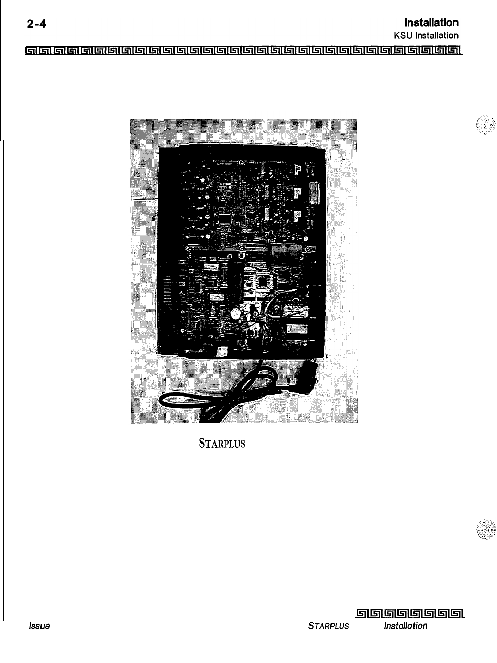
issue
I- December 1998
Figure 2-l:
STARPLUS
Triad-S Basic KSU
klll5llmlinlml~ll5ll~~
STARPLUS
Triad-S
hstallation
Manual
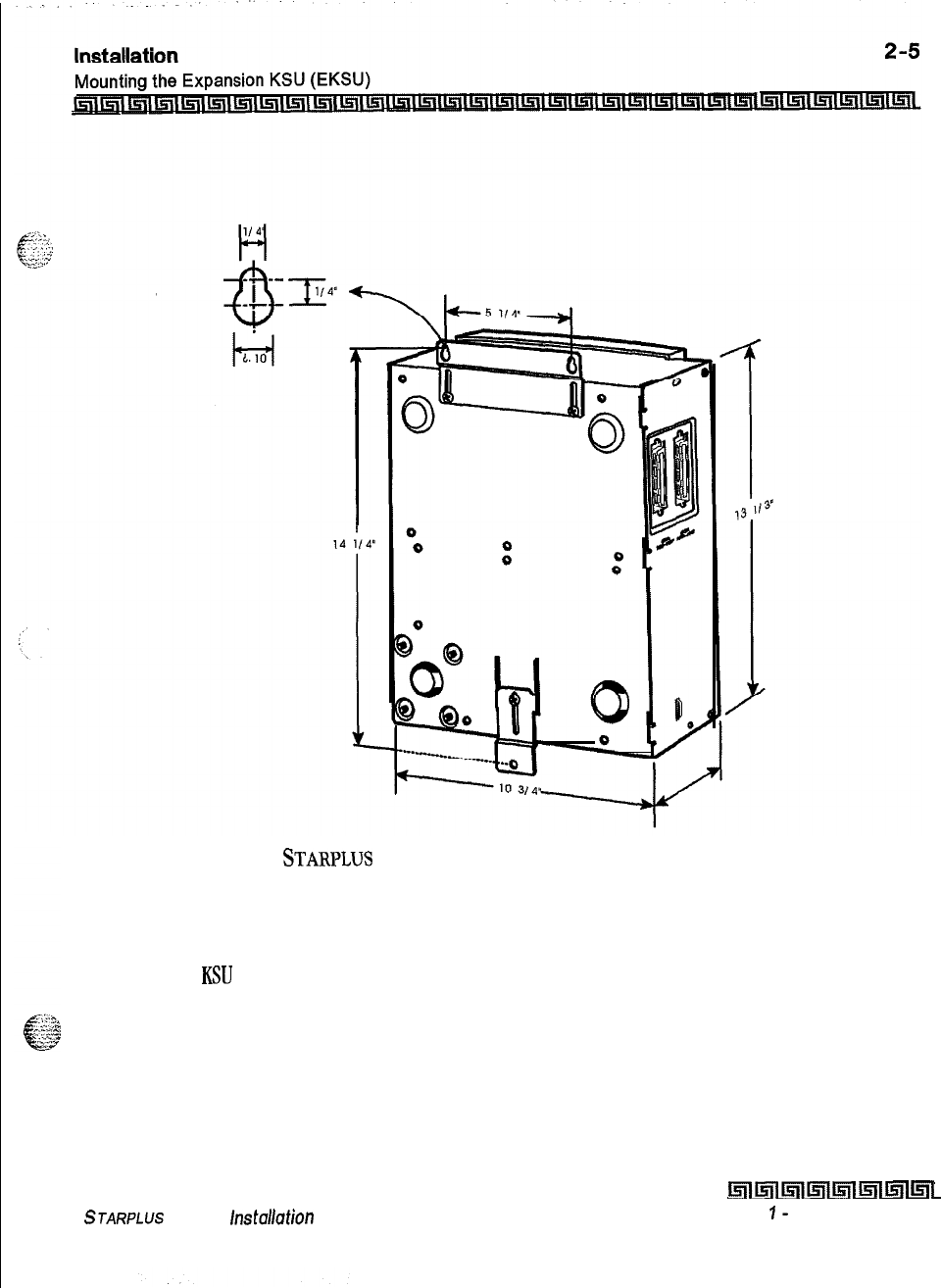
Figure 2-2:
STARPLWS
Triad-S Basic KSU Mounting Holes and Installation
Mounting the Expansion KSU (EKSU)
The Expansion
KSU
consists of a plastic cover, a metal base frame designed for wall mount installation. The
EKSIJ contains a power transformer and expansion interface board (EIB). The EKSU MUST be mounted
above the BKSU. Before installing the BKSU on the wall, the wall mounting plate that is assembled in the
bottom side of the EKSU, must be extended for wall mounting and the fastener provided with the EKSU must
be assembled with the EKSU. After positioning the EKSU above the BKSU, mark the location of the two screws
to mount the BKSU. The EKSU must NOT be mounted on a masonry or dry wall surface; a wooden backboard
is required.
STARPLUS
Triad-S
hstallation
Manual
hllnllr;llmtlmllmal
Issue
1-
December 1998
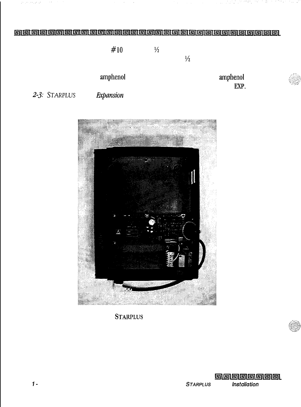
2-6
Installation
Mounting the Expansion KSU (EKSU)
4
The EKSU is mounted with two
#lo
or larger,
1
‘/z
inch or longer screws. Drill pilot holes in the two
locations marked, insert the screws and tighten leaving about
‘/z
inch exposed. Mount the
Expansion KSU on the screws and tighten the screws securely,
Interconnection is achieved via an amphenol type connector and power cable. The amphenol connector is
included and connects the EKSU to the BKSU on the right side through connectors labeled
EXP.
Refer to
Figure
2-j:
STARPLUS
Triad-S I&par&on KSU.
Issue
I-
December 1998
Figure 2-3:
STARPLUS
Triad-S Expansion KSU
hllnlmllnlmlKllmll5l~
STARPLUS
Triad-S
lnstallafion
Manual
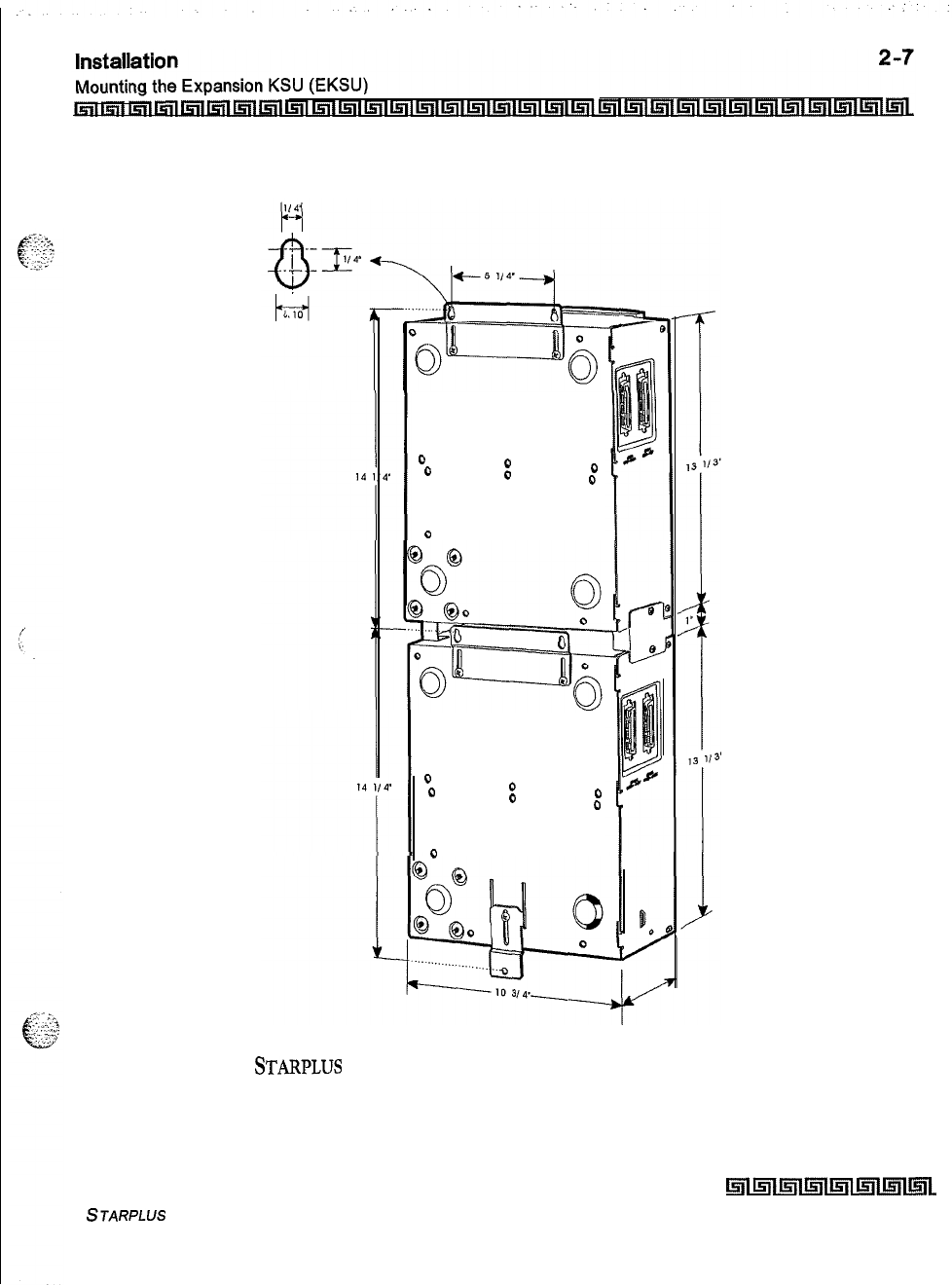
00
000
0
0
0
00
00
0
0
Figure 2-4:
STARPLUS
Triad-S BKSU and EKSU Mounting Holes and Installation
STARPLUS Triad-S Installation Manual
hll5llmImllnlmlml~L
Issue I- December 7998
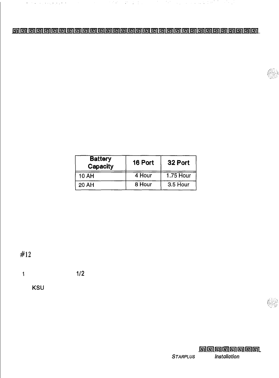
2-8
Installation
Battery Charging Unit (BCU) Installation
Battery Charging Unit (BCU) Installation
The BCU provides power for the system during a power failure. The BCU connects to the Triad-S via the
connector on the bottom of the BKSU. The external gel cell batteries must provide 24V DC. This is generally
accomplished by connecting two 12 volt batteries in series. The BCU provides charging current to the
batteries during normal AC power operation at a maximum of about 0.5 amp. During battery operation, the
BCU discontinues battery operation if AC power is restored or the battery voltage is too low to maintain
proper system operation.
The time the system operates on batteries is dependent on several elements, including: battery charge state,
condition of the batteries, capacity of the batteries, and the system size (number of station ports). The
following chart gives the approximate backup time in ampere hours for two system sizes and different
battery capacities.
KSU Grounding
To ensure proper system operation and for safety purposes, a good earth ground is required. A metallic
COLD water pipe usually provides a reliable ground. Carefully check that the pipe does not contain
insulated joints that could isolate the ground. In the absence of a COLD water pipe, a ground rod or other
source may be used.
A
#12
insulated AWG or larger copper wire should be used between the ground source and the KSU (BKSU
and EKSU, respectively). The wire should be kept as short as possible (recommended 25 feet or less).
1
Remove about 1
112
inches of insulation from both ends. Attach one end of the wire to
the Ground Lug on the lower side of the Basic and on the lower side of the Expansion
KSU
by inserting the wire under the lug screw, then tighten the screw securely.
2
Attach the other end of the wire, as appropriate, to the ground source.
3
Take a DC resistance reading and an AC volt reading between the chassis ground point
(cold water pipe) and AC ground (third wire AC ground). The limit is 5V AC and 5 Ohms
DC resistance. If a higher reading is obtained, choose a different chassis ground point
and repeat this step until a suitable ground point is found.
Issue I- December 7998
lmmlk!iiwll~ll5llml~l
STARPLUS
Triad-S
installation
Manual
Power Line Surge Protection
The AC outlet should be equipped with a power surge protection device or UPS. Systems using such devices
are more resistant to damage from power line surges than unprotected systems. Power line surges often
occur during normal operations and during violent thunderstorms,
Installation of a surge protector meeting the specifications described in the following paragraph may prevent
or minimize the damage resulting from power line surges.
The isolation transformer/surge protector should be:
15
amp self-contained unit that plugs into a standard
grounded
117V
AC wall outlet. The wall outlet must be designed to accept a 3-prong plug (two parallel blades
and a ground pin). The protector should be fast and capable of protecting transients greater than
200
volts.
Lightning Protection
The system provides secondary protection per UL
1459
specifications. Primary protection circuitry is the
installer’s responsibility and should be installed per the National Electric Code (
NEC
).
KSU AC Power Plug
Before plugging the KSU power cord into the AC source (grounded, 3-prong AC outlet required), verify that
the power switch of the BKSU is off.
+
Plug the KSU power cord into the AC outlet and turn the power switch on, The red LED on the MBU
illuminates.
PCB Installation
PCB Handling and General Installation
DO NOT install or remove any boards with power applied.
Power must be turned off prior to installation or removal of the
PCBs.
The system cards contain digital
circuitry which are extremely reliable, but can be damaged by exposure to excessive static electricity, When
handling
PCBs,
a grounded wrist strap should be used to protect the boards from static discharges. Also, use
common sense when handling
PCBs.
For example, do not place a PCB in locations where heavy objects
might fall on the PCB and damage components.
S
JARPLUS
Triad-S
hsfallafion
Manual
hll5lllsm!a~ll5llmlml
Issue 1
-
December 1998
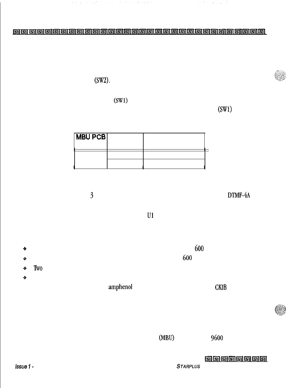
2-10
Installation
BKSU and Main Board Assembly
BKSU and Main Board Assembly
The MBU is installed in the BKSU at the factory before the shipment. The MBU contains a lithium dry cell to
maintain memory and real-time clock functions. The battery is soldered to the MBU and connected to the
circuitry by an ON-OFF dip switch
(SW2).
Make sure the dip switch SW2 is ON before database
programming.
Before programming the system, switch
1
(SWl)
should be placed in the ON position and powered off and
on to initialize the system database to default. Once the database is initialized, switch 1
(SWl)
should be
placed in the OFF position to protect the database. Shown below is the dip switch position functions:
MBU
PC6
Dip Switch
Marking Position Function
SW1
ON
OFF
Flush the database
Retain the database
I
I
II
Figure 2-5: BKSU Dip Switches
The MBU may be equipped with
3
daughter boards: MODU for modem access to the system,
DTMF-4A
for
DTMF receiver expansion up to five, and a MISU for two serial ports and a second music source.
Software for the system is contained on two chips labeled Ul and U2 in the Program Module Unit (PMU)
module.
The MBU provides miscellaneous features:
oOne external page port that is connected to transformers, providing a
600
ohm impedance.
+
One music input that is connected to transformers, providing a
600
ohm impedance.
9
‘Rvo
independent dry relay contacts rated at 1 amp, 24V DC.
o
A DTMF receiver.
These features are provided through the amphenol connector on the front edge of the
CKIB
installed in the
first slot of the BKSU. These features are controlled by system software.
Modem Unit (MODU)
The Modem Unit provides an asynchronous modem for access to the system database and remote
maintenance. The module is optionally installed on the BKSU
(MBU)
and includes a
9600
baud modem.
issue
I-
December 1998
hll!cFlllinlmr~lmll5lll5ll
STARPLUS
Triad-S Installation Manual
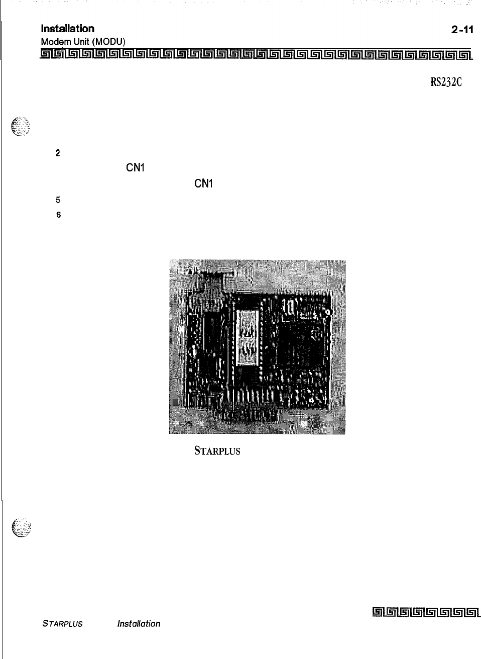
The modem may be accessed from any station or CO. The MODU port is independent of the MISU
RS232C
ports, enabling system database
access,
etc., without interrupting the SMDR output.
To install the MODU:
1
Using a grounding strap, unpack the MODU from its anti-static bag in the packing box.
2
Locate the CN6 connector (outlined) on the MBU.
3
Locate the
CNI
connector on the MODU.
4
Position the MODU so the
CNI
matches with CN6 on the MBU.
5
Push the MODU onto its connector, making sure it is properly seated.
6
Match the screw hole on the MODU PCB bracket with the screw hole on the base frame.
7
Insert a screw and tighten the screws securely.
Figure 2-6:
STARPLUS
Triad-S Modem Unit (MODU)
This completes the MODU installation.
STARPLUS
Triad-S
lnstallafion
Manual
hll5llmlmll5llmlmlmL
Issue I- December 1998
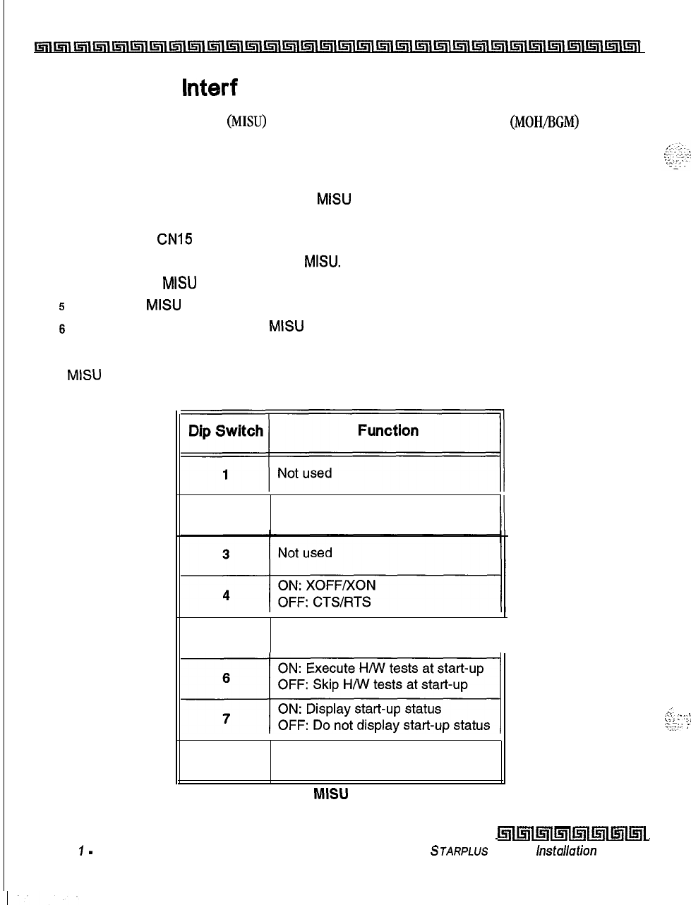
I2-12
Installation
Miscellaneous Interface Unit (MISU) Installation
Inllnl~llnl~l~l~l~~~l~l~l~l~l~l~l~l~l~l~l~l~l~~~l~l~l~l~l~l~l~l~l~~
Miscellaneous lnterf ace Unit (MISU) Installation
The Miscellaneous Interface Unit
(MISU)
contains the second external music source
(MOH/BGM)
and two
serial ports.
To install the MISU:
IUsing a grounding strap, unpack the
MISU
from its anti-static conductive bag in the
packing box.
2
Locate the
CN15
connector (outlined) on the MBU.
3
Locate the CN3 connector on the
MISU.
4
Position the
MISU
so that CN3 matches CN15 on the MBU.
5
Push the
MISU
onto it’s connector making sure it is properly seated.
6
Match the screw hole on the
MISU
PCB bracket with the screw hole on the base frame.
7
Insert a screw and tighten the screws securely.
The MISU has an eight position dip switch. The table below lists the functions of each switch.
“f”‘“,,
2
Not used
II
5
Not used
II
11
OFF: Do not display start-up status
8
Not used
Table 2-1: MISU Dip Switches
Issue
7
-
December 1998
killmlmllnll5ll~lmlmL
STARPLUS
Triad-S
hstullation
Manual
A.‘.
:L.,;-.:
.:‘:.
..,
.:..y:.:
i
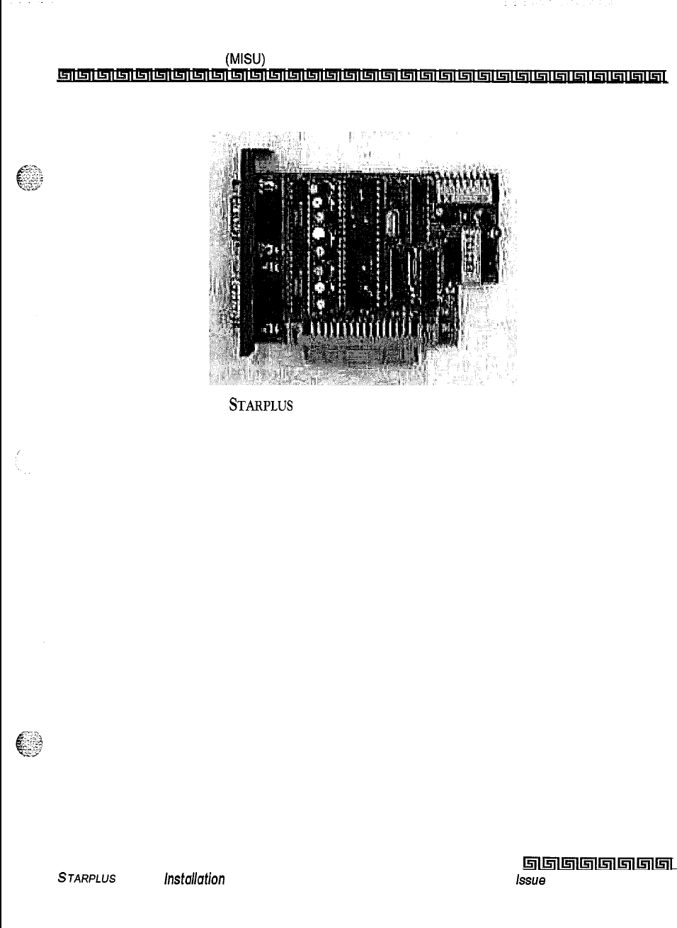
Installation
Miscellaneous Interface Unit
(M&U)
Installation
2-13
Figure 2-6:
STARPLUS
Triad-S Miscellaneous Interface Unit (MISU)
This completes the MISU installation.
STARPLUS
Triad-S
Installafion
Manual
l5llmlmlmll5llmlmll5il
issue
I- December 1998

DTMF4-A
Unit
The
DTMF4-A
provides the additional four DTMF receivers that may be used for detecting the DTMF signal
from the single line telephone port or central office line.
To install the
DTMF4-A:
1
Using a grounding strap, unpack the
DTMF4-A
from its anti-static conductive bag in the
packing box.
2Locate the CN13 and CN14 connectors (outlined) on the MBU.
3Locate the
CONN5
and
CONNG
connectors on the
DTMF4-A.
4Position the
DTMF4-A
so CONN5 and
CONNG
match CN13 and CN14 on the MBU.
5
Push the
DTMF4-A
onto its connector making sure it is properly seated.
Figure 2-7:
STARPLUS
Triad-S DTMF4-A
This completes the
DTMF4-A
installation.
issue 1
-
December 1998
l5lll5ll~lmlsllmlmlml
STARPLUS
Triad-S Installation Manual
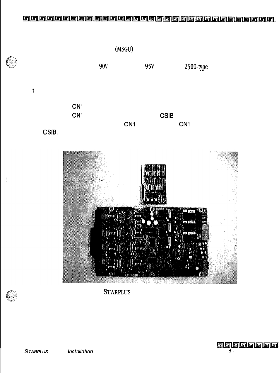
I
Installation
2-15
Message Wait Unit (MSGU)
r;nllnl~llnllnllsrllslllnlInl~l~l~l~Lnl~l~l~~~i~l~l~ILSII~i~1~114ll~lLfll~i~l~11511
Message Wait Unit (MSGU)
The Message Wait Lamp Relay Control
(MSGU)
provides message wait lamp relay control for message lamp
f
--_
;*-...
:
”
g?
single line telephones. The MSGU board mounts on the CSIB as a daughter-board-type arrangement. The
CSIB interfaces with mechanical
9OV
AC ringers and
95V
DC lights on
2500~type
phone sets,
To install the MSGU:
1
Using a grounding strap, unpack the MSGU module from its anti-static conductive bag in
the packing box.
2
Locate the
CNI
and CN2 connectors on the MSGU module.
3
Locate the
CNl
and CN2 connectors on the
CSIB
(outlined).
4
Position the MSGU module so
CNI
and CN2 match
CNI
and CN2 connectors on the
CSIB,
respectively.
5
Push the MSGU module onto these connectors making sure it is properly seated.
Figure 2-8:
STARPLUS
Triad-S Message Wait Unit (MSGU)
This completes the MSGU module installation,
STARPLUS
Triad-S
hstdation
Manual
l5llmlmlmllnlml~l~l
Issue
I-
December 1998
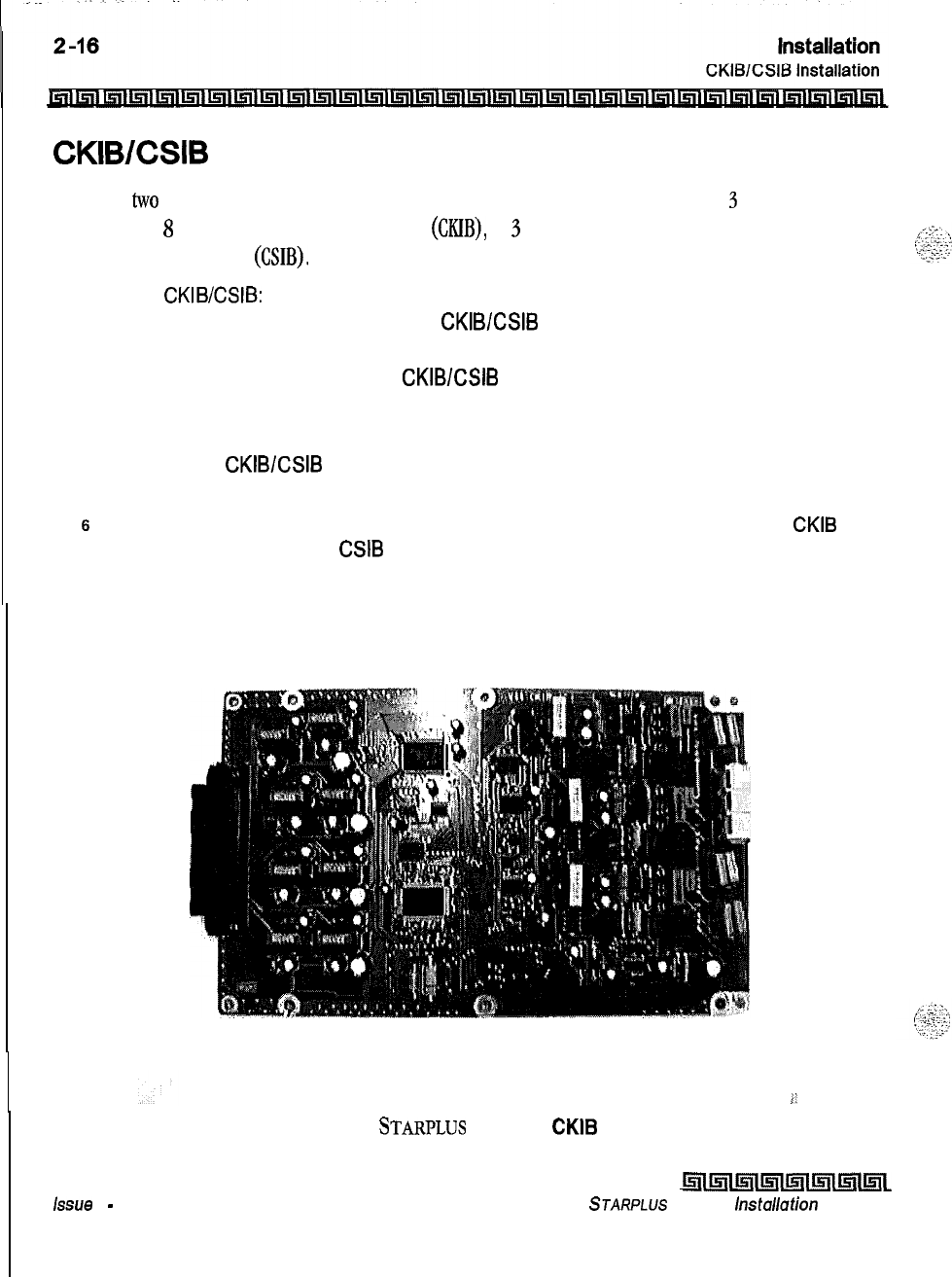
CKIBESIB
Installation
There are
two
types of expansion boards available: CKIB and CSIB. These boards include
3
loop start CO line
interfaces and
8
digital
key telephone interfaces (MB), or
3
loop start CO line interfaces and 8
single
line
telephone interfaces
(CSIB).
To install the CKIWCSIB:
I
Using a grounding strap, unpack the CKIB/CSIB from its anti-static conductive bag and
six standoffs from the auxiliary bag in the packing box.
2
Unscrew the six screws from the CKIB/CSIB installed in the first slot of the BKSU or
EKSU.
3
Insert the standoffs to secure the first card to the BKSU or EKSU.
4
Position the CKIB/CSIB on the six standoffs so the screw holes match.
5
Insert the screws and tighten them securely.
6
Connect the flat cable with the MBU in the BKSU or the EIB in the EKSU. The CKIB
cable is labeled CN4; the CSIB cable is labeled CN5.
Figure 2-9:
STARPLUS
Triad-S CKIB Board
Issue
I
-
December 1998
i5ilml~ll5ll~l~l~l~~
STARPLUS
Triad-S
installation
Manual
i.
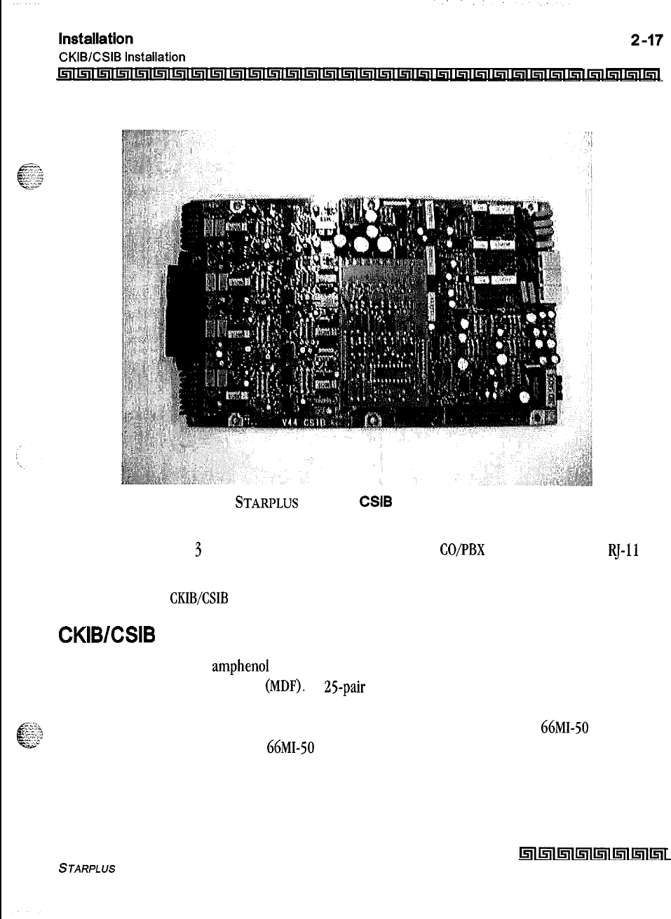
Figure 2-10:
STARPLUS
Triad-S CSIB Board with MSGU Mounted
Each CKIB or CSIB has
3
loop start CO line interfaces. The loop start
CO/PBX
lines are connected to
RJ-11
connectors on the right side of each board.
This completes the
CKIB/CSIB
installation.
CKIB/CSIB Wiring
There is one 50-pin female amphenol connector on the left side of the board. This enables the system to be
cabled to the main distribution frame
(MDF).
A 25-pair telephone cable must be prepared with mating
connectors to extend the interface circuits to the MDF. The cables should be routed through the cable clamps
at the bottom of the KSU to the MDF. These cables are terminated on industry standard
66MI-50
type punch
down blocks. It is recommended that
66MI-50
split blocks with bridging clips be used to simplify
troubleshooting and to quickly isolate any faults.
STARPLUS
Triad-S Installation Manual
Lnll5llmlmlml5llml~l
Issue I- December 1998
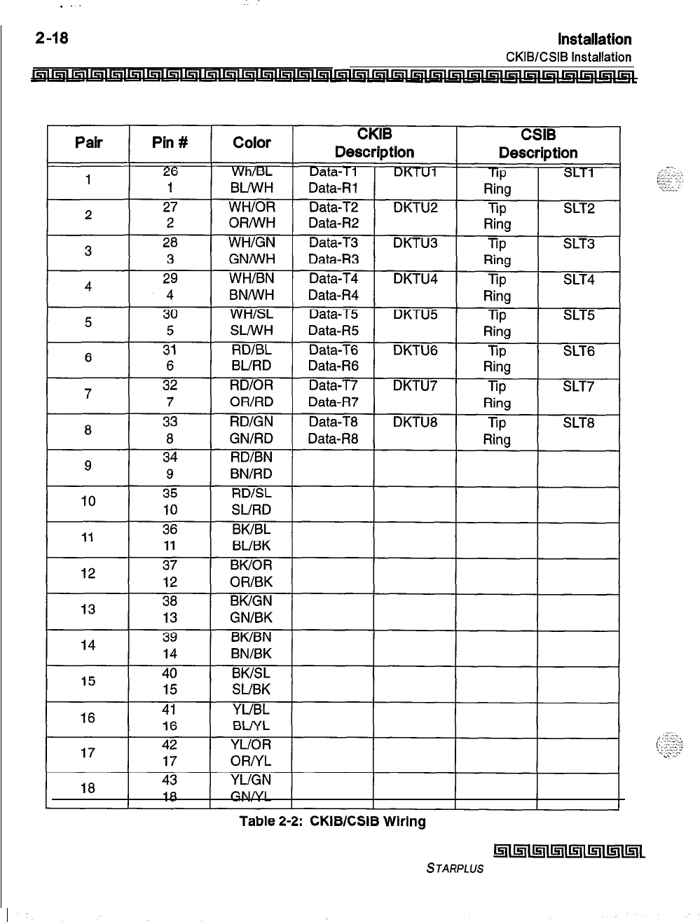
I
_..
:
Issue I- December 7998
k!iwlllsll~Iulml~l~L
STARPLUS Triad-S Installation Manual
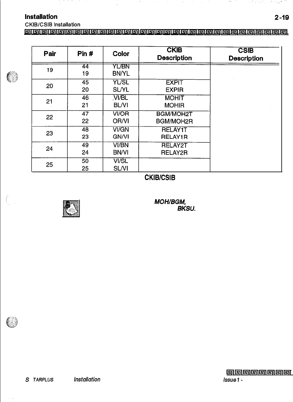
Table 2-2: CKIBESIB Wiring
Wiring for External Page, MOH/BGM, and Relay Is available only
at the first boardposition of the
BKSU.
S
JARPLUS
Triad-S /nsta/lation Manual
lslrl5lllsw5llmlmlmlml
issue
I-
December 1998
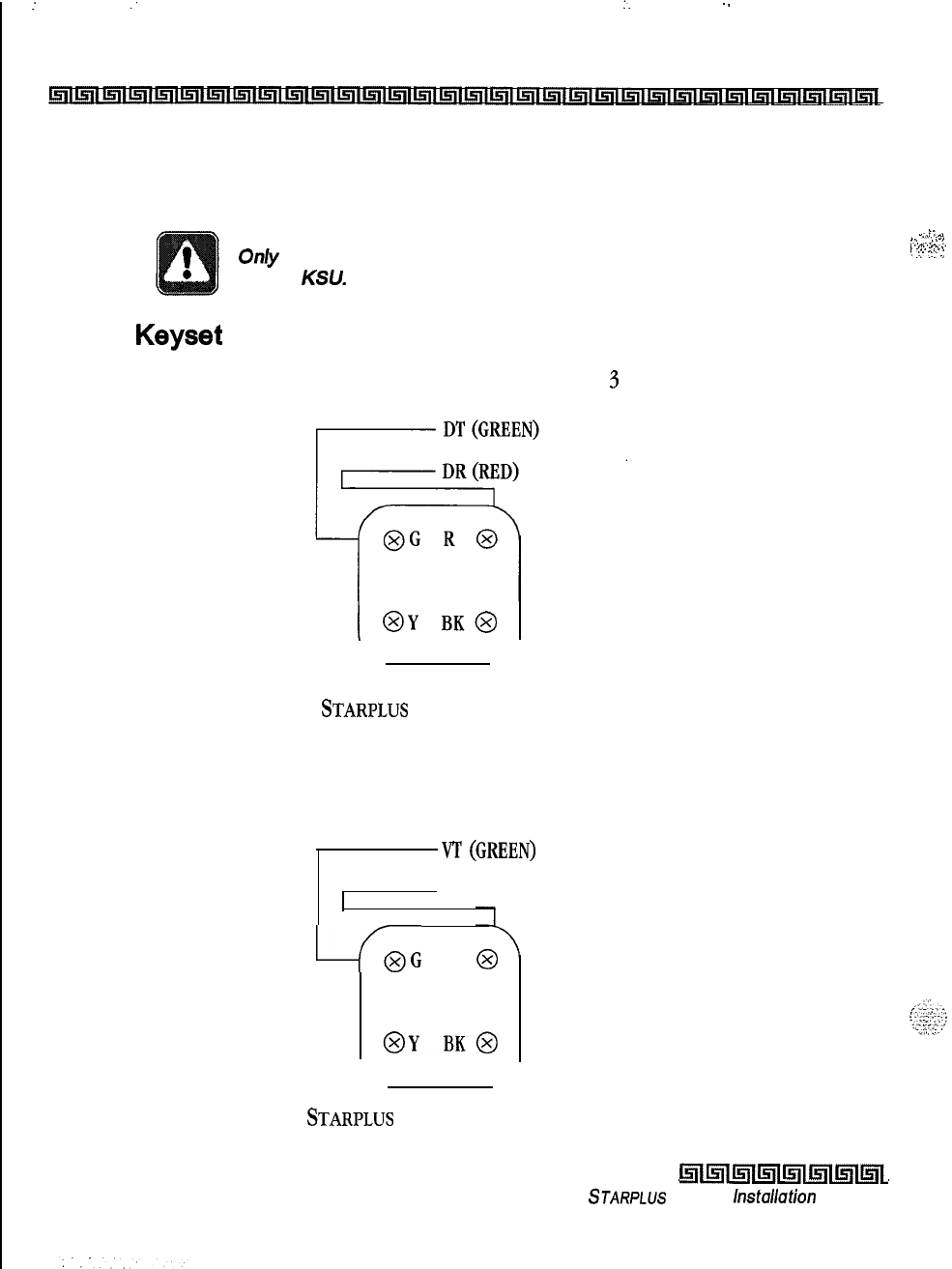
:
:
:.
.-
2-20
Installation
Station Wiring
Station Wiring
The following provides details on the interconnection of each type station interface board and station jack.
Only the first pair (green, red) on the jack should be connected
to the KSU. No other pairs should be connected.
,
.I
,
-.,,.....\
,.
..-.
..I_..
*
,:.
_...
:
.”
2
:
Digital Keyset
Wiring from the CKIB to the station jack requires single pair cable (2 or
3
pair is recommended). Digitized
voice, signaling and battery are sent over this pair.
I
@Y
BK@
Figure 2-11:
STARPLUS
Triad-S Digital Station Jack Wiring
Single Line Telephone
The CSIB is wired to SLT devices with single pair cabling to provide talk battery, voice and signaling to and
from the SLT.
vr
(GREEN)
VR (RED)
-f,G
R
Figure 2-12:
STARPLUS
Triad-S Single Line Telephone Wiring
Issue I- December 1998
t!5llisll~il5lll5lll5lll5ll~L
STARPLUS
Triad-S
lnstallafion
Manual
Installation
Wall Mounting the Digital Key Telephone
2-21
Wall Mounting the Digital Key Telephone
To
wall mount the digital key telephone, it is necessary to use the wall mount bracket and a standard type
-Y
1’1
:
^
6
“L?
jack designed for
630-type
wall hanging applications. See Figure 2-13: Digital Kq Telephone
Wall
Mounting on the following page.
I
2
3
4
5
6
/
\
“I
8
9
Remove the handset from the cradle and locate the plastic retainer in the bottom of the
hook-switch well area.
Push the plastic retainer slowly upward until it is free.
Locate the tab on the plastic retainer, making sure it is toward you, then place it back into
its holder.
Slide the plastic retainer all the way down into its channel. Part of the retainer remains
above its holder to hold the handset secure for the wall mount configuration.
Turn the telephone over and unplug the line cord. If the cord is not plugged into the wall
jack assembly, reroute the line cord through the access channel on the top of the
telephone. If the line cord is plugged into the wall jack assembly, run the line cord through
the hole provided and plug it into the connector on the back of the telephone.
Line up the hooks on the top and bottom of the wall mount bracket so they can engage
with the slots cut into the bottom of the telephone base. Insert the bottom hooks first.
Slide the mounting bracket slowly downwards until the top tabs slide into the top slots.
and snap into place.
Match the two key hole slots on the base plate with the lugs on the 630-A type jack and
align the modular connector, then slide the telephone into place.
Place the handset onto the retainer.
STARPLUS
Triad-S
hstallation
Manual
~lurllli;llurll~ll5lllN!zli
Issue
I-
December 1998
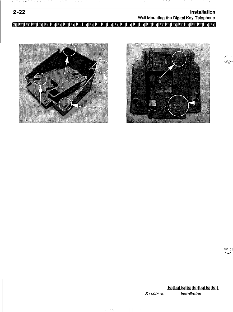
Mounting Bracket Tabs Wall Mounting Holes
Figure 2-13: Digital Key Telephone Wall Mounting
The telephone is now ready to use.
Issue I- December 1998
kal~~m~~~~~~~w~1
STARPLUS
Triad-S
hstallation
Manual
/;
‘,
.,-..
.
--.,
.
.
j
.-._
.i
.
._...
.
._
:.71
:.
‘4
.
.-
-
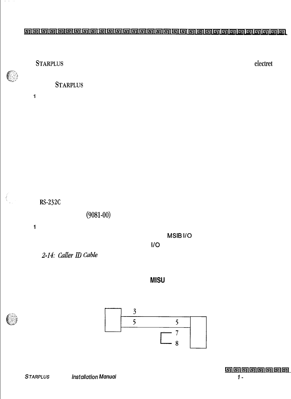
Installation
Headset Installation
2-23
Headset Installation
The
STARPLUS
Triad-S digital key telephones were designed to operate with industry standard electret mic
compatible modular headset adapters and operator headsets.
To modify a
STARPLUS
Triad-S digital key telephone to support an external headset:
1
Plug the headset adapter cord into the vacant handset jack on the key telephone base.
2Plug the telephone handset cord into the headset adapter box where indicated by the
headset manufacturer’s instructions.
Refer to Station Programming in the System Programming manual for instructions on enabling headset
operation. After programming, the station can enable or disable headset mode by dialing a code, When
headset mode is active at the station, the ON/OFF button controls the on-hook or off-hook status.
Additionally, while headset mode is active, features such as on-hook dialing and hands free speakerphone
operation become inoperable.
Caller ID Interface Unit Installation
The Caller Identification Interface Unit receives the data from the telephone company and sends the data, in
ASCII RS-23X format to the KSU.
To connect the cable port
(9081-00)
:
1
Select the correct RS-232 cable.
2Connect one end of the cable on the desired
MSIB
I/O
port (1 or 2).
3Connect the other end to the 1480-00
l/O
port marked RS232.
Figure
Z-14:
Caller
ID
Cable Connections illustrates the connections for the TCI Caller ID Interface Unit,
Triad-S MISU
KSU O-Pin
1480-00 O-Pin
Female Male
r--l3
2
Figure 2-14: Caller ID Cable Connections
hllnlml1nlmlml~lml
STARPLUS
Triad-S
hsfdafion
bkm./a/
Issue
I-
December 7998
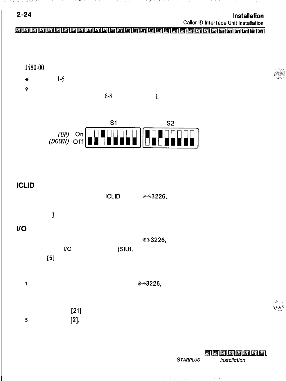
Switch Settings
Sl dip switches select the signaling protocol of the RS-232 OUT connector to assist in matching signals from
the
1480-00
with those of the DTE device. S2 dip switches control two major functions:
9Switches l-5 configure the 1480-00 to the DTE device for baud rate, data bits, and parity,
oSwitches 6-S select the unit number for the 1480-00 when multiple units are connected in series, If
a single unit is used, switches
6-8
are set for Unit #
1,
Set the switches on the 1480-00 as follows:
12345678 12345678
Programming Caller ID
ICLID Enable
1
Verify the programming for
ICLID
enable,
+4+%3226,
Flash 56.
2
Press Button [I].
3
Dial [I
]
on the keypad and press HOLD.
I/O
Ports
1
Verify the programming for the I/O ports,
+M3226,
Flash 15.
2
Select the
I/O
port, Button 1, 2
(SIUI,
SIU2).
3
Dial
[5]
on the keypad and press HOLD to select 2400 baud.
CO Lines
i
Verify the programing for the CO lines,
WK3226,
Flash 40.
2
Enter the CO line range for the Caller ID Unit.
3 Press HOLD.
4
Press Button
[21]
(Page C).
5
Press Button
[2],
ring delay timer.
6
Enter 04 (minimum) and press HOLD.
7
Reset the system and Caller ID Unit.
..I
.
L
_..
_
:i
1
.
_.. .-
\
“.
Issue I- December 1998
l!ifikll~lmlwl~lml~~
STARPLUS
Triad-S
lnstallafion
Manual
SMDR
The SMDR feature provides detailed records of all outgoing and/or incoming, long distance only or all calls,
The SMDR Qualification Timer determines the time needed to determine a valid SMDR call for reporting
purposes. By default, this timer is set to 30 seconds and is variable from
00-60
seconds in one second
increments. This feature is enabled or disabled in system programming. By default, SMDR is disabled and set
to record long distance calls only. A printout format of 80 characters maximum or 30 characters maximum
may be selected in system programming. The standard format is 80 characters per line. A 30 character
format generates three lines per message. If the SMDR feature is enabled, the system starts collecting
information about the call as soon as it starts and terminates when the call ends. If the call was longer than
30
seconds, the following information is printed (see next two pages) :
STARPLUS
Triad-S
installation
Manual
l5lllslll!illmll5llmlml~i
issue
7
-
December 1998
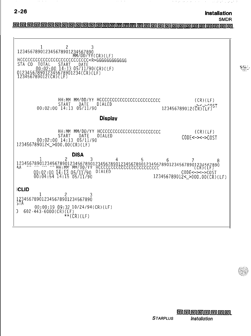
30 character format selected:
123456789L23456789il23456789i
AAA BB HH:MM:SS HH:MM
MM/DD/YY(CR)(LF)
HCCCCCCCCCCCCCCC;;W;CCC;;K;cR>GGGGGGGGGGGG
STA CO TOTAL
116 08
0O:OZ:OO
14:13
05/11/90(CR)(Lt-)
0123456789012345678901234(CR~~LF)
123456789012(CR)(LF)
80 character format selected:
123456789~123456789~123456789~123456789~123456789~123456789~123456789~123456789~
AAA BB HH:MM:SS
;;Hz;:
MM;;;;YY
W;CCCCCCCCCCCCCCCCCCC
GGGGGGGGGGGG
(CR)(LF)
STA CO TOTAL ACCOUNT CODE<
><
XOST
116 08
0O:OZ:OO
14:13
05/11/90
0123456789012345678901234
123456789012(ER)TLF)
80 character format with Call Cost Displav feature enabled:
-4
123456789~123456789~~23456789~1234567890123456789~123456789~123456789~123456789~
AAA BB HH:MM:SS
;;Wly
MM;;;;YY
K;f;;CCCCCCCCCCCCCCCCCCC
GGGGGGGGGGGG
(CR)(LF)
STA CO TOTAL
116 08
0O:OZ:OO
14:13
05/11/90
0123456789012345678901234 ACCOUNT
CODE<->+>COST
123456789012<~>000.0O(CR)(LF)
BO character format for DISA Calls:
123456789~123456789~123456789~123456789~123456789~1234567B9~123456789~123456789~
4A
BB HH:MM:SS
W&l
MM;;K&YY
tW;;CCCCCCCCCCCCCCCCCCC
GGGGGGGGGGGG
(CR)(LF)
STA CO TOTAL
34
01
00:02:00 14:13 05/11/90
I
CODE+>+~COST
ACCOUNT
31 04
00:04:54 14:15 05/11/90 10123456789012345678901234
123456789012~~~000.00(CR)(LF)
ICLID 30 character format selected:
123456789h23456789;1234567B9;
STA
CO TOTAL START DATE
100 01
00:00:19
09:32
10/24/94(CR)(LF)
1
602.443-6000(CR)(LF)
123456789012
**(CR)(LF)
_
_
_ .
.
.
-.-_.
F
.-.
.
.
‘:=;
-
Table 2-3: SMDR Printout
issue I- December 1998
l5lllslllrll~lisnl~l~l~~
STARPLUS
Triad-S
installation
Manual
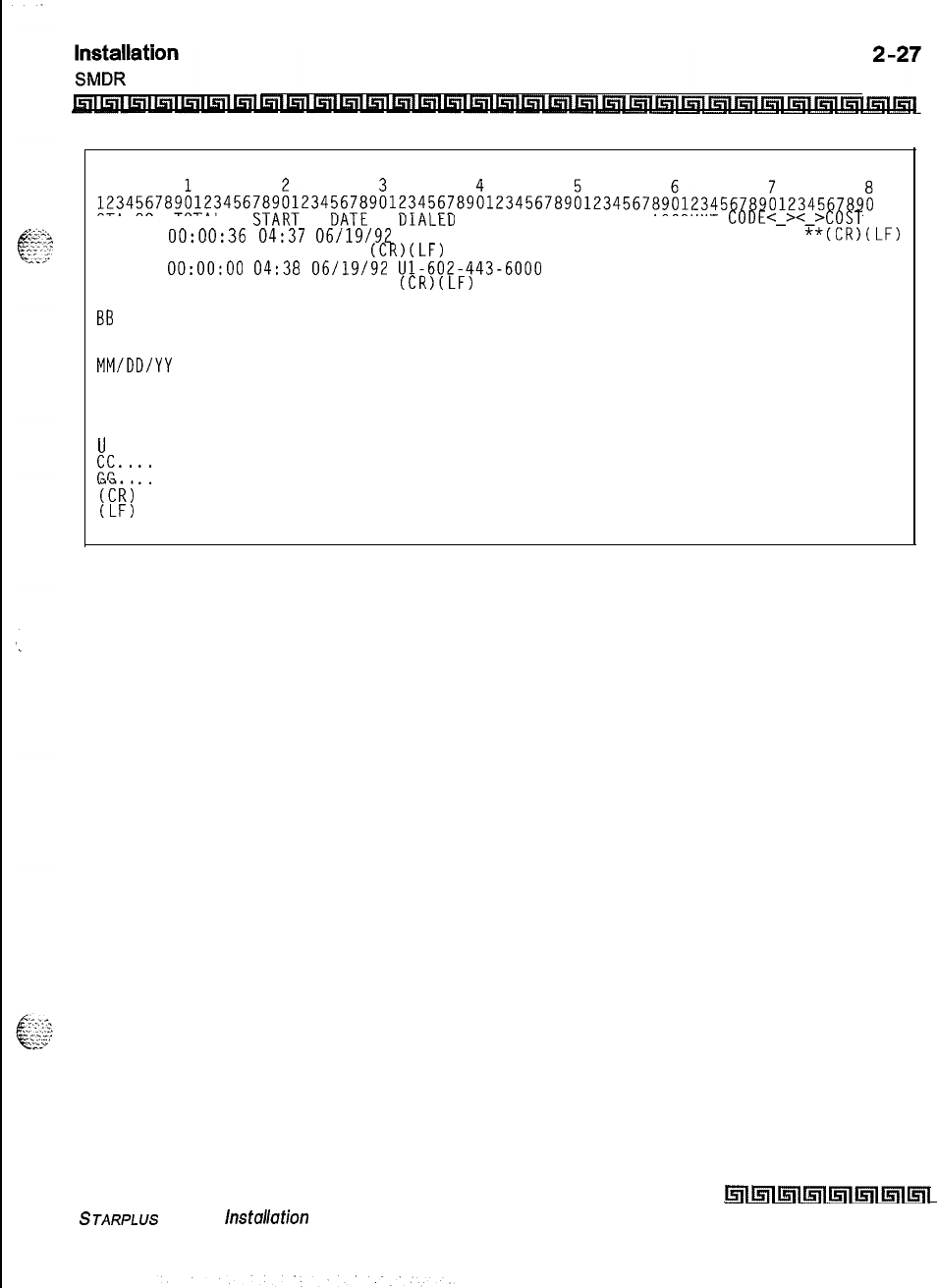
ICLID 80 character format selected:
STA CO TOTAL
100 01
00:00:36
04:37
06/19/92
11-602-443-6000 ACCOUNT
CODE<-><-XOST
**(CR)(LF)
**VODAVI
(CR)(LF)
01
0O:OO:OO
04:38
06/19/92
Ul-602-443-6000
**
**VODAVI
(CR)(LF)
AAA = Station originator or Trunk on DISA and Off-Net (CO Line) calls,
BB
= Outside line number
HH:MM:SS = Duration of call in Hours, Minutes and Seconds
HH:MM = Time of day (start time) in Hours and Minutes
MM/DD/YY
= Date of Call
H = Indicates call type:
I = Incoming*
0 = Outgoing
T = Transferred*
U
= Unanswered calls for ICLID SMDR call records
&-*
CC = Number dialed
..GG = Last Account code entered (optional)
ccij
= Carriage return
(LF)
= Line Feed
Table 2-3: SMDR Printout
STARPLUS
Triad-S
lnstallafion
Manual
wi5ll~l~ll=iill5ll~ll5il
Issue I- December 1998
Issue
7
-
December 1998
Inll57l~ll5ilinl~ll5Ill5l~
STARPLUS
Triad-S
Installation Mutx~al
Prior to actual power up and initialization, check out the
STARPLUS
Triad-S System to avoid start up delays
or improper loading. A step-by-step checklist is provided for this purpose.
I
’
\
Preliminary Procedures
1
Make sure the Basic Key Service Unit (BKSU) is properly grounded to cold water pipe or
earth ground.
2Verify that all expander modules are firmly seated onto their connectors.
3
Inspect the MDF for shorted wiring and improper polarity that would affect the Digital
Terminal or DSS console.
4Make certain the lithium battery switch (SW2) on the MBU of the BSKU is set to the ON
position to enable the battery backup option.
5
Make sure the MDF cables connected to the KSU are secure and are plugged into the
correct position.
Power Up Sequence
The power up sequence involves
1)
the proper application of AC power to the system and 2) defaulting the
system. A successful power up is assured if the installation checklist is followed.
1
Plug the AC power cord of the Key Service Unit into the dedicated 117V AC outlet.
2Remove the BKSU cover, set SW1 on the MBU to the ON position. Set (SW2) (BATT) to
the ON position.
3
Turn the power switch of the KSU to ON.
4Set
(SWI)
on the MBU to the OFF position to retain changes to the database.
5
The system is ready for programming. If problems occur, refer to Section 4,
Maintenance and Troubleshooting.
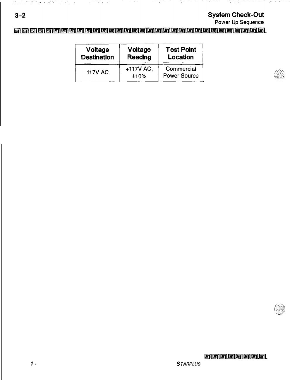
~~
Table 3-1: Power Supply Tests
Issue
I-
December 1998
mml5lll.5llu;il~lmll5l~
STARPLUS
Triad-S Installation Manual
I
Introduction
This section is provided as a guideline in isolating and resolving functional problems that may be
encountered as a result of improper use or component failure of the
STARPLUS
Triad-S systems, Other
failures, such as no dial tone from the central office, must also be considered as an overall troubleshooting
procedure.
System Programming and Verification
System operation should be verified as per the programmed customer database once all customer database
programming was completed. A hard copy of the customer database can be printed from the system and
should be kept on-site and up to date for future reference.
System must be
initiuhzed
before
the
customer
database is programmed.
The
STARPLUS
Triad-S systems are highly-featured digital switches and, as such, feature activation can
sometimes be mistaken for improper operation. First, verify all programmable features are enabled for the
phone or function in question. Then compare the suspected improper operation with the feature operation
description to determine which feature is causing conflict. Be aware that some features can override others
and take precedence in operational priority. Then make the necessary programming changes in customer
database programming to acquire the desired operation.
If feature operation is not the cause of the suspected problem, then general troubleshooting procedures
should be employed. A basic guideline for determining the cause of a reported problem is given below:
IVerify that system programming is correct and that the suspected feature, circuit or
function was enabled in programming.
2
Check the installation cabling/wiring and connectors for cuts, shorts or loose
connections.
By verifying correct operation for each segment of the installation and system, the source of the problem is
isolated and can thereby be identified and resolved.
4-2
Maintenance and Troubleshooting
Telephone and Terminal Troubleshooting
IRl~liritllFlml~l~~~~~l~l~l~l~l~l~l~l~i~l~l~l~l~i~l~l~l~l~l~l~l~i~l~l
Telephone and Terminal Troubleshooting
This section discusses general functions on a variety of key telephones and terminals available for use on
the system. It is assumed that basic troubleshooting skills in the identification and resolution of basic
problems are already possessed (e.g., static/noise heard on conversation, one phone only; Replace worn
handset cord).
Keyset
Self Test
The
STARPLUS
Triad-S system contains a test mode feature that supports the off-line testing of digital
keysets
and DSS units. The term off-line means that the unit under test is operationally disconnected from
the switch during the test operation.
Keysets
not under test continue to operate in the normal manner.
Tests are provided to verify the
keyset
and DSS LED, LCD, and keyboard button operations.
1
The test mode is entered by taking a
keyset’s
handset off hook.
2
Press the SPEED button and dial
[7#]
on the dial pad. This disconnects the
keyset
from
the system and brings up the Test Mode Menu on the
keyset’s
LCD. The test mode is
exited by putting the handset back on hook. This reconnects the
keyset
to the system.
Test Mode Menu: The menu allows the operator to select a test mode by pressing the mode number at the
dial pad. The operator can always return to the main test menu by pressing
[##I.
SELECT l:LCDLED 2:KEYBTN
3: DSSBTN
Keyset
LCD/LED Test
This test outputs a series of continuously repeated LCD string messages to LCD lines 1 and 2. The set of
strings consists of the letters A through X and a through x. The next set of strings are:
PICKUP TRUCK SPEED ZONE!
*** STANDING BACK ***
4
The strings are alternately displayed on lines 1 and 2 of the LCD display,
Issue I- December 1998
kilmlk.!m5ll~lmll5lll5l~
STARPLUS Triad-S Installation Manual
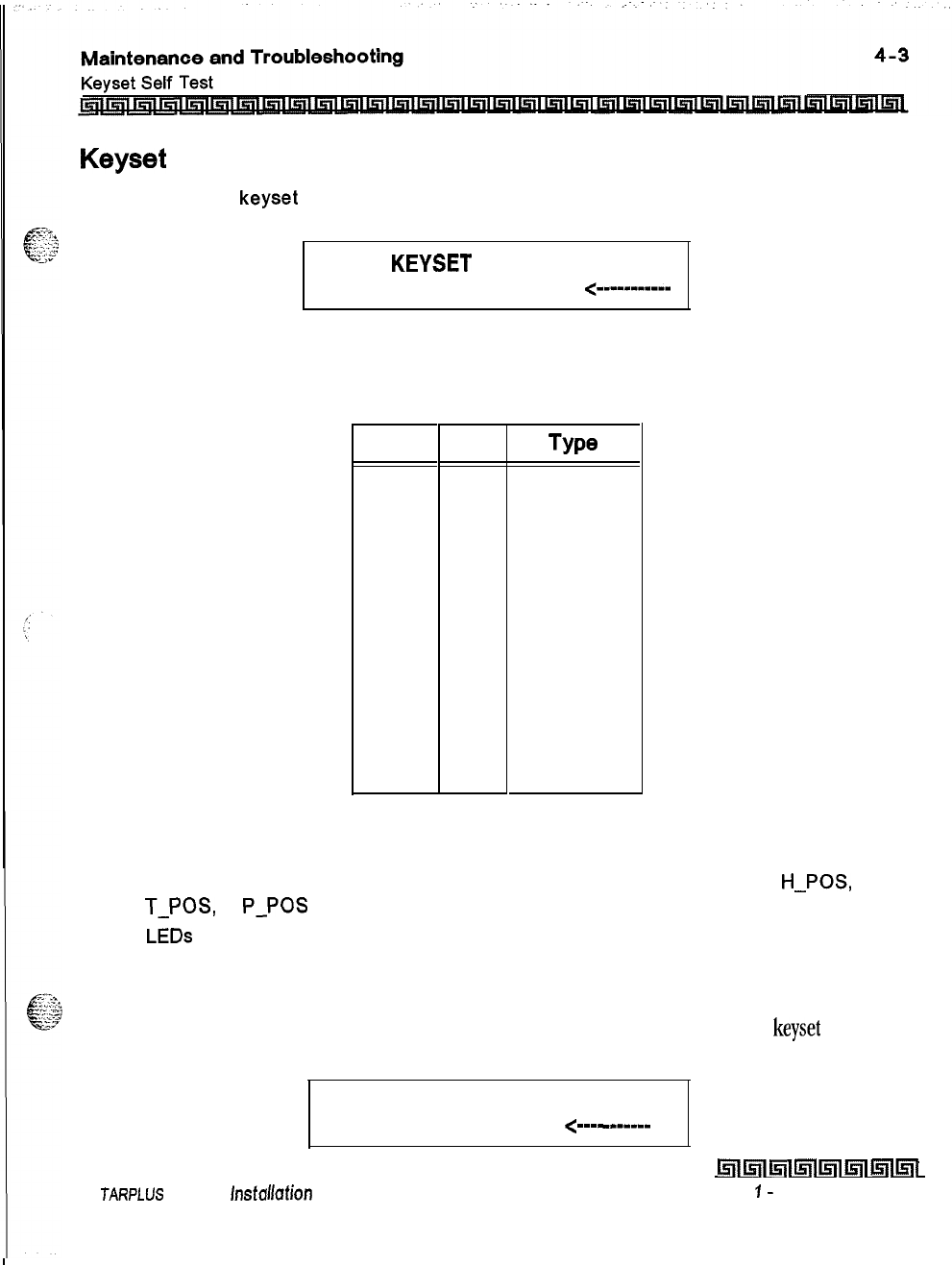
Keyset Button Test
1
Pressing a
keyset
button turns on the LED and displays an LCD message identifying the
button number.
PRESS
KEYSET
BUTTONS
DIGIT1
<----------
a
Each time the selected button is pressed it sequences through the table of flash rates
available.
Button ipm TYPO
01
On
Steady
02 30
Flash
03 60
Flash
04 60
Double Wink
05 240
Flash
06 240
Flutter
07 480
Flash
08 480
Flutter
09
15
Flash
10 120
Flash
11
120
Flutter
12
30
Double Flash
13
480
Double Wink
14
480
Double Flash
Table 4-1: Flash Rates
3
Pressing dial pad keys display an LCD message that indicates which digit was pressed.
Pressing the H-T-P switch from one position to another causes the word
H-POS,
T-POS,
or
P-POS
to display.
4
LEDs
can be tested independently of the KEYS by pressing the flex LED button.
DSS LED/Button Test
When the DSS test is selected and a DSS test is invoked, ALL DSS units associated with the
keyset
are placed
in the test mode.
PRESS DSS BUTTONS
<--mm
-I-----
S
JARPLUS
Triad-S lnsfallafion Manual
hll5llI5llWl5llkll~l~l
Issue
I-
December 1998
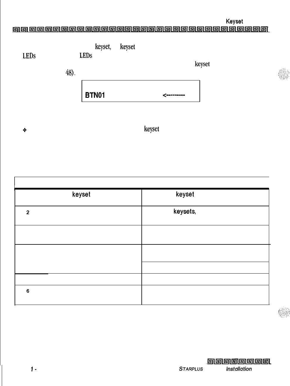
4-4
Maintenance and Troubleshooting
Keyset Self Test
Inl~llr;lllsllll~l~l~l~l~l~l~l~l~l~l~l~l~l~l~l~l~l~l~l~l~l~l~l~l~l~l~l
If no DSS unit is associated with the
keyset,
the
keyset
display indicates NO DSS. The DSS LED test causes all
the
LEDs
to light steady. All
LEDs
remain lit steady until a DSS flex button is pressed. Pressing a DSS button
turns on the DSS button LED and displays an LCD message on the associated
keyset
identifying the DSS
button number
(01
to
48).
In addition, it turns off the previously selected flex LED.
PRESS DSS BUTTONS
BTNOl
<----W-B-
--
Conditions:
oTest mode interrupts the normal operation of a
keyset
or DSS.
Key Telephones/Terminals
The following actions apply to multi-line key telephones:
Symptom
I
Action
I
1
No power to
keyset Verify that keyset is connected to correct
type of station card.
2
No handsfree answer-back on On digital keysets, the mode of intercom
intercom answer is programmable.
3
CO line/station button will not access Check flexible button programming for that
CO line/station button.
4
Speakerphone does not work Check station programming for
speakerphone enable.
Verify phone is a speakerphone model.
5
Cannot call another intercom station Check off hook preference programming.
s
No camp-on signals or override to Check station programming for override
phone enable
Table 4-2: Key Telephones/Terminals
Issue
I-
December 7998
l!iwilll5llmllsll~llsll~l
STARPLUS
Triad-S
lnstullation Manual
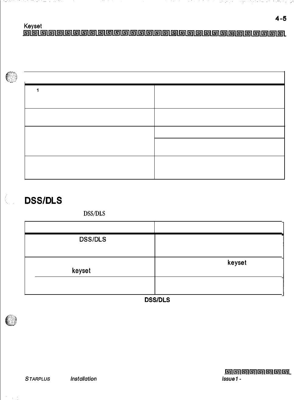
Maintenance and Troubleshooting
Keyset
Self Test
Single Line Telephones
The following applies to all 2500 type single line telephones connected to the system,
I
Symptom
I
Action
1
Phone will not dial out Verify correct SLT type programmed in
station identification. Verify line group
access programming.
2
No ringing to phone Check CO line ringing assignments in
programming.
3
Message waiting lamp does not work Check station ID assignment in programming.
Make sure the MSGU is installed on the
CSIB.
4
Cannot call another intercom station Check off hook preference programming.
Put all unused CO lines in a CO line group not
currently being used.
Table
4-3: Single
Line Telephones
DSWDLS
Console
The following applies to
DSS/DLS
Consoles:
Symptom Action
1
Buttons on
DSSlDLS
do not function Check station identification assignment in
as labeled programming for correct DSS map
assignment.
2
Pressing buttons on DSS does not
activate
keyset
3 No power
DSS must be assigned to
keyset
in station ID
programming.
Verify unit is connected to the correct type
station board (digital or electronic).
Table 4-4:
DSS/DLS
Console
STARPLUS
Triad-S
/nstallation
Manual
Lr;lltf;llmImlml~lmlml
lssoe
I-
December 1998
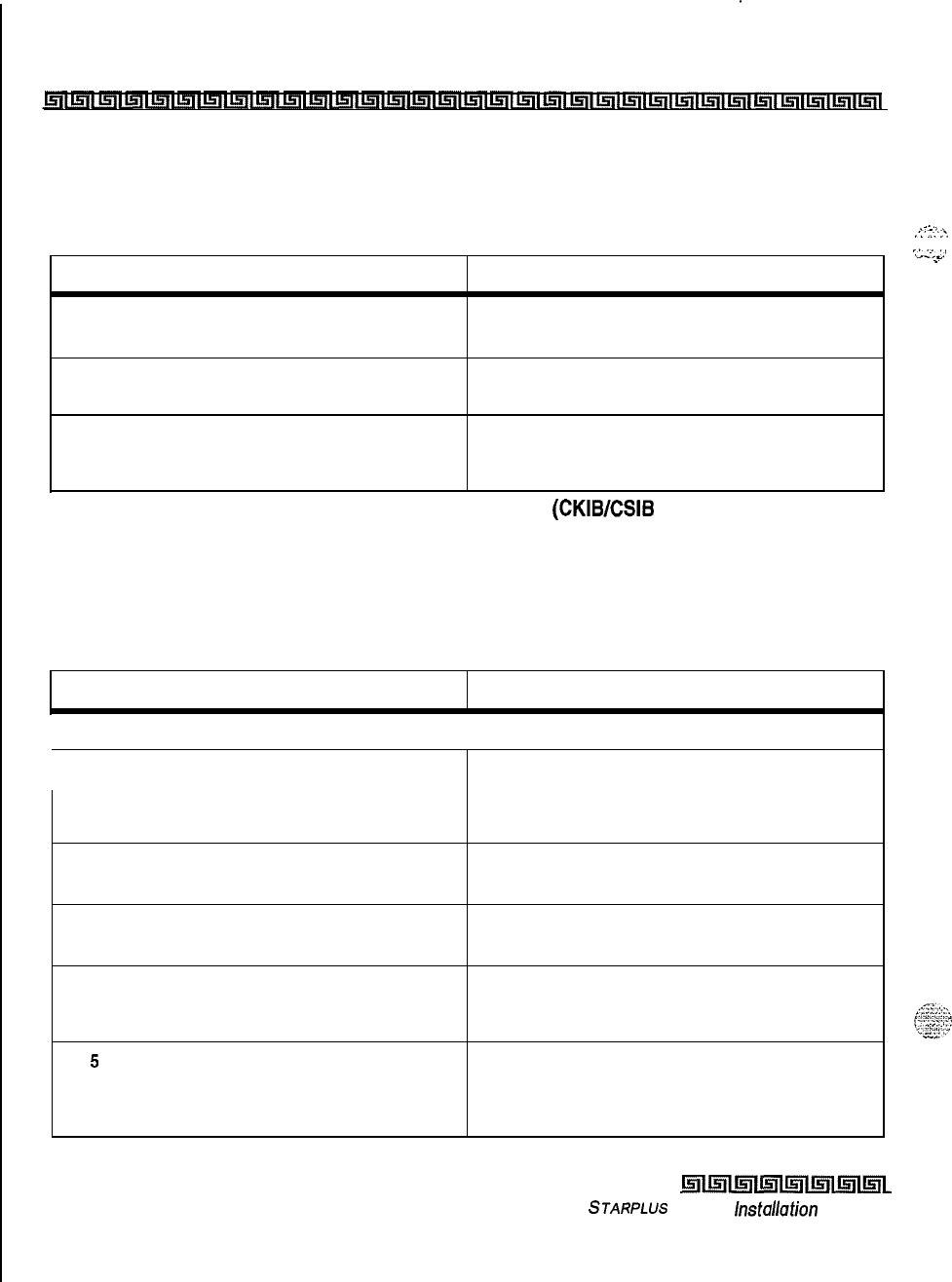
.
.
.
4-6
Maintenance and Troubleshooting
CO Line Card Functions
CO Line Card Functions
The system can be equipped with either a CKIB or CSIB line interface card. Each card type contains three (3)
Loop Start CO lines.
..A.
.:-7:‘.‘.
:z::.
. . .
.-
Symptom Action
1
3 loop start CO lines on the system Check or change card. Check CO line
do not work demarcation.
2
CO line(s) does not ring Check CO line ring assignment in
programming.
3
Noise or cross-talk on the line Check CO line at demarcation for cross-talk.
Check with different card at different
station.
Table 4-5: CO Line Loop Start Board
(CKIBESIB
Board)
System Functions
The following functions are related to system resources and the common equipment boards controlling
them.
Symptom Action
Basic KSU and MBU
I
1
Complete system failure
2
Any correctly activated feature does
not work properly
3
Loss of system intercom dial tone
and call processing tones
4
Loss of customer database
programming
5
Customer database cannot be
programmed
Verify that power switch is on, power cord is
plugged in. Check power LED on MBU (left
edge of card). Verify PMU was installed with
software.
Check system programming related to
specific feature.
Check off hook preferences, headset mode,
and verify on another telephone.
Verify status of initialization switch,
database backup battery connection,
battery voltage, and system programming.
Verify that no one else is accessing
database programming. Check RS232 cable
and verify programming was performed
from Station 100.
Issue I- December 1998
Table 4-6: System Functions
Isrlmlml~ll5lll5llmll5lL
STARPLUS
Triad-S
lnstollafion
Manual
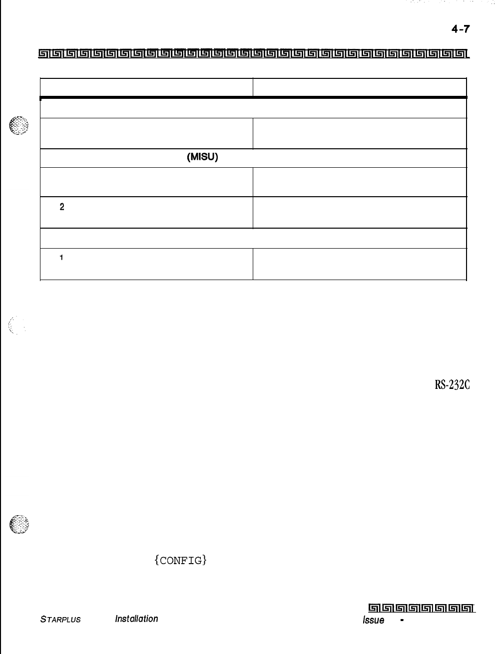
Maintenance and Troubleshooting
Remote Maintenance
I
Symptom Action
Modem Unit (MODU)
1
Cannot access system database Verify modem installation and programming.
programming remotely Check modem baud rate.
Miscellaneous lnterf ace Board (MISU)
1
Music Channel 2 is not functioning Verify MSU is installed and check music
source.
z
Cannot communicate with external Check the baud rate programming and the
devices COMM port selection and cable.
DTMF Receiver Unit (DTMF-A)
1
DTMF single line telephones cannot Verify DTMF-A is installed.
dial out
Table 4-6: System Functions
Remote Maintenance
General Overview
The Remote Maintenance feature allows authorized personnel to survey system, slot configuration information
and programming. This can be done through the optional modem or data terminal connected via the
~~-232~
port on the optional MISU Module. The commands are entered from a keyboard and are limited to those listed.
Overview of Maintenance Commands
There are four basic commands available in the Remote Maintenance feature. All commands begin with a
single character, followed by a space, another character and an optional digit or digits. All commands are
terminated with the [Enter] key.
Maintenance Password
The Maintenance feature, like Programming, is enteredvia a six-character alphanumeric string. The password
prompt is given by pressing [Enter] at the device connected to the RS232 port. After the prompt displays, enter
the password, then press [Enter]. Proper entry of the password displays the maintenance prompt. The
Maintenance password is: {CONFIG]
STARPLUS
Triad-S
hstallation
Manual
hli5il~lmlmlml~iml
issue 1
-
December 1998
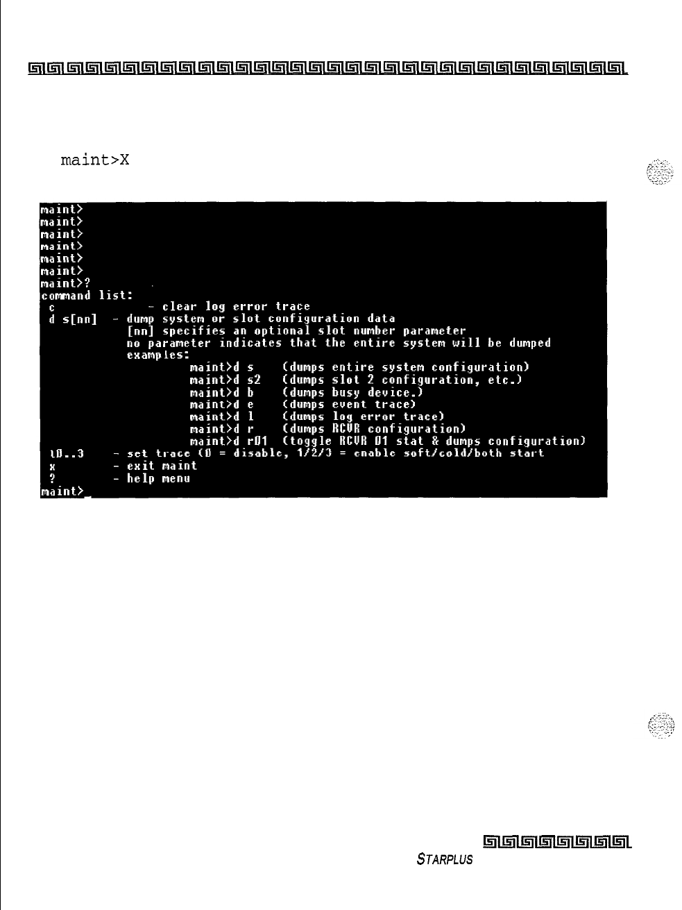
.
.
4-a
Maintenance and Troubleshooting
Remote Maintenance
I;ri(llsli~llFllll~l~l~l~l~l~l~l~l~l~l~l~l~l~l~l~~l~l~l~~~l~l~~~l~l~l~L
Exit Maintenance
The Exit command terminates the current Maintenance feature session. The Exit command format
is:
maint>X
Issue I- December 1998
Figure 4-l: Maintenance Help Menu
l5lll!zllmlmlmlmll5il~~
STARPLUS Triad-S Installation Manual
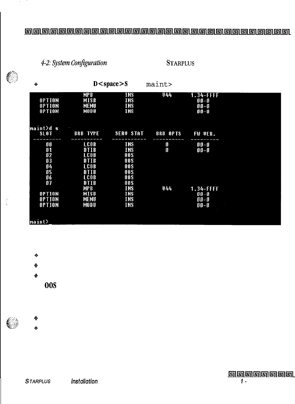
I
.-
Maintenance and Troubleshooting
4-9
Remote Maintenance
~llrrltnll~l~l~l~l~l~l~l~l~l~l~l~l~l~l~l~i~l~l~i~l~l~l~l~i~l~i~l~l~~
System Configuration
Figure
4-2:
System Configuration is a configuration of the
STARPLUS
Triad-S system and displays what is
SF,.
printed when:
.<’
;
6
;:
-2
6The installer enters
D<space>S
at the
maint>
prompt.
Where:
Figure 4-2: System Configuration
o
Column
1 lists the card slot.
+
Column 2
lists card type of that card slot.
+
Column
3 lists card status:
00s
status can indicate the entire card is out of service, or a specific station is not installed or
installed but not operational.
INS
status can indicate a specific station is installed and operating correctly.
*Column
4 lists card options.
+
Column
5 lists firmware version of card.
STARPLUS
Triad-S
hstallation
Manual
hlk5lllnl~lill5ll~l~l
Issue
I-
December 7998
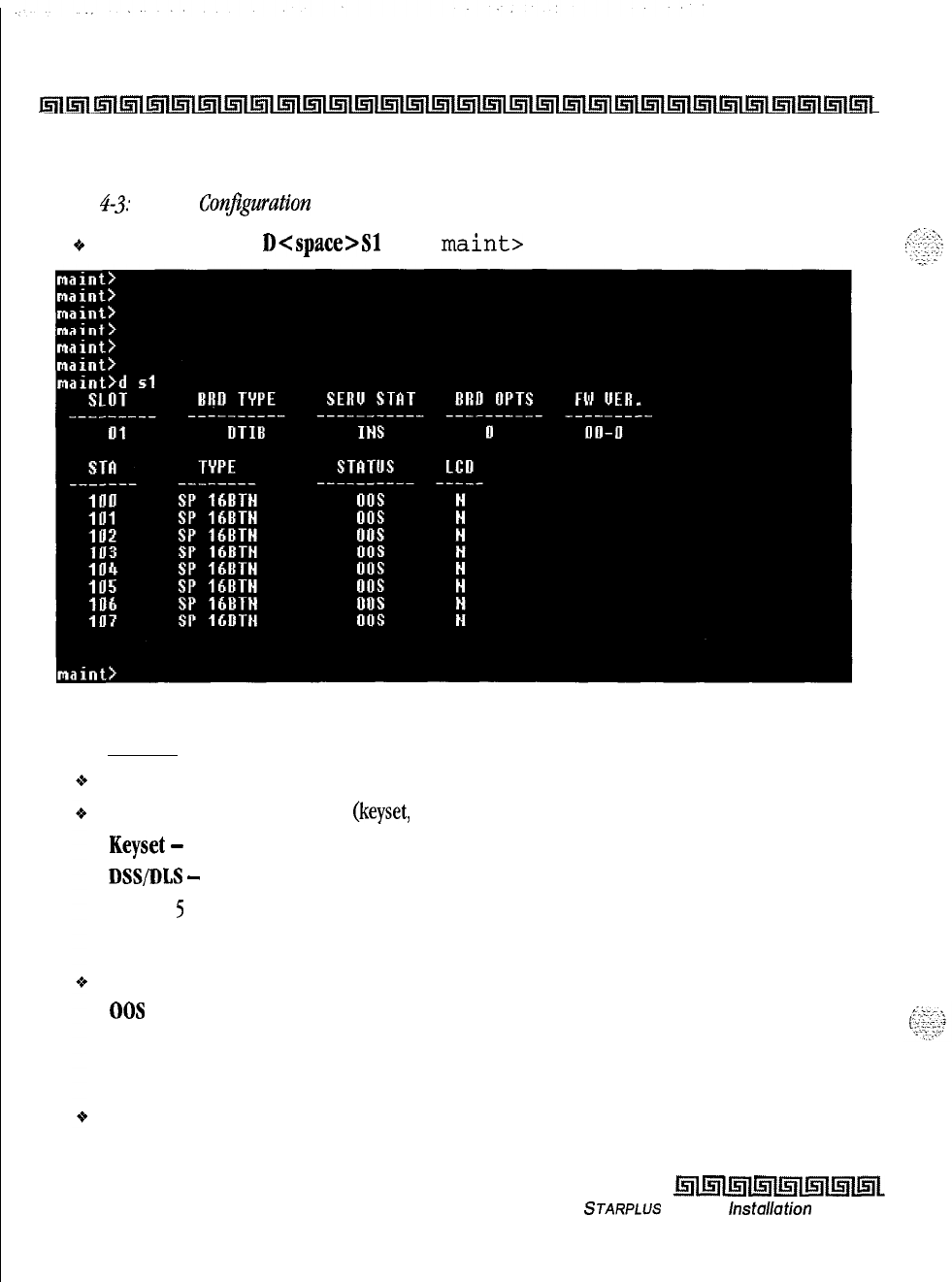
4-10
Maintenance and Troubleshooting
Remote Maintenance
Inl~l~l~l~l~l~l~l~l~l~l~l~l~l~l~l~l~l~l~l~l~l~l~l~l~l~l~l~l~l~l~l
Station Configuration
Figure
4-3;
Station Conjguration illustrates what is printed out when:
+
The installer enters
D<space>Sl
at the
maint>
prompt
Where:
Stations
Figure
4-3: Station Configuration
Column
1
lists the station number.
Column 2 indicates station type
(keyset,
DSS, SLT).
Keyset
-
ID 0 = Key station
DSS/DLS
-
ID
1
= DSS Map
1
SLT-ID
5
= SLT
SLT w/Lamp
-ID
6
= SLT with Message Waiting
Column
3 indicates status:
00s
status can indicate the entire card is out of service, or a specific station is not installed or
installed but not operational.
INS
status can indicate a specific station is installed and operating correctly,
Column
4 indicates if the station has an LCD Display.
Issue I- December 1998
STARPLUS
Triad-S
installation
Manual
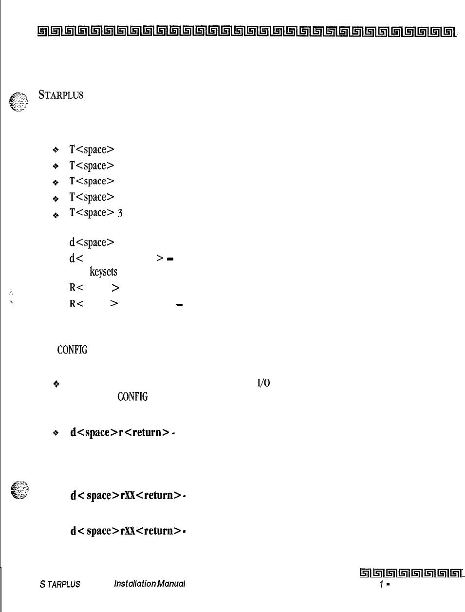
I
Maintenance and Troubleshooting 4-11
Remote Maintenance
lslllnlIsrllnl~lmlmltsjllnllnlrs;ilsllllstllnllnllnlrnlirllInllnllnllnlLE;i(~l~llslllfllL41l~llflllsilllEitL
Event Trace Buffer
The Event Trace Buffer is used to store and dump event traces (up to 30) that occur just prior to a
';.%
c
_-
.-.-.:
STARPLUS
Triad-S system soft or hard restart. These can then be reviewed by authorized personnel to aid in
“:‘1;’
system troubleshooting.
The basic format for the commands are:
4
4
i.
4
\_
4
T<space>
<return>
-displays the current status of the Event trace buffer
T<space> 0 <return> -turns the Trace buffer OFF.
T<space>
1
<return> -turns the Trace buffer ON to record events prior to a soft system reset,
T<space> 2 <return> -turns the Trace buffer ON to record events prior to a hard system restart.
T<space>
3
<return> -turns the Trace buffer ON to record events prior to either a soft reset or a
hard system restart.
d<space> E <return> -dumps Trace Events stored from last system reset (soft or hard),
d<
space> b <return >
-
permits maintenance personnel to determine the busy status of all the
busy
keysets
and CO Lines in the system, including the
Tl
lines,
RC space
>
SXXX <return> -permits a specific station to be reset.
R< space
>
CXX <return>
-
permits a specific CO Line to be reset.
DTMF Receiver Trace
The
CONFIG
utility to allow technicians to take specific DTMF receivers in/out of service. This is useful for
troubleshooting DTMF receiver problems to isolate a specific DTMF receiver that may be faulty.
+
Connect a PC with communication software to the I/O port 1 on the MISU. At the ENTER PASSWORD
prompt type
CONFIG
and press [ENTER].
The basic format for the commands are:
o
d<space>r<return>
-
to display the status of all DTMF receivers in the system. The display
shows the receiver number, cabinet location, card slot location, receiver status, and state of the
receiver.
To make a receiver busy:
cI
:cs.-.,
e
_.L
. .
--‘-.;:
c-
4
d<
space>rX?i<return>
-
Where XX is the specific receiver number to make busy,
To make a receiver available:
4
d<
space>rXX<return>
-
Where XX is the specific receiver number to make available.
S
JARPLUS
Triad-S
/nStCl//Utio/l
hhX/U/
Lnll5llml~lmlmll5lll5ll
Issue
I
-
December 1998
4-12
Maintenance and Troubleshooting
Remote System Monitor
~lilll;nl~ltnl~l~l~l~l~l~l~l~l~l~l~l~l~l~l~l~l~l~l~l~l~l~i~l~l~l~l~l~L
Remote System Monitor
General Overview
The Remote System Monitor feature provides access to the installed system for diagnostic purposes, These
capabilities benefit service personnel enabling them to support the end user. Different levels of access, via
password, allows authorized personnel to trace, monitor and upload critical information directly from the
STARPLUS
Triad-S system. This provides a more accurate means of acquiring system information that
leads to a quick resolution of problems that may occur. This is all done without interfering with ongoing call
processing or normal system operation, and in many cases may be performed without a site visit. The
optional
9600
baud modem is used for remote access.
Capabilities allowed and reserved for this high level troubleshooting in addition are:
o Monitor Mode
oEnable and Disable Event Trace
e
Dump Trace Buffer (up-load)
Monitor Password
The Monitor feature, like Maintenance, is entered via a six-character alphanumeric string. The password
prompt is accessed by pressing the [Enter] key at the PC connected to the MISU. After the prompt displays,
enter the password, then press [Enter]. Proper entry of the password results in the
man>
prompt. The
Maintenance password is:
{
ETRACE}
The remote monitor
feature
is intended for use on/y under the
guidance and instruction by authorized personnel from
VODAVI
Technical Support.
Cufe
and caution must be observed when
using this
feuture
us permanent damage to the
softwure
struc-
ture can occur.
Issue
I
-
December 1998
r!!iIllsllslmlmlrlmll5iL
STARPLUS
Triad-S
hstallation
Manual
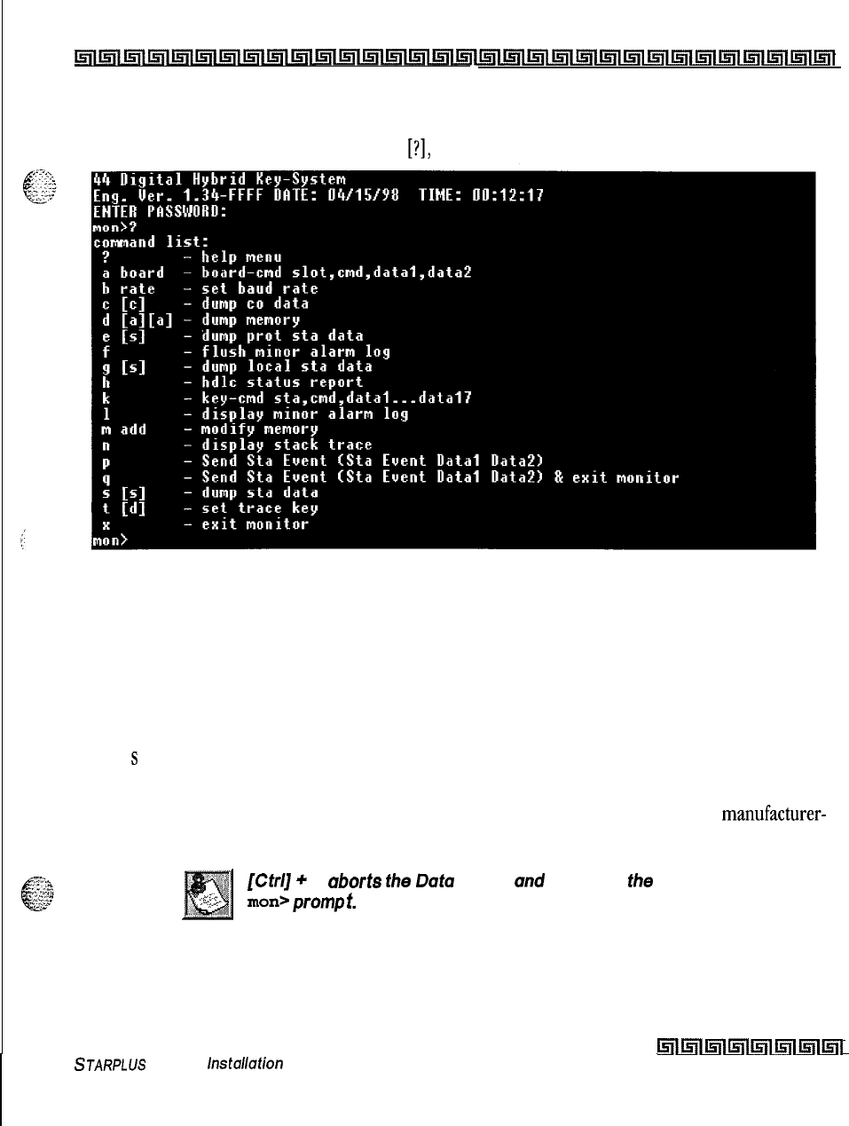
I
Maintenance and Troubleshooting
4-13
Remote System Monitor
Lnllnlinli?nl~llnllnr~sillsllInl~llnlinilnllnlll~~~l[nl~l~llsrllr;l~l~l;rlln~~l~l~l~l~l~~
Help Menu (3)
A convenient Help Menu is provided by typing
[?I,
then pressing [Enter]. The following displays:
Figure 4-4: Help Menu
Dump Memory Data
Three options allow the memory structure to be dumped for viewing. The three options are entered as
follows:
c [c] -Dump CO Line memory structure
s
[s] -Dump Station memory structure
d [a] [a] -Dump a memory address structure
The data obtained from these commands is in hexadecimal format and is used primarily for manufacturer-
level support.
[ctq
+
c
uborts
t/w
Dot0
Dump
und
returns to
the
man>
pomp
t.
STARPLUS
Triad-S
installation
Manual
lmkilll5lll5ilill5llmlml
Issue I- December 1998
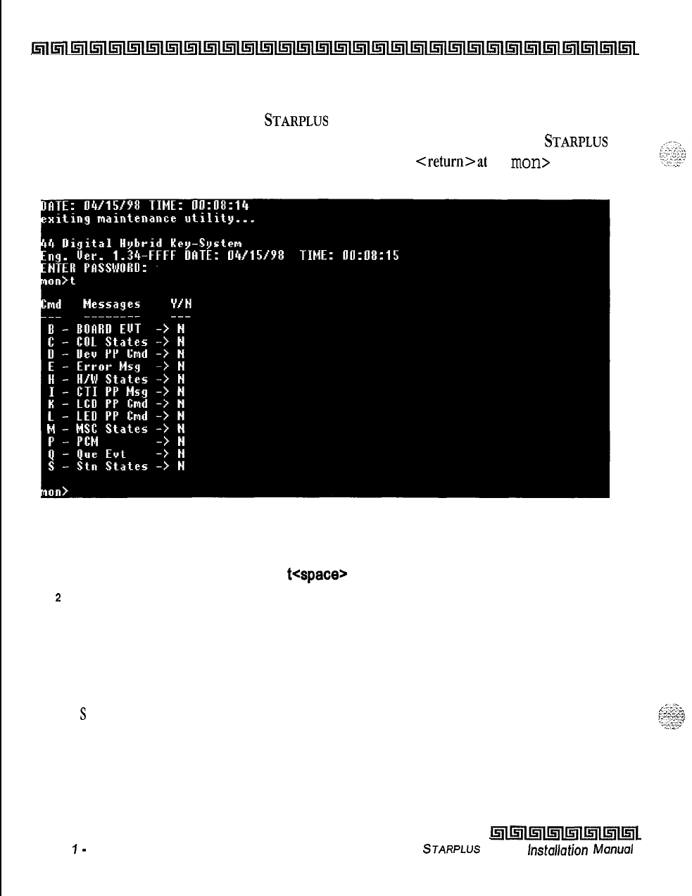
I
4-14
Maintenance and Troubleshooting
Remote System Monitor
~lnllnllnlLslllsl~ls(l~1~1~l~l~l~l~l~l~l~l~l1411~1~lUill~l~l~l~ill~lLnllsll~lisll
Event Trace Mode
The T command enables and disables the
STARPLUS
Triad-S system Trace mode. While the trace mode is
enabled events for the trace desired displays on the monitor, printer or PC connected to the
STARPLUS
Triad-S system. To view the current status of the trace mode type [T]
<return>at
the
man>
prompt, the
following screen displays:
Figure 4-5: Trace Mode Status
1
To enable an Event Trace, type
t<space>
(space bar).
2
Indicate type of trace desired [d], where d is determined as follows:
B = Board event trace (traces events associated with PCB)
M = Miscellaneous State event trace
P = Pulse Coded Modulation (PCM) traces events associated with voice communications.
C = CO Line (LCOB) States (traces events associated with CO Line activity)
S
= Station (STA) States (traces events associated with Station activity)
E = Error Messages (traces error messages)
Q = Queue (QUE) Events (traces queuing events, i.e., DTMF receiver, UCD, LCR, etc.)
D = Device Command (traces commands to peripheral devices).
Issue
7
-
December 7998
l5llmll5llmllnlmlml~~
STARPLUS
Triad-S
hstallation
Manual
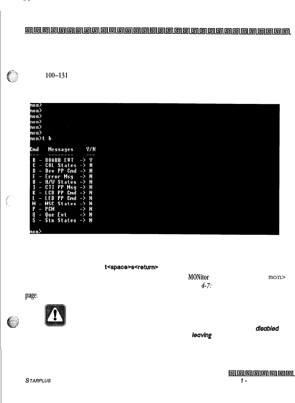
I
.--.
Maintenance and Troubleshooting
4-15
Remote System Monitor
lnllrrllmltsrllnll;ill~llnl~lI;rll;r(l~l~lllill~l~l~l~ltjtltnl~llnlIrill~lLsll~l~l~lI;ill~l~llsl~
3
Enter the specific board, CO line or Station number of the trace desired or type [all], if
all boards, CO lines or Stations events are desired.
001-012
= CO Line port
loo-131
= Station location
All = All Boards, CO lines or Stations
4
Press [Enter] to enable the trace. A screen similar to the following displays:
Figure
4-6: Enable Event Trace
5
To disable or turn off a particular trace mode, do not enter a specific board, CO Line or
Station Number (i.e.,
t<space>s<return>
to disable station event trace).
To have event traces displayed on the screen, you must first exit the
MONitor
mode by typing
x
at the
man>
prompt. After you exit the event(s), the trace begins as shown in Figure 4-7: Event Truce on the following
page-
Unless instructed by personnel at Vodavi Technical Support, do not leave
the trace mode enabled for extended time periods. The system dumps the
requested event(s) trace which may use up paper or fill memory buffers on
the collecting device. It is recommended that the trace events be disab/ed
(turned off) for all event(s) traces before
leav/ng
the system site unless
otherwise instructed by Technical Support.
STARPLUS
Triad-S Installation Manual
brllurllr5WiWilll!5lll5llurii
Issue
I-
December 1998
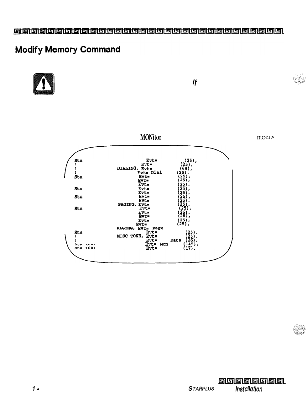
4-16
Maintenance and Troubleshooting
Remote System Monitor
The Modify Memory Command is for
engineering use
only.
Use of this command can alter or damage the Triad-S System operating
database which can result in system malfunction.
If
this
occurs, it is necessary
to power the system down and re-initialize the database, then complete/y
reprogram the customer data.
Exit the Monitor Mode
The Exit command terminates the current Monitor enable/disable session. If Event(s) Trace was or is still
enabled, event records display only after exiting the
MONitor
mode. The Exit command format is:
man>
X
\
sta
100: State- DIAL-TONE.
Evt-
Dial Pad
(25).
Data-7
Sta 100: State- DIALING,
F&z=
Dial Pad
(25).
Data-5
Sta 100: State-
DIALINQ,
Evt-
Int Page
(69).
Data-S
Sta 100: State- PAGING,
Evt-
Dial
Pad
(25).
Data-3
Sta
100: State- PAGING,
Evt-
Dial Pad
(25).
Data-9
Sta 100: State- PAQING,
E"t-
Dial Pad
(25).
Data-5
sta 100: state- PAGING,
Evt-
Dial Pad
(25).
Data-S
sta
100: state- PAGING,
Evt-
Dial Pad
(25).
Data-7
sta 100: state- PAGING,
Evt-
Dial Pad
(25).
Data-4
sta
100: State- PAGING,
Evt-
Dial Pad
(25),
Data-3
Sta 100: State- PAGING,
Evt-
Dial Pad
(25),
Data-9
Sta 100: State-
PAGINGS,
Evt-
Dial Pad
(25).
Data-9
sta
100: state- PAGING,
Evt-
Dial Pad
(25).
Data-9
sta 100: State- PAGING,
EWt-
Dial Pad
(25).
Data-7
Sta 100: State- PAGING,
Evt-
Dial Pad
(25,.
Data-11
Sta 100: State- PAGING,
Evt-
Dial Pad
(25).
Data-3
Sta 100: State- PAGING,
Evt-
Dial Pad
(25).
Data-2
Sta 100: State-
PAGINQ,
Evt-
Page
T/O (150). Data-0
sta
100: State- MISC-TONE.
Evt-
Dial Pad
(25).
Data-4
sta 100: State-
PISC-TONE, Evt-
Dial Pad
(25).
Data-9
sta 100: State- MISC-TONE,
Evt-
Key
Data
(26).
Data-32
sta 100: state- MISC-TONE,
Evt-
Man
Key
(145).
Data--l
State- MISC-TONE,
Evt-
On Hook
(17).
Data-O
/
Figure
4-7:
Event Trace
Issue
7
-
December 7998
i.5ilinllr;lllnl~l~ll5ll~l”
STARPLUS
Triad-S
installation
Manual

System Programming Manual
issue 1
December 1998
Part Number: 5050-13

LIFE SUPPORT APPLICATIONS POLICY
VODAVI Communications Systems products are not authorized for and should not be
used within Life Support applications. Life Support systems are equipment intended
to support or sustain life and whose failure to perform when properly used in accor-
dance with instructions provided can be reasonably expected to result in significant
personal injury or death.
VODAVI Communications Systems warranty is limited to replacement of defective
components and does not cover injury to persons or property or other consequential
damages.
Copyright
0
1998 VODAVI Communications Systems, Inc.
All Rights Reserved
This material is copyrighted by VODAVI Communications Systems. Any unauthorized repro-
ductions, use or disclosure of this material, or any part thereof, is strictly prohibited and is a
violation of the Copyright Laws of the United States (17 U.S.C. Section 101 et. seq.).
VODAVI reserves the right to make changes in specifications at any time and without
notice. The information furnished by VODAVI in this material is believed to be accurate and
reliable, but is not warranted to be true in all cases.
DvxpLY@
*
IS
a Registered trademark of VODAVI Communications Systems, Inc.
STARPLUS'"
is a Registered trademark of VODAVI Communications Systems, Inc.
Triad4Ph*
is a Registered trademark of VODAVI Communications Systems, Inc.

_
i
;,:.;.
:
2’
.’
’
-_
Customer Database Programming
Introduction
.....................................
Program Mode Entry (Key Station)
....................
Program Mode Entry (Data Terminal or PC)
............
Initialization
.....................................
Customer Data Worksheets
..........................
Database Fields
...................................
Database Upload/Download Routine
..
:
................
Upload/Download through Remote Administration , .
.
.
.
.
.
.
*
2System Parameters Programming
Sys tern Timers
..............................................
System Hold Recall Timer
.................................
Exclusive Hold Recall Timer
...............................
Attendant Recall Timer
...................................
Transfer Recall Timer
....................................
Preset Forward Timer
....................................
Call Forward
/
No Answer Timer
............................
PauseTimer
...........................................
Call Park Recall Timer
...................................
Conference
/
DISA Timer
.................................
Paging Time-out Timer
...................................
CO Ring Detect Timer
....................................
SLT DTMF Receiver Timer
................................
Message Wait Reminder Tone
..............................
SLT Hook Flash Timer
...................................
SLT Hook Flash Debounce Timer
...........................
SMDR Call Qualification Timer
.............................
Automatic Call Back Timer
................................
Reminder Ring Timer
....................................
Release Guard Timer
....................................
Inter-Digit Time-out
.....................................
Additional System Timers
......................................
Repeat Redial Timer
.....................................
...............
2-l
...............
2-3
...............
2-3
..............
2-4
..............
2-4
..............
2-5
..............
2-5
..............
2-6
..............
2-7
..............
2-7
..............
2-8
..............
2-9
..............
2-9
.............
2-10
.............
2-10
.............
2-11
.............
2-12
.............
2-13
.............
2-13
.............
2-14
.............
2-14
.............
2-15
.............
2-16
STARPLUS
Triad-S System
Programming Manual
ii
Attendant Display Timer
...............................................
,2-17
Call Coverage Ring Timer
..............................................
.2-18
Modem Answer Timer
................................................
.2-18
Pulse Dial Inter-Digit Timer
............................................
DTMF On/Off Time Operation .2-19
..........................................
,2-19
System Features 1 Programming
.............................................
.2-20
Attendant Override
...................................................
,2-22
Hold Preference
.....................................................
.2-22
External Night Ring
..................................................
.2-23
Executive Override Warning Tone
........................................
.2-23
PageWarningTone....................................................2-2
4
Least Cost Routing (LCR)
..............................................
.2-25
Account Codes
-
Forced
...............................................
,2-26
GroupListening
....................................................
..2-2 6
IdleSpeakerMode
..................................................
..2-2 7
Call Cost Display Feature
..............................................
.2-27
Music On Hold
......................................................
.2-28
Call Qualifier Tone Option
.............................................
.2-28
System Features 2 Programming
.............................................
.2-29
Distinctive CO Ringing
................................................
Verified Account Codes .2-32
................................................
.2-32
Call Forward Display
..................................................
,2-33
ExternalDay
Ring.. .................................................
..2-3 4
Overflow Station Forward
..............................................
.2-34
Direct Transfer Mode
.................................................
,235
StationIDLock.......................................................2-3
5
LCRCallProgress..
.................................................
..2-3
6
One-Touch Recording Warn Tone
.......................................
,2-37
RingbackonTransfer..................................................2-3
7
Programmable Flash Rates
..................................................
,2-38
Incoming CO Line Ringing
.............................................
.2-40
Incoming Intercom Ringing
............................................
.2-40
Call Forward Button
..................................................
.2-41
Message Wait
/VM
Button
.............................................
,2-41
Message Callback
-
DSS
/
BLF
..........................................
.2-42
DoNotDisturb-DSS/BLF
.............................................
2-42
AutoCallback-DSS/BLF
.............................................
UCD Available
/
Unavailable
-
DSS
/
BLF .2-43
..................................
.2-43
kx~e
I- December 1998
STARPLUS Triad-S System Programming Manual
. .
iii
TransferCORinging
.................................................
..2-4 4
RecallCORinging
...................................................
..2-4
5
QueuedCORinging
.................................................
..2-4
5
Exclusive Hold
......................................................
.2-46
System Hold
........................................................
.2-46
In-Use Hold (I-Hold)
.................................................
.2-47
Camp-OnButton
...................................................
..2-4 7
CallbackButton
....................................................
..2-4 8
LineQueueButton..
................................................
..2-4 8
Do Not Disturb Button
................................................
.2-49
Intercom Hold Button
................................................
.2-49
System Parameters Programming.
............................................
.2-50
Leading Digit Translation
..............................................
.2-52
Leading Digit Enable
..................................................
.2-53
Centrex Digit Length
..................................................
.2-54
Four-Digit Voicemail ID
...............................................
,254
MOH Assignments
...................................................
.2-55
Attendant Station Assignment
...........................................
.2-55
System Time and Date
................................................
.2-56
PBX Dialing Codes
...................................................
.2-57
Executive
/
Secretary Pairs
.............................................
,2-57
On-Board Relay Programming
..........................................
.2-58
Baud Rate Assignments
...............................................
,259
Port#1,#2,#3BaudRates
..........................................
.2-59
AccessCodes..
..........................................................
..2-6 0
DISAAccessCode
...................................................
..2-6 1
Database Admin Password
.............................................
.2-61
Station Message Detail Recording
(SMDR)
.................................
-2-62
SMDR Enable
/
Disable
................................................
.2-62
Long Distance /All Calls
...............................................
.2-63
Character Print Assignment
............................................
.2-63
BaudRateDisplay.....................................................2-6
4
SMDR Port Assignments
...............................................
.2-64
Weekly Night Mode Schedule
...........................................
.2-65
Automatic /Manual Operation
..........................................
.2-65
Day of Week Programming
.............................................
.2-66
Directory Dialing
.....................................................
.2-66
STARPLUS Triad-S System Programming Manual Issue
I-
December 1998
iv
HuntCroups..............................................................Z-7
0
Hunt Group Programming
.............................................
.2-70
Station
/
Pilot Hunting Assignment
......................................
.2-71
Verified Account Codes Table/Traveling Class of Service
.2-72
.......................
Local Number
/
Name Translation Table
..................................
.2-74
3CO Line Attribute Programming
Page A Introduction
...................
DTMF /Dial Pulse Programming . . , ,
CO
/
PBX Programming
...........
Universal Night Answer (UNA)
......
DISA Trunk-to-Trunk (Per CO Line)
.
Privacy
........................
Loop Supervision Programming
.....
DISA Programming
..............
Line Group Programming
.........
Class of Service
..................
CO Line Ringing Assignments
.......
CO Line Identification Display
......
Trunk Direction
.................
Display Ring Assignments
..........
Page B Introduction
...................
Transmit Volume Option
..........
Preset Call Forward Destination
.....
Preset Forward Voicemail ID
.......
Universal Day Answer (UDA)
.......
Music On Hold (per CO Line)
......
Distinctive Ringing (per CO Line)
....
Page C Introduction
...................
Flash Timer
....................
Ring Delay Timer
................
Reseize Timer
...................
Guard Timer
....................
Preset Forward Timer
.............
Miscellaneous CO Parameters
...........
Dial Pulse Parameters
............
.
*
*
.
.
.
.
.
.
.
*
.
.
.
.
*
.
.
*
.
.
.
.
.
.
.
.
.
*
.
.
.
.
.
.
.
.
.
.
*
.
.
*
*
.
*
.
.
.
*
.
.
8
.
.
.
.
.
........................
3-l
........................
3-2
........................
3-2
........................
3-3
........................
3-3
........................
3-4
........................
3-5
........................
3-6
.........................
3-7
........................
3-7
........................
3-9
.......................
3-10
.......................
3-12
.......................
3-13
.......................
3-14
.......................
3-15
.......................
3-16
.......................
3-17
.......................
3-17
.......................
3-1s
.......................
3-18
.......................
3-20
.......................
3-21
.......................
3-22
........................
3-22
........................
3-23
........................
3-23
........................
3-24
........................
3-25
Issue I
-
December 1998
STARPLUS
Triad-S System Programming Manual
V
4
Station Attributes Programming
Page A Introduction
.........................................................
.4-l
-
b
::
6,:,-
ProgrammingSteps
..................................................
..4- 1
L. I,’
Description...........................................................4-
1
PagingAccess
......................................................
...4- 2
DoNotDisturb
......................................................
..4- 3
Conference Enable
/
Disable (Per Station)
..................................
.4-3
Executive Override
....................................................
.4-4
Privacy (Per Station)
...................................................
.4-5
System Speed Dial Access
...............................................
.4-6
LineQueuing
.......................................................
..4- 7
PreferredLineAnswer
................................................
..4- 7
Off-Hook Voice Over (OHVO)
............................................
-4-S
CallFonvarding........................................................4-
8
Forced Least Cost Routing (LCR)
.........................................
-4-5,
ACD Supervisor Monitor with Barge-In
.....................................
.4-9
Executive Override Blocking
............................................
.4-10
CO Line Ringing Options
...............................................
.4-l 1
Name
/
Number Display at Idle
.........................................
.4-12
PageBIntroduction
.....................................................
.,.4-l
2
Programming Steps
..................................................
.4-12
Description..........................................................4-1
3
Station Identification
.................................................
.4-14
Station ID for DSS
/
DLS Console with Map
................................
.4-14
SLTStationID........................................................4-1
6
SLT with Message Waiting Lamp Station ID
................................
.4-16
Station Day Class of Service (COS)
.......................................
.4-17
Station Night Class of Service (COS)
......................................
-4-18
Speakerphone
/
Headset
...............................................
.4-19
PickupGroup(s)......................................................4-2
0
PagingZone .....................................................
..4-2 0
Preset Call Forward
...................................................
,4-2 1
7.
c
:.; . . ;d
-./e
-1
;+.:t
s
COLineGroupAccess..................................................4-2
2
N”.S
LCR Class of Service (COS)
.............................................
.4-23
Off-HookPreference..
...............................................
..4-2 3
FlexibleButton..
...................................................
..4-2 4
KeysetMode
.......................................................
..4-2
9
Voicemail ID Translation
..............................................
.4-30
STARPLUS Triad-S System Programming Manual issue
I
-
December 1998
vi
Display Flexible Buttons
...............................................
.4-30
Cordless KTU Feature Button
...........................................
.4-33
5ICLID Route Programming
i
i
,.:
.,
Introduction
~
.1
--’
.............................................................
..5- 1
Calling Number
/
Name Display
..........................................
.5-l
Incoming Number/Name for SMDR Records
................................
,5-2
Unanswered Call Management Table
......................................
,5-2
ICLID Ringing Assignments
..................................................
.5-3
Programming Steps
...................................................
.5-3
Description...........................................................5-
4
View ICLID Ringing Assignments
.........................................
,5-5
Description...........................................................5-
6
ICLIDFeatures
...........................................................
..5- 6
Programming Steps
...................................................
.5-6
Enable/Disable.. ...................................................
..5- 7
NameinDisplay.......................................................5-
7
Baud Rate Display
....................................................
,5-8
PortAssignment.......................................................5-
8
6Automatic Call Distribution (ACD)
ACDGroupProgramming.....................................................6-
I
Programming Steps
...................................................
.6-I
Description...........................................................6-
I
Alternate ACD Group Assignment
.........................................
.6-2
ACD Overflow Station Assignment
........................................
.6-3
ACD Recorded Announcement Assignment(s) (RAN)
.........................
.6-3
ACDSupervisor........................................................6-
5
ACD Auto Wrap-Up Timer
...............................................
.6-5
ACD CIQ Threshold
...................................................
.6-6
ACD Station Assignment(s)
.............................................
.6-6
View ACD Station Assignments
...........................................
(6-8
ACDTimers................................................................6-
8
Programming Steps
...................................................
.6-8
Description..
.......................................................
..6-
9
ACDRingTimer
.....................................................
..6-
9
ACD Message Interval Timer
............................................
.6-IO
ACD Overflow Timer
..................................................
.6-IO
Issue
I- December 1998
STARPLUS Triad-S System Programming Manual
vii
ACD No-Answer Recall Timer
.....................
ACD No-Answer Retry Timer
......................
Guaranteed Message Timer
......................
ACD Announcement Tables (RAN)
......................
Programming Steps
............................
Description
...................................
PC
/
ACD Interface Trace
..............................
Programming Steps
............................
Description
...................................
Enable
/
Disable
...............................
Trace Port Assignment
..........................
Baud Rate Display
..............................
ACDGroup
........................................
Programming Steps
............................
Description
...................................
Alternate ACD Group Assignment
..................
ACD Overflow Station Assignment
..................
ACD Recorded Announcement Assignment(s) (RAN) . , ,
ACD Supervisor
................................
ACD Auto Wrap-Up Timer
........................
ACD
CIQ
Threshold
.............................
ACD Station Assignment(s)
.......................
View ACD Station Assignments
....................
7Uniform Call Distribution (UCD)
UCD Group Programming . . . . . . . . . , . , , , . . . , ,
.
*
. .
. .
.
.7-l
Programming Steps . . . . . . . . . . . . . . . . , , .
.
.*
.
.
.
.7-l
Description , . . . . . . . . . . . . . . . . . . . . . , , , .
.
.
.7-l
Alternate UCD Group Assignment . . . , , . . . .
.
. .
.
17-2
UCD Overflow Station Assignment . . . . . , , .
.
.
.7-3
UCD Announcement Assignment(s) (RAN) .
.
*
.7-3
UCD Auto Wrap-Up Timer . . . . . . . . , , , , . . .
.
* *
.
.7-4
UCD Station Assignment(s)
. . . , . , , , , . . . .
.
.
.7-4
UCD Timers . . . . . . . . . . . . . . . . . . . . . , . , , , . . . . .
.
. .
.
.7-6
Programming Steps . . . . . . . . . . . . . . . , , , .
.
*
.7-6
Description . . . . . . . . . . . . . . . . . . . . . . , , , .
.
*.
.
.7-6
UCD Ring Timer . . . . . . . . . . . . . . . . . . , , . .
.
.
-7-6
UCD Message Interval Timer . . . . . . . . . . , , .
.
..
.
*
7-7
.
.
.
.
.
.
S
JARPLUS
Triad-S System Programming Manual Issue
I
-
December 7998
*
.
.
.
.
.
.
.
.6-11
.6-12
.6-12
.6-14
.6-14
.6-15
96-15
.6-15
.6-15
.6-16
.6-16
.6-17
.6-17
.6-17
.6-1s
.6-19
.6-19
.6-20
.6-21
36-22
.6-22
.6-23
.6-24
. . .
VIII
UCD Overflow Timer . . . , . . .
UCD No-Answer Recall Timer
UCD No-Answer Retry Timer
UCD Announcement Tables (RAN) .
Programming Steps . . . . . . ,
Description . . . . . . . . . . , , . .
.
.
.
.
*
.
*
.
.
.
.
*
.
.
.
.
.
*
.
.
.
.
*
*...
*.,,,..
7-8
.
.
.
.
...*....
7-8
8 Voicemail Groups
Voicemail Programming
.....................................................
.8-l
Programming Steps
...................................................
.8-
1
Description...........................................................8-
1
Alternate Voicemail Group
..............................................
.8-2
Leave Mail Index Entry
.................................................
.8-3
Retrieve Mail Index Entry
...............................................
.8-3
Station Assignment(s)
.................................................
,8-4
Voicemail Outpulsing Table
..................................................
,8-5
Voicemail In-Band Signaling
............................................
.8-5
Voicemail Disconnect Table
.............................................
.8-7
Voicemail In-Band Features
..................................................
.8-8
Programming Steps
...................................................
.8-8
Description...........................................................8-
8
Voicemail In-Band Digits
...............................................
.8-8
Voicemail Transfer
/
Forward
............................................
.8-9
Voicemail Broker
.....................................................
.8-9
Voicemail Index Table
......................................................
.8-10
Description
.........................................................
.8-l
1
9 Exception Tables
Exception Tables Programming . . . . . . . . . . . . . . . . . . . . . . . . . . , , . . . , . . , , . . , , . . . , . . .
,9-l
RELATED ITEMS TO TOLL RESTRICTION . . . . . . . . . . . . . . . . . . . . . . . . . . . . . . . . . . . . . . . . .9-3
CO/PBXLines
. . . . . . . . . . . . . . . . . . . . . . . . . . . . . . . . . . . . . . . . . . . . . . . . . . . . . . ...9-3
Forced Account Codes . . . . . . . . . . . . . . . . . . . . . . . . . . . . . . . . . . . . . . . . . . . . . . . . .
.9-3
SLT DTMF Receivers . . . . . . . . . . . . . . . . . . . . . . . . . . . . . . . . . . . . . . . . . . . , . . . . . . .
.9-3
LCR Versus Toll Restriction . . . . . . . . . . . . . . . . . . . . . . . . , . . . . . . . . . . . . . . . . . , . .9-4
Toll Restriction . . . . . . . . . . . . . . . . . . . . . . . . . . . . . . . . . . . . . . . . . . . . . . . . . . . . . . . . . . , . .9-4
Entering Toll Table . . . . . . . . . . . . . . . . . . . . . . . . . . . . . . . . . . . . . . . . . . . . . . . . . . . . .9-4
Allow
Table .
a
. . . . . . . . . . . . . . . . . . . . . . . . . . . . . . . . . . . . . . . . . . . . . . . . . . . . . . . .9-6
DenyTable . . . . . . . . . . . . . . . . . . . . . . . . . . . . . . . . . . . . . . . . . . . . . . . . . . . . . . . . ...9-8
Issue
I-
December 1998 STARPLUS Triad-S System Programming Manual
SpecialTable..........................................................9-
9
Display Toll Table Entries
..............................................
.9-l 1
::-:z
10 Least Cost Routing
ye.-
Introduction . . . . . . . . . . . . . . . . . . . , , ,
LCR Operation . . . . . . . . . . . . . .
LCR Tables . . . . . . . . . . . . . . . . . . . . . ,
Programming Steps . . . . . . . . . . .
3Digit Area
/
Office Code Table
. .
6-Digit Office Code Table . . . . . . ,
Exception Code Table . . . . . . . . . ,
Route List Table . . . . . . . . . . . , , ,
Insert /Delete Table . . . . . . . . . . .
Daily Start Time Table
. . . . . . . . .
Weekly Schedule Table . . . . . . . , .
LCR Routing for Toll Information ,
Default LCR Database . , . . . . . . . .
11 initialize Database Parameters
Introduction . . . . . . . . . . . . . . . . . . . . . . . . . . . . . , .
Programming Steps . . . . . . . . . . . . . . . . . . . . ,
Description . . . . . . . . . . . . . . . . . . . . . . . . . . . ,
Initialize System Parameters . . . . . . . . . . . . . ,
Initialize CO Line Attributes . . . . . . . . . . . . . . .
Initialize Station Attributes .
I
. . . . . . . . . . . . ,
Initialize CO
/
Station Port Parameters . . . . , . .
Initialize Exception Tables . . . . . . . . . . . . . , . ,
Initialize System Speed Numbers . . . . . . . . . . ,
Initialize LCR Tables . . . . . . . . . . . . . . . , , , , , .
Initialize ICLID Tables
. . . . . . . . . . . . . . . . , . ,
Initialize Directory Dialing Table Parameters . .
Initialize Hunt Group Parameters . . . . . . . , , , ,
Initialize ACD
/
UCD Group Parameters . . , , , ,
Initialize Voicemail Group Parameters . . , . , , .
Initialize Verified Account Code Table . . . . . . . ,
System Reset. . . . . . . . . . . . . . . . . . . . . . . . . . .
.
.
*
*
*
.
.
.
.
.
.
.
.
*
.
*
.
.
.
.
.
.
.
.
.
.
*
.
.
.
.
.
.
.
.
,
,
.
.
.
.
.
.
,
. .10-l
.
*10-l
.
. lO-4
.
-10-4
.
.lO-5
.
.10-6
.
.lO-7
.
.lO-7
.lO-10
-10-12
.lO-13
*
10-14
-10-15
.
.
.
.
.
11-l
*
. . . . 11-l
. .
*
. . 11-l
. . . . . 1 l-2
.
*
*
. .
11-8
. . . . 11-10
. * * *
11-12
. . . , 11-12
. . . . 11-14
. . . . 11-14
. .
*
9
11-16
.
*
*
.
11-17
. .
>
.
11-18
.
*
*
.
11-19
. . . . 11-21
. . . . 11-22
. . . . 11-23
STARPLUS Triad-S System Programming Manual Issue
I-
December 1998
I
X
12 Print System Database Parameters
Introduction
............................................................
..12- 1
Print Database Parameters
.............................................
.12-l
Print System Parameters
..............................................
.12-2
Print CO Line Attributes
...............................................
.12-5
Print Station Attributes
................................................
.12-7
Print CO /Station Port Parameters
.......................................
.12-9
Print Exception Tables
...............................................
,12-10
Print System Speed Numbers
..........................................
,12-12
Print
LCRTables
....................................................
.12-13
Print Entire System Database
..........................................
.12-26
Print ICLID
-
DID Tables
.............................................
.12-27
Print Directory Dial Table Parameters
....................................
12-31
Print Hunt Group Parameters
.........................................
.12-33
Print ACD
/
UCD Group Parameters
.....................................
,12-34
Print Voicemail Group Parameters
.......................................
la-35
Print Verified Account Codes
..........................................
,123
AbortPrinting.......................................................12-4
1
Issue
7
-
December 1998 STARPLUS Triad-S System Programming Manual
xi
Data Terminal Program Codes Cross Reference
..........................................
l-3
Programming Button Mapping
.......................................................
l-3
HookSwitchActivity...............................................................2-1
1
LCRFlowchart
................................................................
..lO- 3
Daily Start Time and Weekly Schedule Tables
..........................................
lo-13
Daily and
WeeMy
Start Time Table
........
LCR Toll Information Routing Program Form
System Parameters
....................
CO Line Attributes
.....................
Station Attributes
.....................
CO /Station Port Attributes
..............
Exception Tables
................
System Speed Numbers
..........
LCR Tables
....................
3-Digit
Table Defaults
............
ICLID /DID Tables
..............
Directory Dialing Table
...........
Hunt Group Parameters
..........
ACD Group Parameters
...........
Voicemail Group Parameters
......
DID
-
TIE Parameters
............
Verified Account Codes
...........
.
.
.
.
.
.
.
.
.
.
.
.
*
.
.
.
.
.
1
1
1
o-14
o-15
12-3
12-6
12-8
2-10
12-12
12-14
12-15
12-17
12-29
12-41
12-42
12-44
12-46
12-47
12-49
STARPLUS Triad-S System Programming Manual
Issue I- December 1998
xii
Default Values
..........................
System Timers Defaults
...................
Additional System Timers Defaults
...........
System Features 1 Defaults
................
System Features 2 Defaults
................
Flash Rates
.............................
Dial Pad Keys.
...........................
CO Line Conference Flag.
..................
CO Line Privacy Flag
......................
Class of Service (COS)
.....................
RingingTones
...........................
Default DID and ICLID Table Entries
.........
Station Privacy Flag
......................
Class of Service (COS)
....................
Flex Button Codes for Remote Programming , , .
Flex Button Display Designations
............
Allow
/
Deny Table
.......................
LCR Class of Service Table
.................
System Parameter Defaults.
................
CO Line Attribute Defaults
.................
Station Attribute Defaults
..................
CO Port Defaults
.........................
Station Port Defaults
......................
Exception Table Defaults
..................
LCR Table Defaults
.......................
ICLID
-
DID Table Defaults
.................
Directory Dialing Table Defaults
.............
Hunt Group Defaults
.....................
ACD
/
UCD Group Defaults
.................
Voicemail Group Defaults
..................
DID
-
TIE Defaults
.......................
Verified Account Code Table Defaults
.........
Issue I- December 1998
STARPLUS
Triad-S System Programming Manual
*
.
*
.
.
.
.
.
.
.
.
.
.
*
.
.
.
.
.
.
*
.
.
.
.
.
.
.
.
,
.
.
.
.
*
.
.
,
*
.
.
.
.
.
.
.
*
.
.
.
*
.
.
.
.
.
.
*
.
*
*
.
.
.
.
.
*
*
2-15
.
*
*
.
2-20
, .
*
.
2-29
. . . . 2-38
,
*
. .
2-68
, . . . . 3-4
. . .
*
.
3-5
. . . . . 3-8
. . . .
3-18
. . . .
3-29
. .
*
*
.
4-6
*
*
. .
4-18
. , . .
4-26
. . . . 4-31
. ,
*
*
.
9-2
. . .
10-10
. . . . 11-3
. , . . 11-7
*
. .
*
11-q
. ,
.ll-11
*
. . 11-12
. .
*
11-13
. . . 11-15
. .
*
11-16
*
. .
11-17
*
. . 11-18
. .
*
11-19
. . .
1 l-20
. .
*
11-22
. .
11-23
w-
.:.;
.Q
c
“..
-
,.~.
.
..-
.
.“”
Introduction
The
STARPLUS
Triad-S’”
Digital Hybrid Telephone System is programmed to meet each customer’s
individual needs.
All
programming is done at Station
100
using the digital telephone as the programming
station through an ASCII terminal or PC. The digital display model is required for programming,
When the programming mode is entered, the digital telephone being used no longer operates as a telephone
but as a programming station with all of the buttons redefined. The keys on the dial pad are used to enter
data fields (Program Codes) associated with system, station, and CO line features as well as specific data that
requires a numeric entry. Flexible buttons toggle on or off features, or enable entry of specific data fields,
LEDs
and the LCD display provide a visual indication of entered data and their value.
Programming is also performed using an ASCII terminal, or a computer capable of emulating an ASCII
terminal. This form of programming is done locally (on-site) by connecting the terminal directly to the
RS-
23X connector on the Miscellaneous Service Unit (MISU) or is performed remotely (off-site) through the
use of the optional
9600
baud modem. The method and steps to program the system via a PC are identical to
those used when programming from a digital key set. A button to keyboard mapping is provided (see Figure
2-1; Programming Button Mapping) to help minimize familiarization and training time.
The system must be initialized to load default data into memory at the time of installation. If this pre-
programming is acceptable to the customer, initialization is all that is needed. Refer to Table
Z-1:
Dejkdt
values for a listing of all the default values.
When features are programmed, tones are provided to determine if a correct or incorrect entry has been
made. A solid one second tone indicates the data was accepted. An interrupted tone means an error was
made. When this occurs, re-enter the data and information. Until new data is entered and accepted, the
system continues to operate under default or previously entered values.
The system database is updated on a real-time basis as new data is entered, by pressing the Hold button. The
system continues to operate with the current database and is updated with any newly entered or changed
data without interruption to telephone operation or call processing in progress, However, if for example a
station’s attributes are changed while that station is off-hook on an active call, the newly entered data does
not take effect until the station goes on-hook or becomes idle.
When using a PC to program the system, the following chart presents the data terminal characters that are
equivalent to the key set buttons.
issue 1
-
December 1998
STARPLUS
Triad-S System Programming Manual
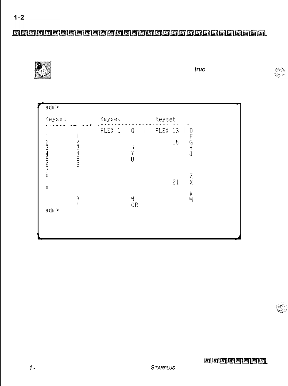
Customer Database Programming
Introduction
Some features must have more than one data field programmed for that
feature to work. This information is stated in the ins
true
tions.
adm>
1
REMOTE ADMIN KEY DEFINITION
Keyset Term Keyset Term Keyset Term
_
_
_
_
_
_
-
_
_
0
:
i
z
L
9
*
#
TRANS
FLASH
adm>
_
-
_
_
-
-
_
0
:
i
z
7
F~Ex-J---a------FLEx-i3---~--
FLEX
2
W
FLEX
14
FLEX
3 E
FLEX
15 k
FLEX
4
FLEX
5
:
FLEX
16FLEX 17
JH
FLEX
6
FLEX
18 K
FLEX
7
:
FLEX
19
L
FLEX
8
I
FLEX
20
:
8
FLEX
9
0
FLEX
2i
9
FLEX 10
P
FLEX 22
s
*
FLEX
11
AFLEX 23
C
#
FLEX 12
S
FLEX
24
I3
MUTE !R ON-OFF
L
‘
HOLD
Figure 2-l: Data Terminal Program Codes Cross Reference
Issue
I-
December 7998
STARPLUS
Triad-S System Programming Manual
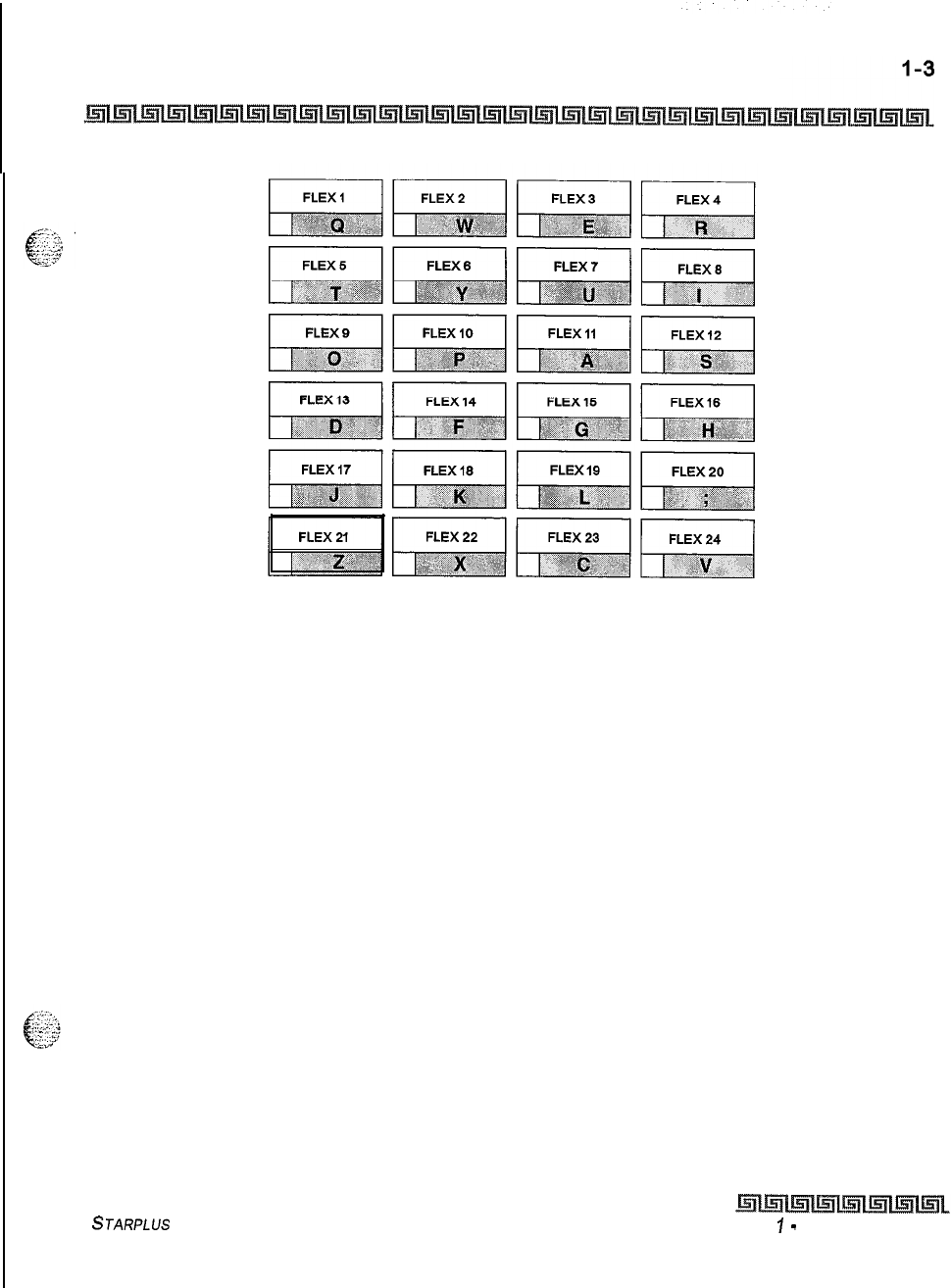
Customer Database Programming
Introduction
Figure 2-l: Programming Button Mapping
STARPLUS Triad-S System Programming Manual Issue
I
-
December 1998
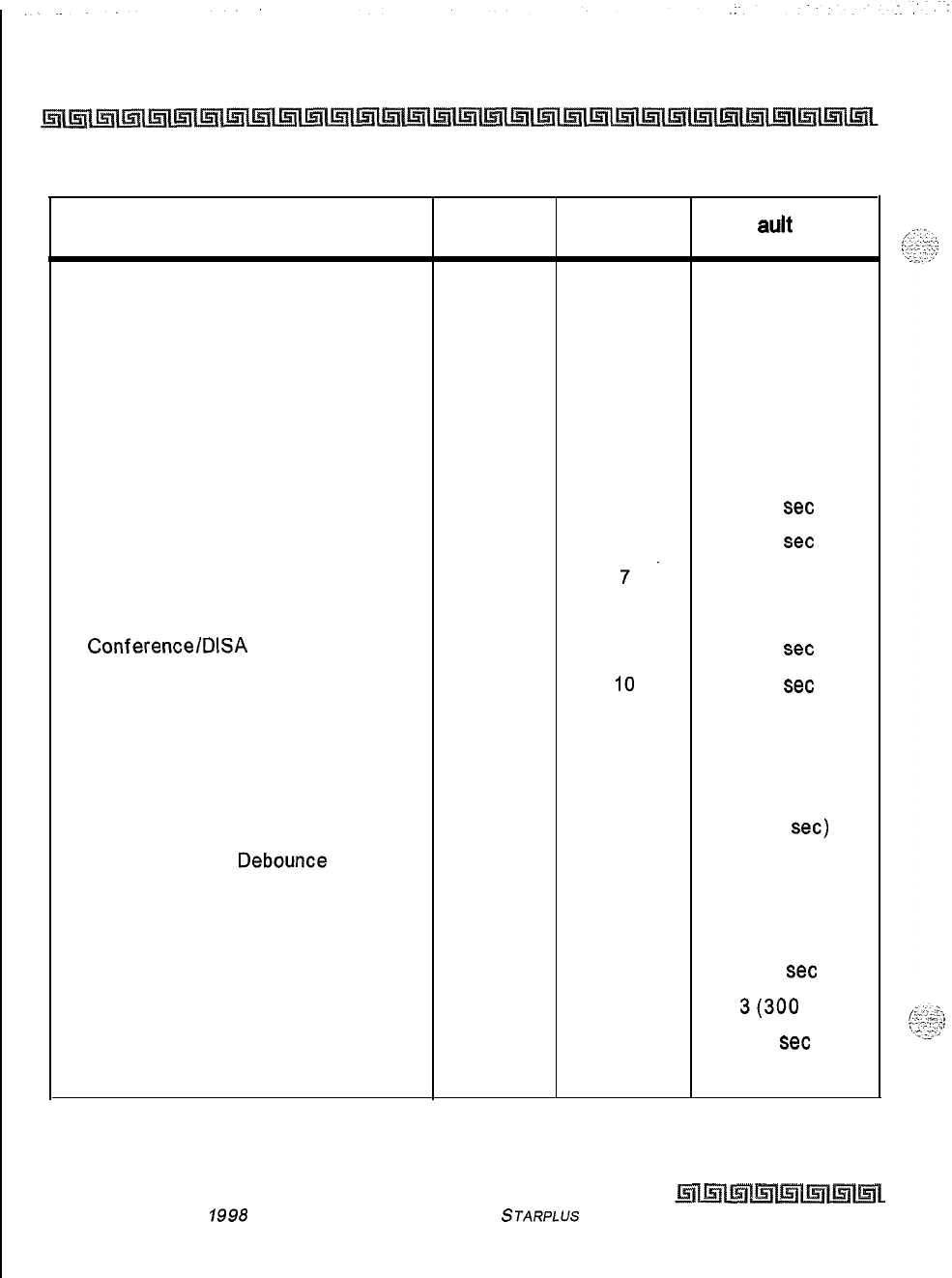
l-4
Customer Database Programming
Introduction
Features Program
Code Flex Button Def auk Value
SYSTEM PARAMETERS
PROGRAMMING
SYSTEM TIMERS FLASH 01
System Hold Recall Timer
1
060sec
Exclusive Hold Recall Timer
2
180sec
Attendant Recall Timer
301 min
Transfer Recall Timer
4
045sec
Preset Forward Timer
5
10
set
Call Forward No/Answer Timer
6
15 set
Pause Timer
7.
2sec
Call Park Recall Timer
8
180sec
Conference/DISA
Timer
9
10
set
Paging Time-out Timer
10
15
set
CO Ring Detect Timer
11
3 (100 ms)
SLT DTMF Receiver Timer
12
020
Message Wait Reminder Tone
13
000 min
SLT Hook Flash Timer
14 10 (1
set)
SLT Hook Flash
Debounce
Timer
15 100 ms
SMDR Call Qualification Timer
16
30sec
Automatic Call Back Timer
17
03sec
Reminder Ring Timer
18
00
set
Release Guard Timer
19
3(300
ms)
Flexible Inter-Digit Time-out 20 5
set
ADDITIONAL SYSTEM TIMERS FLASH 02
* Features available with Optional Software
Table 2-1: Default Values
Issue I- December
1998 STARPLUS Triad-S System Programming Manual
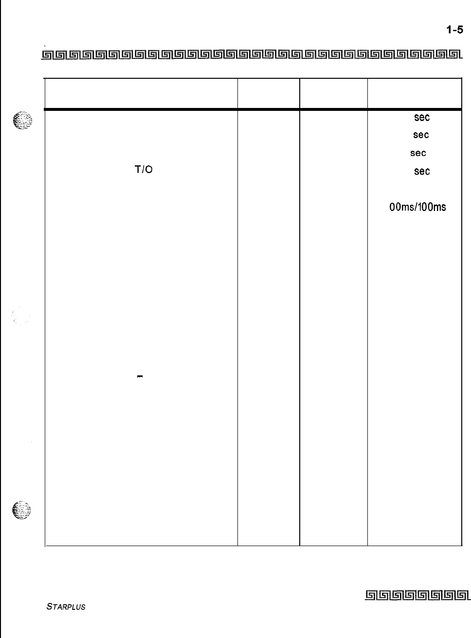
Customer Database Programming
Introduction
Features Program
Code Flex Button Default Value
Repeat Redial Timer
1
60
set
Attendant Display Timer
2
01
set
Call Coverage Ring Timer
3
5
set
Modem Answer
T/O
4
25
set
Pulse Dial Inter-Digit Timer
5
300 ms
Programmable DTMF Time Operation
61 OOms/l OOms
SYSTEM FEATURES 1 FLASH 05
PROGRAMMING
Attendant Override
1
Disabled
Hold Preference
2System
External Night Ring
3Disabled
Executive Override Warning Tone
4
Enabled
Page Warning Tone
5
Enabled
Background Music
6
Enabled
Least Cost Routing
7Disabled
Account Codes
-
Forced
8Disabled
Group Listening
9Disabled
Idle Speaker Mode
10 Disabled
Call Cost Display Feature
11
Disabled
Music-On-Hold
12
Enabled
Call Qualifier Tone Option
13 Disabled
SYSTEM FEATURES 2 FLASH 06
PROGRAMMING
Barge-In/Privacy Release Tone
1
Enabled
Option
Distinctive CO Ringing
2
Enabled
* Features available with Optional Software
Table 2-l: Default Values
STARPLUS
Triad-S System Programming Manual
Issue I- December 7998
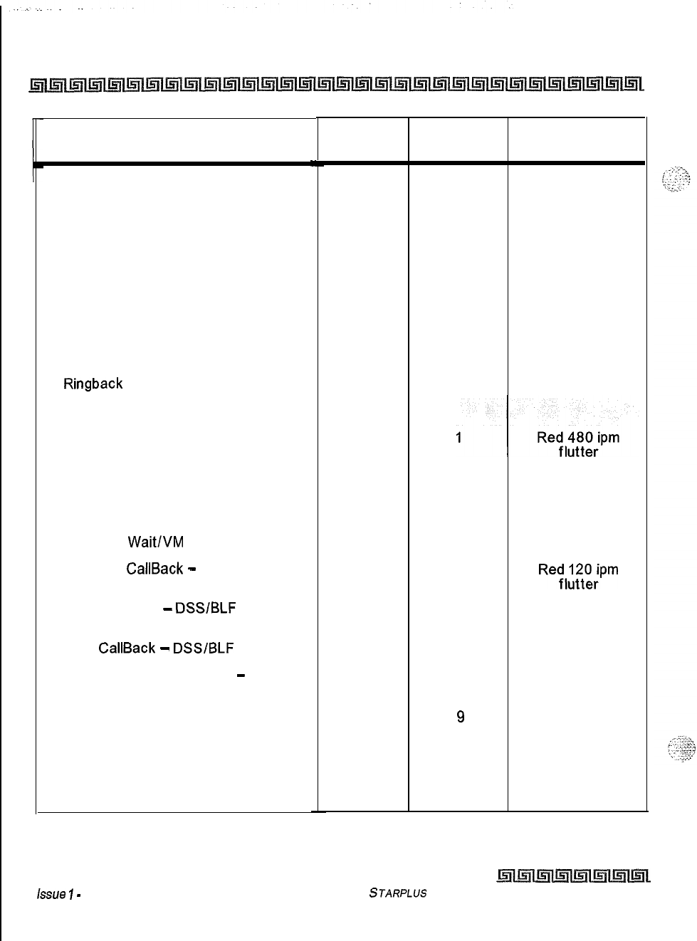
l-6
Customer Database Programming
Introduction
Features
Verified Account Codes
Call Forward Display
External Day Ring
Overflow Station Forward
Direct Transfer Mode
Station ID Lock
LCR Progress
One-Touch Recording Warn Tone
Ringback
on Transfer
FLASH RATES (Programmable)
Incoming CO Line Ringing
Program
Code Flex Button Default Value
.I
3
Disabled
4
Enabled
5
Disabled
6
Disabled
7
Enabled
8
Disabled
9
Enable
10
Enable
12 Disable
FLASH 07
Incoming Intercom Ringing
2
Red 120 ipm
flutter
Call Forward Button
3
Red Steady On
Message
Wait/VM
Button
4
Red Steady On
Message
CallBack
-
DSS/BLF
5
Reyl;‘Q;;pm
Do Not Disturb
-
DSSlBLF
6
Red 60 ipm Dbl
Wink
Auto
CallBack
-
DSS/BLF
7
UCD Available/Unavailable
-
DSS/BLF
8
Red 120 ipm flash
Red 60 ipm Dbl
Wink
Transfer CO Ringing
Recall CO Ringing
9
10
11
Red 120 ipm flash
Red 480 ipm
flutter
Queued CO Ringing Green 480 ipm
flutter
* Features available with Optional Software
Table 2-l: Default Values
Issue
7
-
December 1998
STARPLUS Triad-S System Programming Manual
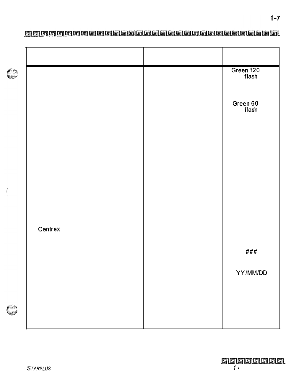
Customer Database Programming
Introduction
Features Program
Code Flax Button Default Value
Exclusive Hold
12
Gree;d;hO
ipm
System Hold
13
Red 60 ipm Dbl
wink
In Use Hold (I-Hold)
14
Greefraz;
ipm
Camp-On Button
15
Red 120 ipm flash
Call Back Button
16
Red 120 ipm flash
Line Queue Button
17
Red 480 ipm
flutter
Do Not Disturb Button
18
Red Steady On
Intercom Hold Button
19
Red 15 ipm flash
SYSTEMPARAMETERS FLASH 09
PROGRAMMING
Leading Digit 1
1
Leading Digit
Leading Digit 2-7 2-7 None
Leading Digit Option
8Disabled
Centrex
Digit Length
9
4 digits
Four Digit Voicemail ID
10 3 digits
MOH Assignments Channels 3-8 13-18
###
ATTENDANT STATION ASSIGNMENT FLASH 10 STA 100
SYSTEM TIME AND DATE
FLASH 11
1
YY/MM/DD
HHMM
PBX DIALING CODES FLASH 12 None
EXECUTIVE/SECRETARY PAIRS FLASH 13 l-4 None
ON BOARD RELAY PROGRAMMING FLASH 14 l-2 None
BAUD RATE ASSIGNMENTS FLASH 15
* Features available with Optional Software
Table 2-l: Default Values
STARPLUS
Triad-S System Programming Manual Issue
I
-
December 1998
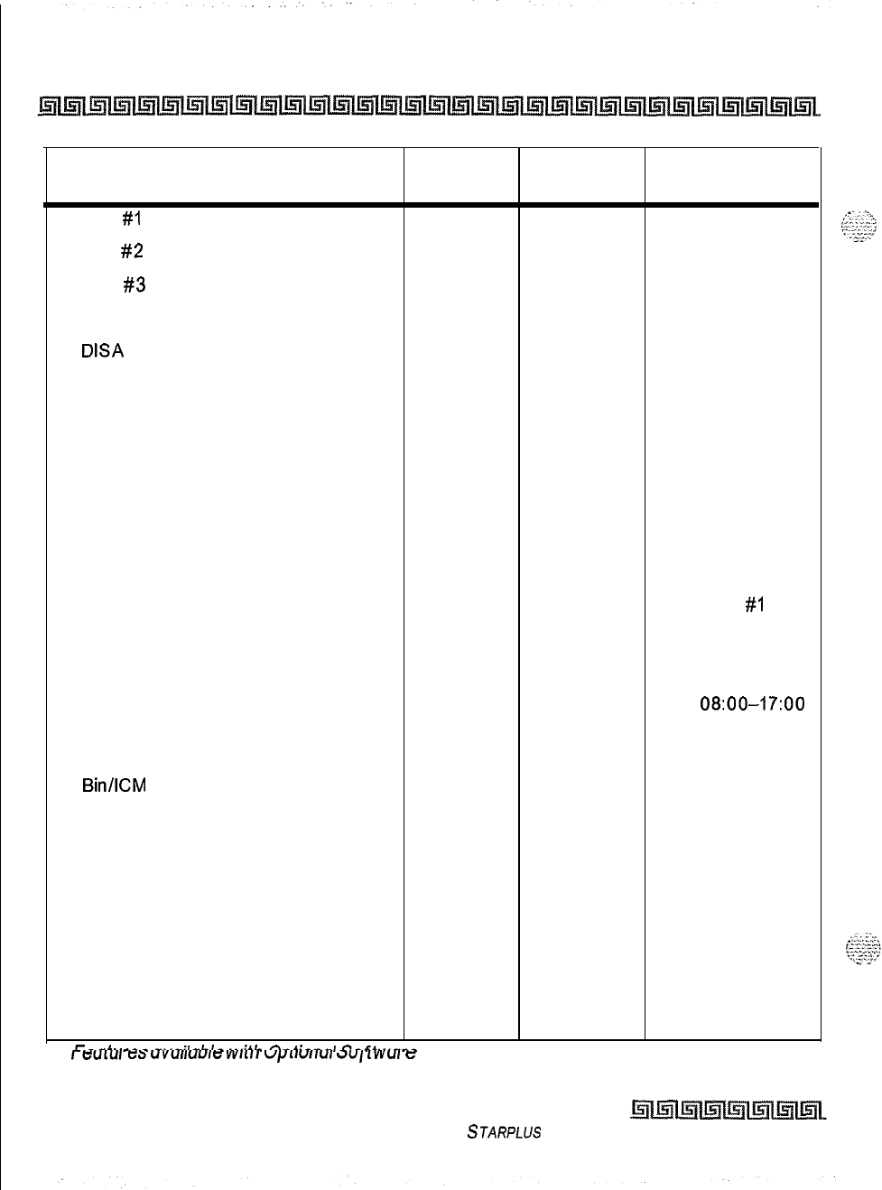
l-8
Customer Database Programming
Introduction
Features Program
Code Flex Button Default Value
Port
#I
(MISU)
1
9600 Baud
Port
#2
(MISU)
2
9600 Baud
Port
#3
(Modem)
3
9600 Baud
ACCESS CODES FLASH 20
DISA
Access Code
1
100
Database Admin Password
2
3226
STATION MESSAGE DETAIL
FLASH 21
RECORDING
SMDR Enable/Disable
1
NO
Long Distance/All Calls
2
Long Distance
Character Print Assignment
3
80
Baud Rate Display 49600
SMDR Port Assignments
5
Port
#I
WEEKLY NIGHT MODE SCHEDULE FLASH 22
Automatic/Manual Operation
1
Manual (NO)
Day of Week Programming 2-8 O-4
08:00-17:00
5-6 ####-####
DIRECTORY DIALING FLASH 23
Bin/lCM
1
None
Name
2
None
Clear
3
None
HUNT GROUPS FLASH 30
Hunt Group Programming
1-12
None
Station/Pilot Hunting Assignment
13 Pilot
VERIFIED ACCOUNT CODES TABLE
FLASH 31
Account Code
1
*
r--t.,,ra^
mm,-;,“I..,,.
..,;,I.
A..G..r,,
c?a61..,-rA
I-t$“LLJ,
es
“Y”,,““Ie
Wllll
“/Jrr”rr”r
J”,
lWU,
e
Table 2-l: Default Values
Issue I- December 1998
STARPLUS
Triad-S System Programming Manual
Customer Database Programming
Introduction
Features Program
Code
Class of Service
Delete Code
Erase Digits
LOCAL NUMBER/NAME
TRANSLATION
TABLE
Route Number
Phone Number
Name
Clear Entry
CO LINES ATTRIBUTES
PROGRAMMING
(Press HOLD for entire range)
PAGE A INTRODUCTION
DTMF/Dial
Pulse Programming
COlPBX
Programming
Universal Night Answer (UNA)
DISA
CO-to-CO (Per CO Line)
Privacy
Loop Supervision Programming
DISA
Programming
Line Group Programming
Class of Service (COS) Programming
CO Line Ringing Assignments
CO Line ldentif
ication
Display
* Features available with Optional Software
FLASH 55
FLASH 40
Page A
Flex Button Default Value
Button 19
1
2
3
4
5
6
7
8
9
10
11
##
None
None
None
None
DTMF
co
Enabled
Enabled
Enabled
400 ms
None
Group 1
cos 1
IOOA
Line XXX
Table 2-l: Default Values
STARPLUS Triad-S System Programming Manual Issue
I
-
December 1998
.
I-IO
Customer Database Programming
Introduction
Features Program
Code Flex Button Default Value
Trunk Direction
12
Incoming/Outgoin
9
Display Ring Assignments
13
IOOA
PAGE B INTRODUCTION FLASH 40 Button 20
Transmit Volume Option Page B
1
5 (0
dB)
Preset Call Forward Destination
2
None
Preset Forward Voicemail
3
None
Universal Day Answer (UDA)
4Disabled
Music-On-Hold (per CO Line)
5Channel 1
Distinctive Ringing (per CO Line)
6
00
PAGE C INTRODUCTION FLASH 40
Button 21
Flash Timer Programming Page C
1
10
Ring Delay Timer
20
Reseize Timer
3
200 ms
Guard Timer
4
0.5
set
Preset Forward Timer
510
MISCELLANEOUS CO PARAMETERS
FLASH 41 Button 1
Dial Pulse Parameters
1
60140
STATION ATTRIBUTES
PROGRAMMING
PAGE A INTRODUCTION FLASH 50 Button 19
Paging Access Page A
1
Enabled
Do Not Disturb
2
Enabled
Conference Enable/Disable (Per
3
Station) Enabled
Executive Override
4
Disabled
*
,Ze.-.f,,rne
a,rr.il-klr.
,.,;+h
Anfinnnl
CnFf,.rmrn
,
lz”L”I~‘3
“Y”,,“U,ci
““,‘,I
“prrvrrur
GJ”,
LYY”,~
Table 2-l: Default Values
Issue
7
-
December 1998
STARPLUS
Triad-S System Programming Manual
Customer Database Programming
Introduction
Features Program
Code Flex Button Default Value
Privacy (Per Station)
5
Enabled
System Speed Dial Access
6
Enabled
Line Queuing
7
Enabled
Preferred Line Answer
a
Enabled
Off -Hook Voice Over (OHVO)
9Disabled
Call Forwarding
IO
Enabled
Forced Least Cost Routing (LCR)
11
Disabled
ACD Supervisor Monitor with Barge-In
12 Disabled
Executive Override Blocking
13 Disabled
CO Line Ringing Options
14
Muted Ring
Name/Number Display at Idle
15
Name (Enabled)
PAGE B INTRODUCTION FLASH 50 Button 20
Station Identification
Page B
1
0 (24-Btn Key
set)
6 (SLT
w/o
MWt)
Station Day Class of Service
2
1
Station Night Class of Service
3
1
Speakerphone/Headset Programming
4 0
(Full
Speakerphone)
Pick-Up Group(s) Programming
5
1
Paging Zone(s) Programming
6
1
Preset Call Forwarding Programming
7
###
CO Line Group Access
a
1
LCR Class of Service (COS)
9 0
Off -Hook Preference Programming
IO
00
(Keyset)
* Features available with Optional Software
Table 2-l: Default Values
STARPLUS
Triad-S System Programming Manual Issue
I-
December 1998
I-12
Customer Database Programming
Introduction
Features Program
Code Flex Button Default Value
Flexible Button Programming
11
None
Key Set Mode
12
Inactive Mode
Voicemail ID Translation
13
xxxx
(Station Number)
Display Flexible Buttons
14
Cordless Key (CKTU) Button
17
00
ICLID PROGRAMMING
ICLID RINGING ASSIGNMENT(S) FLASH 43
1
None
Next ICLID Route Number
18
Previous ICLID Route Number
19
Select Route Number 20
ICLID FEATURES FLASH 56
Disable/Enable
1
No (Disabled)
Name in Display 2
NAME (Yes)
Baud Rate Display 9600
Port Assignment
4
Port
#I
AUTOMATIC CALL DISTRIBUTION*
ACD GROUP PROGRAMMING* FLASH 60
ACD Groups (550-557) Page A l-8 None
Alternate ACD Group Assignment
9
###
ACD Overflow Station Assignment
10
###
ACD Recorded Announcement
11
####
ACD Supervisor Programming
12
###
ACD Auto Wrap-Up Timer (Per
Group)
13
04
set
ACD CIQ Threshold
14
00
* Features available with Optional Software
Table 2-1: Default Values
Customer Database Programming
Introduction
Features Program
Code Flex Button Default Value
Display Stations Sta 9-16
17
None
Sta l-8
19
None
ACD TIMERS
FLASH 61
ACD Ring Timer
1
60
set
ACD Message Interval Timer
2
60
set
ACD Overflow Timer
3
60
set
ACD No-Answer Recall Timer
5
000
set
ACD No-Answer Retry Timer
6
300
set
ACD Guaranteed Message Timer
7
05
set
ACD RAN ANNOUNCEMENT TABLES* FLASH 62 l-8 ###
PClACD
INTERFACE TRACE FLASH 63
Event Trace Disable/Enable
1
No (Disabled)
Trace Port Assignment
2
Port
#I
Baud Rate Display 9600 Baud
ACD GROUP PROGRAMMING* FLASH 64
ACD Groups (558-565) Page A l-8 None
Alternate ACD Group Assignment
9
None
ACD Overflow Station Assignment
10
None
ACD Recorded Announcement
11
None
ACD Supervisor Programming
12
None
ACD Auto Wrap-Up Timer (Per
13
04
set
Group)
ACD CIQ Threshold
14 Disabled
Display Stations Sta 9-16
17
Sta l-8
19
None
*
Features available with Optional Software
Table 2-l: Default Values
STARPLUS Triad-S System Programming
Manual
issue I- December 7998
I’
Customer Database Programming
Introduction
Features
UNIFORM CALL DISTRIBUTION (UCD)
UCD GROUP PROGRAMMING
UCD Groups (550-557)
Alternate UCD Group Assignment
UCD Overflow Station Assignment
UCD Announcement Assignment(s)
UCD Station (550-557)
Assignment(s)
UCD TIMERS
UCD Ring Timer
UCD Message Interval Timer
UCD Overflow Timer
UCD Auto Wrap-Up Timer
UCD No-Answer Recall Timer
UCD No-Answer Retry Timer
UCD ANNOUNCEMENT TABLES (RAN)
VOICE MAIL GROUPS
VOICE MAIL PROGRAMMING
Voicemail
Groups(440-447)
Alternate Voicemail Group
Leave Mail Index Entry
Retrieve Mail Index Entry
Station Assignment(s)
VOICE MAIL OUTPULSING TABLE
Program
Code
FLASH 60
Page A
Page B
FLASH 61
FLASH 62
FLASH 65
FLASH 66
* Features available with Optional Software
Flex Button Default Value
l-8 None
9
None
10
None
11
None
l-8 None
1
60
set
2
60
set
3
60
set
4
04
set
5
000
set
6
300
set
1-8 None
l-8
9
10
11
12
None
###
440 = 0
440 = 1
None
Table 2-l: Default Values
issue
I-
December 1998
STARPLUS Triad-S System Programming Manual
..:‘:
__
/..^.,.
.
:.,
\-
:
:-
.
.
.
Customer Database Programming
Introduction
Features
Voicemail In-Band Signaling
Voicemail Disconnect Table
VOICE MAIL IN-BAND FEATURES
Voicemail In-Band Digits
Voicemail Transfer/Forward
Voicemail Broker
VOICE MAIL INDEX TABLE
Voicemail Group
Voicemail ID Number
FLASH 67
FLASH 68
FLASH 70
EXCEPTION TABLES PROGRAMMING
TOLL RESTRICTION PROGRAMMING
Allow Table A Programming
Deny Table A Programming
Allow Table B Programming
Deny Table B Programming
Special Table 1 Programming
Special Table 2 Programming
Special Table 3 Programming
* Features available with Optional Software
Program
Code Flex
Butt01
1
2
3-7
8
9
TblO
Pre=P7
Suf
=None
Tbl 1
Pre=P7
Suf=*
None
Tb17
Pre=P7
Suf =2
None
Enabled
Enabled
Enabled
1
2
440
1
None
2
None
3None
4
None
5
All Codes Allowed
6
All Codes Allowed
7
All Codes Allowed
Table 2-l: Default Values
n
II
Default Value
STARPLUS
Triad-S System Programming Manual Issue I
-
December 1998
I-16
Customer Database Programming
Introduction
Features Program
Code Flex Button Default Value
Special Table 4 Programming 8Home
Area Code for Special Table 1
9
Area Code for Special Table 2
10
Area Code for Special Table 3
11
Displaying Toll Table Entries
12
LEAST COST ROUTING (LCR)
PROGRAMMING
LCR TABLES PROGRAMMING FLASH 75
3-Digit Area/Office Code Table
1
See LCR Tables
6-Digit Area/Office Code Table
2
None
Exception Code Table 3See LCR Tables
Route List Table 4
Insert/Delete Table
5
Daily Start Time Table
6
Weekly Schedule Table
7
LCR Routing for Toll Information
8
00
INITIALIZE DATABASE PARAMETERS
INTRODUCTION FLASH 80
Initialize System Parameters
1
Default
Initialize CO Line Attributes
2
Default
Initialize Station Attributes
3
Default
Initialize CO/Station Port Parameters
4
Default
Initialize Exception Tables
5
Default
Initialize System Speed Numbers
6
Default
Initialize LCR Tables
7
Default
*
Features available with Optional Software
Table 2-1: Default Values
Issue I- December 1998
STARPLUS Triad-S System Programming Manual
Customer Database Programming
Introduction
Features
Initialize ICLID-DID Tables
Initialize Directory Dialing Tbl
Parameters
Initialize Hunt Group Parameters
Initialize ACD*/UCD Group
Parameters
Initialize Voicemail* Group Parameters
Initialize Verified Account Code Table
System Reset
PRINTING SYSTEM DATABASE
PARAMETERS
INTRODUCTION
Printing System Parameters
Printing CO Line Attributes
Printing Station Attributes
Printing CO/Station Port Parameters
Printing Exception Tables
Printing System Speed Numbers
Printing LCR Tables
Printing Entire System Database
Printing Directory Dial Table
Parameters
Printing Hunt Group Parameters
Printing ACD*/UCD Group
Parameters
Printing
Voicemail*
Group Parameters
Printing Verified Account Codes
Abort Printing
FLASH 85
*Features available with Optional Software
Program
Code Flex Button Default Value
8
9
10
11
12
14
20
Default
Default
Default
Default
Default
Default
1
Default
2
Default
3
Default
4
Default
5
Default
6
Default
7
Default
8
Default
10
Default
11
12
13
15
20
Default
Default
Default
Default
Table 2-l: Default Values
STARPLUS
Triad-S System Programming Manual issue
I
-
December 1998
~...
l-18
Customer Database Programming
Introduction
Features Program
Code Flex Button Default Value
LOAD DATABASE ROUTINE FLASH 86
{:;I::;,
2,
lLi5.
_i
_.
.._
._
-.z.-
-.-
.._
Upload database
1
PC Only
Download database
2
PC Only
L
* Features available with Optional Software
Table 2-l: Default Values
Issue I- December 1998
STARPLUS
Triad-S System Programming Manual
Customer Database Programming
l-19
Program Mode Entry (Key Station)
Program Mode Entry (Key Station)
Programming is performed at Station 100 (defaults to Port 01) using a 24-button Digital Display Terminal.
Programming is always done at this station regardless of the class of service or which station has been
assigned the attendant(s). Before entering the program mode, the programmer must verify that Station 100
is properly connected.
To enter the program mode:
1
Press the ON/OFF button (optional). LED lights and intercom dial tone is heard.
z
On the dial pad, press
[a]
[%I.
3
On the dial pad, enter
[3][2][2][6]*.
A confirmation tone is heard.
4
The ON/OFF button LED is lit. The system is ready to program.
* This is a defaultpassword. However, it may be changed aper entering programming.
Other telephones connected to the system continue to function normally.
Program Mode Entry (Data Terminal or PC)
A PC terminal connected to the RS-232C port on the MISU or remotely through the optional
9600
baud
modem is used for database programming. When using a data terminal (ASCII or PC capable of emulating an
ASCII terminal) on-site or locally, to program the system:
1
Press <Enter> on the terminal.
2
Enter the password
[default=3226VODAVl],
and press
<Enter>
again. Proper entry of
the password results in the
ADM>
prompt. Proceed with programming referring
toFigure
2-I: Data Terminal Program Codes Cross Rqference
for terminal characters that represent
the key set buttons. By entering [?] from the terminal, a Help screen displays.
When entering the system remotely via a PC, access to the optional
9600
baud modem is accomplished by
accessing Port
499
through a direct ringing assignment or through DISA or by being transferred to Port
499.
Initialization
The system was pre-programmed with certain features called default data (refer to
Table 2-I: Default
Values).
These features are loaded into memory when the system is initialized.
The system shouldbe initialized when installed or at any time the database
is corrupted.
STARPLUS
Triad-S System Programming
Mcrwal
issue
I- December 1998
I-20
Customer Database Programming
Customer Data Worksheets
Use the procedures below to return the system database to default values:
1
Place Switch
#l
on the BKSU in the ON position.
2
Turn the power off and on to initialize the system database to the default.
3
Once the database is initialized, place Switch
#I
in the OFF position to protect the
database.
Customer Data Worksheets
Before attempting programming, it is strongly recommended that customer data worksheets be prepared
(Refer to
Product Desription Manual, Appendix C: Customer Database Programming),
These worksheets
should become part of the permanent record of customer programming. Refer to the following sections
when preparing the worksheets.
Database Fields
The data fields set system timers, determine central office line features and Key Telephone features. When
entering CO line data and station data, be sure to enter the exact number of digits specified. The data fields
and features are further described in the following sections.
Database Upload/Download Routine
The Database Upload/Download Routine (Flash 86) provides a maintenance facility which permits the user
to download the database to a PC, when a software change is made or when the system needs to be
initialized and reprogrammed. In addition, the routine facilitates the programming of a database on an
in-
house system which is downloaded to a PC and then uploaded to a system in the field. After the system
maintenance is completed, the file saved in the PC can then be uploaded to the system.
All trace modes (SMDR,
/CL/D
Event, Maintenance Event Traces, etc.)
MUST be turned off before a download is performed!
/s-sue
7
-
December 7998
STARPLUS
Triad-S System Programming Manual
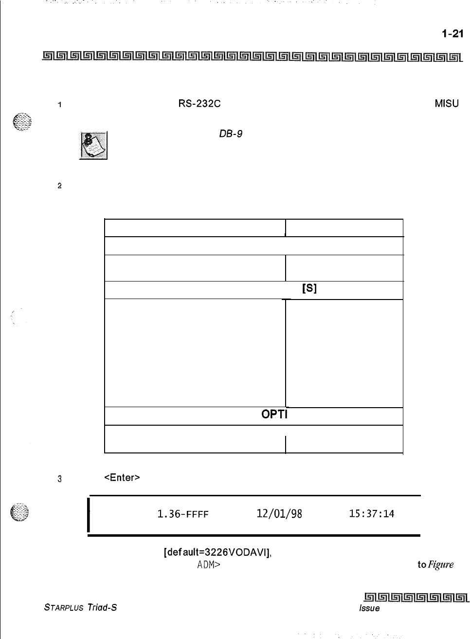
Customer Database Programming
Database Upload/Download Routine
Upload/Download through Remote Administration
1
Connect one end of an
RS232C
serial cable from the RS-232C connector on the
MISU
of the Triad-S System to the desired Comm Port on the PC.
Use a sfraighf-through
LB-9
to DB-9 (female to female) cable.
2
Load a communication software package (i.e., Procomm) into the PC. Make the
necessary changes to the following areas of the communications package. Save these
permanent settings.
Items to Change Change
Baud Rate
PARAMETERS: a + [P]
9600 Baud, N for Parity,
8 Bits, 1 Stop Bit
SETUP OPTIONS: a +
[S]
Protocol Options:
Item A: Echo Locally
Item D: Character Pacing
Item E: Line Pacing
Item F: Pace Character
Item I: CR Translation (upload)
Item J: LF Translation (upload)
Item K: CR Translation (download)
Item L: LF Translation (download)
OFF
0
0
0
NONE
NONE
NONE
NONE
ONS
I
PROTOCOL
OPTI
General Protocol Options: 1 NO
Item C:
Abort xfer if CD lost
Vote: Item C appears in Procomm Plus Version 2.01 or higher.
3
Press
<Enter>
on the PC. The following displays:
I
44 Digital Hybrid Key-System
Eng. Ver.
1.36-FFFF
DATE:
12/01/98
TIME:
15:37:14
ENTER PASSWORD:
I
4
Enter the password
[default=3226VODAVI],
and press <Enter> again. Proper entry of
the password results in the
ADM>
prompt. Proceed with programming referring
toF@m
STARPLUS Triad-S System Programming Manual issue
I- December 1998
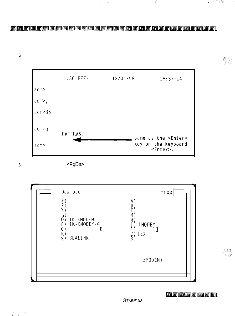
l-22
Customer Database Programming
Database Upload/Download Routine
2-I:
Data Terminal Program Codes Cross Reference
for terminal characters that represent
the key set buttons. By entering [?] from the terminal, a Help screen displays.
5
Enter the information on the following screen capture. Continue with the steps that
follow.
44 Digital Hybrid Key-System
Eng. Ver.
1.36-FFFF
DATE:
12/01/98
TIME:
15:37:14
ENTER PASSWORD:
admr
ADMIN PROGRAMMING
adm>,
ENTER PROGRAM NO
adm>86
LOAD DATABASE ROUTINE
ENTER BUTTON NUMBER
adm>q The HOLD button on
UPLOAD DATEBASE a key set is the
PRESS HOLD
+-
;;;eo;st;~ek;;;;;;;
adm>
.
Press <Enter>.
6
On the PC, press
<PgDn>
to display the Download Protocol screen. Enter X to set the
download file to use X-Modem. This introduces an error correction facility to track
errors and correct them during the download procedure.
I
Dowload
Protocols
-
X1
XMODEM
Z)
ZMODEM
Y)
YMODEM (Batch)
G)
YMODEM-G (Batch)
1
lK-XMODEM
1
lK-XMODEM-G
1
COMPUSERVE
B-t
1
KERMIT
1
SEALINK
124811648 bytes
freeE
A)
ASCII
R)
RAW ASCII
T)
TELINK
M)
MODEM7
W)
WXMODEM
I)
IMODEM
1)
CEXT
11
2)
[EXT
21
3)
CEXT 31
Your Selection: (press ENTER for ZMODEM)
Issue I- December 1998
STARPLUS Triad-S System Programming Manual
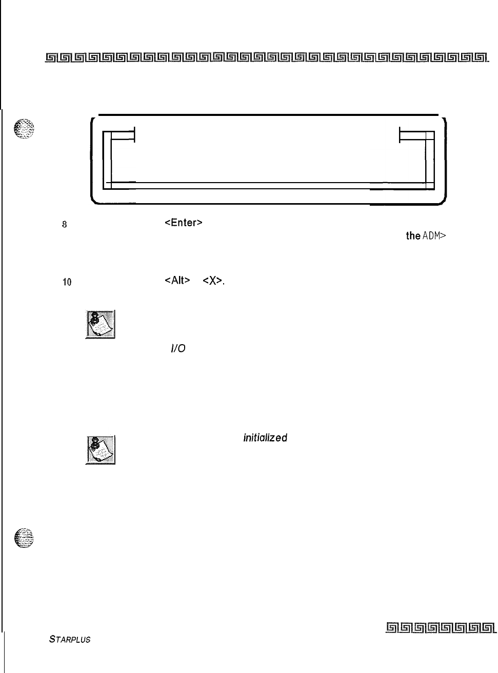
Customer Database Programming
Database Upload/Download Routine
l-23
7
This displays the Receive XMODEM screen on the PC monitor. Enter a path and file
name for the database file and press <Enter> to begin the download routine.
Receive XMODEM
Please enter filename:
8
On the PC, press
<Enter>
to begin the download routine. A Confirmation tone is heard
from the communications package after the download is complete and
theADM>
prompt
displays.
9
Enter
M
and press <Enter>.
10
On the PC, press
<AIt>
+
<X>.
Press <Enter> to exit Procomm and return to the DOS
prompt.
The downloaded database cannot be changed in the PC. The Up-
load/Download routine is only a method to save an existing database.
Database changes are made using the remote admin capabilities. Baud
rates on
I/O
ports are NOT downloaded or uploaded.
The download file contains a series of ASCII strings with a checksum at the end of the string. The checksum
is verified when the system receives the string. An error in the checksum results in rejection of the string. An
error message is sent to the PC when a string is received with an error. The user must watch for no more data
on the screen to determine when the transmission of the download file is complete.
The Database should be
inifialized
prior to an upload. The system should
then be reset after the upload.
Forward and backward compatibility is maintained. If the file uploaded from the PC contains less
information in a string than required by the system database, the system maintains default information in
-..G
c
the area not covered by the string. If the file uploaded from the PC contains more information in a string
,yyy-
-;$
than required by the system database, the system ignores the additional information.
To upload an ASCII database file:
STARPLUS
Triad-S System Programming Manual
Issue I- December 1998
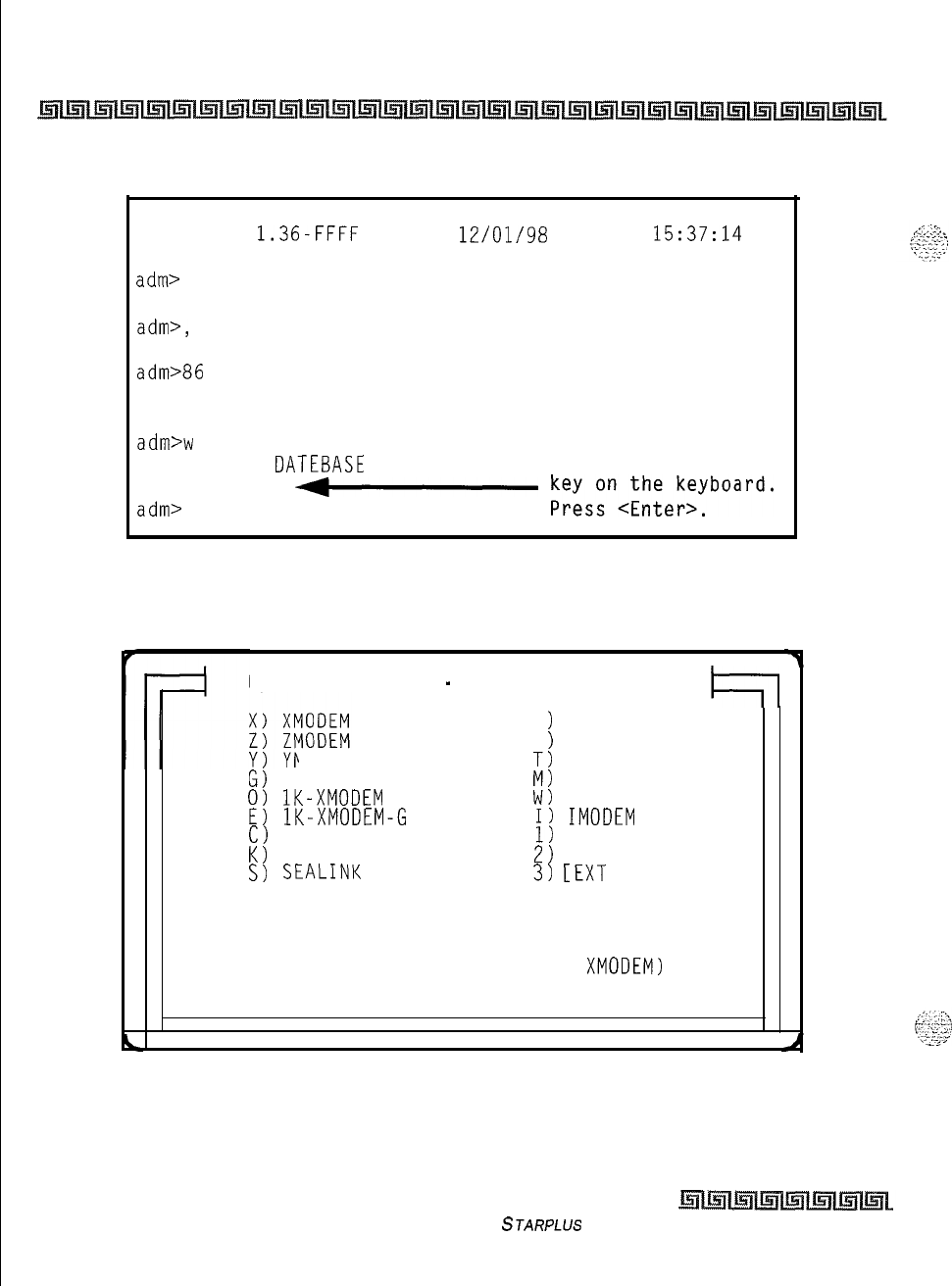
.
.
l-24
Customer Database Programming
Database Upload/Download Routine
I
Enter the information on the following screen capture.
44 Digital Hybrid Key-System
Eng. Ver.
1.36-FFFF
DATE:
12/01/98
TIME:
15:37:14
ENTER PASSWORD:
adm>
ADMIN PROGRAMMING
adm>,
ENTER PROGRAM NO
adm>86
LOAD DATABASE ROUTINE
ENTER BUTTON NUMBER
The HOLD button on
adm>w
a key set is the
DOWNLOAD DATEBASE
same as the <Enter>
PRESS HOLD
+-
kS;szn,;;;e;;yboard.
adm>
2
On the PC, press <PgUp> to display the Upload Protocol screen. Enter X to set the
upload file to use X-Modem. This introduces an error correction facility to track errors
and correct them during the upload procedure.
Upload Protocols
-
124811648 bytes free
4-l
A
R
1
ASCII
1
RAW ASCII
IODEM (Batch)
T)
TELINK
s)
YMODEM-G (Batch)
M)
MODEM7
0)
lK-XMODEM
W)
WXMODEM
E)
lK-XMODEM-G
I)
IMODEM
C)
COMPUSERVE B+
1)
CEXT 11
K)
KERMIT
2)
CEXT 21
S)
SEALINK
3)
[EXT
31
Your Selection: (press ENTER for XMODEM)
Issue I- December 1998
STARPLUS Triad-S System Programming Manual
Customer Database Programming
Database Upload/Download Routine
1-25
3
This displays the Send XMODEM screen on the PC monitor. Enter a path and file name
for the database file and press <Enter> and the desired file is uploaded to the system.
Send XMODEM
Please enter filename:
4
A Confirmation tone is heard after the uploaded is complete and you are returned to the
ADM>
prompt.
5
Enter an M at the
ADM>
prompt and press <Enter>.
adm>m
exiting admin...
DATE:
12/01/98
TIME:
15:41:04
exiting maintenance utility...
s
On the PC, press
<AIt>
+
<X>.
Press <Enter> to exit Procomm and return to the DOS
prompt.
7
After the upload procedure is completed, the system MUST be reset for full activation
of the database programming to take effect.
STARPLUS
Triad-S System Programming Manual
Issue I- December 1998
Customer Database Programming
Database Upload/Download Routine
Issue I- December 1998
STARPLUS Triad-S System Programming Manual
:
Programming Steps
If the system is in the programming mode, continue using the program codes. If starting to program here,
enter the programming mode. Refer to Chapter 1: Customer Database Programming.
I
Press FLASH and dial
[Ol].
The following message displays:
SYSTEM TIMERS
ENTER BUTTON NUMBER
.
Description
This section describes the procedures and steps to program system timers in the System Timers
programming area. The buttons on the digital terminal are illustrated on the following page:
issue
I-
December 1998
STARPLUS
Triad-S System Programming Manual
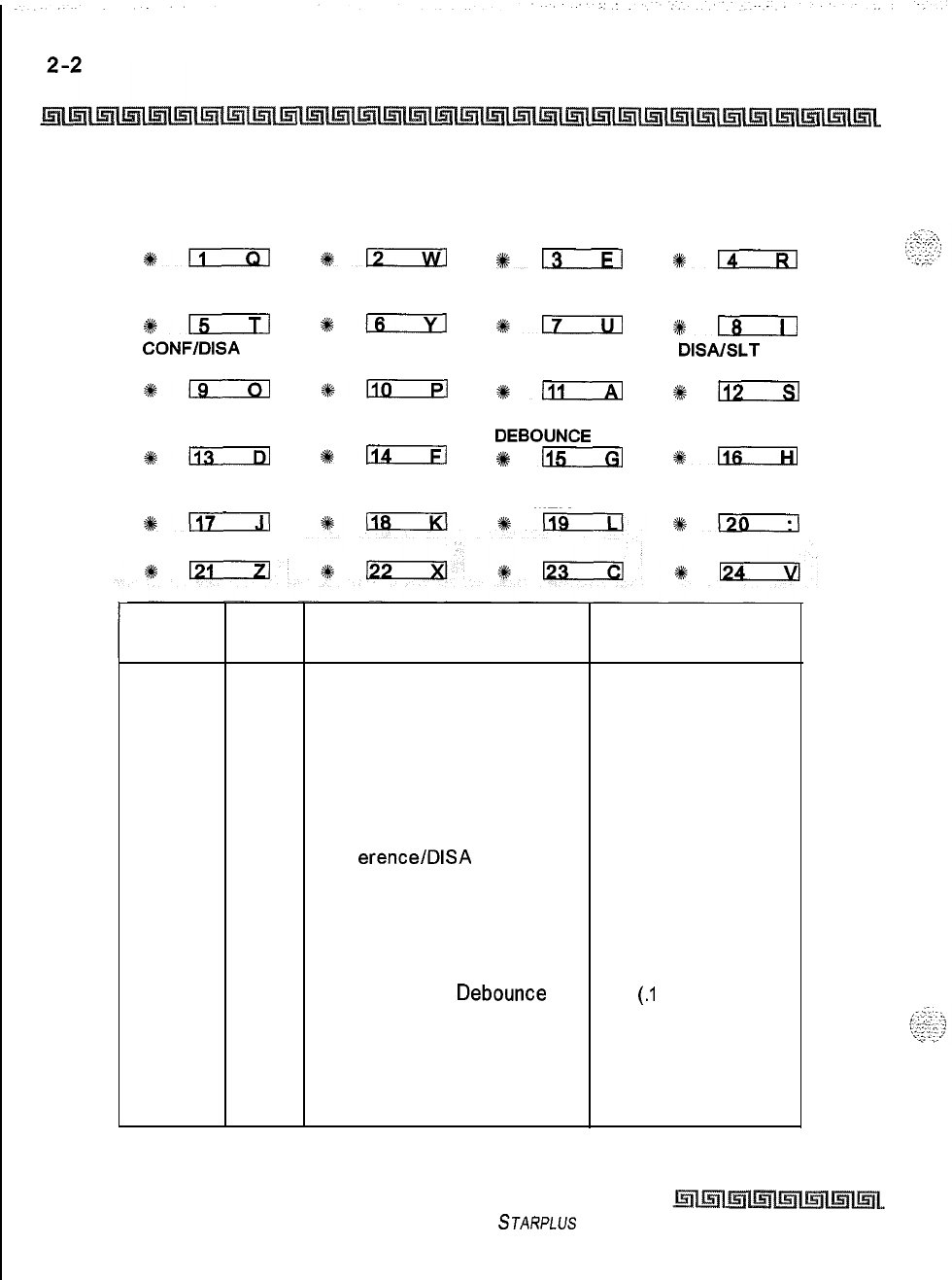
System Parameters Programming
System Timers
SYSTEMHOLD
RECALL
*ll
PRESET
FORWARD
+-
CONFlDlSA
TIMER
119
MSG WAIT
REMINDER
*113
AUTO CALL
BACK TIMER
4#-
EXCL HOLD ATTENDANT
RECALL RECALL
%l?x2iTl
#izKEEl
CALL FWD
NO/ANSWER PAUSE TIMER
%-
*m
PAGING CO RING
TIMEOUT DETECT
*-
4#n
HOOK FLASH HOOK FLASH
DEBOUNCE
%+-
*115
REMINDER RELEASE GUARD
RING TIMER
TRANSFER
RECALL
$14
CALL PARK
TIMER
*m
DISAISLT
RECEIVER
9112
SMDR CALL
QUALIFICATION
4kEiEKa
INTER-DIGIT
TIMEOUT
%k-
Program Flex
Feature Default
Code Button (after initialization)
FLASH
01
1
System Hold Recall 060 seconds
2
Exclusive Hold Recall 180 seconds
3
Attendant Recall Timer
01 minutes
4
Transfer Recall Timer 045 seconds
5
Preset Forward Timer 10 seconds
6
Call Forward No/Answer 015seconds
7
Pause Timer 2 seconds
8
Call Park Recall Timer 180 seconds
9
Conf
erence/DISA
Timer
10 minutes
10
Paging Timeout Timer 15 seconds
11
CO Ring Detect Timer 300 ms
12
SLT DTMF Receiver Timer 020 seconds
13
MSG Wait Reminder Tone 000 minutes
14
SLT Hook Flash Timer 10 (1 second)
15
SLT Hook Flash
Debounce
010
(.I
seconds)
16
SMDR Call Qualification Timer 30 seconds
17
Auto Call Back Timer 03 seconds (enabled)
18
Reminder Ring Timer 00 seconds (disabled)
19
Release Guard Timer 300 ms
20 Inter-Digit Timeout 5 seconds
Table 2-l: System Timers Defaults
Issue I- December 1998
STARPLUS Triad-S System Programming Manual
System Parameters Programming
System Timers
2-3
System Hold Recall Timer
Programming Steps
IPress the SYSTEM HOLD RECALL TIMER flexible button(FLASH 01, button 1). The
following message displays:
SYS HOLD RECALL 000-300
060
2
Enter a 3-digit timer value on the dial pad that corresponds to 000-300 seconds.
3
Press HOLD to save the entry. A confirmation tone is heard and the display updates.
Description
This
timer
determines the time before a call placed on System Hold recalls the station placing the hold, If
unanswered by that station, the call recalls the attendant. By default, the System Hold Recall Timer is set for
60
seconds and is variable from 000-300 seconds. An entry of 000 disables the timer and there is no recall.
Exclusive Hold Recall Timer
Programming Steps
1
Press the EXCLUSIVE HOLD RECALL TIMER flexible button (FLASH 01, button
#2).
The following message displays:
.
EXC HOLD RECALL 000-300
180
2
Enter a 3-digit timer value on the dial pad that corresponds to 000-300 seconds,
3
Press HOLD to save the entry. A confirmation tone is heard and the display updates.
Description
This timer determines the time before a call placed on Exclusive Hold recalls the station placing the Hold. If
unanswered by that station, the call recalls the attendant. By default, the Exclusive Hold Recall Timer is set
for
180
seconds and is variable from 000-300 seconds. An entry of 000 disables the timer and there is no
recall.
STARPLUS Triad-S System Programming Manual
Issue
I-
December 1998
2-4
‘-:
:..-.
System Parameters Programming
System Timers
Attendant Recall Timer
Programming Steps
1
Press the ATTENDANT RECALL TIMER flexible button (FLASH 01, button
#3).
The
following message displays:
ATND RECALL TIMER
00-60
01
6
z
Enter a 2-digit timer value on the dial pad that corresponds to 00-60 minutes.
3
Press HOLD to save the entry. A confirmation tone is heard and the display updates.
Description
This timer determines the time a recalling call rings at the attendant station(s) before the system releases
the line. When a CO Line recalls to the Attendant station and is still unanswered, the system releases the
line at the expiration of this timer and automatically places the line to an idle condition. By default, the
Attendant Recall Timer is set for
1
minute and is variable from
W-60
minutes. An entry of 00 causes the
Attendant(s) to ring until answered.
Transfer Recall Timer
Programming Steps
1
Press the TRANSFER RECALL TIMER flexible button (FLASH 01, button
#4).
The
following message displays:
2
Enter a 3-digit timer value on the dial pad that corresponds to 000-300 seconds.
TRA;;;ER RECALL
000-300
3
Press HOLD to save the entry. A confirmation tone is heard and the display updates.
Description
This timer determines the time a transferred call rings at the station receiving the transfer before it recalls
the station making the transfer. If unanswered by that station, the call recalls the attendant. By default, the
Transfer Recall Timer is set for
45
seconds and is variable from 000-300 seconds. A 000 entry disables the
timer and there is no recall.
Issue I
-
December 1998 STARPLUS Triad-S System Programming Manual
System Parameters Programming
System Timers
2-5
Preset Forward Timer
_.‘,
Programming Steps
e
5.
yi;
....:
_,.
1
e.;
:.;:’
1
Press the PRESET FORWARD TIMER flexible button (FLASH 01, button
#5).
The
following message displays:
I
PRESET FWD TIMER 00-99
10
I
2
Enter a 2-digit timer value on the dial pad that corresponds to 01-99 seconds.
3
Press HOLD to save the entry. A confirmation tone is heard and the display updates.
Description
This timer determines the time an outside line rings before being forwarded to a predetermined station. This
entry works with Preset Forward station assignments in Station Programming. More than one station can be
forwarded to the same party.
Initial incoming CO lines follow the Preset
Call
Forward Timer when
encountering a station in the Forward/No Answer mode.
This timer also governs the time the DISA call rings at a station before returning to intercom dial tone, if not
answered. By default, the Preset Forward Timer is set at
10
seconds and is variable from 01-99 seconds. If
no preset forward destination is programmed, the feature is disabled.
Call Forward
/
No Answer Timer
Programming Steps
1
Press the CALL FORWARD NO/ANSWER TIMER flexible
button(FLASH
01, button
#6).
The following message displays:
I
?i*
4”
_
&.
es-L3
CALL FWD NO ANS
000-600
-'I-i:.
Y
015
2
Enter a 3-digit timer value on the dial pad that corresponds to 000-600 seconds.
3
Press HOLD to save the entry. A confirmation tone is heard and the display updates.
STARPLUS Triad-S Sysfem Programming Manual Issue
I-
December 7998
I
System Parameters Programming
System Timers
Description
This timer is used when a station in the system specifies that no answer calls be forwarded to another
station. The timer determines how long an intercom or transferred call rings before it is considered a no-
answer call. The call then forwards to the designated station for handling. By default, the Call Forward
No/Answer Timer is set for 15 seconds and is variable from
000-600
seconds.
lnifiul
incoming CO lines follow the Preset Call Forward Timer when
encountering a station in the Forward
/
No Answer mode.
Pause Timer
Programing Steps
1
Press the PAUSE TIMER flexible button (FLASH 01, button
#7).
The following message
displays:
+
PAUSE TIMER
l-9
2
.
2
Enter a l-digit timer value on the dial pad that corresponds to l-9 seconds.
3
Press HOLD to save the entry. A confirmation tone is heard and the display updates.
Description
This timer determines the length of the pause when programmed for use with speed dialing and LCR Insert
Tables. By default, the Pause Timer is set at 2 seconds and is variable from l-9 seconds. There is no 0
entry. Use of
this feature may
afect
Centrex transfers.
Issue I- December 7998
STARPLUS Triad-S System Programming Manual
System Parameters Programming
System Timers
2-7
Call Park Recall Timer
in-.,
Programming Steps
::
”
&IT
I
Press the CALL PARK RECALL TIMER flexible button (FLASH 01, button
#8).
The
following message displays:
CALL PARK TIMER
000-600
180
2
Enter a 3-digit timer value on the dial pad that corresponds to 001-600 seconds.
3
Press HOLD to save the entry. A confirmation tone is heard and the display updates.
Description
This timer determines the time before a call placed in a call park location recalls the station placing the call
in park. If unanswered by that station, the call recalls the attendant. By default, the Call Park Recall Timer is
set at
180
seconds and is variable from 000-600 seconds. A 000 entry disables the timer and there is no
recall.
Conference
/
DISA
Timer
Programming Steps
1
Press the
CONFERENCEIDISA
TIMER flexible button (FLASH 01, button
#9).
The
following message displays:
CONFERENCE TIMER 00-99
10
..
2
Enter a 2-digit timer value on the dial pad that corresponds to 01-99 minutes.
3
Press HOLD to save the entry. A confirmation tone is heard and the display updates.
STARPLUS Triad-S System Programming Manual
issue
I
-
December 1998
2-8
System Parameters Programming
System Timers
Description
This timer determines the time an unsupervised conference can continue after the initiator of the
conference has exited. By default, the
Conference/DISA
Timer is set at
10
minutes and is variable from
Ol-
99
minutes. A 00 entry disables the timer and no automatic disconnect occurs.
The Conference Timer also allows the system
administrator
to control the
time a
DISA
caller is allowed after establishing
o
Trunk-to- Trunk call. At
the expiration of the Conference Timer,
u
tone is presented to
both
DISA
parties, then one minute later the system automatically releases both
trunks.
The
Conference Timer does not affect or control a
DISA-to-
Station call.
Paging Time-out Timer
Programming Steps
1
Press the PAGING TIMEOUT TIMER flexible button (FLASH 01, button
#lo).
The
following message displays:
I
PAGING TIMEOUT
00-60
15
I
z
Enter a 2-digit timer value on the dial pad that corresponds to 01-60 seconds.
3
Press HOLD to save the entry. A confirmation tone is heard and the display updates.
Description
This timer determines the maximum length of a page announcement (internal, external or all call). The
system automatically disconnects the page at the end of this time unless the person making the page has
already hung up. By default, the Paging Time-out Timer is set at 15 seconds and is variable from 01-60
seconds. A 00 entry disables the timer and pages are not limited in length. This will
a&et
use
of the Meet
Me Page feature.
issue
I-
December 1998
STARPLUS Triad-S System Programming Manual
System Parameters Programming
System Timers
CO Ring Detect Timer
,f?--,
e
Programming Steps
_.
y:
7.:
2:-
1
Press the CO RING DETECT TIMER flexible button(FLASH 01, button
#ll).
The
following message displays:
CO RING DETECT
2-9
3
2
Enter a l-digit timer value on the dial pad that corresponds to 2-9 (200 ms to 900 ms).
3
Press HOLD to save the entry. A confirmation tone is heard and the display updates.
Description
This timer controls the time necessary to detect an outside line ringing into the system. By default, the CO
Ring Detect Timer is set at 3 (300 ms), and is variable from
2-9
(200 ms to 900ms). There is no 0 or 1 entry.
SLT DTMF Receiver Timer
Programming Steps
1
Press the SLT DTMF RECEIVER TIMER flexible button(FLASH 01, button
#12).
The
following message displays:
l
SLT RCVR TIMER 005-100
020
\
z
Enter a 3-digit timer value on the dial pad that corresponds to 005-100 seconds.
3
Press HOLD to save the entry. A confirmation tone is heard and the display updates.
Description
Single line telephones require the use of a DTMF receiver when going off-hook and dialing, When SMDR or
toll restriction (via COS assignments) is enabled, a DTMF receiver monitors and screens the SLT digits for the
duration of this timer. By adjusting this timer, the system administrator may free system DTMF receivers
sooner if system SLT traffic is heavy, or provide a longer monitoring period if toll restriction becomes a
problem. Note that when LCR is enabled, the DTMF receivers are released when the expected number of
digits are dialed as entered in the LCR database. By default, the SLT DTMF Receiver Timer is set at 20 seconds
and is variable from 005-100 seconds.
STARPLUS Triad-S System Programming Manual Issue
I-
December 1998
System Parameters Programming
System Timers
Message Wait Reminder Tone
Programming Steps
IPress the MESSAGE WAIT REMINDER TONE flexible button(FLASH 01, button
#13).
The following message displays:
M/WO;;NE
TIMER
ooo- 104
b
2
Enter a 3-digit timer value on the dial pad that corresponds to 000-104 minutes.
3
Press HOLD to save the entry. A confirmation tone is heard and the display updates.
Description
This timer determines the time between repeated reminder tones to a key telephone with a message
waiting. Digital Hybrid station users may be reminded of a message waiting on their telephone with an
audible signal presented at a timed interval. By default, the Message Wait Reminder Tone is set at 000
(disabled) and is variable from 000-104 minutes.
SLT Hook Flash Timer
Programming Steps
1
Press the SLT HOOK FLASH TIMER
following message displays:
flexible button (FLASH 01, button
#I
4). The
I
HOOK
SWITCH
TIME
0520
10
I
2
Enter a 2-digit timer value on the dial pad that corresponds to 052.0 seconds in
l/l
0
second increments.
3
Press HOLD to save the entry. A confirmation tone is heard and the display updates.
Description
This timer determines how long an SLT user presses the hook switch for it to be considered a valid on hook
(disconnect) request, An on-hook shorter in duration (but longer than the Hook Switch Bounce Timer) is
Issue I- December 1998
S
TARP1
Us Triad-S Sys tern Programming Manual
System Parameters Programming
System Timers
considered
a Hook Flash (transfer) request. Refer to Figure
2-l.
By default, the SLT Hook Flash Timer is set
at
10
(one second) and is variable from 0.5-2.0 seconds.
Some Single Line telephones have
a
fixed or programmable Flash Timer
(Flash or Tap button). This Hook Switch Timer must be set longer
than
the
SL T Flash Timer to allow Hook Flash transfer.
SLT Hook Flash Debounce Timer
Programming Steps
1
Press the SLT HOOK FLASH
DEBOUNCE
TIMER flexible button (FLASH 01, button
#15).
The following message displays:
I
HOOK SWT BOUNCE
ooo- 100
010
I
2
Enter a 3-digit timer value on the dial pad that corresponds to O-l seconds in 10 ms
increments.
3
Press HOLD to save the entry. A confirmation tone is heard and the display updates.
Description
This timer determines the time needed to determine a valid on-hook or off-hook condition for single line
telephones. On-Hook or Off-Hook signals that are shorter in duration than this timer are ignored by the
system. Refer to Figure 2-I:
&IO/Z
Switch Activity. By default, the SLT Hook Flash Debounce Timer is set to
0.10 seconds and is variable from O-l seconds in 10 ms increments. This is a s-digit entry where 010 equals
0.1 seconds.
STARPLUS
Triad-S System Programming Manual issue
I-
December 1998
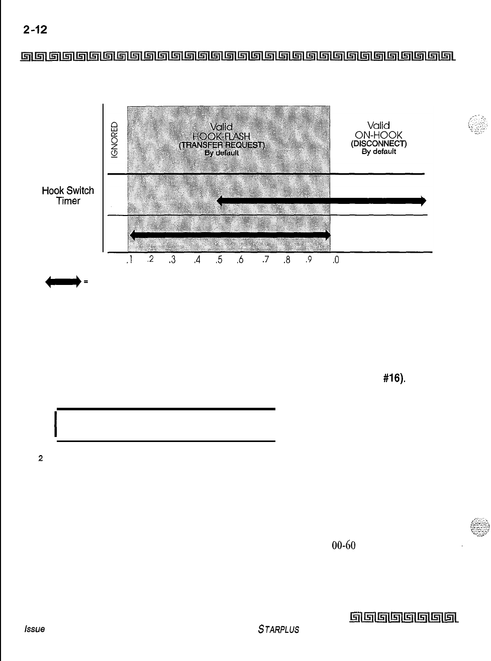
System Parameters Programming
System Timers
System
Response
Hook Switch
Bounce
Timer
0
.l
.2 .3 .4 .5 .6 .7 .8 .9
1
.O
1.5 2.0
e=
programmable range TIME
(in seconds)
Figure 2-l: Hook Switch Activity
SMDR Call Qualification Timer
Programming Steps
1
Press the SMDR CALL QUAL TIMER flexible button(FLASH 01, button
#16).
The
following message displays:
I
SMDR CALL QUAL 00-60
30
I
z
Enter a 2-digit timer value on the dial pad that corresponds to 00-60 seconds in 1
second increments.
3
Press HOLD to save the entry. A confirmation tone is heard and the display updates.
Description
This feature determines the time needed to determine a valid SMDR call for reporting purposes. By default,
the SMDR Call Qualification Timer is set to 30 seconds and is variable from
00-60
seconds in l-second
increments.
issue
I- December 1998
STARPLUS Triad-S System Programming Manual
System Parameters Programming
System Timers
2-13
Automatic Call Back Timer
Programming Steps
1
Press the AUTO CALL BACK TIMER flexible button(FLASH 01, button
#17).
The
following message displays:
AUTO CALL BACK 00-99
03
*
2
Enter a Z-digit timer value on the dial pad that corresponds to 00-99 seconds in 1
second increments.
3
Press HOLD to save the entry. A confirmation tone is heard and the display updates.
Description
This feature invokes a call back anytime a user listens to busy tone for a programmable period of time. By
default, the Automatic Call Back Timer is set for
03
seconds (enabled), and is variable from
00-99
seconds. A
value of 00 disables this timer. An Automatic Call Back does not occur when this timer is disabled.
Reminder Ring Timer
Programming Steps
1
Press the REMINDER RING flexible button (FLASH 01, button
#18).
The following
message displays:
.
REMINDER RING 00-99
00
2
Enter a 2-digit timer value on the dial pad that corresponds to 00-99 seconds in 1 second
increments. A value of 00 disables the timer, therefore the user only receives one ring
burst at the beginning of the call.
3
Press HOLD to save the entry. A confirmation tone is heard and the display updates.
Description
When a CO line rings at a busy station, the call rings at the station using muted ringing. The CO Line Ringing
Option feature enables a user to receive a reminder ring instead of muted ring. This timer provides a
reminder ring every time the timer expires, as long as the incoming CO line remains connected. If the user
continues his present conversation and the CO party does not hang up, the Reminder Ring timer expires and
STARPLIJS Triad-S System Programming Manual Issue
I-
December 1998
2-14 System Parameters Programming
System Timers
the user receives another ring burst. When the key set user ends the existing call, ringing for the CO call
reverts to normal ringing. By default, the Reminder Ring Timer is set to 00 second and is variable from
OO-
99
seconds in 1 second increments.
Release Guard Timer
Programming Steps
1
Press the RELEASE GUARD TIMER flexible button (FLASH 01, button
#19).
The
following message displays:
I
RELEASE GUARD 01-50
03
I
2
Enter a 2-digit timer value on the dial pad that corresponds to
01-50
(0.1 to 5.0
seconds)
s
Press HOLD to save the entry. A confirmation tone is heard and the display updates.
Description
The Release Guard Timer is designed to accommodate variations from one Central Office to another. The
timer is started whenever a CO line is released. If a user attempts to access a CO line before the Release
Guard timer expires, his LED illuminates indicating the CO line was seized, however the CO line is not
seized until the timer expires. The user DOES NOT receive a busy tone, but may get a delayed CO dial tone if
the timer is set to a large value. By default, the Release Guard timer is set for
3
(for 300 ms), and is variable
from 100 ms to 5 seconds.
Inter-Digit Time-out
Programming Steps
1
Press the INTER-DIGIT TIMEOUT flexible button (FLASH 01, button
#20).
The
following
message displays:
INTERDIGIT T/O 01-99
05
2
Enter a 2-digit timer value on the dial pad that corresponds to 01-99 seconds in 1
second increments.
Issue 1
-
December 1998 STARPLUS Triad-S System Programming Manual
System Parameters Programming
Additional System Timers
3
Press HOLD to save the entry. A confirmation tone is heard and the display updates.
Description
This feature provides inter-digit time-out programming on a system-wide basis and applies to intercom and
LCR calls. DISA, DID. TIE inter-digit time-outs remain unaffected by this timer. By default, the Inter-Digit
Time-out is set for
5
seconds, and is variable from
l-99
seconds.
Additional System Timers
Programming Steps
If the system is in the programming mode, continue using the program codes, If starting to program here,
enter the programming mode.
1
Press FLASH and dial
[02].
The following message displays:
I
SYSTEM TIMERS
ENTER BUTTON NUMBER I
Description
This section describes the procedures and steps necessary to program additional System Timers in the
Timers programming area.
STARPLUS
Triad-S System Programming Manual Issue
1
-
December 1998
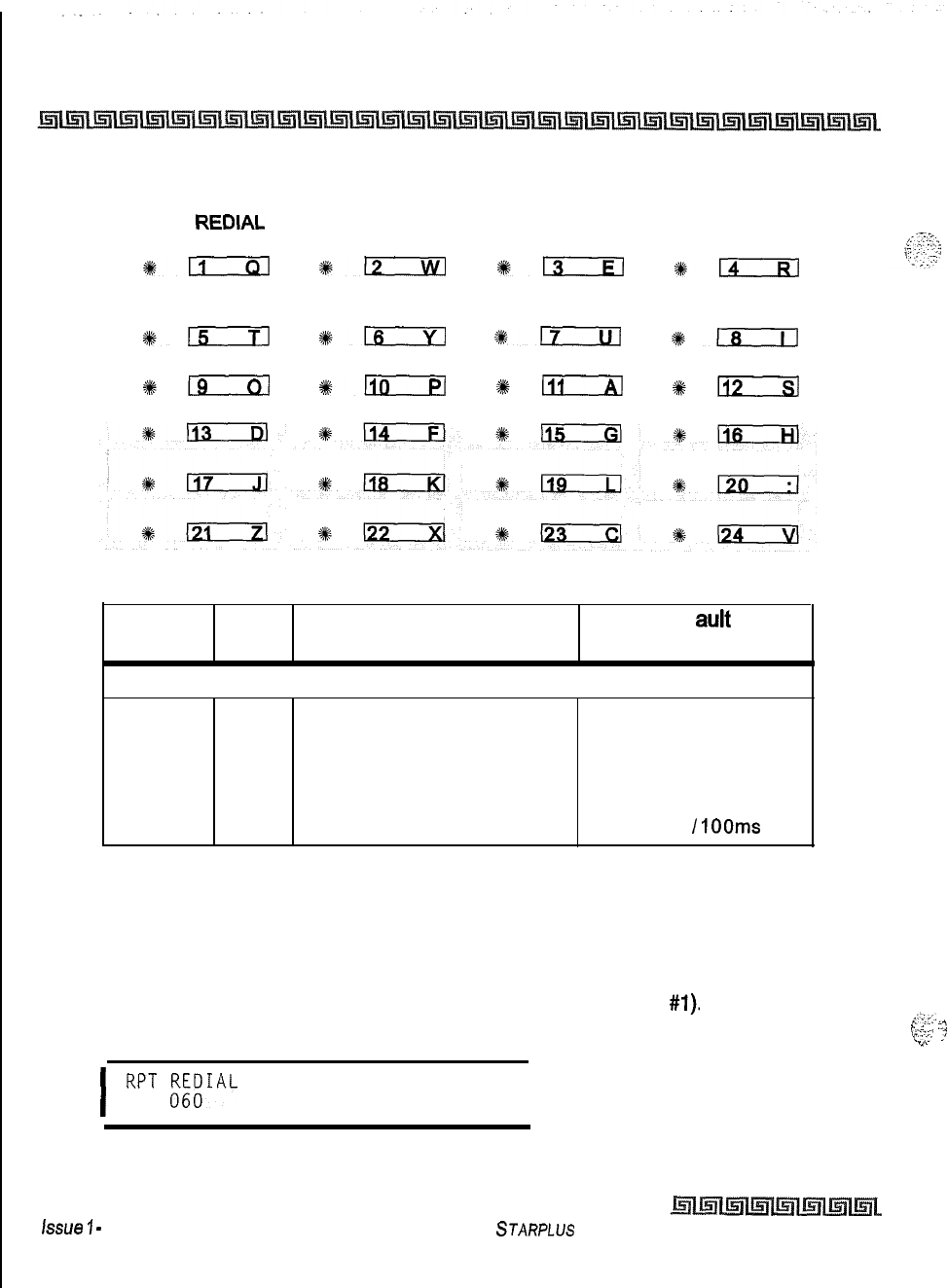
2-16
System Parameters Programming
Additional System Timers
SYSTEM
REDIAL
ATD DISPLAY CALL CVRG MODEM
TIMER TIMER RING TIMER ANSWER T/O
#E
%lzi!zl
%lzcLizl
+Em
PULSE DIAL I/O
DTMF TIME
TIMER OPERATION
#15
#LLic2a
%17
%D
*:
*-
#+n
#kKE
Program Flex Feature Def auk
Code Button (after initialization)
Additional System Timers:
FLASH 02 1Repeat Redial Timer 060 seconds
2
ATD Display Timer 01 seconds
3
Call Coverage Ring Timer
5
seconds
4
Modem Answer Time-out
25
seconds
5
Pulse Dial Inter-Digit Timer
300
ms
6
DTMF Time Operation 100 ms ON
/
IOOms
OFF
Table 2-2: Additional System Timers Defaults
Repeat Redial Timer
Programming Steps
1
Press the RPT REDIAL TIMER flexible button (FLASH 02, button
#I).
The following
message displays:
;-.‘.;y:.
,.
,.
.
:?
yy.::
;
.,I . .
I
RPT
EAL
006-999 I
2
Enter a 3-digit timer value on the dial pad that corresponds to 006-999 seconds.
issue
7
-
December 1998
STARPLUS Triad-S System Programming Manual
System Parameters Programming
Additional System Timers
2-17
3
Press HOLD to save the entry. A confirmation tone is heard and the display updates.
Description
The feature lets a digital key station press a flexible button or dial a code and redial a busy or no-answer
number at specific intervals. The user is signaled via a queue callback indication, The Redial flexible button
flashes at the callback rate of 120 ipm for 15 seconds. If the station does not answer within 15 seconds, the
callback is cancelled. If the station is busy with an internal/external call when the Redial queue callback
occurs, the callback occurs after the user goes on-hook. By default, the Repeat Redial Timer is set for 1
minute
(60)
and is variable from
006-999
seconds.
Attendant Display Timer
Programming Steps
1
Press the ATTENDANT DISPLAY TIMER flexible button (FLASH 02, button
#2).
The
following message displays:
ATTENDANT DISPLAY 006-999
01
2
Enter a 2-digit timer value on the dial pad that corresponds to 00-99 seconds.
3
Press HOLD to save the entry. A confirmation tone is heard and the display updates.
Description
The Attendant display timer modifies the way in which multiple calls ringing at the attendant station display.
Currently, if two calls are ringing at an attendant station, when the station goes off hook, the first call is
answered. The LCD updates to show the second call that is ringing which sometimes does not allow the
station to view the current call’s LCD information. This timer keeps the current calls’ information on the LCD
for the set time period, then shows any other calls ringing in at the time. By default, the Attendant Display
Timer is set for 1 second and is variable from
00-99
seconds.
STARPLUS Triad-S System Programming Manual
Issue I- December 1998
2-18 System Parameters Programming
Additional System Timers
Call Coverage Ring Timer
Programming Steps
1
Press the CALL CVRG RING TIMER flexible button (FLASH 02, button
#3).
The
following message displays:
CALLOgOVERAGE
RING
00-99
a
a
Enter a 2-digit timer value on the dial pad that corresponds to 00-99 seconds.
3
Press HOLD to save the entry. A confirmation tone is heard and the display updates.
Description
A
ringing
Call Coverage
button enables the user to place another station under a flex button. For additional
information refer to Chapter
4:
Table 4-3: Flex Button Codesfor Remote Programming. When that station
rings with an internal or external call, the DSS button for that station rings or flashes. By default, the Call
Coverage Ring Timer is set for
5
seconds and is variable from
00-99
seconds. A value of 00 results in the
LED flashing but the call coverage station does not ring.
Modem Answer Timer
Programming Steps
1
Press the MODEM ANSWER TIMER flexible button (FLASH 02, button
#4).
The
following message displays:
I
MODEM ANSWER T/O 025-099
25
I
2
Enter a 2-digit timer value on the dial pad that corresponds to
025-099
seconds.
3
Press HOLD to save the entry. A confirmation tone is heard and the display updates.
Description
This timer determines how long the On Board modem provides a carrier tone to a distant modem. If a
connection is not made at the end of this timer, the On Board modem hangs up. By default, the Modem
Answer Timer is set for 25 seconds and is variable from
25-95,
seconds.
issue
I- December 1998
STARPLUS Triad-S System Programming Manual
System Parameters Programming
Additional System Timers
2-19
Pulse Dial Inter-Digit Timer
Programming Steps
1
Press the PULSE DIAL
I/D
TIMER flexible button (FLASH 02, button
#5).
The following
message displays:
INT DIGIT PULSE 300-600
300
\
2
Enter a 3-digit timer value on the dial pad that corresponds to 300-600 ms.
3
Press HOLD to save the entry. A confirmation tone is heard and the display updates.
Description
This governs the inter-digit time of the Pulse Dial Digits. By default, the Pulse Dial Ring Timer is set for 300
ms and is variable from 300-600 ms.
DTMF On/Off Time Operation
Programming Steps
t
Press the DTMF TIME OPERATION flexible button (FLASH 02. button
#6).
The
following message displays:
I
DTMF ON/OFF TIME 100-999
100/100
I
2
Enter a 3-digit value (100-999) on the dial pad for the DTMF on and off times.
3
Press HOLD to save the entry. A A confirmation tone is heard.
Description
This feature lets the installer select the DTMF on/off time on a system-wide basis. This lets the installer
customize the system for certain applications that require more than the standard DTMF time of
100ms
on
and
1OOms
off. By default, the DTMF Time Operation is set for 100 ms on and 100 ms off.
STARPLUS
Triad-S System Programming Manual Issue
I-
December 1998
System Parameters Programming
System Features 1 Programming
System Features 1 Programming
Programming Steps
If the system is in the programming mode, continue using the program codes, If starting to program here,
enter the programming mode.
1
Press FLASH and dial
[05].
The following message displays:
I
SYSTEM FEATURES 1
ENTER BUTTON NUMBER
I
Description
This section describes the procedures and steps necessary to program System Features in the System
Features programming area. The buttons on the digital terminal are illustrated on the following page:
Issue 1
-
December 1998 S
JARPLLJS
Triad-S System Programming Manual
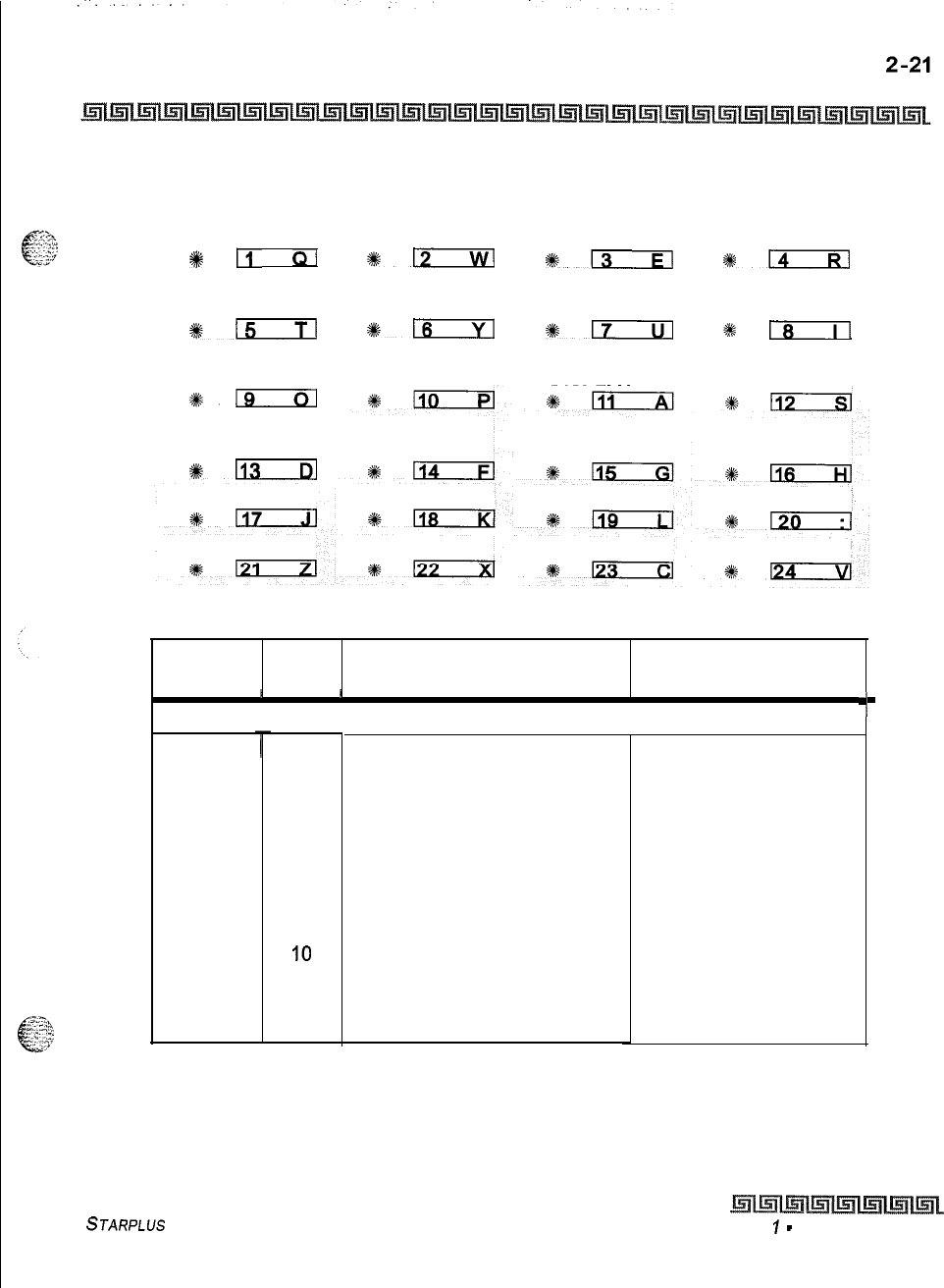
System Parameters Programming
System Features 1 Programming
ATTN HOLD EXTERNAL EXECUTIVE
OVERRIDE
+%
Ei
QI
PAGE WARN
TONE
*15
GROUP
LISTENING
#%19
CALL QUALIFIER
TONE OPTION
+I#-
PREFERENCE NIGHT RING
*-
113
BACKGROUND
MUSIC
LCR ENABLE
%16
#m
IDLE SPEAKER CALL COST
MODE DISPLAY
OVERRIDE
*m
ACCOUNT
CODES
%
Is
MUSIC ON HOLD
Program
Flex
Feature Default
Code Button (after initialization)
I ,
I
System Features 1:
FLASH 05
1
Attendant Override
2
Hold Preference
3
External Night Ring
4Executive Warning
5
Page Warning Tone
6
Background Music
7
Least Cost Routing
8
Account Code
9
Group Listening
IO
Idle Speaker Mode
11
Call Cost Display Feature
12 Music On Hold
13
Call Qualifier Tone Option
Disabled
System
Disabled
Enabled
Enabled
Enabled
Disabled
Disabled
Disabled
Disabled
Disabled
Enabled
Disabled
Table 2-3: System Features 1 Defaults
I
STARPLUS Triad-S System Programming Manual Issue
7
-
December 7998
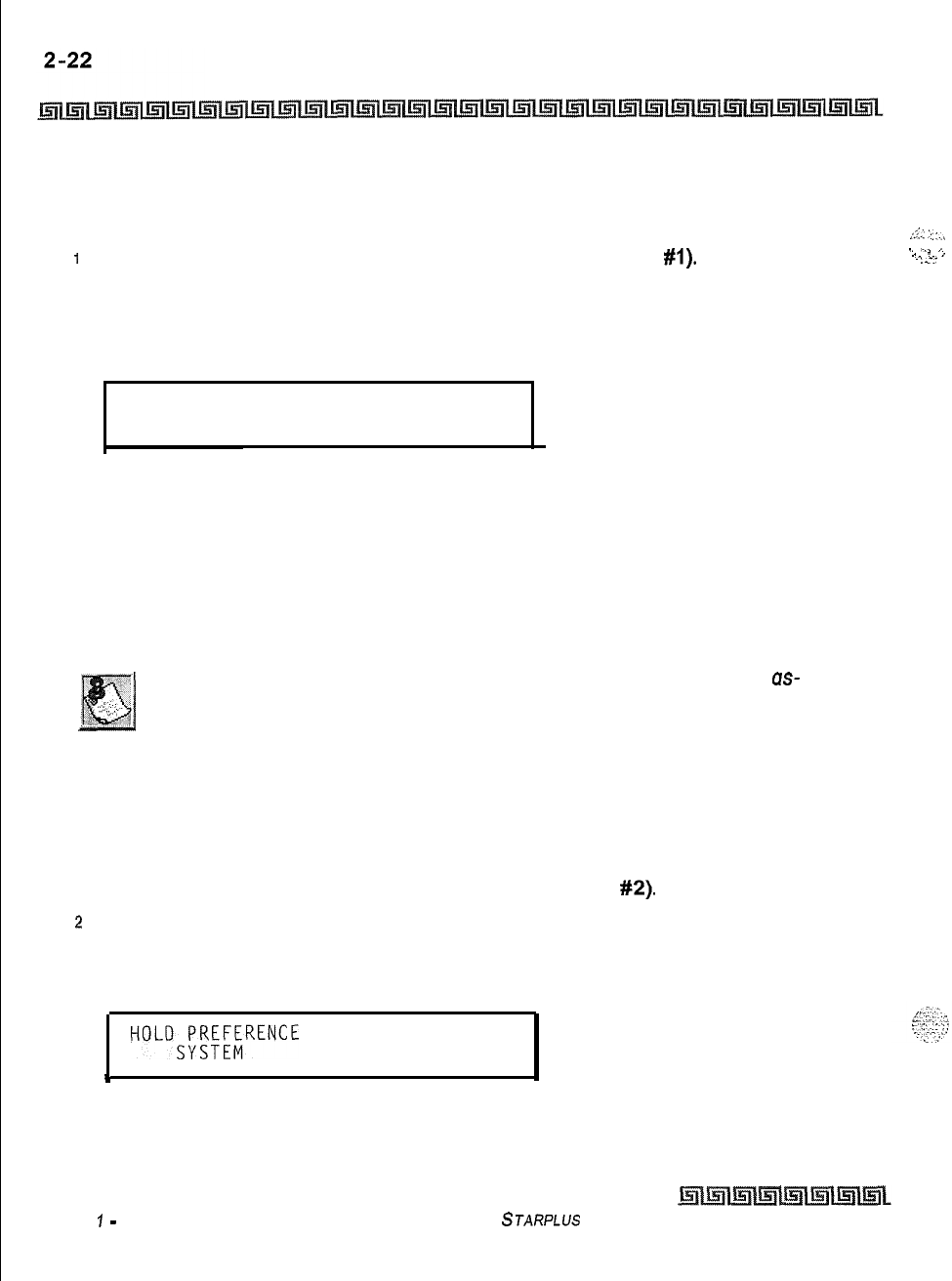
System Parameters Programming
System Features 1 Programming
Attendant Override
Programming Steps
I
Press the ATTN OVERRIDE flexible button (FLASH 05, button
#I).
2
Enter a l-digit value (O-l) that corresponds with the following entries:
[0] = Disabled
[I] = Enabled
ATTENDANT OVERRIDE
o-1
DISABLED
3
Press HOLD to save the entry. A confirmation tone is heard.
Description
When this feature is enabled, it lets the attendant override a busy station or a station in DND. By default,
Attendant Override is disabled.
Attendant Override functions ONLY when the Attendant station is
QS-
signed a flex button designated us Attendant Override.
Hold Preference
Programming Steps
IPress the HOLD PREF flexible button (FLASH 05, button
#2).
2
Enter a l-digit value (O-l) that corresponds with the following entries:
[0] = Exclusive Hold
[I] = System Hold
HOLDM;RENCE
O-l
t
3
Press HOLD to save the entry. A confirmation tone is heard.
Issue
7
-
December 1998
STARPLUS Triad-S System Programming Manual
,::.: :.. :..,
1. -.. ,..
_ . ,
. . . .=:.
System Parameters Programming
System Features
1
Programming
2-23
Description
The system may be programmed to have Exclusive or System Hold preferred. If Exclusive Hold is preferred,
the user presses HOLD once for Exclusive Hold and twice for System Hold. If System Hold is preferred, the
user presses HOLD once for System Hold and twice for Exclusive Hold. Refer to System Timer programming
for System and Exclusive Hold recall times. By default, Hold Preference is System Hold.
External Night Ring
Programming Steps
1
Press the EXT NIGHT RING flexible button (FLASH
05.
button
#3).
2
Enter a l-digit value (O-l) that corresponds with the following entries:
[0] = Disabled
[I] = Enabled
I
EXTERNAL NIGHT RING
O-l
DISABLED
I
3
Press HOLD to save the entry. A confirmation tone is heard.
Description
When this feature is set to yes, it activates
external night ring whichproduces a tone that is sent
ouer all externalpage groups.
When outside lines are marked UNA, ringing activates a tone over
external paging when an incoming call occurs on those lines during night service. By default, External Night
Ring is disabled.
Executive Override Warning Tone
Programming Steps
IPress the EXEC OVER WARN TONE flexible button (FLASH 05, button
#4).
2
Enter a l-digit value (O-l) that corresponds with the following entries:
[0] = Disabled
[I] = Enabled
EXEWME;ARNING
O-l
STARPLUS
Triad-S System Programming Manual Issue
I-
December 1998
2-24
System Parameters Programming
S,ystem
Features 1 Programming
3
Press HOLD to save the entry. A confirmation tone is heard.
Description
This option enables Executive stations to override and barge-in on other key sets engaged in conversation
on a CO line. Prior to actual cut through of the third party, a warning tone is presented to all parties
notifying them of the barge-in. This warning tone, however, is a programmable option on a system-wide
basis, that either enables or disables the tone. When the tone is disabled, no audible signal is presented to
the parties to signal the barge-in. By default, Executive Override Warning Tone is enabled.
Use of this feature when the Executive Override Warning Tone is disabled
may be interpreted as a violation of federal, state, or local laws, and an
invasion of privacy. Check applicable laws in your area before intruding on
calls using this feature.
A change in volume may occur on the CO line or intercom call after the
barge-in occurs. This feature also affects ACD Supervisor Barge-in warn-
ing tone.
Page Warning Tone
Programming Steps
IPress the PAGE WARN TONE flexible button (FLASH 05, button
#5).
z
Enter a l-digit value (O-l) that corresponds with the following entries:
[0] = Disabled
[I] = Enabled
I
PAGE WARNING TONE
o-1
ENABLED
I
s
Press HOLD to save the entry, A confirmation tone is heard.
Description
Determines whether a page warning tone sounds over the Key Telephone speakers or external paging
speakers, prior to a page announcement. By default, Page Warning Tone is enabled.
issue 1
-
December 1998 STARPLUs Triad-S System Programming Manual
System
Parameters Programming
System Features 1 Programming
2-25
Background Music
Programming Steps
T~::*$.
f&,
‘.::”
1
;...
Press the BACKGROUND MUSIC flexible button (FLASH
05.
button
#6).
z
Enter a l-digit value (O-l) that corresponds with the following entries:
[0] = Disabled
[I] = Enabled
BACKGROUND
MUSIC
O-l
ENABLED
3
Press HOLD to save the entry. A confirmation tone is heard.
Description
The system can be programmed to let stations activate their Background Music, in addition to
Music-On-
Hold. A music source must be connected to the
BGM/MOH
connector on the
MISU.
By default, the
Background Music channel is enabled.
Least Cost Routing (LCR)
Programming Steps
I
Press the LCR ENABLE flexible button (FLASH 05, button
#7).
z
Enter a l-digit value (O-l) that corresponds with the following entries:
[
0
]
= Disabled
[I] = Enabled
.
LEAST COST ROUTING
O-l
DISABLED
s
Press HOLD to save the entry. A confirmation tone is heard.
Description
If Least Cost Routing is used, it must be enabled here. Before enabling LCR, refer to the Least Cost Routing
section (Flash
75)
and programming tables (Product Description Manual
-
Appendix C). When the tables are
programmed, you may then enable LCR for the system. After system initialization, a default LCR database is
loaded into the LCR section of memory. By default, LCR is disabled.
STARPLUS
Triad-S System Programming Manual
Issue I- December 1998
.
System Parameters Programming
System Features 1 Programming
Account Codes
-
Forced
Programming Steps
IPress ACCOUNT CODES flexible button (FLASH 05, button
#8)
to determine whether
the use of Account Codes is forced or optional.
2
Enter a l-digit value (O-l) that corresponds with the following entries:
[O]
= Disabled
[I] = Enabled
FORCED ACCOUNT CODE
o-1
DISABLED
3
Press HOLD to save the entry. A confirmation tone is heard.
Description
The system can force the use of account codes on all restricted calls. If forced account code option is
enabled, a station’s Class of Service is upgraded to day
COSl,
night
COSl,
when the account code is entered.
If forced account code option is disabled, a station’s Class of Service is not upgraded but the account code
continues to be part of the SMDR record. By default, the use of account codes is optional.
Group Listening
Programming Steps
1
Press the GROUP LISTENING flexible button (FLASH 05, button
#9).
2
Enter a l-digit value (O-l) that corresponds with the following entries:
[0] = Disabled
[I] = Enabled
I
GROUP LISTENING
O-l
DISABLED
L
3
Press HOLD to save the entry. A confirmation tone is heard.
Description
All
digital key terminals have built-in speakerphones. Station users may use the speaker to monitor a call
while using the handset to converse with the outside party. This enables other people in the room to listen
Issue I- December 1998
STARPLUS Triad-S System Programming Manual
System Parameters Programming
System Features
1
Programming
2-27
to both parties in the conversation. Group listening is unavailable when the station is in the headset mode, By
default, Group Listening is disabled.
y--,
c
-2;
Idle
Speaker Mode
Programming Steps
I
Press the IDLE SPEAKER MODE flexible button (FLASH 05, button
#IO).
2
Enter a l-digit value (O-l) that corresponds with the following entries:
[0] = First digit dialed is Heard (Disabled)
[I] = First digit dialed is Muted (Enabled)
IDLE SPEAKER MODE
O-l
DISABLED
3
Press HOLD to save the entry. A confirmation tone is heard.
Description
The Idle Speaker Mode feature determines whether the first digit dialed is heard over the digital key terminal
speaker. This feature can be enabled or disabled on a system-wide basis. By default, this mode is disabled.
Call Cost Display Feature
Programming Steps
I
Press the CALL COST DISPLAY flexible button (FLASH 05, button
#ll).
2
Enter a l-digit value (O-l) that corresponds with the following entries:
[0] = Disabled
[I] = Enabled
.
CALL COST DISPLAY
o-1
A“
.-.
.i_
6.
DISABLED
:-.2:x
pz;
3
Press HOLD to save the entry. A confirmation tone is heard.
STARPLUS Triad-S Sysfem Programming Manual Issue
I-
December 1998
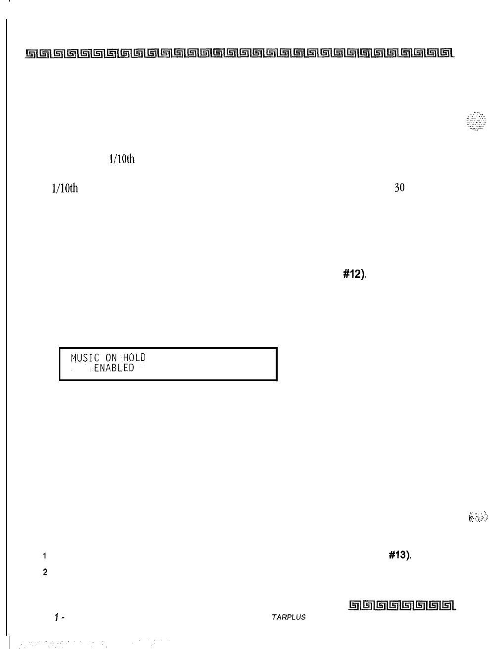
.
2-28
System Parameters Programming
System Features 1 Programming
Description
The Call Cost Display Feature lets a user view the approximate cost of each call made. This approximate cost
also prints as part of the SMDR record. The Call Cost Display replaces the call duration display when a call is
made using LCR. Cost information is programmable in LCR Flash 75. This enables the user to program four
separate costs based on the time of day. Costs entered in the tables are costs for one minute, however, costs
are calculated using
l/lOth
of a minute
value.
These costs are rounded down and based on the call start
time, even if the call extends into a different time period. The SMDR printout contains a cost calculated
using
l/lOth
of a minute increment, however the station display updates approximately every
30
seconds.
The user
must
use LCR to get the call cost display. By default, the Call Cost Display feature is disabled.
Music On Hold
Programming Steps
1
Press the MUSIC ON HOLD flexible button (FLASH 05, button
#12).
This feature
toggles on and off each time the button is pressed. The display updates with each
toggle.
[0] = Disabled
[I] = Enabled
MUSICOOL;;LD
O-l
2
Press HOLD to save the entry. A confirmation tone is heard.
Description
When connected to the system, a music source provides music to all lines on Hold, parked calls,
transferred calls and calls waiting to be answered by Automatic Call Distribution (ACD) or Uniform Call
Distribution (UCD). This feature is allowed or denied on a system-wide basis in programming. By default,
Music-On-Hold is enabled.
Call Qualifier Tone Option
Programming Steps
I
Press the CALL QUAL TONE OPTION flexible button (FLASH 05, button
#13).
2
Enter a l-digit value (O-l) that corresponds with the following entries:
[0] = Disabled
Issue
I-
December 1998 S
JARPLUS
Triad-S System Programming Manual
::.
7
;
‘.
,....
,._.
-,
i-l
,...
c
System Parameters Programming
System Features 2 Programming
[I] = Enabled
CALL QUALIFIER TONE
o-1
DISABLED
3
Press HOLD to save the entry. A confirmation tone is heard.
Description
This feature is associated with the ACD Call Qualifier code and determines if a confirmation tone is heard
after the ACD Call Qualifier code is dialed. If programmed, the confirmation tone is heard through the key set
speaker. This feature provides up to four digits for the ACD SMDR reporting functions that are compatible
with the Basic ACD software package. This feature permits entry of up to twelve digits, By default, the Call
Qualification Confirmation tone is disabled.
System Features 2 Programming
Programming Steps
If the system is in the programming mode, continue using the program codes. If starting to program here,
enter the programming mode.
t
Press FLASH and dial
[06].
The following message displays:
I
SYSTEM FEATURES 2
ENTER BUTTON NUMBER
I
Description
This section describes the procedures and steps necessary to program System Features in System Features
programming area. The buttons on the digital terminal are illustrated on the following page:
STARPLUS Triad-S System Programming Manual Issue
I
-
December 1998
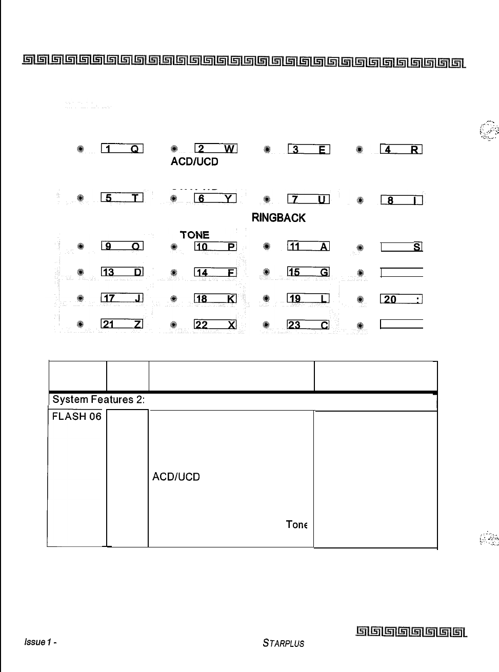
2-30
System Parameters Programming
System Features
2
Programming
PRIVACY
RELEASE TONE
*ll
EXT DAY
RINGING
CO RING TONE VERIFIED ACCT
CODES
+-
*rs--iq
ACD/UCD
OVERFLOW DIRECT
STA FWD TRANSFER
CALL FWD
DISPLAY
STATUS
*EzRl
STATION ID
LOCK
LCR CALL
PROGRESS
ONE-TOUCH
RCD WARNING
RINGBACK
ON
TRANSFER
*ill
17
$1
16
HI
120
74
VI
Program Flex Feature Default
Code Button (after initialization)
FLASH 06
r
1
Privacy Release Tone Enabled
2
CO Ring Tone Enabled
3
Verified Account Codes Disabled
4
Call Forward Display Status Enabled
5
External Day Ringing Disabled
6
ACDNCD
Overflow Sta Fwd Disabled
7
Direct Transfer Enabled
8
Station ID Lock Disabled
9
LCR Call Progress Enabled
10
One-Touch Record Warning
Tone
Enabled
11
Rlngback on Transfer Disabled
Lssue
I-
December 1998
Table 2-4: System Features 2 Defaults
STARPLUS
Triad-S System Programming Manual
,:-‘
!‘.
..+.:
I
..,
-.
l..i..
‘.
,...~;-
.;..
,‘.
,,:;
t:.-,
:
:;;
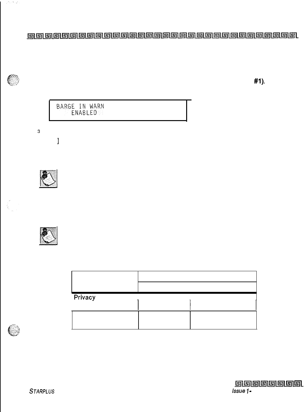
System Parameters Programming
System Features 2 Programming
2-31
Privacy Release Tone Option
Programming Steps
2
Press the PRIVACY RELEASE TONE flexible button (FLASH 06, button
#l).
The
following message displays:
BARGEN;iLF;RN TONE
O-l
s
Enter a l-digit value on the dial pad to enable or disable the conference tone.
[ 0
]
= Disabled
[I] = Enabled
4
Press HOLD to save the entry. A confirmation tone is heard.
Display stations continue to receive the CONFERENCE display regardless
of the warning tone setting.
Privacy is ensured on all communications in the system. If desired, the user may elect to disable the
Automatic Privacy feature, thus allowing up to seven other stations to join existing CO Line conversations.
Disabling of the privacy feature may be limited by federal, state, or local
law, so check the relevant laws in your area before disabling privacy.
Station Attempting to CO Line in Use by Another Station
Access CO Line
IPrivacy Enabled 1 Privacy Disabled
I
I
Privacv
Enabled
I
I Private I Private
1 (no cut-through) 1 (no cut-through) 1
Privacy Disabled Private Privacy Release
(no cut-through) (cut-through allowed)
Table 2-5: CO Line Privacy Flag
STARPLUS
Triad-S System Programming Manual issue
I
-
December 1998
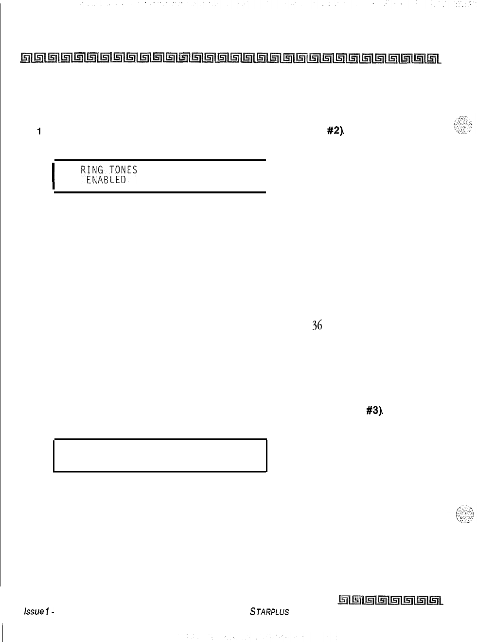
2-32
System Parameters Programming
System Features 2 Programming
Distinctive CO Ringing
Programming Steps
i
Press the CO RING TONE flexible button (FLASH 06, button
#2).
The following
message displays:
I
CO
R&%T;~ES
O-l
I
2
Enter a l-digit value on the dial pad to enable/disable the tone ring signal.
[0] = Disabled
[I] = Enabled
3
Press HOLD to save the entry. A confirmation tone is heard.
Description
The tone ring signal that notifies stations of an incoming call can be changed in administrative
programming to provide distinctive ringing on a per CO line basis. A distinctive ring tone can be
programmed for each CO line that rings each station. The system provides
36
different ring patterns that
can be selected for CO lines in the system. By default, Distinctive CO ringing is enabled.
Verified Account Codes
Programming Steps
1
Press the VERIFIED ACCT CODES flexible button (FLASH 06, button
#3).
The
following message displays:
VERIFIED ACCT CODES O-l
DISABLED
.
2
Enter a l-digit value on the dial pad to enable/disable the use of verified account
codes.
[0] = Disabled
[I] = Enabled
3
Press HOLD to save the entry. A confirmation tone is heard.
~
issue
I-
December 1998
STARPLUS Triad-S System Programming Manual
System Parameters Programming
System Features 2 Programming
2-33
I
Description
The Verified Account Code/Traveling Class of Service (COS) feature provides tracking of specific calls by
-cc..
-
:x.:‘-.
c-
-v1.-.z’:
entering a verified, variable length (up to
12-digits)
identifier. Each account code can be assigned a day and
night Class-of-Service for determining the dialing privileges allowed by that account code. This lets users
override a restricted station. If the dialed account code matches the Verified Account code table, an intercom
dial tone is returned, otherwise an error tone is returned. SMDR must be enabled for the account code to
print as part of the SMDR record. The Triad-S system allows up to 250 12-digit account codes programmed in
at Flash 31. By default, the Verified Account Codes feature is disabled.
Call Forward Display
Programming Steps
1
Press the CALL FWD DISPLAY STATUS flexible button (FLASH
06,
button
#4).
The
following message displays:
I
CALL FWD DISPLAY
O-l
ENABLED
I
2
Enter a l-digit value on the dial pad to enable/disable the call forward display option.
[0] = Disabled
[I] = Enabled
3
Press HOLD to save the entry. A confirmation tone is heard.
Description
When call forwarding is invoked, the LCD display normally indicates the call forwarding mode at all times,
This feature is enabled/disabled in administrative programming on a system-wide basis. By default, the
status of the Call Forward display is enabled.
STARPLUS Triad-S System Programming Manual issue
I- December 1998
2-34
System Parameters Programming
System Features 2 Programming
External Day Ring
Programming Steps
i
Press the EXT DAY RINGING flexible button (FLASH 06, button
#5).
The following
message displays:
I
EXTERNAL DAY RING
o-1
DISABLED
I
2
Enter a l-digit value on the dial pad to enable/disable the use of external day ring
option.
[0] = Disabled
[l]
= Enabled
3
Press HOLD to save the entry. A confirmation tone is heard.
Description
The system can be programmed so CO lines marked for UDA provides ringing out of the external page ports
when the system is in the Day Mode. By default, External Day Ringing is disabled.
Overflow Station Forward
Programming Steps
IPress the ACDIUCD OVERFLOW STA FWD flexible button (FLASH 06, button
#6).
The following message displays:
OVERFLOW STA FWD O-l
DISABLED
6
4
2
Enter a l-digit value on the dial pad to enable/disable the use of this feature.
[0] = Disabled
[I] = Enabled
3
Press HOLD to save the entry. A confirmation tone is heard.
Description
This feature allows
ACD/UCD
calls reaching the
ACD/LJCD
Overflow Station to call forward to another station.
This enhancement is allowed or denied on a system-wide basis. Once enabled in programming, an
Issue I- December 1998
STARPLUS
Triad-S System Programming Manual
System Parameters Programming
System Features 2 Programming
2-35
ACD/UCD
Overflow station can Busy/No-Answer forward to Voice Mail Groups,
ACD/UCD
Groups, Hunt
Groups and stations. If the
ACD/LJCD
Overflow station is busy or does not answer before the no-answer call
timer expires, the
ACD/UCD
call forwards to the destination, By default, this feature is disabled,
Direct Transfer Mode
Programming Steps
1
Press the DIRECT TRANSFER flexible button (FLASH
06.
button
#7).
The following
message displays:
I
DIRECT XFER
O-l
ENABLED
I
2
Enter a l-digit value on the dial pad to enable/disable this feature.
[0] = Disabled
[I] = Enabled
3
Press HOLD to save the entry. A confirmation tone is heard.
Description
When enabled, supervised transfers (screened transfers) to stations in the handset mode connect calls
directly to the handset. The station user must have a direct appearance of that CO line or a Loop button. This
feature is programmed on a system-wide basis. By default, the Direct Transfer Mode is enabled.
Station ID Lock
Programming Steps
1
Press the STATION ID LOCK flexible button (FLASH 06, button
#8).
The
message displays:
following
.
STATION LOCK
O-l
DISABLED
2
Enter a l-digit value on the dial pad to enable/disable the use of this feature.
[0] = Disabled
[I] = Enabled
3
Press HOLD to save the entry. A confirmation tone is heard.
STARPLUS Triad-S System Programming Manual Issue
I-
December 1998
I
:..
2-36
System Parameters Programming
System Features 2 Programming
Description
This feature enables the installer/programmer to lock the station ID
of
all extensions on the system. It also
prevents the loss of station programming that results when a different station type is plugged into a port
already designated as another station type. This feature is programmed on a system-wide basis. By default,
the Station ID Lock feature is disabled.
The proper procedure(s) for changing the Station ID with the Station ID Lock feature enabled:
1
Enter programming mode and disable the Station ID Lock feature.
2
Plug the new device type into the jack. The set is automatically identified.
3
Enter programming mode and disable the Station ID Lock feature.
4
Enter programming and perform Station ID programming. (Flash 50, Page B, button
#I).
The set is automatically identified.
LCR Call Progress
Programming Steps
1
Press the LCR CALL PROGRESS flexible button (FLASH
06,
button
#Q).
The
following message displays:
LCR
;tUP;OGRESS
O-l
2
Enter a l-digit value on the dial pad to enable/disable the use of this feature.
[0] = Disabled
[I] = Enabled
3
Press HOLD to save the entry. A confirmation tone is heard.
Description
This feature enables the installer to select, on a system-wide basis, whether users hear call progress
indications. By default, the LCR Call Progress feature is enabled.
If this feature is disabled, a confirmation tone is given after the last digit is
dialed. The user does not hear the line being seized or the outpulsing of
digits to the Central Office.
Issue I- December 1998
STARPLUS
Triad-S System Programming Manual
System Parameters Programming
System Features 2 Programming
2-37
One-Touch Recording Warn Tone
Programming Steps
Press the ONE-TOUCH RCD WARNING TONE flexible button (FLASH 06, button #IO).
The following message displays:
.
RECORDING WARN TONE
O-l
ENABLED
\
2
Enter a l-digit value on the dial pad to enable/disable the use of this feature.
[0] = Disabled
[I] = Enabled
3
Press HOLD to save the entry. A confirmation tone is heard.
Description
This feature lets the installer enable/disable the One-Touch Recording Warning Tone on a system-wide basis.
By default, the Recording Warning Tone is enabled.
Use of this feature when the One-Touch Recording Warn
Toneis
disabled
may be interpreted as a violation of federal, state, or local laws, and an
invasion of privacy. Check applicable laws in your area before recording
calls using this feature.
Ringback
on Transfer
Programming Steps
1
Press the
RINGBACK
ON TRANSFER flexible button (FLASH 06, button
#ll).
The
following message displays:
I
RINGBACK ON XFER
O-l
DISABLED
I
2
Enter a l-digit value on the dial pad to enable/disable the use of this feature.
[0] = Disabled (Music)
[I] = Enabled (Ringback Tone)
3
Press HOLD to save the entry. A confirmation tone is heard.
STARPLLJS
Triad-S System
Programming Manual Issue 1
-
December 1998
:
--
..-..
2-38
System Parameters Programming
Programmable Flash Rates
Description
This feature provides on a system-wide basis music on hold or ringback tone to the CO caller when CO calls
are transferred. Callers currently hear music. By default, the Ringback on Transfer feature is disabled.
Programmable Flash Rates
Programming Steps
If the system is in the programming mode, continue using the program codes. If starting to program here,
enter the programming mode.
1
Press FLASH and dial
[07].
The following message displays:
.
SYSTEM FLASH RATES
ENTER BUTTON NUMBER
Description
This section describes the procedures and steps necessary to program the Flash Rates in the Flash Rates
programming area. The buttons on the digital terminal are illustrated on the following page:
Issue
1-
December 7998 STARPLUS Triad-S System Programming Manual
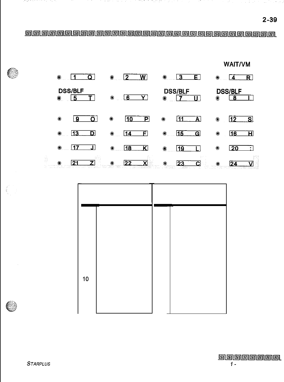
System Parameters Programming
Programmable Flash Rates
INC CO RING
INC ICW RING
CALL FORWARD MSG
WAIT/VM
BTN BTN
*n
%a
%13
+%n
MSG CBCK DND DSS/BLF AUTO CBCK UCD UNAVL
DSS/BLF DSS/BLF DSS/BLF
%+-
116
+#rT---ul
2#
18
TRANSFER CO RECALL CO QUEUED CO EXCLUSIVE
RING RING RING
HOLD
*
lg
+#k
110
I
In
+#n
SYSTEM HOLD IN USE HOLD CAMP-ON BTN CALLBACK BTN
%+113
*-
+%-
*m
LINE QUEUE BTN DND BTN ICM HOLD BTN
%+-
%+-
#Fir-i-l
se
130
Red LED Flash Rates
-
00
01
02
03
04
05
06
07
08
09
IO
11
12
13
14
-
Off
15
Steady On
16
30 ipm Flash 17
60 ipm Flash
18
60 ipm Dbl Wink 19
240 ipm Flash 20
240 ipm Flutter
21
480 ipm Flash 22
480 ipm Flutter 23
15 ipm Flash
24
120 ipm Flash
25
120 ipm Flutter 26
30 ipm Dbl Flash
27
480 ipm Dbl Wink 28
480 ipm Dbl Flash
Green LED
Flash
1
Steady On
30 ipm Flash
60 ipm Flash
60 ipm Dbl Wink
240 ipm Flash
240 ipm Flutter
480 ipm Flash
480 ipm Flutter
15 ipm Flash
120 ipm Flash
120 ipm Flutter
30 ipm Dbl Flash
480 ipm Dbl Wink
480 ipm Dbl Flash
Table 2-6: Flash Rates
STARPLUS Triad-S System Programming Manual Issue
I-
December 1998
Rates
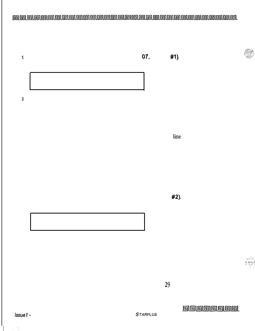
I
2-40
System Parameters Programming
Programmable Flash Rates
Incoming CO Line Ringing
Programming Steps
_.
,cT:.ze>;
p:.>:q
I>
1
Press the INC CO RING flexible button (FLASH
07.
button
#I).
The following message
“?‘
..-L..-
displays:
INC CO RING
00-28
RED 480 IPM FLUTTER
z
Enter a 2-digit value on the dial pad to correspond to one of the 29 available options.
Refer to the flash rate table.
3
Press HOLD to save the entry. A confirmation tone is heard and the display updates.
Description
The Incoming CO Line Ringing flash rate is the rate at which an Incoming CO
li.ne
or Loop Button flashes.
This flash rate can be programmed to 29 different options identified in the flash rate table, which enables
the programmer to customize the key system configuration to desired flash rates. By default, the Incoming
CO Ringing flash rate is set for RED 480 ipm Flutter (08).
Incoming Intercom Ringing
Programming Steps
1
Press the INC ICM RING flexible button (FLASH 07, button
#2).
The following message
displays:
INC ICM RING 00-28
RED 120 IPM FLUTTER
2
Enter a 2-digit value on the dial pad to correspond to one of the 29 available options.
Refer to flash rate table.
3
Press HOLD to save the entry. A confirmation tone is heard and the display updates.
Description
_.
:_-.
,.
._i
.!
,T
:I
.:j
i
1
,
The Incoming Intercom Ringing flash rate is the rate an Incoming DSS button flashes if you have a DSS
appearance for the calling station. This flash rate can be programmed to
29
different options identified in
the flash rate table. This enables the programmer to customize the key system configuration to desired
flash rates. By default, the Incoming Intercom Ringing flash rate is set for RED 120 ipm Flutter (11).
issue
I-
December 7998
STARPLUS Triad-S System Programming Manual
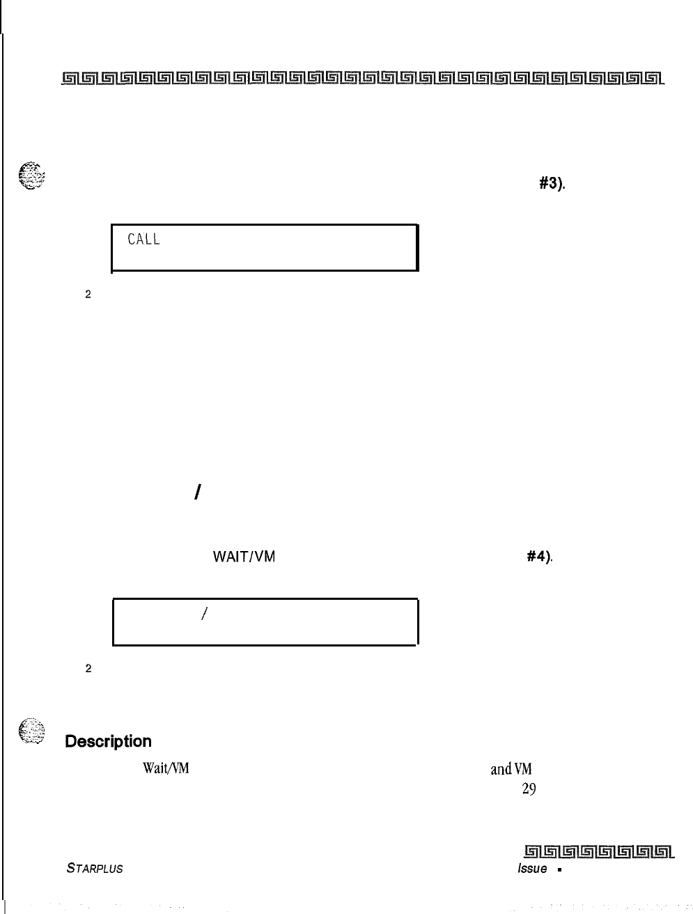
System Parameters Programming
Programmable Flash Rates
2-41
Call Forward Button
*-.-.
c-
Programming Steps
,:-.:a-
‘:..::~T~
CYZ
-
1
Press the CALL FORWARD BTN flexible button (FLASH 07. button
#3).
The following
message displays:
CALL FORWARD BTN 00-28
RED STEADY ON
z
Enter a 2-digit value on the dial pad to correspond to one of the 29 available options.
Refer to flash rate table.
3
Press HOLD to save the entry. A confirmation tone is heard and the display updates.
Description
The Call Forward Button flash rate is the rate at which the Call Forward button flashes when any type of
forward mode is used. This flash rate can be programmed to 29 different options identified in the flash rate
table. This enables the programmer to customize the key system configuration to desired flash rates, By
default, Call Forward Button flash rate is set for a Red Steady On
(01).
Message Wait
/
VM Button
Programming Steps
1
Press the MSG
WAIT/VM
BTN flexible button (FLASH 07, button
#4).
The following
message displays:
.
MSG WAIT
/
VM BTN 00-28
RED STEADY ON
.
z
Enter a 2-digit value on the dial pad to correspond to one of the 29 available options.
Refer to flash rate table.
3
Press HOLD to save the entry. A confirmation tone is heard and the display updates.
.._
r.--.:
c
:.:
.:i?,
::.::..<
Description
_..”
The Message
Wait/VM
Button flash rate is the rate at which the Message Wait
andVM
button(s) flashes when
you receive a message/voice mail message. This flash rate can be programmed to
29
different options
STARPLUS
Triad-S System Programming Manual issue
I
-
December 1998
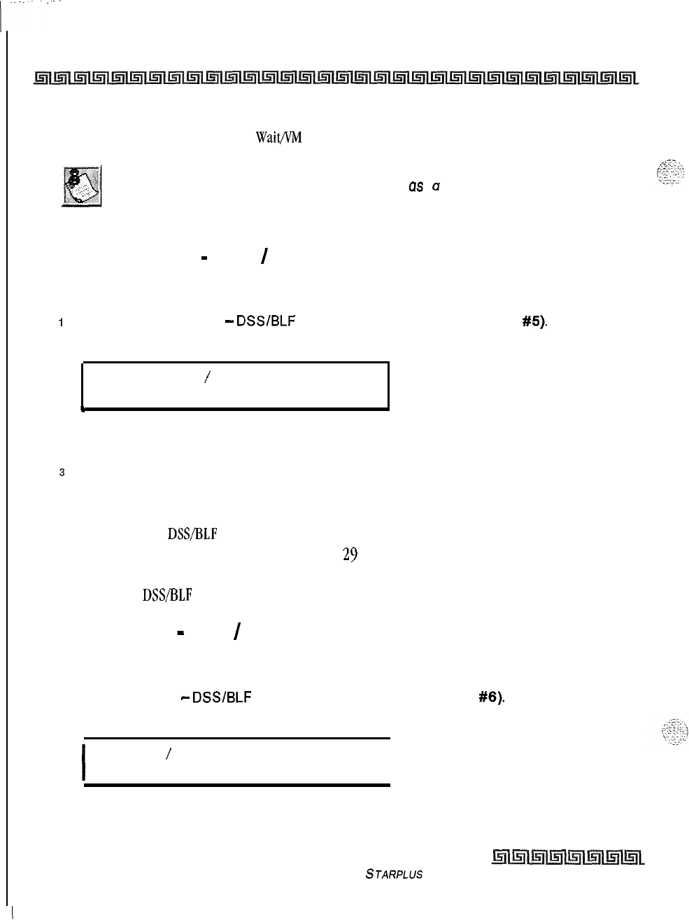
2-42
System Parameters Programming
Programmable Flash Rates
identified in the flash rate
table.
This enables the programmer to customize the key system configuration to
desired flash rates. By default, Message
Wait/I’M
Button flash rate is set for a Red Steady On (01).
The fixed message button should not be used
US
u Voice Mail button.
Message Callback
-
DSS
/
BLF
Programming Steps
1
Press the MSG CBCK
-
DSS/BLF
flexible button (FLASH 07, button
#5).
The following
message displays:
MSG CBCK DSS
/
BLF 00-28
RED 120 IPM FLUTTER
4
2
Enter a 2-digit value on the dial pad to correspond to one of the 29 available options.
Refer to flash rate table.
J
Press HOLD to save the entry. A confirmation tone is heard and the display updates.
Description
The Message Callback
DSS/BLF
flash rate is the rate at which a DSS button of a station returning your
message flashes. This flash rate can be programmed to
29
different options identified in the flash rate table.
This enables the programmer to customize the key system configuration to desired flash rates. By default,
Message Callback
DSS/BLF
flash rate is set for a Red 120 ipm Flutter (11).
Do Not Disturb
-
DSS
/
BLF
Programming Steps
1
Press the DND
-
DSWBLF
flexible button (FLASH 07, button
#6).
The following
message displays:
I
DND DSS
/
BLF 00-28
RED 60 IPM DBL WINK
I
2
Enter a 2-digit value on the dial pad to correspond to one of the 29 available options,
Refer to flash rate table.
Issue I- December 1998
STARPLUS
Triad-S System Programming Manual
.:-.
System Parameters Programming
Programmable Flash Rates
2-43
3
Press HOLD to save the entry. A confirmation tone is heard and the display updates.
Description
c
$$
The Do
Not
Disturb
DSS/BLF
flash rate is the rate at which a DSS button of a station flashes when you are in
a Do Not Disturb mode. This flash rate can be programmed to
29
different options identified in the flash rate
table. This enables the programmer to customize the key system configuration to desired flash rates. By
default, Do Not Disturb
DSS/BLF
flash rate is set for a Red 60 ipm Double Wink (04).
Auto Callback
-
DSS
/
BLF
Programming Steps
I
Press the AUTO CBCK
-
DSS/BLF flexible button (FLASH 07, button
#7).
The following
message displays:
AUTO CBCK DSS
/
BLF 00-28
RED 120 IPM FLASH
2
Enter a 2-digit value on the dial pad to correspond to one of the 29 available options.
Refer to flash rate table.
3
Press HOLD to save the entry. A confirmation tone is heard and the display updates.
Description
The Auto Callback
DSVBLF
flash rate is the rate at which a DSS button of a station returning your call back
flashes. This flash rate can be programmed to 29 different options identified in the flash rate table. This
enables the programmer to customize the key system configuration to desired flash rates. By default, Auto
Callback
DSS/BLF
flash rate is set for a Red 120 ipm Flash (10).
UCD Available
/
Unavailable
-
DSS
/
BLF
Programming Steps
I
Press the UCD UNAVL
-
DSS/BLF
flexible button (FLASH 07, button
#8).
The following
message displays:
I
UCD UNAVL DSS
/
BLF 00-28
RED 60 IPM DBL WINK
I
STARPLUS Triad-S System Programming Manual issue
I- December 1998
2-44
System Parameters Programming
Programmable Flash Rates
2
Enter a 2-digit value on the dial pad to correspond to one of the 29 available options.
Refer to flash rate table.
3Press HOLD to save the entry. A confirmation tone is heard and the display updates.
Description
The UCD Available/Unavailable
DSS/BLF
flash rate is the rate at which a DSS appearance for a station in
ACD/UCD
Unavailable mode flashes. This flash rate can be programmed to
29
different options identified in
the flash rate table. This enables the programmer to customize the key system configuration to desired
flash rates. By default, UCD Available/Unavailable
DSS’BLF
flash rate is set for a Red
60
ipm Double Wink
(04).
Transfer CO Ringing
Programming Steps
1
Press the TRANSFER CO RING flexible button (FLASH 07, button
#9).
The following
message displays:
I
TRANSFER CO RING 00-28
RED 120 IPM FLASH
I
2Enter a 2-digit value on the dial pad to correspond to one of the 29 available options.
Refer to flash rate table.
3Press HOLD to save the entry. A confirmation tone is heard and the display updates.
Description
The Transfer CO Ringing flash rate is the rate at which a CO Line button or Loop button flashes when a call
is transferred to you. This flash rate can be programmed to
29
different options identified in the flash rate
table, This enables the programmer to customize the key system configuration to desired flash rates. By
default, Transfer CO Ringing flash rate is set for a Red 120 ipm Flash (10).
Issue
I
-
December 1998
STARPLUS
Triad-S System Programming Manual
System Parameters Programming
Programmable Flash
Rates
2-45
Recall CO Ringing
f
Programming Steps
s:.%
.;‘.:
.L’
.‘.-.
c’
‘zy
1
Press the RECALL CO RING flexible button (FLASH 07, button
#lo).
The following
message displays:
I
RECALL CO RING 00-28
RED
480 IPM
FLUTTER
I
2
Enter a 2-digit value on the dial pad to correspond to one of the 29 available options.
Refer to flash rate table.
3
Press HOLD to save the entry. A confirmation tone is heard and the display updates
Description
The Recall CO Ringing flash rate is the rate at which a CO Line button or Loop button flashes when a call
recalls to your station. This flash rate can be programmed to
29
different options identified in the flash rate
table. This enables the programmer to customize the key system configuration to desired flash rates, By
default, Recall CO Ringing flash rate is set for a Red 480 ipm Flutter (08).
Queued CO Ringing
Programming Steps
1
Press the QUEUED CO RING flexible button (FLASH 07, button #II). The following
message displays:
I
QUEUED CO RING 00-28
GREEN 480 IPM FLUTTER
I
2
Enter a 2-digit value on the dial pad to correspond to one of the 29 available options.
Refer to flash rate table.
3
Press HOLD to save the entry. A confirmation tone is heard and the display updates.
Description
The Queued CO Ringing flash rate is the rate at which a CO Line button or Loop button flashes when a
queued line becomes available. This flash rate can be programmed to 29 different options identified in the
flash rate table. This enables the programmer to customize the key system configuration to desired flash
rates. By default, Queued CO Ringing flash rate is set for a Green 480 imp Flutter (22).
STARPLUS
Triad-S System Programming Manual issue
I- December 1998
;.
_-
2-46
System Parameters Programming
Programmable Flash Rates
Exclusive Hold
Programming Steps
1
Press the EXCLUSIVE HOLD flexible button (FLASH 07, button
#12).
The following
message displays:
EXCLUSIVE HOLD 00-28
GREEN 120 IPM FLASH
z
Enter a 2-digit value on the dial pad to correspond to one of the 29 available options.
Refer to flash rate table.
3
Press HOLD to save the entry. A confirmation tone is heard and the display updates.
Description
The Exclusive Hold flash rate is the rate at which a CO Line button or Loop button flashes when a call is
placed on Exclusive Hold. This flash rate can be programmed to 29 different options identified in the flash
rate table. This enables the programmer to customize the key system configuration to desired flash rates.
By
default, Exclusive Hold flash rate is set for a Green 120 ipm Flash
(26).
System Hold
Programming Steps
1
Press the SYSTEM HOLD flexible button (FLASH 07, button
#13).
The following
message displays:
SYSTEM HOLD' 00-28
RED 60 IPM DBL WINK
z
Enter a 2-digit value on the dial pad to correspond to one of the 29 available options.
Refer to flash rate table.
3
Press HOLD to save the entry. A confirmation tone is heard and the display updates.
Description
The System Hold flash rate is the rate at which a CO Line button or Loop button flashes when a call is
placed on System Hold. This flash rate can be programmed to
29
different options identified in the flash
rate table. This enables the programmer to customize the key system configuration to desired flash rates.
By default, System Hold flash rate is set for a Red
60
ipm Double Wink (04).
issue
I- December 1998
STARPLUS Triad-S System Programming Manual
.:
.
.
System Parameters Programming
Programmable Flash Rates
2-47
In-Use Hold (I-Hold)
..,?.?%
c
Programming Steps
L....
~.,
F.7
. . .
-.
-g:;
1
Press the IN USE HOLD flexible button (FLASH 07, button
#14).
The following message
displays:
I
IN-USE HOLD 00-28
GREEN 60 IPM FLASH
\
.s
Enter a 2-digit value on the dial pad to correspond to one of the 29 available options.
Refer to flash rate table.
3
Press HOLD to save the entry. A confirmation tone is heard and the display updates.
Description
.’
‘\
The In Use Hold (I-Hold) flash rate is the rate at which a CO Line button or Loop button flashes when a call
is placed on In Use Hold (I-Hold). This flash rate can be programmed to
29
different options identified in the
flash rate table. This enables the programmer to customize the key system configuration to desired flash
rates. By default, In Use Hold (I-Hold) flash rate is set for a Green
60
ipm Flash (17).
Camp-On Button
Programming Steps
1
Press the CAMP-ON BTN flexible button (FLASH 07. button
#15).
The following
message displays:
I
CAMP ON BTN 00-28
RED 120 IPM FLASH
I
z
Enter a 2-digit value on the dial pad to correspond to one of the 29 available options.
Refer to flash rate table.
3
Press HOLD to save the entry. A confirmation tone is heard and the display updates.
Description
The Camp-On Button flash rate is the rate at which the Camp-On button flashes when you receive a
Camp-
On. This hash rate can be programmed to
29
different options identified in the flash rate table, This enables
the programmer to customize the key system configuration to desired flash rates. By default, Camp-On
Button flash rate is set for a Red 120 ipm Flash (12).
STARPLUS
Triad-S System Programming Manual issue
I- December 1998
.:
I
2-48
System Parameters Programming
Programmable Flash Rates
Callback Button
Programming Steps
I
Press the CALL BACK BTN flexible button (FLASH 07, button
#16).
The following
message displays:
CALL BACK BTN 00-28
RED
120
IPM FLASH
2
Enter a 2-digit value on the dial pad to correspond to one of the 29 available options.
Refer to flash rate table.
3
Press HOLD to save the entry. A confirmation tone is heard and the display updates.
Description
The Call Back Button flash rate is the rate at which the Call Back button flashes
yhen
a station at which you
left a call
back
request becomes available. This flash rate can be programmed to
29
different options
identified in the flash rate table. This enables the programmer to customize the key system configuration to
desired flash rates, By default, Call Back Button flash rate is set for a Red 120 ipm Flash (10).
Line Queue Button
Programming Steps
I
Press the LINE QUEUE BTN flexible button (FLASH 07, button
#17).
The following
message displays:
LINE QUEUE BTN 00-28
RED 480 IPM FLUTTER
z
Enter a 2-digit value on the dial pad to correspond to one of the 29 available options.
Refer to flash rate table.
3
Press HOLD to save the entry. A confirmation tone is heard and the display updates.
Description
The Line Queue Button flash rate is the rate at which the Line Queue button flashes after queueing onto a
busy line. This button flashes when the busy line becomes available. This flash rate can be programmed to
29
different options identified in the flash rate table which enables the programmer to customize the key
Issue I- December 1998
S
JARPLUS
Triad-S System Programming Manual
I
System Parameters Programming
Programmable Flash Rates
2-49
system configuration to desired flash rates. By default, Line Queue Button flash rate is set for a Red
480
ipm
Flutter (08).
.-i
e”
$,$
Do Not Disturb Button
Programming Steps
1
Press the DND BTN flexible button (FLASH 07, button
#18).
The following message
displays:
I
DND.BTN 00-28
RED STEADY ON
I
2
Enter a 2-digit value on the dial pad to correspond to one of the 29 available options.
Refer to flash rate table.
3
Press HOLD to save the entry. A confirmation tone is heard and the display updates.
Description
The
Do
Not
Disturb Button flash rate is the rate at which your Do Not Disturb button flashes when you place
your station in a Do Not Disturb mode. This flash rate can be programmed to
29
different options identified
in the flash rate table. This enables the programmer to customize the key system configuration to desired
flash rates. By default, Do Not Disturb Button flash rate is set for Red Steady On
(01).
Intercom Hold Button
Programming Steps
1
Press the ICM HOLD BTN flexible button (FLASH 07, button
#19).
The following
message displays:
ICM
HOLD BTN 00-28
RED 15 IPM FLASH
2
Enter a 2-digit value on the dial pad to correspond to one of the 29 available options.
Refer to flash rate table.
3
Press HOLD to save the entry. A confirmation tone is heard and the display updates.
STARPLUS
Triad-S System Programming Manual Issue I
-
December 1998
System Parameters Programming
System Parameters Programming
Description
The Intercom Hold Button flash rate is the rate at which your Hold button flashes when you receive an
intercom call and your station’s intercom mode selector switch is in the Tposition. This flash rate can be
programmed to
29
different options identified in the flash rate table. This enables the programmer to
customize the key system configuration to desired flash rates. By default, Intercom Hold Button flash rate is
set for a Red
15
ipm Flash
(09).
System Parameters Programming
Programming Steps
If the system is in the programming mode, continue using the program codes. If starting to program here,
enter the programming mode.
1
Press FLASH and dial
[09].
The following message displays:
SYSTEM PARAMETERS
ENTER BUTTON NUMBER
Issue I- December 1998
STARPLUS Triad-S System Programming Manual
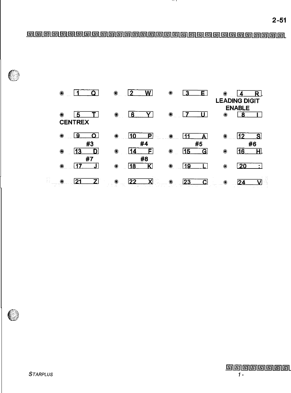
.
.
.._
System Parameters Programming
System Parameters Programming
Description
This section describes the procedures and steps necessary to program System Parameters in the System
Parameters programming area. The buttons on the digital terminal are illustrated below:
LEADING DIGIT 1
LEADING DIGIT 2 LEADING DIGIT 3 LEADING DIGIT 4
9kn
012
*
13
#m
LEADING DIGIT 5 LEADING DIGIT 6 LEADING DIGIT 7
LEA;FA;LplT
%n
%1_6
%m
*!xzil
CENTREX
DIGITS 4 DIGIT VM ID
s-
*Llirizl*-
*Eizxzl
MUSIC CH
#3
MUSIC CH
#4
MUSIC CH
#5
MUSIC CH
#6
+#kn
IllQ
%sm
*n
MUSIC CH
#7
MUSIC CH
#8
*m
88118
*a
#
130
STARPLUS
Triad-S System Programming Manual Issue
I-
December 1998
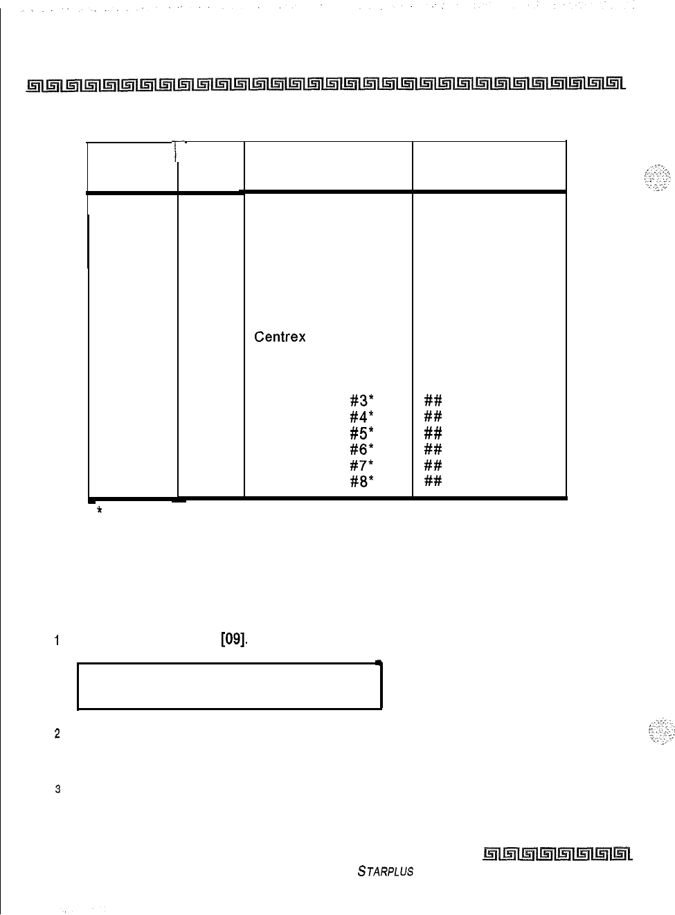
2-52
System Parameters Programming
System Parameters Programming
Program
Code
FLASH 09
T-
Flex
Button
1
2
3
4
5
6
7
8
9
10
11
12
13
14
15
16
17
18
Feature
Leading Digit 1
Leading Digit
Leading Digit 2 None
Leading Digit 3 None
Leading Digit 4 None
Leading Digit 5 None
Leading Digit 6 None
Leading Digit 7 None
Leading Digit Option Disabled
Centrex
Digits 4 digits
Four Digit Voice Mail ID 3 digits
Music Channel
#3* ##
Music Channel
#4* ##
Music Channel
#5* ##
Music Channel
#6* ##
Music Channel
#7* ##
Music Channel
#8* ##
Default
(after initialization)
*
Music Channels 3-8 can only be used for Music-On-Hold functions
Table 2-7: System Parameters Programming
Leading Digit Translation
Programming Steps
I
Press FLASH and dial
[09].
The following message displays:
.
LEADING DIGIT 1 D-8
LEADING DIGIT
2
The top left button in the flexible button field is lit for programming Leading Digit 1. To
change Leading Digits or enter a different Leading Digit, press the appropriate flexible
button 1-8 and perform the following procedures.
s
Enter a l-digit value on the dial pad that corresponds to the leading digit translation.
[0] = NONE
[I] = Trunk Group 1 (81)
Issue I- December 1998
STARPLUS Triad-S System Programming Manual
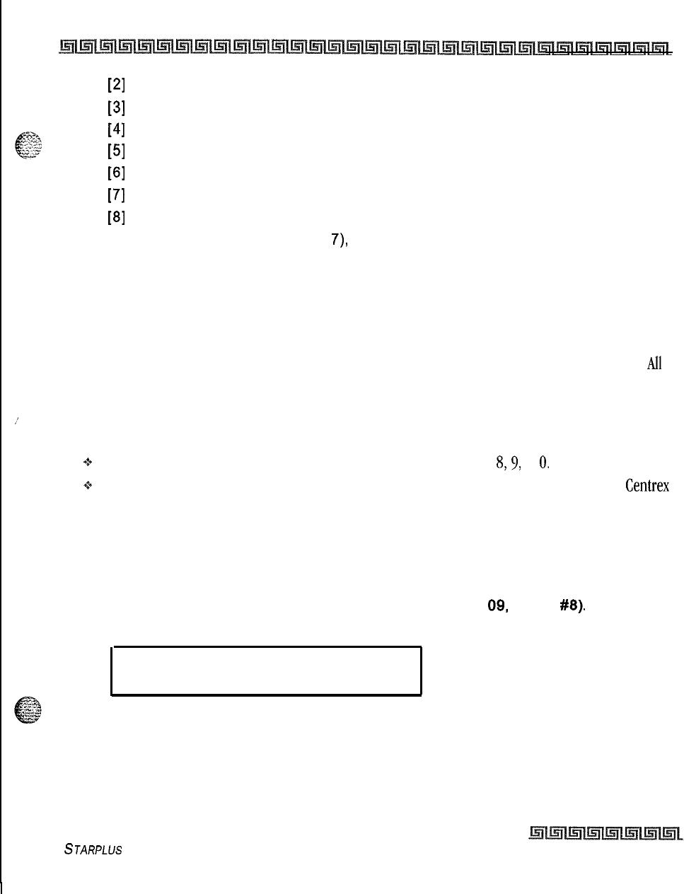
System Parameters Programming
System Parameters Programming
2-53
[2]
= Trunk Group 2 (82)
[3]
= Trunk Group 3 (83)
[4]
= Trunk Group 4 (84)
[5]
= Trunk Group 5 (85)
[6]
= Trunk Group 6 (86)
[7]
= Trunk Group 7 (87)
[8]
= Leading Digit*
* 8 is unavailable on button 7 (digit
7),
only O-7 are available.
4Press HOLD to save the entry. A confirmation tone is heard and the LCD indicates the
change.
Description
This feature lets the system have the dialing plan modified to accommodate multiple systems connected
together via CO lines. The dialing plan is changed to a four digit access with a programmable leading digit.
All
feature access codes and station numbers are dialed by dialing the programmable leading digit first followed
by the standard dialing plan. There is no default for this feature.
_’
Conditions:
+
The leading digit does not apply to feature access codes starting with 8,9, or
0.
-+
The remaining digits selected for the Triad-S system may be used as CO line group access for Centrex
dialing applications.
Leading Digit Enable
Programming Steps
1
Press the LEADING DIGIT ENABLE flexible button (FLASH
09,
button
#8).
The
following message displays:
.
LEADING DIGIT OPTION
O-l
DISABLED
2Enter a l-digit value (O-l) that corresponds with the following entries:
[0] = Disabled
[I] = Enabled
3Press HOLD to save the entry. A confirmation tone is heard.
STARPLUS
Triad-S System Programming Manual
Issue I- December 1998
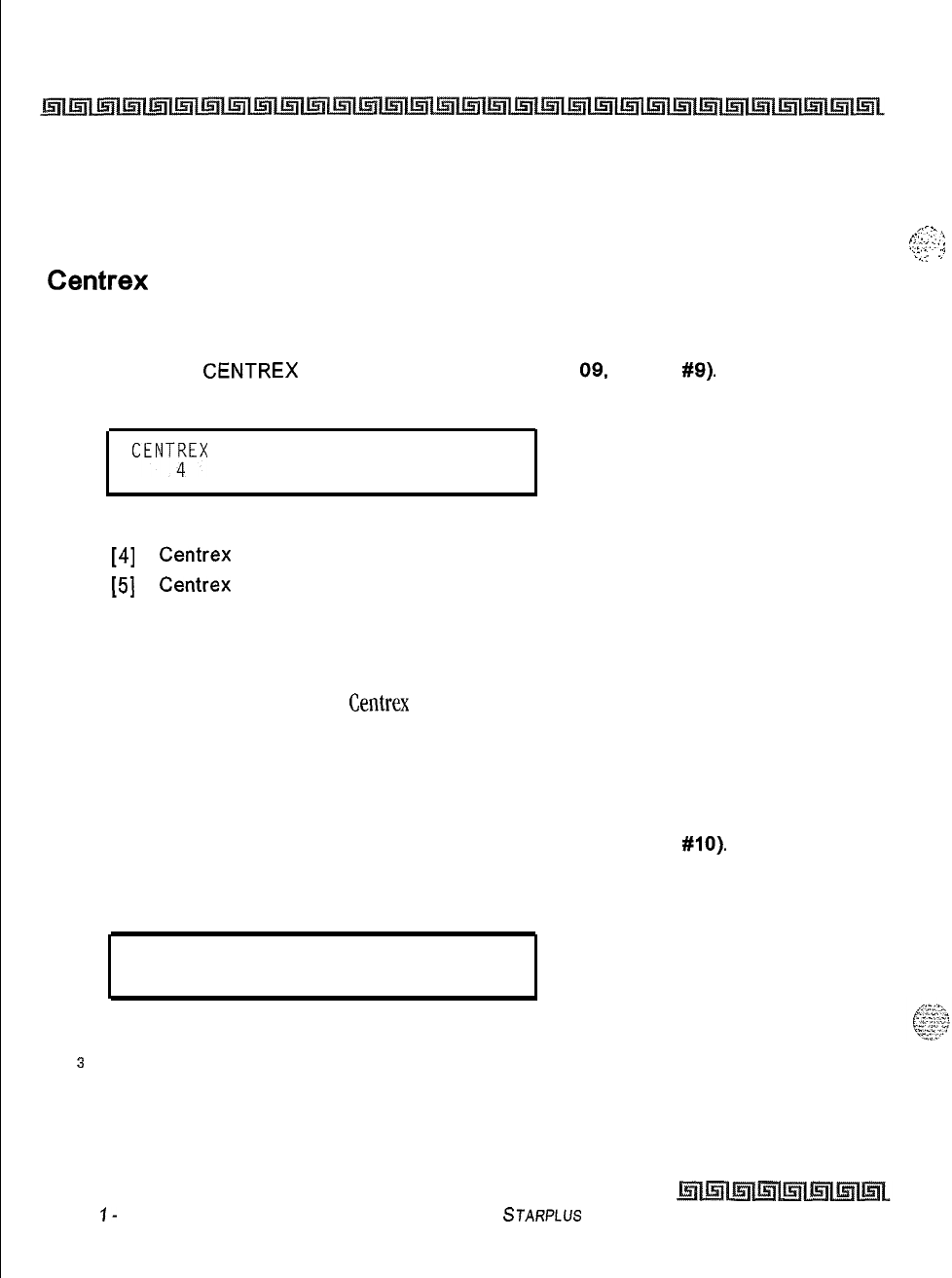
2-54
System Parameters Programming
System Parameters Programming
Description
This feature enables/disables the Leading digit Integration feature option on a system-wide basis. By
default, this feature is disabled.
Centrex Digit Length
Programming Steps
1
Press the
CENTREX
DIGITS flexible button (FLASH
09.
button
#9).
The following
message displays:
CENT;EX DIGITS 4-5
2
Enter a l-digit value (4-5) that corresponds with the following entries:
[4]
=
Centrex
Digit length
[5]
=
Centrex
Digit length
3
Press HOLD to save the entry. A confirmation tone is heard.
Description
This feature determines the number of Centrex digits in the system.
Four-Digit Voicemail ID
Programming Steps
1
Press the FOUR DIGIT VM ID flexible button (FLASH 09, button
#lo).
The following
message displays:
VM ID DIGITS 3-4
3
2
Enter a l-digit entry (3-4) that corresponds to the number of digits to be dialed.
J
Press HOLD to save the entry. A confirmation tone is heard.
Issue
I-
December 7998
STARPLUS
Triad-S System Programming Manual
,,c
.*
,.
,.
_:.
.’
I.
y:<.,,...
:
‘i’
;
.._
L.’
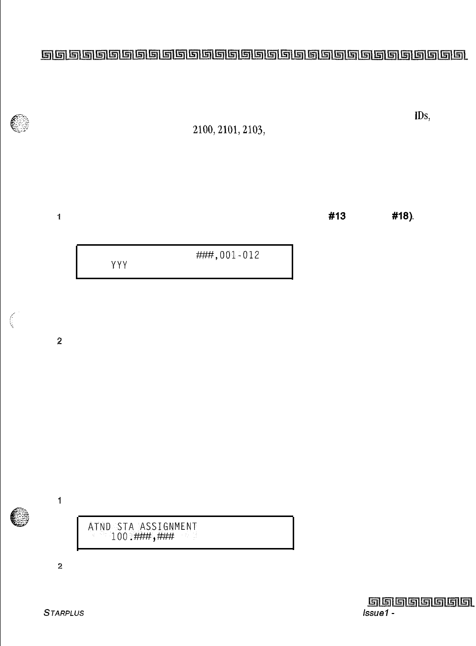
System Parameters Programming
2-55
System Parameters Programming
Description
This feature modifies the station and CO voice mail identification fields such that the maximum length of
these fields is increased from three digits to four digits. When using leading digit for voice mail
IDS,
the new
number must be entered individually... 2100,2101,2103, etc. This is performed in Flash 50, Page B, Button
13.
MOH Assignments
Programming Steps
1
Press the MUSIC CH # flexible button
(FLASH 09, button
#I3
through
#18).
The
following message displays:
MUSIC
CHANNEL X
W,OOl-012
YYY
l
Where:
X= 3-8
YYY = CO Line number
T!
Enter a 2-digit entry (001-012) that corresponds to the CO line number desired.
3Press HOLD to save the entry. A confirmation tone is heard.
Description
This feature enables the system to assign CO line circuits as additional 6 music-on-hold inputs. This
increases the capacity of music channels beyond the 2 available on the MISU board for use by MOH sources.
A total of 8 channels are available for use on the system. By default, no channels are assigned.
Attendant Station Assignment
Programming Steps
i
Press FLASH and dial [IO]. The following message displays:
ATNDl;;A&SI$MENT
,
9
z
Enter up to 3-digit station number(s) on the dial pad.
3100-l 31 for Triad-S.
STARPLUS
Triad-S System Programming Manual issue
I-
December 1998
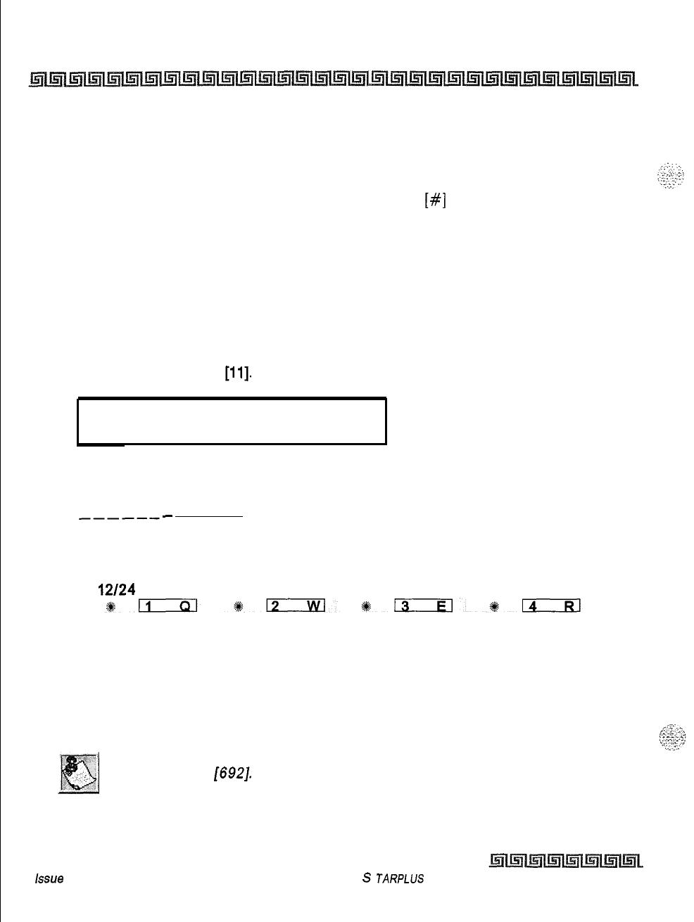
2-56
System Parameters Programming
System Parameters Programming
4
Press HOLD to save the entry. A confirmation tone is heard and the display updates.
Description
The system identifies an attendant station for the purpose
of
receiving recalls and activating night service.
The system can have up to three attendant(s) programmed. Entering
[#]
three times removes that
attendant assignment or different station numbers can be programmed. By default, Station 100 is assigned
as the first attendant.
System Time and Date
Programming Steps
To set the time and date that appears on display Terminals:
1
Press FLASH and dial
[ll].
The following message displays:
DATE AND TIME
MMM DD YY HH:MM am
2
Choose display format by pressing the appropriate button in the flexible button field.
3
Press HOLD or dial the time and date as follows (12 digits):
YYMMDDHHMMSS
_------
4Press HOLD to save the entry. A confirmation tone is heard and the display updates.
The time can be displayed in the standard 12 hour format or the 24 hour format.
12/24
HOUR
By default, the time is set for 12 hour display format. When entering the time and date, use the following
data:
LED Off = 12 Hour Display
LED On = 24 Hour Display
The Date and Time can be changed or set by the first Attendant station
using dial code
[692].
hue
I- December 1998
S
JARPLUS
Triad-S System Programming Manual
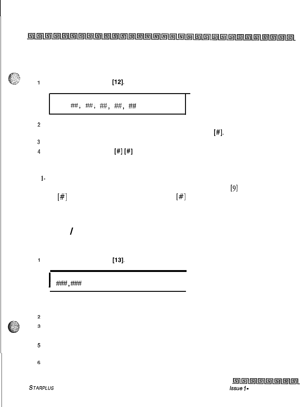
System Parameters Programming
System Parameters Programming
2-57
PBX Dialing Codes
Programming Steps
1
Press FLASH and dial
[12].
The following message displays:
PBX DIAL CODES
w,
H,
w,
w,
##
.
z
Enter five 2-digit code numbers, one right after the other, on the dial pad up to ten digits.
If a single digit code is required, enter the code followed by
[#I.
3
Press HOLD to save the entry. A confirmation tone is heard and the display updates.
4
To delete a code, enter
[#I]
[#I
and press HOLD.
Description
Five l- or Z-digit PBX access codes can be programmed into memory. When dialed, these codes signal the
system so toll restriction is applied at the next dialed digit. When a single digit code
[9]
is entered, it must be
followed by
[#I
as the second digit. To delete an entry, enter
[#I
twice and Press HOLD. Lines must be
programmed as PBX lines before these codes apply. By default, no PBX dialing codes are assigned. This
programming is performed in Flash
40,
Page A, Button 2.
Executive
/
Secretary Pairs
Programming Steps
1
Press FLASH and dial
[13].
The following message displays:
I
EXEC SECY PAIRINGS
*,m
PAIR 1
I
The first button is lit indicating the first pair may be programmed.
2
Enter the 3-digit Executive station number.
3
Enter the 3-digit Secretary station number.
4Press HOLD to save the data. A confirmation tone is heard and the display updates.
pi
To program a second pair, press the second flexible button in the flexible button field and
enter station numbers as in steps 3-5.
6
To program a third pair, press the third button in the flexible button field and enter station
numbers as in steps 3-5.
STARPLUS
Triad-S System Programming Manual issue
I
-
December 1998
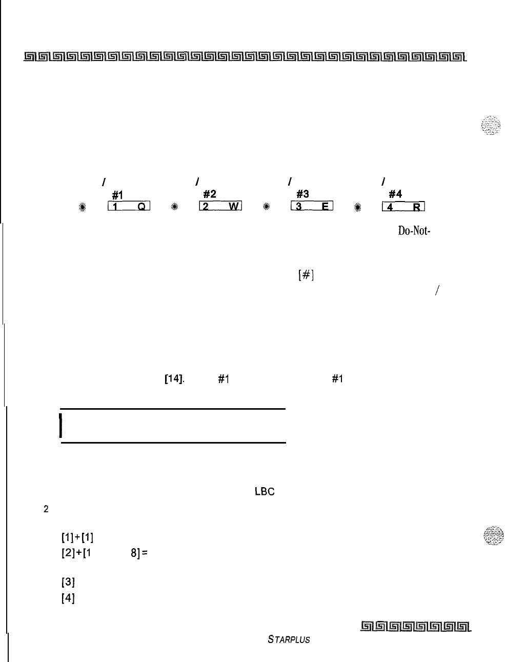
2-58
System Parameters Programming
System Parameters Programming
7To program a fourth pair, press the fourth button in the flexible button field and enter
station numbers as in steps 3-5.
Description
There are four Executive/Secretary pairs available. When an Executive station is busy or in DND, intercom
calls and transfers are automatically routed to the designated Secretary.
EXEC
/
SECY EXEC
/
SECY EXEC
/
SECY EXEC
/
SECY
PAIR
#l
PAIR
#2
PAIR
#3
PAIR
#4
I
II
4s
12
*
13
48
I4
The assigned secretary may Camp-On to the Executive Station when the station is busy or in
Do-Not-
Disturb. There can be only one pairing of stations, with no duplicates. You cannot pair Executive 100 to
Secretary
101, then pair Secretary 101 to Executive 100. The same Secretary station can be specified for
more than one Executive station (101-105 and 102-105). Entering
[#]
six times removes the assignments.
Individual pairs may be changed by pressing the associated flexible button. By default, no Executive
/
Secretary pairs are assigned.
On-Board Relay Programming
Programming Steps
1
Press FLASH and dial
[14].
button
#I
is lit to indicate Relay
#I
is selected. The following
message displays:
I
RELAY X TYPE
YYYYYYYYYYYY
I
Where:
X=1-6
YYYYYYYYYYYY = Ext Page Zone l-l,
LBC
Sta XXX, Ran Start X, CO Control XX
z
Press the button that corresponds to the desired relay. That button lights. Enter one of
the following sequences on the keypad:
[l]+[l]
External Page Zones
[2]+[1
through
8]=
RAN Start
(RAN Announcement Tables 1-8)
[3]
+ STA # = Loud Bell
[4]
+ CO # = CO Line Control
STARPLUS
Triad-S System Programming Manual
Issue I- December 1998
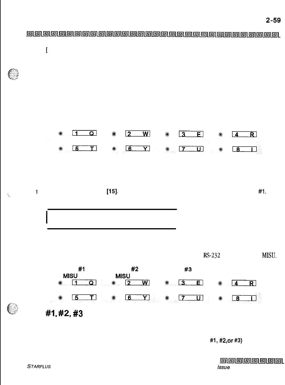
System Parameters Programming
System Parameters Programming
[
0] = Disables Relay
3
Press HOLD to save the entry. A confirmation tone is heard and the display updates.
e-.=<m-
1
c-.
“..lr>
Each time the user presses a relay button, the LCD updates with the relay number and the function assigned
. . .,
‘;-“-:
to it.
Description
The Triad-S has two relays on the BKSLJ that can be programmed to perform certain functions. These
functions are loud bell, external page control, RAN Start, and CO Line control.
RELAY 1
RELAY 2
*n
%
131
113
I
14
Baud Rate Assignments
Programming Steps
‘\.
1
Press FLASH and dial
[15].
The first button is lit and ready for programming Port
#I.
The
following message displays:
I
PORT BAUD
1
9600
I
Description
The Triad-S System provides outputs such as SMDR or ICLID to the optional
RS-232
connectors on the
MISU.
PORT
#l
PORT
#2
PORT
#3
MISU 1 MISU
2
MODEM
%+Eim*12
+%13
*lzcIizl
Port
#I,
#2,
#3
Baud Rates
Programming Steps
1
Press the desired PORT # flexible button (FLASH 15, Buttons
#l,
#2,or
#3)
to determine
the port to program.
STARPLUS Triad-S System Programming Manual issue
I- December 1998
:
2-60
System Parameters Programming
Access Codes
2
Enter a l-digit number for the baud rate:
[I] = 150 Baud
[2]
= 300 Baud
[3]
= 600 Baud
[4]
= 1200 Baud
[5]
= 2400 Baud
[6]
= 4800 Baud
~
[7]
= 9600 Baud
3
Press HOLD to save the entry. A confirmation tone is heard and the display
updates.
Description
Port
#l:
First RS-232C port on the optional MISU board.
Port
#2:
Second RS-232 port on the optional
MISU
board.
By default, Port
#l
(MISU
RS-232C),
Port
#2
(MISU
RS-232) and Port
#3
(Modem) baud rates are set for
9600.
Access Codes
Programming Steps
If the system is in the programming mode, continue using program codes. If starting to program here,
enter the programming mode.
1
Press FLASH and dial
[20].
The following message displays:
ACCESS'CODES
ENTER BUTTON NUMBER
Description
This section describes the procedures and steps necessary to program Access codes.
DISA
ACCESS
ADMIN
CODE PASSWORD
+kn
*a
#mIEl
#Fi---m
Issue I- December 7998
STARPLUS Triad-S System Programming Manual
System Parameters Programming
Access Codes
2-61
DISA
Access Code
.s3w
Programming
Steps
Q’
,..“.S
.,z.;&?
--.
<..
-...-
1
Press the
DISA
ACCESS CODE flexible button (FLASH 20, button
#I).
The following
message displays:
.
DISA ACCESS CODE
100
.
.z
Enter a 3-digit value (100-999) on the dial pad for the
DISA
access code.
3
Press HOLD to save the entry. A confirmation tone is heard and the display updates.
Description
This permits assigning a
3-digit
access code to the system. Anyone calling on a DISA line must use this code
to gain access to system features, To disable the DISA access code, enter
(#)
three times. By default, 100 is
the
assigned access
code. Use of this feature with or without access code can be abused by callers.
Database Admin Password
Programming Steps
-I
Press the ADMIN PASSWORD flexible button (FLASH 20, button
#2).
The following
message displays:
ADMIN PASSWORD
3226
2
Enter a 4-digit value on the dial pad that corresponds with 0000-9999.
3
Press HOLD to save the entry. A confirmation tone is heard and the display updates.
Description
The password used to enter customer database programming can be customized by the programmer. This
lets the system administrator block unauthorized personnel from entering database admin.
Care should be taken when changing the programming password so
autho-
rizedpersonnel are not locked out, which couldprevent or delay them from
making necessary programming changes.
STARPLUS Triad-S System Programming Manual Issue I
-
December 1998
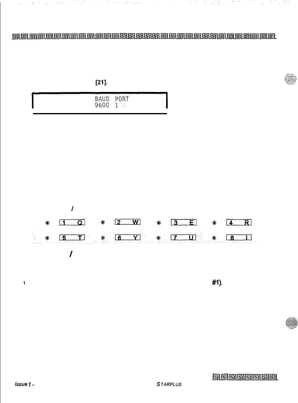
2-62
System Parameters Programming
Access Codes
Station Message Detail Recording (SMDR)
Programming Steps
1
Press FLASH and dial
[21].
The following message displays:
SDR TPE PNT
9";;;
;ORT
NO LD 80
2
To program SMDR features, use the flexible button(s) as defined in the following
procedures.
3
The ENABLE/DISABLE, TYPE, and PRINT features toggle on and off each time the
button is pressed. The display updates with each toggle.
4
After all entries are made, Press HOLD to save the entry. A confirmation tone is heard.
Description
The Triad-S System can provide SMDR output to the optional RS-232C connectors on the MISU. When
SMDR is desired, the following system-wide parameters determine how SMDR information is reported.
ENABLE
/
DISABLE CALL TYPE PRINT FORMAT BAUD RATE
#!2ixzl
4#12
*13
s&n
SMDR Enable
/
Disable
Programming Steps
1
Press the ENABLE/DISABLE flexible button (FLASH 21, button
#I).
This feature
toggles on and off each time the button is pressed. The display updates with each
toggle.
LED ON = SMDR is enabled
LED OFF = SMDR is disabled
2
Press HOLD to save the entry. A confirmation tone is heard
Issue
I-
December 1998
STARPLUS Triad-S System Programming Manual
System Parameters Programming
Access Codes
2-63
Description
A call accounting device can be installed allowing the system to track calls by outside line number, number
t-:=.
.a
c--
2.:
:.
:s dialed, time of day, date, station that placed or received the call, and duration of the call. By default,
SMDR
is
.~~~
disabled.
Long Distance
/
All Calls
Programming Steps
1
Press the CALL TYPE flexible button (FLASH 21, button
#2)
to determine the type of
calls to record. This feature toggles on and off each time the button is pressed. The
display updates with each toggle.
LED ON = Long Distance is enabled
LED OFF = All Calls is enabled
2
Press HOLD to save the entry. A confirmation tone is heard.
Description
;
The system can be set to record all outgoing calls or only outgoing long distance calls. Long Distance calls are
defined as beginning with a 1 or 0, or containing eight or more digits. Incoming calls are only recorded if
TYPE is set for all calls. By default, the system records long distance (LD) calls only.
Character Print Assignment
Programming Steps
I
Press PRINT FORMAT flexible button (FLASH 21, button
#3)
to determine the print
format of SMDR records. This feature toggles on and off each time the button is
pressed. The display updates with each toggle.
LED On = 80-Character is enabled
LED Off =30-Character is enabled
2
Press HOLD to save the entry. A confirmation tone is heard.
cii
252
Description
The system can be programmed to print individual SMDR records in either a l-line 80-character format or a
3-line SO-character format. By default, the l-line SO-character format is selected,
STARPLUS Triad-S System Programming Manual
Issue I- December 1998
2-64
System Parameters Programming
Access Codes
Baud Rate Display
Programming Steps
The SMDR Baud Rate is programmed using Flash 15, Baud Rate Assignments.
FLASH 21, button
#4
returns an error tone when pressed. The LCD displays the current baud rate based on which port is
assigned to the SMDR Port number.
Description
The Triad-S System provides SMDR output to the standard RS-232C connector on the optional MISU. The
baud rate is displayed as 150, 300,600, 1200, 2400,4800, or 9600 baud.
SMDR Port Assignments
Programming Steps
1
Press the PORT flexible button (FLASH 21, button
#5)
to determine which port to use
for SMDR information.
2
Enter a l-digit number for the SMDR Port number:
[I] = Port
#l
(MISU On-Board RS-232C)
[2]
= Port
#2
(MISU On-Board RS-232C)
3
The LCD displays the current baud rate based on which Port number is assigned to the
SMDR Port number.
4
Press HOLD to save the entry. A confirmation tone is heard and the display updates.
Description
PORT
#l:
Refers to the standard RS-232C connector on the optional MISU.
PORT
#2:
Refers to the standard RS-232C connector on the optional MISU.
By default, Port
#l
is used for SMDR.
issue
I-
December 1998
STARPLUS
Triad-S System Programming Manual
System Parameters Programming
Access Codes
2-65
Weekly Night Mode Schedule
Programming Steps
1
Press FLASH and dial
[22].
The following message displays:
I
DAY END START AUTO
MON 0800 1700
YES
I
Description
The Triad-S System can be programmed so it is automatically placed into and out of night mode. A
programmable weekly time schedule lets the system administrator preset the time the system goes into night
mode, and the time night mode is removed on a daily basis, including weekend operation.
AUTO
I
MANUAL MONDAY TUESDAY WEDNESDAY
sn
*lIsci!a
*ELziEl
8
IRI
THURSDAY FRIDAY SATURDAY SUNDAY
%+;:
116
St+-
#lzicil
Automatic
/
Manual Operation
Programming Steps
1
Press the AUTO/MANUAL flexible button (FLASH 22, button
#I).
This feature toggles
on and off each time the button is pressed. The display updates with each toggle.
LED On = Automatic Night Mode
LED Off = Manual operation
2
If no other changes must be made, press HOLD to save the entry. A confirmation tone is
heard.
Once enabled, this feature addresses the entire week.
Description
If the system is operated in the automatic night mode the attendant(s) can override the automatic mode by
pressing the night key on the attendant(s) phone. The schedule does not go into effect until the attendant(s)
STARPLUS Triad-S System Programming Manual
Issue I- December 1998
2-66
System Parameters Programming
Access
Codes
press the night key again. When the system is placed into night mode, CO line ringing follows the night
ringing assignments and stations are governed
by
their respective night COS. The default times for
automatic night mode are:
Monday through Friday
OS:00
17:00 (Daytime operation 8:00 am to 5:00 pm)
Saturday and Sunday
##:##
##:##
(24-hour night-mode operation)
tt An entry of
0O:OO
23:59
indicates 24 hours of day mode
oAn entry of
##;##
##;##
directs the system to ignore these days.
Day of Week Programming
Programming Steps
The MONDAY flexible button (Button #2> LED is lit. To change days of the week:
1
Press the appropriate DAY OF WEEK flexible button (FLASH 22, buttons 2-8).
2
Enter the 8-digit entry to indicate the hour and minutes to end night mode.
3
Press HOLD to save the entry. (Example: 07301830 [HOLD]) A confirmation tone is
heard and the display updates.
Directory Dialing
Programming Steps
To enter, change, erase or view entries in the Directory Dialing list:
I
Press FLASH and dial
[23].The
following message displays:
I
DIR LST AAA BIN
/
ICM:
xxx
nnnnnnnnnnnnnnnnnnnnnnnnnnnn
I
Where:
AAA = Directory list entry number (000-199)
XXX = a station number, a system speed dial bin number, or Local Number/Name
Translation table number
nnn = programmed name (blank if none)
To select a particular list entry:
I
Press Flexible button
#20
for a directory list entry.
2
Dial the 3-digit directory list entry number (000-199).
Issue I- December 1998
STARPLUs Triad-S System Programming Manual
System Parameters Programming
Access Codes
2-67
3
Press HOLD to save the entry. A confirmation tone is heard and the display updates.
To scroll through the list:
1
Press the NEXT flexible button (FLASH 23, button
#18)
to scroll up (next entry)
or
Press the PREV flexible button (FLASH 23, button
#19)
to scroll backwards (previous
entry).
Description
Directory Dialing enables station users obtain a directory of station users and have the system dial the
extension currently displayed. The Triad-S system provides locations for up to 200 names
(000-199).
Directory dialing also lets users program a name with a speed dial bin for use in later locating a speed dial
number. When prompted, the system displays the name associated with a speed dial number so when the
desired name is shown, the user may then have the system dial the number. Directory dialing also lets users
associate a name with an entry in the local number/name translation table. When prompted, the system
displays the name associated with the table so when the desired name is shown, the user may then have the
system dial the number. The Triad-S system provides locations for up to 200 names.
The Directory Dialing list may be programmed and maintained at the first assigned attendant station in one
of two ways. However, this admin routine lets the directory list be maintained by the system programmer
locally (at Station 100) or remotely via modem access.
STARPLUS
Triad-S System Programming Manual Issue
7
-
December 1998
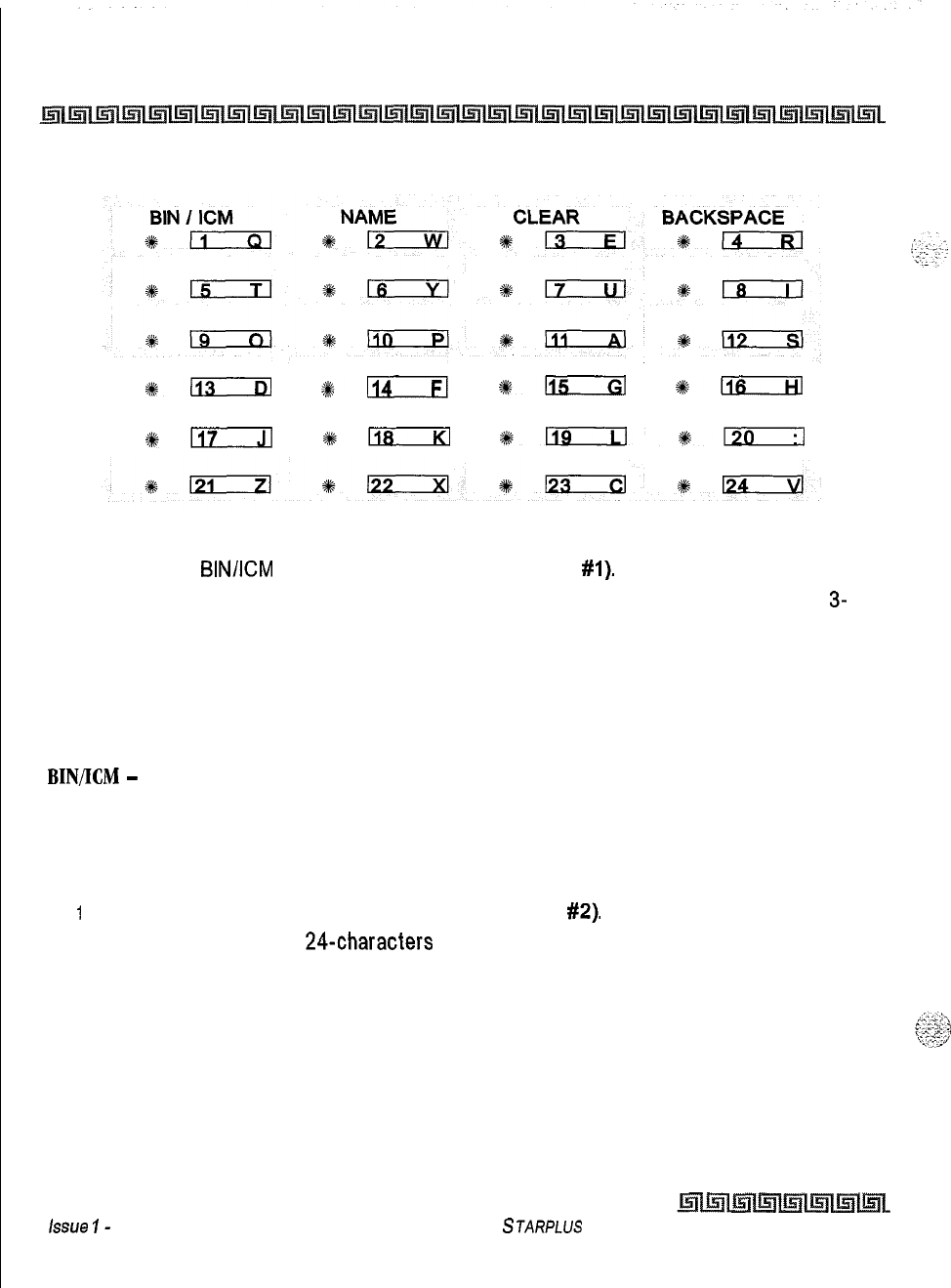
2-68
System Parameters Programming
Access
Codes
%i
#114
de115
#lIoxzil
NEXT ENTRY PREV ENTRY NEW ENTRY
#117
*rscria
%@mzil%;
To enter the Intercom number or System Speed Dial bin to associate to the name:
1
Press the
BIN/KM
flexible button (FLASH 23, button
#l).
2
Enter a 3-digit station intercom number, a 3-digit System Speed Dial number, or a
3-
digit Local Number/name Translation Table number.
100-l 31 = Triad-S Extension Numbers
020-099 = System Speed Number
600-799 = Local Number/Name Table
3
Press HOLD to save the entry. A confirmation tone is heard and the display updates.
BIN/KM
-
Each entry in the directory dialing list must be associated to a system speed dial bin (for calling
a destination outside of the system) or to an intercom station (for calling internal station including CO line
transfers).
To enter or change the current Name shown on the display:
I
Press the NAME flexible button (FLASH 23, button
#2).
2
Enter the name (up to
24-characters
may be entered) by using keys on the dial pad as
illustrated on the following page:
Issue
I-
December 1998
STARPLUS
Triad-S System Programming Manual
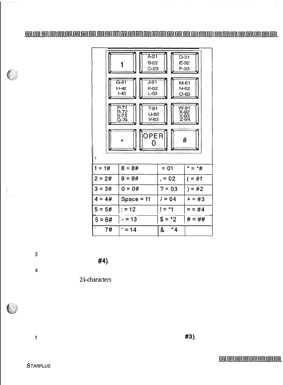
System Parameters Programming
Access Codes
2-69
Other Codes:
I I I
6=6#
l-=13 I$=*2
I#=##
I I I
7 =
7#
‘=14
&
=
*4
Table 2-8: Dial Pad Keys
3
If an error is made while entering the name, press the BACK SPACE flexible button
(FLASH 23, button
#4).
This button backspaces one character at a time.
4
Press HOLD to save the entry. A confirmation tone is heard and the display updates.
NAME -A
name up to 24-characters may be entered into each directory dial list entry. The names display
alphabetically when accessed by a station user. It is possible to have multiple entries that are associated to
the same station number or system speed dial bin. This lets the same name be entered into the list several
times, For example, by last name and by first name, pointed to a station number and a speed dial bin (home,
or mobile phone number). Or, several different names associated to the same speed dial bin.
To clear an entry:
I
Press the CLEAR flexible button (FLASH 23, button
#3).
STARPLUS
Triad-S System Programming Manual
Issue I- December 1998
2-70
System Parameters Programming
Hunt Groups
2
Press HOLD to save the entry. A confirmation tone is heard and the display updates.
The entry is erased (both the
BIN/KM
assignment and the programmed name).
CLEAR
-
Entries in the table may be erased and cleared from the table allowing placement of another entry
into the list. When a system speed dial bin is deleted or changed the name associated to the bin must also
be erased. When a multiple table listing is associated to one system speed dial bin it may be necessary to
clear more than one entry.
Hunt Groups
Hunt Group Programming
Programming Steps
I
Press FLASH and dial
[30].
The following message displays on the display:
I
HUNT GROUP 450 P
#i#'+,
#W
w,
w,
m,
w,
w,
#?%#
I
2
The top left button in the flexible button field is lit for programming Hunt Group 1 (450).
To change Hunt Groups or enter a different Hunt Group, press the appropriate flexible
button 1-12 (450-461) and perform the following procedures.
3
Enter the 3-digit station numbers up to a maximum of 24 digits (8 stations). Hunt groups
are joined together by entering another Hunt Group Pilot Number as the last entry of
the group.
4
Press HOLD to save the entry. A confirmation tone is heard and the display updates.
Description
The system can be programmed for up to 8 hunt groups. Each hunt group can contain up to 8 stations
each. Each hunt group can be independently arranged to utilize a pilot hunting technique or station
hunting technique. Hunt groups may also be chained together when larger groups are desired. Hunt groups
can be joined together by programming a hunt group number as the last member of a hunt group. If a
station is in DND or is forwarded to another station, it is considered busy.
STARPLUS Triad-S System Programming Manual
Issue I- December 1998
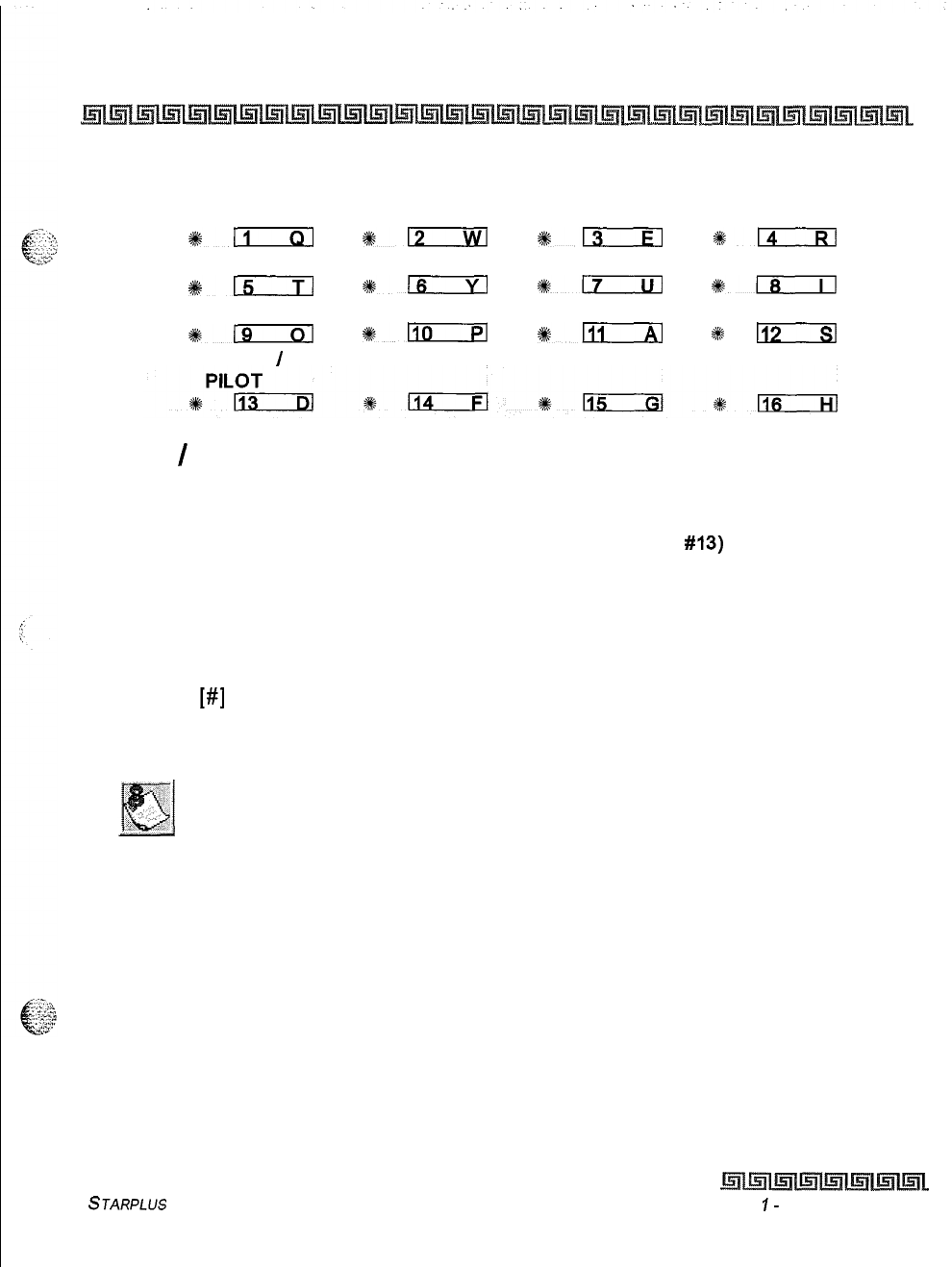
System Parameters Programming
Hunt Groups
2-71
HUNT GRP 450 HUNT
GRP 461
HUNT
GRP
452 HUNT
GRP
453
3&m
*a
Q13
4814
HUNT GRP 454 HUNT
GRP
455 HUNT
GRP
456 HUNT
GRP
457
%+m
s-
%8-
*mril
HUNT GRP 458 HUNT GRP 459 HUNT
GRP
460 HUNT
GRP 461
+%19
#l!iorxl
s:-
a#
II:,
STATION
/
Station
/
Pilot Hunting Assignment
Programming Steps
1
Press the STATION/PILOT flexible button (FLASH 30, button
#13)
to indicate Station
Hunting or Pilot Hunting.
LED On = Station Hunting enabled
LED Off = Pilot Hunting enabled
To remove stations from a Hunt group:
1
Enter
[#]
three times on the dial pad.
2
Press HOLD. A confirmation tone is heard and the display updates. This removes all
stations previously programmed in that group.
458-461 are ONLY for RAN applications.
Description
STATION HUNTING
-Transferred CO, and intercom calls that are presented to a busy, or DND station, that
are members of a Station Hunt group, search sequentially (in the order the extensions were entered in
database programming) for an idle station in the group and rings that station. Direct ringing CO Line calls to
the station number ring at the station. If station hunting is desired on a direct ringing call, program the
station hunting pilot number in the CO Line ring assignment list. This lets the member of the hunt group to
receive private calls and hunt group calls.
STARPLUS Triad-S System Programming Manual Issue
I-
December 1998
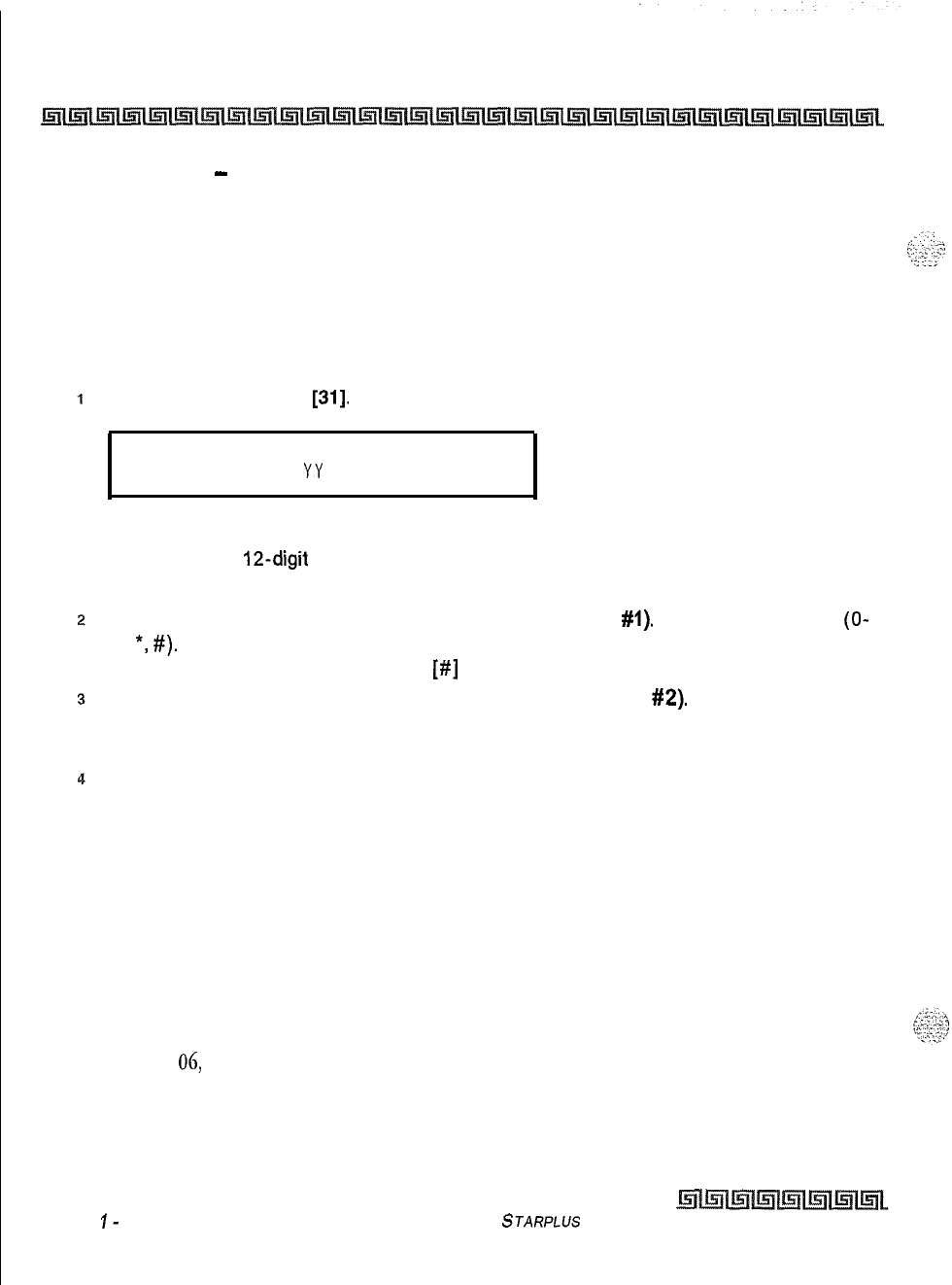
2-72
System Parameters Programming
Hunt Groups
PILOT HUNTING
-
Incoming CO, transferred CO, and intercom calls can be directed to a pilot number of
a hunt group. The system searches sequentially (in the order the extensions were entered in the database
programming) for an idle station in the group and rings that station. Calls directly to stations (by calling the
extension number) within the hunt group do not hunt but receive call progress tones from the extension,
Verified Account Codes Table/Traveling Class of Service
Programming Steps
Press FLASH and dial
[31].
The following message displays:
ACT cos
xxxxxxxxxxxx
YY
Where:
ACCT = Up to
12-digit
account code
COS = Class of Service for account codes
Press the ACCT CODE flexible button (FLASH 31, button
#I).
Enter up to 12 digits
(O-
9,
*,
#).
[*] represents a do not care digit. The system ignores all digits after this digit
when entering an account code. The
[#I
represents a single do not care digit.
Press the Class of Service flexible Button (FLASH 31, button
#2).
Enter a 2-digit Class
of Service Number (l-6) that corresponds to Class of Service l-6. The first digit
represents Day COS and the second digit represents Night COS.
Press HOLD to complete the entry. A confirmation tone is heard.
Description
The Verified Account Code/Traveling Class of Service (COS) feature provides tracking of specific calls by
entering a verified, variable length (up to 12 digits) identifier. Each account code can be assigned a day and
night Class of Service for determining the dialing privileges allowed by that account
code.
This provides a
means for users to override a restricted station. If the dialed account code matches the Verified Account
code table, an intercom dial tone is returned, otherwise an error tone is returned. The use of forced
Account Codes is optional, offered on a system-wide basis. SMDR must be enabled for the account code to
print as part of the SMDR record. The Triad-S System allows up to 250 12-digit account codes and must be
enabled in Flash
06,
Button 3. By default, no Account Codes are assigned.
Issue
I-
December 1998 STARPLUS Triad-S System Programming Manual
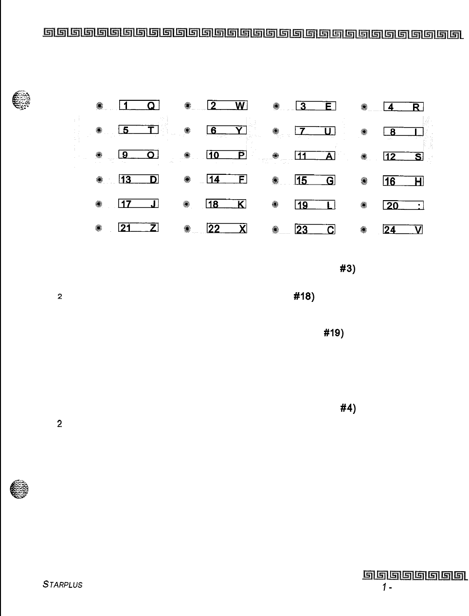
I
..
System Parameters Programming
Hunt Groups
2-73
CLASS OF DELETE ACCT
-_-
;<x-a.
c
ACCT CODE SERVICE CODE ERASE DIGITS
;,.crg
--:c
3.
#i:
%:-
*-
%m
%113
*n
*D
+%
lTir-74
NEXT PREV
*n
#mIcxl
%
l7c-i-l
I
130
IL21
Sk122
#r2z33
0124
To delete the currently displayed account code:
1
Press the DELETE CODE flexible button (FLASH 31. button
#3)
to delete the entire
account code entry.
2
Press the NEXT flexible button (FLASH 31, button
#18)
to display the next account code
on the LCD
or
Press the PREVIOUS flexible button (FLASH 31, button
#IQ)
to display the previous
account code on the LCD.
3
Re-enter the correct digits and press HOLD to complete the entry. A confirmation tone
is heard.
To erase previously entered digits:
1
Press the ERASE DIGITS flexible button (FLASH 31, button
#4)
z
Each time this button is pressed erases one digit. Continue until all desired digits are
erased.
3
Re-enter the correct digits and press HOLD to complete the entry. A confirmation tone
is heard.
STARPLUS Triad-S System Programming Manual Issue
I-
December 1998
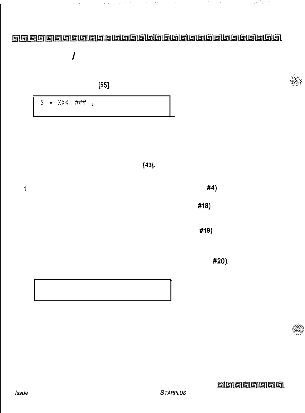
2-74
System Parameters Programming
Hunt Groups
Local Number
/
Name Translation Table
Programming Steps
IPress FLASH and dial
[55].
The following message displays:
s
-
xxx
#?Y#
,
Where:
XXX = Table Number 600-799
### = Route Number 000-199
2
The ROUTE NUMBER LED is lit. Enter the 3-digit Route Number (000-199) from what
was entered in program code, FLASH
[43].
To erase a current phone number and name entry:
I
Press the CLEAR ENTRY flexible button (FLASH 55, button
#4)
to clear an entire
phone number and name from the current index.
2
Press the NEXT TABLE flexible button (FLASH 55, button
#18)
to advance to the next
index and continue entering information into the translation table
or
3
Press the PREV TABLE flexible button (FLASH 55, button
#19)
to return to a previous
index that is already programmed.
To locate an existing index for editing:
1
Press the TABLE NUMBER flexible button (FLASH 55, button
#20).
The following
message displays:
.
ENTER TABLE NUMBER
2
Enter a 3-digit number that corresponds to the table numbers 600-799.
3
Press HOLD to complete the entry.
Description
An administrable table in the KSU provides a local translation from a received calling number to a name.
This is administrable by the customer from the attendant console position, This table is also shared by the
ICLID features. In cases of conflict between the name delivered from the CO and that in the local translation
issue
I- December 1998
STARPLUS Triad-S System Programming Manual
,I..,
,_
.
,--_.
r-
.
.
.
.
.,
. .
.
. . .,..a
. .
,...
.
.
.
I.
.
.._.
.
.
.:.z*
8
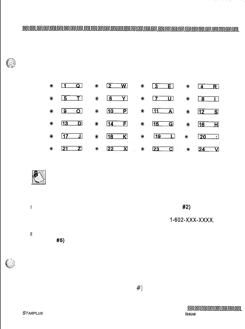
System Parameters Programming
Hunt Groups
2-75
table, the local translation table rules. 200 entries are provided in this table for the Triad-S System. An option
was added to the Local Number/Name translation table to route an ICLID or Caller Entered ID Digits, based
^%.
v-
on a partial compare with the number entered in the translation table.
.
.._
.
-,.
i:‘
.:3
,.‘_
ROUTE NUMBER PHONE NUMBER NAME CLEAR ENTRY
%ll
%%a
%s
13
2#6
lT--R-l
BACKSPACE
#15
#1_6
#em
##
18
*-
#lm--Fl
*lli
%Eizzzl
*-
+Yen
SlzcxI
a-
NEXT TABLE PREV TABLE
1117
#D
s
119
%k
Pa-T-l
If a match is found between a number in the translation tab/e and an
incoming call record, the translated name is displayed and/or stored in the
unanswered call table.
To program a phone number into the Local Number/Name Translation table:
I
Press the PHONE NUMBER flexible button (FLASH 55. button
#2)
to enter the desired
phone number into the translation table. Maximum length of a phone number is 14 digits,
including hyphens. Phone numbers must be in the format:
I-602-XXX-XxXx.
Refer to
Table 2-8: Dial Pad Keys.
2
Press HOLD to update the database. The BACK SPACE flexible button(FLASH 55,
button
#5)
erases the current number for error correction.
An option was added to the Local Number/Name translation table to route an ICLID or Caller Entered ID
. . ..i
Digits based on a partial compare with the number entered in the translation table.
. . .
,-
c-2::
..~
The Guaranteed Message announcement forces incoming callers to an announcement before being placed
into an ACD Queue or routed to an agent. Agents in an ACD Group with a Guaranteed Message enabled
receive incoming callers only after the caller hears the designated recorded announcement in its entirety, or
after the incoming caller dials up to 14 digits followed by [
#]
. These digits are inserted as ICLID incoming
STARPLUS Triad-S System Programming Manual Issue
I- December 1998
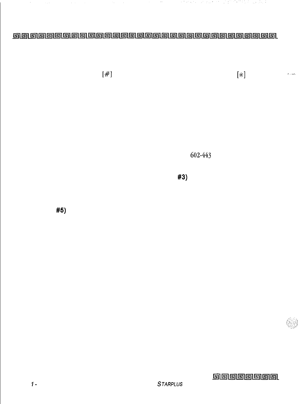
2-76
System Parameters Programming
Hunt Groups
number identification. If the ICLID option is selected, digits received before the announcement time-out
are captured and inserted as incoming ICLID number information,
When the ICLID option is selected,
[#]
is recognized as an announcement termination and
[SC]
is
recognized as an entry error. An entry error causes removal of the ICLID and the incoming caller can re-
enter their phone number.
Example:
If
602-443
is entered in the translation table with a route number, any call received from
ICLID are routed per this partial entry It is important to note that if a partial entry is inserted in the
table, entries that begin with the partial entry, such as
602-443-6000
cause confusion, A call in this
scenario can be routed by either entry depending on the search. This is considered a duplicate
entry and should be avoided. Also note that calls still require exact entries, therefore, a caller
entered number of
602443
requires a separate route entry from
602-443
since there is no dash.
To program a name into the translation table:
1
Press the NAME flexible button (FLASH 55. button
#3)
to enter the desired name into
the translation table. Maximum length is 24 characters. Refer to Table 2-6 for dial pad
keys.
2
Press HOLD to update the database. The BACK SPACE flexible button (FLASH 55,
button
#5)
erases the current letter for error correction.
Issue
I-
December 1998 STARPLUS Triad-S System Programming Manual
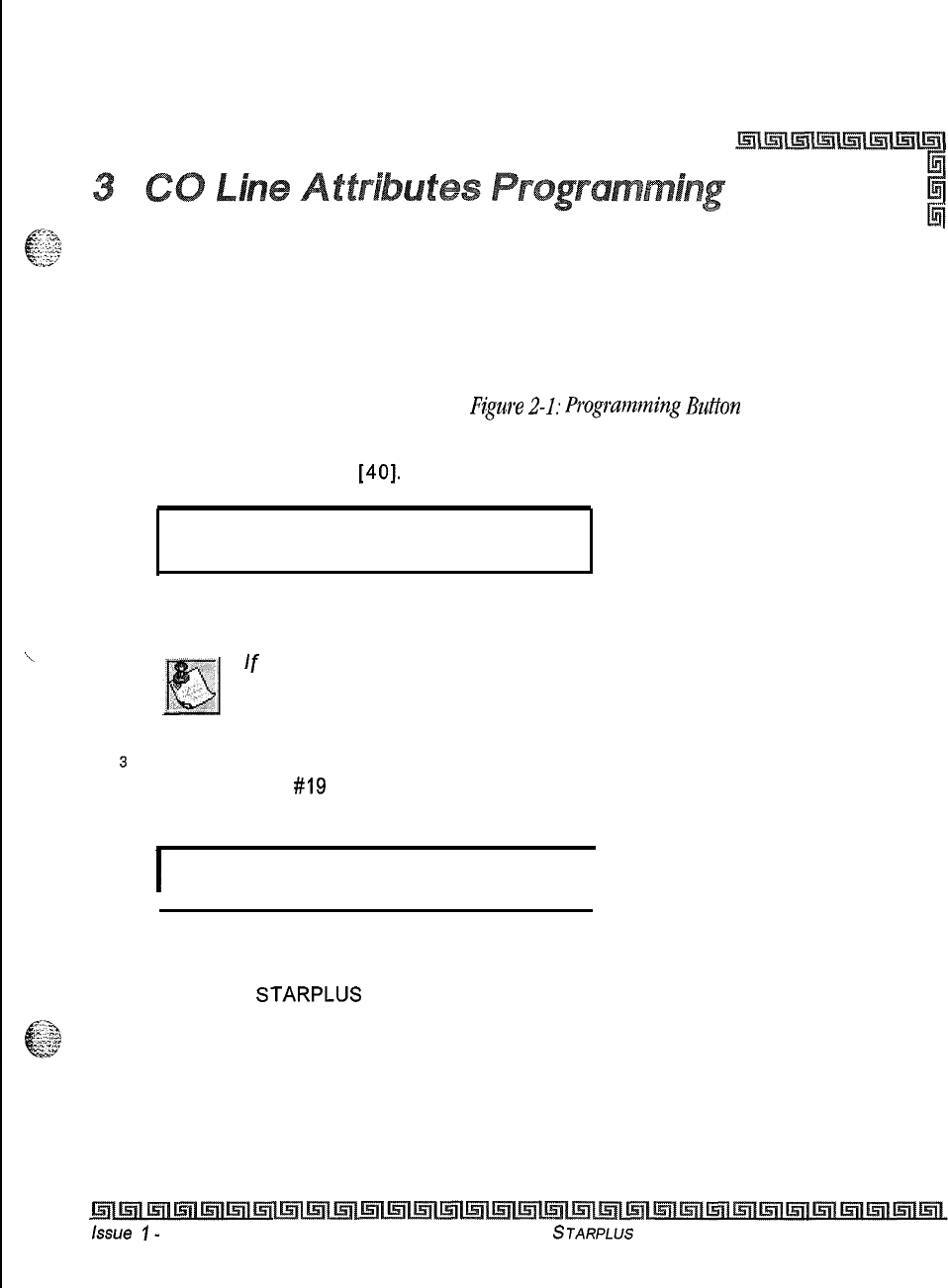
Page A Introduction
Programming Steps
If the system is in the programming mode, continue using the program codes. If starting to program here,
enter the programming mode. Refer to Chapter 1, Figure 2-1: Prog~amning
Button
Mapping. If any CO line
features must be changed
1
Press FLASH and dial
[40].
The following message displays:
CO LINE ATTRIBUTES
SELECT A CO LINE RANGE
2
Enter a 6-digit number for the range of lines being programmed. If only one line is being
programmed, enter that number twice (001 001).
If
HOLD is pressed without entering a CO range, ALL CO lines (001-012)
are selected.
s
Press HOLD to save the entry. A confirmation tone is heard and the display updates.
Flexible Button
#I9
(Page A) is lit. The following message displays to indicate current
programming of that line or group of lines:
I
XXX-XXX PAGE A
ENTER BUTTON NUMBER
I
Where:
XXX-XXX = CO Line Range
001-012 =
STARPLUS
Triad-S
This section describes the procedures and steps necessary to program CO Line attributes. When entering the
CO Line attributes portion of the database, the programmer may decide to enter information for a range of
CO lines or one specific CO Line. Range programming lets the programmer change a specific parameter or a
few parameters for an entire range of CO Lines leaving intact the remaining data fields that do not require
change. Those data fields continue to operate with the previously programmed data. By default, Page A is
shown.
ksue
I-
December 1998
STARPLUS
Triad-S System Programming Manual
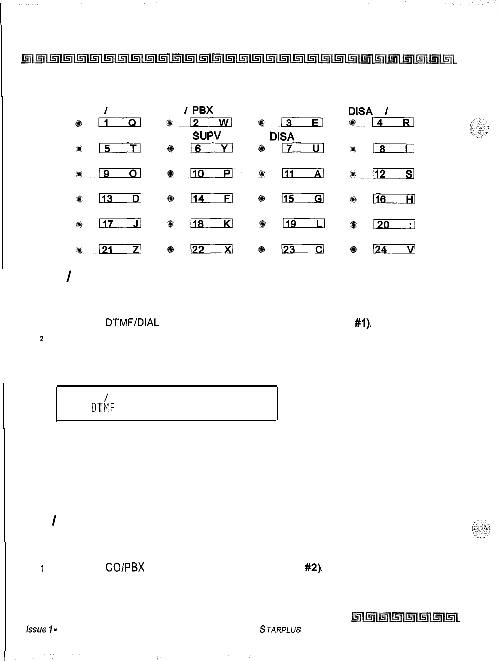
3-2
CO Line Attributes Programming
Page A Introduction
DTMF
/
DP co
I
PBX
UNA
DISA
T
I
T
Ykkizm
*!lcIKi
*Is
%+;
PRIVACY LOOP
SUPV DISA
CO GROUP
*LizEEl
*-
*ilzz!Il
*Is
cos
RING ASSIGN
CO LINE ID
TRUNK DIR
*-
4%isEzizl*-:
%-
DISPLAY RING
*-
+k-
%115
#-;
PAGE A PAGE B
1117
+%-
+n
$120
PAGE C NEXT (FWD) NEXT (BACK) NEW RANGE
%-
%122
%?-
*Ifaz3zl
I
DTMF
/
Dial Pulse Programming
Programming Steps
1
Press the
DTMFIDIAL
PULSE flexible button (FLASH 40, Button
#I).
2
Enter a l-digit value (O-l) that corresponds with the following entries:
[0] = Dial Pulse
[I] = DTMF
PULSE
/
DTMF
DTMF
O-l
.
3
Press HOLD to save the entry. A confirmation tone is heard.
Description
Each individual outside line can be programmed to be DTMF (tone) or dial pulse. By default, all lines are
set for DTMF.
CO
/
PBX Programming
Programming Steps
I
Press the
COlPBX
flexible button (FLASH 40, Button
#2).
2
Enter a l-digit value (O-l) which corresponds with the following entries:
[0] = PBX
Issue
I
-
December 1998
STARPLUS Triad-S System Programming Manual
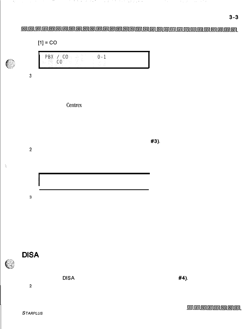
CO Line Attributes Programming
Page A introduction
3
Press HOLD to save the entry. A confirmation tone is heard.
Description
Each individual outside line connected to the system may be programmed as a CO or PBX line. Use the PBX
mark when identifying
Centrex
lines. By default, all lines are assigned as CO lines.
Universal Night Answer (UNA)
Programming Steps
1
Press the UNA flexible button (FLASH 40. Button
#3).
2
Enter a l-digit value (O-l) which corresponds with the following entries:
[0] = Disabled
[I] = Enabled
I
UNA
O-l
ENABLED
I
3
Press HOLD to save the entry. A confirmation tone is heard.
Description
If a line is marked UNA, this activates night service answering of incoming calls on this line by stations not
normally assigned access to the line(s). This station must have a direct CO appearance or an available loop
key assigned to do this. Lines marked as UNA also activate Night Ringing over External Page when in the night
mode if External Night Ringing is set to Yes. By default, UNA is enabled
DISA
Trunk-to-Trunk (Per CO Line)
.,.,.I”*
t?
-;;
.:;-,
-3
Programming Steps
1
Press the
DISA
CO-to-CO flexible button (FLASH 40, Button
#4).
2
Enter a l-digit value (O-l) which corresponds with the following entries:
[0] = Disabled
STARPLUS Triad-S System Programming Manual
Issue I- December 1998
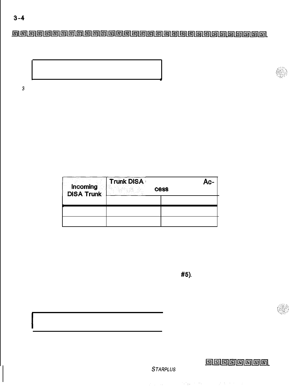
CO Line Attributes Programming
Page A Introduction
[I] = Enabled
DISA CO TO CO
O-l
ENABLED
I
3
Press HOLD to save the entry. A confirmation tone is heard.
Description
The DISA Trunk-to-Trunk (or Conference) mark on the CO line governs a DISA caller’s ability to access
other outside lines. CO lines must have DISA Trunk-to-Trunk enabled to allow a DISA caller to establish an
outgoing
trunk-to-trunk connection. This allows for specific CO line access restriction on DISA calls. A
station with Conference enabled can initiate a conference on CO lines regardless of the CO line conference
marking. By default, DISA Trunk-to-Trunk is enabled for all CO lines.
The CO line conference flag affects a DISA caller’s ability to access outgoing CO lines as shown in the
following table:
Caller Attempts To Ac-
C8SS
T-t-T Enabled
L
T-t-T Enabled Call Allowed
T-t-T Disabled Call Denied
T-t-T Disabled
Call Denied
Call Denied
Table 3-l: CO Line Conference Flag
Privacy
Programming Steps
1
Press the PRIVACY flexible button (FLASH 40, Button
#5).
2Enter a l-digit value (O-l) which corresponds with the following entries:
[0] = Disabled
[I] = Enabled
I
PRIVACY
O-l
ENABLED
I
Issue I- December 1998
STARPLUS
Triad-S System Programming Manual
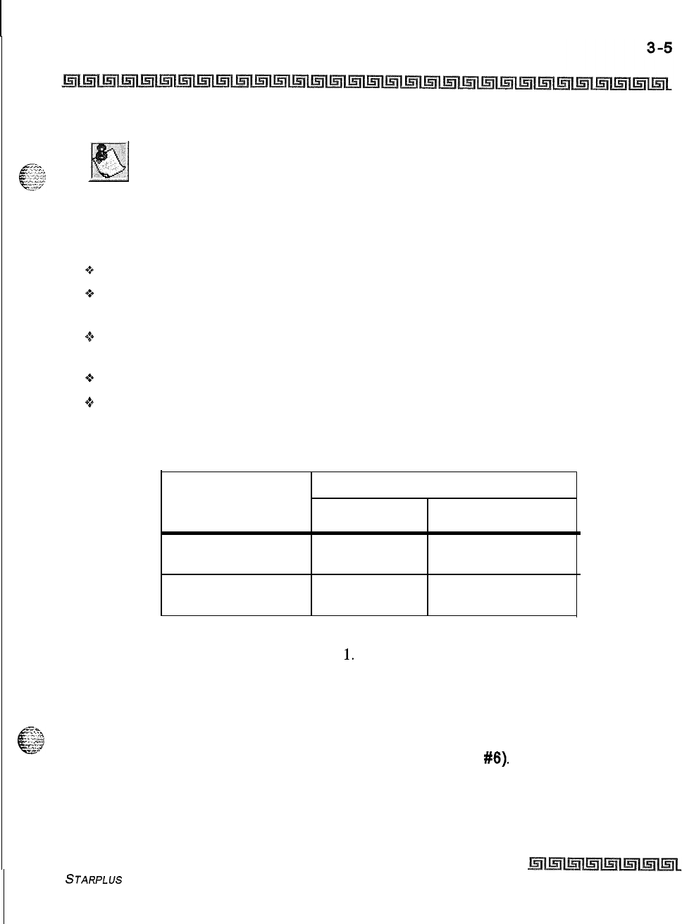
CO Line Attributes Programming
Page A Introduction
3
Press HOLD to save the entry. A confirmation tone is heard.
Disabling the privacy feature may be limited by federal, state or local law,
so check the relevant laws in your area before disabling privacy.
If desired, the system can be programmed to eliminate CO Line privacy, allowing another station to join
existing outside line conversations.
+
Stations must have a direct CO line appearance to join CO line conversations in progress.
9A station must also have Privacy disabled before the system allows that station to enter an existing
conversation.
e
If Privacy is disabled and a station joins an existing call, a programmed warning tone is presented to
both parties prior to actual cut-through.
+
When Privacy is disabled, up to seven other stations may join an existing conversation.
+
The station joining receives a solid red LED indication,
By default, Privacy is enabled for all CO Lines.
Station Attempting CO Line in Use by Another Station
to
Access CO Line
Privacy Enabled Privacy Disabled
Privacy Enabled Private Private
(no cut-through) (no cut-through)
Privacy Disabled Private Privacy Release
(no cut-through) (cut-through allowed)
Table 3-2: CO Line Privacy Flag
Warning tone is programmed in Flash
06,
Button
1.
Loop Supervision Programming
Programming Steps
1
Press the LOOP SUPV flexible button (FLASH 40, Button
#6).
STARPLUS
Triad-S System Programming Manual
Issue I- December 1998
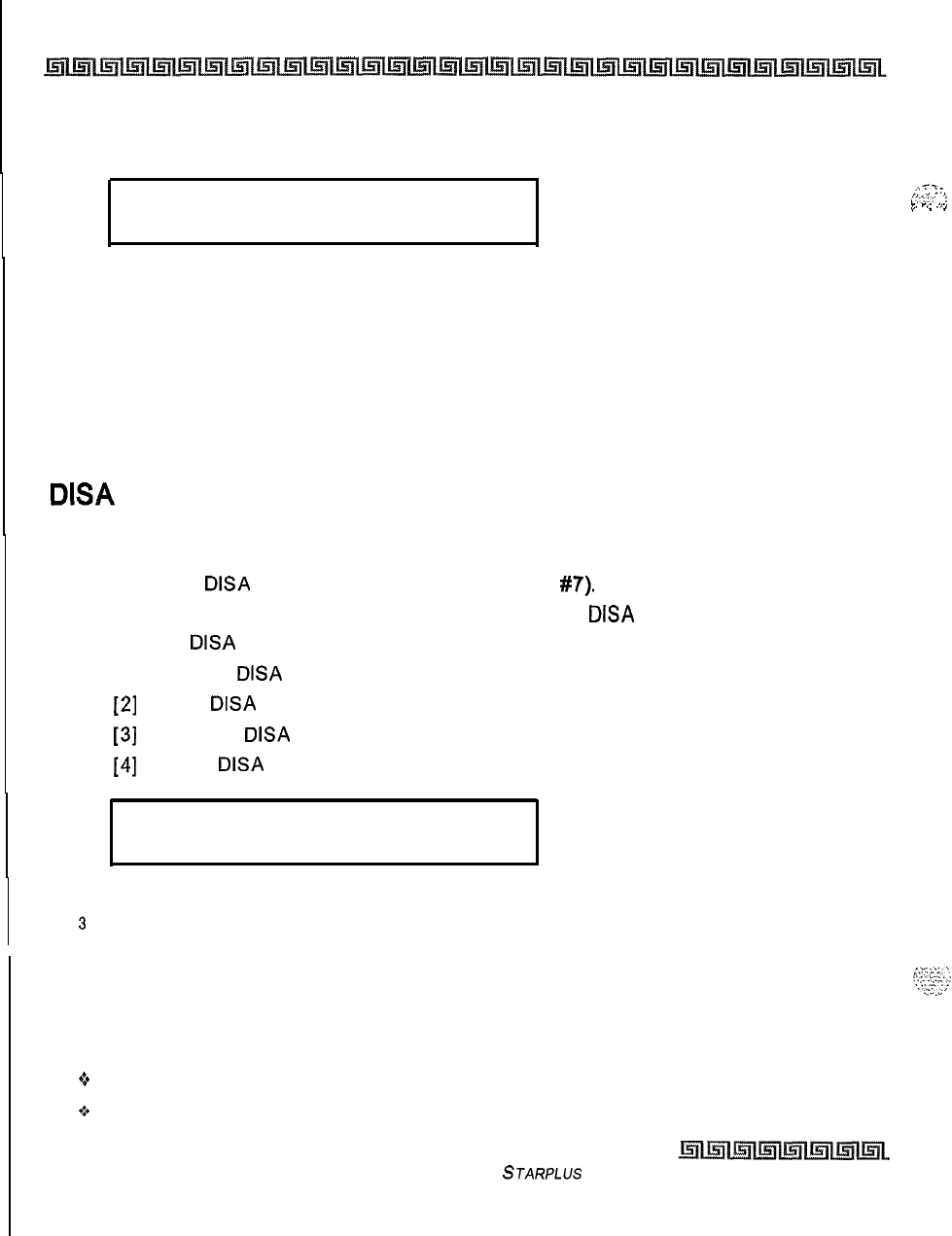
I
3-6
CO Line Attributes Programming
Page A Introduction
2
Enter a l-digit timer value on the dial pad between l-9 which corresponds to 100-900
ms. (0 = disabled)
LOOP SUPERVISION
4
o-9
3
Press HOLD to save the entry. A confirmation tone is heard and the display updates.
Description
Loop supervision is used primarily with DISA, Voice Mail/Auto Attendant and with unsupervised conference
applications. It lets the system detect when loop current is broken and an outside line is no longer being
used. To determine timer value for loop supervision, consult your local central office for type and duration
of loop supervision signal. By default, Loop Supervision is set for 400 ms for all CO Lines.
DISA
Programming
Programming Steps
1
Press the
DISA
flexible button (FLASH 40, Button
#7).
2
Enter a l-digit value on the dial pad to indicate type of
DISA
desired.
[0] = No
DISA
[I] = 24-Hour
DISA
[2]
= Night
DISA
[3]
= 24-Hour
DISA
with forwarding
[4]
= Night
DISA
with forwarding
-i-
,.”
;
:
;
;:3i-
:,
I.
P..
.,,.,
I
.
_
DISA TYPE
NONE
o-4
X = 0 through 4
3
Press HOLD to save the entry. A confirmation tone is heard and the display updates,
Description
Each CO can be assigned as a DISA line with one of the 5 DISA types mentioned above (O-4). One DTMF
Receiver is provided on the BKSU:
+
DISA can be programmed using Range programming.
oDISA callers are subject to the Class of Service placed on the line accessed for out dialing.
Issue I- December 1998
STARPLUS Triad-S System Programming Manual
CO Line Attributes Programming
Page A Introduction
6The system administrator can control the call duration after establishing a Trunk-to-Trunk call,
44
After expiration of the Conference Timer, a tone is presented to both DISA parties, then one minute
later the system automatically releases both trunks.
+
The Conference Timer does not affect or control a DISA-to-Station call. By default, there are no
outside lines assigned as DISA lines.
Line Group Programming
Programming Steps
1
Press the CO LINE GROUP flexible button (FLASH 40, Button
#8).
2
Enter a l-digit value on the dial pad between O-7 which corresponds to Groups O-7.
LINE GROUP
1
o-7
3
Press HOLD to save the entry. A confirmation tone is heard and the display updates.
Description
Eight line groups are available for CO line assignment. Groups should be assigned according to type (local,
FX, WATS, etc.). All unassigned CO lines should be programmed into a different group so they are not
accessed by Line Queuing, Pooled Group access (Pool Buttons), Speed Dial, or LCR features,
Line Group 0 is for programming a line(s) as a private. CO Lines assigned to Line Group 0 can only be
accessed by stations with a direct CO appearance (button) on their phone. By default, all lines are placed in
Line Group
1.
Class of Service
Programming Steps
1
Press the LINE COS flexible button (FLASH 40. Button
#9).
2
Enter a l-digit value on the dial pad between 1-5 which corresponds to five
possible
class-of-service to which a line may be assigned:
COSI
= No restrictions.
COS2 = Table A governs, Station COS 2 and 4 are monitored.
COS3 = Table B governs, Station COS 3 and 4 are monitored.
STARPLUS Triad-S System Programming Manual
Issue I- December 1998
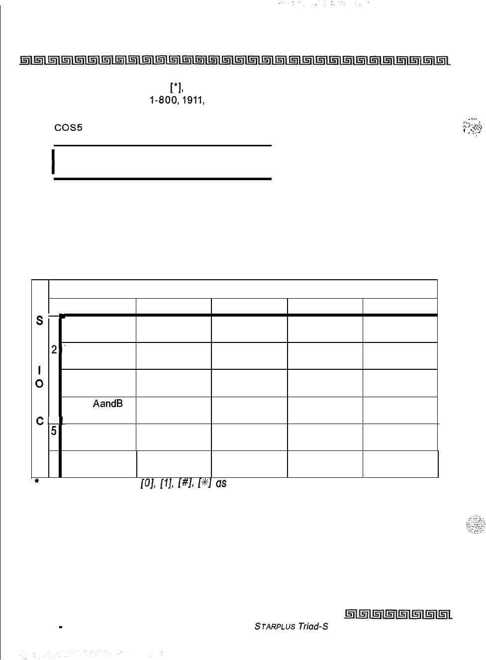
3-8
CO Line Attributes Programming
Page A Introduction
COS4 = Restricts [0], [I],
[*I,
[#] dialed as first-digit and places a 7-digit dialing
limitation. In addition,
I-800,1911,
and 1611 are allowed and 411, 976, and 555 numbers
are denied.
COS5
= Overrides Station COS 2, 3, 4, 5 and allows unrestricted dialing.
I
CLASS OF SERVICE
1-5
1
I
3
Press HOLD to save the entry. A confirmation tone is heard and the display updates.
Description
Through assignments of a CO Class of Service, the assigned CO line interacts with a station Class of Service,
provides a canned restriction, or provides unrestricted dialing capabilities. (When a CO line is marked PBX,
COS restrictions apply to the station only if one of five PBX codes are dialed first.)
CO LINE CLASS OF SERVICE
1
2 3 4 5
-
s
1 1Unrestricted Unrestricted Unrestricted Canned Unrestricted
TRestricted*
A--
Table A
T
2’
Table A Unrestricted Canned Unrestricted
Restricted*
:,
3Table B Unrestricted Table B Canned Unrestricted
Restricted*
N --
4Table
AandB
Table A Table B Canned Unrestricted
C--
Restricted*
Canned
0
5
;Canned Canned Canned Unrestricted
sRestricted* Restricted* Restricted* Restricted*
__
6 IIntercom Intercom Intercom Intercom Intercom
,
Only Only Only Only Only
*
Canned Restriction: No [O],
[I],
[#I,
[+/+I
as first dialed digit, and 7-digit dialing limitation; plus
I-800,
1911, 7611
are allowed, and
411,
976, and 555 numbers are
denied.
Issue 1
-
December 1998
Table 3-3: Class of Service (COS)
STARPLUS
Triad-S System Programming Manual
_.,.-
,._
i
.
.
.
..-..
,.
.
. .
.
_-.l
.
.
.
.
,...
.
.
-.
1
’
-.:-
CO Line Attributes Programming
Page A Introduction
CO Line Ringing Assignments
:--
6.;:
Programming Steps
.,.
,,,
I:
‘f.:
1
Press the RING ASSIGNMENT flexible button (FLASH 40, Button #IO). The display
shows the following information:
RING ASSIGNMENTS
ENTER DDDR
2
Enter the 3-digit destination (DDD) and the l-digit ring type (R) followed by HOLD. A
confirmation tone is heard and the display updates.
DOD
= Valid 3-digit Destinations:
[020-0991
= System Speed Bins 20-99, for Off-Net ringing
[IOO-131]=
STARPLUS
Triad-S Extension Numbers
[440-447]=
Voice Mail Groups l-8
[450-457]=
Hunt Groups l-8
[499]
= Direct Ringing to Modem
‘_.
[550-565]=
ACD Groups 1-16
[550-557]=
UCD Groups l-8
R = Valid Ring
Types
[0] = No Ring; unassigned; or to delete a station
[I] = Day Ring
[D]
[2]
= Night Ring [N]
[3]
= Day/Night Ring
[
41
= Special Only [S]
[5]
= Day/Special [DS]
[6]
= Night/Special [NS]
[7]
= All Modes [Day/Night/Special]
3
To add multiple stations: DDDR HOLD DDDR HOLD DDDR HOLD...etc.
_
::.2,
..‘,‘~
k-
To Delete a single station, enter:
-,
:a
I.
..,
m
..._I
*a,
DDDO HOLD
To Delete Multiple stations:
DDDO HOLD DDDO
HOLD...etc.
STARPLUS Triad-S System Programming Manual Issue
I-
December 1998
I
3-10
CO Line Attributes Programming
Page A introduction
Description
Each CO Line may be assigned to ring any station in the system; UCD, Voice Mail or Hunt Group, or Off-Net
(via speed dial). CO Line ringing is programmed on a per CO Line destination basis. Each destination may
be designated to ring during the day, during the night, or receive both Day and Night ringing. Stations that
are assigned for initial ring-in
must have
a LOOP button(s) to answer calls if a direct CO appearance is
unavailable.
An incoming CO line may be programmed to any number of stations but it cannot be programmed to ring a
mixture of stations and groups in the same time period. Incoming calls directed Off-Net are connected to an
outgoing system speed bin. CO lines assigned to ring multiple stations do not follow any station’s
forwarding. By default, all CO lines ring at the attendant, Station 100 during Day and Night Modes.
CO Line ldentif ication Display
Programming Steps
Each CO line in the system can be programmed to have a name associated to it in database programming.
1
Press the CO LINE IDENTIFICATION flexible button (FLASH 40. Button
#ll).
The
following message displays:
t
LINE ID
LINE 001
z
Enter the name by using keys on the dial pad as follows. Valid alphanumeric characters
are: [A-Z],
[O-9],
[*I,
[#I,
[-]
[spaces] and other ASCII characters as listed below. The
name may be entered in any combination up to
12-characters
(this represents 24-digits
entered). Refer to
Tublej-4:
DialPadKeys.
ksue
I
-
December 1998
STARPLUs Triad-S System Programming Manual
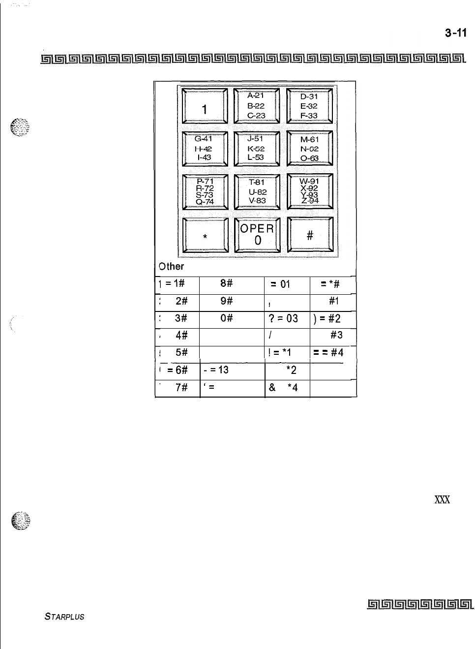
CO Line Attributes Programming
Page A Introduction
3ther
Codes:
I
=I#
8 =
8#
=
01
*
=
*#
2 =
2#
9 =
9#
)
= 02 ( =
#I
3 =
3#
0 =
O#
?=03
)=#2
4 =
4#
Space = 11
I
= 04
+ =
#3
5 =
5#
: = 12
!
=
*I
=
=
#4
6=
6#
-=I3
$ =
*2
# = ##
7 =
7#
I=
14
&
=
*4
Table 3-4: Dial Pad Keys
3
Press HOLD to save the entry. A confirmation tone is heard and the display updates.
Description
This feature provides entry of a name for each line (trunk) connected to the system. Once entered into the
database, LCD phones, including the attendant stations, receive the programmed line name in place of the
default LINE XXX message. This applies to all line call processing conditions where the current LINE
Xxx
message appears. SMDR continues to print out the line number in place of the programmed name. If the
line name was not programmed, the current LINE XXX display is the default. A programmable data field is
available for each line in the system. Line names may be assigned using the range programming.
STARPLUS
Triad-S System Programming Manual
Issue I- December 1998
3-12
CO Line Attributes Programming
Page A Introduction
A message similar to the following display is used for all CO Line displays when a name is programmed for
a CO Line.
.
LINE
RINGING
nnnnnnnnnnnn HH:MM am
Entries can be made using a keyboard by following the same outlined
procedures using Table 2-6.
Trunk Direction
Programming Steps
I
Press the TRUNK DIRECTION flexible button. (FLASH 40, Button
#12).
The following
message displays:
I
CO DIRECTION O-3
INCOMING-OUTGOING
I
2
Enter a l-digit value on the dial pad which corresponds to the desired trunk type:
[0] = Out-of-Service
(00s)
[I] = Incoming Only
[2]
= Outgoing Only
[3]
= Both Incoming and Outgoing
3
Press HOLD to save the entry. A confirmation tone is heard and the display updates.
Description
CO Lines can be programmed on a per CO Line basis for the type of CO Line desired: Incoming, Outgoing,
or Lncoming and Outgoing.
Incoming
+
Incoming restricts the CO Line for incoming calls only.
+
Users can place call on hold, park the call, and other stations can pick-up the call.
issue
I
-
December 1998
STARPLUS
Triad-S System Programming Manual
CO Line Attributes Programming
Page A Introduction
Outgoing
4%
Outgoing restricts the CO Line to outgoing calls only,
+
Users can place call on hold, park the call, and other stations can pick-up the call.
Incoming and Outgoing
Q
Incoming and outgoing type allow calls to be received or dialed out,
By default, all CO Lines default to both incoming and outgoing type.
Display Ring Assignments
Programming Steps
1
Press
FLASH 40, Button
#I3
to display ring assignments. Assignments are displayed in
sets of 8, up to the number programmed. The following format displays the assignments.
I
DDDRR DDDRR DDDRR DDDRR
DDDRR DDDRR DDDRR DDDRR
I
Where:
DDD = Destination
RR:
[0] = No Ring
[D] = Day Ring
[N] = Night Ring
[DN] = Day/Night Ring
[S] = Special Only
[DS] = Day/Special
[NS] = Night/Special
[A] = All Modes (Day/Night/Special)
2
Press FLASH 40, Button
#13
additional times to cycle to the next group of eight ring
assignments etc. ..ring assignments are continuous and display in order of the destination
number from
001-557.
STARPLUS Triad-S System Programming Manual Issue
7
-
December 1998
CO Line Attributes Programming
Page B Introduction
Page B Introduction
Programming Steps
If the system is in the programming mode, continue using the program codes. If starting to program here,
enter the programming mode. If Page B CO Line features must be changed:
1
Press FLASH and dial
[40].
The following message displays:
I
CO LINE ATTRIBUTES
SELECT A CO LINE RANGE
I
2
Enter a 6-digit number for the range of lines being programmed. If only one line is being
programmed, enter that number twice (001 001).
If HOLD is pressed without entering a CO range, ALL CO lines (001-012)
are selected.
3
Press HOLD to save the entry. A confirmation tone is heard and the display updates.
Flexible Button
#I9
(Page A) is lit.
4
Press the Page
6
flexible button (Button
#20).
The following message displays:
XXX-XXX PAGE B
ENTER BUTTON NUMBER
Where:
XXX-XXX = CO Line Range
001-012
Description
This section describes the procedures and steps necessary to program CO Line attributes. When entering
the CO Line attributes portion of the database, the programmer may decide to enter information for a range
of CO lines or one specific CO Line. Range programming lets the programmer change a specific parameter
or a few parameters for an entire range of CO Lines leaving intact the remaining data fields that do not
require change. Those data fields continue to operate with the previously programmed data.
Issue I- December 1998
STARPLUS
Triad-S System Programming Manual
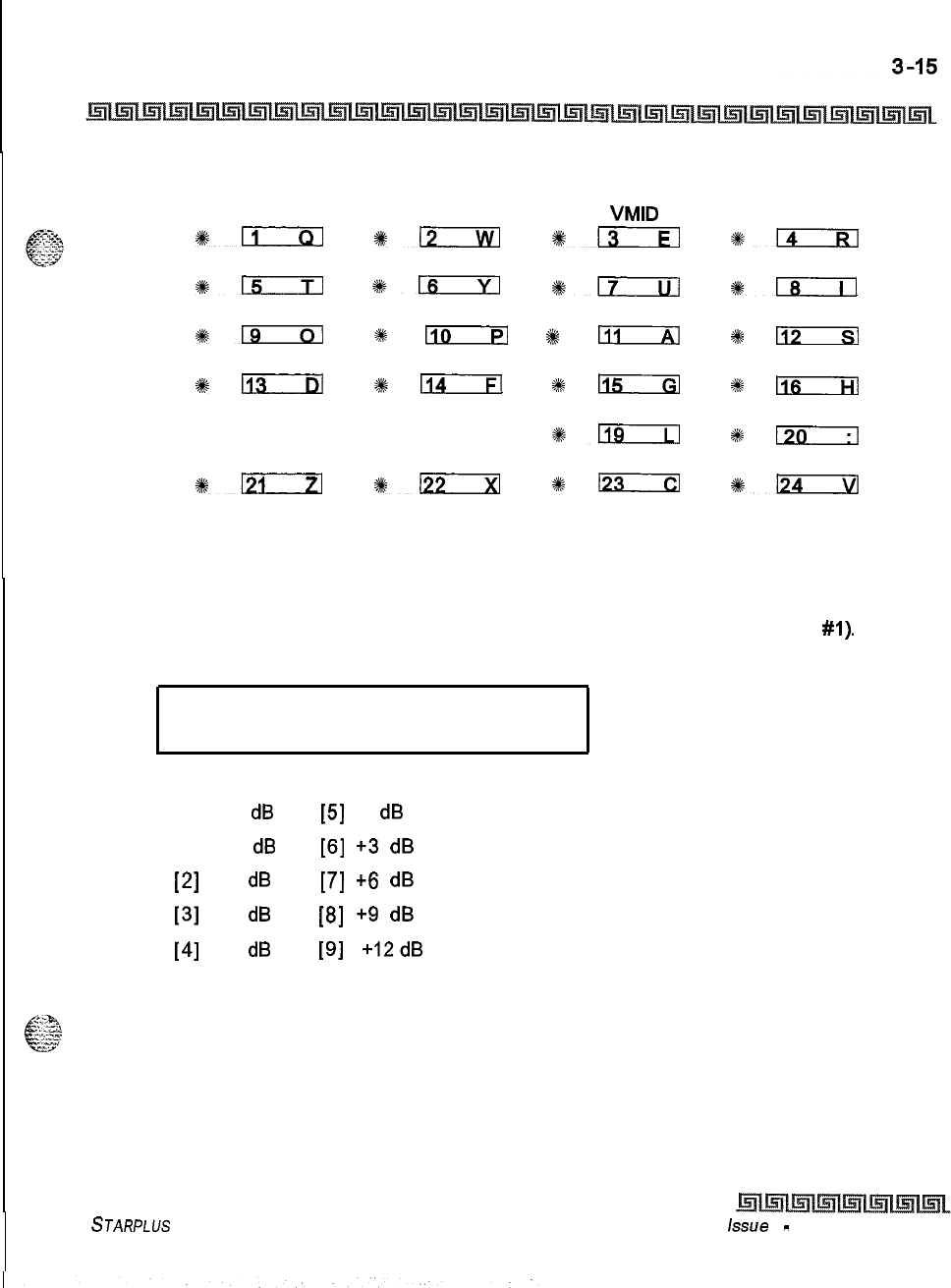
CO Line Attributes Programming
Page B Introduction
When programming the Page B features, the flexible buttons are mapped as follows:
XMT VOLUME P FWD DEST P FWD
VMID
UDA
#ll
*lzIEl
*i-3---n
*14
MOH PER CO RING TONE
#czrm
*- *-
*lT---il
*19
#
110
%
IAl
84
1131
%-
#klTc--Fl
I
115GI
2#
Ils
PAGE A PAGE B
Sk- %+-
*a
%
lm-7-j
PAGE C NEXT (FWD)
0121
NEXT (BACK) NEW RANGE
%122
2#
ICI
*a
Transmit Volume Option
Programming Steps
IPress the TRANSMIT VOLUME flexible button (FLASH 40, Page B, Button
#I).
The
following message displays:
TRANSMIT VOLUME o-9
0 DB
2
Enter the l-digit value for the desired volume level, O-9.
[0] -15
dB
[5]
0
dB
[I] -12
dB
[6]
+3
dB
[2]
-9
dB
[7]
+6
dB
[3]
-6
dB
[8]
+9
dB
[4]
-3
dB
[9]
t12dB
3
When the desired level is selected, press HOLD to complete the entry, A confirmation
tone is heard and the display updates.
STARPLUS Triad-S System Programming Manual issue
I
-
December 1998
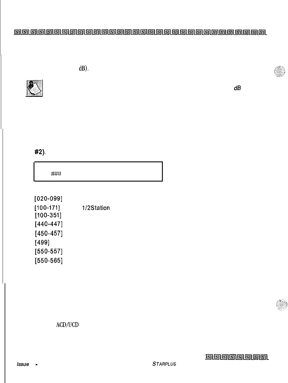
3-16
CO Line Attributes Programming
Page B Introduction
Description
Up to ten volume levels are available for each CO Line in the system. By default, all CO lines are
programmed for level 5 (0
dB).
Do NOT adjust this option without consulting with Technical Support first.
The default settings were set to apply to most applications. Have the
dB
readings on all CO lines available when calling Technical Support.
Preset Call Forward Destination
Programming Steps
1
Press the PRESET FWD DESTINATION flexible button (FLASH 40, Page B, Button
#2).
The following message displays:
PRESET FORWARD DEST
2
Enter the 3-digit forward destination on the dial pad.
[020-0991
= System Speed Bins
[loo-1711
= Triad
lI2Station
Extensions
[IOO-3511
= Triad 3 Station Extensions
[440-4471
= Voice Mail Groups l-8
[450-4571
= Hunt Groups 1-8
[499]
= Direct Ringing to Modem
[550-5571
= UCD Groups l-8
[550-5651
= ACD Groups l-6
3
A confirmation tone is heard and the LCD display updates.
Description
This feature enables a CO line to initially ring at multiple stations and forward to a pre-determined
destination. The destination can be a station group. Each CO line has a preset forward timer. Additionally,
each CO line has a VMID field to allow sending of specific VM digits when a CO line forwards to a VM group,
Calls ringing into
ACD/UCD
Groups or Voice Mail Groups continue to ring the group. The CO line does not
forward when ringing one of these types of groups. By default, no destinations are assigned.
issue I
-
December 1998
STARPLUS Triad-S System Programming Manual
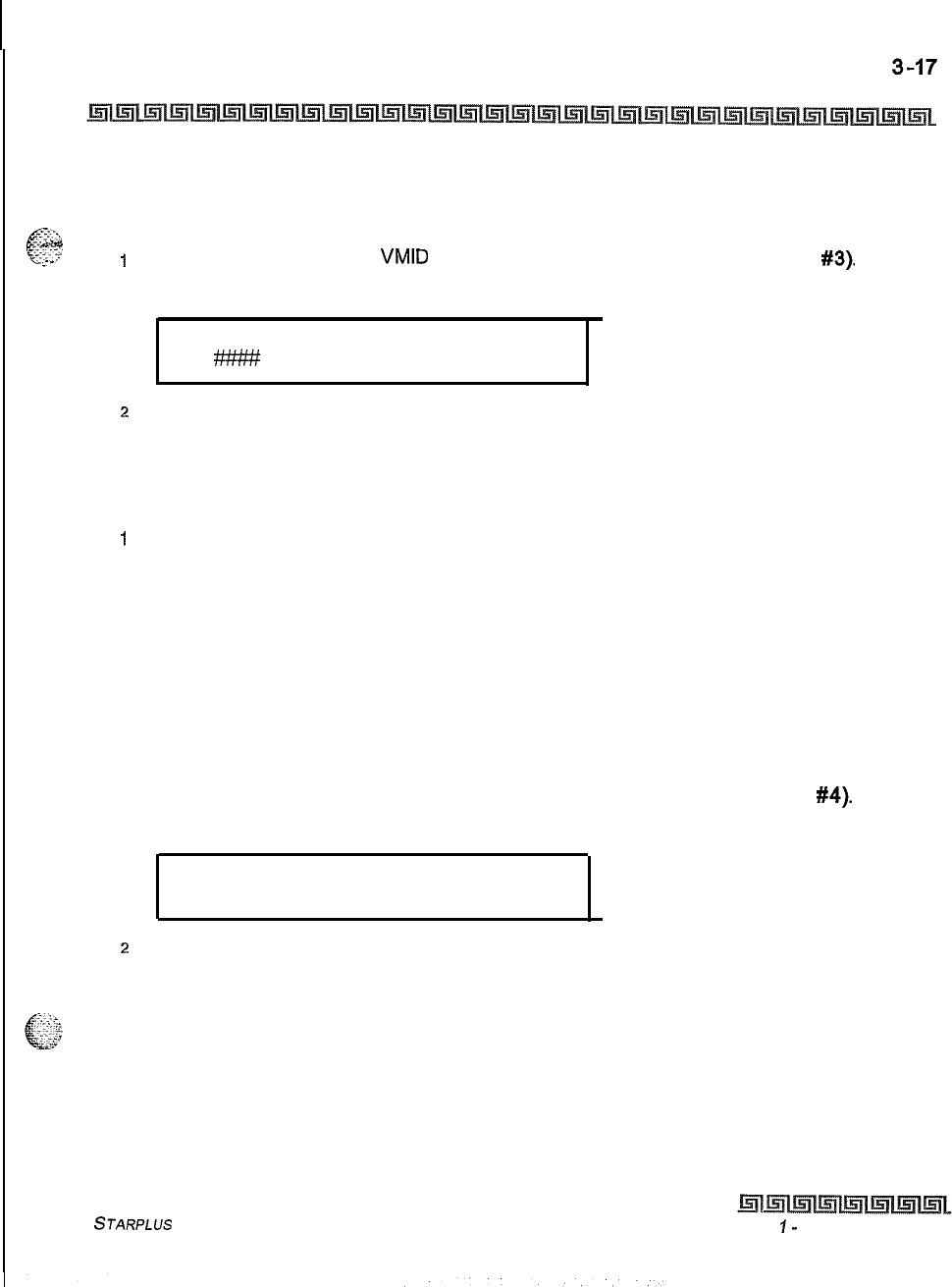
CO Line Attributes Programming
Page B Introduction
Preset Forward Voicemail ID
@$
Programming Steps
.-
-
1
Press the PRESET FWD
VMID
flexible button (FLASH 40, Page B, Button
#3).
The
following message displays:
PRESET FORWARD VMID
z
Enter up to four digits on the dial pad that correspond to 0000-9999 for the Voice Mail
ID digits.
3
Press HOLD to complete the entry. A confirmation tone is heard and the display updates.
To delete numbers that are currently entered:
I
Press [#] four times. Press HOLD to update. All information is erased.
Description
This feature enables a programmer to assign which digits will be sent to voice mail when a CO line is
programmed to preset forward. By default, no digits are sent.
Universal Day Answer (UDA)
Programming Steps
1
Press the UNIV. DAY ANSWER flexible button (FLASH 40, Page B, Button
#4).
The
following message displays:
UNIVERSAL DAY ANSWER
O-l
DISABLED
2
Enter a l-digit value on the dial pad to enable/disable the UDA feature.
[0] = Disabled
[I] = Enabled
3
Press HOLD to save the entry. A confirmation tone is heard and the display updates.
Description
UDA-assigned CO lines can signal over external page port(s). External Day ringing is programmed on a
system-wide basis in administrative programming. Stations that do not have access to a line during the day
STARPLUS Triad-S System Programming Manual Issue
I-
December 1998
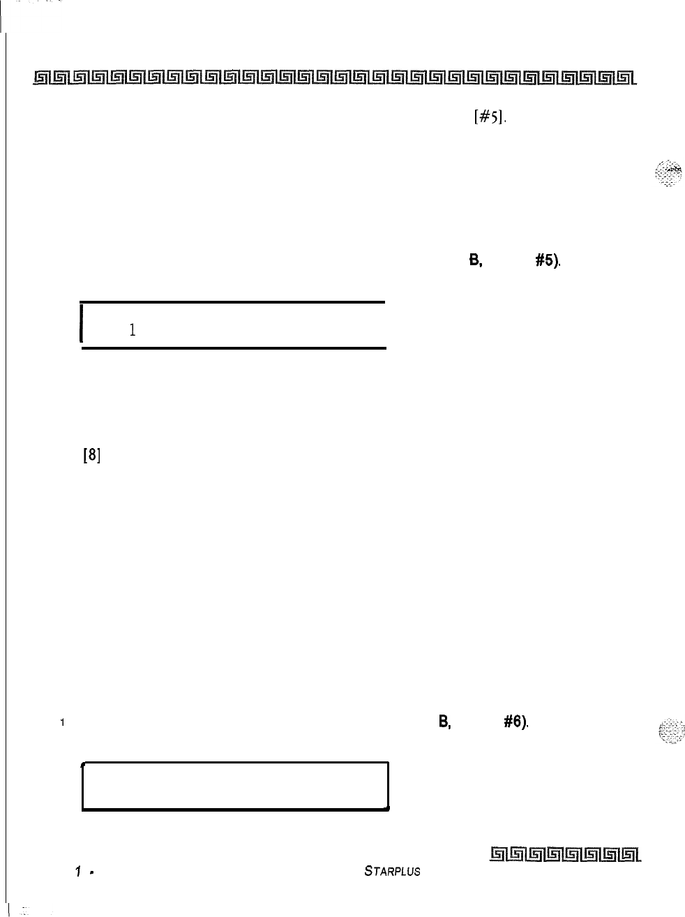
3-18
CO Line Attributes Programming
Page B Introduction
can answer that line while the System is in the day mode by dialing a UDA code [#5]. To utilize this feature,
a LOOP button or an appearance of the trunk must be present on the station. By default, the Universal Day
Answer feature is disabled.
Music On Hold (per CO Line)
Programming Steps
1
Press the MUSIC-ON-HOLD flexible button (FLASH 40, Page
6,
Button
#5).
The
following message displays:
I
MOH CHANNEL
O-l
1
I
2
Enter a l-digit value on the dial pad to change this feature.
[0] = No Music-On-Hold.
[I] = Channel 1.
. . . . .
. . . . .
[8]
= Channel 8.
3
Press HOLD to save the entry. A confirmation tone is heard and the display updates.
Description
This feature provides a method to select the Music-On-Hold channel for each CO line. This feature lets the
system assign CO line circuits as additional music inputs. This increases the capacity of music channels
beyond the two available on the MISU to be used for MOH sources. A total of eight channels are available for
use on the system. The CO line can be assigned to NOT play music for callers on hold. By default, Channel
1 is used for Music-On-Hold.
Distinctive Ringing (per CO Line)
Programming Steps
1
Press the RING TONE flexible button (FLASH 40. Page
B.
Button
#6).
The following
message displays:
.
RING TONE 00-35
00
w
Issue
7
-
December 1998
STARPLUS
Triad-S System Programming Manual
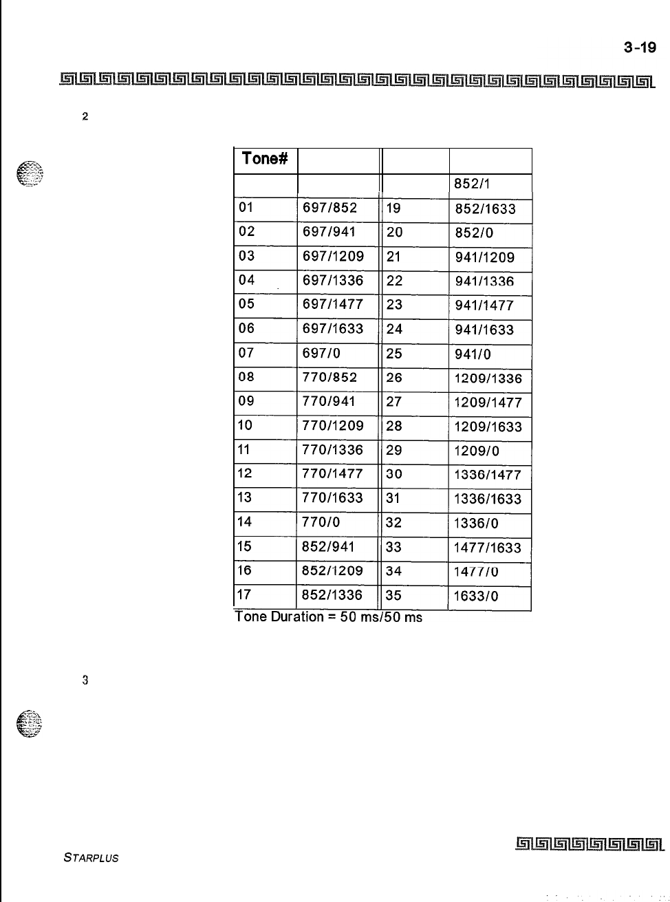
CO Line Attributes Programming
Page B Introduction
2
Enter the 2-digit value on the dial pad to change this feature. The ringing choices are:
Tone#
Freq
Tone #
Freq
00
6971770 18
852/I
477
Table 3-5: Ringing Tones
3
Press HOLD to save the entry. A confirmation tone is heard and the display updates.
Description
The tone ring signal used to notify stations of an incoming call can be changed in administrative
programming to provide distinctive ringing on a per CO line basis. A distinctive ring tone can be programmed
STARPLUS Triad-S System Programming Manual
Issue I- December 1998
3-20
CO Line Attributes Programming
Page C introduction
for each CO line that rings each station. The system provides
36
different ring patterns that can be selected
for each CO line in the system. By default, Distinctive Ringing is set for 00
(697/770).
Dis
tint
tive CO ringing overrides station dis tic tive ringing.
Page C Introduction
Programming Steps
If the system is in the programming mode, continue using the program codes. If starting to program here,
enter the programming mode first.
1
Press FLASH and dial
[40].
The following message displays:
I
CO LINE ATTRIBUTES
SELECT A CO LINE RANGE
I
2
Enter a 6-digit number for the range of lines being programmed. If only one line is being
programmed, enter that number twice (001 001).
If
HOLD is pressed without entering a CO range, ALL CO lines
(001-012)
are selected.
3
Press Button
#21
to select Page C. The display updates. The following message
displays to indicate current programming of that line or group of lines:
I
XXX-XXX PAGE C
ENTER BUTTON NUMBER
I
Where:
XXX-XXX = CO Line Range
001-012
Description
This section describes the procedures and steps necessary to program CO Line attributes. When entering
the CO Line attributes portion of the database, the programmer may decide to enter information for a range
Issue I- December 1998
STARPLUS
Triad-S System Programming Manual
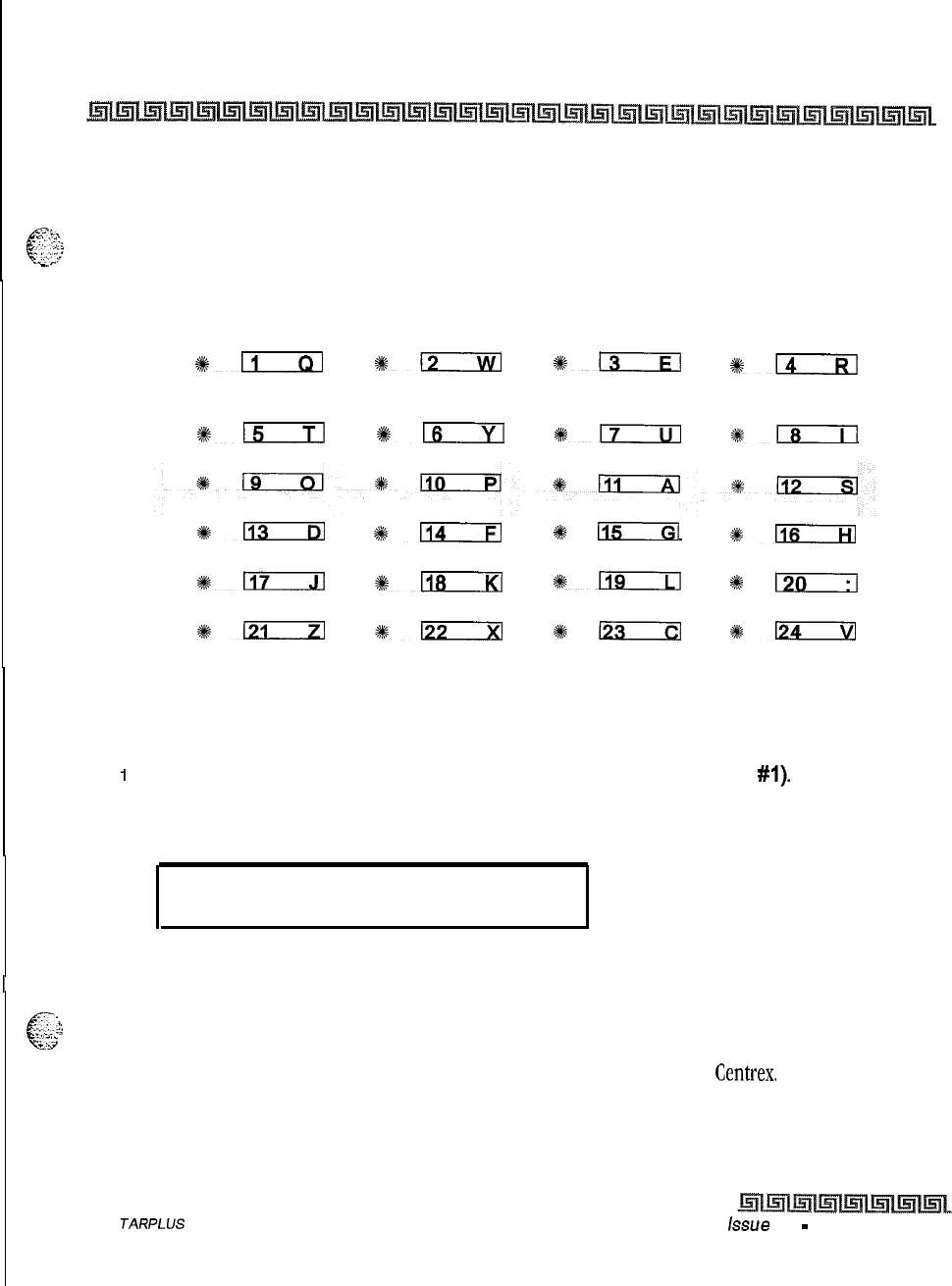
CO Line Attributes Programming
Page C Introduction
3-21
of CO lines or one specific CO Line. Range programming lets the programmer change a specific parameter or
a few parameters for an entire range of CO lines, leaving intact the remaining data fields that do not require
-;<
z,.,
4
=;
‘:
‘;‘;
change. Those data fields continue to operate with the previously programmed data. By default, Page A is
.jL..G,Y
shown.
-.
When programming the Page C features, the flexible buttons are mapped as follows:
FLASH TIMER RING DELAY RESEIZE TIMER GUARD TIMER
+#ll
%+Ec3fI
%:-
s-
PRESET FWD
TIMER
115
+%m
%tEal
$ki-s--il
4kD
*a
%4
115
*l2EcrHl
PAGE A
PAGE B
*m
%mrxl
*a
I
I:/
PAGE C NEXT (FWD) NEXT (BACK)
NEW RANGE
#D
1122
%125
*n
Flash Timer
Programming Steps
1
Press the FLASH TIMER flexible button (FLASH 40, Page C, button
#l).
2
Enter a 2-digit timer value on the dial pad between 01-20 which corresponds to 100 ms
to 2 seconds.
FLASH TIMER 01-20
10
.
3
Press HOLD to save the entry. A confirmation tone is heard and the display updates.
-:
:&
6‘
Description
”
:.
j
. .
-2
-.fl
Flash is a programmable opening on a line for signaling. When using an outside line, flash lets a user obtain
a new dial tone without losing the line. This is particularly useful behind a PBX or
Centrex.
Each CO line can
be programmed for a flash time. By default, the Flash Timer is set for 10 (1.0 seconds) and is variable from
01-20 (100 ms to 2 seconds).
S
JARPLUS
Triad-S System Programming Manual issue 1
-
December 1998
.
3-22
CO Line Attributes Programming
Page C introduction
Ring Delay Timer
Programming Steps
1
Press the RING DELAY TIMER flexible button (FLASH 40, Page
C.
button
#2).
The
following message displays:
RING DELAY TIMER 00-20
00
2
Enter a 2-digit timer value on the dial pad between 00-20 which corresponds to 00-20
seconds.
3
Press HOLD to save the entry. A confirmation tone is heard and the display updates.
Description
The Ring Delay timer was added to the Triad-S to accommodate ICLID interface requirements, The Ring
Delay timer is started whenever a CO Line detects incoming ringing. When the timer expires, CO line ringing
is detected by digital terminals and Single Line telephones. The purpose of this timer is to wait until after
the first ring cycle to be detected by the digital system so the ICLID information is passed down the CO line
prior to being answered. In some cases, it may be necessary to set the Ring Delay Timer to four seconds so
all the ICLID information is received from the Central Office. By default, the Ring Delay Timer is set at 00
(disabled) and is variable from 00-20 seconds.
Reseize Timer
Programming Steps
1
Press the RESEIZE TIMER Button (FLASH 40, Page
C.
button
#3)
in the flexible button
field. The following message displays:
.
m
RESEIZE TIMER 000-255
200
Enter a 3-digit value on the dial pad that corresponds to 000-255 (100 ms to 2.55
^
.
2
l.:.-~.z:
seconds). ,~
.-.
,p;:
::.
:
.
3
Press HOLD to save the entry. A confirmation tone is heard and the display updates.
Issue I- December 1998
STARPLUS Triad-S System Programming Manual
.-
CO Line Attributes Programming
Page C Introduction
3-23
Description
This option lets the user adjust the reseize timer on a per CO Line basis. The reseize timer can be used on
.$C.
<.>.;.x
c
.-
sr,..
any trunk type. This timer sets the time period that a trunk is held disconnected after receiving a disconnect
‘G
before being reseized when a device is queued for a member of the trunk group. By default, the Reseize
Timer is set for two seconds.
Guard Timer
Programming Steps
1
Press the GUARD TIMER button (FLASH 40, Page C, button
#4)
in the flexible button
field. The following message displays:
I
GUARD TIMER l-60
50
I
/
2
Enter a 3-digit value on the dial pad which corresponds to I-60 (100 ms to 6 seconds).
3
Press HOLD to save the entry. A confirmation tone is heard and the display updates.
Description
The outgoing guard timer is the length of time a tie trunk is held busy to outgoing seizure after a valid release
is detected. By default, the Guard Timer is set for five seconds.
Preset Forward Timer
Programming Steps
1
Press the PRESET FWD TIMER flexible button (FLASH 40, Page C, button
#5).
The
following message displays:
PRESET FWD TIMER 00-99
00
2
Enter a 2-digit timer value on the dial pad which corresponds to 00-99 seconds.
3
Press HOLD to save the entry. A confirmation tone is heard and the display updates.
STARPLUS
Triad-S System Programming Manual
Issue I- December 1998
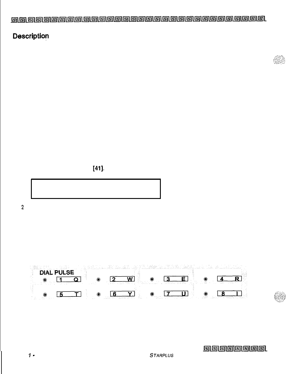
3-24
CO Line Attributes Programming
Miscellaneous CO Parameters
Descriptiop
This timer determines the time an outside line rings before being forwarded to a predetermined
destination, If a forward destination is programmed in the CO line field, the CO calls forward to that
destination after the CO preset forward timer expires. This forward occurs regardless of how many stations
the line is ringing. The digits entered for the CO line are sent in the station field.This feature applies to
initial CO ringing lines only and works with Preset Forward CO Line assignments. By default, the CO Line
Preset Forward Timer is set at
10
seconds and is variable from
00-99
seconds. A [00] entry disables the
timer and the feature is disabled.
Miscellaneous CO Parameters
Programming Steps
If the system is in the programming mode, continue using the program codes.
If
starting to program here,
enter the programming mode first.
1
Press FLASH and dial
[41].
The following message displays:
CO FEATURES
ENTER BUTTON NUMBER
2
Select any of the features by pressing the appropriate flexible button(s) in the flexible
field.
3
Press HOLD to save the entry. A confirmation tone is heard and the display updates.
Description
When entering the Miscellaneous CO Parameters programming area the buttons on the digital terminal are
defined as shown below:
Issue
I
-
December 1998
STARPLLJS
Triad-S System Programming Manual
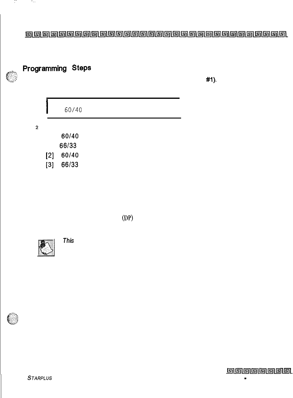
I
:.
--.
CO Line Attributes Programming
Miscellaneous CO Parameters
3-25
Dial Pulse Parameters
&??,,
Pwrammi”g
steps
<-&
,
Press the DIAL PULSE flexible button (FLASH 41, button
#l).
The following message
displays:
I
DIAL PULSE
60/40
10 PPS
I
z
Enter the l-digit value (O-3) which corresponds with the following entries:
[0] =
60/40
(RATIO), 10 pps (SPEED)
[I] =
66/33
(RATIO), 10 pps (SPEED)
[2]
=
60/40
(RATIO), 20 pps (SPEED)
[3]
=
66/33
(RATIO), 20 pps (SPEED
3
Press HOLD to save the entry. A confirmation tone is heard and the display updates.
Description
This
option lets the installer adjust the dial pulse ratio and speed when using dial pulse (rotary) type
signaling.
By
default, all lines are DTMF (tone) signaling. If pulse dialing is required, the individual outside
line must be programmed for Dial Pulse
(DP)
. When Dial Pulse is selected, this system-wide parameter must
be set to determine the break/make ratio and the dial speed of the dial pulse signal.
This
program code is on/y used when an outside (CO) line is programmed
for Dial Pulse.
STARPLUS
Triad-S System Programming Manual Issue I
-
December 1998
3-26
CO Line Attributes Programming
Miscellaneous CO Parameters
issue
I- December
IQ98
STARPLUS
Triad-S System Programming Manual
I
:
.
.
.
.
--:
:..
Programming Steps
If the system is in the programming mode, continue using the program codes, If starting to program here,
enter the programming mode. If station features must be changed:
1
Press FLASH and dial
[50].
The following message displays:
STATION ATTRIBUTES
SELECT A STATION RANGE
z
Enter a 6-digit number for the station range being programmed. If one station is being
programmed, enter that number twice (100100).
,-’
‘.
/f
HOLD is pressed without entering a station range, ALL stations (1&l-
13 1) are
selected.
3
Press Button
#I9
and the display updates.The display updates to current programming
for Page A:
XXX-XXX PAGE A
ENTER BUTTON NUMBER
Where:
.
XXX-XXX = Station Range (100-131)
Description
This section describes the steps and procedures necessary to program station attributes.
cl
;g$
Range programming enables the programmer to change a specific parameter or a few parameters for a range
i
of stations, leaving intact the remaining data fields not requiring changes. Those data fields continue to
operate with the previously programmed data. By default, Page A is shown,
Issue 1
-
December 1998 STARPLUS Triad-S System Programming Manual
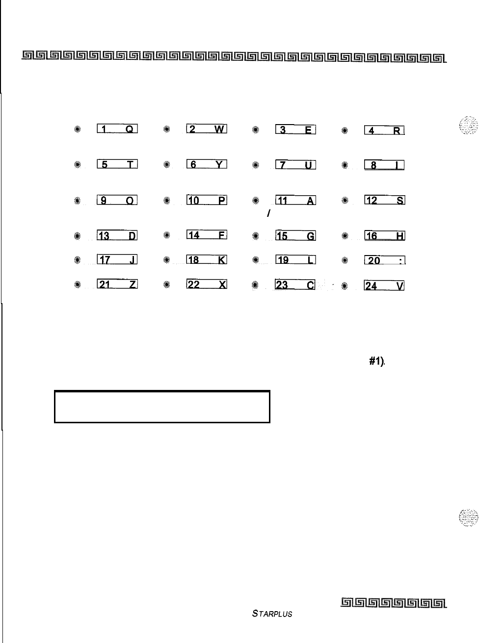
4-2
Station Attributes Programming
Page A Introduction
When programming the Page A features, the flexible buttons are mapped as follows:
PAGE ACCESS DO NOT CONFERENCE EXECUTIVE
DISTURB OVERRIDE
*n
%a
%+13
%pi--Rl
PRIVACY SYSTEM SPEED LINE QUEUING
PREF LINE
ANSWER
%15
%+m
#ITILl
#IT--i-l
OHVO CALL FORWARD FORCED LCR ACD SUPV
BARGE-IN
*n
%+110
#a
%i!cExl
EXEC OVRD CO LINE RING NAME
/
NUMBER
BLOCKING OPTIONS DISPLAY
#L13
*114
Sk+-
#C
PAGE A PAGE B
#a
1118
9119
e
(301
PAGE C NEXT (FWD) NEXT (BACK) NEW RANGE
%D
%kD
1123-%%n
Paging Access
Programming Steps
1
Press the PAGE ACCESS flexible button (FLASH 50, Page A, button
#I).
The
following message displays:
PAGE ACCESS
o-1
ENABLED
2
Enter a l-digit value on the dial pad to enable/disable the Paging Access feature.
[0] = Disabled
[I] = Enabled
3
Press HOLD to save the entry. Confirmation tone is heard.
Description
Stations can individually be
allowed
or denied the ability to make pages. This applies to all internal and
external zone paging. A station denied access to paging may still answer a meet-me page announcement.
(Station COS
6
does not deny a station the ability to make a page.) By default, Paging is enabled at all
stations.
issue I- December 1998
STARPLUS
Triad-S System Programming Manual
I
Station Attributes Programming
4-3
Page A Introduction
Do Not Disturb
Programming Steps
Press the DO NOT DISTURB flexible button (FLASH
50.
Page A, button
#2).
The
following message displays:
I
DO NOT DISTURB O-l
ENABLED
I
2
Enter a l-digit value on the dial pad to enable/disable the Do Not Disturb feature.
[0] = Disabled
[I] = Enabled
3
Press HOLD to save the entry. Confirmation tone is heard.
Description
Stations can be individually allowed or denied the ability to place their telephone in Do Not Disturb. By
default, Do Not Disturb is enabled at all stations. The first programmed attendant cannot utilize DND.
Conference Enable
/
Disable (Per Station)
Programming Steps
1
Press the CONFERENCE flexible button (FLASH 50, Page A, button
#3).
The following
message displays:
CONFERENCE
o-1
ENABLED
b
Enter a l-digit value on the dial pad to enable/disable the Conference feature.
[0] = Disabled
[I] = Enabled
2
Press HOLD to save the entry. Confirmation tone is heard.
““’
Description
I
This feature lets the system be programmed on a per Station basis for the ability to initiate a conference.
STARPLUS
Triad-S System Programming Manual issue
I-
December 1998
Station Attributes Programming
Page A introduction
Executive Override
Programming Steps
1
Press the EXECUTIVE OVERRIDE flexible button (FLASH 50, Page A, button
#4).
The
following message displays:
EXEC OVERRIDE o-1
DISABLED
l
.
2
Enter a l-digit value on the dial pad to enable/disable the Executive Override feature.
[0] = Disabled
[I] = Enabled
3
Press HOLD to save the entry. Confirmation tone is heard.
Use of this feature when the Executive Override Warning Tone is disabled
may be interpreted as a violation of federal, state, or local laws, and an
invasion of privacy. Check applicable laws in your area before intruding on
calls using this feature.
A change in volume may occur on the CO line or intercom call after the
barge-in occurs.
Description
This feature lets certain stations be designated as Executive stations with the ability to override and barge-in
on other key sets engaged in a CO line or intercom conversation. If Supervisor Monitor with barge-in
function is denied, this feature MUST be disabled An optional warning tone is programmed on a system
wide basis to enable or disable the tone. This tone is presented to all parties prior to actual cut through of
the third party.
A separate condition was added to this feature that allows or disallows an
Executive to override an extension. This prevents an extension with
override capability from overriding an Executive’s station.
By default, Executive Override is disabled for all stations. Supervisor Barge-In can be programmed in
[FLASH
so]
[Button
131.
Issue I- December 1998
STARPLUS Triad-S System Programming Manual
:
Station Attributes Programming
Page A introduction
Privacy (Per Station)
,.-~~,
Programming
Steps
.-A...
T
c
.;.:
=
-2
-:>i
.<-.
IPress the PRIVACY flexible button (FLASH 50, Page A, button
#5).
The following
message displays:
PRIVACY
o-1
ENABLED
\
z
Enter a l-digit value on the dial pad to enable/disable the Privacy feature.
[0] = Disabled
[I] = Enabled
3
Press HOLD to save the entry. Confirmation tone is heard.
Disabling the privacy feature
may
be limited by
federal,
state, und
locul
law, so
check the
relevant laws
in your
urea
before
disabling privacy.
For Single Line Telephones:
1
Enter a l-digit value on the dial pad to enable/disable the camp-on feature.
[0] = No Camp-on is allowed
[I] = Camp On is allowed
2
Press HOLD to save the entry. Confirmation tone is heard.
Description
The system provides privacy on all communications in the system which prevents other stations from
accidentally entering an existing conversation. However, the system provides, on a per station basis, the
ability for a station to join an existing outside CO line conversation. Each station can be granted the privilege
to join an existing CO line conversation by simply pressing the CO line button of a CO line in use. The Privacy
flag when enabled on SLT type stations allows/denies Camp-on requests to the SLT. This can be useful in
situations where a modem is using the SLT port for data transmission. Disabling this feature lets data
transfer proceed without being interrupted with a camp on tone.
4.
Both the station and the CO Line must have Privacy disabled before the system allows cut-through.
+z+
If Privacy is disabled and a station joins an existing call, a programmable warming tone is presented
to both parties prior to actual cut-through.
+
If Privacy is disabled, up to eight other stations may join in on an existing conversation.
STARPLUS
Triad-S System Programming Manual Issue
I- December 1998
I
4-6
Station Attributes Programming
Page A Introduction
Privacy is enabled for all stations in default.
Station Attempting to CO Line in Use by Another Station
Access CO Line
Privacy Enabled Privacy Disabled
Privacy Enabled Private Private
(No Cut-through) (No Cut-through)
Privacy Disabled Private Privacy Released
(No Cut-through) (Cut-through Allowed)
Table 4-l: Station Privacy Flag
System Speed Dial Access
Programming Steps
1
Press the SPEED flexible button (FLASH 50, Page A, button
#6).
The following
message displays:
SYSTEM SPEED
o-1
ENABLED
,z
Enter a l-digit value on the dial pad to enable/disable the Speed Dial feature.
[0] = Disabled
[I] = Enabled
3Press HOLD to save the entry. Confirmation tone is heard.
Description
Stations can be individually allowed or denied the ability to use system speed dial (20-99) numbers. The
last 40 system speed numbers are not monitored by toll restriction. Stations cannot be prevented
from using station speed dial. By default, System Speed Dialing is enabled at all stations.
Issue I- December 1998
STARPLUS
Triad-S System Programming Manual
Station Attributes Programming
Page A Introduction
Lihe Queuing
Programming Steps
I
Press the QUEUING flexible button (FLASH 50, Page A, button
#7).
The following
message displays:
.
LINE QUEUING
O-l
ENABLED
l
z
Enter a l-digit value on the dial pad to enable/disable the Line Queuing feature.
[0] = Disabled
[I] = Enabled
3
Press HOLD to save the entry. Confirmation tone is heard.
Description
‘\.
Stations can be allowed or denied the ability to manually queue for a busy group of CO lines. Even when
disabled, stations have automatic LCR queuing privileges. By default, CO Line Queuing is enabled at all
stations.
Preferred Line Answer
Programming Steps
1
Press the PREF LINE ANSWER flexible button
(FLASH 50, Page A, button #8).
The
following message displays:
.
PREF LINE ANSWER
O-l
ENABLED
t
z
Enter a l-digit value on the dial pad to enable/disable the Preferred Line feature.
[0] = Disabled
[I] = Enabled
3
Press HOLD to save the entry. Confirmation tone is heard.
Description
Stations can be given the ability to answer a call by simply going off-hook. By default, Preferred Line Answer
is enabled on all stations.
STARPLUS
Triad-S System Programming Manual
issue I- December 1998
Station Attributes Programming
Page A Introduction
Off-Hook Voice Over (OHVO)
Programming Steps
1
Press the OHVO flexible button (FLASH 50, Page A, button
#g).
The following
message displays:
OFF HOOK VOICE OVER
O-1
DISABLED
.
2Enter a l-digit value on the dial pad to enable/disable the Off-Hook Voice Over
feature.
[0] = Disabled
[I] = Enabled
3Press HOLD to save the entry. Confirmation tone is heard.
Description
When enabled, this feature allows a digital station to receive OHVO while on a call. A station can be denied
the ability to receive OHVO calls by disabling this feature. By default, Off-HookVoice Over is disabled for all
stations. The station must be in H or P mode to enable this feature.
Call Forwarding
Programming Steps
1Press the CALL FORWARD flexible button (FLASH 50, Page A, button #IO). The
following message displays:
CALL FORWARD
o-1
ENABLED
4
2Enter a l-digit value on the dial pad to enable/disable the Call Forwarding feature.
[0] = Disabled
[I] = Enabled
3Press HOLD to save the entry. Confirmation tone is heard.
Issue I- December 1998
STARPLUS
Triad-S System Programming Manual
Station Attributes Programming
Page A introduction
Description
Stations can be allowed or denied the ability to forward incoming CO calls, intercom calls, or transferred
.F.-.
+---.
i
z:--
63
_
..--.
>.
outside lines to another station or group. By default, Call Forwarding is enabled at all stations.
Forced Least Cost Routing (LCR)
Programming Steps
1
Press the FORCED LCR flexible button (FLASH 50, Page A, button
#II).
The following
message displays:
FORCE LCR
o-1
DISABLED
2
Enter a l-digit value on the dial pad to enable/disable the LCR feature.
[0] = Disabled
[I] = Enabled
3
Press HOLD to save the entry. Confirmation tone is heard.
Description
Stations may be forced to place outgoing CO calls by use of LCR (dial
[9])
to access an outside line. This lets
the system administrator control dialing patterns and lines used for outgoing CO calls. This can be
enabled/disabled on a per-station basis for additional flexibility and control. Forced LCR is optional
(disabled) for all stations, and eliminates access to all other line groups.
ACD Supervisor Monitor with Barge-In
Programming Steps
1
Press the SUPV BARGE-IN flexible button (FLASH 50, Page A, button
#12).
The
following message displays:
I
ACD SUPV BARGE IN
o-1
DISABLED
I
2
Enter a l-digit value on the dial pad to enable/disable the ACD Supervisor feature.
[0] = Disabled
[I]
= Enabled
STARPLUS Triad-S System Programming Manual issue
I-
December 1998
4-10
Station Attributes Programming
Page A Introduction
3
Press HOLD to save the entry. Confirmation tone is heard,
The use of Supervisor Monitor with Barge-In is limited by
federal
low and
mayalso
belimitedorprohibitedbystote orlocallaw, so check fherelevant
,.
laws in your area before employing these features.
_,1
‘,;;-;;:
,,
A change in volume may occur on the CO line or intercom call offer the
barge-in occurs.
Description
Eh%feature
k
avadable with optiomzlsoftware.
The ACD Supervisor Monitor with Barge-In feature
provides a means for an ACD Supervisor to monitor an agents call in progress to coach sales techniques or
customer relations skills. When used, a supervisor may intrude into an agent’s call in a listen-only mode or
in a true conference mode. Prior to barge-in, a supervisor must log into the agent’s group using the
supervisor log-in code
576xXx.
This feature is available with or without a warning tone. By default, the
Supervisor Monitor with Barge-In feature is disabled.
Executive Override is a system feature and, therefore, fakes precedence
over this
feature.
If Supervisor Monitor with Barge-In is used properly,
Executive Override MUST be disabled. Otherwise, the barge-in is per-
formed with the MUTE button OFF.
Executive Override Blocking
1
Programming Steps
2
Press the EXECUTIVE OVERRIDE BLOCKING flexible button (FLASH 50, Page A,
button
#13).
The following message displays:
EXEC OVERRIDE BLOCK
O-l
ENABLED
3
Enter a l-digit value on the dial pad to enable/disable the Exec Override Block feature.
[0] = Disabled
[I] = Enabled
4
Press HOLD to save the entry. Confirmation tone is heard.
Issue I
-
December 1998
STARPLUS
Triad-S System Programming Manual
Station Attributes Programming
Page A Introduction
Description
The Executive Override Feature has a separate condition added to it that allows or disallows an Executive to
+,-7.
c.-;
;
_,.:,.G
override an extension. This prevents an extension with override capability from overriding an Executive’s
.‘.2
station. By default, Executive Override is enabled at all stations.
The Executive Override blocking feature also blocks an
AC0
Supervisor
Monitor with Barge-/n.
CO Line Ringing Options
Programming Steps
1
Press the RINGING OPTIONS flexible button (FLASH 50, Page A, button
#14).
The
following message displays:
CO RING OPTIONS
O-1
MUTED RING
2
Enter a l-digit value on the dial pad to enable/disable the Ringing Options feature.
[0] = Reminder Ring
[I] = Muted Ring
-
3
Press HOLD to save the entry. Confirmation tone is heard.
Description
When a CO call rings at a busy station, the call rings at the station using a muted ring signal. This option lets
a user receive a reminder ring at his station, instead of muted ring. In addition, a reminder ring timer has
also been added to the system to provide the reminder ring every time the timer expires, for as long as the
incoming CO line has not been disconnected. By default, Muted Ringing is allowed at all stations.
STARPLUS Triad-S System Programming Manual
Issue I- December 1998
4-12
Station Attributes Programming
Page Blntroduction
Name
/
Number Display at Idle
Programming
Steps
I
Press the NAME/NUMBER DISPLAY flexible button (FLASH 50, Page A, button
#is).
The following message displays:
NAME AT IDLE ICD
O-l
NAME
2
Enter a l-digit value on the dial pad to enable/disable the Name/Number feature.
[0] = Name
[I] = Station Number
3
Press HOLD to save the entry. Confirmation tone is heard.
Description
This feature displays the standard idle LCD showing the programmed 7-digit name and station number
together. This option is programmable on a per station basis, however, the feature must be enabled
/
disabled in admin programming. If a station has this feature enabled but has not programmed a name, the
name portion of the LCD is blank. The idle display priority is
UCD/ACD,
Hunt, Station/Name, or Station. By
default, the Name and Station number display on the LCD.
Page B Introduction
Programming Steps
If the system is in the programming mode, continue using the program codes. If starting to program here,
enter the programming mode.
I
Press FLASH and dial
[50].
The following message displays:
STATION ATTRIBUTES
SELECT A STATION RANGE
*.
,'
i.
',,
.,.:.
1
_..,
I.:;..;
.i
--
2
Enter a 6-digit number for the station range being programmed. If one station is being
programmed, enter that number twice, e.g.,
[100100].
Issue
I-
December 1998 STARPLUS Triad-S System Programming Manual
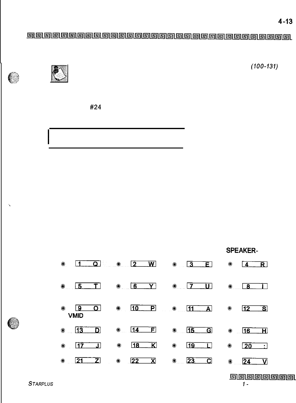
Station Attributes Programming
Page B Introduction
If HOLD is pressed without entering a station range, all stations
(100-131)
are selected.
3
Press HOLD to save the entry. A confirmation tone is heard and the display updates.
Flexible button
#24
(New Range) is lit.
4
Press [PG B] button. The current programming for those features displays as:
I
XXX-XXX PAGE B
ENTER BUTTON NUMBER
I
Where:
XXX = Station Range (100-131)
Description
This section describes the steps and procedures necessary to program station attributes. Range programming
i
enables the programmer to change a specific parameter or a few parameters for a range of stations, leaving
intact the remaining data fields not requiring changes. Those data fields continue to operate with the
previously programmed data.
When programming the Page B features, the flexible buttons are mapped as follows:
STATION ID DAYCLASSOF NIGHT CLASS
SPEAKER-
SERVICE OF SERVICE PHONE
sEiIxl*12
+%l3rIizl *
14
GROUP PICKUP PAGING ZONES PRESET CO LINE GROUP
FORWARD ACCESS
*m
%fn
%a
%+-I
LCR CLASS OF OFF-HOOK BUTTON
SERVICE PREFERENCE ASSIGN KEY SET MODE
s#-
~liEIE!l8111
2#
n
VMID
DISPLAY
TRANSLATION BUTTONS
%+113
%114
%llEIzl
+#lTcr-Hl
CKTU PAGE A PAGE B
%sn
%I!iBzxl
*Ils
Q
130
PAGE C NEXT (FWD) NEXT (BACK) NEW RANGE
%1219122
+%D
%kLi?Kizl
STARPLUS Triad-S System Programming Manual Issue
I-
December 1998
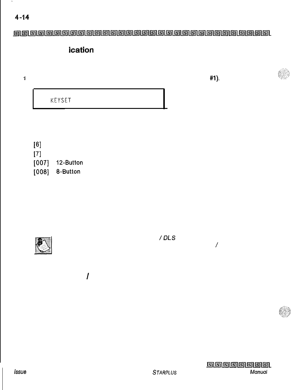
.
Station Attributes Programming
Page B Introduction
Station ldentif ication
Programming Steps
1
Press the STATION ID flexible button (FLASH 50, Page B, button
#l).
STATION ID
o-7
KEYSET
1
Enter a 1, 2, 3 or 4-digit value on the dial pad to identify the type of terminal:
[000] or [0] = 24-Button Terminal
[I] = DSS Console
[6]
= SLT without Message Wait
[7]
= SLT with Message Wait
[007]
=
12-Button
Terminal
[008]
=
g-Button
Terminal
2Press HOLD to save the entry. A confirmation tone is heard and the display updates.
Description
Each system port must be programmed to identify the type of station that operate on that port. Each station
type must be identified. By default, all Key Telephone Boards (DTIB) default to ID 0 (24-Button Digital
Terminal), all Single Line Boards (SLIB) default to ID
6.
When identifying a station as a DSS
/
OLS
console, you must also enter
the station number of the key telephone to which the DSS
/
DL S console
is associated. To associate a DSS console with Station 100, the entry
would be 1100 [HOLD].
Station ID for DSS
/
DLS Console with Map
Programming Steps
IDial [I] on the dial pad.
2Enter the 3-digit station number (100-131) to which the DSS/DLS Console is
associated.
3Press HOLD to save the entry. A confirmation tone is heard and the display updates.
issue
I- December 1998
STARPLUS
Triad-S System Programming
fvk~nual
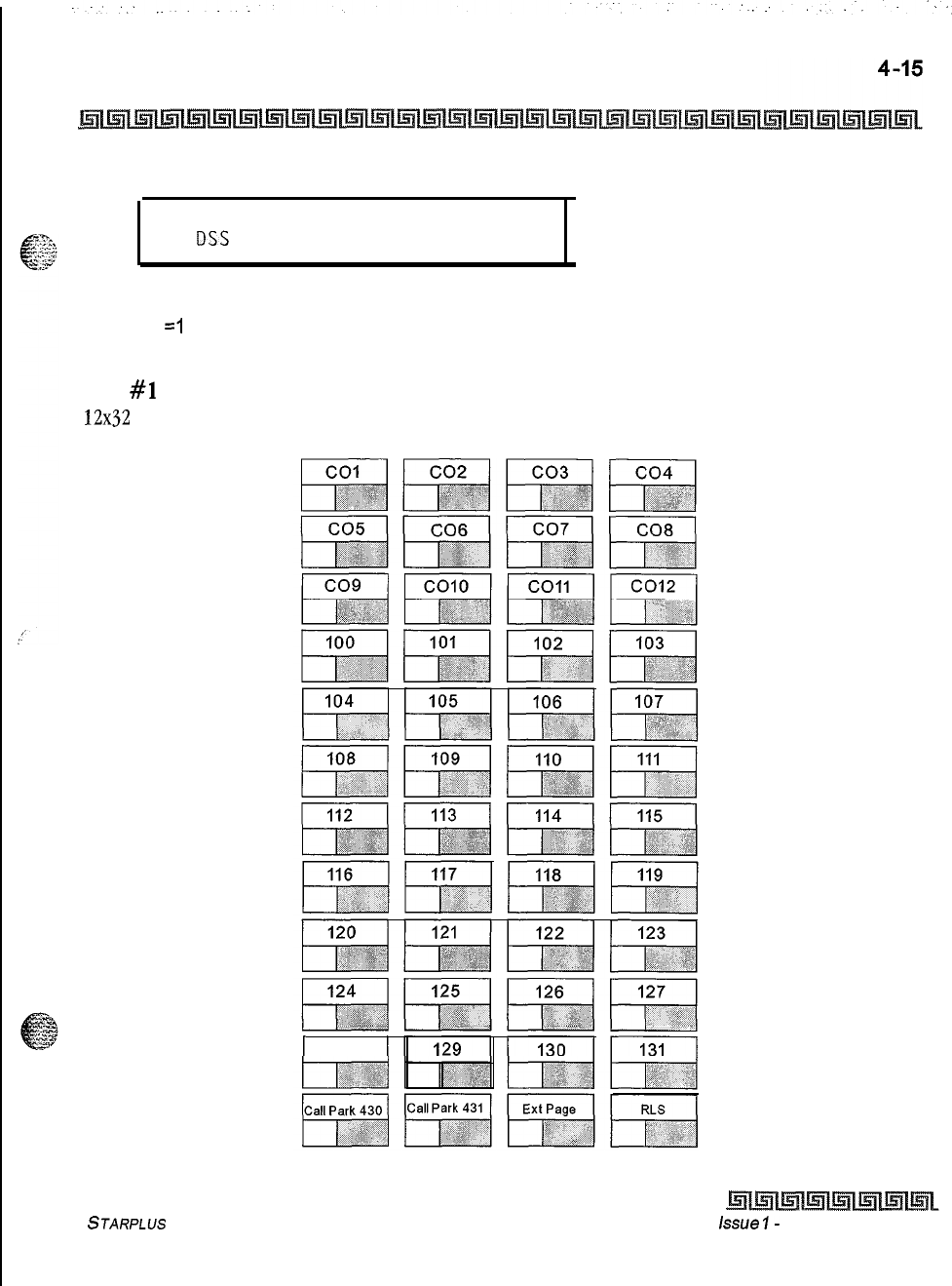
Station Attributes Programming
Page B Introduction
STATION ID
o-7
DSS MAP X ASSOC XXX
1
Where:
x
=I
XXX = Station Range (100-131)
MAP
#l
by default has all 12 CO Lines and all 32 Stations,
100-131.
This provides
12x32
configuration. Station/Feature buttons are flexible and can be changed by the
buttons are NOT changeable.
1 128 1
a default layout for a
station user. CO Line
STARPLUS Triad-S System Programming Manual issue
I-
December 1998
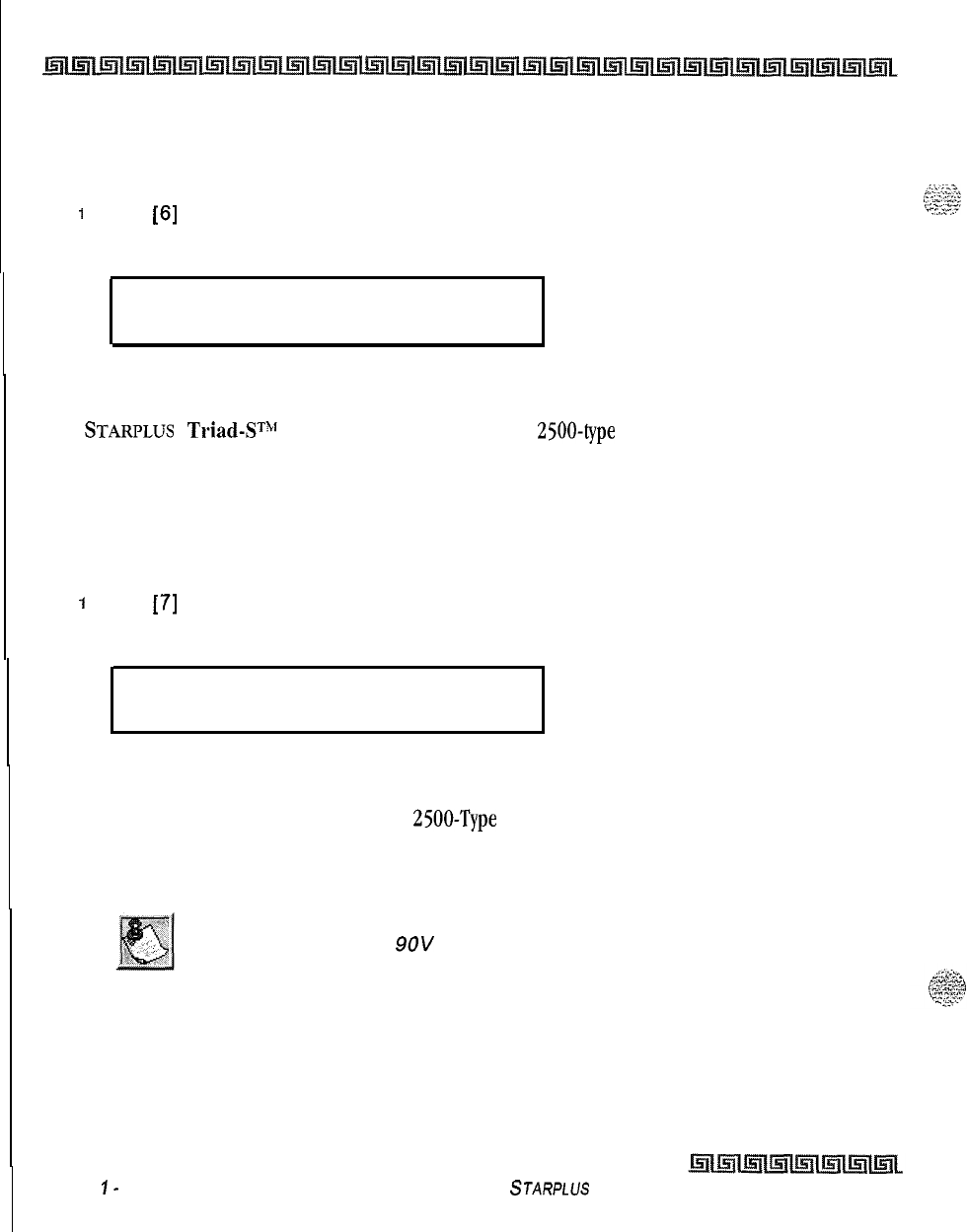
I
4-16
Station Attributes Programming
Page B Introduction
SLT Station ID
Programming Steps
1
Dial
[6]
on the dial pad.
2Press HOLD to save the entry. A confirmation tone is heard and the display updates.
STATION ID
o-7
SLT
Description
The
STARPLUS
Triad-ST”’
system supports industry standard
2500-type
(DTMF)
single line instruments.
When the CSIB is installed in the system, a maximum of 24 single line telephones are supported,
SLT with Message Waiting Lamp Station ID
Programming Steps
1
Dial
[7]
on the dial pad.
2
Press HOLD to save the entry. A confirmation tone is heard and the display updates,
STATION ID
o-7
SLT W MSG
Description
The Triad-S system supports industry standard
2500-Type
(DTMF) single line instruments. When the
CSIB
is installed in the system, a maximum of 8 single line telephones may be supported. The Triad-S system
supports up to 24 single line telephones.
Triad-S system sends
9OV
DC to SL Ts with message waiting lamps.
Issue
I-
December 1998
STARPLUS
Triad-S System Programming Manual
I
Station Attributes Programming
Page B Introduction
4-17
Station Day Class of Service (COS)
Programming Steps
IPress the DAY COS flexible button (FLASH 50, Page
B.
button
#2).
DAY COS
1-6
1
.
The six classes of service are:
COS 1 = No restrictions.
COS 2 = Table A governs
COS 3 = Table B governs
COS 4 = Table A and B govern
COS 5 = Restricts [0], [I],
[*I,
[#]
dialed as first-digit and places a 7-digit maximum.
COS 6 = Intercom Only (no CO line access
-
will result in 911 block)
2
Press HOLD to save the entry. A confirmation tone is heard and the display updates.
STARPLUS Triad-S System Programming Manual issue
I- December 1998
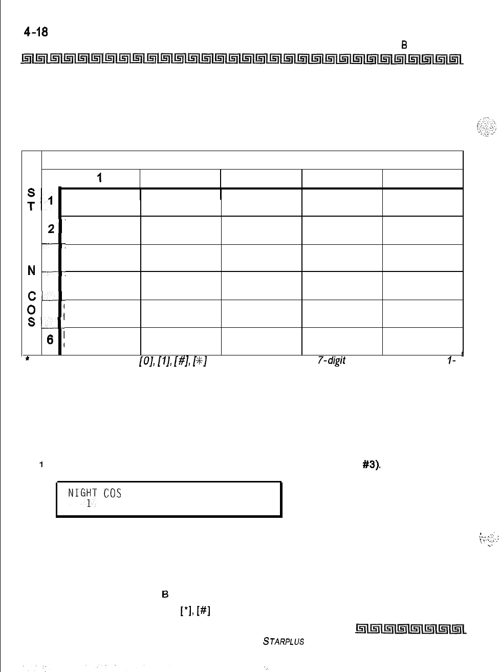
4-18
Station Attributes Programming
Page
6
Introduction
Description
Each station must be assigned a certain COS for Day Mode operation and for Night Mode operation. Class of
Service (COS) determines the station’s dialing privileges. By default, all stations are assigned a
COS 1
for
Day Mode.
CO LINE CLASS OF SERVICE
1
I
2345
Unrestricted Unrestricted Unrestricted Canned Unrestricted
Restricted*
A---
Table A
T
2’
Table A Unrestricted Canned Unrestricted
Restricted*
I
-7
0 3
Table B
Unrestricted Table B Canned Unrestricted
Restricted*
N
---:
4Table A&B Table A Table B Canned Unrestricted
C-....--
Restricted*
Canned
0
;
5Canned Canned Canned Unrestricted
Restricted*
S--
Restricted* Restricted* Restricted*
Intercom
6
1Intercom Intercom Intercom Intercom
Only Only Only Only Only
*
Canned Restriction: No
[O],
[I],
[#I,
[%J
as first dialed digit, and
7-digit
dialing /imitation; plus
I-
!
800, 1911, 1611
are allowed, and
411,
976, and 555 numbers are
denied.
Table 4-2: Class of Service (COS)
Station Night Class of Service (COS)
Programming Steps
I
Press the NIGHT COS flexible button
(FLASH
50, Page B, button
#3).
NIGYT
cos
1-6
The six classes of service are:
COS 1 = No restrictions.
COS 2 = Table A governs
COS 3 = Table B governs
COS 4 = Table A and
6
govern
COS 5 = Restricts [0], [I],
[*I,
[#]
dialed as first-digit and places a 7-digit maximum.
Issue I- December 1998
STARPLUS Triad-S System Programming Manual
L
.-I
::::::
:
\.
..::
_
Station Attributes Programming
Page
8
Introduction
COS 6 = Intercom Only (no CO line access
-
will result in 911 block)
z
Press HOLD to save the entry. A confirmation tone is heard and the display updates.
Description
Each station must be assigned a COS for Night Mode operation. The Night COS goes into affect when the
system is manually or automatically placed into Night Mode. This prevents misuse of phones after hours.
Class of Service (COS) determines the station’s dialing privileges. By default, all stations are assigned a COS
1
for Night Mode. Refer to Table 4-2: Class of Service
(COS).
Speakerphone
/
Headset
Programming Steps
Press the SPEAKERPHONE flexible button (FLASH
50.
Page
6,
button
#4).
The
following message displays:
SPEAKERPHONE O-2
FULL SPEAKERPHONE
Enter a l-digit value on the dial pad to identify the speakerphone operation.
[O]=
Works as normal speakerphone. Full speakerphone capabilities on CO lines and
Intercom.
[I] = Speakerphone enabled for intercom calls only. Speakerphone capabilities disabled
for outgoing CO line calls (monitoring and on-hook dialing are still permitted).
[2]
= Permits toggling of speakerphone and headset operation via the
[634]
Headset
code.
Forces the telephone to always ring in the tone intercom mode.
Forces the telephone to the hand-free intercom mode always.
Press HOLD to save the entry. A confirmation tone is heard.
Description
Speakerphones are programmable. By default, all stations are assigned an ID of 0 (Full Speakerphone).
STARPLUS Triad-S System Programming Mc~nuol
Issue I- December 7998
4-20
Station Attributes Programming
Page B Introduction
Pickup Group(s)
Programming Steps
I
Press the GROUP PICKUP flexible button
(FLASH 50, Page B, button
#5).
The
following message displays:
PICKUP GROUPS
o-4
1
1
2
Enter a 1-4 digit number to program pickup groups.
[0] = No Group
[I] = Group 1
[2]
= Group 2
[3]
= Group 3
[4]
= Group 4
3
Press HOLD to save the entry. A confirmation tone is heard and the display updates,
Description
Stations are assigned to pick-up groups. Stations can be in any combination of the four groups or in no
group at all. By default, all stations are in Group
1.
Paging Zone(s)
Programming Steps
1
Press the PAGING ZONES flexible button
(FLASH 50, Page
B.
button
#6).
The
following message displays:
PAGE ZONE
o-4
1
.
2
Enter a 1-4 digit number to program paging zone(s).
[0] = No Zone (no pages received)
[I] = Zone 1
[2]
= Zone 2
[3]
= Zone 3
[4]
= Zone 4
lssoe
I
-
December 1998
STARPLUS Triad-S System Programming Manual
Station Attributes Programming
Page
I3
Introduction
4-21
3
Press HOLD to save the entry. A confirmation tone is heard and the display updates.
Description
c-
?@ Stations are assigned to internal paging zones. A station can be in any or all zones or in no zone at all. All Call
is all page zones combined. If a station is not in an internal zone, it is excluded from all call pages. Stations
not assigned to a page group can make page announcements if allowed in station programming. Stations can
be assigned to a page group to receive pages but cannot make pages, All stations are in Zone 1.
Preset Call Forward
Programming Steps
1
Press the PRESET FORWARD flexible button (FLASH 50, Page
6,
button
#7).
The
following message displays:
I
PREE
FORWARD
xxx
I
2
Enter a 3-digit entry to determine the destination where calls must be routed when the
Preset Forward Timer expires.
Valid 3 digit destinations are:
[020-099]=
System Speed Bins 20-99 for off-net forwarding
[IOO-1311
= Triad-S Extension Numbers
[440-447]=
Voice Mail Groups l-8
[450-457]=
Hunt Groups l-8
[550-557]=
UCD Groups l-8
[550-565]=
ACD Groups 1-16
3
Press HOLD to save the entry. A confirmation tone is heard and the display updates.
Description
This feature lets the system database be configured so incoming CO Lines, programmed to ring at a
;:z;,
.I
>l.,
”
c
particular station, can be forwarded elsewhere in the system predetermined by programming. This feature is
.,,.,.A
:
+
active if the station ringing is not answered in a specified time. This is particularly useful in overflow
applications where a Voice Mail or Auto Attendant may be in use. A station may have one designated preset
forward location defined in the database.
Preset Call Forward only can be chained to other preset forward stations specified in the database (up to five
stations), If a CO Line forwarded by Preset Call Forward encounters a manually forwarded station (Call
STARPLUS Triad-S System Programming Manual Issue
I-
December 1998
4-22
Station Attributes Programming
Page B Introduction
Forward
-
Station), or a station in DND, the incoming CO Line bypasses that station and forwards to the
next in the chain. If that station is the last in the chain, the call forwards no further and continues to ring at
that station until answered or terminated. Chainable Preset Call Forwarding forces the incoming CO Line to
ring at each station preassigned in the database for the Preset Forward Ring Timer [FLASH
011
[Button
51,
specified in the database, before forwarding.
CO Lines can be preset forwarded to ring into an ACD, UCD, Voice Mail, Hunt Group or Off-Net via speed dial
from any station. A CO Line does not preset forward to a busy Hunt, Voice Mail, ACD, or UCD Group. Each
time the preset forward timer expires (for a total of five attempts), the group is checked for an idle station.
If a member of the group is idle, the call is presented to that member. No preset forward destinations are
programmed.
CO Line Group Access
Programming Steps
I
Press the CO LINE GROUP ACCESS flexible button (FLASH 50, Page B, button
#8)
The following message displays:
LINE GROUP ACCESS
o-7
1
2Enter up to seven digits (0, or l-7) for the outside line groups the station to access.
[0] = No
Access
(911 Calls disallowed/blocked)
[I] = Access to Group 1, Code 9 or 81
[2]
= Access to Group 2, Code 82
[3]
= Access to Group 3, Code 83
[4]
= Access to Group 4, Code 84
[5]
= Access to Group 5, Code 85
[6]
= Access to Group 6, Code 86
[7]
= Access to Group 7, Code 87
3Press HOLD to save the entry. A confirmation tone is heard and the
display
updates.
Description
A station can access any combination of outside line groups, or a station may not be allowed access to
outside lines. CO line groups are used primarily by single line telephones or for flexible buttons assigned as
pooled group buttons on a Key Telephone. B Stations are allowed access to Group
1.
issue I- December 1998
STARPLUS
Triad-S System Programming Manual
Station Attributes Programming
Page B Introduction
4-23
LCR Class of Service (COS)
Programming Steps
1
Press the LCR COS flexible button (FLASH 50, Page B, button
#Q).
The following
message displays:
LCROCLASS OF SERVICE O-6
2
Enter a 1 -digit number (O-6) to correspond to the LCR Class of Service desired.
3
Press HOLD to save the entry. A confirmation tone is heard and the display updates.
Description
Stations can be given a class of service assignment for Least Cost Routing. The range is between
0-6,
with 0
being unrestricted and
6
the most restricted. A station can use LCR routes with a priority number equal to or
higher than the stations LCR COS assignment. Stations are given unrestricted access (0).
Off -Hook Preference
Programming Steps
1
Press the OFF-HOOK PREF flexible button (FLASH 50, Page
8.
button
##lo).
The
following message displays:
I
OFFHOOK PREFENCE BTN
XXY
00 ENABLED
I
2
Enter the 2-digit button number (01-24) or (00) to indicate no specific button is
preferred.
SLTs
use
[Ol]
to enable or [00] to disable.
3
Enter one of the following:
[ 0] = Disables programmable preference so users may not change the of f-hook
preference as set in programming. Also use for SLT stations.
[I]=
Enables programmable preference to key station users so that they may change the
off -hook preference through a user dial code.
4
Press HOLD to save the entry. A confirmation tone is heard and the display updates.
STARPLUS Triad-S System Programming Manual issue
I-
December 1998
4-24
Station Attributes Programming
Page B
Introduction
Description
This lets a key station user automatically have a flex button selected when going off-hook or when pressing
the ON/OFF button, An SLT user may have a particular CO line or a CO line group selected automatically
when going off-hook. This may be established in programming so that key station users can select and/or
change their off-hook preference through the use of a dial code
[691]
+ BB (01-24). Dialing
[691]
+00
disables Off-Hook Preference. This user programmable preference may be allowed or denied in
programming.
When establishing an off-hook preference for SLT stations, it is necessary to program the
SLTs
CO line, or
line group, to access when going off-hook, using a flex button programming procedure. By default, all
digital terminals can change their preference but no button is assigned (00). SLT stations cannot use this
feature.
Flexible Button
Programming Steps
i
Press the BUTTON ASSIGN flexible button (FLASH 50, Page
B.
button
#ll).
The
following message displays:
c
FLEX BUTTON PROG
ENTER BUTTON DATA
2
Enter the
2-digit
button number
[Ol-241
to program followed by the desired button
function as follows:
[0] = Flexible/user changeable
[l]
=
COline
[2]
= Loop button/all-purpose CO appearance
[3]
= Pool for specific groups
[4]
= Direct feature programmable
[#] = Locks button
Description
Each Digital terminal has 8, 12 or 24 flexible buttons that can be programmed. One of the following five
operations can be selected in programming for each button.
issue
I- December 1998
STARPLUS Triad-S System Programming Manual
,X.;T-.-.
,.
.
__.
9
...-
.
.
.
.
I._..._
c
.yy
Station Attributes Programming
Page
B
Introduction
4-25
To assign a button as a Flexible button (user programmable):
I
Enter [BB], [0], [HOLD].
FZ
-‘-:
Y.,
When a button is assigned as a flexible button [0], the user can program any features or functions on the
-:L‘
:..zz
-SZ
buttons to which they have access.
To assign a button as a CO Line button:
IEnter [BB], [I], [LLL], [HOLD]
Where: LLL = CO Line 001-012
Example:
E
:
003 HOLD
002
01 1
001
I
I
I
Button CO CO
Number Code Line
Buttons assigned as specific CO lines provide direct access and appearance of the CO line at a station. The
station receives call status indications such as LED flash rates for incoming ringing when the line is placed
on HOLD, etc. CO Line ringing is programmed in CO Line Attribute programming.
TO assign a button as a Loop button:
1
Enter [BB],
[2],
[HOLD]
Example:
2
p'
I
HOLD
Button Loop
Number Code
Used for a station without direct CO line appearance to answer the line ringing in or transferred to the
station. It is recommended that all stations be given a loop button so they can receive a transferred call on a
L
5~~:
line for which they have no button access.
. . . .
c.::;
To assign a button as a Pool Group button:
I
Enter [BB],
[3],
[G], [HOLD]
Where: G = Line Group Number (l-7)
STARPLUS
Triad-S System Programming Manual Issue
7
-
December 1998
4-26
Station Attributes Programming
Page
6
introduction
Example:
20
1
HOLD
I
1
I
Button
Pool
Line
Number Code Group
Some or all outside CO lines may be grouped together and accessed via a POOL button for the purpose of
placing an outgoing CO call. Pressing this button accesses the highest numbered unused CO line in that CO
line group.
To assign a button as a Feature button (admin programmable):
I
Enter [BB],
[4],
[XXX], [HOLD]
This feature enables flexible buttons to be programmed from a remote location, Range programming can
be used to assign these buttons to multiple stations. When a button is assigned as a feature button
[4],
the
programmer can program any features on the buttons.
To unassign (lock out) a button:
I
Enter [BB],
[#I,
[HOLD]
If SLT stations must be programmed for off-hook preference, program the desired CO line, or CO line group
the SLT must access when going off-hook.
To assign a CO line for an SLT with off-hook preference:
I
Enter
[Ol],
[I], [LLL], [HOLD]
Where: LLL = CO Lines (001-012)
To assign a CO Line Group for an SLT with off-hook preference:
I
Enter
[Ol],
[3],
[G], [HOLD]
Where: G = Line Group Number (l-7)
Issue I
-
December 1998
,.T;-:.
‘.....
,-
.
.
.
.
.
b>
.^...
.,
,;.
.-;
.:
:-;
\;...-,
STARPLUS
Triad-S System Programming Manual
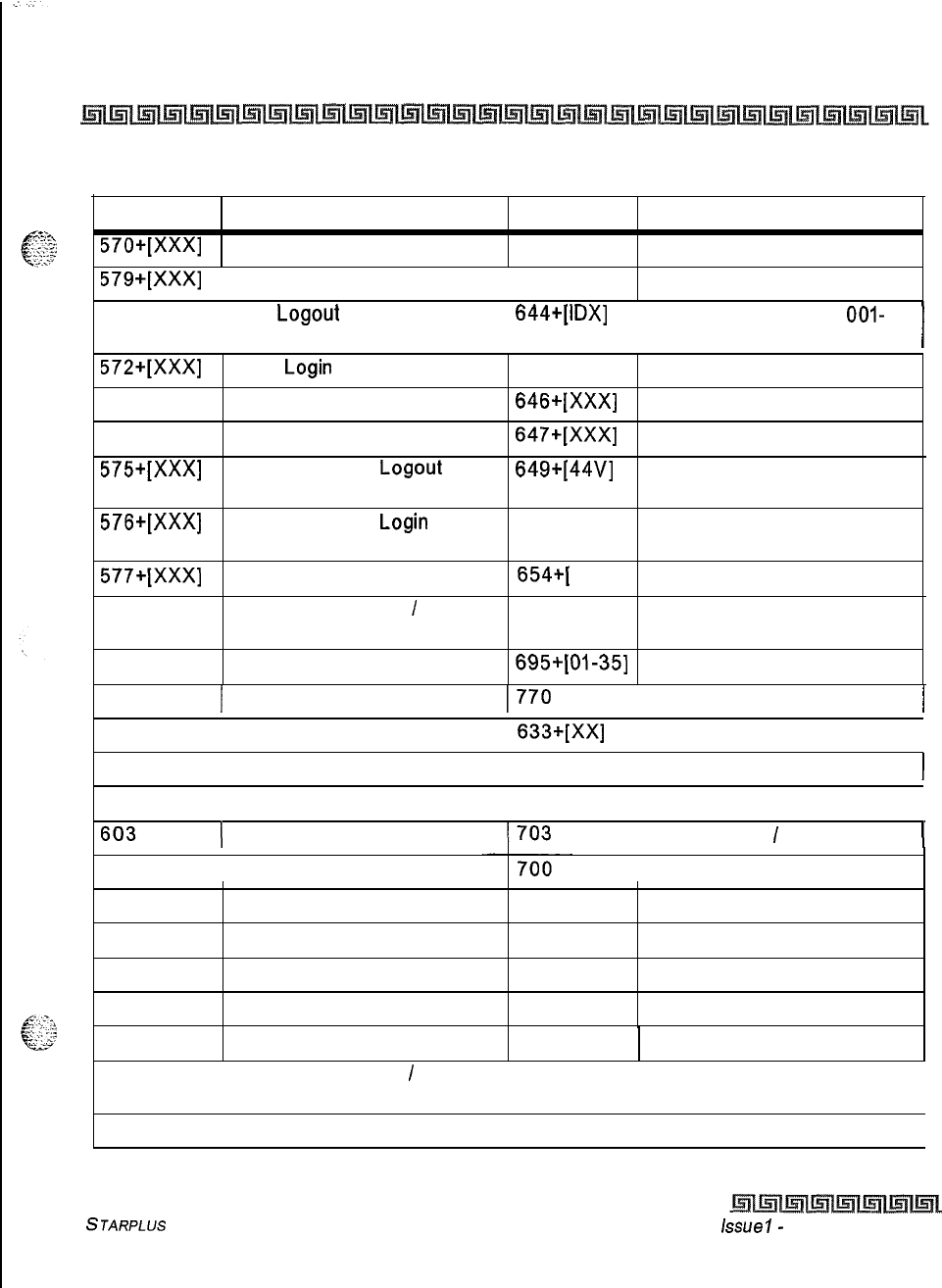
Station Attributes Programming
Page B Introduction
4-27
Code Description Code Description
570+[XXX]
ACD Call Qualifier 643 Repeat Redial
III
579+[XXX]
1ACD Calls in Queue Display 1 694 Custom Message
571
ACD
Logout 644+[lDX]
Mailbox Button (IDX =
OOI-
255)
I
572+[XXX]
ACD
Login
573 ACD Member Status
574 ACD Supervisor Help
575+[XXX]
ACD Supervisor
Logout
576+[XXX]
ACD Supervisor
Login
577+[XXX]
ACD Supervisor Status
607 Attendant Available
/
Unavailable
645 Intercom Button
646+[XXX]
Call Coverage (Ringing)
647+[XXX]
Call Coverage (Non-Ringing)
649+[44V]
One-touch Recording (VM
440-447)
653 Caller ID Name/Number
Toggle
654+[
0, I] Answering Machine Emulation
709 LCR
601
Attendant Override
695+[
01-351
Distinctive Ringing (Station)
622 1 Call Back
1770
1 All Call Page
438 1 Call Park (Personal) I
633+[XX]
1 Personalized Message I
430-437 I Call Park (System) 1 632 I Background Music
I
624 Conference 1 771-774 I Internal Zone Page I
(
CO Off-Net Forward
I
I Disable CO Outgoing
( Universal Day
/
Night Answer
(
602
I
I Group Pickup
625 Executive Override
450-457 Hunt Groups
621
Line Queue
626 LCR Queue Cancel
775 Internal All Call
634 Headset Mode
760 External Page
777 Meet Me Page
604
I I I
Night Service 706
Dial by Name
578 Overflow Available
I
Unavailable 680 Speed Dial Directory
I
000-019 I Station Speed Bins 1 627 I Account Code I
Table 4-3: Flex Button Codes for Remote Programming
STARPLUS Triad-S System Programming Manual issue
I-
December 1998
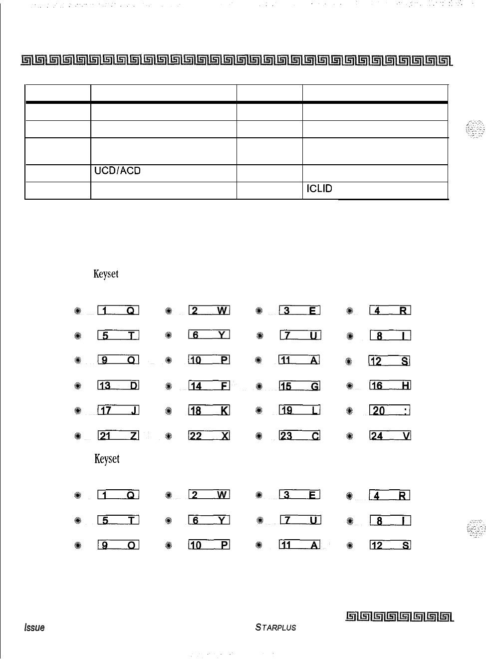
4-28
Station Attributes Programming
Page B introduction
Code Description Code Description
020-099
System Speed Bins 628 OHVO
100-131 Triad-S DSS
631
Do Not Disturb
566
567
440-447
UCDIACD
Available/Unavailable
UCDlACD
Calls in Queue
VM Pilot Groups
640
Call
Forward
641
Release Key
635
ICLID
Unanswered Call
Table 4-3: Flex Button Codes for Remote Programming
Specific buttons may be assigned as unused or locked out. When a button is programmed as unused, the
button may not be programmed by the station user using flex button programming procedures.
24-Button Digital
Keyset
Default:
STA 100 STA
101
STA 102 STA 103
%+n
#12
%ErEl
#D
STA 104 STA 105 STA 106 STA 107
%15 #em
*m
ols
STA 108 STA 109 STA 110
STA 111
*I3rxl*-
*-
%+112
co1 co2 co3 co4
%-
%+licxEl*-
4km
co5 CO6 LOOP POOL
#lirLil
#XK;
#en
$120
CALL BACK
PICKUP
DND LINE QUEUE
%6121*-
*D
*-
12-Button Digital
Keyset
Default:
STA 100
STA 101
STA 102 STA 103
*iIirxl
+%D
3%;
*DzEl
co1 co2 LOOP
POOL
915 116
8617
%#lzEziJ
CALL BACK
PICKUP
DND LINE QUEUE
#t+l3c3zl
%+l3cxl
%+mzxl%112
issue
I- December 1998
STARPLUS Triad-S System Programming Manual
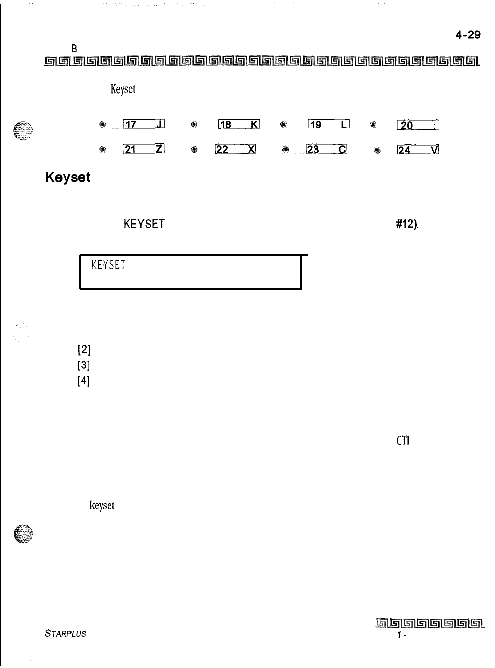
Station Attributes Programming
Page 6 introduction
&Button-Digital
Keyset
Default:
STA 100
STA 101
LOOP POOL
*-
9
118
%
rar--Tl
9#
I?0
CALL BACK
PICKUP DND
LINE QUEUE
#6121
e-
%+123
sit-
Keyset
Mode
Programming Steps
1
Press the
KEYSET
MODE flexible button (FLASH 50, Page B, button
#12).
The
following message displays:
KEYSET MODE
o-4
INACTIVE MODE
2
Enter a l-digit number to change the mode of a digital terminal:
[0] = Inactive Mode (normal mode without CTI box)
[I] = PC Phone Mode at 4800 baud
[2]
= ATD Command Mode at 4800 baud
[3]
= ATH Command Mode at 4800 baud
[4]
= CKTU Mode
3
Press HOLD to save the entry. A confirmation tone is heard and the display updates.
Description
This feature lets the station user determine the mode in which the Digital Terminal with
CT1
Box (optional)
operates, The 5 modes are: Inactive, PC Phone, ATD Command, ATH Command and CKTU. Through the use
of a dial code, the station user can also determine the baud rate for each mode selected. This setting is stored
in back-up memory in the event of a power outage or system reset.
By default,
keyset
is set for Inactive Mode.
STARPLUS
Triad-S System Programming Manual Issue
I-
December 1998
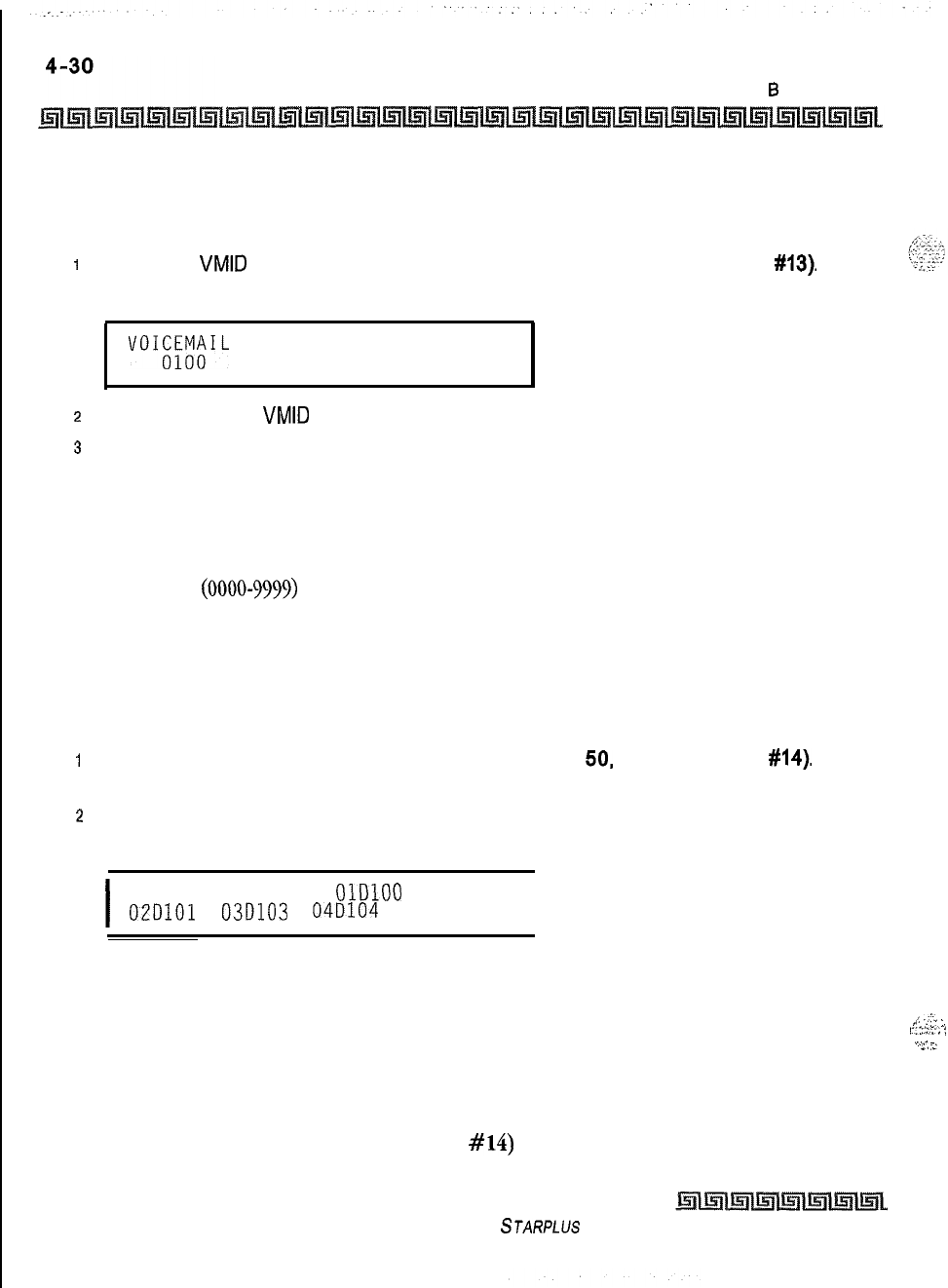
Station Attributes Programming
Page 6 introduction
Voicemail ID Translation
Programming Steps
I
Press the
VMID
TRANSLATION flexible button (FLASH 50, Page B, button
#13).
The
following
message displays:
VOKXW&L
ID 0000-9999
z
Enter a four-digit
VMID
number which corresponds to 0000 to 9999.
3
Press HOLD to update the table. A confirmation tone is heard and the display updates.
Description
This feature enables programming of the station number sent to the Voice Mail via In-Band integration. By
default, the station number is sent to the Voice Mail system. In station programming, there is a field to
insert a $-digit entry
(0000-9999)
which can be sent to the Voice Mail system in place of the station
number. By default, Station Numbers are assigned as VMID Digits.
Display Flexible Buttons
Programming Steps
1
Press the DISPLAY BUTTONS flexible button (FLASH
50.
Page B, button
#14).
The
programming assignment on four buttons display starting with the lowest button number.
2
Each time the DISPLAY BUTTONS button is subsequently pressed, the next four
buttons display. The following message displays:
I
BUTTONS XXX-YYY
OlDlOO
02D101
03D103
04D104
I
Where:
XXX = Station Number
BB = Button Number
YYY = Button Function (See Table 4-4)
Description
Press the display button (FLASH 50, Page B, button
#14)
to display programming assignments. Each
time the DISPLAY BUTTONS button is subsequently pressed, the next four buttons display.
Issue I- December 1998
STARPLUS Triad-S System Programming Manual
/_
.:‘-z
:,
I.
ir::::::‘;
‘:
‘.-‘-,
7;
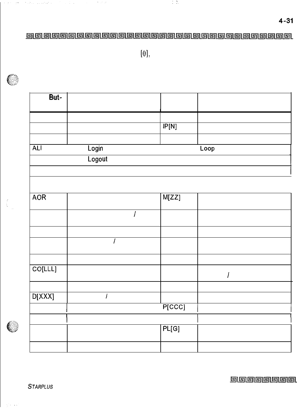
.:.
Station Attributes Programming
Page B Introduction
When a button is assigned as a flexible button
[O],
the user can program any features or functions on the
buttons to which he has access. When the buttons are programmed with user programmed functions, the
display shows the function assigned to the button.
Flex But-
ton Designation Flex But-
ton Designation
A[AAA]
ACC
ACP
ACD Group with Pilot Number
Account Code Enter
W’JI
Internal Page with Zone
All Call Page LCR LCR Access
ALI
1 Agent
Login
I LP 1
Loop
AL0 1 Agent
Logout
1 IAC 1 Internal All Call Page
AMD
I Agent Member Display I LNR Last Number Redial
ANS
Answering Machine Emulation LQU Line Queue
Mode I
AOR
Attendant Override (attn)
ML=1
Personalized Message with
Message Number
AVL
ACD or UCD Available
/
Unavailable
MMP
Meet Me Page
CBK
CID
CIQ
CO[LLL]
Call Back
MUL
Caller ID Name
/
Number
MUS
Toggle
ACD or UCD Calls in Queue NTS
CO Line Button (CO Line [LLL]) OFD
CQD
D[XXX]
ACD Calls in
Queue
Display
Station DSS
/
BLF
OHP
OHV
Flexible Button
Background Music
Night Service
ACD Overflow Station
Available
I
Unavailable
Off -Hook Preference
Off -Hook Voice Over
DND
1 Do Not Disturb 1
ww
(
Call Park with Park Location
I
DRG
)
Distinctive Ringing ) PKU
)
Pickup
DUA
EAC
Display Unanswered Calls
PUGI
Pool with CO Line Group
Number
External All Call
PPK
Personal Park
Table 4-4: Flex Button Display Designations
STARPLUS Triad-S System Programming Manual
Issue I- December 1998
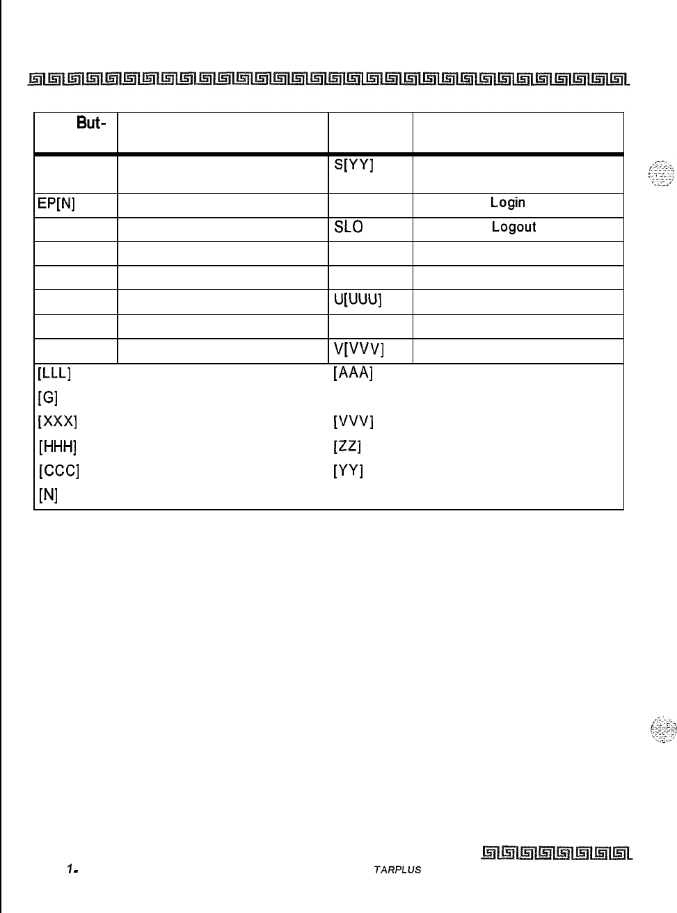
4-32
Station Attributes Programming
Page B Introduction
Flex But- Designation Flex But-
ton ton Designation
EOR Executive Override
WY1
Speed Dial Button with Bin
Number
WNI
External Page with Zone
SLI
Supervisor
Login
FFW
Incoming Transfer CO Line
SLO
Supervisor
Logout
H[ HHH]
Hunt Group with Pilot Number SNR Save Number Redial
HLP
Agent Help STS Supervisor Status Display
HST Headset Mode
U[UUU]
UCD Group with Pilot Number
IAC Internal All Call Page UNA Universal Night Answer
V[VVV]
VM Group with Pilot Number
w-L1
CO Line Number
WA1
ACD Group Pilot Number
[Gl
Pool or CO Line Group Number [UUU] UCD Group Pilot Number
ww
Station Number
tvw
Voicemail Group Number
WW
Hunt Group Number
w3
Personalized Message Number
[CCC1
Call Park Location
WI
Speed Dial Bin
WI
Page Zone Number
Table 4-4: Flex Button Display Designations
Issue
7
-
December 7998 S
JARPLUS
Triad-S
System Programming Manual
Station Attributes Programming
Page B Introduction
Cordless KTU Feature Button
Programming Steps
T
O
assign FEAT Buttons on the Cordless KTU (CKTU) :
I
Press the Cordless Key Flexible Button (Flash 50, Page B, Button
#17).
The following
message displays:
I
CORDLESS KEY BTN 00-24
xx
I
Where XX = the assigned FEAT Button
00 = None
01-24 = Button l-24
Description
If a CKTU is associated with the station, the FEAT Button on the CKTU may be assigned to function as any one
(1) of the 24 Flexible Buttons on the telephone. This programming area defines which Flexible Button on the
telephone will be applied to the CKTU FEAT Button. Not all features are available to be assigned to the CKTU
FEAT button. By default, no button (00) is assigned to the FEAT.
STARPLUS
Triad-S System Programming Manual Issue I
-
December 1998

4-34
Station Attributes Programming
Page B Introduction
Issue I- December 1998
STARPLUS Triad-S System Programming Manual
Introduction
The
ICLID (Incoming Calling Line Identification)
feature was added to the
STARPLUS
TriacMP
System. For this feature to operate properly, it must be activated from the Central Office so the numbers or
name, if available, of the calling party are delivered over the individual tip and ring of the CO lines during the
first silent interval between ringing.
Calling Number
/
Name Display
This feature is the basic offering of the ICLID service when associated with the Triad-S System. Essentially,
whenever an incoming call is received at the system, the number received with the ringing signal is stored in
the line control tables and used during the call processing.
The primary function is that the calling number is displayed (if available) at any point at which the LINE
RINGING
message is displayed in the system.
If
two lines are ringing
at
the same time, the display shows the oldest line
information. After one of the lines is answered, the display shows the
information on the unanswered lines.
Additionally, with the availability of the
calling name
feature, if the calling name is provided, it displays
instead of the calling number. Note that although the Central Office delivery of the calling name is
12
characters, the internal table used to store the name for translation of a received number is 24 characters. If
the Central Office delivers a name, it is positioned left justified in the 24-character field on the display. If a
number is received that matches a number/name translation, the translated name is used and the name
delivered from the Central Office is discarded.
000000000111111111122222
123456789012345678901234
Issue I- December 1998
STARPLUS Triad-S System Programming Manual
:
ICLID Route Programming
Introduction
OR
I
xxxxxxxxxxxxxxxxxxxxxxxx
I
If no name is available, supplied from the Central Office or internally from the translation table, the
delivered number is positioned centered in the display as shown above for the
14
Ns.
An option was added to the Local Number/Name Translation Table to route ICLID or Caller Entered ID
Digits based on a partial compare with the number entered in the translation table.
Incoming Number/Name for SMDR Records
When this feature is implemented, the system operates normally in the absence of ICLID information or
the failure of the ICLID equipment. If the information is present at the time that an SMDR record is
generated for a call, it alters the content and format of the SMDR output record.
Q
If the calling number is available, the number is output in the SMDR record in the same location as
the dialed number is located in the outgoing call record.
oIf the calling name is present, an additional line is output in the SMDR identifying the name, This
record immediately follows the normal SMDR record. The normal SMDR record includes an
indicator that states the following record with name identification is present.
Unanswered calls are recorded in the SMDR record for incoming calls with a U indicator to provide caller
identification for statistical and
call-back
purposes.
Unanswered Call Management Table
An Unanswered Call Management Table with 100 entry capacity for the
DVXp’us
Digital System is maintained
in the system. The calling number/name information pertaining to any unanswered call is placed in this
table at the time the system determines the call was abandoned.
This table may be interrogated from any station user so that the unanswered calls may be reviewed and
handled by the customer. Upon entering the review process, the functions available to a phone are:
Function Function
Button
1. Go to the beginning of table. 1 Dial Code 635
1 2. Review next item in this table entry. 1 MUTE I
1 3. Step to next table entry. 1 HOLD 1
Lssue
I- December 1998
STARPLUS Triad-S System Programming Manual
.,
.
ICLID Route Programming
ICLID Ringing Assignments
4. Delete this table entry.
5. Exit table review function.
6. Step to previous table entry.
7. Call Back
FLASH
ON/OFF
TRANSFER
SPEED
ICLID Ringing Assignments
Programming Steps
If ICLID Ringing Assignments must be assigned or changed:
i
Press FLASH and dial
[43].
The following message is shown on the display phone:
ROUTE 000 XXXY
c
.
Where:
000 = Route Number (000-252)
XXX = Ringing Destination
Y = Ringing Type
2
Press the RING ASSIGNMENT flexible button (FLASH 43, button
#l).
LED
#I
is lit
indicating Route 000 is ready for programming.
s
Enter the 3-digit destination (XXX) and the l-digit ring type (Y) followed by HOLD. A
confirmation tone is heard and the display updates.
Valid
3-Digit
Destinations (XXX) are:
[020-0991
= System Speed Bins 20-99, for Off-Net ringing.
[IOO-1311
=Triad-S
Extension Numbers
[440-447]=
Voice Mail Groups 1-8
[450-457]=
Hunt Groups l-8
[499]
= Direct Ringing to modem
[550-565]=
ACD Groups 1-16
[550-557]=
ACD Groups l-8
Valid Ring Types (Y) are:
[0] = No Ring; unassigned; or to delete a station
[I] = Day Ring [D]
STARPLUS
Triad-S System Programming Manual
Issue I- December 1998

ICLID Route Programming
ICLID Ringing Assignments
[2]
= Night Ring [N]
[3]
= Day/Night Ring [DN]
[4]
= Special Only [S]
[5]
= Day/Special [DS]
[6]
= Night/Special [NS]
[7]
= All Modes [Day/Night/Special [A]
I
Description
ICLID Ringing Assignments let you change the ring assignment based on the incoming number received.
This feature permits you to select from 252 ringing routes for each entry in the name to number translation
table and DID table. For example, this feature could be used to re-route selected customers to a specific
ACD or UCD group and bypass the general attendant. The Direct Inward Dialing (DID) feature permits
one-
way direct inward dialing access to stations on specific DID lines from the public telephone network,
without going through an attendant answering position. DID capabilities refer to incoming calls only.
The system accepts 2-7 digits from the Central Office. This lets the number and name field of the LCD
display on a DID call be presented to the ICLID port. Calls are identified in the SMDR field as answered (I)
or Unanswered (U) followed by the DID number. At least one DTMF receiver must be installed.
RINGING
ASSIGNMENTS
#lirm
%12
4kE
#n
%%-
#K;
%+n
#+-
+ikm
*n
*-
#116
DISPLAY
RINGING
NEXT ROUTE PREVIOUS SELECT ROUTE
ASSIGNMENTS NUMBER ROUTE NUMBER NUMBER
*n
*IaLicl
*lliszil
5%
Es-7-l
*Izizzl
*122
+#a
*n
Issue I- December 1998
STARPLUS
Triad-S System Programming Manual
i
-
I_.
.
.
.
.
_,.“_
I._._..
.
.
_
_.
.,
c-.:-r--
‘:‘_.’
ICLID Route Programming
ICLID Ringing Assignments
View ICLID Ringing Assignments
Programming Steps
If ICLID Ringing Assignments must be viewed:
I
Press FLASH 43, button
#17
to display ring assignments. Assignments are displayed in
sets of six, up to the number programmed. Press FLASH 43, button
#I7
additional times
to cycle to the next group of six ring assignments.
I
ROUTE 000 DOORR OOORR
DDDRR DDDRR DDDRR DDDRR
I
Where:
DDD = Destination
RR:
[0] = No Ring
[D] = Day Ring
[N] = Night Ring
[DN] = Day/Night Ring
[S] = Special Only
[DS] = Day/Special
[NS] = Night/Special
[A] = All Modes (Day/Night/Special)
Multiple station assignments are accomplished by assigning another destination with ring status, DDDR, and
pressing HOLD. This can be done for up to the maximum number of stations on the system.
Ring assignments are continuous and display in order of the destination number from
001-557.
1
A maximum of eight stations display. Additional stations and ringing assignments are
displayed using button
#I
7.
To advance to the next Route:
I
Press the NEXT flexible button (FLASH 43, button
#18)
to advance to the next ICLID
Route number.
To go to a previous Route:
1
Press the PREVIOUS flexible button (FLASH 43, button
#19)
to return to the previous
ICLID Route number.
STARPLUS Triad-S System Programming Manual
Issue I- December 1998
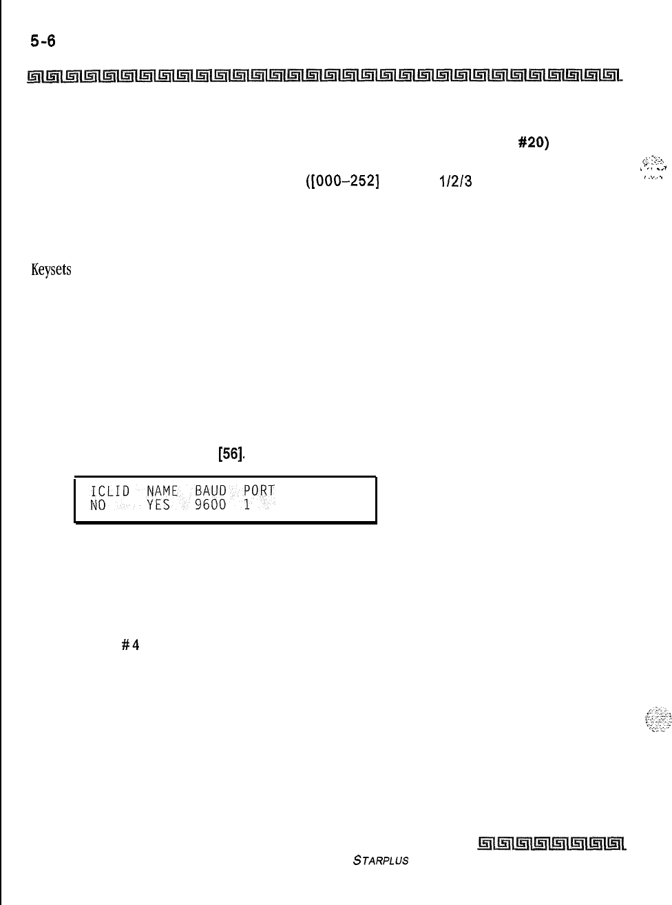
5-6
ICLID Route Programming
ICLID Features
To select a different Route:
1
Press the SELECT ROUTE NUMBER flexible button (FLASH 43, button
#20)
to select
the desired route number.
<;:’
;:;:.
,
-
:
. . . . . . _
I
_.
..,
2
Enter the 3-digit ICLID route number
([000-2521
for Triad
l/2/3
Systems).
I
.\
_
3
Press HOLD to change to the different route entered. A confirmation tone is heard.
Description
Keysets
designated to ring on an incoming CO line but not designated to ring on the ICLID ring, may receive
a ring cycle before the call is moved. The same ringing restrictions applied to CO line ringing are applied to
ICLID ringing. By default, no destinations or ringing assignments exist.
ICLID Features
Programming Steps
If ICLID to use:
IPress FLASH and dial
[56].
The following message is shown on the display phone:
2
To program ICLID features, use the flexible button(s) as defined in the following
procedures.
Button # 1 = Disable/Enable
Button # 2 = Name In Display
Button # 3 = Baud Rate Display
Button
#4
= Port Assignment
3
After all entries are made, press HOLD to accept the data.
The Triad-S system provides ICLID input on the standard RS-232C connector on the MPB, or to the optional
SIU2 Module. When ICLID is desired, the following system-wide parameters determine how the ICLID
information is distributed.
Issue I- December 1998
STARPLUS Triad-S System Programming Manual
I
--
ICLID Route Programming 5-7
ICLID Features
When entering the ICLID features programming area the buttons on the digital terminal are defined as
shown below:
ENABLE
/
DISABLE NAME BAUD RATE PORT
#Eixxl
%#iIz3al
*o
%14
Enable
/
Disable
Programming Steps
I
Press the DISABLE/ENABLE flexible button (FLASH 56, button
#I).
z
Enter a l-digit value on the dial pad to enable/disable this feature.
[0] = Disabled
[I] = Enabled
3
Press HOLD to save the entry. A confirmation tone is heard.
Description
The ICLID (Incoming Calling Line IDentilication) feature was added to the Triad-S system. These features are
\
unavailable unless the Basic ICLID Software package was purchased separately. For this feature to operate
properly, it must be activated from the central office so the numbers of the calling party are delivered over
the individual tip and ring of the CO lines during the first silent interval between ringing. By default, ICLID is
disabled.
Name in Display
Programming Steps
I
Press the NAME flexible button (FLASH 56, button
#2)
to determine whether the name
shows in the LCD display instead of the incoming telephone number.
2
Enter a l-digit value on the dial pad.
[0] = Telephone number in display
[I] = Name in display
3
Press HOLD to save the entry. A confirmation tone is heard.
Description
The system can be set to display the incoming telephone number or the person’s name on the LCD display.
By default, the system shows the telephone number on the LCD display.
STARPLUS
Triad-S System Programming Manual Issue
7
-
December 1998
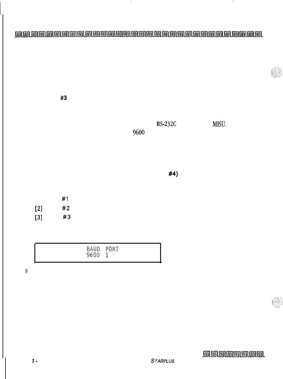
:
:
I
5-8
ICLID Route Programming
ICLID Features
Baud Rate Display
Programming Steps
The ICLID baud rate is programmed using Flash
15
baud rate assignments. The LCD displays the current
baud rate based on which number is assigned to the ICLID Port number.
FLASH 56, button #3
returns an error tone when pressed.
Description
The Triad-S system can provide ICLID input on the standard
RS-232C
on the optional
MISU.
The baud rate
is displayed as 150, 300,600, 1200, 2400, 4800, or
9600
baud.
Port Assignment
Programming Steps
1
Press the PORT flexible button (FLASH 56. button
#4)
to determine which port to use
for ICLID information.
2
Enter a l-digit entry for the ICLID Port number:
[I] = Port
#I
(MPB RS-232C on optional MISU)
[2]
= Port
#2
(MPB RS-232C on optional MISU)
[3]
= Port
#3
(Optional modem)
The LCD displays the current baud rate based on which number is assigned to the ICLID
Port number.
ICLID NAME
f3i3;;
;ORT
NO YES
s
Press HOLD to accept the data. A confirmation tone is heard and the display updates.
Issue
I-
December 1998
STARPLUS
Triad-S System Programming Manual
c
.
$-$;t$
“.“’
ACD Group Programming
Programming Steps
If the system is in the programming mode, continue using the program codes. If starting to program here,
enter the programming mode. If ACD Groups must be assigned:
1
Press FLASH and dial
[60].
The following message displays:
ACDSXXA
ALT OVR AN
SUP
AAA BBB CCCC DDD
Where:
[5Xx]
= ACD Group Number (550457)
[A] = Page A Parameters
[AAA] = Alternate ACD Group Assignment
[BBB] = ACD Overflow Assignment
[CCCC] = ACD Announcement Tables
[DDD] = ACD Supervisor Programming
2
The top left button in the flexible button field is lit for programming ACD Group 1 (550).
To change ACD Groups or enter more ACD Groups
(550-557),
press the appropriate
flexible button and perform the following procedures.
Description
This
feature is available with optional software.
There can be
16
ACD groups of up to
16
stations
each, The ACD groups use a pilot hunting technique. If the pilot number is dialed, the assigned stations in
that ACD group are searched for the station in an idle condition for the longest period of time. Each ACD
.‘A
62
Group may have an assigned Alternate ACD Group, an Overflow station and up to
16
stations as ACD
h..,.il
Yz;‘<
members. The eight system RAN ports (tables) may also be referenced on a per ACD group basis. By default,
ACD Group Tables are empty.
When entering the ACD Group(s) programming area, the buttons on the digital terminal are defined as
shown below:
Issue
I- December 7998
STARPLUS
Triad-S System Programming Manual
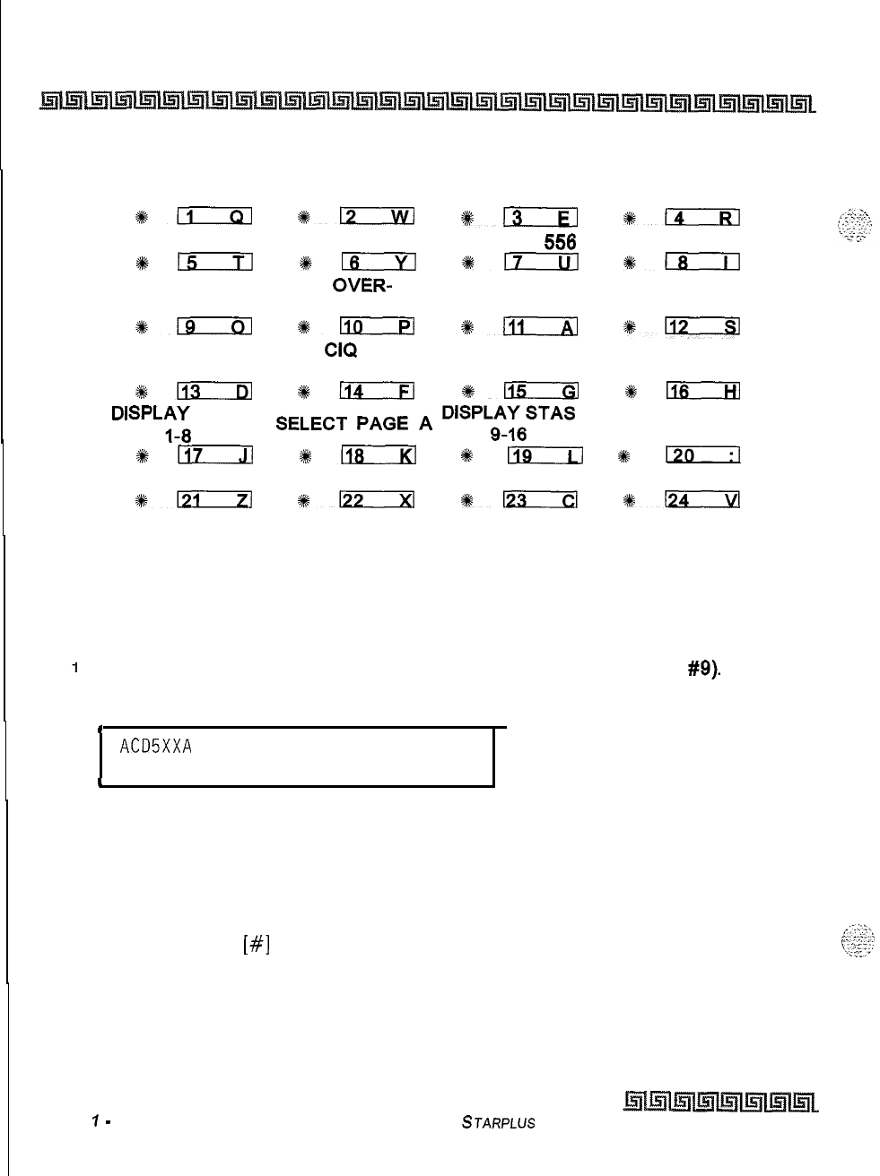
. .
6-2
Automatic Call Distribution (ACD)
ACD Group Programming
ACD GROUP 550 ACD GROUP 551 ACD GROUP 552 ACD GROUP 553
+km
*L2
%13
#kKE
ACD GROUP 554 ACD GROUP 555 ACD GROUP
550
ACD GROUP 557
*-
+kn
*i
s&i;
ALTERNATIVE ACD
OVER-
ANNOUNCMENT ACD SUPV
ACD GROUP FLOW ASSIGN TABLES PROGRAMMING
*-
*110
%D
*m
ACD WRAP-UP
CIQ
TIMER THRESHOLD
%+m
%+n
%115
%116
DISPLK;
STAS
SELECT
PAGE
A
DISPLc6STAS
*m
#ki?iKzKl
%
119
#k
I:1
#D
%a
%a
#124
Alternate ACD Group Assignment
Programming Steps
To program an alternate group:
1
Press the ALTERNATE ACD GROUP flexible button (FLASH 60, button
#Q).
2
Enter the 3-digit pilot number (550 to 557) of the desired alternate ACD group.
c
ACDSXXA
ALT OVR' AN
SUP
AAA BBB CCCC DDD
4
3
Press HOLD to save the entry. A confirmation tone is heard and the display updates.
Description
An alternate ACD group can be programmed so if no station in a group is available, the alternate group is
checked for an available station. This provides a way to chain or link ACD groups together. To delete an
Alternate ACD Group, press
[#I
three times and press HOLD.
Issue
7
-
December 1998
STARPLUS Triad-S System Programming Manual
Automatic Call Distribution (ACD)
ACD Group Programming
ACD Overflow Station Assignment
Programming Steps
To program ACD Overflow station:
I
Press the OVERFLOW ASSIGN flexible button (FLASH
60,
button #IO).
2
Enter a 3-digit station number to designate the ACD Groups overflow station.
c
ACD5XXA
ALT OVR AN
SUP
AAA BBB CCCC
DDD
3
Press HOLD to save the entry. A confirmation tone is heard and the display updates.
Description
When an overflow station is assigned, callers that remain in queue for a specified amount of time are routed
to the assigned overflow station. The overflow station may not be one of the ACD group stations. Only CO calls
transferred to a ACD group overflow to the overflow station when RAN tables are assigned. To delete an
Overflow Station, press
[#I
three times and press HOLD.
ACD Recorded Announcement Assignment(s) (RAN)
Programming Steps
To program a Recorded Announcement:
1
Press the ANNOUNCEMENT TABLES flexible button (FLASH
60,
button #II).
2
Enter a four-digit sequence on the keypad:
First Digit = RAN port specified for Guaranteed Message (Direct Calls)
Second Digit
=
RAN port specified for primary message,
Third Digit = RAN port specified for secondary message.
Fourth Digit = RAN port specified for Guaranteed Message (transferred calls)
3
Press [#] once as the first digit if no Guaranteed Message is desired.
Example:
+z+
An entry of
[#I,
[2],
[3]
= No Guaranteed Message is heard. Announcement Table 2 provides a
primary message and Announcement Table
3
provides a secondary message.
STARPLUS Triad-S System Programming Manual Issue 1
-
December 1998
I
6-4
Automatic Call Distribution (ACD)
ACD Group Programming
+:*
An entry of
[
11,
[2],
[3]
= Announcement Table 1 provides the Guaranteed Message upon initially
answering the call, Announcement Table 2 provides a primary message and Announcement Table
3
provides a secondary message.
An entry of
[8],
[
11,
[2]
= Announcement Table 8 provides the Guaranteed Message upon initially
+
answering the call, Announcement Table 1 provides a primary message and Announcement Table 2
provides a secondary message.
4
Press HOLD to save the entry. A confirmation tone is heard and the display updates.
To erase Recorded Announcement(s):
1
Press
[#]
four times and press HOLD.
I
ACD5XXA
ALT OVR AN
SUP
AAA BBB CCCC DDD
I
Description
Optional Recorded Announcement device(s) may be connected to the system to provide an announcement
if all stations in a ACD group are busy. Up to eight ports in the system may be assigned to provide a path to
Recorded Announcement devices. Incoming CO Callers are answered and routed to the Overflow
assignment only if a RAN Table is assigned.
The Guaranteed Message announcement provides a means to force incoming callers to an announcement
before being placed into an ACD Queue or routed to an agent. Outside callers are presented with a message
before being routed to the ACD Group. Agents in an ACD Group with a Guaranteed Message enabled receive
incoming callers only after the caller hears the designated recorded announcement in its entirety, or after
the incoming caller dials up to 14 digits followed by
(#).
These digits are inserted as ICLID incoming
number identification. If the Guaranteed Message announcement is programmed in Admin, incoming ACD
calls are routed to the Guaranteed Message RAN before going to the ACD Group.
The Guaranteed RAN Enhancement allows a second guaranteed RAN type to be associated with each ACD
Group in the system. This RAN handles only transferred CO calls. This lets a CO call transferred to an ACD
Group enter caller entered ID digits via this RAN. The digits are then compared to the local name/number
translation table and routed based on table entries. If no match is found, the call rings to the ACD Group.
Intercom calls to the group pilot number result in a busy tone. Once the intercom caller hangs up to
complete the transfer, the CO call is presented to the RAN device.
issue
I-
December
1998 STARPLUS Triad-S System Programming Manual
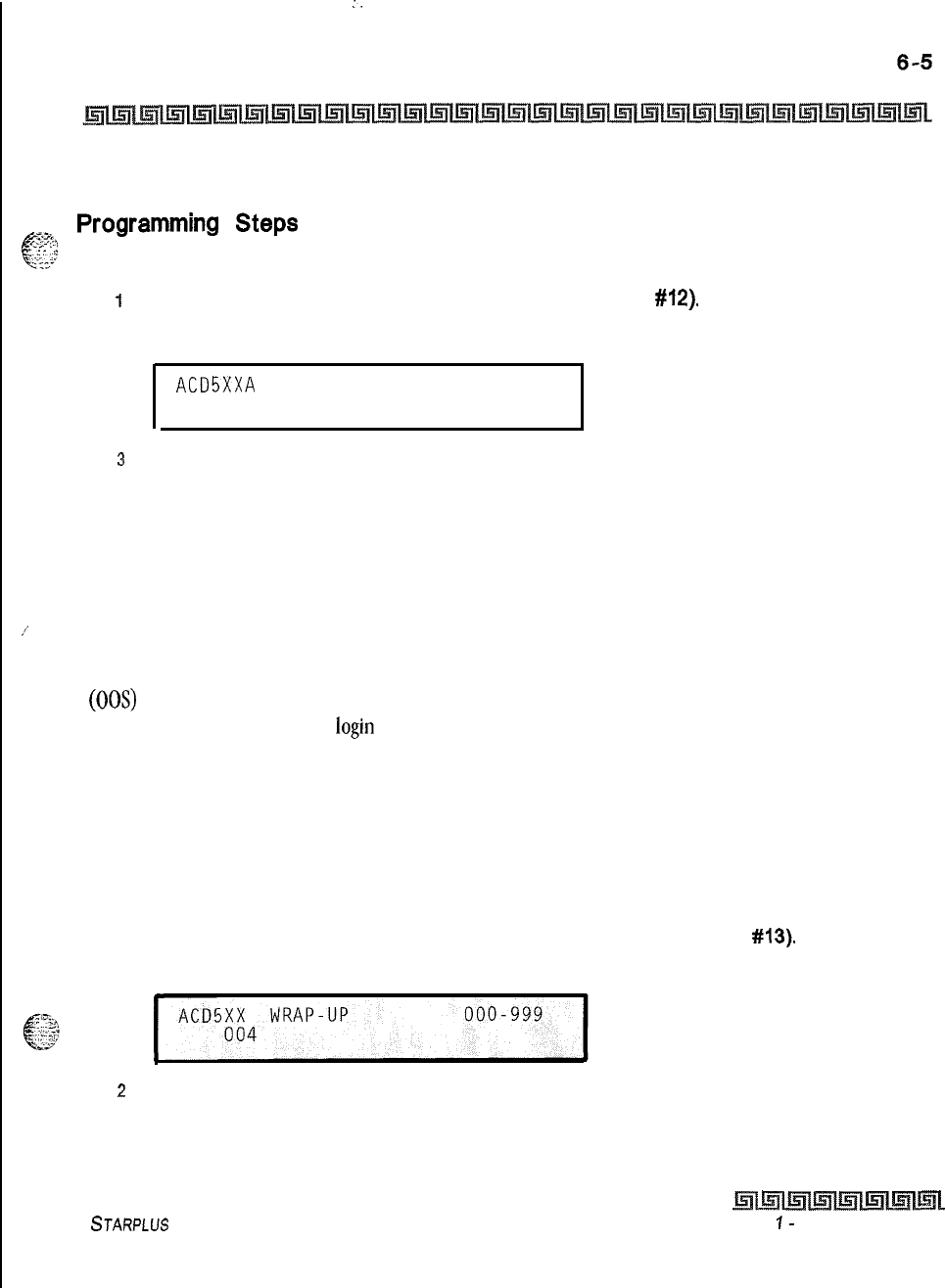
I.
Automatic Call Distribution (ACD)
ACD Group Programming
ACD Supervisor
-zz>
Programming
Steps
f
-.:.
::
‘?2’
To program an ACD Supervisor:
i
Press the ACD SUPV flexible button (FLASH 60, button
#12).
2
Enter the 3-digit station number of the desired ACD Supervisor station.
ACD5XXA
ALT OVR AN
SUP
AAA BBB CCCC DDD
3
Press HOLD to save the entry. A confirmation tone is heard and the display updates.
Description
/’
The ACD Supervisor Station assignment feature provides a means to assign each ACD group a supervisor.
This Supervisor Station can receive the calls in queue display in real time, receives No Answer/Out of Service
conditions, HELP displays from the groups to which the supervisor is assigned, and can barge-in on active
calls in his ACD Group or groups.
A supervisor can be assigned in ADMIN to a group or groups to receive the help request and out of service
(00s) messages. If a supervisor station is assigned in ADMIN, it is considered logged in. In addition, a
supervisor can dial a supervisor login code followed by the ACD group that the supervisor is logging into and
his 4-digit ID number.
ACD Auto Wrap-Up Timer
Programming Steps
To change the ACD Auto Wrap-up Timer:
1
Press the AUTO-WRAP TIMER flexible button (FLASH 60, button
#13).
The following
message displays:
z
Enter the 3-digit value on the dial pad which corresponds to 000-999 seconds.
3
Press HOLD to save the entry. A confirmation tone is heard and the display updates.
STARPLUS Triad-S System Programming Manual Issue
I-
December 1998
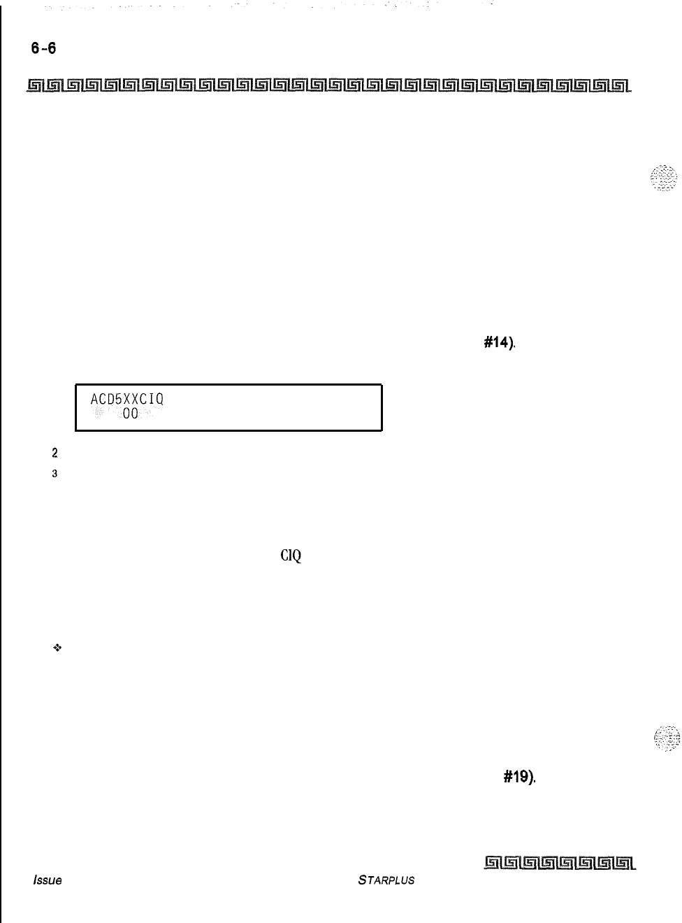
Automatic Call Distribution (ACD)
ACD Group Programming
Description
After completion of a ACD call (on-hook) the agent is not subjected to another ACD call for the duration of
the Auto Wrap-Up Timer allowing the agent to finish call related work or access other facilities. This lets
agents remove themselves from the group (e.g., DND, Call Forward) or originate another call. By default,
the ACD Auto Wrap-Up Timer is set for 4 seconds and is variable from 000-999 seconds.
ACD CIQ Threshold
Programming Steps
To make a change to the CIQ Threshold:
1
Press the CIQ THRESHOLD flexible button (FLASH 60, button
#14).
The following
message displays:
ACD5;;CIQ
THRSHOLD 00-99
,
2
Enter the 3-digit value on the dial pad that corresponds to 00-99 calls.
3
Press HOLD to save the entry. A confirmation tone is heard and the display updates.
Description
This feature determines how many calls appear in queue before the LED flashes at 240 ipm flutter. Once
the number of calls in queue falls below the
CIQ
threshold, the LED extinguishes. By default, this feature is
disabled.
Conditions
+
Any ACD station can have a button assigned to view the calls in queue of any ACD group.
ACD Station Assignment(s)
Programming Steps
To program stations into a ACD group:
IPress the DISPLAY STAS 9-16 flexible button (FLASH 60, button
#lQ).
The following
message displays.
issue
I- December 1008
STARPLUS Triad-S System Programming Manual
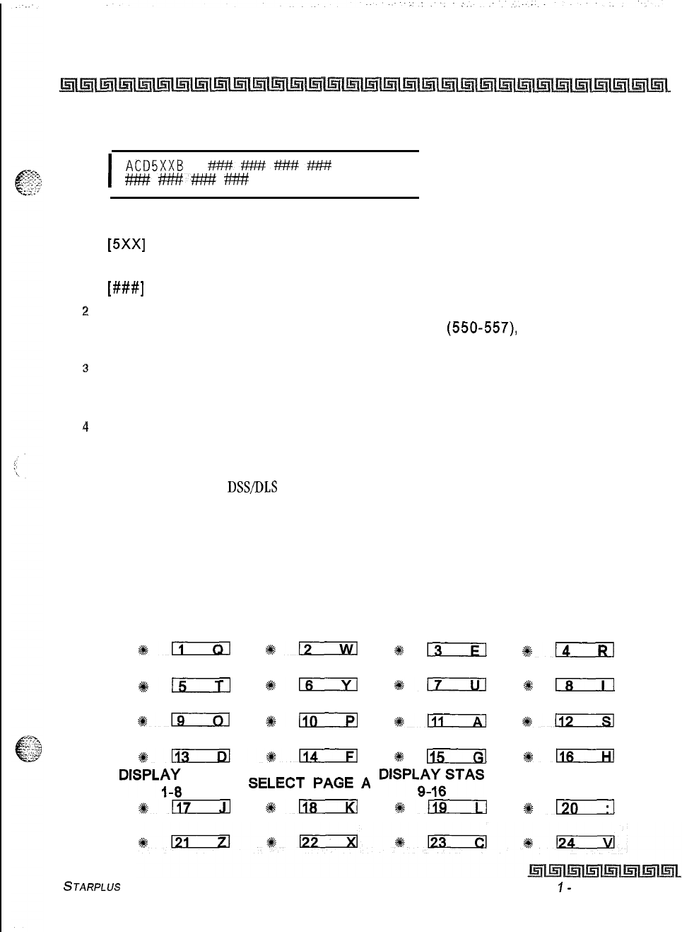
Automatic Call Distribution (ACD)
ACD Group Programming
6-7
I
ACDSXXB
?W#########
#?#######t!w#
I
Where:
[5Xx]
= ACD Grp Number (550457)
[B] = Page B parameters
[###I
= ACD Station assignments
:!
The top left button in the flexible button field is lit for programming ACD Group 1 (550).
To change ACD groups or enter further ACD groups
(550-557)
press the appropriate
flexible button and perform the following procedures.
3
Enter the 3-digit station numbers of the stations in the ACD group in the order in which
they are checked. The order is only relevant for the first call. After that, the rule is oldest
idle. Up to16 stations may be entered. No station entries are displayed at this time.
4
Press HOLD to save the entry. A confirmation tone is heard and the display updates.
Description
Any type of station (excluding
DSSDLS
Consoles) may be entered as valid ACD stations. Calls are routed to
station in the order they are entered for the first round of calls only. After that the calls are routed to stations
based on On-Hook time. The-station with the longest On-Hook time receives the next call. If a specific station
number is dialed, only that station is rung; no distribution is done if that station is busy.
The buttons on the digital terminal are defined as shown below when entering the ACD Station Assignments
programming area:
ACD GROUP 550 ACD GROUP 551 ACD GROUP 552 ACD GROUP 553
s%n
%kn
s#
I3
#slxzizl
ACD GROUP 554 ACD GROUP 555 ACD GROUP 556 ACD GROUP 557
*a
*16
117
s%
l-r-i-l
#iIEzEl
%+n
6111
+%lzrxI
%l!iExl#114
#
115
~lzcxHl
DISPL;-;
STAS
SELECT
PAGE
A
DISPLE6STAS
s%EYil
%k-
#a
*m
STARPLUS Triad-S System Programming Manual Issue
I-
December 1998
Automatic Call Distribution (ACD)
ACD
Timers
To erase all stations, press [
#]
three times and press HOLD.
If an ACD member is assigned to a specific ACD group and uses the
login-
logout
codes to enter and exit an ACD group other than their own assigned
group, the database programming for ACD stations is automatically
changed to re
fleet
the different group.
It is recommended that ACD agent station not be deleted from an ACD
group through database administration when that station is in the Unavail-
able Mode. This causes the LCD to display unavailable even though the
station is no longer part of the ACD group. The station can dial the 566
code to remove the message.
View ACD Station Assignments
Programming Steps
If ACD Station Assignments in the second group of eight (Stations
Y-16)
must be viewed:
1
Press the DISPLAY STAS l-8 flexible button(FLASH 60, Page B, button
#17).
The first
group of station assignments display. If no additional stations are assigned beyond the
first eight stations, the display shows
(#)s
instead of station assignments.
2Press DISPLAY STAS 9-16 flexible button (FLASH 60. button
#IS)
to view the second
group of eight stations in the same ACD group.
Description
Any time a display of the first group of ACD Station assignments (default or changed) is needed, press the
DISPLAY STAS
1-8
button (button
#17).
It
displays the first group of station assignments, up to eight
stations at a time. Button
#
19
always shows the second group of eight stations programmed in the ACD
Group. Button
#17
always displays the first group of eight stations programmed in the same ACD Group.
ACD Timers
Programming Steps
If ACD timers must be changed:
IPress FLASH and dial
[61].
The following message displays:
Lssue
I
-
December 1998
STARPLUS
Triad-S System Programming
Manual
,‘l..
.‘::.
‘I
.I:.‘-!
1:
L‘
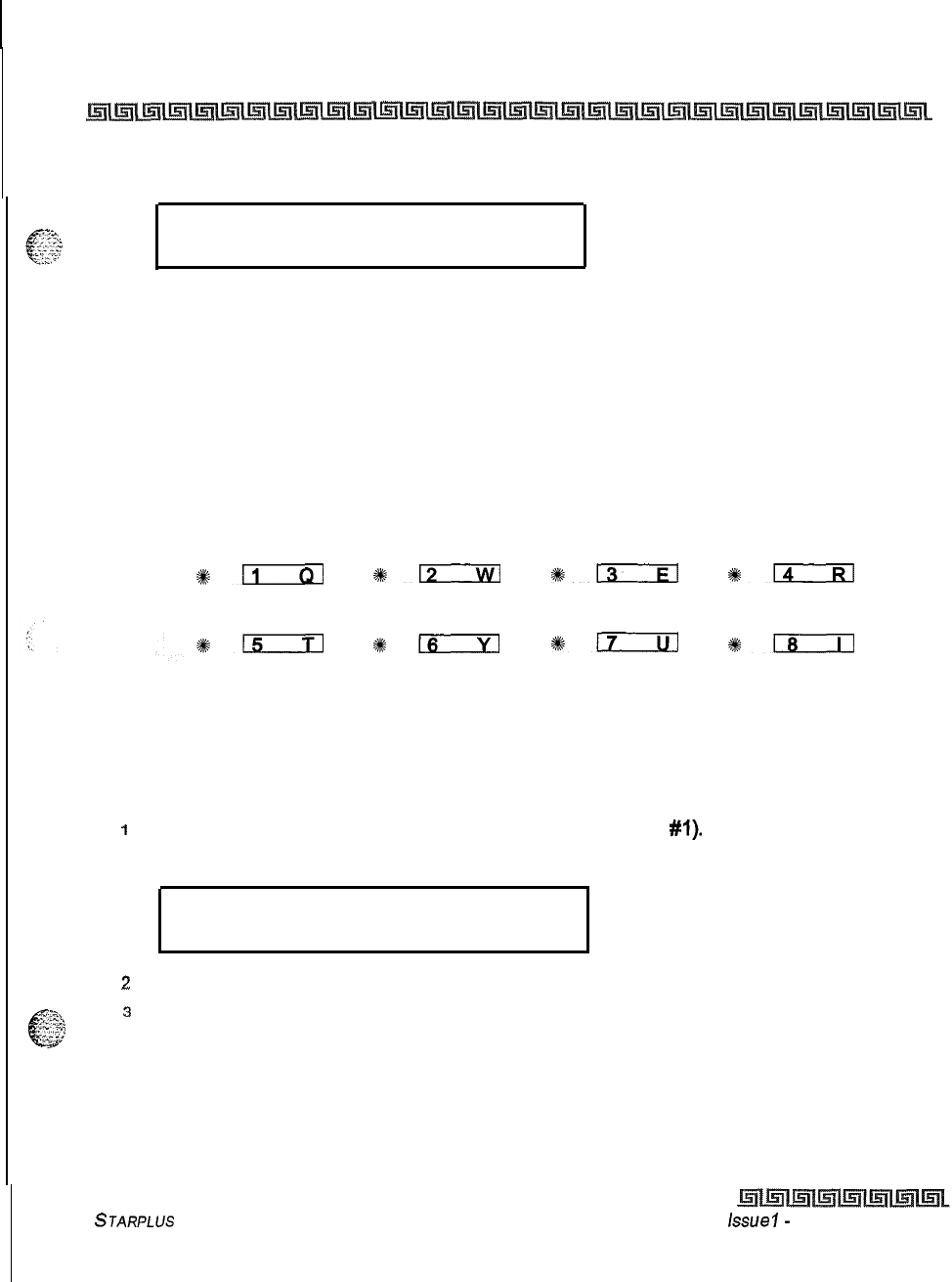
Automatic Call Distribution (ACD)
ACD Timers
6-9
ACD TIMERS
ENTER BUTTON NUMBER
Description
Six timers for ACD operation are programmable on a system-wide basis. The ACD timers include: A Ring
Timer, Message Interval Timer, an Overflow Timer, a No/Answer Recall Timer, a No/Answer Retry Timer, and
a Guaranteed Message Timer. Each timer is described in the following section:
The buttons on the digital terminal are defined as shown below when entering the ACD Timers programming
area:
RING TIMER MIT TIMER OVERFLOW
TIMER
*-
812
3k13
#km
NO-ANSWER NO-ANSWER GUARANTEED
RECALL RETRY MSG TIMER
#15
#m
*-
*m
ACD Ring Timer
Programming Steps
To make a change to the ACD Ring Timer:
1
Press the RING TIMER flexible button (FLASH 61, button
#I).
The following message
displays:
RING
000-300
060
2
Enter the 3-digit timer value on the dial pad which corresponds to 000-300 seconds.
3
Press HOLD to save the entry. A confirmation tone is heard and the display updates.
STARPLUS Triad-S System Programming Manual Lssue
I-
December 1998
6-10
Automatic Call Distribution (ACD)
ACD
Timers
Description
The ACD Ring Timer determines how long a call rings into a busy ACD group before being presented to the
first recorded announcement. By default, the ACD Ring Timer is set for
60
seconds, and is variable from
000-300
seconds.
A RAN Table must be specified in ACD programming.
If
a RAN Tab/e is
NOT specified, incoming CO callers are not answered but continue to
receive ringback.
ACD Message Interval Timer
Programming Steps
To change the ACD Message Interval Timer:
1
Press the MIT TIMER flexible button (FLASH 61, button
#2).
The
following message
displays:
MESS/W& INTERVAL
000-600
2
Enter the 3-digit timer value on the dial pad which corresponds to 000-600 seconds.
3
Press HOLD to save the entry. A confirmation tone is heard and the display updates.
The ACD Ring and Message Interval timers only apply when RAN ports are
specified. If RAN ports are not specified, incoming callers continue to
receive a
ringback
tone.
Description
The ACD Message Interval Timer (MIT) determines the length of time a caller remains in queue (listening
to MOH, if provided) between recorded announcements. By default, the ACD Message Interval Timer is set
for
60
seconds and is variable from
000-600
seconds.
ACD Overflow Timer
Programming Steps
To change the ACD Overflow Timer:
issue
7
-
December 1998
STARPLUS
Triad-S System Programming Manual
Automatic Call Distribution (ACD)
ACD Timers
1
Press the OVERFLOW TIMER flexible button (FLASH 61, button
#3).
The following
message displays:
OVERFLOW 000-600
060
2
Enter the 3-digit value on the dial pad which corresponds to 000-600 seconds.
3
Press HOLD to save the entry. A confirmation tone is heard and the display updates.
Description
The ACD Overflow Timer determines the total length of time a caller remains in queue for a particular ACD
group. When the timer expires, the caller is routed to the designated overflow station. The timer starts when
an incoming call is answered and presented to the first recorded announcement. Transferred CO callers
overflow at the expiration of the Overflow Timer. By default, the ACD Overflow Timer is set for
60
seconds and
is variable from 000-600 seconds.
ACD No-Answer Recall Timer
Programming Steps
To change the ACD No-Answer Recall Timer:
IPress the NO-ANSWER RECALL TIMER flexible button (FLASH 61, button
#5).
The
following message displays:
NO-ANS RECALL 000-300
000
2
Enter the 3-digit value on the dial pad which corresponds to 000-300 seconds.
3
Press HOLD to save the entry. A confirmation tone is heard and the display updates.
Description
If a call routed to a station via ACD is not answered by the ACD Agent/Station before the No-Answer Recall
Timer expires, the call is returned to ACD Queue with the highest priority. In addition, the station that failed
to answer the ringing ACD call is placed into an out-of-service (00s) state. By default, the ACD No-Answer
Timer is at 000 (disabled) and is variable from 000-300 seconds.
STARPLUS
Triad-S System Programming Manual issue
I-
December 1998
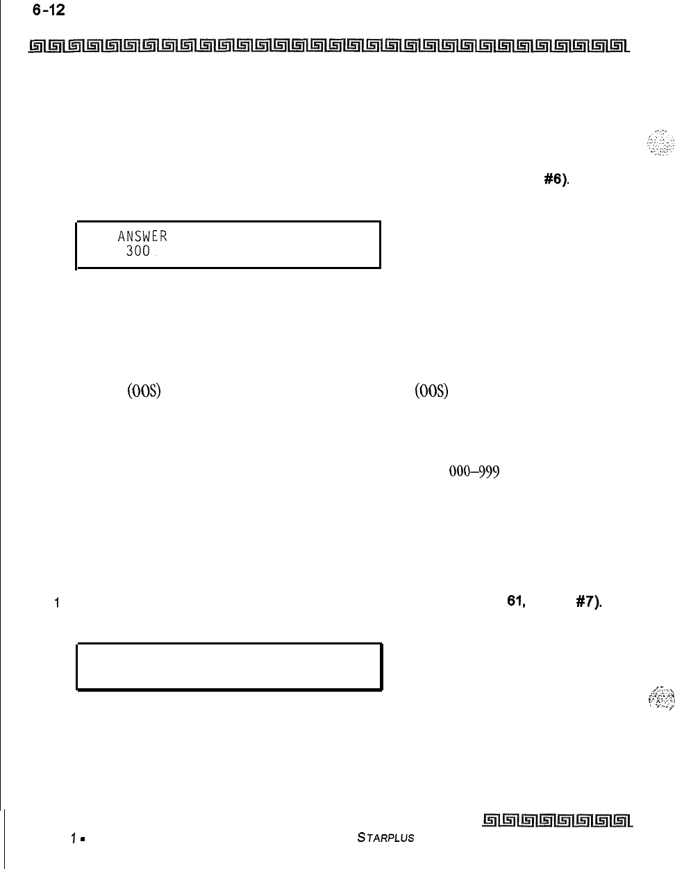
Automatic Call Distribution (ACD)
ACD Timers
ACD No-Answer Retry Timer
Programming Steps
To change the ACD No-Answer Retry Timer:
1
Press the NO-ANSWER RETRY TIMER flexible button (FLASH 61. button
#6).
The
following message displays:
NO AK$;ER RETRY 000-999
.
2
Enter the 3-digit value on the dial pad which corresponds to 000-999 seconds.
3
Press HOLD to save the entry. A confirmation tone is heard and the display updates.
Description
When the No-Answer Recall Timer expires, a station that failed to answer the ringing ACD call is placed into
an out-of-service (00s) state. The station that was taken out-of-service (00s) is placed back in service if the
agent presses the available flex button or dials the available flex code. In addition, the agent is placed back
in service if the No-Answer Retry Timer expires. If the agent does not answer his next ACD call, he is
taken
out-of-service. This cycle continues until the station answers calls, logs out, or goes unavailable. By default,
the ACD No-Answer Retry Timer is set for 300 seconds and is variable from 000-999 seconds.
Guaranteed Message Timer
Programming Steps
To change the ACD Guaranteed Message Timer:
I
Press the GUARANTEED MESSAGE TIMER flexible button (FLASH
61,
button
#7).
The following message displays:
GUARANTEED MSG
000-300
005
._
:.
,;:<.
-‘II
pL-“.<-:Z;:
2
Enter the 3-digit value on the dial pad which corresponds to 000-300 seconds.
:
“,.::y
I
3
Press HOLD to save the entry. A confirmation tone is heard and the display updates.
Issue
7
-
December 7998 STARPLUS Triad-S System Programming Manual
.“-
:
Automatic Call Distribution (ACD)
ACD Timers
6-13
Description
This timer determines how long a call rings before being answered by Guaranteed Message RAN when the
.._
.^.
..-
c-
:
;;
:: Guaranteed Message RAN feature is added to an ACD Group. By default, the Guaranteed Message Timer is set
?Z
for
5
seconds and is variable from 000-300 seconds.
STARPLUS
Triad-S System Programming Manual
Issue I- December 1998
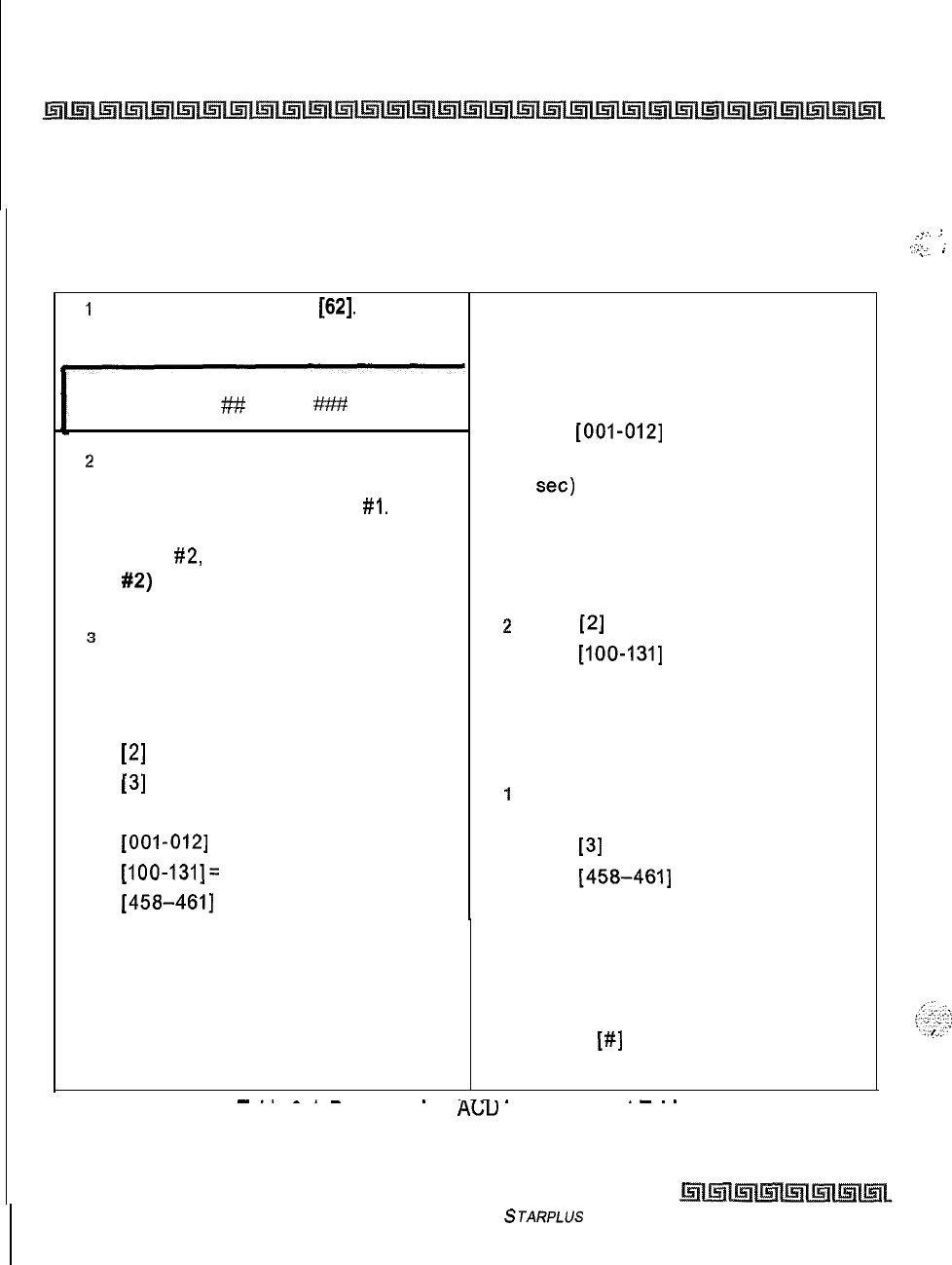
6-14
Automatic Call Distribution (ACD)
ACD Announcement Tables (RAN)
ACD Announcement Tables (RAN)
Programming Steps
If Recorded Announcement devices are installed to operate with ACD, these tables must be programmed
1
Press FLASH and dial
[62].
The
To program a table for CO line port:
following message displays:
1
Press the TABLE X flexible button s
ANNOUNCEMENT TABLE 1
TYPE # INDX
##
TIME
####
z
The top left button in the flexible
button field is lit for programming ACD
RAN Announcement Table
#I.
To
change to ACD RAN Announcement
Table
#2,
press (FLASH 62, button
#2)
flexible button.
(* Repeat the above for Tables 3-8.)
(l-8).
2
Dial [I] for CO Port Interface.
3
Dial
[OOI-0121
for CO Lines used.
4
Enter Message duration (000-300
set)
To program a table for an SLT port:
3
Enter a string of six, or seven digits on
the dial pad. The order of data entry is:
Type Number:
[I] = CO Port Interface
1
Press the TABLE X flexible button
(Buttons 1 to 8).
2
Dial
[2]
for SLT Port Interface.
3
Dial
[IOO-1311
for SLT stations used.
4
Enter Message duration (000-300
seconds).
[2]
= SLT Port Interface
To program a table for RAN Hunt Group port:
[3]
= RAN Hunt Group
1
Press the TABLE X flexible button
Index (port) Number:
(Buttons l-8).
[OOI-0121
= Triad-S CO Line Ports
2
Dial
[3]
for RAN Hunt Group.
[IOO-131]=
Triad-S SLT Station Ports
3
Dial
[458-4611
for RAN Hunt Group
[458-4611
RAN Hunt Group
used.
Message Time:
4
Enter Message duration (000-300
000 to 300 seconds seconds).
4
Press HOLD to save the entry. A
confirmation tone is heard and the
To clear entries in a Table:
display updates.
1
Press
[#]
once followed by HOLD.
I
-..
-.-
.
---_
.-
.
.
I able 6-I: Programming
AC;lJ
Announcement Tables
Issue I- December 1998
STARPLUS Triad-S System Programming Manual
_,
.:
.-,
. .
.
:-.’
,c
i
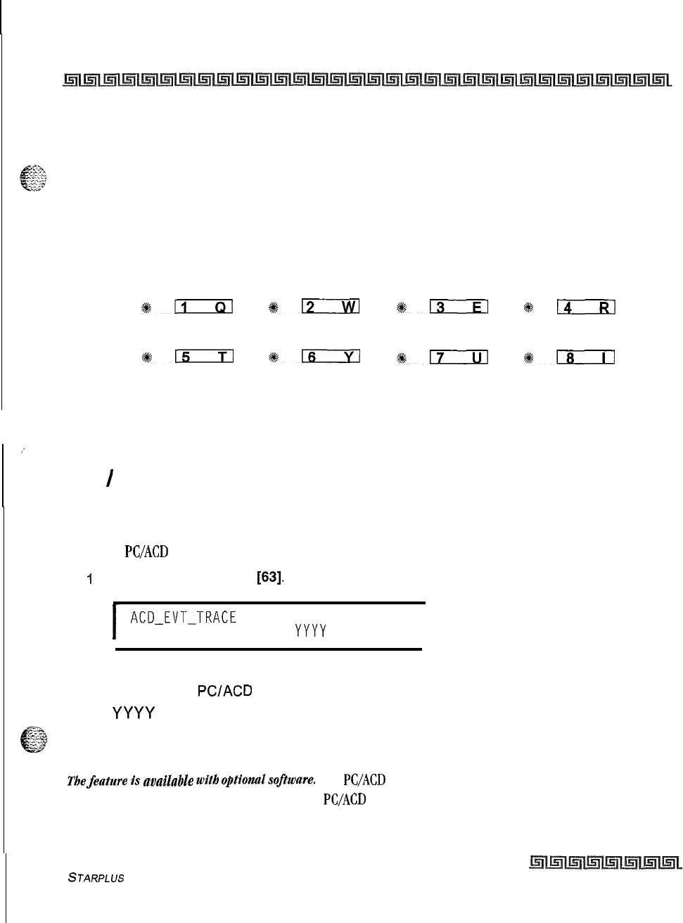
Automatic Call Distribution (ACD)
PC I ACD Interface Trace
6-15
Description
Determines the type, index (port) number and message length for the eight available Recorded
Announcements (RAN). There are eight RAN Tables that can be programmed. Table
1
can be the answer port
for unanswered incoming calls to a ACD group. Table 8 can provide the secondary message or vice versa.
The buttons on the digital terminal are defined as shown below when entering the ACD RAN Announcement
Tables Programming area:
ANNOUNCE- ANNOUNCE- ANNOUNCE- ANNOUNCE-
MENT TABLE 1 MENT TABLE 2 MENT TABLE 3 MENT TABLE 4
811
%12
+#13
#k
14
ANNOUNCE- ANNOUNCE- ANNOUNCE- ANNOUNCE-
MENT TABLE 5 MENT TABLE 6 MENT TABLE 7 MENT TABLE 6
%sn
s:-
%+-
1ls
,’
The type can be either a CO line port, an SLT port or a RAN Hunt Group port. The index number specifies
which circuit for the type of interface. The message length is used to match the maximum length of the
message to the device that is used.
PC
/
ACD Interface Trace
Programming Steps
To enable
PC/ACD
Interface Trace options:
f
Press FLASH and dial
[63].
The following message is shown on the display phone:
I
ACD-EVT-TRACE
I/O BAUD
NO
X
YYYY
I
Where:
X = Port for
PC/ACD
Interface Trace
YYYY
= Baud Rate of desired port
Description
Thefeature
b
avduble
with
opthzdsofume.
The
PC/ACD
Interface Trace feature provides an event trace
output which is compatible with a third-party
PC/ACD
Reporting package
STARPLUS Triad-S System Programming Manual
Issue I- December 1998
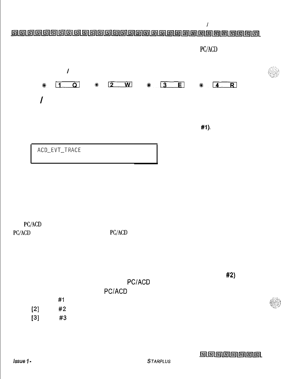
6-16
Automatic Call Distribution (ACD)
PC
/
ACD Interface Trace
The buttons on the digital terminal are defined as shown below when entering the
PC/ACD
Event Trace
feature programming area:
ENABLE
/
TRACE PORT
DISABLE ASSIGNMENT
#km
*D
%EcIa
#k.
Enable
/
Disable
Programming Steps
1
Press the DISABLE/ENABLE flexible button (FLASH 63, button
#l).
The following
message is shown on the display:
ACD-EVT-TRACE
I/O BAUD
NO
X
YYYY
2
Press the ENABLE/DISABLE flexible button.
LED On = YES (Enabled)
LED Off = NO (Disabled)
3
Press HOLD to save the entry. A confirmation tone is heard and the display updates.
Description
The
PC/ACD
Interface Trace provides a series of events trace output which is compatible with a third-party
PC/ACD
Reporting package. By default, the
PC/ACD
Event Trace is disabled (NO).
Trace Port Assignment
Programming Steps
IPress the TRACE PORT ASSIGNMENT flexible button (FLASH 63, button
#2)
to
determine which port to use for the
PC/ACD
Interface Trace.
2
Enter a l-digit entry for the
PC/ACD
Event Trace Port number:
[I] = Port
#I
(MISU)
[2]
= Port
#2
(MISU)
[3]
= Port
#3
(Modem)
issue
I
-
December 7998
STARPLUS Triad-S System Programming Manual
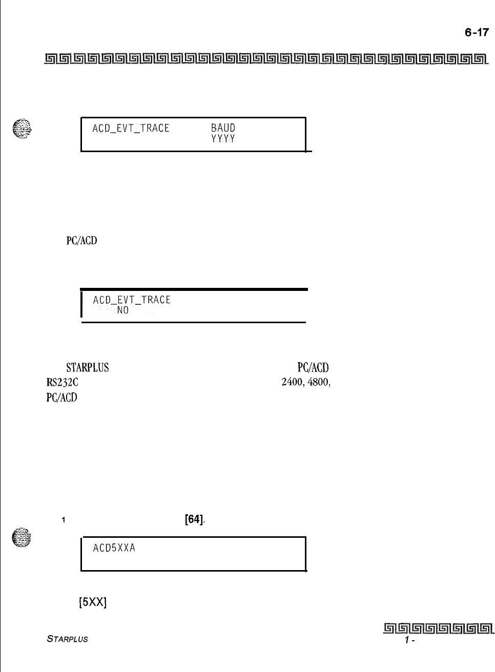
Automatic Call Distribution (ACD)
ACD Group
The LCD displays the current baud rate based on which Port number is assigned to the
ACD SMDR Port number.
52,
I;...:;:
c
_.
.
.-*.
;-:.u
.I
ACD-EVT-TRACE
I/O
#
NO
X
.
3
Press HOLD to save the entry. A confirmation tone is heard and the display updates.
Baud Rate Display
Programming Steps
The
PC/ACD
Port baud rate is programmed using
Flash
15 baud rate assignments, The LCD displays the
current baud rate based on which Port number is assigned to the ACD SMDR Port number. The following
message displays:
I
ACDJ;T-TRACE
I/O BAUD
X
YYYY
I
Description
The
STARPLUS
Digital Hybrid Telephone System can provide
PC/ACD
Reporting output to the optional MISU
RS232C
I/O ports. The baud rate is displayed as 300, 1200, 2400,4800, or
9600
baud. By default, the
PC/ACD
baud rate is set to 9600.
ACD Group
Programming Steps
If the system is in the programming mode, continue using the program codes. If starting to program here,
enter the programming mode. If ACD Groups must be assigned:
1
Press FLASH and dial
[64].
The following message displays:
ACD5XXA
ALT OVR AN
SUP
AAA BBB CCCC DDD
Where:
[5Xx]
= ACD Grp Number (558-565)
STARPLUS Triad-S System Programming Manual lssue
I-
December 1998
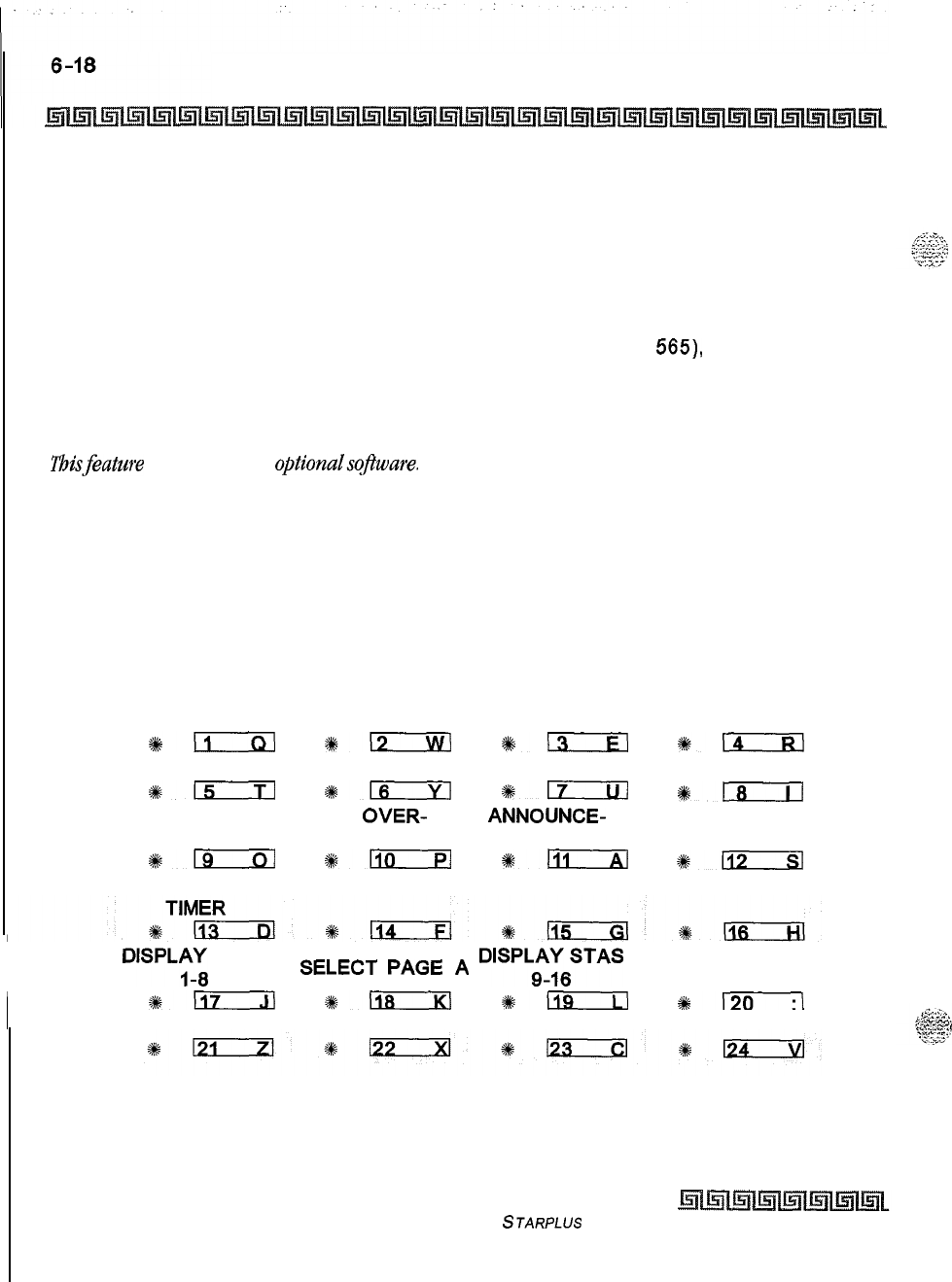
Automatic Call Distribution (ACD)
ACD Group
[A] = Page A Parameters
[AAA] = Alternate ACD Group Assignment
[BBB] = ACD Overflow Assignment
[CCCC] = ACD Announcement Tables
[DDD] = ACD Supervisor Programming
2
The top left button in the flexible button field is lit for programming ACD Group 9 (558).
To change ACD Groups or enter further ACD Groups (558 to
565),
press the
appropriate flexible button and perform the following procedures.
Description
i%isfeature is available with optionalsoflware. There can be sixteen ACD groups of no more than sixteen
stations each. The ACD groups use a pilot hunting technique. If the pilot number is dialed, the assigned
stations in that ACD group are searched for the station that is in an idle condition the longest time. Each
ACD Group may have an assigned Alternate ACD Group, an Overflow station and up to sixteen stations as
ACD members. The eight system RAN ports (tables) may also be referenced on a per ACD group basis. By
default, ACD Group Tables are empty.
The buttons on the digital terminal are defined as shown below when entering the ACD Group(s)
programming area:
ACD GROUP 558 ACD GROUP 559 ACD GROUP 560 ACD GROUP 561
*!IiIxi
*-
+k;
*-
ACD GROUP 562 ACD GROUP 563 ACD GROUP 564 ACD GROUP 565
%+m
s#-
#m
*D
ALTERNATE ACD
OVER- ANNOUNCE-
ACD SUPV
ACD GROUP FLOW ASSIGN MENT TABLES PROGRAMMING
?#;
#llmrE!l
%+a
+#L!cxx.l
ACD WRAP-UP
DISPLA--4
STAS
SELECT
PAGE
A
DISPLE6STAS
*117
*118
*D
at+-
Issue I- December 1998
STARPLUS Triad-S Sysfem Programming Manual
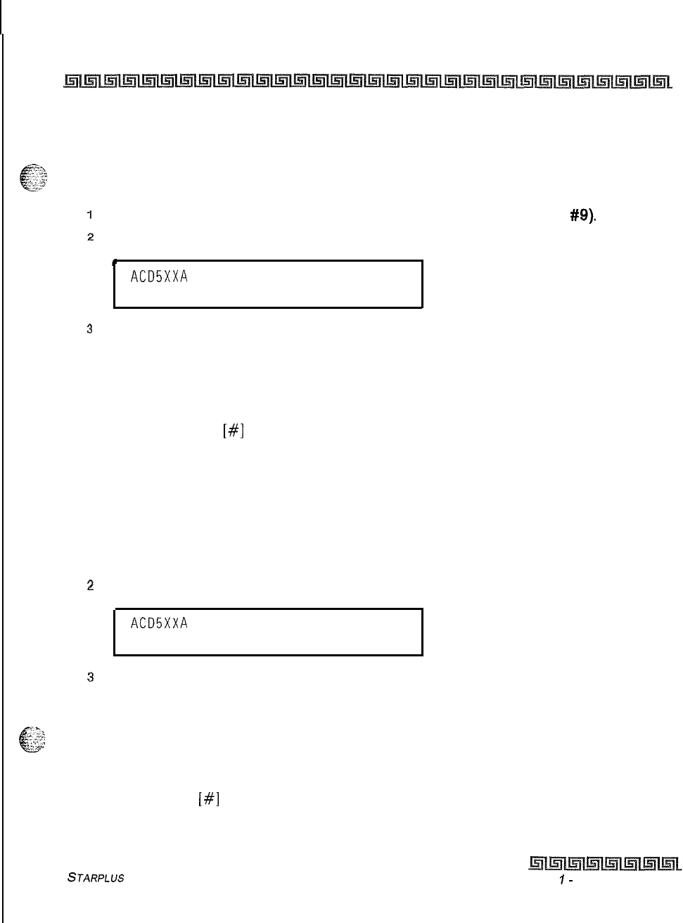
Automatic Call Distribution (ACD)
ACD Group
6-19
Alternate ACD Group Assignment
Programming Steps
To program an alternate group:
I
Press the ALTERNATE ACD GROUP flexible button (FLASH 64, button
#Q).
2
Enter the 3-digit pilot number (558-565) of the desired alternate ACD group.
L
ACD5XXA
ALT OVR AN
SUP
AAA BBB CCCC DDD
.
3
Press HOLD to save the entry. A confirmation tone is heard and the display updates.
Description
An alternate ACD group can be programmed so that if no station in a group is available, the alternate group is
checked for an available station. This provides a means to chain or link ACD groups together. To delete an
Alternate ACD Group, press
[#I
three times and press HOLD.
ACD Overflow Station Assignment
Programming Steps
To program ACD Overflow station:
IPress the OVERFLOW ASSIGN flexible button (FLASH 64, button #IO).
2
Enter a 3-digit station number to designate the ACD Groups overflow station.
ACD5XXA
ALT OVR AN
SUP
AAA BBB CCCC DDD
3
Press HOLD to save the entry. A confirmation tone is heard and the display updates.
Description
.t>
L
.-~.+
/
“;;.:
When an overflow station is assigned, callers that have remained in queue for a specified time are routed to
the assigned overflow station. The overflow station may not be one of the ACD group stations. Only CO calls
transferred to a ACD group overflow to the overflow station when RAN tables are assigned. To delete an
Overflow Station, press
[#I
three times and press HOLD.
STARPLUS Triad-S System Programming Manual Issue
I-
December 1998
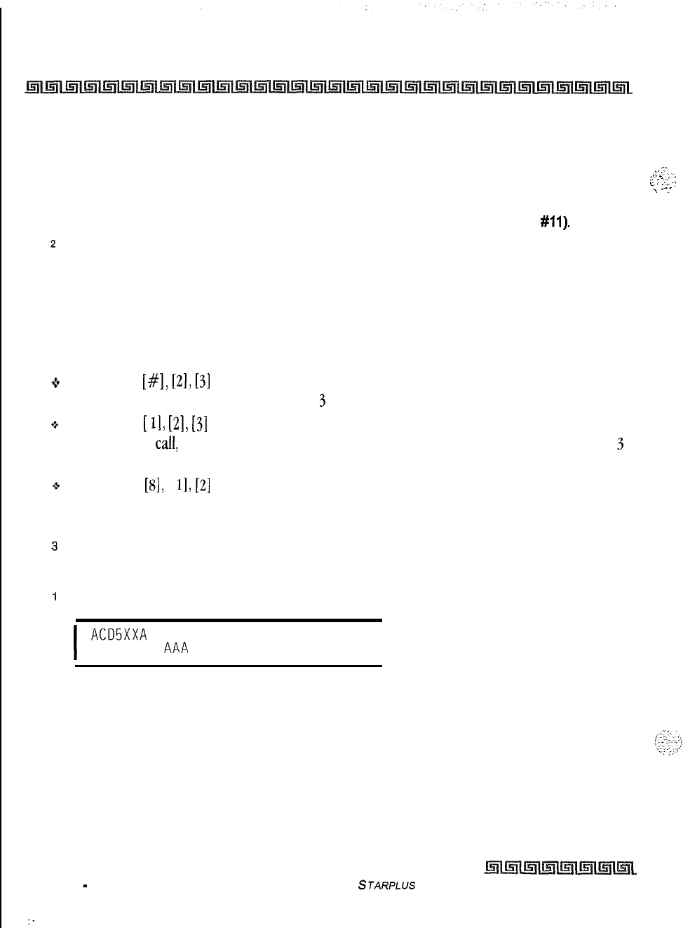
6-20
Automatic Call Distribution (ACD)
ACD Group
ACD Recorded Announcement Assignment(s) (RAN)
Programming Steps
To program a Recorded Announcement:
1
Press the ANNOUNCEMENT TABLES flexible button (FLASH 64, button
#ll).
z
Enter a four-digit sequence on the keypad:
First Digit = RAN port specified for Guaranteed Message (Direct Calls)
Second Digit = RAN port specified for primary message,
Third Digit = RAN port specified for secondary message.
Fourth Digit = RAN port specified for Guaranteed Message (transferred calls)
Example:
+
An entry of
[#I,
[2],
[3]
= No Guaranteed Message is heard. Announcement Table 2 provides a
primary message and Announcement Table
3
provides a secondary message.
o
An entry of
[
11,
[2],
131
= Announcement Table 1 provides the Guaranteed Message upon initially
answering the call, Announcement Table 2 provides a primary message and Announcement Table
3
provides a secondary message.
$8
An entry of
[8],
[
11,
[2]
= Announcement Table 8 provides the Guaranteed Message upon initially
answering the call, Announcement Table 1 provides a primary message and Announcement Table 2
provides a secondary message.
3
Press HOLD to save the entry. A confirmation tone is heard and the display updates.
To erase Recorded Announcement(s) :
1
Press [#] four times and press HOLD.
I
ACD5XXA
ALT OVR AN
SUP
AAA
BBB CCCC DDD
I
Description
Optional Recorded Announcement device(s) may be connected to the system to provide an announcement
if all stations in a ACD group are busy. Up to eight ports in the system may be assigned to provide a path to
Recorded Announcement devices. Incoming CO Callers are answered and routed to the Overflow
assignment only if a RAN Table is assigned.
The Guaranteed Message announcement provides a means to force incoming callers to an announcement
before being placed into an ACD Queue or routed to an agent. The outside callers are presented with a
Issue 1
-
December 1998
STARPLUS
Triad-S System Programming Manual
:
;.-.>‘
,...
_
,..‘_
i
:
:x
.,,
‘-.
b’
.
-:
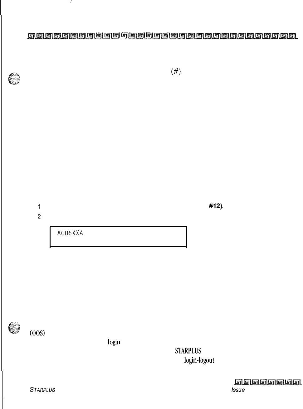
:
Automatic Call Distribution (ACD)
ACD Group
6-21
message before being routed to the ACD Group. Agents in an ACD Group with a Guaranteed Message enabled
receive incoming callers only after the caller hears the designated recorded announcement in its entirety, or
7%
d
after the incoming caller dials up to 14 digits followed by
(#).
These digits are inserted as ICLID incoming
$2
number identification. If the Guaranteed Message announcement is programmed in Admin, incoming ACD
calls are routed to the Guaranteed Message RAN before going to the ACD Group.
The Guaranteed RAN Enhancement allows a second guaranteed RAN type to be associated with each ACD
Group in the system. This RAN handles only transferred CO calls. This lets a CO call transferred to an ACD
Group enter caller entered ID digits via this RAN. The digits are then compared against the local
name/number translation table and routed based on table entries. If no match is found, the call rings to the
ACD Group. Intercom calls to the group pilot number result in a busy tone, Once the intercom caller hangs
up to complete the transfer, the CO call is presented to the RAN device.
ACD Supervisor
Programming Steps
To program an ACD Supervisor:
I
Press the ACD SUPV flexible button (FLASH 64. button
#12).
:!
Enter the 3-digit station number of the desired ACD Supervisor station.
ACD5XXA
ALT OVR AN
SUP
AAA BBB CCCC DDD
3
Press HOLD to save the entry. A confirmation tone is heard and the display updates.
Description
The ACD Supervisor Station assignment feature provides a means to assign each ACD group a supervisor.
This Supervisor Station can receive the calls in queue display in real time, receives No Answer/Out of Service
conditions, HELP displays from the groups to which the supervisor is assigned, and can barge-in on active
calls in his ACD Group or groups.
-iy7,,
L
3;c3
A supervisor can be assigned in ADMIN to a group or groups to receive the help request and out of service
c7c
(00s) messages. If a supervisor station is assigned in ADMIN, it is considered logged in. In addition, a
supervisor can dial a supervisor login code followed by the ACD group that the supervisor is logging into and
his 4-digit ID number. For maximum compatibility with the
STARPLUS
PC-ACD Reporting package, the
supervisor assignment should be left blank and the supervisor login-logout feature used.
STARPLUS Triad-S System Programming Manual Lssue
I- December 1998
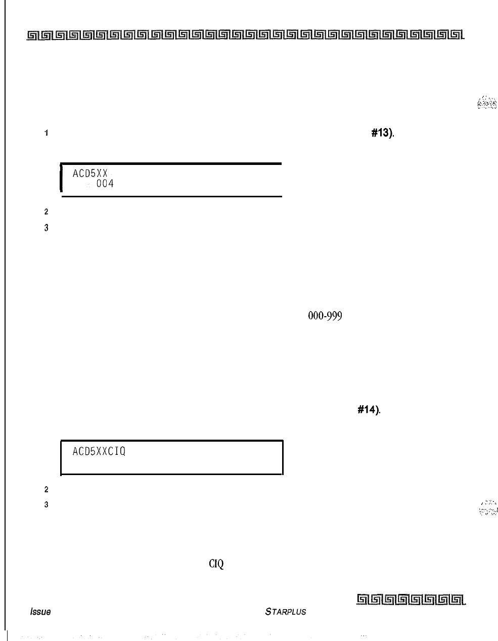
I
6-22
Automatic Call Distribution (ACD)
ACD Group
ACD Auto Wrap-Up Timer
Programming Steps
To change the ACD Auto Wrap-up Timer:
1
Press the AUTO-WRAP TIMER flexible button (FLASH 64, button
#13).
The following
message displays:
I.
,’
:.
:...*
,,_...
r
.;-
‘,.2,
I
ACD5;i4 WRAP-UP 000-999
I
2
Enter the 3-digit value on the dial pad which corresponds to 000-999 seconds.
3
Press HOLD to save the entry. A confirmation tone is heard and the display updates.
Description
After completion of a ACD call (on-hook) the agent is not subjected to another ACD call for the duration of
the Auto Wrap-Up Timer allowing the agent to finish call related work or access other facilities. This lets
agents remove themselves from the group (i.e., DND, Call Forward) or originate another call. By default, the
ACD Auto Wrap-Up Timer is set for four seconds and is variable from
000-999
seconds.
ACD CIQ Threshold
Programming Steps
To change the CIQ Threshold:
1
Press the CIQ THRESHOLD flexible button (FLASH 64, button
#14).
The following
message displays:
ACDSXXCIQ THRSHOLD 00-99
00
..
2
Enter the 2-digit value on the dial pad which corresponds to 00-99 calls.
3
Press HOLD to save the entry. A confirmation tone is heard and the display updates.
Description
This feature determines how many calls appear in queue before the LED flashes at 240 ipm flutter. Once
the number of calls in queue falls below the
CIQ
threshold, the LED extinguishes. By default, this feature is
disabled.
issue
I- December 1998
STARPLUS Triad-S System Programming Manual
,
:(
.:-.
,,::-.
.,..
,
:,
.;
..:I
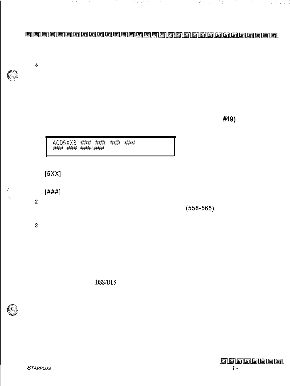
Automatic Call Distribution (ACD)
ACD Group
6-23
Conditions
+z+
Any ACD station can have a button assigned to view the calls in queue of any ACD group.
ACD Station Assignment(s)
Programming Steps
To program stations into a ACD group:
1
Press the DISPLAY STAS 9-16 flexible button (FLASH 64, button
#19).
The following
message displays:
ACD5XXB
###
###
###
###
#Mf##########
Where:
/
‘L.
[5Xx]
= ACD Grp Number (558-565)
[B] = Page B parameters
[###I
= ACD Station assignments
2
The top left button in the flexible button field is lit for programming ACD Group 9 (558).
To change ACD groups or enter further ACD groups
(558-565),
press the appropriate
flexible button and perform the following procedures.
s
Enter the 3-digit station numbers of the stations in the ACD group in the order in which
they are checked. The order is only relevant for the first call. After that, the rule is oldest
idle. A maximum of sixteen stations may be entered. No station entries are displayed at
this time.
4
Press HOLD to save the entry. A confirmation tone is heard and the display updates.
Description
Any type of station (excluding
DSSDLS
Consoles) may be entered as valid ACD stations. Calls are routed to
station in the order they are entered for the first round of calls only. After that the calls are routed to stations
based on On-Hook time. The station with the longest On-Hook time receives the next call. If a specific station
67
<g
. ..?
x.&g
number is dialed, only that station is rung; no distribution is done if that station is busy.
The buttons on the digital terminal are defined as shown below when entering the ACD Station Assignments
programming area:
STARPLUS
Triad-S System Programming Manual Issue
I-
December 7998
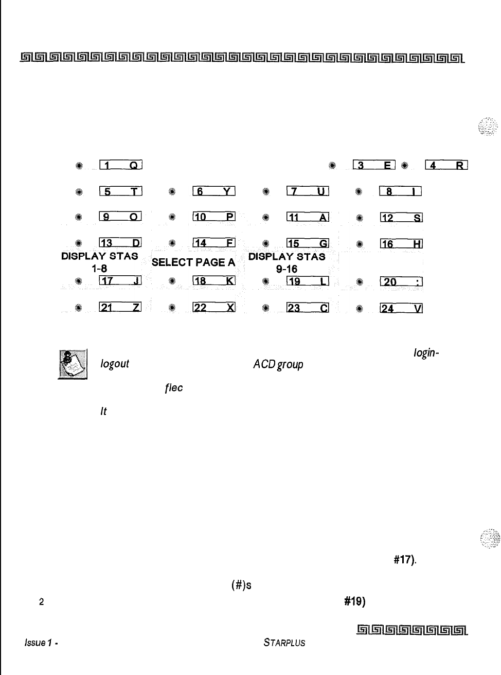
6-24
Automatic Call Distribution (ACD)
ACD Group
ACD GROUP 558 ACD GROUP 559 ACD GROUP 580 ACD GROUP
561
+k-
612
*tEiEl
#lxixl
ACD GROUP 562 ACD GROUP 583 ACD GROUP 564 ACD GROUP 565
3#m
%+a
+kLIial
%+!xziIl
To erase all stations, press [#] three times, then press HOLD.
If an ACD member is assigned to a specific ACD group and uses the
login-
logout
codes to enter and exit an
ACDgroup
other than their own assigned
group, the database programming for ACD stations is automatically
changed to re
flee
t
the
different
group.
It
is recommended that ACD agent station not be deleted from an ACD
group through database administartion when that station is in the Unavail-
able Mode. This causes the LCD to display unavailable even though the
station is no longer part of the ACD group. The station can dial the 566
code to remove the message.
View ACD Station Assignments
Programming Steps
If ACD Station Assignments in the second group of eight (Stations
9-16)
must be viewed:
IPress the DISPLAY STAS l-8 flexible button (FLASH 64, Page B, button
#17).
The first
group of station assignments displays. If no additional stations are assigned beyond the
first eight stations, the display shows
(#)s
instead of station assignments.
2
Press DISPLAY STAS 9-16 flexible button (FLASH 64, button
#19)
to view the second
group of eight stations in the same ACD group.
issue
I-
December 1998
STARPLUS
Triad-S System Programming Manual
Automatic Call Distribution (ACD)
ACD Group
Description
Any time a display of the first group of ACD Station assignments (default or changed) is needed, press the
DISPLAY STAS 1-8 button
(FLASH
64, button
#17).
It displays the first group of station assignments, up to
eight stations at a time. Button
#19
always shows the second group of eight stations programmed in the ACD
Group.
Button
#17
always displays the first group of eight stations programmed in the same ACD Group.
SJARPLUS Triad-S System Programming Manual
Issue
I
-
December 1998
..:.
.‘.
.
.-
6-26
Automatic Call Distribution (ACD)
ACD Group
kSU8
I-
December
1998
STARPLUS Triad-S System Programming Manual
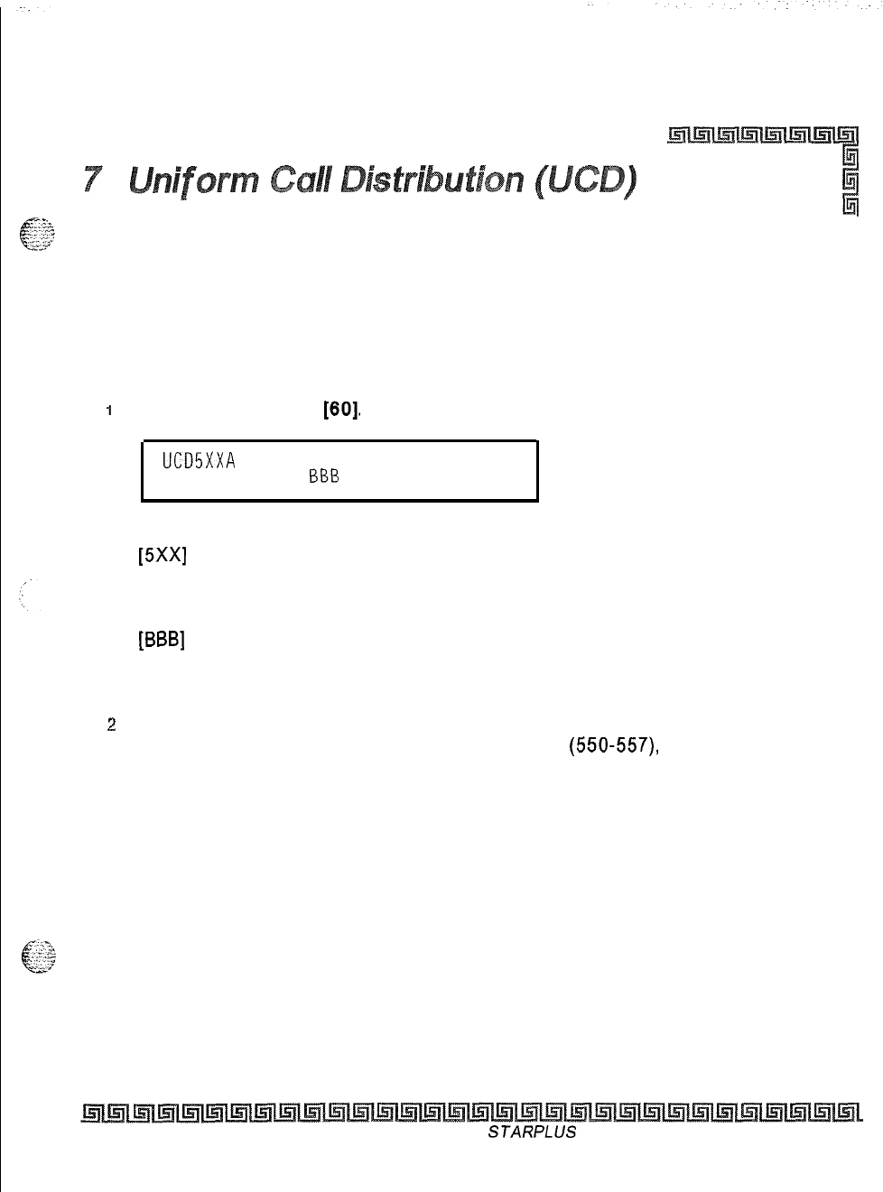
UCD Group Programming
Programming Steps
If the system is in the programming mode, continue using the program codes. If starting to program here,
enter the programming mode.
1
Press FLASH and dial
[60].
The following message displays:
l
UCD5XXA
ALT OVR AN
AAA
BB%
CC
Where:
[5Xx]
= UCD Group Number (550457)
[A] = Page A Parameters
[AAA] = Alternate UCD Group Assignment
[BBB]
= UCD Overflow Assignment
[CCCC] = UCD Announcement Tables
[DDD] = UCD Supervisor Programming
z
The top left button in the flexible button field is lit for programming UCD Group 1 (550).
To change UCD Groups or enter more UCD Groups
(550-557),
press the appropriate
flexible button and perform the following procedures.
Description
There can be eight UCD groups of no more than eight stations each. The UCD groups use a pilot hunting
technique. If the pilot number is dialed, the assigned stations in that UCD group are searched for the station
which has been in an idle condition for the longest time period. Each UCD Group may have an assigned
Alternate UCD Group, an Overflow station and up to eight stations as UCD members. The two system RAN
ports (tables) may also be referenced on a per UCD group basis. By default, UCD Group Tables are empty.
The buttons on the digital terminal are defined as shown below when entering the UCD Group(s)
programming area:
Issue I- November 1998
STARPLUS
Triad-S System Programming Manual
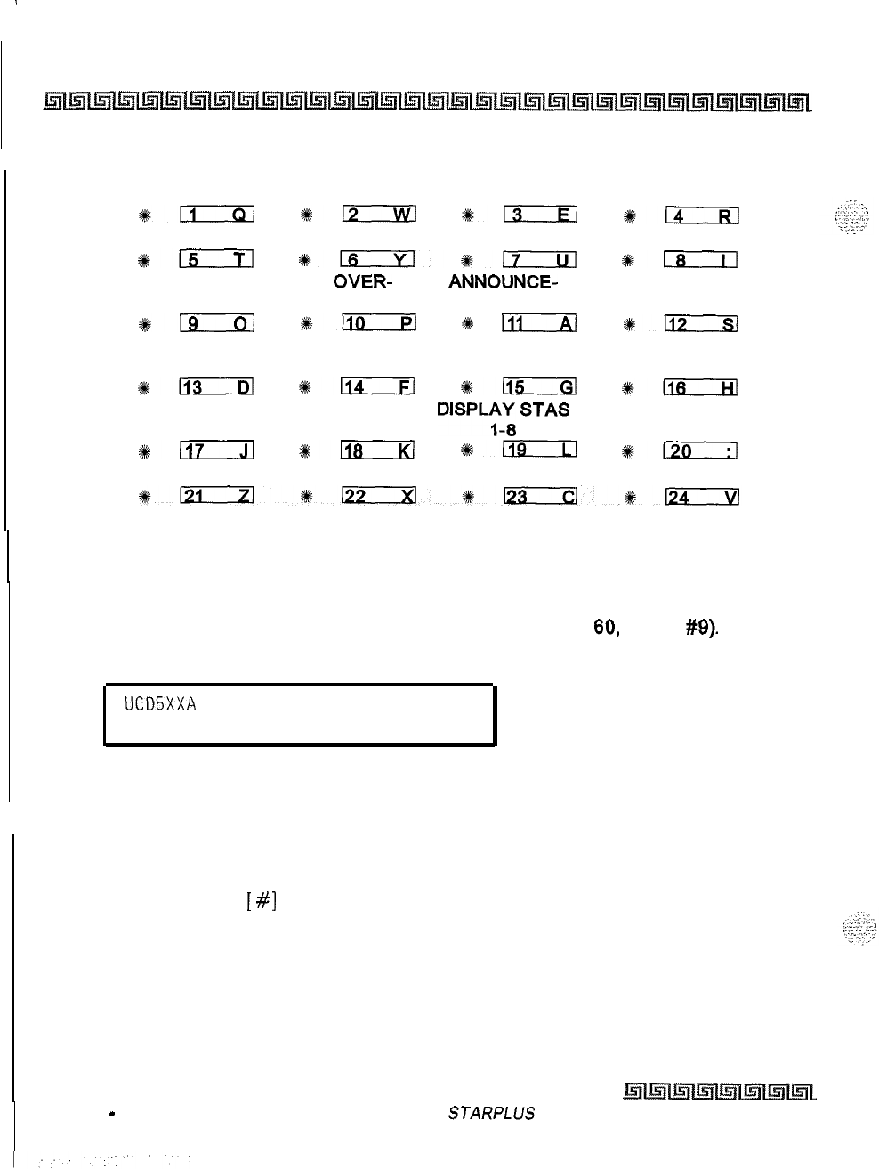
.
7-2
Uniform Call Distribution (UCD)
UCD Group Programming
UCD GROUP 550 UCD GROUP
551
UCD GROUP 552 UCD GROUP 553
%-
+kD
+en
*a
UCD GROUP 554 UCD GROUP 555 UCD GROUP 556 UCD GROUP 557
4km
*lxxxl*-
#klxcil
ALTERNATIVE UCD
OVER- ANNOUNCE-
UCD GROUP FLOW ASSIGN MENT TABLES
s#-
%+-
*
FiT-R
*-
UCD WRAP-UP
TIMER
*-
*n
*115
#mziiil
SELECT PAGE A
D’spL;s;
STAS
*-
*D
den
+120
Alternate UCD Group Assignment
Programming Steps
1
Press the ALTERNATE UCD GROUP flexible button (FLASH
60,
button
#9).
2
Enter the 3-digit pilot number (550 to 557) of the desired alternate UCD group.
UCD5XXA
ALT OVR AN
AAA BBB CC
3
Press HOLD to save the entry. A confirmation tone is heard and the display updates.
I
Description
An alternate UCD group can be programmed so if no station in a group is available, the alternate group is
checked for an available station. This provides a way to chain or link UCD groups together. To delete an
Alternate UCD Group, press
[
#]
three times and press HOLD.
Issue I
-
November 1998
STARPLUS
Triad-S System Programming Manual
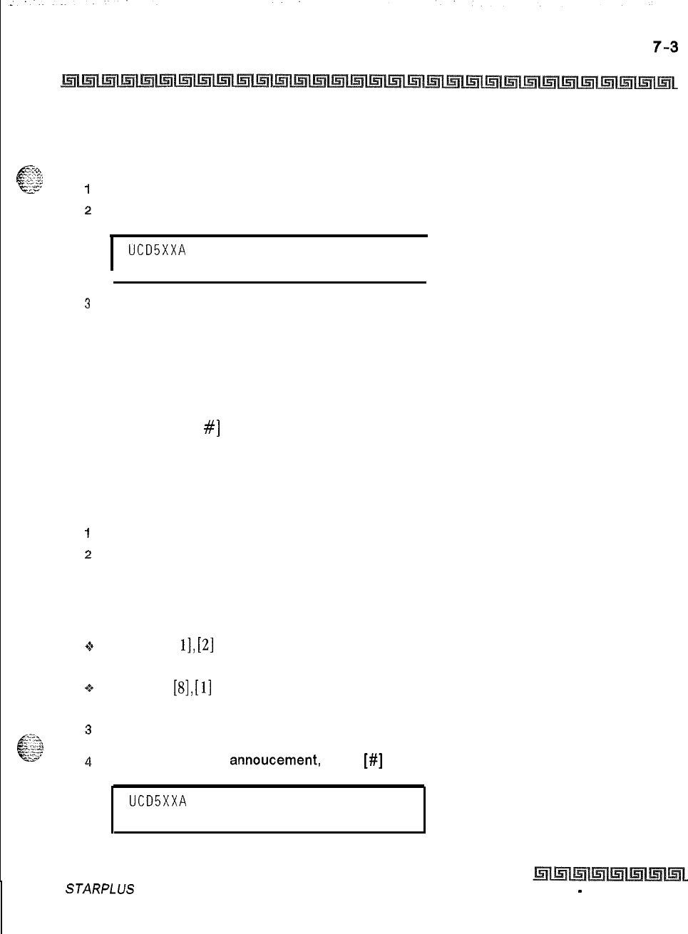
Uniform Call Distribution (UCD)
UCD Group Programming
UCD Overflow Station Assignment
#g?&
Programming Steps
t&z&~
I
Press the OVERFLOW ASSIGN flexible button
(FLASH 60, button #IO).
2
Enter a 3-digit station number to designate the UCD Groups overflow station.
I
UCD5XXA
ALT OVR AN
AAA BBB CC
I
3
Press HOLD to save the entry. A confirmation tone is heard and the display updates,
Description
When an overflow station is assigned, callers that remain in queue for a specified amount of time are routed
to the assigned overflow station. The overflow station may not be one of the UCD group stations. Only CO calls
transferred to a UCD group overflow to the overflow station when RAN tables are assigned. To delete an
Overflow Station, press [
#]
three times and press HOLD.
UCD Announcement Assignment(s) (RAN)
Programming Steps
1
Press the ANNOUNCEMENT TABLES flexible button (FLASH 60, Button #II).
z
Enter a 2-digit sequence:
First Digit = RAN port specified for primary message,
Second Digit = RAN port specified for secondary message.
Example:
1*
An entry of [
11,
[2]
= Announcement Table
1
answers the call, Announcement Table 2 provides a
secondary message.
+z+
An entry of
[S],
[
11
= Announcement Table 8 answers the call, Announcement Table
1
provides a
secondary message.
3
Press HOLD to save the entry. Confirmation tone is heard and the display now updates.
4
To erase recorded
annoucement,
press
[#]
two times and press HOLD.
UCD5XXA
ALT OVR AN
AAA BBB CC
STARPLUS Triad-S System Programming Manual Issue 1
-
November 1998
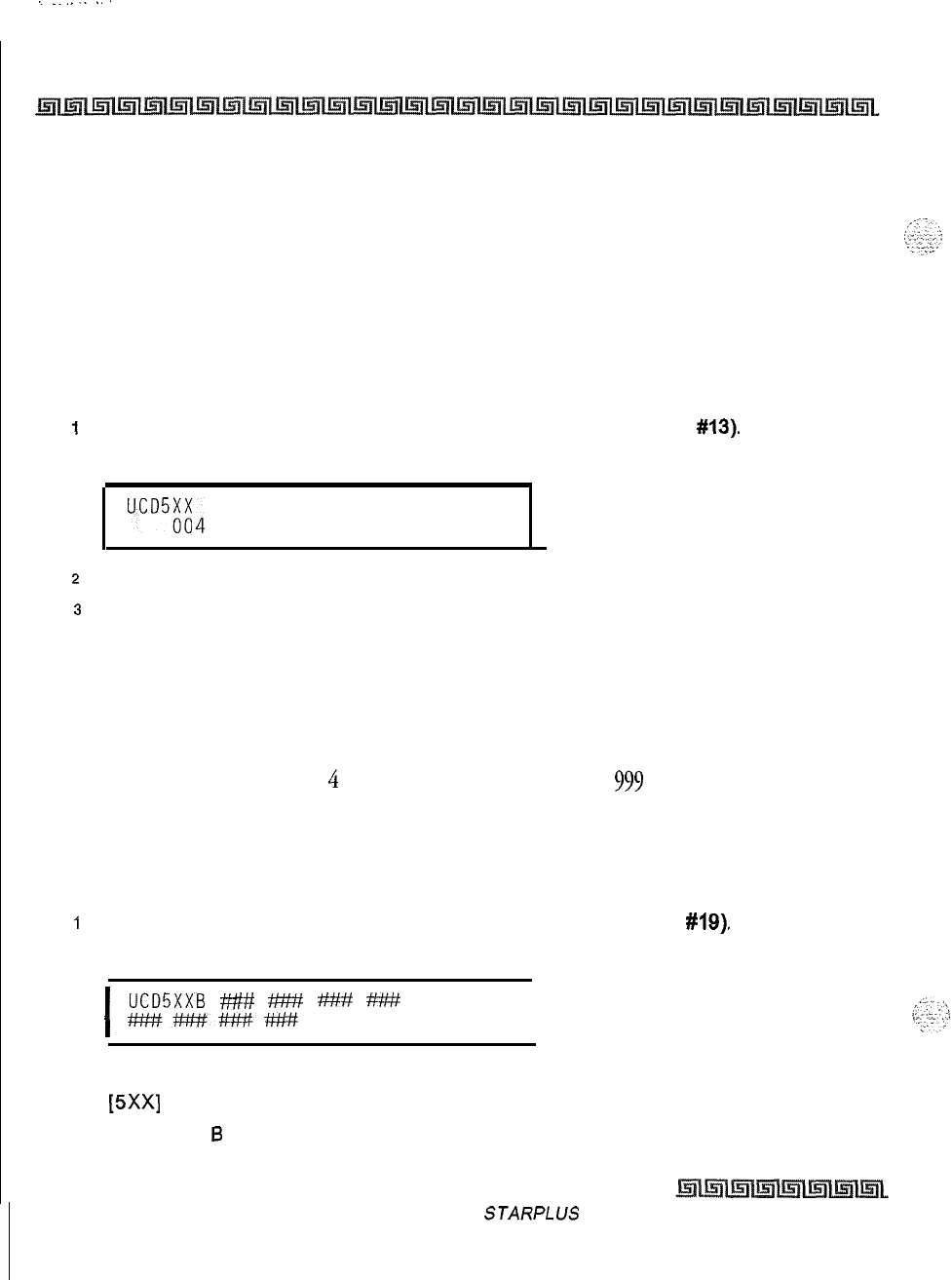
I
.._......
7-4
Uniform Call Distribution (UCD)
UCD Group Programming
Description
Optional Recorded Announcement device may be connected to the system to provide an announcement if
all stations in a UCD group are busy. Up to eight ports in the system may be assigned to provide a path to
Recorded Announcement devices. Incoming CO Callers are answered and routed to the Overflow
assignment only if a RAN Table is assigned.
UCD Auto Wrap-Up Timer
Programming Steps
I
Press the AUTO-WRAP TIMER flexible button (FLASH 60, Button
#13).
The following
message is shown on the display phone:
UCD5;H4 WRAP-UP
000 -999
2
Enter the 3-digit value on the dial pad which corresponds to 000-999 seconds.
3
Press HOLD to save the entry. Confirmation tone is heard and the display now updates.
Description
After completion of a UCD call (on-hook) the agent is not be subjected to another UCD call for the duration
of the Auto Wrap-Up Timer allowing the agent to finish call related work or access other facilities. This lets
agents remove themselves from the group (i.e., DND, Call Forward) or originate another call. By default, the
UCD Auto Wrap-Up Timer is set for
4
seconds and is variable from 000 to
999
seconds,
UCD Station Assignment(s)
Programming Steps
I
Press the DISPLAY STAS l-8 flexible button (FLASH 60, Button
#19).
The following
message is shown on the display phone:
I
UCDSXXB
###
6%
#MY
###
M###H#######
I
Where:
[5Xx]
= UCD Grp Number (550457)
[B] = Page
6
parameters
Issue I- November 1998
STARPLUS
Triad-S System Programming Manual
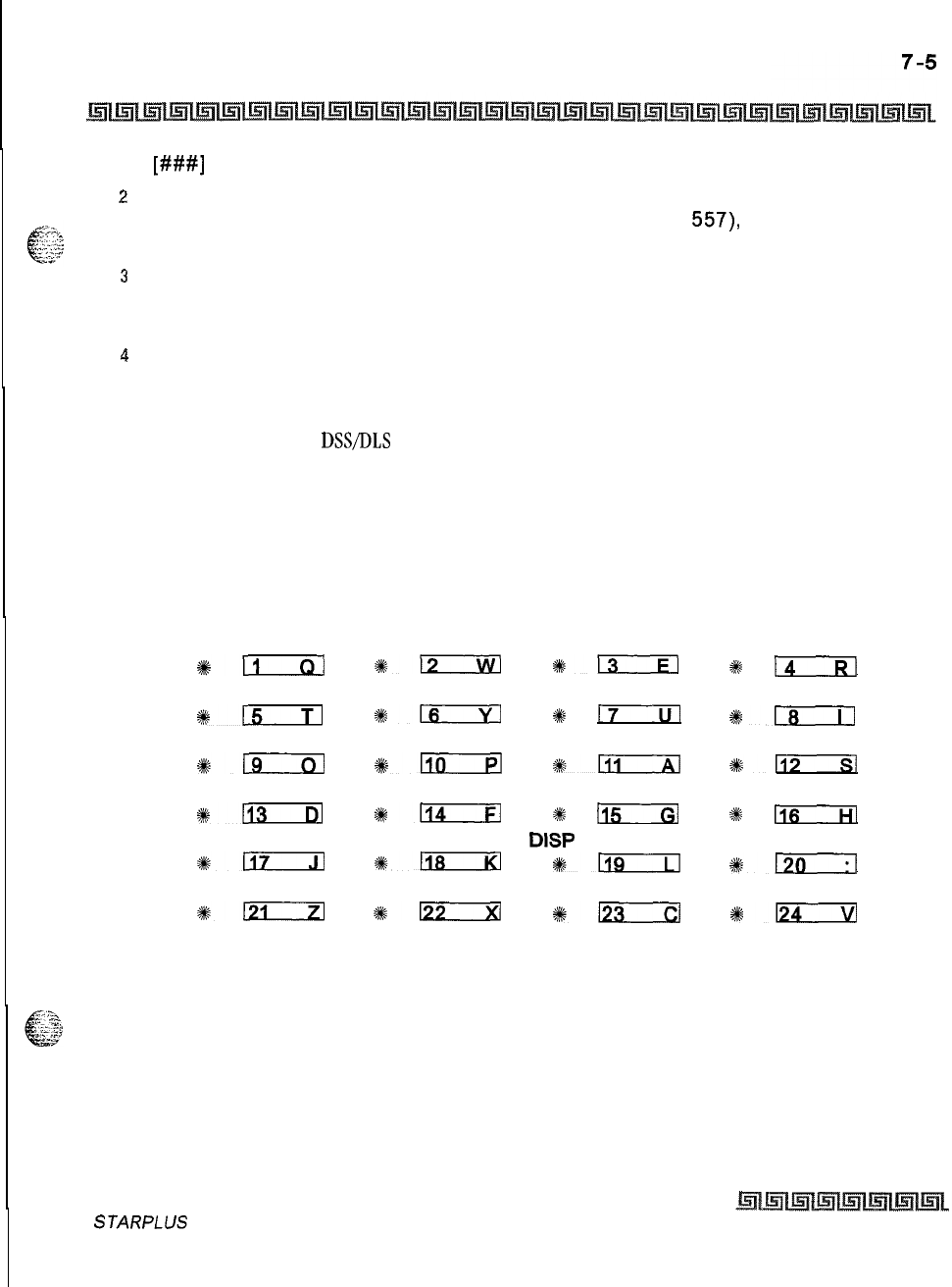
Uniform Call Distribution (UCD)
UCD Group Programming
[###I
= UCD Station assignments
2
The top left button in the flexible button field is lit for programming UCD Group 1 (550).
To change UCD groups or enter further UCD groups (550 to
557),
press the appropriate
flexible button and perform the following procedures.
3
Enter the 3-digit station numbers of the stations in the UCD group in the order in which
they are to be checked. The order is relevant for the first call, then the rule is oldest idle.
A maximum of 8 stations may be entered. No station entries are displayed at this time.
4
Press HOLD to save the entry. Confirmation tone is heard and the display now updates.
Description
Any type of station (excluding
DSVDLS
Consoles) may be entered as valid UCD stations. Calls are routed to
station in the order they are entered for the first round of calls only. After that the calls are routed to stations
based on On-Hook time. The station with the longest On-Hook time receives the next call. If a specific station
number is dialed, only that station is rung; no distribution is done if that station is busy.
The buttons on the digital terminal are defined as shown below when entering the UCD Station Assignments
programming area:
UCD GROUP 560 UCD GROUP 561 UCD GROUP 562 UCD GROUP 563
*n
812
O13
2#
l4
UCD GROUP 564 UCD GROUP 565 UCD GROUP 566 UCD GROUP 567
%15
*m
*
17
*Is
Br9
#lEia
s%n
4#n
+ki
~FixzEl
c
mr-zl
%
la--w
SELECT PAGE A
DISP
STAS l-8
*117 *118
#Eiiril
#rm--!-l
#lziIxl
*Ezxzl
#K;
#lzizIzl
STARPLUS Triad-S System Programming Manual
Issue I- November 1998
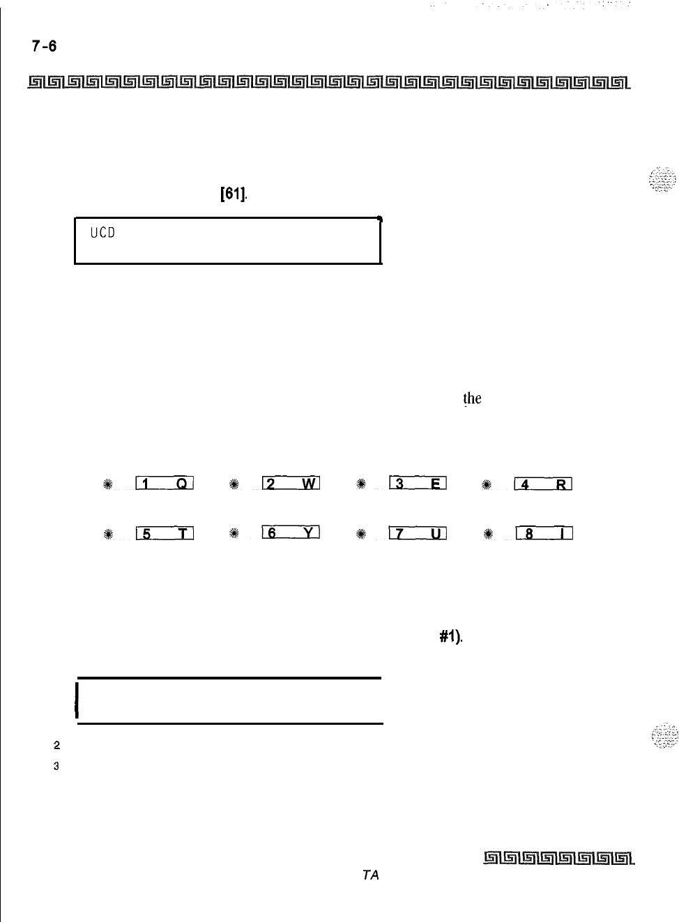
Uniform Call Distribution (UCD)
UCD Timers
UCD Timers
Programming Steps
1
Press FLASH and dial
[61].
The following message is shown on the display phone:
.
UCD TIMERS
ENTER BUTTON NUMBER
Description
Six timers for UCD operation are programmable on a system-wide basis. The UCD timers include: a Ring
Timer, Message Interval Timer, an Overflow Timer, an Auto Wrap-Up Timer, a No/Answer Recall Timer, and
No/Answer Retry Timer. Each timer is described in the following section.
The buttons on the digital terminal are defined as shown below when entering the UCD Timers
programming area:
RING TIMER MIT TIMER OVERFLOW
TIMER
s&m
#E-
s+;
#i.xzizl
NO-ANSWER NO-ANSWER
RECALL RETRY
#km
116 117
*re
UCD Ring Timer
Programming Steps
1
Press the RING TIMER flexible button (FLASH 61. Button
#I).
The following message is
shown on the display phone:
I
RING
000-300
060
I
2
Enter the 3-digit timer value on the dial pad which corresponds to 000-300 seconds.
3
Press HOLD to save the entry. Confirmation tone is heard and the display now updates.
Issue I- November 1998
S TA RPL US Triad-S System Programming Manual
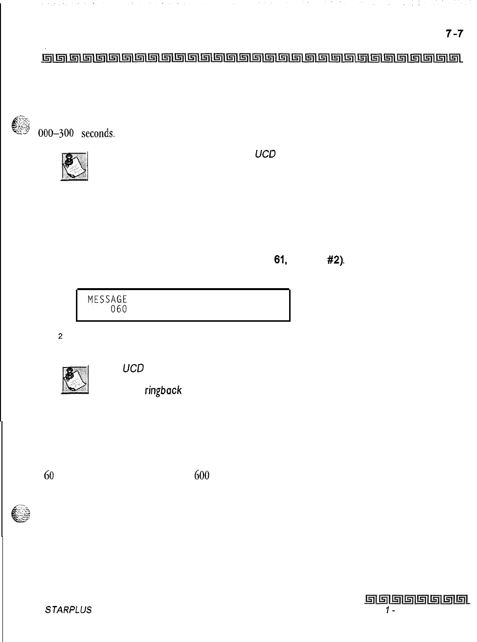
Uniform Call Distribution (UCD)
UCD
Timers
Description
The UCD Ring Timer determines how long a call rings into a busy UCD group before being presented to the
6
21%
first recorded announcement. By default, the UCD Ring Timer is set for
60
seconds, and is variable from
L^“.,.
.‘Ts’
0@)-3()0
seconds.
A RAN Table must be specified in
UC0
programming. If a RAN Table is
NOT specified, incoming CO callers are not answered but continue to
receive ringback.
UCD Message Interval Timer
Programming Steps
1
Press the MIT TIMER flexible button (FLASH
61,
Button
#2).
The following message is
shown on the display phone:
MEW&
INTERVAL 000-600
2
Enter the 3-digit timer value on the dial pad which corresponds to 000-600 seconds.
3
Press HOLD to save the entry. Confirmation tone is heard and the display now updates.
The
UC0
Ring and Message Interval Timers only apply when RAN ports
are specified. If RAN ports are not specified, incoming callers continue to
receive a
ringback
tone.
Description
The UCD Message
Interval
Timer (MIT) determines the length of time a caller remains in queue (listening to
MOH, if provided) between recorded announcements. By default, the UCD Message Interval Timer is set for
60
seconds and is variable from 000 to
600
seconds.
STARPLUS Triad-S System Programming Manual Issue
I-
November 1998
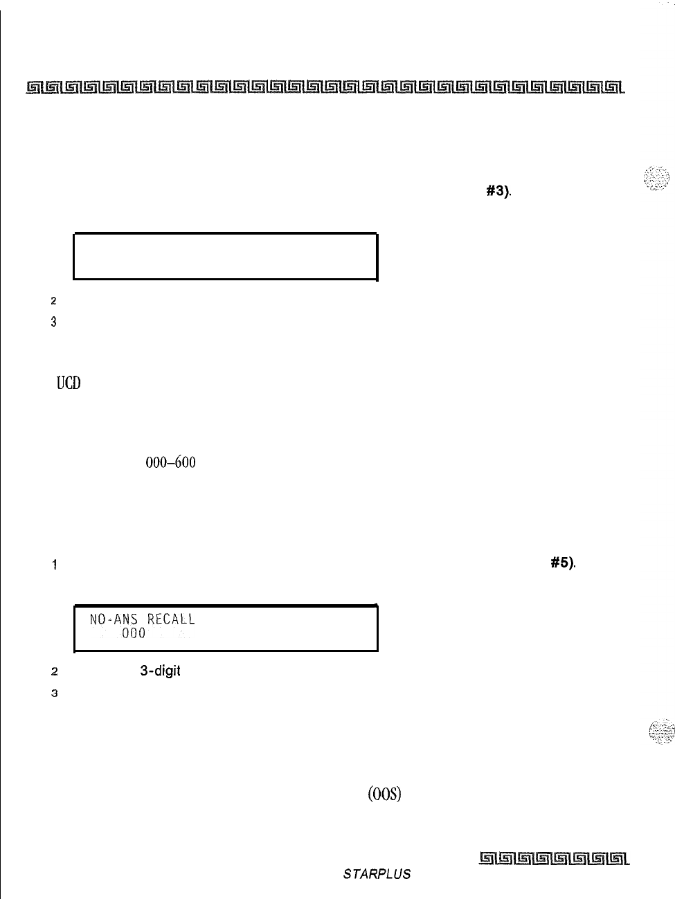
7-8
Uniform Call Distribution (UCD)
UCD Timers
UCD Overflow Timer
Programming Steps
1
Press the OVERFLOW TIMER flexible button (FLASH 61, Button
#3).
The following
message is shown on the display phone:
OVERFLOW
000 -600
060
z
Enter the 3-digit value on the dial pad which corresponds to 000-600 seconds.
3
Press HOLD to save the entry. Confirmation tone is heard and the display now updates.
Description
The
UCD
Overflow Timer determines the total length of time a caller remains in queue for a particular UCD
group. When the timer expires, the caller is routed to the designated overflow station. The timer starts when
an incoming call is answered and presented to the first recorded announcement. Transferred CO callers
overflow at the expiration of the Overflow Timer. By default, the UCD Overflow Timer is set for 60 seconds
and is variable from 000-600 seconds.
UCD No-Answer Recall Timer
Programming Steps
I
Press the NO-ANSWER RECALL TIMER flexible button (FLASH 61, Button
#5).
The
following message is shown on the display phone:
.
NO-Aitt50RECALL
000-300
l
.
2
Enter the
3-digit
value on the dial pad which corresponds to 000-300 seconds.
s
Press HOLD to save the entry. Confirmation tone is heard and the display now updates.
Description
If a call routed to a station via UCD is not answered by the UCD Agent/Station before the No-Answer Recall
Timer expires, the call is returned to UCD Queue with the highest priority. In addition, the station that failed
to answer the ringing UCD call is placed into an out-of-service (00s) state. By default, the UCD No-Answer
Timer is at 000 (disabled) and is variable from 000-300 seconds.
Issue I -November 1998
STARPLUS
Triad-S System Programming Manual
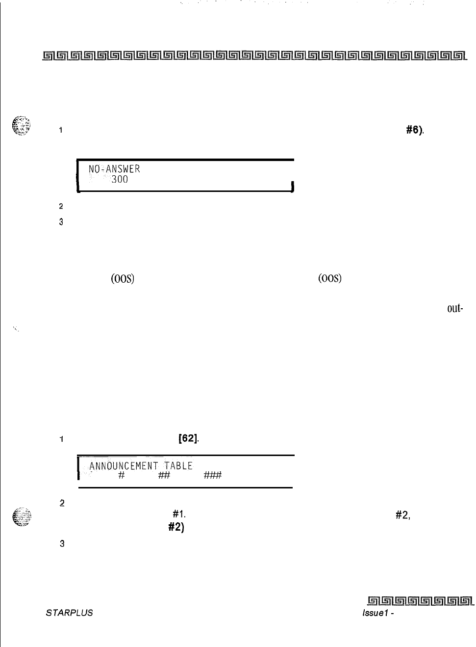
Uniform Call Distribution (UCD)
UCD Announcement Tables (RAN)
7-Q
UCD No-Answer Retry Timer
=;i.
c
Programming Steps
_,.
:.:,
5’
.k..T,
-
*--
g,.-
I
Press the NO-ANSWER RETRY TIMER flexible button (FLASH 61, Button
#6).
The
following message is shown on the display phone:
I
NO-A;;;ER RETRY 000-999
I
z
Enter the 3-digit value on the dial pad which corresponds to 000-999 seconds.
3
Press HOLD to save the entry. Confirmation tone is heard and the display now updates.
Description
When the No-Answer Recall Timer expires, a station that failed to answer the ringing UCD call is placed into
an out-of-service (00s) state. The station that was taken out-of-service (00s) is placed back in service if the
agent
hits his available flex button or dials the available flex code. In addition, the agent is placed back in
service if the No-Answer Retry Timer expires. If the agent does not answer his next UCD call, he is taken
out-
of-service again. This cycle continues until the station answers calls, logs out, or goes unavailable. By default,
the UCD No-Answer Retry Timer is set for 300 seconds and is variable from 000-999 seconds.
UCD Announcement Tables (RAN)
Programming Steps
If Recorded Announcement devices are installed to operate with UCD, these tables must be programmed:
1
Press FLASH and dial
[62].
The following message is shown on the display phone:
1
TYPE
#
INDX ## TIME
W
I
2
The top left button in the flexible button field is lit for programming UCD RAN
Announcement Table
#I.
To change to UCD RAN Announcement Table
#2,
press
(FLASH 62, Button
#2)
flexible button. (*Repeat the above for Tables 3 through 8.)
3
Enter a string of six or seven digits on the dial pad. The order of data entry is:
Type Number:
[I] = CO Port Interface
STARPLUS Triad-S System Programming Manual issue
I-
November 1998

7-10
Uniform Call Distribution (UCD)
UCD Announcement Tables (RAN)
[2]
= SLT Port Interface
Index (port) Number:
[OOl-0121
= Triad-S CO Line Ports
[IOO-1311
= Triad-S SLT Station Ports
Message Time:
000 to 300 seconds
4
Press HOLD to save the entry. Confirmation tone is heard and the display now updates.
To clear entries
in a Table:
I
Press [#] followed by HOLD.
Description
Determines the type, index (port) number and message length for the eight available Recorded
Announcements (RAN). There are eight RAN Tables that can be programmed. Table 1 can be the answer
port for unanswered incoming calls to a UCD group, while another table can provide the secondary
message.
The buttons on the digital terminal are defined as shown below when entering the UCD RAN Announcement
Tables Programming area:
ANNOUNCE- ANNOUNCE- ANNOUNCE- ANNOUNCE-
MENT TABLE 1 MENT TABLE 2 MENT TABLE 3 MENT TABLE 4
#ll
*lzE3a
*-
#D
ANNOUNCE- ANNOUNCE- ANNOUNCE- ANNOUNCE-
MENT TABLE 5 MENT TABLE 6 MENT TABLE 7 MENT TABLE 8
#tc3Tl%16
#i;
#lIEILl
The type can be either a CO line port, or a
SLT
port. The index number specifies which circuit for the type of
interface. The message length matches the maximum length of the message to the device that is used.
I
Issue I
-
November 1998 S TA RPL US Triad-S System Programming Manual
Uniform Call Distribution (UCD)
UCD Announcement Tables (RAN)
Example:
To program a table for CO line port:
<<>A
c-
1
-1
:.l-‘F~
1
Press the TABLE X flexible button (FLASH 62, Buttons 1 to
6).
=<a
2
Dial [I] for CO Port Interface.
3 Dial
[OOI-0121
for CO Lines used.
4
Enter Message duration (000-300 seconds).
To program a table for an SLT port:
1
Press the TABLE X flexible button (FLASH 62. Buttons 1 to 6).
2
Dial
[2]
for SLT Port Interface.
3
Dial [I
00-1311
for SLT stations used.
4
Enter Message duration (000-300 seconds).
STARPLUS Triad-S System Programming Manual Issue I
-
November 1998

7-12
Uniform Call Distribution (UCD)
UCD Announcement Tables (RAN)
Issue I- November 1998
S TA RPL US Triad-S Sys tern Programming Manual
.
4
.
-:.-.
1:
I,:
::.;.s’
-
Voicemail Programming
Programming Steps
Enter the programming mode. To program Voicemail Groups:
1
Press FLASH and dial
[65].
The following message is shown on the display phone.
L
l
VM
446
AAA LLL R
XxX,XxX,
xxx,xxx,xxx,xxx,xxx,xxx
Where:
[G] = Voicemail Group Number (O-7)
[AAA] = Alternate Group (440-447)
[LLL] = Leave Mail Index.
[R] = Retrieve Mail Index from outpulsing table for retrieving messages (O-7)
[XXX] = Voicemail Station Numbers (ports) up to 8 stations maximum.
2
The top left button in the flexible button field is lit for programming Voicemail Group 440.
To change voicemail groups or enter further voicemail groups, press the appropriate
flexible button, l-8 (440-447) and perform the following procedures.
If installing a
STARPLUS
Voicemail system (and if default), skip directly
to Button
1.2
and enter voice mail ports.
Certain programming is required in
the
Voicemail system connected to the
Triad-S system for proper operation.
Tone Mode Calling option
(6#)
must be programmed as leading digits in
transfer sequence(s) to force tone ringing to key telephones in the
hands-
free mode.
g
--;j
‘%%
Description
Up to eight Voicemail groups can be configured in the
STARPLUS
TriaMP
system. Each group can
contain up to eight Voicemail designated ports, each of which interfaces with a port on an SLT card, An
externally provided Voicemail system or Auto Attendant must be connected to the Triad-S system for
hue
I-
December 1998
STARfLus
Triad-S System Programming Manual
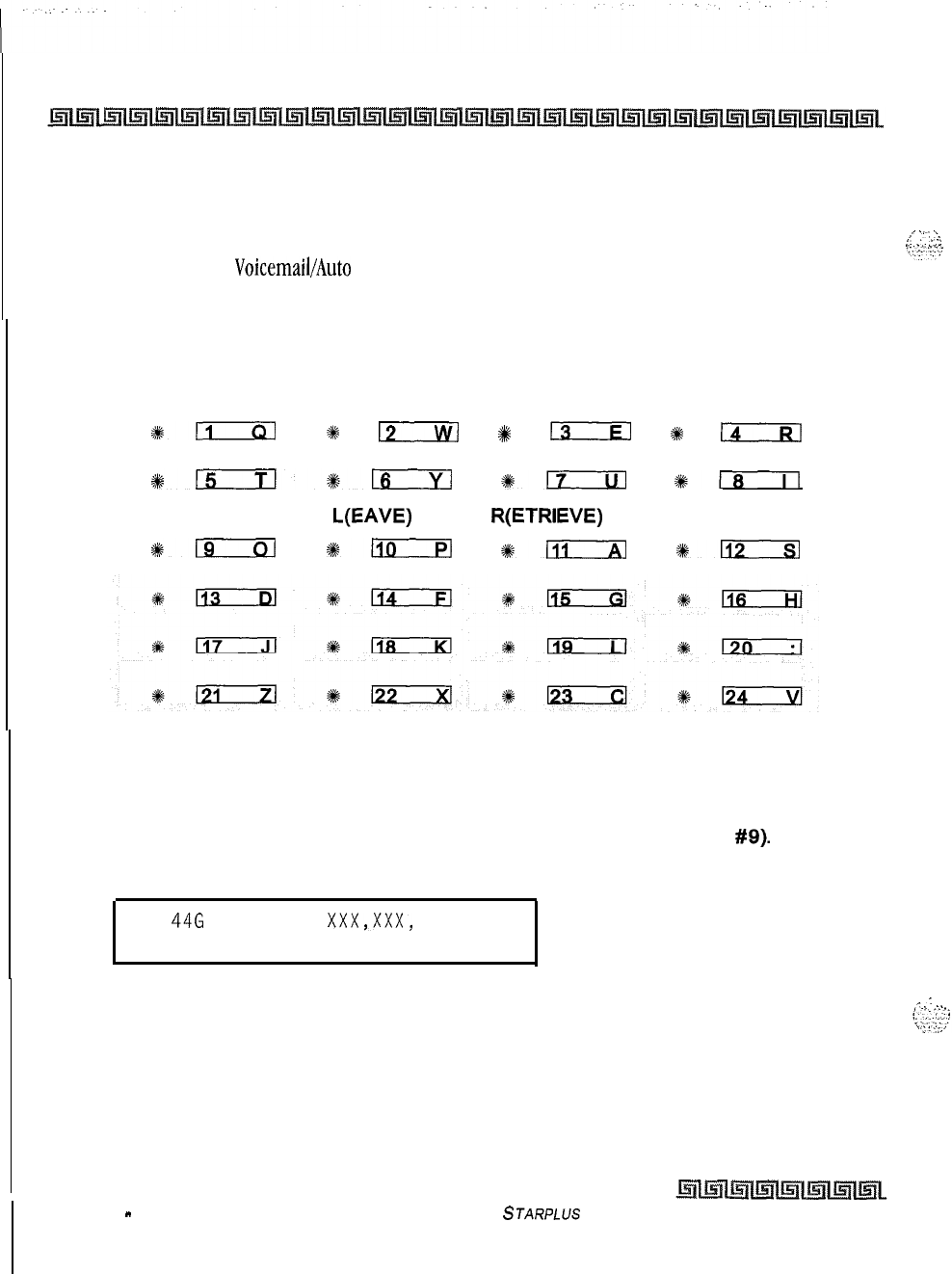
8-2
Voicemail Groups (VM)
Voicemail Programming
Voicemail or Auto Attendant operation. Voicemail automatically handles unanswered calls. Station user can
then retrieve messages left at their stations. Auto Attendants can handle incoming calls and route callers to
station users without intervention from the systems attendant.
,,
.,..,
\.
L.
_:
:;:
Direct incoming ring to
VoicemaibAuto
Attendant groups can be done directly through CO Line Ringing
Assignments. By default, all Voicemail stations are assigned to Pick-Up Group
1.
The buttons on the digital terminal are defined as shown below when entering the Voicemail programming
area:
VM GROUP 440 VM GROUP 441 VM GROUP 442 VM GROUP 443
#SD
+%
12
+
13
#k
(4RI
VM GROUP 444 VM GROUP 445 VM GROUP 446 VM GROUP 447
#kExrl*;
*17
%rn
ALTERNATIVE STATION
VM GROUP
L(EAVE) R(ETRIEVE)
ASSIGN
%kExEl
%kllD
#lTizxI
%n
Alternate Voicemail Group
Programming Steps
1
Press the ALTERNATE VM GROUP flexible button (FLASH 65, Button
#9).
2
Enter the 3-digit pilot number (440 to 447) of the desired group.
VM 446 AAA LLL R XxX,XxX,
xxx,xxx,xxx,xxx,xxx,xxx
3
Press HOLD to save the entry. Confirmation tone is heard and the display now updates.
.A\
:
_..._
To delete an Alternate Voicemail Group assignment:
1
Press [#] three times, then press HOLD.
STARPLUS
Triad-S System Programming Manual
Issue 1
-
December 1998
Voicemail Groups (VM)
Voicemail Programming
8-3
Description
An Alternate Voicemail Group may be programmed so that if all voicemail ports are in use, the call can be
routed to an alternate group. This is useful when more than eight ports are required for voicemail traffic.
Leave Mail Index Entry
Programming Steps
IPress the LEAVE flexible button (FLASH 65, Button #IO).
2
Enter the 3-digit Leave mail index on the dial pad:
First Digit = Standard Leave Table number (O-7).
Second Digit = Leave Table to utilize when station is forwarded to VM in a No-Answer
condition.
Third Digit = Leave Table to utilize when station is forwarded to VM in a Busy condition.
VM 446 AAA LLL R XxX,XxX,
xxx,xxx,xxx,xxx,xxx,xxx
t
I
. .
3
Press HOLD to save the entry. Confirmation tone is heard and the display now updates.
To delete a Leave mail index entry:
1
Press [#] in the desired location on the keypad, then press HOLD (i.e., Tables
1,2,3
entered to delete only Table 2, enter
[1],[#],[3]
and press HOLD).
Description
The Leave Mail Index specifies the outpulsing Table where the in-band digits required to connect a caller,
forwarded into voicemail, to the called stations mail box are stored. By default, Voicemail Group
1 (440)
Leave Table index is set to zero
(0).
Retrieve Mail Index Entry
Programming Steps
7..
c
-&‘-”
..,_
“,,
I
i-
Press the RETRIEVE flexible button (FLASH 65. Button
#ll).
2
Enter the one-digit outpulsing table number (O-7) on the dial pad.
~
STARPLUS Triad-S System Programming Manual issue
I- December 1998
8-4
Voicemail Groups (VM)
Voicemail Programming
VM
446
AAA LLL R
XxX,XxX,
xxx,xxx,xxx,xxx,xxx,xxx
.
3
Press HOLD to save the entry. Confirmation tone is heard and the display now updates.
To delete a Retrieve Mail Index Entry:
1
Press the pound key once
[#I,
then press HOLD.
Description
The Retrieve Mail Index specifies the outpulsing table where the In-Band digits required to connect a station
user to their own mailbox are stored. By default, Voicemail Group 1 (440) Retrieve Table index is set to 1.
For the Triad-S system to send the Station
identification
digits (station 3
or 4-digit extension number), a Leave and a Retrieve tab/e must be
referenced when assigning voicemail groups. However, the Leave and
Retrieve outpulsing tables can be empty (no entries in the referenced
table).
Station Assignment(s)
Programming Steps
IPress the STATION ASSIGN flexible button (FLASH 65, Button
#12).
z
Enter the 3-digit station numbers. A maximum of eight SLT stations may be entered.
VM
446
AAA LLL R
XxX,XxX,
xxx,xxx,xxx,xxx,xxx,xxx
.
3
Press HOLD to save the entry. Confirmation tone is heard and the display now updates.
Description
Up to eight SLT port extension numbers may be programmed into a voicemail group. A flexible button may
be programmed with a voicemail group pilot number
(440-447).
This button then acts as a DSS for that
voicemail group when pressed and also serves as the message waiting indication for that VM group.
Issue I -December 1998
STARPLUS Triad-S System Programming Manual
Voicemail Groups (VM)
Voicemail Outpulsing Table
8-5
Voicemail Outpulsing Table
,,?$.
Voicemail In-Band Signaling
d.,
...
‘L-
”
i.c
-7
Programming Steps
1
Press FLASH and dial
[66].
The following message is shown on the display phone.
VOICE PRE XXXXXXXXXXXXE
MAIL
Y
SUF XXXXXXXXXXXXE
Where:
y = Table Index (O-7)
X = Entered Digits (O-9,
#,
*,
Pauses)
2
The TABLE 00 flexible button (Button
#I)
led is lit. To change tables, press the
appropriate flexible button (Buttons 2-8) and perform the following procedures.
s
Dial one of the following, if required:
[0] = If a prefix is required
[I] = If a suffix is required
[#] = If entry is to be deleted
4
Enter up to 12 digits, including
[X]
and
[#I,
TRANS button = pause.
5
Press HOLD to save the entry. Confirmation tone is heard and the display now updates.
To clear entries in a Table:
1
Press the pound key once
[#I,
followed by HOLD.
Description
Entries in one of the eight Voicemail Outpulsing Tables determine the In-Band signaling required for
Retrieving messages (lets stations pick up mail) and Leaving messages (lets stations leave messages in
voicemail).
STARPLUS Triad-S System Programming Manual Issue
I-
December 1998
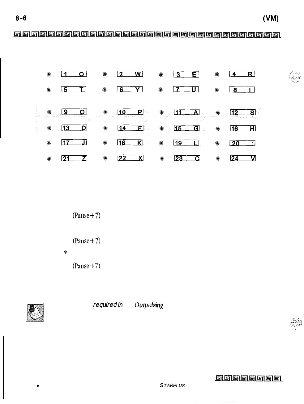
Voicemail Groups
(WA)
Voicemail Outpulsing Table
TABLE
0
TABLE
1
TABLE 2TABLE 3
*EiIm
+12
913
*14
TABLE 4TABLE 5TABLE 6TABLE
7
#:
%F
+em
11_8
DISCONNECT
TABLE
1121
%122
%a
*124
Build a table (0 for example) for any additional digits other than the Station Extension Number (Voicemail
Box Number) needed for a caller to leave a message in a station’s mailbox (Leave). Build another table (1
for example) for any additional digits needed for a mailbox holder to retrieve a message.(Retrieve).
By default:
Table 0
Prefix = P7 (PauseS7)
Suffix = None
Table 1
Prefix = P7 (Pause+7)
Suffix =
*
Table 7
Prefix = P7 (Pause+7)
Suffix = 2
Entries are not
requiredin
the
Outpulsing
Table. However, a tab/e must be
referenced when setting up the Voicemail groups.
,:
.:
,:‘;
,
-.:...>
r::
t
2,
r
.,
. .
.
.
..,
.
.
.
..
Issue I
-
December 1998
STARPLUS
Triad-S System Programming Manual

Voicemail Groups (VM)
Voicemail Outpulsing Table
Voicemail Disconnect Table
Programming Steps
i
Press the DISCONNECT TABLE 8 flexible button (FLASH 66, Button
#9).
This table
number is used for the voicemail disconnect signal.
2
Enter up to 12 digits used for the disconnect signal, including
[+k]
and
[#I,
TRANS button
= pause.
VOICE DIS E
MAIL
1
3
Press HOLD to save the entry. Confirmation tone is heard and the display now updates.
Description
A disconnect signal can be programmed into the Triad-S system to notify the VM system that a call has been
abandoned. This is accomplished through in-band signaling. If a CO or Intercom disconnect signal is
detected, the Triad-S system sends a series of DTMF digits programmed in the voicemail disconnect table to
the voicemail port. This can be any digit stream up to
12
digits including
[++I
and
[#I.
This table serves all
eight voicemail groups. When no digits are programmed in the disconnect table, silence is provided to the
voicemail port followed by busy tone to aid the voicemail system to recognize that the caller has abandoned
the call.
TheTriad-S provides Loop Supervision monitoring while a CO call is connected to a port designated as
voicemail.
Loop Supervision must be enabled on the CO lines (in CO Line program-
ming) for the VM Disconnect feature to operate.
By default, there are no entries in the Disconnect Table (Table #S),
STARPLUS Triad-S System Programming Manual
Issue I- December 1998
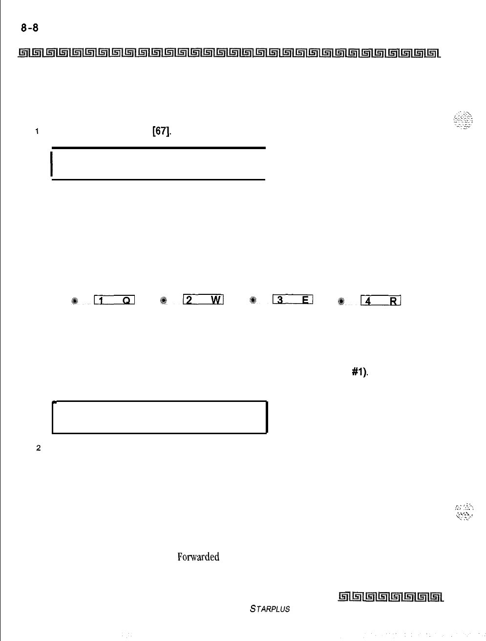
Voicemail Groups (VM)
Voicemail In-Band Features
Voicemail In-Band Features
Programming Steps
I
Press FLASH and dial
[67].
The following message is shown on the display:
I
VM FEATURES ICID AFWD
VBRK
I
Description
Entries into the Voicemail In-Band Features determines the in-band signaling required for ICID Incoming
ID Digits (forwards incoming CO callers directly to a Stations Voicemail Box), and AFWD Call Forward (lets
voicemail calls, upon reaching a forwarded to VM station, forward back into the voicemail system).
INCOMING ID CALL
DIGITS FORWARD VM BROKER
#liIzl
+-
#m
SD
Voicemail In-Band Digits
Programming Steps
IPress the INCOMING ID DIGITS flexible button (FLASH 67. Button
#l).
The following
message is shown on the display phone.
*
VM FEATURES ICID AFWD
VBRK
2
Press the button to Enable/Disable this feature.
LED Off = NO (Disabled)
LED On = YES (Enabled)
3
Press HOLD to save the entry. Confirmation tone is heard and the display now updates.
.
:_,
;5;
‘;L
:
Description
i
^
i-_..
,
/::
-.--
-<
:i-
This feature enables and disables station in-band signaling.
Incoming CO callers can be Station Call Fotwarded into voicemail only when the ringing CO line is
programmed to ring at one station. CO lines programmed to ring at an attendant station, call forward into
Issue I- December 1998
STARPLUS Triad-S System Programming Manual
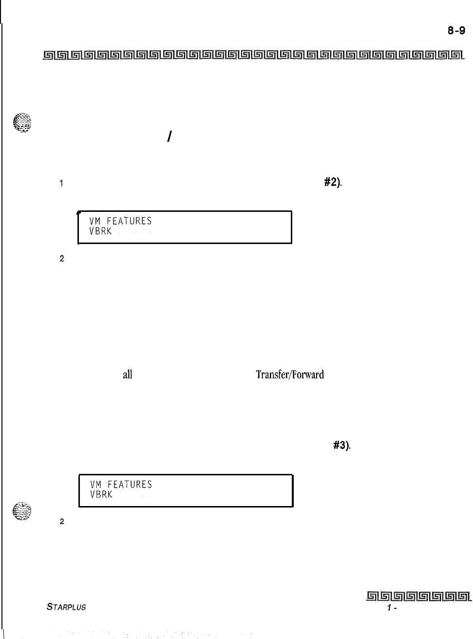
Voicemail Groups (VM)
Voicemail In-Band Features
the voicemail system (if programmed to ring only at one attendant station). Callers are presented to the main
greeting (not the attendant stations’ mail box) even when ID digits are enabled. By default, ID digits for
-.-.-
-~~~~~~
G
incoming CO calls is enabled.
y-.-
5
-
:ir
Voicemail Transfer
/
Forward
Programming Steps
1
Press the CALL FWD flexible button (FLASH 67. Button
#2).
The following message are
shown on the display phone.
.
;;R;EATURES
ICID AFWD
1
a
Press the button to Enable/Disable this feature.
LED Off = NO (Disabled)
LED On = YES (Enabled)
3
Press HOLD to save the entry. Confirmation tone is heard and the display now updates.
Description
This feature forwards voicemail calls, upon reaching a forwarded to VM station, back into the voicemail unit.
It is useful when VM ports are being used as both Auto Attendant and VM ports. This feature can be
enabled/disabled for all VM groups. By default, the VM TransferlForward feature is enabled.
Voicemail Broker
Programming Steps
1
Press the VM BROKER flexible button (FLASH 67, Button
#3).
The following message is
shown on the display phone.
;FR;EATURES ICID AFWD
2
Press the button to Enable/Disable this feature.
LED Off = NO (Disabled)
LED On = YES (Enabled)
3
Press HOLD to save the entry. Confirmation tone is heard and the display now updates.
STARPLUS Triad-S System Programming Manual Issue
I-
December 1998
I
8-10 Voicemail Groups (VM)
Voicemail Index Table
Description
This feature modifies the operation of voicemail ports when disabled. Broker operation is unavailable when
using supervised transfers to stations. If enabled, the current operation of broker mode during supervised
transfers remains in effect. This means that the call to the station remains as the second party in a broker
mode, If disabled, the VM port disconnects the call to a station and return to the original party. By default,
the VM Broker feature is enabled.
Voicemail Index Table
Programming Steps
To add Mailbox buttons, change Voicemail Groups, or Voicemail ID Numbers:
1
Press FLASH and dial
[68].
The following message is shown on the display:
MAILBOX TBL: XXX
VM GROUP: YYY VMID ZZZZ
2
The top left button in the flexible button field (FLASH 68, Button
#I)
is lit for
programming VM Group 1 (440).
To change VM Groups:
1
Enter the 3-digit VM Group number (440-447).
z
Press HOLD to save the entry. Confirmation tone is heard and the display now updates.
To change the VMID Number:
I
Press the
VMID
NUMBER flexible button (FLASH 68, Button
#2).
2
Enter the four-digit
VMID
Number which corresponds to 0000-9999. A value of 0000
disables this table entry. In this case, no VM digits is sent.
3
Press HOLD to save the entry. Confirmation tone is heard and the display now updates.
To advance to the next VM Index Number:
I
Press the NEXT flexible button (FLASH 68, Button
#18).
The Mailbox Table number
increments by 1.
To go to a previous VM Index Number:
1
Press the PREV flexible button (FLASH 68, Button
#19).
The Mailbox Table number
decrements by 1.
To change to a different VM Index Number:
Lssue
I-
December 4998
S
JARPLUS
Triad-S
System Progromming Manual
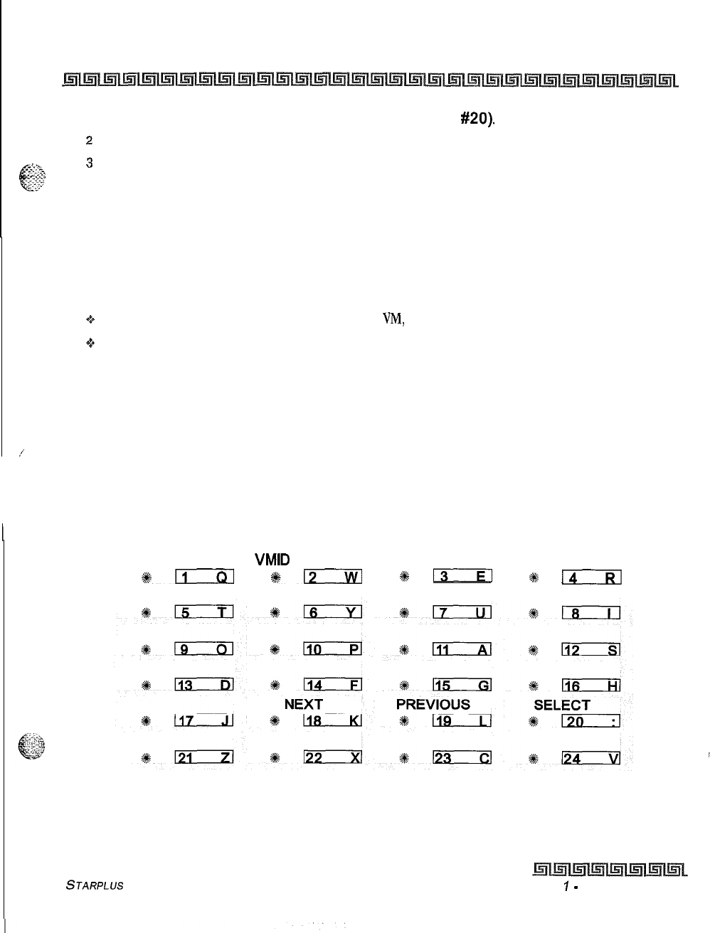
Voicemail Groups (VM)
Voicemail index Table
8-11
1
Press the SELECT flexible button (FLASH 68, Button
#20).
z
Enter a 3-digit Mailbox Table Number (001-255).
&g?+ 3
Press HOLD to save the entry. Confirmation tone is heard and the display now updates
p&
and shows the new Mailbox Table Number.
Description
This feature provides an attendant or station user a way to transfer a caller directly into a voicemail box.
Station identification digits can be entered by the transferring party. Using this feature, a caller can be
transferred to a voicemail box when:
*:a
a station user on the system is not forwarded to
VM,
or
ez.9
the destination voicemail box owner is not a station user.
CO trunks and internal calls may be transferred into voicemail using this feature. If no voicemail ID digits are
dialed by the transferring station, the ID digits of the transferring station are sent to voicemail.
,’
This feature permits dialing digits 0000-9999 when using the VM with ID feature. On a per station basis, the
ID number that is sent to voicemail can be flexible. By default, the station number is sent to the voicemail
system. In administrative programming, there is a field to insert from
O-4
digits (0000-9999) which can be
sent to the voicemail system in place of the station number. This is useful when a station user manually
transfers a caller to a mailbox. By default, no mailbox buttons are assigned at key stations.
VM GROUP
VMID
NUMBER
*m
%cm
2#
13
+%
14
STARPLUS Triad-S System Programming Manual Issue
I
-
December 1998

8-12
Voicemail Groups (VM)
Voicemail index Table
Issue
I
-
December 1998 STARPLUS Triad-S System Programming Manual
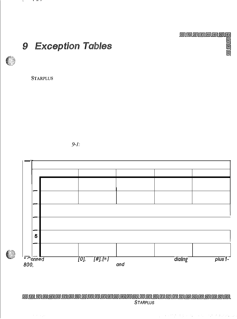
.
----
Exception Tables Programming
The
STARPLUS
Triad-S’”
Systems offer a flexible means of applying toll restriction to stations or
individuals. Dialing privileges (or toll restriction) is determined through assignment of station and CO line
Class Of Service (COS). Several types of restriction can be derived simply by programming COS assignments
and CO line access to stations. This may, in some cases, be all that is necessary. However, when a more
complex or specific type of restriction is desired the system offers two Allow and two Deny tables along with
four special tables. These tables can be programmed in a variety of ways to handle applications that are
straight forward or applications that require a more complex arrangement.
The Allow and Deny tables are assigned to stations based on their station Class of Service (COS) assignment.
The Station (COS) interacts with CO Line COS assignments to provide several different types of dialing
privileges. Rrefer to Table
9-l:
Class of Service.
-
S
T
A
T
I
0
N
C
0
S
r-
C
1
-
2
-
3
-
4
-
5
-
6
ii7
CO LINE CLASS OF SERVICE
1
2
345
Unrestricted Unrestricted Unrestricted Canned Unrestricted
Restricted*
Table A
Table
A
Unrestricted Canned Unrestricted
Restricted*
Table B Unrestricted Table B Canned Unrestricted
Restricted*
I
Table A&B Table A Table B Canned Unrestricted
Restricted*
I
Canned
Restricted* Canned
Restricted* Canned
Restricted* Canned Unrestricted
Restricted*
I
Intercom Intercom Intercom Intercom Intercom
Only Only Only Only Only
j
Restriction: No
[OJ
[I],
[#I,
[S]
as first dialed digit, and 7-digit
diuling
limitation;
plus
I-
fee
600,
1911, 1611
are allowed, und
411,
976, and
555 numbers
are
denied.
Table 9-l: Class of Service
Issue I- December 1998
STARPLUS
Triad-S System Programming Manual
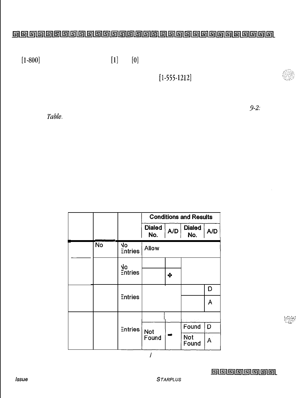
9-2 Exception Tables
Exception Tables Programming
The Allow and Deny tables enable entries of either general or specific allow and deny codes such as allowing
all [l-800] type calls, and/or denying all
[l]
+ or
[O]
+ calls. The Allow and Deny tables allow a maximum
of
8 digits to be entered as allow or deny digits. This enables entry of certain area codes or office codes that
can specifically be allowed or denied. For example, the code
[l-555-1212]
may be entered in the Deny
Table to deny local toll information calls. Each Allow Table contains 20 bins for entry of allow codes. Each
Deny Table contains 10 bins for entry of deny codes.
The following rules should be remembered when setting up the Allow/Deny tables. Refer to Table
$2:
Allow /Deny
Tddde.
1
If both tables (Allow and Deny) have no entries, no restriction is applied.
2
If entries are made in the Allow Table and only there, then only those numbers are
allowed. All other dialing is denied.
3
If entries are made in the Deny Table and only there, then only those numbers are
denied. All other dialing is allowed.
4
If there are entries in both Allow and Deny tables, the Allow Table is searched first, and
if a match is found, it is allowed. If a match is not found, the Deny Table is searched; if a
match is found, the call is denied. If the number does not match an entry in either table,
it is allowed.
I
RULE1
RULE2
RULE3
RULE4
Allow
Table
No
Entries
Entries
No
Entries
Entries
Table
DIaled
Deny
mi
Found A
\lO
Entries
Not
Found
’
Found
D
intries
Not
Found
A
Found 1 A
,
.
.
.
:..
.
7.
‘;-.’
I,_
:.-..:
_..
Table 9-2: Allow
/
Deny Table
issue
I- December 1998
STARPLUS Triad-S System Programming Manual
Exception Tables
RELATED ITEMS TO TOLL RESTRICTION
9-3
A special
Do
Not Care character
(D)
may be entered to allow or deny any digit dialed in that digit sequence.
The Triad-S system also offers four special tables (found in the Product Description Manual) that can be
T.
r’:,
e--
-.
::
referenced from within the two allow tables. Three of the special tables can be assigned to specific area codes
--:<;7
that require further toll restriction definition. The fourth Special Table is reserved for use as a home area
code table (numbers within the same area code as the site where the system is installed). This provides
expanded ability to apply toll restriction on numbers that are dialed within an area code. Each Special Table
allows up to 800 entries (200-999). This offers the ability to allow every office code on an individual basis.
RELATED ITEMS TO TOLL RESTRICTION
CO/PBX Lines
When CO lines are marked as PBX lines the system first checks the PBX code table for a valid match, If the
first digits dialed do not match the entries in the PBX code table the call is considered an attempt to call
another PBX extension and no toll restriction is applied. If the first digits dialed are found in the PBX code
table (FLASH
12),
toll restriction starts with the next dialed digit.
I
Forced Account Codes
The system can be programmed to force the use of account codes on all restricted calls. When forced account
codes are enabled an account code must be entered to place a call that is otherwise restricted through toll
restriction, By entering an account code, the station class of service becomes unrestricted,
When account codes are forced on a system wide basis selected users may be instructed on how to enter
account codes from any station and be allowed to dial unrestricted from a station that may otherwise be
restricted. Use of account codes in this manner, as a traveling class of service, is however, not controlled by
the system. Any station user with knowledge of how to enter account codes to override a stations toll
restriction can do so.
SLT DTMF Receivers
2-2
e
When single line telephones are connected to the Triad-S system and toll restriction is enabled, the DTMF
,...
3
s-27
receivers located in the system monitors the call for a programmed time period. While the DTMF receiver is
monitoring the digits being dialed by a single line telephone, it is considered busy and not available for
monitoring another SLT attempting to dial. When all DTMF receivers are busy, an SLT attempting to go
off-
hook does not receive dial tone until a receiver is available.
STARPLUS Triad-S System Programming Manual issue
I- December 1998
I
‘..
9-4
Exception Tables
Toll
Restriction
The Triad-S system allows up to 5 DTMF receivers for monitoring SLT dialing. If a system has heavy SLT
usage, then toll restriction may inhibit dialing by SLT stations. Two options are available to help alleviate
this problem:
+
Shorten the SLT receiver timer [FLASH
011
[Button
121.
This frees up DTMF receivers faster, but
may not provide the desired toll restriction for SLT stations.
+Enable LCR and force LCR on SLT stations.
When the LCR database is set up, the 3-digit table allows entry of the number of digits to expect. When a SLT
dials the appropriate number of digits, LCR releases the DTMF receiver and then be available for another
SLT call.
LCR Versus Toll Restriction
LCR is not an alternative to toll restriction nor is toll restriction an alternate to LCR. They work best when
programmed together. Toll restriction specifies station dialing privileges, and LCR provides call routing to
appropriate lines. LCR can enhance toll restriction by providing Store and Forward operation to analyze
digits being dialed before a trunk is seized. This prevents users from by-passing toll restriction by taking
advantage of the time required for a central office line to provide dial tone. LCR is recommended when toll
restriction is enabled.
Toll Restriction
Entering Toll Table
Programming Steps
If the system is in the programming mode, continue using the program codes. If starting to program here,
enter the programming mode.
I
Press FLASH and dial
[70].
The following message is shown on the display phone:
.
EX TABLES
ENTER BUTTON NUMBER
.
2
To program Allow/Deny tables, press the appropriate Table button and enter
information as outlined in the following procedures.
Issue I
-
December 1998 STARPLUS Triad-S System Programming Manual
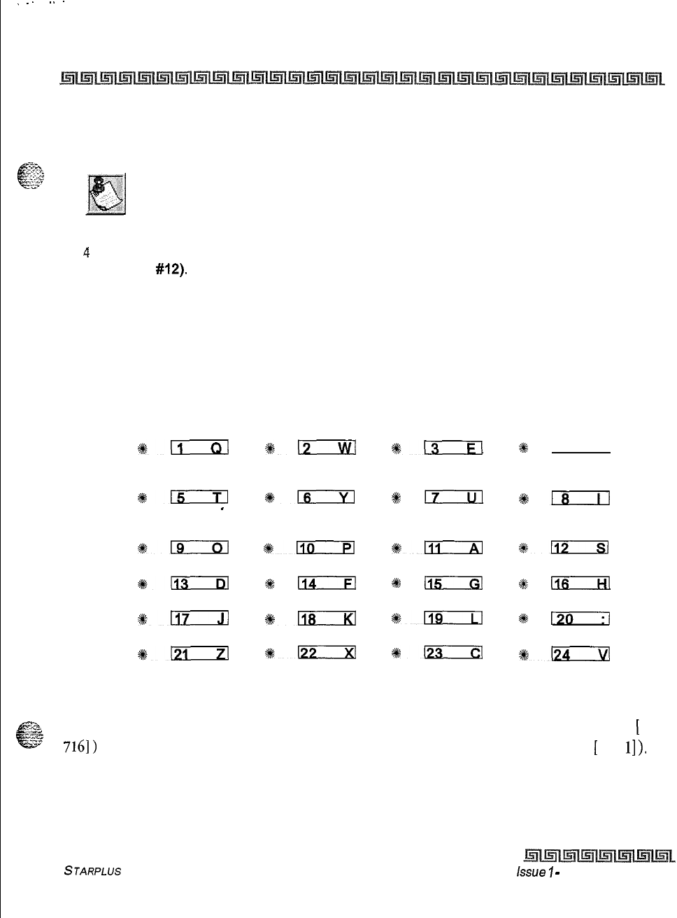
.
.
.
.
..-
Exception Tables
Toll Restriction
9-5
3
To program Special Tables l-3, it is necessary to associate an area code to the table.
This is done by pressing the appropriate AREA CODE TABLE button and assign the area
code.
Special Table 4 is reserved for the home area code and does not require
an area code entry.
4
To display entries in any of the tables, press the DISPLAY TABLES button (FLASH 70,
Button
#12).
Entries in the Allow/Deny tables display two at a time. Entries in the Special
tables display six at a time in ascending order.
Description
All
toll
tables
have been conveniently placed under one program code to allow entry of all toll restriction data.
The buttons on the digital terminal are defined as shown below when entering the Toll Restriction
programming area:
ALLOW TABLE A DENY TABLE A ALLOW TABLE B DENY TABLE B
s%n
*n
%m
#
(4
SPECIAL SPECIAL SPECIAL SPECIAL
TABLE 1
TABLE 2 TABLE 3 TABLE 4
%lxzm
%+n
s#
I7
#lxizil
AREA CODE
-
AREA CODE AREA CODE DISPLAY
TABLE 1
TABLE 2 TABLE 3 TABLES
119
#lliEzEl
~lli
%-
++s-
9ki;
#
In
%
riB--Rl
#a
2i%L!icxl
I119
$5
m--i-l
#k-
%k-
+E-
#lzlrxl
When the system searches the allow and deny tables, the entries are checked starting with Bin 01 and
proceeding sequentially through the table to the last bin. In addition the Allow Table is always searched
-2.
j*md.
e
‘?3
before looking at the Deny Table. Therefore, the entry order is important. Entries that are specific (e.g.,
[
1
7161) are placed ahead of entries that are more general (usually include Do Not Care digits; e.g.,
[
1 D
l]
).
Once a match is found in the Allow Table that references a Special Table, the number dialed are checked for
an allowed code in the Special Table. If a match is not found in the Special Table, the system continues to
STARPLUS Triad-S System Programming Manual issue
7
-
December 1998
9-6
Exception Tables
Toll Restriction
check for a match in the next Allow or Deny Table to check. The system does not return to the table that
sent the call to the Special Table.
Allow Table
Programming Steps
1
Press the ALLOW TABLE A or ALLOW TABLE B flexible button(FLASH 70, Button
#l
or
#3).
The following message is shown on the display telephone:
ALLOW TABLE A
01E
0'2E
The first two bin locations display.
2
Enter the 2-digit bin number (01-20) of the bin to be programmed.
It is recommended that:
+Bin
17
be reserved for an entry that references SPECIAL TABLE 1
o
Bin
18
be reserved for an entry that references SPECIAL TABLE ‘2
Q
Bin
19
be reserved for an entry that references SPECIAL TABLE
3
o
Bin 20 be reserved for an entry that references the Home Area Code Table, SPECIAL TABLE 4.
3
Enter the Allow Code.
Where:
[O-9],
[%I,
[#]
= Corresponding allow digits (numbers)
MUTE = Do Not Care digit (D)
TRANS = Search Special Table (S)
4
Press the HOLD button to save the entry. Confirmation tone is heard and the display
now updates.
5
When all entries for one table are complete, press the flexible button for the next table.
To erase a bin:
1
Enter the 2-digit bin number.
2
Press the HOLD button.
Description
Each Allow Table contains 20 bin numbers. Each bin number may be up to 8 digits, including Do Not Care
digits and Search Special Table commands. Entries into the Allow Table represent exceptions to numbers or
codes that are to be allowed only if they would otherwise be restricted by an entry in the Deny Table. For
Issue I
-
December 1998 STARPLUS Triad-S System Programming Manual
Exception Tables
Toll Restriction
example, if
[
1 555
1212]
is allowed but
[l
+I
numbers are denied, by an entry into the Deny Table,
[l
555
I2
121
is entered into the Allow Table as an allowed number.
+
Allow Table A is referenced and searched first (before Deny Table A) when Station COS is 2 and CO
Line COS is either 1 or 2.
oAllow Table B is referenced and looked at first (before Deny Table B) when Station COS is 3 and CO
Line COS is either 1 or 3.
e
When Station COS is 4 and CO Line COS is 1 both allow tables are looked at first (Allow Table A first,
then Allow Table
B)
then both deny tables (Deny Table A first, then Deny Table
B).
Do Not
Care
digits specify that the system should consider any digit dialed in that position as a match. Do
Not Care digits should not be entered as the last digit in an entry, as this would be an unnecessary or
meaningless command.
Search Special Table
commands must be entered in a specific manner and should always be the last
entries in the Allow Table. It is recommended that the last four bins (17-20) in the Allow Table be reserved
for referencing the four special tables with the reference to the home area code (Special Table 4) always
being located in bin number 20. Search Special table commands can only be entered into the allow tables.
The following rules apply when making entries that references the Special tables:
For entries referencing the first three special tables a specific area code must be
identified (one for each table needed). Then make note as to how the numbers are
dialed when dialing numbers to this area code (i.e., with a leading digit [I] or no leading
digit [I]
).
The entry into the Allow Table would be entered as follows:
Leading digit [I]: Enter:
[BB] [I] [XXX]
[DDDI
[Sl
or,
Non-Leading [I]: Enter
WI
[XXX1
PW
PI
Where:
BB = Bin Number (Bins 17-19)
XXX = Area Code (must match AREA-X entry)
DDD = Do Not Care digit (three entries, DND button)
[S] = Search Special Table Command
(TRANS button)
For an entry that references the Home Area Code table (Special Table 4) the entry may also be entered to
expect or not expect a leading digit
[l].
In fact, in some cases it may be desirable to enter both of the
following entries;
STARPLUS Triad-S
System Programming Manual Issue
I-
December 1998
I
I9-8
Exception Tables
Toll Restriction
Leading digit [I]: Enter
[BB] [I] [DDD] {S} and/or,
Non-Leading [I]: Enter
WI
PW
PI
Where:
BB = Bin number (Bin 20)
DDD = Do Not Care digit (three entries, MUTE button)
{S} = Search Special Table Command
(TRANS button)
If both leading digit [I] and non-leading digit
[I]
entries are made to
reference the same table, it is necessary to place the leading digit
[I]
entry
ahead of the non-leading digit
[I]
entry in the Allow Table.
Deny Table
Programming Steps
1
Press the DENY TABLE A or DENY TABLE B flexible button (FLASH 70, Button
#2
or
#4).
The following message is shown on the display phone:
KEY
TABLE
*
02E
The first two bin locations are displayed.
2
Enter the 2-digit bin number
(01-10)
of the bin to be programmed.
3
Enter the deny code:
Where:
[O-9],
[%I,
[ #] = Corresponding deny digits numbers)
MUTE = Do Not Care digit
4
Press the HOLD button to save the entry. Confirmation tone is heard and the display
now updates.
5
When all entries for one table are complete, press the flexible button for the next table.
To erase
a
bin:
I
Enter the 2-digit bin number
2
Press the HOLD button.
Issue I- December 1998
STARPLUS
Triad-S System Programming Manual
I
-.
..--.
Exception Tables
Toll Restriction
Description
Each Deny Table contains ten bin numbers. Each bin number may be up to eight-digits including {Do Not
4,
t:;-.:F.5
Care} digits. Entries in the Deny Table represent numbers or codes that are to be denied or restricted.
0:.
Common entries would be [I] for restricting all
[
1 +] type of calls. Exceptions to this restriction would be
entered into the Allow Table.
+
Deny Table A is referenced and searched only after the Allow Table A is checked when Station COS is
2 and CO Line COS is either 1 or 2.
+
Deny Table B is referenced and searched only after the Allow Table B is checked when Station
COS
is
3
and CO Line COS is either 1 or 3.
Q
When Station COS is 4 and CO Line COS is 1, both allow tables are looked at first (Allow Table A first,
then Allow Table
B)
then both deny tables (Deny Table A first, then Deny Table B).
Do Not
Care
digits specify that the system should consider any digit dialed in that position as a match. Do
Not Care digits should not be entered as the last digit in an entry.
Search Special Table
commands cannot be entered into the Deny tables.
Special Table
Programming Steps
To program a Special Table, it is first necessary to assign an area code to the table (except for the home area
code), To assign an area code to a Special Table:
1
Press the appropriate AREA CODE TABLE
(#I
to
#4)
flexible button(FLASH 70,
Buttons
#9
to
#Ill).
The following message is shown on the display phone:
I
SPECIAL TABLE 1
AC
I
2
Enter the 3-digit area code.
3
Press the HOLD button to save the entry. Confirmation tone is heard and the
display
now
updates.
To enter office codes into the Special Table:
STARPLUS Triad-S System Programming Manual Issue
I
-
December 1998
.
.
9-10
Exception Tables
Toll Restriction
1
Press the SPECIAL TABLE
(#I
to
#4)
flexible button
(FLASH 70, Buttons
#5
to
#8) that
corresponds to the area code programmed above. The following message is shown on
the display phone:
I
SPECIAL TABLE 1 AC XXX
I
Where:
XXX = Area Code
z
Enter the 3-digit office codes that are to be allowed followed by a [I] which means to
allow this code. To remove a code from the allow list enter the 3-digit office code
followed by a [0] which removes the code from the allow list.
XXX
[l]
= Allow Code
XXX [0] = Remove Code from the list.
Where:
XXX = An office code from 200 to 999.
3
Press HOLD after every code entered. Confirmation tone is heard and the display now
updates. Multiple codes may be entered in a row. The display updates showing the first
six codes in ascending order.
Description
The Special Tables provide greater flexibility in designing a toll plan for a particular site. Each Special Table
allows entry of up to 800
3-digit
office codes (200-999). Three of these tables must be assigned an area
code by which they are referenced. The fourth table is reserved for the home area code and requires no
area code entry. The special tables are referenced through entries in the allow tables. Four area codes,
including the home area code, can be referenced to these special tables for further definition. When a
Special Table is referenced, entries must be made in the Special Table specifying what office codes are
allowed.
Codes can be added to the allow list or removed from the list. When a Special Table is checked for a match
to a 3-digit code and not found, the system continues to search the next Allow/Deny Table to be checked.
The system does not return to the Allow Table which routed the call to the Special Table. By default, no
codes are on the allow list.
Issue I- December 7998
STARPLUS
Triad-S System Programming Manual
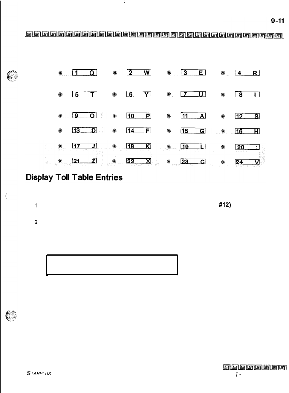
:
Exception Tables
Toll Restriction
ALLOW TABLE A DENY TABLE A ALLOW TABLE B DENY TABLE B
*n
%n
O13
*D
SPECIAL SPECIAL SPECIAL SPECIAL
TABLE 1
TABLE 2 TABLE 3 TABLE 4
#lzzTl
%n
117
2#
18
AREA CODE AREA CODE AREA CODE DISPLAY
TABLE 1
TABLE 2 TABLE 3 TABLES
~lIGIxl+k110
s%lli
+I$
113
lklixi3l1114
*lliKxl*116
Programming Steps
1
Press the DISPLAY TABLES flexible button (FLASH 70, Button
#12)
while entering
information into a table.
2
While viewing entries made into an Allow or Deny Table, two entries at a time are
displayed on the bottom line of the display. By pressing the DISPLAY TABLES button
again, the next higher bins displays. When the last entries are displayed, pressing the
DISPLAY TABLES button again shows the first two entries.
ALLOW TABLE A
01 XXXXXXXE 02 xxxxxxxx
t
Where:
X = Allow or Deny Code
E = End of Entry
STARPLUS Triad-S System Programming Manual Issue
I-
December 1998
9-12
Exception Tables
Toll Restriction
While viewing entries in a Special Table, six 3-digit codes allowed display in ascending order starting with
the lowest entry. By pressing the DISPLAY TABLES button again, the next
6
entries display. This continues
until all codes are displayed.
I
SPECIAL TABLE 1 AC XXX
YYY YYY YYY YYY YYY YYY
I
Where:
XXX= Area Code
YYY=
Allowed Office Code
Description
It is possible to view entries in the toll tables using the display on the Executive telephone. To view all
entries, the DISPLAY TABLES flexible button
(FLASH 70, Button
#12)
is pressed multiple times to scroll
through the entries.
It
is recommended to view all entries in the Allow and Deny Table before
leaving programming. Entries can be entered near the bottom of the list
for searching the special tables or entries made in error. Viewing the entire
Allow Table ensures proper entry and operation.
Issue I- December 1998
STARPLUS Triad-S System Programming Manual
Least Cost Routing (LCR) selects the most economical programmed route for an outgoing call, When a
station user dials an outside number, the LCR feature analyzes the number and then automatically chooses
an outside line from the group that has been programmed as most economical, The LCR feature puts the
responsibility of choosing the least expensive route for each area code and exchange code on the system
administrator, not on the station user. In order to make a routing decision, the LCR feature is programmed
in the system database. The successful operation of this feature is completely dependent on the accuracy of
the programming.
There are eight different tables which are set up to monitor the dialing of digits and to select the best route
for the call depending on time of day and day of week. These tables are:
*:.
,’
0
4.
r,
3-digit Area/Office Code Routing Table
6-digit Office Code Routing Table
Exception Table
Route List Table
Insert/Delete Table
Daily Start Time Table
Weekday (Weekly) Schedule
Toll Information Table
LCR Operation
The system first checks to see if the number dialed is more than two digits. If it is two digits or less, the call is
processed according to instructions in the Exception Table. If the number is not found in the Exception
Table, the call is denied. If the number is more than two digits, it goes to the 3-digit table, If the first digit
dialed is a 1 the Leading 1 table is checked with the following three digits. If the first digit dialed is not a 1,
then the first three digits are checked against the Non-Leading 1
3-digit
table. The first three digits (either
office code or area code) are then checked to see if they are in the 3-digit table. If they are not found there,
the call is not routed. If the digits are found in the 3-digit table, the system then checks for an entry to see if
the &digit table must be referenced.
Issue 1
-
December 1998 STARPLUS Triad-S System Programming Manual
IO-2
Least Cost Routing (LCR)
Introduction
If the 6-digit column is marked [yes] in the three digit table entry, the number is then checked in the
6-
digit table. There are twenty 6-digit tables. Each 6-digit table is programmed and becomes associated to a
specific area code with a selected route. Office codes are entered into the 6-digit
table
that is routed to a
specific route list table. This lets the system administrator split area codes for routing to different lines
connected to the system. This helps when Foreign Exchange lines (FX Lines), Banded WATS lines, or
Dedicated Lines
(OPXs
from another system) are in use.
If the office code is not found in the 6-digit table, the call is referred back to the s-digit table for selecting a
route list table. The office code then goes through the same procedures as described below.
Before actually selecting a route list table, the number is checked against the toll restriction
tables
(station
COS). When LCR is enabled, only station Class of Service is referenced. CO Line Class of Service is no longer
applicable. All CO lines are considered Class of Service 1. If the call is not allowed through the toll restriction
tables, the call is denied. If it is allowed, the call then goes to the Route List
table as
specified
by
either the
j-digit or
6-digit
table.
The time-of-day and day-of-week is determined and the call is presented to the corresponding time period
route within the specified route table. Each of the 16 Route tables contain four time-sensitive routes,
Routes are determined
by
the time-of-day and day-of-week as specified in the Daily Start Time table and the
Weekly Schedule table. After the appropriate route is selected, LCR Class of Service becomes applicable. A
station can use only those line groups programmed with a priority number equal to or higher than the
station’s LCR Class of Service.
If a line is not available in the first choice line group, the system advances to the next choice line group and
searches for a free line. This process continues until an available line is found, or the last available line
group is searched, or until a line group is reached with a priority assignment lower than the station’s LCR
Class of Service assignment. When a line is available the system seizes that line and waits for dial tone. Then
before dialing, the system checks the Insert/Delete table for digits that should
be
deleted from the front of
the number or digits that should be inserted either before or after the number dialed. Finally the system
begins to dial the number out over the selected line. All of this analyzing and manipulation of the number
takes only a fraction of a second from the time the station user begins to dial until the number is dialed out
over the public network lines.
If no lines are available in any of the CO line groups programmed for that route and allowed to that station,
f;
..:
‘.,
I~::;~:M
the call can be automatically queued on to the first choice (least costly) line group. If the user waits three
~
---’
seconds after dialing the number, they will hear confirmation tone which indicates that an automatic LCR
Queue Callback has been activated on the first choice line group. When a CO line becomes available in the
first choice line group the system will ring the calling station. When answered by the station the system will
automatically seize the line and redial the number.
Issue I
-
December 1998 STARPLUS Triad-S System Programming Manual
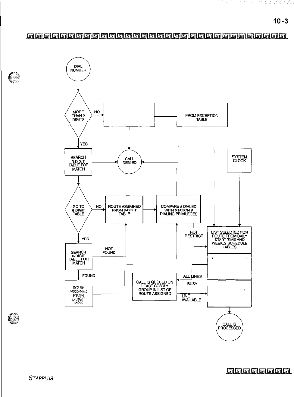
Least Cost Routing (LCR)
Introduction
SEARCH EXCEPTION
TABLE FOR MATCH FOUND
ROUTE ASSIGNED
.
FROM~A\~~PTION
NOT
FOUND
?3%%?
NOT
FOUND
RESTRICT
TA%~~~R
)
FOUND
CALL IS QUEUED ON
L--J
LEAST COSTLY
GROUP IN LIST OF
ROUTE ASSIGNED
CO LINE SELECTED
FROM FIRST
AVAILABLE TRUNK
GROUP IN LIST OF
ROUTE ASSIGNED
INSERT/DELETE
TABLE IS USED IF
ASSIGNED WITH
TRUNK GROUP
Figure 1 O-l: LCR Flowchart
STARPLUS
Triad-S System Programming Manual
issue I- December 1998
I
IO-4
Least Cost Routing (LCR)
LCR Tables
LCR Tables
Programming Steps
If
the system is in the programming mode, continue using the program codes. If starting to program here,
enter the programming mode. To program the system for Least Cost Routing:
_.,
;
‘.
_
._
,.i
/
. . . . . . . .
__
1
Press FLASH and dial
[75].
The following message is shown on the display phone:
LCR TABLES
ENTER BUTTON NUMBER
.
2
There are eight tables which can be programmed here for LCR (you must also program
LCR Class of Service in Station Programming). Use the procedures listed below to
program these LCR tables.
It is extremely important that the worksheets be completed before pro-
gramming the 1 CR tab/es.
Description
The Least Cost Routing
(LCR)
feature allows automatic selection of the most economical trunk according to
the number dialed and the time of the day and day of the week. There are eight different tables which are
set up to monitor the dialing of digits of a station and to select the best route programmed for the call.
These tables are:
+
3-digit Area/Office Code Routing Table
o
6-digit Office Code Routing Table
+
Exception Table
+Route List Table
o
Insert/Delete Table
+z+
Daily Start Time Table
Q
Weekday (Weekly) Schedule
9Toll Information Table
The buttons on the digital terminal are defined as shown
below
when entering the LCR Tables
Programming area:
Issue I
-
December 1998 STARPLUS Triad-S System Programming Manual
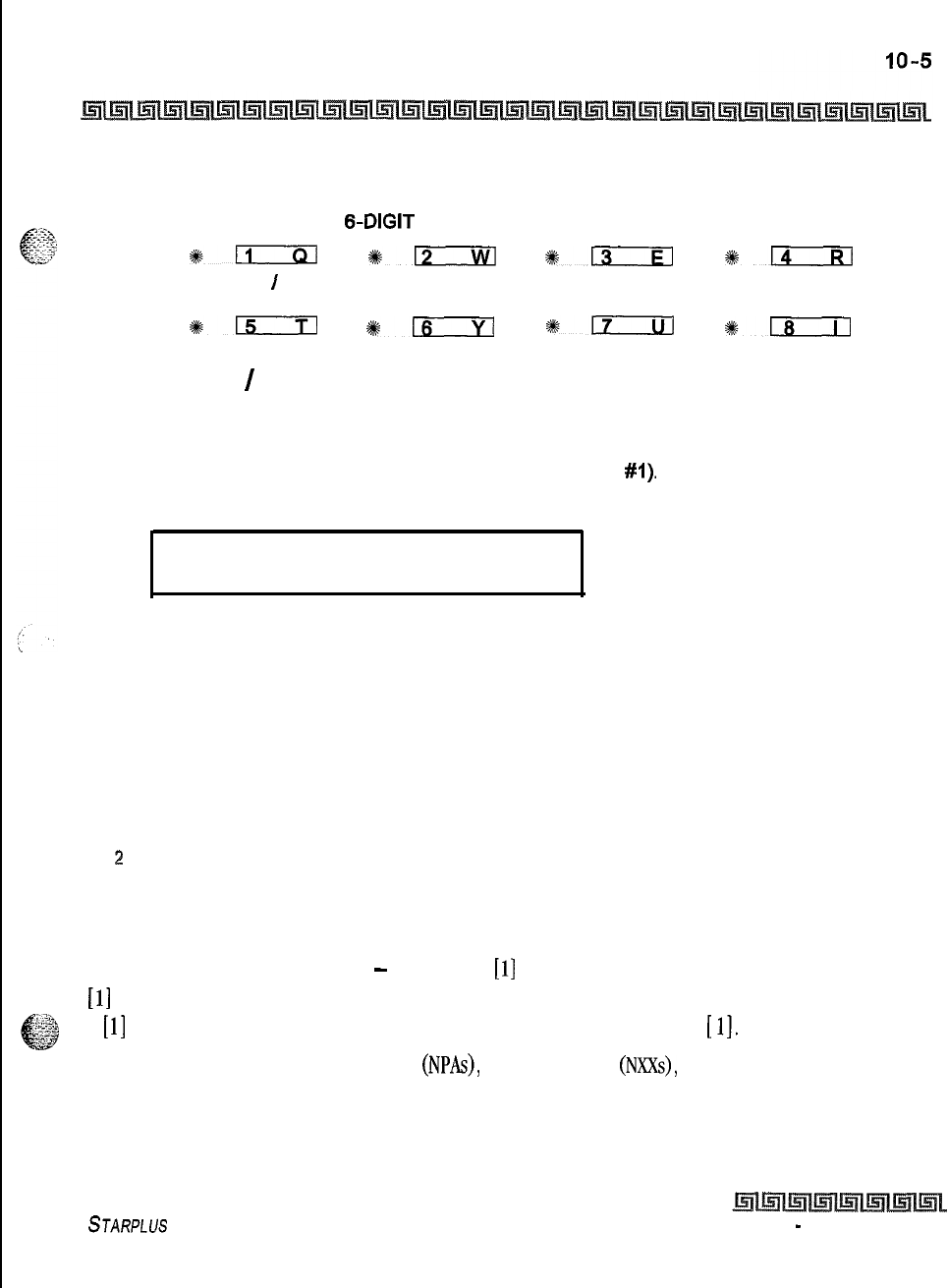
Least Cost Routing (LCR)
LCR Tables
3-DIGIT TABLE
&DIGIT
TABLE EXCEPTION ROUTE LIST
TABLES TABLE
#II
%s12
113
+#-
INSERT
I
DAILY TIME WEEKLY TIME TOLL
DELETE TABLE TABLE TABLE INFORMATION
%Ezrm
*m
%Ezul
%:-
3-Digit Area
/
Off ice Code Table
Programming Steps
1
Press 3-digit Table flexible button (FLASH 75, Button
#I).
The following message will be
shown on the display phone:
3 DIGIT ROUTING TABLE
ENTER L NNN RRY PP HOLD
Where:
L = [0] for Non-Leading 1 (1 not dialed)
[I] for Leading 1 (1 is dialed)
NNN = Area/Office Code
RR = Route List Number 00-15
Y = [0] do not go to 6-digit table
[I] go to 6-digit table
PP = Number of digits expected to be dialed.
:!
Press the HOLD button to save the entry. Confirmation tone is heard and the display will
now update.
Description
This table is divided into two sections
-
Leading
1
(a
[l]
is dialed before the number) and Non-Leading 1 (no
[I] is dialed before the number). This gives the system the ability to handle call routing in areas that require
a
[l]
before a long distance number, as well as in areas that do not require the
[
11,
Both of these tables include all area codes
(NPAs),
and office codes
(NXXs),
from 000 to 999, including such
numbers as 911,411, etc. A complete entry into these tables include a route list table to be used, if the 6-digit
table is to be checked and the number of digits likely to be dialed (Example: 7 or 10 digits). Ail local office
codes must be entered in this table even if they do not require long distance calling.
STARPLUS Triad-S System Programming Manual Issue 1
-
December 1998
IO-6
Least Cost Routing (LCR)
LCR Tables
The number of digits to expect entry will aid the system in identifying when the last digit is dialed and to
begin routing the call. This also helps to free SLT DTMF receivers if SLT traffic in the system is heavy. For
international calls, use 00 as number of digits to expect. This causes the system to wait five seconds (or
inter-digit time-out) after user dials last digit before the system accesses a CO Line and dials out.
6-Digit Office Code Table
Programming Steps
I
Press the 6-digit table flexible button
(FLASH
75, Button
#2).
The following message is
shown on the display phone:
4
6 DIGIT ROUTING TABLE
ENTER S AAA RR NNN HOLD
t
Where:
S = [0] to remove codes, [I] to add codes
AAA = Area Code
RR = Route Number 00-15
NNN = Office Code
2
Press the HOLD button to save the entry. Confirmation tone is heard and the display will
now update.
3
Enter additional office codes to be programmed into the same Area Code/ Route
Table, pressing HOLD after each office code entry.
4
Press a flexible button to program a different table.
To delete all entries in an Area Code/Route Table:
IEnter [0 AAA RR
###I
Description
This table determines a route for one or a group of individual office codes within an area code. Certain
office codes within an area code can be given unique or special routing. If the office code dialed is not found
in the 6-digit Office Code Table, the call is then routed according to the route list table as was entered in the
3-digit table.
The system allows twenty 6-digit Area/Office code tables that may be used to route specific office codes
within an area code. Each table will route calls for a common area code to a specified route. All entries
_
I’
,/
.;.y:‘.,;
,l;
--.:
Issue 1
-
December 1998 STARPLUS Triad-S System Programming Manual
Least Cost Routing (LCR)
LCR Tables
IO-7
made to a table route those office codes to the specified route list table, An area code may be entered into
more than one 6-digit table with different routes specified.
..:.A
8
:.:;$
Exception Code Table
Programming Steps
IPress EXCEPTION TABLES flexible button (FLASH 75, Button
#3).
The following
message will be shown on the display phone:
EXCEPTION CODE TABLE
ENTER S XX RR HOLD
.
Where:
S = [0] to remove code from table,
[I] to add code to table
XX = Exception codes for single digit codes, press MUTE button as 2nd digit. The
[a]
may be entered as the 1st digit only.
RR = Route Table Number 00-15
2
Press the HOLD button to save the entry. Confirmation tone is heard and the display will
now update.
3
Press FLASH 75, Button
#3
again for further entries. Up to 20 Exception Codes may be
programmed in this table.
Description
This table is used for operator calls and any other calls which would use a one-digit or
two-digit
entry, rather
than a three-digit area code.
Route List Table
Programming Steps
1
Press the ROUTE LIST TABLE flexible button (FLASH
75,
Button
#4).
The following
message will be shown on the display phone:
ROUTE LIST TABLE
RR T G DD L
STARPLUS
Triad-S System Programming Manual
Issue I- December 1998
IO-8
Least Cost Routing (LCR)
LCR Tables
Where:
RR = Route List Table Number 00-15
T = Time Period Route List l-4
G = CO Line Group l-7
DD = Insert/Delete Table reference 00-19 (## for none)
L = LCR Class of Service (LCOS)
z
Press the HOLD button to save the entry. Confirmation tone is heard and the display will
now update.
3
To enter additional CO Line groups in the same time period route list number,
Dial:
[G] [DD] [L] [HOLD]
To enter data for a different time period route list:
IPress program FLASH 75, Button
#4
and enter all data (RR T G DD L).
2
Repeat the above to program a new Route Number 00 to 15 or press a flexible button
to program other LCR information.
To use the scroll method, use Button
#
18 to advance to the next entry or use Button #
19
to return to a
previous entry.
The following message displays when the
Call
Cost feature is enabled in
FLASH 05, Button
#I
1,
ROUTE LIST TABLE
RR T CCC G DD L
Where:
RR = Route List Table Number 00-15
T = Time Period Route List l-4
CCC = Cost for one minute ($ O.OO-$9.99)
G = CO Line Group 1-7
DD = Insert/Delete Table reference 00-19 (## for none)
L = LCR Class of Service (LCOS)
Description
Up to
16
different Route List
tables
can be programmed. Each route list table contains four time period
routing lists, one for each of the available (four) daily start time periods. Within each time period route list
up to seven CO (outside) line groups and their corresponding Insert/Delete table, if any, and
LCR
class of
service priority are programmed on a per line group basis.
/
:
:..
.
.
\_
-.
. .:
. .
,‘:
‘,
:
,~,.,-I’.‘:
t,;
.z,.
.._
~
\A.%’
Issue I
-
December 1998 STARPLUS Triad-S System Programming Manual
Least Cost Routing (LCR)
LCR Tables
IO-9
When routing a CO call through LCR, CO Line groups are accessed in sequence so that the first line group
entered represents the least costly (and first selected) and the last line group entered represents the most
:
*,,
,.,,,‘,
~
e?
costly (and last selected).
+* The Route List table references many other tables when processing a call for routing. First of all, the Daily
start time table is referenced to determined what start time entry should be checked in the weekly schedule
table. The corresponding entry in the weekly schedule table depending on the day of the week then
determines which Time Period Route list should be used within the Route List table.
The system then begins to check for idle lines in the first entered CO line group and will proceed until an idle
line is found. While it is searching for an idle CO line the Station LCR COS is checked against the entries for
LCR COS Priority of the specific CO line groups (see LCR COS Priority explanation below). Once an idle CO
Line is found with a LCR priority equal to or higher than the stations LCR COS, then a final check is made to
determine if an Insert/Delete table should be referenced. Once all of the tables and entries are checked the
system then processes the call on the outside CO line.
Make sure you made entries into all Time Period Route Lists referenced
in the weekly schedule table.
LCR COS Priority
-
A station should be assigned a class of service for LCR. The LCR COS can be between 0
and 6, with 0 being unrestricted and 6 being the most restrictive. Within the time period route List table, line
groups are given an LCR COS Priority assignment between 0 and 6. A station using LCR will be able to use
only those CO (outside) line groups with a priority assignment of equal or higher value than the station’s LCR
Class of Service (Le., a station with LCOS 3 can use line groups with a priority between 3 and 6).
STARPLUS
Triad-S System Programming Manual issue
7
-
December 1998
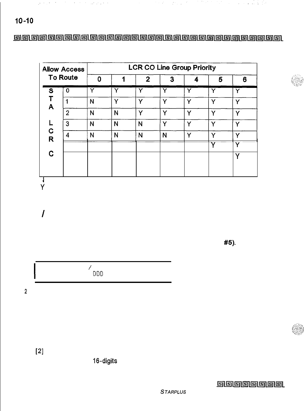
Least Cost Routing (LCR)
LCR Tables
5
NNNNN
Y Y
c
6 NNNNNN
Y
0
S
J
= Cannot Use Line Group
Y
= Has Access to Line Group
Table 1 O-l: LCR Class of Service Table
Insert
/
Delete Table
Programming Steps
1
Press INSERT/DELETE TABLE flexible button (FLASH 75, Button
#5).
The following
message will be shown on the display phone:
I
DIGIT INSERT
/
DELETE
ENTER TT X
DDD
HOLD I
z
Enter the table information as follows:
Where:
T T = Insert/Delete Table Number 00-19
X = [0] Pre-Delete numbers (first digits dialed in the number)
or
[I] Pre-Insert numbers (insert digits in front of number dialed,
or
[2]
Post-Insert numbers (insert digits behind number dialed)
DDD = Digits (up to
16-digits
may be deleted from the beginning of the number dialed
and up to 40 digits can be inserted (20 pre- and 20 post).
Issue I- December 1998
STARPLUS
Triad-S System Programming Manual
Least Cost Routing (LCR)
LCR Tables
IO-II
3
Press the HOLD button to save the entry. Confirmation tone is heard and the display
updates.
To add and delete numbers in the same table, enter the different Insertion/Deletion tables in step 1, and
enter
as
separate entries using the same table number. In the Insert Tables for LCR programming:
1
Press the TRANS button for a pause.
The
[a]
and
[#]
digits are allowed as valid digits for inserting digits dialed over the
network.
The
[%I
and
[#]
are valid entries for adding digits in both the pre (in front of) or post
(behind the number) tables.
The
[%]
and
[#]
cannot be used as delete characters in the Delete tables.
To delete a table:
I
Enter the table number followed by the HOLD button.
Description
Digits can be either added or deleted when dialing a number. For instance, if a user dials a long distance call
that should be placed on a foreign exchange (FX) line, the digit
[
11
and the three-digit area code
(NPA)
dialed
by the user must be deleted before the call can be placed on that FX line. An Insert/Delete table can be
programmed to do this. Digits can also be added to a number that has been dialed by the user. For instance,
Other Common Carrier
(OCC)
access codes and authorization (ID) codes can be automatically inserted by
the system either in front of, and/or behind the number dialed.
There are twenty Insert/Delete tables and each allows entries in a delete table and a pre- and post insert
table. Up to 40 digits (including pauses) can be inserted (20 pre and 20 post) and up to
16
digits can be
deleted. Digits can be inserted before or after the number dialed, but can be deleted only from the start of the
number dialed.
To ensure that a pause is inserted in LCR at default, the database programming was changed to add a pause
in each of the 20 LCR Insert and Delete tables and insert table 0 in each of the route tables,
STARPLUS
Triad-S System Programming Manual
Issue I- December 1998
Least Cost Routing (LCR)
LCR Tables
Daily Start Time Table
Programming Steps
1
Press the DAILY START flexible button (FLASH 75, Button
#6).
The following
message displays on the phone:
DAILY START TIME TABLE
HHMM HHMM HHMM HHMM HOLD
2
Enter times in military format (2400 hours) in succession.
3
Press the HOLD button to save the entry. Confirmation tone is heard and the display
updates.
Default times are 0800,
1700,230O
(8
AM, 5 PM, and 11 PM), and the fourth time is disabled
(####).
To change a Start Time, all times must be re-entered. Four pounds
[####I
are displayed if nothing is
entered for a specific time.
Description
The Daily Start Time table correlates the LCR routing table to the time sensitive discount structure offered
by the customers carrier.
Example:
In the most common situation, the most expensive rate period is between 8:00 am and 5:00 pm,
often called the day rate. The first discount period usually starts at 5:00 pm and runs until 11:00 pm,
often called Evening Rates. The remaining time (from 11:00 pm until 8:00 am) in this example is
referred to as night time rates which usually have the biggest discount.
With the wide selection of Common Carriers, the least costly route for a particular area code may be
different at different times of the day. To accommodate this situation, this table and the Weekly Schedule
table work together, dividing the day into four possible time periods. By default these tables are set at the
standard divisions of
8AM,
5PM,
and
1lPM.
However, these times can be changed.
Entries in the Daily Start Time table are used to select the time period to reference in the weekly schedule.
Based on the time a call is placed, the daily start time table selects the time period to choose in the weekly
schedule. The weekly schedule is then used to determine the time period route list in the Route List table to
use for routing the call for a particular day of the
week.
Times are entered in the 24 hour format.
Issue
1
-
December 7998 STARPLUS Triad-S System Programming Manual
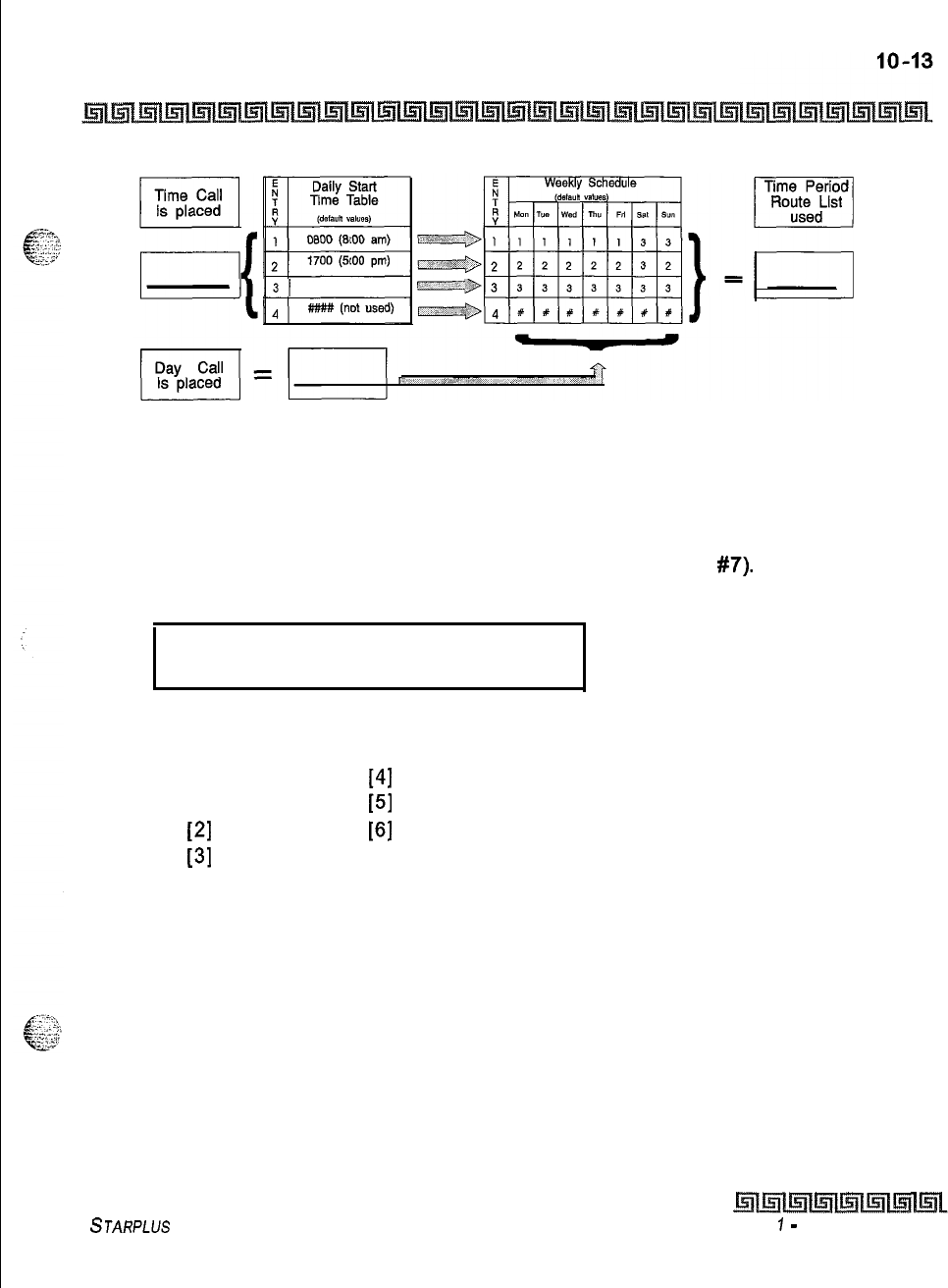
Least Cost Routing (LCR)
LCR Tables
2300 (11100
pm)
Figure 1 O-2: Daily Start Time and Weekly Schedule Tables
Weekly Schedule Table
Programming Steps
1
Press the WEEKLY SCHED flexible button (FLASH 75. Button
#7).
The following
message displays on the phone:
WEEKLY SCHEDULE TABLE
ENTER D T T T T HOLD
.
.
Where:
D = Day of the Week:
[0] = Monday
[4]
= Friday
[I] = Tuesday
[5]
= Saturday
[2]
= Wednesday
[6]
= Sunday
[3]
= Thursday
T = Time Period Route List (l-4) to use for the time-of-day (based on the Daily Start
Time table). Enter values for all time periods specified in the Daily Start Time table for
that day.
First T = Time Period Route List for the FIRST Daily Start Time (applies to all Route List
tables).
Second T = Time Period Route List for the SECOND Daily Start Time (applies to all
Route List tables).
Third T = Time Period Route List for the THIRD Daily Start Time (applies to all Route List
tables).
Fourth T = Time Period Route List for the FOURTH Daily Start Time (applies to all Route
List tables).
STARPLUS Triad-S System Programming Manual Issue
7
-
December 1998
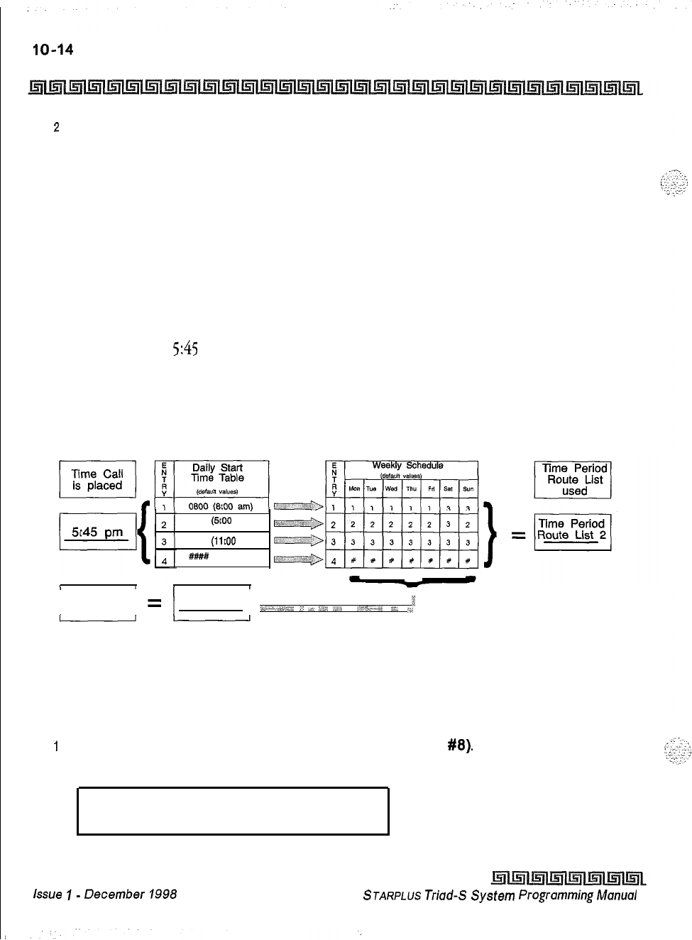
Least Cost Routing (LCR)
LCR Tables
2
Press the HOLD button after each complete daily entry. Confirmation tone is heard and
the display updates.
Description
The weekly schedule table determines what Time Period Route list to use within the Route List table. When
a call is placed and ultimately sent to a route list (call is not denied) based on the time of day the call is
placed, the Daily Start Time table selects the time period to reference in the weekly schedule table. The time
period route entered for the specified time period, as determined in the Daily Start Time table and based on
the day of week, is then selected and the call will be routed according to the specified time period route list.
Example:
If a call is placed at
5:45
pm on a Monday, then according to the Daily Start Time table (using default
values) the entry for time period two of the weekly schedule is checked. Because it is Monday the
entry for time period two on Monday is used and the result is that the Time Period Route List number
two (again using default values) will be used for all routes. Thus, the call is routed according to the
entries in Time Period Two route list no matter what route (00-15) is selected.
1700
(5~00
pm)
2300
(11100
pm)
##I#
(not used)
Day Call
is placed
I
I
=
Monday
5,
rr,*‘.,*e+;/
_,
_*,
!,.W
,r*^ .“%,,#P
I-d_
i,
Figure 10-3: Daily and Weekly Start Time Table
LCR Routing for Toll Information
Programming Steps
I
Press the TOLL INFO flexible button (FLASH 75, Button
#8).
The following message
displays on the phone:
LCR ROUTE FOR 555-1212
ENTER ROUTE
Issue
I-
December
1998 STARPLUS
Triad-S
System
Programming
Manual
::
Least Cost Routing (LCR)
LCR Tables
IO-15
a
Enter the two-digit Route List number (00-15) for the Route to be referenced in the
Route List table.
3
Press the HOLD button after programming the Route number. Confirmation tone is heard
and the display will now update.
4
Enable LCR at this point.
Description
This feature adds provisions to the LCR call processing which will allow common call routing for all toll
information calls.
I-(XXX)
555-1212, (K@
555-1212,1-555-1212
and 555-1212 calls will all be intercepted
and sent to a selected route in the Route List table. Numbers dialed will be integrated and if it is determined
to be a toll information call, either preceded with an area code or without or with a leading digit 1 or not, the
call will be sent to the route designated in programming. By default, Toll Information Calls will be sent to
Route List table zero (0) which will allow toll information calls to be placed on the system at default.
A Toll
Information route is chosen over a j-digit or 6-digit route assignment if both are assigned.
Entering the pound key twice
[##I
denies all Toll Information calls.
Def auk LCR Database
Programming Steps
In an effort to decrease installation and set up time usually associated with LCR, a default LCR database was
incorporated.
Description
The default LCR database provides basic routing for local and long distance dialing. Default entries have been
made in the 3-digit table for local office codes
(NNXS)
and all area codes
(NPAs).
Six routes have been
established with the default database for routing of all calls under default.
STARPLUS Triad-S System Programming Manual
Issue I- December 1998
IIO-16
Least Cost Routing (LCR)
LCR Tables
Issue 1
-
December 1998
STARPLUS
Triad-S System Programming Manual
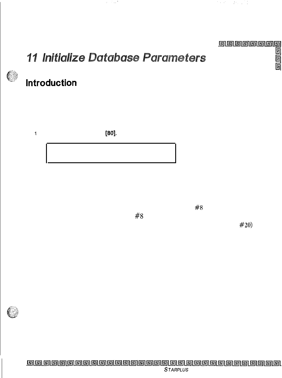
Programming Steps
If the system is in the programming mode, continue using the program codes. If starting to program here,
enter the programming mode. If Database Parameters must be initialized:
1
Press FLASH and dial
[80].
The following message displays on a display phone:
INITIALIZE DATABASE
ENTER BUTTON NUMBER
.
Description
This section describes the procedures and steps necessary to initialize the system database, returning any
programmed data to its original or default value. This section lets portions of the database be initialized
individually. This initialization occurs regardless of the position of switch
#8
on the MPB. The only way to
initialize the entire database is to move switch
#8
on the MPB board to the ON position and reset or power
off/on the system. In addition to initialization of the entire database, a System Reset (button #20) command
is also included in this section for clearing meantime errors without initializing the database,
The buttons on the key telephone are defined as shown below when entering the Initialize Database
Parameters programming area:
Issue I- December 1998
STARPLUS
Triad-S System Programming Manual
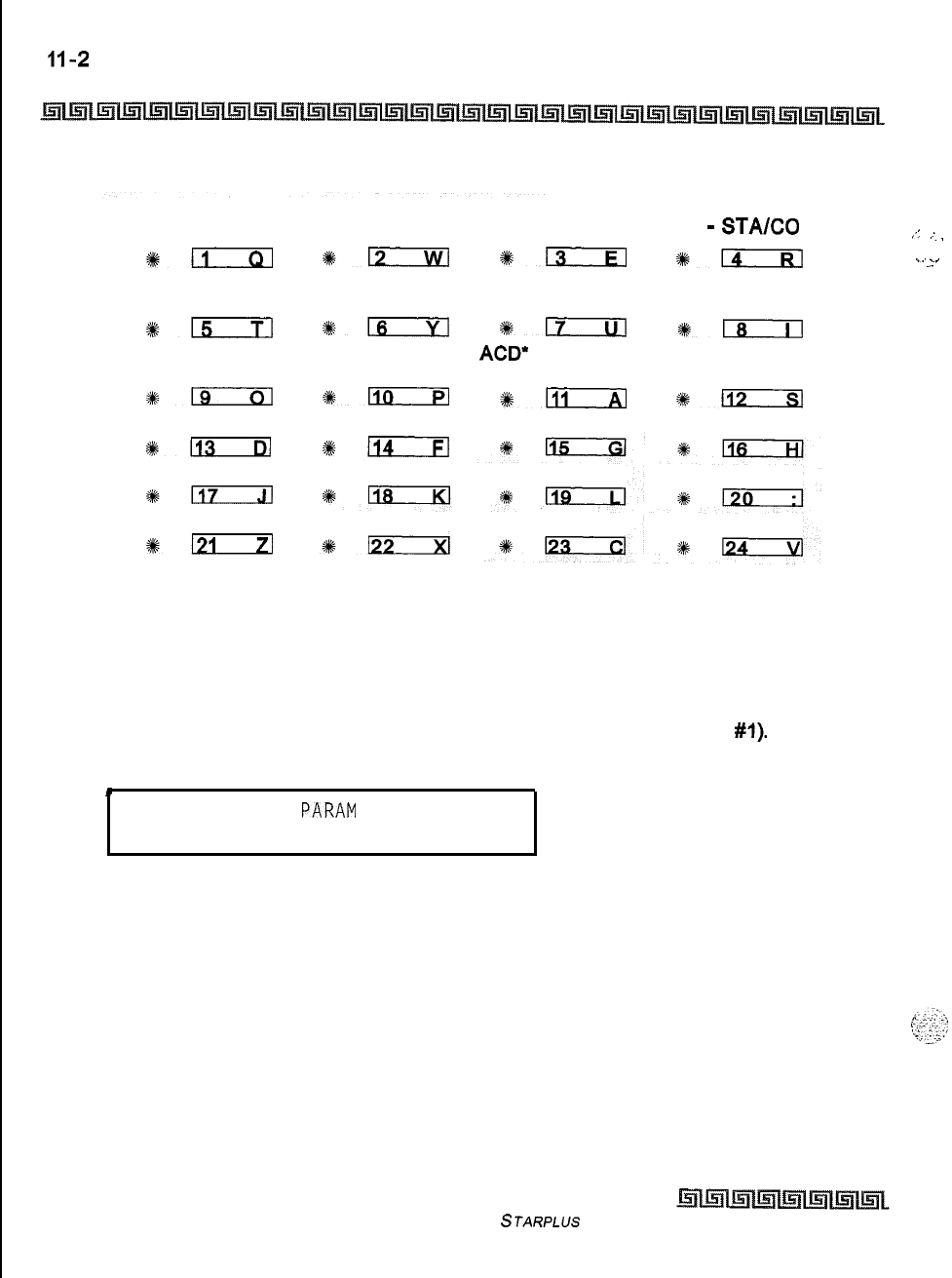
Initialize Database Parameters
Introduction
SYSTEM
PARAMETERS
4k;:
EXCEPTION
TABLES
#15
DIRECTORY
DIAL TABLE
slg
1113
*117
6121
CO LINE
ATTRIBUTES
*lzia
SYSTEM SPEED
NUMBERS
#Is
HUNT GROUPS
s#-
ACCT CODES
%+114
STATION
ATTRIBUTES PORT
-
STA/CO
*EcIEl
+%D
LCR TABLES
ICLID-DID
TABLES
gm
*LEil
ACD*
OR UCD VOICEMAIL
GROUPS GROUPS
%a
%112
Initialize System Parameters
Programming Steps
1
Press the SYSTEM PARAMETERS flexible button (FLASH 80, button
#l).
The
following message displays on the phone:
.
INITIALIZE SYS
PARAM
PRESS HOLD
.
2
To initialize the System Parameters, press the HOLD button. Confirmation tone is
heard.
Description
The system parameters may be initialized setting all data fields to their original, default values. The
following data fields are returned to their default values upon initializing the System Parameters.
Issue I- December 1998
STARPLUS Triad-S System Programming Manual
;:
I
.
..l.
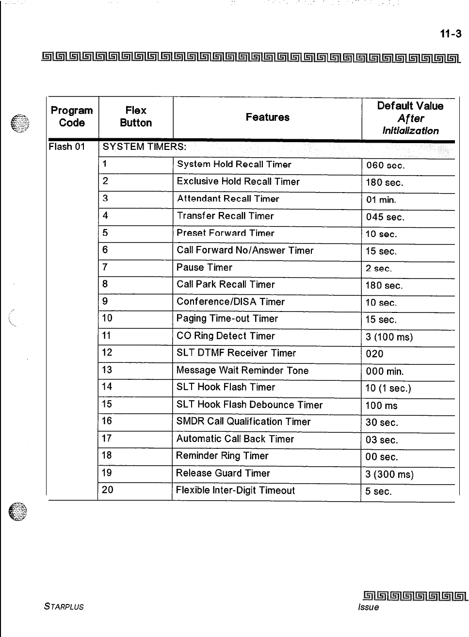
Initialize Database Parameters
Introduction
Table 1 l-l: System Parameter Defaults
STARPLUS Triad-S System Programming Manual issue
I- December 1998
Initialize Database Parameters
Introduction
Program
Code
-lash
02
-lash
02
-lash
05
T
Flex
Button Features Def auk Value
After
Initlallza tion
ADDITIONAL SYSTEM TIMERS
1
Repeat Redial Timer
2
Attendant Display Timer
3
Call Coverage Ring Timer
4
Modem Answer T
/
0
5
Pulse Dial Inter-Digit Timer
60 sec.
1 sec.
5 sec.
25 sec.
300 ms
6
Programmable DTMF Time Operation
1 OOms on/l OOms
off
I
SYSTEM FEATURES 1
1
Attendant Override 1 Disabled
2
Hold Preference
3
External Night Ring
4
Executive Override Warning Tone
5
Page Warning Tone
6
Background Music Channel
7
Least Cost Routing
8
Account Codes
-
Forced
9
Group Listening
10
Idle Speaker Mode
11
Call Cost Display Feature
System
Disabled
Enabled
Enabled
Enabled
Disabled
Disabled
Disabled
Disabled
Disabled
12
I
Music-On-Hold
(
Enabled
I
13
I
Call Qualifier Tone Option Disabled
Table 11-1: System Parameter Defaults
Issue
7
-
December 7998
STARPLUS
Triad-S
System Programming Manual
Initialize Database Parameters
Introduction
Program
Code
-lash
06
Flex
Button Features
SYSTEMFEATURES
1
Privacy Release Tone Option
2
Distinctive CO Ringing
3
Verified Account Codes
Default Value
After
lnltializa tion
Enabled
Enabled
Disabled
4
1 Call Forward Display 1 Enabled
5
(
External Day Ring I
Disabled
I
6
Overflow Station Forward
Disabled
7
Direct Transfer Mode Enabled
I I
a
)
Station ID Lock
)
Disabled
9
LCR Call Progress Enabled
10
One-Touch Recording Warning Tone Enabled
11
12
Ringback
on Transfer
Disabled
Table II-I: System Parameter Defaults
STARPLUS
Triad-S System Programming Manual issue
I- December 1998
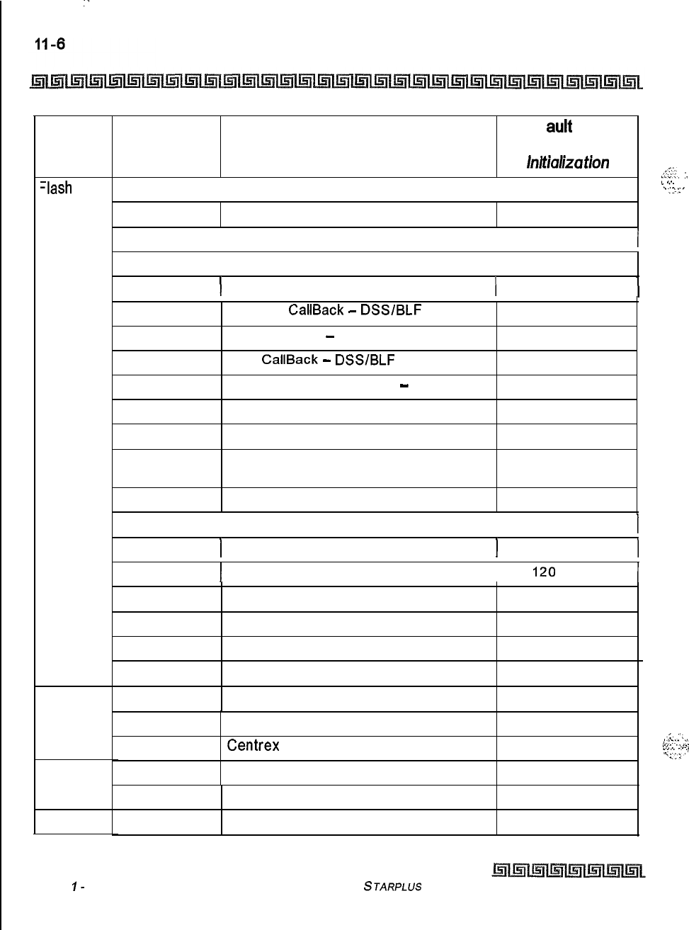
Initialize Database Parameters
Introduction
Program
Code
-lash
07
Flash 09
Flash 10
Flex
Button
FLASH RATES
Features Def auk Value
After
hi
tJaliza t/on
,t.?;‘;.
..“..
:.
, . .
. . .
L
,...
. .
‘.
.:
I’:
’
1
Incoming CO Line Ringing Red 480 ipm flutter
2
1 Incoming Intercom Ringing 1 Red 120 ipm flutter 1
3
Call Forward Button 1 Red Steady On
4
I
Message Wait/VM Button
)
Red Steady On
5
6
7
8
9
10
11
12
Message
CallBack
-
DSS/BLF
Red 120 ipm flutter
Do Not Disturb
-
DSS/BLF Red 60 ipm flash
Auto
CallBack
-
DSS/BLF
Red 120 ipm flash
UCD Available/Unavailable
-
DSS/BLF Red 60 ipm flash
Transfer CO Ringing Red 120 ipm flash
Recall CO Ringing Red 480 ipm flutter
Queued CO Ringing Green 480 ipm
flutter
Exclusive Hold Green 120 ipm flash
13
I System Hold I Red 60 ipm dbl wink
I
14
)
In Use Hold (I-Hold)
I
Green 60 ipm flash
)
15
I
Camp-On Button I Red
120
ipm flash
I
16
Call Back Button Red 120 ipm flash
17
Line Queue Button Red 480 ipm flutter
18
Do Not Disturb Button Red Steady On
19
Intercom Hold Button Red 15 ipm flash
l-7
1I
Leading Digit l-7 None
8
Leading Digit Option Disabled
9
Centrex
Digit Length 4 digits
10
Four Digit Voice Mail ID 3 digits
,<.
.‘\
,-i-2:.
.A
,-.
. .
..=,
:‘<.I
:.:
.,
%::I’
13-18 MOH Assignments
Attendant Station Assignment
Table II-I: System Parameter Defaults
None
STA 100
Issue
I-
December 1998 STARPLUS Triad-S System Programming Manual
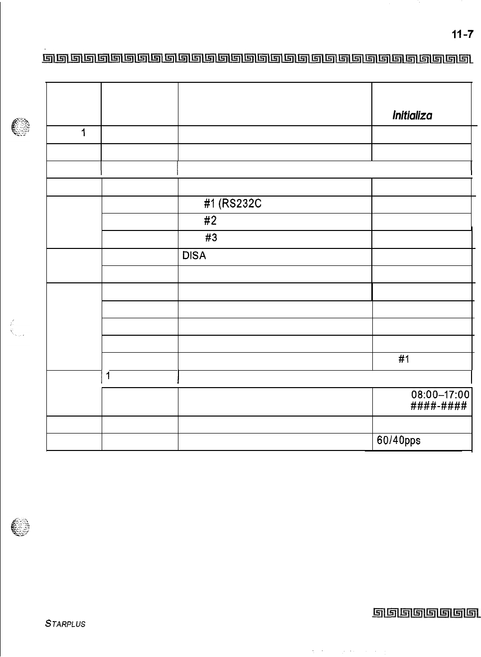
Initialize Database Parameters
Introduction
Program
Code Flex
Button Features Default Value
After
Initial~za tion
Flash 1
I
Flash 12
l-4 System Time And Date
PBX Dialing Codes
12 HR MMIDDIYY
None
Flash 13
(
l-4 1 Executive/Secretary Pairs ( None
Flash 14
l-2 On Board Relay None
Flash 15
1
Port
#I
(RS232C
MISU) 9600
Baud
2
Port
#2
(RS232 MISU) 9600
Baud
3
Port
#3
(Modem) 9600 Baud
Flash
20
1
DISA
Access Code 100
2
Database Admin Password 3226
Flash
21
1
SMDR Enable/Disable
Disabled
2
Long Distance/Local Assignment
3
Character Print Assignment8
4
Baud Rate
Display
5
SMDR Port Assignments
LD
80
9600
Port
#I
Flash 22
II
)
Automatic/Manual Operation 1 Manual
2-8
Flash 23
l-4
Flash 41 1
Day of Week Programming
Directory Dialing Table
Dial Pulse Parameters
(O-4)
08:00-17:00
(5-6)
####-####
None
6014Opps
Table II-I: System Parameter Defaults
STARPLUS
Triad-S System Programming Manual
issue I- December 1998
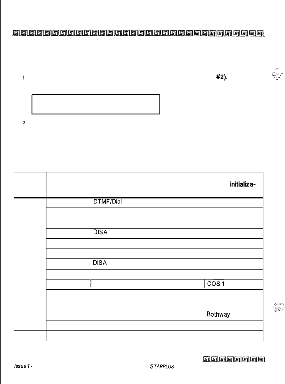
11-8
Initialize Database Parameters
Introduction
Initialize CO Line Attributes
Programming Steps
_-.
i
Press the CO LINE ATTRIBUTES flexible button
(FLASH 80,
button
#2).
The following
.cy_.
.:
,..,
.
_
!
. .
..Tz
message displays on the phone:
INITIALIZE CO LINES
PRESS HOLD
.
z
To initialize the CO Line Attributes, press the HOLD button. Confirmation tone is heard.
Description
The CO Line parameters may be initialized setting all data fields to their original, default values. The
following data fields are returned to their default value upon initializing the CO Line Attributes,
Program
Code
Flex
Button
Features Default Value
(after
initiallza-
tion)
Flash 40 1
Page A 2
3
4
5
6
7
8
DTMF/Dial
Pulse Programming
CO/PBX Programming
UNA Programming
DISA
Trunk-to-Trunk (Per CO Line)
Privacy
Loop Supervision Programming
DISA
Programming
Line Group Programming
DTMF
co
Enabled
Enabled
Enabled
Enabled 400 ms
Disabled
Group 1
9
II
(
Class of Service (COS) Programming
lcos1
10
CO Line Ringing Assignments STA 100
11
CO Line Identification Display None
12
Trunk Direction
Bothway
13
Display Ring Assignments None
Flash 40 1Transmit Volume Option 1 5 (0 db)
Table 11-2: CO Line Attribute Defaults
issue
I
-
December 1998
STARPLUS
Triad-S System Programming Manual
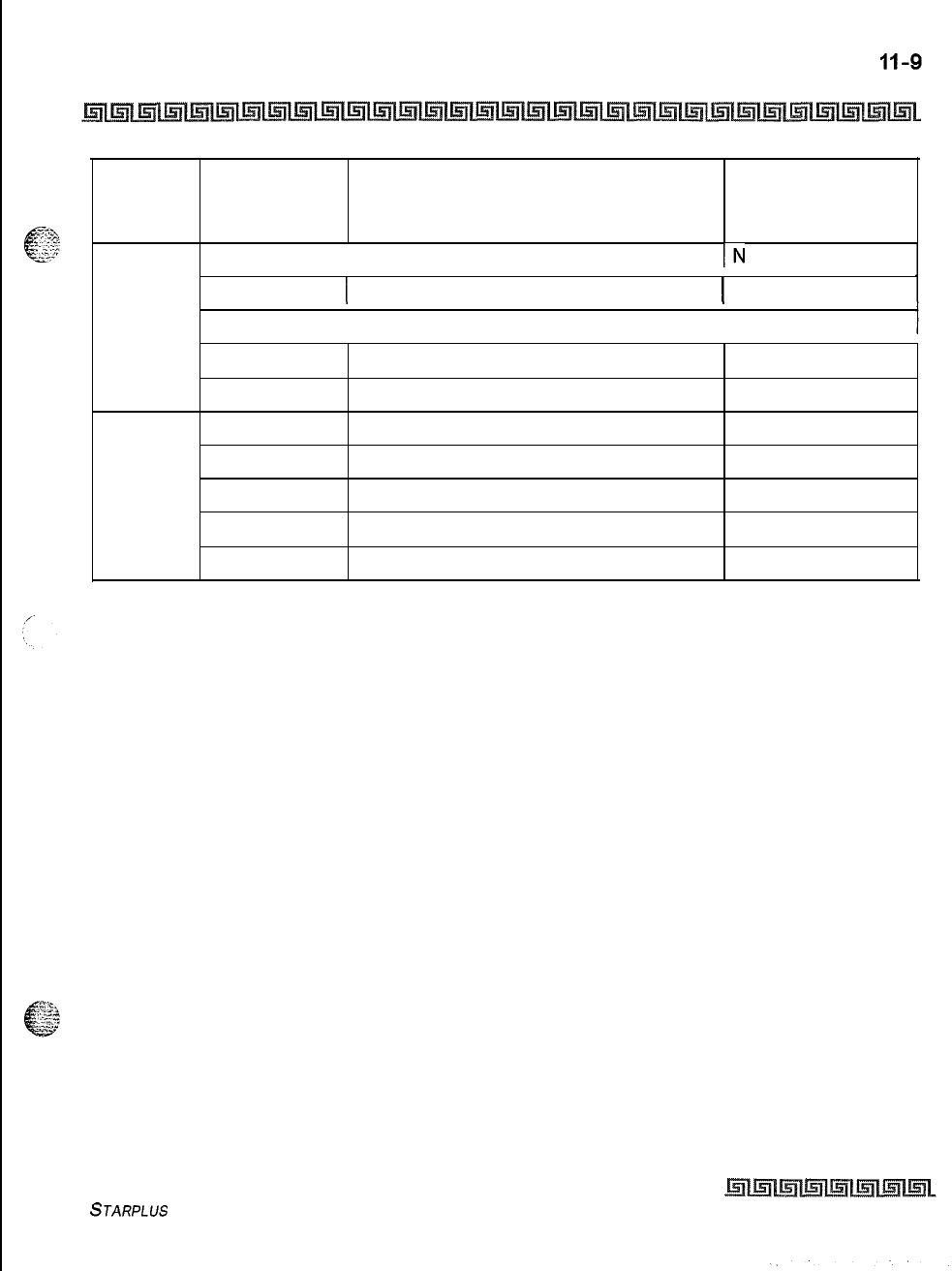
Initialize Database Parameters
Introduction
Program
Code
Page B2
Flash 40
Page C
Flex
Button Features Default Value
(after initializa-
tion)
1 Preset Call Forward Destination
IN
one
3
1 Preset Forward Voice Mail 1 None
4
1 Universal Day Answer I Disabled
5
Music-On-Hold per CO Line
6
Ring Tone
1
Flash Timer Programming
2
Ring Delay Timer
3
Reseize Timer
4
Guard Timer
5
Preset Forward Timer
Channel
1
00
10
10
1.5 sec.
2 sec.
IO sec.
Table 11-2: CO Line Attribute Defaults
STARPLUS Triad-S System Programming Manual
Issue I- December 1998
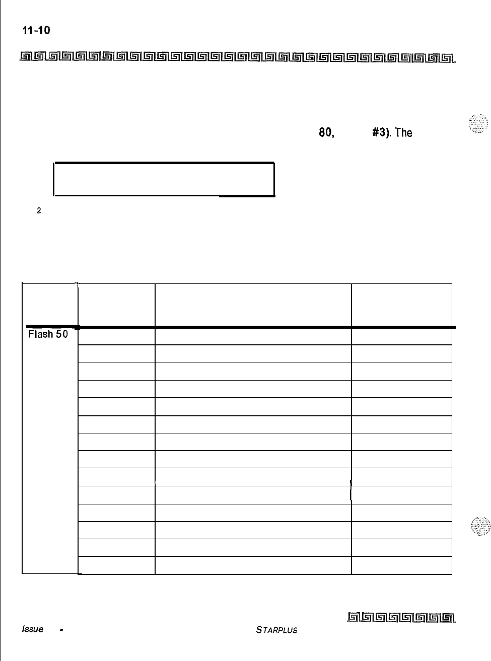
Initialize Database Parameters
Introduction
Initialize Station Attributes
Programming Steps
1
Press the STATION ATTRIBUTES flexible button (FLASH
80.
button
#3).
The
following message displays on the phone:
INITIALIZE STATIONS
PRESS HOLD
.
z
To initialize the Station Attributes, press the HOLD button. Confirmation tone is heard.
Description
The Station parameters may be initialized setting all data fields to their original, default values. The
following data fields are returned to their default value upon initializing the Station Attributes,
Program
Code
Flash
Page A
T
II
Flex
Button
Default Value
Features (after initializa-
tion)
Paging Access Enabled
1
2
Do Not Disturb Enabled
3
Conference Enable/Disable (Per Station) Enabled
4
Executive Override Disabled
5
Privacy (Per Station) Enabled
6
System Speed Dial Access Enabled
7
Line Queuing Enabled
8
Preferred Line Answer Enabled
9
Off -Hook Voice Over (OHVO) Disabled
10
1
I
Call Forwarding
(
Enabled
11
Forced Least Cost Routing (LCR) Disabled
12
ACD Supervisor Monitor w/Barge-In Disabled
14
CO Line Ringing Options Disabled
15
Name/Number Display at Idle
Name
Table 11-3: Station Attribute Defaults
Lssue 1
-
December 1998
STARPLUS
Triad-S System Programming Manual

Initialize Database Parameters
Introduction
Program
Code
Flash 50
Page B
Flex
Button Features Default Value
(after initializa-
tion)
1
Station Identification 0 (24-Btn
Keyset)
G(SLT
w/o
MWt)
2
1 Station Day Class of Service I’ I
3
1 Station Day Class of Service
I’
I
4
I Speakerphone/Headset Programming I
1
I
5
I
I Pick-Up Group(s) Programming I
)I
6
Paging Zone(s) Programming
1
7
Preset Call Forwarding Programming None
8
CO Line Group Access
1
9
LCR Class of Service (COS)
0
10
Off -Hook Preference Programming 00
(Keyset)
11
I
Flexible Button Programming
(
None
12
1
Keyset
Mode Inactive Mode I
13
Voice Mail ID Translation
14
Display Flexible Buttons
VMID
Digits
Table 11-3: Station Attribute Defaults
STARPLUS
Triad-S System Programming Manual Issue I
-
December 1998
Initialize Database Parameters
Introduction
Initialize CO
/
Station Port Parameters
Programming Steps
1
Press the
PORT-STA/CO
flexible button (FLASH 80, button
#4).
The following
message displays on the phone:
INITIALIZE PORT
-
STA
/
CO
PRESS HOLD
.
2
To initialize the Station/CO Port Parameters, press the HOLD button. Confirmation
tone is heard.
Description
Station numbers can be initialized and reset to their original default values after the user has performed the
Station Relocation Feature
(636).
Initialize Exception Tables
Programming Steps
1
Press the EXCEPTION TABLES flexible button (FLASH 80, button
#5).
The following
message displays on the phone:
INITIALIZE EX TABLES
PRESS HOLD
2
To initialize the Exception Tables, press the HOLD button. Confirmation tone is heard.
Description
The Exception Tables parameters, including the Allow/Deny Tables and the Special Tables, may be
initialized setting all tables to their original, default values. The following Tables are cleared returning to
their default value upon initializing the Exception Tables parameters:
Issue
7
-
December 1998
STARPLUS
Triad-S System Programming Manual
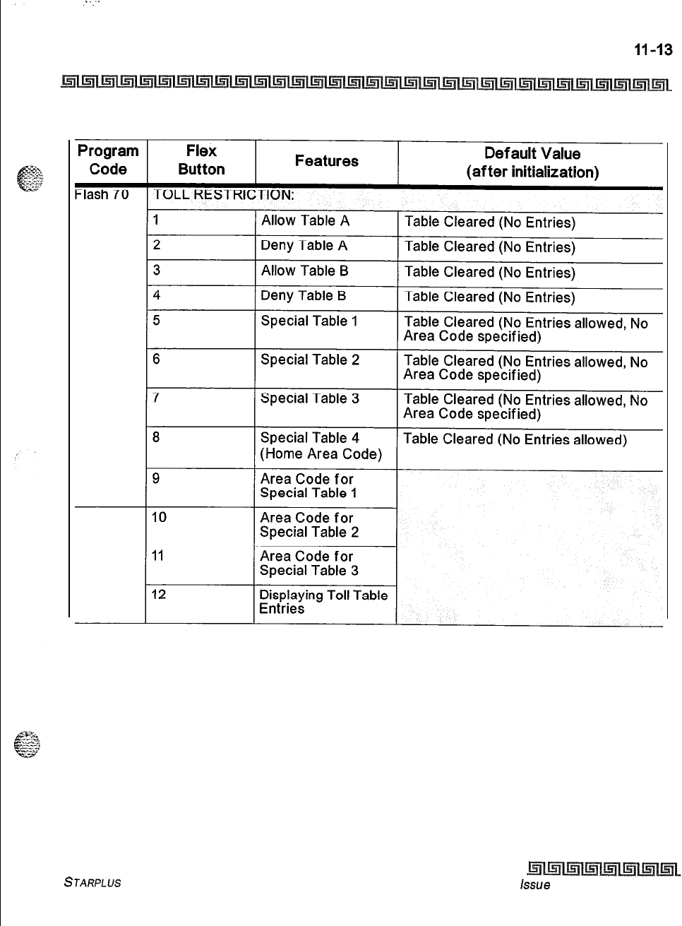
::
Initialize Database Parameters
Introduction
Table 11-4: Exception Table Defaults
STARPLUS
Triad-S System Programming Manual
hue
I- December 1998
.
.
Initialize Database Parameters
Introduction
Initialize System Speed Numbers
Programming Steps
1
Press the SYSTEM SPEED NUMBERS flexible button (FLASH 80, button
#8).
The
following message displays on the phone:
I
INITIALIZE SYS SPEED NO
PRESS HOLD
I
2
To initialize the System Speed bins, press the HOLD button. Confirmation tone is heard.
Description
Numbers entered into the System Speed Dial Table may be initialized clearing all bins to their original,
default value (empty).
All
bins
20-99
are cleared returning to their default value (empty) upon initializing
the Speed Dial Table.
Initialize LCR Tables
Programming Steps
1
Press the LCR TABLES flexible button (FLASH 80, button
#7).
The following message
displays on the phone:
INITIALIZE LCR TABLES
PRESS HOLD
2
To initialize the LCR Tables, press the HOLD button. Confirmation tone is heard.
Description
The LCR Tables may be initialized setting all tables to their original, default values. The following tables are
reset to their original default value after initialization of the LCR Tables:
+
3-Digit
Table
G+
6-Digit Table
+
Exception Table
o
Route List Table
Issue I- December 1998
STARPLUS Triad-S System Programming Manual
Initialize Database Parameters
Introduction
9”
Insert/Delete Table
+
Daily Start
Time Table
+:+
Weekly Schedule
+z+
Toll Information Route
I
I
Program Flex Features Default Value
Code Button
After
/n/tlalization
-lash
75 LCR TABLES:
1
3-Digit Area/Off ice Code Table Default Values assigned
2
6-Digit Area/Off ice Code Table Default Values assigned
3
Exception Code Table Default Values assigned
4
Route List Table Default Values assigned
5
Insert/Delete Table Default Values assigned
6
Daily Start Time Table Default Values assigned
7
Weekly Schedule Table Default Values assigned
8
LCR Routing for Toll Information Default Values assigned
Table 11-5: LCR Table Defaults
STARPLUS
Triad-S System Programming Manual Issue
I-
December 1998
Initialize Database Parameters
Introduction
Initialize ICLID Tables
Programming Steps
I
Press the ICLID-DID TABLES flexible button (FLASH 80, button
#8).
The following
message displays on the phone:
INITIALIZE ICLED
PRESS HOLD
c
2
To initialize the ICLID-DID Tables, press the HOLD button. Confirmation tone is heard.
Description
The ICLID
Tables
parameters may be initialized setting all data fields to their original, default values,
Program Flex
Default Value
Code Button
Features
After
lnlflallzafion
Flash 43 ICLID-DID TABLES:
I
1
ICLID Ringing Assignments None
18
Next ICLID Route Number
19
20
Flash 55
l-4
Flash 56 1
2
3
4
Previous ICLID Route Number
Select Route Number
Local Number/Name Translation
ICLID Disable/Enable
ICLID Name in Display
ICLID Baud Rate Display
ICLID Port Assignment
Table 11-6: ICLID Table Defaults
None
Disable
Telephone Number
9600
Port
#I
Issue I- December 1998
STARPLUS Triad-S System Programming Manual
.
Initialize Database Parameters
Introduction
Initialize Directory Dialing Table Parameters
Programming Steps
I
Press the DIRECTORY DIAL TABLE flexible button (FLASH
80,
button
#9).
The
following message displays on the phone:
INITIALIZE DIR
-
DIAL
PRESS HOLD
2
To initialize the Directory Dialing Table Parameters, press the HOLD button.
Confirmation tone is heard.
Description
The Directory Dialing Table Parameters may be initialized setting all data fields to their original, default
values.
Program
Code Flex
Button Features Default Value
After
/n/f/a/ization
I I I
Flash 23
DIRECTORY DIALING TABLE:
1
BinllCM
2Name
3
Clear
None
None
None
Table 11-7: Directory Dialing Table Defaults
STARPLUS
Triad-S System Programming Manual Issue
I
-
December 1998
Initialize Database Parameters
Introduction
Initialize Hunt Group Parameters
Programming Steps
1
Press the HUNT GROUPS flexible button (FLASH 80, button #IO). The following
message displays on the phone:
.
INITIALIZE HUNT GROUP
PRESS HOLD
t
2
To initialize the Hunt Group Parameters, press the HOLD button. Confirmation tone is
heard.
Description
Hunt Group Parameters may be initialized setting all data fields to their original, default value
Program Flex Features Default Value
Code Button
After
lnitlallza
t/on
Flash 30 HUNT GROUPS:
1-12
Hunt Group Programming None
13
Station/Pilot Hunting Assignment None
Table 11-8: Hunt Group Defaults
Issue I- December 1998
STARPLUS
Triad-S System Programming Manual
Initialize Database Parameters
Introduction
Initialize ACD
/
UCD Group Parameters
Programming Steps
t
Press the ACD* or UCD GROUPS flexible button (FLASH
80,
button
#Ii).
The following
message displays on the phone:
INITIALIZE ACD GROUP
PRESS HOLD
z
To initialize the ACD* or UCD Group Parameters, press the HOLD button. Confirmation
tone is heard.
Description
ACD*
or UCD Group Parameters may be initialized setting all data fields to their original, default values,
Program
Code
Flash
Page
B
.
.
Flex
Button Features Def auk Value
After Initialization
I I
ACD GROUPS
550557:
l-8
1
ACD*/UCD
Groups
(550-557)
1 None
9
Alternate ACD*/UCD Group Assignment None
10
ACD*/UCD Overflow Station Assignment None
11
ACD*/UCD Recorded Announcement None
12
ACD* Supervisor Programming None
13
ACD* Auto Wrap-Up Timer (Per Group)
04sec.
14
ACD*
CIQ Threshold
Disabled
1-8
ACD* Station (550-557) Assignments None
Table 11-9: ACD
/
UCD Group Defaults
STARPLUS Triad-S System Programming Manual Issue
I-
December 1998
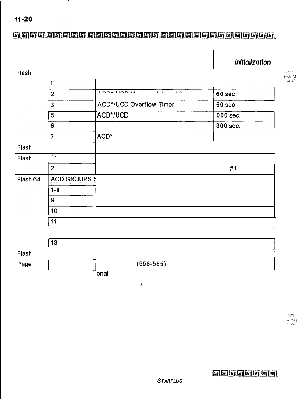
:
Initialize Database Parameters
Introduction
Features
Program
Code Flex
Button Default Value
After
lnltlallzatlon
III
-lash
61
ACD TIMERS:
ACD*/UCD Ring Timer 1 60 sec.
1
I=
2
3
ACD*/UCD Message Interval Timer
ACD*/UCD
No-Answer Recall Timer
ACD*/UCD No-Answer Retry Timer
17
ACD*
Guaranteed Message Timer
ACD* Ran Announcement Tables
1 05 sec.
1 None
-lash
62 1 l-8
-lash
63
II
Event Trace Disable/Enable I Disabled
Trace Port Assignment
58-565:
ACD* Groups (558-565)
Alternate ACD* Group Assignment
ACD* Overflow Station Assignment
Port
#I
None
None
None
III
ACD* Recorded Announcement
ACD* Supervisor Programming
1 None
1 None( 12
I13
ACD* Auto Wrap-Up Timer (Per Group) I 04 sec.
-lash
64 I 14
‘age
B
l-8
Features available with op
ACD* CIQ Threshold I Disabled
i
ti
I
ACD* Station
(558565)
Assignments None
onal
software
Table 11-9: ACD
/
UCD Group Defaults
Issue I- December 1998
STARPLUS
Triad-S System Programming Manual
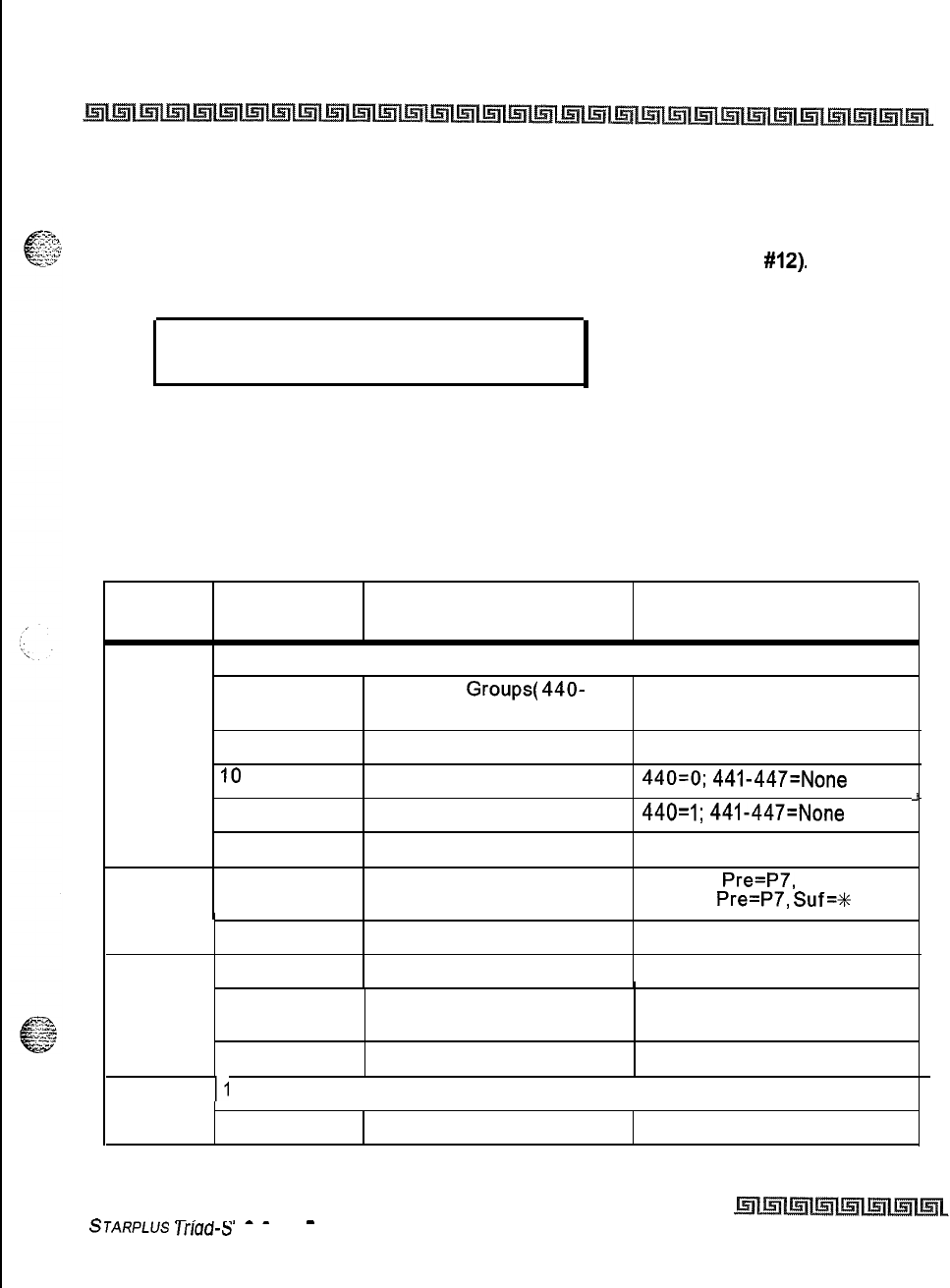
Initialize Database Parameters
Introduction
II-21
Initialize Voicemail Group Parameters
Programming Steps
1
Press the VOICE MAIL GROUPS flexible button (FLASH 80, button
#12).
The following
message displays on the phone:
INITIALIZE VM GROUP
PRESS HOLD
2To initialize the VM Group Parameters, press the HOLD button. Confirmation tone is
heard.
Description
VM Group Parameters may be initialized setting all data fields to their original, default values.
Program Flex Features Default Value
Code Button After Initialization
Flash 65
VOICE MAIL GROUPS
l-8 Voice Mail
Groups(
440-
None
447)
9
Alternate Voice Mail Group None
IO
Leave Mail Index Entry
440=0;
441-447=None
11
Retrieve Mail Index Entry
440=1;
441-447=None
12
Station Assignments None
Flash 66
l-8 Voice Mail In-Band Signaling Table 0:
Pre=P7,
Suf=None
Table 1:
Pre=P7,
Suf=t
9
Flash 67 1
Voice Mail Disconnect Table None
Voice Mail In-Band Digits Enabled
J
2
Voice Mail
Transfer/Forward Enabled
3
Voice Mail Broker Enabled
I
Flash68
II
I
( Voice Mail Group I
1 None
2
I I
Voice Mail ID Number None
Table 1 l-l 0: Voicemail Group Defaults
.-
-.
.--
-
STARPLUS
lrrau-S
System Programming Manual
Issue I- December 1998
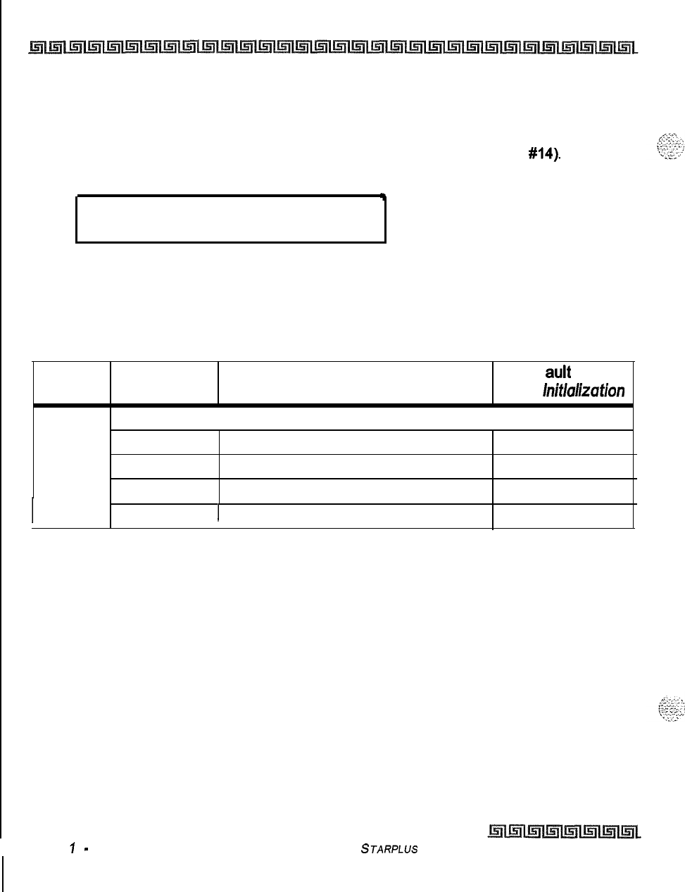
I
11-22 Initialize Database Parameters
Introduction
Initialize Verified Account Code Table
Programming Steps
1
Press the VERIFIED ACCT CODES flexible button (FLASH 80, button
#14).
The
following message displays on the phone:
Y
INITIALIZE ACCT CODES
PRESS HOLD
2To initialize the Verified Account Code Table, press the HOLD button. Confirmation
tone is heard.
Description
The Verified Account Code Table may be initialized setting all data fields to their original, default values,
Program Flex Features
Def
auk Value
Code
Button
After
Initlal~zation
Flash 31
VERIFIED ACCOUNT CODES
1
Class of Service (COS)
2
Account Code None
3
Delete Account Code
4
I
1 Erase Digits I
I
Issue
I
-
December 1998
Table II-II: Verified Account Code Table Defaults
STARPLUS
Triad-S System Programming Manual
Initialize Database Parameters
Introduction
11-23
System Reset
gy<
Programming Steps
k&&I
If the System must be reset but not initialized:
1
Press the RESET flexible button (FLASH 80, button
#20).
The
following
message
displays on the phone:
RESET SYSTEM
PRESS HOLD
t
2
To reset the system without initializing the database, press the HOLD button. No
Confirmation tone is heard and the system now resets.
Description
This feature provides a hard system reset from the
keyset
instead of the KSU. This is useful in cases where
miscellaneous data errors have occurred and the system needs to be reset without initializing the entire
database.
STARPLUS
Triad-S Sysfem Programming Manual issue
I
-
December 7998

11-24
Initialize Database Parameters
Introduction
Issue
I-
December 7998
STARPLUS Triad-S System Programming Manual
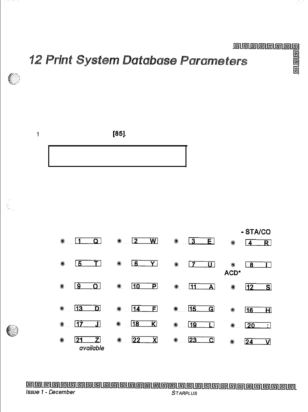
Introduction
Print Database Parameters
Programming Steps
1
Press FLASH and dial
[85].
The following message displays on the phone:
PRINT DATABASE
ENTER BUTTON NUMBER
Description
This section describes the procedures and steps necessary to print the system database parameters and
various portions of the system. The buttons on the key telephone are defined as shown below when entering
the Print Database Parameters programming area:
SYSTEM CO LINE STATION
PARAMETERS ATTRIBUTES ATTRIBUTES PORT
-
STA/CO
III
*n
#@lx--i3
sl3xzEl
EXCEPTION SYSTEM SPEED LCR TABLES ENTIRE
TABLES NUMBERS SYSTEM
815
gm
%sm
sn
ICLID-DID
DIRECTORY
ACD-
OR UCD
TABLES DIAL TABLE HUNT GROUPS GROUPS
*19
IL10
*!Tizxl
*n
VOICEMAIL VERIFIED ACCT
GROUPS CODES
%%m
0114
%6n
#k
Ils
ABORT PRINT
#n
4kLiEza
#:-
#l?m--Yl
%+D
ak-
#km s124
* Features
available
with optional software.
This command dumps the entire database as a permanent record which can serve as a hardcopy of the
database. The system baud rate must match that of the printer or receiving device.
ecember 1998
STARPLUS
Triad-S System Programming Manual
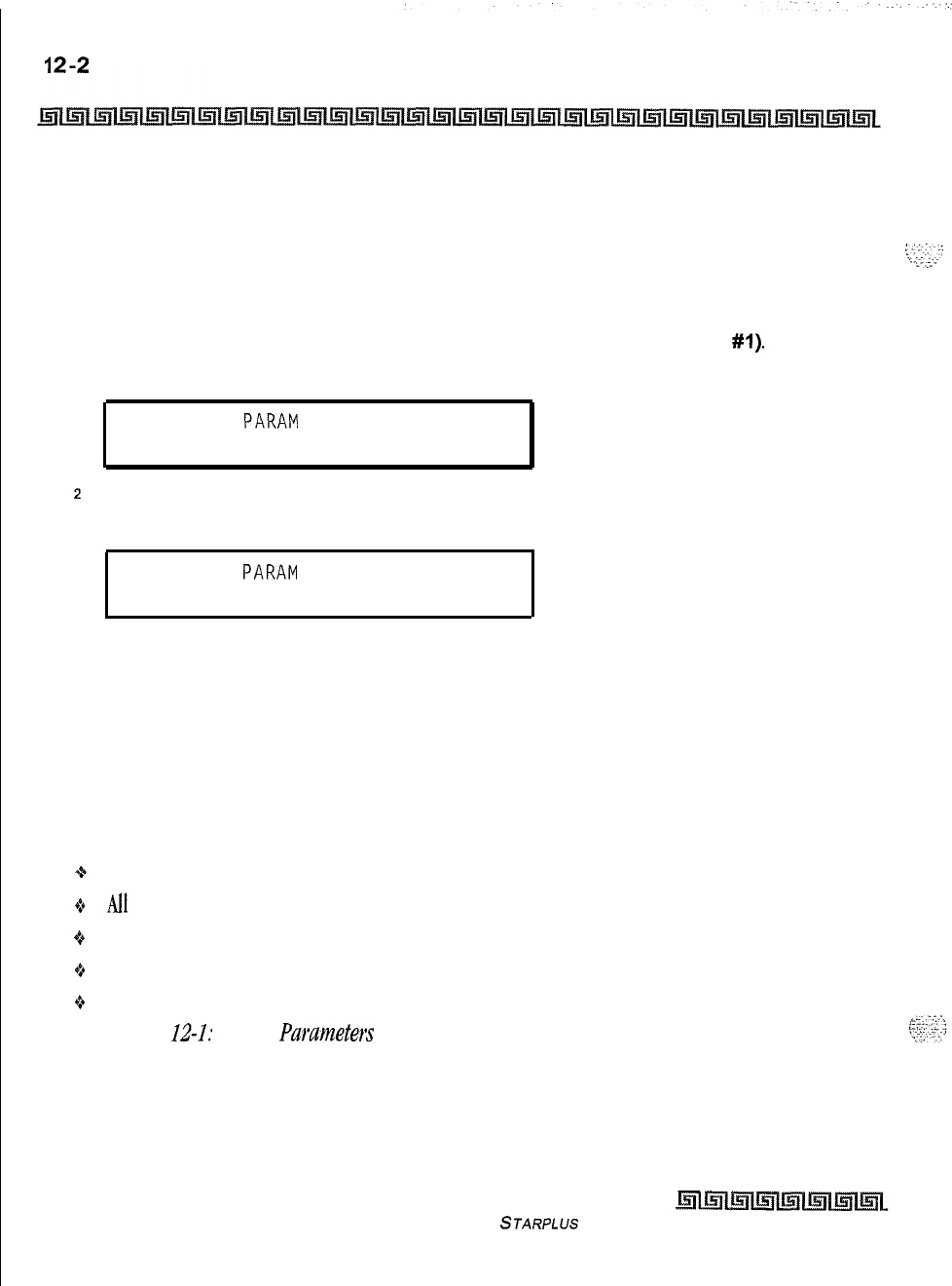
Print System Database Parameters
Introduction
Refer to the following figures for examples of the database printouts. Also refer to the following paragraphs
for instructions on printing portions of the database.
Print System Parameters
Programming Steps
1
Press the SYSTEM PARAMETERS flexible button (FLASH 85, button
#I).
The
following message displays on the display phone:
PRINT SYS
PARAM
PRESS HOLD
2
To print the System Parameters database, press the HOLD button. The following
message displays on the display phone:
PRINT SYS
PARAM
,
When the system finishes sending the information to the printer, a confirmation tone is heard.
Description
The currently stored customer database can be printed or uploaded into a file. This command dumps the
entire database as a permanent record which can serve as a hardcopy of the database. The system baud rate
must match that of the printer or receiving device.
When printing the System Parameters the following data prints:
+
All System Timers
oAil
System Wide Options (e.g., External Night Ringing, Hold Preference, etc.)
o Attendant Station(s) Programming
+
Other System Assignments (e.g., Page/Relay Assignments, Executive/Secretary, SMDR, etc.)
+Weekly Night Mode Schedule
Refer to Figure U-1: System Purameters (Continued) for an example of the System Parameters database
printout.
Issue I- December 1998
STARPLUS Triad-S System Programming Manual
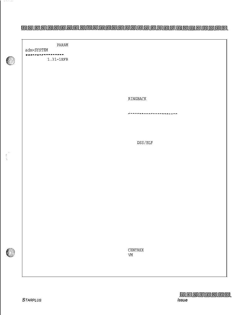
Print System Database Parameters
Introduction
12-3
PRINTING SYS
PARAM
adm>SYSTEM
PARAMETERS
______-_---------
Eng. Ver.
1.31-1EFB
SYS HOLD RECALL
60
EXC HOLD RECALL
180
ATND RECALL TIMER
1
TRANSFER RECALL
45
PRESET FWD TIMER
10
CALL FWD NO ANS
15
PAUSE TIMER
2
CALL PARK TIMER
180
CONFERENCE TIMER
10
PAGING TIMEOUT
15
CO RING DETECT
3
SLT RCVR TIMER
20
M/W TONE TIMER
0
HOOK SWITCH TIME
10
HOOK SWT BOUNCE
10
SMDR CALL QUAL
30
AUTO CALL BACK
3
REMINDER RING
0
RELEASE GUARD
3
INTERDIGIT T/O
5
RPT REDIAL
60
ATTENDANT DISPLAY
1
CALL COVERAGE RING 5
MODEM ANSWER T/O
25
INT DIGIT PULSE
300
DTMF ON/OFF TIME
1
SYSTEM FEATURES
---------------
ATTENDANT OVERRIDE DISABLED
HOLD PREFERENCE SYSTEM
EXTERNAL NIGHT RING DISABLED
EXECUTIVE WARNING ENABLED
PAGE WARNING TONE ENABLED
BACKGROUND MUSIC ENABLED
LEAST COST ROUTING DISABLED
FORCED ACCOUNT CODE DISABLED
GROUP LISTENING DISABLED
IDLE SPEAKER MODE DISABLED
CALL COST DISPLAY DISABLED
MUSIC ON HOLD ENABLED
CALL QUALIFIER TONE DISABLED
BARGE IN WARN TONE ENABLED.
CO RING TONES ENABLED
VERIFIED ACCT CODES DISABLED
CALL FWD DISPLAY ENABLED
EXTERNAL DAY RING DISABLED
OVERFLOW STA FWD DISABLED
DIRECT XFER ENABLED
STATION LOCK DISABLED
LCR CALL PROGRESS ENABLED
RECORDING WARN TONE ENABLED
MAINTENANCE DISABLED
RINGBACK
ON XFER DISABLED
SYSTEM LED FLASH RATES
---------__----_____--
INC CO RING RED 480 IPM FLUTTER
INC ICM RING RED 120 IPM FLUTTER
CALL FORWARD BTN RED STEADY ON
MSG WAIT VM BTN RED STEADY ON
MSG CBCK DSS/BLF RED 120 IPM FLUTTER
DND
DSS/BLF
RED 60 IPM DBL WINK OFF
AUTO CBCK DSS/BLF RED 120 IPM FLASH
UCD UNAVL DSS/BLF RED 60 IPM DBL WINK OFF
TRANSFER CO RING RED 120 IPM FLASH
RECALL CO RING RED 480 IPM FLUTTER
EXCLUSIVE HOLD GREEN 120 IPM FLASH
QUEUED CO RING GREEN 480 IPM FLUTTER
SYSTEM HOLD RED 60 IPM DBL WINK OFF
IN USE HOLD GREEN 60 IPM FLASH
CAMP ON BTN RED 120 IPM FLASH
CALL BACK BTN RED 120 IPM FLASH
LINE QUEUE BTN RED 480 IPM FLUTTER
DND BTN RED STEADY ON
ICM HOLD BTN
RED
15 IPM FLASH
LEADING DIGIT 1 LEADING DIGIT
LEADING DIGIT 2 NONE
LEADING DIGIT 3 NONE
LEADING DIGIT 4 NONE
LEADING DIGIT 5 NONE
LEADING DIGIT 6 NONE
LEADING DIGIT 7 NONE
LEADING DIGIT OPTION DISABLED
CENTREX
DIGITS
4
VM
ID DIGITS
3
Figure 12-1: System Parameters
STARPLUS Triad-S System Programming Manual issue
I- December 1998
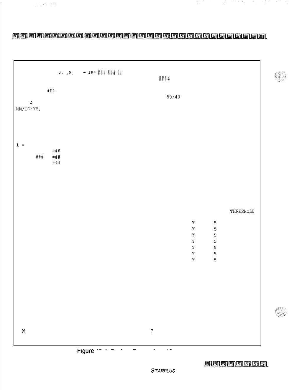
12-4
Print System Database Parameters
Introduction
MUSIC CHANNEL
13.
.81
CO
-
##it
###
###
#t
ATTENDANT STATIONS
100 ###
###
F 4
0800 1700
s 5
#+I##
####
S 6
#### ####
DIAL PULSE
-
60/40
10 PPS
DATE
&
TIME FORMAT
MM/DD/YY,
12 HOURS
PBX DIALING CODES
## ## ## ## ##
EXECUTIVE/SECRETARY PAIRINGS
1=
### ###
2 = ### ###
3 = ### ###
4 = ### ###
ON BOARD RELAY RELAY ASSIGNMENTS
NONE NONE
I/O BAUD RATE
-------------
Port
1 = 9600
Port
2 = 9600
Port 3 = 9600
Port 4 = 9600
ACCESS CODE
1 DISA ACCESS
100
2 ADMIN PASSWORD
3226
SDR TPE PNT BAUD PORT
N
LD
80 9600 3
AUTO NIGHT MODE
N
WEEKLY NIGHT MODE SCHEDULE
END
START
DAY TIME TIME
M
0
0800 1700
T 1
0800 1700
w
2
0800 1700
T
3
0800 1700
CABINET SLOT TYPE
00
LCOB
0 1
DTIB
02
LCOB
0 3
DTIB
0 4
LCOB
0 5
DTIB
0 6
LCOB
07
DTIB
POWER SUPPLY TYPES
10 AMPS LO AMPS 10 AMPS 10 AMPS
ALARM DESCRIPTION
CARRIER LOSS
BLUE ALARM
YELLOW ALARM
RED ALARM
BIPOLAR VARIATIONS
SLIP ALARM
DATA ERRORS
COLINE GROUP QUEUING
GROUP
0
ENABLED
GROUP
1
ENABLED
GROUP
2
ENABLED
GROUP
3
ENABLED
GROUP
4
ENABLED
GROUP
5
ENABLED
GROUP
6
ENABLED
GROUP
I
ENABLED
ALARM PERIOD
THRESHOLt
MINOR MAJOR
15 30
15 30
15 30
15 30
15 30
15 30
15 30
krgure
12-I: System Parameters (Continued)
Issue I- December 1998
STARPLUS Triad-S System Programming Manual
.~.
Print System Database Parameters
12-5
Introduction
Print CO Line Attributes
~~~
Programming Steps
G=
..I.:,
:’
. .
._..
.IPress the CO LINE ATTRIBUTES flexible button (FLASH 85, button
#2).
The following
message displays on the display phone:
PRINT CO LINES
PRESS HOLD
2
To print the data for ALL CO Lines, press the HOLD button. To print CO Line data for a
specified CO Line Range, enter 6 digits to specify the CO Line
.Range
(3 digits for the
first line within the range and 3 digits for the last line in the range):
If a only one line is desired, enter that line twice:
[OOI
0011
3
Then press the HOLD button. The following message displays on the display phone and
the CO Line data prints:
PRINTING CO LINES
When the system finishes sending the requested information to the printer, a confirmation tone is heard.
Description
This command dumps the entire database as a permanent record which can serve as a hardcopy of the
database The system baud rate must match that of the printer or receiving device.
When printing the CO Line attributes the following data prints:
-z+
All CO Line parameters within the specified range.
8t
CO Line ringing assignments within the specified range.
4.
Dial Pulse Ratio and Speed settings
STARPLUS Triad-S System Programming Manual Issue
I-
December 1998
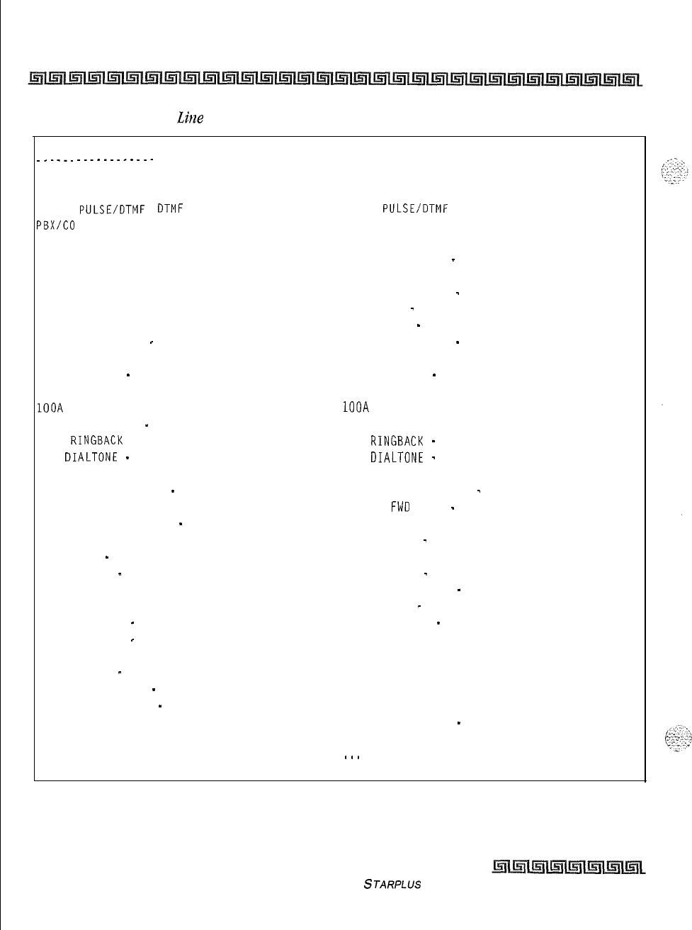
12-6
Print System Database Parameters
Introduction
Refer to
Figure 12-Z: CO
Li?ze
Attributes for an example of the CO Line Attributes database printout.
CO LINE ATTRIBUTES
-_.__....--..--..-
co 001
DIAL
PULSE/DTMF
DTMF
PBX/CO
co
UNIVERSAL NIGHT ANS ENABLED
DISA TRK TO TRK ENABLED
PRIVACY ENABLED
LOOOP SUPERVISION 4
DISA TYPE NONE
LINE GROUP 1
CLASS OF SERVICE
-
1
LINE IDENTIFICATION LINE 001
CO DIRECTION
-
INCOMING-OUTGOING
RING ASSIGNMENTS
1OOA
T-l SIGNAL TYPE
-
LOOP START
T-l
RINGBACK
ENABLED
T-l
DIALTONE
-
DISABLED
TRANSMIT VOLUME ODB
PRESET FORWARD DEST
-
NONE
PRESET FWD VMID NONE
UNIVERSAL DAY ANSWER
-
DISABLED
MOH CHANNEL 1
RING TONE
-
0
FLASH TIMER
-
10
RING DELAY TIMER 0
WINK TIMER 140
RELEASE TIMER
-
20
RESEIZE TIMER
-
200
GUARD TIMER 50
SIEZE TIMER
-
10
PRESET FWD TIMER
-
100
DID COLLECT TIMER
-
150
TI COLLECT TIMER 150
co 02
DIAL
PULSE/DTMF
DTMF
PBX/CO CO
UNIVERSAL. NIGHT ANS ENABLED
DISA TRK TO TRK
-
ENABLED
PRIVACY ENABLED
LOOP SUPERVISION
-
4
DISA TYPE
-
NONE
LINE GROUP
-
1
CLASS OF SERVICE
-
1
LINE IDENTIFICATION LINE 002
CO DIRECTION
-
INCOMING-OUTGOING
RING ASSIGNMENTS
1OOA
T-l SIGNAL TYPE LOOP START
T-l
RINGBACK
-
ENABLED
T-l
DIALTONE
-
DISABLED
TRANSMIT VOLUME ODB
PRESET FORWARD DEST
-
NONE
PRESET
FWD
VMID
-
NONE
UNIVERSAL DAY ANSWER DISABLED
MOH CHANNEL
-
1
RING TONE 0
FLASH TIMER
-
10
RING DELAY TIMER
-
0
WINK TIMER
-
140
RELEASE TIMER
-
20
RESEIZE TIMER 200
GUARD TIMER 50
SEIZE TIMER 10
PRESET FWD TIMER 100
DID COLLECT TIMER 150
TI COLLECT TIMER
-
150
.
.
.
and so on through CO lines 012
Figure 12-2: CO Line Attributes
Issue I- December 1998
STARPLUS
Triad-S System Programming Manual
Print System Database Parameters
Introduction
12-7
Print Station Attributes
Programming Steps
Press the STATION ATTRIBUTES flexible button (FLASH 85, button
#3).
The following
message displays on the display phone:
PRINT STATIONS
PRESS HOLD
To print data for all stations, press the HOLD button. To print Station data for a specified
Station Range, enter six digits to specify the Station range (three digits for the first
station within the range and three digits for the last station in the range):
[IOO-1311
= Triad-S
If only one station is desired, enter that station twice: [I
OIIOI]
Then press the HOLD button. The following message displays on the display phone and
the requested information prints:
PRINTING STATIONS
When the system finishes sending the requested information to the printer, a confirmation tone is heard.
Description
This command dumps the entire database as a permanent record which can serve as a hardcopy of the
database. The system baud rate must match that of the printer or receiving device.
When printing the Station attributes the following data prints:
44
All current station parameters
Refer to
Figure
Gf-3: Station
Attdmtes
for an example of the Station Attributes database printout.
STARPLUS Triad-S System Programming Manual Issue
I-
December 7998
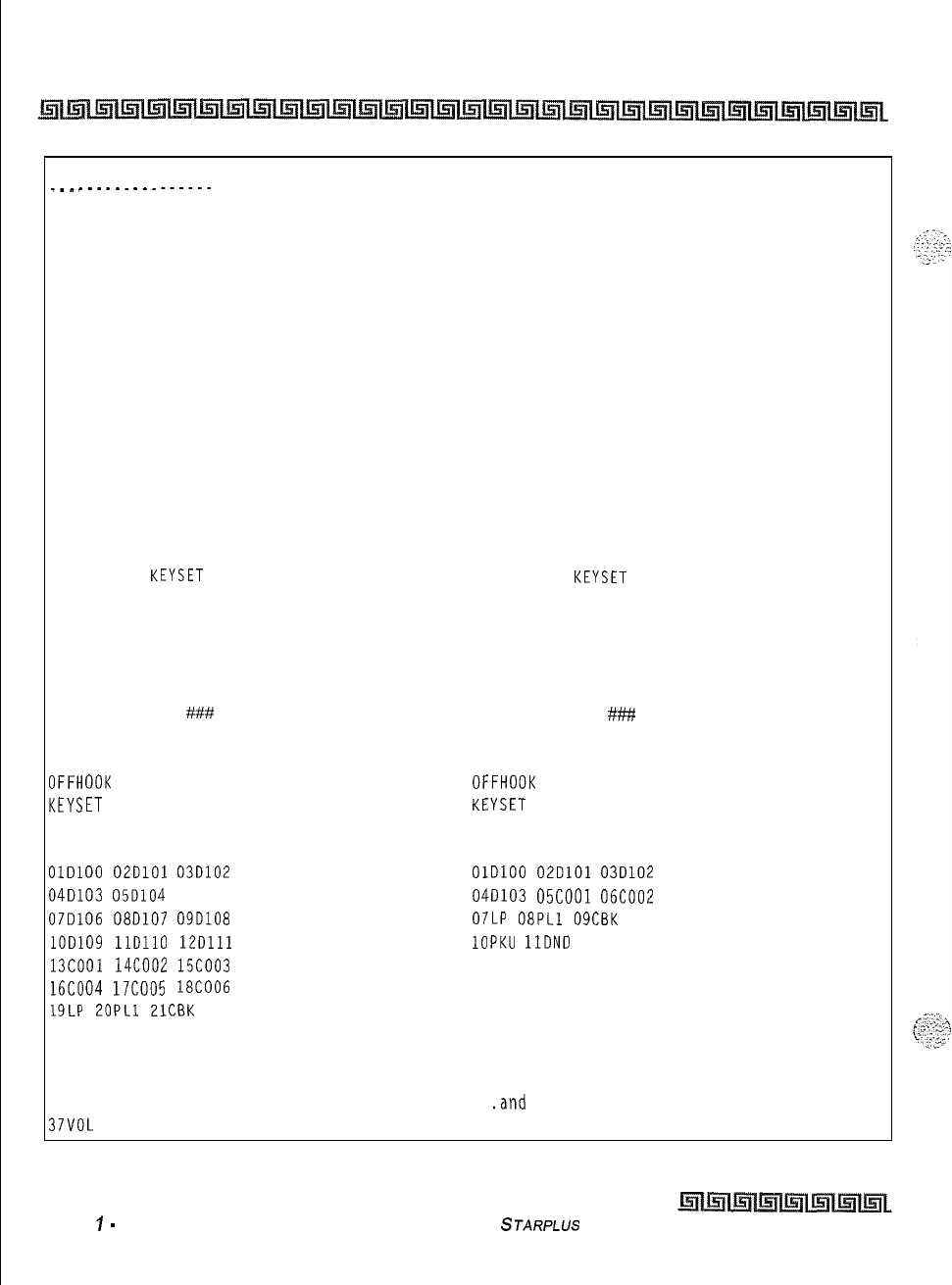
12-8
Print System Database Parameters
Introduction
STATION ATTRIBUTES
________.__--.....
STA 100
PAGE ACCESS ENABLED
DO NOT DISTURB ENABLED
CONFERENCE ENABLED
EXEC OVERRIDE DISABLED
PRIVACY ENABLED
SYSTEM SPEED ENABLED
LINE QUEUING ENABLED
PREF LINE ANSWER DISABLED
OFF HOOK VOICE OVER DISABLED
CALL FORWARD ENABLED
FORCE LCR DISABLED
ACD SUPV BARGE IN DISABLED
EXEC OVERRIDE BLOCK DISABLED
COC RING OPTIONS MUTED RING
NAME AT IDLE LCD EXT NUMBER
STATION ID
KEYSET
DAY COS 1
NIGHT COS 1
SPEAKERPHONE FULL SPEAKERPHONE
PICKUP GROUPS 1
PAGE ZONE 1
PRESET FORWARD
###
LINE GROUP ACCESS 1
LCR CLASS OF SERVICE 0
OFFHOOK
PREFENCE BTN 00 ENABLED
KEYSET
MODE INACTIVE MODE
VOICEMAIL ID 100
BUTTONS
OlDlOO
02DlOl
03D102
04D103
05D104
060105
07D106
08D107
09D108
lOD109
llDll0
12Dlll
13COOl
14coo2
15coo3
16COO4
17COO5
18COO6
19LP
2OPLl
PlCBK
22PKU 23DND 24LQU
25SPD 26MSG 27XFR
28CNF 29CP0 30FWD
31MUT 32FLA 33MON
37VOL
STA 101
PAGE ACCESS ENABLED
DO NOT DISTURB ENABLED
CONFERENCE ENABLED
EXEC OVERRIDE DISABLED
PRIVACY ENABLED
SYSTEM SPEED ENABLED
LINE QUEUING ENABLED
PREF LINE ANSWER DISABLED
OFF HOOK VOICE OVER DISABLED
CALL FORWARD ENABLED
FORCE LCR DISABLED
ACD SUPV BARGE IN DISABLED
EXEC OVERRIDE BLOCK DISABLED
CO RING OPTIONS MUTED RING
NAME AT IDLE LCD EXT NUMBER
STATION ID
KEYSET
DAY COS 1
NIGHT COS 1
SPEAKERPHONE FULL SPEAKERPHONE
PICKUP GROUPS 1
PAGE ZONE 1
PRESET FORWARD
###
LINE GROUP ACCESS 1
LCR CLASS OF SERVICE 0
OFFHOOK
PREFENCE BTN 00 ENABLED
KEYSET
MODE INACTIVE MODE
VOICEMAIL ID 101
BUTTONS
OlDlOO
02DlOl
03D102
04D103
05COOl
06COO2
07LP
08PLl
09CBK
1OPKU
1lDND
12LQU
13 14 15
16 17 18
19 20 21
22 23 24
25SPD
.and
so on through stations 131
Figure 12-3: Station Attributes
Issue
I
-
December 1998 STARPLUS Triad-S System Programming Manual
Print System Database Parameters
Introduction
The button printout for
the
8-button
keyset
displays
u/l
flexible buttons
and fixed buttons the same as a
24-button
keyset.
Print CO
/
Station Port Parameters
Programming Steps
I
Press the PORT-STA/CO flexible button (FLASH 85, button
#4).
The following
message displays on the display phone:
PRINT PORT
-
STA
/
CO
PRESS HOLD
t
2
To print the CO/Station Port parameters, press the HOLD button. The following
message displays on the display phone:
PRINTING PORT
-
STA
/
CO
When the system finishes sending the requested information to the printer, a confirmation tone is heard.
Description
This command dumps the entire database as a permanent record which can serve as a hardcopy of the
database. The system baud rate must match that of the printer or receiving device.
CO PORT NUMBERS
____..-.-----..
001 002 003
004 005 006
007 008 009
010 011 012
STATION PORT NUMBERS
100 101 102 103 104 105 106 107
108 109 110 111 112 113 114 115
116 117 118 119 120 121 122 123
124 125 126 127 128 129 130 131
Figure 12-4: CO
I
Station Port Attributes
STARPLUS
Triad-S System Programming Manual Issue
I-
December 1998
Print System Database Parameters
Introduction
Print Exception Tables
Programming Steps
_-..
..,
“
1
Press the EXCEPT TABLES flexible button (FLASH 85, button
#5).
The following
‘~~%~~
message displays on the display phone:
I
PRINT EX TABLES
PRESS HOLD
I
2
To print the Except Tables, press the HOLD button. The following message displays on
the display phone:
P
PRINTING EX TABLES
When the system finishes sending the requested information to the printer, a confirmation tone is heard.
Description
This command dumps the entire database as a permanent record which can serve as a hardcopy of the
database. The system baud rate must match that of the printer or receiving device.
When printing information from the Exception Tables, the following data prints:
+Allow Table A
e:+
Deny Table A
oAllow Table B
+Deny Table B
+
Special Table
1
+Special Table 2
+
Special Table
3
0%
Special Table
4
Refer to
Figwe
12-5:
Exeption
Tables
for an example of the Exception Tables database printout.
Issue I- December 1998
STARPLUS Triad-S System Programming Manual
Print System Database Parameters
Introduction
r-
1LLOW
TABLE A SPECIAL TABLE 1 AREA CODE
._-----------
31 11
ALLOWED
OFFICE CODES
32 12
33 13
14 14
35 15
SPECIAL TABLE 2 AREA CODE
36 16
37 17
ALLOWED
OFFICE CODES
38 18
39 19
10 20
SPECIAL TABLE 3 AREA CODE
__--.-.._--._.__--....~-~
DENY TABLE A ALLOWED OFFICE CODES
01 06
02 07
03 08
SPECIAL TABLE 4 HOME AREA CODE
.LLOWED
OFFICE CODES
04 09
05 10
A
ALLOW TABLE B
01 11
02 12
03 13
04 14
05 15
06 16
07 17
08 18
09 19
10 20
DENY TABLE B
.._-..-.-...
01 06
02 07
03 08
04 09
05 10
Figure 12-5: Exception Tables
STARPLUS
Triad-S System Programming Manual Issue
7
-
December 7998
Print System Database Parameters
Introduction
Print System Speed Numbers
Programming Steps
1
Press the SYSTEM SPEED flexible button (FLASH 85, button
#8).
The following
message displays on the display phone:
PRINT SYS SPEED NO
PRESS HOLO
2
To print the System Speed bins, press the HOLD button. The following displays on the
display phone:
I
PRINTING SYS SPEED NO
I
When the system finishes sending the requested information to the printer, a confirmation tone is heard.
Description
This command dumps the entire database as a permanent record which can serve as a hardcopy of the
database. The system baud rate must match that of the printer or receiving device.
issue
1
-
December 1998
STARPLUS
Triad-S System Programming bfanual
Print System Database Parameters
Introduction
12-13
Refer to Figure 12-6 System Speed Numbers for an example of the System Speed Numbers database
printout.
jYSTEM
SPEED NUMBERS
20 45
21 46
22 47
23 48
24 49
25 50
26 51
27 52
28 53
29 54
30 55
31 56
32 57
33 58
34 59
35 60
36 61
37 62
38 63
39 64
40 65
41 66
42 67
43 68
44
. . .
and so on through Speed Number 99
Figure 12-6: System Speed Numbers
Print LCR Tables
Programming Steps
1
Press the LCR TABLES flexible button (FLASH 85, button
#7).
The following message
displays on the display phone:
I
PRINT LCR TABLES
PRESS HOLD
I
STARPLUS
Triad-S Sysfem Programming Manual Issue
I
-
December 1998
12-14
Print System Database Parameters
Introduction
z
To print the LCR Tables, press the HOLD button. The following displays on the display
phone:
PRINTING LCR TABLES
.
,:
-:
-2
-7--
When the system finishes sending the requested information to the printer, a confirmation tone is heard.
Description
This command dumps the entire database as a permanent record which can serve as a hardcopy of the
database. The system baud rate must match that of the printer or receiving device.
When printing information from the LCR Tables, the following data prints:
8 Exception Table
o
Route List Table
+:+
Insert/Delete Table
G
Daily Time Table
ce
Weekly Time Table
Q
Toll Tables
+z+
6-Digit Table
Q
3-Digit
Table
Refer to Figure 12-7:
LCR
Tables and Figure 12-8: Three-Digit Table Defaults for examples of the LCR
Tables database printout.
I
Issue
7
-
December 1998
STARPLUS
Triad-S System Programming Manual
Print System Database Parameters
Introduction
adm>EXCEPTION
CODE TABLE
CODE ROUTE NO
ROUTE LIST TABLE
RT TIME COST CO GRP INS/DEL GRP PR
0 1026
1 0 1
2
026
1 0 1
3
026
1 0 1
4
026
1 0
1
DIGIT INS/DEL TABLE
TABLE DIGITS
0 PRE P
1 PRE P
2 PRE P
3 PRE P
4 PRE P
5 PRE P
6 PRE P
11
000
1 0 1 7
PRE
P
2
000
1 0 1 8
PRE
P
3
000
1 0
1 9
PRE
P
4
000
10 1 10
PRE
P
2 1010
1 0 111
PRE
P
2
010
10 1 12
PRE
P
3
010
1 0 1
13
PRE
P
4
010
1 0 1
14
PRE
P
3 1072
1 0 1
15
PRE
P
2
072
1 0 116
PRE
P
3
072
1 0
117
PRE
P
4
072
1 0 1
18
PRE
P
19
PRE
P
Figure 12-7: LCR Tables
STARPLUS
Triad-S System Programming Manual
Issue I- December 1998

Print System Database Parameters
Introduction
4 1
171
10 1
2
171
1 0 1
3
171
1 0 1
4
171
1 0 1
5 1
106
10 1
2
106
10 1
3
106
10 1
4
106
1 0 1
6 1
277
1 0 1
2
277
1 0 1
3
277
I.
0 1
4
277
10 1
DAILY START TIME TABLE
TABLE TIME
1
800
2
1700
3
2300
4
####
WEEKLY SCHEDULE TABLE
START
TIME
MTWTFSS
------------_--_--__--
800
111113
3
1700
2 2 2 2 2 3
2
2300
3 3 3 3 3 3
3
####
3 3 3 3 3 3
3
LCR ROUTE FOR 555-1212
0
6 DIGIT TABLE
AREA ROUTE OFFICE CODES
CODE NO
Issue 1 -December 1998
STARPLUS
Triad-S System Programming Manual
Figure 12-7: LCR Tables (Continued)
Print System Database Parameters
Introduction
12-17
3 DIGIT TABLE
59728N17N
598 2 8 N 1 7 N
CODE LEADING 1 NON-LEADING
1
599 2 8 N 1 7 N
RR PP 6 RR PP 6 600 0 11 N 1 7 N
601 0 11 N 1 7 N
11 ## ## N 6
##
N
200 0 11 N 1 7 N
201 0 11 N 1 7 N
202 0 11 N 1 7 N
203 0 11 N 1 7 N
204 3 11 N 1 7 N
205 0 11 N 1 7 N
206 0 11 N 1 7 N
207 0 11 N 1 7 N
208 0 11 N 1 7 N
209 0 11 N 1 7 N
210 0 11 N 1 7 N
Zll####N17N
212 0 11 N 1 7 N
213 0 11 N 1 7 N
214 0 11 N 1 7 N
215 0 11 N 1 7 N
216 0 11 N 1 7 N
217 0 11 N 1 7 N
218 0 11 N 1 N
219 0 11 N 1 7 N
220 2 8 N 1 7 N
221 2 8 N 1 7 N
222 2 8 N 1 7 N
223 2 8 N 1 7 N
224 2 8 N 1 7 N
225 2 8 N 1 7 N
226 2 8 N 1 7 N
227 2 8 N 1 7 N
228 0 11 N 1 7 N
22928N 17N
230 2 8 N 1 7 N
231 2 8 N 1 7 N
232 2 8 N 1 7 N
233 2 8 N 1 7 N
234 2 8 N 1 7 N
235 2 8 N 1 7 N
602 0 11 N 1 7 N
603 0 11 N 1 7 N
604 0 11 N 1 7 N
605 0 11 N 1 7 N
606 0 11 N 1 7 N
607 0 11 N 1 7 N
608 0 11 N 1 7 N
609 0 11 N 1 7 N
610 0 11 N 1 7 N
611####N17N
612 0 11 N 1 7 N
613 3 11 N 1 7 N
614 0 11 N 1 7 N
615 0 11 N 1 7 N
616 0 11 N 1 7 N
617 0 11 N 1 7 N
618 0 11 N 1 7 N
619 0 11 N 1 7 N
620 2 8 N 1 7 N
62128Nl7
N
622 2 8 N 1 7 N
623 2 8 N 1 7 N
624 2 8 N 1 7 N
625 2 8 N 1 7 N
626 0 11 N 1 7 N
627 2 8 N 1 7 N
628 2 8 N 1 7 N
629 2 8 N 1 7 N
630 0 11 N 1 7 N
631 2 8 N 1 7 N
632 2
8
N 1
7
N
633 2 8 N 1 7 N
634 2 8 N 1 7 N
635 2 8 N 1 7 N
636 2 8 N 1 7 N
637 2 8 N 1 7 N
638 2 8 N 1 7 N
Figure 12-8: Three-Digit Table Def
auk
STARPLUS
Triad-S System Programming Manual Issue
I-
December 1998
12-18
Print System Database Parameters
Introduction
236
28N17
N
23728N17
N
23828 N17 N
239
28N17
N
240 0 11 N 1 7 N
24128 N17 N
24228N17
N
24328 N17 N
24428 N17 N
24528 N17 N
24628 N17 N
24728 N17 N
248 0 11 N 1 7 N
24928 N17 N
25028N17N
25128N17N
25228 N17 N
253 0 11 N 1 7 N
254 0 11 N 1 7 N
25528
N17N
25628N17N
25728
N17N
25828 N17 N
25928 N17 N
2602aN17
N
26128N17N
28228N17
N
28328
N17N
2642aN17
N
26528N17N
26628N17
N
26728N17N
26828
Nil
N
26928 N17 N
27028N17N
2712 8
N17
N
27228N17
N
27328
N17N
27428N17
N
2752aN17N
27628N17N
27728N17N
2782aN17N
j392aN17N
j402aN17N
54128N17
N
;4228N17N
j43
2 8 N 1 7 N
i4428N17N
545
2
8
N 1 7 N
546
28N17N
j4728N17N
j482aN17N
j4928N17N
550
0 11 N 1 7 N
j5128N17N
j5228N17N
j53
28N17N
i5428N17N
j5528N17N
j562aN17N
i5728N17N
55828N17N
j5928N17N
j60
0 11 N 1 7 N
j6128N17
N
i6228N
17N
j6328N17N
i6428N17N
565
28N17N
666
28N17N
66728N17N
66828
N17N
669
28N17N
67028N17N
6712aN17N
67228N17N
67328N17N
67428N17N
67528N17N
676 28
N17N
6772aN17N
67828
N17N
67928N17N
68028N17N
68128 N17 N
Figure 12-8: Three-Digit Table Defaults
-.
.-..;
1.
I..
:
1
,..
,:
.,..
:.
-
,
.1;..’
;’
x,
_‘.
:..
\;
‘.
“.I
.
.
.
Issue 1
-
December 1998
STARPLUS
Triad-S Sysfem Programming Manual
.
Print System Database Parameters
Introduction
!7928N17N
?8028N17N
281
0 11 N 1 7 N
282
2 8 N 1 7 N
283 2 8 N 1 7 N
284
2 8 N 1 7 N
285 2 8 N 1 7 N
286 2 8 N 1 7 N
287 2 8 N 1 7 N
288
2 8 N 1 7 N
289 2 8 N 1 7 N
29028N 17N
29128N
17N
29228N 17 N
29328N 17N
294 2 8 N 1 7 N
29528N17N
29628N 17N
297 2 8 N 1 7 N
29828N
17N
299 2 8 N 1 7 N
300 0 11 N 1 7 N
301 0 11 N 1 7 N
302 0 11 N 1 7 N
303 0 11 N 1 7 N
304 0 11 N 1 7 N
305 0 11 N 1 7 N
306 3 11 N 1 7 N
307 0 11 N 1 7 N
308 0 11 N 1 7 N
309 0 11 N 1 7 N
310 0 11 N 1 7 N
311####N17N
312 0 11 N 1 7 N
313 0 11 N 1 7 N
314 0 11 N 1 7 N
315 0 11 N 1 7 N
316 0 11 N 1 7 N
317 0 11 N 1 7 N
318 0 11 N 1 7 N
319 0 11 N 1 7 N
320 0 11 N 1 7 N
321 2 8 N 1 7 N
682 2 8 N 1 7 N
683 2 8 N 1 7 N
684 2 8 N 1 7 N
685 2 8 N 1 7 N
686 2 8 N 1 7 N
687 2 8 N 1 7 N
688 2 8 N 1 7 N
689 2 8 N 1 7 N
69028N 17 N
69128 N17 N
692 2 8 N 1 7 N
69328 N17 N
69428 N17 N
695 2 8 N 1 7 N
696 2 8 N 1 7 N
697 28N 17 N
69828N 17 N
699 2 8 N 1 7 N
700 0 11 N 1 7 N
701 0 11 N 1 7 N
702 0 11 N 1 7 N
703 0 11 N 1 7
M
704 0 11 N 1 7 N
705 3 11 N 1 7 N
706 4 11 N 1 7 N
707 0 11 N 1 7 N
708 0 11 N 1 7 N
709 3 11 N 1 7 N
710 0 11 N 1 7 N
711
##
#I#
N 1 7 N
712 0 11 N 1 7 N
713 0 11 N 1 7 N
714 0 11 N 1 7 N
715 0 11 N 1 7 N
716 0 11 N 1 7 N
717 0 11 N 1 7 N
718 0 11 N 1 7 N
719 0 11 N 1 7 N
720 2 8 N 1 7 N
721 2 8 N 1 7 N
722 2 8 N 1 7 N
723 2 8 N 1 7 N
724 0 11 N 1 7 N
Figure 12-8: Three-Digit Table Defaults
STARPLUS
Triad-S System Programming Manual
Issue I- December 1998
322 28117 N
72528N17N
323 0 11 N 1 7 N
72628N17N
32428N17
N
72728N17N
325 28117 N
72828N17N
32628N17
N
729
28N17N
32728N17
N
73028N17N
32828N 17 N
73128N17N
32928N17N
732
0 11 N 1 7 N
330 0 11 N 1 7 N
733
28N17
N
33128N17N
734
0 11 N 1 7 N
33228N17N
73528N 17N
33328 N17 N73628N 17N
334 0 11 N 1 7 N 73728N 17N
335
2 8
N 1
7 N
73828N17N
336
2 8
N 1
7 N
739
28N17N
337
2 8
N 1
7 N
740
0 11 N 1 7 N
338
2 8
N 1
7 N
74128N17N
339
2 8
N 1
7 N
74228N17N
340
2 8
N 1
7 N
743
28 N17 N
341
2 8
N 1
7 N
74428N 17N
342
2 8
N 1
7 N
745
28N 17N
343
2 8
N 1
7 N
74628N 17N
344
2 8
N 1
7 N
74728N 17N
345
2 8
N 1
7 N
74828N
17N
346
2 8
N 1
7 N
74928N 17N
347
2 8
N 1
7 N
75028N 17N
348
2 8
N 1
7 N
75128N17N
349
2 8 N
1
7 N
75228N17N
350
2 8
N 1
7 N
753
2 8 N 1 7 N
351
2 8
N 1
7 N
75428N 17N
352
011
N
17N
75528N17N
1
353
2 8
N 1
7 N
75628N
17N
354
2 8
N 1
7 N
757
,
0 11 N 1 7 N
355
2 8
N 1
7 N
;
‘58
2 8 N 1 7 N
356
2 8 N 1
7 N
759
/
28N 17N
357
2 8
N 1
7 N
760
,
0 11 N 1 7 N
358
2 8
N 1
7 N
;
'6128N17N
35928N17N
‘62
I
2 8 N 1 7 N
360 0 11 N 1 7 N
;
‘63
2 8 N 1 7 N
36128 N17 N
i
‘64
2 8 N 1 7 N
36228
N17
N
i
‘65
0 11 N 1 7 N
36328 N17 N
7
‘66
2 8 N 1 7 N
36428
N17N
i
‘67
2 8 N 1 7 N
Figure 12-8: Three-Digit Table Defaults
Issue I-December1998
STARPLUS
Triad-S System Programming Manual
12-20
Print System Database Parameters
Introduction
Print System Database Parameters
Introduction
365 2 8 N 1 7 N
366 2 8 N 1 7 N
367 2 8 N 1 7 N
368 2 8 N 1 7 N
36928N
17N
370
2 8 N 1 7 N
371 2 8 N 1 7 N
372 2 8 N 1 7 N
373 2 8 N 1 7 N
374 2 8 N 1 7 N
375 2 8 N 1 7 N
376 2 8 N 1 7 N
377 2 8 N 1 7 N
378 2 8 N 1 7 N
37928N 17N
380 2 8 N 1 7 N
381 2 8 N 1 7 N
382 2 8 N 1 7 N
383 2 8 N 1 7 N
384 2 8 N 1 7 N
385 2 8 N 1 7 N
386 2 8 N 1 7 N
387 2 8 N 1 7 N
388 2 8 N 1 7 N
389 2 8 N 1 7 N
390 2 8 N 1 7 N
39128N 17 N
392 2 8 N 1 7 N
393 2 8 N 1 7 N
39428N 17N
39528N 17N
396 2 8 N 1 7 N
39728N 17 N
398 2 8 N 1 7 N
399 2 8 N 1 7 N
400 0 11 N 1 7 N
401 0 11 N 1 7 N
402 0 11 N 1 7 N
403 3 11 N 1 7 N
404 0 11 N 1 7 N
405 0 11 N 1 7 N
406 0 11 N 1 7 N
407 0 11 N 1 7 N
768 2 8 N 1 7 N
76928N 17 N
770 0 11 N 1 7 N
771 2 8 N 1 7 N
772 2 8 N 1 7 N
773 0 11 N 1 7 N
774 2 8 N 1 7 N
775 2 8 N 1 7 N
776 2 8 N 1 7 N
777 2 8 N 1 7 N
778 2 8 N 1 7 N
779 2 8 N 1 7 N
780 2 8 N 1 7 N
781 0 11 N 1 7 N
782 2 8 N 1 7 N
783 2 8 N 1 7 N
784 2 8 N 1 7 N
785 0 11 N 1 7 N
786 2 8 N 1 7 N
787 2 8 N 1 7 N
788 2 8 N 1 7 N
789 2 8 N 1 7 N
79028N 17 N
79128N17
N
79228N 17 N
793 2 8 N 1 7 N
79428N 17 N
795 2 8 N 1 7 N
796 2 8 N 1 7 N
79728N 17 N
79828N 17 N
799 2 8 N 1 7 N
800 0 11 N 1 7 N
801 0 11 N 1 7 N
802 0 11 N 1 7 N
803 0 11 N 1 7 N
804 0 11 N 1 7 N
805 0 11 N 1 7 N
806 0 11 N 1 7 N
807 3 11 N 1 7 N
808 0 11 N 1 7 N
809 5 11 N 1 7 N
810 0 11 N 1 7 N
Figure 12-8: Three-Digit Table Defaults
STARPLUS
Triad-S System Programming Manual Issue I- December 1998
Print System Database Parameters
Introduction
IO8
0 11 N 1 7 N
109 0 11 N 1 7 N
I10
0 11 N 1 7 N
Ill
14 N 1 3 N
112
0 11 N 1 7 N
I13
0 11 N 1 7 N
i14
0 11 N 1 7 N
Il.5
0 11 N 1 7 N
116
3 11 N 1 7 N
117 0 11 N 1 7 N
118 3 11 N 1 7 N
119
0 11 N 1 7 N
12028N
17N
121 2 8 N 1 7 N
$2228 N17 N
$23
0 11 N 1 7 N
12428
N17
N
425 0 11 N 1 7 N
12628 N17 N
42728 N17 N
42828N17
N
42928 N17 N
43028 N17 N
431 2 8 N 1 7 N
43228 N17 N
43328
N17N
43428
N17
N
435 0 11 N 1 7 N
43628N 17N
43728
N17
N
43828
N17N
439 2 8 N 1
7
N
440 0 11 N 1 7 N
441 5 11 N 1 7 N
44228N17
N
443 0 11 N 1 7 N
44428 N17 N
44528 N17 N
44628 N17 N
44728N 17 N
44828
N17
N
449 2 8 N 1 7 N
4502 8N 17 N
311##N17N
312 0 11 N 1 7 N
313 0 11 N 1 7 N
314
0
11 N 1 7 N
315 0 11 N 1 7 N
316 0 11 N 1 7 N
917 0 11 N 1 7 N
318 0 11 N 1 7 N
919 0 11 N 1 7 N
82028N
17N
521 2 8 N 1 7 N
82228N17N
82328N
17N
82428N17N
82528N 17N
826 28N 17N
82728N17N
82828N 17N
82928
N17N
830 0 11 N 1 7 N
831 0 11 N 1 7 N
83228N17N
833 28N 17N
834
28N17N
83528N17N
83628
N17N
83728N17N
83828N17N
83928N17N
84028N17N
84128N17N
84228N17N
843 0 11 N 1 7 N
844 28 N17 N
845
28N17N
846
28N17N
847 0 11 N 1 7 N
84828N17N
84928
N17N
850 0 11 N 1 7 N
85128N17N
85228N 17N
85328N 17N
Figure 12-8: Three-Digit Table Defaults
Issue I- December 1998
S
JARPLUS
Triad-S System Programming Manual
Print System Database Parameters
Introduction
12-23
15128N17
N
$52
2 8 N 1 7 N
953 2 8 N 1 7 N
154 2 8 N 1 7 N
155 2 8 N 1 7 N
456 2 8 N 1 7 N
457 2 8 N 1 7 N
458 2 8 N 1 7 N
459 28N 17N
460 2 8 N 1 7 N
461 2 8 N 1 7 N
462 2 8 N 1 7 N
463 2 8 N 1 7 N
464 2 8 N 1 7 N
165 2 8 N 1 7 N
466 2 8 N 1 7 N
467 2 8 N 1 7 N
468 2 8 N 1 7 N
46928N 17N
470 2 8 N 1 7 N
47128N17N
472 2 8 N 1 7 N
473 2 8 N 1
7
N
474 2 8 N 1 7 N
475 2 8 N 1 7 N
476 2 8 N 1 7 N
477 2 8 N 1 7 N
478 2 8 N 1 7 N
479 2 8 N 1 7 N
480 2 8 N 1 7 N
481 2 8 N 1 7 N
482 2 8 N 1 7 N
483 2 8 N 1 7 N
484 2 8 N 1 7 N
485 2 8 N 1 7 N
486 2 8 N 1 7 N
487 2 8 N 1 7 N
488 2 8 N 1 7 N
489 28N 17N
490 28N 17N
49128 N17 N
492 2 8 N 1
7
N
493 28N 17N
954 2 8 N 1 7 N
855 2 8 N 1 7 N
856 2 8 N 1 7 N
857 2 8 N
1
1
N
858 2 8 N 1 7 N
85928N 17 N
860 0 11 N 1 7 N
861 2 8 N 1 7 N
862 2 8 N 1 7 N
863 2 8 N 1 7 N
864 0 11 N 1 7 N
865 2 8 N 1 7 N
866 2 8 N 1 7 N
867 2 8 N 1 7 N
868 2 8 N 1 7 N
869 2 8 N 1 7 N
870 0 11 N 1 7 N
87128N17
N
872 2 8 N 1 7 N
873 2 8 N 1 7 N
874 0 11 N 1 7 N
875 2 8 N 1 7 N
876 2 8 N 1 7 N
877 2 8 N 1 7 N
878 2 8 N 1 7 N
87928N 17 N
880 2 8 N 1 7 N
881 2 8 N 1 7 N
882 2 8 N 1 7 N
883 2 8 N 1 7 N
884 2 8 N 1 7 N
885 2 8 N 1 7 N
886 2 8 N 1 7 N
887 2 8 N 1 7 N
888 2 8 N 1 7 N
889 2 8 N 1 7 N
89028N 17 N
89128 N17 N
892 2 8 N 1 7 N
893 2 8 N 1 7 N
89428N 17 N
895 2 8 N 1 7 N
896 2 8 N 1 7 N
Figure 12-8: Three-Digit Table Defaults
STARPLUS Triad-S System Programming Manual issue
I-
December 1998
:-
12-24
Print System Database Parameters
Introduction
194
2 8 N 1 7 N897 2 8 N 1 7 N
i9528N
17N 89828N 17N
!96
2 8 N 1 7 N899 2 8 N 1 7 N
i97
2 8 N 1 7 N900 0 11 N 1 7 N
!9828N
17 N901
0
11 N
1
7 N
199
2 8 N 1 7 N902 3 11 N 1 7 N
jO0
0 11 N 1 7 N 903 0 11 N
1
7 N
jO1
0 11 N 1 7 N 904 0 11 N 1 7 N
SO1
0 11 N 1 7 N 905 4 11 N 1 7 N
jO3
0 11 N 1 7 N 906 0 11 N 1 7 N
304
0 11 N 1 7 N 907 0 11 N
1
7 N
305
0 11 N 1 7 N 908 0 11 N
1
7 N
jO6
3 11 N 1 7 N 909 0 11 N 1 7 N
507
0 11 N 1 7 N 910 0 11 N
1
7 N
508
0 11 N 1 7 N 91114 N13 N
509
0 11 N 1 7 N 912 0 11 N 1 7 N
510
0 11 N 1 7 N 913 0 11 N 1 7 N
jll####N17N
914 0 11 N 1 7 N
.
512
0 11 N 1 7 N 915 0 11 N 1 7 N
513
0 11 N 1 7 N 916 0 11 N 1 7 N
514
3 11 N 1 7 N 917 0 11 N 1 7 N
515
0 11 N 1 7 N 918 0 11 N 1 7 N
516 0 11 N 1 7 N 919 0 11 N 1 7 N
517
0 11 N 1 7 N920 0 11 N
1
7 N
518
0 11 N 1 7 N921 2 8 N 1 7 N
519
3 11 N 1 7 N92228N 17N
520
0 11 N 1 7 N 92328N 17N
521
2 8 N 1 7 N92428N 17N
522 2 8 N 1 7 N925 0 11 N 1 7 N
523 2 8 N 1 7 N926 2 8 N 1 7 N
324
2 8 N 1 7 N92728N 17N
525 2 8 N 1 7 N928 2 8 N 1 7 N
526 2 8 N 1 7 N929 2 8 N 1 7 N
527 2 8 N 1 7 N930 2 8 N 1 7 N
528 2 8 N 1 7 N931 0 11 N 1 7 N
52928N 17 N 932 2 8 N 1 7 N
530 0 11 N 1 7 N933 2 8 N 1 7 N
53128N17N
934 2 8 N 1 7 N
532 2 8 N 1 7 N935 2 8 N 1 7 N
533 2 8 N 1 7 N 936 2 8 N 1 7 N
534 2 8 N 1 7 N937 0 11 N 1 7 N
535 2 8 N 1 7 N938 2 8 N 1 7 N
536 2 8 N 1 7 N 939 2 8 N 1 7 N
Figure 12-8: Three-Digit Table Defaults
issue
I- December 1998
STARPLUS Triad-S System Programming Manual
Print System Database Parameters
Introduction
12-25
537
2 8 N 1 7 N
538
2 8 N 1 7 N
53928N
17N
540
0 11 N 1 7 N
541
0 11 N 1 7 N
542 2 8 N 1 7 N
543 28N 17 N
544
2 8 N 1 7 N
545
2 8 N 1 7 N
546 2 8 N 1 7 N
547 2 8 N 1 7 N
348
28N 17 N
549 28 N17 N
550 2 8 N 1 7 N
55128N17
N
55228N
17N
553 2 8 N 1 7 N
55428N17N
555 2 8 N 1 7 N
556 2 8 N 1 7 N
557 2 8 N 1 7 N
558 2 8 N 1 7 N
559 28N 17N
560 2 8 N 1 7 N
561 0 11 N 1 7 N
562 0 11 N 1 7 N
563 2 8 N 1 7 N
564 2 8 N 1 7 N
565 2 8 N 1 7 N
566 2 8 N 1 7 N
567 2 8 N 1 7 N
568 2 8 N 1 7 N
569
ZEN
17N
57028N17N
571 2 8 N 1 7 N
572 2 8 N 1 7 N
573 0 11 N 1 7 N
57428N17N
575 2 8 N 1 7 N
576 2 8 N 1 7 N
577 2 8 N 1 7 N
57828N17N
579 28N 17N
940 0 11 N 1 7 N
941 0 11 N 1 7 N
94228N 17 N
943 2 8 N 1 7 N
944 2 8 N 1 7 N
945 28 N17 N
946 2 8 N 1 7 N
94728N 17N
94828 N17 N
949 0 11 N 1 7 N
95028N 17N
95128N17
N
952 2 8 N 1 7 N
95328N 17N
954 0 11 N 1 7 N
95528N 17N
956 0 11 N 1 7 N
95728N 17 N
95828N 17 N
95928N 17N
96028N 17N
96128 N17 N
962 2 8 N 1 7 N
96328N 17 N
96428N 17 N
965 2 8 N 1 7 N
966 2 8 N 1 7 N
967 2 8 N 1 7 N
96828N 17 N
96928N 17 N
970 0 11 N 1 7 N
97128 N17 N
972 0 11 N 1 7 N
973 0 11 N 1 7 N
974 2 8 N 1 7 N
97528N 17N
97628N 17N
97728N 17 N
978 0 11 N 1 7 N
979 2 8 N 1 7 N
980 2 8 N 1 7 N
98128N17
N
98228N 17 N
Figure 12-8: Three-Digit Table Defaults
STARPLUS
Triad-S System Programming Manual
issue
I- December 1998
12-26 Print System Database Parameters
Introduction
580 0 11 N 1 7
N
5812 8 N 1 7
N
582 2 8 N 1 7
N
583 2 8 N 1 7
N
584 2 8 N 1 7
N
585 2 8 N 1 7
N
586 2 8 N 1 7
N
587 2 8 N 1 7
N
588 2 8 N 1 7
N
58928 N17
N
59028N 17N
59128N17N
59228 N17
N
59328 N17
N
59428N 17N
59528 N17
N
596 2 8 N 1 7
N
983
2 8 N1 7 N
984
2 8 N1 7 N
98528N 17N
98628N 17N
98728N 17N
988
2 8 N1 7 N
989
2 8 N1 7 N
99028N 17N
99128N17N
99228N 17N
99328N 17N
994
2 8 N1 7 N
99528N 17N
996
28N 17N
997
28N 17N
998
2 8 N1 7 N
999
2 8 N1 7 N
Figure 12-8: Three-Digit Table Defaults
Print Entire System Database
Programming Steps
1
Press the ENTIRE SYSTEM flexible button (FLASH 85, button
#8).
The following
message displays on the display phone:
PRINT DATABASE
PRESS HOLD
.
2
To print the entire database, press the HOLD button. The display updates to indicate
what portion of the database is printing.
When the system finishes sending the database to the printer, a confirmation tone is heard.
Description
This command dumps the entire database as a permanent record which can serve as a hardcopy of the
database, The system baud rate must match that of the printer or receiving device. Printing the entire
database takes a while to print. The database is printed in the following order:
9 All System Parameters
8
All CO Line programming
,,::
._
‘.
,;,<:
.
_.
--.._,
.
.
.-
/:.::.
__..,.--,
.
*-,.7:
,;:;‘;
,-.
,.
.;
.::
Issue
7
-
December 1998
STARPLUS
Triad-S
System Programming Manual
Print System Database Parameters
introduction
12-27
Ail CO Ports
All Station Attributes
All Station Ports
Exception Tables (Allow, Deny and Special)
System Speed Dial Numbers (Bins 20-99)
LCR Tables
ICLID Parameters and Table(s)
ICLID Ringing Assignment Table
Directory Dialing Table
Hunt Group Parameters
ACD*
or UCD Group Parameters
Voice Mail Group Parameters
DID Translation Table
DID-TIE Timers
Verified Account Codes Table
“Thisfeature
is available with optional
sojhare.
Print
ICLID
-
DID Tables
Programming Steps
1
Press the ICLID-DID TABLES flexible button (FLASH 85, button
#9).
The following
message displays on the display phone:
PRINT
ICLID-DID
PRESS HOLD
2
To print the ICLID-DID Table(s), press the HOLD button. The following message displays
on the display phone:
STARPLUS
Triad-S System Programming Manual
issue I- December 1998
I
12-28 Print System Database Parameters
Introduction
PRINTING ICLID-DID
PRINTING ROUTE
.
PRINTING DID TRANS NO
When the system finishes sending the requested information to the printer, a confirmation tone is heard.
Description
This command dumps the entire database as a permanent record which can serve as a hardcopy of the
database. The system baud rate must match that of the printer or receiving device. When printing the
ICLID-DID Table(s), the following data prints:
+
ICLID Features
+z+
ICLID Translation Table
+a
ICLID Unanswered Call Table
+
ICLID Ringing Assignments Table
+
DID Translation Table
Refer to
Figure
13.9:
ZCLZD
/DID
Tables
for an example of the ICLID-DID Tables database printout.
kSU8
?
-
December
1998
STARPLUS
Triad-S System Programming Manual
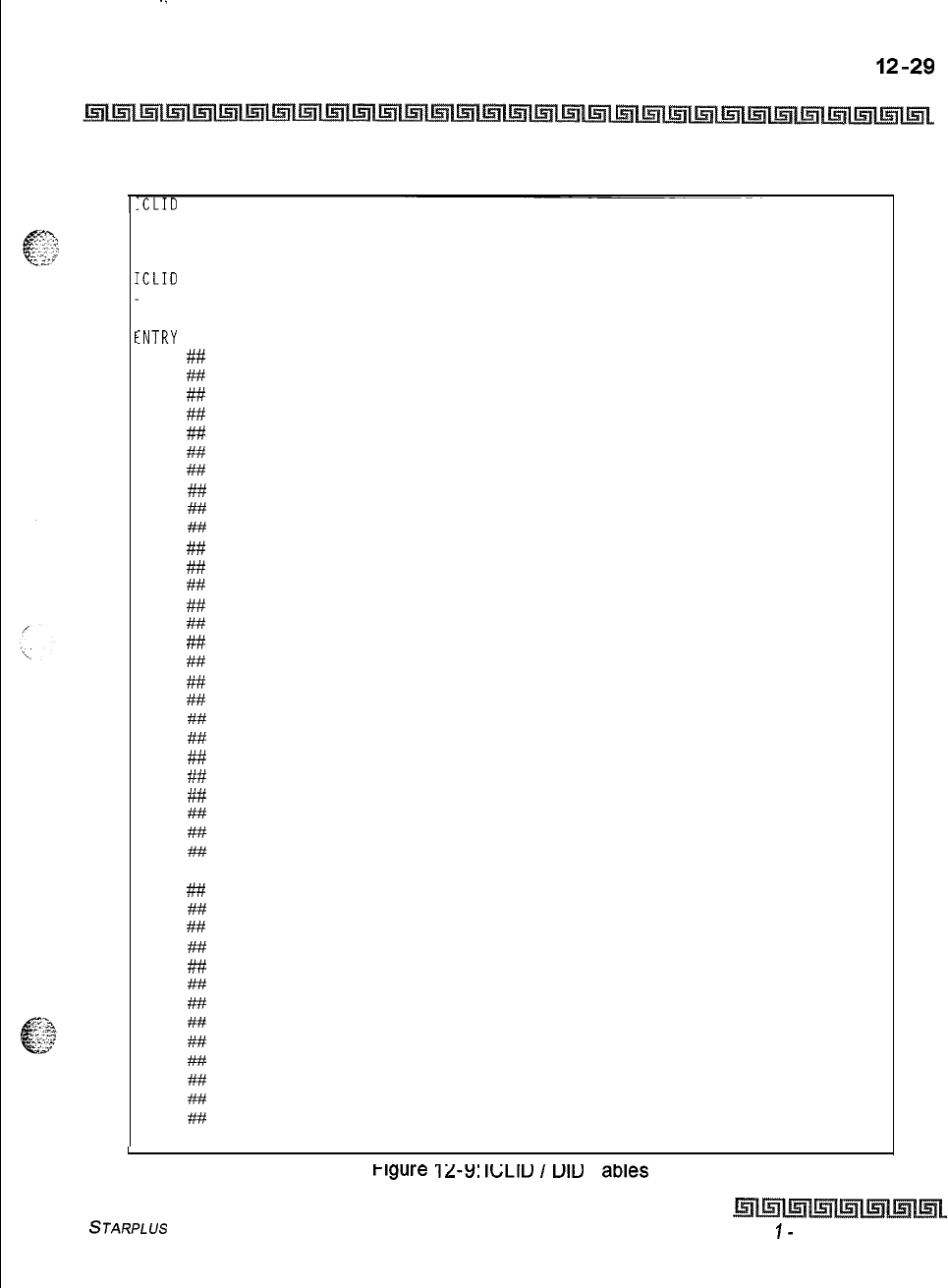
-.
Print System Database Parameters
Introduction
.CLID
NAME BAUD PORT
N Y 9600
1
ICLID UNANSWERED CALL TABLE
.CLID
TRANSLATION TABLE
NONE
:NTRY
ROUTE NAME
NUMBER
ROUTE RING ASSIGNMENTS
600
##
601
##
00
602
## NONE
603
##
604
##
01
605
##I
NONE
606
#iv
607
##
02
608
## NONE
609
##
610
##
03
611
## NONE
612
##
613
##
04
614
## NONE
615
##
616
#
05
617
## NONE
618
##
619
##
06
620
## NONE
621
##
622
##
07
623
## NONE
624
##
625
#
08
626
## NONE
627 ##
628
##
09
629
## NONE
630
##
631
##
10
632
## NONE
633
##
634
##
11
635
## NONE
636
##
637
##
12
638
## NONE
639
##
640
##
13
. . and so on through 799 NONE
L
Figure
12-Y:
Ic;LIu
1
ulu
I
awes
STARPLUS
Triad-S System Programming Manual Issue
I-
December 1998
12-30
Print System Database Parameters
introduction
16
NONE 108
108A
17
NONE
109
109A
18
110
NONE 1lOA
19
NONE
.
.
.
.
.
.
.
20
NONE
.
.
.
.
.
.
.
21
NONE
.
.
.
22
NONE
23
NONE
155
155A
24
NONE 156
156A
25
NONE 157
157A
.
.
.
and so on through 99
158
158A
100
1OOA 159
159A
101
1OlA 160
160A
102
102A
103
103A
104
104A
.
.
.
.
and so on through 252
Figure 12-9.
ICLID
/
DID Tables (Continued)
issue
I-
December 1998 STARPLUS Triad-S System Programming Manual
Print System Database Parameters
Introduction
12-31
Print Directory Dial Table Parameters
Programming Steps
1
Press the DIRECTORY DIAL TABLE flexible button (FLASH 85, button
#lo).
The
following message displays on the display phone:
PRINT DIR
-
DIAL
PRESS HOLD
2
To print the Directory Dialing Table parameters, press the HOLD button. The
following
message displays on the display phone:
PRINTING DIR
-
DIAL
.
When the system finishes sending the requested information to the printer, a confirmation tone is heard.
Description
This command dumps the entire database as a permanent record which can serve as a hardcopy of the
database. The system baud rate must match that of the printer or receiving device. Refer to Figure
12-10.
Directory
Diahg
Table for an example of the Directory Dialing Table database printout,
STARPLUS
Triad-S System Programming Manual
Issue I- December 1998
.‘.....
12-32
Print System Database Parameters
Introduction
LST BIN NAME
000 100
001 101
002 102
003 103
004 104
005 105
006 106
007 107
008 108
009 109
010
110
011 111
012 112
013 113
014 114
015 115
016 116
317 117
018 118
319 119
320 120
321 121
322 122
323 123
324 124
325 125
326 126
327 127
328 128
329 129
330 130
331 131
132 132
133 133
334 134
135
135
136 136
137 137
338 138
141 141
142
142
343 143
144
144
145
145
146
146
147
147
148 148
349 149
050 150
051 151
052 152
053 153
054 154
055 155
056 156
057 157
058 158
059 159
060 160
061 161
062 162
063 163
064 164
065 165
066 166
067 167
068 168
069 169
070 170
071 171
072 172
073 173
074 174
075 175
076 176
077 177
078 178
079 179
080 180
081 181
082 182
083 183
084 184
085 185
086 186
087 187
088 188
089 189
090 190
093 193
094 194
095 195
096 196
097 197
098 198
099 199
. .
and so on through bin 199
Figure 12-10: Directory Dialing Table
-
issue
I- December 1998
STARPLUS Triad-S System Programming Manual
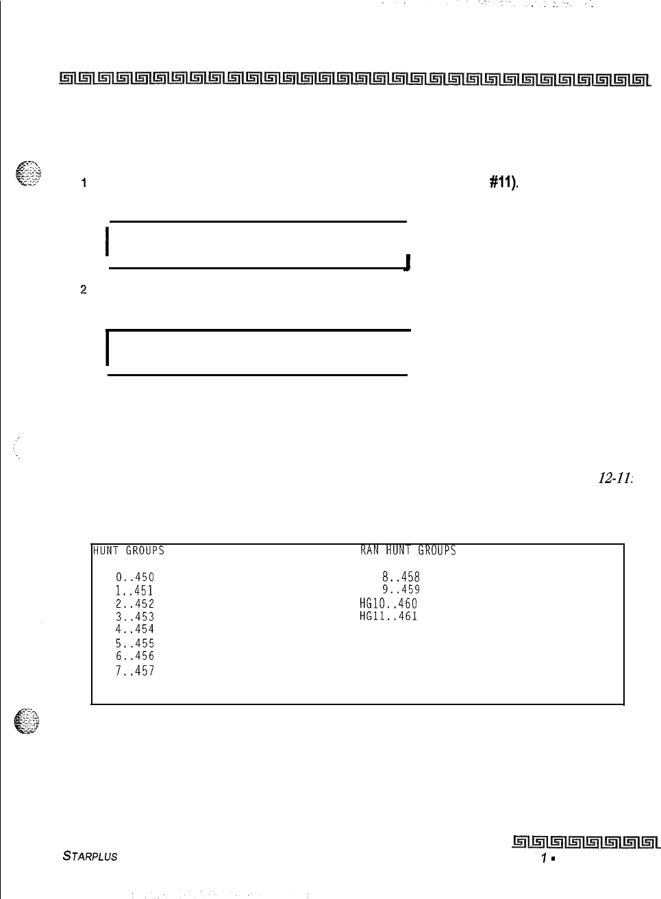
Print System Database Parameters
Introduction
12-33
Print Hunt Group Parameters
Programming Steps
I
Press the HUNT GROUPS flexible button (FLASH 85. button
#ll).
The following
message displays on the display phone:
I
PRINT HUNT GROUP
PRESS HOLD
I
2
To print data for Hunt Group Parameters, press the HOLD button. The following display
displays on the display phone:
I
PRINTING HUNT GROUP
I
When the system finishes sending the requested information to the printer, a confirmation tone is heard.
Description
This command dumps the entire database as a permanent record which can serve as a hardcopy of the
database. The system baud rate must match that of the printer or receiving device. Refer to Figure
12-11:
Hunt Group Parameters for an example of the Hunt Group Parameter database printout.
HG
0..450
PILOT HUNT
HG
1..451
PILOT HUNT
HG
2..452
PILOT HUNT
HG
3..453
PILOT HUNT
HG
4..454
PILOT HUNT
HG
5..455
PILOT HUNT
HG
6..456
PILOT HUNT
HG
7..457
PILOT HUNT
HG
8..458
PILOT HUNT
HG
9..459
PILOT HUNT
HG10..460
PILOT HUNT
HG11..461
PILOT HUNT
Figure 12-l 1: Hunt Group Parameters
STARPLUS
Triad-S System Programming Manual Issue
7
-
December 1998
.:
12-34 Print System Database Parameters
Introduction
Print ACD
/
UCD Group Parameters
Programming Steps
1
Press the
ACD*
or UCD GROUPS flexible button (FLASH 85, button
#12).
The
following message displays on the display phone:
PRINT ACD GROUP
PRESS HOLD
2
To print data for the
ACD*
or UCD Group Parameters, press the HOLD button. The
following display displays on the display phone:
PRINTING ACD GROUP
.
When the system finishes sending the requested information to the printer, a confirmation tone is heard.
*This
feature is available with optional sojfware.
Description
This command dumps the entire database as a permanent record which can serve as a hardcopy of the
database. The system baud rate must match that
of
the printer or receiving device. Refer to Figure
22-22:
ACD Group Parameters for an example of the ACD or UCD Group Parameters database printout.
Lssue
I-
December 1998
S
JARPLUS
Triad-S System Programming
Manual
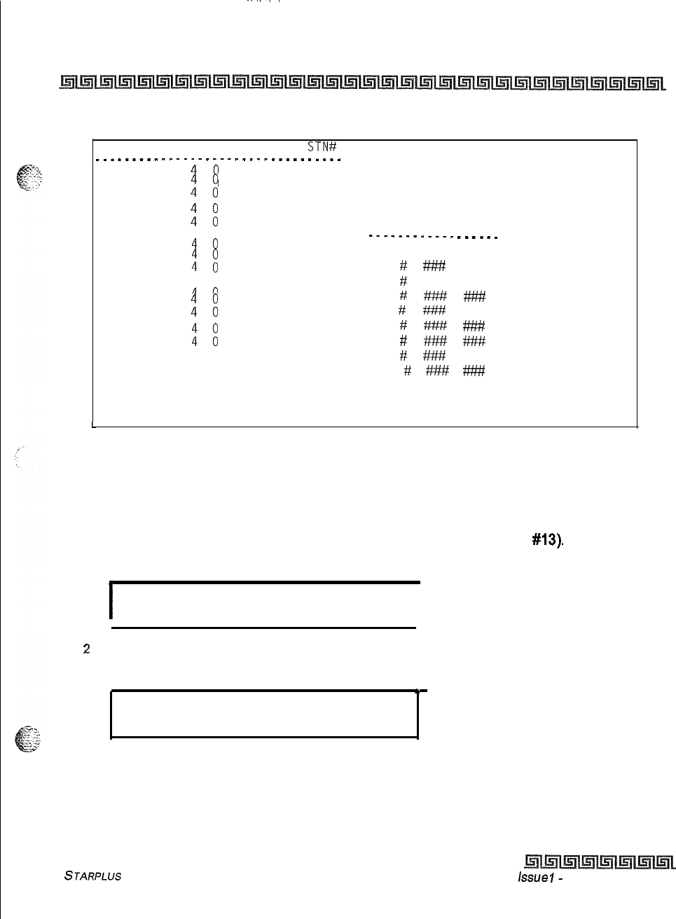
-...
Print System Database Parameters
Introduction
12-35
ACD ALT OVR AN0 SUP WRAP CIQ
STN# ACD TIMERS
.__________----_-.._______________
550
551
:
i
RING MIT OVER WRAP NAT NAR FRT
552
553
:
i
60 60 60 4 0 300
5
554
ANNOUNCEMENT TABLE
555
t :
--________-_
_____-
556
557
: i
TABLE TYPE INDEX TIME
558 1
#
####
###
559
: i
2
#
### ###
560561
: i
3
#
#####
###
562
563
t i
4
#
###
###
5
#
###
###
564
565
1
i
6
#
####
###
7
#
###
###
8#
###
###
ACD SMDR REPORTING
CO ICM EVT I/O BAUD
N N N 1 9600
Figure 12-12: ACD Group Parameters
L
Print Voicemail Group Parameters
Programming Steps
1
Press the VOICE MAIL GROUP flexible button (FLASH 85, button
#13).
The following
message displays on the display phone:
I
PRINT VM GROUP
PRESS HOLD
I
2
To print data for Voice Mail Group Parameters, press the HOLD button. The following
display displays on the display phone:
*
PRINTING VM GROUP
When the system finishes sending the requested information to the printer, a confirmation tone is heard,
STARPLUS
Triad-S System Programming Manual issue
I-
December 1998
12-36 Print System Database Parameters
Introduction
Description
This command dumps the entire database as a permanent record which can serve as a hardcopy of the
database. The system baud rate must match that of the printer or receiving device. When printing the VM
Group Parameters, the following data prints:
+
Voice Mail Group Parameters
Q
Voice Mail Outpulsing Table (including the disconnect table)
*Voice Mail Options
Refer to Figure
12-1.33:
Voicemail
Group
Parameters
for an example of the VM Group Parameters
database
printout.
Issue
I
-
December 1998 STARPLUS Triad-S System Programming Manual
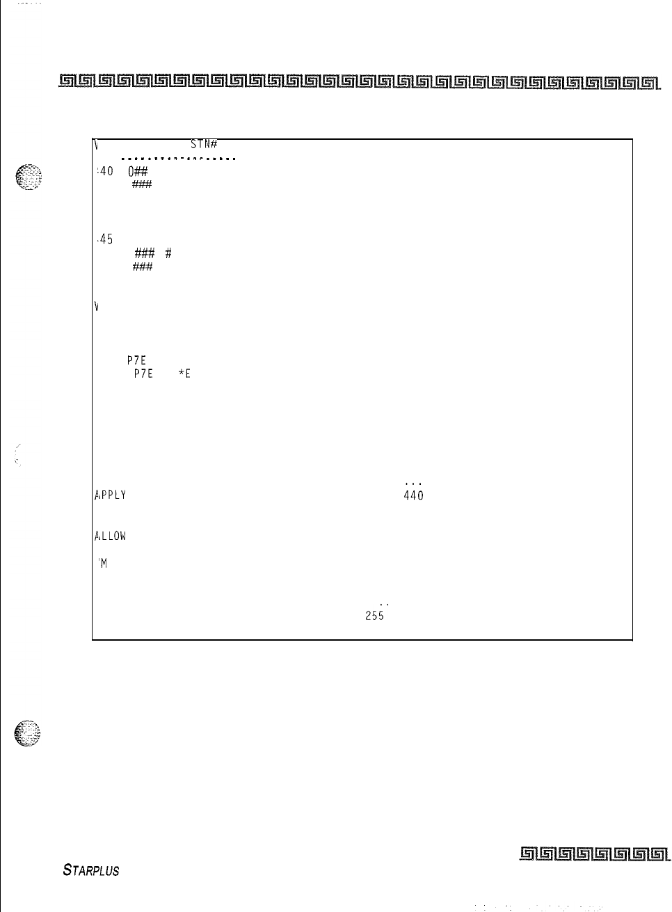
Print System Database Parameters
Introduction
12-37
b
4
4
4
4
4
4
4
4
v
I
V
P
P
V
'M ALT LEV RET
STN#
.-_______.___.__-.
140
O##
#
-41 ####
#
-42 ### #
-43 ### #
-44 ### #
.45
### #
-46
###
#
-47
###
#
'OICE MAIL OUT TABLE
TABLE
DX PREFIX SUFFIX
0
P7E
1
P7E
*E
2
3
4
5
6
7
'OICE MAIL CO DISCONNECT SIGNAL
Mailbox Table
Index Group ID
1
440
2
440
3
440
4
440
5
440
6
440
7
440
8
440
9
440
10
440
11
440
12
440
13
440
14
440
15
440
16
440
17
440
18
440
19
440
20 440
. . . . .
iPPLY
IN-BAND DIGITS TO CO CALLS
Y
iLLOW
FORWARD TO VM GROUP
Y
'M
BROKER CALL
Y
246
446
241 440
242 440
243 440
244 440
245 440
246 440
. . .
. .
25;'
440'
Figure 12-l 3: Voicemail Group Parameters
STARPLUS Triad-S System Programming Manual
Issue I- December 1998
12-38 Print System Database Parameters
Introduction
Print Verified Account Codes
Programming Steps
I
Press the VERIFIED ACCT CODES flexible button (FLASH 85, button
#15).
The
following message displays on the display phone:
PRINT ACCT CODES
PRESS HOLD
b
2
To print the VERIFIED ACCT CODES, press the HOLD button. The following message
displays on the display phone:
PRINT ACCT CODES
When the system finishes sending the requested information to the printer, a confirmation tone is heard.
Description
This command dumps the entire database as a permanent record which can serve as a hardcopy of the
database. The system baud rate must match that of the printer or receiving device. Refer to
Figure 22-14:
~eQ%~dccount Codes for an example of the Verified Account Codes database printout.
issue I- December 1998
STARPLUS Triad-S
System Programming Manual
Print System Database Parameters
Introduction
,CCOUNT
CODE TABLE
51
##
107
##
_................
52
#t#
108
##
53
##
109
##
NTRY COS DGTS
54
##
110
##
55
##I
111
##
00
##
56
##
112
##
01
##
57
##
113
##
02
##
58
##
114
##
03
##
59 7% 115
##
04
##
60
##
116
##
05
##
61
##
117
##
06
##
62
##
118
##
07
##
63
##
119
##
08
##
64
##
120
##
09
##
65
##
121
##
10 ##
66
##
122
##
11
##/ 67
##
123
##
12 ##
68
##
124
##
13
##
69
##
125
##
14
##
70
##
126
##
15 ##
71
##
127
##
16 ##
72
##
128
##
17
##
73
#
129
##
18 ##
74
##
130
##
19
##
75
##
131
##
20
##
76
#
132
##
21
##
77
##
133
##
22
##
78
##
134
##
23
##
79
##
135
##
24 ##
80
##
136
##
25
##
81
##
137
##
26
##
82
##
138
##
27 ##
83
##
139
##
28
##
84
##
140
##
29
##
85
##
141
##
30
##
86
##
142
##
31
##
87
##
143
##
32 ##
88
##
144
##
33
##
89
##
145
##
34 ##
90
##
146
##
35
##
91
##
147
##
36
##
92
##
148
##
37 ##
93
#
149
##
38 ##
94
##
150
##
39
##
95
##
151
##
40
##
96
##
152
##
41 ##
97
##
153
##
42
##
98
##
154
##
Figure 12-14: Verified Account Codes
-.
.--
-
STARPLUS ITfad-S System Programming Manual
Issue I- December 1998
12-40
Print System Database Parameters
introduction
163
##
221
##
164
##
222
##
165
##
223
##
166
##/
224
##
167
##
225
##
168
##
226
##
169
##
227
##
170
##
228
##
171
##
229
##
172
##
230
##
173
##
231
##
174
##
232
##
175
##
233
##
176
##
234
##
177
##
235
##
178
##
236
##
179
##
237
i'#
180
##
238
##
181
i#
239
##
182
##
240
#
183
##
241
##
184
##I
242
##
185
##
243
##
186
##
244
##
187
##
245
##
188
##
246
##
189
##
247
##
190
##I
248
##
191
##
249
##
192
##
193
##
194
##
195
##
196
##
197
##I
198
##f
199
##I
200
##
201
##
202
##
203
#
204
##
205
#
206
##
207
##
208
##
209
6%
210
##
Figure 12-15. Verified Account Codes (Continued)
Issue
7
-
uecember
7x48
STARPLUS
Triad-S System Programming Manual
Print System Database Parameters
Introduction
12-41
Abort Printing
f$c:
Programming Steps
kL*’
To
abort a printout:
iPress the ABORT PRINTING flexible button (FLASH 85, button
#20).
2
Press the HOLD button. The message currently on the display phone remains unchanged,
however, printing aborts.
STARPLUS
Triad-S System Programming Manual
Issue I- December 1998
I
:.
12-42
Print System Database Parameters
Introduction
Issue
I
-
December 1998 STARPLUS
Triad-S System Programming Manual
