Vulkan Programming Guide Graham Sellers
Vulkan%20Programming%20Guide
User Manual:
Open the PDF directly: View PDF ![]() .
.
Page Count: 792 [warning: Documents this large are best viewed by clicking the View PDF Link!]
- About This E-Book
- Vulkan™ Programming Guide
- Contents
- Figures
- Tables
- Listings
- About This Book
- Acknowledgments
- About the Author
- Chapter 1. Overview of Vulkan
- Chapter 2. Memory and Resources
- Chapter 3. Queues and Commands
- Chapter 4. Moving Data
- Chapter 5. Presentation
- Chapter 6. Shaders and Pipelines
- Chapter 7. Graphics Pipelines
- Chapter 8. Drawing
- Chapter 9. Geometry Processing
- Chapter 10. Fragment Processing
- Chapter 11. Synchronization
- Chapter 12. Getting Data Back
- Chapter 13. Multipass Rendering
- Appendix. Vulkan Functions
- Glossary
- Index
- Code Snippets

About This E-Book
EPUB is an open, industry-standard format for e-books. However, support for EPUB and its many
features varies across reading devices and applications. Use your device or app settings to customize
the presentation to your liking. Settings that you can customize often include font, font size, single or
double column, landscape or portrait mode, and figures that you can click or tap to enlarge. For
additional information about the settings and features on your reading device or app, visit the device
manufacturer’s Web site.
Many titles include programming code or configuration examples. To optimize the presentation of
these elements, view the e-book in single-column, landscape mode and adjust the font size to the
smallest setting. In addition to presenting code and configurations in the reflowable text format, we
have included images of the code that mimic the presentation found in the print book; therefore,
where the reflowable format may compromise the presentation of the code listing, you will see a
“Click here to view code image” link. Click the link to view the print-fidelity code image. To return
to the previous page viewed, click the Back button on your device or app.
Vulkan™ Programming Guide
The Official Guide to Learning Vulkan
Graham Sellers
With contributions from John Kessenich
Boston • Columbus • Indianapolis • New York • San Francisco • Amsterdam • Cape Town
Dubai • London • Madrid • Milan • Munich • Paris • Montreal • Toronto • Delhi • Mexico City
São Paulo • Sydney • Hong Kong • Seoul • Singapore • Taipei • Tokyo

Many of the designations used by manufacturers and sellers to distinguish their products are claimed
as trademarks. Where those designations appear in this book, and the publisher was aware of a
trademark claim, the designations have been printed with initial capital letters or in all capitals.
The author and publisher have taken care in the preparation of this book, but make no expressed or
implied warranty of any kind and assume no responsibility for errors or omissions. No liability is
assumed for incidental or consequential damages in connection with or arising out of the use of the
information or programs contained herein.
For information about buying this title in bulk quantities, or for special sales opportunities (which
may include electronic versions; custom cover designs; and content particular to your business,
training goals, marketing focus, or branding interests), please contact our corporate sales department
at corpsalespearsoned.com or (800) 382-3419.
For government sales inquiries, please contact governmentsales@pearsoned.com.
For questions about sales outside the U.S., please contact intlcs@pearson.com.
Visit us on the Web: informit.com/aw
Library of Congress Control Number: 2016948832
Copyright © 2017 Pearson Education, Inc.
All rights reserved. Printed in the United States of America. This publication is protected by
copyright, and permission must be obtained from the publisher prior to any prohibited reproduction,
storage in a retrieval system, or transmission in any form or by any means, electronic, mechanical,
photocopying, recording, or likewise. For information regarding permissions, request forms and the
appropriate contacts within the Pearson Education Global Rights & Permissions Department, please
visit www.pearsoned.com/permissions/.
Vulkan and the Vulkan logo are trademarks of the Khronos Group Inc.
ISBN-13: 978-0-13-446454-1
ISBN-10: 0-13-446454-0
Text printed in the United States.
1 16

For you, the reader.
—Graham Sellers
Contents
Figures
Tables
Listings
About This Book
About the Sample Code
Errata
Acknowledgments
About the Author
1 Overview of Vulkan
Introduction
Instances, Devices, and Queues
The Vulkan Instance
Vulkan Physical Devices
Physical Device Memory
Device Queues
Creating a Logical Device
Object Types and Function Conventions
Managing Memory
Multithreading in Vulkan
Mathematical Concepts
Vectors and Matrices
Coordinate Systems
Enhancing Vulkan
Layers
Extensions
Shutting Down Cleanly
Summary
2 Memory and Resources
Host Memory Management
Resources
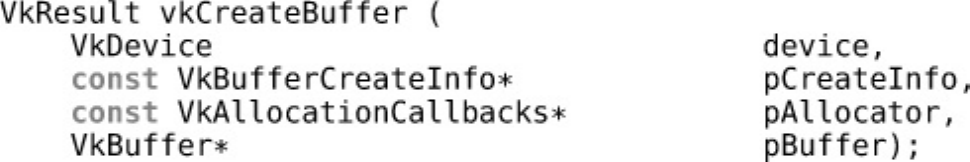
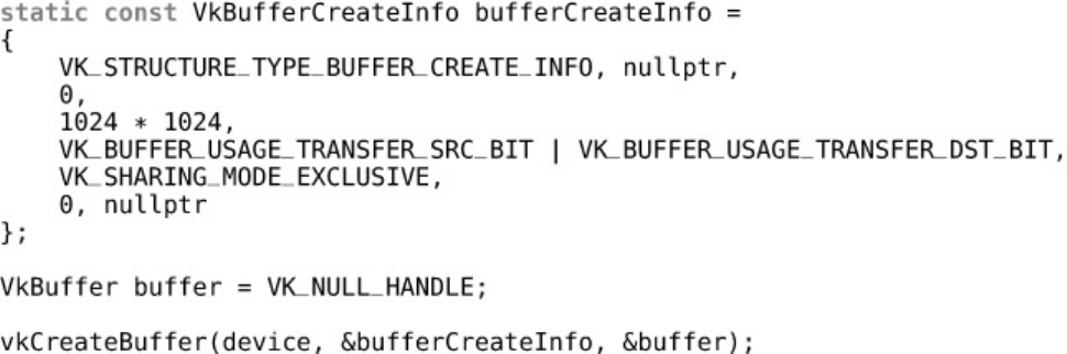
Buffers
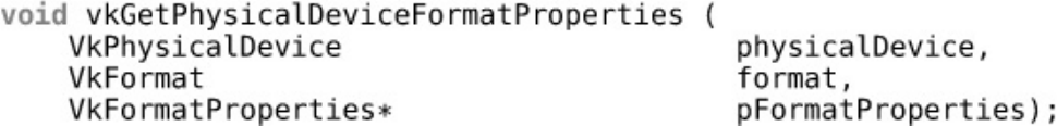
Formats and Support
Images
Resource Views
Destroying Resources
Device Memory Management
Allocating Device Memory
Host Access to Device Memory
Binding Memory to Resources
Sparse Resources
Summary
3 Queues and Commands
Device Queues
Creating Command Buffers
Recording Commands
Recycling Command Buffers
Submission of Commands
Summary
4 Moving Data
Managing Resource State
Pipeline Barriers
Global Memory Barriers
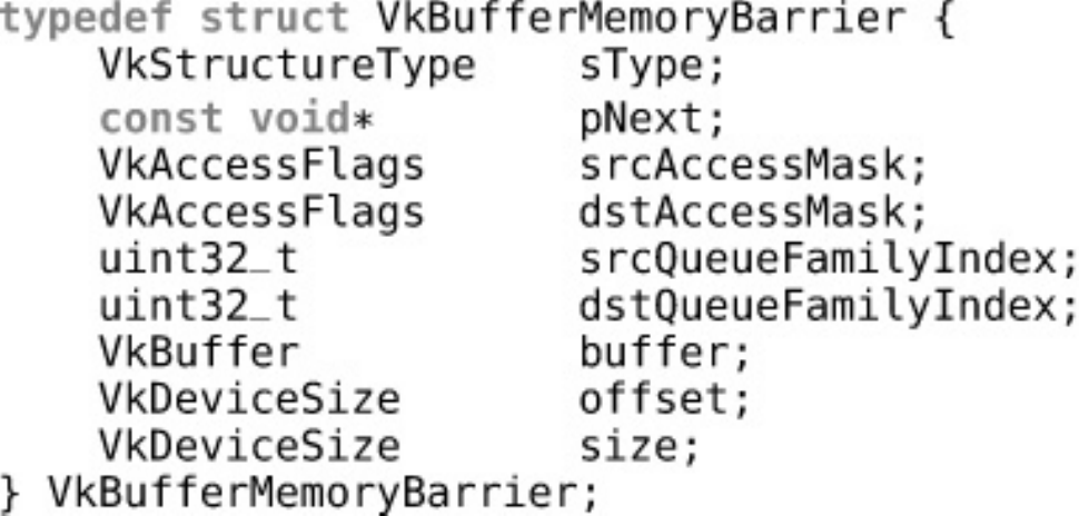
Buffer Memory Barriers
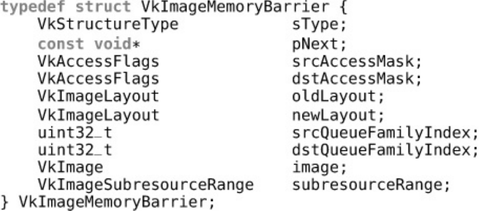
Image Memory Barriers
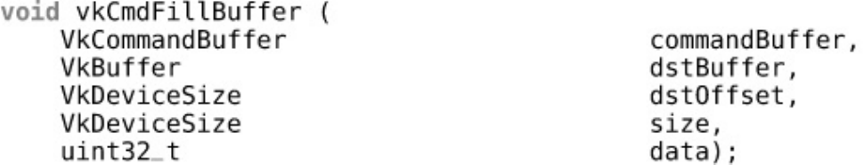
Clearing and Filling Buffers
Clearing and Filling Images
Copying Image Data
Copying Compressed Image Data
Stretching Images
Summary
5 Presentation
Presentation Extension
Presentation Surfaces
Presentation on Microsoft Windows
Presentation on Xlib-Based Platforms
Presentation with Xcb
Swap Chains
Full-Screen Surfaces
Performing Presentation
Cleaning Up
Summary
6 Shaders and Pipelines
An Overview of GLSL
An Overview of SPIR-V
Representation of SPIR-V
Handing SPIR-V to Vulkan
Pipelines
Compute Pipelines
Creating Pipelines
Specialization Constants
Accelerating Pipeline Creation
Binding Pipelines
Executing Work
Resource Access in Shaders
Descriptor Sets
Binding Resources to Descriptor Sets
Binding Descriptor Sets
Uniform, Texel, and Storage Buffers
Push Constants
Sampled Images
Summary
7 Graphics Pipelines
The Logical Graphics Pipeline
Renderpasses
The Framebuffer
Creating a Simple Graphics Pipeline
Graphics Shader Stages
Vertex Input State
Input Assembly
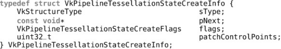
Tessellation State
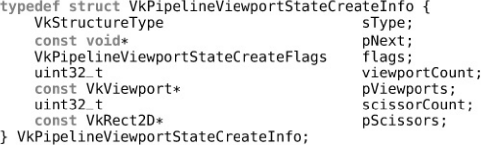
Viewport State
Rasterization State
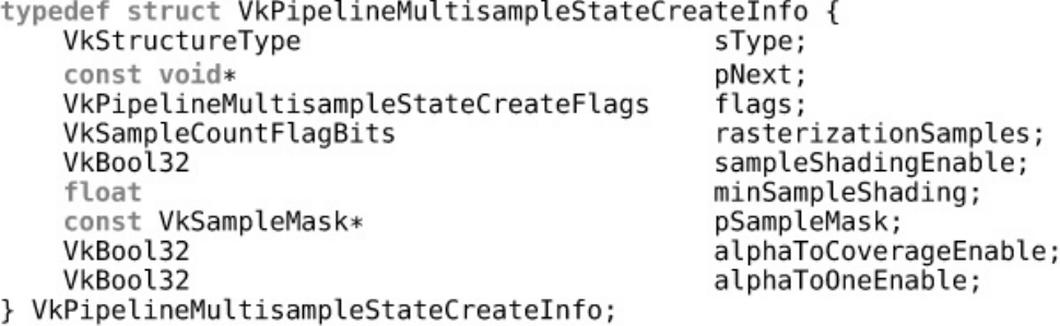
Multisample State
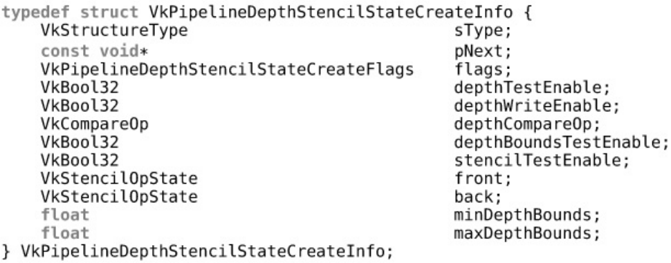
Depth and Stencil State
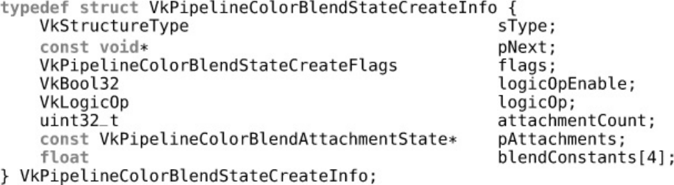
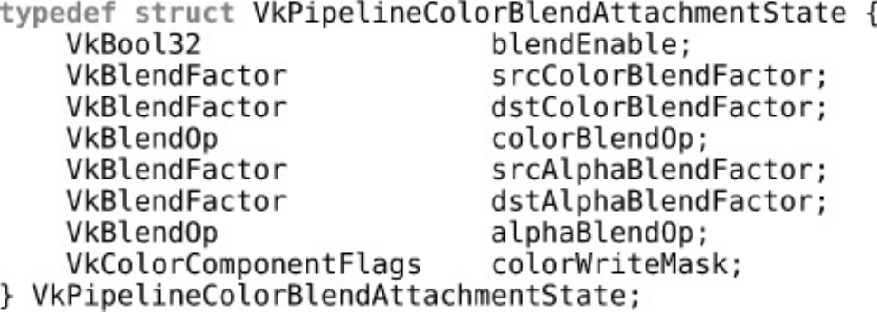
Color Blend State
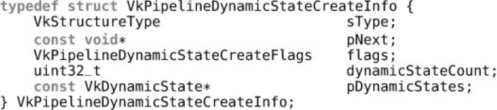
Dynamic State
Summary
8 Drawing
Getting Ready to Draw
Vertex Data
Indexed Draws
Index-Only Rendering
Reset Indices
Instancing
Indirect Draws
Summary
9 Geometry Processing
Tessellation
Tessellation Configuration
Tessellation Variables
Tessellation Example: Displacement Mapping
Geometry Shaders
Cutting Primitives
Geometry Shader Instancing
Programmable Point Size
Line Width and Rasterization
User Clipping and Culling
The Viewport Transformation
Summary
10 Fragment Processing
Scissor Testing
Depth and Stencil Operations
Depth Testing
Stencil Testing
Early Fragment Tests
Multisample Rendering
Sample Rate Shading
Multisample Resolves
Logic Operations
Fragment Shader Outputs
Color Blending
Summary
11 Synchronization
Fences
Events
Semaphores
Summary
12 Getting Data Back
Queries
Executing Queries
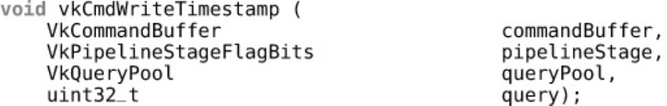
Timing Queries
Reading Data with the Host
Summary
13 Multipass Rendering
Input Attachments
Attachment Contents
Attachment Initialization
Render Areas
Preserving Attachment Content
Secondary Command Buffers
Summary
Appendix: Vulkan Functions
Glossary
Index

Figures
Figure 1.1 Vulkan Hierarchy of Instance, Device, and Queue
Figure 2.1 Mipmap Image Layout
Figure 2.2 Memory Layout of LINEAR Tiled Images
Figure 2.3 Gamma Curves for sRGB (Top) and Simple Powers (Bottom)
Figure 2.4 Cube Map Construction
Figure 2.5 Host and Device Memory
Figure 4.1 Data Layout of Images Stored in Buffers
Figure 6.1 Descriptor Sets and Pipeline Sets
Figure 6.2 Linear Sampling
Figure 6.3 Effect of Sampling Modes
Figure 7.1 The Full Vulkan Graphics Pipeline
Figure 7.2 Strip (Left) and Fan (Right) Topologies
Figure 7.3 Triangles with Adjacency Topology
Figure 7.4 Triangle Strip with Adjacency Topology
Figure 8.1 Index Data Flow
Figure 8.2 The Effect of Primitive Restart on Triangle Strips
Figure 8.3 Many Instanced Cubes
Figure 9.1 Quad Tessellation
Figure 9.2 Triangle Tessellation
Figure 9.3 Isoline Tessellation
Figure 9.4 Tessellation Spacing Modes
Figure 9.5 Result of Tessellated Displacement Mapping
Figure 9.6 Rasterization of Strict Lines
Figure 9.7 Rasterization of Nonstrict Lines
Figure 9.8 Clipping Against a Viewport
Figure 10.1 Standard Sample Locations
Figure 13.1 Data Flow for a Simple Deferred Renderer
Figure 13.2 Serial Dependency of Translucent on Opaque Geometry
Figure 13.3 Parallel Rendering of Translucent and Opaque Geometry
Tables
Table 2.1 Sparse Texture Block Sizes
Table 6.1 Pipeline Resource Limits
Table 6.2 Texture Comparison Functions
Table 7.1 Dynamic and Static State Validity
Table 9.1 GLSL and SPIR-V Tessellation Modes
Table 9.2 GLSL and SPIR-V Tessellation Winding Order
Table 10.1 Depth Comparison Functions
Table 10.2 Stencil Operations
Table 10.3 Logic Operations
Table 10.4 Blend Equations
Table 10.5 Blend Factors

Listings
Listing 1.1 Creating a Vulkan Instance
Listing 1.2 Querying Physical Device Properties
Listing 1.3 Creating a Logical Device
Listing 1.4 Querying Instance Layers
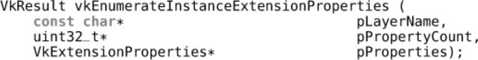
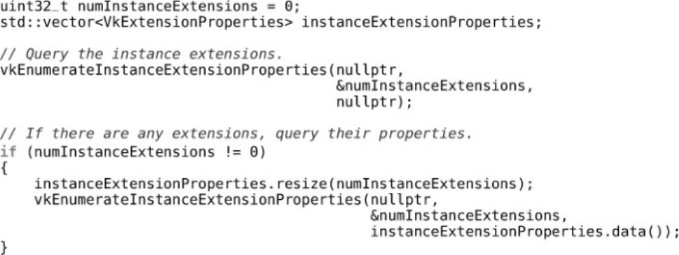
Listing 1.5 Querying Instance Extensions
Listing 2.1 Declaration of a Memory Allocator Class
Listing 2.2 Implementation of a Memory Allocator Class
Listing 2.3 Creating a Buffer Object
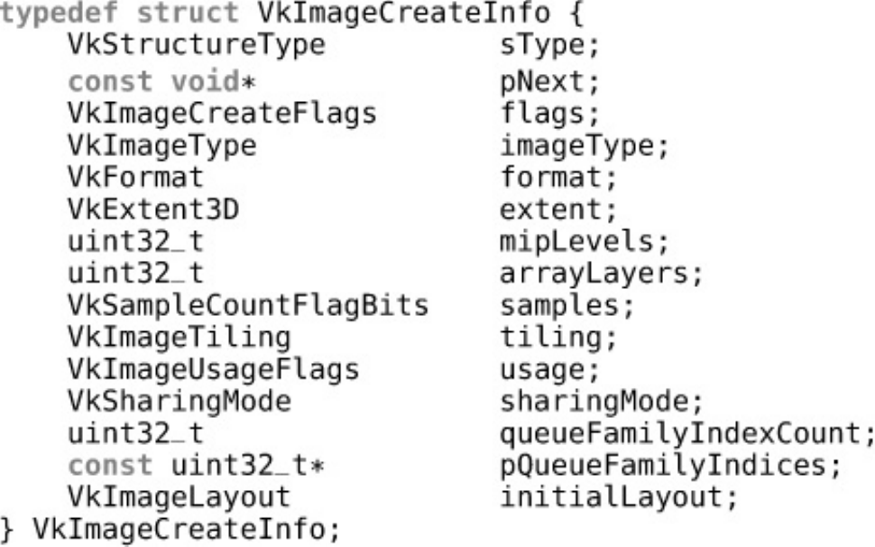
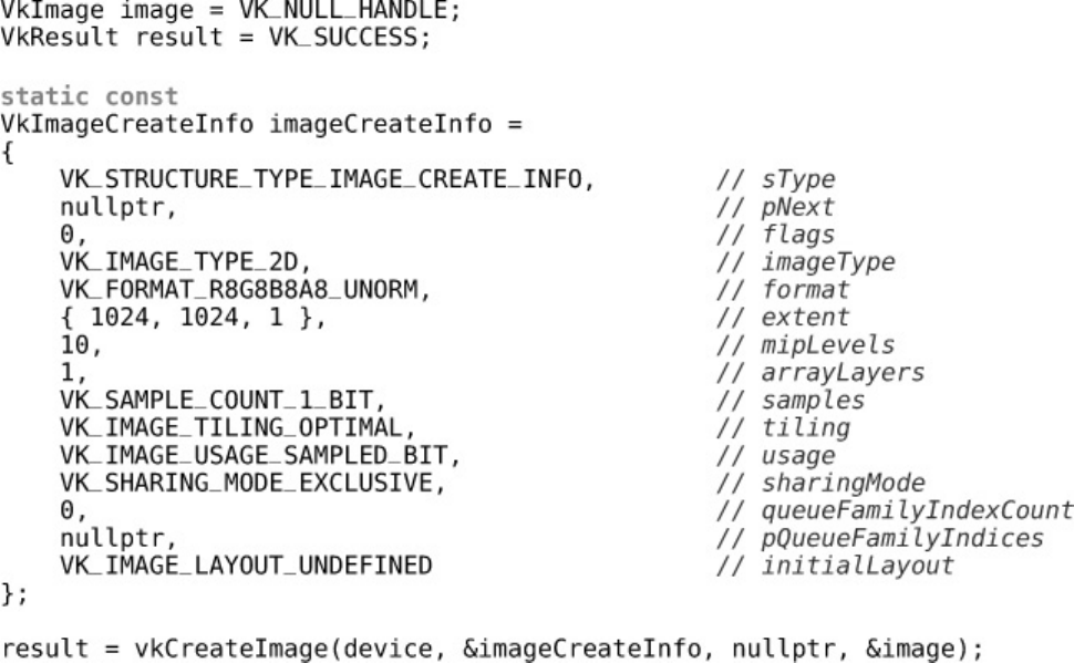
Listing 2.4 Creating an Image Object
Listing 2.5 Choosing a Memory Type for an Image
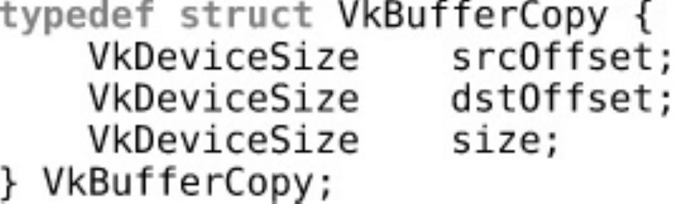
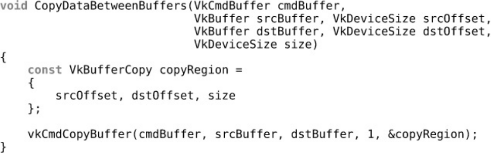
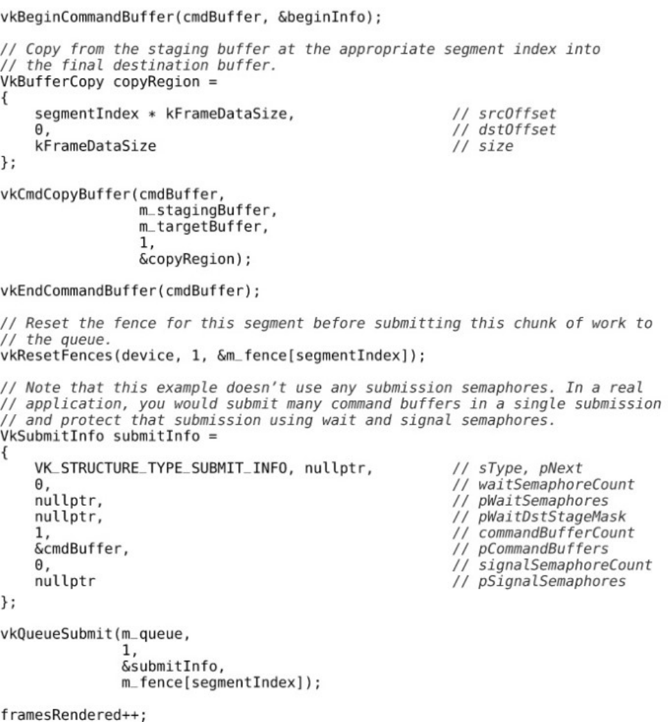
Listing 3.1 Example of Using vkCmdCopyBuffer()
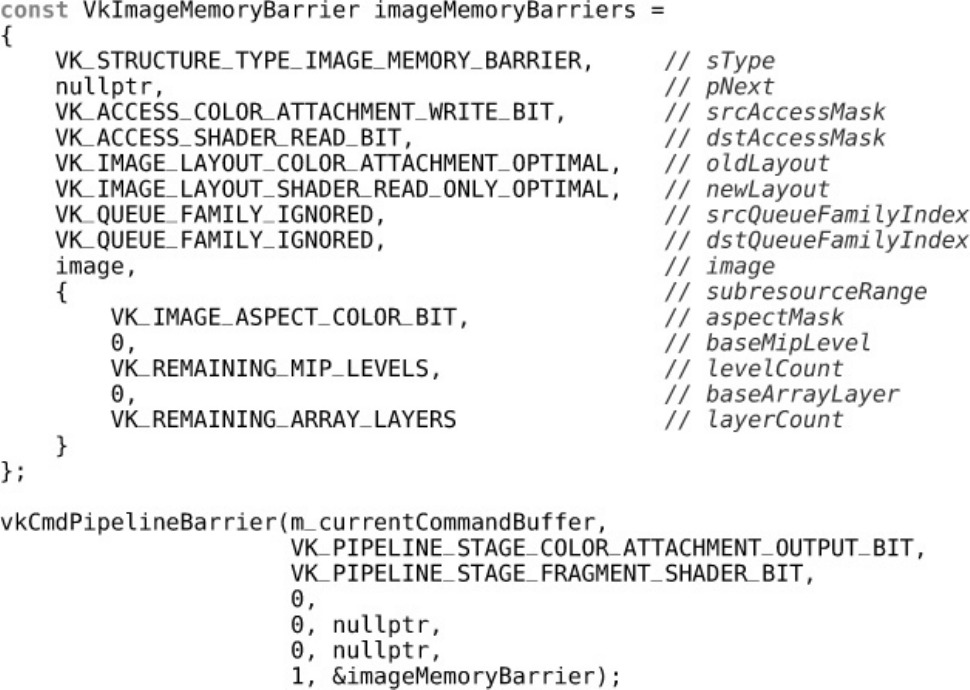
Listing 4.1 Image Memory Barrier
Listing 4.2 Filling a Buffer with Floating-Point Data
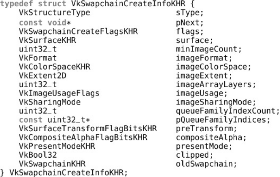
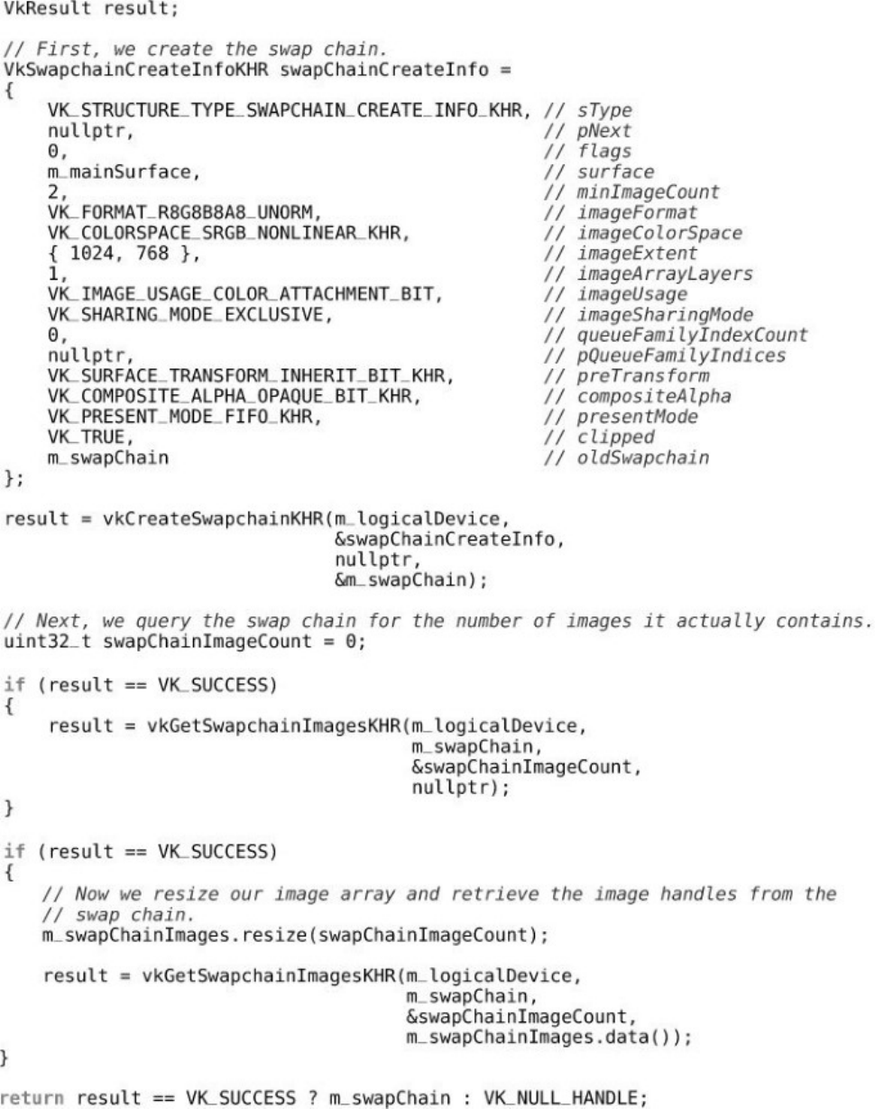
Listing 5.1 Creating a Swap Chain
Listing 5.2 Transitioning an Image to Present Source
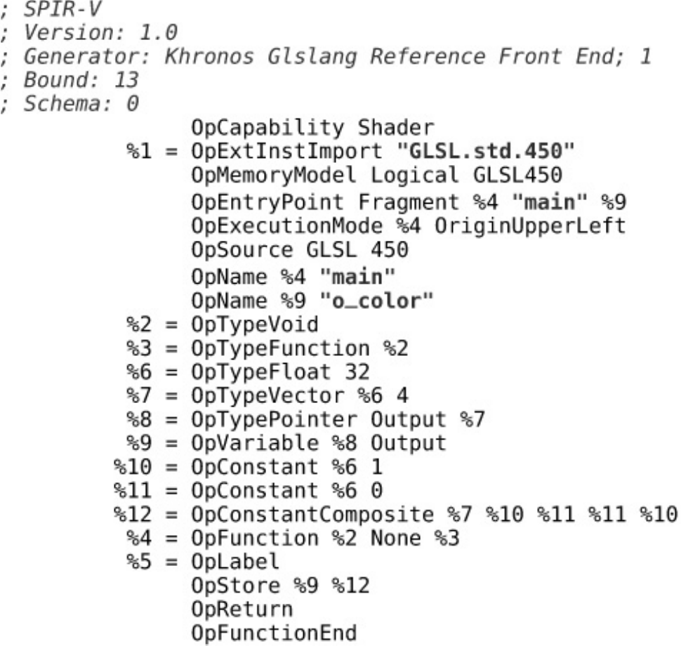
Listing 6.1 Simplest Possible GLSL Shader
Listing 6.2 Simplest SPIR-V
Listing 6.3 Local Size Declaration in a Compute Shader (GLSL)
Listing 6.4 Local Size Declaration in a Compute Shader (SPIR-V)
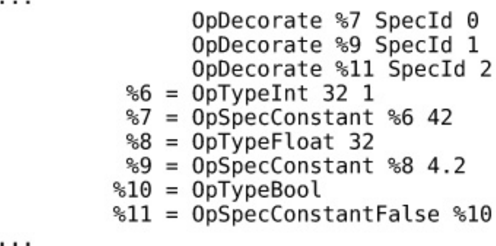
Listing 6.5 Specialization Constants in GLSL
Listing 6.6 Specialization Constants in SPIR-V
Listing 6.7 Saving Pipeline Cache Data to a File
Listing 6.8 Declaring Resources in GLSL
Listing 6.9 Declaring Resources in SPIR-V
Listing 6.10 Creating a Pipeline Layout
Listing 6.11 Declaring Uniform and Shader Blocks in GLSL
Listing 6.12 Declaring Uniform and Shader Blocks in SPIR-V
Listing 6.13 Declaring Texel Buffers in GLSL
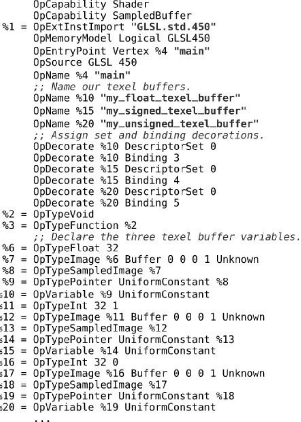
Listing 6.14 Declaring Texel Buffers in SPIR-V
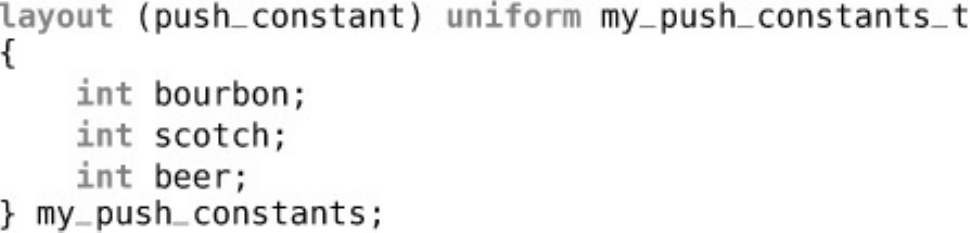
Listing 6.15 Declaring Push Constants in GLSL
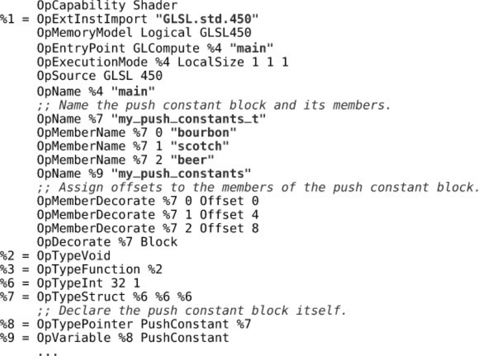
Listing 6.16 Declaring Push Constants in SPIR-V

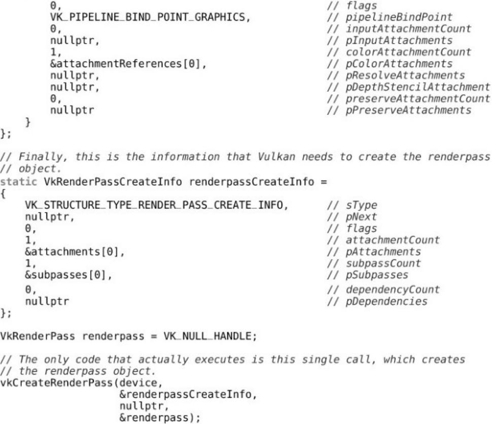
Listing 7.1 Creating a Simple Renderpass
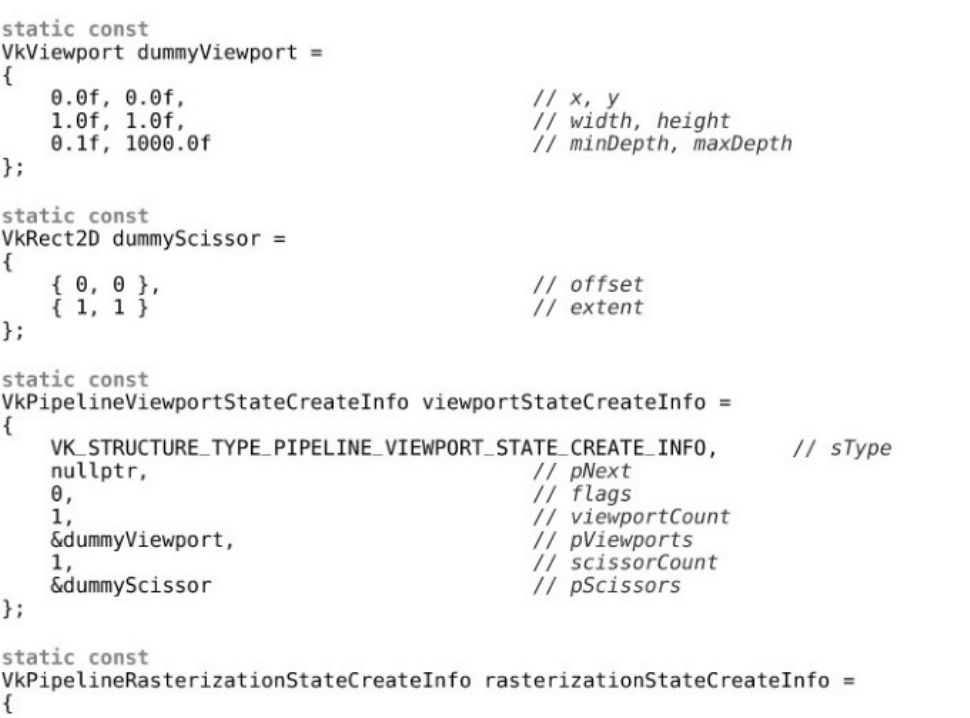
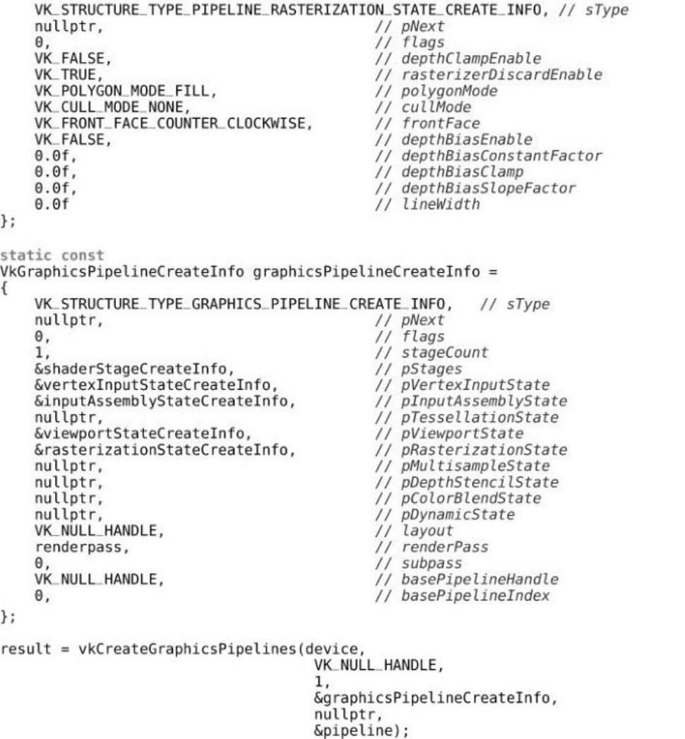
Listing 7.2 Creating a Simple Graphics Pipeline
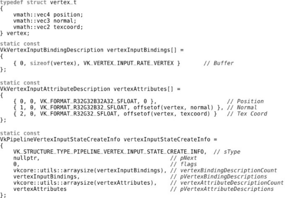
Listing 7.3 Describing Vertex Input Data
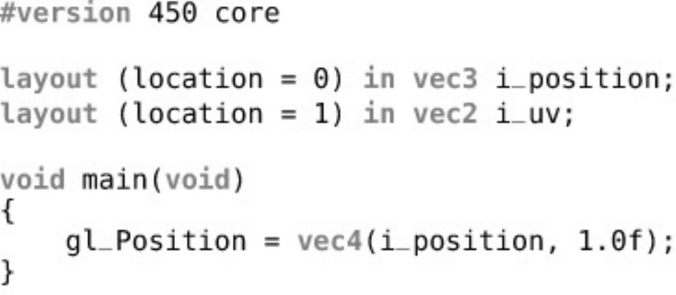
Listing 7.4 Declaring Inputs to a Vertex Shader (GLSL)
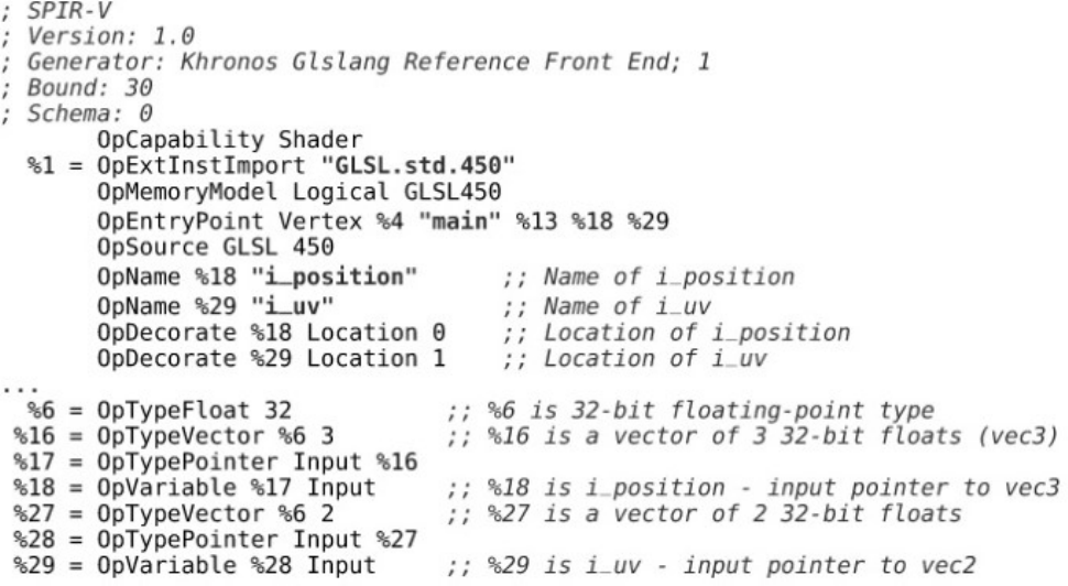
Listing 7.5 Declaring Inputs to a Vertex Shader (SPIR-V)
Listing 8.1 Separate Vertex Attribute Setup
Listing 8.2 Indexed Cube Data
Listing 8.3 Using the Vertex Index in a Shader
Listing 8.4 Using the Instance Index in a Shader
Listing 8.5 Draw Index Used in a Shader
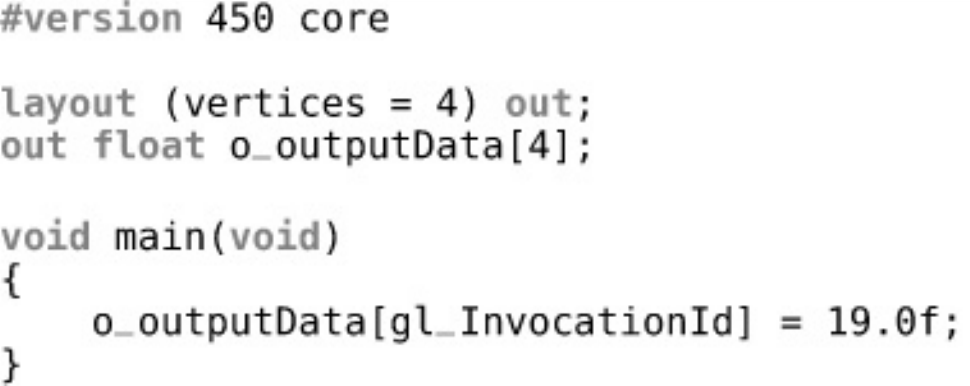
Listing 9.1 Trivial Tessellation Control Shader (GLSL)
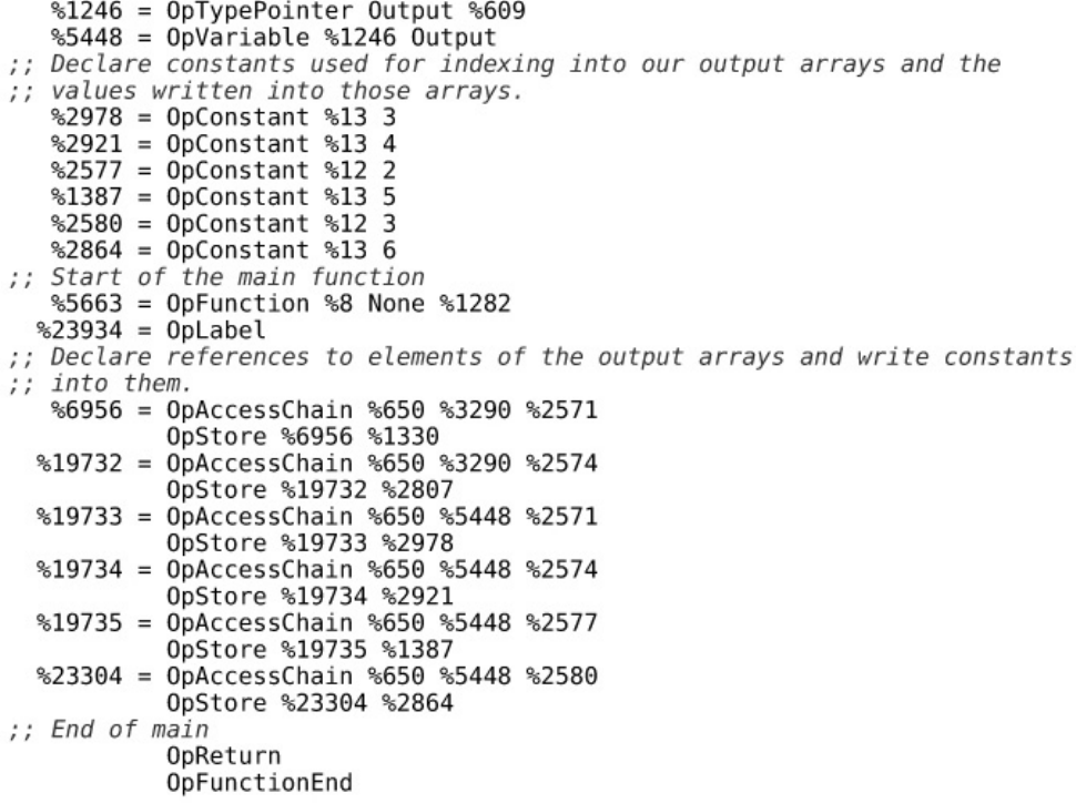
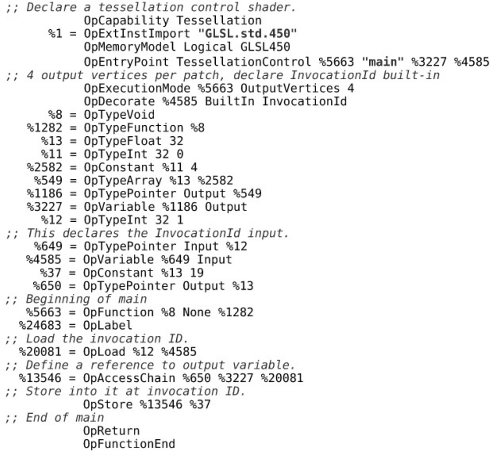
Listing 9.2 Trivial Tessellation Control Shader (SPIR-V)
Listing 9.3 Declaring Outputs in Tessellation Control Shaders (GLSL)
Listing 9.4 Declaring Outputs in Tessellation Control Shaders (SPIR-V)
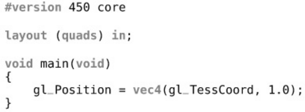
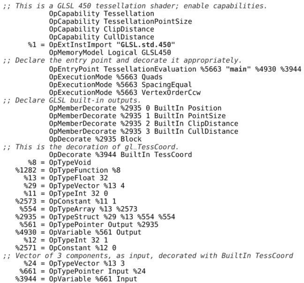
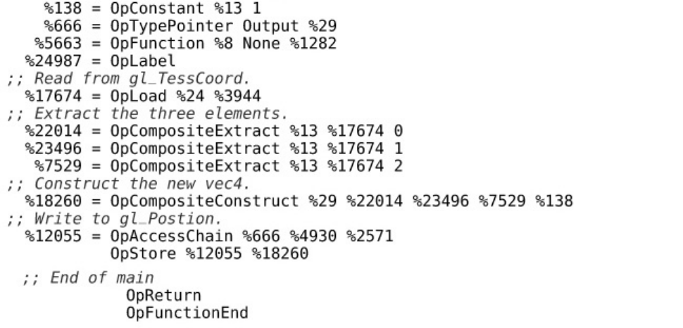
Listing 9.5 Accessing gl_TessCoord in Evaluation Shader (GLSL)
Listing 9.6 Accessing gl_TessCoord in Evaluation Shader (SPIR-V)
Listing 9.7 Descriptor Setup for Displacement Mapping
Listing 9.8 Vertex Shader for Displacement Mapping
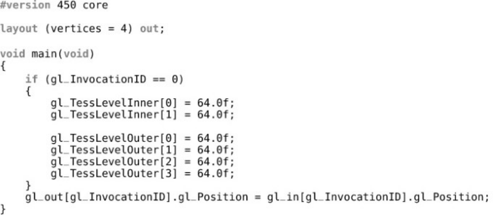
Listing 9.9 Tessellation Control Shader for Displacement Mapping
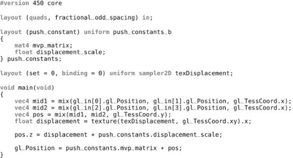
Listing 9.10 Tessellation Evaluation Shader for Displacement Mapping
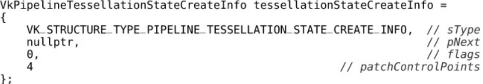
Listing 9.11 Tessellation State Creation Information
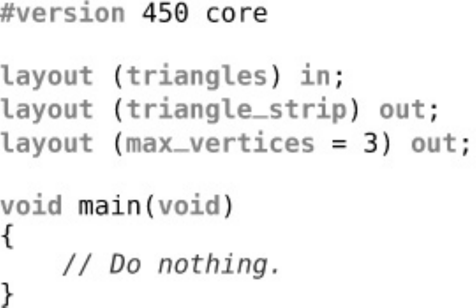
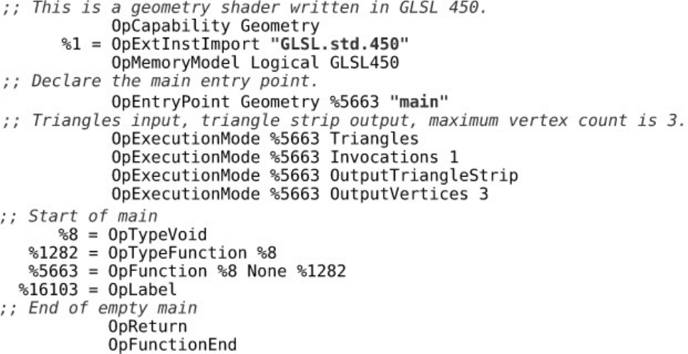
Listing 9.12 Minimal Geometry Shader (GLSL)
Listing 9.13 Minimal Geometry Shader (SPIR-V)
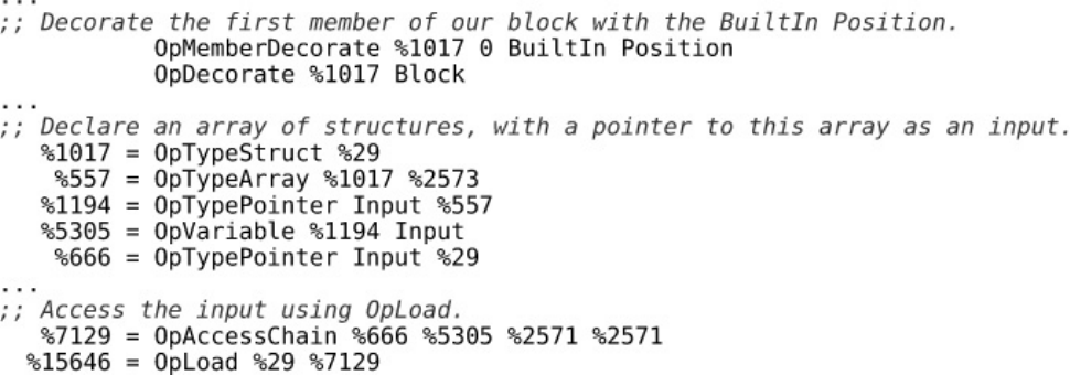
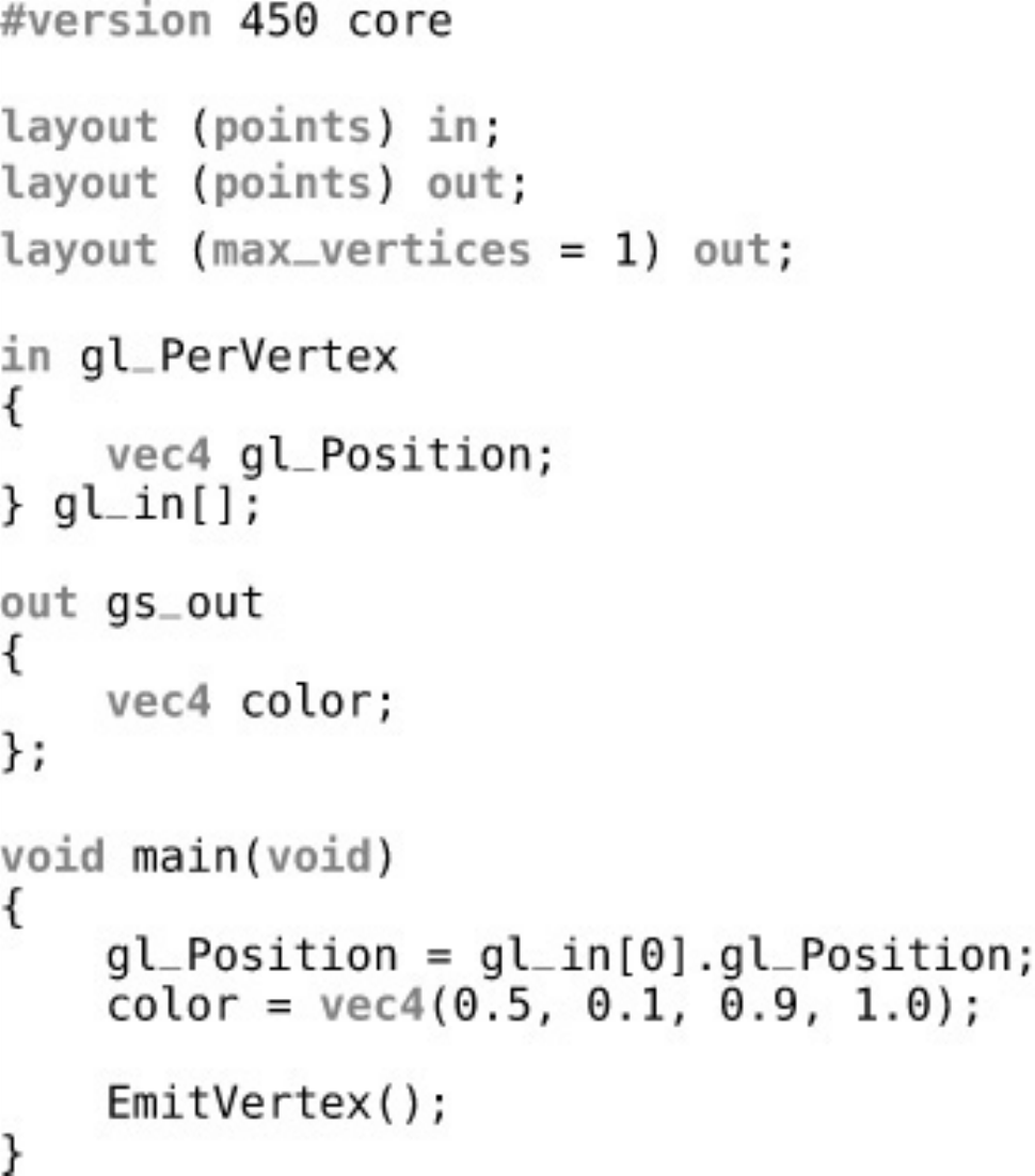
Listing 9.14 Declaring gl_PerVertex in a GLSL Geometry Shader
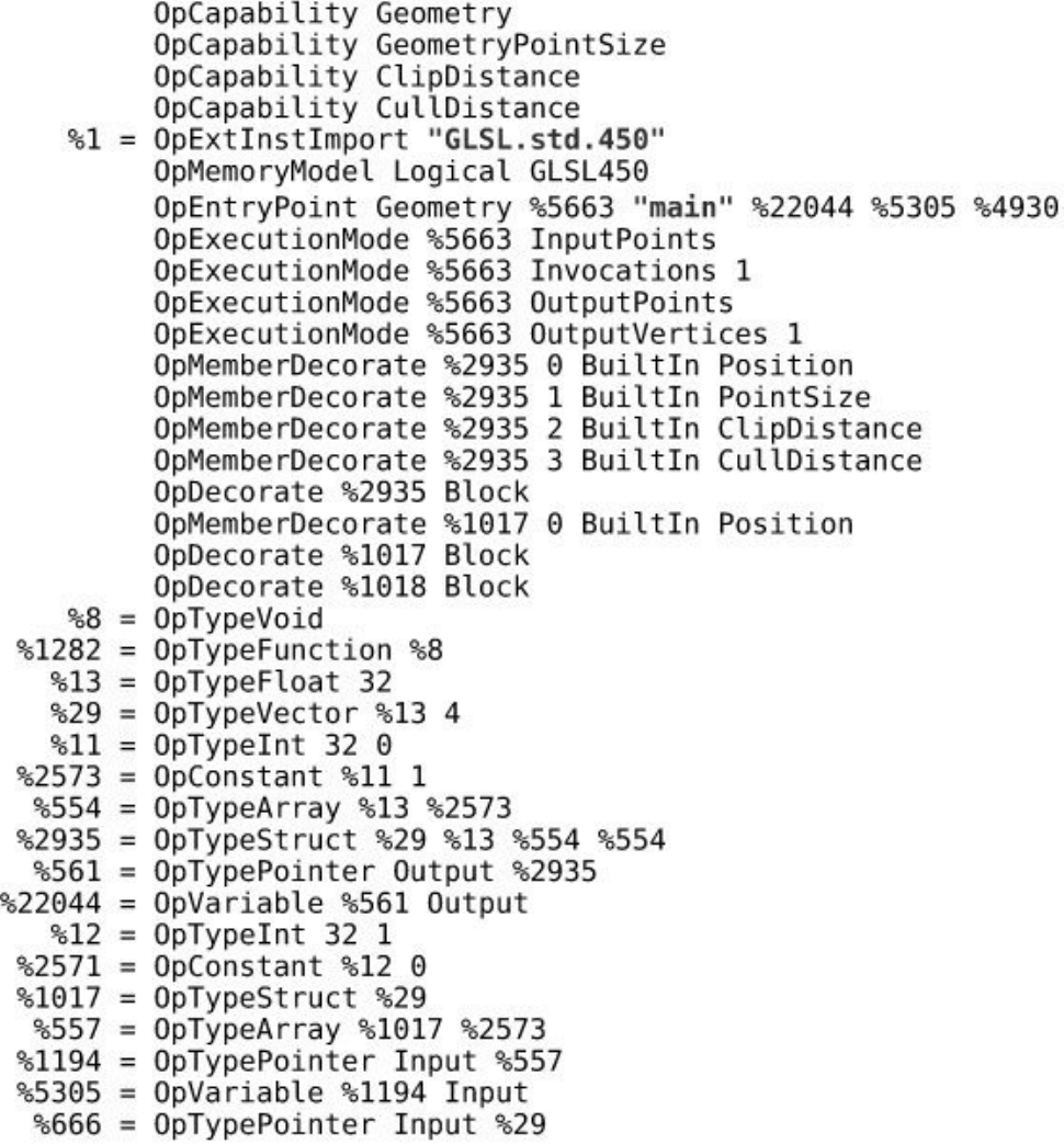
Listing 9.15 Reading gl_PerVertex in a SPIR-V Geometry Shader
Listing 9.16 Declaring an Output Block in GLSL
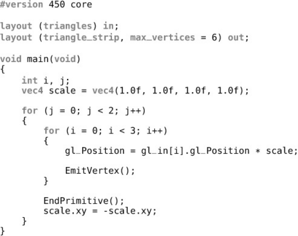
Listing 9.17 Pass-Through GLSL Geometry Shader
Listing 9.18 Pass-Through SPIR-V Geometry Shader
Listing 9.19 Cutting Strips in a Geometry Shader
Listing 9.20 Instanced GLSL Geometry Shader
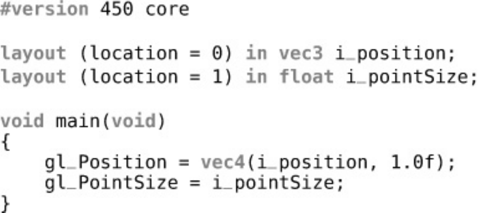
Listing 9.21 Use of gl_PointSize in GLSL
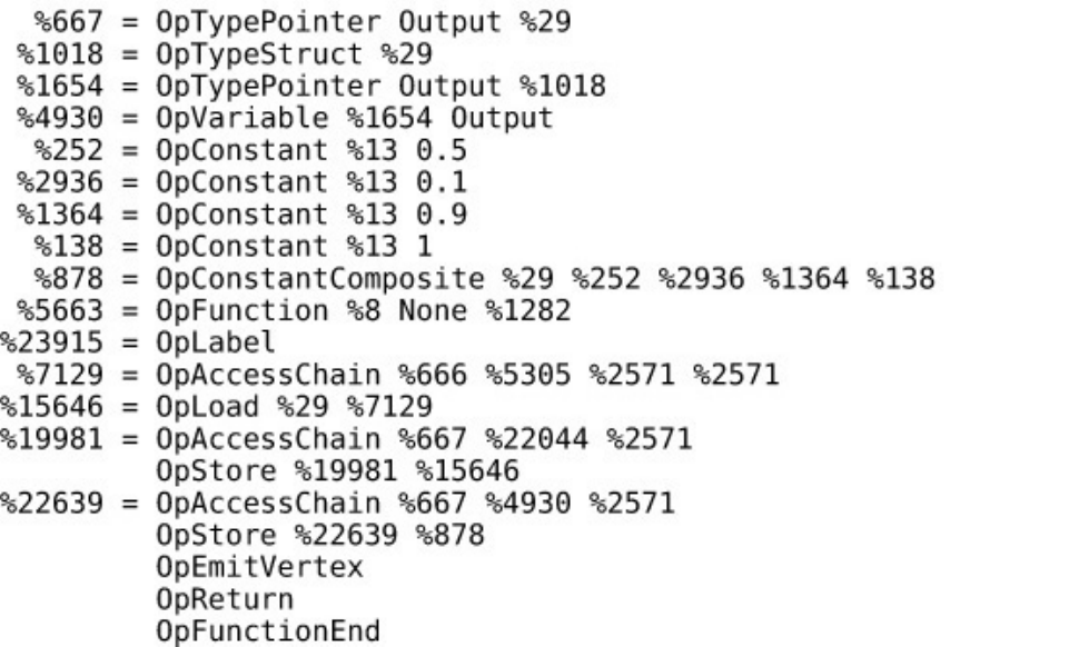
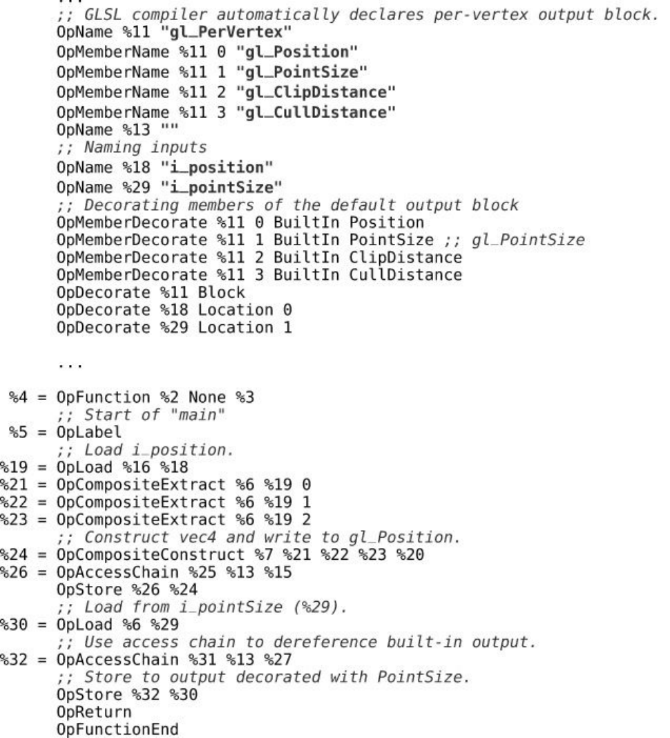
Listing 9.22 Decorating an Output with PointSize
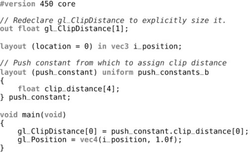
Listing 9.23 Use of gl_ClipDistance in GLSL
Listing 9.24 Decorating Outputs with ClipDistance
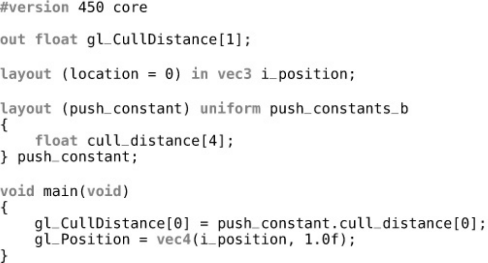
Listing 9.25 Use of gl_CullDistance in GLSL
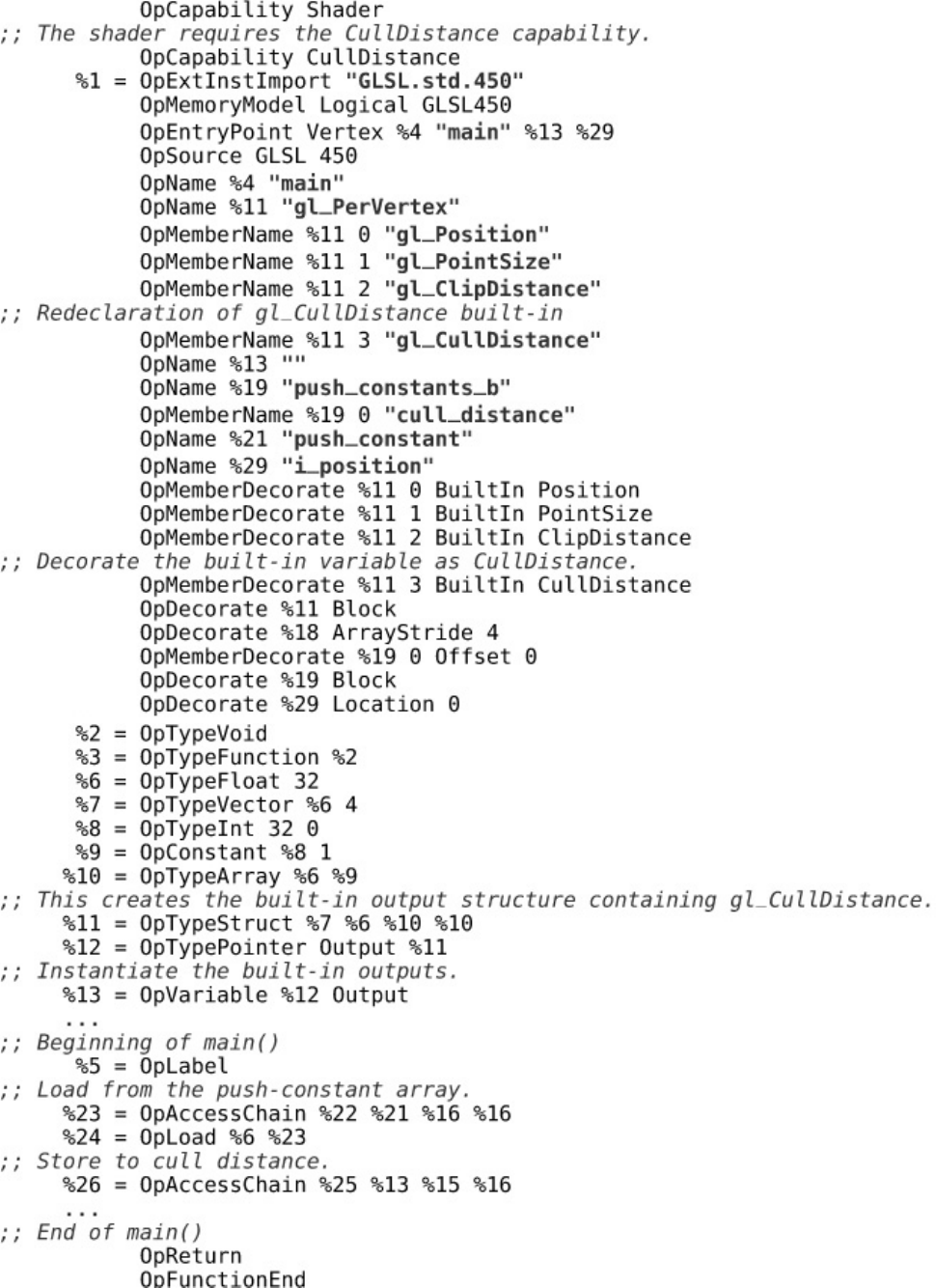
Listing 9.26 Decorating Outputs with CullDistance

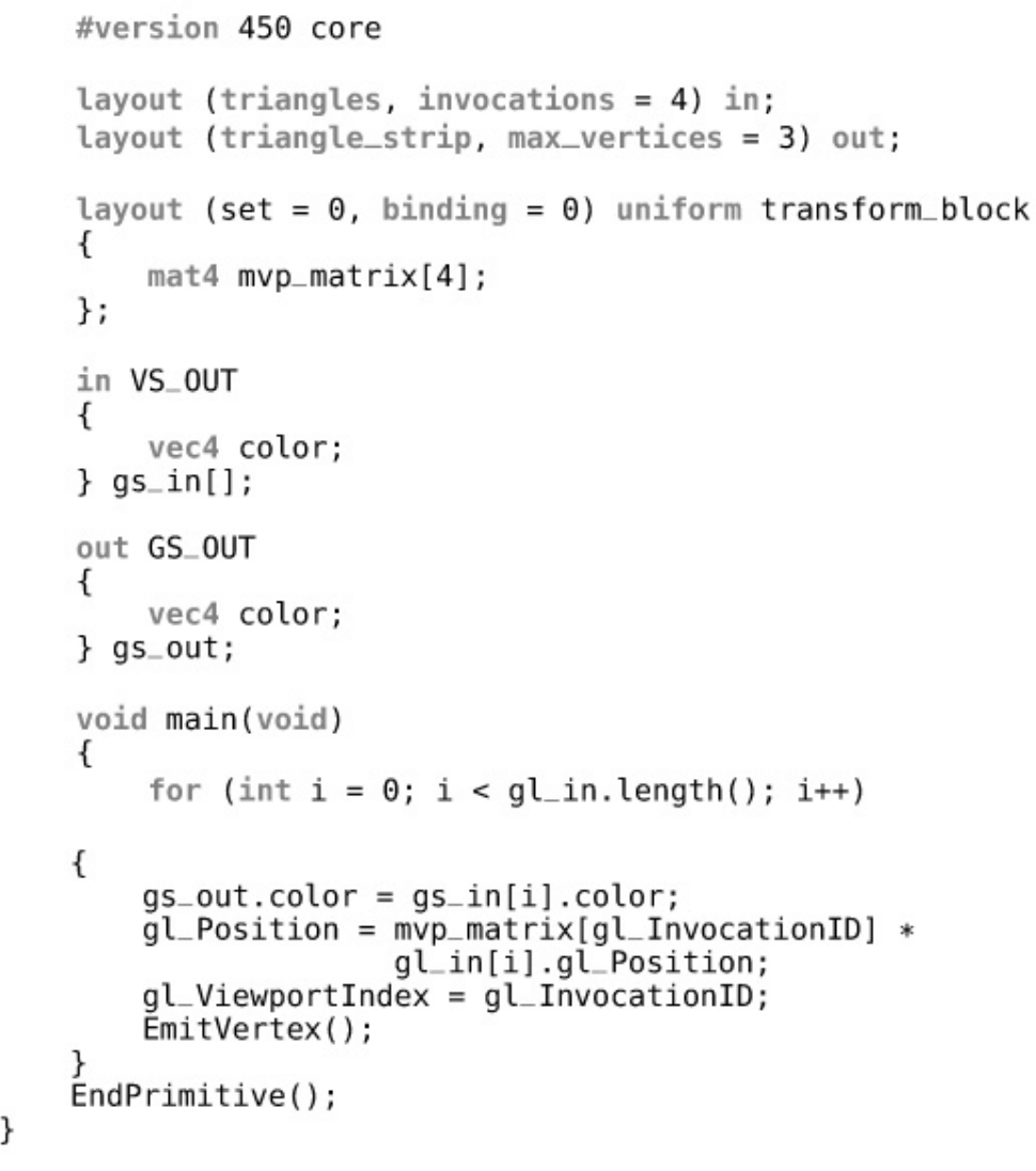
Listing 9.27 Using Multiple Viewports in a Geometry Shader (GLSL)
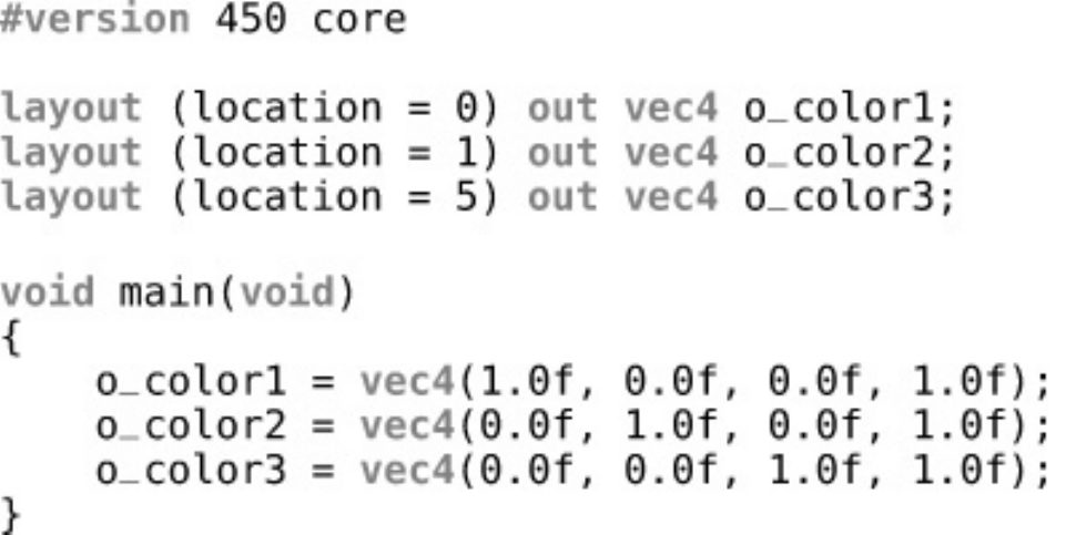
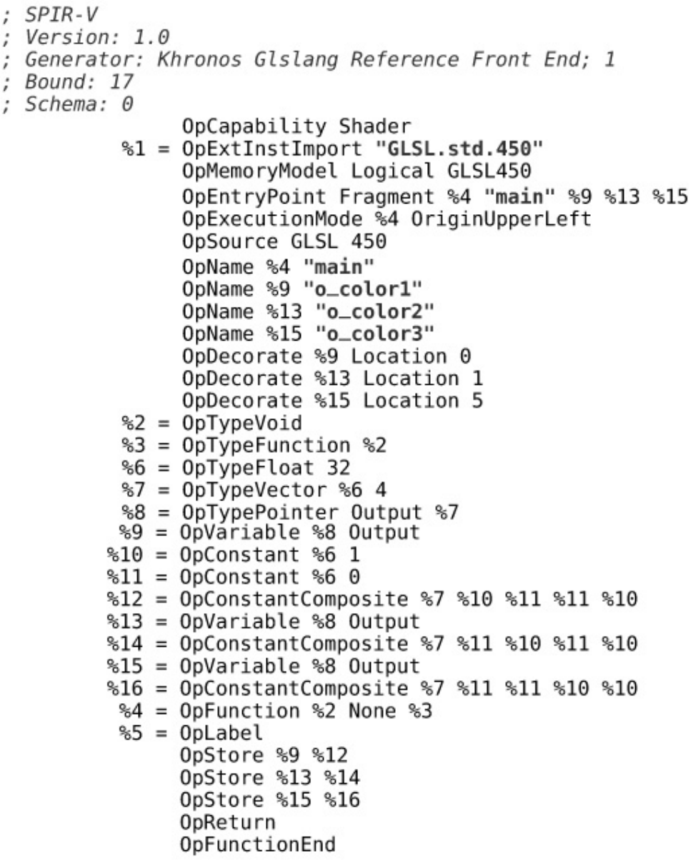
Listing 10.1 Declaring an Output in a Fragment Shader (GLSL)
Listing 10.2 Declaring an Output in a Fragment Shader (SPIR-V)
Listing 10.3 Several Outputs in a Fragment Shader (GLSL)
Listing 10.4 Several Outputs in a Fragment Shader (SPIR-V)
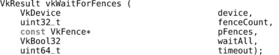
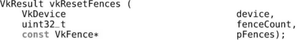
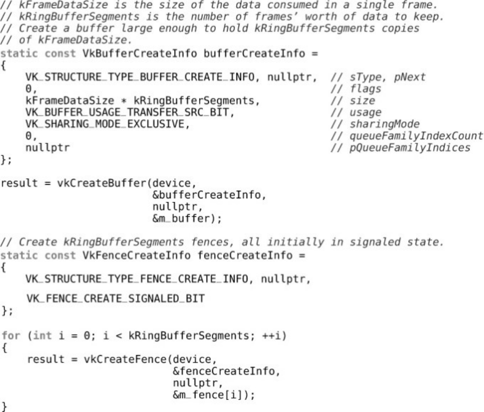
Listing 11.1 Setup for Four-Fence Synchronization
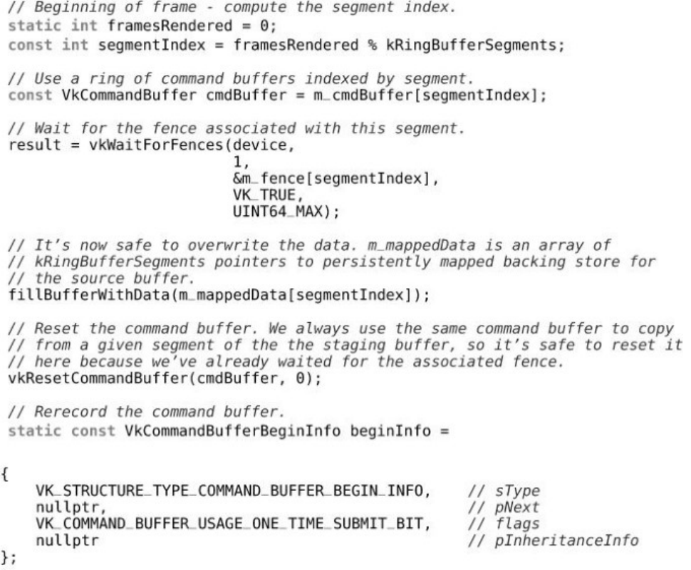
Listing 11.2 Loop Waiting on Fences for Synchronization
Listing 11.3 Cross-Queue Submission with Semaphores
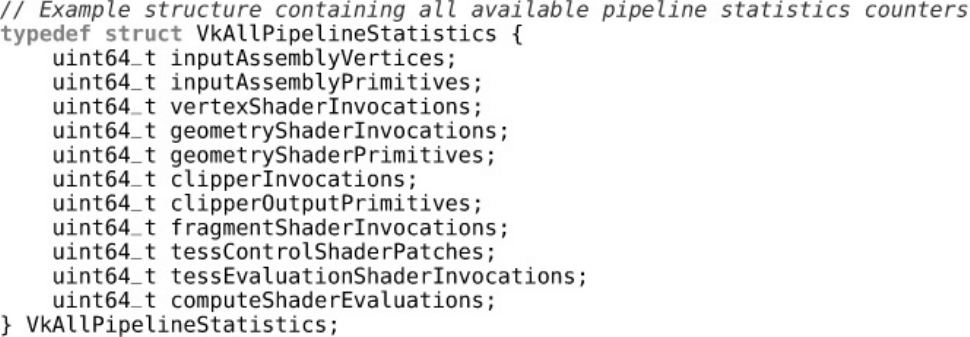
Listing 12.1 C Structure for All Pipeline Statistics
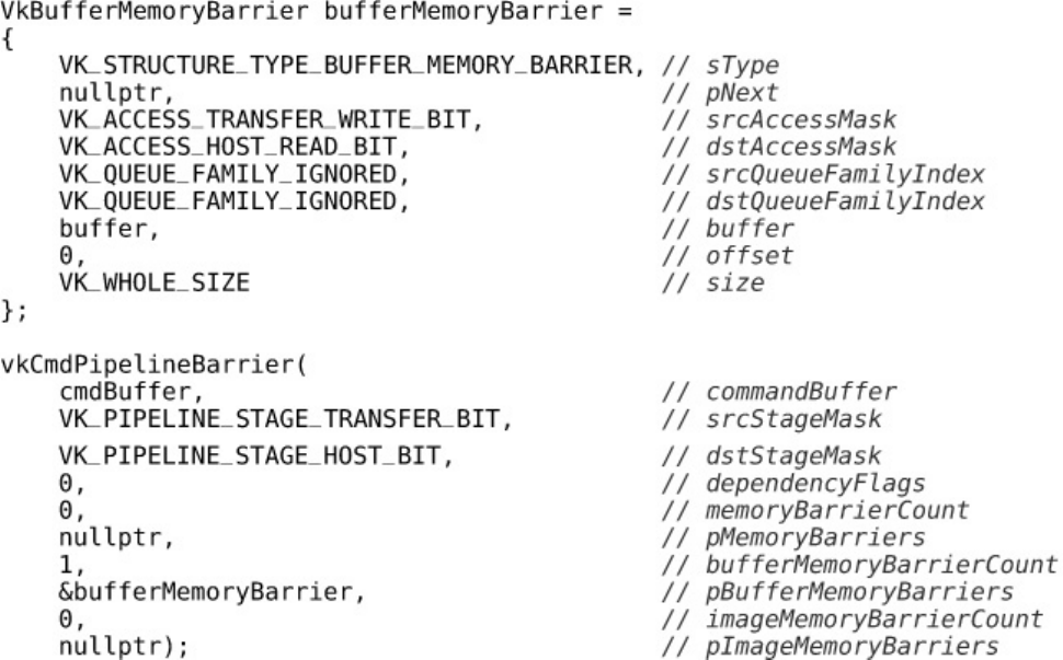
Listing 12.2 Moving a Buffer to Host-Readable State
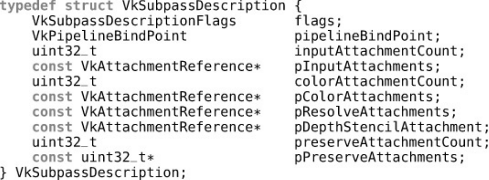
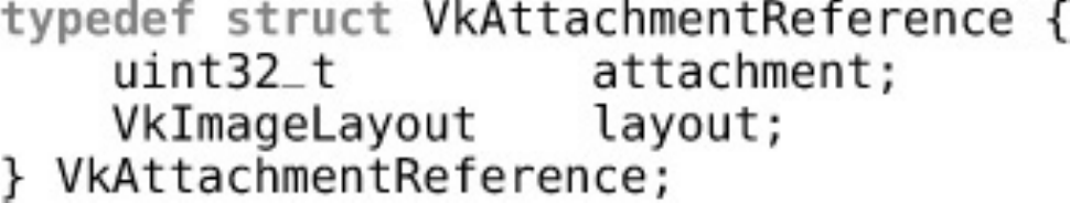
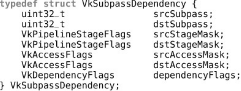
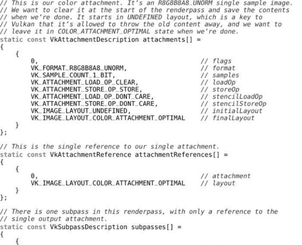
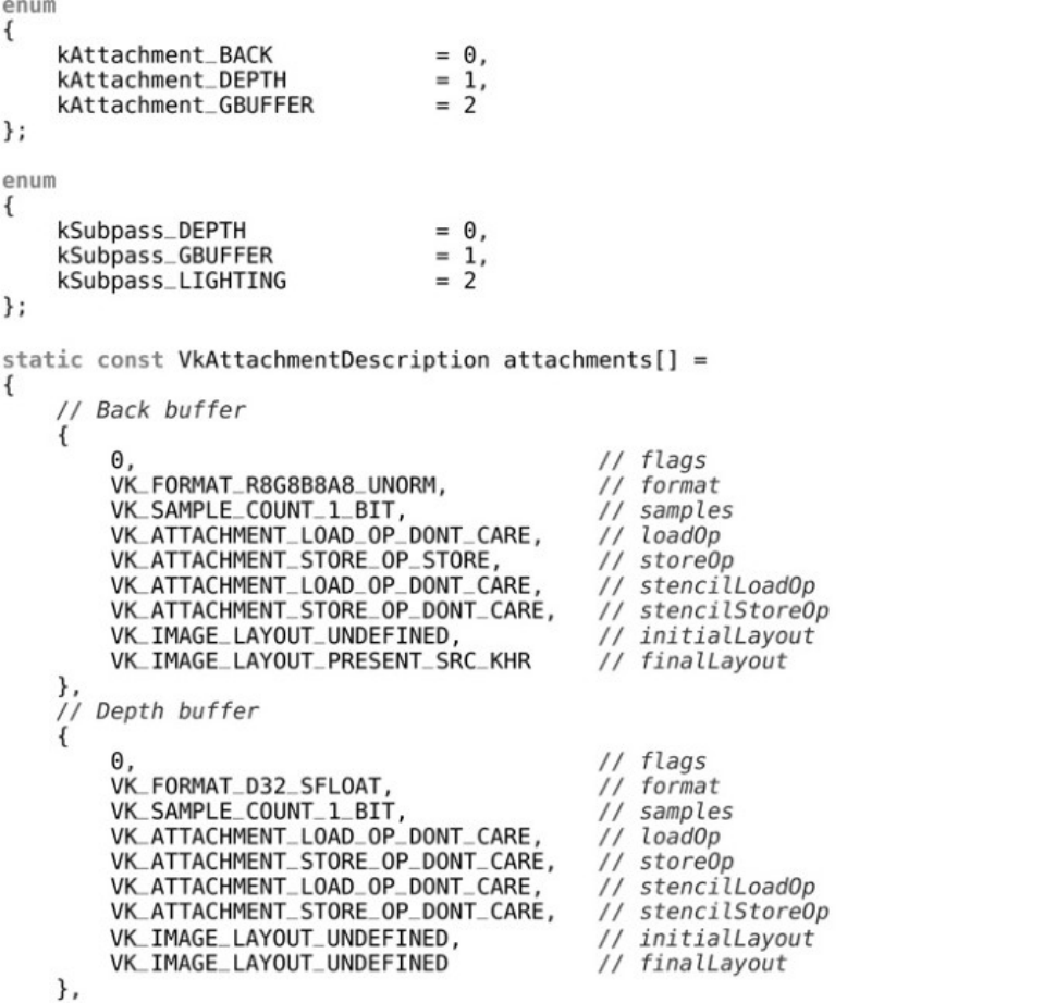
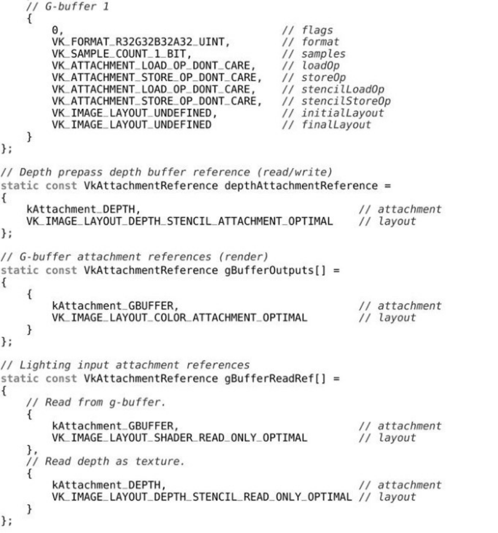
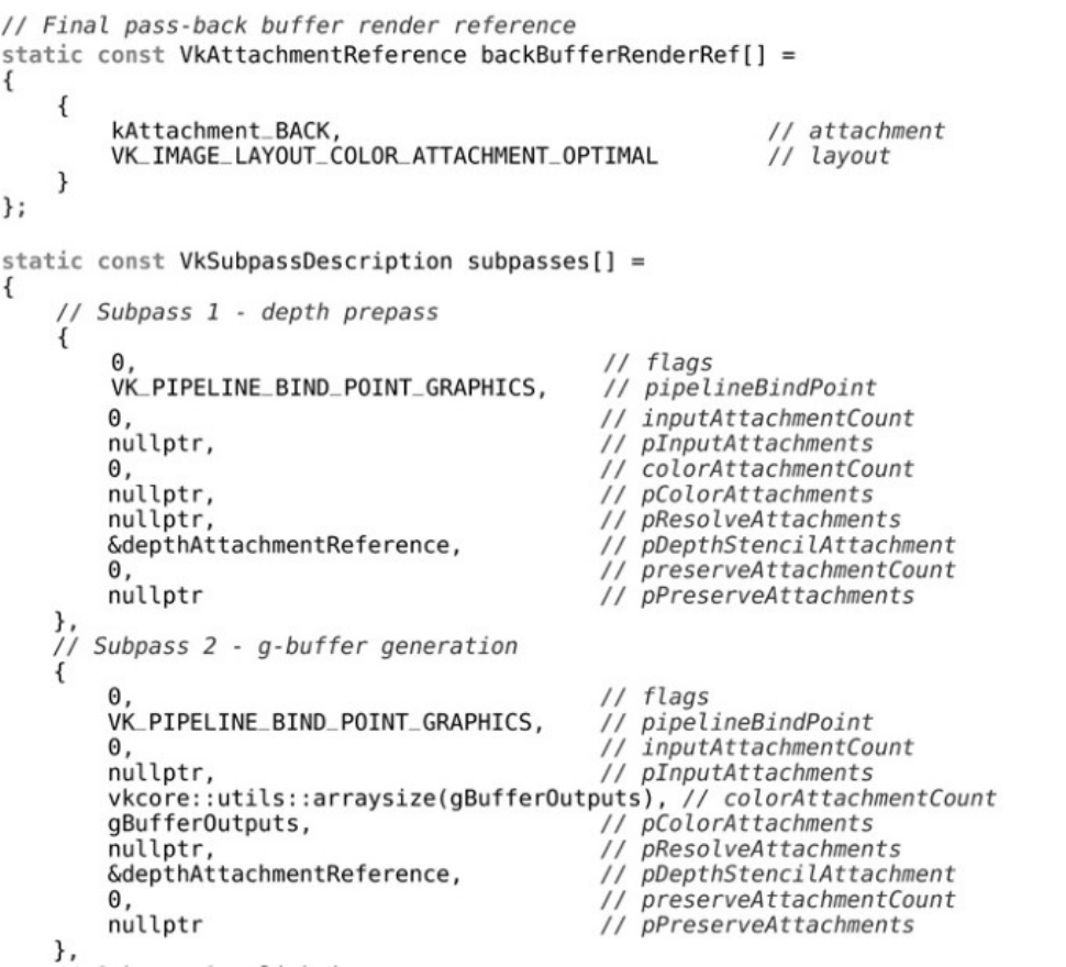
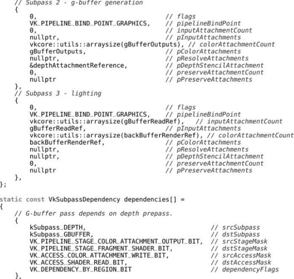
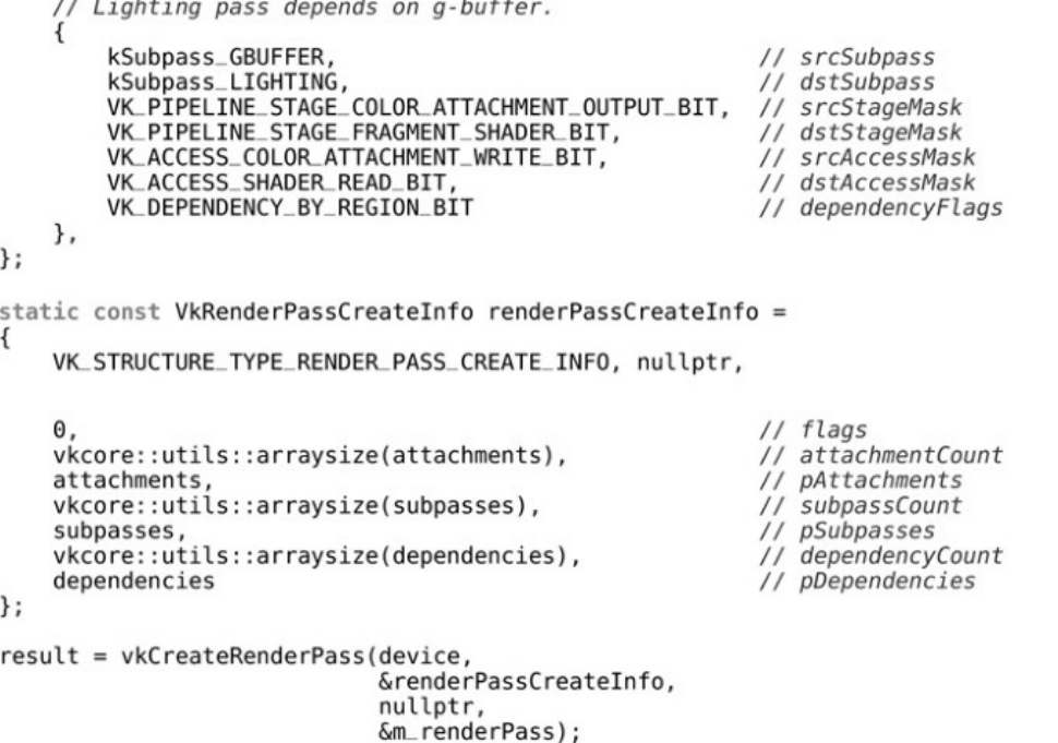
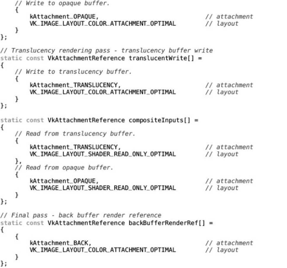
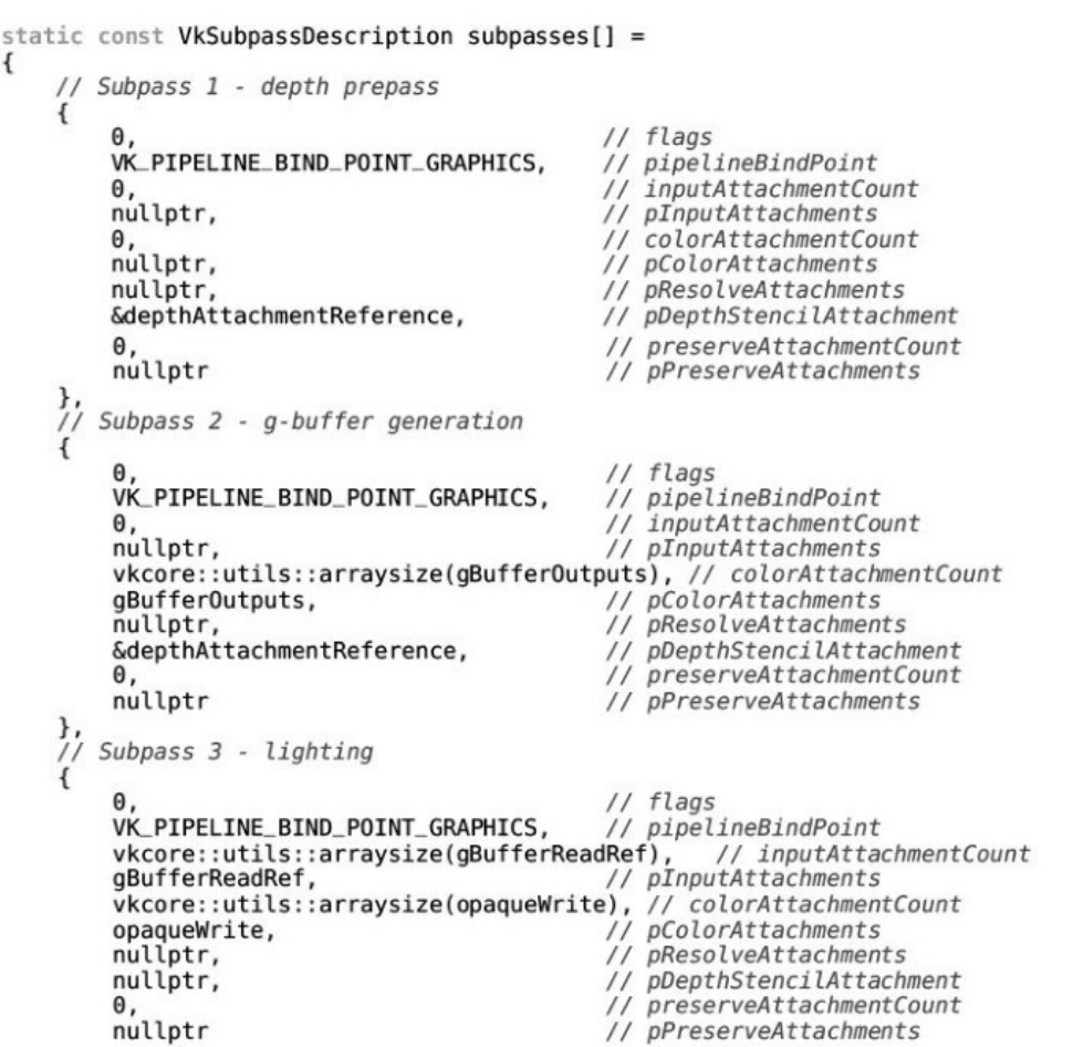
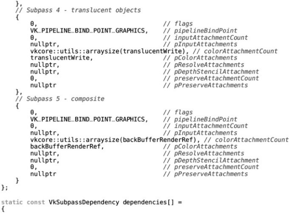
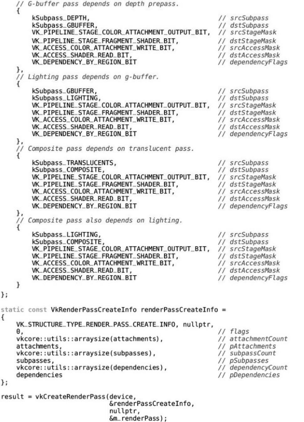
Listing 13.1 Deferred Shading Renderpass Setup
Listing 13.2 Translucency and Deferred Shading Setup
About This Book
This book is about Vulkan. Vulkan is an application programming interface (API) for controlling
devices such as graphics processing units (GPUs). Although Vulkan is a logical successor to
OpenGL, it is quite different from OpenGL in form. One of the things that experienced practitioners
will notice about Vulkan is that it is very verbose. You need to write a lot of application code to get
Vulkan to do anything useful, let alone anything remarkable. Many of the things that an OpenGL
driver would do are now the responsibility of the Vulkan application writer. These things include
synchronization, scheduling, memory management, and so on. As such, you will find a good deal of
this book dedicated to such topics, even though they are general topics applicable to more than just
Vulkan.
The intended audience for this book is experienced programmers who are already familiar with other
graphics and compute APIs. As such, many graphics-related topics are discussed without deep
introduction, there are some forward references, and code samples are incomplete or illustrative in
scope rather than being complete programs that you can type in. The sample code available from the
book’s website is complete and tested, however, and should serve as a good reference to follow along
with.
Vulkan is intended to be used as the interface between large, complex graphics and compute
applications and graphics hardware. Many of the features and responsibilities previously assumed by
drivers implementing APIs such as OpenGL now fall to the application. Complex game engines,
large rendering packages, and commercial middleware are well-suited to this task; they have more
information about their specific behavior than any driver could hope to have. Vulkan is not well-
suited to simple test applications; neither is it a suitable aid for teaching graphics concepts.
In the first chapters of this book, we introduce Vulkan and some of the fundamental concepts that
frame the API. As we progress through the Vulkan system, we cover more advanced topics,
eventually producing a more complex rendering system that shows off some of the unique aspects of
Vulkan and demonstrates its capabilities.
In Chapter 1, “Overview of Vulkan,” we provide a brief introduction to Vulkan and the concepts that
form its foundation. We cover the basics of creating Vulkan objects and show the basics of getting
started with the Vulkan system.
In Chapter 2, “Memory and Resources,” we introduce the memory system of Vulkan, perhaps the
most fundamental part of the interface. We show how to allocate memory used by the Vulkan device
and by Vulkan drivers and system components running inside your application.
In Chapter 3, “Queues and Commands,” we cover command buffers and introduce the queues to
which they are submitted. We show how Vulkan processes work and how your application can build
packets of commands to be sent to the device for execution.
In Chapter 4, “Moving Data,” we introduce our first few Vulkan commands, all of which are focused
on moving data. We use the concepts first discussed in Chapter 3 to build command buffers that can
copy and format data stored in the resources and memory introduced in Chapter 2.
In Chapter 5, “Presentation,” we show how to get images produced by your application onto the
screen. Presentation is the term used for interacting with a window system, which is platform-
specific, so this chapter delves into some platform-specific topics.
In Chapter 6, “Shaders and Pipelines,” we introduce SPIR-V, the binary shading language used by
Vulkan. We also introduce the pipeline object; show how one is constructed using SPIR-V shaders;
and then introduce compute pipelines, which can be used to do computation work with Vulkan.
In Chapter 7, “Graphics Pipelines,” we build upon what we covered in Chapter 6 and introduce the
graphics pipeline, which includes all of the configuration necessary to render graphical primitives
with Vulkan.
In Chapter 8, “Drawing,” we discuss the various drawing commands available in Vulkan, including
indexed and nonindexed draws, instancing, and indirect commands. We show how to get data into the
graphics pipeline and how to draw more complex geometries than were introduced in Chapter 7.
In Chapter 9, “Geometry Processing,” we dig deeper into the first half of the Vulkan graphics
pipeline and take another look at the tessellation and geometry shader stages. We show some of the
more advanced things that these stages can do and cover the pipeline up to the rasterization stage.
In Chapter 10, “Fragment Processing,” we pick up where Chapter 9 left off and cover everything that
happens during and after rasterization in order to turn your geometry into a stream of pixels that can
be displayed to the user.
In Chapter 11, “Synchronization,” we cover the various synchronization primitives available to the
Vulkan application, including fences,events, and semaphores. Together, these form the foundation of
any application that makes efficient use of the parallel nature of Vulkan.
In Chapter 12, “Getting Data Back,” we reverse the direction of communication used in previous
chapters and discuss the issues involved in reading data from Vulkan into your application. We show
how to time operations executed by a Vulkan device, how to gather statistics about the operation of
Vulkan devices, and how to get data produced by Vulkan back into your application.
Finally, in Chapter 13, “Multipass Rendering,” we revisit a number of topics covered earlier, tying
things together to produce a more advanced application—a deferred rendering application using
complex multipass architecture and multiple queues for processing.
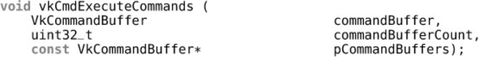
The appendix to this book contains a table of the command buffer building functions available to
Vulkan applications, providing a quick reference to determine their attributes.
Vulkan is a large, complex, and new system. It is extremely difficult to cover every corner of the API
in a book of this scope. The reader is encouraged to thoroughly read the Vulkan specification in
addition to this book, as well as to read other books on using heterogeneous compute systems and
computer graphics with other APIs. Such material will provide a good foundation in the mathematics
and other concepts assumed by this book.
About the Sample Code
The sample code that accompanies this book is available from our website
(http://www.vulkanprogrammingguide.com). One thing that seasoned users of other graphics APIs
will notice is that Vulkan is very verbose. This is primarily because many of the responsibilities
historically assumed by drivers have been delegated to your application. In many cases, however,
simple boilerplate code will do the job just fine. Therefore, we have created a simple application
framework that deals with much of the functionality that will be common to all samples and real-
world applications. This does not mean that this book is a tutorial on how to use our framework. This
is simply a practical matter of keeping code samples concise.
Of course, as we discuss specific Vulkan functionality throughout the book, we will include snippets
of code, many of which may actually come from the book’s sample framework rather than from any
particular example. Some features discussed in the book may not have examples in the code package.
This is particularly true of some advanced features that are relevant primarily to large-scale
applications. There is no such thing as a short, simple Vulkan example. In many cases, a single
example program demonstrates the use of many features. The features that each example uses are
listed in that example’s read-me file. Again, there is not a 1:1 correspondence between examples and
listings in this book and specific examples in the sample code. It shall be assumed that anyone that
files a bug asking for a 1:1 list of which samples go with which chapter has not read this paragraph.
Such bugs will be summarily closed, quoting this very sentence.
The sample code is designed to link against the latest official Vulkan SDK from LunarG, which is
available from http://lunarg.com/vulkan-sdk/. At the time of writing, the latest SDK version is 1.0.22.
Newer versions of the SDK are designed to be backward-compatible with older versions, so we
recommend that users obtain the latest available version of the SDK before attempting to compile and
run the sample applications. The SDK also comes with some samples of its own, and we suggest
running those to verify that the SDK and drivers are installed correctly.
In addition to the Vulkan SDK, you will need a working installation of CMake in order to create the
build environment for the samples. You will also need an up-to-date compiler. The code samples
make use of several C++11 features and rely heavily on the C++ standard libraries for things like
threading and synchronization primitives. These features are known to be problematic in early
versions of various compiler runtimes, so please make sure that your compilers are up to date. We
have tested with Microsoft Visual Studio 2015 on Windows and with GCC 5.3 on Linux. The
samples have been tested on 64-bit Windows 7, Windows 10, and Ubuntu 16.10 with recent drivers
from AMD, Intel, and NVIDIA.
It should be noted that Vulkan is a cross-platform, cross-vendor, and cross-device system. Many of
these samples should work on Android and other mobile platforms. We hope to port the samples to as
many of these platforms as possible in the future and would very much appreciate help and
contributions from you, the reader.
Errata
Vulkan is a new technology. At the time of writing, the specification has been available for only a
matter of weeks. Although the author and contributor had a hand in creating the Vulkan specification,
it’s large and complex and had many contributors. Some of the code in the book is not fully tested,
and although it is believed to be correct, it may contain errors. As we were putting the samples
together, available Vulkan implementations still had bugs, the validation layers didn’t catch as many
errors as they could, and the specification itself had gaps and unclear sections. Like the readers, we
are still learning Vulkan, so although this text was edited for technical accuracy, we depend on
readers to view any updates by visiting this book’s website:
http://www.vulkanprogrammingguide.com
Register your copy of VulkanTM Programming Guide at informit.com for convenient access to
downloads, updates, and corrections as they become available. To start the registration process, go to
informit.com/register and log in or create an account. Enter the product ISBN (9780134464541) and
click Submit. Once the process is complete, you will find any available bonus content under
“Registered Products.”

Acknowledgments
First and foremost, I’d like to acknowledge the members of the Vulkan working group. Through a
tireless and extremely long process, we produced what I believe to be a very solid foundation for
computer graphics and compute acceleration in the years to come. I would especially like to
recognize the contributions of my peers at AMD who developed the original Mantle specification,
from which Vulkan was derived.
I would like to thank our reviewers, Dan Ginsburg and Chris “Xenon” Hanson. Thank you for your
valuable feedback, without which this book would certainly contain more errors and omissions than it
does. I would also like to thank my colleague Mais Alnasser, who provided excellent feedback and
contributed to the quality of this book. Further thanks are due to the rest of the Vulkan team at AMD,
whose work allowed me to test much of the sample code before access to Vulkan was available to the
wider public.
The cover image was produced by Dominic Agoro-Ombaka of Agoro Design
(http://agorodesign.com/) on short notice. Thanks to him for delivering on a tight schedule.
A huge thank you goes to my editor, Laura Lewin, and the rest of the team at Addison-Wesley for
allowing me to repeatedly slip the schedule, make late edits, deliver work in an ad-hoc manner, and
generally be a pain to work with. I appreciate your trust in me with this project.
Finally, I need to thank my family—my wife, Chris, and my children, Jeremy and Emily. “Dad, are
you still writing your book?” has become a regular chant in our house. I appreciate your patience,
love, and support as I’ve crunched out a whole new book over the last few months.
—Graham Sellers
About the Author
Graham Sellers is a software architect at AMD who oversees the development of the OpenGL and
Vulkan drivers for AMD’s Radeon and FirePro products. His passion for computers and technology
began at a young age with a BBC Micro, followed by a long line of 8- and 16-bit home computers
that he still enjoys working with. He earned his master’s in engineering from the University of
Southampton, England, and now lives in Orlando, Florida, with his wife and two children.

Chapter 1. Overview of Vulkan
What You’ll Learn in This Chapter
• What Vulkan is and the fundamentals behind it
• How to create a minimal Vulkan application
• The terminology and concepts used in the remainder of this book
In this chapter, we introduce Vulkan and explain what it is. We introduce some of the fundamental
concepts behind the API, including initialization, object lifetimes, the Vulkan instance, and logical
and physical devices. By the end of the chapter, we produce a simple Vulkan application that can
initialize the Vulkan system, discover available Vulkan devices and show their properties and
capabilities, and finally shut down cleanly.
Introduction
Vulkan is a programming interface for graphics and compute devices. A Vulkan device typically
consists of a processor and a number of fixed-function hardware blocks to accelerate operations used
in graphics and compute. The processor in the device is usually a very wide multithreaded processor
and so the computational model in Vulkan is heavily based on parallel computing. The Vulkan device
also has access to memory that may or may not be shared with the main processor upon which your
application is running. Vulkan also exposes this memory to you.
Vulkan is an explicit API. That is, almost everything is your responsibility. A driver is a piece of
software that takes the commands and data forming the API and translates them into something that
hardware can understand. In older APIs such as OpenGL, drivers would track the state of a lot of
objects, manage memory and synchronization for you, and check for errors in your application as it
ran. This is great for developers but burns valuable CPU time once your application is debugged and
running correctly. Vulkan addresses this by placing almost all state tracking, synchronization, and
memory management into the hands of the application developer and by delegating correctness
checks to layers that must be enabled. They do not participate in the execution of your application
under normal circumstances.
For these reasons, Vulkan is both very verbose and somewhat fragile. You need to do an awful lot of
work to get Vulkan running well, and incorrect usage of the API can often lead to graphical
corruption or even program crashes where in older APIs you would have received a helpful error
message. In exchange for this, Vulkan provides more control over the device, a clean threading
model, and much higher performance than the APIs that it supersedes.
Further, Vulkan has been designed to be more than a graphics API. It can be used for heterogeneous
devices such as graphics processing units (GPUs), digital signal processors (DSPs), and fixed-
function hardware. Functionality is divided into coarse-grained, broadly overlapping categories. The
current edition of Vulkan defines the transfer category, which is used for copying data around; the
compute category, which is used for running shaders over compute workloads; and the graphics
category, which includes rasterization, primitive assembly, blending, depth and stencil tests, and other
functionality that will be familiar to graphics programmers.

To the extent that support for each category is optional, it’s possible to have a Vulkan device that
doesn’t support graphics at all. As a consequence, even the APIs to put pictures onto a display device
(which is called presentation) are not only optional, but are provided as extensions to Vulkan rather
than being part of the core API.
Instances, Devices, and Queues
Vulkan includes a hierarchy of functionality, starting at the top level with the instance, which
aggregates all Vulkan-capable devices together. Each device then exposes one or more queues. It is
the queues that perform the work that your application requests.
The Vulkan instance is a software construct that logically separates the state of your application from
other applications or libraries running within the context of your application. The physical devices in
the sytem are presented as members of the instance, each of which has certain capabilities, including
a selection of available queues.
A physical device usually represents a single piece of hardware or a collection of hardware that is
interconnected. There is a fixed, finite number of physical devices in any system unless that system
supports reconfiguration such as hot-plug. A logical device, which is created by the instance, is the
software construct around a physical device and represents a reservation of resources associated with
a particular physical device. This includes a possible subset of the available queues on the physical
device. It is possible to create multiple logical devices representing a single physical device, and it is
the logical device that your application will spend most of its time interacting with.
Figure 1.1 illustrates this hierarchy. In the figure, the application has created two Vulkan instances.
There are three physical devices in the system that are available to both instances. After enumeration,
the application creates one logical device on the first physical device, two logical devices for the
second device, and another for the third. Each logical device enables a different subset of its
corresponding physical device’s queues. In practice, most Vulkan applications won’t be nearly this
complex and will simply create a single logical device for one of the physical devices in the system,
using a single instance. Figure 1.1 only serves to demonstrate the flexibility of the Vulkan system.
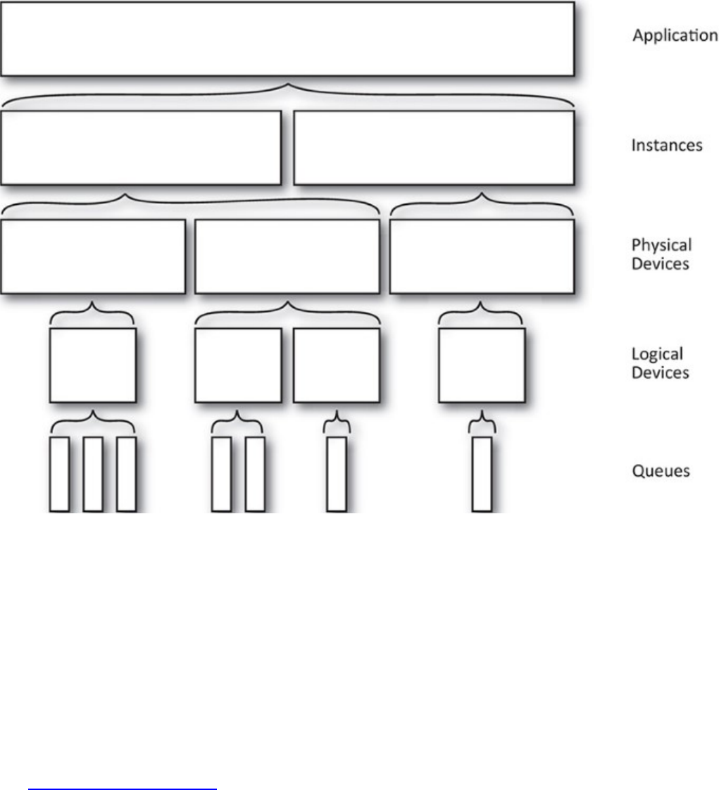
Figure 1.1: Vulkan Hierarchy of Instance, Device, and Queue
The following subsections discuss how to create the Vulkan instance, query the physical devices in
the system, attach a logical device corresponding to one of them, and finally retrieve handles to the
queues exposed by the device.
The Vulkan Instance
Vulkan can be seen as a subsystem of your application. Once you link your application to the Vulkan
libraries and initialize it, it tracks some state. Because Vulkan doesn’t introduce any global state into
your application, all tracked state must be stored in an object that you provide. This is the instance
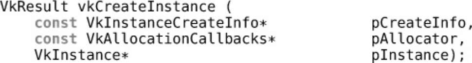
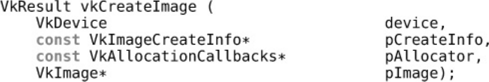
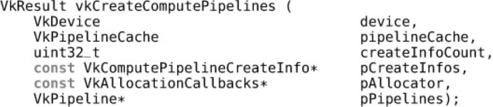
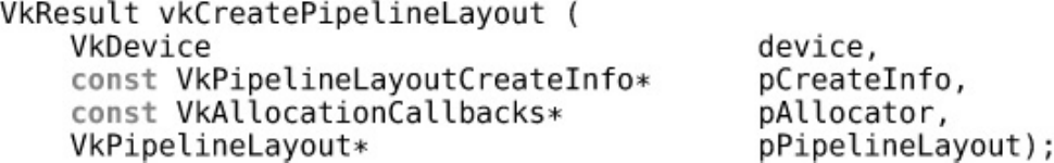
object and is represented by a VkInstance object. To construct one, we’ll call our first Vulkan
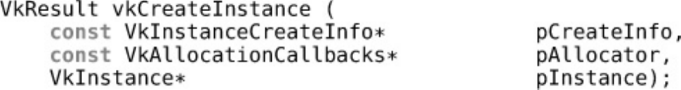
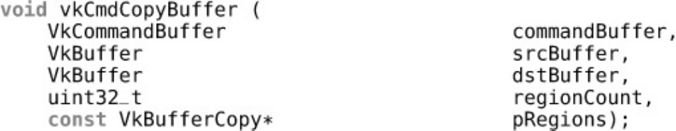
function, vkCreateInstance(), the prototype of which is
Click here to view code image
VkResult vkCreateInstance (
const VkInstanceCreateInfo* pCreateInfo,
const VkAllocationCallbacks* pAllocator,
VkInstance* pInstance);
This declaration is typical of a Vulkan function. Where more than a handful of parameters are to be
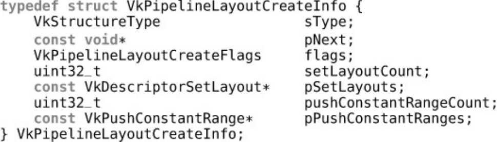
passed to Vulkan, functions often take pointers to structures. Here, pCreateInfo is a pointer to an

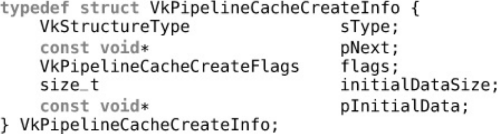
instance of the VkInstanceCreateInfo structure that contains the parameters describing the
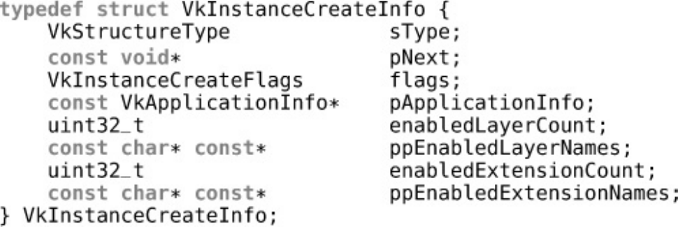
new Vulkan instance. The definition of VkInstanceCreateInfo is
Click here to view code image
typedef struct VkInstanceCreateInfo {
VkStructureType sType;
const void* pNext;
VkInstanceCreateFlags flags;
const VkApplicationInfo* pApplicationInfo;
uint32_t enabledLayerCount;
const char*const* ppEnabledLayerNames;
uint32_t enabledExtensionCount;
const char*const* ppEnabledExtensionNames;
} VkInstanceCreateInfo;
The first member in almost every Vulkan structure that is used to pass parameters to the API is the
sType field, which tells Vulkan what type of structure this is. Each structure in the core API and in
any extension has an assigned structure tag. By inspecting this tag, Vulkan tools, layers, and drivers
can determine the type of the structure for validation purposes and for use in extensions. Further, the
pNext field allows a linked list of structures to be passed to the function. This allows the set of
parameters to be extended without needing to replace the core structure wholesale in an extension.
Because we are using the core instance creation structure here, we pass
VK_STRUCTURE_TYPE_INSTANCE_CREATE_INFO in the sType field and simply set pNext
to nullptr.
The flags field of VkInstanceCreateInfo is reserved for future use and should be set to
zero. The next field, pApplicationInfo, is an optional pointer to another structure describing
your application. You can set this to nullptr, but a well-behaved application should fill this in with
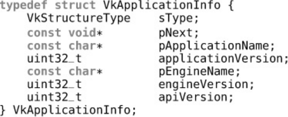
something useful. pApplicationInfo points to an instance of the VkApplicationInfo
structure, the definition of which is
Click here to view code image
typedef struct VkApplicationInfo {
VkStructureType sType;
const void* pNext;
const char* pApplicationName;
uint32_t applicationVersion;
const char* pEngineName;
uint32_t engineVersion;
uint32_t apiVersion;
} VkApplicationInfo;
Again, we see the sType and pNext fields in this structure. sType should be set to
VK_STRUCTURE_TYPE_APPLICATION_INFO, and we can leave pNext as nullptr.
pApplicationName is a pointer to a nul-terminated1string containing the name of your
application, and applicationVersion is the version of the application. This allows tools and
drivers to make decisions about how to treat your application without needing to guess2which
application is running. Likewise, pEngineName and engineVersion contain the name and
version, respectively, of the engine or middleware that your application is based on.
1. Yes, really, nul. The ASCII character whose literal value is zero is officially called NUL. Now, stop telling
me to change it to NULL. That’s a pointer, not a name of a character.
2. What’s best for one application might be different from what’s best for another. Also, applications are written
by humans, and humans write code with bugs. To optimize fully or work around application bugs, drivers
would sometimes use executable names or even application behavior to guess at which application was
running and alter behavior appropriately. While not ideal, this new mechanism at least removes the
guesswork.
Finally, apiVersion contains the version of the Vulkan API that your application is expecting to
run on. This should be set to the absolute minimum version of Vulkan that your application requires
to run—not just to the version of the header that you happen to have installed. This allows the widest
possible assortment of devices and platforms to run your application, even if updates to their Vulkan
implementations might not be available.
Returning to the VkInstanceCreateInfo structure, we see the enabledLayerCount and
ppEnabledLayerNames fields. These are the count of the number of instance layers that you
wish to enable and their names, respectively. Layers are used to intercept the Vulkan API and provide
logging, profiling, debugging, or other additional features. If no layers are needed, simply set
enabledLayerCount to zero and leave ppEnabledLayerNames as nullptr. Likewise,
enabledExtensionCount is the count of the number of extensions you wish to enable,3and
ppEnabledExtensionNames is a list of their names. Again, if we’re not using any extensions,
we can set these fields to zero and nullptr, respectively.
3. As with OpenGL, Vulkan supports extensions as a central part of the API. However, in OpenGL, we would
create a context, query the supported extensions, and then start using them. This meant that drivers would
need to assume that your application might suddenly start using an extension at any time and be ready for it.
Further, it couldn’t tell which extensions you were looking for, which made the process even more difficult.
In Vulkan, applications are required to opt in to extensions and explicitly enable them. This allows drivers to
disable extensions that aren’t in use and makes it harder for applications to accidentally start using
functionality that’s part of an extension they weren’t intending to enable.
Finally, returning to the vkCreateInstance() function, the pAllocator parameter is a
pointer to a host memory allocator that your application can supply in order to manage the host
memory that the Vulkan system uses. Setting this to nullptr causes the Vulkan system to use its
own internal allocator, which is what we will do here. Application-managed host memory will be
covered in Chapter 2, “Memory and Resources.”
Assuming the vkCreateInstance() function succeeds, it will return VK_SUCCESS and place a
handle to the new instance in the variable pointed to by the pInstance parameter. A handle is the
value by which objects are referenced. Vulkan handles are always 64 bits wide, regardless of the
bitness of the host system. Once we have a handle to our Vulkan instance, we can use it to call other
instance functions.

Vulkan Physical Devices
Once we have an instance, we can use it to discover Vulkan-compatible devices installed in the
system. Vulkan has two types of devices: physical and logical. Physical devices are normally parts of
the system—a graphics card, accelerator, DSP, or other component. There are a fixed number of
physical devices in a system, and each has a fixed set of capabilities. A logical device is a software
abstraction of a physical device, configured in a way that is specified by the application. The logical
device is the one that your application will spend most of its time dealing with, but before we can
create a logical device, we must discover the connected physical devices. To do this, we call the
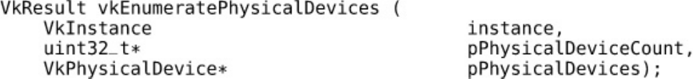
vkEnumeratePhysicalDevices() function, the prototype of which is
Click here to view code image
VkResult vkEnumeratePhysicalDevices (
VkInstance instance,
uint32_t* pPhysicalDeviceCount,
VkPhysicalDevice* pPhysicalDevices);
The first parameter to the vkEnumeratePhysicalDevices() function, instance, is the
instance we created earlier. Next, the pPhysicalDeviceCount parameter is a pointer to an
unsigned integer variable that is both an input and an output. As an output, Vulkan writes the number
of physical devices in the system into it. As an input, it should be preinitialized with the maximum
number of devices your application can handle. The pPhysicalDevices parameter is a pointer to
an array of this number of VkPhysicalDevice handles.
If you just want to know how many devices there are in the system, set pPhysicalDevices to
nullptr, and Vulkan will ignore the initial value of pPhysicalDeviceCount, simply
overwriting it with the number of supported devices. You can dynamically adjust the size of your
VkPhysicalDevice array by calling vkEnumeratePhysicalDevices() twice, the first
time with only pPhysicalDevices set to nullptr (although pPhysicalDeviceCount
must still be a valid pointer) and the second time with pPhysicalDevices set to an array that has
been appropriately sized for the number of physical devices reported by the first call.
Assuming there are no problems, vkEnumeratePhysicalDevices() returns VK_SUCCESS
and deposits the number of recognized physical devices in pPhysicalDeviceCount along with
their handles in pPhysicalDevices.Listing 1.1 shows an example of constructing the
VkApplicationInfo and VkInstanceCreateInfo structures, creating the Vulkan instance,
querying it for the number of supported devices, and finally querying the physical device handles
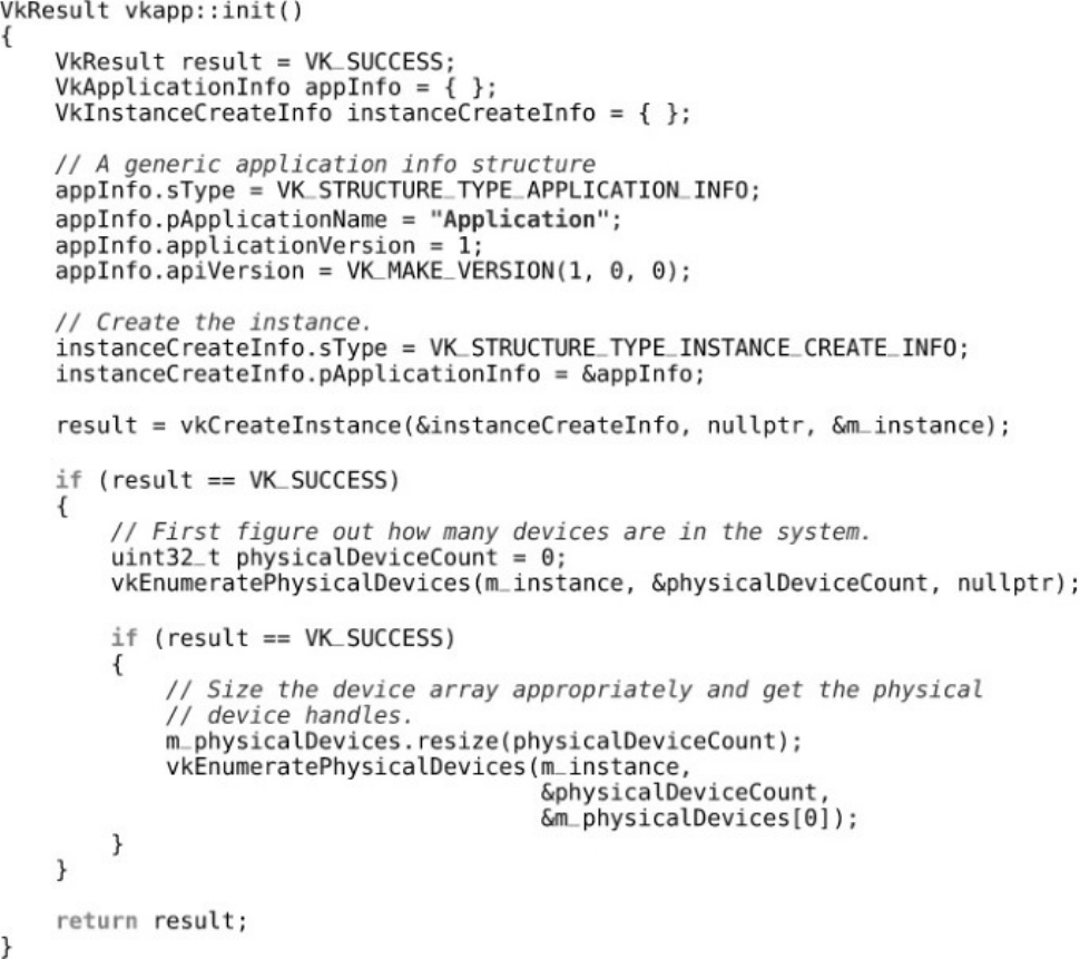
themselves. This is a slightly simplified version of vkapp::init from the example framework.
Listing 1.1: Creating a Vulkan Instance
Click here to view code image
VkResult vkapp::init()
{
VkResult result = VK_SUCCESS;
VkApplicationInfo appInfo = { };
VkInstanceCreateInfo instanceCreateInfo = { };
// A generic application info structure

appInfo.sType = VK_STRUCTURE_TYPE_APPLICATION_INFO;
appInfo.pApplicationName = "Application";
appInfo.applicationVersion = 1;
appInfo.apiVersion = VK_MAKE_VERSION(1, 0, 0);
// Create the instance.
instanceCreateInfo.sType = VK_STRUCTURE_TYPE_INSTANCE_CREATE_INFO;
instanceCreateInfo.pApplicationInfo = &appInfo;
result = vkCreateInstance(&instanceCreateInfo, nullptr, &m_instance);
if (result == VK_SUCCESS)
{
// First figure out how many devices are in the system.
uint32_t physicalDeviceCount = 0;
vkEnumeratePhysicalDevices(m_instance, &physicalDeviceCount,
nullptr);
if (result == VK_SUCCESS)
{
// Size the device array appropriately and get the physical
// device handles.
m_physicalDevices.resize(physicalDeviceCount);
vkEnumeratePhysicalDevices(m_instance,
&physicalDeviceCount,
&m_physicalDevices[0]);
}
}
return result;
}
The physical device handle is used to query the device for its capabilities and ultimately to create the
logical device. The first query we’ll perform is vkGetPhysicalDeviceProperties(), which
fills in a structure describing all the properties of the physical device. Its prototype is
Click here to view code image
void vkGetPhysicalDeviceProperties (
VkPhysicalDevice physicalDevice,
VkPhysicalDeviceProperties* pProperties);
When you call vkGetPhysicalDeviceProperties(), pass one of the handles returned from
vkEnumeratePhysicalDevices() in the physicalDevice parameter, and in
pProperties, pass a pointer to an instance of the VkPhysicalDeviceProperties
structure. This is a large structure that contains a large number of fields describing the properties of
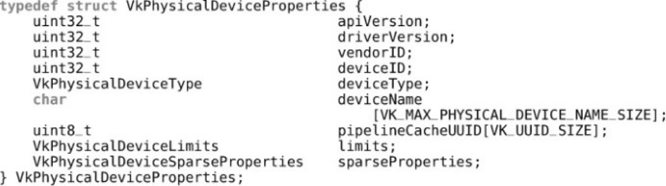
the physical device. Its definition is
Click here to view code image
typedef struct VkPhysicalDeviceProperties {
uint32_t apiVersion;
uint32_t driverVersion;
uint32_t vendorID;
uint32_t deviceID;
VkPhysicalDeviceType deviceType;
char deviceName
[VK_MAX_PHYSICAL_DEVICE_NAME_SIZE];
uint8_t pipelineCacheUUID[VK_UUID_SIZE];
VkPhysicalDeviceLimits limits;
VkPhysicalDeviceSparseProperties sparseProperties;
} VkPhysicalDeviceProperties;
The apiVersion field contains the highest version of Vulkan supported by the device, and the
driverVersion field contains the version of the driver used to control the device. This is vendor-
specific, so it doesn’t make sense to compare driver versions across vendors. The vendorID and
deviceID fields identify the vendor and the device, and are usually PCI vendor and device
identifiers.4
4. There is no official central repository of PCI vendor or device identifiers. The PCI SIG
(http://pcisig.com/) assigns vendor identifiers to its members, and those members assign device
identifiers to their products. A fairly comprehensive list in both human- and machine-readable forms is
available from http://pcidatabase.com/.
The deviceName field will contain a human-readable string naming the device. The
pipelineCacheUUID field is used for pipeline caching, which we will cover in Chapter 6,
“Shaders and Pipelines.”
In addition to the properties just listed, the VkPhysicalDeviceProperties structure embeds
VkPhysicalDeviceLimits and VkPhysicalDeviceSparseProperties, which contain
the minimum and maximum limits for the physical device and properties related to sparse textures.
There’s a lot of information in these structures, and we’ll cover the fields separately as the related
features are discussed rather than enumerating them all here.
In addition to core features, some of which have optionally higher limits or bounds, Vulkan has a
number of optional features that may be supported by a physical device. If a device advertises
support for a feature, it must still be enabled (much like an extension), but once enabled, that feature
becomes a first-class citizen of the API just like any core feature. To determine which features a
physical device supports, call vkGetPhysicalDeviceFeatures(), the prototype of which is
Click here to view code image
void vkGetPhysicalDeviceFeatures (
VkPhysicalDevice physicalDevice,
VkPhysicalDeviceFeatures* pFeatures);
Again, the VkPhysicalDeviceFeatures structure is very large and has a Boolean field for
each optional feature supported by Vulkan. There are too many fields to list and describe individually
here, but the sample application presented at the end of this chapter reads the feature set and prints its
content.

Physical Device Memory
In many cases, a Vulkan device is either a separate physical piece of hardware to the main host
processor or works sufficiently differently that it will access memory in specialized ways. Device
memory in Vulkan refers to memory that is accessible to the device and usable as a backing store for
textures and other data. Memory is classified into types, each of which has a set of properties, such as
caching flags and coherency behavior between host and device. Each type of memory is then backed
by one of the device’s heaps, of which there may be several.
To query the configuration of heaps and the memory types supported by the device, call
Click here to view code image
void vkGetPhysicalDeviceMemoryProperties (
VkPhysicalDevice physicalDevice,
VkPhysicalDeviceMemoryProperties* pMemoryProperties);
The resulting memory organization is written into the
VkPhysicalDeviceMemoryProperties structure, the address of which is passed in
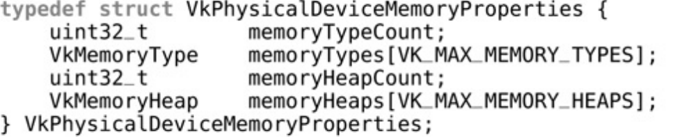
pMemoryProperties. The VkPhysicalDeviceMemoryProperties structure contains the
properties of both the device’s heaps and its supported memory types. The definition of this structure
is
Click here to view code image
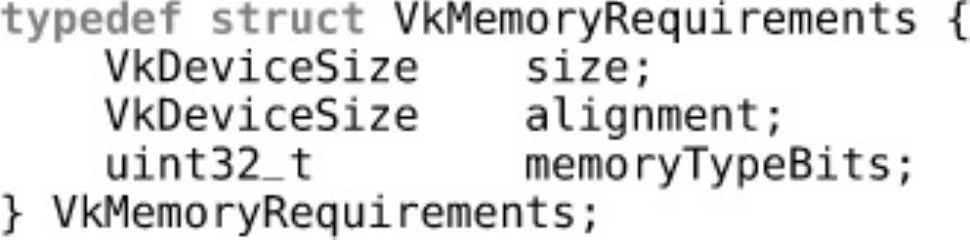
typedef struct VkPhysicalDeviceMemoryProperties {
uint32_t memoryTypeCount;
VkMemoryType memoryTypes[VK_MAX_MEMORY_TYPES];
uint32_t memoryHeapCount;
VkMemoryHeap memoryHeaps[VK_MAX_MEMORY_HEAPS];
} VkPhysicalDeviceMemoryProperties;
The number of memory types is reported in the memoryTypeCount field. The maximum number
of memory types that might be reported is the value of VK_MAX_MEMORY_TYPES, which is defined
to be 32. The memoryTypes array contains memoryTypeCount VkMemoryType structures
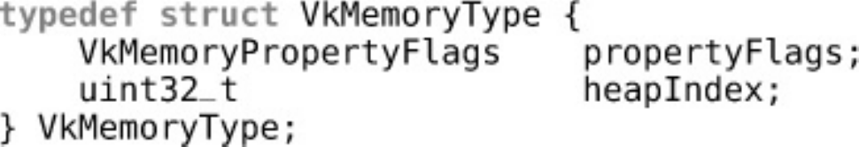
describing each of the memory types. The definition of VkMemoryType is
Click here to view code image
typedef struct VkMemoryType {
VkMemoryPropertyFlags propertyFlags;
uint32_t heapIndex;
} VkMemoryType;
This is a simple structure containing only a set of flags and the memory type’s heap index. The
flags field describes the type of memory and is made up of a combination of the
VkMemoryPropertyFlagBits flags. The meanings of the flags are as follows:
•VK_MEMORY_PROPERTY_DEVICE_LOCAL_BIT means that the memory is local to (that is,
physically connected to) the device. If this bit is not set, then the memory can be assumed to be
local to the host.
•VK_MEMORY_PROPERTY_HOST_VISIBLE_BIT means that memory allocations made with
this type can be mapped and read or written by the host. If this bit is not set then memory of this
type cannot be directly accessed by the host and is rather for exclusive use by the device.

•VK_MEMORY_PROPERTY_HOST_COHERENT_BIT means that when this type of memory is
concurrently accessed by both the host and device, those accesses will be coherent between the
two clients. If this bit is not set, then the device or host may not see the results of writes
performed by each until caches are explicitly flushed.
•VK_MEMORY_PROPERTY_HOST_CACHED_BIT means that data in this type of memory is
cached by the host. Read accesses to this type of memory are typically faster than they would be
if this bit were not set. However, access by the device may have slightly higher latency,
especially if the memory is also coherent.
•VK_MEMORY_PROPERTY_LAZILY_ALLOCATED_BIT means that memory allocated with
this type doesn’t necessarily consume space from the associated heap immediately and that a
driver might defer physical memory allocation until the memory object is used to back a
resource.
Each memory type reports the heap from which it consumes space in the heapIndex field of the
VkMemoryType structure. This is an index into the memoryHeaps array returned in the
VkPhysicalDeviceMemoryProperties structure from the call to
vkGetPhysicalDeviceMemoryProperties(). Each element of the memoryHeaps array
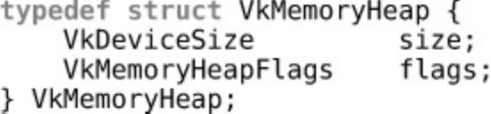
describes one of the device’s memory heaps. The definition of this structure is
Click here to view code image
typedef struct VkMemoryHeap {
VkDeviceSize size;
VkMemoryHeapFlags flags;
} VkMemoryHeap;
Again, this is a simple structure. It contains only the size, in bytes, of the heap and some flags
describing the heap. In Vulkan 1.0, the only defined flag is
VK_MEMORY_HEAP_DEVICE_LOCAL_BIT. If this bit is set, then the heap is local to the device.
This corresponds to the similarly named flag describing memory types.
Device Queues
Vulkan devices execute work that is submitted to queues. Each device will have one or more queues,
and each of those queues will belong to one of the device’s queue families. A queue family is a group
of queues that have identical capabilities but are able to run in parallel. The number of queue
families, the capabilities of each family, and the number of queues belonging to each family are all
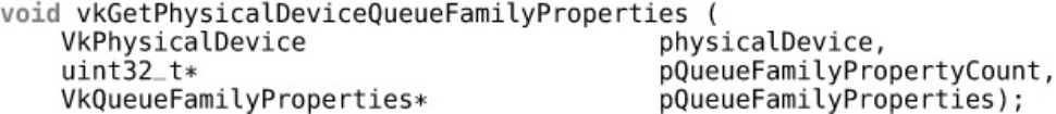
properties of the physical device. To query the device for its queue families, call
vkGetPhysicalDeviceQueueFamilyProperties(), the prototype of which is
Click here to view code image
void vkGetPhysicalDeviceQueueFamilyProperties (
VkPhysicalDevice physicalDevice,
uint32_t* pQueueFamilyPropertyCount,
VkQueueFamilyProperties* pQueueFamilyProperties);
vkGetPhysicalDeviceQueueFamilyProperties() works somewhat like
vkEnumeratePhysicalDevices() in that it is expected that you call it twice. The first time,
you pass nullptr as pQueueFamilyProperties, and in
pQueueFamilyPropertyCount, you pass a pointer to a variable that will be overwritten with

the number of queue families supported by the device. You can use this number to appropriately size
an array of VkQueueFamilyProperties. Then, on the second call, pass this array in
pQueueFamilyProperties, and Vulkan will fill it with the properties of the queues. The
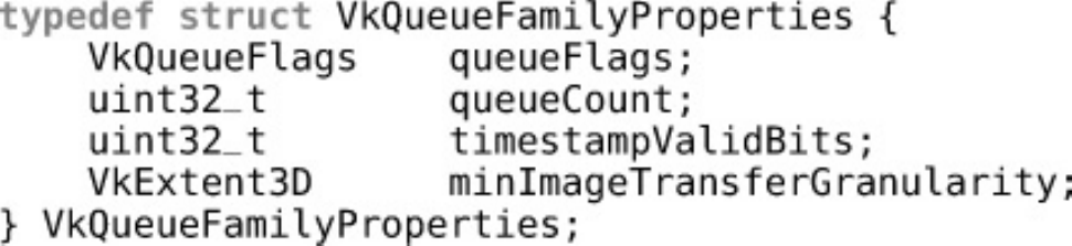
definition of VkQueueFamilyProperties is
Click here to view code image
typedef struct VkQueueFamilyProperties {
VkQueueFlags queueFlags;
uint32_t queueCount;
uint32_t timestampValidBits;
VkExtent3D minImageTransferGranularity;
} VkQueueFamilyProperties;
The first field in this structure, queueFlags, describes the overall capabilities of the queue. This
field is made up of a combination of the VkQueueFlagBits bits, the meanings of which are as
follows:
• If VK_QUEUE_GRAPHICS_BIT is set, then queues in this family support graphics operations
such as drawing points, lines, and triangles.
• If VK_QUEUE_COMPUTE_BIT is set, then queues in this family support compute operations
such as dispatching compute shaders.
• If VK_QUEUE_TRANSFER_BIT is set, then queues in this family support transfer operations
such as copying buffer and image contents.
• If VK_QUEUE_SPARSE_BINDING_BIT is set, then queues in this family support memory
binding operations used to update sparse resources.
The queueCount field indicates the number of queues in the family. This might be set to 1, or it
could be substantially higher if the device supports multiple queues with the same basic functionality.
The timestampValidBits field indicates how many bits are valid when timestamps are taken
from the queue. If this value is zero, then the queue doesn’t support timestamps. If it’s nonzero, then
it’s guaranteed to be at least 36 bits. Furthermore, if the timestampComputeAndGraphics field
of the device’s VkPhysicalDeviceLimits structure is VK_TRUE, then all queues supporting
either VK_QUEUE_GRAPHICS_BIT or VK_QUEUE_COMPUTE_BIT are guaranteed to support
timestamps with at least 36 bits of resolution. In this case, there’s no need to check each queue
individually.
Finally, the minImageTimestampGranularity field specifies the units with which the queue
supports image transfers (if at all).
Note that it might be the case that a device reports more than one queue family with apparently
identical properties. Queues within a family are essentially identical. Queues in different families
may have different internal capabilities that can’t be expressed easily in the Vulkan API. For this
reason, an implementation might choose to report similar queues as members of different families.
This places additional restrictions on how resources are shared between those queues, which might
allow the implementation to accommodate those differences.
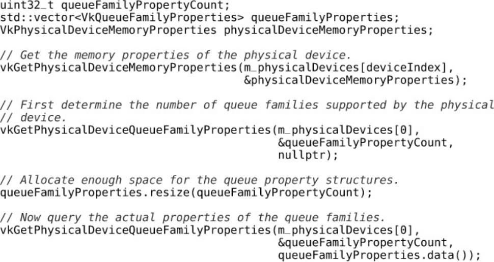
Listing 1.2 illustrates how to query the physical device’s memory properties and queue family
properties. You will need to retrieve the queue family properties before creating the logical device, as
discussed in the next section.

Listing 1.2: Querying Physical Device Properties
Click here to view code image
uint32_t queueFamilyPropertyCount;
std::vector<VkQueueFamilyProperties> queueFamilyProperties;
VkPhysicalDeviceMemoryProperties physicalDeviceMemoryProperties;
// Get the memory properties of the physical device.
vkGetPhysicalDeviceMemoryProperties(m_physicalDevices[deviceIndex],
&physicalDeviceMemoryProperties);
// First determine the number of queue families supported by the physical
// device.
vkGetPhysicalDeviceQueueFamilyProperties(m_physicalDevices[0],
&queueFamilyPropertyCount,
nullptr);
// Allocate enough space for the queue property structures.
queueFamilyProperties.resize(queueFamilyPropertyCount);
// Now query the actual properties of the queue families.
vkGetPhysicalDeviceQueueFamilyProperties(m_physicalDevices[0],
&queueFamilyPropertyCount,
queueFamilyProperties.data());
Creating a Logical Device
After enumerating all of the physical devices in the system, your application should choose a device
and create a logical device corresponding to it. The logical device represents the device in an
initialized state. During creation of the logical device, you get to opt in to optional features, turn on
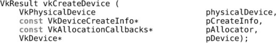
extensions you need, and so on. Creating the logical device is performed by calling
vkCreateDevice(), the prototype of which is
Click here to view code image
VkResult vkCreateDevice (
VkPhysicalDevice physicalDevice,
const VkDeviceCreateInfo* pCreateInfo,
const VkAllocationCallbacks* pAllocator,
VkDevice* pDevice);
The physical device to which the new logical device corresponds is passed in physicalDevice.
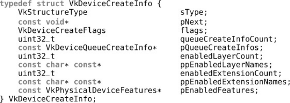
The information about the new logical device is passed in an instance of the
VkDeviceCreateInfo structure through the pCreateInfo structure. The definition of
VkDeviceCreateInfo is
Click here to view code image
typedef struct VkDeviceCreateInfo {
VkStructureType sType;
const void* pNext;
VkDeviceCreateFlags flags;
uint32_t queueCreateInfoCount;

const VkDeviceQueueCreateInfo* pQueueCreateInfos;
uint32_t enabledLayerCount;
const char*const* ppEnabledLayerNames;
uint32_t enabledExtensionCount;
const char*const* ppEnabledExtensionNames;
const VkPhysicalDeviceFeatures* pEnabledFeatures;
} VkDeviceCreateInfo;
The sType field of the VkDeviceCreateInfo structure should be set to
VK_STRUCTURE_TYPE_DEVICE_CREATE_INFO. As usual, unless you’re using extensions,
pNext should be set to nullptr. In the current version of Vulkan, no bits are defined for the
flags field of the structure, so set this to zero too.
Next comes the queue creation information. pQueueCreateInfos is a pointer to an array of one
or more VkDeviceQueueCreateInfo structures, each of which allows the specification of one
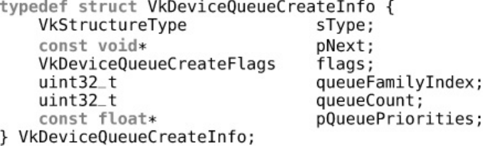
or more queues. The number of structures in the array is given in queueCreateInfoCount. The
definition of VkDeviceQueueCreateInfo is
Click here to view code image
typedef struct VkDeviceQueueCreateInfo {
VkStructureType sType;
const void* pNext;
VkDeviceQueueCreateFlags flags;
uint32_t queueFamilyIndex;
uint32_t queueCount;
const float* pQueuePriorities;
} VkDeviceQueueCreateInfo;
The sType field for VkDeviceQueueCreateInfo is
VK_STRUCTURE_TYPE_DEVICE_QUEUE_CREATE_INFO. There are currently no flags defined
for use in the flags field, so it should be set to zero. The queueFamilyIndex field specifies the
family of the queues you want to create. This is an index into the array of queue families returned
from vkGetPhysicalDeviceQueueFamilyProperties(). To create queues in this family,
set queueCount to the number of queues you want to use. Of course, the device must support at
least this many queues in the family you choose.
The pQueuePriorities field is an optional pointer to an array of floating point values
representing the relative priority of work submitted to each of the queues. These numbers are
normalized numbers in the range of 0.0 to 1.0. Queues with higher priority may be allocated more
processing resources or scheduled more aggressively than queues with lower priority. Setting
pQueuePriorities to nullptr has the effect of leaving the queues at the same, default
priority.
The requested queues are sorted in order of priority and then assigned device-dependent relative
priorities. The number of discrete priorities that a queue may take on is a device-specific parameter.
You can determine this by checking the discreteQueuePriorities field of the
VkPhysicalDeviceLimits structure returned from a call to
vkGetPhysicalDeviceProperties(). For example, if a device supports only low- and high-
priority workloads, this field will be 2. All devices support at least two discrete priority levels.
However, if a device supports arbitrary priorities, then this field could be much higher. Regardless of

the value of discreteQueuePriorities, the relative priorities of the queue are still expressed
as floating-point values.
Returning to the VkDeviceCreateInfo structure, the enabledLayerCount,
ppEnabledLayerNames,enabledExtensionCount, and ppEnabledExtensionNames
fields are for enabling layers and extensions. We will cover both of these topics later in this chapter.
For now, we’ll set both enabledLayerCount and enabledExtensionCount to zero and
both ppEnabledLayerNames and ppEnabedExtensionNames to nullptr.
The final field of VkDeviceCreateInfo,pEnabledFeatures, is a pointer to an instance of
the VkPhysicalDeviceFeatures structure that specifies which of the optional features that
your application wishes to use. If you don’t want to use any optional features, you can simply set this
to nullptr. However, Vulkan in this form is relatively limited, and much of its interesting
functionality will be disabled.
To determine which of the optional features the device supports, call
vkGetPhysicalDeviceFeatures() as discussed earlier.
vkGetPhysicalDeviceFeatures() writes the set of features supported by the device into an
instance of the VkPhysicalDeviceFeatures structure that you pass in. By simply querying the
phyiscal device’s features and then passing the very same VkPhysicalDeviceFeatures
structure back to vkCreateDevice(), you enable every optional feature that the device supports
and do not request features that the device does not support.
Simply enabling every supported feature, however, may come with some performance impact. For
some features, a Vulkan implementation may need to allocate extra memory, track additional state,
configure hardware slightly differently, or perform some other operation that otherwise costs your
application. It’s not a good idea to enable features that won’t be used. In an optimized application,
you should query the supported features from the device; then, from the supported features, enable
the specific features that your application requires.
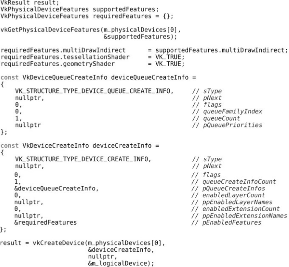
Listing 1.3 shows a simple example of querying the device for its supported features, setting up a list
of features that the application requires. Support for tessellation and geometry shaders is absolutely
required, and support for multidraw indirect is enabled if it is supported by the device. The code then
creates a device using a single instance of its first queue.
Listing 1.3: Creating a Logical Device
Click here to view code image
VkResult result;
VkPhysicalDeviceFeatures supportedFeatures;
VkPhysicalDeviceFeatures requiredFeatures = {};
vkGetPhysicalDeviceFeatures(m_physicalDevices[0],
&supportedFeatures);
requiredFeatures.multiDrawIndirect =
supportedFeatures.multiDrawIndirect;
requiredFeatures.tessellationShader = VK_TRUE;
requiredFeatures.geometryShader = VK_TRUE;
const VkDeviceQueueCreateInfo deviceQueueCreateInfo =

{
VK_STRUCTURE_TYPE_DEVICE_QUEUE_CREATE_INFO, // sType
nullptr, // pNext
0, // flags
0, // queueFamilyIndex
1, // queueCount
nullptr // pQueuePriorities
};
const VkDeviceCreateInfo deviceCreateInfo =
{
VK_STRUCTURE_TYPE_DEVICE_CREATE_INFO, // sType
nullptr, // pNext
0, // flags
1, //
queueCreateInfoCount
&deviceQueueCreateInfo, // pQueueCreateInfos
0, // enabledLayerCount
nullptr, // ppEnabledLayerNames
0, //
enabledExtensionCount
nullptr, //
ppEnabledExtensionNames
&requiredFeatures // pEnabledFeatures
};
result = vkCreateDevice(m_physicalDevices[0],
&deviceCreateInfo,
nullptr,
&m_logicalDevice);
After the code in Listing 1.3 has run and successfully created the logical device, the set of enabled
features is stored in the requiredFeatures variable. This may be kept for later so that code that
can optionally use a feature can check whether it was successfully enabled and fall back gracefully.
Object Types and Function Conventions
Virtually everything in Vulkan is represented as an object that is referred to by a handle. Handles are
divided into two broad categories: dispatchable objects and nondispatchable objects. For the most
part, this is not relevant to applications and affects only how the API is structured and how system-
level components such as the Vulkan loader and layers interoperate with those objects.
Dispatchable objects are objects that internally contain a dispatch table. This is the table of functions
used by various components to determine which parts of code to execute when your application
makes calls to Vulkan. These types of objects are generally heavier-weight constructs and currently
consist of the instance (VkInstance), physical device (VkPhysicalDevice), logical device
(VkDevice), command buffer (VkCommandBuffer), and queue (VkQueue). All other objects
are considered nondispatchable.
The first argument to any Vulkan function is always a dispatchable object. The only exceptions to
this rule are the functions related to creating and initializing the instance.

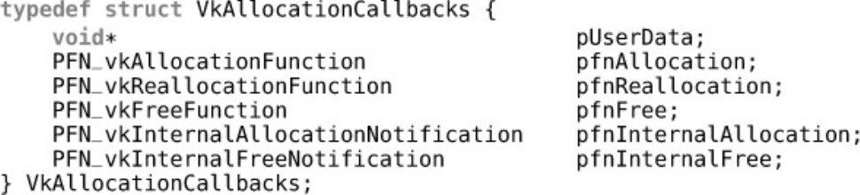
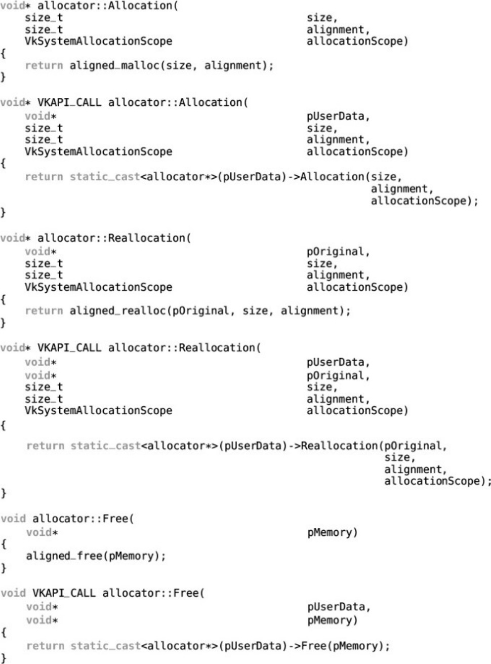
Managing Memory
Vulkan provides two types of memory: host memory and device memory. Objects created by the
Vulkan API generally require some amount of host memory. This is where the Vulkan
implementation will store the state of the object and any data it needs to implement the Vulkan API.
Resource objects such as buffers and images require some amount of device memory. This is the
memory where the data stored in the resource is kept.
It is possible for your application to manage host memory for the Vulkan implementation, and it is
required that your application manage device memory. To do this, you will need to create a device
memory management subsystem. Each resource that you create can be queried for the amount and
type of memory it requires for it to be backed. It will be up to your application to allocate the correct
amount of memory and attach it to the resource object before it can be used.
In higher-level APIs such as OpenGL, this “magic” is performed by drivers on behalf of your
application. However, some applications require a very large number of small resources, and other
applications require a smaller number of very large resources. Some applications create and destroy
resources over the course of their execution, whereas other applications create all of their resources at
startup and do not free them until they are terminated.
The allocation strategies used in these cases might be quite different. There is no one-size-fits-all
strategy. An OpenGL driver has no idea how your application will behave and so must adapt
allocation strategies to attempt to fit your usage patterns. On the other hand, you, the application
developer, know exactly how your application will behave. You can partition resources into long-
lived and transient groups. You can bucket resources that will be used together into a small number of
pooled allocations. You are in the best position to decide the allocation strategies used by your
application.
It is important to note that each “live” memory allocation places some cost on the system. Therefore,
it is important to keep the number of allocation objects to a minimum. It is recommended that device
memory allocators allocate memory in large chunks. Many small resources can be placed inside a
much smaller number of device memory blocks. An example of a device memory allocator is
discussed in Chapter 2, “Memory and Resources,” which discusses memory allocation in much more
detail.
Multithreading in Vulkan
Support for multithreaded applications is an integral part of the design of Vulkan. Vulkan generally
assumes that the application will ensure that no two threads are mutating the same object at the same
time. This is known as external synchronization. The vast majority of Vulkan commands in the
performance-critical portions of Vulkan (such as building command buffers) provide no
synchronization at all.
In order to concretely define the threading requirements of various Vulkan commands, each
parameter that must be protected from concurrent access by the host is marked as externally
synchronized. In some cases, handles to objects or other data are embdedd in data structures,
included in arrays, or otherwise passed to commands through some indirect means. Those paramters
must also be externally synchronized.
The intention of this is that a Vulkan implementation never needs to take a mutex or use other
synchronization primitives internally to protect data structures. This means that multithreaded
programs rarely stall or block across threads.
In addition to requiring the host to synchronize access to shared objects when they are used across
threads, Vulkan includes a number of higher-level features that are designed specifically to allow
threads to perform work without blocking one another. These include the following:
• Host memory allocations can be handled through a host memory allocation structure passed to
object creation functions. By using an allocator per thread, the data structures in that allocator
don’t need to be protected. Host memory allocators are covered in Chapter 2, “Memory and
Resources.”
• Command buffers are allocated from pools, and access to the pool is externally synchronized. If
an application uses a separate command pool per thread, command buffers can be allocated
from those pools without blocking against one another. Command buffers and pools are covered
in Chapter 3, “Queues and Commands.”
• Descriptors are allocated in sets from descriptor pools. Descriptors are the representation of
resources as used by shaders running on the device. They are covered in detail in Chapter 6,
“Shaders and Pipelines.” If a separate pool is used for each thread, then descriptor sets can be
allocated from those pools without the threads blocking one another.
• Second-level command buffers allow the contents of a large renderpass (which must be
contained in a single command buffer) to be generated in parallel and then grouped as they’re
called from the primary command buffer. Secondary command buffers are covered in detail in
Chapter 13, “Multipass Rendering.”
When you are building a very simple, single-threaded application, the requirement to create pools
from which to allocate objects may seem like a lot of unnecessary indirection. However, as
applications scale in number of threads, these objects are indispensible to achieving high
performance.
Throughout the remainder of this book, any special requirements with respect to threading will be
noted as the commands are introduced.
Mathematical Concepts
Computer graphics and most heterogeneous compute applications are fairly heavily math-based.
Most Vulkan devices are based on extremely powerful computational processors. At the time of
writing, even modest mobile processors are capable of providing many gigaflops of processing
power, while higher-end desktop and workstation processors deliver many teraflops of number-
crunching ability. As a consequence, really interesting applications will build on math-heavy shaders.
Further, several fixed-function sections of Vulkan’s processing pipeline are built upon mathematical
concepts that are hard-wired into the device and specification.
Vectors and Matrices
One of the fundamental building blocks of any graphics application is the vector. Whether they’re the
representations of a position, a direction, a color, or some other quantity, vectors are used throughout
the graphics literature. One common form of vector is the homogeneous vector, which is a vector in a
space one dimension higher than the quantity it’s representing. These vectors are used to store
projective coordinates. Multiplying a homogeneous vector by any scalar produces a new vector
representing the same projective coordinate. To project a point vector, divide through by its last
component, producing a vector of the form x, y, z, 1.0 (for a four-component vector).
To transform a vector from one coordinate space to another, multiply the vector by a matrix. Just as a
point in 3D space is represented as a four-component homogeneous vector, a transformation matrix
operating on a 3D homogeneous vector is a 4 × 4 matrix.
A point in 3D space is typically represented as a homogeneous vector of four components
conventionally called x,y,z, and w. For a point, the wcomponent generally begins as 1.0 and
changes as the vector is transformed through projective matrices. After division through by the w
component, the point is projected through whichever transforms it’s been subjected to. If none of the
transforms is a projective transform, then wremains 1.0, and division by 1.0 has no effect on the
vector. If the vector was subjected to a projective transform, then wwill not be equal to 1.0, but
dividing through by it will project the point and return wto 1.0.
Meanwhile, a direction in 3D space is also represented as a homogeneous vector whose wcomponent
is 0.0. Multiplying a direction vector by a properly constructed 4 × 4 projective matrix will leave the
wcomponent at 0.0, and it will have no effect on any of the other components. By simply discarding
the additional component, you can put a 3D direction vector through the same transformations as a
4D homogeneous 3D point vector and make it undergo rotations, scales, and other transforms
consistently.
Coordinate Systems
Vulkan deals with graphics primitives such as lines and triangles by representing their endpoints or
corners as points in 3D space. These primitives are known as vertices. The inputs to the Vulkan
system are vertex coordinates in a 3D coordinate space (represented as homogenous vectors with w
components of 1.0) relative to the origin of the object of which they are part. This coordinate space is
known as object space or sometimes model space.
Typically, the first shaders in the pipeline will transform this vertex into view space, which is a
position relative to the viewer. This transformation is performed by multiplying the vertex’s position
vector by a transformation matrix. This is often called the object-to-view matrix or the model-view
matrix.
Sometimes, absolute coordinates of a vertex are required, such as when finding the coordinate of a
vertex relative to some other object. This global space is known as world space and is the position of
vertices relative to a global origin.
From view space, the positions of vertices are transformed into clip space. This is the final space
used by the geometry-processing part of Vulkan and is the space into which vertices are typically
transformed when pushing them into the projective space used by typical 3D applications. Clip space
is so called because it is the coordinate space in which most implementations perform clipping,
which removes sections of primitives that lie outside the visible region being rendered.
From clip space, vertex positions are normalized by dividing through by their wcomponents. This
yields a coordinate space called normalized device coordinates, or NDC, and the process is often
called the perspective divide. In this space, the visible part of the coordinate system is from −1.0 to
1.0 in the xand ydirections and from 0.0 to 1.0 in the zdirection. Anything outside this region will
be clipped away prior to perspective division.
Finally, a vertex’s normalized device coordinate is transformed by the viewport, which describes how
NDC maps into a window or image into which the picture is being rendered.

Enhancing Vulkan
Although the core API specification of Vulkan is quite extensive, it’s by no means all-encompassing.
Some functionality is optional, while yet more is available in the form of layers (which modify or
enhance existing behavior) and extensions (which add new functionality to Vulkan). Both
enhancement mechanisms are described in the following sections.
Layers
Layers are features of Vulkan that allow its behavior to be modified. Layers generally intercept all or
part of Vulkan and add functionality such as logging, tracing, providing diagnostics, profiling, and so
on. A layer can be added at the instance level, in which case it affects the whole Vulkan instance and
possibly every device created by it. Alternatively, the layer can be added at the device level, in which
case it affects only the device for which it is enabled.
To discover the layers available to an instance on a system, call
vkEnumerateInstanceLayerProperties(), the prototype of which is
Click here to view code image
VkResult vkEnumerateInstanceLayerProperties (
uint32_t* pPropertyCount,
VkLayerProperties* pProperties);
If pProperties is nullptr, then pPropertyCount should point to a variable that will be
overwritten with the count of the number of layers available to Vulkan. If pProperties is not
nullptr, then it should point to an array of VkLayerProperties structures that will be filled
with information about the layers registered with the system. In this case, the initial value of the
variable pointed to by pPropertyCount is the length of the array pointed to by pProperties,
and this variable will be overwritten with the number of entries in the array overwritten by the
command.
Each element of the pProperties array is an instance of the VkLayerProperties structure,
the definition of which is
Click here to view code image
typedef struct VkLayerProperties {
char layerName[VK_MAX_EXTENSION_NAME_SIZE];
uint32_t specVersion;
uint32_t implementationVersion;
char description[VK_MAX_DESCRIPTION_SIZE];
} VkLayerProperties;
Each layer has a formal name that is stored in the layerName member of the
VkLayerProperties structure. As the specification for each layer might be improved, clarified,
or appended to over time, the version of the layer implementation is reported in specVersion.
As specifications are improved over time, so too are implementations of those specifications. The
implementation version is stored in the implementationVersion field of the
VkLayerProperties structure. This allows implementations to improve performance, fix bugs,
implement a wider set of optional features, and so on. An application writer may recognize a

particular implementation of a layer and choose to use it only if the version of that implementation is
past a certain version where, for example, a critical bug was known to be fixed.
Finally, a human-readable string describing the layer is stored in description. The only purpose
of this field is for logging or display in a user interface, and it is for informational purposes only.
Listing 1.4 illustrates how to query the instance layers supported by the Vulkan system.
Listing 1.4: Querying Instance Layers
Click here to view code image
uint32_t numInstanceLayers = 0;
std::vector<VkLayerProperties> instanceLayerProperties;
// Query the instance layers.
vkEnumerateInstanceLayerProperties(&numInstanceExtensions,
nullptr);
// If there are any layers, query their properties.
if (numInstanceLayers != 0)
{
instanceLayerProperties.resize(numInstanceLayers);
vkEnumerateInstanceLayerProperties(nullptr,
&numInstanceLayers,
instanceLayerProperties.data());
}
As mentioned, it is not only at the instance level that layers can be injected. Layers can also be
applied at the device level. To determine which layers are available to devices, call
vkEnumerateDeviceLayerProperties(), the prototype of which is
Click here to view code image
VkResult vkEnumerateDeviceLayerProperties (
VkPhysicalDevice physicalDevice,
uint32_t* pPropertyCount,
VkLayerProperties* pProperties);
The layers available to each physical device in a system may be different, so each physical device can
report a different set of layers. The physical device whose layers to query is passed in
physicalDevice. The pPropertyCount and pProperties parameters to
vkEnumerateDeviceLayerProperties() behave similarly to the identically named
parameters to vkEnumerateInstanceLayerProperties(). Device layers are also described
by instances of the VkLayerProperties structure.
To enable a layer at the instance level, include its name in the ppEnabledLayerNames field of
the VkInstanceCreateInfo structure used to create the instance. Likewise, to enable a layer
when creating a logical device corresponding to a physical device in the system, include the layer
name in the ppEnabledLayerNames member of the VkDeviceCreateInfo used to create the
device.
Several layers are included in the offical SDK, most of which are related to debugging, parameter
validation, and logging. These include the following:

•VK_LAYER_LUNARG_api_dump prints Vulkan calls and their parameters and values to the
console.
•VK_LAYER_LUNARG_core_validation performs validation on parameters and state used
in descriptor sets, pipeline state, and dynamic state; validates the interfaces between SPIR-V
modules and the graphics pipeline; and tracks and validates usage of GPU memory used to back
objects.
•VK_LAYER_LUNARG_device_limits ensures that values passed to Vulkan commands as
arguments or data structure members fall within the device’s supported feature set limits.
•VK_LAYER_LUNARG_image validates that image usage is consistent with supported formats.
•VK_LAYER_LUNARG_object_tracker performs tracking on Vulkan objects, attempting to
catch leaks, use-after-free errors, and other invalid object usage.
•VK_LAYER_LUNARG_parameter_validation confirms that all parameter values passed
to Vulkan functions are valid.
•VK_LAYER_LUNARG_swapchain performs validation on functionality provided by the WSI
(Window System Integration) extensions described in Chapter 5, “Presentation.”
•VK_LAYER_GOOGLE_threading ensures valid usage of Vulkan commands with respect to
threading, ensuring that no two threads access the same object at the same time when they
shouldn’t.
•VK_LAYER_GOOGLE_unique_objects ensures that every object will have a unique handle
for easier tracking by the application, avoiding cases where an implementation might de-
duplicate handles that represent objects with the same parameters.
In addition to this, a large number of separate layers are grouped into a larger, single layer called
VK_LAYER_LUNARG_standard_validation, making it easy to turn on. The book’s
application framework enables this layer when built in debug mode, leaving all layers disabled when
built in release mode.
Extensions
Extensions are fundamental to any cross-platform, open API such as Vulkan. They allow
implementers to experiment, innovate, and ultimately push technology forward. Eventually, useful
features originally introduced as extensions make their way into future versions of the API after
having been proved in the field. However, extensions are not without cost. Some may require
implementations to track additional state, make additional checks during command buffer build, or
come with some performance penalty even when the extension is not in direct use. Therefore,
extensions must be explicitly enabled by an application before they can be used. This means that
applications that don’t use an extension don’t pay for it in terms of performance or complexity and
that it’s almost impossible to accidentally use features from an extension, which improves portability.
Extensions are divided into two categories: instance extensions and device extensions. An instance
extension is one that generally enhances the entire Vulkan system on a platform. This type of
extension is either supplied via a device-independent layer or is simply an extension that is exposed
by every device on the system and promoted into an instance. Device extensions are extensions that
extend the capabilities of one or more devices in the sytem but aren’t necessarily available on every
device.

Each extension can define new functions, new types, structures, enumerations, and so on. Once
enabled, an extension can be considered part of the API that is available to the application. Instance
extensions must be enabled when the Vulkan instance is created, and device extensions must be
enabled when the device is created. These leaves us with a chicken-and-egg situation: How do we
know which extensions are supported before initializing a Vulkan instance?
Querying the supported instance extensions is one of the few pieces of Vulkan functionality that may
be used before a Vulkan instance is created. This is performed using the
vkEnumerateInstanceExtensionProperties() function, the prototype of which is
Click here to view code image
VkResult vkEnumerateInstanceExtensionProperties (
const char* pLayerName,
uint32_t* pPropertyCount,
VkExtensionProperties* pProperties);
pLayerName is the name of a layer that might provide extensions. For now, set this to nullptr.
pPropertyCount is a pointer to a variable containing the count of the number of instance
extensions to query Vulkan about, and pProperties is a pointer to an array of
VkExtensionProperties structures that will be filled with information about the supported
extensions. If pProperties is nullptr, then the initial value of the variable pointed to by
pPropertyCount is ignored and is overwritten with the number of instance extensions supported.
If pProperties is not nullptr, then the number of entries in the array is assumed to be in the
variable pointed to by pPropertyCount, and up to this many entries of the array are populated
with information about the supported extensions. The variable pointed to by pPropertyCount is
then overwritten with the number of entries actually written to pProperties.
To correctly query all of the supported instance extensions, call
vkEnumerateInstanceExtensionProperties() twice. The first time, call it with
pProperties set to nullptr to retrieve the number of supported instance extensions. Then appropriately
size an array to receive the extension properties and call
vkEnumerateInstanceExtensionProperties() again, this time passing the address of
the array in pProperties. Listing 1.5 demonstrates how to do this.
Listing 1.5: Querying Instance Extensions
Click here to view code image
uint32_t numInstanceExtensions = 0;
std::vector<VkExtensionProperties> instanceExtensionProperties;
// Query the instance extensions.
vkEnumerateInstanceExtensionProperties(nullptr,
&numInstanceExtensions,
nullptr);
// If there are any extensions, query their properties.
if (numInstanceExtensions != 0)
{
instanceExtensionProperties.resize(numInstanceExtensions);

vkEnumerateInstanceExtensionProperties(nullptr,
&numInstanceExtensions,
instanceExtensionProperties.data());
}
After the code in Listing 1.5 has completed execution, instanceExtensionProperties will
contain a list of the extensions supported by the instance. Each element of the array of
VkExtensionProperties describes one extension. The definition of
VkExtensionProperties is
Click here to view code image
typedef struct VkExtensionProperties {
char extensionName[VK_MAX_EXTENSION_NAME_SIZE];
uint32_t specVersion;
} VkExtensionProperties;
The VkExtensionProperties structure simply contains the name of the extension and the
version of that extension. Extensions may add functionality over time as new revisions of the
extension are produced. The specVersion field allows updates to extensions without the need to
create an entirely new extension in order to add minor functionality. The name of the extension is
stored in extensionName.
As you saw earlier, when creating the Vulkan instance, the VkInstanceCreateInfo structure
has a member called ppEnabledExtensionNames, which is a pointer to an array of strings
naming the extensions to enable. If the Vulkan system on a platform supports an extension, that
extension will be included in the array returned from
vkEnumerateInstanceExtensionProperties(), and its name can be passed to
vkCreateInstance() via the ppEnabledExtensionNames field of the
VkInstanceCreateInfo structure.
Querying the support for device extensions is a similar process. To do this, call
vkEnumerateDeviceExtensionProperties(), whose prototype is
Click here to view code image
VkResult vkEnumerateDeviceExtensionProperties (
VkPhysicalDevice physicalDevice,
const char* pLayerName,
uint32_t* pPropertyCount,
VkExtensionProperties* pProperties);
The prototype of vkEnumerateDeviceExtensionProperties() is almost identical to that
of vkEnumerateInstanceExtensionProperties(), with the addition of a
physicalDevice parameter. The physicalDevice parameter is the handle to the device
whose extensions to query. As with vkEnumerateInstanceExtensionProperties(),
vkEnumerateDeviceExtensionProperties() overwrites pPropertyCount with the
number of supported extensions if pProperties is nullptr, and if pProprties is not
nullptr, it fills that array with information about the supported extensions. The same
VkExtensionProperties structure is used for device extensions and for instance extensions.

When you are creating the physical device, the ppEnabledExtensionNames field of the
VkDeviceCreateInfo structure may contain a pointer to one of the strings returned from
vkEnumerateDeviceExtensionProperties().
Some extensions provide new functionality in the form of additional entry points that you can call.
These are exposed as function pointers, the values of which you must query either from the instance
or from the device after enabling the extension. Instance functions are functions that are valid for the
entire instance. If an extension extends instance-level functionality, you should use an instance-level
function pointer to access the new features.
To retrieve an instance-level function pointer, call vkGetInstanceProcAddr(), the prototype
of which is
Click here to view code image
PFN_vkVoidFunction vkGetInstanceProcAddr (
VkInstance instance,
const char* pName);
The instance parameter is the handle to the instance for which to retrieve a new function pointer.
If your application does use more than one Vulkan instance, then the function pointer returned from
this command is valid only for objects owned by the referenced instance. The name of the function is
passed in pName, which is a nul-terminated UTF-8 string. If the function name is recognized and
the extension is enabled, the return value from vkGetInstanceProcAddr() is a function
pointer that you can call from your application.
The PFN_vkVoidFunction is a type definition for a pointer to a function of the following
declaration:
Click here to view code image
VKAPI_ATTR void VKAPI_CALL vkVoidFunction(void);
There are no functions in Vulkan that have this particular signature, and it is unlikely that an
extension would introduce such a function. In all likelihood, you will need to cast the resulting
function pointer to a pointer of the appropriate signature before you can call it.
Instance-level function pointers are valid for any object owned by the instance, assuming the device
that created the object (or the device itself, if the function dispatches on the device) supports the
extension and the extension is enabled for that device. Because each device might be implemented
inside a different Vulkan driver, instance function pointers must dispatch though a layer of indirection
to land in the correct module. Managing this indirection may incur some overhead; to avoid this, you
can get a device-specific function pointer that goes directly to the appropriate driver.
To get a device-level function pointer, call vkGetDeviceProcAddr(), the prototype of which is
Click here to view code image
PFN_vkVoidFunction vkGetDeviceProcAddr (
VkDevice device,
const char* pName);
The device with which the function pointer will be used is passed in device. Again, the name of the
function you are querying is passed as a nul-terminated UTF-8 string in pName. The resulting
function pointer is valid only with the device specified in device.device must refer to a device

that supports the extension that provides the new function and for which the extension has been
enabled.
The function pointer produced by vkGetDeviceProcAddr() is specific to device. Even if the
same physical device is used to create two or more logical devices with the exact same parameters,
you must use the resulting function pointers only with the devices from which they were queried.
Shutting Down Cleanly
Before your program exits, you should clean up after yourself. In many cases, an operating system
will clean up resources that you’ve allocated when your application terminates. However, it will not
always be the case that the end of your code is the end of the application. If you are writing a
component of a larger application, for example, that application may terminate rendering or compute
operations using Vulkan without actually exiting.
When cleaning up, it is generally good practice to do the following:
• Complete or otherwise terminate all work that your application is doing both on the host and the
device, in all threads related to Vulkan.
• Destroy objects in the reverse order from the order in which they were created.
The logical device is likely to be the last object (aside from objects used at runtime) that you created
during initialization of your application. Before destroying the device, you should ensure that it is not
executing any work on behalf of your application. To do this, call vkDeviceWaitIdle(), the
prototype of which is
Click here to view code image
VkResult vkDeviceWaitIdle (
VkDevice device);
The handle to the device is passed in device. When vkDeviceWaitIdle() returns, all work
submitted to the device on behalf of your application is guaranteed to have completed—unless, of
course, you submit more work to the device in the meantime. You should ensure that any other
threads that might be submitting work to the device have been terminated.
Once you have ensured that the device is idle, you can safely destroy it. To do this, call
vkDestroyDevice(), the prototype of which is
Click here to view code image
void vkDestroyDevice (
VkDevice device,
const VkAllocationCallbacks* pAllocator);
The handle to the device to destroy is passed in the device parameter, access to which must be
externally synchronized. Note that access to a device does not need to be externally synchronized
with respect to any other command. The application should ensure, however, that a device is not
destroyed while any other command accessing it is still executing in another thread.
pAllocator should point to an allocation structure that is compatible with the one used to create
the device. Once the device object has been destroyed, no more commands can be submitted to it.
Further, it is no longer possible to use the device handle as an argument to any function, including

other object-destruction functions that take a device handle as their first argument. This is another
reason why you should destroy objects in reverse order from the order in which they were created.
Once all devices associated with a Vulkan instance have been destroyed, it is safe to destroy the
instance. This is accomplished by calling the vkDestroyInstance() function, whose prototype
is
Click here to view code image
void vkDestroyInstance (
VkInstance instance,
const VkAllocationCallbacks* pAllocator);
The handle to the instance to destroy is passed in instance and, as with vkDestroyDevice(),
a pointer to an allocation structure compatible with the one with which the instance was allocated
should be passed in pAllocator. If the pAllocator parameter to vkCreateInstance()
was nullptr, then the pAllocator parameter to vkDestroyInstance() should be too.
Note that it’s not necessary to destroy the physical devices. Physical devices are not created with a
dedicated creation function as logical devices are. Rather, physical devices are returned from a call to
vkEnumeratePhysicalDevices() and are considered to be owned by the instance. Therefore,
when the instance is destroyed, that instance’s resources associated with each physical device are
freed as well.
Summary
This chapter introduced you to Vulkan. You have seen how the entirety of Vulkan state is contained
within an instance. The instance provides access to physical devices, and each physical device
exposes a number of queues that can be used to do work. You have seen how to create a logical
device corresponding to the physical device. You have seen how Vulkan can be extended, how to
determine the extensions available to the instance and to a device, and how to enable those
extensions. You have seen how to cleanly shut down the Vulkan system by waiting for a device to
complete work submitted by your application, destroying the device handles, and finally destroying
the instance handle.

Chapter 2. Memory and Resources
What You’ll Learn in This Chapter
• How Vulkan manages host and device memory
• How to manage memory effectively in your application
• How Vulkan uses images and buffers to consume and produce data
Memory is fundamental to the operation of virtually all computing systems, including Vulkan. In
Vulkan, there are two fundamental types of memory: host memory and device memory. All resources
upon which Vulkan operates must be backed by device memory, and it is the application’s
responsibility to manage this memory. Further, memory is used to store data structures on the host.
Vulkan provides the opportunity for your application to manage this memory too. In this chapter,
you’ll learn about the mechanisms through which you can manage memory used by Vulkan.
Host Memory Management
Whenever Vulkan creates new objects, it might need memory to store data related to them. For this, it
uses host memory, which is regular memory accessible to the CPU that might be returned from a call
to malloc or new, for example. However, beyond a normal allocator, Vulkan has particular
requirements for some allocations. Most notably, it expects allocations to be aligned correctly. This is
because some high-performance CPU instructions work best (or only) on aligned memory addresses.
By assuming that allocations storing CPU-side data structures are aligned, Vulkan can use these high-
performance instructions unconditionally, providing substantial performance advantages.
Because of these requirements, Vulkan implementations will use advanced allocators to satisfy them.
However, it also provides the opportunity for your application to replace the allocators for certain, or
even all, operations. This is performed through the pAllocator parameter available in most device
creation functions. For example, let’s revisit the vkCreateInstance() function, which is one of
the first that your application might call. Its prototype is
Click here to view code image
VkResult vkCreateInstance (
const VkInstanceCreateInfo* pCreateInfo,
const VkAllocationCallbacks* pAllocator,
VkInstance* pInstance);
The pAllocator parameter is a pointer to a VkAllocationCallbacks structure. Until now,
we’ve been setting pAllocator to nullptr, which tells Vulkan to use its own internal allocator
rather than rely on our application. The VkAllocationCallbacks structure encapsulates a
custom memory allocator that we can provide. The definition of the structure is
Click here to view code image
typedef struct VkAllocationCallbacks {
void* pUserData;
PFN_vkAllocationFunction pfnAllocation;

PFN_vkReallocationFunction pfnReallocation;
PFN_vkFreeFunction pfnFree;
PFN_vkInternalAllocationNotification pfnInternalAllocation;
PFN_vkInternalFreeNotification pfnInternalFree;
} VkAllocationCallbacks;
You can see from the definition of VkAllocationCallbacks that the structure is essentially a
set of function pointers and an additional void pointer, pUserData. The pointer is for your
application’s use. It can point anywhere; Vulkan will not dereference it. In fact, it doesn’t even need
to be a pointer. You can put anything in there, so long as it fits into a pointer-size blob. The only thing
that Vulkan will do with pUserData is pass it back to the callback functions to which the remaining
members of VkAllocationCallbacks point.
pfnAllocation,pfnReallocation, and pfnFree are used for normal, object-level memory
management. They are defined as pointers to functions that match the following declarations:
Click here to view code image
void* VKAPI_CALL Allocation(
void* pUserData,
size_t size,
size_t alignment,
VkSystemAllocationScope allocationScope);
void* VKAPI_CALL Reallocation(
void* pUserData,
void* pOriginal
size_t size,
size_t alignment,
VkSystemAllocationScope allocationScope);
void VKAPI_CALL Free(
void* pUserData,
void* pMemory);
Notice that all three functions take a pUserData parameter as their first argument. This is the same
pUserData pointer that’s part of the VkAllocationCallbacks structure. If your application
uses data structures to manage memory, this is a good place to put their addresses. One logical thing
to do with this is to implement your memory allocator as a C++ class (assuming you’re writing in
C++) and then put the class’s this pointer in pUserData.
The Allocation function is responsible for making new allocations. The size parameter gives
the size of the allocation, in bytes. The alignment parameter gives the required alignment of the
allocation, also in bytes. This is an often-overlooked parameter. It is very tempting to simply hook
this function up to a naïve allocator such as malloc. If you do this, you will find that it works for a
while but that certain functions might mysteriously crash later. If you provide your own allocator, it
must honor the alignment parameter.
The final parameter, allocationScope, tells your application what the scope, or lifetime, of the
allocation is going to be. It is one of the VkSystemAllocationScope values, which have the
following meanings:

•VK_SYSTEM_ALLOCATION_SCOPE_COMMAND means that the allocation will be live only
for the duration of the command that provoked the allocation. Vulkan will likely use this for
very short-lived temporary allocations, as it works on a single command.
•VK_SYSTEM_ALLOCATION_SCOPE_OBJECT means that the allocation is directly associated
with a particular Vulkan object. This allocation will live at least until the object is destroyed.
This type of allocation will only ever be made as part of executing a creation command (one
beginning with vkCreate).
•VK_SYSTEM_ALLOCATION_SCOPE_CACHE means that the allocation is associated with
some form of internal cache or a VkPipelineCache object.
•VK_SYSTEM_ALLOCATION_SCOPE_DEVICE means that the allocation is scoped to the
device. This type of allocation is made when the Vulkan implementation needs memory
associated with the device that is not tied to a single object. For example, if the implementation
allocates objects in blocks, this type of allocation might be made in response to a request to
create a new object, but because many objects might live in the same block, the allocation can’t
be tied directly to any specific object.
•VK_SYSTEM_ALLOCATION_SCOPE_INSTANCE means that the allocation is scoped to the
instance. This is similar to VK_SYSTEM_ALLOCATION_SCOPE_DEVICE. This type of
allocation is typically made by layers or during early parts of Vulkan startup, such as by
vkCreateInstance() and vkEnumeratePhysicalDevices().
The pfnInternalAllocation and pfnInternalFree function pointers point to alternate
allocator functions that are used when Vulkan makes memory allocations using its own allocators.
These callbacks have the same signatures as pfnAllocation and pfnFree, except that
pfnInternalAllocation doesn’t return a value and pfnInternalFree shouldn’t actually
free the memory. These functions are used only for notification so that your application can keep
track of how much memory Vulkan is using. The prototypes of these functions should be
Click here to view code image
void VKAPI_CALL InternalAllocationNotification(
void* pUserData,
size_t size,
VkInternalAllocationType allocationType,
VkSystemAllocationScope allocationScope);
void VKAPI_CALL InternalFreeNotification(
void* pUserData,
size_t size,
VkInternalAllocationType allocationType,
VkSystemAllocationScope allocationScope);
There’s not much you can do with the information provided through pfnInternalAllocation
and pfnInternalFree besides log it and keep track of the total memory usage made by the
application. Specifying these function pointers is optional, but if you supply one, you must supply
both. If you don’t want to use them, set them both to nullptr.
Listing 2.1 shows an example of how to declare a C++ class that can be used as an allocator that
maps the Vulkan allocation callback functions. Because the callback functions used by Vulkan are
naked C function pointers, the callback functions themselves are declared as static member functions

of the class, whereas the actual implementations of those functions are declared as regular nonstatic
member functions.
Listing 2.1: Declaration of a Memory Allocator Class
Click here to view code image
class allocator
{
public:
// Operator that allows an instance of this class to be used as a
// VkAllocationCallbacks structure
inline operator VkAllocationCallbacks() const
{
VkAllocationCallbacks result;
result.pUserData = (void*)this;
result.pfnAllocation = &Allocation;
result.pfnReallocation = &Reallocation;
result.pfnFree = &Free;
result.pfnInternalAllocation = nullptr;
result.pfnInternalFree = nullptr;
return result;
};
private:
// Declare the allocator callbacks as static member functions.
static void* VKAPI_CALL Allocation(
void* pUserData,
size_t size,
size_t alignment,
VkSystemAllocationScope allocationScope);
static void* VKAPI_CALL Reallocation(
void* pUserData,
void* pOriginal,
size_t size,
size_t alignment,
VkSystemAllocationScope allocationScope);
static void VKAPI_CALL Free(
void* pUserData,
void* pMemory);
// Now declare the nonstatic member functions that will actually
perform
// the allocations.
void* Allocation(
size_t size,
size_t alignment,
VkSystemAllocationScope allocationScope);

void* Reallocation(
void* pOriginal,
size_t size,
size_t alignment,
VkSystemAllocationScope allocationScope);
void Free(
void* pMemory);
};
An example implementation of this class is shown in Listing 2.2. It maps the Vulkan allocation
functions to the POSIX aligned_malloc functions. Note that this allocator is almost certainly not
better than what most Vulkan implementations use internally and serves only as an example of how
to hook the callback functions up to your own code.
Listing 2.2: Implementation of a Memory Allocator Class
Click here to view code image
void* allocator::Allocation(
size_t size,
size_t alignment,
VkSystemAllocationScope allocationScope)
{
return aligned_malloc(size, alignment);
}
void* VKAPI_CALL allocator::Allocation(
void* pUserData,
size_t size,
size_t alignment,
VkSystemAllocationScope allocationScope)
{
return static_cast<allocator*>(pUserData)->Allocation(size,
alignment,
allocationScope);
}
void* allocator::Reallocation(
void* pOriginal,
size_t size,
size_t alignment,
VkSystemAllocationScope allocationScope)
{
return aligned_realloc(pOriginal, size, alignment);
}
void* VKAPI_CALL allocator::Reallocation(
void* pUserData,
void* pOriginal,
size_t size,
size_t alignment,
VkSystemAllocationScope allocationScope)

{
return static_cast<allocator*>(pUserData)->Reallocation(pOriginal,
size,
alignment,
allocationScope);
}
void allocator::Free(
void* pMemory)
{
aligned_free(pMemory);
}
void VKAPI_CALL allocator::Free(
void* pUserData,
void* pMemory)
{
return static_cast<allocator*>(pUserData)->Free(pMemory);
}
As can be seen in Listing 2.2, the static member functions simply cast the pUserData parameters
back to a class instance and call the corresponding nonstatic member function. Because the nonstatic
and static member functions are located in the same compilation unit, the nonstatic member function
is likely to be inlined into the static one, making the efficiency of this implementation quite high.
Resources
Vulkan operates on data. Everything else is really secondary to this. Data is stored in resources, and
resources are backed by memory. There are two fundamental types of resources in Vulkan: buffers
and images. A buffer is a simple, linear chunk of data that can be used for almost anything—data
structures, raw arrays, and even image data, should you choose to use them that way. Images, on the
other hand, are structured and have type and format information, can be multidimensional, form
arrays of their own, and support advanced operations for reading and writing data from and to them.
Both types of resources are constructed in two steps: first the resource itself is created, and then the
resource needs to be backed by memory. The reason for this is to allow the application to manage
memory itself. Memory management is complex, and it is very difficult for a driver to get it right all
the time. What works well for one application might not work well for another. Therefore, it is
expected that applications can do a better job of managing memory than drivers can. For example, an
application that uses a small number of very large resources and keeps them around for a long time
might use one strategy in its memory allocator, while another application that continually creates and
destroys small resources might implement another.
Although images are more complex structures, the procedure for creating them is similar to buffers.
This section looks at buffer creation first and then moves on to discuss images.
Buffers
Buffers are the simplest type of resource but have a wide variety of uses in Vulkan. They are used to
store linear structured or unstructured data, which can have a format or be raw bytes in memory. The
various uses for buffer objects will be discussed as we introduce those topics. To create a new buffer
object, call vkCreateBuffer(), the prototype of which is

Click here to view code image
VkResult vkCreateBuffer (
VkDevice device,
const VkBufferCreateInfo* pCreateInfo,
const VkAllocationCallbacks* pAllocator,
VkBuffer* pBuffer);
As with most functions in Vulkan that consume more than a couple of parameters, those parameters
are bundled up in a structure and passed to Vulkan via a pointer. Here, the pCreateInfo parameter
is a pointer to an instance of the VkBufferCreateInfo structure, the definition of which is
Click here to view code image
typedef struct VkBufferCreateInfo {
VkStructureType sType;
const void* pNext;
VkBufferCreateFlags flags;
VkDeviceSize size;
VkBufferUsageFlags usage;
VkSharingMode sharingMode;
uint32_t queueFamilyIndexCount;
const uint32_t* pQueueFamilyIndices;
} VkBufferCreateInfo;
The sType for VkBufferCreateInfo should be set to
VK_STRUCTURE_TYPE_BUFFER_CREATE_INFO, and the pNext member should be set to
nullptr unless you’re using an extension. The flags field of the structure gives Vulkan some
information about the properties of the new buffer. In the current version of Vulkan, the only bits
defined for use in the flags field are related to sparse buffers, which we will cover later in this
chapter. For now, flags can be set to zero.
The size field of VkBufferCreateInfo specifies the size of the buffer, in bytes. The usage
field tells Vulkan how you’re going to use the buffer and is a bitfield made up of a combination of
members of the VkBufferUsageFlagBits enumeration. On some architectures, the intended
usage of the buffer can have an effect on how it’s created. The currently defined bits along with the
sections where we’ll discuss them are as follows:
•VK_BUFFER_USAGE_TRANSFER_SRC_BIT and
VK_BUFFER_USAGE_TRANSFER_DST_BIT mean that the buffer can be the source or
destination, respectively, of transfer commands. Transfer operations are operations that copy
data from a source to a destination. They are covered in Chapter 4, “Moving Data.”
•VK_BUFFER_USAGE_UNIFORM_TEXEL_BUFFER_BIT and
VK_BUFFER_USAGE_STORAGE_TEXEL_BUFFER_BIT mean that the buffer can be used to
back a uniform or storage texel buffer, respectively. Texel buffers are formatted arrays of texels
that can be used as the source or destination (in the case of storage buffers) of reads and writes
by shaders running on the device. Texel buffers are covered in Chapter 6, “Shaders and
Pipelines.”
•VK_BUFFER_USAGE_UNIFORM_BUFFER_BIT and
VK_BUFFER_USAGE_STORAGE_BUFFER_BIT mean that the buffer can be used to back
uniform or storage buffers, respectively. As opposed to texel buffers, regular uniform and
storage buffers have no format associated with them and can therefore be used to store arbitrary
data and data structures. They are covered in Chapter 6, “Shaders and Pipelines.”
•VK_BUFFER_USAGE_INDEX_BUFFER_BIT and
VK_BUFFER_USAGE_VERTEX_BUFFER_BIT mean that the buffer can be used to store
index or vertex data, respectively, used in drawing commands. You’ll learn more about drawing
commands, including indexed drawing commands, in Chapter 8, “Drawing.”
•VK_BUFFER_USAGE_INDIRECT_BUFFER_BIT means that the buffer can be used to store
parameters used in indirect dispatch and drawing commands, which are commands that take
their parameters directly from buffers rather than from your program. These are covered in
Chapter 6, “Shaders and Pipelines,” and Chapter 8, “Drawing.”
The sharingMode field of VkBufferCreateInfo indicates how the buffer will be used on the
multiple command queues supported by the device. Because Vulkan can execute many operations in
parallel, some implementations need to know whether the buffer will essentially be used by a single
command at a time or potentially by many. Setting sharingMode to
VK_SHARING_MODE_EXCLUSIVE says that the buffer will only be used on a single queue,
whereas setting sharingMode to VK_SHARING_MODE_CONCURRENT indicates that you plan to
use the buffer on multiple queues at the same time. Using VK_SHARING_MODE_CONCURRENT
might result in lower performance on some systems, so unless you need this, set sharingMode to
VK_SHARING_MODE_EXCLUSIVE.
If you do set sharingMode to VK_SHARING_MODE_CONCURRENT, you need to tell Vulkan
which queues you’re going to use the buffer on. This is done using the pQueueFamilyIndices
member of VkBufferCreateInfo, which is a pointer to an array of queue families that the
resource will be used on. queueFamilyIndexCount contains the length of this array—the
number of queue families that the buffer will be used with. When sharingMode is set to
VK_SHARING_MODE_EXCLUSIVE,queueFamilyCount and pQueueFamilies are both
ignored.
Listing 2.3 demonstrates how to create a buffer object that is 1MiB in size, usable as the source or
destination of transfer operations, and used on only one queue family at a time.
Listing 2.3: Creating a Buffer Object
Click here to view code image
static const VkBufferCreateInfo bufferCreateInfo =
{
VK_STRUCTURE_TYPE_BUFFER_CREATE_INFO, nullptr,
0,
1024 * 1024,
VK_BUFFER_USAGE_TRANSFER_SRC_BIT | VK_BUFFER_USAGE_TRANSFER_DST_BIT,
VK_SHARING_MODE_EXCLUSIVE,
0, nullptr
};
VkBuffer buffer = VK_NULL_HANDLE;
vkCreateBuffer(device, &bufferCreateInfo, &buffer);

After the code in Listing 2.3 has run, a new VkBuffer handle is created and placed in the buffer
variable. The buffer is not yet fully usable because it first needs to be backed with memory. This
operation is covered in “Device Memory Management” later in this chapter.
Formats and Support
While buffers are relatively simple resources and do not have any notion of the format of the data
they contain, images and buffer views (which we will introduce shortly) do include information about
their content. Part of that information describes the format of the data in the resource. Some formats
have special requirements or restrictions on their use in certain parts of the pipeline. For example,
some formats might be readable but not writable, which is common with compressed formats.
In order to determine the properties and level of support for various formats, you can call
vkGetPhysicalDeviceFormatProperties(), the prototype of which is
Click here to view code image
void vkGetPhysicalDeviceFormatProperties (
VkPhysicalDevice physicalDevice,
VkFormat format,
VkFormatProperties* pFormatProperties);
Because support for particular formats is a property of a physical device rather than a logical one, the
physical device handle is specified in physicalDevice. If your application absolutely required
support for a particular format or set of formats, you could check for support before even creating the
logical device and reject particular physical devices from consideration early in application startup,
for example. The format for which to check support is specified in format. If the device recognizes
the format, it will write its level of support into the instance of the VkFormatProperties
structure pointed to by pFormatProperties. The definition of the VkFormatProperties
structure is
Click here to view code image
typedef struct VkFormatProperties {
VkFormatFeatureFlags linearTilingFeatures;
VkFormatFeatureFlags optimalTilingFeatures;
VkFormatFeatureFlags bufferFeatures;
} VkFormatProperties;
All three fields in the VkFormatProperties structure are bitfields made up from members of the
VkFormatFeatureFlagBits enumeration. An image can be in one of two primary tiling
modes: linear, in which image data is laid out linearly in memory, first by row, then by column, and
so on; and optimal, in which image data is laid out in highly optimized patterns that make efficient
use of the device’s memory subsystem. The linearTilingFeatures field indicates the level of
support for a format in images in linear tiling, the optimalTilingFeatures field indicates the
level of support for a format in images in optimal tiling, and the bufferFeatures field indicates
the level of support for the format when used in a buffer.
The various bits that might be included in these fields are defined as follows:
•VK_FORMAT_FEATURE_SAMPLED_IMAGE_BIT: The format may be used in read-only
images that will be sampled by shaders.

•VK_FORMAT_FEATURE_SAMPLED_IMAGE_FILTER_LINEAR_BIT: Filter modes that
include linear filtering may be used when this format is used for a sampled image.
•VK_FORMAT_FEATURE_STORAGE_IMAGE_BIT: The format may be used in read-write
images that will be read and written by shaders.
•VK_FORMAT_FEATURE_STORAGE_IMAGE_ATOMIC_BIT: The format may be used in
read-write images that also support atomic operations performed by shaders.
•VK_FORMAT_FEATURE_UNIFORM_TEXEL_BUFFER_BIT: The format may be used in a
read-only texel buffer that will be read from by shaders.
•VK_FORMAT_FEATURE_STORAGE_TEXEL_BUFFER_BIT: The format may be used in
read-write texel buffers that may be read from and written to by shaders.
•VK_FORMAT_FEATURE_STORAGE_TEXEL_BUFFER_ATOMIC_BIT: The format may be
used in read-write texel buffers that also support atomic operations performed by shaders.
•VK_FORMAT_FEATURE_VERTEX_BUFFER_BIT: The format may be used as the source of
vertex data by the vertex-assembly stage of the graphics pipeline.
•VK_FORMAT_FEATURE_COLOR_ATTACHMENT_BIT: The format may be used as a color
attachment in the color-blend stage of the graphics pipeline.
•VK_FORMAT_FEATURE_COLOR_ATTACHMENT_BLEND_BIT: Images with this format may
be used as color attachments when blending is enabled.
•VK_FORMAT_FEATURE_DEPTH_STENCIL_ATTACHMENT_BIT: The format may be used
as a depth, stencil, or depth-stencil attachment.
•VK_FORMAT_FEATURE_BLIT_SRC_BIT: The format may be used as the source of data in
an image copy operation.
•VK_FORMAT_FEATURE_BLIT_DST_BIT: The format may be used as the destination of an
image copy operation.
Many formats will have a number of format support bits turned on. In fact, many formats are
compulsory to support. A complete list of the mandatory formats is contained in the Vulkan
specification. If a format is on the mandatory list, then it’s not strictly necessary to test for support.
However, for completeness, implementations are expected to accurately report capabilities for all
supported formats, even mandatory ones.
The vkGetPhysicalDeviceFormatProperties() function really returns only a coarse set
of flags indicating whether a format may be used at all under particular scenarios. For images
especially, there may be more complex interactions between a specific format and its effect on the
level of support within an image. Therefore, to retrieve even more information about the support for a
format when used in images, you can call
vkGetPhysicalDeviceImageFormatProperties(), the prototype of which is
Click here to view code image
VkResult vkGetPhysicalDeviceImageFormatProperties (
VkPhysicalDevice physicalDevice,
VkFormat format,
VkImageType type,
VkImageTiling tiling,
VkImageUsageFlags usage,

VkImageCreateFlags flags,
VkImageFormatProperties* pImageFormatProperties);
Like vkGetPhysicalDeviceFormatProperties(),
vkGetPhysicalDeviceImageFormatProperties() takes a VkPhysicalDevice
handle as its first parameter and reports support for the format for the physical device rather than for
a logical one. The format you’re querying support for is passed in format.
The type of image that you want to ask about is specified in type. This should be one of the image
types: VK_IMAGE_TYPE_1D,VK_IMAGE_TYPE_2D, or VK_IMAGE_TYPE_3D. Different image
types might have different restrictions or enhancements. The tiling mode for the image is specified in
tiling and can be either VK_IMAGE_TILING_LINEAR or VK_IMAGE_TILING_OPTIMAL,
indicating linear or optimal tiling, respectively.
The intended use for the image is specified in the usage parameter. This is a bitfield indicating how
the image is to be used. The various uses for an image are discussed later in this chapter. The flags
field should be set to the same value that will be used when creating the image that will use the
format.
If the format is recognized and supported by the Vulkan implementation, then it will write
information about the level of support into the VkImageFormatProperties structure pointed to
by pImageFormatProperties. The definition of VkImageFormatProperties is
Click here to view code image
typedef struct VkImageFormatProperties {
VkExtent3D maxExtent;
uint32_t maxMipLevels;
uint32_t maxArrayLayers;
VkSampleCountFlags sampleCounts;
VkDeviceSize maxResourceSize;
} VkImageFormatProperties;
The extent member of VkImageFormatProperties reports the maximum size of an image
that can be created with the specified format. For example, formats with fewer bits per pixel may
support creating larger images than those with wider pixels. extent is an instance of the
VkExtent3D structure, the definition of which is
Click here to view code image
typedef struct VkExtent3D {
uint32_t width;
uint32_t height;
uint32_t depth;
} VkExtent3D;
The maxMipLevels field reports the maximum number of mipmap levels supported for an image
of the requested format along with the other parameters passed to
vkGetPhysicalDeviceImageFormatProperties(). In most cases, maxMipLevels will
either report log2(max (extent.x, extent.y, extent.z)) for the image when mipmaps are supported or 1
when mipmaps are not supported.

The maxArrayLayers field reports the maximum number of array layers supported for the image.
Again, this is likely to be a fairly high number if arrays are supported or 1 if arrays are not supported.
If the image format supports multisampling, then the supported sample counts are reported through
the sampleCounts field. This is a bitfield containing one bit for each supported sample count. If
bit nis set, then images with 2nsamples are supported in this format. If the format is supported at all,
at least one bit of this field will be set. It is very unlikely that you will ever see a format that supports
multisampling but does not support a single sample per pixel.
Finally, the maxResourceSize field specifies the maximum size, in bytes, that a resource of this
format might be. This should not be confused with the maximum extent, which reports the maximum
size in each of the dimensions that might be supported. For example, if an implementation reports
that it supports images of 16,384 × 16,384 pixels × 2,048 layers with a format containing 128 bits per
pixel, then creating an image of the maxium extent in every dimension would produce 8TiB of image
data. It’s unlikely that an implementation really supports creating an 8TiB image. However, it might
well support creating an 8 × 8 × 2,048 array or a 16,384 × 16,284 nonarray image, either of which
would fit into a more moderate memory footprint.
Images
Images are more complex than buffers in that they are multidimensional; have specific layouts and
format information; and can be used as the source and destination for complex operations such as
filtering, blending, depth or stencil testing, and so on. Images are created using the
vkCreateImage() function, the prototype of which is
Click here to view code image
VkResult vkCreateImage (
VkDevice device,
const VkImageCreateInfo* pCreateInfo,
const VkAllocationCallbacks* pAllocator,
VkImage* pImage);
The device that is used to create the image is passed in the device parameter. Again, the description
of the image is passed through a data structure, the address of which is passed in the pCreateInfo
parameter. This is a pointer to an instance of the VkImageCreateInfo structure, the definition of
which is
Click here to view code image
typedef struct VkImageCreateInfo {
VkStructureType sType;
const void* pNext;
VkImageCreateFlags flags;
VkImageType imageType;
VkFormat format;
VkExtent3D extent;
uint32_t mipLevels;
uint32_t arrayLayers;
VkSampleCountFlagBits samples;
VkImageTiling tiling;
VkImageUsageFlags usage;
VkSharingMode sharingMode;
uint32_t queueFamilyIndexCount;
const uint32_t* pQueueFamilyIndices;
VkImageLayout initialLayout;
} VkImageCreateInfo;
As you can see, this is a significantly more complex structure than the VkBufferCreateInfo
structure. The common fields, sType and pNext, appear at the top, as with most other Vulkan
structures. The sType field should be set to VK_STRUCTURE_TYPE_IMAGE_CREATE_INFO.
The flags field of VkImageCreateInfo contains flags describing some of the properties of the
image. These are a selection of the VkImageCreateFlagBits enumeration. The first
three—VK_IMAGE_CREATE_SPARSE_BINDING_BIT,
VK_IMAGE_CREATE_SPARSE_RESIDENCY_BIT, and
VK_IMAGE_CREATE_SPARSE_ALIASED_BIT—are used for controlling sparse images, which
are covered later in this chapter.
If VK_IMAGE_CREATE_MUTABLE_FORMAT_BIT is set, then you can create views of the image
with a different format from the parent. Image views are essentially a special type of image that
shares data and layout with its parent but can override parameters such as format. This allows data in
the image to be interpreted in multiple ways at the same time. Using image views is a way to create
two different aliases for the same data. Image views are covered later in this chapter. If
VK_IMAGE_CREATE_CUBE_COMPATIBLE_BIT is set, then the you will be able to create cube
map views of it. Cube maps are covered later in this chapter.
The imageType field of the VkImageCreateInfo structure specifies the type of image that you
want to create. The image type is essentially the dimensionality of the image and can be one of
VK_IMAGE_TYPE_1D,VK_IMAGE_TYPE_2D, or VK_IMAGE_TYPE_3D for a 1D, 2D, or 3D
image, respectively.
Images also have a format, which describes how texel data is stored in memory and how it is
interpreted by Vulkan. The format of the image is specified by the format field of the
VkImageCreateInfo structure and must be one of the image formats represented by a member of
the VkFormat enumeration. Vulkan supports a large number of formats—too many to list here. We
will use some of the formats in the book examples and explain how they work at that time. For the
rest, refer to the Vulkan specification.
The extent of an image is its size in texels. This is specified in the extent field of the
VkImageCreateInfo structure. This is an instance of the VkExtent3D structure, which has
three members: width,height, and depth. These should be set to the width, height, and depth of
the desired image, respectively. For 1D images, height should be set to 1, and for 1D and 2D
images, depth should be set to 1. Rather than alias the next-higher dimension as an array count,
Vulkan uses an explicit array size, which is set in arrayLayers.
The maximum size of an image that can be created is device-dependent. To determine the largest
image size, call vkGetPhysicalDeviceFeatures() and check the
maxImageDimension1D,maxImageDimension2D, and maxImageDimension3D fields of
the embedded VkPhysicalDeviceLimits structure. maxImageDimension1D contains the
maximum supported width for 1D images, maxImageDimension2D the maximum side length for
2D images, and maxImageDimension3D the maximum side length for 3D images. Likewise, the
maximum number of layers in an array image is contained in the maxImageArrayLayers field.
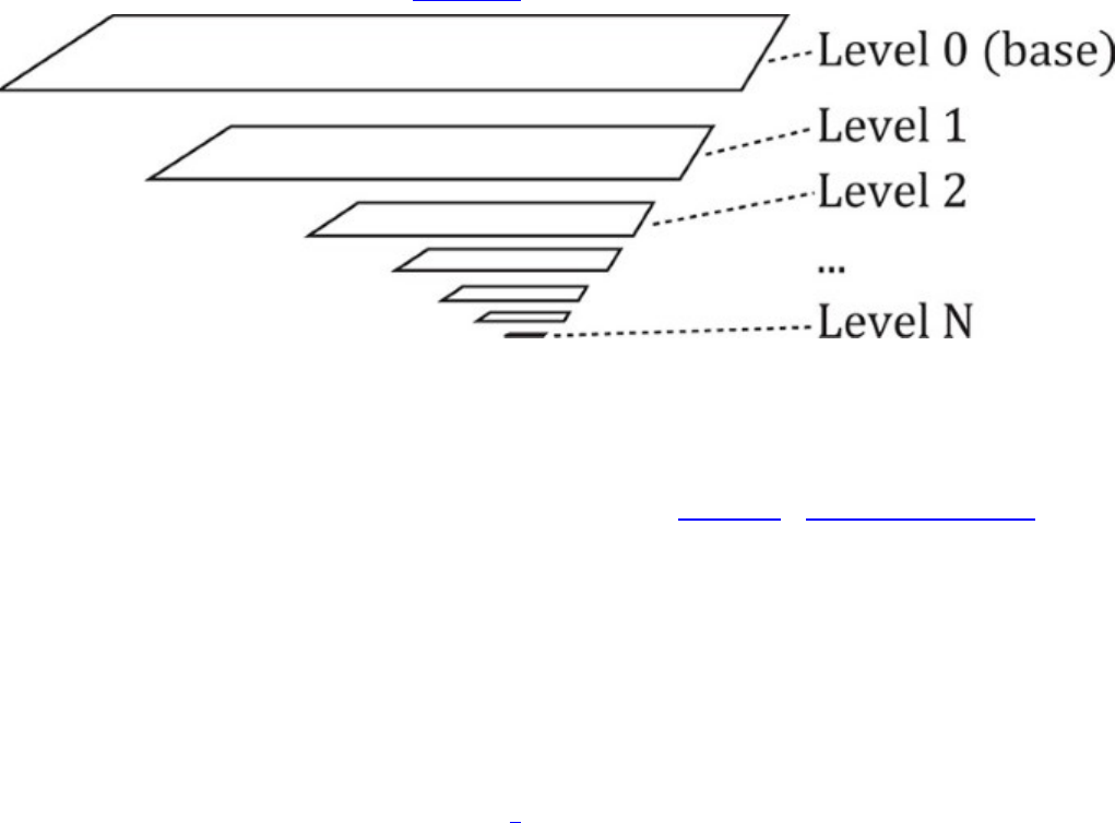
If the image is a cube map, then the maximum side length for the cube is stored in
maxImageDimensionCube.
maxImageDimension1D,maxImageDimension2D, and maxImageDimensionCube are
guaranteed to be at least 4,096 texels, and maxImageDimensionCube and
maxImageArrayLayers are guaranteed to be at least 256. If the image you want to create is
smaller than these dimensions, then there’s no need to check the device features. Further, it’s quite
common to find Vulkan implementations that support significantly higher limits. It would be
reasonable to make larger image sizes a hard requirement rather than trying to create fallback paths
for lower-end devices.
The number of mipmap levels to create in the image is specified in mipLevels. Mipmapping is the
process of using a set of prefiltered images of successively lower resolution in order to improve
image quality when undersampling the image. The images that make up the various mipmap levels
are arranged in a pyramid, as shown in Figure 2.1.
Figure 2.1: Mipmap Image Layout
In a mipmapped texture, the base level is the lowest-numbered level (usually level zero) and has the
resolution of the texture. Each successive level is half the size of the level above it until halving the
size of the image again in one of the dimensions would result in a single texel in that direction.
Sampling from mipmapped textures is covered in some detail in Chapter 6, “Shaders and Pipelines.”
Likewise, the number of samples in the image is specified in samples. This field is somewhat
unlike the others. It must be a member of the VkSampleCountFlagBits enumeration, which is
actually defined as bits to be used in a bitfield. However, only power-of-two sample counts are
currently defined in Vulkan, which means they’re “1-hot” values, so single-bit enumerant values
work just fine.
The next few fields describe how the image will be used. First is the tiling mode, specified in the
tiling field. This is a member of the VkImageTiling enumeration, which contains only
VK_IMAGE_TILING_LINEAR or VK_IMAGE_TILING_OPTIMAL.Linear tiling means that
image data is laid out left to right, top to bottom,1such that if you map the underlying memory and
write it with the CPU, it would form a linear image. Meanwhile, optimal tiling is an opaque
representation used by Vulkan to lay data out in memory to improve efficiency of the memory
subsystem on the device. This is generally what you should choose unless you plan to map and
manipulate the image with the CPU. Optimal tiling will likely perform significantly better than linear
tiling in most operations, and linear tiling might not be supported at all for some operations or
formats, depending on the Vulkan implementation.

1. Really, images don’t have a “top” or a “bottom.” They have a positive direction in their sampling coordinates.
By convention, however, we call positive u“down,” making the texels at u= 1.0 the “bottom” of the image.
The usage field is a bitfield describing where the image will be used. This is similar to the usage
field in the VkBufferCreateInfo structure. The usage field here is made up of members of the
VkImageUsageFlags enumeration, the members of which are as follows:
•VK_IMAGE_USAGE_TRANSFER_SRC_BIT and
VK_IMAGE_USAGE_TRANSFER_DST_BIT mean that the image will be the source or
destination of transfer commands, respectively. Transfer commands operating on images are
covered in Chapter 4, “Moving Data.”
•VK_IMAGE_USAGE_SAMPLED_BIT means that the image can be sampled from in a shader.
•VK_IMAGE_USAGE_STORAGE_BIT means that the image can be used for general-purpose
storage, including writes from a shader.
•VK_IMAGE_USAGE_COLOR_ATTACHMENT_BIT means that the image can be bound as a
color attachment and drawn into using graphics operations. Framebuffers and their attachments
are covered in Chapter 7, “Graphics Pipelines.”
•VK_IMAGE_USAGE_DEPTH_STENCIL_ATTACHMENT_BIT means that the image can be
bound as a depth or stencil attachment and used for depth or stencil testing (or both). Depth and
stencil operations are covered in Chapter 10, “Fragment Processing.”
•VK_IMAGE_USAGE_TRANSIENT_ATTACHMENT_BIT means that the image can be used as
a transient attachment, which is a special kind of image used to store intermediate results of a
graphics operation. Transient attachments are covered in Chapter 13, “Multipass Rendering.”
•VK_IMAGE_USAGE_INPUT_ATTACHMENT_BIT means that the image can be used as a
special input during graphics rendering. Input images differ from regular sampled or storage
images in that only fragment shaders can read from them and only at their own pixel location.
Input attachments are also covered in detail in Chapter 13, “Multipass Rendering.”
The sharingMode is identical in function to the similarly named field in the
VkBufferCreateInfo structure described in “Buffers” earlier in this chapter. If it is set to
VK_SHARING_MODE_EXCLUSIVE, the image will be used with only a single queue family at a
time. If it is set to VK_SHARING_MODE_CONCURRENT, then the image may be accessed by
multiple queues concurrently. Likewise, queueFamilyIndexCount and
pQueueFamilyIndices provide similar function and are used when sharingMode is
VK_SHARING_MODE_CONCURRENT.
Finally, images have a layout, which specifies in part how it will be used at any given moment. The
initialLayout field determines which layout the image will be created in. The available layouts
are the members of the VkImageLayout enumeration, which are
•VK_IMAGE_LAYOUT_UNDEFINED: The state of the image is undefined. The image must be
moved into one of the other layouts before it can be used almost for anything.
•VK_IMAGE_LAYOUT_GENERAL: This is the “lowest common denominator” layout and is
used where no other layout matches the intended use case. Images in
VK_IMAGE_LAYOUT_GENERAL can be used almost anywhere in the pipeline.
•VK_IMAGE_LAYOUT_COLOR_ATTACHMENT_OPTIMAL: The image is going to be rendered
into using a graphics pipeline.

•VK_IMAGE_LAYOUT_DEPTH_STENCIL_ATTACHMENT_OPTIMAL: The image is going to
be used as a depth or stencil buffer as part of a graphics pipeline.
•VK_IMAGE_LAYOUT_DEPTH_STENCIL_READ_ONLY_OPTIMAL: The image is going to be
used for depth testing but will not be written to by the graphics pipeline. In this special state, the
image can also be read from in shaders.
•VK_IMAGE_LAYOUT_SHADER_READ_ONLY_OPTIMAL: The image will be bound for
reading by shaders. This layout is typically used when an image is going to be used as a texture.
•VK_IMAGE_LAYOUT_TRANSFER_SRC_OPTIMAL: The image is the source of copy
operations.
•VK_IMAGE_LAYOUT_TRANSFER_DST_OPTIMAL: The image is the destination of copy
operations.
•VK_IMAGE_LAYOUT_PREINITIALIZED: The image contains data placed there by an
external actor, such as by mapping the underlying memory and writing into it from the host.
•VK_IMAGE_LAYOUT_PRESENT_SRC_KHR: The image is used as the source for presentation,
which is the act of showing it to the user.
Images can be moved from layout to layout, and we will cover the various layouts as we introduce
the topics related to them. However, images must initially be created in either the
VK_IMAGE_LAYOUT_UNDEFINED or the VK_IMAGE_LAYOUT_PREINITIALIZED layout.
VK_IMAGE_LAYOUT_PREINITIALIZED should be used only when you have data in memory
that you will bind to the image resource immediately. VK_IMAGE_LAYOUT_UNDEFINED should be
used when you plan to move the resource to another layout before use. Images can be moved out of
VK_IMAGE_LAYOUT_UNDEFINED layout at little or no cost at any time.
The mechanism for changing the layout of an image is known as a pipeline barrier, or simply a
barrier. A barrier not only serves as a means to change the layout of a resource but can also
synchronize access to that resource by different stages in the Vulkan pipeline and even by different
queues running concurrently on the same device. As such, a pipeline barrier is fairly complex and
quite difficult to get right. Pipeline barriers are discussed in some detail in Chapter 4, “Moving Data,”
and are further explained in the sections of the book where they are relevant.
Listing 2.4 shows a simple example of creating an image resource.
Listing 2.4: Creating an Image Object
Click here to view code image
VkImage image = VK_NULL_HANDLE;
VkResult result = VK_SUCCESS;
static const
VkImageCreateInfo imageCreateInfo =
{
VK_STRUCTURE_TYPE_IMAGE_CREATE_INFO, // sType
nullptr, // pNext
0, // flags
VK_IMAGE_TYPE_2D, // imageType
VK_FORMAT_R8G8B8A8_UNORM, // format
{ 1024, 1024, 1 }, // extent

10, // mipLevels
1, // arrayLayers
VK_SAMPLE_COUNT_1_BIT, // samples
VK_IMAGE_TILING_OPTIMAL, // tiling
VK_IMAGE_USAGE_SAMPLED_BIT, // usage
VK_SHARING_MODE_EXCLUSIVE, // sharingMode
0, // queueFamilyIndexCount
nullptr, // pQueueFamilyIndices
VK_IMAGE_LAYOUT_UNDEFINED // initialLayout
};
result = vkCreateImage(device, &imageCreateInfo, nullptr, &image);
The image created by the code in Listing 2.4 is a 1,024 × 1,024 texel 2D image with a single sample,
in VK_FORMAT_R8G8B8A8_UNORM format and optimal tiling. The code creates it in the undefined
layout, which means that we can move it to another layout later to place data into it. The image is to
be used as a texture in one of our shaders, so we set the VK_IMAGE_USAGE_SAMPLED_BIT usage
flag. In our simple applications, we use only a single queue, so we set the sharing mode to exclusive.
Linear Images
As discussed earlier, two tiling modes are available for use in image resources:
VK_IMAGE_TILING_LINEAR and VK_IMAGE_TILING_OPTIMAL. The
VK_IMAGE_TILING_OPTIMAL mode represents an opaque, implementation-defined layout that is
intended to improve the efficiency of the memory subsystem of the device for read and write
operations on the image. However, VK_IMAGE_TILING_LINEAR is a transparent layout of the
data that is intended to be intuitive. Pixels in the image are laid out left to right, top to bottom.
Therefore, it’s possible to map the memory used to back the resource to allow the host to read and
write to it directly.
In addition to the image’s width, height, depth, and pixel format, a few pieces of information are
needed to enable host access to the underlying image data. These are the row pitch of the image,
which is the distance in bytes between the start of each row of the image; the array pitch, which is the
distance between array layers; and the depth pitch, which is the distance between depth slices. Of
course, the array pitch and depth pitch apply only to array or 3D images, respectively, and the row
pitch applies only to 2D or 3D images.
An image is normally made up of several subresources. Some formats have more than one aspect,
which is a component of the image such as the depth or stencil component in a depth-stencil image.
Mipmap levels and array layers are also considered to be separate subresources. The layout of each
subresource within an image may be different and therefore has different layout information. This
information can be queried by calling vkGetImageSubresourceLayout(), the prototype of
which is
Click here to view code image
void vkGetImageSubresourceLayout (
VkDevice device,
VkImage image,
const VkImageSubresource* pSubresource,
VkSubresourceLayout* pLayout);

The device that owns the image that is being queried is passed in device, and the image being
queried is passed in image. A description of the subresource is passed through an instance of the
VkImageSubresource structure, a pointer to which is passed in the pSubresource parameter.
The definition of VkImageSubresource is
Click here to view code image
typedef struct VkImageSubresource {
VkImageAspectFlags aspectMask;
uint32_t mipLevel;
uint32_t arrayLayer;
} VkImageSubresource;
The aspect or aspects of the image that you want to query the layout of is specified in aspectMask.
For color images, this should be VK_IMAGE_ASPECT_COLOR_BIT, and for depth, stencil, or
depth-stencil images, this should be some combination of VK_IMAGE_ASPECT_DEPTH_BIT, and
VK_IMAGE_ASPECT_STENCIL_BIT. The mipmap level for which the parameters are to be
returned is specified in mipLevel, and the array layer is specified in arrayLayer. You should
normally set arrayLayer to zero, as the parameters of the image aren’t expected to change across
layers.
When vkGetImageSubresourceLayout() returns, it will have written the layout parameters
of the subresource into the VkSubresourceLayout structure pointed to by pLayout. The
definition of VkSubresourceLayout is
Click here to view code image
typedef struct VkSubresourceLayout {
VkDeviceSize offset;
VkDeviceSize size;
VkDeviceSize rowPitch;
VkDeviceSize arrayPitch;
VkDeviceSize depthPitch;
} VkSubresourceLayout;
The size of the memory region consumed by the requested subresource is returned in size, and the
offset within the resource where the subresource begins is returned in offset. The rowPitch,
arrayPitch, and depthPitch fields contain the row, array layer, and depth slice pitches,
respectively. The unit of these fields is always bytes, regardless of the pixel format of the images.
Pixels within a row are always tightly packed. Figure 2.2 illustrates how these parameters represent
memory layout of an image. In the figure, the valid image data is represented by the grey grid, and
padding around the image is shown as blank space.
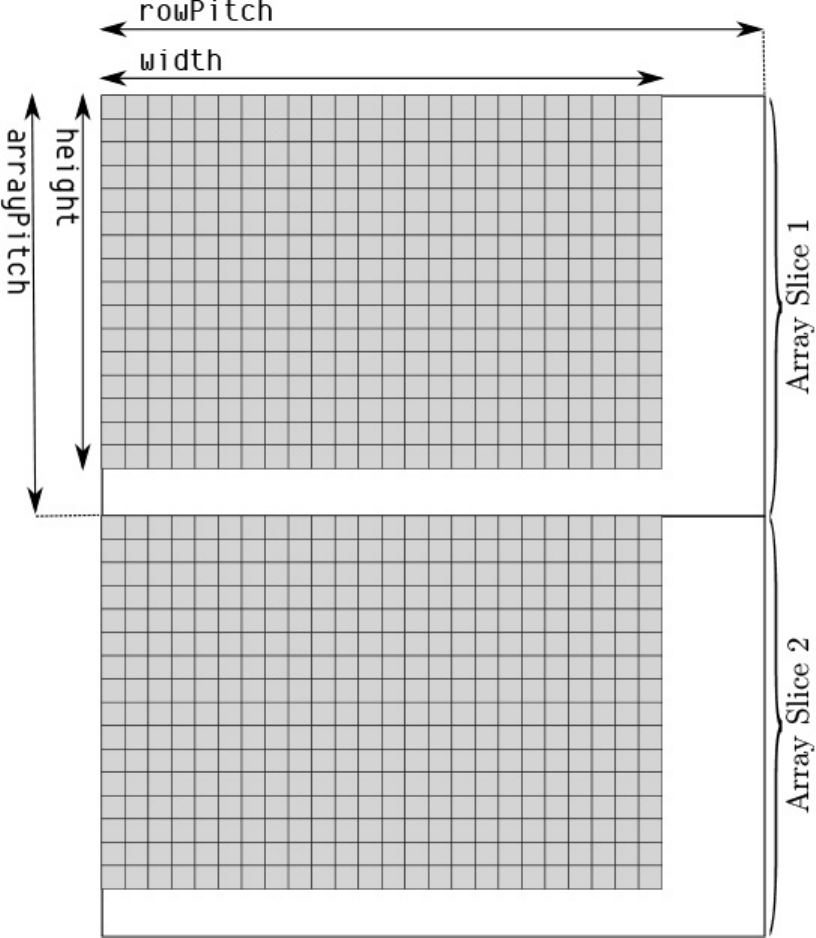
Figure 2.2: Memory Layout of LINEAR Tiled Images
Given the memory layout of an image in LINEAR tiling mode, it is possible to trivially compute the
memory address for a single texel within the image. Loading image data into a LINEAR tiled image
is then simply a case of loading scanlines from the image into memory at the right location. For many
texel formats and image dimensions, it is highly likely that the image’s rows are tightly packed in
memory—that is, the rowPitch field of the VkSubresourceLayout structure is equal to the
subresource’s width. In this case, many image-loading libraries will be able to load the image directly
into the mapped memory of the image.

Nonlinear Encoding
You may have noticed that some of the Vulkan image formats include SRGB in their names. This
refers to sRGB color encoding, which is a nonlinear encoding that uses a gamma curve
approximating that of CRTs. Although CRTs are all but obsolete now, sRGB encoding is still in
widespread use for texture and image data.
Because the amount of light energy produced by a CRT is not linear with the amount of electrical
energy used to produce the electron beam that excites the phosphor, an inverse mapping must be
applied to color signals to make a linear rise in numeric value produce a linear increase in light
output. The amount of light output by a CRT is approximately
Lout =Vinγ
The standard value of γ in NTSC television systems (common in North America, parts of South
America, and parts of Asia) is 2.2. Meanwhile, the standard value of γ in SECAM and PAL systems
(common in Europe, Africa, Australia, and other regions of Asia) is 2.8.
The sRGB curve attempts to compensate for this by applying gamma correction to linear data in
memory. The standard sRGB transfer function is not a pure gamma curve but is made up of a short
linear section followed by a curved, gamma-corrected section. The function applied to data to go
from linear to sRGB space is
Click here to view code image
if (cl >= 1.0)
{
cs = 1.0;
}
else if (cl <= 0.0)
{
cs = 0.0;
}
else if (cl < 0.0031308)
{
cs = 12.92 * cl;
}
else
{
cs = 1.055 * pow(cl, 0.41666) - 0.055;
}
To go from sRGB space to linear space, the following transform is made:
Click here to view code image
if (cs >= 1.0)
{
cl = 1.0;
}
else if (cs <= 0.0)
{
cl = 0.0;
}

else if (cs <= 0.04045)
{
cl = cs / 12.92;
}
else
{
cl = pow((cs + 0.0555) / 1.055), 2.4)
}
In both code snippets, cs is the sRGB color space value, and cl is the linear value. Figure 2.3 shows
a side-by-side comparison of a simple γ = 2.2 curve and the standard sRGB transfer function. As you
can see in the figure, the curves for sRGB correction (shown on the top) and a simple power curve
(shown on the bottom) are almost identical. While Vulkan implementations are expected to
implement sRGB using the official definition, if you need to perform the transformation manually in
your shaders, you may be able to get away with a simple power function without accumulating too
much error.
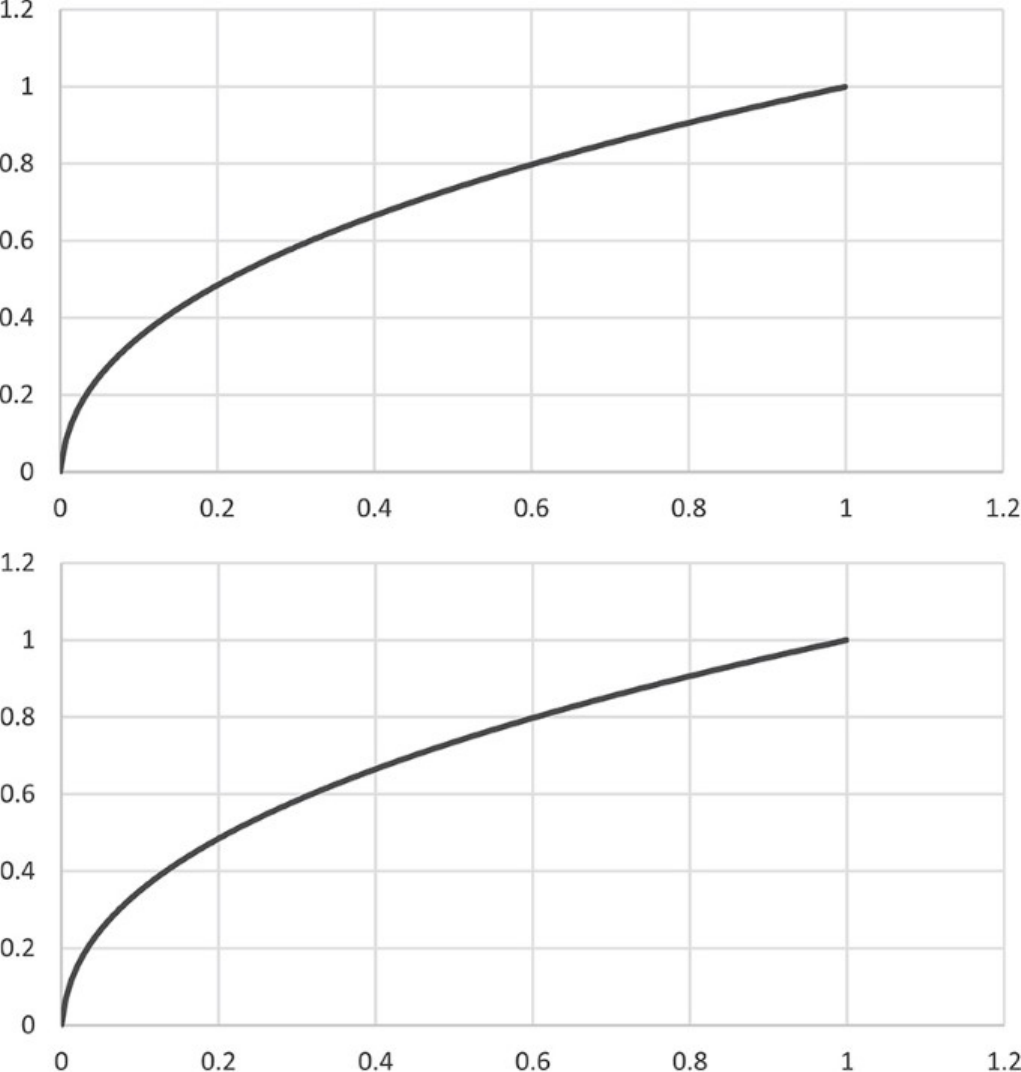
Figure 2.3: Gamma Curves for sRGB (Top) and Simple Powers (Bottom)
When rendering to an image in sRGB format, linear values produced by your shaders are transformed
to sRGB encoding before being written into the image. When reading from an image in sRGB
format, texels are transformed from sRGB format back to linear space before being returned to your
shader.
Blending and interpolation always occurs in linear space such that data read from a framebuffer is
first transformed from sRGB to linear space and then blended with the source data in linear space,
and the final result is transformed back to sRGB encoding before being written into the framebuffer.
Rendering in sRGB space provides more precision in darker colors and can result in less banding
artifacts and richer colors. However, for best image quality, including high-dynamic-range rendering,
it’s best to choose a floating-point color format and render in a linear space, converting to sRGB as
late as possible before display.
Compressed Image Formats
Image resources are likely to be the largest consumers of device memory in your application. For this
reason, Vulkan provides the capability for images to be compressed. Image compression provides
two significant benefits to an application:
• It reduces the total amount of memory consumed by image resources used by the application.
• It reduces the total memory bandwidth consumed while accessing those resources.
All currently defined compressed image formats in Vulkan are what are known as block compressed
formats. Texels within an image are compressed in small square or rectangular blocks that can be
decompressed independently of all others. All formats are lossy, and the compression ratio is not
competitive with formats such as JPEG or even PNG. However, decompression is fast and cheap to
implement in hardware, and random access to texels is relatively straightforward.
Support for various compressed image formats is optional, but all Vulkan implementations are
required to support at least one family of formats. You can determine which family of compressed
formats is supported by checking various fields of the device’s VkPhysicalDeviceFeatures
structure as returned from a call to vkGetPhysicalDeviceProperties().
If textureCompressionBC is VK_TRUE, then the device supports the block compressed
formats, also known as BC formats. The BC family includes
• BC1: Made up of the VK_FORMAT_BC1_RGB_UNORM_BLOCK,
VK_FORMAT_BC1_RGB_SRGB_BLOCK,VK_FORMAT_BC1_RGBA_UNORM_BLOCK, and
VK_FORMAT_BC1_RGBA_SRGB_BLOCK formats, BC1 encodes images in blocks of 4 × 4
texels, with each block represented as a 64-bit quantity.
• BC2: Consisting of VK_FORMAT_BC2_UNORM_BLOCK and
VK_FORMAT_BC2_SRGB_BLOCK, BC2 encodes images in blocks of 4 × 4 texels, with each
block represented as a 128-bit quantity. BC2 images always have an alpha channel. The
encoding for the RGB channels is the same as with BC1 RGB formats, and the alpha is stored as
4 bits per texel in a second 64-bit field before the BC1 encoded RGB data.
• BC3: The VK_FORMAT_BC3_UNORM_BLOCK and VK_FORMAT_BC3_SRGB_BLOCK
formats make up the BC3 family, again encoding texels in 4 × 4 blocks, with each block
consuming 128 bits of storage. The first 64-bit quantity stores compressed alpha values,
allowing coherent alpha data to be stored with higher precision than BC2. The second 64-bit
quantity stores compressed color data in a similar form to BC1.
• BC4: VK_FORMAT_BC4_UNORM_BLOCK and VK_FORMAT_BC4_SRGB_BLOCK represent
single-channel formats, again encoded as 4 × 4 blocks of texels, with each block consuming 64
bits of storage. The encoding of the single-channel data is essentially the same as that of the
alpha channel of a BC3 image.
• BC5: Made up of VK_FORMAT_BC5_UNORM_BLOCK and
VK_FORMAT_BC5_SRGB_BLOCK, the BC5 family is a two-channel format, with each 4 × 4
block essentially consisting of two BC4 blocks back-to-back.
• BC6: The VK_FORMAT_BC6H_SFLOAT_BLOCK and VK_FORMAT_BC6H_UFLOAT_BLOCK
formats are signed and unsigned floating-point compressed formats, respectively. Each 4 × 4
block of RGB texels is stored in 128 bits of data.
• BC7: VK_FORMAT_BC7_UNORM_BLOCK and VK_FORMAT_BC7_SRGB_BLOCK are four-
channel formats with each 4 × 4 block of RGBA texel data stored in a 128-bit component.
If the textureCompressionETC2 member of VkPhysicalDeviceFeatures is VK_TRUE,
then the device supports the ETC formats, including ETC2 and EAC. The following formats are
included in this family:
•VK_FORMAT_ETC2_R8G8B8_UNORM_BLOCK and
VK_FORMAT_ETC2_R8G8B8_SRGB_BLOCK: Unsigned formats where 4 × 4 blocks of RGB
texels are packed into 64 bits of compressed data.
•VK_FORMAT_ETC2_R8G8B8A1_UNORM_BLOCK and
VK_FORMAT_ETC2_R8G8B8A1_SRGB_BLOCK: Unsigned formats where 4 × 4 blocks of
RGB texels plus a one-bit alpha value per texel are packed into 64 bits of compressed data.
•VK_FORMAT_ETC2_R8G8B8A8_UNORM_BLOCK and
VK_FORMAT_ETC2_R8G8B8A8_SRGB_BLOCK: Each 4 × 4 block of texels is represented as
a 128-bit quantity. Each texel has 4 channels.
•VK_FORMAT_EAC_R11_UNORM_BLOCK and VK_FORMAT_EAC_R11_SNORM_BLOCK:
Unsigned and signed single-channel formats with each 4 × 4 block of texels represented as a
64-bit quantity.
•VK_FORMAT_EAC_R11G11_UNORM_BLOCK and
VK_FORMAT_EAC_R11G11_SNORM_BLOCK: Unsigned and signed two-channel formats with
each 4 × 4 block of texels represented as a 64-bit quantity.
The final family is the ASTC family. If the textureCompressionASTC_LDR member of
VkPhysicalDeviceFeatures is VK_TRUE, then the device supports the ASTC formats. You
may have noticed that for all of the formats in the BC and ETC families, the block size is fixed at 4 ×
4 texels, but depending on format, the texel format and number of bits used to store the compressed
data vary.
ASTC is different here in that the number of bits per block is always 128, and all ASTC formats have
four channels. However, the block size in texels can vary. The following block sizes are supported: 4
× 4, 5 × 4, 5 × 5, 6 × 5, 6 × 6, 8 × 5, 8 × 6, 8 × 8, 10 × 5, 10 × 6, 10 × 8, 10 × 10, 12 × 10, and 12 ×
12.
The format of the token name for ASTC formats is formulated as
VK_FORMAT_ASTC_{N}x{M}_{encoding}_BLOCK, where {N} and {M} represent the width
and height of the block, and {encoding} is either UNORM or SRGB, depending on whether the data
is linear or encoded as sRGB nonlinear. For example, VK_FORMAT_ASTC_8x6_SRGB_BLOCK is
an RGBA ASTC compressed format with 8 × 6 blocks and sRGB encoded data.
For all formats including SRGB, only the R, G, and B channels use nonlinear encoding. The A
channel is always stored with linear encoding.

Resource Views
Buffers and images are the two primary types of resources supported in Vulkan. In addition to
creating these two resource types, you can create views of existing resources in order to partition
them, reinterpret their content, or use them for multiple purposes. Views of buffers, which represent a
subrange of a buffer object, are known as buffer views, and views of images, which can alias formats
or represent a subresource of another image, are known as image views.
Before a view of a buffer or image can be created, you need to bind memory to the parent object.
Buffer Views
A buffer view is used to interpret the data in a buffer with a specific format. Because the raw data in
the buffer is then treated as a sequence of texels, this is also known as a texel buffer view. A texel
buffer view can be accessed directly in shaders, and Vulkan will automatically convert the texels in
the buffer into the format expected by the shader. One example use for this functionality is to directly
fetch the properties of vertices in a vertex shader by reading from a texel buffer rather than using a
vertex buffer. While this is more restrictive, it does allow random access to the data in the buffer.
To create a buffer view, call vkCreateBufferView(), the prototype of which is
Click here to view code image
VkResult vkCreateBufferView (
VkDevice device,
const VkBufferViewCreateInfo* pCreateInfo,
const VkAllocationCallbacks* pAllocator,
VkBufferView* pView);
The device that is to create the new view is passed in device. This should be the same device that
created the buffer of which you are creating a view. The remaining parameters of the new view are
passed through a pointer to an instance of the VkBufferViewCreateInfo structure, the
definition of which is
Click here to view code image
typedef struct VkBufferViewCreateInfo {
VkStructureType sType;
const void* pNext;
VkBufferViewCreateFlags flags;
VkBuffer buffer;
VkFormat format;
VkDeviceSize offset;
VkDeviceSize range;
} VkBufferViewCreateInfo;
The sType field of VkBufferViewCreateInfo should be set to
VK_STRUCTURE_TYPE_BUFFER_VIEW_CREATE_INFO, and pNext should be set to
nullptr. The flags field is reserved and should be set to 0. The parent buffer is specified in
buffer. The new view will be a “window” into the parent buffer starting at offset bytes and
extending for range bytes. When bound as a texel buffer, the data in the buffer is interpreted as a
sequence of texels with the format as specified in format.

The maximum number of texels that can be stored in a texel buffer is determined by inspecting the
maxTexelBufferElements field of the device’s VkPhysicalDeviceLimits structure,
which can be retrieved by calling vkGetPhysicalDeviceProperties(). If the buffer is to be
used as a texel buffer, then range divided by the size of a texel in format must be less than or
equal to this limit. maxTexelBufferElements is guaranteed to be at least 65,536, so if the view
you’re creating contains fewer texels, there’s no need to query this limit.
The parent buffer must have been created with the
VK_BUFFER_USAGE_UNIFORM_TEXEL_BUFFER_BIT or
VK_BUFFER_USAGE_STORAGE_TEXEL_BUFFER_BIT flags in the usage field of the
VkBufferCreateInfo used to create the buffer. The specified format must support the
VK_FORMAT_FEATURE_UNIFORM_TEXEL_BUFFER_BIT,
VK_FORMAT_FEATURE_STORAGE_TEXEL_BUFFER_BIT, or
VK_FORMAT_FEATURE_STORAGE_TEXEL_BUFFER_ATOMIC_BIT as reported by
vkGetPhysicalDeviceFormatProperties().
On success, vkCreateBufferView() places the handle to the newly created buffer view in the
variable pointed to by pView. If pAllocator is not nullptr, then the allocation callbacks
specified in the VkAllocationCallbacks structure it points to are used to allocate any host
memory required by the new object.
Image Views
In many cases, the image resource cannot be used directly, as more information about it is needed
than is included in the resource itself. For example, you cannot use an image resource directly as an
attachment to a framebuffer or bind an image into a descriptor set in order to sample from it in a
shader. To satisfy these additional requirements, you must create an image view, which is essentially
a collection of properties and a reference to a parent image resource.
An image view also allows all or part of an existing image to be seen as a different format. The
resulting view of the parent image must have the same dimensions as the parent, although a subset of
the parent’s array layers or mip levels may be included in the view. The format of the parent and
child images must also be compatible, which usually means that they have the same number of bits
per pixel, even if the data formats are completely different and even if there are a different number of
channels in the image.
To create a new view of an existing image, call vkCreateImageView(), the prototype of which
is
Click here to view code image
VkResult vkCreateImageView (
VkDevice device,
const VkImageViewCreateInfo* pCreateInfo,
const VkAllocationCallbacks* pAllocator,
VkImageView* pView);
The device that will be used to create the new view and that should own the parent image is specified
in device. The remaining parameters used in the creation of the new view are passed through an
instance of the VkImageViewCreateInfo structure, a pointer to which is passed in
pCreateInfo. The definition of VkImageViewCreateInfo is

Click here to view code image
typedef struct VkImageViewCreateInfo {
VkStructureType sType;
const void* pNext;
VkImageViewCreateFlags flags;
VkImage image;
VkImageViewType viewType;
VkFormat format;
VkComponentMapping components;
VkImageSubresourceRange subresourceRange;
} VkImageViewCreateInfo;
The sType field of VkImageViewCreateInfo should be set to
VK_STRUCTURE_TYPE_IMAGE_VIEW_CREATE_INFO, and pNext should be set to nullptr.
The flags field is reserved for future use and should be set to 0.
The parent image of which to create a new view is specified in image. The type of view to create is
specified in viewType. The view type must be compatible with the parent’s image type and is a
member of the VkImageViewType enumeration, which is larger than the VkImageType
enumeration used in creating the parent image. The image view types are as follows:
•VK_IMAGE_VIEW_TYPE_1D,VK_IMAGE_VIEW_TYPE_2D, and
VK_IMAGE_VIEW_TYPE_3D are the “normal” 1D, 2D, and 3D image types.
•VK_IMAGE_VIEW_TYPE_CUBE and VK_IMAGE_VIEW_TYPE_CUBE_ARRAY are cube
map and cube map array images.
•VK_IMAGE_VIEW_TYPE_1D_ARRAY and VK_IMAGE_VIEW_TYPE_2D_ARRAY are 1D
and 2D array images.
Note that all images are essentially considered array images, even if they only have one layer. It is,
however, possible to create nonarray views of parent images that refer to one of the layers of the
image.
The format of the new view is specified in format. This must be a format that is compatible with
that of the parent image. In general, if two formats have the same number of bits per pixel, then they
are considered compatible. If either or both of the formats is a block compressed image format, then
one of two things must be true:
• If both images have compressed formats, then the number of bits per block must match between
those formats.
• If only one image is compressed and the other is not, then bits per block in the compressed
image must be the same as the number of bits per texel in the uncompressed image.
By creating an uncompressed view of a compressed image, you give access to the raw, compressed
data, making it possible to do things like write compressed data from a shader into the image or
interpret the compressed data directly in your application. Note that while all block-compressed
formats encode blocks either as 64-bit or 128-bit quantities, there are no uncompressed, single-
channel 64-bit or 128-bit image formats. To alias a compressed image as an uncompressed format,
you need to choose an uncompressed format with the same number of bits per texel and then
aggregate the bits from the different image channels within your shader to extract the individual
fields from the compressed data.

The component ordering in the view may be different from that in the parent. This allows, for
example, an RGBA view of a BGRA format image to be created. This remapping is specified using
an instance of VkComponentMapping, the definition of which is simply
Click here to view code image
typedef struct VkComponentMapping {
VkComponentSwizzle r;
VkComponentSwizzle g;
VkComponentSwizzle b;
VkComponentSwizzle a;
} VkComponentMapping;
Each member of VkComponentMapping specifies the source of data in the parent image that will
be used to fill the resulting texel fetched from the child view. They are members of the
VkComponentSwizzle enumeration, the members of which are as follows:
•VK_COMPONENT_SWIZZLE_R,VK_COMPONENT_SWIZZLE_G,
VK_COMPONENT_SWIZZLE_B, and VK_COMPONENT_SWIZZLE_A indicate that the source
data should be read from the R, G, B, or A channels of the parent image, respectively.
•VK_COMPONENT_SWIZZLE_ZERO and VK_COMPONENT_SWIZZLE_ONE indicate that the
data in the child image should be read as zero or one, respectively, regardless of the content of
the parent image.
•VK_COMPONENT_SWIZZLE_IDENTITY indicates that the data in the child image should be
read from the corresponding channel in the parent image. Note that the numeric value of
VK_COMPONENT_SWIZZLE_IDENTITY is zero, so simply setting the entire
VkComponentMapping structure to zero will result in an identity mapping between child and
parent images.
The child image can be a subset of the parent image. This subset is specified using the embedded
VkImageSubresourceRange structure in subresourceRange. The definition of
VkImageSubresourceRange is
Click here to view code image
typedef struct VkImageSubresourceRange {
VkImageAspectFlags aspectMask;
uint32_t baseMipLevel;
uint32_t levelCount;
uint32_t baseArrayLayer;
uint32_t layerCount;
} VkImageSubresourceRange;
The aspectMask field is a bitfield made up from members of the VkImageAspectFlagBits
enumeration specifying which aspects of the image are affected by the barrier. Some image types
have more than one logical part, even though the data itself might be interleaved or otherwise related.
An example of this is depth-stencil images, which have both a depth component and a stencil
component. Each of these two components may be viewable as a separate image in its own right, and
these subimages are known as aspects. The flags that can be included in aspectMask are
•VK_IMAGE_ASPECT_COLOR_BIT: The color part of an image. There is usually only a color
aspect in color images.
•VK_IMAGE_ASPECT_DEPTH_BIT: The depth aspect of a depth-stencil image.
•VK_IMAGE_ASPECT_STENCIL_BIT: The stencil aspect of a depth-stencil image.
•VK_IMAGE_ASPECT_METADATA_BIT: Any additional information associated with the
image that might track its state and is used, for example, in various compression techniques.
When you create the new view of the parent image, that view can refer to only one aspect of the
parent image. Perhaps the most common use case of this is to create a depth- or stencil-only view of a
combined depth-stencil format image.
To create a new image view that corresponds only to a subset of the parent’s mip chain, use the
baseMipLevel and levelCount to specify where in the mip chain the view begins and how
many mip levels it will contain. If the parent image does not have mipmaps, these fields should be set
to zero and one, respectively.
Likewise, to create an image view of a subset of a parent’s array layers, use the baseArrayLayer
and layerCount fields to specify the starting layer and number of layers, respectively. Again, if
the parent image is not an array image, then baseArrayLayer should be set to zero and
layerCount should be set to one.
Image Arrays
The defined image types (VkImageType) include only VK_IMAGE_TYPE_1D,
VK_IMAGE_TYPE_2D, or VK_IMAGE_TYPE_3D, which are used to create 1D, 2D, and 3D
images, respectively. However, in addition to their sizes in each of the x,y, and zdimensions, all
images have a layer count, contained in the arrayLayers field of their VkImageCreateInfo
structure.
Images can be aggregated into arrays, and each element of an array image is known as a layer. Array
images allow images to be grouped into single objects, and sampling from multiple layers of the
same array image is often more performant than sampling from several loose array objects. Because
all Vulkan images have a layerCount field, they are all technically array images. However, in
practice, we only refer to images with a layerCount greater than 1 as an array image.
When views are created of images, the view is explicitly marked as either an array or a nonarray. A
nonarray view implicitly has only one layer whereas an array view has multiple layers. Sampling
from a nonarray view may perform better than sampling from a single layer of an array image,
simply because the device needs to perform fewer indirections and parameter lookups.
A 1D array texture is conceptually different from a 2D texture, and a 2D array texture is different
from a 3D texture. The primary difference is that linear filtering can be performed in the ydirection
of a 2D texture and in the zdirection in a 3D texture, whereas filtering cannot be performed across
multiple layers in an array image. Notice that there is no 3D array image view type included in
VkImageViewType, and most Vulkan implementations will not allow you to create a 3D image
with an arrayLayers field greater than 1.
In addition to image arrays, a cube map is a special type of image that allows groups of six layers of
an array image to be interpreted as the sides of a cube. Imagine standing in the center of a cube-
shaped room. The room has four walls, a floor, and a ceiling. To your left and right are considered the
negative and positive Xdirections, behind and in front of you are the negative and positive Z
directions, and the floor and ceiling are the negative and positive Ydirections. These faces are often
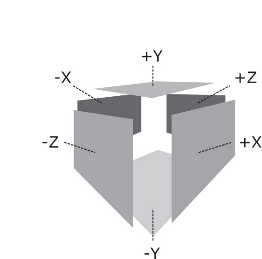
notated as the -X, +X, -Y, +Y, -Z, and +Z faces. These are the six faces of a cube map, and a group of
six consecutive array layers can be interpreted in that order.
A cube map is sampled using a 3D coordinate. This coordinate is interpreted as a vector pointing
from the center of the cube map outward, and the point sampled in the cube-map is the point where
the vector meets the cube. Again, put yourself back into the cube-map room and imagine you have a
laser pointer. As you point the laser in different directions, the spot on the wall or ceiling is the point
from which texture data is taken when the cube map is sampled.
Figure 2.4 shows this pictorially. As you can see in the figure, the cube map is constructed from a
selection of six consecutive elements from the parent texture. To create a cube-map view, first create
a 2D array image with at least six faces. The imageType field of the VkImageCreateInfo
structure should be set to VK_IMAGE_TYPE_2D and the arrayLayers field should be at least 6.
Note that the number of layers in the parent array doesn’t have to be a multiple of 6, but it has to be at
least 6.
Figure 2.4: Cube Map Construction
The flags field of the parent image’s VkImageCreateInfo structure must have the
VK_IMAGE_CREATE_CUBE_COMPATIBLE_BIT set, and the image must be square (because the
faces of a cube are square).
Next, we create a view of the 2D array parent, but rather than creating a normal 2D (array) view of
the image, we create a cube-map view. To do this, set the viewType field of the
VkImageViewCreateInfo structure used to create the view to
VK_IMAGE_VIEW_TYPE_CUBE. In the embedded subresourceRange field, the

baseArrayLayer and layerCount fields are used to determine where in the array the cube map
begins. To create a single cube, layerCount should be set to 6.
The first element of the array (at the index specified in the baseArrayLayer field) becomes the -
X face, and the next five layers become the +X, -Y, +Y, -Z, and +Z faces, in that order.
Cube maps can also form arrays of their own. This is simply a concatenation of an integer multiple of
six faces, with each group of six forming a separate cube. To create a cube-map array image, set the
viewType field of VkImageViewCreateInfo to VK_IMAGE_VIEW_TYPE_CUBE_ARRAY,
and set the layerCount to a multiple of 6. The number of cubes in the array is therefore the
layerCount for the array divided by 6. The number of layers in the parent image must be at least
as many layers as are referenced by the cube-map view.
When data is placed in a cube map or cube-map array image, it is treated identically to an array
image. Each array layer is laid out consecutively, and commands such as
vkCmdCopyBufferToImage() (which is covered in Chapter 4, “Moving Data”) can be used to
write into the image. The image can be bound as a color attachment and rendered to. Using layered
rendering, you can even write to multiple faces of a cube map in a single drawing command.
Destroying Resources
When you are done with buffers, images, and other resources, it is important to destroy them cleanly.
Before destroying a resource, you must make sure that it is not in use and that no work is pending
that might access it. Once you are certain that this is the case, you can destroy the resource by calling
the appropriate destruction function. To destroy a buffer resource, call vkDestroyBuffer(), the
prototype of which is
Click here to view code image
void vkDestroyBuffer (
VkDevice device,
VkBuffer buffer,
const VkAllocationCallbacks* pAllocator);
The device that owns the buffer object should be specified in device, and the handle to the buffer
object should be specified in buffer. If a host memory allocator was used to create the buffer
object, a compatible allocator should be specified in pAllocator; otherwise, pAllocator
should be set to nullptr.
Note that destroying a buffer object for which other views exist will also invalidate those views. The
view objects themselves must still be destroyed explicitly, but it is not legal to access a view of a
buffer that has been destroyed. To destroy a buffer view, call vkDestroyBufferView(), the
prototype of which is
Click here to view code image
void vkDestroyBufferView (
VkDevice device,
VkBufferView bufferView,
const VkAllocationCallbacks*pAllocator);

Again, device is a handle to the device that owns the view, and bufferView is a handle to the
view to be destroyed. pAllocator should point to a host memory allocator compatible with that
used to create the view or should be set to nullptr if no allocator was used to create the view.
Destruction of images is almost identical to that of buffers. To destroy an image object, call
vkDestroyImage(), the prototype of which is
Click here to view code image
void vkDestroyImage (
VkDevice device,
VkImage image,
const VkAllocationCallbacks* pAllocator);
device is the device that owns the image to be destroyed, and image is the handle to that image.
Again, if a host memory allocator was used to create the original image, then pAllocator should
point to one compatible with it; otherwise, pAllocator should be nullptr.
As with buffers, destroying an image invalidates all views of that image. It is not legal to access a
view of an image that has already been destroyed. The only thing you can do with such views is to
destroy them. Destroying an image view is accomplished by calling vkDestroyImageView(),
the prototype of which is
Click here to view code image
void vkDestroyImageView (
VkDevice device,
VkImageView imageView,
const VkAllocationCallbacks* pAllocator);
As you might expect, device is the device that owns the view being destroyed, and imageView is
the handle to that view. As with all other destruction functions mentioned so far, pAllocator is a
pointer to an allocator compatible with the one used to create the view or nullptr if no allocator
was used.
Device Memory Management
When the Vulkan device operates on data, the data must be stored in device memory. This is memory
that is accessible to the device. In a Vulkan system there are four classes of memory. Some systems
may have only a subset of these, and some may only have two. Given a host (the processor upon
which your application is running) and a device (the processor that executes your Vulkan
commands), there could be separate memory physically attached to each. In addition, some regions of
the physical memory attached to each processor might be accessible to the other processor or
processors in the system.
In some cases, the visible region of shared memory might be relatively small, and in other cases,
there may actually be only one physical piece of memory, which is shared between the host and the
device. Figure 2.5 demonstrates the memory map of a host and device with physically separate
memories.
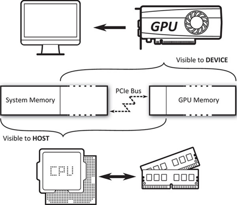
Figure 2.5: Host and Device Memory
Any memory that is accessible to the device is known as device memory, even if that memory is
physically attached to the host. In this case, it is host local device memory. This is distinct from host
memory, which might also be known as system memory, which is regular memory allocated with a
function such as malloc or new. Device memory may also be accessible to the host through a
mapping.
A typical discrete GPU as found on an add-in card plugged into a PCI-Express slot will have an
amount of dedicated memory physically attached to its circuit board. Some part of this memory may
be accessible only to the device, and some part of the memory may be accessible to the host through
some form of window. In addition, the GPU will have access to some or all of the host’s system
memory. All of these pools of memory will appear as a heap to the host, and memory will be mapped
into those heaps via the various types of memory.
On the other hand, a typical embedded GPU—such as those found in embedded systems, mobile
devices, or even laptop processors—may share memory controller and subsystem with the host
processor. In this case, it is likely that access to main system memory is coherent and the device will
expose fewer heaps—perhaps only one. This is considered a unified memory architecture.

Allocating Device Memory
A device memory allocation is represented as a VkDeviceMemory object that is created using the
vkAllocateMemory() function, the prototype of which is
Click here to view code image
VkResult vkAllocateMemory (
VkDevice device,
const VkMemoryAllocateInfo* pAllocateInfo,
const VkAllocationCallbacks* pAllocator,
VkDeviceMemory* pMemory);
The device that will use the memory is passed in device.pAllocateInfo describes the new
device memory object which, if the allocation is successful, will be placed in the variable pointed to
by pMemory.pAllocateInfo points to an instance of the VkMemoryAllocateInfo
structure, the definition of which is
Click here to view code image
typedef struct VkMemoryAllocateInfo {
VkStructureType sType;
const void* pNext;
VkDeviceSize allocationSize;
uint32_t memoryTypeIndex;
} VkMemoryAllocateInfo;
This is a simple structure containing only the size and the memory type to be used for the allocation.
sType should be set to VK_STRUCTURE_TYPE_MEMORY_ALLOCATE_INFO, and pNext should
be set to nullptr unless an extension is in use that requires more information about the allocation.
The size of the allocation is passed in allocationSize and is measured in bytes. The memory
type, passed in memoryTypeIndex, is an index into the memory type array returned from a call to
vkGetPhysicalDeviceMemoryProperties(), as described in “Physical Device Memory”
in Chapter 1, “Overview of Vulkan.”
Once you have allocated device memory, it can be used to back resources such as buffers and images.
Vulkan may use device memory for other purposes, such as other types of device objects, internal
allocations and data structures, scratch storage, and so on. These allocations are managed by the
Vulkan driver, as the requirements may vary quite widely between implementations.
When you are done with a memory allocation, you need to free it. To do this, call
vkFreeMemory(), the prototype of which is
Click here to view code image
void vkFreeMemory (
VkDevice device,
VkDeviceMemory memory,
const VkAllocationCallbacks* pAllocator);
vkFreeMemory() takes the memory object directly in memory. It is your responsibility to ensure
that there is no work queued up to a device that might use the memory object before you free it.
Vulkan will not track this for you. If a device attempts to access memory after it’s been freed, the
results can be unpredictable and can easily crash your application.

Further, access to memory must be externally synchronized. Attempting to free device memory with
a call to vkFreeMemory() while another command is executing in another thread will produce
undefined behavior and possibly crash your application.
On some platforms, there may be an upper bound to the total number of memory allocations that can
exist within a single process. If you try to create more allocations than this limit, allocation could fail.
This limit can be determined by calling vkGetPhysicalDeviceProperties() and inspecting
the maxMemoryAllocationCount field of the returned VkPhysicalDeviceLimits
structure. The limit is guaranteed to be at least 4,096 allocations, though some platforms may report a
much higher limit. Although this may seem low, the intention is that you create a small number of
large allocations and then suballocate from them to place many resources in the same allocation.
There is no upper limit to the total number of resources can be created, memory allowing.
Normally, when you allocate memory from a heap, that memory is permanently assigned to the
returned VkDeviceMemory object until that object is destroyed by calling vkFreeMemory(). In
some cases, you (or even the Vulkan implementation) may not know exactly how much memory is
required for certain operations, or indeed whether any memory is required at all.
In particular, this is often the case for images that are used for intermediate storage of data during
rendering. When the image is created, if the
VK_IMAGE_USAGE_TRANSIENT_ATTACHMENT_BIT is included in the
VkImageCreateInfo structure, then Vulkan knows that the data in the image will live for a short
time, and therefore, it’s possible that it may never need to be written out to device memory.
In this case, you can ask Vulkan to be lazy with its allocation of the memory object to defer true
allocation until Vulkan can determine that the physical storage for data is really needed. To do this,
choose a memory type with the VK_MEMORY_PROPERTY_LAZILY_ALLOCATED_BIT set.
Choosing an otherwise-appropriate memory type that does not have this bit set will still work
correctly but will always allocate the memory up front, even if it never ends up being used.
If you want to know whether a memory allocation is physically backed and how much backing has
actually been allocated for a memory object, call vkGetDeviceMemoryCommitment(), the
prototype of which is
Click here to view code image
void vkGetDeviceMemoryCommitment (
VkDevice device,
VkDeviceMemory memory,
VkDeviceSize* pCommittedMemoryInBytes);
The device that owns the memory allocation is passed in device and the memory allocation to
query is passed in memory.pCommittedMemoryInBytes is a pointer to a variable that will be
overwritten with the number of bytes actually allocated for the memory object. That commitment will
always come from the heap associated with the memory type used to allocate the memory object.
For memory objects allocated with memory types that don’t include
VK_MEMORY_PROPERTY_LAZILY_ALLOCATED_BIT, or if the memory object ended up fully
committed, vkGetDeviceMemoryCommitment() will always return the full size of the memory
object. The commitment returned from vkGetDeviceMemoryCommitment() is informational
at best. In many cases, the information could be out of date, and there’s not much you can do with the
information anyway.

Host Access to Device Memory
As discussed earlier in this chapter, device memory is divided into multiple regions. Pure device
memory is accessible only to the device. However, there are regions of memory that are accessible to
both the host and the device. The host is the processor upon which your application is running, and it
is possible to ask Vulkan to give you a pointer to memory allocated from host-accessible regions.
This is known as mapping memory.
To map device memory into the host’s address space, the memory object to be mapped must have
been allocated from a heap that has the VK_MEMORY_PROPERTY_HOST_VISIBLE_BIT flag set
in its heap properties. Assuming that this is the case, mapping the memory to obtain a pointer usable
by the host is achieved by calling vkMapMemory(), the prototype of which is
Click here to view code image
VkResult vkMapMemory (
VkDevice device,
VkDeviceMemory memory,
VkDeviceSize offset,
VkDeviceSize size,
VkMemoryMapFlags flags,
void** ppData);
The device that owns the memory object to be mapped is passed in device, and the handle to the
memory object being mapped is passed in memory. Access to the memory object must be externally
synchronized. To map a range of a memory object, specify the starting offset in offset and the size
of the region in size. If you want to map the entire memory object, set offset to 0 and size to
VK_WHOLE_SIZE. Setting offset to a nonzero value and size to VK_WHOLE_SIZE will map
the memory object starting from offset to the end. offset and size are both specified in bytes.
You should not attempt to map a region of the memory object that extends beyond its bounds.
The flags parameter is reserved for future use and should be set to zero.
If vkMapMemory() is successful, a pointer to the mapped region is written into the variable pointed
to by ppData. This pointer can then be cast to the appropriate type in your application and
dereferenced to directly read and write the device memory. Vulkan guarantees that pointers returned
from vkMapMemory() are aligned to an integer multiple of the device’s minimum memory
mapping alignment when offset is subtracted from them.
This value is reported in the minMemoryMapAlignment field of the
VkPhysicalDeviceLimits structure returned from a call to
vkGetPhysicalDeviceProperties(). It is guaranteed to be at least 64 bytes but could be
any higher power of two. On some CPU architectures, much higher performance can be achieved by
using memory load and store instructions that assume aligned addresses.
minMemoryMapAlignment will often match a cache line size or the natural alignment of the
machine’s widest register, for example, to facilitate this. Some host CPU instructions will fault if
passed an unaligned address. Therefore, you can check minMemoryMapAlignment once and
decide whether to use optimized functions that assume aligned addressing or fallback functions that
can handle unaligned addresses at the expense of performance.
When you’re done with the pointer to the mapped memory range, it can be unmapped by calling
vkUnmapMemory(), the prototype of which is

Click here to view code image
void vkUnmapMemory (
VkDevice device,
VkDeviceMemory memory);
The device that owns the memory object is passed in device, and the memory object to be
unmapped is passed in memory. As with vkMapMemory(), access to the memory object must be
externally synchronized.
It’s not possible to map the same memory object more than once at the same time. That is, you can’t
call vkMapMemory() on the same memory object with different memory ranges, whether they
overlap or not, without unmapping the memory object in between. The range isn’t needed when
unmapping the object because Vulkan knows the range that was mapped.
As soon as the memory object is unmapped, any pointer received from a call to vkMapMemory() is
invalid and should not be used. Also, if you map the same range of the same memory object over and
over, you shouldn’t assume that the pointer you get back will be the same.
When device memory is mapped into host address space, there are effectively two clients of that
memory, which may both perform writes into it. There is likely to be a cache hierarchy on both the
host and the device sides of the mapping, and those caches may or may not be coherent. In order to
ensure that both the host and the device see a coherent view of data written by the other client, it is
necessary to force Vulkan to flush caches that might contain data written by the host but not yet made
visible to the device or to invalidate a host cache that might hold stale data that has been overwritten
by the device.
Each memory type advertised by the device has a number of properties, one of which might be
VK_MEMORY_PROPERTY_HOST_COHERENT_BIT. If this is the case, and a mapping is made from
a region with this property set, then Vulkan will take care of coherency between caches. In some
cases, the caches are automatically coherent because they are either shared between host and device
or have some form of coherency protocol to keep them in sync. In other cases, a Vulkan driver might
be able to infer when caches need to be flushed or invalidated and then perform these operations
behind the scenes.
If VK_MEMORY_PROPERTY_HOST_COHERENT_BIT is not set in the memory properties of a
mapped memory region, then it is your responsibility to explicitly flush or invalidate caches that
might be affected by the mapping. To flush host caches that might contain pending writes, call
vkFlushMappedMemoryRanges(), the prototype of which is
Click here to view code image
VkResult vkFlushMappedMemoryRanges (
VkDevice device,
uint32_t memoryRangeCount,
const VkMappedMemoryRange* pMemoryRanges);
The device that owns the mapped memory objects is specified in device. The number of ranges to
flush is specified in memoryRangeCount, and the details of each range are passed in an instance
of the VkMappedMemoryRange structure. A pointer to an array of memoryRangeCount of
these structures is passed through the pMemoryRanges parameter. The definition of
VkMappedMemoryRange is

Click here to view code image
typedef struct VkMappedMemoryRange {
VkStructureType sType;
const void* pNext;
VkDeviceMemory memory;
VkDeviceSize offset;
VkDeviceSize size;
} VkMappedMemoryRange;
The sType field of VkMappedMemoryRange should be set to
VK_STRUCTURE_TYPE_MAPPED_MEMORY_RANGE, and pNext should be set to nullptr.
Each memory range refers to a mapped memory object specified in the memory field and a mapped
range within that object, specified by offset and size. You don’t have to flush the entire mapped
region of the memory object, so offset and size don’t need to match the parameters used in
vkMapMemory(). Also, if the memory object is not mapped, or if offset and size specify a
region of the object that isn’t mapped, then the flush command has no effect. To just flush any
existing mapping on a memory object, set offset to zero and size to VK_WHOLE_SIZE.
A flush is necessary if the host has written to a mapped memory region and needs the device to see
the effect of those writes. However, if the device writes to a mapped memory region and you need the
host to see the effect of the device’s writes, you need to invalidate any caches on the host that might
now hold stale data. To do this, call vkInvalidateMappedMemoryRanges(), the prototype of
which is
Click here to view code image
VkResult vkInvalidateMappedMemoryRanges (
VkDevice device,
uint32_t memoryRangeCount,
const VkMappedMemoryRange* pMemoryRanges);
As with vkFlushMappedMemoryRanges(),device is the device that owns the memory
objects whose mapped regions are to be invalidated. The number of regions is specified in
memoryRangeCount, and a pointer to an array of memoryRangeCount
VkMappedMemoryRange structures is passed in pMemoryRanges. The fields of the
VkMappedMemoryRange structures are interpreted exactly as they are in
vkFlushMappedMemoryRanges(), except that the operation performed is an invalidation rather
than a flush.
vkFlushMappedMemoryRanges() and vkInvalidateMappedMemoryRanges() affect
only caches and coherency of access by the host and have no effect on the device. Regardless of
whether a memory mapping is coherent or not, access by the device to memory that has been mapped
must still be synchronized using barriers, which will be discussed later in this chapter.

Binding Memory to Resources
Before a resource such as a buffer or image can be used by Vulkan to store data, memory must be
bound to it. Before memory is bound to a resource, you should determine what type of memory and
how much of it the resource requires. There is a different function for buffers and for textures. They
are vkGetBufferMemoryRequirements() and vkGetImageMemoryRequirements(),
and their prototypes are
Click here to view code image
void vkGetBufferMemoryRequirements (
VkDevice device,
VkBuffer buffer,
VkMemoryRequirements* pMemoryRequirements);
and
Click here to view code image
void vkGetImageMemoryRequirements (
VkDevice device,
VkImage image,
VkMemoryRequirements* pMemoryRequirements);
The only difference between these two functions is that
vkGetBufferMemoryRequirements() takes a handle to a buffer object and
vkGetImageMemoryRequirements() takes a handle to an image object. Both functions return
the memory requirements for the resource in an instance of the VkMemoryRequirements
structure, the address of which is passed in the pMemoryRequirements parameter. The definition
of VkMemoryRequirements is
Click here to view code image
typedef struct VkMemoryRequirements {
VkDeviceSize size;
VkDeviceSize alignment;
uint32_t memoryTypeBits;
} VkMemoryRequirements;
The amount of memory needed by the resource is placed in the size field, and the alignment
requirements of the object are placed in the alignment field. When you bind memory to the object
(which we will get to in a moment), you need to ensure that the offset from the start of the memory
object meets the alignment requirements of the resource and that there is sufficient space in the
memory object to store the object.
The memoryTypeBits field is populated with all the memory types that the resource can be bound
to. One bit is turned on, starting from the least significant bit, for each type that can be used with the
resource. If you have no particular requirements for the memory, simply find the lowest-set bit and
use its index to choose the memory type, which is then used as the memoryTypeIndex field in the
allocation info passed to a call to vkAllocateMemory(). If you do have particular requirements
or preferences for the memory—if you want to be able to map the memory or prefer that it be host
local, for example—look for a type that includes those bits and is supported by the resource.

Listing 2.5 shows an example of an appropriate algorithm for choosing the memory type for an image
resource.
Listing 2.5: Choosing a Memory Type for an Image
Click here to view code image
uint32_t application::chooseHeapFromFlags(
const VkMemoryRequirements& memoryRequirements,
VkMemoryPropertyFlags requiredFlags,
VkMemoryPropertyFlags preferredFlags)
{
VkPhysicalDeviceMemoryProperties deviceMemoryProperties;
vkGetPhysicalDeviceMemoryProperties(m_physicalDevices[0],
&deviceMemoryProperties);
uint32_t selectedType = ~0u;
uint32_t memoryType;
for (memoryType = 0; memoryType < 32; ++memoryType)
{
if (memoryRequirements.memoryTypeBits & (1 << memoryType))
{
const VkMemoryType& type =
deviceMemoryProperties.memoryTypes[memoryType];
// If it exactly matches my preferred properties, grab it.
if ((type.propertyFlags & preferredFlags) == preferredFlags)
{
selectedType = memoryType;
break;
}
}
}
if (selectedType != ~0u)
{
for (memoryType = 0; memoryType < 32; ++memoryType)
{
if (memoryRequirements.memoryTypeBits & (1 << memoryType))
{
const VkMemoryType& type =
deviceMemoryProperties.memoryTypes[memoryType];
// If it has all my required properties, it'll do.
if ((type.propertyFlags & requiredFlags) == requiredFlags)
{
selectedType = memoryType;
break;
}
}
}

}
return selectedType;
}
The algorithm shown in Listing 2.5 chooses a memory type given the memory requirements for an
object, a set of hard requirements, and a set of preferred requirements. First, it iterates through the
device’s supported memory types and checks each for the set of preferred flags. If there is a memory
type that contains all of the flags that the caller prefers, then it immediately returns that memory type.
If none of the device’s memory types exactly matches the preferred flags, then it iterates again, this
time returning the first memory type that meets all of the requirements.
Once you have chosen the memory type for the resource, you can bind a piece of a memory object to
that resource by calling either vkBindBufferMemory() for buffer objects or
vkBindImageMemory() for image objects. Their prototypes are
Click here to view code image
VkResult vkBindBufferMemory (
VkDevice device,
VkBuffer buffer,
VkDeviceMemory memory,
VkDeviceSize memoryOffset);
and
Click here to view code image
VkResult vkBindImageMemory (
VkDevice device,
VkImage image,
VkDeviceMemory memory,
VkDeviceSize memoryOffset);
Again, these two functions are identical in declaration except that vkBindBufferMemory()
takes a VkBuffer handle and vkBindImageMemory() takes a VkImage handle. In both cases,
device must own both the resource and the memory object, whose handle is passed in memory.
This is the handle of a memory allocation created through a call to vkAllocateMemory().
Access to buffer and image from vkBindBufferMemory() and vkBindImageMemory(),
respectively, must be externally synchronized. Once memory has been bound to a resource object, the
memory binding cannot be changed again. If two threads attempt to execute
vkBindBufferMemory() or vkBindImageMemory() concurrently, then which thread’s
binding takes effect and which one is invalid is subject to a race condition. Even resolving the race
condition would not produce a legal command sequence, so this should be avoided.
The memoryOffset parameter specifies where in the memory object the resource will live. The
amount of memory consumed by the object is determined from the size of the object’s requirements,
as discovered with a call to vkGetBufferMemoryRequirements() or
vkGetImageMemoryRequirements().
It is very strongly recommended that rather than simply creating a new memory allocation for each
resource, you create a pool of a small number of relatively large memory allocations and place
multiple resources in each one at different offsets. It is possible for two resources to overlap in

memory. In general, aliasing data like this is not well defined, but if you can be sure that two
resources are not used at the same time, this can be a good way to reduce the memory requirements
of your application.
An example of a device memory allocator is included with the book’s source code.
Sparse Resources
Sparse resources are a special type of resource that can be partially backed by memory and can have
their memory backing changed after they have been created and even used in the application. A
sparse resource must still be bound to memory before it can be used, although that binding can be
changed. Additionally, an image or buffer can support sparse residency, which allows parts of the
image to not be backed by memory at all.
To create a sparse image, set the VK_IMAGE_CREATE_SPARSE_BINDING_BIT in the flags
field of the VkImageCreateInfo structure used to create the image. Likewise, to create a sparse
buffer, set the VK_BUFFER_CREATE_SPARSE_BINDING_BIT in the flags field of the
VkBufferCreateInfo structure used to create the buffer.
If an image was created with the VK_IMAGE_CREATE_SPARSE_BINDING_BIT bit set, your
application should call vkGetImageSparseMemoryRequirements() to determine the
additional requirements that the image needs. The prototype of
vkGetImageSparseMemoryRequirements() is
Click here to view code image
void vkGetImageSparseMemoryRequirements (
VkDevice device,
VkImage image,
uint32_t* pSparseMemoryRequirementCount,
VkSparseImageMemoryRequirements* pSparseMemoryRequirements);
The device that owns the image should be passed in device, and the image whose requirements to
query should be passed in image. The pSparseMemoryRequirements parameter points to an
array of VkSparseImageMemoryRequirements structures that will be filled with the
requirements of the image.
If pSparseMemoryRequirements is nullptr, then the initial value of the variable pointed to
by pSparseMemoryRequirementCount is ignored and is overwritten with the number of
requirements of the image. If pSparseMemoryRequirements is not nullptr, then the initial
value of the variable pointed to by pSparseMemoryRequirementCount is the number of
elements in the pSparseMemoryRequirements array and is overwritten with the number of
requirements actually written to the array.
The definition of VkSparseImageMemoryRequirements is
Click here to view code image
typedef struct VkSparseImageMemoryRequirements {
VkSparseImageFormatProperties formatProperties;
uint32_t imageMipTailFirstLod;
VkDeviceSize imageMipTailSize;
VkDeviceSize imageMipTailOffset;

VkDeviceSize imageMipTailStride;
} VkSparseImageMemoryRequirements;
The first field of VkSparseImageMemoryRequirements is an instance of the
VkSparseImageFormatProperties structure that provides general information about how the
image is laid out in memory with respect to binding.
Click here to view code image
typedef struct VkSparseImageFormatProperties {
VkImageAspectFlags aspectMask;
VkExtent3D imageGranularity;
VkSparseImageFormatFlags flags;
} VkSparseImageFormatProperties;
The aspectMask field of VkSparseImageFormatProperties is a bitfield indicating the
image aspects to which the properties apply. This will generally be all of the aspects in the image. For
color images, it will be VK_IMAGE_ASPECT_COLOR_BIT, and for depth, stencil, and depth-stencil
images, it will be either or both of VK_IMAGE_ASPECT_DEPTH_BIT and
VK_IMAGE_ASPECT_STENCIL_BIT.
When memory is bound to a sparse image, it is bound in blocks rather than to the whole resource at
once. Memory has to be bound in implementation-specific sized blocks, and the
imageGranularity field of VkSparseImageFormatProperties contains this size.
Finally, the flags field contains some addional flags describing further behavior of the image. The
flags that may be included are
•VK_SPARSE_IMAGE_FORMAT_SINGLE_MIPTAIL_BIT: If this bit is set and the image is
an array, then the mip tail shares a binding shared by all array layers. If the bit is not set, then
each array layer has its own mip tail that can be bound to memory independently of others.
•VK_SPARSE_IMAGE_FORMAT_ALIGNED_MIP_SIZE_BIT: If this bit is set, it is an
indicator that the mip tail begins with the first level that is not a multiple of the image’s binding
granularity. If the bit is not set, then the tail begins at the first level that is smaller than the
image’s binding granularity.
•VK_SPARSE_IMAGE_FORMAT_NONSTANDARD_BLOCK_SIZE_BIT: If this bit is set, then
the image’s format does support sparse binding, but not with the standard block sizes. The
values reported in imageGranularity are still correct for the image but don’t necessarily
match the standard block for the format.
Unless VK_SPARSE_IMAGE_FORMAT_NONSTANDARD_BLOCK_SIZE_BIT is set in flags,
then the values in imageGranularity match a set of standard block sizes for the format. The
size, in texels, of various formats is shown in Table 2.1.
The remaining fields of VkSparseImageMemoryRequirements describe how the format used
by the image behaves in the mip tail. The mip tail is the region of the mipmap chain beginning from
the first level that cannot be sparsely bound to memory. This is typically the first level that is smaller
than the size of the format’s granularity. As memory must be bound to sparse resources in units of the
granularity, the mip tail presents an all-or-nothing binding opportunity. Once any level of the
mipmap’s tail is bound to memory, all levels within the tail become bound.
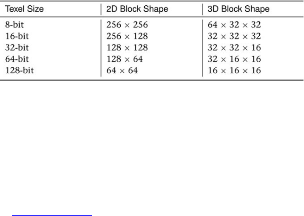
Table 2.1: Sparse Texture Block Sizes
The mip tail begins at the level reported in the imageMipTailFirstLod field of
VkSparseImageMemoryRequirements. The size of the tail, in bytes, is contained in
imageMipTailSize, and it begins at imageMipTailOffset bytes into the image’s memory
binding region. If the image does not have a single mip tail binding for all array layers (as indicated
by the presence of VK_SPARSE_IMAGE_FORMAT_SINGLE_MIPTAIL_BIT in the
aspectMask field of VkSparseImageFormatProperties), then imageMipTailStride
is the distance, in bytes, between the start of the memory binding for each mip tail level.
The properties of a specific format can also be determined by calling
vkGetPhysicalDeviceSparseImageFormatProperties(), which, given a specific
format, will return a VkSparseImageFormatProperties describing that format’s sparse
image requirements without the need to create an image and query it. The prototype of
vkGetPhysicalDeviceSparseImageFormatProperties() is
Click here to view code image
void vkGetPhysicalDeviceSparseImageFormatProperties (
VkPhysicalDevice physicalDevice,
VkFormat format,
VkImageType type,
VkSampleCountFlagBits samples,
VkImageUsageFlags usage,
VkImageTiling tiling,
uint32_t* pPropertyCount,
VkSparseImageFormatProperties* pProperties);
As you can see, vkGetPhysicalDeviceSparseImageFormatProperties() takes as
parameters many of the properties that would be used to construct an image. Sparse image properties
are a function of a physical device, a handle to which should be passed in physicalDevice. The
format of the image is passed in format, and the type of image (VK_IMAGE_TYPE_1D,
VK_IMAGE_TYPE_2D, or VK_IMAGE_TYPE_3D) is passed in type. If multisampling is required,
the number of samples (represented as one of the members of the VkSampleCountFlagBits
enumeration) is passed in samples.
The intended usage for the image is passed in usage. This should be a bitfield containing the flags
specifying how an image with this format will be used. Be aware that sparse images may not be
supported at all under certain use cases, so it’s best to set this field conservatively and accurately
rather than just turning on every bit and hoping for the best. Finally, the tiling mode to be used for the
image is specified in tiling. Again, standard block sizes may be supported only in certain tiling

modes. For example, it’s very unlikely that an implementation would support standard (or even
reasonable) block sizes when LINEAR tiling is used.
Just as with vkGetPhysicalDeviceImageFormatProperties(),
vkGetPhysicalDeviceSparseImageFormatProperties() can return an array of
properties. The pPropertyCount parameter points to a variable that will be overwritten with the
number of properties reported for the format. If pProperties is nullptr, then the initial value
of the variable pointed to by pPropertyCount is ignored and the total number of properties is
written into it. If pProperties is not nullptr, then it should be a pointer to an array of
VkSparseImageFormatProperties structures that will receive the properties of the image. In
this case, the initial value of the variable pointed to by pPropertyCount is the number of
elements in the array, and it is overwritten with the number of items populated in the array.
Because the memory binding used to back sparse images can be changed, even after the image is in
use, the update to the binding properties of the image is pipelined along with that work. Unlike
vkBindImageMemory() and vkBindBufferMemory(), which are operations likely carried
out by the host, memory is bound to a sparse resource using an operation on the queue, allowing the
device to execute them. The command to bind memory to a sparse resource is
vkQueueBindSparse(), the prototype of which is
Click here to view code image
VkResult vkQueueBindSparse (
VkQueue queue,
uint32_t bindInfoCount,
const VkBindSparseInfo* pBindInfo,
VkFence fence);
The queue that will execute the binding operation is specified in queue. Several binding operations
can be performed by a single call to vkQueueBindSparse(). The number of operations to
perform is passed in bindInfoCount, and pBindInfo is a pointer to an array of
bindInfoCount VkBindSparseInfo structures, each describing one of the bindings. The
definition of VkBindSparseInfo is
Click here to view code image
typedef struct VkBindSparseInfo {
VkStructureType sType;
const void* pNext;
uint32_t waitSemaphoreCount;
const VkSemaphore* pWaitSemaphores;
uint32_t bufferBindCount;
const VkSparseBufferMemoryBindInfo* pBufferBinds;
uint32_t imageOpaqueBindCount;
const VkSparseImageOpaqueMemoryBindInfo* pImageOpaqueBinds;
uint32_t imageBindCount;
const VkSparseImageMemoryBindInfo* pImageBinds;
uint32_t signalSemaphoreCount;
const VkSemaphore* pSignalSemaphores;
} VkBindSparseInfo;
The act of binding memory to sparse resources is actually pipelined with other work performed by
the device. As you read in Chapter 1, “Overview of Vulkan,” work is performed by submitting it to
queues. The binding is then performed along with the execution of commands submitted to the same
queue. Because vkQueueBindSparse() behaves a lot like a command submission,
VkBindSparseInfo contains many fields related to synchronization.
The sType field of VkBindSparseInfo should be set to
VK_STRUCTURE_TYPE_BIND_SPARSE_INFO, and pNext should be set to nullptr. As with
VkSubmitInfo, each sparse binding operation can optionally wait for one or more semaphores to
be signaled before performing the operation and can signal one or more semaphores when it is done.
This allows updates to the sparse resource’s bindings to be synchronized with other work performed
by the device.
The number of semaphores to wait on is specified in waitSemaphoreCount, and the number of
semaphores to signal is specified in signalSemaphoreCount. The pWaitSemaphores field is
a pointer to an array of waitSemaphoreCount semaphore handles to wait on, and
pSignalSemaphores is a pointer to an array of signalSemaphoreCount semaphores to
signal. Semaphores are covered in some detail in Chapter 11, “Synchronization.”
Each binding operation can include updates to buffers and images. The number of buffer binding
updates is specified in bufferBindCount and pBufferBinds is a pointer to an array of
bufferBindCount VkSparseBufferMemoryBindInfo structures, each describing one of
the buffer memory binding operations. The definition of VkSparseBufferMemoryBindInfo is
Click here to view code image
typedef struct VkSparseBufferMemoryBindInfo {
VkBuffer buffer;
uint32_t bindCount;
const VkSparseMemoryBind* pBinds;
} VkSparseBufferMemoryBindInfo;
Each instance of VkSparseBufferMemoryBindInfo contains the handle of the buffer to which
memory will be bound. A number of regions of memory can be bound to the buffer at different
offsets. The number of memory regions is specified in bindCount, and each binding is described
by an instance of the VkSparseMemoryBind structure. pBinds is a pointer to an array of
bindCount VkSparseMemoryBind structures. The definition of VkSparseMemoryBind is
Click here to view code image
typedef struct VkSparseMemoryBind {
VkDeviceSize resourceOffset;
VkDeviceSize size;
VkDeviceMemory memory;
VkDeviceSize memoryOffset;
VkSparseMemoryBindFlags flags;
} VkSparseMemoryBind;
The size of the block of memory to bind to the resource is contained in size. The offsets of the
block in the resource and in the memory object are contained in resourceOffset and
memoryOffset, respectively, and are both expressed in units of bytes. The memory object that is

the source of storage for the binding is specified in memory. When the binding is executed, the block
of memory, size bytes long and starting at memoryOffset bytes into the memory object
specified in memory, will be bound into the buffer specified in the buffer field of the
VkSparseBufferMemoryBindInfo structure.
The flags field contains additional flags that can be used to further control the binding. No flags
are used for buffer resources. However, image resources use the same VkSparseMemoryBind
structure to affect memory bindings directly to images. This is known as an opaque image memory
binding, and the opaque image memory bindings to be performed are also passed through the
VkBindSparseInfo structure. The pImageOpaqueBinds member of VkBindSparseInfo
points to an array of imageOpaqueBindCount VkSparseImageOpaqueMemoryBindInfo
structures defining the opaque memory bindings. The definition of
VkSparseImageOpaqueMemoryBindInfo is
Click here to view code image
typedef struct VkSparseImageOpaqueMemoryBindInfo {
VkImage image;
uint32_t bindCount;
const VkSparseMemoryBind* pBinds;
} VkSparseImageOpaqueMemoryBindInfo;
Just as with VkSparseBufferMemoryBindInfo,
VkSparseImageOpaqueMemoryBindInfo contains a handle to the image to which to bind
memory in image and a pointer to an array of VkSparseMemoryBind structures in pBinds,
which is bindCount elements long. This is the same structure used for buffer memory bindings.
However, when this structure is used for images, you can set the flags field of each
VkSparseMemoryBind structure to include the
VK_SPARSE_MEMORY_BIND_METADATA_BIT flag in order to explicitly bind memory to the
metadata associated with the image.
When memory is bound opaquely to a sparse image, the blocks of memory have no defined
correlation with texels in the image. Rather, the backing store of the image is treated as a large,
opaque region of memory with no information about how texels are laid out in it provided to the
application. However, so long as memory is bound to the entire image when it is used, results will
still be well-defined and consistent. This allows sparse images to be backed by multiple, smaller
memory objects, potentially easing pool allocation strategies, for example.
To bind memory to an explicit region of an image, you can perform a nonopaque image memory
binding by passing one or more VkSparseImageMemoryBindInfo structures through the
VkBindSparseInfo structures passed to vkQueueBindSparse(). The definition of
VkSparseImageMemoryBindInfo is
Click here to view code image
typedef struct VkSparseImageMemoryBindInfo {
VkImage image;
uint32_t bindCount;
const VkSparseImageMemoryBind* pBinds;
} VkSparseImageMemoryBindInfo;

Again, the VkSparseImageMemoryBindInfo structure contains a handle to the image to which
to bind memory in image, a count of the number of bindings to perform in bindCount, and a
pointer to an array of structures describing the bindings in pBinds. This time, however, pBinds
points to an array of bindCount VkSparseImageMemoryBind structures, the definition of
which is
Click here to view code image
typedef struct VkSparseImageMemoryBind {
VkImageSubresource subresource;
VkOffset3D offset;
VkExtent3D extent;
VkDeviceMemory memory;
VkDeviceSize memoryOffset;
VkSparseMemoryBindFlags flags;
} VkSparseImageMemoryBind;
The VkSparseImageMemoryBind structure contains much more information about how the
memory is to be bound to the image resource. For each binding, the image subresource to which the
memory is to be bound is specified in subresource, which is an instance of the
VkImageSubresource, the definition of which is
Click here to view code image
typedef struct VkImageSubresource {
VkImageAspectFlags aspectMask;
uint32_t mipLevel;
uint32_t arrayLayer;
} VkImageSubresource;
The VkImageSubresource allows you to specify the aspect of the image
(VK_IMAGE_ASPECT_COLOR_BIT,VK_IMAGE_ASPECT_DEPTH_BIT, or
VK_IMAGE_ASPECT_STENCIL_BIT, for example) in aspectMask, the mipmap level to which
you want to bind memory in mipLevel, and the array layer where the memory should be bound in
arrayLayer. For nonarray images, arrayLayer should be set to zero.
Within the subresource, the offset and extent fields of the VkSparseImageMemoryBind
structure define the offset and size of the region of texels to bind the image data to. This must be
aligned to the tile-size boundaries, which are either the standard sizes as shown in Table 2.1 or the
per-format block size that can be retrieved from
vkGetPhysicalDeviceSparseImageFormatProperties().
Again, the memory object from which to bind memory is specified in memory, and the offset within
the memory where the backing store resides is specified in memoryOffset. The same flags are
available in the flags field of VkSparseImageMemoryBind.
Summary
This chapter introduced you to the different types of resources that are used by Vulkan. It described
how the memory used to back them is allocated and then associated with them. It also explained how
you can manage the application memory used by Vulkan through the use of a custom allocator. You
have seen how to move resources from state to state and how to synchronize acess to them through
pipeline barriers. This enables efficient, parallel access to resources both from multiple stages of the
Vulkan pipeline and from the host.
Chapter 3. Queues and Commands
What You’ll Learn in This Chapter
• What a queue is and how to use it
• How to create commands and send them to Vulkan
• How to ensure that a device has finished processing your work
Vulkan devices expose multiple queues that perform work. In this chapter, we discuss the various
queue types and explain how to submit work to them in the form of command buffers. We also show
how to instruct a queue to complete all of the work you’ve sent it.
Device Queues
Each device in Vulkan has one or more queues. The queue is the part of the device that actually
performs work. It can be thought of as a subdevice that exposes a subset of the device’s functionality.
In some implementations, each queue may even be a physically separate part of the system.
Queues are grouped into one or more queue families, each containing one or more queues. Queues
within a single family are essentially identical. Their capabilities are the same, their performance
level and access to system resources is the same, and there is no cost (beyond synchronization) of
transferring work between them. If a device contains multiple cores that have the same capabilities
but differ in performance, access to memory, or some other factor that might mean they can’t operate
identically, it may expose them in separate families that otherwise appear identical.
As discussed in Chapter 1, “Overview of Vulkan,” you can query the properties of each of a physical
device’s queue families by calling vkGetPhysicalDeviceQueueFamilyProperties().
This function writes the properties of the queue family into an instance of the
VkQueueFamilyProperties structure that you hand it.
The number and type of queues that you wish to use must be specified when you create the device.
As you saw in Chapter 1, “Overview of Vulkan,” the VkDeviceCreateInfo structure that you
pass to vkCreateDevice() contains the queueCreateInfoCount and
pQueueCreateInfos members. Chapter 1, “Overview of Vulkan,” glossed over them, but now
it’s time to fill them in. The queueCreateInfoCount member contains the number of
VkDeviceQueueCreateInfo structures stored in the array pointed to by
pQueueCreateInfos. The definition of the VkDeviceQueueCreateInfo structure is
Click here to view code image
typedef struct VkDeviceQueueCreateInfo {
VkStructureType sType;
const void* pNext;
VkDeviceQueueCreateFlags flags;
uint32_t queueFamilyIndex;
uint32_t queueCount;
const float* pQueuePriorities;
} VkDeviceQueueCreateInfo;

As with most Vulkan structures, the sType field is the structure type, which in this case should be
VK_STRUCTURE_TYPE_QUEUE_CREATE_INFO, and the pNext field is used for extensions and
should be set to nullptr when none are used. The flags field contains flags controlling queue
construction, but no flag is defined for use in the current version of Vulkan, so this field should be set
to zero.
The fields of interest here are queueFamilyIndex and queueCount. The
queueFamilyIndex field specifies the family from which you want to allocate queues, and the
queueCount field specifies the number of queues to allocate from that family. To allocate queues
from multiple families, simply pass an array of more than one VkDeviceQueueCreateInfo
structure in the pQueueCreateInfos member of the VkDeviceCreateInfo structure.
The queues are constructed when the device is created. For this reason, we don’t create queues, but
obtain them from the device. To do this, call vkGetDeviceQueue():
Click here to view code image
void vkGetDeviceQueue (
VkDevice device,
uint32_t queueFamilyIndex,
uint32_t queueIndex,
VkQueue* pQueue);
The vkGetDeviceQueue() function takes as arguments the device from which you want to
obtain the queue, the family index, and the index of the queue within that family. These are specified
in device,queueFamilyIndex, and queueIndex, respectively. The pQueue parameter
points to the VkQueue handle that is to be filled with the handle to the queue.
queueFamilyIndex and queueIndex must refer to a queue that was initialized when the
device was created. If they do, a queue handle is placed into the variable pointed to by pQueue;
otherwise, this variable is set to VK_NULL_HANDLE.
Creating Command Buffers
The primary purpose of a queue is to process work on behalf of your application. Work is represented
as a sequence of commands that are recorded into command buffers. Your application will create
command buffers containing the work it needs to do and submit them to one of the queues for
execution. Before you can record any commands, you need to create a command buffer. Command
buffers themselves are not created directly, but allocated from pools. To create a pool, call
vkCreateCommandPool(), whose prototype is
Click here to view code image
VkResult vkCreateCommandPool (
VkDevice device,
const VkCommandPoolCreateInfo* pCreateInfo,
const VkAllocationCallbacks* pAllocator,
VkCommandPool* pCommandPool);
As with most Vulkan object creation functions, the first parameter, device, is the handle to the
device that will own the new pool object, and a description of the pool is passed via a structure, a
pointer to which is placed in pCreateInfo. This structure is an instance of
VkCommandPoolCreateInfo, the definition of which is

Click here to view code image
typedef struct VkCommandPoolCreateInfo {
VkStructureType sType;
const void* pNext;
VkCommandPoolCreateFlags flags;
uint32_t queueFamilyIndex;
} VkCommandPoolCreateInfo;
As with most Vulkan structures, the first two fields, sType and pNext, contain the structure type
and a pointer to another structure containing more information about the pool to be created. Here,
we’ll set sType to VK_STRUCTURE_TYPE_COMMAND_POOL_CREATE_INFO and, because
we’re not passing any extra information, set pNext to nullptr.
The flags field contains flags that determine the behavior of the pool and the command buffers that
are allocated from it. These are members of the VkCommandPoolCreateFlagBits
enumeration, and there are currently two flags defined for use here.
• Setting the VK_COMMAND_POOL_CREATE_TRANSIENT_BIT indicates that command
buffers taken from the pool will be short-lived and returned to the pool shortly after use. Not
setting this bit suggests to Vulkan that you might keep the command buffers around for some
time.
• Setting the VK_COMMAND_POOL_CREATE_RESET_COMMAND_BUFFER_BIT allows
individual command buffers to be reused by resetting them or restarting them. (Don’t worry,
we’ll cover that in a moment.) If this bit is not specified, then only the pool itself can be reset,
which implicitly recycles all of the command buffers allocated from it.
Each of these bits may add some overhead to the work done by a Vulkan implementation to track the
resources or otherwise alter its allocation strategy. For example, setting
VK_COMMAND_POOL_CREATE_TRANSIENT_BIT may cause a Vulkan implementation to employ
a more advanced allocation strategy for the pool in order to avoid fragmentation as command buffers
are frequently allocated and then returned to it. Setting
VK_COMMAND_POOL_CREATE_RESET_COMMAND_BUFFER_BIT may cause the implementation
to track the reset status of each command buffer rather than simply track it at the pool level.
In this case, we’re actually going to set both bits. This gives us the most flexibility, possibly at the
expense of some performance in cases where we could have managed command buffers in bulk.
Finally, the queueFamilyIndex field of VkCommandPoolCreateInfo specifies the family of
queues to which command buffers allocated from this pool will be submitted. This is necessary
because even where two queues on a device have the same capabilities and support the same set of
commands, issuing a particular command to one queue may work differently from issuing that same
command to another queue.
The pAllocator parameter is used for application-managed host memory allocations, which is
covered in Chapter 2, “Memory and Resources.” Assuming successful creation of the command pool,
its handle will be written into the variable pointed to by pCommandPool, and
vkCreateCommandPool() will return VK_SUCCESS.
Once we have a pool from which to allocate command buffers, we can grab new command buffers by
calling vkAllocateCommandBuffers(), which is defined as

Click here to view code image
VkResult vkAllocateCommandBuffers (
VkDevice device,
const VkCommandBufferAllocateInfo* pAllocateInfo,
VkCommandBuffer* pCommandBuffers);
The device used to allocate the command buffers is passed in device, and the remaining parameters
describing the command buffers to allocate are passed in an instance of the
VkCommandBufferAllocateInfo structure, the address of which is passed in
pCommandBuffers. The definition of VkCommandBufferAllocateInfo is
Click here to view code image
typedef struct VkCommandBufferAllocateInfo {
VkStructureType sType;
const void* pNext;
VkCommandPool commandPool;
VkCommandBufferLevel level;
uint32_t commandBufferCount;
} VkCommandBufferAllocateInfo;
The sType field should be set to
VK_STRUCTURE_TYPE_COMMAND_BUFFER_ALLOCATE_INFO, and as we’re using only the
core feature set here, we set the pNext parameter to nullptr. A handle to the command pool that
we created earlier is placed into the commandPool parameter.
The level parameter specifies the level of the command buffers that we want to allocate. It can be
set to either VK_COMMAND_BUFFER_LEVEL_PRIMARY or
VK_COMMAND_BUFFER_LEVEL_SECONDARY. Vulkan allows primary command buffers to call
secondary command buffers. For our first few examples, we will use only primary-level command
buffers. We’ll cover secondary-level command buffers later in the book.
Finally, commandBufferCount specifies the number of command buffers that we want to allocate
from the pool. Note that we don’t tell Vulkan anything about the length or size of the command
buffers we’re creating. The internal data structures representing device commands will generally vary
too greatly for any unit of measurement, such as bytes or commands, to make much sense. Vulkan
will manage the command buffer memory for you.
If vkAllocateCommandBuffers() is successful, it will return VK_SUCCESS and place the
handles to the allocated command buffers in the array pointed to by pCommandBuffers. This
array should be big enough to hold all the handles. Of course, if you want to allocate only a single
command buffer, you can point this at a regular VkCommandBuffer handle.
To free command buffers, we use the vkFreeCommandBuffers() command, which is declared
as
Click here to view code image
void vkFreeCommandBuffers (
VkDevice device,
VkCommandPool commandPool,
uint32_t commandBufferCount,
const VkCommandBuffer* pCommandBuffers);

The device parameter is the device that owns the pool from which the command buffers were
allocated. commandPool is a handle to that pool, commandBufferCount is the number of
command buffers to free, and pCommandBuffers is a pointer to an array of
commandBufferCount handles to the command buffers to free. Note that freeing a command
buffer doesn’t necessarily free all of the resources associated with it but returns them to the pool from
which they were allocated.
To free all of the resources used by a command pool and all of the command buffers allocated from
it, call vkDestroyCommandPool(), the prototype of which is
Click here to view code image
void vkDestroyCommandPool (
VkDevice device,
VkCommandPool commandPool,
const VkAllocationCallbacks* pAllocator;
The device that owns the command pool is passed in the device parameter, and a handle to the
command pool to destroy is passed in commandPool. A pointer to a host memory allocation
structure compatible with the one used to create the pool is passed in pAllocator. This parameter
should be nullptr if the pAllocator parameter to vkCreateCommandPool() was also
nullptr.
There is no need to explicitly free all of the command buffers allocated from a pool before destroying
the pool. The command buffers allocated from the pool are all freed as a part of destroying the pool
and freeing its resources. Care should be taken, however, that no command buffers allocated from the
pool are still executing or queued for execution on the device when vkDestroyCommandPool()
is called.
Recording Commands
Commands are recorded into command buffers using Vulkan command functions, all of which take a
command buffer handle as their first parameter. Access to the command buffer must be externally
synchronized, meaning that it is the responsibility of your application to ensure that no two threads
simultaneously attempt to record commands into the same command buffer at the same time.
However, the following is perfectly acceptable:
• One thread can record commands into multiple command buffers by simply calling command
buffer functions on different command buffers in succession.
• Two or more threads can participate in building a single command buffer, so long as the
application can guarantee that no two of them are ever executing a command buffer building
function concurrently.
One of the key design principles of Vulkan is to enable efficient multithreading. To achieve this, it is
important that your application’s threads do not block each other’s execution by, for example, taking
a mutex to protect a shared resource. For this reason, it’s best to have one or more command buffers
for each thread rather than to try sharing one. Further, as command buffers are allocated from pools,
you can go further and create a command pool for each thread, allowing command buffers to be
allocated by your worker threads from their respective pools without interacting.

Before you can start recording commands into a command buffer, however, you have to begin the
command buffer, which resets it to an initial state. To do this, call vkBeginCommandBuffer(),
the prototype of which is
Click here to view code image
VkResult vkBeginCommandBuffer (
VkCommandBuffer commandBuffer,
const VkCommandBufferBeginInfo* pBeginInfo);
The command buffer to begin recording is passed in commandBuffer, and the parameters that are
used in recording this command buffer are passed through a pointer to a
VkCommandBufferBeginInfo structure specified in pBeginInfo. The definition of
VkCommandBufferBeginInfo is
Click here to view code image
typedef struct VkCommandBufferBeginInfo {
VkStructureType sType;
const void* pNext;
VkCommandBufferUsageFlags flags;
const VkCommandBufferInheritanceInfo* pInheritanceInfo;
} VkCommandBufferBeginInfo;
The sType field of VkCommandBufferBeginInfo should be set to
VK_STRUCTURE_TYPE_COMMAND_BUFFER_BEGIN_INFO, and pNext should be set to
nullptr. The flags field is used to tell Vulkan how the command buffer will be used. This
should be a bitwise combination of some of the members of the
VkCommandBufferUsageFlagBits enumeration, which include the following:
•VK_COMMAND_BUFFER_USAGE_ONE_TIME_SUBMIT_BIT means that the command
buffer will be recorded, executed only once, and then destroyed or recycled.
•VK_COMMAND_BUFFER_USAGE_RENDER_PASS_CONTINUE_BIT means that the
command buffer will be used inside a renderpass and is valid only for secondary command
buffers. The flag is ignored when you create a primary command buffer, which is what we will
cover in this chapter. Renderpasses and secondary command buffers are covered in more detail
in Chapter 13, “Multipass Rendering.”
•VK_COMMAND_BUFFER_USAGE_SIMULTANEOUS_USE_BIT means that the command
buffer might be executed or pending execution more than once.
For our purposes, it’s safe to set flags to zero, which means that we might execute the command
buffer more than once but not simultaneously and that we’re not creating a secondary command
buffer.
The pInheritanceInfo member of VkCommandBufferBeginInfo is used when beginning
a secondary command buffer to define which states are inherited from the primary command buffer
that will call it. For primary command buffers, this pointer is ignored. We’ll cover the content of the
VkCommandBufferInheritanceInfo structure when we introduce secondary command
buffers in Chapter 13, “Multipass Rendering.”

Now it’s time to create our first command. Back in Chapter 2, “Memory and Resources,” you learned
about buffers, images, and memory. The vkCmdCopyBuffer() command is used to copy data
between two buffer objects. Its prototype is
Click here to view code image
void vkCmdCopyBuffer (
VkCommandBuffer commandBuffer,
VkBuffer srcBuffer,
VkBuffer dstBuffer,
uint32_t regionCount,
const VkBufferCopy* pRegions);
This is the general form of all Vulkan commands. The first parameter, commandBuffer, is the
command buffer to which the command is appended. The srcBuffer and dstBuffer parameters
specify the buffer objects to be used as the source and destination of the copy, respectively. Finally,
an array of regions is passed to the function. The number of regions is specified in regionCount,
and the address of the array of regions is specified in pRegions. Each region is represented as an
instance of the VkBufferCopy structure, the definition of which is
Click here to view code image
typedef struct VkBufferCopy {
VkDeviceSize srcOffset;
VkDeviceSize dstOffset;
VkDeviceSize size;
} VkBufferCopy;
Each element of the array simply contains the source and destination offsets and the size of each
region to be copied in srcOffset, dstOffset, and size, respectively. When the command is
executed, for each region in pRegions,size bytes of data will be copied from srcOffset in
srcBuffer to dstOffset in dstBuffer. The offsets are also measured in bytes.
One thing that is fundamental to the operation of Vulkan is that the commands are not executed as
soon as they are called. Rather, they are simply added to the end of the specified command buffer. If
you are copying data to or from a region of memory that is visible to the host (i.e., it’s mapped), then
you need to be sure of several things:
• Ensure that the data is in the source region before the command is executed by the device.
• Ensure that the data in the source region is valid until after the command has been executed on
the device.
• Ensure that you don’t read the destination data until after the command has been executed on the
device.
The first of these is perhaps the most interesting. In particular, it means that you can build the
command buffer containing the copy command before putting the source data in memory. So long as
the source data is in the right place before the command buffer is executed, things will work out.
Listing 3.1 demonstrates how to use vkCmdCopyBuffer() to copy a section of data from one
buffer to another. The command buffer to perform the copy with is passed in the cmdBuffer
parameter; the source and destination buffers are passed in srcBuffer and dstBuffer
parameters, respectively; and the offsets of the data within them is passed in the srcOffset and

dstOffset parameters. The function packs these parameters, along with the size of the copy, into a
VkBufferCopy structure and calls vkCmdCopyBuffer() to perform the copy operation.
Listing 3.1: Example of Using vkCmdCopyBuffer()
Click here to view code image
void CopyDataBetweenBuffers(VkCmdBuffer cmdBuffer,
VkBuffer srcBuffer, VkDeviceSize srcOffset,
VkBuffer dstBuffer, VkDeviceSize dstOffset,
VkDeviceSize size)
{
const VkBufferCopy copyRegion =
{
srcOffset, dstOffset, size
};
vkCmdCopyBuffer(cmdBuffer, srcBuffer, dstBuffer, 1, ©Region);
}
Remember that srcOffset and dstOffset are relative to the start of the source and destination
buffers, respectively, but that each of those buffers could be bound to memory at different offsets and
could potentially be bound to the same memory object. Therefore, if one of the memory objects is
mapped, the offset within the memory object is the offset at which the buffer object is bound to it
plus the offset you pass to vkCmdCopyBuffer().
Before the command buffer is ready to be sent to the device for execution, we must tell Vulkan that
we’re done recording commands into it. To do this, we call vkEndCommandBuffer(), the
prototype of which is
Click here to view code image
VkResult vkEndCommandBuffer (
VkCommandBuffer commandBuffer);
The vkEndCommandBuffer() function takes only a single parameter, commandBuffer, which
is the command buffer to end recording. After vkEndCommandBuffer() is executed on a
command buffer, Vulkan finishes any final work it needs to do to get the command buffer ready for
execution.

Recycling Command Buffers
In many applications, a similar sequence of commands is used to render all or part of each frame.
Therefore, it is likely that you will record similar command buffers over and over. Using the
commands introduced so far, you would call vkAllocateCommandBuffers() to grab one or
more command buffer handles, record commands into the command buffers, and then call
vkFreeCommandBuffers() to return the command buffers to their respective pools. This is a
relatively heavyweight operation, and if you know that you will reuse a command buffer for similar
work many times in a row, it may be more efficient to reset the command buffer. This effectively puts
the command buffer back into its original state but does not necessarily interact with the pool at all.
Therefore, if the command buffer dynamically allocates resources from the pool as it grows, it can
hang on to those resources and avoid the cost of reallocation the second and subsequent times it’s
rebuilt. To reset a command buffer, call vkResetCommandBuffer(), the prototype of which is
Click here to view code image
VkResult vkResetCommandBuffer (
VkCommandBuffer commandBuffer,
VkCommandBufferResetFlags flags);
The command buffer to reset is passed in commandBuffer.flags specifies additional operations
to perform while resetting the command buffer. The only flag defined for use here is
VK_COMMAND_BUFFER_RESET_RELEASE_RESOURCES_BIT. If this bit is set, then resources
allocated from the pool by the command buffer are returned to the pool. Even with this bit set, it’s
probably still more efficient to call vkResetCommandBuffer() than it is to free and reallocate a
new command buffer.
It’s also possible to reset all the command buffers allocated from a pool in one shot. To do this, call
vkResetCommandPool(), the prototype of which is
Click here to view code image
VkResult vkResetCommandPool (
VkDevice device,
VkCommandPool commandPool,
VkCommandPoolResetFlags flags);
The device that owns the command pool is specified in device, and the pool to reset is specified in
commandPool. Just as with vkResetCommandBuffer(), the flags parameter specifies
additional action to be taken as part of resetting the pool. Again, the only flag defined for use here is
VK_COMMAND_POOL_RESET_RELEASE_RESOURCES_BIT. When this bit is set, any resources
dynamically allocated by the pool are freed as part of the reset operation.
Command buffers allocated from the pool are not freed by vkResetCommandPool(), but all
reenter their initial state as if they had been freshly allocated. vkResetCommandPool() is
typically used at the end of a frame to return a batch of reusable command buffers to their pool rather
than individually reset individual command buffers.
Care should be taken to try to keep the complexity of command buffers consistent over their multiple
uses if they are reset without returning resources to the pool. As a command buffer grows, it may
allocate resources dynamically from the pool, and the command pool may allocate resources from a
systemwide pool. The amount of resources that a command buffer may consume is essentially

unbounded, because there is no hard-wired limit to the number of commands you can place in a
single command buffer. If your application uses a mix of very small and very large command buffers,
it’s possible that eventually all command buffers will grow as large as the most complex command
buffers.
To avoid this scenario, either periodically specify the
VK_COMMAND_BUFFER_RESET_RELEASE_RESOURCES_BIT or
VK_COMMAND_POOL_RESET_RELEASE_RESOURCES_BIT when resetting command buffers or
their pools, respectively, or try to ensure that the same command buffers are always used in the same
way—either short, simple command buffers or long, complex command buffers. Avoid mixing use
cases.
Submission of Commands
To execute the command buffer on the device, we need to submit it to one of the device’s queues. To
do this, call vkQueueSubmit(), the prototype of which is
Click here to view code image
VkResult vkQueueSubmit (
VkQueue queue,
uint32_t submitCount,
const VkSubmitInfo* pSubmits,
VkFence fence);
This command can submit one or more command buffers to the device for execution. The queue
parameter specifies the device queue to which to send the command buffer. Access to the queue must
be externally synchronized. All of the command buffers to submit were allocated from a pool, and
that pool must have been created with respect to one of the device’s queue families. This is the
queueFamilyIndex member of the VkCommandPoolCreateInfo structure passed to
vkCreateCommandPool(). queue must be a member of that family.
The number of submissions is specified in submitCount, and an array of structures describing
each of the submissions is specified in pSubmits. Each submission is represented by an instance of
the VkSubmitInfo structures, the definition of which is
Click here to view code image
typedef struct VkSubmitInfo {
VkStructureType sType;
const void* pNext;
uint32_t waitSemaphoreCount;
const VkSemaphore* pWaitSemaphores;
const VkPipelineStageFlags* pWaitDstStageMask;
uint32_t commandBufferCount;
const VkCommandBuffer* pCommandBuffers;
uint32_t signalSemaphoreCount;
const VkSemaphore* pSignalSemaphores;
} VkSubmitInfo;
The sType field of VkSubmitInfo should be set to VK_STRUCTURE_TYPE_SUBMIT_INFO,
and pNext should be set to nullptr. Each VkSubmitInfo structure can represent multiple
command buffers that are to be executed by the device.
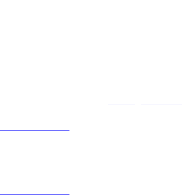
Each set of command buffers can be wrapped in a set of semaphores upon which to wait before
beginning execution and can signal one or more semaphores when they complete execution. A
semaphore is a type of synchronization primitive that allows work executed by different queues to be
scheduled and coordinated correctly. We will cover semaphores along with other synchronization
primitives in Chapter 11, “Synchronization.” For now, we’re not going to use these fields, so
waitSemaphoreCount and signalSemaphoreCount can be set to zero, and
pWaitSemaphores,pWaitDstStageMask, and pSignalSemaphores can all be set to
nullptr.
The command buffers we want to execute are placed in an array, and its address is passed in
pCommandBuffers. The number of command buffers to execute (the length of the
pCommandBuffers array) is specified in commandBufferCount. At some time after the
vkQueueSubmit() command is called, the commands in the command buffers begin executing on
the device. Commands submitted to different queues on the same device (or to queues belonging to
different devices) may execute in parallel. vkQueueSubmit() returns as soon as the specified
command buffers have been scheduled, possibly long before they’ve even begun executing.
The fence parameter to vkQueueSubmit() is a handle to a fence object, which can be used to wait
for completion of the commands executed by this submission. A fence is another type of
synchronization primitive that we will cover in Chapter 11, “Synchronization.” For now, we’ll set
fence to VK_NULL_HANDLE. Until we cover fences, we can wait for all work submitted to a
queue to complete by calling vkQueueWaitIdle(). Its prototype is
Click here to view code image
VkResult vkQueueWaitIdle (
VkQueue queue);
The only parameter to vkQueueWaitIdle(), queue, is the queue upon which to wait. When
vkQueueWaitIdle() returns, all command buffers submitted to queue are guaranteed to have
completed execution. A shortcut to wait for all commands submitted to all queues on a single device
to have completed is to call vkDeviceWaitIdle(). Its prototype is
Click here to view code image
VkResult vkDeviceWaitIdle (
VkDevice device);
Calling vkQueueWaitIdle() or vkDeviceWaitIdle() is really not recommended, as they
fully flush any work on the queue or device and are very heavyweight operations. Neither should be
called in any performance-critical part of your application. Suitable use cases include just before
shutting down the application or when reinitializing application subsystems such as thread
management, memory management, and so on, where there is likely to be a substantial pause
anyway.
Summary
This chapter introduced you to command buffers, which are the mechanisms by which commands are
communicated by your application to the Vulkan device. We introduced our first Vulkan command
and showed you how to ask the device to execute work for you.
We discussed how to send the command buffers to the Vulkan device for execution by submitting
them to the queue. You saw how to ensure that all work submitted to a queue or to a device has
finished executing. Although we glossed over a number of important topics, such as how to call one
command buffer from another and how to implement fine-grained synchronization between the host
and the device and between queues on the device, these topics will be discussed in upcoming
chapters.

Chapter 4. Moving Data
What You’ll Learn in This Chapter
• How to manage the state of resources as they are used by Vulkan
• How to copy data between resources and fill buffers and images with a known value
• How to perform blit operations to stretch and scale image data
Graphics and compute operations are generally data-intensive. Vulkan includes several objects that
provide a means to store and manipulate data. It is often necessary to move data into and out of those
objects, and several commands are provided to do exactly that: copy data and fill buffer and image
objects. Further, at any given time a resource may be in one of any number of states, and many parts
of the Vulkan pipeline may need access to them. This chapter covers data movement commands that
can be used to copy data and fill memory—the commands needed to manage the state of resources as
they are accessed by your applications.
Chapter 3, “Queues and Commands,” showed that commands executed by the device are placed in
command buffers and submitted to one of its queues for execution. This is important because it
means that commands are not executed as you call them in your application, but as they are
encoutered by the device while it makes its way through the command buffers you’ve submitted. The
first command you were introduced to, vkCmdCopyBuffer(), copies data between two buffers or
between different regions in the same buffer. This is one of may commands that affect buffers,
images, and other objects in Vulkan. This chapter covers similar commands for filling, copying, and
clearing buffers and images.
Managing Resource State
At any given time in the execution of a program, each resource can be in one of many different states.
For example, if the graphics pipeline is drawing to an image or using it as the source of texture data,
or if Vulkan is copying data from the host into an image, each of those usage scenarios is different.
For some Vulkan implementations, there may be no real difference between some of these states, and
for others, accurately knowing the state of a resource at a given point in time can make the difference
between your application working or rendering junk.
Because commands in command buffers are responsible for most access to resources, and because
command buffers might be built in a different order from the order in which they are submitted for
execution, it’s not really practical for Vulkan implementations to attempt to track the state of a
resource and make sure it’s in the right one for each usage scenario. In particular, a resource may
begin in one state and move to another due to the execution of a command buffer. While drivers
could track the state of resources as they are used in a command buffer, tracking state across
command buffers would require significant effort1when the command buffers were submitted for
execution. Therefore, this responsibility falls to your application. Resource state is perhaps most
important for images because they are complex, structured resources.
1. The validation layers do, in fact, attempt to track this state. While this comes with a substantial performance
impact, the layer is capable of catching and reporting many resource-state-related issues.

The state of an image is roughly divided into two essentially orthogonal pieces of state: its layout,
which determines how the data is laid out in memory and was discussed briefly earlier in the book,
and a record of who last wrote to the image, which affects caching and coherency of data on the
device. The initial layout of an image is specified when it is created, and then can be changed
throughout the image’s lifetime, either explicitly using barriers or implicitly using renderpass.
Barriers also marshal access to resources from different parts of the Vulkan pipeline, and in some
cases, transitioning a resource from one layout to another can be accomplished at other midpipeline
synchronization work performed by barriers.
The specific use cases for each layout are discussed in some depth later in the book. However, the
fundamental act of moving a resource from state to state is known as a barrier, and it is extremely
important to get barriers right and to use them effectively in your application.
Pipeline Barriers
A barrier is a synchronization mechanism for memory access mamangement and resource state
movement within the stages of the Vulkan pipeline. The primary command for synchronizing access
to resources and moving them from state to state is vkCmdPipelineBarrier(), the prototype of
which is
Click here to view code image
void vkCmdPipelineBarrier (
VkCommandBuffer commandBuffer,
VkPipelineStageFlags srcStageMask,
VkPipelineStageFlags dstStageMask,
VkDependencyFlags dependencyFlags,
uint32_t memoryBarrierCount,
const VkMemoryBarrier* pMemoryBarriers,
uint32_t bufferMemoryBarrierCount,
const VkBufferMemoryBarrier* pBufferMemoryBarriers,
uint32_t imageMemoryBarrierCount,
const VkImageMemoryBarrier* pImageMemoryBarriers);
The command buffer that will execute the barrier is passed in commandBuffer. The next two
parameters, srcStageMask and dstStageMask, specify which pipeline stages wrote to the
resource last and which stages will read from the resource next, respectively. That is, they specify the
source and destination for the data flow represented by the barrier. Each is constructed from a number
of the members of the VkPipelineStageFlagBits enumeration.
•VK_PIPELINE_STAGE_TOP_OF_PIPE_BIT: The top of pipe is considered to be hit as soon
as the device starts processing the command.
•VK_PIPELINE_STAGE_DRAW_INDIRECT_BIT: When the pipeline executes an
indirect command, it fetches some of the parameters for the command from memory. This
is the stage that fetches those parameters.
•VK_PIPELINE_STAGE_VERTEX_INPUT_BIT: This is the stage where vertex attributes are
fetched from their respective buffers. After this, content of vertex buffers can be overwritten,
even if the resulting vertex shaders have not yet completed execution.
•VK_PIPELINE_STAGE_VERTEX_SHADER_BIT: This stage is passed when all vertex
shader work resulting from a drawing command is completed.
•VK_PIPELINE_STAGE_TESSELLATION_CONTROL_SHADER_BIT: This stage is passed
when all tessellation control shader invocations produced as the result of a drawing command
have completed execution.
•VK_PIPELINE_STAGE_TESSELLATION_EVALUATION_SHADER_BIT: This stage is
passed when all tessellation evaluation shader invocations produced as the result of a drawing
command have completed execution.
•VK_PIPELINE_STAGE_GEOMETRY_SHADER_BIT: This stage is passed when all geometry
shader invocations produced as the result of a drawing command have completed execution.
•VK_PIPELINE_STAGE_FRAGMENT_SHADER_BIT: This stage is passed when all fragment
shader invocations produced as the result of a drawing command have completed execution.
Note that there is no way to know that a primitive has been completely rasterized while the
resulting fragment shaders have not yet completed. However, rasterization does not access
memory, so no information is lost here.
•VK_PIPELINE_STAGE_EARLY_FRAGMENT_TESTS_BIT: All per-fragment tests that
might occur before the fragment shader is launched have completed.
•VK_PIPELINE_STAGE_LATE_FRAGMENT_TESTS_BIT: All per-fragment tests that might
occur after the fragment shader is executed have completed. Note that outputs to the depth and
stencil attachments happen as part of the test, so this stage and the early fragment test stage
include the depth and stencil outputs.
•VK_PIPELINE_STAGE_COLOR_ATTACHMENT_OUTPUT_BIT: Fragments produced by the
pipeline have been written to the color attachments.
•VK_PIPELINE_STAGE_COMPUTE_SHADER_BIT: Compute shader invocations produced as
the result of a dispatch have completed.
•VK_PIPELINE_STAGE_TRANSFER_BIT: Any pending transfers triggered as a result of calls
to vkCmdCopyImage() or vkCmdCopyBuffer(), for example, have completed.
•VK_PIPELINE_STAGE_BOTTOM_OF_PIPE_BIT: All operations considered to be part of
the graphics pipeline have completed.
•VK_PIPELINE_STAGE_HOST_BIT: This pipeline stage corresponds to access from the host.
•VK_PIPELINE_STAGE_ALL_GRAPHICS_BIT: When used as a destination, this special flag
means that any pipeline stage may access memory. As a source, it’s effectively equivalent to
VK_PIPELINE_STAGE_BOTTOM_OF_PIPE_BIT.
•VK_PIPELINE_STAGE_ALL_COMMANDS_BIT: This stage is the big hammer. Whenever
you just don’t know what’s going on, use this; it will synchronize everything with everything.
Just use it wisely.
Because the flags specified in srcStageMask and dstStageMask are used to indicate when
things happen, it’s acceptable for Vulkan implementations to move them around or interpret them in
various ways. The srcStageMask specifies when the source stage has finished reading or writing
a resource. As a result, moving the effective position of that stage later in the pipeline doesn’t change
the fact that those accesses have completed; it may mean only that the implementation waits longer
than it really needs to for them to complete.
Likewise, the dstStageMask specifies the point at which the pipeline will wait before proceeding.
If an implementation moves that wait point earlier, that will still work. The event that it waits on will

still have completed when the logically later parts of the pipeline begin execution. That
implementation just misses the opportunity to perform work when it was instead waiting.
The dependencyFlags parameter specifies a set of flags that describes how the dependency
represented by the barrier affects the resources referenced by the barrier. The only defined flag is
VK_DEPENDENCY_BY_REGION_BIT, which indicates that the barrier affects only the region
modified by the source stages (if it can be determined), which is consumed by the destination stages.
A single call to vkCmdPipelineBarrier() can be used to trigger many barrier operations.
There are three types of barrier operations: global memory barriers, buffer barriers, and image
barriers. Global memory barriers affect things such as synchronized access to mapped memory
between the host and the device. Buffer and image barriers primarily affect device access to buffer
and image resources, respectively.
Global Memory Barriers
The number of global memory barriers to be triggered by vkCmdPipelineBarrier() is
specified in memoryBarrierCount. If this is nonzero, then pMemoryBarriers points to an
array of memoryBarrierCount VkMemoryBarrier structures, each defining a single
memory barrier. The definition of VkMemoryBarrier is
Click here to view code image
typedef struct VkMemoryBarrier {
VkStructureType sType;
const void* pNext;
VkAccessFlags srcAccessMask;
VkAccessFlags dstAccessMask;
} VkMemoryBarrier;
The sType field of VkMemoryBarrier should be set to
VK_STRUCTURE_TYPE_MEMORY_BARRIER, and pNext should be set to nullptr. The only
other fields in the structure are the source and destination access masks specified in
srcAccessMask and dstAccessMask, respectively. The access masks are bitfields containing
members of the VkAccessFlagBits. The source access mask specifies how the memory was last
written, and the destination access mask specifies how the memory will next be read. The available
access flags are
•VK_ACCESS_INDIRECT_COMMAND_READ_BIT: The memory referenced will be the source
of commands in an indirect drawing or dispatch command such as vkCmdDrawIndirect()
or vkCmdDispatchIndirect().
•VK_ACCESS_INDEX_READ_BIT: The memory referenced will be the source of index data in
an indexed drawing command such as vkCmdDrawIndexed() or
vkCmdDrawIndexedIndirect().
•VK_ACCESS_VERTEX_ATTRIBUTE_READ_BIT: The memory referenced will be the source
of vertex data fetched by Vulkan’s fixed-function vertex assembly stage.
•VK_ACCESS_UNIFORM_READ_BIT: The memory referenced is the source of data for a
uniform block accessed by a shader.
•VK_ACCESS_INPUT_ATTACHMENT_READ_BIT: The memory referenced is used to back an
image used as an input attachment.
•VK_ACCESS_SHADER_READ_BIT: The memory referenced is used to back an image object
that is read from using image loads or texture reads in a shader.
•VK_ACCESS_SHADER_WRITE_BIT: The memory referenced is used to back an image object
that is written to using image stores in a shader.
•VK_ACCESS_COLOR_ATTACHMENT_READ_BIT: The memory referenced is used to back an
image used as a color attachment where reads are performed, perhaps because blending is
enabled. Note that this is not the same as an input attachment, where data is read explicitly by
the fragment shader.
•VK_ACCESS_COLOR_ATTACHMENT_WRITE_BIT: The memory referenced is used to back
an image used as a color attachment that will be written to.
•VK_ACCESS_DEPTH_STENCIL_ATTACHMENT_READ_BIT: The memory referenced is
used to back an image used as a depth or stencil attachment that will be read from because the
relevant test is enabled.
•VK_ACCESS_DEPTH_STENCIL_ATTACHMENT_WRITE_BIT: The memory referenced is
used to back an image used as a depth or stencil attachment that will be written to because the
relevant write mask is enabled.
•VK_ACCESS_TRANSFER_READ_BIT: The memory referenced is used as the source of data
in a transfer operation such as vkCmdCopyImage(),vkCmdCopyBuffer(), or
vkCmdCopyBufferToImage().
•VK_ACCESS_TRANSFER_WRITE_BIT: The memory referenced is used as the destination of
a transfer operation.
•VK_ACCESS_HOST_READ_BIT: The memory referenced is mapped and will be read from by
the host.
•VK_ACCESS_HOST_WRITE_BIT: The memory referenced is mapped and will be written to
by the host.
•VK_ACCESS_MEMORY_READ_BIT: All other memory reads not explicitly covered by the
preceding cases should specify this bit.
•VK_ACCESS_MEMORY_WRITE_BIT: All other memory writes not explicitly covered by the
preceding cases should specify this bit.
Memory barriers provide two important pieces of functionality. First, they help avoid hazards, and
second, they help ensure data consistency.
Ahazard occurs when read and write operations are reordered relative to the order in which the
programmer expects them to execute. They can be very hard to diagnose because they are often
platform- or timing-dependent. There are three types of hazards:
• A read-after-write, or RaW, hazard occurs when the programmer expects to read from a piece of
memory that has recently been written to and that those reads will see the results of the writes. If
the read is rescheduled and ends up executing before the write is complete, the read will see old
data.
• A write-after-read, or WaR, hazard occurs when a programmer expects to overwrite a piece of
memory that had previously been read by another part of the program. If the write operation

ends up being scheduled before the read operation, then the read operation will see the new data,
not the older data it was expecting.
• A write-after-write, or WaW, hazard occurs when a programmer expects to overwrite the same
location in memory multiple times and that only the results of the last write will be visible to
subsequent readers. If the writes are rescheduled with respect to one another, then only the result
of the write that happened to execute last will be visible to readers.
There is no such thing as a read-after-read hazard because no data is modified.
In the memory barrier, the source isn’t necessarily a producer of data but the first operation that is
protected by that barrier. For avoiding RaW hazards, the source is actually a read operation.
For example, to ensure that all texture fetches are complete before overwriting an image with a copy
operation, we need to specify VK_ACCESS_SHADER_READ_BIT in the srcAccessMask field
and VK_ACCESS_TRANSFER_WRITE_BIT in the dstAccessMask field. This tells Vulkan that
the first stage is reading from an image in a shader and that the second stage may overwrite that
image, so we should not reorder the copy into the image before any shaders that may have read from
it.
Note that there is some overlap between the bits in VkAccessFlagBits and those in
VkPipelineStageFlagBits. The VkAccessFlagBits flags specify what operation is being
performed, and the VkPipelineStageFlagBits describe where in the pipeline the action is
performed.
The second piece of functionality provided by the memory barrier is to ensure consistency of the
views of data from different parts of the pipeline. For example, if an application contains a shader
that writes to a buffer from a shader and then needs to read that data back from the buffer by mapping
the underlying memory object, it should specify VK_ACCESS_SHADER_WRITE_BIT in
srcAccessMask and VK_ACCESS_HOST_READ_BIT in dstAccessMask. If there are caches
in the device that may buffer writes performed by shaders, those caches may need to be flushed in
order for the host to see the results of the write operations.
Buffer Memory Barriers
Buffer memory barriers provide finer-grained control of the memory used to back buffer objects. The
number of buffer memory barriers executed by a call to vkCmdPipelineBarrier() is specified
in the bufferMemoryBarrierCount parameter, and the pBufferMemoryBarriers field is
a pointer to an array of this many VkBufferMemoryBarrier structures, each defining a buffer
memory barrier. The definition of VkBufferMemoryBarrier is
Click here to view code image
typedef struct VkBufferMemoryBarrier {
VkStructureType sType;
const void* pNext;
VkAccessFlags srcAccessMask;
VkAccessFlags dstAccessMask;
uint32_t srcQueueFamilyIndex;
uint32_t dstQueueFamilyIndex;
VkBuffer buffer;
VkDeviceSize offset;
VkDeviceSize size;
} VkBufferMemoryBarrier;

The sType field of each VkBufferMemoryBarrier structure should be set to
VK_STRUCTURE_TYPE_BUFFER_MEMORY_BARRIER, and pNext should be set to nullptr.
The srcAccessMask and dstAccessMask fields have the same meanings as they do in the
VkMemoryBarrier structure. Obviously, some of the flags that refer specifically to images, such
as color or depth attachments, have little meaning when dealing with buffer memory.
When ownership of the buffer is being transferred from one queue to another and those queues are in
different families, the family indices of the source and destination queues must be supplied in
srcQueueFamilyIndex and dstQueueFamilyIndex, respectively. If there is no transfer of
ownership, then srcQueueFamilyIndex and dstQueueFamilyIndex can both be set to
VK_QUEUE_FAMILY_IGNORED. In this case, the sole ownership is assumed to be the queue family
for which the command buffer is being built.
The buffer the access to which is being controlled by the barrier is specified in buffer. To
synchronize access to a range of a buffer, use the offset and size fields of the structure to specify
that range, in bytes. To control access to the whole buffer, simply set offset to zero and size to
VK_WHOLE_SIZE.
If the buffer will be accessed by work executing on more than one queue, and those queues are of
different families, additional action must be taken by your application. Because a single device
exposing multiple queue families may actually be made up of multiple physical components, and
because those components may have their own caches, scheduling architecture, memory controllers,
and so on, Vulkan needs to know when a resource is moved from queue to queue. If this is the case,
specify the queue family index of the source queue in srcQueueFamilyIndex and the family of
the destination queue in dstQueueFamilyIndex.
Similarly to image memory barriers, if the resource is not being transferred between queues
belonging to different families, srcQueueFamilyIndex and dstQueueFamilyIndex should
be set to VK_QUEUE_FAMILY_IGNORED.
Image Memory Barriers
Just as with buffers, special attention should be paid to images, and image memory barriers are used
to control access to images. The number of image memory barriers to be performed by the call to
vkCmdPipelineBarrier() is specified in the imageMemoryBarrierCount parameter, and
pImageMemoryBarriers is a pointer to an array of this many VkImageMemoryBarrier
structures, each describing a single barrier. The definition of VkImageMemoryBarrier is
Click here to view code image
typedef struct VkImageMemoryBarrier {
VkStructureType sType;
const void* pNext;
VkAccessFlags srcAccessMask;
VkAccessFlags dstAccessMask;
VkImageLayout oldLayout;
VkImageLayout newLayout;
uint32_t srcQueueFamilyIndex;
uint32_t dstQueueFamilyIndex;
VkImage image;
VkImageSubresourceRange subresourceRange;
} VkImageMemoryBarrier;

The sType field of each VkImageMemoryBarrier structure should be set to
VK_STRUCTURE_TYPE_IMAGE_MEMORY_BARRIER, and pNext should be set to nullptr.
Just as with the other memory barriers, the srcAccessMask and dstAccessMask fields specify
the source and destination access type. Again, only some of the access types will apply to images.
Also, when you are controlling access across queues, the srcQueueFamilyIndex and
dstQueueFamilyIndex fields should be set to the family indices of the queues where the source
and destination work will take place.
The oldLayout and newLayout fields specify the layouts to be used for the image before and
after the barrier. These are the same fields that can be used when creating the image. The image that
the barrier is to affect is specified in image, and the parts of the image to be affected by the barrier
are specified in subresourceRange, which is an instance of the
VkImageSubresourceRange structure, the definition of which is
Click here to view code image
typedef struct VkImageSubresourceRange {
VkImageAspectFlags aspectMask;
uint32_t baseMipLevel;
uint32_t levelCount;
uint32_t baseArrayLayer;
uint32_t layerCount;
} VkImageSubresourceRange;
The image aspect is the part of the image that is to be included in the barrier. Most image formats and
types have only a single aspect. A common exception is a depth-stencil image, which may have a
separate aspect for each of the depth and stencil components of the image. It is possible, using the
aspect flags, to discard stencil data while keeping depth data for later sampling, for example.
For images with mipmaps, a subset of the mipmaps can be included in the barrier by specifying the
lowest-numbered (highest-resolution) mipmap level in the baseMipLevel field and the number of
levels in the levelCount field. If the image doesn’t have a full mipmap chain, baseMipLevel
should be set to 0, and levelCount should be set to 1.
Likewise, for array images, a subset of the image layers can be included in the barrier by setting
baseArrayLayer to the index of the first layer and layerCount to the number of layers to
include. Again, even if the image is not an array image, you should set baseArrayLayer to 0 and
layerCount to 1. In short, treat all images as though they have mipmaps (even if it’s only one
level) and all images as though they are arrays (even if they have only one layer).
Listing 4.1 shows an example of how to perform an image memory barrier.
Listing 4.1: Image Memory Barrier
Click here to view code image
const VkImageMemoryBarrier imageMemoryBarriers =
{
VK_STRUCTURE_TYPE_IMAGE_MEMORY_BARRIER, // sType
nullptr, // pNext
VK_ACCESS_COLOR_ATTACHMENT_WRITE_BIT, // srcAccessMask
VK_ACCESS_SHADER_READ_BIT, // dstAccessMask
VK_IMAGE_LAYOUT_COLOR_ATTACHMENT_OPTIMAL, // oldLayout

VK_IMAGE_LAYOUT_SHADER_READ_ONLY_OPTIMAL, // newLayout
VK_QUEUE_FAMILY_IGNORED, // srcQueueFamilyIndex
VK_QUEUE_FAMILY_IGNORED, // dstQueueFamilyIndex
image, // image
{// subresourceRange
VK_IMAGE_ASPECT_COLOR_BIT, // aspectMask
0, // baseMipLevel
VK_REMAINING_MIP_LEVELS, // levelCount
0, // baseArrayLayer
VK_REMAINING_ARRAY_LAYERS // layerCount
}
};
vkCmdPipelineBarrier(m_currentCommandBuffer,
VK_PIPELINE_STAGE_COLOR_ATTACHMENT_OUTPUT_BIT,
VK_PIPELINE_STAGE_FRAGMENT_SHADER_BIT,
0,
0, nullptr,
0, nullptr,
1, &imageMemoryBarrier);
The image memory barrier shown in Listing 4.1 takes an image that was previously in the
VK_IMAGE_LAYOUT_COLOR_ATTACHMENT_OPTIMAL layout and moves it to the
VK_IMAGE_LAYOUT_SHADER_READ_ONLY_OPTIMAL layout. The source of data is the color
output from the pipeline, as specified by VK_ACCESS_COLOR_ATTACHMENT_WRITE_BIT, and
the destination of the data is sampling by a shader, as specified by
VK_ACCESS_SHADER_READ_BIT.
There is no transfer of ownership across queues, so both srcQueueFamilyIndex and
dstQueueFamilyIndex are set to VK_QUEUE_FAMILY_IGNORED. Also, we’re performing the
barrier across all mipmap levels and array layers in the image, so the levelCount and
layerCount members of the subresourceRange structure are set to
VK_REMAINING_MIP_LEVELS and VK_REMAINING_ARRAY_LAYERS, respectively.
This barrier takes an image that previously was written to as a color attachment by a graphics
pipeline and moves it into a state in which it can be read from by a shader.
Clearing and Filling Buffers
You were introduced to buffer objects in Chapter 2, “Memory and Resources.” A buffer is a linear
region of data backed by memory. In order for a buffer to be useful, you need to be able to fill it with
data. In some cases, simply clearing the whole buffer to a known value is all you need to do. This
allows you to, for example, initialize a buffer that you will eventually write into using a shader or
some other operation.
To fill a buffer with a fixed value, call vkCmdFillBuffer(), the prototype of which is
Click here to view code image
void vkCmdFillBuffer (
VkCommandBuffer commandBuffer,
VkBuffer dstBuffer,
VkDeviceSize dstOffset,

VkDeviceSize size,
uint32_t data);
The command buffer into which to place the command is specified in commandBuffer. The buffer
that will be filled with data is specified in dstBuffer. To fill a section of the buffer with data,
specify the starting offset of the fill operation, in bytes, in dstOffset and the size of the region,
again in bytes, in size. Both dstOffset and size must be multiples of 4. To fill from
dstOffset to the end of the buffer, pass the special value, VK_WHOLE_SIZE, in the size
parameter. It follows that to fill an entire buffer, simply set dstOffset to 0 and size to
VK_WHOLE_SIZE.
The value that you want to fill the buffer with is passed in data. This is a uint32_t variable that
is simply replicated for the region of the fill operation. It is as though the buffer is interpreted as an
array of uint32_t, and each element from dstOffset to the end of the region is filled with this
value. To clear a buffer with a floating-point value, you can reinterpret the floating-point value as a
uint32_t value and pass that to vkCmdFillBuffer(). Listing 4.2 demonstrates this.
Listing 4.2: Filling a Buffer with Floating-Point Data
Click here to view code image
void FillBufferWithFloats(VkCommandBuffercmdBuffer,
VkBuffer dstBuffer,
VkDeviceSize offset,
VkDeviceSize length,
const float value)
{
vkCmdFillBuffer(cmdBuffer,
dstBuffer,
0,
1024,
*(const uint32_t*)&value);
}
Sometimes, filling a buffer with a fixed value is not enough, and there is a need to place data more
explicitly in a buffer object. When a large amount of data is needed to be transfered into or between
buffers, either mapping the buffer and writing to it with the host or copying data from another
(possibly mapped) buffer with vkCmdCopyBuffer() is most appropriate. However, for small
updates, such as updating the values of a vector or small data structures, vkCmdUpdateBuffer()
can be used to place data directly into a buffer object.
The prototype for vkCmdUpdateBuffer() is
Click here to view code image
void vkCmdUpdateBuffer (
VkCommandBuffer commandBuffer,
VkBuffer dstBuffer,
VkDeviceSize dstOffset,
VkDeviceSize dataSize,
const uint32_t* pData);

vkCmdUpdateBuffer() copies data directly from host memory into a buffer object. The data is
consumed from host memory as soon as vkCmdUpdateBuffer() is called, and as such, it’s fine
to free the host memory data structure or overwrite its content once vkCmdUpdateBuffer()
returns. Be aware, though, that the data is not written into the buffer until
vkCmdUpdateBuffer() is executed by the device after the command buffer has been submitted.
For this reason, Vulkan must make a copy of the data you’ve supplied and hold it either in some
auxiliary data structure associated with the command buffer or directly inside the command buffer
itself.
Again, the command buffer that will contain the command is passed in commandBuffer, and the
destination buffer object is passed in dstBuffer. The offset at which the data is to be placed is
passed in dstOffset, and the size of the data to place into the buffer is passed in dataSize. Both
dstOffset and dataSize are in units of bytes, but as with vkCmdFillBuffer(), both must
be a multiple of 4. The special value VK_WHOLE_SIZE is not accepted for the size parameter to
vkCmdUpdateBuffer() because it is also used as the size of the host memory region that is the
source of the data. The maximum size of data that can be placed in a buffer with
vkCmdUpdateBuffer() is 65,536 bytes.
pData points to the host memory containing the data that will eventually be placed into the buffer
object. Although the type of the variable expected here is a pointer to uint32_t, any data can be in
the buffer. Simply typecast a pointer to any memory region readable by the host to const
uint32_t*, and pass it to pData. Ensure that the data region is at least size bytes long. For
example, it’s reasonable to construct a C++ data structure matching the layout of a uniform or shader
storage block and simply copy its entire content into a buffer that will be used appropriately in a
shader.
Again, be cautious when using vkCmdFillBuffer(). It is intended for short, immediate updates
to buffers. For example, writing a single value into a uniform buffer is probably much more
efficiently achieved with vkCmdFillBuffer() than it is with a buffer mapping and a call to
vkCmdCopyBuffer().
Clearing and Filling Images
Just as with buffers, it it possible to copy data directly between images and to fill images with fixed
values. Images are larger, more complex, opaque data structures, so the raw offsets and data are not
generally visible to an application.2
2. Of course, it’s possible to map the memory that is used for backing an image. In particular, when linear tiling
is used for an image, this is standard practice. However, in general, this is not recommended.
To clear an image to a fixed value, call vkCmdClearColorImage(), the prototype of which is
Click here to view code image
void vkCmdClearColorImage (
VkCommandBuffer commandBuffer,
VkImage image,
VkImageLayout imageLayout,
const VkClearColorValue* pColor,
uint32_t rangeCount,
const VkImageSubresourceRange* pRanges);

The command buffer that will contain the clear command is passed in commandBuffer. The image
that is to be cleared is passed in image, and the layout that the image is expected to be in when the
clear command is executed is passed in imageLayout.
The accepted layouts for imageLayout are VK_IMAGE_LAYOUT_GENERAL and
VK_IMAGE_LAYOUT_TRANSFER_DST_OPTIMAL. To clear images that are in different layouts, it
is necessary to move them to one of these two layouts using a pipeline barrier before executing the
clear command.
The values to clear the image to are specified in an instance of the VkClearColorValue union,
the definition of which is
Click here to view code image
typedef union VkClearColorValue {
float float32[4];
int32_t int32[4];
uint32_t uint32[4];
} VkClearColorValue;
The VkClearColorValue is simply a union of three arrays of four values each. One is for
floating-point data, one is for signed integer data, and one is for unsigned integer data. Vulkan will
read the appropriate member for the format of the image being cleared. Your application can write
into the member that matches the source of data. No data conversion is performed by
vkCmdClearColorImage(); it is up to your application to fill the VkClearColorValue
union correctly.
Any number of regions of the destination image can be cleared with a single call to
vkCmdClearColorImage(), although each will be cleared with the same values. If you need to
clear multiple regions of the same image with different colors, you will need to call
vkCmdClearColorImage() multiple times. However, you want to clear all regions with the
same color, specify the number of regions in rangeCount, and pass a pointer to an array of
rangeCount VkImageSubresourceRange structures in pRanges. The definition of
VkImageSubresourceRange is
Click here to view code image
typedef struct VkImageSubresourceRange {
VkImageAspectFlags aspectMask;
uint32_t baseMipLevel;
uint32_t levelCount;
uint32_t baseArrayLayer;
uint32_t layerCount;
} VkImageSubresourceRange;
This structure was first introduced in Chapter 2, “Memory and Resources,” when we discussed
creation of image view. Here, it is used to define the regions of the image that you want to clear.
Because we are clearing a color image, the aspectMask must be set to
VK_IMAGE_ASPECT_COLOR_BIT. The baseMipLevel and levelCount fields are used to
specify the starting mipmap level and number of levels to clear, respectively, and if the image is an
array image, the baseArrayLayer and layerCount fields are used to specify the starting layer

and number of layers to clear. If the image is not an array image, these fields should be set to 0 and 1,
respectively.
Clearing a depth-stencil image is similar to clearing a color image, except that a special
VkClearDepthStencilValue structure is used to specify the clear values. The prototype of
vkCmdClearDepthStencilImage() is similar to that of vkCmdClearColorImage() and
is
Click here to view code image
void vkCmdClearDepthStencilImage (
VkCommandBuffer commandBuffer,
VkImage image,
VkImageLayout imageLayout,
const VkClearDepthStencilValue* pDepthStencil,
uint32_t rangeCount,
const VkImageSubresourceRange * pRanges);
Again, the command buffer that will perform the clear operation is specified in commandBuffer,
the image to clear is specified in image, and the layout that the image is expected to be in at the time
of the clear operation is specified in imageLayout. As with vkCmdClearColorImage(),
imageLayout should be either VK_IMAGE_LAYOUT_GENERAL or
VK_IMAGE_LAYOUT_TRANSFER_DST_OPTIMAL. No other layouts are valid for a clear
operation.
The values to which to clear the depth-stencil image are passed through an instance of the
VkClearDepthStencilValue structure, which contains both the depth and stencil clear values.
Its definition is
Click here to view code image
typedef struct VkClearDepthStencilValue {
float depth;
uint32_t stencil;
} VkClearDepthStencilValue;
As with vkCmdClearColorImage(), a number of ranges of the image can be cleared in a single
call to vkCmdClearDepthStencilImage(). The number of ranges to clear is specified in
rangeCount, and the pRanges parameter should point to an array of rangeCount
VkImageSubresourceRange structures defining the ranges to be cleared.
Because depth-stencil images may contain both a depth and a stencil aspect, the aspectMask field
of each member of pRanges can contain VK_IMAGE_ASPECT_DEPTH_BIT,
VK_IMAGE_ASPECT_STENCIL_BIT, or both. If aspectMask contains
VK_IMAGE_ASPECT_DEPTH_BIT, then the value stored in the depth field of the
VkClearDepthStencilValue structure is used to clear the depth aspect of the specified range.
Likewise, if aspectMask contains VK_IMAGE_ASPECT_STENCIL_BIT, then the stencil aspect
of the specified range will be cleared using the stencil member of the
VkClearDepthStencilValue structure.
Note that it’s generally much more efficient to specify a single region with both
VK_IMAGE_ASPECT_DEPTH_BIT and VK_IMAGE_ASPECT_STENCIL_BIT set than it is to
specify two regions each with only one bit set.

Copying Image Data
In the previous section, we discussed clearing images to a fixed value passed through a simple
structure. In many cases, though, you need to upload texture data into images or copy image data
between images. Vulkan supports copying image data from a buffer to an image, between images,
and from an image to a buffer.
To copy data from a buffer to one or more regions of an image, call
vkCmdCopyBufferToImage(), the prototype of which is
Click here to view code image
void vkCmdCopyBufferToImage (
VkCommandBuffer commandBuffer,
VkBuffer srcBuffer,
VkImage dstImage,
VkImageLayout dstImageLayout,
uint32_t regionCount,
const VkBufferImageCopy* pRegions);
The command buffer that will execute the command is specified in commandBuffer, the source
buffer object is specified in srcBuffer, and the image into which the data will be copied is
specified in dstImage. As with the destination image in clears, the layout of the destination image
for copies is expected to be either VK_IMAGE_LAYOUT_GENERAL or
VK_IMAGE_LAYOUT_TRANSFER_DST_OPTIMAL and is specified in the dstImageLayout
parameter.
The number of regions to update is given in regionCount, and pRegions is a pointer to an array
of regionCount VkBufferImageCopy structures, each definining an area of the image to
copy data into. The definition of VkBufferImageCopy is
Click here to view code image
typedef struct VkBufferImageCopy {
VkDeviceSize bufferOffset;
uint32_t bufferRowLength;
uint32_t bufferImageHeight;
VkImageSubresourceLayers imageSubresource;
VkOffset3D imageOffset;
VkExtent3D imageExtent;
} VkBufferImageCopy;
The bufferOffset field contains the offset of the data in the buffer, in bytes. The data in the
buffer is laid out left to right, top to bottom, as shown in Figure 4.1. The bufferRowLength field
specifies the number of texels in the source image, and bufferImageHeight specifies the
number of rows of data in the image. If bufferRowLength is zero, the image is assumed to be
tightly packed in the buffer and therefore equal to imageExtent.width. Likewise, if
bufferImageHeight is zero, then the number of rows in the source image is assumed to be equal
to the height of the image extent, which is in imageExtent.height.
Figure 4.1: Data Layout of Images Stored in Buffers
The subresource into which to copy the image data is specified in an instance of the
VkImageSubresourceLayers structure, the definition of which is
Click here to view code image
typedef struct VkImageSubresourceLayers {
VkImageAspectFlags aspectMask;
uint32_t mipLevel;
uint32_t baseArrayLayer;
uint32_t layerCount;
} VkImageSubresourceLayers;
The aspectMask field of VkImageSubresourceLayers contains the aspect or aspects that
are the destination of the image copy. Usually, this will be a single bit from the
VkImageAspectFlagBits enumeration. If the target image is a color image, then this should
simply be set to VK_IMAGE_ASPECT_COLOR_BIT. If the image is a depth-only image, it should
be VK_IMAGE_ASPECT_DEPTH_BIT, and if the image is a stencil-only image, it should be
VK_IMAGE_ASPECT_STENCIL_BIT. If the image is a combined depth-stencil image, then you
can copy data into both the depth and stencil aspects simultaneously by specifying both
VK_IMAGE_ASPECT_DEPTH_BIT and VK_IMAGE_ASPECT_STENCIL_BIT.
The target mipmap level is specified in mipLevel. You can copy data into only a single mipmap
level with each element in the pRegions array, although you can of course specify multiple
elements, each targeting a different level.
If the target image is an array image, then you can specify the starting layer and number of layers for
the image copy in baseArrayLayer and layerCount, respectively. If the image is not an array
image, then these fields should be set to 0 and 1.
Each region can target either an entire mipmap level or a smaller window within each mipmap level.
The offset of the window is specified in imageOffset, and the size of the window is specified in
imageExtent. To overwrite an entire mipmap level, set imageOffset.x and

imageOffset.y to 0, and set imageExtent.width and imageExtent.height to the size
of the mipmap level. It is up to you to calculate this. Vulkan will not do it for you.
It’s also possible to perform the copy in the opposite direction—to copy data from an image into a
buffer. To do this, call vkCmdCopyImageToBuffer(), the prototype of which is
Click here to view code image
void vkCmdCopyImageToBuffer (
VkCommandBuffer commandBuffer,
VkImage srcImage,
VkImageLayout srcImageLayout,
VkBuffer dstBuffer,
uint32_t regionCount,
const VkBufferImageCopy* pRegions);
The command buffer to execute the copy is specified in commandBufer, the source image in
srcImage, and the destination buffer in dstBuffer. As with the other copy commands, the
srcImageLayout parameter specifies the layout that the source image is expected to be in.
Because the image is now the source of data, the layout should either be
VK_IMAGE_LAYOUT_GENERAL or VK_IMAGE_LAYOUT_TRANSFER_SRC_OPTIMAL.
Again, a number of regions can be copied in a single call to vkCmdCopyImageToBuffer(),
each represented by an instance of the VkBufferImageCopy structure. The number of regions to
copy is specified in regionCount, and the pRegions parameter contains a pointer to an array of
regionCount VkBufferImageCopy structures defining each of these regions. This is the
same structure accepted by vkCmdCopyBufferToImage(). However, in this use case,
bufferOffset,bufferRowLength, and bufferImageHeight contain parameters for the
destination of the copy, and imageSubresource,imageOffset, and imageExtent contain
parameters for the source of the copy.
Finally, it’s also possible to copy data between two images. To do this, use the
vkCmdCopyImage() command, the prototype of which is
Click here to view code image
void vkCmdCopyImage (
VkCommandBuffer commandBuffer,
VkImage srcImage,
VkImageLayout srcImageLayout,
VkImage dstImage,
VkImageLayout dstImageLayout,
uint32_t regionCount,
const VkImageCopy* pRegions);
The command buffer that will execute the command is passed in commandBuffer, the image
containing the source data is passed in srcImage, and the image that is the destination for the copy
is passed in dstImage. Again, the layout for both images must be passed to the copy command.
srcImageLayout is the expected layout of the source image at the time of the copy and should be
either VK_IMAGE_LAYOUT_GENERAL or VK_IMAGE_LAYOUT_TRANSFER_SRC_OPTIMAL (as
this is the source of a transfer operation). Similarly, dstImageLayout is the expected layout of the

destination image and should be either VK_IMAGE_LAYOUT_GENERAL or
VK_IMAGE_LAYOUT_TRANSFER_DST_OPTIMAL.
As with the buffer-to-image and image-to-buffer copy commands, vkCmdCopyImage() can copy
several regions at a time. The number of regions to copy is specified in regionCount, and each is
represented by an instance of the VkImageCopy structure contained in an array, the address of
which is passed in pRegions. The definition of VkImageCopy is
Click here to view code image
typedef struct VkImageCopy {
VkImageSubresourceLayers srcSubresource;
VkOffset3D srcOffset;
VkImageSubresourceLayers dstSubresource;
VkOffset3D dstOffset;
VkExtent3D extent;
} VkImageCopy;
Each instance of VkImageCopy contains the subresource information and offsets for the source and
destination windows. vkCmdCopyImage() cannot resize image data, so the extent of the source
and destination regions is the same and is contained in the extent field.
srcSubresource contains the subresource definition for the source data and has the same
meaning as the imageSubresource field in the VkBufferImageCopy structure passed to
vkCmdCopyImageToBuffer(). Likewise, the dstSubresource field contains the
subresource definition for the destination region and has the same meaning as the
imageSubresource field in the VkBufferImageCopy structure passed to
vkCmdCopyBufferToImage().
The srcOffset and dstOffset fields contain the coordinates of the source and destination
windows, respectively.
Copying Compressed Image Data
As discussed in Chapter 2, “Memory and Resources,” Vulkan supports a number of compressed
image formats. All compression formats currently defined are block-based formats with fixed block
sizes. For many of these formats, the block size is 4 × 4 texels. For the ASTC formats, the block size
varies by image.
When copying data between buffers and images, only an integral number of blocks may be copied.
Therefore, the width and height of each image region, in texels, must be integer multiples of the
block size used by the image. Further, the origins of copy regions must also be integer multiples of
the block size.
It is also possible to copy data between two compressed images or between a compressed and an
uncompressed image using vkCmdCopyImage(). When you do so, the source and destination
image formats must have the same compressed block size. That is, if the size of the compressed block
is 64 bits, for example, then both the source and destination formats must be compressed images with
64-bit block sizes, or the uncompressed image format must be a 64-bit per-texel format.
When copying from an uncompressed image to a compressed one, each source texel is treated as a
single raw value containing the same number of bits as a block in the compressed image. This value
is written directly into the compressed image as though it were the compressed data. The texel values

are not compressed by Vulkan. This allows you to create compressed image data in your application
or shaders and then copy it into compressed images for later processing. Vulkan does not compress
raw image data for you. Further, for uncompressed to compressed copies, the extent field of the
VkImageCopy structure is in units of texels in the source image but must conform to the block size
requirements of the destination image.
When copying from a compressed format to an uncompressed format, the opposite is true. Vulkan
does not decompress the image data. Rather, it pulls raw 64-bit or 128-bit compressed block values
from the source image and deposits them in the destination image. In this case, the destination image
should have the same number of bits per texel as bits per block in the source image. For a
compressed to uncompressed copy, the extent field of the VkImageCopy structure is measured in
units of texels in the destination image but must conform to the requiremnts imposed by the block
size in the source image.
Copying between two block compressed image formats is allowed, so long as both formats have an
equal number of bits per block. However, the value of this is debatable, as image data compressed in
one format generally does not decode meaningfully when interpreted as another format. Regardless
of its worth, when performing this operation, the regions to be copied are still measured in texels, but
all offsets and extents must be integer multiples of the common block size.
The only exception to the rule that image copies into, out of, and between compressed images are
aligned to multiples of the block size occurs when the source or destination image is not an integer
multiple of the block size wide or high, and the region to be copied extends to the edge of the image.
Stretching Images
Of all the image-related commands covered so far, none supports format conversion or resizing of the
copied area. To do this, you need to use the vkCmdBlitImage() command, which can take
images of different formats and stretch or shrink the region to be copied as it is written into the target
image. The term blit is short for block image transfer and refers to the operation of not only copying
image data, but potentially also processing it along the way.
The prototype of vkCmdBlitImage() is
Click here to view code image
void vkCmdBlitImage (
VkCommandBuffer commandBuffer,
VkImage srcImage,
VkImageLayout srcImageLayout,
VkImage dstImage,
VkImageLayout dstImageLayout,
uint32_t regionCount,
const VkImageBlit* pRegions,
VkFilter filter);
The command buffer that will execute the command is passed in commandBuffer. The source and
destination images are passed in srcImage and dstImage, respectively. Again, as with
vkCmdCopyImage(), the expected layouts of the source and destination images are passed in
srcImageLayout and dstImageLayout. The layout of the source image must be either
VK_IMAGE_LAYOUT_GENERAL or VK_IMAGE_LAYOUT_TRANSFER_SRC_OPTIMAL, and the

layout of the destination image must be either VK_IMAGE_LAYOUT_GENERAL or
VK_IMAGE_LAYOUT_TRANSFER_DST_OPTIMAL.
As with the other copy commands, vkCmdBlitImage() can copy any number of regions of the
source image into the destination image, and each is represented by a data structure. The number of
regions to copy is passed in regionCount, and pRegion points to an array of regionCount
VkImageBlit structures, each defining one of the regions to copy. The definition of
VkImageBlit is
Click here to view code image
typedef struct VkImageBlit {
VkImageSubresourceLayers srcSubresource;
VkOffset3D srcOffsets[2];
VkImageSubresourceLayers dstSubresource;
VkOffset3D dstOffsets[2];
} VkImageBlit;
The srcSubresource and dstSubresource fields of VkImageBlit define the subresource
for the source and destination images. Whereas in VkImageCopy each region was defined by a
VkOffset3D structure and shared a VkExtent3D structure, in VkImageBlit each region is
defined by a pair of VkOffset3D structures arranged as arrays of two elements.
The first element of the srcOffsets and dstOffsets arrays defines one corner of the region to
be copied, and the second element of these arrays defines the opposite corner of the region. The
region defined by srcOffsets in the source image is then copied into the region defined by
dstOffsets in the destination image. If either region is “upside down” with respect to the other,
then the copied region will be flipped vertically. Likewise, if one region is “back to front” with
respect to the other, then the image will be flipped horizontally. If both of these conditions are met,
then the copied region will be rotated 180° with respect to the original.
If the regions are different sizes in the source and destination rectangles, then the image data will be
magnified or minified, accordingly. In this case, the filter mode specified in the filter parameter
to vkCmdBlitImage() will be used to filter the data. filter must be one of
VK_FILTER_NEAREST or VK_FILTER_LINEAR to apply point sampling or linear filtering,
respectively.
The format of the source image must be one that supports the
VK_FORMAT_FEATURE_BLIT_SRC_BIT feature. In most implementations, this will include
almost all image formats. Further, the destination format must be one that supports
VK_FORMAT_FEATURE_BLIT_DST_BIT. In general, this is any format that can be rendered to or
written to by the device using image stores in shaders. It is unlikely that any Vulkan device supports
blitting to a compressed image format.
Summary
This chapter discussed how to clear images with fixed values and full buffer objects with data. We
placed small amounts of data directly into buffer objects using commands embedded inside command
buffers and explained how Vulkan is able to copy image data between buffers and images, between
images and buffers, and between pairs of images. Finally, we introduced you to the concept of a blit,
which is an operation that allows image data to be scaled and to undergo format conversion as it is
copied. These operations provide a foundation for getting large amounts of data into and out of the
Vulkan device for further processing.

Chapter 5. Presentation
What You’ll Learn in This Chapter
• How to display the results of your program onscreen
• How to determine the display devices attached to the system
• How to change display modes and interface with a native window system
Vulkan is primarily a graphics API in the sense that the majority of its functionality is dedicated to
generating and processing images. Most Vulkan applications will be designed to show their results to
the user. This is a process known as presentation. However, because the variety of platforms upon
which Vulkan runs is large, and because not all applications need to present their outputs to the user
visually, presentation is not a core part of the API but is handled by a set of extensions. This chapter
discusses how to enable and use those extensions to get pictures on the screen.
Presentation Extension
Presentation in Vulkan is not part of the core API. In fact, a given implementation of Vulkan may not
support presentation at all. The reasons for this are
• Not all Vulkan applications need to present images to the user. Computecentric applications, for
example, might produce nonvisual data or produce images that only need to be saved to disk
rather than displayed in real time.
• Presentation is generally handled by the operating system, window system, or other platform-
specific library, which can vary quite a bit from platform to platform.
Due to this, presentation is handled by a set of extensions collectively known as the WSI extensions,
or Window System Integration systems. Extensions in Vulkan must be enabled explicitly before they
can be used, and the extension needed for each platform is slightly different, as some of the functions
take platform-specific parameters. Before you can perform any presentation-related operations,
therefore, you need to enable the appropriate presentation-related extensions using the mechanisms
described in Chapter 1, “Overview of Vulkan.”
Presentation in Vulkan is handled by a small suite of extensions. Functionality that is common to
almost all platforms that support presenting graphical output to the user is supported by one
extension, and functionality that is specific to each platform is supported by a number of smaller,
platform-specific extensions.
Presentation Surfaces
The object to which graphics data is rendered in order to be presented is known as a surface and is
represented by a VkSurfaceKHR handle. This special object is introduced by the
VK_KHR_surface extension. This extension adds general functionality for handling surface
objects but is customized on a per-platform basis to provide the platform-specific interfaces to
associate a surface with a window. Interfaces are defined for Microsoft Windows, Mir and Wayland,
X Windows via either the XCB or Xlib interface, and Android. Further platforms may be added in
the future.

The prototypes and data types for the platform-specific parts of the extension are included in the
main vulkan.h header file but are protected behind platform-specific preprocessor guards. The
code for this book supports the Windows platform and the Linux platform via the Xlib and Xcb
interfaces. To enable the code for these platforms, before including vulkan.h, we must define one
of the VK_USE_PLATFORM_WIN32_KHR,VK_USE_PLATFORM_XLIB_KHR, or
VK_USE_PLATFORM_LIB_XCB_KHR defines. The build system for the book’s source code does
this for you using a compiler command-line option.
Vulkan is also supported on a wide range of other operating systems and device types. In particular,
many of Vulkan’s features are geared to mobile and embedded devices. For example, Vulkan is the
API of choice on the Android platform, and in addition to the interfaces covered here, the Android
platform has full support through its own platform interfaces. Outside of initialization, though, using
Vulkan on Android should be a fairly similar experience to using Vulkan on other platforms.
Presentation on Microsoft Windows
Before we can present, we need to determine whether any queues on a device support presentation
operations. Presentation capability is a per-queue-family feature. On Windows platforms, call the
vkGetPhysicalDeviceWin32PresentationSupportKHR() function to determine
whether a particular queue family supports presentation. Its prototype is
Click here to view code image
VkBool32 vkGetPhysicalDeviceWin32PresentationSupportKHR(
VkPhysicalDevice physicalDevice,
uint32_t queueFamilyIndex);
The physical device being queried is passed in physicalDevice, and the queue family index is
passed in queueFamilyIndex. If at least one queue family supports presentation, then we can
proceed to create presentable surfaces using the device. To create a surface, use the
vkCreateWin32SurfaceKHR() function, whose prototype is
Click here to view code image
VkResult vkCreateWin32SurfaceKHR(
VkInstance instance,
const VkWin32SurfaceCreateInfoKHR* pCreateInfo,
const VkAllocationCallbacks* pAllocator,
VkSurfaceKHR* pSurface);
This function associates a Windows native window handle with a new surface object and returns the
object in the variable pointed to by pSurface. Only a Vulkan instance is required, and its handle is
passed into instance. The information describing the new surface is passed through
pCreateInfo, which is a pointer to an instance of the VkWin32SurfaceCreateInfoKHR
structure, the definition of which is
Click here to view code image
typedef struct VkWin32SurfaceCreateInfoKHR {
VkStructure Type sType;
const void* pNext;
VkWin32SurfaceCreateFlagsKHR flags;
HINSTANCE hinstance;

HWND hwnd;
} VkWin32SurfaceCreateInfoKHR;
The sType field of VkWin32SurfaceCreateInfoKHR should be set to
VK_STRUCTURE_TYPE_DISPLAY_SURFACE_CREATE_INFO_KHR, and pNext should be set
to nullptr unless another extension in use extends the structure. The flags field is reserved for
future use and should be set to zero.
The hinstance parameter should be set to the HINSTANCE of the application or module that was
used to create the the native window. This is typically passed to the application in the first parameter
of WinMain or can be obtained by calling the Win32 function GetModuleHandle with a null
pointer. The hwnd member is the handle to the native window with which to associate the Vulkan
surface. This is the window in which the results of presentation to swap chains created for the surface
will be displayed.
Presentation on Xlib-Based Platforms
The process for creating a surface on an Xlib-based system is similar. First, we need to determine
whether the platform supports presentation to an Xlib surface on an X server. To do this, call
vkGetPhysicalDeviceXlibPresentationSupportKHR(), whose prototype is
Click here to view code image
VkBool32 vkGetPhysicalDeviceXlibPresentationSupportKHR(
VkPhysicalDevice physicalDevice,
uint32_t queueFamilyIndex,
Display* dpy,
VisualID visualID);
For the physical device whose handle is specified in physicalDevice, and the queue family
index specified in queueFamilyIndex,
vkGetPhysicalDeviceXlibPresentationSupportKHR() reports whether queues in that
family support presentation to Xlib surfaces for a given X server. The connection to the X server is
represented by the dpy parameter. Presentation is supported on a per-format basis. In Xlib, formats
are represented by visual IDs, and the visual ID for the intended format of the surface is passed in
visualID.
Asssuming that at least one queue family on a device supports presentation to a format we’d like to
use, we can then create a surface for an Xlib window by calling the
vkCreateXlibSurfaceKHR() function, the prototype of which is
Click here to view code image
VkResult vkCreateXlibSurfaceKHR(
VkInstance instance,
const VkXlibSurfaceCreateInfoKHR* pCreateInfo,
const VkAllocationCallbacks* pAllocator,
VkSurfaceKHR* pSurface);
vkCreateXlibSurfaceKHR() creates a new surface associated with an Xlib window. The
Vulkan instance should be passed in instance, and the remaining parameters controlling the

creation of the surface are passed in pCreateInfo, which is a pointer to an instance of the
VkXlibSurfaceCreateInfoKHR structure, the definition of which is
Click here to view code image
typedef struct VkXlibSurfaceCreateInfoKHR {
VkStructureType sType;
const void* pNext;
VkXlibSurfaceCreateFlagsKHR flags;
Display* dpy;
Window window;
} VkXlibSurfaceCreateInfoKHR;
The sType field of VkXlibSurfaceCreateInfoKHR should be set to
VK_STRUCTURE_TYPE_XLIB_SURFACE_CREATE_INFO_KHR, and pNext should be set to
nullptr. The flags field is reserved and should be set to zero.
The dpy field is the Xlib Display representing the connection to the X server, and window is the
Xlib Window handle to the window with which the new surface will be associated.
If vkCreateXlibSurfaceKHR() requires any host memory, it will use the host memory
allocator passed in pAllocator. If pAllocator is nullptr, then an internal allocator will be
used.
If surface creation is successful, the resulting VkSurface handle is written into the variable pointed
to by pSurface.
Presentation with Xcb
Xcb is a slightly lower-level interface to the X protocol than is provided by Xlib and may be a better
choice for applications that wish to achieve lower latency. As with Xlib and the other platforms,
before creating objects for presentation on an Xcb system, we need to determine whether any of the
queues on a physical device support presentation. To do this, call
vkGetPhysicalDeviceXcbPresentationSupportKHR(), the prototype of which is
Click here to view code image
VkBool32 vkGetPhysicalDeviceXcbPresentationSupportKHR(
VkPhysicalDevice physicalDevice,
uint32_t queueFamilyIndex,
xcb_connection_t* connection,
xcb_visualid_t visual_id);
The physical device being queried is passed in physicalDevice, and the index of the queue
family is passed in queueFamilyIndex. The connection to the X server is passed in
connection. Again, presentation capability is reported on a per-visual ID basis, and the visual ID
being queried is passed in visual_id.
Once you have determined that at least one queue family on the device supports presentation in the
visual ID of your choice, you can create a surface into which to render using
vkCreateXcbSurfaceKHR(), the prototype of which is

Click here to view code image
VkResult vkCreateXcbSurfaceKHR(
VkInstance instance,
const VkXcbSurfaceCreateInfoKHR* pCreateInfo,
const VkAllocationCallbacks* pAllocator,
VkSurfaceKHR* pSurface);
The Vulkan instance is passed in instance, and the remaining parameters controlling creation of
the surface are passed through an instance of the VkXcbSurfaceCreateInfoKHR structure
pointed to by pCreateInfo. The definition of VkXcbSurfaceCreateInfoKHR is
Click here to view code image
typedef struct VkXcbSurfaceCreateInfoKHR {
VkStructureType sType;
const void* pNext;
VkXcbSurfaceCreateFlagsKHR flags;
xcb_connection_t* connection;
xcb_window_t window;
} VkXcbSurfaceCreateInfoKHR;
The sType field for VkXcbSurfaceCreateInfoKHR should be set to
VK_STRUCTURE_TYPE_XCB_SURFACE_CREATE_INFO_KHR, and pNext should be set to
nullptr. The flags field is reserved and should be set to zero. The connection to the X server is
passed in the connection field, and the handle to the window is passed in window.
If vkCreateXcbSurfaceKHR() is successful, it will write the handle to the new surface into the
variable pointed to by pSurface. If it needs any host memory to construct the handle and
pAllocator is not nullptr, then it will use your allocator to request that memory.
Swap Chains
Regardless of which platform you’re running on, the resulting VkSurfaceKHR handle refers to
Vulkan’s view of a window. In order to actually present anything to that surface, it’s necessary to
create a special image that can be used to store the data in the window. On most platforms, this type
of image is either owned by or tightly integrated with the window system, so rather than creating a
normal Vulkan image object, we use a second object called a swap chain to manage one or more
image objects.
Swap-chain objects are used to ask the native window system to create one or more images that can
be used to present into a Vulkan surface. This is exposed using the VK_KHR_swapchain
extension. Each swap-chain object manages a set of images, usually in some form of ring buffer. The
application can ask the swap chain for the next available image, render into it, and then hand the
image back to the swap chain ready for display. By managing presentable images in a ring or queue,
one image can be presented to the display while another is being drawn to by the application,
overlapping the operation of the window system and application.
To create a swap-chain object, call vkCreateSwapchainKHR(), the prototype of which is
Click here to view code image
VkResult vkCreateSwapchainKHR(
VkDevice device,

const VkSwapchainCreateInfoKHR* pCreateInfo,
const VkAllocationCallbacks* pAllocator,
VkSwapchainKHR* pSwapchain);
The device with which the swap chain is to be associated is passed in device. The resulting swap
chain can be used with any of the queues on device that support presentation. The information
about the swap chain is passed in an instance of the VkSwapchainCreateInfoKHR structure, the
address of which is passed in pCreateInfo. The definition of VkSwapchainCreateInfoKHR
is
Click here to view code image
typedef struct VkSwapchainCreateInfoKHR {
VkStructureType sType;
const void* pNext;
VkSwapchainCreateFlagsKHR flags;
VkSurfaceKHR surface;
uint32_t minImageCount;
VkFormat imageFormat;
VkColorSpaceKHR imageColorSpace;
VkExtent2D imageExtent;
uint32_t imageArrayLayers;
VkImageUsageFlags imageUsage;
VkSharingMode imageSharingMode;
uint32_t queueFamilyIndexCount;
const uint32_t* pQueueFamilyIndices;
VkSurfaceTransformFlagBitsKHR preTransform;
VkCompositeAlphaFlagBitsKHR compositeAlpha;
VkPresentModeKHR presentMode;
VkBool32 clipped;
VkSwapchainKHR oldSwapchain;
} VkSwapchainCreateInfoKHR;
The sType field for VkSwapchainCreateInfoKHR should be set to
VK_STRUCTURE_TYPE_SWAPCHAIN_CREATE_INFO_KHR, and pNext should be set to
nullptr. The flags field is reserved for use in future versions of the VK_KHR_swapchain
extension and should be set to zero.
The surface to which the new swap chain will present is passed in surface. This should be a
surface created with one of the the platform-specific surface creation functions such as
vkCreateWin32SurfaceKHR() or vkCreateXlibSurfaceKHR(). The number of images
in the swap chain is passed in minImageCount. For example, to enable double or triple buffering,
set minImageCount to 2 or 3, respectively. Setting minImageCount to 1 represents a request to
render to the front buffer or directly to the display. Some platforms don’t support this (and may not
even support double buffering). To determine the minimum and maximum number of images
supported in a swap chain, call vkGetPhysicalDeviceSurfaceCapabilitiesKHR(),
which is discussed later in this section.
Note that setting minImageCount to 2 means that you’ll have a single front buffer and a single
back buffer. After triggering presentation of a finished back buffer, you won’t be able to begin
rendering to the other buffer until the presentation has completed. For best performance, possibly at
the price of some latency, you should set minImageCount to at least 3 if the device supports it.
The format and color space of the presentable images is specified in imageFormat and
imageColorSpace. The format must be a Vulkan format for which the device reports the
presentation capability. imageColorSpace is a member of the VkColorSpaceKHR
enumeration, the only member of which is VK_COLORSPACE_SRGB_NONLINEAR_KHR, which
means that the presentation engine can expect sRGB nonlinear data, if the imageFormat member
indicates an sRGB format image.
The imageExtent field specifies the dimensions of the images in the swap chain, in pixels, and
imageArrayLayers field specifies the number of layers in each image. This can be used to
render to a layered image and then present specific layers of it to the user. The imageUsage field is
a collection of the standard VkImageUsageFlags enumeration specifying how the images will be
used (in addition to as present sources). For example, if you want to render to the image as a normal
color attachment, you would include VK_IMAGE_USAGE_COLOR_ATTACHMENT_BIT, and if you
want to write directly to it with a shader, you would include VK_IMAGE_USAGE_STORAGE_BIT.
The set of usages that are included in imageUsage must be selected from the usages supported for
swap-chain images. This is determined by calling
vkGetPhysicalDeviceSurfaceCapabilitiesKHR().
The sharingMode field specifies how the images are to be shared across queues. If the image is
going to be used by only one queue at a time (which is likely, as presentable images are generally
write-only), then set this to VK_SHARING_MODE_EXCLUSIVE. If the image is likely to be used
across multiple queues, then this can be set to VK_SHARING_MODE_CONCURRENT. In this case,
pQueueFamilyIndices should be a pointer to an array of indices of the queues with which the
images will be used, and queueFamilyIndexCount is the length of this array, in elements.
When sharingMode is VK_SHARING_MODE_EXCLUSIVE, these two fields are ignored.
The preTransform field specifies how the images should be transformed prior to presentation to
the user. This allows images to be rotated or flipped (or both) to accommodate things like portrait
displays and rear-projection systems. It is a bitwise combination of a selection of members of the
VkSurfaceTransformFlagBitsKHR enumeration.
The compositeAlpha field controls how alpha composition is handled by the window system.
This is a member of the VkCompositeAlphaFlagBitsKHR enumeration. If this is set to
VK_COMPOSITE_ALPHA_OPAQUE_BIT_KHR, then the alpha channel of the presentable image (if
it exists) is ignored and treated as though it contains constant 1.0 values. Other values of
compositeAlpha allow partially transparent images to be composited by the native window
system.
The presentMode field controls synchronization with the window system and the rate at which the
images are presented to the surface. The available modes are
•VK_PRESENT_MODE_IMMEDIATE_KHR: When presentation is scheduled, the image is
presented to the user as soon as possible, without waiting for any external events such as
vertical blanking. This provides the highest possible frame rate but can introduce tearing or
other artifacts.
•VK_PRESENT_MODE_MAILBOX_KHR: When a new image is presented, it is marked as the
pending image, and at the next opportunity (probably after the next vertical refresh), the system
will display it to the user. If a new image is presented before this happens, that image will be
shown, and the previously presented image will be discarded.

•VK_PRESENT_MODE_FIFO_KHR: Images to be presented are stored in an internal queue and
shown to the user in order. A new image is taken from the queue at regular intervals (usually
after each vertical refresh).
•VK_PRESENT_MODE_FIFO_RELAXED_KHR: This mode behaves similarly to
VK_PRESENT_MODE_FIFO_KHR, except that if the queue is empty and vertical refresh
occurs, the next image posted to the queue will be displayed immediately, similarly to
VK_PRESENT_MODE_IMMEDIATE_KHR. This allows an application running faster than the
vertical refresh rate to avoid tearing while still going as fast as possible if it can’t keep up in
places.
As a general rule, if you want to run with vertical sync (vsync) on, select
VK_PRESENT_MODE_FIFO_KHR, and if you want to run as fast as possible, select
VK_PRESENT_MODE_IMMEDIATE_KHR or VK_PRESENT_MODE_MAILBOX_KHR.
VK_PRESENT_MODE_IMMEDIATE_KHR will show visible tearing in most cases but provides the
lowest possible latency. VK_PRESENT_MODE_MAILBOX_KHR continues to flip at regular intervals,
producing a maximum latency of one vertical refresh, but will not exhibit tearing.
The clipped member of VkSwapchainCreateInfoKHR is used to optimize cases where not
all of the surface might be visible. For example, if the surface to which the images will be presented
represents a window that might be covered or partially off the screen, it may be possible to avoid
rendering the parts of it that the user will never see. When clipped is VK_TRUE, Vulkan can
eliminate those parts of the image from rendering operations. When clipped is VK_FALSE,
Vulkan will render the entire image, regardless of whether it’s visible or not.
Finally, the oldSwapchain field of VkSwapchainCreateInfoKHR may be used to pass an
existing swap chain associated with the surface back to Vulkan for recycling. This is used when one
swap chain is being replaced by another, such as when a window is resized and the swap chain needs
to be reallocated with larger images.
The parameters contained in the VkSwapchainCreateInfoKHR structure must all conform to
the capabilities of the suface, which you can determine by calling
vkGetPhysicalDeviceSurfaceCapabilitiesKHR(), the prototype of which is
Click here to view code image
VkResult vkGetPhysicalDeviceSurfaceCapabilitiesKHR(
VkPhysicalDevice physicalDevice,
VkSurfaceKHR surface,
VkSurfaceCapabilitiesKHR* pSurfaceCapabilities);
The physical device that owns the surface is passed in physicalDevice, and the surface whose
capabilies are being queried is passed in surface.
vkGetPhysicalDeviceSurfaceCapabilitiesKHR() then returns information about the
surface in an instance of the VkSurfaceCapabilitiesKHR structure, a pointer to which is
provided through the pSurfaceCapabilities parameter. The definition of
VkSurfaceCapabilitiesKHR is
Click here to view code image
typedef struct VkSurfaceCapabilitiesKHR {
uint32_t minImageCount;
uint32_t maxImageCount;

VkExtent2D currentExtent;
VkExtent2D minImageExtent;
VkExtent2D maxImageExtent;
uint32_t maxImageArrayLayers;
VkSurfaceTransformFlagsKHR supportedTransforms;
VkSurfaceTransformFlagBitsKHR currentTransform;
VkCompositeAlphaFlagsKHR supportedCompositeAlpha;
VkImageUsageFlags supportedUsageFlags;
} VkSurfaceCapabilitiesKHR;
The number of images in the swap chain must fall between the minImageCount and
maxImageCount parameters of the surface’s capabilities. The current size of the surface at the time
of the query is returned in currentExtent. If the surface is resizable (such as a sizeable window
on a desktop), then the smallest and largest sizes that the surface can become are returned in
minImageExtent and maxImageExtent. If the surface supports presentation from array
images, the maximum number of layers in those images is returned in minArrayLayers.
Some surfaces support performing transformations on images as they are presented. For example, an
image might be flipped or rotated to accommodate presentation to displays or other devices that are
at nonstandard angles. The set of supported transforms is returned in the supportedTransforms
field of VkSurfaceCapabilitiesKHR and is a bitfield made up of a selection of members of
the VkSurfaceTransformFlagBitsKHR enumeration. One of those bits is set in
currentTransform, which contains the current transform applied when the query is made.
If the surface supports composition, then the supported composition modes are contained as a
combination of flags from the VkCompositeAlphaFlagBitsKHR enumeration in the
supportedCompositeAlpha field.
Finally, the allowed usage for the images created through a swap chain on this surface is returned in
supportedUsageFlags.
Once you have a swap chain associated with a surface to which you want to present, you need to get
handles to the images representing the items in the chain. To do this, call
vkGetSwapchainImagesKHR(), the prototype of which is
Click here to view code image
VkResult vkGetSwapchainImagesKHR(
VkDevice device,
VkSwapchainKHR swapchain,
uint32_t* pSwapchainImageCount,
VkImage* pSwapchainImages);
The device that owns the swap chain should be passed in device, and the swap chain from which
you are requesting images should be passed in swapchain.pSwapchainImageCount points to
a variable that will contain the number of images received. If pSwapchainImages is nullptr,
then the initial value of pSwapchainImageCount will be ignored, and the variable will instead
be overwritten with the number of swap-chain images in the swap-chain object. If
pSwapchainImages is not nullptr, then it should be a pointer to an array of VkImage
handles that will be filled with the images from the swap chain. The intial value of the variable
pointed to by pSwapchainImageCount is the length of the array, and it will be overwritten with
the number of images actually placed in the array.

Because when you create the swap chain, you get to specify only the minimum number of images in
the swap chain, not the exact number of images, you need to use
vkGetSwapchainImagesKHR() to determine how many images there really are in a swap chain,
even if you just created it. Listing 5.1 demonstrates how to create a swap chain for an existing
surface, query the number of images in it, and then query the actual image handles.
Listing 5.1: Creating a Swap Chain
Click here to view code image
VkResult result;
// First, we create the swap chain.
VkSwapchainCreateInfoKHR swapChainCreateInfo =
{
VK_STRUCTURE_TYPE_SWAPCHAIN_CREATE_INFO_KHR, // sType
nullptr, // pNext
0, // flags
m_mainSurface, // surface
2, // minImageCount
VK_FORMAT_R8G8B8A8_UNORM, // imageFormat
VK_COLORSPACE_SRGB_NONLINEAR_KHR, // imageColorSpace
{ 1024, 768 }, // imageExtent
1, // imageArrayLayers
VK_IMAGE_USAGE_COLOR_ATTACHMENT_BIT, // imageUsage
VK_SHARING_MODE_EXCLUSIVE, // imageSharingMode
0, // queueFamilyIndexCount
nullptr, // pQueueFamilyIndices
VK_SURFACE_TRANSFORM_INHERIT_BIT_KHR, // preTransform
VK_COMPOSITE_ALPHA_OPAQUE_BIT_KHR, // compositeAlpha
VK_PRESENT_MODE_FIFO_KHR, // presentMode
VK_TRUE, // clipped
m_swapChain // oldSwapchain
};
result = vkCreateSwapchainKHR(m_logicalDevice,
&swapChainCreateInfo,
nullptr,
&m_swapChain);
// Next, we query the swap chain for the number of images it actually
contains.
uint32_t swapChainImageCount = 0;
if (result == VK_SUCCESS)
{
result = vkGetSwapchainImagesKHR(m_logicalDevice,
m_swapChain,
&swapChainImageCount,
nullptr);
}
if (result == VK_SUCCESS)

{
// Now we resize our image array and retrieve the image handles from
the
// swap chain.
m_swapChainImages.resize(swapChainImageCount);
result = vkGetSwapchainImagesKHR(m_logicalDevice,
m_swapChain,
&swapChainImageCount,
m_swapChainImages.data());
}
return result == VK_SUCCESS? m_swapChain : VK_NULL_HANDLE;
Note that the code in Listing 5.1 contains many hard-coded values. In a more robust application, you
should call vkGetPhysicalDeviceSurfaceCapabilitiesKHR() to determine the
capabilities of the device with respect to presenting the surface and the capabilities of the surface to
support parameters such as the transform mode, number of images in the swap chain, and so on.
In particular, the surface format chosen in the imageFormat field of
VkSwapchainCreateInfoKHR must be a format that is supported by the surface. To determine
which formats can be used for swap chains associated with a surface, call
vkGetPhysicalDeviceSurfaceFormatsKHR(), the prototype of which is
Click here to view code image
VKAPI_ATTR VkResult VKAPI_CALL vkGetPhysicalDeviceSurfaceFormatsKHR(
VkPhysicalDevice physicalDevice,
VkSurfaceKHR surface,
uint32_t* pSurfaceFormatCount,
VkSurfaceFormatKHR* pSurfaceFormats);
The physical device that you are querying is passed in physicalDevice, and the surface to which
you want to present is passed in surface. If pSurfaceFormats is nullptr, then the variable
pointed to by pSurfaceFormatCount is overwritten with the number of formats supported by
the surface. If pSurfaceFormats is not nullptr, then it is a pointer to an array of
VkSurfaceFormatKHR structures large enough to receive the number of formats supported by the
surface. In this case, the number of elements in the array is passed as the initial value of the variable
pointed to by pSurfaceFormats, and this is overwritten with the number of formats actually
written to the array.
The definition of VkSurfaceFormatKHR is
Click here to view code image
typedef struct VkSurfaceFormatKHR {
VkFormat format;
VkColorSpaceKHR colorSpace;
} VkSurfaceFormatKHR;

The format field of VkSurfaceFormatKHR is the format of pixels in memory for the surface,
and colorSpace is the supported color space. At present, the only defined color space is
VK_COLORSPACE_SRGB_NONLINEAR_KHR.
In some cases, devices will support presentation from almost any format. This is generally true of
compositing systems that use the image you’ve rendered to as an input to some further processing.
However, other devices may support presenting from a very limited set of surface formats—perhaps
only a single format for a particular surface. This is likely to be the case when you are presenting
directly to a display device.
The images you get back from a call to vkGetSwapchainImagesKHR() aren’t immediately
usable. Before you can write any data into them, you need to acquire the next available image by
using a call to vkAcquireNextImageKHR(). This function retrieves the index of the next image
in the swap chain that your application should render to. Its prototype is
Click here to view code image
VkResult vkAcquireNextImageKHR(
VkDevice device,
VkSwapchainKHR swapchain,
uint64_t timeout,
VkSemaphore semaphore,
VkFence fence,
uint32_t* pImageIndex);
The device parameter is the device that owns the swap chain, and swapchain is the handle to the
swap chain to retrieve the next swap-chain image index from.
vkAcquireNextImageKHR() waits for a new image to become available before returning to the
application. timeout specifies the time, in nanoseconds, that it will wait before returning. If the
timeout is exceeded, then vkAcquireNextImageKHR() will return VK_NOT_READY. By setting
timeout to 0, you can implement nonblocking behavior whereby
vkAcquireNextImageKHR() will either return a new image immediately or return
VK_NOT_READY to indicate that it would block if called with a nonzero timeout.
The index of the next image into which the application should render will be written into the variable
pointed to by pImageIndex. The presentation engine might still be reading data from the image, so
in order to synchronize access to the image, the semaphore parameter can be used to pass the
handle of a semaphore that will become signaled when the image can be rendered to, or the fence
parameter can be used to pass the handle to a fence that will become signaled when it is safe to
render to the image.
Semaphores and fences are two of the synchronization primitives supported by Vulkan. We will
cover synchronization primitives in more detail in Chapter 11, “Synchronization.”
Full-Screen Surfaces
The platform-specific extensions mentioned in the previous section allow a VkSurface object to be
created that represents a native window owned by the operating system or window system. These
extensions are typically used to render into a window that is visible on a desktop. Although it is often
possible to create a window with no border that covers an entire display, it is often more efficient to
render directly to a display instead.

This functionality is provided by the VK_KHR_display and VK_KHR_display_swapchain
extensions. These extensions provide a platform-independent mechanism for discovering displays
attached to a system, determining their properties and supported modes, and so on.
If the Vulkan implementation supports VK_KHR_display, you can discover the number of display
devices attached to a physical device by calling
vkGetPhysicalDeviceDisplayPropertiesKHR(), the prototype of which is
Click here to view code image
VkResult vkGetPhysicalDeviceDisplayPropertiesKHR(
VkPhysicalDevice physicalDevice,
uint32_t* pPropertyCount,
VkDisplayPropertiesKHR* pProperties);
Displays are attached to physical devices, and the physical device whose displays you want
information about is passed in the physicalDevice parameter. pPropertyCount is a pointer
to a variable that will be overwritten with the number of physical devices attached to the display. If
pProperties is nullptr, then the initial value of the variable pointed to by
pPropertyCount is ignored, and it is simply overwritten with the total number of displays
attached to the device. However, if pPropertyCount is not nullptr, then it is a pointer to an
array of VkDisplayPropertiesKHR structures. The length of this array is passed as the initial
value of the variable pointed to by pPropertyCount. The definition of
VkDisplayPropertiesKHR is
Click here to view code image
typedef struct VkDisplayPropertiesKHR {
VkDisplayKHR display;
const char* displayName;
VkExtent2D physicalDimensions;
VkExtent2D physicalResolution;
VkSurfaceTransformFlagsKHR supportedTransforms;
VkBool32 planeReorderPossible;
VkBool32 persistentContent;
} VkDisplayPropertiesKHR;
The display member of each of the VkDisplayPropertiesKHR structures is a handle to the
display that can be used to reference it later. The displayName is a human-readable string
describing the display. The physicalDimensions field gives the dimensions of the display, in
millimeters, and the physicalResolution field gives the native resolution of the display, in
pixels.
Some displays (or display controllers) support flipping or rotating images as they’re displayed. If this
is the case, those capabilities are reported in the supportedTransforms field. This bitfield is
made up of the members of the VkSurfaceTransformsFlagsKHR enumeration described
earlier.
If the display supports more than one plane, then planeReorderPossible will be set to
VK_TRUE if those planes can be reordered with respect to one another. If the planes can be shown
only in a fixed order, then planeReorderPossible will be set to VK_FALSE.

Finally, some displays can accept partial or infrequent updates, which in many cases can improve
power efficiency. If the display does support being updated in this manner, persistentContent
will be set to VK_TRUE; otherwise, it will be set to VK_FALSE.
All devices will support at least one plane on each connected display. A plane can display images to
the user. In some cases, a device will support more than one plane that it can mix in various other
planes to produce a final image. These planes are sometimes known as overlay planes because each
plane can be overlaid on those logically beneath it. When a Vulkan application presents, it presents to
one of the planes of the display. It’s possible to present to multiple planes from the same application.
The supported plane count is considered to be part of the device, as it is generally the device—not the
physical display—that performs composition operations to merge information from the planes into a
single image. The physical device can then display a subset of its supported planes on each connected
display. To determine the number and type of planes supported by a device, call
vkGetPhysicalDeviceDisplayPlanePropertiesKHR(), the prototype of which is
Click here to view code image
VkResult vkGetPhysicalDeviceDisplayPlanePropertiesKHR(
VkPhysicalDevice physicalDevice,
uint32_t* pPropertyCount,
VkDisplayPlanePropertiesKHR* pProperties);
The physical device whose overlay capabilities to query is passed in physicalDevice. If
pProperties is nullptr, then pPropertyCount is a pointer to a variable that will be
overwritten with the number of display planes supported by the device. If pProperties is not
nullptr, then it must be a pointer to an array of VkDisplayPlanePropertiesKHR structures
large enough to hold information about the supported display planes. The number of elements in the
array is determined from the initial value of the variable pointed to by pPropertyCount. The
definition of VkDisplayPlanePropertiesKHR is
Click here to view code image
typedef struct VkDisplayPlanePropertiesKHR {
VkDisplayKHR currentDisplay;
uint32_t currentStackIndex;
} VkDisplayPlanePropertiesKHR;
For each display plane supported by the device, one entry is placed in the pProperties array.
Each plane appears on a single physical display, which is represented by the currentDisplay
member, and if the device supports more than one plane on each display, the
currentStackIndex indicates the order in which the planes are overlaid on one another.
Some of the device’s display planes may span multiple physical displays. To determine which display
devices a display plane is visible on, you can call
vkGetDisplayPlaneSupportedDisplaysKHR(), which is declared as
Click here to view code image
VkResult vkGetDisplayPlaneSupportedDisplaysKHR(
VkPhysicalDevice physicalDevice,
uint32_t planeIndex,
uint32_t* pDisplayCount,
VkDisplayKHR* pDisplays);

For a given physical display, specified in physicalDevice, and display plane, specified in
planeIndex,vkGetDisplayPlaneSupportedDisplaysKHR() writes the number of
displays across which that plane is visible into the variable pointed to by pDisplayCount. If
pDisplays is not nullptr, then the handles to those displays are written into the array to which
it points.
Each display plane has a set of capabilities such as maximum resolution and whether or not it
supports various composition modes, and these capabilities will vary by display mode. To determine
these capabilities, call vkGetDisplayPlaneCapabilitiesKHR(), the prototype of which is
Click here to view code image
VkResult vkGetDisplayPlaneCapabilitiesKHR(
VkPhysicalDevice physicalDevice,
VkDisplayModeKHR mode,
uint32_t planeIndex,
VkDisplayPlaneCapabilitiesKHR* pCapabilities);
For a given device (passed in physicalDevice) and display mode (a handle to which is passed in
mode), the support for this mode supported by the plane specified in planeIndex is written into
an instance of the VkDisplayPlaneCapabilitiesKHR structure, the address of which is
passed in pCapabilities. The definition of VkDisplayPlaneCapabilitiesKHR is
Click here to view code image
typedef struct VkDisplayPlaneCapabilitiesKHR {
VkDisplayPlaneAlphaFlagsKHR supportedAlpha;
VkOffset2D minSrcPosition;
VkOffset2D maxSrcPosition;
VkExtent2D minSrcExtent;
VkExtent2D maxSrcExtent;
VkOffset2D minDstPosition;
VkOffset2D maxDstPosition;
VkExtent2D minDstExtent;
VkExtent2D maxDstExtent;
} VkDisplayPlaneCapabilitiesKHR;
The supported composition modes for the display plane are reported in supportedAlpha. This is
a combination of the bits defined in VkDisplayPlaneAlphaFlagBitsKHR, which include
•VK_DISPLAY_PLANE_ALPHA_OPAQUE_BIT_KHR: The plane does not support blended
composition at all, and all surfaces presented on that plane are considered to be fully opaque.
•VK_DISPLAY_PLANE_ALPHA_GLOBAL_BIT_KHR: The plane supports a single, global
alpha value that is passed through the globalAlpha member of the
VkDisplaySurfaceCreateInfoKHR structure used to create the surface.
•VK_DISPLAY_PLANE_ALPHA_PER_PIXEL_BIT_KHR: The plane supports per-pixel
transparency that is sourced from the alpha channel of the images presented to the surfaces.
The minSrcPosition and maxSrcPosition fields specify the minimum and maximum offset
of the displayable region within a presentable surface that can be displayed on the plane, and the
minSrcExtent and maxSrcExtent fields specify its minimum and maximum size.

The minDstPosition and maxDstPosition fields specify the minimum and maximum offset
at which the plane may be placed on the corresponding physical display, and minDstExtent and
maxDstExtent indicate its physical size, in pixels, on that display.
Together, these fields allow a subset of a surface to be displayed in a window that may span one or
more physical displays. This is considered to be a relatively advanced display capability, and in
practice, most devices will report minSrcPosition,minDstPosition,maxSrcPosition,
and maxDstPosition as the display origin and the maximum extents as the supported resolution
of the display.
Each physical display may support multiple display modes. Each mode is represented by a
VkDisplayModeKHR handle and has a number of properties. Each display can report a list of
predefined display modes, which can be retrieved by calling
vkGetDisplayModePropertiesKHR(), the prototype of which is
Click here to view code image
VkResult vkGetDisplayModePropertiesKHR(
VkPhysicalDevice physicalDevice,
VkDisplayKHR display,
uint32_t* pPropertyCount,
VkDisplayModePropertiesKHR* pProperties);
The physical device to which the display is attached is passed in physicalDevice, and the
display whose modes you want to query is passed in display. Remember that multiple displays
may be connected to a single physical device and each may support a different selection of display
modes. The pPropertyCount parameter points to a variable that will be overwritten with the
number of supported display modes. The initial value of this variable is ignored if pProperties is
nullptr. If pProperties is not nullptr, then it should point to an array of
VkDisplayModePropertiesKHR structures that will be filled with information about the
display modes. The definition of VkDisplayModePropertiesKHR is
Click here to view code image
typedef struct VkDisplayModePropertiesKHR {
VkDisplayModeKHR displayMode;
VkDisplayModeParametersKHR parameters;
} VkDisplayModePropertiesKHR;
The first member of VkDisplayModePropertiesKHR,displayMode, is a
VkDisplayModeKHR handle to the display mode that can be used to refer to it unambiguously. The
second member is an instance of the VkDisplayModeParametersKHR structure containing the
parameters of the display mode. The definition of this structure is
Click here to view code image
typedef struct VkDisplayModeParametersKHR {
VkExtent2D visibleRegion;
uint32_t refreshRate;
} VkDisplayModeParametersKHR;
The parameters of the display mode are quite simple, containing only the extent of the display, in
pixels, represented by the visibleRegion member of VkDisplayModeParametersKHR and

the refresh rate, measured in thousandths of a Hertz. Generally, an application will enumerate the
display modes supported by the device to which it wishes to render and select the most appropriate
one. If none of the preexisting display modes are suitable, it’s also possible to create new ones by
calling vkCreateDisplayModeKHR(), the prototype of which is
Click here to view code image
VkResult vkCreateDisplayModeKHR(
VkPhysicalDevice physicalDevice,
VkDisplayKHR display,
const VkDisplayModeCreateInfoKHR* pCreateInfo,
const VkAllocationCallbacks* pAllocator,
VkDisplayModeKHR* pMode);
The physical device that will own the mode is passed in physicalDevice, and the display upon
which the mode will be used is passed in display. If creation of the new mode is successful, a
handle to it will be written into the variable pointed to by pMode. The parameters of the new mode
are passed through a pointer to an instance of the VkDisplayModeCreateInfoKHR structure,
the definition of which is
Click here to view code image
typedef struct VkDisplayModeCreateInfoKHR {
VkStructureType sType;
const void* pNext;
VkDisplayModeCreateFlagsKHR flags;
VkDisplayModeParametersKHR parameters;
} VkDisplayModeCreateInfoKHR;
The sType field of the VkDisplayModeCreateInfoKHR structure should be set to
VK_STRUCTURE_TYPE_DISPLAY_MODE_CREATE_INFO_KHR, and pNext should be set to
nullptr. The flags field is reserved for future use and should be set to zero. The remaining
parameters of the new display mode are contained in an instance of the
VkDisplayModeParametersKHR.
Once you have determined the topology of the displays connected to the physical devices in the
system, their supported planes, and their display modes, you can create a VkSurfaceKHR object
referencing one of them, which you can use just like a surface referencing a window. To do this, call
vkCreateDisplayPlaneSurfaceKHR(), the prototype of which is
Click here to view code image
VkResult vkCreateDisplayPlaneSurfaceKHR(
VkInstance instance,
const VkDisplaySurfaceCreateInfoKHR* pCreateInfo,
const VkAllocationCallbacks* pAllocator,
VkSurfaceKHR* pSurface);
vkCreateDisplayPlaneSurfaceKHR() is a function that operates at the instance level
because a single display mode might span multiple planes across multiple displays, even being
connected to to multiple physical devices. The parameters describing the surface are passed through
an instance of the VkDisplaySurfaceCreateInfoKHR structure, the address of which is
passed in pCreateInfo. The definition of VkDisplaySurfaceCreateInfoKHR is

Click here to view code image
typedef struct VkDisplaySurfaceCreateInfoKHR {
VkStructureType sType;
const void* pNext;
VkDisplaySurfaceCreateFlagsKHR flags;
VkDisplayModeKHR displayMode;
uint32_t planeIndex;
uint32_t planeStackIndex;
VkSurfaceTransformFlagBitsKHR transform;
float globalAlpha;
VkDisplayPlaneAlphaFlagBitsKHR alphaMode;
VkExtent2D imageExtent;
} VkDisplaySurfaceCreateInfoKHR;
The sType field of VkDisplaySurfaceCreateInfoKHR should be set to
VK_STRUCTURE_TYPE_DISPLAY_SURFACE_CREATE_INFO_KHR, and pNext should be set
to nullptr. The flags field is reserved for future use and should be set to zero. The handle to the
display mode that is to be used for the new surface is passed through the displayMode field. This
can be one of the predefined display modes returned from a call to
vkGetDisplayModePropertiesKHR() or a user-created display mode produced from a call to
vkCreateDisplayModeKHR().
The plane to which the surface will be presented is passed in planeIndex, and the relative order in
which the plane should appear when composited with other planes on the device should be passed in
planeStackIndex. At time of presentation, the image can be flipped or rotated, assuming that the
operation is supported by the display. The operation to be performed is specified in transform,
which is a single bit selected from the VkSurfaceTransformFlagBitsKHR enumeration. This
must be a supported transform for the video mode.
The transforms that can be applied to a surface during presentation depend on the device and surface
capabilities, which can be retrieved by using a call to
vkGetPhysicalDeviceSurfaceCapabilitiesKHR().
If the image is to be composited on top of other planes, it is possible to set the transparency for the
surface by using the globalAlpha and alphaMode fields. If alphaMode is
VK_DISPLAY_PLANE_ALPHA_GLOBAL_BIT_KHR, then globalAlpha sets the global alpha
value for composition. If alphaMode is
VK_DISPLAY_PLANE_ALPHA_PER_PIXEL_BIT_KHR, then the alpha value for each pixel is
taken from the presented image, and the value of globalAlpha is ignored. If alphaMode is
VK_DISPLAY_PLANE_ALPHA_OPAQUE_BIT_KHR, then blended composition is disabled.
The imageExtent field specifies the size of the presentable surface. In general, for full-screen
rendering, this should be the same as the extent of the display mode selected in displayMode.

Performing Presentation
Presentation is an operation that occurs in the context of a queue. Generally, commands executed
inside command buffers submitted to a queue produce the images that are to be presented, so those
images should be shown to the user only when the rendering operations that created them have
completed. While a device in a system may support many queues, it is not required that all of them
support presentation. Before you can use a queue for presentation to a surface, you must determine
whether that queue supports presentation to that surface.
To determine whether a queue supports presentation, pass the physical device, surface and queue
family to a call to vkGetPhysicalDeviceSurfaceSupportKHR(), the prototype of which is
Click here to view code image
VkResult vkGetPhysicalDeviceSurfaceSupportKHR(
VkPhysicalDevice physicalDevice,
uint32_t queueFamilyIndex,
VkSurfaceKHR surface,
VkBool32* pSupported);
The physical device to query is passed in physicalDevice. All queues are members of a queue
family, and all members of a queue family are considered to have identical properties. Therefore,
only the family of a queue is needed to determine whether that queue supports presentation. The
queue-family index is passed in queueFamilyIndex.
The capability of a queue to present is dependent on the surface. For example, some queues may be
able to present into windows owned by the operating system but have no direct access to physical
hardware that controls full-screen surfaces. Therefore, the surface to which you want to present is
passed in surface.
If vkGetPhysicalDeviceSurfaceSupportKHR() is successful, the ability of queues in the
specified family to present to the surface specified in surface is written into the variable pointed to
by pSupported—VK_TRUE indicating support and VK_FALSE indicating lack of support. If
something goes wrong, vkGetPhysicalDeviceSurfaceSupportKHR() will return a failure
code, and the value of pSupported will not be overwritten.
Before an image can be presented, it must be in the correct layout. This state is the
VK_IMAGE_LAYOUT_PRESENT_SRC_KHR layout. Images are transitioned from layout to layout
using image memory barriers, as discussed briefly in Chapter 2, “Memory and Resources.” Listing
5.2 shows how to transition an image from
VK_IMAGE_LAYOUT_COLOR_ATTACHMENT_OPTIMAL to
VK_IMAGE_LAYOUT_PRESENT_SRC_KHR layout using an image memory barrier.
Listing 5.2: Transitioning an Image to Present Source
Click here to view code image
const VkImageMemoryBarrier barrier =
{
VK_STRUCTURE_TYPE_IMAGE_MEMORY_BARRIER, // sType
nullptr, // pNext
VK_ACCESS_COLOR_ATTACHMENT_WRITE_BIT, // srcAccessMask
VK_ACCESS_MEMORY_READ_BIT, // dstAccessMask

VK_IMAGE_LAYOUT_COLOR_ATTACHMENT_OPTIMAL, // oldLayout
VK_IMAGE_LAYOUT_PRESENT_SRC_KHR, // newLayout
0, // srcQueueFamilyIndex
0, // dstQueueFamilyIndex
sourceImage, // image
{// subresourceRange
VK_IMAGE_ASPECT_COLOR_BIT, // aspectMask
0, // baseMipLevel
1, // levelCount
0, // baseArrayLayer
1, // layerCount
}
};
vkCmdPipelineBarrier(cmdBuffer,
VK_PIPELINE_STAGE_COLOR_ATTACHMENT_OUTPUT_BIT,
VK_PIPELINE_STAGE_BOTTOM_OF_PIPE_BIT,
0,
0, nullptr,
0, nullptr,
1, &barrier);
Note that the image memory barrier is executed inside a command buffer and this command buffer
should be submitted to a device queue for execution. Once the image is in
VK_IMAGE_LAYOUT_PRESENT_SRC_KHR layout, it can be presented to the user by calling
vkQueuePresentKHR(), the prototype of which is
Click here to view code image
VkResult vkQueuePresentKHR(
VkQueue queue,
const VkPresentInfoKHR* pPresentInfo);
The queue to which the image should be submitted for presentation is specified in queue. The rest
of the parameters to the command are passed through an instance of the VkPresentInfoKHR
structure, the definition of which is
Click here to view code image
typedef struct VkPresentInfoKHR {
VkStructureType sType;
const void* pNext;
uint32_t waitSemaphoreCount;
const VkSemaphore* pWaitSemaphores;
uint32_t swapchainCount;
const VkSwapchainKHR* pSwapchains;
const uint32_t* pImageIndices;
VkResult* pResults;
} VkPresentInfoKHR;
The sType field of VkPresentInfoKHR should be set to
VK_STRUCTURE_TYPE_PRESENT_INFO_KHR, and pNext should be set to nullptr. Before
the images are presented, Vulkan will optionally wait on one or more semaphores to enable rendering
to the images to be synchronized with the presentation operation. The number of semaphores to wait

on is passed in the waitSemaphoreCount member, and the pWaitSemaphores member
points to an array of this many semaphore handles to wait on.
A single call to vkQueuePresentKHR() can actually present multiple images to multiple swap
chains at the same time. This is useful, for example, in an application that is rendering to multiple
windows at the same time. The number of images to preset is specified in swapchainCount.
pSwapchains is an array of the swap-chain objects to present with.
The images presented to each of the swap chains are not referenced by their VkImage handles but
by the indices into their arrays of swap-chain images as retrieved from the swap-chain object. For
each swap chain that will be presented to, one image index is passed through the corresponding
element in the array pointed to by pImageIndices.
Each of the separate present operations triggered by the call to vkQueuePresentKHR() can
produce its own result code. Remember that some values of VkResult indicate success.
pResults is a pointer to an array of swapchainCount VkResult variables that will be filled
with the results of the present operations.
Cleaning Up
Regardless of the method of presentation you’ve used in your application, it is important to clean up
correctly. First, you should destroy the swap chain to which you are presenting. To do this, call
vkDestroySwapchainKHR(), the prototype of which is
Click here to view code image
void vkDestroySwapchainKHR(
VkDevice device,
VkSwapchainKHR swapchain,
const VkAllocationCallbacks* pAllocator);
The device that owns the swap chain is passed in device, and the swap chain to destroy is passed in
swapchain. If a host memory allocator was used to create the swap chain, then a pointer to a
compatible allocator is passed in pAllocator.
When the swap chain is destroyed, all of the presentable images associated with the swap chain are
also destroyed. Therefore, before you destroy a swap chain, you should ensure that there is no
pending work that might write to any of its surfaces and that there are no pending present operations
that might read from them. The easiest way to do this is to call vkDeviceWaitIdle() on the
device. While not normally recommended, destruction of a swap chain usually does not occur in a
performance-critical part of an application, so in this case, simple is best.
When images are acquired from a swap chain using vkAcquireNextImageKHR() or presented
using vkQueuePresentKHR(), semaphores are passed to these functions to signal and wait on,
resepectively. Care should be taken that the semaphores live long enough that the swap chain can
complete any signaling operations on them before they are destroyed. To ensure this, it is best to
destroy the swap chain before destroying any semaphores that might have been used with it.
Summary
In this chapter, you learned about the operations supported by Vulkan for getting images onto
displays. We covered presenting to various window systems, the mechanism by which you determine
which images to render into, and how to enumerate and control the physical display devices attached
to a system. We briefly covered synchronization involved in presenting and will dig further into
synchronization primitives later in the book. We also discussed methods for configuring display
synchronization. With the information in this chapter, you should have a decent understanding of how
Vulkan presents images to the user.
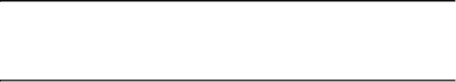
Chapter 6. Shaders and Pipelines
What You’ll Learn in This Chapter
• What a shader is and how it’s used
• The basics of SPIR-V, the Vulkan shading language
• How to construct a shader pipeline and use it to do work
Shaders are small programs that are executed directly on the device. These are the fundamental
building blocks of any complex Vulkan program. Shaders are perhaps more important to the
operation of your program than the Vulkan API itself. This chapter introduces shaders and shader
modules, shows how they are constructed from SPIR-V binaries, and illustrates how those binaries
are generated from GLSL using standard tools. It discusses the construction of pipelines containing
those shaders and other information required to run them, and then shows how to execute the shaders
to do work on the device.
Shaders are the fundamental building blocks of work to be executed on the device. Vulkan shaders
are represented by SPIR-V, which is a binary intermediate representation of program code. SPIR-V
can be generated offline using a compiler, online directly inside your application, or by passing a
high-level language to a library at runtime. The sample applications accompanying this book take the
first approach: compiling the shaders offline and then loading the resulting SPIR-V binaries from
disk.
The original shaders are written in GLSL using the Vulkan profile. This is a modified and enhanced
version of the same shading language used with OpenGL. Most of the examples, therefore, discuss
Vulkan features in terms of their representation in GLSL. However, it should be clear that Vulkan
itself knows nothing of GLSL and doesn’t care where SPIR-V shaders come from.
An Overview of GLSL
Although not officially part of the Vulkan specification, Vulkan shares much of its heritage with
OpenGL. In OpenGL, the officially supported high-level language is GLSL—the OpenGL Shading
Language. Therefore, during the design of SPIR-V, much attention was paid to ensuring that at least
one high-level language would be suitable for use in the generation of SPIR-V shaders. Minor
modifications were made to the GLSL specification for use with Vulkan. Some features were added
to enable GLSL shaders to interact cleanly with the Vulkan system, and legacy features in OpenGL
that were not carried forward into Vulkan were removed from the Vulkan profile of GLSL.
The result is a slimline version of GLSL that supports most of the features of Vulkan while enabling
a high level of portability between OpenGL and Vulkan. In short, if you stick to the modern features
of OpenGL in an OpenGL application, much of what you write in your shaders will compile directly
into SPIR-V using the official reference compiler. Of course, you are free to write your own
compilers and tools or to use a third-party compiler to produce SPIR-V modules from any language
you choose.
The modifications to GLSL to allow it to be used to produce a SPIR-V shader suitable for use with
Vulkan are documented in the GL_KHR_vulkan_glsl extension.

In this section, we provide a brief overview of GLSL. It is assumed that the reader is somewhat
familiar with high-level shading languages in general and is capable of researching GLSL in more
depth if needed.
Listing 6.1 shows the simplest possible GLSL shader. It is simply an empty function, returning
void, that does absolutely nothing. It’s actually a valid shader for any stage in the Vulkan pipeline,
although executing it in some stages would result in some undefined behavior.
Listing 6.1: Simplest Possible GLSL Shader
#version 450 core
void main (void)
{
// Do nothing!
}
All GLSL shaders should begin with a #version directive to inform the GLSL compiler which
version of GLSL we’re using. This allows the compiler to perform appropriate error checks and to
allow certain language constructs that have been introduced over time.
When compiled to SPIR-V for use in Vulkan, a compiler should automatically define VULKAN to the
version of the GL_KHR_vulkan_glsl extension in use such that you can wrap Vulkan-specific
constructs or functionality in your GLSL shader in #ifdef VULKAN or #if VULKAN >
{version} blocks in order to allow the same shaders to be used with OpenGL or Vulkan.
Throughout this book, when Vulkan-specific features are discussed in the context of GLSL, it is
assumed that the code beging written is either exclusively for Vulkan or is wrapped in the appropriate
#ifdef preprocessor conditionals to allow it to be compiled for Vulkan.
GLSL is a C-like language, with its syntax and many of its semantics taken from C or C++. If you are
a C programmer, you should be comfortable with constructs such as for and while loops; flow-
control keywords such as break and continue;switch statements; relational operators such as
==,<, and >; the ternary operator a ? b : c; and so on. All of these are available in GLSL
shaders.
The fundamental data types in GLSL are signed and unsigned integer and floating-point values,
denoted as int,uint, and float, respectively. Double-precision floating-point values are also
supported using the double data type. Inside GLSL, they have no defined bit width, much as in C.
GLSL has no stdint analog, so defining a specific bit width for variables is not supported,
although the GLSL and SPIR-V specifications do provide some minimum guarantees for the range
and precision of numeric representations used by Vulkan. However, bit width and layouts are defined
for variables sourced from and written to memory. Integers are stored in memory in twos-component
form, and floating-point variables follow IEEE conventions wherever possible, aside from minor
differences in precision requirements, handling of denormals and not-a-number (NaN) values, and so
on.
In addition to the basic scalar integer and floating-point data types, GLSL represents short vectors of
up to four components and small matrices of up to 4 × 4 elements as first-class citizens in the
language. Vectors and matrices of the fundamental data types (signed and unsigned integers and
floating-point scalars) can be declared. The vec2,vec3, and vec4 types, for example, are vectors
of two, three, and four floating-point values, respectively. Integer vectors are notated using the ior u
prefixes for signed and unsigned integers, respectively. Thus, ivec4 is a vector of four signed
integers, and uvec4 is a vector of four unsigned integers. The dprefix is used to denote double-
precision floating-point. Thus, dvec4 is a vector of four double-precision floating-point values.
Matrices are written using the form matN or matNxM, representing N×Nsquare matrices and N×M
rectangular matrices, respectively. The dprefix may also be used with matrix data types to form
double-precision matrices. Therefore, dmat4 is a 4 × 4 matrix of double-precision floating-point
values. Matrices of integers, however, are not supported. Matrices are considered to be column-
primary and may be treated as arrays of vectors. Thus, writing m[3] where mis of type mat4 yields
a four-element vector of floating-point values (a vec4) representing the last column of m.
The Boolean type is also a first-class citizen in GLSL and can be formed into vectors (but not
matrices), just like floating-point and integer variables. Boolean variables are written using the bool
type. Relational operators comparing vectors produce vectors of Booleans, with each element
representing one of the comparison results. The special built-in functions any() and all() are
used to produce a single Boolean expressing whether any element of the source vector is true and
whether all of the elements of the source vector are true, respectively.
Data produced by the system is passed into GLSL shaders through built-in variables. Examples are
variables such as gl_FragCoord,gl_VertexIndex, and so on, which will each be introduced
as we reach the relevant parts of Vulkan throughout this book. Built-in variables often have specific
semantics, and reading and writing them can change how a shader behaves.
User-specified data is normally passed into shaders through memory. Variables can be bound together
into blocks, which can then be bound to device-accessible resources backed by memory that your
application can write into. This allows you to pass large amounts of data to shaders. For smaller but
more frequently updated data, special variables called push constants are available and will be
covered later in the book.
GLSL provides a very large number of built-in functions. In contrast to C, however, GLSL has no
header files, and it is not necessary to #include anything. Rather, the GLSL equivalent to a
standard library is automatically provided by the compiler. It includes a large suite of math functions,
functions for accessing textures, and special functions such as flow-control functions that control the
execution of the shader on the device.
An Overview of SPIR-V
SPIR-V shaders are embedded in modules. Each module can contain one or many shaders. Each
shader has an entry point that has a name and a shader type, which is used to define which shading
stage the shader runs in. The entry point is where the shader begins execution when it is run. A SPIR-
V module is passed to Vulkan along with creation information, and Vulkan returns an object
representing that module. The module can then be used to construct a pipeline, which is a fully
compiled version of a single shader along with information required to run it on the device.
Representation of SPIR-V
SPIR-V is the only officially supported shading language for Vulkan. It is accepted at the API-level
and is ultimately used to construct pipelines, which are objects that configure a Vulkan device to do
work for your application.
SPIR-V was designed to be easy for tools and drivers to consume. This improves portability by
reducing the variability between implementations. The native representation of a SPIR-V module is a

stream of 32-bit words stored in memory. Unless you are a tool writer or plan to generate SPIR-V
yourself, it is unlikely that you will deal with the binary encoding of SPIR-V directly. Rather, you
will either look at a textual representation of SPIR-V or generate SPIR-V using a tool such as
glslangvalidator, the official Khronos GLSL compiler.
Saving the shader in Listing 6.1 as a text file with the .comp extension tells glslangvalidator
that the shader is to be compiled as a compute shader. We can then compile this shader using
glslangvalidator with the command line
Click here to view code image
glslangvalidator simple.comp -o simple.spv
This produces a SPIR-V binary named simple.spv. We can disassemble the binary using the
SPIR-V disassembler, spirv-dis, which outputs a human-readable disassembly of the generated
SPIR-V binary. This is shown in Listing 6.2.
Listing 6.2: Simplest SPIR-V
Click here to view code image
; SPIR-V
; Version: 1.0
; Generator: Khronos Glslang Reference Front End; 1
; Bound: 6
; Schema: 0
OpCapability Shader
%1 = OpExtInstImport "GLSL.std.450"
OpMemoryModel Logical GLSL450
OpEntryPoint GLCompute %4 "main"
OpExecutionMode %4 LocalSize 1 1 1
OpSource GLSL 450
OpName %4 "main"
%2 = OpTypeVoid
%3 = OpTypeFunction %2
%4 = OpFunction %2 None %3
%5 = OpLabel
OpReturn
OpFunctionEnd
You can see that the text form of SPIR-V looks like a strange dialect of assembly language. We can
step through this disassembly and see how it relates to the original input. Each line of the output
assembly represents a single SPIR-V instruction, possibly made up of multiple tokens.
The first instruction in the stream, OpCapability Shader, requests that the Shader capability
be turned on. SPIR-V functionality is roughly divided into related groups of instructions and features.
Before your shader can use any of these features, it must declare that it will be using the capability of
which the feature is part. The shader in Listing 6.2 is a graphics shader and therefore uses the
Shader capability. This is the most fundamental capability. Without this, we cannot compile
graphics shaders. As we introduce more SPIR-V and Vulkan functionality, we will introduce the
various capabilities that each feature depends on.
Next, we see %1 = OpExtInstImport "GLSL.std.450". This is essentially importing an
additional set of instructions corresponding to the functionality included in GLSL version 450, which
is what the original shader was written in. Notice that this instruction is preceeded by %1 =. This
names the result of the instruction by assigning it an ID. The result of OpExtInstImport is
effectively a library. When we want to call functions in this library, we do so using the OpExtInst
instruction, which takes both a library (the result of the OpExtInstImport instruction) and an
instruction index. This allows the SPIR-V instruction set to be arbitrarily extended.
Next, we see some additional declarations. OpMemoryModel specifies the working memory model
for this module, which in this case is the logical memory model corresponding to GLSL version 450.
This means that all memory access is performed through resources rather than a physical memory
model, which accesses memory through pointers.
Next is the declaration of an entry point in the module. The OpEntryPoint GLCompute %4
"main" instruction means that there is an available entry point corresponding to an OpenGL
compute shader, with ID 4 exported with the function name main. This name is used to reference the
entry point when we hand the resulting shader module back to Vulkan.
We use this ID in the subsequent instruction, OpExecutionMode %4 LocalSize 1 1 1,
which defines the execution group size of this shader to be 1 × 1 × 1 work item. This is implicit in
GLSL if the local size layout qualifier is not present.
The next two instructions are simply informational. OpSource GLSL 450 indicates that the
module was compiled from GLSL version 450, and OpName 4 "main" provides a name for the
token with ID 4.
Now we see the real meat of the function. First, %2 = OpTypeVoid declares that we want to use
ID 2 as the type void. Everything in SPIR-V has an ID, even type definitions. Large, aggregate
types can be built up by referencing sequentially smaller, simpler types. However, we need to start
from somewhere, and assigning a type to void is where we’re starting.
%3 = OpTypeFunction %2 means that we’re defining ID 3 as a function type taking void
(previously declared as ID 2) and taking no parameters. We use this in the following line, %4 =
OpFunction %2 None %3. This means that we’re declaring ID 4 (which we previously named
"main") to be an instance of the function 3 (declared in the line above), returning void (as ID 2),
and having no particular decarations. This is indicated by None in the instructions and can be used
for things like inlining, whether the variable is constant (its constness), and so on.
Finally, we see the declaration of a label (which is unused and only a side effect of the way the
compiler operates), the implicit return statement, and eventually the end of the function. This is the
end of our SPIR-V module.
The complete binary dump of the shader is 192 bytes long. SPIR-V is quite verbose, as 192 bytes is
quite a bit longer than the original shader. However, SPIR-V makes explicit some of the things that
are implicit in the original shading language. For example, declaring a memory model is not
necessary in GLSL because it supports only a logical memory model. Further, there is some
redundancy in the SPIR-V module as compiled here; we don’t care about the name of the main
function, the label with ID 5 is never actually used, and the shader imports the GLSL.std.450
library but never actually uses it. It is possible to strip such unneeded instructions from a module.
Even after this, because SPIR-V is relatively sparsely encoded, the resulting binaries are fairly easy

to compress with even a generic compressor and probably significantly more compressible with a
specialized compression library.
All SPIR-V code is written in SSA (single static assignment) form, which means that every virtual
register (the tokens written as %n in the listing above) are written exactly once. Almost every
instruction that does work produces a result identifier. As we progress to more complex shaders, you
will see that machine-generated SPIR-V is somewhat unwieldy, and because of its verbosity and
enforced SSA form, it is quite difficult to write by hand. It is strongly recommended that you use a
compiler to generate SPIR-V offline or online by using the compiler as a library that your application
can link to.
If you do plan to generate or interpret SPIR-V modules yourself, you can use the defined binary
encoder to build tools to parse or create them. However, they have a well-defined binary storage
format that is explained later in this chapter.
All SPIR-V modules begin with a magic number that can be used to weakly validate that the binary
blob is, in fact, a SPIR-V module. This magic number is 0x07230203 when viewed as a native
unsigned integer. This number can also be used to deduce the endianness of the module. Because
each SPIR-V token is a 32-bit word, if a SPIR-V module is passed by disk or network to a host of a
different endianness, the bytes within the word are swapped, and its value is changed. For example, if
a SPIR-V module stored in little-endian format is loaded by a big-endian host, the magic number will
be read as 0x03022307, so the host knows to swap the byte order of the words in the module.
Following the magic number are several more words that describe properties of the module. First is
the version number of SPIR-V used in the module. This is encoded using the bytes of the 32-bit word
where bits 16 through 23 contain the major version and bits 8 through 15 contain the minor version.
SPIR-V 1.0 therefore uses the encoding 0x00010000. The remaining bits in the version number are
reserved. Next is a token containing the version of the tool that generated the SPIR-V module. This
value is tool-dependent.
Next is the maximum number of IDs used in the module. All variables, functions, and other
components of the SPIR-V module are assigned an ID less than this number, so including it up front
allows tools consuming SPIR-V to allocate arrays of data structures to hold them in rather than
allocating those structures on the fly. The last word in the header is reserved and should be set to
zero. Following this is the stream of instructions.
Handing SPIR-V to Vulkan
Vulkan doesn’t care too much where the SPIR-V shaders and modules come from. Typically, they
will be compiled offline as part of building your application, compiled using an online compiler, or
generated directly in your application. Once you have a SPIR-V module, you need to hand it to
Vulkan so that a shader module object can be created from it. To do this, call
vkCreateShaderModule(), the prototype of which is
Click here to view code image
VkResult vkCreateShaderModule (
VkDevice device,
const VkShaderModuleCreateInfo* pCreateInfo,
const VkAllocationCallbacks* pAllocator,
VkShaderModule* pShaderModule);

As with all Vulkan object creation functions, vkCreateShaderModule() takes a device handle
as input along with a pointer to a structure containing a descrtiption of the object being created. In
this case, this is a VkShaderModuleCreateInfo structure, the definition of which is
Click here to view code image
typedef struct VkShaderModuleCreateInfo {
VkStructureType sType;
const void* pNext;
VkShaderModuleCreateFlags flags;
size_t codeSize;
const uint32_t* pCode;
} VkShaderModuleCreateInfo;
The sType field of VkShaderModuleCreateInfo should be set to
VK_STRUCTURE_TYPE_SHADER_MODULE_CREATE_INFO, and pNext should be set to
nullptr. The flags field is reserved for future use and should be set to zero. The codeSize
field contains the size of the SPIR-V module in bytes, the code for which is passed in pCode.
If the SPIR-V code is valid and understood by Vulkan, then vkCreateShaderModule() will
return VK_SUCCESS and place a handle to a new shader module in the variable pointed to by
pShaderModule. You can then use the shader module to create pipelines, which are the final form
of the shader used to do work on the device.
Once you are done with a shader module, you should destroy it to free its resources. This is
performed by calling vkDestroyShaderModule(), the prototype of which is
Click here to view code image
void vkDestroyShaderModule (
VkDevice device,
VkShaderModule shaderModule,
const VkAllocationCallbacks* pAllocator);
A handle to the device that owns the shader module should be passed in device, and the shader
module to be destroyed should be passed in shaderModule. Access to the shader module must be
externally synchronized. No other access to the shader module needs to be externally synchronized.
In particular, it is possible to use the same shader module to create multiple pipelines in parallel, as
discussed in the next section. Your application only needs to ensure that the shader module is not
destroyed while there are Vulkan commands executing on other threads that might access the same
module.
After the module has been destroyed, its handle is immediately invalidated. However, pipelines
created using the module remain valid until they are destroyed. If a host memory allocator was used
when the shader module was created, then a pointer to a compatible allocator should be passed in
pAllocator; otherwise, pAllocator should be set to nullptr.

Pipelines
As you read in the previous sections, Vulkan uses shader modules to represent collections of shaders.
Shader modules are created by handing the module code to vkCreateShaderModule(), but
before they can be used to do useful work on the device, you need to create a pipeline. There are two
types of pipeline in Vulkan: compute and graphics. The graphics pipeline is rather complex and
contains a lot of state unrelated to shaders. However, a compute pipeline is conceptually much
simpler and contains essentially nothing but the shader code itself.
Compute Pipelines
Before we discuss creating a compute pipeline, we should cover the basics of compute shaders in
general. The shader and its execution are the core of Vulkan. Vulkan also provides access to various
fixed blocks of functionality for performing things such as copying data around and processing pixel
data. However, the shader will form the core of any nontrivial application.
The compute shader provides raw access to the compute capabilities of the Vulkan device. The
device can be seen as a collection of wide vector processing units that operate on related pieces of
data. A compute shader is written as though it were a serial, single track of execution. However, there
are hints that many such tracks of execution may run together. This is, in fact, how most Vulkan
devices are constructed. Each track of execution is known as an invocation.
When a compute shader is executed, many invocations are started at once. The invocations are
grouped into local work groups of fixed size, and then one or more such groups are launched together
in what is sometimes known as a global work group. Logically, both the local and global work groups
are three-dimensional. However, setting the size of any one of the three dimensions to one reduces
the dimensionality of the group.
The size of the local work group is set in the compute shader. In GLSL, this is done using a layout
qualifier, which is translated to the LocalSize decoration on the OpExecutionMode declaration
in the SPIR-V shader passed to Vulkan. Listing 6.3 shows the size declaration applied to a GLSL
shader, and Listing 6.4 shows the resulting SPIR-V disassembly, truncated for clarity.
Listing 6.3: Local Size Declaration in a Compute Shader (GLSL)
Click here to view code image
#version 450 core
layout (local_size_x = 4, local_size_y = 5, local_size_z 6) in;
void main(void)
{
// Do nothing.
}
Listing 6.4: Local Size Declaration in a Compute Shader (SPIR-V)
Click here to view code image
...
OpCapability Shader
%1 = OpExtInstImport "GLSL.std.450"

OpMemoryModel Logical GLSL450
OpEntryPoint GLCompute %4 "main"
OpExecutionMode %4 LocalSize 4 5 6
OpSource GLSL 450
...
As you can see, the OpExecutionMode instruction in Listing 6.4 sets the local size of the shader
to {4, 5, 6} as specified in Listing 6.3.
The maximum local work group size for a compute shader is generally fairly small and is required
only to be at least 128 invocations in the xand ydimensions and 64 invocations in the zdimension.
Further, the total “volume” of the work group (the product of the limit in x,y, and zdirections) is
subject to a further limit, which is required only to be at least 128 invocations. Although many
implementations support higher limits, you should always query those limits if you want to exceed
the required minimums.
The maximum size of a work group can be determined from the maxComputeWorkGroupSize
field of the VkPhysicalDeviceLimits structure returned from a call to
vkGetPhysicalDeviceProperties(), as explained in Chapter 1, “Overview of Vulkan.”
Further, the maximum total number of invocations in the local work group is contained in the
maxComputeWorkGroupInvocations field of the same structure. An implementation will
likely reject a SPIR-V shader that exceeds any of those limits, although behavior can technically be
undefined in this case.
Creating Pipelines
To create one or more compute pipelines, call vkCreateComputePipelines(), the prototype
of which is
Click here to view code image
VkResult vkCreateComputePipelines (
VkDevice device,
VkPipelineCache pipelineCache,
uint32_t createInfoCount,
const VkComputePipelineCreateInfo* pCreateInfos,
const VkAllocationCallbacks* pAllocator,
VkPipeline* pPipelines);
The device parameter to vkCreateComputePipelines() is the device with which the
pipelines will be used and is responsible for allocating the pipeline objects. pipelineCache is a
handle to an object that can be used to accelerate the creation of pipeline objects and is covered later
in this chapter. The parameters for the creation of each new pipeline is represented by an instance of
the VkComputePipelineCreateInfo structure. The number of structures (and therefore the
number of pipelines to create) is passed in createInfoCount, and the address of an array of these
structures is passed in pCreateInfos. The definition of VkComputePipelineCreateInfo
is
Click here to view code image
typedef struct VkComputePipelineCreateInfo {
VkStructureType sType;
const void* pNext;

VkPipelineCreateFlags flags;
VkPipelineShaderStageCreateInfo stage;
VkPipelineLayout layout;
VkPipeline basePipelineHandle;
int32_t basePipelineIndex;
} VkComputePipelineCreateInfo;
The sType field of VkComputePipelineCreateInfo should be set to
VK_STRUCTURE_TYPE_COMPUTE_PIPELINE_CREATE_INFO, and pNext should be set to
nullptr. The flags field is reserved for future use, and in the current version of Vulkan, it should
be set to zero. The stage field is an embedded structure containing information about the shader
itself and is an instance of the VkPipelineShaderStageCreateInfo structure, the definition
of which is
Click here to view code image
typedef struct VkPipelineShaderStageCreateInfo {
VkStructureType sType;
const void* pNext;
VkPipelineShaderStageCreateFlags flags;
VkShaderStageFlagBits stage;
VkShaderModule module;
const char* pName;
const VkSpecializationInfo* pSpecializationInfo;
} VkPipelineShaderStageCreateInfo;
The sType for VkPipelineShaderStageCreateInfo is
VK_STRUCTURE_TYPE_PIPELINE_SHADER_STAGE_CREATE_INFO, and pNext should be
set to nullptr. The flags field is reserved in the current version of Vulkan and should be set to
zero.
The VkPipelineShaderStageCreateInfo structure is used for all stages of pipeline
creation. Although graphics pipelines have multiple stages (which you’ll learn about in Chapter 7,
“Graphics Pipelines”), compute pipelines have only a single stage, and therefore stage should be
set to VK_SHADER_STAGE_COMPUTE_BIT.
module is the handle to the shader module you created earlier; it contains the shader code for the
compute pipeline you want to create. Because a single shader module can contain multiple entry
points and ultimately many shaders, the entry point that represents this particular pipeline is specified
in the pName field of VkPipelineShaderStageCreateInfo. This is one of the few instances
where human-readable strings are used in Vulkan.
Specialization Constants
The final field in VkPipelineShaderStageCreateInfo is a pointer to an instance of the
VkSpecializationInfo structure. This structure contains the information required to specialize
a shader, which is the process of building a shader with some of its constants compiled in.
A typical Vulkan implementation will delay final code generation for pipelines until
vkCreateComputePipelines() is called. This allows the values of specialization constants to
be considered during the final passes of optimization over the shader. Typical uses and applications
of specialization constants include

• Producing special cases through branching: Including a condition on a Boolean specialization
constant will result in the final shader taking only one branch of the if statement. The nontaken
branch will probably be optimized away. If you have two similar versions of a shader that differ
in only a couple of places, this is a good way to merge them into one.
• Special cases through switch statements: Likewise, using an integer specialization constant as
the tested variable in a switch statement will result in only one of the cases ever being taken in
that particular pipeline. Again, most Vulkan implementations will optimize out all the never-
taken cases.
• Unrolling loops: Using an integer specialization constant as the iteration count in a for loop
may result in the Vulkan implementation making better decisions about how to unroll the loop
or whether to unroll it at all. For example, if the loop counter ends up with a value of 1, then the
loop goes away and its body becomes straight-line code. A small loop iteration count might
result in the compiler unrolling the loop exactly that number of times. A larger iteration count
may result in the compiler unrolling the loop by a factor of the count and then looping over that
unrolled section a smaller number of times.
• Constant folding: Subexpressions involving specialization constants can be folded just as with
any other constant. In particular, expressions involving multiple specialization constants may
fold into a single constant.
• Operator simplification: Trivial operations such as adding zero or multiplying by one disappear,
multiplying by negative one can be absorbed into additions turning them to subtractions,
multiplying by small integers such as two can be turned into additions or even absorbed into
other operations, and so on.
In GLSL, a specialization constant is declared as a regular constant that is given an ID in a layout
qualifier. Specialization constants in GLSL can be Booleans, integers, floating-point values, or
composites such as arrays, structures, vectors, or matrices. When translated to SPIR-V, these become
OpSpecConstant tokens. Listing 6.5 shows an example GLSL declaration of some specialization
constants, and Listing 6.6 shows the resulting SPIR-V produced by the GLSL compiler.
Listing 6.5: Specialization Constants in GLSL
Click here to view code image
layout (constant_id = 0) const int numThings = 42;
layout (constant_id = 1) const float thingScale = 4.2f;
layout (constant_id = 2) const bool doThat = false;
Listing 6.6: Specialization Constants in SPIR-V
Click here to view code image
...
OpDecorate %7 SpecId 0
OpDecorate %9 SpecId 1
OpDecorate %11 SpecId 2
%6 = OpTypeInt 32 1
%7 = OpSpecConstant %6 42
%8 = OpTypeFloat 32
%9 = OpSpecConstant %8 4.2

%10 = OpTypeBool
%11 = OpSpecConstantFalse %10
...
Listing 6.6 has been edited to remove portions unrelated to the specialization constants. As you can
see, however, %7 is declared as a specialization constant using OpSpecConstant of type %6 (a
32-bit integer) with a default value of 42. Next, %9 is declared as a specialization constant of type %8
(a 32-bit floating-point value) with a default value of 4.2. Finally, %11 is decalared as a Boolean
value (type %10 in this SPIR-V) with a default value of false. Note that Booleans are declared
with either OpSpecConstantTrue or OpSpecConstantFalse, depending on whether their
default value is true or false, respectively.
Note that in both the GLSL shader and the resulting SPIR-V shader, the specialization constants are
assigned default values. In fact, they must be assigned default values. These constants may be used
like any other constant in the shader. In particular, they can be used for things like sizing arrays
where only compile-time constants are otherwise allowed. If new values are not included in the
VkSpecializationInfo structure passed to vkCreateComputePipelines(), then those
default values are used. However, the constants can be overridden by passing new values when the
pipeline is created. The definition of VkSpecializationInfo is
Click here to view code image
typedef struct VkSpecializationInfo {
uint32_t mapEntryCount;
const VkSpecializationMapEntry* pMapEntries;
size_t dataSize;
const void* pData;
} VkSpecializationInfo;
Inside the VkSpecializationInfo structure, mapEntryCount contains the number of
specialization constants that are to be set, and this is the number of entries in the array of
VkSpecializationMapEntry structures in the array pointed to by pMapEntries. Each of
these represents a single specialization constant. The definition of
VkSpecializationMapEntry is
Click here to view code image
typedef struct VkSpecializationMapEntry {
uint32_t constantID;
uint32_t offset;
size_t size;
} VkSpecializationMapEntry;
The constantID field is the ID of the specialization constant and is used to match the constant ID
used in the shader module. This is set using the constant_id layout qualifier in GLSL and the
SpecId decoration in SPIR-V. The offset and size fields are the offset and size of the raw data
containing the values of the specicialization constants. The raw data is pointed to by pData field of
the VkSpecializationInfo structure, and its size is given in dataSize. Vulkan uses the data
in this blob to initialize the specialization constants. If one or more of the specialization constants in
the shader is not specified in the specialization info when the pipeline is constructed, its default value
is used.

When you are done with a pipeline and no longer need it, you should destroy it in order to free any
resources associated with it. To destroy a pipeline object, call vkDestroyPipeline(), the
prototype of which is
Click here to view code image
void vkDestroyPipeline (
VkDevice device,
VkPipeline pipeline,
const VkAllocationCallbacks* pAllocator);
The device that owns the pipeline is specified in device, and the pipeline to be destroyed is passed
in pipeline. If a host memory allocator was used to create the pipeline, a pointer to a compatible
allocator should be passed in pAllocator; otherwise, pAllocator should be set to nullptr.
After a pipeline has been destroyed, it should not be used again. This includes any references to it
from command buffers that may not yet have completed execution. It is the application’s
responsibility to ensure that any submitted command buffers referencing the pipeline have completed
execution and that any command buffers into which the pipeline is bound are not submitted after the
pipeline is destroyed.
Accelerating Pipeline Creation
Creation of pipelines is possibly one of the most expensive operations that your application might
perform. Although SPIR-V code is consumed by vkCreateShaderModule(), it is not until you
call vkCreateGraphicsPipelines() or vkCreateComputePipelines() that Vulkan
sees all of the shader stages and other state associated with the pipeline that might affect the final
code that will execute on the device. For this reason, a Vulkan implementation may delay the
majority of work involved in creating a ready-to-run pipeline object until the last possible moment.
This includes shader compilation and code generation, which are typically fairly intensive operations.
Because an application that runs many times will use the same pipelines over and over, Vulkan
provides a mechanism to cache the results of pipeline creation across runs of an application. This
allows applications that build all of their pipelines at startup to start more quickly. The pipeline cache
is represented as an object that is created by calling
Click here to view code image
VkResult vkCreatePipelineCache (
VkDevice device,
const VkPipelineCacheCreateInfo* pCreateInfo,
const VkAllocationCallbacks * pAllocator,
VkPipelineCache* pPipelineCache);
The device that will be used to create the pipeline cache is specified in device. The remaining
parameters for the creation of the pipeline cache are passed through a pointer to an instance of the
VkPipelineCacheCreateInfo structure, the definition of which is
Click here to view code image
typedef struct VkPipelineCacheCreateInfo {
VkStructureType sType;
const void * pNext;
VkPipelineCacheCreateFlags flags;

size_t initialDataSize;
const void * pInitialData;
} VkPipelineCacheCreateInfo;
The sType field of the VkPipelineCacheCreateInfo structure should be set to
VK_STRUCTURE_TYPE_PIPELINE_CACHE_CREATE_INFO, and pNext should be set to
nullptr. The flags field is reserved for future use and should be set to zero. If existing data is
available from a previous run of the application, its address can be passed through pInitialData.
The size of the data is passed in initialDataSize. If no initial data is available,
initialDataSize should be set to zero, and pInitialData should be set to nullptr.
When the cache is created, the initial data (if any) is used to prime the cache. If necessary, Vulkan
makes a copy of the data. The data pointed to by pInitialData is not modified. As more
pipelines are created, data describing them may be added to the cache, growing it over time. To
retrieve the data from the cache, call vkGetPipelineCacheData(). The prototype of
vkGetPipelineCacheData() is
Click here to view code image
VkResult vkGetPipelineCacheData (
VkDevice device,
VkPipelineCache pipelineCache,
size_t* pDataSize,
void* pData);
The device that owns the pipeline cache should be specified in device, and the handle to the
pipeline cache whose data is being queried should be passed in pipelineCache. If pData is not
nullptr, then it points to a region of memory that will receive the cache data. In this case, the
initial value of the variable pointed to by pDataSize is the size, in bytes, of this region of memory.
That variable will be overwritten with the amount of data actually written into memory.
If pData is nullptr, then the initial value of the variable pointed to by pDataSize is ignored,
and the variable is overwritten with the size of the data required to store the cache. In order to store
the entire cache data, call vkGetPipelineCacheData() twice; the first time, call it with
pData set to nullptr and pDataSize pointing to a variable that will receive the required size of
the cache data. Then size a buffer appropriately to store the resulting cache data and call
vkGetPipelineCacheData() again, this time passing a pointer to this memory region in
pData.Listing 6.7 illustrates how to save the pipeline data to a file.
Listing 6.7: Saving Pipeline Cache Data to a File
Click here to view code image
VkResult SaveCacheToFile(VkDevice device, VkPipelineCache cache,
const char* fileName)
{
size_t cacheDataSize;
VkResult result = VK_SUCCESS;
// Determine the size of the cache data.
result = vkGetPipelineCacheData(device,
cache,

&cacheDataSize,
nullptr);
if (result == VK_SUCCESS && cacheDataSize != 0)
{
FILE* pOutputFile;
void* pData;
// Allocate a temporary store for the cache data.
result = VK_ERROR_OUT_OF_HOST_MEMORY;
pData = malloc(cacheDataSize);
if (pData != nullptr)
{
// Retrieve the actual data from the cache.
result = vkGetPipelineCacheData(device,
cache,
&cacheDataSize,
pData);
if (result == VK_SUCCESS)
{
// Open the file and write the data to it.
pOutputFile = fopen(fileName, "wb");
if (pOutputFile != nullptr)
{
fwrite(pData, 1, cacheDataSize, pOutputFile);
fclose(pOutputFile);
}
free(pData);
}
}
}
return result;
}
Once you have received the pipeline data, you can store it to disk or otherwise archive it ready for a
future run of your application. There is no defined structure to the content of the cache; it is
implementation-dependent. However, the first few words of the cache data always form a header that
can be used to verify that a blob of data is a valid cache and which device created it.
The layout of the cache header can be represented as the following C structure:
Click here to view code image
// This structure does not exist in official headers but is included here
// for illustration.
typedef struct VkPipelineCacheHeader {
uint32_t length;
uint32_t version;
uint32_t vendorID;

uint32_t deviceID;
uint8_t uuid[16];
} VkPipelineCacheHeader;
Although the members of the structure are listed as uint32_t typed variables, the data in the cache
is not formally of type uint32_t. Caches are always stored in little-endian byte order, regardless of
the byte ordering of the host. This means that if you want to interpret this structure on a big-endian
host, you need to reverse the byte order of the uint32_t fields.
The length field is the size of the header structure, in bytes. In the current revision of the
specification, this length should be 32. The version field is the version of the structure. The only
defined version is 1. The vendorID and deviceID fields should match the vendorID and
deviceID fields of the VkPhysicalDeviceProperties structure returned from a call to
vkGetPhysicalDeviceProperties(). The uuid field is an opaque string of bytes that
uniquely identifies the device. If there is a mismatch between the vendorID,deviceID, or uuid
field and what the Vulkan driver expects, it may reject the cache data and reset the cache to empty. A
driver may also embed checksum, encryption, or other data inside the cache to ensure that invalid
cache data is not loaded into the device.
If you have two cache objects and wish to merge them, you can do that by calling
vkMergePipelineCaches(), the prototype of which is
Click here to view code image
VkResult vkMergePipelineCaches (
VkDevice device,
VkPipelineCache dstCache,
uint32_t srcCacheCount,
const VkPipelineCache* pSrcCaches);
The device parameter is a handle to the device that owns the caches that are to be merged.
dstCache is a handle to the destination cache, which will end up as an amalgamation of all of the
entries from all source caches. The number of caches that are to be merged is specified in
srcCacheCount, and pSrcCaches is a pointer to an array of VkPipelineCache handles to
the caches to be merged.
After vkMergePipelineCaches() has executed, dstCache will contain all of the cache
entries from all of the source caches specified in pSrcCaches. It is then possible to call
vkGetPipelineCacheData() on the destination cache to retrieve a single, large cache data
structure representing all entries from all of the caches.
This is particularly useful, for example, when creating pipelines in many threads. Although access to
the pipeline cache is thread-safe, implementations may internally take locks to prevent concurrent
write access to multiple caches. If you instead create multiple pipeline caches—one for each
thread—and use them during initial creation of your pipelines, any per-cache locks taken by the
implementation will be uncontested, speeding access to them. Later, when all pipelines are created,
you can merge the pipelines in order to save their data in one large resource.
When you are done creating pipelines and no longer need the cache, it’s important to destroy it,
because it could be quite large. To destroy a pipeline cache object, call
vkDestroyPipelineCache(), the prototype of which is

Click here to view code image
void vkDestroyPipelineCache (
VkDevice device,
VkPipelineCache pipelineCache,
const VkAllocationCallbacks* pAllocator);
device is a handle to the device that owns the pipeline cache, and pipelineCache is a handle to
the pipeline cache object that is to be destroyed. After the pipeline cache has been destroyed, it
should not be used again, although pipelines created using the cache are still valid. Also, any data
retrieved from the cache using a call to vkGetPipelineCacheData() is valid and can be used
to construct a new cache that should result in matches on subsequent pipeline creation requests.
Binding Pipelines
Before you can use a pipeline, it must be bound into the a command buffer that will execute drawing
or dispatching commands. When such a command is executed, the current pipeline (and all the
shaders in it) are used to process the commands. To bind a pipeline to a command buffer, call
vkCmdBindPipeline(), the prototype of which is
Click here to view code image
void vkCmdBindPipeline (
VkCommandBuffer commandBuffer,
VkPipelineBindPoint pipelineBindPoint,
VkPipeline pipeline);
The command buffer to which you are binding the pipeline is specified in commandBuffer, and
the pipeline you are binding is specified in pipeline. There are two binding points for pipelines on
each command buffer: the graphics and compute binding points. The compute bind point is where
compute pipelines should be bound. Graphics pipelines are covered in the next chapter and should be
bound to the graphics pipeline bind point.
To bind a pipeline to the compute binding point, set pipelineBindPoint to
VK_PIPELINE_BIND_POINT_COMPUTE, and to bind the pipeline to the graphics binding point,
set pipelineBindPoint to VK_PIPELINE_BIND_POINT_GRAPHICS.
The current pipeline binding for each of compute and graphics is part of the state of a command
buffer. When a new command buffer is begun, this state is undefined. Therefore, you must bind a
pipeline to the relevant binding point before invoking any work that would use a pipeline.
Executing Work
In the previous section, you saw how to construct a compute pipeline using
vkCreateComputePipelines() and bind it into a command buffer. Once a pipeline is bound,
you can use it to execute work.
Compute shaders running as part of a compute pipeline execute in groups called local work groups.
These groups logically execute in lockstep and are of a fixed size specified in the shader. The
maximum size of a local work group is typically small but must be at least 128 invocations × 128
invocations × 64 invocations. Further, the maximum number of total invocations in a single local
work group may also be smaller than this total volume and is required only to be 128 invocations.

For this reason, local work groups are started in larger groups, sometimes called the global work
group or dispatch size. Kicking off work in a compute shader is therefore called dispatching work, or
adispatch. The local work group is logically a 3D construct, or volume of invocations, although one
or two of the dimensions can be a single invocation in size, making the work group flat in that
direction. Likewise, these local work groups are dispatched together in three dimensions, even if one
or more of those dimensions is a single work group deep.
The command to dispatch a global work group using a compute pipeline is vkCmdDispatch(),
the prototype of which is
Click here to view code image
void vkCmdDispatch (
VkCommandBuffer commandBuffer,
uint32_t x,
uint32_t y,
uint32_t z);
The command buffer that will execute the command is passed in commandBuffer. The number of
local work groups in each of the x,y, and zdimensions is passed in the x,y, and zparameters,
respectively. A valid compute pipeline must be bound to the command buffer at the
VK_PIPELINE_BIND_POINT_COMPUTE binding point. When the command is executed by the
device, a global work group of x×y×zlocal work groups begins executing the shader contained in
the bound pipeline.
It is perfectly possible to have a local work group that has a different effective dimensionality from
that of the global work group. For example, it’s fine to have a 32 × 32 × 1 dispatch of 64 × 1 × 1 local
work groups.
In addition to being able to specify the number of work groups in the dispatch using parameters to
vkCmdDispatch(), it’s possible to perform an indirect dispatch, where the size of the dispatch in
work groups is sourced from a buffer object. This allows dispatch sizes to be computed after a
command buffer is built by performing an indirect dispatch using a buffer and then overwriting the
contents of the buffer using the host. The content of the buffer can even be updated using the device
itself to provide a limited means for the device to feed itself work.
The prototype of vkCmdDispatchIndirect() is
Click here to view code image
void vkCmdDispatchIndirect (
VkCommandBuffer commandBuffer,
VkBuffer buffer,
VkDeviceSize offset);
Again, the command buffer that will contain the command is passed in commandBuffer. Rather
than passing the dispatch size as in vkCmdDispatch(), the number of workgroups in each
dimension are expected to be stored as three consecutive uint32_tvariables at the offset specified
in offset (in bytes) in the buffer object specified in buffer. The parameters in the buffer
essentially represent an instance of the VkDispatchIndirectCommand structure, the definition
of which is

Click here to view code image
typedef struct VkDispatchIndirectCommand {
uint32_t x;
uint32_t y;
uint32_t z;
} VkDispatchIndirectCommand;
Again, the contents of the buffer are not read until the vkCmdDispatchIndirect() command is
reached during processing of the command buffer by the device.
The maximum number of work groups in each dimension supported by a device can be determined
by inspecting the maxComputeWorkGroupCount field of the device’s
VkPhysicalDeviceLimits structure returned from a call to
vkGetPhysicalDeviceProperties(), as explained in Chapter 1, “Overview of Vulkan.”
Exceeding those limits in a call to vkCmdDispatch() or placing values outside those limits in the
buffer referenced by vkCmdDispatchIndirect() will result in undefined (probably bad)
behavior.
Resource Access in Shaders
The shaders in your program consume and produce data in one of two ways. The first is through
interaction with fixed function hardware, and the second is by directly reading and writing resources.
You saw in Chapter 2, “Memory and Resources,” how to create buffers and images. In this section,
we introduce descriptor sets, which are representations of the set of resources that shaders can
interact with.
Descriptor Sets
A descriptor set is a set of resources that are bound into the pipeline as a group. Multiple sets can be
bound to a pipeline at a time. Each set has a layout, which describes the order and types of resources
in the set. Two sets with the same layout are considered to be compatible and interchangeable. The
descriptor set layout is represented by an object, and sets are created with respect to this object.
Further, the set of sets that are accessible to a pipeline are grouped into another object: the pipeline
layout. Pipelines are created with respect to this pipeline layout object.
The relationship between the descriptor set layout and the pipeline layout is illustrated in Figure 6.1.
As you can see in the figure, two descriptor sets are defined, the first having a texture, a sampler, and
two buffers. The second set contains four textures, two samplers, and three buffers. These descriptor
sets’ layouts are aggregated into a single pipeline layout. A pipeline can then be created with respect
to the pipeline layout, while descriptor sets are created with respect to descriptor set layouts. Those
descriptor sets can be bound into command buffers along with compatible pipelines to allow those
pipelines to access the resources in them.
Figure 6.1: Descriptor Sets and Pipeline Sets
At any time, the application can bind a new descriptor set to the command buffer in any point that has
an identical layout. The same descriptor set layouts can be used to create multiple pipelines.
Therefore, if you have a set of objects that share a common set of resources, but additionally each
require some unique resources, you can leave the common set bound and replace the unique
resources as your application moves through the objects that need to be rendered.
To create a descriptor set layout object, call vkCreateDescriptorSetLayout(), the
prototype of which is
Click here to view code image
VkResult vkCreateDescriptorSetLayout (
VkDevice device,
const VkDescriptorSetLayoutCreateInfo* pCreateInfo,
const VkAllocationCallbacks* pAllocator,
VkDescriptorSetLayout* pSetLayout);
As usual, the information required to construct the descriptor set layout object is passed through a
pointer to a structure. This is an instance of the VkDescriptorSetLayoutCreateInfo
structure, the definition of which is

Click here to view code image
typedef struct VkDescriptorSetLayoutCreateInfo {
VkStructureType sType;
const void* pNext;
VkDescriptorSetLayoutCreateFlags flags;
uint32_t bindingCount;
const VkDescriptorSetLayoutBinding* pBindings;
} VkDescriptorSetLayoutCreateInfo;
The sType field of VkDescriptorSetLayoutCreateInfo should be set to
VK_STRUCTURE_TYPE_DESCRIPTOR_SET_LAYOUT_CREATE_INFO, and pNext should be
set to nullptr.flags is reserved for future use and should be set to zero.
Resources are bound to binding points in the descriptor set. The bindingCount and pBindings
members of VkDescriptorSetLayoutCreateInfo contain the number of binding points that
the set will contain and a pointer to an array containing their descriptions, respectively. Each binding
is described by an instance of the VkDescriptorSetLayoutBinding structure, the definition
of which is
Click here to view code image
typedef struct VkDescriptorSetLayoutBinding {
uint32_t binding;
VkDescriptorType descriptorType;
uint32_t descriptorCount;
VkShaderStageFlags stageFlags;
const VkSampler* pImmutableSamplers;
} VkDescriptorSetLayoutBinding;
Each resource accessible to a shader is given a binding number. This binding number is stored in the
binding field of VkDescriptorSetLayoutBinding. The bindings used in a descriptor set
do not need to be contiguous, and there can be gaps (unused binding numbers) in a set. However, it’s
recommended that you don’t create sparsely populated sets because this can waste resources in the
device.
The type of descriptor at this binding point is stored in descriptorType. This a member of the
VkDescriptorType enumeration. We’ll discuss the various resource types a little later, but they
include
•VK_DESCRIPTOR_TYPE_SAMPLER: A sampler is an object that can be used to perform
operations such as filtering and sample coordinate transformations when reading data from an
image.
•VK_DESCRIPTOR_TYPE_SAMPLED_IMAGE: A sampled image is an image that can be used
in conjunction with a sampler to provide filtered data to a shader.
•VK_DESCRIPTOR_TYPE_COMBINED_IMAGE_SAMPLER: A combined image-sampler
object is a sampler and an image paired together. The same sampler is always used to sample
from the image, which can be more efficient on some architectures.
•VK_DESCRIPTOR_TYPE_STORAGE_IMAGE: A storage image is an image that cannot be
used with a sampler but can be written to. This is in contrast to a sampled image, which cannot
be written to.

•VK_DESCRIPTOR_TYPE_UNIFORM_TEXEL_BUFFER: A uniform texel buffer is a buffer
that is filled with homogeneous formatted data that cannot be written by shaders. Knowing that
buffer content is constant may allow some Vulkan implementations to optimize access to the
buffer better.
•VK_DESCRIPTOR_TYPE_STORAGE_TEXEL_BUFFER: A storage texel buffer is a buffer
that contains formatted data much like a uniform texel buffer, but a storage buffer can be written
to.
•VK_DESCRIPTOR_TYPE_UNIFORM_BUFFER and
VK_DESCRIPTOR_TYPE_STORAGE_BUFFER: These are similar to
VK_DESCRIPTOR_TYPE_UNIFORM_TEXEL_BUFFER and
VK_DESCRIPTOR_TYPE_STORAGE_TEXEL_BUFFER, except that the data is unformatted
and described by structures declared in the shader.
•VK_DESCRIPTOR_TYPE_UNIFORM_BUFFER_DYNAMIC and
VK_DESCRIPTOR_TYPE_STORAGE_BUFFER_DYNAMIC: These are similar to
VK_DESCRIPTOR_TYPE_UNIFORM_BUFFER and
VK_DESCRIPTOR_TYPE_STORAGE_BUFFER, but include an offset and size that are passed
when the descriptor set is bound to the pipeline rather than when the descriptor is bound into the
set. This allows a single buffer in a single set to be updated at high frequency.
•VK_DESCRIPTOR_TYPE_INPUT_ATTACHMENT: An input attachment is a special type of
image whose content is generated by earlier operations on the same image in a graphics
pipeline.
Listing 6.8 illustrates how a selection of resources is declared inside a GLSL shader.
Listing 6.8 : Declaring Resources in GLSL
Click here to view code image
#version 450 core
layout (set = 0, binding = 0) uniform sampler2DmyTexture;
layout (set = 0, binding = 2) uniform sampler3DmyLut;
layout (set = 1, binding = 0) uniform myTransforms
{
mat4 transform1;
mat3 transform2;
};
void main(void)
{
// Do nothing!
}
Listing 6.9 shows a condensed form of what the shader in Listing 6.8 translates to when compiled
with the GLSL compiler.

Listing 6.9: Declaring Resources in SPIR-V
Click here to view code image
; SPIR-V
; Version: 1.0
; Generator: Khronos Glslang Reference Front End; 1
; Bound: 22
; Schema: 0
OpCapability Shader
%1 = OpExtInstImport "GLSL.std.450"
OpMemoryModel Logical GLSL450
OpEntryPoint GLCompute %4 "main"
OpExecutionMode %4 LocalSize 1 1 1
OpSource GLSL 450
OpName %4 "main"
OpName %10 "myTexture"
OpName %14 "myLut"
OpName %19 "myTransforms"
OpMemberName %19 0 "transform1"
OpMemberName %19 1 "transform2"
OpName %21 ""
OpDecorate %10 DescriptorSet 0
OpDecorate %10 Binding 0
OpDecorate %14 DescriptorSet 0
OpDecorate %14 Binding 2
OpMemberDecorate %19 0 ColMajor
OpMemberDecorate %19 0 Offset 0
OpMemberDecorate %19 0 MatrixStride 16
OpMemberDecorate %19 1 ColMajor
OpMemberDecorate %19 1 Offset 64
OpMemberDecorate %19 1 MatrixStride 16
OpDecorate %19 Block
OpDecorate %21 DescriptorSet 1
OpDecorate %21 Binding 0
%2 = OpTypeVoid
%3 = OpTypeFunction %2
%6 = OpTypeFloat 32
%7 = OpTypeImage %6 2D 0 0 0 1 Unknown
%8 = OpTypeSampledImage %7
%9 = OpTypePointer UniformConstant %8
%10 = OpVariable %9 UniformConstant
%11 = OpTypeImage %6 3D 0 0 0 1 Unknown
%12 = OpTypeSampledImage %11
%13 = OpTypePointer UniformConstant %12
%14 = OpVariable %13 UniformConstant
%15 = OpTypeVector %6 4
%16 = OpTypeMatrix %15 4
%17 = OpTypeVector %6 3
%18 = OpTypeMatrix %17 3
%19 = OpTypeStruct %16 %18
%20 = OpTypePointer Uniform %19
%21 = OpVariable %20 Uniform

%4 = OpFunction %2 None %3
%5 = OpLabel
OpReturn
OpFunctionEnd
Multiple descriptor set layouts can be used in a single pipeline. As you can see in Listings 6.8 and
6.9, the resources are placed in two sets, the first containing "myTexture" and "myLut" (both
samplers) and the second containing "myTransforms" (a uniform buffer). To group two or more
descriptor sets into something the pipeline can use, we need to aggregate them into a
VkPipelineLayout object. To do this, call vkCreatePipelineLayout(), the prototype of
which is
Click here to view code image
VkResult vkCreatePipelineLayout (
VkDevice device,
const VkPipelineLayoutCreateInfo* pCreateInfo,
const VkAllocationCallbacks* pAllocator,
VkPipelineLayout* pPipelineLayout);
This function uses the device specified in device to create a new VkPipelineLayout object
using the information in a VkPipelineLayoutCreateInfo structure passed by address in
pCreateInfo. The definition of VkPipelineLayoutCreateInfo is
Click here to view code image
typedef struct VkPipelineLayoutCreateInfo {
VkStructureType sType;
const void* pNext;
VkPipelineLayoutCreateFlags flags;
uint32_t setLayoutCount;
const VkDescriptorSetLayout* pSetLayouts;
uint32_t pushConstantRangeCount;
const VkPushConstantRange* pPushConstantRanges;
} VkPipelineLayoutCreateInfo;
The sType field for VkPipelineLayoutCreateInfo should be set to
VK_STRUCTURE_TYPE_PIPELINE_LAYOUT_CREATE_INFO, and pNext should be set to
nullptr. The flags field is reserved in the current version of Vulkan and should be set to zero.
The number of descriptor set layouts (which is the same as the number of sets in the pipeline layout)
is given in setLayoutCount, and pSetLayouts is a pointer to an array of
VkDescriptorSetLayout handles created previously with calls to
vkCreateDescriptorSetLayout(). The maximum number of descriptor sets that can be
bound at once (and therefore the maximum number of set layouts in a pipeline layout) is at least 4.
Some implementations may support a higher limit than this. You can determine the absolute
maximum number of layouts supported by inspecting the maxBoundDescriptorSets member
of the device’s VkPhysicalDeviceLimits structure, which you can retrieve by calling
vkGetPhysicalDeviceProperties().
The final two parameters, pushConstantRangeCount and pPushConstantRanges, are
used to describe the push constants used in the pipeline. Push constants are a special class of resource

that can be used directly as constants in a shader. It is extremely fast to update the values of push
constants, requiring no synchronization. We discuss push constants later in this chapter.
When the VkDescriptorSetLayout object is created, the resources used by all of the sets
within the pipeline layout are aggregated and must fall within a device-dependent limit. Effectively,
there is an upper bound on the number and type of resources that can be accessed by a single
pipeline.
Further, some devices may not support accessing all of the pipeline’s resources from every shader
stage simultaneously and therefore have a per-stage upper limit on the number of resources
accessible from each stage.
Each of the limits can be checked by retrieving the device’s VkPhysicalDeviceLimits
structure through a call to vkGetPhysicalDeviceProperties() and checking the relevant
members. The members of VkPhysicalDeviceLimits associated with pipeline layout
maximums are shown in Table 6.1.


Table 6.1: Pipeline Resource Limits
If your shaders or the resulting pipeline need to use more resources than are guaranteed to be
supported as shown in Table 6.1, then you need to check the resource limits and be prepared to fail
gracefully if you exceed them. However, if your resource requirements fit comfortably inside this
range, there’s no reason to query any of it directly as Vulkan guarantees at least this level of support.
Two pipelines can be used with the same set of descriptor sets if their pipeline layouts are considered
to be compatible. For two pipeline layouts to be compatible for descriptor sets, they must
• Use the same number of push constant ranges
• Use the same descriptor set layouts (or identical layouts) in the same order
Two pipeline layouts are also considered to be partially compatible if they use the same (or
identically defined) set layouts for the first few sets and then differ after that. In that case, the
pipelines are compatible up to the point where the descriptor set layouts change.
When a pipeline is bound to a command buffer, it can continue to use any bound descriptor sets that
are compatible with the set bindings in the pipeline layout. Thus, switching between two (partially)
compatible pipelines doesn’t require re-binding any sets up to the point where the pipelines share
layouts. If you have a set of resources that you want to be globally available, such as a uniform block
containing some per-frame constants, or a set of textures that you want to be available to every
shader, put those in the first set(s). Resources that might change at higher frequency can be placed in
higher-numbered sets.
Listing 6.10 shows the application-side code to create the descriptor set layouts and pipeline layout
describing the sets referenced in Listings 6.8 and 6.9.
Listing 6.10: Creating a Pipeline Layout
Click here to view code image
// This describes our combined image-samplers. One set, two disjoint
bindings.
static const VkDescriptorSetLayoutBinding Samplers[] =
{
{
0, // Start from binding
0
VK_DESCRIPTOR_TYPE_COMBINED_IMAGE_SAMPLER, // Combined image-
sampler
1, // Create one binding
VK_SHADER_STAGE_ALL, // Usable in all
stages
nullptr // No static samplers
},
{
2, // Start from binding
2
VK_DESCRIPTOR_TYPE_COMBINED_IMAGE_SAMPLER, // Combined image-
sampler
1, // Create one binding
VK_SHADER_STAGE_ALL, // Usable in all
stages
nullptr // No static samplers
}
};
// This is our uniform block. One set, one binding.
static const VkDescriptorSetLayoutBinding UniformBlock =
{
0, // Start from binding
0
VK_DESCRIPTOR_TYPE_UNIFORM_BUFFER, // Uniform block
1, // One binding
VK_SHADER_STAGE_ALL, // All stages
nullptr // No static samplers
};
// Now create the two descriptor set layouts.
static const VkDescriptorSetLayoutCreateInfo createInfoSamplers =
{
VK_STRUCTURE_TYPE_DESCRIPTOR_SET_LAYOUT_CREATE_INFO,
nullptr,
0,
2,
&Samplers[0]
};
static const VkDescriptorSetLayoutCreateInfo createInfoUniforms =
{
VK_STRUCTURE_TYPE_DESCRIPTOR_SET_LAYOUT_CREATE_INFO,
nullptr,
0,
1,
&UniformBlock
};
// This array holds the two set layouts.
VkDescriptorSetLayout setLayouts[2];
vkCreateDescriptorSetLayout(device, &createInfoSamplers,
nullptr, &setLaouts[0]);
vkCreateDescriptorSetLayout(device, &createInfoUniforms,
nullptr, &setLayouts[1]);
// Now create the pipeline layout.
const VkPipelineLayoutCreateInfo pipelineLayoutCreateInfo =
{
VK_STRUCTURE_TYPE_PIPELINE_LAYOUT_CREATE_INFO, nullptr,
0,
2, setLayouts,
0, nullptr
};
VkPipelineLayout pipelineLayout;
vkCreatePipelineLayout(device, &pipelineLayoutCreateInfo,
nullptr, pipelineLayout);
The pipeline layout we create in Listing 6.10 matches the layout expected by the shader code in
Listings 6.9 and 6.10. When we create a compute pipeline using that shader, we pass the pipeline
layout object created in Listing 6.10 as the layout field of the
VkComputePipelineCreateInfo structure passed to vkCreateComputePipelines().
When the pipeline layout is no longer needed, it should be destroyed by calling
vkDestroyPipelineLayout(). This frees any resources associated with the pipeline layout
object. The prototype of vkDestroyPipelineLayout() is
Click here to view code image
void vkDestroyPipelineLayout (
VkDevice device,
VkPipelineLayout pipelineLayout,
const VkAllocationCallbacks* pAllocator);
After the pipeline layout object is destroyed, it should not be used again. However, any pipelines
created using the pipeline layout object remain valid until they are destroyed. It is therefore not
necessary to keep pipeline layout objects around in order to use the pipelines created using them.
To destroy a descriptor set layout object and free its resources, call
Click here to view code image
void vkDestroyDescriptorSetLayout (
VkDevice device,
VkDescriptorSetLayout descriptorSetLayout,
const VkAllocationCallbacks* pAllocator);
The device that owns the descriptor set layout should be passed in device, and the handle to the
descriptor set layout is passed in descriptorSetLayout.pAllocator should point to a host
memory allocation structure that is compatible with the one used to create the descriptor set layout or
should be nullptr if the pAllocator parameter to vkCreateDescriptorSetLayout()
was also nullptr.
After a descriptor set layout is destroyed, its handle is no longer valid, and it should not be used
again. However, descriptor sets, pipeline layouts, and other objects created by referencing the set
remain valid.
Binding Resources to Descriptor Sets
Resources are represented by descriptors and are bound to the pipeline by first binding their
descriptors into sets and then binding those descriptor sets to the pipeline. This allows a large number
of resources to be bound with very little processing time because the exact set of resources used by a
particular drawing command can be determined in advance and the descriptor set holding them
created up front.
The descriptors are allocated from pools called descriptor pools. Because descriptors for different
types of resources are likely to have similar data structures on any given implementation, pooling the
allocations used to store descriptors allows drivers to make efficient use of memory. To create a
descriptor pool, call vkCreateDescriptorPool(), the prototype of which is

Click here to view code image
VkResult vkCreateDescriptorPool (
VkDevice device,
const VkDescriptorPoolCreateInfo* pCreateInfo,
const VkAllocationCallbacks* pAllocator,
VkDescriptorPool* pDescriptorPool);
The device that is to be used to create the descriptor pool is specified in device, and the remaining
parameters describing the new pool are passed through a pointer to an instance of the
VkDescriptorPoolCreateInfo structure in pCreateInfo. The definition of
VkDescriptorPoolCreateInfo is
Click here to view code image
typedef struct VkDescriptorPoolCreateInfo {
VkStructureType sType;
const void* pNext;
VkDescriptorPoolCreateFlags flags;
uint32_t maxSets;
uint32_t poolSizeCount;
const VkDescriptorPoolSize* pPoolSizes;
} VkDescriptorPoolCreateInfo;
The sType field of VkDescriptorPoolCreateInfo should be set to
VK_STRUCTURE_TYPE_DESCRIPTOR_POOL_CREATE_INFO, and the pNext field should be
set to nullptr. The flags field is used to pass additional information about the allocation strategy
that should be used to manage the resources consumed by the pool. The only defined flag is
VK_DESCRIPTOR_POOL_CREATE_FREE_DESCRIPTOR_SET_BIT, which, if set, indicates that
the application may free individual descriptors allocated from the pool, so the allocator should be
prepared for that. If you don’t intend to return individual descriptors to the pool, simply set flags to
zero.
The maxSets field specifies the maximum total number of sets that may be allocated from the pool.
Note that this is the total number of sets, regardless of the size of each set or the overall size of the
pool. The next two fields, poolSizeCount and pPoolSize, specify the number of resource
descriptors for each type of resoruce that might be stored in the set. pPoolSize is a pointer to an
array of poolSizeCount instances of the VkDescriptorPoolSize structure, each one
specifying the number of descriptors of a particular type that may be allocated from the pool. The
definition of VkDescriptorPoolSize is
Click here to view code image
typedef struct VkDescriptorPoolSize {
VkDescriptorType type;
uint32_t descriptorCount;
} VkDescriptorPoolSize;
The first field of VkDescriptorPoolSize,type, specifies the type of resource, and the second
field, descriptorCount, specifies the number of descriptors of that type to be stored in the pool.
type is a member of the VkDescriptorType enumeration. If no element of the pPoolSize
array specifies a particular type of resource, then no descriptors of that type can be allocated from the

resulting pool. If a particular type of resource appears twice in the array, then the sum of all of their
descriptorCount fields is used to size the pool for that type of resource. The total number of
resources in the pool is divided among the sets allocated from the pool.
If creation of the pool is successful, then a handle to the new VkDescriptorPool object is
written into the variable pointed to by pDescriptorPool. To allocate blocks of descriptors from
the pool, we create new descriptor set objects by calling vkAllocateDescriptorSets(), the
declaration of which is
Click here to view code image
VkResult vkAllocateDescriptorSets (
VkDevice device,
const VkDescriptorSetAllocateInfo* pAllocateInfo,
VkDescriptorSet* pDescriptorSets);
The device that owns the descriptor pool from which the sets are to be allocated is passed in
device. The remaining information describing the sets to be allocated is passed via a pointer to an
instance of the VkDescriptorSetAllocateInfo structure in pDescriptorSets. The
definition of VkDescriptorSetAllocateInfo is
Click here to view code image
typedef struct VkDescriptorSetAllocateInfo {
VkStructureType sType;
const void* pNext;
VkDescriptorPool descriptorPool;
uint32_t descriptorSetCount;
const VkDescriptorSetLayout* pSetLayouts;
} VkDescriptorSetAllocateInfo;
The sType field of the VkDescriptorSetAllocateInfo structure should be set to
VK_STRUCTURE_TYPE_DESCRIPTOR_SET_ALLOCATE_INFO, and the pNext field should be
set to nullptr. A handle to the descriptor pool from which to allocate the sets is specified in
descriptorPool, which should be a handle of a descriptor set created by a call to
vkCreateDescriptorPool(). Access to descriptorPool should be externally
synchronized. The number of sets to create is specified in descriptorSetCount. The layout of
each set is then passed through an array of VkDescriptorSetLayout object handles in
pSetLayouts.
When successful, vkAllocateDescriptorSets() consumes sets and descriptors from the
specified pool and deposits the new descriptor set handles in the array pointed to by
pDescriptorSets. The number of descriptors consumed from the pool for each descriptor set is
determined from the descriptor set layouts passed through pSetLayouts, the creation of which we
described earlier.
If the descriptor pool was created with the flags member of the
VkDescriptorSetCreateInfo structure containing
VK_DESCRIPTOR_POOL_CREATE_FREE_DESCRIPTOR_SET_BIT, then descriptor sets may
be returned to the pool by freeing them. To free one or more descriptor sets, call
vkFreeDescriptorSets(), the prototype of which is

Click here to view code image
VkResult vkFreeDescriptorSets (
VkDevice device,
VkDescriptorPool descriptorPool,
uint32_t descriptorSetCount,
const VkDescriptorSet* pDescriptorSets);
The device that owns the descriptor pool is specified in device, and the pool to which the
descriptor sets should be returned is specified in descriptorPool. Access to
descriptorPool must be externally synchronized. The number of descriptor sets to free is passed
in descriptorSetCount, and pDescriptorSets points to an array of VkDescriptorSet
handles to the objects to free. When the descriptor sets are freed, their resources are returned to the
pool from which they came and may be allocated to a new set in the future.
Even if VK_DESCRIPTOR_POOL_CREATE_FREE_DESCRIPTOR_SET_BIT was not specified
when a descriptor pool was created, it’s still possible to recycle all the resources from all sets
allocated from the pool. This is accomplished by resetting the pool itself by calling
vkResetDescriptorPool(). With this command, it’s not necessary to explicitly specify every
set allocated from the pool. The prototype of vkResetDescriptorPool() is
Click here to view code image
VkResult vkResetDescriptorPool (
VkDevice device,
VkDescriptorPool descriptorPool,
VkDescriptorPoolResetFlags flags);
device is a handle to the device that owns the descriptor pool, and descriptorPool is a handle
to the descriptor pool being reset. Access to the descriptor pool must be externally synchronized.
flags is reserved for future use and should be set to zero.
Regardless of whether sets are individually freed by calling vkFreeDescriptorSets() or freed
in bulk by calling vkResetDescriptorPool(), care must be taken to ensure that sets are not
referenced after they have been freed. In particular, any command buffer containing commands that
might reference descriptor sets that are to be freed should either have completed execution or should
be discarded without submission.
To completely free the resources associated with a descriptor pool, you should destroy the pool object
by calling vkDestroyDescriptorPool(), the prototype of which is
Click here to view code image
void vkDestroyDescriptorPool(
VkDevice device,
VkDescriptorPool descriptorPool,
const VkAllocationCallbacks* pAllocator);
A handle to the device that owns the pool should be passed in device, and the handle to the pool to
destroy is passed in descriptorPool.pAllocator should point to a host memory allocation
structure that is compatible with the one used to create the pool or should be nullptr if the
pAllocator parameter to vkCreateDescriptorPool() was also nullptr.

When the descriptor pool is destroyed, all of its resources are freed, including any sets allocated from
it. There is no need to explicitly free the descriptor sets allocated from the pool before destroying it or
to reset the pool with a call to vkResetDescriptorPool(). However, just as when descriptor
sets are freed explicitly, you must make sure that your application does not access sets allocated from
a pool after that pool has been destroyed. This includes any work performed by the device during
execution of command buffers submitted but not yet completed.
To bind resources into descriptor sets, we can either write to the descriptor set directly or copy
bindings from another descriptor set. In either case, we use the vkUpdateDescriptorSets()
command, the prototype of which is
Click here to view code image
void vkUpdateDescriptorSets (
VkDevice device,
uint32_t descriptorWriteCount,
const VkWriteDescriptorSet* pDescriptorWrites,
uint32_t descriptorCopyCount,
const VkCopyDescriptorSet* pDescriptorCopies);
The device that owns the descriptor set to be updated is passed in device. The number of direct
writes is passed in descriptorWriteCount, and the number of descriptor copies is passed in
descriptorCopyCount. The parameters for each write are contained in a
VkWriteDescriptorSet structure, and the parameters for each copy are contained in a
VkCopyDescriptorSet structure. The pDescriptorWrites and pDescriptorCopies
parameters contain pointers to descriptorWriteCount and descriptorCopyCount
VkWriteDescriptorSet and VkCopyDescriptorSet structures, respectively. The
definition of VkWriteDescriptorSet is
Click here to view code image
typedef struct VkWriteDescriptorSet {
VkStructureType sType;
const void* pNext;
VkDescriptorSet dstSet;
uint32_t dstBinding;
uint32_t dstArrayElement;
uint32_t descriptorCount;
VkDescriptorType descriptorType;
const VkDescriptorImageInfo* pImageInfo;
const VkDescriptorBufferInfo* pBufferInfo;
const VkBufferView* pTexelBufferView;
} VkWriteDescriptorSet;
The sType field of VkWriteDescriptorSet should be set to
VK_STRUCTURE_TYPE_WRITE_DESCRIPTOR_SET, and pNext should be set to nullptr.
For each write operation, the destination descriptor set is specified in dstSet, and the binding index
is specified in dstBinding. If the binding in the set refers to an array of resources, then
dstArrayElement is used to specify the starting index of the update, and descriptorCount
is used to specify the number of consecutive descriptors to update. If the target binding is not an
array, then dstArrayElement should be set to 0, and descriptorCount should be set to 1.

The type of resource being updated is specified in descriptorType, which is a member of the
VkDescriptorType enumeration. The value of this parameter determines which of the next
parameters is considered by the function. If the descriptor being updated is an image resource, then
pImageInfo is a pointer to an instance of the VkDescriptorImageInfo structure containing
information about the image. The definition of VkDescriptorImageInfo is
Click here to view code image
typedef struct VkDescriptorImageInfo {
VkSampler sampler;
VkImageView imageView;
VkImageLayout imageLayout;
} VkDescriptorImageInfo;
A handle to the image view that is to be bound into the descriptor set is passed in imageView. If the
resource in the descriptor set is a VK_DESCRIPTOR_TYPE_COMBINED_IMAGE_SAMPLER, then
a handle to the accompanying sampler is specified in sampler. The layout that the image is
expected to be in when it is used in the descriptor set is passed in imageLayout.
If the resource to be bound into the descriptor set is a buffer, then the parameters describing the
binding are stored in an instance of the VkDescriptorBufferInfo structure, and a pointer to
this structure is stored in the pBufferInfo of VkWriteDescriptorSet. The definition of
VkDescriptorBufferInfo is
Click here to view code image
typedef struct VkDescriptorBufferInfo {
VkBuffer buffer;
VkDeviceSize offset;
VkDeviceSize range;
} VkDescriptorBufferInfo;
The buffer object to bind is specified in buffer, and the offset and size of binding, expressed in
bytes, are specified in offset and range, respectively. The bound range must lie entirely inside
the buffer object. To bind the whole buffer (inferring the size of the range from the buffer object),
then range can be set to VK_WHOLE_SIZE.
If the referenced buffer binding is a uniform buffer binding, then range must be less than or equal
to the device’s maxUniformBufferRange limit, as determined by calling
vkGetPhysicalDeviceProperties() and inspecting the VkPhysicalDeviceLimits
structure. Also, the offset parameter must be an integer multiple of the device’s uniform buffer
offset alignment requirement, which is contained in the
minUniformBufferOffsetAlignment field of the VkPhysicalDeviceLimits structure.
Likewise, if the buffer binding is a storage buffer, then range must be less than or equal to the
maxStorageBufferRange field of VkPhysicalDeviceLimits. For storage buffers, the
offset parameter must be an integer multiple of the minStorageBufferOffsetAlignment
field of the VkPhysicalDeviceLimits structure.
The maxUniformBufferRange and maxStorageBufferRange limits are guaranteed to be
at least 16,384 and 227, respectively. If the buffers you’re using fit within these limits, there’s no
reason to query them. Note that the guaranteed maximum size of a storage buffer is much larger than

that of a uniform buffer. If you have a very large amount of data, it may be worth considering using
storage buffers over uniform buffers, even if access to the buffer’s content is uniform in nature.
The minUniformBufferOffsetAlignment and
minStorageBufferOffsetAlignment are guaranteed to be at most 256 bytes. Note that these
are maximum minimums, and the values reported for a device may be smaller than this.
In addition to writing directly into descriptor sets, vkUpdateDescriptorSets() can copy
descriptors from one set to another or between bindings in the same set. These copies are described in
the array of VkCopyDescriptorSet structures passed through the pDescriptorCopies
parameter. The definition of VkCopyDescriptorSet is
Click here to view code image
typedef struct VkCopyDescriptorSet {
VkStructureType sType;
const void* pNext;
VkDescriptorSet srcSet;
uint32_t srcBinding;
uint32_t srcArrayElement;
VkDescriptorSet dstSet;
uint32_t dstBinding;
uint32_t dstArrayElement;
uint32_t descriptorCount;
} VkCopyDescriptorSet;
The sType field of VkCopyDescriptorSet should be set to
VK_STRUCTURE_TYPE_COPY_DESCRIPTOR_SET, and pNext should be set to nullptr. The
handles of the source and destination descriptor sets are specified in the srcSet and dstSet,
respectively. These can be the same set so long as the range of descriptors to copy does not overlap.
The srcBinding and dstBinding fields specify the binding indices of the source and
destination descriptors, respectively. If the descriptors to be copied form an array of bindings, the
indices of the start of the range of descriptors in the source and destination sets are specified in
srcArrayElement and dstArrayElement, respectively. If the descriptors do not form arrays,
both of these fields should be set to 0. The length of the array of descriptors to copy is specified in
descriptorCount. If the copy is not of an array of descriptors, then descriptorCount
should be set to 1.
When vkUpdateDescriptorSets() executes, the updates are performed by the host. Any
access by the device to the descriptor sets referenced by the pDescriptorWrites or
pDescriptorCopies arrays must be complete before vkUpdateDescriptorSets() is
called. This includes work described in command buffers that have already been submitted but may
not yet have completed execution.
All of the descriptor writes described by pWriteDescriptors are executed first, in the order in
which they appear in the array, followed by all of the copies described by pCopyDescriptors.
This means that if a particular binding is the destination of a write or copy operation more than once,
only the last action on that binding as a destination will be visible after all the operations complete.

Binding Descriptor Sets
Just as with pipelines, to access the resources attached to a descriptor set, the descriptor set must be
bound to the command buffer which will execute the commands that access those descriptors. There
are also two binding points for descriptor sets—one for compute and one for graphics—which are the
sets that will be accessed by the pipelines of the appropriate type.
To bind descriptor sets to a command buffer, call vkCmdBindDescriptorSets(), the prototype
of which is
Click here to view code image
void vkCmdBindDescriptorSets (
VkCommandBuffer commandBuffer,
VkPipelineBindPoint pipelineBindPoint,
VkPipelineLayout layout,
uint32_t firstSet,
uint32_t descriptorSetCount,
const VkDescriptorSet* pDescriptorSets,
uint32_t dynamicOffsetCount,
const uint32_t* pDynamicOffsets);
The command buffer to which the descriptor sets will be bound is specified in commandBuffer.
The pipelineBindPoint argument specifies whether to bind the descriptor sets into the compute
or graphics binding point by setting it to VK_PIPELINE_BIND_POINT_COMPUTE or
VK_PIPELINE_BIND_POINT_GRAPHICS, respectively.
The pipeline layout that will be used by pipelines that will access the descriptors in the set specified
in layout. This layout needs to be compatible with any pipeline that will use the sets and allows
Vulkan to correctly configure the set bindings before a pipeline is bound to the command buffer. This
means that the order in which you bind resources and pipelines into a command buffer doesn’t matter
so long as by the time you issue any drawing or dispatch commands, the layouts match.
To bind a subset of the sets accessible to the pipeline layout, use the firstSet and
descriptorSetCount arguments to specify the index of the first set to bind and the number of
sets, respectively. pDescriptorSets is a pointer to an array of VkDescriptorSet handles to
the sets to be bound. These are obtained from calls to vkAllocateDescriptorSets()
discussed earlier.
vkCmdBindDescriptorSets() is also responsible for setting the offsets used in any dynamic
uniform or shader storage bindings. These are passed in the dynamicOffsetCount and
pDynamicOffsets parameters. dynamicOffsetCount is the number of dynamic offsets to
set, and pDynamicOffsets is a pointer to an array of dynamicOffsetCount 32-bit offsets.
For each dynamic uniform or shader storage buffer in the descriptor set(s) being bound, there should
be one offset specified in the pDynamicOffsets array. This offset is added to the base of the
buffer view bound to the block in the descriptor set. This allows uniform and shader storage blocks to
be re-bound to sections of a larger buffer without needing to create a new buffer view each time the
offset is updated. Some implementations may need to pass additional information to the shader to
account for this offset, but it is still generally faster than creating buffer views on the fly.
Uniform, Texel, and Storage Buffers
Shaders can access the content of buffer memory directly through three types of resources:

• Uniform blocks provide fast access to constant (read-only) data stored in buffer objects. They
are declared as though they were structures in a shader and are attached to memory using a
buffer resource bound into the descriptor set.
• Shader storage blocks provide read-write access to buffer objects. Declared similarly to uniform
blocks, data is arranged as though it were a structure but can be written to. Shader storage
blocks also support atomic operations.
• Texel buffers provide access to long, linear arrays of formatted texel data. They are read-only,
and a texel buffer binding performs format conversion from the underlying data format into the
floating-point representation that the shader expects when the buffer is read.
Which type of resource you use depends on how you want to access it. The maximum size of a
uniform block is often limited, while access to it is generally very fast. On the other hand, the
maximum size of a shader storage block is very large, but in some implementations, access to it could
be slower—especially if write operations are enabled. For access to large arrays of formatted data, a
texel buffer is probably the best choice.
Unform and Shader Storage Blocks
To declare a uniform block in GLSL, use the uniform keyword, as shown in Listing 6.11. A shader
storage block is declared similarly, except that the uniform keyword is omitted and the buffer
keyword is used instead. The listing shows an example of each. The uniform block uses a descriptor
set and binding index that is specified using a GLSL layout qualifier.
Listing 6.11: Declaring Uniform and Shader Blocks in GLSL
Click here to view code image
layout (set = 0, binding = 1) uniform my_uniform_buffer_t
{
float foo;
vec4 bar;
int baz[42];
} my_uniform_buffer;
layout (set = 0, binding = 2) buffer my_storage_buffer_t
{
int peas;
float carrots;
vec3 potatoes[99];
} my_storage_buffer;
The layout of variables inside the block is determined by a set of rules, which by default follow the
std140 rules for uniform blocks and std430 rules for shader storage blocks. These rule sets are
named for the version of GLSL in which they were introduced. The set of rules for packing data into
memory may be changed by specifying a different layout in GLSL. Vulkan itself, however, does not
automatically assign offsets to members of the block. This is the job of the front-end compiler that
produces the SPIR-V shader that Vulkan consumes.
The resulting SPIR-V shader must conform to either the std140 or std430 layout rules (the latter
being more flexible than the former), although those rules are not explicitly part of the SPIR-V
specification. When the declarations are translated to SPIR-V by the front-end compiler, the members

of the block are explictly assigned locations. If the shader is generated from something other than
GLSL, such as from another high-level language, or programmatically by a component of an
application, then so long as the offsets assigned by the SPIR-V generator conform to the appropriate
rule set, then the shader will work.
Listing 6.12 shows the shader from Listing 6.11 after it has been translated to SPIR-V by the
reference compiler.
Listing 6.12: Declaring Uniform and Shader Blocks in SPIR-V
Click here to view code image
OpCapability Shader
%1 = OpExtInstImport "GLSL.std.450"
OpMemoryModel Logical GLSL450
OpEntryPoint Vertex %4 "main"
OpSource GLSL 450
OpName %4 "main"
;; Name the my_uniform_buffer_t block and its members.
OpName %12 "my_uniform_buffer_t"
OpMemberName %12 0 "foo"
OpMemberName %12 1 "bar"
OpMemberName %12 2 "baz"
OpName %14 "my_uniform_buffer"
;; Name the my_storage_buffer_t block and its members.
OpName %18 "my_storage_buffer_t"
OpMemberName %18 0 "peas"
OpMemberName %18 1 "carrots"
OpMemberName %18 2 "potatoes"
OpName %20 "my_storage_buffer"
OpDecorate %11 ArrayStride 16
;; Assign offsets to the members of my_uniform_buffer_t.
OpMemberDecorate %12 0 Offset 0
OpMemberDecorate %12 1 Offset 16
OpMemberDecorate %12 2 Offset 32
OpDecorate %12 Block
OpDecorate %14 DescriptorSet 0
OpDecorate %14 Binding 1
OpDecorate %17 ArrayStride 16
;; Assign offsets to the members of my_storage_buffer_t.
OpMemberDecorate %18 0 Offset 0
OpMemberDecorate %18 1 Offset 4
OpMemberDecorate %18 2 Offset 16
OpDecorate %18 BufferBlock
OpDecorate %20 DescriptorSet 0
OpDecorate %20 Binding 2
...
As you can see from Listing 6.12, the compiler has explicitly assigned offsets to each member of the
blocks declared in Listing 6.11. Any mention of std140 and std430 is absent from the SPIR-V
version of the shader.1

1. std140 and std430 are also absent from the GLSL version of the shader, but they are implied and
assumed by the front-end compiler.
Texel Buffers
Atexel buffer is a special type of buffer binding used in a shader that can perform format conversion
when the data is read. Texel buffers are read-only and are declared in GLSL using a
samplerBuffer typed variable, as shown in Listing 6.13. Sampler buffers can return floating-
point or signed or unsigned integer data to the shader. An example of each is shown in Listing 6.13.
Listing 6.13: Declaring Texel Buffers in GLSL
Click here to view code image
layout (set = 0, binding = 3) uniform samplerBuffer my_float_texel_buffer;
layout (set = 0, binding = 4) uniform isamplerBuffer
my_signed_texel_buffer;
layout (set = 0, binding = 5) uniform usamplerBuffer
my_unsigned_texel_buffer;
When translated to SPIR-V using the reference compiler, the declarations from Listing 6.13 produce
the SPIR-V shader shown in Listing 6.14.
Listing 6.14: Declaring Texel Buffers in SPIR-V
Click here to view code image
OpCapability Shader
OpCapability SampledBuffer
%1 = OpExtInstImport "GLSL.std.450"
OpMemoryModel Logical GLSL450
OpEntryPoint Vertex %4 "main"
OpSource GLSL 450
OpName %4 "main"
;; Name our texel buffers.
OpName %10 "my_float_texel_buffer"
OpName %15 "my_signed_texel_buffer"
OpName %20 "my_unsigned_texel_buffer"
;; Assign set and binding decorations.
OpDecorate %10 DescriptorSet 0
OpDecorate %10 Binding 3
OpDecorate %15 DescriptorSet 0
OpDecorate %15 Binding 4
OpDecorate %20 DescriptorSet 0
OpDecorate %20 Binding 5
%2 = OpTypeVoid
%3 = OpTypeFunction %2
;; Declare the three texel buffer variables.
%6 = OpTypeFloat 32
%7 = OpTypeImage %6 Buffer 0 0 0 1 Unknown
%8 = OpTypeSampledImage %7
%9 = OpTypePointer UniformConstant %8
%10 = OpVariable %9 UniformConstant

%11 = OpTypeInt 32 1
%12 = OpTypeImage %11 Buffer 0 0 0 1 Unknown
%13 = OpTypeSampledImage %12
%14 = OpTypePointer UniformConstant %13
%15 = OpVariable %14 UniformConstant
%16 = OpTypeInt 32 0
%17 = OpTypeImage %16 Buffer 0 0 0 1 Unknown
%18 = OpTypeSampledImage %17
%19 = OpTypePointer UniformConstant %18
%20 = OpVariable %19 UniformConstant
...
To fetch from a texel buffer in GLSL, the texelFetch function is used with the sampler variable
to read individual texels. A samplerBuffer (or the corresponding signed or unsigned integer
variants, isamplerBuffer and usamplerBuffer) can be thought of as a 1D texture that
supports only point sampling. However, the maximum size of a texel buffer attached to one of these
variables is generally much, much larger than the maximum size of a 1D texture. For example, the
minimum required upper bound for a texel buffer in Vulkan is 65,535 elements, whereas the
minimum required size for a 1D texture is only 4,096 texels. In some cases, implementations will
support texel buffers that are gigabytes in size.
Push Constants
One special type of resource briefly introduced earlier is the push constant. A push constant is a
uniform variable in a shader that can be used just like a member of a uniform block, but rather than
being backed by memory, it is owned and updated by Vulkan itself.2As a consequence, new values
for these constants can be pushed into the pipeline directly from the command buffer, hence the term.
2. In reality, some implementations may still back push constants with device memory internally. However, it is
likely that such implementations will have more optimal paths for updating that memory; some
implementations will have fast, dedicated memory or registers for these constants; and a single call to
vkCmdPushConstants() is likely to perform better than memory barriers associated with updating a
uniform block in any case.
Push constants are logically considered to be part of the pipeline’s resources and are therefore
declared along with the other resources in the pipeline layout used to create pipeline objects. In the
VkPipelineLayoutCreateInfo structure, two fields are used to define how many push
constants will be used by the pipeline. Push constants belong to ranges, each defined by a
VkPushConstantRange structure. The pushConstantRanges member of
VkPipelineLayoutCreateInfo specifies the count of the number of ranges of push constants
that are included in the pipeline’s resource layout, and the pPushConstantRanges of
VkPipelineLayoutCreateInfo is a pointer to an array of VkPushConstantRange
structures, each defining a range of push constants used by the pipeline. The definition of
VkPushConstantRange is
Click here to view code image
typedef struct VkPushConstantRange {
VkShaderStageFlags stageFlags;
uint32_t offset;
uint32_t size;
} VkPushConstantRange;

The space used for push constants is abstracted as though it were a contiguous region of memory,
even if that may not be the case in practice in some implementations. In some implementations, each
shader stage has its own space for constant storage, and in such implementations, passing a single
constant to multiple shading stages may require broadcasting it and consuming more resources. The
stages that will “see” each range of constants are included in the stageFlags field of
VkPushConstantRange. This is a bitwise combination of a selection of flags from
VkShaderStageFlagBits. The starting offset and size of the region are specified in offset
and size, respectively.
To consume push constants inside the pipeline, variables representing them are declared in the
pipeline’s shaders. A push constant is declared in a SPIR-V shader using the PushConstant
storage class on a variable declaration. In GLSL, such a declaration can be produced by declaring a
uniform block with the push_constant layout qualifier. There is one such block declaration
available per pipeline. Logically, it has the same “in-memory” layout as a std430 block. However,
this layout is used only to compute offsets to members and may not be how a Vulkan implementation
internally represents the data in the block.
Listing 6.15 shows a GLSL declaration of a push constant block, and Listing 6.16 shows the resulting
SPIR-V.
Listing 6.15: Declaring Push Constants in GLSL
Click here to view code image
layout (push_constant) uniform my_push_constants_t
{
int bourbon;
int scotch;
int beer;
} my_push_constants;
Listing 6.16: Declaring Push Constants in SPIR-V
Click here to view code image
OpCapability Shader
%1 = OpExtInstImport "GLSL.std.450"
OpMemoryModel Logical GLSL450
OpEntryPoint GLCompute %4 "main"
OpExecutionMode %4 LocalSize 1 1 1
OpSource GLSL 450
OpName %4 "main"
;; Name the push constant block and its members.
OpName %7 "my_push_constants_t"
OpMemberName %7 0 "bourbon"
OpMemberName %7 1 "scotch"
OpMemberName %7 2 "beer"
OpName %9 "my_push_constants"
;; Assign offsets to the members of the push constant block.
OpMemberDecorate %7 0 Offset 0
OpMemberDecorate %7 1 Offset 4
OpMemberDecorate %7 2 Offset 8

OpDecorate %7 Block
%2 = OpTypeVoid
%3 = OpTypeFunction %2
%6 = OpTypeInt 32 1
%7 = OpTypeStruct %6 %6 %6
;; Declare the push constant block itself.
%8 = OpTypePointer PushConstant %7
%9 = OpVariable %8 PushConstant
...
Push constants become part of the layout of the pipeline that will use them. When push constants are
included in a pipeline, they may consume some of the resources that Vulkan would otherwise use to
track pipeline or descriptor bindings. Therefore, you should treat push constants as relatively precious
resources.
To update the content of one or more push constants, call vkCmdPushConstants(), the
prototype of which is
Click here to view code image
void vkCmdPushConstants (
VkCommandBuffer commandBuffer,
VkPipelineLayout layout,
VkShaderStageFlags stageFlags,
uint32_t offset,
uint32_t size,
const void* pValues);
The command buffer that will perform the update is specified in commandBuffer, and the layout
that defines the locations of the push constants is specified in layout. This layout must be
compatible with any pipeline that is subsequently bound and used in dispatch or drawing commands.
The stages that will need to see the updated constants should be specified in stageFlags. This is a
bitwise combination of some of the flags from the VkShaderStageFlagBits enumeration.
Although there is only one push constant block available to each pipeline, it may be that in some
implementations, push constants are implemented by using per-stage resources. When stageFlags
is set accurately, performance may increase by allowing Vulkan to not update the stages that aren’t
included. Be careful, though: In implementations that do support broadcasting constants across stages
at no cost, these flags might be ignored, and your shaders may see the updates anyway.
As push constants are logically represented as backed by memory with a std430 layout, the content
of each push constant “lives” at an offset from the beginning of the block that can be computed using
the std430 rules. The offset of the first constant to update within this virtual block is specified in
offset, and the size of the update, in bytes, is specified in size.
A pointer to the data to place in the push constants is passed in pValues. Typically, this will be a
pointer to an array of uint32_t or float variables. Both offset and size must be a multiple
of 4 to align them correctly with respect to the size of these data types. When
vkCmdPushConstants() is executed, it is as though the contents of the array were copied
directly into a std430 block.
You are free to replace the content of the array or free the memory immediately after calling
vkCmdPushConstants(). The data in the array is consumed immediately by the command, and

the value of the pointer is not retained. Therefore, it’s perfectly fine to set pValues to something
that lives on the stack or to the address of a local variable.
The total amount of space available for push constants in a single pipeline (or pipeline layout) can be
determined by inspecting the maxPushConstantsSize field of the device’s
VkPhysicalDeviceLimits structure. This is guaranteed to be at least 128 bytes (enough for a
couple of 4 × 4 matrices). It’s not particularly large, but if this is sufficient, there’s no reason to query
the limit. Again, treat push constants as scarce resources. Prefer to use a normal uniform block for
larger data structures, and use push constants for single integers or very frequently updated data.
Sampled Images
When shaders read from images, they can do so in one of two ways. The first is to perform a raw
load, which directly reads formatted or unformatted data from a specific location in the image, and
the second is to sample the image using a sampler. Sampling can include operations such as
performing basic transformations on the image coordinates or filtering texels to smooth the image
data returned to the shader.
The state of a sampler is represented by a sampler object, which is bound into descriptor sets just as
images and buffers are. To create a sampler object, call vkCreateSampler(), the prototype of
which is
Click here to view code image
VkResult vkCreateSampler (
VkDevice device,
const VkSamplerCreateInfo* pCreateInfo,
const VkAllocationCallbacks* pAllocator,
VkSampler* pSampler);
The device that will create the sampler is passed in device, and the remaining parameters of the
sampler are passed through a pointer to an instance of the VkSamplerCreateInfo structure in
pCreateInfo. The upper bound on the total number of samplers that can be created by a device is
implementation-dependent. It’s guaranteed to be at least 4,000. If there’s a possibility that your
application may create more than this limit, then you need to check the device’s level of support for
creating large numbers of samplers. The total number of samplers that a device can manage is
contained in the maxSamplerAllocationCount field of its VkPhysicalDeviceLimits
structure, which you can obtain from a call to vkGetPhysicalDeviceProperties().
The definition of VkSamplerCreateInfo is
Click here to view code image
typedef struct VkSamplerCreateInfo {
VkStructureType sType;
const void* pNext;
VkSamplerCreateFlags flags;
VkFilter magFilter;
VkFilter minFilter;
VkSamplerMipmapMode mipmapMode;
VkSamplerAddressMode addressModeU;
VkSamplerAddressMode addressModeV;
VkSamplerAddressMode addressModeW;

float mipLodBias;
VkBool32 anisotropyEnable;
float maxAnisotropy;
VkBool32 compareEnable;
VkCompareOp compareOp;
float minLod;
float maxLod;
VkBorderColor borderColor;
VkBool32 unnormalizedCoordinates;
} VkSamplerCreateInfo;
The sType field of VkSamplerCreateInfo should be set to
VK_STRUCTURE_TYPE_SAMPLER_CREATE_INFO, and pNext should be set to nullptr. The
flags field is reserved for future use and should be set to zero.
Image Filtering
The magFilter and minFilter fields specify the filtering mode to be used when the image is
magnified or minified, respectively. Whether an image is magnified or minified is determined by
comparing sampling coordinates across adjacent pixels being shaded. If the gradient of the sampling
coordinates is greater than one, then the image is minified; otherwise, it is magnified. magFilter
and minFilter are both members of the VkFilter enumeration. The members of VkFilter
are
•VK_FILTER_NEAREST: When sampling, the nearest texel in the image is chosen and returned
directly to the shader.
•VK_FILTER_LINEAR: A 2 × 2 footprint containing the texel coordinates is used to produce a
weighted average of four texels, and this average is returned to the shader.
The VK_FILTER_NEAREST mode causes Vulkan to simply select the nearest texel to the requested
coordinates when sampling from an image. In many cases, this can lead to a blocky or aliased image,
causing shimmering artifacts in the rendered picture. The VK_FILTER_LINEAR mode tells Vulkan
to apply linear filtering to the image when it is sampled.
When you are filtering an image with linear filtering, the requested sample may lie somewhere
between two texel centers in 1D, four centers in 2D, and so on. Vulkan will read from the
surrounding texels and then combine the results using a weighted sum of the values based on the
distance to each center. This is illustrated in Figure 6.2. In the figure, a sample is taken at the ×,
which lies between the four texel centers marked A, B, C, and D. Regardless of the integer part of the
texture coordinate {u, v}, the fractional part of the texture coordinate is given by {α, β}.
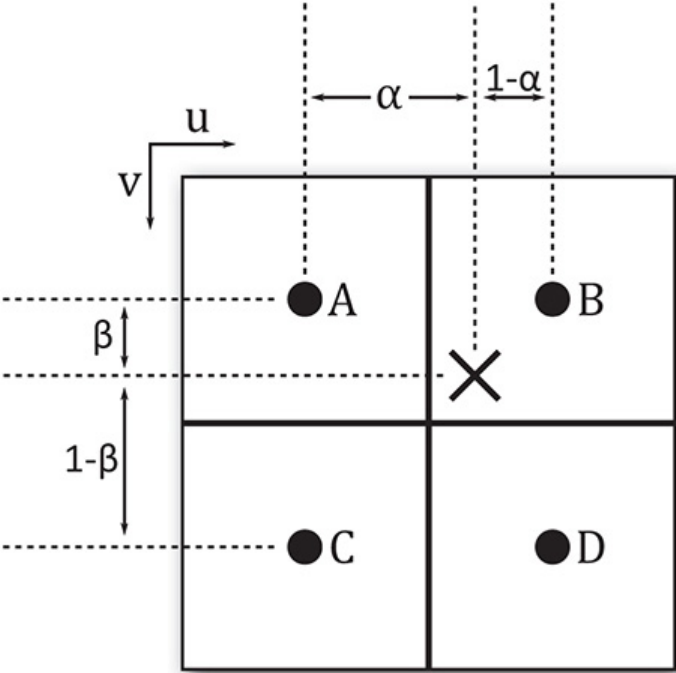
Figure 6.2: Linear Sampling
To form a linear weighted sum of the texels at A and B, their values are simply combined according
to the relationship
Tu0=αA + (1 −α) B
This can be writen as
Tu0=B+ α (B−A)
Likewise, a weighted sum of C and D is formed as
Tu1=αC + (1 −α) D or
Tu1=D−α (D−C)
The two temporary values Tu0and Tu1can then be combined into a single, weighted sum using a
similar mechanism, but with β:
T=βTu0+ (1 −β) Tu1or
T=Tu1+ β(Tu1−Tu0)
This can be extended in any number of dimensions, although only texture dimensionalities up to
three are defined by Vulkan.
Mipmapping
The mipmapMode field specifies how mipmaps are used in the image when it is sampled. This is a
member of the VkSamplerMipmapMode enumeration, whose members have the following
meanings:
•VK_SAMPLER_MIPMAP_MODE_NEAREST: The computed level-of-detail is rounded to the
nearest integer, and that level is used to select the mipmap level. If sampling from the base
level, then the filtering mode specified in magFilter is used to sample from that level;
otherwise, the minFilter filter is used.
•VK_SAMPLER_MIPMAP_MODE_LINEAR: The computed level of detail is rounded both up
and down, and the two resulting mipmap levels are sampled. The two resulting texel values are
then blended and returned to the shader.
To select a mipmap from the image, Vulkan will compute the derivative of the coordinates used to
sample from the texture. The exact math is covered in some detail in the Vulkan specification. In
short, the level selected is the log2of the maximum of the derivatives of each of the texture
coordinate dimensions. This level can also be biased using parameters taken from the sampler or
supplied by the shader, or it can be entirely specified in the shader. Regardless of its source, the result
may not be an exact integer.
When the mipmap mode is VK_SAMPLER_MIPMAP_MODE_NEAREST, then the selected mipmap
level is simply rounded down to the next-lowest integer, and then that level is sampled as though it
were a single-level image. When the mipmap mode is VK_SAMPLER_MIPMAP_MODE_LINEAR, a
sample is taken from each of the next-lower and next-higher levels using the filtering mode selected
by the minFilter field, and then those two samples are further combined using a weighted
average, similarly to how the samples are combined during linear sampling, as described earlier.
Note that this filtering mode applies only to minification, which is the process of sampling from a
mipmap level other than the base level. When the log2of the texture coordinate derivatives is less
than 1, then the 0th level is selected, so only a single level is available for sampling. This is known as
magnification and uses the filtering mode specified in magFilter to sample from the base level
only.
The next three fields in VkSamplerCreateInfo—addressModeU,addressModeV, and
addressModeW—are used to select the transform that is applied to texture coordinates that would
otherwise sample outside the image. The following modes are available:
•VK_SAMPLER_ADDRESS_MODE_REPEAT: As the texture coordinate progresses from 0.0 to
1.0 and beyond, it is wrapped back to 0.0, effectively using only the fractional part of the
coordinate to sample from the image. The effect is to tile the image indefinitely.
•VK_SAMPLER_ADDRESS_MODE_MIRRORED_REPEAT: The texture coordinate progresses
from 0.0 to 1.0 as normal, and then in the range 1.0 to 2.0, the fractional part is subtracted from
1.0 to form a new coordinate moving back toward 0.0. The effect is to alternately tile the normal
and mirror-image version of a texture.
•VK_SAMPLER_ADDRESS_MODE_CLAMP_TO_EDGE: Texture coordinates beyond 1.0 are
clamped to 1.0, and negative coordinates are clamped to 0.0. This clamped coordinate is used to
sample from the image. The effect is that the texels along the edge of the image are used to fill
any area that would be sampled outside the image.
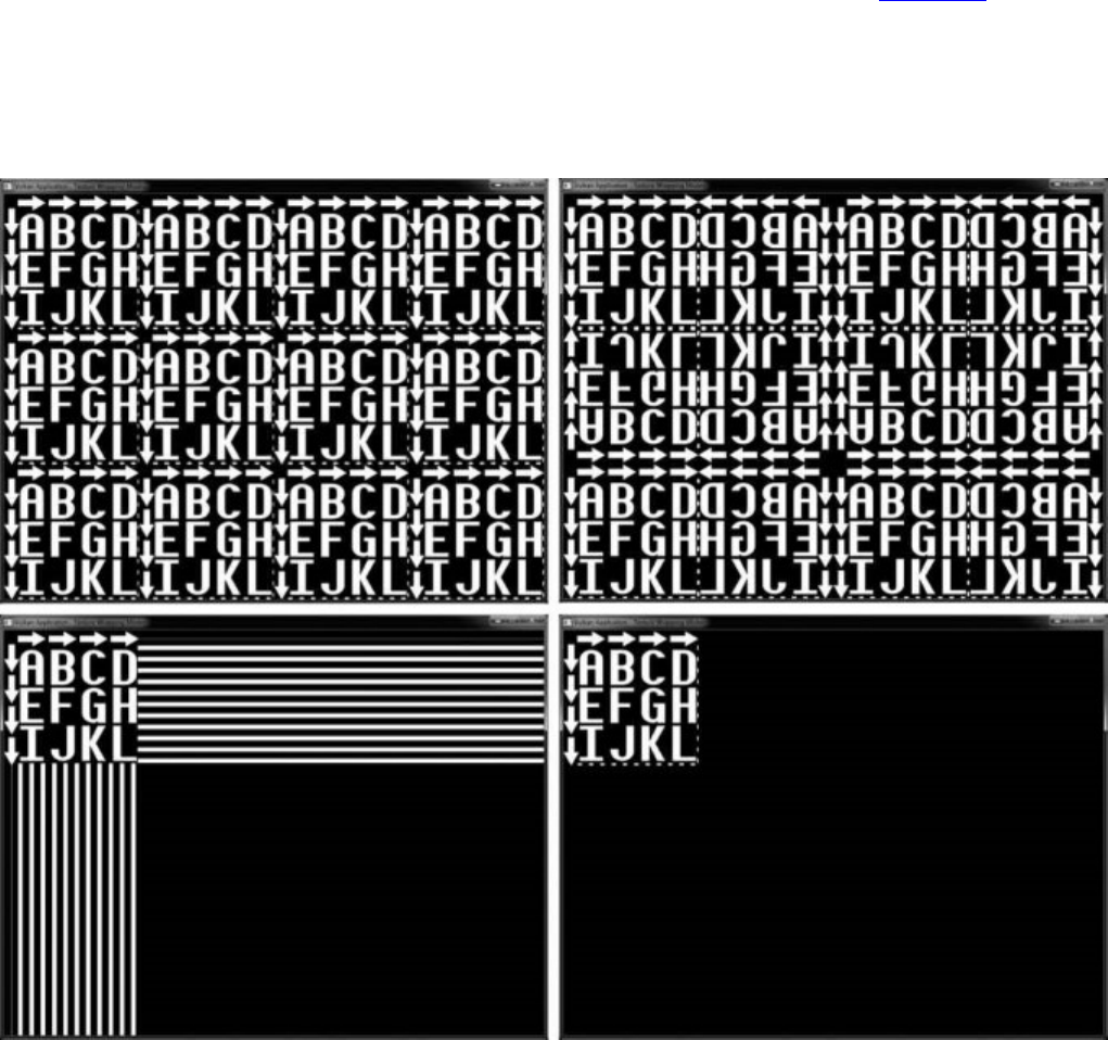
•VK_SAMPLER_ADDRESS_MODE_CLAMP_TO_BORDER: Sampling from the texture outside
its bounds will result in texels of the border color, as specified in the borderColor field,
being returned rather than data from the image.
•VK_SAMPLER_ADDRESS_MODE_MIRROR_CLAMP_TO_EDGE: This is a hybrid mode that
first applies a single mirroring of the texture coordinate and then behaves like
VK_SAMPLER_ADDRESS_MODE_CLAMP_TO_EDGE.
The effect of each of the sampler addressing modes applied to an image is shown in Figure 6.3. In the
figure, the top-left image shows the result of the VK_SAMPLER_ADDRESS_MODE_REPEAT
addressing mode. As you can see, the texture is simply repeated across the frame. The top-right
image shows the result of VK_SAMPLER_ADDRESS_MODE_MIRRORED_REPEAT. Each alternate
repetition of the texture is mirrored in the X or Y direction.
Figure 6.3: Effect of Sampling Modes
The bottom-left image applies the VK_SAMPLER_ADDRESS_MODE_CLAMP_TO_EDGE addressing
mode to the texture. Here, the last column or row of pixels is repeated indefinitely after the sampling
coordinates leave the texture. Finally, the bottom-right image shows the result of the
VK_SAMPLER_ADDRESS_MODE_CLAMP_TO_BORDER mode. This texture was created with a
black border color, so the area outside the texture appears to be blank, but Vulkan is actually
sampling black texels from this region. This allows you to see the original texture.
When the filter mode is VK_FILTER_LINEAR, wrapping or clamping the texture coordinate is
applied to each of the generated coordinates in the 2 × 2 footprint used to create the resulting texel.
The result is that filtering is applied as though the image really wrapped.
For the VK_SAMPLER_ADDRESS_MODE_CLAMP_TO_BORDER filter mode, when texels are
sampled from the border (i.e., what would be outside the image), the border color is substituted rather
than fetching data from the image. The color that is used depends on the value of the borderColor
field. This is not a full color specification, but a member of the VkBorderColor enumeration,
which allows one of a small, predefined set of colors to be selected. These are
•VK_BORDER_COLOR_FLOAT_TRANSPARENT_BLACK: Returns floating-point zeros to the
shader in all channels
•VK_BORDER_COLOR_INT_TRANSPARENT_BLACK: Returns integer zeros to the shader in
all channels
•VK_BORDER_COLOR_FLOAT_OPAQUE_BLACK: Returns floating-point zeros in the R, G,
and B channels, and floating-point one in A
•VK_BORDER_COLOR_INT_OPAQUE_BLACK: Returns integer zeros in R, G, and B, and
integer one in A
•VK_BORDER_COLOR_FLOAT_OPAQUE_WHITE: Returns floating-point ones to the shader in
all channels
•VK_BORDER_COLOR_INT_OPAQUE_WHITE: Returns integer ones to the shader in all
channels
The mipLodBias field of VkSamplerCreateInfo specifies a floating-point bias that is added
to the computed level of detail before mipmap selection is made. This allows you to nudge the level
of detail up or down the mipmap chain to make the resulting filtered texture look sharper or blurrier
than it might otherwise.
If you want to use anisotropic filtering, set anisotropyEnable to VK_TRUE. The exact details of
anisotropic filtering are implementation-dependent. Anisotropic filtering generally works by
considering a projected footprint of the area to be sampled rather than using a fixed 2 × 2 footprint.
An approximation to an area sample is formed by taking many samples within the footprint.
Because the number of samples taken can be quite large, anisotropic filtering can have a negative
effect on performance. Also, under extreme cases, the projected footprint can be quite large, and this
can result in a large area and correspondingly blurry filter result. To limit these effects, you can clamp
the maximum amount of anisotropy by setting maxAnisotropy to a value between 1.0 and the
maximum value supported by the device. You can determine this by calling
vkGetPhysicalDeviceProperties() and inspecting the maxSamplerAnisotropy
member of the embedded VkPhysicalDeviceLimits structure.
When a sampler is used with a depth image, it can be configured to perform a comparison operation
and return the result of the comparison rather than the raw values stored in the image. When this
mode is enabled, the comparison is performed on each sample taken from the image, and the
resulting value is the fraction of the total samples taken that passed the test. This can be used to
implement a technique known as percentage closer filtering, or PCF. To enable this mode, set
compareEnable to VK_TRUE, and set the comparison operation in compareOp.

compareOp is a member of the VkCompareOp enumeration, which is used in many places in
Vulkan. As you will see in Chapter 7, “Graphics Pipelines,” this is the same enumeration that is used
to specify the depth test operation. The available operations and how they are interpreted in the
context of shader accesses to depth resources are shown in Table 6.2.
The sampler can be configured to restrict sampling to a subset of the mip levels in an image with
mipmaps. The range of mipmaps to sample from is specified in minLod and maxLod, which
contain the lowest (highest-resolution) and highest (lowest-resolution) mipmaps that should be
sampled from, respectively. To sample from the entire mipmap chain, set minLod to 0.0, and set
maxLod to a level of detail high enough that the computed level of detail will never be clamped.
Finally, unnormalizedCoordinates is a flag that, when set to VK_TRUE, indicates that the
coordinates used to sample from the image are in units of raw texels, rather than a value that is
normalized between 0.0 and 1.0 across each dimension of the texture. This allows texels to be
explicitly fetched from the image. However, several restrictions exist in this mode. When
unnormalizedCoordinates is VK_TRUE,minFilter and magFilter must be the same,
mipmapMode must be VK_SAMPLER_MIPMAP_MODE_NEAREST, and anisotropyEnable
and compareEnable must be VK_FALSE.
When you are done with a sampler, you should destroy it by calling vkDestroySampler(), the
prototype of which is
Click here to view code image
void vkDestroySampler (
VkDevice device,
VkSampler sampler,
const VkAllocationCallbacks* pAllocator);
device is the device that owns the sampler object, and sampler is the sampler object to destroy.
If a host memory allocator was used when the sampler was created, a compatible allocator should be
passed through the pAllocator parameter; otherwise, pAllocator should be nullptr.
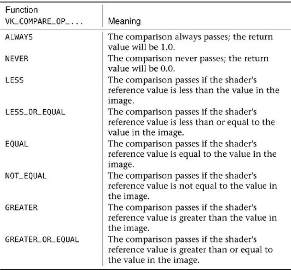
Table 6.2: Texture Comparison Functions
Summary
This chapter covered the basics of the shading language supported by Vulkan, SPIR-V, including how
SPIR-V shader modules are consumed by Vulkan and how pipelines containing those shaders are
constructed. You saw how to construct a compute shader and use it to create a compute pipeline, how
to dispatch work into that pipeline, and how a pipeline can access resources in order to consume and
produce data. In upcoming chapters, we will build on the concept of pipelines to produce pipeline
objects with multiple stages and make use of more advanced features.

Chapter 7. Graphics Pipelines
What You’ll Learn in This Chapter
• What the Vulkan graphics pipeline looks like
• How to create a graphics pipeline object
• How to draw graphical primitives with Vulkan
Perhaps the most common use of Vulkan is as a graphics API. Graphics are a fundamental part of
Vulkan and drive the core of almost any visual application. Graphics processing in Vulkan can be
seen as a pipeline that takes graphics commands through the many stages required to produce a
picture on a display. This chapter covers the basics of graphics pipelines in Vulkan and introduces our
first graphics example.
The Logical Graphics Pipeline
The graphics pipeline in Vulkan can be seen as a production line, where commands enter the front of
the pipeline and are processed in stages. Each stage performs some kind of transform, taking the
commands and their associated data and turning them into something else. By the end of the pipeline,
the commands have been transformed into colorful pixels making up your output picture.
Many parts of the graphics pipeline are optional and can be disabled or might not even be supported
by a Vulkan implementation. The only part of the pipeline that an application must enable is the
vertex shader. The full Vulkan graphics pipeline is shown in Figure 7.1. However, don’t be alarmed;
we’ll introduce each stage gently in this chapter and dig into more details in subsequent parts of the
book.
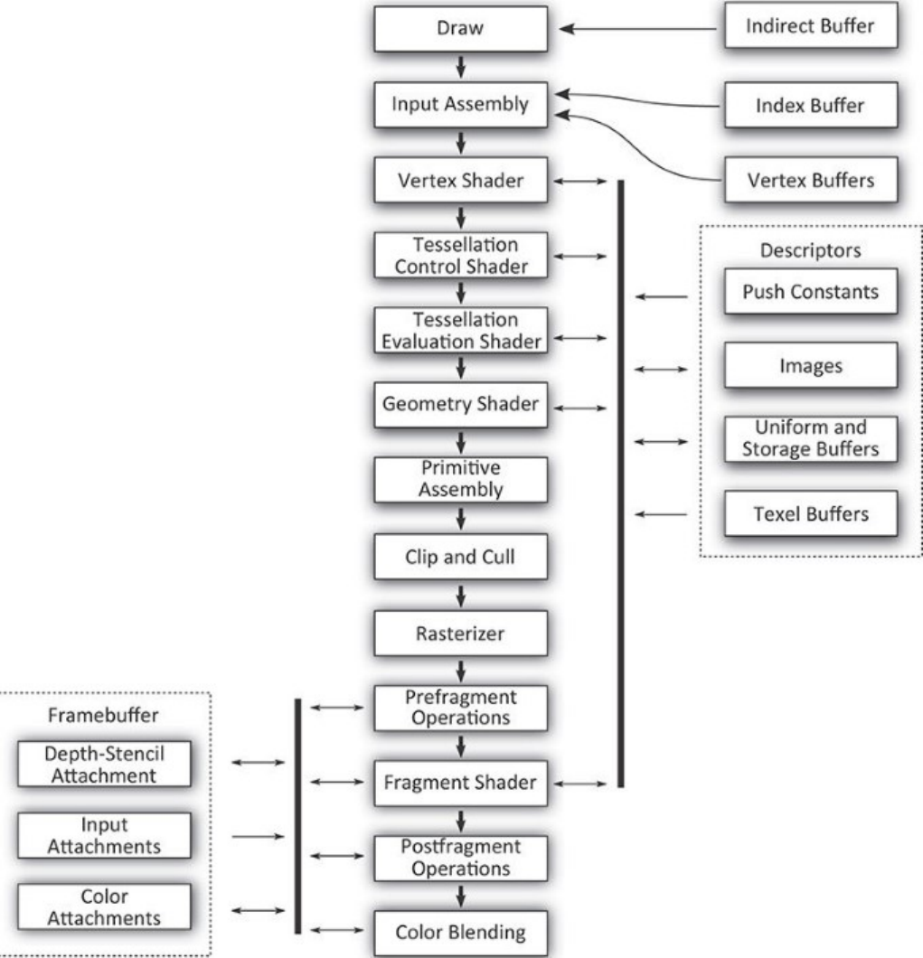
Figure 7.1: The Full Vulkan Graphics Pipeline
The following is a brief description of each stage of the pipeline and what it does.
• Draw: This is where your commands enter the Vulkan graphics pipeline. Typically, a small
processor or dedicated piece of hardware inside the Vulkan device interprets the commands in
the command buffer and directly interacts with the hardware to induce work.
• Input assembly: This stage reads the index and vertex buffers that contain information about the
vertices making up the draw you’ve sent.

• Vertex shader: This is where the vertex shader executes. It takes as input the properties of the
vertex and prepares transformed and processed vertex data for the next stage.
• Tessellation control shader: This programmable shading stage is responsible for producing
tessellation factors and other per-patch data that is used by the fixed-function tessellation
engine.
• Tessellation primitive generation: Not shown in Figure 7.1, this fixed function stage uses the
tessellation factors produced in the tessellation control shader to break patch primitives into
many smaller, simpler primitives ready to be shaded by the tessellation evaluation shader.
• Tessellation evaluation shader: This shading stage runs on each new vertex produced by the
tessellation primitive generator. It operates similarly to a vertex shader except that the incoming
vertices are generated rather than read from memory.
• Geometry shader: This shading stage operates on full primiitves. The primitives might be points,
lines or triangles, or special variations of them that include additional vertices surrounding
them. This stage also has the ability to change the primitive type midpipeline.
• Primitive assembly: This stage groups vertices produced by the vertex, tessellation, or geometry
stage and groups them into primitives suitable for rasterization. It also culls and clips primitives
and transforms them into the appropriate viewport.
• Clip and cull: This fixed-function stage determines which parts of which primitives might
contribute to the output image and discards parts of primitives that do not, forwarding
potentially visible primitives to the rasterizer.
• Rasterizer: Rasterization is the fundamental core of all graphics in Vulkan. The rasterizer takes
assembled primitives that are still represented by a sequence of vertices and turns them into
individual fragments, which may become the pixels that make up your image.
• Prefragment operations: Several operations can be performed on fragments once their positions
are known but before they are shaded. These prefragment operations include depth and stencil
tests when they are enabled.
• Fragment assembly: Not shown in the figure, the fragment assembly stage takes the output of
the rasterizer along with any per-fragment data and sends it, as a group, into the fragment
shading stage.
• Fragment shader: This stage runs the final shader in the pipeline, which is responsible for
computing the data that will be sent on to the final fixed-function processing stages that follow.
• Postfragment operations: In some circumstances, the fragment shader modifies data that would
normally be used in prefragment operations. In these cases, those prefragment operations move
to the postfragment stage and are executed here.
• Color blending: The color operations take the final results of the fragment shader and
postfragment operations and use them to update the framebuffer. The color operations include
blending and logic operations.
As you can tell, there are a lot of interrelated stages in the graphics pipeline. Unlike the compute
pipeline introduced in Chapter 6, “Shaders and Pipelines,” the graphics pipeline contains not only the
configuration of a wide selection of fixed functionality, but also up to five shader stages. Further,
depending on the implementation, some of the logically fixed-function stages are actually at least
partially implemented in shader code generated by drivers.

The purpose of representing the graphics pipeline as an object in Vulkan is to provide the
implementation as much information as needed to move parts of the pipeline between fixed-function
hardware and programmable shader cores. If the information were not all available at the same time
in the same object, it would mean that some implementations of Vulkan may need to recompile a
shader based on configurable state. The set of states contained in the graphics pipeline has been
carefully chosen to prevent this, making switching states as fast as possible.
The fundamental unit of drawing in Vulkan is a vertex. Vertices are grouped into primitives and
processed by the Vulkan pipeline. The simplest drawing command in Vulkan is vkCmdDraw(),
whose prototype is
Click here to view code image
void vkCmdDraw (
VkCommandBuffer commandBuffer,
uint32_t vertexCount,
uint32_t instanceCount,
uint32_t firstVertex,
uint32_t firstInstance);
Like other Vulkan commands, vkCmdDraw() appends a command to a command buffer that will
later be executed by the device. The command buffer to append to is specified in commandBuffer.
The number of vertices to push into the pipeline is specified in vertexCount. If you want to draw
the same set of vertices over and over with slightly different parameters, you can specify the number
of instances in instanceCount. This is known as instancing, and we’ll cover that later in this
chapter. For now, we can just set instanceCount to 1. It’s also possible to start drawing from a
vertex or instance other than 0. To do this, we can use firstVertex and firstInstance,
respectively. Again, we’ll cover that later. For the time being, we’ll set both of these parameters to 0.
Before you can draw anything, you must bind a graphics pipeline to the command buffer, and before
that, you must create a graphics pipeline. Undefined behavior (generally bad behavior) will occur if
you try drawing without binding a pipeline first.
When you call vkCmdDraw(),vertexCount vertices are generated and pushed into the current
Vulkan graphics pipeline. For each vertex, input assembly is executed, followed by your vertex
shader. Declaring inputs beyond what is provided for you by Vulkan is optional, but having a vertex
shader is not. Thus, the simplest possible graphics pipeline consists only of a vertex shader.
Renderpasses
One of the things that distinguishes a Vulkan graphics pipeline from a compute pipeline is that,
usually, you’ll be using the graphics pipeline to render pixels into images that you will either further
process or display to the user. In complex graphics applications, the picture is built up over many
passes where each pass is responsible for producing a different part of the scene, applying full-frame
effects such as postprocessing or composition, rendering user interface elements, and so on.
Such passes can be represented in Vulkan using a renderpass object. A single renderpass object
encapsulates multiple passes or rendering phases over a single set of output images. Each pass within
the renderpass is known as a subpass. Renderpass objects can contain many subpasses, but even in
simple applications with only a single pass over a single output image, the renderpass object contains
information about that output image.

All drawing must be contained inside a renderpass. Further, graphics pipelines need to know where
they’re rendering to; therefore, it’s necessary to create a renderpass object before creating a graphics
pipeline so that we can tell the pipeline about the images it’ll be producing. Renderpasses are covered
in great depth in Chapter 13, “Multipass Rendering.” In this chapter, we’ll create the simplest
possible renderpass object that will allow us to render into an image.
To create a renderpass object, call vkCreateRenderPass(), the prototype of which is
Click here to view code image
VkResult vkCreateRenderPass (
VkDevice device,
const VkRenderPassCreateInfo* pCreateInfo,
const VkAllocationCallbacks* pAllocator,
VkRenderPass* pRenderPass);
The device parameter to vkCreateRenderPass() is the device that will create the renderpass
object, and pCreateInfo points to a structure defining the renderpass. This is an instance of the
VkRenderPassCreateInfo structure, whose definition is
Click here to view code image
typedef struct VkRenderPassCreateInfo {
VkStructureType sType;
const void* pNext;
VkRenderPassCreateFlags flags;
uint32_t attachmentCount;
const VkAttachmentDescription* pAttachments;
uint32_t subpassCount;
const VkSubpassDescription* pSubpasses;
uint32_t dependencyCount;
const VkSubpassDependency* pDependencies;
} VkRenderPassCreateInfo;
The sType field of VkRenderPassCreateInfo should be set to
VK_STRUCTURE_TYPE_RENDERPASS_CREATE_INFO, and pNext should be set to nullptr.
The flags field is reserved for future use and should be set to zero.
pAttachments is a pointer to an array of attachmentCount
VkAttachmentDescription structures that define the attachments associated with the
renderpass. Each of these structures defines a single image that is to be used as an input, output, or
both within one or more of the subpasses in the renderpass. If there really are no attachments
associated with the renderpass, you can set attachmentCount to zero and pAttachments to
nullptr. However, outside of some advanced use cases, almost all graphics rendering will use at
least one attachment. The definition of VkAttachmentDescription is
Click here to view code image
typedef struct VkAttachmentDescription {
VkAttachmentDescriptionFlags flags;
VkFormat format;
VkSampleCountFlagBits samples;
VkAttachmentLoadOp loadOp;
VkAttachmentStoreOp storeOp;
VkAttachmentLoadOp stencilLoadOp;
VkAttachmentStoreOp stencilStoreOp;
VkImageLayout initialLayout;
VkImageLayout finalLayout;
} VkAttachmentDescription;
The flags field is used to give Vulkan additional information about the attachment. The only
defined bit is VK_ATTACHMENT_DESCRIPTION_MAY_ALIAS_BIT, which, if set, indicates that
the attachment might be using the same memory as another attachment referenced by the same
renderpass. This tells Vulkan not to do anything that might make data in that attachment inconsistent.
This bit can be used in some advanced cases where memory is at a premium and you are trying to
optimize its usage. In most cases, flags can be set to zero.
The format field specifies the format of the attachment. This is one of the VkFormat
enumerations and should match the format of the image used as the attachment. Likewise, samples
indicates the number of samples in the image and is used for multisampling. When multisampling is
not in use, set samples to VK_SAMPLE_COUNT_1_BIT.
The next four fields specify what to do with the attachment at the beginning and end of the
renderpass. The load operations tell Vulkan what to do with the attachment when the renderpass
begins. This can be set to one of the following values:
•VK_ATTACHMENT_LOAD_OP_LOAD indicates that the attachment has data in it already and
that you want to keep rendering to it. This causes Vulkan to treat the contents of the attachment
as valid when the renderpass begins.
•VK_ATTACHMENT_LOAD_OP_CLEAR indicates that you want Vulkan to clear the attachment
for you when the renderpass begins. The color to which you want to clear the attachments is
specified when the renderpass has begun.
•VK_ATTACHMENT_LOAD_OP_DONT_CARE indicates that you don’t care about the content of
the attachment at the beginning of the renderpass and that Vulkan is free to do whatever it
wishes with it. You can use this if you plan to explicitly clear the attachment or if you know that
you’ll replace the content of the attachment inside the renderpass.
Likewise, the store operations tell Vulkan what you want it to do with the contents of the attachments
when the renderpass ends. These can be set to one of the following values:
•VK_ATTACHMENT_STORE_OP_STORE indicates that you want Vulkan to keep the contents
of the attachment for later use, which usually means that it should write them out into memory.
This is usually the case for images you want to display to the user, read from later, or use as an
attachment in another renderpass (with the VK_ATTACHMENT_LOAD_OP_LOAD load
operation).
•VK_ATTACHMENT_STORE_OP_DONT_CARE indicates that you don’t need the content after
the renderpass has ended. This is normally used for intermediate storage or for the depth or
stencil buffers.
If the attachment is a combined depth-stencil attachment, then the stencilLoadOp and
stencilStoreOp fields tell Vulkan what to do with the stencil part of the attachment (the regular
loadOp and storeOp fields specify what should happen to the depth part of the attachment),
which can be different from the depth part.

The initialLayout and finalLayout fields tell Vulkan what layout to expect the image to be
in when the renderpass begins and what layout to leave it in when the renderpass ends. Note that
renderpass objects do not automatically move images into the initial layout. This is the layout that the
image is expected to be in when the renderpass is used. The renderpass does, however, move the
image to the final layout when it’s done.
You can use barriers to explicitly move images from layout to layout, but where possible, it’s best to
try to move images from layout to layout inside renderpasses. This gives Vulkan the best opportunity
to choose the right layout for each part of the renderpass and even perform any operations required to
move images between layouts in parallel with other rendering. Advanced usage of these fields and
renderpasses in general is covered in Chapter 13, “Multipass Rendering.”
After you define all of the attachments that are going to be used in the renderpass, you need to define
all of the subpasses. Each subpass references a number of attachments (from the array you passed in
pAttachments) as inputs or outputs. Those descriptions are specified in an array of
VkSubpassDescription structures, one for each subpass in the renderpass. The definition of
VkSubpassDescription is
Click here to view code image
typedef struct VkSubpassDescription {
VkSubpassDescriptionFlags flags;
VkPipelineBindPoint pipelineBindPoint;
uint32_t inputAttachmentCount;
const VkAttachmentReference* pInputAttachments;
uint32_t colorAttachmentCount;
const VkAttachmentReference* pColorAttachments;
const VkAttachmentReference* pResolveAttachments;
const VkAttachmentReference* pDepthStencilAttachment;
uint32_t preserveAttachmentCount;
const uint32_t* pPreserveAttachments;
} VkSubpassDescription;
The flags field of VkSubpassDescription is reserved for future use and should be set to
zero. Also, the current version of Vulkan supports renderpasses only for graphics, so
pipelineBindPoint should be set to VK_PIPELINE_BIND_POINT_GRAPHICS. The
remaining fields describe the attachments used by the subpass. Each subpass can have a number of
input attachments, which are attachments from which it can read data; color attachments, which are
attachments to which its outputs are written; and a depth-stencil attachment, which is used as a depth
and stencil buffer. These attachments are specified in the pInputAttachments,
pColorAttachments, and pDepthStencilAttachment fields, respectively. The numbers
of input and color attachments are specified in inputAttachmentCount and
colorAttachmentCount, respectively. There is only one depth-stencil attachment, so this
parameter is not an array and has no associated count.
The maximum number of color attachments that a single subpass can render to can be determined by
inspecting the maxColorAttachments member of the device’s VkPhysicalDeviceLimits
structure, which you can retrieve by calling vkGetPhysicalDeviceProperties().
maxColorAttachments is guaranteed to be at least 4, so if you never use more than this many
color attachments, you don’t need to query the limit. However, many implementations support a

higher limit than this, so you may be able to implement more advanced algorithms in fewer passes by
writing to more outputs at once.
Each of these arguments is a pointer to either a single VkAttachmentReference structure or an
array of them and forms a reference to one of the attachments described in pAttachments. The
definition of VkAttachmentReference is
Click here to view code image
typedef struct VkAttachmentReference {
uint32_t attachment;
VkImageLayout layout;
} VkAttachmentReference;
Each attachment reference is a simple structure containing an index into the array of attachments in
attachment and the image layout that the attachment is expected to be in at this subpass. In
addition to the input and output attachment references, two further sets of references are provided to
each subpass.
First, the resolve attachments, which are specified through pResolveAttachments, are the
attachments to which multisample image data is resolved. These attachments correspond to the color
attachments specified in pColorAttachments, and the number of resolve attachments is assumed
to be the same, as specified in colorAttachmentCount.
If one of the elements of pColorAttachments is a multisample image, but only the final,
resolved image is needed after the renderpass is complete, you can ask Vulkan to resolve the image
for you as part of the renderpass, and possibly disacard the original multisample data. To do this, set
the store operation for the multisample color attachment to
VK_ATTACHMENT_STORE_OP_DONT_CARE, and set a corresponding single-sample attachment in
the matching element of pResolveAttachments. The store operation for the resolve attachment
should be set to VK_ATTACHMENT_STORE_OP_STORE, which will cause Vulkan to keep the
single-sample data but throw out the original multisample data.
Second, if there are attachments that you want to live across a subpass but that are not directly
referenced by the subpass, you should reference them in the pPreserveAttachments array. This
reference will prevent Vulkan from making any optimizations that might disturb the contents of those
attachments.
When there is more than one subpass in a renderpass, Vulkan can figure out which subpasses are
dependent on one another by following the attachment references and looking for inputs and outputs
that make subpasses dependent on one another. However, there are cases in which dependencies
cannot easily be represented by a simple input-to-output relationship. This generally happens when a
subpass writes directly to a resource such as an image or buffer and a subsequent subpass reads that
data back. Vulkan cannot figure this out automatically, so you must provide such dependency
information explicitly. This is done using the pDependencies member of
VkRenderPassCreateInfo, which is a pointer to an array of dependencyCount
VkSubpassDependency structures. The definition of VkSubpassDependency is
Click here to view code image
typedef struct VkSubpassDependency {
uint32_t srcSubpass;
uint32_t dstSubpass;

VkPipelineStageFlags srcStageMask;
VkPipelineStageFlags dstStageMask;
VkAccessFlags srcAccessMask;
VkAccessFlags dstAccessMask;
VkDependencyFlags dependencyFlags;
} VkSubpassDependency;
Each dependency is a reference from a source subpass (the producer of data) and a destination
subpass (the consumer of that data), specified in srcSubpass and dstSubpass, respectively.
Both are indices into the array of subpasses that make up the renderpass. The srcStageMask is a
bitfield specifying which pipeline stage(s) of the source subpass produced the data. Likewise,
dstStageMask is a bitfield specifying which stages of the destination subpass will consume the
data.
The srcAccessMask and dstAccessMask fields are also bitfields. They specify how each of
the source and destination subpasses access the data. For example, the source stage may perform
image stores from its vertex shader or write to a color attachment through regular fragment shader
outputs. Meanwhile, the destination subpass may read through an input attachment or an image load.
For the purpose of creating a simple renderpass with a single subpass, with a single output attachment
and no external dependencies, the data structures are mostly empty. Listing 7.1 demonstrates how to
set up a simple renderpass in this configuration.
Listing 7.1: Creating a Simple Renderpass
Click here to view code image
// This is our color attachment. It's an R8G8B8A8_UNORM single sample
image.
// We want to clear it at the start of the renderpass and save the
contents
// when we're done. It starts in UNDEFINED layout, which is a key to
// Vulkan that it's allowed to throw the old content away, and we want to
// leave it in COLOR_ATTACHMENT_OPTIMAL state when we're done.
static const VkAttachmentDescription attachments[] =
{
{
0, // flags
VK_FORMAT_R8G8B8A8_UNORM, // format
VK_SAMPLE_COUNT_1_BIT, // samples
VK_ATTACHMENT_LOAD_OP_CLEAR, // loadOp
VK_ATTACHMENT_STORE_OP_STORE, // storeOp
VK_ATTACHMENT_LOAD_OP_DONT_CARE, // stencilLoadOp
VK_ATTACHMENT_STORE_OP_DONT_CARE, // stencilStoreOp
VK_IMAGE_LAYOUT_UNDEFINED, // initialLayout
VK_IMAGE_LAYOUT_COLOR_ATTACHMENT_OPTIMAL // finalLayout
}
};
// This is the single reference to our single attachment.
static const VkAttachmentReference attachmentReferences[] =
{
{

0, // attachment
VK_IMAGE_LAYOUT_COLOR_ATTACHMENT_OPTIMAL // layout
}
};
// There is one subpass in this renderpass, with only a reference to the
// single output attachment.
static const VkSubpassDescription subpasses[] =
{
{
0, // flags
VK_PIPELINE_BIND_POINT_GRAPHICS, // pipelineBindPoint
0, // inputAttachmentCount
nullptr, // pInputAttachments
1, // colorAttachmentCount
&attachmentReferences[0], // pColorAttachments
nullptr, // pResolveAttachments
nullptr, //
pDepthStencilAttachment
0, //
preserveAttachmentCount
nullptr // pPreserveAttachments
}
};
// Finally, this is the information that Vulkan needs to create the
renderpass
// object.
static VkRenderPassCreateInfo renderpassCreateInfo =
{
VK_STRUCTURE_TYPE_RENDER_PASS_CREATE_INFO, // sType
nullptr, // pNext
0, // flags
1, // attachmentCount
attachments[0], // pAttachments
1, // subpassCount
&subpasses[0], // pSubpasses
0, // dependencyCount
nullptr // pDependencies
};
VkRenderPass renderpass = VK_NULL_HANDLE;
// The only code that actually executes is this single call, which creates
// the renderpass object.
vkCreateRenderPass(device,
&renderpassCreateInfo,
nullptr,
&renderpass);
In Listing 7.1, we set up a simple renderpass with a single color attachment of format
VK_FORMAT_R8G8B8A8_UNORM, no depth-stencil attachment, and no dependencies. It looks like
a lot of code, but that’s because we need to specify full data structures even though we’re not using
most of the fields. As your applications grow more complex, the amount of code you need to write

doesn’t actually grow correspondingly. Further, because the structures are constant, the amount of
code executed by Listing 7.1 is minimal.
We’ll use the renderpass created in Listing 7.1 to create a graphics pipeline in the next section.
Of course, when we are done using the renderpass object, we should destroy it. To do this, call
vkDestroyRenderPass(), the prototype of which is
Click here to view code image
void vkDestroyRenderPass (
VkDevice device,
VkRenderPass renderPass,
const VkAllocationCallbacks* pAllocator);
device is the device that created the renderpass, and renderPass is the handle to the renderpass
object to destroy. If a host memory allocator was used to create the renderpass, pAllocator should
point to a compatible allocator; otherwise, pAllocator should be nullptr.
The Framebuffer
The framebuffer is an object that represents the set of images that graphics pipelines will render into.
These affect the last few stages in the pipeline: depth and stencil tests, blending, logic operations,
multisampling, and so on. A framebuffer object is created by using a reference to a renderpass and
can be used with any renderpass that has a similar arrangement of attachments.
To create a framebuffer object, call vkCreateFramebuffer(), the prototype of which is
Click here to view code image
VkResult vkCreateFramebuffer (
VkDevice device,
const VkFramebufferCreateInfo* pCreateInfo,
const VkAllocationCallbacks* pAllocator,
VkFramebuffer* pFramebuffer);
The device that will be used to create the framebuffer object is passed in device, and the remaining
parameters describing the new framebuffer object are passed through a pointer to an instance of the
VkFramebufferCreateInfo structure in pCreateInfo. The definition of
VkFramebufferCreateInfo is
Click here to view code image
typedef struct VkFramebufferCreateInfo {
VkStructureType sType;
const void* pNext;
VkFramebufferCreateFlags flags;
VkRenderPass renderPass;
uint32_t attachmentCount;
const VkImageView* pAttachments;
uint32_t width;
uint32_t height;
uint32_t layers;
} VkFramebufferCreateInfo;

The sType field of VkFramebufferCreateInfo should be set to
VK_STRUCTURE_TYPE_FRAMEBUFFER_CREATE_INFO, and pNext should be set to
nullptr. The flags field is reserved and should be set to zero.
A handle to a renderpass object that is compatible with the framebuffer being created should be
passed in renderPass. For the purposes of compatibility with framebuffer objects, two
renderpasses are compatible if their attachment references are the same.
The set of images that is to be bound into the framebuffer object is passed through an array of
VkImageView handles, a pointer to which is passed in pAttachments. The number of images in
pAttachments is specified in attachmentCount. The passes comprising the renderpass make
references to the image attachments, and those references are specified as indices into the array
specified in pAttachments. If you know that a particular renderpass doesn’t use some of the
attachments, but you want the framebuffer to be compatible with several renderpass objects or to
keep a consistent layout of images in your application, some of the image handles in
pAttachments can be VkNullHandle.
Although each of the images in the framebuffer has a native width, height, and (in the case of array
images) layer count, you must still specify the dimensions of the framebuffer. These dimensions are
passed in the width,height, and layers fields of the VkFramebufferCreateInfo
structure. Rendering to regions of the framebuffer that are outside some of the images results in no
rendering to those parts of the attachment images that are outside the image while continuing to
render to those parts of the images that are.
The maximum supported size of a framebuffer is device-dependent. To determine the supported
dimensions of the framebuffer, check the maxFramebufferWidth,
maxFramebufferHeight, and maxFramebufferLayers fields of the device’s
VkPhysicalDeviceLimits structure. These provide the maximum supported width, height, and
layer count for framebuffers, respectively. The supported width and height are guaranteed to be at
least 4,096 pixels, and the number of supported layers is guaranteed to be at least 256. However,
most desktop-class hardware will support limits of 16,384 pixels in width and height and 2,048
layers.
It’s also possible to create a framebuffer with no attachments at all. This is known as an
attachmentless framebuffer. In this case, the framebuffer’s dimensions are solely defined by the
width,height, and layers fields. This type of framebuffer is typically used with fragment
shaders that have other side effects, such as performing image stores, or with occlusion queries,
which can measure other aspects of rendering but don’t necessarily require that the result of
rendering be stored anywhere.
If vkCreateFramebuffer() is successful, it will write the new VkFramebuffer handle into
the variable pointed to by pFramebuffer. If it requires any host memory, it will use the allocator
pointed to by pAllocator to allocate it. If pAllocator is not nullptr, then a compatible
allocator should be used when the framebuffer is destroyed.
As you will see in Chapter 8, “Drawing,” we will use the framebuffer object in conjunction with a
renderpass in order to draw into the images attached to the framebuffer. When you are done using a
framebuffer, you should destroy it by calling vkDestroyFramebuffer(), the prototype of
which is

Click here to view code image
void vkDestroyFramebuffer (
VkDevice device,
VkFramebuffer framebuffer,
const VkAllocationCallbacks* pAllocator);
device is a handle to the device that created the framebuffer object, and framebuffer is a
handle to the framebuffer object being destroyed. If a host memory allocator was used to allocate the
framebuffer, a compatible allocator should be passed through the pAllocator object.
Destroying a framebuffer object does not affect any of the images attached to the framebuffer. Images
can be attached to multiple framebuffers at the same time and can be used in multiple ways at the
same time as being attached to a framebuffer. However, even if the images are not destroyed, the
framebuffer should not be used—including any access in command buffers by the device. You should
ensure that any command buffers referencing the framebuffer have completed execution if they have
been submitted or have not been submitted after the framebuffer object is destroyed.
Creating a Simple Graphics Pipeline
Creating a graphics pipeline is achieved using a method similar to the one for creating a compute
pipeline, as described in Chapter 6, “Shaders and Pipelines.” However, as you have seen, the graphics
pipeline includes many shading stages and fixed-function processing blocks, so the description of a
graphics pipeline is correspondingly that much more complex. Graphics pipelines are created by
calling vkCreateGraphicsPipelines(), the prototype of which is
Click here to view code image
VkResult vkCreateGraphicsPipelines (
VkDevice device,
VkPipelineCache pipelineCache,
uint32_t createInfoCount,
const VkGraphicsPipelineCreateInfo* pCreateInfos,
const VkAllocationCallbacks*pAllocator,
VkPipeline* pPipelines);
As you can see, the prototype for vkCreateGraphicsPipelines() is similar to
vkCreateComputePipelines(). It takes a device (device), a handle to a pipeline cache
(pipelineCache), and an array of createInfo structures along with the count of the number
of structures in the array (pCreateInfos and createInfoCount, respectively). This is where
the real guts of the function are. VkGraphicsPipelineCreateInfo is a large, complex
structure, and it contains pointers to several other structures along with handles to other objects that
you need to have created. Take a deep breath: The definition of
VkGraphicsPipelineCreateInfo is
Click here to view code image
typedef struct VkGraphicsPipelineCreateInfo {
VkStructureType sType;
const void* pNext;
VkPipelineCreateFlags flags;
uint32_t stageCount;
const VkPipelineShaderStageCreateInfo* pStages;
const VkPipelineVertexInputStateCreateInfo* pVertexInputState;
const
VkPipelineInputAssemblyStateCreateInfo* pInputAssemblyState;
const VkPipelineTessellationStateCreateInfo* pTessellationState;
const VkPipelineViewportStateCreateInfo* pViewportState;
const
VkPipelineRasterizationStateCreateInfo* pRasterizationState;
const VkPipelineMultisampleStateCreateInfo* pMultisampleState;
const VkPipelineDepthStencilStateCreateInfo* pDepthStencilState;
const VkPipelineColorBlendStateCreateInfo* pColorBlendState;
const VkPipelineDynamicStateCreateInfo* pDynamicState;
VkPipelineLayout layout;
VkRenderPass renderPass;
uint32_t subpass;
VkPipeline basePipelineHandle;
int32_t basePipelineIndex;
} VkGraphicsPipelineCreateInfo;
As you were warned, VkGraphicsPipelineCreateInfo is a large structure with many
substructures referenced by pointers. However, it’s easy enough to break down into blocks, and many
of the additional creation info is optional and can be left as nullptr. As with all other Vulkan
creation info structures, VkGraphicsPipelineCreateInfo starts with an sType field and a
pNext field. The sType for VkGraphicsPipelineCreateInfo is
VK_GRAPHICS_PIPELINE_CREATE_INFO, and pNext can be left as nullptr unless
extensions are in use.
The flags field contains information about how the pipeline will be used. Three flags are defined in
the current version of Vulkan, and their meanings are as follows:
•VK_PIPELINE_CREATE_DISABLE_OPTIMIZATION_BIT tells Vulkan that this pipeline is
not going to be used in performance-critical applications and that you would prefer to receive a
ready-to-go pipeline object quickly rather than have Vulkan spend a lot of time optimizing the
pipeline. You might use this for things like simple shaders for displaying splash screens or user
interface elements that you want to display quickly.
•VK_PIPELINE_CREATE_ALLOW_DERIVATIVES_BIT and
VK_PIPELINE_CREATE_DERIVATIVE_BIT are used with derivative pipelines. This is a
feature whereby you can group similar pipelines and tell Vulkan that you’ll switch rapidly
among them. The VK_PIPELINE_CREATE_ALLOW_DERIVATIVES_BIT flag tells Vulkan
that you will want to create derivatives of the new pipeline, and
VK_PIPELINE_CREATE_DERIVATIVE_BIT tells Vulkan that this pipeline is a pipeline.
Graphics Shader Stages
The next two fields in the VkGraphicsPipelineCreateInfo structure, stageCount and
pStages, are where you pass your shaders into the pipeline. pStages is a pointer to an array of
stageCount VkPipelineShaderStageCreateInfo structures, each describing one of the
shading stages. These are the same structures that you saw in the definition of
VkComputePipelineCreateInfo, except now you have an array of them. The definition of
VkPipelineShaderStageCreateInfo is

Click here to view code image
typedef struct VkPipelineShaderStageCreateInfo {
VkStructureType sType;
const void* pNext;
VkPipelineShaderStageCreateFlags flags;
VkShaderStageFlagBits stage;
VkShaderModule module;
const char* pName;
const VkSpecializationInfo* pSpecializationInfo;
} VkPipelineShaderStageCreateInfo;
All graphics pipelines must have at least a vertex shader, and the vertex shader is always the first
shading stage in the pipeline. Therefore, the pStages of VkGraphicsPipelineCreateInfo
should point to a VkPipelineShaderStageCreateInfo describing a vertex shader. The
parameters in the VkPipelineShaderStageCreateInfo structure have the same meaning as
they did when we created a compute pipeline in Chapter 6, “Shaders and Pipelines.” module should
be a shader module that contains at least one vertex shader, and pName should be the name of a
vertex shader entry point in that module.
Because in our simple pipeline we’re not using most of the stages of the Vulkan graphics pipeline, we
can leave most of the other fields of the VkGraphicsPipelineCreateInfo structure as their
defaults or as nullptr for the pointers. The layout field is the same as the layout field in the
VkComputePipelineCreateInfo structure and specifies the pipeline layout used for resources
by this pipeline.
We can set the renderPass member of our structure to the handle of the renderpass object we
created earlier in Listing 7.1. There’s only one subpass in this renderpass, so we can set subpass to
zero.
Listing 7.2 shows a minimal example of creating a graphics pipeline containing only a vertex shader.
It looks long, but most of it is setting up default values in structures that are not actually used by the
pipeline. These structures will be explained in the following few paragraphs.
Listing 7.2: Creating a Simple Graphics Pipeline
Click here to view code image
VkPipelineShaderStageCreateInfo shaderStageCreateInfo =
{
VK_STRUCTURE_TYPE_PIPELINE_SHADER_STAGE_CREATE_INFO, // sType
nullptr, // pNext
0, // flags
VK_SHADER_STAGE_VERTEX_BIT, // stage
module, // module
"main",// pName
nullptr // pSpecializationInfo
};
static const
VkPipelineVertexInputStateCreateInfo vertexInputStateCreateInfo =
{
VK_STRUCTURE_TYPE_PIPELINE_VERTEX_INPUT_STATE_CREATE_INFO, // sType
nullptr, // pNext
0, // flags
0, //
vertexBindingDescriptionCount
nullptr, // pVertexBindingDescriptions
0, //
vertexAttributeDescriptionCount
nullptr // pVertexAttributeDescriptions
};
static const
VkPipelineInputAssemblyStateCreateInfo inputAssemblyStateCreateInfo =
{
VK_STRUCTURE_TYPE_PIPELINE_INPUT_ASSEMBLY_STATE_CREATE_INFO,// sType
nullptr, // pNext
0, // flags
VK_PRIMITIVE_TOPOLOGY_POINT_LIST, // topology
VK_FALSE // primitiveRestartEnable
};
static const
VkViewport dummyViewport =
{
0.0f, 0.0f, // x, y
1.0f, 1.0f, // width, height
0.1f, 1000.0f // minDepth, maxDepth
};
static const
VkRect2D dummyScissor =
{
{ 0, 0 }, // offset
{ 1, 1 } // extent
};
static const
VkPipelineViewportStateCreateInfo viewportStateCreateInfo =
{
VK_STRUCTURE_TYPE_PIPELINE_VIEWPORT_STATE_CREATE_INFO, // sType
nullptr, // pNext
0, // flags
1, // viewportCount
&dummyViewport, // pViewports
1, // scissorCount
&dummyScissor // pScissors
};
static const
VkPipelineRasterizationStateCreateInfo rasterizationStateCreateInfo =
{
VK_STRUCTURE_TYPE_PIPELINE_RASTERIZATION_STATE_CREATE_INFO, // sType
nullptr, // pNext
0, // flags
VK_FALSE, // depthClampEnable
VK_TRUE, // rasterizerDiscardEnable
VK_POLYGON_MODE_FILL, // polygonMode
VK_CULL_MODE_NONE, // cullMode
VK_FRONT_FACE_COUNTER_CLOCKWISE, // frontFace
VK_FALSE, // depthBiasEnable
0.0f, // depthBiasConstantFactor
0.0f, // depthBiasClamp
0.0f, // depthBiasSlopeFactor
0.0f // lineWidth
};
static const
VkGraphicsPipelineCreateInfo graphicsPipelineCreateInfo =
{
VK_STRUCTURE_TYPE_GRAPHICS_PIPELINE_CREATE_INFO, // sType
nullptr, // pNext
0, // flags
1, // stageCount
&shaderStageCreateInfo, // pStages
&vertexInputStateCreateInfo, // pVertexInputState
&inputAssemblyStateCreateInfo, // pInputAssemblyState
nullptr, // pTessellationState
&viewportStateCreateInfo, // pViewportState
&rasterizationStateCreateInfo, // pRasterizationState
nullptr, // pMultisampleState
nullptr, // pDepthStencilState
nullptr, // pColorBlendState
nullptr, // pDynamicState
VK_NULL_HANDLE, // layout
renderpass, // renderPass
0, // subpass
VK_NULL_HANDLE, // basePipelineHandle
0, // basePipelineIndex
};
result = vkCreateGraphicsPipelines(device,
VK_NULL_HANDLE,
1,
&graphicsPipelineCreateInfo,
nullptr,
&pipeline);
Of course, most of the time, you won’t be using a graphics pipeline containing only a vertex shader.
Up to five shader stages make up the graphics pipeline, as introduced earlier in this chapter. These
stages include the following:
• The vertex shader, specified as VK_SHADER_STAGE_VERTEX_BIT, processes one vertex at a
time and passes it to the next logical stage in the pipeline.
• The tessellation control shader, specified as
VK_SHADER_STAGE_TESSELLATION_CONTROL_BIT, processes one control point at a
time but has access to all of the data that makes up the patch. It can be considered to be a patch
shader, and it produces the tessellation factors and per-patch data associated with the patch.

• The tessellation evaluation shader, specified using
VK_SHADER_STAGE_TESSELLATION_EVALUATION_BIT, processes one tessellated
vertex at a time. In many applications, it evaluates the patch function at each point—hence, the
name. It also has access to the full patch data produced by the tessellation control shader.
• The geometry shader, specified using VK_SHADER_STAGE_GEOMETRY_BIT, executes once
for each primitive that passes through the pipeline: points, lines, or triangles. It can produce new
primitives or throw them away rather than passing them on. It can also change the type of a
primitive as it passes by.
• The fragment shader, specified using VK_SHADER_STAGE_FRAGMENT_BIT, executes once
per fragment, after rasterization. It is primarily responsible for computing the final color of each
pixel.
Most straightforward rendering will include at least a vertex and a fragment shader. Each shader
stage can consume data from the previous stage or pass data on to the next, forming a pipeline. In
some cases, the inputs to a shader are supplied by fixed-function blocks, and sometimes the outputs
from a shader are consumed by fixed-function blocks. Regardless of the source or destination of data,
the means of declaring the inputs and outputs to shaders are the same.
To declare an input to a shader in SPIR-V, a variable must be decorated as Input when it is
declared. Likewise, to create an output from the shader, decorate a variable as Output when it is
declared. Unlike in GLSL, special-purpose inputs and outputs do not have predefined names in SPIR-
V. Rather, they are decorated with their purpose. Then you write shaders in GLSL and compile them
to SPIR-V using a GLSL compiler. The compiler will recognize access to built-in variables and
translate them into appropriately declared and decorated input and output variables in the resulting
SPIR-V shader.
Vertex Input State
To render real geometry, you need to feed data into the front of the Vulkan pipeline. You can use the
vertex and instance indices that are provided by SPIR-V to programmatically generate geometry or
explicitly fetch geometry data from a buffer. Alternatively, you can describe the layout of geometric
data in memory and Vulkan can fetch it for you, supplying it directly to your shader.
To do this, we use the pVertexInputState member of
VkGraphicsPipelineCreateInfo, which is a pointer to an instance of the
VkPipelineVertexInputStateCreateInfo structure, the definition of which is
Click here to view code image
typedef struct VkPipelineVertexInputStateCreateInfo {
VkStructureType sType;
const void* pNext;
VkPipelineVertexInputStateCreateFlags flags;
uint32_t vertexBindingDescriptionCount;
const VkVertexInputBindingDescription* pVertexBindingDescriptions;
uint32_t vertexAttributeDescriptionCount;
const
VkVertexInputAttributeDescription* pVertexAttributeDescriptions;
} VkPipelineVertexInputStateCreateInfo;

The VkPipelineVertexInputStateCreateInfo structure begins with the familiar sType
and pNext fields, which should be set to
VK_STRUCTURE_TYPE_PIPELINE_VERTEX_INPUT_STATE_CREATE_INFO and nullptr,
respectively. The flags field of VkPipelineVertexInputStateCreateInfo is reserved
for future use and should be set to zero.
Vertex input state is divided into a set of vertex bindings to which you can bind buffers containing
data and a set of vertex attributes that describe how vertex data is laid out in those buffers. Buffers
bound to the vertex buffer binding points are sometimes referred to as vertex buffers. It should be
noted, though, that there’s not really any such thing as a “vertex buffer” in the sense that any buffer
can store vertex data, and a single buffer can store vertex data and other kinds of data as well. The
only requirement for a buffer to be used as storage for vertex data is that it must have been created
with the VK_BUFFER_USAGE_VERTEX_BUFFER_BIT set.
vertexBindingDescriptionCount is the number of vertex bindings used by the pipeline,
and pVertexBindingDescriptions is a pointer to an array of that many
VkVertexInputBindingDescription structures, each describing one of the bindings. The
definition of VkVertexInputBindingDescription is
Click here to view code image
typedef struct VkVertexInputBindingDescription {
uint32_t binding;
uint32_t stride;
VkVertexInputRate inputRate;
} VkVertexInputBindingDescription;
The binding field is the index of the binding described by this structure. Each pipeline can address
a number of vertex buffer bindings, and their indices do not need to be contiguous. It is not necessary
to describe every binding in a given pipeline so long as every binding that is used by that pipeline is
described.
The last binding index addressed by the array of VkVertexInputBindingDescription
structures must be less than the maximum number of bindings supported by the device. This limit is
guaranteed to be at least 16, but for some devices, it could be higher. If you don’t need more than 16
bindings, then there’s no reason to check the limit. However, you can determine the highest binding
index by checking the maxVertexInputBindings member of the device’s
VkPhysicalDeviceLimits structure, which is returned from a call to
vkGetPhysicalDeviceProperties().
Each binding can be seen as an array of structures located in a buffer object. The stride of the
array—that is, the distance between the start of each structure, measured in bytes—is specified in
stride. If the vertex data is specified as an array of structures, the stride parameter essentially
contains the size of the structure, even if the shader doesn’t use every member of it. The maximum
value of stride for any particular binding is implementation-dependent but is guaranteed to be at
least 2,048 bytes. If you want to use vertex data with a greater stride than this, you need to query the
supported stride to make sure that the device can handle it.
To determine the maximum supported stride, check the maxVertexInputBindingStride field
of the device’s VkPhysicalDeviceLimits structure.

Further, Vulkan can iterate through the array either as a function of the vertex index or as a function
of the instance index when instancing is in use. This is specified in the inputRate field, which
should be either VK_VERTEX_INPUT_RATE_VERTEX or
VK_VERTEX_INPUT_RATE_INSTANCE.
Each vertex attribute is essentially a member of one of the structures stored in the vertex buffer. Each
vertex attribute sourced from the vertex buffer shares the step rate and stride of the array but has its
own data type and offset within that structure. This is described using the
VkVertexInputAttributeDescription structure. The address of an array of these
structures is passed in the pVertexAttributeDescriptions field of
VkPipelineVertexInputStateCreateInfo, and the number of elements in the array
(which is the number of vertex attributes) is passed in
vertexAttributeDescriptionCount. The definition of
VkVertexInputAttributeDescription is
Click here to view code image
typedef struct VkVertexInputAttributeDescription {
uint32_t location;
uint32_t binding;
VkFormat format;
uint32_t offset;
} VkVertexInputAttributeDescription;
Each attribute has a location that is used to refer to it in the vertex shader. Again, the vertex attribute
locations don’t need to be contiguous, and it’s not necessary to describe every single vertex attribute
location so long as all the attributes used by the pipeline are described. The attribute’s location is
specified though the location member of VkVertexInputAttributeDescription.
The binding to which the buffer is bound, and from which this attribute sources its data, is specified
in binding and should match one of the bindings specified in the array of
VkVertexInputBindingDescription structures described earlier. The format of the vertex
data is specified in format, and the offset within each structure is specified in offset.
Just as the total size of the structure has an upper limit, there is an upper limit to the offset from the
start of the structure for each attribute: the upper bound on offset. This is guaranteed to be at least
2,047 bytes, which is high enough to place a single byte right at the end of a structure of the
maximum guaranteed size (2,048 bytes). If you need to use bigger structures than this, you need to
check the capability of the device to handle it. The maxVertexInputAttributeOffset field
of the device’s VkPhysicalDeviceLimits structure contains the maximum value that can be
used in offset. You can retrieve this structure by calling
vkGetPhysicalDeviceProperties().
Listing 7.3 shows how to create a structure in C++ and describe it using the
VkVertexInputBindingDescription and VkVertexInputAttributeDescription
such that you can use it to hand vertex data to Vulkan.

Listing 7.3: Describing Vertex Input Data
Click here to view code image
typedef struct vertex_t
{
vmath::vec4 position;
vmath::vec3 normal;
vmath::vec2 texcoord;
} vertex;
static const
VkVertexInputBindingDescription vertexInputBindings[] =
{
{ 0, sizeof(vertex), VK_VERTEX_INPUT_RATE_VERTEX } // Buffer
};
static const
VkVertexInputAttributeDescription vertexAttributes[] =
{
{ 0, 0, VK_FORMAT_R32G32B32A32_SFLOAT, 0 }, //
Position
{ 1, 0, VK_FORMAT_R32G32B32_SFLOAT, offsetof(vertex, normal) }, //
Normal
{ 2, 0, VK_FORMAT_R32G32_SFLOAT, offsetof(vertex, texcoord) } // Tex
Coord
};
static const
VkPipelineVertexInputStateCreateInfo vertexInputStateCreateInfo =
{
VK_STRUCTURE_TYPE_PIPELINE_VERTEX_INPUT_STATE_CREATE_INFO, // sType
nullptr, // pNext
0, // flags
vkcore::utils::arraysize(vertexInputBindings), //
vertexBindingDescriptionCount
vertexInputBindings, //
pVertexBindingDescriptions
vkcore::utils::arraysize(vertexAttributes), //
vertexAttributeDescriptionCount
vertexAttributes //
pVertexAttributeDescriptions
};
The maximum number of input attributes that can be used in a single vertex shader is
implementation-dependent but is guaranteed to be at least 16. This is the upper limit on the number
of VkVertexInputAttributeDescription structures in the
pVertexInputAttributeDescriptions array. Some implementations may support more
inputs than this. To determine the maximum number of vertex shader inputs that you can use, check
the maxVertexInputAttributes field of the device’s VkPhysicalDeviceLimits
structure.

Vertex data is read from the vertex buffers that you bind to the command buffer and then passed to
the vertex shader. For the vertex shader to be able to interpret that vertex data, it must declare inputs
corresponding to the vertex attributes you have defined. To do this, create a variable in your SPIR-V
vertex shader with the Input storage class. In a GLSL shader, this can be expressed using an in
variable.
Each input must have an assigned location. This is specified in GLSL using the location layout
qualifier, which is then translated into a SPIR-V Location decoration applied to the input. Listing
7.4 shows a fragment of a GLSL vertex shader that declares a number of inputs. The resulting SPIR-
V produced by glslangvalidator is shown in Listing 7.5.
The shader shown in Listing 7.5 is incomplete, as it has been edited to make the declared inputs
clearer.
Listing 7.4: Declaring Inputs to a Vertex Shader (GLSL)
Click here to view code image
#version 450 core
layout (location = 0) in vec3 i_position;
layout (location = 1) in vec2 i_uv;
void main(void)
{
gl_Position = vec4(i_position, 1.0f);
}
Listing 7.5: Declaring Inputs to a Vertex Shader (SPIR-V)
Click here to view code image
; SPIR-V
; Version: 1.0
; Generator: Khronos Glslang Reference Front End; 1
; Bound: 30
; Schema: 0
OpCapability Shader
%1 = OpExtInstImport "GLSL.std.450"
OpMemoryModel Logical GLSL450
OpEntryPoint Vertex %4 "main" %13 %18 %29
OpSource GLSL 450
OpName %18 "i_position" ;; Name of i_position
OpName %29 "i_uv" ;; Name of i_uv
OpDecorate %18 Location 0 ;; Location of i_position
OpDecorate %29 Location 1 ;; Location of i_uv
...
%6 = OpTypeFloat 32 ;; %6 is 32-bit floating-point type
%16 = OpTypeVector %6 3 ;; %16 is a vector of 3 32-bit floats
(vec3)
%17 = OpTypePointer Input %16
%18 = OpVariable %17 Input ;; %18 is i _position - input pointer to
vec3

%27 = OpTypeVector %6 2 ;; %27 is a vector of 2 32-bit floats
%28 = OpTypePointer Input %27
%29 = OpVariable %28 Input ;; %29 is i _uv - input pointer to vec2
...
It is also possible to declare a vertex shader input that corresponds only to certain components of the
vertex attribute. Again, the attribute is the data supplied by your application through vertex buffers,
and the vertex shader input is the variable in the vertex shader corresponding to the data read by
Vulkan on your behalf.
To create a vertex shader input that corresponds to a subset of the components of an input vector, use
the GLSL component layout qualifier, which is translated into a SPIR-V Component decoration
applied to the vertex shader input. Each vertex shader input can begin at a component numbered 0
through 3, corresponding to the x,y,z, and wchannels of the source data. Each input consumes as
many consecutive components as it requires. That is, a scalar consumes a single component, a vec2
consumes 2, a vec3 consumes 3, and so on.
Vertex shaders can also declare matrices as inputs. In GLSL, this is as simple as using the in storage
qualifier on a variable in the vertex shader. In SPIR-V, a matrix is effectively declared as a special
type of vector consisting of vector types. The matrix is considered to be column primary by default.
Therefore, each set of contiguous data fills a single column of the matrix.
Input Assembly
The input assembly phase of the graphics pipeline takes the vertex data and groups it into primitives
ready for processing by the rest of the pipeline. It is described by an instance of the
VkPipelineInputAssemblyStateCreateInfo structure that is passed through the
pInputAssemblyState member of the VkGraphicsPipelineCreateInfo structure. The
definition of VkPipelineInputAssemblyStateCreateInfo is
Click here to view code image
typedef struct VkPipelineInputAssemblyStateCreateInfo {
VkStructureType sType;
const void* pNext;
VkPipelineInputAssemblyStateCreateFlags flags;
VkPrimitiveTopology topology;
VkBool32 primitiveRestartEnable;
} VkPipelineInputAssemblyStateCreateInfo;
The sType field should be set to
VK_STRUCTURE_TYPE_PIPELINE_VERTEX_INPUT_STATE_CREATE_INFO, and pNext
should be set to nullptr. The flags field is reserved for future use and should be set to zero.
The primitive topology is specified in topology, which should be one of the primitive topologies
supported by Vulkan. These are members of the VkPrimitiveTopology enumeration. The
simplest members of this enumeration are the list topologies, which are
•VK_PRIMITIVE_TOPOLOGY_POINT_LIST: Each vertex is used to construct an
independent point.
•VK_PRIMITIVE_TOPOLOGY_LINE_LIST: Vertices are grouped into pairs, each pair
forming a line segment from the first to the second vertex.
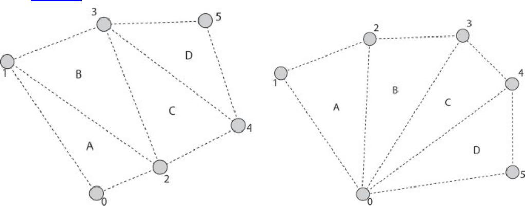
•VK_PRIMITIVE_TOPOLOGY_TRIANGLE_LIST: Vertices are grouped into triplets forming
triangles.
Next are the strip and fan primitives. These are groupings of vertices into primitives (lines or
triangles) in which each line or triangle shares one or two vertices with the previous one. The strip
and fan primitives are as follows:
•VK_PRIMITIVE_TOPOLOGY_LINE_STRIP: The first two vertices in a draw form a single
line segment. Each new vertex after them forms a new line segment from the last processed
vertex. The result is a connected sequence of lines.
•VK_PRIMITIVE_TOPOLOGY_TRIANGLE_STRIP: The first three vertices in a draw form a
single triangle. Each subsequent vertex forms a new triangle along with the last two vertices.
The result is a connected row of triangles, each sharing an edge with the last.
•VK_PRIMITIVE_TOPOLOGY_TRIANGLE_FAN: The first three vertices in a draw form a
single triangle. Each subsequent vertex forms a new triangle along with the last vertex and the
first vertex in the draw.
Strip and fan topologies are not complex but can be difficult to visualize if you are not familiar with
them. Figure 7.2 shows these topologies laid out graphically.
Figure 7.2: Strip (Left) and Fan (Right) Topologies
Next are the adjacency primitives, which are typically used only when a geometry shader is enabled
and are able to convey additional information about primitives next to them in an original mesh. The
adjacency primitive topologies are
•VK_PRIMITIVE_TOPOLOGY_LINE_LIST_WITH_ADJACENCY: Every four vertices in the
draw form a single primitive, with the center two vertices forming a line and the first and last
vertex in each group of four being presented to the geometry shader, when present.
•VK_PRIMITIVE_TOPOLOGY_LINE_STRIP_WITH_ADJACENCY: The first four vertices in
the draw form a single primitive, with the center two vertices forming a line segment and the
first and last being presented to the geometry shader as adjacency information. Each subsequent
vertex essentially slides this window of four vertices along by one, forming a new line segment
and presenting the new vertex as adjacency information.
•VK_PRIMITIVE_TOPOLOGY_TRIANGLE_LIST_WITH_ADJACENCY: Similar to lines with
adjacency, each group of six vertices is formed into a single primitive, with the first, third, and
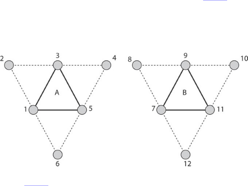
fifth in each group constructing a triangle and the second, fourth, and sixth being presented to
the geometry shader as adjacency information.
•VK_PRIMITIVE_TOPOLOGY_TRIANGLE_STRIP_WITH_ADJACENCY: This is perhaps the
most confusing primitive topology and certainly needs a diagram to visualize. Essentially, the
strip begins with the first six vertices forming a triangle with adjacency information as in the list
case. For every two new vertices, a new triangle is formed, with the odd-numbered vertices
forming the triangle and the even-numbered vertices providing adjacency information.
Again, adjacency topologies can be quite difficult to visualize—especially the
VK_PRIMITIVE_TOPOLOGY_TRIANGLE_STRIP_WITH_ADJACENCY topology. Figure 7.3
illustrates the layout of vertices within the
VK_PRIMITIVE_TOPOLOGY_TRIANGLE_LIST_WITH_ADJACENCY topology. In the figure
you can see that there are two triangles formed from a total of 12 vertices. The vertices wrap around
the outside of each triangle, with the odd-numbered vertices forming the center triangles (A and B)
and the even-numbered vertices forming virtual triangles that are not rendered, but carry adjacency
information. This concept carries on to the triangle strip
Figure 7.3: Triangles with Adjacency Topology
primitive. Figure 7.4 shows how it is applied to the
VK_PRIMITIVE_TOPOLOGY_TRIANGLE_STRIP_WITH_ADJACENCY.
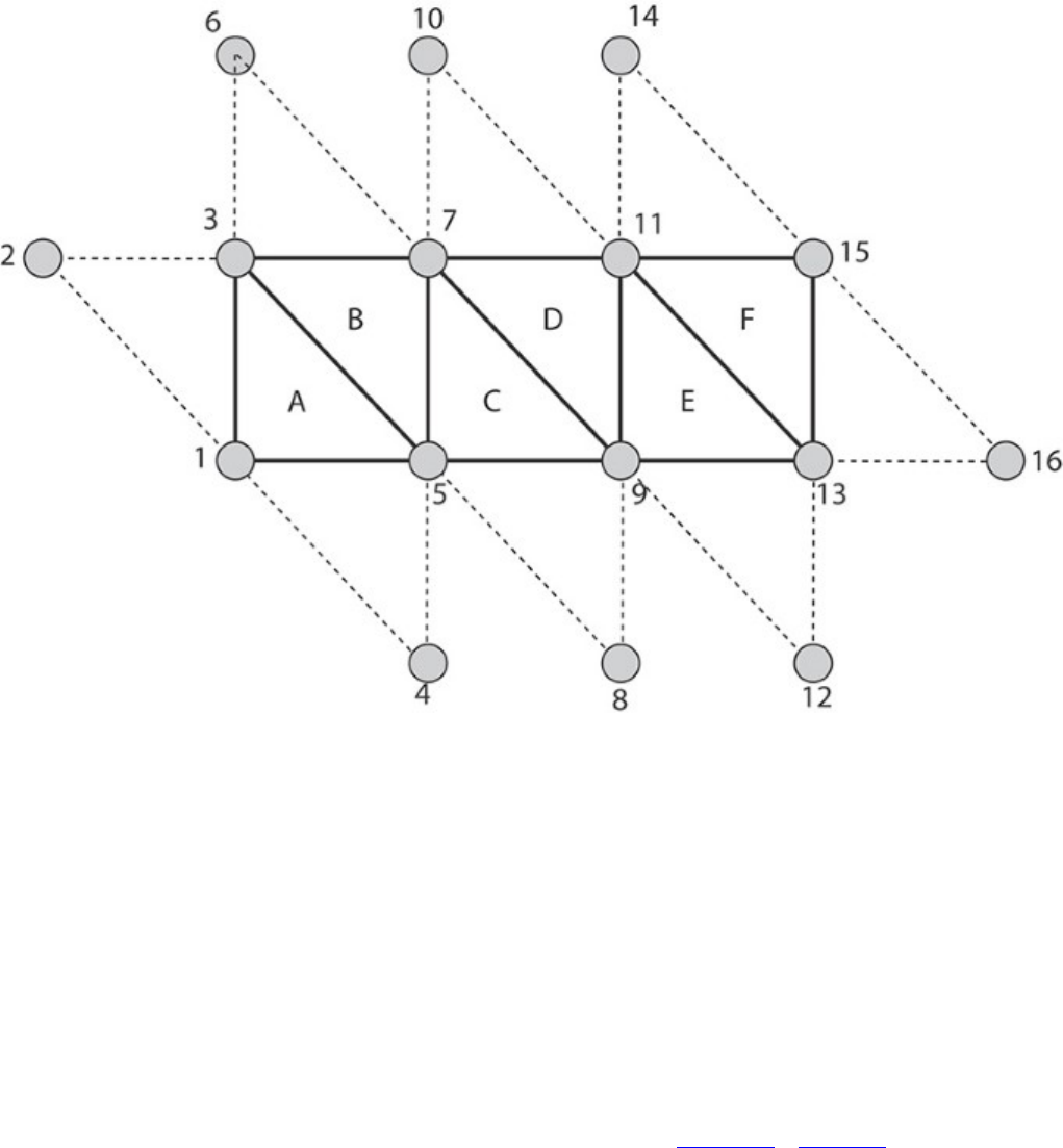
Figure 7.4: Triangle Strip with Adjacency Topology
Adjacency topologies are typically used only when a geometry shader is present, as the geometry
shader is the only stage that really sees the adjacency vertices. However, it’s possible to use
adjacency primitives without a geometry shader; the adjacency vertices will simply be discarded.
The last primitive topology is VK_PRIMITIVE_TOPOLOGY_PATCH_LIST. This topology is used
when tessellation is enabled, which requires additional information to be passed to pipeline
construction.
The last field in VkPipelineInputAssemblyStateCreateInfo is
primitiveRestartEnable. This is a flag that is used to allow strip and fan primitive topologies
to be cut and restarted. Without this, each strip or fan would need to be a separate draw. When you
use restarts, many strips or fans can be combined into a single draw. Restarts take effect only when
indexed draws are used because the point at which to restart the strip is marked using a special,
reserved value in the index buffer. This is covered in more detail in Chapter 8, “Drawing.”

Tessellation State
Tessellation is the process of breaking a large, complex primitive into a large number of smaller
primitives approximating the original. Vulkan can tessellate a patch primitive into many smaller
point, line, or triangle primitives prior to geometry shading and rasterization. Most of the state related
to tessellation is configured using the tessellation control shader and tessellation evaluation shader.
However, because these shading stages don’t run until vertex data has already been fetched and
processed by the vertex shader, some information is needed up front to configure this stage of the
pipeline.
This information is provided through an instance of the
VkPipelineTessellationStateCreateInfo structure, pointed to by the
pTessellationState member of VkGraphicsPipelineCreateInfo. The definition of
VkPipelineTessellationStateCreateInfo is
Click here to view code image
typedef struct VkPipelineTessellationStateCreateInfo {
VkStructureType sType;
const void* pNext;
VkPipelineTessellationStateCreateFlags flags;
uint32_t patchControlPoints;
} VkPipelineTessellationStateCreateInfo;
When the topology field of the VkPipelineInputAssemblyStateCreateInfo structure
is set to VK_PRIMITIVE_TOPOLOGY_PATCH_LIST,pTessellationState must be a
pointer to a VkPipelineTessellationStateCreateInfo structure; otherwise,
pTessellationState can be nullptr.
sType for VkPipelineTessellationStateCreateInfo is
VK_STRUCTURE_TYPE_PIPELINE_TESSELLATION_STATE_CREATE_INFO.pNext should
be set to nullptr, and flags is reserved for use in future versions of Vulkan and should be set to
zero. The only field of significance in VkPipelineTessellationStateCreateInfo is
patchControlPoints, which sets the number of control points that will be grouped into a single
primitive (patch). Tessellation is a somewhat advanced topic and will be covered in more detail in
Chapter 9, “Geometry Processing.”
Viewport State
Viewport transformation is the final coordinate transform in the Vulkan pipeline before rasterization
occurs. It transforms vertices from normalized device coordinates into window coordinates. Multiple
viewports can be in use simultaneously. The state of these viewports, including the number of active
viewports and their parameters, is set through an instance of the
VkPipelineViewportStateCreateInfo structure, the address of which is passed through
the pViewportState member of VkGraphicsPipelineCreateInfo. The definition of
VkPipelineViewportStateCreateInfo is
Click here to view code image
typedef struct VkPipelineViewportStateCreateInfo {
VkStructureType sType;
const void* pNext;

VkPipelineViewportStateCreateFlags flags;
uint32_t viewportCount;
const VkViewport* pViewports;
uint32_t scissorCount;
const VkRect2D* pScissors;
} VkPipelineViewportStateCreateInfo;
The sType field of VkPipelineViewportStateCreateInfo should be set to
VK_STRUCTURE_TYPE_PIPELINE_VIEWPORT_STATE_CREATE_INFO, and pNext should
be set to nullptr. The flags field is reserved for use in a future version of Vulkan and should be
set to zero.
The number of viewports that will be available to the pipeline is set in viewportCount, and the
dimensions of each viewport are passed in an array of VkViewport structures, the address of which
is specified in pViewports. The definition of VkViewport is
typedef struct VkViewport {
float x;
float y;
float width;
float height;
float minDepth;
float maxDepth;
} VkViewport;
The VkPipelineViewportStateCreateInfo structure is also used to set the scissor
rectangles for the pipeline. As with viewports, a single pipeline can define multiple scissor
rectangles, and they are passed through an array of VkRect2D structures. The number of scissor
rectangles is specified in scissorCount. Note that the index used for the viewport and scissor
rectangles when drawing is the same, so you must set scissorCount to the same value as
viewportCount.VkRect2D is a simple structure defining a rectangle in 2D and is used for many
things in Vulkan. Its definition is
typedef struct VkRect2D {
VkOffset2D offset;
VkExtent2D extent;
} VkRect2D;
Support for multiple viewports is optional. When multiple viewports are supported, then at least 16
are available. The maximum number of viewports that can be enabled in a single graphics pipeline
can be determined by inspecting the maxViewports member of the
VkPhysicalDeviceLimits structure returned from a call to
vkGetPhysicalDeviceProperties(). If multiple viewports are supported, then this limit
will be at least 16. Otherwise, this field will contain the value 1.
More information about how the viewport transformation works and how to utilize multiple
viewports in your application is given in Chapter 9, “Geometry Processing.” Further information
about scissor testing is contained in Chapter 10, “Fragment Processing.” In order to simply render to
the full framebuffer, disable the scissor test and create a single viewport with the same dimensions as
the framebuffer’s color attachments.

Rasterization State
Rasterization is the fundamental process whereby primitives represented by vertices are turned into
streams of fragments ready to be shaded by your fragment shader. The state of the rasterizer controls
how this process occurs and is set using an instance of the
VkPipelineRasterizationStateCreateInfo passed through the
pRasterizationState member of VkGraphicsPipelineCreateInfo. The definition of
VkPipelineRasterizationStateCreateInfo is
Click here to view code image
typedef struct VkPipelineRasterizationStateCreateInfo {
VkStructureType sType;
const void* pNext;
VkPipelineRasterizationStateCreateFlags flags;
VkBool32 depthClampEnable;
VkBool32 rasterizerDiscardEnable;
VkPolygonMode polygonMode;
VkCullModeFlags cullMode;
VkFrontFace frontFace;
VkBool32 depthBiasEnable;
float depthBiasConstantFactor;
float depthBiasClamp;
float depthBiasSlopeFactor;
float lineWidth;
} VkPipelineRasterizationStateCreateInfo;
The sType field of VkPipelineRasterizationStateCreateInfo should be set to
VK_STRUCTURE_TYPE_PIPELINE_RASTERIZATION_STATE_CREATE_INFO and pNext
should be set to nullptr. The flags field is reserved and should be set to zero.
The depthClampEnable field is used to turn depth clamping on or off. Depth clamping causes
fragments that would have been clipped away by the near or far planes to instead be projected onto
those planes and can be used to fill holes in geometry that would be caused by clipping.
rasterizerDiscardEnable is used to turn off rasterization altogether. When this flag is set,
the rasterizer will not run, and no fragments will be produced.
The polygonMode field can be used to get Vulkan to turn triangles into points or lines
automatically. The possible values for polygonMode are
•VK_POLYGON_MODE_FILL: This is the normal mode that is used to fill in triangles. Triangles
will be drawn solid, and every point inside the triangle will create a fragment.
•VK_POLYGON_MODE_LINE: This mode turns the triangles into lines, with each edge of each
triangle becoming a line. This is useful for drawing geometry in wireframe mode.
•VK_POLYGON_MODE_POINT: This mode simply draws each vertex as a point.
The advantage of using the polygon mode to turn geometry into wireframe or point clouds over
simply drawing lines or points is that operations that operate only on complete triangles, such as
back-face culling, are still performed. Thus, lines that would have encompassed a culled triangle are
not drawn, whereas they would be if the geometry were simply drawn as lines.
Culling is controlled with cullMode, which can be zero or a bitwise combination of either of the
following:

•VK_CULL_MODE_FRONT_BIT: Polygons (triangles) that are considered to face the viewer are
discarded.
•VK_CULL_MODE_BACK_BIT: Polygons that are considered to face away from the viewer are
discarded.
For convenience, Vulkan defines VK_CULL_MODE_FRONT_AND_BACK as the bitwise OR of both
VK_CULL_MODE_FRONT_BIT and VK_CULL_MODE_BACK_BIT. Setting cullMode to this
value will result in all triangles being dicarded. Note that culling doesn’t affect lines or points
because they don’t have a facing direction.
Which direction a triangle is facing is determined from the winding order of its vertices—whether
they proceed clockwise or counterclockwise in window space. Which of clockwise or
counterclockwise is considered front-facing is determined by the frontFace field. This is a
member of the VkFrontFace enumeration and can be either
VK_FRONT_FACE_COUNTER_CLOCKWISE or VK_FRONT_FACE_CLOCKWISE.
The next four parameters—depthBiasEnable,depthBiasConstantFactor,
depthBiasClamp, and depthBiasSlopeFactor—control the depth bias feature. This feature
allows fragments to be offset in depth before the depth test and can be used to prevent depth fighting.
This feature is discussed in some detail in Chapter 10, “Fragment Processing.”
Finally, lineWidth sets the width of line primitives, in pixels. This applies to all lines rasterized
with the pipeline. This includes pipelines in which the primitive topology is one of the line
primitives, the geometry or tessellation shaders turn the input primitives into lines, and the polygon
mode (set by polygonMode) is VK_POLYGON_MODE_LINE. Note that some Vulkan
implementations don’t support wide lines and will ignore this field. Others may run very slowly
when this field is not 1.0; still others may honor this field completely and throw away all your lines if
you set lineWidth to 0.0. Therefore, you should always set this field to 1.0 unless you’re sure you
want something else.
Even when wide lines are supported, the maximum width of a line is device-dependent. It is
guaranteed to be at least 8 pixels but could be much higher. To determine the maximum line width
supported by a device, check the lineWidthRange field of its VkPhysicalDeviceLimits
structure. This is an array of two floating-point values, the first being the minimum width of a line
(which will be at most 1 pixel; its purpose is for drawing lines that are less than a pixel wide) and the
second being the maximum width of a line. If variable line width is not supported, then both elements
of the array will be 1.0.
Further, as line width is changed, a device may snap the width you specify into fixed-size increments.
For example, it may support only whole-pixel size changes. This is the line width granularity, which
can be determined by inspecting the lineWidthGranularity field of the
VkPhysicalDeviceLimits structure.
Multisample State
Multisampling is the process of generating multiple samples for each pixel in an image. It is used to
combat aliasing and can greatly improve image quality when used effectively. When you use
multisampling, the color and depth-stencil attachments must be multisample images, and the
multisample state of the pipeline should be set appropriately through the pMultisampleState
member of VkGraphicsPipelineCreateInfo. This is a pointer to an instance of the
VkPipelineMultisampleStateCreateInfo structure, the definition of which is

Click here to view code image
typedef struct VkPipelineMultisampleStateCreateInfo {
VkStructureType sType;
const void* pNext;
VkPipelineMultisampleStateCreateFlags flags;
VkSampleCountFlagBits rasterizationSamples;
VkBool32 sampleShadingEnable;
float minSampleShading;
const VkSampleMask* pSampleMask;
VkBool32 alphaToCoverageEnable;
VkBool32 alphaToOneEnable;
} VkPipelineMultisampleStateCreateInfo;
The sType field of VkPipelineMultisampleStateCreateInfo should be set to
VK_STRUCTURE_TYPE_PIPELINE_MULTISAMPLE_STATE_CREATE_INFO and pNext
should be set to nullptr. The flags field is reserved and should be set to zero.
Depth and Stencil State
The depth-stencil state controls how the depth and stencil tests are conducted and what happens to a
fragment should it pass or fail either of those tests. The depth and stencil tests can be performed
either before or after the fragment shader runs. By default, the tests occur after the fragment shader.1
1. Most implementations will only keep up the appearance that the depth and stencil tests are running after the
fragment shader and, if possible, run the tests before running the shader to avoid running shader code when
the test would fail.
To run the fragment shader before the depth test, we can apply the SPIR-V
EarlyFragmentTests execution mode to the entry point of our fragment shader.
The depth-stencil state is configured through the pDepthStencilState member of
VkGraphicsPipelineCreateInfo, which is a pointer to an instance of the
VkPipelineDepthStencilStateCreateInfo structure. The definition of
VkPipelineDepthStencilStateCreateInfo is
Click here to view code image
typedef struct VkPipelineDepthStencilStateCreateInfo {
VkStructureType sType;
const void* pNext;
VkPipelineDepthStencilStateCreateFlags flags;
VkBool32 depthTestEnable;
VkBool32 depthWriteEnable;
VkCompareOp depthCompareOp;
VkBool32 depthBoundsTestEnable;
VkBool32 stencilTestEnable;
VkStencilOpState front;
VkStencilOpState back;
float minDepthBounds;
float maxDepthBounds;
} VkPipelineDepthStencilStateCreateInfo;
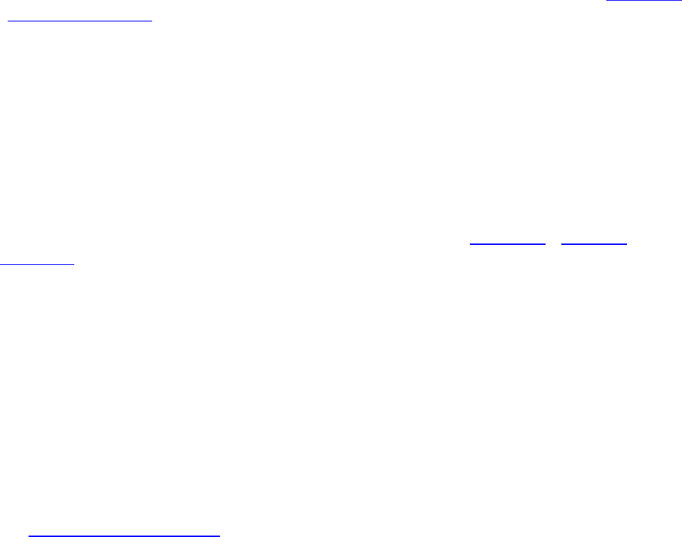
The sType field for VkPipelineDepthStencilStateCreateInfo should be set to
VK_STRUCTURE_TYPE_PIPELINE_DEPTH_STENCIL_CREATE_INFO and pNext should be
set to nullptr. The flags field is reserved and should be set to zero.
The depth test is enabled if depthTestEnable is set to VK_TRUE. If the depth test is enabled,
then the test to use is selected using depthCompareOp, which is one of the VkCompareOp
enumerant values. The available depth testing operations are discussed in more detail in Chapter 10,
“Fragment Processing.” If depthTestEnable is set to VK_FALSE, then the depth test is enabled.
The value of depthCompareOp is enabled, and all fragments are considered to have passed the
depth test. It should be noted, however, that when the depth test is disabled, no writes to the depth
buffer occur.
If the depth test passes (or if the depth test is disabled), then the fragment passes on to the stencil test.
The stencil test is enabled if the stencilTestEnable field of
VkPipelineDepthStencilCreateInfo is set to VK_TRUE and disabled otherwise. When
stencil testing is enabled, a separate state is provided for front- and back-facing primitives in the
front and back members, respectively. If stencil test is disabled, all fragments are considered to
have passed the stencil test.
The details of depth and stencil testing are covered in more depth in Chapter 10, “Fragment
Processing.”
Color Blend State
The final stage in the Vulkan graphics pipeline is the color blend stage. This stage is responsible for
writing fragments into the color attachments. In many cases, this is a simple operation that simply
overwrites the existing content of the attachment with value(s) output from the fragment shader.
However, the color blender is capable of mixing (blending) those values with the values already in
the framebuffer and performing simple logical operations between the output of the fragment shader
and the current content of the framebuffer.
The state of the color blender is specified using the pColorBlendState member of the
VkGraphicsPipelineCreateInfo structure. This is a pointer to an instance of the
VkPipelineColorBlendStateCreateInfo structure, the definition of which is
Click here to view code image
typedef struct VkPipelineColorBlendStateCreateInfo {
VkStructureType sType;
const void* pNext;
VkPipelineColorBlendStateCreateFlags flags;
VkBool32 logicOpEnable;
VkLogicOp logicOp;
uint32_t attachmentCount;
const VkPipelineColorBlendAttachmentState* pAttachments;
float blendConstants[4];
} VkPipelineColorBlendStateCreateInfo;
The sType field of VkPipelineColorBlendStateCreateInfo should be set to
VK_STRUCTURE_TYPE_PIPELINE_COLOR_BLEND_STATE_CREATE_INFO, and pNext
should be set to nullptr. The flags field is reserved for future use and should be set to zero.

The logicOpEnable field specifies whether to perform logical operations between the output of
the fragment shader and the content of the color attachments. When logicOpEnable is
VK_FALSE, then logical operations are disabled and values produced by the fragment shader are
written into the color attachment unmodified. When logicOpEnable is VK_TRUE, logic
operations are enabled for the attachments that support them. The logic operation to apply is the same
for every attachment and is a member of the VkLogicOp numeration. The meaning of each of the
enumerants and more information about logical operations is given in Chapter 10, “Fragment
Processing.”
Each attachment can have a different format, and can support different blending operations. These are
specified with an array of VkPipelineColorBlendAttachmentState structures, the address
of which is passed through the pAttachments member of
VkPipelineColorBlendStateCreateInfo. The number of attachments is set in
attachmentCount. The definition of VkPipelineColorBlendAttachmentState is
Click here to view code image
typedef struct VkPipelineColorBlendAttachmentState {
VkBool32 blendEnable;
VkBlendFactor srcColorBlendFactor;
VkBlendFactor dstColorBlendFactor;
VkBlendOp colorBlendOp;
VkBlendFactor srcAlphaBlendFactor;
VkBlendFactor dstAlphaBlendFactor;
VkBlendOp alphaBlendOp;
VkColorComponentFlags colorWriteMask;
} VkPipelineColorBlendAttachmentState;
For each color attachment, the members of VkPipelineColorBlendAttachmentState
control whether blending is enabled, what the source and destination factors are, what the blending
operation is (for both the color and alpha channels separately), and which channels in the output
image are to be updated.
If the colorBlendEnable field of VkPipelineColorBlendAttachmentState is
VK_TRUE, then the remaining parameters control the state of blending. Blending will be covered in
more detail in Chapter 10, “Fragment Processing.” When colorBlendEnable is VK_FALSE, the
blending parameters in VkPipelineColorBlendAttachmentState are ignored, and
blending is disabled for that attachment.
Regardless of the state of colorBlendEnable, the final field, colorWriteMask, controls
which channels of the output image are written in this attachment. It is a bitfield made up of bits from
the VkColorComponentFlagBits enumeration. The four channels, represented by
VK_COLOR_COMPONENT_R_BIT,VK_COLOR_COMPONENT_G_BIT,
VK_COLOR_COMPONENT_B_BIT, and VK_COLOR_COMPONENT_A_BIT, can be individually
masked out for writing. If the flag corresponding to a particular channel is not included in
colorWriteMask, then that channel will not be modified. Only the channels included in
colorWriteMask will be updated through rendering to the attachment.

Dynamic State
As you have seen, the graphics pipeline object is large and complex, and contains a lot of state. In
many graphics applications, it is often desirable to be able to change some states at a relatively high
frequency. If every change in every state required that you created a new graphics pipeline object,
then the number of objects your application would have to manage would quickly become very large.
To make fine-grained state changes more manageable, Vulkan provides the ability to mark particular
parts of the graphics pipeline as dynamic, which means that they can be updated on the fly using
commands directly inside the command buffer rather than using an object. Because this reduces the
opportunity for Vulkan to optimize or absorb parts of state, it’s necessary to specify exactly what
state you want to make dynamic. This is done through the pDynamicState member of the
VkGraphicsPipelineCreateInfo structure, which is a pointer to an instance of the
VkPipelineDynamicStateCreateInfo structure, the definition of which is
Click here to view code image
typedef struct VkPipelineDynamicStateCreateInfo {
VkStructureType sType;
const void* pNext;
VkPipelineDynamicStateCreateFlags flags;
uint32_t dynamicStateCount;
const VkDynamicState* pDynamicStates;
} VkPipelineDynamicStateCreateInfo;
The sType for VkPipelineDynamicStateCreateInfo should be set to
VK_STRUCTURE_TYPE_PIPELINE_DYNAMIC_STATE_CREATE_INFO, and pNext should be
set to nullptr. The flags field is reserved and should be set to zero.
The number of states that you wish to be dynamic is specified in dynamicStateCount. This is
the length of the array pointed to by pDynamicStates, which is an array of elements from the
VkDynamicState enumeration. Including a member of this enumeration in the
pDynamicStates array tells Vulkan that you want to be able to change that state using the
corresponding dynamic state setting commands. The members of VkDynamicState and their
meanings are as follows:
•VK_DYNAMIC_STATE_VIEWPORT: The viewport rectangle is dynamic and will be updated
using vkCmdSetViewport().
•VK_DYNAMIC_STATE_SCISSOR: The scissor rectangle is dynamic and will be updated using
vkCmdSetScissor().
•VK_DYNAMIC_STATE_LINE_WIDTH: The line width is dynamic and will be updated using
vkCmdSetLineWidth().
•VK_DYNAMIC_STATE_DEPTH_BIAS: The depth bias parameters are dynamic and will be
updated using vkCmdSetDepthBias().
•VK_DYNAMIC_STATE_BLEND_CONSTANTS: The color blend constants are dynamic and
will be updated using vkCmdSetBlendConstants().
•VK_DYNAMIC_STATE_DEPTH_BOUNDS: The depth bounds parameters are dynamic and will
be updated using vkCmdSetDepthBounds().
•VK_DYNAMIC_STATE_STENCIL_COMPARE_MASK,
VK_DYNAMIC_STATE_STENCIL_WRITE_MASK, and
VK_DYNAMIC_STATE_STENCIL_REFERENCE: The corresponding stencil parameters are
dynamic and will be updated using vkCmdSetStencilCompareMask(),
vkCmdSetStencilWriteMask(), and vkCmdSetStencilReference(),
respectively.
If a state is specified as being dynamic, then it becomes your responsibility to set that state when
binding the pipeline. If the state is not marked as dynamic, then it is considered static and is set when
the pipeline is bound. Binding a pipeline with static state makes the dynamic state undefined. The
reason for this is that Vulkan implementations might optimize static states into the pipeline object and
not actually program them into hardware if they’re not used or if it can otherwise be determined that
this is valid. When a pipeline with that state marked dynamic is subsequently bound, it’s not defined
whether the dynamic state is consistent in hardware.
When you are switching between pipelines that mark the same state as dynamic, however, then the
state remains persistent across binds. Table 7.1 illustrates this.
Table 7.1: Dynamic and Static State Validity
As you can see in Table 7.1, the only case in which state becomes undefined occurs when switching
from a pipeline with that state marked as static to one in which the same state is marked as dynamic.
In all other cases, the state is well defined and comes from either the pipeline’s state or the dynamic
state set with the appropriate command.
If you set a dynamic state when a pipeline with that state set as static is currently bound, the results
are undefined if you then draw with that pipeline. The effect could be to ignore the state-setting
command and continue to use the static version of the state from the pipeline, honor the state-setting
command and use the new dynamic state, or corrupt state altogether and break your application
entirely. The effect will be different across implementations and will likely depend on which state is
erroneously overridden.
Setting dynamic state and then binding a pipeline with that state marked as dynamic should cause the
dynamic state to be used. However, it’s good practice to bind the pipeline first and then bind any
related state simply to avert the possibility of undefined behavior.

Summary
This chapter provided a whirlwind tour of the Vulkan graphics pipeline. The pipeline consists of
multiple stages, some of which are configurable but fixed-function, and some of which are made up
of extremely powerful shaders. Building on the concept of the pipeline object introduced in Chapter
6, “Shaders and Pipelines,” the graphics pipeline object was introduced. This object includes a large
amount of fixed function state. Although the pipelines built in this chapter were simple, a solid
foundation was laid upon which to build more complex and expressive pipelines in later chapters.
Chapter 8. Drawing
What You’ll Learn in This Chapter
• The details of the different drawing commands in Vulkan
• How to draw many copies of data through instancing
• How to pass drawing parameters through buffers
Drawing is the fundamental operation in Vulkan that triggers work to be performed by a graphics
pipeline. Vulkan includes several drawing commands, each generating graphics work in slightly
different ways. This chapter delves deep into the drawing commands supported by Vulkan. First, we
reintroduce the basic drawing command first discussed in Chapter 7, “Graphics Pipelines”; then we
explore indexed and instanced drawing commands. Finally, we discuss a method to retrieve the
parameters for a drawing command from device memory and even generate them on the device itself.
Back in Chapter 7, “Graphics Pipelines,” you were introduced to your first drawing command,
vkCmdDraw(). This command simply pushes vertices into the Vulkan graphics pipeline. When we
introduced the command, we glossed over some of its parameters. We also hinted at the existence of
other drawing commands. For reference, here is the prototype for vkCmdDraw() again:
Click here to view code image
void vkCmdDraw (
VkCommandBuffer commandBuffer,
uint32_t vertexCount,
uint32_t instanceCount,
uint32_t firstVertex,
uint32_t firstInstance);
As with all commands that execute on the device, the first parameter is a VkCommandBuffer
handle. The number of vertices in each draw is specified in vertexCount, and the vertex index
from which the vertices start is specified in firstVertex. The vertices that are sent down the
pipeline have indices starting from firstVertex and proceed through vertexCount contiguous
vertices. If you’re using vertex buffers and attributes to automatically feed data into your vertex
shader, then the shader will see data fetched from that contiguous section of the arrays. If you’re
using the vertex index directly in your shader, you will see it count monotonically from
firstVertex upward.
Getting Ready to Draw
As we mentioned back in Chapter 7, “Graphics Pipelines,” all drawing is contained inside a
renderpass. Although renderpass objects can encapsulate many subpasses, even simple rendering that
draws into a single output image must be part of a renderpass. The renderpass is created by calling
vkCreateRenderPass() as described in Chapter 7. To prepare for rendering, we need to call
vkCmdBeginRenderPass(), which sets the current renderpass object and, perhaps more
important, configures the set of output images that will be drawn into. The prototype of
vkCmdBeginRenderPass() is

Click here to view code image
void vkCmdBeginRenderPass (
VkCommandBuffer commandBuffer,
const VkRenderPassBeginInfo* pRenderPassBegin,
VkSubpassContents contents);
The command buffer that will contain the commands issued inside the renderpass is passed in
commandBuffer. The bulk of the parameters describing the renderpass are passed through a
pointer to an instance of the VkRenderPassBeginInfo structure in pRenderPassBegin. The
definition of VkRenderPassBeginInfo is
Click here to view code image
typedef struct VkRenderPassBeginInfo {
VkStructureType sType;
const void* pNext;
VkRenderPass renderPass;
VkFramebuffer framebuffer;
VkRect2D renderArea;
uint32_t clearValueCount;
const VkClearValue* pClearValues;
} VkRenderPassBeginInfo;
The sType field of the VkRenderPassBeginInfo structure should be set to
VK_STRUCTURE_TYPE_RENDER_PASS_BEGIN_INFO, and pNext should be set to nullptr.
The renderpass that is begun is specified in renderPass, and the framebuffer that we’re going to
render into is specified in framebuffer. As discussed in Chapter 7, “Graphics Pipelines,” the
framebuffer is the collection of images that will be rendered to by graphics commands.
Within any particular use of a renderpass, we can choose to render only into a small area of the
attached images. To do this, use the renderArea member of the VkRenderPassBeginInfo
structure to specify the rectangle in which all rendering will be contained. Simply setting
renderArea.offset.x and renderArea.offset.y to 0 and
renderArea.extent.width and renderArea.extent.height to the width and height of
the images in the framebuffer tells Vulkan that you’re going to render into the whole rendering area
of the framebuffer.
If any of the attachments in the renderpass have a load operation of
VK_ATTACHMENT_LOAD_OP_CLEAR, then the colors or values that you want to clear them to are
specified in an array of VkClearValue unions, a pointer to which is passed in pClearValues.
The number of elements in pClearValues is passed in clearValueCount. The definition of
VkClearValue is
Click here to view code image
typedef union VkClearValue {
VkClearColorValue color;
VkClearDepthStencilValue depthStencil;
} VkClearValue;
If the attachment is a color attachment, then the values stored in the color member of the
VkClearValue union are used, and if the attachment is a depth, stencil, or depth-stencil

attachment, then the values stored in the depthStencil member are used. color and
depthStencil are instances of the VkClearColorValue and
VkClearDepthStencilValue structures, respectively, the definitions of which are
Click here to view code image
typedef union VkClearColorValue {
float float32[4];
int32_t int32[4];
uint32_t uint32[4];
} VkClearColorValue;
and
Click here to view code image
typedef struct VkClearDepthStencilValue {
float depth;
uint32_t stencil;
} VkClearDepthStencilValue;
The index of each attachment is used to index into the array of VkClearValue unions. This means
that if only some of the attachments have a load operation of
VK_ATTACHMENT_LOAD_OP_CLEAR, then there could be unused entries in the array. There must
be at least as many entries in the pClearValues array as the highest-indexed attachment with a
load operation of VK_ATTACHMENT_LOAD_OP_CLEAR.
For each attachment with a load operation of VK_ATTACHMENT_LOAD_OP_CLEAR, if it is a color
attachment, then the values of the float32,int32, or uint32 arrays are used to clear the
attachment, depending on whether it is a floating-point or normalized format, a signed integer format,
or an unsigned integer format, respectively. If the attachment is a depth, stencil, or depth-stencil
attachment, then the values of the depth and stencil members of the depthStencil member
of the VkClearValue union are used to clear the appropriate aspect of the attachment.
Once the renderpass has begun, you can place drawing commands (which are discussed in the next
section) in the command buffer. All rendering will be directed into the framebuffer specified in the
VkRenderPassBeginInfo structure passed to vkCmdBeginRenderPass(). To finalize
rendering contained in the renderpass, you need to end it by calling vkCmdEndRenderPass(),
the prototype of which is
Click here to view code image
void vkCmdEndRenderPass (
VkCommandBuffer commandBuffer);
After vkCmdEndRenderPass() has executed, any rendering directed through the renderpass is
completed, and the content of the framebuffer is updated. Until then, the framebuffer’s content is
undefined. Only attachments with a store operation of VK_ATTACHMENT_STORE_OP_STORE will
reflect the new content produced by the rendering inside the renderpass. If an attachment has a store
operation of VK_ATTACHMENT_STORE_OP_DONT_CARE, then its content is undefined after the
renderpass has completed.

Vertex Data
If the graphics pipeline you’re going to use requires vertex data, before performing any drawing
commands, you need to bind buffers to source the data from. When buffers are in use as the sources
of vertex data, they are sometimes known as vertex buffers. The command to buffers for use as vertex
data is vkCmdBindVertexBuffers(), and its prototype is
Click here to view code image
void vkCmdBindVertexBuffers (
VkCommandBuffer commandBuffer,
uint32_t firstBinding,
uint32_t bindingCount,
const VkBuffer* pBuffers,
const VkDeviceSize* pOffsets);
The command buffer to which to bind the buffers is specified in commandBuffer. A given
pipeline may reference many vertex buffers, and vkCmdBindVertexBuffers() is capable of
updating a subset of the bindings on a particular command buffer. The index of the first binding to
update is passed in firstBinding, and the number of contiguous bindings to update is passed in
bindingCount. To update noncontiguous ranges of vertex buffer bindings, you need to call
vkCmdBindVertexBuffers() multiple times.
The pBuffers parameter is a pointer to an array of bindingCount VkBuffer handles to the
buffer objects to be bound, and pOffsets is a pointer to an array of bindingCount offsets into
the buffer objects at which the data for each binding starts. The values in pOffsets are specified in
bytes. It is perfectly reasonable to bind the same buffer object with different offsets (or even the same
offset, if that’s what’s required) to a command buffer; simply include the same VkBuffer handle
multiple times in the pBuffers array.
The layout and format of the data in the buffers are defined by the graphics pipeline that will
consume the vertex data. Therefore, the format of the data is not specified here, but in the
VkPipelineVertexInputStateCreateInfo structure passed via the
VkGraphicsPipelineCreateInfo used to create the graphics pipeline. Back in Chapter 7,
“Graphics Pipelines,” we showed an example of setting up interleaved vertex data as a C++ structure
in Listing 7.3.Listing 8.1 shows a slightly more advanced example that uses one buffer to store
position data alone and a second buffer that stores a per-vertex normal and texture coordinate.
Listing 8.1: Separate Vertex Attribute Setup
Click here to view code image
typedef struct vertex_t
{
vmath::vec3 normal;
vmath::vec2 texcoord;
} vertex;
static const
VkVertexInputBindingDescription vertexInputBindings[] =
{
{ 0, sizeof(vmath::vec4), VK_VERTEX_INPUT_RATE_VERTEX }, // Buffer 1

{ 1, sizeof(vertex), VK_VERTEX_INPUT_RATE_VERTEX } // Buffer 2
};
static const
VkVertexInputAttributeDescription vertexAttributes[] =
{
{ 0, 0, VK_FORMAT_R32G32B32A32_SFLOAT, 0 }, // Position
{ 1, 1, VK_FORMAT_R32G32B32_SFLOAT, 0 }, // Normal
{ 2, 1, VK_FORMAT_R32G32_SFLOAT, sizeof(vmath::vec3) } // Tex Coord
};
static const
VkPipelineVertexInputStateCreateInfo vertexInputStateCreateInfo =
{
VK_STRUCTURE_TYPE_PIPELINE_VERTEX_INPUT_STATE_CREATE_INFO, // sType
nullptr, // pNext
0, // flags
vkcore::utils::arraysize(vertexInputBindings), //
vertexBindingDescription-
// Count
vertexInputBindings, // pVertexBinding-
// Descriptions
vkcore::utils::arraysize(vertexAttributes), // vertexAttribute-
// DescriptionCount
vertexAttributes // pVertexAttribute-
// Descriptions
};
In Listing 8.1, we have defined three vertex attributes spread across two buffers. In the first buffer,
only a single vec4 variable is stored, and this is used for position. The stride for this buffer is
therefore the size of a vec4, which is 16 bytes. In the second buffer, we store the interleaved normal
and texture coordinates for the vertex. We represent this as the vertex structure, allowing the
compiler to compute the stride for us.
Indexed Draws
Simply pushing contiguous runs of vertices into the pipeline isn’t always what you want. In most
geometric meshes, many vertices are used more than once. A fully connected mesh may share a
single vertex among many triangles. Even a simple cube shares each vertex among three adjacent
triangles. It is extremely wasteful to have to specify each vertex three times in your vertex buffers.
Besides this, some Vulkan implementations are smart enough that if they see a vertex with the same
input parameters more than once, they can skip processing it a second time and subsequent times, and
instead reuse the results of the first vertex shader invocation.
To enable this, Vulkan allows indexed draws. The indexed equivalent of vkCmdDraw() is
vkCmdDrawIndexed(), the prototype of which is
Click here to view code image
void vkCmdDrawIndexed (
VkCommandBuffer commandBuffer,
uint32_t indexCount,
uint32_t instanceCount,

uint32_t firstIndex,
int32_t vertexOffset,
uint32_t firstInstance);
Again, the first parameter to vkCmdDrawIndexed() is the handle to the command buffer in which
the draw will be executed. Rather than simply starting from zero and counting upward, however,
vkCmdDrawIndexed() fetches indices from an index buffer. The index buffer is a regular buffer
object that you bind to the command buffer by calling vkCmdBindIndexBuffer(), the
prototype of which is
Click here to view code image
void vkCmdBindIndexBuffer (
VkCommandBuffer commandBuffer,
VkBuffer buffer,
VkDeviceSize offset,
VkIndexType indexType);
The command buffer to which to bind the index buffer is specified in commandBuffer, and the
handle to the buffer object containing indexed data is specified in buffer. A section of a buffer
object can be bound to the command buffer starting from offset. The bound section always
extends to the end of the buffer object. There is no bounds checking on the index buffer; Vulkan will
read as many indices from the buffer as you tell it to. However, it will never read past the end of the
buffer object.
The data type of the indices in the buffer is specified in indexType. This is a member of the
VkIndexType enumeration, the members of which are
•VK_INDEX_TYPE_UINT16: Unsigned 16-bit integers
•VK_INDEX_TYPE_UINT32: Unsigned 32-bit integers
When you call vkCmdDrawIndexed(), Vulkan will start fetching data from the currently bound
index buffer at an offset of
Click here to view code image
offset + firstIndex * sizeof(index)
where sizeof(index) is 2 for VK_INDEX_TYPE_UINT16 and 4 for
VK_INDEX_TYPE_UINT32. The code will fetch indexCount contiguous integers from the index
buffer and then add vertexOffset to them. This addition is always performed in 32 bits,
regardless of the index type for the currently bound index buffer. It is not defined what would happen
if this addition overflowed the 32-bit unsigned integer range, so you should avoid that.
A schematic illustrating the data flow is shown in Figure 8.1.
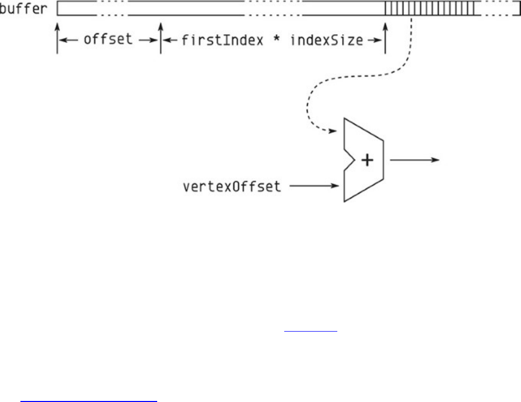
Figure 8.1: Index Data Flow
Note that when the index type is VK_INDEX_TYPE_UINT32, the maximum range of index values
may not be supported. To check this, look at the maxDrawIndexedIndexValue field of the
device’s VkPhysicalDeviceLimits structure, which you can retrieve by calling
vkGetPhysicalDeviceProperties(). This value will always be at least 224-1 and may be as
high as 232-1.
To demonstrate the effectiveness of the use of index data, Listing 8.2 shows the difference between
the data required for drawing a simple cube using indexed and nonindexed data.
Listing 8.2: Indexed Cube Data
Click here to view code image
// Raw, non-indexed data
static const float vertex_positions[] =
{
-0.25f, 0.25f, -0.25f,
-0.25f, -0.25f, -0.25f,
0.25f, -0.25f, -0.25f,
0.25f, -0.25f, -0.25f,
0.25f, 0.25f, -0.25f,
-0.25f, 0.25f, -0.25f,
0.25f, -0.25f, -0.25f,
0.25f, -0.25f, 0.25f,
0.25f, 0.25f, -0.25f,
0.25f, -0.25f, 0.25f,
0.25f, 0.25f, 0.25f,
0.25f, 0.25f, -0.25f,
0.25f, -0.25f, 0.25f,
-0.25f, -0.25f, 0.25f,
0.25f, 0.25f, 0.25f,
-0.25f, -0.25f, 0.25f,
-0.25f, 0.25f, 0.25f,
0.25f, 0.25f, 0.25f,
-0.25f, -0.25f, 0.25f,
-0.25f, -0.25f, -0.25f,
-0.25f, 0.25f, 0.25f,
-0.25f, -0.25f, -0.25f,
-0.25f, 0.25f, -0.25f,
-0.25f, 0.25f, 0.25f,
-0.25f, -0.25f, 0.25f,
0.25f, -0.25f, 0.25f,
0.25f, -0.25f, -0.25f,
0.25f, -0.25f, -0.25f,
-0.25f, -0.25f, -0.25f,
-0.25f, -0.25f, 0.25f,
-0.25f, 0.25f, -0.25f,
0.25f, 0.25f, -0.25f,
0.25f, 0.25f, 0.25f,
0.25f, 0.25f, 0.25f,
-0.25f, 0.25f, 0.25f,
-0.25f, 0.25f, -0.25f
};
static const uint32_t vertex_count = sizeof(vertex_positions) /
(3 * sizeof(float));
// Indexed vertex data
static const float indexed_vertex_positions[] =
{
-0.25f, -0.25f, -0.25f,
-0.25f, 0.25f, -0.25f,
0.25f, -0.25f, -0.25f,
0.25f, 0.25f, -0.25f,
0.25f, -0.25f, 0.25f,
0.25f, 0.25f, 0.25f,
-0.25f, -0.25f, 0.25f,
-0.25f, 0.25f, 0.25f,
};
// Index buffer
static const uint16_t vertex_indices[] =
{
0, 1, 2,

2, 1, 3,
2, 3, 4,
4, 3, 5,
4, 5, 6,
6, 5, 7,
6, 7, 0,
0, 7, 1,
6, 0, 2,
2, 4, 6,
7, 5, 3,
7, 3, 1
};
static const uint32_t index_count =
vkcore::utils::arraysize(vertex_indices);
As you can see in Listing 8.2, the amount of data used to draw the cube is quite small. Only the
vertex data for the 8 unique vertices is stored, along with 36 indices used to reference them. As
geometry sizes go up with scene complexity, the savings can be quite large. In this simple example,
the nonindexed vertex data is 36 vertices, each consisting of 3 elements of 4 bytes, which is a total of
432 bytes of data. Meanwhile, the indexed data is 12 vertices, again each of 3 elements of 4 bytes,
plus 36 indices, each consuming 2 bytes of storage. This produces a total 168 bytes of data for the
indexed cube.
In addition to the space savings provided by using indexed data, many Vulkan implementations
include a vertex cache that can reuse the results of computations performed on vertex data. If the
vertices are nonindexed, then the pipeline must assume that they are all unique. However, when the
vertices are indexed, two vertices with the same index are the same. In any closed mesh, the same
vertex will appear more than once, as it is shared among multiple primitives. This reuse can save
quite a bit of work.
Index-Only Rendering
The raw index of the current vertex is available to your vertex shaders. This index appears in the
variable decorated with VertexIndex in a SPIR-V shader, which is generated using the
gl_VertexIndex built-in variable in GLSL. This contains the content of the index buffer (or the
automatically generated vertex index) plus the value of vertexOffset passed to
vkCmdDrawIndexed().
You can use this index to fetch data from a buffer, for example. This allows you to pump geometry
into the pipeline without worrying about vertex attributes. However, in some scenarios, a single
32-bit value might be all you need. In these cases, you can use the vertex index directly as data.
Vulkan doesn’t actually care what the values in the index buffer are so long as you don’t use them to
address into vertex buffers.
The object local vertex position for many pieces of geometry can be represented by 16-, 10-, or even
8-bit data with sufficient precision. Three 10-bit values can be packed inside a single 32-bit word. In
fact, this is exactly what the VK_FORMAT_A2R10G10B10_SNORM_PACK32 format (and its
unsigned counterpart) represent. Although the vertex data is not usable directly as an index buffer, it’s
possible to manually unpack the vertex data in the shader as though it had that format. As such, by
simply unpacking the index in our shader, we can draw simple geometry without anything more than
an index buffer.

Listing 8.3 shows the GLSL shader you use to do this unpacking operation.
Listing 8.3: Using the Vertex Index in a Shader
Click here to view code image
#version 450 core
vec3 unpackA2R10G10B10_snorm(uint value)
{
int val_signed = int(value);
vec3 result;
const float scale = (1.0f / 512.0f);
result.x = float(bitfieldExtract(val_signed, 20, 10));
result.y = float(bitfieldExtract(val_signed, 10, 10));
result.z = float(bitfieldExtract(val_signed, 0, 10));
return result * scale;
}
void main(void)
{
gl_Position = vec4(unpackA2R10G10B10_snorm(gl_VertexIndex), 1.0f);
}
The vertex shader shown in Listing 8.3 simply unpacks the incoming vertex index by using the
unpackA2R10G10B10_snorm function. The resulting value is written to gl_Position. The
10 bits of precision in each of the x,y, and zcoordinates effectively snap our vertices to a 1,024 ×
1,024 × 1,024 grid of positions. This is sufficient in many cases. If an additional scale is applied, this
can be passed to the shader via a push constant, and if the vertex is to undergo other transforms via
matrix multiplications, for example, those transforms still proceed at full precision.
Reset Indices
Another subfeature of indexed draws allows you to use the primitive restart index. This special index
value can be stored in the index buffer that can be used to signal the start of a new primitive. It is
most useful when the primitive topology is one of the long, continuous primitives, including
VK_PRIMITIVE_TOPOLOGY_TRIANGLE_STRIP,
VK_PRIMITIVE_TOPOLOGY_TRIANGLE_FAN, and
VK_PRIMITIVE_TOPOLOGY_LINE_STRIP, along with the adjacency versions of those
topologies, VK_PRIMITIVE_TOPOLOGY_TRIANGLE_STRIP_WITH_ADJACENCY, and
VK_PRIMITIVE_TOPOLOGY_LINE_STRIP_WITH_ADJACENCY.
The primitive restart feature is enabled using the
VkPipelineInputAssemblyStateCreateInfo structure passed through the
pInputAssemblyState member of the VkGraphicsPipelineCreateInfo structure used
to create a graphics pipeline. Again, the definition of this structure is

Click here to view code image
typedef struct VkPipelineInputAssemblyStateCreateInfo {
VkStructureType sType;
const void* pNext;
VkPipelineInputAssemblyStateCreateFlags flags;
VkPrimitiveTopology topology;
VkBool32 primitiveRestartEnable;
} VkPipelineInputAssemblyStateCreateInfo;
The topology field has to be set to one of the primitive topologies that supports primitive restarts
(the list and fan topologies mentioned earlier), and the primitiveRestartEnable field is set to
VK_TRUE. When primitive restart is enabled, the special value of the maximum possible value for
the index type (0xFFFF for VK_INDEX_TYPE_UINT16 and 0xFFFFFFFF for
VK_INDEX_TYPE_UINT32) is used as the special restart marker.
If primitive restart is not enabled, the special reset marker is treated as a normal vertex index. While
using 32-bit indices, it’s unlikely that you’ll ever need to use this value, because that would mean you
had more than 4 billion vertices. However, the index value can still be passed to the vertex shader.
It’s not valid to enable the reset for primitive topologies other than the strip and fan topologies
mentioned earlier.
When Vulkan encounters the reset value in the index buffer, it ends the current strip or fan and starts
a new one beginning with the vertex addressed by the next index in the index buffer. If the reset value
appears multiple times in a row, Vulkan simply skips them, looking for the next nonreset index value.
If there aren’t enough vertices to form a complete primitive (for example, if the reset index appears
before three nonreset vertices are seen when the primitive topology is
VK_PRIMITIVE_TOPOLOGY_TRIANGLE_STRIP or
VK_PRIMITIVE_TOPOLOGY_TRIANGLE_FAN), then Vulkan will throw out all the vertices used
so far and start a new primitive.
Figure 8.2 shows how reset indices affect the VK_PRIMITIVE_TOPOLOGY_TRIANGLE_STRIP
topology. In the top strip, contiguous indices between 0 and 12 are used to create a single long strip.
When you enable primitive resets and replace index 6 with reset index value 0xFFFFFFFF, the strip
stops after the first four triangles and restarts with a triangle between vertices 7, 8, and 9.
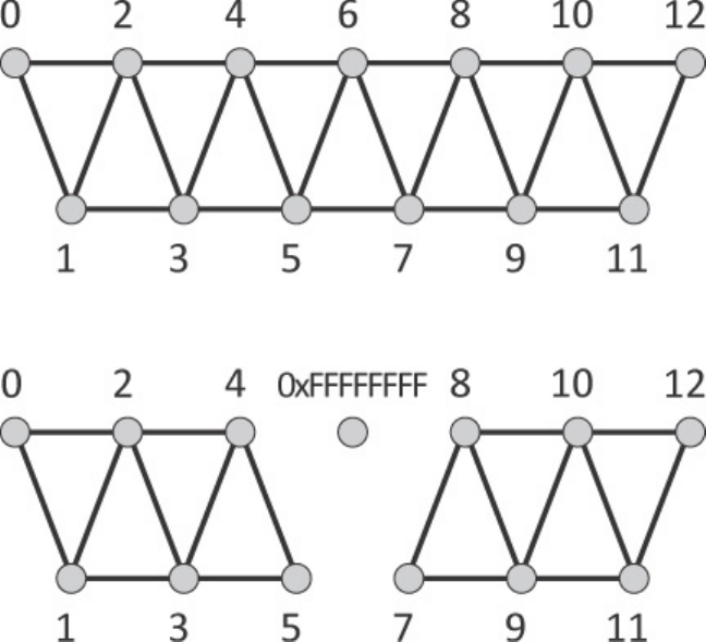
Figure 8.2: The Effect of Primitive Restart on Triangle Strips
The reset index is useful for cutting a very large draw using strips or fans into many smaller pieces.
There comes a cut-off point in usefulness when the number of subdraws (individual strips or fans)
decreases and their size increases, at which point it’s probably best to simply produce two separate
draws. This is especially true if it means switching pipelines between one with primitive restart
enabled and one with it disabled.
If your model consists of hundreds or thousands of short strips, it might be a good idea to use
primitive restart. If your model consists of a handful of very long strips, just make multiple drawing
commands. Also, in some architectures, using the reset index can affect performance, and it may be
better to simply use list topologies and unroll the index buffer rather than try to use strips.
Instancing
There are two parameters to vkCmdDraw() and vkCmdDrawIndexed() that we have thus far
glossed over. These are the firstInstance and instanceCount parameters, and they are used
to control instancing. This is a technique whereby many copies of the same geometry can be sent into
the graphics pipeline. Each copy is known as an instance. At first, this seems like it wouldn’t be
much use, but there are two ways that your application can apply variation to each of the instances of
the geometry:
• Use the InstanceIndex built-in decoration on a vertex shader input to receive the index of
the current instance as an input to the shader. This input variable can then be used to fetch
parameters from a uniform buffer or programmatically compute per-instance variation, for
example.
• Use instanced vertex attributes to have Vulkan feed your vertex shader with unique data for
each instance.

Listing 8.4 shows an example of using the instance index through the gl_InstanceIndex built-
in variable in GLSL. The example draws many different cubes using instancing where each instance
of the cube has a different color and transformation applied. The transformation matrix and color of
each cube are placed in arrays that are stored in a pair of uniform buffers. The shader then indexes
into these arrays with the gl_InstanceIndex built-in variable. The result of rendering with this
shader is shown in Figure 8.3.
Listing 8.4: Using the Instance Index in a Shader
Click here to view code image
#version 450 core
layout (set = 0, binding = 0) uniform matrix_uniforms_b
{
mat4 mvp_matrix[1024];
};
layout (set = 0, binding = 1) uniform color_uniforms_b
{
vec4 cube_colors[1024];
};
layout (location = 0) in vec3 i_position;
out vs_fs
{
flat vec4 color;
};
void main(void)
{
float f = float(gl_VertexIndex / 6) / 6.0f;
vec4 color1 = cube_colors[gl_InstanceIndex];
vec4 color2 = cube_colors[gl_InstanceIndex & 512];
color = mix(color1, color2, f);
gl_Position = mvp_matrix[gl_InstanceIndex] * vec4(i_position, 1.0f);
}
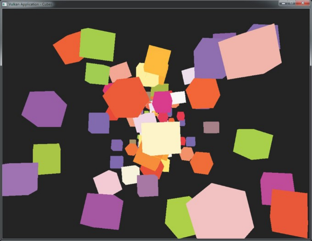
Figure 8.3: Many Instanced Cubes
Indirect Draws
In the vkCmdDraw() and vkCmdDrawIndexed() commands, the parameters to the command
(vertexCount,vertexOffset, and so on) are passed as immediate parameters directly to the
commands themselves. This means that you need to know the exact parameters of each draw call at
the time that your application builds its command buffers. In most cases, having access to the
parameters of drawing commands is a natural part of the application. However, in some situations,
you don’t know the exact parameters for each and every draw. Examples include the following:
• The overall structure of the geometry is known, but the exact number of vertices and locations
of data in the vertex buffers is not known, such as when an object is always rendered the same
way but its level of detail may change over time.
• The drawing commands are to be generated by the device, rather than the host. In this situation,
the total number and layout of vertex data may never be known to the host.
In these cases, you can use an indirect draw, which is a drawing command that sources its parameters
from device-accessible memory rather than embedding them in the command buffer along with the
command. The first indirect draw command is vkCmdDrawIndirect(), which performs a
nonindexed draw using parameters contained in a buffer. Its prototype is

Click here to view code image
void vkCmdDrawIndirect (
VkCommandBuffer commandBuffer,
VkBuffer buffer,
VkDeviceSize offset,
uint32_t drawCount,
uint32_t stride);
The command itself is still placed into the command buffer, just as with vkCmdDraw().
commandBuffer is the command buffer into which the command is placed. However, the
parameters of the command are sourced from the buffer specified in buffer at the offset specified
in offset, which is measured in bytes. At this offset in the buffer, an instance of the
VkDrawIndirectCommand structure should appear, containing the actual parameters of the
command. Its definition is
Click here to view code image
typedef struct VkDrawIndirectCommand {
uint32_t vertexCount;
uint32_t instanceCount;
uint32_t firstVertex;
uint32_t firstInstance;
} VkDrawIndirectCommand;
The members of VkDrawIndirectCommand have the same meanings as the similarly named
parameters of vkCmdDraw().vertexCount and instanceCount are the numbers of vertices
and indices to invoke, respectively, and firstVertex and firstInstance are the starting
values for the vertex and instance indices, respectively.
vkCmdDrawIndirect() performs a nonindexed, indirect draw using parameters from a buffer
object. It’s also possible to perform an indexed indirect draw using
vkCmdDrawIndexedIndirect(). The prototype of this function is
Click here to view code image
void vkCmdDrawIndexedIndirect (
VkCommandBuffer commandBuffer,
VkBuffer buffer,
VkDeviceSize offset,
uint32_t drawCount,
uint32_t stride);
The parameters of vkCmdDrawIndexedIndirect() are identical to those of
vkCmdDrawIndirect().commandBuffer is the command buffer into which the command is
written, buffer is the buffer containing the parameters; and offset is the offset, in bytes, at
which the parameters are located in that buffer. However, the data structure containing the parameters
of vkCmdDrawIndexedIndirect() is different. It is an instance of the
VkDrawIndexedIndirectCommand structure, the definition of which is
Click here to view code image
typedef struct VkDrawIndexedIndirectCommand {
uint32_t indexCount;

uint32_t instanceCount;
uint32_t firstIndex;
int32_t vertexOffset;
uint32_t firstInstance;
} VkDrawIndexedIndirectCommand;
Again, the members of VkDrawIndexedIndirectCommand have the same meanings as the
similarly named parameters of vkCmdDrawIndexed().indexCount and instanceCount
are the numbers of vertex indices and instances to push into the pipeline; the firstIndex member
specifies where to start fetching indices from the index buffer; vertexOffset specifies the offset
value to be added to the index data; and firstInstance specifies the value from which the
instance counter should start counting.
What is important to remember about indirect drawing commands is that while the buffer object and
the offset into it are baked into the command buffer, the parameters for the draw don’t need to be in
the sourced buffer object until the command buffer is executed by the device. As the device executes
the command buffer, when it reaches the command, it will read whatever parameters are in the buffer
and execute the drawing command as though those parameters had been specified directly to a
regular drawing command. As far as the rest of the pipeline is concerned, there is no difference
between a direct and an indirect draw.
This means several things:
• You can build command buffers with indirect draws long before they’re needed, filling in the
final parameters for the draw (in the buffer object rather than the command buffer) before the
command buffer is submitted for execution.
• You can create a command buffer containing an indirect draw, submit it, overwrite the
parameters in the buffer object, and submit the same command buffer again. This effectively
patches new parameters into what could be a long, complex command buffer.
• You can write parameters into a buffer object by using stores from a shader object, or by using a
command such as vkCmdFillBuffer() or vkCmdCopyBuffer() to generate drawing
parameters on the device itself—either in the same command buffer or in another submitted just
before the one containing the draw commands.
You may have noticed that both vkCmdDrawIndirect() and
vkCmdDrawIndexedIndirect() take a drawCount and a stride parameter. These
parameters allow you to pass arrays of drawing commands to Vulkan. A single call to
vkCmdDrawIndirect() or vkCmdDrawIndexedIndirect() will kick off drawCount
separate draws, each sourcing its parameters from a VkDrawIndirectCommand or
VkDrawIndexedIndirectCommand structure, respectively.
The array of structures still begins at offset bytes into the buffer object, and each of these
structures is separated from the previous by stride bytes. If stride is zero, then the same
parameter structure will be used for every draw.1
1. Note that this behavior differs from OpenGL, in which a stride of zero causes the device to assume a tightly
packed array, and it is impossible to source the same parameters over and over.
The number of draws is still baked into the command buffer, but draws whose indexCount or
instanceCount parameters are zero will be skipped by the device. While this doesn’t mean that
you can truly produce a fully dynamic draw count, by using a fixed upper limit on the number of
draws and ensuring that all unused entries in the array of parameters have at least one of

vertexCoount,indexCount, or instanceCount, set to zero, you can generate a variable
number of draws by using a single command.
Note that support for counts other than one (and zero) is optional. To check whether the device
supports a count greater than one, check the multiDrawIndirect field of the device’s
VkPhysicalDeviceFeatures structure as returned from a call to
vkGetPhysicalDeviceFeatures(), and remember to enable the feature in the set of enabled
features passed to vkCreateDevice() when creating the logical device.
When indirect counts are supported, the maximum number of draws that can be passed to a single
call to vkCmdDrawIndirect() or vkCmdDrawIndexedIndirect() may still be limited. To
check the supported count, inspect the maxDrawIndirectCount field of the device’s
VkPhysicalDeviceLimits structure. When multiDrawIndirect is not supported, this
field will be 1. If it is supported, then it is guaranteed to be at least 65,535. If the number of draws
you’re pushing through each of these commands is less than this amount, then there’s no need to
directly check the limit.
Drawing many pieces of geometry back to back with the same pipeline and graphics state can
sometimes be limiting. However, in many cases, all that is different between draws is parameters
passed to shaders. This is especially true when applications use über shaders or physically based
rendering techniques. There is no direct way to pass parameters to the individual draws that make up
a single call to vkCmdDrawIndirect() or vkCmdDrawIndexedIndirect() with a
drawCount greater than one. However, what is available in the shader is the SPIR-V decoration
DrawIndex decoration on an input to the vertex shader. This is produced by using the
gl_DrawIDARB input in GLSL.
When decorated with DrawIndex, the shader input will contain the index of the draw, starting from
zero and counting upward as the draws are generated by the device. This can then be used to index
into arrays of data stored in uniform or shader storage blocks. Listing 8.5 shows a GLSL shader that
uses gl_DrawIDARB to retrieve per-draw parameters from a shader storage block.
Listing 8.5: Draw Index Used in a Shader
Click here to view code image
#version 450 core
// Enable the GL_ARB_shader_draw_parameters extensions.
#extension GL_ARB_shader_draw_parameters : require
layout (location = 0) in vec3 position_3;
layout (set = 0, binding = 0) uniform FRAME_DATA
{
mat4 view_matrix;
mat4 proj_matrix;
mat4 viewproj_matrix;
};
layout (set = 0, binding = 1) readonly buffer OBJECT_TRANSFORMS
{
mat4 model_matrix[];

};
void main(void)
{
// Extend input position to vec4.
vec4 position = vec4(position_3, 1.0);
// Compute per-object model-view matrix.
mat4 mv_matrix = view_matrix * model_matrix[gl_DrawIDARB];
// Output position using global projection matrix.
gl_Position = proj_matrix * P;
}
The shader in Listing 8.5 uses a single uniform block to store per-frame constants and a single shader
storage block to store a large array of per-object transformation matrices.2The gl_DrawIDARB
built-in variable is used to index into the model_matrix array stored in the shader storage block.
The result is that each subdraw in the single vkCmdDrawIndirect() call uses its own model
transformation matrix.
2. At the time of writing, the reference GLSL compiler does not contain support for the
GL_ARB_draw_parameters extension that exposes gl_DrawID. This shader was developed in an
OpenGL test environment and then edited to suit Vulkan. It is expected to work once support for
GL_ARB_draw_parameters lands in the reference compiler.
Summary
This chapter covered the various drawing commands supported by Vulkan. You were reintroduced to
vkCmdDraw(), which was first mentioned in Chapter 7, “Graphics Pipelines,” and which produces
nonindexed draws. Indexed draws were covered, and then we explored instancing, which is a
technique for drawing many copies of the same geometry with varying parameters driven by the
instance index. Finally, we looked at indirect draws, which allow the parameters for drawing
commands to be sourced from device memory rather than specified at command-buffer construction
time. Together, instancing and indirect draws are powerful tools that allow complex scenes to be built
up with very few drawing commands.

Chapter 9. Geometry Processing
What You’ll Learn in This Chapter
• Using tessellation to increase the geometric detail of your scene
• Using geometry shaders to process whole primitives
• Clipping geometry against user-specified planes
While many Vulkan programs will stick to vertex and fragment shaders, two optional pieces of
functionality can be used to increase the geometric detail of the rendered images. These functions are
tessellation and geometry shading. Although these concepts were briefly introduced earlier, this
chapter digs deeper into the details of both tessellation and geometry shader functionality and
discusses how to make effective use of these powerful sections of the geometry processing pipeline.
Tessellation
Tessellation is controlled by a collection of stages that appear near the front of the graphics pipeline,
immediately after vertex shading. We briefly introduced tessellation in Chapter 7, “Graphics
Pipelines.” However, because tessellation is an optional stage in the pipeline, we mostly glossed over
it in order to cover the remaining stages. This section covers it in more detail.
Tessellation takes as input patches, which are really just collections of control points represented as
vertices, and breaks them down into many smaller, simpler primitives—such as points, lines, or
triangles—that can be rendered by the rest of the pipeline in the normal manner. Tessellation is an
optional feature in Vulkan. Presence of support can be determined by checking the
tessellationShader member of the device’s VkPhysicalDeviceFeatures structure. If
this is VK_FALSE, then pipelines containing tessellation shaders cannot be created or used in your
application.
Tessellation Configuration
From the application’s perspective, the tessellation engine is a fixed-function, though highly
configurable, block of functionality surrounded by two shader stages. The first stage, the tessellation
control shader, is responsible for processing the control points of a patch, setting up some per-patch
parameters, and handing control to the fixed-function tessellation block. This block takes the patch
and breaks it up into the fundamental point, line, or triangle primitives, finally passing the resulting
generated vertex data to a second shading stage: the tessellation evaluation shader. This shader
appears much like a vertex shader except that it runs for each generated vertex.
Tessellation is controlled and configured through a combination of two sources of information. The
first source is the VkPipelineTessellationStateCreateInfo structure passed through
the VkGraphicsPipelineCreateInfo structure used to create the graphics pipeline.
Introduced in Chapter 7, “Graphics Pipelines,”
VkPipelineTessellationStateCreateInfo is defined as

Click here to view code image
typedef struct VkPipelineTessellationStateCreateInfo {
VkStructureType sType;
const void* pNext;
VkPipelineTessellationStateCreateFlags flags;
uint32_t patchControlPoints;
} VkPipelineTessellationStateCreateInfo;
The only member that affects tessellation state in this structure is patchControlPoints, which
sets the number of control points that make up a patch. The remaining state of the tessellation system
is set by using the two shaders.
The maximum number of control points that can be used to construct a patch is implementation-
dependent but is guaranteed to be at least 32. If tessellation is supported, then the Vulkan
implementation will support at least 32 control points per patch, so if you never use patches larger
than this, there is no reason to query the upper limit. If you need to use patches larger than 32 control
points, you can determine the supported maximum by inspecting the
maxTessellationPatchSize member of the device’s VkPhysicalDeviceLimits
structure as returned from a call to vkGetPhysicalDeviceProperties().
Tessellation Modes
The fundamental operation of the tessellation engine is to take the patch and, given a set of
tessellation levels, subdivide each edge according to its level. The distance of each subdivided point
along each edge is assigned a value between 0.0 and 1.0. The two main modes of tessellation treat the
patch as either a rectangle or a triangle. When the patch is tessellated as a rectangle, the subdivided
coordinates form a 2D barycentric coordinate, and when the patch is tessellated as a triangle, the
generated vertices have 3D barycentric coordinates.
Each patch has a set both of inner and of outer tessellation levels. The outer tessellation levels control
the level of tessellation along the outer edge of the patch. If you set this level the same as that
calculated for adjacent patches in a larger geometry, you can form seamless joins. The inner
tessellation modes control the level of tessellation in the center of the patch. Figure 9.1 shows how
the inner and outer levels are assigned to edges within quad patches and how barycentric coordinates
are assigned to points within each patch.

Figure 9.1: Quad Tessellation
As you can see from the figure, the four outer tessellation factors control the level of tessellation
along each of the four outer edges of the quad. The uand vdirections in barycentric coordinate space
are marked in the figure. For triangle tessellation, the principle is similar, but the assignment of the
3D barycentric coordinate within the triangle is a little different. Figure 9.2 demonstrates.

Figure 9.2: Triangle Tessellation.
As you can see in Figure 9.2, for triangle tessellation modes, the three outer tessellation factors
control the level of tessellation along the outer edge of the triangular patch. Unlike with quad
tessellation, triangle tessellation mode uses just a single tessellation factor, which is applied to the
entire patch besides the outermost ring of triangles around its edge.
In addition to the quad and triangle tessellation modes, a special mode known as isoline mode allows
a patch to be broken down into a series of straight lines. This can be considered to be a special case
of quad tessellation mode. In isoline mode, the barycentric coordinates of generated points within the
patch are still 2D, but there is no inner tessellation level, and there are only two outer tessellation
levels. Figure 9.3 shows how this mode works.

Figure 9.3: Isoline Tessellation
When you set the tessellation mode, one (or both) of the tessellation control or evaluation shaders
must include the OpExecutionMode instruction with the Triangles,Quads, or IsoLines
argument. To generate such a shader from GLSL, use an input layout qualifier in the tessellation
evaluation shader, as shown in Table 9.1.
In the table, %n represents the index given to the main entry point. As SPIR-V modules can have
multiple entry points, it’s possible to create a tessellation evaluation shader with an entry point for
each mode. Note, however, that the tessellation mode affects the definition of the barycentric
coordinate, so care must be taken to interpret it correctly.
In SPIR-V, the tessellation mode instruction can appear in the tessellation control shader, the
tessellation evaluation shader, or both, so long as both shaders agree.
In addition to the Quads and Triangles tessellation modes, which produce triangles, and the
IsoLines tessellation mode, which produces lines, a special fourth mode, PointMode, is
supported. As its name suggests, this mode allows the tessellation engine to produce points. To
enable this mode, use the OpExecutionMode instruction with the PointMode argument. Again,
this mode can appear in the tessellation evaluation shader, the tessellation control shader, or both, so
long as they agree. In GLSL, this mode appears in the tessellation evaluation shader as an input
layout qualifier, so that
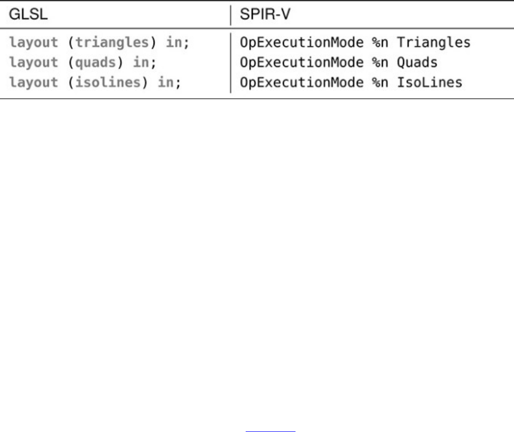
layout (point_mode) in;
becomes
OpExecutionMode %n PointMode
PointMode applies on top of other tessellation modes such as Quads or Triangles. In this
mode, the patch is tessellated as normal, but rather than being joined, the resulting vertices are sent
into the remainder of the pipeline as though they were points. Note that this is subtly different from
simply setting the polygonMode field of the
VkPipelineRasterizationStateCreateInfo structure to VK_POLYGON_MODE_POINT.
In particular, points produced by the tessellator in this mode appear to the geometry shader (if
enabled) to be points and are rasterized exactly once, rather than once for each generated primitive in
which they appear, as they would be otherwise.
Table 9.1: GLSL and SPIR-V Tessellation Modes
Controlling Subdivision
When subdividing the edges of the patches, the tessellator can use one of three strategies to place the
split points, which eventually become vertices in the resulting tessellated mesh. This feature allows
you to control the appearance of the tessellated patch and particularly to control how the edges of
adjacent patches line up. The available modes are
•SpacingEqual: The tessellation level assigned to each edge is clamped to the range [1,
maxLevel] and then rounded to the next higher integer n. The edge is then divided into n
segments of equal length in barycentric space.
•SpacingFractionalEven: The tessellation level assigned to each edge is clamped to the
range [2, maxLevel] and then rounded to the nearest even integer n. The edge is then subdivided
into n− 2 segements of equal length, with two additional, shorter segments filling the center
region of the edge.
•SpacingFractionalOdd: The tessellation level assigned to each edge is clamped to the
range [1, maxLevel − 1] and then rounded to the nearest odd integer n. The edge is then
subdivided into n− 2 segements of equal length, with two additional, shorter segments filling
the center region of the edge.
For both SpacingFractionalEven and SpacingFractionalOdd, the edge is not
tessellated at all if the clamped tessellation level is equal to 1. At levels over 1, the modes produce
different visual effects. These effects are shown in Figure 9.4.
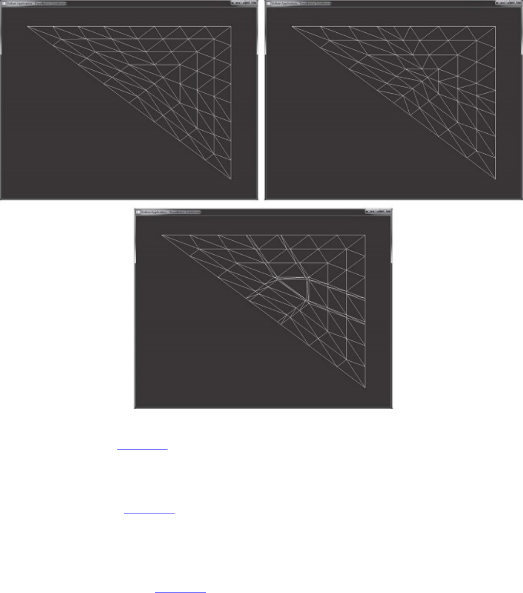
Figure 9.4: Tessellation Spacing Modes
In the top-left image of Figure 9.4, the tessellation mode is set to SpacingEqual. As you can see,
each outer edge of the tessellated triangle is divided into a number of equal-length segments. The
tessellation level in all three images is set to 7.3. This level has been rounded up to 8, and the edge
has been divided into that number of segments.
In the top-right image of Figure 9.4, the tessellation mode is SpacingFractionalEven. The
tessellation level (7.3) has been rounded down to the next-lower even integer (6), and the outer edges
of the triangle have been divided into this many equal-length segments. The remaining section of the
edge is then divided into two equal-size pieces, producing two shorter segments in the center of the
edge. This is most easily seen on the long diagonal edge of the triangle.
Finally, in the bottom image of Figure 9.4, the tessellation mode is set to
SpacingFractionalOdd. Here, the tessellation level has been rounded down to the next-lower
odd number (7). The outer edges of the tessellated triangle are then divided into this many equal-
length segments, with the remaining space made up from two smaller segments inserted on either
side of the central large segment. Again, this is easiest to see on the long, diagonal edge of the
triangle. However, here we see the effect of the two small segments as they produce lines of higher
tessellation leading into the center of the tessellated region.

Table 9.2: GLSL and SPIR-V Tessellation Winding Order
Again, the tessellation spacing mode is set using the OpExecutionMode instruction in SPIR-V in
the tessellation control shader, the evalaution shader, or both, so long as they agree. In GLSL, this
instruction is also generated by using an input layout qualifier.
When the tessellation mode is either Triangles or Quads, the tessellation engine will produce
triangles as outputs. The order in which the resulting vertices are processed by the remainder of the
pipeline determines which way the triangles face relative to the original patch. The vertices of a
triangle are said to appear either in clockwise or counterclockwise order, which is the order in which
you would encounter them when traversing the triangle edges in the specified direction while
viewing the triangle from the front.
Again, the tessellation winding order is set by using the OpExecutionMode instruction in the
tessellation control shader, the evaluation shaders, or both, and the equivalent GLSL declaration is an
input layout qualifier specified in the tessellation evaluation shader. The GLSL layout qualifier
declarations and resulting SPIR-V OpExecutionMode instructions are shown in Table 9.2. Once
again, in the table, the SPIR-V notation of %n indicates the index of the entry point to which the
OpExecutionMode instruction applies.
Tessellation Variables
Each patch processed by the tessellation control shader has a fixed number of control points. This
number is set by using the patchControlPoints member of the
VkPipelineTessellationStateCreateInfo structure used to create the pipeline, as
discussed earlier. Each control point is represented as a vertex passed into the pipeline by one of the
drawing commands. The vertex shader processes the vertices one at a time before they are passed in
groups to the tessellation control shader, which has access to all of the vertices making up a patch.
The tessellation evaluation shader also has access to all of the control points making up a patch, but
the number of control points in the patch can be changed between the tessellation control shader and
the tessellation evaluation shader. The number of control points that are passed from the tessellation
control shader to the tessellation evaluation shader is set by using a SPIR-V OutputVertices
argument to the OpExecutionMode instruction applied to the entry point. Again, this can appear
in the tessellation control shader, the tessellation evaluation shader, or both, so long as they agree.
This operation takes an integer constant (or specialization constant).
In GLSL, the number of control points passed from the tessellation control shader to the tessellation
evaluation shader is specified by using an output layout qualifier in the tessellation control shader.
For example, the GLSL declaration
layout (vertices = 9) out;
becomes

Click here to view code image
OpExecutionMode %n OutputVertices 9}
The inner and outer tessellation levels are set by using the tessellation control shader. This is
accomplished in SPIR-V by decorating variables in the tessellation control shader with the
TessLevelInner and TessLevelOuter decorations, respectively.
The variable representing the outer tessellation levels is an array of four floating-point values, all of
which are used for Quads tessellation mode, the first three of which are used in Triangles
tessellation mode, and only the first two of which are significant in IsoLines tessellation mode.
The variable representing the inner tessellation levels is an array of two floating-point values. In
Quads tessellation mode, the two values control the inner tessellation level in the uand vdomains.
In Triangles tessellation mode, the first element of the array sets the tessellation mode for the
center patch, and the second is ignored. In IsoLines mode, there is no inner tessellation level.
The inner and outer tessellation levels appear in GLSL as the gl_TessLevelInner and
gl_TessLevelOuter built-in variables, respectively. When you are using these variables in a
GLSL tessellation control shader, the compiler will generate the appropriate SPIR-V variable
declaration and decorate it accordingly.
The maximum tessellation level that can be used in a Vulkan pipeline is device-dependent. You can
determine the maximum tessellation level that the device supports by checking the
maxTessellationGenerationLevel field of the device’s VkPhysicalDeviceLimits
structure, which can be retrieved by calling vkGetPhysicalDeviceProperties(). The
minimum guaranteed limit for maxTessellationGenerationLevel is 64, but some devices
may support higher levels. However, most applications will not need higher levels of tessellation than
this, and in this case, there is no reason to query the limit.
Consider the GLSL tessellation control shader shown in Listing 9.1, which simply sets the inner and
outer tessellation levels of a patch to some hard-coded constants. This is not a complete tessellation
control shader, but it is sufficient to demonstrate how tessellation assignments are translated from
GLSL to SPIR-V.
Listing 9.1: Trivial Tessellation Control Shader (GLSL)
Click here to view code image
#version 450 core
layout (vertices = 1) out;
void main(void)
{
gl_TessLevelInner[0] = 7.0f;
gl_TessLevelInner[1] = 8.0f;
gl_TessLevelOuter[0] = 3.0f;
gl_TessLevelOuter[1] = 4.0f;
gl_TessLevelOuter[2] = 5.0f;
gl_TessLevelOuter[3] = 6.0f;
}

After compilation into SPIR-V, the shader shown in Listing 9.1 becomes the (substantially longer)
SPIR-V shader shown in Listing 9.2. This listing is the raw output of the SPIR-V disassembler with
comments added by hand.
Listing 9.2: Trivial Tessellation Control Shader (SPIR-V)
Click here to view code image
;; Require tessellation capability; import GLSL450 constructs.
OpCapability Tessellation
%1 = OpExtInstImport "GLSL.std.450"
OpMemoryModel Logical GLSL450
;; Define "main" as the entry point for a tessellation control shader.
OpEntryPoint TessellationControl %5663 "main" %3290 %5448
;; Number of patch output vertices = 1
OpExecutionMode %5663 OutputVertices 1
;; Decorate the tessellation level variables appropriately.
OpDecorate %3290 Patch
OpDecorate %3290 BuiltIn TessLevelInner
OpDecorate %5448 Patch
OpDecorate %5448 BuiltIn TessLevelOuter
;; Declare types used in this shader.
%8 = OpTypeVoid
%1282 = OpTypeFunction %8
%13 = OpTypeFloat 32
%11 = OpTypeInt 32 0
;; This is the declaration of the gl_TessLevelInner[2] variable.
%2576 = OpConstant %11 2
%549 = OpTypeArray %13 %2576
%1186 = OpTypePointer Output %549
%3290 = OpVariable %1186 Output
%12 = OpTypeInt 32 1
%2571 = OpConstant %12 0
%1330 = OpConstant %13 7
%650 = OpTypePointer Output %13
%2574 = OpConstant %12 1
%2807 = OpConstant %13 8
;; Declare the gl_TessLevelOuter[4] variable.
%2582 = OpConstant %11 4
%609 = OpTypeArray %13 %2582
%1246 = OpTypePointer Output %609
%5448 = OpVariable %1246 Output
;; Declare constants used for indexing into our output arrays and the
;; values written into those arrays.
%2978 = OpConstant %13 3
%2921 = OpConstant %13 4
%2577 = OpConstant %12 2
%1387 = OpConstant %13 5
%2580 = OpConstant %12 3
%2864 = OpConstant %13 6
;; Start of the main function
%5663 = OpFunction %8 None %1282
%23934 = OpLabel

;; Declare references to elements of the output arrays and write constants
;; into them.
%6956 = OpAccessChain %650 %3290 %2571
OpStore %6956 %1330
%19732 = OpAccessChain %650 %3290 %2574
OpStore %19732 %2807
%19733 = OpAccessChain %650 %5448 %2571
OpStore %19733 %2978
%19734 = OpAccessChain %650 %5448 %2574
OpStore %19734 %2921
%19735 = OpAccessChain %650 %5448 %2577
OpStore %19735 %1387
%23304 = OpAccessChain %650 %5448 %2580
OpStore %23304 %2864
;; End of main
OpReturn
OpFunctionEnd
Tessellation control shaders execute a single invocation for each output control point defined in the
patch. All of those invocations have access to all of the data associated with the input control points
for the patch. As a result, the input variables to the tessellation control shader are defined as arrays.
As discussed, the number of input and output control points in a patch do not have to be equal. In
addition to the tessellation level outputs, the tessellation shader can define more outputs to be used
for per-control point and per-patch data.
The per-control-point output from the tessellation control shader is declared as arrays whose sizes
match the number of output control points in the patch. There is one tessellation control shader
invocation per output control point, so there is one entry in each of the output arrays that corresponds
to each of those invocations. The per-control-point outputs can only be written by the corresponding
invocation. The index of the shader invocation within the patch is available as a built-in variable,
which can be accessed by declaring an integer variable decorated by the SPIR-V InvocationId
built-in. In GLSL, this variable is declared as the gl_InvocationID built-in variable. This
variable must be used to index into the output arrays.
Listing 9.3 shows how to declare output variables in a GLSL tessellation control shader, and Listing
9.4 shows how that shader is translated into SPIR-V. Again, Listing 9.3 is not a complete tessellation
control shader and, while legal, will not produce any useful output. Also, the SPIR-V shader shown
in Listing 9.4 has been commented by hand.
Listing 9.3: Declaring Outputs in Tessellation Control Shaders (GLSL)
Click here to view code image
#version 450 core
layout (vertices = 4) out;
out float o_outputData[4];
void main(void)
{
o_outputData[gl_InvocationId] = 19.0f;
}

Listing 9.4: Declaring Outputs in Tessellation Control Shaders (SPIR-V)
Click here to view code image
;; Declare a tessellation control shader.
OpCapability Tessellation
%1 = OpExtInstImport "GLSL.std.450"
OpMemoryModel Logical GLSL450
OpEntryPoint TessellationControl %5663 "main" %3227 %4585
;; 4 output vertices per patch, declare InvocationId built-in
OpExecutionMode %5663 OutputVertices 4
OpDecorate %4585 BuiltIn InvocationId
%8 = OpTypeVoid
%1282 = OpTypeFunction %8
%13 = OpTypeFloat 32
%11 = OpTypeInt 32 0
%2582 = OpConstant %11 4
%549 = OpTypeArray %13 %2582
%1186 = OpTypePointer Output %549
%3227 = OpVariable %1186 Output
%12 = OpTypeInt 32 1
;; This declares the InvocationId input.
%649 = OpTypePointer Input %12
%4585 = OpVariable %649 Input
%37 = OpConstant %13 19
%650 = OpTypePointer Output %13
;; Beginning of main
%5663 = OpFunction %8 None %1282
%24683 = OpLabel
;; Load the invocation ID.
%20081 = OpLoad %12 %4585
;; Define a reference to output variable.
%13546 = OpAccessChain %650 %3227 %20081
;; Store into it at invocation ID.
OpStore %13546 %37
;; End of main
OpReturn
OpFunctionEnd
The output variables declared in the tessellation control shader are made available in the tessellation
evaluation shader as inputs. The total number of components that can be produced per output vertex
by a tessellation control shader is device-dependent and is determined by inspecting the
maxTessellationControlTotalOutputComponents member of the device’s
VkPhysicalDeviceLimits structure, which you can obtain by calling
vkGetPhysicalDeviceProperties(). This is guaranteed to be at least 2,048 components.
Some of these components may be used per vertex, and some may be applied to the patch, as
discussed in the next section.
Of course, the per-vertex limit is the limit that applies to variables passed for each vertex from
tessellation control to tessellation evaluation shader. The total number of components that a
tessellation evaluation shader can receive as input from the tessellation control shader is contained in
the maxTessellationEvaluationInputComponents field of the
VkPhysicalDeviceLimits structure. This limit is at least 64 but could be higher, depending on
the device.
Patch Variables
Although normal output variables in tessellation control shaders are instantiated as arrays
corresponding to the output control points, sometimes specific pieces of data are needed that apply
everywhere in the patch. These pieces of data can be declared as patch outputs. Patch outputs serve
two purposes:
• They store per-patch data and pass it from tessellation control shader to tessellation evaluation
shader.
• They allow data sharing between tessellation control shader invocations within a single patch.
Within the group of tessellation control shader invocations corresponding to a single patch, patch
outputs are actually readable as well as writable. If other invocations in the same patch have written
to a patch output, it is possible to read the data they have placed there.
To declare a patch output variable in GLSL, use the patch qualifier on the variable declaration. This
declaration is translated into the Patch decoration on the variable subsequently declared in the
SPIR-V shader. For example,
patch out myVariable;
becomes
OpName %n "myVariable"
OpDecorate %n Patch
where %n is the identifier assigned to the myVariable variable.
Because all of the tessellation control shader invocations corresponding to a single patch may be
running in parallel, perhaps at different rates, simply writing to one patch variable and then reading
from another patch variable won’t produce well-defined results. If some invocations get ahead of
others while processing a patch, the invocations that are behind won’t “see” the results of writes
performed by the other invocations that haven’t reached the write yet.
To synchronize the invocations within a patch and ensure that they all reach the same place at the
same time, we can use the OpControlBarrier instruction, which can synchronize control flow of
invocations within the tessellation control shader. Further, to ensure that the write to the patch
variable is made visible to other invocations within the same patch, we also need to include either an
OpMemoryBarrier instruction or further memory semantics in the OpControlBarrier
instruction.
In GLSL, these instructions can be generated by calling the barrier() built-in function inside the
tessellation control shader. When called, the GLSL compiler generates an OpMemoryBarrier
instruction to force memory coherency across the set of tessellation control shader invocations, and
then it generates an OpControlBarrier instruction to synchronize their control flow. After these
instructions have executed, tessellation control shader invocations can read data written to patch
variables by other invocations in the same patch.
If any one of the tessellation levels written by the tessellation control shader is 0.0 or a floating-point
NaN, then the entire patch is discarded. This provides a mechanism for the tessellation control shader

to programmatically throw out patches that it determines will not contribute to the output image. For
example, if the maximum deviation from a plane for a displacement map is known, then the
tessellation control shader can inspect a patch, determine whether all of the geomery that would
result from tessellating that patch would face away from the viewer, and cull the patch. If such a
patch were to be passed through by the tessellation control shader, then it would be tessellated, the
tessellation evaluation shader would run, and all the resulting triangles would individually be culled
by subsequent stages in the pipeline. This would be very inefficient.
Tessellation Evaluation Shaders
After the tessellation control shader runs and passes tessellation factors to the fixed-function
tessellation unit, it generates new vertices inside the patch and assigns them barycentric coordinates
in patch space. Each new vertex generates an invocation of the tessellation evaluation shader, to
which the barycentric coordinate of the vertex is passed.
For IsoLines and Quads tessellation mode, these are 2D coordinates. For Triangles
tessellation mode, these are 3D coordinates. Regardless of the mode, they are delivered to the
tessellation evaluation shader via built-in variables.
In GLSL, this declaration corresponds to the gl_TessCoord built-in variable. When this variable
is used, the GLSL compiler automatically generates the appropriate variable declarations and
decorations in SPIR-V.
In SPIR-V, the result is the declaration of a three-element vector of floating-point values, decorated
with the TessCoord decoration. Note that this is always a three-element array, even when the
tessellation mode calls for a 2D barycentric coordinate (IsoLines or Quads). In those modes, the
third component of the array is simply zero.
For example, the minimal tessellation evaluation shader in Listing 9.5 becomes the SPIR-V shader in
Listing 9.6.
Listing 9.5: Accessing gl_TessCoord in Evaluation Shader (GLSL)
Click here to view code image
#version 450 core
layout (quads)in;
void main(void)
{
gl_Position = vec4(gl_TessCoord, 1.0);
}
Listing 9.6: Accessing gl_TessCoord in Evaluation Shader (SPIR-V)
Click here to view code image
;; This is a GLSL 450 tessellation shader; enable capabilities.
OpCapability Tessellation
OpCapability TessellationPointSize
OpCapability ClipDistance
OpCapability CullDistance
%1 = OpExtInstImport "GLSL.std.450"
OpMemoryModel Logical GLSL450
;; Declare the entry point and decorate it appropriately.
OpEntryPoint TessellationEvaluation %5663 "main" %4930 %3944
OpExecutionMode %5663 Quads
OpExecutionMode %5663 SpacingEqual
OpExecutionMode %5663 VertexOrderCcw
;; Declare GLSL built-in outputs.
OpMemberDecorate %2935 0 BuiltIn Position
OpMemberDecorate %2935 1 BuiltIn PointSize
OpMemberDecorate %2935 2 BuiltIn ClipDistance
OpMemberDecorate %2935 3 BuiltIn CullDistance
OpDecorate %2935 Block
;; This is the decoration of gl_TessCoord.
OpDecorate %3944 BuiltIn TessCoord
%8 = OpTypeVoid
%1282 = OpTypeFunction %8
%13 = OpTypeFloat 32
%29 = OpTypeVector %13 4
%11 = OpTypeInt 32 0
%2573 = OpConstant %11 1
%554 = OpTypeArray %13 %2573
%2935 = OpTypeStruct %29 %13 %554 %554
%561 = OpTypePointer Output %2935
%4930 = OpVariable %561 Output
%12 = OpTypeInt 32 1
%2571 = OpConstant %12 0
;; Vector of 3 components, as input, decorated with BuiltIn TessCoord
%24 = OpTypeVector %13 3
%661 = OpTypePointer Input %24
%3944 = OpVariable %661 Input
%138 = OpConstant %13 1
%666 = OpTypePointer Output %29
%5663 = OpFunction %8 None %1282
%24987 = OpLabel
;; Read from gl_TessCoord.
%17674 = OpLoad %24 %3944
;; Extract the three elements.
%22014 = OpCompositeExtract %13 %17674 0
%23496 = OpCompositeExtract %13 %17674 1
%7529 = OpCompositeExtract %13 %17674 2
;; Construct the new vec4.
%18260 = OpCompositeConstruct %29 %22014 %23496 %7529 %138
;; Write to gl_Postion.
%12055 = OpAccessChain %666 %4930 %2571
OpStore %12055 %18260
;; End of main
OpReturn
OpFunctionEnd
The outputs declared in the tessellation evaluation shader are fed to the next stage of the pipeline.
When a geometry shader is enabled, it receives its input from the tessellation evaluation shader;
otherwise, the tessellation evaluation shader outputs are used to feed interpolation and are

subsequently passed to the fragment shader. The total amount of data that a tessellation evaluation
shader can produce is device-dependent and can be determined by checking the
maxTessellationEvaluationOutputComponents field of the device’s
VkPhysicalDeviceLimits structure.
Tessellation Example: Displacement Mapping
To tie all of this together, we’ll walk through a simple but complete example of using tessellation to
implement displacement mapping. Displacement mapping is a common technique to add detail to a
surface by offesetting along its normal by using a texture. To implement this, we’ll take a patch with
four control points, each having a position and a normal. We will transform their positions and
normals into world space in the vertex shader; then, in the tessellation control shader, we will
compute their view space positions and set their tessellation levels. The tessellation control shader
then passes the world-space positions to the tessellation evaluation shader.
In the tessellelation evaluation shader, we take the barycentric coordinates generated by the
tessellator and use them to compute an interpolated normal and world space position, fetch from a
texture, and then displace the computed vertex coordinate along the computed normal by a value
derived from the texture. This final world-space coordinate is transformed into view space by using
the world-to-view matrix, which is stored in the same buffer as our object-to-world matrix used in
our vertex shader.
To set this up, we’ll use a texture to store our displacement map. In addition to our texture resources,
we’ll use push constants to communicate with our shaders. For the purposes of this example, we’ll
use a simple push constant to send a transformation matrix into the tessellation control shader.
The next two push constants are floating-point values. The first is used in the tessellation evaluation
shader to scale the level of tessellation applied to the patch. The second is used in the tessellation
evaluation shader to scale the amount of displacement applied to each vertex. The values read from
the texture are normalized to the range [0.0, 1.0], so an external tessellation scale allows us to use this
range optimally.
The description of the VkDescriptorSetLayoutCreateInfo used to create this descriptor set
layout is shown in Listing 9.7.
Listing 9.7: Descriptor Setup for Displacement Mapping
Click here to view code image
struct PushConstantData
{
vmath::mat4 mvp_matrix;
float displacement_scale;
};
static const VkDescriptorSetLayoutBinding descriptorBindings[] =
{
// Only binding is a sampled image with combined sampler.
{
0,
VK_DESCRIPTOR_TYPE_COMBINED_IMAGE_SAMPLER,
1,
VK_SHADER_STAGE_TESSELLATION_EVALUATION_BIT,

nullptr
}
};
static const VkDescriptorSetLayoutCreateInfo descriptorSetLayoutCreateInfo
=
{
VK_STRUCTURE_TYPE_DESCRIPTOR_SET_LAYOUT_CREATE_INFO, nullptr,
0,
vkcore::utils::arraysize(descriptorBindings),
descriptorBindings
};
vkCreateDescriptorSetLayout(getDevice(),
&descriptorSetLayoutCreateInfo,
nullptr,
&m_descriptorSetLayout);
// Define a push constant range.
static const VkPushConstantRange pushConstantRange[] =
{
// Push data into the evaluation shader.
{
VK_SHADER_STAGE_TESSELLATION_EVALUATION_BIT,
0,
sizeof (PushConstantData)
}
};
VkPipelineLayoutCreateInfo pipelineLayoutCreateInfo =
{
VK_STRUCTURE_TYPE_PIPELINE_LAYOUT_CREATE_INFO, nullptr,
0,
1,
&m_descriptorSetLayout,
vkcore::utils::arraysize(pushConstantRange),
pushConstantRange
};
result = vkCreatePipelineLayout(getDevice(),
&pipelineLayoutCreateInfo,
&nullptr,
&m_pipelineLayout);
As the geometry for the tessellated quad is simply four vertices arranged in a square, we’re not going
to use vertex buffers in this example, but instead we’ll programmatically generate the object space
positions in the vertex shader. The GLSL vertex shader used in this example is shown in Listing 9.8.
Listing 9.8: Vertex Shader for Displacement Mapping
Click here to view code image
#version 450 core
void main(void)

{
float x = float(gl_VertexIndex & 1) - 0.5f;
float y = float(gl_VertexIndex & 2) * 0.5f - 0.5f;
gl_Position = vec4(x, y, 0.0f, 1.0f);
}
The output of the vertex shader is simply a quad of side length 1, centered on the origin. This is
passed into the tessellation control shader shown in Listing 9.9, which sets the tessellation factors and
passes the position of the vertices through otherwise unchanged.
Listing 9.9: Tessellation Control Shader for Displacement Mapping
Click here to view code image
#version 450 core
layout (vertices = 4) out;
void main(void)
{
if (gl_InvocationID == 0)
{
gl_TessLevelInner[0] = 64.0f;
gl_TessLevelInner[1] = 64.0f;
gl_TessLevelOuter[0] = 64.0f;
gl_TessLevelOuter[1] = 64.0f;
gl_TessLevelOuter[2] = 64.0f;
gl_TessLevelOuter[3] = 64.0f;
}
gl_out[gl_InvocationID].gl_Position =
gl_in[gl_InvocationID].gl_Position;
}
Note that the tessellation control shader shown in Listing 9.9 unconditionally sets the tessellation
factors to 64, which is the minimum required tessellation level that must be supported by Vulkan
implementations. This is a very high amount of tessellation, and most applications will not need this
level. Rather, we would divide the patch into several smaller patches and then use a smaller, probably
different tessellation level for each of them. The output of the tessellation control shader is then
passed to the tessellation evaluation shader shown in Listing 9.10.
Listing 9.10: Tessellation Evaluation Shader for Displacement Mapping
Click here to view code image
#version 450 core
layout (quads, fractional_odd_spacing) in;
layout (push_constant) uniform push_constants_b
{
mat4 mvp_matrix;

float displacement_scale;
} push_constants;
layout (set = 0, binding = 0) uniform sampler2D texDisplacement;
void main(void)
{
vec4 mid1 = mix(gl_in[0].gl_Position, gl_in[1].gl_Position,
gl_TessCoord.x);
vec4 mid2 = mix(gl_in[2].gl_Position, gl_in[3].gl_Position,
gl_TessCoord.x);
vec4 pos = mix(mid1, mid2, gl_TessCoord.y);
float displacement = texture(texDisplacement, gl_TessCoord.xy).x;
pos.z = displacement * push_constants.displacement_scale;
gl_Position = push_constants.mvp_matrix * pos;
}
The shader in Listing 9.10 uses the content of gl_TessCoord.xy to interpolate the position of the
vertices that land at the four corners of the quad patch produced by the tessellation control shader.
The final position, pos, is simply a weighted average of the four corners. Additionally,
gl_TessCoord.xy is used as a texture coordinate to sample from the displacement map texture,
texDisplacement.
This displacement value is scaled by the displacement_scale push constant, which allows our
application to vary the amount of displacement applied to the mesh. We know that our vertex and
tessellation control shaders set up our patch in the x-yplane and that the zvalue for all of our
tessellated points will therefore be zero. Overwriting the zcomponent with displacement produces a
patch that is like a landscape with the zdirection being up. We transform this through our final
transformation matrix to produce a vertex in view space.
The rest of the graphics pipeline setup for the displacement mapping example is similar to other
applications shown thus far. However, because tessellation is enabled, we must set the
pTessellationState member of our VkGraphicsPipelineCreateInfo to the address
of a valid VkPipelineTessellationStateCreateInfo structure. This structure is
extremely simple and is used only to set the number of control points in our patch. The
VkPipelineTessellationStateCreateInfo for this application is shown in Listing 9.11.
Listing 9.11: Tessellation State Creation Information
Click here to view code image
VkPipelineTessellationStateCreateInfo tessellationStateCreateInfo =
{
VK_STRUCTURE_TYPE_PIPELINE_TESSELLATION_STATE_CREATE_INFO, // sType
nullptr, // pNext
0, // flags
4// patchControlPoints
};
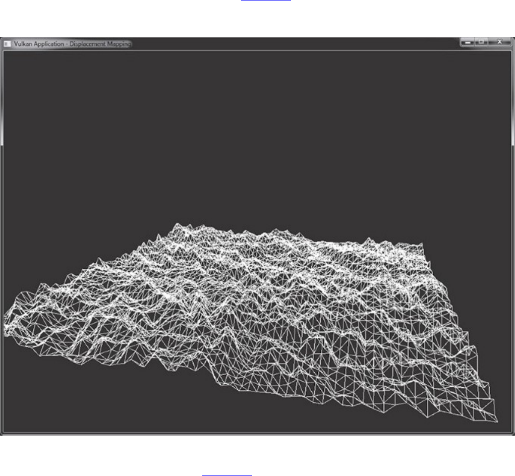
The result of running this application is shown in Figure 9.5. As you can see in the figure, we have
set the polygon mode to VK_POLYGON_MODE_LINE, which allows us to see the structure of the
tessellated patch.
Figure 9.5: Result of Tessellated Displacement Mapping
For all of the geometric density shown in Figure 9.5, remember that no real geometry was passed into
the graphics pipeline. The four corners of the patch are programmatically generated by the vertex
shader, and no real vertex attributes are used. All of the triangles in the patch are generated by the
tessellation engine, and their positions are computed by using a texture. By applying shading and
detail textures to the surface of the patch, you can simulate even more apparent detail. Depending on
the performance of the system, the tessellation levels chosen by the tessellation control shader can be
scaled to balance performance and visual quality. Tessellation is therefore a very effective way to
introduce geometric density to a scene without needing to regenerate mesh data or produce multiple
versions of 3D art assets.

Geometry Shaders
The geometry shader is the final stage in the front-end, geometry-processing part of the pipeline.
When enabled, it runs immediately after the tessellation evaluation shader if tessellation is enabled
and after the vertex shader if tessellation is not in use. A geometry shader is unique in that a single
invocation of the geometry shader processes an entire primitive. Further, the geometry shader is the
only shader stage that can see adjacency primitives.1Finally, the geometry shader is special in that it
can both destroy and programmatically create new geometry.
1. The vertex shader can see the additional vertices that make up the adjacency primitive, but it has no
knowledge of whether any particular vertex is part of the main primitive or the adjacency information.
To enable the geometry shader stage, include a geometry shader in the pipeline by including an
instance of the VkPipelineShaderStageCreateInfo structure describing a geometry shader
in the array of stages passed through pStages in the VkGraphicsPipelineCreateInfo
structure. Support for geometry shaders is optional, so before creating a pipeline containing a
geometry shader, your application should check for support by inspecting the geometryShader
member of the VkPhysicalDeviceFeatures structure returned from a call to
vkGetPhysicalDeviceFeatures(), and then set that same member to VK_TRUE in the
VkDeviceCreateInfo structure passed to vkCreateDevice().
A geometry shader is created in SPIR-V by using the Geometry execution model with the
OpEntryPoint instruction. A geometry shader must include the following pieces of information:
• The input primitive type, which must be one of points, lines, triangles, lines with adjacency, or
triangles with adjacency
• The output primitive type, which must be one of points, line strips, or triangle strips
• The maximum number of vertices expected to be produced by a single invocation of the
geometry shader
All of these attributes are specified as arguments to OpExecutionMode instructions in the SPIR-V
shader. In GLSL, the first is specified by using an input layout qualifier, and the second two are
specified by using output layout qualifiers. The shader shown in Listing 9.12 is a minimal GLSL
geometry shader, which is legal, but it will throw away all of the geometry that passes down the pipe.
Listing 9.12: Minimal Geometry Shader (GLSL)
Click here to view code image
#version 450 core
layout (triangles)in;
layout (triangle_strip)out;
layout (max_vertices = 3) out;
void main(void)
{
// Do nothing.
}
As you can see, Listing 9.12 contains only the required input and output layout definitions, while its
main function is empty. When compiled to SPIR-V, the shader shown in Listing 9.13 is produced.

Listing 9.13: Minimal Geometry Shader (SPIR-V)
Click here to view code image
;; This is a geometry shader written in GLSL 450.
OpCapability Geometry
%1 = OpExtInstImport "GLSL.std.450"
OpMemoryModel Logical GLSL450
;; Declare the main entry point.
OpEntryPoint Geometry %5663 "main"
;; Triangles input, triangle strip output, maximum vertex count is 3.
OpExecutionMode %5663 Triangles
OpExecutionMode %5663 Invocations 1
OpExecutionMode %5663 OutputTriangleStrip
OpExecutionMode %5663 OutputVertices 3
;; Start of main
%8 = OpTypeVoid
%1282 = OpTypeFunction %8
%5663 = OpFunction %8 None %1282
%16103 = OpLabel
;; End of empty main
OpReturn
OpFunctionEnd
In Listing 9.13, the main entry point is decorated using three OpExecutionMode instructions.
The first uses Triangles to indicate that the shader expects triangles as input. The second,
OutputTriangleStrip, specifies that the shader produces triangle strips. Finally,
OutputVertices is used to specify that each shader invocation will produce a maximum of 3
vertices—a single triangle. The Invocations decoration is also specified, but it is set to 1, which
is the default, and could therefore have been omitted.
The maximum number of vertices that a single geometry shader can produce is device-dependent. To
determine the limit for your device, check the maxGeometryOutputVertices field of the
device’s VkPhysicalDeviceLimits structure, which you can retrieve by calling
vkGetPhysicalDeviceProperties(). The OutputVertices argument to the execution
mode instruction must be less than or equal to this value. maxGeometryOutputVertices is
guaranteed to be at least 256.
The maximum number of components that a geometry shader can produce for each vertex it outputs
is also device-dependent and is determined by checking the maxGeometryOutputComponents
field of the device’s VkPhysicalDeviceLimits structure. This is guaranteed to be at least 64.
In addition to the limit on the number of vertices that the shader can produce, the number of
components that the shader can produce is subject to a device-dependent limit. This is stored in the
maxGeometryTotalOutputComponents field of the VkPhysicalDeviceLimits
structure. This is guaranteed to be at least 1,024—enough for 256 vertices (the minimum guarantee
for maxGeometryOutputVertices), each consisting of a single vec4. Some devices may
advertise a higher value for one or both limits. Note that the minimum guarantees aren’t a simple
product of one another. That is, the gaurantee for maxGeometryTotalOutputComponents
(1,024) is not equal to the product of maxGeometryOutputComponents (64) and

maxGeometryOutputVertices (256). Many devices will support producing a large number of
small vertices or a small number of larger vertices.
The inputs to the geometry shader come from two places:
• Built-in inputs that are declared inside a gl_PerVertex input block declaration
• User-defined inputs that match the corresponding output declaration in the next-earlier shader
stage (tessellation evaluation or vertex, depending on whether tessellation is enabled)
To declare the gl_PerVertex input block, declare an input block called gl_PerVertex and
include in it all of the built-in per-vertex input variables that your shader needs to use. For example,
Listing 9.14 shows the input block declared containing gl_Position, which corresponds to
gl_Position as written by the previous stage. This block is declared as an array of instances
called gl_in[], which is implicitly sized given the primitive type.
Listing 9.14: Declaring gl_PerVertex in a GLSL Geometry Shader
in gl_PerVertex
{
vec4 gl_Position;
} gl_in[];
When a shader containing the declaration shown in Listing 9.14 and performing a read from
gl_Position is compiled to SPIR-V, the disassembly shown in Listing 9.15 is produced.
Listing 9.15: Reading gl_PerVertex in a SPIR-V Geometry Shader
Click here to view code image
...
;; Decorate the first member of our block with the BuiltIn Position.
OpMemberDecorate %1017 0 BuiltIn Position
OpDecorate %1017 Block
...
;; Declare an array of structures, with a pointer to this array as an
input.
%1017 = OpTypeStruct %29
%557 = OpTypeArray %1017 %2573
%1194 = OpTypePointer Input %557
%5305 = OpVariable %1194 Input
%666 = OpTypePointer Input %29
...
;; Access the input using OpLoad.
%7129 = OpAccessChain %666 %5305 %2571 %2571
%15646 = OpLoad %29 %7129
As with other shader stages, declaring an input in the geometry shader that does not include a
BuiltIn decoration means that it will read its value from those produced in the vertex shader that
precedes it. The total number of components across all inputs to the geometry shader is subject to a
device-dependent limit. This can be determined by checking the
maxGeometryInputComponents member of the device’s VkPhysicalDeviceLimits
structure. This is guaranteed to be at least 64 components.

Unless a geometry shader explicitly produces output data, it effectively does nothing. The shader can
produce individual vertices one at a time, and the vertices will then be assembled into primitives after
the shader has executed. To produce a vertex, the shader should execute the OpEmitVertex
instruction, which is produced by the GLSL built-in function EmitVertex().
When the OpEmitVertex instruction is executed, the current values of all output variables are used
to create a new vertex and pushed down the pipeline. The values of the output variables become
undefined at this point, so for each output vertex, it is necessary to rewrite all of the outputs of the
shader. Before OpEmitVertex is useful, then, we must declare some outputs in our shader.
Outputs are declared in GLSL using an output-block declaration. For example, to produce a vec4
and pass it to the subsequent fragment shader, declare a block as shown in Listing 9.16.
Listing 9.16: Declaring an Output Block in GLSL
out gs_out
{
vec4 color;
};
Again, compiling this fragment to SPIR-V produces a declaration of a block with a single member
containing a vector of four floating-point values. When this variable is written to in the shader, an
OpStore operation is performed to write into the block.
A complete, pass-through geometry shader is shown in Listing 9.17, and the resulting SPIR-V is
shown in Listing 9.18.
Listing 9.17: Pass-Through GLSL Geometry Shader
Click here to view code image
#version 450 core
layout (points)in;
layout (points)out;
layout (max_vertices = 1) out;
in gl_PerVertex
{
vec4 gl_Position;
} gl_in[];
out gs_out
{
vec4 color;
};
void main(void)
{
gl_Position = gl_in[0].gl_Position;
color = vec4(0.5, 0.1, 0.9, 1.0);

EmitVertex();
}
Listing 9.18: Pass-Through SPIR-V Geometry Shader
Click here to view code image
OpCapability Geometry
OpCapability GeometryPointSize
OpCapability ClipDistance
OpCapability CullDistance
%1 = OpExtInstImport "GLSL.std.450"
OpMemoryModel Logical GLSL450
OpEntryPoint Geometry %5663 "main" %22044 %5305 %4930
OpExecutionMode %5663 InputPoints
OpExecutionMode %5663 Invocations 1
OpExecutionMode %5663 OutputPoints
OpExecutionMode %5663 OutputVertices 1
OpMemberDecorate %2935 0 BuiltIn Position
OpMemberDecorate %2935 1 BuiltIn PointSize
OpMemberDecorate %2935 2 BuiltIn ClipDistance
OpMemberDecorate %2935 3 BuiltIn CullDistance
OpDecorate %2935 Block
OpMemberDecorate %1017 0 BuiltIn Position
OpDecorate %1017 Block
OpDecorate %1018 Block
%8 = OpTypeVoid
%1282 = OpTypeFunction %8
%13 = OpTypeFloat 32
%29 = OpTypeVector %13 4
%11 = OpTypeInt 32 0
%2573 = OpConstant %11 1
%554 = OpTypeArray %13 %2573
%2935 = OpTypeStruct %29 %13 %554 %554
%561 = OpTypePointer Output %2935
%22044 = OpVariable %561 Output
%12 = OpTypeInt 32 1
%2571 = OpConstant %12 0
%1017 = OpTypeStruct %29
%557 = OpTypeArray %1017 %2573
%1194 = OpTypePointer Input %557
%5305 = OpVariable %1194 Input
%666 = OpTypePointer Input %29
%667 = OpTypePointer Output %29
%1018 = OpTypeStruct %29
%1654 = OpTypePointer Output %1018
%4930 = OpVariable %1654 Output
%252 = OpConstant %13 0.5
%2936 = OpConstant %13 0.1
%1364 = OpConstant %13 0.9
%138 = OpConstant %13 1
%878 = OpConstantComposite %29 %252 %2936 %1364 %138
%5663 = OpFunction %8 None %1282

%23915 = OpLabel
%7129 = OpAccessChain %666 %5305 %2571 %2571
%15646 = OpLoad %29 %7129
%19981 = OpAccessChain %667 %22044 %2571
OpStore %19981 %15646
%22639 = OpAccessChain %667 %4930 %2571
OpStore %22639 %878
OpEmitVertex
OpReturn
OpFunctionEnd
As you can see in Listing 9.18, the shader enables the Geometry capability and then simply copies
its input to its output. You can see the call to the OpEmitVertex instruction toward the end of the
shader, immediately before the main function ends.
Cutting Primitives
You may have noticed that the only output primitive types available in a geometry shader are points,
line strips, and triangle strips. It is not possible to directly output individual lines or triangles. A
geometry shader can output any number of vertices, up to an implementation-defined limit, so long as
the maximum output vertex count is properly declared. However, just calling EmitVertex() many
times will produce a single long strip.
In order to output several smaller strips and (within the limit) individual lines or triangles, the
EndPrimitive() function is available. This function ends the current strip and starts a new one
when the next vertex is emitted. The current strip is automatically ended when the shader exits, so if
your maximum vertex count is 3, and the output primitive type is triangle_strip, then it’s not
necessary to explicitly call EndPrimitive(). However, if you want to produce several
independent lines or triangles from a single geometry shader invocation, call EndPrimitive()
between each strip.
The geometry shaders shown in previous listings use point primitives as both input and output to
sidestep this issue. Listing 9.19 shows a shader that uses the triangle_strip output primitive
type to output triangle strips. However, this shader produces six output vertices, each group of three
representing a separate triangle. The EndPrimitive() function is used to cut the triangle strip
after each triangle in order to produce two separate strips of one triangle each.
Listing 9.19: Cutting Strips in a Geometry Shader
Click here to view code image
#version 450 core
layout (triangles)in;
layout (triangle_strip,max_vertices = 6) out;
void main(void)
{
int i, j;
vec4 scale = vec4(1.0f, 1.0f, 1.0f, 1.0f);
for (j = 0; j < 2; j++)
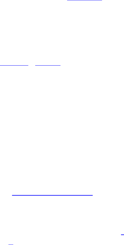
{
for (i = 0; i < 3; i++)
{
gl_Position = gl_in[i].gl_Position * scale;
EmitVertex();
}
EndPrimitive();
scale.xy = -scale.xy;
}
}
In the shader shown in Listing 9.19, the first iteration of the outer loop produces a first triangle by
simply copying all three vertices’ positions (in the inner loop) into the output position, multiplying by
a scale factor, and then calling EmitVertex(). After the inner loop has completed, the shader calls
EndPrimitive() to cut the strip at that point. It then inverts the xand yaxes of the scale, rotating
the triangle 180 degress around the zaxis and iterates a second time. This produces a second triangle.
Geometry Shader Instancing
Chapter 8, “Drawing,” covered instancing, which is a technique to quickly draw many copies of the
same geometry using a single drawing command. The number of instances is passed as a parameter
to vkCmdDraw() or vkCmdDrawIndexed(), or through a structure in memory to
vkCmdDrawIndirect() or vkCmdDrawIndexedIndirect(). With draw-level instancing,
the entire draw is effectively executed many times. This includes fetching data from index and vertex
buffers that does not change, checking for primitive restart indices (if enabled), and so on.
When a geometry shader is enabled, a special mode of instancing is available that runs the pipeline
from the geometry shader onward multiple times, leaving all of the stages behind the geometry
shader (including tessellation, for example) running only once. While it may not be worth
introducing a geometry shader simply to use this form of instancing, when a geometry shader is
required anyway, this can be a very efficient mechanism to quickly render multiple copies of a piece
of geometry, with the properties of each instance controlled by the geometry shader.
You may have noticed that some of the SPIR-V listings shown earlier in this chapter include a
declaration of the following form at the front of all of the geometry shaders:
Click here to view code image
OpExecutionMode %n Invocations 1
This Invocations execution mode tells Vulkan how many times to run the geometry
shader—which is the number of instances2to run.
2. In references to an instanced geometry shader, the term invocation is often used to mean instance because an
invocation of the geometry shader is run for each instance. This disambiguates the instance used in instanced
draws from the invocation being the execution of the geometry shader. In fact, both can be used at the same
time to have an instanced draw using a geometry shader with multiple invocations.
Setting the invocation count to 1 simply means that the shader will run once as expected. This is the
default and is inserted by the GLSL compiler if you don’t instruct it otherwise. To control the number
of invocations of the geoemtry, use the invocations input layout qualifier in the GLSL shader.
For example, the following declaration sets the invocation count for the shader to 8:

layout (invocations = 8) in;
When this layout qualifier is included in a GLSL shader, the compiler will insert the appropriate
OpExecutionMode instruction to set the invocation count for the entry point to the value you
specified. While the invocation count is hard-coded into the shader rather than passed as a parameter,
as it is in draw instancing, you can use a specialization constant to set its value. This allows you to
customize a single geometry shader to run in a number of different scenarios.
As the shader executes, the invocation number is made available to it through the GLSL
gl_InvocationID built-in variable. In SPIR-V, this is translated into a decoration attaching the
built-in InvocationId to an input variable.
The GLSL shader shown in Listing 9.20 is a complete example of running two instances with each
sourcing a separate object-to-world matrix in order to draw two copies of an object, each with a
different transform. By using the gl_InvocationID (which turns into the InvocationId
decoration), we can index into an array of matrices in order to get a different transform for each
invocation.
Listing 9.20: Instanced GLSL Geometry Shader
Click here to view code image
#version 450 core
layout (triangles,invocations = 2) in;
layout (triangle_strip,max_vertices = 3) out;
layout (set = 0, binding = 0) uniform
{
mat4 projection;
mat4 objectToWorld[2];
} transforms;
void main(void)
{
int i;
mat4 objectToWorld = transforms.objectToWorld[gl_InvocationID];
mat4 objectToClip = objectToWorld * transforms.projection;
for (i = 0; i < 3; i++)
{
gl_Position = gl_in[i].gl_Position * objectToClip;
EmitVertex();
}
}
The maximum number of geometry shader invocations is implementation-dependent but is
guaranteed to be at least 32. Some implementations support more invocations than this, and the limit
for a particular implementation can be determined by checking the
maxGeometryShaderInvocations field of the device’s VkPhysicalDeviceLimits
structure as returned from a call to vkGetPhysicalDeviceProperties().

Programmable Point Size
When you are rendering points, by default, a single vertex produces a point that is exactly 1 pixel
wide. On modern high-resolution displays, a single pixel is extremely small, so it is often the case
that you wish to render points that are much larger than this. When the primitives are rasterized as
points, it is possible to set the point size by using the last stage of the geometry-processing pipeline.
Points are rasterized in one of three ways:
• Rendering with only a vertex and fragment shader, and setting the primitive topology to
VK_PRIMITIVE_TOPOLOGY_POINT_LIST
• Enabling tessellation and setting the tessellation mode to points by decorating the tessellation
shader’s entry point with the SPIR-V PointMode execution mode
• Using a geometry shader that produces points
The last stage in the geometry pipeline (vertex, tessellation evaluation, or geometry) can specify the
size of points by decorating a floating-point output with the PointSize parameter to the BuiltIn
decoration. The value written to this output will be used as the diameter of the rasterized points.
In GLSL, such a decorated output can be produced by writing to the gl_PointSize built-in
output. An example vertex shader that writes to gl_PointSize is shown in Listing 9.21, and the
resulting SPIR-V output is shown in Listing 9.22.
Listing 9.21: Use of gl_PointSize in GLSL
Click here to view code image
#version 450 core
layout (location = 0) in vec3 i_position;
layout (location = 1) in float i_pointSize;
void main(void)
{
gl_Position = vec4(i_position, 1.0f);
gl_PointSize = i_pointSize;
}
The shader in Listing 9.21 declares two inputs: i_position and i_pointSize. Both are passed
through to their respective outputs. Simply writing to gl_PointSize causes the GLSL compiler to
automatically declare an output variable in the SPIR-V shader and decorate it with the PointSize
decoration, as you can see in Listing 9.22, which has been manually edited and commented.
Listing 9.22: Decorating an Output with PointSize
Click here to view code image
...
;; GLSL compiler automatically declares per-vertex output block.
OpName %11 "gl_PerVertex"
OpMemberName %11 0 "gl_Position"
OpMemberName %11 1 "gl_PointSize"
OpMemberName %11 2 "gl_ClipDistance"
OpMemberName %11 3 "gl_CullDistance"
OpName %13 ""
;; Naming inputs
OpName %18 "i_position"
OpName %29 "i_pointSize"
;; Decorating members of the default output block
OpMemberDecorate %11 0 BuiltIn Position
OpMemberDecorate %11 1 BuiltIn PointSize ;; gl_PointSize
OpMemberDecorate %11 2 BuiltIn ClipDistance
OpMemberDecorate %11 3 BuiltIn CullDistance
OpDecorate %11 Block
OpDecorate %18 Location 0
OpDecorate %29 Location 1
...
%4 = OpFunction %2 None %3
;; Start of "main"
%5 = OpLabel
;; Load i_position.
%19 = OpLoad %16 %18
%21 = OpCompositeExtract %6 %19 0
%22 = OpCompositeExtract %6 %19 1
%23 = OpCompositeExtract %6 %19 2
;; Construct vec4 and write to gl_Position.
%24 = OpCompositeConstruct %7 %21 %22 %23 %20
%26 = OpAccessChain %25 %13 %15
OpStore %26 %24
;; Load from i_pointSize (%29).
%30 = OpLoad %6 %29
;; Use access chain to dereference built-in output.
%32 = OpAccessChain %31 %13 %27
;; Store to output decorated with PointSize.
OpStore %32 %30
OpReturn
OpFunctionEnd
The size produced by the shader and written to the output decorated as PointSize must fall within
the range of point sizes supported by the device. This can be determined by inspecting the
pointSizeRange member of the device’s VkPhysicalDeviceLimits structure, which you
can obtain through a call to vkGetPhysicalDeviceProperties(). This is an array of two
floating-point values, the first being the smallest point that can be rasterized and the second being the
diameter of the largest point that can be rasterized.
The pixel size of a point will be quantized to a device-dependent scale. The delta between supported
point sizes can be determined from the pointSizeGranularity field of the
VkPhysicalDeviceLimits structure. For example, if an implementation can render points at
any size in quarter-pixel increments, then pointSizeGranularity will be 0.25. All devices
must be able to render any supported point size with at least single-pixel accuracy, though many
devices will provide much more precision than this.
The largest guaranteed value for the minimum point size is a single pixel. That is, some
implementations may be able to accurately rasterize points smaller than a single pixel, but all
implementations must be able to rasterize single-pixel points. The smallest guaranteed point size, in

pixels, is 64.0 minus one unit of the device’s granularity as given in pointSizeGranularity.
So if the device renders points in quarter-pixel increments, the maximum point size will be 63.75
pixels.
If none of the geometry processing shaders writes a variable decorated as PointSize, then the
default point size of 1 pixel will be assumed. Many implementations may be more efficient when a
compile-time constant is written to PointSize, often removing the executable code from the
shader and instead programming the point size as the state of the rasterizer. It is possible to set the
point size through a specialization constant to produce a shader that writes a compile-time constant to
the point size but is still configurable at pipeline build time, much as the line width is.
Line Width and Rasterization
Optionally, Vulkan is able to rasterize lines that are greater than a single pixel wide. The width of
lines to be rasterized can be specified when a graphics pipeline is created by setting the lineWidth
of the VkPipelineRasterizationStateCreateInfo structure used to create the pipeline.
Lines greater than a single pixel wide are known as wide lines. Wide lines are supported by the
implementation if the wideLines field of its VkPhysicalDeviceFeatures is VK_TRUE. In
this case, the range of supported line widths is contained in the lineWidthRange member of the
device’s VkPhysicalDeviceLimits structure, which can be retrieved with a call to
vkGetPhysicalDeviceProperties().
A given Vulkan implementation may render lines in one of two ways: strict or nonstrict. Which
method the device uses is reported in the strictLines field of its
VkPhysicalDeviceLimits structure. If this is VK_TRUE, then strict line rasterization is
implemented; otherwise, only nonstrict rasterization is supported by the device. There is no way to
choose which method is used; a device will implement only one method.
In general, strict or nonstrict line rasterization does not affect single-pixel wide lines, so it really
applies only to wide lines. When wide lines are in use, a strict line is essentially rasterized as though
it were a rectangle centered on the line running from the starting point to the ending point of each
segment. As a result, the square end caps of the line are perpendicular to the direction of the line.
This is illustrated in Figure 9.6, which shows a line segment from {xa,ya,za}to {xb,yb,zb}rotated
onto the diagonal. The original line is shown as a dotted line, and the outline of the rasterized line is
solid. You should be able to see from Figure 9.6 that as the line rotates away from horizontal or
vertical, the width of its cross-section does not change. It is effectively rasterized as a rectangle
whose long edge is the length of the line and whose short edge is the width of the line.
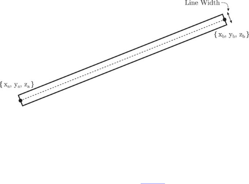
Figure 9.6: Rasterization of Strict Lines
Meanwhile, nonstrict lines are rasterized as a series of horizontal or vertical columns of fragments,
depending on the major axis of the line. The major axis of a line is the axis (either xor y) in which it
moves the farthest. If the change in xcoordinate along the line is greatest, then it is an x-major line
and will be rasterized as a sequence of vertical columns of fragments. Conversely, if it moves farthest
in y, then it is a y-major line and will be rasterized as a sequence of horizontal rows of fragments.
As a consequence, the end of the line is no longer square unless the line is perfectly horizontal or
vertical. Instead, it is wedge-shaped, with the endcap of the line perpendicular to the line’s major axis
rather than to the line itself. For small line widths up to a few pixels, this may not be noticeable. For
larger line widths, however, this can be visually distracting. Figure 9.7 illustrates nonstrict line
rasterization. As you can see in the figure, as the line rotates away from the horizontal or vertical, it
becomes a parallelogram, with the short side length being the line width. The farther the line
becomes from the horizontal or vertical, the narrower it will appear as its perpendicular width
decreases.
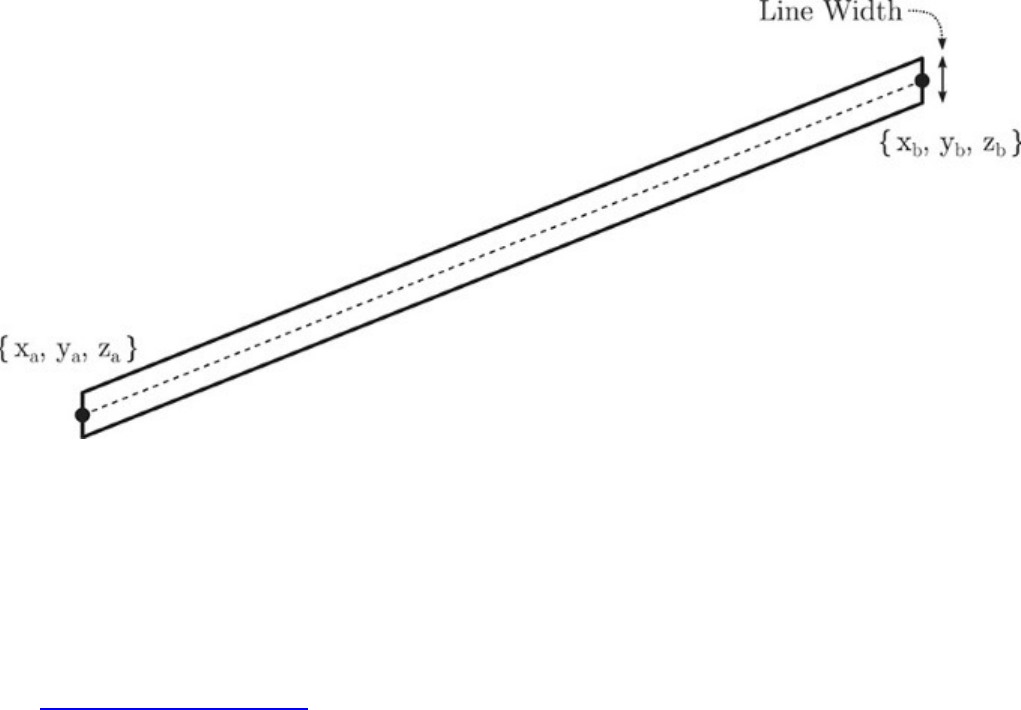
Figure 9.7: Rasterization of Nonstrict Lines
The width of lines used for rasterization can also be marked as a dynamic state. To do this, include
the VK_DYNAMIC_STATE_LINE_WIDTH token in the list of dynamic states passed through the
pDynamicStates member of the VkPipelineDynamicStateCreateInfo structure used
to create the graphics pipeline. Once the line width is marked as dynamic, the lineWidth field of
VkPipelineRasterizationStateCreateInfo is ignored, and the line width is instead set
by calling vkCmdSetLineWidth(), whose prototype is
Click here to view code image
void vkCmdSetLineWidth (
VkCommandBuffer commandBuffer,
float lineWidth);
The lineWidth parameter sets the width of lines, in pixels. Any line primitive rendered will take
this thickness, whether it is the result of drawing with one of the line topologies or whether a
tessellation or geometry shader turns another type of primitive into lines. The new line-width
parameter must be between the minimum and maximum line widths supported by the Vulkan
implementation. This can be determined by checking the lineWidthRange member of the
device’s VkPhysicalDeviceLimits structure. The first element of lineWidthRange is the
minimum width, and the second element is the maximum. Support for lines is optional, so some
implementations will return 1.0 for both elements. However, if wide lines are supported, the Vulkan
implementation will support a range of line widths that includes 1.0 to 8.0 pixels.

User Clipping and Culling
In order to ensure that no geometry is rendered outside the viewport, Vulkan performs clipping of
geometry against the viewport bounds. A typical method for doing this is to determine the distance of
each vertex to the planes, defining the viewport as a signed quantity. Positive distances are on the
“inside” of the volume, and negative distances are “outside” the volume. The distance to each plane
is computed separately for each vertex. If all of the vertices belonging to a primitive are on the
outside of a single plane, then the whole primitive can be discarded. Conversely, if all of the vertices
have a positive distance to all planes, that means that they are all inside the volume, so the entire
primitive can be safely rendered.
If there is a mix of “inside” and “outside” that make up the primitive, then it must be clipped, which
normally means breaking it down into a set of smaller primitives. Figure 9.8 illustrates this. As you
can see in the figure, four triangles have been sent into the pipeline. Triangle A is entirely contained
within the viewport and is rendered directly. Triangle B, on the other hand, lies entirely outside the
viewport and can be trivially discarded. Triangle C penetrates a single edge of the viewport and is
therefore clipped against it. The smaller triangle is produced by the clipper, and this is the one that is
rasterized. Finally, triangle D presents a more complex scenario. It lies partially inside the viewport
but penetrates two of the viewport’s edges. In this case, the clipper breaks the triangle into several
smaller triangles and rasterizes those. The resulting polygon is shown in bold, and the generated
interior edges are shown as dotted lines.
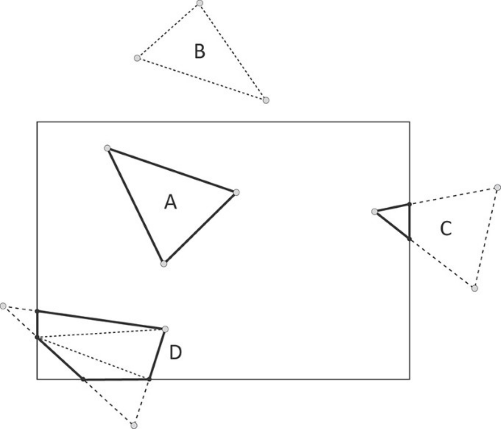
Figure 9.8: Clipping Against a Viewport
In addition to being able to clip a primitive against the edges of the viewport, it is possible to supply
other distance values generated in your shaders that contribute to this clipping procedure. These are
known as clip distances and, once assigned, are treated exactly as the distances computed to the
viewport planes. Positive values are treated as being inside the view volume, and negative values are
treated as being outside the view volume.
To generate a clip distance in your shader, decorate an output variable by using the ClipDistance
decoration. This variable must be declared as an array of 32-bit floating-point values, each element of
which is a separate clip distance. Vulkan will aggregate all of the clip distances written by your
shaders when performing clipping on the generated primitives.
Not all devices support clip distances. If clip distance is supported by a device, then the maximum
number of clip distances supported by that device is guaranteed to be at least 8. Some devices may
support more distances than this. You can check how many distances are supported by the device by
inspecting the maxClipDistances field of its VkPhysicalDeviceLimits structure. You

can retrieve this by calling vkGetPhysicalDeviceProperties(). If clip distances are not
supported or are not enabled at device-creation time, then this field will be 0.
The last geometry-processing stage (vertex, tessellation evaluation, or geometry shader) produces the
clip distances that will be used by the clipping stage to clip the generated primitives. In any stage
after the clip distances have been declared as outputs, the produced distances can be made available
as inputs. Therefore, in the tessellation control, tessellation evaluation, or geometry shader stages,
you can read (and rewrite) the values produced in the previous stage if you need to.
The clip distance is also available as an input to the fragment shader. While clipping will be
performed at the primitive level by most implementations, another way to implement clipping by
using the clip distance is to interpolate the clip distances applied to the vertices across the primitive.
Fragments to which are assigned any negative clip distance values are discarded before fragment
processing completes. Even if an implementation doesn’t implement clip distances this way, the
interpolated value of each clip distance is made available to the fragment shader should it decorate an
input variable with the ClipDistance decoration.
Listing 9.24 shows an example of decorating an output variable with ClipDistance in SPIR-V,
and Listing 9.23 shows the GLSL fragment that was used to generate this SPIR-V. As you can see, in
GLSL, the built-in variable gl_ClipDistance is used to write clip distances and is translated to
an output variable with the appropriate decorations by the GLSL compiler.
Listing 9.23: Use of gl_ClipDistance in GLSL
Click here to view code image
#version 450 core
// Redeclare gl_ClipDistance to explicitly size it.
out float gl_ClipDistance[1];
layout (location = 0) in vec3 i_position;
// Push constant from which to assign clip distance
layout (push_constant) uniform push_constants_b
{
float clip_distance[4];
} push_constant;
void main(void)
{
gl_ClipDistance[0] = push_constant.clip_distance[0];
gl_Position = vec4(i_position, 1.0f);
}
The shader in Listing 9.23 simply assigns the value of a push constant directly to the
gl_ClipDistance output. A more practical use of gl_ClipDistance would compute a
distance to a plane for each vertex and assign that to the clip-distance output. This rather simple
shader serves to demonstrate how the SPIR-V result is generated. This is shown in Listing 9.24.

Listing 9.24: Decorating Outputs with ClipDistance
Click here to view code image
OpCapability Shader
;; The shader requires the ClipDistance capability.
OpCapability ClipDistance
%1 = OpExtInstImport "GLSL.std.450"
OpMemoryModel Logical GLSL450
OpEntryPoint Vertex %4 "main" %13 %29
OpSource GLSL 450
OpName %4 "main"
OpName %11 "gl_PerVertex"
OpMemberName %11 0 "gl_Position"
OpMemberName %11 1 "gl_PointSize"
;; Redeclaration of gl_ClipDistance built-in
OpMemberName %11 2 "gl_ClipDistance"
OpMemberName %11 3 "gl_CullDistance"
OpName %13 ""
OpName %19 "push_constants_b"
OpMemberName %19 0 "clip_distance"
OpName %21 "push_constant"
OpName %29 "i_position"
OpMemberDecorate %11 0 BuiltIn Position
OpMemberDecorate %11 1 BuiltIn PointSize
;; Decorate the built-in variable as ClipDistance.
OpMemberDecorate %11 2 BuiltIn ClipDistance
OpMemberDecorate %11 3 BuiltIn CullDistance
OpDecorate %11 Block
OpDecorate %18 ArrayStride 4
OpMemberDecorate %19 0 Offset 0
OpDecorate %19 Block
OpDecorate %29 Location 0
%2 = OpTypeVoid
%3 = OpTypeFunction %2
%6 = OpTypeFloat 32
%7 = OpTypeVector %6 4
%8 = OpTypeInt 32 0
%9 = OpConstant %8 1
%10 = OpTypeArray %6 %9
;; This creates the built-in output structure containing gl_ClipDistance.
%11 = OpTypeStruct %7 %6 %10 %10
%12 = OpTypePointer Output %11
;; Instantiate the built-in outputs.
%13 = OpVariable %12 Output
...
;; Beginning of main()
%5 = OpLabel
;; Load from the push-constant array.
%23 = OpAccessChain %22 %21 %16 %16
%24 = OpLoad %6 %23
;; Store to clip distance.
%26 = OpAccessChain %25 %13 %15 %16

OpStore %26 %24
...
;; End of main()
OpReturn
OpFunctionEnd
There is no reason that your shader should assign values to the ClipDistance outputs by
computing distance to a plane. You could assign the distance to an analytic function, to a higher-order
surface, or even to a displacement map read from a texture, for example. However, bear in mind that
because the primitives are clipped as though the distance was computed from a flat plane, the
resulting edges will be a piecewise linear approximation of the function used to compute those
distances. If your function represents tight curves or detailed surfaces, you will need quite a bit of
geometry to make the resulting edges appear smooth.
While the tessellation control and geometry shading stages have access to entire primitives, the
vertex and tessellation evaluation shaders do not. Therefore, if you wish to discard an entire primitive
from one of these stages, it is hard to coordinate the shader invocations corresponding to that
primitive in order to assign a negative clip distance to all of them. For this purpose, you can instead
use the cull distance for each vertex. The cull distance works very similarly to the clip distance. The
difference is that the entire primitive is discarded if any vertex it contains has a negative cull distance,
regardless of the values of the cull distances for the other vertices.
To use cull distance, decorate an output variable with the CullDistance decoration. The cull
distance is also available as in input to subsequent shader stages, just as ClipDistance is. Also, if
CullDistance is used as an input in the fragment shader, its content will be the interpolated value
of the distance assigned in the geometry-processing stages. Listings 9.25 and 9.26 show minor
modifications to Listings 9.23 and 9.24, respectively, to show assignment to variables decorated with
CullDistance rather than ClipDistance.
Listing 9.25: Use of gl_CullDistance in GLSL
Click here to view code image
#version 450 core
out float gl_CullDistance[1];
layout (location = 0) in vec3 i_position;
layout (push_constant) uniform push_constants_b
{
float cull_distance[4];
} push_constant;
void main(void)
{
gl_CullDistance[0] = push_constant.cull_distance[0];
gl_Position = vec4(i_position, 1.0f);
}
As you can see, Listing 9.25 is almost identical to Listing 9.23 except that we have used
gl_CullDistance in place of gl_ClipDistance. As you might expect, the resulting SPIR-V

shader shown in Listing 9.26 is also almost identical to that in Listing 9.24, which uses the
ClipDistance decoration.
Listing 9.26: Decorating Outputs with CullDistance
Click here to view code image
OpCapability Shader
;; The shader requires the CullDistance capability.
OpCapability CullDistance
%1 = OpExtInstImport "GLSL.std.450"
OpMemoryModel Logical GLSL450
OpEntryPoint Vertex %4 "main" %13 %29
OpSource GLSL 450
OpName %4 "main"
OpName %11 "gl_PerVertex"
OpMemberName %11 0 "gl_Position"
OpMemberName %11 1 "gl_PointSize"
OpMemberName %11 2 "gl_ClipDistance"
;; Redeclaration of gl_CullDistance built-in
OpMemberName %11 3 "gl_CullDistance"
OpName %13 ""
OpName %19 "push_constants_b"
OpMemberName %19 0 "cull_distance"
OpName %21 "push_constant"
OpName %29 "i_position"
OpMemberDecorate %11 0 BuiltIn Position
OpMemberDecorate %11 1 BuiltIn PointSize
OpMemberDecorate %11 2 BuiltIn ClipDistance
;; Decorate the built-in variable as CullDistance.
OpMemberDecorate %11 3 BuiltIn CullDistance
OpDecorate %11 Block
OpDecorate %18 ArrayStride 4
OpMemberDecorate %19 0 Offset 0
OpDecorate %19 Block
OpDecorate %29 Location 0
%2 = OpTypeVoid
%3 = OpTypeFunction %2
%6 = OpTypeFloat 32
%7 = OpTypeVector %6 4
%8 = OpTypeInt 32 0
%9 = OpConstant %8 1
%10 = OpTypeArray %6 %9
;; This creates the built-in output structure containing gl_CullDistance.
%11 = OpTypeStruct %7 %6 %10 %10
%12 = OpTypePointer Output %11
;; Instantiate the built-in outputs.
%13 = OpVariable %12 Output
...
;; Beginning of main()
%5 = OpLabel
;; Load from the push-constant array.
%23 = OpAccessChain %22 %21 %16 %16

%24 = OpLoad %6 %23
;; Store to cull distance.
%26 = OpAccessChain %25 %13 %15 %16
...
;; End of main()
OpReturn
OpFunctionEnd
As you can see in Listing 9.25, outputs decorated with CullDistance are produced by writing to
the GLSL built-in variable gl_CullDistance.
Whenever ClipDistance or CullDistance is used in the fragment shader, you should only see
positive values for those inputs. This is because any fragment that would have had a negative clip or
cull distance should have been discarded. The only possible exception to this is helper invocations,
which are invocations of the fragment shader that are used to generate deltas during the computation
of gradients. If your fragment shader is sensitive to negative values of ClipDistance, then this
may be a case you care about.
As with clip distances, cull distances are declared in your shaders as arrays of floating-point values,
and the number of elements in those arrays is device-dependent. Some devices do not support cull
distances, but if they do, they are guaranteed to support at least 8. To determine the number of
distances supported, check the maxCullDistances field of the device’s
VkPhysicalDeviceLimits structure. If cull distances are not supported, then this field will be
0.
Before cull distances can be used in a SPIR-V shader, the shader must enable the CullDistance
capability using an OpCapability instruction. You can check whether the device supports the
CullDistance capability in SPIR-V shaders by inspecting the shaderCullDistance member
of the device’s VkPhysicalDeviceFeatures structure obtained through a call to
vkGetPhysicalDeviceProperties(). You must also enable this feature when the device is
created by setting shaderCullDistance to VK_TRUE in the VkPhysicalDeviceFeatures
structure used to create the device. Likewise, for clip distances, the capability is enabled by executing
OpCapability with the ClipDistance argument, and checked and enabled through the
shaderClipDistance field of VkPhysicalDeviceFeatures.
Because clip and cull distances may consume similar resources, in addition to the
maxClipDistances and maxCullDistances limits, many devices have a combined limit for
the number of distances that you can use at once. This often precludes you from using the maximum
number of both at the same time. To check the combined limit, look at the
maxCombinedClipAndCullDistances field of the device’s VkPhysicalDeviceLimits
structure.
The Viewport Transformation
The final transformation in the pipeline before rasterization is the viewport transformation. The
coordinates produced by the last stage in the geometry pipeline (or produced by the clipper) are in
homogeneous clip coordinates. First, the homogeneous coordinates are all divided through by their
own wcomponents, producing normalized device coordinates.
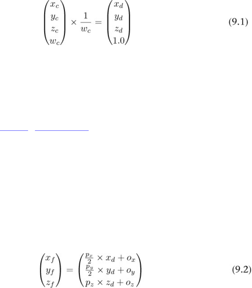
Here, the vertex’s clip coordinates are represented by {xc, yc, zc, wc}, and the normalized device
coordinates are represented by {xd, yd, zd}. Because the vertex’s wcomponent is divided by itself, it
always becomes 1.0 and so can be discarded at this point, and the normalized device coordinate is
considered to be a 3D coordinate.
Before the primitive can be rasterized, it needs to be transformed into framebuffer coordinates, which
are coordinates relative to the origin of the framebuffer. This is performed by scaling and biasing the
vertex normalized device coordinates by the selected viewport transform.
One or more viewports are configured as part of the graphics pipeline. This was briefly introduced in
Chapter 7, “Graphics Pipelines.” Most applications will use a single viewport at a time. When there
are multiple viewports configured, each behaves the same way; only the selection of viewport is
controlled by the geometry shader if it is present. If there is no geometry shader, then only the first
configured viewport is accessible.
Each viewport is defined by an instance of the VkViewport structure, the definition of which is
typedef struct VkViewport {
float x;
float y;
float width;
float height;
float minDepth;
float maxDepth;
} VkViewport;
The transformation from normalized device coordinates to framebuffer coordinates is performed as
Here, xf, yf, and zfare the coordinates of each vertex in framebuffer coordinates. The xand yfields of
VkViewport are oxand oy, respectively, and minDepth is oz. The width and height fields are
used for pxand py.pzis formed from the expression (maxDepth - minDepth).
The maximum size of a viewport is a device-dependent quantity, although it is guaranteed to be at
least 4,096 × 4,096 pixels in size. If all of your color attachments are smaller than this (or if the width
and height of all of your viewports are smaller), then there is no reason to query the upper limit of
viewport size. If you want to render into an image that is larger than this, you can determine the
upper limit on viewport size by inspecting the maxViewportDimensions member of the
device’s VkPhysicalDeviceLimits structure, which you can retrieve by calling
vkGetPhysicalDeviceFeatures().

maxViewportDimensions is an array of two floating-point values. The first element is the
maximum supported viewport width, and the second is the maximum supported viewport height. The
width and height members of VkViewport must be less than or equal to these values.
Although the width and height of each viewport must be within the limits reported in
maxViewportDimensions, it is possible to offset the viewport within a larger set of attachments.
The maximum extent to which the viewport can be offset is determined by checking the
viewportBoundsRange field of the device’s VkPhysicalDeviceLimits structure. So long
as the left, right, top, and bottom of the viewport lie within the range of
viewportBoundsRange[0] and viewportBoundsRange[1], then the viewport can be
used.
Although the outputs of the vertex shader and the parameters of the viewport are all floating-point
quantities, the resulting framebuffer coordinates are generally converted to fixed-point representation
before rasterization. The range supported by the viewport coordinates must obviously be large
enough to represent the maximum viewport size. The number of fractional bits determines the
accuracy at which vertices are snapped to pixel coordinates.
This precision is device-dependent, and some devices might snap directly to pixel centers. However,
this is uncommon, and most devices employ some subpixel precision. The amount of precision a
device uses in its viewport coordinate representation is contained in the
viewportSubPixelBits field of its VkPhysicalDeviceLimits structure.
As well as specifying the bounds of the viewports when the graphics pipeline is created, the viewport
state can be made dynamic. To do this, include VK_DYNAMIC_STATE_VIEWPORT in the list of
dynamic states when the pipeline is created. When this token is included, the values of the viewport
bounds specified at pipeline-creation time are ignored. Only the number of viewports is relevant. To
set the viewport bounds dynamically, call vkCmdSetViewport(), the prototype of which is
Click here to view code image
void vkCmdSetViewport (
VkCommandBuffer commandBuffer,
uint32_t firstViewport,
uint32_t viewportCount,
const VkViewport* pViewports);
Any subset of the active viewports can be updated with vkCmdSetViewport(). The
firstViewport parameter specifies the first viewport to update, and the viewportCount
parameter specifies the number of viewports (starting from firstViewport) to update. The
dimensions of the viewports is specified in pViewports, which is a pointer to an array of
viewportCount VkViewport structures.
The number of viewports supported by the current pipeline is specified in the viewportCount
field of VkPipelineViewportStateCreateInfo and is always considered to be static.
Unless the pipeline disables rasterization, there must be at least one viewport in the pipeline. You can
set viewports outside the number supported by the current pipeline and then switch to a pipeline with
more viewports, and it will use the state you specified.
Usually, you will use a single viewport that covers all of the framebuffer attachments. However, in
some cases you might want to render to a smaller window within the framebuffer. Further, you may
want to render to multiple windows. For example, in a CAD-type application, you may have a top,

side, front, and perspective view of an object being modeled. It is possible to render to multiple
viewports simultaneously with a single graphics pipeline.
Support for multiple viewports is optional. The total number of viewports supported by a device can
be determined by checking the maxViewports member of its VkPhysicalDeviceLimits
structure, as returned from a call to vkGetPhysicalDeviceProperties(). If multiple
viewports are supported, then this will be at least 16 and may be higher. If multiple viewports are not
supported, then this field will be 1.
When you are creating the graphics pipeline, the number of viewports the pipeline will use is
specified in the viewportCount field of the VkPipelineViewportStateCreateInfo
structure passed through pViewportState in VkGraphicsPipelineCreateInfo. When
the viewports are configured as static state, their parameters are passed through the pViewports
member of the same structure.
Once a pipeline is in use, its geometry shader can select the viewport index by decorating one of its
outputs with the ViewportIndex decoration. You can generate this code by writing to the
gl_ViewportIndex built-in output in a GLSL shader.
All of the vertices in a primitive produced by the geometry shader should have the same viewport
index. When the primitive is rasterized, it will use the viewport parameters from the selected
viewport. Because geometry shaders can run instanced, a simple way to broadcast geometry to
multiple viewports is to run the geometry shader with as many instances as there are viewports in the
pipeline, and then, for each viewport, assign the invocation index to the viewport index, causing the
version of the geometry to be rendered into the appropriate viewport. Listing 9.27 shows an example
of how to do this.
Listing 9.27: Using Multiple Viewports in a Geometry Shader (GLSL)
Click here to view code image
#version 450 core
layout (triangles,invocations = 4) in;
layout (triangle_strip,max_vertices = 3) out;
layout (set = 0, binding = 0) uniform transform_block
{
mat4 mvp_matrix[4];
};
in VS_OUT
{
vec4 color;
} gs_in[];
out GS_OUT
{
vec4 color;
} gs_out;
void main(void)
{

for (int i = 0; i < gl_in.length(); i++)
{
gs_out.color = gs_in[i].color;
gl_Position = mvp_matrix[gl_InvocationID]*
gl_in[i].gl_Position;
gl_ViewportIndex = gl_InvocationID;
EmitVertex();
}
EndPrimitive();
}
In Listing 9.27, the transformation matrix to be applied to the geometry for each shader invocation is
stored in a uniform block called transform_block. The number of invocations is set to 4, using
an input layout qualifier, and then the gl_InvocationID built-in variable is used to index into the
array of matrices. The invocation index is also used to specify the viewport index.
Summary
This chapter discussed the optional geometry processing stages of the Vulkan graphics pipeline:
tessellation and geometry. You saw that the tessellation stage is made up of a pair of shaders
surrounding a fixed-function, configurable block that breaks large patches into many smaller points,
lines, or triangles. After the tessellation stage is the geometry shading stage, which receives
primitives from the previous stage and can process entire primitives, discard them, or create new
ones, decimating or amplifying geometry as it passes down the pipeline.
You also saw how geometry can be clipped and culled using per-vertex controls and how selection of
the viewport index in a geometry shader can be used to confine geometry to user-specified regions.

Chapter 10. Fragment Processing
What You’ll Learn in This Chapter
• What happens after a primitive is rasterized
• How your fragment shaders determine the color of fragments
• How the results of your fragment shaders are merged into the final picture
The previous chapters covered everything that occurs in the Vulkan graphics pipeline up until the
point of rasterization. The rasterizer takes your primitives and breaks them into many fragments,
which ultimately come together to form the final pixels that will be shown to your users. In this
chapter, you will see what happens to those fragments as they undergo per-fragment tests, shading
and then blending into color attachments used by your application.
Scissor Testing
The scissor test is a stage in fragment processing that operates before any other testing is performed.
This test simply ensures that fragments are within a specified rectangle on the framebuffer. While this
is somewhat similar to viewport transformations, there are two important differences between using a
viewport that is not the full size of the framebuffer and the scissor test:
• The viewport transformation changes the locations of primitives in the framebuffer; as the
viewport rectangle moves, so do the primitives inside it. The scissor rectangles have no effect on
the the position of primitives and operate after they have been rasterized.
• While the viewport rectangles affect clipping and in some cases may produce new primitives,
the scissor rectangle operates directly on rasterized fragments, discarding them before fragment
shading.
The scissor test always runs before the fragment shader, so if your fragment shader produces side
effects, those side effects will not be seen for fragments that are scissored away. The scissor test is
always enabled. However, in most implementations, setting the scissor rectangle to the full size of the
framebuffer effectively disables it.
The number of scissor rectangles is specified in the scissorCount field of the
VkPipelineViewportStateCreateInfo structure used to create the graphics pipeline. This
must be the same as the viewportCount field. As discussed in Chapter 9, “Geometry Processing,”
the viewport to use for the viewport transformation is chosen by writing to an output in the geometry
shader decorated with the ViewportIndex decoration. This same output is used to select the
scissor rectangle used for the scissor test. As such, it’s not possible to select an arbitrary combination
of scissor rectangle and viewport. If you want to use multiple viewports and disable the scissor test,
then you need to specify as many scissor rectangles as you do viewports, but set all of the scissor
rectangles to the full size of the framebuffer.
Each scissor rectangle is represented by an instance of the VkRect2D structure, the definition of
which is
typedef struct VkRect2D {
VkOffset2D offset;

VkExtent2D extent;
} VkRect2D;
A rectangle is made up of an origin and a size, stored in the offset and extent fields of
VkRect2D. These are VkOffset2D and VkExtent2D structures, the definitions of which are
typedef struct VkOffset2D {
int32_t x;
int32_t y;
} VkOffset2D;
and
typedef struct VkExtent2D {
uint32_t width;
uint32_t height;
} VkExtent2D;
The xand yfields of offset contain the coordinates, in pixels, of the origin of each scissor
rectangle, and the width and height fields of extent contain its size.
As with the viewport rectangles, the number of rectangles accessible to a pipeline is always
considered to be static state, but the sizes of the rectangles may be made dynamic. If
VK_DYNAMIC_STATE_SCISSOR is included in the list of dynamic states when the pipeline is
created, then the scissor rectangle state becomes dynamic and can be modified using
vkCmdSetScissor().
Click here to view code image
void vkCmdSetScissor (
VkCommandBuffer commandBuffer,
uint32_t firstScissor,
uint32_t scissorCount,
const VkRect2D* pScissors);
The index of the first scissor rectangle to update is passed in firstScissor, and the number of
scissor rectangles to update is passed in scissorCount. The range of scissor rectangles can be a
subset of the scissor rectangles supported by Vulkan. However, it’s important to set all the scissor
rectangles that the current pipeline might use before rendering into them. The extent of the scissor
rectangles is contained in an array of VkRect2D structures, the address of which is passed in
pScissors.
The scissor test is essentially always enabled. Setting one or more of the scissor rectangles to cover
the entire renderable area effectively disables the test for that rectangle. The number of scissor
rectangles used by a pipeline is always considered to be part of the pipeline’s static state. This
number is set through the scissorCount member of the
VkPipelineViewportStateCreateInfo structure used to create the pipeline. The range of
scissor rectangles specified in vkCmdSetScissor() can extend outside the number of scissor
rectangles supported by the currently bound pipeline. If you switch to another pipeline with more
scissor rectangles, the rectangles you set will be used.

Depth and Stencil Operations
The depth and stencil buffers are special attachments that allow fragments to be evaluated against
information already contained in them either before or after the fragment shader runs. Chapter 7,
“Graphics Pipelines,” introduced the depth state. Additional state in the rasterization state also
controls how rasterized fragments interact with the depth and stencil buffers.
Logically, the depth and stencil operations run after the fragment shader has executed. In practice,
most implementations will execute the depth and stencil operations before1running the fragment
shader wherever they can prove that execution of the fragment shader has no visible side effects, so
the result of running tests (and potentially rejecting fragments) will have no visible effect on the
rendered scene. In the following sections, we will discuss operation in logical terms—that is,
assuming that tests occur after shading—but mention explicitly where this is not the case or where
some caveat may preclude an implementation from running tests early.
1. An entire class of rendering hardware—deferred shading hardware—will attempt to run the depth test for
every fragment in the scene before running any fragment shading. Configuring state to preclude this can have
serious performance consequences on this type of hardware.
During testing against the depth and stencil buffers, those buffers can be optionally updated with new
data. In fact, writing to depth or stencil buffers is so much considered to be part of the test that the
tests must be enabled in order to see writes to depth or stencil buffers occur. This is a common
omission for developers new to graphics programming, so it’s important to mention it here.
As introduced in Chapter 7, “Graphics Pipelines,” depth and stencil operation state is configured
using the VkPipelineDepthStencilStateCreateInfo structure passed through the
VkGraphicsPipelineCreateInfo structure used to create the graphics pipeline. For
reference, the definition of VkPipelineDepthStencilStateCreateInfo is
Click here to view code image
typedef struct VkPipelineDepthStencilStateCreateInfo {
VkStructureType sType;
const void* pNext;
VkPipelineDepthStencilStateCreateFlags flags;
VkBool32 depthTestEnable;
VkBool32 depthWriteEnable;
VkCompareOp depthCompareOp;
VkBool32 depthBoundsTestEnable;
VkBool32 stencilTestEnable;
VkStencilOpState front;
VkStencilOpState back;
float minDepthBounds;
float maxDepthBounds;
} VkPipelineDepthStencilStateCreateInfo;
As you can see, this structure is rather large and contains several substructures that define properties
of the depth and stencil tests. We necessarily glossed over much of this detail in Chapter 7, “Graphics
Pipelines,” but dig into more of it here. Each of the substructures is discussed in the following
sections.

Depth Testing
The first operation performed after rasterization is the depth test. The depth test compares the depth
value for the fragment with the value stored in the current depth-stencil attachment using an
operation chosen when the pipeline is created. The fragment’s depth value can come from one of two
places:
• It may be interpolated as part of rasterization using the depth values at each of the primitive’s
vertices.
• It may be generated in the fragment shader and output along with other color attachments.
Of course, generating the depth value in the fragment shader is one of the cases in which an
implementation would be forced to run the shader before performing the depth test.
The depth value interpolated by rasterization is taken from the result of the viewport transformation.
Each vertex has a depth value in the range 0.0, 1.0 as produced from the last stage in the geometry-
processing pipeline. This is then scaled and biased using the parameters of the selected viewport to
yield a framebuffer depth.
The depth test must be enabled by setting the depthTestEnable field of the
VkPipelineDepthStencilStateCreateInfo structure to VK_TRUE.
When enabled, the operation used to compare the fragment’s computed depth value (either
interpolated during rasterization or produced by your fragment shader) is specified in the
depthCompareOp field of the pipeline’s VkPipelineDepthStencilStateCreateInfo.
This is one of the standard VkCompareOp tokens, and their meanings when applied to depth testing
are shown in Table 10.1.
If the depth test passes, the resulting depth (whether interpolated or produced by the fragment shader)
may be written to the depth buffer. To do this, set depthWriteEnable to VK_TRUE. If
depthWriteEnable is VK_FALSE, then the depth buffer is not written to, regardless of the
outcome of the depth test.
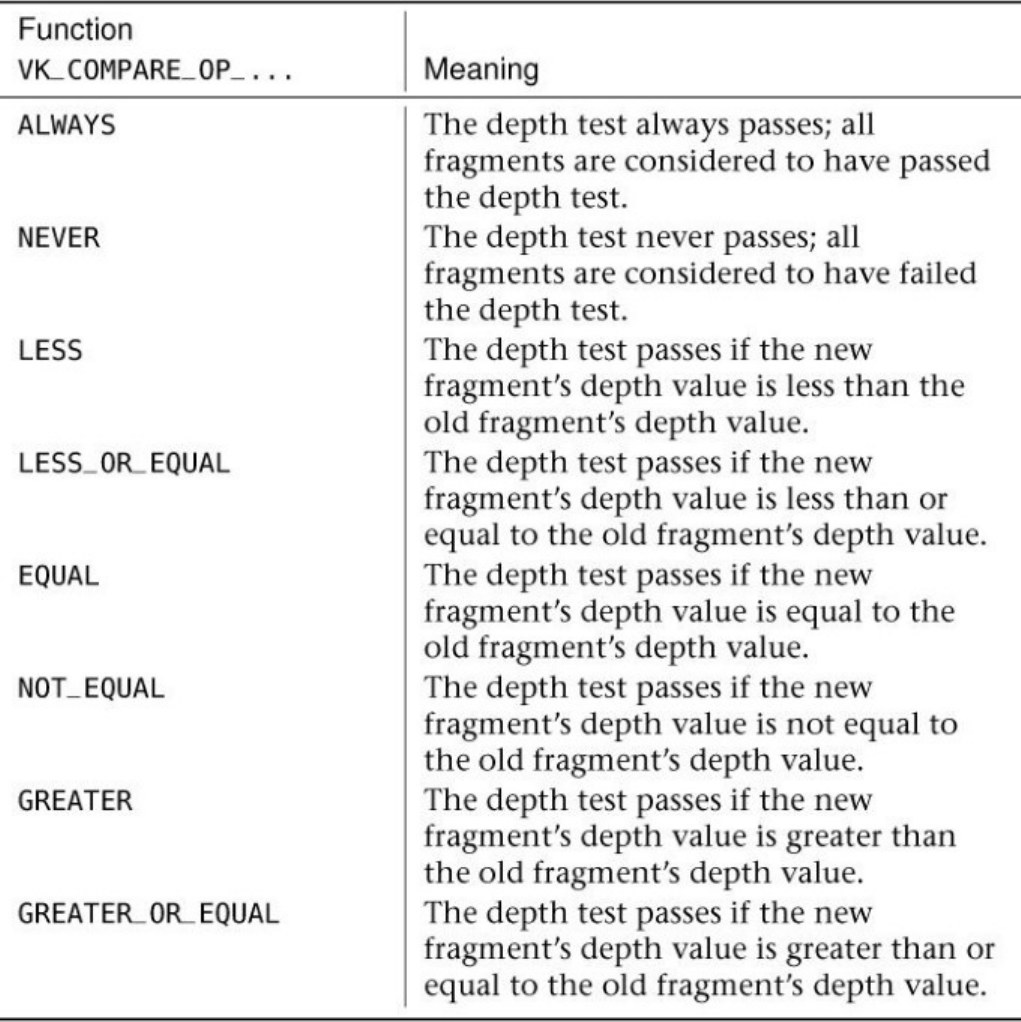
Table 10.1: Depth Comparison Functions
It is important to note that the depth buffer is not updated unless the depth test is enabled, regardless
of the state of depthWriteEnable. Therefore, if you want to unconditionally write the fragment’s
depth value into the depth buffer, you need to enable the test (set depthTestEnable to
VK_TRUE), enable depth writes (set depthWriteEnable to VK_TRUE), and configure the depth
test to always pass (set depthCompareEnable to VK_COMPARE_OP_ALWAYS).

Depth-Bounds Testing
The depth-bounds test is a special, additional test that can be performed as part of depth testing. The
value stored in the depth buffer for the current fragment is compared with a specified range of values
that is part of the pipeline. If the value in the depth buffer falls within the specified range, then the
test passes; otherwise, it fails. What’s interesting about the depth-bounds test is that it is not in any
way dependent on the depth value of the fragment being tested. This means that it can be quickly
evaluated at the same time as or even before depth interpolation or fragment shading executes.
A use case for the depth-bounds test is to intersect volumetric geometry with an existing depth buffer.
For example, if we prerender the depth buffer for a scene, we can project a light’s sphere of influence
into the scene. We then set the depth bounds to the minimum and maximum distance from the light’s
center and enable the test. When we render the light geometry (using a fragment shader that will
perform deferred shading computations), the depth-bounds test will quickly reject fragments that will
not be influenced by the light.
To enable the depth-bounds test, set the depthBoundsTestEnable member of
VkPipelineDepthStencilStateCreateInfo to VK_TRUE, and configure the minimum
and maximum depth-bounds values in minDepthBounds and maxDepthBounds, respectively.
Perhaps more usefully, though, the minimum and maximum extents for the depth-bounds test can be
configured as dynamic state.
To do this, include VK_DYNAMIC_STATE_DEPTH_BOUNDS as one of the dynamic states in the
pipeline’s VkPipelineDynamicStateCreateInfo structure. Once the depth-bounds test is
set to dynamic, the minimum and maximum extents for the test are set with
vkCmdSetDepthBounds(), the prototype of which is
Click here to view code image
void vkCmdSetDepthBounds (
VkCommandBuffer commandBuffer,
float minDepthBounds,
float maxDepthBounds);
Again, for the depth-bounds test to take effect, it must be enabled by setting the
depthBoundsTestEnable member of the
VkPipelineDepthStencilStateCreateInfo structure used to create the pipeline to
VK_TRUE. The minDepthBounds and maxDepthBounds parameters take similar meaning to
the similarly named parameters in the VkPipelineDepthStencilStateCreateInfo
structure. Whether the depth-bounds test is enabled or not is always static state, even if the depth-
bounds values themselves are marked as dynamic.
Note that the depth-bounds test is an optional feature, and not all Vulkan implementations support it.
To determine whether the Vulkan implementation supports the depth-bounds test, check the
depthBounds member of the device’s VkPhysicalDeviceFeatures structure. In order to
use the depth-bounds test, you should also set the depthBounds field of the
VkPhysicalDeviceFeatures structure used to create the device to VK_TRUE.
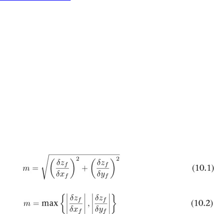
Depth Bias
When two primitives are rendered on top of each other or very close to it, their interpolated depth
values may be the same or very close. If the primitives are exactly coplanar, then their interpolated
depth values should be identical. If there is any deviation, then their depth values will differ by a very
small amount. As the interpolated depth values are subject to floating-point imprecision, this can
result in depth testing producing inconsistent and implementation-dependent results. The visual
artifact that results is known as depth fighting.
To counteract this, and to enable predictable results from depth testing generally, a programmable
bias value can be applied to the interpolated depth values to force them to be offset toward or away
from the viewer. This is known as depth bias and is actually part of rasterization state because it is the
rastrerizer that produces the interoplated depth values.
To enable depth bias, set the depthBiasEnable field of the
VkPipelineRasterizationStateCreateInfo structure used to create the rasterizer state
in the graphics pipeline to VK_TRUE. For reference, the definition of
VkPipelineRasterizationStateCreateInfo is
Click here to view code image
typedef struct VkPipelineRasterizationStateCreateInfo {
VkStructureType sType;
const void* pNext;
VkPipelineRasterizationStateCreateFlags flags;
VkBool32 depthClampEnable;
VkBool32 rasterizerDiscardEnable;
VkPolygonMode polygonMode;
VkCullModeFlags cullMode;
VkFrontFace frontFace;
VkBool32 depthBiasEnable;
float depthBiasConstantFactor;
float depthBiasClamp;
float depthBiasSlopeFactor;
float lineWidth;
} VkPipelineRasterizationStateCreateInfo;
When depthBiasEnable is VK_TRUE, the next three fields—depthBiasConstantFactor,
depthBiasClamp, and depthBiasSlopeFactor—configure the depth-bias equations used to
compute an offset that is applied to the interpolated depth values.
First, the maximum depth slope of the polygon mis computed as
This is often approximated as
In both equations, xf,yf, and zfrepresent a point on the triangle.
Once mis computed, the offset ois computed as
The term ris the minimum resolvable delta in depth values for the primitive. For fixed-point depth
buffers, this is a constant that depends only on the number of bits in the depth buffer. For floating-
point depth buffers, this depends on the range of depth values spanned by the primitive.
If depthBiasClamp in VkPipelineRasterizationStateCreateInfo is 0.0 or NaN,
then the computed value of ois used to directly bias the interpolated depth values. However, if
depthBiasClamp is positive, then it forms an upper bound on o, and if it is negative, it forms a
lower bound on o.
By biasing the depth value toward or away from the viewer slightly, it’s possible to ensure that for a
given pair of coplanar (or almost coplanar) primitives, one always “wins” the depth test. This can
essentially eliminate depth fighting.
The depth-bias parameters can either be static state contained in the rasterization state of the graphics
pipeline or configured to be dynamic state. To enable the depth-bias state to be dynamic, include
VK_DYNAMIC_STATE_DEPTH_BIAS in the list of dynamic states passed in the
pDynamicStates member of the VkPipelineDynamicStateCreateInfo structure used
to create the graphics pipeline.
Once depth bias is configured to be dynamic, the parameters for depth-bias equations can be set by
calling vkCmdSetDepthBias(), the prototype of which is
Click here to view code image
void vkCmdSetDepthBias (
VkCommandBuffer commandBuffer,
float depthBiasConstantFactor,
float depthBiasClamp,
float depthBiasSlopeFactor);
The command buffer to set the depth-bias state for is specified in commandBuffer. The
depthBiasConstantFactor,depthBiasClampFactor, and depthBiasSlopeFactor
have the same meanings as the similarly named members of
VkPipelineRasterizationStateCreateInfo. Note that while the depth bias parameters
can be made part of a pipeline’s dynamic state, the depth bias must still be enabled by setting the
depthBiasEnable flag to VK_TRUE in the
VkPipelineRasterizationStateCreateInfo structure used to create the pipeline. The
depthBiasEnable flag is always considered to be static state, although setting the depth-bias
factors to 0.0 effectively disables it.
Stencil Testing
The stencil test is enabled by setting the stencilTestEnable field of
VkPipelineDepthStencilStateCreateInfo to VK_TRUE.
The stencil test can actually be different for front- and back-facing primitives. The state of the stencil
test is represented by an instance of the VkStencilOpState structure, and there is one for each of
the front- and back-facing states. The definition of VkStencilOpState is
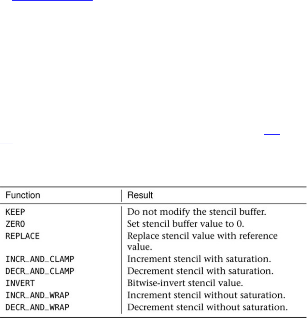
Click here to view code image
typedef struct VkStencilOpState {
VkStencilOp failOp;
VkStencilOp passOp;
VkStencilOp depthFailOp;
VkCompareOp compareOp;
uint32_t compareMask;
uint32_t writeMask;
uint32_t reference;
} VkStencilOpState;
There are three possible outcomes between the depth and stencil tests. If the depth test fails, then the
operation specified in depthFailOp is performed, and the stencil test is skipped. If the depth test
passes, however, then the stencil test is performed, producing one of two further outcomes: If the
stencil test fails, then the operation specified in failOp is performed, and if the stencil test passes,
the operation specified in passOp is performed. Each of depthFailOp,failOp, and passOp is
a member of the VkStencilOp enumeration. The meaning of each operation is shown in Table
10.2.
If enabled, the stencil test compares the stencil reference value with that of the current content of the
stencil buffer. The operator used to compare the two values is specified in the compareOp field of
the VkStencilOpState structure. This is the same set of values used for depth testing, only
comparing the stencil reference with the content of the stencil buffer.
Table 10.2: Stencil Operations
The reference value, compare mask value, and write mask value can also be made dynamic. To mark
these states as dynamic, include VK_DYNAMIC_STATE_STENCIL_REFERENCE,
VK_DYNAMIC_STATE_STENCIL_COMPARE_MASK, and
VK_DYNAMIC_STATE_STENCIL_WRITE_MASK, respectively, in the list of dynamic states passed
in the pDynamicStates member of the VkPipelineDynamicStateCreateInfo structure
used to create the graphics pipeline.

Parameters of the stencil test can be set using three functions: vkCmdSetStencilReference(),
vkCmdSetStencilCompareMask(), and vkCmdSetStencilWriteMask(). They set the
stencil reference value and the compare and write masks, respectively. Their prototypes are
Click here to view code image
void vkCmdSetStencilReference (
VkCommandBuffer commandBuffer,
VkStencilFaceFlags faceMask,
uint32_t reference);
void vkCmdSetStencilCompareMask (
VkCommandBuffer commandBuffer,
VkStencilFaceFlags faceMask,
uint32_t compareMask);
void vkCmdSetStencilWriteMask (
VkCommandBuffer commandBuffer,
VkStencilFaceFlags faceMask,
uint32_t writeMask);
Each of these three states can be independently made either static or dynamic. All three functions
take a faceMask parameter, which determines whether the new state applies to front-facing
primitives, back-facing primitives, or both. To specify each of these, set faceMask to
VK_STENCIL_FACE_FRONT_BIT,VK_STENCIL_FACE_BACK_BIT, or
VK_STENCIL_FRONT_AND_BACK, respectively. Note that VK_STENCIL_FRONT_AND_BACK
has the same numeric value as VK_STENCIL_FACE_FRONT_BIT and
VK_STENCIL_FACE_BACK_BIT added together.
Early Fragment Tests
Normally, the depth and stencil tests are configured to run after the fragment shader has run. Because
updating the depth buffer occurs as part of the test—the test is considered to be an indivisible read-
modify-write operation—this has three primary consequences that are visible to the application:
• The fragment shader can update the depth value of the fragment by writing to a floating-point
output decorated with the BuiltIn FragDepth decoration. In this case, the depth test
executes after the fragment shader and uses the value produced by the shader rather than the
value generated by interpolation.
• The fragment shader has side effects such as storing into an image. In this case, the side effects
from shader execution will be visible, even for fragments that later fail the depth test.
• If the fragment shader throws away the fragment by executing the OpKill SPIR-V instruction
(produced by calling the discard() function in GLSL), then the depth buffer is not updated.
If none of these conditions can occur, Vulkan implementations are permitted to detect this case and
reorder testing such that the depth and stencil tests occur before the fragment shader executes. This
saves the work of executing the fragment shader for fragments that would fail the tests.
Because the default logical order of the pipeline specifies that the depth and stencil tests occur after
the fragment shader has executed, when any of the conditions hold, the implementation must run
operations in that order. You can, however, force the shader to run after the depth and stencil tests
even when one of these conditions is true. There are two ways to do this.
First, you can force the fragment shader to run early regardless of any other condition detected by the
Vulkan implementation. To do this, decorate the SPIR-V entry point for the fragment shader with the
EarlyFragmentTests decoration. This will cause execution of the fragment shader to be
delayed (or at least appear to be delayed) until after the depth and stencil tests have been executed.
Should the depth test fail, then the fragment shader will not be executed, and any side effects that it
may have produced, such as updates to an image via image stores, will not be visible.
This first mode is useful, for example, to run depth tests against a prerendered depth image produced,
say, in an earlier subpass of a renderpass, but to produce output from the fragment shader using
image stores rather than normal fragment shader outputs. Because the number of fixed-function
outputs from the fragment shader is limited but the number of stores it may perform to images is
effectively unlimited, this is a good way to increase the amount of data that a fragment shader can
produce for a single fragment.
The second mechanism for running the fragment shader after depth testing is more subtle. It interacts
specifically with the case where the fragment shader writes to the fragment’s depth value. Under
normal circumstances, the implementation must assume that the fragment shader may write any
arbitrary value to the fragment’s depth unless it can definitively prove otherwise.
In cases where you know that the fragment shader will move the depth value in only one direction
(toward or away from the viewer), you can apply the SPIR-V DepthGreater or DepthLess
execution modes to the fragment shader’s entry point with the OpExecutionMode instruction.
When DepthGreater is applied, then Vulkan knows that no matter what your shader does, the
resulting depth values produced by the fragment shader will only be greater than the values produced
by interpolation. Therefore, if the depth test is VK_COMPARE_OP_GREATER or
VK_COMPARE_OP_GREATER_OR_EQUAL, then the fragment shader cannot negate the result of a
depth test that’s already passed.
Likewise, when DepthLess is applied, then Vulkan knows that the fragment shader will only make
the resulting depth value less than it would have been and therefore cannot negate the result of a
passing VK_COMPARE_OP_LESS or VK_COMPARE_OP_LESS_OR_EQUAL test.
Finally, the SPIR-V DepthUnchanged execution mode tells Vulkan that no matter what the
fragment shader appears to do to the depth value of the fragment shader, it should treat it as though it
did not update the value at all. Therefore, any optimizations it might make if the shader did not write
to the fragment’s depth remain valid and can be enabled where appropriate.
Multisample Rendering
Multisample rendering is a method to improve image quality by storing multiple depth, stencil, or
color values for each pixel. As the image is rendered, multiple samples within each pixel are
generated (hence the term multisample rendering) and when the image is to be displayed to the user,
the samples are merged using a filter to produce a final, single value per pixel.
There are two general ways to produce a multisample image:
• Multisampling: Determining which samples within a pixel are covered, computing a single color
value for that pixel, and then broadcasting that value to all covered samples within the pixel
• Supersampling: Computing unique color values for each and every sample within a pixel
Obviously, supersampling comes at significantly higher cost than multisampling because potentially
many more color values are computed and stored.

To create a multisample image, set the samples field of the VkImageCreateInfo structure used
to create the image to one of the values of the VkSampleCountFlagBits enumeration. The
samples field is a one hot encoding of the sample count to be used in the image. The numeric value
for the enumeration is simply n, where nis the number of samples in the image. Only power-of-two
sample counts are supported.
While the current Vulkan header defines enumerants from VK_SAMPLE_COUNT_1_BIT to
VK_SAMPLE_COUNT_64_BIT, most Vulkan implementations will support sample counts between
1 and 8 or maybe 16. Further, not every sample count between 1 and the maximum sample count
supported by an implementation will be supported for every image format. In fact, support for
different sample counts varies per format and even per tiling mode and should be queried using
vkGetPhysicalDeviceFormatProperties(). As discussed in Chapter 2, “Memory and
Resources,” vkGetPhysicalDeviceImageFormatProperties() returns information about
a particular format. For reference, its prototype is
Click here to view code image
VkResult vkGetPhysicalDeviceImageFormatProperties (
VkPhysicalDevice physicalDevice,
VkFormat format,
VkImageType type,
VkImageTiling tiling,
VkImageUsageFlags usage,
VkImageCreateFlags flags,
VkImageFormatProperties* pImageFormatProperties);
The format to be queried is passed along with the image type, tiling mode, usage flags and other
information, and vkGetPhysicalDeviceImageFormatProperties() writes the support
information about the format into the VkImageFormatProperties structure pointed to by
pImageFormatProperties. The sampleCounts field of this structure then contains the
supported sample counts for an image in the specified format with the configuration described by the
remaining parameters.
As a primitive is rasterized, the rasterizer computes coverage information for the pixels hit by it.
When multisample rendering is off, rasterization works by simply determining whether the center of
each pixel is inside the primitive and, if so, considering the pixel hit. The depth and stencil tests are
then performed at the center of the pixel, and the fragment shader is executed to determine the
resulting shading information for that pixel.
When multisample rendering is enabled, coverage is determined for each sample in each pixel. For
each sample that is considered to be inside the pixel, the depth and stencil tests are computed
individually. If any sample is determined to be visible, then the fragment shader is run once to
determine the output color for the fragment. That output color is then written into every visible
sample in the image.
By default, the samples are distributed evenly within a pixel at a set of standard locations. These
locations are illustrated in Figure 10.1. The standard sample locations shown in the figure are
supported if the standardSampleLocations field of the device’s
VkPhysicalDeviceLimits structure is VK_TRUE. In this case, the sample locations shown in
Figure 10.1 are used for 1-, 2-, 4-, 8-, and 16-sample images (if supported). Even if the device
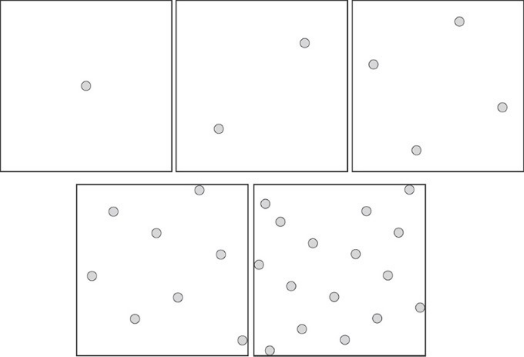
supports 32, 64, or higher sample count images, there are no defined standard sample locations for
those sample counts.
Figure 10.1: Standard Sample Locations
If standardSampleLocations is VK_FALSE in the VkPhysicalDeviceLimits structure,
then those sample counts may be supported with nonstandard sample locations. Determining the
sample locations used by a device in this scenario would likely require a device extension.
Sample Rate Shading
Usually, when a multisample image is bound to the framebuffer, multisampling is used to render into
it. As described earlier, coverage is determined at each of the sample locations in each pixel, and if
any of them is covered by the primitive, the fragment shader is run once to determine the values of its
outputs. Those values are then broadcast to all covered samples in the pixel.
For even higher image quality, we can use supersampling, which causes the fragment shader to be
executed for each covered sample and the unique output values it produces to be written directly to
the pixel’s samples.
While multisampling can improve the appearance of the edges of primitives, it can do nothing to
prevent aliasing artifacts resulting from high spacial frequencies produced by the fragment shader.
However, by running a fragment shader at sample rate, high frequencies produced by the fragment
shader can be antialiased along with primitive edges.
To enable sample rate shading, set the sampleShadingEnable member of the
VkPipelineMultisampleStateCreateInfo structure used to create the graphics pipeline to
VK_TRUE. When sampleShadingEnable is enabled, the minSampleShading field further
controls the frequency at which the shader will be executed. This is a floating-point value between
0.0 and 1.0. At least this fraction of the samples in the pixel will receive a unique set of values as
produced by a separate invocation of the fragment shader.
If minSampleShading is 1.0, then every sample in the pixel is guaranteed to receive its own data
from a separate invocation of the fragment shader. Any value less than 1.0 causes the device to
compute colors for at least that many samples and then distribute the values to the samples in a
device-dependent manner. For example, if minSampleShading is 0.5, then a fully covered
8-sample pixel would cause the fragment shader to execute at least 4 times and for the 4 sets of
outputs to be distributed to the 8 samples in the pixel in a device-dependent manner.
It is possible to configure the pipeline to update only a subset of the samples in the framebuffer. You
can specify a sample mask, which is a bitmask with a single bit corresponding to each of the samples
in the framebuffer. This mask is specified by passing an array of unsigned 32-bit integers through the
pSampleMask member of VkPipelineMultisampleStateCreateInfo. The array divides
the arbitrarily long bitmask into 32-bit chunks, each chunk being an element of the array. If the
framebuffer has 32 or fewer samples, then the array becomes a single element long.
The Nth sample is represented by the (N%32)th bit of the (N/32)th element of the array. When the bit
is set, the sample may be updated by the pipeline. If the bit is cleared, then the pipeline will not
modify the content of samples at that index. In effect, the sample mask is logically ANDed with the
coverage computed during rasterization. If pSampleMask is nullptr, then all samples are
enabled for writing.
In addition to generating coverage during rasterization, it is possible for a fragment shader to produce
a pseudo-coverage value by writing into the alpha channel of its output. By setting the
alphaToCoverage field of VkPipelineMultisampleStateCreateInfo to VK_TRUE,
the alpha value written into the fragment shader’s first output is used to create a new coverage value
for the fragment. A fraction of the samples in the temporarily created sample mask are enabled in an
implementation-defined order, according to the value written by the shader into the alpha channel.
This is then logically ANDed with the coverage mask computed during rasterization. This allows
simple transparency and coverage effects to be implemented by simply exporting alpha values from
the shader.
The question then remains what to do with the actual alpha channel in the framebuffer. If the shader
writes a fraction of coverage into the alpha channel, it may not make sense to write this value directly
into the framebuffer along with the RGB color data. Instead, you can ask Vulkan to subsitute a value
of 1.0 for alpha for the other alpha-related operations, as though the shader had not produced an alpha
value at all. To do this, set the alphaToOneEnable field to VK_TRUE.
Multisample Resolves
When rendering to a multisample image is completed, it can be resolved to a single sample image.
This process aggregates all of the values stored in the multiple samples for each pixel into a single
value, producing a nonmultisampled image. There are two ways to resolve an image.
The first is to include a nonmultisampled image in the pResolveAttachments array passed to
through the VkSubpassDescription used to create a subpass that would render to the original
multisample color attachments. The subpass will produce a multisample image into the
corresponding color attachment, and when the subpass ends (or at least by the time the renderpass
ends), Vulkan will automatically resolve the multisample image into the corresponding
nonmultisampled image in pResolveAttachments.
You can then set the storeOp for the multisample image to
VK_ATTACHMENT_STORE_OP_DONT_CARE to discard the original multisampled data, assuming
that it is not needed for something else. This is likely the most efficient way of resolving a
multisample image, as many implementations will be able to fold the resolve operation into some
other internal operations that are already part of the renderpass, or at least perform the resolve
operation while the original multisample data is in caches rather than writing it all into memory and
reading it back later.
It’s also possible to explicitly resolve a multisample image into a single sample image by calling
vkCmdResolveImage(), the prototype of which is
Click here to view code image
void vkCmdResolveImage (
VkCommandBuffer commandBuffer,
VkImage srcImage,
VkImageLayout srcImageLayout,
VkImage dstImage,
VkImageLayout dstImageLayout,
uint32_t regionCount,
const VkImageResolve* pRegions);
The command buffer that will perform the resolve operation is passed in commandBuffer. The
source image and its expected layout at the time of the resolve operation are passed in srcImage
and srcImageLayout, respectively. Likewise, the destination image and its expected layout are
passed in dstImage and dstImageLayout.vkCmdResolveImage() behaves much like the
blit and copy operations discussed in Chapter 4, “Moving Data.” As such, the layout of the source
image should be either VK_IMAGE_LAYOUT_GENERAL or
VK_IMAGE_LAYOUT_TRANSFER_SRC_OPTIMAL, and the layout of the destination image should
be VK_IMAGE_LAYOUT_GENERAL or VK_IMAGE_LAYOUT_TRANSFER_DST_OPTIMAL.
As with the other blit and copy commands, vkCmdResolveImage() can resolve only parts of an
image if needed. The number of regions to resolve is passed in regionCount, and pRegions
points to an array of VkImageResolve structures, each defining one of the regions. The definition
of VkImageResolve is
Click here to view code image
typedef struct VkImageResolve {
VkImageSubresourceLayers srcSubresource;
VkOffset3D srcOffset;
VkImageSubresourceLayers dstSubresource;
VkOffset3D dstOffset;
VkExtent3D extent;
} VkImageResolve;
Each region to resolve is represented by one instance of the VkImageResolve structure. Each
structure contains a description of the regions in the source and destination regions. The subresource

from which source data is to be taken is in the srcSubresource field, and the subresource to
which the resolved image data is to be written is in the dstSubresource field.
vkCmdResolveImage() cannot rescale the multisample image, so the sizes of the source and
destination regions are the same. This is stored in the extent member of the VkImageResolve
structure. However, the region in the source and destination image does not need to be at the same
location in the two images. The origin of the region in the source image is stored in the srcOffset
field, and the origin of the output region is stored in the dstOffset field.
When an image is resolved by specifying it as one of the resolve attachments in the renderpass, the
entire region is resolved at the end of the subpass that references it—at least the region that is
included in the renderArea passed to vkCmdBeginRenderPass(). With
vkCmdResolveImage(), however, it’s possible to resolve parts of an image. Although explicitly
calling vkCmdResolveImage() is likely to be less efficient than resolving attachments at the end
of a renderpass, it may be that you need to resolve only part of the image, so
vkCmdResolveImage() is the more appropriate choice in that case.
Logic Operations
Logic operations allow logical operations such as AND and XOR to be applied between the output of
the fragment shader and the content of a color attachment. Logical operations are supported on most
integer formats that can be used as color attachments. Logical operations are enabled by setting the
logicOpEnable field of the VkPipelineColorBlendStateCreateInfo used to create a
color blend state object to VK_TRUE. Introduced in Chapter 7, “Graphics Pipelines,” the definition of
VkPipelineColorBlendStateCreateInfo is
Click here to view code image
typedef struct VkPipelineColorBlendStateCreateInfo {
VkStructureType sType;
const void* pNext;
VkPipelineColorBlendStateCreateFlags flags;
VkBool32 logicOpEnable;
VkLogicOp logicOp;
uint32_t attachmentCount;
const VkPipelineColorBlendAttachmentState* pAttachments;
float blendConstants[4];
} VkPipelineColorBlendStateCreateInfo;
When logical operations are enabled, the logical operation specified by logicOp, is performed
between each of the fragment shader’s outputs and the corresponding color attachment. The same
logical operation is used for every attachment—that is, it is not possible to use a different logical
operation for different attachments. The available logical operations, represented by members of the
VkLogicOp, are shown in Table 10.3.
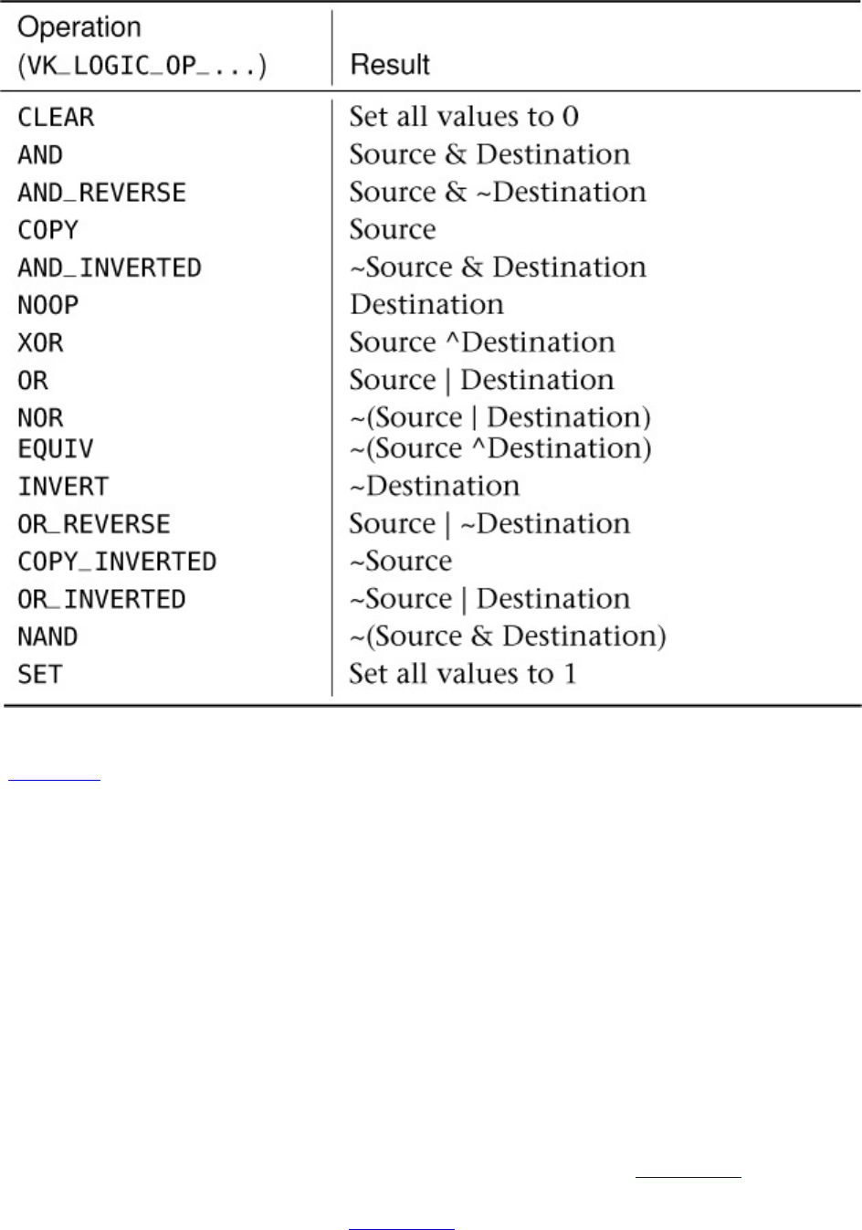
Table 10.3: Logic Operations
In Table 10.3,Source refers to the value(s) produced by the fragment shader, and Destination refers
to the values already in the color attachment.
Although the selected logical operation is global (if enabled) and applies to all color outputs, logical
operations are applied only to color attachments with formats that support them. If the format used
for one of the color attachments does not support logical operations, then the selected logic operation
is ignored for that attachment, and the value is written directly to the attachment.
Fragment Shader Outputs
Each fragment shader may have one or more outputs. It is possible to construct a fragment shader
that has no outputs and produces visible side effects by performing image store operations. However,
in the majority of cases, fragment shaders produce outputs by writing them to special variables
declared as outputs.
To declare an output in a GLSL fragment, simply create a variable at global scope with the out
storage qualifier. This produces a SPIR-V declaration of an output variable, which in turn is used by
Vulkan to connect the fragment shader’s output to subsequent processing. Listing 10.1 shows a
simple GLSL fragment shader that declares a single output and writes an opaque red color into it.
The resulting SPIR-V shader is shown in Listing 10.2.
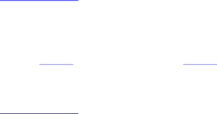
Listing 10.1: Declaring an Output in a Fragment Shader (GLSL)
Click here to view code image
#version 450 core
out vec4 o_color;
void main(void)
{
o_color = vec4(1.0f, 0.0f, 0.0f, 1.0f);
}
When the code in Listing 10.1 is used to create the SPIR-V shader in Listing 10.2, you can see that
the o_color output is translated into an output variable (%9) of type vector of four floating-point
values (%7). The OpStore instruction is then used to write to it.
Listing 10.2: Declaring an Output in a Fragment Shader (SPIR-V)
Click here to view code image
; SPIR-V
; Version: 1.0
; Generator: Khronos Glslang Reference Front End; 1
; Bound: 13
; Schema: 0
OpCapability Shader
%1 = OpExtInstImport "GLSL.std.450"
OpMemoryModel Logical GLSL450
OpEntryPoint Fragment %4 "main" %9
OpExecutionMode %4 OriginUpperLeft
OpSource GLSL 450
OpName %4 "main"
OpName %9 "o_color"
%2 = OpTypeVoid
%3 = OpTypeFunction %2
%6 = OpTypeFloat 32
%7 = OpTypeVector %6 4
%8 = OpTypePointer Output %7
%9 = OpVariable %8 Output
%10 = OpConstant %6 1
%11 = OpConstant %6 0
%12 = OpConstantComposite %7 %10 %11 %11 %10
%4 = OpFunction %2 None %3
%5 = OpLabel
OpStore %9 %12
OpReturn
OpFunctionEnd
When the framebuffer color attachment is floating-point, or signed- or unsigned-normalized format,
the fragment shader output should be declared using a floating-point variable. When the color
attachment is a signed or unsigned integer format, then the fragment shader output should be declared
as a signed or unsigned integer type too. The number of components in the fragment shader output
should be at least as many as the number of components in the corresponding color attachment.

As you saw in Chapter 7, “Graphics Pipelines,” a single graphics pipeline can have many color
attachments and access these attachments through attachment references in each subpass. Each
subpass can reference several output attachments, which means that a fragment shader can write to
several attachments. To do this, we declare multiple outputs in our fragment shader and, in GLSL,
specify an output location using a location layout qualifier.
Listing 10.3 shows a GLSL fragment shader that declares multiple outputs, writing a different
constant color to each one. Each is assigned a different location using a location layout qualifier.
Listing 10.3: Several Outputs in a Fragment Shader (GLSL)
Click here to view code image
#version 450 core
layout (location = 0) out vec4 o_color1;
layout (location = 1) out vec4 o_color2;
layout (location = 5) out vec4 o_color3;
void main(void)
{
o_color1 = vec4(1.0f, 0.0f, 0.0f, 1.0f);
o_color2 = vec4(0.0f, 1.0f, 0.0f, 1.0f);
o_color3 = vec4(0.0f, 0.0f, 1.0f, 1.0f);
}
The result of compiling the shader in Listing 10.3 to SPIR-V is shown in Listing 10.4.
Listing 10.4: Several Outputs in a Fragment Shader (SPIR-V)
Click here to view code image
; SPIR-V
; Version: 1.0
; Generator: Khronos Glslang Reference Front End; 1
; Bound: 17
; Schema: 0
OpCapability Shader
%1 = OpExtInstImport "GLSL.std.450"
OpMemoryModel Logical GLSL450
OpEntryPoint Fragment %4 "main" %9 %13 %15
OpExecutionMode %4 OriginUpperLeft
OpSource GLSL 450
OpName %4 "main"
OpName %9 "o_color1"
OpName %13 "o_color2"
OpName %15 "o_color3"
OpDecorate %9 Location 0
OpDecorate %13 Location 1
OpDecorate %15 Location 5
%2 = OpTypeVoid
%3 = OpTypeFunction %2
%6 = OpTypeFloat 32

%7 = OpTypeVector %6 4
%8 = OpTypePointer Output %7
%9 = OpVariable %8 Output
%10 = OpConstant %6 1
%11 = OpConstant %6 0
%12 = OpConstantComposite %7 %10 %11 %11 %10
%13 = OpVariable %8 Output
%14 = OpConstantComposite %7 %11 %10 %11 %10
%15 = OpVariable %8 Output
%16 = OpConstantComposite %7 %11 %11 %10 %10
%4 = OpFunction %2 None %3
%5 = OpLabel
OpStore %9 %12
OpStore %13 %14
OpStore %15 %16
OpReturn
OpFunctionEnd
As you can see in Listing 10.4, the outputs are declared as normal but are decorated using
OpDecorate instructions with the locations assigned in the original GLSL shader of Listing 10.3.
The locations assigned in the fragment shader do not have to be contiguous. That is, you can leave
gaps. The shader in Listing 10.3 assigns to outputs at locations 0, 1, and 5, leaving locations 2, 3, and
4 (and locations beyond 5) unwritten. However, it is best practice to tightly assign locations to
fragment shader outputs.
Further, the maximum location that can be assigned to a fragment shader output is device-dependent.
All Vulkan devices support writing to at least four color attachments from a fragment shader. The
actual maximum supported by a device can be determined by checking the
maxFragmentOutputAttachments member of the device’s VkPhysicalDeviceLimits
structure as returned from a call to vkGetPhysicalDeviceProperties(). Most desktop-
class hardware will support writing to eight or possibly more color attachments.
Fragment shader outputs may also be aggregated into arrays. Of course, all elements in the array have
the same type, so this method is suitable only for writing to multiple color attachments with the same
types. When a fragment shader declares an output as an array, the first element in that array consumes
the location assigned by the location layout qualifier, and each subsequent element in the array
consumes a consecutive location. In the resulting SPIR-V shader, this produces a single output
variable declared as an array with a single OpDecorate instruction. When writing to the outputs, an
OpAccessChain instruction is used to dereference the appropriate element of the array, the result
of which is passed to the OpStore instruction as normal.

Color Blending
Blending is the process of merging the outputs of the fragment shader into the corresponding color
attachments. When blending is disabled, the outputs of the fragment shader are simply written into
the color attachment unmodified, and the original content of the attachment is overwritten. However,
when blending is enabled, the value written into the color attachment becomes a function of the value
produced by the shader, some configurable constants, and the value already in the color attachment.
This allows effects such as transparency, accumulation, translucency, and so on to be implemented
using fast, often fixed-function hardware acceleration rather than shader code. Blending also happens
entirely in order, whereas read-modify-write operations in a fragment shader may execute out of
order with respect to the primitives that they are part of.
Blending, whether it’s enabled, and the parameters of the equation are controlled on a per-attachment
basis using the VkPipelineColorBlendAttachmentState structure passed for the
attachment in the VkPipelineColorBlendStateCreateInfo structure used to create a color
blend state object. Introduced in Chapter 7, “Graphics Pipelines,” the definition of
VkPipelineColorBlendAttachmentState is
Click here to view code image
typedef struct VkPipelineColorBlendAttachmentState {
VkBool32 blendEnable;
VkBlendFactor srcColorBlendFactor;
VkBlendFactor dstColorBlendFactor;
VkBlendOp colorBlendOp;
VkBlendFactor srcAlphaBlendFactor;
VkBlendFactor dstAlphaBlendFactor;
VkBlendOp alphaBlendOp;
VkColorComponentFlags colorWriteMask;
} VkPipelineColorBlendAttachmentState;
If the colorBlendEnable member of each VkPipelineColorBlendAttachmentState
structure is VK_TRUE, then blending is applied to the corresponding color attachment. The outputs of
the fragment shader are considered to be the source, and the existing content of the color attachment
is considered to be the destination. First, the source color (R, G, and B) channels are multiplied by a
factor specified in the srcColorBlendFactor. Likewise, the destination color channels are
multiplied by factors specified by dstColorBlendFactor. The results of these multiplications
are then combined using an operation specified by colorBlendOp.
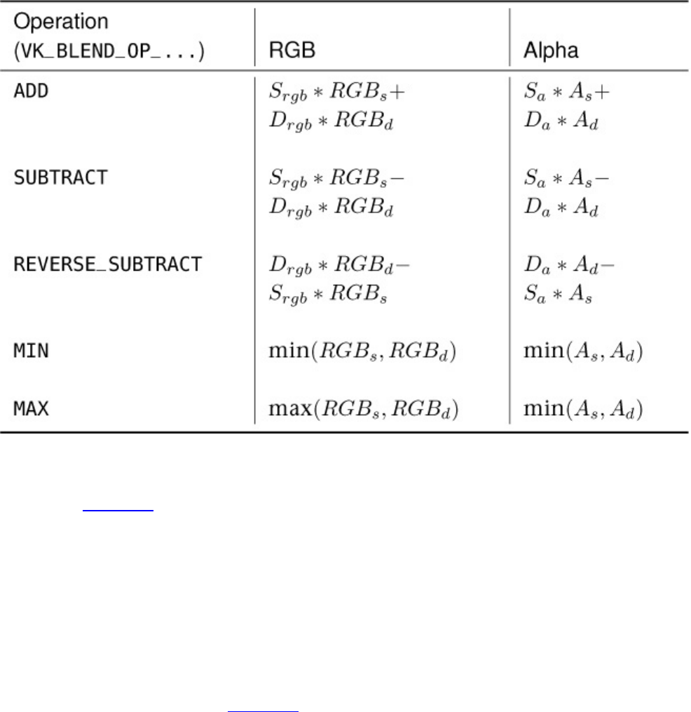
Table 10.4: Blend Equations
The blend operations are specified with members of the VkBlendOp enumeration, and their effects
are listed in Table 10.4. In the table, Srgb and Drgb are the the source and destination color factors, Sa
and Daare the source and destination alpha factors, RGBsand RGBdare the source and destination
RGB values, and Asand Adare the source and destination alpha values.
Note that the VK_BLEND_FACTOR_MIN and VK_BLEND_FACTOR_MAX modes do not include the
source or destination factors (Srgb,Sa,Drgb or Da), only the source and destination colors or alpha
values. These modes can be used to find the maximum or minumum values produced at a particular
pixel for the attachment.
The available blend factors for use in srcColorBlendFactor,dstColorBlendFactor,
srcAlphaBlendFactor, and dstAlphaBlendFactor are represented by members of the
VkBlendFactor enumeration. Table 10.5 shows its members and their meanings.
In the table, Rs0,Gs0,Bs0, and As0are the R, G, B, and A channels of the first color output from the
fragment shader, and Rs1,Gs1,Bs1, and As1are the R, G, B, and A channels of the secondary color
output from the fragment shader. These are used for dual-source blending, which is explained in
more detail in the next section.
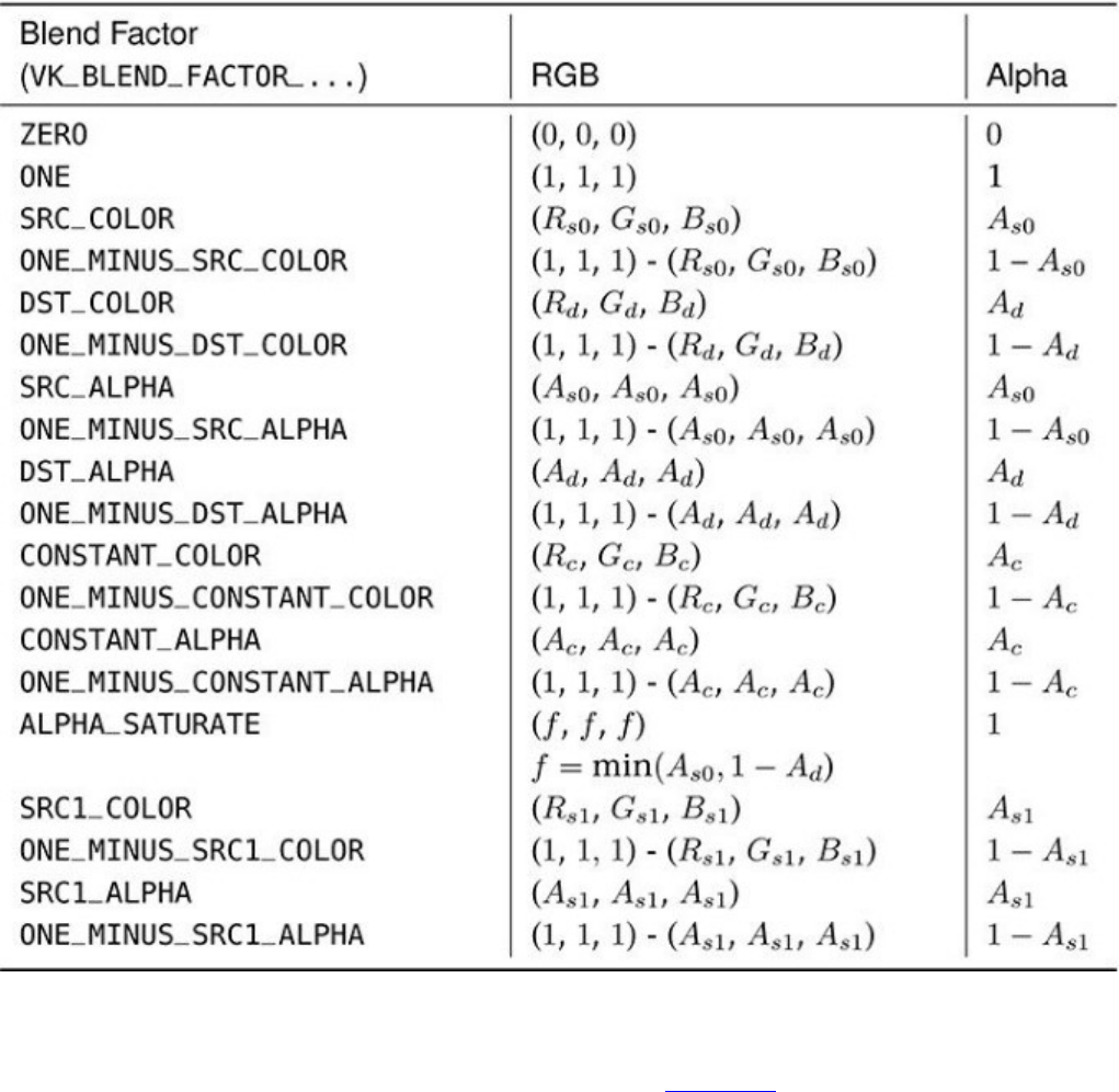
Table 10.5: Blend Factors
In the entries VK_BLEND_FACTOR_CONSTANT_COLOR and
VK_BLEND_FACTOR_ONE_MINUS_CONSTANT_COLOR in Table 10.5, the term
CONSTANT_COLOR refers to the (Rc,Gc,Bc,Ac)constant color, which is a constant that is part of
the pipeline. This can be any arbitrary set of floating-point values and can be used, for example, to
scale the content of the framebuffer by a fixed amount.
When this state is static, it is specified in the blendConstants field of the
VkPipelineColorBlendStateCreateInfo structure used to create the color blend state
object. When the color blend constant state is configured as dynamic, the
vkCmdSetBlendConstants() function is used to change the blend constants. The prototype of
vkCmdSetBlendConstants() is

Click here to view code image
void vkCmdSetBlendConstants (
VkCommandBuffer commandBuffer,
const float blendConstants[4]);
The command buffer to set the blend constant state for is specified in commandBuffer, and the
new blend constants are specified in blendConstants. This is an array of four floating-point
values that take the place of the blendConstants member of the
VkPipelineColorBlendStateCreateInfo structure used to initialize the graphics
pipeline’s blend state.
As discussed in Chapter 7, “Graphics Pipelines,” to set the constant blend color as part of the
dynamic state for a pipeline, include VK_DYNAMIC_STATE_BLEND_CONSTANTS in the list of
dynamic states passed through the VkPipelineDynamicStateCreateInfo structure when
creating the graphics pipeline.
In Table 10.5, you notice that the last few factor tokens include the terms SRC1_COLOR or
SRC1_ALPHA, which correspond to RGBs1and As1, respectively. These are the second source-
blending values taken from the fragment shader. The fragment shader can output two terms for a
single color attachment, and these terms can be used in the blending stage to implement slightly more
advanced blending modes than are achievable with a single color output.
For example, it is possible to multiply the destination color (the values already in the color
attachment) by one set of values produced by the fragment shader and then add a second set of values
produced by the same shader invocation. To implement this, set srcColorBlendFactor to
VK_BLEND_FACTOR_ONE and dstColorBlendFactor to
VK_BLEND_FACTOR_SRC1_COLOR.
When dual-source blending is in use, the two source colors produced by the fragment shader are both
directed to the same attachment location, but with different color indices. To specify the color index
in SPIR-V, decorate the output from the fragment shader with the Index decoration using the
OpDecorate or OpMemberDecorate instruction. Index 0 (which is the default if the decoration
is missing) corresponds to the first color output, and index 1 corresponds to the second color output.
Dual-source blending may not be supported by all Vulkan implementations. To determine whether
your Vulkan drivers and hardware supports dual-source blending, check the dualSrcBlend
member of the device’s VkPhysicalDeviceFeatures structure, which you can retrieve by
calling vkGetPhysicalDeviceFeatures(). When dual-source blending is supported and
enabled, the total number of color attachments that can be referenced by a subpass in the pipeline
using that mode may be limited. This limit is stored in maxFragmentDualSrcAttachments. If
there is any support at all, then at least one attachment can be used in dual-source blending mode.
Summary
This chapter covered the operations that occur as part of fragment processing, after rasterization.
These operations include depth and stencil tests, scissor testing, fragment shading, blending, and
logic operations. Together, these operations compute the final colors of the pixels produced by your
application. They determine visibility and ultimately produce the image that will be shown to your
users.

Chapter 11. Synchronization
What You’ll Learn in This Chapter
• How to synchronize the host and the device
• How to synchronize work on different queues on the same device
• How to synchronize work conducted at different points in the pipeline
Vulkan is designed to run work asynchronously, in parallel, with multiple queues on a device
working together with the host to keep physical resources busy and in use. At various points in your
application, you will need to keep the host and the various parts of the device in sync. In this chapter,
we discuss the multiple synchronization primitives that are available to Vulkan applications for this
purpose.
Synchronization in Vulkan is accomplished through the use of various synchronization primitives.
There are several types of synchronization primitives and they are intended for different uses in an
application. The three main types of synchronization primitives are
• Fences: Used when the host needs to wait for the device to complete execution of large pieces of
work represented by a submission, usually with the assistance of the operating system.
• Events: Represent a fine-grained synchronization primitive that can be signaled either by the
host or the device. It can be signaled mid-command buffer when signaled by the device, and it
can be waited on by the device at specific points in the pipeline.
• Semaphores: Synchronization primitives that are used to control ownership of resources across
different queues on a single device. They can be used to synchronize work executing on
different queues that would otherwise operate asynchronously.
We’ll cover each of these three synchronization primitives in the following few sections.
Fences
A fence is a medium-weight synchronization primitive that is generally implemented with the help of
the operating system. A fence is given to commands that interact with the operating system, such as
vkQueueSubmit(), and when the work that these commands provoke is completed, the fence is
signaled.
Because the fence often corresponds to a native synchronization primitive provided by the operating
system, it is generally possible to put threads to sleep while they wait on fences, which saves power.
However, this is intended for operations in which waiting may take some time, such as waiting for
the completion of the execution of a number of command buffers or the presentation of a completed
frame to the user.
To create a new fence object, call vkCreateFence(), the prototype of which is
Click here to view code image
VkResult vkCreateFence (
VkDevice device,

const VkFenceCreateInfo* pCreateInfo,
const VkAllocationCallbacks* pAllocator,
VkFence* pFence);
The device that will create the fence object is specified in device, and the remaining parameters of
the fence are passed through a pointer to an instance of the VkFenceCreateInfo structure, the
definition of which is
Click here to view code image
typedef struct VkFenceCreateInfo {
VkStructureType sType;
const void* pNext;
VkFenceCreateFlags flags;
} VkFenceCreateInfo;
The sType field of the VkFenceCreateInfo structure should be set to
VK_STRUCTURE_TYPE_FENCE_CREATE_INFO, and pNext should be set to nullptr. The
only remaining field, flags, specifies a set of flags that controls the behavior of the fence. The only
flag defined for use here is VK_FENCE_CREATE_SIGNALED_BIT. If this bit is set in flags, then
the initial state of the fence is signaled; otherwise, it is unsignaled.
If vkCreateFence() is successful, a handle to the new fence object is placed in the variable
pointed to by pFence. If pAllocator is not nullptr, it should point to a host memory
allocation structure that will be used to allocate any host memory required by the fence.
As with most other Vulkan objects, when you are done with the fence, you should destroy it in order
to free its resources. To do this, call vkDestroyFence(), the prototype of which is
Click here to view code image
void vkDestroyFence (
VkDevice device,
VkFence fence,
const VkAllocationCallbacks* pAllocator);
The device that owns the fence object is specified in device, and the handle to the fence to be
destroyed is passed in fence. If a host memory allocator was used with vkCreateFence(), then
pAllocator should point to a host memory allocation structure compatible with the one used to
allocate the object; otherwise, pAllocator should be nullptr.
The fence may be used in any command that takes a fence parameter. These commands usually
operate on queues and provoke work to be executed on that queue. For example, here is the prototype
of vkQueueSubmit():
Click here to view code image
VkResult vkQueueSubmit (
VkQueue queue,
uint32_t submitCount,
const VkSubmitInfo* pSubmits,
VkFence fence);
Notice that the last parameter to vkQueueSubmit() is a VkFence handle. When all of the work
provoked on queue is complete, the fence specified in fence will be set to signaled. In some cases,

the device can signal the fence directly. In other cases, the device will signal the operating system
through an interrupt or other hardware mechanism, and the operating system will change the state of
the fence.
The application can determine the state of the fence at any time by calling
vkGetFenceStatus(), the prototype of which is
Click here to view code image
VkResult vkGetFenceStatus (
VkDevice device,
VkFence fence);
The device that owns the fence is specified in device, and the fence whose status to query is passed
in fence. The value returned from vkGetFenceStatus() indicates the state of the fence. On
success, vkGetFenceStatus() can be one of the following values:
•VK_SUCCESS: The fence is currently signaled.
•VK_NOT_READY: The fence is currently unsignaled.
If there was some problem retrieving the status of the fence, vkGetFenceStatus() may return
an error code. It can be tempting to poll the state of a fence by spinning in a loop until
vkGetFenceStatus() returns VK_SUCCESS. However, this is extremely inefficient and bad for
performance, especially if there is any chance that the application could wait for a long time. Rather
than spin, your application should call vkWaitForFences(), which allows the Vulkan
implementation to provide a more optimal mechanism for waiting on one or more fences.
The prototype of vkWaitForFences() is
Click here to view code image
VkResult vkWaitForFences (
VkDevice device,
uint32_t fenceCount,
const VkFence* pFences,
VkBool32 waitAll,
uint64_t timeout);
The device that owns the fences that will be waited on is passed in device.
vkWaitForFences() can wait on any number of fences. The number of fences upon which it
should wait is passed in fenceCount, and pFences should point to an array of this many
VkFence handles to the fences to wait on.
vkWaitForFences() can either wait for all the fences in the pFences array to become signaled
or can return as soon as any fence in the array becomes signaled. If waitAll is VK_TRUE, then
vkWaitForFences() will wait for all of the fences in pFences to become signaled; otherwise,
it will return as soon as any of them becomes signaled. In this case, you can use
vkGetFenceStatus() to determine which fences are signaled and which are unsignaled.
Because vkWaitForFences() could end up waiting for a very long time, it is possible to ask it to
time out. The timeout parameter specifies the time, in nanoseconds, that vkWaitForFences()
should wait for the termination condition (at least one of the fences becomes signaled) to be met. If

timeout is zero, then vkWaitForFences() will simply check the status of the fences and
return immediately. This is similar to vkGetFenceStatus() except for two differences:
•vkWaitForFences() can check the status of multiple fences, possibly more efficiently than
multiple calls to vkGetFenceStatus().
• If the fences in the pFences array are not signaled, then vkWaitForFences() indicates a
timeout rather than a not-ready condition.
There is no way to ask vkWaitForFences() to wait forever. However, because timeout is a
64-bit value measured in nanoseconds and 264 − 1 nanoseconds is a little over 584 years, the value
~0ull is probably a sufficient proxy for infinity.
The result of the wait operation is represented by the value returned from vkWaitForFences().
It may be one of the following values:
•VK_SUCCESS: The condition being waited on was met. If waitAll was VK_FALSE, then at
least one fence in pFences was signaled. If waitAll was VK_TRUE, then all of the fences in
pFences became signaled.
•VK_TIMEOUT: The condition being waited on was not met before the timeout period occurred.
If timeout was zero, this represents an instantaneous polling of the fences.
If an error occurs, such as one of the handles in the pFences array being invalid, then
vkWaitForFences() will return an appropriate error code.
Once a fence has become signaled, it will remain in that state until it is reset to an unsignaled state
explicitly. When a fence is no longer signaled, it can be reused in commands such as
vkQueueSubmit(). There are no commands that cause the device to reset a fence, and there are
no commands that can wait for a fence to become unsignaled. To reset one or more fences to an
unsignaled state, call vkResetFences(), the prototype of which is
Click here to view code image
VkResult vkResetFences (
VkDevice device,
uint32_t fenceCount,
const VkFence* pFences);
The device that owns the fences is passed in device; the number of fences to reset is passed in
fenceCount; and a pointer to an array of VkFence handles is passed in pFences. Take care that
you don’t try waiting on a fence that has been reset without calling another function that will
eventually signal that fence.
A primary use case for fences is to prevent the host from overwriting data that might be in use by the
device—or, more accurately, data that might be about to be used by the device. When a command
buffer is submitted, it does not execute immediately, but is placed in queue and executed by the
device in turn. It also does not execute infinitely quickly, but takes some time to execute. Therefore,
if you place data in memory and then submit a command buffer that references that data, you must be
careful to ensure that the data remains valid and in place until the command buffer has executed. The
fence supplied to vkQueueSubmit() is the means to determine this.
In this example, we create a buffer, map it, and place some data in it using the host; then we submit a
command buffer that references that data. Three mechanisms are provided to perform

synchronization between the host and device and to ensure that the host does not overwrite the data in
the buffer before it’s used by the device.
In the first method, we call vkQueueWaitIdle() to ensure that all work submitted to the queue
(including our work that consumes the data in the buffer) has completed. In the second method, we
use a single fence, associated with the submission that consumes the data, and we wait on that fence
before overwriting the content of the buffer. In the third method, we subdivide the buffer into four
quarters, associate a fence with each quarter, and wait for the fence associated with that section of the
buffer before overwriting it.
In addition, a method with no synchronization at all is provided. This method simply overwrites the
data in the buffer without waiting at all. In this method, we invalidate the data in the buffer before
overwriting it with new, valid data. This should demonstrate the kind of corruption that can occur in
the absence of proper synchronization.
The code for the first two methods—brute-force idle of the queue and waiting for a single fence
(which is essentially equivalent in this scenario)—is somewhat trivial and is therefore not shown
here. Listing 11.1 shows the initialization sequence for the method using four separate fences.
Listing 11.1: Setup for Four-Fence Synchronization
Click here to view code image
// kFrameDataSize is the size of the data consumed in a single frame.
// kRingBufferSegments is the number of frames' worth of data to keep.
// Create a buffer large enough to hold kRingBufferSegments copies
// of kFrameDataSize.
static const VkBufferCreateInfo bufferCreateInfo =
{
VK_STRUCTURE_TYPE_BUFFER_CREATE_INFO, nullptr, // sType,pNext
0, // flags
kFrameDataSize*kRingBufferSegments, // size
VK_BUFFER_USAGE_TRANSFER_SRC_BIT, // usage
VK_SHARING_MODE_EXCLUSIVE, // sharingMode
0, //
queueFamilyIndexCount
nullptr // pQueueFamilyIndices
};
result = vkCreateBuffer(device,
&bufferCreateInfo,
nullptr,
&m_buffer);
// Create kRingBufferSegments fences, all initially in signaled state.
static const VkFenceCreateInfo fenceCreateInfo =
{
VK_STRUCTURE_TYPE_FENCE_CREATE_INFO,nullptr,
VK_FENCE_CREATE_SIGNALED_BIT
};
for (int i = 0;i < kRingBufferSegments; ++i)

{
result = vkCreateFence(device,
&fenceCreateInfo,
nullptr,
&m_fence[i]);
}
As you can see, in Listing 11.1 we create a buffer that is four times the size of the data to be used by
the device; then we create four fences, each guarding one quarter of the total buffer size. The fences
are created in the signaled state. This is so we can simply enter our loop that waits on the fence
guarding the current section of the buffer to be signaled, fills the buffer, and generates a new
command buffer referencing that section of the buffer. The first time this loop executes, the fence is
already signaled because it was created in that state, and no special case is required for the first entry
into the loop.
Listing 11.2 shows the inner loop that waits for each fence to be signaled, fills the appropriate section
of the buffer, resets the fence, generates a command buffer to consume the data, submits it to the
queue, and specifies the fence.
Listing 11.2: Loop Waiting on Fences for Synchronization
Click here to view code image
// Beginning of frame - compute the segment index.
static int framesRendered = 0;
const int segmentIndex = framesRendered % kRingBufferSegments;
// Use a ring of command buffers indexed by segment.
const VkCommandBuffer cmdBuffer = m_cmdBuffer[segmentIndex];
// Wait for the fence associated with this segment.
result = vkWaitForFences(device,
1,
&m_fence[segmentIndex],
VK_TRUE,
UINT64_MAX);
// It's now safe to overwrite the data. m_mappedData is an array of
// kRingBufferSegments pointers to persistently mapped backing store for
// the source buffer.
fillBufferWithData(m_mappedData[segmentIndex]);
// Reset the command buffer. We always use the same command buffer to copy
// from a given segment of the the staging buffer, so it's safe to reset
it
// here because we've already waited for the associated fence.
vkResetCommandBuffer(cmdBuffer, 0);
// Rerecord the command buffer.
static const VkCommandBufferBeginInfo beginInfo =
{
VK_STRUCTURE_TYPE_COMMAND_BUFFER_BEGIN_INFO, // sType
nullptr, // pNext
VK_COMMAND_BUFFER_USAGE_ONE_TIME_SUBMIT_BIT, // flags
nullptr // pInheritanceInfo
};
vkBeginCommandBuffer(cmdBuffer, &beginInfo);
// Copy from the staging buffer at the appropriate segment index into
// the final destination buffer.
VkBufferCopy copyRegion =
{
segmentIndex * kFrameDataSize, // srcOffset
0, // dstOffset
kFrameDataSize // size
};
vkCmdCopyBuffer(cmdBuffer,
m_stagingBuffer,
m_targetBuffer,
1,
©Region);
vkEndCommandBuffer(cmdBuffer);
// Reset the fence for this segment before submitting this chunk of work
to
// the queue.
vkResetFences(device, 1, &m_fence[segmentIndex]);
// Note that this example doesn't use any submission semaphores. In a real
// application, you would submit many command buffers in a single
submission
// and protect that submission using wait and signal semaphores.
VkSubmitInfo submitInfo =
{
VK_STRUCTURE_TYPE_SUBMIT_INFO, nullptr, // sType, pNext
0, // waitSemaphoreCount
nullptr, // pWaitSemaphores
nullptr, // pWaitDstStageMask
1, // commandBufferCount
&cmdBuffer, // pCommandBuffers
0, //
signalSemaphoreCount
nullptr // pSignalSemaphores
};
vkQueueSubmit(m_queue,
1,
&submitInfo,
m_fence[segmentIndex]);
framesRendered++;

Note that the code in Listing 11.2 is incomplete and serves only to demonstrate the use of fences to
protect shared data. In particular, the example omits several things that a real application will need:
• It does not include any pipeline barriers to protect the target buffer (m_targetBuffer) from
being overwritten or to move the source buffer from host writable to the source for transfers.
• It does not use any semaphores to protect the submission. Semaphores will be needed if this is
part of a larger frame that includes presentation or submission to other queues.
• It does not include any calls to vkFlushMappedMemoryRanges(), which will be required
unless the memory backing the buffer was allocated with the
VK_MEMORY_PROPERTY_HOST_COHERENT_BIT set.
Events
Event objects represent a fine-grained synchronization primitive that can be used to accurately
delimit operations occurring within a pipeline. An event exists in one of two states: signaled and
unsignaled. Unlike a fence, which is typically moved from state to state by the operating system,
events can be signaled or reset explicitly by the device or host. Not only can the device directly
manipulate the state of an event, but it can do this at specific points in the pipeline.
Unlike a fence, where only the host can wait on the object, the device can wait on event objects.
When waiting, the device can wait at a specific point in the pipeline. Because the device can signal
an event at one part of the pipeline and wait for it at another, events provide a way to synchronize
execution occurring at different parts of the same pipeline.
To create an event object, call vkCreateEvent(), the prototype of which is
Click here to view code image
VkResult vkCreateEvent (
VkDevice device,
const VkEventCreateInfo* pCreateInfo,
const VkAllocationCallbacks* pAllocator,
VkEvent* pEvent);
The device which is to create the event is specified in device, and the remaining parameters
describing the event are passed through a pointer to an instance of the VkEventCreateInfo
structure, the definition of which is
Click here to view code image
typedef struct VkEventCreateInfo {
VkStructureType sType;
const void* pNext;
VkEventCreateFlags flags;
} VkEventCreateInfo;
The sType field of VkEventCreateInfo should be set to
VK_STRUCTURE_TYPE_EVENT_CREATE_INFO, and pNext should be set to nullptr. The
flags field of VkEventCreateInfo specifies additional behavior of the event. However, there
are currently no event creation flags defined, and flags should be treated as reserved and set to
zero.

If vkCreateEvent() is successful, it will place the VkEvent handle to the newly created object
in the variable pointed to by pEvent. If vkCreateEvent() requires host memory, then it will
use the allocator specified in pAllocator. A compatible allocator should be used when the event
is destroyed.
When you are done with the event, you should free its resources by destroying the object. To destroy
an event object, call vkDestroyEvent(), the prototype of which is
Click here to view code image
void vkDestroyEvent (
VkDevice device,
VkEvent event,
const VkAllocationCallbacks* pAllocator);
The device that owns the event object should be passed in device, and the event object to be
destroyed should be passed in event. You should make sure that the event is not accessed again
after it has been destroyed. This includes direct access to the event on the host by passing its handle
to a function call, and also implied access to the event through the execution of a command buffer
that may contain a reference to it.
The initial state of an event is unsignaled or reset. Either the host or the device can change the state of
the event. To change the state of an event to set on the host, call vkSetEvent(), the prototype of
which is
Click here to view code image
VkResult vkSetEvent (
VkDevice device,
VkEvent event);
The device that owns the event object should be passed in device, and the event object to set is
specified in event. Access to the event object should be externally synchronized. Attempting to set
or reset the event from multiple threads concurrently will result in a race condition and produce an
undefined result. When an event object is set by the host, its state immediately changes to set. If
another thread is waiting on the event through a call to vkCmdWaitEvents(), then that thread
will immediately be unblocked, assuming that other waiting conditions are satisfied.
Events can also be moved from set to reset state on the host by calling vkResetEvent(). The
prototype of vkResetEvent is
Click here to view code image
VkResult vkResetEvent (
VkDevice device,
VkEvent event);
Again, the device that owns the event is passed in device, and the event object to reset is passed in
event. Again, access to the event must be externally synchronized. The specified event is
immediately moved to the reset state. The vkSetEvent() and vkResetEvent() commands
have no effect if the specified event is already in the set or reset state, respectively. That is, it is not an
error to call vkSetEvent() on an event that is already set or vkResetEvent() on an event that
is already reset, although it might not be what you intended to do.

You can determine the immediate state of an event with vkGetEventStatus(), the prototype of
which is
Click here to view code image
VkResult vkGetEventStatus (
VkDevice device,
VkEvent event);
The device that owns the event is passed in device, and the event whose state to query is passed in
event. Unlike with vkSetEvent() and vkResetEvent(),vkGetEventStatus() can be
called on an event object without synchronization. In fact, this is the intended use case.
The return value of vkGetEventStatus() reports the state of the event. The possible return
values include
•VK_EVENT_SET: The specified event is in the set or signaled state.
•VK_EVENT_RESET: The specified event is in the reset or unsignaled state.
If anything goes wrong, such as the event parameter not being a handle to a valid event,
vkGetEventStatus() will return an appropriate error code.
There is no way for the host to wait on an event besides spinning in a loop waiting for
vkGetEventStatus() to return VK_EVENT_SET. This is not particularly efficient, and you
should be sure to cooperate with the system in the case that you need to do this by, for example,
sleeping the current thread or doing other useful work in between queries of the event object status.
Event objects may also be manipulated by the device. As with almost any other work executed by the
device, this is done by placing commands in a command buffer and then submitting the command
buffer to one of the device’s queues for execution. The command for setting an event is
vkCmdSetEvent(), the prototype of which is
Click here to view code image
void vkCmdSetEvent (
VkCommandBuffer commandBuffer,
VkEvent event,
VkPipelineStageFlags stageMask);
The command buffer that will eventually set the event is specified in commandBuffer, and a
handle to the event object that will be signaled is passed in event. Unlike vkSetEvent(),
vkCmdSetEvent() takes a pipeline stage at which to signal the event. This is passed in
stageMask, which is a bitfield made up of members of the VkPipelineStageFlagBits
enumeration. If multiple bits are set in stageMask, then the event will be set when execution of the
command passes each of the specified stages. This may seem redundant, but if there are calls to
vkCmdResetEvent(), it may be possible to observe the state of the event object toggle between
set and reset as the commands pass down the pipeline.
The corresponding command to reset an event is vkCmdResetEvent(), the prototype of which is
Click here to view code image
void vkCmdResetEvent (
VkCommandBuffer commandBuffer,

VkEvent event,
VkPipelineStageFlags stageMask);
Again, the command buffer that is to reset the event is passed in commandBuffer; the event to
reset is passed in event; and as with vkCmdSetEvent(), the vkCmdResetEvent() command
takes a stageMask parameter that contains a bitfield representing the stages at which the event will
assume the reset state.
While it is possible on the host to retrieve the immediate state of an event object using
vkGetEventStatus() but it is not possible to directly wait on the event, the converse is true on
the device; there is no command to directly retrieve the state of an event on the device, but it is
possible to wait on one or more events. To do this, call vkCmdWaitEvents(), the prototype of
which is
Click here to view code image
void vkCmdWaitEvents (
VkCommandBuffer commandBuffer,
uint32_t eventCount,
const VkEvent* pEvents,
VkPipelineStageFlags srcStageMask,
VkPipelineStageFlags dstStageMask,
uint32_t memoryBarrierCount,
const VkMemoryBarrier* pMemoryBarriers,
uint32_t bufferMemoryBarrierCount,
const VkBufferMemoryBarrier* pBufferMemoryBarriers,
uint32_t imageMemoryBarrierCount,
const VkImageMemoryBarrier* pImageMemoryBarriers);
The vkCmdWaitEvents() command takes many parameters and behaves much as a barrier does.
The command buffer whose execution will be stalled waiting for the events is specified in
commandBuffer; the number of events to wait on is specified in eventCount; and a pointer to
an array of VkEvent handles to the events to be waited on is passed in pEvents.
The srcStageMask and dstStageMask specify the pipeline stages in which the events may
have been signaled and the stages that will wait for the events to become signaled, respectively.
Waiting will always occur at the stages specified in dstStageMask. The stages specified in
srcStageMask allow a Vulkan implementation to synchronize pairs of stages rather than all work
in the pipeline, which can be somewhat more efficient.
Once all of the events contained in the pEvents array have become signaled, the device will
execute all of the memory, buffer, and image barriers specified in pMemoryBarriers,
pBufferMemoryBarriers, and pImageMemoryBarriers before resuming execution of the
work in the pipeline. The number of elements in the array pointed to by pMemoryBarriers is
memoryBarrierCount; the number of elements in the array pointed to by
pBufferMemoryBarriers is bufferMemoryBarrierCount; and the number of elements
in the array pointed to by pImageMemoryBarriers is imageMemoryBarrierCount.
Although the flags contained in VkPipelineStageFlagBits are quite fine-grained, most
Vulkan implementations will be able to perform a wait operation at only some of them. It is always
legal for an implementation to wait at an earlier point in the pipeline. It is still guaranteed that work

executed at later points in the pipeline will happen after the events in pEvents have become
signaled.
Semaphores
The final type of synchronization primitive supported in Vulkan is the semaphore. Semaphores
represent flags that can be atomically set or reset by the hardware, the views of which are coherent
across queues. When you are setting the semaphore, the device will wait for it to be unset, set it, and
then return control to the caller. Likewise, when resetting the semaphore, the device waits for the
semaphore to be set, resets it, and then returns to the caller. This all happens atomically. If multiple
agents are waiting on a semaphore, only one of them will “see” the semaphore as unset or set and
receive control. The rest will continue to wait.
Semaphores cannot be explicitly signaled or waited on by the device. Rather, they are signaled and
waited on by queue operations such as vkQueueSubmit().
To create a semaphore object, call vkCreateSemaphore(), the prototype of which is
Click here to view code image
VkResult vkCreateSemaphore (
VkDevice device,
const VkSemaphoreCreateInfo* pCreateInfo,
const VkAllocationCallbacks* pAllocator,
VkSemaphore* pSemaphore);
The device that will create the semaphore is passed in device, and additional parameters of the
semaphore are passed through pCreateInfo, which is a pointer to an instance of the
VkSemaphoreCreateInfo structure. The definition of VkSemaphoreCreateInfo is
Click here to view code image
typedef struct VkSemaphoreCreateInfo {
VkStructureType sType;
const void* pNext;
VkSemaphoreCreateFlags flags;
} VkSemaphoreCreateInfo;
The sType field of VkSemaphoreCreateInfo should be set to
VK_STRUCTURE_TYPE_SEMAPHORE_CREATE_INFO, and pNext should be set to nullptr.
The flags field is reserved and should be set to zero.
If vkCreateSemaphore() is successful, the resulting semaphore object is written into the
variable pointed to by pSemaphore.
When you are done with the semaphore object, you should destroy it in order to free any resources
associated with it. To destroy a semaphore, call vkDestroySemaphore(), the prototype of which
is
Click here to view code image
void vkDestroySemaphore (
VkDevice device,
VkSemaphore semaphore,
const VkAllocationCallbacks* pAllocator);

The device that owns the semaphore object should be passed in device, and the semaphore that is
to be destroyed should be passed in semaphore. Access to the semaphore must be externally
synchronized. In particular, a semaphore must not be destroyed while it may be accessed from
another thread. If a host memory allocator was used to create the semaphore, a pointer to a
compatible allocator should be passed in pAllocator.
Unlike the other synchronization primitives, events and fences, semaphore objects do not allow you
to explicitly set, reset, or wait on them. Instead, you use these objects to synchronize access to
resources across queues and form an integral part of submission of work to the device. Recall that the
prototype of vkQueueSubmit() is
Click here to view code image
VkResult vkQueueSubmit (
VkQueue queue,
uint32_t submitCount,
const VkSubmitInfo* pSubmits,
VkFence fence);
vkQueueSubmit() takes an array of VkSubmitInfo structures, the definition of which is
Click here to view code image
typedef struct VkSubmitInfo {
VkStructureType sType;
const void* pNext;
uint32_t waitSemaphoreCount;
const VkSemaphore* pWaitSemaphores;
const VkPipelineStageFlags* pWaitDstStageMask;
uint32_t commandBufferCount;
const VkCommandBuffer* pCommandBuffers;
uint32_t signalSemaphoreCount;
const VkSemaphore* pSignalSemaphores;
} VkSubmitInfo;
Each entry of the pSubmits array passed to vkQueueSubmit() contains a
pWaitSemaphores and a pSignalSemaphores member, which are pointers to arrays of
semaphore objects. Before executing the commands in pCommandBuffers, the queue will wait for
all of the semaphores in pWaitSemaphores. In doing so, it will take “ownership” of the
semaphores.
It will then execute the commands contained in each of the command buffers in the
pCommandBuffers array, and when it is done, it will signal each of the semaphores contained in
pSignalSemaphores.
Access to the semaphores referenced by the pWaitSemaphores and pSignalSemaphores
arrays must be externally synchronized. In practice, this means that if you submit command buffers
to two different queues from two different threads (which is perfectly legal), you need to be careful
that the same semaphore doesn’t end up in the wait list for one submission and the signal list for the
other.
This mechanism can be used to synchronize access to resources that is performed by work submitted
to two or more different queues. For example, we can submit a number of command buffers to a
compute-only queue, which then signals a semaphore upon completion. That same semaphore

appears in the wait list for a second submission to a graphics queue. Listing 11.3 shows an example
of this.
Listing 11.3: Cross-Queue Submission with Semaphores
Click here to view code image
// First, perform a submission to the compute queue. The compute
submission
// includes the compute -> graphics semaphore (m_computeToGfxSemaphore) in
// the pSignalSemaphores list. This sempaphore will become signaled once
the
// compute queue finishes processing the command buffers in the
submission.
VkSubmitInfo computeSubmitInfo =
{
VK_STRUCTURE_TYPE_SUBMIT_INFO, nullptr, // sType, pNext
0, // waitSemaphoreCount
nullptr, // pWaitSemaphores
nullptr, // pWaitDstStageMask
1, // commandBufferCount
&computeCmdBuffer, // pCommandBuffers
1, // signalSemaphoreCount
&m_computeToGfxSemaphore // pSignalSemaphores
};
vkQueueSubmit(m_computeQueue,
1,
&computeSubmitInfo,
VK_NULL_HANDLE);
// Now perform a submission to the graphics queue. This submission
includes
// m_computeToGfxSemaphore in the pWaitSemaphores list passed to the
// submission. We need to wait at a specific stage. Here, we just use
// VK_PIPELINE_STAGE_TOP_OF_PIPE_BIT, but if you know that the data
produced
// on the source queue will be consumed at a later stage of the pipeline
in
// the destination queue, you could place the wait point later.
static const VkFlags waitStages = VK_PIPELINE_STAGE_TOP_OF_PIPE_BIT;
VkSubmitInfo graphicsSubmitInfo =
{
VK_STRUCTURE_TYPE_SUBMIT_INFO, nullptr, // sType, pNext
1, // waitSemaphoreCount
&m_computeToGfxSemaphore, // pWaitSemaphores
&waitStages, // pWaitDstStageMask
1, // commandBufferCount
&graphicsCmdBuffer, // pCommandBuffers
0, //
signalSemaphoreCount
nullptr // pSignalSemaphores
};

vkQueueSubmit(m_graphicsQueue,
1,
&graphicsSubmitInfo,
VK_NULL_HANDLE);
In Listing 11.3, you can see that a single semaphore object is used in both submissions. The first
time, it appears in the signal list for work performed on the compute queue. When the work is
complete, the compute queue signals the semaphore. The same semaphore then appears in the wait
list for the submission on the graphics queue. The graphics queue will wait for this semaphore to
become signaled before proceeding to execute the command buffers submitted to it. This ensures that
work executed on the compute queue to produce data is completed before work executing on the
graphics queue that consumes that data begins.
The same synchonization mechanism using semaphores is employed by the sparse memory binding
commands that also operate at the queue level. The vkQueueBindSparse() function was
introduced in the “Sparse Resources” section of Chapter 2, “Memory and Resources.” To recap, the
prototype of vkQueueBindSparse() is
Click here to view code image
VkResult vkQueueBindSparse (
VkQueue queue,
uint32_t bindInfoCount,
const VkBindSparseInfo* pBindInfo,
VkFence fence);
Each binding operation is represented as an instance of the VkBindSparseInfo structure, and
each of those operations also has a pWaitSemaphores and pSignalSemaphores array that
behaves similarly to the parameters passed to vkQueueSubmit(). Again, access to those
semaphores must be externally synchronized, meaning that you must ensure that no two threads
attempt to access the same semaphores at the same time.
Summary
This chapter taught you about the synchronization primitives available in Vulkan: fences, events, and
semaphores. Fences provide a mechanism for the operating system to signal your application when it
has completed operations requested of it, such as submission of command buffers or presentation of
images via the window system. Events provide a fine-grained signaling mechanism that can be used
to control flow of data through the pipeline and allow different points within the pipeline to
synchronize. Finally, semaphores provide a primitive that can be signaled and waited on different
queues on the same device, allowing synchronization and transfer of ownership of resources across
queues.
Together, these primitives provide a powerful toolbox. As Vulkan is an asynchronous API with work
occurring in parallel across the host and device, and across multiple queues on a single device,
synchronization primitives and their correct use are key to the operation of an efficient application.

Chapter 12. Getting Data Back
What You’ll Learn in This Chapter
• Gather information about the execution of your application on the device
• Time operations performed by the device
• Read data produced by the device on the host
For the most part, graphics and compute operations supported by Vulkan are “fire and forget,” in that
you build a command buffer and submit it, and eventually, data is displayed to the user. Your
application has very little feedback or input from Vulkan. However, there are reasons to want to
retrieve data from Vulkan. This chapter covers topics related to reading data and information back
from Vulkan. This data includes statistics about the operations your application performs, timing
information, and reading data produced directly by your application.
Queries
The primary mechanism for reading statistical data back from Vulkan is the query object. Query
objects are created and managed in pools, and each object is effectively one slot in a pool rather than
a discrete object that is managed alone. There are several types of query objects, each measuring a
different aspect of the device’s operation as it executes work you submit to it. All types of queries are
managed in pools, so the first step in using queries is creating a pool object to store them in.
Most queries execute by wrapping commands contained inside a command buffer with a pair of
commands to start and stop the query. The exception to this is the timestamp query, which takes an
instantaneous snapshot of the device time and therefore doesn’t really have a duration. For other
query types, while they execute, statistics about the operation of the device are gathered, and when
the query is stopped, the results are written into device memory represented by the pool. At some
later time, your application can gather the results of any number of queries contained in the pool and
read them back.
A query pool is created by callingvkCreateQueryPool(), the prototype of which is
Click here to view code image
VkResult vkCreateQueryPool (
VkDevice device,
const VkQueryPoolCreateInfo* pCreateInfo,
const VkAllocationCallbacks* pAllocator,
VkQueryPool* pQueryPool);
The device that will create the pool is specified in device. The remaining parameters of the pool
are passed through a pointer to an instance of the VkQueryPoolCreateInfo structure, the
definition of which is
Click here to view code image
typedef struct VkQueryPoolCreateInfo {
VkStructureType sType;

const void* pNext;
VkQueryPoolCreateFlags flags;
VkQueryType queryType;
uint32_t queryCount;
VkQueryPipelineStatisticFlags pipelineStatistics;
} VkQueryPoolCreateInfo;
The sType field of VkQueryPoolCreateInfo should be set to
VK_STRUCTURE_TYPE_QUERY_POOL_CREATE_INFO, and pNext should be set to nullptr.
The flags field is reserved for future use and should be set to zero. The type of query to be stored
in the pool is specified in the queryType field, which is a member of the VkQueryType
enumeration.
Each pool can contain only one type of query, although it is possible to create as many pools as you
wish and to run several queries at the same time.
The types of query are
•VK_QUERY_TYPE_OCCLUSION: Occlusion queries count the number of samples that pass
the depth and stencil tests.
•VK_QUERY_TYPE_PIPELINE_STATISTICS: Pipeline statistics queries count various
statistics generated by operations of the device.
•VK_QUERY_TYPE_TIMESTAMP: Timestamp queries measure the amount of time the
execution of commands in a command buffer takes.
Each type of query is discussed in more detail later in this chapter.
The number of queries that can be stored in the pool is specified in queryCount. When the pool is
used to execute queries, the individual queries are referenced by their index within the pool.
Finally, when the query type is VK_QUERY_TYPE_PIPELINE_STATISTICS, some additional
flags controlling how those statistics are gathered is specified in pipelineStatistics.
IfvkCreateQueryPool() is successful, a handle to the new query pool object will be written
into the variable pointed to by pQueryPool. If pAllocator is a pointer to a valid host memory
allocator, then that allocator will be used to allocate any host memory needed by the pool object.
Otherwise, pAllocator should be nullptr.
As with any other object in Vulkan, when you are done with it, you should destroy the query pool to
free its resources. To do this, call vkDestroyQueryPool(), the prototype of which is
Click here to view code image
void vkDestroyQueryPool (
VkDevice device,
VkQueryPool queryPool,
const VkAllocationCallbacks* pAllocator);
The device that owns the pool should be passed in device, and the pool to be destroyed should be
passed in queryPool. If a host memory allocator was used when the pool was created, a pointer to
a compatible allocator should be passed in pAllocator; otherwise, pAllocator should be
nullptr.
Each query in the query pool is marked as available or unavailable. Initially, all queries in the pool
are in an undefined state, and before any query can be used, you need to reset the pool. As the only

agent that can write into the pool is the device, you need to execute a command on the device to reset
the pool. The command to do this is vkCmdResetQueryPool(), the prototype of which is
Click here to view code image
void vkCmdResetQueryPool (
VkCommandBuffer commandBuffer,
VkQueryPool queryPool,
uint32_t firstQuery,
uint32_t queryCount);
The command buffer that will execute the reset command is specified in commandBuffer, and the
pool containing the queries is specified in queryPool. It is possible to reset only a selection of
queries within a pool. The firstQuery parameter specifies the index of the first query to reset, and
queryCount is the number of queries to reset. You must submit the command buffer
containingvkCmdResetQueryPool() to an appropriate queue before the pool can be used for
anything else.
Executing Queries
Queries are executed by wrapping commands contained inside a command buffer in a pair of
additional commands to start and stop the query:vkCmdBeginQuery() and
vkCmdEndQuery(), respectively.
The prototype for vkCmdBeginQuery() is
Click here to view code image
void vkCmdBeginQuery (
VkCommandBuffer commandBuffer,
VkQueryPool queryPool,
uint32_t query,
VkQueryControlFlags flags);
The command buffer that contains the commands to gather statistics about and that will execute the
query is specified in commandBuffer. Queries are referred to by their index within the pool that
contains them. The pool is specified in queryPool, and the index of the query within the pool is
specified in query.
Additional flags that control the execution of the query can be specified in flags. The only defined
flag is VK_QUERY_CONTROL_PRECISE_BIT. If this flag is set, then the results gathered by the
query will be precise (the meaning of precise varies by query type); otherwise, Vulkan might produce
approximate results. In some cases, gathering precise results may reduce performance, so you should
set this flag only when you require exact results.
Be aware, however, that if there is no performance penalty to running an exact query, an
implementation might ignore this flag and always return exact results. You should be sure to test your
application on multiple Vulkan implementations to make sure that it really is tolerant of inexact
results.
Once the query has begun, place the commands to gather statistics about in the command buffer, and
after you have executed those commands, end the query by callingvkCmdEndQuery(). The
prototype ofvkCmdEndQuery() is

Click here to view code image
void vkCmdEndQuery (
VkCommandBuffer commandBuffer,
VkQueryPool queryPool,
uint32_t query);
The command buffer containing the currently executing query is specified in commandBuffer.
The pool containing the query is passed in queryPool, and the index of the query within the pool
is specified in query.
Before you begin a query, the query must be reset. The queries in a pool are reset by
thevkCmdResetQueryPool() command, as discussed earlier. This command must be executed
when the queue is created and also between each use of a query object.
Calls tovkCmdBeginQuery() andvkCmdEndQuery() must appear in pairs. If you begin a
query and forget to end it, the result will never become available to your application. If you end a
query more than once or without beginning it first, the result of the query will be undefined.
To retrieve the results of one or more queries from a pool, callvkGetQueryPoolResults(). Its
prototype is
Click here to view code image
VkResult vkGetQueryPoolResults (
VkDevice device,
VkQueryPool queryPool,
uint32_t firstQuery,
uint32_t queryCount,
size_t dataSize,
void* pData,
VkDeviceSize stride,
VkQueryResultFlags flags);
The device that owns the pool from which to retrieve results is passed in device, and the pool is
passed in queryPool. The index of the first query to retrieve results for is passed in
firstQuery, and the number of queries is passed in queryCount.
vkGetQueryPoolResults() places the results of the requested queries in host memory pointed
to by pData. The size of the memory region is passed in dataSize. Vulkan will not write more
than this amount of data into memory. The result of each query is written to memory stride bytes
apart. If stride is not at least as large as the amount of data produced by each query, the results
may overwrite one another, and the result is undefined.
What is written to memory depends on the query type. flags provides additional information to
Vulkan about how the queries should be reported. The flags available for use in flags are
•VK_QUERY_RESULT_64_BIT: If this bit is set, results are returned as 64-bit quantities;
otherwise, results are returned as 32-bit quantities.
•VK_QUERY_RESULT_WAIT_BIT: If this bit is set, thenvkGetQueryPoolResults()
will wait until results of the queries are available. Otherwise,vkGetQueryPoolResults()
returns a status code to report whether the commands contributing to the results of the queries
were ready.

•VK_QUERY_RESULT_WITH_AVAILABILITY_BIT: If this bit is set, then Vulkan will write
a zero result for queries that were not ready whenvkGetQueryPoolResults() was called.
Any query that was ready will have a nonzero result.
•VK_QUERY_RESULT_PARTIAL_BIT: If this bit is set, Vulkan might write the current value
of a query into the result buffer even if the commands surrounded by the query have not finished
executing.
It is also possible to write the results of queries directly into a buffer object. This allows results to be
gathered asynchronously by the device, depositing results into a buffer for later use. The buffer can
then either be mapped and accessed by the host or used as the source of data in subsequent graphics
or compute operations.
To write the results of queries into a buffer object, callvkCmdCopyQueryPoolResults(), the
prototype of which is
Click here to view code image
void vkCmdCopyQueryPoolResults (
VkCommandBuffer commandBuffer,
VkQueryPool queryPool,
uint32_t firstQuery,
uint32_t queryCount,
VkBuffer dstBuffer,
VkDeviceSize dstOffset,
VkDeviceSize stride,
VkQueryResultFlags flags);
The command buffer that will execute the copy operation is specified in commandBuffer. This
does not need to be the same command buffer that executed the queries. The queryPool parameter
specifies the pool containing the queries that will be summarized into the buffer, and firstQuery
and queryCount specify the index of the first query and the number of queries to copy,
respectively. They have the same meanings as the similarly named parameters
tovkGetQueryPoolResults().
Rather than taking a pointer to host memory asvkGetQueryPoolResults()
does,vkCmdCopyQueryPoolResults() takes a buffer object handle in dstBuffer and an
offset into that buffer, measured in bytes, where the results will be written in dstOffset. The
stride parameter is the number of bytes between each result in the buffer, and flags is a bitfield
made up of the same flags as the flags parameter tovkGetQueryPoolResults().
AftervkCmdCopyQueryPoolResults() executes, access to the resulting values written to the
buffer object must be synchronized using a barrier where the source is
VK_PIPELINE_STAGE_TRANSFER_BIT and the access is
VK_ACCESS_TRANSFER_WRITE_BIT.
Occlusion Queries
If the query type of the pool is VK_QUERY_TYPE_OCCLUSION, then the count is the number of
fragments that pass the depth and stencil tests. This can be used to determine visibility or even to
measure the area of geometry, in pixels. If the depth and stencil tests are disabled, then the result of
the occlusion query is simply the area of the rasterized primitives.
A common use case is to render a view of part of a scene—for example, buildings or terrain—only to
the depth buffer. Then render a simplified version of characters or other high-detail geometry—such
as trees and vegetation, objects, or building details—with an occlusion query surrounding each. Such
low-detail stand-ins are often referred to as proxies. Finally, make the decision as to whether to
render the full-detail version of the object based on the result of each query. Because the query also
tells you the approximate area of the object, you can perhaps render different versions of the final
geometry based on its expected size onscreen. As an object gets farther away, you can substitute a
version with lower geometric detail, substitute simplified shaders, or reduce tessellation levels, for
example.
If you don’t care too much about the visible area of an object but only about whether the object is
visible, be sure not to set the VK_QUERY_CONTROL_PRECISE_BIT flag in the flags parameter
when you create the query pool. If this flag is not set (indicating that you’re interested only in
approximate results), then the results of the queries should be treated as Boolean values. That is, they
will be zero if the object was not visible and nonzero if it was. The actual value is not defined.
Pipeline Statistics Queries
Pipeline statistics queries allow your application to measure various aspects of the operation of the
graphics pipeline. Each query can measure a number of different counters that are updated by the
device as it executes the command buffer. The set of counters to enable is a property of the query
pool and is specified at pool-creation time in the pipelineStatistics parameter.
The counters available and the flags that need to be set in pipelineStatistics are
VK_QUERY_PIPELINE_STATISTIC_...
•...INPUT_ASSEMBLY_VERTICES_BIT: When enabled, the pipeline statistics query will
count the number of vertices assembled by the vertex assembly stage of the graphics pipeline.
•...INPUT_ASSEMBLY_PRIMITIVES_BIT: When enabled, the pipeline statistics query
will count the number of complete primitives assembled by the primitive assembly stage of the
graphics pipeline.
•...VERTEX_SHADER_INVOCATIONS_BIT: When enabled, the pipeline statistics query
will count the total number of invocations of the vertex shader produced in the graphics
pipeline. Note that this may not be the same as the number of vertices assembled because
Vulkan can sometimes skip vertex shader execution if a vertex is determined not to be part of a
primitive or if it is part of multiple primitives and its result can be reused.
•...GEOMETRY_SHADER_INVOCATIONS_BIT: When enabled, the pipeline statistics query
will count the total number of invocations of the geometry shader produced by the graphics
pipeline.
•...GEOMETRY_SHADER_PRIMITIVES_BIT: When enabled, the pipeline statistics query
will count the total number of primitives produced by the geometry shader.
•...CLIPPING_INVOCATIONS_BIT: When enabled, the pipeline statistics query will count
the number of primitives that enter the clipping stage of the graphics pipeline. If a primitive can
be trivially discarded without clipping, this counter does not increment.
•...CLIPPING_PRIMITIVES_BIT: When enabled, the pipeline statistics query will count
the number of primitives produced when clipping. If the clipping stage of a Vulkan

implementation breaks primitives that clip against the viewport or a user-defined plane into
multiple smaller primitives, this query will count those smaller primitives.
•...FRAGMENT_SHADER_INVOCATIONS_BIT: When enabled, the pipeline statistics query
will count the total number of invocations of the fragment shader. This includes helper
invocations and invocations of a fragment shader that produce a fragment that is ultimately
discarded due to late depth or stencil tests.
•...TESSELLATION_CONTROL_SHADER_PATCHES_BIT: When enabled, the pipeline
statistics query will count the total number of patches processed by the tessellation control
shader. This is not the same as the number of tessellation control shader invocations because the
tessellation control shader runs an invocation for each output control point in each patch,
whereas this counter increments once for each patch.
•...TESSELLATION_EVALUATION_SHADER_INVOCATIONS_BIT: When enabled, the
pipeline statistics query will increment each time the tessellation evaluation shader is invoked
during tessellation processing. This is not necessarily the same as the number of vertices
produced by the tessellator as, depending on the implementation, the tessellation evaluation
shader may be invoked more than once for some tessellated vertices.
•...COMPUTE_SHADER_INVOCATIONS_BIT: When enabled, the pipeline statistics query
will count the total number of compute shader invocations. This is the only counter that will
count when dispatches are passed down the pipeline.
When reading the results of a pipeline statistics query, the number of counters written into memory
(either host memory usingvkGetQueryPoolResults() or buffer memory
usingvkCmdCopyQueryPoolResults()) depends on the number of enabled counters—i.e., the
number of set bits in pipelineStatistics. Each result is written into consecutive 32- or 64-bit
unsigned integers, and the start of each block of results is separated by stride bytes, as specified to
the relevant command.
The counters are written into memory in the order of the lowest-valued member of the
VkQueryPipelineStatisticFlagBits enumeration to the highest.
For a given set of enabled pipeline statistics queries and bitness of results, it is therefore possible to
construct a C structure that represents the results. For example, the C structure shown in Listing 12.1
represents the full set of counters available when every defined bit is set in
pipelineStatistics for 64-bit queries.
Listing 12.1: C Structure for All Pipeline Statistics
Click here to view code image
// Example structure containing all available pipeline statistics counters
typedef struct VkAllPipelineStatistics {
uint64_t inputAssemblyVertices;
uint64_t inputAssemblyPrimitives;
uint64_t vertexShaderInvocations;
uint64_t geometryShaderInvocations;
uint64_t geometryShaderPrimitives;
uint64_t clipperInvocations;
uint64_t clipperOutputPrimitives;
uint64_t fragmentShaderInvocations;

uint64_t tessControlShaderPatches;
uint64_t tessEvaluationShaderInvocations;
uint64_t computeShaderEvaluations;
} VkAllPipelineStatistics;
Note that there may be a performance penalty for accumulating the statistics queries or gathering
their results. You should enable only the counters you actually need.
Because the results of some of the counters may be approximate, and because their exact values are
generally implementation-dependent—for example, how many output primitives the clipping stage
produces depends on how the clipper is implemented—you shouldn’t use the results of these queries
to compare Vulkan implementations. However, you can use these queries to get a measure of the
relative complexity of different parts of your application, which can help you find bottlenecks while
performance tuning.
Also, comparing different counters can give you insight into the operation of Vulkan. For example,
by comparing the number of primitives produced by the primitive assembler with the number of
clipper invocations and the number of clipper output primitives, you can determine some details of
how clipping is implemented by a particular Vulkan device and how that device handles the geometry
rendered by your application.
Timing Queries
A timing query measures the amount of time taken to execute commands in a command buffer. If the
type of query in the query pool is VK_QUERY_TYPE_TIMESTAMP, then the values written into the
output buffer are the number of nanoseconds taken to execute the commands in the command buffer
betweenvkCmdBeginQuery() andvkCmdEndQuery().
You can also retrieve an instantaneous measure of time from the pipeline by using
thevkCmdWriteTimestamp() command to write the current device time into a slot in a query
pool. The prototype ofvkCmdWriteTimestamp() is
Click here to view code image
void vkCmdWriteTimestamp (
VkCommandBuffer commandBuffer,
VkPipelineStageFlagBits pipelineStage,
VkQueryPool queryPool,
uint32_t query);
The command buffer that will write a timestamp into the pool is specified in commandBuffer, and
the pool and the index within it where the timestamp should be written are specified in queryPool
and query, respectively. When the device executes the vkCmdWriteTimestamp() command, it
writes the current device time into the specified query at the pipeline stage specified in
pipelineStage. This is a single member of the VkPipelineStageFlagBits enumeration,
each bit representing a single logical pipeline stage.
In theory, it’s possible to ask the device to write multiple timestamps from different stages of the
pipeline. However, not all devices are capable of writing a timestamp from every stage of the
pipeline. If a device cannot write a timestamp from a particular stage, it will write it at the next
logical stage of the pipeline after the one requested. Therefore, the results might not reflect the actual
time taken to process the commands between timestamps if they are not written from the same stage.

For example, if you perform a draw with tessellation enabled, request a timestamp after vertex
processing by using VK_PIPELINE_STAGE_VERTEX_SHADER_BIT, and then request another
after the tessellation evaluation shader has executed by using
VK_PIPELINE_STAGE_TESSELLATION_EVALUATION_SHADER_BIT, you might expect that
the measured time delta would be the amount of time taken to execute the tessellation control shader,
the fixed-function tessellation, and the tessellation evaluation shader for that draw. However, if the
implementation cannot write timestamps in the middle of geometry processing, it may honor your
timestamps at some later stage in the pipeline, possibly even after fragment processing is complete.
Hence, the time measured will be very small.
The units of measure used for timestamps are device-dependent. The timestamp will always be
monotonically increasing, but each increment of the timestamp value represents a device-dependent
number of nanoseconds. You can determine the number of nanoseconds represented by a single
increment of the device timestamp by inspecting the timestampPeriod member of the device’s
VkPhysicalDeviceProperties structure, which you can retrieve by
callingvkGetPhysicalDeviceProperties().
To determine the absolute time delta between two timestamps, therefore, you should take the two
integer timestamp values, subtract the first from the second to compute a delta in “ticks,” and then
multiply this integer delta by the floating-point timestampPeriod value in order to get a time in
nanoseconds.
Reading Data with the Host
In some cases, it may be necessary to read data produced by the device into your application.
Example uses of this include reading image data to take screen shots or, in compute applications, to
save the results of compute shaders to disk. The primary mechanism for this is to issue commands to
copy data into a buffer that is mapped and then read the data from the mapping using the host.
Memory allocations are mapped into host address space by callingvkMapMemory(). This function
was introduced in Chapter 2, “Memory and Resources.” You can map memory and leave it mapped
indefinitely. This is known as a persistent mapping. When you are performing a read from a mapped
memory region, data is typically written to the memory by the device with a command such
asvkCmdCopyBuffer() or vkCmdCopyImageToBuffer(). Before the host reads the
memory, it must do two things:
• Ensure that the device has executed the command. This is normally accomplished by waiting on
a fence that is signaled when the command buffer containing the copy command completes
execution.
• Ensure that the host memory system’s view of the data is the same as the device’s.
If the memory mapping was made using a memory object allocated from a memory type that exposes
the VK_MEMORY_PROPERTY_HOST_COHERENT_BIT property, then the mapping between the
host and device is always coherent. That is, the host and device communicate in order to ensure that
their respective caches are synchronized and that any reads or writes to shared memory are seen by
the other peer.
If memory is not allocated from a memory type exposing the
VK_MEMORY_PROPERTY_HOST_COHERENT_BIT property, then you must execute a pipeline
barrier to move the resource into a host-readable state. To do this, make sure that the destination
access mask includes VK_ACCESS_HOST_READ_BIT.Listing 12.2 shows an example of how to

construct a pipeline barrier that moves a buffer resource (and therefore the memory backing it) into a
host-readable state after being written to by a vkCmdCopyImageToBuffer() command.
Listing 12.2: Moving a Buffer to Host-Readable State
Click here to view code image
VkBufferMemoryBarrier bufferMemoryBarrier =
{
VK_STRUCTURE_TYPE_BUFFER_MEMORY_BARRIER, // sType
nullptr, // pNext
VK_ACCESS_TRANSFER_WRITE_BIT, // srcAccessMask
VK_ACCESS_HOST_READ_BIT, // dstAccessMask
VK_QUEUE_FAMILY_IGNORED, // srcQueueFamilyIndex
VK_QUEUE_FAMILY_IGNORED, // dstQueueFamilyIndex
buffer, // buffer
0, // offset
VK_WHOLE_SIZE // size
};
vkCmdPipelineBarrier(
cmdBuffer, // commandBuffer
VK_PIPELINE_STAGE_TRANSFER_BIT, // srcStageMask
VK_PIPELINE_STAGE_HOST_BIT, // dstStageMask
0, // dependencyFlags
0, // memoryBarrierCount
nullptr, // pMemoryBarriers
1, // bufferMemoryBarrierCount
&bufferMemoryBarrier, // pBufferMemoryBarriers
0, // imageMemoryBarrierCount
nullptr); // pImageMemoryBarriers
In Listing 12.2, we insert a pipeline barrier after the vkCmdCopyImageToBuffer() command
(not shown in the listing), which is considered to be a transfer command. Therefore, the source
pipeline stage is VK_PIPELINE_STAGE_TRANSFER_BIT, and as the host will read the data, the
destination pipeline stage is VK_PIPELINE_STAGE_HOST_BIT. These stages are virtual pipeline
stages that do not participate in normal graphics operations but potentially represent points in
internally created pipelines that perform copy operations.
In addition to the pipeline stages, which is what the barrier synchronizes, we specify the access mask
for each end of the barrier. The source of data is writes by the transfer operation, so we specify
VK_ACCESS_TRANSFER_WRITE_BIT, and the destination of the data is reads performed by the
host, so we specify VK_ACCESS_HOST_READ_BIT. These bits are used to ensure that any caches
that need to be synchronized are correctly made coherent between device and host.
Summary
In this chapter, you read about the two ways that Vulkan can produce information that your
application can consume: queries and explicit data reads.
Queries provide a series of counters that can be enabled and will increment when events occur inside
the graphics pipeline. You learned about occlusion queries, which count fragments that pass the depth
and stencil tests. You learned about pipeline statistics queries, which can provide insight into the
inner operation of Vulkan graphics and compute pipelines. You saw how timing queries allow you to
measure the amount of time taken to execute commands inside a command buffer, as well as how to
ask Vulkan to write immediate timestamps into buffers that you can read.
Finally, you learned about reading data from mapped buffers and correctly synchronizing access to
buffers from the device and the host.
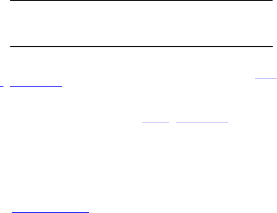
Chapter 13. Multipass Rendering
What You’ll Learn in This Chapter
• How to use renderpass objects to accelerate multipass rendering
• How to fold clears and barriers into renderpass objects
• How to control how and when data gets saved to memory
Many graphics applications make multiple passes over each frame or are otherwise able to subdivide
rendering into multiple logical phases. Vulkan brings this into the core of its operation, exposing the
concept of multipass rendering within a single object. This object was briefly introduced in Chapter
7, “Graphics Pipelines,” but we skimmed over many of the details, instead going only into enough
depth to enable basic single-pass rendering to be achieved. In this chapter, we dig deeper into the
topic to explain how multipass rendering algorithms can be implemented in a few renderpass objects
or even a single one.
When we introduced the renderpass object back in Chapter 7, “Graphics Pipelines,” we covered it in
only enough detail to explain how a framebuffer can be attached to a command buffer at the
beginning of a renderpass and how the renderpass could be configured to allow drawing into a single
set of color attachments. A renderpass object, however, can contain many subpasses, each performing
some of the operations required to render the final scene. Dependency information can be introduced,
allowing a Vulkan implementation to build a directed acyclic graph (DAG) and determine where data
flows, who produces it and who consumes it, what needs to be ready by when, and so on.
Input Attachments
Recall the VkRenderPassCreateInfo structure, the definition of which is
Click here to view code image
typedef struct VkRenderPassCreateInfo {
VkStructureType sType;
const void* pNext;
VkRenderPassCreateFlags flags;
uint32_t attachmentCount;
const VkAttachmentDescription* pAttachments;
uint32_t subpassCount;
const VkSubpassDescription* pSubpasses;
uint32_t dependencyCount;
const VkSubpassDependency* pDependencies;
} VkRenderPassCreateInfo;
Within this structure, we have pointers to arrays of attachments, subpasses, and dependency
information. Each subpass is defined by a VkSubpassDescription structure, the definition of
which is

Click here to view code image
typedef struct VkSubpassDescription {
VkSubpassDescriptionFlags flags;
VkPipelineBindPoint pipelineBindPoint;
uint32_t inputAttachmentCount;
const VkAttachmentReference * pInputAttachments;
uint32_t colorAttachmentCount;
const VkAttachmentReference * pColorAttachments;
const VkAttachmentReference * pResolveAttachments;
const VkAttachmentReference * pDepthStencilAttachment;
uint32_t preserveAttachmentCount;
const uint32_t* pPreserveAttachments;
} VkSubpassDescription;
In the example renderpass we set up in Chapter 7, we used a single subpass with no dependencies and
a single set of outputs. However, each subpass can have one or more input attachments, which are
attachments from which you can read in your fragment shaders. The primary difference between an
input attachment and a normal texture bound into a descriptor set is that when you read from an input
attachment, you read from the current fragment.
Each subpass may write to one or more output attachments. These are either the color attachments or
the depth-stencil attachment (of which there is only one). By inspecting the subpasses, which output
attachments they write to and input attachments they read from, Vulkan can build up a graph of
where data flows within a renderpass.
In order to demonstrate this, we will construct a simple three-pass renderpass object that performs
deferred shading. In the first pass, we render only to a depth attachment in order to produce what is
known as a depth prepass.
In a second pass, we render all the geometry with a special shader that produces a g-buffer, which is a
color attachment (or set of color attachments) that stores a normal diffuse color, specular power, and
other parameters needed for shading. In this second pass, we test against the depth buffer we just
generated, so we do not write out the large amounts of data for geometry that will not be visible in
the final output. Even when the geometry is visible, we do not run complex lighting shaders; we
simply write out data.
In our third pass, we perform all of our shading calculations. We read from the depth buffer in order
to reconstruct the view-space position, which allows us to create our eye and view vectors. We also
read from our normal, specular, and diffuse buffers, which supply parameters for our lighting
computation. Note that in the third pass, we don’t actually need the real geometry, and we instead
render a single triangle that, after clipping, covers the entire viewport.
Figure 13.1 shows this schematically. As you can see from the figure, the first subpass has no inputs
and only a depth attachment. The second subpass uses the same depth attachment for testing but also
has no inputs, producing only outputs. The third and final pass uses the depth buffer produced by the
first pass and the g-buffer attachments produced by the second pass as input attachments. It can do
this because the lighting calculations at each pixel require only the data computed by previous shader
invocations at the same location.

Figure 13.1: Data Flow for a Simple Deferred Renderer
Listing 13.1 shows the code required to construct a renderpass that represents these three subpasses
and their attachments.
Listing 13.1: Deferred Shading Renderpass Setup
Click here to view code image
enum
{
kAttachment_BACK = 0,
kAttachment_DEPTH = 1,
kAttachment_GBUFFER = 2
};
enum
{
kSubpass_DEPTH = 0,
kSubpass_GBUFFER = 1,
kSubpass_LIGHTING = 2
};
static const VkAttachmentDescription attachments[] =
{
// Back buffer
{
0, // flags
VK_FORMAT_R8G8B8A8_UNORM, // format
VK_SAMPLE_COUNT_1_BIT, // samples
VK_ATTACHMENT_LOAD_OP_DONT_CARE, // loadOp
VK_ATTACHMENT_STORE_OP_STORE, // storeOp
VK_ATTACHMENT_LOAD_OP_DONT_CARE, // stencilLoadOp
VK_ATTACHMENT_STORE_OP_DONT_CARE, // stencilStoreOp
VK_IMAGE_LAYOUT_UNDEFINED, // initialLayout
VK_IMAGE_LAYOUT_PRESENT_SRC_KHR // finalLayout
},
// Depth buffer
{
0, // flags
VK_FORMAT_D32_SFLOAT, // format
VK_SAMPLE_COUNT_1_BIT, // samples
VK_ATTACHMENT_LOAD_OP_DONT_CARE, // loadOp
VK_ATTACHMENT_STORE_OP_DONT_CARE, // storeOp
VK_ATTACHMENT_LOAD_OP_DONT_CARE, // stencilLoadOp
VK_ATTACHMENT_STORE_OP_DONT_CARE, // stencilStoreOp
VK_IMAGE_LAYOUT_UNDEFINED, // initialLayout
VK_IMAGE_LAYOUT_UNDEFINED // finalLayout
},
// G-buffer 1
{
0, // flags
VK_FORMAT_R32G32B32A32_UINT, // format
VK_SAMPLE_COUNT_1_BIT, // samples
VK_ATTACHMENT_LOAD_OP_DONT_CARE, // loadOp
VK_ATTACHMENT_STORE_OP_DONT_CARE, // storeOp
VK_ATTACHMENT_LOAD_OP_DONT_CARE, // stencilLoadOp
VK_ATTACHMENT_STORE_OP_DONT_CARE, // stencilStoreOp
VK_IMAGE_LAYOUT_UNDEFINED, // initialLayout
VK_IMAGE_LAYOUT_UNDEFINED // finalLayout
}
};
// Depth prepass depth buffer reference (read/write)
static const VkAttachmentReference depthAttachmentReference =
{
kAttachment_DEPTH, // attachment
VK_IMAGE_LAYOUT_DEPTH_STENCIL_ATTACHMENT_OPTIMAL // layout
};
// G-buffer attachment references (render)
static const VkAttachmentReference gBufferOutputs[] =
{
{
kAttachment_GBUFFER, // attachment
VK_IMAGE_LAYOUT_COLOR_ATTACHMENT_OPTIMAL // layout
}
};
// Lighting input attachment references
static const VkAttachmentReference gBufferReadRef[] =
{
// Read from g-buffer.
{
kAttachment_GBUFFER, // attachment
VK_IMAGE_LAYOUT_SHADER_READ_ONLY_OPTIMAL // layout
},
// Read depth as texture.
{
kAttachment_DEPTH, // attachment
VK_IMAGE_LAYOUT_DEPTH_STENCIL_READ_ONLY_OPTIMAL // layout
}
};
// Final pass-back buffer render reference
static const VkAttachmentReference backBufferRenderRef[] =
{
{
kAttachment_BACK, // attachment
VK_IMAGE_LAYOUT_COLOR_ATTACHMENT_OPTIMAL // layout
}
};
static const VkSubpassDescription subpasses[] =
{
// Subpass 1 - depth prepass
{
0, // flags
VK_PIPELINE_BIND_POINT_GRAPHICS, // pipelineBindPoint
0, // inputAttachmentCount
nullptr, // pInputAttachments
0, // colorAttachmentCount
nullptr, // pColorAttachments
nullptr, // pResolveAttachments
&depthAttachmentReference, // pDepthStencilAttachment
0, // preserveAttachmentCount
nullptr // pPreserveAttachments
},
// Subpass 2 - g-buffer generation
{
0, // flags
VK_PIPELINE_BIND_POINT_GRAPHICS, // pipelineBindPoint
0, // inputAttachmentCount
nullptr, // pInputAttachments
vkcore::utils::arraysize(gBufferOutputs), // colorAttachmentCount
gBufferOutputs, // pColorAttachments
nullptr, // pResolveAttachments
&depthAttachmentReference, // pDepthStencilAttachment
0, // preserveAttachmentCount
nullptr // pPreserveAttachments
},
// Subpass 3 - lighting
{
0, // flags
VK_PIPELINE_BIND_POINT_GRAPHICS, // pipelineBindPoint
vkcore::utils::arraysize(gBufferReadRef), // inputAttachmentCount
gBufferReadRef, // pInputAttachments
vkcore::utils::arraysize(backBufferRenderRef),//
colorAttachmentCount

backBufferRenderRef, // pColorAttachments
nullptr, // pResolveAttachments
nullptr, // pDepthStencilAttachment
0, // preserveAttachmentCount
nullptr // pPreserveAttachments
},
};
static const VkSubpassDependency dependencies[] =
{
// G-buffer pass depends on depth prepass.
{
kSubpass_DEPTH, // srcSubpass
kSubpass_GBUFFER, // dstSubpass
VK_PIPELINE_STAGE_COLOR_ATTACHMENT_OUTPUT_BIT, // srcStageMask
VK_PIPELINE_STAGE_FRAGMENT_SHADER_BIT, // dstStageMask
VK_ACCESS_COLOR_ATTACHMENT_WRITE_BIT, // srcAccessMask
VK_ACCESS_SHADER_READ_BIT, // dstAccessMask
VK_DEPENDENCY_BY_REGION_BIT // dependencyFlags
},
// Lighting pass depends on g-buffer.
{
kSubpass_GBUFFER, // srcSubpass
kSubpass_LIGHTING, // dstSubpass
VK_PIPELINE_STAGE_COLOR_ATTACHMENT_OUTPUT_BIT, // srcStageMask
VK_PIPELINE_STAGE_FRAGMENT_SHADER_BIT, // dstStageMask
VK_ACCESS_COLOR_ATTACHMENT_WRITE_BIT, // srcAccessMask
VK_ACCESS_SHADER_READ_BIT, // dstAccessMask
VK_DEPENDENCY_BY_REGION_BIT // dependencyFlags
},
};
static const VkRenderPassCreateInfo renderPassCreateInfo =
{
VK_STRUCTURE_TYPE_RENDER_PASS_CREATE_INFO, nullptr,
0, // flags
vkcore::utils::arraysize(attachments), // attachmentCount
attachments, // pAttachments
vkcore::utils::arraysize(subpasses), // subpassCount
subpasses, // pSubpasses
vkcore::utils::arraysize(dependencies), // dependencyCount
dependencies // pDependencies
};
result = vkCreateRenderPass(device,
&renderPassCreateInfo,
nullptr,
&m_renderPass);
As you can see, Listing 13.1 is quite long. However, the code complexity is relatively low; most of
the listing is simply definitions of static data structures describing the renderpass.
The attachments[] array contains a list of all of the attachments used in the renderpass. This is
referenced by index by the arrays of VkAttachmentReference structures,

depthAttachmentReference,gBufferOutputs,gBufferReadRef, and
backBufferRenderRef. These reference the depth buffer, the g-buffer as an output, the g-buffer
as an input, and the back buffer, respectively.
The subpasses[] array is a description of the subpasses contained in the renderpass. Each is
desribed by an instance of the VkSubpassDescription structure, and you can see there is one
for each of the depth prepass, g-buffer generation, and lighting passes.
Note that for the lighting pass, we include the g-buffer read references and the depth buffer as input
attachments to the pass. This is so that the lighting computations performed in the shader can read the
g-buffer content and the pixels’ depth value.
Finally, we see the dependencies between the passes described in the dependencies[] array.
There are two entries in the array, the first describing the dependency of the g-buffer pass on the
depth prepass, and the second describing the dependency of the lighting pass on the g-buffer pass.
Note that there is no reason to have a dependency between the lighting pass and the depth prepass
even though one technically exists, because there is already an implicit depencency through the g-
buffer generation pass.
The subpasses inside a renderpass are logically executed in the order in which they are declared in
the array of subpasses referenced by the VkRenderPassCreateInfo structure used to create the
renderpass object. When vkCmdBeginRenderPass() is called, the first subpass in the array is
automatically begun. In simple renderpasses with a single subpass, this is sufficient to execute the
entire renderpass. However, once we have multiple subpasses, we need to be able to tell Vulkan when
to move from subpass to subpass.
To do this, we call vkCmdNextSubpass(), the prototype of which is
Click here to view code image
void vkCmdNextSubpass (
VkCommandBuffer commandBuffer,
VkSubpassContents contents);
The command buffer in which to place the command is specified in commandBuffer. The
contents parameter specifies where the commands for the subpass will come from. For now, we’ll
set this to VK_SUBPASS_CONTENTS_INLINE, which indicates that you will continue to add
commands to the same command buffer. It’s also possible to call other command buffers, in which
case we’d set this to VK_SUBPASS_CONTENTS_SECONDARY_COMMAND_BUFFERS. We’ll cover
this scenario later in this chapter.
When vkCmdNextSubpass() is called, the current command buffer moves to the next subpass in
the current renderpass. Correspondingly, you can call vkCmdNextSubpass() only between calls
to vkCmdBeginRenderPass() and vkCmdEndRenderPass(), and only until you have
exhausted the subpasses within the renderpass.
With renderpasses containing multiple subpasses, we still must call vkCmdEndRenderPass() to
terminate the current renderpass and finalize rendering.

Attachment Contents
Each color and depth-stencil attachment associated with a renderpass has a load operation and a store
operation that determine how its contents are loaded from and stored to memory as the renderpass is
begun and ended.
Attachment Initialization
When the renderpass is begun, the operations that should be performed on each of the attachments
are specified in the loadOp field of the VkAttachmentDescription structure describing the
attachment. There are two possible values for this field.
VK_ATTACHMENT_LOAD_OP_DONT_CARE means that you don’t care about the initial contents of
the attachment. This means that Vulkan can do whatever it needs to do to get the attachment ready to
render into (including doing nothing), without worrying about the actual values in the attachment.
For example, if it has a super-fast clear that clears only to purple, then purple it shall be.
Setting loadOp for the attachment to VK_ATTACHMENT_LOAD_OP_CLEAR means that the
attachment will be cleared to a value you specify at vkCmdBeginRenderPass() time. While
logically, this operation happens at the very start of the renderpass, in practice, implementations may
delay the actual clear operation to the beginning of the first pass that uses the attachment. This is the
preferred method of clearing color attachments.
It’s also possible to explicitly clear one or more color or depth-stencil attachments inside a renderpass
by calling vkCmdClearAttachments(), the prototype of which is
Click here to view code image
void vkCmdClearAttachments (
VkCommandBuffer commandBuffer,
uint32_t attachmentCount,
const VkClearAttachment* pAttachments,
uint32_t rectCount,
const VkClearRect* pRects);
The command buffer that will execute the command is specified in commandBuffer.
vkCmdClearAttachments() will clear the contents of several attachments. The number of
attachments to clear is specified in attachmentCount, and pAttachments should be a pointer
to an array of attachmentCount VkClearAttachment structures, each defining one of the
attachments to clear. The definition of VkClearAttachment is
Click here to view code image
typedef struct VkClearAttachment {
VkImageAspectFlags aspectMask;
uint32_t colorAttachment;
VkClearValue clearValue;
} VkClearAttachment;
The aspectMask field of VkClearAttachment specifies the aspect or aspects of the
attachment to be cleared. If aspectMask contains VK_IMAGE_ASPECT_DEPTH_BIT,
VK_IMAGE_ASPECT_STENCIL_BIT, or both, then the clear operation will be applied to the
depth-stencil attachment for the current subpass. Each subpass can have at most one depth-stencil

attachment. If aspectMask contains VK_IMAGE_ASPECT_COLOR_BIT, then the clear operation
will be applied to the color attachment at index colorAttachment in the current subpass. It is not
possible to clear a color attachment and a depth-stencil attachment with a single
VkClearAttachment structure, so aspectMask should not contain
VK_IMAGE_ASPECT_COLOR_BIT along with VK_IMAGE_ASPECT_DEPTH_BIT or
VK_IMAGE_ASPECT_STENCIL_BIT.
The values to clear the attachment with are specified in the clearValue field, which is an instance
of the VkClearValue union. This was introduced in Chapter 8, “Drawing,” and its definition is
Click here to view code image
typedef union VkClearValue {
VkClearColorValue color;
VkClearDepthStencilValue depthStencil;
} VkClearValue;
If the referenced attachment is a color attachment, then the values from the color field of the
VkClearAttachment structure will be used. Otherwise, the values contained in the
depthStencil field of the structure will be used.
In addition to clearing multiple attachments, a single call to vkCmdClearAttachments() can
clear rectangular regions of each attachment. This provides additional functionality over setting the
loadOp for the attachment to VK_ATTACHMENT_LOAD_OP_CLEAR. If an attachment is cleared
with VK_ATTACHMENT_LOAD_OP_CLEAR (which is what you want in the majority of cases), the
whole attachment is cleared, and there is no opportunity to clear only part of the attachment.
However, when you use vkCmdClearAttachments(), multiple smaller regions can be cleared.
The number of regions to clear is specified in the rectCount parameter to
vkCmdClearAttachments(), and the pRects parameter is a pointer to an array of
rectCount VkClearRect structures, each defining one of the rectangles to clear. The definition
of VkClearRect is
Click here to view code image
typedef struct VkClearRect {
VkRect2D rect;
uint32_t baseArrayLayer;
uint32_t layerCount;
} VkClearRect;
The VkClearRect structure defines more than a rectangle. The rect field contains the actual
rectangle to clear. If the attachment is an array image, then some or all of its layers can be cleared by
specifying the range of layers in baseArrayLayer and layerCount, which contain,
respectively, the index of the first layer to clear and the number of layers to clear.
In addition to containing more information and providing more functionality than the attachments
load operation, vkCmdClearAttachments() also potentially provides more convenience than
vkCmdClearColorImage() or vkCmdClearDepthStencilImage(). Both of these
commands require that the image be in VK_IMAGE_LAYOUT_GENERAL or
VK_IMAGE_LAYOUT_TRANSFER_DST_OPTIMAL layout and therefore may require a pipeline
barrier around them to ensure this. Also, these commands cannot be called inside a renderpass. On

the other hand, vkCmdClearAttachments() takes advantage of the fact that the attachments are
already bound for rendering and are considered to be part of the renderpass content, almost like a
special kind of draw. Therefore, no barrier or special handling is needed beyond ensuring that the
command is executed inside a renderpass.
That said, it is still recommended that you use the VK_ATTACHMENT_LOAD_OP_CLEAR load
operation when you need the entirety of an attachment to be cleared as part of a renderpass, and the
VK_ATTACHMENT_LOAD_OP_DONT_CARE operation when you will guarantee that you will
overwrite every pixel in the attachment by the time the renderpass has completed.
Render Areas
When a renderpass instance is executed, it is possible to tell Vulkan that you’re going to update only
a small area of the attachments. This area is known as the render area and can be specified when
vkCmdBeginRenderPass() is called. We introduced this briefly in Chapter 8, “Drawing,” and
the renderArea member of the VkRenderPassBeginInfo structure is passed to
vkCmdBeginRenderPass().
If you are rendering to the entire framebuffer, set the renderArea field to cover the entire area of
the framebuffer. However, if you want to update only a small part of the framebuffer, you can set the
renderArea rectangle accordingly. Any part of the renderpass’s attachments that are not contained
inside this render area are not affected by any of the operations in the renderpass including the
renderpass’s load and store operations for those attachments.
When you are using a render area smaller than the entire attachment, it is the application’s
responsibility to ensure that it doesn’t render outside this area. Some implementations may ignore the
render area entirely and trust your application to stick within it; some may round the render area up to
some multiple of an internal rectangular region; and some may strictly adhere to the area you’ve
specified. The only way to get well-defined behavior is to make sure you render only inside this area,
using a scissor test if needed.
Rendering to a smaller render area than the entire attachment may also come at some performance
cost unless the area matches the granularity of the supported render areas for the implementation.
Consider the framebuffer to be tiles in a grid that are potentially rendered one at a time. Completely
covering and redefining the content of a single tile should be fast, but updating only part of a tile may
cause Vulkan to do extra work to keep the untouched parts of the tile well defined.
To acheive maximum performance, you should ensure that the render areas you use match the render
area granularity supported by the implementation. This can be queried using
vkGetRenderAreaGranularity(), the prototype of which is
Click here to view code image
void vkGetRenderAreaGranularity (
VkDevice device,
VkRenderPass renderPass,
VkExtent2D* pGranularity);
For a renderpass specified in renderPass,vkGetRenderAreaGranularity() returns, in
the variable pointed to by pGranularity, the dimensions of a tile used for rendering. The device
that owns the renderpass should be passed in device.

To ensure that the render area you pass to vkCmdBeginRenderPass() performs optimally, you
should ensure two things: First, that the xand ycomponents of its origin are integer multiples of the
width and height of the render-area granularity; and second, that the width and height of the
render area are either integer multiples of that granularity or extend to the edge of the framebuffer.
Obviously, a render area that completely covers the attachments trivially meets these requirements.
Preserving Attachment Content
In order to preserve the contents of the attachment, we need to set the attachment’s store operation
(contained in the storeOp field of the VkAttachmentDescription structure used to create
the renderpass) to VK_ATTACHMENT_STORE_OP_STORE. This causes Vulkan to ensure that after
the renderpass has completed, the contents of the image used as the attachment accurately reflect
what was rendered during the renderpass.
The only other choice for this field is VK_ATTACHMENT_STORE_OP_DONT_CARE, which tells
Vulkan that you don’t need the content of the attachment after the renderpass has completed. This is
used, for example, when an attachment is used to store intermediate data that will be consumed by
some later subpass in the same renderpass. In this case, the content doesn’t need to live longer than
the renderpass itself.
In some cases, you need to produce content in one subpass, execute an unrelated subpass, and then
consume the content created more than one subpass ago. In this case, you should tell Vulkan that it
cannot discard the content of an attachment over the course of rendering another subpass. In practice,
a Vulkan implementation should be able to tell by inspecting the input and output attachments for the
subpasses in a renderpass which ones produce and which ones consume data and will do the right
thing. However, to be fully correct, every live attachment should appear as an input, an output, or a
preserve attachment in each subpass. Furthermore, by including an attachment in the preserve
attachment array for a subpass, you are telling Vulkan that you are about to use the attachment
content in an upcoming subpass. This may enable it to keep some of the data in cache or some other
high-speed memory.
The list of attachments to preserve across a subpass is specified using the
pPreserveAttachments field of the VkSubpassDescription structure describing each
subpass. This is a pointer to an array of uint32_t indices into the renderpass’s attachment list, and
the number of integers in this array is contained in the preserveAttachmentCount field of
VkSubpassDescription.
To demonstrate this, we extend our example further to render transparent objects. We render a depth
buffer, then render a g-buffer containing per-pixel information, and finally we render a shading pass
that calculates lighting information. Because we have only 1 pixel’s worth of information, this
deferred shading approach cannot render transparent or translucent objects. Therefore, these objects
must be rendered separately. The traditional approach is to simply render all the opaque geometry in
one pass (or passes) and then composite the translucent geometry on top at the end. This introduces a
serial dependency, causing rendering of the translucent geometry to wait for opaque geometry to
complete rendering.
This serial dependency is shown in the DAG illustrated in Figure 13.2.
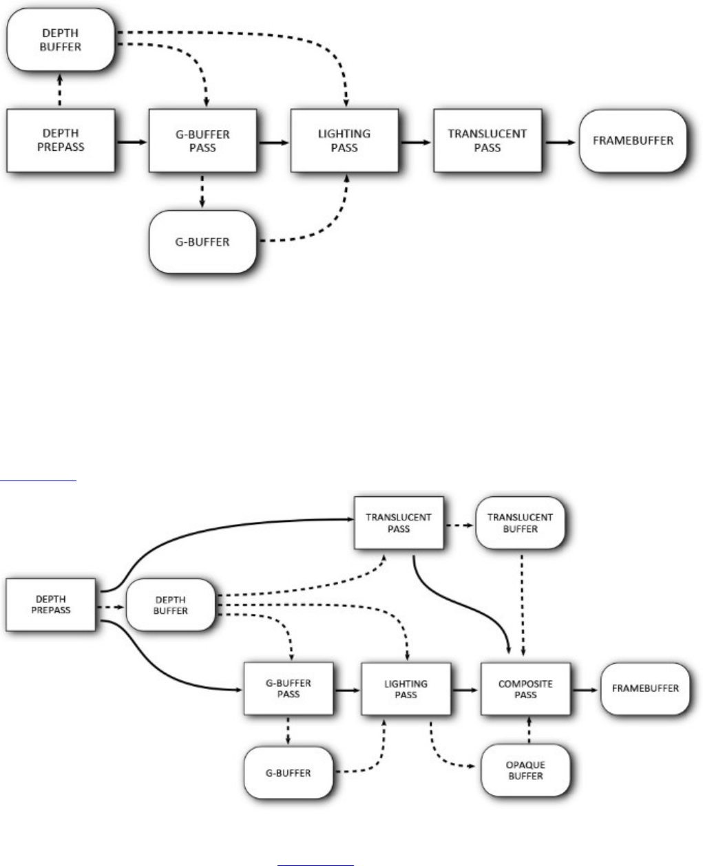
Figure 13.2: Serial Dependency of Translucent on Opaque Geometry
Rather than introduce a serial dependency, which would preclude Vulkan from rendering any of the
translucent geometry in parallel with opaque geometry, we take another approach: Render the
translucent geometry to another color attachment (using the same depth prepass information for depth
rejection) and the opaque geometry into a second temporary attachment. After both the opaque and
transparent geometry have been rendered, we perform a composition pass that blends the translucent
geometry on top of the opaque geometry. This pass can also perform other per-pixel operations, such
as color grading, vignetting, film-grain application, and so on. The new DAG for this is shown in
Figure 13.3.
Figure 13.3: Parallel Rendering of Translucent and Opaque Geometry
As you can see from the updated DAG in Figure 13.3, first the depth information is rendered and
then the g-buffer generation pass executes, followed by the lighting pass. The translucency buffer
generation pass has no dependency on the g-buffer or the result of the lighting pass, so it is able to

run in parallel, depending only on the depth information from the depth prepass. The new composite
pass now depends on the result of the lighting pass and the translucent pass.
As the subpasses in the renderpass are expressed serially, regardless of the serial ordering of the
opaque g-buffer pass and the translucency pass in the renderpass, we need to preserve the content of
the first pass’s outputs until the shading pass is able to execute. Because there is less data to store, we
render the translucent objects first and preserve the translucency buffer across the g-buffer generation
pass. The g-buffer and translucency buffer are then used as input attachments to the shading pass.
The code to set all this up is shown in Listing 13.2.
Listing 13.2: Translucency and Deferred Shading Setup
Click here to view code image
enum
{
kAttachment_BACK = 0,
kAttachment_DEPTH = 1,
kAttachment_GBUFFER = 2,
kAttachment_TRANSLUCENCY = 3,
kAttachment_OPAQUE = 4
};
enum
{
kSubpass_DEPTH = 0,
kSubpass_GBUFFER = 1,
kSubpass_LIGHTING = 2,
kSubpass_TRANSLUCENTS = 3,
kSubpass_COMPOSITE = 4
};
static const VkAttachmentDescription attachments[] =
{
// Back buffer
{
0, // flags
VK_FORMAT_R8G8B8A8_UNORM, // format
VK_SAMPLE_COUNT_1_BIT, // samples
VK_ATTACHMENT_LOAD_OP_DONT_CARE, // loadOp
VK_ATTACHMENT_STORE_OP_STORE, // storeOp
VK_ATTACHMENT_LOAD_OP_DONT_CARE, // stencilLoadOp
VK_ATTACHMENT_STORE_OP_DONT_CARE, // stencilStoreOp
VK_IMAGE_LAYOUT_UNDEFINED, // initialLayout
VK_IMAGE_LAYOUT_PRESENT_SRC_KHR // finalLayout
},
// Depth buffer
{
0, // flags
VK_FORMAT_D32_SFLOAT, // format
VK_SAMPLE_COUNT_1_BIT, // samples
VK_ATTACHMENT_LOAD_OP_DONT_CARE, // loadOp
VK_ATTACHMENT_STORE_OP_DONT_CARE, // storeOp
VK_ATTACHMENT_LOAD_OP_DONT_CARE, // stencilLoadOp
VK_ATTACHMENT_STORE_OP_DONT_CARE, // stencilStoreOp
VK_IMAGE_LAYOUT_UNDEFINED, // initialLayout
VK_IMAGE_LAYOUT_UNDEFINED // finalLayout
},
// G-buffer 1
{
0, // flags
VK_FORMAT_R32G32B32A32_UINT, // format
VK_SAMPLE_COUNT_1_BIT, // samples
VK_ATTACHMENT_LOAD_OP_DONT_CARE, // loadOp
VK_ATTACHMENT_STORE_OP_DONT_CARE, // storeOp
VK_ATTACHMENT_LOAD_OP_DONT_CARE, // stencilLoadOp
VK_ATTACHMENT_STORE_OP_DONT_CARE, // stencilStoreOp
VK_IMAGE_LAYOUT_UNDEFINED, // initialLayout
VK_IMAGE_LAYOUT_UNDEFINED // finalLayout
},
// Translucency buffer
{
0, // flags
VK_FORMAT_R8G8B8A8_UNORM, // format
VK_SAMPLE_COUNT_1_BIT, // samples
VK_ATTACHMENT_LOAD_OP_DONT_CARE, // loadOp
VK_ATTACHMENT_STORE_OP_DONT_CARE, // storeOp
VK_ATTACHMENT_LOAD_OP_DONT_CARE, // stencilLoadOp
VK_ATTACHMENT_STORE_OP_DONT_CARE, // stencilStoreOp
VK_IMAGE_LAYOUT_UNDEFINED, // initialLayout
VK_IMAGE_LAYOUT_UNDEFINED // finalLayout
}
};
// Depth prepass depth buffer reference (read/write)
static const VkAttachmentReference depthAttachmentReference =
{
kAttachment_DEPTH, // attachment
VK_IMAGE_LAYOUT_DEPTH_STENCIL_ATTACHMENT_OPTIMAL // layout
};
// G-buffer attachment references (render)
static const VkAttachmentReference gBufferOutputs[] =
{
{
kAttachment_GBUFFER, // attachment
VK_IMAGE_LAYOUT_COLOR_ATTACHMENT_OPTIMAL // layout
}
};
// Lighting input attachment references
static const VkAttachmentReference gBufferReadRef[] =
{
// Read from g-buffer.
{
kAttachment_GBUFFER, // attachment
VK_IMAGE_LAYOUT_SHADER_READ_ONLY_OPTIMAL // layout
},
// Read depth as texture.
{
kAttachment_DEPTH, // attachment
VK_IMAGE_LAYOUT_DEPTH_STENCIL_READ_ONLY_OPTIMAL // layout
}
};
// Lighting pass - write to opaque buffer.
static const VkAttachmentReference opaqueWrite[] =
{
// Write to opaque buffer.
{
kAttachment_OPAQUE, // attachment
VK_IMAGE_LAYOUT_COLOR_ATTACHMENT_OPTIMAL // layout
}
};
// Translucency rendering pass - translucency buffer write
static const VkAttachmentReference translucentWrite[] =
{
// Write to translucency buffer.
{
kAttachment_TRANSLUCENCY, // attachment
VK_IMAGE_LAYOUT_COLOR_ATTACHMENT_OPTIMAL // layout
}
};
static const VkAttachmentReference compositeInputs[] =
{
// Read from translucency buffer.
{
kAttachment_TRANSLUCENCY, // attachment
VK_IMAGE_LAYOUT_SHADER_READ_ONLY_OPTIMAL // layout
},
// Read from opaque buffer.
{
kAttachment_OPAQUE, // attachment
VK_IMAGE_LAYOUT_SHADER_READ_ONLY_OPTIMAL // layout
}
};
// Final pass - back buffer render reference
static const VkAttachmentReference backBufferRenderRef[] =
{
{
kAttachment_BACK, // attachment
VK_IMAGE_LAYOUT_COLOR_ATTACHMENT_OPTIMAL // layout
}
};
static const VkSubpassDescription subpasses[] =
{
// Subpass 1 - depth prepass
{
0, // flags
VK_PIPELINE_BIND_POINT_GRAPHICS, // pipelineBindPoint
0, // inputAttachmentCount
nullptr, // pInputAttachments
0, // colorAttachmentCount
nullptr, // pColorAttachments
nullptr, // pResolveAttachments
&depthAttachmentReference, // pDepthStencilAttachment
0, // preserveAttachmentCount
nullptr // pPreserveAttachments
},
// Subpass 2 - g-buffer generation
{
0, // flags
VK_PIPELINE_BIND_POINT_GRAPHICS, // pipelineBindPoint
0, // inputAttachmentCount
nullptr, // pInputAttachments
vkcore::utils::arraysize(gBufferOutputs), // colorAttachmentCount
gBufferOutputs, // pColorAttachments
nullptr, // pResolveAttachments
&depthAttachmentReference, // pDepthStencilAttachment
0, // preserveAttachmentCount
nullptr // pPreserveAttachments
},
// Subpass 3 - lighting
{
0, // flags
VK_PIPELINE_BIND_POINT_GRAPHICS, // pipelineBindPoint
vkcore::utils::arraysize(gBufferReadRef), // inputAttachmentCount
gBufferReadRef, // pInputAttachments
vkcore::utils::arraysize(opaqueWrite), // colorAttachmentCount
opaqueWrite, // pColorAttachments
nullptr, // pResolveAttachments
nullptr, // pDepthStencilAttachment
0, // preserveAttachmentCount
nullptr // pPreserveAttachments
},
// Subpass 4 - translucent objects
{
0, // flags
VK_PIPELINE_BIND_POINT_GRAPHICS, // pipelineBindPoint
0, // inputAttachmentCount
nullptr, // pInputAttachments
vkcore::utils::arraysize(translucentWrite), //
colorAttachmentCount
translucentWrite, // pColorAttachments
nullptr, // pResolveAttachments
nullptr, // pDepthStencilAttachment
0, // preserveAttachmentCount
nullptr // pPreserveAttachments
},
// Subpass 5 - composite
{
0, // flags
VK_PIPELINE_BIND_POINT_GRAPHICS, // pipelineBindPoint
0, // inputAttachmentCount
nullptr, // pInputAttachments
vkcore::utils::arraysize(backBufferRenderRef), //
colorAttachmentCount
backBufferRenderRef, // pColorAttachments
nullptr, // pResolveAttachments
nullptr, // pDepthStencilAttachment
0, // preserveAttachmentCount
nullptr // pPreserveAttachments
}
};
static const VkSubpassDependency dependencies[] =
{
// G-buffer pass depends on depth prepass.
{
kSubpass_DEPTH, // srcSubpass
kSubpass_GBUFFER, // dstSubpass
VK_PIPELINE_STAGE_COLOR_ATTACHMENT_OUTPUT_BIT, // srcStageMask
VK_PIPELINE_STAGE_FRAGMENT_SHADER_BIT, // dstStageMask
VK_ACCESS_COLOR_ATTACHMENT_WRITE_BIT, // srcAccessMask
VK_ACCESS_SHADER_READ_BIT, // dstAccessMask
VK_DEPENDENCY_BY_REGION_BIT // dependencyFlags
},
// Lighting pass depends on g-buffer.
{
kSubpass_GBUFFER, // srcSubpass
kSubpass_LIGHTING, // dstSubpass
VK_PIPELINE_STAGE_COLOR_ATTACHMENT_OUTPUT_BIT, // srcStageMask
VK_PIPELINE_STAGE_FRAGMENT_SHADER_BIT, // dstStageMask
VK_ACCESS_COLOR_ATTACHMENT_WRITE_BIT, // srcAccessMask
VK_ACCESS_SHADER_READ_BIT, // dstAccessMask
VK_DEPENDENCY_BY_REGION_BIT // dependencyFlags
},
// Composite pass depends on translucent pass.
{
kSubpass_TRANSLUCENTS, // srcSubpass
kSubpass_COMPOSITE, // dstSubpass
VK_PIPELINE_STAGE_COLOR_ATTACHMENT_OUTPUT_BIT, // srcStageMask
VK_PIPELINE_STAGE_FRAGMENT_SHADER_BIT, // dstStageMask
VK_ACCESS_COLOR_ATTACHMENT_WRITE_BIT, // srcAccessMask
VK_ACCESS_SHADER_READ_BIT, // dstAccessMask
VK_DEPENDENCY_BY_REGION_BIT // dependencyFlags
},
// Composite pass also depends on lighting.
{
kSubpass_LIGHTING, // srcSubpass
kSubpass_COMPOSITE, // dstSubpass
VK_PIPELINE_STAGE_COLOR_ATTACHMENT_OUTPUT_BIT, // srcStageMask

VK_PIPELINE_STAGE_FRAGMENT_SHADER_BIT, // dstStageMask
VK_ACCESS_COLOR_ATTACHMENT_WRITE_BIT, // srcAccessMask
VK_ACCESS_SHADER_READ_BIT, // dstAccessMask
VK_DEPENDENCY_BY_REGION_BIT // dependencyFlags
}
};
static const VkRenderPassCreateInfo renderPassCreateInfo =
{
VK_STRUCTURE_TYPE_RENDER_PASS_CREATE_INFO, nullptr,
0, // flags
vkcore::utils::arraysize(attachments), // attachmentCount
attachments, // pAttachments
vkcore::utils::arraysize(subpasses), // subpassCount
subpasses, // pSubpasses
vkcore::utils::arraysize(dependencies), // dependencyCount
dependencies // pDependencies
};
result = vkCreateRenderPass(device,
&renderPassCreateInfo,
nullptr,
&m_renderPass);
Again, the code in Listing 13.2 is extremely long but is mostly a set of constant data structures. Here,
we’ve added the translucent pass and the composite pass to the list of passes in subpasses[]. The
final pass is now the composite pass, so it is the one that references the back buffer in its
pColorAttachments array. The result of the lighting pass is now written to the temporary
opaque buffer, indexed by kAttachment_OPAQUE.
Although this appears to consume a significant amount of memory, we can note several redeeming
points about this configuration:
• There are likely to be at least two or three back buffers, while you can use the same buffer every
frame for intermediate results. The additional overhead of one extra buffer is not that large.
• The lighting pass consumes the g-buffer, after which it is no longer needed. You can either write
the opaque result back into the g-buffer or mark the attachment as transient and hope that the
Vulkan implementation does this for you.
• If you are rendering high dynamic range, then you may want your rendering results to be in a
higher-precision format than the back buffer anyway and then perform tone mapping or other
processing during the composition pass. In this case, you’ll need the intermediate buffers.
Secondary Command Buffers
Secondary command buffers are command buffers that can be called from primary command buffers.
Although not directly related to multipass rendering, they are used primarily to allow the commands
contributing to a render consisting of many subpasses to be built up in multiple command buffers. As
you know, a renderpass must begin and end in the same command buffer. That is, the call to
vkCmdEndRenderPass() must appear in the same command buffer as its corresponding
vkCmdBeginRenderPass().

Given this requirement, it’s very difficult to render a large amount of the scene in a single renderpass
and still build command buffers in parallel. In the ideal case (from an implementation point of view),
the entire scene will be rendered in a single large renderpass, with potentially many subpasses.
Without secondary command buffers, this would require most, if not all, of a scene to be rendered
using a single long command buffer, precluding parallelized command generation.
To create a secondary command buffer, create a command pool and then from it allocate one or more
command buffers. In the VkCommandBufferAllocateInfo structure passed to
vkAllocateCommandBuffers(), set the level field to
VK_COMMAND_BUFFER_LEVEL_SECONDARY. We then record commands into the command
buffer as usual, but with certain restrictions as to which commands can be executed. A table listing
which commands may and may not be recorded in secondary command buffers is shown in the
Appendix, “Vulkan Functions.”
When the secondary command buffer is ready to execute from another primary command buffer, call
vkCmdExecuteCommands(), the prototype of which is
Click here to view code image
void vkCmdExecuteCommands (
VkCommandBuffer commandBuffer,
uint32_t commandBufferCount,
const VkCommandBuffer* pCommandBuffers);
The command buffer from which to call the secondary command buffers is passed in
commandBuffer. A single call to vkCmdExecuteCommands() can execute many secondary-
level command buffers. The number of command buffers to execute is passed in
commandBufferCount, and pCommandBuffers should point to an array of this many
VkCommandBuffer handles to the command buffers to execute.
Vulkan command buffers contain a certain amount of state. In particular, the currently bound
pipeline, the various dynamic states, and the currently bound descriptor sets are effectively properties
of each command buffer. When multiple command buffers are executed back to back, even when sent
to the same call to vkQueueSubmit(), no state is inherited from one to the next. That is, the initial
state of each command buffer is undefined, even if the previously executed command buffer left
everything as it needs to be for the next.
When you are executing a large, complex command buffer, it’s probably fine to begin with an
undefined state because the first thing you’ll do in the command buffer is set up everything required
for the first few drawing commands. That cost is likely to be small relative to the cost of the whole
command buffer, even if it’s partially redundant with respect to previously executed command
buffers.
When a primary command buffer calls a secondary command buffer, and especially when a primary
command buffer calls many short secondary command buffers back to back, it can be costly to reset
the complete state of the pipeline in each and every secondary command buffer. To compensate for
this, some state can be inherited from primary to secondary command buffers. This is done using the
VkCommandBufferInheritanceInfo structure, which is passed to
vkBeginCommandBuffer(). The definition of this structure is

Click here to view code image
typedef struct VkCommandBufferInheritanceInfo {
VkStructureType sType;
const void* pNext;
VkRenderPass renderPass;
uint32_t subpass;
VkFramebuffer framebuffer;
VkBool32 occlusionQueryEnable;
VkQueryControlFlags queryFlags;
VkQueryPipelineStatisticFlags pipelineStatistics;
} VkCommandBufferInheritanceInfo;
The VkCommandBufferInheritanceInfo provides a mechanism for your application to tell
Vulkan that you know what the state will be when the secondary command buffer is executed. This
allows the properties of the command buffer to begin in a well-defined state.
The sType field of VkCommandBufferInheritanceInfo should be set to
VK_STRUCTURE_TYPE_COMMAND_BUFFER_INHERITANCE_INFO, and pNext should be set
to nullptr.
The renderpass and subpass fields specify the renderpass and the subpass of the render that the
command buffer will be called inside, respectively. If the framebuffer to which the renderpass will be
rendering is known, then it can be specified in the framebuffer field. This can sometimes result
in better performance when the command buffer is executed. However, if you don’t know which
framebuffer will be used, then you should set this field to VK_NULL_HANDLE.
The occlusionQueryEnable field should be set to VK_TRUE if the secondary command buffer
will be executed while the primary command buffer is executing an occlusion query. This tells
Vulkan to keep any counters associated with occlusion queries consistent during execution of the
secondary command buffer. If this flag is VK_FALSE, then the secondary command buffer should
not be executed while occlusion queries are active in the calling command buffer. While the behavior
is technically undefined, the most likely outcome is that the results of the occlusion queries are
garbage.
You can execute occlusion queries inside secondary command buffers regardless of the value of
occlusionQueryEnable. You will need to begin and end the query inside the same secondary
command buffer if you don’t inherit the state from a calling primary.
If occlusion query inheritance is enabled, then the queryFlags field contains additional flags that
control the behavior of occlusion queries. The only flag defined for use here is
VK_QUERY_CONTROL_PRECISE_BIT, which, if set, indicates that precise occlusion-query results
are needed.
The pipelineStatistics field includes flags that tell Vulkan which pipeline statistics are being
gathered by calling the primary command buffer. Again, you can gather pipeline statistics during the
execution of a secondary command buffer, but if you want the operation of the pipeline invoked by a
secondary command buffer to contribute counters accumulated by the primary command buffer, you
need to set these flags accurately. The available bits are members of the
VkQueryPipelineStatisticFlagBits enumeration.
Summary
This chapter delved deeper into the renderpass, a fundamental feature of Vulkan that enables efficient
multipass rendering. You saw how to construct a nontrivial renderpass that contains many subpasses
and how to build the contents of those subpasses as separate command buffers that can be called from
your main command buffer. We discussed some potential optimizations that Vulkan implementations
could make to improve the performance of rendering when they are given all the information about
what will come in the frame. You also saw how many of the functions performed by barriers and
clears can be folded into the renderpass, sometimes making them close to free. The renderpass is a
powerful feature and, if possible, you should endeavor to make use of it in your applications.
Appendix. Vulkan Functions
This appendix contains a table of the Vulkan command buffer building commands. It provides a
quick reference to what can and cannot be used inside and outside a renderpass, as well as to what is
legal inside a primary or secondary command buffer.
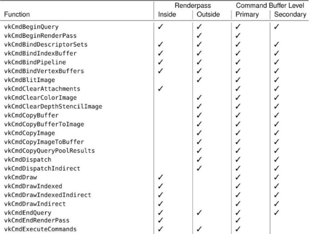
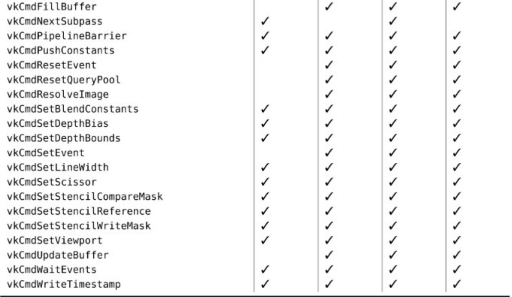
Command Buffer Building Functions
Glossary
adjacency primitive One of the primitive topologies that includes, for each primitive, additional
vertex data representing adjacent primitives in the original geometry. Examples include triangles
and lines with adjacency.
aliasing Technically, the loss of signal information in an image reproduced at some finite resolution.
It is most often characterized by the appearance of sharp, jagged edges along points, lines, or
polygons due to the nature of having a limited number of fixed-size pixels.
alpha A fourth color value added to provide a degree of transparency to the color of an object. An
alpha value of 0.0 means complete transparency; 1.0 denotes no transparency (opaque).
ambient light Light in a scene that doesn’t come from any specific point source or direction.
Ambient light illuminates all surfaces evenly and on all sides.
antialiasing A rendering method used to smooth lines, curves, and polygon edges. This technique
averages the color of pixels adjacent to the line. It has the visual effect of softening the transition
from the pixels on the line and those adjacent to the line, thus providing a smoother appearance.
Apple An apple is a piece of fruit. Fruit does not support Vulkan.
ARB Acronym for the Architecture Review Board, the committee body consisting of 3D graphics
hardware vendors, previously charged with maintaining the OpenGL Specification. This function
has since been assumed by the Khronos Group. See Khronos Group.
aspect When applied to an image, a logical part of that image, such as the depth or stencil component
of a combined depth-stencil image.
aspect ratio The ratio of the width of a window to the height of the window—specifically, the width
of the window in pixels divided by the height of the window in pixels.
associativity A sequence of operations in which changing the order of the operations (but not the
order of the arguments) does not affect the result. For example, addition is associative because a
+ (b+c) = (a+b) + c.
atomic operation A sequence of operations that must be indivisible for correct operation. The term
usually refers to a read-modify-write sequence on a single memory location.
attachment An image associated with a renderpass that can be used as the input or output of one or
more of its subpasses.
barrier A point in a computer program that serves as a marker across which operations may not be
reordered. Between barriers, certain operations may be exchanged if their movement does not
logically change the operation of the program. Barriers operate on resources or memory and can
also be used to change the layout of images.
Bézier curve A curve whose shape is defined by control points near the curve rather than by the
precise set of points that define the curve itself.
bitplane An array of bits mapped directly to screen pixels.
blending The process of merging a new color value into an existing color attachment using an
equation and parameters that are configured as part of a graphics pipeline.
blit Short for block image transfer—an operation that copies image data from one place to another,
potentially processing it further as it is copied. In Vulkan, a blit is used to scale image data and to
perform basic operations such as format conversion.
branch prediction An optimization strategy used in processor design whereby the processor tries to
guess (or predict) the outcome of some conditional code and start executing the more likely
branch before it is certain that it is required. If the processor is right, it gets ahead by a few
instructions. If the processor is wrong, it needs to throw away the work and start again with the
other branch.
buffer An area of memory used to store image information. This information can be color, depth, or
blending information. The red, green, blue, and alpha buffers are often collectively referred to as
the color buffers.
Cartesian A coordinate system based on three directional axes placed at a 90° orientation to one
another. These coordinates are labeled x,y, and z.
clip coordinates The 2D geometric coordinates that result from the model-view and projection
transformation.
clip distance A distance value assigned by a shader that is used by fixed-function clipping to allow
primitives to be clipped against an arbitrary set of planes before rasterization.
clipping The elimination of a portion of a single primitive or group of primitives. The points that
would be rendered outside the clipping region or volume are not drawn. The clipping volume is
generally specified by the projection matrix. Clipped primitives are reconstructed such that the
edges of the primitive do not lie outside the clipping region.
command buffer A list of commands that can be executed by the device.
commutative An operation in which changing the order of its operands does not change its result.
For example, addition is commutative, whereas subtraction is not.
compute pipeline A Vulkan pipeline object consisting of a compute shader and related state that is
used to execute computational work on a Vulkan device.
compute shader A shader that executes a work item per invocation as part of a local work group, a
number of which may be grouped into a global work group.
concave A reference to the shape of a polygon. A polygon is said to be concave if a straight line
through it will enter and subsequently exit the polygon more than once.
contention A term used to describe the condition in which two or more threads of execution attempt
to use a single shared resource.
convex A reference to the shape of a polygon. A convex polygon has no indentations, and no straight
line can be drawn through the polygon that intersects it more than twice (once entering, once
leaving).
CRT Cathode ray tube.
cull distance A value applied to a vertex within a primitive that will cause the entire primitive to be
discarded if any of its vertices are assigned a negative value.
culling The elimination of graphics primitives that would not be seen if rendered. Back-face culling
eliminates the front or back face of a primitive so that the face isn’t drawn. Frustum culling
eliminates whole objects that would fall outside the viewing frustum.
depth fighting A visual artifact caused by primitives with very close depth values being rendered on
top of one another and producing inconsistent depth-test results.
depth test A test performed between a depth value computed for a fragment and a value stored in a
depth buffer.
descriptor A data structure containing an implementation-specific description of a resource such as a
buffer or an image.
destination color The stored color at a particular location in the color buffer. This terminology is
usually used when describing blending operations to distinguish between the color already
present in the color buffer and the color coming into the color buffer (source color).
device memory Memory that is accessible to a Vulkan device. This may be dedicated memory that’s
physically attached to the device, or some or all of the host’s memory that is accessible to the
device.
dispatch A command that begins the execution of compute shaders.
displacement mapping The act of taking a flat surface and displacing it along a normal by an
amount determined by a texture or other source of data.
dithering A method used to simulate a wider range of color depth by placing different-colored pixels
together in patterns that create the illusion of shading between the two colors.
double buffering A drawing technique used to present stable images. The image to be displayed is
assembled in memory and then placed on the screen in a single update operation rather than built
primitive by primitive onscreen. Double buffering is a much faster and smoother update
operation and can produce animations.
event A synchronization primitive used within a Vulkan command buffer to synchronize the
execution of different parts of the pipeline.
extruding The process of taking a 2D image or shape and adding a third dimension uniformly across
the surface. This process can transform 2D fonts into 3D lettering.
eye coordinates The coordinate system based on the position of the viewer. The viewer’s position is
placed along the positive zaxis, looking down the negative zaxis.
fence An object used to synchronize execution on the host with completion of command buffers
executed by the device.
FMA Acronym for fused multiply add, an operation commonly implemented in a single piece of
hardware that multiplies two numbers together and adds a third, with the intermediate result
generally computed at higher precision than a stand-alone multiplication or addition operation.
fragment A single piece of data that may eventually contribute to the color of a pixel in an image.
fragment shader A shader that executes once per fragment and generally computes the final color of
that fragment.
framebuffer An object containing references to images that will be used as the attachments during
rendering with graphics pipelines.
frustum A pyramid-shaped viewing volume that creates a perspective view. (Near objects are large;
far objects are small.)
gamma correction The process of transforming a linear value through a gamma curve to produce
nonlinear output. Gamma (γ) can be greater or less than one to move from linear to gamma space
and back again, respectively.
garbage Uninitialized data that is read and consumed by a computer program, often resulting in
corruption, crashes, or other undesired behavior.
geometry shader A shader that executes once per primitive, having access to all vertices making up
that primitive.
gimbal lock A state in which a sequence of rotations can essentially become stuck on a single axis.
This occurs when one of the rotations early in the sequence rotates one Cartesian axis onto
another. After this, rotation around either of the axes results in the same rotation, making it
impossible to escape from the locked position.
GLSL Acronym for OpenGL Shading Language, a high-level C-like shading language.
GPU Acronym for graphics processing unit—a specialized processor that does most of the
heavyweight lifting for Vulkan.
graphics pipeline A Vulkan pipeline object constructed using one or more graphics shaders (vertex,
tessellation, geometry, and fragment) and related state that is capable of processing drawing
commands and rendering graphics primitives on a Vulkan device. See also pipeline and compute
pipeline.
handle An opaque variable used to refer to another object. In Vulkan, all handles are 64-bit integers.
hazard In reference to memory operations, a situation in which undefined order of transactions in
memory may lead to undefined or undesired results. Typical examples include read-after-write
(RAW), write-after-write (WAW), and write-after-read (WAR) hazards.
helper invocation An invocation of a fragment shader that does not represent a fragment that lies
inside a primitive, but is executed in order to produce derivatives or other information required
to correctly process shader invocations for fragments that do lie inside the primitive.
host memory Memory that is dedicated for use by the host and inaccessible to the device. This type
of memory is generally used to store data for use by the CPU.
implementation A software- or hardware-based device that performs Vulkan rendering operations.
index buffer A buffer bound for use as the source of indices for an indexed draw.
indexed draw A drawing command that chooses vertices by using indices read from a buffer rather
than simply counting them monotonically.
indirect draw A drawing command that sources its parameters from device memory accessed
through a buffer object rather than reading them directly from a command buffer.
instance Applied to drawing commands, the process of drawing the same set of data many times,
potentially with different parameters applied.
instancing See instance.
invocation A single execution of a shader. The term is most commonly used to describe compute
shaders but is applicable to any shader stage.
Khronos Group The industry consortium that manages the maintenance and promotion of the
Vulkan specification.
linked list A list of data elements joined by pointers or indices stored or associated with each element
in the list.
literal A value, not a variable name. A literal is a specific string or numeric constant embedded
directly in source code.
mapping See memory mapping.
matrix A 2D array of numbers. Matrices can be operated on mathematically and are used to perform
coordinate transformations.
memory mapping Obtaining a pointer to a region of device memory that is usable by the host.
mipmapping A technique that uses multiple levels of detail for a texture. This technique selects
among the different sizes of an image available or possibly combines the two nearest matches to
produce the final fragments used for texturing.
model-view matrix The matrix that transforms position vectors from model (or object) space to view
(or eye) space
multisample An image in which each pixel has more than one sample. Multisample images are
typically used in antialiasing. See antialiasing.
multisampling The act of rendering to a multisample image.
normal A directional vector that points perpendicularly to a plane or surface. When used, normals
must be specified for each vertex in a primitive.
normalize The reduction of a normal to a unit normal. A unit normal is a vector that has a length of
exactly 1.0.
normalized device coordinate The coordinate space produced by taking a homogeneous position
and dividing it through by its own wcomponent.
occlusion query A graphics operation whereby visible (or more accurately potentially visible) pixels
are counted and the count is returned to the application.
one hot A method of encoding a number or state using a single bit of a binary number. For example,
a state machine or enumeration with 32 states would require only 5 bits using regular encoding
but an entire 32-bit value to encode as one hot. In hardware, one hot is often simpler to decode,
and multiple one-hot flags can be included in a single integer value.
orthographic A drawing mode (also called parallel projection) in which no perspective or
foreshortening takes place. The lengths and dimensions of all primitives are undistorted
regardless of orientation or distance from the viewer.
out-of-order execution The ability of a processor to determine interinstruction dependencies and
start executing those instructions whose inputs are ready before other instructions that may have
preceded them in program order.
overloading In computer languages, the practice of creating two or more functions that share a name
but have different function signatures.
perspective A drawing mode in which objects farther from the viewer appear smaller than nearby
objects.
perspective divide The transformation applied to homogeneous vectors to move them from clip
space into normalized device coordinates by dividing them through by their wcomponents.
pipeline An object representing the state of a large part of the device that is used to execute work.
pixel Condensed from the words picture element, the smallest visual division available on the
computer screen. Pixels are arranged in rows and columns and are individually set to the
appropriate color to render any given image.
pixmap A 2D array of color values that comprise a color image. Pixmaps are so called because each
picture element corresponds to a pixel onscreen.
polygon A 2D shape drawn with any number of sides (but must have at least three sides).
presentation The act of taking an image and displaying it to the user.
primitive A group of one or more vertices formed into a geometric shape by Vulkan, such as a line,
point, or triangle. All objects and scenes are composed of various combinations of primitives.
primitive topology The arrangement of vertices into a single primitive or group of primitives. This
arrangement includes points, lines, strips, and triangles, as well as adjoined primives such as line
strips, triangle strips, and adjacency primitives.
projection The transformation of lines, points, and polygons from eye coordinates to clipping
coordinates onscreen.
push constant A uniform constant accessible to a shader that can be updated directly from a
command buffer by calling vkCmdPushConstants() without synchronization, avoiding the
need for memory backing or barriers associated with the update of small uniform buffers. In
some implementations, these constants may be accelerated in hardware.
quadrilateral A polygon with exactly four sides.
query object An object used to retrieve statistical data about the operation of your application as it
runs on the device.
queue A construct within a device that can execute work, potentially in parallel with work submitted
to other queues on the same device.
queue family Queues with identical properties grouped into families within a device. Queues within
a family are considered to be compatible, and command buffers built for a particular family may
be submitted to any member of that family.
race condition A state in which multiple parallel processes such as threads in a program or
invocations of a shader attempt to communicate or otherwise depend on one another in some
way, but no ensurance of ordering is performed.
rasterization The process of converting projected primitives and bitmaps into pixel fragments in the
framebuffer.
render The conversion of primitives in object coordinates to an image in the framebuffer. The
rendering pipeline is the process by which Vulkan commands and statements become pixels
onscreen.
renderpass An object representing one or more subpasses over a common set of framebuffer
attachments.
sample A component of a pixel or texel that, when resolved, will contribute to the final output color.
Sampling an image is the process of gathering one or more samples from it and resolving that
group of samples to produce a final color.
scintillation A sparkling or flashing effect produced on objects when a nonmipmapped texture map
is applied to a polygon that is significantly smaller than the size of the texture being applied.
scissor A fragment ownership test that rejects fragments that lie outside a window-aligned rectangle.
semaphore A synchronization primitive that can be used to synchronize work executed by different
queues on a single device.
shader A small program that is executed by the graphics hardware, often in parallel, to operate on
individual vertices or pixels.
single static assignment A form of writing a program in which any variable, often represented as a
register for a virtual machine, is written to or assigned only once. This makes data-flow
resolution simple and facilitates a number of common optimizations in compilers and other code
generation applications.
source color The color of the incoming fragment, as opposed to the color already present in the color
buffer (destination color). This term is usually used to describe how the source and destination
colors are combined during a blending operation.
specification The design document that specifies Vulkan operation and fully describes how an
implementation must work.
spline A general term used to describe any curve created by placing control points near the curve that
have a pulling effect on the curve’s shape. This effect is similar to the reaction of a piece of
flexible material when pressure is applied at various points along its length.
sRGB Nonlinear encoding used for image data using a gamma curve that matches phosphor-based
CRTs of the late 1990s.
SSA See single static assignment.
stipple A binary bit pattern used to mask out pixel generation in the framebuffer. This is similar to a
monochrome bitmap, but 1D patterns are used for lines and 2D patterns are used for polygons.
submission See submit.
submit When applied to work executed by devices, the act of sending the work in the form of
command buffers to one of the device’s queues.
subpass A single pass of rendering contained within a renderpass object.
super scalar A processor architecture that is capable of executing two or more independent
instructions at the same time on multiple processor pipelines, which may or may not have the
same capabilities.
supersampling The process of computing multiple color, depth, and stencil values for every sample
within a multisample image.
surface An object representing an output for presentation. This type of object is generally platform-
specific and is provided using the VK_KHR_surface extension.
swap chain An object representing a sequence of images that can be presented into a surface for
viewing by the user.
tessellation The process of breaking down a complex polygon or analytic surface into a mesh of
convex polygons. This process can also be applied to separate a complex curve into a series of
less-complex lines.
tessellation control shader A shader that runs before fixed-function tessellation occurs. The shader
executes once per control point in a patch primitive, producing tessellation factors and a new set
of control points as an output primitive.
tessellation evaluation shader A shader that runs after fixed-function tessellation occurs. The shader
executes once per vertex generated by the tessellator.
tessellation shader A term used to describe either a tessellation control shader or a tessellation
evaluation shader.
texel A texture element. A texel represents a color from a texture that is applied to a pixel fragment
in the framebuffer.
texture An image pattern of colors applied to the surface of a primitive.
texture mapping The process of applying a texture image to a surface. The surface does not have to
be planar (flat). Texture mapping is often used to wrap an image around a curved object or to
produce a patterned surface, such as wood or marble.
transformation The manipulation of a coordinate system. This can include rotation, translation,
scaling (both uniform and nonuniform), and perspective division.
translucence A degree of transparency of an object. In Vulkan, this is represented by an alpha value
ranging from 1.0 (opaque) to 0.0 (transparent).
unified memory architecture A memory architecture in which multiple devices in the system, such
as a Vulkan device and the host processor, have equal access to a common pool of memory
rather than accessing physically segmented memory.
vector A directional quantity usually represented by x,y, and zcomponents.
vertex A single point in space. Except when used for point and line primitives, the term also defines
the point at which two edges of a polygon meet.
vertex buffer A buffer being used as the source of data for vertex shader inputs.
vertex shader A shader that executes once per incoming vertex.
view Applied to a resource, another object that references the same underlying data in a different
manner from the object of which it is a view, allowing that data to be reinterpreted or sectioned
as required by an application.
viewing volume The area in 3D space that can be viewed in the window. Objects and points outside
the viewing volume are clipped (cannot be seen).
viewport The area within a window that is used to display a Vulkan image. Usually, this area
encompasses the entire client area. Stretched viewports can produce enlarged or shrunken output
within the physical window.
wireframe The representation of a solid object by a mesh of lines rather than solid shaded polygons.
Wireframe models are usually rendered faster and can be used to view both the front and back of
an object at the same time.
Index
Enumerations
VkAccessFlagBits,116,119
VkBlendFactor,363
VkBlendOp,362
VkBorderColor,221
VkBufferUsageFlagBits,43
VkColorComponentFlagBits,263
VkColorSpaceKHR,145
VkCommandBufferUsageFlagBits,102
VkCommandPoolCreateFlagBits,98
VkCompareOp,222,261,342
VkComponentSwizzle,67
VkCompositeAlphaFlagBitsKHR,145,148
VkDescriptorType,191,201,204
VkDisplayPlaneAlphaFlagBitsKHR,155
VkDynamicState,264,265
VkFilter,216
VkFormat,50,231
VkFormatFeatureFlagBits,45
VkFrontFace,259
VkImageAspectFlagBits,68,130
VkImageCreateFlagBits,50
VkImageLayout,53
VkImageTiling,52
VkImageType,66,69
VkImageUsageFlags,52,145
VkImageViewType,66,70
VkIndexType,273
VkLogicOp,263,357
VkMemoryPropertyFlagBits,11
VkPipelineStageFlagBits,113,119,379,380,397
VkPrimitiveTopology,251
VkQueryPipelineStatisticFlagBits,396,423
VkQueryType,388
VkQueueFlagBits,13
VkResult,162
VkSampleCountFlagBits,52,88,351
VkSamplerMipmapMode,218
VkShaderStageFlagBits,213,214
VkStencilOp,347
VkSurfaceTransformFlagBitsKHR,145,148,158
VkSurfaceTransformsFlagsKHR,153
VkSystemAllocationScope,37
Functions
vkAcquireNextImageKHR,151,162
vkAllocateCommandBuffers,99,100,105,420
vkAllocateDescriptorSets,201,202,208
vkAllocateMemory,76,83,85
vkBeginCommandBuffer,102,422
vkBindBufferMemory,85,91
vkBindImageMemory,85,91
vkCmdBeginQuery,390,391,397
vkCmdBeginRenderPass,268,270,356,408,409,411,412,420
vkCmdBindDescriptorSets,207,208
vkCmdBindIndexBuffer,273
vkCmdBindPipeline,186
vkCmdBindVertexBuffers,271
vkCmdBlitImage,133–135
vkCmdClearAttachments,409–411
vkCmdClearColorImage,125–127,411
vkCmdClearDepthStencilImage,127,411
vkCmdCopyBuffer,103–105,112,115,117,124,125,399
vkCmdCopyBufferToImage,73,117,128,131,132
vkCmdCopyImage,115,117,131,132,134
vkCmdCopyImageToBuffer,130–132,399,400
vkCmdCopyQueryPoolResults,393,396
vkCmdDispatchIndirect,116,188
vkCmdDispatch,187,188
vkCmdDraw,229,268,273,280–282,286,316
vkCmdDrawIndexed,116,273,274,276,280,281,283,316
vkCmdDrawIndexedIndirect,116,283–285,317
vkCmdDrawIndirect,116,282–286,317
vkCmdEndQuery,390,391,397
vkCmdEndRenderPass,270,408,420
vkCmdExecuteCommands,421

vkCmdFillBuffer,123–125,284
vkCmdNextSubpass,408
vkCmdPipelineBarrier,113,116,119,120
vkCmdPushConstants,212,214,215
vkCmdResetEvent,379
vkCmdResetQueryPool,390,391
vkCmdResolveImage,355,356
vkCmdSetBlendConstants,265,365
vkCmdSetDepthBias,265,346
vkCmdSetDepthBounds,265,343
vkCmdSetEvent,379
vkCmdSetLineWidth,265,323
vkCmdSetScissor,265,339,340
vkCmdSetStencilCompareMask,265,348
vkCmdSetStencilReference,265,348
vkCmdSetStencilWriteMask,265,348
vkCmdSetViewport,265,333
vkCmdUpdateBuffer,124,125
vkCmdWaitEvents,377,380
vkCmdWriteTimestamp,397
vkCreateBufferView,64,65
vkCreateBuffer,42
vkCreateCommandPool,97–99,101,107
vkCreateComputePipelines,177,178,180,181,186,199,240
vkCreateDescriptorPool,200,202,203
vkCreateDescriptorSetLayout,190,194,199
vkCreateDevice,16,18,96,285,309
vkCreateDisplayModeKHR,157,158
vkCreateDisplayPlaneSurfaceKHR,158
vkCreateEvent,376,377
vkCreateFence,368,369
vkCreateFramebuffer,238,239
vkCreateGraphicsPipelines,181,240
vkCreateImage,49
vkCreateImageView,66
vkCreateInstance,4,7,30,33,36,38
vkCreatePipelineCache,182
vkCreatePipelineLayout,194
vkCreateQueryPool,388,389
vkCreateRenderPass,230,268
vkCreateSampler,216
vkCreateSemaphore,381
vkCreateShaderModule,173–175,181
vkCreateSwapchainKHR,143
vkCreateWin32SurfaceKHR,139,144
vkCreateXcbSurfaceKHR,142,143
vkCreateXlibSurfaceKHR,141,144
vkDestroyBuffer,73
vkDestroyBufferView,73
vkDestroyCommandPool,101
vkDestroyDescriptorPool,203
vkDestroyDescriptorSetLayout,199
vkDestroyDevice,33
vkDestroyEvent,377
vkDestroyFence,369
vkDestroyFramebuffer,239
vkDestroyImage,74
vkDestroyImageView,74
vkDestroyInstance,33
vkDestroyPipeline,181
vkDestroyPipelineCache,185
vkDestroyPipelineLayout,199
vkDestroyQueryPool,389
vkDestroyRenderPass,237
vkDestroySampler,224
vkDestroySemaphore,382
vkDestroyShaderModule,174
vkDestroySwapchainKHR,162
vkDeviceWaitIdle,32,108,162
vkEndCommandBuffer,105
vkEnumerateDeviceExtensionProperties,30
vkEnumerateDeviceLayerProperties,26
vkEnumerateInstanceExtensionProperties,28–30
vkEnumerateInstanceLayerProperties,25,26
vkEnumeratePhysicalDevices,7–9,14,34,38
vkFlushMappedMemoryRanges,81,82,376
vkFreeCommandBuffers,100,105
vkFreeDescriptorSets,202,203
vkFreeMemory,77,78
vkGetBufferMemoryRequirements,82,83,85
vkGetDeviceMemoryCommitment,78
vkGetDeviceProcAddr,31,32
vkGetDeviceQueue,97
vkGetDisplayModePropertiesKHR,156,158
vkGetDisplayPlaneCapabilitiesKHR,155
vkGetDisplayPlaneSupportedDisplaysKHR,154
vkGetEventStatus,378,379
vkGetFenceStatus,370,371
vkGetImageMemoryRequirements,82,83,85
vkGetImageSparseMemoryRequirements,86
vkGetImageSubresourceLayout,56,57
vkGetInstanceProcAddr,30
vkGetPhysicalDeviceDisplayPlanePropertiesKHR,154
vkGetPhysicalDeviceDisplayPropertiesKHR,152
vkGetPhysicalDeviceFeatures,10,18,51,285,309,332,366
vkGetPhysicalDeviceFormatProperties,45,47,65,351
vkGetPhysicalDeviceImageFormatProperties,47,48,90,351,352
vkGetPhysicalDeviceMemoryProperties,10,12,77
vkGetPhysicalDeviceProperties,9,17,61,65,77,80,176,184,188,194,195,205,
216,222,234,247,248,257,274,289,297,300,311,318,320,321,325,330,334,361,398
vkGetPhysicalDeviceQueueFamilyProperties,12,14,17,96
vkGetPhysicalDeviceSparseImageFormatProperties,90,95
vkGetPhysicalDeviceSurfaceCapabilitiesKHR,144,145,147,150,159
vkGetPhysicalDeviceSurfaceFormatsKHR,150
vkGetPhysicalDeviceSurfaceSupportKHR,159,160
vkGetPhysicalDeviceWin32PresentationSupportKHR,139
vkGetPhysicalDeviceXcbPresentationSupportKHR,142
vkGetPhysicalDeviceXlibPresentationSupportKHR,140
vkGetPipelineCacheData,182,183,185,186
vkGetQueryPoolResults,391–393,396
vkGetRenderAreaGranularity,412
vkGetSwapchainImagesKHR,148,149,151
vkInvalidateMappedMemoryRanges,82
vkMapMemory,79–81,399
vkMergePipelineCaches,185
vkQueueBindSparse,91,94,384
vkQueuePresentKHR,161,162
vkQueueSubmit,107,108,368,370,372,381,382,384,421
vkQueueWaitIdle,108,373
vkResetCommandBuffer,105,106
vkResetCommandPool,106
vkResetDescriptorPool,202,203
vkResetEvent,378
vkResetFences,372
vkSetEvent,377–379
vkUnmapMemory,80
vkUpdateDescriptorSets,203,206,207
vkWaitForFences,370–372
Objects
VkBuffer,44,84,271
VkCommandBuffer,18,100,268,421
VkCommandBufferAllocateInfo,99
VkDescriptorPool,201
VkDescriptorSet,202,208
VkDescriptorSetLayout,194,195,202
VkDevice,18
VkDeviceMemory,75,76
VkDisplayModeKHR,156
VkEvent,377,380
VkFence,370–372
VkFramebuffer,239
VkImage,84,149,161
VkImageView,238
VkInstance,18
VkNullHandle,238
VkPhysicalDevice,7,18,47
VkPipelineCache,38,185
VkPipelineLayout,194
VkQueue,18,97
VkSurface,141,152
VkSurfaceKHR,138,143,158
Structures and Unions
VkAllocationCallbacks,36,37,65
VkApplicationInfo,5,8
VkAttachmentDescription,231,409,413
VkAttachmentReference,234,407
VkBindSparseInfo,89–92,384
VkBufferCopy,103,104
VkBufferCreateInfo,42–44,49,52,53,65,85
VkBufferImageCopy,128,131,132
VkBufferMemoryBarrier,119
VkBufferViewCreateInfo,64
VkClearAttachment,409,410
VkClearColorValue,126,270
VkClearDepthStencilValue,127,128,270
VkClearRect,410
VkClearValue,269,270,410
VkCommandBufferAllocateInfo,99,420
VkCommandBufferBeginInfo,102,103
VkCommandBufferInheritanceInfo,103,422
VkCommandPoolCreateInfo,98,99,107
VkComponentMapping,67,68
VkComputePipelineCreateInfo,177,198,242
VkCopyDescriptorSet,204,206
VkDescriptorBufferInfo,205
VkDescriptorImageInfo,204
VkDescriptorPoolCreateInfo,200
VkDescriptorPoolSize,200,201
VkDescriptorSetAllocateInfo,201
VkDescriptorSetCreateInfo,202
VkDescriptorSetLayoutBinding,191
VkDescriptorSetLayoutCreateInfo,190,305
VkDeviceCreateInfo,15,16,25,29,96,97,309
VkDeviceQueueCreateInfo,15,16,96,97
VkDispatchIndirectCommand,188
VkDisplayModeCreateInfoKHR,157
VkDisplayModeParametersKHR,157
VkDisplayModePropertiesKHR,156
VkDisplayPlaneCapabilitiesKHR,155
VkDisplayPlanePropertiesKHR,154
VkDisplayPropertiesKHR,152,153
VkDisplaySurfaceCreateInfoKHR,155,158
VkDrawIndexedIndirectCommand,283,284
VkDrawIndirectCommand,282,284
VkEventCreateInfo,376,377
VkExtensionProperties,28,29
VkExtent2D,339
VkExtent3D,48,50,134
VkFenceCreateInfo,369
VkFormatProperties,45
VkFramebufferCreateInfo,238,239
VkGraphicsPipelineCreateInfo,240–242,246,251,255–257,260–262,264,271,278,
288,308,309,334,340
VkImageBlit,134
VkImageCopy,131–134
VkImageCreateInfo,49,50,69–71,77,85,351
VkImageFormatProperties,48,352
VkImageMemoryBarrier,120,121
VkImageResolve,356
VkImageSubresource,56,92
VkImageSubresourceLayers,129
VkImageSubresourceRange,68,121,126,127
VkImageViewCreateInfo,66,71,72
VkInstanceCreateInfo,5,6,8,25,29
VkLayerProperties,24,25
VkMappedMemoryRange,80,81
VkMemoryAllocateInfo,75
VkMemoryBarrier,116,119
VkMemoryHeap,12
VkMemoryRequirements,82
VkMemoryType,11,12
VkOffset2D,339
VkOffset3D,134
VkPhysicalDeviceFeatures,10,16,17,61–63,285,288,309,321,330,344,366
VkPhysicalDeviceLimits,10,13,16,51,65,76,79,176,188,194,195,205,215,216,
222,234,239,247–249,257,260,274,285,289,297,300,304,311,313,318,320–322,324,
325,330,332–334,352,361
VkPhysicalDeviceMemoryProperties,11,12
VkPhysicalDeviceProperties,9,10,184,398
VkPhysicalDeviceSparseProperties,10
VkPipelineCacheCreateInfo,182
VkPipelineColorBlendAttachmentState,263,362
VkPipelineColorBlendStateCreateInfo,262,263,357,362,364,365
VkPipelineDepthStencilCreateInfo,262
VkPipelineDepthStencilStateCreateInfo,261,340–344,346
VkPipelineDynamicStateCreateInfo,264,323,343,346,348,365
VkPipelineInputAssemblyStateCreateInfo,251,255,278
VkPipelineLayoutCreateInfo,194,212
VkPipelineLayout,194
VkPipelineMultisampleStateCreateInfo,260,353,354
VkPipelineRasterizationStateCreateInfo,257,258,293,321,323,344–346
VkPipelineShaderStageCreateInfo,177,178,242,309
VkPipelineTessellationStateCreateInfo,255,256,288,295
VkPipelineVertexInputStateCreateInfo,246,247,271
VkPipelineViewportStateCreateInfo,256,257,333,334,338,340
VkPresentInfoKHR,161
VkPushConstantRange,212,213
VkQueryPoolCreateInfo,388
VkQueueFamilyProperties,13,96
VkRect2D,257,338,339
VkRenderPassBeginInfo,269,270,411
VkRenderPassCreateInfo,230,231,235,402,408
VkSamplerCreateInfo,216,219,222
VkSemaphoreCreateInfo,381
VkShaderModuleCreateInfo,174
VkSparseBufferMemoryBindInfo,90,91
VkSparseImageFormatProperties,86–89
VkSparseImageMemoryBind,92,93
VkSparseImageMemoryBindInfo,92
VkSparseImageMemoryRequirements,85–87
VkSparseImageOpaqueMemoryBindInfo,91
VkSparseMemoryBind,90,91
VkSpecializationInfo,178,180
VkSpecializationMapEntry,180
VkStencilOpState,347
VkSubmitInfo,90,107,382
VkSubpassDependency,235
VkSubpassDescription,233,355,402,407,413
VkSubresourceLayout,57
VkSurfaceCapabilitiesKHR,147,148
VkSurfaceFormatKHR,150,151
VkSwapchainCreateInfoKHR,144,147,150
VkVertexInputAttributeDescription,247–249
VkVertexInputBindingDescription,246–248
VkViewport,256,331–333
VkWin32SurfaceCreateInfoKHR,140
VkWriteDescriptorSet,204,205
VkXcbSurfaceCreateInfoKHR,142
VkXlibSurfaceCreateInfoKHR,141
adjacency primitive, 253
antialiasing, 435
aspect, 68
attachment, 231
color, 117
input, 117
barrier, 113,380,393
blending, 361
blit, 133,135
cache, 119
clip distance, 324
clipping, 23
command buffer, xxii,97
compute pipeline, xxii
compute shader, 431
cull distance, 328
depth fighting, 344
descriptor, 199
device memory, 19
dispatch, 187
displacement mapping, 304
event, xxiii
fence, xxiii
framebuffer, 237
gamma correction, 59
graphics pipeline, xxii
handle, 7,18
hazard, 118
helper invocation, 330,395
host memory, 19
index buffer, 273
indexed draw, 273,434
indirect draw, 282
instance, 229,280,435
instancing, 229,280,316
invocation, 175
layout, 112
image, 121
layout qualifier, 292
linked list, 5
mapping, 78
memory mapping, 435
mipmap, 121
multisample, 350,435
multisampling, 231
normalized device coordinate, 23,331
one hot, 351
perspective divide, 23
pipeline, xxii
presentation, 137
primitive, 229
primitive topology, 251
push constant, 169,212,277
query object, 388
queue, xxii
queue family, 96
renderpass, 102,230,430,439
sample, 215
semaphore, xxiii
shader, 165
shading sample rate, 352
single static assignment, 172,439
specialization constant, 321
sRGB, 57
SSA, 172