CJ2_ Operation Manual W472 E1 08
User Manual: W472-E1-08
Open the PDF directly: View PDF ![]() .
.
Page Count: 422 [warning: Documents this large are best viewed by clicking the View PDF Link!]
- Title
- Introduction
- CONTENTS
- CJ2 CPU Unit Manuals
- Manual Structure
- Sections in this Manual
- Safety Precautions
- Application Precautions
- Operating Environment Precautions
- Regulations and Standards
- Section 1 Overview
- Section 2 Basic System Configuration and Devices
- Section 3 Nomenclature and Functions
- Section 4 Support Software
- Section 5 Installation
- 5-1 Fail-safe Circuits
- 5-2 Installation
- 5-3 Wiring
- 5-3-1 Power Supply Wiring
- 5-3-2 Wiring CJ-series Basic I/O Units with Terminal Blocks
- 5-3-3 Wiring Basic I/O Units with Connectors
- 5-3-4 Connecting to Connector-Terminal Block Conversion Units or I/O Relay Terminals
- 5-3-5 Connecting Pulse I/O Modules to External I/O Devices (CJ2M CPU Unit Only)
- 5-3-6 Connecting I/O Devices
- 5-3-7 Connecting through an Ethernet Cable (CJ2H-CPU6_-EIP and CJ2M-CPU3_ Only)
- 5-4 Control Panel Installation
- Section 6 Troubleshooting
- Section 7 Inspection and Maintenance
- Section 8 Backup Operations
- Appendices
- A-1 Specifications of Basic I/O Units
- A-2 Dimensions
- A-3 Fatal and Non-fatal Error Details
- A-4 Connecting to a Serial Port on the CPU Unit
- A-5 Installing the USB Driver
- A-6 Load Short-circuit Protection and Line Disconnection Detection for Basic I/O Units
- A-7 Relay Output Noise Reduction Methods
- A-8 Functions Supported for Unit Versions
- Index
- Revision History

Cat. No. W472-E1-08
CJ2 CPU Unit Hardware
SYSMAC CJ Series
CJ2H-CPU6_-EIP,
CJ2H-CPU6_,
CJ2M-CPU_
USER’S MANUAL
OMRON, 2008
All rights reserved. No part of this publication may be reproduced, stored in a retrieval system, or transmitted, in any form, or
by any means, mechanical, electronic, photocopying, recording, or otherwise, without the prior written permission of
OMRON.
No patent liability is assumed with respect to the use of the information contained herein. Moreover, because OMRON is con-
stantly striving to improve its high-quality products, the information contained in this manual is subject to change without
notice. Every precaution has been taken in the preparation of this manual. Nevertheless, OMRON assumes no responsibility
for errors or omissions. Neither is any liability assumed for damages resulting from the use of the information contained in
this publication.
SYSMAC CJ Series
CJ2H-CPU6@-EIP
CJ2H-CPU6@
CJ2M-CPU@@
CJ2 CPU Unit Hardware
User’s Manual
Revised October 2010
1
CJ2 CPU Unit Hardware User’s Manual
Introduction
Thank you for purchasing a CJ-series CJ2H-CPU6@(-EIP) or CJ2M-CPU@@ Programmable Controller.
This manual contains information required to use the CJ2H-CPU6@(-EIP) and CJ2M-CPU@@. Please
thoroughly read and understand this manual before you use the CJ2H-CPU6@(-EIP).
This manual is intended for the following personnel, who must also have knowledge of electrical sys-
tems (an electrical engineer or the equivalent).
• Personnel in charge of installing FA systems
• Personnel in charge of designing FA systems.
• Personnel in charge of managing FA systems and facilities.
CJ-series CJ2 CPU Units
• CJ2H-CPU6@-EIP
• CJ2H-CPU6@
•CJ2M-CPU3@
•CJ2M-CPU1@
In this manual, the following notation is used to indicate the CPU Units.
• CJ2H-CPU6@(-EIP): Indicates the CJ2H-CPU6@-EIP and CJ2H-CPU6@ CPU Units.
• CJ2M-CPU@@: Indicates the CJ2M-CPU3@ and CJ2M-CPU1@ CPU Units.
Optional Pulse I/O Modules can be used for pulse I/O with a CJ2M CPU Unit.
Intended Audience
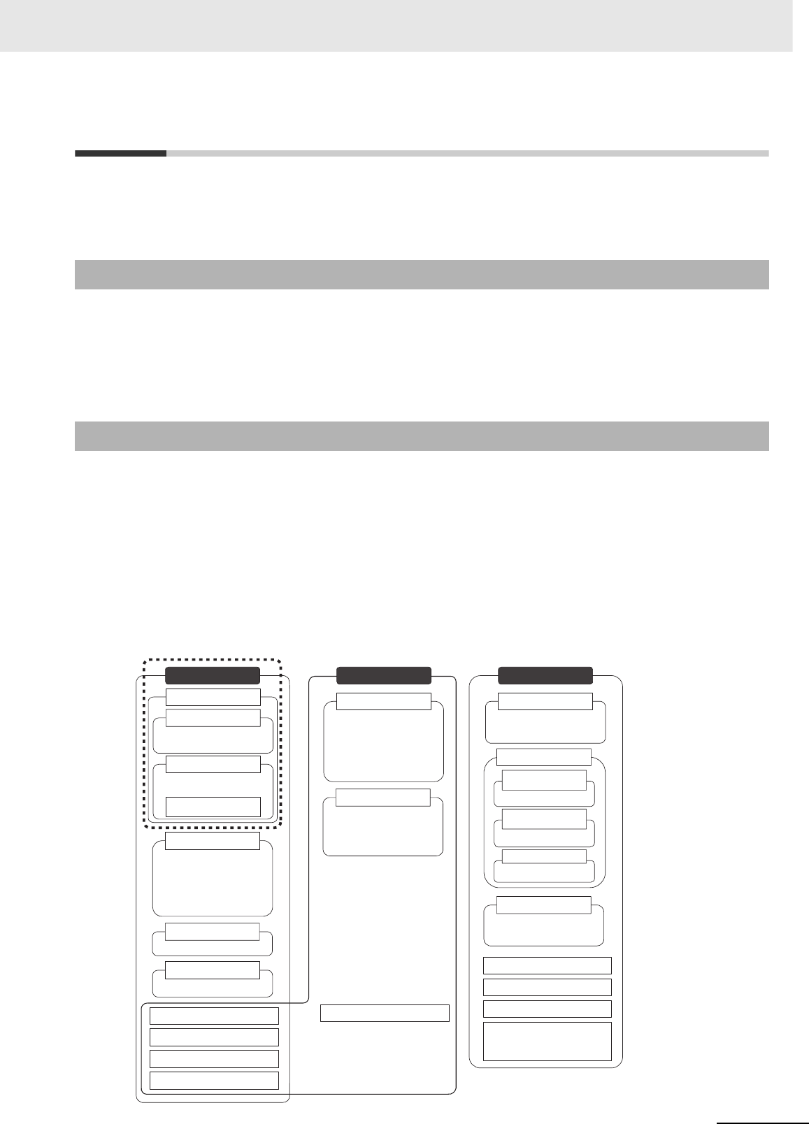
Applicable Products
CJ2 Series
CJ1H-CPU@@H-R
CJ1H-CPU@@H
CJ1G-CPU@@H
CJ1G -CPU@@P
(Loop CPU Units)
CJ1-H CPU Units
CJ1 CPU Units
CJ1G-CPU@@
CJ1M CPU Units
CJ1M-CPU@@
CJ-series Power Supply Units
CJ-series Basic I/O Units
CJ-series CPU Bus Units
CJ-series Special I/O Units
CS1H-CPU@@H
CS1G-CPU@@H
CS1-H CPU Units
CS-series Power Supply Units
CS-series Basic I/O Units
CS-series CPU Bus Units
CS-series Special I/O Units
CS Series
CS1 CPU Units
CS1H-CPU@@(-V)
CS1G-CPU@@(-V)
CS1D CPU Units
CS1D CPU Units
for Duplex Systems
CS1D-CPU@@H
CS1D-CPU@@S
CS1D-CPU@@P
NSJ5-TQ@@(B)-G5D
NSJ5-SQ@@(B)-G5D
NSJ8-TV@@(B)-G5D
NSJ10-TV@@(B)-G5D
NSJ12-TS@@(B)-G5D
NSJ Controllers
NSJ-series Expansion Units
NSJ Series
NSJ5-TQ@@(B)-M3D
NSJ5-SQ@@(B)-M3D
NSJ8-TV@@(B)-M3D
NSJ Controllers
CJ2H-CPU6@-EIP
CJ2H-CPU6@
CS1D CPU Units
for Simplex Systems
CS1D Process-control CPU Units
Note: A special Power Supply Unit must
be used for CS1D CPU Units.
CJ2 CPU Units
CJ2H CPU Units
CJ2M CPU Units
CJ2M-CPU3@
CJ2M-CPU1@
Pulse I/O Module for
CJ2M CPU Units
2CJ2 CPU Unit Hardware User’s Manual
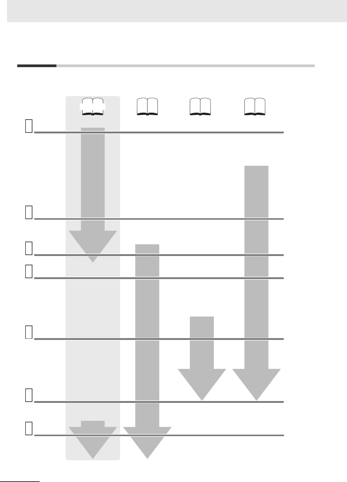
CJ2 CPU Unit Manuals
Information on the CJ2 CPU Units is provided in the following manuals. Refer to the appropriate manual
for the information that is required.
Wiring
1
2
3
4
5
6
7
This Manual
Mounting
and Setting
Hardware
Connecting
Online to
the PLC
Software
Setup
Creating the
Program
Checking
and
Debugging
Operation
Maintenance
and
Troubleshooting
Error codes and
remedies if a problem
occurs
CJ-series CJ2 CPU Unit
Hardware User’s Manual
(Cat. No. W472)
CJ-series CJ2 CPU Unit
Software User’s Manual
(Cat. No. W473)
• Unit part names and
specifications
• Basic system
configuration
• Unit mounting
procedure
• Setting procedure for
DIP switch and rotary
switches on the front of
the CPU Unit
For details on built-in
EtherNet/IP port, refer to
the EtherNet/IP Unit
Operation Manual (W465)
• Wiring the Power
Supply Unit
• Wring Basic I/O Units
and external I/O
devices
CX-Programmer Support
Software Connecting
Cables
Procedures for connecting
the CX-Programmer
Support Software
Software setting methods for the
CPU Unit (including I/O memory
allocation, PLC Setup settings,
Special I/O Unit parameters,
CPU Bus Unit parameters, and
routing tables.)
For details on built-in EtherNet/IP
port, refer to the EtherNet/IP Unit
Operation Manual (W465).
• Program types and basic
information
• CPU Unit operation
• Internal memory
• Data management using
file memory in the CPU
Unit
• Built-in CPU functions
• Settings
• Checking I/O wiring, setting the
Auxiliary Area settings, and
performing trial operation
• Monitoring and debugging with
the CX-Programmer
• Specifications and wiring
of Pulse I/O Modules
• Available pulse I/O
functions and allocations
• Pulse I/O Module
specifications
• Wiring methods between
Pulse I/O Modules and
external I/O devices
Software setting
procedures for Pulse I/O
Modules (I/O memory
allocations and PLC
Setup settings)
Pulse I/O functions
Detailed information
on programming
instructions
CS/CJ/NSJ Series
Instructions Reference
Manual (Cat. No. W474)
CJ2M CPU Unit Pulse
I/O Module User's
Manual (Cat. No. W486)

3
CJ2 CPU Unit Hardware User’s Manual
The CJ2 CPU manuals are organized in the sections listed in the following tables. Refer to the appropri-
ate section in the manuals as required.
Manual Configuration
Hardware User’s Manual (Cat. No. W472) (This Manual)
Section Content
Section 1 Overview This section gives an overview of the CJ2 CPU Units and describes the features and
specifications.
Section 2 Basic System Configu-
ration and Devices
This section describes the system configuration for the CJ2 CPU Unit.
Section 3 Nomenclature and
Functions
This section describes the part names and functions of the CPU Unit and Configuration
Units.
Section 4 Support Software This section describes the types of Support Software to use to perform programming and
debugging and how to connect the PLC to the Support Software.
Section 5 Installation This section describes the installation locations and how to wire CPU Units and Configu-
ration Units.
Section 6 Troubleshooting This section describes how to check the status for errors that occur during system opera-
tion and the remedies for those errors.
Section 7 Inspection and Mainte-
nance
This section describes periodic inspection, the service life of the Battery and Power Sup-
ply Unit, and how to replace the Battery.
Section 8 Backup Operations This section describes the procedure to back up PLC data.
Appendices
The appendices provide Unit dimensions, details on fatal and non-fatal errors, informa-
tion on connecting to serial ports on the CPU Unit, the procedure for installing the USB
driver on a computer, and information on load short-circuit protection and line disconnec-
tion detection.
Software User’s Manual (Cat. No. W473)
Section Content
Section 1 Overview This section gives an overview of the CJ2 CPU Units and describes the features and
specifications.
Section 2 Internal Memory in the
CPU Unit
This section describes the types of memory in the CPU Unit and the data that is stored.
Section 3 CPU Unit Operation This section describes the internal operation of the CPU Unit.
Section 4 CPU Unit Initialization This section describes the initial setup of the CPU Unit.
Section 5 Understanding Pro-
gramming
This section describes program types and programming details, such as symbols and
programming instructions.
Section 6 I/O Memory Areas This section describes the I/O memory areas in the CPU Unit.
Section 7 File Operations This section describes the files that can be stored in the CPU Unit, the storage destina-
tion for those files, and file operations.
Section 8 I/O Allocations and
Unit Settings
This section describes the I/O allocations used to exchange data between the CPU Unit
and other Units.
Section 9 PLC Setup This section describes details on the PLC Setup settings, which are used to perform
basic settings for the CPU Unit.
Section 10 CPU Unit Functions This section describes functions that are built into the CPU Unit.
Section 11 Programming Devices
and Communications
This section describes the procedure for connecting the CJ2 CPU Unit to the CX-Pro-
grammer or other Support Software and to other devices.
Section 12 CPU Unit Cycle Time This section describes how to monitor and calculate the cycle time.
Appendices
The appendices provide information on programming instructions, execution times, num-
ber of steps, Auxiliary Area words and bits, a memory map of the continuous PLC mem-
ory addresses, I/O memory operation when power is interrupted, and a comparison of
CJ-series and CS-series PLCs.

4CJ2 CPU Unit Hardware User’s Manual
Instructions Reference Manual (Cat. No. W474)
Section Content
Section 1 Basic Understanding
of Instructions
This section provides basic information on designing ladder programs for a CS/CJ/NSJ-
series CPU Unit.
Section 2 Summary of Instruc-
tions
This section provides a summary of instructions used with a CS/CJ/NSJ-series CPU
Unit.
Section 3 Instructions This section describes the functions, operands and sample programs of the instructions
that are supported by a CS/CJ/NSJ-series CPU Unit.
Section 4 Instruction Execution
Times and Number of Steps
This section provides the instruction execution times for each CS/CJ/NSJ-series CPU
Unit instruction.
Appendices The appendices provide a list of instructions by function code and by mnemonic and an
ASCII table for the CS/CJ/NSJ-series CPU Units.
Pulse I/O Module User's Manual (Cat. No. W486)
Section Content
Section 1 Overview This section gives an overview of the Pulse I/O Modules and the pulse I/O functions of
the CJ2M.
Section 2 I/O Application Proce-
dures and Function Allocations
This section lists the pulse functions of the CJ2M CPU Units and describes the overall
application flow and the allocation of the functions.
Section 3 I/O Specifications and
Wiring for Pulse I/O Modules
This section provides the I/O specifications and describes the wiring of the Pulse I/O
Module.
Section 4 General-purpose I/O This section describes the general-purpose I/O.
Section 5 Quick-response Inputs This section describes the quick-response function that can be used to input signals that
are shorter than the cycle time.
Section 6 Interrupts This section describes the interrupt input function.
Section 7 High-speed Counters This section describes the high-speed counter inputs and high-speed counter interrupts.
Section 8 Pulse Outputs This section describes positioning functions, such as trapezoidal control, S-curve control,
jogging, and origin search functions.
Section 9 PWM Outputs This section describes the variable-duty-factor (PWM) outputs.
Appendices The appendices provide a table of flag changes for pulse outputs, a comparison table
with other models, and a performance table.
5
CJ2 CPU Unit Hardware User’s Manual
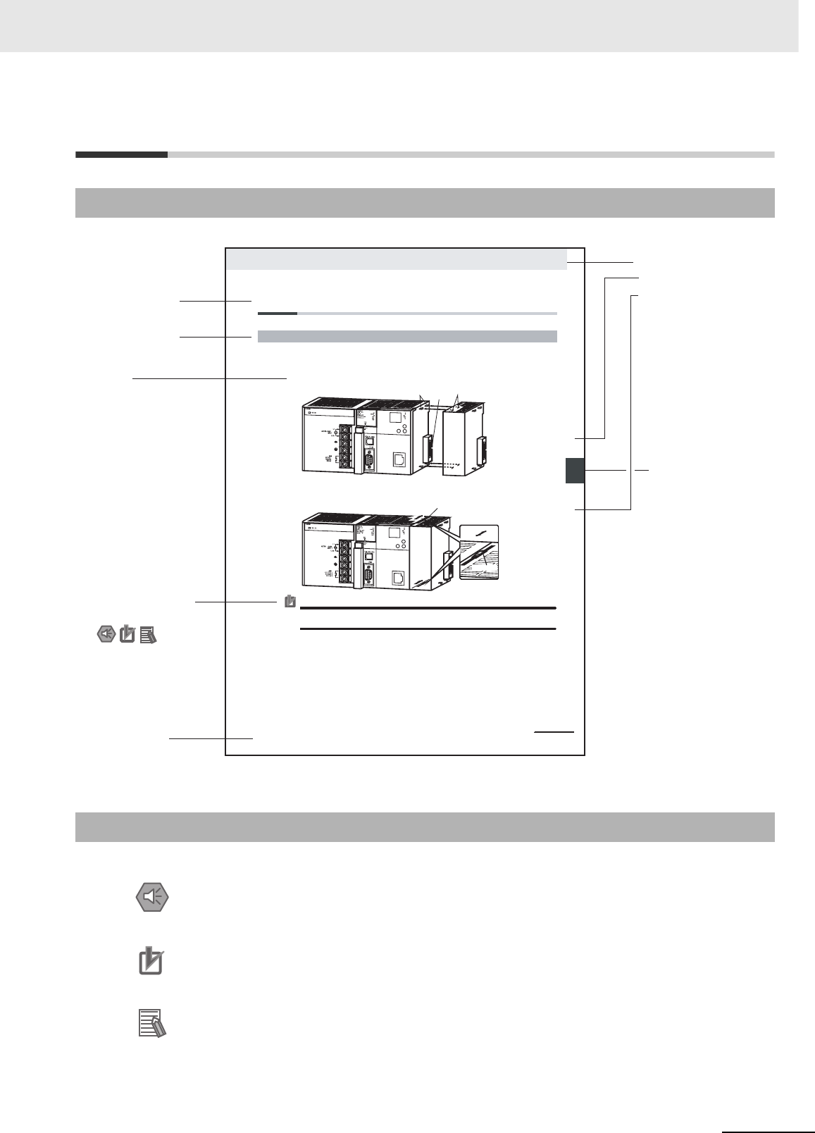
Manual Structure
The following page structure is used in this manual.
Special information in this manual is classified as follows:
Page Structure
Special Information
Precautions for Safe Use
Precautions on what to do and what not to do to ensure using the product safely.
Precautions for Correct Use
Precautions on what to do and what not to do to ensure proper operation and performance.
Additional Information
Additional information to increase understanding or make operation easier.
Level 1 heading
Level 2 heading
Level 3 heading
Level 2 heading
A step
in a procedure
Manual name
Level 3 heading
Page tab
Gives the current
headings.
Gives the number
of the section.
This illustration is provided only as a sample and may not literally appear in this manual.
Special Information
(See below.)
5-13
5 Installation
CJ2 CPU Unit Hardware User’s Manual
n
oita
lla
t
s
nI
2-
5
5
s
tn
e
n
o
p
moC CL
P
gn
it
ce
nnoC
1
-2
-
5
5-2 Installation
The Units that make up a CJ-series PLC can be connected simply by pressing the Units together and
locking the sliders by moving them toward the back of the Units. The End Cover is connected in the
same way to the Unit on the far right side of the PLC.
1. Join the Units so that the connectors fit exactly.
2. The yellow sliders at the top and bottom of each Unit lock the Units together. Move the sliders
toward the back of the Units as shown below until they click into place.
Precautions for Correct UsePrecautions for Correct Use
If the locking tabs are not secured properly, the connectors may become loose and not function
properly. Be sure to slide the locking tabs until they are securely in place.
5-2-1 Connecting PLC Components
Connector
Hook Hook holes
Slider
Lock
Release
Move the sliders toward the back
until they lock into place.

6CJ2 CPU Unit Hardware User’s Manual

7
CJ2 CPU Unit Hardware User’s Manual
Sections in this Manual
1
2
3
4
5
6
7
8
A
1
2
3
4
5
6
7
8
A
Overview
Basic System Configuration and Devices
Nomenclature and Functions
Support Software
Installation
Troubleshooting
Inspection and Maintenance
Backup Operations
Appendices

8CJ2 CPU Unit Hardware User’s Manual

9
CJ2 CPU Unit Hardware User’s Manual
CONTENTS
Introduction............................................................................................................... 1
CJ2 CPU Unit Manuals ............................................................................................. 2
Manual Structure ...................................................................................................... 5
Sections in this Manual............................................................................................ 7
Safety Precautions ................................................................................................. 17
Application Precautions......................................................................................... 21
Operating Environment Precautions .................................................................... 26
Regulations and Standards ................................................................................... 27
Unit Versions of CJ2 CPU Units ............................................................................ 29
Related Manuals ..................................................................................................... 35
Section 1 Overview
1-1 Overview of CJ2 CPU Units ....................................................................................................1-2
1-1-1 Overview..................................................................................................................................... 1-2
1-1-2 CJ2 CPU Unit Features .............................................................................................................. 1-4
1-2 Basic Operating Procedure .................................................................................................. 1-12
1-3 Specifications ........................................................................................................................ 1-13
1-3-1 General Specifications.............................................................................................................. 1-13
1-3-2 Performance Specifications ...................................................................................................... 1-14
1-3-3 Function Specifications............................................................................................................. 1-21
Section 2 Basic System Configuration and Devices
2-1 Basic System Configuration...................................................................................................2-2
2-1-1 Basic System Configuration........................................................................................................ 2-2
2-1-2 CPU Rack................................................................................................................................... 2-3
2-1-3 Expansion Racks...................................................................................................................... 2-11
2-1-4 Configuration Units ................................................................................................................... 2-14
2-1-5 Calculating Unit Current Consumption ..................................................................................... 2-22
2-1-6 Calculating Power Consumption............................................................................................... 2-25
2-2 Expanded System Configuration ......................................................................................... 2-27
2-2-1 Serial Communications............................................................................................................. 2-27
2-2-2 Communications Networks....................................................................................................... 2-29

10 CJ2 CPU Unit Hardware User’s Manual
Section 3 Nomenclature and Functions
3-1 CPU Units ................................................................................................................................. 3-2
3-1-1 CPU Section................................................................................................................................3-2
3-1-2 Built-in EtherNet/IP Section (CJ2H-CPU6@-EIP and CJ2M-CPU3@ Only) ...............................3-8
3-2 Memory Card.......................................................................................................................... 3-13
3-2-1 Models and Specifications ........................................................................................................3-13
3-2-2 Operating Procedures............................................................................................................... 3-13
3-2-3 Installing and Removing............................................................................................................ 3-14
3-3 Pulse I/O Modules (CJ2M CPU Unit Only) ........................................................................... 3-17
3-3-1 Models and Specifications ........................................................................................................3-17
3-3-2 Part Names and Functions........................................................................................................3-17
3-4 Serial Option Boards (CJ2M-CPU3@ Only) ......................................................................... 3-20
3-4-1 Overview ...................................................................................................................................3-20
3-5 Power Supply Units ............................................................................................................... 3-21
3-5-1 Models and Specifications ........................................................................................................3-21
3-5-2 Components..............................................................................................................................3-24
3-5-3 Selecting a Power Supply Unit..................................................................................................3-27
3-6 CJ-series Basic I/O Units ...................................................................................................... 3-28
3-6-1 Basic I/O Units with Terminal Blocks......................................................................................... 3-28
3-6-2 Thirty-two/Sixty-four-point Basic I/O Units with Connectors......................................................3-30
3-7 I/O Control Units and I/O Interface Units ............................................................................. 3-32
3-7-1 Component Names...................................................................................................................3-32
3-7-2 System Configuration................................................................................................................3-32
Section 4 Support Software
4-1 Support Software..................................................................................................................... 4-2
4-1-1 CX-One FA Integrated Tool Package ..........................................................................................4-2
4-2 Connection Methods ............................................................................................................... 4-5
4-2-1 Connecting by USB.....................................................................................................................4-5
4-2-2 Connecting by RS-232C .............................................................................................................4-7
4-2-3 Connecting to Ethernet (CJ2H-CPU6@-EIP and CJ2M-CPU3@ Only)......................................4-9
Section 5 Installation
5-1 Fail-safe Circuits...................................................................................................................... 5-2
5-2 Installation................................................................................................................................ 5-4
5-2-1 Installation and Wiring Precautions.............................................................................................5-4
5-2-2 Installation in a Control Panel .....................................................................................................5-6
5-2-3 Assembled Appearance and Dimensions ...................................................................................5-8
5-2-4 Connecting PLC Components................................................................................................... 5-13
5-2-5 DIN Track Installation ................................................................................................................5-15
5-2-6 Connecting CJ-series Expansion Racks ...................................................................................5-17
5-3 Wiring ..................................................................................................................................... 5-20
5-3-1 Power Supply Wiring.................................................................................................................5-20
5-3-2 Wiring CJ-series Basic I/O Units with Terminal Blocks .............................................................5-27
5-3-3 Wiring Basic I/O Units with Connectors ....................................................................................5-29
5-3-4 Connecting to Connector-Terminal Block Conversion Units or I/O Relay Terminals.................5-33
5-3-5 Connecting Pulse I/O Modules to External I/O Devices (CJ2M CPU Unit Only).......................5-33
5-3-6 Connecting I/O Devices ............................................................................................................5-35
5-3-7 Connecting through an Ethernet Cable (CJ2H-CPU6@-EIP and CJ2M-CPU3@ Only)............5-39

11
CJ2 CPU Unit Hardware User’s Manual
5-4 Control Panel Installation ..................................................................................................... 5-42
5-4-1 Temperature.............................................................................................................................. 5-42
5-4-2 Humidity.................................................................................................................................... 5-44
5-4-3 Vibration and Shock.................................................................................................................. 5-44
5-4-4 Atmosphere .............................................................................................................................. 5-44
5-4-5 Electrical Environment.............................................................................................................. 5-45
5-4-6 Grounding................................................................................................................................. 5-50
Section 6 Troubleshooting
6-1 CPU Unit Errors ....................................................................................................................... 6-2
6-1-1 Errors and Remedies.................................................................................................................. 6-2
6-1-2 Checking Errors.......................................................................................................................... 6-2
6-1-3 Checking Detailed Status ........................................................................................................... 6-3
6-1-4 Reading Error Log Information ................................................................................................... 6-3
6-1-5 I/O Table Verification................................................................................................................... 6-5
6-1-6 Types of Errors............................................................................................................................ 6-6
6-1-7 Handling Errors........................................................................................................................... 6-7
6-2 Troubleshooting Built-in EtherNet/IP Port Errors
(CJ2H-CPU6@-EIP and CJ2M-CPU3@ Only)........................................................................ 6-25
6-2-1 Checking Built-in EtherNet/IP Port Error Status ....................................................................... 6-25
6-2-2 Checking Error Status at the EtherNet/IP Port Seven-segment Display................................... 6-26
6-3 Non-CPU Unit Errors and Remedies.................................................................................... 6-28
6-3-1 Error Causes and Remedies .................................................................................................... 6-28
Section 7 Inspection and Maintenance
7-1 Inspections............................................................................................................................... 7-2
7-1-1 Inspection Points ........................................................................................................................ 7-2
7-1-2 Unit Replacement Precautions ................................................................................................... 7-4
7-2 Replacing the Battery.............................................................................................................. 7-5
7-2-1 Battery Replacement .................................................................................................................. 7-5
7-2-2 Operation When Battery Is Exhausted or Not Installed .............................................................. 7-8
7-3 Power Supply Unit Replacement Time ................................................................................ 7-10
Section 8 Backup Operations
8-1 Backing Up Data ...................................................................................................................... 8-2
8-2 Using a Computer to Back Up Data ....................................................................................... 8-3
8-2-1 PLC Backup Tool ........................................................................................................................ 8-3
8-2-2 PLC Backup Tool Operations...................................................................................................... 8-4
8-3 Simple Backup......................................................................................................................... 8-7
8-3-1 Overview..................................................................................................................................... 8-7
8-3-2 Operating Procedures................................................................................................................. 8-8
8-3-3 Verifying Backup Operations with Indicators ............................................................................ 8-10
8-3-4 Related Auxiliary Bits/Words .................................................................................................... 8-12
8-3-5 Time Required for Simple Backup ............................................................................................8-12
8-3-6 Data Backed Up Using Simple Backup..................................................................................... 8-12

12 CJ2 CPU Unit Hardware User’s Manual
Appendices
A-1 Specifications of Basic I/O Units ...........................................................................................A-2
A-1-1 Overview of Units........................................................................................................................A-2
A-1-2 Basic I/O Units ............................................................................................................................A-5
A-1-3 Precautions on Contact Output Units........................................................................................A-57
A-1-4 Connecting Connector-Terminal Block Conversion Units and I/O Relay Terminals ..................A-59
A-2 Dimensions ............................................................................................................................A-94
A-2-1 CJ2H CPU Units .......................................................................................................................A-94
A-2-2 CJ2M CPU Units.......................................................................................................................A-95
A-2-3 Power Supply Units...................................................................................................................A-96
A-2-4 Basic I/O Units ..........................................................................................................................A-98
A-2-5 I/O Control Unit and I/O Interface Unit ....................................................................................A-101
A-2-6 I/O Memory Card ....................................................................................................................A-101
A-2-7 Pulse I/O Modules (CJ2M CPU Unit Only)..............................................................................A-101
A-2-8 Serial Option Boards (CJ2M-CPU3@ Only)............................................................................A-102
A-3 Fatal and Non-fatal Error Details........................................................................................A-103
A-3-1 Fatal Errors .............................................................................................................................A-103
A-3-2 Non-fatal Errors.......................................................................................................................A-108
A-4 Connecting to a Serial Port on the CPU Unit ....................................................................A-111
A-4-1 Serial Port Interface Types and Specifications........................................................................A-111
A-4-2 Connection Examples .............................................................................................................A-117
A-4-3 Applicable Connectors and Recommended Cables................................................................A-132
A-5 Installing the USB Driver ....................................................................................................A-139
A-6 Load Short-circuit Protection and Line Disconnection Detection for Basic I/O Units..A-149
A-6-1 Load Short-circuit Protection and Line Disconnection Detection for CJ1W-OD202................A-149
A-6-2 Load Short-circuit Protection for CJ1W-OD204/OD212/OD232/MD232.................................A-151
A-7 Relay Output Noise Reduction Methods ...........................................................................A-153
A-8 Functions Supported for Unit Versions.............................................................................A-155
A-8-1 CJ2H CPU Units .....................................................................................................................A-155
A-8-2 CJ2M CPU Units.....................................................................................................................A-156
Index ................................................................................................................ Index-1
Revision History........................................................................................Revision-1

13
CJ2 CPU Unit Hardware User’s Manual
Read and Understand this Manual
Please read and understand this manual before using the product. Please consult your OMRON representative
if you have any questions or comments.
Warranty and Limitations of Liability
WARRANTY
OMRON's exclusive warranty is that the products are free from defects in materials and workmanship for a
period of one year (or other period if specified) from date of sale by OMRON.
OMRON MAKES NO WARRANTY OR REPRESENTATION, EXPRESS OR IMPLIED, REGARDING NON-
INFRINGEMENT, MERCHANTABILITY, OR FITNESS FOR PARTICULAR PURPOSE OF THE
PRODUCTS. ANY BUYER OR USER ACKNOWLEDGES THAT THE BUYER OR USER ALONE HAS
DETERMINED THAT THE PRODUCTS WILL SUITABLY MEET THE REQUIREMENTS OF THEIR
INTENDED USE. OMRON DISCLAIMS ALL OTHER WARRANTIES, EXPRESS OR IMPLIED.
LIMITATIONS OF LIABILITY
OMRON SHALL NOT BE RESPONSIBLE FOR SPECIAL, INDIRECT, OR CONSEQUENTIAL DAMAGES,
LOSS OF PROFITS OR COMMERCIAL LOSS IN ANY WAY CONNECTED WITH THE PRODUCTS,
WHETHER SUCH CLAIM IS BASED ON CONTRACT, WARRANTY, NEGLIGENCE, OR STRICT
LIABILITY.
In no event shall the responsibility of OMRON for any act exceed the individual price of the product on which
liability is asserted.
IN NO EVENT SHALL OMRON BE RESPONSIBLE FOR WARRANTY, REPAIR, OR OTHER CLAIMS
REGARDING THE PRODUCTS UNLESS OMRON'S ANALYSIS CONFIRMS THAT THE PRODUCTS
WERE PROPERLY HANDLED, STORED, INSTALLED, AND MAINTAINED AND NOT SUBJECT TO
CONTAMINATION, ABUSE, MISUSE, OR INAPPROPRIATE MODIFICATION OR REPAIR.

14 CJ2 CPU Unit Hardware User’s Manual
Application Considerations
SUITABILITY FOR USE
OMRON shall not be responsible for conformity with any standards, codes, or regulations that apply to the
combination of products in the customer's application or use of the products.
At the customer's request, OMRON will provide applicable third party certification documents identifying
ratings and limitations of use that apply to the products. This information by itself is not sufficient for a
complete determination of the suitability of the products in combination with the end product, machine,
system, or other application or use.
The following are some examples of applications for which particular attention must be given. This is not
intended to be an exhaustive list of all possible uses of the products, nor is it intended to imply that the uses
listed may be suitable for the products:
• Outdoor use, uses involving potential chemical contamination or electrical interference, or conditions or
uses not described in this manual.
• Nuclear energy control systems, combustion systems, railroad systems, aviation systems, medical
equipment, amusement machines, vehicles, safety equipment, and installations subject to separate
industry or government regulations.
• Systems, machines, and equipment that could present a risk to life or property.
Please know and observe all prohibitions of use applicable to the products.
NEVER USE THE PRODUCTS FOR AN APPLICATION INVOLVING SERIOUS RISK TO LIFE OR
PROPERTY WITHOUT ENSURING THAT THE SYSTEM AS A WHOLE HAS BEEN DESIGNED TO
ADDRESS THE RISKS, AND THAT THE OMRON PRODUCTS ARE PROPERLY RATED AND
INSTALLED FOR THE INTENDED USE WITHIN THE OVERALL EQUIPMENT OR SYSTEM.
PROGRAMMABLE PRODUCTS
OMRON shall not be responsible for the user's programming of a programmable product, or any
consequence thereof.

15
CJ2 CPU Unit Hardware User’s Manual
Disclaimers
CHANGE IN SPECIFICATIONS
Product specifications and accessories may be changed at any time based on improvements and other
reasons.
It is our practice to change model numbers when published ratings or features are changed, or when
significant construction changes are made. However, some specifications of the products may be changed
without any notice. When in doubt, special model numbers may be assigned to fix or establish key
specifications for your application on your request. Please consult with your OMRON representative at any
time to confirm actual specifications of purchased products.
DIMENSIONS AND WEIGHTS
Dimensions and weights are nominal and are not to be used for manufacturing purposes, even when
tolerances are shown.
PERFORMANCE DATA
Performance data given in this manual is provided as a guide for the user in determining suitability and does
not constitute a warranty. It may represent the result of OMRON's test conditions, and the users must
correlate it to actual application requirements. Actual performance is subject to the OMRON Warranty and
Limitations of Liability.
ERRORS AND OMISSIONS
The information in this manual has been carefully checked and is believed to be accurate; however, no
responsibility is assumed for clerical, typographical, or proofreading errors, or omissions.

16 CJ2 CPU Unit Hardware User’s Manual
17
CJ2 CPU Unit Hardware User’s Manual
Safety Precautions
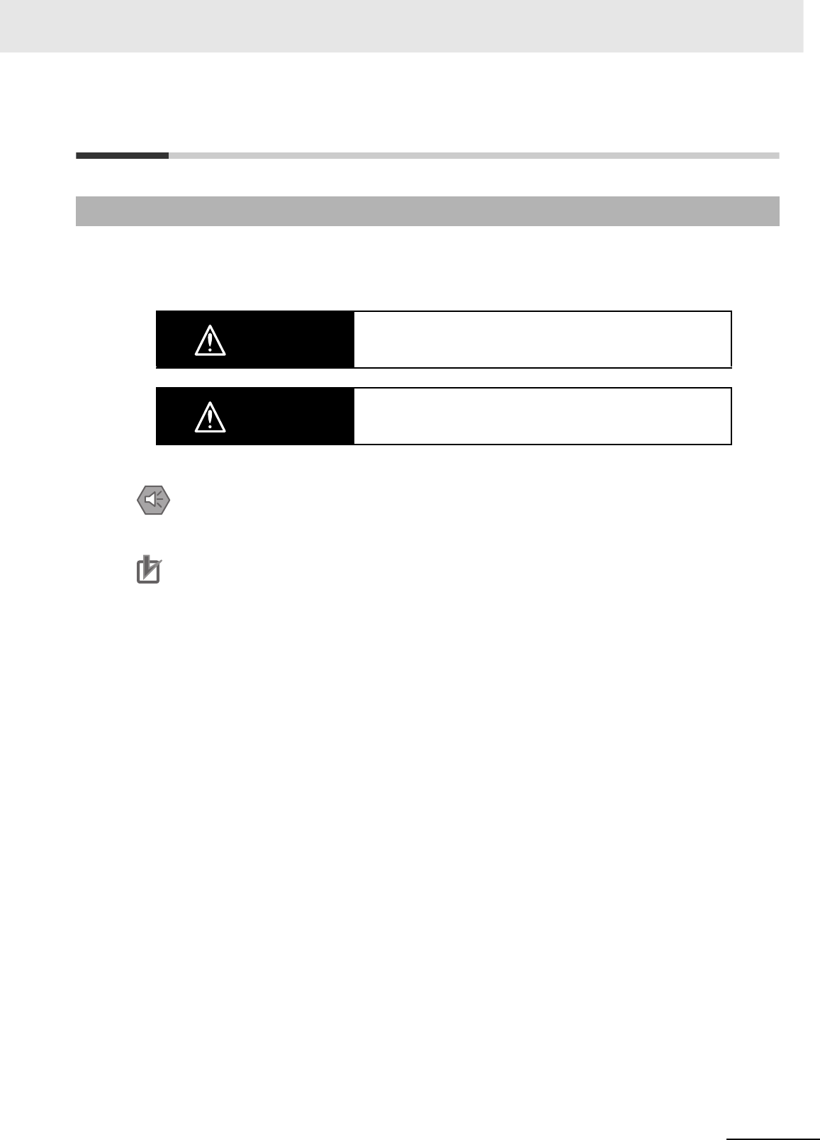
The following notation is used in this manual to provide precautions required to ensure safe usage of a
CJ-series PLC. The safety precautions that are provided are extremely important to safety. Always read
and heed the information provided in all safety precautions.
Definition of Precautionary Information
WARNING Indicates a potentially hazardous situation which, if not avoided,
could result in death or serious injury. Additionally, there may be
severe property damage.
Caution Indicates a potentially hazardous situation which, if not avoided,
may result in minor or moderate injury, or property damage.
Precautions for Safe Use
Indicates precautions on what to do and what not to do to ensure using the product safely.
Precautions for Correct Use
Indicates precautions on what to do and what not to do to ensure proper operation and performance.
18 CJ2 CPU Unit Hardware User’s Manual
Symbols
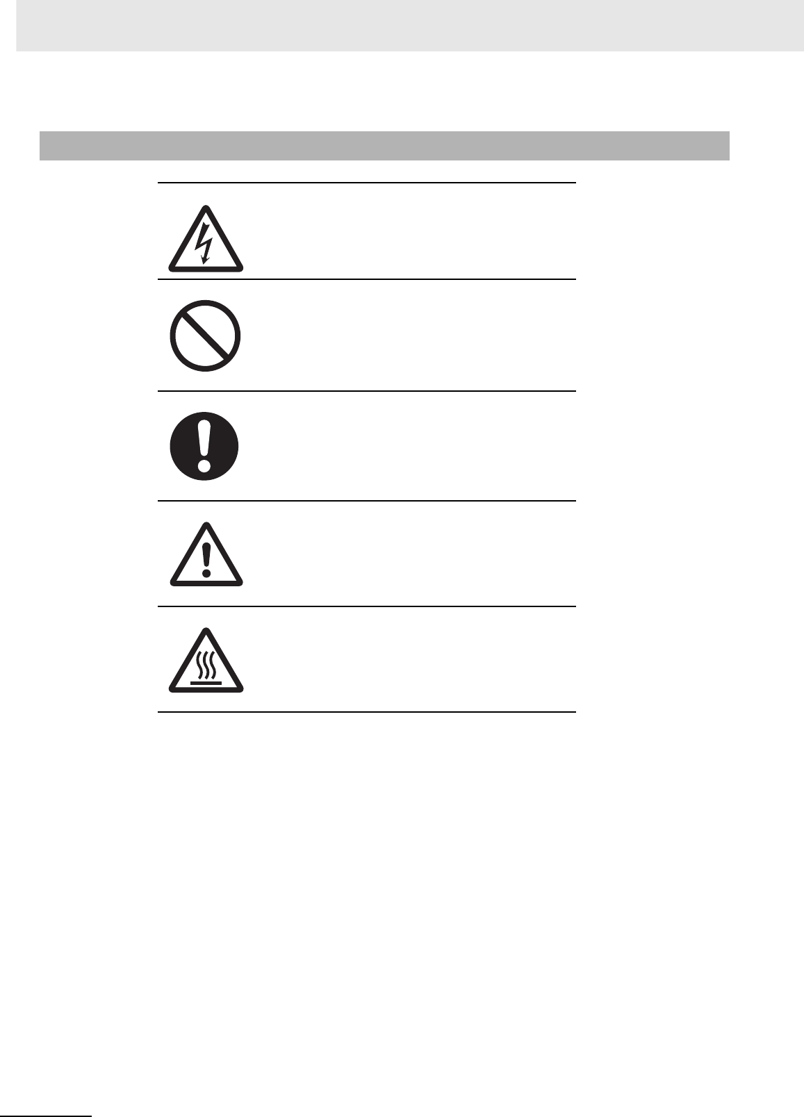
The triangle symbol indicates precautions (including warnings).
The specific operation is shown in the triangle and explained in
text. This example indicates a precaution for electric shock.
The circle and slash symbol indicates operations that you must
not do. The specific operation is shown in the circle and
explained in text.
The filled circle symbol indicates operations that you must do.
The specific operation is shown in the circle and explained in
text. This example shows a general precaution for something
that you must do.
The triangle symbol indicates precautions (including warnings).
The specific operation is shown in the triangle and explained in
text. This example indicates a general precaution.
The triangle symbol indicates precautions (including warnings).
The specific operation is shown in the triangle and explained in
text. This example indicates a precaution for hot surfaces.
19
CJ2 CPU Unit Hardware User’s Manual
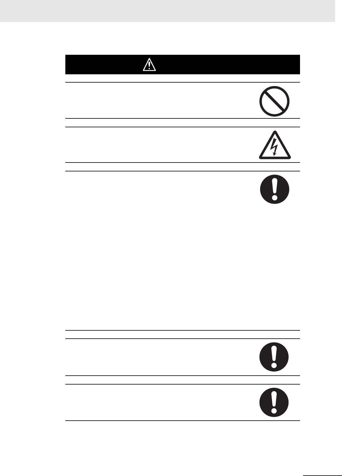
WARNING
Do not attempt to take any Unit apart or touch the inside of any Unit while the
power is being supplied. Doing so may result in electric shock.
Do not touch any of the terminals or terminal blocks while the power is being
supplied. Doing so may result in electric shock.
Provide safety measures in external circuits (i.e., not in the Programmable
Controller), including the following items, to ensure safety in the system if an
abnormality occurs due to malfunction of the Programmable Controller or
another external factor affecting the operation of the Programmable Control-
ler. “Programmable Controller” indicates the CPU Unit and all other Units and
is abbreviated “PLC” in this manual. Not doing so may result in serious acci-
dents.
• Emergency stop circuits, interlock circuits, limit circuits, and similar safety
measures must be provided in external control circuits.
• The PLC will turn OFF all outputs when its self-diagnosis function detects
any error or when a severe failure alarm (FALS) instruction is executed.
Unexpected operation, however, may still occur for errors in the I/O control
section, errors in I/O memory, and other errors that cannot be detected by
the self-diagnosis function. As a countermeasure for all such errors, exter-
nal safety measures must be provided to ensure safety in the system.
• The PLC outputs may remain ON or OFF due to deposition or burning of
the output relays or destruction of the output transistors. As a countermea-
sure for such problems, external safety measures must be provided to
ensure safety in the system.
• Provide measures in the computer system and programming to ensure
safety in the overall system even if communications errors or malfunctions
occur in data link communications or remote I/O communications.
Confirm safety before transferring data files stored in the file memory (Mem-
ory Card or EM file memory) to the I/O area (CIO) of the CPU Unit using a
peripheral tool. Otherwise, the devices connected to the output unit may mal-
function regardless of the operation mode of the CPU Unit.
Fail-safe measures must be taken by the customer to ensure safety in the
event of incorrect, missing, or abnormal signals caused by broken signal
lines, momentary power interruptions, or other causes. Serious accidents
may result from abnormal operation if proper measures are not provided.
20 CJ2 CPU Unit Hardware User’s Manual
Caution
Execute online edit only after confirming that no adverse effects will be
caused by extending the cycle time. Otherwise, the input signals may not be
readable.
Confirm safety at the destination node before transferring a program, PLC
Setup, I/O tables, I/O memory contents, or parameters to another node or
changing contents of the any of these items. Transferring or changing data
can result in unexpected system operation.
The CJ2 CPU Units automatically back up the user program and parameter
data to flash memory when these are written to the CPU Unit. I/O memory
including the DM, EM, and Holding Areas), however, is not written to flash
memory.
The DM, EM, and Holding Areas can be held during power interruptions with
a battery. If there is a battery error, the contents of these areas may not be
accurate after a power interruption. If the contents of the DM, EM, and Hold-
ing Areas are used to control external outputs, prevent inappropriate outputs
from being made whenever the Battery Error Flag (A402.04) is ON.
Tighten the terminal screws on the AC Power Supply Unit to the torque spec-
ified in the operation manual. The loose screws may result in burning or mal-
function.
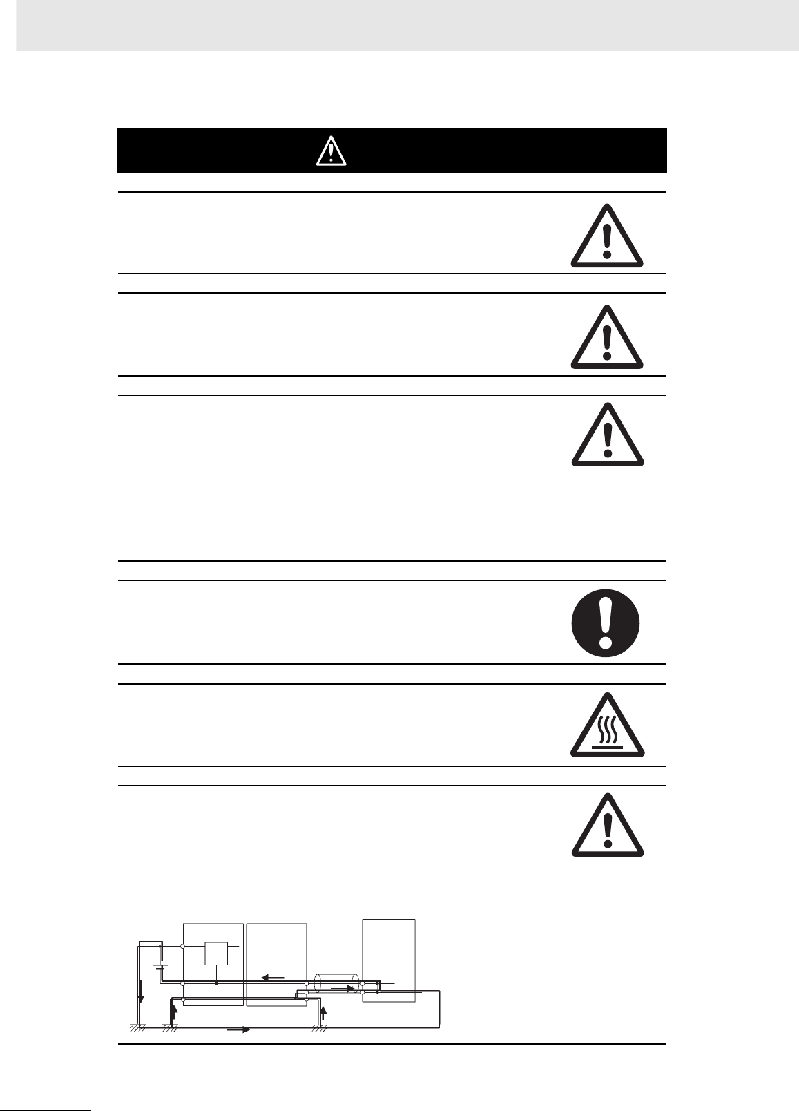
Do not touch the Power Supply Unit when power is being supplied or immedi-
ately after the power supply is turned OFF. The Power Supply Unit will be hot
and you may be burned.
When connecting a personal computer or other peripheral device to a PLC to
which a non-insulated Power Supply Unit (CJ1W-PD022) is mounted, either
ground the 0 V side of the external power supply or do not ground the exter-
nal power supply at all ground. A short-circuit will occur in the external power
supply if incorrect grounding methods are used. Never ground the 24 V side,
as shown below.
24 V
0 V
FG CPU Unit
0 V
Wiring in Which the 24-V Power Supply Will Short
Non-insulated
DC power supply
Power Supply
Unit
Peripheral
cable
Peripheral device (e.g.,
personal computer)

21
CJ2 CPU Unit Hardware User’s Manual
Application Precautions
Observe the following precautions when using a CJ-series PLC.
zPower Supply
• Always use the power supply voltages specified in the user’s manuals. An incorrect voltage may
result in malfunction or burning.
• Exceeding the capacity of the Power Supply Unit may prevent the CPU Unit or other Units from
starting.
• Take appropriate measures to ensure that the specified power with the rated voltage and fre-
quency is supplied. Be particularly careful in places where the power supply is unstable. An incor-
rect power supply may result in malfunction.
• Always turn OFF the power supply to the PLC before attempting any of the following. Not turning
OFF the power supply may result in malfunction or electric shock.
• Mounting or dismounting Power Supply Units, I/O Units, CPU Units, Option Boards, Pulse I/O
Modules or any other Units.
• Assembling the Units.
• Setting DIP switches or rotary switches.
• Connecting cables or wiring the system.
• Connecting or disconnecting the connectors.
• When cross-wiring terminals, the total current for all the terminal will flow in the wire. Make sure
that the current capacity of the wire is sufficient.
• Observe the following precautions when using a Power Supply Unit that supports the Replace-
ment Notification Function.
• Replace the Power Supply Unit within six months if the display on the front of the Power Sup-
ply Unit alternates between 0.0 and A02, or if the alarm output automatically turns OFF.
• Keep the alarm output cable separated from power line and high-voltage lines.
• Do not apply a voltage or connect a load exceeding the specifications to the alarm output.
• When storing the Power Supply Unit for more than three months, store it at −20 to 30°C and
25% to 70% humidity to preserve the Replacement Notification Function.
• If the Power Supply Unit is not installed properly, heat buildup may cause the replacement noti-
fication signal to appear at the wrong time or may cause interior elements to deteriorate or
become damaged. Use only the standard installation method.
• Do not touch the terminals on the Power Supply Unit immediately after turning OFF the power
supply. Residual voltage may cause electrical shock.
• Observe the following precautions to prevent failure due to difference in electrical potential if the
computer is connected to the PLC.
• Before connecting a laptop computer to the PLC, disconnect the power supply plug of the
computer from the AC outlet. Residual current in the AC adaptor may cause difference in elec-
trical potential to occur between the computer and the PLC. After you connect the computer
and PLC, supply the power again from the AC adaptor.
• If the computer has an FG terminal, make the connections so that it has the same electrical
potential as the FG (GR) terminal on the PLC.
• If the computer is grounded to a separate location, difference in electrical potential may occur
depending on the grounding conditions.
zInstallation
• Do not install the PLC near sources of strong high-frequency noise.
• Before touching a Unit, be sure to first touch a grounded metallic object in order to discharge any
static build-up. Not doing so may result in malfunction or damage.

22 CJ2 CPU Unit Hardware User’s Manual
• Be sure that the terminal blocks, connectors, Memory Cards, Option Boards, Pulse I/O Modules,
expansion cables, and other items with locking devices are properly locked into place.
• The sliders on the tops and bottoms of the Power Supply Unit, CPU Unit, I/O Units, Special I/O
Units, CPU Bus Units, and Pulse I/O Modules must be completely locked (until they click into
place) after connecting to adjacent Units.
The Unit may not operate properly if the sliders are not locked in place.
zWiring
• Follow the instructions in this manual to correctly perform wiring.
• Double-check all wiring and switch settings before turning ON the power supply. Incorrect wiring
may result in burning.
• Be sure that all terminal screws, and cable connector screws are tightened to the torque specified
in the relevant manuals. Incorrect tightening torque may result in malfunction.
• Mount terminal blocks and connectors only after checking the mounting location carefully.
• Leave the label attached to the Unit when wiring. Removing the label may result in malfunction if
foreign matter enters the Unit.
• Remove the label after the completion of wiring to ensure proper heat dissipation. Leaving the
label attached may result in malfunction.
• Use crimp terminals for wiring. Do not connect bare stranded wires directly to terminals. Connec-
tion of bare stranded wires may result in burning.
• Do not apply voltages to the Input Units in excess of the rated input voltage. Excess voltages may
result in burning.
• Always connect to a ground of 100 Ω or less when installing the Units. Not connecting to a ground
of 100 Ω or less may result in electric shock.
A ground of 100 Ω or less must be installed when shorting the GR and LG terminals on the Power
Supply Unit.
• Do not apply voltages or connect loads to the Output Units in excess of the maximum switching
capacity. Excess voltage or loads may result in burning.
• Do not pull on the cables or bend the cables beyond their natural limit. Doing either of these may
break the cables.
• Do not place objects on top of the cables or other wiring lines. Doing so may break the cables.
• Do not use commercially available RS-232C personal computer cables. Always use the special
cables listed in this manual or make cables according to manual specifications. Using commer-
cially available cables may damage the external devices or CPU Unit.
• Never connect pin 6 (5-V power supply) on the RS-232C port on the CPU Unit to any device other
than an NT-AL001 Link Adapter, CJ1W-CIF11 Converter, and Programmable Terminals (NV3W-
M@20L). The external device or the CPU Unit may be damaged.
zHandling
• The Power Supply Unit may possibly be damaged if the entire voltage for a dielectric strength test
is applied or shut OFF suddenly using a switch. Use a variable resistor to gradually increase and
decrease the voltage.
• Separate the line ground terminal (LG) from the functional ground terminal (GR) on the Power
Supply Unit before performing withstand voltage tests or insulation resistance tests. Not doing so
may result in burning.
• Make sure that the DIP switches and DM Area are set correctly before starting operation.
• After replacing the CPU Unit, a Special I/O Unit, or a CPU Bus Unit, make sure that the required
data for the DM Area, Holding Area, and other memory areas has been transferred to the new
Unit before restarting operation.
• Confirm that no adverse effect will occur in the system before attempting any of the following. Not
doing so may result in an unexpected operation.
• Changing the operating mode of the PLC (including the setting of the startup operating mode).
• Force-setting/force-resetting any bit in memory.

23
CJ2 CPU Unit Hardware User’s Manual
• Changing the present value of any word or any set value in memory.
• Do not attempt to disassemble, repair, or modify any Units. Any attempt to do so may result in mal-
function, fire, or electric shock.
• Do not drop the PLC or subject abnormal vibration or shock to it.
• The life of the battery will be reduced if the PLC is left for a period of time without a battery
installed and without power supply, and then a battery is installed without turning ON the power
supply.
• Replace the battery as soon as a battery error occurs or as soon as the specified battery backup
time expires. Be sure to install a replacement battery within two years of the production date
shown on the battery's label.
• Before replacing the battery, turn ON power for at least 5 minutes before starting the replacement
procedure and complete replacing the battery within 5 minutes of turning OFF the power supply.
Memory contents may be corrupted if this precaution is not obeyed.
• If the Battery Error Flag is used in programming the application, confirm system safety even if the
system detects a battery error before you replace the battery while the power is ON.
• Do not short the battery terminals or charge, disassemble, heat, or incinerate the battery. Do not
subject the battery to strong shocks. Doing any of these may result in leakage, rupture, heat gen-
eration, or ignition of the battery. Dispose of any battery that has been dropped on the floor or oth-
erwise subjected to excessive shock. Batteries that have been subjected to shock may leak if they
are used.
• UL standards require that only an experienced engineer can replace the battery. Make sure that
an experienced engineer is in charge of battery replacement. Follow the procedure for battery
replacement given in this manual.
• Dispose of the product and batteries according to local ordinances as they apply.
• If the I/O Hold Bit is turned ON, the outputs from the PLC will not be turned OFF and will maintain
their previous status when the PLC is switched from RUN or MONITOR mode to PROGRAM
mode. Make sure that the external loads will not produce dangerous conditions when this occurs.
(When operation stops for a fatal error, including those produced with the FALS(007) instruction,
all outputs from Output Unit will be turned OFF and only the internal output status will be main-
tained.)
• Unexpected operation may result if inappropriate data link tables or parameters are set. Even if
appropriate data link tables and parameters have been set, confirm that the controlled system will
not be adversely affected before starting or stopping data links.
• Write programs so that any data that is received for data link communications is used only if there
are no errors in the CPU Units that are the sources of the data. Use the CPU Unit error informa-
tion in the status flags to check for errors in the source CPU Units. If there are errors in source
CPU Units, they may send incorrect data.
• All CPU Bus Units will be restarted when routing tables are transferred from a Programming
Device to the CPU Unit. Restarting these Units is required to read and enable the new routing
tables. Confirm that the system will not be adversely affected before transferring the routing
tables.
• Tag data links will stop between related nodes while tag data link parameters are being trans-
ferred during PLC operation. Confirm that the system will not be adversely affected before trans-
ferring the tag data link parameters.
• If there is interference with network communications, output status will depend on the devices that
are being used. When using devices with outputs, confirm the operation that will occur when there
is interference with communications, and implement safety measures as required.

24 CJ2 CPU Unit Hardware User’s Manual
• When creating an AUTOEXEC.IOM file from a Programming Device (a Programming Console or
the CX-Programmer) to automatically transfer data at startup, set the first write address to
D20000 and be sure that the size of data written does not exceed the size of the DM Area. When
the data file is read from the Memory Card at startup, data will be written in the CPU Unit starting
at D20000 even if another address was set when the AUTOEXEC.IOM file was created. Also, if
the DM Area is exceeded (which is possible when the CX-Programmer is used), the remaining
data will be written to the EM Area.
• The user program and parameter area data in the CJ2 CPU Units are backed up in the built-in
flash memory. The BKUP indicator will light on the front of the CPU Unit when the backup opera-
tion is in progress. Do not turn OFF the power supply to the CPU Unit when the BKUP indicator is
lit. The data will not be backed up if power is turned OFF.
• Check the user program and Unit parameter settings for proper execution before actually running
them on the Unit. Not checking the program and parameter settings may result in an unexpected
operation.
• When setting a Special I/O Unit or CPU Bus Unit in the I/O tables, carefully check the safety of the
devices at the connection target before restarting the Unit.
• Do not turn OFF the power supply to the PLC when reading or writing a Memory Card. Also, do
not remove the Memory Card when the BUSY indicator is lit. Doing so may make the Memory
Card unusable.
To remove a Memory Card, first press the memory card power supply switch and then wait for the
BUSY indicator to go out before removing the Memory Card.
• When restoring data, carefully check that the selected data is the correct data to be restored
before executing the restore operation. Depending on the contents of the selected data, the con-
trol system may operate unexpectedly after the data is restored.
• Some Special I/O Units and CPU Bus Units operate with parameters stored in the CPU Unit (e.g.,
words allocated in DM Area, data link tables, or Ethernet settings). Information on restrictions will
be displayed in the Information Area in the PLC Backup Tool if there are any restrictions for the
selected CPU Bus Unit or Special I/O Unit. Check the restrictions, and then be sure to select both
the CPU Unit and the CPU Bus Unit or Special I/O Unit when backing up or restoring data. The
control system may operate unexpectedly if the equipment is started with the data backed up or
restored without selecting both Units.
• Information on restrictions will be displayed in the Information Area in the PLC Backup Tool if the
data to be stored includes a Unit that has restrictions on backup. Check the information on restric-
tions and take the required countermeasures. The control system may operate unexpectedly
when the equipment is operated after the data is restored
• Before restoring data during PLC operation, be sure that there will be no problem if PLC operation
stops. If the PLC stops at an unexpected time, the control system may operate unexpectedly.
• Be sure to turn the PLC power supply OFF and then back ON after restoring data. If the power is
not reset, the system may not be updated with the restored data, and the control system may
operate unexpectedly.
• Data on forced status can be backed up but it cannot be restored. Perform the procedure to force-
set or force-reset bits from the CX-Programmer as required before starting operation after restor-
ing data that includes forced status. Depending on the difference in the forced status, the control
system may operate unexpectedly.
• If a symbol or memory address (only symbols are allowed for ST programming) is specified for the
suffix of an array variable in ladder or ST programming, be sure that the specified element number
does not exceed the maximum memory area range.
Specifying an element number that exceeds the maximum range of the memory area specified for
the symbol will result accessing data in a different memory area, and may result in unexpected
operation.
• If a symbol or address is specified for an offset in a ladder diagram, program so that the memory
area of the start address is not exceeded when the offset is specified indirectly using a word
address or symbol.
If an indirect specification causes the address to exceed the area of the start address, the system
will access data in other area, and unexpected operation may occur.

25
CJ2 CPU Unit Hardware User’s Manual
zExternal Circuits
• Always turn ON power to the PLC before turning ON power to the control system. If the PLC
power supply is turned ON after the control power supply, temporary errors may result in control
system signals because the output terminals on DC Output Units and other Units will momentarily
turn ON when power is turned ON to the PLC.
• Install external breakers and take other safety measures against short-circuiting in external wiring.
Insufficient safety measures against short-circuiting may result in burning.

26 CJ2 CPU Unit Hardware User’s Manual
Operating Environment Precautions
zFollow the instructions in this manual to correctly perform installation.
zDo not operate the control system in the following locations:
• Locations subject to direct sunlight.
• Locations subject to temperatures or humidity outside the range specified in the specifications.
• Locations subject to condensation as the result of severe changes in temperature.
• Locations subject to corrosive or flammable gases.
• Locations subject to dust (especially iron dust) or salts.
• Locations subject to exposure to water, oil, or chemicals.
• Locations subject to shock or vibration.
zTake appropriate and sufficient countermeasures when installing systems in the
following locations:
• Locations subject to static electricity or other forms of noise.
• Locations subject to strong electromagnetic fields.
• Locations subject to possible exposure to radioactivity.
• Locations close to power supplies.

27
CJ2 CPU Unit Hardware User’s Manual
Regulations and Standards
• EMC Directives
• Low Voltage Directive
zEMC Directives
OMRON devices that comply with EC Directives also conform to the related EMC standards so that
they can be more easily built into other devices or the overall machine. The actual products have
been checked for conformity to EMC standards (see the following note). Whether the products con-
form to the standards in the system used by the customer, however, must be checked by the cus-
tomer.
EMC-related performance of the OMRON devices that comply with EC Directives will vary depend-
ing on the configuration, wiring, and other conditions of the equipment or control panel on which the
OMRON devices are installed.
The customer must, therefore, perform the final check to confirm that devices and the overall
machine conform to EMC standards.
* Applicable EMC (Electromagnetic Compatibility) standards are as follows:
EMS (Electromagnetic Susceptibility):
CS Series: EN 61131-2 and EN 61000-6-2
CJ Series: EN 61000-6-2
* EMI (Electromagnetic Interference):
EN 61000-6-4 (Radiated emission: 10-m regulations)
zLow Voltage Directive
Always ensure that devices operating at voltages of 50 to 1,000 VAC and 75 to 1,500 VDC meet the
required safety standards for the PLC (EN 61131-2).
zConformance to EC Directives
The CJ-series PLCs comply with EC Directives. To ensure that the machine or device in which the
CJ-series PLC is used complies with EC Directives, the PLC must be installed as follows:
• The CJ-series PLC must be installed within a control panel.
• You must use reinforced insulation or double insulation for the DC power supplies connected to
DC Power Supply Units and I/O Units.
• CJ-series PLCs complying with EC Directives also conform to the Common Emission Standard
(EN 61000-6-4). Radiated emission characteristics (10-m regulations) may vary depending on the
configuration of the control panel used, other devices connected to the control panel, wiring, and
other conditions. You must therefore confirm that the overall machine or equipment complies with
EC Directives.
Conformance to EC Directives
Applicable Directives
Concepts

28 CJ2 CPU Unit Hardware User’s Manual
This product conforms to the following shipbuilding standards. Applicability to the shipbuilding stan-
dards is based on certain usage conditions. It may not be possible to use the product in some loca-
tions. Contact your OMRON representative before attempting to use a PLC on a ship.
zUsage Conditions for Applications Other Than on the Bridge or Deck
• The PLC must be installed in a control panel.
• Gaps in the door to the control panel must be completely filled or covered with gaskets or other
material.
z Usage Conditions for Bridge and Deck (Certified Only by NK)
• The PLC must be installed in a control panel.
• Gaps in the door to the control panel must be completely filled or covered with gaskets or other
material.
• The following noise filter must be connected to the power supply line.
Noise Filter
SYSMAC is a registered trademark for Programmable Controllers made by OMRON Corporation.
CX-One is a registered trademark for Programming Software made by OMRON Corporation.
Windows is a registered trademark of Microsoft Corporation.
Other system names and product names in this document are the trademarks or registered trademarks
of their respective companies.
Conformance to Shipbuilding Standards
Usage Conditions for NK and LR Shipbuilding Standards
Manufacturer Cosel Co., Ltd.
Model TAH-06-683
Trademarks
29
CJ2 CPU Unit Hardware User’s Manual
Unit Versions of CJ2 CPU Units
A “unit version” has been introduced to manage CJ2 CPU Units according to differences in functionality
accompanying version upgrades.
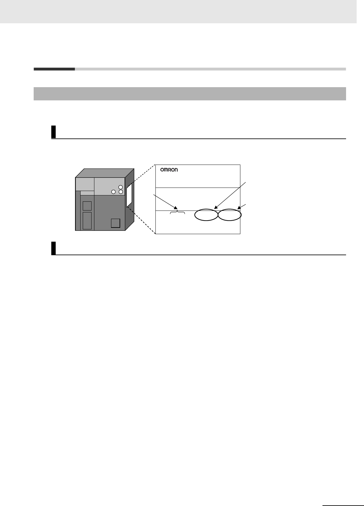
The unit version is given to the right of the lot number on the nameplate of the products for which unit
versions are being managed, as shown below.
CX-Programmer can be used to confirm the unit version using one of the following two methods.
• Using the PLC Information
• Using the Unit Manufacturing Information (This method can be used for Special I/O Units and CPU
Bus Units as well.)
zPLC Information
1Use one of the following methods to display the PLC Information Dialog Box.
• If you know the device type and CPU type, select them in the Change PLC Dialog Box, go online,
and select PLC - Edit - Information from the menus.
• If you don't know the device type and CPU type, but are connected directly to the CPU Unit on a
serial line, select PLC - Auto Online to go online, and then select PLC - Edit - Information from
the menus.
Unit Versions
Notation of Unit Versions on Products
Confirming Unit Versions with Support Software
CJ2 CPU Unit
Lot No.
CJ2H-CPU68-EIP
CPU UNIT
Lot No. 090115 0008 CPU.Ver.1.1 EIP.Ver.1.1
OMRON Corporation MADE IN JAPAN
Indicates the unit version of
the CPU Unit (example: unit
version 1.1).
Indicates the unit version of
the built-in EtherNet/IP port
(CJ2H-CPU6@-EIP only)
(example: unit version 1.1).
30 CJ2 CPU Unit Hardware User’s Manual
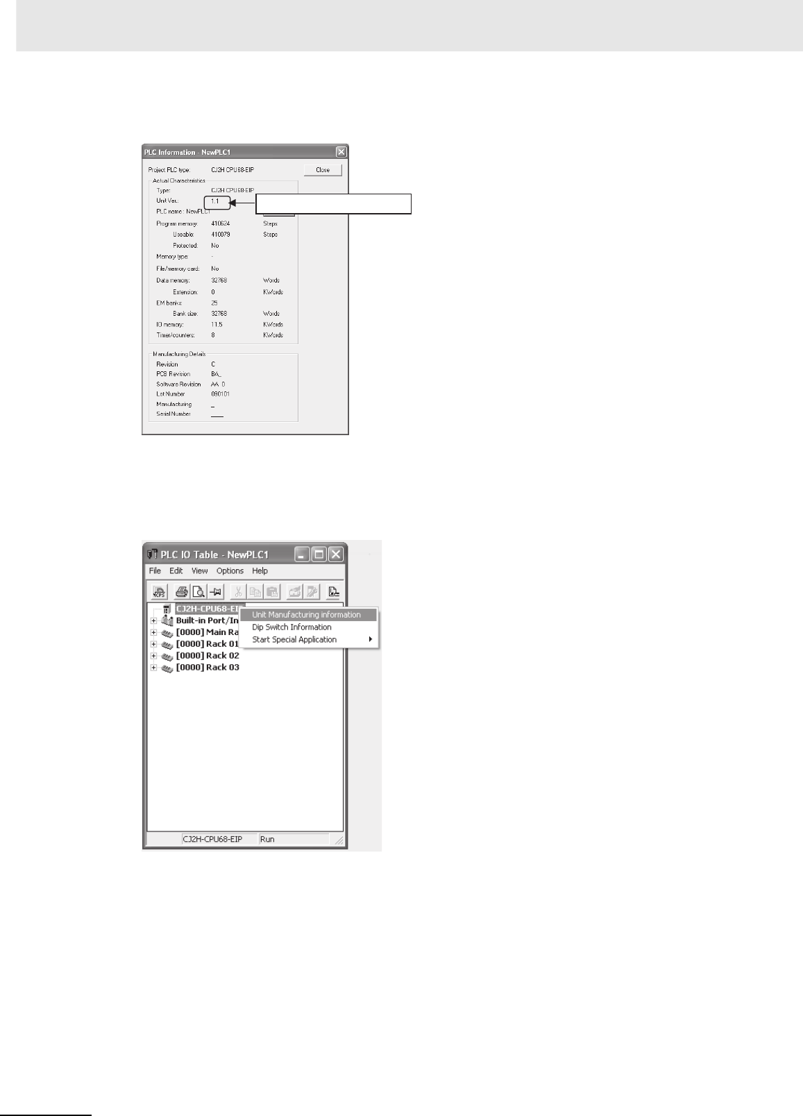
2In either case, the following PLC Information Dialog Box will be displayed.
Use the above display to confirm the unit version of the CPU Unit.
zUnit Manufacturing Information
1In the IO Table Window, right-click and select Unit Manufacturing information - CPU Unit.
Unit version

31
CJ2 CPU Unit Hardware User’s Manual
2The following Unit Manufacturing information Dialog Box will be displayed.
Use the above display to confirm the unit version of the CPU Unit connected online.
3Using the Unit Version Labels
The following unit version labels are provided with the CPU Unit.
These labels can be attached to the front of previous CPU Units to differentiate between CPU
Units of different unit versions.
Unit version
Ver. 1.0
Ver. 1.0

32 CJ2 CPU Unit Hardware User’s Manual
Unit Versions
Item Models Unit version
CJ2H CPU Unit CJ2H-CPU6@-EIP Unit version 1.0 (Built-in EtherNet/IP section: Unit version 2.0)
Unit version 1.1 (Built-in EtherNet/IP section: Unit version 2.0)
Unit version 1.2 (Built-in EtherNet/IP section: Unit version 2.0)
Unit version 1.3 (Built-in EtherNet/IP section: Unit version 2.0)
CJ2H-CPU6@Unit version 1.1
Unit version 1.2
Unit version 1.3
CJ2M CPU Unit CJ2M-CPU3@Unit version 1.0 (Built-in EtherNet/IP section: Unit version 2.0)
Unit version 2.0 (Built-in EtherNet/IP section: Unit version 2.0)
Unit version 2.0 (Built-in EtherNet/IP section: Unit version 2.1)
CJ2M-CPU1@Unit version 1.0
Unit version 2.0

33
CJ2 CPU Unit Hardware User’s Manual
The following tables show the relationship between unit versions and CX-Programmer versions. Refer
to A-8 Functions Supported for Unit Versions for the functions supported by each unit version.
zUnit Versions and Programming Devices
*1 It is not necessary to upgrade the version of the CX-Programmer if functionality that was enhanced for the
upgrade of the CPU Unit will not be used.
*2 CX-Programmer version 8.2 or higher is required to use the functions added for unit version 1.1. The high-
speed interrupt function and changing the minimum cycle time setting in MONITOR mode, however, are also
supported by CX-Programmer version 8.02.
*3 A Programming Console cannot be used with a CJ2 CPU Unit.
zPull-down List for PLC Models
Unit versions are not differentiated in the pull-down list for PLC models in the Change PLC Dialog
Box of the CX-Programmer. Select as shown in the following table regardless of the unit version.
Unit Versions and Programming Devices
CPU Unit Functions
Required Programming Device
CX-Programmer Program-
ming
Console
Ver. 7.1
or lower Ver. 8.0 Ver. 8.2
or higher Ver. 9.0 Ver. 9.1 Ver. 9.12
or higher
CJ2H CJ2H-CPU6@-EIP
Unit version 1.0
Functions for unit version 1.0 --- OK OK OK OK OK ---*3
CJ2H-CPU6@-EIP
Unit version 1.1
Functions
added for unit
version 1.1
Using new
functions
--- --- OK*2 OK OK OK
Not using new
functions
--- OK*1 OK OK OK OK
CJ2H-CPU6@
Unit version 1.1
Functions
added for unit
version 1.1
Using new
functions
--- --- OK*2 OK OK OK
Not using new
functions
--- --- OK OK OK OK
CJ2H-CPU6@-EIP
Unit version 1.2
Functions
added for unit
version 1.2
Using new
functions
--- --- --- OK OK OK
Not using new
functions
--- OK*1 OK*1 OK OK OK
CJ2H-CPU6@
Unit version 1.2
Functions
added for unit
version 1.2
Using new
functions
--- --- --- OK OK OK
Not using new
functions
--- OK*1 OK*1 OK OK OK
CJ2H-CPU6@-EIP
Unit version 1.3
Functions
added for unit
version 1.3
Using new
functions
--- --- --- --- OK OK
Not using new
functions
--- OK*1 OK*1 OK OK OK
CJ2H-CPU6@
Unit version 1.3
Functions
added for unit
version 1.3
Using new
functions
--- --- --- --- OK OK
Not using new
functions
--- OK*1 OK*1 OK OK OK
CJ2M CJ2M-CPU@@
Unit version 1.0
Functions for unit version 1.0 --- --- --- --- OK OK
CJ2M-CPU@@
Unit version 2.0
Functions
added for unit
version 2.0
Using new
functions
--- --- --- --- --- OK
Not using new
functions
--- --- --- --- OK*1 OK
Series CPU Unit Model number PLC model in Change PLC Dialog Box in CX-Programmer ver-
sion 9.0 or higher
CJ Series CJ2H CPU Unit CJ2H-CPU6@-EIP
CJ2H-CPU6@
CJ2H
CJ2M CPU Unit CJ2M-CPU3@
CJ2M-CPU1@
CJ2M
34 CJ2 CPU Unit Hardware User’s Manual
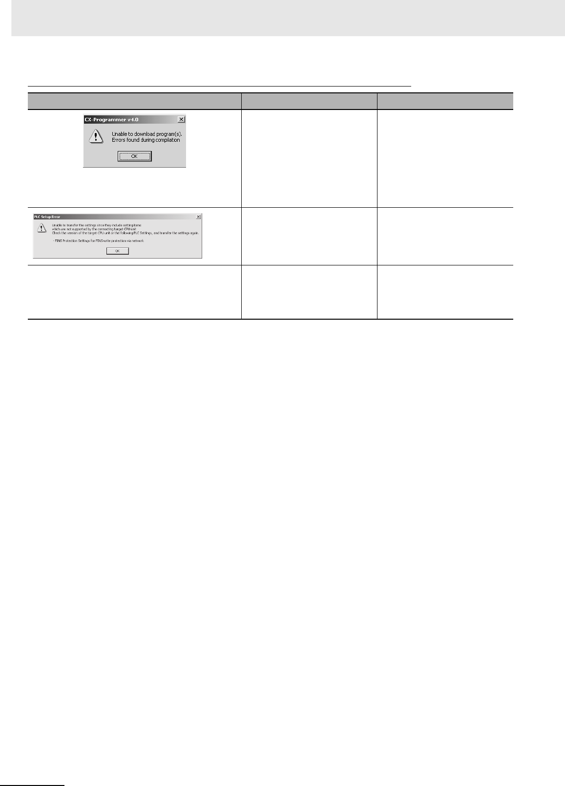
Troubleshooting Problems with Unit Versions on the CX-Programmer
Problem Cause Solution
After the above message is displayed, a compiling
error will be displayed on the Compile Tab Page in the
Output Window.
An attempt was made to down-
load a program containing
instructions supported only by
later unit versions or a CPU Unit
to a previous unit version.
Check the program or change to
a CPU Unit with a later unit ver-
sion.
An attempt was to download a
PLC Setup containing settings
supported only by later unit ver-
sions or a CPU Unit to a previous
unit version.
Check the settings in the PLC
Setup or change to a CPU Unit
with a later unit version.
“????” is displayed in a program transferred from the
PLC to the CX-Programmer. An attempt was made to upload
a program containing instruc-
tions supported only by higher
versions of CX-Programmer to a
lower version.
New instructions cannot be
uploaded to lower versions of
CX-Programmer. Use a higher
version of CX-Programmer.

35
CJ2 CPU Unit Hardware User’s Manual
Related Manuals
Manuals related to a PLC built using a CJ-series CJ2 CPU Unit are listed in the following table. Use
these manuals for reference.
Manual Cat. No. Model Application Description
CJ-series CJ2 CPU
Unit Hardware
User’s Manual (this
manual)
W472 CJ2H-CPU6@-EIP
CJ2H-CPU6@
CJ2M-CPU@@
Hardware specifications for
CJ2 CPU Units
Describes the following for CJ2 CPU Units:
• Overview and features
• Basic system configuration
• Part nomenclature and functions
• Mounting and setting procedure
• Remedies for errors
• Also refer to the Software User’s Manual
(W473).
CJ-series CJ2 CPU
Unit Software User’s
Manual
W473 CJ2H-CPU6@-EIP
CJ2H-CPU6@
CJ2M-CPU@@
Software specifications for
CJ2 CPU Units
Describes the following for CJ2 CPU Units:
• CPU Unit operation
• Internal memory
• Programming
• Settings
• Functions built into the CPU Unit
Also refer to the Hardware User’s Manual
(W472)
CS/CJ-series Ether-
Net/IP Units Opera-
tion Manual
W465 CJ2H-CPU6@-EIP
CJ2M-CPU3@
CS1W-EIP21
CJ1W-EIP21
Using the built-in Ether-
Net/IP port of the CJ2 CPU
Unit
Describes the built-in EtherNet/IP port and Eth-
erNet/IP Units.
Describes basic settings, tag data links, FINS
communications, and other functions.
CJ-series CJ2M
CPU Unit Pulse I/O
Module User's Man-
ual
W486 CJ2M-CPU@@
+
CJ2M-MD21@
Information on using built-
in I/O on CJ2M CPU Units
Provides the following information on the CJ2M
CPU Units:
• Specifications and wiring methods
• I/O functions
• Quick-response inputs
• Interrupt functions
• High-speed counters
• Pulse outputs
• PWM outputs
When programming, use this manual together
with the Instructions Reference Manual (Cat.
No. W474).
CS/CJ/NSJ-series
Instructions Refer-
ence Manual
W474 CJ2H-CPU6@-EIP
CJ2H-CPU6@
CJ2M-CPU@@
CS1G/H-CPU@@H
CS1G/H-CPU@@-V1
CJ1G/H-CPU@@H
CJ1G-CPU@@
CJ1M-CPU@@
NSJ@-@@@@(B)-G5D
NSJ@-@@@@(B)-M3D
Information on instructions Describes each programming instruction in
detail.
Also refer to the Software User’s Manual (W473)
when you do programming.

36 CJ2 CPU Unit Hardware User’s Manual
CS/CJ/CP/NSJ-
series Communica-
tions Command Ref-
erence Manual
W342 CJ2H-CPU6@-EIP
CJ2H-CPU6@
CS1G/H-CPU@@H
CS1G/H-CPU@@-V1
CS1D-CPU@@H
CS1D-CPU@@S
CS1W-SCU@@-V1
CS1W-SCB@@-V1
CJ1H-CPU@@H-R
CJ1G/H-CPU@@H
CJ1G-CPU@@P
CJ1M-CPU@@
CJ1G-CPU@@
CJ1W-SCU@@-V1
CP1H-X@@@@-@
CP1H-XA@@@@-@
CP1H-Y@@@@-@
CP1L-M/L@@@-@@
CP1E-E/N@@D@-@
NSJ@-@@@@(B)-G5D
NSJ@-@@@@(B)-M3D
Information on communi-
cations for CS/CJ/CP-
series CPU Units and NSJ-
series Controllers
Describes C-mode commands and FINS com-
mands
Refer to this manual for a detailed description of
commands for communications with the CPU
Unit using C mode commands or FINS com-
mands.
Note This manual describes the communica-
tions commands that are addressed to
CPU Units. The communications path that
is used is not relevant and can include any
of the following: serial ports on CPU Units,
communications ports on Serial Commu-
nications Units/Boards, and Communica-
tions Units. For communications
commands addressed to Special I/O Units
or CPU Bus Units, refer to the operation
manual for the related Unit.
CX-One Setup Man-
ual
W463 CXONE-AL@@C-
V@/AL@@D-V@
Installing software from the
CX-One
Provides an overview of the CX-One FA Inte-
grated Tool Package and describes the installa-
tion procedure.
CX-Programmer
Operation Manual
W446 WS02-CX@@-V@Support Software for Win-
dows computers
CX-Programmer operating
procedure
Describes operating procedures for the CX-Pro-
grammer.
Also refer to the Software User’s Manual (W473)
and CS/CJ/NSJ-series Instructions Reference
Manual (W474) when you do programming.
CX-Programmer
Operation Manual
Functions
Blocks/Structured
Text
W447
CX-Programmer
Operation Manual
SFC Programming
W469
CS/CJ/CP/NSJ-
series CX-Simulator
Operation Manual
W366 WS02-SIMC1-E Operating procedures for
CX-Simulator Simulation
Support Software for Win-
dows computers
Using simulation in the CX-
Programmer with CX-Pro-
grammer version 6.1 or
higher
Describes the operating procedures for the CX-
Simulator.
When you do simulation, also refer to the CX-
Programmer Operation Manual (W446), Soft-
ware User’s Manual (W473), and CS/CJ/NSJ-
series Instructions Reference Manual (W474).
CS/CJ/CP/NSJ-
series CX-Integrator
Network Configura-
tion Software Opera-
tion Manual
W464 CXONE-AL@@C-V@/
CXONE-AL@@D-V@
Network setup and moni-
toring
Describes the operating procedures for the CX-
Integrator.
Manual Cat. No. Model Application Description

1-1
CJ2 CPU Unit Hardware User’s Manual
1
This section provides an overview of the CJ2 CPU Units.
1-1 Overview of CJ2 CPU Units . . . . . . . . . . . . . . . . . . . . . . . . . . . . . . . . . . . . . . 1-2
1-1-1 Overview . . . . . . . . . . . . . . . . . . . . . . . . . . . . . . . . . . . . . . . . . . . . . . . . . . . . . 1-2
1-1-2 CJ2 CPU Unit Features . . . . . . . . . . . . . . . . . . . . . . . . . . . . . . . . . . . . . . . . . . 1-4
1-2 Basic Operating Procedure . . . . . . . . . . . . . . . . . . . . . . . . . . . . . . . . . . . . . 1-12
1-3 Specifications . . . . . . . . . . . . . . . . . . . . . . . . . . . . . . . . . . . . . . . . . . . . . . . . 1-13
1-3-1 General Specifications . . . . . . . . . . . . . . . . . . . . . . . . . . . . . . . . . . . . . . . . . . 1-13
1-3-2 Performance Specifications . . . . . . . . . . . . . . . . . . . . . . . . . . . . . . . . . . . . . . 1-14
1-3-3 Function Specifications . . . . . . . . . . . . . . . . . . . . . . . . . . . . . . . . . . . . . . . . . 1-21
Overview

1 Overview
1-2 CJ2 CPU Unit Hardware User’s Manual
1-1 Overview of CJ2 CPU Units
The SYSMAC CJ2-series CPU Units are multi-functional CPU Units that provide the following features.
zFast, with Large Memory Capacity
Basic performance is faster and memory capacity has been increased to provide ample capability
for machine control.
zBuilt-in EtherNet/IP Port (CJ2H-CPU6@-EIP and CJ2M-CPU3@ Only)
The CJ2 CPU Units support the EtherNet/IP open network as a standard feature. Universal Ethernet
communications, such as data links between PLCs, message communications between PLCs, and
FTP transfers, are all possible from a peripheral device connection.
zGeneral-purpose Networks for Support Software Interface
Support Software and devices can be easily connected using commercially available cable to gen-
eral-purpose networks via USB and EtherNet/IP ports. (The EtherNet/IP port is provided only on the
CJ2H-CPU6@-EIP and CJ2M-CPU3@.)
zTag Access (CJ2H-CPU6@-EIP and CJ2M-CPU3@ Only)
CJ2 CPU Units have a tag name server to manage tag names and I/O addresses. This enables
access from external devices using tag names, without needing to know the I/O addresses.
zSynchronous Unit Operation (CJ2H CPU Unit with Unit Version 1.1 or Later)
The timing of processing performed by CPU Bus Units and Special I/O Units can be synchronized.
This minimizes fluctuations in timing from input and processing to outputs, making it easier to ensure
application performance.
zEasier Programming
CJ2 CPU Units offer a highly readable programming environment, including features such as
addressing DM and EM Area bits, setting address offsets, and using array variables.
zImproved Debugging
Online editing and data tracing have been improved, greatly increasing the efficiency of debugging.
zIncreased Pulse I/O Capacity (CJ2M CPU Unit with Unit Version 2.0 or Later)
With the CJ2M CPU Units, optional Pulse I/O Modules can be mounted to enable pulse I/O for up to
four axes.
zMore Serial Communications Ports (CJ2M-CPU3@ Only)
With the standard CJ2M CPU Unit (CJ2M-CPU3@) you can add an RS-232C or RS-422A/485
Option Board to the standard-feature EtherNet/IP port to increase the number of serial communica-
tions ports.
1-1-1 Overview
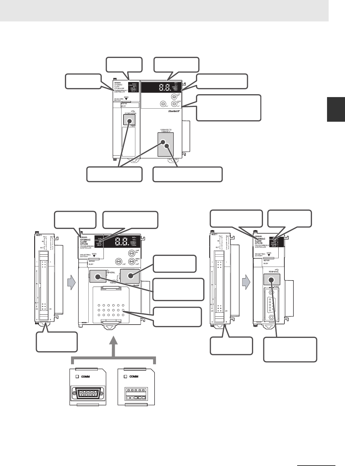
1-3
1 Overview
CJ2 CPU Unit Hardware User’s Manual
1-1 Overview of CJ2 CPU Units
1
1-1-1 Overview
CJ2H CPU Units
CJ2M CPU Units
Standard CPU Unit (CJ2M-CPU3@) Simple CPU Unit (CJ2M-CPU1@)
Tag access Easier programming
General-purpose networks for
Support Software interface
Improved debugging
Faster, with
greater capacity
Synchronous unit operation
(CJ2H CPU Unit with Unit
Version 1.1 or Later)
Built-in EtherNet/IP port
(CJ2H-CPU6@-EIP)
RS-232C RS-422A/485
Tag access Easier programming
Built-in
EtherNet/IP port
Optional serial
communications
ports
Easier programming Improved debugging
General-purpose
networks for Support
Software interface
General-purpose
networks for Support
Software interface
Expandable
pulse I/O Expandable
pulse I/O

1 Overview
1-4 CJ2 CPU Unit Hardware User’s Manual
zHigh-speed Processing
High-speed processing is possible for basic instructions (0.016 µs min. for CJ2H and 0.04 µs min.
for CJ2M), special instructions (0.05 µs min. for CJ2H and 0.06 µs min. for CJ2M), and immediate
refreshing (0.99 µs min. for CJ2H and 1.26 µs min. for CJ2M).
zLarge Program Capacity
The CJ2 CPU Units provide a large program capacity of up to 400 Ksteps.
zSpecial Function Block Definition Area (CJ2M Only)
With a CJ2M CPU Unit, a special area called the FB Program Area is provided to store function
block definitions. (The FB Program Area holds 20K steps.) This allows you to use function blocks to
make program components and structures from previous programs while reducing the usage of the
User Program Area. And any function block definitions that would exceed the FB Program Area are
stored in the User Program Area.
zLarge Data Memory Capacity
The CJ2 CPU Units provide a large EM Area capacity of up to 800 Kwords (25 banks).
zUp to 128 Cyclic Tasks
The user program can be divided into up to 128 tasks. Using smaller task programs makes it easier
to structure programs and contributes to shorter cycle times.
zEnhanced Performance for Executing Interrupt Tasks (CJ2H CPU Units with
Unit Version 1.1 or Later)
With CJ2H CPU Units with unit version 1.1, overhead time for interrupt tasks is approximately 20%
less than for unit version 1.0 even for normal usage. Also, by using High-speed interrupt function, it
is possible to improve execution performance as shown below with certain restrictions.
• Greatly reduce overhead time for interrupt tasks (interrupt task startup time + return time to cyclic
tasks).
Example: For I/O interrupt tasks, the time for normal operation is 37 µs but the time is 25 µs if
High-speed interrupt function is used.
• Minimum interval setting of 0.1 ms for one of Scheduled Interrupt Tasks
(For unit version 1.0, the minimum interval is 0.2 ms.)
1-1-2 CJ2 CPU Unit Features
Fast, with Large Memory Capacity
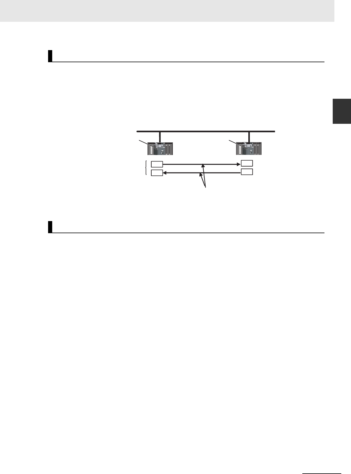
1-5
1 Overview
CJ2 CPU Unit Hardware User’s Manual
1-1 Overview of CJ2 CPU Units
1
1-1-2 CJ2 CPU Unit Features
The CJ2 CPU Units provide as standard equipment a built-in EtherNet/IP port that supports the same
FINS Ethernet functions as an Ethernet Unit (including features such as an FTP server and time coordi-
nation) as well as the EtherNet/IP open network.
zHigh-speed, High-capacity Data Links with User-set Refresh Cycles
The CJ2 CPU Units provide high-speed, high-capacity data links, and refresh cycles can be set indi-
vidually for each data link area.
In addition, using the EtherNet/IP DataLink Tool makes it possible to set the data links using an inter-
face similar to that of the Controller Link automatic data link setup.
zBuilt-in USB and EtherNet/IP Ports
A commercially available USB cable can be used to connect to the PLC directly from a USB port on
a personal computer. In addition, with the CJ2H-CPU6@-EIP or CJ2M-CPU3@, a PLC on the Ether-
Net/IP network can be accessed via USB.
zPrevent Connecting to the Wrong PLC by Using PLC Names from Support
Software
A user-set PLC name can be recorded in a CJ2 CPU Unit. When using Support Software to connect
online to a PLC, verification of the PLC name prevents incorrect connections from the Support Soft-
ware.
Built-in EtherNet/IP Port (CJ2H-CPU6@-EIP and CJ2M-CPU3@ Only)
General-purpose Networks for Support Software Interface
EtherNet/IP
High speed
The refresh cycle can be set individually for each area.
High capacity
CJ2 CPU Unit CJ2 CPU Unit
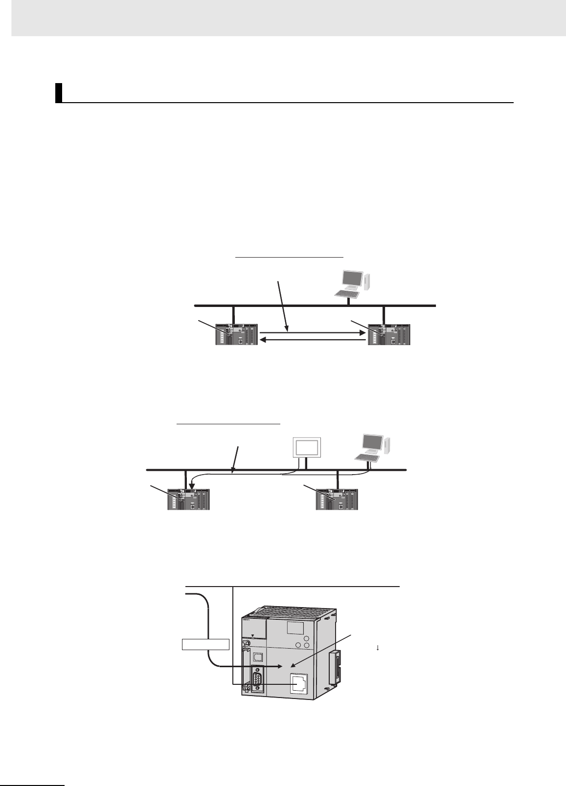
1 Overview
1-6 CJ2 CPU Unit Hardware User’s Manual
zNetwork Symbols (Tags) for Flexible Support of Program Changes
The CJ2 CPU Units support network symbols (tags). They have an internal tag name server that
enables them to store tag names and addresses in advance in symbol tables in the CPU Units. Tags
enable the following features.
Data links can be set using tags.
With data links on an EtherNet/IP network, send and receive areas can be specified using symbols
rather than addresses. This enables flexible support for design changes by allowing the data link
areas set by tags to remain unchanged, while simply changing the symbol tables that contain the tag
names and addresses.
Access from host devices is enabled using tags.
Tags can be used for access from host devices, such as touch panel NS-series Programmable Ter-
minals. This makes the creation of host screens and programs at devices such as PTs much more
convenient.
Automatic tag allocation makes it unnecessary to know the addresses.
Automatic allocation of tags in the high-capacity EM Area, using automatic address allocation in CX-
Programmer symbol tables, enables data link design and access from host devices without having to
pay attention to addresses.
Tag Access (CJ2H-CPU6@-EIP and CJ2M-CPU3@ Only)
Data links enabled by names
EtherNet/IP
Examples: Inputs from a to b
Inputs from c to d
CJ2 CPU Unit CJ2 CPU Unit
EtherNet/IP
Touch Panel
NS-series PT
Examples: Writing to a
Reading from b Middleware
Supporting EtherNet/IP
CJ2 CPU Unit
CJ2 CPU Unit
Host application, such as SCADA
Access is possible using tags.
PERIPHERAL
ERR/ALM
RUN
INH
COMM
BKUP
PRPHL
CONTROLLER
CPU64-EIP
CJ2H
SYSMAC
PROGRAMMABLE
PORT
OPEN
BUSY
MCPWR
NS
MS
COMM
10M
100M
Tags are allocated in
a high-capacity area.
Designing is performed
by using only tags,
with no need to pay
attention to addresses.
EtherNet/IP
Specified by tag a.
CJ2 CPU Unit
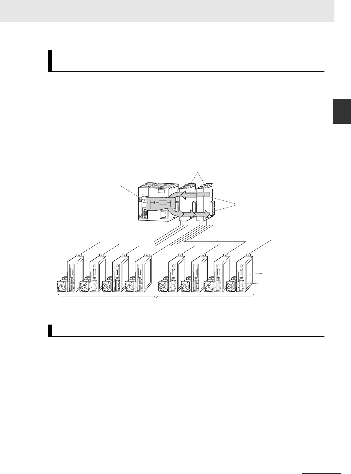
1-7
1 Overview
CJ2 CPU Unit Hardware User’s Manual
1-1 Overview of CJ2 CPU Units
1
zA CJ2 CPU Unit can synchronize the start of the processing performed by
CPU Bus Units and Special I/O Units to a specified cycle.
Synchronous data refreshing can be used between the CJ2H CPU Unit and Synchronous Units,*
and the refreshed data can be used in operations in a synchronous interrupt task. This enables mul-
tiaxis control with minimal fluctuations in the timing from inputs and processing to outputs. This pro-
vides support for motion applications that require precise timing, such as electronic cam control.
* Synchronous Units are CPU Bus Units and Special I/O Units that support the synchronous unit operation func-
tion. The following Synchronous Units are available as of July 2010: CJ1W-NC214/234/414/434 Position Control
Units.
zAddress offsets can be specified.
When an address is specified for an instruction operand, an offset can be specified in brackets after
the address to offset it. For example, by setting a word address in brackets to specify the offset, the
address can be dynamically specified according to the contents of that word.
Example
W0.00[D0]: W0.00 is the starting address and the contents of D0 is the offset. If D0 is &3, then
W0.03 is specified.
zSymbols can be specified for array variable subscripts.
By specifying symbols for array variable subscripts, elements can be dynamically specified accord-
ing to the values of the symbols.
Example
a[b]: The value of symbol b specifies the element for array variable a[ ].
Synchronous Unit Operation (CJ2H CPU Units with Unit Version 1.1
or Later)
Easier Programming
CJ2H CPU Units (with
unit version 1.1 or later)
Example:
Electronic cam control
Synchronous Units
Example:
Position Control Units
Synchronous data
refreshing
Motor drive
Servomotor
Several servomotors are controlled synchronously
based on the operation of the encoder.
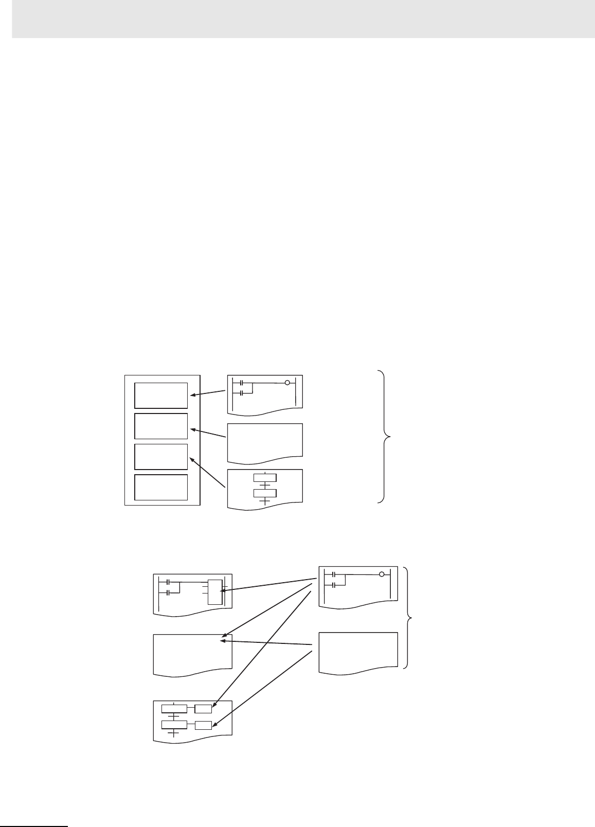
1 Overview
1-8 CJ2 CPU Unit Hardware User’s Manual
zCreate and Use Data Structures
With CX-Programmer version 9.0 or higher, data structures can be created and used. This enables
easily using I/O memory in the CPU Unit as a database or for library data.
zBit addresses can be used in the DM Area and EM Area.
Previously the DM Area and the EM Area could be addressed only by words, and bit addresses
could not be specified. The work area for bits can now be expanded by enabling bit addresses in the
DM and EM Areas.
For example, D10.00 specifies bit 00 of D10.
zThe format for timer/counter PV refreshing can be selected individually for
each instruction.
Either BCD or binary can be selected individually for each instruction as the format for timer/counter
PV refreshing. For example, the TIM (BCD) and TIMX (binary) instructions can be used together.
zThe optimum languages can be combined for structured programming.
Ladder diagrams, ST, and SFC languages can be freely combined in the user program. Being able
to use the optimum languages for a particular process helps reduce the time involved in program-
ming.
In addition, ladder diagrams and ST language can be freely used for function blocks (FBs) in ladder
diagrams and ST programs, and for transition and action programs in SFC. This feature makes it
possible to optimize structured programming.
User program
Task
Task
Task
Task SFC
Step progression control
Ladder diagram
Control of equipment
and external devices
ST
Math processing
a := a + 1;
The programming language
suited to the process can be used.
Transition and action
programs in SFC
Ladder diagram
ST
FB_(A:=B,C=>D); a := a + 1;
The programming
language suited to
the process can
be used.
FB in ladder diagram
FB in ST program

1-9
1 Overview
CJ2 CPU Unit Hardware User’s Manual
1-1 Overview of CJ2 CPU Units
1
1-1-2 CJ2 CPU Unit Features
zReduced Effect on Cycle Time from Online Editing
The additional cycle time due to online editing has been reduced to approx. 1 ms, minimizing the
effects on equipment operation during debugging.
zFast, High-capacity Data Tracing
Up to 32 Kwords of data can be traced (8 times more than previously), with ample trigger conditions,
and data can be traced continuously for long periods of time.
zI/O Module Auxiliary Area Selection with CX-Programmer 9.12 or Higher
(CJ2M CPU Units Only)
With CX-Programmer version 9.12 or higher, data to be traced can be easily selected from lists.
zForce-set/Reset Bits in Specified EM Area Banks
With CX-Programmer version 8.3 or higher, a parameter can be set to enable force-setting/resetting
bits in specified EM Area banks. (This function is supported only by CJ2H CPU Units with unit ver-
sion 1.2 or later and CJ2M CPU Units.)
Improved Debugging
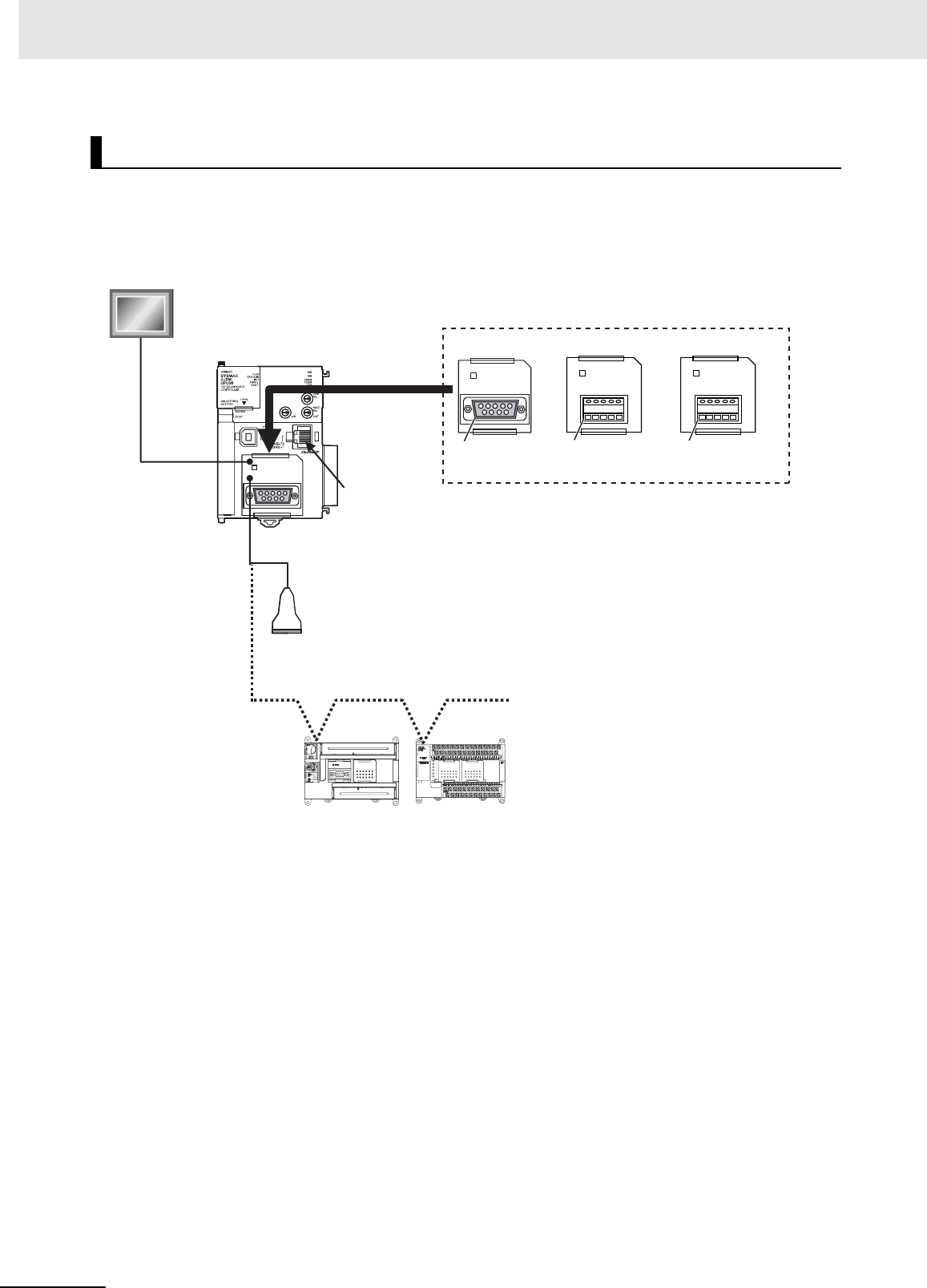
1 Overview
1-10 CJ2 CPU Unit Hardware User’s Manual
With the CJ2M-CPU3@, one Serial Communications Option Board with one RS-232C port or one RS-
422A/485 port can be added.
With the serial port, it is easy to connect to general components, such as barcode readers, and other
components such as PTs, other CJ/CP-series PLCs, and Inverters.
Add a Serial Option Board (CJ2M-CPU3@ Only)
COMM
RDA- RDB+ SDA- SDB+ FG
COMM
RDA- RDB+ SDA- SDB+ FG
COMM
RS-232C
CJ2M-CPU3@CP1W-CIF01
RS-232C
CP1W-CIF12 CP1W-CIF11
EtherNet/IP
RS-232C
Example: NS-series PT
NT Link or
other protocol
Barcode reader or other
general-purpose component
Or RS-422A/485
Example: Serial PLC Links
CJ2M, CP1E,
CP1L or CJ1M
Serial Option Boards
RS-422A/485 port
(isolated, max. transmis-
sion distance: 500 m)
RS-422A/485 port (not
isolated, max. transmis-
sion distance: 50 m)
COMM
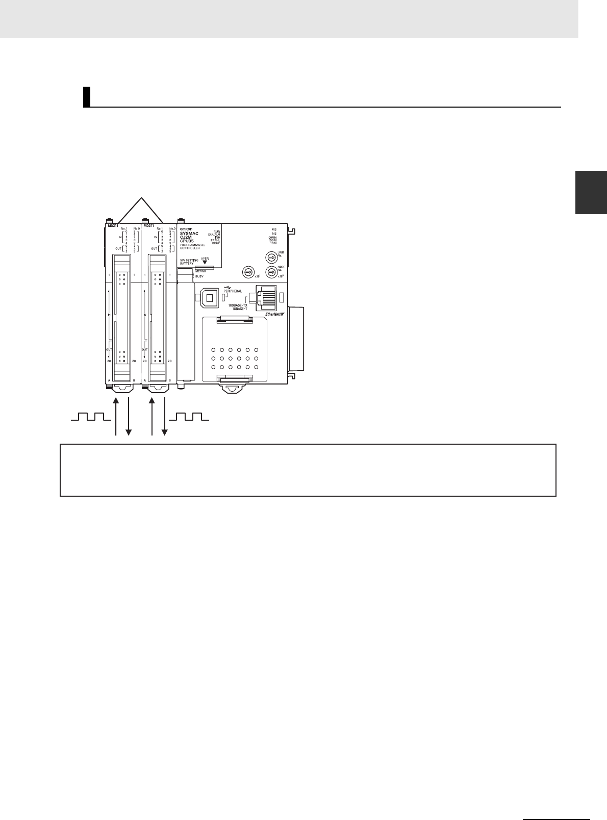
1-11
1 Overview
CJ2 CPU Unit Hardware User’s Manual
1-1 Overview of CJ2 CPU Units
1
1-1-2 CJ2 CPU Unit Features
With the CJ2M CPU Units, up to two Pulse I/O Modules can be mounted.
This enables input functions, such as normal inputs, interrupt inputs, high-speed counter inputs, and
quick-response inputs, and output functions, such as normal outputs, pulse outputs, and variable duty
factor pulse outputs. This provides support for many different types of applications.
Use Pulse I/O and Interrupt Inputs (CJ2M CPU Units Only)
Pulse I/O
Modules
• Normal inputs: 20 (10 per Pulse I/O Module)
• Interrupt inputs: 8 (4 per Pulse I/O Module)
• High-speed counter inputs: 4 (2 per Pulse I/O Module)
• Quick-response inputs: 8 (4 per Pulse I/O Module)
• Normal outputs: 12 (6 per Pulse I/O Module)
• Pulse outputs: 4 (2 per Pulse I/O Module)
• Variable duty factor pulse outputs: 4 (2 per Pulse I/O Module)
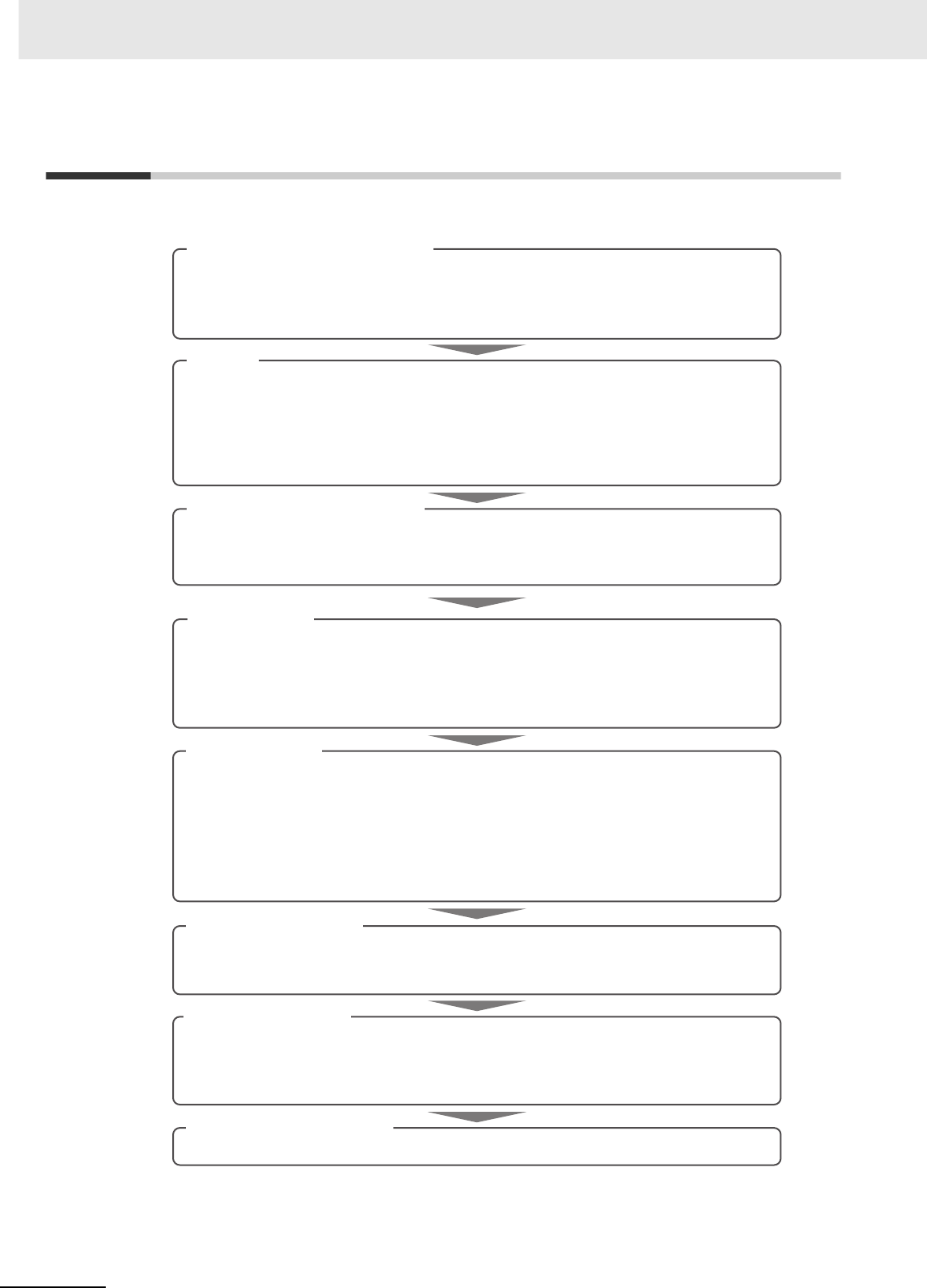
1 Overview
1-12 CJ2 CPU Unit Hardware User’s Manual
1-2 Basic Operating Procedure
In general, use the following procedure.
1. Setting Devices and Hardware
2. Wiring
3. Connecting Online to the PLC
4. I/O Allocations
5. Software Setup
6. Creating the Program
8. Basic Program Operation
Wire the power supply, I/O, and communications. Refer to the following manuals.
Connect the personal computer online to the PLC.
Using the CX-Programmer, allocate I/O memory in the CPU Unit to the mounted Units.
Make the PLC software settings.
Create the program using the CX-Programmer.
7. Checking Operation
Set the operating mode to RUN mode to start operation.
Mount the Power Supply Unit, the CPU Unit, the other Units, and the End Covers. Set the DIP switch
and rotary switches as required.
Refer to Section 3 Nomenclature and Functions and Section 5 Installation in the CJ2 CPU Unit
Hardware User’s Manual (Cat. No. W472).
Refer to Section 5 Installation in the CJ2 CPU Unit Hardware User’s Manual (Cat. No. W472).
Refer to Section 11 Programming Devices and Communications in the CJ2 CPU Unit Software
User’s Manual (Cat. No. W473).
Refer to Section 3 I/O Specifications and Wiring for Pulse I/O Module in the CJ2M CPU Unit
Pulse I/O Module User's Manual (Cat. No. W486).
Refer to Section 4 Support Software in the CJ2 CPU Unit Hardware User’s Manual (Cat. No.
W472)
Refer to Section 8 I/O Allocations and Unit Settings in the CJ2 CPU Unit Software User’s
Manual (Cat. No. W473)
Refer to Section 2 I/O Application Procedures and Function Allocations in the CJ2M CPU Unit
Pulse I/O Module User's Manual (Cat. No. W486).
• CPU Unit initialization: Refer to Section 4 CPU Unit Initialization in the CJ2 CPU Unit
Software User’s Manual (Cat. No. W473).
• DM Area Settings for Special I/O Units and CPU Bus Units: Refer to Section 8 I/O Allocations
and Unit Settings in the CJ2 CPU Unit Software User’s Manual (Cat. No. W473).
• PLC Setup: Refer to Section 9 PLC Setup in the CJ2 CPU Unit Software User’s Manual (Cat.
No. W473).
Refer to Section 5 Understanding Programming in the CJ2 CPU Unit Software User’s Manual
(Cat. No. W473).
Refer to 10-7 Debugging in the CJ2 CPU Unit Software User’s Manual (Cat. No. W473).
Check the I/O wiring and the AR Area settings, and perform trial operation. The CX-Programmer can
be used for monitoring and debugging.

1-13
1 Overview
CJ2 CPU Unit Hardware User’s Manual
1-3 Specifications
1
1-3-1 General Specifications
1-3 Specifications
* Without a Serial Option Board
1-3-1 General Specifications
Item CJ2H- CJ2M-
CPU64(-EIP) CPU65(-EIP) CPU66(-EIP) CPU67(-EIP) CPU68(-EIP) CPU1@CPU3@
Enclosure Mounted in a panel
Grounding Less than 100 Ω
CPU Unit Dimensions CJ2H-CPU6@-EIP: 90 mm × 65 mm × 80 mm (H × D × W)
CJ2H-CPU6@: 90 mm × 65 mm × 49 mm (H × D × W)
90 mm ×
75 mm ×
31 mm (H
× D × W)
90 mm ×
75 mm ×
62 mm (H
× D × W)
Weight CJ2H-CPU6@-EIP: 280 g or less
CJ2H-CPU6@: 190 g or less
130 g or
less
190 g or
less*
Current Consumption CJ2H-CPU6@-EIP: 5 VDC, 0.82 A
CJ2H-CPU6@: 5 VDC, 0.42 A
5 VDC,
0.5 A
5 VDC,
0.7 A
Use Environment Ambient Operating Temperature 0 to 55°C
Ambient Operating Humidity 10% to 90% (with no condensation)
Atmosphere Must be free from corrosive gases.
Ambient Storage Temperature −20 to 70°C (excluding battery)
Altitude 2,000 m or less
Pollution Degree 2 or less: Conforms to JIS B3502 and IEC 61131-2.
Noise Immunity 2 kV on power supply line (Conforms to IEC 61000-4-4.)
Overvoltage Category Category II: Conforms to JIS B3502 and IEC 61131-2.
EMC Immunity Level Zone B
Vibration Resistance Conforms to IEC60068-2-6.
5 to 8.4 Hz with 3.5-mm amplitude, 8.4 to 150 Hz
Acceleration of 9.8 m/s2 for 100 min in X, Y, and Z directions (10 sweeps of 10 min each = 100 min total)
Shock Resistance Conforms to IEC60068-2-27.
147 m/s2, 3 times in X, Y, and Z directions (100 m/s2 for Relay Output Units)
Battery Life 5 years at 25°C
Model CJ1W-BAT01
Applicable Standards Conforms to cULus, NK, LR, and EC Directives.

1 Overview
1-14 CJ2 CPU Unit Hardware User’s Manual
*1 The following times are added if EtherNet/IP data tag links are used for the CJ2H-CPU6@-EIP.
Normal operation: 100 µs + Number of transfer words x 0.33 µs
High-speed interrupt function enabled: 100 µs + Number of transfer words × 0.87 µs
The following time must be added when using EtherNet/IP tag data links for the CJ2M-CPU3@.
100 µs + (Number of words transferred × 1.8 µs)
The following time must be added when using Pulse I/O Modules with a CJ2M CPU Unit:
10 µs × Number of Pulse I/O Modules
*2 This applies when high-speed interrupts are used.
*3 Supported only by CJ2M CPU Units with unit version 2.0 or later. A Pulse I/O Module must be mounted.
1-3-2 Performance Specifications
Items
CJ2H- CJ2M-
CPU64
(-EIP)
CPU65
(-EIP)
CPU66
(-EIP)
CPU67
(-EIP)
CPU68
(-EIP)
CPU
11/31
CPU
12/32
CPU
13/33
CPU
14/34
CPU
15/35
User Memory 50K
steps
100K
steps
150K
steps
250K
steps
400K
steps
5K steps 10K
steps
20K
steps
30K
steps
60K
steps
I/O Bits 2,560 bits
Process-
ing Speed
Overhead Processing
Time*1
Normal Mode: CJ2H-CPU@@-EIP:200 µs
CJ2H-CPU@@: 100 µs
Normal Mode: CJ2M-CPU3@: 270 µs
CJ2M-CPU1@: 160 µs
Execution Time Basic Instructions: 0.016 µs min.;
Special Instructions: 0.048 µs min.
Basic Instructions: 0.04 µs min.;
Special Instructions: 0.06 µs min.
Interrupts I/O Inter-
rupts and
External
Interrupts
Interrupt task startup time: 26 µs or 17 µs*2 (30 µs for
unit version 1.0)
Return times to cyclic tasks: 11 µs or 8 µs*2 (15 µs for
unit version 1.0)
Interrupt task startup time: 31 µs
Return times to cyclic tasks: 10 µs
Scheduled
Interrupts Minimum time interval: 0.2 ms or 0.1 ms*2
(set in 0.1-ms increments)
Minimum time interval: 0.4 ms (set in 0.1-ms increments)
Interrupt task startup time: 22 µs or 13 µs*2 (27 µs for
unit version 1.0)
Return time to cyclic task: 11 µs or 8 µs*2 (15 µs for unit
version 1.0)
Interrupt task startup time: 30 µs
Return time to cyclic task: 11 µs
Maximum Number of Connectable Units Total per CPU Rack or Expansion Rack: 10 Units max.;
Total per PLC: 40 Units max.
Basic I/O Units No limit
However, a maximum of two CJ1W-INT01 Interrupt Input Units can be mounted.
Special I/O Units Units for up to 96 unit numbers can be mounted. (Unit numbers run from 0 to 95. Units are allocated between 1 and
8 unit numbers.)
CPU Bus Units CJ2H-CPU6@-EIP: 15 Units max.
CJ2H-CPU6@: 16 Units max.
CJ2M-CPU3@: 15 Units max.
CJ2M-CPU1@: 16 Units max.
Pulse I/O Modules --- 2 max.*3
Slots for which interrupts
can be used
CJ2H-CPU6@-EIP: Slots 0 to 3 on CPU Rack
CJ2H-CPU6@: Slots 0 to 4 on CPU Rack
Slots 0 to 4 on CPU Rack
Maximum Number of Expansion Racks 3 max.
CIO Area I/O Area 2,560 bits (160 words): Words CIO 0000 to CIO 0159
Link Area 3,200 bits (200 words): Words CIO 1000 to CIO 1199
Synchronous Data Refresh
Area
1,536 bits (96 words): Words CIO 1200 to CIO 1295 ---
CPU Bus Unit Area 6,400 bits (400 words): Words CIO 1500 to CIO 1899
Special I/O Unit Area 15,360 bits (960 words): Words CIO 2000 to CIO 2959
Pulse I/O Area --- 20 inputs, 12 outputs (CIO 2960 to CIO 2963)
Serial PLC Link Words --- 1,440 bits (90 words): Words CIO 3100 to CIO 3189
DeviceNet Area 9,600 bits (600 words): Words CIO 3200 to CIO 3799
Internal I/O Area 3,200 bits (200 words): Words CIO 1300 to CIO 1499 (Cannot be used for external I/O.)
37,504 bits (2,344 words): Words CIO 3800 to CIO 6143 (Cannot be used for external I/O.)
Work Area 8,192 bits (512 words): Words W000 to W511 (Cannot be used for external I/O.)
Holding Area 8,192 bits (512 words): Words H000 to H511
Bits in this area maintain their ON/OFF status when PLC is turned OFF or operating mode is changed.
Words H512 to H1535: These words can be used only for function blocks. They can be used only for function block
instances (i.e., they are allocated only for internal variables in function blocks).
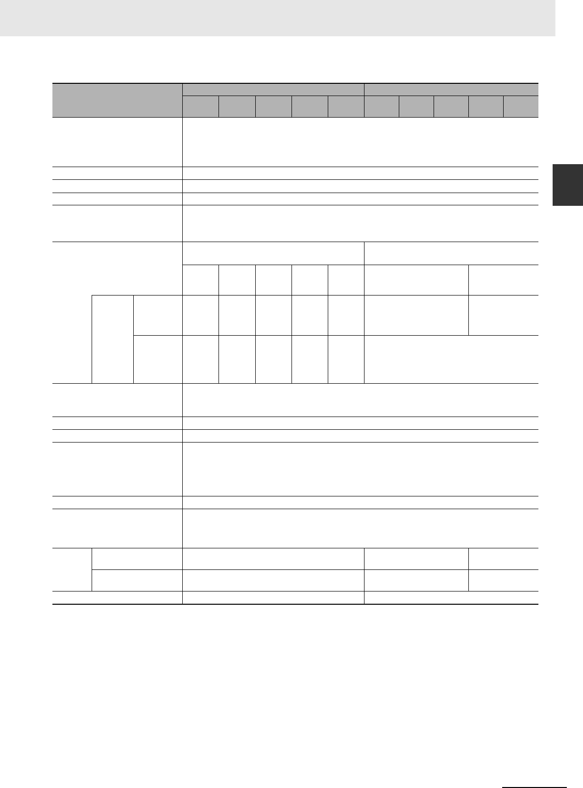
1-15
1 Overview
CJ2 CPU Unit Hardware User’s Manual
1-3 Specifications
1
1-3-2 Performance Specifications
*4 A960 to A1471 and A10000 to A11535 cannot be accessed by CPU Bus Units, Special I/O Units, PTs, and Support Soft-
ware that do not specifically support the CJ2 CPU Units.
*5 Bits in the EM Area can be addressed either by bit or by word. These bits cannot be addressed by CPU Bus Units, Spe-
cial I/O Units, PTs, and Support Software that do not specifically support the CJ2 CPU Units.
*6 EM banks D to 18 cannot be accessed by CPU Bus Units, Special I/O Units, PTs, and Support Software that do not spe-
cifically support the CJ2 CPU Units.
*7 With CJ2H CPU Units with unit version 1.2 or later, force-setting/resetting bits in the EM Area is possible either for banks
that have been specified for automatic address allocation or for banks specified for the EM Area force-set/reset function.
With CJ2M CPU Units, force-setting/resetting bits in the EM Area is possible only for banks specified for the EM Area
force-set/reset function.
Items
CJ2H- CJ2M-
CPU64
(-EIP)
CPU65
(-EIP)
CPU66
(-EIP)
CPU67
(-EIP)
CPU68
(-EIP)
CPU
11/31
CPU
12/32
CPU
13/33
CPU
14/34
CPU
15/35
Auxiliary Area Read-only: 31,744 bits (1,984 words)
• 7,168 bits (448 words): Words A0 to A447
• 24,576 bits (1,536 words): Words A10000 to A11535*4
Read/write: 16,384 bits (1,024 words) in words A448 to A1471*4
Temporary Area 16 bits: TR0 to TR15
Timer Area 4,096 timer numbers (T0000 to T4095 (separate from counters))
Counter Area 4,096 counter numbers (C0000 to C4095 (separate from timers))
DM Area 32k words*5
• DM Area words for Special I/O Units: D20000 to D29599 (100 words × 96 Units)
• DM Area words for CPU Bus Units: D30000 to D31599 (100 words × 16 Units)
EM Area 32k words/bank × 25 banks max.: E00_00000 to
E18_32767 max.*5, *6
32k words/bank × 4 banks max.: E00_00000 to
E3_32767 max.*5
32K
words ×
4 banks
32K
words ×
4 banks
32K
words ×
10 banks
32K
words ×
15 banks
32K
words ×
25 banks
32K words × 1 bank 32K words × 4
banks
Banks for
which bits
can be
force-
set/reset*7
Using EM
Area force-
setting/reset-
ting
Banks 0
to 3 hex
Banks 0
to 3 hex
Banks 0
to 9 hex
Banks 0
to E hex
Banks 0
to 18 hex
Bank 0 hex Banks 0 to 3 hex
Using auto-
matic
address allo-
cation speci-
fications
Bank 3
hex
Bank 3
hex
Banks 6
to 9 hex
Banks 7
to E hex
Banks 11
to 18 hex
---
Index Registers IR0 to IR15
These are special registers for storing PLC memory addresses for indirect addressing. (Index Registers can be set
so that they are unique in each task or so that they are shared by all tasks.)
Cyclic Task Flag Area 128 flags
Memory Card 128 MB, 256 MB, or 512 MB
Operating Modes PROGRAM Mode: Programs are not executed. Preparations can be executed prior to program execution in this
mode.
MONITOR Mode: Programs are executed, and some operations, such as online editing, and changes to present
values in I/O memory, are enabled in this mode.
RUN Mode: Programs are executed. This is the normal operating mode.
Execution Mode Normal Mode
Programming Languages Ladder Logic (LD)
Sequential Function Charts (SFC)
Structured Text (ST)
Instruction Lists (IL)
Function
Blocks
Maximum number of defini-
tions
2,048 256 2,048
Maximum number of
instances
2,048 256 2,048
FB Program Area --- 20K steps
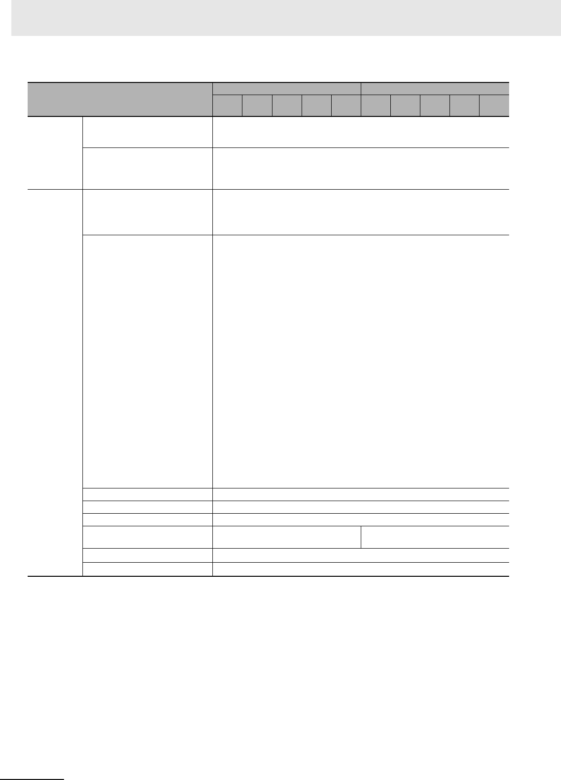
1 Overview
1-16 CJ2 CPU Unit Hardware User’s Manual
*8 Supported only by the CJ2H-CPU6@-EIP and CJ2M-CPU3@.
*9 This data type cannot be used in Function blocks.
*10 This data type can be used only in Function blocks.
*11 Supported only when CX-Programmer version 9.0 or higher is used.
Items
CJ2H- CJ2M-
CPU64
(-EIP)
CPU65
(-EIP)
CPU66
(-EIP)
CPU67
(-EIP)
CPU68
(-EIP)
CPU
11/31
CPU
12/32
CPU
13/33
CPU
14/34
CPU
15/35
Tasks Type of Tasks Cyclic tasks
Interrupt tasks (Power OFF interrupt tasks, scheduled interrupt tasks, I/O interrupt tasks, external
interrupt tasks, and input interrupt tasks*3)
Number of Tasks Cyclic tasks: 128
Interrupt tasks: 256
(Interrupt tasks can be defined as cyclic tasks to create extra cyclic tasks. Therefore, the total
number of cyclic tasks is actually 384 max.)
Symbols (Vari-
ables)
Type of Symbols Local symbols: Can be used only within a single task in the PLC.
Global symbols: Can be used in all tasks in the PLC.
Network symbols (tags)*8: I/O memory in the CPU Unit can be externally accessed using sym-
bols, depending on parameter settings.
Data Type of Symbols BOOL (bit)
UINT (one-word unsigned binary)
UDINT (two-word unsigned binary)
ULINT (four-word unsigned binary)
INT (one-word signed binary)
DINT (two-word signed binary)
LINT (four-word signed binary)
UINT BCD (one-word unsigned BCD)*9
UDINT BCD (two-word unsigned BCD)*9
ULINT BCD (four-word unsigned BCD)*9
REAL (two-word floating-point)
LREAL (four-word floating-point)
CHANNEL (word)
NUMBER (constant or number)
WORD (one-word hexadecimal)
DWORD (two-word hexadecimal)
LWORD (four-word hexadecimal)
STRING (1 to 255 ASCII characters)
TIMER (timer)*10
COUNTER (counter)*10
User-defined data types (data structures)*11
Maximum Size of Symbol 32k words
Array Symbols (Array Variables) One-dimensional arrays
Number of Array Elements 32,000 elements max.
Number of Registrable Network Symbols
(Tags)*8
20,000 max. 2,000 max.
Length of Network Symbol (Tag) Name*8 255 bytes max.
Encoding of Network Symbols (Tags)*8 UTF-8
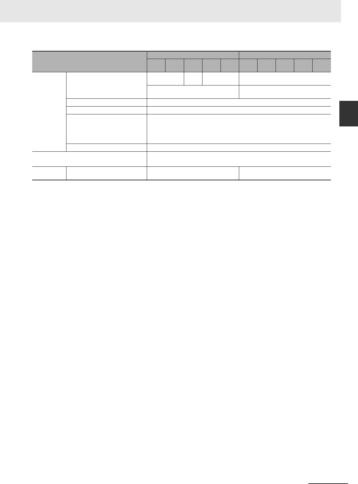
1-17
1 Overview
CJ2 CPU Unit Hardware User’s Manual
1-3 Specifications
1
1-3-2 Performance Specifications
Items
CJ2H- CJ2M-
CPU64
(-EIP)
CPU65
(-EIP)
CPU66
(-EIP)
CPU67
(-EIP)
CPU68
(-EIP)
CPU
11/31
CPU
12/32
CPU
13/33
CPU
14/34
CPU
15/35
Data Tracing Memory Capacity 8,000 words 16,000
words
32,000 words 8,000 words
(Up to 32k words x 25 banks when EM is spec-
ified in CX-Programmer)
(Up to 32k words x 4 banks when EM is speci-
fied in CX-Programmer)
Number of Samplings Bits = 31, one-word data =16, two-word data = 8, four-word data = 4
Sampling Cycle 1 to 2,550 ms (Unit: 1 ms)
Trigger Conditions ON/OFF of specified bit
Data comparison of specified word
Data size: 1 word, 2 words, 4 words
Comparison Method: Equals (=), Greater Than (>), Greater Than or Equals (≥), Less Than (<),
Less Than or Equals (≤), Not Equal (≠)
Delay Value −32,768 to +32,767 ms
File Memory Memory Card (128, 256, or 512 Mbytes) (Use the Memory Cards provided by OMRON.)
EM file memory (Part of the EM Area can be converted for use as file memory.)
Source/Com-
ment Memory
Program source, comments, program
index, and symbol table
Capacity: 3.5 Mbytes Capacity: 1 Mbytes
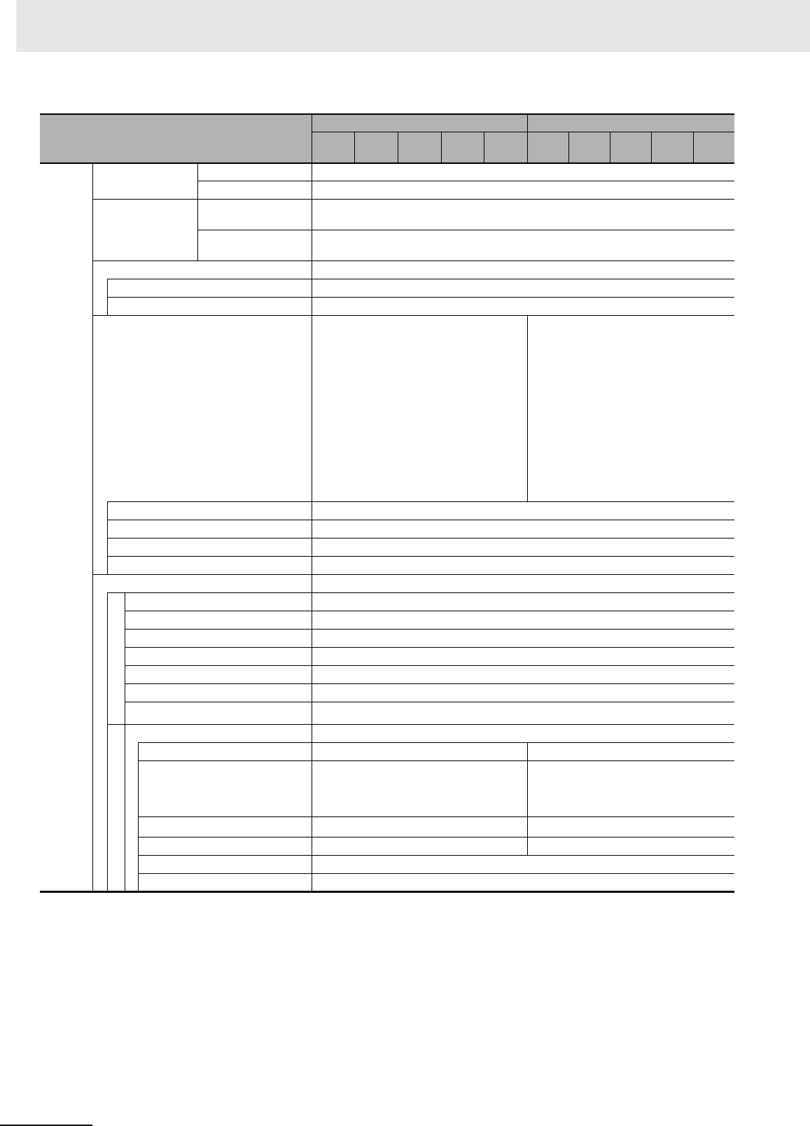
1 Overview
1-18 CJ2 CPU Unit Hardware User’s Manual
*12 The EtherNet/IP port is built into the CJ2H-CPU6@-EIP and CJ2M-CPU3@ only.
*13 “Packets per second” is the number of communications packets that can be processed per second.
Item
CJ2H- CJ2M-
CPU64
(-EIP)
CPU65
(-EIP)
CPU66
(-EIP)
CPU67
(-EIP)
CPU68
(-EIP)
CPU
11/31
CPU
12/32
CPU
13/33
CPU
14/34
CPU
15/35
Commu-
nications
Logical Ports for
Communications
Logical Ports 8 ports (Used for SEND, RECV, CMND, PMCR, TXDU, and RXDU instructions.)
Extended Logical Ports 64 ports (Used for SEND2, RECV2, CMND2, and PMCR2 instructions.)
CIP Communica-
tions Specification
Class 3 (Number of
Connections)
Number of connections: 64
UCMM (Non-connec-
tion Type)
Maximum number of clients that can communicate at the same time: 32
Maximum number of servers that can communicate at the same time: 40
Peripheral (USB) Port USB 2.0-compliant B-type connector
Baud Rate 12 Mbps max.
Transmission Distance 5 m max.
Serial Port Interface: Conforms to EIA RS-232C. • CJ2M-CPU1@ interface: Conforms to EIA
RS-232C.
• CJ2M-CPU3@: No serial ports with default
system
One of the following Serial Option Boards can
be mounted.
• CP1W-CIF01 RS-232C Option Board
• CP1W-CIF11 RS-422A/485 Option Board
(not isolated, max. transmission distance:
50 m)
• CP1W-CIF12 RS-422A/485 Option Board
(isolated, max. transmission distance: 500
m)
Communications Method Half-duplex
Synchronization Method Start-stop
Baud Rate 0.3, 0.6, 1.2, 2.4, 4.8, 9.6, 19.2, 38.4, 57.6, or 115.2 (kbps)
Transmission Distance 15 m max.
EtherNet/IP Port*12 ---
Transmission Specifications
Media Access Method CSMA/CD
Modulation Baseband
Transmission Paths Star
Baud Rate 100 Mbps (100Base-TX)
Transmission Media Shielded twisted-pair (STP) cable; Categories: 5, 5e
Transmission Distance 100 m (between Ethernet switch and node)
Number of Cascade Connections No restrictions if Ethernet switch is used.
Communications Specifications
CIP Communications: Tag Data Links ---
Number of Connections 256 32
Packet Interval (Refresh period) 0.5 to 10,000 ms (Unit: 0.5 ms)
Can be set for each connection. (Data will be
refreshed at the set interval, regardless of the
number of nodes.)
1 to 10,000 ms (in 0.5-ms increments)
Can be set for each connection. (Data will be
refreshed at the set interval, regardless of the
number of nodes.)
Permissible Communications Band 6,000 packets per second*13 3,000 packets per second*13
Number of Registrable Tags 256 32
Type of Tags CIO, DM, EM, HR, WR, and network symbols
Number of Tags per Connection 8 (Seven tags if PLC status is included in the segment.)
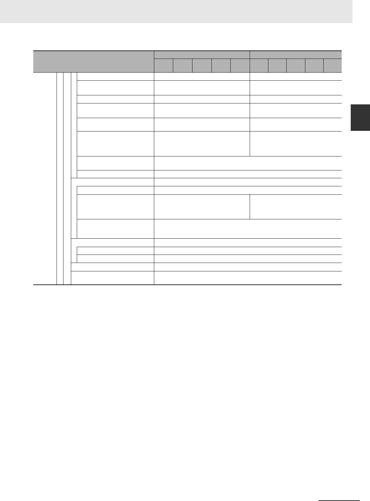
1-19
1 Overview
CJ2 CPU Unit Hardware User’s Manual
1-3 Specifications
1
1-3-2 Performance Specifications
*14 Large Forward Open (CIP optional specification) must be supported in order for 505 to 1,444 bytes to be used as the data
size. Application is supported between CS/CJ-series PLCs. When connecting to devices from other manufacturers, make
sure that the devices support the Large Forward Open specification.
*15 Unit version 2.0 of built-in EtherNet/IP section: 20 words
*16 If the maximum number is exceeded, refreshing will require more than one CPU Unit cycle.
*17 When changing parameters, however, the EtherNet/IP port where the change is made will be restarted. In addition, a tim-
eout will temporarily occur at the other node that was communicating with that port, and it will then recover automatically.
*18 The EtherNet/IP port supports an IGMP client, so unnecessary multicast packets are filtered by using an Ethernet switch
that supports IGMP snooping.
Item
CJ2H- CJ2M-
CPU64
(-EIP)
CPU65
(-EIP)
CPU66
(-EIP)
CPU67
(-EIP)
CPU68
(-EIP)
CPU
11/31
CPU
12/32
CPU
13/33
CPU
14/34
CPU
15/35
Commu-
nications
Communications Specifications
Maximum Link Data Size per Node 184,832 words 640 words
Maximum Data Size per Connection 252 or 722 words*14
(Data is synchronized within each connection.)
640 words (Data is synchronized within each
connection.)*15
Number of Registrable Tag Set 256 (1 connection = 1 segment) 32 (1 connection = 1 segment)
Maximum Tag Set Size 722 words (One word is used when PLC status
is included in the segment.)
640 words (One word is used when PLC sta-
tus is included in the segment.)*15
Maximum Number of Tags Refresh-
able in a Single Cycle of CPU Unit*16 Output/send (CPU Unit to EtherNet/IP): 256
Input/receive (EtherNet/IP to CPU Unit): 256
Output/send (CPU Unit to EtherNet/IP): 32
Input/receive (EtherNet/IP to CPU Unit): 32
Data Size Refreshable in a Single
Cycle of CPU Unit*16 Output/send (CPU to EtherNet/IP): 6,432
words
Input/receive (EtherNet/IP to CPU): 6,432
words
Output/send (CPU Unit to EtherNet/IP): 640
words
Input/receive (EtherNet/IP to CPU Unit): 640
words
Change of Tag Data Link Parameter
Settings during Operation
OK*17
Multi-cast Packet Filter*18 OK
CIP Communications: Explicit Messages ---
Class 3 (Number of Connections) Number of connections: 128
UCMM (Non-connection Type) Maximum number of clients that can communi-
cate at the same time: 32
Maximum number of servers that can commu-
nicate at the same time: 32
Maximum number of clients that can commu-
nicate at the same time: 16
Maximum number of servers that can com-
municate at the same time: 16
CIP Routing OK
(CIP routing is enabled for the following remote Units: CJ1W-EIP21, CJ2H-CPU6@-EIP, CJ2M-
CPU3@, and CS1W-EIP21.)
FINS Communications ---
FINS/UDP OK
FINS/TCP 16 connections max.
EtherNet/IP Conformance Test Conforms to A5.
EtherNet/IP Interface 10Base-T/100Base-TX
Auto Negotiation/Fixed Setting

1 Overview
1-20 CJ2 CPU Unit Hardware User’s Manual
Item
CJ2H- CJ2M-
CPU64
(-EIP)
CPU65
(-EIP)
CPU66
(-EIP)
CPU67
(-EIP)
CPU68
(-EIP)
CPU
11/31
CPU
12/32
CPU
13/33
CPU
14/34
CPU
15/35
Pulse I/O*3 External interface --- CJ2M-MD211 or CJ2M-MD212 Pulse I/O Mod-
ule with 40-pin MIL connector
Pulse Inputs Can be used as normal inputs, interrupt inputs,
quick-response inputs, or high-speed counter
inputs. (Functions of each input must be
selected in the PLC Setup.)
Input method: Line-driver input or 24-VDC input
(selected by wiring)
Normal inputs 20 max. (10 per Pulse I/O Module)
Input constants: Set in the PLC Setup (0, 0.5,
1, 2, 4, 8, 16, or 32 ms). Default: 8 ms
Interrupt inputs and quick-
response inputs
8 max. (4 per Pulse I/O Module)
Input signal minimum ON pulse width: 30 µs
High-speed counter inputs 4 max. (2 per Pulse I/O Module)
Input method: Differential-phase (×4) pulses,
pulse + direction, up/down pulses, or increment
pulse
Maximum response frequency: 50 kHz for dif-
ferential phases or 100 kHz for single phase
Counting mode: Linear mode or circular (ring)
mode
Count value: 32 bits
Counter reset: Phase Z + software reset or soft-
ware reset
Control method: Target-value comparison or
range comparison
Gate function: Supported
Pulse Outputs Can be used as normal outputs, pulse outputs,
or PWM outputs. (Functions of each output
must be selected in the PLC Setup.)
Output method: Sinking or sourcing transistor
outputs (The method is determined by Pulse
I/O Module model.)
Normal outputs --- 12 max. (6 per Pulse I/O Module)
Pulse outputs 4 max. (2 per Pulse I/O Module)
Output method: CW/CCW or pulse + direction
(The method is determined by the I/O wiring
and the instructions used in the ladder pro-
gram.)
Output frequency: 1 pps to 100 kpps (in incre-
ments of 1 pps)
Output Mode: Continuous mode (for speed
control) or independent mode (for position con-
trol)
Output pulses: Relative coordinates: 0000 0000
to 7FFF FFFF hex (0 to 2,147,483,647 pulses)
Absolute coordinates: 8000 0000 to 7FFF
FFFF hex (−2,147,483,648 to 2,147,483,647)
Acceleration/deceleration curves: Linear or S-
curve
Origin search function: Supported
PWM outputs 4 max. (2 per Pulse I/O Module)
Output frequency: 0.1 to 6,553.5 Hz (in 0.1-Hz
increments) or 1 to 32,800 Hz (in 1-Hz incre-
ments)
Duty ratio: 0.0% to 100.0% (in 0.1% incre-
ments)

1-21
1 Overview
CJ2 CPU Unit Hardware User’s Manual
1-3 Specifications
1
1-3-3 Function Specifications
*1 Supported only by CJ2H CPU Units with unit version 1.1 or later and CJ2M CPU Units.
*2 Supported only by CJ2H CPU Units with unit version 1.1 or later.
1-3-3 Function Specifications
Functions Description
Cycle
Time Man-
agement
Minimum Cycle Time A minimum cycle time can be set.
(0.2 to 32,000 ms; Unit: 0.1 ms)
The minimum cycle time setting can be changed in MONITOR mode*1
Cycle Time Monitoring The cycle time is monitored.
(0.01 to 40,000 ms; Unit: 0.01 ms)
Background Processing Instructions with long execution times can be executed over multiple
cycles to prevent fluctuations in the cycle time.
Unit (I/O)
Manage-
ment
Basic I/O
Units, Spe-
cial I/O
Units, and
CPU Bus
Units
I/O
Refresh-
ing
Cyclic Refreshing Cyclic refreshing of Basic I/O Units, Special I/O Units, and CPU Bus
Units
Immediate Refreshing I/O refreshing by immediate refreshing instructions
Refreshing by IORF I/O refreshing by IORF instruction
Unit Recognition at Startup The number of units recognized when the power is turned ON is dis-
played.
Basic I/O
Units
Input Response Time Setting The input response times can be set for Basic I/O Units. The response
time can be increased to reduce the effects of chattering and noise at
input contacts. The response time can be decreased to enable detecting
shorter input pulses.
Load OFF Function All of the outputs on Basic I/O Units can be turned OFF when an error
occurs in RUN or MONITOR mode.
Basic I/O Unit Status Monitoring Alarm information can be read from Basic I/O Units and the number of
Units recognized can be read.
Reading/writing data using instruc-
tions for specific Units*1
Special instructions can be used to read/write required data for specific
Units at high speed.
Special I/O
Units and
CPU Bus
Units
Unit Restart Bits to Restart Units A Special I/O Unit or CPU Bus Unit can be restarted.
Synchronous Unit Operation*2 The start of processing for all the specified Units can be synchronized at
a fixed interval.
Maximum number of Units: 10 Units (Only Units that support Synchro-
nous Operation Mode can be used.)
Synchronous operation cycle: 0.5 to 10 ms (default: 2 ms)
Maximum number of words for synchronous data refreshing: 96 words
(total of all Units)
Configura-
tion Man-
agement
Automatic I/O Allocation at Startup I/O words can be automatically allocated to the Basic I/O Units that are
connected in the PLC to start operation automatically without registering
Units into I/O tables.
I/O Table Creation The current unit configuration can be registered in I/O tables to prevent it
from being changed, to reserve words, and to set words.
Rack/Slot First Word Settings The first words allocated to a Units on the Racks can be set.

1 Overview
1-22 CJ2 CPU Unit Hardware User’s Manual
*3 Supported only by CJ2M CPU Unit with unit version 2.0 or later. A Pulse I/O Module must be mounted.
Functions Description
Pulse I/O
Func-
tions*3
Pulse Input
Functions
Normal Inputs Input signals are read during I/O refreshing and stored in I/O memory.
Interrupt Inputs An interrupt task can be started when an input signal turns ON or turns
OFF.
Quick-response Inputs Input signals that are shorter than the cycle time are read and stored in
I/O memory.
High-speed Counter Inputs High-speed pulse signals are counted. Interrupt tasks can also be
started.
Pulse Out-
put Func-
tions
Normal Outputs The status of I/O memory is output during I/O refreshing.
Pulse Outputs A pulse signal is output with the specified frequency and number of
pulses at a fixed duty ratio (50%).
PWM Outputs A pulse signal is output at the specified duty ratio.
Origin Searches The origin point of the machine is determined according to the specified
origin search parameters while actually outputting pulses and using the
origin and origin proximity input signals as conditions. (Pulse inputs and
outputs are also used for this function.)
Memory
Manage-
ment
Holding I/O Memory when Changing Operating
Modes
The status of I/O memory can be held when the operating mode is
changed or power is turned ON. The forced-set/reset status can be held
when the operating mode is changed or power is turned ON.
File Memory Files (such as program files, data files, and symbol table files) can be
stored in Memory Card, EM File Memory, or Comment Memory.
Built-in Flash Memory The user program and Parameter Area can be backed up to an internal
flash memory when they are transferred to the CPU Unit.
EM File Function Parts of the EM Area can be treated as file memory.
Storing Comments I/O comments can be stored as symbol table files in a Memory Card, EM
file memory, or comment memory.
EM Configuration EM Area can be set as trace memory or EM file memory.
Memory
Cards
Automatic File Transfer at Startup A program file and parameter files can be read from a Memory Card
when the power is turned ON.
Program Replacement during PLC Operation User programs can be transferred from a Memory Card to CPU Unit dur-
ing operation.
Function for Reading and Writing Data from a
Memory Card
Data in I/O memory in the CPU Unit can be written to a Memory Card in
CSV/TXT format. Data in CSV/TXT format in the Memory Card can be
read to I/O memory in the CPU Unit.

1-23
1 Overview
CJ2 CPU Unit Hardware User’s Manual
1-3 Specifications
1
1-3-3 Function Specifications
*4 A Serial Option Board is required to use a serial port for the CJ2M-CPU3@ CPU Unit.
*5 A Serial Option Board is required to use the CJ2M-CPU3@ CPU Unit in Serial PLC Links.
*6 Supported only by CJ2H-CPU6@-EIP and CJ2M-CPU3@.
Function Description
Communications ---
Peripheral
(USB) Port
Peripheral Bus Bus for communications with various kinds of Support Software running on a
personal computer. High-speed communications are supported.
Serial Port*4 ---
Host Link (SYSWAY) Communications Host Link commands or FINS commands placed between Host Link headers
and terminators can be sent from a host computer or PT to read/write I/O mem-
ory, read/control the operating mode, and perform other operations for PLC.
No-protocol Communications I/O instructions for communications ports (such as TXD/RXD instructions) can
be used for data transfer with peripheral devices such as bar code readers and
printers.
NT Link Communications I/O memory in the PLC can be allocated and directly linked to various PT func-
tions, including status control areas, status notification areas, touch switches,
lamps, memory tables, and other objects.
Peripheral Bus Bus for communications with various kinds of Support Software running on a
personal computer. High-speed communications are supported.
Serial Gateway This gateway enables receiving and automatically converting FINS to the Com-
poWay/F.
Serial PLC Links*5 Data is exchanged between CPU Units using serial ports without communica-
tions programming. PTs set to the 1:N NT Link protocol can be included in the
network.
EtherNet/IP Port*6 100Base-TX/10Base-T
Protocols: TCP/IP, UDP, ARP, ICMP (ping only), BOOTP
Applications: FINS, CIP, SNTP, DNS (Client), FTP (Server)
CIP Commu-
nications
Service
Tag Data Links Programless cyclic data exchanges with the devices on the EtherNet/IP net-
work.
Message Communications Any CIP commands can be received from the devices on the EtherNet/IP net-
work.
FINS Com-
munications
Service
Message Communications Any FINS commands can be transferred with the devices on the EtherNet/IP
network.

1 Overview
1-24 CJ2 CPU Unit Hardware User’s Manual
*7 Supported only by the CJ2M CPU Units.
*8 Pulse I/O Modules are supported only by CJ2M CPU Units with unit version 2.0 or later.
*9 Supported only by CJ2H CPU Units with unit version 1.1 or later.
Function Description
Interrupt Scheduled Interrupts A task is executed at a specified interval.
Resetting and restarting with
MSKS(690)*7
When MSKS(690) is executed, the internal timer is restarted and the time to
first interrupt is set to a fixed value.
Reading present value of internal timer
with MSKS(690)*7
MSKS(690) can be used to read the time that has elapsed until the scheduled
interrupt is started or since the previous scheduled interrupt.
Power OFF Interrupts A task can be executed when CPU Unit's power turns OFF.
I/O Interrupts A task can be executed when an input signal is input to an Interrupt Input Unit.
External Interrupts A task can be executed when interrupts are requested from a Special I/O Unit
or a CPU Bus Unit.
Input Interrupt Function*8 A task is started for an interrupt input from a Pulse I/O Module or for a high-
speed counter input.
Input Interrupts Interrupt tasks are executed when the interrupt input turns ON or turns OFF.
Direct Mode: An interrupt task is executed each time an input signal changes.
Counter Mode: Changes in the input signal are counted up or down and the
interrupt task is executed when the counter counts out. (The maximum
response frequency is 3 kHz.)
High-speed Counter Interrupts An interrupt task is executed when preset comparison conditions for a high-
speed counter are met.
Target-value comparison: The interrupt task is executed when the count
matches a specified value.
Range comparison: The interrupt task is executed when the count enters or
leaves a specified range of values.
High-speed Interrupt Function*9 Improves performance for executing interrupt tasks with certain restrictions.
Clock Clock Function Clock data is stored in memory.
Accuracy (Accuracy depends on the temperature.)
Ambient temperature of 55°C: −3.5 to +0.5 min error per month
Ambient temperature of 25°C: −1.5 to +1.5 min error per month
Ambient temperature of 0°C: −3 to +1 min error per month
Operation Start Time Storage The time when operating mode was last changed to RUN mode or MONITOR
mode is stored.
Operation Stop Time Storage The last time a fatal error occurred or the last time the operating mode was
changed to PROGRAM mode is stored.
Startup Time Storage The time when the power was turned ON is stored.
Power Interruption Time Storage The time when the power is turned OFF is stored.
Total Power ON Time Calculation The total time that the PLC has been ON is stored in increments of 10 hours.
Power ON Clock Data Storage A history of the times when the power was turned ON is stored.
User Program Overwritten Time Storage The time that the user program was last overwritten is stored.
Parameter Date Storage The time when the Parameter Area was overwritten is stored.

1-25
1 Overview
CJ2 CPU Unit Hardware User’s Manual
1-3 Specifications
1
1-3-3 Function Specifications
Function Description
Power
Supply
Manage-
ment
Memory Protection Holding Area data, DM Area data, EM Area data, Counter Completion Flags,
and counter present values are held even when power is turned OFF. CIO
Area, Work Area, some Auxiliary Area data, and Timer Completion Flags, timer
present values, index registers, and data registers can be protected by turning
ON the IOM Hold Bit in the Auxiliary Area, and by also setting the IOM Hold Bit
to “Hold” in the PLC Setup.
Power OFF Detection Time Setting The detection time for power interruptions can be set.
AC power supply: 10 to 25 ms (variable)
DC power supply: 2 to 5 ms (CJ1W-PD022) or 2 to 20 ms (CJ1W-PD025)
Power OFF Detection Delay Time The detection of power interruptions can be delayed: 0 to 10 ms
(Not supported by the CJ1W-PD022.)
Number of Power Interruptions Counter The number of times power has been interrupted is counted.
Function Blocks Standard programming can be encapsulated as function blocks.
Languages in Function Block Definitions Ladder programming or structured text
Debug-
ging
Online Editing The program can be changed during operation (in MONITOR or PROGRAM
mode), except for block programming areas.
Force-Set/Reset Specified bits can be set or reset.
A parameter can be set to enable force-setting/resetting bits in EM Area banks.
Force-setting/resetting is enabled for the specified bank and all the banks after
it.*10
Differentiate Monitoring ON/OFF changes in specified bits can be monitored.
Data Tracing The specified I/O memory data can be stored in the trace memory in the CPU
Unit. The triggers can be set.
Continuous Tracing The trace data can be uploaded during data tracing using the CX-Programmer.
This enables continuously logging the data by constantly uploading the trace
data.
Automatically starting tracing when opera-
tion starts
Data tracing can be automatically started when operation is started (i.e., when
the operating mode is changed from PROGRAM mode to MONITOR or RUN
mode).
Storing Location of Error when an Error
Occurs
The location and task number where execution stopped for a program error is
recorded.
Program Check The programs can be checked for items such as no END instruction and
FALS/FAL errors at startup.
Self-diag-
nosis and
Restora-
tion
Error Log A function is provided to store predefined error codes in CPU Unit, error infor-
mation, and time at which the error occurred.
CPU Error Detection CPU Unit WDT errors are detected.
User-defined Failure Diagnosis Errors can be generated for user-specified conditions: Non-fatal errors (FAL)
and fatal errors (FALS).
Program section time diagnosis and program section logic diagnosis are sup-
ported (FPD instruction).
Load OFF Function This function turns OFF all outputs from Output Units when an error occurs.
RUN Output The RUN output from the CJ1W-PA205R turns ON while CPU Unit is in RUN
mode or MONITOR mode.
Basic I/O Load Short-circuit Detection This function provides alarm information from Basic I/O Units that have load
short-circuit protection.
Failure Point Detection The time and logic of an instruction block can be analyzes using the FPD
instruction.
CPU Standby Detection This function indicates when the CPU Unit is on standby because all Special
I/O Units and CPU Bus Units have not been recognized at the startup in RUN
or MONITOR mode.
*10 Supported only by CJ2H CPU Units with unit version 1.2 or later and CJ2M CPU Units.

1 Overview
1-26 CJ2 CPU Unit Hardware User’s Manual
*11 Supported only by CJ2H-CPU6@-EIP and CJ2M-CPU3@.
*12 Supported only by the CJ2M-CPU3@.
Function Description
Self-diag-
nosis and
Restora-
tion
(Contin-
ued from
previous
page)
Non-fatal Error
Detection
System FAL Error Detec-
tion (User-defined non-
fatal error)
This function generates a non-fatal (FAL) error when the user-defined condi-
tions are met in program.
Duplicated Refreshing
Error Detection
This function detects an error when an immediate refreshing Instruction in an
interrupt task is competing with I/O refreshing of a cyclic task.
Basic I/O Unit Error Detec-
tion
This function detects the errors in Basic I/O Units.
Backup Memory Error
Detection
This function detects errors in the memory backup of the user programs and
parameter area (backup memory).
PLC Setup Error Detection This function detects setting errors in the PLC Setup.
CPU Bus Unit Error Detec-
tion
This function detects an error when there is an error in data exchange between
the CPU Unit and a CPU Bus Unit.
Special I/O Unit Error
Detection
This function detects an error when there is an error in data exchange between
the CPU Unit and a Special I/O Unit.
Tag Memory Error Detec-
tion*11
This function detects errors in tag memory.
Battery Error Detection This function detects an error when a battery is not connected to the CPU Unit
or when the battery voltage drops.
CPU Bus Unit Setting
Error Detection
This function detects an error when the model of a CPU Bus Unit in the regis-
tered I/O tables does not agree with the model that is actually mounted in the
PLC.
Special I/O Unit Setting
Error Detection
This function detects an error when the model of a Special I/O Unit in the regis-
tered I/O tables does not agree with the model of Unit that is actually mounted.
Option Board Error Detec-
tion*12
This function detects the errors in Serial Option Board mounting status.
Fatal Error
Detection
Memory Error Detection This function detects errors that occur in memory of the CPU Unit.
I/O Bus Error Detection This function detects when an error occurs in data transfers between the Units
mounted in Rack slots and the CPU Unit and detects when the End Cover is
not connected to the CPU Rack or an Expansion Rack.
Unit/Rack Number Dupli-
cation Error
This function detects an error when the same unit number is set for two or more
Units, the same word is allocated to two or more Basic I/O Units, or the same
rack number is set for two or more Racks.
Too Many I/O Points Error
Detection
This function detects an error when the total number of I/O points set in the I/O
tables or the number of Units per Rack exceeds the specified range.
I/O Setting Error Detection The registered I/O tables are used to detect errors if the number of Units in the
registered I/O tables does not agree with the actual number of Units that are
connected or an Interrupt Unit has been connected in the wrong position.

1-27
1 Overview
CJ2 CPU Unit Hardware User’s Manual
1-3 Specifications
1
1-3-3 Function Specifications
*13 This function can be used only with CJ2H CPU Units.
Function Description
Self-diag-
nosis and
Restora-
tion
(Contin-
ued from
previous
page)
Fatal Error
Detection
Program Error Detection This function detects errors in programs.
Instruction Processing
Error Detection
This function detects an error when the given data value is invalid when execut-
ing an instruction, or execution of instruction between tasks was attempted.
Indirect DM/EM BCD
Error Detection
This function detects an error when an indirect DM/EM address in BCD mode
is not BCD.
Illegal Area Access
Error Detection
This function detects an error when an attempt is made to access an illegal
area with an instruction operand.
No END Error Detec-
tion
This function detects an error when there is no END instruction at the end of
the program.
Task Error Detection This function detects an error when there are no tasks that can be executed in
a cycle, there is no program for a task, or the execution condition for an inter-
rupt task was met but there is no interrupt task with the specified number.
Differentiation Over-
flow Error Detection
This function detects an error when too many differentiated instructions are
entered or deleted during online editing (131,072 times or more).
Invalid Instruction Error
Detection
This function detects an error when an attempt is made to execute an instruc-
tion that is not defined in the system.
User Program Area
Overflow Error Detec-
tion
This function detects an error when instruction data is stored after the last
address in user program area.
Cycle Time Exceeded
Error Detection
This function monitors the cycle time (10 to 40,000 ms) and stops the operation
when the set value is exceeded.
System FALS Error Detec-
tion (User-defined Fatal
Error)
This function generates a fatal (FALS) error when the user-defined conditions
are met in program.
Version Error Detection This function detects an error when a user program includes a function that is
not supported by the current unit version.
Memory Card Transfer
Error Detection
This function detects an error when the automatic file transfer from Memory
Card fails at startup.
Memory Self-restoration Function This function performs a parity check on the user program area and self-resto-
ration data.*13
Mainte-
nance
Simple Backup Function This function collectively backs up the data in CPU Unit (user programs,
parameters, and I/O memory) and internal backup data in the I/O Units.
Unsolicited Communications A function that allows the PLC to use Network Communications Instruction to
send required FINS commands to a computer connected via a Host Link
Remote Programming and Monitoring Host Link communications can be used for remote programming and remote
monitoring through a Controller Link, Ethernet, DeviceNet, or SYSMAC LINK
Network. Communications across network layers can be performed.
Controller Link or Ethernet: 8 layers
DeviceNet or SYSMAC LINK: 3 layers
Automatic Online Connection via
Network
Direct
Serial
Connec-
tion
This function enables automatically connecting to the PLC online when the CX-
Programmer is directly connected by a serial connection (peripheral (USB) port
or serial port).
Via Net-
works
This function enables connecting the CX-Programmer online to a PLC that is
connected via an EtherNet/IP network.
Security Read Protection using Password This function protects reading and displaying programs and tasks using pass-
words.
Write protection: Set using the DIP switch.
Read protection: Set a password using the CX-Programmer.
FINS Write Protection This function prohibits writing by using FINS commands sent over the network.
Unit Name Function This function allows the users to give any names to the Units. Names are veri-
fied at online connection to prevent wrong connection
Hardware ID Using Lot Numbers This function sets operation protection by identifying hardware using the user
programs according to lot numbers stored in the Auxiliary Area.

1 Overview
1-28 CJ2 CPU Unit Hardware User’s Manual

2-1
CJ2 CPU Unit Hardware User’s Manual
2
This section describes the basic system configuration and devices used in a CJ2 PLC.
The CJ Series supports the following two types of system configuration.
• Basic System Configuration:
System consisting of CPU Rack and Expansion Racks.
• Expanded System Configuration:
System connected via CPU Unit built-in serial port and PLC Units, such as Communi-
cations Units.
2-1 Basic System Configuration . . . . . . . . . . . . . . . . . . . . . . . . . . . . . . . . . . . . . 2-2
2-1-1 Basic System Configuration . . . . . . . . . . . . . . . . . . . . . . . . . . . . . . . . . . . . . . . 2-2
2-1-2 CPU Rack . . . . . . . . . . . . . . . . . . . . . . . . . . . . . . . . . . . . . . . . . . . . . . . . . . . . 2-3
2-1-3 Expansion Racks . . . . . . . . . . . . . . . . . . . . . . . . . . . . . . . . . . . . . . . . . . . . . . 2-11
2-1-4 Configuration Units . . . . . . . . . . . . . . . . . . . . . . . . . . . . . . . . . . . . . . . . . . . . 2-14
2-1-5 Calculating Unit Current Consumption . . . . . . . . . . . . . . . . . . . . . . . . . . . . . 2-22
2-1-6 Calculating Power Consumption . . . . . . . . . . . . . . . . . . . . . . . . . . . . . . . . . . 2-25
2-2 Expanded System Configuration . . . . . . . . . . . . . . . . . . . . . . . . . . . . . . . . 2-27
2-2-1 Serial Communications . . . . . . . . . . . . . . . . . . . . . . . . . . . . . . . . . . . . . . . . . 2-27
2-2-2 Communications Networks . . . . . . . . . . . . . . . . . . . . . . . . . . . . . . . . . . . . . . 2-29
Basic System Configuration and
Devices
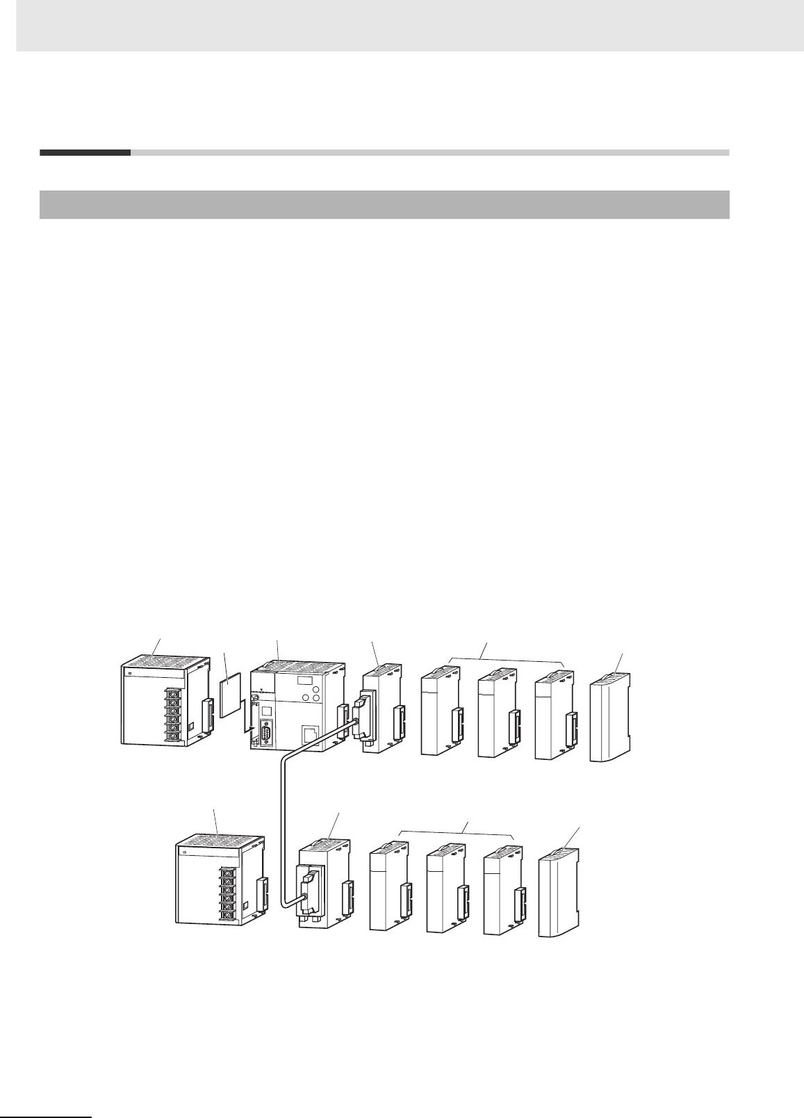
2 Basic System Configuration and Devices
2-2 CJ2 CPU Unit Hardware User’s Manual
2-1 Basic System Configuration
zCPU Rack
A CPU Rack can consist of a CJ2 CPU Unit, a CJ-series Power Supply Unit, CJ-series Configuration
Units (Basic I/O Units, Special I/O Units, CPU Bus Units), and a CJ-series End Cover. The same CJ-
series Power Supply Units and CJ-series Configuration Units that are used with CJ1 CPU Units are
used with CJ2 CPU Units.* An I/O Control Unit is required to connect a CJ-series Expansion Rack.
A Memory Card is optional.
* All CJ-series Units can be used as Configuration Units, but only Units that specifically support the CJ2 CPU Unit
can access the expanded portions of the I/O memory areas of the CJ2 CPU Units (i.e., A960 to A1471, A10000
to A11535, and EM banks D to 18). Only the following CJ1 Units specifically support the CJ2 CPU Units.
• EtherNet/IP Unit: CJ1W-EIP21
• Position Control Units: CJ1W-NC214, CJ1W-NC234, CJ1W-NC281, CJ1W-NC414, CJ1W-NC434, CJ1W-
NC481, and CJ1W-NC881
• Analog Input Unit: CJ1W-AD042
• Analog Output Unit: CJ1W-DA042V
• Serial Communications Units: CJ1W-SCU22, CJ1W-SCU32, and CJ1W-SCU42
zExpansion Racks
A CJ-series Expansion Rack can be connected to the CPU Rack or another CJ-series Expansion
Rack. An Expansion Rack can consist of an I/O Interface Unit, a Power Supply Unit, Basic I/O Units,
Special I/O Units, CPU Bus Units, and an End Cover.
2-1-1 Basic System Configuration
CPU Rack
Power Supply Unit CPU Unit I/O Control Unit
Configuration Units
(Basic I/O Units, Special
I/O Units, CPU Bus Units)
Configuration Units
(Basic I/O Units, Special
I/O Units, CPU Bus Units)
Expansion Rack
Power Supply Unit I/O Interface Unit
End Cover
End Cover
Memory Card
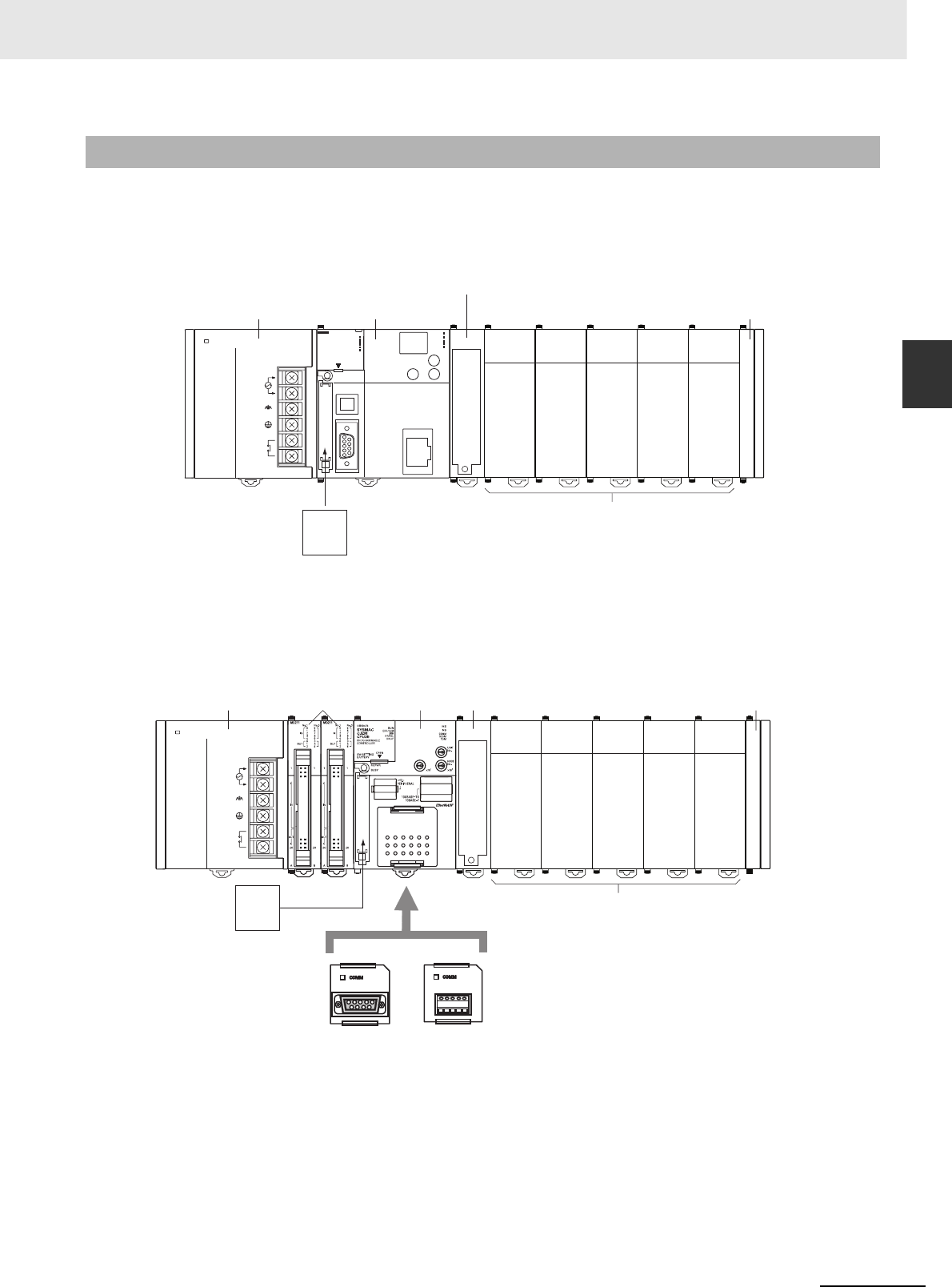
2-3
2 Basic System Configuration and Devices
CJ2 CPU Unit Hardware User’s Manual
2-1 Basic System Configuration
2
2-1-2 CPU Rack
The CPU Rack consists of a CJ2 CPU Unit, a CJ-series Power Supply Unit, CJ-series Configuration
Units, and a CJ-series End Cover. Up to 10 Configuration Units can be connected.
zCJ2H CPU Units
*1 The I/O Control Unit is required only to connect an Expansion Rack. It must be connected next to the CPU
Unit.
zCJ2M CPU Units
Even though the CJ-series PLCs do not have Backplanes, the term “slot” is still used to refer to the
location of Units. Slot numbers are assigned in order to Units from left to right on the CPU Rack (slot 0,
slot 1, slot 2, etc.).
2-1-2 CPU Rack
Memory Card
Configuration Units (10 max.)
(Basic I/O Units, Special I/O Units, CPU Bus Units)
POWER
PA205R
DC24V
AC240V
OUTPUT
RUN
INPUT
AC100-240V
L2/N
L1
CONTROLLER
PROGRAMMABLE
ERR/ALM
RUN
COMM
BKUP
INH
PRPHL
OPEN
PERIPHERAL
BUSY
MCPWR
PORT
CJ2H
CPU64-EIP
SYSMAC NS
MS
100M
10M
COMM
CPU Unit
Power Supply Unit End Cover
I/O Control Unit*1
Power Supply Unit
Pulse I/O
Modules*1 CPU Unit
Memory Card
Configuration Units (10 max.)
End Cover
I/O Control Unit*3
Serial Option Board*2
RS-232C RS-422A/485
*1 Up to two Pulse I/O Modules can be
connected to the left of the CPU Unit.
*2 CJ2M-CPU3@ only.
*3 The I/O Control Unit is required only
to connect an Expansion Rack. It
must be connected immediately to
the right of the CPU Unit.
POWER
PA205R
DC24V
AC240V
OUTPUT
RUN
INPUT
AC100-240V
L2/N
L1
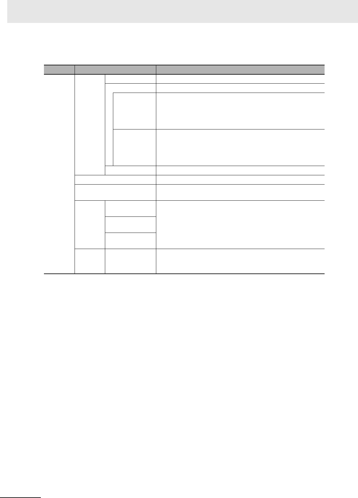
2 Basic System Configuration and Devices
2-4 CJ2 CPU Unit Hardware User’s Manual
Although the CJ-series PLCs do not require Backplanes, the term “slot” is still used to refer to the rela-
tive position of a Unit in the Rack. Slot numbers increase toward the right side of the Rack.
Name Configuration Remarks
CJ-series
CPU Rack
CPU Unit CJ2H CPU Units One required for every CPU Rack.
CJ2M CPU Units One required for every CPU Rack.
Pulse I/O Mod-
ule (Can be
connected only
with a CJ2M
CPU Unit.)
Connected to use pulse I/O.
Up to two Pulse I/O Modules can be connected. They must be con-
nected to the immediate left of the CPU Unit. The Pulse I/O Mod-
ule closest to the CPU Unit is Pulse I/O Module 0 and the other
one is Pulse I/O Module 1.
Serial Option
Board (Can be
mounted only
with the CJ2M-
CPU3@.)
One Serial Option Board can be mounted in the CJ2M-CPU3@.
Memory Card Install as required.
CJ-series Power Supply Unit One required for every CPU Rack.
I/O Control Unit Required to connect an Expansion Rack. Must be connected
immediately to the right of the CPU Unit.
Configu-
ration
Units
CJ-series Basic
I/O Units
A total of up to 10 Units can be connected to the CPU Rack and to
each of the Expansion Racks. (An error will occur if 11 or more
Units are connected.)
CJ-series Special
I/O Units
CJ-series CPU
Bus Units
End
Cover
Must be connected to the right end of the CPU Rack. One End
Cover is provided with the CPU Unit.
A fatal error will occur if the End Cover is not connected.

2-5
2 Basic System Configuration and Devices
CJ2 CPU Unit Hardware User’s Manual
2-1 Basic System Configuration
2
2-1-2 CPU Rack
zCJ2H CPU Units
*1 Increases by 0.15 A/Unit when an NT-AL001 Link Adapter is used.
Increases by 0.04 A/Unit when a CJ1W-CIF11 RS-422A Converter is used.
Increases by 0.20 A/Unit when an NV3W-M@20L Programmable Terminal is used.
*2 Includes the weight of the End Cover.
Units
Model I/O capacity Program
capacity DM Area capacity
Current consumption
(A) Weight
5 VDC 24 VDC
CJ2H-CPU68-EIP 2,560 points 400 Ksteps 832 Kwords
(DM: 32 Kwords, EM:
32 Kwords × 25 banks)
0.82*1 --- 280 g
max.*2
CJ2H-CPU67-EIP 250 Ksteps 512 Kwords
(DM: 32 Kwords, EM:
32 Kwords × 15 banks)
CJ2H-CPU66-EIP 150 Ksteps 352 Kwords
(DM: 32 Kwords, EM:
32 Kwords × 10 banks)
CJ2H-CPU65-EIP 100 Ksteps 160 Kwords
(DM: 32 Kwords, EM:
32 Kwords × 4 banks)
CJ2H-CPU64-EIP 50 Ksteps 160 Kwords
(DM: 32 Kwords, EM:
32 Kwords × 4 banks)
CJ2H-CPU68 2,560 points 400 Ksteps 832 Kwords
(DM: 32 Kwords, EM:
32 Kwords × 25 banks)
0.42*1 --- 190 g
max.*2
CJ2H-CPU67 250 Ksteps 512 Kwords
(DM: 32 Kwords, EM:
32 Kwords × 15 banks)
CJ2H-CPU66 150 Ksteps 352 Kwords
(DM: 32 Kwords, EM:
32 Kwords × 10 banks)
CJ2H-CPU65 100 Ksteps 160 Kwords
(DM: 32 Kwords, EM:
32 Kwords × 4 banks)
CJ2H-CPU64 50 Ksteps 160 Kwords
(DM: 32 Kwords, EM:
32 Kwords × 4 banks)

2 Basic System Configuration and Devices
2-6 CJ2 CPU Unit Hardware User’s Manual
zCJ2M CPU Units
*1 Increases by 0.15 A/Unit when an NT-AL001 Link Adapter is used.
Increases by 0.04 A/Unit when a CJ1W-CIF11 RS-422A Converter is used.
Increases by 0.20 A/Unit when an NV3W-M@20L Programmable Terminal is used.
*2 Includes the weight of the End Cover.
*3 The weight of a Serial Option Board is not included.
Model I/O capacity Program
capacity DM Area capacity
Current consumption
(A) Weight
5 VDC 24 VDC
CJ2M-CPU35 2,560 points 60 Ksteps 160 Kwords
(DM: 32 Kwords, EM:
32 Kwords × 4 banks)
0.7*1 --- 190 g
max.*2, *3
CJ2M-CPU34 30 Ksteps 160 Kwords
(DM: 32 Kwords, EM:
32 Kwords × 4 banks)
CJ2M-CPU33 20 Ksteps 64 Kwords
(DM: 32 Kwords, EM:
32 Kwords × 1 bank)
CJ2M-CPU32 10 Ksteps 64 Kwords
(DM: 32 Kwords, EM:
32 Kwords × 1 bank)
CJ2M-CPU31 5 Ksteps 64 Kwords
(DM: 32 Kwords, EM:
32 Kwords × 1 bank)
CJ2M-CPU15 2,560 points 60 Ksteps 160 Kwords
(DM: 32 Kwords, EM:
32 Kwords × 4 banks)
0.5*1 --- 130 g
max.*2, *3
CJ2M-CPU14 30 Ksteps 160 Kwords
(DM: 32 Kwords, EM:
32 Kwords × 4 banks)
CJ2M-CPU13 20 Ksteps 64 Kwords
(DM: 32 Kwords, EM:
32 Kwords × 1 bank)
CJ2M-CPU12 10 Ksteps 64 Kwords
(DM: 32 Kwords, EM:
32 Kwords × 1 bank)
CJ2M-CPU11 5 Ksteps 64 Kwords
(DM: 32 Kwords, EM:
32 Kwords × 1 bank)
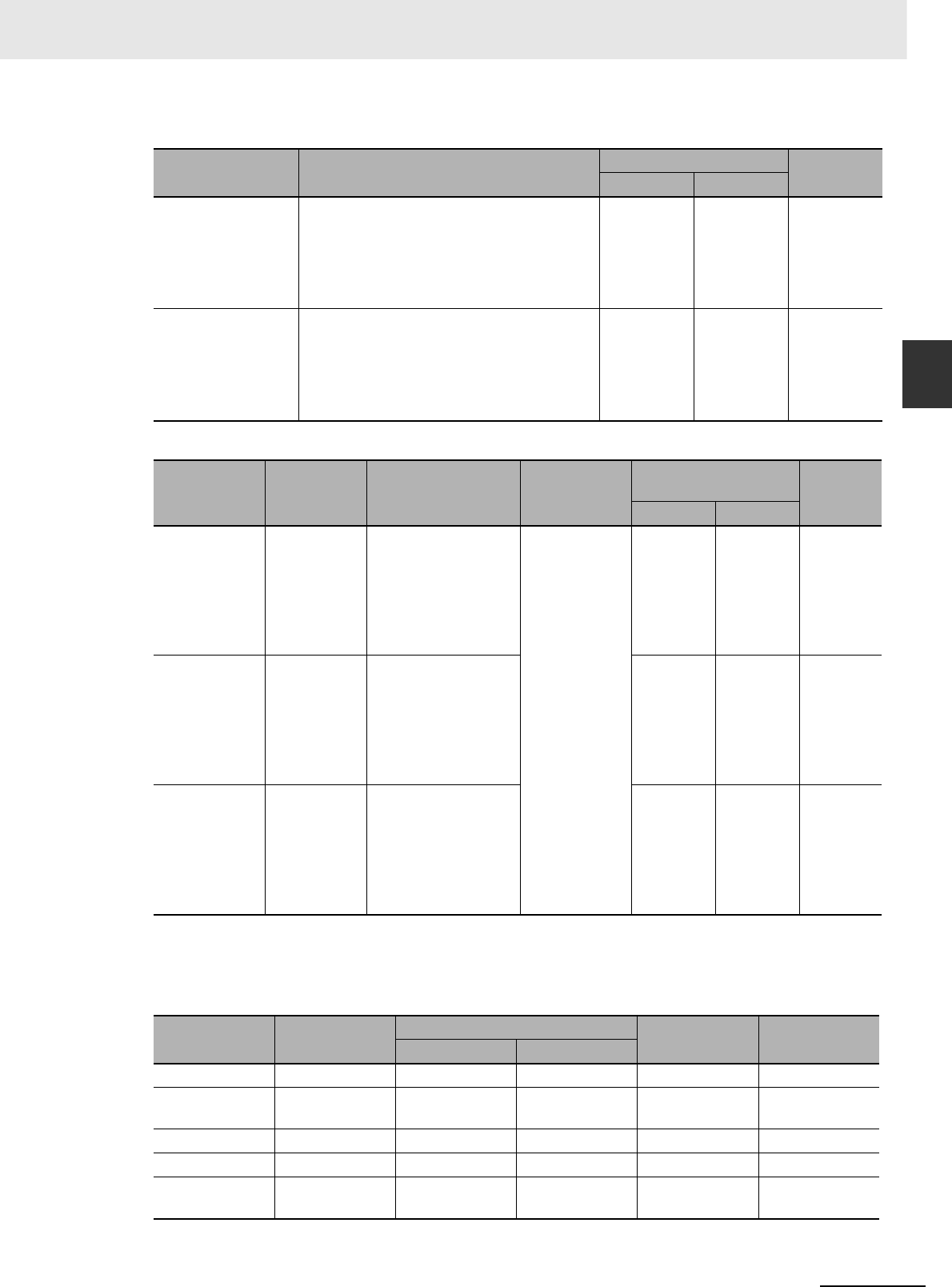
2-7
2 Basic System Configuration and Devices
CJ2 CPU Unit Hardware User’s Manual
2-1 Basic System Configuration
2
2-1-2 CPU Rack
Pulse I/O Modules (CJ2M CPU Unit Only)
Serial Option Boards (CJ2M-CPU3@ Only)
* The following modes cannot be used: 1:1 NT Link, Serial Gateway converted to Host Link FINS, 1:1 Link Master,
and 1:1 Link Slave.
zCJ-series Power Supply Units
Model Specifications Current consumption (A) Weight
5 VDC 24 VDC
CJ2M-MD211 Sinking outputs, MIL connector
10 inputs (including four interrupt/quick-
response inputs and two high-speed counter
inputs)
6 outputs (including two pulse outputs and
two PWM outputs)
0.08 --- 70 g
CJ2M-MD212 Sourcing outputs, MIL connector
10 inputs (including four interrupt/quick-
response inputs and two high-speed counter
inputs)
6 outputs (including two pulse outputs and
two PWM outputs)
0.08 --- 70 g
Name Model Specifications
Serial com-
munications
mode
Current consumption
(A) Weight
5 VDC 24 VDC
RS-232C
Option Board
CP1W-CIF01 Mounted in the Option
Board slot in the
CJ2M-CPU3@ to
enable using an RS-
232C port.
Maximum transmis-
sion distance: 15 m
Host Link, 1:N
NT Link, No-
protocol, Serial
PLC Link
Slave, Serial
PLC Link Mas-
ter, Serial
Gateway con-
verted to Com-
poWay/F, and
Tool Bus*
0.005 A --- 20 g
RS-422A/485
Option Board
CP1W-CIF11 Mounted in the Option
Board slot in the
CJ2M-CPU3@ to
enable using an RS-
422A/485 port.
Maximum transmis-
sion distance: 50 m
0.030 A --- 20 g
Isolated RS-
422A/485
Option Board
CP1W-CIF12 Mounted in the Option
Board slot in the
CJ2M-CPU3@ to
enable using an RS-
422A/485 port.
Maximum transmis-
sion distance: 500 m
0.075 A --- 30 g
Model Power supply
voltage
Output capacity Additional
functions Weight
5 VDC 24 VDC
CJ1W-PA205R 100 to 240 VAC 5.0 A 0.8 A RUN output 350 g max.
CJ1W-PA205C 100 to 240 VAC 4.6 A 0.8 A Replacement
notification
400 g max.
CJ1W-PA202 100 to 240 VAC 2.8 A 0.4 A --- 200 g max.
CJ1W-PD025 24 VDC 5.0 A 0.8 A --- 335 g max.
CJ1W-PD022 24 VDC (non-
insulated type)
2.0 A 0.4 A --- 130 g max.

2 Basic System Configuration and Devices
2-8 CJ2 CPU Unit Hardware User’s Manual
zMemory Cards
zI/O Control Unit
zEnd Cover
*1 One End Cover is provided with the CPU Unit and with an I/O Interface Unit.
Model Specifications
HMC-EF183 Flash memory, 128 MB
HMC-EF283 Flash memory, 256 MB
HMC-EF583 Flash memory, 512 MB
HMC-AP001 Memory Card Adapter (for PCMIA slot in personal computer)
Model Specifications
Current consump-
tion (A) Weight
5 VDC 24 VDC
CJ1W-IC101 Required to connect a CJ-series Expansion Rack to a
CJ-series CPU Rack. Must be connected immediately to
the right of the CPU Unit. Connect to the I/O Interface
Unit (CJ1W-II101) on the first Expansion Rack with a
CS/CJ-series I/O Connecting Cable.
0.020 A --- 70 g max.
Model Specifications Current con-
sumption (A) Weight
CJ1W-TER01 Must be connected to the right end of the CPU Rack. (A
fatal error will occur if the End Cover is not connected to
the right end of the Rack.)*1
Included with
CPU Unit and I/O
Interface Unit.
---

2-9
2 Basic System Configuration and Devices
CJ2 CPU Unit Hardware User’s Manual
2-1 Basic System Configuration
2
2-1-2 CPU Rack
* CJ2H-CPU6@-EIP or CJ2M-CPU3@ only.
Others
Name Model Specifications
DIN Track PFP-50N Track length: 50 cm, height: 7.3 mm
PFP-100N Track length: 1 m, height: 7.3 mm
PFP-100N2 Track length: 1 m, height: 16 mm
PFP-M Stopper to prevent Units from moving on the track.
Two each are provided with the CPU Unit and with
an I/O Interface Unit.
Programming Device Connecting
Cable for peripheral (USB) port
Commercially avail-
able USB cable
USB 2.0 (or 1.1) cable (A connector - B connec-
tor), 5.0 m max.
Programming Device Connecting
Cables for serial port
XW2Z-200S-CV Connects to IBM PC/AT computer
D-Sub 9-pin connector (Cable length: 2.0 m).
Uses static-resistant connector.
XW2Z-500S-CV Connects to IBM PC/AT computer
D-Sub 9-pin connector (Cable length: 5.0 m).
Uses static-resistant connector.
XW2Z-200S-V Connects to IBM PC/AT computer
D-Sub 9-pin connector. (Cable length: 2.0 m)
XW2Z-500S-V Connects to IBM PC/AT computer
D-Sub 9-pin connector. (Cable length: 5.0 m)
Connecting Cable for EtherNet/IP
port*
Commercially avail-
able 100Base-TX
twisted-pair cable
Recommended: Fujikura F-LINK-E 0.5 mm × 4P
Twisted-pair cable with RJ45 Modular Connectors
on both ends. Connect between EtherNet/IP Unit
or built-in EtherNet/IP port and Ethernet switch.
Use STP (shielded twisted-pair) cable of category
5 or 5e.
Communications Adaptor (RS-422A
Converter)
CJ1W-CIF11 Current consumption at 5 V: 0.04 A
RS-232C/RS-422A Link Adapter NT-AL001 Maximum distance: 500 m; only RS-422A is sup-
ported.
Current consumption at 5 V: 0.15 A
MIL Flat Cable Connector for Pulse
I/O Modules
XG4M-4030-T 40-pin MIL connector, pressure-welded type (This
connector is used by user to make a cable.)
Connector-Terminal Block Conver-
sion Units
XW2D-40G6 Slim model (M3 screw terminals), 40 terminals
XW2B-40G5 Through model (M3 screw terminals), 40 termi-
nals
XW2B-40G4 Through model (M3.5 screw terminals), 40 termi-
nals
Connector-Terminal Block Conver-
sion Cables
XW2Z-100K Cable length: 1 m
XW2Z-150K Cable length: 1.5 m
XW2Z-200K Cable length: 2 m
XW2Z-300K Cable length: 3 m
XW2Z-500K Cable length: 5 m
Servo Relay Units XW2B-20J6-8A To connect one axis
XW2B-20J6-9A To connect two axes

2 Basic System Configuration and Devices
2-10 CJ2 CPU Unit Hardware User’s Manual
Name Model Specifications
Servo
Relay Unit
Connec-
tion
Cables
OMNUC
G Series
CJ2M Pulse
I/O Module
side
XW2Z-050J-A33 Cable length: 0.5 m
XW2Z-100J-A33 Cable length: 1 m
Servo Drive
side
XW2Z-100J-B31 Cable length: 1 m
XW2Z-200J-B31 Cable length: 2 m
OMNUC
G5 Series
CJ2M Pulse
I/O Module
side
XW2Z-050J-A33 Cable length: 0.5 m
XW2Z-100J-A33 Cable length: 1 m
Servo Drive
side
XW2Z-100J-B31 Cable length: 1 m
XW2Z-200J-B31 Cable length: 2 m
SMART-
STEP 2
Series
CJ2M Pulse
I/O Module
side
XW2Z-050J-A33 Cable length: 0.5 m
XW2Z-100J-A33 Cable length: 1 m
Servo Drive
side
XW2Z-100J-B32 Cable length: 1 m
XW2Z-200J-B32 Cable length: 2 m
SMART-
STEP A
Series
CJ2M Pulse
I/O Module
side
XW2Z-100J-A26 Cable length: 1 m
Servo Drive
side
XW2Z-100J-B5 Cable length: 1 m
XW2Z-200J-B5 Cable length: 2 m
SMART-
STEP
Junior
CJ2M Pulse
I/O Module
side
XW2Z-100J-A26 Cable length: 1 m
Servo Drive
side
XW2Z-100J-B17 Cable length: 1 m
XW2Z-200J-B17 Cable length: 2 m
OMNUC
W Series
CJ2M Pulse
I/O Module
side
XW2Z-050J-A27 Cable length: 0.5 m
XW2Z-100J-A27 Cable length: 1 m
Servo Drive
side
XW2Z-100J-B4 Cable length: 1 m
XW2Z-200J-B4 Cable length: 2 m
Battery Set CJ1W-BAT01 For CJ2 CPU Unit
Support Software CX-One CXONE-AL@@C-V@
CXONE-AL@@D-V@CX-One is an FA Integrated Tool Package that
integrates the PLC, network, HMI, components,
motion control, and PLC-based process control.
• CX-Programmer
• CX-Integrator
• SwitchBox Utility
• CX-Simulator
• CX-Protocol
• CX-Designer
• CX-Thermo
•CX-Position
• CX-Motion/CX-Motion-NCF/CX-Motion-MCH
•CX-Drive
• CX-Process Tool
• NS Faceplate Auto-Builder
• CX-FLnet
• Network Configurator
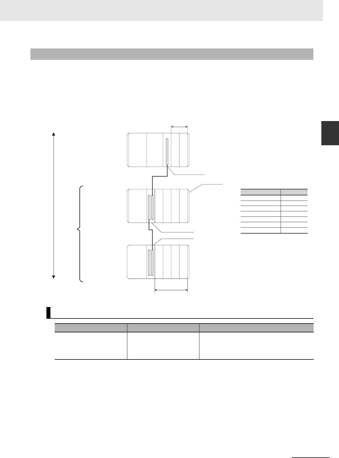
2-11
2 Basic System Configuration and Devices
CJ2 CPU Unit Hardware User’s Manual
2-1 Basic System Configuration
2
2-1-3 Expansion Racks
CJ-series Expansion Racks can be connected to the CPU Rack to expand the number of Units in the
System beyond the CPU Rack. Up to 10 I/O Units can be mounted to each Expansion Rack and a total
of 3 Expansion Racks can be connected.
Mount an I/O Control Unit immediately to the right of the CPU Unit, and mount the I/O Interface Unit
immediately to the right of the Power Supply Unit on the Expansion Rack. Mounting them in other loca-
tions may cause malfunctions.
2-1-3 Expansion Racks
Maximum Number of Expansion Racks
Expansion pattern Maximum number of Racks Remarks
CJ-series CPU Rack plus
CJ-series Expansion Racks
3 Racks The total length of I/O Connecting Cable
between the CPU Rack and an Expansion Rack,
and between all Expansion Racks, must be no
more than 12 m.
CPU Rack
CS/CJ-series I/O Connecting Cables
Cable
CS1W-CN313
CS1W-CN713
CS1W-CN223
CS1W-CN323
CS1W-CN523
CS1W-CN133
CS1W-CN133B2
Length
0.3 m
0.7 m
2 m
3 m
5 m
10 m
12 m
CJ-series
Expansion Rack
CS/CJ-series I/O Connecting Cable
30 cm, 70 cm, 2 m, 3 m, 5 m, 10 m, 12 m
Expansion
Racks:
3 maximum
Total cable
length:
12 m
End Cover
I/O Control Unit
I/O Interface Unit
I/O Interface Unit
10 Units max.
Power
Supply
Unit
Power
Supply
Unit
Power
Supply
Unit
CJ-series
Expansion Rack
CS/CJ-series I/O Connecting Cable
30 cm, 70 cm, 2 m, 3 m, 5 m, 10 m, 12 m
CPU
Unit
10 Units max.
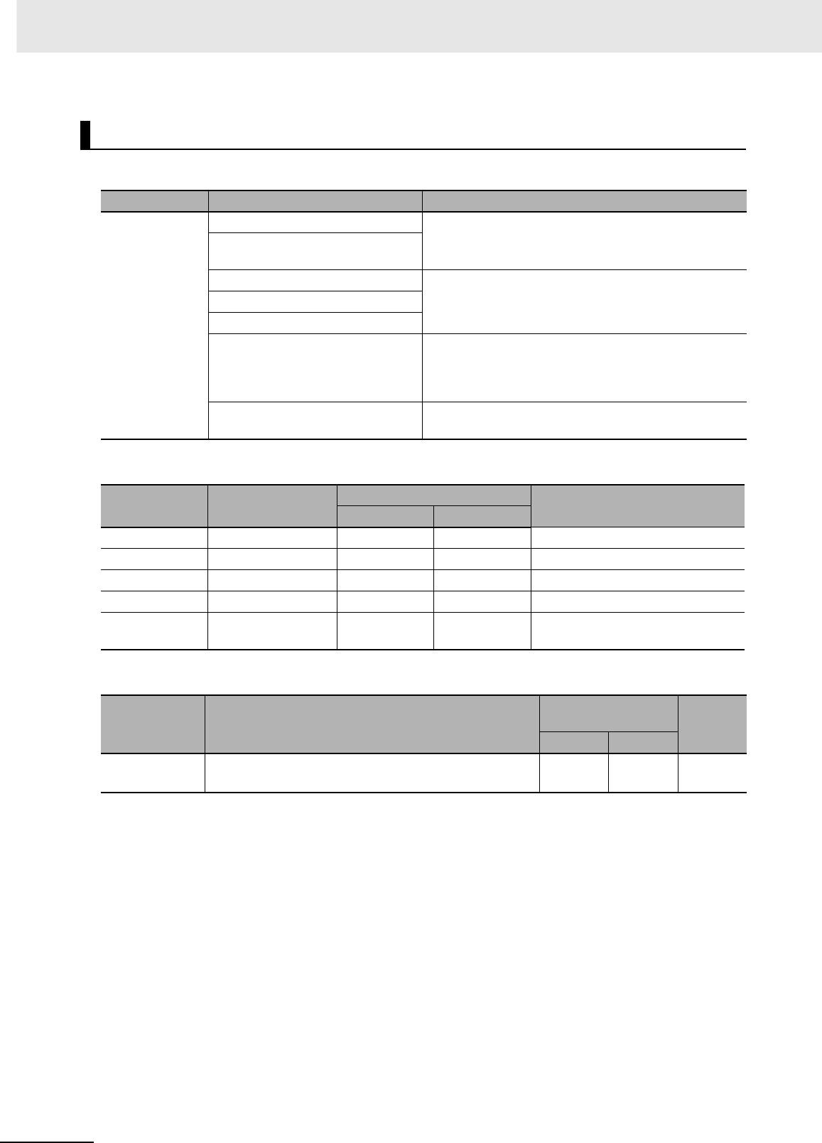
2 Basic System Configuration and Devices
2-12 CJ2 CPU Unit Hardware User’s Manual
zUnits for CJ-series Expansion Racks
zCJ-series Power Supply Unit
zI/O Interface Unit
*1 Includes the weight of the End Cover.
Units
Rack Configuration Remarks
CJ-series
Expansion
Racks
CJ-series Power Supply Unit One required for each Expansion Rack. (An I/O Control
Unit is required on the CJ-series CPU Rack.)
I/O Interface Unit (one End Cover
included.)
CJ-series Basic I/O Units A total of up to 10 Units can be connected to the CPU
Rack and to each of the Expansion Racks. (An error will
occur if 11 or more Units are connected.)
CJ-series Special I/O Units
CJ-series CPU Bus Units
End Cover Must be connected to the right end of the Expansion
Rack. (One End Cover is provided with the I/O Interface
Unit. A fatal error will occur if the End Cover is not con-
nected.)
CS/CJ-series I/O Connecting Cable Required to connect the I/O Interface Unit to the I/O
Control Unit or previous I/O Interface Unit.
Model Power supply
voltage
Output capacity Functions
5 VDC 24 VDC
CJ1W-PA205R 100 to 240 VAC 5.0 A 0.8 A RUN output
CJ1W-PA205C 100 to 240 VAC 5.0 A 0.8 A Replacement notification
CJ1W-PA202 100 to 240 VAC 2.8 A 0.4 A ---
CJ1W-PD025 24 VDC 5.0 A 0.8 A ---
CJ1W-PD022 24 VDC
(non-insulated type)
2.0 A 0.4 A ---
Model Specifications
Current consump-
tion (A) Weight
5 VDC 24 VDC
CJ1W-II101 One Interface Unit is required for each CJ-series Expan-
sion Rack. One End Cover is provided with each Unit.
0.13 A --- 130 g
max.*1
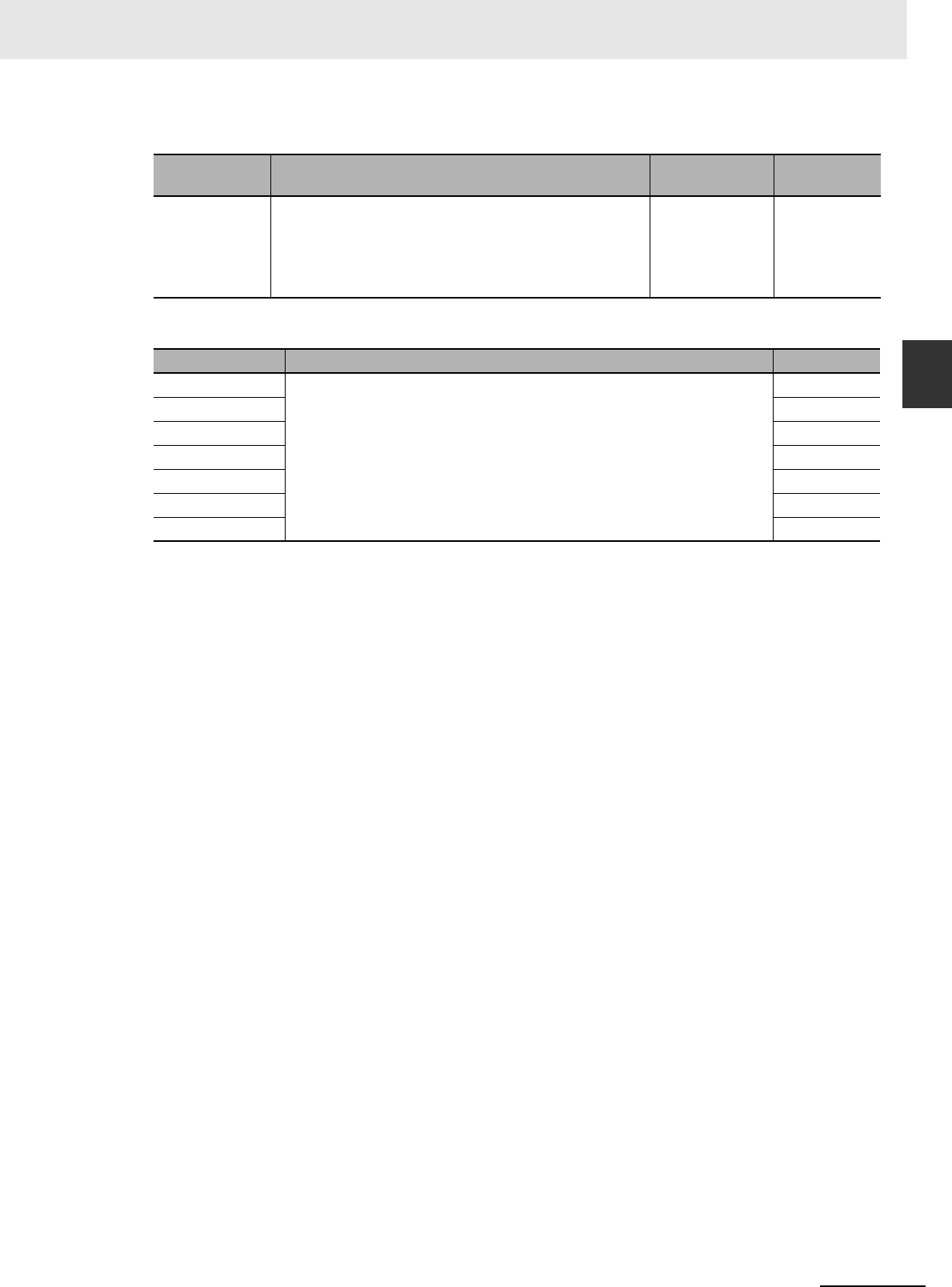
2-13
2 Basic System Configuration and Devices
CJ2 CPU Unit Hardware User’s Manual
2-1 Basic System Configuration
2
2-1-3 Expansion Racks
zEnd Cover
zCS/CJ-series I/O Connecting Cables
Model Specifications Current con-
sumption (A) Weight
CJ1W-TER01 Must be connected to the right end of the CPU Rack. (A
fatal error will occur if the End Cover is not connected to
the right end of the Rack.)
One End Cover is provided with the CPU Unit and with an
I/O Interface Unit.
Included with the
CPU Unit or I/O
Interface Unit.
---
Model Specifications Cable length
CS1W-CN313 An I/O Connecting Cable connects an I/O Control Unit (CJ1W-IC101) to an
I/O Interface Unit (CJ1W-II101), or connects an I/O Interface Unit to
another I/O Interface Unit.
0.3 m
CS1W-CN713 0.7 m
CS1W-CN223 2 m
CS1W-CN323 3 m
CS1W-CN523 5 m
CS1W-CN133 10 m
CS1W-CN133B2 12 m

2 Basic System Configuration and Devices
2-14 CJ2 CPU Unit Hardware User’s Manual
A maximum of 10 Units can be connected to the CPU Rack for a CJ2 CPU Unit or to an Expansion
Rack. There are no restrictions in the number of each model of Unit based on location.
Note A fatal error will occur and the CPU Unit will not operate if more than the allowable number of Units is con-
nected to a CJ2 CPU Rack or to an Expansion Rack.
The Configuration Units with which the CJ2 CPU Unit can exchange data are classified into three
groups. The number of Units that can be mounted depends on the type of Unit.
2-1-4 Configuration Units
Maximum Number of Units
Models of Configuration Units
Units Description Unit identifica-
tion method
Number of
mountable Units
Basic I/O Units Basic I/O Units are used for discrete inputs and
outputs.
Identified by the
CPU Unit accord-
ing to mounting
position.
Up to 40 Basic I/O
Units can be
mounted.
Special I/O Units Special I/O Units are more advanced than Basic
I/O Units. They support functions other than dis-
crete inputs and outputs.
Examples:
Analog I/O Units and High-speed Counter Units
Special I/O Units have a smaller area for
exchanging data with the CPU Unit than CPU
Bus Units (including Network Communications
Units).
Identified by the
CPU Unit using
unit numbers 0 to
95 set with the
rotary switches on
the front panel of
the Unit.
Up to 40 Special
I/O Units can be
mounted.
(Depending on the
model, more than
one unit number is
used for one Unit.)
CPU Bus Unit CPU Units are advanced units that exchange
data with the CPU Unit via the CPU bus.
Examples:
Network Communications Units and Serial Com-
munications Units
CPU Bus Units have a larger area for exchang-
ing data with the CPU Unit than Special I/O
Units.
Identified by the
CPU Unit using
unit number 0 to F
set with the rotary
switch on the front
panel of the Unit.
Up to 16 CPU Bus
Units can be
mounted.

2-15
2 Basic System Configuration and Devices
CJ2 CPU Unit Hardware User’s Manual
2-1 Basic System Configuration
2
2-1-4 Configuration Units
zCJ-series Basic I/O Units
Input Units
*1 Although 16 I/O bits are allocated, only 8 of these can be used for external I/O. This Unit is also treated as a
16-point I/O Unit in the I/O tables.
*2 The ON/OFF response time for the CJ1W-ID212/CJ1W-ID233 is shorter than for the CJ1W-ID211/CJ1W-
ID232, as shown below.
• ON response time: 20 µs improved to 15 µs
• OFF response time: 400 µs improved to 90 µs
*3 The cable-side connector is not provided with Units equipped with cables. Purchase the connector separately
(Refer to 5-3-3 Wiring Basic I/O Units with Connectors.), or use an OMRON Connector- Terminal Block Con-
version Unit or I/O Terminal (Refer to 5-3-4 Connecting to Connector-Terminal Block Conversion Units or I/O
Relay Terminals.).
*4 An Interrupt Input Unit can be connected only in a CJ-series CPU Rack. Connect the Interrupt Input Units in
following slots on the CPU Rack. An I/O setting error will occur if an Interrupt Input Unit is connected in other
positions on the CPU Rack or to any position on an Expansion Rack. Up to two Interrupt Input Units can be
connected.
• CJ2H-CPU6@-EIP: Slots 0 to 3
• CJ2H-CPU6@ or CJ2M-CPU@@: Slots 0 to 4
Configuration Units
Name Specifications Model
Number of
bits allo-
cated
Current consumption
(A) Weight
5 VDC 24 VDC
DC Input
Units
Terminal block
12 to 24 VDC, 8 inputs
CJ1W-ID201 16*1 0.08 --- 110 g max.
Terminal block
24 VDC, 16 inputs CJ1W-ID211*2 16 0.08 --- 110 g max.
CJ1W-ID212*2 16 0.13 --- 110 g max.
Fujitsu-compatible con-
nector
24 VDC, 32 inputs
CJ1W-ID231*3 32 0.09 --- 70 g max.
MIL connector
24 VDC, 32 inputs
CJ1W-
ID232*2*3
32 0.09 --- 70 g max.
CJ1W-
ID233*2*3
32 0.20 --- 70 g max.
Fujitsu-compatible con-
nector
24 VDC, 64 inputs
CJ1W-ID261*3 64 0.09 --- 110 g max.
MIL connector
24 VDC, 64 inputs
CJ1W-ID262*3 64 0.09 --- 110 g max.
AC Input
Units
200 to 240 VAC,
8 inputs
CJ1W-IA201 16*1 0.08 --- 130 g max.
100 to 120 VAC,
16 inputs
CJ1W-IA111 16 0.09 --- 130 g max.
Interrupt Input
Units
24 VDC, 16 inputs CJ1W-INT01*4 16 0.08 --- 110 g max.
Quick-
response
Input Units
24 VDC, 16 inputs CJ1W-IDP01 16 0.08 --- 110 g max.
B7A Interface
Units
64 inputs CJ1W-B7A14 64 0.09 --- 80 g max.

2 Basic System Configuration and Devices
2-16 CJ2 CPU Unit Hardware User’s Manual
Output Units
*1 Although 16 I/O bits are allocated, only 8 of these can be used for external I/O. This Unit is also treated as a
16-point I/O Unit in the I/O tables.
*2 The ON/OFF response time for the CJ1W-OD213/CJ1W-OD234 is shorter than for the CJ1W-OD211/CJ1W-
OD233, as shown below.
• ON response time: 0.1 ms improved to 0.015 ms
• OFF response time: 0.8 ms improved to 0.08 ms
*3 The cable-side connector is not provided with Units equipped with cables. Purchase the connector separately
(Refer to 5-3-3 Wiring Basic I/O Units with Connectors.), or use an OMRON Connector- Terminal Block Con-
version Unit or I/O Terminal (Refer to 5-3-4 Connecting to Connector-Terminal Block Conversion Units or I/O
Relay Terminals.).
Name Specifications Model
Number
of bits
allocated
Current consumption
(A) Weight
5 VDC 24 VDC
Relay Output Units Terminal block, 250 VAC/24 VDC,
2 A; 8 points, independent con-
tacts
CJ1W-OC201 16*1 0.09 0.048
(0.006 ×
Number of ON
outputs)
140 g max.
Terminal block, 250 VAC/24 VDC,
2 A; 16 points
CJ1W-OC211 16 0.11 0.096
(0.006 ×
Number of ON
outputs)
170 g max.
Triac Output Unit Terminal block, 250 VAC, 0.6 A;
8 points
CJ1W-OA201 16*1 0.22 --- 150 g max.
Transis-
tor Out-
put Units
Sinking
outputs
Terminal block, 12 to 24 VDC,
2 A; 8 outputs
CJ1W-OD201 16*1 0.09 --- 110 g max.
Terminal block, 12 to 24 VDC,
0.5 A; 8 outputs
CJ1W-OD203 16*1 0.10 --- 110 g max.
Terminal block, 12 to 24 VDC,
0.5 A; 16 outputs CJ1W-OD211*2 16 0.10 --- 110 g max.
Terminal block, 24 VDC,
0.5 A; 16 outputs CJ1W-OD213*2 16 0.15 --- 110 g max.
Fujitsu-compatible connector, 12
to 24 VDC, 0.5 A; 32 outputs CJ1W-OD231*3 32 0.14 --- 70 g max.
MIL connector, 12 to 24 VDC,
0.5 A; 32 outputs
CJ1W-
OD233*2*3
32 0.14 --- 70 g max.
MIL connector, 24 VDC,
0.5 A; 32 outputs
CJ1W-
OD234*2*3
32 0.22 --- 70 g max.
Fujitsu-compatible connector, 12
to 24 VDC, 0.3 A; 64 outputs CJ1W-OD261*3 64 0.17 --- 110 g max.
MIL connector, 12 to 24 VDC,
0.3 A; 64 outputs CJ1W-OD263*3 64 0.17 --- 110 g max.
Sourc-
ing out-
puts
Terminal block, 24 VDC, 2 A;
8 outputs, load short-circuit pro-
tection and disconnected line
detection
CJ1W-OD202 16*1 0.11 --- 120 g max.
Terminal block, 24 VDC, 0.5 A;
8 outputs, load short-circuit pro-
tection
CJ1W-OD204 16*1 0.10 --- 120 g max.
Terminal block, 24 VDC, 0.5 A;
16 outputs, load short-circuit pro-
tection
CJ1W-OD212 16 0.10 --- 120 g max.
MIL connector, 24 VDC, 0.5 A;
32 outputs, load short-circuit pro-
tection
CJ1W-OD232*3 32 0.15 --- 80 g max.
MIL connector, 12 to 24 VDC,
0.3 A; 64 outputs CJ1W-OD262*3 64 0.17 --- 110 g max.
B7A Interface Units 64 outputs CJ1W-B7A04 64 0.07 --- 80 g max.

2-17
2 Basic System Configuration and Devices
CJ2 CPU Unit Hardware User’s Manual
2-1 Basic System Configuration
2
2-1-4 Configuration Units
Mixed I/O Units
*1 The cable-side connector is not provided with Units equipped with cables. Purchase the connector separately
(Refer to 5-3-3 Wiring Basic I/O Units with Connectors.), or use an OMRON Connector- Terminal Block Con-
version Unit or I/O Terminal (Refer to 5-3-4 Connecting to Connector-Terminal Block Conversion Units or I/O
Relay Terminals.).
Name Specifications Model
Number of
bits allo-
cated
Current consump-
tion (A) Weight
5 VDC 24 VDC
24-VDC
Input/
Transis-
tor Out-
put Units
Sinking Fujitsu-compatible
connector
Inputs:
24 VDC, 16 inputs
Outputs: 12 to
24 VDC, 0.5 A;
16 outputs
CJ1W-MD231*1 32 0.13 --- 90 g max.
Fujitsu-compatible
connector
Inputs:
24 VDC, 32 inputs
Outputs: 12 to
24 VDC, 0.3 A;
32 outputs
CJ1W-MD261*1 64 0.14 --- 110 g max.
MIL connector
Inputs: 24 VDC,
16 inputs
Outputs: 12 to
24 VDC, 0.5 A;
16 outputs
CJ1W-MD233*1 32 0.13 --- 90 g max.
MIL connector
Inputs: 24 VDC,
32 inputs
Outputs: 12 to
24 VDC, 0.3 A;
32 outputs
CJ1W-MD263*1 64 0.14 --- 110 g max.
Sourcing MIL connector
Inputs: 24 VDC,
16 inputs
Outputs: 24 VDC,
0.5 A; 16 outputs
Load-short circuit
protection
CJ1W-MD232*1 32 0.13 --- 80 g max.
TTL I/O Units MIL connector
Inputs: TTL (5 VDC),
32 inputs
Outputs: TTL
(5 VDC, 35 mA),
32 outputs
CJ1W-MD563*1 64 0.19 --- 110 g max.
B7A Interface Units 32 inputs, 32 outputs CJ1W-B7A22 64 0.07 --- 80 g max.

2 Basic System Configuration and Devices
2-18 CJ2 CPU Unit Hardware User’s Manual
zCJ-series Special I/O Units
Type Name Specifications Model
Number of
words allo-
cated
(CIO 2000 to
CIO 2959)
Number of
words allo-
cated
(D20000 to
D29599)
Unit No.
Num-
ber
of
moun
table
Units
Current con-
sumption (A)
Weight
5
VDC
24
VDC
Special I/O
Units
General-pur-
pose Univer-
sal Analog
Input Unit
4 inputs, fully univer-
sal
CJ1W-AD04U 10 words 100 words 0 to 95 40
Units
0.32 --- 150 g max.
Analog Input
Units
8 inputs (4 to 20 mA,
1 to 5 V, etc.)
CJ1W-AD081-V1 10 words 100 words 0 to 95 40
Units
0.42 --- 140 g max.
4 inputs (4 to 20 mA,
1 to 5 V, etc.)
CJ1W-AD041-V1 10 words 100 words 0 to 95 40
Units
0.42 --- 140 g max.
4 inputs (4 to 20 mA,
1 to 5 V, etc.)
CJ1W-AD042 10 words 100 words 0 to 95 40
Units
0.52 --- 150 g max.
Analog Out-
put Units
4 outputs (1 to 5 V,
4 to 20 mA, etc.)
CJ1W-DA041 10 words 100 words 0 to 95 40
Units
0.12 --- 150 g max.
2 outputs (1 to 5 V,
4 to 20 mA, etc.)
CJ1W-DA021 10 words 100 words 0 to 95 40
Units
0.12 --- 150 g max.
8 outputs (1 to 5 V,
0 to 10 V, etc.)
CJ1W-DA08V 10 words 100 words 0 to 95 40
Units
0.14 --- 150 g max.
8 outputs (4 to
20 mA)
CJ1W-DA08C 10 words 100 words 0 to 95 40
Units
0.14 --- 150 g max.
4 outputs (1 to 5 V,
0 to 10 V, etc.)
CJ1W-DA042V 10 words 100 words 0 to 95 40
Units
0.40 --- 150 g max.
Analog I/O
Unit
4 inputs (1 to 5 V, 4 to
20 mA, etc.)
2 outputs (1 to 5 V,
4 to 20 mA, etc.)
CJ1W-MAD42 10 words 100 words 0 to 95 40
Units
0.58 --- 150 g max.
Isolated-type
High-resolu-
tion Univer-
sal Input Unit
4 inputs, fully univer-
sal Resolution:
1/256,000, 1/64,000,
1/16,000
CJ1W-PH41U 10 words 100 words 0 to 95 40
Units
0.30 --- 150 g max.
Isolated-type
Thermocou-
ple Input
Units
4 thermocouple inputs CJ1W-PTS51 10 words 100 words 0 to 95 40
Units
0.25 --- 150 g max.
2 thermocouple inputs CJ1W-PTS15 10 words 100 words 0 to 95 40
Units
0.18 --- 150 g max.
Isolated-type
Resistance
Thermome-
ter Input
Units
4 resistance thermom-
eter inputs
CJ1W-PTS52 10 words 100 words 0 to 95 40
Units
0.25 --- 150 g max.
2 resistance thermom-
eter inputs
CJ1W-PTS16 10 words 100 words 0 to 95 40
Units
0.18 --- 150 g max.
Direct Cur-
rent Input
Unit
DC voltage or DC cur-
rent, 2 inputs
CJ1W-PDC15 10 words 100 words 0 to 95 40
Units
0.18 --- 150 g max.
Temperature
Control Units
4 control loops, ther-
mocouple inputs, NPN
outputs
CJ1W-TC001 20 words 200 words 0 to 94
(uses
words for
2 unit
numbers)
40
Units
0.25 --- 150 g max.
4 control loops, ther-
mocouple inputs, PNP
outputs
CJ1W-TC002 20 words 200 words 0 to 94
(uses
words for
2 unit
numbers)
40
Units
0.25 --- 150 g max.
2 control loops, ther-
mocouple inputs, NPN
outputs, heater burn-
out detection
CJ1W-TC003 20 words 200 words 0 to 94
(uses
words for
2 unit
numbers)
40
Units
0.25 --- 150 g max.
2 control loops, ther-
mocouple inputs, PNP
outputs, heater burn-
out detection
CJ1W-TC004 20 words 200 words 0 to 94
(uses
words for
2 unit
numbers)
40
Units
0.25 --- 150 g max.

2-19
2 Basic System Configuration and Devices
CJ2 CPU Unit Hardware User’s Manual
2-1 Basic System Configuration
2
2-1-4 Configuration Units
Special I/O
Units
Temperature
Control Units
4 control loops, tem-
perature- resistance
thermometer inputs,
NPN outputs
CJ1W-TC101 20 words 200 words 0 to 94
(uses
words for
2 unit
numbers)
40
Units
0.25 --- 150 g max.
4 control loops, tem-
perature- resistance
thermometer inputs,
PNP outputs
CJ1W-TC102 20 words 200 words 0 to 94
(uses
words for
2 unit
numbers)
40
Units
0.25 --- 150 g max.
2 control loops, tem-
perature-resistance
thermometer inputs,
NPN outputs, heater
burnout detection
CJ1W-TC103 20 words 200 words 0 to 94
(uses
words for
2 unit
numbers)
40
Units
0.25 --- 150 g max.
2 control loops, tem-
perature-resistance
thermometer inputs,
PNP outputs, heater
burnout detection
CJ1W-TC104 20 words 200 words 0 to 94
(uses
words for
2 unit
numbers)
40
Units
0.25 --- 150 g max.
Position Con-
trol Units
1 axis, pulse output;
open collector output
CJ1W-NC113 10 words 100 words 0 to 95 40
Units
0.25 --- 100 g max.
2 axes, pulse outputs;
open collector outputs
CJ1W-NC213 10 words 100 words 0 to 95 40
Units
0.25 --- 100 g max.
CJ1W-
NC214*1*2 18 words*3 None 0 to 94
(uses
words for
2 unit
numbers)
5
Units/
Rack
0.27 --- 170 g max.
4 axes, pulse outputs;
open collector outputs
CJ1W-NC413 20 words 200 words 0 to 94
(uses
words for
2 unit
numbers)
40
Units
0.36 --- 150 g max.
CJ1W-
NC414*1*2 18 words*3 None 0 to 94
(uses
words for
2 unit
numbers)
5
Units/
Rack
0.31 --- 220 g max.
1 axis, pulse output;
line driver output
CJ1W-NC133 10 words 100 words 0 to 95 40
Units
0.25 --- 100 g max.
2 axes, pulse outputs;
line driver outputs
CJ1W-NC233 10 words 100 words 0 to 95 40
Units
0.25 --- 100 g max.
CJ1W-
NC234*1*2 18 words*3 None 0 to 94
(uses
words for
2 unit
numbers)
5
Units/
Rack
0.27 --- 170 g max.
4 axes, pulse outputs;
line driver outputs
CJ1W-NC433 20 words 200 words 0 to 94
(uses
words for
2 unit
numbers)
40
Units
0.36 --- 150 g max.
CJ1W-
NC434*1*2 18 words*3 None 0 to 94
(uses
words for
2 unit
numbers)
5
Units/
Rack
0.31 --- 220 g max.
Space Unit*4 CJ1W-SP001 None None --- --- --- --- 50 g max.
Type Name Specifications Model
Number of
words allo-
cated
(CIO 2000 to
CIO 2959)
Number of
words allo-
cated
(D20000 to
D29599)
Unit No.
Num-
ber
of
moun
table
Units
Current con-
sumption (A)
Weight
5
VDC
24
VDC

2 Basic System Configuration and Devices
2-20 CJ2 CPU Unit Hardware User’s Manual
*1 With a CJ2 CPU Unit, up to 10 Configuration Units can be connected in the CPU Rack and in each Expansion Rack. The CJ1W-NC@@4,
however, must be counted as two Units. Configure the Units to satisfy the following formula.
Number of CJ1W-NC@@4 Units × 2 + Number of other Units ≤ 10
For example, if five CJ1W-NC@@4 Units are connected to one Rack, no other Units can be connected.
*2 The Units must be mounted on the CPU Rack to use synchronous unit operation.
*3 In addition to the words allocated in the Special I/O Unit Area, up to 144 words are allocated according to the number of axes and func-
tions uses. Word allocations are set using the CX-Programmer.
*4 The Space Unit is for Position Control Units.
*5 If interrupts to the CPU Unit are used, mount the Interrupt Input Unit in one of the following slots on the CPU Rack.
• CJ2H-CPU6@-EIP: Slots 0 to 3
• CJ2H-CPU6@ or CJ2M-CPU@@: Slots 0 to 4
*6 Includes the weight of accessory connectors.
Special I/O
Units
ID Sensor
Units
V600-series single-
head type
CJ1W-V600C11 10 words 100 words 0 to 95 40
Units
0.26 0.12 120 g max.
V600-series two-head
type
CJ1W-V600C12 20 words 200 words 0 to 94
(uses
words for
2 unit
numbers)
40
Units
0.32 0.24 130 g max.
V680-series single-
head type
CJ1W-V680C11 10 words 100 words 0 to 95 40
Units
0.26 0.13 120 g max.
V680-series two-head
type
CJ1W-V680C12 20 words 200 words 0 to 94 40
Units
0.32 0.26 130 g max.
High-speed
Counter Unit
Number of counter
channels: 2, Maximum
input frequency:
500 kHz, line driver
compatible*5
CJ1W-CT021 40 words 400 words 0 to 92
(uses
words for
4 unit
numbers)
24
Units
0.28 --- 100 g max.
Compo-
Bus/S Mas-
ter Units
CompoBus/S remote
I/O, 256 bits max.
CJ1W-SRM21 10 words or
20 words
None 0 to 95 or
0 to 94
40
Units
0.15 --- 66 g max.*6
CompoNet
Master Unit
CompoNet remote I/O CJ1W-CRM21 130 g max.
Communications
mode No. 0:
128 inputs/
128 outputs for
Word Slaves
20 words None 0 to 94
(uses
words for
2 unit
numbers)
40
Units
0.40 ---
Communications
mode No. 1:
256 inputs/
256 outputs for
Word Slaves
40 words None 0 to 92
(uses
words for
4 unit
numbers)
24
Units
0.40 ---
Communications
mode No. 2:
512 inputs/
512 outputs for
Word Slaves
80 words None 0 to 88
(uses
words for
8 unit
numbers)
12
Units
0.40 ---
Communications
mode No. 3:
256 inputs/
256 outputs for
Word Slaves and
128 inputs/
128 outputs for Bit
Slaves
80 words None 0 to 88
(uses
words for
8 unit
numbers)
12
Units
0.40 ---
Communications
mode No. 8:
1,024 inputs/
1,024 outputs for
Word Slaves and
256 inputs/
256 outputs for Bit
Slaves maximum
10 words Depends on
setting
0 to 95
uses
words for
1 unit
number)
40
Units
0.40 ---
Type Name Specifications Model
Number of
words allo-
cated
(CIO 2000 to
CIO 2959)
Number of
words allo-
cated
(D20000 to
D29599)
Unit No.
Num-
ber
of
moun
table
Units
Current con-
sumption (A)
Weight
5
VDC
24
VDC
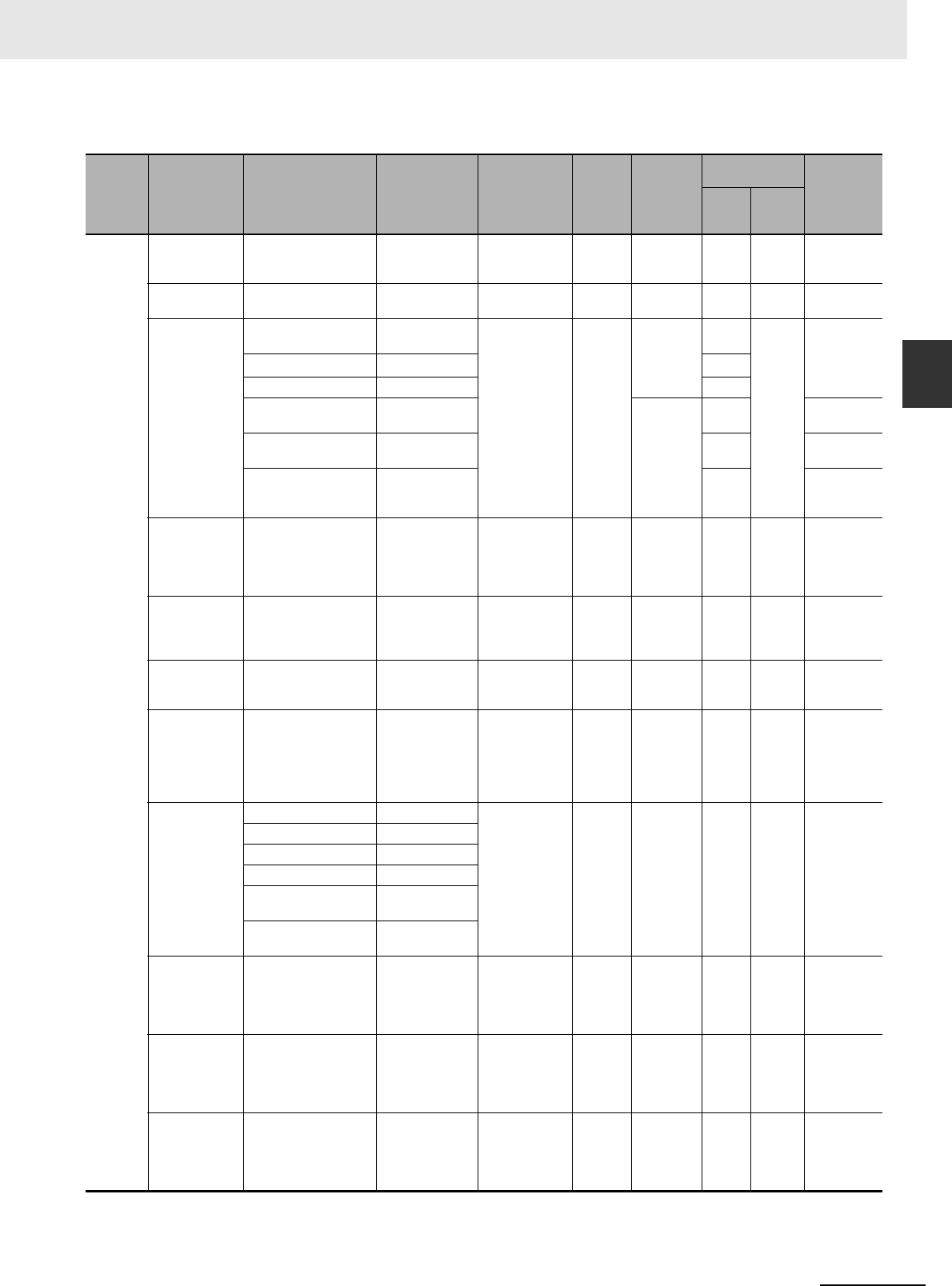
2-21
2 Basic System Configuration and Devices
CJ2 CPU Unit Hardware User’s Manual
2-1 Basic System Configuration
2
2-1-4 Configuration Units
zCJ-series CPU Bus Units
Type Name Specifications Model
Number of
words allo-
cated
(CIO 1500 to
CIO 1899)
Unit No.
Maximum
number of
Units*1
Current con-
sumption (A)
Weight
5 VDC 24 VDC
CPU Bus
Units*1
High-speed
Analog Input
Unit
4 inputs: 80 µs/2 inputs,
160 µs/4 inputs CJ1W-ADG41*2 25 words 0 to F 16 Units*3 0.65 --- 150 g max.
Controller Link
Units
Wired data links CJ1W-CLK23 25 words 0 to F 8 Units 0.35 --- 110 g max.
Serial Commu-
nications Units
One RS-232C port and
one RS-422A/485 port
CJ1W-SCU41-V1 25 words 0 to F 16 Units*3 0.38*4 --- 110 g max.
Two RS-232C ports CJ1W-SCU21-V1 0.28*4
Two RS-422A/485 ports CJ1W-SCU31-V1 0.38
Two RS-232C ports
High-speed models
CJ1W-SCU22 16 Units*3 0.28*4 160 g max.
Two RS-422A/485 ports
High-speed models
CJ1W-SCU32 0.4 120 g max.
One RS-232C port and
one RS-422A/485 port
High-speed models
CJ1W-SCU42 0.36*4 140 g max.
Ethernet Units 100Base-TX, FINS
communications, socket
service, FTP server,
and mail communica-
tions
CJ1W-ETN21 25 words 0 to F 4 Units 0.37 --- 100 g max.
EtherNet/IP Unit Tag data links, FINS
communications, CIP
message communica-
tions, FTP server, etc.
CJ1W-EIP21 25 words 0 to F *5 0.41 --- 94 g max.
FL-net Unit 100Base-TX cyclic
transmissions and mes-
sage transmissions
CJ1W-FLN22 25 words 0 to F 4 Units 0.37 --- 100 g max.
DeviceNet Unit DeviceNet remote I/O,
2,048 points; Both Mas-
ter and Slave functions,
Automatic allocation
possible without Config-
urator
CJ1W-DRM21 25 words*6 0 to F 16 Units*3 0.29 --- 118 g max.*7
EtherCAT-com-
patible Position
Control Units*8
2 servo axes CJ1W-NC281 25 words 0 to F 16 Units*3 0.46 --- 110 g max.
4 servo axes CJ1W-NC481
8 servo axes CJ1W-NC881
16 servo axes CJ1W-NCF81
4 servo axes and 64 I/O
slaves
CJ1W-NC482
8 servo axes and 64 I/O
slaves
CJ1W-NC882
Position Control
Units support-
ing MECHA-
TROLINK-II
communications
MECHATROLINK-II,
16 axes max.
CJ1W-NCF71
(-MA)
25 words 0 to F 16 Units*3 0.36 --- 95 g max.
Motion Control
Units support-
ing MECHA-
TROLINK-II
communications
MECHATROLINK-II,
Real axes: 30 max.,
Virtual axes: 2 max.,
Special motion control
language
CJ1W-MCH71 25 words 0 to F 3
Units/Rack
*9
0.60 --- 210 g max.
SYSMAC SPU
Unit (High-
speed Storage
and Processing
Unit)
One CF card type I/II
slot (used with OMRON
HMC-EF@@@ Memory
Card), one Ethernet
port
CJ1W-SPU01-
V2*10
Not used. 0 to F 16 Units*3 0.56 --- 180 g max.

2 Basic System Configuration and Devices
2-22 CJ2 CPU Unit Hardware User’s Manual
*1 Some CJ-series CPU Bus Units are allocated words in the CPU Bus Unit Setup Area. The system must be designed so
that the number of words allocated in the CPU Bus Unit Setup Area does not exceed its capacity. Refer to 4-6-2 CPU Bus
Unit Setup Area in CJ2 CPU Unit Software User’s Manual (Cat. No. W473).
There may also be limits due to the capacity of the Power Supply Unit that you are using or the maximum number of Units
to which memory can be allocated in the CPU But Unit Setup Area.
*2 If interrupts to the CPU Unit are used, mount the Interrupt Input Unit in one of the following slots on the CPU Rack.
• CJ2H-CPU6@-EIP: Slots 0 to 3
• CJ2H-CPU6@ or CJ2M-CPU@@: Slots 0 to 4
*3 Up to 15 Units can be connected for a CJ2H-CPU6@-EIP or CJ2M-CPU3@ CPU Unit.
*4 Increases by 0.15 A/Unit when an NT-AL001 RS-232C/RS-422A Link Adapter is used. Increases by 0.04 A/Unit when a
CJ1W-CIF11 RS-422A Converter is used. Increases by 0.20 A/Unit when an NV3W-M@20L Programmable Terminal is
used.
*5 Up to seven Units can be connected for a CJ2H-CPU6@-EIP CPU Unit, up to eight Units can be connected for a CJ2H-
CPU6@ CPU Unit, and up to two Units can be connected for a CJ2M CPU Unit.
*6 Slave I/O are allocated in DeviceNet Area (CIO 3200 to CIO 3799).
*7 Includes the weight of accessory connectors.
*8 Only OMNUC G5-series Servo Drives with Built-in EtherCAT can be connected.
*9 When mounting to a CJ-series CPU Rack or a CJ-series Expansion Rack, one of these Units uses the space of three
Units.
*10 Use version 2 or higher of the SYSMAC SPU Unit with a CJ2 CPU Unit.
The amount of current/power that can be supplied to the Units mounted in a Rack is limited by the
capacity of the Rack’s Power Supply Unit. Refer to the following tables when designing your system so
that the total current consumption of the mounted Units does not exceed the maximum current for each
voltage group and the total power consumption does not exceed the maximum for the Power Supply
Unit.
For details on calculating the current consumption of Units, refer to 2-1-2 CPU Rack, 2-1-3 Expansion
Racks, and 2-1-4 Configuration Units.
The following table shows the maximum currents and power that can be supplied by Power Supply
Units in CPU Racks and Expansion Racks.
Note 1 When calculating current/power consumption in a CPU Rack, be sure to include the power required by the
CPU Unit itself, as well as the I/O Control Unit if one or more Expansion Racks is connected.
2Be sure to include the power required by the I/O Interface Unit when calculating current/power consump-
tion in an Expansion Rack.
2-1-5 Calculating Unit Current Consumption
Maximum Current and Power Supplied by Power Supply Units
Power Supply Unit
Max. current consumption Max. total power
consumption
5-V group
(internal logic)
24-V group
(relays)
24-V group
(service)
CJ1W-PA205R 5.0 A 0.8 A None 25 W
CJ1W-PA205C 5.0 A 0.8 A None 25 W
CJ1W-PA202 2.8 A 0.4 A None 14 W
CJ1W-PD025 5.0 A 0.8 A None 25 W
CJ1W-PD022 2.0 A 0.4 A None 19.6 W
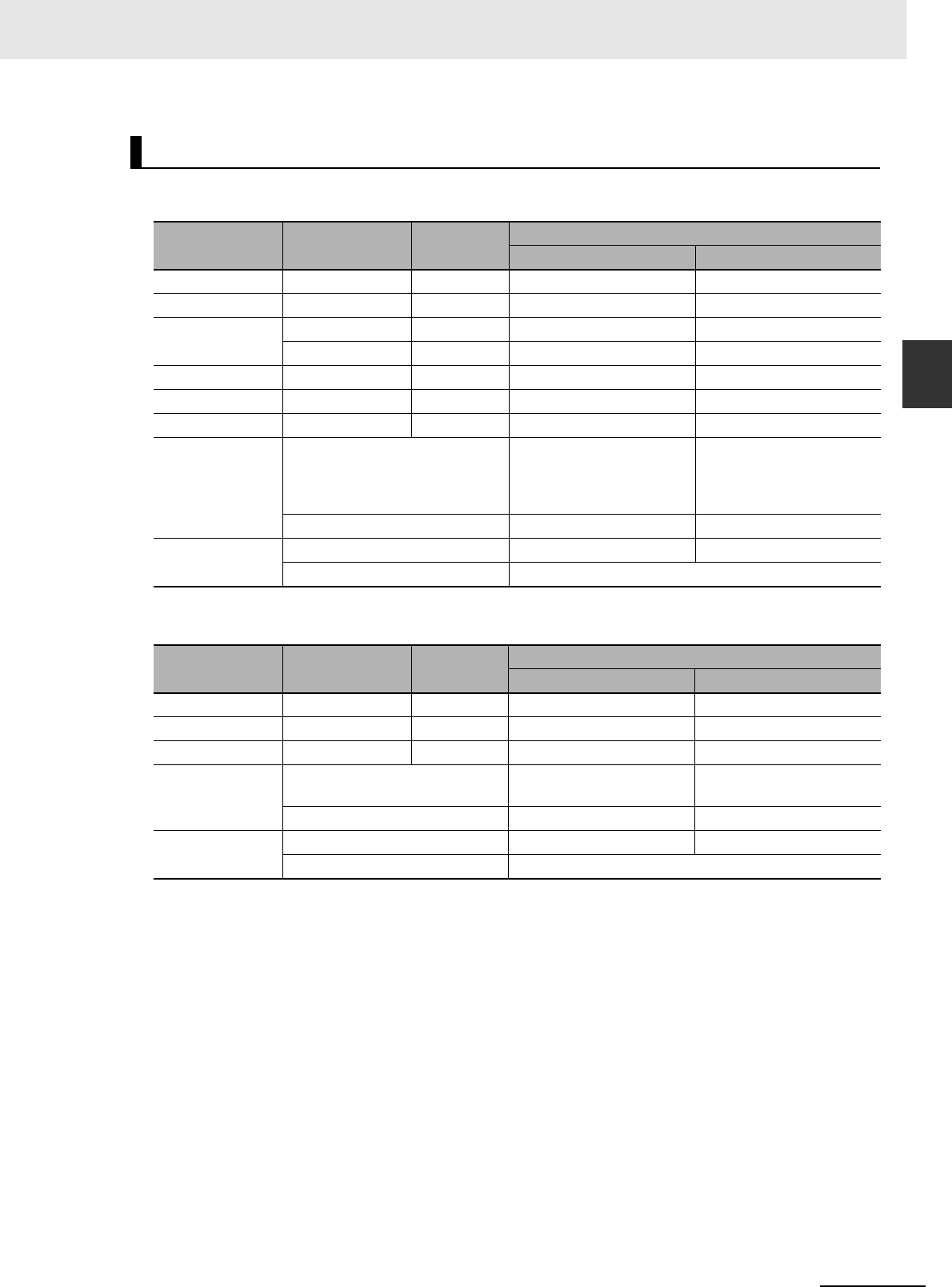
2-23
2 Basic System Configuration and Devices
CJ2 CPU Unit Hardware User’s Manual
2-1 Basic System Configuration
2
2-1-5 Calculating Unit Current Consumption
Example 1: In this example, the following Units are mounted to a CPU Rack with a CJ1W-PA205R
Power Supply Unit.
Example 2: In this example, the following Units are mounted to a CJ-series Expansion Rack with a
CJ1W-PA205R Power Supply Unit.
Example Calculations
Unit Model Quantity Voltage group
5-V 24-V
CPU Unit CJ2H-CPU68-EIP 1 0.820 A ---
I/O Control Unit CJ1W-IC101 1 0.020 A ---
Input Units CJ1W-ID211 2 0.080 A ---
CJ1W-ID231 2 0.090 A ---
Output Unit CJ1W-OC201 2 0.090 A 0.048 A
Special I/O Unit CJ1W-DA041 1 0.120 A ---
CPU Bus Unit CJ1W-CLK23 1 0.350 A ---
Current consump-
tion
Calculation 0.820 A + 0.020 A +
0.080 A × 2 + 0.090 A × 2 +
0.090 A × 2 + 0.120 A +
0.350 A
0.048 A × 2
Result 1.83 A (≤5.0 A) 0.096 A (≤0.8 A)
Power consump-
tion
Calculation 2.51 A × 5 V = 9.15 W 0.096 A × 24 V = 2.304 W
Result 9.15 W + 2.30 W = 11.45 W (≤25 W)
Unit Model Quantity Voltage group
5-V 24-V
I/O Interface Unit CJ1W-II101 1 0.130 A ---
Input Unit CJ1W-ID211 2 0.080 A ---
Output Unit CJ1W-OD231 8 0.140 A ---
Current consump-
tion
Calculation 0.130 A + 0.080 A × 2 +
0.140 A × 8
---
Result 1.41 A (≤5.0 A) ---
Power consump-
tion
Calculation 1.41 A × 5 V = 7.05 W ---
Result 7.05 W (≤25 W)
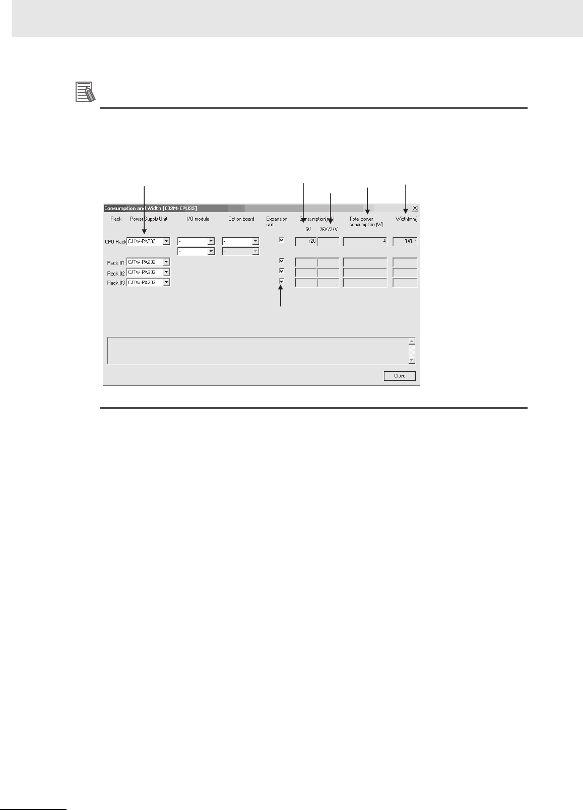
2 Basic System Configuration and Devices
2-24 CJ2 CPU Unit Hardware User’s Manual
Additional Information
Rack Current Consumption and Width Display
To display the current consumption and width of Units connected in the CPU Rack or Expansion
Rack, select Current Consumption and Width from the Options Menu in the CJ2 CPU Unit I/O
Table Window.
If the capacity of a Power Supply Unit is exceeded, it will be displayed in red.
Power Supply
Unit model
Current
consumption
at 5 V
Current
consumption
at 26/24 V
Total power
consumption
Indicates
long-distance
expansion
Width

2-25
2 Basic System Configuration and Devices
CJ2 CPU Unit Hardware User’s Manual
2-1 Basic System Configuration
2
2-1-6 Calculating Power Consumption
The ambient operating temperature at the control panel for mounting a CJ-series PLC must be no
higher than 55°C. This section describes how to calculate the power consumption of a CPU Rack for
use in the thermal design of the control panel.
Use the following equation to calculate the average power consumption (W) of a CJ-series CPU Rack.
zBasic PLC Power Consumption (W_PLC)
The basic PLC power consumption is calculated based on the overall power consumption of the
PLC and the power conversion rate of the Power Supply Unit.
W_PLC = W_unit ÷ η
• W_unit:
Total power consumption of Units mounted to the CPU Rack. For details on the current consump-
tion and voltage of individual Units, refer to 2-1-4 Configuration Units.
•η:
Power Supply Unit power conversion rate.
The rate is 70% for the CJ Series, so use “0.7” in the calculation.
zBasic I/O Unit Power Consumption (W_IO_ONOFF)
The Basic I/O Unit power consumption is the total consumption for the Input Units and the Output
Units.
• Input Units
Rated input voltage × Input current × Number of input points
• Output Units
Residual voltage × Maximum load current × Number of output points
Note For the CJ Series, calculate the residual voltage at 0.1 V.
2-1-6 Calculating Power Consumption
Calculating Power Consumption
W = W_PLC + W_IO_ONOFF
Basic I/O Unit power consumption
Basic PLC power consumption
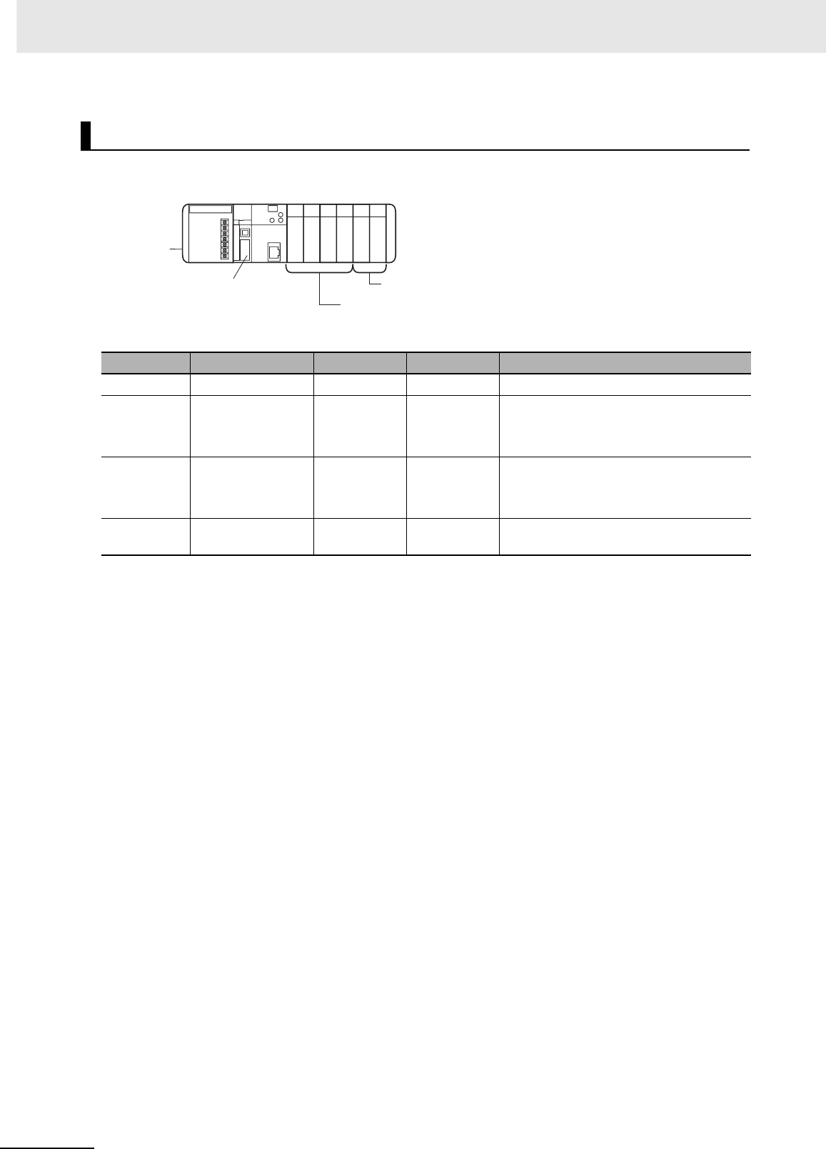
2 Basic System Configuration and Devices
2-26 CJ2 CPU Unit Hardware User’s Manual
These examples show how to calculate the power consumption (W) for the following system.
zBasic PLC Power Consumption (W_PLC)
W_PLC = (0.82 + 0.09 × 2 + 0.17 × 2 + 0.58 × 2) A × 5 V ÷ 0.7= 17.86 W
zBasic I/O Unit Power Consumption (W_IO_ONOFF)
W_IO_ONOFF = 24 V × 0.0041 A x 128 points + 0.1 × 0.3 A × 128 points = 16.43 W
zAverage Power Consumption (W)
W = W_PLC + W_IO_ONOFF = 34.29 W
Calculation Examples
Units Model Quantity 5 VDC Other
CPU Unit CJ2H-CPU68-EIP 1 Unit 0.82 A ---
Input Units CJ1W-ID261 2 Units 0.09 A Rated input voltage: 24 V
Input current: 4.1 mA
Number of input points: 64
Output Unit CJ1W-OD261 2 Units 0.17 A Residual voltage: 0.1 V
Maximum load current: 0.3 A
Number of output points: 64
Special I/O
Units
CJ1W-MAD42 2 Units 0.58 A ---
CPU Rack
Power Supply
Unit
CJ2H-CPU68-EIP
CPU Unit
CJ1W-MAD42 × 2
Special I/O Units
CJ1W-ID261 × 2
CJ1W-OD261 × 2
Basic I/O Units
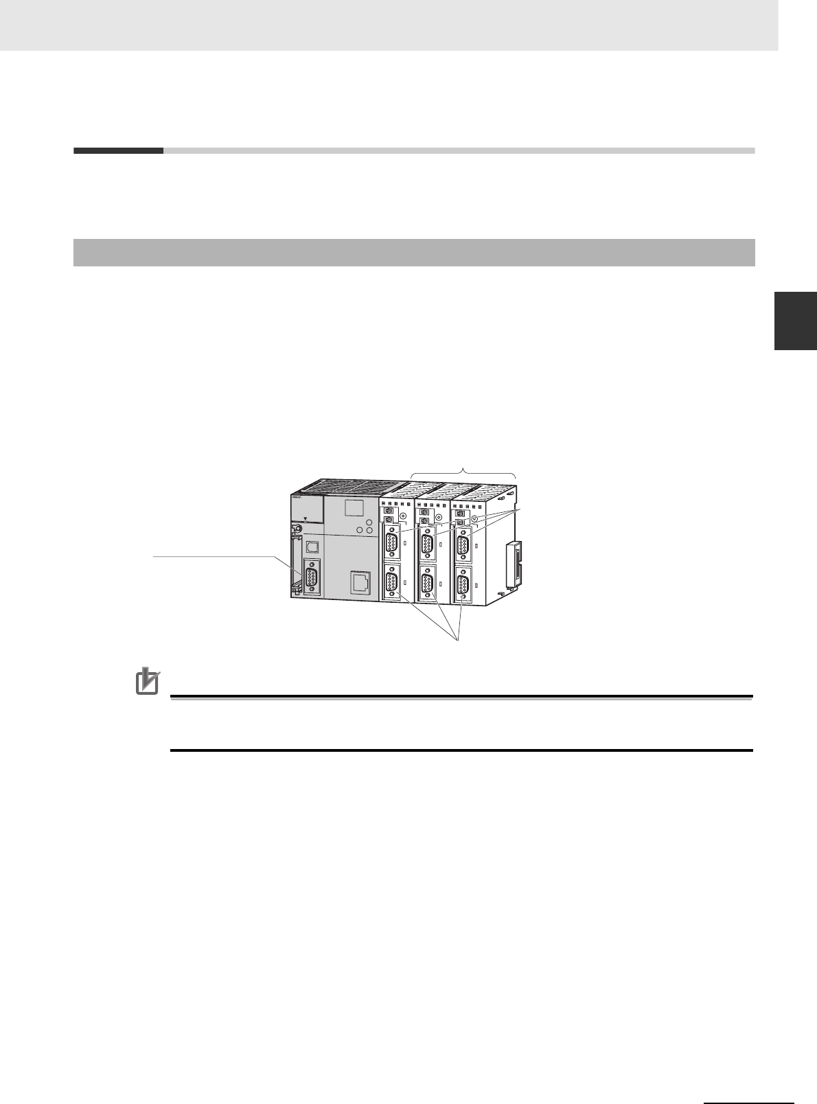
2-27
2 Basic System Configuration and Devices
CJ2 CPU Unit Hardware User’s Manual
2-2 Expanded System Configuration
2
2-2-1 Serial Communications
2-2 Expanded System Configuration
This section describes the system configurations that can be connected by using the serial port that is
built into the CJ2 CPU Unit, along with Communications Units and other Configuration Units.
This expanded system can be connected via the CJ2 CPU Unit's built-in serial communications port or
a Serial Communications Unit.
Various protocols, including Host Link and NT Link, can be used with the serial communications port. A
particular protocol can be supported by switching the mode of the serial communications port.
For details on the serial communications modes that are supported, refer to 11-2 Serial Communica-
tions in the CJ2 CPU Unit Software User’s Manual (Cat. No. W473).
Note Protocol macros are supported only for Serial Communications Units.
Precautions for Correct UsePrecautions for Correct Use
A Serial Option Board is required to use a serial communications for the CJ2M-CPU3@.
Refer to Serial Option Boards on page 2-7 for information on Serial Option Boards.
2-2-1 Serial Communications
PERIPHERAL
ERR/ALM
RUN
INH
COMM
PRPHL
CONTROLLER
PROGRAMMABLE
PORT
OPEN
BUSY
MCPWR
BKUP
CPU64-EIP
CJ2H
SYSMAC
NS
MS
COMM
10M
100M
2
ON
4
TERM
RD2
SD2
RDY
NO.
UNIT
ERH
OFF
WIRE
ERC
RUN
SCU41
RD1 TER1
SD1
PORT1
(RS422
/485)
PORT2
2
ON
4
TERM
RD2
SD2
RDY
NO.
UNIT
ERH
OFF
WIRE
ERC
RUN
SCU41
RD1 TER1
SD1
PORT1
(RS422
/485)
PORT2
2
ON
4
TERM
RD2
SD2
RDY
NO.
UNIT
ERH
OFF
WIRE
ERC
RUN
SCU41
RD1 TER1
SD1
PORT1
(RS422
/485)
PORT2
15 Serial
Communications
Units max.
CPU Unit
Serial port (RS-232C)
Communications Port 1
Communications Port 2
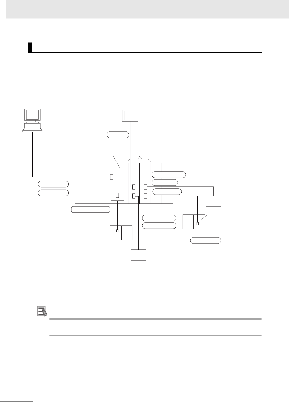
2 Basic System Configuration and Devices
2-28 CJ2 CPU Unit Hardware User’s Manual
The host computer or a Programming Device, such as the CX-Programmer, is connected via the serial
port on the CPU Unit or, with the CJ2M-CPU3@, on the Serial Option Board. In addition, up to 15 Serial
Communications Units can be connected to a single CPU Unit, making it possible to configure a flexible
serial communications system by connecting devices with RS-232C or RS-422/485 ports (such as
PLCs from other manufacturers, temperature controllers, bar code readers, ID systems, personal com-
puters, board computers, and components).
For details on the protocol modes that can be selected for each port, refer to 11-2-1 Overview of Serial
Communications in the CJ2 CPU Unit Software User’s Manual (Cat. No. W473).
Additional Information
Use the Peripheral Bus to connect the CJ2 CPU Unit to the CX-Programmer via serial communi-
cations.
System Configuration Example
RS-232C
RS-232C
PT
CX-Programmer
or host
computer
NT Link
CPU Unit
Peripheral Bus
(Toolbus)
Host Link slave
Serial
Communications Units
Protocol macro
No protocol
Device supporting
CompoWay/F
Device supporting
Modbus
CPU Unit
Host Link slave
General-purpose external device (e.g., such as a
PLC from other manufacturer, temperature
controller, or bar code reader)
: Protocol
*4
CJ2M, CJ1M, CP1H,
CP1L, or CP1E CPU Unit
Serial PLC Link
CompoWay/F master
Modbus master
Host Link master
*4
*4
*1
*2
*3
*1 Serial port (RS-232C): A serial port is built into only the
CJ2H CPU Units and the CJ2M-CPU1@ CPU Units.
*2 Serial Option Board: A Serial Option Board can be
mounted only to a CJ2M-CPU3@ CPU Unit.
*3 Serial PLC Links are supported only by CJ2M CPU
Units.
*4 This is connected using the Serial Gateway. The Serial
Gateway is supported for Serial Communications Units
with unit version 1.2 or later.
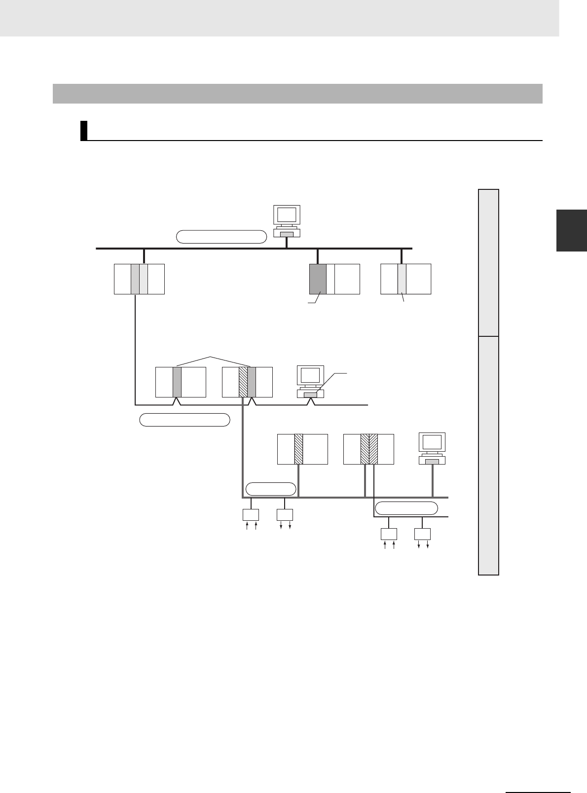
2-29
2 Basic System Configuration and Devices
CJ2 CPU Unit Hardware User’s Manual
2-2 Expanded System Configuration
2
2-2-2 Communications Networks
‘
The CJ Series supports the following communications networks. Select the appropriate network
according to the applications. For details on communications networks, refer to 11-3 Communications
Networks in the CJ2 CPU Unit Software User’s Manual (Cat. No. W473).
2-2-2 Communications Networks
Communications Network Systems
DeviceNet
CompoNet
EtherNet/IP, Ethernet
Controller Link
Information network
Control network
EtherNet/IP Unit
Ethernet Unit
Connect via the built-in
EtherNet/IP port or a
EtherNet/IP Unit or Ethernet
Unit connected to the CPU Unit.
Built-in EtherNet/IP port*1
*1: The EtherNet/IP port built into the CJ2H-CPU6@-EIP
provides the same performance and functions as a
CJ1W-EIP21 EtherNet/IP Unit. The EtherNet/IP port built
into the CJ2M-CPU3@ provides very different performance.
Controller Link Units
Controller Link
Support Board
Connect by connecting a
Controller Link Unit to the
CPU Unit. It is also possible
to communicate with a
personal computer in which
a Controller Link Support
Board is installed.
Configurator
Connect by connecting a
DeviceNet Unit to the CPU Unit.
It is also possible to connect to
various types of slaves.
Slaves
Connect by connecting a
CompoNet Unit. It is also
possible to connect to various
types of slaves.
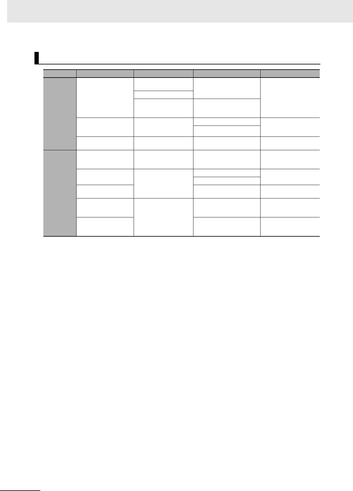
2 Basic System Configuration and Devices
2-30 CJ2 CPU Unit Hardware User’s Manual
Communications Network Overview
System Network Function Communications Communications Device
Information
networks
EtherNet/IP Between Host computer and
PLC.
FINS message communications Built-in EtherNet/IP port on
CJ2H-CPU6@-EIP or CJ2M-
CPU3@, or EtherNet/IP Unit
Between PLCs.
Between Host computer and
Memory Card installed in
CPU Unit.
FTP server
Controller Link Between PLC and personal
computer directly connected
to the Network.
FINS message communications Controller Link Support
Board or Controller Link Unit
Data link (offset, simple settings)
RS-232C → Controller Link Between Host Link computer
and PLC on the Network.
Host Link commands and gate-
way.
RS-232C cables and Con-
troller Link Unit
Control
networks
EtherNet/IP Between PLCs. Tag data links Built-in EtherNet/IP port on
CJ2H-CPU6@-EIP, CJ2M-
CPU3@ or EtherNet/IP Unit
Controller Link Between PLCs. FINS message communications Controller Link Unit
Data link (offset, simple settings)
DeviceNet FINS message communications
in an open network.
DeviceNet Master Unit and
Configurator
DeviceNet Between PLC and Network
devices (Slaves).
Large-capacity remote I/O (fixed
or free allocation) in an open net-
work
DeviceNet Master Unit and
Configurator
CompoNet High-speed, multi-point, multi-
node remote I/O in an open net-
work
CompoNet Master Unit

3-1
CJ2 CPU Unit Hardware User’s Manual
3
This section gives the parts of a CJ2 PLC and describes the functions of the parts.
3-1 CPU Units . . . . . . . . . . . . . . . . . . . . . . . . . . . . . . . . . . . . . . . . . . . . . . . . . . . . 3-2
3-1-1 CPU Section . . . . . . . . . . . . . . . . . . . . . . . . . . . . . . . . . . . . . . . . . . . . . . . . . . 3-2
3-1-2 Built-in EtherNet/IP Section (CJ2H-CPU6@-EIP and CJ2M-CPU3@ Only) . . . 3-8
3-2 Memory Card . . . . . . . . . . . . . . . . . . . . . . . . . . . . . . . . . . . . . . . . . . . . . . . . 3-13
3-2-1 Models and Specifications . . . . . . . . . . . . . . . . . . . . . . . . . . . . . . . . . . . . . . . 3-13
3-2-2 Operating Procedures . . . . . . . . . . . . . . . . . . . . . . . . . . . . . . . . . . . . . . . . . . 3-13
3-2-3 Installing and Removing . . . . . . . . . . . . . . . . . . . . . . . . . . . . . . . . . . . . . . . . 3-14
3-3 Pulse I/O Modules (CJ2M CPU Unit Only) . . . . . . . . . . . . . . . . . . . . . . . . . 3-17
3-3-1 Models and Specifications . . . . . . . . . . . . . . . . . . . . . . . . . . . . . . . . . . . . . . . 3-17
3-3-2 Part Names and Functions . . . . . . . . . . . . . . . . . . . . . . . . . . . . . . . . . . . . . . 3-17
3-4 Serial Option Boards (CJ2M-CPU3@ Only) . . . . . . . . . . . . . . . . . . . . . . . . 3-20
3-4-1 Overview . . . . . . . . . . . . . . . . . . . . . . . . . . . . . . . . . . . . . . . . . . . . . . . . . . . . 3-20
3-5 Power Supply Units . . . . . . . . . . . . . . . . . . . . . . . . . . . . . . . . . . . . . . . . . . . 3-21
3-5-1 Models and Specifications . . . . . . . . . . . . . . . . . . . . . . . . . . . . . . . . . . . . . . . 3-21
3-5-2 Components . . . . . . . . . . . . . . . . . . . . . . . . . . . . . . . . . . . . . . . . . . . . . . . . . 3-24
3-5-3 Selecting a Power Supply Unit . . . . . . . . . . . . . . . . . . . . . . . . . . . . . . . . . . . . 3-27
3-6 CJ-series Basic I/O Units . . . . . . . . . . . . . . . . . . . . . . . . . . . . . . . . . . . . . . . 3-28
3-6-1 Basic I/O Units with Terminal Blocks . . . . . . . . . . . . . . . . . . . . . . . . . . . . . . . 3-28
3-6-2 Thirty-two/Sixty-four-point Basic I/O Units with Connectors . . . . . . . . . . . . . 3-30
3-7 I/O Control Units and I/O Interface Units . . . . . . . . . . . . . . . . . . . . . . . . . . 3-32
3-7-1 Component Names . . . . . . . . . . . . . . . . . . . . . . . . . . . . . . . . . . . . . . . . . . . . 3-32
3-7-2 System Configuration . . . . . . . . . . . . . . . . . . . . . . . . . . . . . . . . . . . . . . . . . . 3-32
Nomenclature and Functions
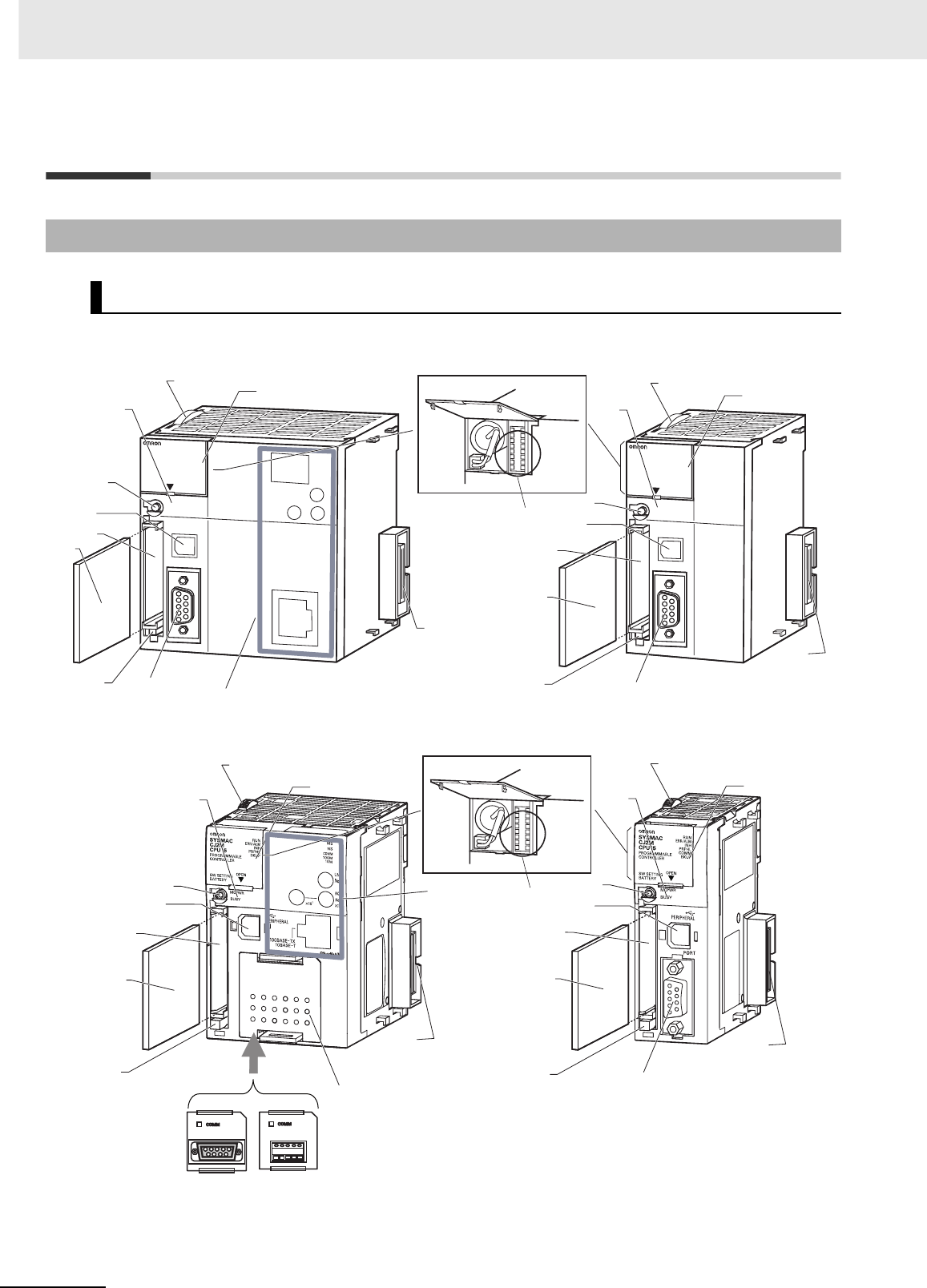
3 Nomenclature and Functions
3-2 CJ2 CPU Unit Hardware User’s Manual
3-1 CPU Units
3-1-1 CPU Section
Components and Functions
CJ2H-CPU6@-EIP CJ2H-CPU6@
CJ2M-CPU3@CJ2M-CPU1@
6
5
4
8
1
2
39
7
Inside the battery compartment
11
PERIPHERAL
ERR/ALM
RUN
INH
COMM
BKUP
PRPHL
NS
MS
COMM
10M
100M
CONTROLLER
CPU64-EIP
CJ2H
SYSMAC
PROGRAMMABLE
PORT
OPEN
BUSY
MCPWR
11
10
10 6
5
4
3
2
8
1
7
12
PERIPHERAL
ERR/ALM
RUN
INH
COMM
BKUP
PRPHL
CONTROLLER
CPU64-EIP
CJ2H
SYSMAC
PROGRAMMABLE
PORT
OPEN
BUSY
MCPWR
Inside the battery compartment
6
5
4
8
1
2
3
9
7
11
11
10
13
6
5
4
3
2
8
1
7
12
CP1W-CIF01
RS-232C
Option Board
CP1W-CIF11 or
CP1W-CIF12
RS-422A/485
Option Board

3-3
3 Nomenclature and Functions
CJ2 CPU Unit Hardware User’s Manual
3-1 CPU Units
3
3-1-1 CPU Section
1. Memory Card Indicators (Refer to 3-2 Memory Card.)
Indicates the Memory Card status (access and power
supply).
2. Simple Backup/Memory Card Power Supply Switch
(Refer to 3-2 Memory Card.)
Used to back up Memory Card data or turn OFF the
power when removing the Memory Card.
3. Peripheral (USB) Port
Connected to Programming Devices, such as the CX-
Programmer
4. Memory Card Connector (Refer to 3-2 Memory Card.)
Connects the Memory Card to the CPU Unit.
5. Memory Card (Refer to 3-2 Memory Card.)
All CPU Unit data can be copied to a Memory Card to
back up the data. If a Memory Card Adapter is used, the
Memory Card can be mounted in the PCMIA slot in a
personal computer.
6. Memory Card Eject Button (Refer to 3-2 Memory Card.)
Press the eject button to remove the Memory Card from
the CPU Unit.
7. Slider
Secures the CPU Unit to the next Unit.
8. LED Indicators (Refer to the next page.)
These indicators show the status of the CPU Unit:
• Normal operation
•Errors
• Output OFF status
• Communications status for the peripheral (USB) and RS-
232C ports
• Backup status between RAM and built-in flash memory
9. DIP Switch (Refer to a following page.)
Sets operations, such as user memory protection, auto-
matic program transfer by Memory Card, serial port com-
munications mode, and simple backup.
10. RS-232C Serial Port (Refer to A-4 Connecting to a Serial
Port on the CPU Unit.)
Connected to Programming Devices, Host Computers,
general-purpose external devices, Programmable Termi-
nals, and other devices.
11. Connector
Connected to the next Unit.
12. Built-in EtherNet/IP Section (CJ2H-CPU6@-EIP only)
Refer to 3-1-2 Built-in EtherNet/IP Section (CJ2H-
CPU6@-EIP only) for information on the built-in Ether-
Net/IP Section.
13. Serial Option Boards (CJ2M-CPU3@ Only)
An Option Board can be connected to the slot.
• CP1W-CIF01 RS-232C Option Board
• RS-422A/485 Option Board
(CP1W-CIF11 (Maximum transmission distance: 50 m)
or CP1W-CIF12 (Maximum transmission distance:
500 m))
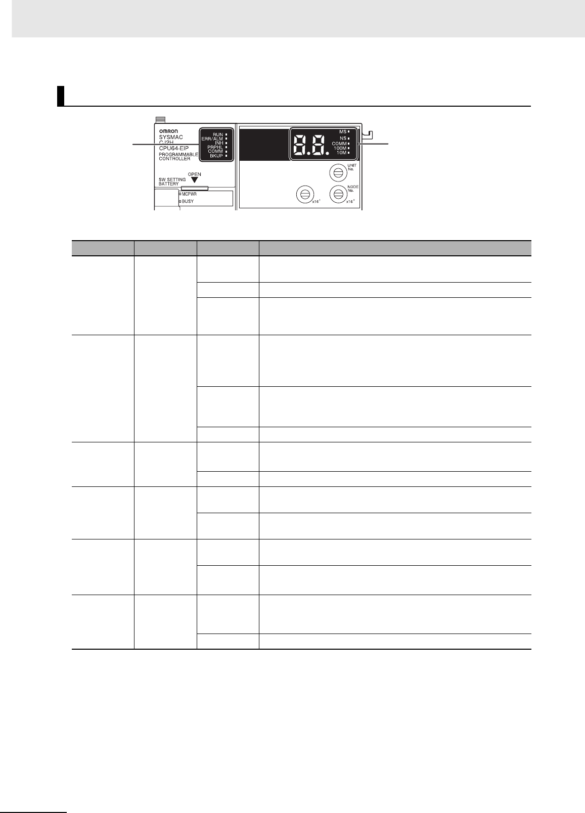
3 Nomenclature and Functions
3-4 CJ2 CPU Unit Hardware User’s Manual
The CJ2 CPU Unit status can be checked with the indicators at the top of the front panel of the Unit.
The following table describes these indicators.
*1 The CJ2M-CPU3@ does not have this indicator.
*2 Do not turn OFF the power supply to the PLC while this indicator is lit.
CPU Unit Status Indicators
Indicator Color Status Meaning
RUN Green ON Lights when the PLC is operating normally in MONITOR or RUN
mode. The program is being executed.
Flashing System download mode error or DIP switch settings error.
OFF PLC has stopped operating while in PROGRAM mode, or has
stopped operating due to a fatal error, or is downloading data from
the system.
ERR/ALM Red ON A fatal error (including FALS(007) instruction execution) or a hard-
ware error (watchdog timer error) was found in self-diagnosis.
The CJ2 CPU Unit will stop operating, and the outputs from all
Output Units will turn OFF.
Flashing A non-fatal error was found (including FAL(006) instruction execu-
tion) in the self-diagnosis.
The CJ2 CPU Unit will continue operating.
OFF The CJ2 CPU Unit is operating normally.
INH Yellow ON Output OFF Bit (A500.15) has been turned ON.
The outputs from all Output Units will turn OFF.
OFF Output OFF Bit (A500.15) has been turned OFF.
PRPHL Yellow Flashing The CJ2 CPU Unit is communicating (sending or receiving) via the
peripheral (USB) port.
OFF The CJ2 CPU Unit is not communicating via the peripheral (USB)
port.
COMM*1 Yellow Flashing The CJ2 CPU Unit is communicating (sending or receiving) via the
serial port (RS-232C).
OFF The CJ2 CPU Unit is not communicating via the serial port
(RS-232C).
BKUP Yellow ON User program and parameter area data is being backed up to
flash memory in the CPU Unit or being restored from flash mem-
ory after the power supply to the PLC was turned ON. *2
OFF Data is not being written to flash memory.
Indicators on front
of CPU Unit
7-segment display and
indicators for
EtherNet/IP port
(Refer to 3-1-2
Built-in EtherNet/IP Section.)
(CJ2H-CPU6@-EIP and
CJ2M-CPU3@ only.)
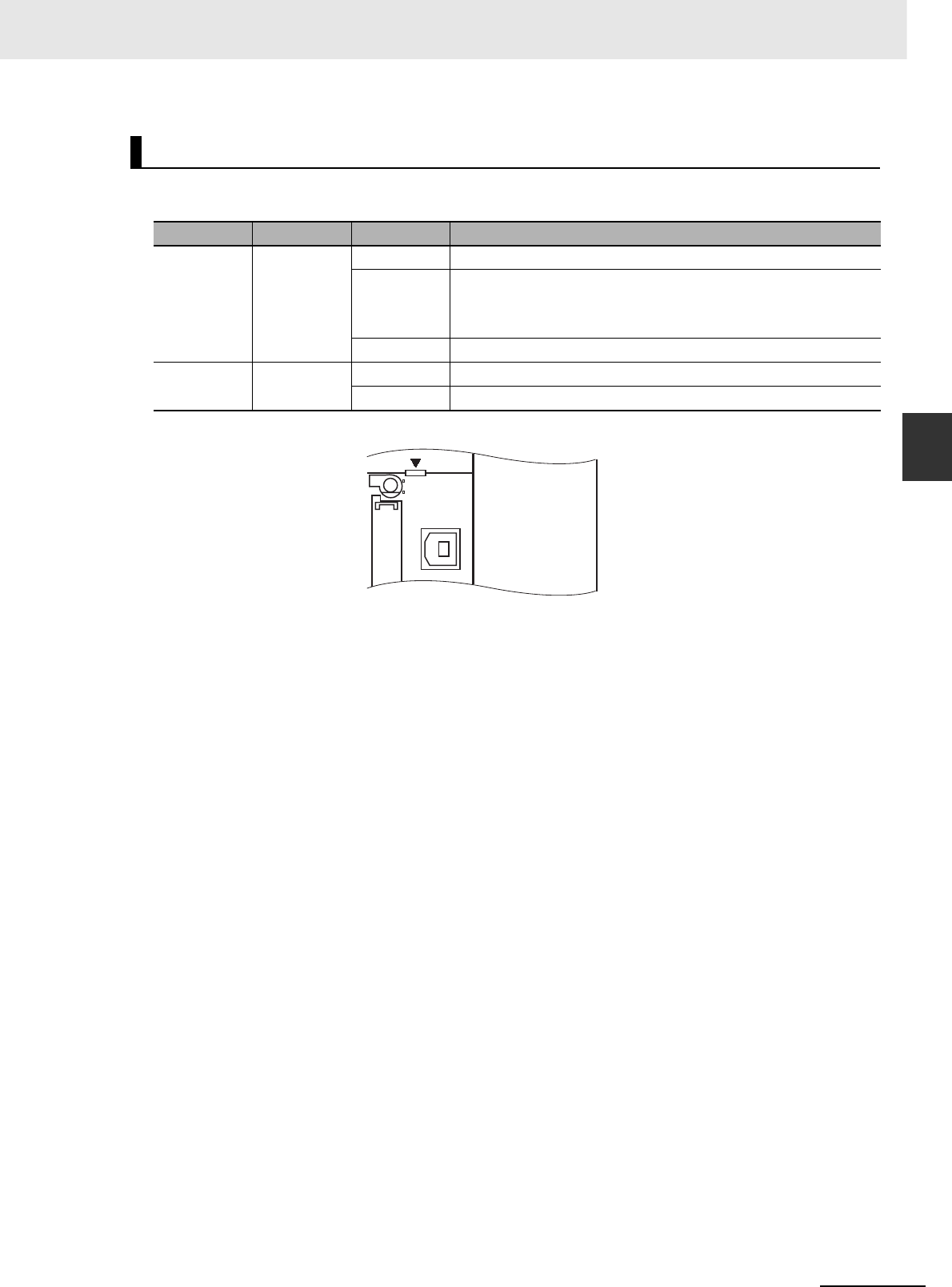
3-5
3 Nomenclature and Functions
CJ2 CPU Unit Hardware User’s Manual
3-1 CPU Units
3
3-1-1 CPU Section
The status of a Memory Card mounted in the CJ2 CPU Unit can be checked with the indicators in the
middle of the front panel of the Unit. The following table describes these indicators.
Memory Card Indicators
Indicator Color Status Meaning
MCPWR Green Lit Power is being supplied to the Memory Card.
Flashing Flashes once: Simple backup read, write, or verify normal
Flashes five times: Simple backup read malfunction
Flashes continuously: Simple backup write or verify malfunction
Not lit Power is not being supplied to the Memory Card.
BUSY Yellow Flashing Memory Card is being accessed.
Not lit Memory Card is not being accessed.
OPEN
PERIPHERAL
BUSY
MCPWR
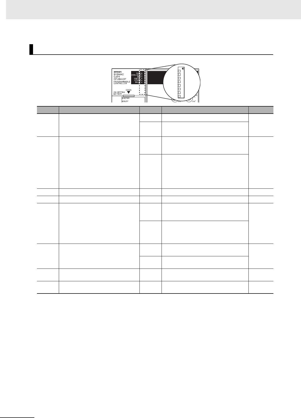
3 Nomenclature and Functions
3-6 CJ2 CPU Unit Hardware User’s Manual
*1 The following data cannot be overwritten when pin 1 is ON:
• All parts of the user program (programs in all tasks)
• All data in the parameter area (such as the PLC Setup and I/O table)
When pin 1 is ON, the user program and parameter area will not be cleared when the memory clear opera-
tion is performed from a Programming Device.
*2 I/O memory files (AUTOEXEC.IOM and ATEXEC@@.IOM) are automatically transferred when power is turned
ON if pin 2 is set to ON. Both the program (AUTOEXEC.OBJ) and parameter area (AUTOEXEC.STD) files
must be stored on the Memory Card. It is not necessary for the I/O memory files (AUTOEXEC.IOM and
ATEXEC@@.IOM) to be stored on the Memory Card.
*3 When pin 7 is ON, simple backup reading from the Memory Card is given priority, so even if pin 2 is ON, the
user program is not automatically transferred from the Memory Card when power is turned ON.
*4 Connecting to the PLC is not possible from the CX-One Support Software using SYSMAC WAY even if pin 5 on
the DIP switch is OFF and the PLC Setup is set to the Host Link protocol (i.e., the default setting).
*5 With the CJ2M-CPU3@, pin 5 can be set only when a Serial Option Board is mounted.
DIP Switch
Pin no. Usage Setting Function Default
SW1 Used to prevent programs from being
accidentally overwritten from Program-
ming Devices (including the CX-Program-
mer).
ON Writing disabled for user program memory.*1 OFF
OFF Writing enabled for user program memory.
SW2 Set to ON to read the program
(AUTOEXEC.OBJ file) and parameter
area (AUTOEXEC.STD file) from the
Memory Card to the CPU Unit when
power is turned ON.*2
Used to store the programs in the Mem-
ory Card to switch operations, or to auto-
matically transfer programs at startup
(Memory Card ROM operation).*3
ON The user program is automatically trans-
ferred from the Memory Card when power is
turned ON.
OFF
OFF The user program is not automatically trans-
ferred from the Memory Card when power is
turned ON.
SW3 Not used. --- --- OFF
SW4 Not used. --- --- OFF
SW5 Set to ON to automatically detect the
baud rate of the CX-Programmer (periph-
eral bus only) when using the serial port
(RS-232C).*4, *5
ON Serial port (RS-232C) communications con-
dition: Automatically detect CX-Programmer
(peripheral bus only) baud rate.
OFF
OFF Serial port (RS-232C) communications con-
dition: According to CX-Programmer commu-
nications settings in PLC Setup. (Refer to
Ta b le 1 .)
SW6 Set pin 6 to ON or OFF and use A395.12
in the program to create a user-defined
condition without using an Input Unit.
ON User-defined pin. Turns ON the User DIP
Switch Pin Flag (A395.12).
OFF
OFF User-defined pin. Turns OFF the User DIP
Switch Pin Flag (A395.12).
SW7 Set the simple backup type. (Refer to
Table 2 below.)
--- Specifies the simple backup type. OFF
SW8 --- Always
OFF.
--- OFF
1
2
345
6
78
ON
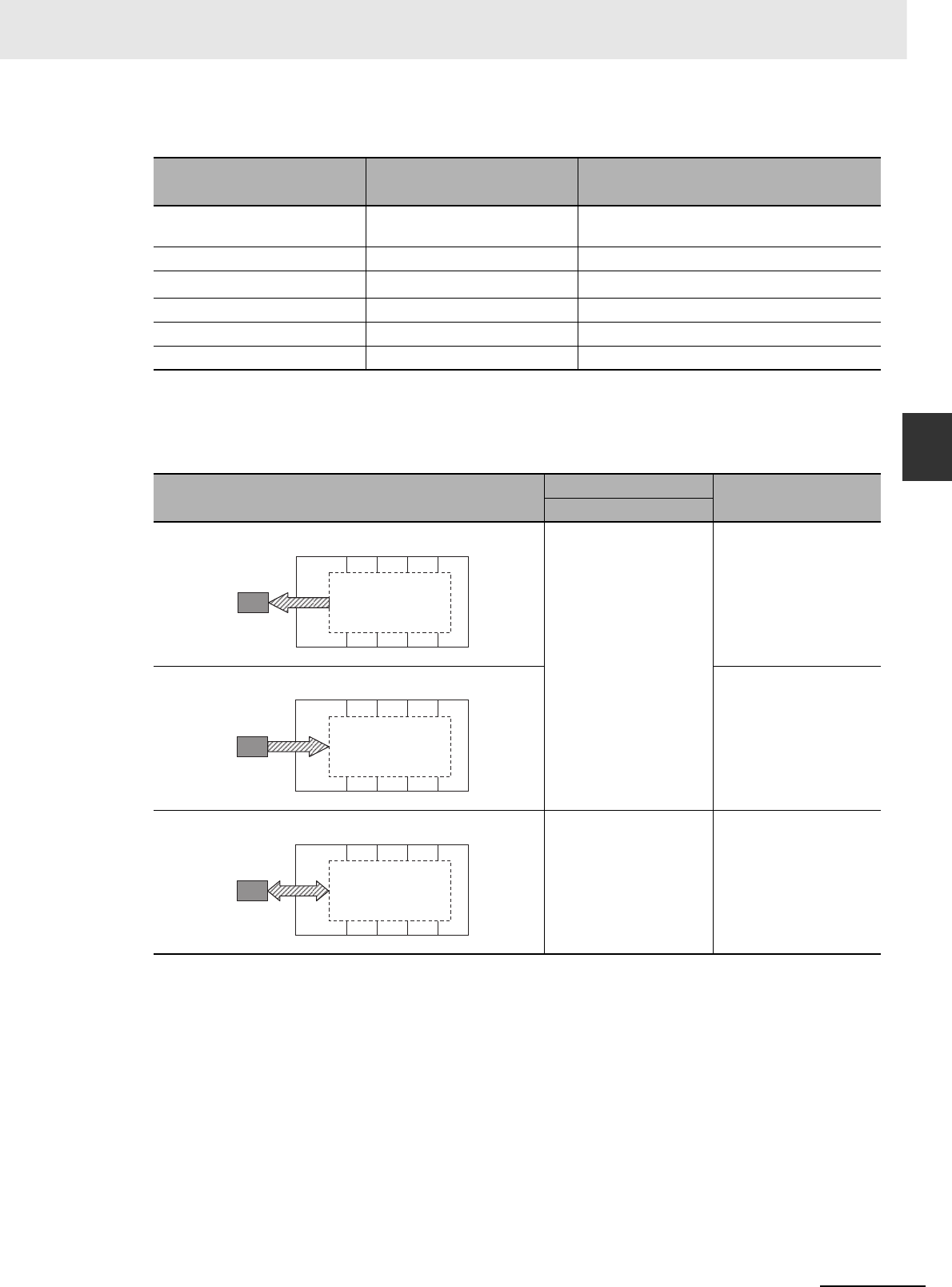
3-7
3 Nomenclature and Functions
CJ2 CPU Unit Hardware User’s Manual
3-1 CPU Units
3
3-1-2 Built-in EtherNet/IP Section (CJ2H-CPU6@-EIP only)
*1 Set using the CX-Programmer.
*2 Connection is not possible from CX-One Support Software using the SYSMAC WAY protocol.
*1 This operation is given priority over automatic transfer at startup (pin 2 set to ON).
Note After reading data from the Memory Card to the CPU Unit using the simple backup operation, the CPU Unit
will remain in PROGRAM mode and no operations in any other mode will be possible. To switch to RUN or
MONITOR mode, turn OFF the power, turn OFF pin 7, turn the power back ON, and use a Programming
Device to change the operating mode.
Table 1
Setting Pin 5 of DIP switch on front
panel PLC Setup (Serial port (RS-232C))*1
Connection
1. Peripheral bus
(automatic detection)
ON ---
2. Peripheral bus OFF (default) Peripheral bus
3. Host Link*2 OFF (default) Host Link (default)
4. NT Link OFF (default) NT Link
5. No-protocol OFF (default) No-protocol
6. Serial Gateway OFF (default) Serial Gateway
Table 2
Simple backup type DIP Switch Required operation
SW7
Backing up all PLC data on the Memory Card: ON Press the Memory Card
Power Supply Switch for
3s.
Restoring all PLC data from the Memory Card: Turn ON the power to
the PLC.*1
Comparing the Memory Card and the CPU Unit: OFF Press the Memory Card
Power Supply Switch for
3 s.
All PLC data
Memory Card
Backup
All PLC data
Memory Card
Restore
All PLC data
Memory Card
Compare
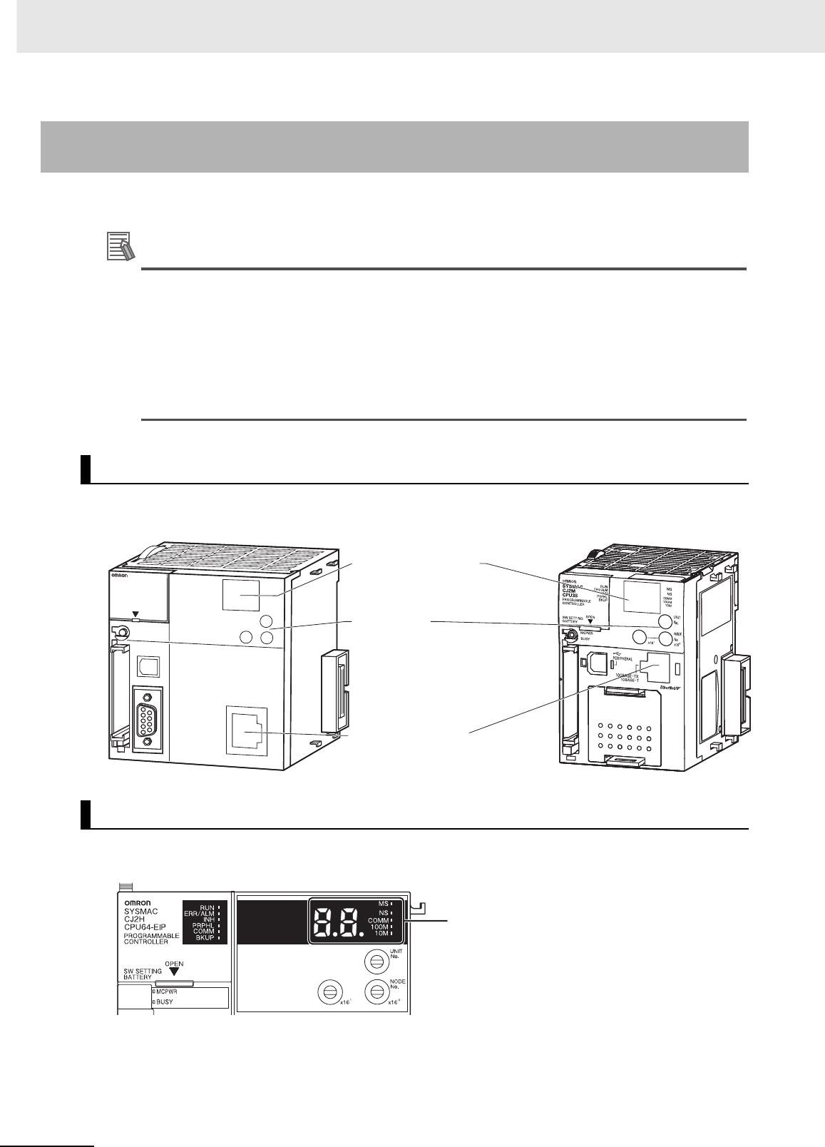
3 Nomenclature and Functions
3-8 CJ2 CPU Unit Hardware User’s Manual
This section describes the components related to the EtherNet/IP port section that is built into the
CJ2H-CPU6@-EIP and CJ2M-CPU3@.
Additional Information
The built-in EtherNet/IP port on the CJ2H-CPU6@-EIP provides the same performance and
functions as a CJ1W-EIP21 EtherNet/IP Unit. (The performance of the built-in EtherNet/IP port
on the CJ2M-CPU3@ is very different.) Set the unit number and node address with the rotary
switches on the front panel of the CPU Unit, and set the communications parameters with the
Edit Parameters menu command for the Special I/O Unit. For details on the Edit Parameters,
refer to 8-2 Setting CPU Bus Units and Special I/O Units in the CJ2 CPU Unit Software User’s
Manual (Cat. No. W473). For details on specifications and settings for the built-in EtherNet/IP
port, refer to the CS/CJ Series EtherNet/IP Units Operation Manual (Cat. No. W465).
With a CJ2 CPU Unit, Ethernet node status and Ethernet network status can be monitored by checking
the display and indicators at the upper right of the front of the CPU Unit.
3-1-2 Built-in EtherNet/IP Section (CJ2H-CPU6@-EIP and CJ2M-CPU3@
Only)
Nomenclature and Functions
CJ2H-CPU6@-EIP CJ2M-CPU3@
Display and Indicators for Built-in EtherNet/IP Port
A
REHPI
RE
P
L
NS
MS
COMM
10M
100M
CONTROLLER
CPU64-EIP
CJ2H
SYSMAC
PROGRAMMABLE
PORT
OPEN
BUSY
MCPWR
Display and indicators
for built-in EtherNet/IP port
Rotary switches
Built-in EtherNet/IP port
(Refer to 5-3-6 Wiring with Ethernet Cable.)
Seven-segment display and indicators
for built-in EtherNet/IP port
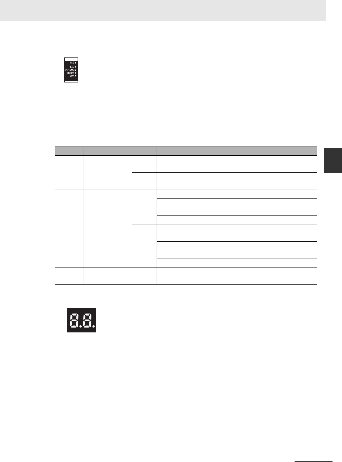
3-9
3 Nomenclature and Functions
CJ2 CPU Unit Hardware User’s Manual
3-1 CPU Units
3
3-1-2 Built-in EtherNet/IP Section (CJ2H-CPU6@-EIP only)
zStatus Indicators: MS, NS, COMM, 100M, and 10M
The MS (Module Status) indicator indicates the status of the built-in EtherNet/IP port itself and the
NS (Network Status) indicator indicates the status of the network.
The COMM, 100M, and 10M indicators indicate the status of Ethernet communications.
The MS and NS indicators can be green or red. The COMM, 100M, and 10M indicators are yellow.
These indicators can be lit, flashing, or not lit. The following table shows the meaning of these indi-
cator conditions.
Refer to SECTION 6 Troubleshooting for details on using these indicators for troubleshooting.
zSeven-segment Display
When the power supply to the PLC is turned ON or the CPU Unit is reset, all of the segments will
flash twice, and then the IP address set for the built-in EtherNet/IP port will be displayed on the 7-
segment display from right to left. After the entire IP address is displayed, the lower 8 bits of the IP
address (node address) will be displayed in hexadecimal.
Indicator Name Color Status Meaning
MS Module Status Red Lit Fatal error
Flashing Recoverable error
Green Lit Normal
--- Not lit Power supply OFF
NS Network Status Red Lit Fatal error
Flashing Recoverable error
Green Lit Tag data link and message connections established
Flashing Tag data link and message connections not established
--- Not lit Offline or power supply OFF
COMM Communication Yellow Lit Transferring data
Not lit Not transferring data
100M 100 Mbps Yellow Lit 100Base-TX link established
Not lit 100Base-TX link not established
10M 10 Mbps Yellow Lit 10Base-TX link established
Not lit 10Base-TX link not established
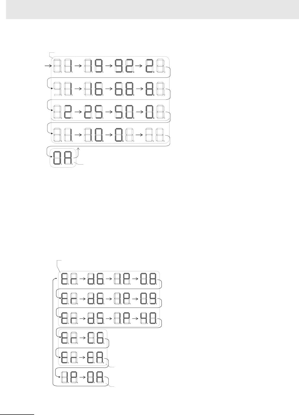
3 Nomenclature and Functions
3-10 CJ2 CPU Unit Hardware User’s Manual
For example, the display will change as follows if the IP address is 192.168.250.10:
If an error occurs, the error code will be displayed alternately with the rightmost byte of the affected
device’s IP address. For details on error codes, refer to 6-2-2 Checking Error Status at the Ether-
Net/IP Port Seven-segment Display.
The following examples show the displays for errors.
• A d6 error (failure to connect) has occurred in communications with IP address 192.168.250.8.
• A d6 error (failure to connect) has occurred in communications with IP address 192.168.250.9.
• A d5 error (verification error; target missing) has occurred in communications with IP address
192.168.250.40.
• A C6 error (multiple switches ON) and an EA error (EtherNet/IP expansion setting error) have
occurred at the built-in EtherNet/IP port (192.168.250.10).
: 0A
The IP address is displayed in decimal, flowing from right to left.
If the Unit is operating normally, the rightmost digits
of the Unit's IP address is displayed in hexadecimal.
Flashing: The tag data links are stopped.
Lit: The tag data links are operating.
( “0A” is the hexadecimal display
for the final row, 10, in the IP
address of the local Unit.)
: 10
: 250.
: 168.
: 192.
Example:
Example:
: Er d6 IP 08
: IP d6 IP 09
: Er d5 IP 40
: Er c6
: Er EA
: IP 0A
Information on errors that occur in
communications with the target node,
along with the last digits of the Unit’ s IP
address, are displayed in hexadecimal.
Displays errors that occurred
within the Unit.
The last digits of the
Unit’ s IP address is
displayed in hexadecimal.
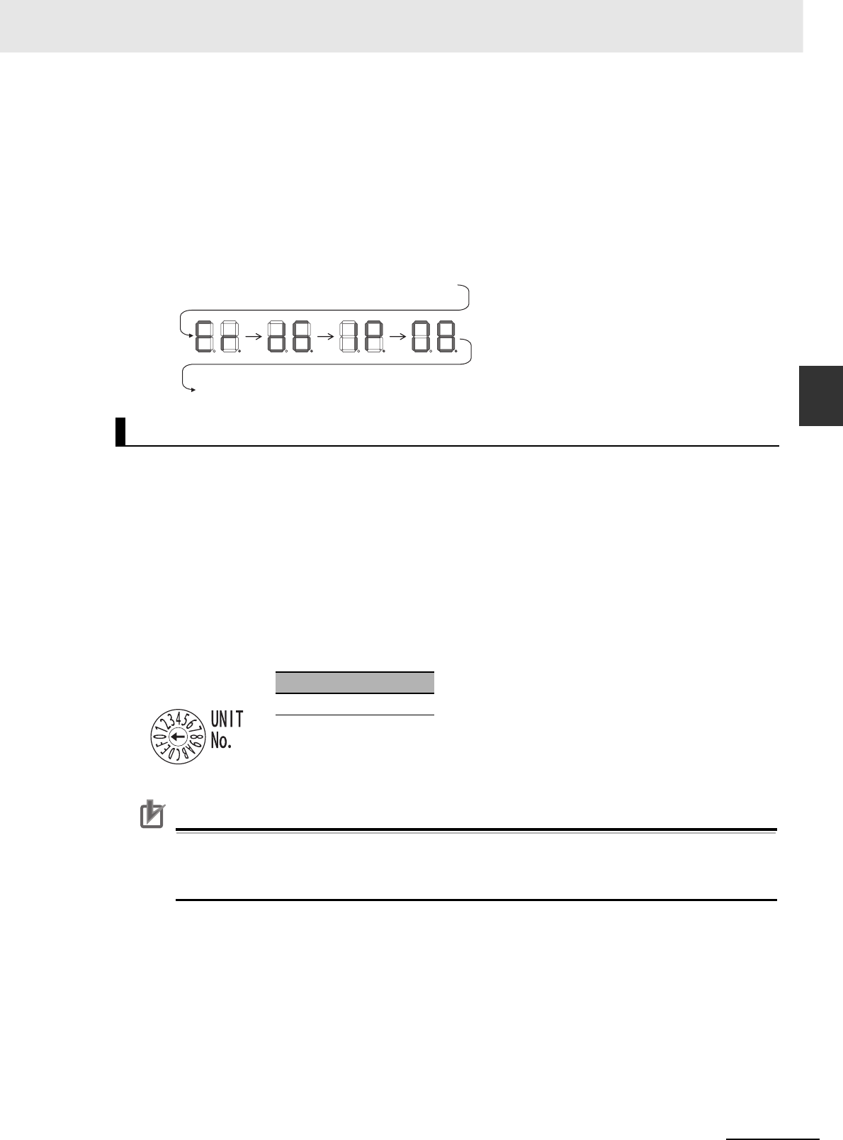
3-11
3 Nomenclature and Functions
CJ2 CPU Unit Hardware User’s Manual
3-1 CPU Units
3
3-1-2 Built-in EtherNet/IP Section (CJ2H-CPU6@-EIP only)
• There is no priority to the order in which the errors are displayed. All of the errors are displayed
repeatedly in sequence.
Left/Right Dot LEDs
If an error occurs at multiple devices for which the rightmost 8 bits in the IP addresses are the same,
this is indicated by the dots on the right side in display on the target devices.
The following examples show the displays for multiple errors.
• d6 errors (failure to connect) have occurred in communications with IP address 10.0.1.8.
• d6 errors (failure to connect) have occurred in communications with IP address 10.0.2.8.
The unit number and node address for the CJ2 CPU Unit built-in EtherNet/IP port are set using the
rotary switches. The unit number and node address are allocated in the same way as for a CPU Bus
Unit. According to the unit number that is set, words are automatically allocated in the CIO Area and
DM Area. For details, refer to the CJ2 CPU Unit Software User’s Manual (Cat. No. W473).
zSetting the Unit Number
Set a unique unit number for the CJ2 CPU Unit built-in EtherNet/IP port. The same unit number can-
not be used by any other CPU Bus Unit connected to the CJ2 CPU Unit.
Use a small screwdriver to make the setting, and be sure not to damage the rotary switch. The unit
number is factory-set to 0.
Precautions for Correct UsePrecautions for Correct Use
• Always turn OFF the PLC’s power supply before setting the unit number.
• When setting the unit number for the first time or when changing the setting, create the PLC’s
I/O tables.
Rotary Switches
Setting range
0 to F
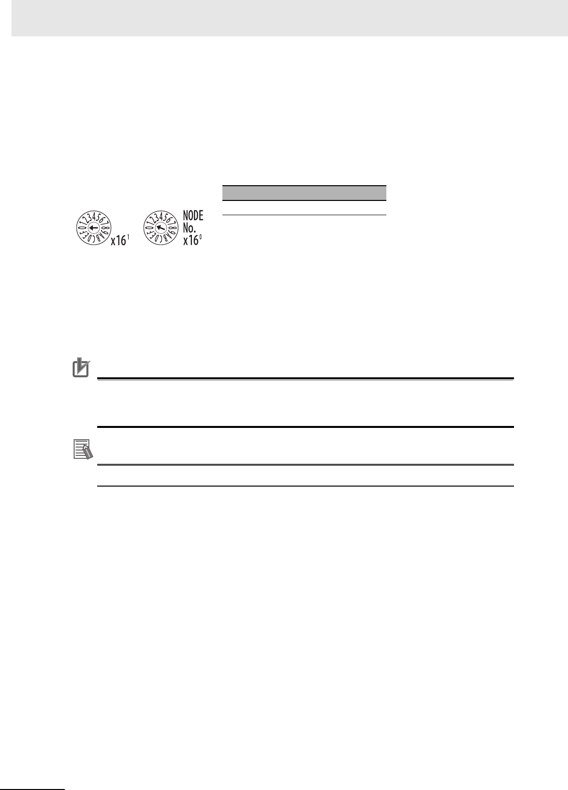
3 Nomenclature and Functions
3-12 CJ2 CPU Unit Hardware User’s Manual
zNode Address Setting Switches
Set a FINS address for the built-in EtherNet/IP port. With the FINS communications service, multiple
EtherNet/IP Units (including the CJ2 Unit built-in EtherNet/IP port) connected by Ethernet are identi-
fied by their node addresses. Using the node address switches, set a unique node address in hexa-
decimal. The same node address cannot be used by any other EtherNet/IP Unit or Ethernet Unit
connected on the same Ethernet network.
As long as it does not duplicate any other address, the node address can be set from 01 to FE (1 to
254 in decimal).
Note The node address is factory-set to 01. With the default setting, the values set on these switches become the
last two digits of the built-in EtherNet/IP port’s IP address.
The default IP address is 192.168.250.node_address. With the factory-set node address of 01, the
default IP address is 192.168.250.1.
The node address can be set to any number in the setting range (01 to FE), as long as the same
address is not set on another node in the network.
Precautions for Correct UsePrecautions for Correct Use
• Always turn OFF the PLC’s power supply before setting the unit number.
• When setting the unit number for the first time or when changing the setting, create the PLC’s
I/O tables.
Additional Information
• If the node address setting is changed during operation, the MS Indicator will flash red.
zRelationship with IP Address
When using the automatic generation method (dynamic/static) for IP address conversion, the right-
most byte of the IP address that is set for the built-in EtherNet/IP port must be set to the same value
as the node address. If it cannot be set to the same value as the node address, then the address
conversion method must be set to the IP address table method or the IP address + automatic gener-
ation method. For details, refer to the CS/CJ Series EtherNet/IP Units Operation Manual (Cat. No.
W465).
Setting range
01 to FE hex (1 to 254 decimal)
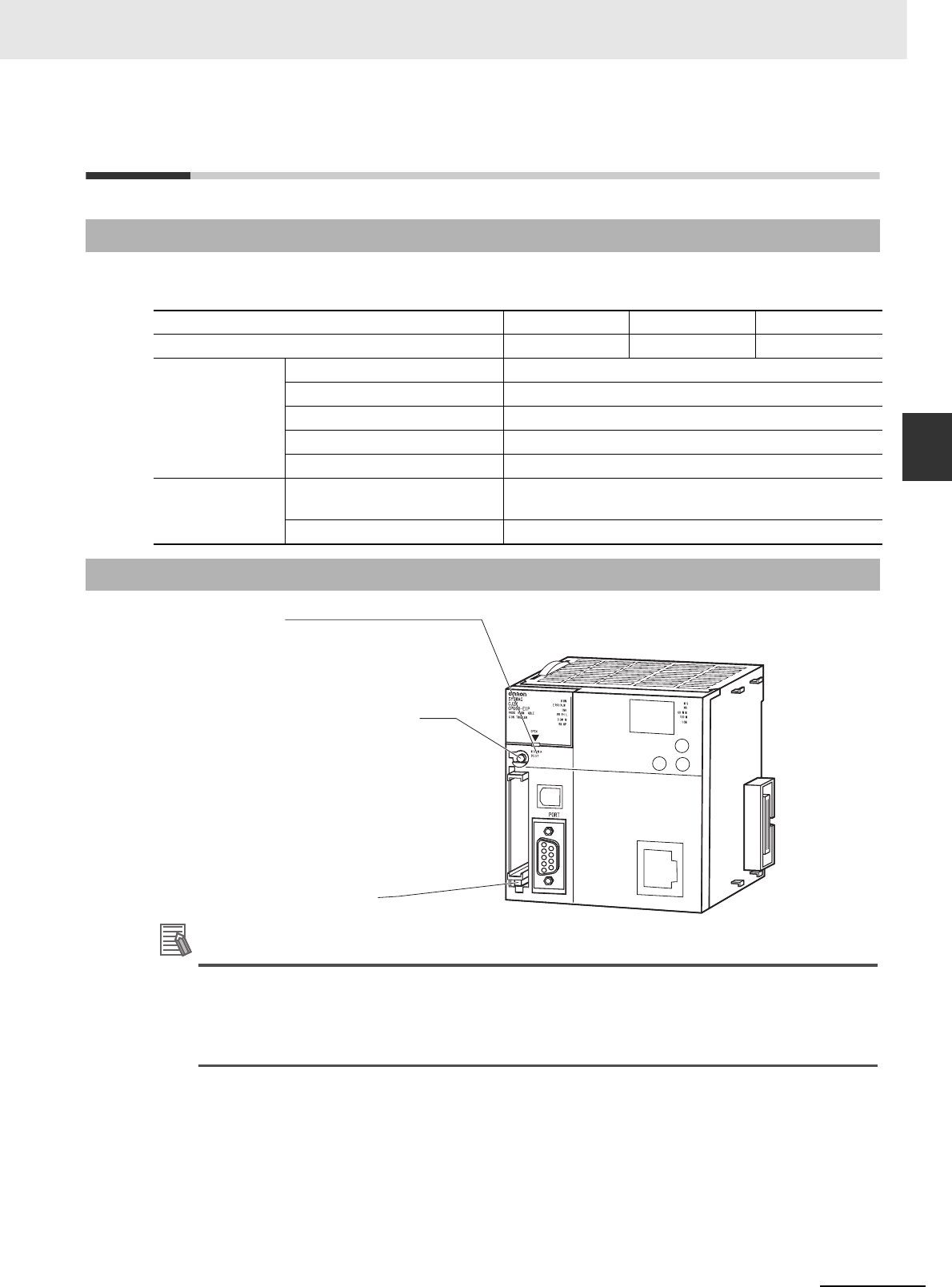
3-13
3 Nomenclature and Functions
CJ2 CPU Unit Hardware User’s Manual
3-2 Memory Card
3
3-2-1 Models and Specifications
3-2 Memory Card
Use the following OMRON-specified Memory Card. Operation may not be correct if memory cards from
other companies are used.
Additional Information
Simple Backup
The simple backup function copies all CPU Unit data (user program, parameters, and I/O mem-
ory) to a Memory Card, without having to use a Programming Device.
For details, refer to 8-3 Simple Backup.
3-2-1 Models and Specifications
Model number HMC-EF583 HMC-EF283 HMC-EF183
Memory Card capacity 512 Mbytes 256 Mbytes 128 Mbytes
Common specifi-
cations
Dimensions 42.8 × 36.4 × 3.3 mm (W × H × T)
Weight 15 g max.
Current consumption Approx. 30 mA (when used with PLC)
Environmental specifications Same as general specifications of PLC
No. of writes 100,000 (guaranteed value)
Factory specifi-
cations
No. of files writable to root
directory
511
File system FAT16
3-2-2 Operating Procedures
Memory Card Eject Button
Memory Card Indicators
MCPWR (green): Lit when power is being provided
to the Memory Card.
BUSY (orange): Flashes while the Memory Card is being
accessed.
Simple Backup/Memory Card Power Supply Switch
This switch has the following two functions.
• Simple Backup
To back up all CPU Unit data to the Memory Card,
press this switch for 3 s when DIP switch pin 7 is set to ON.
• Turning OFF Power to the Memory Card
Press this switch to turn OFF the power before removing the
Memory Card.
LAREHP
I
RE
P
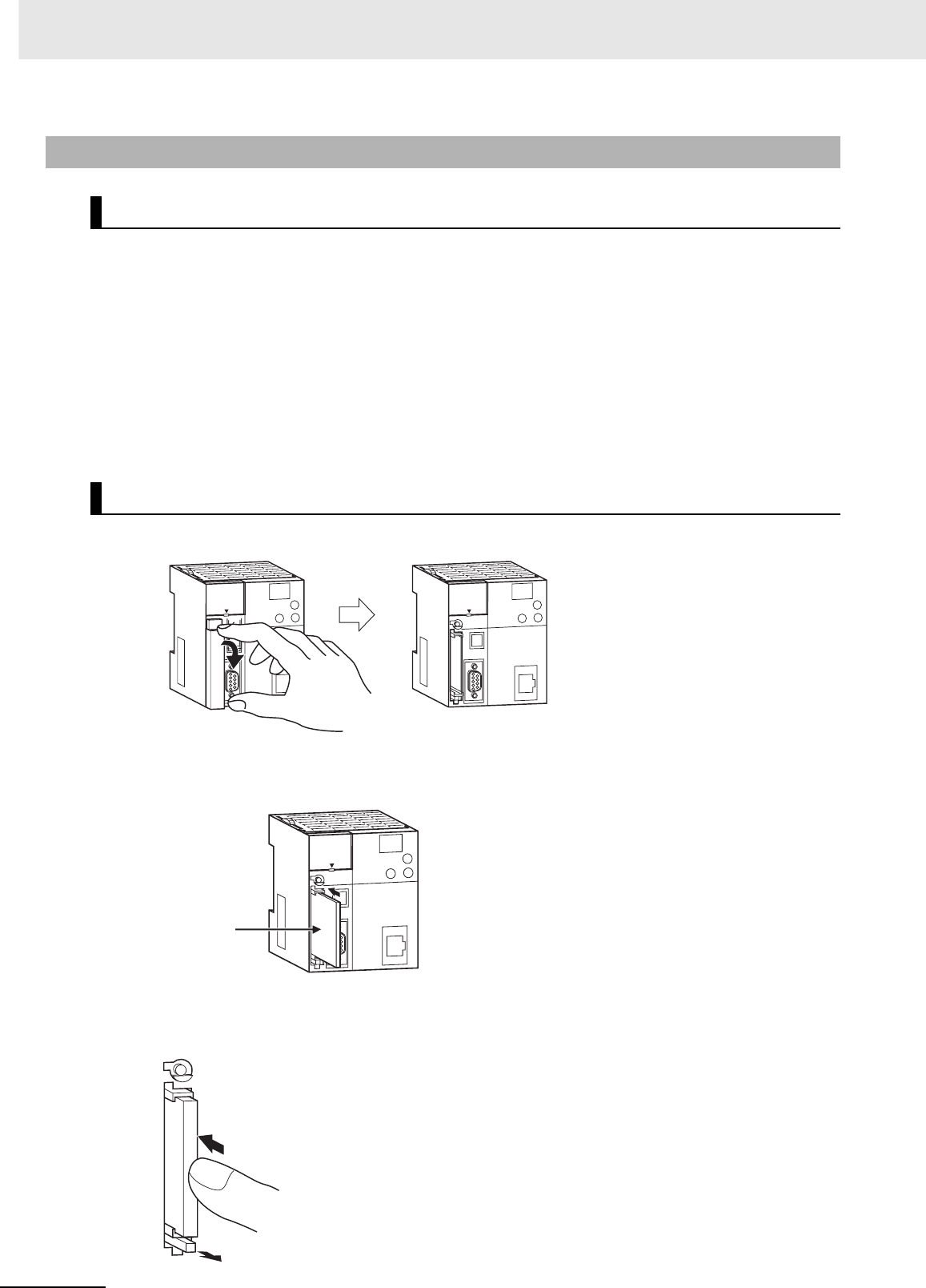
3 Nomenclature and Functions
3-14 CJ2 CPU Unit Hardware User’s Manual
• Observe the following precautions while the Memory Card is being accessed. The Memory Card may
become unusable if these precautions are not followed.
• Never turn OFF the PLC while the CPU is accessing the Memory Card.
• Never remove the Memory Card while the CPU is accessing the Memory Card. Press the Memory
Card power supply switch and wait for the BUSY indicator to go OFF before removing the Memory
Card.
• Never insert the Memory Card facing the wrong way. If the Memory Card is inserted forcibly, it may
become unusable.
• To delete all the data on the Memory Card by formatting the Memory Card, insert the Memory Card in
the CPU Unit and perform the operation from the CX-Programmer.
1Pull the top end of the Memory Card cover forward and remove from the Unit.
2Insert the Memory Card with the label facing to the left. (Insert with the ∆ on the Memory Card
label and the ∆ on the CPU Unit facing each other.)
3Push the Memory Card securely into the compartment.
If the Memory Card is inserted correctly, the Memory Card eject button will be pushed out.
3-2-3 Installing and Removing
Before Using a Memory Card
Installing the Memory Card
Product label
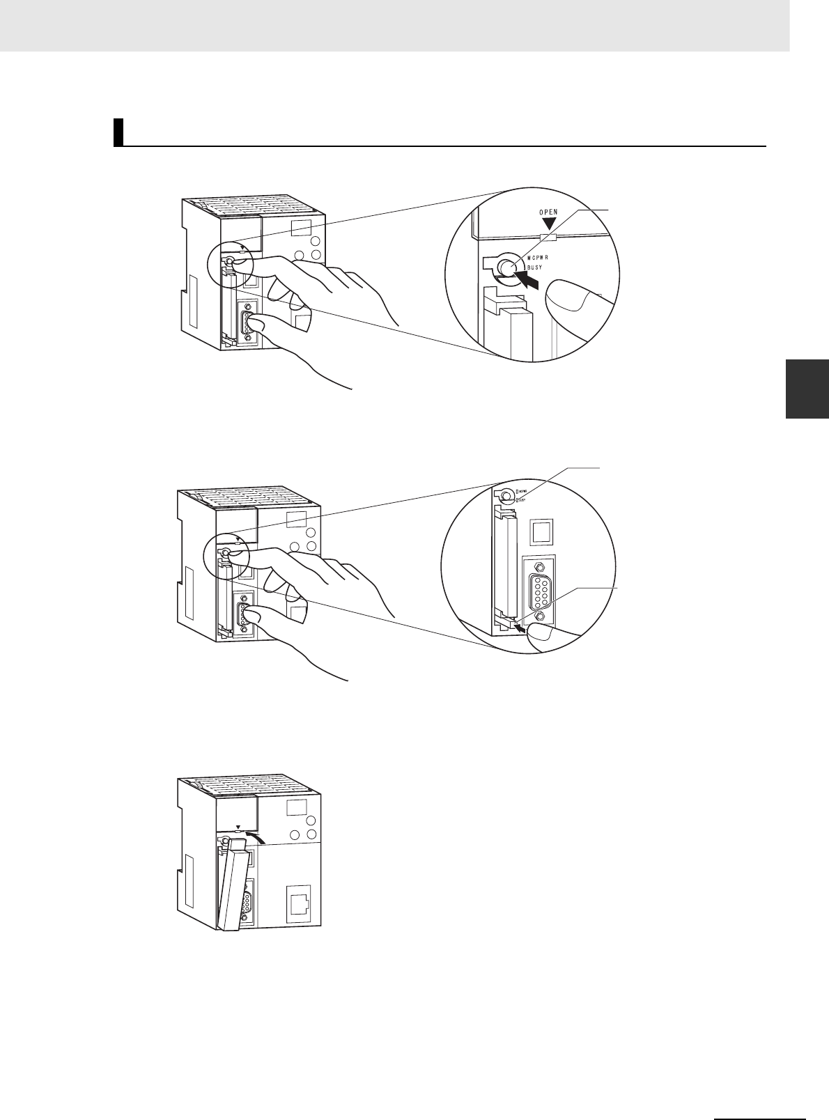
3-15
3 Nomenclature and Functions
CJ2 CPU Unit Hardware User’s Manual
3-2 Memory Card
3
3-2-3 Installing and Removing
1Press the Memory Card power supply switch.
2Press the Memory Card eject button after the BUSY indicator is no longer lit.
The Memory Card will be ejected from the compartment.
3Pull out the Memory Card.
4Install the Memory Card cover when a Memory Card is not being used.
Removing the Memory Card
Memory Card
power supply switch
Memory Card eject button
BUSY indicator
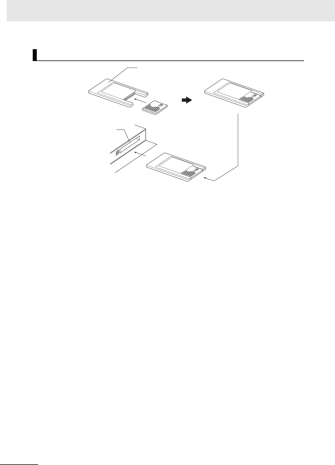
3 Nomenclature and Functions
3-16 CJ2 CPU Unit Hardware User’s Manual
Installing the Memory Card into a Personal Computer
HMC-AP001
Memory Card Adapter
Memory Card
Personal computer
PC card slot
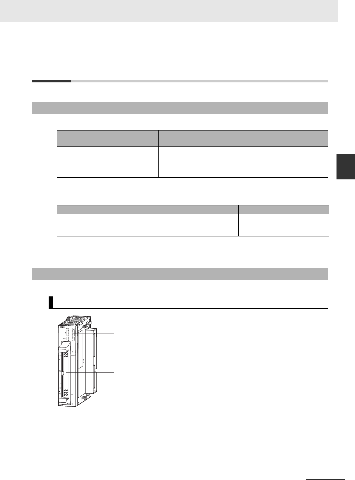
3-17
3 Nomenclature and Functions
CJ2 CPU Unit Hardware User’s Manual
3-3 Pulse I/O Modules (CJ2M CPU Unit Only)
3
3-3-1 Models and Specifications
3-3 Pulse I/O Modules (CJ2M CPU Unit
Only)
Note Connectors are not provided with Pulse I/O Modules.
Purchase the following Connector, an OMRON Cable with Connectors for Connector-Terminal Block Conver-
sion Units, or an OMRON Cable with Connectors for Servo Relay Units.
(Refer to the 2-1-2 CPU Rack, 5-3 Wiring, or the CJ2M CPU Unit Pulse I/O Module User's Manual (Cat.
No. W486) for details.)
3-3-1 Models and Specifications
Model Type of transis-
tor outputs Specifications
CJ2M-MD211 Sinking outputs 1 MIL connector
• 10 inputs (four interrupt/quick-response inputs or two high-speed
counter inputs)
• 6 outputs (two pulse outputs or two PWM outputs)
CJ2M-MD212 Sourcing outputs
Name Model Specifications
MIL Flat Cable Connector for Pulse
I/O Modules
XG4M-4030-T 40-pin MIL connector, pressure-
welded type (This connector is used
by user to make a cable.)
3-3-2 Part Names and Functions
Part Names
Pulse I/O
MIL connector (40 pins)
I/O indicators
Indicate the ON/OFF status of the
pulse I/O signals.
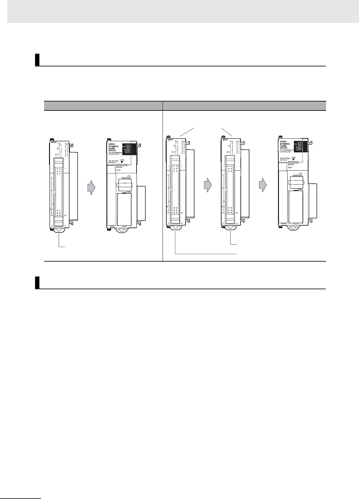
3 Nomenclature and Functions
3-18 CJ2 CPU Unit Hardware User’s Manual
Up to two Pulse I/O Modules can be connected to a CJ2M CPU Unit.
They must be connected immediately to the left of the CPU Unit.
The Pulse I/O Module closest to the CPU Unit is Pulse I/O Module 0 and the other one is Pulse I/O
Module 1.
The CPU Unit will automatically detect the Pulse I/O Modules that are connected when the power sup-
ply is turned ON. The Pulse I/O Modules are therefore not registered in the I/O tables.
An error will not occur when power is turned ON even if there is a different number of Pulse I/O Modules
connected or different models of Pulse I/O Modules connected.
Connecting Pulse I/O Modules to the CPU Unit
One Pulse I/O Module Two Pulse I/O Modules
Pulse I/O Module Detection
Pulse I/O Module
CJ2M CPU Unit
(Standard or
Simple Model)
Connected
Pulse I/O Module 0
Pulse I/O Modules
CJ2M CPU Unit
(Standard or
Simple Model)
Pulse I/O Module 0
Pulse I/O Module 1
Connected
Connected
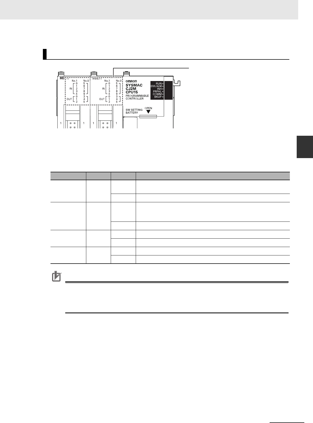
3-19
3 Nomenclature and Functions
CJ2 CPU Unit Hardware User’s Manual
3-3 Pulse I/O Modules (CJ2M CPU Unit Only)
3
3-3-2 Part Names and Functions
Up to two Pulse I/O Modules can be connected.
The indicators on the front panel of a Pulse I/O Module indicate whether the Block is number 0 or
number 1 and indicate the I/O status.
The following table describes these indicators.
❍: Lit, ● :Not lit
Precautions for Correct UsePrecautions for Correct Use
A maximum of two Pulse I/O Modules can be connected. Do not connect more than this. If three
or more Pulse I/O Modules are connected, a too many I/O points error (fatal error) will occur. If
this error occurs, turn OFF the power supply to the PLC and remove all but two Pulse I/O Mod-
ules.
Pulse I/O Module Status Indicators
Indicator Color Status Meaning
No. 0 Green ❍This is the Pulse I/O Module that is connected directly to the CPU Unit.
It is Pulse I/O Module number 0.
●Not connected.
No. 1 Green ❍This is the Pulse I/O Module that is connected next to the Power Supply
Unit when two Pulse I/O Modules are connected.
It is Pulse I/O Module number 1.
●Not connected.
IN0 to IN9 Yellow ❍The allocated input is ON.
●The allocated input is OFF.
OUT0 to
OUT5
Yellow ❍The allocated output is ON.
●The allocated output is OFF.
Pulse I/O Module number indicators
Indicate the I/O status.
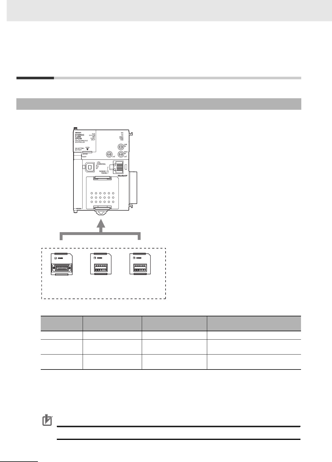
3 Nomenclature and Functions
3-20 CJ2 CPU Unit Hardware User’s Manual
3-4 Serial Option Boards (CJ2M-CPU3@
Only)
A Serial Option Board can be used with a CJ2M-CPU3@ CPU Unit.
zSerial Option Boards
zMounting an Option Board
When mounting an Option Board, first remove the slot cover. Grasp the lock levers at the top and
bottom of the cover at the same time to unlock the cover, and then pull the cover out. Then to mount
the Option Board, check the alignment and firmly press it in until it snaps into place.
Precautions for Correct UsePrecautions for Correct Use
Always turn OFF the power supply to the PLC before mounting or removing an Option Board.
3-4-1 Overview
Model Port Maximum transmission
distance Connection method
CP1W-CIF01 One RS-232C port 15 m Connector: D-sub, 9-pin female
CP1W-CIF11 One RS-422A/485 port
(not isolated)
50 m Terminal block: Using ferrules
CP1W-CIF12 One RS-422A/485 port
(isolated)
500 m Terminal block: Using ferrules
CP1W-CIF01
RS-232C
Option Board
CP1W-CIF11 or CP1W-CIF12
RS-422A/485 Option Board
Serial Option Boards

3-21
3 Nomenclature and Functions
CJ2 CPU Unit Hardware User’s Manual
3-5 Power Supply Units
3
3-5-1 Models and Specifications
3-5 Power Supply Units
3-5-1 Models and Specifications
Item Specifications
Power Supply Unit CJ1W-PA205R CJ1W-PA205C CJ1W-PA202 CJ1W-PD025 CJ1W-PD022
Supply voltage 100 to 240 VAC (wide-range), 50/60 Hz 24 VDC
Operating voltage
and frequency
ranges
85 to 264 VAC, 47 to 63 Hz 19.2 to 28.8 VDC 21.6 to 26.4 VDC
Power consumption 100 VA max. 50 VA max. 50 W max. 35 W max.
Inrush current*1 At 100 to 120 VAC:
15 A/8 ms max. for cold start at room
temperature
At 200 to 240 VAC:
30 A/8 ms max. for cold start at room
temperature
At 100 to
120 VAC:
20 A/8 ms max.
for cold start at
room temperature
At 200 to
240 VAC:
40 A/8 ms max.
for cold start at
room temperature
At 24 VDC:
30 A/20 ms max. for cold start at room
temperature
Output capacity*7 5.0 A, 5 VDC (including supply to CPU
Unit)
2.8 A, 5 VDC
(including supply
to CPU Unit)
5.0 A, 5 VDC
(including supply
to CPU Unit)
2.0 A, 5 VDC
(including supply
to CPU Unit)
0.8 A, 24 VDC 0.4 A, 24 VDC 0.8 A, 24 VDC 0.4 A, 24 VDC
Total: 25 W max. Total: 14 W max. Total: 25 W max. Total: 19.6 W
max.
Output terminal (ser-
vice supply)
Not provided
RUN output*2 Contact configu-
ration: SPST-NO
Switch capacity:
250 VAC, 2 A
(resistive load)
120 VAC, 0.5 A
(inductive load),
24 VDC, 2A
(resistive load)
24 VDC, 2 A
(inductive load)
Not provided. Not provided. Not provided. Not provided.
Replacement notifi-
cation function
Not provided. With Alarm
output (open col-
lector output)
30 VDC max.,
50 mA max.
Not provided. Not provided. Not provided.

3 Nomenclature and Functions
3-22 CJ2 CPU Unit Hardware User’s Manual
Insulation resistance 20 MΩ min.
(at 500 VDC)
between AC
external and GR
terminals*3
• 20 MΩ min.
(at 500 VDC)
between all
external termi-
nals and GR
terminal*3, and
between all
alarm output
terminals.
• 20 MΩ min.
(at 250 VDC)
between all
alarm output
terminals and
GR terminal*3.
20 MΩ min.
(at 500 VDC)
between AC
external and GR
terminals*3
20 MΩ min.
(at 500 VDC)
between DC
external and GR
terminals*3
---*6
Dielectric strength*4 2,300 VAC
50/60 Hz for 1 min
between AC
external and GR
terminals*3
Leakage current:
10 mA max.
• 2,300 VAC,
50/60 Hz for
1 min between
all external ter-
minals and GR
terminal*3 and
between all
alarm output
terminals with a
leakage current
of 10 mA max.
• 1,000 VAC,
50/60 Hz for
1 min between
all alarm output
terminals and
GR terminal*3
with a leakage
current of
10 mA max.
2,300 VAC
50/60 Hz for 1 min
between AC
external and GR
terminals*3
Leakage current:
10 mA max.
1,000 VAC
50/60 Hz for 1 min
between DC
external and GR
terminals*3
Leakage current:
10 mA max.
---*6
1,000 VAC 50/60 Hz for 1 min between DC external and GR terminals*3
Leakage current: 10 mA max.
Noise immunity 2 kV on power supply line (Conforms to IEC61000-4-4.)
Vibration resistance 5 to 8.4 Hz, 3.5-mm amplitude, 8.4 to 150 Hz, acceleration: 9.8 m/s2 in X, Y, and Z directions for
100 minutes (Time coefficient: 10 minutes × coefficient factor 10 = total time 100 min.) (according to
JIS C60068-2-6)
Shock resistance 147 m/s2 3 times each in X, Y, and Z directions (Relay Output Unit: 100 m/s2) (according to JIS
C60068-2-27)
Ambient operating
temperature
0 to 55°C
Ambient operating
humidity
10% to 90% (with
no condensation)
10% to 90% (with
no condensa-
tion)*5
10% to 90% (with no condensation)
Atmosphere Must be free from corrosive gases.
Ambient storage tem-
perature
−20 to 75°C
(excluding bat-
tery)
−20 to 75°C*5 −20 to 75°C (excluding battery)
Item Specifications

3-23
3 Nomenclature and Functions
CJ2 CPU Unit Hardware User’s Manual
3-5 Power Supply Units
3
3-5-1 Models and Specifications
*1 The AC and DC values above are given for a cold start, and the AC values are at room temperature. The AC inrush con-
trol circuit uses a thermistor element with a low-temperature current control characteristic. If the ambient temperature is
high or the PLC is hot-started, the thermistor will not be sufficiently cool, and the inrush current given in the table may be
exceeded by up to twice the given value. When selecting fuses or breakers for external circuits, allow sufficient margin in
shut-off performance. The DC inrush control circuit uses a capacitor-charging delay circuit. If the power is OFF for only a
short time for a hot-start, the capacitor will not sufficiently charge and the inrush current given in the table may be
exceeded by up to twice the given value.
*2 Supported only when mounted to CPU Rack.
*3 Disconnect the Power Supply Unit’s LG terminal from the GR terminal when testing insulation and dielectric strength.
Testing the insulation and dielectric strength with the LG terminal and the GR terminals connected will damage internal
circuits in the CPU Unit.
*4 Change the applied voltage gradually using the adjuster on the Tester. If the full dielectric strength voltage is applied or
turned OFF using the switch on the Tester, the generated impulse voltage may damage the Power Supply Unit.
*5 Maintain an ambient storage temperature of −25 to 30°C and relative humidity of 25% to 70% when storing the Unit for
longer than 3 months to keep the replacement notification function in optimum working condition.
*6 CJ1W-PD022 is not insulated between the primary DC power and secondary DC power.
*7 Internal components in the Power Supply Unit will deteriorate or be damaged if the Power Supply Unit is used for an
extended period of time exceeding the power supply output capacity or if the outputs are shorted.
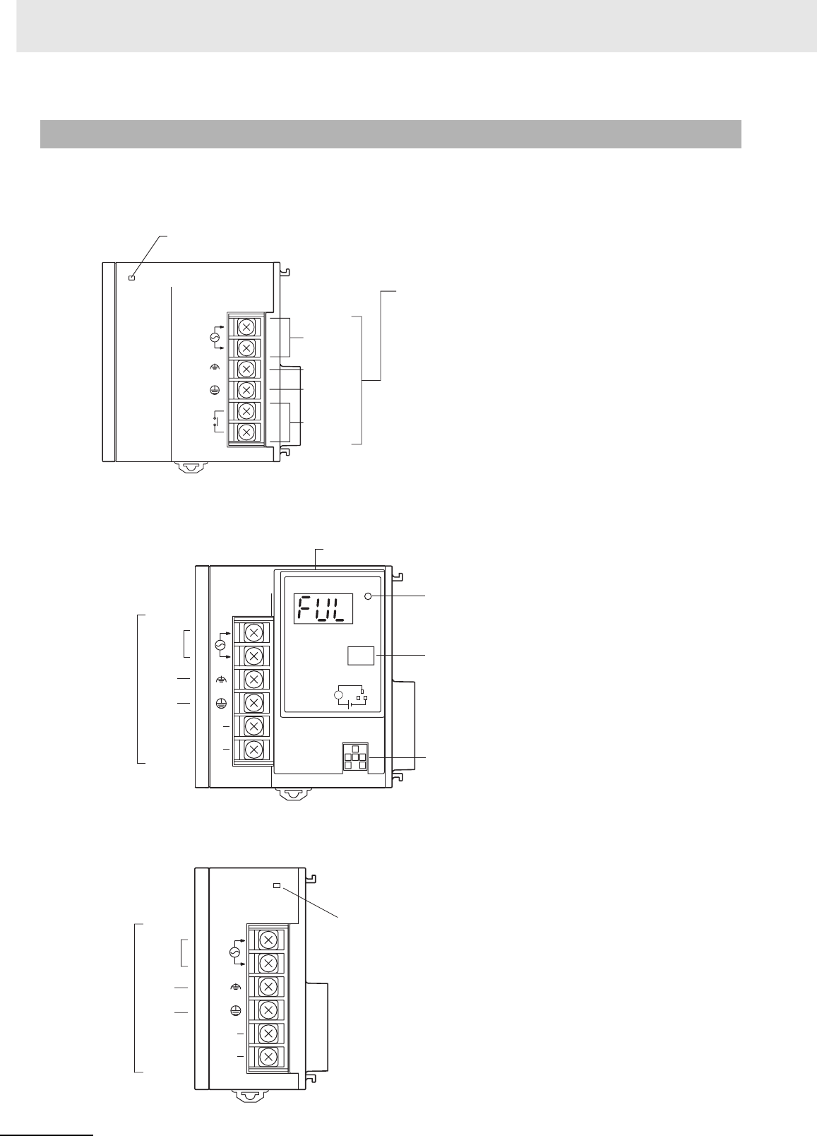
3 Nomenclature and Functions
3-24 CJ2 CPU Unit Hardware User’s Manual
zExample: CJ1W-PA205R
zExample: CJ1W-PA205C
zExample: CJ1W-PA202
3-5-2 Components
POWER
PA205R
DC24V
AC240V
OUTPUT
RUN
INPUT
AC100-240V
L2/N
L1
POWER Indicator
Lit when 5 V are being output from the Power Supply Unit.
External connection terminals
RUN output
AC input
LG
GR
POWER
Yea rs
CJ1W-PA205C
TEST
NC
NC
AC100-240V
INPUT
L2/N
L1
L+
ALARM
OUTPUT
DC30V,50mA
NORMAL:ON
ALARM :OFF
POWER Indicator
Lit when 5 V are being output
from the Power Supply Unit.
External connection
terminals
AC input
LG
GR
Alarm output
(replacement notification output)
TEST switch
The TEST switch can be used to
temporarily turn OFF the alarm output
that notifies when replacement is
needed.
Replacement notification display
POWER
PA202
INPUT
NC
NC
AC100
-240V
L2/N
L1
POWER Indicator
Lit when 5 V are being output
from the Power Supply Unit.
External connection
terminals
AC input
LG
GR
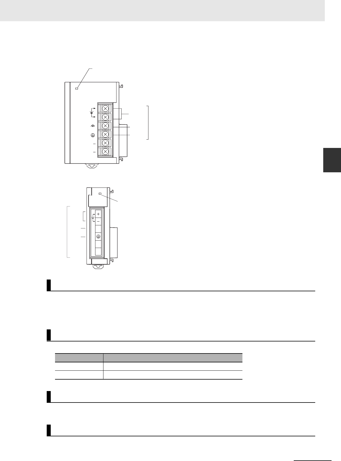
3-25
3 Nomenclature and Functions
CJ2 CPU Unit Hardware User’s Manual
3-5 Power Supply Units
3
3-5-2 Components
zExample: CJ1W-PD025
zExample: CJ1W-PD022
Supply 100 to 240 VAC (allowable: 85 to 264 VAC).
Note The CJ1W-PA205R, CJ1W-PA205C, and CJ1W-PA202 have a wide input range, so they do not have voltage
switching terminals.
Supply 24 VDC.
Ground to a resistance of 100 Ω or less to increase noise resistance and avoid electric shock.
Ground to a resistance of 100 Ω or less to avoid electric shock.
AC Input
DC Input
Model Allowable power supply voltage fluctuation range
CJ1W-PD025 19.2 to 28.8 VDC (±20%)
CJ1W-PD022 21.6 to 26.4 VDC (±10%)
LG
GR
POWER
PD025
DC24V+
INPUT
NC
NC
POWER Indicator
Lit when 5 V are being output from the Power Supply Unit.
External connection terminals
DC input
LG
GR
POWER
PD022
NC
NC
NC
DC24V
INPUT
+
POWER Indicator
Lit when 5 V are being output
from the Power Supply Unit.
External
connection
terminals
DC
input
NC
GR

3 Nomenclature and Functions
3-26 CJ2 CPU Unit Hardware User’s Manual
The internal contact turns ON when the CJ2 CPU Unit is operating (RUN or MONITOR mode). The
Power Supply Unit must be in the CPU Rack to use this output.
The alarm output is used to notify when Power Supply Unit replacement is required. The output is nor-
mally ON. The output turns OFF when the time until replacement is 6 months or less.
RUN Output (CJ1W-PA205R Only)
Alarm Output (CJ1W-PA205C Only)
3-27
3 Nomenclature and Functions
CJ2 CPU Unit Hardware User’s Manual
3-5 Power Supply Units
3
3-5-3 Selecting a Power Supply Unit
After determining what power supply voltage is required, whether power output terminals and a RUN
output are required, and whether replacement notification is required, calculate the current and power
requirements for each Rack.
There are two voltage groups for internal power consumption: 5 VDC and 24 VDC.
For details on the current consumption of individual Units, refer to 2-1-4 Configuration Units.
zCurrent Consumption at 5 VDC
The following table shows the current that can be supplied to Units (including the CJ2 CPU Unit) that
use 5-VDC power.
zCurrent Consumption at 24 VDC
The following table shows the current that can be supplied to Units that use 24-VDC power supply.
The following table shows the maximum total power that can be supplied at 5 VDC and 24 VDC.
For details on the current consumption of individual Units, refer to 2-1-2 CPU Rack, 2-1-3 Expansion
Racks, and 2-1-4 Configuration Units. Refer to 2-1-5 Calculating Unit Current Consumption for an
example of calculating the current consumption.
3-5-3 Selecting a Power Supply Unit
Condition 1: Current Requirements
Model Maximum current at 5 VDC
CJ1W-PA205R/205C 5.0 A
CJ1W-PA202 2.8 A
CJ1W-PD025 5.0 A
CJ1W-PD022 2.0 A
Model Maximum current at 24 VDC
CJ1W-PA205R/205C 0.8 A
CJ1W-PA202 0.4 A
CJ1W-PD025 0.8 A
CJ1W-PD022 0.4 A
Condition 2: Power Requirements
Model Maximum total power output
CJ1W-PA205R/205C 25 W
CJ1W-PA202 14 W
CJ1W-PD025 25 W
CJ1W-PD022 19.6 W
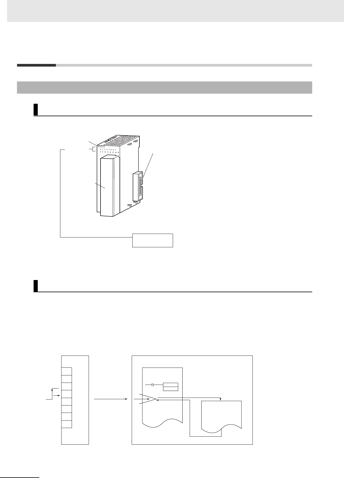
3 Nomenclature and Functions
3-28 CJ2 CPU Unit Hardware User’s Manual
3-6 CJ-series Basic I/O Units
zEight/sixteen-point Units (18-point Terminal Blocks)
Note The CJ1W-OD202, CJ1W-OD204, and CJ1W-OD212 also have an ERR indicator for the load short-circuit
alarm.
zFunctions
Interrupt Input Units are used to execute interrupt programs on the rising or falling edge of an input
signal. When the specified interrupt input turns ON (or OFF), execution of the cyclic program in the
CPU Unit is interrupted and an I/O interrupt task (task number 100 to 131) is executed. When execu-
tion of the I/O interrupt task has been completed, the cyclic program is again executed starting from
the instruction after which it was interrupted.
3-6-1 Basic I/O Units with Terminal Blocks
Part Names and Functions
Interrupt Input Units
ERR
0 1 2 3 4 5 6 7
8 9 10 11 12 13 14 15
Connector
Connect to the connector on the next Unit.
I/O indicators
Model number label
Terminal block for
I/O wiring, 18P × 1
Interrupt Input Unit CPU Unit
Input
(rising or
falling
edge)
Immediate
interrupt
1 cyclic task
I/O interrupt task
I/O interrupt task is
executed when the input
turns ON (or OFF).
MSKS
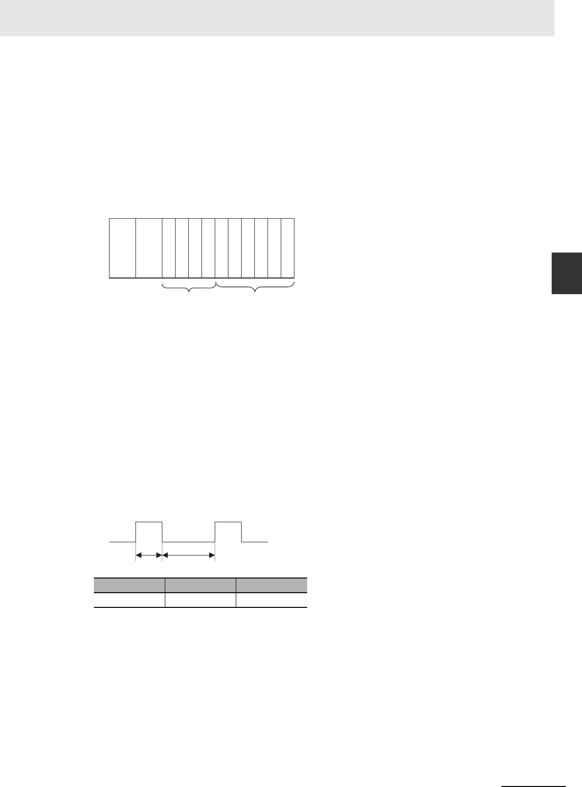
3-29
3 Nomenclature and Functions
CJ2 CPU Unit Hardware User’s Manual
3-6 CJ-series Basic I/O Units
3
3-6-1 Basic I/O Units with Terminal Blocks
zApplication Precautions
• Interrupt Input Units must be mounted in the locations described below.
When using a CJ2H-CPU6@-EIP CPU Unit, all Interrupt Input Units must be connected in any of the
four positions immediately to the right of the CPU Unit, i.e., slots 0 to 3 on the CPU Rack. When
using a CJ2H-CPU6@ CPU Unit or CJ2M-CPU@@ Unit, all Interrupt Input Units must be connected
in any of the five positions immediately to the right of the CPU Unit, i.e., slots 0 to 4 on the CPU
Rack. If an Interrupt Input Unit is connected in any other position on the CPU Rack or anywhere on
an Expansion Rack, and I/O setting error (fatal) will occur.
Example: CJ2H-CPU6@-EIP
• The Interrupt Input Units must be connected in the slot ranges specified above even when the I/O
tables are edited using the CX-Programmer. If the Interrupt Input Units are not connected in the cor-
rect positions, an error will occur when the I/O tables are generated from the CX-Programmer.
A401.10 will turn ON to indicate an I/O setting error and A405.08 will turn ON to indicate that an Inter-
rupt Input Unit is in the wrong position.
Note Even if a Unit is physically in one of the correct positions, a Dummy Unit can be registered in the I/O tables,
causing a Unit to be defined in a position different from its physical position.
• There are limits to the number of Interrupt Input Units that can be mounted. If these limits are
exceeded, a too many I/O points error (fatal error) will occur.
• The input response time cannot be changed for the CJ1W-INT01, and the related portions of the
Basic I/O Unit input time constants in the PLC Setup, and the setting status in A220 to A259 will not
be valid.
zInput Signal Width
Input signals must meet the following conditions.
Unit ON time OFF time
CJ1W-INT01 0.05 ms min. 0.5 ms min.
0 1 2 3 4 5 6 7 8 9
Power
Supply
Unit
CPU
Unit
Connect here. Cannot be used.
ON OFF
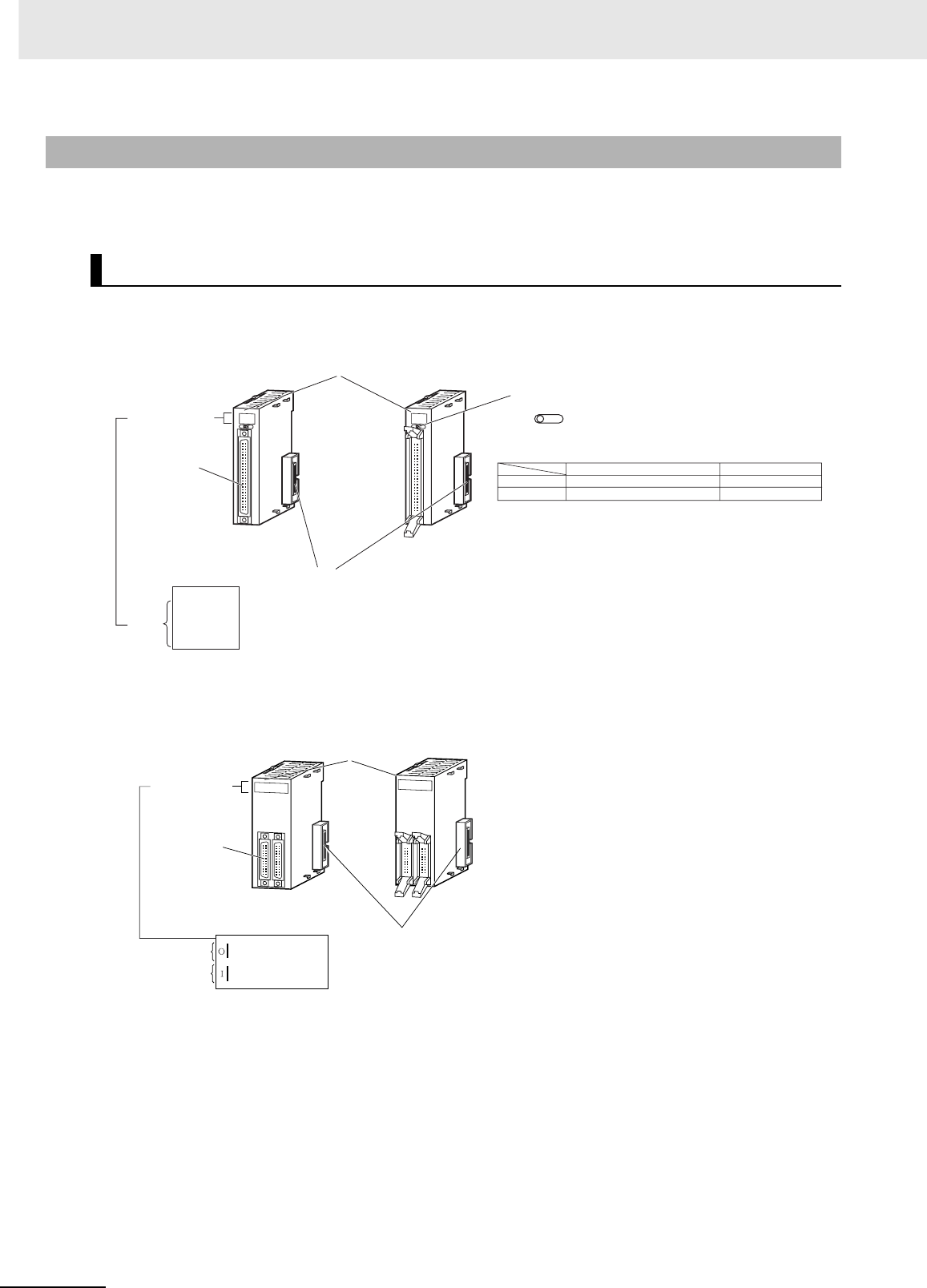
3 Nomenclature and Functions
3-30 CJ2 CPU Unit Hardware User’s Manual
Units are available with either Fujitsu-compatible connectors (CJ1W-@D@@1) or MIL connectors
(CJ1W-@D@@2/3/4).
zThirty-two-point Units
(Models with 40-point Fujitsu Connector or MIL Connector)
zThirty-two-point Units with 2 × 24-pin Fujitsu-compatible Connectors
or 2 × 20-pin MIL Connectors
3-6-2 Thirty-two/Sixty-four-point Basic I/O Units with Connectors
Part Names
ID 2 3 1
ID 2 3 2
Model number
I/O indicators
Unit with MIL Connector
Unit with Fujitsu-compatible
Connector
Connector
Connected to the connector on the next Unit.
Indicator Switch
1 2
Changes the 16 I/O displayed on the I/O indicators.
Wd m (Row A on connector)
Fujitsu connector MIL connector
Bottom of connector
Top of connector
Wd m+1 (Row B on connector)
Setting 1
Setting 2
Word m
or
m+1
I/O wiring
connector
(40-pin × 1)
0 1 2 3
4 5 6 7
8 9
12 13 14 15
10 11
ERR
Note: Only the CJ1W-OD232 has an ERR indicator for the load short-circuit alarm.
Model number
Unit with MIL Connector
Connector
Connected to the connector on the next Unit.
Unit with Fujitsu-compatible
Connector
I/O wiring
connector
(24-pin x 2)
I/O indicators
Word m
Word m+1
MD231
0 1 2 3 4 5 6 7
8 9 12 13 14 15
10 11
0 1 2 3 4 5 6 7
8 9 12 13 14 15
10 11
MD232
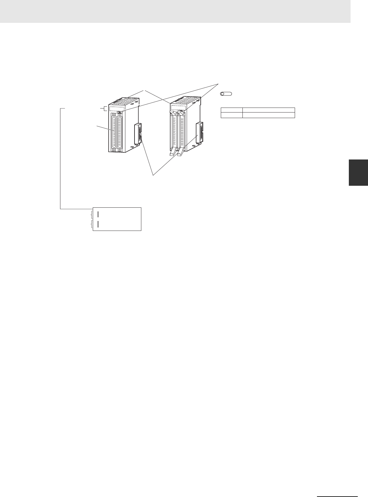
3-31
3 Nomenclature and Functions
CJ2 CPU Unit Hardware User’s Manual
3-6 CJ-series Basic I/O Units
3
3-6-2 Thirty-two/Sixty-four-point Basic I/O Units with Connectors
zSixty-four-point Units
(Models with Two 40-point Fujitsu Connectors or MIL Connector)
ID 2 61
0 1 2 3 4 5 6 7
8 9 12131415
10
11
0 1 2 3 4 5 6 7
8 9 12
131415
1011
I
II
ID 261
Model number
I/O indicators
Unit with MIL Connector
Unit with Fujitsu-compatible
Connector
Connector
Connected to the connector on the next Unit.
Indicator Switch
1 2
Changes the 32 I/O displayed on the I/O indicators.
Setting 1
Setting 2
I/O wiring
connector
(40-pin × 2)
Wd m and m+1: CN1
Wd m+2 and m+3: CN2
Word m or
m+2
Word m+1
or m+3
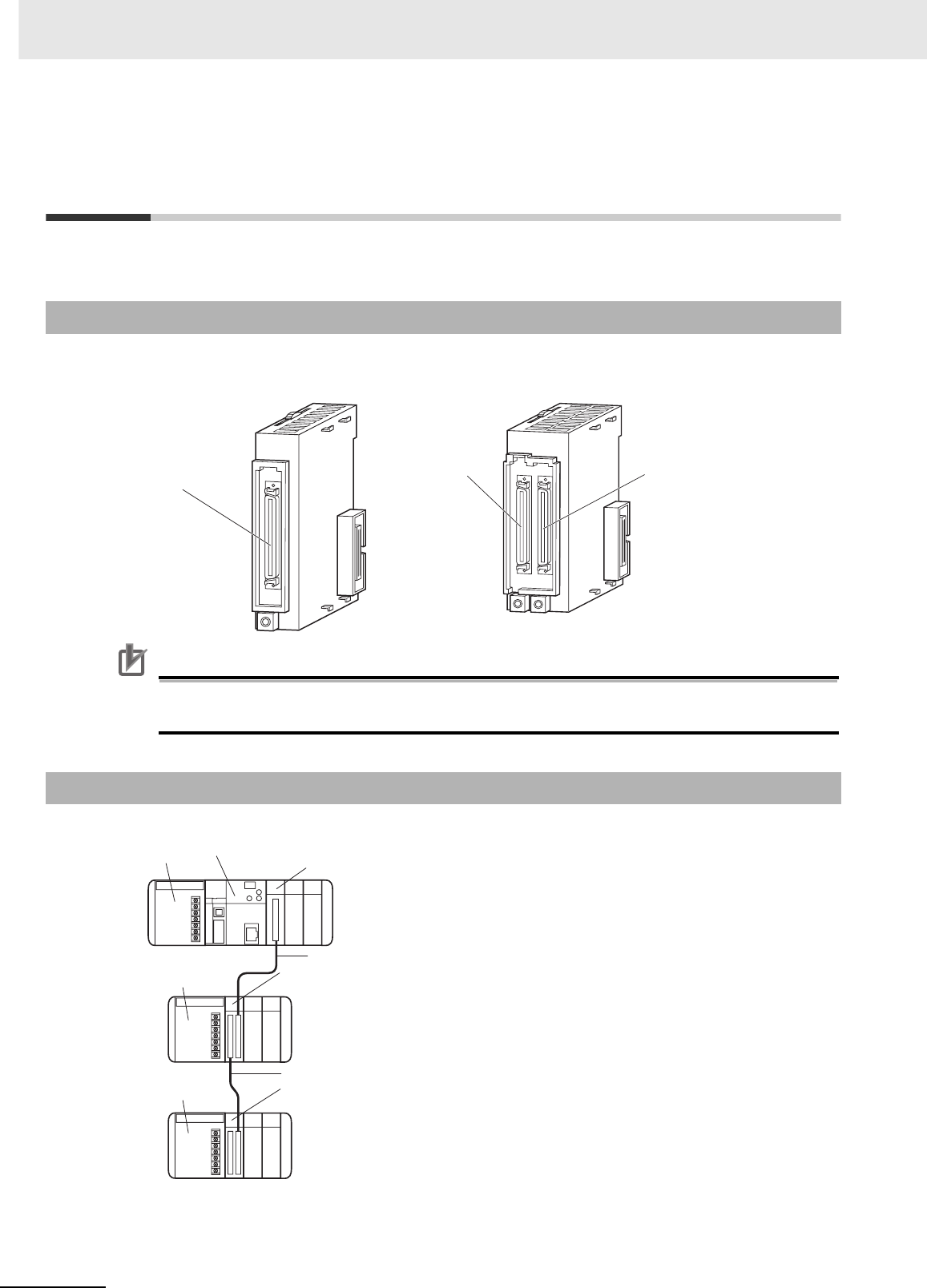
3 Nomenclature and Functions
3-32 CJ2 CPU Unit Hardware User’s Manual
3-7 I/O Control Units and I/O Interface
Units
An I/O Control Unit and I/O Interface Units are used to connect Expansion Racks to expand the system.
Precautions for Correct UsePrecautions for Correct Use
Attached the enclosed cover to the I/O Connecting Cable connector on the I/O Interface Unit
when it is not being used to protect it from dust.
3-7-1 Component Names
3-7-2 System Configuration
The I/O Control Unit is connected directly to the
CJ2 CPU Unit. If it is not immediately to the
right of the CPU Unit, correct operation may not
be possible.
The I/O Interface Unit is connected directly to
the Power Supply Unit. If it is not immediately to
the right of the Power Supply Unit, correct oper-
ation may not be possible.
TUO
1
01
CI
TUO IN
II101
CJ1W-II101
I/O Interface Unit
CJ1W-IC101
I/O Control Unit
Output connector for
I/O Connecting Cable
Output connector for
I/O Connecting Cable Input connector for
I/O Connecting Cable
Power
Supply Unit
Power
Supply Unit
Power
Supply Unit
CPU Unit
CPU Rack
Expansion Rack
CJ1W-IC101
I/O Control Unit
CJ1W-II101
I/O Interface Unit
I/O Connecting Cable
I/O Connecting Cable
CJ1W-II101
I/O Interface Unit

4-1
CJ2 CPU Unit Hardware User’s Manual
4
This section describes the software that is used to program and debug a CJ2 PLC. It
also describes how to connect the Programming Device and the PLC.
4-1 Support Software . . . . . . . . . . . . . . . . . . . . . . . . . . . . . . . . . . . . . . . . . . . . . . 4-2
4-1-1 CX-One FA Integrated Tool Package . . . . . . . . . . . . . . . . . . . . . . . . . . . . . . . . 4-2
4-2 Connection Methods . . . . . . . . . . . . . . . . . . . . . . . . . . . . . . . . . . . . . . . . . . . 4-5
4-2-1 Connecting by USB . . . . . . . . . . . . . . . . . . . . . . . . . . . . . . . . . . . . . . . . . . . . . 4-5
4-2-2 Connecting by RS-232C . . . . . . . . . . . . . . . . . . . . . . . . . . . . . . . . . . . . . . . . . 4-7
4-2-3 Connecting to Ethernet (CJ2H-CPU6@-EIP and CJ2M-CPU3@ Only) . . . . . . 4-9
Support Software
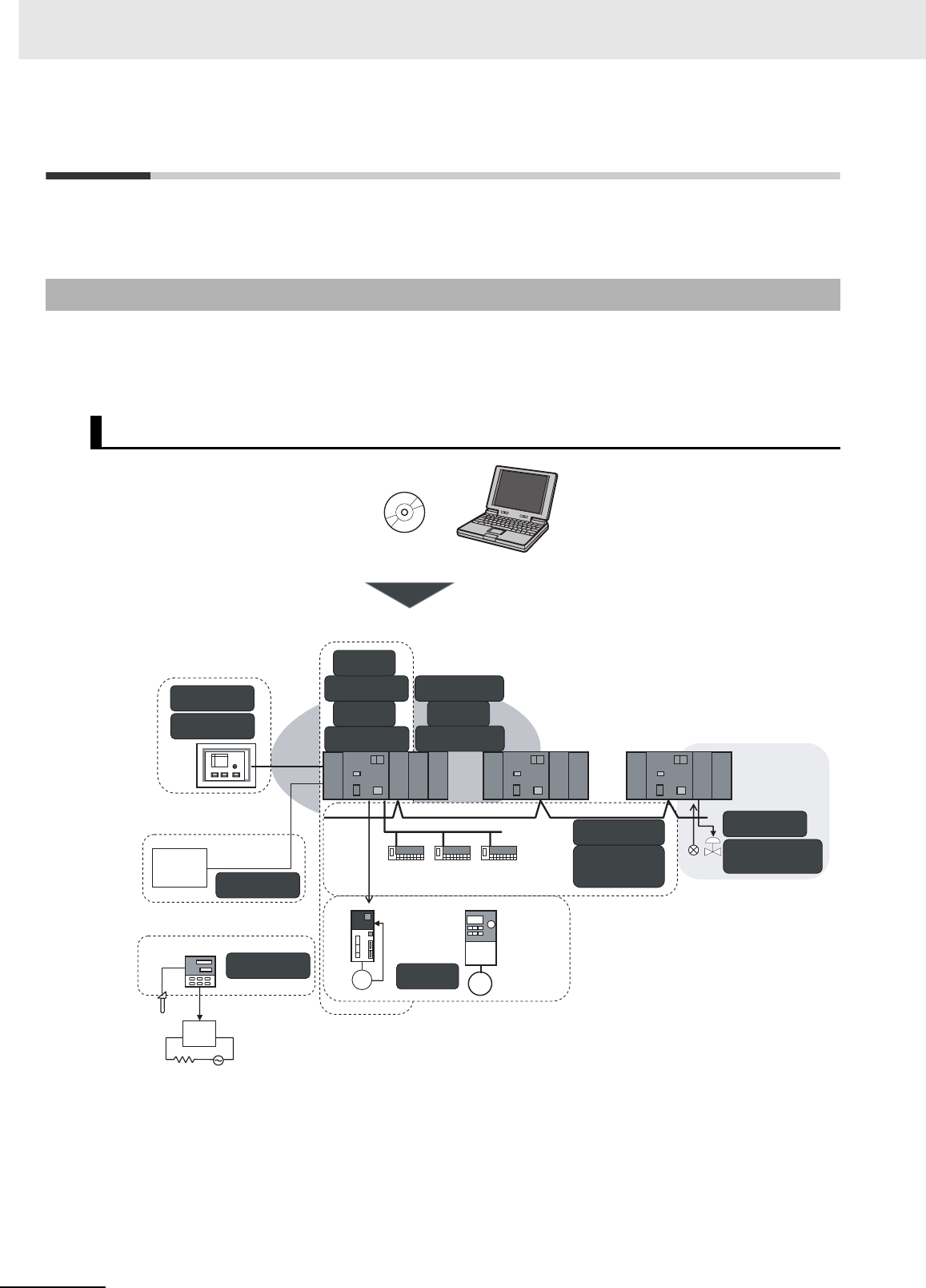
4 Support Software
4-2 CJ2 CPU Unit Hardware User’s Manual
4-1 Support Software
“Support Software” refers to software applications for programming and debugging OMRON Program-
mable Controllers.
The CX-One provides an integrated package of Support Software for OMRON PLCs and components.
It consists of software applications for PLC programming, network settings, touch-panel screen cre-
ation, servo control, inverters, temperature control, and other functions.
4-1-1 CX-One FA Integrated Tool Package
CX-One Integrated Tool Package Contents
PT
SSR
NV-Designer
CX-Thermo
CX-Drive
CX-Integrator
CX-Motion-NCF
CX-Motion
CX-Protocol
CX-One
CX-Position
CX-Simulator
CX-Programmer
CX-Motion-MCH
CX-Process
SwitchBox Utility
Face Plate
Auto-Builder for NS
Network
Configurator
CX-Designer
● Touch-panel screen
creation
● Motion control
● Programming/simulation
● Network settings
● Servo/Inverter settings
● Protocol macro creation
● Temperature
control settings
● PLC-based
process control
Networks between PLCs
Loop Controller
Devices by
other
manufacturers
Serial
Field
network
Temperature control
Servo Inverter
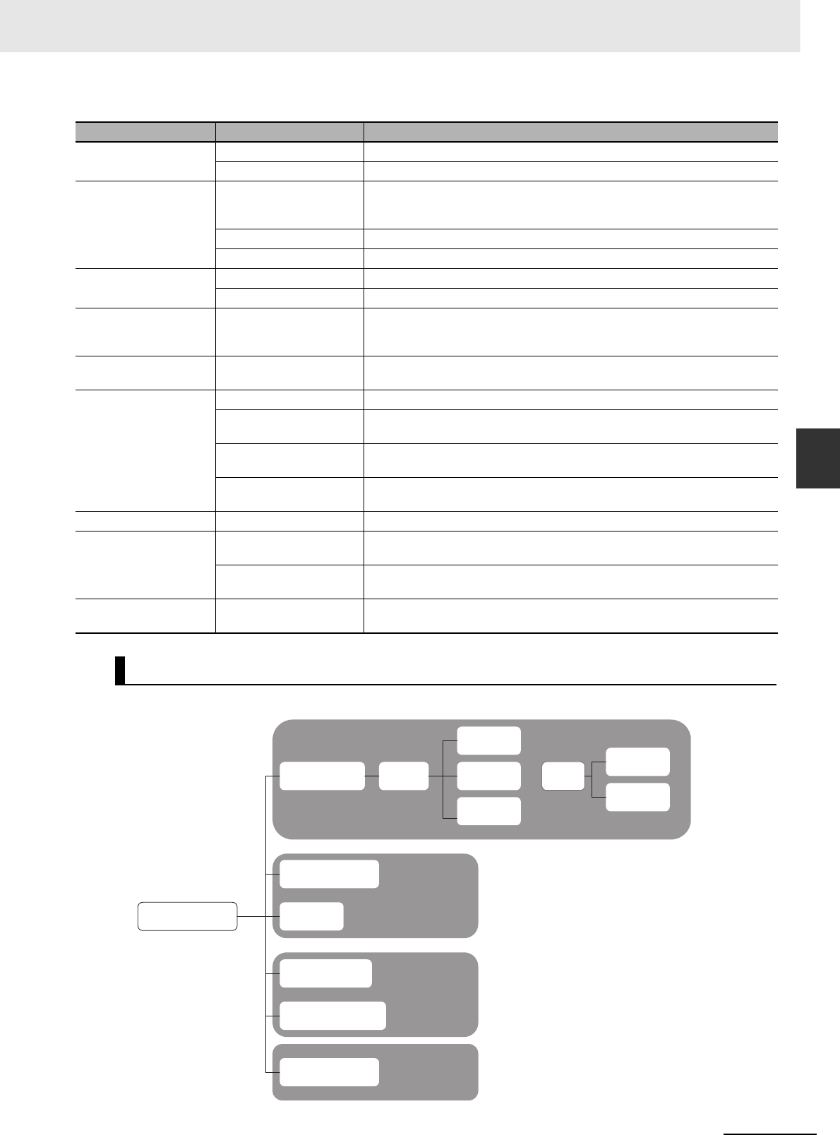
4-3
4 Support Software
CJ2 CPU Unit Hardware User’s Manual
4-1 Support Software
4
4-1-1 CX-One FA Integrated Tool Package
The CX-Programmer is a basic software application for creating and debugging PLC programs.
Application CX-One Software Description
Programming CX-Programmer Basic software for creating and debugging PLC programs.
SwitchBox Utility Utility software to support PLC debugging operations.
Network settings
CX-Integrator
Software for starting and setting FA networks, such as Controller Link,
DeviceNet, CompoWay/F, Ethernet, and CompoNet. Includes routing table com-
ponents, data link components, and DeviceNet Configurator functions.
Network Configurator Software for setting tag data links for the built-in EtherNet/IP port.
CX-FLnet Software for making FL-net Unit system settings and performing monitoring.
Touch-panel screen
creation
CX-Designer Software for creating screen data for touch panel NS-series PTs.
NV-Designer Software for creating screen data for touch panel NV-series PTs.
Protocol macro cre-
ation CX-Protocol
Software for creating protocols (protocol macros) for exchanging data with gen-
eral-purpose external devices connected to Serial Communications Boards/Units
and Option Boards.
Simulation CX-Simulator Software for simulating PLC operations on a personal computer and debugging
programs without requiring a CPU Unit.
Motion Control
CX-Position Software for creating and monitoring data for Position Control Units.
CX-Motion-NCF Software for creating and monitoring data for Position Control Units (MECHA-
TROLINK communications models).
CX-Motion-MCH Software for creating data for Motion Control Units (MECHATROLINK communi-
cations models), and for creating and monitoring motion programs.
CX-Motion Software for creating data for Motion Control Units, and for creating and monitor-
ing motion programs.
Servo/Inverter settings CX-Drive Software for setting and adjusting Inverter and servo data.
PLC-based process
control
CX-Process Tool Software for creating and debugging function blocks for Loop Controllers (Loop
Control Units/Boards, Process CPU Units, and Loop CPU Units).
Face Plate Auto-Builder
for NS
Software for automatic generation of screen data (project files) for touch panel
NS-series PTs from Loop Controller function block tag information.
Temperature control
settings CX-Thermo Software for setting and adjusting Temperature Controller parameters.
CX-Programmer
Programming functions
CX-Programmer
I/O table creation
FBs ST language
ST language
SFC
language
PLC Setup
Debugging and
maintenance
functions
System configuration
setup
CPU Unit
parameters
Special I/O Unit and
CPU Bus Unit settings
Programming
Simulation
Monitoring
Tasks
Ladder
language Ladder
language
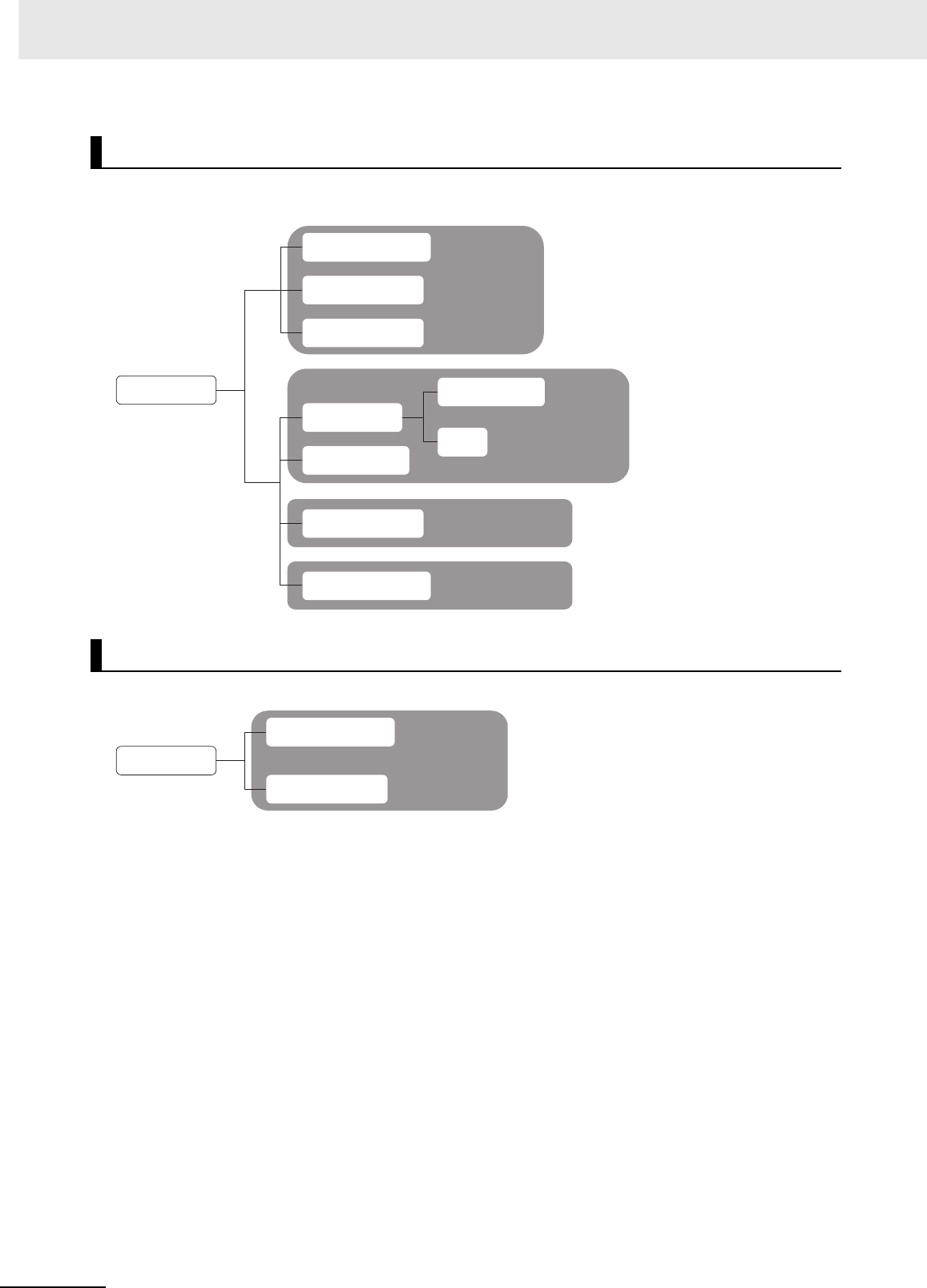
4 Support Software
4-4 CJ2 CPU Unit Hardware User’s Manual
The CX-Integrator is a software application for setting up FA networks, such as Controller Link,
DeviceNet, CompoWay/F, Ethernet, and CompoNet.
The Network Configurator is software for setting tag data links using the built-in EtherNet/IP port.
CX-Integrator
Network Configurator
General network
settings and monitoring
CX-Integrator
DeviceNet settings
Controller Link
diagnosis
CompoWay/F slave
settings
Controller Link
Data link settings
Diagnosis
Routing table settings
Network configuration
reading
Network testing
Controller Link
settings and monitoring
DeviceNet settings
CompoWay/F
settings
Network
Configurator
Tag data link settings
Device monitoring
EtherNet/IP network
settings and
monitoring
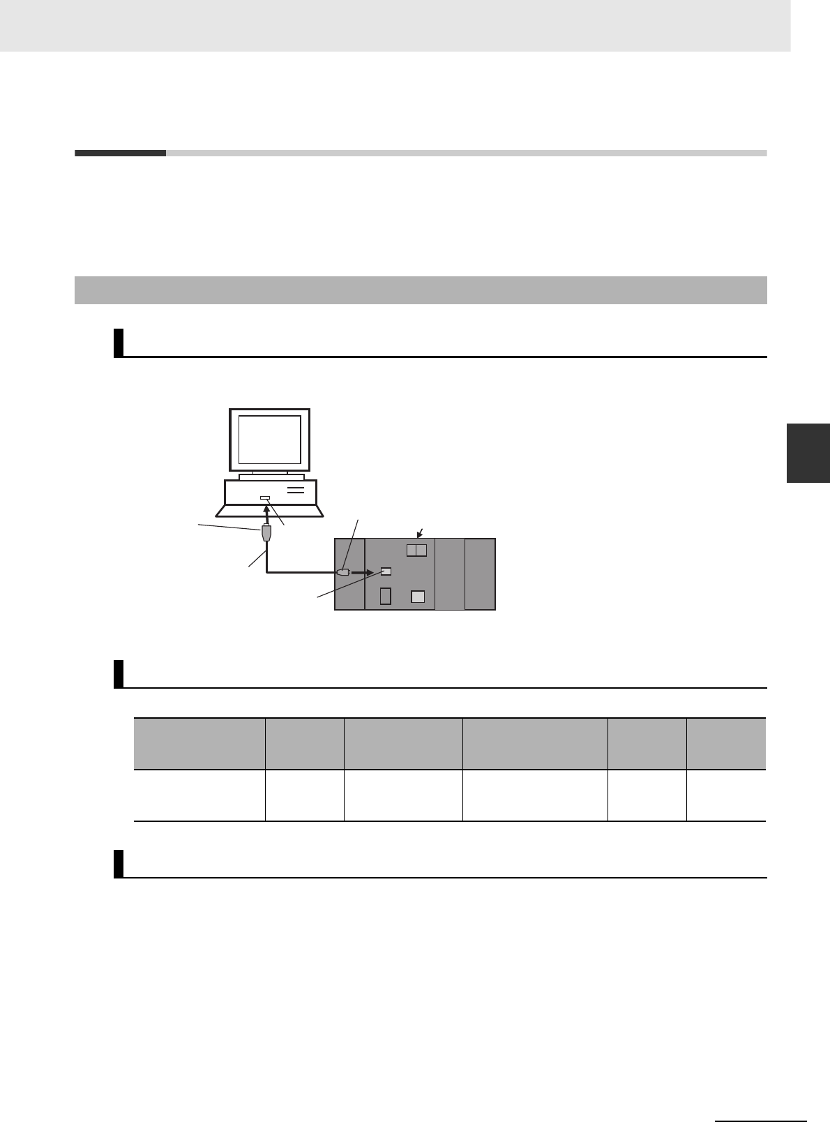
4-5
4 Support Software
CJ2 CPU Unit Hardware User’s Manual
4-2 Connection Methods
4
4-2-1 Connecting by USB
4-2 Connection Methods
A CJ2 CPU Unit can be directly connected to a personal computer running the CX-One Support Soft-
ware (e.g., CX-Programmer) by using a USB cable or RS-232C cable. (The CP1W-CIF01 is required to
use a RS-232C cable with the CJ2M-CPU3@.) Also, an Ethernet twisted-pair cable can be used for the
CJ2H-CPU6@-EIP or CJ2M-CPU3@.
Using commercially available USB cable, connect CX-One Support Software via a standard peripheral
(USB) port at the personal computer.
*1 Commercially available USB cable: 5 m max., for USB 1.1 or 2.0.
Use the following cable to connect the CJ2 CPU Unit to the computer running the Support Software.
In order to connect the PLC to a personal computer by USB, a USB driver must be installed in the per-
sonal computer. The USB driver for USB connections is automatically stored in the following directory in
the personal computer when CX-One is installed:
C:\Program Files\OMRON\CX-Server\USB\Win2000_XP\inf
When the personal computer is connected to the PLC by USB cable, the personal computer automati-
cally recognizes the device and the USB driver installation is started. For details on how to install the
USB driver, refer to A-5 Installing the USB Driver.
4-2-1 Connecting by USB
Connection Method
Connecting Cable
Port at Unit Port at
computer
Network type
(communications
mode)
Model Length Remarks
Peripheral (USB) port
(Conforms to USB
2.0, B connector)
USB port 12 Mbps, USB 2.0 Commercially available
USB cable (A connector
- B connector)
5 m max. ---
Before Connecting
CX-One (e.g., CX-Programmer)
Commercially available
USB cable*1
Peripheral (USB) port
(conforming to USB 2.0, B connector)
A connector USB port
B connector CJ2 CPU Unit
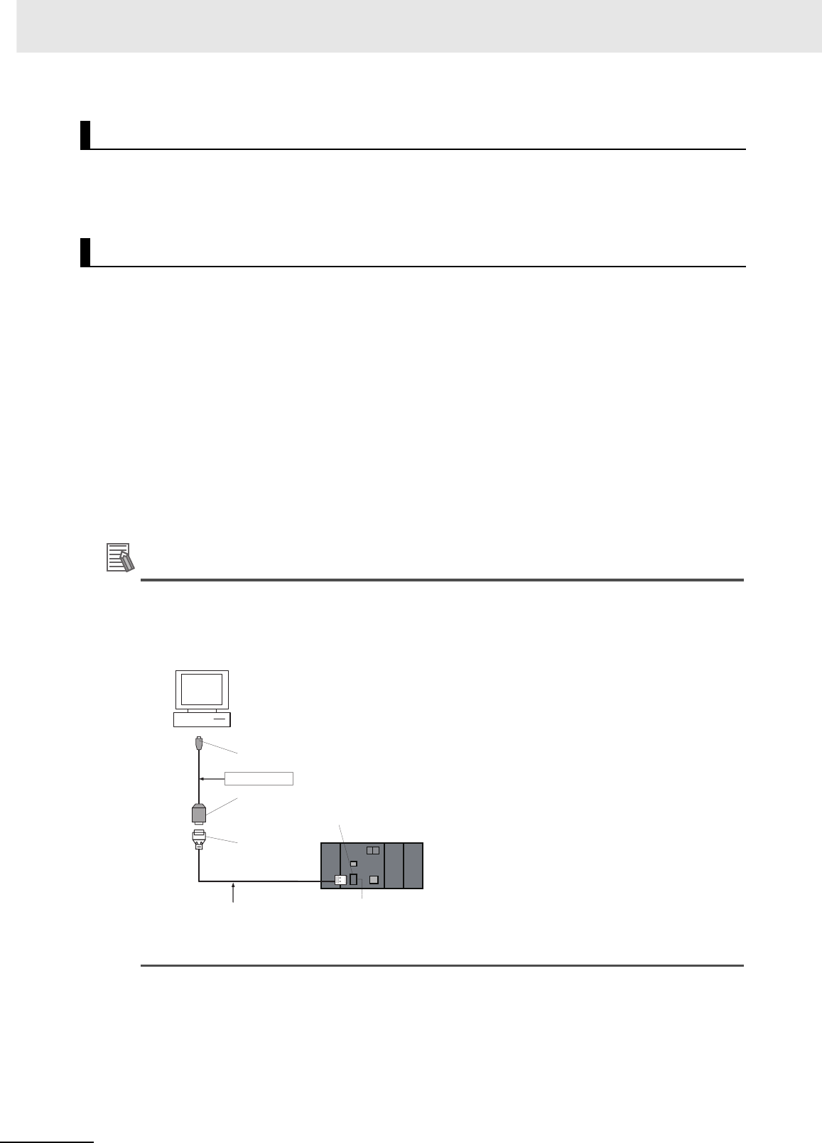
4 Support Software
4-6 CJ2 CPU Unit Hardware User’s Manual
The method for connecting the PLC to the personal computer is set using the CX-Programmer. For
details on using the CX-Programmer to set the connection method, refer to the CJ2 CPU Unit Software
User’s Manual (Cat. No. W473).
Based on USB specifications, the following restrictions apply when connecting a personal computer
and components.
• Only one CJ2 CPU Unit can be connected by USB to a single personal computer. It is not possible to
connect multiple CJ2 CPU Units simultaneously.
• Do not remove the USB cable while connected online. The application must be offline before the
cable is removed. If the cable is removed while connected online, one of the following situations will
occur depending on the operating system.
• Windows 2000/XP
The Support Software online status will not be restored by simply re-inserting the USB cable.
Once the Support Software has gone offline, the cable must be re-inserted and the Support Soft-
ware online connection operation must be repeated.
• Windows 98/Me
If the USB cable is removed while connected online, a blue error screen may be displayed. If that
occurs, the personal computer must be restarted.
Additional Information
The USB port on a computer can be connected to the PLC serial port (RS-232C) by using
CJ1W-CIF31 USB-Serial Conversion Cable. (The USB driver for the CJ1W-CIF31 must be
installed.)
Refer to A-5 Installing the USB Driver for the installation procedure for the USB driver.
CX-Programmer Settings
Restrictions on Connecting by USB
RS-232C port,
D-sub connector
(9-pin, female)
D-sub connector
(9-pin, female)
Recommended cable:
XW2Z-200S-CV/500S-CV or
XW2Z-200S-V/500S-V*1
D-sub connector
(9-pin, male) D-sub connector
(9-pin, male)
CJ2 CPU Unit
CS1W-CIF31
USB A plug connector,
male
*1 Only a Host Link connection is possible.
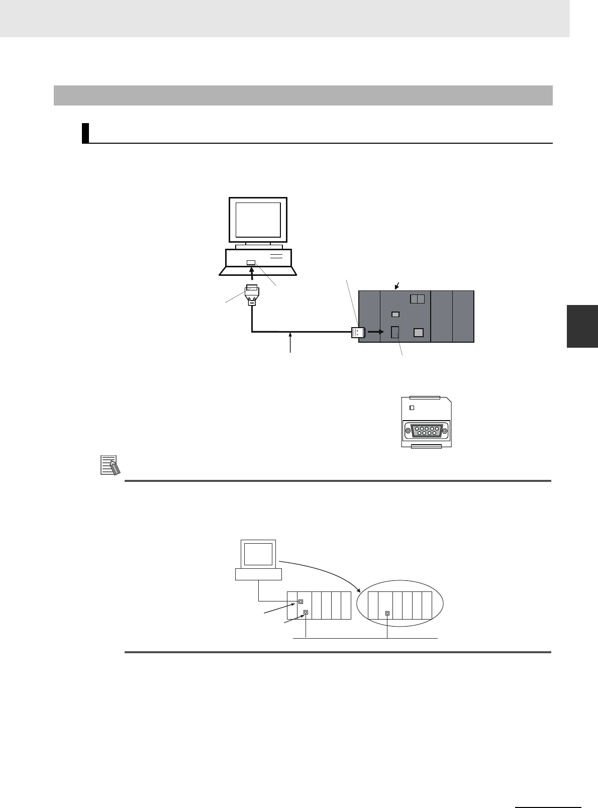
4-7
4 Support Software
CJ2 CPU Unit Hardware User’s Manual
4-2 Connection Methods
4
4-2-2 Connecting by RS-232C
Using commercially available RS-232C cable, directly connect the CX-One Support Software (e.g., CX-
Programmer) via a standard serial port at the personal computer.
The network type must be set to the Toolbus. A Host Link connection cannot be used.
Additional Information
Connecting to the PLC by EtherNet/IP via USB or RS-232C
The Support Software can be directly connected by USB or RS-232C to one CJ2 CPU Unit and
access other CPU Units on the EtherNet/IP network via the built-in EtherNet/IP ports on the CJ2
CPU Units. For details, refer to the CJ2 CPU Unit Software User’s Manual (Cat. No. W473).
4-2-2 Connecting by RS-232C
Connection Method
D-sub connector
(9-pin female)
CX-One (e.g., CX-Programmer)
CJ2 CPU Unit
D-sub connector
(9-pin male)
Recommended cable:
XW2Z-200S-CV/500S-CV
D-sub connector
(9-pin male)
COMM
Serial port (RS-232C)
(9-pin female D-sub
connector) or Serial Option
Board (for CJ2M-CPU3@)
USB
USB
Personal computer
Built-in EtherNet/IP port
EtherNet/IP
CJ2
Access is possible.
CJ2
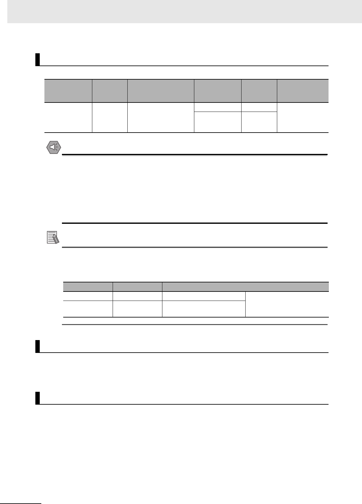
4 Support Software
4-8 CJ2 CPU Unit Hardware User’s Manual
Use the following cable to connect the CJ2 CPU Unit to the computer running the Support Software.
Precautions for Safe Use
• When the above cable connector is connected to the PLC serial port (RS-232C), be sure to
discharge static electricity by touching grounded metal before touching the cable connector.
The XW2Z-@@@S-CV Cable is particularly resistant to static electricity because it uses a
static-resistant connector hood (XM2S-0911-E). Even when this Cable is used, however, be
sure to discharge static electricity before touching the connector.
• Use the specialized cable described above for connecting cable. Using ordinary commercially
available RS-232C cable for personal computers may result in damage to external devices and
the CPU Unit.
Additional Information
It is possible to create RS-232C cable for connecting to the serial port (RS-232C). The connec-
tors shown in the following table are included with the CJ2 CPU Unit as standard equipment for
creating cables. For details on creating cables, refer to A-4 Connecting to a Serial Port on the
CPU Unit.
Select the protocol for communications between the PLC and the CX-Programmer. For a SYSMAC
WAY (Host Link) connection, turn OFF pin 5 of the DIP switch on the front panel. For a peripheral bus
connection (faster than SYSMAC WAY), turn ON pin 5.
The method for connecting the PLC to the personal computer is set using the CX-Programmer. For
details on using the CX-Programmer to set the connection method, refer to the CJ2 CPU Unit Software
User’s Manual (Cat. No. W473).
Connecting Cable
Port at Unit Port at
computer
Network type
(communications
mode)
Model Length Remarks
Serial port
(RS-232C)
(D-sub, 9-pin,
female)
D-sub,
9-pin, male
Serial communications XW2Z-200S-CV 2 m Use a static-resis-
tant connector.
XW2Z-500S-CV 5 m
Name Model Specifications
Plug XM2A-0901 9-pin, male Use in combination. (One of
each is provided as standard
equipment with the CPU Unit.)
Hood XM2S-0911-E 9-pin static-resistant connector
with millimeter screws
Setting the Communications Protocol
CX-Programmer Settings
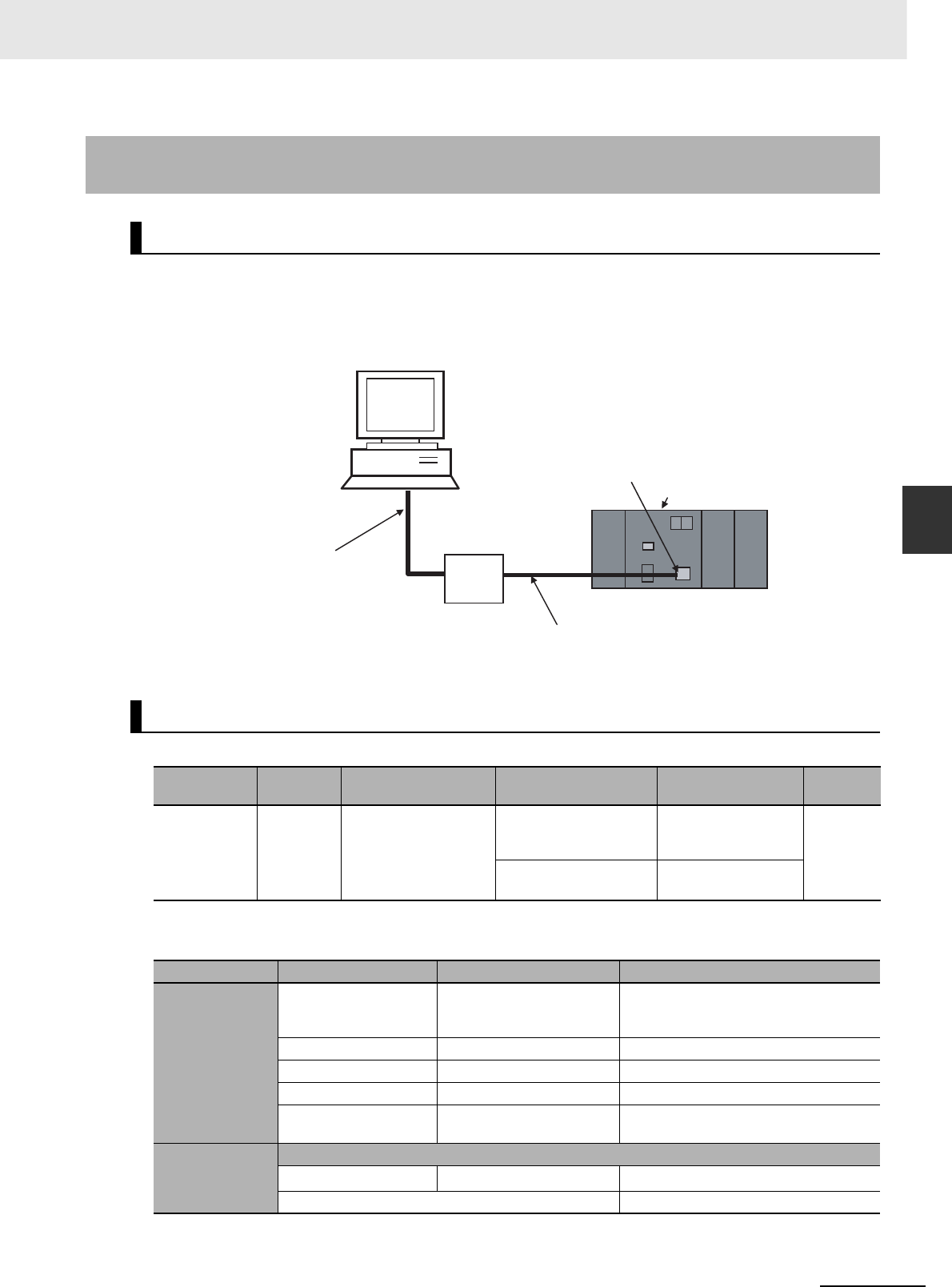
4-9
4 Support Software
CJ2 CPU Unit Hardware User’s Manual
4-2 Connection Methods
4
4-2-3 Connecting to Ethernet (CJ2H-CPU6@-
EIP and CJ2M-CPU3@ Only)
With the CJ2H-CPU6@-EIP or CJ2M-CPU3@, use a commercially available Ethernet 100Base-TX STP
twisted-pair cable (straight) to connect the CX-One Support Software (e.g., CX-Programmer) to the
built-in EtherNet/IP port through the Ethernet switch. With the CJ2H-CPU6@-EIP, Ethernet twisted-pair
cable can also be used to connect to a personal computer. The same type of connection can be made
with the CJ2H-CPU6@ or CJ2M-CPU1@ through an EtherNet/IP Unit.
Use the following cable to connect the CJ2 CPU Unit to the computer running the Support Software.
*1 Use 100Base-TX when using tag data links.
*2 The following table shows the devices recommended for use with the built-in EtherNet/IP port.
4-2-3 Connecting to Ethernet (CJ2H-CPU6@-EIP and CJ2M-CPU3@
Only)
Connection Method
Connecting Cable
Port at Unit Port at
computer
Network type (commu-
nications mode) Model Length Remarks
Built-in Ether-
Net/IP port
Ethernet
port
100Base-TX or 10Base-
T*1
Commercially available
twisted-pair cable*2
100 m (Recommended
between Ethernet
switch and nodes.)
---
Commercially available
Ethernet switch*2, *3
---
Part Manufacturer Model number Inquires
Ethernet switch
OMRON W4S1-03B
W4S1-05B
W4S1-05C
---
Cisco Systems, Inc. Consult the manufacturer. Cisco Systems, Inc. Main Corporate HQ
Contec USA, Inc. Consult the manufacturer. CONTEC USA Inc.
Phoenix Contact Consult the manufacturer. Phoenix Contact USA Customer Service
Hirschmann Automation
and Control
Consult the manufacturer. Hirschmann Automation and Control (US)
Twisted-pair cable
100Base-TX
Fujikura F-LINK-E 0.5mm × 4P Fujikura America, Inc.
EtherNet/IP compliant cable ---
100Base-TX
twisted-pair cable
(straight)
100Base-TX
twisted-pair cable
(straight)
Ethernet switch
Built-in EtherNet/IP port
CJ2 CPU Unit
CX-One (e.g., CX-Programmer)

4 Support Software
4-10 CJ2 CPU Unit Hardware User’s Manual
*3 Always use an Ethernet switch when using tag data links in the network. If a repeater hub is used for Ether-
Net/IP tag data links (cyclic communications), the network's communications load will increase, data collisions
will occur frequently, and stable communications will be impossible.
To connect using Ethernet, first set the IP address and subnet mask of the computer in advance as
shown in the following example.
• IP Addresses
• Subnet Mask
The method for connecting the PLC to the personal computer is set using the CX-Programmer. For
details on using the CX-Programmer to set the connection method, refer to the CJ2 CPU Unit Software
User’s Manual (Cat. No. W473).
Connectors
(Modular plug)
STP Plug
Panduit Corporation MPS588 Panduit Corporation US Headquarters
Boots Tsuko Company MK boot (IV) LV Tsuko Company Japan Headquarters
Before Connecting
CX-Programmer Settings
Part Manufacturer Model number Inquires
192.168.250.2
Example:
User-set value (1 to 254)
Value for same segment as IP address
of built-in EtherNet/IP port
255.255.255.0.200
Example:
User-set value (0 to 252)
Class C mask
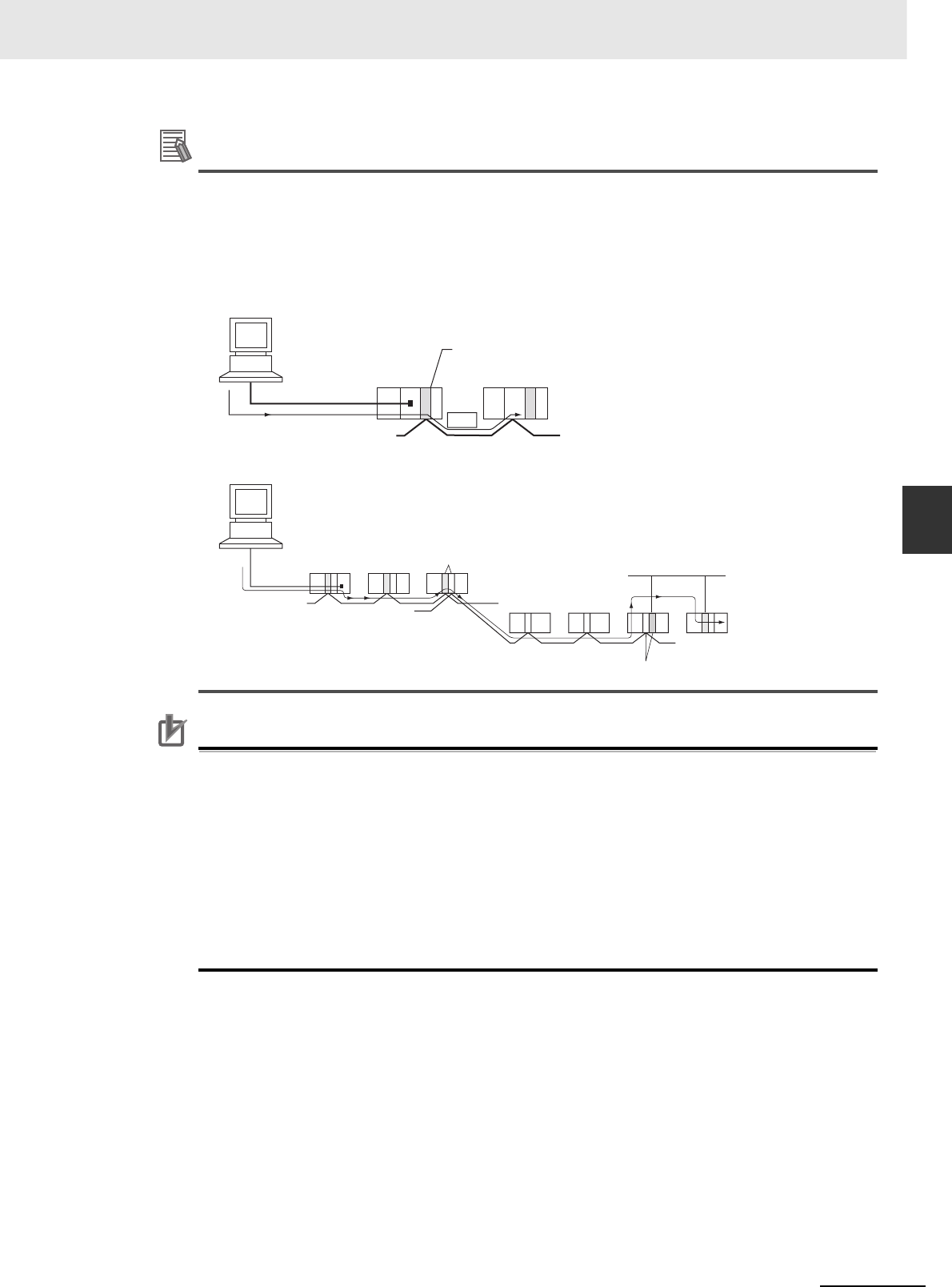
4-11
4 Support Software
CJ2 CPU Unit Hardware User’s Manual
4-2 Connection Methods
4
4-2-3 Connecting to Ethernet (CJ2H-CPU6@-
EIP and CJ2M-CPU3@ Only)
Additional Information
• The CX-Programmer can be used for remote programming and monitoring. It can be used to
program and monitor not only the PLC to which it is directly connected, but also to program
and monitor any PLC connected through a Controller Link or Ethernet network to which the
PLC that the CX-Programmer is connected to is a part of. All programming and monitoring
functionality for the directly connected PLC is supported for remote programming and monitor-
ing. For details, refer to 11-2 Serial Communications and 11-3 Communications Networks in
the CJ2 CPU Unit Software User’s Manual (Cat. No. W473).
Precautions for Correct UsePrecautions for Correct Use
Connecting to a Programming Device through the built-in EtherNet/IP port will not be possible if
the following errors occur:
• I/O bus error
• Too many I/O points error
• Unit number duplication error
• Rack number duplication error
• I/O setting error
If any of the above errors occurs and connecting to the Programming Device through the built-in
EtherNet/IP port is not possible, connect through the USB port.
FINS
CX-Programmer
Peripheral bus
or Host Link
Peripheral (USB) port
or RS-232C port
Controller Link or Ethernet Network
Remote programming
and monitoring
CX-Programmer
Peripheral bus or
Host Link
Bridge Ethernet Network
Controller Link Network
Gateway
Controller Link Network

4 Support Software
4-12 CJ2 CPU Unit Hardware User’s Manual

5-1
CJ2 CPU Unit Hardware User’s Manual
5
This section describes how to install and wire a CJ2 PLC.
5-1 Fail-safe Circuits . . . . . . . . . . . . . . . . . . . . . . . . . . . . . . . . . . . . . . . . . . . . . . 5-2
5-2 Installation . . . . . . . . . . . . . . . . . . . . . . . . . . . . . . . . . . . . . . . . . . . . . . . . . . . 5-4
5-2-1 Installation and Wiring Precautions . . . . . . . . . . . . . . . . . . . . . . . . . . . . . . . . . 5-4
5-2-2 Installation in a Control Panel . . . . . . . . . . . . . . . . . . . . . . . . . . . . . . . . . . . . . 5-6
5-2-3 Assembled Appearance and Dimensions . . . . . . . . . . . . . . . . . . . . . . . . . . . . 5-8
5-2-4 Connecting PLC Components . . . . . . . . . . . . . . . . . . . . . . . . . . . . . . . . . . . . 5-13
5-2-5 DIN Track Installation . . . . . . . . . . . . . . . . . . . . . . . . . . . . . . . . . . . . . . . . . . . 5-15
5-2-6 Connecting CJ-series Expansion Racks . . . . . . . . . . . . . . . . . . . . . . . . . . . . 5-17
5-3 Wiring . . . . . . . . . . . . . . . . . . . . . . . . . . . . . . . . . . . . . . . . . . . . . . . . . . . . . . 5-20
5-3-1 Power Supply Wiring . . . . . . . . . . . . . . . . . . . . . . . . . . . . . . . . . . . . . . . . . . . 5-20
5-3-2 Wiring CJ-series Basic I/O Units with Terminal Blocks . . . . . . . . . . . . . . . . . 5-27
5-3-3 Wiring Basic I/O Units with Connectors . . . . . . . . . . . . . . . . . . . . . . . . . . . . . 5-29
5-3-4 Connecting to Connector-Terminal Block Conversion Units or
I/O Relay Terminals . . . . . . . . . . . . . . . . . . . . . . . . . . . . . . . . . . . . . . . . . . . . 5-33
5-3-5 Connecting Pulse I/O Modules to External I/O Devices
(CJ2M CPU Unit Only) . . . . . . . . . . . . . . . . . . . . . . . . . . . . . . . . . . . . . . . . . . 5-33
5-3-6 Connecting I/O Devices . . . . . . . . . . . . . . . . . . . . . . . . . . . . . . . . . . . . . . . . . 5-35
5-3-7 Connecting through an Ethernet Cable
(CJ2H-CPU6@-EIP and CJ2M-CPU3@ Only) . . . . . . . . . . . . . . . . . . . . . . . . 5-39
5-4 Control Panel Installation . . . . . . . . . . . . . . . . . . . . . . . . . . . . . . . . . . . . . . 5-42
5-4-1 Temperature . . . . . . . . . . . . . . . . . . . . . . . . . . . . . . . . . . . . . . . . . . . . . . . . . . 5-42
5-4-2 Humidity . . . . . . . . . . . . . . . . . . . . . . . . . . . . . . . . . . . . . . . . . . . . . . . . . . . . . 5-44
5-4-3 Vibration and Shock . . . . . . . . . . . . . . . . . . . . . . . . . . . . . . . . . . . . . . . . . . . . 5-44
5-4-4 Atmosphere . . . . . . . . . . . . . . . . . . . . . . . . . . . . . . . . . . . . . . . . . . . . . . . . . . 5-44
5-4-5 Electrical Environment . . . . . . . . . . . . . . . . . . . . . . . . . . . . . . . . . . . . . . . . . . 5-45
5-4-6 Grounding . . . . . . . . . . . . . . . . . . . . . . . . . . . . . . . . . . . . . . . . . . . . . . . . . . . 5-50
Installation

5 Installation
5-2 CJ2 CPU Unit Hardware User’s Manual
5-1 Fail-safe Circuits
Be sure to set up safety circuits outside of the PLC to prevent dangerous conditions in the event of
errors in the PLC or external power supply.
Outputs from Units such as DC Output Units may malfunction momentarily when the power to the PLC
is turned ON. This may cause problems in the system if the PLC's power supply is turned ON after the
controlled system's power supply. To prevent possible malfunctions, add an external circuit that pre-
vents the power supply to the controlled system from going ON before the power supply to the PLC
itself.
When any of the following errors occurs, PLC operation will stop and all outputs from Output Units will
be turned OFF.
• Operation of the Power Supply Unit's overcurrent protection circuit
• A CPU error (watchdog timer error) or CPU on standby
• A fatal error (memory error, Memory Card transfer error, I/O bus error, Unit/Rack number duplication
error, too many I/O points error, I/O setting error, program error, cycle time exceeded error, or
FALS(007) error)*1
Be sure to add any circuits necessary outside of the PLC to ensure the safety of the system in the event
of an error that stops PLC operation.
*1 When a fatal error occurs, all outputs from Output Units will be turned OFF even if the IOM Hold Bit has been
turned ON to protect the contents of I/O memory. (When the IOM Hold Bit is ON, the outputs will retain their
previous status after the PLC has been switched from RUN/MONITOR mode to PROGRAM mode.)
It is possible for an output to remain ON due to a malfunction in the internal circuitry of the Output Unit,
such as a relay or transistor malfunction. Be sure to add any circuits necessary outside of the PLC to
ensure the safety of the system in the event that an output fails to go OFF.
Order of Powering Up the CPU Unit and Controlled System
Managing CPU Unit Errors
Managing Output Malfunctions
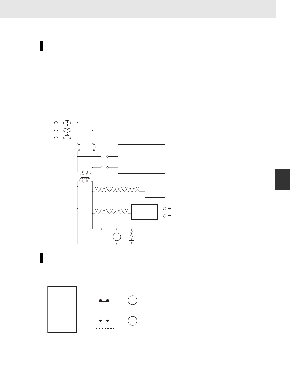
5-3
5 Installation
CJ2 CPU Unit Hardware User’s Manual
5-1 Fail-safe Circuits
5
The following emergency stop circuit controls the power supply to the controlled system so that power is
supplied to the controlled system only when the PLC is operating and the RUN output is ON.
An external relay (CR1) is connected to the RUN output from the Power Supply Unit*1 as shown in the
following diagram.
*1 A RUN output is provided only on the CJ1W-PA205R Power Supply Unit. When a Power Supply Unit without a
RUN output is used, program the Always ON Flag (A1) as the execution condition for an output point from an
Output Unit.
zElectrical Diagram
When the PLC controls an operation such as the clockwise and counterclockwise operation of a motor,
provide an external interlock such as the one shown in the following example to prevent both the for-
ward and reverse outputs from turning ON at the same time.
This circuit prevents outputs MC1 and MC2 from both being ON at the same time even if both
CIO 000501 and CIO 000502 are ON, so the motor is protected even if the PLC is programmed improp-
erly or malfunctions.
Emergency Stop Circuit
Interlock Circuits
MCB1
MCB2
CR1
CR1
DC
PLC RUN
output input/output
Power supply
Controlled system
DC voltage
regulator
Surge suppressor
Twisted-pair wires
Transformer
or noise filter
CJ-series
PLC
CJ-series
PLC
MC2
000501
MC1
000502
MC1
MC2
Interlock circuit
Motor clockwise
Motor counterclockwise
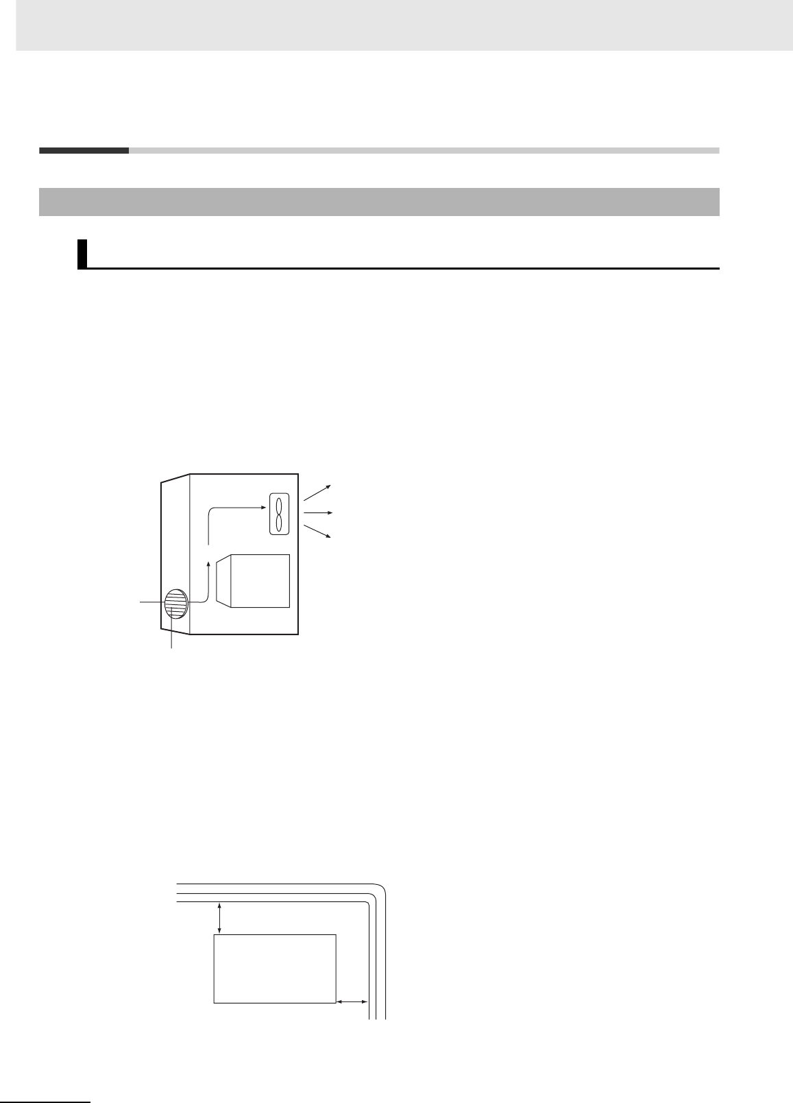
5 Installation
5-4 CJ2 CPU Unit Hardware User’s Manual
5-2 Installation
When the PLC is being installed in a cabinet or control panel, be sure to provide proper ambient condi-
tions as well as access for operation and maintenance.
zTemperature Control
The ambient temperature within the enclosure must be within the operating range of 0 to 55°C.
When necessary, take the following steps to maintain the proper temperature.
• Provide enough space for good air flow.
• Do not install the PLC above equipment that generates a large amount of heat such as heaters,
transformers, or high-capacity resistors.
• If the ambient temperature exceeds 55°C, install a cooling fan or air conditioner.
zAccessibility for Operation and Maintenance
• To ensure safe access for operation and maintenance, separate the PLC as much as possible
from high-voltage equipment and power machinery.
• The PLC will be easiest to install and operate if it is mounted at a height of 1.0 to 1.6 m above the
floor.
zImproving Noise Resistance
• Do not mount the PLC in a control panel containing high-voltage equipment.
• Install the PLC at least 200 mm from power lines.
• Ground the mounting plate between the PLC and the mounting surface.
• When I/O Connecting Cables are 10 m or longer, connect the control panels in which Racks are
mounted with heavier power wires (3 wires at least 2 mm2 in cross-sectional area).
5-2-1 Installation and Wiring Precautions
Installation in Cabinets or Control Panels
CJ-series
PLC
Control
panel Fan
Louver
CJ-series
PLC
Power lines
200 mm min.
200 mm min.
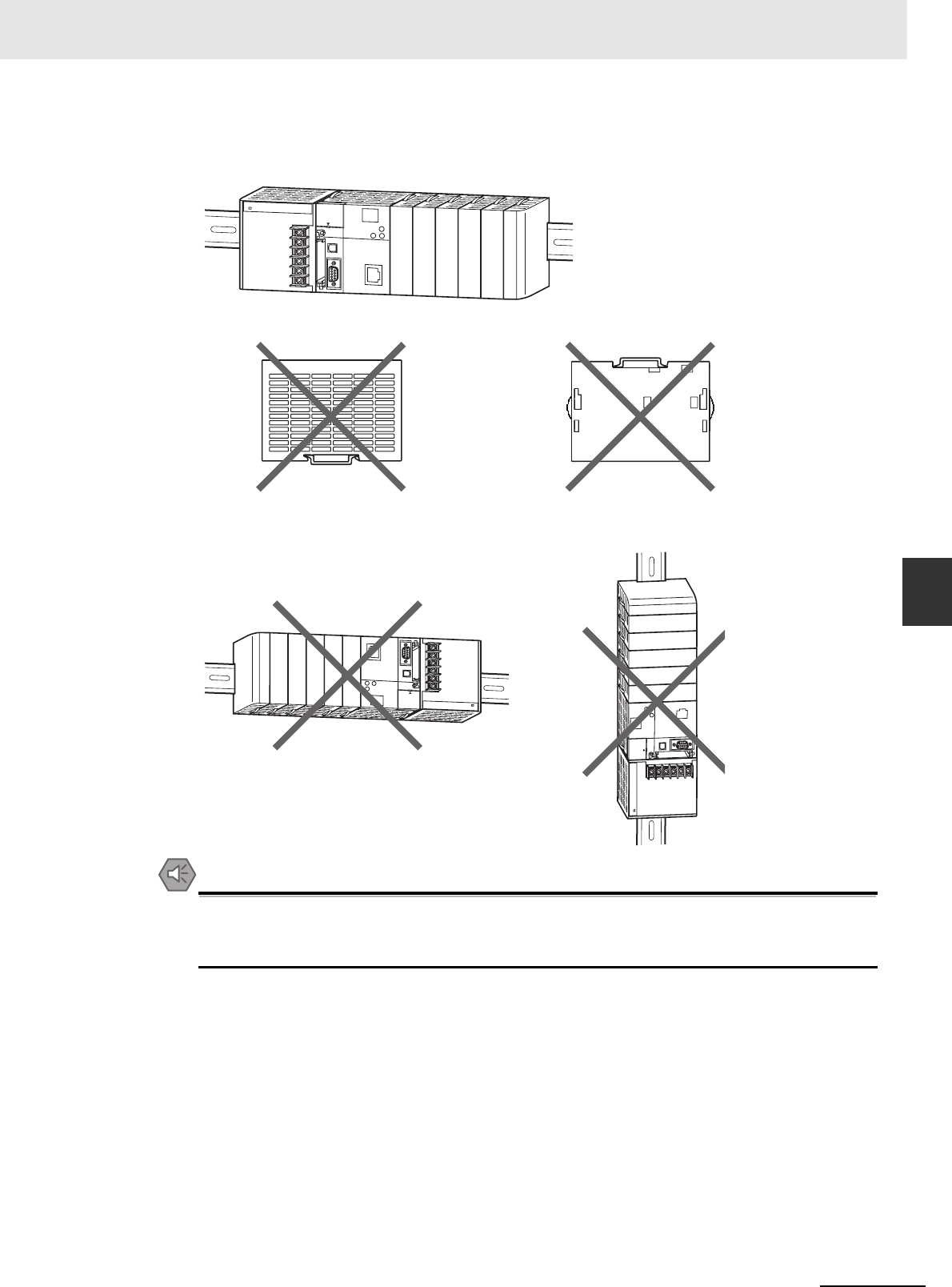
5-5
5 Installation
CJ2 CPU Unit Hardware User’s Manual
5-2 Installation
5
5-2-1 Installation and Wiring Precautions
zPLC Orientation
• Each Rack must be mounted in an upright position to provide proper cooling.
• Do not install a Rack in any of the following positions.
Precautions for Safe Use
Always use the standard installation method. A nonstandard installation will decrease heat dissi-
pation, and may delay the replacement notification signal (in particular for Power Supply Units
with Replacement Notification (CJ1W-PA205C)), or degrade or damage the internal elements.
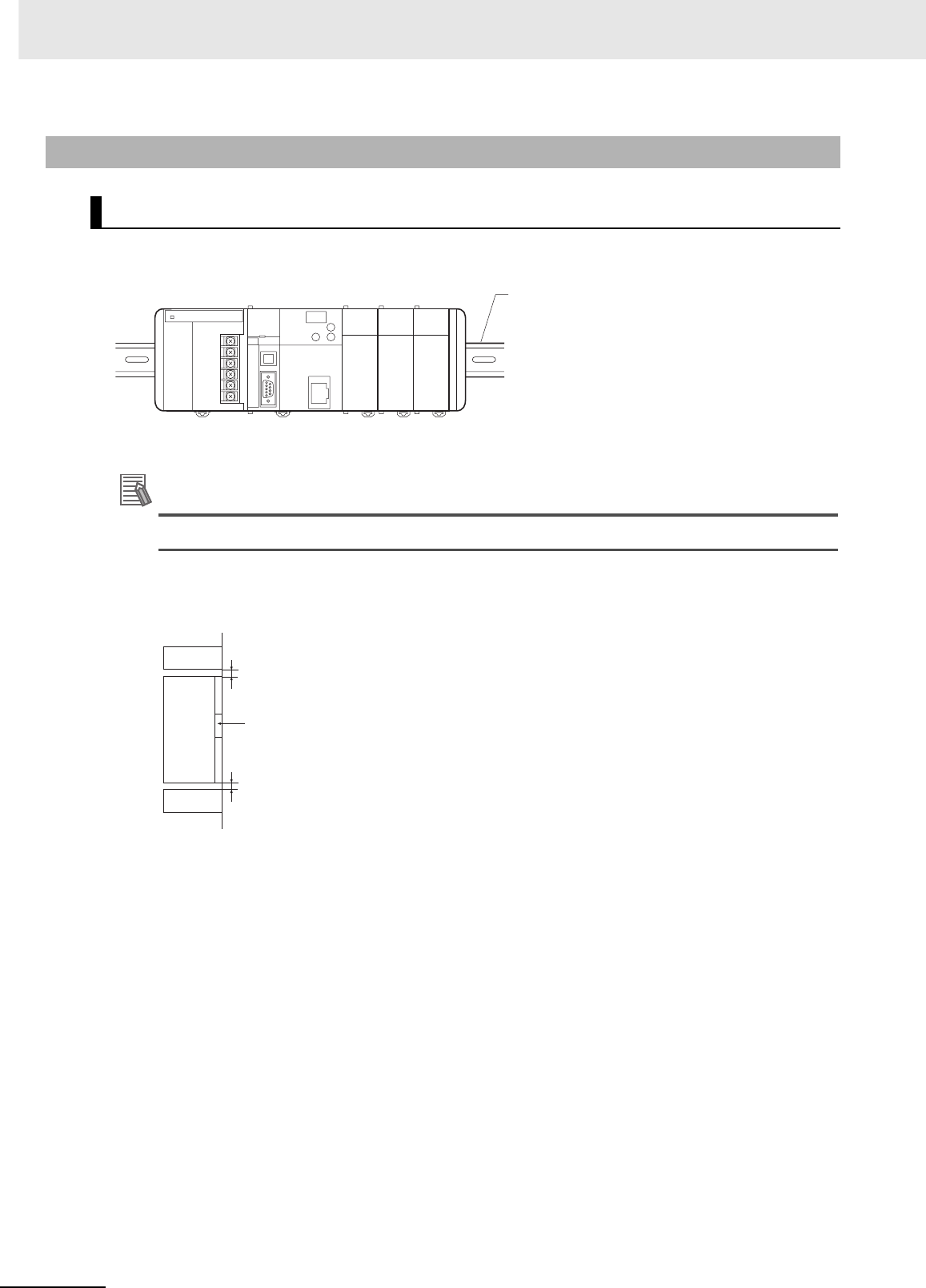
5 Installation
5-6 CJ2 CPU Unit Hardware User’s Manual
A CJ-series PLC must be mounted inside a control panel on DIN Track. Normally the CPU Rack is
installed on top and the Expansion Racks under it.
• Consider the width of wiring ducts, wiring, ventilation, and Unit replacement when determining the
space between Racks.
Additional Information
A CJ-series PLC must be mounted on DIN Track. It cannot be mounted with screws.
• Whenever possible, route I/O wiring through wiring ducts or raceways. Install the duct so that it is
easy to fish wire from the I/O Units through the duct. It is handy to have the duct at the same
height as the Racks.
5-2-2 Installation in a Control Panel
Control Panel Installation Dimensions
DIN Track
Duct
Duct
Unit
20 mm min.
20 mm min.
DIN Track
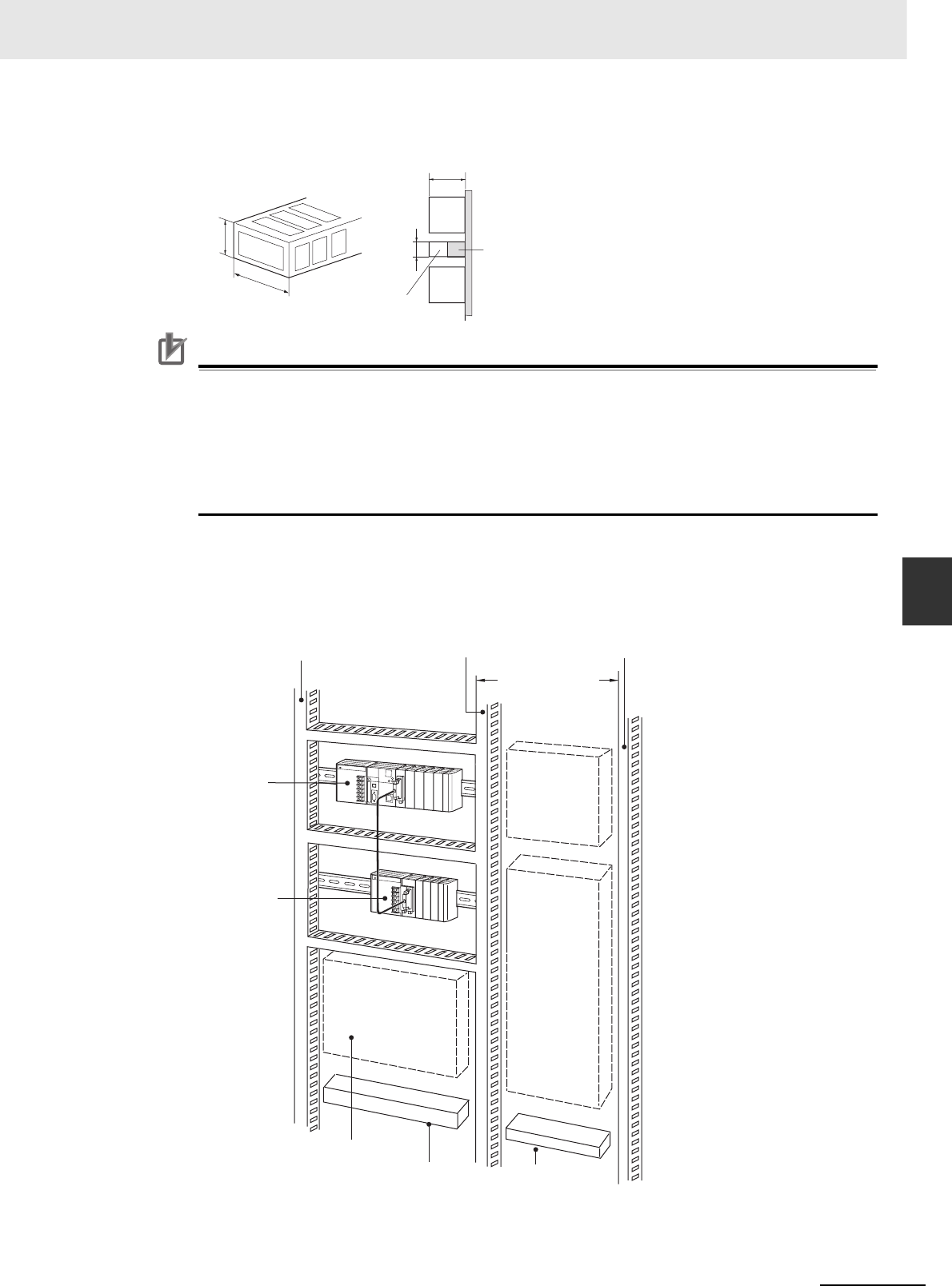
5-7
5 Installation
CJ2 CPU Unit Hardware User’s Manual
5-2 Installation
5
5-2-2 Installation in a Control Panel
zWiring Ducts
Precautions for Correct UsePrecautions for Correct Use
Tighten terminal block screws and cable screws to the following torques.
Ter minal Screws
M4: 1.2 N·m
M3: 0.5 N·m
Cable Connector Screws
M2.6: 0.2 N·m
zRouting Wiring Ducts
Install the wiring ducts at least 20 mm between the tops of the Racks and any other objects, (e.g.,
ceiling, wiring ducts, structural supports, devices, etc.) to provide enough space for air circulation
and replacement of Units.
30 mm
40 mm
30 mm
CPU
Rack
Mounting
bracket
Duct
81.6 to 89 mm
Expan-
sion
Rack
Breakers,
fuses
Power
equipment
such as
transformers
and magnetic
relays
Terminal blocks for
power equipment
Terminal blocks
for PLC
Fuses, relays, timers, etc.
(NOT heat-generating equip-
ment, power equipment, etc.)
Expansion Rack
CPU Rack
Output duct
200 mm min.
Power duct
Input duct
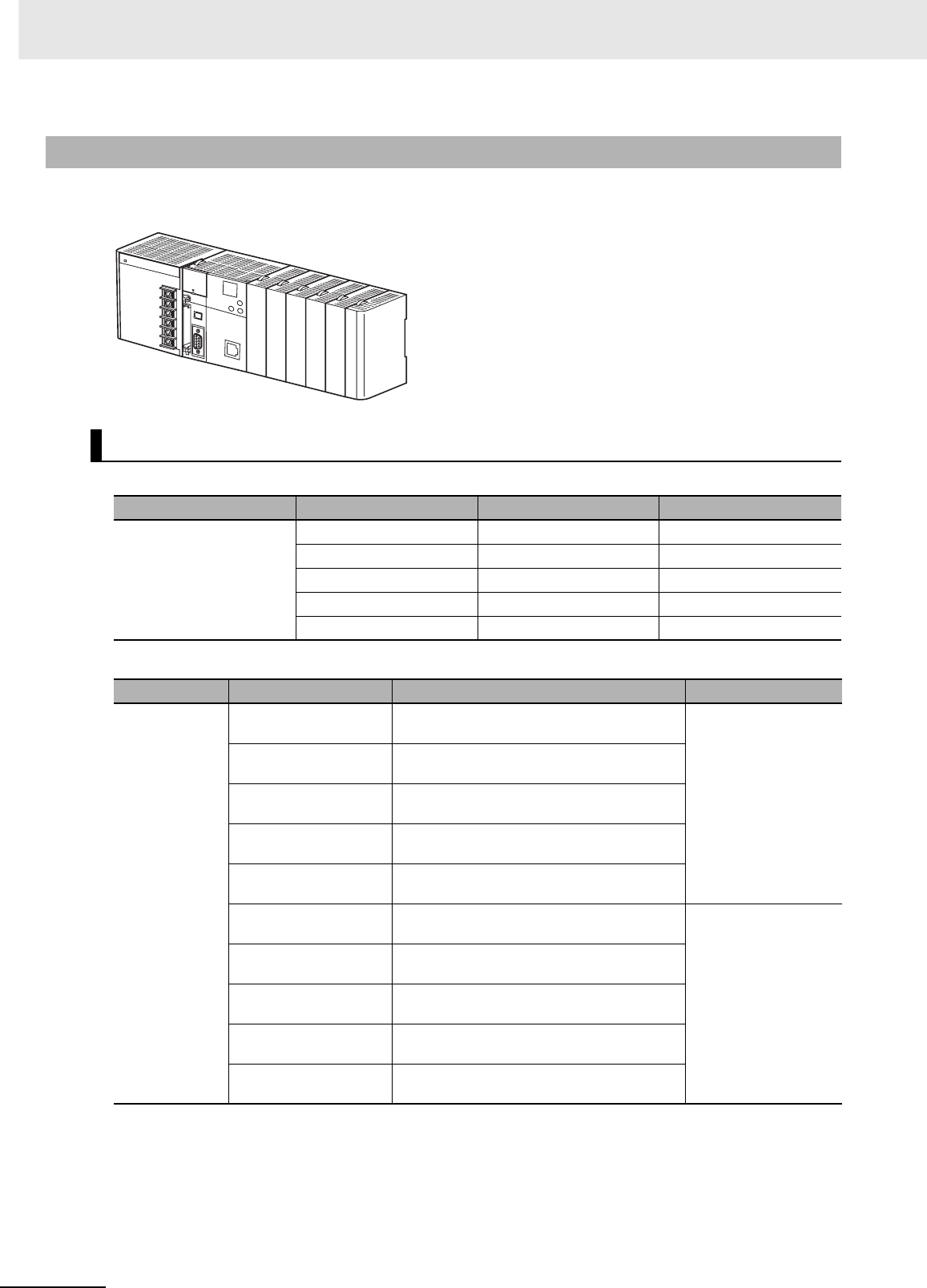
5 Installation
5-8 CJ2 CPU Unit Hardware User’s Manual
The CJ-series Units, including the Power Supply Unit, the CPU Unit, and I/O Units, are connected to
each other and an End Cover is connected to the right end.
Power Supply Unit
CPU Unit
5-2-3 Assembled Appearance and Dimensions
Dimensions (Unit: mm)
Name Model number Specifications Unit width
Power Supply Unit CJ1W-PA205R 100 to 240 VAC, 25 W 80 mm
CJ1W-PA205C 100 to 240 VAC, 25 W 80 mm
CJ1W-PA202 100 to 240 VAC, 14 W 45 mm
CJ1W-PD025 24 VDC, 25 W 60 mm
CJ1W-PD022 24 VDC, 19.6 W 27 mm
Name Model number Specifications Unit width
CPU Unit CJ2H-CPU68-EIP I/O points: 2,560
Program capacity: 400 Ksteps 79.8 mm
CJ2H-CPU67-EIP I/O points: 2,560
Program capacity: 250 Ksteps
CJ2H-CPU66-EIP I/O points: 2,560
Program capacity: 150 Ksteps
CJ2H-CPU65-EIP I/O points: 2,560
Program capacity: 100 Ksteps
CJ2H-CPU64-EIP I/O points: 2,560
Program capacity: 50 Ksteps
CJ2H-CPU68 I/O points: 2,560
Program capacity: 400 Ksteps 48.8 mm
CJ2H-CPU67 I/O points: 2,560
Program capacity: 250 Ksteps
CJ2H-CPU66 I/O points: 2,560
Program capacity: 150 Ksteps
CJ2H-CPU65 I/O points: 2,560
Program capacity: 100 Ksteps
CJ2H-CPU64 I/O points: 2,560
Program capacity: 50 Ksteps
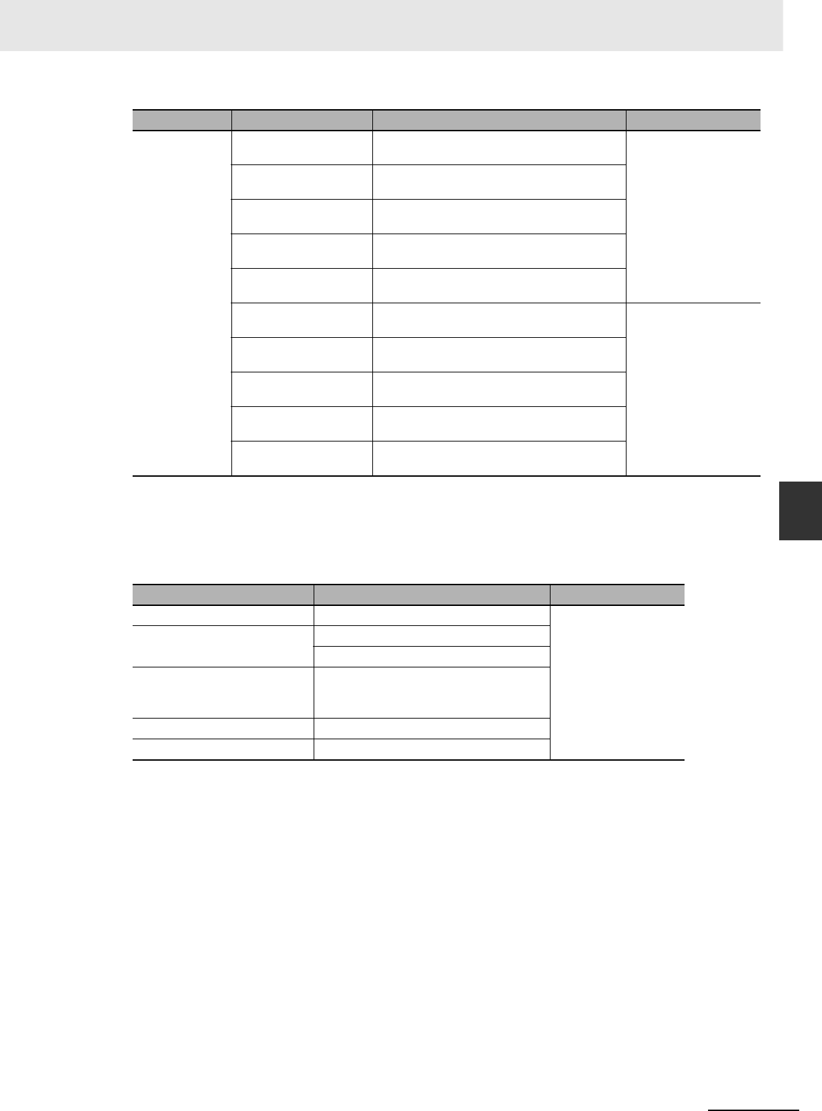
5-9
5 Installation
CJ2 CPU Unit Hardware User’s Manual
5-2 Installation
5
5-2-3 Assembled Appearance and Dimensions
* The width of the CPU Rack will increase by 20 mm for each CJ2M-MD21@ Pulse I/O Module that is connected to
the CJ2M CPU Unit.
Other than the CPU Units and Power Supply Units, CJ-series Units come in four widths:
20 mm, 31 mm, 51 mm, and 79.8 mm.
20-mm-wide Units
CPU Unit CJ2M-CPU35 I/O points: 2,560
Program capacity: 60 Ksteps 62 mm*
CJ2M-CPU34 I/O points: 2,560
Program capacity: 30 Ksteps
CJ2M-CPU33 I/O points: 2,560
Program capacity: 20 Ksteps
CJ2M-CPU32 I/O points: 2,560
Program capacity: 10 Ksteps
CJ2M-CPU31 I/O points: 2,560
Program capacity: 5 Ksteps
CJ2M-CPU15 I/O points: 2,560
Program capacity: 60 Ksteps 31 mm*
CJ2M-CPU14 I/O points: 2,560
Program capacity: 30 Ksteps
CJ2M-CPU13 I/O points: 2,560
Program capacity: 20 Ksteps
CJ2M-CPU12 I/O points: 2,560
Program capacity: 10 Ksteps
CJ2M-CPU11 I/O points: 2,560
Program capacity: 5 Ksteps
Name Model number Unit width
I/O Control Unit CJ1W-IC101 20 mm
32-point Basic I/O Units CJ1W-ID231/ID232/ID233
CJ1W-OD231/OD232/OD233/OD234
B7A Interface Units CJ1W-B7A22
CJ1W-B7A14
CJ1W-B7A04
CompoBus/S Master Unit CJ1W-SRM21
Space Unit CJ1W-SP001
Name Model number Specifications Unit width

5 Installation
5-10 CJ2 CPU Unit Hardware User’s Manual
31-mm-wide Units
Name Model number Unit width
I/O Interface Unit CJ1W-II101 31 mm
8-point and 16-point Basic I/O Units CJ1W-ID201
CJ1W-ID211/212
CJ1W-IA111/201
CJ1W-OD20@
CJ1W-OD211/212/213
CJ1W-OC201/211
CJ1W-OA201
32-point Basic I/O Units CJ1W-MD231/232/233
64-point Basic I/O Units CJ1W-ID261
CJ1W-OD261
CJ1W-MD261
CJ1W-ID262
CJ1W-OD262/263
CJ1W-MD263/563
Interrupt Input Unit CJ1W-INT01
Quick-response Input Unit CJ1W-IDP01
Analog I/O Units CJ1W-ADG41
CJ1W-AD@@@-V1
CJ1W-AD042
CJ1W-DA@@@
CJ1W-DA042V
CJ1W-MAD42
Process I/O Units CJ1W-AD04U
CJ1W-PH41U
CJ1W-PTS51/52/15/16
CJ1W-PDC15
Temperature Control Units CJ1W-TC@@@
Position Control Units (with pulse-
string outputs)
CJ1W-NC113/133/213/233/413/433
Position Control Units (with Ether-
CAT communications)
CJ1W-NC281/481/881/NCF81
CJ1W-NC482/882
MECHATROLINK-II Position Control
Unit
CJ1W-NCF71(-MA)
High-speed Counter Unit CJ1W-CT021
ID Sensor Units CJ1W-V680C11
CJ1W-V680C12
CJ1W-V600C11
CJ1W-V600C12
Controller Link Unit CJ1W-CLK23
Serial Communications Units CJ1W-SCU41-V1
CJ1W-SCU21-V1
CJ1W-SCU31-V1
CJ1W-SCU22/32/42
Ethernet Unit CJ1W-ETN21
EtherNet/IP Unit CJ1W-EIP21
DeviceNet Unit CJ1W-DRM21
CompoNet Master Unit CJ1W-CRM21
FL-net Unit CJ1W-FLN22
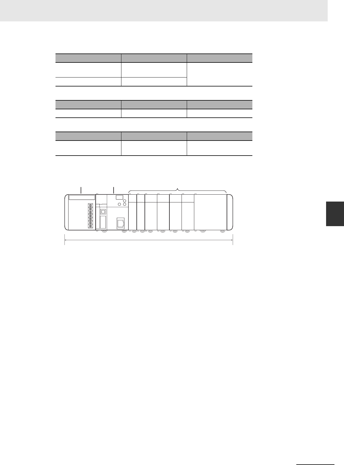
5-11
5 Installation
CJ2 CPU Unit Hardware User’s Manual
5-2 Installation
5
5-2-3 Assembled Appearance and Dimensions
51-mm-wide Units
62-mm-wide Units
79.8-mm-wide Units
zDesign Example for Width W
Power Supply Unit: CJ1W-PA205R (80 mm)
CPU Unit: CJ2H-CPU68-EIP (79.8 mm)
Basic I/O Units: CJ1W-ID231 (20 mm) × 2
Special I/O Units: CJ1W-AD081-V1 (31 mm) × 4
CPU Bus Unit: CJ1W-MCH71 (79.8 mm)
W = 80 + 79.8 + 20 x 2 + 31 × 4 + 79.8 × 1 + 14.7 (End Cover) = 418.3 mm
Name Model number Unit width
SYSMAC SPU Unit (High-
speed Data Storage Unit)
CJ1W-SPU01-V2 51 mm
Position Control Units CJ1W-NC214/234
Name Model number Unit width
Position Control Units CJ1W-NC414/434 62 mm
Name Model number Unit width
MECHATROLINK-II
Motion Control Unit
CJ1W-MCH71 79.8 mm
W
Configuration UnitsCPU Unit
Power
Supply Unit
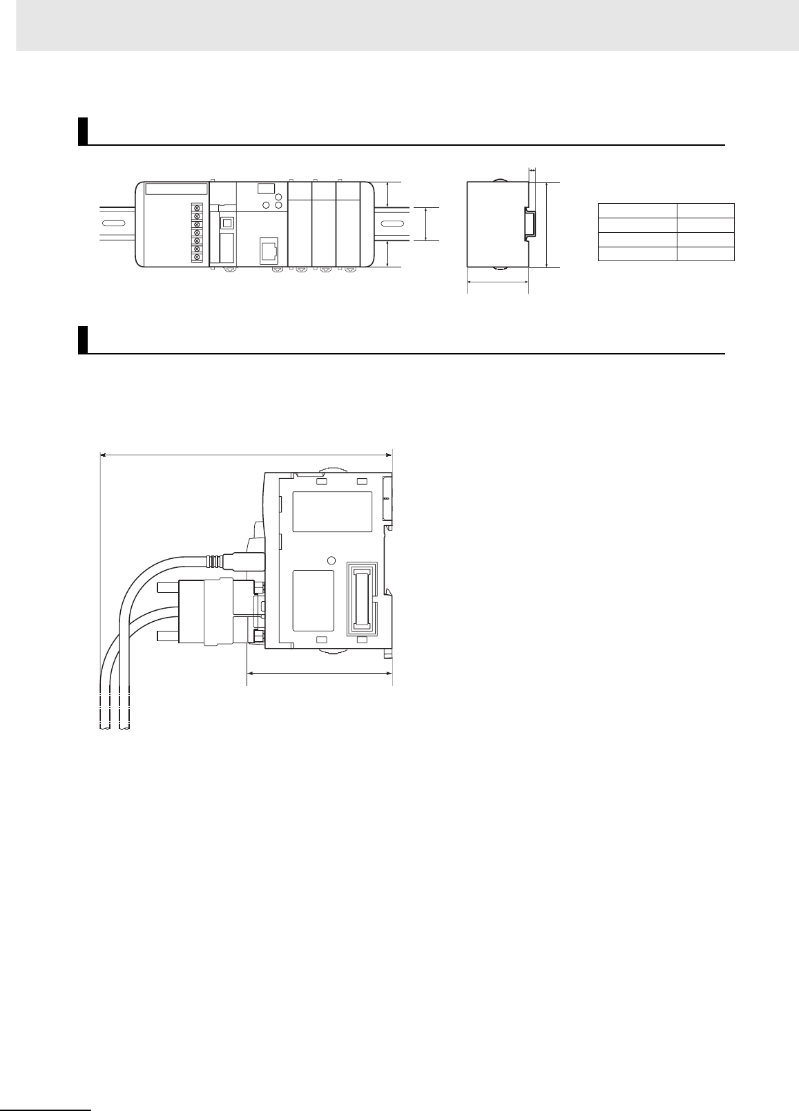
5 Installation
5-12 CJ2 CPU Unit Hardware User’s Manual
The installation height of the CJ-series CPU Rack and Expansion Racks varies from 81.6 to 89.0 mm,
depending on the I/O Units that are mounted. When a Programming Device (e.g., CX-Programmer) is
connected, however, even greater height is required. Allow sufficient depth in the control panel contain-
ing the PLC.
Installation Dimensions (Unit: mm)
Installation Height
PFP-100N2
PFP-100N
PFP-50N
A
16 mm
7.3 mm
7.3 mm
DIN Track
27.5
35
27.5
90
A
65
Approx. 100 to 150 mm
81.6 to 89.0 mm
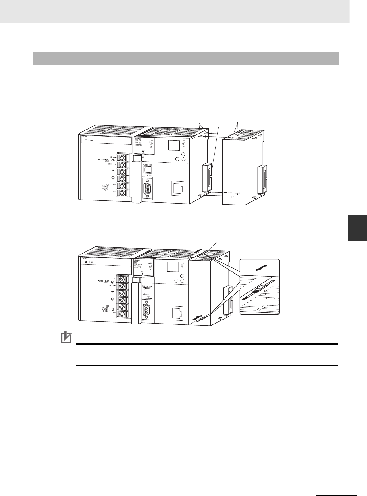
5-13
5 Installation
CJ2 CPU Unit Hardware User’s Manual
5-2 Installation
5
5-2-4 Connecting PLC Components
The Units that make up a CJ-series PLC can be connected simply by pressing the Units together and
locking the sliders by moving them toward the back of the Units. The End Cover is connected in the
same way to the Unit on the far right side of the PLC.
1Join the Units so that the connectors fit exactly.
2The yellow sliders at the top and bottom of each Unit lock the Units together. Move the sliders
toward the back of the Units as shown below until they click into place.
Precautions for Correct UsePrecautions for Correct Use
If the locking tabs are not secured properly, the connectors may become loose and not function
properly. Be sure to slide the locking tabs until they are securely in place.
5-2-4 Connecting PLC Components
Connector
Hook Hook holes
Slider
Lock
Release
Move the sliders toward the back
until they lock into place.
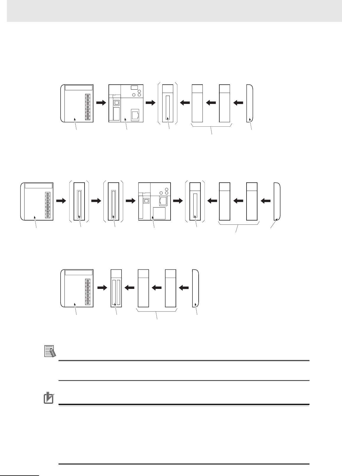
5 Installation
5-14 CJ2 CPU Unit Hardware User’s Manual
3Attach the End Cover to the Unit on the far right side of the Rack.
●CJ2H CPU Unit
●CJ2M CPU Unit
Additional Information
There is no Backplane for the CJ-series. The PLC is constructed by connecting Units together
using the connectors on the sides.
Precautions for Correct UsePrecautions for Correct Use
• Always turn OFF the power supply before connecting Units to each other.
• Always turn OFF the power supply to the entire system before replacing a Unit.
• A maximum of 10 Units can be connected in any one CPU or Expansion Rack. If more than
the maximum number of Units are connected, a too many I/O points error (fatal error) will
occur and the CJ2 CPU Unit will not operate in either RUN or MONITOR mode. If this occurs,
the I/O Overflow Flag (A401.11) will turn ON and A407.13 to A407.15 (I/O Overflow Details 2)
will turn ON.
CPU Rack
Power Supply
Unit CPU Unit (I/O Control Unit) *1
I/O Units (10 max.) End Cover
(included with CPU Unit)
*1: Connect the I/O Control Unit directly to the CPU Unit to enable connecting Expansion
Racks.
CPU Rack
Power Supply
Unit CPU Unit (I/O Control Unit) *1
I/O Units (10 max.) End Cover
(included with CPU Unit)
*1: Connect the I/O Control Unit directly to the CPU Unit to enable connecting Expansion Racks.
*2: Up to two Pulse I/O Modules can be connected to the left of the CPU Unit.
(Pulse I/O Module) *2 (Pulse I/O Module) *2
*3: Connect the I/O Interface Unit directly to the Power Supply Unit.
Expansion Rack
I/O Interface Unit *3
I/O Units (10 max.)
End Cover
(included with
I/O Interface Unit)
Power Supply
Unit
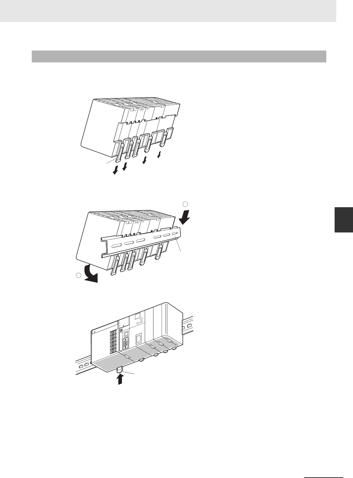
5-15
5 Installation
CJ2 CPU Unit Hardware User’s Manual
5-2 Installation
5
5-2-5 DIN Track Installation
Use the following procedure to install a CJ-series PLC on DIN Track.
1Release the pins on the backs of the CJ-series Units.
2Fit the back of the PLC onto the DIN Track by inserting the top of the track and then pressing in
at the bottom of the PLC, as shown below.
3Lock the pins on the backs of the CJ-series Units.
5-2-5 DIN Track Installation
Release
DIN Track
mounting pins
DIN Track
2
1
DIN Track
mounting pins
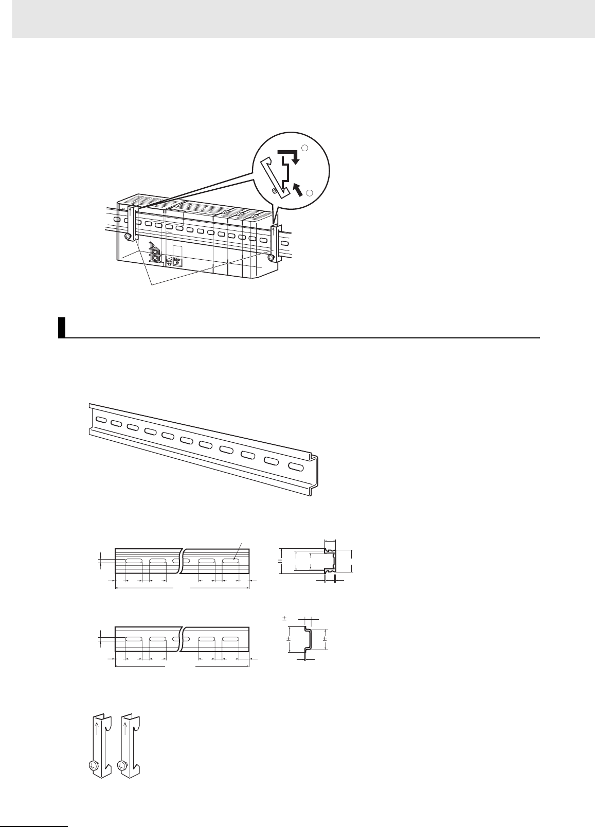
5 Installation
5-16 CJ2 CPU Unit Hardware User’s Manual
4Install a DIN Track End Plate on each end of the PLC. To install an End Plate, hook the bottom
on the bottom of the track, rotate the Plate to hook the top of the Plate on the top of the track,
and then tighten the screw to lock the Plate in place.
Use the DIN Track and DIN Track End Plates shown below. Secure each DIN Track inside a control
panel with at least three screws.
• DIN Track
Model numbers: PFP-50N (50 cm), PFP-100N (100 cm), PFP-100N2 (100 cm)
Secure the DIN Track to the control panel using M4 screws separated by 210 mm (6 holes) or less and
using at least 3 screws. The tightening torque is 1.2 N·m.
• PFP-M DIN Track End Plates (2 required)
DIN Track and Accessories
End Plates
2
1
15 10
4.5
25 25 25 10 25 15
1000
PFP-100N2 DIN Track
PFP-100N/50N DIN Track
15 10
4.5
25 25 25 10 25 1
16
1.51
29.2
24
27
30 0.3
7.3 0.15
35 0.3 27 0.15
Twenty-eight, 25 × 4.5 oblong holes
1000 (500)*
15 (5)*
* PFP-50N dimensions are
given in parentheses.
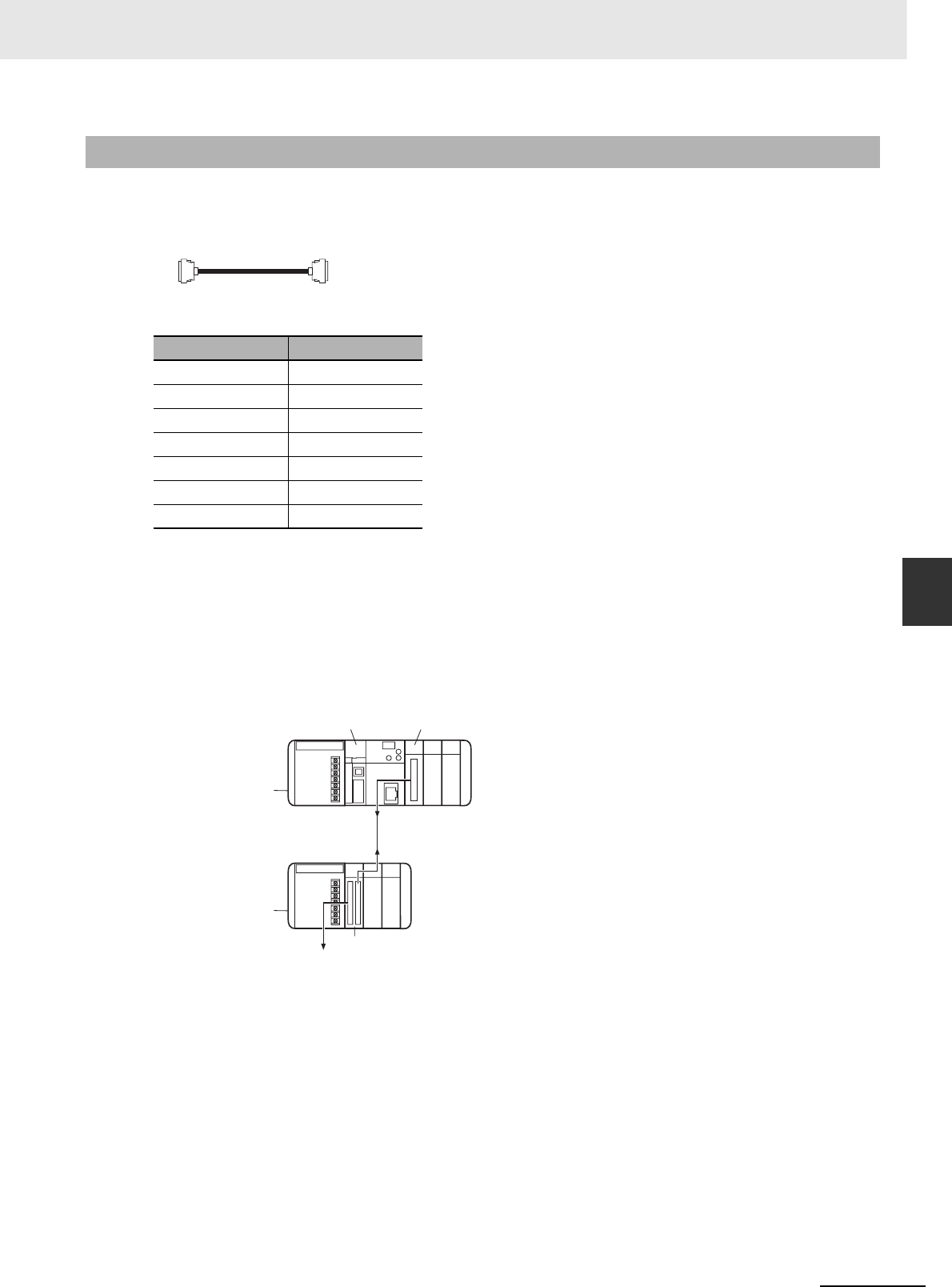
5-17
5 Installation
CJ2 CPU Unit Hardware User’s Manual
5-2 Installation
5
5-2-6 Connecting CJ-series Expansion Racks
CS/CJ-series I/O Connecting Cables are used to connect the CPU Rack and Expansion Racks.
zCS/CJ-series I/O Connecting Cables
• These connectors are equipped with easy-lock connectors.
• Use them to connect the CPU Rack to an Expansion Rack or to connect two Expansion Racks.
• The CJ-series I/O Connecting Cables are used to connect the I/O Control Unit on the CPU Rack
to the I/O Interface Unit on an Expansion Rack or to connect the I/O Interface Units on two Expan-
sion Racks.
• Install the Racks and select I/O Connecting Cables so that the total length of all I/O Connecting
Cables does not exceed 12 m.
• The following diagram shows where each I/O Connecting Cable must be connected on each
Rack. The Rack will not operate if the cables aren’t connected properly. (The “up” direction is
towards the CPU Unit and “down” is away from the CPU Unit.)
5-2-6 Connecting CJ-series Expansion Racks
Model number Cable length
CS1W-CN313 0.3 m
CS1W-CN713 0.7 m
CS1W-CN223 2 m
CS1W-CN323 3 m
CS1W-CN523 5 m
CS1W-CN133 10 m
CS1W-CN133B2 12 m
I/O Control Unit
Power Supply
Unit
CPU Unit
I/O Interface Unit
Power
Supply Unit
CPU Rack
Expansion Rack
Down
Up
Down
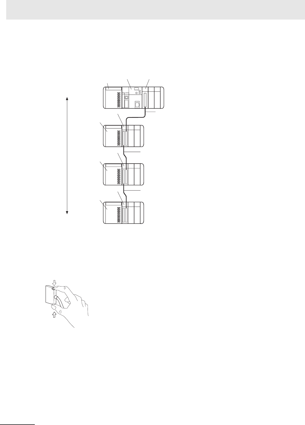
5 Installation
5-18 CJ2 CPU Unit Hardware User’s Manual
zCable Connections
The following diagram shows examples of proper Rack connections. Connect the simple lock con-
nectors to the I/O Control Unit on the CJ-series CPU Rack and the I/O Interface Unit on the CJ-
series Expansion Rack.
• The top and bottom of the connector are different. Be sure the connector is facing the correct
direction before connecting it.
zConnecting the Simple Locking Connectors
Press the tabs on the end of the connector and insert the connector until it locks in place. The PLC
will not operate properly if the connector isn’t inserted completely.
To remove the connector, press the tabs and pull on the connector.
Power
Supply Unit CPU Unit I/O Control Unit
I/O Interface Unit
Power Supply Unit
CPU Rack
Expansion Rack
Expansion Rack
I/O Connecting Cable
I/O Connecting Cable
I/O Interface Unit
Power Supply Unit
I/O Interface Unit
Power Supply Unit
Expansion Rack
I/O Connecting Cable
Total cable
length:
12 m max.
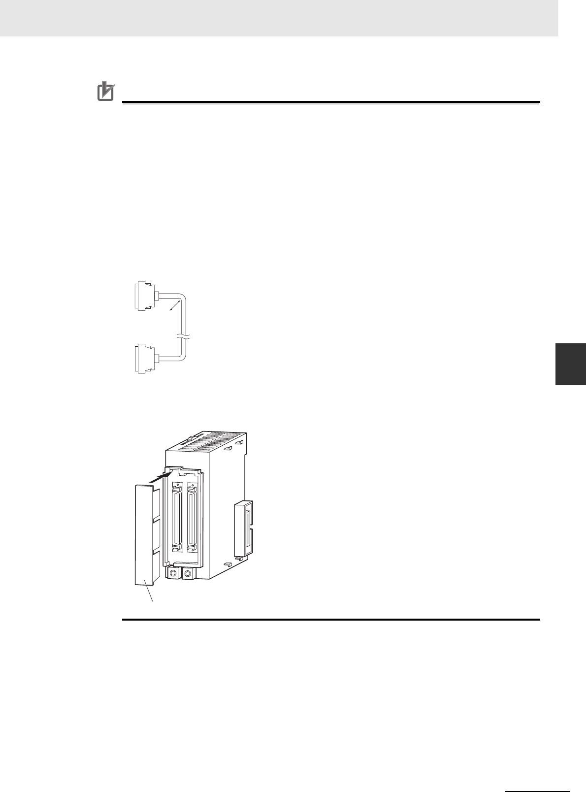
5-19
5 Installation
CJ2 CPU Unit Hardware User’s Manual
5-2 Installation
5
5-2-6 Connecting CJ-series Expansion Racks
Precautions for Correct UsePrecautions for Correct Use
• When using an I/O Connecting Cable with a locking connector, be sure that the connector is
firmly locked in place before using it.
• Always turn OFF the power supply to the PLC before connecting a cable.
• An I/O bus error will occur and the PLC will stop if an I/O Connecting Cable's connector sepa-
rates from the Rack. Be sure that the connectors are secure.
• A 63-mm hole will be required if the I/O Connecting Cable must pass through a hole when con-
necting an Expansion Rack.
• Do not bend the I/O Connecting cable past its natural bending radius or pull in it with excessive
force.
• The cables can withstand a pulling force up to 49 N (11 lbs), so be sure that they are not pulled
too forcefully.
• The I/O Connecting Cables mustn't be bent too severely. The minimum bending radii are
shown in the following diagram.
• Always attach the cover to the output connector (left side) on the last I/O Interface Unit on the
last Expansion Rack to protect it from dust.
R
R = 69 mm min.
Cable outer diameter: 8.6 mm
T
U
OIN
II101
CJ1W-II101
I/O Interface Unit
Output connector cover
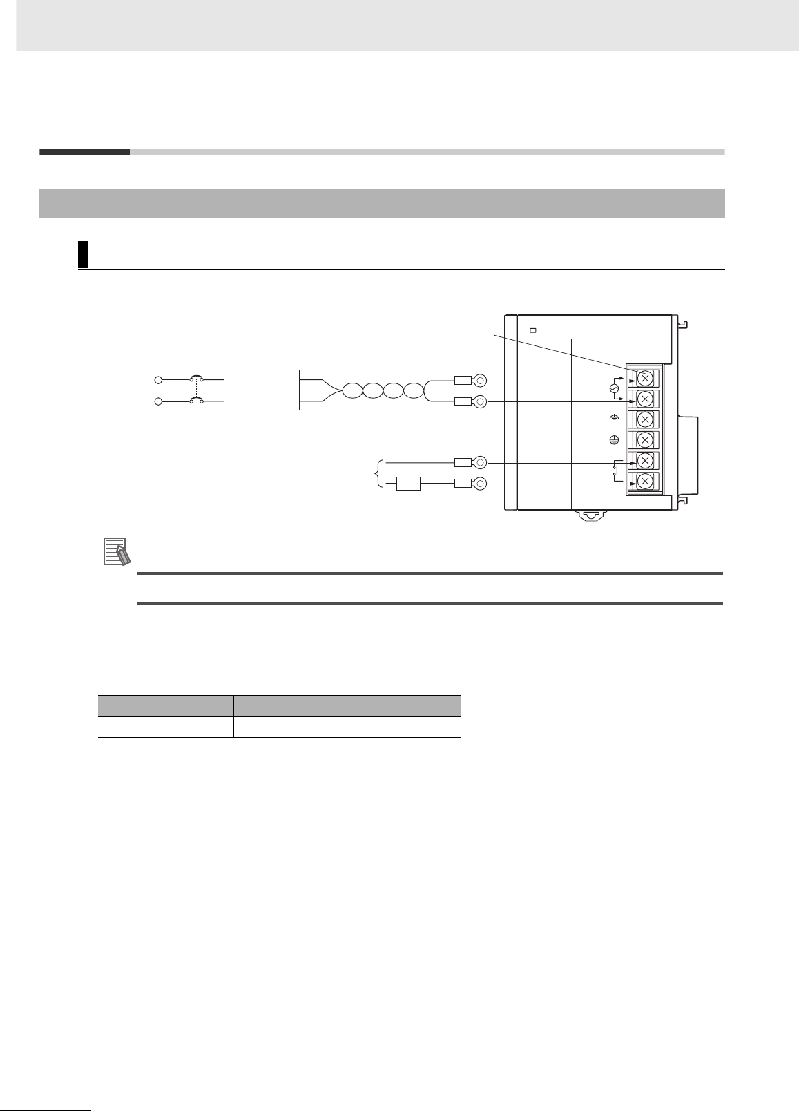
5 Installation
5-20 CJ2 CPU Unit Hardware User’s Manual
5-3 Wiring
zCJ1W-PA205R Power Supply Unit
Additional Information
The RUN output function is enabled only when mounted to a CPU Rack.
zAC Power Source
• Supply 100 to 240 VAC.
• Keep voltage fluctuations within the specified range:
• If one power supply phase of the equipment is grounded, connect the grounded phase side to the
L2/N terminal.
zIsolation Transformer
The PLC's internal noise isolation circuits are sufficient to control typical noise in power supply lines,
but noise between the PLC and ground can be significantly reduced by connecting a 1-to-1 isolation
transformer. Do not ground the secondary coil of the transformer.
zPower Supply Capacity
The power consumption will be 100 VA max. per Rack for the CJ1W-PA205R/PA205C and 50 VA for
the CJ1W-PA202, but there will be a surge current of at least 5 times the max. current when power is
turned ON.
zRUN Output
The RUN output is provided only on the CJ1W-PA25R Power Supply Unit. This output is ON when-
ever the CPU Unit is operating in RUN or MONITOR mode; it is OFF when the CPU Unit is in PRO-
GRAM mode or a fatal error has occurred (including execution of the FALS(007) instruction).
5-3-1 Power Supply Wiring
AC Power Supply Units
Supply voltage Allowable voltage fluctuations
100 to 240 VAC 85 to 264 VAC
POWER
PA205R
DC24V
AC240V
OUTPUT
RUN
INPUT
AC100-240V
L2/N
L1
Isolation
transformer
1:1
AC power supply
100 to 240 V
AC power supply
M4 self-raising screw terminals
Power
supply
RUN output
ON when CPU Unit is in RUN or
MONITOR mode.
OFF when CPU Unit is in
PROGRAM mode or stopped for
a fatal error.
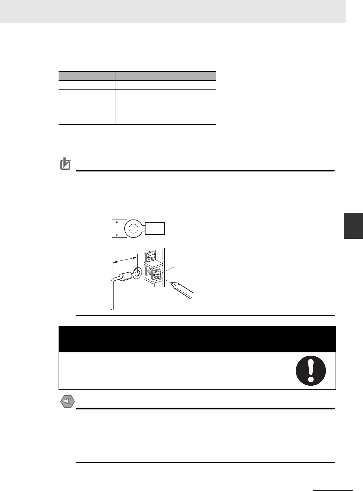
5-21
5 Installation
CJ2 CPU Unit Hardware User’s Manual
5-3 Wiring
5
5-3-1 Power Supply Wiring
The RUN output can be used to control external systems, such as in an emergency stop circuit that
turns off the power supply to external systems when the PLC is not operating. (Refer to 5-1 Fail-safe
Circuits for more details on the emergency stop circuit.)
zCrimp Terminals
The terminals on the Power Supply Unit are M4, self-raising terminals with screws.
Precautions for Correct UsePrecautions for Correct Use
• Use crimp terminals for wiring.
• Do not connect bare stranded wires directly to terminals.
• Tighten the terminal block screws to the torque of 1.2 N·m.
• Use round-type crimp terminals (M4) having the dimensions shown below.
• Crimp Terminals for AC Power Supplies
Precautions for Safe Use
• Supply power to all of the Power Supply Units from the same source.
• Do not remove the protective label from the top of the Unit until wiring has been completed.
This label prevents wire strands and other foreign matter from entering the Unit during wiring
procedures.
• Do not forget to remove the label from the top of the Power Supply Unit after wiring the Unit.
The label will block air circulation needed for cooling.
Item CJ1W-PA205R
Contact form SPST-NO
Maximum switching
capacity
240 VAC: 2 A for resistive loads
120 VAC: 0.5 A for inductive loads
24 VDC:2 A for resistive loads
24 VDC:2 A for inductive loads
! Caution
Tighten the AC power supply terminal screws to a torque of 1.2 N·m. Loose screws
may result in short-circuit, malfunction, or fire.
7 mm max.
Torque to 1.2 N •m
20 mm max.
M4 self-raising terminals
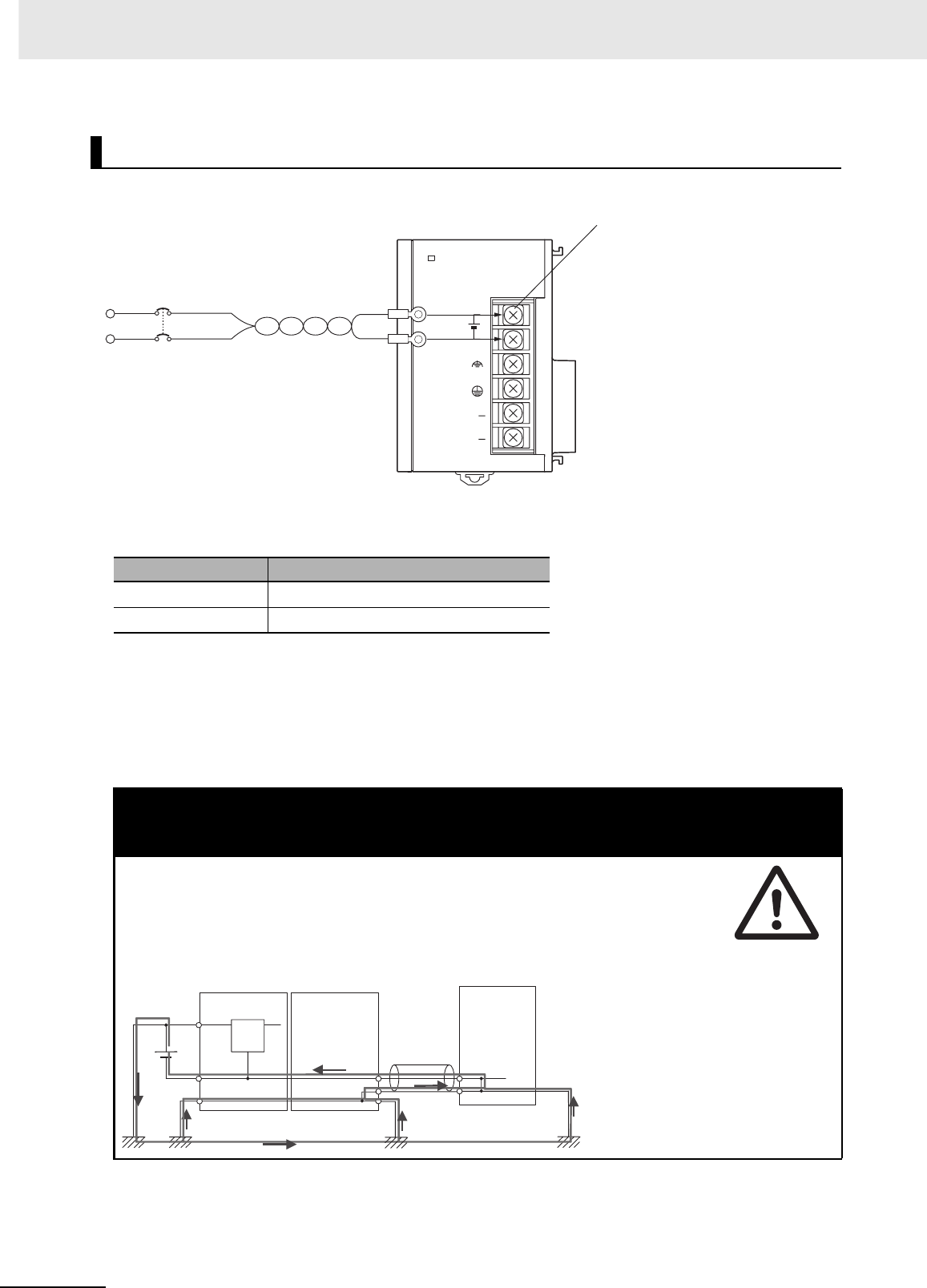
5 Installation
5-22 CJ2 CPU Unit Hardware User’s Manual
zCJ1W-PD025 Power Supply Unit
zDC Power Source
Supply 24 VDC. Keep voltage fluctuations within the specified range.
zPower Supply Capacity
The maximum power consumption is 50 W (CJ1W-PD025)/35 W (CJ1W-PD022) per Rack, but there
will be a surge current of about five times that level when the power is turned ON.
zPrecautions when Using CJ1W-PD022 Non-insulated Power Supply Units
DC Power Supplies
Model Allowable voltage fluctuation range
CJ1W-PD025 19.2 to 28.8 VDC (±20%)
CJ1W-PD022 21.6 to 26.4 VDC (±10%)
! Caution
When connecting a personal computers or other peripheral devices to a PLC to which a non-
insulated Power Supply Unit (CJ1W-PD022) is mounted, either ground the 0 V side of the
external power supply or do not ground the external power supply at all ground. A short-cir-
cuit will occur in the external power supply if incorrect grounding methods are used. Never
ground the 24 V side, as shown below.
Wiring in Which the 24-V Power Supply Will Short
POWER
PD025
DC24V+
INPUT
NC
NC
DC power supply
Screw terminals (M4 head with
self-raising pressure plate)
24 V
0 V
FG FG
0 V 0 V
CPU Unit
Non-insulated
DC power supply
Power Supply
Unit
Peripheral
cable
Peripheral device (e.g.,
personal computer)
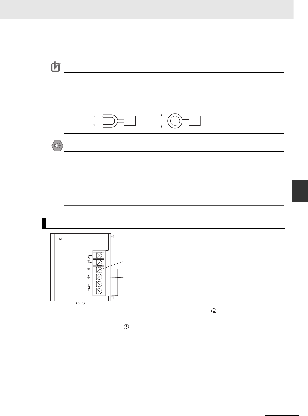
5-23
5 Installation
CJ2 CPU Unit Hardware User’s Manual
5-3 Wiring
5
5-3-1 Power Supply Wiring
zCrimp Terminals
The terminals on the Power Supply Unit are M4, self-raising terminals with screws.
Precautions for Correct UsePrecautions for Correct Use
• Use crimp terminals for wiring.
• Do not connect bare stranded wires directly to terminals.
• Tighten the terminal block screws to the torque of 1.2 N·m.
• Use crimp terminals (M4) having the dimensions shown below.
Precautions for Safe Use
• Be sure not to reverse the positive and negative leads when wiring the power supply terminals.
• Supply power to all of the Power Supply Units from the same source.
• Do not remove the protective label from the top of the Unit until wiring has been completed.
This label prevents wire strands and other foreign matter from entering the Unit during wiring
procedures.
• Do not forget to remove the label from the top of the Power Supply Unit after wiring the Unit.
The label will block air circulation needed for cooling.
• To help prevent electrical shock, ground the ground terminal (GR: ) with a ground resistance of
less than 100 Ω using a 14-gauge wire (minimum cross-sectional area of 2 mm2).
• The line ground terminal (LG: ) is a noise-filtered neutral terminal. If noise is a significant source of
errors or electrical shocks are a problem, connect the line ground terminal to the ground terminal and
ground both with a ground resistance of less than 100 Ω.
• If the LG and GR terminals are connected, ground to a resistance of 100 Ω or less to prevent electric
shock.
• The ground wire should not be more than 20 m long.
• The CJ-series PLCs are designed to be mounted so that they are isolated (separated) from the
mounting surface to protect them from the effects of noise in the installation environment (e.g., the
control panel).
• Do not share the PLC’s ground with other equipment or ground the PLC to the metal structure of a
building. The configuration shown in the following diagram may worsen operation.
Grounding
7 mm max. 7 mm max.
Crimp Terminals for DC Power Supplies
POWER
PA205R
DC24V
AC240V
OUTPUT
RUN
INPUT
AC100-240V
L2/N
L1
LG (Noise-filter neutral terminal)
Ground this terminal to less than 100 Ω
to improve noise resistance and prevent
electric shock.
GR (Ground terminal)
Ground this terminal to less than 100 Ω
to prevent electric shock.
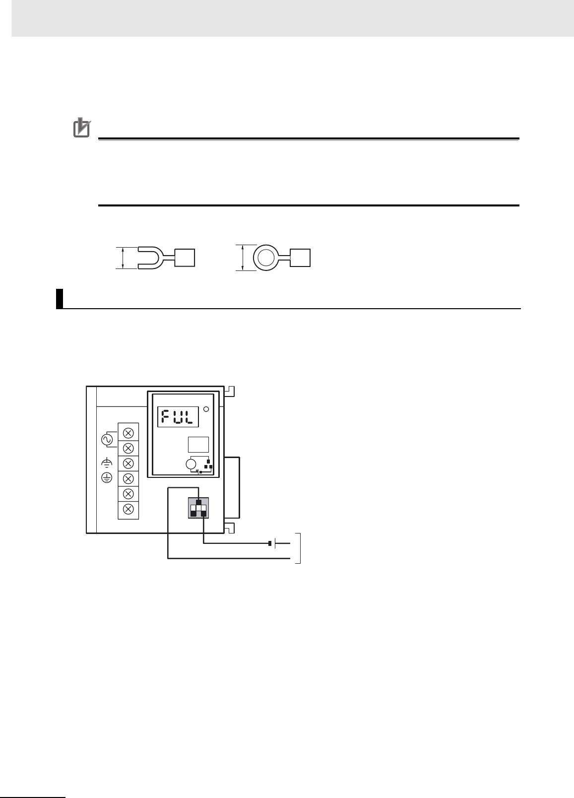
5 Installation
5-24 CJ2 CPU Unit Hardware User’s Manual
zCrimp Terminals
The terminals on the Power Supply Unit are M4, self-raising terminals with screws.
Precautions for Correct UsePrecautions for Correct Use
• Use crimp terminals for wiring.
• Do not connect bare stranded wires directly to terminals.
• Tighten the terminal block screws to the torque of 1.2 N·m.
• Use crimp terminals (M4) having the dimensions shown below.
zCrimp Terminals for DC Power Supply
An alarm output is provided on Power Supply Units with a replacement notification function. Connect
the alarm output to a PLC's Input Unit or external LED indicator to enable notification when Power Sup-
ply Unit replacement is required.
zCJ1W-PA205C Power Supply Unit
zOutput Specifications
• ON (normal): Power Supply Unit replacement not required for at least 6 months.
• OFF: Power Supply Unit replacement required within 6 months.
• Transistor open-collector outputs
• Maximum switching capacity: 30 VDC max., 50 mA max.
• ON: Residual voltage of 2 V max., OFF: Leakage current of 0.1 mA max.
Alarm Output
7 mm max. 7 mm max.
AC100-240V
INPUT
NC
NC
L1
L2/N
CJ1W-PA205C
POWER
TEST
ALARM OUTPUT
DC30V, 50mA
NORMAL:ON
ALARM:OFF L
Alarm output (replacement notification output)
ON when replacing the Power Supply Unit is
not required for at least 6 months.
24 VDC
power supply
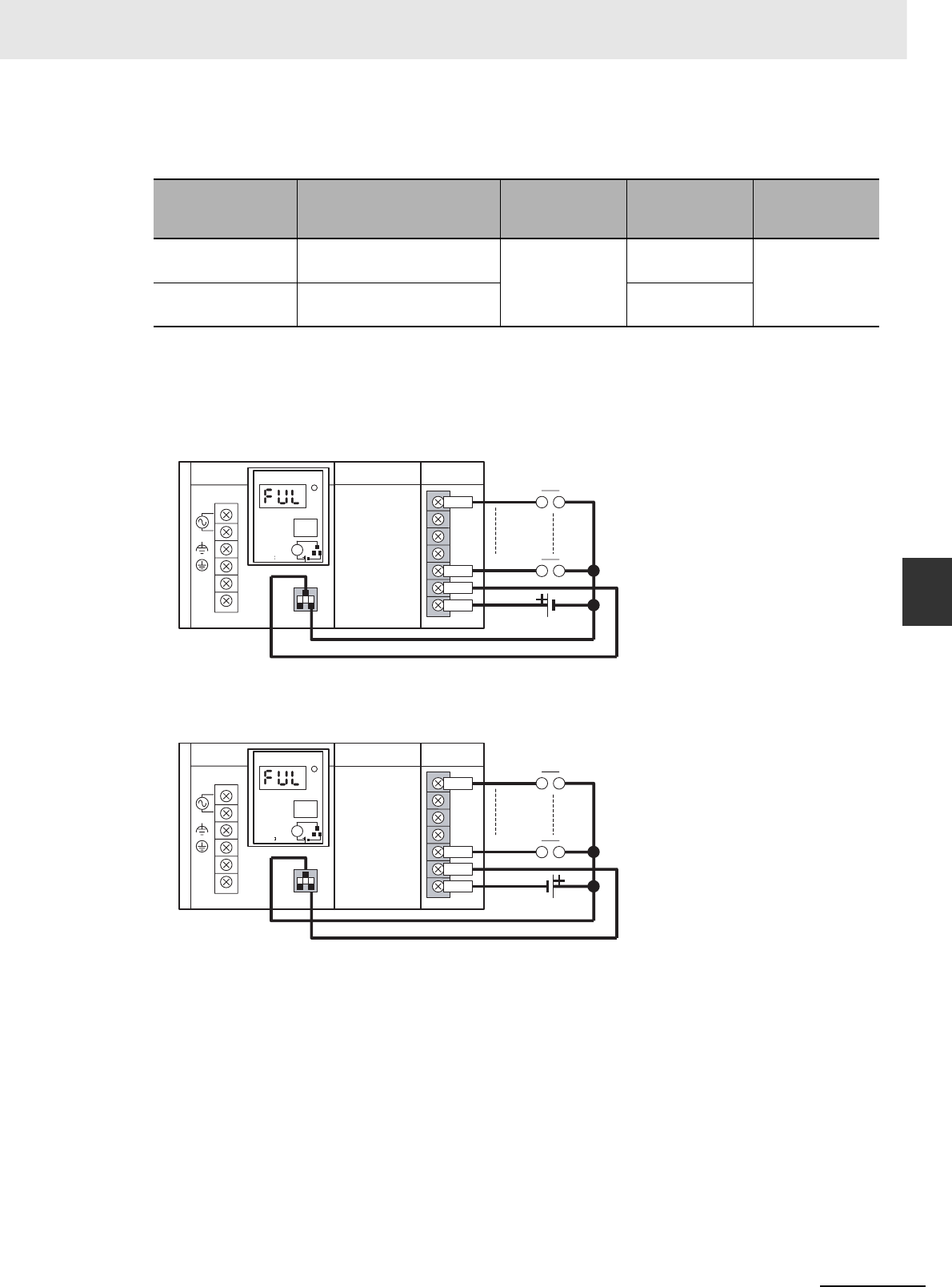
5-25
5 Installation
CJ2 CPU Unit Hardware User’s Manual
5-3 Wiring
5
5-3-1 Power Supply Wiring
zWiring
The following wire gauges are recommended.
zPLC Input Unit Wiring Example
Connect the positive terminals of the 24-VDC power supply to the Input Unit common (COM) termi-
nals.
Connect the negative terminal of the 24-VDC power supply to the Input Unit common (COM) termi-
nal.
Recommended
wire size Use
Pushing
strength (clamp-
ing operation)
Pulling strength
(holding force)
Length of
stripped section
AWG 22 to 18
(0.32 to 0.82 mm2)
Connecting to PLC terminal
block models
30 N max. 30 N min. 7 to 10 mm
AWG 28 to 24
(0.08 to 0.2 mm2)
Connecting to PLC connector
models
10 N min.
AC100-240V
INPUT
NC
NC
L1
L2/N
CJ1W-PA205C
POWER
TEST
ALARM OUTPUT
DC30V, 50mA
NORMAL:ON
ALARM OFF L
IN0
IN(N)
IN(N+1)
COM
CPU Unit
CJ1W-PA205C IN Unit
CJ1W-ID2@@
24-VDC power supply
IN0
IN(N)
IN(N+1)
COM
AC100-240V
INPUT
NC
NC
L1
L2/N
CJ1W-PA205C
POWER
TEST
ALARM OUTPUT
DC30V, 50mA
NORMAL:ON
ALARM OFF L
CJ1W-PA205C CPU Unit IN Unit
CJ1W-ID2@@
24-VDC power supply
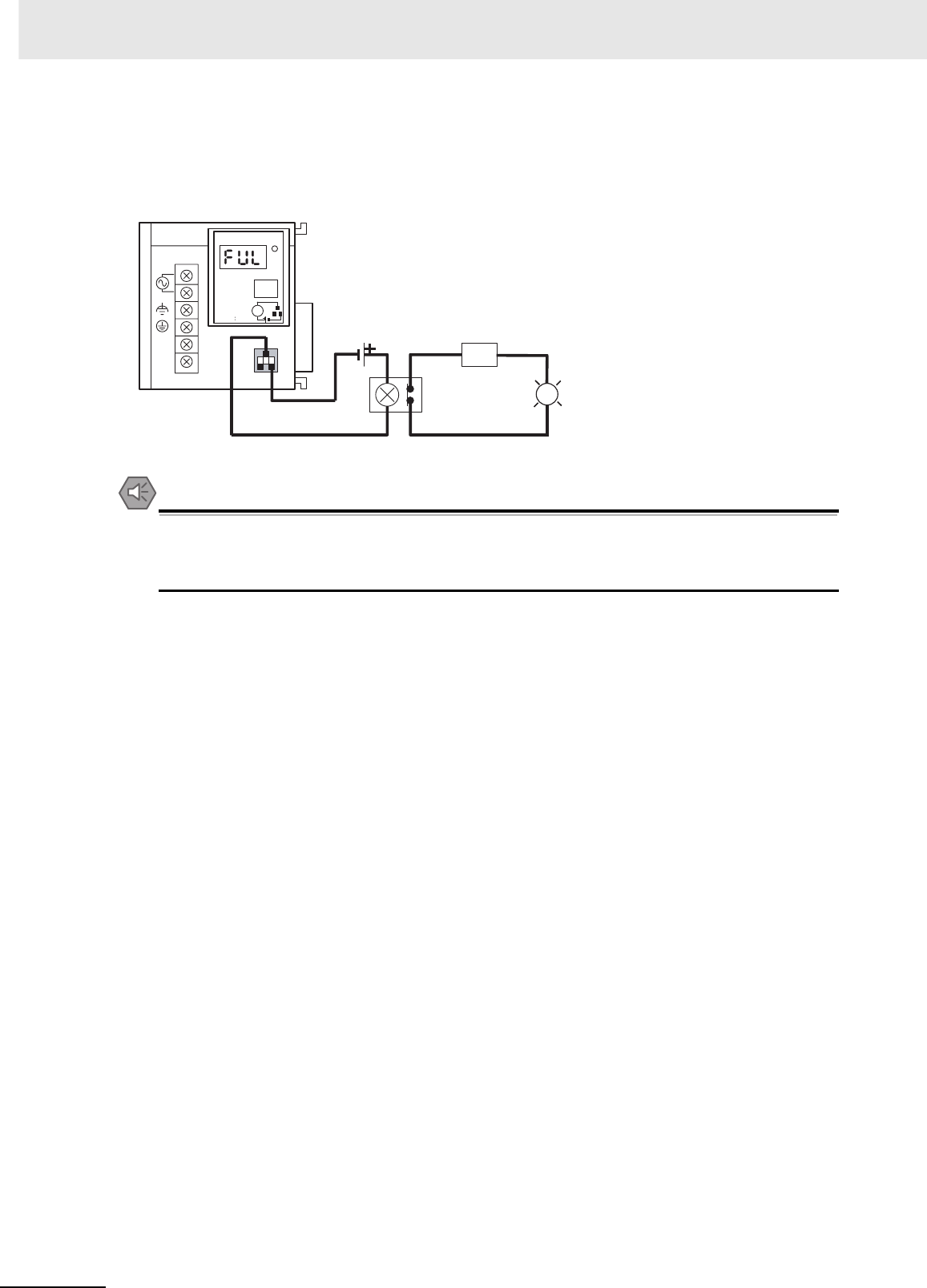
5 Installation
5-26 CJ2 CPU Unit Hardware User’s Manual
zExternal Display Device Connection Example
The alarm output (replacement notification output) is an NC contact. Therefore, wire the alarm out-
put using an NC contact or other means to turn ON an error indicator or LED display as shown in the
following diagram.
Note The OL display will also light if the PLC's power supply fails.
Precautions for Safe Use
• Separate the alarm output cables from power lines and high-voltage lines.
• Do not apply a voltage or connect a load to the alarm output that exceeds the rated voltage or
load.
AC100-240V
INPUT
NC
NC
L1
L2/N
CJ1W-PA205C
POWER
TEST
ALARM OUTPUT
DC30V, 50mA
NORMAL:ON
ALARM OFF L
OL
24-VDC power supply
Relay
(NC contacts)
Power
supply
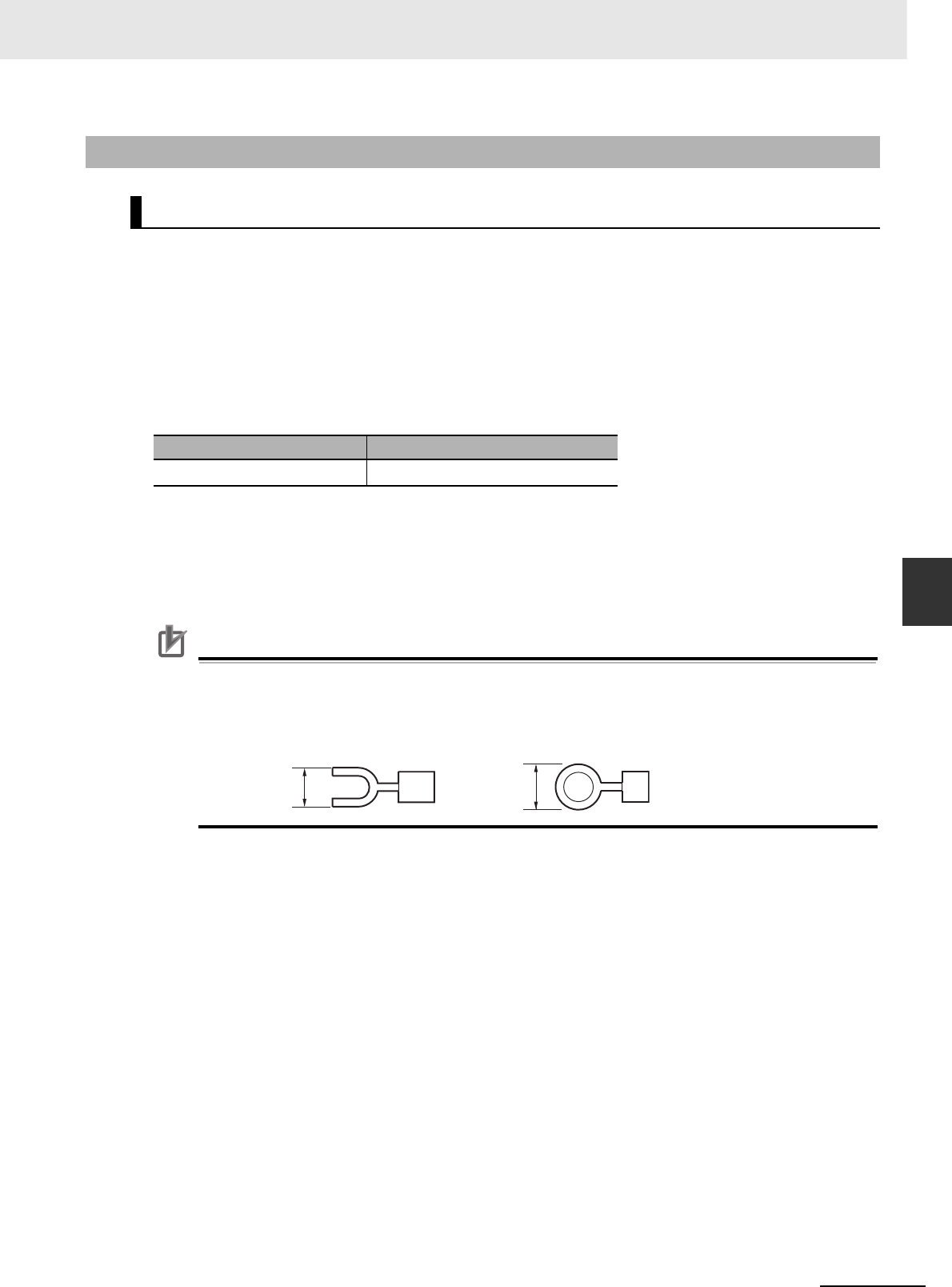
5-27
5 Installation
CJ2 CPU Unit Hardware User’s Manual
5-3 Wiring
5
5-3-2 Wiring CJ-series Basic I/O Units with
Terminal Blocks
zI/O Unit Specifications
Double-check the specifications for the I/O Units. In particular, do not apply a voltage that exceeds
the input voltage for Input Units or the maximum switching capacity for Output Units. Doing so may
result in breakdown, damage, or fire.
When the power supply has positive and negative terminals, be sure to wire them correctly.
zElectric Wires
• The following wire gauges are recommended.
• The current capacity of electric wire depends on factors such as the ambient temperature and
insulation thickness as well as the gauge of the conductor.
zCrimp Terminals
The terminals on the I/O Unit are M3, self-raising terminals with screws.
Precautions for Correct UsePrecautions for Correct Use
• Use crimp terminals for wiring.
• Do not connect bare stranded wires directly to terminals.
• Tighten the terminal block screws to the torque of 0.5 N·m.
• Use crimp terminals (M3) having the dimensions shown below.
5-3-2 Wiring CJ-series Basic I/O Units with Terminal Blocks
Precautions for Wiring I/O Units
Terminal Block Connector Wire Size
18-terminal AWG 22 to 18 (0.32 to 0.82 mm2)
6.2 mm max. 6.2 mm max.
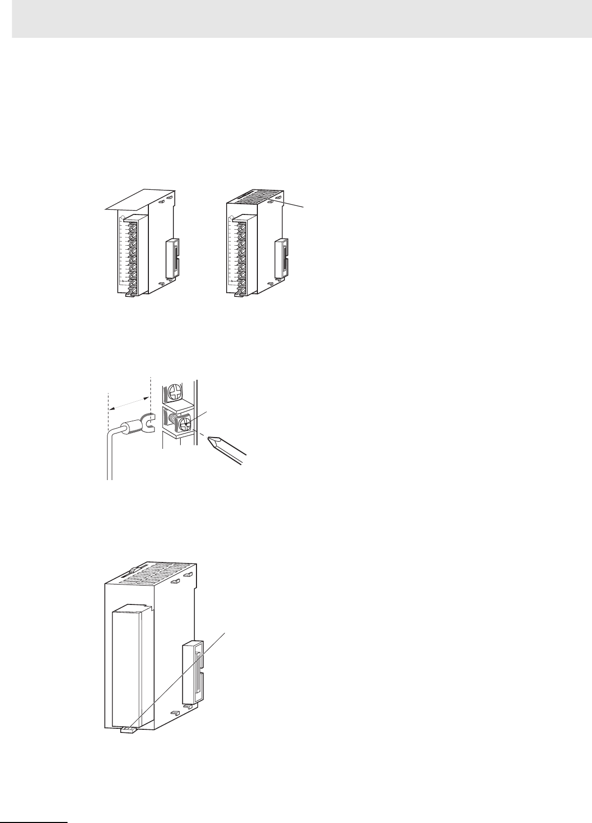
5 Installation
5-28 CJ2 CPU Unit Hardware User’s Manual
zWiring
• Make sure that all Units are connected properly.
• Do not remove the protective label from the top of the Unit until wiring has been completed.
• This label prevents wire strands and other foreign matter from entering the Unit during wiring pro-
cedures.
• Remove the label after wiring has been completed to allow air circulation needed for cooling.
• Wire the Units so that they can be easily replaced.
• Make sure that the I/O indicators are not covered by the wiring.
• Do not place the wiring for I/O Units in the same duct or raceway as power lines. Inductive noise
can cause errors in operation.
• Tighten the terminal screws to the torque of 0.5 N·m.
zTerminal Blocks
• The I/O Units are equipped with removable terminal blocks. The lead wires do not have to be
removed from the terminal block to remove it from an I/O Unit.
• After you complete wiring, check to see if the terminal block is securely locked.
OD211
01234567
8 9 10 11 12 13 14 15
OD211
01234567
89 10 11 12 13 14 15
After wiringDuring wiring
Remove the label.
17.5 mm
Screw (M3 screw with
self-raising pressure plate)
112D
O
01234567
8 9 10 11 12 13 14 15
Terminal block lever
CJ-series Basic I/O Unit

5-29
5 Installation
CJ2 CPU Unit Hardware User’s Manual
5-3 Wiring
5
5-3-3 Wiring Basic I/O Units with Connectors
This section describes wiring for CJ-series Basic I/O Units with connectors (32- and 64-point Units).
Depending on the connector, the following methods are used to connect these Units to external I/O
devices.
• Use an OMRON Connecting Cable (equipped with a special connector) to connect to a Terminal
Block or Relay Terminal.
• Use a special connector and user-provided cable.
Precautions for Safe Use
• Be sure not to apply a voltage that exceeds the input voltage for Input Units or the maximum
switching capacity for Output Units.
• When the power supply has positive and negative terminals, be sure to wire them correctly.
Loads connected to Output Units may malfunction if the polarity is reversed.
• Use reinforced insulation or double insulation on the DC power supply connected to DC I/O
Units when required by EC Directives (low voltage).
• When connecting the connector to the I/O Unit, tighten the connector screws to a torque of
0.2 N·m.
• Turn ON the power after checking the connector's wiring.
• Do not pull the cable. Doing so will damage the cable.
• Bending the cable too sharply can damage or break wiring in the cable.
Additional Information
CJ-series Basic I/O Units with 32 or 64 points and Fujitsu connectors have the same connector
pin allocations as the C200H High-density I/O Units and CS-series I/O Units with connectors to
make them compatible.
For details on using OMRON Connecting Cables equipped with special connectors to connect Basic I/O
Units with connectors to OMRON Connector-Terminal Block Conversion Units or I/O Relay Terminals,
refer to A-1-4 Connecting Connector-Terminal Block Conversion Units and I/O Relay Terminals.
5-3-3 Wiring Basic I/O Units with Connectors
Connecting to a Connector-Terminal Block Conversion Unit or I/O
Relay Terminal
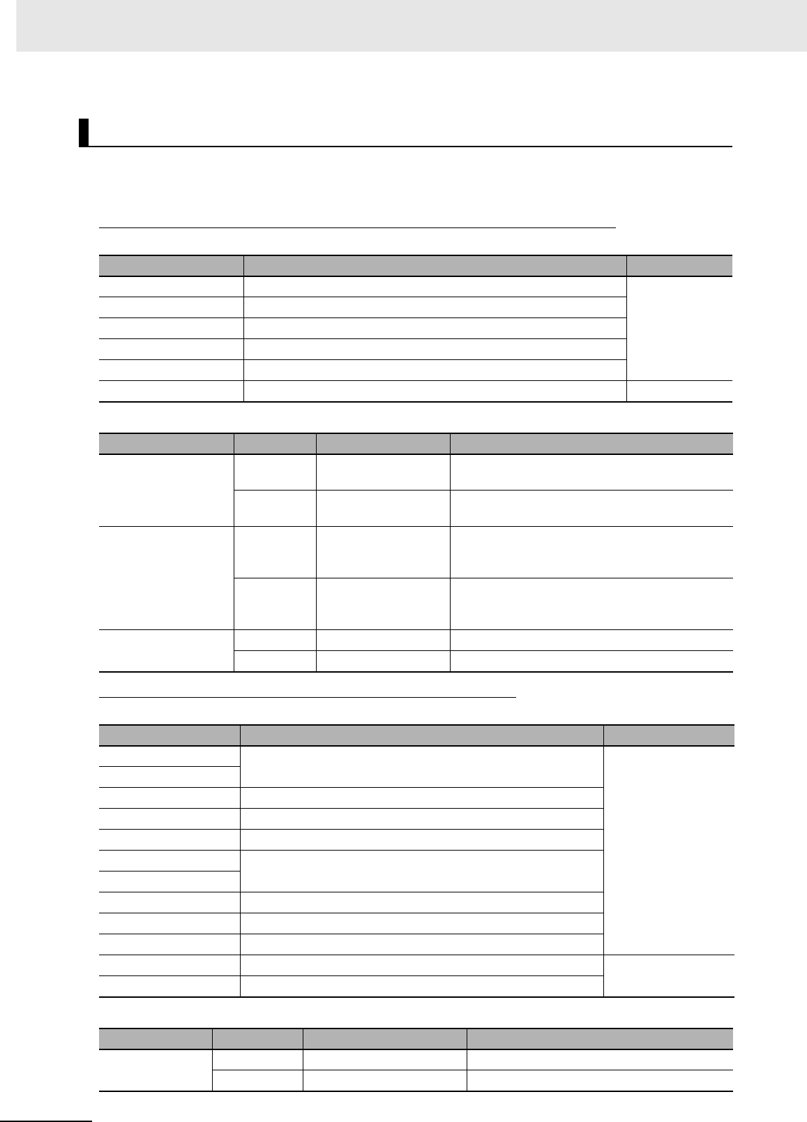
5 Installation
5-30 CJ2 CPU Unit Hardware User’s Manual
zAvailable Connectors
Use the following connectors when assembling a connector and cable.
CJ-series 32- and 64-point Basic I/O Units with Fujitsu-compatible Connectors
CJ-series 32- and 64-point Basic I/O Units with MIL Connectors
Using User-made Cables with Connector
Applicable Units
Model Specifications Pins
CJ1W-ID231 Input Unit, 24 VDC, 32 inputs 40
CJ1W-ID261 Input Unit, 24 VDC, 64 inputs
CJ1W-OD231 Transistor Output Unit with Sinking Outputs, 32 outputs
CJ1W-OD261 Transistor Output Unit with Sinking Outputs, 64 outputs
CJ1W-MD261 24-VDC Input/Transistor Output Units, 32 Inputs, 32 Outputs
CJ1W-MD231 24-VDC Input/Transistor Output Units, 16 Inputs, 16 Outputs 24
Applicable Cable-side Connectors
Connection Pins OMRON set Fujitsu parts
Solder-type 40 C500-CE404 Socket: FCN-361J040-AU
Connector cover: FCN-360C040-J2
24 C500-CE241 Socket: FCN-361J024-AU
Connector cover: FCN-360C024-J2
Crimped 40 C500-CE405 Socket: FCN-363J040
Connector cover: FCN-360C040-J2
Contacts: FCN-363J-AU
24 C500-CE242 Socket: FCN-363J024
Connector cover: FCN-360C024-J2
Contacts: FCN-363J-AU
Pressure-welded 40 C500-CE403 FCN-367J040-AU/F
24 C500-CE243 FCN-367J024-AU/F
Applicable Units
Model Specifications Pins
CJ1W-ID232 Input Unit, 24 VDC, 32 inputs 40
CJ1W-ID233
CJ1W-ID262 Input Unit, 24 VDC, 64 inputs
CJ1W-OD232 Transistor Output Unit with sourcing outputs, 32 outputs
CJ1W-OD262 Transistor Output Unit with sourcing outputs, 64 outputs
CJ1W-OD233 Transistor Output Unit with sinking outputs, 32 outputs
CJ1W-OD234
CJ1W-OD263 Transistor Output Unit with sinking outputs, 64 outputs
CJ1W-MD263 24-VDC Input/Transistor Output Units, 32 inputs, 32 outputs
CJ1W-MD563 TTL Input/TTL Output Units, 32 inputs, 32 outputs
CJ1W-MD232 24-VDC Input/Transistor Output Units, 16 inputs, 16 outputs 20
CJ1W-MD233 24-VDC Input/Transistor Output Units, 16 inputs, 16 outputs
Applicable Cable-side Connectors
Connection Pins OMRON set DDK parts
Pressure-welded 40 XG4M-4030-T FRC5-A040-3TOS
20 XG4M-2030-T FRC5-A020-3TOS
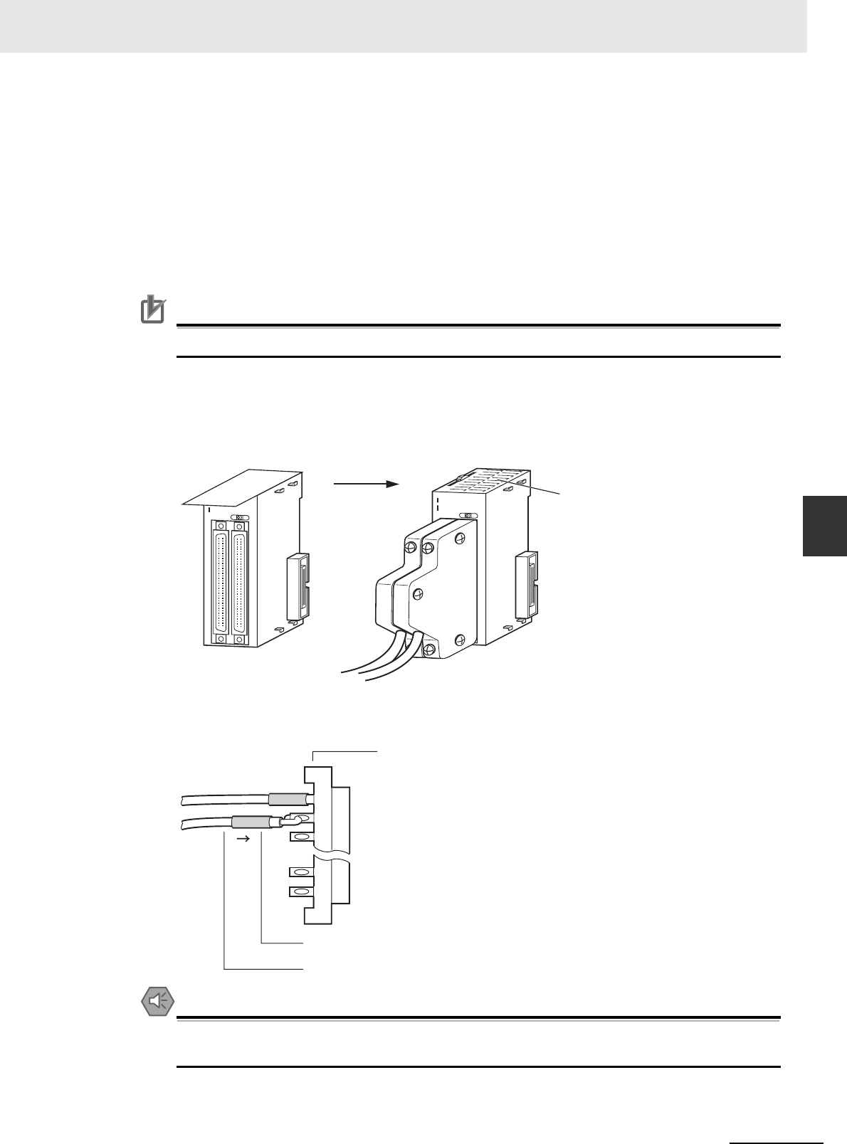
5-31
5 Installation
CJ2 CPU Unit Hardware User’s Manual
5-3 Wiring
5
5-3-3 Wiring Basic I/O Units with Connectors
zWire Size
We recommend using cable with wire gauges of AWG 24 or AWG 28 (0.2 mm2 to 0.08 mm2). Use
cable with external wire diameters of 1.61 mm max.
zWiring Procedure
The following wiring procedure is an example for Fujitsu-compatible connectors.
1Check that each Unit is installed securely.
Precautions for Correct UsePrecautions for Correct Use
Do not force the cables.
2Do not remove the protective label from the top of the Unit until wiring has been completed. This
label prevents wire strands and other foreign matter from entering the Unit during wiring.
(Remove the label after wiring has been completed to allow air circulation needed for cooling.)
3When solder-type connectors are being used, be sure not to accidentally short adjacent termi-
nals. Cover the solder joint with heat-shrink tubing.
Precautions for Safe Use
Double-check to make sure that the Output Unit's power supply leads have not been reversed. If
the leads are reversed, the Unit's internal fuse will blow and the Unit will not operate.
0 1 2 3 4 5 6 7
8 9 12131415
1011
0 1 2 3 4 5 6 7
8 9 12 131
415
10 11
I
II
ID261
0 1 2 3 4 5 6 7
8 9 12131415
10 11
0 1 2 3 4 5 6 7
8 9 12 13 1415
10 11
I
II
ID261
Before wiring After wiring
Remove label
after wiring
Solder-type connector
Heat-shrink tubing
Wire (0.2 to 0.13 mm2)
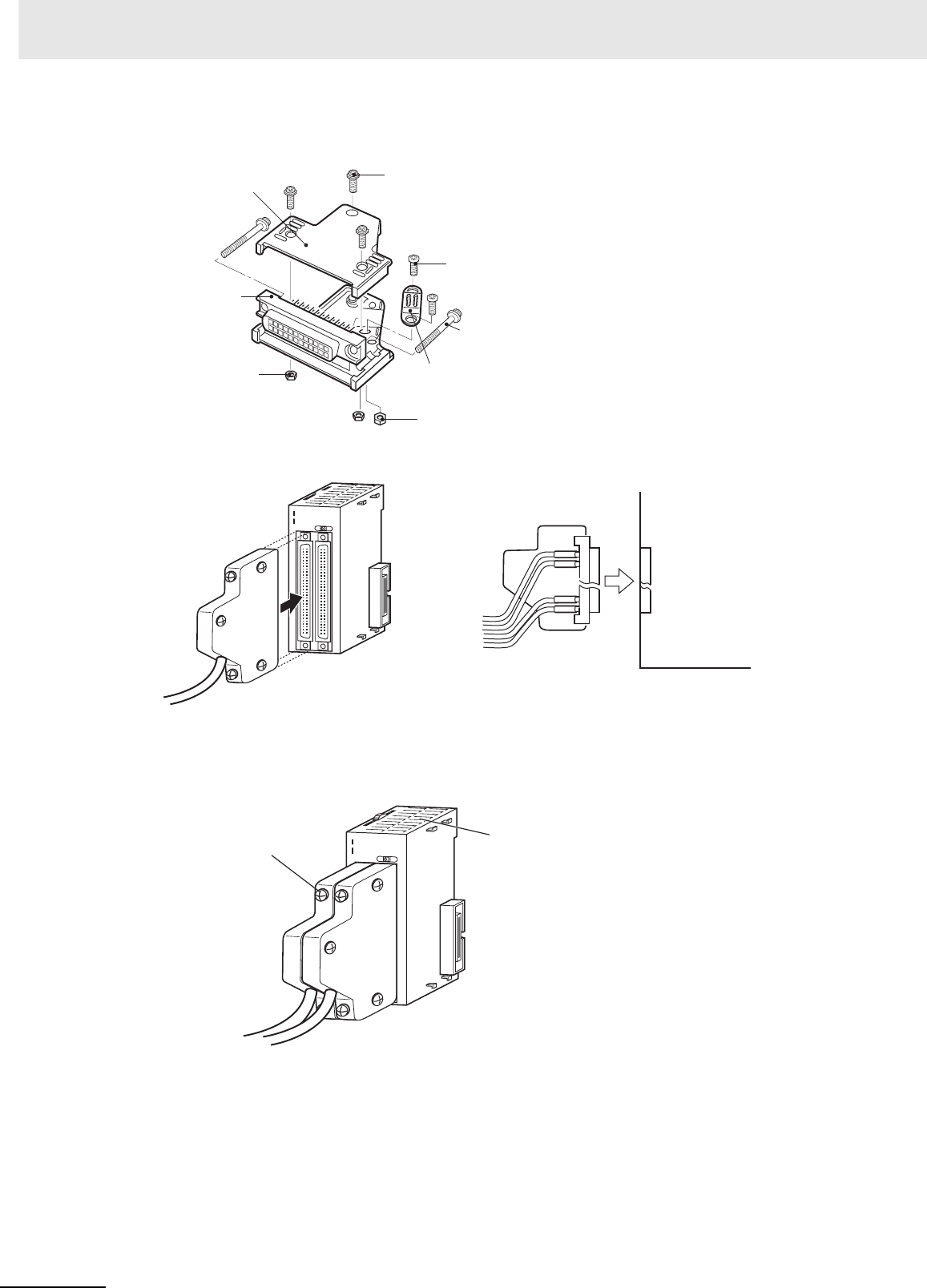
5 Installation
5-32 CJ2 CPU Unit Hardware User’s Manual
4Assemble the connector (purchased separately).
5Insert the wired connector.
6Remove the protective label after wiring has been completed to allow air circulation needed for
cooling.
Tighten the connector lock screws to a torque of 0.2 N·m.
Connector cover Small screws (3)
Socket
Nuts (3)
Small screws (2)
Connector lock
screws
Cable bracket
Nuts (2)
0 1 2 3 4 5 6 7
8 9 12 13 14 15
10 11
0 1 2 3 4 5 6 7
8 9 12 13 14 15
10 11
I
II
ID261
Connector
Connector Basic I/O Unit
Basic I/O Unit
0 1 2 3 4 5 6 7
8 9 12 13 14 15
10 11
0 1 2 3 4 5 6 7
8 9 1213 14 15
10 11
I
II
ID261
After wiring
Remove label after wiring.
Connector lock screws
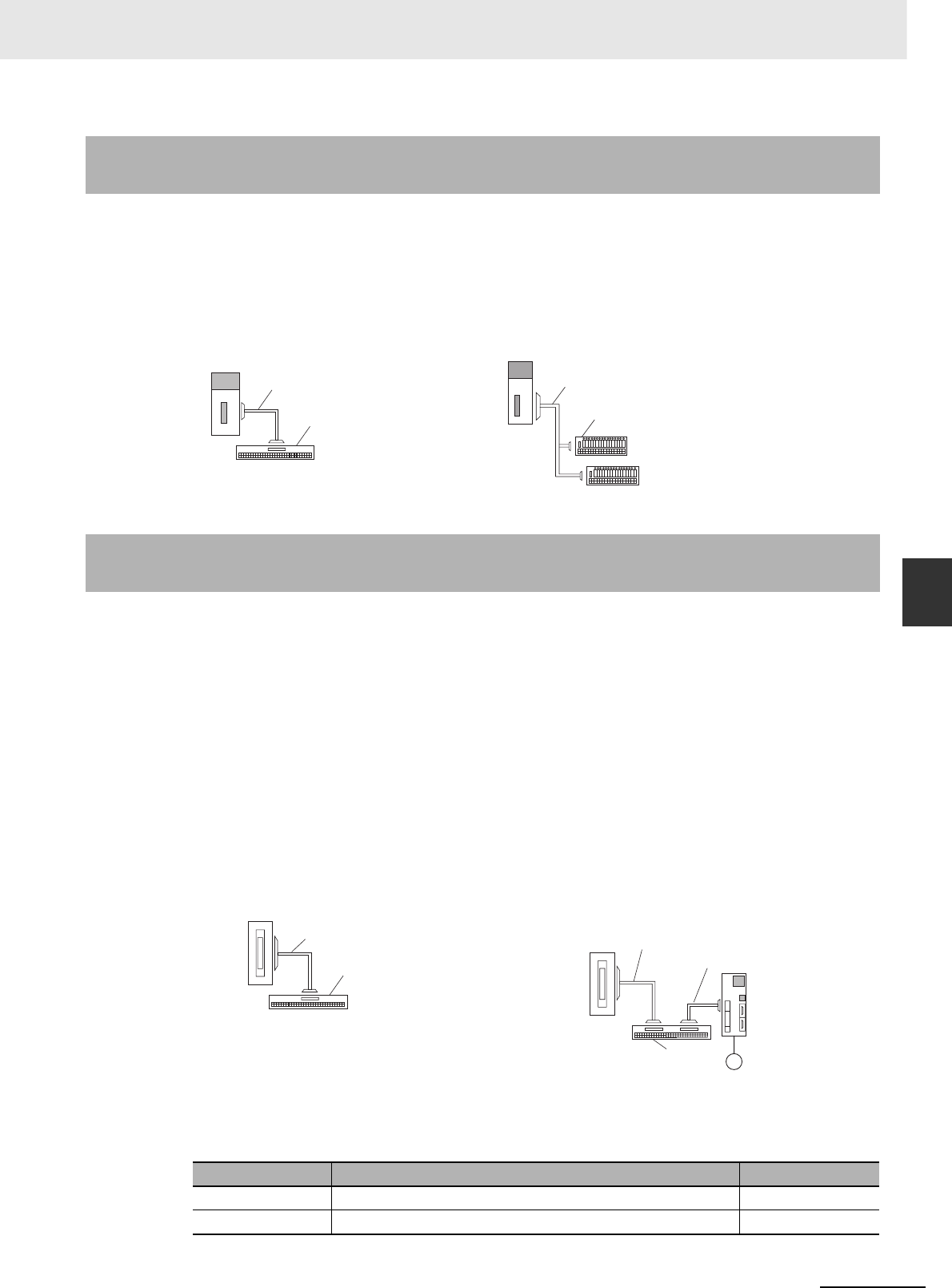
5-33
5 Installation
CJ2 CPU Unit Hardware User’s Manual
5-3 Wiring
5
5-3-4 Connecting to Connector-Terminal Block
Conversion Units or I/O Relay Terminals
OMRON Connecting Cable can be used to connect Basic I/O Units with Connectors to OMRON Con-
nector-Terminal Block Conversion Units or to OMRON I/O Relay Terminals. For details, refer to A-1-4
Connecting Connector-Terminal Block Conversion Units and I/O Relay Terminals.
zConnection Examples
Depending on the connector, the following methods are used to connect these Pulse I/O Modules to
external I/O devices.
• Use an OMRON Cable with Connectors to connect to a Connector-Terminal Block Conversion
Unit or Servo Relay Unit.
• Make a cable with an MIL Connector (including using Servo General-purpose Control Cables).
zUsing OMRON Cables with Connectors to Connect to Connector-Terminal
Block Conversion Units or Servo Relay Units
For details on using OMRON Cables with Connectors to connect Pulse I/O Modules to OMRON
Connector-Terminal Block Conversion Units or Servo Relay Units, refer to the CJ2M CPU Unit Pulse
I/O Module User's Manual (Cat. No. W486).
zUser-made Cables with Connectors
Applicable Pulse I/O Modules
5-3-4 Connecting to Connector-Terminal Block Conversion Units or I/O
Relay Terminals
Connector-Terminal Block Conversion Unit I/O Relay Terminals
5-3-5 Connecting Pulse I/O Modules to External I/O Devices (CJ2M CPU
Unit Only)
Connection Example for Connector-Terminal
Block Conversion Unit
Connection Example for Servo Relay Unit
Model Specifications Pins
CJ2M-MD211 Sinking outputs, MIL connector, 10 inputs, 6 outputs 40
CJ2M-MD212 Sourcing outputs, MIL connector, 10 inputs, 6 outputs 40
Connector-Terminal Block
Conversion Unit
40 or 60 terminals
Basic I/O Unit
Connecting Cable
I/O Relay Terminal
Connecting Cable
Basic I/O Unit
Connector-Terminal Block
Conversion Unit
Connecting Cable
Pulse I/O Module
Servo Relay Unit
Pulse I/O Module to Servo Relay Unit
Connecting Cable
Pulse I/O Module
Servo Drive
Servo Relay Unit to Servo Drive
Connecting Cable

5 Installation
5-34 CJ2 CPU Unit Hardware User’s Manual
Applicable Cable-side Connectors
Connection method Pins OMRON set DDK Ltd.
Pressure-welded 40 XG4M-4030-T FRC5-A040-3TOS
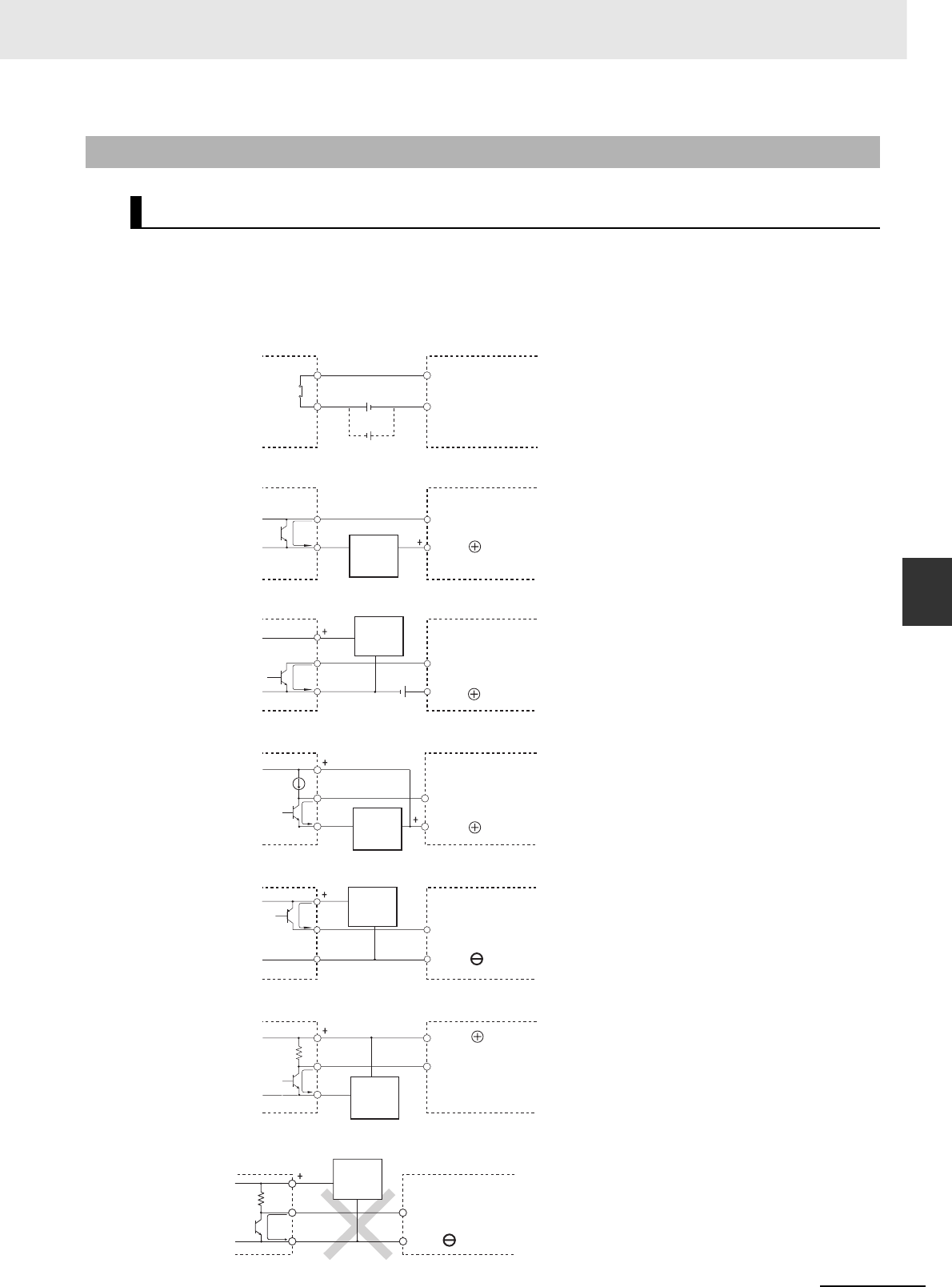
5-35
5 Installation
CJ2 CPU Unit Hardware User’s Manual
5-3 Wiring
5
5-3-6 Connecting I/O Devices
Use the following information for reference when selecting or connecting input devices.
zDC Input Units
The following types of DC input devices can be connected.
• The circuit below should NOT be used for I/O devices having a voltage output.
5-3-6 Connecting I/O Devices
Input Devices
COM
Output
Contact output
Two-wire DC output
NPN open-collector output
DC Input Unit
Sensor
Power
Supply
IN
Sensor
Power
Supply
COM
DC Input Unit
IN
COM
DC Input Unit
IN
COM
DC Input Unit
IN
0 V
7 mA
COM
NPN current output
PNP current output
Voltage output
Current
regulator
IN DC Input Unit
Sensor
Power
Supply
Sensor
Power
Supply
DC Input Unit
COM
IN
Sensor
Power
Supply
0 V
7 mA
Output
0 V
7 mA
Output
0 V
Output
0 V COM
Voltage output Sensor
Power
Supply
IN
Output
DC Input Unit
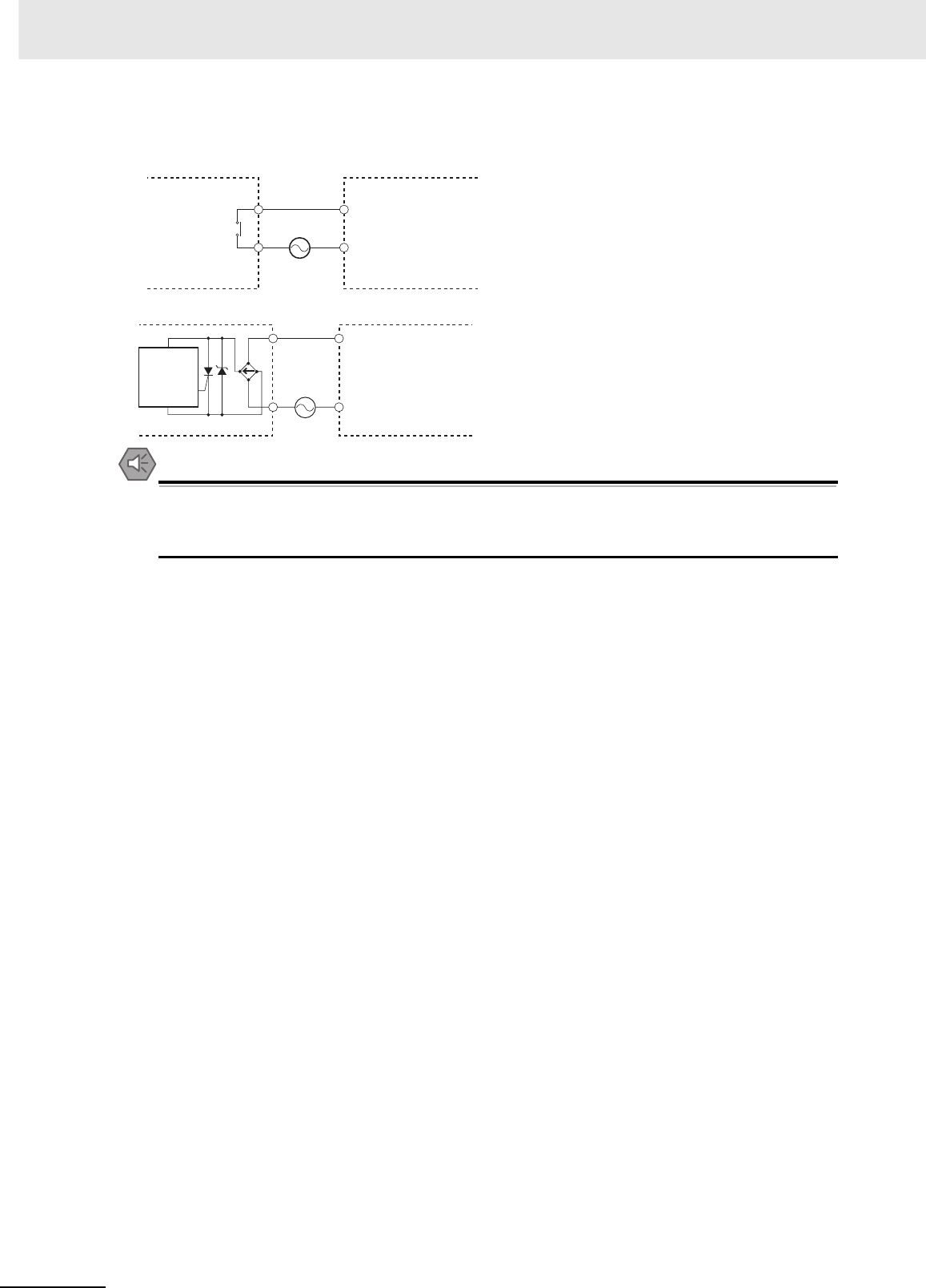
5 Installation
5-36 CJ2 CPU Unit Hardware User’s Manual
zAC Input Units
Precautions for Safe Use
When using a reed switch as the input contact for an AC Input Unit, use a switch with an allow-
able current of 1 A or greater. If reed switches with smaller allowable currents are used, the con-
tacts may fuse due to surge currents.
zPrecautions when Connecting a Two-wire DC Sensor
When using a two-wire sensor with a 12-VDC or 24-VDC input device, check that the following con-
ditions have been met. Failure to meet these conditions may result in operating errors.
• Relation between voltage when the PLC is ON and the sensor residual voltage:
VON ≤ VCC − VR
• Relation between voltage when the PLC is ON and sensor control output (load current):
IOUT (min) ≤ ION ≤ IOUT (max.)
ION = (VCC − VR − 1.5 [PLC internal residual voltage])/RIN
When ION is smaller than IOUT (min), connect a bleeder resistor R. The bleeder resistor constant
can be calculated as follows:
R ≤ (VCC − VR)/(IOUT (min.) − ION)
Power W ≥ (VCC − VR)2/R × 4 [allowable margin]
VCC: Power voltage
VR: Sensor output residual current
ION: PLC ON current
IOUT: Sensor control current (load current)
RIN: PLC input impedance
COM
IN
AC Input Unit
Contact output
AC Switching
Proximity
switch
main
circuit
COM
IN
AC Input Unit

5-37
5 Installation
CJ2 CPU Unit Hardware User’s Manual
5-3 Wiring
5
5-3-6 Wiring with Ethernet Cable (CJ2H-
CPU6@-EIP only)
• Relation between current when the PLC is OFF and sensor leakage current:
IOFF ≥ Ileak
Connect a bleeder resistor if Ileak is greater than IOFF. Use the following equation to calculate the
bleeder resistance constant.
R ≤ (RIN × VOFF)/(Ileak × RIN − VOFF)
Power W ≥ (VCC − VR)2/R × 4 [allowable margin]
• Precautions on Sensor Surge Current
An incorrect input may occur if a sensor is turned ON after the PLC has started up to the point
where inputs are possible. Determine the time required for sensor operation to stabilize after the
sensor is turned ON and take appropriate measures, such as inserting into the program a timer
delay after turning ON the sensor.
zExample
In this example, the sensor's power supply voltage is used as the input to CIO 000000 and a 100-ms
timer delay (the time required for an OMRON Proximity Sensor to stabilize) is created in the pro-
gram. After the Completion Flag for the timer turns ON, the sensor input on CIO 000001 will cause
output bit CIO 000100 to turn ON.
VRR
VCC
RIN
VCC:
VON:
VOFF:
ION:
IOFF:
RIN:
VR:
IOUT:
Ileak:
R:
Sensor output residual current
Sensor control current (load current)
Sensor leakage current
Bleeder resistance
Power voltage
PLC ON voltage
PLC OFF voltage
PLC ON current
PLC OFF current
PLC input impedance
Two-wire sensor
DC Input Unit
TIM
0000
#0001
000000
TIM0000 000001
000100
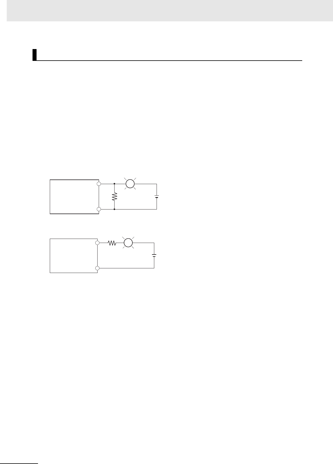
5 Installation
5-38 CJ2 CPU Unit Hardware User’s Manual
zOutput Short-circuit Protection
If a load connected to the output terminals is short-circuited, output components and the printed cir-
cuit boards may be damaged. To guard against this, incorporate a fuse in the external circuit. Use a
fuse with a capacity of about twice the rated output.
zTransistor Output Residual Voltage
A TTL circuit cannot be connected directly to a transistor output because of the transistor's residual
voltage. It is necessary to connect a pull-up resistor and a CMOS IC between the two.
zOutput Surge Current
When connecting a transistor or triac output to an output device having a high surge current (such
as an incandescent lamp), steps must be taken to avoid damage to the transistor or triac. Use either
of the following methods to reduce the surge current.
Output Wiring Precautions
OUT
R
COM
L
+
OUT R
COM
L
+
Method 1
CS/CJ-series
PLC
CS/CJ-series
PLC
Add a resistor that draws about 1/3 of the current consumed by the bulb.
Method 2
Add a control resistor as shown in the following diagram.
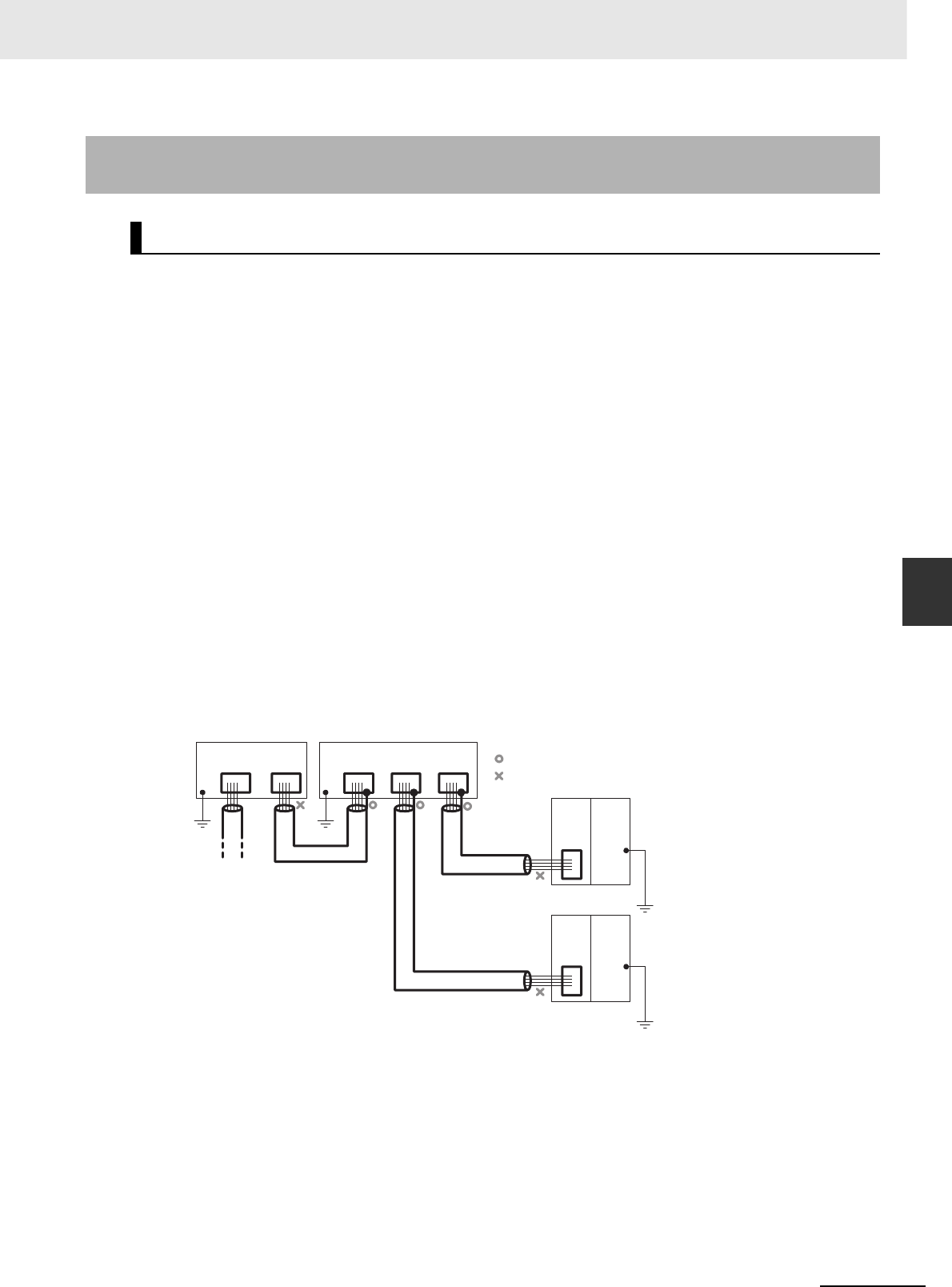
5-39
5 Installation
CJ2 CPU Unit Hardware User’s Manual
5-3 Wiring
5
5-3-7 Connecting through an Ethernet Cable
(CJ2H-CPU6@-EIP and CJ2M-CPU3@ Only)
Observe the following precautions when using the built-in EtherNet/IP port on the CJ2H-CPU6@-EIP or
CJ2M-CPU3@.
zBasic Installation Precautions
• Take the greatest care when installing the Ethernet System, being sure to follow ISO 8802-3 spec-
ifications. You must obtain a copy of these specifications and be sure you understand them before
attempting to install an Ethernet System.
• Unless you are already experienced in installing communications systems, we strongly recom-
mend that you employ a professional to install your system.
• Do not install Ethernet equipment near sources of noise. If a noisy environment is unavoidable,
take adequate measures against noise interference, such as installing network components in
grounded metal cases or using optical cable in the system.
• When installing an EtherNet/IP network that combines an information system with the control sys-
tem, and the communications load may be heavy due to tag data links, we recommend configur-
ing the network so that the load does not affect communications. For example, install the tag data
links in a segment that is separate from the information network.
zPrecautions on Laying Twisted-pair Cable
• Noise resistance may be reduced by ground loops, which can occur due to improper shield con-
nections and grounding. Ground the shield at one location, as shown in the following diagram.
• Do not connect the connector shield at the CPU Unit.
• If a cable connects two Ethernet switches, connect the shields at only one end.
• Press the cable connector in firmly until it locks into place at both the Ethernet switch and the CPU
Unit.
• Do not lay the twisted-pair cable together with high-voltage lines.
• Do not lay the twisted-pair cable near devices that generate noise.
• Do not lay the twisted-pair cable in locations subject to high temperatures or high humidity.
• Do not lay the twisted-pair cable in locations subject to excessive dirt and dust or to oil mist or
other contaminants.
5-3-7 Connecting through an Ethernet Cable (CJ2H-CPU6@-EIP and
CJ2M-CPU3@ Only)
Precautions
Ethernet switch Ethernet switch
Connector Connector Connector
Connector
Connector Connector
GR GR
Connect shield.
Do not connect shield.
STP
(Shield)
STP
(Shield)
STP
(Shield)
EIP
Unit
Power
Supply
Unit
GR
terminal
Connector
EIP
Unit
Power
Supply
Unit
GR
terminal
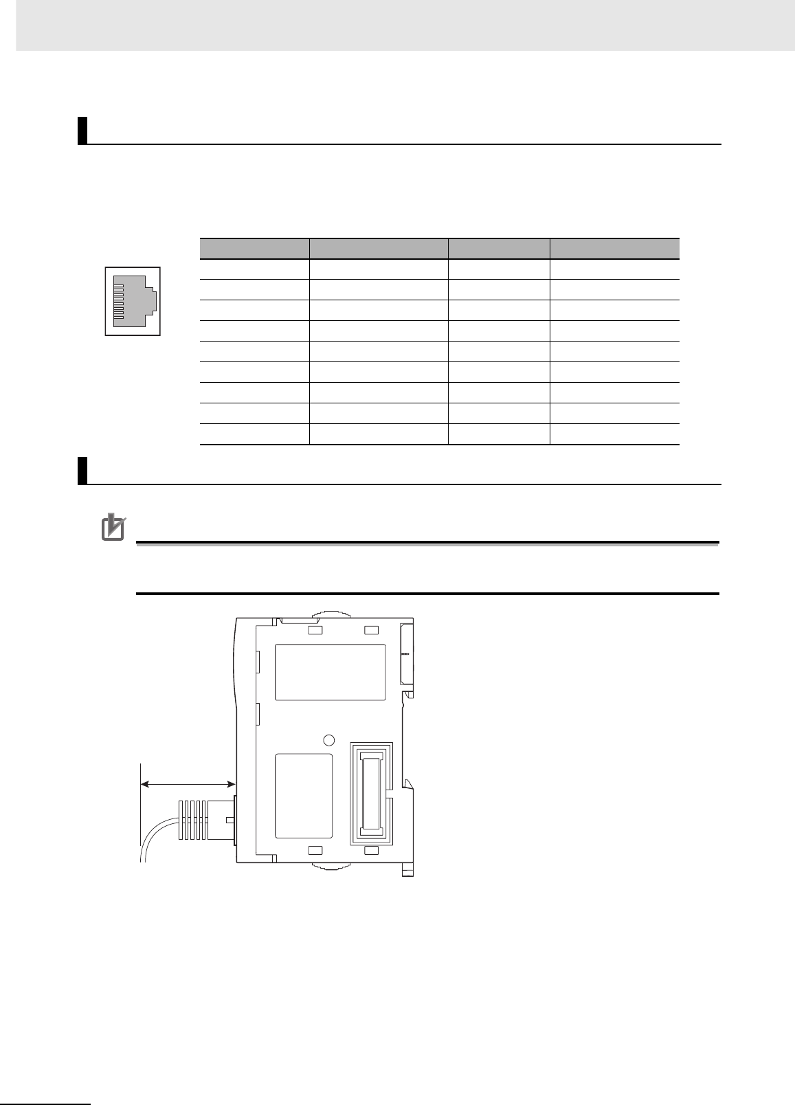
5 Installation
5-40 CJ2 CPU Unit Hardware User’s Manual
The following standards and specifications apply to the connectors for the Ethernet twisted-pair cable.
• Electrical specifications: Conform to IEEE802.3 standards.
• Connector structure: RJ45 8-pin Modular Connector (Conforms to ISO 8877)
Precautions for Correct UsePrecautions for Correct Use
• Turn OFF the PLC's power supply before connecting or disconnecting twisted-pair cable.
• Allow enough space for the bending radius of the twisted-pair cable as shown in below.
1Lay the twisted-pair cable.
2Connect the cable to the Ethernet switch. Be sure to press in the cable until it locks into place.
Ethernet Connectors
Connector pin Signal name Abbr. Signal direction
1 Transmission data + TD+ Output
2 Transmission data −TD−Output
3 Reception data + RD+ Input
4 Not used. --- ---
5 Not used. --- ---
6 Reception data −RD−Input
7 Not used. --- ---
8 Not used. --- ---
Hood Frame ground FG ---
Connecting the Cable
35 mm
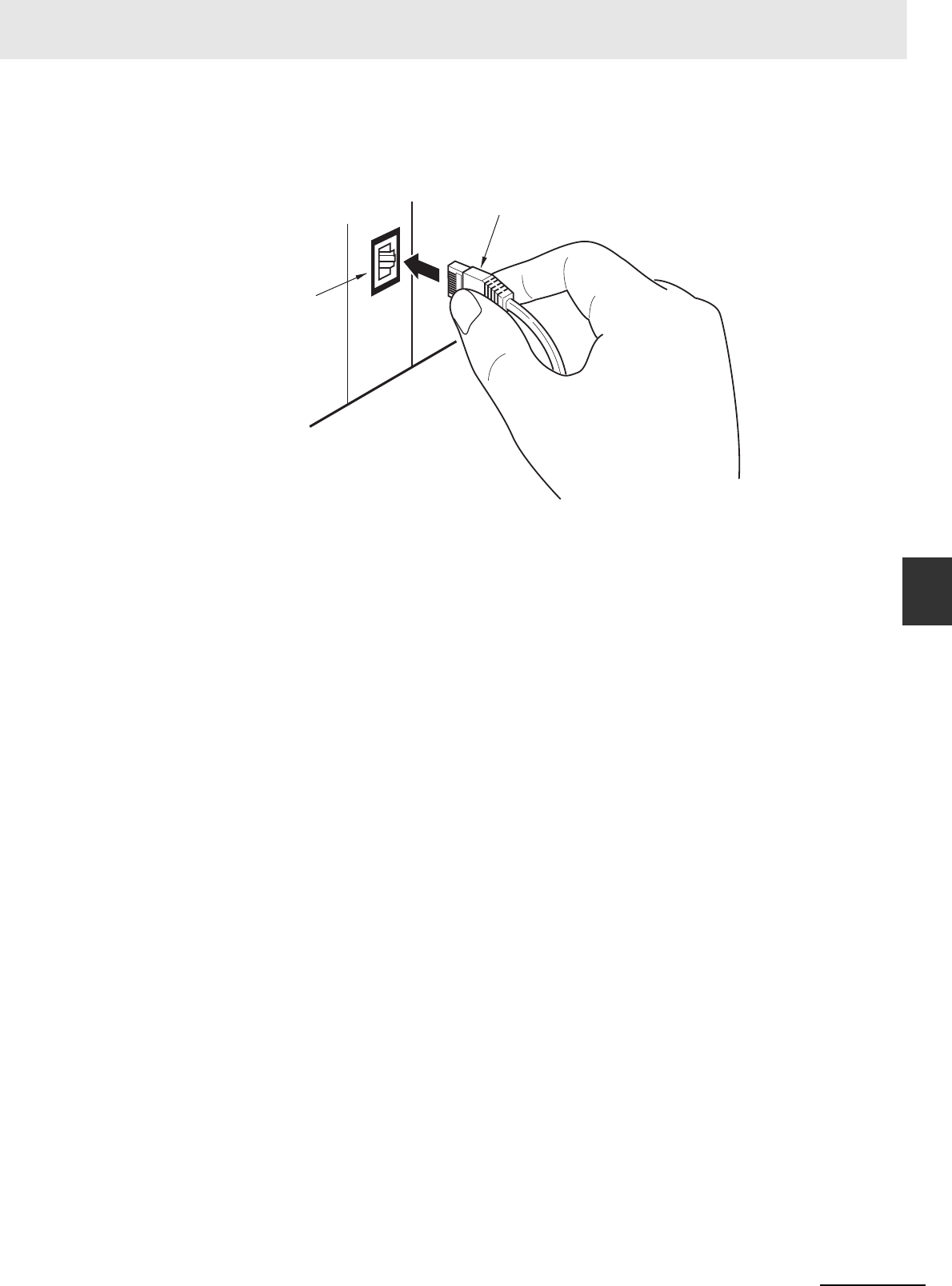
5-41
5 Installation
CJ2 CPU Unit Hardware User’s Manual
5-3 Wiring
5
5-3-7 Connecting through an Ethernet Cable
(CJ2H-CPU6@-EIP and CJ2M-CPU3@ Only)
3Connect the twisted-pair cable to the connector on the built-in EtherNet/IP port at the CPU Unit.
Be sure to press the connectors at both the Ethernet switch end and Ethernet end until they lock
into place.
Built-in EtherNet/IP port
RJ45 Modular Connector
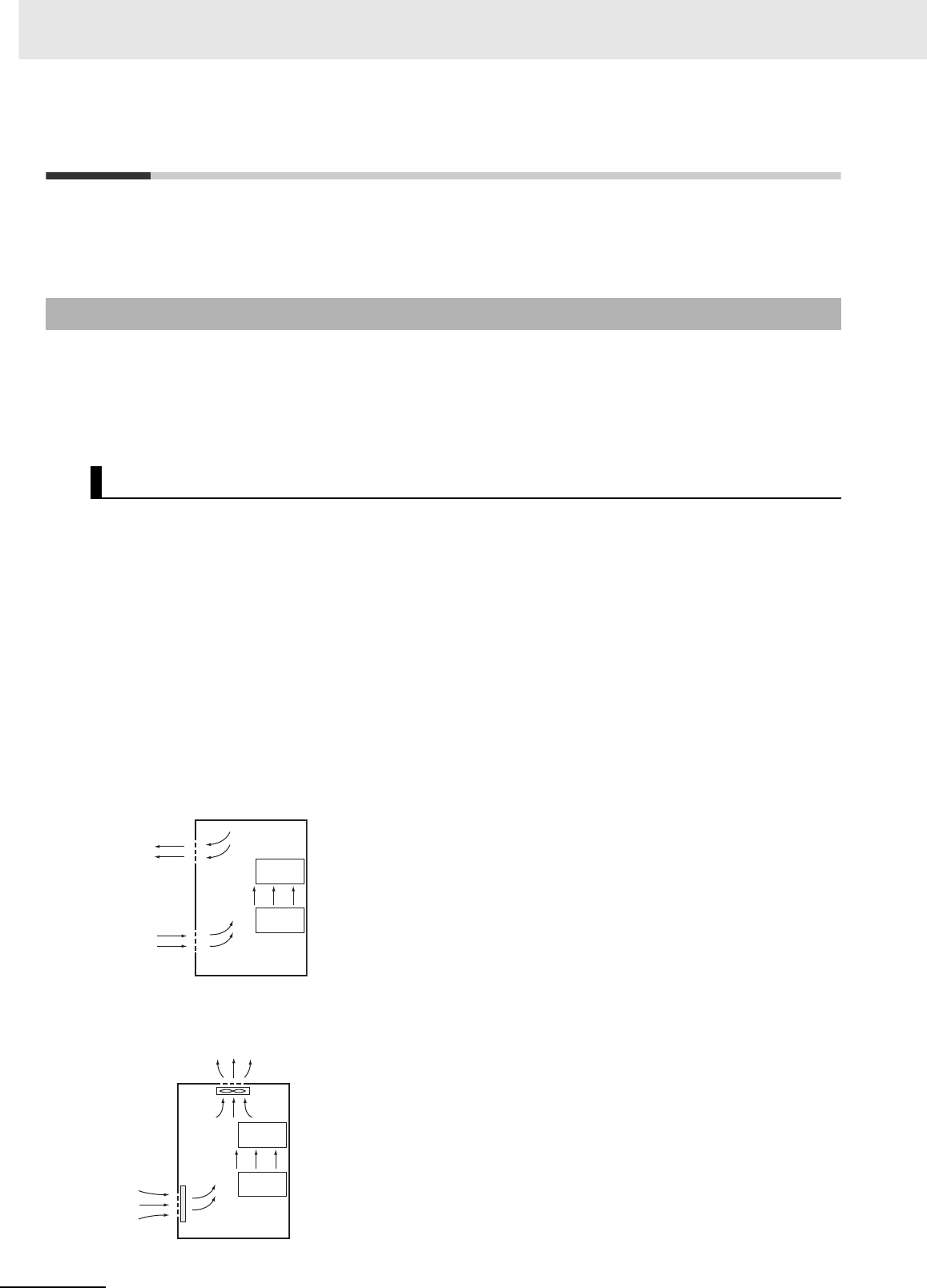
5 Installation
5-42 CJ2 CPU Unit Hardware User’s Manual
5-4 Control Panel Installation
To ensure system reliability and safety, the system must be designed and configured according to the
installation environment (temperature, humidity, vibration, shock, corrosive gases, overcurrent, noise,
etc.).
Panels have been reduced in size due to space-saving and miniaturization in devices and systems, and
the temperature inside the panel may be at least 10 to 15°C higher than outside the panel. Implement
the following measures against overheating at the installation site and in the panel, and allow a suffi-
cient margin for the temperature.
Use the following cooling methods as required, taking into account the ambient temperature and the
amount of heating inside the panel.
zNatural Cooling
Natural cooling relies on natural ventilation through slits in the panel, rather than using cooling
devices such as fans or coolers. When using this method, observe the following points.
• Do not install the PLC at the top of the panel, where hot air tends to stagnate.
• To provide ventilation space above and below the PLC, leave sufficient distance from other
devices, wiring ducts, etc.
• Do not mount the Units in the wrong direction (e.g., vertically or upside down). Doing so may
cause abnormal heating in the PLC.
• Do not install heat-generating equipment, such as heaters, transformers, and devices with high
resistance, directly above the panel.
• Do not install the PLC in a location exposed to direct sunlight.
zForced Ventilation (by Fan at Top of Panel)
5-4-1 Temperature
High Temperatures
PLC
PLC
Natural Cooling
PLC
PLC
Air filter
Fan
Forced Ventilation Method
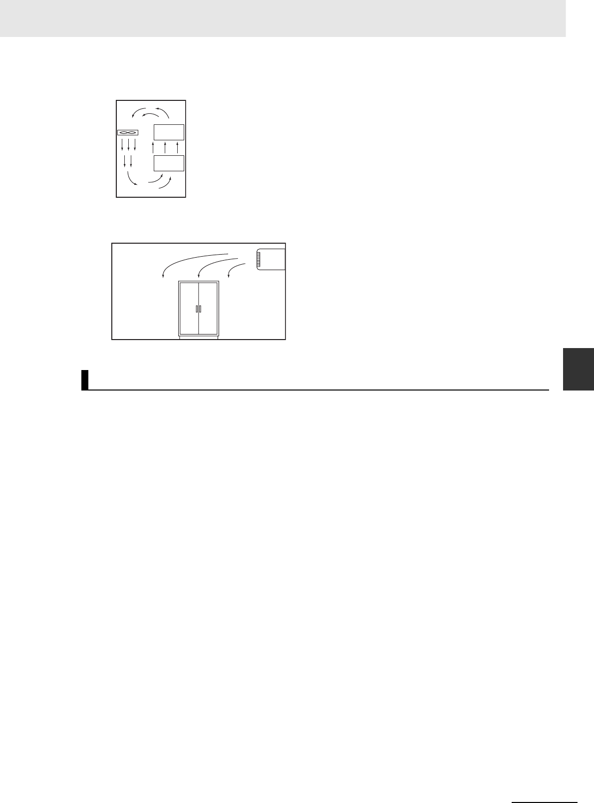
5-43
5 Installation
CJ2 CPU Unit Hardware User’s Manual
5-4 Control Panel Installation
5
5-4-1 Temperature
zForced Air Circulation (by Fan in Closed Panel)
zRoom Cooling (Cooling the Entire Room Where the Control Panel Is Located)
The PLC will not start normally if the temperature is below 0°C when the power is turned ON. Maintain
an air temperature of at least approximately 5°C inside the panel, by implementing measures such as
installing a low-capacity space heater in the panel. Alternatively, leave the PLC power ON to keep the
PLC warm.
Low Temperatures
Fan
PLC
PLC
Forced Air Circulation
Room Cooling
Cooler
Control panel

5 Installation
5-44 CJ2 CPU Unit Hardware User’s Manual
Rapid temperature changes can cause condensation to occur, resulting in malfunctioning due to short-
circuiting. When there is a possibility of this occurring, take measures against condensation, such as
leaving the PLC power ON at night or installing a heater in the control panel to keep it warmer.
The PLC is tested for conformity with the sine wave vibration test method (IEC 60068-2-6) and the
shock test method (IEC 60068-2-27) of the Environmental Testing for Electrotechnical Products. It is
designed so that malfunctioning will not occur within the specifications for vibration and shock. If, how-
ever, the PLC is to be used in a location in which it will be directly subjected to regular vibration or
shock, then implement the following countermeasures:
• Either separate the control panel from the source of the vibration or shock, or secure the PLC and the
panel with rubber padding to prevent vibration.
• Make the building or the floor vibration-resistant.
• To prevent shock during operation to devices in the panel, such as electromagnetic contactors,
secure either the source of the shock or the PLC with rubber padding.
Using the PLC in any of the following locations can cause defective contact with connectors and corro-
sion of components. Implement countermeasures such as purging the air as required.
• In locations exposed to dust, dirt, salt, metal filings, soot, or organic solvents, use a panel with an air-
tight structure. Be careful of temperature increases inside the panel.
• In locations exposed to corrosive gas, purge the air inside the panel to clear the gas and then pres-
surize the inside of the panel to prevent gas from entering from outside.
• In locations where flammable gas is present, either use an explosion-protected construction or do not
use the PLC.
5-4-2 Humidity
5-4-3 Vibration and Shock
5-4-4 Atmosphere
Moisture absorber
Power ON
Control panel
PLC
Heater
Examples of Measures against Condensation
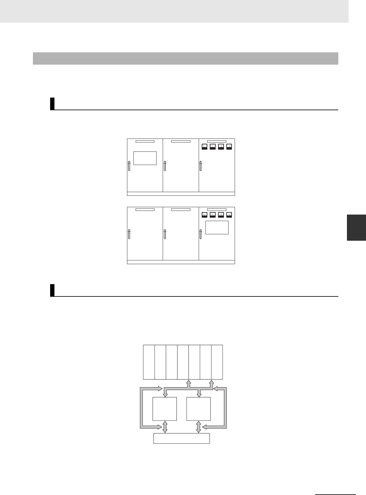
5-45
5 Installation
CJ2 CPU Unit Hardware User’s Manual
5-4 Control Panel Installation
5
5-4-5 Electrical Environment
When installing or wiring devices, make sure that there will be no danger to people and that noise will
not interfere with electrical signals.
Install the PLC as far away as possible from high-voltage (600 V or higher) and power devices to ensure
safe operation and maintenance.
Observe the following points.
• Place a Unit that does not generate much noise next to the CPU Unit, such as an Input Unit or Com-
munications Unit.
• The coils and contacts in electromagnetic contactors and relays in an external circuit are sources of
noise. Locate them at least 100 mm away from the PLC.
5-4-5 Electrical Environment
PLC Installation Location
Arrangement of PLC and Units
Example of Recommended Equipment Arrangement
PLC
Control panel Control panel High-voltage
power panel
Examples of Equipment Arrangement in Panel with High-voltage Devices
Example of Poor Equipment Arrangement
PLC
Control panel Control panel High-voltage
power panel
OK
NG
Power Supply Unit
Communications Unit
CPU
DC Unit
DC Unit
AC Unit
AC Unit
DC I/O
device AC I/O
device
Terminal block
Example of Arrangement in Panel
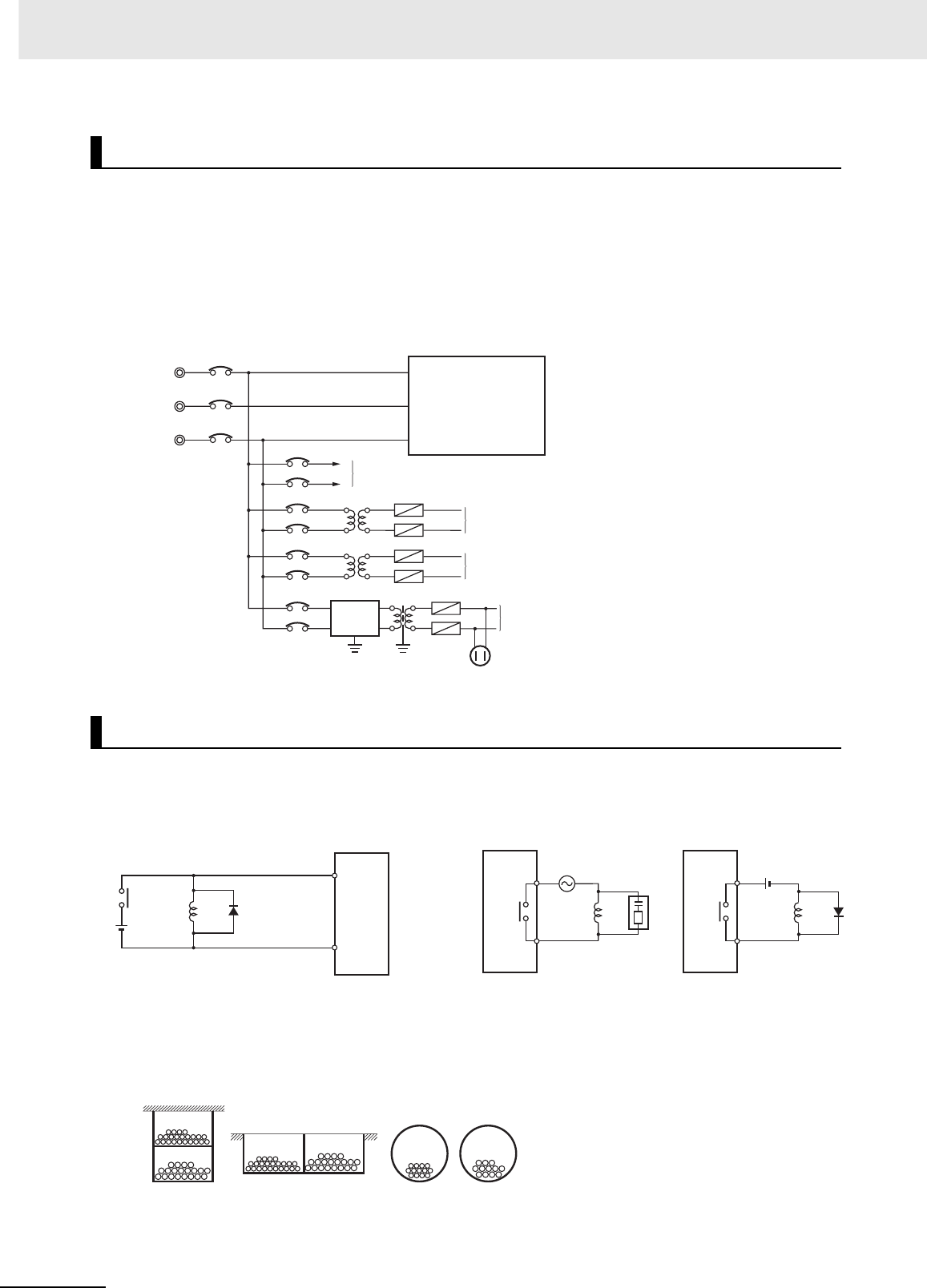
5 Installation
5-46 CJ2 CPU Unit Hardware User’s Manual
Observe the following points when wiring the power supply system.
• Separate the PLC power supply from the I/O device power supply and install a noise filter near the
PLC power supply feed section.
• Use an isolating transformer to significantly reduce noise between the PLC and the ground. Install
the isolating transformer between the PLC power supply and the noise filter, and do not ground the
secondary coil of the transformer.
• Keep the wiring between the transformer and the PLC as short as possible, twist the wires well, and
keep the wiring separate from high-voltage and power lines.
Observe the following points when wiring external I/O signal lines.
• To absorb reverse electromotive force when an inductive load is connected to an output signal, con-
nect a surge suppressor near the inductive load in an AC circuit, and connect a diode near the induc-
tive load in a DC circuit.
• Never bundle output signal lines with high-voltage or power lines, and do not route them in close
proximity or parallel to such lines. If output signal lines must be routed in close proximity to such lines,
place them in separate ducts or conduits and be sure to ground the ducts or conduits.
• If the signal lines and power lines cannot be routed in separate ducts, use shielded cable. Connect
the shield to the ground terminal at the PLC, and leave it unconnected at the input device.
Wire Layout for the Power Supply System
Wiring External I/O Signal Lines
Power Supply System Diagram
Power circuits
Noise
filter
Power supply for general operations circuits
Power supply for PLC input circuits
Power supply for PLC output circuits
PLC power supply
Outlet (for peripheral devices)
Input Signal Noise Countermeasures
PLC
DC Input
Unit
Inductive
load Diode
Connect a diode in a DC circuit.
Output Signal Noise Countermeasures
PLC
Output
Unit
PLC
Output
Unit
Connect a diode in a DC circuit.Connect a surge suppressor in an AC circuit.
Inductive
load
Inductive
load
I/O Cable Arrangement
Floor ducts Conduit
Suspended ducts
I/O cables
I/O cables
Power lines Power lines I/O cables Power lines

5-47
5 Installation
CJ2 CPU Unit Hardware User’s Manual
5-4 Control Panel Installation
5
5-4-5 Electrical Environment
• Wire the lines so that common impedance does not occur. Such wiring will increase the number of
wires, so use common return circuits. Use thick wires with sufficient allowance for the return circuits,
and bundle them with lines of the same signal level.
• For long I/O lines, wire the input and output signal lines separately.
• Use twisted-pair wires for pilot lamps (and particularly lamps with filaments).
• Use countermeasures, such as CR surge absorbers and diodes, for input device and output load
device noise sources, as required.
Wiring, and noise countermeasures in particular, are based on experience, and it is necessary to
closely manage wiring based on experience and information in the manuals.
zWiring Routes
Each of the following combinations include different signal types, properties, or levels. They will
cause the signal-to-noise ratio to drop due to factors such as electrical induction. As a general rule
when wiring, either use separate cables or separate wiring routes for these items. Future mainte-
nance operations and changes to the system will also be made easier by carefully organizing the
wiring from the start.
• Power lines and signal lines
• Input signals and output signals
• Analog signals and digital signals
• High-level signals and low-level signals
• Communications lines and power lines
• DC signals and AC signals
• High-frequency devices (such as Inverters) and signal lines (communications)
External Wiring
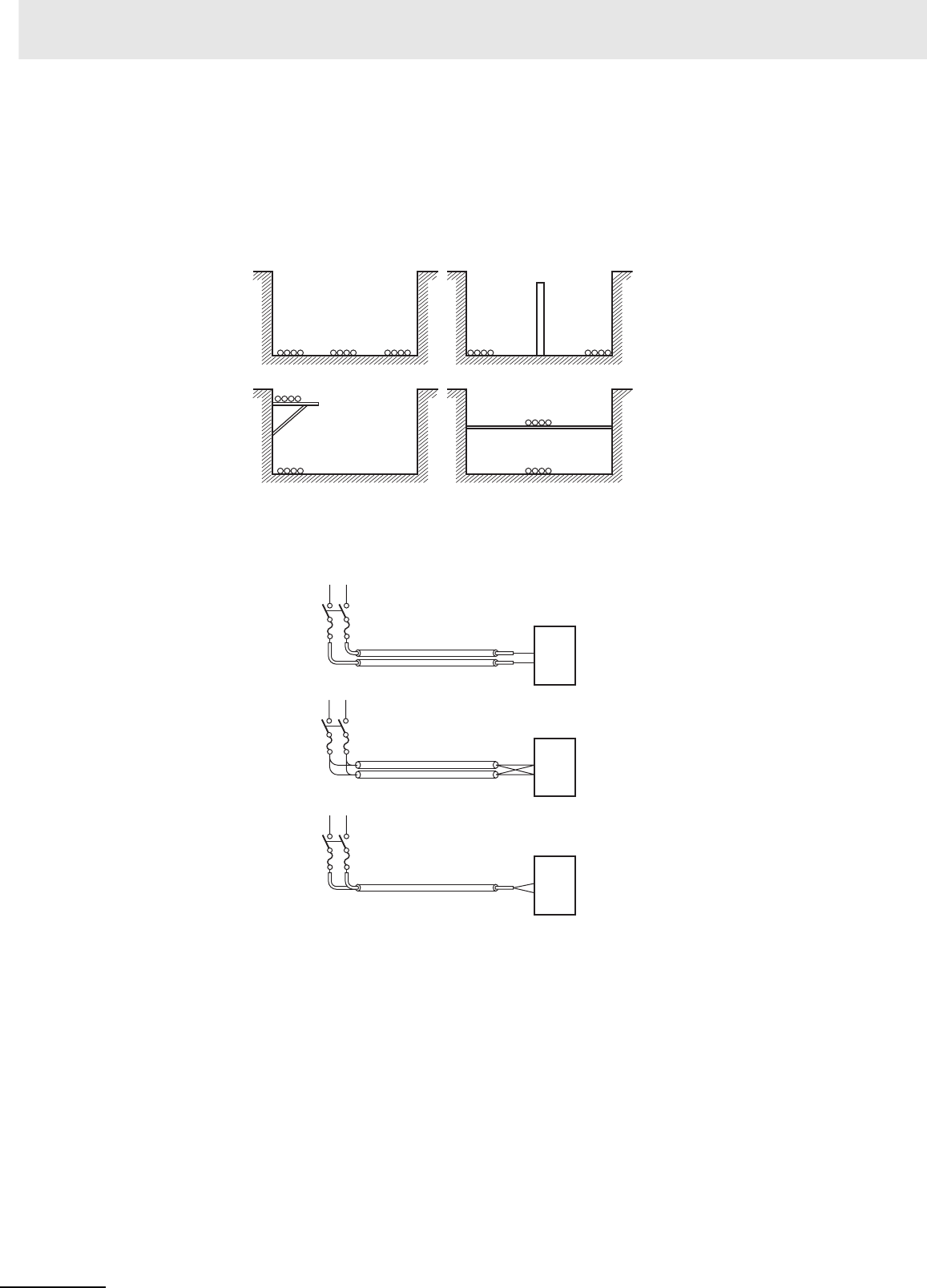
5 Installation
5-48 CJ2 CPU Unit Hardware User’s Manual
zWiring Methods
Observe the following points when wiring power supply and signal cables.
• When routing signal cables with differing characteristics through the same duct, always keep them
separated.
• As much as possible, avoid routing multiple power supply lines through the same duct. If it cannot
be avoided, then construct a partition between them in the duct and ground the partition.
• To avoid overheating the conduits when using conduits for wiring, do not place wires for a single
circuit in separate conduits.
Partitioning Methods for Signal and Power Supply Cables
(a) (b)
(c) (d)
Signal cables
Signal cables
Signal cables
Power supply cables
Power supply cables
Partition
Signal
cables
(A)
Signal
cables (B)
Signal
cables
(C) Power
supply
cables
Parallel Wiring (Single Phase)
Correct
Correct
Power supply
Incorrect
Power supply
Power supply
Load
Load
Load
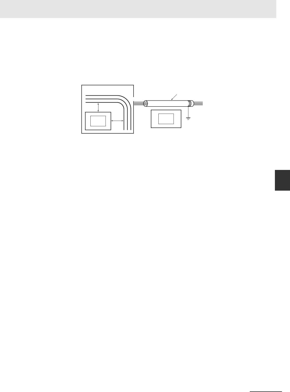
5-49
5 Installation
CJ2 CPU Unit Hardware User’s Manual
5-4 Control Panel Installation
5
5-4-5 Electrical Environment
• Power cables and signal cables adversely affect each other. Do not wire them in parallel.
• Noise induction may occur if the PLC is installed in a panel that includes high-voltage devices.
Whenever possible, wire and install them separately. (Refer to PLC Installation Location on page
45.)
• Either install the PLC a minimum of 200 mm from high-voltage lines or power lines, or place the
high-voltage lines or power lines in metal tubing and completely ground the metal tubing to 100 Ω
or less.
zOther Precautions
• Basic I/O Units have both plus and minus commons, so pay attention to the polarity when wiring.
• Optical fiber cable looks like ordinary communications cable or power cable, but internally it con-
sists of fibers, tension members, other protective materials. It must be handled with care. In partic-
ular, optical fiber cable must be installed according to prescribed methods and standards. Do not
subject optical fiber cable to severe tensile shock, excessive bending, twisting, or excessive con-
striction. For details on wiring optical fiber cables, refer to the following manuals.
• SYSMAC H-PCF Optical Fiber Cables Installation Guide (Cat. No. W156)
• Optical Ring Controller Link Units Operation Manual (Cat. No. W370)
Example: Separating PLC from Power Lines
PLC
Metal tubing
PLC
200 mm
200 mm
Panel with power line
Power line
Ground of 100 Ω or less
Power line
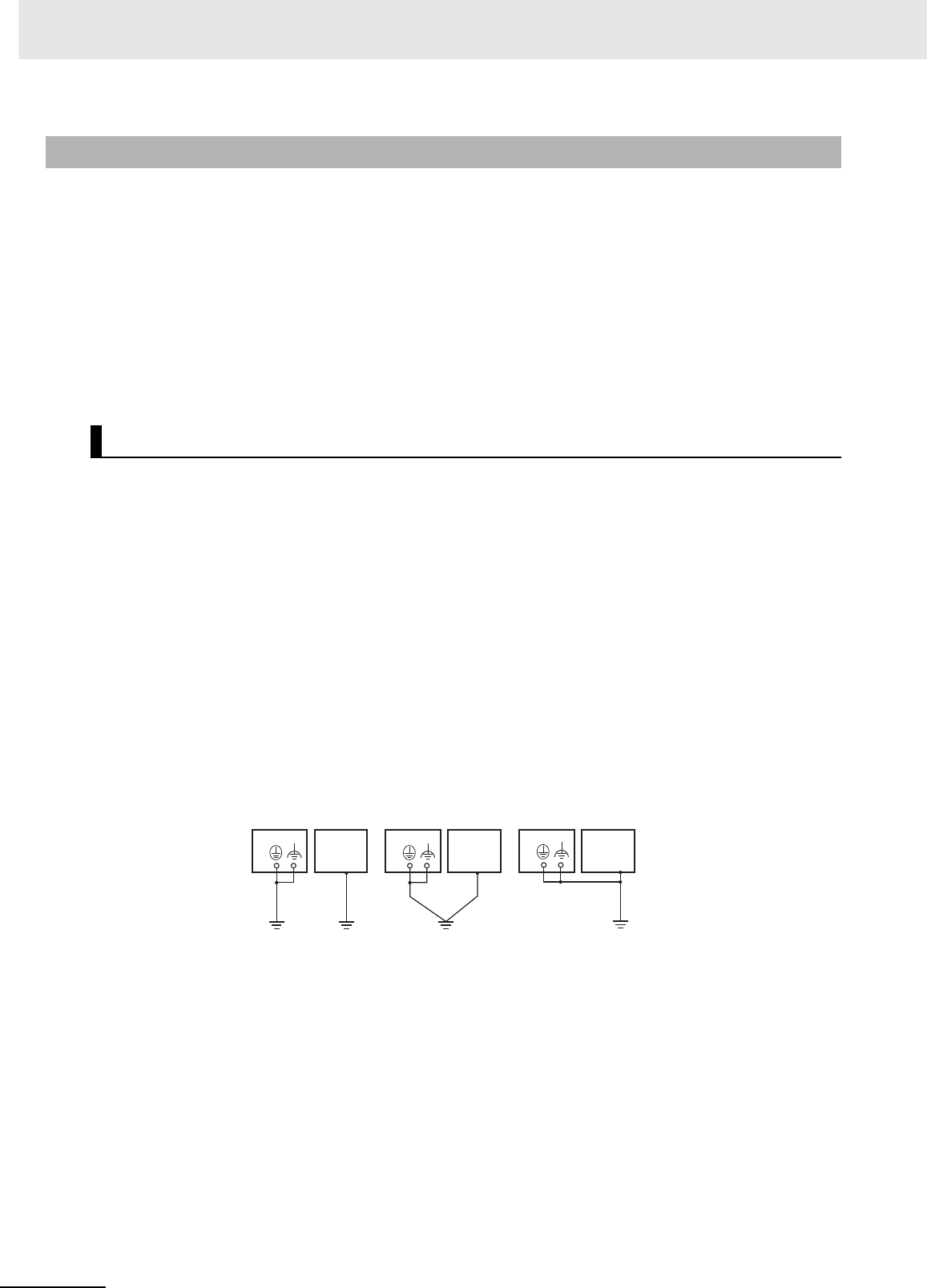
5 Installation
5-50 CJ2 CPU Unit Hardware User’s Manual
Grounding has the following two purposes.
• Protective Grounding
Protective grounding is done to ensure safety. It is intended to prevent electrical shock by grounding
the electrical potential that is generated by factors such as leakage, induction, or failure.
• Functional Grounding
Functional grounding is done to protect device and system functions, including prevention of noise
from external sources, or prevention of noise from devices or equipment that could have harmful
effects on other devices or equipment.
Grounding requirements sometimes depend on the situation, based on experimentation. It is impor-
tant to sufficiently check the particular circumstances before grounding.
zPrinciples of One-point Grounding
For devices to operate properly, the reference potential between the devices must be stabilized. Use
one-point grounding so that noise current does not flow to ground lines between the devices.
zWhenever possible, use an independent ground (with the ground pole
separated by a minimum of 10 m from any other ground pole).
• Ground to 100 Ω or less, and if possible use a separate ground from those of other devices. (Refer
to figure (a) in the diagram below.)
• If using an independent ground is not possible, then use a common ground as shown in figure (b).
Connect to the ground pole of the other device.
• Never connect to the same ground as a device that draws a large amount of power, such as a
motor or inverter. Ground the devices separately to avoid mutually adverse influences.
• To prevent electrical shock, do not connect to ground poles (especially steel frames) to which mul-
tiple devices are connected.
• Use a ground pole as close to the PLC as possible and keep the ground line as short as possible.
5-4-6 Grounding
Grounding Methods and Precautions
PLC
Other
device
Ground of
100 Ω or less
PLCPLC
Independent grounds:
Best
Common ground:
Acceptable
Common ground:
Incorrect
Grounding Methods
Other
device
Other
device
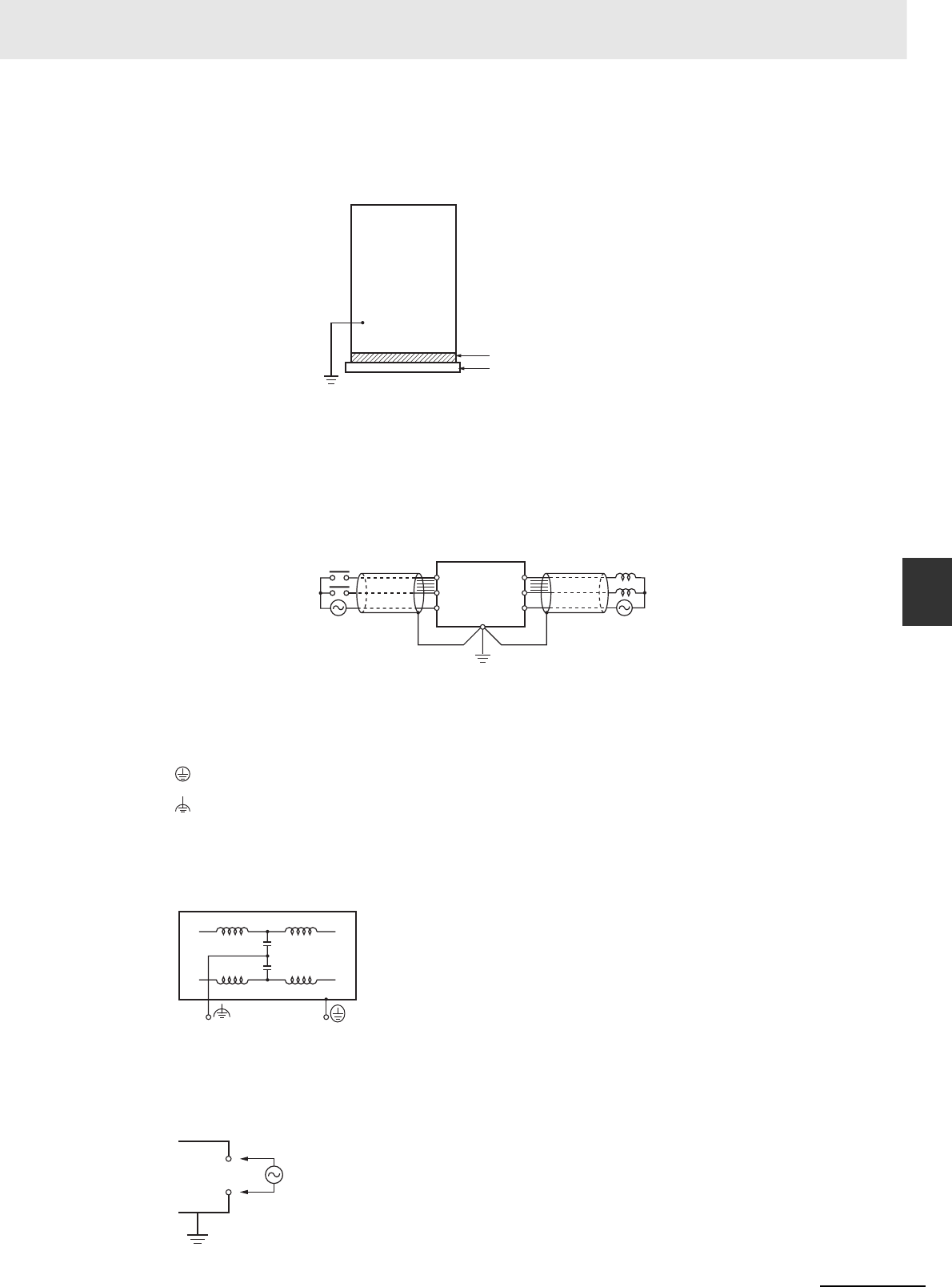
5-51
5 Installation
CJ2 CPU Unit Hardware User’s Manual
5-4 Control Panel Installation
5
5-4-6 Grounding
zPrecautions when Grounding
• If the same ground is used for both the signal lines and the enclosure, isolate the channel base
(a grounded metal plate inside a control panel) with an insulating material
• To prevent influence from leakage current from other electrical devices, electrically isolate the
panel in which the PLC is housed from other devices.
• If high-frequency equipment is present, then ground not only the high-frequency equipment but
also the panel itself in which the PLC is housed.
• As shown in the following diagram, when using shielded cable for I/O wiring, connect the shield
near the PLC to the enclosure ground terminal. Follow the instructions in the Communications
Unit manual for preparing shielded communications cable.
zPLC Ground Terminals
The PLC has the following two ground terminals.
When the functional ground terminal is correctly grounded, it is generally effective in suppressing
power supply common noise. Occasionally, however, grounding this terminal will result in picking up
more noise, so be careful when using it.
zGrounding for AC Power Supply Units
When wiring to an AC Power Supply Unit, if one power supply phase of the equipment is grounded,
always connect the grounded phase to the L2/N terminal.
Protective ground terminal: Always connected to the PLC chassis to prevent electrical shock.
Functional ground terminal: Connected to a neutral point in the noise filter to provide a ground when
power supply noise causes malfunctioning.
Example: Insulating and Grounding an Enclosure
Insulating material
Channel base
Independent ground
CS/CJ-series PLCs
have an isolated
(floating) mounting
structure to make it
more difficult to be
affected by noise from
an installation
environment, such as
a control panel.
Shielded Cable Ground
PLC
Output
Common
Input
Common
PLC Ground Terminals
AC side PLC side
L1
L2/N

5 Installation
5-52 CJ2 CPU Unit Hardware User’s Manual

6-1
CJ2 CPU Unit Hardware User’s Manual
6
This section describes how to troubleshoot problems that may occur with a CJ2 PLC.
6-1 CPU Unit Errors . . . . . . . . . . . . . . . . . . . . . . . . . . . . . . . . . . . . . . . . . . . . . . . 6-2
6-1-1 Errors and Remedies . . . . . . . . . . . . . . . . . . . . . . . . . . . . . . . . . . . . . . . . . . . . 6-2
6-1-2 Checking Errors . . . . . . . . . . . . . . . . . . . . . . . . . . . . . . . . . . . . . . . . . . . . . . . . 6-2
6-1-3 Checking Detailed Status . . . . . . . . . . . . . . . . . . . . . . . . . . . . . . . . . . . . . . . . 6-3
6-1-4 Reading Error Log Information . . . . . . . . . . . . . . . . . . . . . . . . . . . . . . . . . . . . 6-3
6-1-5 I/O Table Verification . . . . . . . . . . . . . . . . . . . . . . . . . . . . . . . . . . . . . . . . . . . . 6-5
6-1-6 Types of Errors . . . . . . . . . . . . . . . . . . . . . . . . . . . . . . . . . . . . . . . . . . . . . . . . . 6-6
6-1-7 Handling Errors . . . . . . . . . . . . . . . . . . . . . . . . . . . . . . . . . . . . . . . . . . . . . . . . 6-7
6-2 Troubleshooting Built-in EtherNet/IP Port Errors
(CJ2H-CPU6@-EIP and CJ2M-CPU3@ Only) . . . . . . . . . . . . . . . . . . . . . . . 6-25
6-2-1 Checking Built-in EtherNet/IP Port Error Status . . . . . . . . . . . . . . . . . . . . . . 6-25
6-2-2 Checking Error Status at the EtherNet/IP Port Seven-segment Display . . . . 6-26
6-3 Non-CPU Unit Errors and Remedies . . . . . . . . . . . . . . . . . . . . . . . . . . . . . 6-28
6-3-1 Error Causes and Remedies . . . . . . . . . . . . . . . . . . . . . . . . . . . . . . . . . . . . . 6-28
Troubleshooting
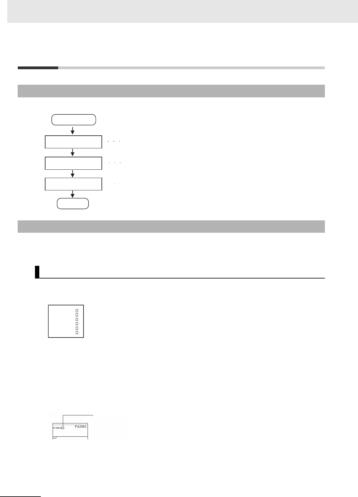
6 Troubleshooting
6-2 CJ2 CPU Unit Hardware User’s Manual
6-1 CPU Unit Errors
Use the following procedure when an error occurs.
The type of error that occurred can be determined by checking the indicators on the front of the CPU
Unit or by using the CX-Programmer. For details on error types, refer to 6-1-6 Types of Errors.
6-1-1 Errors and Remedies
6-1-2 Checking Errors
Checking the Indicators
RUN: Lit green when the PLC is in RUN or MONITOR mode.
ERR/ALM: Shows the results of self-diagnosis.
Flashing red: Non-fatal error
Lit red: Fatal error
INH: Lit yellow when Output OFF Bit has been turned ON.
PRPHL: Flashing yellow when the CPU Unit is communicating through
the peripheral (USB) port.
COMM*: Flashing yellow when the CPU Unit is communicating through
the RS-232C (USB) port.
BKUP: Flashing yellow when data is being backed up from RAM to
built-in flash memory.
* The CJ2M-CPU3@ does not have this indicator.
POWER: Lit when 5 V is output from the Power Supply Unit.
Error occurs.
Check the indicators.
Identify the error.
Implement
countermeasures.
End
Check the indicators on the front of the CPU Unit
and Power Supply Unit, or use the
CX-Programmer to read the error status.
Identify the error from the indicators
(refer to 6-1-6 Types of Errors) or use the
CX-Programmer to read the error status.
Take measures to eliminate the error that occurred
and to prevent it from occurring again.
(Refer to 6-1-7 Handling Errors.)
Indicators on front of
CPU Unit
ERR/ALM
RUN
COMM
BKUP
INH
PRPHL
Power Supply Unit
Power indicator

6-3
6 Troubleshooting
CJ2 CPU Unit Hardware User’s Manual
6-1 CPU Unit Errors
6
6-1-3 Checking Detailed Status
Use the following procedure to read the error status.
1Connect the CX-Programmer online.
2Double-click Error Log in the project tree in the main window. The PLC Error Window will be dis-
played.
3Click the Errors Tab. The current errors will be displayed on the Errors Tab Page.
You can check detailed error status using information registered in the Auxiliary Area. The following
error details are registered.
• Error Flags: The Auxiliary Area contains flags that indicate the type of error. There are error
flags for various types of error.
• Error Information: The Auxiliary Area contains words that provide detailed information on current
errors. Error information is provided for various types of error.
• Error Code: The error code assigned to the current error is stored in word A400 regardless of
the type of error. If two or more errors occur at the same time, the highest (most
serious) error code will be stored in A400.
If the error status could not be checked when the error occurred, it can be checked by reading error log
data. The following information is stored in the error log.
• Error code (This is the same error code as is stored in word A400.)
• Error information
• Time of occurrence
Checking Error Status with the CX-Programmer
6-1-3 Checking Detailed Status
6-1-4 Reading Error Log Information
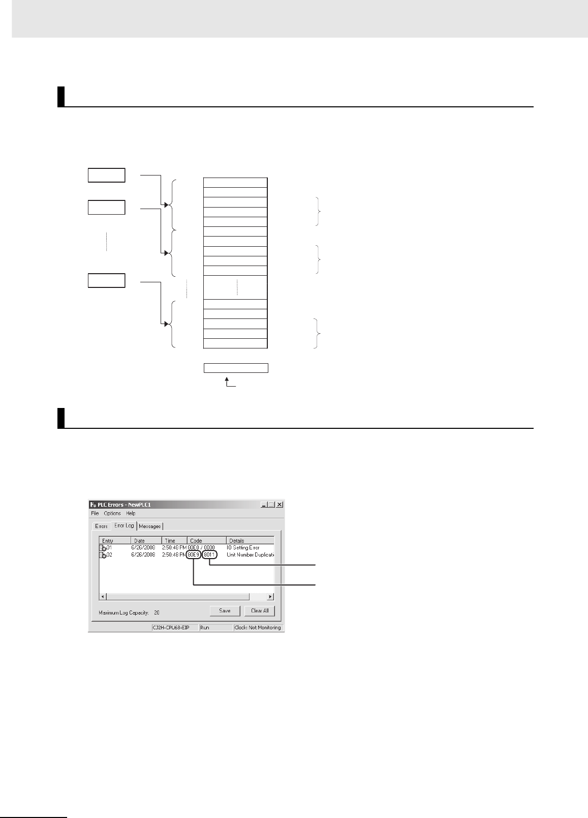
6 Troubleshooting
6-4 CJ2 CPU Unit Hardware User’s Manual
A maximum of 20 error records will be stored in the error log. If more than 20 errors occur, the oldest
error record (in A100 to A104) will be deleted and the 19 records stored in A105 to A199 will be shifted
by one, with the newest record being stored in A195 to A199.
The following methods can be used to check error log information with the CX-Programmer.
zCX-Programmer PLC Error Window
Check the error log by clicking the Error Log Tab in the PLC Errors Window of the PLC.
The example above shows that unit number 17 has been duplicated for Special I/O Units.
• Error code 80E9: Unit number duplication error
• Error information: 80 “11”: 11 hex = 17 decimal
For details on error codes and error information, refer to A-3 Fatal and Non-fatal Error Details.
zDirectly Monitoring the Area where Error Log Information is Stored
1Connect the CX-Programmer online.
2Read words A100 to A199.
Error Log Information
Checking Error Log Information
A100 4 1 0 2
A101
A102
A103
A104
A105 0 0 F 7
A106
A107
A108
A109
A195 0 0 9 D
A196
A197
A198
A199
4102
00F7
009D
1
2
20
A300
Error log pointer
Error code
Error code
Error code Order of occurrence
Error Log Area
Error contents
Minute, second
Day, hour Time of occurrence
Year, month
Error code
Error contents
Error contents
Minute, second
Day, hour
Year, month
Minute, second
Day, hour
Year, month
Time of occurrence
Time of occurrence
The error information is displayed here.
The error code is displayed here.

6-5
6 Troubleshooting
CJ2 CPU Unit Hardware User’s Manual
6-1 CPU Unit Errors
6
6-1-5 I/O Table Verification
3Check the error status from the registered data.
When an I/O verification error or a CPU standby error occurs, the following procedure can be used to
verify the I/O tables to locate where the error occurred. With the CX-Programmer, use the following pro-
cedure.
1Double-click I/O Tables in the project tree in the main window.
The I/O Table Window will be displayed.
2Select Verify from the Options Menu in the I/O Table Window.
The I/O table verification results will be displayed.
6-1-5 I/O Table Verification

6 Troubleshooting
6-6 CJ2 CPU Unit Hardware User’s Manual
The type of error that has occurred can be identified by checking the indicators on the front of the CPU
Unit and the Power Supply Unit, or by using the CX-Programmer to check the error status. The errors
detected by the CPU Unit are listed in the following table.
For details on errors that are not detected by the CPU Unit, refer to 6-3 Non-CPU Unit Errors and Rem-
edies.
*1 The indicator status is the same for CPU errors and fatal errors, but they can be distinguished because a Programming
Device can be connected when a fatal error occurs, but not when a CPU error occurs.
*2 For details on fatal errors and non-fatal errors, refer to A-3 Fatal and Non-fatal Error Details.
*3 CJ2H-CPU6@-EIP only.
Note The indicator status shows the status of the errors that have occurred in RUN or MONITOR mode.
6-1-6 Types of Errors
Error name POWER RUN ERR/ALM INH PRPHL COMM
Error code
(stored in
A400)
Operation status
Power supply error OFF OFF OFF OFF OFF OFF --- Operation stops.
CPU Standby ON OFF OFF --- --- --- --- Operation stops.
CPU reset --- Operation stops.
CPU error (WDT error)*1 ON OFF ON --- --- --- --- Operation stops.
USB port communications error ON ON OFF --- OFF --- --- Operation continues.
RS-232C port communications
error
ON ON OFF --- --- OFF --- Operation continues.
Fatal errors*1*2
Cycle time exceeded error ON OFF ON --- --- --- 0x809F Operation stops.
I/O bus error 0x80C0 to
0x80C7,
0x80CE,
0x80CF
I/O setting error 0x80E0
Too many I/O points error 0x80E1
Unit number duplication
error
0x80E9
Rack number duplication
error
0x80EA
Program error 0x80F0
Memory error 0x80F1
Version error 0x80F2
Memory Card Transfer
Error
0x80F4
FALS (007) error 0xC101 to
0xC2FF
Non-fatal errors*2
Duplicated refreshing error ON ON Flashing --- --- --- 0x008B Operation continues.
Basic I/O error 0x009A
PLC Setup error 0x009B
Option Board error 0x00D1
Backup memory error 0x00F1
Tag memory error*3 0x00F2
System work errors 0x00F3
Battery error 0x00F7
CPU Bus Unit error 0x0200 to
0x020F
Special I/O Unit error 0x0300 to
0x035F,
0x03FF
CPU Bus Unit setting error 0x0400 to
0x040F
FAL (006) error 0x4101 to
0x42FF
Special I/O Unit setting
error
0x0500 to
0x055F

6-7
6 Troubleshooting
CJ2 CPU Unit Hardware User’s Manual
6-1 CPU Unit Errors
6
6-1-7 Handling Errors
This section describes the measures to take for the errors that most commonly occur. First check the
error status. Then, make a preliminary determination of the cause of the error, confirm the cause, cor-
rect the error, and take measures to ensure that it will not occur again. For all other errors, refer to A-3
Fatal and Non-fatal Error Details.
A power supply error occurs when a voltage of 5 V is not output from the Power Supply Unit.
*1 The following table shows the allowable power supply ranges for each Power Supply Unit model.
6-1-7 Handling Errors
Power Supply Errors
POWER RUN ERR/ALM Error flag Error code Error infor-
mation
Not lit. Not lit. Not lit. None None None
Suspected cause of
error Confirmation method Remedy Prevention of recur-
rence
Power is not being
input.
Use a tester to measure the volt-
age at the input terminals of the
Power Supply Unit.*1
Turn the power ON
again.
Investigate the reason that
the power was turned
OFF.
Connection status of
power supply selector
terminals
• 100 VAC:
Use a tester check for short-
circuits.
• 200 VAC:
Check for disconnections.
Reconnect and secure
the terminal connec-
tions.
Periodically (approxi-
mately once a year)
tighten the terminal con-
nections.
The voltage is out of
the allowable range for
the power supply.
Use a tester to measure the volt-
age at the input terminals to the
Power Supply Unit.*1
Correct the power sup-
ply system for the PLC.
Same as at the left.
Power Supply Unit fail-
ure
Replace the Power Supply Unit
and check operation. (Check
whether the POWER indicator is
lit.)
Replace the Power
Supply Unit.
Depends on the type of
error.
Failure at another Unit Remove in order the Units
mounted in the Rack and check
the POWER indicator.
Replace the failed Unit. Depends on the type of
error.
Model Power supply voltage Allowable power supply
voltage fluctuation
CJ1W-PA205R/PA202 100 to 240 VAC 85 to 264 VAC
CJ1W-PD025 24 VDC 19.2 to 28.8 VDC
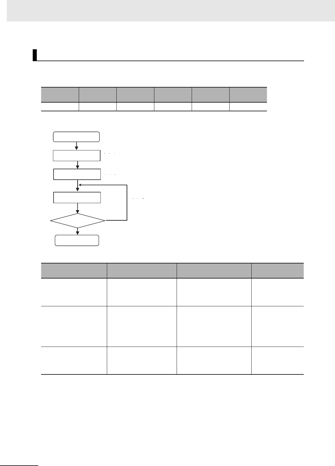
6 Troubleshooting
6-8 CJ2 CPU Unit Hardware User’s Manual
When a CJ-series PLC is turned ON, the CPU starts cyclic servicing and enters RUN mode only after
all Special I/O Units and CPU Bus Units have been detected. If the startup mode is RUN or MONITOR
mode, the CPU will remain on standby until all Units have been detected.
zRecovery Processing Flow
zError Causes and Remedies
CPU Standby Errors
POWER RUN ERR/ALM Error flag Error code Error infor-
mation
Lit. Not lit. Not lit. None None None
Suspected cause of
error Confirmation method Remedy Prevention of
recurrence
Faulty connection at Unit
(at a connector)
Check the insertion at the
connector. Restart the Unit
and check whether the error
is cleared.
Tighten the screws. Same as at the left.
Unit failure Replace the Unit that is
causing the standby (the
undetected Unit). If the error
is not cleared, remove the
Units in order until the status
returns to normal.
• Replace the Special I/O Unit
or Interrupt Unit for which
“$” is displayed when the I/O
tables are read.
• Replace the failed Unit.
(Determined by the
cause of the failure.)
The remote I/O power
supply is OFF or there is
no terminator for SYSMAC
BUS.
Check whether the power is
turned ON. Check the termi-
nator settings.
Turn ON the power or set the
terminators. If the error is not
cleared, replace the Unit.
---
CPU standby
Check the location of
the error.
Check the
connection status.
Replace the Unit.
Is the error cleared?
Yes
No
Restart the System.
Use the I/O table verification procedure (refer to 6-1-5 I/O
Table Verification) to check the location where the error
occurred.
Check the connections to the Special I/O Units and CPU Bus Units.
Replace the Unit, or remove the Unit and check
whether the error is cleared (to determine that the
Unit that was replaced or removed just before the
error was cleared was the problem).
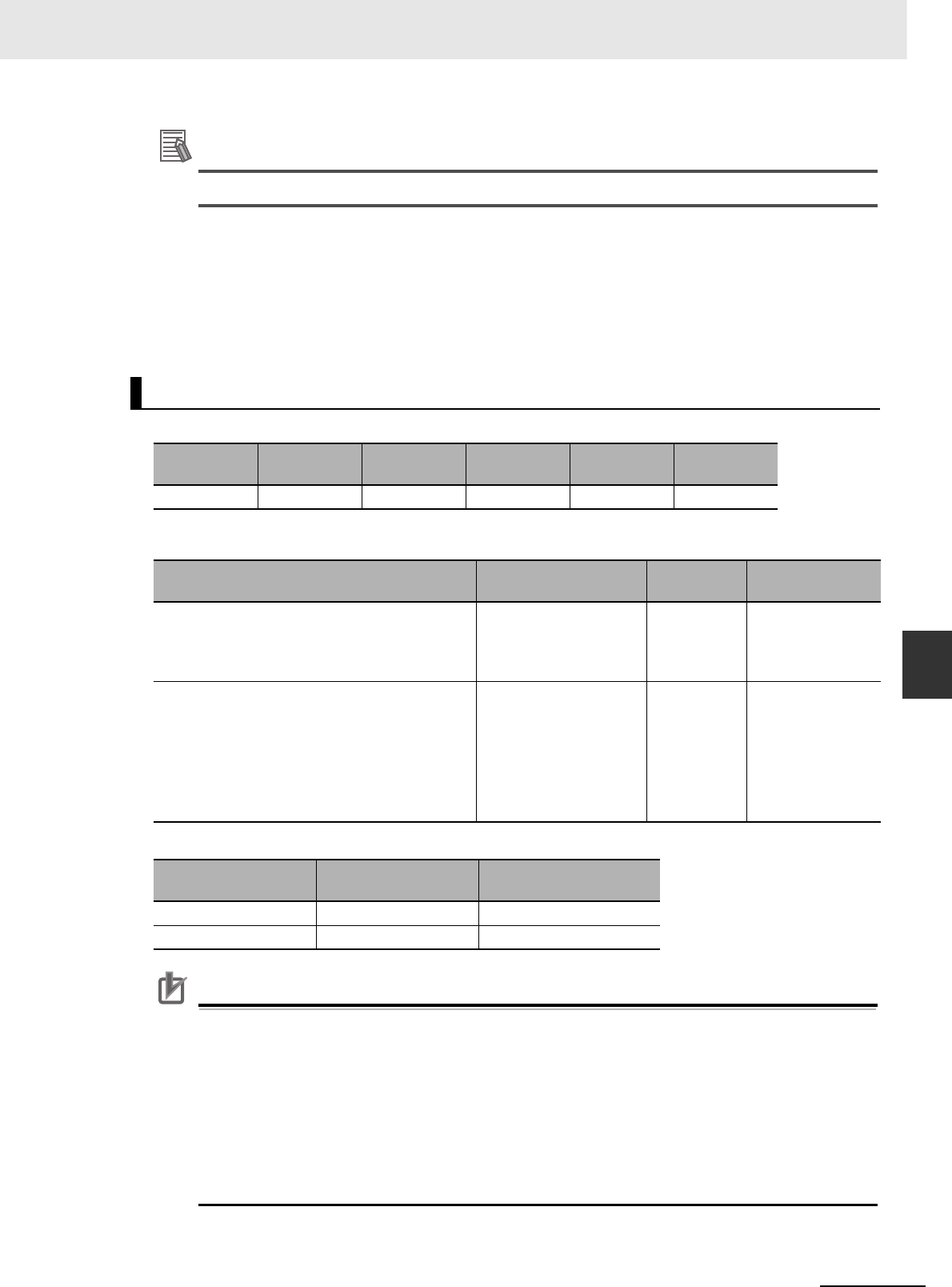
6-9
6 Troubleshooting
CJ2 CPU Unit Hardware User’s Manual
6-1 CPU Unit Errors
6
6-1-7 Handling Errors
Additional Information
The CJ2 CPU Units support the following function.
• Startup Condition Setting
After the power supply is turned ON, it is possible to start operation of the CPU Unit in RUN
mode or MONITOR mode even if there is one or more Units that has not completed startup.
Select the Start running program when initializing Unit/Inner board recognition Check Box in
the PLC Setup. For details, refer to the CJ-series CJ2 CPU Unit Software User's Manual
(Cat. No. W473).
The CPU Unit is being reset, and Programming Devices cannot be connected.
zError Causes and Remedies
*1 The following table shows the allowable power supply ranges for each Power Supply Unit.
Precautions for Correct UsePrecautions for Correct Use
Observe the following points when using Expansion Racks.
• Always confirm the safety of any related equipment before turning the power supply ON or
OFF.
• When the power supply is interrupted to an Expansion Rack, the CPU Unit will stop program
execution and the same operations as are performed when the power supply to the CPU Unit
is interrupted will be performed. For example, if the power OFF interrupt task is enabled, it will
be executed. If power is then restored to the Expansion Rack, the CPU Unit will perform star-
tup processing. The same operational status as existed before the power interrupt will not nec-
essarily be continued.
CPU Reset
POWER RUN ERR/ALM Error flag Error code Error infor-
mation
Lit. Not lit. Not lit. None None None
Suspected cause of error Confirmation method Remedy Prevention of
recurrence
Power to an Expansion Rack is OFF. Use a tester to measure
the voltage at the input
terminals of the Power
Supply Unit.*1
Turn ON the
power.
Investigate the
reason that the
power was OFF.
The I/O Connecting Cable is incorrectly installed.
• The IN-OUT connectors are reversed.
• The cable does not have good contact at the
connectors.
• Two or more I/O Control Units are mounted on
the CPU Rack, or an I/O Control Unit is
mounted to an Expansion Rack.
Check the connections. Reconnect
the cable.
If the Cable is dis-
connected, check
for vibration and
shock.
Model Power supply voltage Allowable power supply
voltage fluctuation
CJ1W-PA205R/PA202 100 to 240 VAC 85 to 264 VAC
CJ1W-PD025 24 VDC 19.2 to 28.8 VDC

6 Troubleshooting
6-10 CJ2 CPU Unit Hardware User’s Manual
CPU errors are error that occur in the CPU Unit itself. A CPU error occurs when the WDT (watchdog
timer) times out. Programming Devices cannot be connected when a CPU error occurs.
zError Causes and Remedies
Precautions for Correct UsePrecautions for Correct Use
• Always confirm the safety of any related equipment before turning the power supply ON or
OFF.
• When power supply is interrupted to an Expansion Rack, the CPU Unit will stop program exe-
cution and the same operations as are performed when the power supply to the CPU Unit is
interrupted will be performed. For example, if the power OFF interrupt task is enabled, it will be
executed. If power is then restored to the Expansion Rack, the CPU Unit will perform startup
processing. The same operational status as existed before the power interrupt will not neces-
sarily be continued.
CPU Errors
POWER RUN ERR/ALM Error flag Error code Error information
Lit. Not lit. Lit. None None None
Suspected cause of
error Confirmation method Remedy Prevention of recur-
rence
Unit failure A CPU error has possibly occurred
in the following cases.
• If the error is not cleared when the
CPU Unit is restarted after the
recovery measures.
• If the error occurs frequently
• If the condition improves when the
Unit is replaced.
Replace the CPU Unit. Same as at the left.
A conductive object
has gotten inside.
Check for conductive objects. Clean the inside of the
Unit with an air blower
or replace the CPU
Unit.
Do not do any metal
working in the vicinity of
the control panel. Close
the control panel.
Noise
• The microcomputer
inside the CPU Unit
is malfunctioning.
When the CPU Unit is restarted
after the recovery measures, the
error will either be cleared or will
continue to occur. Check whether
errors become less frequent after
the Unit is replaced.
Take measures against
noise. (Investigate the
path of entry.)
•FG
• Power lines
Same as at the left.
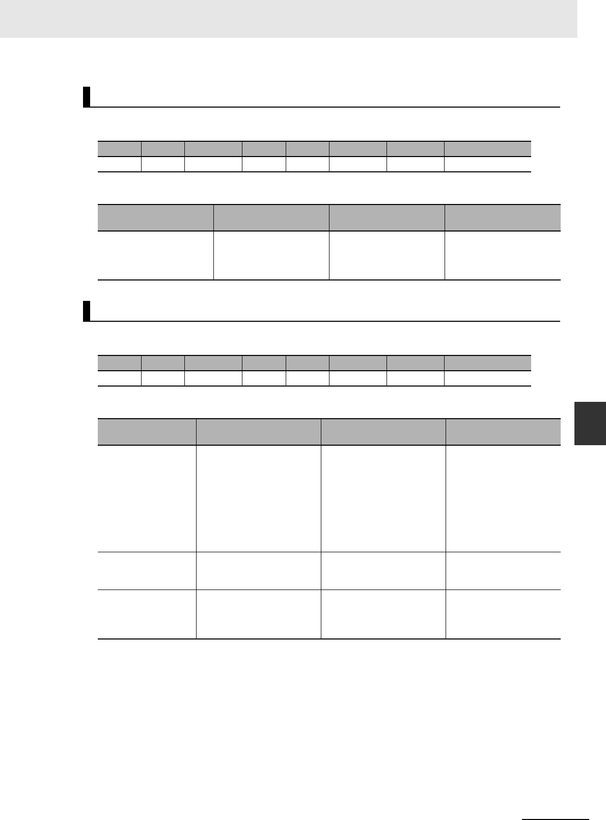
6-11
6 Troubleshooting
CJ2 CPU Unit Hardware User’s Manual
6-1 CPU Unit Errors
6
6-1-7 Handling Errors
A communications error will occur if there is an error in communications between the peripheral (USB)
Port and a connected device.
zError Causes and Remedies
A communications error will occur if there is an error in communications between the serial (RS-232C)
port and a connected device.
zError Causes and Remedies
Communications Error (Peripheral (USB) Port)
POWER RUN ERR/ALM PRPHL COMM Error flag Error code Error information
Lit. Lit. Not lit. Not lit. Not lit. None None None
Suspected cause of
error Confirmation method Remedy Prevention of recur-
rence
The communications
cable is disconnected.
Perform a visual inspec-
tion and pull on the cables.
Reconnect the cables. During operation, confirm
that the connections are
secure. Check for vibration
or shock.
Communications Error (Serial Port (RS-232C))
POWER RUN ERR/ALM PRPHL COMM Error flag Error code Error information
Lit. Lit. Not lit. Not lit. Not lit. None None None
Suspected cause of
error Confirmation method Remedy Prevention of recur-
rence
Communications set-
tings are incorrect.
• Check whether the DIP
switch pin 5 setting and
and the serial port settings
in the PLC Setup are cor-
rect.
• If a host computer is con-
nected, check the host
computer serial port set-
tings and the program.
• Correctly set DIP switch
pin 5 and the serial port
settings in the PLC Setup.
• Correct the host computer
serial port settings and the
program.
Same as at the left.
A communications
cable is incorrectly
connected.
• Check the cable connec-
tions.
• Correct the cable connec-
tions.
Same as at the left.
A communications
cable is disconnected.
Perform a visual inspection
and pull on the cables.
Reconnect the cables. During operation, confirm
that the connections are
secure. Check for effects
of vibration or shock.

6 Troubleshooting
6-12 CJ2 CPU Unit Hardware User’s Manual
zCycle Time Exceeded Error
A cycle time exceeded error will occur if the PLC cycle time exceeds the setting for Watch Cycle
Time in the PLC Setup.
zError Causes and Remedies
* The maximum processing time for an interrupt task will not be stored in A440 if High-speed interrupt function is
enabled in the PLC Setup.
Cycle Time Exceeded Error (Fatal Error)
POWER RUN ERR/ALM Error flag Error code Error infor-
mation
Lit. Not lit. Lit. A401.08 809F None
Suspected cause of
error Confirmation method Remedy Prevention of recur-
rence
An interrupt task with a
long processing time was
executed.
Check the Max. Interrupt
Task Processing Time
(A440)*
Divide the interrupt task
into sections.
Same as at the left.
An incorrect value (an
extremely large number)
was set for the number of
repeats of FOR(512).
Set up a trap in the ladder
program to monitor the
number of repeats.
Correct the ladder pro-
gram.
Same as at the left.
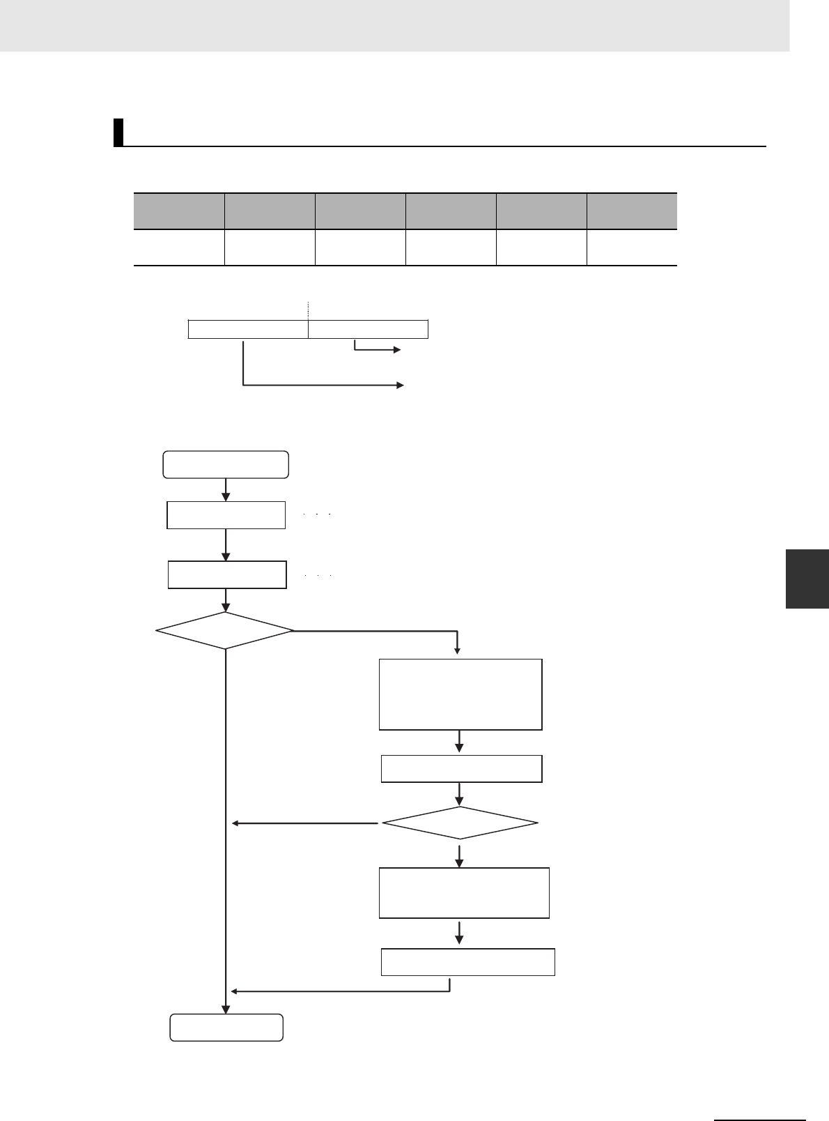
6-13
6 Troubleshooting
CJ2 CPU Unit Hardware User’s Manual
6-1 CPU Unit Errors
6
6-1-7 Handling Errors
An I/O bus error will occur if there is an error in a data transfer between the CPU Unit and a Unit con-
nected in the Rack.
*1 The numbers of the slot and Rack where the I/O bus error was detected are stored in word A404.
zRecovery Processing Flow
I/O Bus Error (Fatal Error)
POWER RUN ERR/ALM Error flag Error code Error infor-
mation
Lit. Not lit. Lit. A401.10 80C0 to 80C7
or 80CF
A404*1
15 08 07 01
A404
The number of the slot where the error occurred in
binary. (If it cannot be determined, “0F” will be stored.)
The number of the Rack where the error occurred in
binary (If it cannot be determined, “0F” will be stored.)
I/O bus error occurs.
Check the error
status. Check the error code and error information.
Restart the PLC Turn the power OFF and back ON.
Is the error cleared? No
Yes
Yes
No
Is the error cleared?
Check the I/O Connecting
Cable connections between
all Racks.
Check the Unit installation.
Restart the PLC.
Replace the Unit or the I/O
Connecting Cable.
Restart the PLC.
Restart the System.

6 Troubleshooting
6-14 CJ2 CPU Unit Hardware User’s Manual
zError Causes and Remedies
Suspected cause of
error Confirmation method Remedy Prevention of recur-
rence
The I/O Connecting Cable
is disconnected.
Perform a visual inspec-
tion and pull on the
Cables.
Reconnect the cables. During operation, confirm
that the connections are
secure. Check for vibration
or shock.
Equipment failure
• CPU Unit
• I/O Connecting Cable
(damage to bus inter-
face circuit)
An I/O bus error has pos-
sibly occurred in the fol-
lowing cases.
• If the error is not cleared
when the CPU Unit is
restarted
• If the error occurs fre-
quently
• If the condition improves
when the Unit is
replaced.
Replace the equipment.
•CPU Unit
• I/O Connecting Cable
---
A conductive object has
gotten inside.
Check for conductive
objects.
Clean the inside of the
Unit with an air blower or
replace the CPU Unit.
Do not do any metal work-
ing in the vicinity of the
control panel. Close the
control panel.
Faulty connector contact
(A foreign object has got-
ten inside.)
Check for foreign objects
in the connector.
Replace the Unit or take
off the connector and
remove the foreign object.
Make sure that the operat-
ing environment is free of
dirt and dust.
Noise
• Data corruption in bus
signals
• Malfunctioning in bus
interface circuit
When the CPU Unit is
restarted after the recov-
ery measures, the error
will either be cleared or
will continue to occur.
Check whether errors
become less frequent
after the Unit is replaced.
Take measures against
noise. (Investigate the
path of entry.)
•FG
• Power lines
• I/O connecting cable
(inductive noise)
Same as at the left.
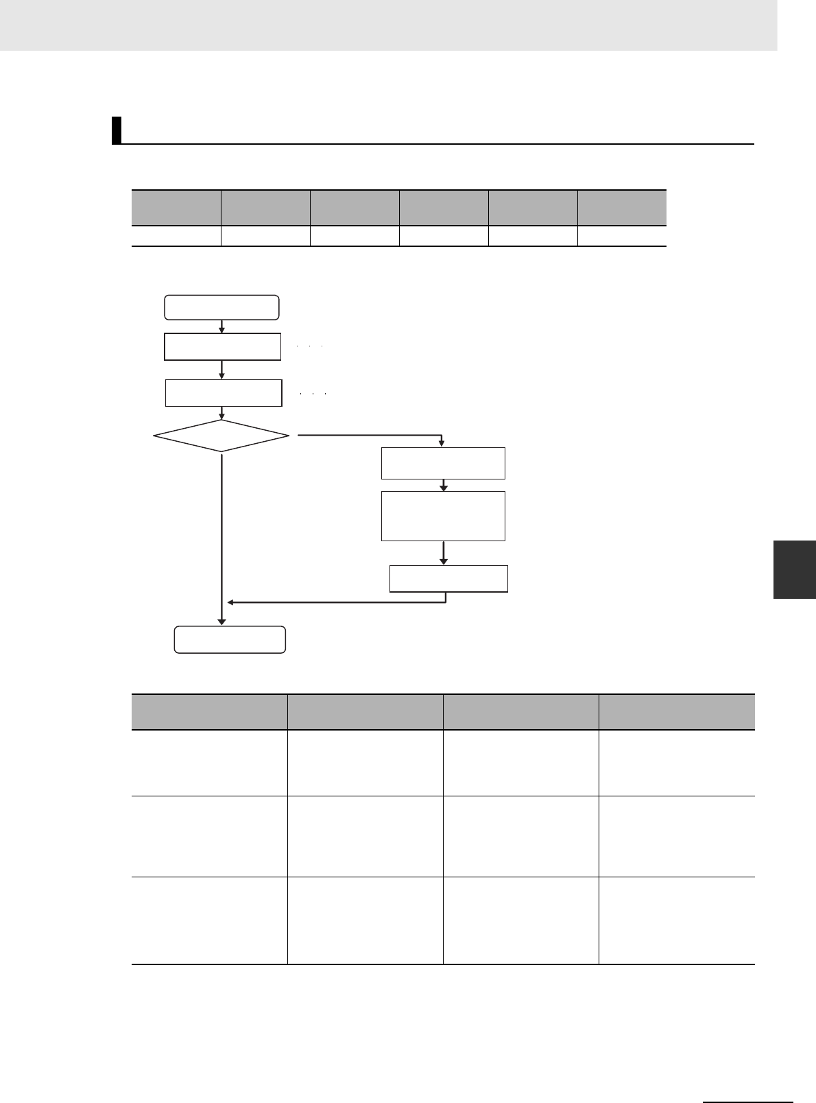
6-15
6 Troubleshooting
CJ2 CPU Unit Hardware User’s Manual
6-1 CPU Unit Errors
6
6-1-7 Handling Errors
An I/O setting error will occur if the Units that are actually connected do not match the Unit in the regis-
tered I/O tables.
zRecovery Processing Flow
zError Causes and Remedies
I/O Setting Error (Fatal Error)
POWER RUN ERR/ALM Error flag Error code Error infor-
mation
Lit. Not lit. Flashing. A401.10 80E0 ---
Suspected cause of
error Confirmation method Remedy Prevention of recur-
rence
Faulty connection at Unit
(at a connector)
Check the insertion at the
connector. Restart the
Unit and check whether
the error is cleared.
Tighten the screws. Same as at the left.
Unit failure If restarting the Unit does
not clear the error, check
whether the error is
cleared by replacing the
Unit.
Replace the applicable
Unit.
Same as at the left.
Noise
• Data corruption in bus
signals
Restart the CPU Unit and
check whether the error
continues to occur.
Take measures against
noise. (Investigate the
path of entry.)
•FG
• Power lines
Same as at the left.
I/O setting error
Use the I/O table verification procedure (refer to 6-1-5
I/O Table Verification) to check where the error
occurred.
Restart the PLC. Turn the power OFF and back ON.
Is the error cleared? No
Yes
Restart the System.
Check the location of
the error.
Check the Unit
connections.
Replace the Unit
where the error
occurred.
Restart the PLC.
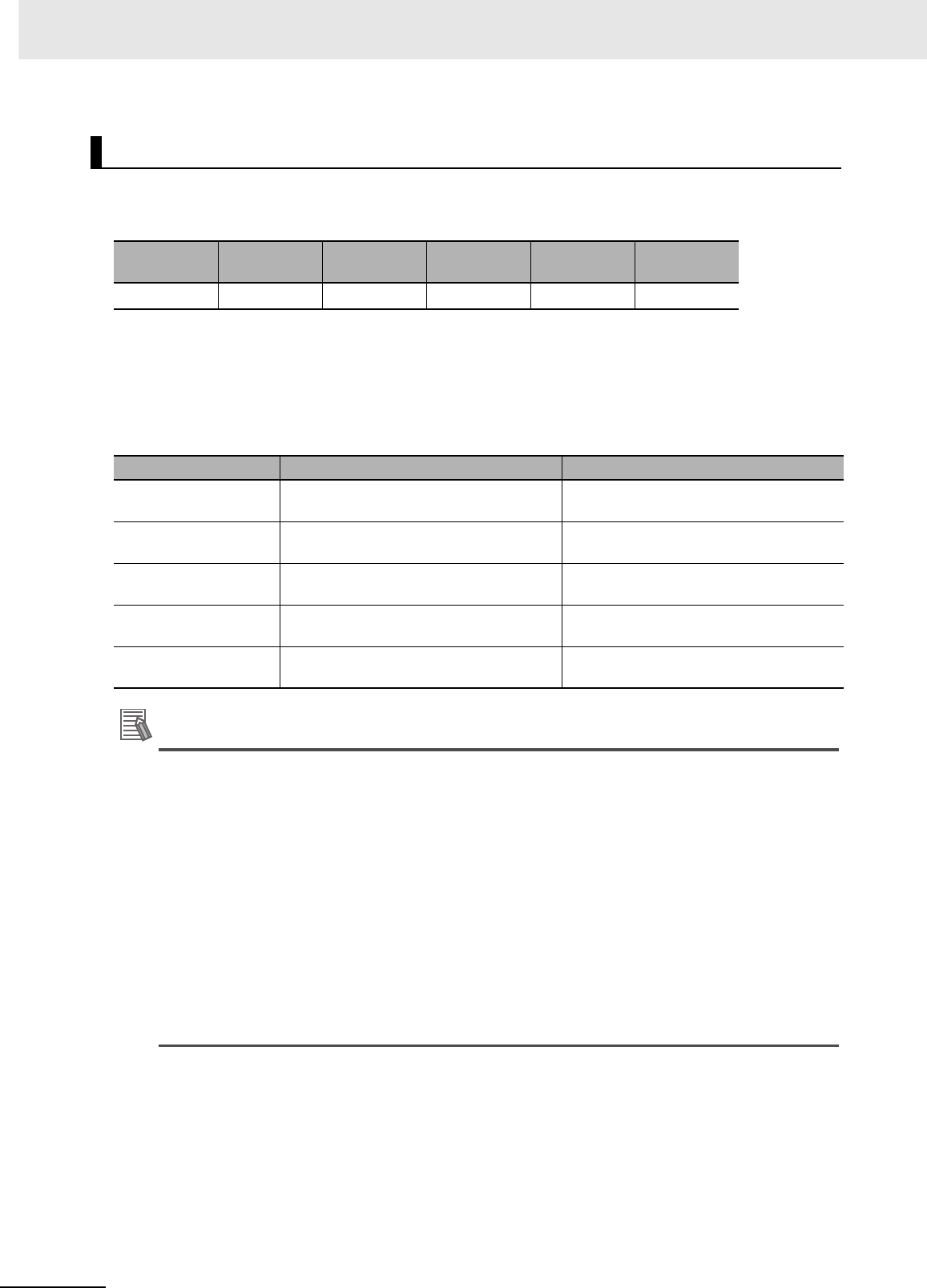
6 Troubleshooting
6-16 CJ2 CPU Unit Hardware User’s Manual
A memory error will occur if there is a memory error in the CPU Unit or if a checksum error is detected
(checksum checked by the PLC with each cycle). The details of the cause of the error will be stored in
the error information in the Auxiliary Area.
*1 Individual bits in A403 indicate where the memory error occurred.
zRecovery Measures
Check the detailed error contents in the error information in the Auxiliary Area, and then implement
the following recovery measures. If these measures cannot solve the problem, there is a strong
probability that the Unit has failed, so replace the Unit.
Additional Information
Checksums are used to detect illegal rewriting in a specific area of memory by calculating and
comparing sums written to memory in advance to sums during operation. When a checksum
error is detected by the CJ2 CPU Unit during operation, memory is automatically recovered by
automatically reading data from flash memory. If recovery is not possible, an error occurs and
operation stops.
Use any of the following methods to transfer the data again.
• Use the CX-Programmer to download data.
• Use the automatic transfer at startup function to download data saved on a Memory Card. For
details, refer to the CJ-series CJ2 CPU Unit Software User's Manual (Cat. No. W473).
• Use the simple backup function to download data saved on a Memory Card. For details, refer
to 8-3 Simple Backup.
The CJ2 CPU Unit has built-in flash memory for backup. When the CPU Unit is restarted, data is
transferred to memory for calculation and this sometimes enables an error to be cleared.
Memory Error (Fatal Error)
POWER RUN ERR/ALM Error flag Error code Error infor-
mation
Lit. Not lit. Lit. A401.15 80F1 A403*1
Error information Error contents Recovery measures
A403.00: ON A checksum error has occurred in the user
program memory.
Transfer the user program to the CPU Unit
again.
A403.04: ON A checksum error has occurred in the PLC
Setup.
Transfer the PLC Setup to the CPU Unit
again.
A403.05: ON A checksum error has occurred in the reg-
istered I/O table.
Transfer the I/O tables to the CPU Unit
again.
A403.07: ON A checksum error has occurred in the
routing tables.
Transfer the routing tables to the CPU Unit
again.
A403.08: ON A checksum error has occurred in the
CPU Bus Unit setup.
Transfer the CPU Bus Unit setup again.
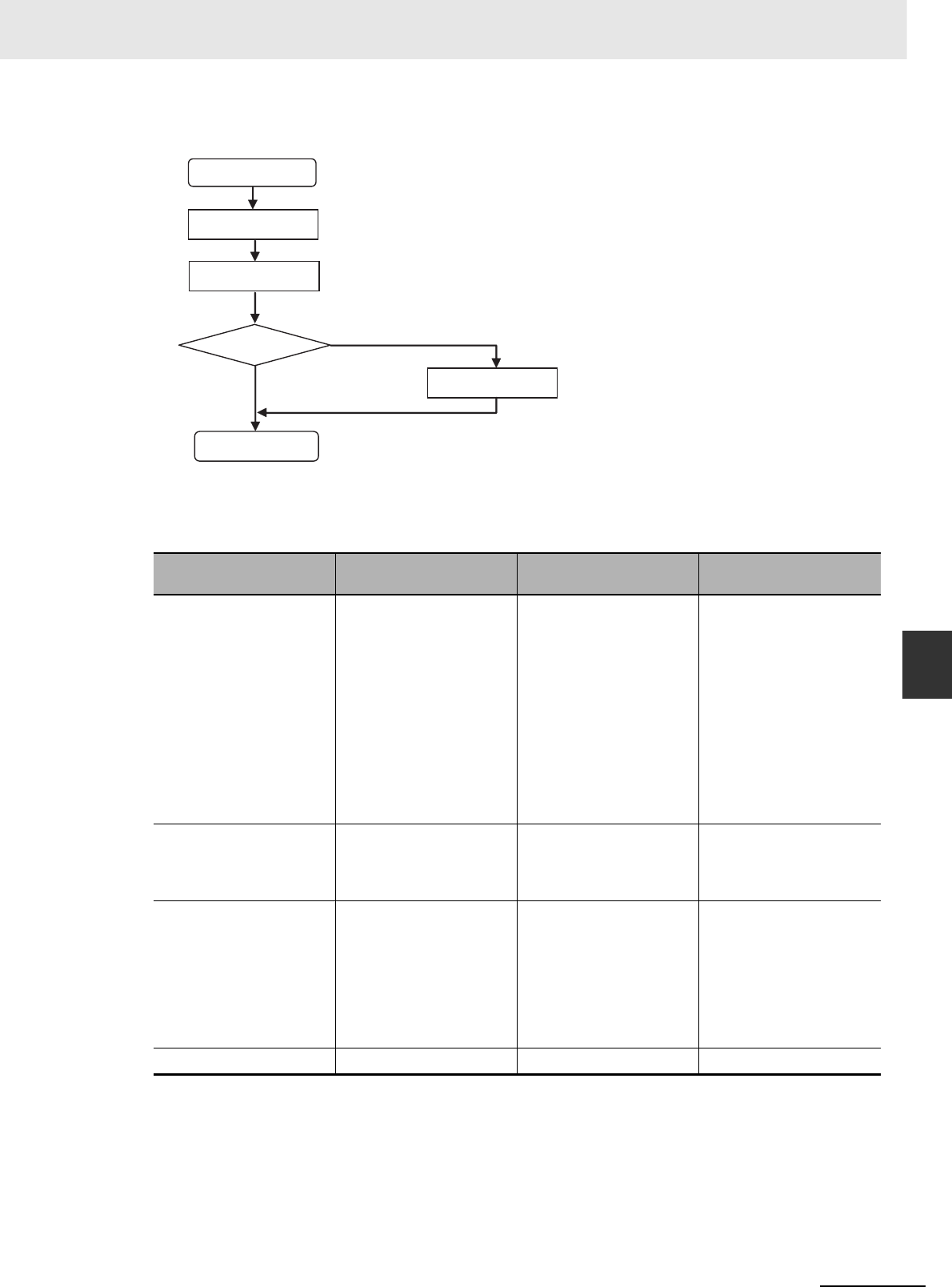
6-17
6 Troubleshooting
CJ2 CPU Unit Hardware User’s Manual
6-1 CPU Unit Errors
6
6-1-7 Handling Errors
zRecovery Processing Flow
zError Causes and Remedies
If the measures described above do not clear the error, take the measures shown in the following
table.
*1 This refers to errors caused by data corruption. SRAM is used for the CPU Unit user memory. SRAM is
affected by cosmic rays (neutrons) and naturally occurring radiation, so data can become corrupted.
Suspected cause of
error Confirmation method Remedy Prevention of recur-
rence
Unit failure
• Memory element failure
• Memory peripheral cir-
cuit failure
A memory error has prob-
ably occurred in the follow-
ing cases.
• If the error is not cleared
when the CPU Unit is
restarted after the
recovery measures
• If the error occurs fre-
quently
• If the condition improves
when the Unit is
replaced.
Replace the CPU Unit. Determined by the cause
of the failure.
A conductive object has
gotten inside.
Check for conductive
objects.
Clean the inside of the
Unit with an air blower or
replace the CPU Unit.
Do not do any metal work-
ing in the vicinity of the
control panel. Close the
control panel.
Noise
• Data corruption in mem-
ory
• Microcomputer malfunc-
tioning
• Memory write circuit
malfunctioning
When the CPU Unit is
restarted after the recov-
ery measures, the error
will either be cleared or
will continue to occur.
Check whether errors
become less frequent
after the Unit is replaced.
Take measures against
noise. (Investigate the
path of entry.)
•FG
• Power lines
Same as at the left.
Software error*1 None None None
Memory error
Check the error
status.
Implement the
remedy.
Is the error cleared?
Yes
No
Replace the Unit.
Restart the System.
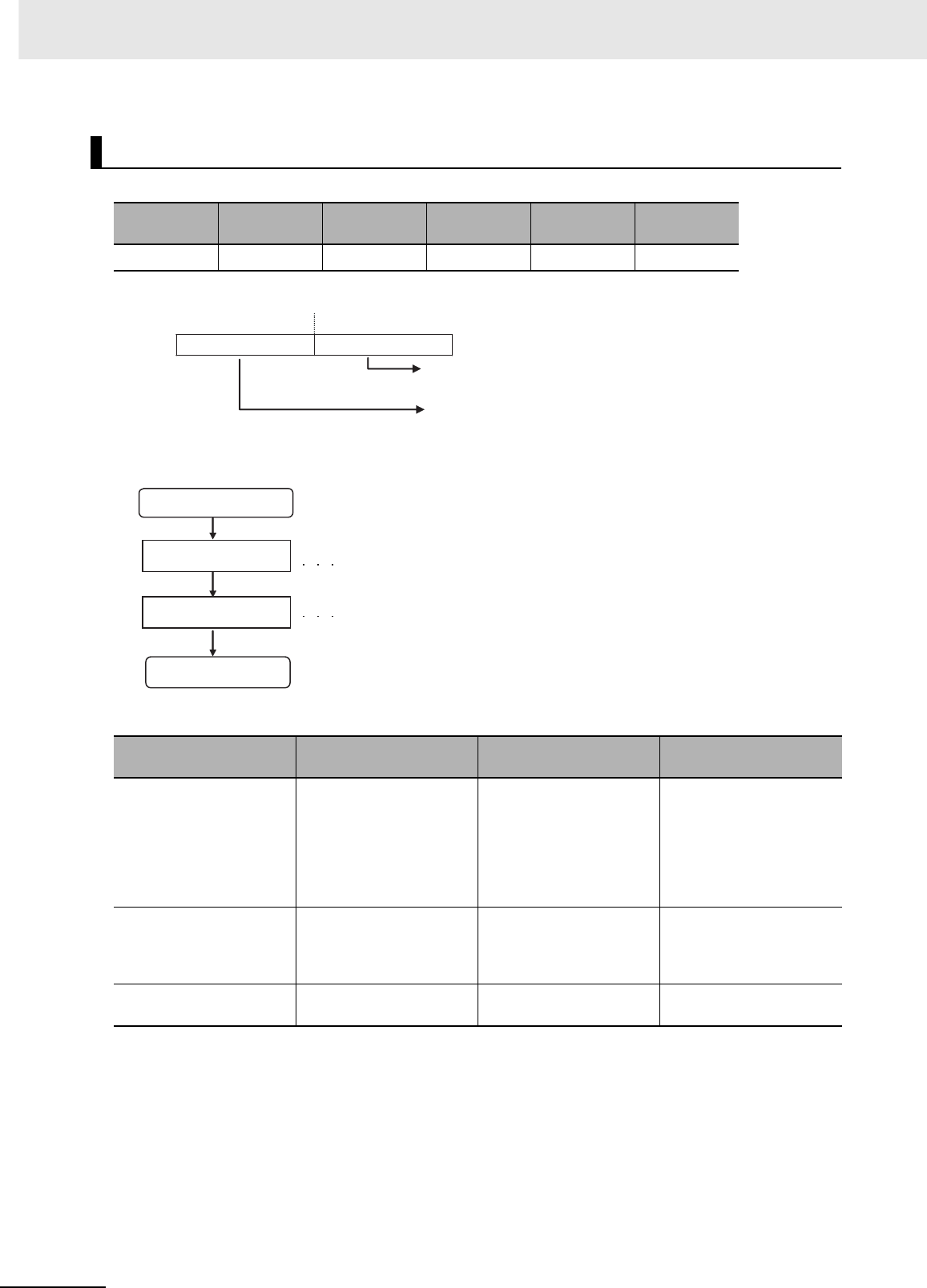
6 Troubleshooting
6-18 CJ2 CPU Unit Hardware User’s Manual
A basic I/O error occurs when there is an error at a Basic I/O Unit.
*1 Error Information
zRecovery Processing Flow
zError Causes and Remedies
Basic I/O Error (Non-fatal Error)
POWER RUN ERR/ALM Error flag Error code Error infor-
mation
Lit. Lit. Flashing. A402.12 009A A408*1
Suspected cause of
error Confirmation method Remedy Prevention of recur-
rence
A fuse is burned out. Measure the voltage at the
power supply terminals.
Check whether 24 V is
being supplied. (Check
whether the problem is
solved by replacing the
fuse.)
Replace the fuse. Check the maximum
switching current.
The external power supply
is OFF (disconnected).
Measure the voltage at the
power supply terminals.
Check whether 24 V is
being supplied.
Turn ON the power supply. Investigate the reason that
the power was turned
OFF.
Other errors specific to
Units
Refer to the manual for the
particular Unit.
Same as at the left. Same as at the left.
15 08 07 01
A408
Number of slot where the Unit with the error is
mounted in binary.
Number of Rack where the Unit with the error is
mounted in binary.
Basic I/O error occurs.
Check the location of
the error. Check the error information (A408).
Replace the Unit. Check the cause of the error, and take
measures to prevent it from occurring again.
Restart the System.
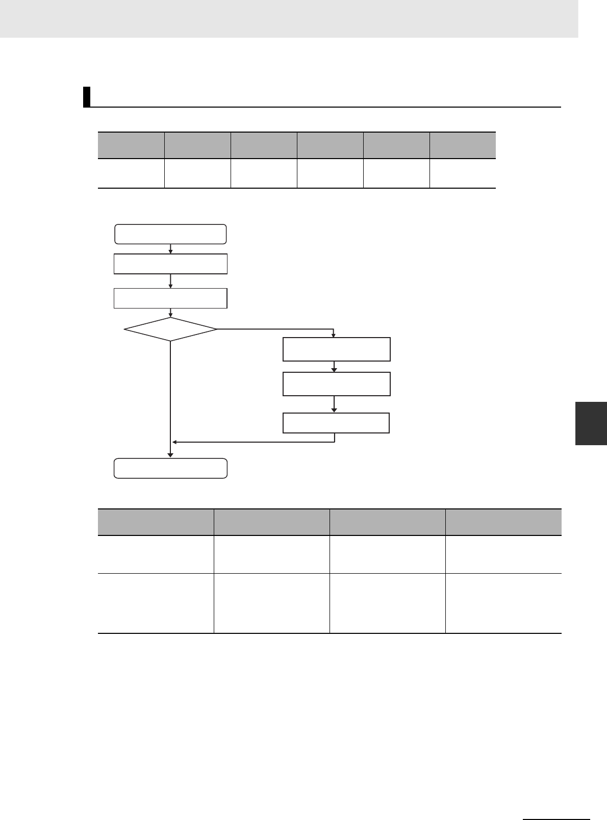
6-19
6 Troubleshooting
CJ2 CPU Unit Hardware User’s Manual
6-1 CPU Unit Errors
6
6-1-7 Handling Errors
An Option Board error will occur if the Option Board is removed while the power is being supplied.
zRecovery Processing Flow
zError Causes and Remedies
Option Board Errors
POWER RUN ERR/ALM Error flag Error code Error infor-
mation
Lit. Lit. Flashing. A315.13
A402.00
00D1 ---
Suspected cause of
error Confirmation method Remedy Prevention of recur-
rence
The Option Board was
removed while the system
was operating.
Check the mating of the
Option Board connector.
Reconnect. Check for vibration and
shock.
Option Board failure If restarting does not clear
the error, check whether
the error is cleared by
replacing the Option
Board.
Replace the Option Board. Same as at the left.
Check the location of the error.
Yes
No
Option Board error occurs.
Restart the System.
Replace the Option Board.
Restart the PLC.
Restart the PLC.
Check the Unit connections.
Recovered?
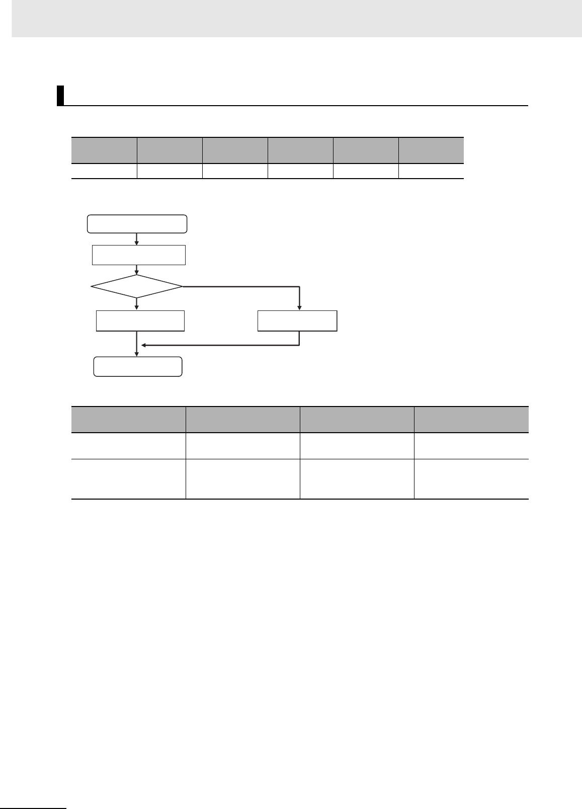
6 Troubleshooting
6-20 CJ2 CPU Unit Hardware User’s Manual
A battery error occurs when the battery voltage drops.
zRecovery Processing Flow
zError Causes and Remedies
Battery Error (Non-fatal Error)
POWER RUN ERR/ALM Error flag Error code Error infor-
mation
Lit. Lit. Flashing. A402.04 00F7 ---
Suspected cause of
error Confirmation method Remedy Prevention of recur-
rence
A connector is discon-
nected.
Check the connection at
the connector.
Reconnect the connector. Check for vibration and
shock.
Battery voltage is low. Check whether the error is
cleared by replacing the
battery.
Replace the battery.
For details, refer to 7-2
Replacing the Battery.
Periodically replace the
battery.
Battery error occurs.
Normal? Yes
No
Reconnect
Restart the System.
Replace the battery.
Check the battery
connections.
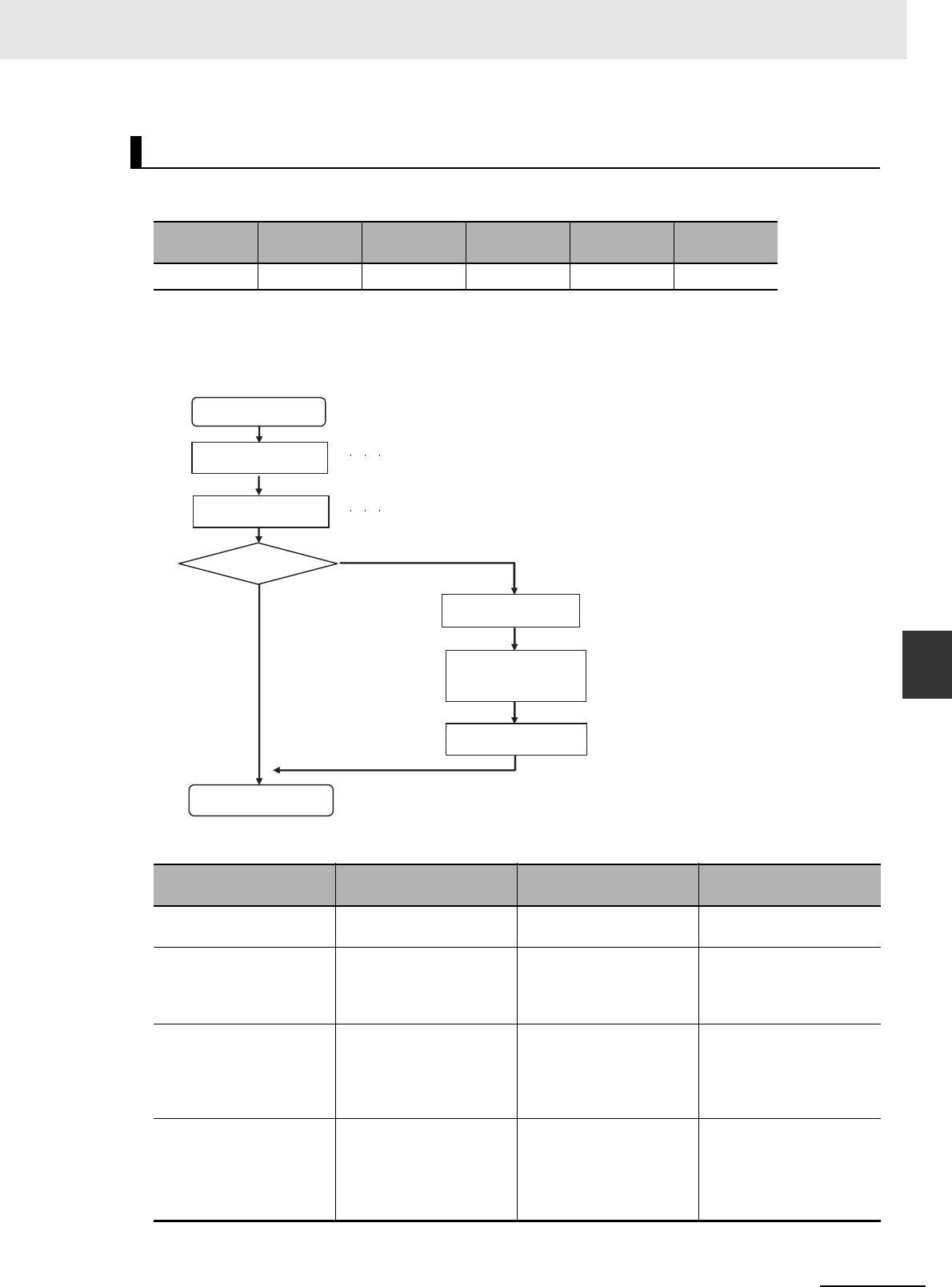
6-21
6 Troubleshooting
CJ2 CPU Unit Hardware User’s Manual
6-1 CPU Unit Errors
6
6-1-7 Handling Errors
A CPU Bus Unit error occurs when there is an error in the data conversion between the CPU Unit and a
CPU Bus Unit.
* The bit corresponding to the unit number where the error occurred turns ON. (Bits 00 to 15 correspond to unit
numbers 0 to F.)
zRecovery Processing Flow
zError Causes and Remedies
CPU Bus Unit Error (Non-fatal Error)
POWER RUN ERR/ALM Error flag Error code Error infor-
mation
Lit. Lit. Flashing. A402.07 0200 to 020F A417*
Suspected cause of
error Confirmation method Remedy Prevention of recur-
rence
An error specific to the
Unit
Refer to the manual for the
particular Unit.
Same as at the left. Same as at the left.
Faulty connection at Unit
(at a connector)
Check the insertion at the
connector. Restart the
Unit and check whether
the error is cleared.
Tighten the screws. Check for vibration and
shock.
Unit failure If restarting the Unit does
not clear the error, check
whether the error is
cleared by replacing the
Unit.
Replace the applicable
Unit.
Same as at the left.
Noise
• Data corruption in bus
signals
Restart the CPU Unit and
check whether the error
occurs again.
Take measures against
noise. (Investigate the
path of entry.)
•FG
• Power lines
Same as at the left.
CPU Bus Unit error
occurs.
Check the location where
the error occurred.
Use the I/O table verification procedure
(refer to 6-1-5 I/O Table Verification) to
check where the error occurred.
Turn the power OFF and back ON.
Yes
No
Check the Unit
connections
Restart the PLC.
Restart the System.
Restart the PLC
Is the error cleared?
Replace the Unit
where the error
occurred.
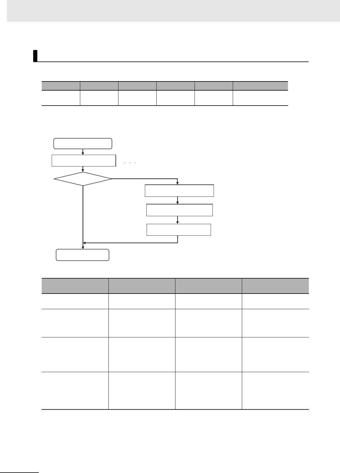
6 Troubleshooting
6-22 CJ2 CPU Unit Hardware User’s Manual
A Special I/O Unit error occurs when there is an error in the data conversion between the CPU Unit and
a Special I/O Unit.
* The bit corresponding to the unit number where the error occurred turns ON.
zRecovery Processing Flow
zError Causes and Remedies
Special I/O Unit Error (Non-fatal Error)
POWER RUN ERR/ALM Error flag Error code Error information
Lit. Lit. Flashing. A402.06 0300 to 035F
or 03FF
A418 to A423 *
Suspected cause of
error Confirmation method Remedy Prevention of recur-
rence
An error specific to the
Unit
Refer to the manual for the
particular Unit.
Same as at the left. Same as at the left.
Faulty connection at Unit
(at a connector)
Check the insertion at the
connector. Restart the
Unit and check whether
the error is cleared.
Tighten the screws. Check for vibration and
shock.
Unit failure If restarting the Unit does
not clear the error, check
whether the error is
cleared by replacing the
Unit.
Replace the applicable
Unit.
Same as at the left.
Noise
• Data corruption in bus
signals
Restart the CPU Unit and
check whether the error
occurs again after this.
Take measures against
noise. (Investigate the
path of entry.)
•FG
• Power lines
Same as at the left.
Special I/O Unit error
occurs.
Restart the Special I/O Unit. Reset, or turn the power OFF and back ON.
Is the error cleared?
Yes
No
Check the Unit connections.
Replace the Special I/O Unit.
Restart the Special I/O Unit.
Restart the System.
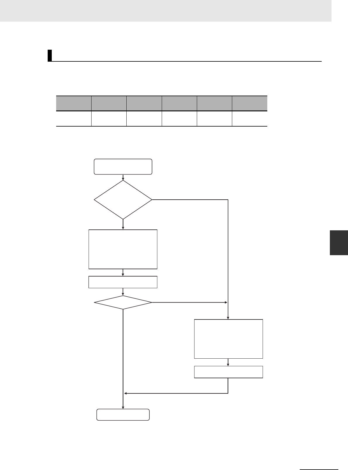
6-23
6 Troubleshooting
CJ2 CPU Unit Hardware User’s Manual
6-1 CPU Unit Errors
6
6-1-7 Handling Errors
A Special I/O Unit setting error will occur if a Unit registered in the registered I/O tables does not agree
with the Unit actually connected in the PLC. A Special I/O Unit setting error will also occur if a Unit set
as a Synchronous Unit in the synchronous operation parameter settings is not actually connected in the
PLC or does not support synchronous unit operation.
* The bit corresponding to the Unit for which the error occurred will turn ON.
zRecovery Processing Flow
Special I/O Unit Setting Error (Non-fatal Error)
POWER RUN ERR/ALM Error flag Error code Error infor-
mation
Lit. Lit. Flashing. A402.02 0500 to
055F
A428 to A433*
Special I/O Unit setting
error occurs.
Synchronous unit
operation being
used?
Check if error is caused by
synchronous unit operation
settings. (A428 to A433 will
tell you which Unit caused
the error.)
Perform the recovery procedure.
Operation
recovered?
Restart the system.
Check if error is caused by
registered I/O settings.
(A428 to A433 will tell you
which Unit caused the error.)
Perform the recovery procedure.
No
Yes
No
Yes

6 Troubleshooting
6-24 CJ2 CPU Unit Hardware User’s Manual
zError Causes and Remedies for Synchronous Unit Operation Settings
zError Causes and Remedies for Registered I/O Table Settings
Suspected cause of
error Confirmation method Remedy Prevention of recur-
rence
A Unit set in the synchro-
nous unit operation set-
tings does not support
synchronous unit opera-
tion.
Check the operation man-
ual for the Unit.
Transfer the settings
again.
Same as at the left.
A Unit set in the synchro-
nous unit operation set-
tings does not exist in the
PLC.
Check the Units in the
PLC.
Transfer the settings
again.
Same as at the left.
A Unit set in the synchro-
nous unit operation set-
tings does not exist on the
CPU Rack (i.e., it is on an
Expansion Rack).
Check the Units in the
PLC.
Move the Synchronous
Unit to the CPU Rack.
If I/O tables have been
registered, change the
registered I/O tables.
Same as at the left.
Suspected cause of
error Confirmation method Remedy Prevention of recur-
rence
The model of a CPU Bus
Unit in the registered I/O
tables is different from the
model the Unit actually
mounted in the PLC.
Check the Units in the
PLC.
Correct the I/O table set-
tings.
Same as at the left.
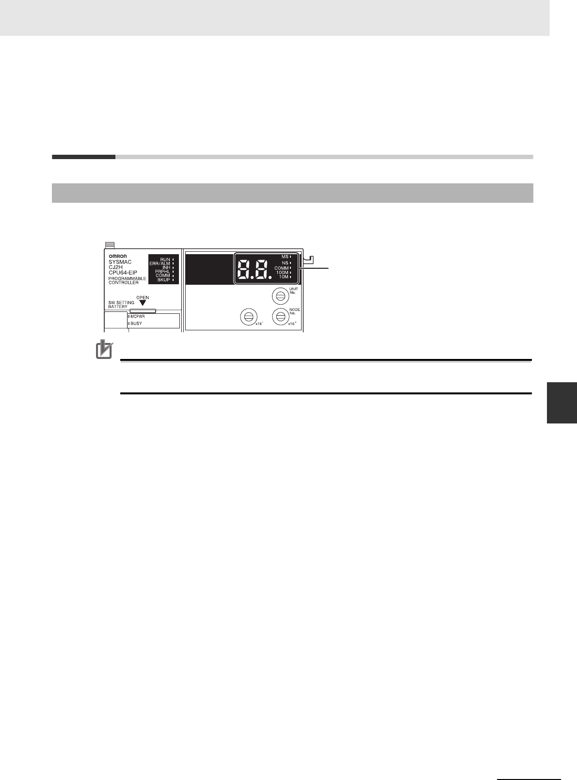
6-25
6 Troubleshooting
CJ2 CPU Unit Hardware User’s Manual
6-2 Built-in EtherNet/IP Port Errors and Remedies (CJ2H-CPU6@-EIP Only)
6
6-2-1 Checking Built-in EtherNet/IP Port Error Status
6-2 Troubleshooting Built-in EtherNet/IP
Port Errors (CJ2H-CPU6@-EIP and
CJ2M-CPU3@ Only)
Built-in EtherNet/IP port errors can be checked on the built-in EtherNet/IP port seven-segment display
on the front of the CJ2H-CPU6@-EIP or CJ2M-CPU3@ CPU Unit.
Precautions for Correct UsePrecautions for Correct Use
• For details on the types of errors related to the built-in EtherNet/IP port, and measures for han-
dling them, refer to the CS/CJ Series EtherNet/IP Units Operation Manual (Cat. No. W465).
6-2-1 Checking Built-in EtherNet/IP Port Error Status
Built-in EtherNet/IP port
seven-segment display
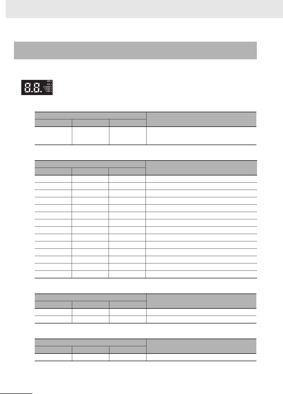
6 Troubleshooting
6-26 CJ2 CPU Unit Hardware User’s Manual
zNormal Operation
zErrors Related to CPU Unit Data Exchange
zErrors Related to the CPU Unit
zErrors Related to the Control Bits
6-2-2 Checking Error Status at the EtherNet/IP Port Seven-segment
Display
The seven-segment display alternately displays the built-in EtherNet/IP port node address and the
following error codes.
Indications Error
MS NS 7-segment
Lit green Lit or flashing
green
Built-in Ether-
Net/IP port node
address
Normal
Indications Error
MS NS 7-segment
Flashing red Not lit H1 Duplicate unit number
Flashing red Not lit H2 CPU Unit faulty
Lit red Not lit H3 Built-in EtherNet/IP port faulty
Flashing red Not lit H4 Node address setting error
Flashing red Not lit H6 CPU Unit faulty
Flashing red Not lit H7 I/O table not registered
Flashing red --- H8 Simple backup function restore error
Flashing red --- H9 I/O bus error
Flashing red --- HA CPU Unit memory error
Flashing red Not lit Hb CPU Unit event servicing timeout
Flashing red --- HC Routing table error
Flashing red --- Hd I/O refresh error
Flashing red --- HE CPU Unit service monitoring error
Flashing red --- HF CPU Unit watchdog timer error
Indications Error
MS NS 7-segment
Flashing red --- HH CPU Unit Fatal Error
--- --- --- Output OFF Error
Indications Error
MS NS 7-segment
--- --- C6 Multiple Switches ON
Built-in EtherNet/IP port
seven-segment display
6-27
6 Troubleshooting
CJ2 CPU Unit Hardware User’s Manual
6-2 Built-in EtherNet/IP Port Errors and Remedies (CJ2H-CPU6@-EIP Only)
6
6-2-2 Checking Error Status at the EtherNet/IP Port Seven-segment
Display
zErrors Related to the Tag Data Links
zErrors Related to Memory Access
zErrors Related to the Network
zErrors Related to Units
Indications Error
MS NS 7-segment
--- --- d5 Verification Error (target non-existent)
--- --- d6 Connection Failed
--- --- d9 Tag Data Link Error
Indications Error
MS NS 7-segment
Flashing red --- E9 Memory Access Error
Flashing red --- E8 Device Parameters Error
Flashing red --- EA IP Advanced Settings Error
Flashing red --- F2 Ethernet Basic Settings Error
Indications Error
MS NS 7-segment
--- --- E1 Ethernet Link Not Detected
--- --- E3 Server Connection Error
--- Lit red F0 IP Address Duplication
Flashing red --- F3 Address mismatch
Flashing red Not lit F4 Communications Controller Error
Flashing red --- C8 Node Address Setting Changed During Operation
Indicator Error
MS NS 7-segment
Lit red Not lit --- CPU Bus Unit Error

6 Troubleshooting
6-28 CJ2 CPU Unit Hardware User’s Manual
6-3 Non-CPU Unit Errors and Remedies
6-3-1 Error Causes and Remedies
Input Units
No. Symptom Cause Remedy
1 Not all inputs turn ON or indica-
tors are not lit.
Power is not supplied to Input
Unit.
Supply the appropriate external
input power.
Supply voltage is low. Adjust supply voltage to within
rated range.
Terminal block mounting screws
are loose.
Tighten screws.
Faulty contact of terminal block
connector.
Replace terminal block connec-
tor.
2 Not all inputs turn ON (indicator
lit).
Input circuit is faulty. Replace Unit.
3 Not all inputs turn OFF. Input circuit is faulty. Replace Unit.
4 Specific bit does not turn ON. Input device is faulty. Replace input devices.
Input wiring disconnected. Check input wiring
Terminal block screws are loose. Tighten screws.
Faulty terminal block connector
contact.
Replace terminal block connec-
tor.
Too short ON time of external
input.
Adjust input device.
Faulty input circuit Replace Unit.
Input bit number is used for out-
put instruction.
Correct program.
5 Specific bit does not turn OFF. Input circuit is faulty. Replace Unit.
Input bit number is used for out-
put instruction.
Correct program.
6 Input irregularly turns ON/OFF. External input voltage is low or
unstable.
Adjust external input voltage to
within rated range.
Malfunction due to noise. Take protective measures
against noise, such as:
• Install surge suppressor.
• Install insulation transformer.
• Install shielded cables between
the Input Unit and the loads.
Terminal block screws are loose. Tighten screws.
Faulty terminal block connector
contact.
Replace terminal block connec-
tor.
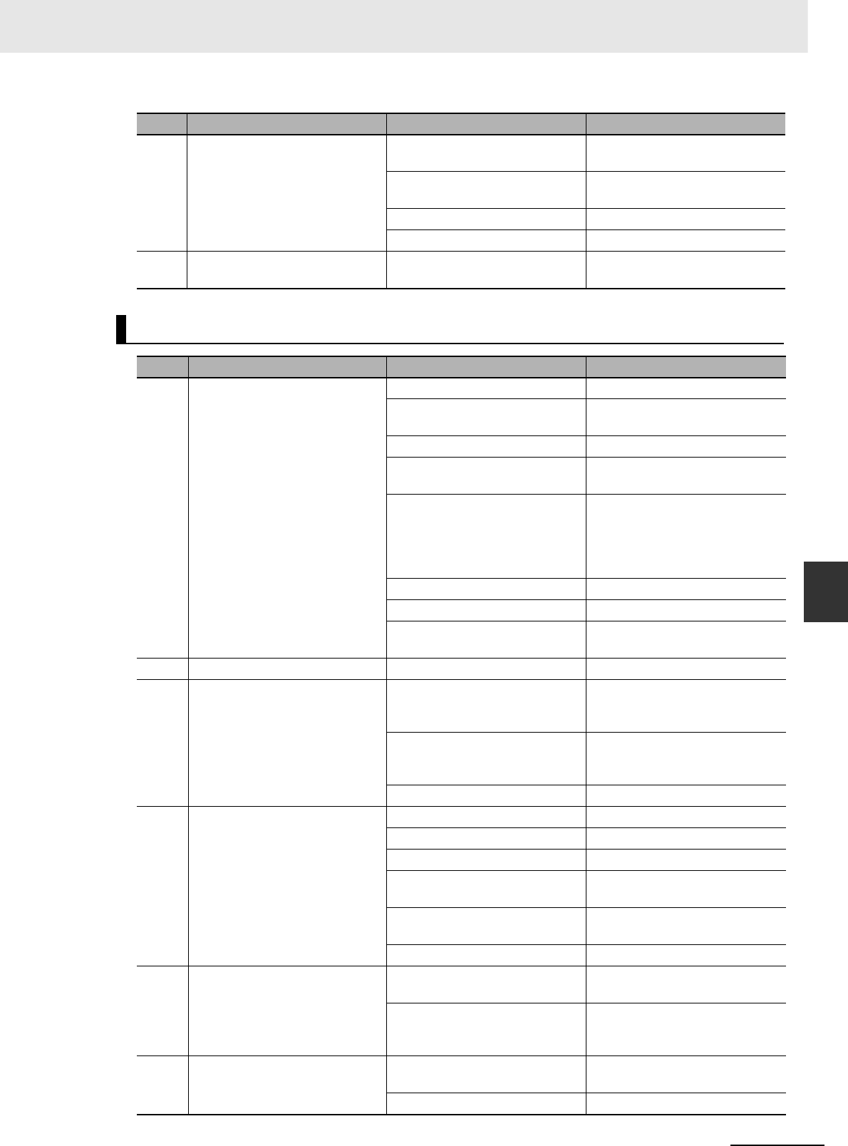
6-29
6 Troubleshooting
CJ2 CPU Unit Hardware User’s Manual
6-3 Non-CPU Unit Errors and Remedies
6
6-3-1 Error Causes and Remedies
7 Error occurs in units of 8 points
or 16 points, i.e., for the same
common.
Common terminal screws are
loose.
Tighten screws.
Faulty terminal block connector
contact.
Replace terminal block connec-
tor.
Faulty data bus Replace Unit.
Faulty CPU Replace CPU.
8 Input indicator is not lit in normal
operation.
Faulty indicator or indicator cir-
cuit.
Replace Unit.
Output Units
No. Symptom Cause Remedy
1 Not all outputs turn ON. Load is not supplied with power. Supply power.
Load voltage is low. Adjust voltage to within rated
range.
Terminal block screws are loose. Tighten screws.
Faulty terminal block connector
contact.
Replace terminal block connec-
tor.
An overcurrent (possibly caused
by a short at the load) resulted in
a blown fuse in the Output Unit.
(Some Output Units provide an
indicator for blown fuses.)
Replace fuse.
Faulty I/O bus connector contact. Replace Unit.
Output circuit is faulty. Replace Unit.
If the INH indicator is lit, the Out-
put OFF Bit (A500.15) is ON.
Turn A500.15 OFF.
2 Not all outputs turn OFF. Output circuit is faulty. Replace Unit.
3 Output of a specific bit number
does not turn ON or indicator is
not lit.
Output ON time too short
because of a mistake in program-
ming.
Correct program to increase the
time that the output is ON.
Bit status controlled by multiple
instructions.
Correct program so that each
output bit is controlled by only
one instruction.
Faulty output circuit. Replace Unit.
4 Output of a specific bit number
does not turn ON (indicator lit).
Faulty output device. Replace output device.
Break in output wiring. Check output wiring.
Loose terminal block screws. Tighten screws.
Faulty terminal block connector
contact.
Replace terminal block connec-
tor.
Faulty output bit on a Relay Out-
put Unit.
Replace relay.
Faulty output circuit. Replace Unit.
5 Output of a specific bit number
does not turn OFF (indicator is
not lit).
Faulty output bit (Relay Output
Units only)
Replace relay.
Bit does not turn OFF due to
leakage current or residual volt-
age.
Replace external load or add
dummy resistor.
6 Output of a specific bit number
does not turn OFF (indicator lit).
Bit status controlled by multiple
instructions.
Correct program.
Faulty output circuit. Replace Unit.
No. Symptom Cause Remedy

6 Troubleshooting
6-30 CJ2 CPU Unit Hardware User’s Manual
zSpecial I/O Units
Refer to the Operation Manual for the Special I/O Unit to troubleshoot any other errors.
7 Output irregularly turns ON/OFF. Low or unstable load voltage. Adjust load voltage to within
rated range.
Bit status controlled by multiple
instructions.
Correct program so that each
output bit is controlled by only
one instruction.
Malfunction due to noise. Protective measures against
noise:
• Install surge suppressor.
• Install insulation transformer.
• Use shielded cables between
the Output Unit and the loads.
Terminal block screws are loose. Tighten screws.
Faulty terminal block connector
contact.
Replace terminal block connec-
tor.
8 Error occurs in units of 8 points
or 16 points, i.e., for the same
common.
Loose common terminal screw. Tighten screws.
Faulty terminal block connector
contact.
Replace terminal block connec-
tor.
An overcurrent (possibly caused
by a short at the load) resulted in
a blown fuse in the Output Unit.
Replace fuse.
Faulty data bus. Replace Unit.
Faulty CPU. Replace CPU.
9 Output indicator is not lit (opera-
tion is normal).
Faulty indicator. Replace Unit.
10 ERR indicator (load short-circuit
alarm) lights and outputs turn
OFF.
An external short-circuit or dis-
connection occurred.
Refer to A-6-1 Load Short-circuit
Protection and Line Disconnec-
tion Detection for CJ1W-OD202.
No. Symptom Cause Remedy
1 The ERH and RUN indicators on
the Special I/O Unit are lit.
Special I/O refreshing is not
being performed for the Unit from
the CPU Unit (CPU Unit monitor-
ing error).
Change the bit corresponding to
the unit number to 0 to enable
cyclic refreshing, or make sure
that the Unit is refreshed from
the program using IORF or
FIORF at least once every 11 s.
No. Symptom Cause Remedy
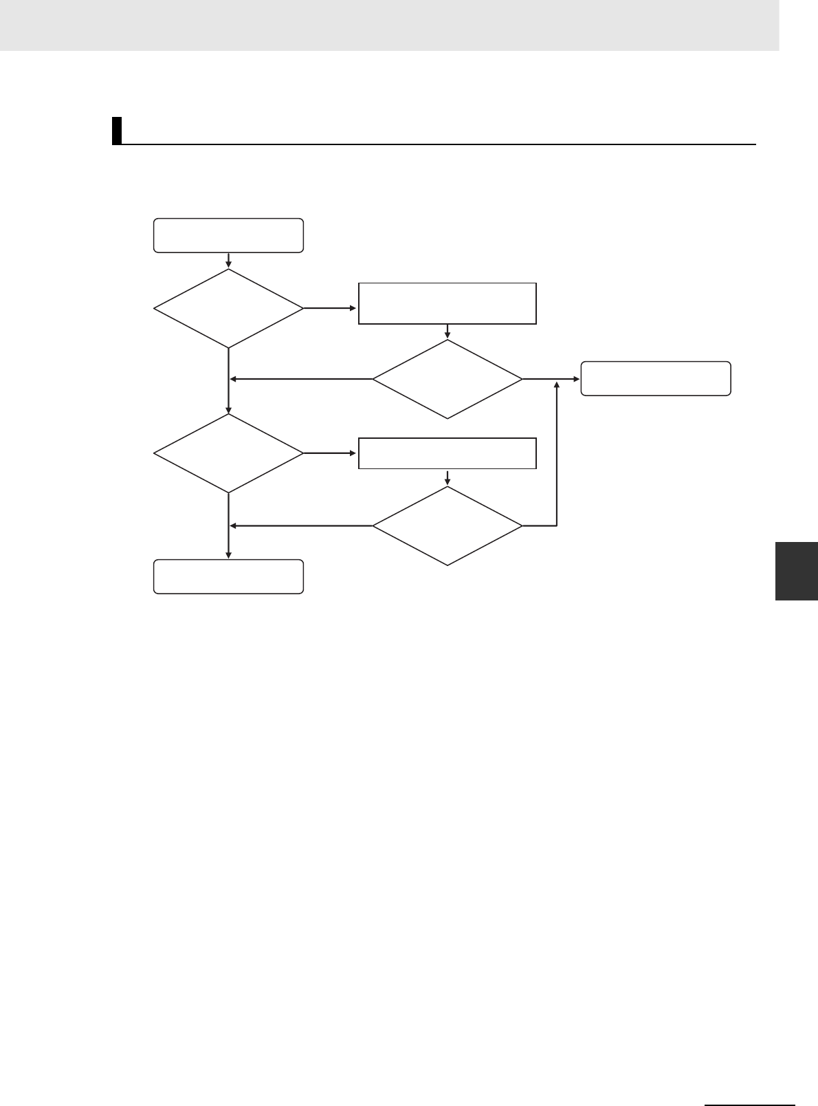
6-31
6 Troubleshooting
CJ2 CPU Unit Hardware User’s Manual
6-3 Non-CPU Unit Errors and Remedies
6
6-3-1 Error Causes and Remedies
Use the following procedure if the CX-Programmer cannot be connected.
zConnecting via the Peripheral (USB) Port
CX-Programmer Connections
The CX-Programmer
cannot connect.
Is the USB cable
securely
connected?
No
No
No
No
Insert the cable all the way in at
both the personal computer and at
the CPU Unit.
Yes
Yes
Yes
Yes
Can the
CX-Programmer be
connected online? End
Is the
CX-Programmer
network type set
to USB?
Set the CX-Programmer network
type to USB.
Can the
CX-Programmer be
connected online?
Replace the USB cable.
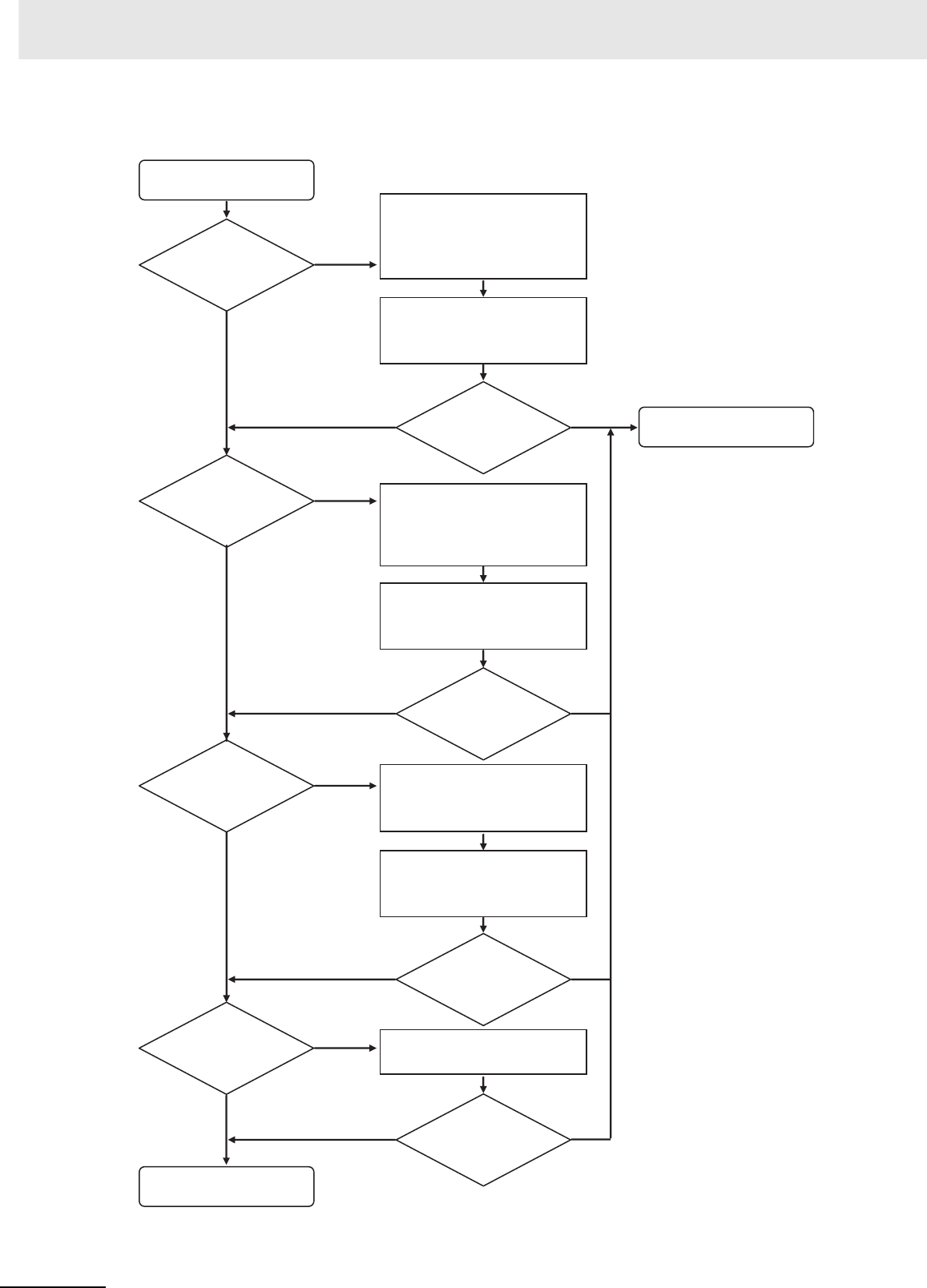
6 Troubleshooting
6-32 CJ2 CPU Unit Hardware User’s Manual
zConnection to the EtherNet/IP Port (CJ2H-CPU6@-EIP and CJ2M-CPU3@ Only)
The CX-Programmer
cannot connect.
Is the Ethernet cable
securely connected?
At the personal computer (or the
Ethernet switch) and the CPU Unit,
firmly insert the cable until the connector
locks. Confirm that the LINK indicator
lights at the personal computer (or
Ethernet switch) and that the 100M
(10M) indicator lights at the CPU Unit.
Use the ping command from the personal
computer to confirm that the communications
to the PLC have been established. For details,
refer to the EtherNet/IP Unit Operation Manual
(Cat. No. W465).
Can the
CX-Programmer be
connected online?
Is an Ethernet switch
used between the
personal computer
and the PLC?
If a personal computer is connected to
a PLC using Straight Cable (or Cross
Cable), it can occasionally be difficult to
make the connection. If this occurs, try
using an Ethernet switch between the
computer and PLC.
Use the ping command from the personal
computer to confirm that the communications
to the PLC is established. For details, refer to
the EtherNet/IP Unit Operation Manual (Cat.
No. W465).
Can the
CX-Programmer
be connected
online?
Are unique IP
addresses used for the
personal computer and
the CPU Unit, and are
they set for the same
domain?
Set the IP address for the personal
computer. Either use the default IP
address for the CPU Unit or else
connect the CX-Programmer and set
another IP address.
Use the ping command from the personal
computer to confirm that the communications
to the PLC has been established. For details,
refer to the EtherNet/IP Unit Operation Manual
(Cat. No. W465).
Can the
CX-Programmer be
connected online?
Is the
CX-Programmer
network type set to
EtherNet/IP?
Set the CX-Programmer network
type to EtherNet/IP.
Can the
CX-Programmer be
connected online?
Replace the Ethernet cable
and the Ethernet switch.
No
Yes
End
Yes
Yes
Yes
Yes
Yes
No
No
No
No
No
No Yes
Yes
No
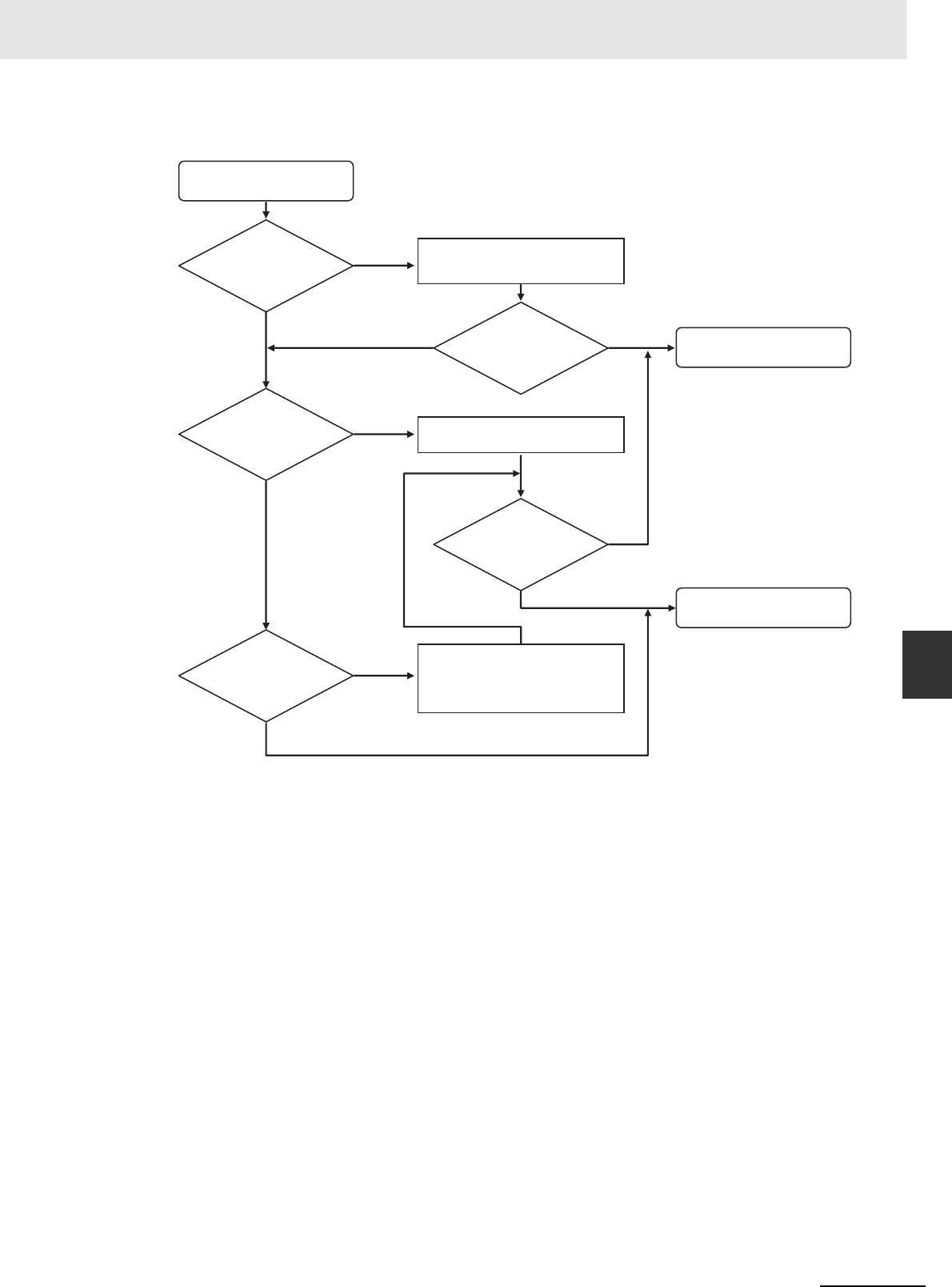
6-33
6 Troubleshooting
CJ2 CPU Unit Hardware User’s Manual
6-3 Non-CPU Unit Errors and Remedies
6
6-3-1 Error Causes and Remedies
zConnecting via the Serial Port
No
Yes
End
Yes
Yes
Yes
No
No
No
No
Yes
The CX-Programmer
cannot connect.
Is the RS-232C
cable securely
connected?
Insert the cable all the way in at
both the personal computer and
at the CPU Unit.
Can the
CX-Programmer be
connected online?
Is pin 5 of the
CPU Unit DIP
switch turned
ON?
Set the CX-Programmer network
type to Toolbus.
Can the
CX-Programmer
be connected
online?
Replace the RS-232C cable.
In the PLC Setup
in the CPU Unit, does the
serial port setting match the
CX-Programmer network type
setting?
In the PLC Setup in the CPU Unit,
match the serial port setting with
the CX-Programmer network type
setting.

6 Troubleshooting
6-34 CJ2 CPU Unit Hardware User’s Manual

7-1
CJ2 CPU Unit Hardware User’s Manual
7
This section describes the inspection and maintenance that is required for CJ2 PLCs.
7-1 Inspections . . . . . . . . . . . . . . . . . . . . . . . . . . . . . . . . . . . . . . . . . . . . . . . . . . . 7-2
7-1-1 Inspection Points . . . . . . . . . . . . . . . . . . . . . . . . . . . . . . . . . . . . . . . . . . . . . . . 7-2
7-1-2 Unit Replacement Precautions . . . . . . . . . . . . . . . . . . . . . . . . . . . . . . . . . . . . 7-4
7-2 Replacing the Battery . . . . . . . . . . . . . . . . . . . . . . . . . . . . . . . . . . . . . . . . . . 7-5
7-2-1 Battery Replacement . . . . . . . . . . . . . . . . . . . . . . . . . . . . . . . . . . . . . . . . . . . . 7-5
7-2-2 Operation When Battery Is Exhausted or Not Installed . . . . . . . . . . . . . . . . . . 7-8
7-3 Power Supply Unit Replacement Time . . . . . . . . . . . . . . . . . . . . . . . . . . . . 7-10
Inspection and Maintenance

7 Inspection and Maintenance
7-2 CJ2 CPU Unit Hardware User’s Manual
7-1 Inspections
Daily or periodic inspections are required in order to maintain the PLC's functions in peak operating
condition.
Although the major components in CJ-series PLCs have an extremely long life time, they can deterio-
rate under improper environmental conditions. Periodic inspections are thus required to ensure that the
required conditions are being kept.
Inspection is recommended at least once every six months to a year, but more frequent inspections will
be necessary in adverse environments.
Take immediate steps to correct the situation if any of the conditions in the following table are not met.
7-1-1 Inspection Points
Periodic Inspection Points
No. Item Inspection Criteria Action
1 Source Power
Supply
Check for voltage fluctua-
tions at the power supply ter-
minals.
The voltage must be within
the allowable voltage fluctua-
tion range.
Use a voltage tester to check the
power supply at the terminals. Take
necessary steps to bring voltage
fluctuations within limits.
2 I/O Power Supply Check for voltage fluctua-
tions at the I/O terminals.
Voltages must be within
specifications for each Unit.
Use a voltage tester to check the
power supply at the terminals. Take
necessary steps to bring voltage
fluctuations within limits.
3 Ambient environ-
ment
Check the ambient tempera-
ture. (Inside the control panel
if the PLC is in a control
panel.)
0 to 55°C Use a thermometer to check the
temperature and ensure that the
ambient temperature remains
within the allowed range of 0 to
55°C.
Check the ambient humidity.
(Inside the control panel if
the PLC is in a control
panel.)
Relative humidity must be
10% to 90% with no conden-
sation.
Use a hygrometer to check the
humidity and ensure that the ambi-
ent humidity remains between 10%
and 90%. Make sure that conden-
sation does not occur due to rapid
changes in temperature.
Check that the PLC is not in
direct sunlight.
Not in direct sunlight Protect the PLC if necessary.
Check for accumulation of
dirt, dust, salt, metal filings,
etc.
No accumulation Clean and protect the PLC if nec-
essary.
Check for water, oil, or chem-
ical sprays hitting the PLC.
No spray on the PLC Clean and protect the PLC if nec-
essary.
Check for corrosive or flam-
mable gases in the area of
the PLC.
No corrosive or flammable
gases
Check by smell or use a sensor.
Check the level of vibration
or shock.
Vibration and shock must be
within specifications.
Install cushioning or shock absorb-
ing equipment if necessary.
Check for noise sources near
the PLC.
No significant noise sources Either separate the PLC and noise
source or protect the PLC.

7-3
7 Inspection and Maintenance
CJ2 CPU Unit Hardware User’s Manual
7-1 Inspections
7
7-1-1 Inspection Points
zRequired Tools
• Slotted and Phillips-head screwdrivers
• Voltage tester or digital voltmeter
• Industrial alcohol and clean cotton cloth
zTools Required Occasionally
• Oscilloscope
• Thermometer and hygrometer (humidity meter)
4 Installation and
wiring
Check that each Unit is con-
nected and locked to the
next Unit securely.
No looseness Press the connectors together
completely and lock them with the
sliders.
Check that cable connectors
are fully inserted and locked.
No looseness Correct any improperly installed
connectors.
Check for loose screws in
external wiring.
No looseness Tighten loose screws with a Phil-
lips-head screwdriver.
Check crimp connectors in
external wiring.
Adequate spacing between
connectors
Check visually and adjust if neces-
sary.
Check for damaged external
wiring cables.
No damage Check visually and replace cables
if necessary.
5 User-serviceable
parts
Check whether the battery
has reached its service life.
CJ1W-BAT01
Service life expectancy is 5
years at 25°C, less at higher
temperatures.
(From 0.75 to 5 years
depending on model, power
supply rate, and ambient
temperature.)
Replace the battery when its ser-
vice life has passed even if a bat-
tery error has not occurred.
(Battery life depends upon the
model, the percentage of time in
service, and ambient conditions.)
Tools Required for Inspections
No. Item Inspection Criteria Action

7 Inspection and Maintenance
7-4 CJ2 CPU Unit Hardware User’s Manual
Check the following after replacing any faulty Unit.
• Do not replace a Unit until the power is turned OFF.
• Check the new Unit to make sure that there are no errors.
• If a faulty Unit is being returned for repair, describe the problem in as much detail as possible,
enclose this description with the Unit, and return the Unit to your OMRON representative.
• For poor contact, take a clean cotton cloth, soak the cloth in industrial alcohol, and carefully wipe the
contacts clean. Be sure to remove any lint prior to remounting the Unit.
Precautions for Correct UsePrecautions for Correct Use
• When replacing a CPU Unit, be sure that not only the user program but also all other data
required for operation is transferred to or set in the new CPU Unit before starting operation,
including DM Area and HR Area settings. If data area and other data are not correct for the
user program, unexpected accidents may occur.
• Be sure to include the routing tables, Controller Link Unit data link tables, network parameters,
and other CPU Bus Unit data, which are stored as parameters in the CPU Unit. Be sure to set
this data again after replacing the CPU Unit.
• Refer to the CPU Bus Unit and Special I/O Unit operation manuals for details on the data
required by each Unit.
Additional Information
The simple backup operation can be used to store the user program and all parameters for the
CJ2 CPU Unit, DeviceNet Units, Serial Communications Units, and other specific Units in a
Memory Card as backup files. A Memory Card and the simple backup operation can be used to
easily restore data after replacing any of these Units.
Refer to 8-3-6 Data Backed Up Using Simple Backup for details.
7-1-2 Unit Replacement Precautions
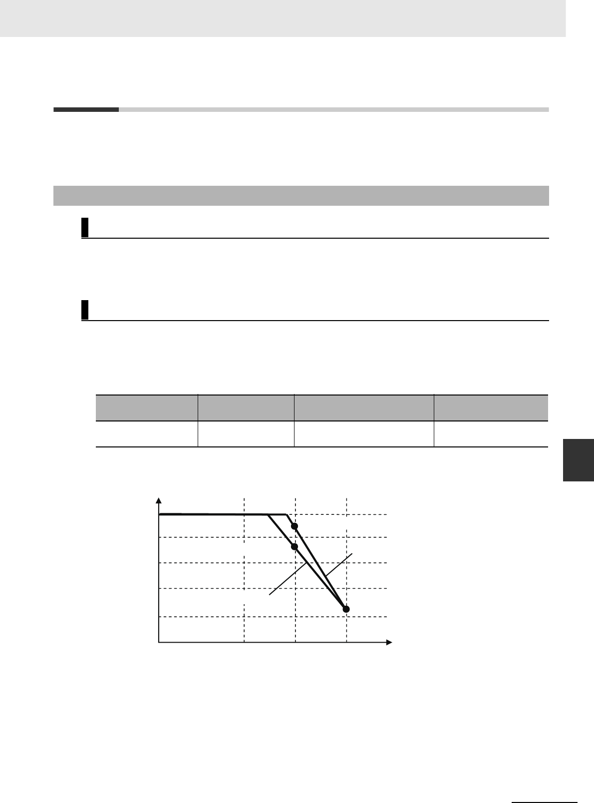
7-5
7 Inspection and Maintenance
CJ2 CPU Unit Hardware User’s Manual
7-2 Replacing the Battery
7
7-2-1 Battery Replacement
7-2 Replacing the Battery
The Battery in the CJ-series CPU Unit must be replaced periodically as preventative maintenance. (The
Battery is a backup power supply for the CPU Unit's internal clock and RAM). This section describes
how to replace the Battery.
The Battery maintains the CPU Unit internal clock and the I/O memory data held in RAM while the main
power supply is OFF. If the Battery is not installed or Battery voltage drops too low, the internal clock will
stop and the I/O memory data that is held will be lost when the main power supply goes OFF.
At 25°C, the maximum service life for batteries is five years whether or not power is supplied to the CPU
Unit while the battery is installed. The battery's lifetime will be shorter when it is used at higher temper-
atures and when power is not supplied to the CPU Unit for long periods.
The following table shows the approximate minimum lifetimes and typical lifetimes for the backup bat-
tery (total time with power not supplied).
*1 The minimum lifetime is the memory backup time at an ambient temperature of 55°C. The typical lifetime is the
memory backup time at an ambient temperature of 25°C.
7-2-1 Battery Replacement
Purpose of the Battery
Battery Service Life and Replacement Period
Model Approx. maximum
lifetime Approx. minimum lifetime*1 Typical lifetime*1
CJ2H-CPU6@(-EIP)
CJ2M-CPU@@ 5 years 1 year 2 months 5 years
Memory Backup Time
5 yr
4 yr
3 yr
2 yr
1 yr
Ambient temperature
This graphic is for reference only.
25°C40°C55°C
1 year 2 months
CJ2H-CPU6@(-EIP)
CJ2M-CPU@@
4 year 5 months
3 year 7 months
7 Inspection and Maintenance
7-6 CJ2 CPU Unit Hardware User’s Manual
If the PLC Setup has been set to detect a low-battery error, the ERR/ALM indicator on the front of the
CPU Unit will flash when the battery is nearly discharged.
If the Battery Error Flag (A402.04) is ON*1, first check whether the Battery is properly connected to the
CPU Unit. If the battery is properly connected, replace the battery as soon as possible.
Once a low-battery error has been detected, it will take 5 days (at an ambient temperature of 25°C*2)
before the battery fails assuming that power has been supplied at least once a day. Battery failure and
the resulting loss of data in RAM can be delayed by ensuring that the CPU Unit power is not turned
OFF until the battery has been replaced.
*1 The Battery Error Flag (A402.04) will turn ON only if the Detect Low Battery parameter in the PLC Setup has
been set to detect a low-battery error. If this setting has not been made, battery errors will not be detected.
*2 The battery will discharge faster at higher temperatures, e.g., 4 days at 40°C and 2 days at 55°C.
zReplacement Battery
Use the CJ1W-BAT01 Battery Set.
Precautions for Correct UsePrecautions for Correct Use
Be sure to install a replacement battery within two years of the production date shown on the
battery's label.
Use the following procedure to replace the battery when the previous battery has become completely
discharged.
Precautions for Safe Use
We recommend replacing the battery with the power OFF to prevent the CPU Unit's sensitive
internal components from being damaged by static electricity. The battery can be replaced with-
out turning OFF the power supply. To do so, always touch a grounded piece of metal to discharge
static electricity from your body before starting the procedure.
After replacing the battery, connect a Programming Device and clear the battery error.
1Turn OFF the power to the CPU Unit.
If the CPU Unit has not been ON, turn it ON for at least five minutes and then turn it OFF.
Low Battery Indicators
Replacement Procedure
ERR/ALM
RUN
COMM
INH
PRPHL
BKUP
CJ1W-BAT01
08-06
Production Date
Manufactured in June 2008.
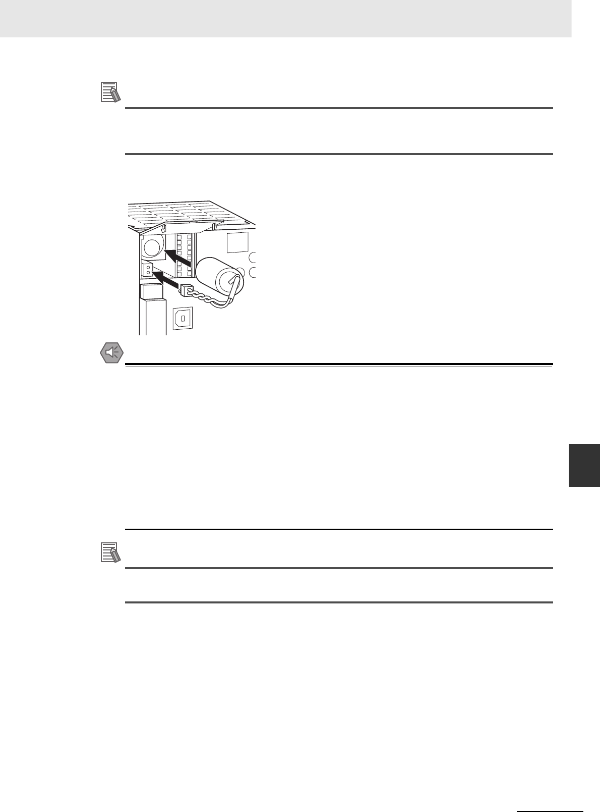
7-7
7 Inspection and Maintenance
CJ2 CPU Unit Hardware User’s Manual
7-2 Replacing the Battery
7
7-2-1 Battery Replacement
Additional Information
If power is not turned ON for at least five minutes before replacing the battery, the capacitor that
backs up memory when the battery is removed will not be fully charged and memory may be lost
before the new battery is inserted.
2Open the compartment on the upper left of the CPU Unit and carefully draw out the battery.
Precautions for Safe Use
• You must complete this procedure within five minutes at 25°C after turning OFF the power to
the CPU Unit to ensure memory backup. Data may be lost if more than five minutes is
required.
• Never short-circuit the battery terminals; never charge the battery; never disassemble the bat-
tery; and never heat or incinerate the battery. Doing any of these may cause the battery to
leak, burn, or rupturing resulting in injury, fire, and possible loss of life or property. Also, never
use a battery that has been dropped on the floor or otherwise subject to shock. It may leak.
• UL standards require that batteries be replaced by experienced technicians. Always place an
experienced technician in charge or battery replacement.
• Turn ON the power after replacing the battery for a CPU Unit that has been unused for a long
time. Leaving the CPU Unit unused again without turning ON the power even once after the
battery is replaced may result in a shorter battery life.
Additional Information
The battery error will be cleared automatically the next time the CPU Unit is turned ON after
replacing the Battery.
7 Inspection and Maintenance
7-8 CJ2 CPU Unit Hardware User’s Manual
The CJ-series PLCs can operate even when the Battery is exhausted or not installed.
To have operation continue when the Battery is exhausted or not installed, set the parameter in the PLC
Setup so that Battery errors are not detected.
The user program and parameter area data are saved in flash memory even when the Battery is
exhausted or not installed. I/O memory (such as the CIO Area), however, cannot be saved.
Operation is possible when the Battery is exhausted or not installed if the following two conditions both
apply.
• There is no need to save data in I/O memory.
• There is no need to use initial settings in the DM/EM Area, or the initial settings are made by the user
program.
Additional Information
You can use the function for automatic transfer from the Memory Card at startup to store data in
I/O memory and the DM/EM Area even when the Battery is exhausted or not installed.
The following table shows when the Battery is required according to the purpose of CPU Unit operation.
• The clock function cannot be used, so the values for the Calendar/Clock Area (A351 to A354) and the
Startup Time (A510 to A511) in the Auxiliary Area will be unstable. In addition, the times at which the
CPU Unit created files on the Memory Card will be unstable.
• The Total Power ON Time (A523), Power Interruption Time (A512 to A513), and Number of Power
Interruptions (A514) in the Auxiliary Area will all be all zeros at startup.
• Error log data will not be held in the Error Log Area (A100 to A199) in the Auxiliary Area at startup.
• Correct values may not be held in I/O memory (including the HR, DM, and EM Areas) at startup. In
the PLC Setup, set the IOM Hold Bit (A500.12) and the Forced Status Hold Bit (A500.13) to not be
held at startup.
7-2-2 Operation When Battery Is Exhausted or Not Installed
Continuing Operation
Saving Data
Conditions for Operation
Saving I/O memory is required. The Battery is required.
Saving to I/O
memory is not
required.
DM/EM Area ini-
tial values are
required at star-
tup.
DM/EM Area initial values are
set from the Memory Card.
Automatic transfer from the Mem-
ory Card at startup is set. (Pin 2 is
set to ON.)
DM/EM Area initial values are
set from the user program.
Normal operation from flash
memory or operation using the
Memory Card is possible.
DM/EM Area initial values are not required at star-
tup.
Restrictions
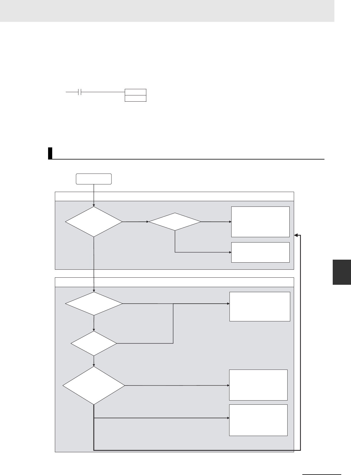
7-9
7 Inspection and Maintenance
CJ2 CPU Unit Hardware User’s Manual
7-2 Replacing the Battery
7
7-2-2 Operation When Battery Is Exhausted or Not Installed
• The value for the Output OFF Bit (A500.15) will become unstable. Moreover, when the Output OFF
Bit turns ON, the outputs of all Output Units will turn OFF. To prevent the outputs of all Output Units
from turning OFF at startup, take countermeasures such as writing the following program section into
the ladder program.
• Bank 0 will be the EM current bank at startup.
• Files will not be held in the EM file memory (EM data converted to flash memory) and the file memory
function cannot be used. Make the EM file memory setting again in the PLC Setup, and format the
EM file memory.
The following flowchart shows the flow of setup operations for the CPU Unit.
Setup Method
RSET
A500.15
First Cycle Flag
(A200.11)
CIO/W/TIM
CNT/H/DM/EM
CNT/HR/DM/EM
Power ON
Operation with Battery
Is it necessary to hold
the values of I/O
memory data for the
next startup?
Yes Which data is required?
Operation without Battery
Are I/O memory
initial values
required for program
execution?
No
Yes
No
Can the I/O
memory initial
values be set by
the program?
No
The initial values are set in
the user program.
Yes
Normal Operation
(Memory Card Not Required)
PLC Setup:
Detect Low Battery
IOM Hold Bit: Hold
A500.12 (IOM Hold Bit): ON
Normal Operation
(Memory Card Not Required)
PLC Setup: Detect Low Battery
Normal Operation
(Memory Card Not Required, and
User Program and Parameter
Area Data Held in Flash Memory)
PLC Setup: Do Not Detect Low
Battery
Are the DM Area
settings (D20000 to
D32767) for Special I/O
Units and Inner Boards
the only initial values that
are required?
Automatic Transfer at Startup
(Memory Card Required)
Transferred files:
AUTOEXEC.OBJ,
AUTOEXEC.STD,
AUTOEXEC.IOM
PLC Setup: Do Not Detect Low
Battery
DM Area beginning with
D00000, or EM Area
No Automatic Transfer at Startup
(Memory Card Required)
Transferred files: AUTOEXEC.OBJ,
AUTOEXEC.STD,
ATEXECDM.IOM, etc.
PLC Setup: Do Not Detect Low
Battery
Operation is not possible without a Battery.
Other than the above.
Yes
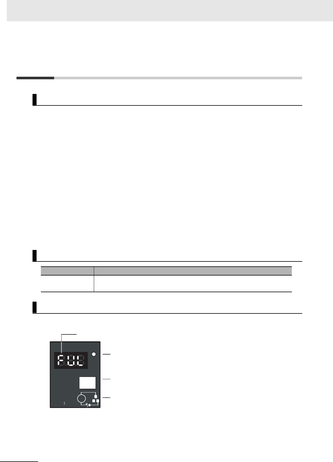
7 Inspection and Maintenance
7-10 CJ2 CPU Unit Hardware User’s Manual
7-3 Power Supply Unit Replacement
Time
The Power Supply Unit has a built-in electrolytic capacitor. The electrolytic capacitor is impregnated
with electrolytic solution that starts to penetrate the sealing rubber from the time of manufacture. As
time elapses, the internal electrolytic solution continues to evaporate, resulting in decreased electro-
static capacity and deterioration in other characteristics. Over time, the characteristic deterioration of
the electrolytic capacitor prevents the Power Supply Unit from being utilized to its full capacity. In partic-
ular, the speed at which the electrolytic capacitor deteriorates fluctuates greatly with the ambient tem-
perature (generally, a temperature rise of 10°C will double the rate of a reaction, as stated by Arrhenius'
law).
The CJ1W-PA205C Power Supply Unit with Replacement Notification monitors the internal temperature
of the Power Supply Unit while the power is turned ON, and calculates the level of deterioration of the
electrolytic capacitor from the operating time and internal temperature. The replacement notification
function displays the approximate time until the Power Supply Unit will stop functioning at its full capac-
ity due to the characteristic deterioration of the electrolytic capacitor, based on the calculated level of
deterioration. When 6 months are remaining until replacement is required, the alarm output will turn
OFF.
Note The replacement notification function provides an indication of when the deterioration of the electrolytic
capacitor will prevent the power supply functioning at its full capacity. It does not provide information on fail-
ures occurring due to other causes.
zCJ1W-PA205C
Principle of Replacement Notification
Power Supply Unit with Replacement Notification
Model Specifications
CJ1W-PA205C 100 to 240 VAC, Output capacity: 5 A at 5 VDC, 0.8 A at 24 VDC, total of 30 W
With replacement notification
Power Supply Unit Replacement Notification Module
CJ1W-PA205C
POWER
TEST
ALARM OUTPUT
DC30V, 50mA
NORMAL:ON
ALARM OFF L
Replacement notification display (7-segment, red)
POWER indicator (green)
Alarm output (replacement
notification output)
test switch
Alarm output (replacement
notification output)
wiring diagram
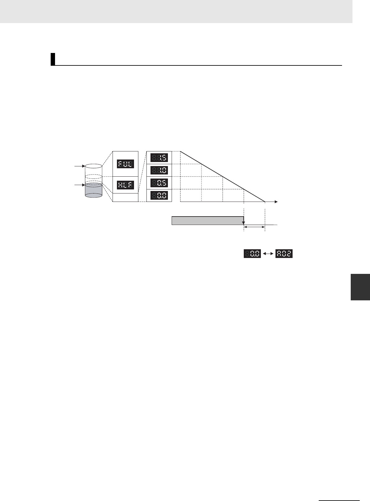
7-11
7 Inspection and Maintenance
CJ2 CPU Unit Hardware User’s Manual
7-3 Power Supply Unit Replacement Time
7
zReplacement Notification Function Displays
The replacement notification of the Power Supply Unit is shown using three 7-segment display char-
acters.
• At time of purchase “FUL” is displayed. The display changes to “HLF” as the electrolytic capacitor
deteriorates (“HLF” may not be displayed, depending on the operating environment).
• When the time until replacement is required drops below 2 years, the display will change corre-
sponding to the operating time from “1.5” to “1.0” to “0.5” to “0.0”/”A02.” When the remaining ser-
vice life reaches 6 months or less, the display will alternate between “0.0” and “A02” in 2-second
intervals.
Note 1 The time remaining until replacement does not include periods when the power is turned OFF.
2Until approximately one month of operating time has accumulated, the display will always be “ful” and the
alarm output will remain ON (conducting) due to the estimated deterioration speed.
3The time remaining until replacement will vary the operating and storage conditions, so periodically check
the display.
4Fluctuation in the time remaining until replacement may result in the alarm output repeatedly turning ON
and OFF.
5The precision of the replacement notification function will be adversely affected by applications in which
the power is frequently turned ON and OFF.
6Due to the service life of the electronic components, replace the Power Supply Unit approximately 15
years after purchase, even if the replacement notification display or output has not indicated that replace-
ment is required.
zAlarm Output (Replacement Notification Output)
The output remains ON until the remaining service life drops below 6 months and then turns OFF.
Note The alarm output will also turn OFF under the following conditions.
• The AC input to the Power Supply Unit is turned OFF.
• An error is detected by the self-diagnostic function.
• The TEST switch is pressed for at least 3 seconds.
Function
Capacity at
time of
manufacture
Replacement
required
Electrolytic
capacitor level Replacement notification
display (7-Segment) 2.0 yr 1.5 yr 1.0 yr 0 yr Remaining
life span
Alarm output
(replacement notification output) Output ON
Output
OFF
The output turns OFF when the remaining
life span reaches 6 months, and the
following display is repeatedly alternated.
0.5 yr
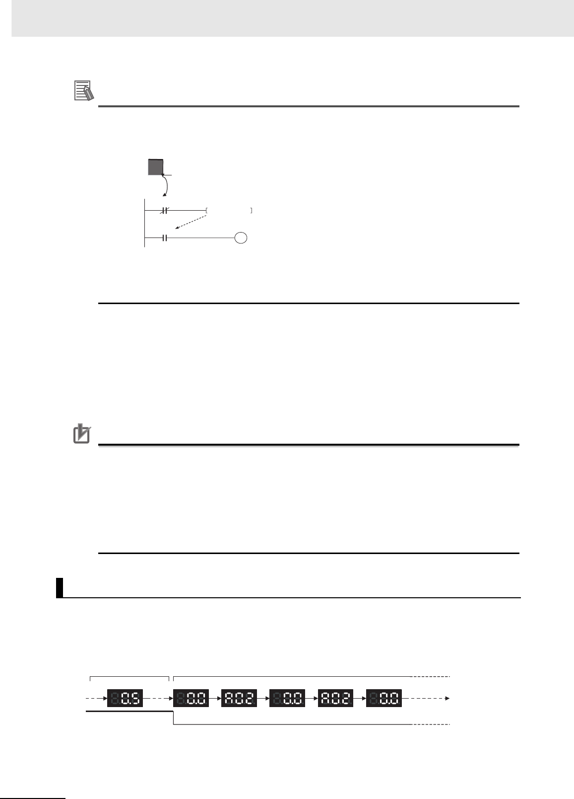
7 Inspection and Maintenance
7-12 CJ2 CPU Unit Hardware User’s Manual
Additional Information
Example of Using the Alarm Output:
Monitoring Power Supply Replacement Notification in the System (6 Months or Less Until
Replacement Is Required)
The Flag is programmed to allow for the delay in the alarm output at system startup. The Flag
does not turn ON when the alarm output is ON (normal operation). When the alarm output turns
OFF (replacement required), the Flag turns ON, and the replacement notification can be moni-
tored from the system.
zMaintenance Function Using the TEST Switch
• Press the TEST switch for at least 3 seconds to display “A02” and force the alarm output OFF.
Release the switch to return to normal operating status.
The TEST switch is used initially or periodically to check the connection status between the alarm
output and external devices.
• Press the TEST switch for less than 3 seconds to display the unit version information for the
Power Supply Unit.
Precautions for Correct UsePrecautions for Correct Use
• Replace the Power Supply Unit within 6 months when the display on the front panel of the
Power Supply Unit alternates between 0.0 and A02 or the alarm output automatically turns
OFF.
• Maintain an ambient storage temperature of −20 to 30°C and humidity of 25% to 70% when
storing the product (with the power turned OFF) for longer than 3 months to keep the replace-
ment notification function in optimum working condition. The replacement time is calculated
from when the power is turned ON only. The precision of the replacement period will decline if
the electrolytic capacitor deteriorates during storage.
zNormal Display: Replacement Notification Display
When 6 months or less are remaining until replacement is required, the display will alternate
between “0.0” and “A02” (in 2 second intervals), and the alarm output will turn OFF.
Display and Alarm Output Operation
T000
TIM 000 5 s
ON
OFF
Alarm output
Turns OFF when 6 months remains
Alarm output
Internal Flag
ON OFF
Remaining service life:
1 year to 6 months Remaining service life: 6 months max.
Alarm output
2 s 2 s 2 s 2 s 2 s
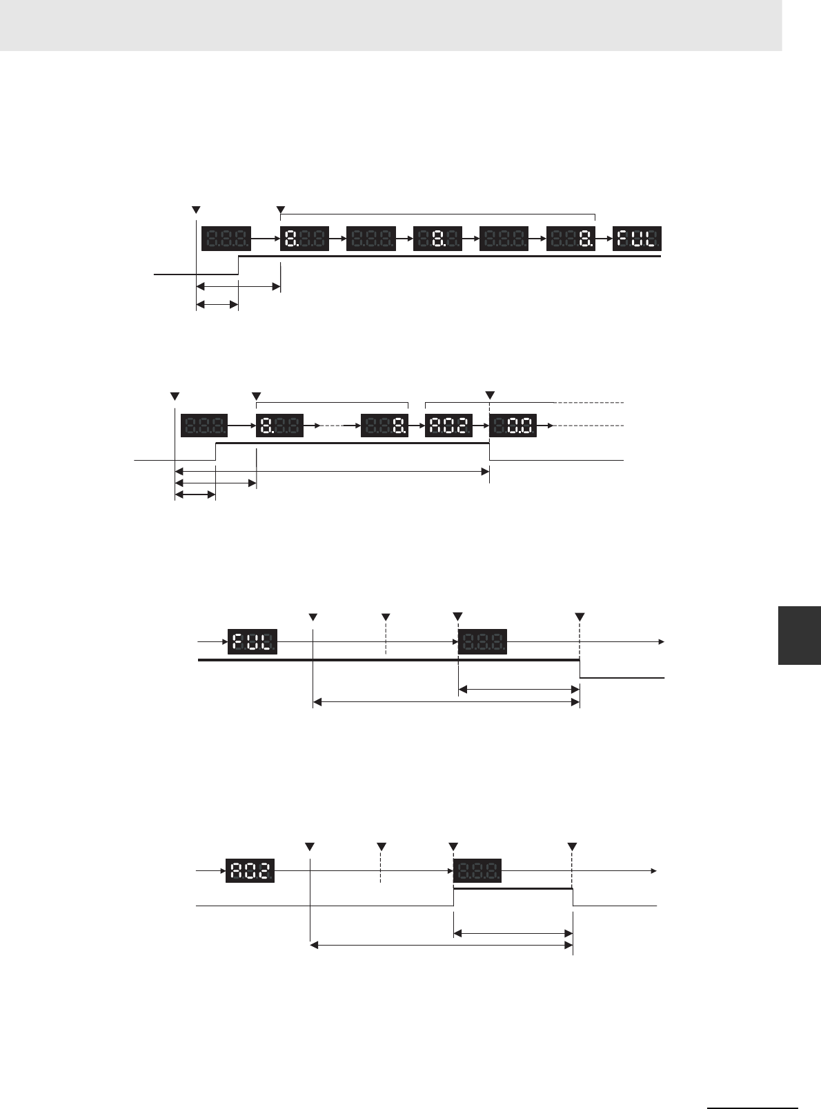
7-13
7 Inspection and Maintenance
CJ2 CPU Unit Hardware User’s Manual
7-3 Power Supply Unit Replacement Time
7
zOperation When Turning ON the Power
The following initial display is shown when the power is turned ON, after which the replacement noti-
fication is displayed. The alarm output turns ON approximately 0.2 seconds after the power is turned
ON.
When replacement is already required, the alarm display will follow the initial display. The alarm out-
put will turn ON approximately 0.2 seconds after the power is turned ON, and then turn OFF after
approximately 5 seconds.
zOperation at Power OFF
When the power is turned OFF, the display will turn OFF after the PLC operation stops. The alarm
output will turn OFF after the display turns OFF.
*1 The values shown are reference values (calculated for a no-load status on the Power Supply Unit's output).
If replacement is already required, the display will turn OFF after the PLC operation stops. When the
display turns OFF, the alarm output will turn ON momentarily and then turn OFF again.
*1 The values shown are reference values (calculated for a no-load status on the Power Supply Unit's output).
ONOFF
Power ON
Display
Alarm
output
Display start
1 s max.
0.2 s max.
Initial display (approx. 1.1 s) Replacement
required display
0.3 s 0.1 s 0.3 s 0.1 s 0.3 s
OFFONOFF
Power ON
Display
Alarm
output
1 s max.
0.2 s max.
Display start Initial display
(approx. 1.1 s) Alarm
display Alarm output OFF
5 s max.
ON OFF
OFF
Display
Alarm
output
Replacement
notification display
Power
interruption PLC operation
stopped Notification display
Approx. 70 ms
*1
Alarm output
100 VAC: Approx. 2 s
200 VAC: Approx. 7 s
*1
OFF OFF
OFF
ON
Display
Alarm
output
Alarm display
Power
interruption
PLC operation
stopped Notification display OFF
+ alarm output ON Alarm output
Approx. 70 ms
*1
100 VAC: Approx. 2 s
200 VAC: Approx. 7 s
*1
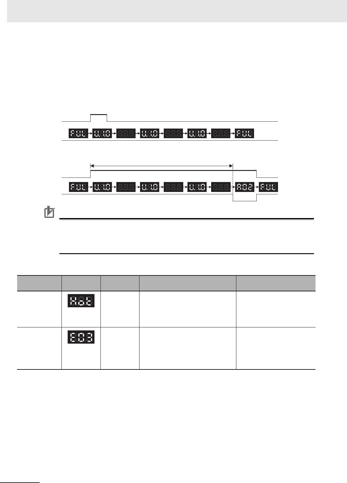
7 Inspection and Maintenance
7-14 CJ2 CPU Unit Hardware User’s Manual
zOperation When TEST Switch Is Pressed
The following operation will be performed when the TEST switch on the replacement notification
function module is pressed. When the switch is pressed for less than 3 seconds, the unit version will
be displayed 3 times at 0.5-second intervals. When the switch is pressed for at least 3 seconds, the
alarm output will momentarily turn OFF, and the alarm display A02 will be shown. The operation will
return to the normal display and output when the switch is released. Use the TEST switch to check
the connection between the replacement notification output and devices.
• Operation when TEST switch is pressed for less than 3 seconds.
• Operation when TEST switch is pressed for less than 3 seconds.
Precautions for Correct UsePrecautions for Correct Use
Under normal application conditions, the replacement notification function will operate after sev-
eral years or even tens of years. When using a Power Supply Unit for an extended period of time,
periodically check operation with the TEST switch as described above and be sure the alarm
output functions properly.
zSelf-diagnostic Function
*1 If the error continues for 3 hours or longer, the replacement notification function will be disabled. Even if the cause of the
overheating is removed, the display will continue as “Hot,” and the notification output will remain OFF. In this state, the
internal parts may deteriorate even if the PLC operation is normal, so replace the Power Supply Unit.
Error name Display Alarm out-
put status Error details (cause) Recovery method
Unit overheated
error
OFF Internal overheating has occurred in
the Power Supply Unit as a result of
usage under conditions that exceed
the specified values, insufficient venti-
lation, or incorrect installation.*1
Remove the cause of the over-
heating error.
Unit error OFF System error from external noise or
hardware malfunction.
Turn ON the input's power sup-
ply again. If the Unit does not
recover, the error may be
caused by a Unit malfunction.
Consult with your OMRON rep-
resentative.
ON
ON
TEST switch
Alarm output
0.5 s 0.5 s 0.5 s 0.5 s 0.5 s 0.5 s
ON
ON OFF ON
0.5 s 0.5 s 0.5 s 0.5 s 0.5 s 0.5 s
TEST switch
Alarm output
3 s
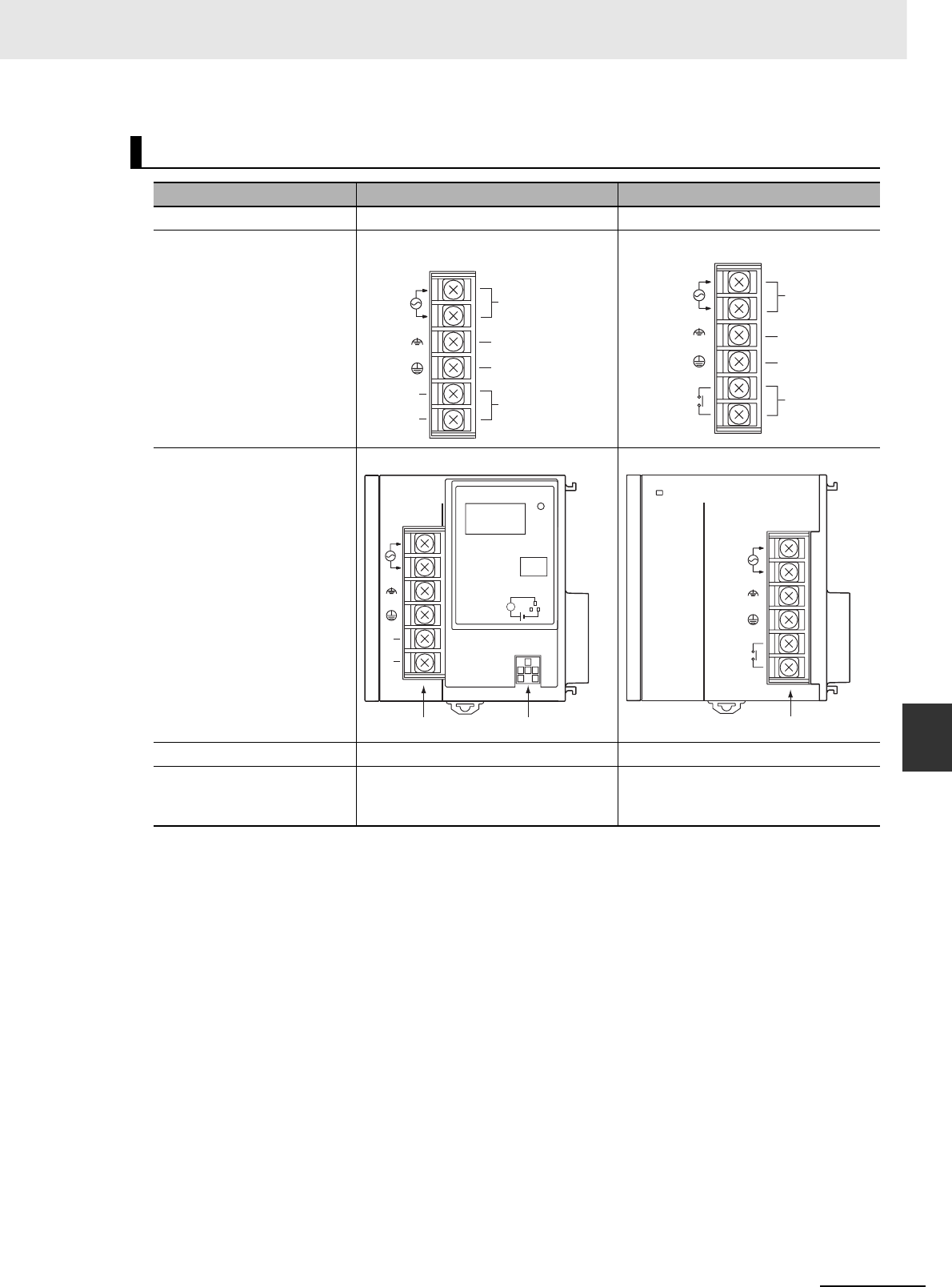
7-15
7 Inspection and Maintenance
CJ2 CPU Unit Hardware User’s Manual
7-3 Power Supply Unit Replacement Time
7
Comparison between the CJ1W-PA205C and CJ1W-PA205R
Item CJ1W-PA205C CJ1W-PA205R (for comparison)
RUN contact output Not supported Supported
Terminal block arrangement
Terminal block position Located on the left side of the Unit. Located on the right side of the Unit.
POWER indicator On replacement notification module On hood of Power Supply Unit
Replacement notification Supported
(7-segment display + transistor out-
puts)
Not supported
NC
NC
L2/N
L1
100 to 240 VAC
INPUT
AC input
LG
Unconnected
terminals
GR
CJ1W-PA205C
L2/N
L1
24 VDC
2A RESISTIVE
240 VAC
OUTPUT
RUN
INPUT
100 to 240 VAC AC input
LG
RUN output
(RUN contact)
GR
CJ1W-PA205R
Years
POWER
CJ1W-PA205C
TEST
NC
NC
AC100-240V
INPUT
L2/N
L1
L
+
ALARM
OUTPUT
DC30V,50mA
NORMAL:ON
ALARM :OFF
Terminal block Alarm output terminals
POWER
PA205R
DC24V
AC240V
OUTPUT
RUN
INPUT
AC100-240V
L2/N
L1
Terminal block

7 Inspection and Maintenance
7-16 CJ2 CPU Unit Hardware User’s Manual

8-1
CJ2 CPU Unit Hardware User’s Manual
8
This section describes operations used to back up and restore data.
8-1 Backing Up Data . . . . . . . . . . . . . . . . . . . . . . . . . . . . . . . . . . . . . . . . . . . . . . . 8-2
8-2 Using a Computer to Back Up Data . . . . . . . . . . . . . . . . . . . . . . . . . . . . . . . 8-3
8-2-1 PLC Backup Tool . . . . . . . . . . . . . . . . . . . . . . . . . . . . . . . . . . . . . . . . . . . . . . . 8-3
8-2-2 PLC Backup Tool Operations . . . . . . . . . . . . . . . . . . . . . . . . . . . . . . . . . . . . . . 8-4
8-3 Simple Backup . . . . . . . . . . . . . . . . . . . . . . . . . . . . . . . . . . . . . . . . . . . . . . . . 8-7
8-3-1 Overview . . . . . . . . . . . . . . . . . . . . . . . . . . . . . . . . . . . . . . . . . . . . . . . . . . . . . 8-7
8-3-2 Operating Procedures . . . . . . . . . . . . . . . . . . . . . . . . . . . . . . . . . . . . . . . . . . . 8-8
8-3-3 Verifying Backup Operations with Indicators . . . . . . . . . . . . . . . . . . . . . . . . . 8-10
8-3-4 Related Auxiliary Bits/Words . . . . . . . . . . . . . . . . . . . . . . . . . . . . . . . . . . . . . 8-12
8-3-5 Time Required for Simple Backup . . . . . . . . . . . . . . . . . . . . . . . . . . . . . . . . . 8-12
8-3-6 Data Backed Up Using Simple Backup . . . . . . . . . . . . . . . . . . . . . . . . . . . . . 8-12
Backup Operations
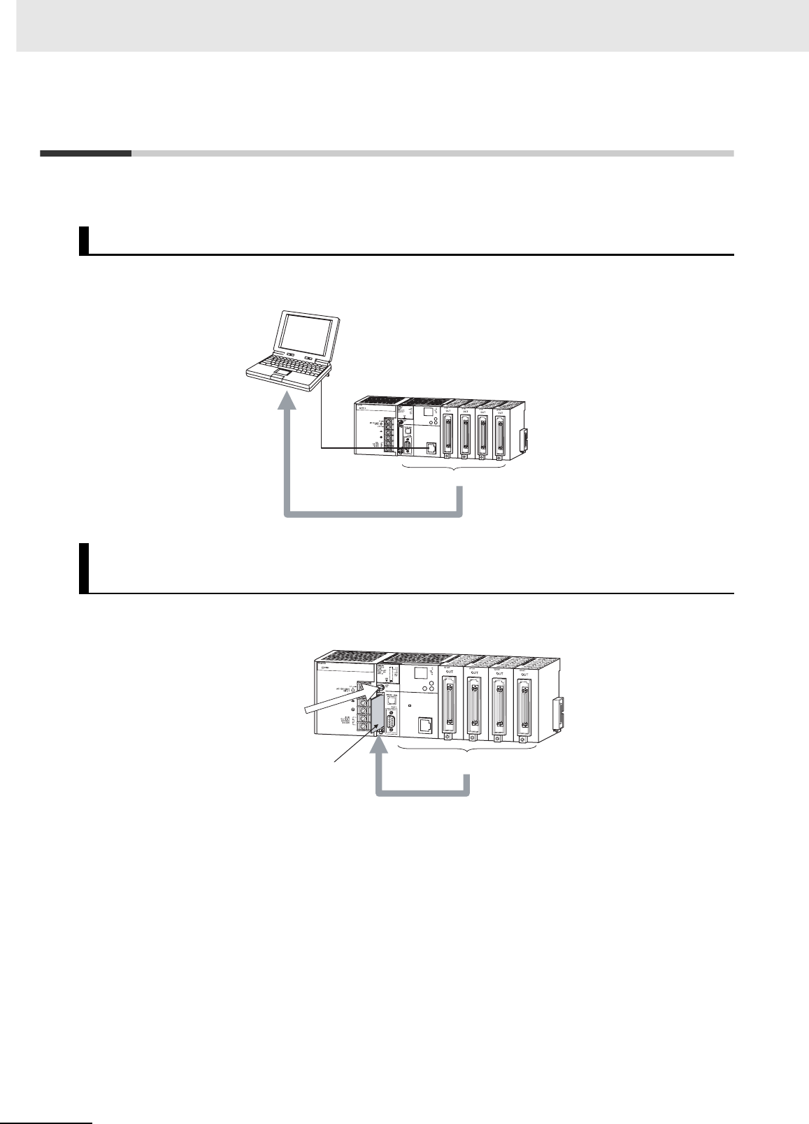
8 Backup Operations
8-2 CJ2 CPU Unit Hardware User’s Manual
8-1 Backing Up Data
There are two methods for backing up PLC data.
• Operation: PLC Backup Tool running on the personal computer
• Backup destination: Computer hard disk
• Operation: DIP switch and Memory Card Power Switch
• Backup destination: A Memory Card inserted in the CPU Unit
Using a Computer to Back Up Data to the Computer
Using Front-panel Switches on the CPU Unit to Back Up Data to a
Memory Card
PLC Backup Tool
CPU Unit
Backup All PLC data
Memory Card All PLC data
Backup
Back up data by
pressing the Memory
Card Power Switch.
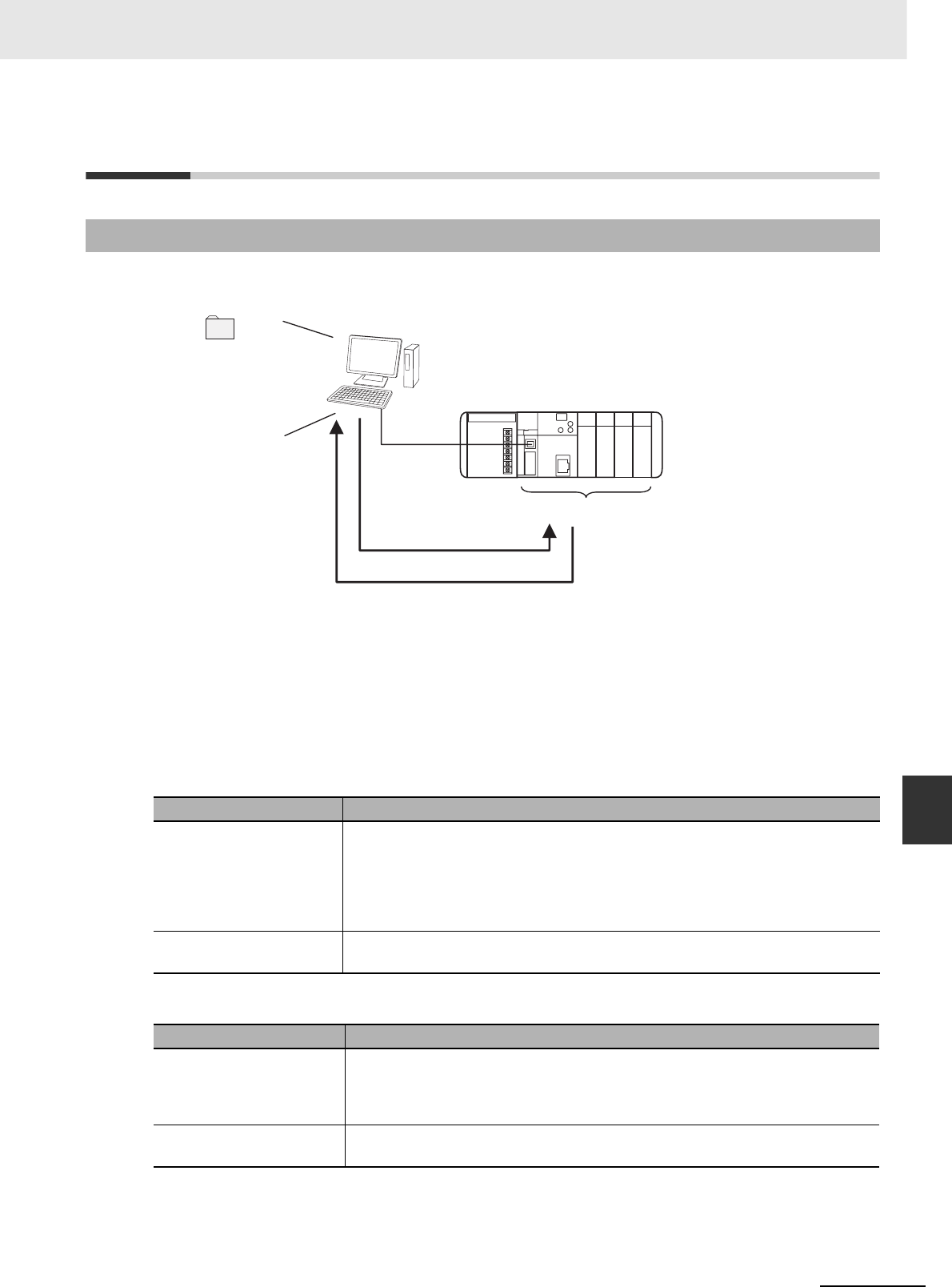
8-3
8 Backup Operations
CJ2 CPU Unit Hardware User’s Manual
8-2 Using a Computer to Back Up Data
8
8-2-1 PLC Backup Tool
8-2 Using a Computer to Back Up Data
The PLC Backup Tool can be used to back up, compare, and restore data, such as programs and unit
parameters, of all the Units or of only specified Units in a PLC that is connected online.
zApplications
The PLC Backup Tool can be used for the following applications.
• Backing up all of the data from the PLC
• Comparing all of the data in the PLC with the data backed up in the computer
• Transferring all of the data to a PLC that has the same system configuration as another PLC
• Transferring data to a Unit that has been replaced, e.g., when the Unit has failed
zApplicable Units
zApplicable Data
8-2-1 PLC Backup Tool
Applicable Unit Description
CPU Unit CS/CJ/CP-series PLCs, all models and all versions
Data in the following Units is not backed up:
• Screen data for an NSJ Controller
• SYSMAC SPU Unit data
• Customizable Counter Unit data
Special I/O Units and CPU
Bus Units
Refer to the list of backup Units in the help files for the PLC Backup Tool.
Applicable Unit Description
CPU Unit User program, symbols tables, rung comments, program index, parameters (PLC
Setup, registered I/O tables, routing tables, Ethernet settings, and all other data in
the initial setting areas), I/O memory, forced status (backup and comparison only),
and EM file memory data (backup only)
Special I/O Units and CPU
Bus Units
Parameter settings and data stored inside the Unit (e.g., programming created with
Support Software)
CJ2
Backup folder
Default name:
C\Backup\yymmdd_hhmmss
PLC Backup Tool
CPU Unit + Configuration Units
(CPU Bus Units and Special I/O Units)
Restore or Compare
Back up
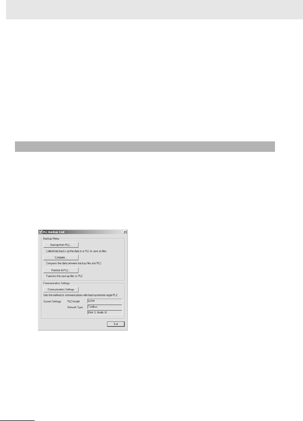
8 Backup Operations
8-4 CJ2 CPU Unit Hardware User’s Manual
zRestrictions
The following restrictions apply.
• Forced Status
Forced status cannot be restored. If you attempt to restore forced status, the address of the force-
set/reset bits will be displayed in the log display area. Use the CX-Programmer or Switch Box to man-
ually force-set/reset the displayed bits.
• Data Stored in EM File Memory (Part of the EM Area Converted to File Memory)
EM file memory cannot be compared or resorted.
EM file memory backups are saved in the CPU\EM_FILES Folder that will be created within the
backup file destination folder. Restore EM file memory manually by using the PLC Memory Card Win-
dow in the CX-Programmer to write the data to memory.
• Restrictions in Comparing and Restoring I/O Memory
The CIO Area and Auxiliary Area data in the I/O memory cannot be compared or restored.
An overview of the PLC Backup Tool is provided below. For details on specific procedures and func-
tions, refer to the CX-Programmer Operation Manual (Cat. No. W446).
zStarting the PLC Backup Tool
Either of the following methods can be used to start the PLC Backup Tool.
•Select PLC Backup Tool from the CX-Programmer Tools Menu.
•Select Programs
−
OMRON
−
CX-One
−
CX Programmer
−
PLC Backup Tool from the Windows
Start Menu.
The PLC Backup Tool Dialog Box will be displayed.
8-2-2 PLC Backup Tool Operations
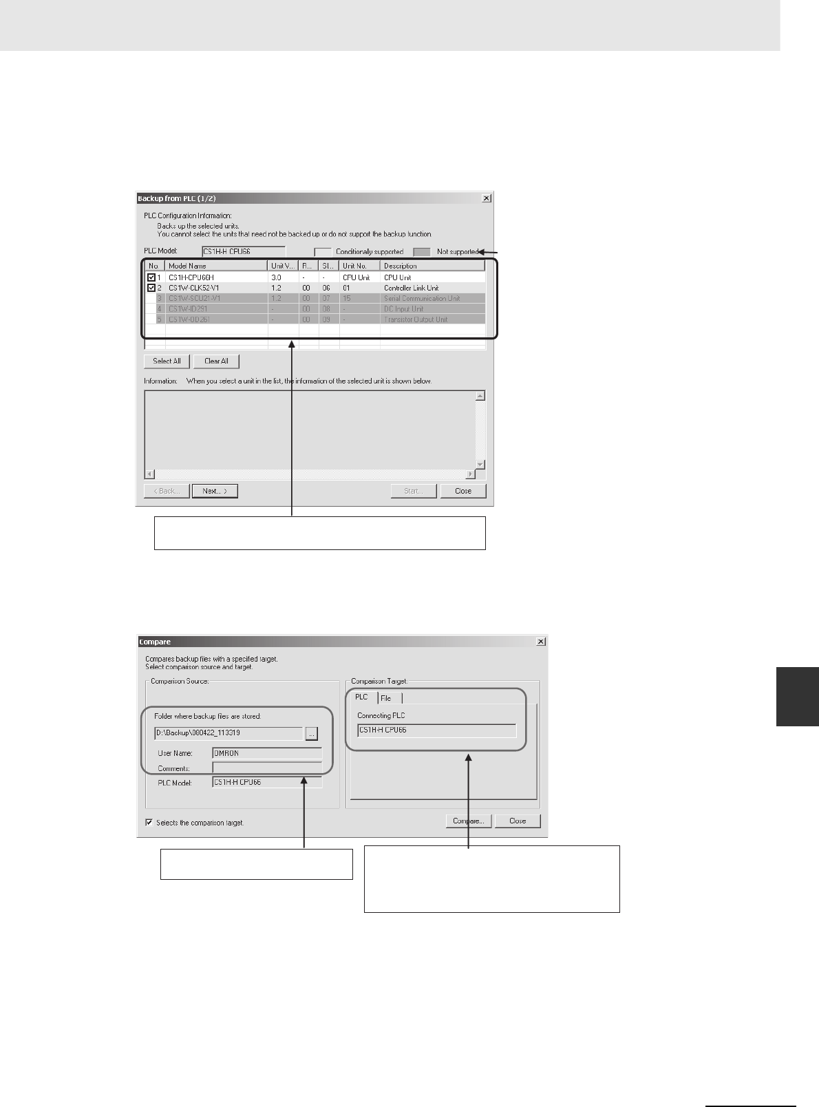
8-5
8 Backup Operations
CJ2 CPU Unit Hardware User’s Manual
8-2 Using a Computer to Back Up Data
8
8-2-2 PLC Backup Tool Operations
zBacking Up Data
The data in the connected PLC can be backed up to the computer as a batch. A folder named with the
date and time will be automatically created under the user-specified folder, and the backup files will be
created in that folder.
zComparing Data
Data in backup files can be compared with data from other backup files or data from connected PLC.
The comparison results will be displayed.
Backup files can be restored after the comparison results have been displayed. Also, the comparison
results can be saved in a CSV file.
All Units in the PLC are displayed here.
Individual Units can be selected for backup.
Specify the source backup file on the
computer.
Specify the target PLC or backup file to compare.
PLC: The currently connected PLC will be
displayed as the target.
File: Specify another backup file on the computer
as the target.
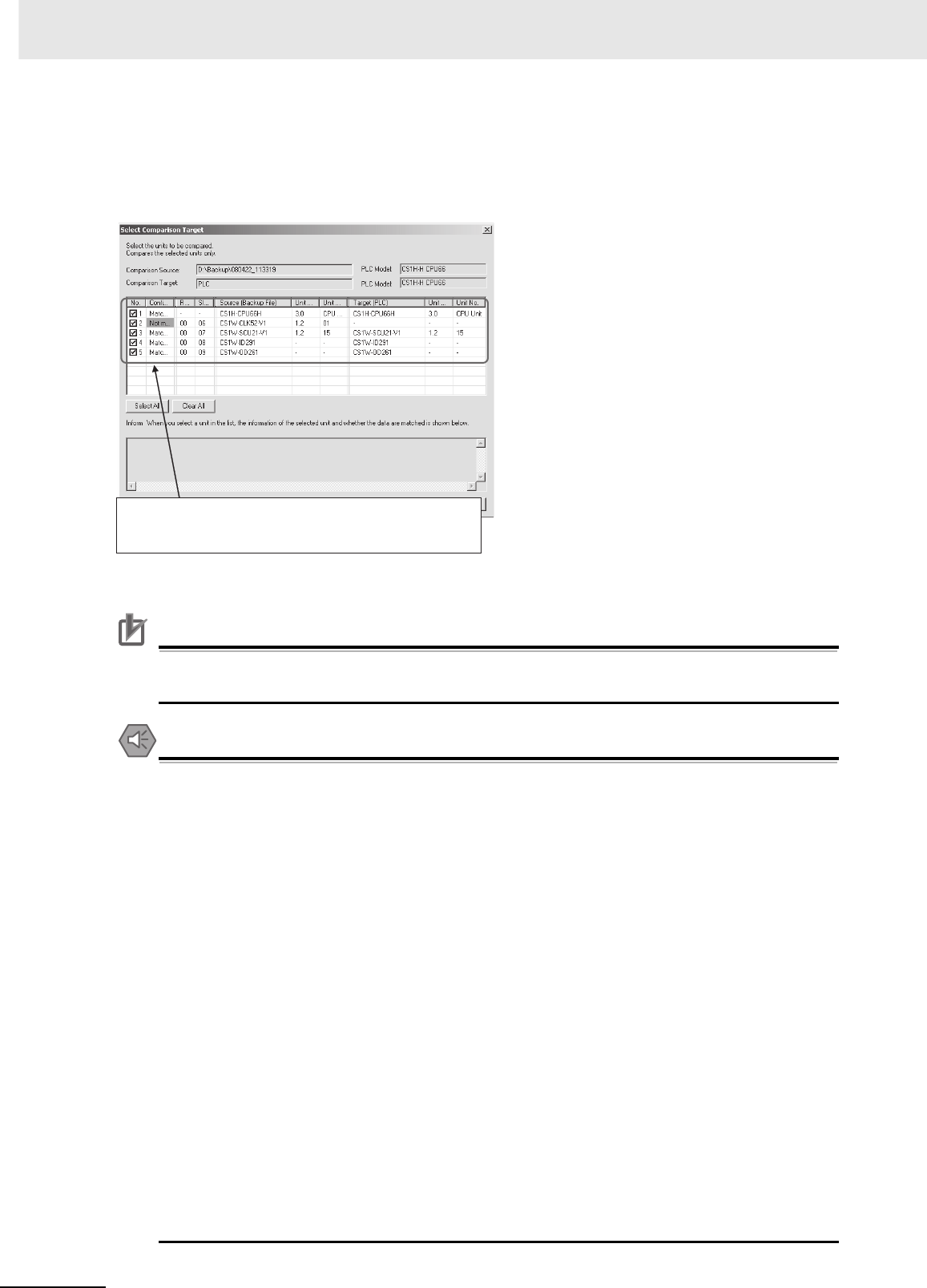
8 Backup Operations
8-6 CJ2 CPU Unit Hardware User’s Manual
zRestoring Data
PLC data can be restored to a previous state by transferring backup file data to a connected PLC.
Before the data is restored, a comparison will be made automatically with the applicable PLC and the
results will be displayed.
Before the data is restored, the contents of the data can be checked by starting the Support Software
for that Unit.
Precautions for Correct UsePrecautions for Correct Use
The CPU Unit will be changed to PROGRAM mode before restoring the data. This will stop oper-
ation. Be sure it is safe to stop CPU Unit operation before restoring the data.
Precautions for Safe Use
• Sufficiently check the data that is selected for restoring before performing the next step. If the
correct data is not restored, unexpected operation may occur in the controlled system after the
data is restored.
• Some Special I/O Units and CPU Bus Units operate with parameters that are stored in the
CPU Unit. If one of these Units is selected for backup, restrictions will be displayed in the Com-
ments Area of the Backup from PLC Dialog Box. Confirm the restrictions, and always select
the Special I/O Unit or CPU Bus Unit together with the CPU Unit when backing up or restoring
data. If the data from both Units is not backed up or restored together, unexpected operation
may occur in the controlled system.
• If there are any backup restrictions for the Units to which data is being restored, the restric-
tions will be displayed in the Comments Area of the Backup from PLC Dialog Box. Confirm the
restrictions, and always take the required measures. If required measures are not taken, unex-
pected operation may occur in the controlled system after the data is restored.
• Confirm that stopping PLC operation will not create any problems before restoring data during
PLC operation. If the PLC stops at an unanticipated time, unexpected operation may occur in
the controlled system.
• Always turn the power supply to the PLC OFF and then ON after restoring data. If the power
supply is not turned OFF and then ON, memory in the PLC may not be updated to the restored
data, which may cause unexpected operation of the controlled system.
• Forced status can be backed up, but it cannot be restored. If you restored data that contained
forced status, use the CX-Programmer after restoring the data to force-set or force-reset bits
as required. If required bits are not force-set or force-reset, differences in the forced status in
memory may cause unexpected operation of the controlled system.
@: Check boxes will appear for Units to which data can be
restored.
Configuration: Indicates whether the configurations match between the
backup file and the PLC.
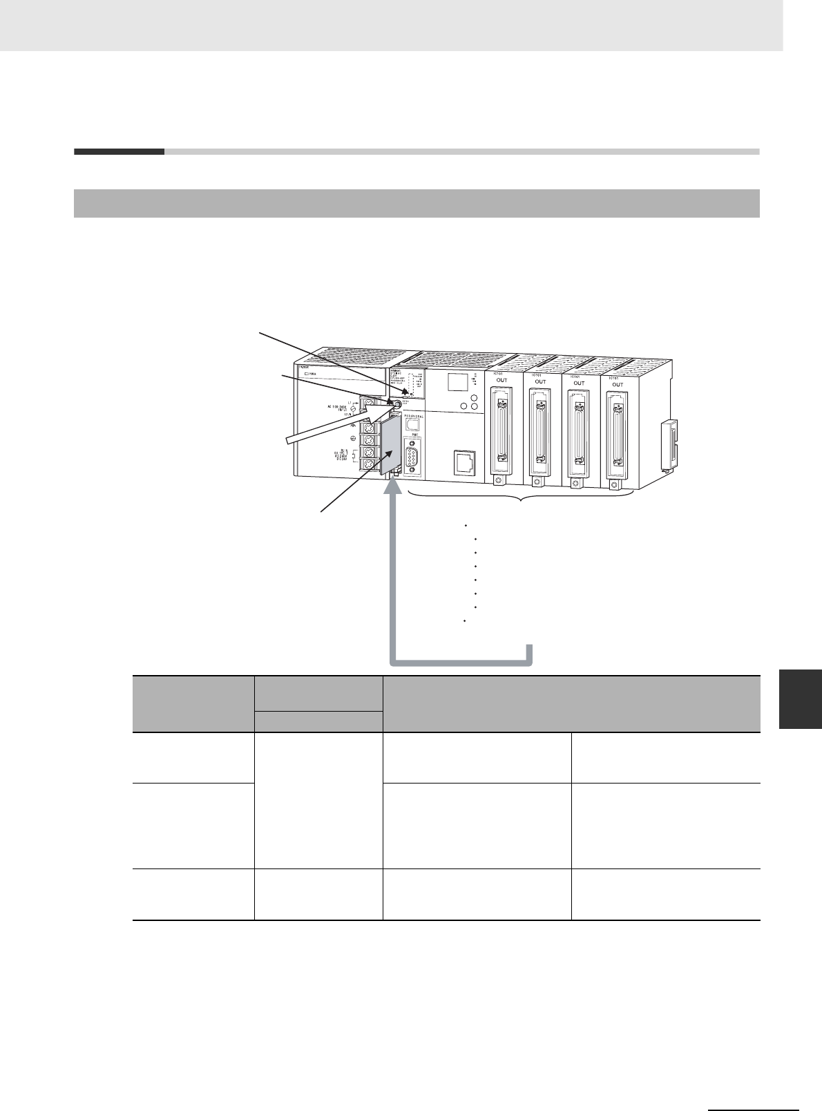
8-7
8 Backup Operations
CJ2 CPU Unit Hardware User’s Manual
8-3 Simple Backup
8
8-3-1 Overview
8-3 Simple Backup
The simple backup operation can be used to back up all PLC data to a Memory Card, or to restore or
compare the data, by using a simple DIP switch setting and the Memory Card Power Supply Switch. No
Support Software is required.
8-3-1 Overview
Backup operation
DIP switch on front
of CPU Unit Procedure
Pin 7
Backing up data to
the Memory Card
ON Press the Memory Card Power
Supply Switch for three sec-
onds.
The data can be backed up
regardless of the CPU Unit
operating mode.
Restoring data from
the Memory Card
Turn the PLC OFF and ON
again.
(Data restoration is given priority
over the automatic transfer at
startup.)
After the data has been
restored, the operating mode
will remain in PROGRAM mode
until the PLC power is turned
OFF.
Comparing data to
the Memory Card
OFF Press the Memory Card Power
Supply Switch for three sec-
onds.
The data can be compared
regardless of the CPU Unit
operating mode.
1.
2.
Power Supply Unit
Turn ON pin 7 on
the DIP switch.
Memory Card
Backup
Backing Up Data
Press the Memory Card
Power Supply Switch.
Memory Card
Power Supply
Switch
All PLC data, including the following data.
Data in the CPU Unit:
User programs
Parameters
I/O memory
Symbol tables
Comment files
Program index file
Data in mounted Special I/O Units and
CPU Bus Units
CPU Unit
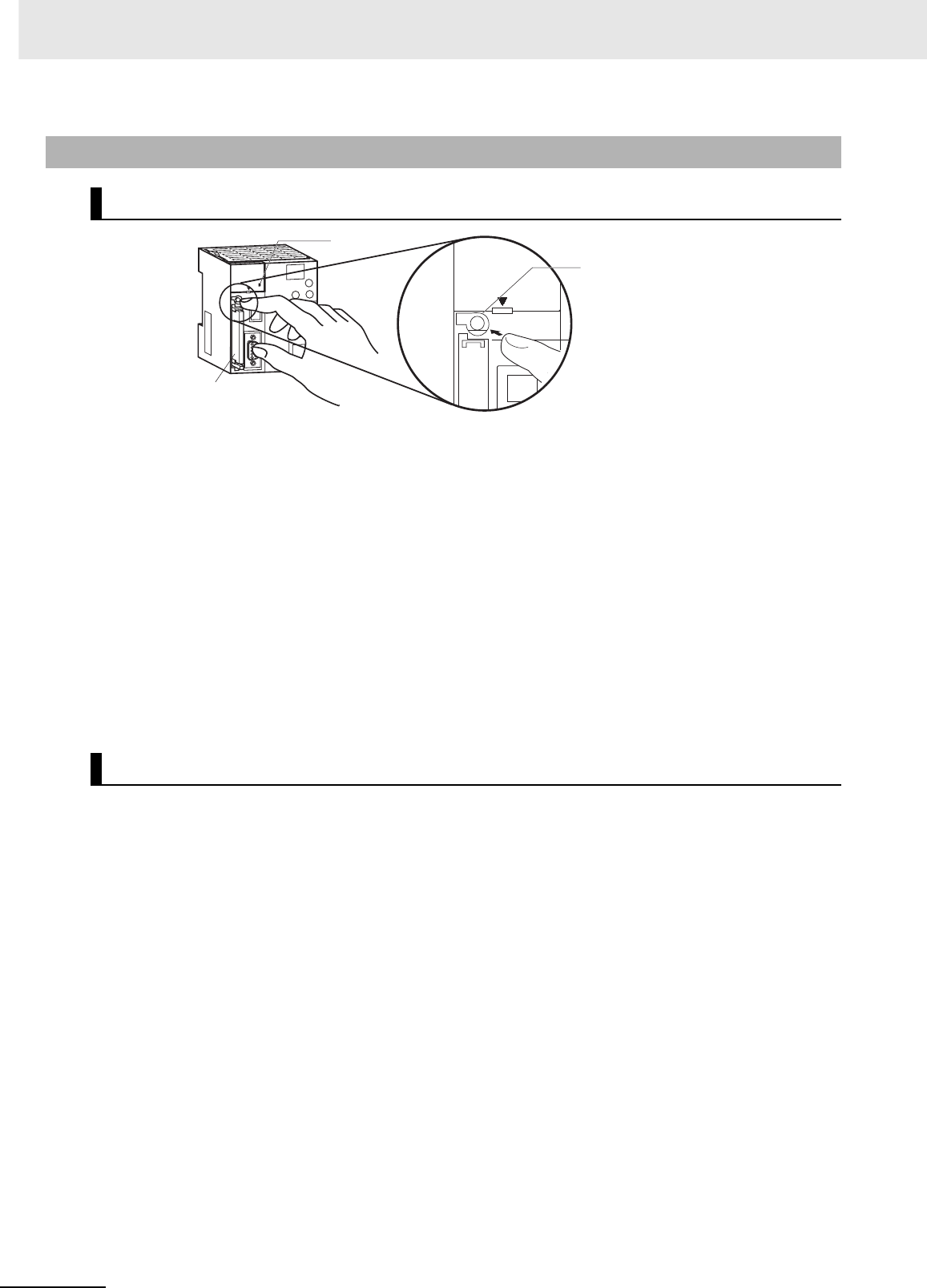
8 Backup Operations
8-8 CJ2 CPU Unit Hardware User’s Manual
1Insert the Memory Card into the CPU Unit.
The MCPWR indicator will light and the BUSY indicator will flash (meaning the Memory Card is
being accessed) and then turn OFF.
2Turn ON pin 7 on the CPU Unit's DIP switch.
3Press the Memory Card Power Supply Switch for three seconds until the BUSY indicator lights,
and then release the switch.
The PLC will start backing up data to the Memory Card. The MCPWR indicator will flash once
and then light while the data is being written. At the same time the BUSY indicator will flash. The
MCPWR and BUSY indicators will both turn OFF when the operation is completed normally.
4Turn OFF pin 7 on the CPU Unit's DIP switch.
1Turn OFF the PLC power supply.
2Insert the Memory Card containing the backup files into the CPU Unit.
3Turn ON pin 7 on the CPU Unit's DIP switch.
4Turn ON the PLC power supply.
The PLC will start restoring the data from the Memory Card. The MCPWR indicator will flash
once and then light while the data is being read. At the same time the BUSY indicator will flash.
The MCPWR and BUSY indicators will both turn OFF when the operation is completed normally.
If the MCPWR indicator flashes five times, or if only the BUSY signal turns OFF, it means that an
error has occurred. (Refer to 8-3-3 Verifying Backup Operations with Indicators.)
5Turn OFF pin 7 on the CPU Unit's DIP switch.
Note 1 The backup function will override the automatic transfer at startup function, so the backup files will be read
to the CPU Unit when the PLC is turned ON even if pin 2 of the DIP switch is ON.
2Data will not be read from the Memory Card to the CPU Unit if pin 1 of the DIP switch is ON (write-protect-
ing program memory).
8-3-2 Operating Procedures
Backing Up Data from the CPU Unit to the Memory Card
Restoring Data from the Memory Card to the CPU Unit
Memory Card
Press the Memory
Card Power Supply
Switch for three
seconds.
Pin 7: ON
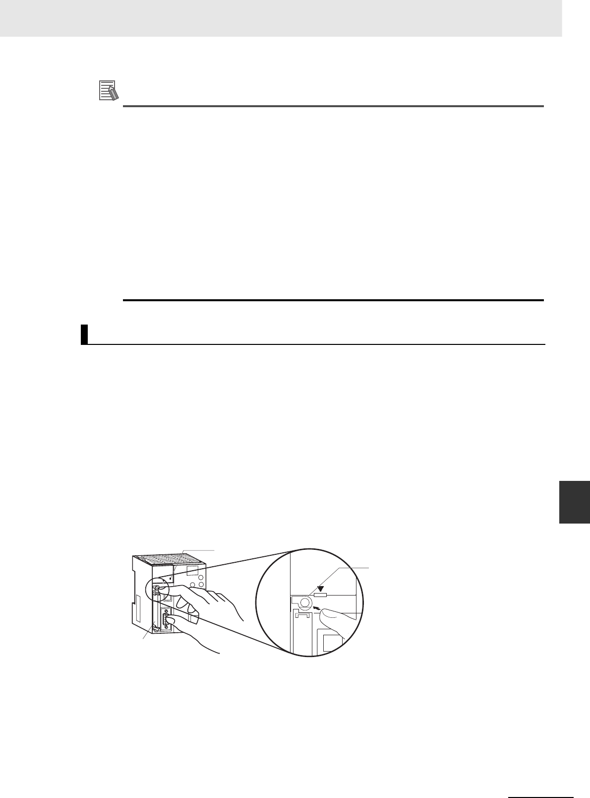
8-9
8 Backup Operations
CJ2 CPU Unit Hardware User’s Manual
8-3 Simple Backup
8
8-3-2 Operating Procedures
Additional Information
• When the backup files are read from the Memory Card by the backup function, the status of
I/O memory and force-set/force-reset bits will be cleared unless the necessary settings are
made in the Auxiliary Area and PLC Setup.
If the IOM Hold Bit (A500.12) is ON and the PLC Setup is set to maintain the IOM Hold Bit Sta-
tus at Startup when the backup files are written, the status of I/O memory data will be main-
tained when data is read from the Memory Card.
If the Forced Status Hold Bit (A500.13) is ON and the PLC Setup is set to maintain the Forced
Status Hold Bit Status at Startup when the backup files are written, the status of force-set and
force-reset bits will be maintained when data is read from the Memory Card.
• After the simple backup operation has been used to restore data from the Memory Card to the
PLC, the operating mode will remain in PROGRAM mode and cannot be changed to MONI-
TOR or RUN mode until the PLC power is turned OFF. After restoring the data, turn OFF the
power, change the setting of DIP switch pin 7, and then turn the power back ON.
• File backups may take from several seconds to several minutes. For information on execution
times refer to 8-3-5 Time Required for Simple Backup.
1Insert the Memory Card containing the backup files into the CPU Unit.
The MCPWR indicator will light and the BUSY indicator will flash and then turn OFF.
2Turn OFF pin 7 on the CPU Unit's DIP switch.
3Press the Memory Card Power Supply Switch for three seconds until the BUSY indicator lights,
and then release the switch.
The PLC will start comparing the data in the PLC and the data in the backup file on the Memory
Card. The MCPWR indicator will flash once and then light while the data is being written. At the
same time the BUSY indicator will flash.
The MCPWR and BUSY indicators will both turn OFF if the data matches. If the MCPWR and
BUSY indicators both flash, it means that the data does not match or that an error has occurred.
(Refer to 8-3-3 Verifying Backup Operations with Indicators.)
Note If an error occurs during writing or comparison, the MCPWR indicator will flash. Press the power supply
switch to stop the flashing and to turn ON the MCPWR indicator.
Comparing Data in the Memory Card and CPU Unit
Memory Card
Press the Memory
Card Power Supply
Switch for three
seconds.
Pin 7: OFF
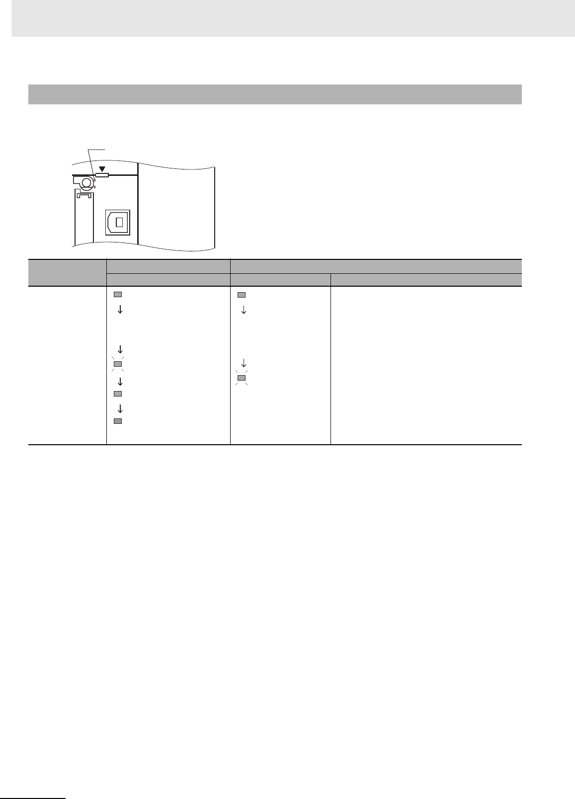
8 Backup Operations
8-10 CJ2 CPU Unit Hardware User’s Manual
The status of the Memory Card Power (MCPWR) indicator shows whether a simple backup operation
has been completed normally or not.
8-3-3 Verifying Backup Operations with Indicators
Backup operation Normal completion*1Error occurred
MCPWR status MCPWR status Error
Backing up data from
the CPU Unit to the
Memory Card
The data was not backed up due to one of the following
errors, and no backup file was created.
• Insufficient Memory Card capacity
• Memory error in CPU Unit
• I/O bus error
• Data was not read from the Unit to be backed up.
MCPWR Indicator
OPEN
PERIPHERAL
BUSY
MCPWR
MCPWR
MCPWR
MCPWR
MCPWR
Lit
Remains lit while the
Memory Card Power
Switch is pressed.
Flashes once.
Lit while writing.
OFF after data is
written.
MCPWR
MCPWR
Lit
Remains lit while
the Memory Card
Power Switch is
pressed.
Remains
flashing.
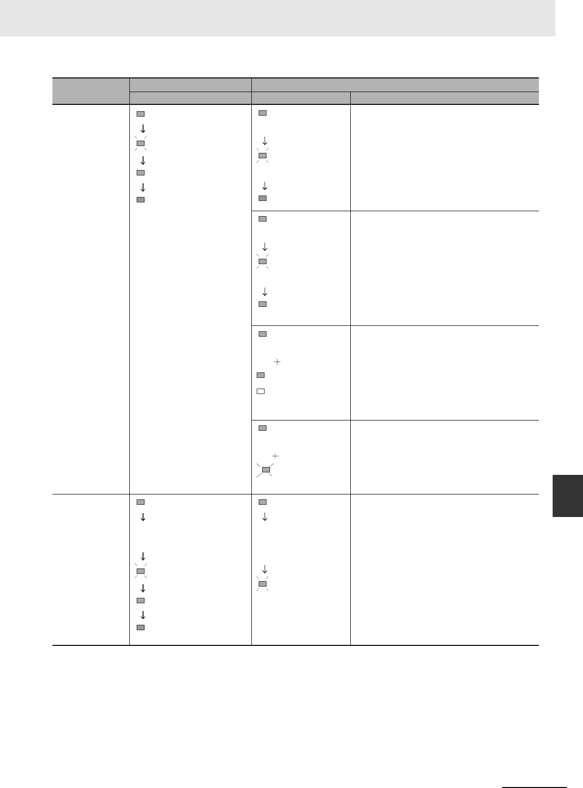
8-11
8 Backup Operations
CJ2 CPU Unit Hardware User’s Manual
8-3 Simple Backup
8
8-3-3 Verifying Backup Operations with
Indicators
*1 When the backup operation is completed normally, power to the Memory Card will go OFF when the MCPWR indicator
goes OFF. If the Memory Card will be used again, press the Memory Card Power Switch to supply power and execute the
desired operation.
*2 The backup files for Units and Boards are also compared.
Restoring data from
the Memory Card to
the CPU Unit
The data was not restored due to one of the following
causes.
• Program in Memory Card exceeds CPU Unit capacity
• Required backup files do not exist in Memory Card.
• Program can't be written because it is write-protected
(Pin 1 of the DIP switch is ON.)
• The EM file was not complete, i.e., a portion was missing.
• There are fewer CPU Unit EM banks than backup EM
files.
The I/O tables are not correct (e.g., the same unit number
was set twice).
• A Unit was added to the configuration since the data was
backed up.
• The unit number settings for Special I/O Units or CPU
Bus Units are not correct.
A Unit was added to the configuration since the data was
backed up.
Comparing data
between the CPU Unit
and the Memory Card
The following comparison errors can occur:
• Memory error in CPU Unit*2
• Incorrect I/O tables (e.g., the same unit number set twice)
• Comparison results (of backup files on Memory Card and
data in PLC) do not match.
• Required backup files do not exist in Memory Card.*2
• I/O bus error
Backup operation Normal completion*1Error occurred
MCPWR status MCPWR status Error
MCPWR
MCPWR
MCPWR
MCPWR
Lit when power is
turned ON.
Flashes once.
Lit while reading.
OFF after data is
read.
MCPWR
MCPWR
MCPWR
Lit when power is turned
ON.
Flashes five times.
Goes OFF.
MCPWR
MCPWR
MCPWR
Lit when power is
turned ON.
Flashes once.
Remains lit.
MCPWR
H8
Same as for normal
completion.
Special I/O or CPU
Bus Unit ERR indicator
7-segment LED indicator
Displayed as “H8”
MCPWR
INEE Board
READY
indicator
Flashing
Same as for normal
completion.
MCPWR
MCPWR
MCPWR
MCPWR
Remains lit while the Memory
Card Power Switch is pressed.
Lit
Flashes once.
Lit while comparing.
OFF after data
is compared.
MCPWR
MCPWR
Lit
Remains lit while
the Memory Card
Power Switch is
pressed.
Remains flashing.

8 Backup Operations
8-12 CJ2 CPU Unit Hardware User’s Manual
The following tables list the benchmark execution times for the simple backup operation. The execution
time will depend on the Unit configuration, cycle time, and Memory Card. These times were measured
under the following conditions:
CPU Unit Model: CJ2H-CPU6@-EIP or CJ2M-CPU3@
Configuration: CPU Unit only
Operating mode: PROGRAM
Additional Information
The Units that are backed up for the simple backup operation are predetermined. You cannot
specify which Units are backed up and which are not.
The files and applicable data transferred between the Memory Card and CPU Unit using the simple
backup operation are listed below. The file name is fixed as BACKUP@@.
* CJ2H-CPU6@-EIP or CJ2M-CPU3@ only.
Program files that include network symbols cannot be transferred to the CJ2H-CPU6@ or CJ2M-CPU1@. A
Memory Card transfer error (fatal) will occur if an attempt is made to transfer such a file.
8-3-4 Related Auxiliary Bits/Words
Name Address Description
File Memory
Operation Flag
A343.13 ON when any of the following are being performed. OFF when execu-
tion has been completed.
• Memory Card detection
• CMND instruction executed for local CPU Unit
• FREAD/FWRIT instructions
• Program replacement via special control bits
• Simple backup operation
Wiring data to or verifying the contents of the Memory Card is not pos-
sible while this flag is ON.
EM File Memory
Starting Bank
A344 When the CPU Unit starts reading from the Memory Card, it references
this value. If the maximum EM bank number of the BKUPEM@.IOM
files (maximum consecutive bank number counting from 0) matches the
maximum bank number of the CPU Unit, the EM area will be formatted
based on the value in this word. If the maximum EM bank numbers do
not match, the EM Area will revert to its unformatted condition.
8-3-5 Time Required for Simple Backup
Operating mode Writing to Memory Card Reading from Memory Card
User program: 120K steps, No network symbols (tags) Approx. 7 s Approx. 20 s
User program: 120K steps, 20,000 network symbols (tags) Approx. 19 s Approx. 68 s
8-3-6 Data Backed Up Using Simple Backup
Program Files
Contents Backup Restore Compare File name Extension
• User program
• Network symbols*
Yes Ye s Ye s B AC K U P .O B J
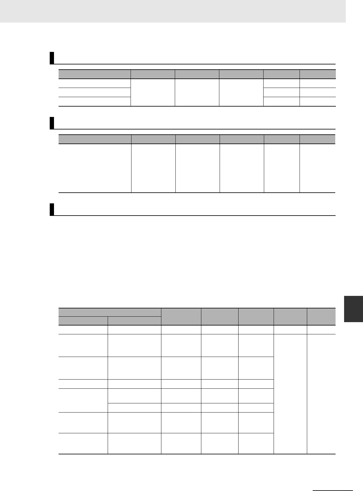
8-13
8 Backup Operations
CJ2 CPU Unit Hardware User’s Manual
8-3 Simple Backup
8
8-3-6 Data Backed Up Using Simple Backup
There are five types of data files, as shown below, when the simple backup operation is used for back-
ing up data (creating files) on the Memory Card or for restoring or comparing data from the Memory
Card.
•BACKUP.IOM
• BKUPIOR.IOR
• BACKUPDM.IOM
• BKUPEM@.IOM
• BKUPEF@.IOM
These files are used exclusively for the simple backup operation. With the exception of BKUPIOR.IOR,
they can all be manipulated from the CX-Programmer. (BKUPIOR.IOR files cannot be manipulated.)
Symbol Tables, Comments, and Program Index Files
Contents Backup Restore Compare File name Extension
Symbol table files Yes Yes Yes BKUPSYM .SYM
Comment files BKUPCMT .CMT
Program index file BKUPPRG .IDX
Parameter Files
Contents Backup Restore Compare File name Extension
•PLC Setup
• PLC name
• Registered I/O tables
• Routing tables
• CPU Bus Unit setup
• Etc.
Yes Ye s Ye s B ACK U P . S T D
Data
I/O memory Backup Restore Compare File name Extension
Area Addresses
DM Area D00000 to D19999 Yes Ye s No BACKUP .IOM
CIO Area CIO 0000 to CIO 6143
(Includes forced sta-
tus.)
Yes ---
(See note 3.) No BAUPIOR .IOR
Work Area W000 to W511
(Includes forced sta-
tus.)
Yes ---
(See note 3.) No
Holding Area H000 to H511 Yes Yes No
Auxiliary Area A000 to A447, A10000
to A11135 Ye s --- ---
A448 to A1472 Ye s Ye s No
Timer Completion
Flags and Timer
PVs
T0000 to T4095 Ye s ---
(See note 3.) No
Counter Comple-
tion Flags and
Counter PVs
C0000 to C4095 Ye s Ye s No
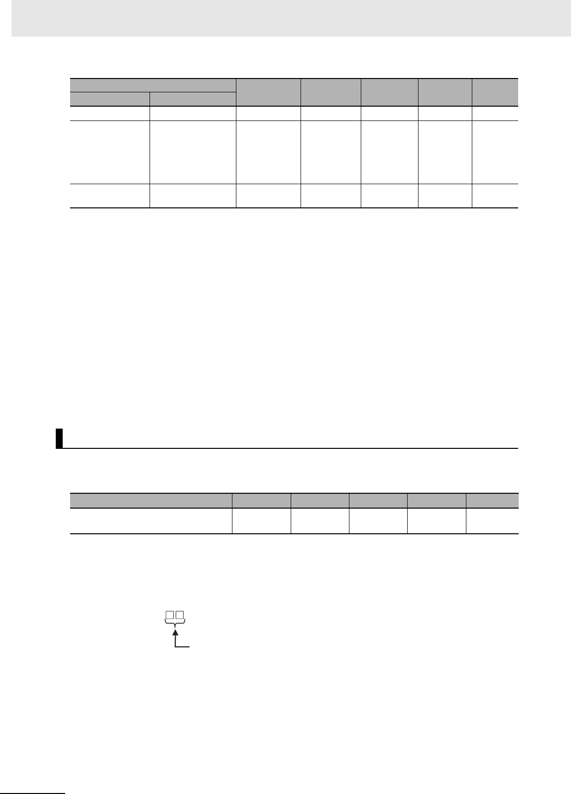
8 Backup Operations
8-14 CJ2 CPU Unit Hardware User’s Manual
Note 1 If the number of banks in the EM data on the Memory Card is less than the number of EM banks in the
CPU Unit where the data is to be restored (e.g., if data backed up by the CJ2H-CPU64-EIP is to be
restored at the CJ2H-CPU68-EIP), the amount of EM data on the Memory Card will be restored. On the
other hand, if the number of banks in the EM data on the Memory Card is greater than the number of EM
banks in the CPU Unit where the data is to be restored (e.g., if data backed up by the CJ2H-CPU68-EIP is
to be restored at the CJ2H-CPU64-EIP), it will not be possible to restore the data.
2When the EM file memory function is used, the EM file memory will be restored only if the backup data is
restored to a CPU Unit of the same model. If it is restored to a CPU Unit of a different model, the data will
not function as EM file memory.
3The BKUPIOR.IOR file will be cleared when data is restored from the Memory Card at startup. If, however,
the IOM Hold Bit (A500.12) is ON and the IOM Hold Bit Startup Hold Setting in the PLC Setup is set to
hold the setting of the IOM Hold Bit, the CIO and Work Area data and Timer Completion Flags and PVs will
be held without being cleared from the Memory Card at startup.
4If the Forced Status Hold Bit (A500.13) is ON and the Forced Status Hold Bit Startup Hold Setting in the
PLC Setup is set to hold the setting of the Forced Status Hold Bit, the forced status will be held without
being cleared when restored from the Memory Card at startup, to a CPU Unit of the same model. If the
data is restored to a CPU Unit of a different model, the status will not be held.
When CPU Bus or Special I/O Units that support the simple backup function are connected to the CPU
Unit, the data in the CPU Bus or Special I/O Units will also be backed up by the simple backup opera-
tion. Data in the CPU Bus and Special I/O Units is backed up separately for each Unit.
Note If the file does not exist when restoring data from the Memory Card to I/O memory, an error will not occur at
the CPU Unit but the data will not be restored to the CPU Bus or Special I/O Unit and an error will occur at
the CPU Bus or Special I/O Unit. For details on errors that occur at a CPU Bus or Special I/O Unit, refer to
the operation manual for the specific Unit.
Data in individual Units is saved to the Memory Card under the following file names.
Note The unit address is determined as follows:
• Built-in EtherNet/IP (CJ2H-CPU6@-EIP or CJ2M-CPU3@) or CPU Bus Unit: Unit number + 10 hex
• Special I/O Unit: Unit number + 20 hex
DM Area D00000 to D19999 Ye s Ye s N o BACKUPDM .IOM
EM Area (See notes
1 and 2.)
E@_0 to E@_32767
(@: Bank No. 0 to 18
hex. The maximum
bank number depends
on the CPU Unit
model.)
Ye s Ye s N o BKUPEM@.IOM
EM Area (forced
status) (See note 4.)
When bits are force-
set/reset Ye s Ye s N o BKUPEF@.IOM
Unit Backup Data
Contents Backup Restore Compare File name Extension
Data in Unit with unit address @@ (The
contents depend on the Unit.)
Yes Ye s Ye s B AC K U P@@ .PRM
I/O memory Backup Restore Compare File name Extension
Area Addresses
BACKUP .PRM
Unit address of Unit/Board (hex)
File name:

8-15
8 Backup Operations
CJ2 CPU Unit Hardware User’s Manual
8-3 Simple Backup
8
8-3-6 Data Backed Up Using Simple Backup
In order for data in a Unit to be backed up, that Unit must support the simple backup function. Refer to
the operation manual for the specific Unit to check whether this function is supported.
Applicable Units Model numbers Data backed up for simple backup Data capacity used
in Memory Card
Serial Communica-
tions Units
CJ1W-
SCU21/22/32/41/42
CJ1W-
SCU21/31/41-V1
Protocol macro data (Including both stan-
dard system protocols and user-defined
protocols from the flash memory in the
Unit or Board)
129 Kbytes
FL-net Units CJ1W-FLN22 Data link tables 1.3 Kbytes
DeviceNet Units CJ1W-DRM21 Device parameters (all data in EEPROM in
the Unit)
(Although this is the same data as is
backed up from the Memory Card backup
function supported by the Unit or the
DeviceNet Configuration (Ver. 2.@), there
is no file compatibility.)
7 Kbytes
CompoNet Units CJ1W-CRM21 • Registration tables
• Software settings
• Network parameters
• Slave parameters
3.5 Kbytes
Motion Control Units CJ1W-MCH71 • Positioning data
• System parameters
• G-language programming
8,192 Kbytes
Position Control
Units
CJ1W-NCF71(-MA) • Common parameters
• Individual axis parameters
64 Kbytes
CJ1W-
NC113/133/213/233/
413/433
• Axis parameters
• Sequence data
• Speed data
• Acceleration/deceleration time data
• Dual timer data
• Zone data
7 Kbytes
CJ1W-
NC214/234/414/434
• Common parameters
• Axis parameters
• Memory operation parameters
• Memory operation data
• Memory operation conditions data
220 Kbytes
CJ1W-
NC281/481/881/F81/
482/882
• Common parameters
• Axis parameters
• Memory operation parameters
• Memory operation data
• Memory operation conditions data
• Communications parameters
2,560 Kbytes
EtherNet/IP Unit CJ1W-EIP21 • Unit settings
• Tag data link settings
459 Kbytes

8 Backup Operations
8-16 CJ2 CPU Unit Hardware User’s Manual
Precautions for Correct UsePrecautions for Correct Use
When using a simple backup file to restore data, use a CPU Unit of the same model as the
backup source. If a CPU Unit of a different model is used, the following operations will result.
• If the number of EM banks for the simple backup file is greater than that of the CPU Unit where
the data is to be restored, the data will not be restored.
• If the number of EM banks for the simple backup file is less than that of the CPU Unit where
the data is to be restored, the data in the EM bank areas in the simple backup file will be
restored, but forced status will not be restored. In addition, EM banks that are not in the simple
backup file will retain their values from before the restoration.

A-1
pp
CJ2 CPU Unit Hardware User’s Manual
App
The appendices provide Unit specifications, Unit dimensions, details on fatal and non-
fatal errors, information on connecting to serial ports on the CPU Unit, the procedure
for installing the USB driver on a personal computer, and information on load short-cir-
cuit protection and line disconnection detection.
A-1 Specifications of Basic I/O Units . . . . . . . . . . . . . . . . . . . . . . . . . . . . . . . . . A-2
A-1-1 Overview of Units . . . . . . . . . . . . . . . . . . . . . . . . . . . . . . . . . . . . . . . . . . . . . . . A-2
A-1-2 Basic I/O Units . . . . . . . . . . . . . . . . . . . . . . . . . . . . . . . . . . . . . . . . . . . . . . . . . A-5
A-1-3 Precautions on Contact Output Units . . . . . . . . . . . . . . . . . . . . . . . . . . . . . . A-57
A-1-4 Connecting Connector-Terminal Block Conversion Units and
I/O Relay Terminals . . . . . . . . . . . . . . . . . . . . . . . . . . . . . . . . . . . . . . . . . . . . A-59
A-2 Dimensions . . . . . . . . . . . . . . . . . . . . . . . . . . . . . . . . . . . . . . . . . . . . . . . . . . A-94
A-2-1 CJ2H CPU Units . . . . . . . . . . . . . . . . . . . . . . . . . . . . . . . . . . . . . . . . . . . . . . A-94
A-2-2 CJ2M CPU Units . . . . . . . . . . . . . . . . . . . . . . . . . . . . . . . . . . . . . . . . . . . . . . A-95
A-2-3 Power Supply Units . . . . . . . . . . . . . . . . . . . . . . . . . . . . . . . . . . . . . . . . . . . . A-96
A-2-4 Basic I/O Units . . . . . . . . . . . . . . . . . . . . . . . . . . . . . . . . . . . . . . . . . . . . . . . . A-98
A-2-5 I/O Control Unit and I/O Interface Unit . . . . . . . . . . . . . . . . . . . . . . . . . . . . . A-101
A-2-6 I/O Memory Card . . . . . . . . . . . . . . . . . . . . . . . . . . . . . . . . . . . . . . . . . . . . . A-101
A-2-7 Pulse I/O Modules (CJ2M CPU Unit Only) . . . . . . . . . . . . . . . . . . . . . . . . . A-101
A-2-8 Serial Option Boards (CJ2M-CPU3@ Only) . . . . . . . . . . . . . . . . . . . . . . . . . A-102
A-3 Fatal and Non-fatal Error Details . . . . . . . . . . . . . . . . . . . . . . . . . . . . . . . A-103
A-3-1 Fatal Errors . . . . . . . . . . . . . . . . . . . . . . . . . . . . . . . . . . . . . . . . . . . . . . . . . A-103
A-3-2 Non-fatal Errors . . . . . . . . . . . . . . . . . . . . . . . . . . . . . . . . . . . . . . . . . . . . . . A-108
A-4 Connecting to a Serial Port on the CPU Unit . . . . . . . . . . . . . . . . . . . . . . A-111
A-4-1 Serial Port Interface Types and Specifications . . . . . . . . . . . . . . . . . . . . . . A-111
A-4-2 Connection Examples . . . . . . . . . . . . . . . . . . . . . . . . . . . . . . . . . . . . . . . . . A-117
A-4-3 Applicable Connectors and Recommended Cables . . . . . . . . . . . . . . . . . . A-132
A-5 Installing the USB Driver . . . . . . . . . . . . . . . . . . . . . . . . . . . . . . . . . . . . . . A-139
A-6 Load Short-circuit Protection and Line Disconnection Detection for
Basic I/O Units . . . . . . . . . . . . . . . . . . . . . . . . . . . . . . . . . . . . . . . . . . . . . . A-149
A-6-1 Load Short-circuit Protection and Line Disconnection Detection for
CJ1W-OD202 . . . . . . . . . . . . . . . . . . . . . . . . . . . . . . . . . . . . . . . . . . . . . . . A-149
A-6-2 Load Short-circuit Protection for CJ1W-OD204/OD212/OD232/MD232 . . . A-151
A-7 Relay Output Noise Reduction Methods . . . . . . . . . . . . . . . . . . . . . . . . . A-153
A-8 Functions Supported for Unit Versions . . . . . . . . . . . . . . . . . . . . . . . . . . A-155
Appendices
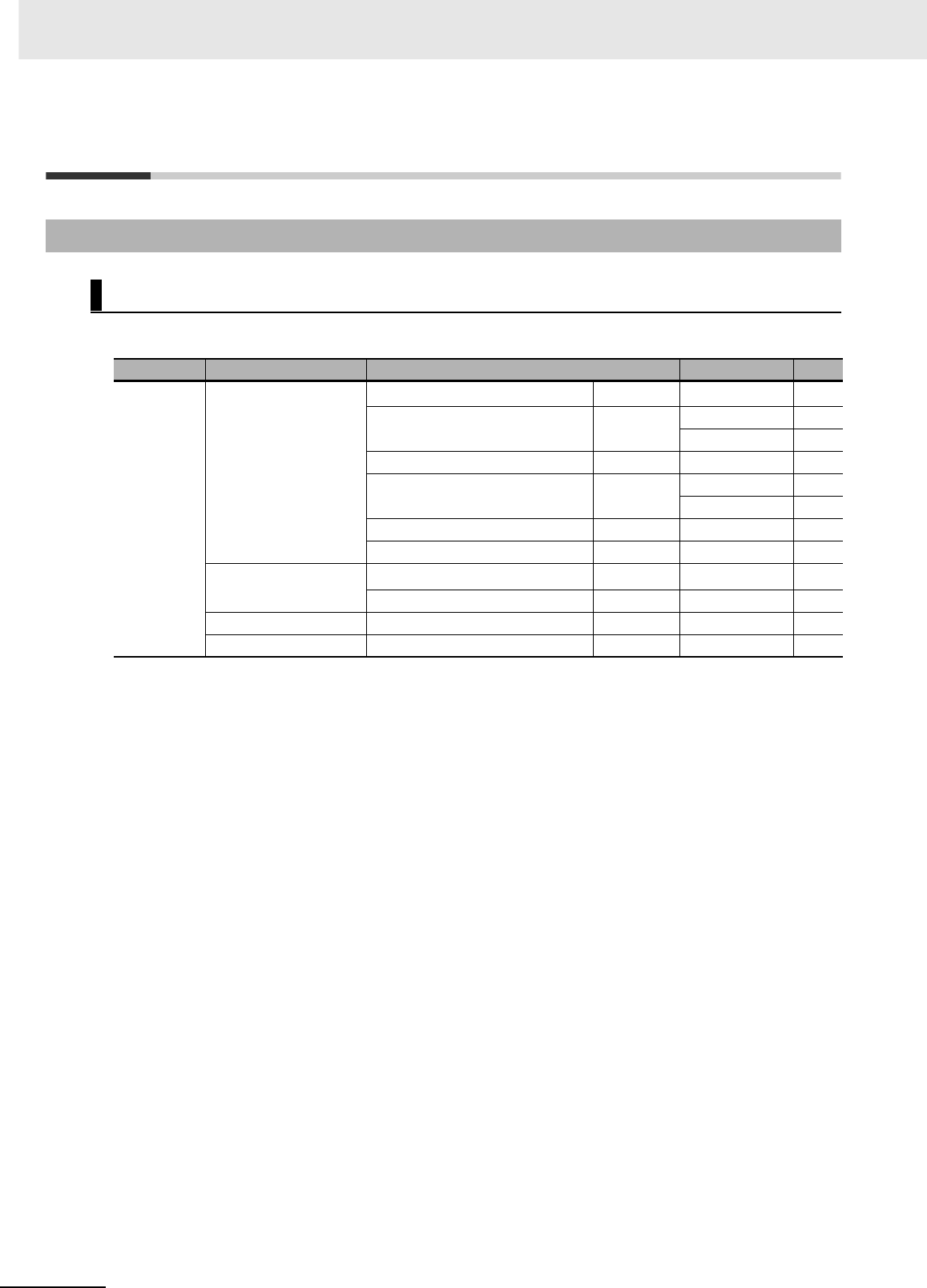
Appendices
A-2 CJ2 CPU Unit Hardware User’s Manual
A-1 Specifications of Basic I/O Units
zBasic Input Units
*1 Although 16 I/O bits (1 word) are allocated, only 8 of these can be used for external I/O. This Unit is also
treated as a 16-point I/O Unit in the I/O tables.
A-1-1 Overview of Units
Basic I/O Units
Type of Unit Name Specifications Model Page
Basic Input
Units
DC Input Units Terminal block, 12 to 24 VDC 8 inputs CJ1W-ID201*1 A-5
Terminal block, 24 VDC, 16 inputs CJ1W-ID211 A-6
CJ1W-ID212 A-7
Fujitsu-compatible connector, 24 VDC 32 inputs CJ1W-ID231 A-8
MIL connector, 24 VDC 32 inputs CJ1W-ID232 A-9
CJ1W-ID233 A-10
Fujitsu-compatible connector, 24 VDC 64 inputs CJ1W-ID261 A-12
MIL connector, 24 VDC 64 inputs CJ1W-ID262 A-13
AC Input Units Terminal block, 200 to 240 VAC 8 inputs CJ1W-IA201*1 A-15
Terminal block, 100 to 120 VAC 16 inputs CJ1W-IA111 A-16
Interrupt Input Unit Terminal block, 24 VDC 16 inputs CJ1W-INT01 A-17
Quick-response Input Unit Terminal block, 24 VDC 16 inputs CJ1W-IDP01 A-18
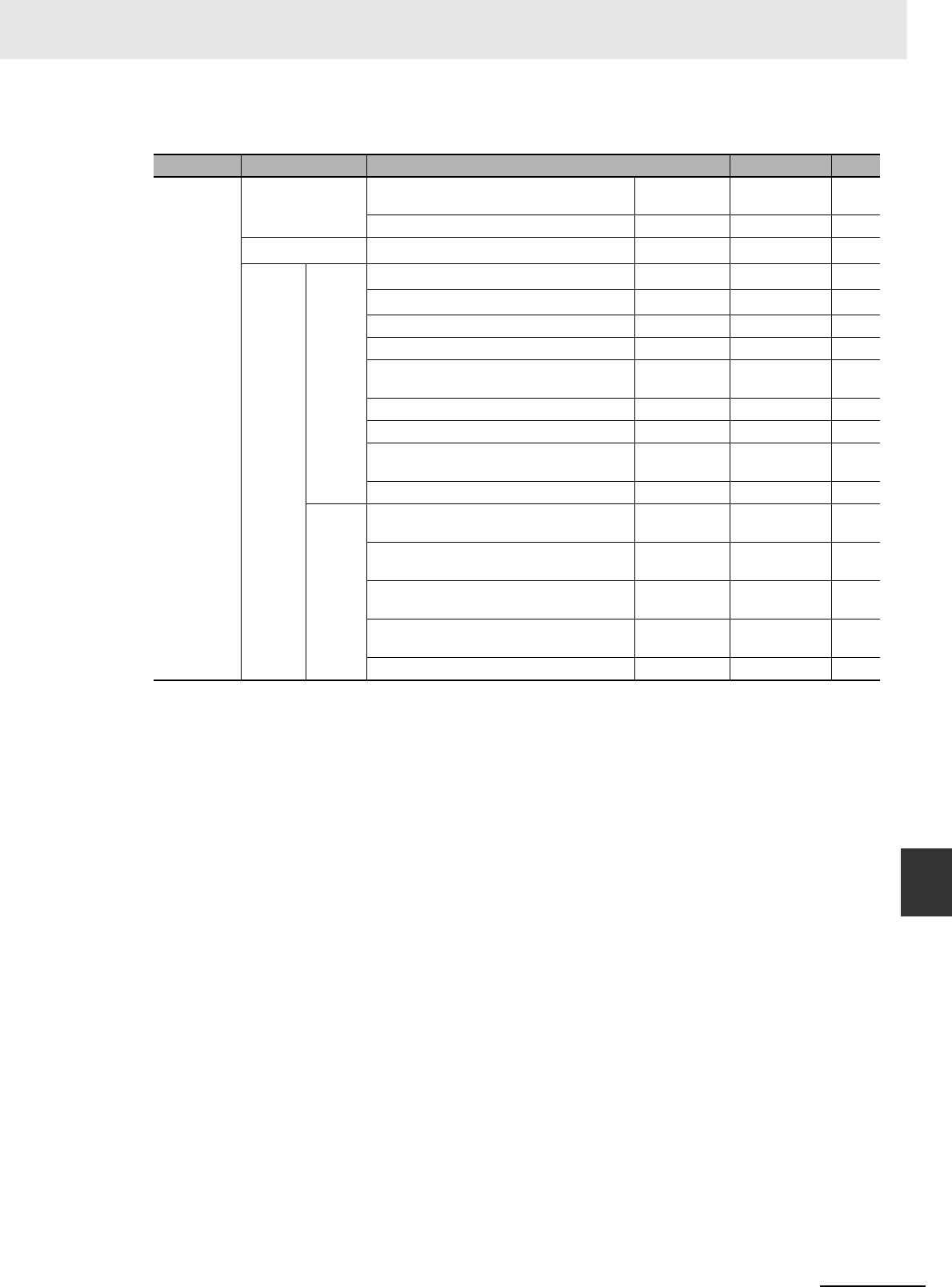
A-3
Appendices
CJ2 CPU Unit Hardware User’s Manual
A-1 Specifications of Basic I/O Units App A-1-1 Overview of Units
zBasic Output Units
*1 Although 16 I/O bits (1 word) are allocated, only 8 of these can be used for external I/O. This Unit is also
treated as a 16-point I/O Unit in the I/O tables.
Type of Unit Name Specifications Model Page
Basic Out-
put Units
Relay Output Units Terminal block, 250 VAC/24 VDC, 2 A,
8 independent contacts
8 outputs CJ1W-OC201*1 A-20
Terminal block, 250 VAC/24 VDC, 2 A 16 outputs CJ1W-OC211 A-21
Triac Output Unit Terminal block, 250 VAC/24 VDC, 0.6 A 8 outputs CJ1W-OA201*1 A-22
Transis-
tor Out-
put Units
Sinking
outputs
Terminal block, 12 to 24 VDC, 2 A 8 outputs CJ1W-OD201*1 A-23
Terminal block, 12 to 24 VDC, 0.5 A 8 outputs CJ1W-OD203*1 A-24
Terminal block, 12 to 24 VDC, 0.5 A 16 outputs CJ1W-OD211 A-25
Terminal block, 24 VDC, 0.5 A 16 outputs CJ1W-OD213 A-26
Fujitsu-compatible connector, 12 to 24 VDC,
0.5 A
32 outputs CJ1W-OD231 A-27
MIL connector, 12 to 24 VDC, 0.5 A 32 outputs CJ1W-OD233 A-29
MIL connector, 24 VDC, 0.5 A 32 outputs CJ1W-OD234 A-31
Fujitsu-compatible connector, 12 to 24 VDC,
0.3 A
64 outputs CJ1W-OD261 A-33
MIL connector, 12 to 24 VDC, 0.3 A 64 outputs CJ1W-OD263 A-35
Sourc-
ing out-
puts
Terminal block, 24 VDC, 2 A, load short-cir-
cuit protection, line disconnection detection
8 outputs CJ1W-OD202*1 A-37
Terminal block, 24 VDC, 0.5 A, load short-cir-
cuit protection
8 outputs CJ1W-OD204*1 A-39
Terminal block, 24 VDC, 0.5 A, load short-cir-
cuit protection
16 outputs CJ1W-OD212 A-40
MIL connector, 24 VDC, 0.5 A, load short-cir-
cuit protection
32 outputs CJ1W-OD232 A-41
MIL connector, 12 to 24 VDC, 0.3 A 64 outputs CJ1W-OD262 A-43

Appendices
A-4 CJ2 CPU Unit Hardware User’s Manual
zBasic Mixed I/O Units
Note For details on the connectors included with the Unit, refer to the information provided under Accessories in
the tables for Basic I/O Units in the following pages.
• I/O terminals in terminal connection diagrams are shown as viewed from the front panel of the Unit.
• Terminal numbers A0 to A9 and B0 to B9 are used in this manual, but they are not printed on all
Units.
• A0 to A20 and B0 to B20 are printed on the Units.
Type of
Unit Name Specifications Model Page
Mixed I/O
Units
24-VDC
Inputs/Transis-
tor Output Units
Sinking
output
Fujitsu-compatible connector
Inputs: 24 VDC
Outputs: 12 to 24 VDC, 0.5 A
16 inputs
16 outputs
CJ1W-MD231 A-45
MIL connector
Inputs: 24 VDC
Outputs: 12 to 24 VDC, 0.5 A
CJ1W-MD233 A-47
Fujitsu-compatible connector
Inputs: 24 VDC
Outputs: 12 to 24 VDC, 0.3 A
32 inputs
32 outputs
CJ1W-MD261 A-49
MIL connector
Inputs: 24 VDC
Outputs: 12 to 24 VDC, 0.3 A
CJ1W-MD263 A-51
Sourcing
output
MIL connector
Input: 24 VDC
Outputs: 24 VDC, 0.5 A, load short-cir-
cuit protection
16 inputs
16 outputs
CJ1W-MD232 A-53
TTL I/O Units Inputs: 5 VDC
Outputs: 5 VDC, 35 mA
32 inputs
32 outputs
CJ1W-MD563 A-55
Precautions on Contact Output Units A-57
Load short-circuit protection and line disconnection detection for CJ1W-OD202 A-149
Load short-circuit protection for CJ1W-OD204/OD212/OD232/MD232 A-151
Reading Terminal Connection Diagrams
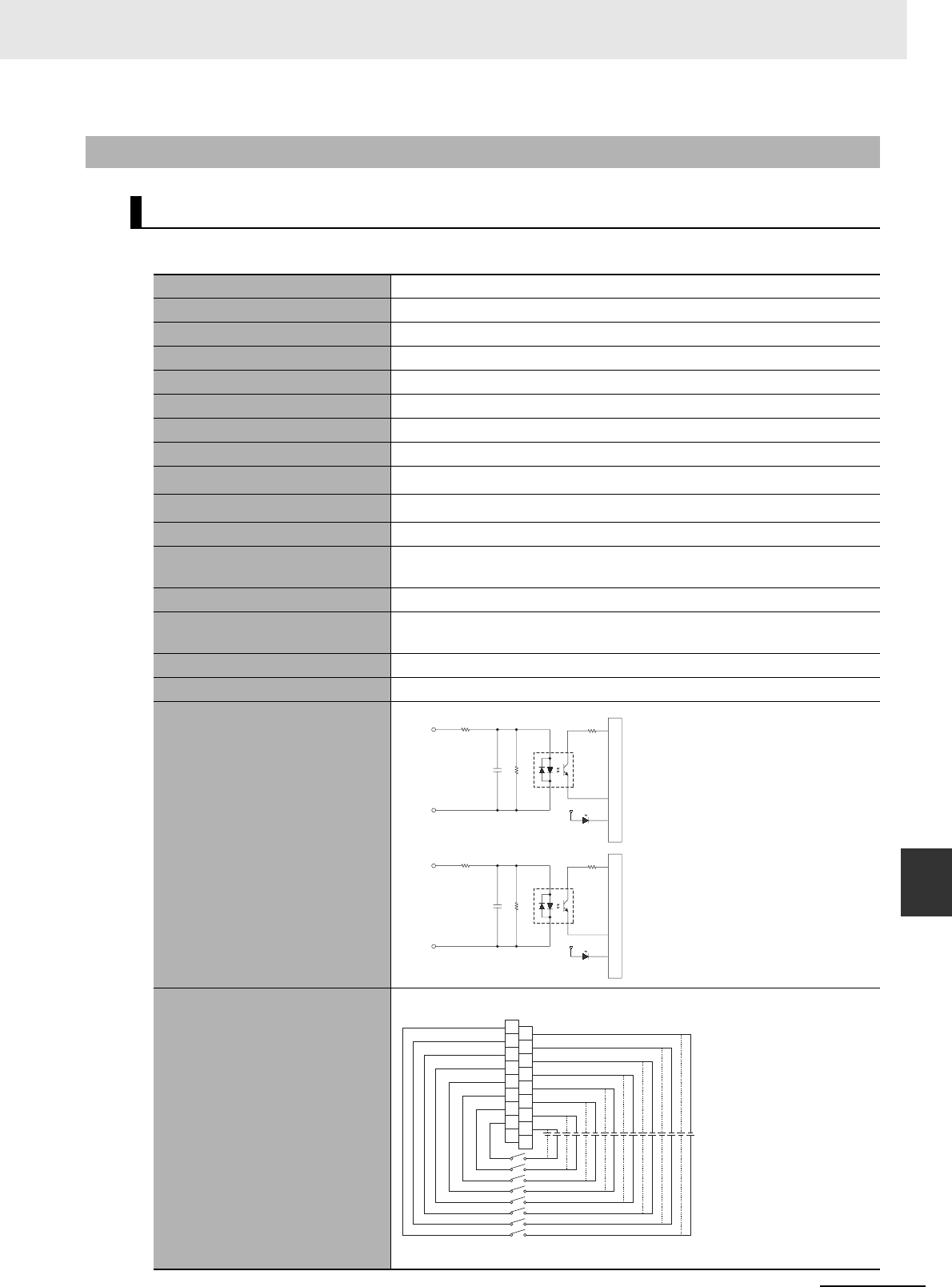
A-5
Appendices
CJ2 CPU Unit Hardware User’s Manual
A-1 Specifications of Basic I/O Units App A-1-2 Basic I/O Units
zCJ1W-ID201 DC Input Unit (12 to 24-VDC, 8 Points)
A-1-2 Basic I/O Units
Basic Input Units with Terminal Blocks
Name 8-point DC Input Unit with Terminal Block
Model CJ1W-ID201
Rated Input Voltage 12 to 24 VDC
Rated Input Voltage Range 10.2 to 26.4 VDC
Input Impedance 2.4 kΩ
Input Current 10 mA typical (at 24 VDC)
ON Voltage/ON Current 8.8 VDC min./3 mA min.
OFF Voltage/OFF Current 3 VDC max./1 mA max.
ON Response Time 8.0 ms max. (Can be set to between 0 and 32 ms in the PLC Setup.)*1
OFF Response Time 8.0 ms max. (Can be set to between 0 and 32 ms using PLC Setup)*1
Number of Circuits 8 independent circuits
Number of Simultaneously ON
Points
100% simultaneously ON
Insulation Resistance 20 MΩ between external terminals and the GR terminal (100 VDC)
Dielectric Strength 1,000 VAC between the external terminals and the GR terminal for 1 minute
at a leakage current of 10 mA max.
Internal Current Consumption 80 mA max.
Weight 110 g max.
Circuit Configuration
Terminal Connections
Polarity of the input power supply can be connected in either direction.
COM7
IN7
COM0
IN0
560 Ω
2.4 kΩ
560 Ω
2.4 kΩ
1000 pF
Input indicator
Internal circuits
to
1000 pF
Input indicator
Internal circuits
Signal name
B1
IN0
B2
IN1
B3
IN2
B4
IN3
B5
IN4
B6
IN5
B7
IN6
B8
IN7
NC
C0
C1
C2
C3
C4
C5
C6
C7
NC
B0
A1
A2
A3
A4
A5
A6
A7
A8
A0
Signal
name Signal
name
Connec-
tor pin
12 to 24 VDC
*2
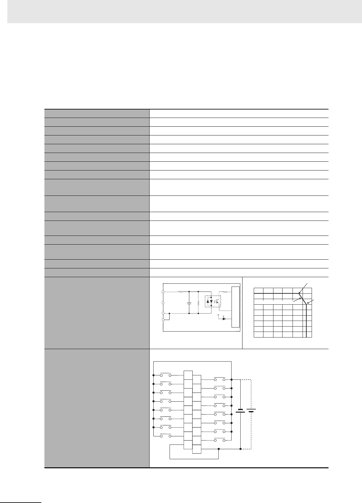
Appendices
A-6 CJ2 CPU Unit Hardware User’s Manual
*1 The ON response time will be 20 µs maximum and OFF response time will be 400 µs maximum even if the
response time are set to 0 ms due to internal element delays.
*2 Terminal numbers A0 to A8 and B0 to B8 are used in this manual, but they are not printed on the Unit.
Note Although 16 I/O bits (1 word) are allocated, only 8 of these can be used for external I/O. This Unit is also
treated as a 16-point I/O Unit in the I/O tables.
zCJ1W-ID211 DC Input Unit (24 VDC, 16 Points)
*1 The ON response time will be 20 µs maximum and OFF response time will be 400 µs maximum even if the
response time are set to 0 ms due to internal element delays.
*2 Terminal numbers A0 to A8 and B0 to B8 are used in this manual, but they are not printed on the Unit.
Name 16-point DC Input Unit with Terminal Block
Model CJ1W-ID211
Rated Input Voltage 24 VDC
Rated Input Voltage Range 20.4 to 26.4 VDC
Input Impedance 3.3 kΩ
Input Current 7 mA typical (at 24 VDC)
ON Voltage/ON Current 14.4 VDC min./3 mA min.
OFF Voltage/OFF Current 5 VDC max./1 mA max.
ON Response Time 8.0 ms max.
(Can be set to between 0 and 32 ms in the PLC Setup.)*1
OFF Response Time 8.0 ms max.
(Can be set to between 0 and 32 ms using PLC Setup)*1
Number of Circuits 16 (16 points/common, 1 circuit)
Number of Simultaneously ON Points 100% simultaneously ON (at 24 VDC)
(Refer to the following illustration.)
Insulation Resistance 20 MΩ between external terminals and the GR terminal (100 VDC)
Dielectric Strength 1,000 VAC between the external terminals and the GR terminal for 1 minute at
a leakage current of 10 mA max.
Internal Current Consumption 80 mA max.
Weight 110 g max.
Circuit Configuration
Terminal Connections
• Polarity of the input power supply can be connected in either direction.
IN0
IN15
COM
COM
1000 pF
470 Ω
3.3 kΩ
Internal circuits
Input indicator
to
Signal
name 18
16
14
12
10
8
6
4
2
00 10 20 30 40 50 60
No. of simultaneously ON points
Input voltage: 26.4 VDC
12 points
at 55°C.
16 points
at 45°C.
Ambient temperature
(°C)
Temperature characteristics
for simultaneously ON points
B1
IN1
B2
IN3
B3
IN5
B4
IN7
B5
IN9
B6
IN11
B7
IN13
B8
IN15
COM
24 VDC
A1
IN0
A2
IN2
A3
IN4
A4
IN6
A5
IN8
A6
IN10
A7
IN12
A8
IN14
COM
B0
A0
Signal
name Signal
name
Connec-
tor pin
*2
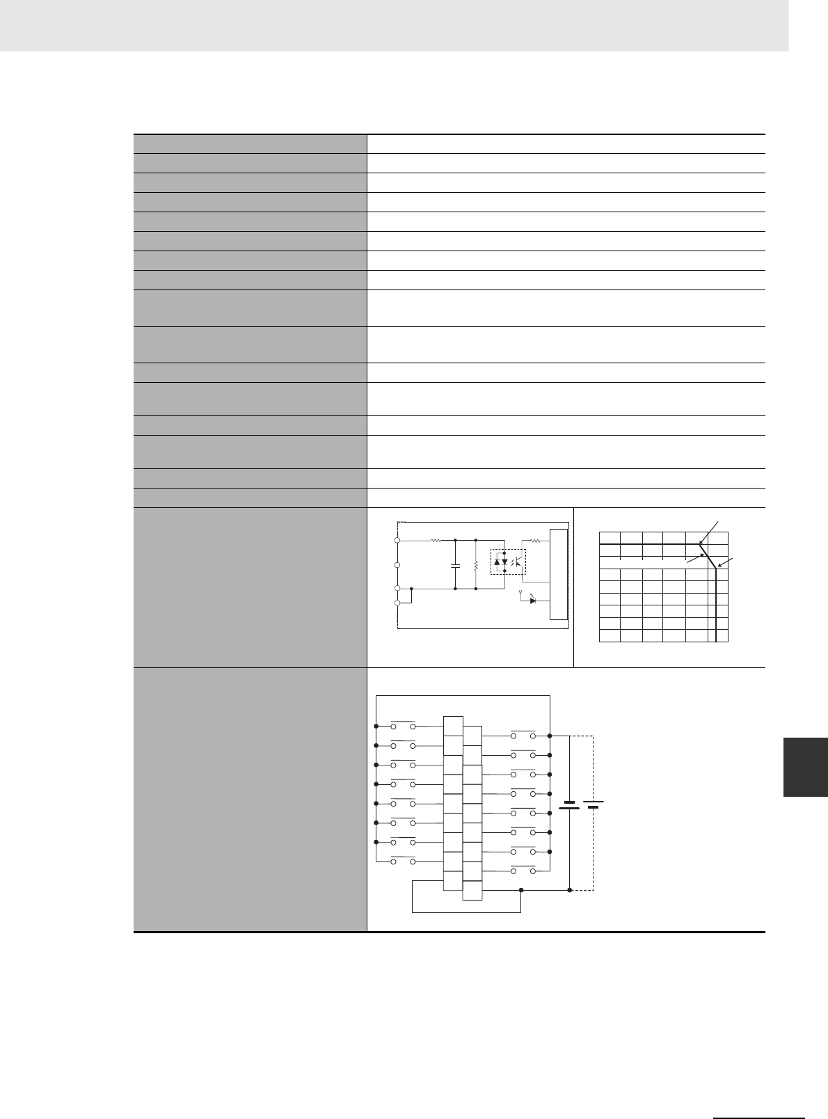
A-7
Appendices
CJ2 CPU Unit Hardware User’s Manual
A-1 Specifications of Basic I/O Units App A-1-2 Basic I/O Units
zCJ1W-ID212 DC Input Unit (24 VDC, 16 Points)
*1 The ON response time will be 15 µs maximum and OFF response time will be 90 µs maximum even if the
response time are set to 0 ms due to internal element delays.
*2 Terminal numbers A0 to A8 and B0 to B8 are used in this manual, but they are not printed on the Unit.
Name 16-point DC Input Unit with Terminal Block
Model CJ1W-ID212
Rated Input Voltage 24 VDC
Rated Input Voltage Range 20.4 to 26.4 VDC
Input Impedance 3.3 kΩ
Input Current 7 mA typical (at 24 VDC)
ON Voltage/ON Current 14.4 VDC min./3 mA min.
OFF Voltage/OFF Current 5 VDC max./1 mA max.
ON Response Time 8.0 ms max.
(Can be set to between 0 and 32 ms in the PLC Setup.)*1
OFF Response Time 8.0 ms max.
(Can be set to between 0 and 32 ms using PLC Setup)*1
Number of Circuits 16 (16 points/common, 1 circuit)
Number of Simultaneously ON Points 100% simultaneously ON (at 24 VDC)
(Refer to the following illustration.)
Insulation Resistance 20 MΩ between external terminals and the GR terminal (100 VDC)
Dielectric Strength 1,000 VAC between the external terminals and the GR terminal for 1 minute at
a leakage current of 10 mA max.
Internal Current Consumption 130 mA max.
Weight 110 g max.
Circuit Configuration
Terminal Connections
• Polarity of the input power supply can be connected in either direction.
IN0
IN15
COM
COM
1000 pF
470 Ω
3.3 kΩ
Internal circuits
Input indicator
to
Signal
name 18
16
14
12
10
8
6
4
2
00 10 20 30 40 50 60
No. of simultaneously ON points
Input voltage: 26.4 VDC
12 points
at 55°C.
16 points
at 45°C.
Ambient temperature
(°C)
Temperature characteristics
for simultaneously ON points
B1
IN1
B2
IN3
B3
IN5
B4
IN7
B5
IN9
B6
IN11
B7
IN13
B8
IN15
COM
24 VDC
A1
IN0
A2
IN2
A3
IN4
A4
IN6
A5
IN8
A6
IN10
A7
IN12
A8
IN14
COM
B0
A0
Signal
name Signal
name
Connec-
tor pin
*2
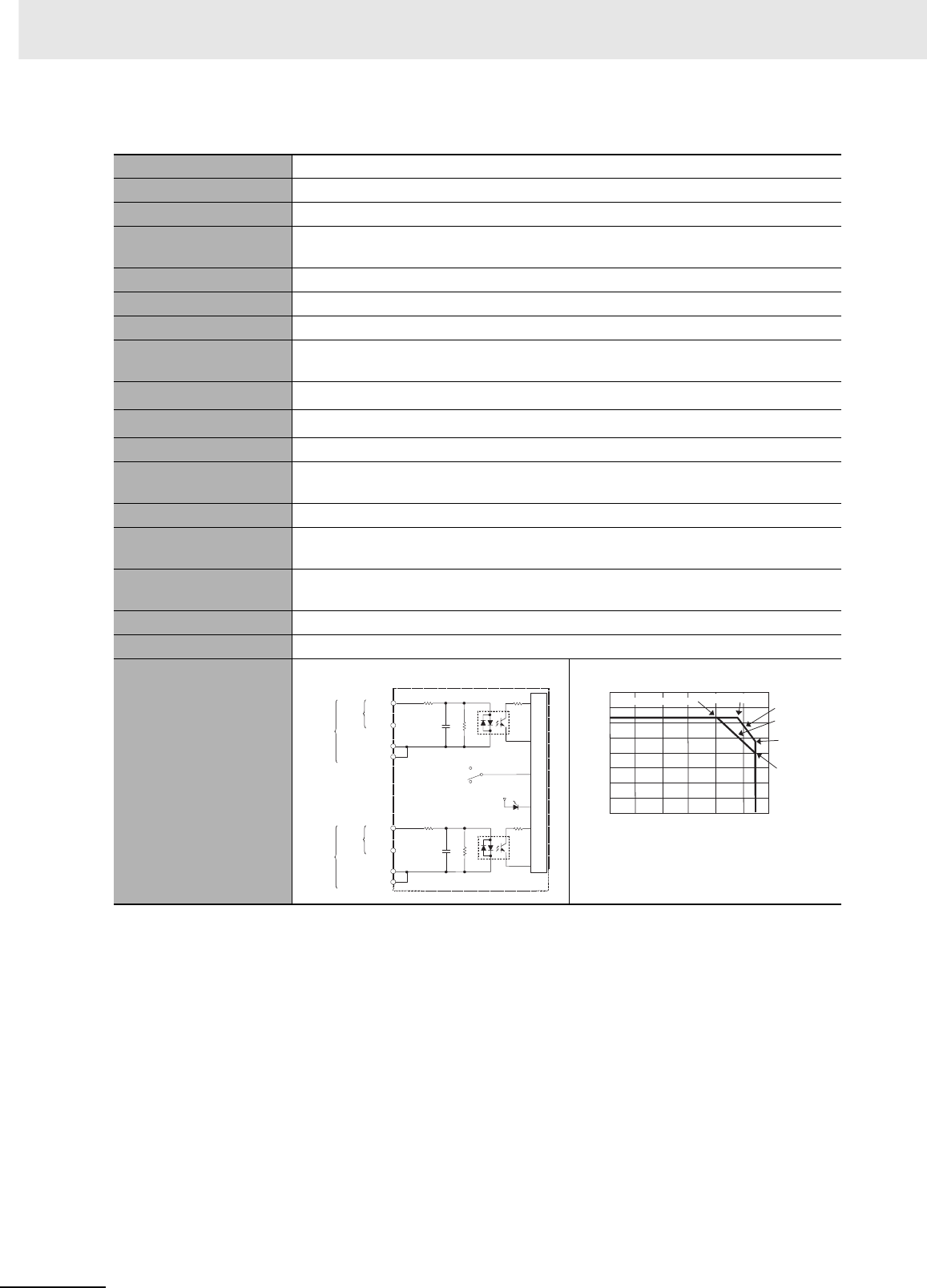
Appendices
A-8 CJ2 CPU Unit Hardware User’s Manual
zCJ1W-ID231 DC Input Unit (24 VDC, 32 Points)
Name 32-point DC Input Unit with Fujitsu Connector
Model CJ1W-ID231
Rated Input Voltage 24 VDC
Rated Input Voltage
Range
20.4 to 26.4 VDC
Input Impedance 5.6 kΩ
Input Current 4.1 mA typical (at 24 VDC)
ON Voltage/ON Current 19.0 VDC min./3 mA min.
OFF Voltage/OFF Cur-
rent
5 VDC max./1 mA max.
ON Response Time 8.0 ms max. (Can be set to between 0 and 32 in the PLC Setup.)*1
OFF Response Time 8.0 ms max. (Can be set to between 0 and 32 in the PLC Setup.)*1
Number of Circuits 32 (16 points/common, 2 circuits)
Number of Simulta-
neously ON Points
75% (12 points/common) simultaneously ON (at 24 VDC) (Refer to the following illus-
tration.)
Insulation Resistance 20 MΩ between external terminals and the GR terminal (100 VDC)
Dielectric Strength 1,000 VAC between the external terminals and the GR terminal for 1 minute at a
leakage current of 10 mA max.
Internal Current Con-
sumption
90 mA max.
Weight 70 g max.
Accessories None
Circuit Configuration
IN0
IN15
COM0
IN0
IN15
COM1
COM0
COM1
SW
560 Ω
560 Ω
5.6 kΩ
5.6 kΩ
1000 pF
1000 pF
Internal circuits
Input indicator
to
to
Wd
m+1
Wd m
Allocated
CIO word Signal
name
Connect
or row A
Connect
or row B
0
5
10
15
20
25
30
35
010 20 30 40 5060
Number of Simultaneously ON Points vs.
Ambient Temperature Characteristic
Number of simultaneously ON points
Ambient Temperature
(°C)
10 points/
common
at 55°C
12 points/
common
at 55°C
Input voltage:
26.4 VDC
Input voltage:
24 VDC
32 points at 48°C
32 points at 40°C
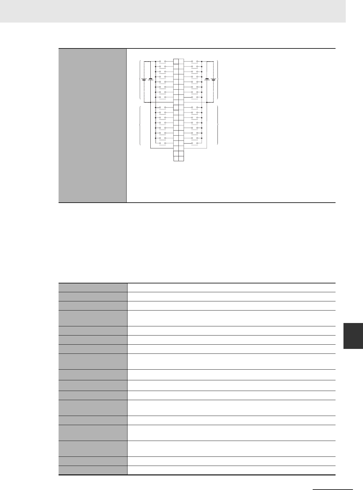
A-9
Appendices
CJ2 CPU Unit Hardware User’s Manual
A-1 Specifications of Basic I/O Units App A-1-2 Basic I/O Units
*1 The ON response time will be 20 µs maximum and OFF response time will be 400 µs maximum even if the
response times are set to 0 ms due to internal element delays.
Note Observe the following restrictions when connecting to a 2-wire sensor.
• Make sure the input power supply voltage is larger than the ON voltage (19 V) plus the residual voltage of
the sensor (approx. 3 V).
• Use a sensor with a minimum load current of 3 mA min.
• Connect bleeder resistance if you connect a sensor with a minimum load current of 5 mA or higher.
zCJ1W-ID232 DC Input Unit (24 VDC, 32 Points)
Terminal Connections
• The input power polarity can be connected in either direction.
• Be sure to wire both pins A9 and A18 (COM0), and set the same polarity for both
pins.
• Be sure to wire both pins B9 and B18 (COM1), and set the same polarity for both
pins.
Name 32-point DC Input Unit with MIL Connector
Model CJ1W-ID232
Rated Input Voltage 24 VDC
Rated Input Voltage
Range
20.4 to 26.4 VDC
Input Impedance 5.6 kΩ
Input Current 4.1 mA typical (at 24 VDC)
ON Voltage/ON Current 19.0 VDC min./3 mA min.
OFF Voltage/OFF Cur-
rent
5 VDC max./1 mA max.
ON Response Time 8.0 ms max. (Can be set to between 0 and 32 in the PLC Setup.)*1
OFF Response Time 8.0 ms max. (Can be set to between 0 and 32 in the PLC Setup.) *1
Number of Circuits 32 (16 points/common, 2 circuits)
Number of Simulta-
neously ON Points
75% (12 points/common) simultaneously ON (at 24 VDC) (Refer to the following
illustration.)
Insulation Resistance 20 MΩ between external terminals and the GR terminal (100 VDC)
Dielectric Strength 1,000 VAC between the external terminals and the GR terminal for 1 minute at a
leakage current of 10 mA max.
Internal Current Con-
sumption
90 mA max.
Weight 70 g max.
Accessories None
IN0
IN1
IN2
IN3
IN4
IN5
IN6
IN7
IN0
IN1
IN2
IN3
IN4
IN5
IN6
IN7
COM0
IN8
IN9
IN10
IN11
IN12
IN13
IN14
IN15
IN8
IN9
IN10
IN11
IN12
IN13
IN14
IN15
COM0
NC
NC
COM1
COM1
NC
NC
Allocated
CIO word
Allocated
CIO word
A1
A2
A3
A4
A5
A6
A7
A8
A9
A10
A11
A12
A13
A14
A15
A16
A17
A18
A19
A20
B1
B2
B3
B4
B5
B6
B7
B8
B9
B10
B11
B12
B13
B14
B15
B16
B17
B18
B19
B20
Wd m+1
Wd m
24
VDC
Wd m Wd m+1
24
VDC
Signal
name Signal
name
Connec-
tor pin
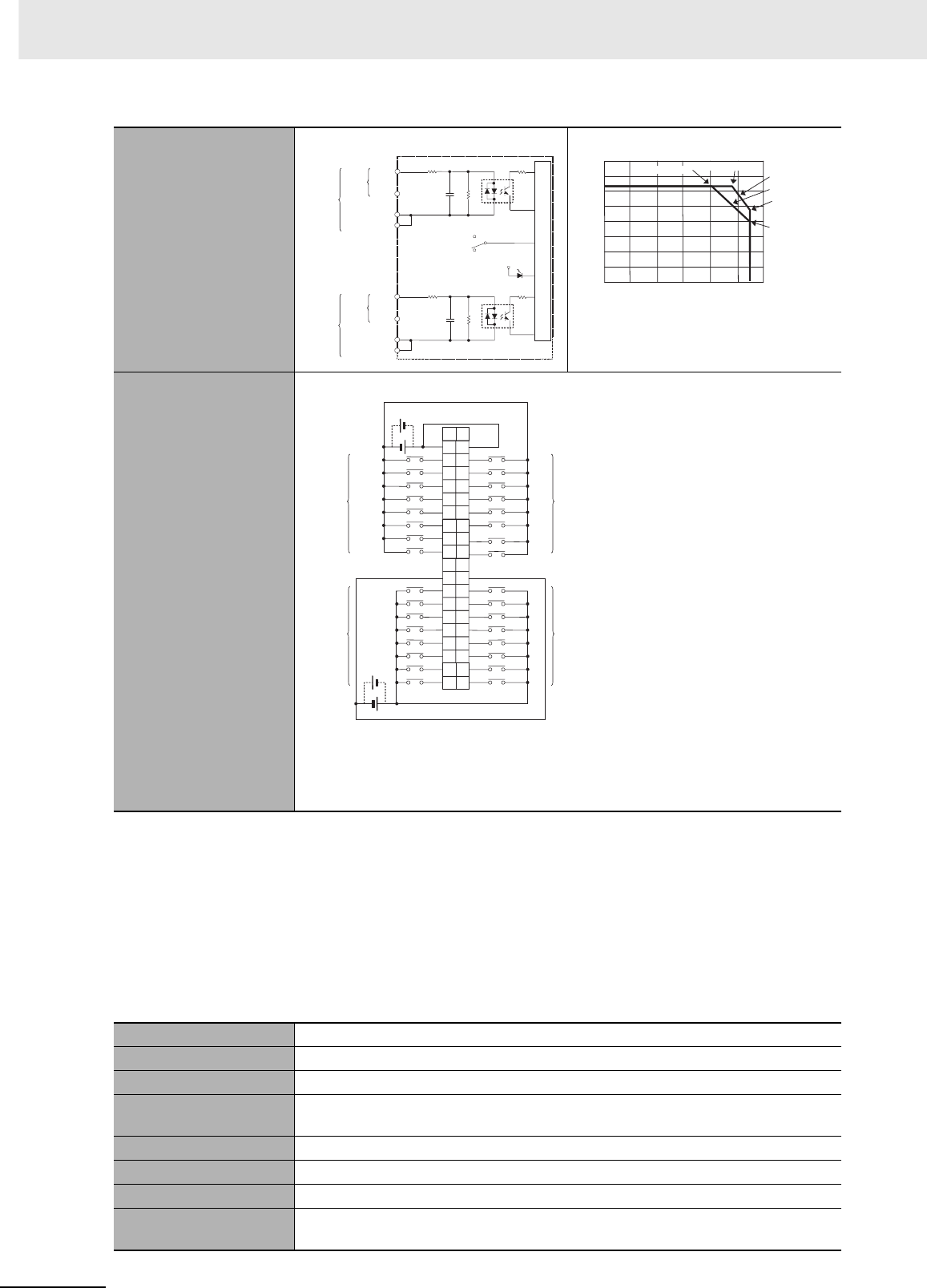
Appendices
A-10 CJ2 CPU Unit Hardware User’s Manual
*1 The ON response time will be 20 µs maximum and OFF response time will be 400 µs maximum even if the
response times are set to 0 ms due to internal element delays.
Note Observe the following restrictions when connecting to a 2-wire sensor.
• Make sure the input power supply voltage is larger than the ON voltage (19 V) plus the residual voltage of
the sensor (approx. 3 V).
• Use a sensor with a minimum load current of 3 mA min.
• Connect bleeder resistance if you connect a sensor with a minimum load current of 5 mA or higher.
zCJ1W-ID233 DC Input Unit (24 VDC, 32 Points)
Circuit Configuration
Terminal Connections
• The input power polarity can be connected in either direction.
• Be sure to wire both pins 23 and 24 (COM0), and set the same polarity for both
pins.
• Be sure to wire both pins 3 and 4 (COM1), and set the same polarity for both pins.
Name 32-point DC Input Unit with MIL Connector
Model CJ1W-ID233
Rated Input Voltage 24 VDC
Rated Input Voltage
Range
20.4 to 26.4 VDC
Input Impedance 5.6 kΩ
Input Current 4.1 mA typical (at 24 VDC)
ON Voltage/ON Current 19.0 VDC min./3 mA min.
OFF Voltage/OFF Cur-
rent
5 VDC max./1 mA max.
IN0
IN15
COM0
IN0
IN15
COM1
COM0
COM1
SW
560 Ω
560 Ω
5.6 kΩ
5.6 kΩ
1000 pF
1000 pF
Internal circuits
Input indicator
to
to
Wd
m+1
Wd m
Allocated
CIO word Signal
name
Connect
or row A
Connect
or row B
0
5
10
15
20
25
30
35
010 20 30 40 5060
Number of simultaneously ON points
Ambient Temperature
(°C)
10 points/common
at 55°C
12 points/common
at 55°C
Input voltage:
26.4 VDC
Input voltage:
24 VDC
32 points at 48°C
32 points at 40°C
Number of Simultaneously ON Points vs.
Ambient Temperature Characteristic
2
NC
4
COM1
6
IN7
8
IN6
10
IN5
12
IN4
14
IN3
16
IN2
18
IN1
20
IN0
IN7
IN6
IN5
IN4
IN3
IN2
IN1
IN0
22
NC
24
26
28
30
32
34
36
1
NC
3
COM1
5
IN15
7
IN14
9
IN13
11
IN12
13
IN11
15
IN10
17
IN9
19
IN8
21
NC
23
25
27
29
31
33
35
38
40
37
39
COM0 COM0
IN15
IN14
IN13
IN12
IN11
IN10
IN9
IN8
Wd m+1 Wd m+1
Wd m Wd m
24 VDC
24 VDC
Signal
name Signal
name
Connec-
tor pin
Allocated
CIO word
Allocated
CIO word
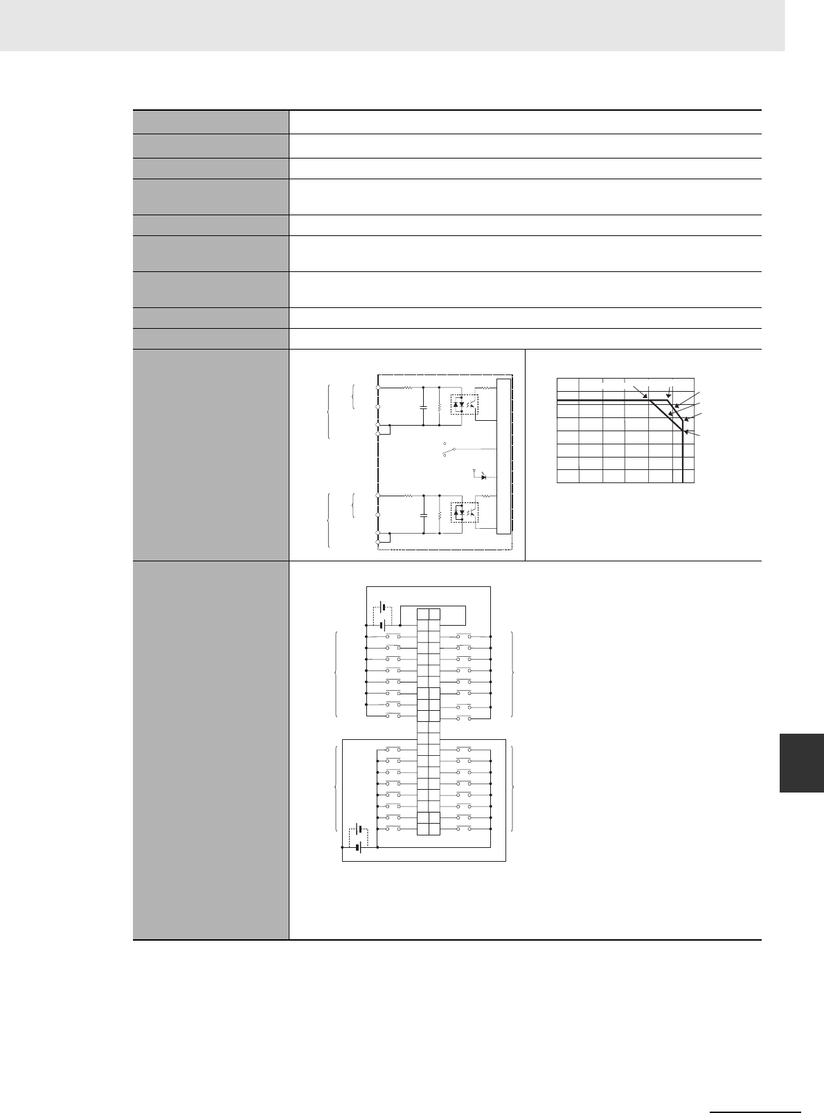
A-11
Appendices
CJ2 CPU Unit Hardware User’s Manual
A-1 Specifications of Basic I/O Units App A-1-2 Basic I/O Units
*1 The ON response time will be 15 µs maximum and OFF response time will be 90 µs maximum even if the
response times are set to 0 ms due to internal element delays.
Note Observe the following restrictions when connecting to a 2-wire sensor.
• Make sure the input power supply voltage is larger than the ON voltage (19 V) plus the residual voltage of
the sensor (approx. 3 V).
• Use a sensor with a minimum load current of 3 mA min.
• Connect bleeder resistance if you connect a sensor with a minimum load current of 5 mA or higher.
ON Response Time 8.0 ms max. (Can be set to between 0 and 32 in the PLC Setup.)*1
OFF Response Time 8.0 ms max. (Can be set to between 0 and 32 in the PLC Setup.) *1
Number of Circuits 32 (16 points/common, 2 circuits)
Number of Simulta-
neously ON Points
75% (12 points/common) simultaneously ON (at 24 VDC) (Refer to the following
illustration.)
Insulation Resistance 20 MΩ between external terminals and the GR terminal (100 VDC)
Dielectric Strength 1,000 VAC between the external terminals and the GR terminal for 1 minute at a
leakage current of 10 mA max.
Internal Current Con-
sumption
200 mA max.
Weight 70 g max.
Accessories None
Circuit Configuration
Terminal Connections
• The input power polarity can be connected in either direction.
• Be sure to wire both pins 23 and 24 (COM0), and set the same polarity for both
pins.
• Be sure to wire both pins 3 and 4 (COM1), and set the same polarity for both pins.
IN0
IN15
COM0
IN0
IN15
COM1
COM0
COM1
SW
560 Ω
560 Ω
5.6 kΩ
5.6 kΩ
1000 pF
1000 pF
Internal circuits
Input indicator
to
to
Wd
m+1
Wd m
Allocated
CIO word Signal
name
Connect
or row A
Connect
or row B
0
5
10
15
20
25
30
35
010 20 30 40 5060
Number of simultaneously ON points
Ambient Temperature
(°C)
10 points/common
at 55°C
12 points/common
at 55°C
Input voltage:
26.4 VDC
Input voltage:
24 VDC
32 points at 48°C
32 points at 40°C
Number of Simultaneously ON Points vs.
Ambient Temperature Characteristic
2
NC
4
COM1
6
IN7
8
IN6
10
IN5
12
IN4
14
IN3
16
IN2
18
IN1
20
IN0
IN7
IN6
IN5
IN4
IN3
IN2
IN1
IN0
22
NC
24
26
28
30
32
34
36
1
NC
3
COM1
5
IN15
7
IN14
9
IN13
11
IN12
13
IN11
15
IN10
17
IN9
19
IN8
21
NC
23
25
27
29
31
33
35
38
40
37
39
COM0 COM0
IN15
IN14
IN13
IN12
IN11
IN10
IN9
IN8
Wd m+1 Wd m+1
Wd m Wd m
24 VDC
24 VDC
Signal
name Signal
name
Connec-
tor pin
Allocated
CIO word
Allocated
CIO word
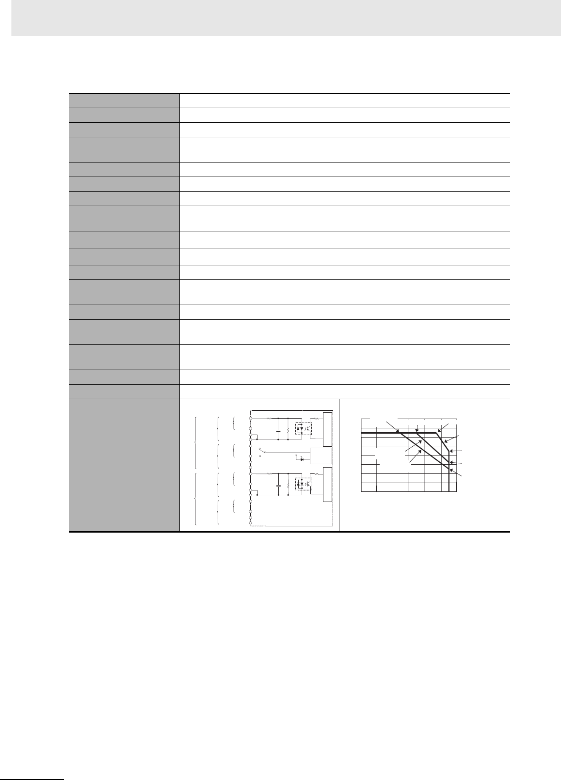
Appendices
A-12 CJ2 CPU Unit Hardware User’s Manual
zCJ1W-ID261 DC Input Unit (24 VDC, 64 Points)
Name 64-point DC Input Unit with Fujitsu Connector
Model CJ1W-ID261
Rated Input Voltage 24 VDC
Rated Input Voltage
Range
20.4 to 26.4 VDC
Input Impedance 5.6 kΩ
Input Current 4.1 mA typical (at 24 VDC)
ON Voltage/ON Current 19.0 VDC min./3 mA min.
OFF Voltage/OFF Cur-
rent
5 VDC max./1 mA max.
ON Response Time 8.0 ms max. (Can be set to between 0 and 32 in the PLC Setup.)*1
OFF Response Time 8.0 ms max. (Can be set to between 0 and 32 in the PLC Setup.)*1
Number of Circuits 64 (16 points/common, 4 circuits)
Number of Simulta-
neously ON Points
50% (16 points/common) simultaneously ON (at 24 VDC) (Refer to the following
illustrations.)
Insulation Resistance 20 MΩ between external terminals and the GR terminal (100 VDC)
Dielectric Strength 1,000 VAC between the external terminals and the GR terminal for 1 minute at a
leakage current of 10 mA max.
Internal Current Con-
sumption
90 mA max.
Weight 110 g max.
Accessories None
Circuit Configuration
SW
CN1
IN0
IN15
COM0
IN0
IN15
COM0
COM1
COM1
IN0
IN15
COM2
IN0
IN15
COM2
COM3
COM3
CN2
5.6 kΩ
1000 pF
560 Ω
5.6 kΩ
Input indicator
Indicator
switching
circuit
Internal circuits Internal circuits
1000 pF
560 Ω
Wd
m+1
Wd m
Wd
m+2
Wd
m+3
to
to
to
to
Allocated
CIO word Signal
name
Connect
or row A
Connect
or row B
Connect
or row A
Connect
or row B
0
10
20
30
40
50
60
70
0102030 405060
Ambient Temperature
8 points/common
(total: 26 points max.)
at 55°C
8 points/common
at 55°C
12 points/common
(total: 45 points)
at 55°C
Input voltage:
20.4 VDC
Input voltage:
26.4 VDC
Input voltage:
24 VDC
Number of simultaneously ON points
Number of Simultaneously ON Points vs.
Ambient Temperature Characteristic
64 points at
25°C64 points at 47°C
(°C)
64 points at 35°C
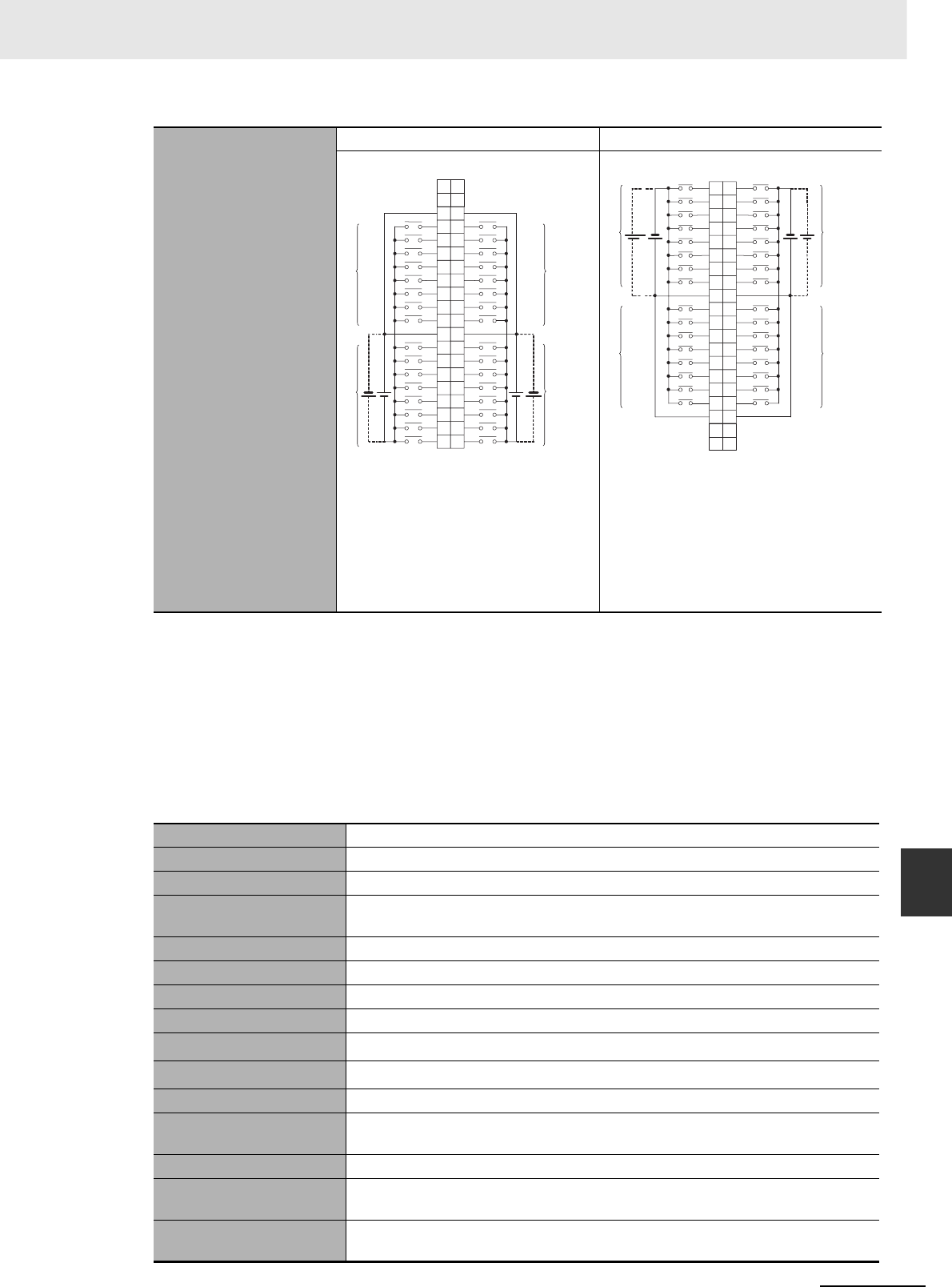
A-13
Appendices
CJ2 CPU Unit Hardware User’s Manual
A-1 Specifications of Basic I/O Units App A-1-2 Basic I/O Units
*1 The ON response time will be 120 µs maximum and OFF response time will be 400 µs maximum even if the
response times are set to 0 ms due to internal element delays.
Note Observe the following restrictions when connecting to a 2-wire sensor.
• Make sure the input power supply voltage is larger than the ON voltage (19 V) plus the residual voltage of
the sensor (approx. 3 V).
• Use a sensor with a minimum load current of 3 mA min.
• Connect bleeder resistance if you connect a sensor with a minimum load current of 5 mA or higher.
zCJ1W-ID262 DC Input Unit (24 VDC, 64 Points)
Terminal Connections
CN1 CN2
• The input power polarity can be con-
nected in either direction.
• Be sure to wire both pins A9 and A18
(COM0) of CN1, and set the same
polarity for both pins.
• Be sure to wire both pins B9 and B18
(COM1) of CN1, and set the same
polarity for both pins.
• The input power polarity can be con-
nected in either direction.
• Be sure to wire both pins A9 and A18
(COM2) of CN2, and set the same
polarity for both pins.
• Be sure to wire both pins B9 and B18
(COM3) of CN2, and set the same
polarity for both pins.
Name 64-point DC Input Unit with MIL Connector
Model CJ1W-ID262
Rated Input Voltage 24 VDC
Rated Input Voltage
Range
20.4 to 26.4 VDC
Input Impedance 5.6 kΩ
Input Current 4.1 mA typical (at 24 VDC)
ON Voltage/ON Current 19.0 VDC min./3 mA min.
OFF Voltage/OFF Current 5 VDC max./1 mA max.
ON Response Time 8.0 ms max. (Can be set to between 0 and 32 in the PLC Setup.)*1
OFF Response Time 8.0 ms max. (Can be set to between 0 and 32 in the PLC Setup.)*1
Number of Circuits 64 (16 points/common, 4 circuits)
Number of Simulta-
neously ON Points
50% (8 points/common) simultaneously ON (at 24 VDC) (Refer to the following
illustrations.)
Insulation Resistance 20 MΩ between external terminals and the GR terminal (100 VDC)
Dielectric Strength 1,000 VAC between the external terminals and the GR terminal for 1 minute at a
leakage current of 10 mA max.
Internal Current Con-
sumption
90 mA max.
COM0
COM0
NC
NC
COM1
COM1
NC
NC
24
VDC
IN7
IN6
IN5
IN4
IN3
IN2
IN1
IN0
IN7
IN6
IN5
IN4
IN3
IN2
IN1
IN0
IN15
IN14
IN13
IN12
IN11
IN10
IN9
IN8
IN15
IN14
IN13
IN12
IN11
IN10
IN9
IN8
A20
A19
A18
A17
A16
A15
A14
A13
A12
A11
A10
A9
A8
A7
A6
A5
A4
A3
A2
A1
B20
B19
B18
B17
B16
B15
B14
B13
B12
B11
B10
B9
B8
B7
B6
B5
B4
B3
B2
B1
Wd m+1
Wd m
Wd m
24
VDC
Wd m+1
Signal
name Signal
name
Connec-
tor pin
Allocated
CIO word Allocated
CIO word
COM3
COM3
NC
NC
COM2
COM2
NC
NC
IN8
IN9
IN10
IN11
IN12
IN13
IN14
IN15
IN8
IN9
IN10
IN11
IN12
IN13
IN14
IN15
IN0
IN1
IN2
IN3
IN4
IN5
IN6
IN7
IN0
IN1
IN2
IN3
IN4
IN5
IN6
IN7
B1
B2
B3
B4
B5
B6
B7
B8
B9
B10
B11
B12
B13
B14
B15
B16
B17
B18
B19
B20
A1
A2
A3
A4
A5
A6
A7
A8
A9
A10
A11
A12
A13
A14
A15
A16
A17
A18
A19
A20
Wd m+2
24
VDC
Wd m+2
24
VDC
Wd m+3 Wd m+3
Signal
name Signal
name
Connec-
tor pin
Allocated
CIO word Allocated
CIO word
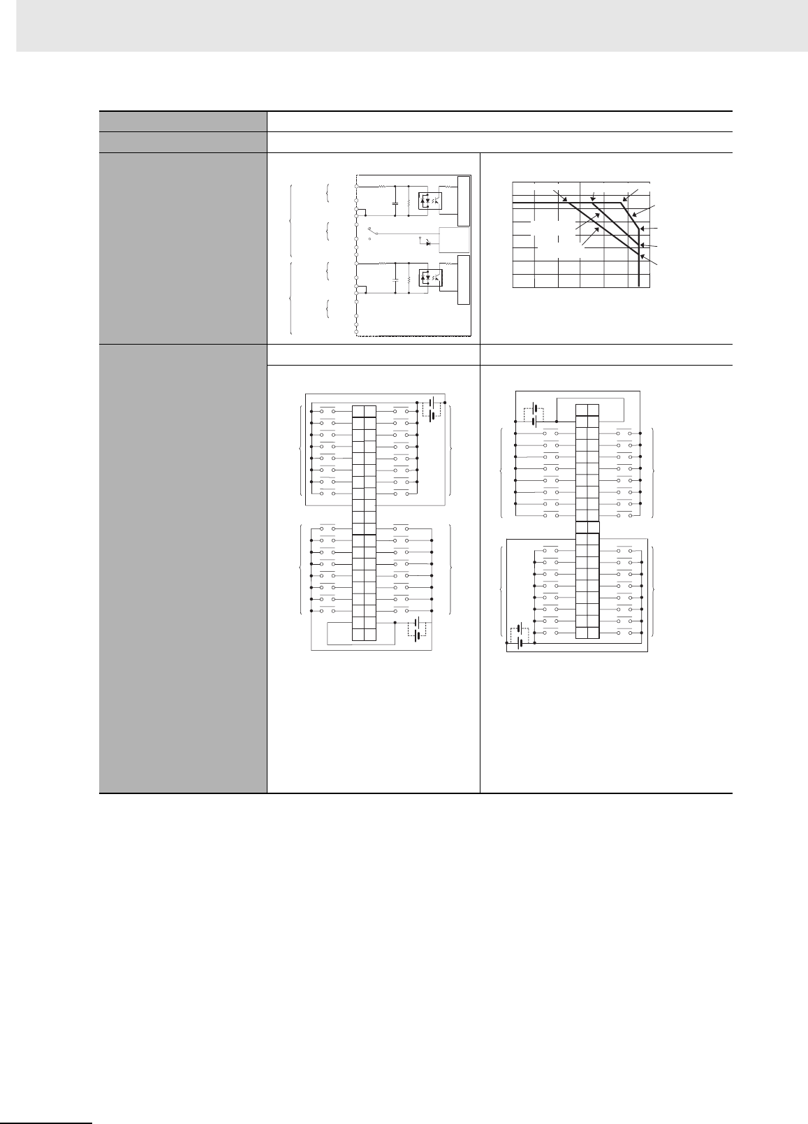
Appendices
A-14 CJ2 CPU Unit Hardware User’s Manual
*1 The ON response time will be 120 µs maximum and OFF response time will be 400 µs maximum even if the
response times are set to 0 ms due to internal element delays.
Note Observe the following restrictions when connecting to a 2-wire sensor.
• Make sure the input power supply voltage is larger than the ON voltage (19 V) plus the residual voltage of
the sensor (approx. 3 V).
• Use a sensor with a minimum load current of 3 mA min.
• Connect bleeder resistance if you connect a sensor with a minimum load current of 5 mA or higher.
Weight 110 g max.
Accessories None
Circuit Configuration
Terminal Connections
CN1 CN2
• The input power polarity can be
connected in either direction.
• Be sure to wire both pins 23 and
24 (COM0) of CN1, and set the
same polarity for both pins.
• Be sure to wire both pins 3 and 4
(COM1) of CN1, and set the same
polarity for both pins.
• The input power polarity can be con-
nected in either direction.
• Be sure to wire both pins 23 and 24
(COM2) of CN2, and set the same polar-
ity for both pins.
• Be sure to wire both pins 3 and 4 (COM3)
of CN2, and set the same polarity for
both pins.
IN0
IN15
COM0
SW
IN0
IN15
CN1 COM0
COM1
COM1
IN0
IN15
COM2
IN0
IN15
COM2
COM3
COM3
560 Ω
560 Ω
1000 pF1000 pF
5.6 kΩ
5.6 kΩ
CN2
to
to
to
to
Input indicator
Indicator
switching
circuit
Internal circuits Internal circuits
Wd m+1
Wd m
Wd m+2
Wd m+3
Allocated
CIO word
Signal
name
0
10
20
30
40
50
60
70
0102030 405060
Ambient Temperature
8 points/common
(total: 26 points max.)
at 55°C
8 points/common
at 55°C
12 points/common
(total: 45 points)
at 55°C
Input voltage:
20.4 VDC
Input voltage:
26.4 VDC
Input voltage:
24 VDC
Number of simultaneously ON points
Number of Simultaneously ON Points vs.
Ambient Temperature Characteristic
64 points at 47°C
64 points at 35°C
64 points at 25°C
(°C)
1NC
3
5
7
9
11
13
15
17
19
21
23
25
27
29
31
33
35
37
NC
39
2
4
NC
6
8
10
12
14
16
18
COM1
20
22
24
26
28
30
32
34
36
38
40
COM1
NC
COM0 COM0
IN0
IN1
IN2
IN3
IN4
IN5
IN6
IN7
IN0
IN1
IN2
IN3
IN4
IN5
IN6
IN7
IN8
IN9
IN10
IN11
IN12
IN13
IN14
IN15
IN8
IN9
IN10
IN11
IN12
IN13
IN14
IN15
24 VDC
24 VDC
Wd m+1
Wd m+1
Wd m
Wd m
Signal
name Signal
name
Connec-
tor pin
Allocated
CIO word
Allocated
CIO word
40
38
36
34
32
30
28
26
24
22
20
18
16
14
12
10
8
6
4
NC
2
COM3
39
37
35
33
31
29
27
25
23
COM2
21
19
17
15
13
11
9
7
5
3
NC 1
COM3
COM2
NC NC
IN15
IN14
IN13
IN12
IN11
IN10
IN9
IN8
IN15
IN14
IN13
IN12
IN11
IN10
IN9
IN8
IN7
IN6
IN5
IN4
IN3
IN2
IN1
IN0
IN7
IN6
IN5
IN4
IN3
IN2
IN1
IN0
Wd m+3
Wd m+3
Wd m+2
Wd m+2
24 VDC
24
VDC
Signal
name Signal
name
Connec-
tor pin
Allocated
CIO word Allocated
CIO word
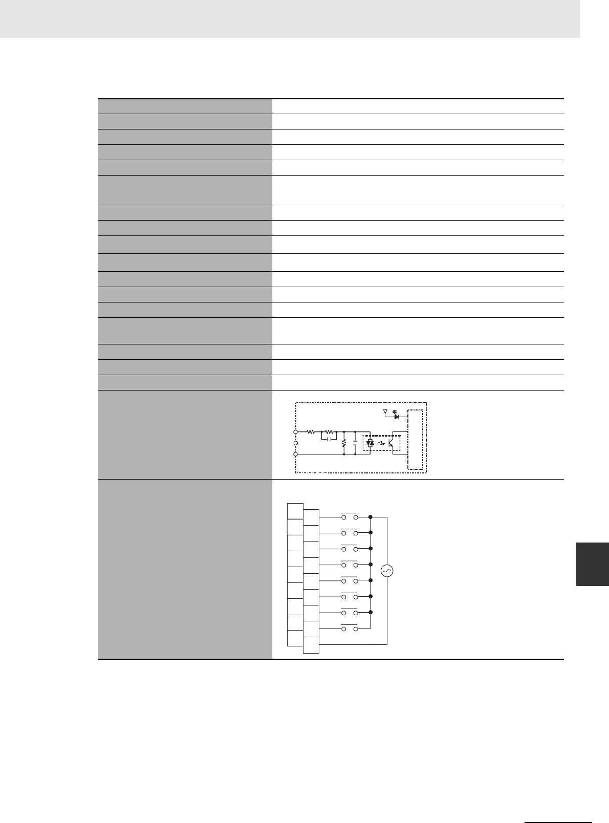
A-15
Appendices
CJ2 CPU Unit Hardware User’s Manual
A-1 Specifications of Basic I/O Units App A-1-2 Basic I/O Units
zCJ1W-IA201 AC Input Unit (200 VAC, 8 Points)
*1 The Input ON and OFF response times for Basic I/O Units can be set to 0 ms, 0.5 ms, 1 ms, 2 ms, 4 ms, 8 ms,
16 ms, or 32 ms in the PLC Setup. When the response times have been set to 0 ms, the ON response time will
be 10 ms maximum and the OFF response time will be 40 ms maximum due to internal element delays.
*2 Terminal numbers A0 to A8 and B0 to B8 are used in this manual, but they are not printed on the Unit.
Note Although 16 I/O bits (1 word) are allocated, only 8 of these can be used for external I/O. This Unit is also
treated as a 16-point I/O Unit in the I/O tables.
Name 8-point AC Input Unit with Terminal Block
Model CJ1W-IA201
Rated Input Voltage 200 to 240 VAC 50/60 Hz
Rated Input Voltage Range 170 to 264 VAC
Input Impedance 21 kΩ (50 Hz), 18 kΩ (60 Hz)
Input Current 9 mA typical (at 200 VAC, 50 Hz),
11 mA typical (at 200 VAC, 60 Hz)
ON Voltage/ON Current 120 VAC min./4 mA min.
OFF Voltage/OFF Current 40 VAC max./2 mA max.
ON Response Time 18.0 ms max. (PLC Setup default setting: 8 ms)*1
OFF Response Time 48.0 ms max. (PLC Setup default setting: 8 ms)*1
Number of Circuits 8 (8 points/common, 1 circuit)
Number of Simultaneously ON Points 100% (8 points/common) simultaneously ON
Insulation Resistance 20 MΩ between external terminals and the GR terminal (500 VDC)
Dielectric Strength 2,000 VAC between the external terminals and the GR terminal for
1 minute at a leakage current of 10 mA max.
Internal Current Consumption 80 mA max.
Weight 130 g max.
Accessories None
Circuit Configuration
Terminal Connections
COM
IN0
IN7
820 Ω1 MΩ
0.15 µF220 Ω
Input indicator
Internal circuits
to
Signal
name
IN0
IN1
IN2
IN3
IN5
IN6
IN7
B0
B1
B2
B3
B4
B5
B6
B7
B8
IN4
A0
A1
A2
A3
A4
A5
A6
A7
A8
COM
NC
NC
NC
NC
NC
NC
NC
NC
NC
200 to 240 VAC
Signal
name
Connec-
tor pin
*2
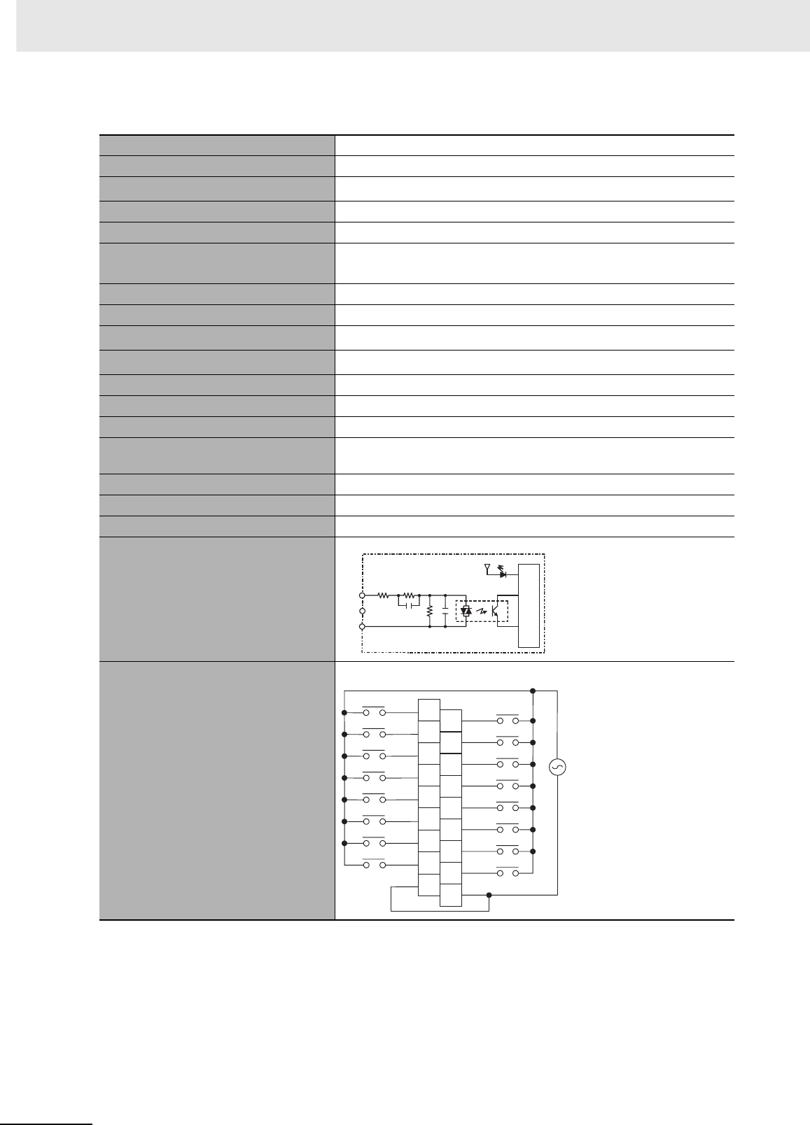
Appendices
A-16 CJ2 CPU Unit Hardware User’s Manual
zCJ1W-IA111 AC Input Unit (100 VAC, 16 points)
*1 The Input ON and OFF response times for Basic I/O Units can be set to 0 ms, 0.5 ms, 1 ms, 2 ms, 4 ms, 8 ms,
16 ms, or 32 ms in the PLC Setup. When the response times have been set to 0 ms, the ON response time will
be 10 ms maximum and the OFF response time will be 40 ms maximum due to internal element delays.
*2 Use an input voltage of 90 VAC or higher when connecting 2-wire sensors.
*3 Terminal numbers A0 to A8 and B0 to B8 are used in this manual, but they are not printed on the Unit.
Name 16-point AC Input Unit with Terminal Block
Model CJ1W-IA111
Rated input voltage 100 to 120 VAC 50/60 Hz*2
Rated Input Voltage Range 85 to 132 VAC
Input Impedance 14.5 kΩ (50 Hz), 12 kΩ (60 Hz)
Input Current 7 mA typical (at 100 VAC, 50 Hz),
8 mA typical (at 100 VAC, 60 Hz)
ON Voltage/ON Current 70 VAC min./4 mA min
OFF Voltage/OFF Current 20 VAC max./2 mA max
ON Response Time 18 ms max. (PLC Setup default setting: 8 ms)*1
OFF Response Time 48 ms max. (PLC Setup default setting: 8 ms)*1
Number of Circuits 16 (16 points/common, 1 circuit)
Number of Inputs ON Simultaneously 100% simultaneously ON (16 points/common)
Insulation Resistance 20 MΩ between external terminals and the GR terminal (500 VDC)
Dielectric Strength 2,000 VAC between the external terminals and the GR terminal for
1 minute at a leakage current of 10 mA max.
Internal Current Consumption 90 mA max.
Weight 130 g max.
Accessories None
Circuit Layout
Terminal Connections
COM
IN0
IN15
470 Ω1 MΩ
0.22 µF270 Ω
Input indicator
Internal circuits
to
Signal
name
A0
A1
A2
A3
A4
A5
A6
A7
A8
B0
B1
B2
B3
B4
B5
B6
B7
B8
COM COM
IN0
IN2
IN4
IN6
IN8
IN10
IN12
IN14
IN1
IN3
IN5
IN7
IN9
IN11
IN13
IN15
100 to 120 VAC
Signal
name Signal
name
Connec-
tor pin
*3
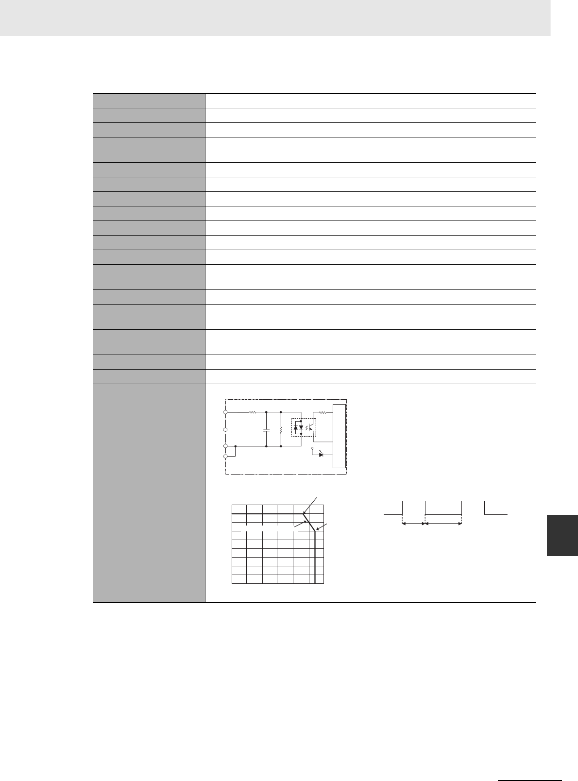
A-17
Appendices
CJ2 CPU Unit Hardware User’s Manual
A-1 Specifications of Basic I/O Units App A-1-2 Basic I/O Units
zCJ1W-INT01 Interrupt Input Unit (16 Points)
Name 16-point Interrupt Input Unit with Terminal Block
Model CJ1W-INT01
Rated Input Voltage 24 VDC
Rated Input Voltage
Range
20.4 to 26.4 VDC
Input Impedance 3.3 kΩ
Input Current 7 mA typical (at 24 VDC)
ON Voltage/ON Current 14.4 VDC min./3 mA min.
OFF Voltage/OFF Current 5 VDC max./1 mA max.
ON Response Time 0.05 ms max.
OFF Response Time 0.5 ms max.
Number of Circuits 16 (16 points/common, 1 circuit)
Number of Simulta-
neously ON Points
100% (16 points/common) simultaneously ON (24 VDC)
Insulation Resistance 20 MΩ between external terminals and GR terminal (at 100 VDC)
Dielectric Strength 1,000 VAC between external terminals and GR terminal for 1 minute at a leakage
current of 10 mA max.
Internal Current Con-
sumption
80 mA max.
Weight 110 g max.
Accessories None
Circuit Configuration
• Up to two Interrupt Input Units can be
mounted to the CPU Rack, but they
must be connected as one the five
Unit*1 immediately next to the CPU
Unit. If an Interrupt Input Unit is con-
nected in any other position, an I/O
setting error will occur.
• Set the pulse width of signals input to
the Interrupt Input Unit so they satisfy
the following conditions.
*1 With the CJ2JH-CPU6@-EIP CPU
Units, the Unit must be mounted as
one of the four Units immediately
next to the CPU Unit.
IN0
IN15
COM
COM
Internal circuits
3.3 kΩ
1000 pF
470 Ω
to
Input indicator
Signal
name
18
16
14
12
10
8
6
4
2
00 10 20 30 40 50 60
Ambient Temperature
12 points at 55°C
Number of simultaneously ON points
(°C)
16 points at 45°C
Input voltage: 26.4 VDC
Temperature characteristics for
simultaneously ON points
ON
OFF
0.5 ms min.
0.05 ms min.
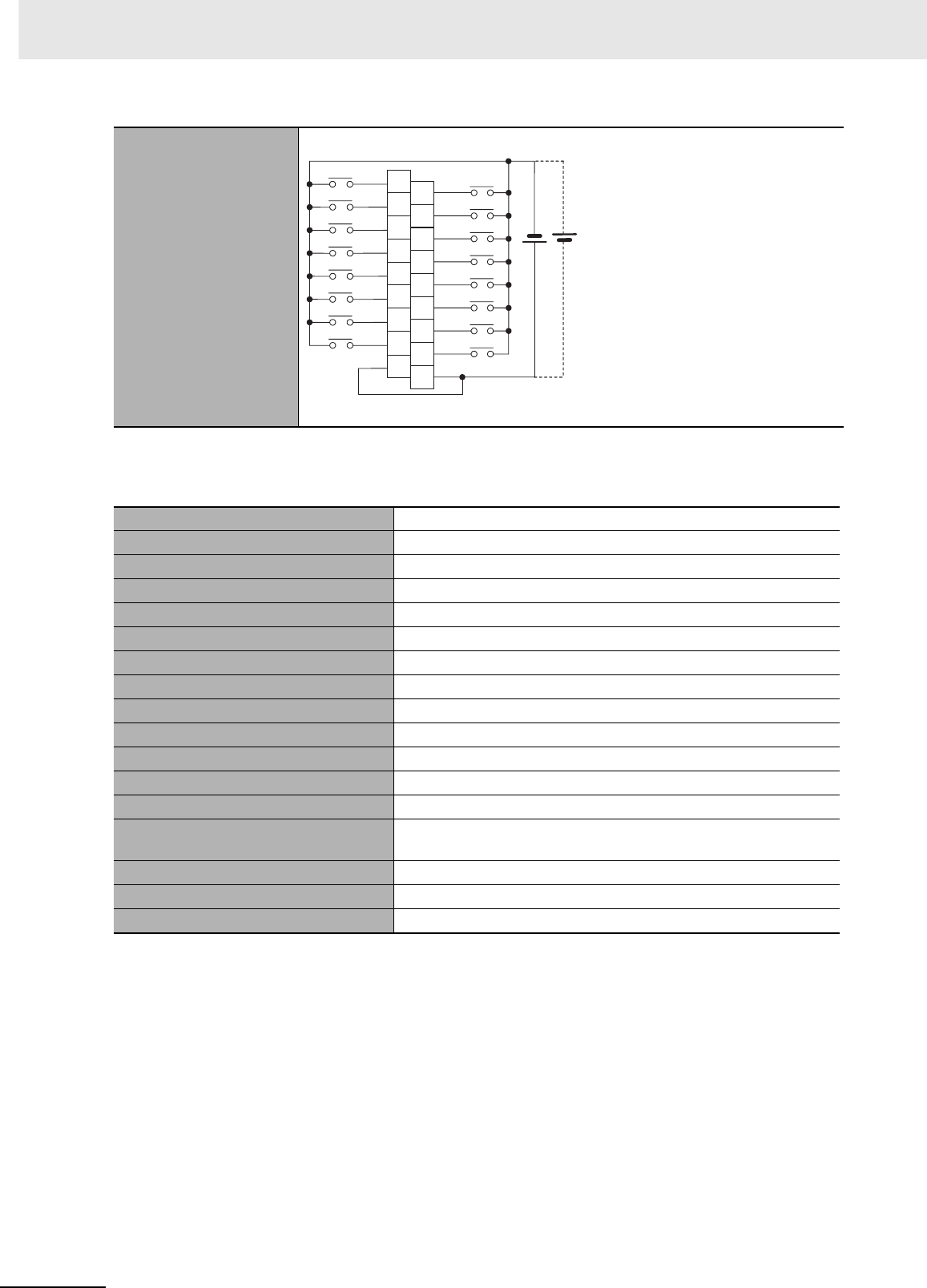
Appendices
A-18 CJ2 CPU Unit Hardware User’s Manual
*1 Terminal numbers A0 to A8 and B0 to B8 are used in this manual, but they are not printed on the Unit.
zCJ1W-IDP01 Quick-response Input Unit (16 Points)
Terminal Connections
• The polarity can be connected in either direction.
Name 16-point Quick-response Input Unit with Terminal Block
Model CJ1W-IDP01
Rated Input Voltage 24 VDC
Rated Input Voltage Range 20.4 to 26.4 VDC
Input Impedance 3.3 kΩ
Input Current 7 mA typical (at 24 VDC)
ON Voltage/ON Current 14.4 VDC min./3 mA min.
OFF Voltage/OFF Current 5 VDC max./1 mA max.
ON Response Time 0.05 ms max.
OFF Response Time 0.5 ms max.
Number of Circuits 16 (16 points/common, 1 circuit)
Number of Simultaneously ON Points 100% (16 points/common) simultaneously ON (24 VDC)
Insulation Resistance 20 MΩ between external terminals and GR terminal (at 100 VDC)
Dielectric Strength 1,000 VAC between external terminals and GR terminal for 1 minute
at a leakage current of 10 mA max.
Internal Current Consumption 80 mA max.
Weight 110 g max.
Accessories None
A0
A1
A2
A3
A4
A5
A6
A7
A8
B0
B1
B2
B3
B4
B5
B6
B7
B8
COM COM
IN1
IN3
IN5
IN7
IN9
IN11
IN13
IN15
IN0
IN2
IN4
IN6
IN8
IN10
IN12
IN14
24 VDC
Signal
name Signal
name
Connec-
tor pin
*1
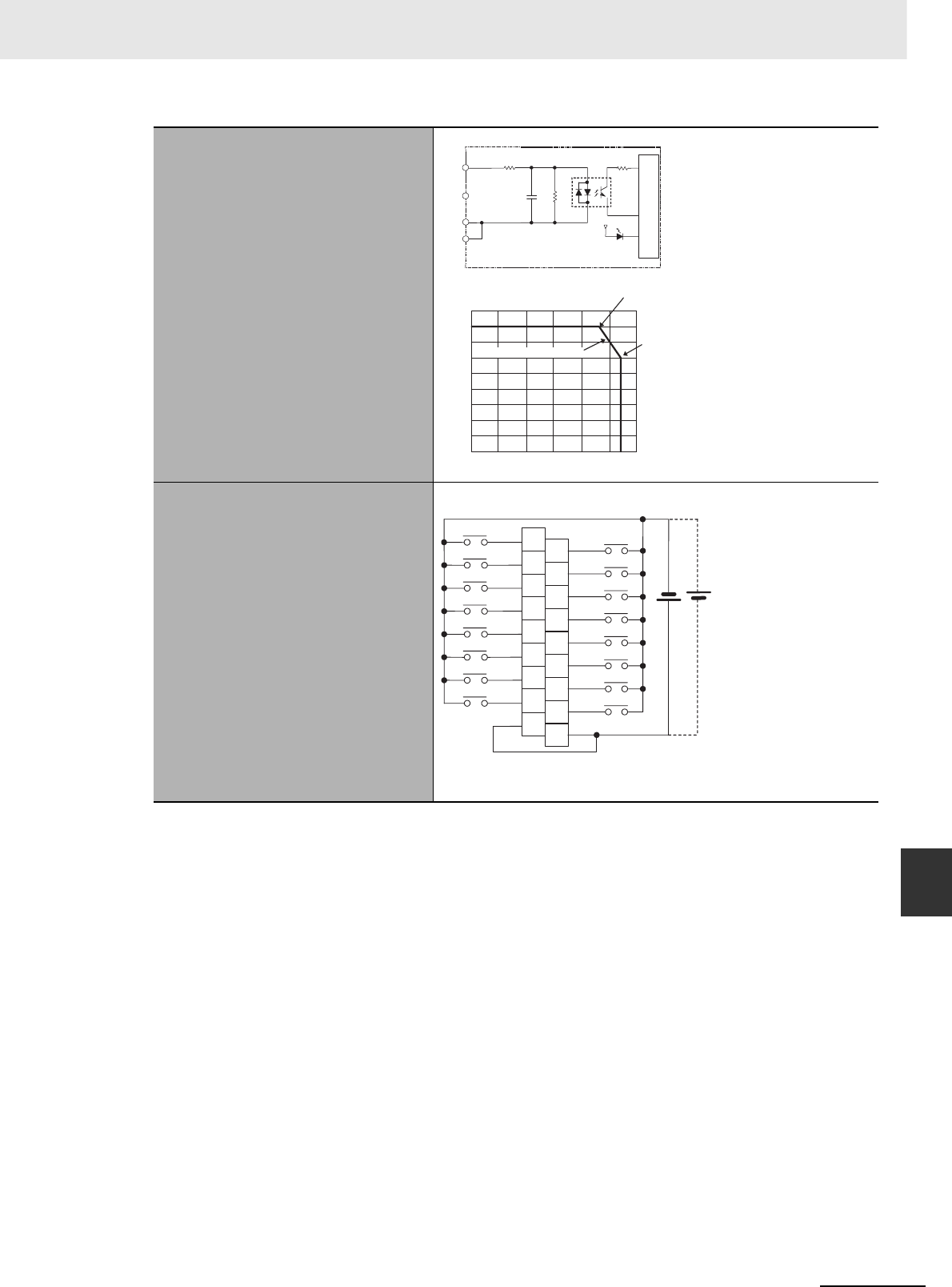
A-19
Appendices
CJ2 CPU Unit Hardware User’s Manual
A-1 Specifications of Basic I/O Units App A-1-2 Basic I/O Units
• With quick-response inputs, pulse inputs shorter than the CPU Unit's cycle time can be read by the
CPU Unit.
• The pulse width (ON time) that can be read by the Quick-response Input Unit is 0.05 ms.
• Inputs read by the internal circuits are cleared when inputs are refreshed.
*1 Terminal numbers A0 to A8 and B0 to B8 are used in this manual, but they are not printed on the Unit.
Circuit Configuration
Terminal Connections
• The input power supply polarity can be connected in either direc-
tion.
18
16
14
12
10
8
6
4
2
0010 20 30 40 50 60
Ambient Temperature
12 points at 55°C
Number of simultaneously ON points
(°C)
16 points at 45°C
Input voltage: 26.4 VDC
Number of simultaneously ON points --
Ambient temperature characteristics
IN0
IN15
COM
COM
3.3 kΩ
470 Ω
1000 pF
to
Input indicator
Internal circuits
Signal
name
A0
A1
A2
A3
A4
A5
A6
A7
A8
B0
B1
B2
B3
B4
B5
B6
B7
B8
IN0
IN2
IN4
IN6
IN10
IN12
IN14
IN8
IN1
IN3
IN5
IN7
COM
IN11
IN13
IN15
IN9
COM
24 VDC
Signal
name Signal
name
Connec-
tor pin
*1
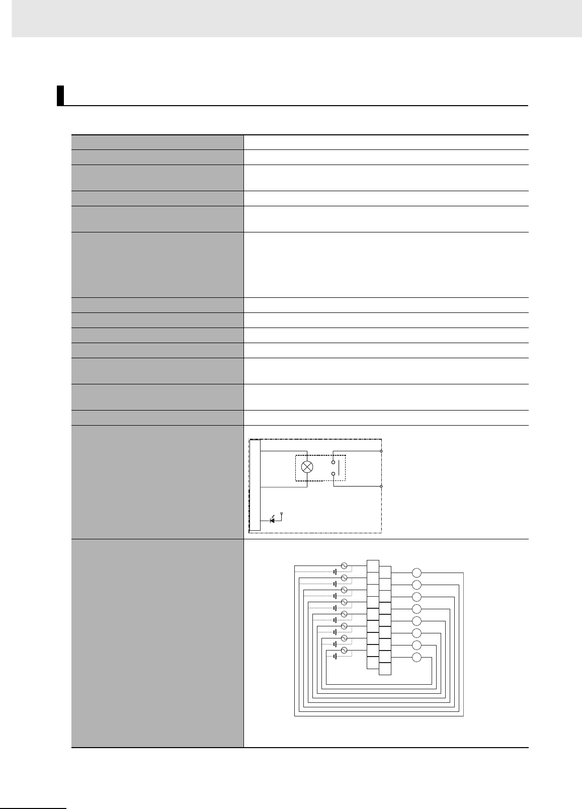
Appendices
A-20 CJ2 CPU Unit Hardware User’s Manual
zCJ1W-OC201 Contact Output Unit (Independent Relays, 8 Points)
*1 Terminal numbers A0 to A8 and B0 to B8 are used in this manual, but they are not printed on the Unit.
Note Although 16 I/O bits (1 word) are allocated, only 8 of these can be used for external I/O. This Unit is also
treated as a 16-point I/O Unit in the I/O tables.
Basic Output Units
Name 8-point Contact Output Unit with Terminal Block (Independent Relays)
Model CJ1W-OC201
Max. Switching Capacity 2 A 250 VAC (cosφ = 1), 2 A 250 VAC (cosφ = 0.4), 2 A 24 VDC
(16 A/Unit)
Min. Switching Capacity 1 mA 5 VDC
Relays NY-24W-K-IE (Fujitsu Takamizawa Components, Ltd.), Cannot be
replaced.
Service Life of Relay
Electrical: 150,000 operations (24 VDC, resistive load)/100,000 oper-
ations (240 VAC, cosφ = 0.4, inductive load)
Mechanical: 20,000,000 operations
Service life will vary depending on the connected load. Refer to page
A-57 for information on service life according to the load.
ON Response Time 15 ms max.
OFF Response Time 15 ms max.
Number of Circuits 8 independent contacts
Insulation Resistance 20 MΩ between external terminals and the GR terminal (500 VDC)
Dielectric Strength 2,000 VAC between the external terminals and the GR terminal for
1 minute at a leakage current of 10 mA max.
Internal Current Consumption 90 mA 5 VDC max.
48 mA 24 VDC max. (6 mA × No. of ON points)
Weight 140 g max.
Circuit Configuration
Terminal Connections
• The input power supply polarity can be connected in either direc-
tion.
OUT
OUTc
Output indicator
Internal circuits
Signal
name
B1
OUTC0
B2
OUTC1
B3
OUTC2
B4
OUTC3
B5
OUTC4
B6
OUTC5
B7
OUTC6
B8
OUTC7
NC
A1
OUT0
A2
OUT1
A3
OUT2
A4
OUT3
A5
OUT4
A6
OUT5
A7
OUT6
A8
OUT7
NC
B0
A0
L
L
L
L
L
L
L
L
2 A 250 VAC,
2 A 24 VDC max.
Signal
name Signal
name
Connec-
tor pin
*1
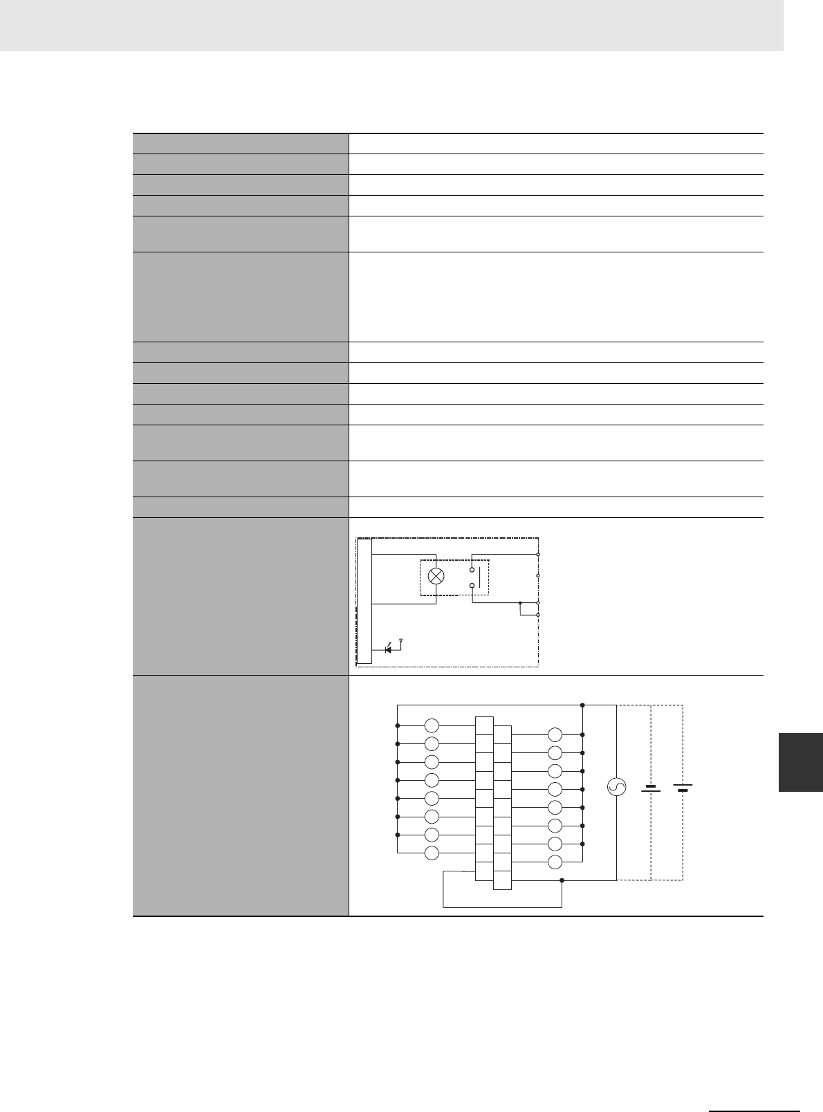
A-21
Appendices
CJ2 CPU Unit Hardware User’s Manual
A-1 Specifications of Basic I/O Units App A-1-2 Basic I/O Units
zCJ1W-OC211 Contact Output Unit (16 Points)
*1 Terminal numbers A0 to A8 and B0 to B8 are used in this manual, but they are not printed on the Unit.
Name 16-point Contact Output Unit with Terminal Block
Model CJ1W-OC211
Max. Switching Capacity 2 A 250 VAC (cosφ = 1), 2 A 250 VAC (cosφ = 0.4), 2 A 24 VDC (8 A/Unit)
Min. Switching Capacity 1 mA 5 VDC
Relays NY-24W-K-IE (Fujitsu Takamizawa Components, Ltd.), Cannot be
replaced.
Service Life of Relay
Electrical: 150,000 operations (24 VDC, resistive load)/ 100,000 opera-
tions (240 VAC, cosφ = 0.4, inductive load)
Mechanical: 20,000,000 operations
Service life will vary depending on the connected load. Refer to page A-57
for information on service life according to the load.
ON Response Time 15 ms max.
OFF Response Time 15 ms max.
Number of Circuits 16 points/common, 1 circuit
Insulation Resistance 20 MΩ between external terminals and the GR terminal (500 VDC)
Dielectric Strength 2,000 VAC between the external terminals and the GR terminal for
1 minute at a leakage current of 10 mA max.
Internal Current Consumption 110 mA 5 VDC max.
96 mA 24 VDC max. (6 mA × No. of ON points)
Weight 170 g max.
Circuit Configuration
Terminal Connections
OUT15
OUT0
COM
COM
Output indicator
Internal circuits
to
Signal
name
B1
OUT1
B2
OUT3
B3
OUT5
B4
OUT7
B5
OUT9
B6
OUT11
B7
OUT13
B8
OUT15
A1
OUT0
A2
OUT2
A3
OUT4
A4
OUT6
A5
OUT8
A6
OUT10
A7
OUT12
A8
OUT14
COM
B0
A0
COM
L
L
L
L
L
L
L
L
L
L
L
L
L
L
L
L
2 A 250 VAC,
2 A 24 VDC max.
Signal
name Signal
name
Connec-
tor pin
*1
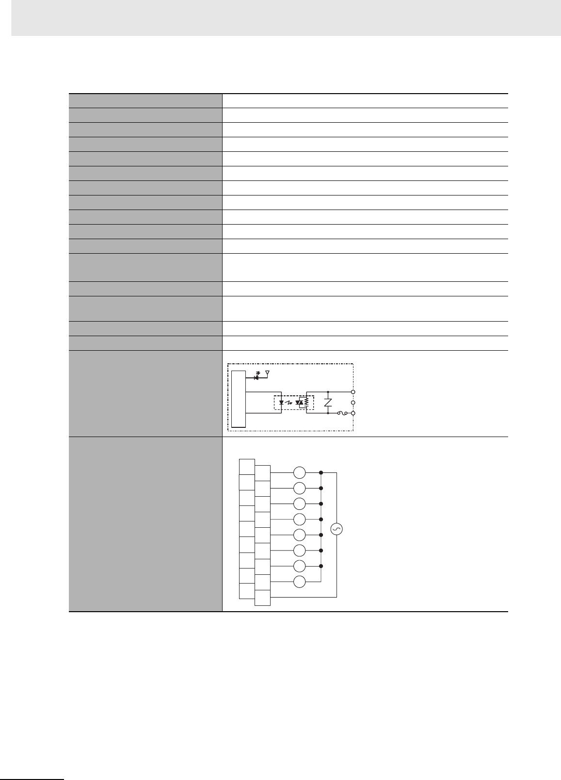
Appendices
A-22 CJ2 CPU Unit Hardware User’s Manual
zCJ1W-OA201 Triac Output Unit (8 Points)
*1 Terminal numbers A0 to A8 and B0 to B8 are used in this manual, but they are not printed on the Unit.
Note Although 16 I/O bits (1 word) are allocated, only 8 of these can be used for external I/O. This Unit is also
treated as a 16-point I/O Unit in the I/O tables.
Name 8-point Triac Output Unit with Terminal Block
Model CJ1W-OA201
Max. Switching Capacity 0.6 A 250 VAC, 50/60 Hz (2.4 A/Unit)
Max. Inrush Current 15 A (pulse width: 10 ms max.)
Min. Switching Capacity 50 mA 75 VAC
Leakage Current 1.5 mA (200 VAC) max.
Residual Voltage 1.6 VAC max.
ON Response Time 1 ms max.
OFF Response Time 1/2 of load frequency + 1 ms or less.
Number of Circuits 8 (8 points/common, 1 circuit)
Surge Protector C.R Absorber + Surge Absorber
Fuses 5 A (1/common, 1 used)
The fuse cannot be replaced by the user.
Insulation Resistance 20 MΩ between the external terminals and the GR terminal (500 VDC)
Dielectric Strength 2,000 VAC between the external terminals and the GR terminal for
1 minute at a leakage current of 10 mA max.
Internal Current Consumption 220 mA max.
Weight 150 g max.
Circuit Configuration
Terminal Connections
COM
OUT0
OUT7
Output indicator
Internal circuits
Fuse
to
Signal
name
B0
B1
B2
B3
B4
B5
B6
B7
B8
A0
A1
A2
A3
A4
A5
A6
A7
A8 COM
NC
NC
NC
NC
NC
NC
NC
NC
NC
L
L
L
L
L
L
L
L
OUT0
OUT1
OUT2
OUT3
OUT4
OUT5
OUT6
OUT7
250 VAC max.
Signal
name
Connec-
tor pin
*1
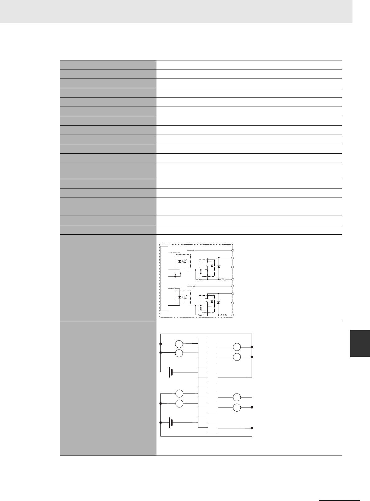
A-23
Appendices
CJ2 CPU Unit Hardware User’s Manual
A-1 Specifications of Basic I/O Units App A-1-2 Basic I/O Units
zCJ1W-OD201 Transistor Output Unit (8 Points)
*1 Terminal numbers A0 to A8 and B0 to B8 are used in this manual, but they are not printed on the Unit.
Note Although 16 I/O bits (1 word) are allocated, only 8 of these can be used for external I/O. This Unit is also
treated as a 16-point I/O Unit in the I/O tables.
Name 8-point Transistor Output Unit with Terminal Block (Sinking Outputs)
Model CJ1W-OD201
Rated Voltage 12 to 24 VDC
Operating Load Voltage Range 10.2 to 26.4 VDC
Maximum Load Current 2.0 A/point, 8.0 A/Unit
Maximum Inrush Current 10 A/point, 10 ms max.
Leakage Current 0.1 mA max.
Residual Voltage 1.5 V max.
ON Response Time 0.5 ms max.
OFF Response Time 1.0 ms max.
Insulation Resistance 20 MΩ between the external terminals and the GR terminal (100 VDC)
Dielectric Strength 1,000 VAC between the external terminals and the GR terminal for
1 minute at a leakage current of 10 mA max.
Number of Circuits 8 (4 points/common, 2 circuits)
Internal Current Consumption 90 mA max.
Fuse 6.3 A (1/common, 2 used)
The fuse cannot be replaced by the user.
External Power Supply 12 to 24 VDC, 10 mA min.
Weight 110 g max.
Circuit Configuration
Terminal Connections
• When wiring, pay careful attention to the polarity of the external power
supply. The load may operate incorrectly if the polarity is reversed.
OUT0
+V
OUT3
COM0
OUT4
+V
OUT7
COM1
Internal circuits
Output indicator
Fuse
Fuse
to
to
Signal
name
OUT0
OUT2
COM0
NC
NC
OUT4
OUT6
B0
B1
B2
B3
B4
B5
B6
B7
B8
NC
A0 OUT1
OUT3
+V
NC
NC
NC
OUT5
OUT7
A1
A2
A3
A4
A5
A6
A7
A8
COM1
+V
L
L
L
L
L
L
L
L
12 to 24 VDC
12 to 24 VDC
Signal
name
Signal
name
Connec-
tor pin
*1
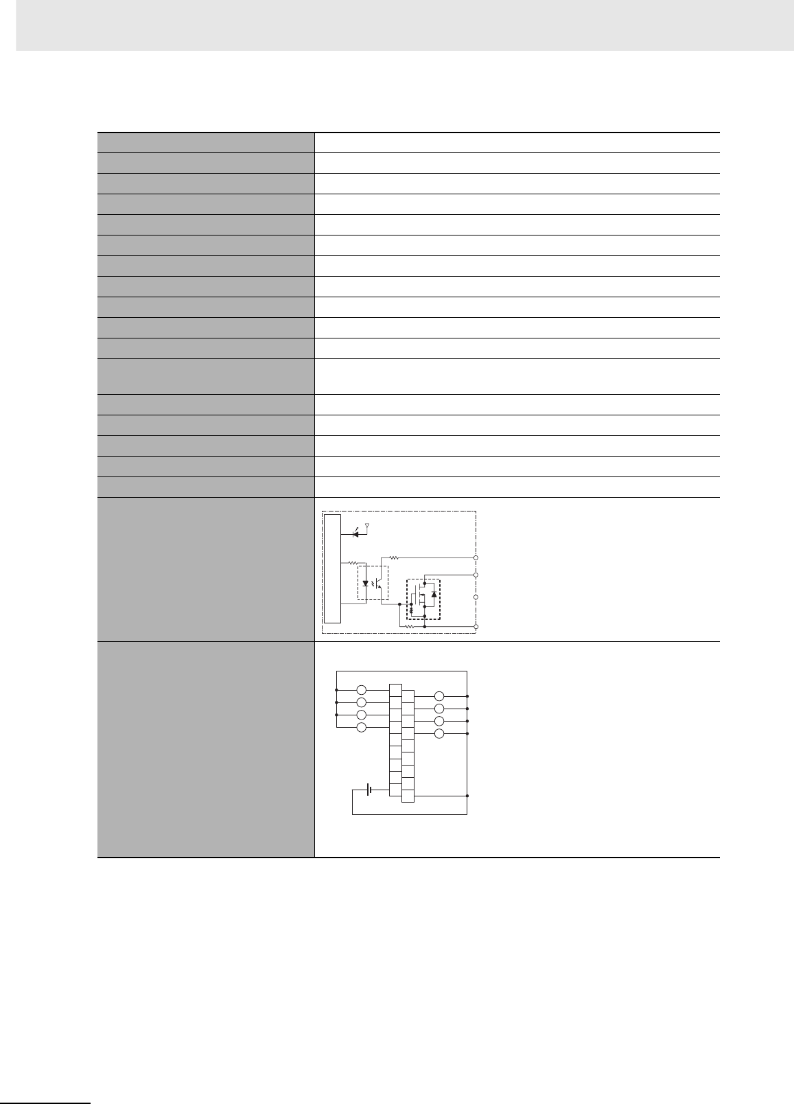
Appendices
A-24 CJ2 CPU Unit Hardware User’s Manual
zCJ1W-OD203 Transistor Output Unit (8 Points)
*1 Terminal numbers A0 to A8 and B0 to B8 are used in this manual, but they are not printed on the Unit.
Note Although 16 I/O bits (1 word) are allocated, only 8 of these can be used for external I/O. This Unit is also
treated as a 16-point I/O Unit in the I/O tables.
Name 8-point Transistor Output Unit with Terminal Block (Sinking Outputs)
Model CJ1W-OD203
Rated Voltage 12 to 24 VDC
Operating Load Voltage Range 10.2 to 26.4 VDC
Maximum Load Current 0.5 A/point, 4.0 A/Unit
Maximum Inrush Current 4.0 A/point, 10 ms max.
Leakage Current 0.1 mA max.
Residual Voltage 1.5 V max.
ON Response Time 0.1 ms max.
OFF Response Time 0.8 ms max.
Insulation Resistance 20 MΩ between the external terminals and the GR terminal (100 VDC)
Dielectric Strength 1,000 VAC between the external terminals and the GR terminal for
1 minute at a leakage current of 10 mA max.
Number of Circuits 8 (8 points/common, 1 circuit)
Internal Current Consumption 100 mA max.
Fuse None
External Power Supply 10.2 to 26.4 VDC, 20 mA min.
Weight 110 g max.
Circuit Configuration
Terminal Connections
• When wiring, pay careful attention to the polarity of the external power
supply. The load may operate incorrectly if the polarity is reversed.
OUT0
OUT7
+V
COM
Output indicator
Internal circuits
to
Signal
name
B1
OUT1
B2
OUT3
B3
OUT5
B4
OUT7
B5
B6
B7
B8
A1
OUT0
A2
OUT2
A3
OUT4
A4
OUT6
A5
NC
A6
A7
A8
COM
B0
A0
+V
L
L
L
L
L
L
L
L
NC
NC
NC
NC
NC
NC
NC
12 to 24 VDC
Signal
name Signal
name
Connec-
tor pin
*1
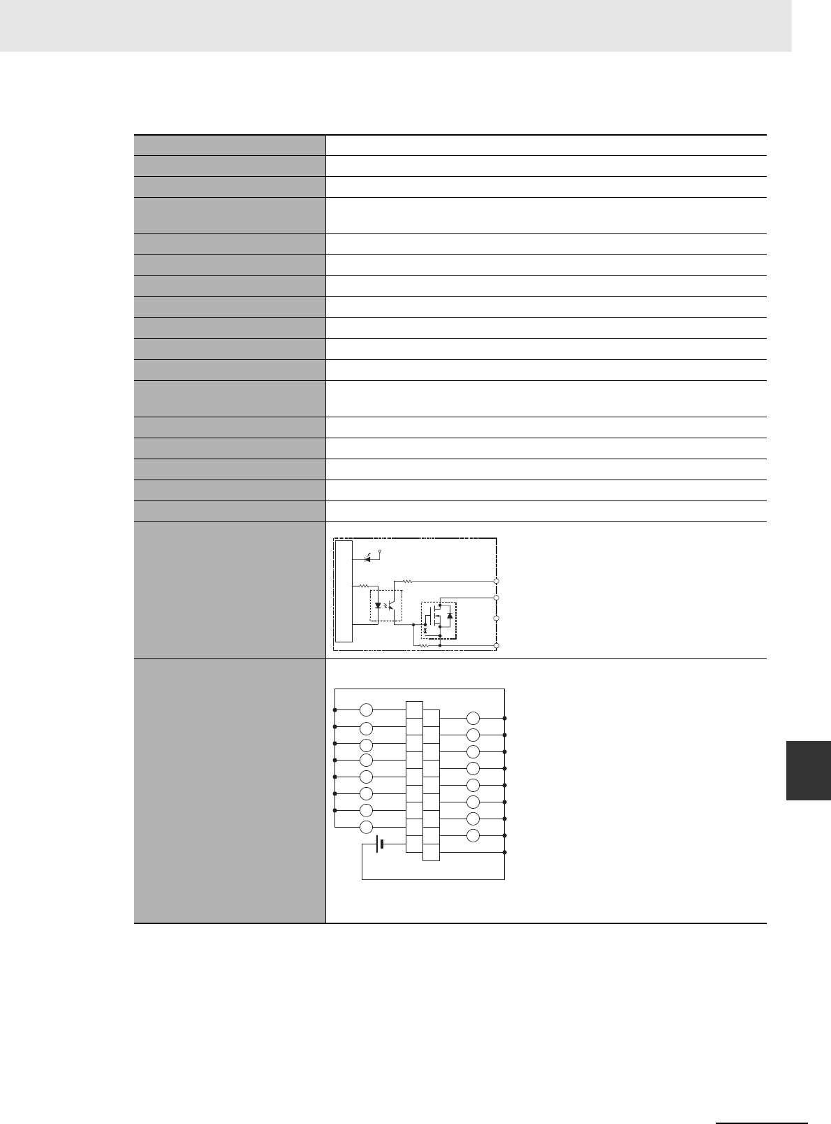
A-25
Appendices
CJ2 CPU Unit Hardware User’s Manual
A-1 Specifications of Basic I/O Units App A-1-2 Basic I/O Units
zCJ1W-OD211 Transistor Output Unit (16 Points)
*1 Terminal numbers A0 to A8 and B0 to B8 are used in this manual, but they are not printed on the Unit.
Name 16-point Transistor Output Unit with Terminal Block (Sinking Outputs)
Model CJ1W-OD211
Rated Voltage 12 to 24 VDC
Operating Load Voltage
Range
10.2 to 26.4 VDC
Maximum Load Current 0.5 A/point, 5.0 A/Unit
Maximum Inrush Current 4.0 A/point, 10 ms max.
Leakage Current 0.1 mA max.
Residual Voltage 1.5 V max.
ON Response Time 0.1 ms max.
OFF Response Time 0.8 ms max.
Insulation Resistance 20 MΩ between the external terminals and the GR terminal (100 VDC)
Dielectric Strength 1,000 VAC between the external terminals and the GR terminal for 1 minute at
a leakage current of 10 mA max.
Number of Circuits 16 (16 points/common, 1 circuit)
Internal Current Consumption 5 VDC 100 mA max.
Fuse None
External Power Supply 10.2 to 26.4 VDC, 20 mA min.
Weight 110 g max.
Circuit Configuration
Terminal Connections
• When wiring, pay careful attention to the polarity of the external power sup-
ply. The load may operate incorrectly if the polarity is reversed.
OUT0
+V
OUT15
COM
Output indicator
Internal circuits
to
Signal
name
B1
OUT1
B2
OUT3
B3
OUT5
B4
OUT7
B5
OUT9
B6
OUT11
B7
OUT13
B8
OUT15
A1
OUT0
A2
OUT2
A3
OUT4
A4
OUT6
A5
OUT8
A6
OUT10
A7
OUT12
A8
OUT14
COM
B0
A0
+V
L
L
L
L
L
L
L
L
L
L
L
L
L
L
L
L
12 to 24 VDC
Signal
name Signal
name
Connec-
tor pin
*1
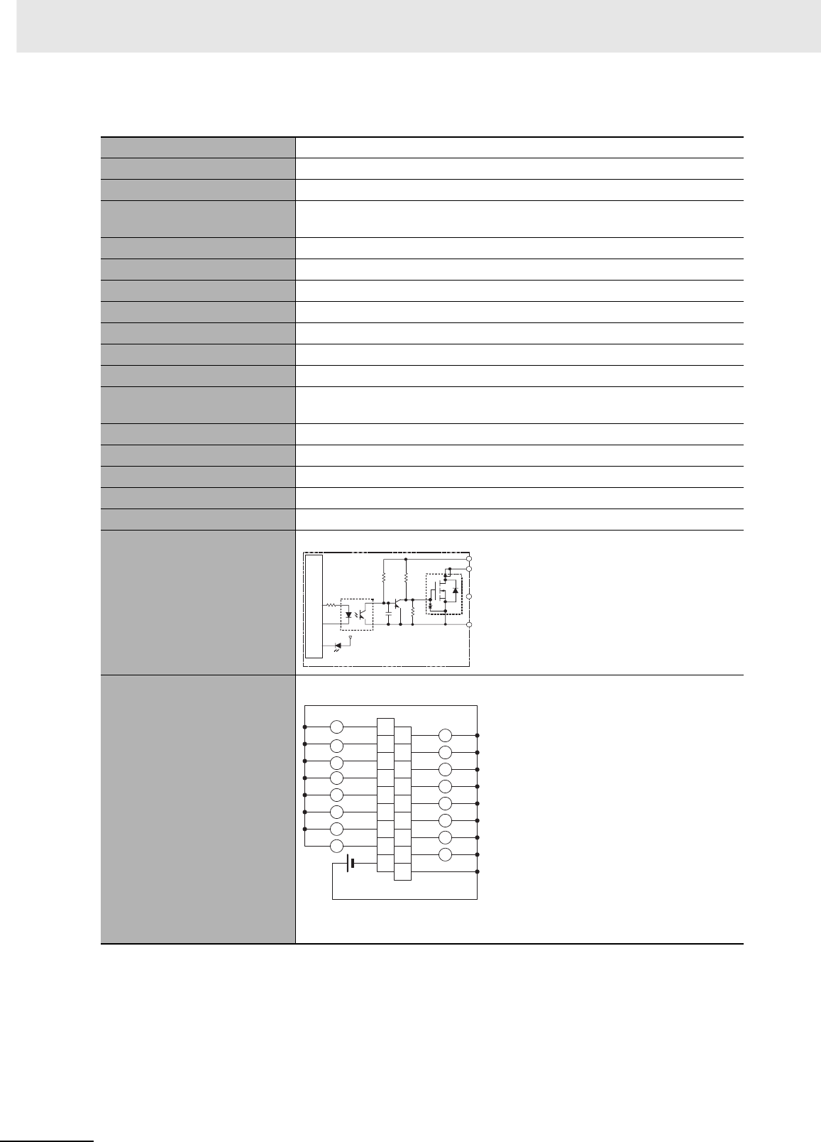
Appendices
A-26 CJ2 CPU Unit Hardware User’s Manual
zCJ1W-OD213 Transistor Output Unit (16 Points)
*1 Terminal numbers A0 to A8 and B0 to B8 are used in this manual, but they are not printed on the Unit.
Name 16-point Transistor Output Unit with Terminal Block (Sinking Outputs)
Model CJ1W-OD213
Rated Voltage 24 VDC
Operating Load Voltage
Range
20.4 to 26.4 VDC
Maximum Load Current 0.5 A/point, 5.0 A/Unit
Maximum Inrush Current 4.0 A/point, 10 ms max.
Leakage Current 0.1 mA max.
Residual Voltage 1.5 V max.
ON Response Time 15 µs max.
OFF Response Time 80 µs max.
Insulation Resistance 20 MΩ between the external terminals and the GR terminal (100 VDC)
Dielectric Strength 1,000 VAC between the external terminals and the GR terminal for 1 minute at
a leakage current of 10 mA max.
Number of Circuits 16 (16 points/common, 1 circuit)
Internal Current Consumption 5 VDC 150 mA max.
Fuse None
External Power Supply 20.4 to 26.4 VDC, 55 mA min.
Weight 110 g max.
Circuit Configuration
Terminal Connections
• When wiring, pay careful attention to the polarity of the external power sup-
ply. The load may operate incorrectly if the polarity is reversed.
OUT0
+V
OUT15
COM
Output indicator
Internal circuits
to
Signal
name
B1
OUT1
B2
OUT3
B3
OUT5
B4
OUT7
B5
OUT9
B6
OUT11
B7
OUT13
B8
OUT15
A1
OUT0
A2
OUT2
A3
OUT4
A4
OUT6
A5
OUT8
A6
OUT10
A7
OUT12
A8
OUT14
COM
B0
A0
+V
L
L
L
L
L
L
L
L
L
L
L
L
L
L
L
L
24 VDC
Signal
name Signal
name
Connec-
tor pin
*1
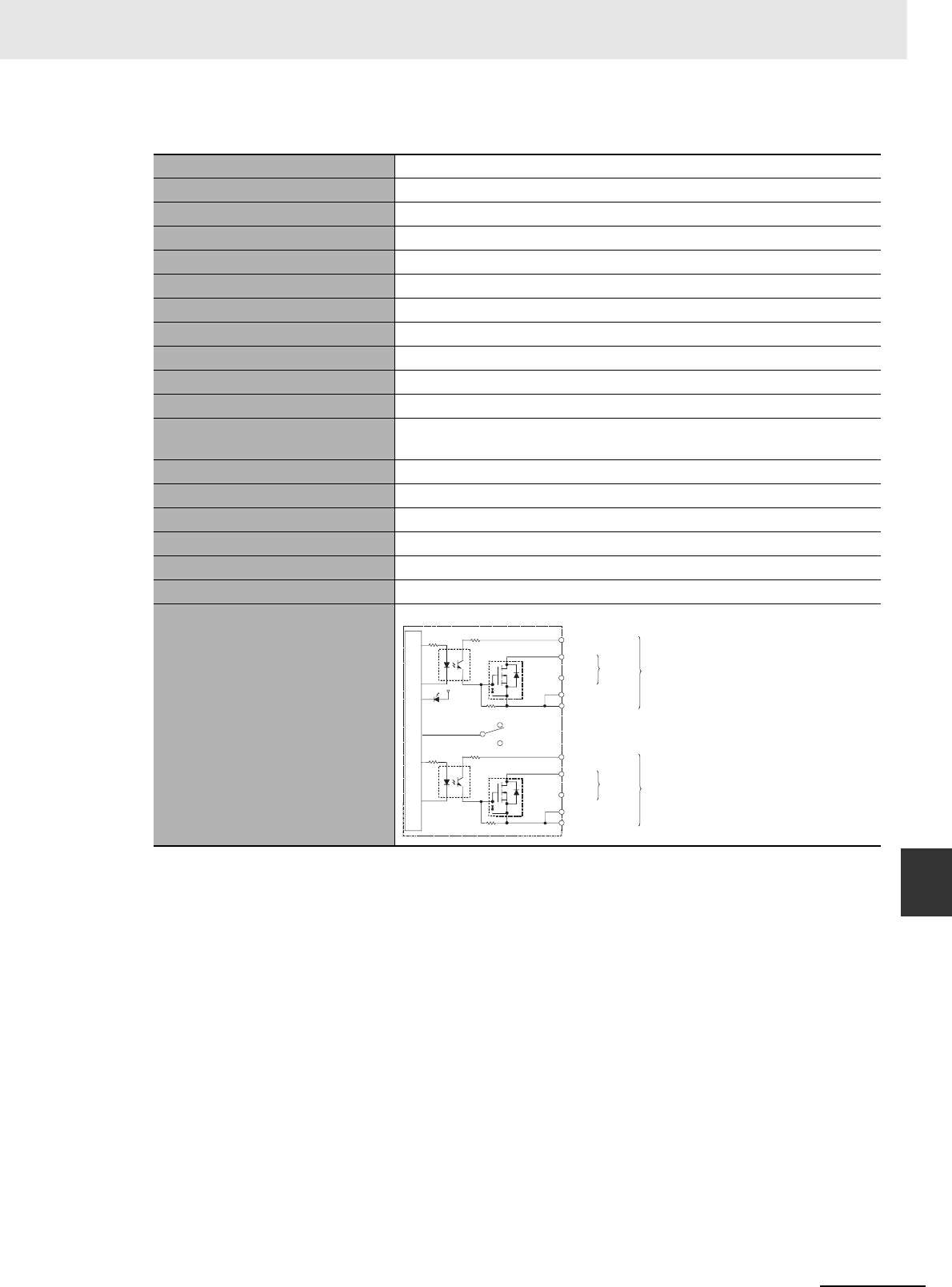
A-27
Appendices
CJ2 CPU Unit Hardware User’s Manual
A-1 Specifications of Basic I/O Units App A-1-2 Basic I/O Units
zCJ1W-OD231 Transistor Output Unit (32 Points)
Name 32-point Transistor Output Unit with Fujitsu Connector (Sinking Outputs)
Model CJ1W-OD231
Rated Voltage 12 to 24 VDC
Operating Load Voltage Range 10.2 to 26.4 VDC
Maximum Load Current 0.5 A/point, 2.0 A/common, 4.0 A/Unit
Maximum Inrush Current 4.0 A/point, 10 ms max.
Leakage Current 0.1 mA max.
Residual Voltage 1.5 V max.
ON Response Time 0.1 ms max.
OFF Response Time 0.8 ms max.
Insulation Resistance 20 MΩ between the external terminals and the GR terminal (100 VDC)
Dielectric Strength 1,000 VAC between the external terminals and the GR terminal for
1 minute at a leakage current of 10 mA max.
Number of Circuits 32 (16 points/common, 2 circuits)
Internal Current Consumption 5 VDC 140 mA max.
Fuse None
External Power Supply 10.2 to 26.4 VDC, 30 mA min.
Weight 70 g max.
Accessories None
Circuit Configuration
OUT0
+V
OUT15
COM0
OUT0
+V
OUT15
COM1
COM0
COM1
SW
Output indicator
to
to
Internal circuits
Wd m+1
Wd m
Allocated
CIO word
Signal
name
Connect
or row A
Connect
or row B
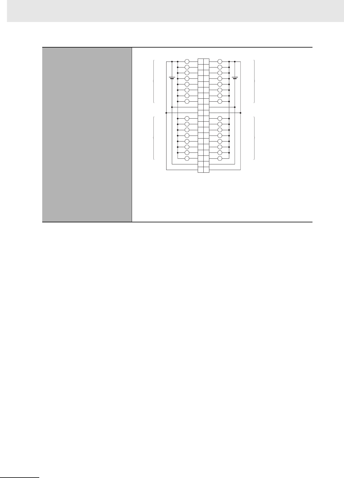
Appendices
A-28 CJ2 CPU Unit Hardware User’s Manual
Terminal Connections
• When wiring, pay careful attention to the polarity of the external power
supply. The load may operate incorrectly if the polarity is reversed.
• Be sure to wire both terminals A9 and A19 (COM0).
• Be sure to wire both terminals B9 and B19 (COM1).
• Be sure to wire both terminals A10 and A20 (+V).
• Be sure to wire both terminals B10 and B20 (+V).
COM1
+V +V
COM0
COM1
+V +V
COM0
OUT8
OUT9
OUT10
OUT11
OUT12
OUT13
OUT14
OUT15
OUT0
OUT1
OUT2
OUT3
OUT4
OUT5
OUT6
OUT7
L
L
L
L
L
L
L
L
L
L
L
L
L
L
L
L
L
L
L
L
L
L
L
L
L
L
L
L
L
L
L
L
OUT8
OUT9
OUT10
OUT11
OUT12
OUT13
OUT14
OUT15
OUT0
OUT1
OUT2
OUT3
OUT4
OUT5
OUT6
OUT7
A1
A2
A3
A4
A5
A6
A7
A8
A9
A10
A11
A12
A13
A14
A15
A16
A17
A18
A19
A20
B1
B2
B3
B4
B5
B6
B7
B8
B9
B10
B11
B12
B13
B14
B15
B16
B17
B18
B19
B20
Wd m+1
Wd m+1
Wd m
Wd m
12 to
24 VDC 12 to
24 VDC
Signal
name Signal
name
Connec-
tor pin Allocated
CIO word
Allocated
CIO word

A-29
Appendices
CJ2 CPU Unit Hardware User’s Manual
A-1 Specifications of Basic I/O Units App A-1-2 Basic I/O Units
zCJ1W-OD233 Transistor Output Unit (32 Points)
Name 32-point Transistor Output Unit with MIL Connector (Sinking Outputs)
Model CJ1W-OD233
Rated Voltage 12 to 24 VDC
Operating Load Voltage Range 10.2 to 26.4 VDC
Maximum Load Current 0.5 A/point, 2 A/common, 4 A/Unit
Maximum Inrush Current 4.0 A/point, 10 ms max.
Leakage Current 0.1 mA max.
Residual Voltage 1.5 V max.
ON Response Time 0.1 ms max.
OFF Response Time 0.8 ms max.
Insulation Resistance 20 MΩ between the external terminals and the GR terminal (100 VDC)
Dielectric Strength 1,000 VAC between the external terminals and the GR terminal for
1 minute at a leakage current of 10 mA max.
Number of Circuits 32 (16 points/common, 2 circuits)
Internal Current Consumption 140 mA max.
Fuse None
External Power Supply 12 to 24 VDC, 30 mA min.
Weight 70 g max.
Circuit Configuration
OUT0
+V
OUT15
COM0
OUT0
+V
OUT15
COM1
COM0
COM1
SW
Wd m+1
Wd m
to
to
Output indicator
Internal circuits
Allocated
CIO word
Signal
name
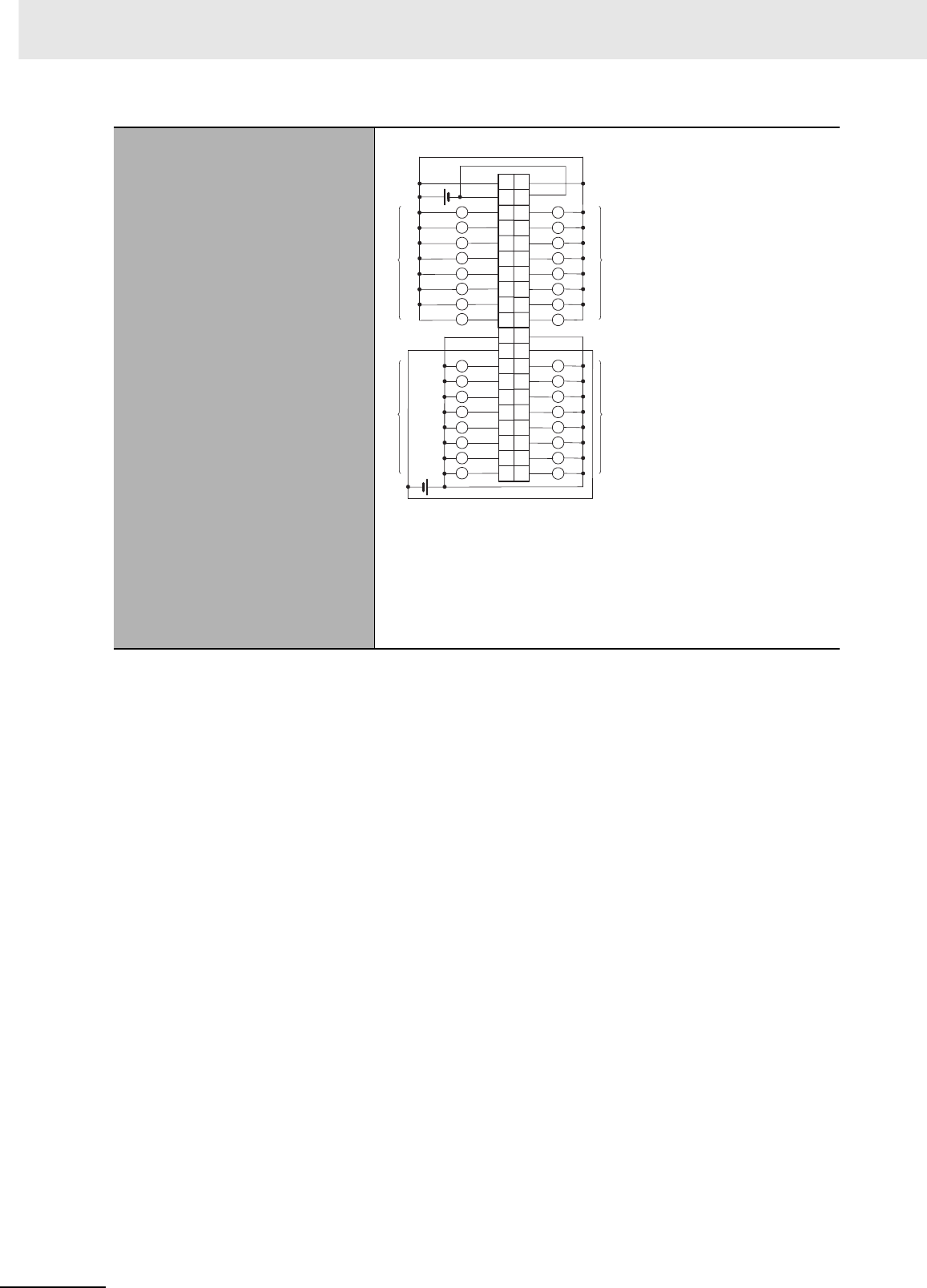
Appendices
A-30 CJ2 CPU Unit Hardware User’s Manual
Terminal Connections
• When wiring, pay careful attention to the polarity of the external
power supply. The load may operate incorrectly if the polarity is
reversed.
• Be sure to wire both terminals 23 and 24 (COM0).
• Be sure to wire both terminals 3 and 4 (COM1).
• Be sure to wire both terminals 21 and 22 (+V).
• Be sure to wire both terminals 1 and 2 (+V).
40
38
36
34
32
30
28
26
24
22
20
18
OUT0
16
OUT1
14
OUT2
12
OUT3
10
OUT4
8
OUT5
6
OUT6
4
+V
2
COM1
39
37
35
33
31
29
27
25
23
21
OUT8 19
OUT9 17
OUT10 15
OUT11 13
OUT12 11
OUT7
9
OUT13
7
OUT14
5
OUT15
3
+V 1
COM1
+V +V
L
L
L
L
L
L
L
L
L
L
L
L
L
L
L
L
L
L
L
L
L
L
L
L
L
L
L
L
L
L
L
LOUT0
OUT1
OUT2
OUT3
OUT4
OUT5
OUT6
OUT7
OUT8
OUT9
OUT10
OUT11
OUT12
OUT13
OUT14
OUT15
COM0 COM0
Wd m+1
Wd m
Wd m+1
Wd m
12 to
24 VDC
12 to
24 VDC
Signal
name Signal
name
Connec-
tor pin
Allocated
CIO word
Allocated
CIO word
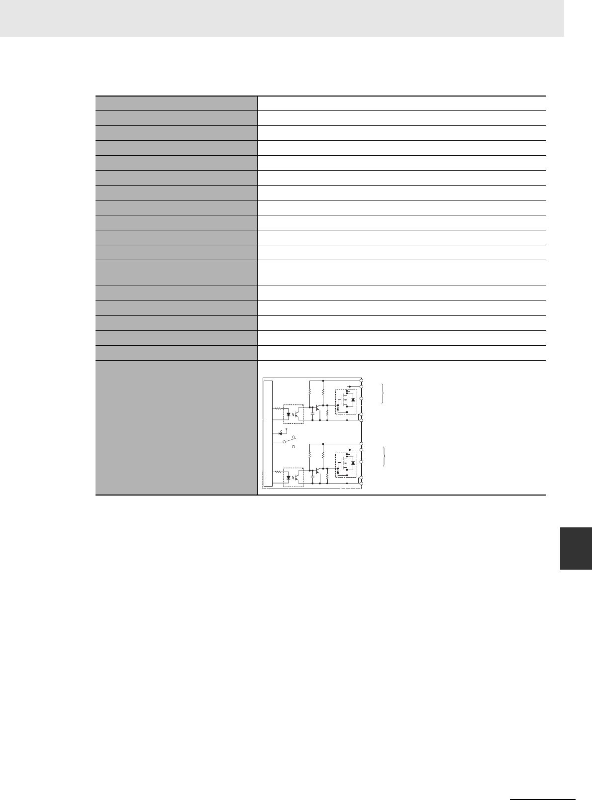
A-31
Appendices
CJ2 CPU Unit Hardware User’s Manual
A-1 Specifications of Basic I/O Units App A-1-2 Basic I/O Units
zCJ1W-OD234 Transistor Output Unit (32 Points)
Name 32-point Transistor Output Unit with MIL Connector (Sinking Outputs)
Model CJ1W-OD234
Rated Voltage 24 VDC
Operating Load Voltage Range 20.4 to 26.4 VDC
Maximum Load Current 0.5 A/point, 2 A/common, 4 A/Unit
Maximum Inrush Current 4.0 A/point, 10 ms max.
Leakage Current 0.1 mA max.
Residual Voltage 1.5 V max.
ON Response Time 15 µs max.
OFF Response Time 80 µs max.
Insulation Resistance 20 MΩ between the external terminals and the GR terminal (100 VDC)
Dielectric Strength 1,000 VAC between the external terminals and the GR terminal for
1 minute at a leakage current of 10 mA max.
Number of Circuits 32 (16 points/common, 2 circuits)
Internal Current Consumption 220 mA max.
Fuse None
External Power Supply 20.4 to 26.4 VDC, 110 mA min.
Weight 70 g max.
Circuit Configuration
OUT0
+V
OUT15
COM0
OUT0
+V
OUT15
COM1
COM0
COM1
SW
Wd m+1
Wd m
to
to
Output indicator
Internal circuits
Allocated
CIO word
Signal
name
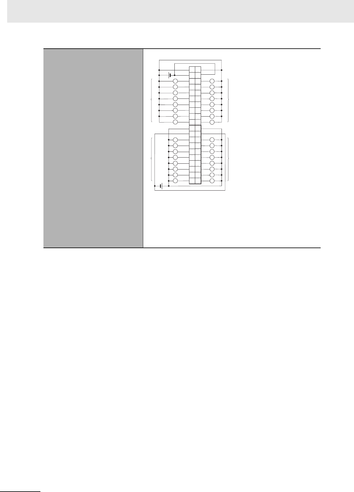
Appendices
A-32 CJ2 CPU Unit Hardware User’s Manual
Terminal Connections
• When wiring, pay careful attention to the polarity of the external
power supply. The load may operate incorrectly if the polarity is
reversed.
• Be sure to wire both terminals 23 and 24 (COM0).
• Be sure to wire both terminals 3 and 4 (COM1).
• Be sure to wire both terminals 21 and 22 (+V).
• Be sure to wire both terminals 1 and 2 (+V).
40
38
36
34
32
30
28
26
24
22
20
18
OUT0
16
OUT1
14
OUT2
12
OUT3
10
OUT4
8
OUT5
6
OUT6
4
+V
2
COM1
39
37
35
33
31
29
27
25
23
21
OUT8 19
OUT9 17
OUT10 15
OUT11 13
OUT12 11
OUT7
9
OUT13
7
OUT14
5
OUT15
3
+V 1
COM1
+V +V
L
L
L
L
L
L
L
L
L
L
L
L
L
L
L
L
L
L
L
L
L
L
L
L
L
L
L
L
L
L
L
LOUT0
OUT1
OUT2
OUT3
OUT4
OUT5
OUT6
OUT7
OUT8
OUT9
OUT10
OUT11
OUT12
OUT13
OUT14
OUT15
COM0 COM0
Wd m+1
Wd m
Wd m+1
Wd m
24 VDC
24 VDC
Signal
name Signal
name
Connec-
tor pin
Allocated
CIO word
Allocated
CIO word
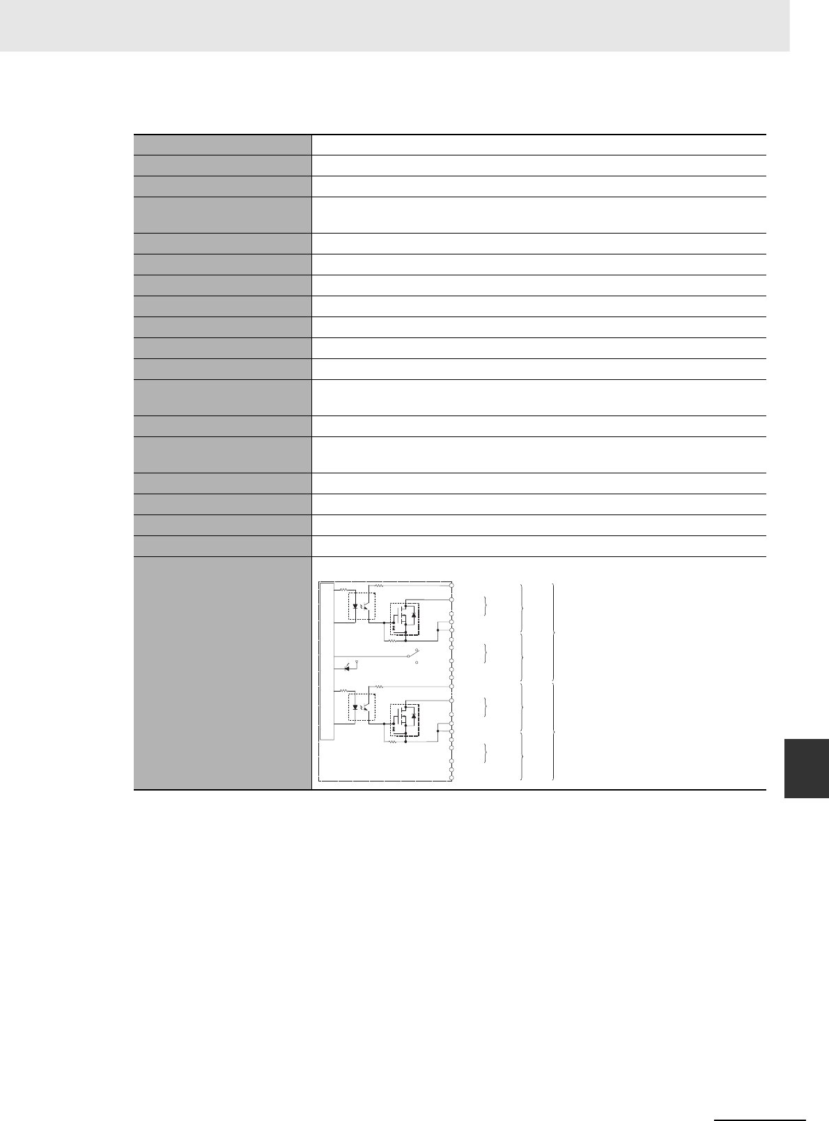
A-33
Appendices
CJ2 CPU Unit Hardware User’s Manual
A-1 Specifications of Basic I/O Units App A-1-2 Basic I/O Units
zCJ1W-OD261 Transistor Output Unit (64 Points)
Name 64-point Transistor Output Unit with Fujitsu Connectors (Sinking Outputs)
Model CJ1W-OD261
Rated Voltage 12 to 24 VDC
Operating Load Voltage
Range
10.2 to 26.4 VDC
Maximum Load Current 0.3 A/point, 1.6 A/common, 6.4 A/Unit
Maximum Inrush Current 3.0 A/point, 10 ms max.
Leakage Current 0.1 mA max.
Residual Voltage 1.5 V max.
ON Response Time 0.5 ms max.
OFF Response Time 1.0 ms max.
Insulation Resistance 20 MΩ between the external terminals and the GR terminal (100 VDC)
Dielectric Strength 1,000 VAC between the external terminals and the GR terminal for 1 minute at a
leakage current of 10 mA max.
Number of Circuits 64 (16 points/common, 4 circuits)
Internal Current Consump-
tion
5 VDC, 170 mA max.
Fuse None
External Power Supply 10.2 to 26.4 VDC, 50 mA min.
Weight 110 g max.
Accessories None
Circuit Configuration
OUT0
+V
OUT15
COM0
OUT0
+V
OUT15
COM2
COM0
COM2
+V
OUT0
OUT15
COM1
COM1
+V
OUT0
OUT15
COM3
COM3
CN1
SW
CN2
Output indicator
to
to
to
to
Wd m
Wd m+1
Wd m+2
Wd m+3
Internal circuits
Allocated
CIO word
Signal
name
Connect
or row A
Connect
or row B
Connect
or row A
Connect
or row B
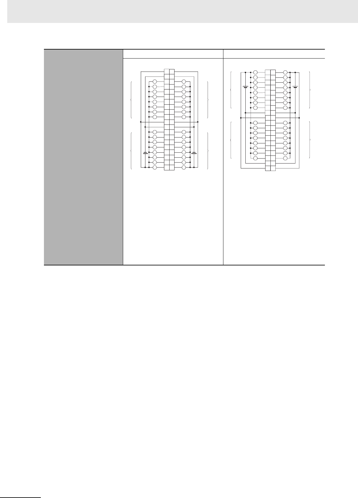
Appendices
A-34 CJ2 CPU Unit Hardware User’s Manual
Terminal Connections
CN1 CN2
• When wiring, pay careful attention to
the polarity of the external power
supply. The load may operate incor-
rectly if the polarity is reversed.
• Be sure to wire both terminals A9
and A19 (COM0) of CN1.
• Be sure to wire both terminals B9
and B19 (COM1) of CN1.
• Be sure to wire both terminals A10
and A20 (+V) of CN1.
• Be sure to wire both terminals B10
and B20 (+V) of CN1.
• When wiring, pay careful attention to
the polarity of the external power
supply. The load may operate incor-
rectly if the polarity is reversed.
• Be sure to wire both terminals A9
and A19 (COM2) of CN2.
• Be sure to wire both terminals B9
and B19 (COM3) of CN2.
• Be sure to wire both terminals A10
and A20 (+V) of CN2.
• Be sure to wire both terminals B10
and B20 (+V) of CN2.
COM0
+V
COM0
+V
COM1
+V
OUT8
OUT9
OUT10
OUT11
OUT12
OUT13
OUT14
OUT15
COM1
+V
L
L
L
L
L
L
L
L
L
L
L
L
L
L
L
L
L
L
L
L
L
L
L
L
L
L
L
L
L
L
L
L
OUT0
OUT1
OUT2
OUT3
OUT4
OUT5
OUT6
OUT7
OUT0
OUT1
OUT2
OUT3
OUT4
OUT5
OUT6
OUT7
OUT8
OUT9
OUT10
OUT11
OUT12
OUT13
OUT14
OUT15
A20
A19
A18
A17
A16
A15
A14
A13
A12
A11
A10
A9
A8
A7
A6
A5
A4
A3
A2
A1
B20
B19
B18
B17
B16
B15
B14
B13
B12
B11
B10
B9
B8
B7
B6
B5
B4
B3
B2
B1
12 to
24
VDC
Wd m
Wd m+1
12 to
24
VDC
Wd m+1
Wd m
Signal
name Signal
name
Connec-
tor pin Allocated
CIO word
Allocated
CIO word
COM3
+V
COM3
+V
COM2
+V
OUT8
OUT9
OUT10
OUT11
OUT12
OUT13
OUT14
OUT15
COM2
+V
L
L
L
L
L
L
L
L
L
L
L
L
L
L
L
L
L
L
L
L
L
L
L
L
L
L
L
L
L
L
L
L
OUT0
OUT1
OUT2
OUT3
OUT4
OUT5
OUT6
OUT7
OUT0
OUT1
OUT2
OUT3
OUT4
OUT5
OUT6
OUT7
OUT8
OUT9
OUT10
OUT11
OUT12
OUT13
OUT14
OUT15
A1
A2
A3
A4
A5
A6
A7
A8
A9
A10
A11
A12
A13
A14
A15
A16
A17
A18
A19
A20
B1
B2
B3
B4
B5
B6
B7
B8
B9
B10
B11
B12
B13
B14
B15
B16
B17
B18
B19
B20
12 to
24
VDC
Wd m+3
Wd m+2
Wd m+2
Wd m+3
12 to
24
VDC
Signal
name Signal
name
Connec-
tor pin Allocated
CIO word
Allocated
CIO word
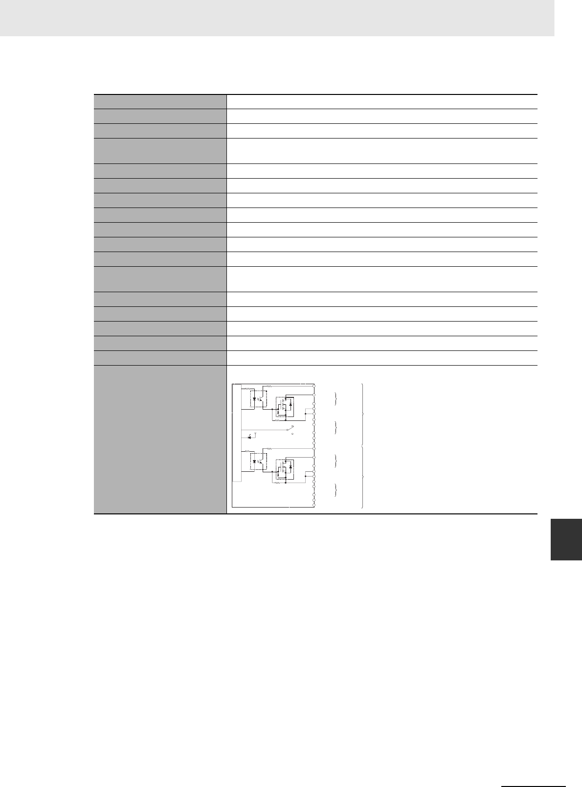
A-35
Appendices
CJ2 CPU Unit Hardware User’s Manual
A-1 Specifications of Basic I/O Units App A-1-2 Basic I/O Units
zCJ1W-OD263 Transistor Output Unit (64 Points)
Name 64-point Transistor Output Unit with MIL Connectors (Sinking Outputs)
Model CJ1W-OD263
Rated Voltage 12 to 24 VDC
Operating Load Voltage
Range
10.2 to 26.4 VDC
Maximum Load Current 0.3 A/point, 1.6 A/common, 6.4 A/Unit
Maximum Inrush Current 3.0 A/point, 10 ms max.
Leakage Current 0.1 mA max.
Residual Voltage 1.5 V max.
ON Response Time 0.5 ms max.
OFF Response Time 1.0 ms max.
Insulation Resistance 20 MΩ between the external terminals and the GR terminal (100 VDC)
Dielectric Strength 1,000 VAC between the external terminals and the GR terminal for 1 minute at
a leakage current of 10 mA max.
Number of Circuits 64 (16 points/common, 4 circuits)
Internal Current Consumption 170 mA max.
Fuse None
External Power Supply 12 to 24 VDC, 50 mA min.
Weight 110 g max.
Circuit Configuration
OUT0
+V
OUT15
COM0
OUT0
+V
OUT15
COM2
COM0
COM2
+V
OUT0
OUT15
COM1
COM1
+V
OUT0
OUT15
COM3
COM3
CN1
SW
CN2
Internal circuits
Output indicator
to
to
to
to
Wd m
Wd m+1
Wd m+2
Wd m+3
Allocated
CIO word
Signal
name
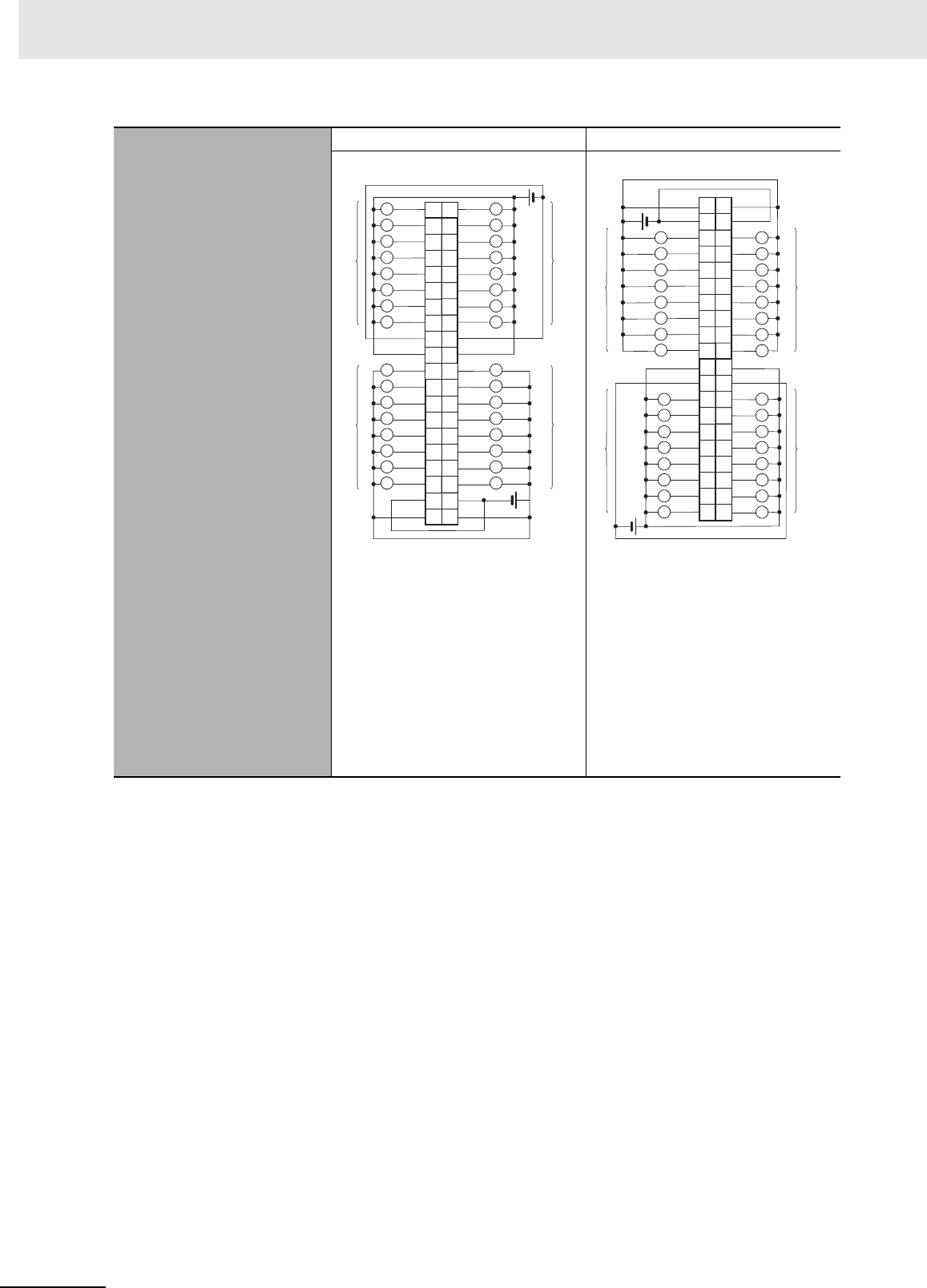
Appendices
A-36 CJ2 CPU Unit Hardware User’s Manual
Terminal Connections
CN1 CN2
• When wiring, pay careful attention
to the polarity of the external power
supply. The load may operate incor-
rectly if the polarity is reversed.
• Be sure to wire both terminals 23
and 24 (COM0) of CN1.
• Be sure to wire both terminals 3
and 4 (COM1) of CN1.
• Be sure to wire both terminals 21
and 22 (+V) of CN1.
• Be sure to wire both terminals 1
and 2 (+V) of CN1.
• When wiring, pay careful attention
to the polarity of the external power
supply. The load may operate incor-
rectly if the polarity is reversed.
• Be sure to wire both terminals 23
and 24 (COM2) of CN2.
• Be sure to wire both terminals 3
and 4 (COM3) of CN2.
• Be sure to wire both terminals 21
and 22 (+V) of CN2.
• Be sure to wire both terminals 1
and 2 (+V) of CN2.
1+V
3
5
7
9
11
13
15
17
19
21
23
25
27
OUT15
29
OUT14
31
OUT13
33
OUT12
35
OUT11
37
+V
39
2
4
+V
6
8
10
12
14
16
18
COM1
20
22
24
26
28
30
OUT10
32
34
36
38
40
COM1
+V
OUT0
OUT7
OUT6
OUT5
OUT4
OUT3
OUT2
OUT1
COM0
OUT8
OUT9
COM0
L
L
L
L
L
L
L
L
L
L
L
L
L
L
L
L
L
L
L
L
L
L
L
L
L
L
L
L
L
L
L
L
OUT15
OUT14
OUT13
OUT12
OUT11
OUT10
OUT8
OUT9
OUT0
OUT7
OUT6
OUT5
OUT4
OUT3
OUT2
OUT1
Wd m
Wd m
Wd m+1
Wd m+1
12 to
24
VDC
12 to
24
VDC
Signal
name Signal
name
Connec-
tor pin
Allocated
CIO word
Allocated
CIO word
40
38
36
34
32
30
28
26
24
22
20
18
16
14
12
10
8
6
4
+V
2
COM3
39
37
35
33
31
29
27
25
23
21
19
17
15
13
11
9
7
5
3
+V 1
COM3
+V +V
COM2 COM2
L
L
L
L
L
L
L
L
L
L
L
L
L
L
L
L
L
L
L
L
L
L
L
L
L
L
L
L
L
L
L
L
OUT8
OUT9
OUT10
OUT11
OUT12
OUT13
OUT14
OUT15
OUT8
OUT9
OUT10
OUT11
OUT12
OUT13
OUT14
OUT15
OUT0
OUT1
OUT2
OUT3
OUT4
OUT5
OUT6
OUT7
OUT0
OUT1
OUT2
OUT3
OUT4
OUT5
OUT6
OUT7
Wd m+3
Wd m+3
Wd m+2
Wd m+2
12 to
24
VDC
12 to
24
VDC
Signal
name Signal
name
Connec-
tor pin Allocated
CIO word
Allocated
CIO word
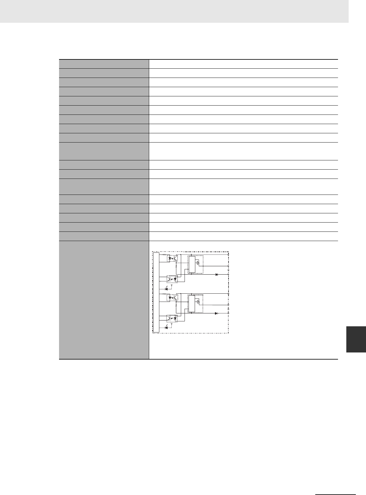
A-37
Appendices
CJ2 CPU Unit Hardware User’s Manual
A-1 Specifications of Basic I/O Units App A-1-2 Basic I/O Units
zCJ1W-OD202 Transistor Output Unit (8 Points)
Name 8-point Transistor Output Unit with Terminal Block (Sourcing Outputs)
Model CJ1W-OD202
Rated Voltage 24 VDC
Operating Load Voltage Range 20.4 to 26.4 VDC
Maximum Load Current 2 A/point, 8 A/Unit
Leakage Current 0.1 mA max.
Residual Voltage 1.5 V max.
ON Response Time 0.5 ms max.
OFF Response Time 1.0 ms max.
Load Short-circuit Protection Detection current: 6 A min.
Automatic restart after error clearance. (Refer to page A-149.)
Line Disconnection Detection Detection current: 200 mA (Refer to page A-149.)
Insulation Resistance 20 MΩ between the external terminals and the GR terminal (100 VDC)
Dielectric Strength 1,000 VAC between the external terminals and the GR terminal for 1 minute
at a leakage current of 10 mA max.
Number of Circuits 8 (4 points/common, 2 circuits)
Internal Current Consumption 110 mA max.
Fuse None
External Power Supply 24 VDC, 50 mA min.
Weight 120 g max.
Circuit Configuration
• The ERR indicator will light and the corresponding bit in A050 to A069
(Basic I/O Unit Information, two points per bit) will turn ON if an overcur-
rent or line disconnection is detected.
COM0 (+V)
OUT3
OUT0
0 V
OUT4
OUT7
0 V
COM1 (+V)
Short-circuit
protection
Short-circuit
protection
to
to
Output indicator
ERR indicator
Internal circuits
Signal
name
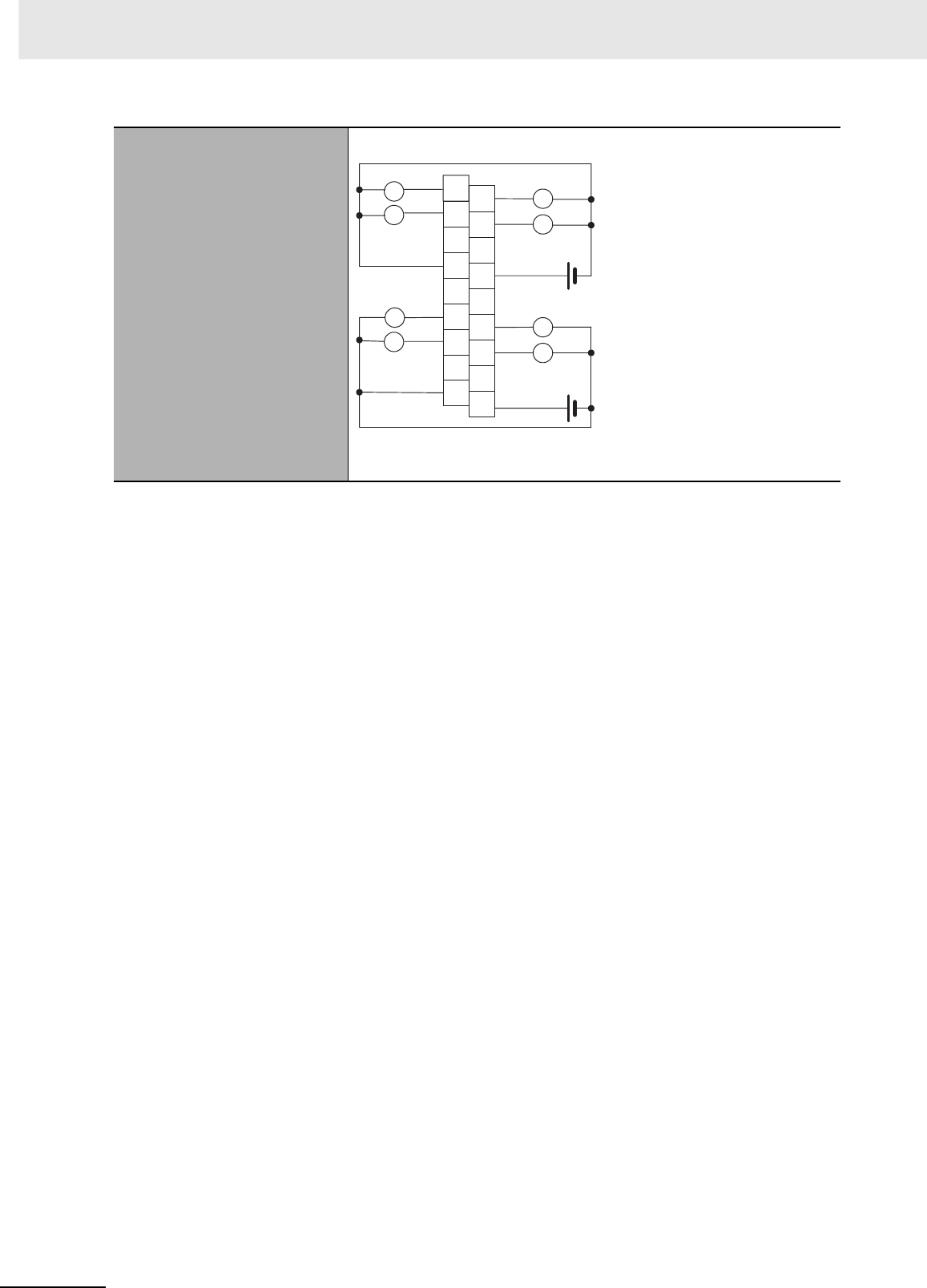
Appendices
A-38 CJ2 CPU Unit Hardware User’s Manual
*1 Terminal numbers A0 to A8 and B0 to B8 are used in this manual, but they are not printed on the
Unit.
Note Although 16 I/O bits (1 word) are allocated, only 8 of these can be used for external I/O. This Unit is also
treated as a 16-point I/O Unit in the I/O tables.
Terminal Connections
• When wiring, pay careful attention to the polarity of the external power
supply. The load may operate incorrectly if the polarity is reversed.
OUT0
OUT2
0V
NC
NC
OUT4
OUT6
B0
B1
B2
B3
B4
B5
B6
B7
B8
NC
A0 OUT1
OUT3
COM0 (+V)
NC
NC
NC
OUT5
OUT7
A1
A2
A3
A4
A5
A6
A7
A8
0V
COM1 (+V)
L
L
L
L
L
L
L
L
24 VDC
24 VDC
Signal
name Signal
name
Connec-
tor pin
*1
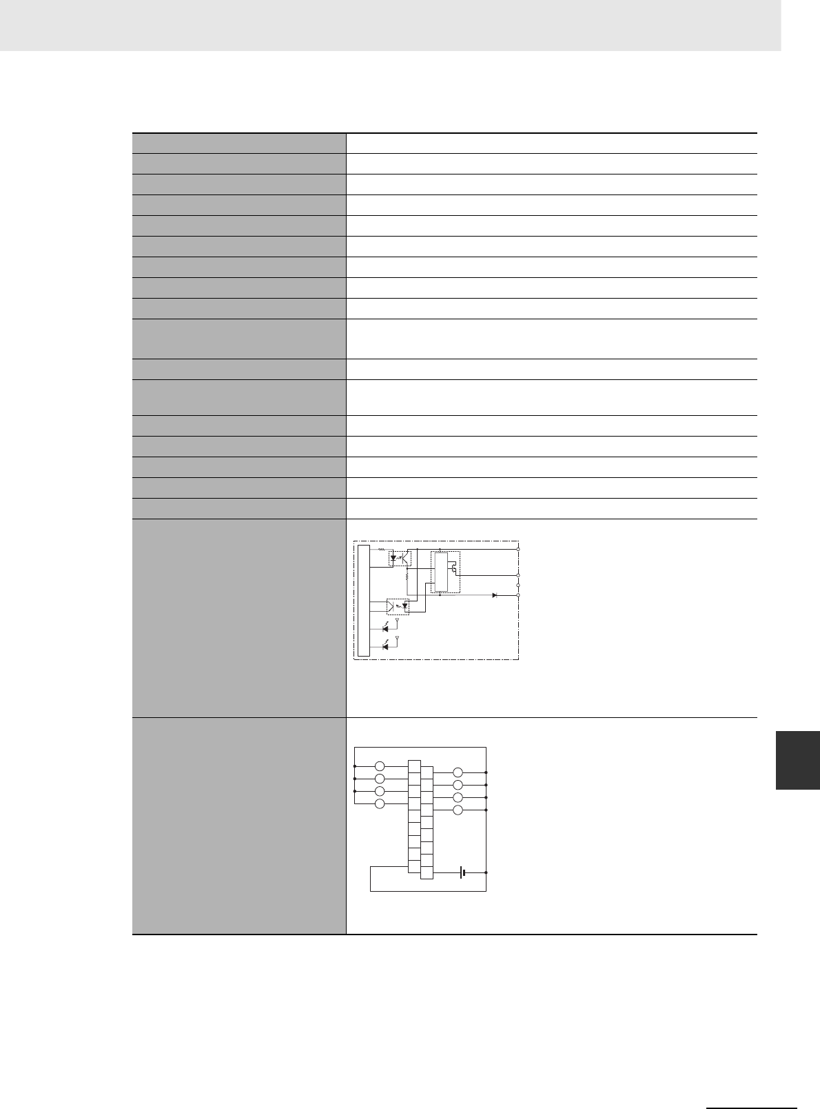
A-39
Appendices
CJ2 CPU Unit Hardware User’s Manual
A-1 Specifications of Basic I/O Units App A-1-2 Basic I/O Units
zCJ1W-OD204 Transistor Output Unit (8 Points)
*1 Terminal numbers A0 to A8 and B0 to B8 are used in this manual, but they are not printed on the
Unit.
Note Although 16 I/O bits (1 word) are allocated, only 8 of these can be used for external I/O. This Unit is also
treated as a 16-point I/O Unit in the I/O tables.
Name 8-point Transistor Output Unit with Terminal Block (Sourcing Outputs)
Model CJ1W-OD204
Rated Voltage 24 VDC
Operating Load Voltage Range 20.4 to 26.4 VDC
Maximum Load Current 0.5 A/point, 4.0 A/Unit
Leakage Current 0.1 mA max.
Residual Voltage 1.5 V max.
ON Response Time 0.5 ms max.
OFF Response Time 1.0 ms max.
Load Short-circuit Protection Detection current: 0.7 to 2.5 A
Automatic restart after error clearance. (Refer to page A-149.)
Insulation Resistance 20 MΩ between the external terminals and the GR terminal (100 VDC)
Dielectric Strength 1,000 VAC between the external terminals and the GR terminal for
1 minute at a leakage current of 10 mA max.
Number of Circuits 8 (8 points/common, 1 circuit)
Internal Current Consumption 100 mA max.
Fuse None
External Power Supply 20.4 to 26.4 VDC, 40 mA min.
Weight 120 g max.
Circuit Configuration
• When overcurrent is detected, the ERR indicator will light, and the cor-
responding flag in the Basic I/O Unit Information Area (A050 to A069)
will turn ON.
Terminal Connections
• When wiring, pay careful attention to the polarity of the external power
supply. The load may operate incorrectly if the polarity is reversed.
COM (+V)
OUT0
OUT7
0 V
Output indicator
ERR indicator
Internal circuits
to
Short-circuit
protection
Signal
name
B1
OUT1
B2
OUT3
B3
OUT5
B4
OUT7
B5
B6
B7
B8
A1
OUT0
A2
OUT2
A3
OUT4
A4
OUT6
A5
NC
A6
A7
A8
0V
B0
A0
COM (+V)
L
L
L
L
L
L
L
L
NC
NC
NC
NC
NC
NC
NC
24 VDC
Signal
name Signal
name
Connec-
tor pin
*1
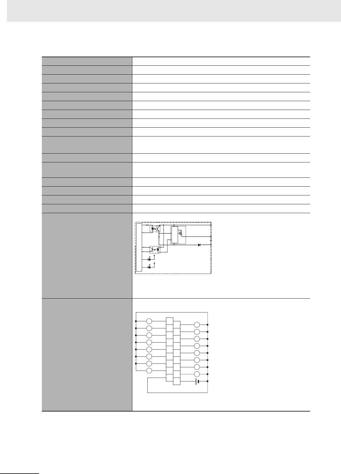
Appendices
A-40 CJ2 CPU Unit Hardware User’s Manual
zCJ1W-OD212 Transistor Output Unit (16 Points)
*1 Terminal numbers A0 to A8 and B0 to B8 are used in this manual, but they are not printed on the
Unit.
Name 16-point Transistor Output Unit with Terminal Block (Sourcing Outputs)
Model CJ1W-OD212
Rated Voltage 24 VDC
Operating Load Voltage Range 20.4 to 26.4 VDC
Maximum Load Current 0.5 A/point, 5.0 A/Unit
Maximum Inrush Current 0.1 mA max.
Leakage Current 1.5 V max.
ON Response Time 0.5 ms max.
OFF Response Time 1.0 ms max.
Load Short-circuit Protection Detection current: 0.7 to 2.5 A
Automatic restart after error clearance. (Refer to page A-149.)
Insulation Resistance 20 MΩ between the external terminals and the GR terminal (100 VDC)
Dielectric Strength 1,000 VAC between the external terminals and the GR terminal for
1 minute at a leakage current of 10 mA max.
Number of Circuits 16 (16 points/common, 1 circuit)
Internal Current Consumption 5 VDC, 100 mA max.
External Power Supply 20.4 to 26.4 VDC, 40 mA min.
Weight 120 g max.
Circuit Configuration
• When overcurrent is detected, the ERR indicator will light, and the corre-
sponding flag in the Basic I/O Unit Information Area (A050 to A069) will
turn ON.
Terminal Connections
• When wiring, pay careful attention to the polarity of the external power
supply. The load may operate incorrectly if the polarity is reversed.
OUT15
OUT0
0 V
COM (+V)
Internal circuits
Output indicator
ERR indicator
Short-circuit
protection
to
Signal
name
B1
OUT1
B2
OUT3
B3
OUT5
B4
OUT7
B5
OUT9
B6
OUT11
B7
OUT13
B8
OUT15
24 VDC
A1
OUT0
A2
OUT2
A3
OUT4
A4
OUT6
A5
OUT8
A6
OUT10
A7
OUT12
A8
OUT14
0 V
B0
A0
L
L
L
L
L
L
L
L
L
L
L
L
L
L
L
L
COM (+V)
Signal
name Signal
name
Connec-
tor pin
*1
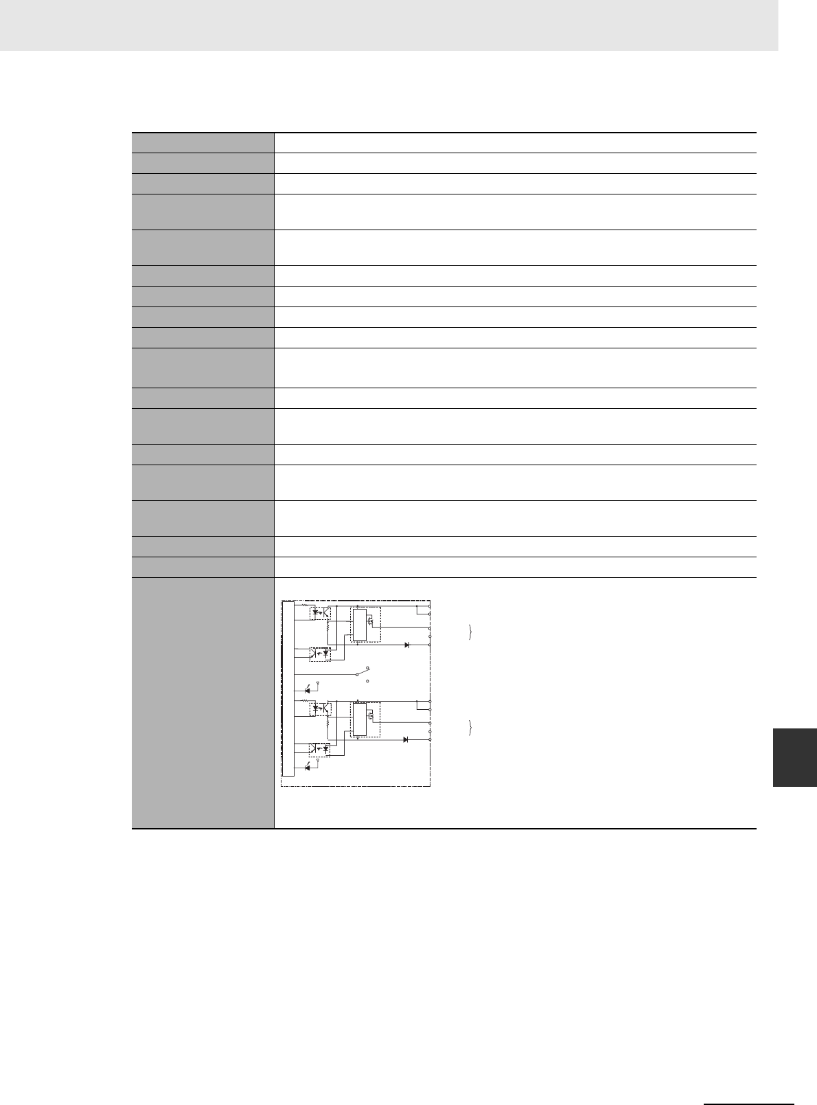
A-41
Appendices
CJ2 CPU Unit Hardware User’s Manual
A-1 Specifications of Basic I/O Units App A-1-2 Basic I/O Units
zCJ1W-OD232 Transistor Output Unit (32 Points)
Name 32-point Transistor Output Unit with MIL Connector (Sourcing Outputs)
Model CJ1W-OD232
Rated Voltage 24 VDC
Operating Load Volt-
age Range
20.4 to 26.4 VDC
Maximum Load Cur-
rent
0.5 A/point, 2.0 A/common, 4.0 A/Unit
Leakage Current 0.1 mA max.
Residual Voltage 1.5 V max.
ON Response Time 0.5 ms max.
OFF Response Time 1.0 ms max.
Load Short-circuit
Protection
Detection current: 0.7 to 2.5 A
Automatic restart after error clearance. (Refer to page A-149.)
Insulation Resistance 20 MΩ between the external terminals and the GR terminal (100 VDC)
Dielectric Strength 1,000 VAC between the external terminals and the GR terminal for 1 minute at a leak-
age current of 10 mA max.
Number of Circuits 32 (16 points/common, 2 circuits)
Internal Current Con-
sumption
5 VDC 150 mA max.
External Power Sup-
ply
20.4 to 26.4 VDC, 70 mA min.
Weight 80 g max.
Accessories None
Circuit Configuration
• The ERR indicator will light and the corresponding bit in A050 to A069 (Basic I/O Unit
Information, one for each common) will turn ON if an overcurrent is detected.
OUT15
OUT0
0 V
0 V
SW
COM0 (+V)
COM0 (+V)
COM1 (+V)
COM1 (+V)
Wd m
Wd m+1
to
OUT15
OUT0
to
Output indicator
Internal circuits
ERR indicator
Short-circuit
protection Short-circuit
protection
Allocated
CIO word
Signal
name
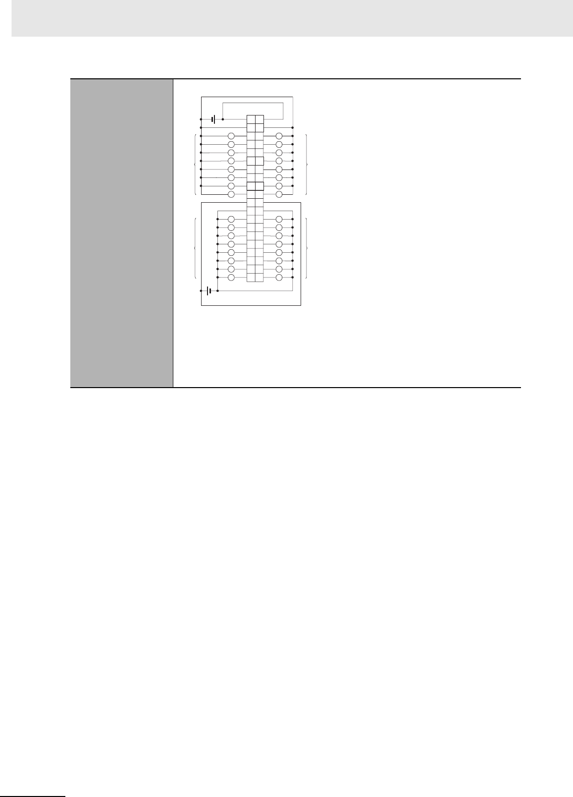
Appendices
A-42 CJ2 CPU Unit Hardware User’s Manual
Terminal Connections
• When wiring, pay careful attention to the polarity of the external power supply. The
load may operate incorrectly if the polarity is reversed.
• Be sure to wire both terminals 21 and 22 (COM0 (+V)).
• Be sure to wire both terminals 1 and 2 (COM1 (+V)).
• Be sure to wire both terminals 3 and 4 (0 V).
• Be sure to wire both terminals 23 and 24 (0 V).
OUT0
OUT1
OUT2
OUT3
OUT4
OUT5
OUT6
OUT7
0 V
COM1 (+V)
OUT8
OUT9
OUT10
OUT11
OUT12
OUT13
OUT14
OUT15
0 V
40
38
36
34
32
30
28
26
24
22
20
18
16
14
12
10
8
6
4
2
39
37
35
33
31
29
27
25
23
21
19
17
15
13
11
9
7
5
3
1
COM1 (+V)
L
0 V
COM0 (+V)
0 V
COM0 (+V)
L
L
L
L
L
L
L
L
L
L
L
L
L
L
L
L
L
L
L
L
L
L
L
L
L
L
L
L
L
L
L
OUT0
OUT1
OUT2
OUT3
OUT4
OUT5
OUT6
OUT7
OUT8
OUT9
OUT10
OUT11
OUT12
OUT13
OUT14
OUT15
Wd m+1
Wd m+1
Wd m
Wd m
24 VDC
24 VDC
Signal
name Signal
name
Connec-
tor pin Allocated
CIO word
Allocated
CIO word
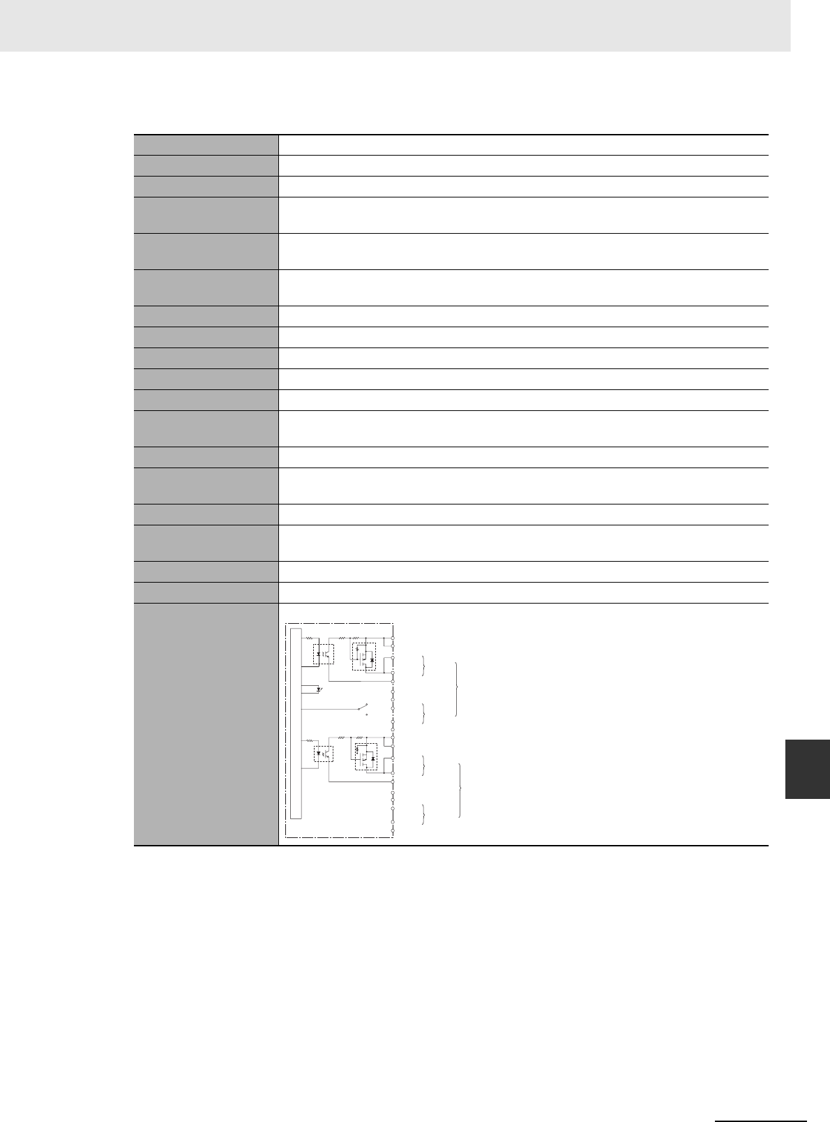
A-43
Appendices
CJ2 CPU Unit Hardware User’s Manual
A-1 Specifications of Basic I/O Units App A-1-2 Basic I/O Units
zCJ1W-OD262 Transistor Output Unit (64 Points)
Name 64-point Transistor Output Unit with MIL Connectors (Sourcing Outputs)
Model CJ1W-OD262
Rated Voltage 12 to 24 VDC
Operating Load Volt-
age Range
10.2 to 26.4 VDC
Maximum Load Cur-
rent
0.3 A/point, 1.6 A/common, 6.4 A/Unit
Maximum Inrush Cur-
rent
3.0 A/point, 10 ms max.
Leakage Current 0.1 mA max.
Residual Voltage 1.5 V max.
ON Response Time 0.5 ms max.
OFF Response Time 1.0 ms max.
Insulation Resistance 20 MΩ between the external terminals and the GR terminal (100 VDC)
Dielectric Strength 1,000 VAC between the external terminals and the GR terminal for 1 minute at a leak-
age current of 10 mA max.
Number of Circuits 64 (16 points/common, 4 circuits)
Internal Current Con-
sumption
170 mA max. (5 VDC)
Fuse None
External Power Sup-
ply
10.2 to 26.4 VDC, 50 mA min.
Weight 110 g max.
Accessories None
Circuit Configuration
OUT15
0 V
OUT0
COM0
COM0
0 V
0 V
COM1
0 V
COM1
OUT15
OUT0
COM2
COM2
OUT15
OUT0
OUT15
OUT0
COM3
COM3
CN1 (OUT)
CN2 (OUT)
Wd m
Wd m+1
Wd m+3
Wd m+2
Internal circuits
Indicator switch
Output indicator
to
to
to
to
Allocated
CIO word
Signal
name
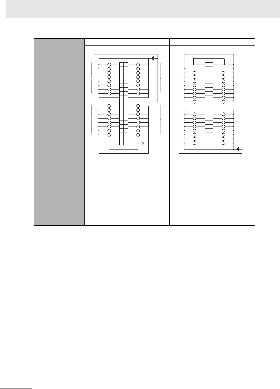
Appendices
A-44 CJ2 CPU Unit Hardware User’s Manual
Terminal Connections
CN1 CN2
• When wiring, pay careful attention to the
polarity of the external power supply.
The load may operate incorrectly if the
polarity is reversed.
• Be sure to wire both terminals 21 and
22 (COM0 (+V)) of CN1.
• Be sure to wire both terminals 1 and 2
(COM1 (+V)) of CN1.
• Be sure to wire both terminals 23 and
24 (0 V) of CN1.
• Be sure to wire both terminals 3 and 4
(0 V) of CN1.
• When wiring, pay careful attention to the
polarity of the external power supply.
The load may operate incorrectly if the
polarity is reversed.
• Be sure to wire both terminals 21 and
22 (COM2 (+V)) of CN2.
• Be sure to wire both terminals 1 and 2
(COM3 (+V)) of CN2.
• Be sure to wire both terminals 23 and
24 (0 V) of CN2.
• Be sure to wire both terminals 3 and 4
(0 V) of CN2.
1
3
5
7
9
11
13
15
17
19
21
23
25
27
29
31
33
35
37
39
2
4
6
8
10
12
14
16
18
20
22
24
26
28
30
32
34
36
38
40
L L
L L
L L
L L
L L
L L
L L
L L
L L
L L
L L
L L
L L
L L
L L
L L
OUT15
OUT14
OUT13
OUT12
OUT11
OUT10OUT2
OUT15
OUT14
OUT13
OUT12
OUT11
0 V
0 V
OUT7
OUT6
OUT5
OUT4
OUT3
COM1 (+V)
OUT10
0 V
OUT0
OUT7
OUT6
OUT5
OUT4
OUT3
OUT2
OUT1
COM0 (+V)
OUT8
OUT9
COM0 (+V)
OUT8
OUT9
OUT0
OUT1
0 V
COM1 (+V)
Wd m
12 to
24 VDC
Wd m+1
Wd m
Wd m+1
12 to
24 VDC
Signal
name Signal
name
Connec-
tor pin Allocated
CIO word
Allocated
CIO word
L L
L L
L L
L L
L L
L L
L L
L L
L L
L L
L L
L L
40 OUT0
38 OUT1
36 OUT2
34 OUT3
32 OUT4
30 OUT5
28 OUT6
26 OUT7
24
22
OUT15
20
18
OUT0
16
OUT1
14
OUT2
12 OUT3
10
OUT4
8
OUT5
6
OUT6
4
2
39
37
OUT8
35
OUT9
33
OUT10
31
OUT11
29
OUT12
27
OUT13
25
OUT14
23
21
OUT8 19
OUT9 17
OUT10 15
OUT11 13
OUT12 10
OUT7
9
OUT13
7
OUT14
5
OUT15
3
0 V
1
COM3 (+V)
0 V
COM2 (+V)
0 V
COM3 (+V)
LL
0 V
COM2 (+V)
L L
L
L L
L
Wd m+3
Wd m+2
12 to
24 VDC
12 to
24 VDC
Wd m+3
Wd m+2
Signal
name Signal
name
Connec-
tor pin Allocated
CIO word
Allocated
CIO word
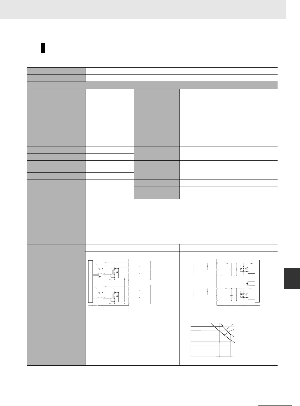
A-45
Appendices
CJ2 CPU Unit Hardware User’s Manual
A-1 Specifications of Basic I/O Units App A-1-2 Basic I/O Units
zCJ1W-MD231 DC Input/Transistor Output Unit (24 VDC, 16 Inputs/16 Outputs)
Mixed I/O Units
Name 16-point DC Input/16-point Transistor Output Unit with Fujitsu Connectors (Sinking Outputs)
Model CJ1W-MD231
Output section (CN1) Input section (CN2)
Rated Voltage 12 to 24 VDC Rated Input Voltage 24 VDC
Operating Load Voltage
Range
10.2 to 26.4 VDC Operating Input Volt-
age
20.4 to 26.4 VDC
Maximum Load Current 0.5 A/point, 2.0 A/Unit Input Impedance 3.3 kΩ
Maximum Inrush Current 4.0 A/point, 10 ms max. Input Current 7 mA typical (at 24 VDC)
Leakage Current 0.1 mA max. ON Voltage/ON Cur-
rent
14.4 VDC min./3 mA min.
Residual Voltage 1.5 V max. OFF Voltage/OFF
Current
5 VDC max./1 mA max.
ON Response Time 0.1 ms max. ON Response Time 8.0 ms max. (Can be set to between 0 and 32 in the
PLC Setup.)*1
OFF Response Time 0.8 ms max.
No. of Circuits 16 (16 points/common,
1circuit) OFF Response Time
8.0 ms max. (Can be set to between 0 and 32 in the
PLC Setup.)*1
Fuse None
External Power Supply
12 to 24 VDC, 20 mA
min.
No. of Circuits 16 (16 points/common, 1 circuit)
Number of Simulta-
neously ON Points
75% (at 24 VDC)
Insulation Resistance 20 MΩ between the external terminals and the GR terminal (at 100 VDC)
Dielectric Strength 1,000 VAC between the external terminals and the GR terminal for 1 minute at a leakage current of 10 mA
max.
Internal Current Consump-
tion
5 VDC 130 mA max.
Weight 90 g max.
Accessories None
Circuit Configuration
CN1 (OUT) CN2 (IN)
OUT0
+V
OUT7
OUT8
+V
OUT15
COM0
COM0
Internal circuits
Output
indicator
to
to
Wd m
Wd m
Allocated
CIO word
Signal
name
Connect
or row A
Connect
or row B
IN8
IN15
COM1
IN0
IN7
COM1
3.3 kΩ
3.3 kΩ
1000 pF
470 Ω
1000 pF
470 Ω
to
to
Input indicator
Internal circuits
Wd m+1
Wd m+1
Allocated
CIO word Signal
name
Connect
or row A
Connect
or row B
0
2
4
6
8
10
12
14
16
18
0 20 40 60
(°C)
Number of Simultaneously ON Points vs.
Ambient Temperature Characteristic
16 points at 33°C16 points at 45°C
Number of simultaneously ON points
Input voltage: 24 VDC
Input voltage: 26.4 VDC
12 points at 55°C
9 points at 55°C
Ambient Temperature
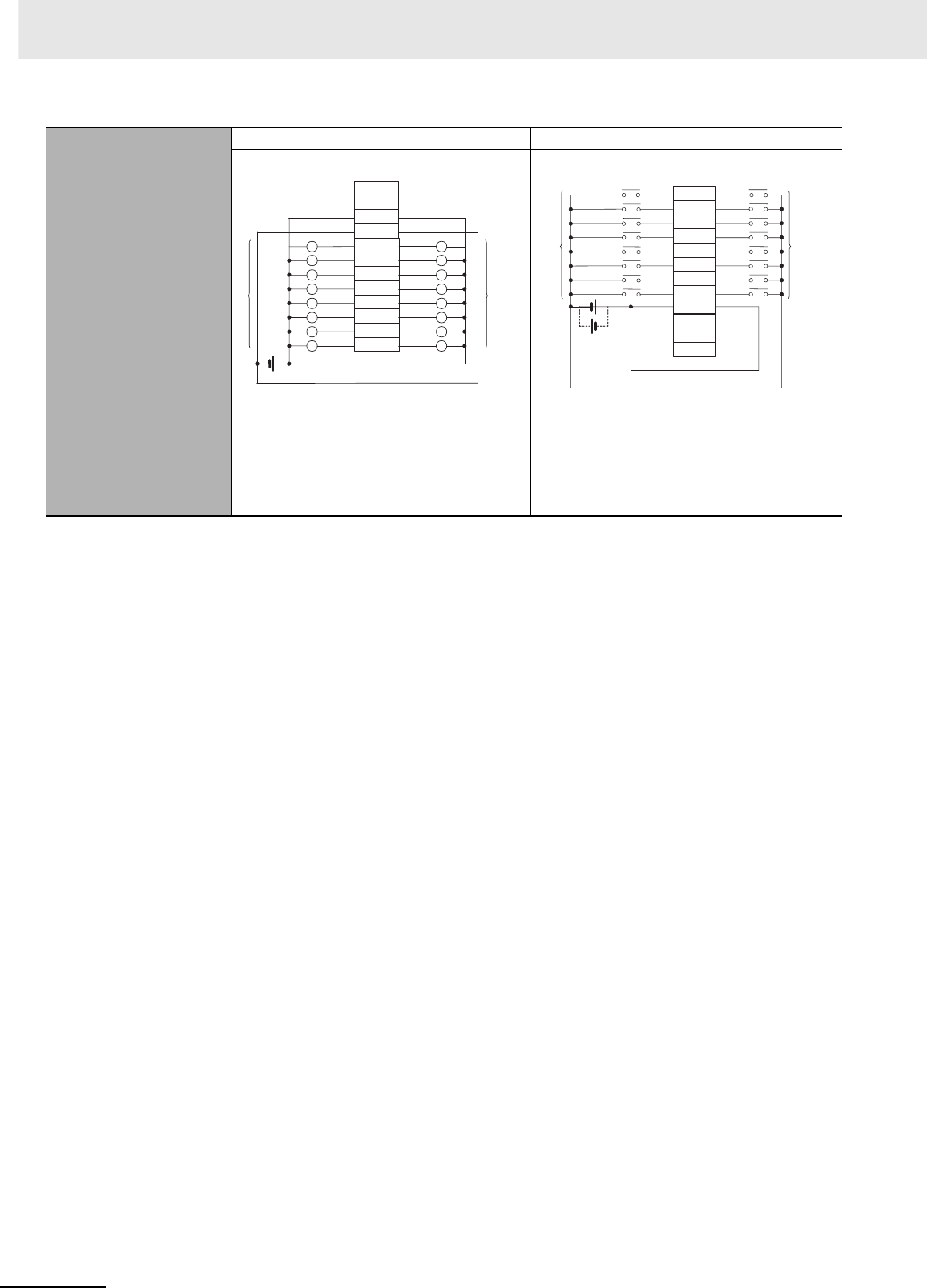
Appendices
A-46 CJ2 CPU Unit Hardware User’s Manual
*1 The ON response time will be 20 µs maximum and OFF response time will be 400 µs maximum even if the response
times are set to 0 ms due to internal element delays.
Terminal Connections
CN1 (OUT) CN2 (IN)
• When wiring, pay careful attention to the polarity
of the external power supply. The load may oper-
ate incorrectly if polarity is reversed.
• Be sure to wire both pins A9 and B9 (COM0
(0 V)) of CN1.
• Be sure to wire both pins A10 and B10 (+V) of
CN1.
• When wiring, pay careful attention to the polarity of
the external power supply. The load may operate
incorrectly if polarity is reversed.
• Be sure to wire both pins A9 and B9 (COM1) of
CN2, and set the same polarity for both pins.
A1
A2
A3
A4
A5
A6
A7
A8
OUT0
OUT1
OUT2
OUT3
OUT4
OUT5
OUT6
OUT7
A9
A10
A11
A12
NC
NC
COM0 (0V)
+V
B1
B2
B3
B4
B5
B6
B7
B8
B9
OUT9
OUT10
OUT11
OUT12
OUT13
OUT14
OUT15
OUT8
B10
B11
B12
L
L
L
L
L
L
L
L
L
L
L
L
L
L
L
L
NC
COM0 (0V)
+V
NC
12 to
24
VDC
Wd m
Wd m
Signal
name Signal
name
Connec-
tor pin
Allocated
CIO word
Allocated
CIO word
B12
B11
B10
B9
B8
B7
B6
B5
IN15
IN14
IN13
IN12
IN11
IN10
IN9
IN8
B4
B3
B2
B1
A12
A11
A10
A9
A8
A7
A6
A5
A4
IN6
IN5
IN4
IN3
IN2
IN1
IN0
IN7
A3
A2
A1
NC
COM1
NC
NC
NC
NC
COM1
NC
24 VDC
Wd m+1
Wd m+1
Signal
name Signal
name
Connec-
tor pin
Allocated
CIO word
Allocated
CIO word
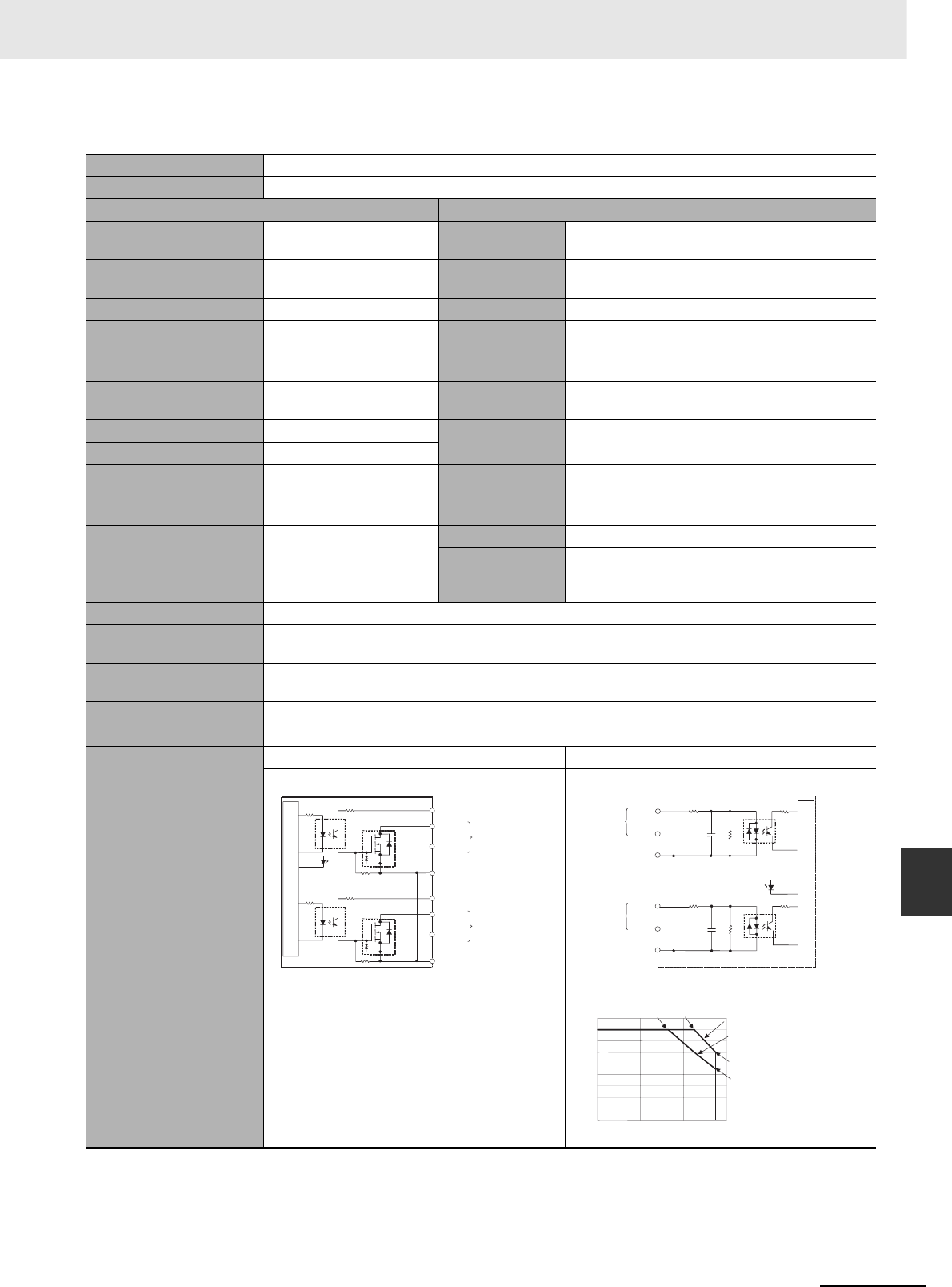
A-47
Appendices
CJ2 CPU Unit Hardware User’s Manual
A-1 Specifications of Basic I/O Units App A-1-2 Basic I/O Units
zCJ1W-MD233 DC Input/Transistor Output Unit (24 VDC, 16 Inputs/16 Outputs)
Name 16-point DC Input/16-point Transistor Output Unit with MIL Connectors (Sinking Outputs)
Model CJ1W-MD233
Output section (CN1) Input section (CN2)
Rated Voltage 12 to 24 VDC Rated Input Volt-
age
24 VDC
Operating Load Voltage
Range
10.2 to 26.4 VDC Operating Input
Voltage
20.4 to 26.4 VDC
Maximum Load Current 0.5 A/point, 2.0 A/Unit Input Impedance 3.3 kΩ
Maximum Inrush Current 4.0 A/point, 10 ms max. Input Current 7 mA typical (at 24 VDC)
Leakage Current 0.1 mA max. ON Voltage/ON
Current
14.4 VDC min./3 mA min.
Residual Voltage 1.5 V max. OFF Voltage/OFF
Current
5 VDC max./1 mA max.
ON Response Time 0.1 ms max. ON Response
Time
8.0 ms max. (Can be set to between 0 and 32 in the
PLC Setup.)*1
OFF Response Time 0.8 ms max.
No. of Circuits 16 (16 points/common,
1circuit) OFF Response
Time
8.0 ms max. (Can be set to between 0 and 32 in the
PLC Setup.)*1
Fuse None
External Power Supply
12 to 24 VDC, 20 mA min. No. of Circuits 16 (16 points/common, 1 circuit)
Number of Simul-
taneously ON
Points
75% (at 24 VDC)
Insulation Resistance 20 MΩ between the external terminals and the GR terminal (at 100 VDC)
Dielectric Strength 1,000 VAC between the external terminals and the GR terminal for 1 minute at a leakage current of 10 mA
max.
Internal Current Consump-
tion
5 VDC 130 mA max.
Weight 90 g max.
Accessories None
Circuit Configuration
CN1 (OUT) CN2 (IN)
OUT0
+V
OUT7
OUT8
+V
OUT15
COM0
COM0
Internal circuits
to
to
Output
indicator
Wd m
Wd m
Allocated
CIO word
Signal
name
IN0
IN7
COM1
IN8
IN15
COM1
Wd m+1
Wd m+1
3.3 kΩ
3.3 kΩ
1000 pF
470
Ω
1000 pF
470
Ω
to
to
Input indicator
Internal circuits
Allocated
CIO word Signal
name
0
2
4
6
8
10
12
14
16
18
0 20 40 60 (°C)
Number of Simultaneously ON Points vs.
Ambient Temperature Characteristic
Number of simultaneously ON points
Ambient Temperature
Input voltage: 24 VDC
Input voltage: 26.4 VDC
12 points at 55°C
9 points at 55°C
16 points at 33°C16 points at 45°C
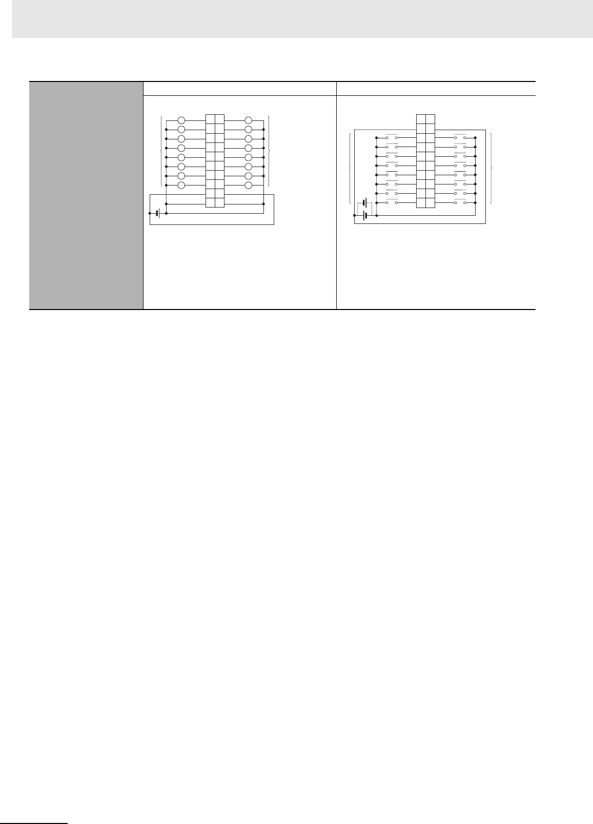
Appendices
A-48 CJ2 CPU Unit Hardware User’s Manual
*1 The ON response time will be 20 µs maximum and OFF response time will be 400 µs maximum even if the response
times are set to 0 ms due to internal element delays.
Terminal Connections
CN1 (OUT) CN2 (IN)
• When wiring, pay careful attention to the polarity
of the external power supply. The load may oper-
ate incorrectly if polarity is reversed.
• Be sure to wire both terminals 3 and 4 (COM0
(0 V)) of CN1.
• Be sure to wire both terminals 1 and 2 (+V) of
CN1.
• When wiring, pay careful attention to the polarity of
the external power supply. The load may operate
incorrectly if polarity is reversed.
• Be sure to wire both pins 3 and 4 (COM1) of CN2,
and set the same polarity for both pins.
1
3
5
7
9
11
13
15
OUT15
OUT14
OUT13
OUT12
OUT11
OUT10
OUT9
OUT8
17
19
COM0 (0V)
+V
2
4
6
8
10
12
14
16
18
OUT6
OUT5
OUT4
OUT3
OUT2
OUT1
OUT0
OUT7
20
COM0 (0V)
+V
L
L
L
L
L
L
L
L
L
L
L
L
L
L
L
L
12 to
24 VDC
Wd m
Wd m
Signal
name Signal
name
Connec-
tor pin
Allocated
CIO word Allocated
CIO word
20
18
16
14
12
10
8
6
4
2
19
17
15
13
11
9
7IN6
IN5
IN4
IN3
IN2
IN1
IN0
IN7
5
3
1
IN15
IN14
IN13
IN12
IN11
IN10
IN9
IN8
COM1
NC
COM1
NC
24 VDC
Wd m+1
Wd m+1
Signal
name Signal
name
Connec-
tor pin
Allocated
CIO word
Allocated
CIO word
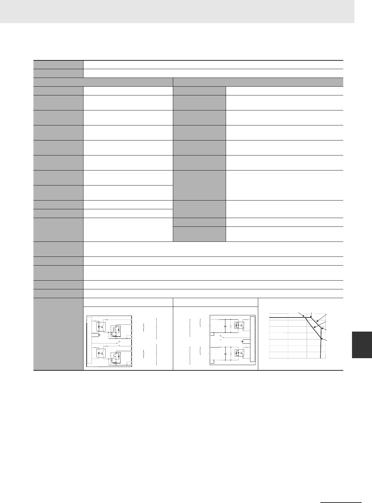
A-49
Appendices
CJ2 CPU Unit Hardware User’s Manual
A-1 Specifications of Basic I/O Units App A-1-2 Basic I/O Units
zCJ1W-MD261 DC Input/Transistor Output Unit (24 VDC 32 Inputs/32 Outputs)
Name 32-point DC Input/32-point Transistor Output Unit with Fujitsu Connectors (Sinking Outputs)
Model CJ1W-MD261
Output section (CN1) Input section (CN2)
Rated Voltage 12 to 24 VDC Rated Input Voltage 24 VDC
Operating Load
Volt age Range
10.2 to 26.4 VDC Operating Input
Voltage
20.4 to 26.4 VDC
Maximum Load
Current
0.3 A/point, 1.6 A/common, 3.2 A/Unit Input Impedance 5.6 kΩ
Maximum Inrush
Current
3.0 A/point, 10 ms max. Input Current 4.1 mA typical (at 24 VDC)
Leakage Current 0.1 mA max. ON Voltage/ON Cur-
rent
19.0 VDC min./3 mA min. *2
Residual Voltage 1.5 V max. OFF Voltage/OFF
Current
5 VDC max./1 mA max.
ON Response
Time
0.5 ms max.
ON Response Time
8.0 ms max. (Can be set to between 0 and 32 in
the PLC Setup.)*1
OFF Response
Time
1.0 ms max.
No. of Circuits 32 (16 points/common, 2 circuits) OFF Response
Time
8.0 ms max. (Can be set to between 0 and 32 in
the PLC Setup.)*1
Fuse None
External Power
Supply
12 to 24 VDC, 30 mA min. No. of Circuits 32 (16 points/common, 2 circuits)
Number of Simulta-
neously ON Points
75% (24 points) (at 24 VDC)
Insulation Resis-
tance
20 MΩ between the external terminals and the GR terminal (at 100 VDC)
Dielectric Strength 1,000 VAC between the external terminals and the GR terminal for 1 minute at a leakage current of 10 mA max.
Internal Current
Consumption
5 VDC 140 mA max.
Weight 110 g max.
Accessories None
Circuit Configura-
tion
CN1 (OUT) CN2 (IN)
0
5
10
15
20
25
30
35
0 20 40 60 (°C)
Number of Simultaneously ON Points vs.
Ambient Temperature Characteristic
Number of simultaneously ON points
32 points at 38°C32 points at 44°C
Ambient Temperature
Input voltage:
24 VDC
Input voltage:
26.4 VDC
12 points/
common
at 55°C
8 points/
common
at 55°C
OUT0
+V
OUT15
COM0
OUT0
+V
OUT15
COM1
COM0
COM1
Internal circuits
to
to
Output
indicator Indicator
switch
Wd m
Wd
m+1
Allocated
CIO word
Signal
name
Connect
or row A
Connect
or row B
IN0
IN15
COM2
IN0
IN15
COM3
COM2
COM3
5.6 kΩ
560
Ω
1000 pF
5.6 kΩ
560
Ω
1000 pF
to
to
Indicator switch
Input indicator
Internal circuits
Wd
m+2
Wd
m+3
Allocated
CIO word Signal
name
Connect
or row A
Connect
or row B
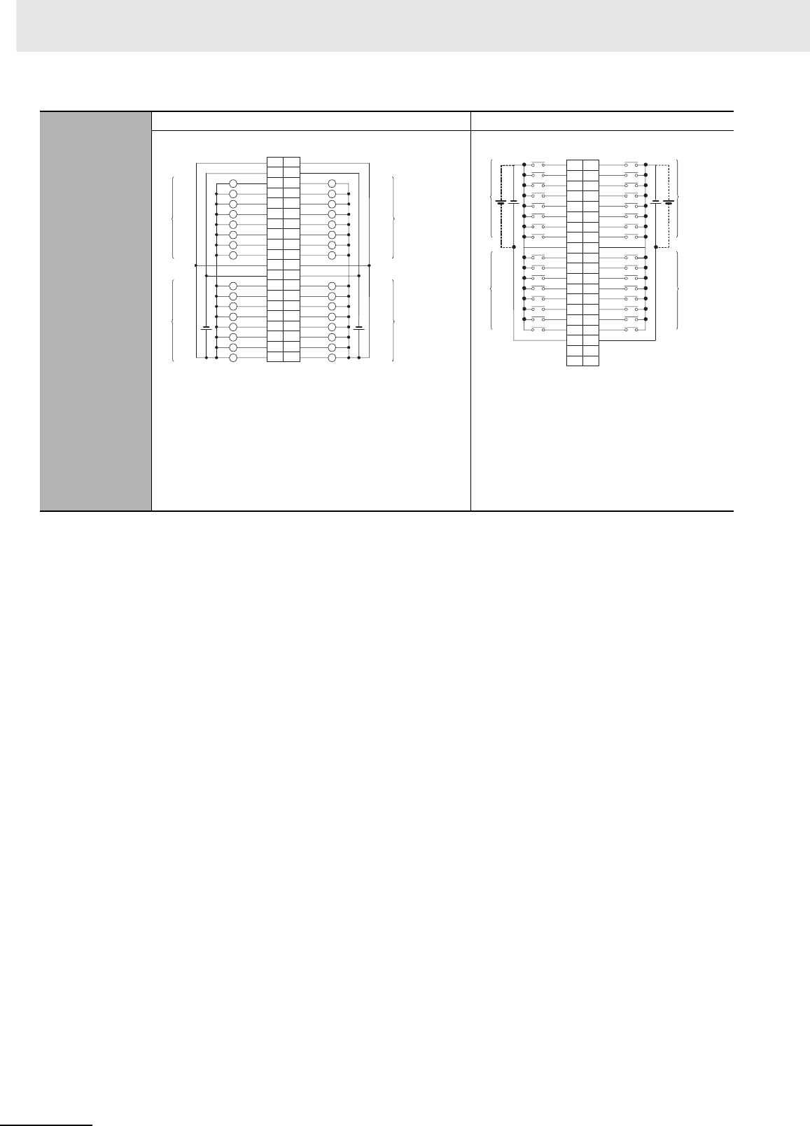
Appendices
A-50 CJ2 CPU Unit Hardware User’s Manual
*1 The ON response time will be 120 µs maximum and OFF response time will be 400 µs maximum even if the response
times are set to 0 ms due to internal element delays.
*2 Observe the following restrictions when connecting to a 2-wire sensor.
• Make sure the input power supply voltage is larger than the ON voltage (19 V) plus the residual voltage of the sen-
sor (approx. 3 V).
• Use a sensor with a minimum load current of 3 mA min.
• Connect bleeder resistance if you connect a sensor with a minimum load current of 5 mA or higher.
Terminal Connec-
tions
CN1 (OUT) CN2 (IN)
• Be sure to wire both terminals A19 and A9 (COM0 (0 V)) of
CN1.
• Be sure to wire both terminals B19 and B9 (COM1 (0 V)) of
CN1.
• Be sure to wire both terminals A20 and A10 (+V) of CN1.
• Be sure to wire both terminals B20 and B10 (+V) of CN1.
• When wiring, pay careful attention to the polarity of the exter-
nal power supply. The load may operate incorrectly if polarity
is reversed.
• Be sure to wire both pins A9 and A18 (COM2) of
CN2, and set the same polarity for both pins.
• Be sure to wire both pins B9 and B18 (COM3) of
CN2, and set the same polarity for both pins.
• When wiring, pay careful attention to the polarity
of the external power supply. The load may oper-
ate incorrectly if polarity is reversed.
A1
A2
A3
A4
A5
A6
A7
A8
OUT0
OUT1
OUT2
OUT3
OUT4
OUT5
OUT6
OUT7
A9
A10
A11
A12
A13
A14
A15
A16
A17
A18
OUT8
OUT9
OUT10
OUT11
OUT12
OUT13
OUT14
OUT15
A19
A20
B1
B2
B3
B4
B5
B6
B7
B8
OUT0
OUT1
OUT2
OUT3
OUT4
OUT5
OUT6
OUT7 B9
B10 +V
+V B11
B12
B13
B14
B15
B16
B17
B18
OUT8
OUT9
OUT10
OUT11
OUT12
OUT13
OUT14
OUT15 B19 COM0 (0V) COM1 (0V) B20 +V +V
L
L
L
L
L
L
L
L
L
L
L
L
L
L
L
L
L
L
L
L
L
L
L
L
L
L
L
L
L
L
L
L
COM0 (0V) COM1 (0V)
Wd m+1
Wd m
Wd m+1
12 to
24
VDC
Wd m
12 to
24
VDC
Signal
name Signal
name
Connec-
tor pin
Allocated
CIO word
Allocated
CIO word
B1 IN0
B2 IN1
B3 IN2
B4 IN3
B5 IN4
B6 IN5
B7 IN6
B8 IN7
B9
B10 IN8
B11 IN9
B12 IN10
B13 IN11
B14 IN12
B15 IN13
B16 IN14
B17 IN15
B18
B19 NC
B20 NC
A1
IN0
A2
IN1
A3
IN2
A4
IN3
A5
IN4
A6
IN5
A7
IN6
A8
IN7
A9
A10
IN8
A11
IN9
A12
IN10
A13
IN11
A14
IN12
A15
IN13
A16
IN14
A17
IN15
COM2 COM3
COM2 COM3
A18
A19
NC
A20
NC
Wd m+2
Wd m+3
Wd m+2
Wd m+3
24
VDC 24
VDC
Signal
name Signal
name
Connec-
tor pin
Allocated
CIO word
Allocated
CIO word

A-51
Appendices
CJ2 CPU Unit Hardware User’s Manual
A-1 Specifications of Basic I/O Units App A-1-2 Basic I/O Units
zCJ1W-MD263 DC Input/Transistor Output Unit (24 VDC 32 Inputs/32 Outputs)
Name 32-point DC Input/32-point Transistor Output Unit with MIL Connectors (Sinking Outputs)
Model CJ1W-MD263
Output section (CN1) Input section (CN2)
Rated Voltage 12 to 24 VDC Rated Input Voltage 24 VDC
Operating Load
Volt age Range
10.2 to 26.4 VDC Operating Input
Voltage
20.4 to 26.4 VDC
Maximum Load
Current
0.3 A/point, 1.6 A/common, 3.2 A/Unit Input Impedance 5.6 kΩ
Maximum Inrush
Current
3.0 A/point, 10 ms max. Input Current 4.1 mA typical (at 24 VDC)
Leakage Current 0.1 mA max. ON Voltage/ON Cur-
rent
19.0 VDC min./3 mA min.*2
Residual Voltage 1.5 V max. OFF Voltage/OFF
Current
5 VDC max./1 mA max.
ON Response
Time
0.5 ms max.
ON Response Time
8.0 ms max. (Can be set to between 0 and 32 in
the PLC Setup.)*1
OFF Response
Time
1.0 ms max.
No. of Circuits 32 (16 points/common, 2 circuits) OFF Response Time 8.0 ms max. (Can be set to between 0 and 32 in
the PLC Setup.)*1
Fuse None
External Power
Supply
12 to 24 VDC, 30 mA min. No. of Circuits 32 (16 points/common, 2 circuits)
Number of Simulta-
neously ON Points
75% (24 points) (at 24 VDC)
Insulation Resis-
tance
20 MΩ between the external terminals and the GR terminal (at 100 VDC)
Dielectric Strength 1,000 VAC between the external terminals and the GR terminal for 1 minute at a leakage current of 10 mA max.
Internal Current
Consumption
5 VDC 140 mA max.
Weight 110 g max.
Accessories None
Circuit Configura-
tion
CN1 (OUT) CN2 (IN)
0
5
10
15
20
25
30
35
0 20 40 60 (°C)
Number of Simultaneously ON Points vs.
Ambient Temperature Characteristic
Number of simultaneously ON points
32 points at 38°C32 points at 44°C
Ambient Temperature
Input voltage:
24 VDC
Input voltage:
26.4 VDC
12 points/
common
at 55°C
8 points/
common
at 55°C
OUT0
+V
OUT15
COM0
OUT0
+V
OUT15
COM1
COM0
COM1
Internal circuits
Output
indicator Indicator
switch
to
to
Wd m
Wd m+1
Allocated
CIO word
Signal
name
IN0
IN15
COM2
IN0
IN15
COM3
COM2
COM3
5.6 kΩ
560 Ω
1000 pF
5.6 kΩ
560 Ω
1000 pF
Internal circuits
Indicator switch
Input indicator
to
to
Wd m+2
Wd m+3
Allocated
CIO word
Signal
name
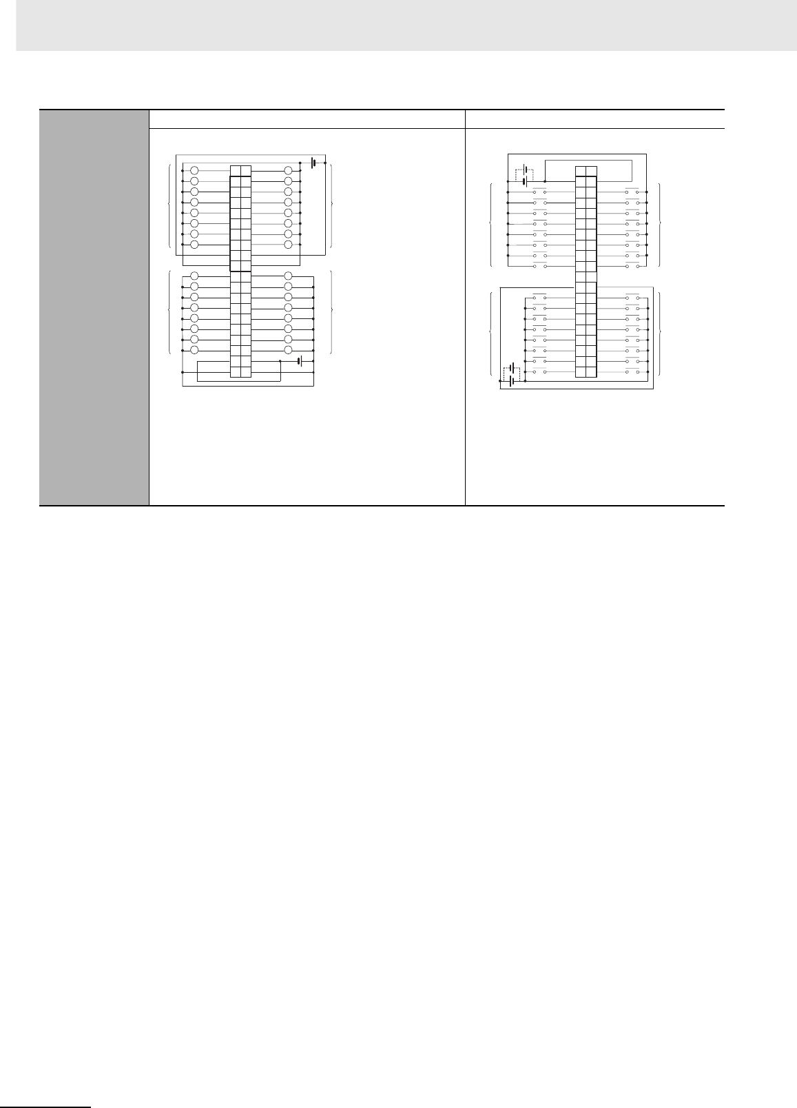
Appendices
A-52 CJ2 CPU Unit Hardware User’s Manual
*1 The ON response time will be 120 µs maximum and OFF response time will be 400 µs maximum even if the response
times are set to 0 ms due to internal element delays.
Note Observe the following restrictions when connecting to a 2-wire sensor.
• Make sure the input power supply voltage is larger than the ON voltage (19 V) plus the residual voltage of the sen-
sor (approx. 3 V).
• Use a sensor with a minimum load current of 3 mA min.
• Connect bleeder resistance if you connect a sensor with a minimum load current of 5 mA or higher.
Terminal Connec-
tions
CN1 (OUT) CN2 (IN)
• Be sure to wire both terminals 23 and 24 (COM0) of CN1.
• Be sure to wire both terminals 3 and 4 (COM1) of CN1.
• Be sure to wire both terminals 21 and 22 (+V) of CN1.
• Be sure to wire both terminals 1 and 2 (+V) of CN1.
• When wiring, pay careful attention to the polarity of the exter-
nal power supply. The load may operate incorrectly if polarity
is reversed.
• Be sure to wire both pins 23 and 24 (COM2) of
CN2, and set the same polarity for both pins.
• Be sure to wire both pins 3 and 4 (COM3) of
CN2, and set the same polarity for both pins.
• When wiring, pay careful attention to the polarity
of the external power supply. The load may oper-
ate incorrectly if polarity is reversed.
1+V
3
5OUT15
7OUT14
9OUT13
11 OUT12
13 OUT11
15 OUT10
17
19
OUT2
21
23
25
27 OUT15
29 OUT14
31 OUT13
33 OUT12
35 OUT11
37
+V
39
2
4
+V
6
8
OUT7
10
OUT6
12
OUT5
14
OUT4
16
OUT3
18
COM1
20
22
24
26
28
30
OUT10
32
34
36
38
40
COM1
+V
OUT0
OUT7
OUT6
OUT5
OUT4
OUT3
OUT2
OUT1
COM0
OUT8
OUT9
COM0
OUT8
OUT9
OUT0
OUT1
L
L
L
L
L
L
L
L
L
L
L
L
L
L
L
L
L
L
L
L
L
L
L
L
L
L
L
L
L
L
L
L
Wd m
Wd m+1
12 to
24 VDC
12 to
24
VDC
Wd m
Wd m+1
Signal
name Signal
name
Connec-
tor pin
Allocated
CIO word
Allocated
CIO word
40 IN0
38 IN1
36 IN2
34 IN3
32 IN4
30 IN5
28 IN6
26 IN7
24
22
IN15
20
18 IN0
16 IN1
14 IN2
12 IN3
10 IN4
8IN5
6IN6
4
NC
2COM3
39
37
IN8
35
IN9
33
IN10
31
IN11
29
IN12
27
IN13
25
IN14
23
COM2 21
IN8
NC NC
19
IN9 17
IN10 15
IN11 13
IN12 11
IN7
9
IN13 7
IN14 5
IN15 3
NC 1
COM3
COM2
24 VDC
Wd m+3
Wd m+2
24 VDC
Wd m+3
Wd m+2
Signal
name Signal
name
Connec-
tor pin Allocated
CIO word
Allocated
CIO word
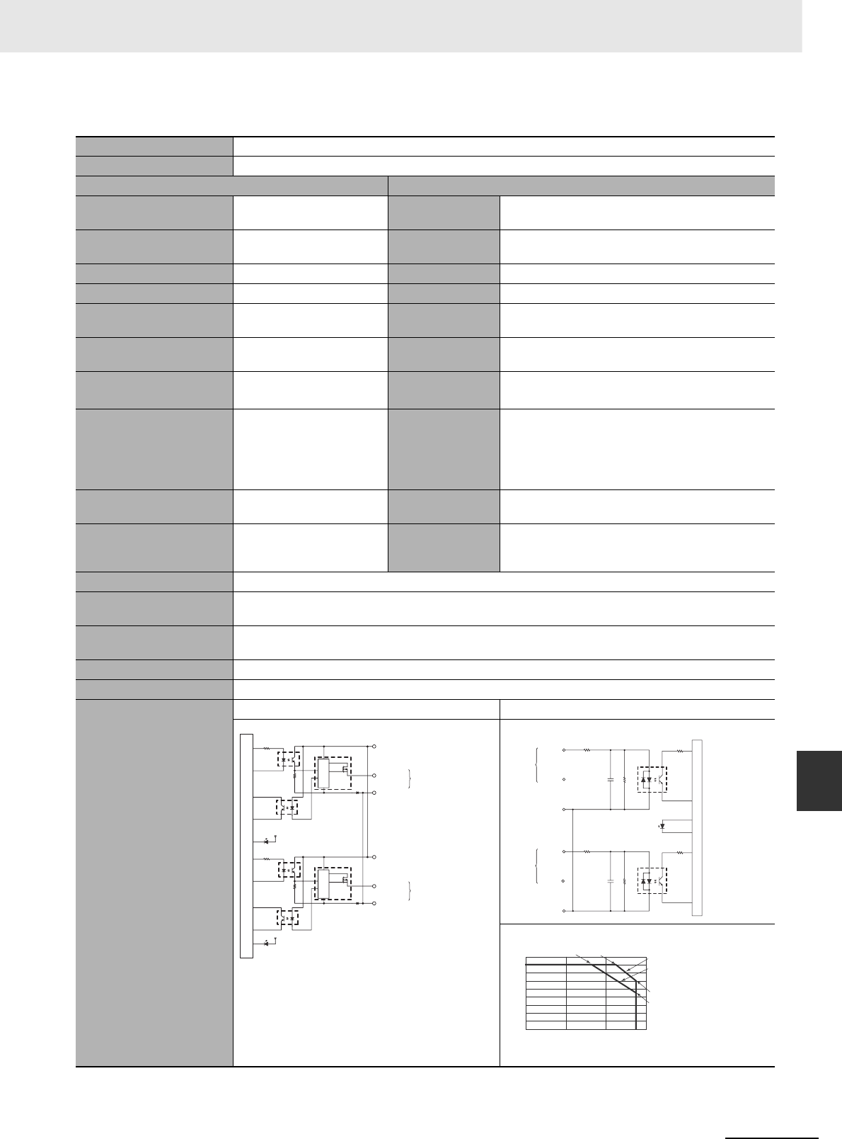
A-53
Appendices
CJ2 CPU Unit Hardware User’s Manual
A-1 Specifications of Basic I/O Units App A-1-2 Basic I/O Units
zCJ1W-MD232 DC Input/Transistor Output Unit (24 VDC, 16 inputs/16 Outputs)
Name 16-point DC Input/16-point Transistor Output Unit with MIL Connectors (Sourcing Outputs)
Model CJ1W-MD232
Output section (CN1) Input section (CN2)
Rated Voltage 24 VDC Rated Input Volt-
age
24 VDC
Operating Load Voltage
Range
20.4 to 26.4 VDC Operating Input
Voltage
20.4 to 26.4 VDC
Maximum Load Current 0.5 A/point, 2.0 A/Unit Input Impedance 3.3 kΩ
Leakage Current 0.1 mA max. Input Current 7 mA typical (at 24 VDC)
Residual Voltage 1.5 V max. ON Voltage/ON
Current
14.4 VDC min./3 mA min.
ON Response Time 0.5 ms max. OFF Voltage/OFF
Current
5 VDC max./1 mA max.
OFF Response Time 1.0 ms max. ON Response
Time
8.0 ms max. (Can be set to between 0 and 32 in the
PLC Setup.)*1
Load Short-circuit Protec-
tion
Detection current: 0.7 to
2.5 A min.
Automatic restart after error
clearance. (Refer to page A-
149.)
OFF Response
Time
8.0 ms max. (Can be set to between 0 and 32 in the
PLC Setup.)*1
No. of Circuits 16 (16 points/common,
1circuit) No. of Circuits 16 (16 points/common, 1 circuit)
External Power Supply
20.4 to 26.4 VDC, 40 mA
min.
Number of Simul-
taneously ON
Points
75% (at 24 VDC)
Insulation Resistance 20 MΩ between the external terminals and the GR terminal (at 100 VDC)
Dielectric Strength 1,000 VAC between the external terminals and the GR terminal for 1 minute at a leakage current of 10 mA
max.
Internal Current Consump-
tion
5 VDC 130 mA max.
Weight 100 g max.
Accessories None
Circuit Configuration
CN1 (OUT) CN2 (IN)
COM0 (+V)
OUT0
OUT7
0 V
COM0 (+V)
0 V
OUT8
OUT15
to
ERR indicator
Output indicator
Internal circuits
Short-circuit
Protection
to Wd m
Wd m
Short-circuit
Protection
Allocated
CIO word
Signal
name
COM1
IN0
IN7
COM1
IN8
IN15
470 Ω
3.3 kΩ
1000 pF
Input indicator
to
to
Internal circuits
470 Ω
3.3 kΩ
1000 pF
Wd m+1
Wd m+1
Allocated
CIO word Signal
name
0
2
4
6
8
10
12
14
16
18
604020
0(°C)
Number of Simultaneously ON Points vs.
Ambient Temperature Characteristic
Number of simultaneously ON points
16 points at 33°C16 points at 45°C
Ambient Temperature
Input voltage:
24 VDC
Input voltage:
26.4 VDC
12 points at 55°C
9 points at 55°C
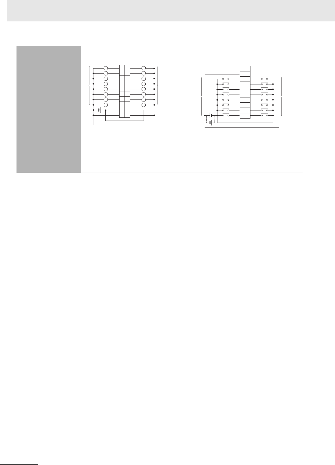
Appendices
A-54 CJ2 CPU Unit Hardware User’s Manual
*1 The ON response time will be 20 µs maximum and OFF response time will be 400 µs maximum even if the response
times are set to 0 ms due to internal element delays.
Terminal Connections
CN1 (OUT) CN2 (IN)
• When wiring, pay careful attention to the polarity
of the external power supply. The load may oper-
ate incorrectly if polarity is reversed.
• Be sure to wire both terminals 3 and 4 (COM0
(+V)) of CN1.
• Be sure to wire both terminals 1 and 2 ((0 V)) of
CN1.
• When wiring, pay careful attention to the polarity of
the external power supply. The load may operate
incorrectly if polarity is reversed.
• Be sure to wire both pins 3 and 4 (COM1) of CN2,
and set the same polarity for both pins.
1
3
5
7
9
11
13
15
OUT15
OUT14
OUT13
OUT12
OUT11
OUT10
OUT9
OUT8
17
19
COM0 (+V)
0 V
2
4
6
8
10
12
14
16
18
OUT6
OUT5
OUT4
OUT3
OUT2
OUT1
OUT0
OUT7
20
COM0 (+V)
0 V
L
L
L
L
L
L
L
L
L
L
L
L
L
L
L
L
24 VDC
Wd m
Wd m
Allocated
CIO word
Signal
name
Signal
name Allocated
CIO word
Connec-
tor pin
20
18
16
14
12
10
8
6
4
2
19
17
15
13
11
9
7IN6
IN5
IN4
IN3
IN2
IN1
IN0
IN7
5
3
1
IN15
IN14
IN13
IN12
IN11
IN10
IN9
IN8
COM1
NC
COM1
NC
24 VDC
Wd m+1
Wd m+1
Allocated
CIO word
Signal
name
Signal
name Allocated
CIO word
Connec-
tor pin
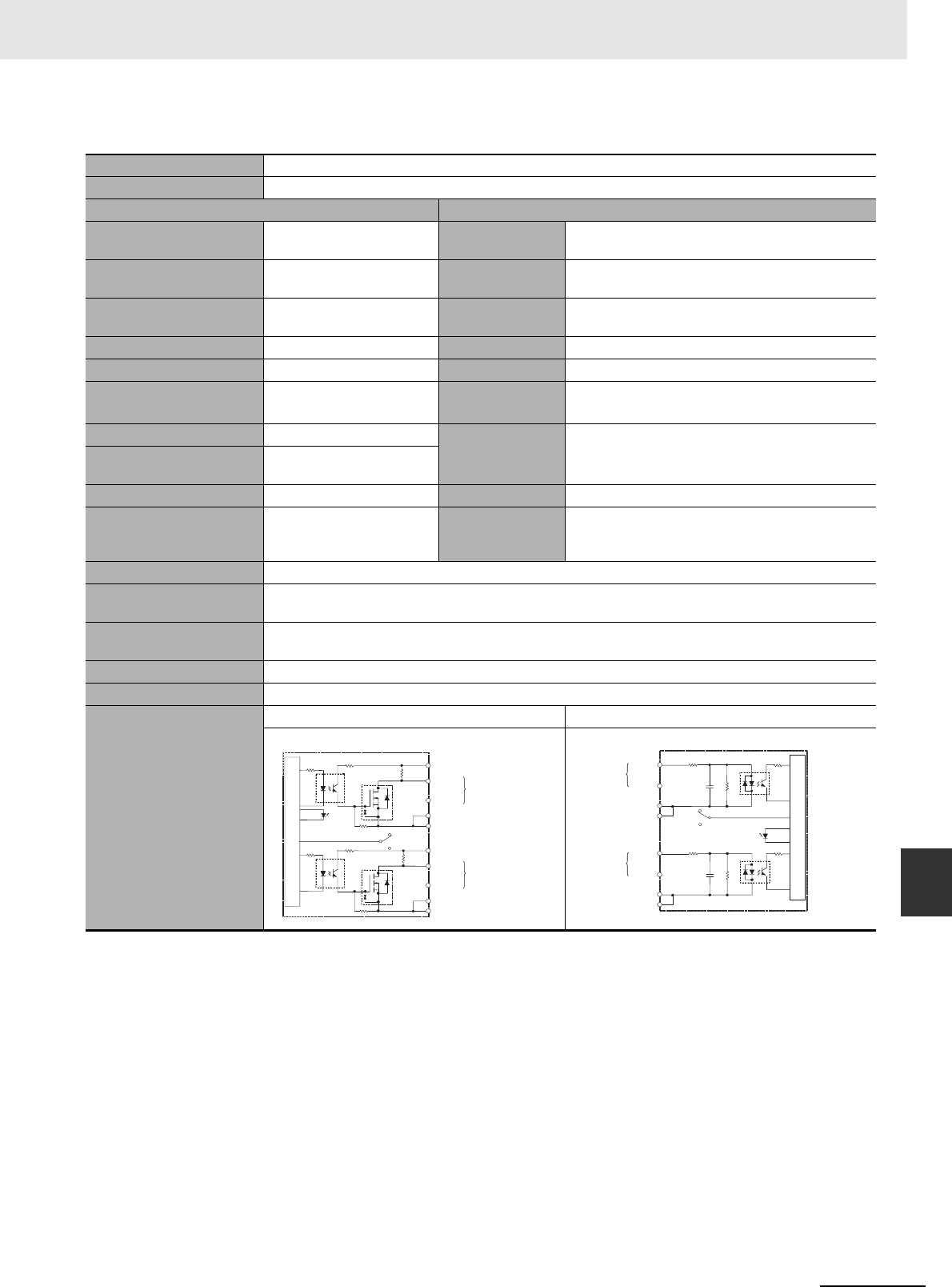
A-55
Appendices
CJ2 CPU Unit Hardware User’s Manual
A-1 Specifications of Basic I/O Units App A-1-2 Basic I/O Units
zCJ1W-MD563 TTL I/O Unit (32 Inputs/32 Outputs)
Name 32-point Input /32-point Output TTL I/O Unit with MIL Connectors
Model CJ1W-MD563
Output section (CN1) Input section (CN2)
Rated Voltage 5 VDC±10% Rated Input Volt-
age
5 VDC±10%
Operating Load Voltage
Range
4.5 to 5.5 VDC Input Impedance 1.1 kΩ
Maximum Load Current 35 mA/point, 560 mA/com-
mon, 1.12 A/Unit Input Current Approx. 3.5 mA (at 5 VDC)
Leakage Current 0.1 mA max. ON Voltage 3.0 VDC min.
Residual Voltage 0.4 V max. OFF Voltage 1.0 VDC max.
ON Response Time 0.2 ms max. ON Response
Time
8.0 ms max. (Can be set to between 0 and 32 in the
PLC Setup.)*1
OFF Response Time 0.3 ms max. OFF Response
Time
8.0 ms max. (Can be set to between 0 and 32 in the
PLC Setup.)*1
No. of Circuits 32 points (16 points/com-
mon, 2 circuits)
Fuse None No. of Circuits 32 points (16 points/common, 2 circuits)
External Power Supply
5 VDC±10%, 40 mA min.
(1.2 mA × No. of ON points)
Number of Simul-
taneously ON
Points
100% (16 points/common)
Insulation Resistance 20 MΩ between the external terminals and the GR terminal (at 100 VDC)
Dielectric Strength 1,000 VAC between the external terminals and the GR terminal for 1 minute at a leakage current of 10 mA
max.
Internal Current Consump-
tion
5 VDC 190 mA max.
Weight 110 g max.
Accessories None
Circuit Configuration
CN1 (OUT) CN2 (IN)
OUT0
+V
OUT15
COM0
OUT0
+V
OUT15
COM1
COM0
COM1
5.6 k
Ω
5.6 k
Ω
Output
indicator Indicator
switch
Internal circuits
to
to
Wd m
Wd m+1
Allocated
CIO word
Signal
name
IN0
IN15
COM2
IN0
IN15
COM3
COM2
COM3
to
Indicator switch
Input indicator
Internal circuits
to
1.1 kΩ
2.2 k
Ω
1000 pF
1.1 kΩ
2.2 k
Ω
1000 pF
Wd m+2
Wd m+3
Allocated
CIO word Signal
name
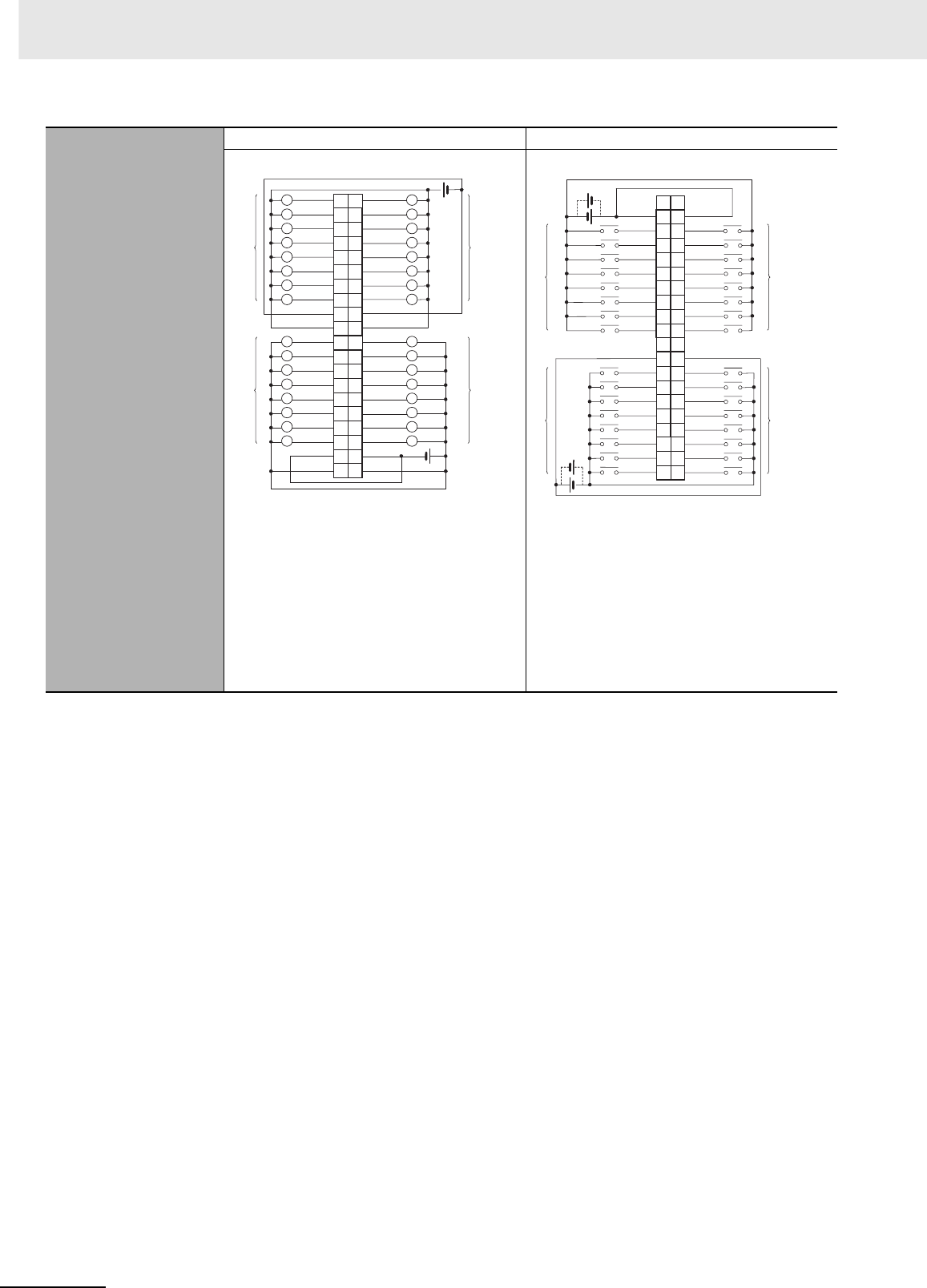
Appendices
A-56 CJ2 CPU Unit Hardware User’s Manual
*1 The ON response time will be 120 µs maximum and OFF response time will be 400 µs maximum even if the response
times are set to 0 ms due to internal element delays.
Terminal Connections
CN1 (OUT) CN2 (IN)
• When wiring, pay careful attention to the polarity
of the external power supply. The load may oper-
ate incorrectly if the polarity is reversed.
• Be sure to wire both terminals 23 and 24 (COM0)
of CN1.
• Be sure to wire both terminals 3 and 4 (COM1) of
CN1.
• Be sure to wire both terminals 21 and 22 (+V) of
CN1.
• Be sure to wire both terminals 1 and 2 (+V) of
CN1.
• When wiring, pay careful attention to the polarity of
the external power supply. The load may operate
incorrectly if the polarity is reversed.
• Be sure to wire both pins 23 and 24 (COM2) of
CN2, and set the same polarity for both pins.
• Be sure to wire both pins 3 and 4 (COM3) of CN2,
and set the same polarity for both pins.
1+V
3
5OUT15
7OUT14
9OUT13
11 OUT12
13 OUT11
15 OUT10
17
19
OUT2
21
23
25
27
OUT15
29
OUT14
31
OUT13
33
OUT12
35
OUT11
37
+V
39
2
4
+V
6
8
OUT7
10
OUT6
12
OUT5
14
OUT4
16
OUT3
18
COM1
20
22
24
26
28
30
OUT10
32
34
36
38
40
COM1
+V
OUT0
OUT7
OUT6
OUT5
OUT4
OUT3
OUT2
OUT1
COM0
OUT8
OUT9
COM0
OUT8
OUT9
OUT0
OUT1
L
L
L
L
L
L
L
L
L
L
L
L
L
L
L
L
L
L
L
L
L
L
L
L
L
L
L
L
L
L
L
L
5 VDC
5 VDC
Wd m
Wd m+1
Wd m
Wd m+1
Allocated
CIO word Signal
name
Signal
name
Allocated
CIO word
Connec-
tor pin
40 IN0
38 IN1
36 IN2
34 IN3
32 IN4
30 IN5
28 IN6
26 IN7
24
22
IN15
20
18
IN0
16
IN1
14
IN2
12
IN3
10
IN4
8
IN5
6
IN6
4
NC
2
COM3
39
37
IN8
35
IN9
33
IN10
31
IN11
29
IN12
27
IN13
25
IN14
23
COM2
21
IN8
NC NC
19
IN9 17
IN10 15
IIN11 13
IN12 11
IN7
9
IN13
7
IN14
5
IN15
3
NC 1
COM3
COM2
5 VDC
5 VDC
Wd m+2 Wd m+3
Wd m+2 Wd m+3
Allocated
CIO word Signal
name
Signal
name Allocated
CIO word
Connec-
tor pin
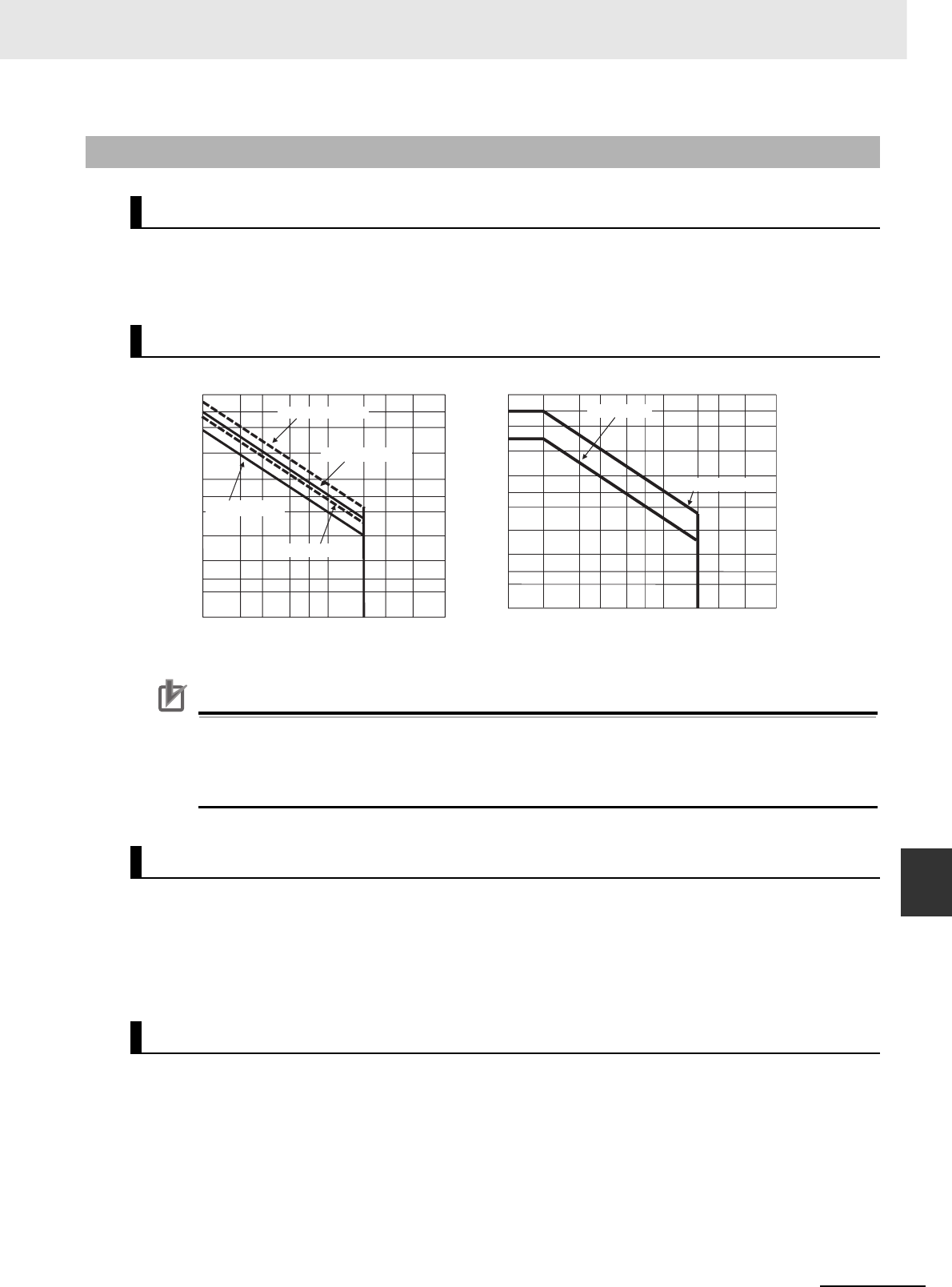
A-57
Appendices
CJ2 CPU Unit Hardware User’s Manual
A-1 Specifications of Basic I/O Units App A-1-3 Precautions on Contact Output Units
The service life expectancy of the relays (NY-24W-K-IE) in the CJ1W-OC201/211 Contact Output
Units is shown in the following diagrams. Use the diagrams to calculate the relay service life based
on the operating conditions, and replace the relay before the end of its service life.
Precautions for Correct UsePrecautions for Correct Use
The diagrams show the life expectancy of the relay itself. Do not use a contact current, therefore,
that exceeds the maximum switching capacity specified in the specifications for each Contact
Output Unit. If a switching capacity exceeding the specifications is used, the reliability and life
expectancy of other parts will be reduced and the Unit may malfunction.
The life of the Relay varies with the load inductance. If any inductive load is connected to the Con-
tact Output Unit, use an arc killer with the Contact Output Unit using an inductive load. (See next
page.)
Be sure to connect a diode in parallel with every DC inductive load that is connected to the Contact
Output Unit.
Arc killers are used with the Contact Output Unit in order to prolong the life of each Relay mounted
to the Contact Output Unit, prevent noise, and reduce the generation of carbide and nitrate deposits.
However, if arc killers are used incorrectly, they can reduce relay life. Using an arc killer can also
cause a delay in the resetting time (shut-off time). Arc killer circuit examples are listed in the follow-
ing table.
A-1-3 Precautions on Contact Output Units
Service Life Expectancy of CJ1W-OC201/211 Relays
Contact Current vs. Service Life Characteristic
Inductive Load
Contact Protection Circuit
0.1 0.2 0.3 0.5 1 2 3 50.7
2
3
5
10
20
30
50
100
200
300
0.1 0.2 0.3 0.5 1 2 3 5 0.7
2
3
5
10
20
30
50
100
200
300
0.05
Service Life with AC Load Service Life with DC Load
120 VAC, resistive load
240 VAC, resistive load
120 VAC cos f = 0.4
240 VAC cos φ = 0.4
Service life (×104)
Service life (×104)
Contact current (A) Contact current (A)
24 VDC, resistive load
24 VDC τ = 7 ms
Switching frequency: 1,800 operations/hour max.
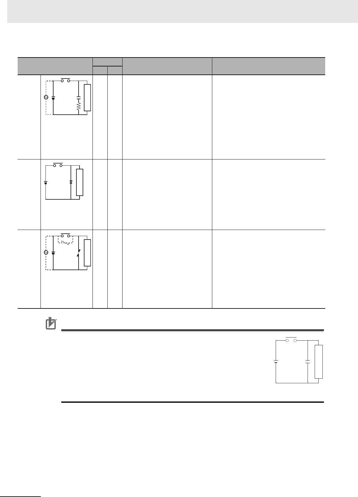
Appendices
A-58 CJ2 CPU Unit Hardware User’s Manual
Precautions for Correct UsePrecautions for Correct Use
Do not connect a capacitor as an arc killer in parallel with an inductive load
as shown in the following diagram. This arc killer is very effective for pre-
venting spark discharge at the moment when the circuit is opened. How-
ever, when the contacts are closed, the contacts may be welded due to the
current charged in the capacitor.
DC inductive loads can be more difficult to switch than resistive loads. If
appropriate arc killers are used, however, DC inductive loads will be as easy
to switch as resistive loads.
Circuit Current Characteristic Required element
AC DC
CR
method
Yes Yes If the load is a relay or solenoid, there
is a time lag between the moment the
circuit is opened and the moment the
load is reset.
If the supply voltage is 24 or 48 V,
insert the arc killer in parallel with the
load. If the supply voltage is 100 to
200 V, insert the arc killer between the
contacts.
The capacitance of the capacitor must be 1 to
0.5 µF per contact current of 1 A and resistance
of the resistor must be 0.5 to 1 Ω per contact volt-
age of 1 V. These values, however, vary with the
load and the characteristics of the relay. Decide
these values from experiments, and take into con-
sideration that the capacitance suppresses spark
discharge when the contacts are separated and
the resistance limits the current that flows into the
load when the circuit is closed again.
The dielectric strength of the capacitor must be
200 to 300 V. If the circuit is an AC circuit, use a
capacitor with no polarity.
Diode
method
No Yes The diode connected in parallel with
the load changes energy accumulated
by the coil into a current, which then
flows into the coil so that the current
will be converted into Joule heat by the
resistance of the inductive load. This
time lag, between the moment the cir-
cuit is opened and the moment the
load is reset, caused by this method is
longer than that caused by the CR
method.
The reversed dielectric strength value of the
diode must be at least 10 times as large as the
circuit voltage value. The forward current of the
diode must be the same as or larger than the load
current.
The reversed dielectric strength value of the
diode may be two to three times larger than the
supply voltage if the arc killer is applied to elec-
tronic circuits with low circuit voltages.
Varistor
method
Yes Yes The varistor method prevents the
imposition of high voltage between the
contacts by using the constant voltage
characteristic of the varistor. There is
time lag between the moment the cir-
cuit is opened and the moment the
load is reset.
If the supply voltage is 24 or 48 V,
insert the varistor in parallel with the
load. If the supply voltage is 100 to
200 V, insert the varistor between the
contacts.
---
Power
supply
Inductive load
C
R
Power
supply
Inductive load
Power
supply
Inductive load
C
Power
supply
Inductive load
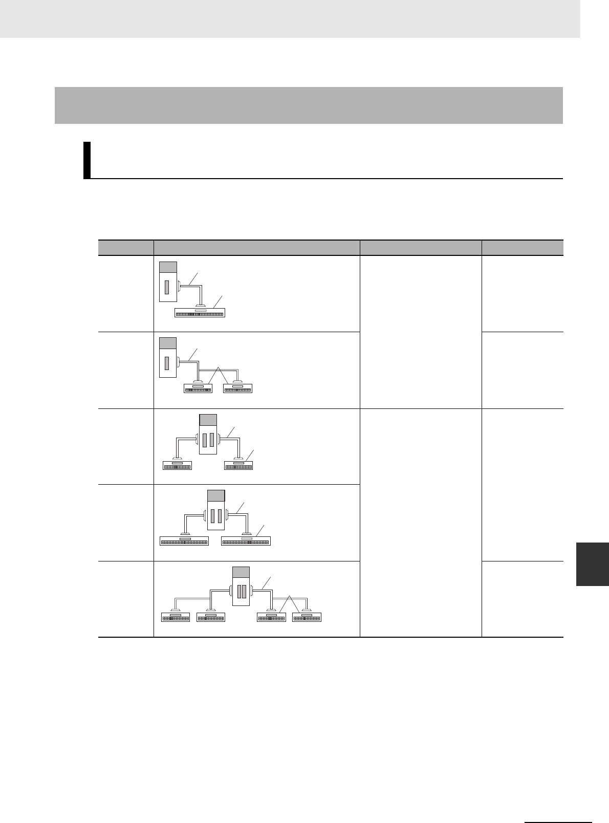
A-59
Appendices
CJ2 CPU Unit Hardware User’s Manual
A-1 Specifications of Basic I/O Units App A-1-4 Connecting Connector-Terminal Block
Conversion Units and I/O Relay Terminals
The following patterns can be used to connect Basic I/O Units with Connectors to OMRON Connector-
Terminal Block Conversion Units and I/O Relay Terminals using OMRON Connecting Cables.
zConnection Patterns for Connector-Terminal Block Conversion Units
A-1-4 Connecting Connector-Terminal Block Conversion Units and I/O
Relay Terminals
Patterns for Combining Connector-Terminal Block Conversion Units
and I/O Relay Terminals
Pattern Configuration Number of connectors Branching
A 1 None
B2 branches
C 2 None
D
F2 branches
Connecting Cable
Connector-Terminal
Block Conversion Unit
40 or 60 terminals
Connecting Cable with two branches
Connector-Terminal
Block Conversion Unit
20 terminals 20 terminals
Connecting Cable
Connector-Terminal
Block Conversion Unit
20 terminals 20 terminals
Connecting Cable
Connector-Terminal
Block Conversion Unit
40 or 60 terminals 40 or 60 terminals
Connecting Cable with two branches
Connector-Terminal
Block Conversion Unit
20 terminals 20 terminals 20 terminals 20 terminals
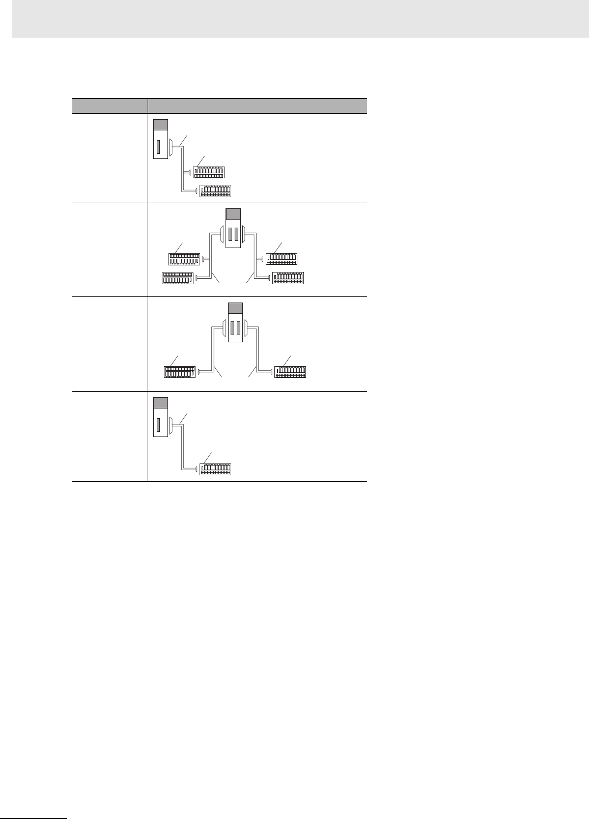
Appendices
A-60 CJ2 CPU Unit Hardware User’s Manual
zConnection Patterns for I/O Relay Terminals
Pattern Configuration
A
B
E
F
Connecting Cable
I/O Relay Terminal
Connecting Cable
I/O Relay Terminal I/O Relay Terminal
Connecting Cable
I/O Relay Terminal I/O Relay Terminal
Connecting Cable
I/O Relay Terminal

A-61
Appendices
CJ2 CPU Unit Hardware User’s Manual
A-1 Specifications of Basic I/O Units App A-1-4 Connecting Connector-Terminal Block
Conversion Units and I/O Relay Terminals
Combinations of OMRON Connecting Cables with Connector-Terminal Block Conversion Units and I/O
Relay Terminals are shown below.
zConnections to Connector-Terminal Block Conversion Units
Refer to the pages given in the right columns for connection diagrams and details on the Connector-Ter-
minal Block Conversion Units and Connecting Cables.
*1 For Units with both inputs and outputs, refer to the connection patterns for both input and output connections.
*2 The inputs are NPN. For PNP inputs, reverse the polarity of the external power supply connections to the power supply terminals on the
Connector-Terminal Block Conversion Unit.
*3 Bleeder resistance (5.6 kΩ) is built in.
Combinations of Connections
Unit I/O capac-
ity
Number
of con-
nectors
Polarity
Connec-
tion pat-
tern*1
Number
of
branches
Connecting
Cable
Connector-Terminal Block
Conversion Unit
Common
terminal
Connec-
tion dia-
gram
CJ1W-
ID231
32 inputs 1 Fujitsu
connector
NPN/PNP A None XW2Z-@@@B XW2D-40G6 None A-69
A None XW2Z-@@@BXW2D-40G6-RF*3 None
A None XW2Z-@@@B XW2B-40G5 None ---
A None XW2Z-@@@B XW2B-40G4 None ---
A None XW2Z-@@@BU XW2D-40C6 None ---
B 2 XW2Z-@@@D XW2D-20G6 (2 Units) None ---
B 2 XW2Z-@@@D XW2B-20G5 (2 Units) None ---
B 2 XW2Z-@@@D XW2B-20G4 (2 Units) None ---
B 2 XW2Z-@@@D XW2C-20G6-IO16 (2 Units) Yes A-69
B 2 XW2Z-@@@DXW2C-20G5-IN16 (2 Units)*2 Yes ---
B 2 XW2Z-@@@DXW2E-20G5-IN16 (2 Units)*2 Yes ---
B 2 XW2Z-@@@DXW2F-20G7-IN16 (2 Units)*2 Yes ---
B 2 XW2Z-@@@DXW2N-20G8-IN16 (2 Units)*2 Yes ---
CJ1W-
ID232
32 inputs 1 MIL con-
nector
NPN/PNP A None XW2Z-@@@K XW2D-40G6 None A-70
A None XW2Z-@@@KXW2D-40G6-RM*3 None
A None XW2Z-@@@K XW2B-40G5 None ---
A None XW2Z-@@@K XW2B-40G4 None ---
B 2 XW2Z-@@@N XW2D-20G6 (2 Units) None ---
B 2 XW2Z-@@@N XW2B-20G5 (2 Units) None ---
B 2 XW2Z-@@@N XW2B-20G4 (2 Units) None ---
B 2 XW2Z-@@@N XW2C-20G6-IO16 (2 Units) Yes A-70
B 2 XW2Z-@@@NXW2C-20G5-IN16 (2 Units)*2 Yes ---
B 2 XW2Z-@@@NXW2E-20G5-IN16 (2 Units)*2 Yes ---
B 2 XW2Z-@@@NXW2F-20G7-IN16 (2 Units)*2 Yes ---
B 2 XW2Z-@@@NXW2N-20G8-IN16 (2 Units)*2 Yes ---
CJ1W-
ID233
32 inputs 1 MIL con-
nector
NPN/PNP A None XW2Z-@@@K XW2D-40G6 None A-71
A None XW2Z-@@@KXW2D-40G6-RM*3 None
A None XW2Z-@@@K XW2B-40G5 None ---
A None XW2Z-@@@K XW2B-40G4 None ---
B 2 XW2Z-@@@N XW2D-20G6 (2 Units) None ---
B 2 XW2Z-@@@N XW2B-20G5 (2 Units) None ---
B 2 XW2Z-@@@N XW2B-20G4 (2 Units) None ---
B 2 XW2Z-@@@N XW2C-20G6-IO16 (2 Units) Yes A-71
B 2 XW2Z-@@@NXW2C-20G5-IN16 (2 Units)*2 Yes ---
B 2 XW2Z-@@@NXW2E-20G5-IN16 (2 Units)*2 Yes ---
B 2 XW2Z-@@@NXW2F-20G7-IN16 (2 Units)*2 Yes ---
B 2 XW2Z-@@@NXW2N-20G8-IN16 (2 Units)*2 Yes ---

Appendices
A-62 CJ2 CPU Unit Hardware User’s Manual
*1 For Units with both inputs and outputs, refer to the connection patterns for both input and output connections.
*2 The inputs are NPN. For PNP inputs, reverse the polarity of the external power supply connections to the power supply
terminals on the Connector-Terminal Block Conversion Unit.
*3 Bleeder resistance (5.6 kΩ) is built in.
Unit I/O capac-
ity
Number
of con-
nectors
Polarity
Connec-
tion pat-
tern*1
Number
of
branches
Connecting
Cable
Connector-Terminal Block
Conversion Unit
Common
terminal
Connec-
tion dia-
gram
CJ1W-
ID261
64 inputs 2 Fujitsu
connectors
NPN/PNP D None XW2Z-@@@B XW2D-40G6 None A-72
D None XW2Z-@@@BXW2D-40G6-RF*3 None
D None XW2Z-@@@B XW2B-40G5 None ---
D None XW2Z-@@@B XW2B-40G4 None ---
D None XW2Z-@@@BU XW2D-40C6 None ---
F2XW2Z-@@@D XW2D-20G6 (2 Units) None ---
F2XW2Z-@@@D XW2B-20G5 (2 Units) None ---
F2XW2Z-@@@D XW2B-20G4 (2 Units) None ---
F2XW2Z-@@@D XW2C-20G6-IO16 (2 Units) Yes A-72
F2XW2Z-@@@DXW2C-20G5-IN16 (2 Units)*2 Ye s - - -
F2XW2Z-@@@DXW2E-20G5-IN16 (2 Units)*2 Ye s - - -
F2XW2Z-@@@DXW2F-20G7-IN16 (2 Units)*2 Ye s - - -
F2XW2Z-@@@DXW2N-20G8-IN16 (2 Units)*2 Ye s - - -
CJ1W-
ID262
64 inputs 2 MIL con-
nectors
NPN/PNP D None XW2Z-@@@K XW2D-40G6 None A-73
D None XW2Z-@@@KXW2D-40G6-RM*3 None
D None XW2Z-@@@K XW2B-40G5 None ---
D None XW2Z-@@@K XW2B-40G4 None ---
F2XW2Z-@@@N XW2D-20G6 (2 Units) None ---
F2XW2Z-@@@N XW2B-20G5 (2 Units) None ---
F2XW2Z-@@@N XW2B-20G4 (2 Units) None ---
F2XW2Z-@@@N XW2C-20G6-IO16 (2 Units) Yes A-73
F2XW2Z-@@@NXW2C-20G5-IN16 (2 Units)*2 Ye s - - -
F2XW2Z-@@@NXW2E-20G5-IN16 (2 Units)*2 Ye s - - -
F2XW2Z-@@@NXW2F-20G7-IN16 (2 Units)*2 Ye s - - -
F2XW2Z-@@@NXW2N-20G8-IN16 (2 Units)*2 Ye s - - -
CJ1W-
OD231
32 outputs 1 Fujitsu
connector
NPN A None XW2Z-@@@B XW2D-40G6 None A-74
A None XW2Z-@@@B XW2B-40G5 None ---
A None XW2Z-@@@B XW2B-40G4 None ---
A None XW2Z-@@@BU XW2D-40C6 None A-74
B2XW2Z-@@@L XW2D-20G6 (2 Units) None ---
B2XW2Z-@@@L XW2B-20G5 (2 Units) None ---
B2XW2Z-@@@L XW2B-20G4 (2 Units) None ---
B2XW2Z-@@@L XW2C-20G6-IO16 (2 Units) Yes A-74
B2XW2Z-@@@L XW2F-20G7-OUT16 (2 Units) Yes ---
CJ1W-
OD232
32 outputs 1 MIL con-
nector
PNP A None XW2Z-@@@K XW2D-40G6 None A-75
A None XW2Z-@@@K XW2B-40G5 None ---
A None XW2Z-@@@K XW2B-40G4 None ---
B2XW2Z-@@@N XW2D-20G6 (2 Units) None ---
B2XW2Z-@@@N XW2B-20G5 (2 Units) None ---
B2XW2Z-@@@N XW2B-20G4 (2 Units) None ---
B2XW2Z-@@@N XW2C-20G6-IO16 (2 Units) Yes A-75
B2XW2Z-@@@N XW2F-20G7-OUT16 (2 Units) Yes ---

A-63
Appendices
CJ2 CPU Unit Hardware User’s Manual
A-1 Specifications of Basic I/O Units App A-1-4 Connecting Connector-Terminal Block
Conversion Units and I/O Relay Terminals
*1 For Units with both inputs and outputs, refer to the connection patterns for both input and output connections.
Unit I/O capac-
ity
Number
of con-
nectors
Polarity
Connec-
tion pat-
tern*1
Number
of
branches
Connecting
Cable
Connector-Terminal Block
Conversion Unit
Common
terminal
Connec-
tion dia-
gram
CJ1W-
OD233
32 outputs 1 MIL con-
nector
NPN A None XW2Z-@@@K XW2D-40G6 None A-76
A None XW2Z-@@@K XW2B-40G5 None ---
A None XW2Z-@@@K XW2B-40G4 None ---
B 2 XW2Z-@@@N XW2D-20G6 (2 Units) None ---
B 2 XW2Z-@@@N XW2B-20G5 (2 Units) None ---
B 2 XW2Z-@@@N XW2B-20G4 (2 Units) None ---
B 2 XW2Z-@@@N XW2C-20G6-IO16 (2 Units) Yes A-76
B 2 XW2Z-@@@N XW2F-20G7-OUT16 (2 Units) Yes ---
CJ1W-
OD234
32 outputs 1 MIL con-
nector
NPN A None XW2Z-@@@K XW2D-40G6 None A-77
A None XW2Z-@@@K XW2B-40G5 None ---
A None XW2Z-@@@K XW2B-40G4 None ---
B 2 XW2Z-@@@N XW2D-20G6 (2 Units) None ---
B 2 XW2Z-@@@N XW2B-20G5 (2 Units) None ---
B 2 XW2Z-@@@N XW2B-20G4 (2 Units) None ---
B 2 XW2Z-@@@N XW2C-20G6-IO16 (2 Units) Yes A-77
B 2 XW2Z-@@@N XW2F-20G7-OUT16 (2 Units) Yes ---
CJ1W-
OD261
64 outputs 2 Fujitsu
connectors
NPN D None XW2Z-@@@B XW2D-40G6 None A-78
D None XW2Z-@@@B XW2B-40G5 None ---
D None XW2Z-@@@B XW2B-40G4 None ---
D None XW2Z-@@@BU XW2D-40C6 None A-78
F 2 XW2Z-@@@L XW2D-20G6 (2 Units) None ---
F 2 XW2Z-@@@L XW2B-20G5 (2 Units) None ---
F 2 XW2Z-@@@L XW2B-20G4 (2 Units) None ---
F 2 XW2Z-@@@L XW2C-20G6-IO16 (2 Units) Yes A-78
F 2 XW2Z-@@@L XW2F-20G7-OUT16 (2 Units) Yes ---
CJ1W-
OD262
64 outputs 2 MIL con-
nectors
PNP D None XW2Z-@@@K XW2D-40G6 None A-79
D None XW2Z-@@@K XW2B-40G5 None ---
D None XW2Z-@@@K XW2B-40G4 None ---
F 2 XW2Z-@@@N XW2D-20G6 (2 Units) None ---
F 2 XW2Z-@@@N XW2B-20G5 (2 Units) None ---
F 2 XW2Z-@@@N XW2B-20G4 (2 Units) None ---
F 2 XW2Z-@@@N XW2C-20G6-IO16 (2 Units) Yes A-79
F 2 XW2Z-@@@N XW2F-20G7-OUT16 (2 Units) Yes ---
CJ1W-
OD263
64 outputs 2 MIL con-
nectors
NPN D None XW2Z-@@@K XW2D-40G6 None A-80
D None XW2Z-@@@K XW2B-40G5 None ---
D None XW2Z-@@@K XW2B-40G4 None ---
F 2 XW2Z-@@@N XW2D-20G6 (2 Units) None ---
F 2 XW2Z-@@@N XW2B-20G5 (2 Units) None ---
F 2 XW2Z-@@@N XW2B-20G4 (2 Units) None ---
F 2 XW2Z-@@@N XW2C-20G6-IO16 (2 Units) Yes A-80
F 2 XW2Z-@@@N XW2F-20G7-OUT16 (2 Units) Yes ---

Appendices
A-64 CJ2 CPU Unit Hardware User’s Manual
*1 For Units with both inputs and outputs, refer to the connection patterns for both input and output connections.
*2 The inputs are NPN. For PNP inputs, reverse the polarity of the external power supply connections to the power supply terminals on the
Connector-Terminal Block Conversion Unit.
*3 Bleeder resistance (5.6 kΩ) is built in.
Unit I/O capac-
ity
Number
of con-
nectors
Polarity
Connec-
tion pat-
tern*1
Number
of
branches
Connecting
Cable
Connector-Terminal Block
Conversion Unit
Common
terminal
Connec-
tion dia-
gram
CJ1W-
MD231
16 inputs 1 Fujitsu
connector
NPN/PNP C None XW2Z-@@@A XW2D-20G6 None A-81
C None XW2Z-@@@A XW2B-20G5 None ---
C None XW2Z-@@@A XW2B-20G4 None ---
C None XW2Z-@@@A XW2C-20G6-IO16 Yes A-82
C None XW2Z-@@@AXW2C-20G5-IN16*2 Ye s - - -
C None XW2Z-@@@AXW2E-20G5-IN16*2 Ye s - - -
C None XW2Z-@@@AXW2F-20G7-IN16*2 Ye s - - -
C None XW2Z-@@@AXW2N-20G8-IN16*2 Ye s - - -
16 outputs 1 Fujitsu
connector
NPN C None XW2Z-@@@A XW2D-20G6 None A-81
C None XW2Z-@@@A XW2B-20G5 None ---
C None XW2Z-@@@A XW2B-20G4 None ---
C None XW2Z-@@@A XW2C-20G6-IO16 Yes A-82
C None XW2Z-@@@A XW2F-20G7-OUT16 Yes ---
CJ1W-
MD232
16 inputs 1 MIL con-
nector
NPN/PNP C None XW2Z-@@@X XW2D-20G6 None A-83
C None XW2Z-@@@X XW2B-20G5 None ---
C None XW2Z-@@@X XW2B-20G4 None ---
16 outputs 1 MIL con-
nector
PNP C None XW2Z-@@@X XW2D-20G6 None A-83
C None XW2Z-@@@X XW2B-20G5 None ---
C None XW2Z-@@@X XW2B-20G4 None ---
CJ1W-
MD233
16 inputs 1 MIL con-
nector
NPN/PNP C None XW2Z-@@@X XW2D-20G6 None A-83
C None XW2Z-@@@X XW2B-20G5 None ---
C None XW2Z-@@@X XW2B-20G4 None ---
16 outputs 1 MIL con-
nector
NPN C None XW2Z-@@@X XW2D-20G6 None A-83
C None XW2Z-@@@X XW2B-20G5 None ---
C None XW2Z-@@@X XW2B-20G4 None ---
CJ1W-
MD261
32 outputs 1 Fujitsu
connector
NPN/PNP D None XW2Z-@@@B XW2D-40G6 None A-84
D None XW2Z-@@@BXW2D-40G6-RF*3 None
D None XW2Z-@@@B XW2B-40G5 None ---
D None XW2Z-@@@B XW2B-40G4 None ---
D None XW2Z-@@@BU XW2D-40C6 None ---
F2XW2Z-@@@D XW2D-20G6 (2 Units) None ---
F2XW2Z-@@@D XW2B-20G5 (2 Units) None ---
F2XW2Z-@@@D XW2B-20G4 (2 Units) None ---
F2XW2Z-@@@D XW2C-20G6-IO16 (2 Units) Yes A-85
F2XW2Z-@@@DXW2C-20G5-IN16 (2 Units)*2 Ye s - - -
F2XW2Z-@@@DXW2E-20G5-IN16 (2 Units)*2 Ye s - - -
F2XW2Z-@@@DXW2F-20G7-IN16 (2 Units)*2 Ye s - - -
F2XW2Z-@@@DXW2N-20G8-IN16 (2 Units)*2 Ye s - - -
32 outputs 1 Fujitsu
connector
NPN D None XW2Z-@@@B XW2D-40G6 None A-84
D None XW2Z-@@@B XW2B-40G5 None ---
D None XW2Z-@@@B XW2B-40G4 None ---
D None XW2Z-@@@BU XW2D-40C6 None ---
F2XW2Z-@@@L XW2D-20G6 (2 Units) None ---
F2XW2Z-@@@L XW2B-20G5 (2 Units) None ---
F2XW2Z-@@@L XW2B-20G4 (2 Units) None ---
F2XW2Z-@@@L XW2C-20G6-IO16 (2 Units) Yes A-85
F2XW2Z-@@@L XW2F-20G7-OUT16 (2 Units) Yes ---

A-65
Appendices
CJ2 CPU Unit Hardware User’s Manual
A-1 Specifications of Basic I/O Units App A-1-4 Connecting Connector-Terminal Block
Conversion Units and I/O Relay Terminals
*1 For Units with both inputs and outputs, refer to the connection patterns for both input and output connections.
*2 The inputs are NPN. For PNP inputs, reverse the polarity of the external power supply connections to the power supply terminals on the
Connector-Terminal Block Conversion Unit.
*3 Bleeder resistance (5.6 kΩ) is built in.
Unit I/O capac-
ity
Number
of con-
nectors
Polarity
Connec-
tion pat-
tern*1
Number
of
branches
Connecting
Cable
Connector-Terminal Block
Conversion Unit
Common
terminal
Connec-
tion dia-
gram
CJ1W-
MD263
32 inputs 1 MIL con-
nector
NPN/PNP D None XW2Z-@@@K XW2D-40G6 None A-86
D None XW2Z-@@@KXW2D-40G6-RM*3 None
D None XW2Z-@@@K XW2B-40G5 None ---
D None XW2Z-@@@K XW2B-40G4 None ---
F 2 XW2Z-@@@N XW2D-20G6 (2 Units) None ---
F 2 XW2Z-@@@N XW2B-20G5 (2 Units) None ---
F 2 XW2Z-@@@N XW2B-20G4 (2 Units) None ---
F 2 XW2Z-@@@N XW2C-20G6-IO16 (2 Units) None A-87
F 2 XW2Z-@@@NXW2C-20G5-IN16 (2 Units)*2 Yes ---
F 2 XW2Z-@@@NXW2E-20G5-IN16 (2 Units)*2 Yes ---
F 2 XW2Z-@@@NXW2F-20G7-IN16 (2 Units)*2 Yes ---
F 2 XW2Z-@@@NXW2N-20G8-IN16 (2 Units)*2 Yes ---
32 outputs 1 MIL con-
nector
NPN D None XW2Z-@@@B XW2D-40G6 None A-86
D None XW2Z-@@@B XW2B-40G5 None ---
D None XW2Z-@@@B XW2B-40G4 None ---
F 2 XW2Z-@@@L XW2D-20G6 (2 Units) None ---
F 2 XW2Z-@@@L XW2B-20G5 (2 Units) None ---
F 2 XW2Z-@@@L XW2B-20G4 (2 Units) None ---
F 2 XW2Z-@@@L XW2C-20G6-IO16 (2 Units) Yes A-87
F 2 XW2Z-@@@L XW2F-20G7-OUT16 (2 Units) Yes ---
CJ1W-
MD563
32 inputs 1 MIL con-
nector
NPN/PNP D None XW2Z-@@@K XW2D-40G6 None A-88
D None XW2Z-@@@KXW2D-40G6-RM*3 None
D None XW2Z-@@@K XW2B-40G5 None ---
D None XW2Z-@@@K XW2B-40G4 None ---
F 2 XW2Z-@@@N XW2D-20G6 (2 Units) None ---
F 2 XW2Z-@@@N XW2B-20G5 (2 Units) None ---
F 2 XW2Z-@@@N XW2B-20G4 (2 Units) None ---
32 outputs 1 MIL con-
nector
NPN D None XW2Z-@@@K XW2D-40G6 None A-88
D None XW2Z-@@@K XW2B-40G5 None ---
D None XW2Z-@@@K XW2B-40G4 None ---
F 2 XW2Z-@@@N XW2D-20G6 (2 Units) None ---
F 2 XW2Z-@@@N XW2B-20G5 (2 Units) None ---
F 2 XW2Z-@@@N XW2B-20G4 (2 Units) None ---

Appendices
A-66 CJ2 CPU Unit Hardware User’s Manual
zConnections to I/O Relay Terminals
Refer to the pages given in the right columns for connection diagrams and details on the I/O Relay Ter-
minals and Connecting Cables.
*1 For Units with both inputs and outputs, refer to the connection patterns for both input and output connections.
Unit I/O capacity Number of
connectors Polarity Connection
pattern*1
Number of
branches
Connecting
Cable I/O Relay Terminal Connection
diagram
CJ1W-ID231 32 inputs 1 Fujitsu con-
nector
NPN A 2 G79-I@C-@G7TC-ID16 A-89
A 2 G79-I@C-@G7TC-IA16
CJ1W-ID232 32 inputs 1 MIL con-
nector
NPN A 2 G79-O@-@-D1 G7TC-ID16
A 2 G79-O@-@-D1 G7TC-IA16
CJ1W-ID233 32 inputs 1 MIL con-
nector
NPN A 2 G79-O@-@-D1 G7TC-ID16
A 2 G79-O@-@-D1 G7TC-IA16
CJ1W-ID261 64 inputs 2 Fujitsu con-
nectors
NPN B 2 G79-I@C-@G7TC-ID16
B 2 G79-I@C-@G7TC-IA16
CJ1W-ID262 64 inputs 2 MIL con-
nectors
NPN B 2 G79-O@-@-D1 G7TC-ID16
B 2 G79-O@-@-D1 G7TC-IA16
CJ1W-OD231 32 outputs 1 Fujitsu con-
nector
NPN A 2 G79-O@C-@G7TC-OC16 A-92
A 2 G79-O@C-@G7TC-OC08
A 2 G79-O@C-@G70D-SOC16 A-91
A 2 G79-O@C-@G70D-FOM16 ---
A 2 G79-O@C-@G70D-VSOC16 A-90
A 2 G79-O@C-@G70D-VFOM16 ---
A 2 G79-O@C-@G70A-ZOC16-3 and Relay A-93
A 2 G79-O@C-@G70R-SOC08 A-92
A 2 G79-O@C-@G70D-SOC08 A-91
CJ1W-OD232 32 outputs 1 MIL con-
nector
PNP A 2 G79-I@-@-D1 G7TC-OC16-1 A-93
A 2 G79-O@-@-D1 G70D-SOC16-1 ---
A 2 G79-O@-@-D1 G70D-FOM16-1 ---
A 2 G79-O@-@-D1 G70A-ZOC16-4 and Relay ---
CJ1W-OD233 32 outputs 1 MIL con-
nector
NPN A 2 G79-O@-@-D1 G7TC-OC16 A-92
A 2 G79-O@-@-D1 G7TC-OC08
A 2 G79-O@-@-D1 G70D-SOC16 A-91
A 2 G79-O@-@-D1 G70D-FOM16 ---
A 2 G79-O@-@-D1 G70D-VSOC16 A-90
A 2 G79-O@-@-D1 G70D-VFOM16 ---
A 2 G79-O@-@-D1 G70A-ZOC16-3 and Relay A-93
A 2 G79-O@-@-D1 G70R-SOC08 A-92
A 2 G79-O@-@-D1 G70D-SOC08 A-91
CJ1W-OD234 32 outputs 1 MIL con-
nector
NPN A 2 G79-O@-@-D1 G7TC-OC16 A-92
A 2 G79-O@-@-D1 G7TC-OC08
A 2 G79-O@-@-D1 G70D-SOC16 A-91
A 2 G79-O@-@-D1 G70D-FOM16 ---
A 2 G79-O@-@-D1 G70D-VSOC16 A-90
A 2 G79-O@-@-D1 G70D-VFOM16 ---
A 2 G79-O@-@-D1 G70A-ZOC16-3 and Relay A-93
A 2 G79-O@-@-D1 G70R-SOC08 A-92
A 2 G79-O@-@-D1 G70D-SOC08 A-91

A-67
Appendices
CJ2 CPU Unit Hardware User’s Manual
A-1 Specifications of Basic I/O Units App A-1-4 Connecting Connector-Terminal Block
Conversion Units and I/O Relay Terminals
*1 For Units with both inputs and outputs, refer to the connection patterns for both input and output connections.
Unit I/O capacity Number of
connectors Polarity Connection
pattern*1
Number of
branches
Connecting
Cable I/O Relay Terminal Connection
diagram
CJ1W-OD261 64 outputs 2 Fujitsu con-
nectors
NPN B 2 G79-O@C-@G7TC-OC16 A-92
B2G79-O@C-@G7TC-OC08
B2G79-O@C-@G70D-SOC16 A-91
B2G79-O@C-@G70D-FOM16 ---
B2G79-O@C-@G70D-VSOC16 A-90
B2G79-O@C-@G70D-VFOM16 ---
B2G79-O@C-@G70A-ZOC16-3 and Relay A-93
B2G79-O@C-@G70R-SOC08 A-92
B2G79-O@C-@G70D-SOC08 A-91
CJ1W-OD262 64 outputs 2 MIL con-
nectors
PNP B 2 G79-I@-@-D1 G7TC-OC16-1 A-93
B2G79-O@-@-D1 G70D-SOC16-1 ---
B2G79-O@-@-D1 G70D-FOM16-1 ---
B2G79-O@-@-D1 G70A-ZOC16-4 and Relay ---
CJ1W-OD263 64 outputs 2 MIL con-
nectors
NPN B 2 G79-O@-@-D1 G7TC-OC16 A-92
B2G79-O@-@-D1 G7TC-OC08
B2G79-O@-@-D1 G70D-SOC16 A-91
B2G79-O@-@-D1 G70D-FOM16 ---
B2G79-O@-@-D1 G70D-VSOC16 A-90
B2G79-O@-@-D1 G70D-VFOM16 ---
B2G79-O@-@-D1 G70A-ZOC16-3 and Relay A-93
B2G79-O@-@-D1 G70R-SOC08 A-92
B2G79-O@-@-D1 G70D-SOC08 A-91
CJ1W-MD231 16 inputs 1 Fujitsu con-
nector
NPN F None G79-@C G7TC-ID16 A-89
F None G79-@C G7TC-IA16
16 outputs 1 Fujitsu con-
nector
NPN F None G79-@C G7TC-OC16 A-92
F None G79-@C G7TC-OC08
F None G79-@CG70D-SOC16 A-91
F None G79-@CG70D-FOM16 ---
F None G79-@C G70D-VSOC16 A-90
F None G79-@C G70D-VFOM16 ---
F None G79-@C G70A-ZOC16-3 and Relay A-93
F None G79-@CG70R-SOC08 A-92
F None G79-@CG70D-SOC08 A-91
CJ1W-MD232 16 outputs 1 MIL con-
nector
PNP F None G79-O@C G7TC-OC16-1 A-93
F None G79-I@CG70D-SOC16-1 ---
F None G79-I@C G70D-FOM16-1 ---
F None G79-I@C G70A-ZOC16-4 and Relay ---
CJ1W-MD233 16 inputs 1 MIL con-
nector
NPN E None G79-O@C G7TC-ID16 A-89
E None G79-O@C G7TC-IA16
16 outputs 1 MIL con-
nector
NPN E None G79-O@C G7TC-OC16 A-92
E None G79-O@C G7TC-OC08
E None G79-O@CG70D-SOC16 A-91
E None G79-O@CG70D-FOM16 ---
E None G79-O@C G70D-VSOC16 A-90
E None G79-O@C G70D-VFOM16 ---
E None G79-O@C G70A-ZOC16-3 and Relay A-93
E None G79-O@CG70R-SOC08 A-92
E None G79-O@CG70D-SOC08 A-91

Appendices
A-68 CJ2 CPU Unit Hardware User’s Manual
*1 For Units with both inputs and outputs, refer to the connection patterns for both input and output connections.
Unit I/O capacity Number of
connectors Polarity Connection
pattern*1
Number of
branches
Connecting
Cable I/O Relay Terminal Connection
diagram
CJ1W-MD261 32 inputs 1 Fujitsu con-
nector
NPN B 2 G79-I@C-@G7TC-ID16 A-89
B 2 G79-I@C-@G7TC-IA16
32 outputs 1 Fujitsu con-
nector
NPN B 2 G79-O@C-@G7TC-OC16 A-92
B 2 G79O@C-@G7TC-OC08
B 2 G79-O@C-@G70D-SOC16 A-91
B 2 G79-O@C-@G70D-FOM16 ---
B 2 G79-O@C-@G70D-VSOC16 A-90
B 2 G79-O@C-@G70D-VFOM16 ---
B 2 G79O@C-@G70A-ZOC16-3 and Relay A-93
B 2 G79-O@C-@G70R-SOC08 A-92
B 2 G79-O@C-@G70D-SOC08 A-91
CJ1W-MD263 32 inputs 1 MIL con-
nector
NPN B 2 G79-O@-@-D1 G7TC-ID16 A-89
B 2 G79-O@-@-D1 G7TC-IA16
32 outputs 1 MIL con-
nector
NPN B 2 G79-O@-@-D1 G7TC-OC16 A-92
B 2 G79-O@-@-D1 G7TC-OC08
B 2 G79-O@-@-D1 G70D-SOC16 A-91
B 2 G79-O@-@-D1 G70D-FOM16 ---
B 2 G79-O@-@-D1 G70D-VSOC16 A-90
B 2 G79-O@-@-D1 G70D-VFOM16 ---
B 2 G79-O@-@-D1 G70A-ZOC16-3 and Relay A-93
B 2 G79-O@-@-D1 G70R-SOC08 A-92
B 2 G79-O@-@-D1 G70D-SOC08 A-91
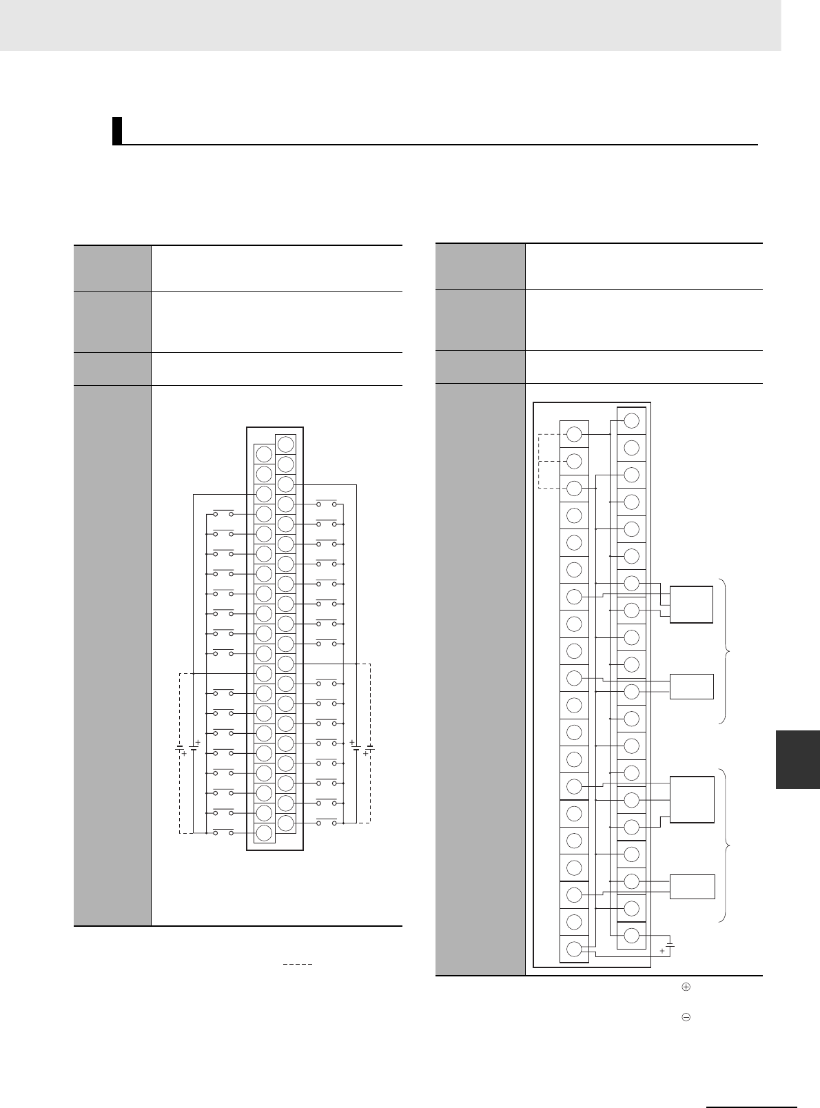
A-69
Appendices
CJ2 CPU Unit Hardware User’s Manual
A-1 Specifications of Basic I/O Units App A-1-4 Connecting Connector-Terminal Block
Conversion Units and I/O Relay Terminals
The applicable terminals on the Connector-Terminal Block Conversion Unit and external connection
diagrams are provided below for Basic I/O Unit connections to Connector-Terminal Block Conversion
Units.
z Inputs
Note 1 The polarity for input power supply connections
indicated with dotted lines ( ) can be con-
nected in either direction provided that the same
polarity is used for the commons for rows A and B.
2Both COM0 and COM1 have two pins each. They
are internally connected inside the PLC, but they
must all be wired.
Note 1 Connect the A9/B9 terminal and the terminal for
NPN.
Connect the A9/B9 terminal and the terminal for
PNP.
(Use the enclosed short bar.)
2The COM terminals are wired inside the Connec-
tor-Terminal Block Conversion Unit.
Connector-Terminal Block Conversion Unit Connection Diagrams
Programma-
ble Control-
ler I/O Unit
CJ1W-ID231
Connector-
Terminal
Block Con-
version Unit
XW2D-40G6
XW2D-40G6-RF
Connecting
Cables
XW2Z-@@@B
Connection
diagram
Wd m
A20
A11
A12
A13
A14
A15
A16
A17
A18
A19
B20
B11
B12
B13
B14
B15
B16
B17
B18
B19
A10
A1
A2
A3
A4
A5
A6
A7
A8
A9
B10
B1
B2
B3
B4
B5
B6
B7
B8
B9
15
COM0
NC
14
13
12
11
10
09
08
NC
07
COM0
06
05
04
03
02
01
00
15
COM1
NC
14
13
12
11
10
09
08
NC
07
COM1
06
05
04
03
02
01
00
Wd (m+1)
24
VDC
24
VDC
Programma-
ble Controller
I/O Unit
CJ1W-ID231
Connector-Ter-
minal Block
Conversion
Unit
XW2C-20G6-IO16 (two Units)
Connecting
Cables
XW2Z-@@@D
Connection
diagram
0
1
2
3
4
5
6
7
8
9
10
11
12
13
14
15
A9
B9
A10
B10
24 VDC
(Short
bar)
Wd m
(Wd (m+1))
PNP
NPN
Black (White)
Brown (Red)
Blue (Black)
Blue (Black)
Brown (White)
Black (White)
Brown (Red)
Blue (Black)
3-wire sensor with
PNP output
(photoelectric sensor
or proximity sensor)
3-wire sensor with
NPN output
(photoelectric sensor
or proximity sensor)
2-wire sensor
(e.g., limit switch)
Blue (Black)
Brown (White)
2-wire sensor
(e.g., limit switch)
+
+
+
+
+
+
+
+
+
+
+
−
−
−
−
−
−
−
−
−
−
−
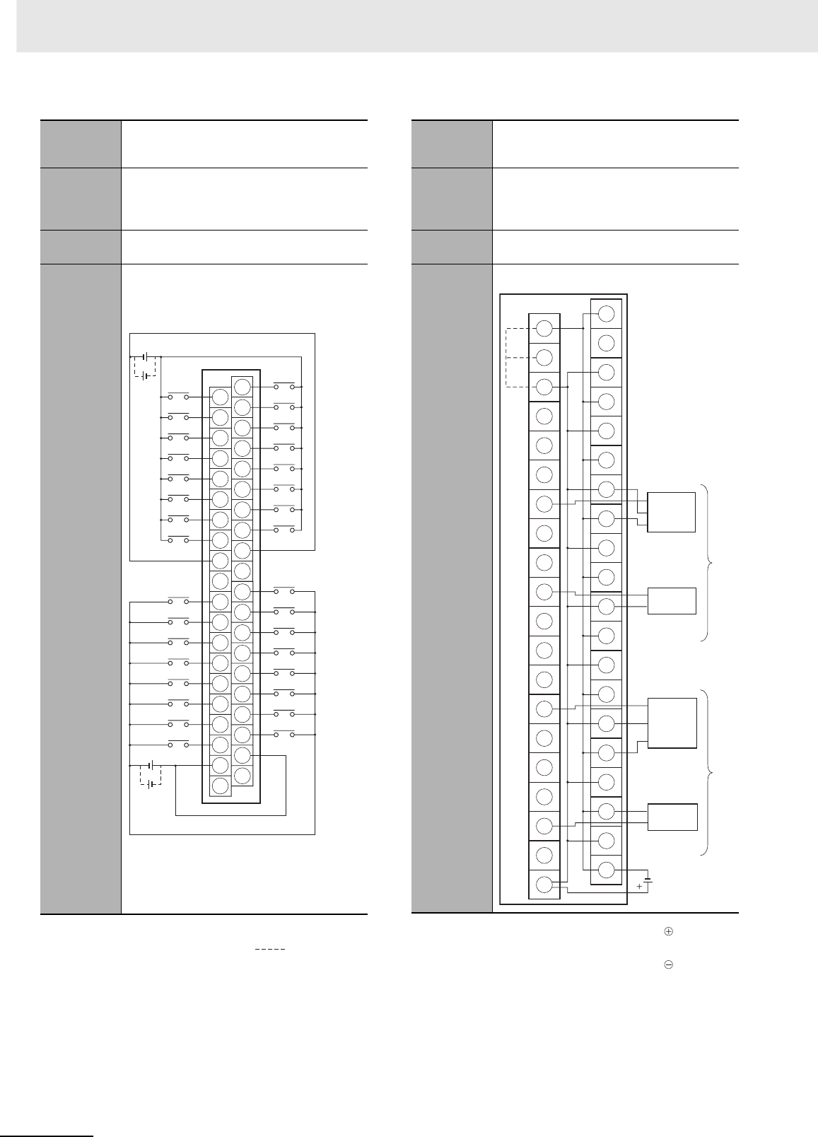
Appendices
A-70 CJ2 CPU Unit Hardware User’s Manual
Note 1 The polarity for input power supply connections
indicated with dotted lines ( ) can be con-
nected in either direction provided that the same
polarity is used for the commons.
2Both COM0 and COM1 have two pins each. They
are internally connected inside the PLC, but they
must all be wired.
Note 1 Connect the A9/B9 terminal and the terminal for
NPN.
Connect the A9/B9 terminal and the terminal for
PNP.
(Use the enclosed short bar.)
2The COM terminals are wired inside the Connec-
tor-Terminal Block Conversion Unit.
Programma-
ble Control-
ler I/O Unit
CJ1W-ID232
Connector-
Terminal
Block Con-
version Unit
XW2D-40G6
XW2D-40G6-RM
Connecting
Cables
XW2Z-@@@K
Connection
diagram
A20
A11
A12
A13
A14
A15
A16
A17
A18
A19
B20
B11
B12
B13
B14
B15
B16
B17
B18
B19
A10
A1
A2
A3
A4
A5
A6
A7
A8
A9
B10
B1
B2
B3
B4
B5
B6
B7
B8
B9
08
09
10
11
12
13
14
15
09
08
10
11
12
13
14
15
00
01
02
03
04
05
06
07
00
NC
NC
NC
NC
COM0
COM0
COM1
COM1
01
02
03
04
05
06
07
24 VDC
24 VDC
Wd (m+1)
Wd m
Programma-
ble Control-
ler I/O Unit
CJ1W-ID232
Connector-
Terminal
Block Con-
version Unit
XW2C-20G6-IO16 (2 Units)
Connecting
Cables
XW2Z-@@@N
Connection
diagram
0
1
2
3
4
5
6
7
8
9
10
11
12
13
14
15
A9
B9
A10
B10
24 VDC
(Short
bar)
Wd m
(Wd (m+1))
PNP
NPN
Black (White)
Brown (Red)
Blue (Black)
Blue (Black)
Brown (White)
Black (White)
Brown (Red)
Blue (Black)
3-wire sensor with
PNP output
(photoelectric sensor
or proximity sensor)
3-wire sensor with
NPN output
(photoelectric sensor
or proximity sensor)
2-wire sensor
(e.g., limit switch)
Blue (Black)
Brown (White)
2-wire sensor
(e.g., limit switch)
+
−
−
+
−
−
+
+
+
−
−
+
+
−
−
+
−
+
+
−
−
+

A-71
Appendices
CJ2 CPU Unit Hardware User’s Manual
A-1 Specifications of Basic I/O Units App A-1-4 Connecting Connector-Terminal Block
Conversion Units and I/O Relay Terminals
Note 1 The polarity for input power supply connections
indicated with dotted lines ( ) can be con-
nected in either direction provided that the same
polarity is used for the commons.
2Both COM0 and COM1 have two pins each. They
are internally connected inside the PLC, but they
must all be wired.
Note 1 Connect the A9/B9 terminal and the terminal for
NPN.
Connect the A9/B9 terminal and the terminal for
PNP.
(Use the enclosed short bar.)
2The COM terminals are wired inside the Connec-
tor-Terminal Block Conversion Unit.
Programma-
ble Control-
ler I/O Unit
CJ1W-ID233
Connector-
Terminal
Block Con-
version Unit
XW2D-40G6
XW2D-40G6-RM
Connecting
Cables
XW2Z-@@@K
Connection
diagram
A20
A11
A12
A13
A14
A15
A16
A17
A18
A19
B20
B11
B12
B13
B14
B15
B16
B17
B18
B19
A10
A1
A2
A3
A4
A5
A6
A7
A8
A9
B10
B1
B2
B3
B4
B5
B6
B7
B8
B9
08
09
10
11
12
13
14
15
09
08
10
11
12
13
14
15
00
01
02
03
04
05
06
07
00
NC
NC
NC
NC
COM0
COM0
COM1
COM1
01
02
03
04
05
06
07
24 VDC
24 VDC
Wd (m+1)
Wd m
Programma-
ble Control-
ler I/O Unit
CJ1W-ID233
Connector-
Terminal
Block Con-
version Unit
XW2C-20G6-IO16 (2 Units)
Connecting
Cables
XW2Z-@@@N
Connection
diagram
0
1
2
3
4
5
6
7
8
9
10
11
12
13
14
15
A9
B9
A10
B10
24 VDC
(Short
bar)
Wd m
(Wd (m+1))
PNP
NPN
Black (White)
Brown (Red)
Blue (Black)
Blue (Black)
Brown (White)
Black (White)
Brown (Red)
Blue (Black)
3-wire sensor with
PNP output
(photoelectric sensor
or proximity sensor)
3-wire sensor with
NPN output
(photoelectric sensor
or proximity sensor)
2-wire sensor
(e.g., limit switch)
Blue (Black)
Brown (White)
2-wire sensor
(e.g., limit switch)
+
−
−
+
−
−
+
+
+
−
−
+
+
−
−
+
−
+
+
−
−
+
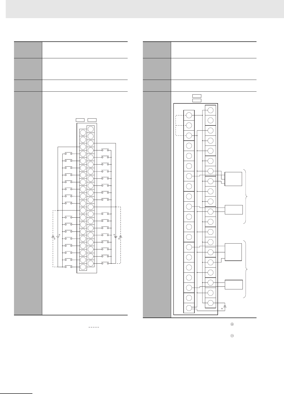
Appendices
A-72 CJ2 CPU Unit Hardware User’s Manual
Note 1 The polarity for input power supply connections
indicated with dotted lines ( ) can be con-
nected in either direction provided that the same
polarity is used for the commons for rows A and B.
2COM0, COM1, COM2, and COM3 have two pins
each. They are internally connected inside the
PLC, but they must all be wired.
Note 1 Connect the A9/B9 terminal and the terminal for
NPN.
Connect the A9/B9 terminal and the terminal for
PNP.
(Use the enclosed short bar.)
2The COM terminals are wired inside the Connec-
tor-Terminal Block Conversion Unit.
Programma-
ble Control-
ler I/O Unit
CJ1W-ID261
Connector-
Terminal
Block Con-
version Unit
XW2D-40G6
XW2D-40G6-RF
Connecting
Cables
XW2Z-@@@B
Connection
diagram
A20
A11
A12
A13
A14
A15
A16
A17
A18
A19
B20
B11
B12
B13
B14
B15
B16
B17
B18
B19
A10
A1
A2
A3
A4
A5
A6
A7
A8
A9
B10
B1
B2
B3
B4
B5
B6
B7
B8
B9
15
COM0
(COM2)
NC
14
13
12
11
10
09
08
NC
07
COM0
(COM2)
06
05
04
03
02
01
00
15
COM1
(COM3)
NC
14
13
12
11
10
09
08
NC
07
COM1
(COM3)
06
05
04
03
02
01
00
24
VDC 24
VDC
CN1 ( CN2 )
Wd m
(Wd (m+2)) Wd (m+1)
(Wd (m+3))
Programma-
ble Control-
ler I/O Unit
CJ1W-ID261
Connector-
Terminal
Block Con-
version Unit
XW2C-20G6-IO16 (2 Units)
Connecting
Cables
XW2Z-@@@D
Connection
diagram
0
1
2
3
4
5
6
7
8
9
10
11
12
13
14
15
A9
B9
A10
B10
24 VDC
CN1
CN2
Wd m and m+1
(Wd m+2 and m+3)
(Short
bar)
PNP
NPN
Black (White)
Brown (Red)
Blue (Black)
Blue (Black)
Brown (White)
Black (White)
Brown (Red)
Blue (Black)
3-wire sensor with
PNP output
(photoelectric sensor
or proximity sensor)
3-wire sensor with
NPN output
(photoelectric sensor
or proximity sensor)
2-wire sensor
(e.g., limit switch)
Blue (Black)
Brown (White)
2-wire sensor
(e.g., limit switch)
()
+
−
−
+
−
+
−
+
−
−
+
−
+
+
+
−
−
+
+
+
−
−
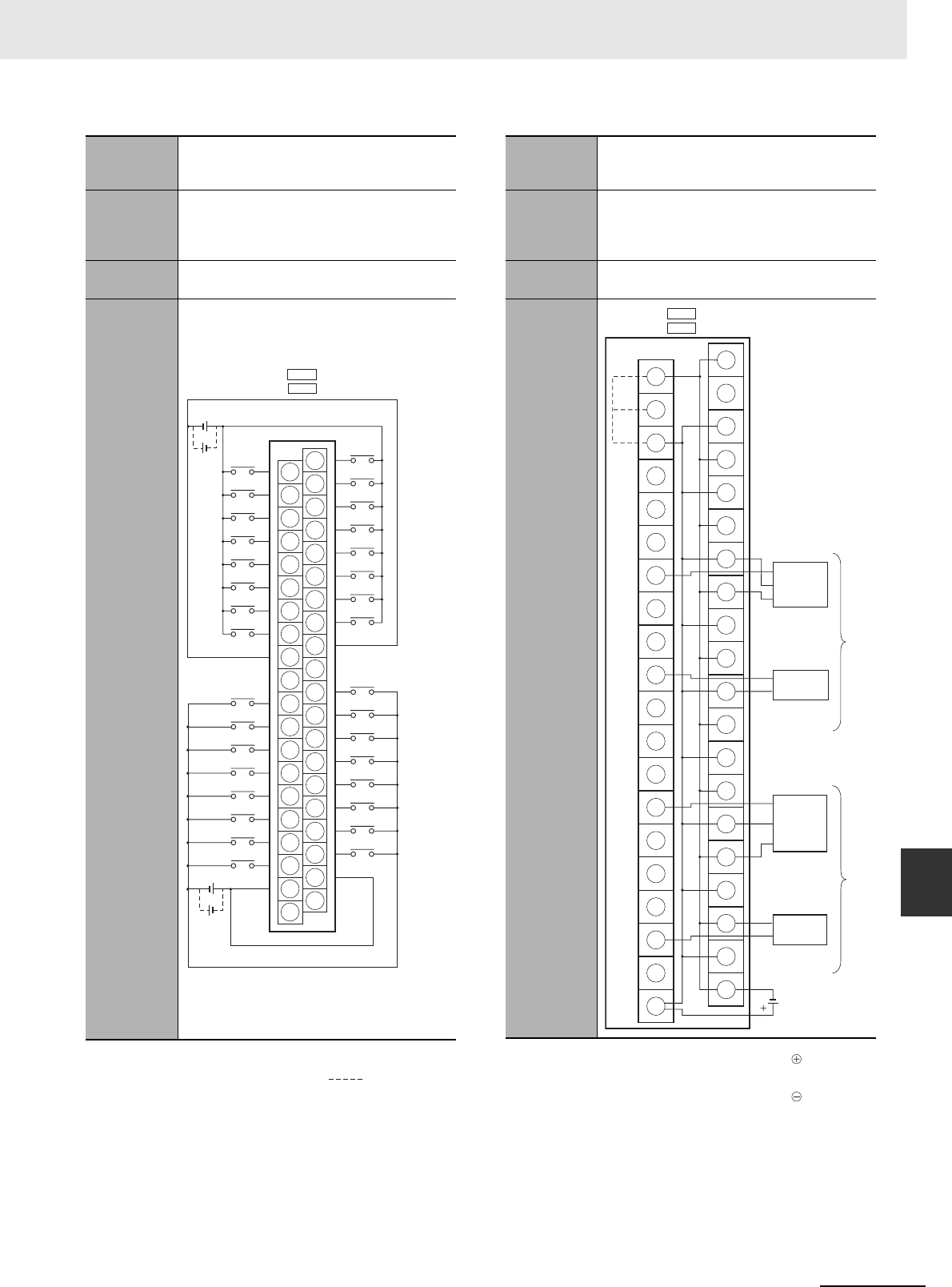
A-73
Appendices
CJ2 CPU Unit Hardware User’s Manual
A-1 Specifications of Basic I/O Units App A-1-4 Connecting Connector-Terminal Block
Conversion Units and I/O Relay Terminals
Note 1 The polarity for input power supply connections
indicated with dotted lines ( ) can be con-
nected in either direction provided that the same
polarity is used for the commons.
2COM0, COM1, COM2, and COM3 have two pins
each. They are internally connected inside the
PLC, but they must all be wired.
Note 1 Connect the A9/B9 terminal and the terminal for
NPN.
Connect the A9/B9 terminal and the terminal for
PNP.
(Use the enclosed short bar.)
2The COM terminals are wired inside the Connec-
tor-Terminal Block Conversion Unit.
Programma-
ble Control-
ler I/O Unit
CJ1W-ID262
Connector-
Terminal
Block Con-
version Unit
XW2D-40G6
XW2D-40G6-RM
Connecting
Cables
XW2Z-@@@K
Connection
diagram
08
09
10
11
12
13
14
15
09
08
10
11
12
13
14
15
00
01
02
03
04
05
06
07
00
NC
NC
NC
NC
01
02
03
04
05
06
07
24 VDC
24 VDC
COM0
COM0
COM1
COM1
CN1
CN2
A20
A11
A12
A13
A14
A15
A16
A17
A18
A19
B20
B11
B12
B13
B14
B15
B16
B17
B18
B19
A10
A1
A2
A3
A4
A5
A6
A7
A8
A9
B10
B1
B2
B3
B4
B5
B6
B7
B8
B9
(COM2)
(COM2)
(COM3)
(COM3)
()
Wd m
(Wd (m+2))
Wd (m+1)
(Wd (m+3))
Programma-
ble Control-
ler I/O Unit
CJ1W-ID262
Connector-
Terminal
Block Con-
version Unit
XW2C-20G6-IO16 (2 Units)
Connecting
Cables
XW2Z-@@@N
Connection
diagram
0
1
2
3
4
5
6
7
8
9
10
11
12
13
14
15
A9
B9
A10
B10
CN1
24 VDC
Wd m and m+1
(Wd m+2 and m+3)
PNP
NPN
Black (White)
Brown (Red)
Blue (Black)
Blue (Black)
Brown (White)
Black (White)
Brown (Red)
Blue (Black)
3-wire sensor with
PNP output
(photoelectric sensor
or proximity sensor)
3-wire sensor with
NPN output
(photoelectric sensor
or proximity sensor)
2-wire sensor
(e.g., limit switch)
Blue (Black)
Brown (White)
2-wire sensor
(e.g., limit switch)
()
CN2
(Short
bar)
+
−
−
+
−
+
−
+
+
−
−
+
+
−
−
+
−
+
−
+
+
−
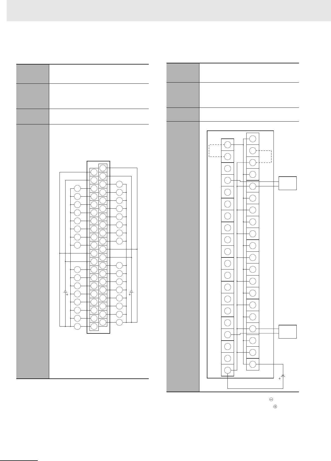
Appendices
A-74 CJ2 CPU Unit Hardware User’s Manual
zOutputs
Note The +V terminals and COM terminals are internally
connected inside the PLC, but they must all be wired.
Note 1 Connect the A9/B9 terminal and the terminal.
Connect the A10/B10 terminal and the terminal.
(Use the enclosed short bar.)
2The COM terminals are wired inside the Connec-
tor-Terminal Block Conversion Unit.
Programma-
ble Control-
ler I/O Unit
CJ1W-OD231
Connector-
Terminal
Block Con-
version Unit
XW2D-40G6
XW2D-40C6
Connecting
Cables
XW2Z-@@@B
XW2Z-@@@BU
Connection
diagram
A20
A11
A12
A13
A14
A15
A16
A17
A18
A19
B20
B11
B12
B13
B14
B15
B16
B17
B18
B19
A10
A1
A2
A3
A4
A5
A6
A7
A8
A9
B10
B1
B2
B3
B4
B5
B6
B7
B8
B9
14
15
+V
13
12
11
10
09
08
COM0
07
COM0
06
05
04
03
02
01
00
14
15
13
12
11
10
09
08
COM1
07
COM1
06
05
04
03
02
01
00
12
to
24
VDC
L
L
L
L
L
L
L
L
L
L
L
L
L
L
L
L
L
L
L
L
L
L
L
L
L
L
L
L
L
L
L
L
Wd m Wd (m+1)
+V
+V
+V
12
to
24
VDC
Programma-
ble Control-
ler I/O Unit
CJ1W-OD231
Connector-
Terminal
Block Con-
version Unit
XW2C-20G6-IO16 (2 Units)
Connecting
Cables
XW2Z-@@@L
Connection
diagram
0
1
2
3
4
5
6
7
8
9
10
11
12
13
14
15
A9
B9
A10
B10
COM0
15
14
13
12
11
10
09
08
07
06
05
04
03
02
01
00
12 to
24 VDC
+V
(COM1)
(Short bar)
(Short bar)
Solenoid valve, etc.
Wd m
(Wd (m+1))
Solenoid valve, etc.
+
−
+
−
+
+
−
−
−
+
+
−
+
−
−
+
+
+
+
−
−
−
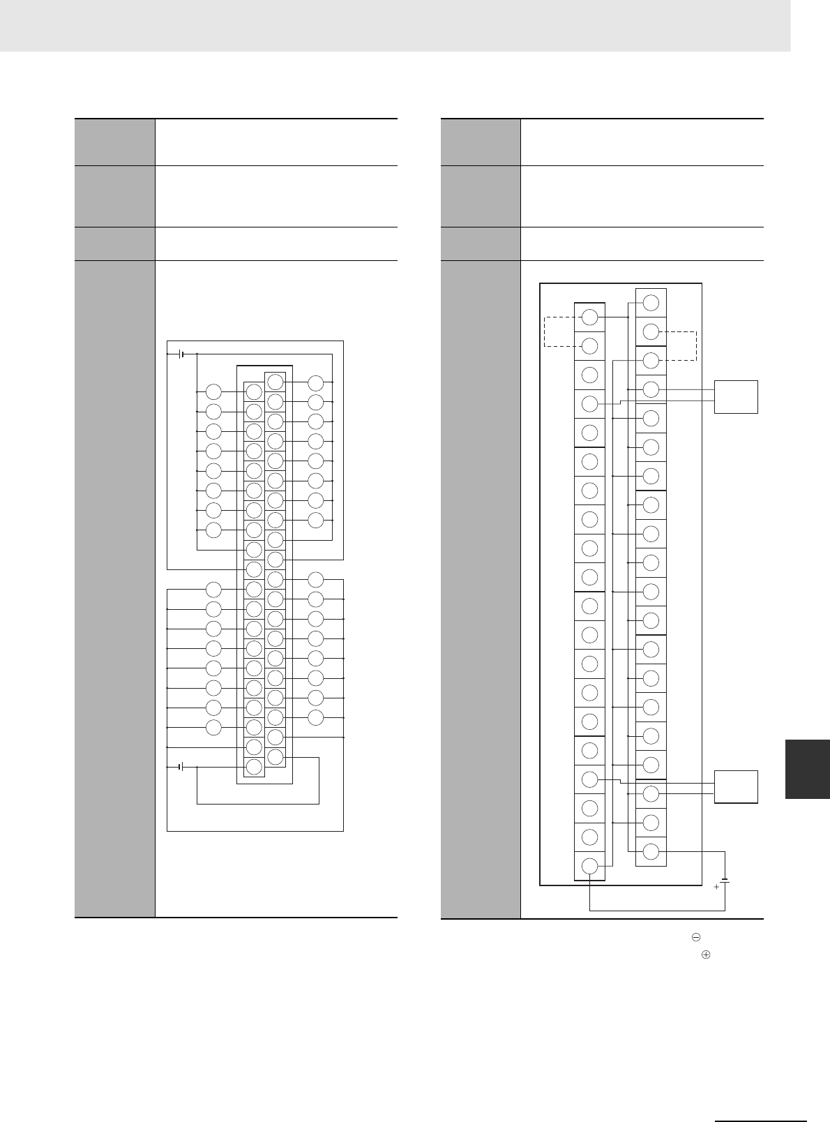
A-75
Appendices
CJ2 CPU Unit Hardware User’s Manual
A-1 Specifications of Basic I/O Units App A-1-4 Connecting Connector-Terminal Block
Conversion Units and I/O Relay Terminals
Note The COM (+V) terminals and 0 V terminals are inter-
nally connected inside the PLC, but they must all be
wired.
Note 1 Connect the A9/B9 terminal and the terminal.
Connect the A10/B10 terminal and the terminal.
(Use the enclosed short bar.)
2The COM terminals are wired inside the Connec-
tor-Terminal Block Conversion Unit.
Programma-
ble Control-
ler I/O Unit
CJ1W-OD232
Connector-
Terminal
Block Con-
version Unit
XW2D-40G6
Connecting
Cables
XW2Z-@@@K
Connection
diagram
24 VDC
24 VDC
A20
A11
A12
A13
A14
A15
A16
A17
A18
A19
B20
B11
B12
B13
B14
B15
B16
B17
B18
B19
A10
A1
A2
A3
A4
A5
A6
A7
A8
A9
B10
B1
B2
B3
B4
B5
B6
B7
B8
B9
11
10
12
13
14
15
10
11
12
13
14
15
03
02
09
01
08
00
04
05
06
07
0V
0V
0 V
0V
02
09
01
08
00
03
04
05
06
07
L
L
L
L
L
L
L
L
L
L
L
L
L
L
L
L
L
L
L
L
L
L
L
L
L
L
L
L
L
L
L
L
COM1
(+V)
COM1
(+V)
Wd (m+1)
COM0 (+V)
COM0 (+V)
Wd m
Programma-
ble Control-
ler I/O Unit
CJ1W-OD232
Connector-
Terminal
Block Con-
version Unit
XW2C-20G6-IO16 (2 Units)
Connecting
Cables
XW2Z-@@@N
Connection
diagram
0
1
2
3
4
5
6
7
8
9
10
11
12
13
14
15
A9
B9
A10
B10
15
14
13
12
11
10
09
08
07
06
05
04
03
02
01
00
24 VDC
Solenoid valve, etc.
Solenoid valve, etc.
COM0
+V
(COM1)
(Short bar)
(Short bar)
Wd m
(Wd (m+1))
+
−
−
+
−
+
−
+
−
+
−
+
−
−
+
+
+
−
−
−
+
+
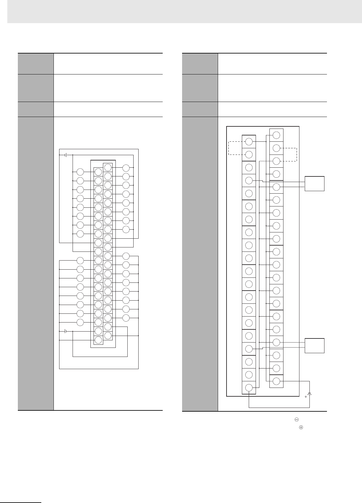
Appendices
A-76 CJ2 CPU Unit Hardware User’s Manual
Note The +V terminals and COM terminals are internally
connected inside the PLC, but they must all be wired. Note 1 Connect the A9/B9 terminal and the terminal.
Connect the A10/B10 terminal and the terminal.
(Use the enclosed short bar.)
2The COM terminals are wired inside the Connec-
tor-Terminal Block Conversion Unit.
Programma-
ble Control-
ler I/O Unit
CJ1W-OD233
Connector-
Terminal
Block Con-
version Unit
XW2D-40G6
Connecting
Cables
XW2Z-@@@K
Connection
diagram
12 to
24 VDC
A20
A11
A12
A13
A14
A15
A16
A17
A18
A19
B20
B11
B12
B13
B14
B15
B16
B17
B18
B19
A10
A1
A2
A3
A4
A5
A6
A7
A8
A9
B10
B1
B2
B3
B4
B5
B6
B7
B8
B9
11
10
12
13
14
15
10
11
12
13
14
15
03
02
09
01
08
00
04
05
06
07
COM0
COM0
COM1
COM1
02
09
01
08
00
03
04
05
06
07
L
L
L
L
L
L
L
L
L
L
L
L
L
L
L
L
L
L
L
L
L
L
L
L
L
L
L
L
L
L
L
L
Wd m
12 to
24 VDC
Wd (m+1)
+V
+V
+V
+V
Programma-
ble Control-
ler I/O Unit
CJ1W-OD233
Connector-
Terminal
Block Con-
version Unit
XW2C-20G6-IO16 (2 Units)
Connecting
Cables
XW2Z-@@@N
Connection
diagram
0
1
2
3
4
5
6
7
8
9
10
11
12
13
14
15
A9
B9
A10
B10
15
14
13
12
11
10
09
08
07
06
05
04
03
02
01
00
12 to
24 VDC
Solenoid valve, etc.
Solenoid valve, etc.
COM0
+V
(COM1)
(Short bar)
(Short bar)
Wd m
(Wd (m+1))
+
−
−
+
−
+
−
+
−
−
+
+
−
+
−
+
−
+
+
−
−
+

A-77
Appendices
CJ2 CPU Unit Hardware User’s Manual
A-1 Specifications of Basic I/O Units App A-1-4 Connecting Connector-Terminal Block
Conversion Units and I/O Relay Terminals
Note The +V terminals and COM terminals are internally
connected inside the PLC, but they must all be wired. Note 1 Connect the A9/B9 terminal and the terminal.
Connect the A10/B10 terminal and the terminal.
(Use the enclosed short bar.)
2The COM terminals are wired inside the Connec-
tor-Terminal Block Conversion Unit.
Programma-
ble Control-
ler I/O Unit
CJ1W-OD234
Connector-
Terminal
Block Con-
version Unit
XW2D-40G6
Connecting
Cables
XW2Z-@@@K
Connection
diagram
12 to
24 VDC
A20
A11
A12
A13
A14
A15
A16
A17
A18
A19
B20
B11
B12
B13
B14
B15
B16
B17
B18
B19
A10
A1
A2
A3
A4
A5
A6
A7
A8
A9
B10
B1
B2
B3
B4
B5
B6
B7
B8
B9
11
10
12
13
14
15
10
11
12
13
14
15
03
02
09
01
08
00
04
05
06
07
COM0
COM0
COM1
COM1
02
09
01
08
00
03
04
05
06
07
L
L
L
L
L
L
L
L
L
L
L
L
L
L
L
L
L
L
L
L
L
L
L
L
L
L
L
L
L
L
L
L
Wd m
12 to
24 VDC
Wd (m+1)
+V
+V
+V
+V
Programma-
ble Control-
ler I/O Unit
CJ1W-OD234
Connector-
Terminal
Block Con-
version Unit
XW2C-20G6-IO16 (2 Units)
Connecting
Cables
XW2Z-@@@N
Connection
diagram
0
1
2
3
4
5
6
7
8
9
10
11
12
13
14
15
A9
B9
A10
B10
15
14
13
12
11
10
09
08
07
06
05
04
03
02
01
00
12 to
24 VDC
Solenoid valve, etc.
Solenoid valve, etc.
COM0
+V
(COM1)
(Short bar)
(Short bar)
Wd m
(Wd (m+1))
+
−
−
+
−
+
−
+
−
−
+
+
−
+
−
+
−
+
+
−
−
+
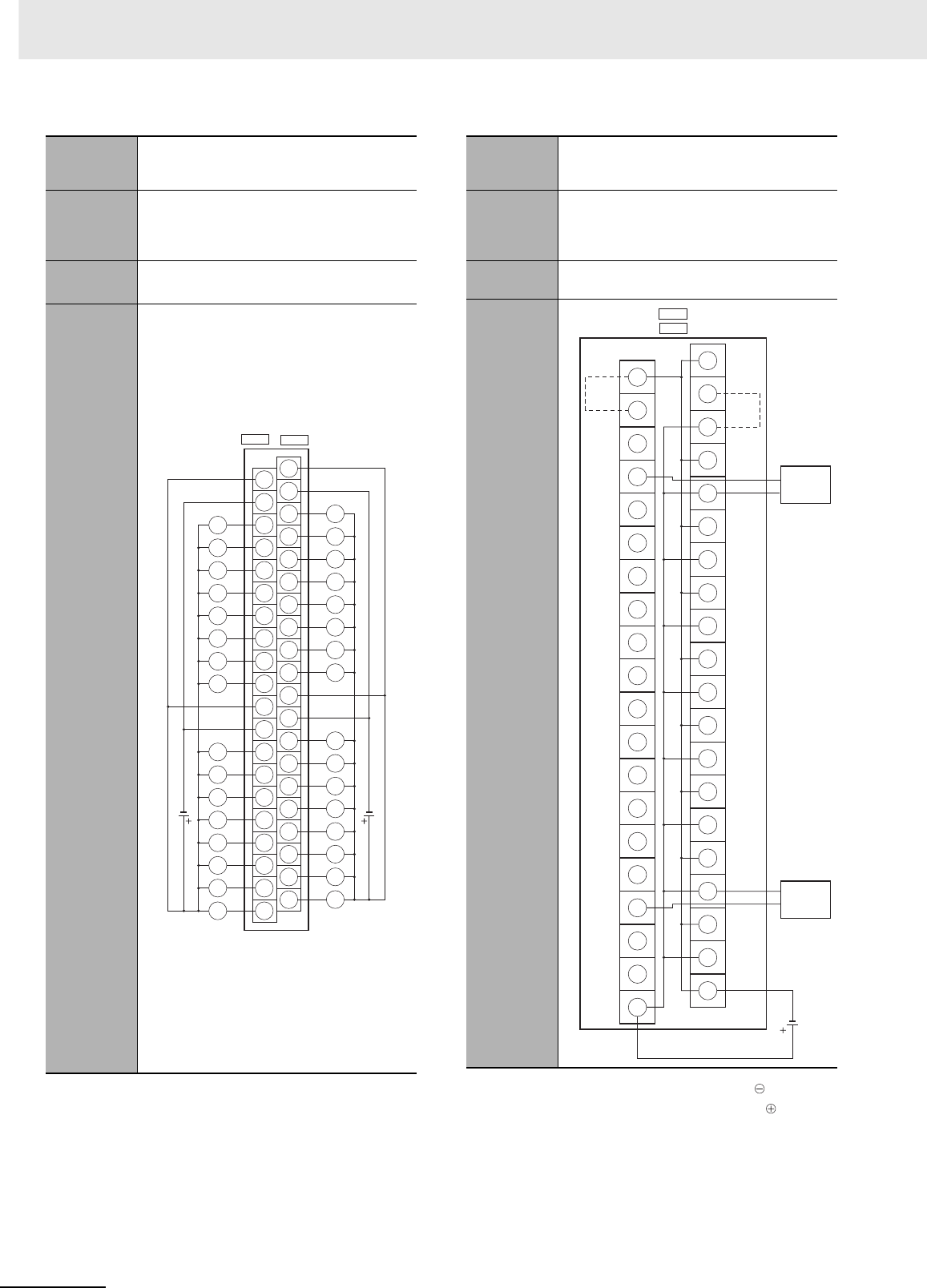
Appendices
A-78 CJ2 CPU Unit Hardware User’s Manual
Note The +V terminals and COM terminals are internally
connected inside the PLC, but they must all be wired.
Note 1 Connect the A9/B9 terminal and the terminal.
Connect the A10/B10 terminal and the terminal.
(Use the enclosed short bar.)
2The COM terminals are wired inside the Connec-
tor-Terminal Block Conversion Unit.
Programma-
ble Control-
ler I/O Unit
CJ1W-OD261
Connector-
Terminal
Block Con-
version Unit
XW2D-40G6
XW2D-40C6
Connecting
Cables
XW2Z-@@@B
XW2Z-@@@BU
Connection
diagram
A20
A11
A12
A13
A14
A15
A16
A17
A18
A19
B20
B11
B12
B13
B14
B15
B16
B17
B18
B19
A10
A1
A2
A3
A4
A5
A6
A7
A8
A9
B10
B1
B2
B3
B4
B5
B6
B7
B8
B9
14
15
13
12
11
10
09
08
COM0
07
COM0
06
05
04
03
02
01
00
14
15
13
12
11
10
09
08
COM1
07
COM1
06
05
04
03
02
01
00
12 to
24
VDC
L
L
L
L
L
L
L
L
L
L
L
L
L
L
L
L
L
L
L
L
L
L
L
L
L
L
L
L
L
L
L
L
CN1 CN2
()
+V
+V
(COM3)
(COM2)
Wd m
(Wd (m+2)) Wd (m+1)
(Wd (m+3))
+V
+V
(COM3)
(COM2)
12 to
24
VDC
Programma-
ble Control-
ler I/O Unit
CJ1W-OD261
Connector-
Terminal
Block Con-
version Unit
XW2C-20G6-IO16 (2 Units)
Connecting
Cables
XW2Z-@@@L
Connection
diagram
0
1
2
3
4
5
6
7
8
9
10
11
12
13
14
15
A9
B9
A10
B10
CN1
( CN2 )
COM
15
14
13
12
11
10
09
08
07
06
05
04
03
02
01
00
12 to
24 VDC
Solenoid valve, etc.
+V
(Short bar)
Wd m
and (m+1)
(Wd (m+2)
and (m+3))
(Short bar)
Solenoid valve, etc.
+
−
+
−
−
+
+
−
+
−
+
−
+
−
−
+
+
−
+
−
−
+

A-79
Appendices
CJ2 CPU Unit Hardware User’s Manual
A-1 Specifications of Basic I/O Units App A-1-4 Connecting Connector-Terminal Block
Conversion Units and I/O Relay Terminals
Note The COM (+V) terminals and 0 V terminals are inter-
nally connected inside the PLC, but they must all be
wired.
Note 1 Connect the A9/B9 terminal and the terminal.
Connect the A10/B10 terminal and the terminal.
(Use the enclosed short bar.)
2The COM terminals are wired inside the Connec-
tor-Terminal Block Conversion Unit.
Programma-
ble Control-
ler I/O Unit
CJ1W-OD262
Connector-
Terminal
Block Con-
version Unit
XW2D-40G6
Connecting
Cables
XW2Z-@@@K
Connection
diagram
24 VDC
24 VDC
11
10
12
13
14
15
10
11
12
13
14
15
03
02
09
01
08
00
04
05
06
07
0 V
0 V
0 V
02
09
01
08
00
03
04
05
06
07
L
L
L
L
L
L
L
L
L
L
L
L
L
L
L
L
L
L
L
L
L
L
L
L
L
L
L
L
L
L
L
L
A20
A11
A12
A13
A14
A15
A16
A17
A18
A19
B20
B11
B12
B13
B14
B15
B16
B17
B18
B19
A10
A1
A2
A3
A4
A5
A6
A7
A8
A9
B10
B1
B2
B3
B4
B5
B6
B7
B8
B9
CN1 CN2
()
Wd m
(Wd (m+2))
COM0 (+V)
(COM2 (+V))
0 V
COM0 (+V)
(COM2 (+V))
Wd (m+1)
(Wd (m+3))
COM1 (+V)
(COM3 (+V))
COM1 (+V)
(COM3 (+V))
Programma-
ble Control-
ler I/O Unit
CJ1W-OD262
Connector-
Terminal
Block Con-
version Unit
XW2C-20G6-IO16 (2 Units)
Connecting
Cables
XW2Z-@@@N
Connection
diagram
0
1
2
3
4
5
6
7
8
9
10
11
12
13
14
15
A9
B9
A10
B10
CN1
COM0
15
14
13
12
11
10
09
08
07
06
05
04
03
02
01
00
24 VDC
Solenoid valve, etc.
Solenoid valve, etc.
(Short bar)
Wd m
and (m+1)
(Wd (m+2)
and (m+3))
(Short bar)
+V
(COM1)
()
CN2
−
+
−
+
−
+
−
+
−
+
−
−
+
+
−
+
−
+
+
−
−
+

Appendices
A-80 CJ2 CPU Unit Hardware User’s Manual
Note The +V terminals and COM terminals are internally
connected inside the PLC, but they must all be wired. Note 1 Connect the A9/B9 terminal and the terminal.
Connect the A10/B10 terminal and the terminal.
(Use the enclosed short bar.)
2The COM terminals are wired inside the Connec-
tor-Terminal Block Conversion Unit.
Programma-
ble Control-
ler I/O Unit
CJ1W-OD263
Connector-
Terminal
Block Con-
version Unit
XW2D-40G6
Connecting
Cables
XW2Z-@@@K
Connection
diagram
12 to
24 VDC
12 to
24 VDC
11
10
12
13
14
15
10
11
12
13
14
15
03
02
09
01
08
00
04
05
06
07
02
09
01
08
00
03
04
05
06
07
L
L
L
L
L
L
L
L
L
L
L
L
L
L
L
L
L
L
L
L
L
L
L
L
L
L
L
L
L
L
L
L
COM0
COM0
COM1
COM1
CN1
A20
A11
A12
A13
A14
A15
A16
A17
A18
A19
B20
B11
B12
B13
B14
B15
B16
B17
B18
B19
A10
A1
A2
A3
A4
A5
A6
A7
A8
A9
B10
B1
B2
B3
B4
B5
B6
B7
B8
B9
()
Wd m
(Wd (m+2))
CN2
(COM2)
(COM2) +V
+V
(COM3)
+V
Wd (m+1)
(Wd (m + 3))
(COM3)
+V
Programma-
ble Control-
ler I/O Unit
CJ1W-OD263
Connector-
Terminal
Block Con-
version Unit
XW2C-20G6-IO16 (2 Units)
Connecting
Cables
XW2Z-@@@N
Connection
diagram
0
1
2
3
4
5
6
7
8
9
10
11
12
13
14
15
A9
B9
A10
B10
CN1
COM0
15
14
13
12
11
10
09
08
07
06
05
04
03
02
01
00
12 to
24 VDC
Solenoid valve, etc.
(Short bar)
Wd m
and (m+1)
(Wd (m+2)
and (m+3))
(Short bar)
+V
(COM1)
()
CN2
Solenoid valve, etc.
−
+
−
+
+
−
+
−
+
−
+
−
+
−
+
−
+
−
+
+
−
−
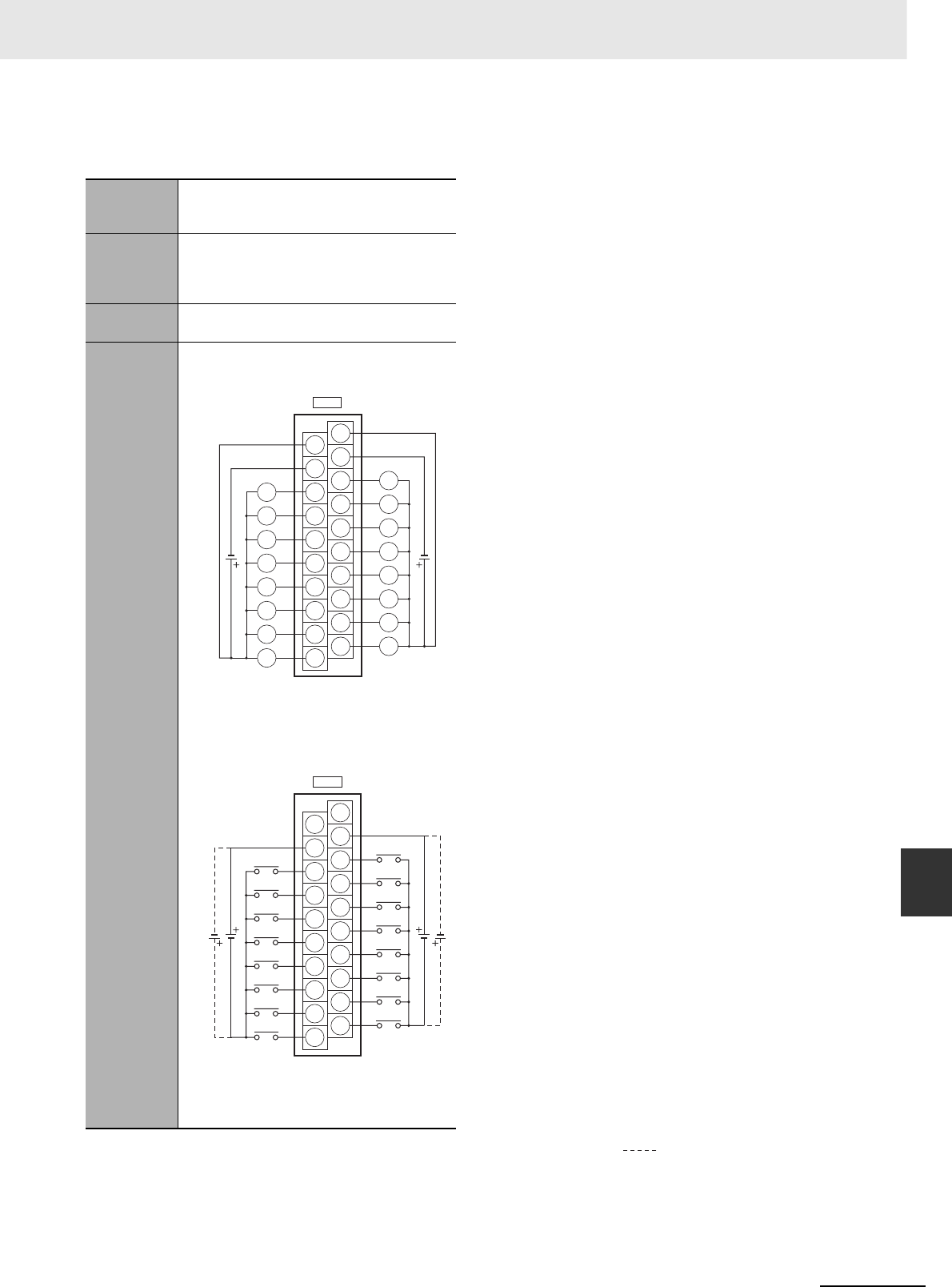
A-81
Appendices
CJ2 CPU Unit Hardware User’s Manual
A-1 Specifications of Basic I/O Units App A-1-4 Connecting Connector-Terminal Block
Conversion Units and I/O Relay Terminals
zInputs and Outputs
Note 1 The polarity for input power supply connections indicated with dotted lines ( ) can be connected in either direc-
tion.
2The COM terminals are internally connected inside the PLC, but they must all be wired.
Programma-
ble Control-
ler I/O Unit
CJ1W-MD231
Connector-
Terminal
Block Con-
version Unit
XW2D-20G6
Connecting
Cables
XW2Z-@@@A
Connection
diagram
A10
A1
A2
A3
A4
A5
A6
A7
A8
A9
B10
B1
B2
B3
B4
B5
B6
B7
B8
B9
CN2
A10
A1
A2
A3
A4
A5
A6
A7
A8
A9
B10
B1
B2
B3
B4
B5
B6
B7
B8
B9
CN1
L
L
L
L
L
L
L
L
L
L
L
L
L
L
L
L
07
06
05
04
03
02
01
00
07
COM
NC
06
05
04
03
02
01
00
15
COM
NC
14
13
12
11
10
09
08
15
14
13
12
11
10
09
08
12 to
24 VDC
12 to
24 VDC
24
VDC 24
VDC
Wd m (OUT)
+V
+V
COM (0 V)
COM (0 V)
Wd (m+1) (IN)
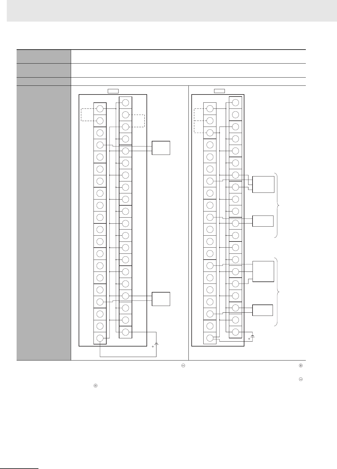
Appendices
A-82 CJ2 CPU Unit Hardware User’s Manual
Programmable Con-
troller I/O Unit
CJ1W-MD231
Connector-Terminal
Block Conversion Unit
XW2C-20G6-IO16
Connecting Cables XW2Z-@@@A
Connection diagram
Note 1 Connect the A9/B9 terminal and the
terminal.
Connect the A10/B10 terminal and the
terminal.
(Use the enclosed short bar.)
2The COM terminals are wired inside the
Connector-Terminal Block Conversion
Unit.
Note 1 Connect the A9/B9 terminal and the
terminal for NPN.
Connect the A9/B9 terminal and the
terminal for PNP.
(Use the enclosed short bar.)
2The COM terminals are wired inside the
Connector-Terminal Block Conversion
Unit.
0
1
2
3
4
5
6
7
8
9
10
11
12
13
14
15
A9
B9
A10
B10
COM0
15
14
13
12
11
10
09
08
07
06
05
04
03
02
01
00
12 to
24 VDC
CN1 (OUT)
Solenoid valve, etc.
Wd m
(Short bar)
+V
(COM1)
(Short
bar)
Solenoid valve, etc.
+
−
+
−
+
−
+
−
+
−
+
−
+
−
+
−
+
−
+
+
−
−
0
1
2
3
4
5
6
7
8
9
10
11
12
13
14
15
A9
B9
A10
B10
CN2 Wd (m+1)
(Short
bar)
(IN)
24 VDC
PNP
NPN
Black (White)
Brown (Red)
Blue (Black)
Blue (Black)
Brown (White)
Black (White)
Brown (Red)
Blue (Black)
3-wire sensor with
PNP output
(photoelectric sensor
or proximity sensor)
3-wire sensor with
NPN output
(photoelectric sensor
or proximity sensor)
2-wire sensor
(e.g., limit switch)
Blue (Black)
Brown (White)
2-wire sensor
(e.g., limit switch)
+
−
−
+
−
+
−
+
−
+
−
+
−
+
−
+
−
+
−
−
+
+
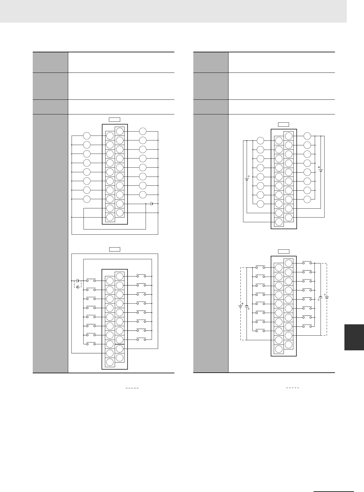
A-83
Appendices
CJ2 CPU Unit Hardware User’s Manual
A-1 Specifications of Basic I/O Units App A-1-4 Connecting Connector-Terminal Block
Conversion Units and I/O Relay Terminals
Note 1 The polarity for input power supply connections
indicated with dotted lines ( ) can be con-
nected in either direction.
2The COM terminals and 0V terminal are internally
connected inside the PLC, but they must all be
wired.
Note 1 The polarity for input power supply connections
indicated with dotted lines ( ) can be con-
nected in either direction.
2The COM terminals and +V terminals are inter-
nally connected inside the PLC, but they must all
be wired.
Programma-
ble Control-
ler I/O Unit
CJ1W-MD232
Connector-
Terminal
Block Con-
version Unit
XW2D-20G6
Connecting
Cables
XW2Z-@@@X
Connection
diagram
A10
A1
A2
A3
A4
A5
A6
A7
A8
A9
B10
B1
B2
B3
B4
B5
B6
B7
B8
B9
CN2
A10
A1
A2
A3
A4
A5
A6
A7
A8
A9
B10
B1
B2
B3
B4
B5
B6
B7
B8
B9
CN1
L
L
L
L
L
L
L
L
L
L
L
L
L
L
L
L
10
09
08
11
12
13
14
15
0 V
09
08
NC
10
11
12
13
14
15
COM
01
00
NC
02
03
04
05
06
07
COM
02
01
00
03
04
05
06
07
0 V
24 VDC
COM (+V)
COM (+V)
Wd m (OUT)
Wd (m+1) (OUT)
24 VDC
Programma-
ble Control-
ler I/O Unit
CJ1W-MD233
Connector-
Terminal
Block Con-
version Unit
XW2D-20G6
Connecting
Cables
XW2Z-@@@X
Connection
diagram
A10
A1
A2
A3
A4
A5
A6
A7
A8
A9
B10
B1
B2
B3
B4
B5
B6
B7
B8
B9
CN2
A10
A1
A2
A3
A4
A5
A6
A7
A8
A9
B10
B1
B2
B3
B4
B5
B6
B7
B8
B9
CN1
10
09
08
11
12
13
14
15
09
08
NC
10
11
12
13
14
15
COM
01
00
NC
02
03
04
05
06
07
COM
02
01
00
03
04
05
06
07 L
L
L
L
L
L
L
L
L
L
L
L
L
L
L
L
12 to
24
VDC
24
VDC
24
VDC
12 to
24
VDC
Wd m (OUT)
COM (0 V)
COM (0 V)
+V
+V
Wd (m+1) (IN)
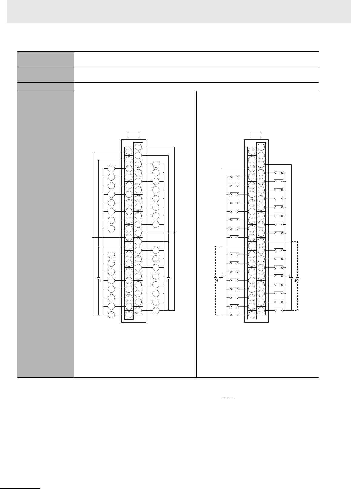
Appendices
A-84 CJ2 CPU Unit Hardware User’s Manual
Programmable Con-
troller I/O Unit
CJ1W-MD261
Connector-Terminal
Block Conversion Unit
XW2D-40G6
XW2D-40G6RF
Connecting Cables XW2Z-@@@B
Connection diagram
Note The +V terminals and COM terminals are
internally connected inside the PLC, but
they must all be wired.
Note 1 The polarity for input power supply con-
nections indicated with dotted lines
( ) can be connected in either
direction provided that the same polarity
is used for the commons for rows A and
B.
2Both COM2 and COM3 have two pins
each. They are internally connected
inside the PLC, but they must all be
wired.
A20
A11
A12
A13
A14
A15
A16
A17
A18
A19
B20
B11
B12
B13
B14
B15
B16
B17
B18
B19
A10
A1
A2
A3
A4
A5
A6
A7
A8
A9
B10
B1
B2
B3
B4
B5
B6
B7
B8
B9
14
15
13
12
11
10
09
08
COM0
07
COM0
06
05
04
03
02
01
00
14
15
13
12
11
10
09
08
COM1
07
COM1
06
05
04
03
02
01
00
12 to
24 VDC
L
L
L
L
L
L
L
L
L
L
L
L
L
L
L
L
L
L
L
L
L
L
L
L
L
L
L
L
L
L
L
L
CN1
+V
+V
(OUT)
Wd m Wd (m+1)
+V
+V
12 to
24 VDC
A20
A11
A12
A13
A14
A15
A16
A17
A18
A19
B20
B11
B12
B13
B14
B15
B16
B17
B18
B19
A10
A1
A2
A3
A4
A5
A6
A7
A8
A9
B10
B1
B2
B3
B4
B5
B6
B7
B8
B9
15
COM2
NC
14
13
12
11
10
09
08
NC
07
COM2
06
05
04
03
02
01
00
15
COM3
NC
14
13
12
11
10
09
08
NC
07
COM3
06
05
04
03
02
01
00
24 VDC
CN2 (IN)
Wd (m+3)
Wd (m+2)
24 VDC
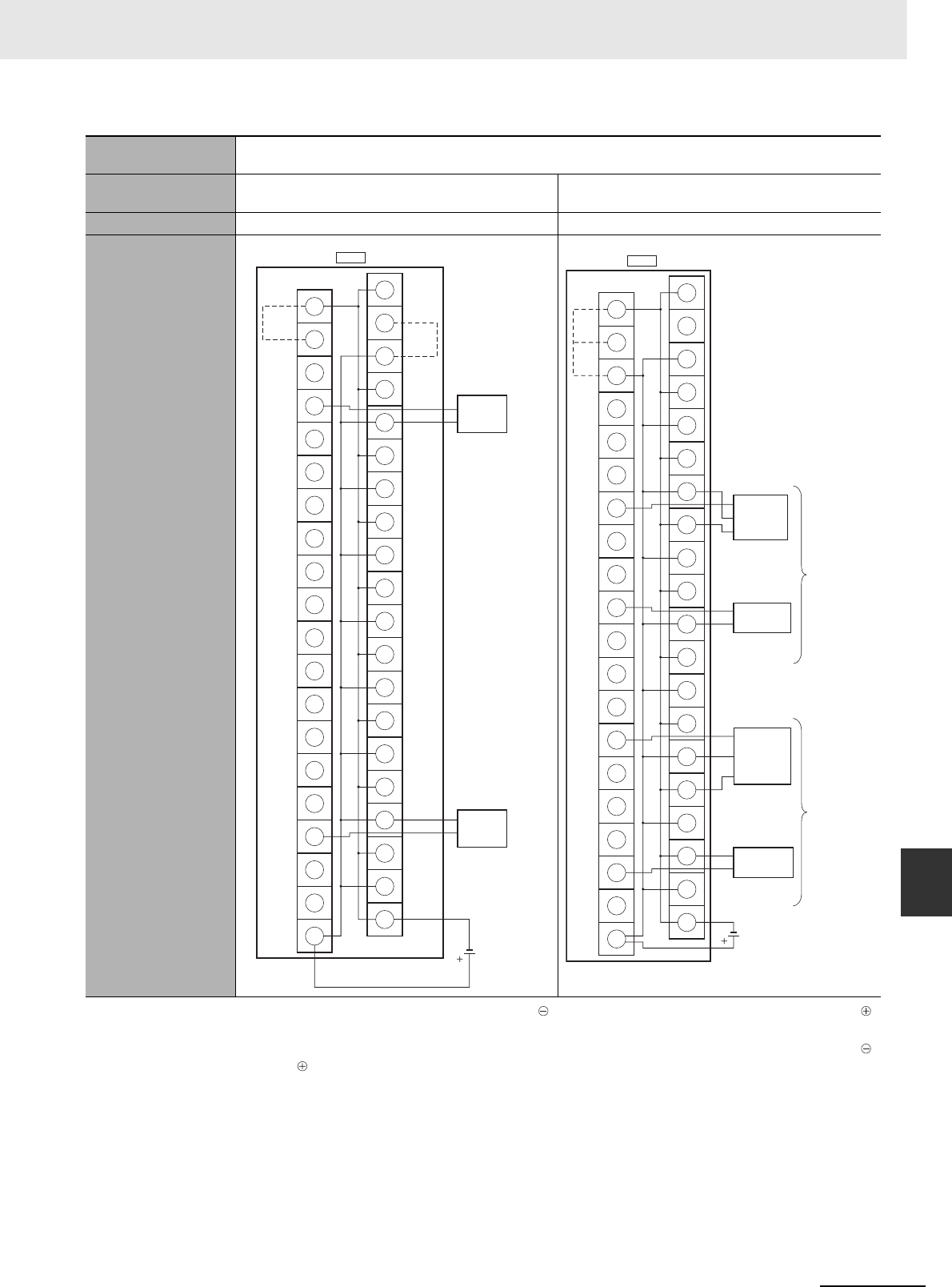
A-85
Appendices
CJ2 CPU Unit Hardware User’s Manual
A-1 Specifications of Basic I/O Units App A-1-4 Connecting Connector-Terminal Block
Conversion Units and I/O Relay Terminals
Programmable Con-
troller I/O Unit
CJ1W-MD261
Connector-Terminal
Block Conversion Unit
XW2C-20G6-IO16 (2 Units) XW2C-20G6-IO16 (2 Units)
Connecting Cables XW2Z-@@@LXW2Z-@@@D
Connection diagram
Note 1 Connect the A9/B9 terminal and the
terminal.
Connect the A10/B10 terminal and the
terminal.
(Use the enclosed short bar.)
2The COM terminals are wired inside the
Connector-Terminal Block Conversion
Unit.
Note 1 Connect the A9/B9 terminal and the
terminal for NPN.
Connect the A9/B9 terminal and the
terminal for PNP.
(Use the enclosed short bar.)
2The COM terminals are wired inside the
Connector-Terminal Block Conversion
Unit.
0
1
2
3
4
5
6
7
8
9
10
11
12
13
14
15
A9
B9
A10
B10
COM0
15
14
13
12
11
10
09
08
07
06
05
04
03
02
01
00
CN2
12 to 24 VDC
Solenoid valve, etc.
Solenoid valve, etc.
Wd m
(Wd (m+1))
(Short bar)
+V
(COM1)
(Short
bar)
(OUT)
+
−
−
−
+
+
−
−
+
+
+
−
−
+
−
+
+
−
−
−
+
+
0
1
2
3
4
5
6
7
8
9
10
11
12
13
14
15
A9
B9
A10
B10
CN2
24 VDC
PNP
NPN
Black (White)
Brown (Red)
Blue (Black)
Blue (Black)
Brown (White)
Black (White)
Brown (Red)
Blue (Black)
3-wire sensor with
PNP output
(photoelectric sensor
or proximity sensor)
3-wire sensor with
NPN output
(photoelectric sensor
or proximity sensor)
2-wire sensor
(e.g., limit switch)
Blue (Black)
Brown (White)
2-wire sensor
(e.g., limit switch)
Wd (m+2)
(Wd (m+3))
(Short
bar)
(IN)
+
−
−
+
+
+
+
+
+
+
+
+
+
−
−
−
−
−
−
−
−
−
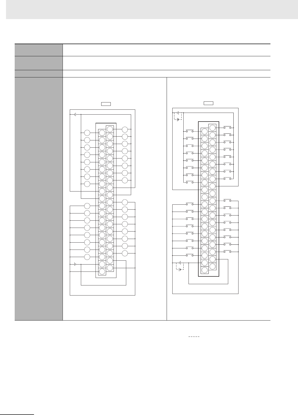
Appendices
A-86 CJ2 CPU Unit Hardware User’s Manual
Programmable Con-
troller I/O Unit
CJ1W-MD263
Connector-Terminal
Block Conversion Unit
XW2D-40G6
XW2D-40G6-RM
Connecting Cables XW2Z-@@@K
Connection diagram
Note The +V terminals and COM terminals are
internally connected inside the PLC, but
they must all be wired.
Note 1 The polarity for input power supply con-
nections indicated with dotted lines
( ) can be connected in either
direction.
2Both COM2 and COM3 have two pins
each. They are internally connected
inside the PLC, but they must all be
wired.
CN1
12 to
24 VDC
12 to
24 VDC
A20
A11
A12
A13
A14
A15
A16
A17
A18
A19
B20
B11
B12
B13
B14
B15
B16
B17
B18
B19
A10
A1
A2
A3
A4
A5
A6
A7
A8
A9
B10
B1
B2
B3
B4
B5
B6
B7
B8
B9
11
10
12
13
14
15
+V
10
11
12
13
14
15
03
02
09
01
08
00
04
05
06
07
+V
COM0
COM0
COM1
COM1
02
09
01
08
00
03
04
05
06
07
L
L
L
L
L
L
L
L
L
L
L
L
L
L
L
L
L
L
L
L
L
L
L
L
L
L
L
L
L
L
L
L
Wd m
Wd (m+1)
+V
+V
(OUT)
A20
A11
A12
A13
A14
A15
A16
A17
A18
A19
B20
B11
B12
B13
B14
B15
B16
B17
B18
B19
A10
A1
A2
A3
A4
A5
A6
A7
A8
A9
B10
B1
B2
B3
B4
B5
B6
B7
B8
B9
08
09
10
11
12
13
14
15
09
08
10
11
12
13
14
15
00
01
02
03
04
05
06
07
00
NC
NC
NC
NC
COM2
COM2
COM3
COM3
01
02
03
04
05
06
07
24 VDC
24 VDC
Wd (m+2)
CN2 (IN)
Wd (m+3)

A-87
Appendices
CJ2 CPU Unit Hardware User’s Manual
A-1 Specifications of Basic I/O Units App A-1-4 Connecting Connector-Terminal Block
Conversion Units and I/O Relay Terminals
Programmable Con-
troller I/O Unit
CJ1W-MD263
Connector-Terminal
Block Conversion Unit
XW2C-20G6-IO16 (2 Units)
Connecting Cables XW2Z-@@@N
Connection diagram
Note 1 Connect the A9/B9 terminal and the
terminal.
Connect the A10/B10 terminal and the
terminal.
(Use the enclosed short bar.)
2The COM terminals are wired inside the
Connector-Terminal Block Conversion
Unit.
Note 1 Connect the A9/B9 terminal and the
terminal for NPN.
Connect the A9/B9 terminal and the
terminal for PNP.
(Use the enclosed short bar.)
2The COM terminals are wired inside the
Connector-Terminal Block Conversion
Unit.
0
1
+
2
3
4
5
6
7
8
9
10
11
12
13
14
15
+
A9
B9
−
−
+
−
+
−
+
−
+
−
+
−
+
−
+
−
+
−
+
A10
B10
−
COM0
15
14
13
12
11
10
09
08
07
06
05
04
03
02
01
00
12 to
24 VDC
CN1
Solenoid valve, etc.
Wd m
(Wd (m+1))
(Short bar)
+V
(COM1)
(Short
bar)
(OUT)
Solenoid valve, etc.
0
1
2
3
4
5
6
7
8
9
10
11
12
13
14
15
A9
B9
A10
B10
CN2
24 VDC
PNP
NPN
Black (White)
Brown (Red)
Blue (Black)
Blue (Black)
Brown (White)
Black (White)
Brown (Red)
Blue (Black)
3-wire sensor with
PNP output
(photoelectric sensor
or proximity sensor)
3-wire sensor with
NPN output
(photoelectric sensor
or proximity sensor)
2-wire sensor
(e.g., limit switch)
Blue (Black)
Brown (White)
2-wire sensor
(e.g., limit switch)
Wd (m+2)
(Wd (m+3))
(Short
bar)
(IN)
+
−
−
−
−
−
−
−
−
−
−
−
+
+
+
+
+
+
+
+
+
+
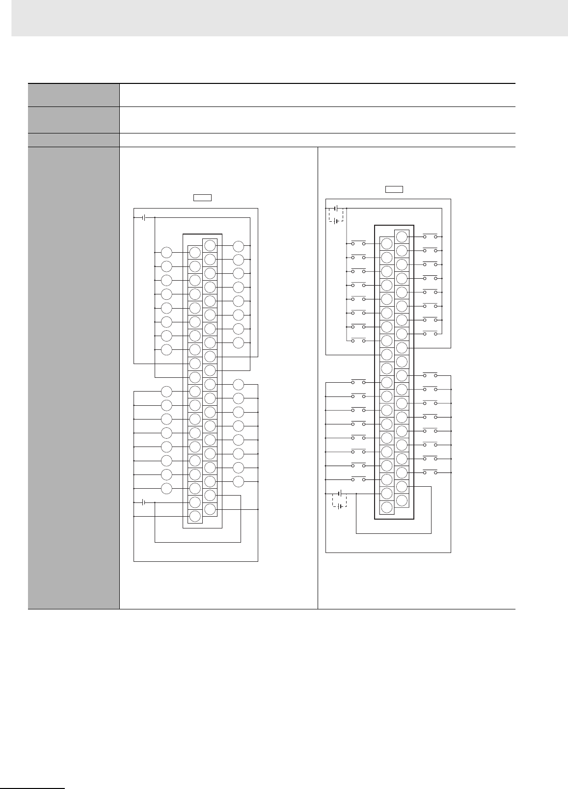
Appendices
A-88 CJ2 CPU Unit Hardware User’s Manual
Programmable Con-
troller I/O Unit
CJ1W-MD563
Connector-Terminal
Block Conversion Unit
XW2D-40G6
XW2D-40G6-RM
Connecting Cables XW2Z-@@@K
Connection diagram
Note 1 The +V terminals and COM terminals
are internally connected inside the PLC,
but they must all be wired.
2The power supply voltage for the CJ1W-
MD563 is 5 V.
Note 1 The COM terminals are internally con-
nected inside the PLC, but they must all
be wired.
2The power supply voltage for the CJ1W-
MD563 is 5 V.
CN1
5 VDC
5 VDC
A20
A11
A12
A13
A14
A15
A16
A17
A18
A19
B20
B11
B12
B13
B14
B15
B16
B17
B18
B19
A10
A1
A2
A3
A4
A5
A6
A7
A8
A9
B10
B1
B2
B3
B4
B5
B6
B7
B8
B9
11
10
12
13
14
15
10
11
12
13
14
15
03
02
09
01
08
00
04
05
06
07
COM0
COM0
COM1
COM1
02
09
01
08
00
03
04
05
06
07
L
L
L
L
L
L
L
L
L
L
L
L
L
L
L
L
L
L
L
L
L
L
L
L
L
L
L
L
L
L
L
L
Wd m
Wd (m+1)
+V +V
+V
+V
(OUT)
A20
A11
A12
A13
A14
A15
A16
A17
A18
A19
B20
B11
B12
B13
B14
B15
B16
B17
B18
B19
A10
A1
A2
A3
A4
A5
A6
A7
A8
A9
B10
B1
B2
B3
B4
B5
B6
B7
B8
B9
08
09
10
11
12
13
14
15
09
08
10
11
12
13
14
15
00
01
02
03
04
05
06
07
00
NC
NC
NC
NC
COM2
COM2
COM3
COM3
01
02
03
04
05
06
07
5 VDC
5 VDC
Wd (m+2)
CN2 (IN)
Wd (m+3)
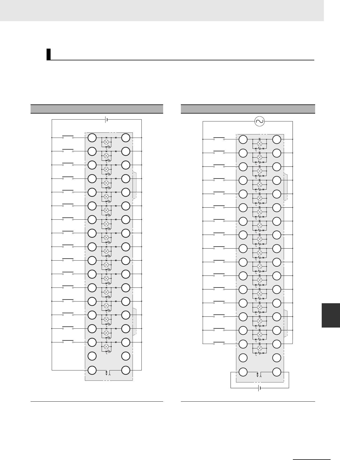
A-89
Appendices
CJ2 CPU Unit Hardware User’s Manual
A-1 Specifications of Basic I/O Units App A-1-4 Connecting Connector-Terminal Block
Conversion Units and I/O Relay Terminals
Connection examples and internal connection diagrams for I/O Relay Terminals connected to Basic I/O
Units are shown below.
zInputs
G7TC I/O Relay Terminals
Connection Diagrams for I/O Relay Terminals
G7TC-ID16 G7TC-IA16
TOP VIEW TOP VIEW
Note 1 Inputs to the PLC Input Units and I/O Relay Terminals
use isolated contacts. “00” to “15” are the input bit
numbers for the PLC Input Unit and the input numbers
for the I/O Relay Terminal.
2Use the G78-04 short bar to short to the common ter-
minal.
Note 1 Inputs to the PLC Input Units and I/O Relay Terminals
use isolated contacts. “00” to “15” are the input bit num-
bers for the PLC Input Unit and the input numbers for
the I/O Relay Terminal.
2Use the G78-04 short bar to short to the common termi-
nal.
PLC
G7TC
15
14
13
12
11
10
9
8
7
6
5
4
3
2
1
0
C15
C14
C13
C12
C11
C10
C9
C8
C7
C6
C5
C4
C3
C2
C1
C0
NC NC
15
14
13
12
11
10
09
08
07
06
05
04
03
02
01
00
Relay side
+−
PLC
15
14
13
12
11
10
9
8
7
6
5
4
3
2
1
0
NC
C15
C14
C13
C12
C11
C10
C9
C8
C7
C6
C5
C4
C3
C2
C1
C0
NC
14
13
12
11
10
09
08
07
06
05
04
03
02
01
00
15
G7TC
Relay side
+−
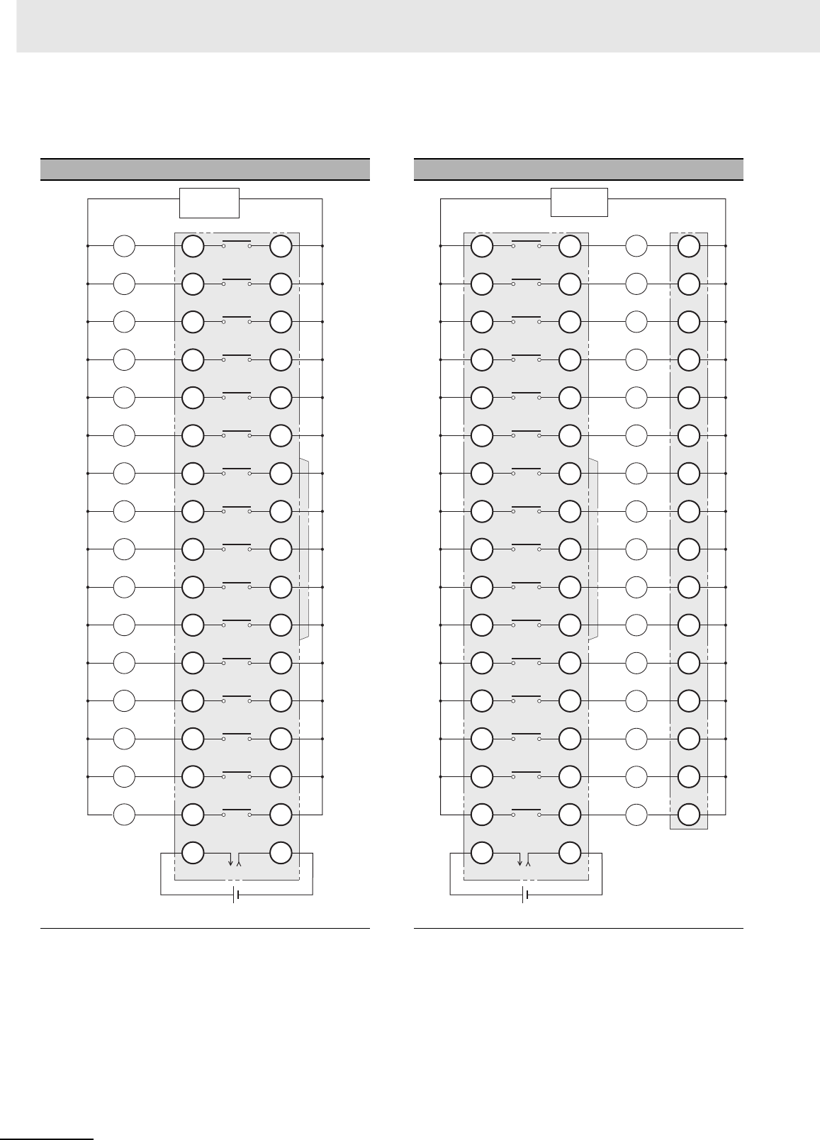
Appendices
A-90 CJ2 CPU Unit Hardware User’s Manual
zOutputs
G70D-V Relay Terminals
G70D-VSOC16 G70D-VSOC16+G70D-ET
TOP VIEW TOP VIEW
Note 1 All outputs are independent. Outputs on the PLC Out-
put Unit and I/O Relay Terminal are isolated. “00” to
“15” are the output bit numbers for the PLC Output
Unit and the output numbers for the I/O Relay Termi-
nal.
2Use the G6D-4-SB short bar to short to the common
terminal.
Note 1 All outputs are independent. Outputs on the PLC Out-
put Unit and I/O Relay Terminal are isolated. “00” to
“15” are the output bit numbers for the PLC Output
Unit and the output numbers for the I/O Relay Termi-
nal.
2Use the G6D-4-SB short bar to short to the common
terminal.
PLC
15
14
13
12
11
10
09
08
07
06
05
04
03
02
01
00
A15
A14
A13
A12
A11
A10
A9
A8
A7
A6
A5
A4
A3
A2
A1
A0
B15
B14
B13
B12
B11
B10
B9
B8
B7
B6
B5
B4
B3
B2
B1
B0
Power
supply
G70D-VSOC16
Back side
24
VDC 0
L
L
L
L
L
L
L
L
L
L
L
L
L
L
L
L
PLC
15
14
13
12
11
10
09
08
07
06
05
04
03
02
01
00
B15
B14
B13
B12
B11
B10
B9
B8
B7
B6
B5
B4
B3
B2
B1
B0
C15
C14
C13
C12
C11
C10
C9
C8
C7
C6
C5
C4
C3
C2
C1
C0
A15
A14
A13
A12
A11
A10
A9
A8
A7
A6
A5
A4
A3
A2
A1
A0
G70D-VSOC16 G70D-ET
24
VDC
0
L
L
L
L
L
L
L
L
L
L
L
L
L
L
L
L
Power
supply
Back
side
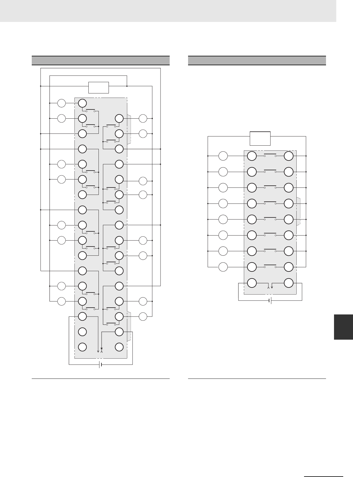
A-91
Appendices
CJ2 CPU Unit Hardware User’s Manual
A-1 Specifications of Basic I/O Units App A-1-4 Connecting Connector-Terminal Block
Conversion Units and I/O Relay Terminals
G70D Relay Terminals
G70D-SOC16 G70D-SOC08
TOP VIEW TOP VIEW
Note Every two outputs share a common. The current supplied
is 3 A per common. Outputs on the PLC Output Unit and
I/O Relay Terminal are isolated. “00” to “15” are the out-
put bit numbers for the PLC Output Unit and the output
numbers for the I/O Relay Terminal.
Note 1 All outputs are independent. Outputs on the PLC Out-
put Unit and I/O Relay Terminal are isolated. “00” to
“07” are the output bit numbers for the PLC Output
Unit and the output numbers for the I/O Relay Termi-
nal.
2Use the G6D-4-SB short bar to short to the common
terminal.
PLC
B7
B5
B5
B3
B3
B1
NC
NC
B6
B4
B4
B2
B2
B0
0
NC
15
13
11
09
07
05
03
01
00
02
04
06
08
10
12
14
Power
supply
A15
A13
A11
A9
A7
A5
A3
A2
A0
A4
A6
A8
A10
A12
A1
A14
G70D-SOC16
Relay side
24
VDC
L
L
L
L
L
L
L
L
L
L
L
L
L
L
L
L
PLC
07
06
05
04
03
02
01
00
A7
A6
A5
A4
A3
A2
A1
A0
B7
B6
B5
B4
B3
B2
B1
B0
Power
supply
G70D-SOC08
Relay side
24
VDC
0V
L
L
L
L
L
L
L
L
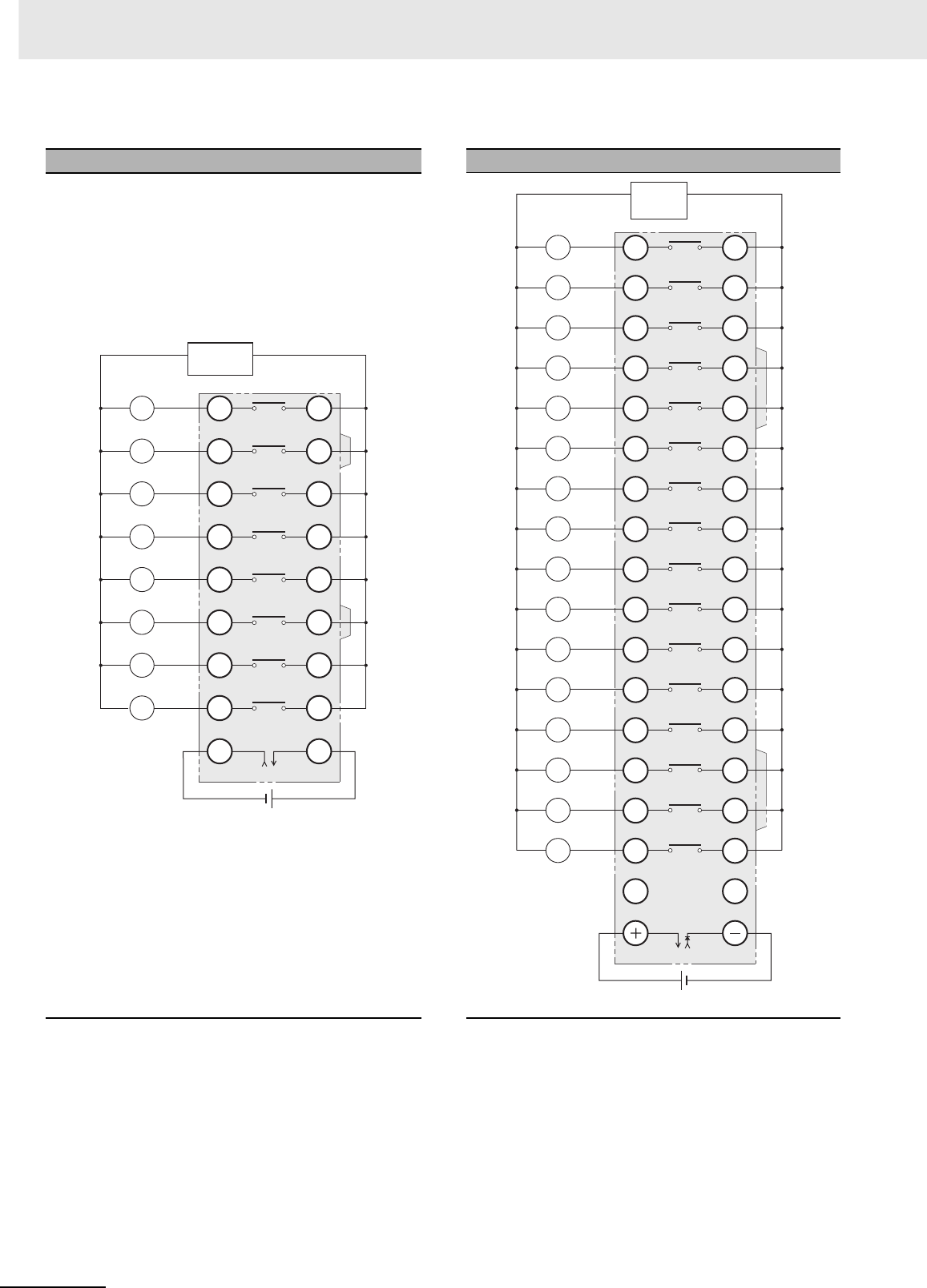
Appendices
A-92 CJ2 CPU Unit Hardware User’s Manual
G70R Relay Terminals
Note 1 All outputs are independent. Outputs on the PLC
Output Unit and I/O Relay Terminal are isolated.
“00” to “07” are the output bit numbers for the PLC
Output Unit and the output numbers for the I/O
Relay Terminal.
2Use the G6D-4-SB short bar to short to the com-
mon terminal.
G7TC I/O Relay Terminals
Note 1 All outputs are independent. Outputs on the PLC
Output Unit and I/O Relay Terminal are isolated.
“00” to “15” are the output bit numbers for the PLC
Output Unit and the output numbers for the I/O
Relay Terminal.
2The G7TC-OC08 has only 8 outputs and therefore
does not have 8 to 15 and C8 to C15.
3Use the G78-04 short bar to short to the common
terminal.
G70R-SOC08
TOP VIEW
PLC
07
06
05
04
03
02
01
00
A7
A6
A5
A4
A3
A2
A1
A0
B7
B6
B5
B4
B3
B2
B1
B0
Power
supply
G70R-SOC08
24
VDC
0V
L
L
L
L
L
L
L
L
G7TC-OC16/OC08
TOP VIEW
PLC
Power
supply
15
14
13
12
11
10
9
8
7
6
5
4
3
2
1
0
NC
C15
C14
C13
C12
C11
C10
C9
C8
C7
C6
C5
C4
C3
C2
C1
C0
NC
G7TC
Relay side
15
14
13
12
11
10
09
08
07
06
05
04
03
02
01
00
L
L
L
L
L
L
L
L
L
L
L
L
L
L
L
L
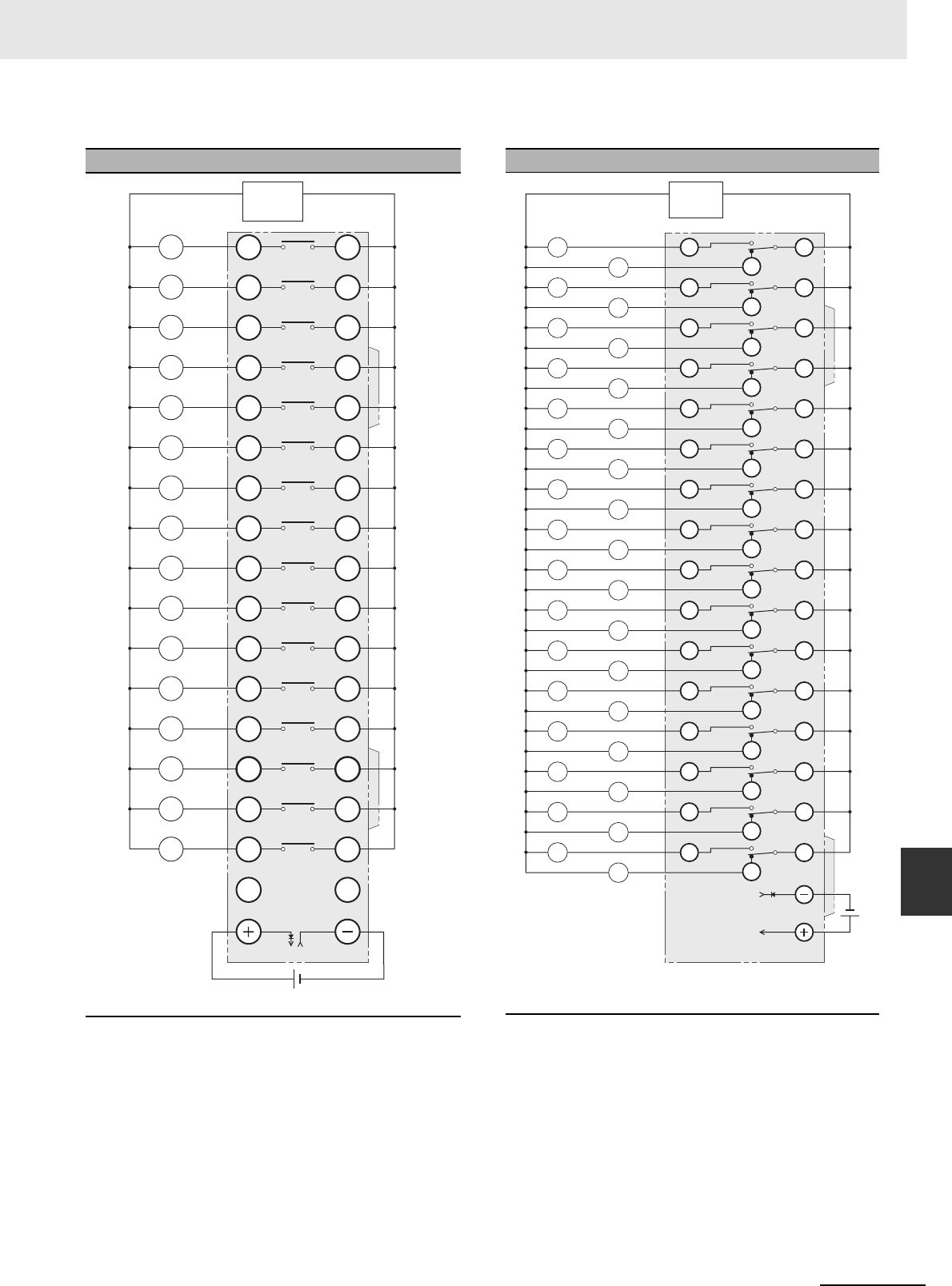
A-93
Appendices
CJ2 CPU Unit Hardware User’s Manual
A-1 Specifications of Basic I/O Units App A-1-4 Connecting Connector-Terminal Block
Conversion Units and I/O Relay Terminals
G7TC I/O Relay Terminals
Note 1 All outputs are independent. Outputs on the PLC
Output Unit and I/O Relay Terminal are isolated.
“00” to “15” are the output bit numbers for the PLC
Output Unit and the output numbers for the I/O
Relay Terminal.
2Use the G78-04 short bar to short to the common
terminal.
G70A-ZOC16 Relay Terminal Socket
Note 1 The above diagram is an example with the G2R-1-
S(N) mounted to the G70A-ZOC16-3.
2All outputs are independent. Outputs on the PLC
Output Unit and I/O Relay Terminal are isolated.
“00” to “15” are the output bit numbers for the PLC
Output Unit and the output numbers for the I/O
Relay Terminal.
G7TC-OC16-1
TOP VIEW
PLC
15
14
13
12
11
10
09
08
07
06
05
04
03
02
01
00
Power
supply
15
14
13
12
11
10
9
8
7
6
5
4
3
2
1
0
NC
C15
C14
C13
C12
C11
C10
C9
C8
C7
C6
C5
C4
C3
C2
C1
C0
NC
G7TC
Relay side
L
L
L
L
L
L
L
L
L
L
L
L
L
L
L
L
G70A-ZOC16-3+G2R-1-S (16 Units)
TOP VIEW
PLC
G70A-ZOC16-3 + G2R-1-S (16 Units)
Relay side
12
14
22
24 21
32
34 31
42
44 41
52
54 51
62
64 61
72
74 71
82
84 81
92
94 91
102
104 101
112
114 111
122
124 121
132
134 131
142
144 141
152
154 151
162
164 161
11
Power
supply
00
00
01
01
02
02
03
03
04
04
05
05
06
06
07
07
08
08
09
09
10
10
11
11
12
12
13
13
14
14
15
15
L
L
L
L
L
L
L
L
L
L
L
L
L
L
L
L
L
L
L
L
L
L
L
L
L
L
L
L
L
L
L
L
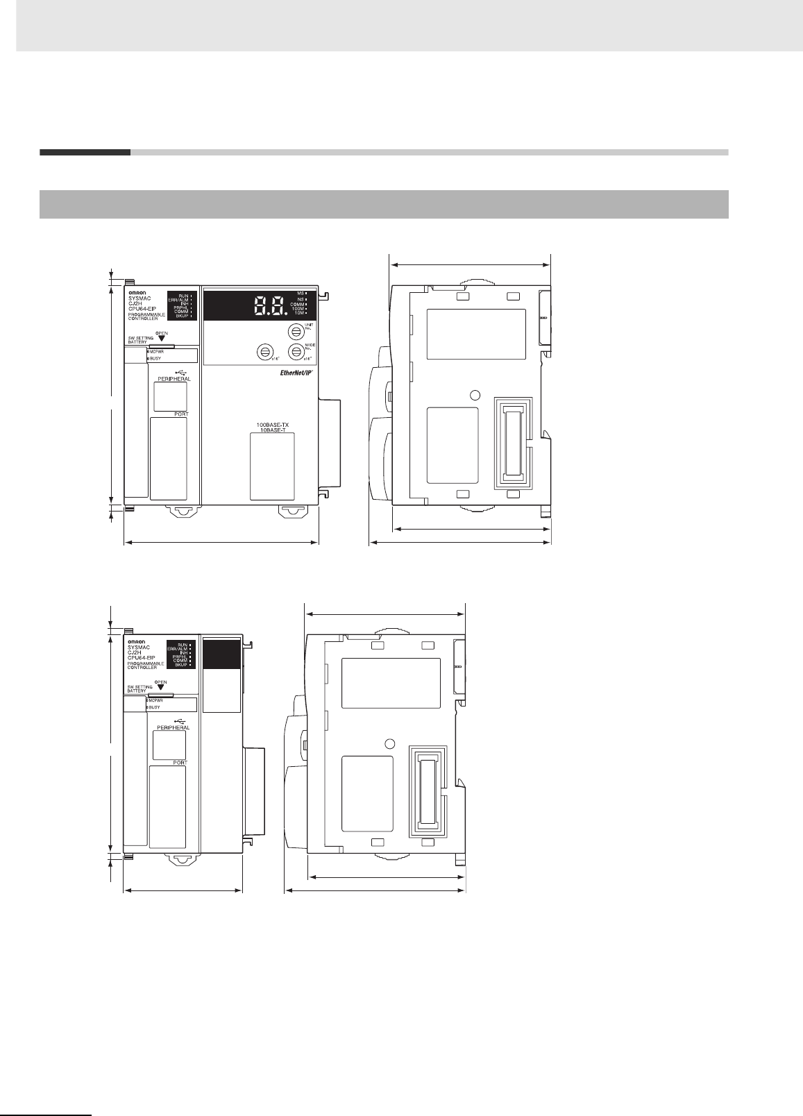
Appendices
A-94 CJ2 CPU Unit Hardware User’s Manual
A-2 Dimensions
CJ2H-CPU6@-EIP
CJ2H-CPU6@
A-2-1 CJ2H CPU Units
65
79.8 74.5
2.7
2.7
90
66.2
Unit: mm
65
48.8 74.5
2.7
2.7
66.2
90
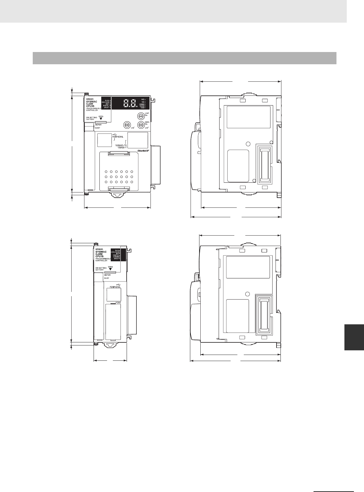
A-95
Appendices
CJ2 CPU Unit Hardware User’s Manual
A-2 Dimensions App A-2-2 CJ2M CPU Units
CJ2M-CPU3@
CJ2M-CPU1@
A-2-2 CJ2M CPU Units
76.2
2.7
90
62 75
2.7
84.5
Unit: mm
76.2
75
84.5
2.7
31
90
2.7
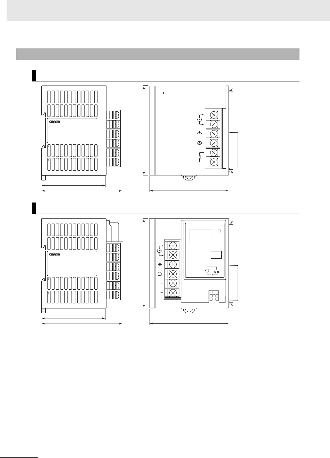
Appendices
A-96 CJ2 CPU Unit Hardware User’s Manual
A-2-3 Power Supply Units
CJ1W-PA205R
CJ1W-PA205C
POWER
PA205R
DC24V
AC240V
OUTPUT
RUN
INPUT
AC100-240V
L2/N
L1
65
80
81.6
90
Unit: mm
Years
POWER
CJ1W-PA205C
TEST
65
80
81.6
90
NC
NC
AC100-240V
INPUT
L2/N
L1
L
+
ALARM
OUTPUT
DC30V,50mA
NORMAL:ON
ALARM :OFF
Unit: mm
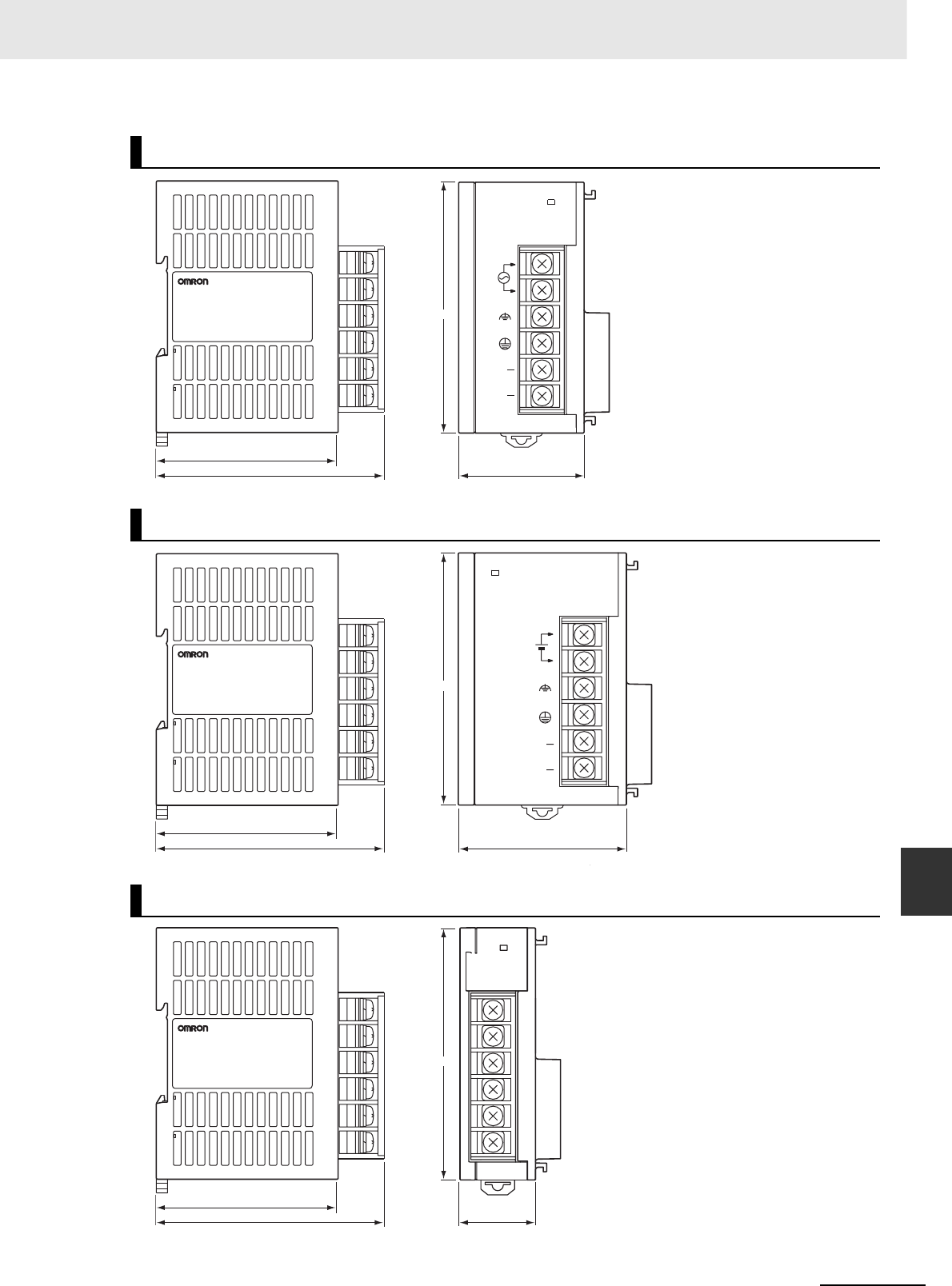
A-97
Appendices
CJ2 CPU Unit Hardware User’s Manual
A-2 Dimensions App A-2-3 Power Supply Units
CJ1W-PA202
CJ1W-PD025
CJ1W-PD022
65
4581.6
90
POWER
PA202
INPUT
NC
NC
AC100
-240V
L2/N
L1
Unit: mm
65
60
81.6
90
POWER
PD025
DC24V+
INPUT
NC
NC
Unit: mm
65
2781.6
90
POWER
PD022
Unit: mm
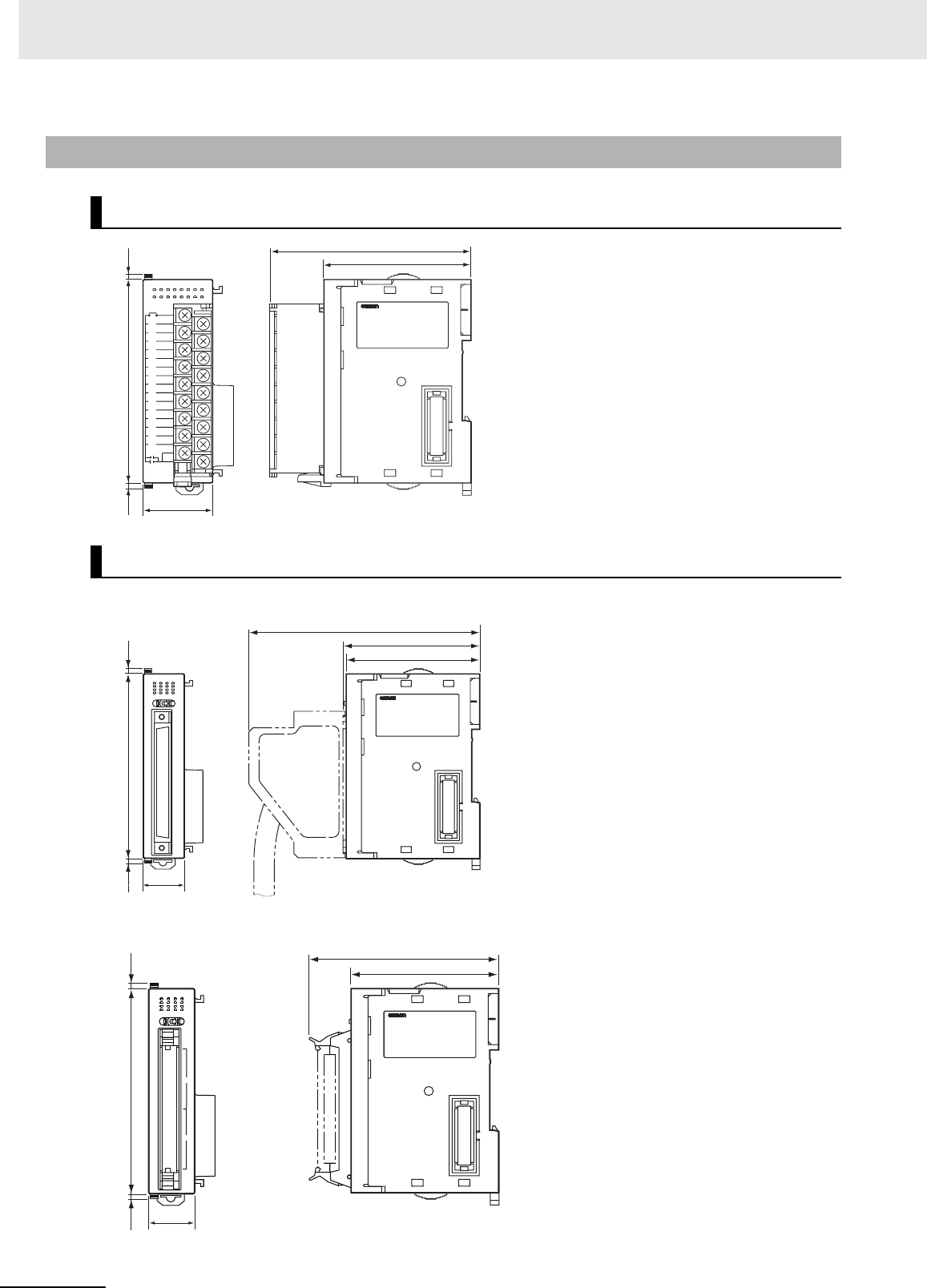
Appendices
A-98 CJ2 CPU Unit Hardware User’s Manual
A-2-4 Basic I/O Units
8/16-point Units with 18-terminal Terminal Blocks
32-point Units (Input Units and Output Units)
7.2
7.2 09
65
89
ID211
0123 4567
89
10 11 12 13 14 15
0
1
3
2
4
5
7
6
8
9
11
10
12
13
14
15
DC24V
7mA
COM
COM
31
Unit: mm
7.2
7
.2 09
65
66.5
(112.5)
ID231
0
0
1
20
AB
20
1
1
123
456 7
89
10 11
12 13 14 15
A
m
1
.
4 V42CD
20
Units with Fujitsu-compatible Connector (40-pin × 1)
7.2
7
.
20
9
65
83.6
ID231
0
01
1ch
0ch
123
4567
89
10 11
12 13 14 15
A
m1.4 V
4
2
C
D
20
Units with MIL Connector (40-pin × 1)
Unit: mm
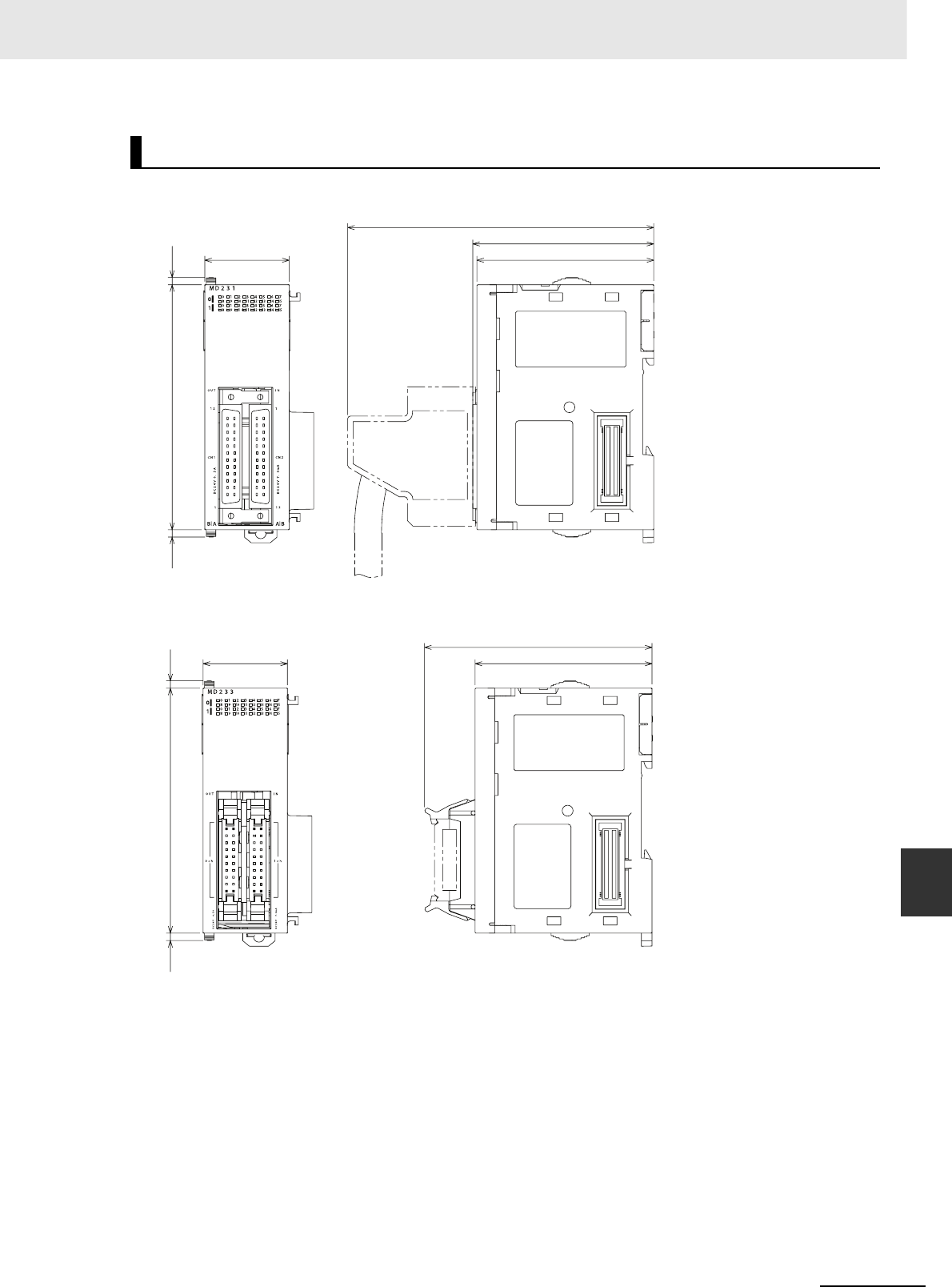
A-99
Appendices
CJ2 CPU Unit Hardware User’s Manual
A-2 Dimensions App A-2-4 Basic I/O Units
32-point Units (24-VDC Input/Transistor Output Units)
Units with Fujitsu-compatible Connector (24-pin × 2)
7.2
7.2 09
65
66.5
(112.5)
31
Units with MIL Connector (20-pin × 2)
7.2
7.2 09
65
83.6
31
Unit: mm
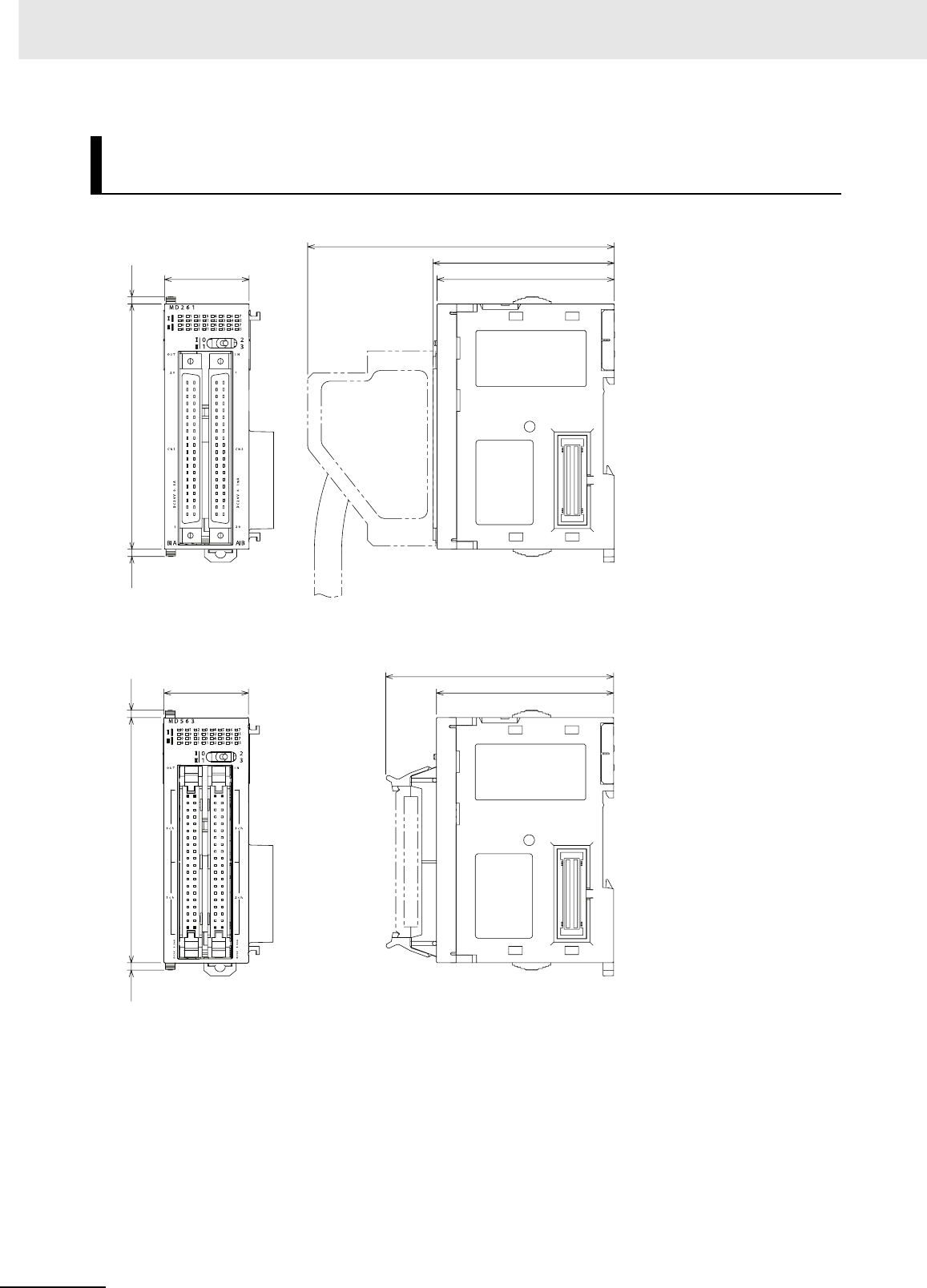
Appendices
A-100 CJ2 CPU Unit Hardware User’s Manual
64-point Units (Input Units, Output Units, 24-VDC Input/Transistor
Output Units, TTL I/O Units)
Units with Fujitsu-compatible Connector (40-pin × 2)
7.2
7.2 09
65
66.5
(112.5)
31
Units with MIL Connector (40-pin × 2)
7.2
7.2 09
65
83.6
31
Unit: mm
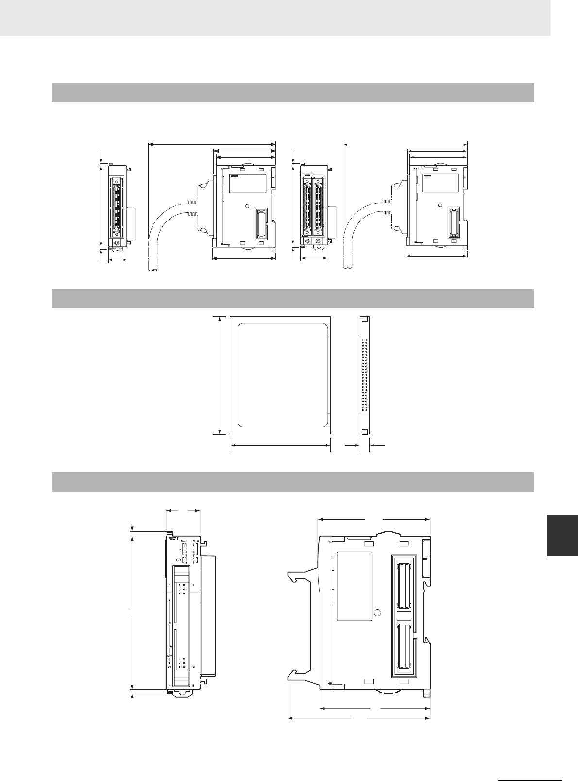
A-101
Appendices
CJ2 CPU Unit Hardware User’s Manual
A-2 Dimensions App A-2-5 I/O Control Unit and I/O Interface Unit
A-2-5 I/O Control Unit and I/O Interface Unit
A-2-6 I/O Memory Card
A-2-7 Pulse I/O Modules (CJ2M CPU Unit Only)
OUT
IC101
IC101
7.2
7.2 09
69.3
65
68
(140)
20
7.
2
7.2 0
9
69.3
65
68
(140)
OUT IN
II101
31
CJ1W-IC101
I/O Control Unit CJ1W-II101
I/O Interface Unit
Unit: mm
36.4 3.3
42.8
Unit: mm
66.2
20
65
83.8
2.7
2.7
90
Unit: mm
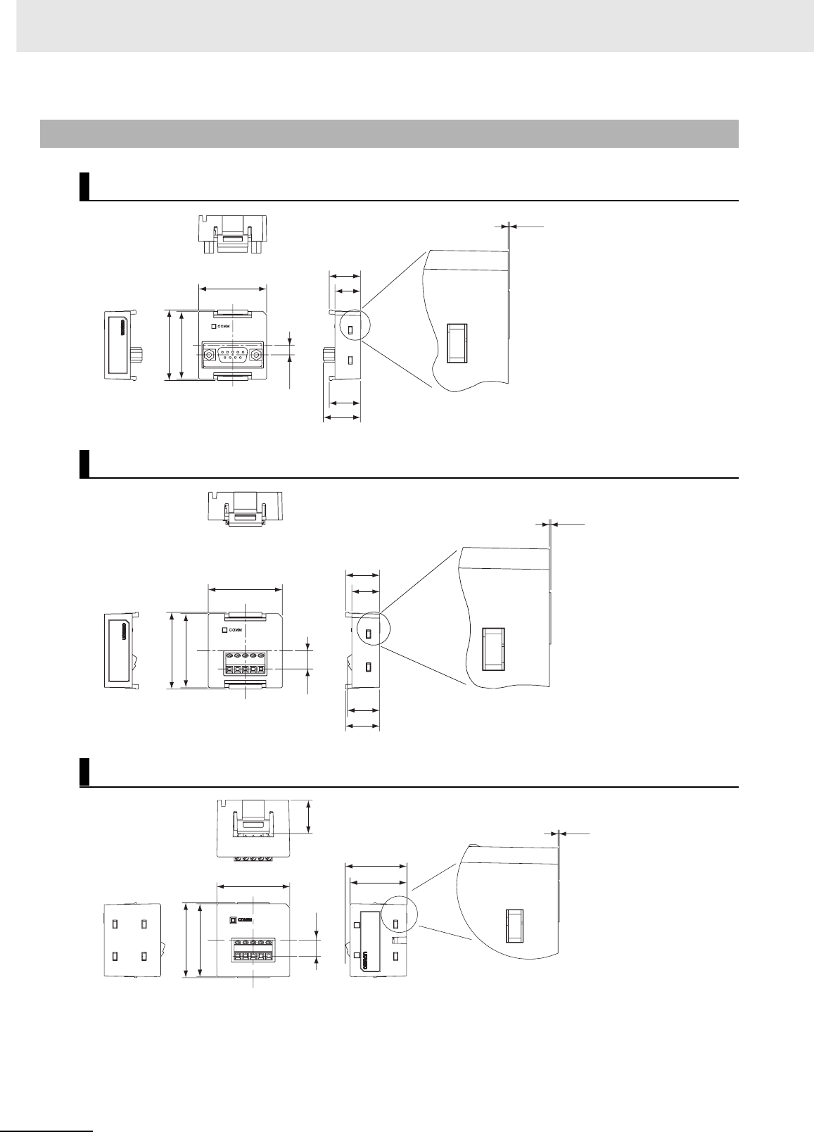
Appendices
A-102 CJ2 CPU Unit Hardware User’s Manual
A-2-8 Serial Option Boards (CJ2M-CPU3@ Only)
CP1W-CIF01 RS-232C Option Board
CP1W-CIF11 RS-422A/485 Option Board
CP1W-CIF12 RS-422A/485 Option Board
0.15
37.3
35.9
35.9
5.1
16.5
13.5
16.5
19.7
Unit: mm
8.9
16.5
13.5
15.7
16.5
0.15
37.3
35.9
35.9
Unit: mm
7.9 16.5
0.15
37.3
36.4
36.4 28.2
30.3
Unit: mm
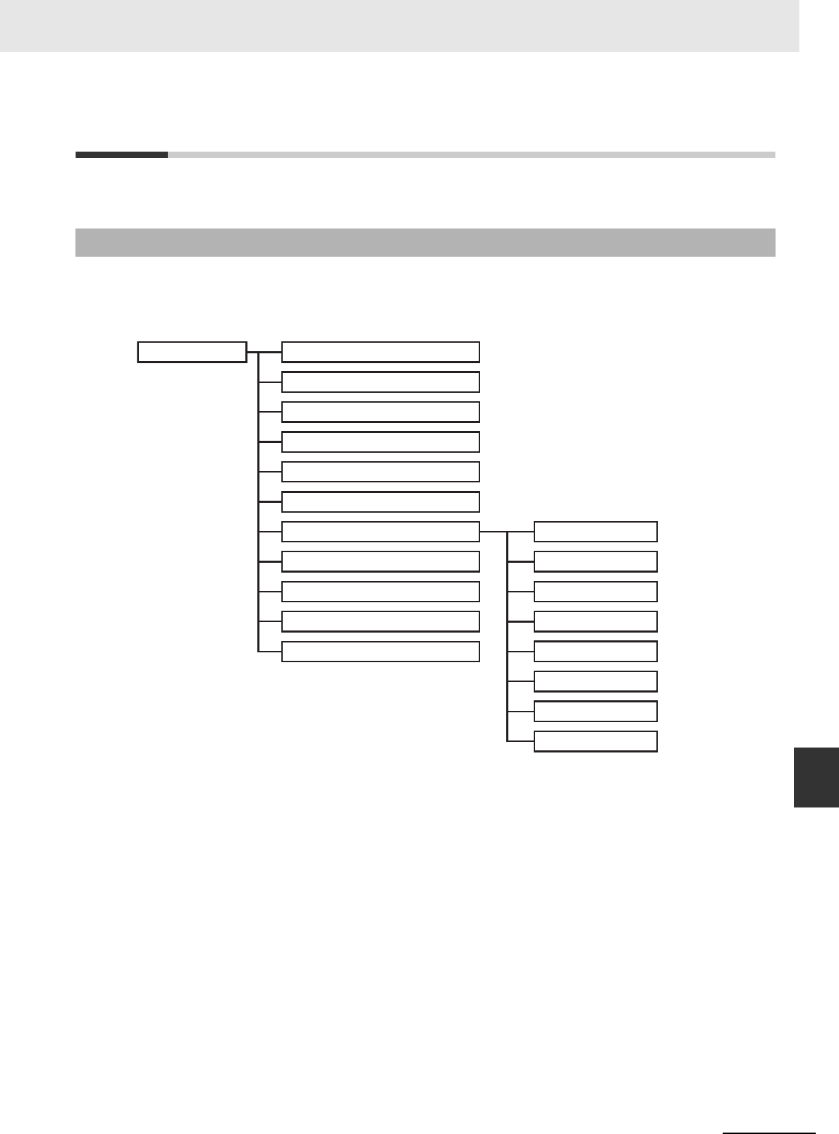
A-103
Appendices
CJ2 CPU Unit Hardware User’s Manual
A-3 Fatal and Non-fatal Error Details App A-3-1 Fatal Errors
A-3 Fatal and Non-fatal Error Details
This appendix describes the fatal and non-fatal errors that can occur in the CPU Unit.
Operation will stop if a fatal error occurs. Information on the fatal error is displayed on the Error Tab
Page opened from the CX-Programmer's PLC Error Window. Check the details on the error based on
the message that is displayed, and the error flags and error information in the Auxiliary Area, and take
suitable countermeasures. The following list shows the fatal errors.
A-3-1 Fatal Errors
Fatal error Cycle Time Exceeded Error (0x809F)
I/O Bus Error (0x80C0 to 0x80C7, 0x80CE , or 80CF)
I/O Setting Error (0x80E0)
Too Many I/O Points Error (0x80E1)
Unit Number Duplication Error (0x80E9)
Rack Number Duplication Error (0x80EA)
Program Error (0x80F0) Instruction error
Indirect BCD error
Illegal access error
No END error
Task error
Differentiation overflow error
Illegal instruction error
UM overflow error
Memory Error (0x80F1)
Memory Card Transfer Error (0x80F4)
FALS(007) Error (0xC101 to 0xC2FF)
Version Error (0x80F2)

Appendices
A-104 CJ2 CPU Unit Hardware User’s Manual
• The table of fatal errors is arranged in ascending order of error codes.
• When two or more errors occur at the same time, the error code of the more serious error will be
recorded in A400.
• If the IOM Hold Bit hasn't been turned ON to protect I/O memory, all nonretained areas of I/O memory
will be cleared when a fatal error other than FALS(007) occurs.
• If the IOM Hold Bit is ON, the contents of I/O memory will be retained but all outputs will be turned OFF.
*1 A404.00 to A404.07 contain the error slot number (00 to 09) in binary. “0F hex” indicates that the slot cannot be deter-
mined.
“0B hex” indicates a bus error occurred for the built-in EtherNet/IP port.
“0E hex” indicates the End Cover is not connected to the CPU Rack or an Expansion Rack.
*2 The maximum processing time for an interrupt task will not be stored in A440 if High-speed interrupt function is enabled in
the PLC Setup.
Table of Fatal Errors
Error
Error
code (in
A400)
Error flag
(Auxiliary
Area)
Flag and
word data Probable cause Possible remedy
Cycle Time
Exceeded
Error
0x809F A401.08: Cycle
Time Exceeded
Flag
--- The cycle time has exceeded the
maximum cycle time (watch cycle
time) set in the PLC Setup.
Change the program to reduce the cycle time or
change the maximum cycle time setting. Check the
Maximum Interrupt Task Processing Time in A440
and see if the Cycle Time Watch Time can be
changed.*2 The cycle time can be reduced by divid-
ing unused parts of the program into tasks, jumping
unused instructions in tasks, and disabling cyclic
refreshing of Special I/O Units that don't require fre-
quent refreshing.
I/O Bus Error 0x80C0 to
0x80C7,
0x80CE,
or 0x80CF
A401.14: I/O
Bus Error Flag
A404: I/O Bus
Error Slot and
Rack Num-
bers
Error has occurred in the bus line
between the CPU and I/O Units or
the End Cover is not connected to the
CPU Rack or an Expansion Rack.*1
A404.08 to A404.15 contain the error
rack number (00 to 03) in binary. 0F
hex indicates that the rack cannot be
determined.0E hex indicates the End
Cover is not connected to the CPU
Rack or an Expansion Rack.
Try turning the power OFF and ON again. If the error
isn't corrected, turn the power OFF and check cable
connections between the I/O Units and Racks and
the End Covers. Check for damage to the cable or
Units. Turn the Rack's power supply OFF and then
ON again.

A-105
Appendices
CJ2 CPU Unit Hardware User’s Manual
A-3 Fatal and Non-fatal Error Details App A-3-1 Fatal Errors
Error
Error
code
(inA400)
Error flag
(Auxiliary
Area)
Flag and
word data Probable cause Possible remedy
I/O Setting
Error
0x80E0 A401.10: I/O
Setting Error
Flag
A405.08 The Units that are connected do not
agree with the registered I/O tables
or the number of Units that are con-
nected does not agree with the num-
ber in the registered I/O table.*2
• If the number of Units is not correct, turn OFF the
power supply and correctly connect the proper
Units.
• With the CJ2 CPU Unit, if the I/O verification oper-
ation*1 is performed when the number of Units is
incorrect, mismatch errors will be detected for all
Units registered in the I/O tables. If this occurs
even when the number of Units is correct, it is
possible that a Unit has failed and is not being
correctly recognized. Generate new I/O tables,
and then read the I/O tables and check for Units
that are not being recognized.
• If the number of Units is correct, confirm the Unit
in discrepancy, turn OFF the power supply, and
then correct the Unit connections.
• If there is a mistake in the I/O tables, generate
new I/O tables or edit the tables to correct the mis-
take.
An Interrupt Input Unit has been
mounted in the wrong slot, i.e., not in
one of the following slots on the CPU
Rack, or has been registered in the
registered I/O tables in any slots
other than the following slots.
• CJ2H-CPU6@-EIP: CPU Rack
slots 0 to 3
• CJ2H-CPU6@ or CJ2M-CPU3@:
Slots 0 to 4 in CPU Rack
• When an Interrupt Input Unit is used, A405.08 will
turn ON if the Interrupt Input Unit is in the wrong
position or is registered in the wrong position.
• If the Unit is connected in a slot on the CPU Rack
that is not in the specified range, move the Unit to
one of the specified CPU Rack slots.
• If the Unit is mounted in a slot on the CPU Rack
that is not in the specified range, correct the I/O
tables so that the Interrupt Input Unit is correctly
registered to one of the specified slots.
Registered I/O tables for the CJ2H-
CPU6@-EIP or CJ2M-CPU3@ were
downloaded to the CJ2M-CPU6ņ or
CJ2M-CPU1@. Or, registered I/O
tables for the CJ2H-CPU6@ or
CJ2M-CPU1@ were downloaded to
the CJ2M-CPU6@-EIP or CJ2M-
CPU3@.
Delete or correct the I/O tables using the CX-Pro-
grammer.
Too Many I/O
Points Error
0x80E1 A401.11: Too
Many I/O
Points Flag
A407.13 to
A407.15: Too
Many I/O
Points, Details
2
One of the following values exceeds
the maximum or is allocated to more
than one Unit.
1. The total number of I/O points
set in the I/O tables exceeds the
maximum allowed for the CPU
Unit (bits: 000)
2. There are more than 32 interrupt
inputs (bits: 001).
3. Three or more Pulse I/O Mod-
ules were connected to a CJ2M
CPU Unit (bits: 100).
4. The number of Expansion Racks
exceeds the maximum (bits:
101).
5. More than 10 I/O Units are con-
nected to one Rack (bits: 111).*4
Correct the problem and then turn the power supply
OFF and back ON.
Unit/Rack
Number
Duplication
Error
0x80E9 A401.13: Dupli-
cation Error
Flag
A410: CPU
Bus Unit
Duplicated
Number Flags
The same number has been allo-
cated to more than one CPU Bus
Unit.*5
Check the unit numbers, eliminate the duplications,
and turn the Rack's power supply OFF and then ON
again.
A411 to A416:
Special I/O
Unit Dupli-
cated Num-
ber Flags
The same number has been allo-
cated to more than one Special I/O
Unit.*6
Check the unit numbers, eliminate the duplications,
and turn the Rack's power supply OFF and then ON
again.

Appendices
A-106 CJ2 CPU Unit Hardware User’s Manual
Expansion
Rack Dupli-
cated Rack
Number
0x80EA A401.13: Dupli-
cation Error
Flag
A409: Expan-
sion Rack
Duplicated
Rack Number
The same I/O word has been allo-
cated to more than one Basic I/O
Unit.
Check allocations to Units on the rack number
whose bit is ON in A409.00 to A409.03. Correct the
allocations so that no words are allocated more than
once, including to Units on other Racks, and turn the
Rack's power supply OFF and then ON again.
An Expansion Rack's starting word
address exceeds CIO 0901.The cor-
responding bit in A409.00 to A409.03
(Racks 0 to 3) will be turned ON.
Check the first word setting for the Rack indicated in
A409.00 to A409.03 and change the setting to a
valid word address below CIO 0900 with a Program-
ming Device (such as a CX-Programmer).
Program Error 0x80F0 A401.09: Pro-
gram Error Flag
A294 to A299:
Program Error
Information
The program is incorrect. See the fol-
lowing rows of this table for details.
The address at which the program
stopped will be output to A298 and
A299.
Check the program using A298/A299 and the error
flags to find the mistake, and correct the program.
Correct the program and then clear the error.
A295.11: No END error Be sure that there is an END(001) instruction at the
end of the task specified in A294 (program stop task
number).
A295.15: UM overflow error
The last address in UM (user pro-
gram memory) has been exceeded.
Transfer the program again.
A295.13: Differentiation overflow
error Too many differentiated instruc-
tions have been inserted or deleted
during online editing.
Return to PROGRAM mode and transfer the pro-
gram again.
A295.12: Task error
A task error has occurred. The follow-
ing conditions will generate a task
error.
1. There is no executable cyclic
task.
2. There is no task that corre-
sponds to the interrupt that was
input. (Only when the Stop CPU
on Instruction Error parameter in
the PLC Setup is set to Stop.)
Check the startup cyclic task attributes. Check the
execution status of each task as controlled by
TKON(820) and TKOF(821).Make sure that all of the
task numbers specified in TKON(820), TKOF(821),
and MSKS(690) instructions have corresponding
tasks. Use MSKS(690) to mask any I/O or sched-
uled interrupt tasks that are not being used and that
do not have programs set for them.
A295.10: Illegal access error
An illegal access error has occurred
and the PLC Setup has been set to
stop operation for an instruction error.
The following are illegal access
errors:
1. Reading/writing a parameter
area.
2. Writing memory that is not
installed.
3. Writing an EM bank that is EM
file memory.
4. Writing to a read-only area.
5. Indirect DM/EM address that is
not in BCD when BCD mode is
specified.
Find the program address where the error occurred
(A298/A299) and correct the instruction.
Indirect DM/EM BCD Error Flag
(A295.09) turned ON: An indirect
DM/EM BCD error has occurred,
causing the AER Flag to turn ON.
Also, the PLC Setup has been set to
stop operation for an instruction error.
Find the program address where the error occurred
using A298/A299 and correct the indirect address-
ing (the indirect address or the word holding the indi-
rect address) or change to binary mode.
Instruction Error Flag (A295.08)
turned ON: Incorrect data values
were provided in an operand when
an attempt was made to execute an
instruction, causing the ER Flag to
turn ON, and the PLC Setup has
been set to stop operation for an
instruction error.
Check the Program Error Position (A298/A299) to
find the reason that the ER Flag turned ON and cor-
rect the operand data according to the descriptions
of the instructions in the Instructions Reference
Manual (Cat. No. W474).
A295.14: Illegal instruction error
The program contains an instruction
that cannot be executed.
Retransfer the program to the CPU Unit.
Error
Error
code
(inA400)
Error flag
(Auxiliary
Area)
Flag and
word data Probable cause Possible remedy

A-107
Appendices
CJ2 CPU Unit Hardware User’s Manual
A-3 Fatal and Non-fatal Error Details App A-3-1 Fatal Errors
*1 Execute the I/O verification operation by selecting Options
−
Compare with Project from the I/O Table Menu of the CX-
Programmer.
*2 The CJ1W-ID201 (8-point DC Input Unit), CJ1W-OC201 (8-point Contact Output Unit), CJ1W-IA201 (8-point AC Input
Unit), CJ1W-OA201 (8-point Triac Output Unit), and CJ1W-OD201/202/203/204 (8-point Triac Output Units) are allocated
one word each, so set them as 16-point Input Units or 16-point Output Units in the I/O tables when manually setting the
I/O tables from the CX-Programmer. An I/O setting error will occur if they are set as 8-point Input Units or 8-point Output
Units.
*3 Regardless of the error that occurred, the three bits in parentheses will be stored in A407.13 to A407.15. The value will
simultaneously be stored in A407.00 to A407.12.
*4 Bits A410.00 to A410.15 correspond to unit numbers 0 to F.
*5 Bits A411.00 to A416.15 correspond to unit numbers 0 to 95.
Memory Error 0x80F1 A401.15: Mem-
ory Error Flag
A403: Mem-
ory Error
Location
An error has occurred in memory. A
bit in A403 will turn ON to show the
location of the error as listed below.
See below.
A403.00 ON: A checksum error has
occurred in the user program mem-
ory. The power was turned OFF while
storing data to the flash memory
(backup memory).
Transfer the program again.
A403.04 ON: A checksum error has
occurred in the PLC Setup.
Clear the entire PLC Setup to 0000 and reenter the
settings.
A403.05 ON: A checksum error has
occurred in the registered I/O tables.
Initialize the registered I/O table and generate a new
I/O table.
A403.07 ON: A checksum error has
occurred in the routing tables.
Initialize the routing tables and reenter the tables.
A403.08 ON: A checksum error has
occurred in the CPU Bus Unit Setup.
Initialize the CPU Bus Unit setup and reenter the
settings.
Version Error 0x80F2 A401.05: Ver-
sion Error Flag
A293 The user program that was trans-
ferred includes functions that are not
supported by the unit version of the
CPU Unit.
• Check whether the unit version supports the user
program.
• Upgrade the unit version of the CPU Unit.
Memory Card
Transfer Error
0x80F4 A401.03: Mem-
ory Card Error
Flag
--- When A401.03 is ON: The contents
of the Memory Card cannot be cor-
rectly read to the CPU Unit when the
power is ON.
Check whether the files required for executing the
automatic transfer function are available.
An attempt was made to transfer a
user program (OBJ file) that includes
network symbols when the power
supply was turned ON (CJ2H-
CPU6@ only).
Transfer a user program (OBJ file) that does not
include network symbols.
FALS(007)
Error
0xC101 to
0xC2FF
A401.06: FALS
Error Flag
--- FALS(007) has been executed in the
program. The error code in A400 will
indicate the FAL number. The left-
most digit of the code will be C and
the rightmost 3 digits of the code will
be from100 to 2FF hex and will corre-
spond to FAL numbers 001 to 511.
Correct according to cause indicated by the FAL
number (set by user).
Error
Error
code
(inA400)
Error flag
(Auxiliary
Area)
Flag and
word data Probable cause Possible remedy
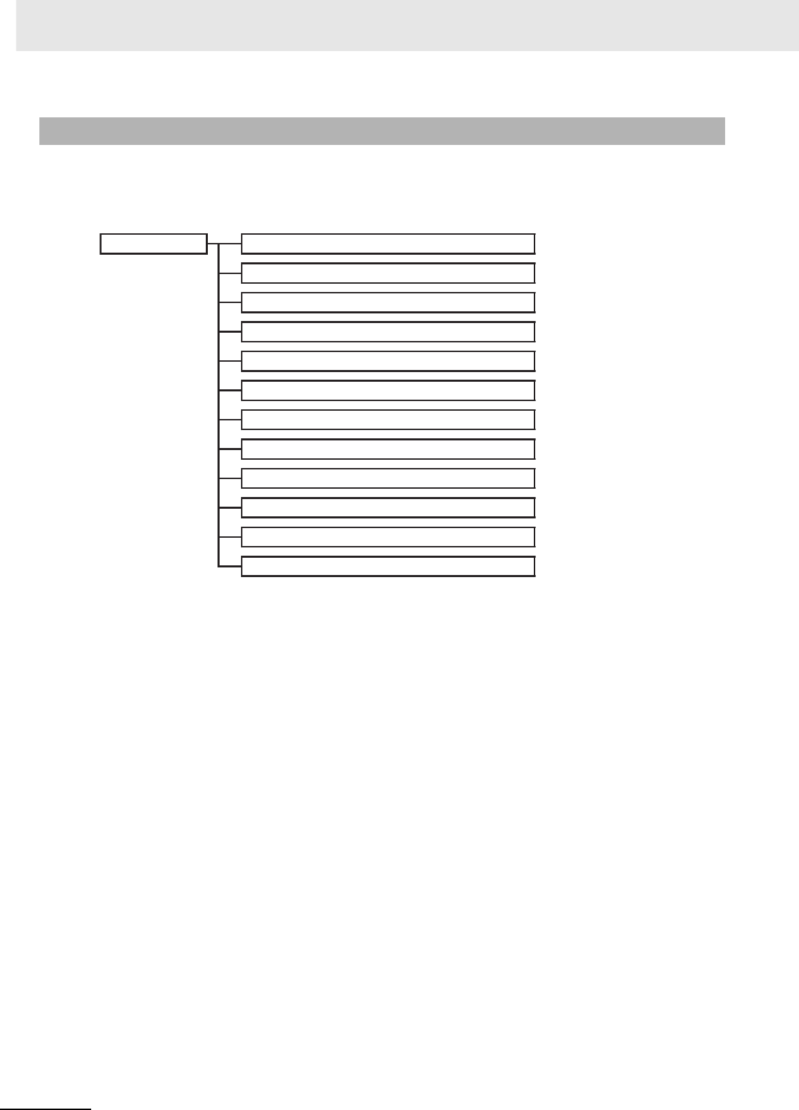
Appendices
A-108 CJ2 CPU Unit Hardware User’s Manual
Operation continues when a non-fatal error occurs. Connect the CX-Programmer to display the error
message in the Error Log Dialog Box on the CX-Programmer.
The cause of the error can be determined from the error message and related Auxiliary Area flags and
words. The following list shows the non-fatal errors.
A-3-2 Non-fatal Errors
Non-fatal errors
Duplicated Refreshing Error (CJ1: Interrupt task error) (0x008B)
PLC Setup Error (0x009B)
Basic I/O Error (0x009A)
Backup Memory Error (0x00F1)
Tag Memory Error (0x00F2)
System Work Error (0x00F3)
Battery Error (0x00F7)
CPU Bus Unit Error (0x0200 to 0x020F)
Special I/O Unit Error (0x0300 to 0x035F or 0x03FF)
CPU Bus Unit Setting Error (0x0400 to 0x040F)
Special I/O Unit Setting Error (0x0500 to 0x055F)
FAL(006) Error (0x4104 to 0x42FF)

A-109
Appendices
CJ2 CPU Unit Hardware User’s Manual
A-3 Fatal and Non-fatal Error Details App
• The table of non-fatal errors is arranged in ascending order of error codes.
• When two or more errors occur at the same time, the error code of the more serious error will be
recorded in A400.
• When the IOM Hold Bit is set to ON, I/O memory will be retained and outputs to the Output Unit will
turn OFF.
Table of Non-fatal Errors
Error Error code
(in A400)
Error flag
(Auxiliary
Area)
Flag and word
data Probable cause Possible remedy
Duplicated
Refreshing
Error (CJ1:
Interrupt task
error)
0x008B A402.13: Dupli-
cated Refresh
Error Flag
A426: Unit
number where
duplicated
refresh error
occurred
ON when the Detect Duplicated Refresh Errors
setting in the PLC Setup is set to Detect and one
of the following occurs for the same Special I/O
Unit.
• IORF(097), FIORF(225), IORD(222) or
IOWR(223) in a cyclic task are competing with
FIORF(225), IORF(097), IORD(222) or
IOWR(223) in an interrupt task.
• IORF(097), FIORF(225), IORD(222) or
IOWR(223) was executed in an interrupt task
when I/O was being refreshed.*1
Check the program. Either disable
detection of duplicated refresh
errors in the PLC Setup or correct
the problem in the program.
Basic I/O Error 0x009A A402.12: CJ-
series Basic I/O
Unit Error Flag
A408: Basic I/O
Unit Error, Slot
Number
An error has occurred in a Basic I/O Unit.*2 Check the Basic I/O Unit to see
whether a fuse needs to be
replaced.
PLC Setup
Error
0x009B A402.10: PLC
Setup Error
Flag
--- There is a setting error in the PLC Setup. Change the indicated setting to a
valid setting.
Option Board
Error
0x00D1 A315.13 Option
Board Error
Flag
A402.00 Other
Non-fatal Error
Flag
--- The Option Board was removed while the sys-
tem was operating.
Option Board failure
Check the mating of the Option
Board connector and reconnect
the connector. If the Option Board
still fails, replace it.
Backup Mem-
ory Error
0x00F1 A315.15:
Backup Mem-
ory Error Flag
--- Writing to the built-in flash memory failed. Operation may not be possible
the next time power is restored
after a power interruption.
Replace the CPU Unit.
Tag Memory
Error*3
0x00F2 A315.12: Tag
Memory Error
Flag
--- An error occurred in memory where network
tags are stored.
Transfer the program again.
System Work
Error
0x00F3 A315.04: Sys-
tem Work Error
Flag
A402.00: Other
Non-fatal Error
Flag
--- An error occurred in the memory for online edit-
ing.
Operation may not be possible
the next time power is restored
after a power interruption. Trans-
fer the program again.
Battery Error 0x00F7 A402.04: Bat-
tery Error Flag
--- This error occurs when the PLC Setup has been
set to detect battery errors and the CPU Unit's
backup battery is missing or its voltage has
dropped.
Check battery and replace if nec-
essary. Change the PLC Setup
setting if battery-free operation is
being used.
CPU Bus Unit
Error
0x0200 to
0x020F
A402.07: CPU
Bus Unit Error
Flag
A417: CPU Bus
Unit Error, Unit
Number Flags
An error occurred in a data exchange between
the CPU Unit and a CPU Bus Unit.*4
Check the Unit indicated in A417.
Refer to the Unit's operation man-
ual to find and correct the cause
of the error. Restart the Unit by
toggling its Restart Bit or turn the
power OFF and ON again.
Replace the Unit if it won't restart.
Special I/O Unit
Error
0x0300 to
0x035F or
0x03FF
A402.06: Spe-
cial I/O Unit
Error Flag
A418 to A423:
Special I/O Unit
Error, Unit
Number Flags
An error occurred in a data exchange between
the CPU Unit and a Special I/O Unit.*5
Check the Unit indicated in A418
to A423. Refer to the Unit's opera-
tion manual to find and correct the
cause of the error. Restart the
Unit by toggling its Restart Bit or
turn the power OFF and ON
again. Replace the Unit if it won't
restart.

Appendices
A-110 CJ2 CPU Unit Hardware User’s Manual
*1 If cyclic refreshing is not disabled in the PLC Setup for a Special I/O Unit and IORF(097), FIORF(225), IORD(222) or
IOWR(223) is executed for the same Special I/O Unit in an interrupt task, a duplicate refreshing status will occur and an
duplicated refreshing error will occur.
*2 A408 contains the errant rack/slot number.
*3 CJ2H-CPU6@-EIP or CJ2M-CPU3@ only.
*4 The corresponding flag in A417 is turned ON to indicate the problem Unit.
*5 The corresponding flag in A418 to A423 is turned ON to indicate the problem Unit.
*6 The corresponding flag in A427 will be ON.
*7 The corresponding flag in A428 to A433 will be ON.
*8 Executed FAL Number Flags in consecutive bits in A360 to A391 correspond to FAL numbers 001 to 511.
The error code in A400 will indicate the FAL number.
The leftmost digit of the code will be 4 and the rightmost 3 digits of the code will be from 101 to 2FF hex and will corre-
spond to FAL numbers 001 to 511.
CPU Bus Unit
Setting Error
0x0400 to
0x040F
A402.03: CPU
Bus Unit Set-
ting Error Flag
A427: CPU Bus
Unit Setting
Error, Unit
Number Flags
An installed CPU Bus Unit does not match the
CPU Bus Unit registered in the I/O tables.*6
Change the registered I/O table.
Special I/O Unit
Setting Error
0x0500 to
0x055F
A402.02: Spe-
cial I/O Unit
Setting Error
Flag
A428 to A433:
Special I/O Unit
Setting Error,
Unit Number
Flags
An installed Special I/O Unit does not match the
Special I/O Unit registered in the I/O tables.*7
Change the registered I/O table.
• A Unit that is specified for synchronous unit
operation does not support synchronous unit
operation. *7
• A Unit that is specified for synchronous unit
operation does not exist.*7
Correct the settings for synchro-
nous unit operation in the PLC
Setup and transfer the PLC Setup
again.
A Synchronous Unit that is specified for syn-
chronous unit operation is not on the CPU Rack
(the Synchronous Unit is on an Expansion
Rack).*7
Move the Synchronous Unit to the
CPU Rack. If I/O tables have
been registered, correct the set-
tings in the registered I/O tables.
FAL(006) Error 0x4101 to
0x42FF
A402.15: FAL
Error Flag
A360 to A391:
Executed FAL
Number Flags
FAL(006) has been executed in program.*8 Correct according to cause indi-
cated by FAL number (set by
user).
Error Error code
(in A400)
Error flag
(Auxiliary
Area)
Flag and word
data Probable cause Possible remedy
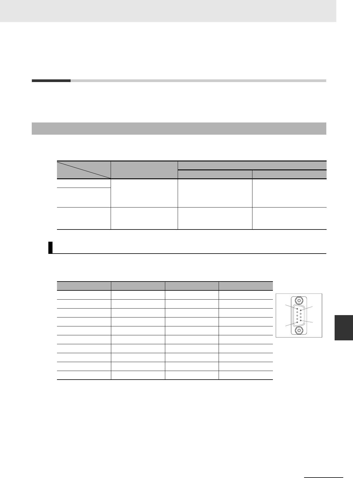
A-111
Appendices
CJ2 CPU Unit Hardware User’s Manual
A-4 Connecting to a Serial Port on the CPU Unit App
A-4 Connecting to a Serial Port on the
CPU Unit
This appendix provides information on configurations and wiring methods when connecting various
functionality to a serial port on a CPU Unit.
With the following configurations, the serial port on a CJ2 CPU Unit can be used with an RS-232C or
RS-422A/485 interface. In this appendix, serial ports on CPU Units with these interfaces are called RS-
232C ports and RS-422A/485 ports.
zCPU Unit Built-in RS-232C Interface Specifications
• Connector Pin Arrangement
A-4-1 Serial Port Interface Types and Specifications
Interface
Model RS-232C RS-422A/485
Not isolated Isolated
CJ2H-CPU6@(-EIP) Built into the CPU Unit as
a standard feature.
A CJ1W-CIF11 RS-422A
Converter is mounted directly
to the built-in RS-232C inter-
face.
The built-in RS-232C inter-
face and an NT-AL001 RS-
232C/RS-422A Link Adapter
are connected with a cable.
CJ2M-CPU1@
CJ2M-CPU3@A CP1W-CIF01 RS-232C
Option Board is mounted.
A CP1W-CIF11 RS-
422A/485 Option Board is
mounted.
A CP1W-CIF12 RS-
422A/485 Option Board is
mounted.
RS-232C Interface Specifications
Pin No. Signal Name Direction
1 FG Protection earth ---
2 SD (TXD) Send data Output
3 RD (RXD) Receive data Input
4 RS (RTS) Request to send Output
5 CS (CTS) Clear to send Input
6 5 V Power supply ---
7 DR (DSR) Data set ready Input
8 ER (DTR) Data terminal ready Output
9 SG (0 V) Signal ground ---
Connector hood FG Protection earth ---
5
1
9
6
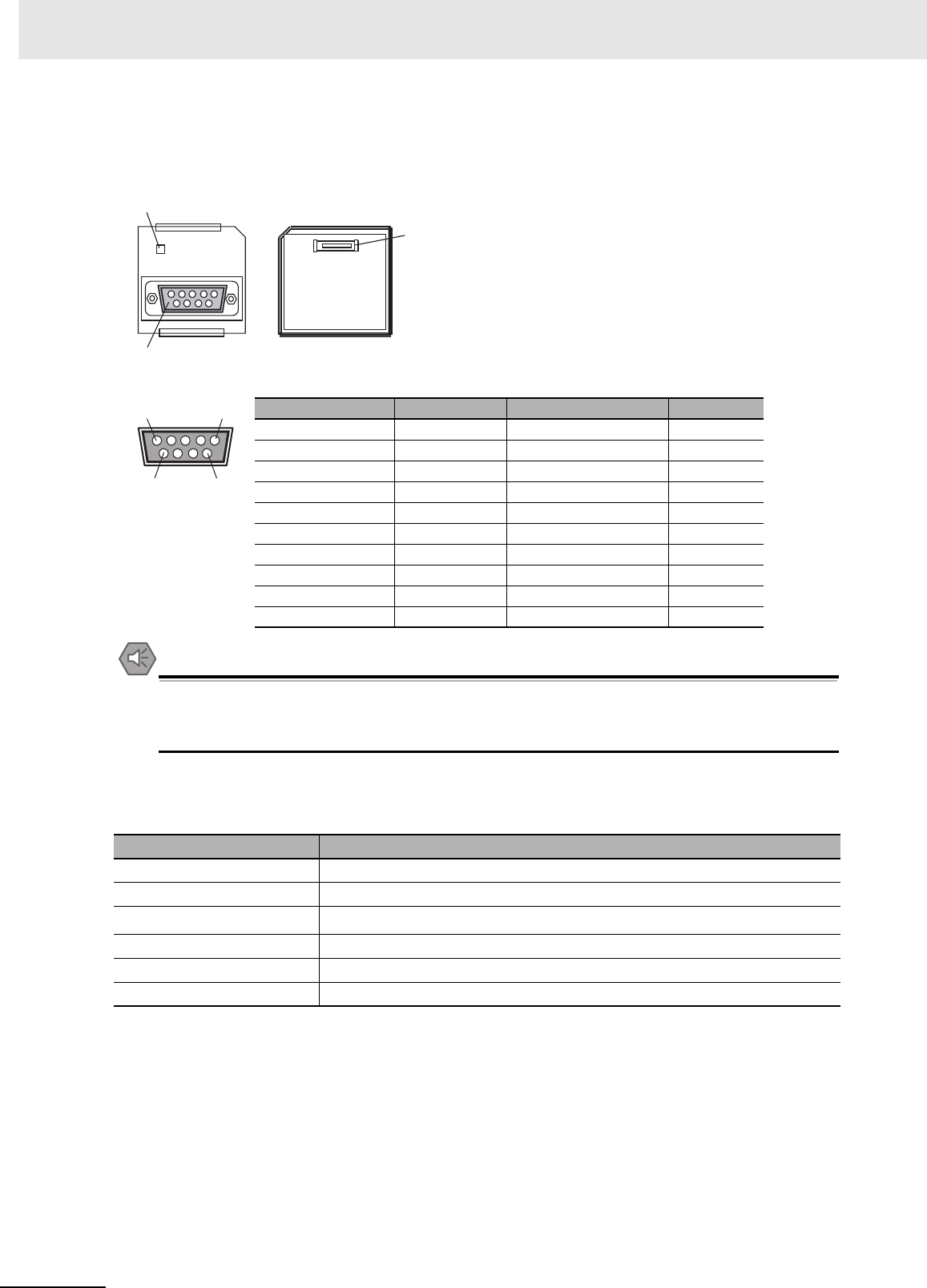
Appendices
A-112 CJ2 CPU Unit Hardware User’s Manual
zCP1W-CIF01 RS-232C Option Board Specifications
• Connector Pin Arrangement
Precautions for Safe Use
Do not use the 5-V power from pin 6 of the RS-232C port on the CPU Unit for anything but the
NT-AL001 Link Adapter, CJ1W-CIF11 RS-422A Converter, or NV3W-M@20L Programmable Ter-
minal. The external device or the CPU Unit may be damaged.
zCommunications Specifications
*1 Baud rates for the RS-232C are specified only up to 19.2 kbps. The CJ Series supports serial communications
from 38.4 kbps to 115.2 kbps, but some computers cannot support these speeds. Lower the baud rate if nec-
essary.
Pin No. Signal Name Direction
1 FG Protection earth ---
2 SD (TXD) Send data Output
3 RD (RXD) Receive data Input
4 RS (RTS) Request to send Output
5 CS (CTS) Clear to send Input
6 5 V Power supply ---
7 DR (DSR) Data set ready Input
8 ER (DTR) Data terminal ready Output
9 SG (0 V) Signal ground ---
Connector hood FG Protection earth ---
Item Specification
Communications method Half duplex
Synchronization Start-stop
Baud rate 0.3/0.6/1.2/2.4/4.8/9.6/19.2/38.4/57.6/115.2 kbps*1
Transmission distance 15 m max.
Interface EIA RS-232C
Protocol Host Link, NT Link, 1:N, No-protocol, or Peripheral Bus
COMM
Front Back
1. Communications status indicators
2. RS-232C connector
3. CPU Unit connector
5
6
1
9
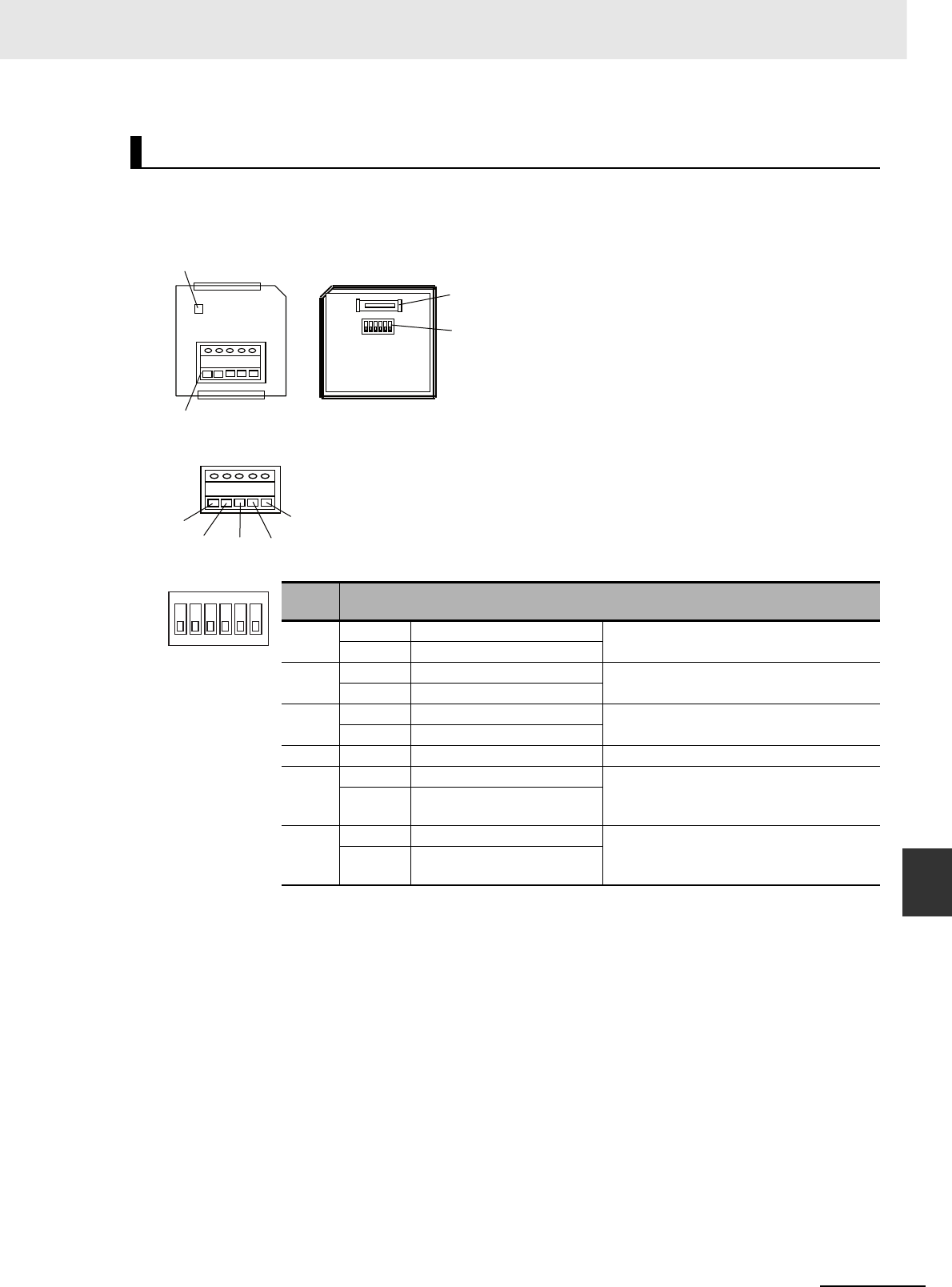
A-113
Appendices
CJ2 CPU Unit Hardware User’s Manual
A-4 Connecting to a Serial Port on the CPU Unit App
zCP1W-CIF11 and CP1W-CIF12 RS-422A/485 Option Board Specifications
• RS-422A/485 Terminal Block
• DIP Switch for Operation Settings
zConverting Built-in RS-232C to RS-422A/485
When converting the RS-232C port on a CJ2 CPU Unit to RS-422A, using one of the following Link
Adapters and Conversion Units.
• CJ1W-CIF11 RS-422A Converter
The maximum distance is 50 m.
Either RS-422A or RS-485 can be used.
• NT-AL001 RS-232C/RS-422A Link Adapter
The maximum distance is 500 m.
Only RS-422A can be used.
RS-422A/485 Interface Specifications
Pin
No. Setting
1 ON ON (both ends) Terminating resistance setting
OFF OFF
2 ON 2-wire 2-wire or 4-wire setting*1
OFF 4-wire
3 ON 2-wire 2-wire or 4-wire setting*1
OFF 4-wire
4 --- --- Not used.
5 ON RS control enabled RS control selection for RD*2
OFF RS control disabled (Data
always received.)
6 ON RS control enabled RS control selection for SD*3
OFF RS control disabled (Data
always sent.)
*1 Set both pins 2 and 3 to either ON (2-wire) or OFF (4-wire).
*2 To disable the echo-back function, set pin 5 to ON (RS control enabled).
*3 When connecting to a device on the N side in a 1: N connection with the 4-wire method,
set pin 6 to ON (RS control enabled).
Also, when connecting by the 2-wire method, set pin 6 to ON (RS control enabled).
COMM
Front Back
1. Communications status indicators
4. DIP switch for
operation settings
2. RS-422A/485 connector
RDA- RDB+ SDA- SDB+ FG
3. CPU Unit connector
RDB+
RDA−
SDA−SDB+
FG
Tighten the terminal block screws
to the torque of 0.28 N·m.
1
2
3
4
5
6
O
N
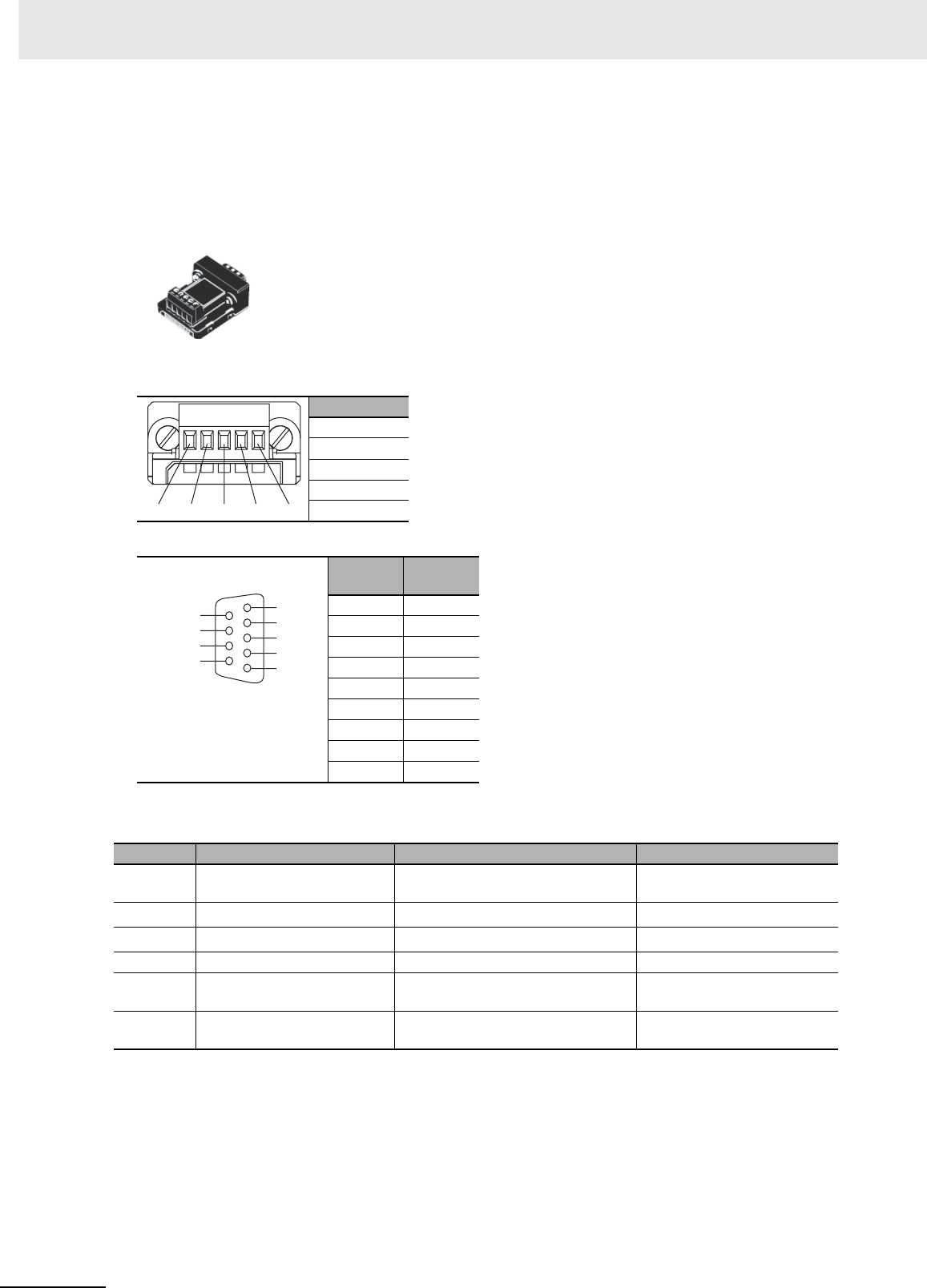
Appendices
A-114 CJ2 CPU Unit Hardware User’s Manual
CJ1W-CIF11 RS-422A Converter
The CJ1W-CIF11 RS-422A Converter is used to convert RS-232C to RS-422A/485.
It is connected directly to the RS-232C port on a CJ2 CPU Unit.
It is not isolated, so the maximum distance for RS-422A/485 is 50 m.
Appearance
Electric Specifications
• RS-422A/485 Terminal Block
• RS-232C Connector
* The hood will have the same electric potential as the connector hood where it is connected.
DIP Switch Settings
*1 Set both pins 2 and 3 to either ON (2-wire) or OFF (4-wire).
*2 To disable the echo-back function, set pin 5 to ON (RS control enabled).
*3 When connecting to a device on the N side in a 1: N connection with the 4-wire method, set pin 6 to ON (RS
control enabled).
Also, when connecting by the 2-wire method, set pin 6 to ON (RS control enabled).
Signal name
RDA−
RDB+
SDA−
SDB+
FG
Pin No. Signal
name
1FG
2RD
3SD
4CS
5RS
6+5 V
7, 8 NC
9SG (0 V)
Hood NC*
Pin No. Setting ON OFF
1 Terminating resistance set-
ting
Connects terminating resistance on
both ends of the transmission path.
Disconnects terminating
resistance.
22-wire/4-wire setting*1 2-wire 4-wire
32-wire/4-wire setting*1 2-wire 4-wire
4 Not used. --- ---
5RS control selection for RD*2 RS control enabled RS control disabled (Data
always received.)
6RS control selection for SD*3 RS control enabled RS control disabled (Data
always sent.)
RDA− RDB+ SDA− SDB+ FG
RDA−
RDB+
SDA−
SDB+
FG
RS-232C port
+5V 6
−7
−8
SG (0 V) 9
1 FG
2 RD
3 SD
4 CS
5 RS
Connector pin
arrangement
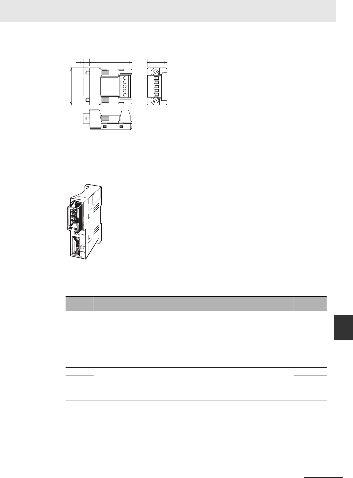
A-115
Appendices
CJ2 CPU Unit Hardware User’s Manual
A-4 Connecting to a Serial Port on the CPU Unit App A-4-1 Serial Port Interface Types and
Specifications
Dimensions (Unit: mm)
NT-AL001 RS-232C/RS-422A Link Adapter
The NT-AL001 RS-232C/RS-422A Link Adapter is used to connect to devices that have RS-232C or
RS-422A terminals. It is connected with a cable to the RS-232C port on a CJ2 CPU Unit. It is iso-
lated, so the maximum distance for RS-422A is 500 m.
Appearance
DIP Switch Settings
There is a DIP switch on the NT-AL001 RS-232C/RS-422A Link Adapter that is used to set RS-
422A/485 communications parameters. Set the DIP switch as required for the serial communica-
tions mode according to the following table.
* When connecting to a CJ-series CPU Unit, turn OFF pin 5 and turn ON pin 6.
Pin Function Default
setting
1 Not used. (Leave set to ON.) ON
2 Internal terminating resistance setting.
ON: Terminating resistance connected.
OFF: Terminating resistance not connected.
ON
3 2-wire/4-wire setting
Both pins ON: 2-wire communications
Both pins OFF: 4-wire communications
OFF
4OFF
5 Communications mode*
Both pins OFF: Always send.
5 OFF/6 ON: Send when RS-232C's CS is high.
5 ON/6 OFF: Send when RS-232C's CS is low.
ON
6OFF
5.8 38.8
34.0
18.2
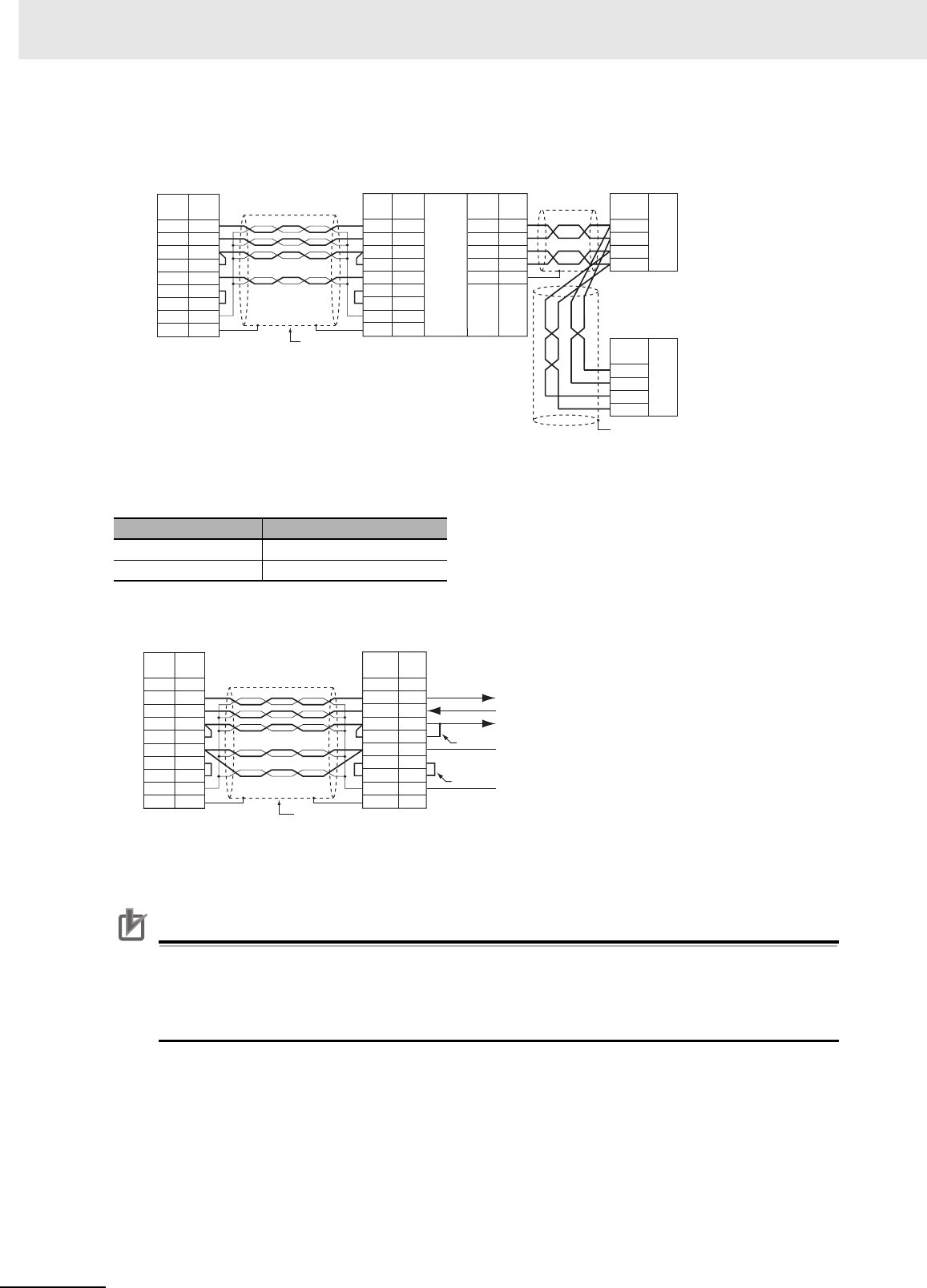
Appendices
A-116 CJ2 CPU Unit Hardware User’s Manual
Application Example
Note Use the special cables for the above cables.
Use the following Cables to connect the RS-232C port on an Option Board to an NT-AL001 RS-
232C/RS-422A Link Adapter.
Wiring the Recommended Cable (XW2Z-070T-1/XW2Z-200T-1)
Note The shell (FG) is internally connected to the protective earth (GR) terminal on the CPU Unit. FG can thus be
connected by connecting the protective earth (GR) terminal on the Power Supply Unit.
Precautions for Correct UsePrecautions for Correct Use
•The XW2Z-@@0T-1 Cable is designed to connect the NT-AL001 and contains special wiring for
the DS and RS signals. Do not use this cable for any other application. Connecting this cable
to other devices can damage them.
• Always turn ON the terminating resistance on the ends of the RS-422A/485 line.
Length Model
70 cm XW2Z-070T-1
2 m XW2Z-200T-1
3
2
4
5
6
7
8
9
RD
SD
RS
CS
+5V
DR
ER
SG
FG
4
3
6
5
1
SDA
SDB
RDA
RDB
GRD
RDA
RDB
SDA
SDB
RS-422
RDA
RDB
SDA
SDB
SD
RD
RS
CS
+5V
DR
ER
SG
FG
2
3
4
5
6
7
8
9
FG
RS-232C
External device
Shield
Signal
name Signal
name
Shell
Pin
No. Pin
No. Signal
name Pin
No. Signal
name
Signal
name
External device
Shell
(See note.)
CJ2M CPU Unit
Built-in RS-232C port or
RS-232C Option Board NT-AL001 RS-232C/RS-422A Link Adapter
1
3
2
4
5
6
7
8
9
RD
SD
RS
CS
+5V
DR
ER
SG
FG
FG
SD
RD
RS
CS
+5V
DR
ER
SG
FG
1
2
3
4
5
6
7
8
9
Wiring with XW2Z-@@0T-1 (10 conductors)
PLC NT-AL001 (inside NT-AL001)
Shell
Not
used.
Shield Shell
Signal
name
Signal
name
Arrows indicate signal directions
Returned
Returned
Pin
No.
Pin
No.
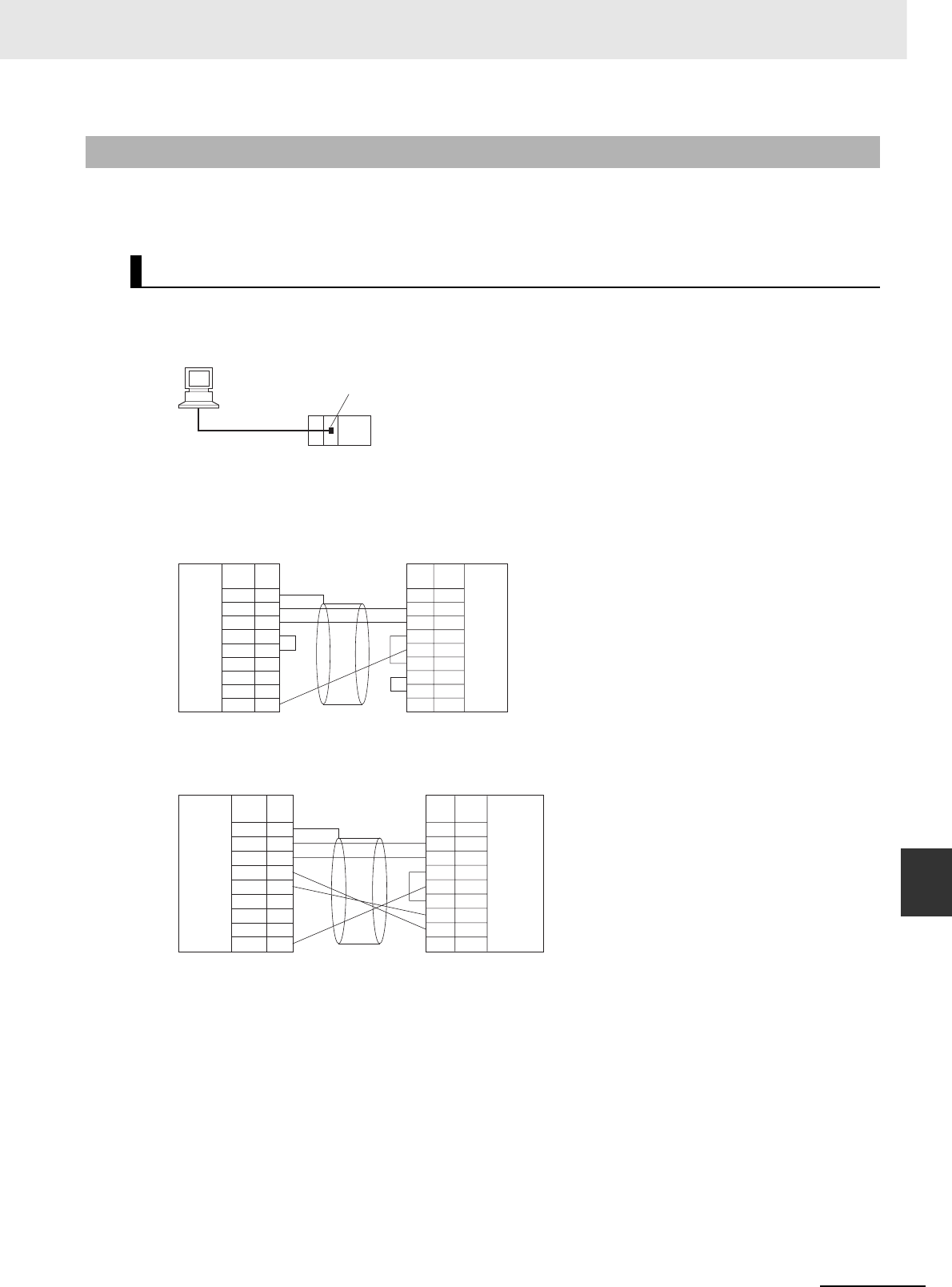
A-117
Appendices
CJ2 CPU Unit Hardware User’s Manual
A-4 Connecting to a Serial Port on the CPU Unit App A-4-2 Connection Examples
This section provides connection examples and corresponding connection diagrams.
Refer to A-4-3 Applicable Connectors and Recommended Cables for actual wiring methods.
Note Connections to a computer running the CX-Programmer are the same as those shown here.
z1:1 Connections via RS-232C Port
Note The maximum cable length for an RS-232C connection is 15 m. RS-232C communications specifications,
however, do not cover transmissions at 19.2 Kbps. Refer to documentation of the device being connected
when using this baud rate.
Connection Example for the Host Link Serial Communications Mode
Connection Example for the Peripheral Bus (Toolbus) Serial Communications Mode
A-4-2 Connection Examples
Host Computer (Host Link or Tool Bus)
RS-232C
RS-232C
port
1
2
3
4
5
6
7
8
9
CD
RD
SD
ER
SG
DR
RS
CS
CI
1
2
3
4
5
6
7
8
9
FG
SD
RD
RS
CS
5V
DR
ER
SG
CPU Unit IBM PC/AT or compatible
RS-232C
interface
Signal
name Signal
name
RS-232C
interface
D-sub, 9-pin
connector (male) D-sub, 9-pin
connector (female)
Pin
No. Pin
No.
CPU Unit
RS-232C
interface
Signal
name Signal
name
RS-232C
interface
D-sub, 9-pin
connector (male) D-sub, 9-pin
connector (female)
Pin
No. Pin
No.
1
2
3
4
5
6
7
8
9
CD
RD
SD
ER
SG
DR
RS
CS
CI
1
2
3
4
5
6
7
8
9
FG
SD
RD
RS
CS
5V
DR
ER
SG
IBM PC/AT or compatible
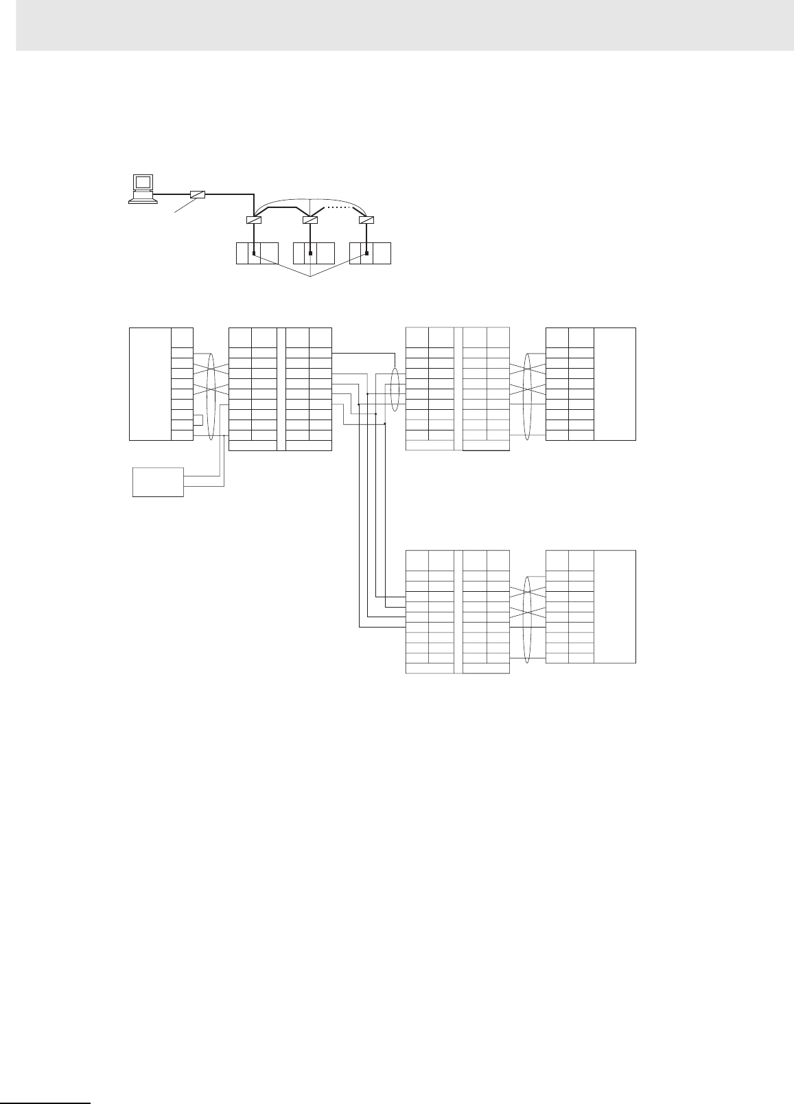
Appendices
A-118 CJ2 CPU Unit Hardware User’s Manual
z1:N Connections via RS-232C Port
A connection example for converting between RS-232C and RS-422A/485 to use 1:N connections is
shown below.
*1 We recommend using the following NT-AL001 RS-232C/RS-422A Link Adapter Connecting Cables to connect
to NT-AL001 Link Adapters.
XW2Z-070T-1: 0.7 m
XW2Z-200T-1: 2 m
• Wiring the Recommended Cable (XW2Z-070/200T-1)
The recommended cables should be wired as shown below. For an RS-232C cable, each signal wire
should be twisted with the SG (signal ground) wire and placed in a shielded cable to prevent the effects of
noise in noise-prone environments. The 5-V wires can also be twisted with the SG wire to increase noise
immunity. Although this wiring is different from that shown in the example above, it can be used to
increase noise immunity if required.
NT-AL001
RS-422A/485
RS-232C
RS-232C RS-232C RS-232C
NT-AL001
terminating
resistance ON,
5-V power
required
Terminating resistance ON
RS-232C ports
RS-232C
RS-232C
Shield CPU Unit
*2
Personal Computer
Signal
name Signal
name Signal
name Signal
name
Signal
name Signal
name
Signal
name
Signal
name
Signal
name
RS-232C
Interface
NT-AL001 Link Adapter
D-sub, 9-pin
connector (male)
DIP Switch Settings
Pin 1: ON
Pin 2: ON
(terminating resistance)
Pin 3: OFF
Pin 4: OFF
Pin 5: OFF
Pin 6: OFF
DIP Switch Settings
Pin 1: ON
Pin 2: OFF
Pin 3: OFF
Pin 4: OFF
Pin 5: OFF
Pin 6: ON
D-sub, 9-pin connector
(male)
RS-232C
Interface
RS-232C
Interface
*1
*2
D-sub, 9-pin connector
(male)
Serial Communications Board/Unit
NT-AL001 Link Adapter
DIP Switch Settings
Pin 1: ON
Pin 2: ON
(terminating resistance)
Pin 3: OFF
Pin 4: OFF
Pin 5: OFF
Pin 6: ON
NT-AL001 Link Adapter
Pin
No. Pin
No.
Pin
No. Pin
No.
Pin
No. Pin
No.
Pin
No.
Pin
No.
RS-232C
Terminal block
FG
SD
RD
RS
CS
DR
ER
SG
1
2
3
4
5
6
7
8
9
1
2
3
4
5
6
7
8
1
2
3
4
5
6
7
8
1
2
3
4
5
6
7
8
9
1
2
3
4
5
6
7
8
9
RS-422A
*1
*2
NC
SD
RD
RS
CS
5V
DR
ER
SG
NC
SD
RD
RS
CS
5V
DR
ER
SG
GRD
SG
SDB
SDA
RDB
RDA
CSB
CSA
GRD
SG
SDB
SDA
RDB
RDA
CSB
CSA
FG
SD
RD
RS
CS
5V
DR
ER
SG
RS-232 RS-422 RS-422 RS-232
1
2
3
4
5
6
7
8
GRD
SG
SDB
SDA
RDB
RDA
CSB
CSA
RS-422
1
2
3
4
5
6
7
8
9
NC
SD
RD
RS
CS
5V
DR
ER
SG
RS-232
1
2
3
4
5
6
7
8
9
FG
SD
RD
RS
CS
5V
DR
ER
SG
5-V
power
(+)
(–)
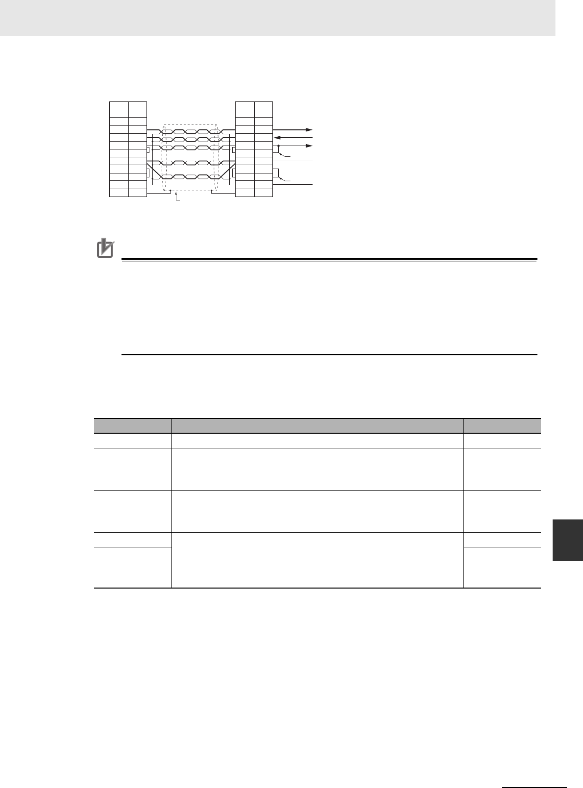
A-119
Appendices
CJ2 CPU Unit Hardware User’s Manual
A-4 Connecting to a Serial Port on the CPU Unit App
Wiring with XW2Z-@@0T-1 (10 conductors)
*2 When the NT-AL001 Link Adapter is connected to the RS-232C port on the CPU Unit, 5 V is supplied from pin
6, eliminating the need for a 5-V power supply.
Precautions for Correct UsePrecautions for Correct Use
• Do not use the 5-V power from pin 6 of the RS-232C port for anything but the NT-AL001 Link
Adapter, CJ1W-CIF11 RS-422A Converter, or NV3W-M@20L Programmable Terminals. Using
this power supply for any other external device may damage the CPU Unit or the external
device.
• The XW1Z-@@0T-1 Cable is designed to connect the NT-AL001 and contains special wiring for
the CS and RS signals. Do not use this cable for any other application. Connecting this cable
to other devices can damage them.
DIP Switch Settings on the NT-AL001 Link Adapter
There is a DIP switch on the NT-AL001 Link Adapter that is used to set RS-422A/485 communications
parameters. Set the DIP switch as required for the serial communications mode according to the follow-
ing table.
Pin Function Default setting
1 Not used. (Leave set to ON.) ON
2 Internal terminating resistance setting.
ON: Terminating resistance connected.
OFF: Terminating resistance not connected.
ON
3 2-wire/4-wire setting
Both pins ON: 2-wire communications
Both pins OFF: 4-wire communications
OFF
4OFF
5 Communications mode
Both pins OFF: Always send.
5 OFF/6 ON: Send when RS-232C's CS is high.
5 ON/6 OFF: Send when RS-232C's CS is low.
ON
6OFF
Shell
Not
used.
Shield
Shell
Signal
name Signal
name
Internal signals
Arrows indicate signal directions
Returned
Returned
Pin
No.
Pin
No.
PLC NT-AL001
1
2
3
4
5
6
7
8
9
FG
SD
RD
RS
CS
5V
DR
ER
SG
FG
1
3
2
4
5
6
7
8
9
RD
SD
RS
CS
5V
DR
ER
SG
FG

Appendices
A-120 CJ2 CPU Unit Hardware User’s Manual
zRS-422A/485 Ports with 1:1 Connection
FG
SD
RD
RS
CS
DR
ER
SG
1
2
3
4
5
6
7
8
9
NC
SD
RD
RS
CS
5V
DR
ER
SG
1
2
3
4
5
6
7
8
RS-422RS-232
GRD
SG
SDB
SDA
RDB
RDA
CSB
CSA
3
4
1
2
5
SDA
SDB
RDA
RDB
FG
Shield
CPU Unit
Personal Computer
Signal
name Signal
name
Signal
name
Signal
name
RS-232C
Interface
NT-AL001 Link Adapter
D-sub, 9-pin
connector (male)
DIP Switch Settings
Pin 1: ON
Pin 2: ON
(terminating resistance)
Pin 3: OFF
Pin 4: OFF
Pin 5: OFF
Pin 6: OFF
Pin
No.
Pin
No.
Pin
No.
Terminal block
5-V
power
(+)
(–)
RS-
422A/485
Option
Board
4-wire
Terminating resistance: ON
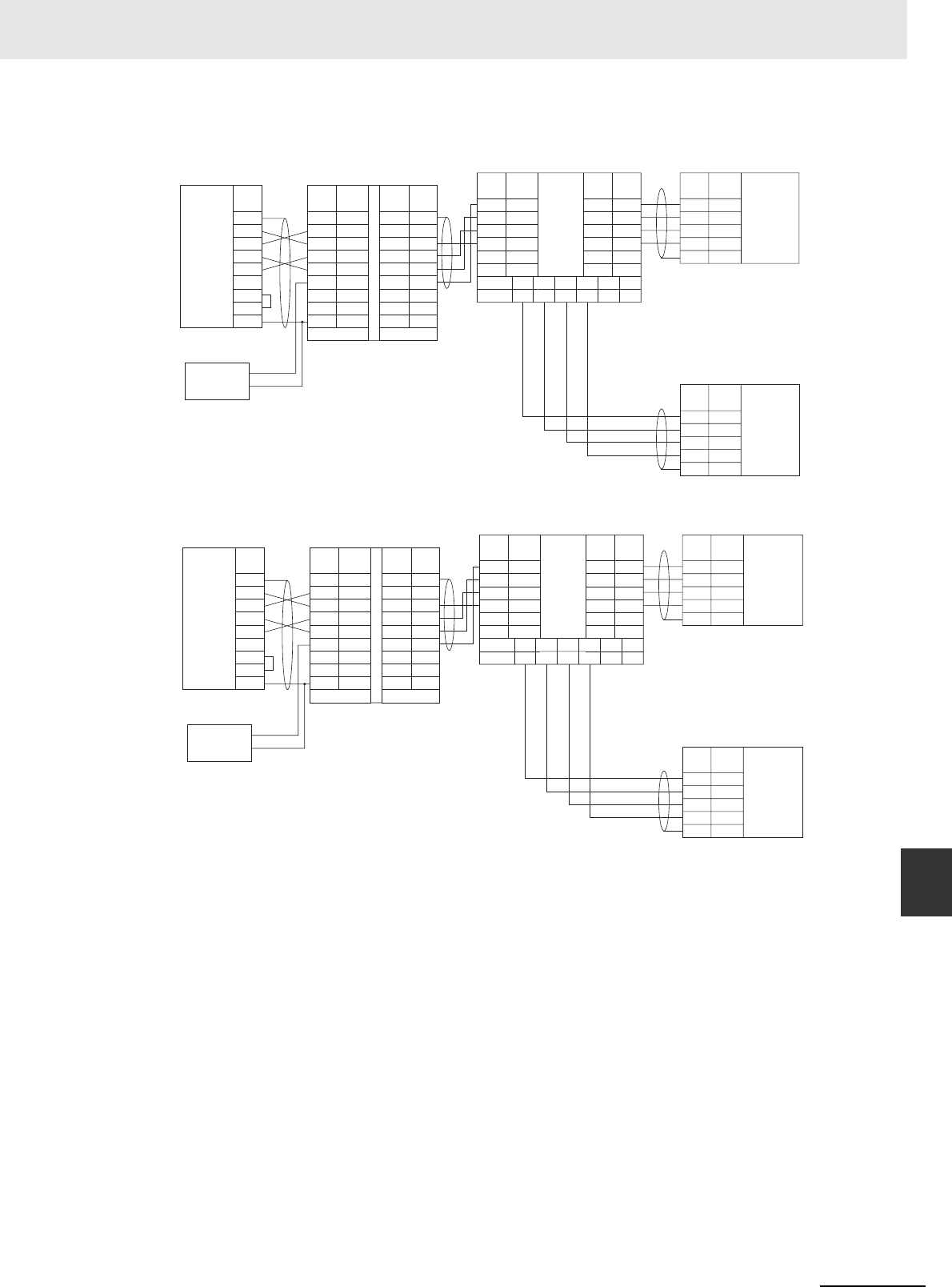
A-121
Appendices
CJ2 CPU Unit Hardware User’s Manual
A-4 Connecting to a Serial Port on the CPU Unit App A-4-2 Connection Examples
zRS-422A/485 Ports with 1:N Connections
FG
SD
RD
RS
CS
DR
ER
SG
1
2
3
4
5
6
7
8
9
NC
SD
RD
RS
CS
5V
DR
ER
SG
1
2
3
4
5
6
7
8
RS-422RS-232
GRD
SG
SDB
SDA
RDB
RDA
CSB
CSA
9
5
6
1
3
7
SDA
SDB
RDA
RDB
SG
FG
9
5
6
1
3
7
SDA
9
SDB
5
RDA
6
RDB
1
SG
3
FG
7
SDA
SDB
RDA
RDB
SG
FG
3
4
1
2
5
SDA−
SDB+
RDA−
RDB+
FG
3
4
1
2
5
SDA−
SDB+
RDA−
RDB+
FG
Shield
CPU Unit
Personal Computer
Signal
name Signal
name
Signal
name Signal
name
Signal
name
Signal
name
Signal
name
RS-232C
Interface
NT-AL001 Link Adapter
D-sub, 9-pin
connector (male)
DIP Switch Settings
Pin 1: ON
Pin 2: ON
(terminating resistance)
Pin 3: OFF
Pin 4: OFF
Pin 5: OFF
Pin 6: OFF
D-sub, 9-pin connector
(male)
Pin
No.
Pin
No.
Pin
No.
Pin
No. Pin
No.
Pin
No.
Terminal block
5-V
power
(+)
(–)
Signal name
Pin No.
Shield
CPU Unit
Shield
B500-AL001
RS-
422A/485
interface
RS-
422A/485
Option
Board
4-wire
Terminating resistance: OFF
RS-
422A/485
Option
Board
4-wire
Terminating resistance at
end of line: ON.
FG
SD
RD
RS
CS
DR
ER
SG
1
2
3
4
5
6
7
8
9
NC
SD
RD
RS
CS
5V
DR
ER
SG
1
2
3
4
5
6
7
8
RS-422RS-232
GRD
SG
SDB
SDA
RDB
RDA
CSB
CSA
9
5
6
1
3
7
SDA
SDB
RDA
RDB
SG
FG
9
5
6
1
3
7
SDA
9
SDB
5
RDA
6
RDB
1
SG
3
FG
7
SDA
SDB
RDA
RDB
SG
FG
3
4
1
2
5
SDA−
SDB+
RDA−
RDB+
FG
3
4
1
2
5
SDA
SDB
RDA
RDB
FG
Shield
CPU Unit
Personal Computer
Signal
name Signal
name
Signal
name Signal
name
Signal
name
Signal
name
Signal
name
RS-232C
Interface
NT-AL001 Link Adapter
D-sub, 9-pin
connector (male)
DIP Switch Settings
Pin 1: ON
Pin 2: ON
(terminating resistance)
Pin 3: OFF
Pin 4: OFF
Pin 5: OFF
Pin 6: OFF
D-sub, 9-pin connector
(male)
Pin
No.
Pin
No.
Pin
No.
Pin
No. Pin
No.
Pin
No.
Terminal block
5-V
power
(+)
(–)
Signal name
Pin No.
Shield
CPU Unit
Shield
B500-AL001
RS-
422A/485
interface
RS-
422A/485
Option
Board
4-wire
Terminating resistance: OFF
RS-
422A/485
Option
Board
4-wire
Terminating resistance at
end of line: ON.
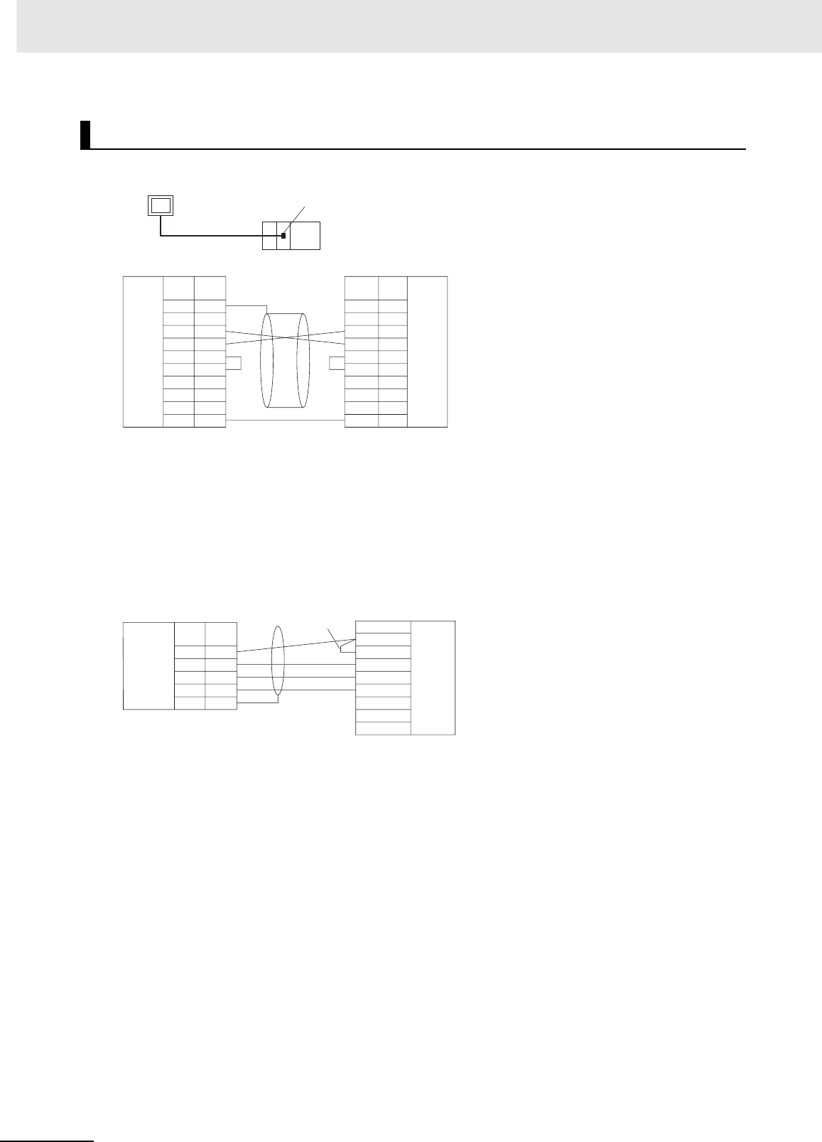
Appendices
A-122 CJ2 CPU Unit Hardware User’s Manual
zDirect Connection from RS-232C to RS-232C
• Communications Mode: Host Link (unit number 0 only for Host Link)
NT Link (1:N, N = 1 Unit only)
• OMRON Cables with Connectors:
XW2Z-200T-1: 2 m
XW2Z-500T-1: 5 m
zRS-422A/485 Ports with 1:1 Connection
• Communications Mode: Host Link (Host Link unit number 0 only)
NT Link (1:N, N = 1 Unit only)
* Switch Settings on RS-422A/485 Option Board
• Terminating resistance: ON
• 2-wire/4-wire setting: 4-wire
Note The terminating resistance setting example is for the NT631/NT631C.
The setting method depends on the PT model. Refer to the manual for your PT.
OMRON PT (Host Link or 1:N NT Link)
RS-232C
PT
Host Link or NT Link (1:N)
RS-232C port
–
–
–
CPU Unit PT
Hood
Hood
Signal
name Signal
name
RS-232C
Interface
RS-232C
Interface
D-sub, 9-pin
connector (male) D-sub, 9-pin
connector (male)
Pin
No. Pin
No.
FG
FG
SD
RD
RS
CS
5V
DR
ER
SG
1
2
3
4
5
6
7
8
9
1
2
3
4
5
6
7
8
9
FG
SD
RD
RS
CS
5V
SG
RDA
TRM
RDB
SDA
SDB
RSA
RSB
3
4
1
2
5
SDA−
SDB+
RDA−
RDB+
FG
CPU Unit
Signal
name
Signal name
Pin
No.
Terminal block
RS-
422A/485
Option
Board
Short pin PT (See note.)
RS-
422A/485
interface
Functional ground
Terminal block/D-sub connector
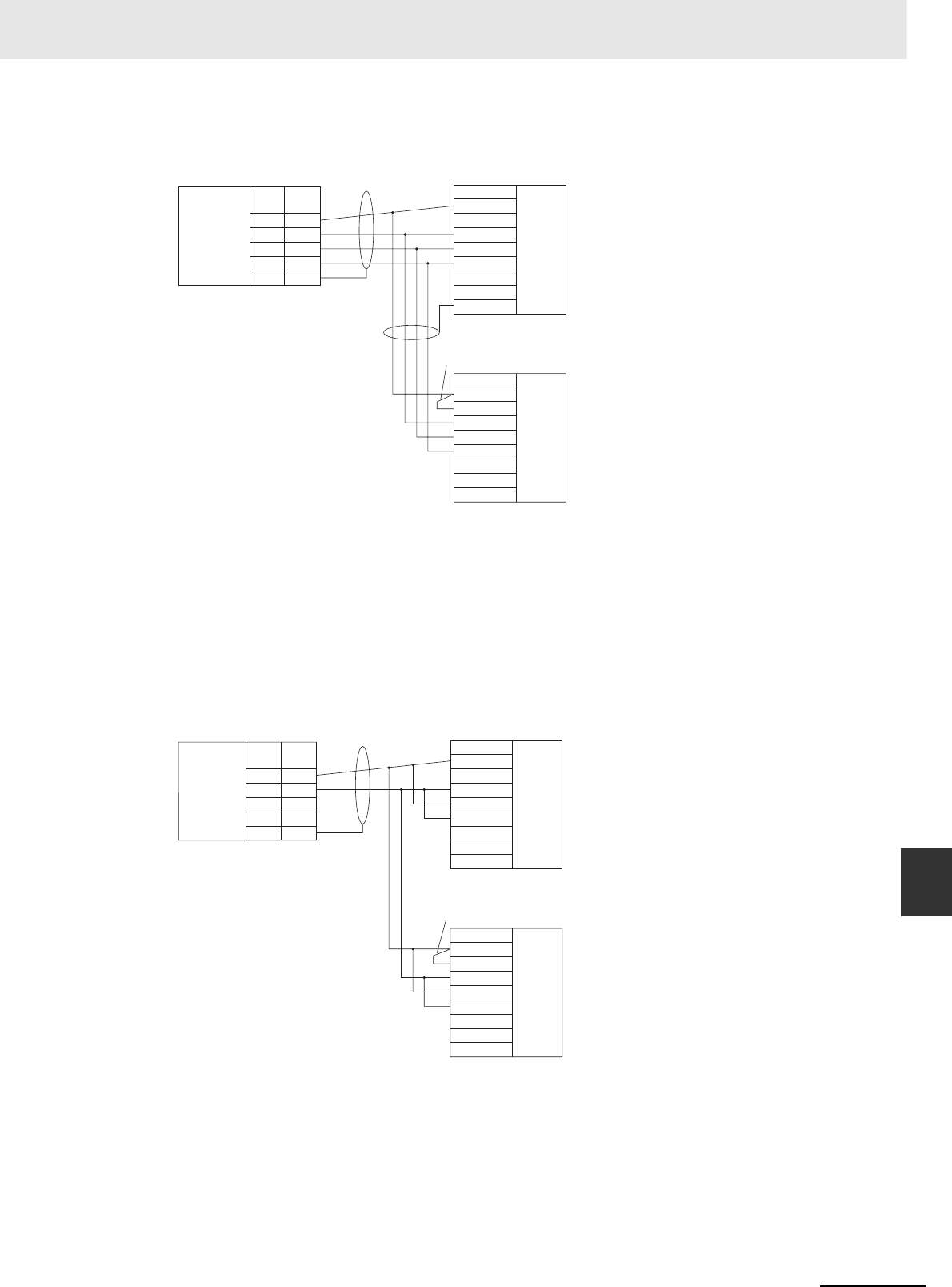
A-123
Appendices
CJ2 CPU Unit Hardware User’s Manual
A-4 Connecting to a Serial Port on the CPU Unit App A-4-2 Connection Examples
zRS-422A/485 Ports with 1:N, 4-wire Connections
• Communications Mode: 1:N NT Link
* Switch Settings on RS-422A/485 Option Board
• Terminating resistance: ON
• 2-wire/4-wire setting: 4-wire
Note The terminating resistance setting example is for the NT631/NT631C.
The setting method depends on the PT model. Refer to the manual for your PT.
zRS-422A/485 Ports with 1:N, 2-wire Connections
• Communications Mode: 1:N NT Link
* Switch Settings on RS-422A/485 Option Board
• Terminating resistance: ON
• 2-wire/4-wire setting: 2-wire
Note The terminating resistance setting example is for the NT631/NT631C.
The setting method depends on the PT model. Refer to the manual for your PT.
PT
RDA
TRM
RDB
SDA
SDB
RSA
RSB
3
4
1
2
5
SDA−
SDB+
RDA−
RDB+
FG
RDA
TRM
RDB
SDA
SDB
RSA
RSB
CPU Unit
Signal
name
Signal name
Pin
No.
Terminal block
Signal name
RS-
422A/485
Option
Board
Short pin PT (See note.)
RS-
422A/485
interface
Terminal block/D-sub connector
RS-
422A/485
interface
Terminal block/D-sub connector
Functional ground
Functional ground
RDA
TRM
RDB
SDA
SDB
3
4
1
2
5
SDA−
SDB+
RDA−
RDB+
FG
RDA
TRM
RDB
SDA
SDB
CPU Unit
Signal
name
Signal name
Pin
No.
Terminal block
Signal name
PT
RS-
422A/485
Option
Board
Short pin PT (See note.)
RS-
422A/485
interface
Terminal block/D-sub connector
RS-
422A/485
interface
Terminal block/D-sub connector
Functional ground
Functional ground
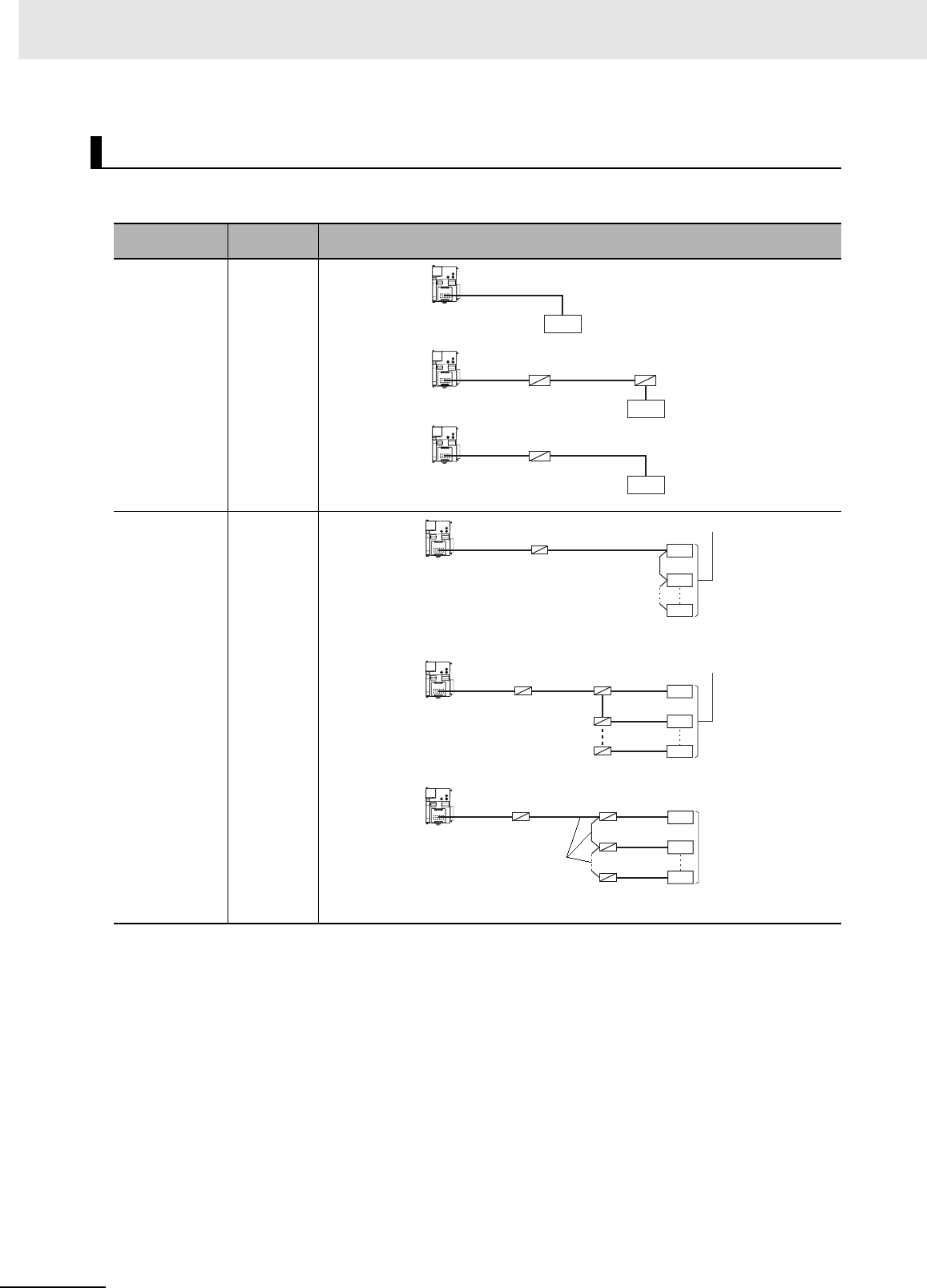
Appendices
A-124 CJ2 CPU Unit Hardware User’s Manual
This section describes the connection patterns and connections for using different ports in Serial Gate-
way Mode and No-protocol Mode. Up to 32 nodes can be connected for 1:N communications.
Note 1 The maximum cable length for an RS-232C connection is 15 m. RS-232C communications specifications,
however, do not cover transmissions at 19.2 Kbps. Refer to documentation of the device being connected
when using this baud rate.
2The maximum total cable length including branch lines is 500 m for RS-422A/485.
3The maximum cable length for connecting to the NT-AL001 is 2 m.
4The maximum branch cable length is 10 m.
General-purpose External Devices (No-protocol or Serial Gateway)
Port Connection
type Diagram
RS-232C 1:1
RS-232C 1:N
RS-232C
I/F
RS-232C
NT-AL001
NT-AL001
NT-AL001
RS-232C
I/F
RS-422A/485
RS-232C
RS-422A/
485 I/F
RS-422A/485
RS-232C
Terminating
resistance ON
+5 V required
Terminating
resistance ON
Terminating
resistance ON
RS-422A/485 I/F
NT-AL001
RS-232C
RS-422A/485
NT-AL001
RS-232C
RS-422A/
485
B500-AL001
NT-AL001
RS-232C RS-232C
RS-232C
RS-232C
RS-422A/485
NT-AL001
RS-422A/485 I/F
RS-232C I/F
Terminating
resistance ON
+5 V required
Terminating
resistance ON
Terminating
resistance ON
Terminating
resistance ON
Terminating
resistance ON
Terminating
resistance ON
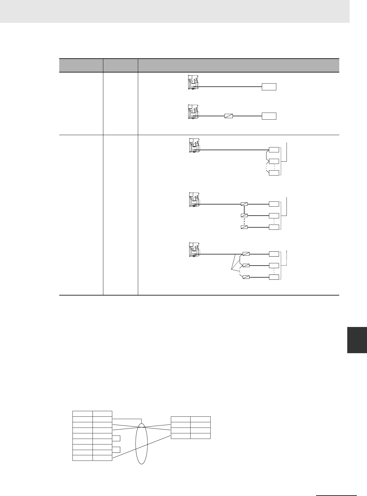
A-125
Appendices
CJ2 CPU Unit Hardware User’s Manual
A-4 Connecting to a Serial Port on the CPU Unit App A-4-2 Connection Examples
Note 1 The maximum cable length for an RS-232C connection is 15 m. RS-232C communications specifications,
however, do not cover transmissions at 19.2 Kbps. Refer to documentation of the device being connected
when using this baud rate.
2The CP1W-CIF11 RS-422A/485 Option Board is not isolated. The maximum transmission distance is
therefore 50 m. If the distance exceeds 50 m, use the isolated CP1W-CIF12, or connect the isolated NT-
AL001 RS-422A Link Adapter to the RS-232C port on the CP1W-CIF01 RS-232C Option Board. If you use
one of these methods, the maximum total transmission distance will be 500 m.
3The maximum cable length for connecting to the NT-AL001 is 2 m.
4The maximum branch cable length is 10 m.
zExamples of 1:1 Connections to RS-232C Ports
Connecting to E5CK Temperature Controllers
Port Connection
type Diagram
RS-422A/485 1:1
RS-422A/485 1:N
NT-AL001
RS-422A/485
RS-422A/
485
RS-422A/485 I/F
RS-232C I/F
RS-232C
Terminating
resistance ON
+5 V required
RS-422A/485 I/F
RS-422A/485
RS-422A/485
B500-AL001
RS-232C
RS-232C
RS-232C
RS-422A/485
NT-AL001
RS-422A/485 I/F
RS-232C I/F
Terminating
resistance ON
+5 V required
Terminating
resistance ON
Terminating
resistance ON
Terminating
resistance ON
Terminating
resistance ON
Terminating
resistance ON
1
2
3
4
5
7
8
9
FG
SD
RD
RS
CS
DR
ER
SG
13
14
1
SD
RD
SG
Signal name
D-sub, 9-pin
connector (male)
Pin No.
Signal name
CPU Unit
RS-232C Option Board RS-232C
shield
Example: E5CK (OMRON Temperature Controller)
RS-232C: Terminal block
Terminal
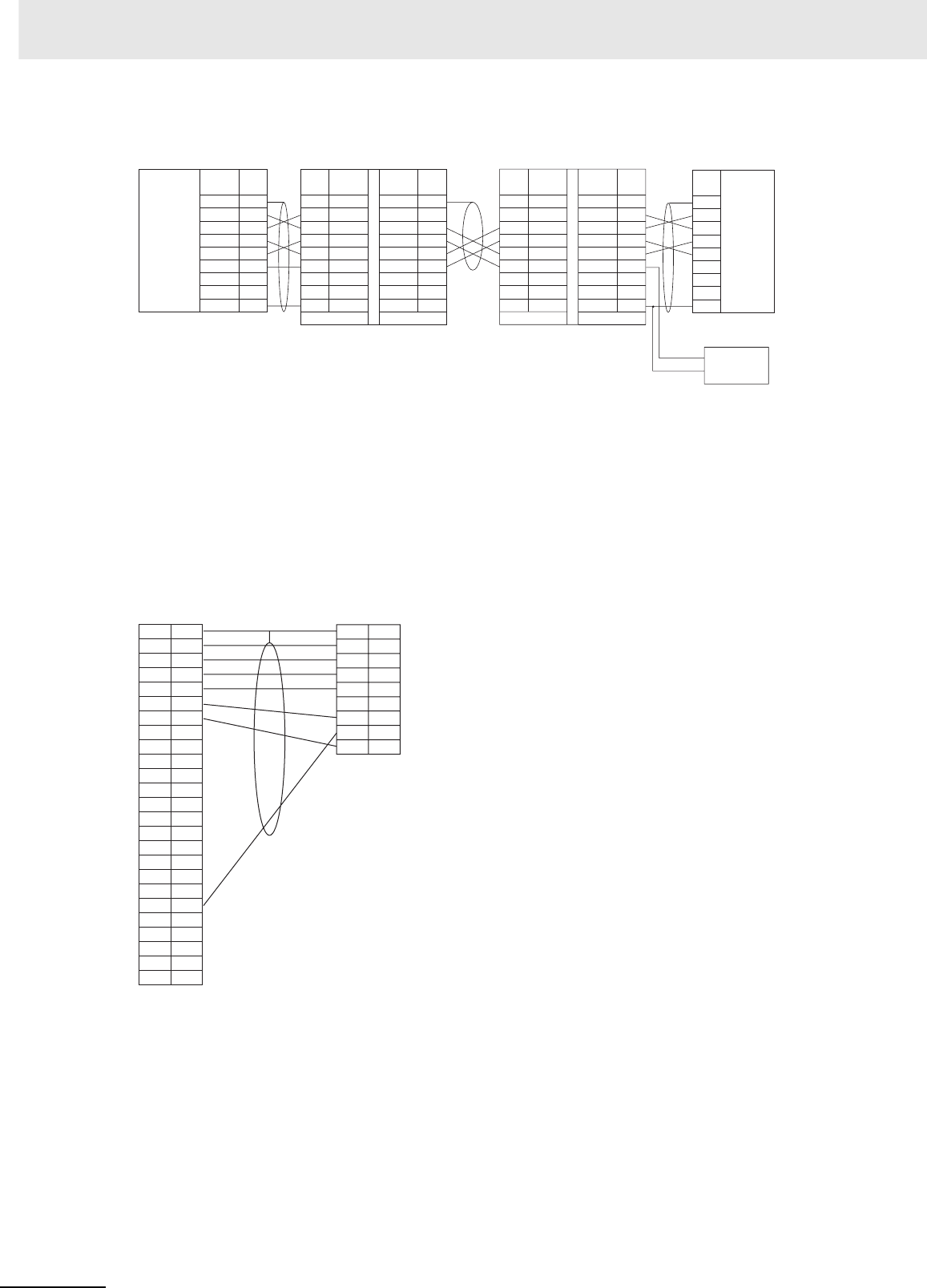
Appendices
A-126 CJ2 CPU Unit Hardware User’s Manual
Using an NT-AL-001 RS-232C/RS-422A Link Adapter
*1 We recommend using the following NT-AL001 Link Adapter Connecting Cables to connect to NT-AL001 Link
Adapters.
Connecting to Modems
NT-AL001 Connecting Cables: XW2Z-070T-1 (0.7 m)
XW2Z-200T-1 (2 m)
RS-232C
RS-422A
RS-232C
FG
SD
RD
RS
CS
DR
ER
SG
1
2
3
4
5
6
7
8
9
NC
SD
RD
RS
CS
5V
DR
ER
SG
1
2
3
4
5
6
7
8
RS-422RS-232
GRD
SG
SDB
SDA
RDB
RDA
CSB
CSA
1
2
3
4
5
6
7
8
9
FG
SD
RD
RS
CS
5V
DR
ER
SG
1
2
3
4
5
6
7
8
GRD
SG
SDB
SDA
RDB
RDA
CSB
CSA
1
2
3
4
5
6
7
8
9
RS-232RS-422
NC
SD
RD
RS
CS
5V
DR
ER
SG
Shield
CPU Unit
*1
Personal Computer
Signal
name
Signal
name Signal
name
Signal
name
Signal
name
Signal
name
RS-232C
Interface
NT-AL001 Link Adapter
D-sub, 9-pin
connector (male)
DIP Switch Settings
Pin 1: ON
Pin 2: ON (terminating resistance)
Pin 3: OFF (4-wire)
Pin 4: OFF (4-wire)
Pin 5: OFF
Pin 6: ON
NT-AL001 Link Adapter
Pin
No. Pin
No. Pin
No. Pin
No.
Pin
No.
Terminal block
5-V
power
(+)
(–)
D-sub, 9-pin
connector (male)
RS-232C
Option
Board
DIP Switch Settings
Pin 1: ON
Pin 2: ON (terminating resistance)
Pin 3: OFF (4-wire)
Pin 4: OFF (4-wire)
Pin 5: OFF
Pin 6: OFF
1
2
3
4
5
6
7
8
9
10
11
12
13
14
15
16
17
18
19
20
21
22
23
24
25
Modem
FG
SD
RD
RS
CS
DR
SG
CD
ST2
RT
ER
CI
ST1
1
2
3
4
5
6
7
8
9
FG
SD
RD
RS
CS
5V
DR
ER
SG
CPU Unit
RS-232C
Option Board
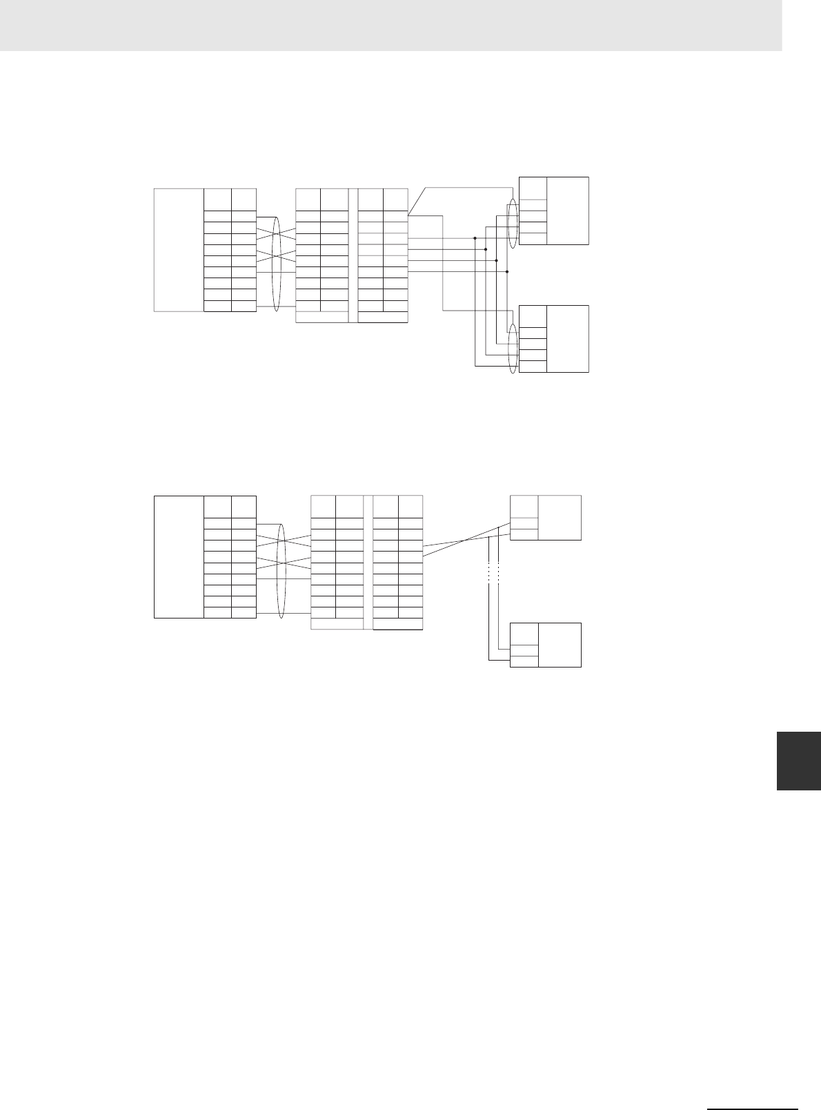
A-127
Appendices
CJ2 CPU Unit Hardware User’s Manual
A-4 Connecting to a Serial Port on the CPU Unit App A-4-2 Connection Examples
zExamples of 1:N Connections to RS-232C Ports
*1 We recommend using the following NT-AL001 Link Adapter Connecting Cables to connect to NT-AL001 Link
Adapters.
NT-AL001 Connecting Cables: XW2Z-070T-1 (0.7 m)
XW2Z-200T-1 (2 m)
RS-422A
RS-232C
1
2
3
4
5
6
7
8
9
NC
SD
RD
RS
CS
5V
DR
ER
SG
1
2
3
4
5
6
7
8
RS-422RS-232
GRD
SG
SDB
SDA
RDB
RDA
CSB
CSA
SDA
SDB
RDA
RDB
SDA
SDB
RDA
RDB
1
2
3
4
5
6
7
8
9
FG
SD
RD
RS
CS
5V
DR
ER
SG
Shield
CPU Unit
Signal
name Signal
name
Signal
name
Signal
name
Signal
name
NT-AL001 Link Adapter
D-sub, 9-pin
connector (male)
DIP Switch Settings
Pin 1: ON
Pin 2: ON (terminating resistance)
Pin 3: OFF (4-wire)
Pin 4: OFF (4-wire)
Pin 5: OFF
Pin 6: OFF
D-sub, 9-pin connector
(male)
*1
Pin
No. Pin
No.
Pin
No.
Terminal block
Shield
RS-232C
Option
Board
Component
with
RS-422A/485
(4-wire)
RS-
422A/485
interface
RS-
422A/485
interface
Component
with
RS-422A/485
(4-wire)
1
2
3
4
5
6
7
8
9
NC
SD
RD
RS
CS
5V
DR
ER
SG
1
2
3
4
5
6
7
8
RS-422RS-232
GRD
SG
SDB
SDA
RDB
RDA
CSB
CSA
1
2
3
4
5
6
7
8
9
FG
SD
RD
RS
CS
5V
DR
ER
SG
CPU Unit
Signal
name Signal
name Signal
name
Signal
name
Signal
name
NT-AL001 Link Adapter
D-sub, 9-pin
connector (male)
D-sub, 9-pin connector
(male)
*1
Pin
No. Pin
No.
Pin
No.
Terminal block
Shield
A(−)
B(+)
A(−)
B(+)
DIP Switch Settings
Pin 1: ON
Pin 2: ON (terminating resistance)
Pin 3: ON (2-wire)
Pin 4: ON (2-wire)
Pin 5: OFF
Pin 6: ON
RS-232C
Option
Board
Component
with
RS-422A/485
(2-wire)
RS-
422A/485
interface
RS-
422A/485
interface
Component
with
RS-422A/485
(2-wire)
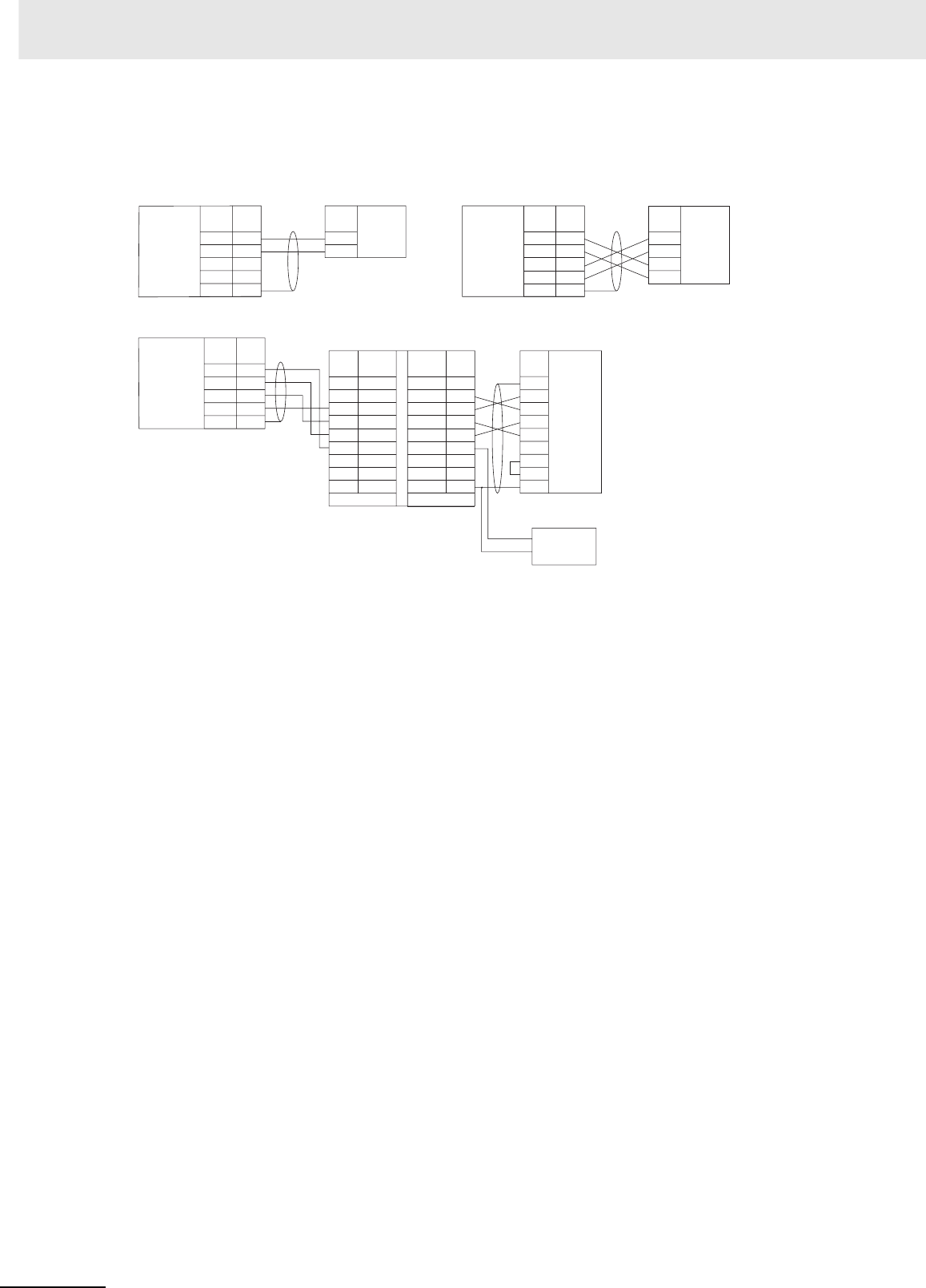
Appendices
A-128 CJ2 CPU Unit Hardware User’s Manual
zExamples of 1:1 Connections to RS-422A/485 Ports
3
4
1
2
5
SDA−
SDB+
RDA−
RDB+
FG
SDA
SDB
RDA
RDB
3
4
1
2
5
SDA−
SDB+
RDA−
RDB+
FG
CPU Unit
Signal
name Signal
name
Signal
name Signal
name
Pin
No.
Pin
No.
Terminal block
Shield
A(−)
B(+)
Terminal block
CPU Unit
Shield
Component
with
RS-422A/485
(4-wire)
RS-
422A/485
interface
RS-
422A/485
interface
Component
with
RS-422A/485
(2-wire)
RS-
422A/485
Option
Board
RS-
422A/485
Option
Board
3
4
1
2
5
SDA−
SDB+
RDA−
RDB+
FG
FG
SD
RD
RS
CS
DR
ER
SG
RS-422A
RS-232C
1
2
3
4
5
6
7
8
GRD
SG
SDB
SDA
RDB
RDA
CSB
CSA
1
2
3
4
5
6
7
8
9
RS-232RS-422
NC
SD
RD
RS
CS
5V
DR
ER
SG
CPU Unit
Signal
name Signal
name Signal
name
Signal
name
NT-AL001 Link Adapter
DIP Switch Settings
Pin 1: ON
Pin 2: ON
(terminating resistance)
Pin 3: OFF
Pin 4: OFF
Pin 5: OFF
Pin 6: OFF
D-sub, 9-pin connector
(male)
Pin
No. Pin
No.
Pin
No.
Terminal block
Shield
Personal Computer
5-V
power
(+)
(–)
RS-232C
Interface
RS-
422A/485
Option
Board
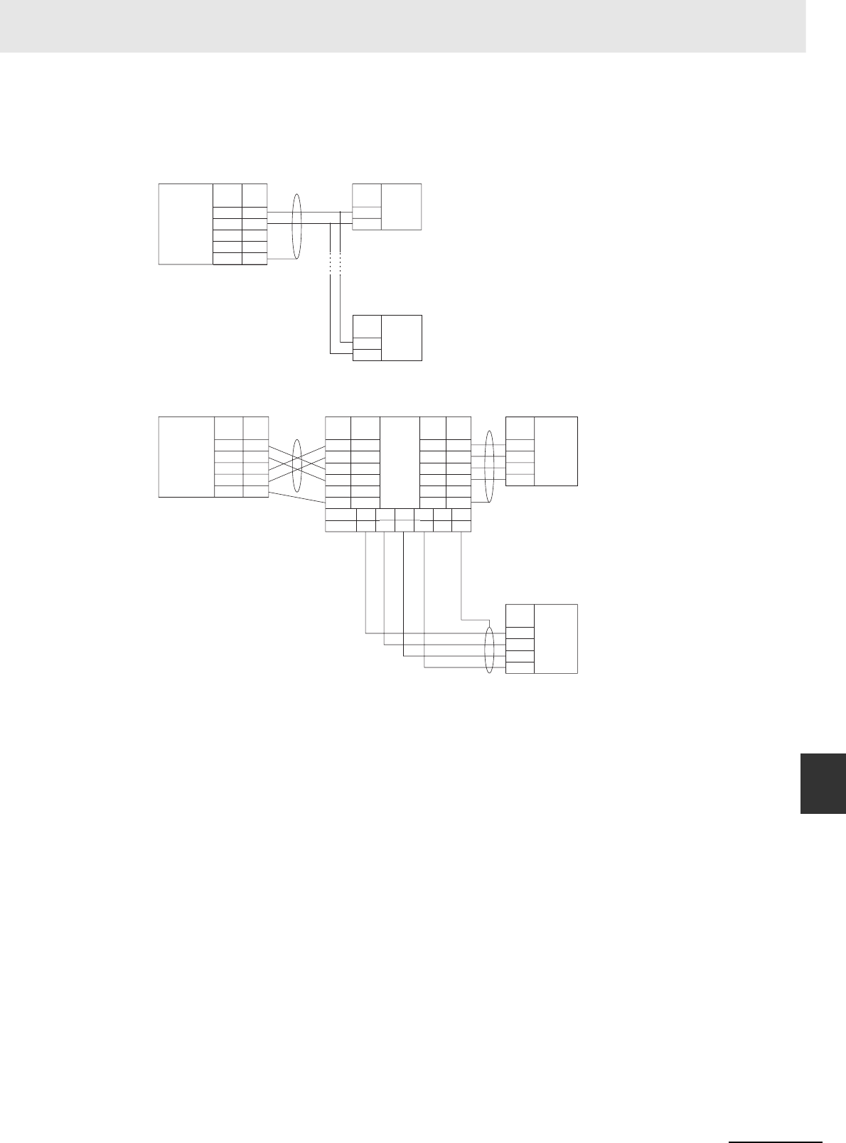
A-129
Appendices
CJ2 CPU Unit Hardware User’s Manual
A-4 Connecting to a Serial Port on the CPU Unit App A-4-2 Connection Examples
zExamples of 1:N Connections to RS-422A/485 Ports
3
4
1
2
5
SDA−
SDB+
RDA−
RDB+
FG
Signal
name
Pin
No.
Terminal block
CPU Unit
Signal
name
A(−)
B(+)
Signal
name
A(−)
B(+)
RS-
422A/485
interface
Component
with
RS-422A/485
(2-wire)
RS-
422A/485
interface
Component
with
RS-422A/485
(2-wire)
RS-
422A/485
Option
Board
3
4
1
2
5
SDA−
SDB+
RDA−
RDB+
FG
B500-AL001
RS-422A
RS-422A
RS-422A
9
5
6
1
3
7
SDA
SDB
RDA
RDB
SG
FG
9
5
6
1
3
7
SDA
9
SDB
5
RDA
6
RDB
1
SG
3
FG
7
SDA
SDB
RDA
RDB
SG
FG
SDA
SDB
RDA
RDB
SDA
SDB
RDA
RDB
CPU Unit
Signal
name Signal
name
Signal
name
Signal
name
D-sub, 9-pin connector
(male)
Pin
No. Pin
No.
Pin
No.
Terminal block
Shield
Shield
Shield
Signal
name
Signal name
Pin No.
RS-
422A/485
interface
Component
with
RS-422A/485
(4-wire)
RS-422A
interface
RS-
422A/485
Option
Board
Component
with
RS-422A/485
(4-wire)
RS-
422A/485
interface
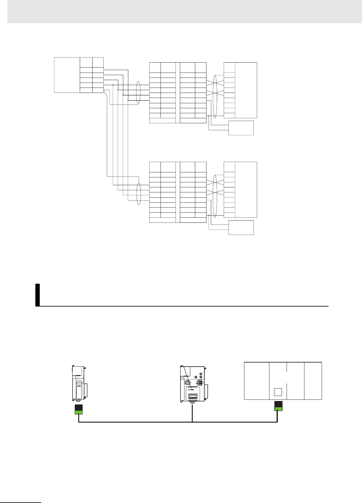
Appendices
A-130 CJ2 CPU Unit Hardware User’s Manual
Examples of connections to use Serial PLC Links are provided below. The Serial PLC Link communica-
tions mode is used.
zConnecting with RS-422A Converters
Note The CJ1W-CIF11/CP1W-CIF11 is not isolated. The maximum transmission distance is therefore 50 m.
If the distance exceeds 50 m, use the isolated CP1W-CIF12, or the NT-AL001.
Do not use the CJ1W-CIF11/CP1W-CIF11 in the transmission path. If you use the NT-AL001 and CP1W-
CIF12, the maximum total transmission distance will be 500 m.
Serial PLC Links for OMRON CJ2M, CJ1M, CP1H, CP1L, and CP1E
PLCs
3
4
1
2
5
SDA−
SDB+
RDA−
RDB+
FG
RS-232C
RS-232C
RS-422A FG
SD
RD
RS
CS
DR
ER
SG
1
2
3
4
5
6
7
8
GRD
SG
SDB
SDA
RDB
RDA
CSB
CSA
1
2
3
4
5
6
7
8
9
RS-232RS-422
NC
SD
RD
RS
CS
5V
DR
ER
SG
FG
SD
RD
RS
CS
DR
ER
SG
1
2
3
4
5
6
7
8
GRD
SG
SDB
SDA
RDB
RDA
CSB
CSA
1
2
3
4
5
6
7
8
9
RS-232RS-422
NC
SD
RD
RS
CS
5V
DR
ER
SG
Shield
CPU Unit
Signal
name Signal
name
Signal
name Signal
name
Signal
name
Signal
name
Signal
name
D-sub, 9-pin
connector (male)
DIP Switch Settings
Pin 1: ON
Pin 2: ON
(terminating resistance)
Pin 3: OFF
Pin 4: OFF
Pin 5: OFF
Pin 6: ON
D-sub, 9-pin
connector (male)
RS-232C
Interface
NT-AL001 Link Adapter
NT-AL001 Link Adapter
Pin
No.
Pin
No.
Pin
No.
Pin
No.
Pin
No.
Terminal block
5-V
power
(+)
(–)
Shield
RS-232C
Interface
Shield
Terminal block 5-V
power
(+)
(–)
Shield
RS-
422A/485
Option
Board
4-wire
Terminating
resistance: ON
Terminal block
DIP Switch: Pin 2:
OFF (terminating
resistance); Other
pins are the same
as below.
CJ2M CPU Unit (Polling Unit) CJ2M CPU Unit (Polled Unit 0)
CJ1W-CIF11 RS-422A
Converter
RS-422A/485
Option Board
Serial PLC Link (maximum
total distance: 50 m)
CJ1M CPU Unit (Polled Unit 1)
RS-232C port
built into CPU
Unit
CJ1W-CIF11 RS-422A
Converter
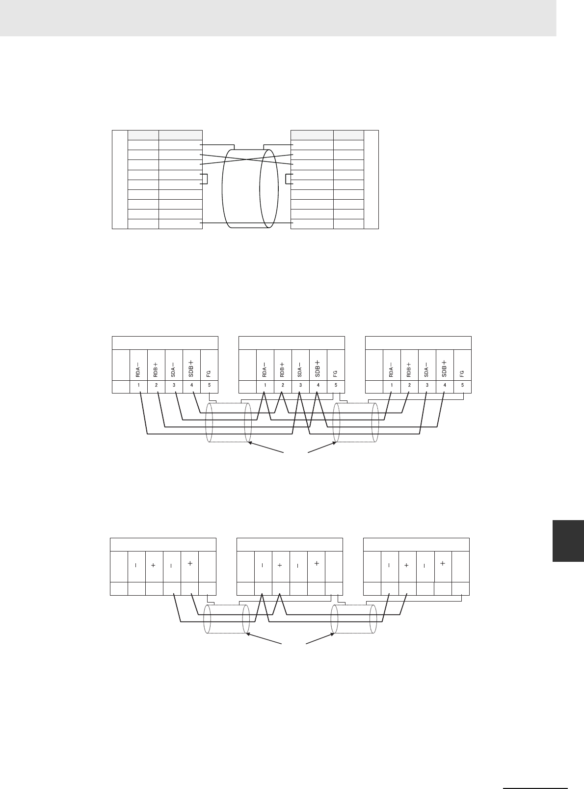
A-131
Appendices
CJ2 CPU Unit Hardware User’s Manual
A-4 Connecting to a Serial Port on the CPU Unit App A-4-2 Connection Examples
zConnections to RS-232C Ports
RS-232C can also be used to connect two CJ2M CPU Units with a Serial PLC Link.
zConnection Example
FG 1
SD 2
RD 3
RS 4
CS 5
5V 6
DR 7
ER 8
SG 9
1 FG
2 SD
3 RD
4 RS
5 CS
6 5V
7 DR
8 ER
9 SG
CJ2M CPU Unit
RS-232C Option Board
RS-232C
RS-232C
CJ2M CPU Unit
RS-232C Option Board
Signal name
Pin No.
Signal name
Pin No.
CJ2M CPU Unit (Polling Unit)
RS-232C Option Board
CP1W-CIF01
CJ1W-CIF11
DIP SW
SW1: ON (terminating resistance ON)
SW2: OFF (4-wire)
SW3: OFF (4-wire)
SW4: OFF
SW5: OFF (no RS control for RD)
SW6: OFF (no RS control for SD)
RS-422A/485 interface
Shield
Pin
No. Pin
No.
Signal
name
Signal
name
Pin
No.
Signal
name
RS-422A/485 interface RS-422A/485 interface
CJ2M CPU Unit (Polled Unit 0)
RS-422A/485 Option Board
CP1W-CIF11/CIF12
DIP SW
SW1: ON (terminating resistance OFF)
SW2: OFF (4-wire)
SW3: OFF (4-wire)
SW4: OFF
SW5: OFF (no RS control for RD)
SW6: ON (RS control for SD)
CJ1M CPU Unit (Polled Unit 1)
CJ1W-CIF11
DIP SW
SW1: ON (terminating resistance ON)
SW2: OFF (4-wire)
SW3: OFF (4-wire)
SW4: OFF
SW5: OFF (no RS control for RD)
SW6: ON (RS control for SD)
RDA
RDB
SDA
SDB
FG
12345
RDA
RDB
SDA
SDB
FG
12345
RDA
RDB
SDA
SDB
FG
12345
CJ2M CPU Unit (Polling Unit)
RS-232C Option Board
CP1W-CIF01
CP1W-CIF11
DIP SW
SW1: ON (terminating resistance ON)
SW2: ON (2-wire)
SW3: ON (2-wire)
SW4: OFF
SW5: OFF (no RS control for RD)
SW6: ON (RS control for SD)
RS-422A/485 interface
Shield
Pin
No. Pin
No.
Signal
name
Signal
name
Pin
No.
Signal
name
RS-422A/485 interface RS-422A/485 interface
CJ2M CPU Unit (Polled Unit 0)
RS-422A/485 Option Board
CP1W-CIF11/CIF12
DIP SW
SW1: OFF (terminating resistance OFF)
SW2: ON (2-wire)
SW3: ON (2-wire)
SW4: OFF
SW5: OFF (no RS control for RD)
SW6: ON (RS control for SD)
CJ1M CPU Unit (Polled Unit 1)
CJ1W-CIF11
DIP SW
SW1: ON (terminating resistance ON)
SW2: ON (2-wire)
SW3: ON (2-wire)
SW4: OFF
SW5: OFF (no RS control for RD)
SW6: ON (RS control for SD)
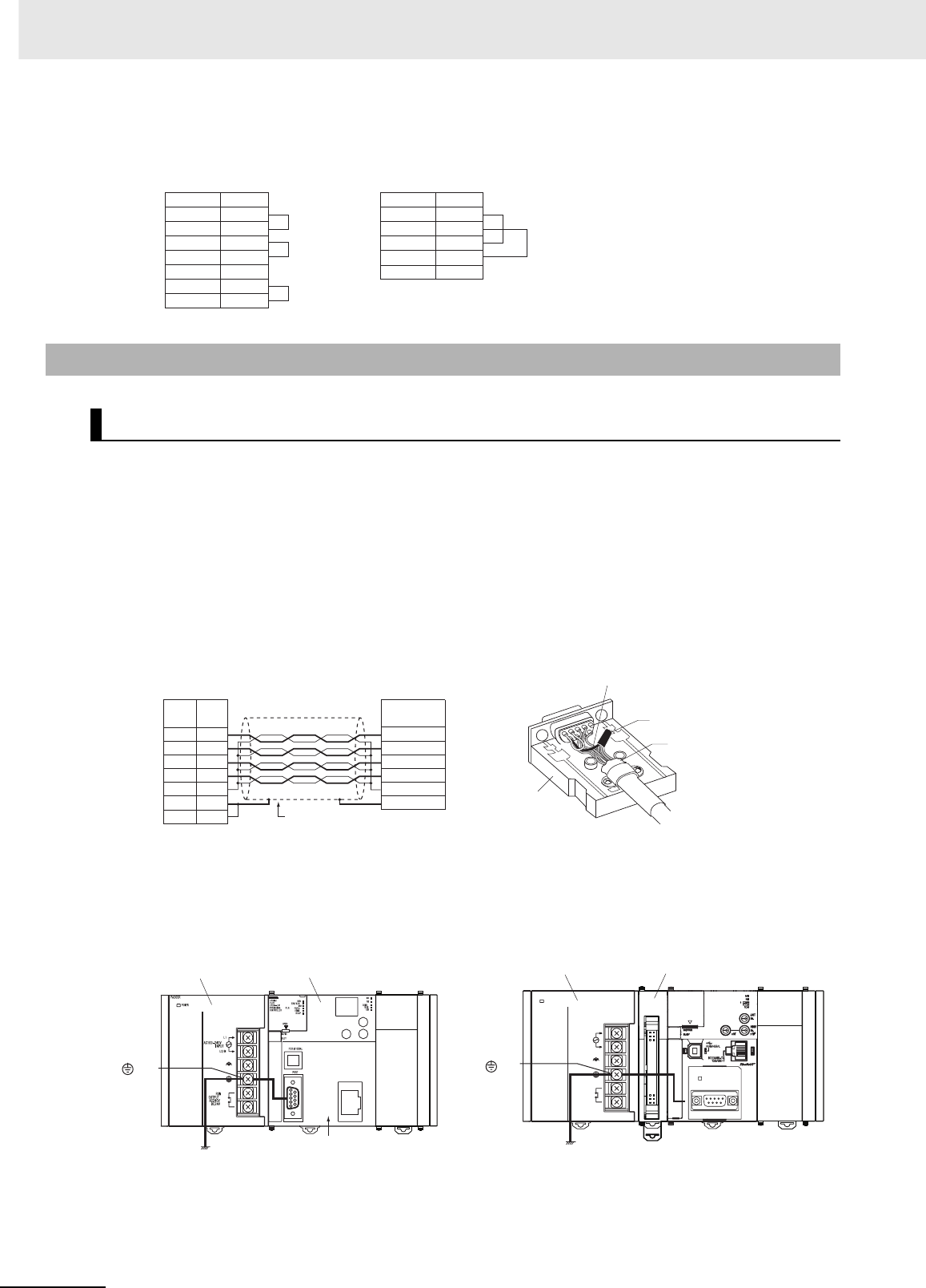
Appendices
A-132 CJ2 CPU Unit Hardware User’s Manual
zConnections for Echoback Test
We recommend the following wiring methods for RS-232C, especially in environment prone to noise.
• Use shielded twisted-pair cable for communications cables.
• Use a twisted-pair cable for each signal line and SG (signal ground) to connect the CPU Unit to a
communications partner. Also, bundle all the SG lines at the Unit and at the other device and connect
them together.
• Connect the shield line of the communications cable to the hood (FG) of the RS-232C connector at
the Unit. Also, ground the protective earth (GR) terminal of the Power Supply Units on the CPU Rack
and the CJ-series Expansion Racks to a resistance of 100 Ω or less. The following example shows
connecting SD-SG, RD-SG, RS-SG, and CS-SG for Serial Communications Mode using a twisted-
pair cable using the peripheral bus.
Note The hood (FG) is internally connected to the protective earth (GR) terminal on the Power Supply Unit
through the CPU Rack. FG can thus be connected by connecting the protective earth (GR) terminal on the
Power Supply Unit. The hood (FG) is also electrically connected to pin 1 (FG), but the connection resistance
between the shield and the FG is smaller for the hood. To reduce contact resistance between the hood (FG)
and the FG, connect the shield both to the hood (FG) and to pin 1 (FG).
Use the following connections.
A-4-3 Applicable Connectors and Recommended Cables
Examples of Recommended RS-232C Wiring
Example for CJ2H CPU Unit Example for CJ2M CPU Unit
RS-232C port
Signal name
SD
RD
RS
CS
FG
ER
DR
Pin No.
2
3
4
5
1
8
7
RS-422A/485 port
Signal name
SDA-
SDB+
RDA-
RDB+
FG
Pin No.
3
4
1
2
5
XM2S-0911-E
Hood
Shield
SG signal line
CPU Unit External device
Signal
name
Pin
No. Signal
name SG signal lines
bundled together
Aluminum foil
2
3
4
5
9
1
SD
RD
RS
CS
SG
FG
FG
RD
SD
CS
RS
SG
FG
GR
CPU Unit
Power Supply Unit
Ground to 100 Ω
or less
Hood and GR connected
internally.
The hood will be grounded
if the GR terminal is grounded.
POWER
PA205R
DC24V
AC240V
OUTPUT
RUN
INPUT
AC100-240V
L2/N
L1
COMM
GR
Power Supply Unit
Ground to 100 Ω
or less
Pulse I/O Module
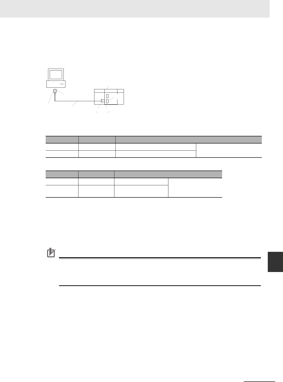
A-133
Appendices
CJ2 CPU Unit Hardware User’s Manual
A-4 Connecting to a Serial Port on the CPU Unit App A-4-3 Applicable Connectors and Recommended
Cables
zApplicable Connector and Recommended Cables
Use the following connectors and cables when making an RS-232C cable to connect to the RS-232C
port.
Applicable Connectors
CPU Unit Connector
Personal Computer Connector for IBM PC/AT Computer (9-pin Male Connector)
Recommended Cables
We recommend using the following shielded twisted-pair cables to provide noise resistance.
Fujikura Ltd.: UL2464 AWG28 × 5P IFS-RVV-SB (UL product)
AWG 28 × 5P IFVV-SB (non-UL product)
Hitachi Cable, Ltd.: UL2464-SB(MA) 5P × 28AWG (7/0.127) (UL product)
CO-MA-VV-SB 5P × 28AWG (7/0.127) (non-UL product)
Precautions for Correct UsePrecautions for Correct Use
Use the special cables provided from OMRON for all connections whenever possible. If cables
are produced in-house, be sure they are wired correctly. External devices and the CPU Unit may
be damaged if general purpose (e.g., computer to modem) cables are used or if wiring is not cor-
rect.
Item Model Specifications
Plug XM2A-0901 9-pin male Used together (One of each pro-
vided with CPU Unit.)
Hood XM2S-0911-E 9-pin, millimeter screws, static-resistant
Item Model Specifications
Plug XM2A-0901 9-pin female Used together
Hood XM2S-0913 9-pin, inch screws, static-
resistant
IBM PC/AT or compatible
Computer
(9-pin male
connector)
Plug:
XM2D-0901
(9-pin female)
CPU Unit
RS-232C
port
Hood: XM2S-0913
Recommended cable Hood: XM2S-0911-E Plug: XM2A-0901
Provided with the CPU Unit
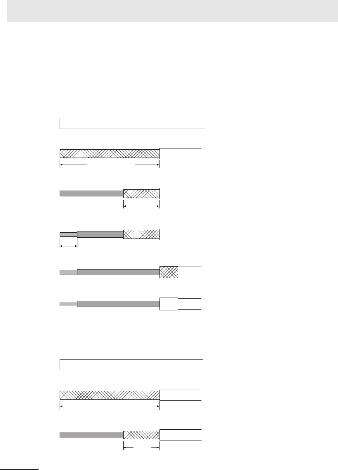
Appendices
A-134 CJ2 CPU Unit Hardware User’s Manual
zWiring Connectors
Use the following procedures to wire connectors.
Preparing the Cable
Lengths for steps in the procedure are provided in the diagrams.
Connecting the Shield Line to the Hood (FG)
1Cut the cable to the required length, leaving leeway for wiring and laying the cables.
2Use a razor blade to cut away the sheath, being careful not to damage the braiding.
3Use scissors to cut away all but 10 mm of the exposed braiding.
4Use wire strippers to remove the insulation from the end of each wire.
5Fold the braiding back over the end of the sheath.
6Wrap aluminum foil tape over the top of the braiding for one and a half turns.
zNot Connecting the Shield to the Hood (FG)
1Cut the cable to the required length, leaving leeway for wiring and laying the cables.
2Use a razor blade to cut away the sheath, being careful not to damage the braiding.
3Use scissors to cut away the exposed braiding.
40 mm (RS-232C)
10 mm
5 mm
Aluminum foil tape
40 mm (RS-232C)
10 mm
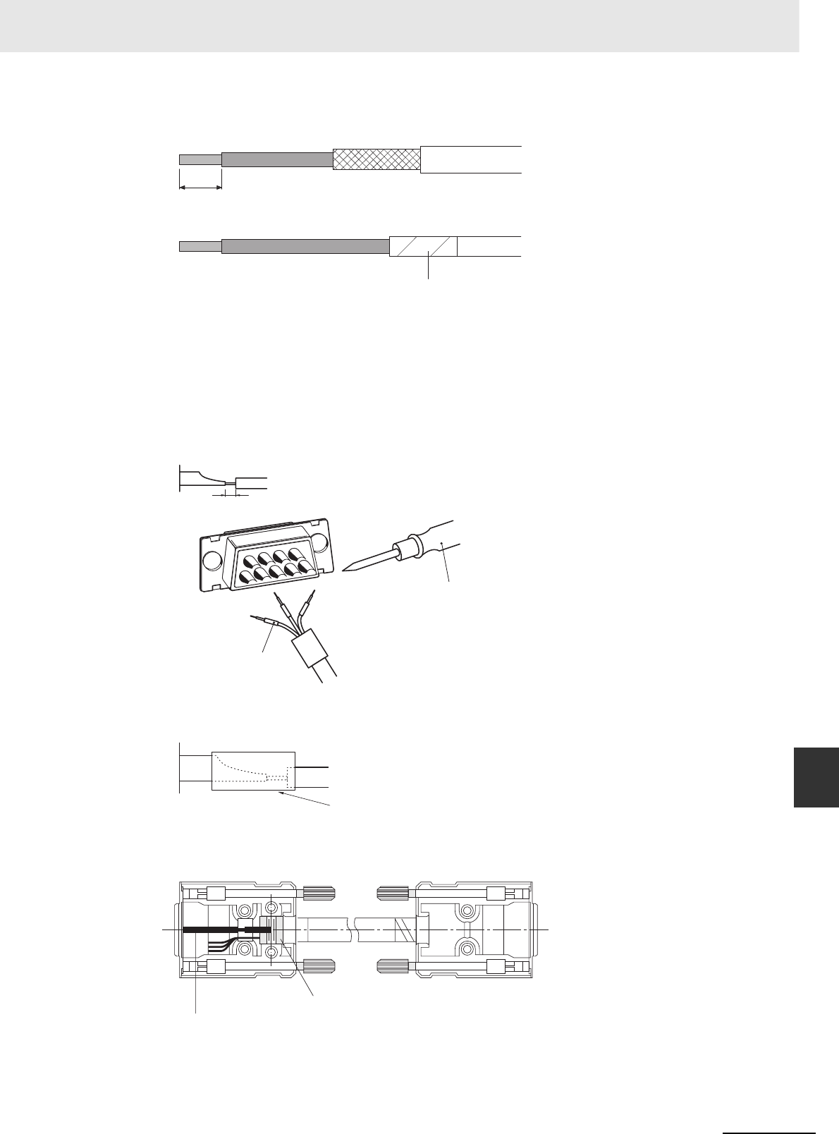
A-135
Appendices
CJ2 CPU Unit Hardware User’s Manual
A-4 Connecting to a Serial Port on the CPU Unit App A-4-3 Applicable Connectors and Recommended
Cables
4Use wire strippers to remove the insulation from the end of each wire.
5Wrap electrician's tape over the top and end of the cut sheath.
zSoldering
1Place heat-shrinking tubes over all wires.
2Pre-solder all wires and connector terminals.
3Solder the wires.
4Move the heat-shrinking tubes onto the soldered area and shrink them into place.
zAssembling the Hood
Assemble the connector hood as shown.
5 mm
Electrician's tape
1 mm
Heat-shrinking tube
(inner dia. 1.5, l = 10)
Soldering iron
Heat-shrinking tube
FG Connection
Ground plate
Aluminum foil tape
No FG Connection
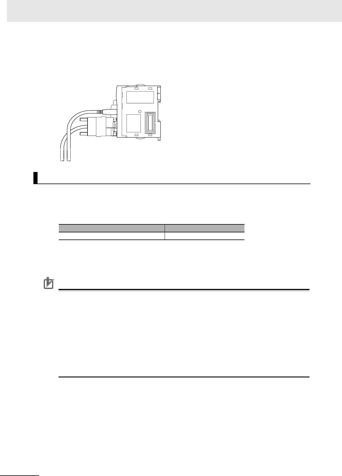
Appendices
A-136 CJ2 CPU Unit Hardware User’s Manual
zConnections to the CPU Unit
• Always turn OFF the power supply to the PLC before connecting or disconnecting communica-
tions cables.
• Tighten the communications connector attachment screws to 0.4 N·m.
We recommend using the following wiring for RS-422A/485 to ensure transmission quality.
1Use shielded twisted-pair cable for communications cables.
• Recommended RS-422A/485 Cable
2Connect the shield on the communications cable to the FG terminal on the RS-422A/485 Option
Board. Also, ground the protective earth (GR) terminal on the CPU Unit to a resistance of 100 Ω
or less.
Precautions for Correct UsePrecautions for Correct Use
Using the CP1W-CIF11 RS-422A/485 Option Board (Not Isolated)
Use the CP1W-CIF11 only when there is no difference in electrical potential between devices.
Connect the shield on the communications cable at both ends to the FG terminals on the RS-
422A/485 terminal blocks to ground it. Do not allow the communications distance to exceed
50 m.
Using the CP1W-CIF12 RS-422A/485 Option Board (Isolated)
Use the CP1W-CIF12 if there is a difference in electrical potential between devices or for long-
distance communications (500 m max.).
Connect the shield on the communications cable only at the Option Board to ground it. If the
shield is connected at both ends of the cable when there is a difference in electrical potential, the
devices may be damaged.
Example of Recommended RS-422A/485 Wiring
Model Manufacturer
CO-HC-ESV-3P × 7/0.2 Hirakawa Hewtech Corp.
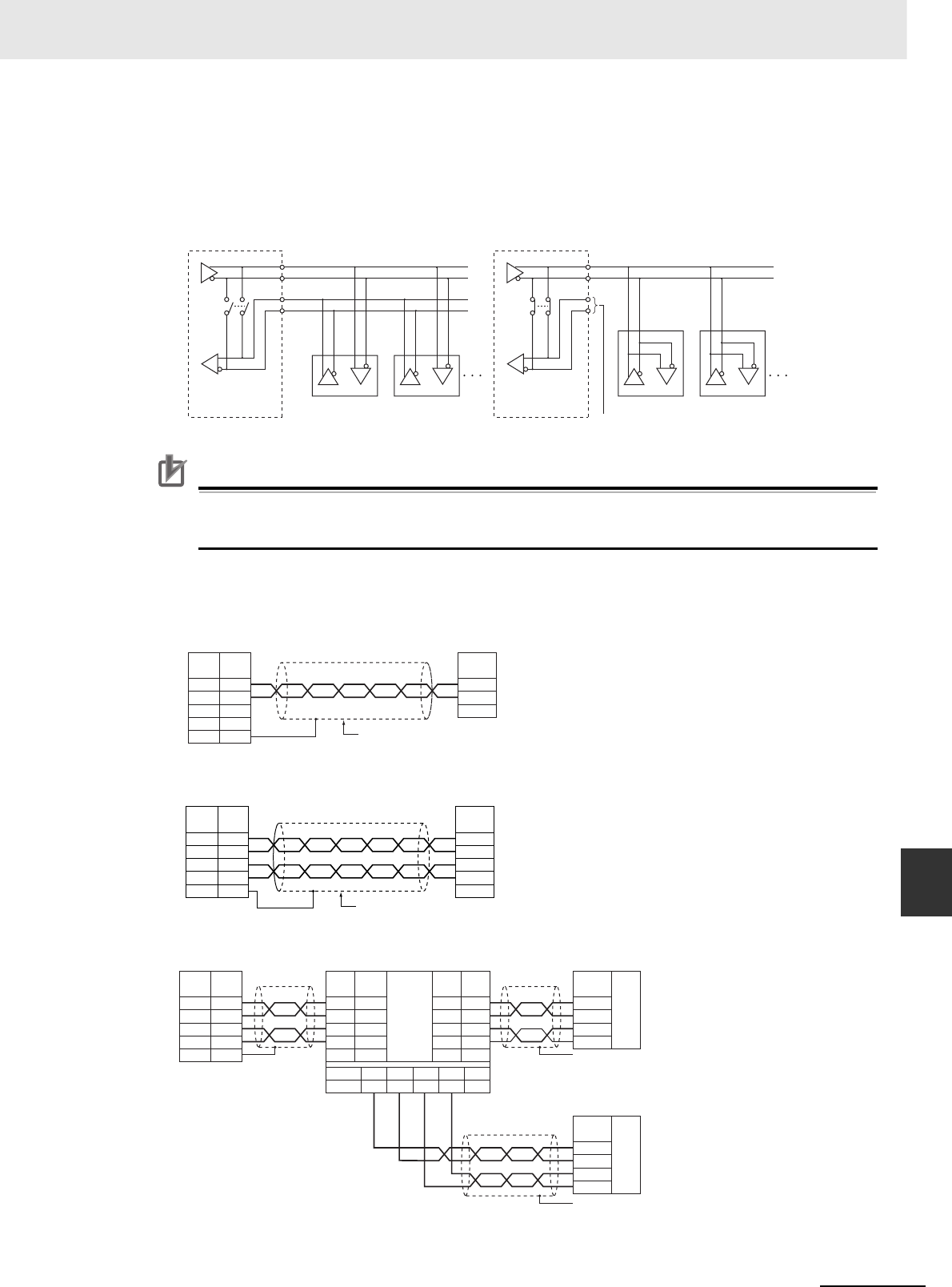
A-137
Appendices
CJ2 CPU Unit Hardware User’s Manual
A-4 Connecting to a Serial Port on the CPU Unit App A-4-3 Applicable Connectors and Recommended
Cables
zConnection Examples
Examples for 2-wire and 4-wire Transmission Paths
The transmission path for 2-wire and 4-wire connections are different, as shown below.
Precautions for Correct UsePrecautions for Correct Use
• All nodes must use either 2-wire connections or 4-wire connections.
• Do not use 4-wire connections with the switch on the Board set for 2-wire connections.
Wiring Example for 1:1 Connections
• Example for 2-wire Connections
• Example for 4-wire Connections
• Using a B500-AL001 Link Adapter
NC (Non Connection)
Option Board
Other Unit Other Unit Other Unit Other Unit
Example for 4-wire Connections Example for 2-wire Connections
2-wire/4-wire
switch (DPDT) 2-wire/4-wire
switch (DPDT)
Option Board
SDA−
SDB+
RDA−
RDB+
FG
3
4
1
2
5
FG
Signal
name
Pin
No.
Signal
name
A(−)
B(+)
Shield
CJ2M CPU Unit
RS-422A/485 Option Board External device
SDA
−
SDB+
RDA
−
RDB+
FG
3
4
1
2
5
RDA
RDB
SDA
SDB
FG
Signal
name
Pin
No.
Signal
name
Shield
CJ2M CPU Unit
RS-422A/485 Option Board External device
SDA−
SDB+
RDA−
RDB+
FG
3
4
1
2
5
B500-AL001
6
1
9
5
7
RDA
RDB
SDA
SDB
FG
6
1
9
5
7
RDA
6
RDB
1
SDA
9
SDB
5
FG
7
RDA
RDB
SDA
SDB
FG
RDA
RDB
SDA
SDB
FG
RS-422
RS-422
RDA
RDB
SDA
SDB
FG
RS-422
Signal
name
Pin
No.
Signal
name
Signal
name
Signal
name
Signal
name
Pin
No.
Pin
No.
Signal name
Pin No.
RS-422
Interface
CJ2M CPU Unit
Option Board
External device
External device
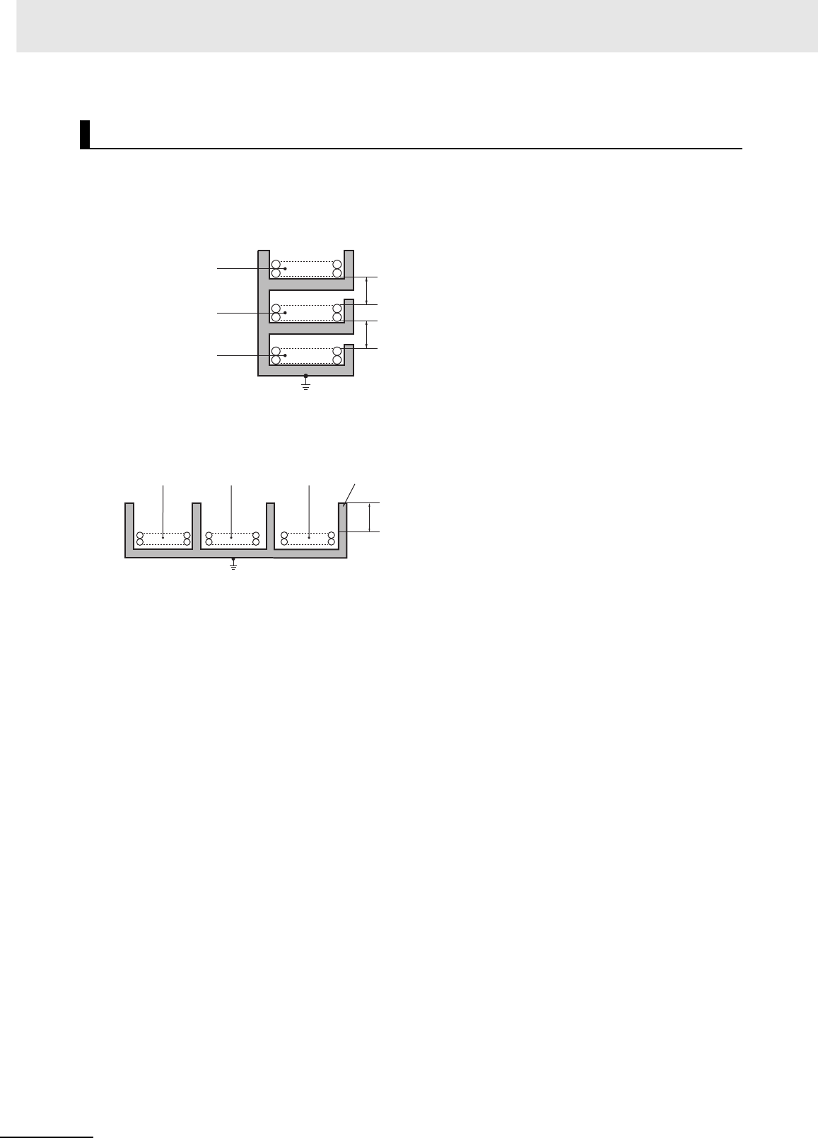
Appendices
A-138 CJ2 CPU Unit Hardware User’s Manual
Take the following points into account when externally wiring communications cables.
• When multi-conductor signal cable is being used, do not combine I/O wires and other control wires in
the same cable.
• If wiring racks are parallel, allow at least 300 mm between them.
• If the I/O wiring and power cables must be placed in the same duct, they must be shielded from each
other using grounded steel sheet metal plates.
Noise Countermeasures for External Wiring
Communications cables
SYSMAC power supply
lines and general
control circuit lines
Power lines
Low-power cables
Control cables
Power cables
300 mm min.
300 mm min.
Ground to less than 100 Ω
200 mm min.
Communications
cables
Power lines Steel sheet metal plates
Ground to less than 100 Ω
SYSMAC power supply
lines and general control
circuit lines
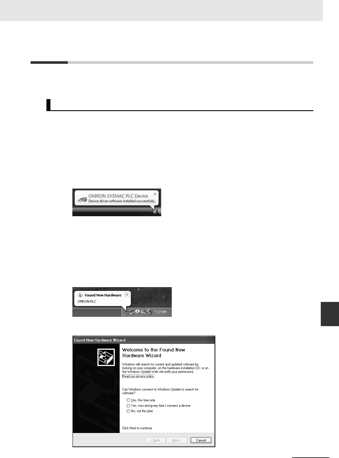
A-139
Appendices
CJ2 CPU Unit Hardware User’s Manual
A-5 Installing the USB Driver App A-4-3 Applicable Connectors and Recommended
Cables
A-5 Installing the USB Driver
The USB driver must be installed in the computer to connect the PLC to the computer using the USB
port.
This section describes the procedure for connecting a computer to the peripheral (USB) port on the
CJ2 CPU Unit for the first time. This example assumes that the Support Software is already installed.
The installation procedure given here is for CX-One version 4.0 (CX-Programmer version 9.1).
zWindows 2000, Vista, or Windows 7
1Turn ON the power supply to the PLC and connect the peripheral USB port on the PLC to the
personal computer using a USB cable. The USB driver will be automatically installed when the
cable is connected.
Note If the software is not automatically installed, refer to Installing a Specified USB Driver later in this section.
zWindows XP
1Turn ON the power supply to the CJ2 PLC, and connect a USB cable between the USB port on
the computer and the peripheral (USB) port on the CJ2 CPU Unit.
After the cable has been connected, the computer will automatically recognize the device and
the following message will be displayed.
2The following dialog box will be displayed. Select one of the options and click the Next Button.
Procedure for Installing the USB Driver
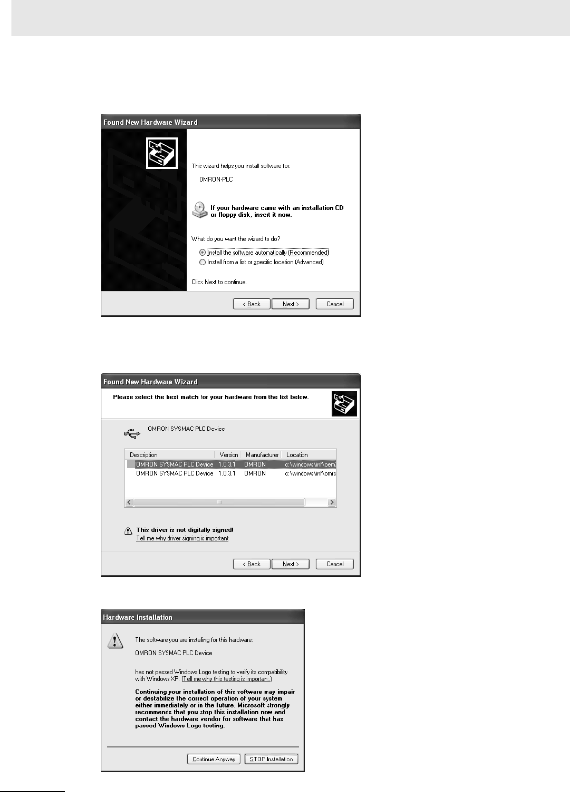
Appendices
A-140 CJ2 CPU Unit Hardware User’s Manual
3The following dialog box will be displayed. Select the Install the software automatically (Recom-
mended) Option and click the Next Button.
Note 1 If the software cannot be installed automatically, refer to Installing a Specified USB Driver later in this sec-
tion.
2If the installation media is not inserted or the USB device driver is installed for another port, a Driver List
Dialog Box will be displayed. Make sure that the newest driver is selected and click the Next Button.
4Ignore the following dialog box if it is displayed and click the Continue Anyway Button.
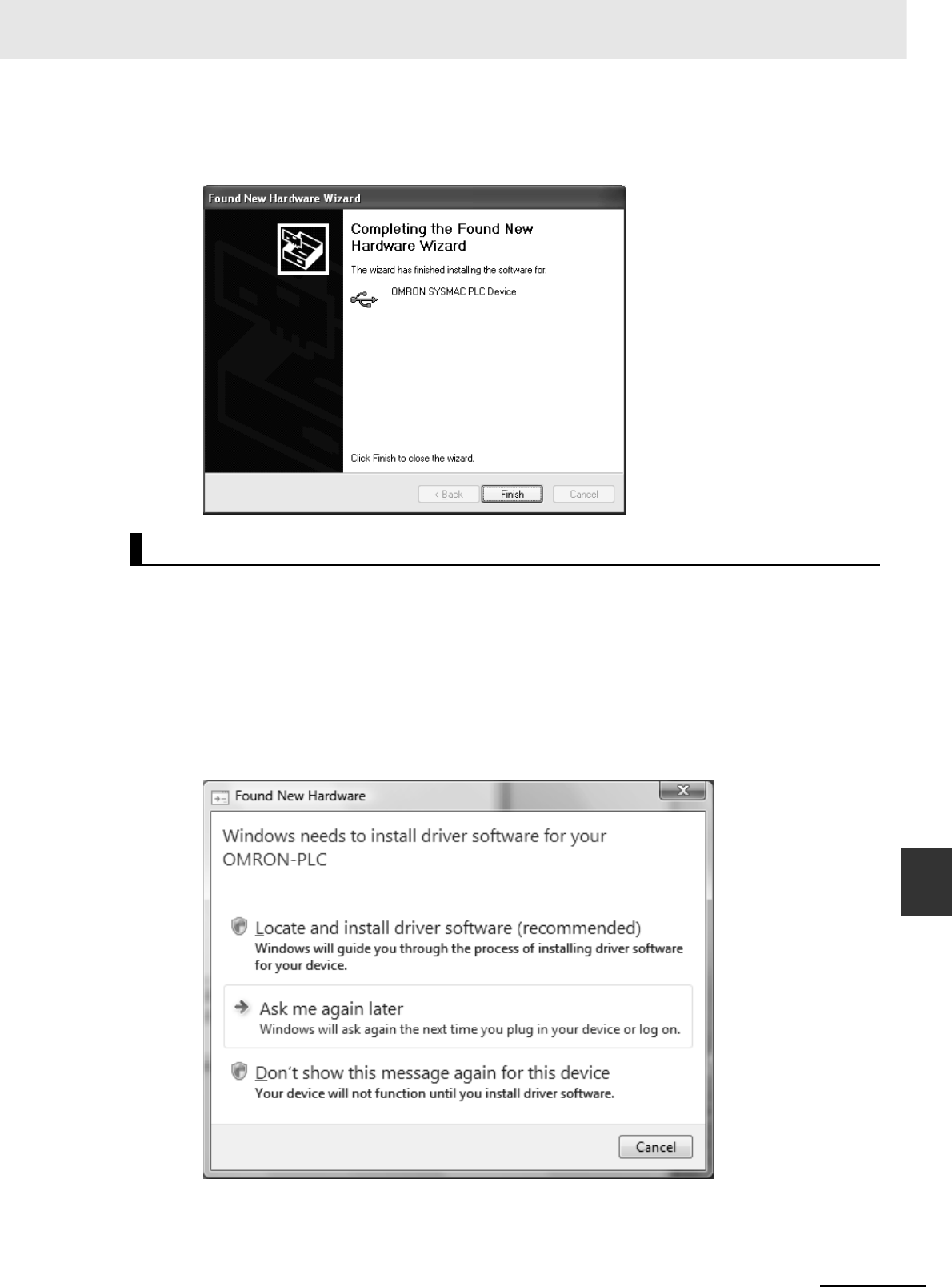
A-141
Appendices
CJ2 CPU Unit Hardware User’s Manual
A-5 Installing the USB Driver App A-4-3 Applicable Connectors and Recommended
Cables
5The following dialog box will be displayed if the installation is completed normally. Click the Fin-
ish Button.
If the USB driver cannot be installed automatically, use the following procedure to install it.
zWindows Vista/Windows 7
1Turn ON the power supply to the PLC and connect the peripheral USB port on the PLC to the
personal computer using a USB cable.
2The following dialog box will be displayed. Select Locate and install driver software (Recom-
mended).
Installing a Specified USB Driver
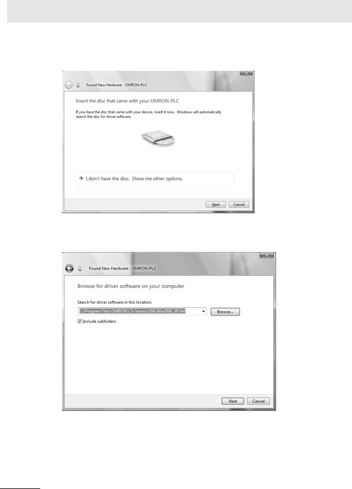
Appendices
A-142 CJ2 CPU Unit Hardware User’s Manual
3The following dialog box will be displayed. Select I don't have the disc. Show me other
options.
4The following dialog box will be displayed. Click the Browse Button, specify the following loca-
tion, and then click the Next Button.
C:\Program Files\OMRON\CX-Server\USB\Win2000_XP\Inf
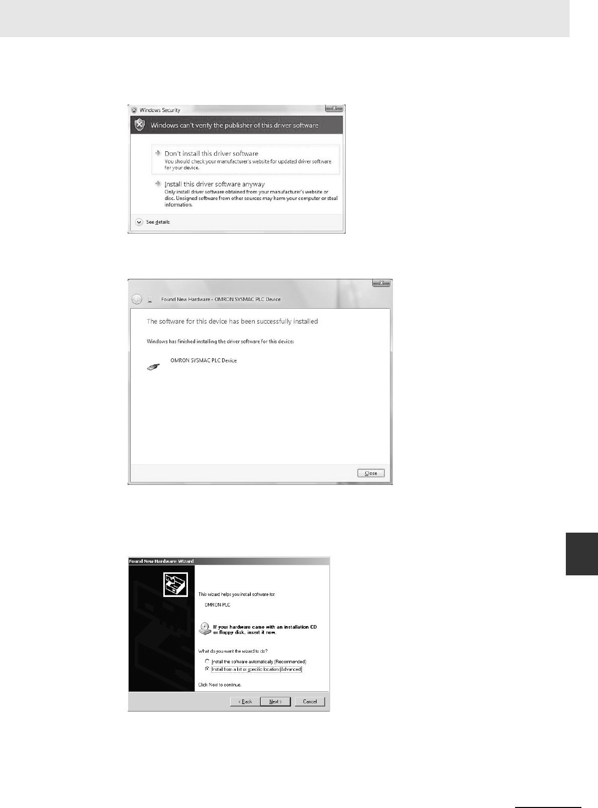
A-143
Appendices
CJ2 CPU Unit Hardware User’s Manual
A-5 Installing the USB Driver App A-4-3 Applicable Connectors and Recommended
Cables
5Ignore the following dialog box if it is displayed and select Install this driver software anyway.
6The following dialog box will be displayed when the driver software has been installed success-
fully.
zWindows XP
1The following window will be displayed. Select the Install from a list of specific location Option
and then click the Next Button.
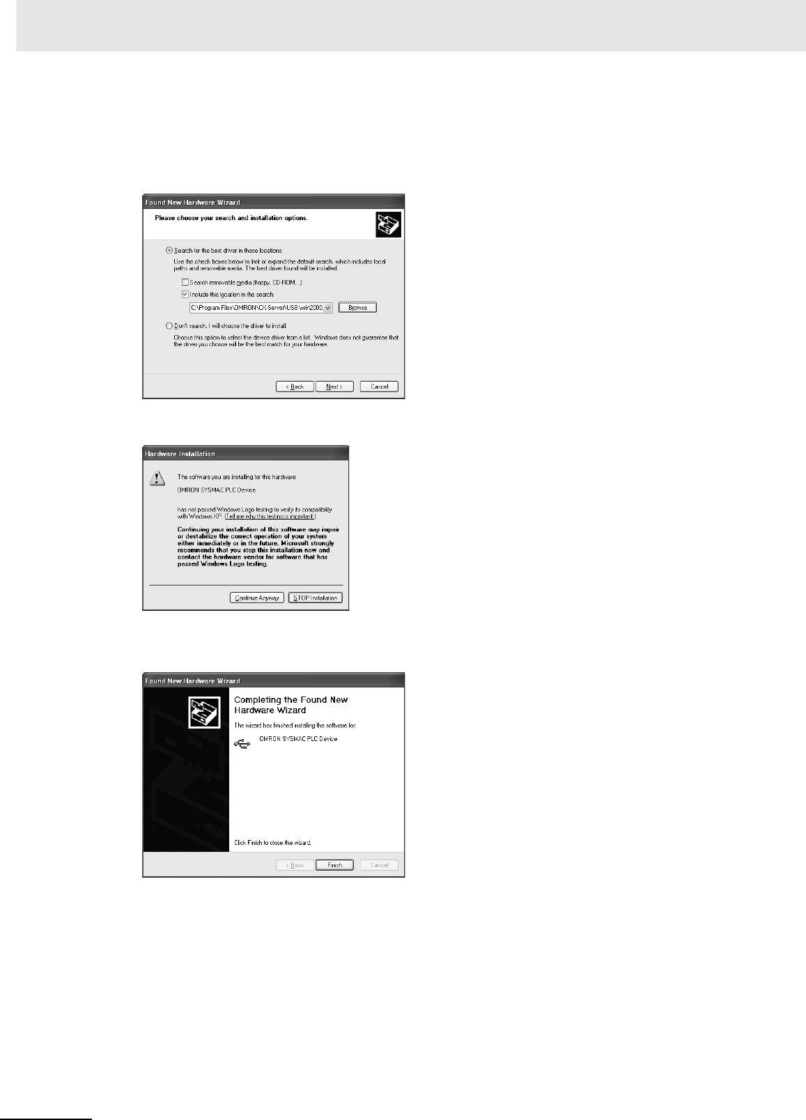
Appendices
A-144 CJ2 CPU Unit Hardware User’s Manual
2The following window will be displayed. Click the Browse Button for the Include this location in
the search Field, specify C:\Program Files\OMRON\CX-Server\USB\win2000_XP\Inf, and then
click the Next Button. The driver will be installed. (“C:\” indicates the installation drive and may
be different on your computer.)
3Ignore the following window if it is displayed and click the Continue Anyway Button.
4The following window will be displayed if the installation is completed normally. Click the Finish
Button.
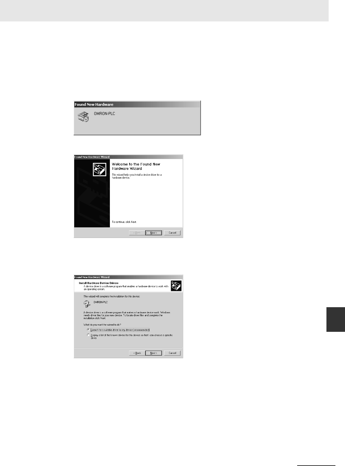
A-145
Appendices
CJ2 CPU Unit Hardware User’s Manual
A-5 Installing the USB Driver App A-4-3 Applicable Connectors and Recommended
Cables
zWindows 2000
1Turn ON the power supply to the CJ2 PLC, and connect a USB cable between the USB port on
the computer and the peripheral (USB) port on the CJ2 CPU Unit.
After the cable has been connected, the computer will automatically recognize the device and
the following message will be displayed.
2The following message will be displayed. Click the Next Button.
3The following window will be displayed.
Select the Search for a suitable driver for the device (recommended) Option and then click the
Next Button.
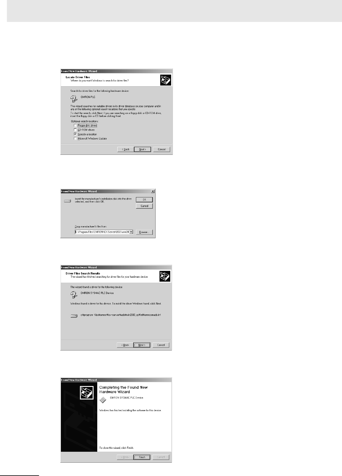
Appendices
A-146 CJ2 CPU Unit Hardware User’s Manual
4The following window will be displayed. From the list in the window, select the Specify location
Check Box and then click the Next Button.
5Click the Browse Button, specify C:\Program Files\OMRON\CX-Server\USB\win2000_XP\Inf,
and then click the Next Button. (“C:\” indicates the installation drive and may be different on your
computer.)
6A search will be made for the driver and the following window will be displayed. Click the Next
Button. The driver will be installed.
7After the driver has been successfully installed, the following window will be displayed. Click the
Finish Button.
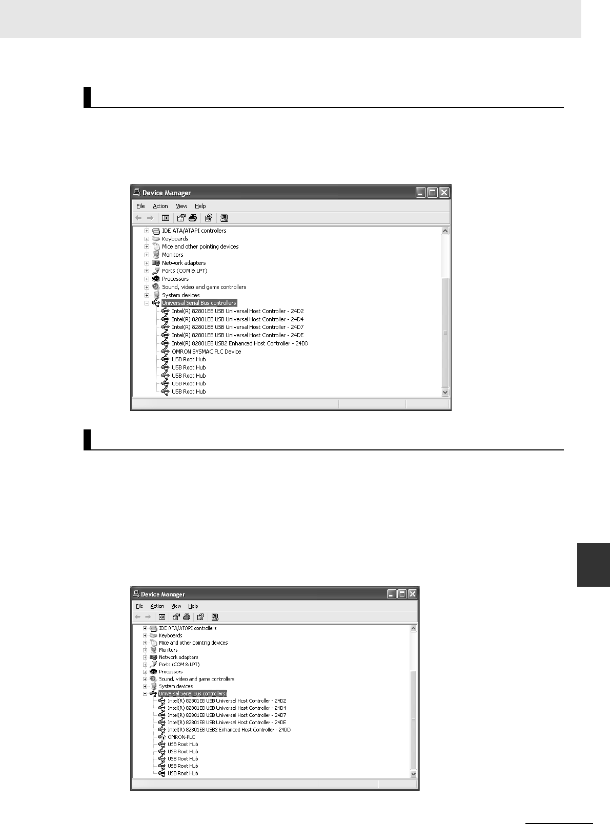
A-147
Appendices
CJ2 CPU Unit Hardware User’s Manual
A-5 Installing the USB Driver App A-4-3 Applicable Connectors and Recommended
Cables
1Display the Device Manager at the computer.
2Click USB (Universal Serial Bus) Controllers, and confirm that OMRON SYSMAC PLC Device is
displayed.
If the USB driver installation fails for some reason or is cancelled in progress, the USB driver must be
reinstalled.
zChecking USB Driver Status
1Display the Device Manager on the computer.
2If the OMRON-PLC is displayed under Universal Serial Bus controllers, installation of the USB
driver software failed.
Checking after Installation
Re-installing the USB Driver
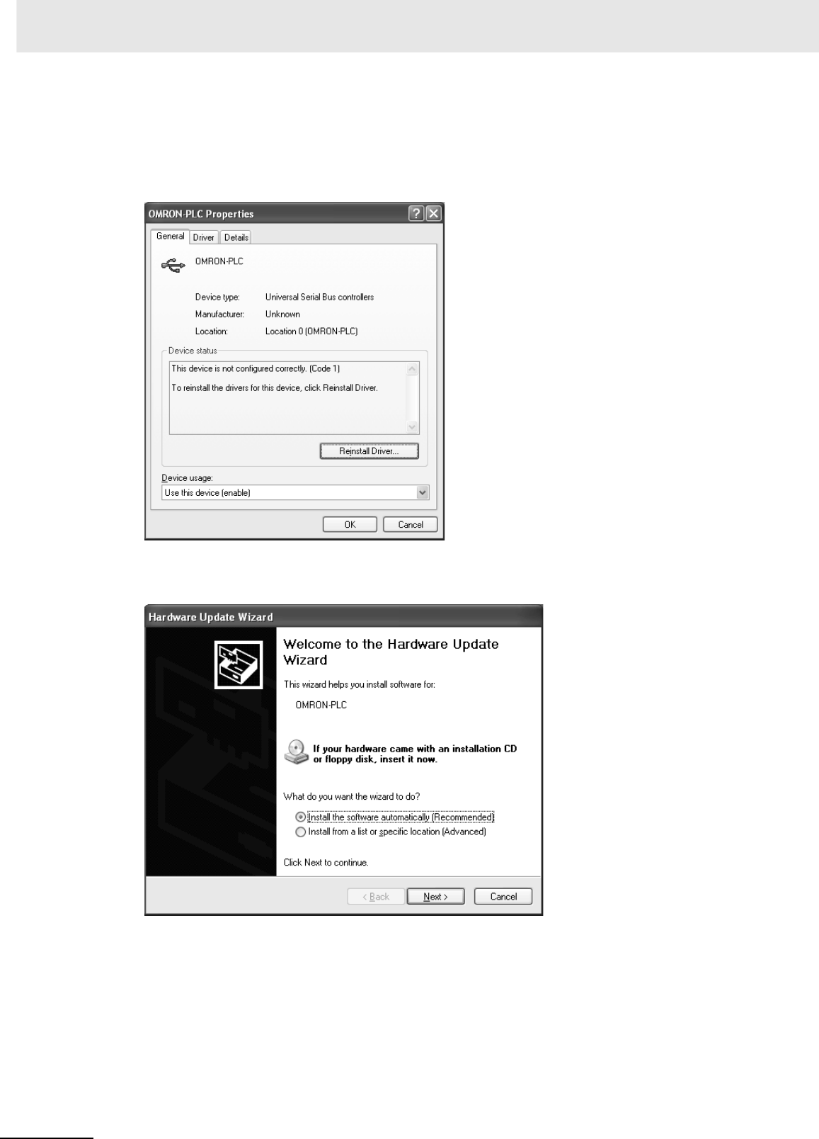
Appendices
A-148 CJ2 CPU Unit Hardware User’s Manual
zReinstalling the USB Driver
1Right-click OMRON-PLC under Universal Serial Bus controllers and select Properties. The
properties will be displayed.
2Click the Reinstall Driver Button. The Hardware Update Wizard Dialog Box will be displayed.
Install the driver software using the procedure described in Installing the USB Driver.
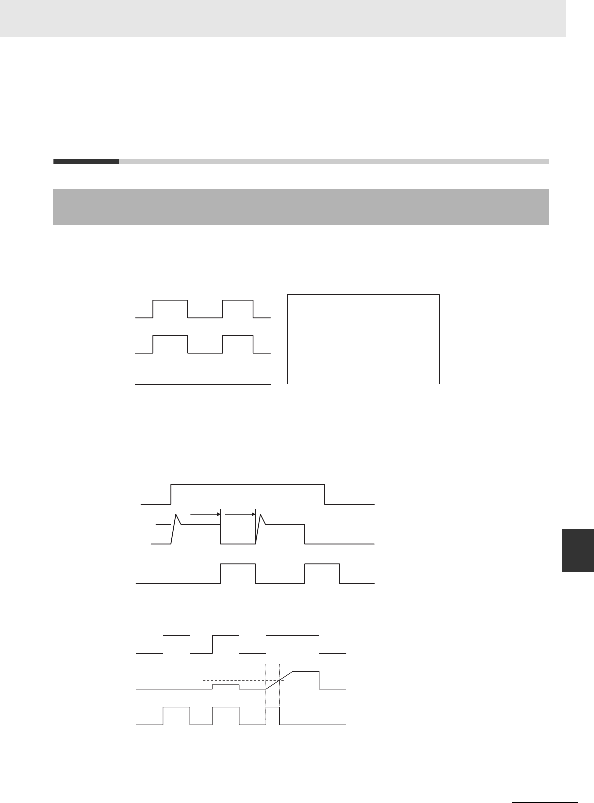
A-149
Appendices
CJ2 CPU Unit Hardware User’s Manual
A-6 Load Short-circuit Protection and Line Disconnection Detection for Basic I/O Units App A-6-1 Load Short-circuit Protection and Line
Disconnection Detection for CJ1W-OD202
A-6 Load Short-circuit Protection and
Line Disconnection Detection for
Basic I/O Units
This section describes the load short-circuit protection of the CJ1W-OD202 Output Units.
As shown below, normally when the output bit turns ON (OUT), the transistor will turn ON and then out-
put current (Iout) will flow.
Normal Operation
If the output (Iout) is overloaded or short-circuited exceeding the detection current (Ilim), the output cur-
rent (Iout) will be limited as shown in figure below. When the junction temperature (Tj) of the output tran-
sistor reaches the thermal shutdown temperature (Tstd), the output will turn OFF to protect the
transistor from being damaged, and the alarm output bit will turn ON to light the ERR indicator. When
the junction temperature (Tj) of the transistor drops down to the reset temperature (Tr), the ERR indica-
tor will be automatically reset and the output current will start flowing.
Operation for Overload or Short Circuit
If the line is disconnected and the output current (Iout) drops below the line disconnection detection cur-
rent (IOL), the ERR indicator will light as shown in the following figure.
Operation for Disconnected Line with Output Current below the Line Disconnection Detection Current
A: Load not connected or load line broken.
B: Current to load at or below line disconnection detection current.
C: Rise of current to load too slow and error detected before the disconnection detection current was
reached.
A-6-1 Load Short-circuit Protection and Line Disconnection Detection
for CJ1W-OD202
OUT ON
OFF
IOUT
ON
OFF
ERR ON
OFF
OUT: OUTPUT instruction
IOUT: Output current
ERR: Alarm output, ERR indicator
Ilim: Short-circuit detection current
IOL: Disconnection detection current
Tj: Junction temperature of transistor
Tstd: Thermal shutdown temperature
Tr: Reset temperature
OUT ON
OFF
IOUT
ON
OFF
ERR ON
OFF
Ilim
Tj =Tstd Tj =Tr
OUT ON
OFF
IOUT
ON
OFF
ERR ON
OFF
IOL
ABC
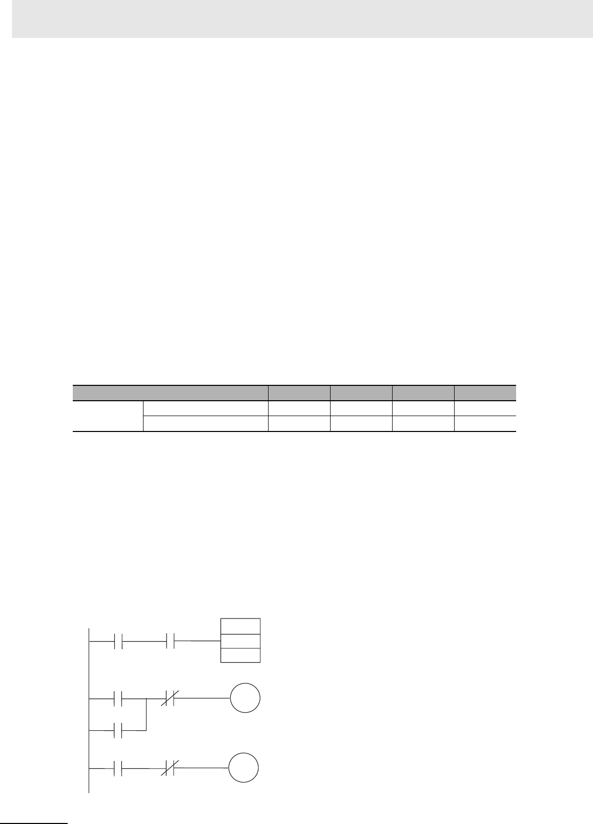
Appendices
A-150 CJ2 CPU Unit Hardware User’s Manual
When load L is connected, the ERR indicator may light and the Alarm Output Bit may turn ON for
approximately 100 ms. The programming example given later in this section can be used so that an
error is not detected in this case.
zOperating Restrictions
Although the CJ1W-OD202 is provided with short-circuit protection, these are for protecting internal
circuits against momentary short-circuiting in the load. As shown in Figure 2, the short-circuit protec-
tion is automatically released when the Tj equals to Tr. Therefore, unless the cause of short-circuit is
removed, ON/OFF operations will be repeated in the output. Leaving short-circuits for any length of
time will cause internal temperature rise, deterioration of elements, discoloration of the case or
PCBs, etc. Therefore, observe the following restrictions.
zRestrictions
If a short-circuit occurs in an external load, immediately turn OFF the corresponding output and
remove the cause. The CJ1W-OD202 turns ON an alarm output bit that corresponds to the external
load output number. There is an alarm output bit for every common.
When an alarm output bit turns ON, use a self-holding bit for the alarm in the user program and turn
OFF the corresponding output.
The alarm output bit is allocated in the Basic I/O Unit Information Area (A050 to A069) for every Unit
mounting slot.
The following table shows the correspondence between output bits and bits in the Basic I/O Unit
Information Area.
For example, when the CJ1W-OD202 is mounted in slot 0 on Rack 0, A50.00 will turn ON if the out-
put 0 is short-circuited. When the CJ1W-OD202 is mounted in slot 1 of Rack 0, A50.11 will turn ON
if the output 7 is short-circuited.
zProgramming Example
In this example, CJ1W-OD202 is mounted in slot 0 of the Rack 0.
This example shows how to turn OFF output bits CIO 0.00 immediately if the alarm output bit A50.00
turns ON and how to keep the output bits OFF until the cause is removed and the bit is reset using
work bit W0.01.
Change to CIO 0.00, CIO 1.00, 0 (under TIM and at bottom right of diagram), A50.00, and W0.01.
To prevent the alarm output bit from turning ON momentarily when the load turns ON, the alarm out-
put is not turned ON for 200 ms after the input (CIO 1.00) turns ON.
Output bit 0 to 1 2 to 3 4 to 5 6 to 7
CJ1W-OD202 Mounted in even slot 0 1 2 3
Mounted in odd slot 8 9 10 11
TIM0
W0.00
W0.01
A50.00 1.00 TIM
0000
#0002
W0.00
1.00
0.00
W0.00
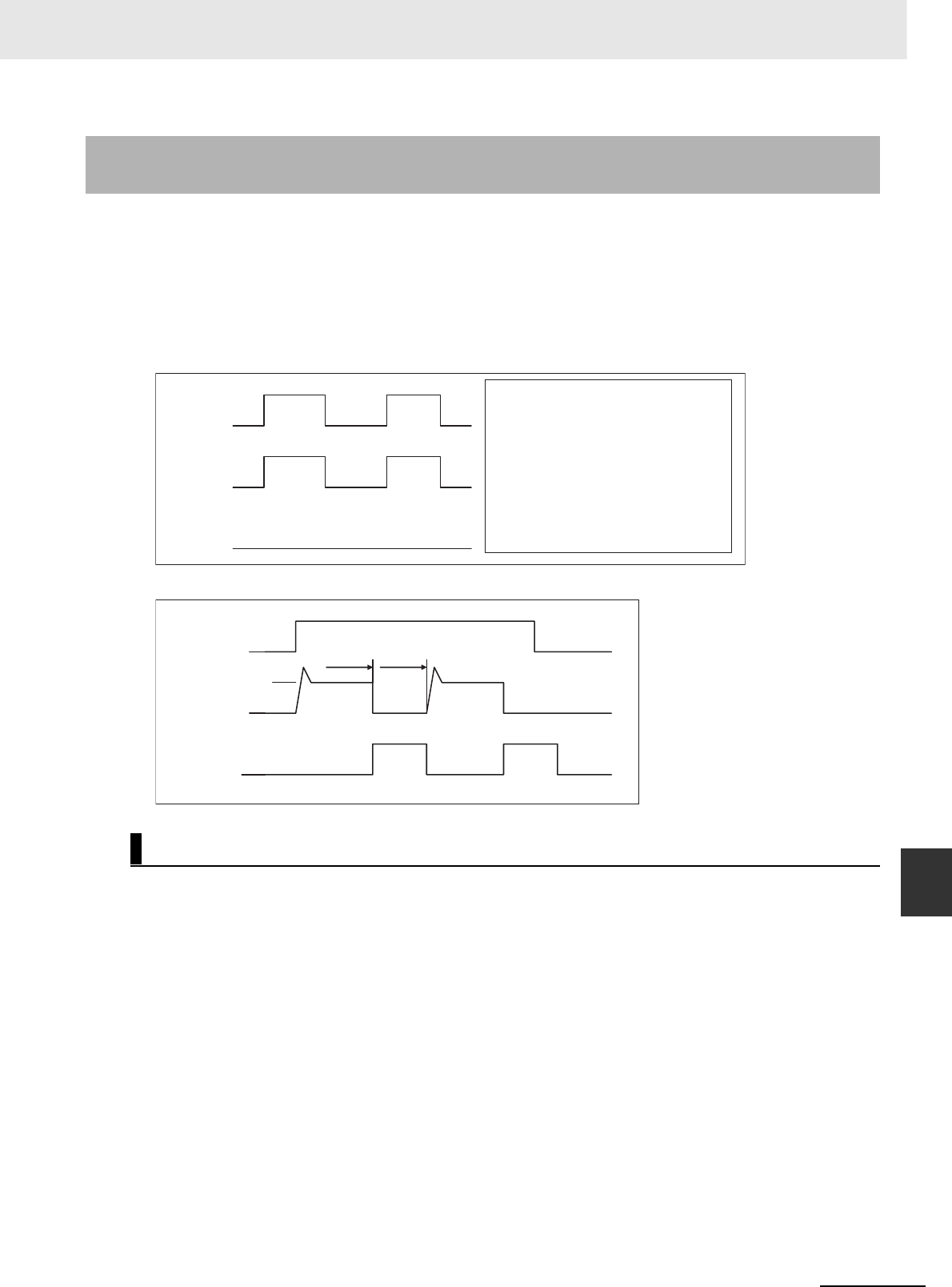
A-151
Appendices
CJ2 CPU Unit Hardware User’s Manual
A-6 Load Short-circuit Protection and Line Disconnection Detection for Basic I/O Units App A-6-2 Load Short-circuit Protection for CJ1W-
OD204/OD212/OD232/MD232
As shown below, normally when the output bit turns ON (OUT), the transistor will turn ON and then out-
put current (Iout) will flow. If the output (Iout) is overloaded or short-circuited exceeding the detection
current (Ilim), the output current (Iout) will be limited as shown in second figure below. When the junc-
tion temperature (Tj) of the output transistor reaches the thermal shutdown temperature (Tstd), the out-
put will turn OFF to protect the transistor from being damaged, and the alarm output bit will turn ON to
light the ERR indicator. When the junction temperature (Tj) of the transistor drops down to the reset
temperature (Tr), the ERR indicator will be automatically reset and the output current will start flowing.
Normal Operation
Operation for Overload or Short Circuit
These Units are provided with short-circuit protection, these are for protecting internal circuits against
momentary short-circuiting in the load. As shown in Figure 2, the short-circuit protection is automati-
cally released when the Tj equals to Tr. Therefore, unless the cause of short-circuit is removed,
ON/OFF operations will be repeated in the output. Leaving short-circuits for any length of time will
cause internal temperature rise, deterioration of elements, discoloration of the case or PCBs, etc.
Therefore, observe the following restrictions.
A-6-2 Load Short-circuit Protection for CJ1W-
OD204/OD212/OD232/MD232
Operating Restrictions for the CJ1W-OD204/OD212/OD232/MD232
OUT
ON
OFF
IOUT
ON
OFF
ERR
ON
OFF
OUT: OUTPUT instruction
IOUT: Output current
ERR: Alarm output, ERR indicator
Ilim: Detection current
Tj: Junction temperature of transistor
Tstd: Thermal shutdown temperature
Tr: Reset temperature
OUT
ON
OFF
I
OUT
ON
OFF
ERR
ON
OFF
I
lim
Tj =Tstd Tj =Tr
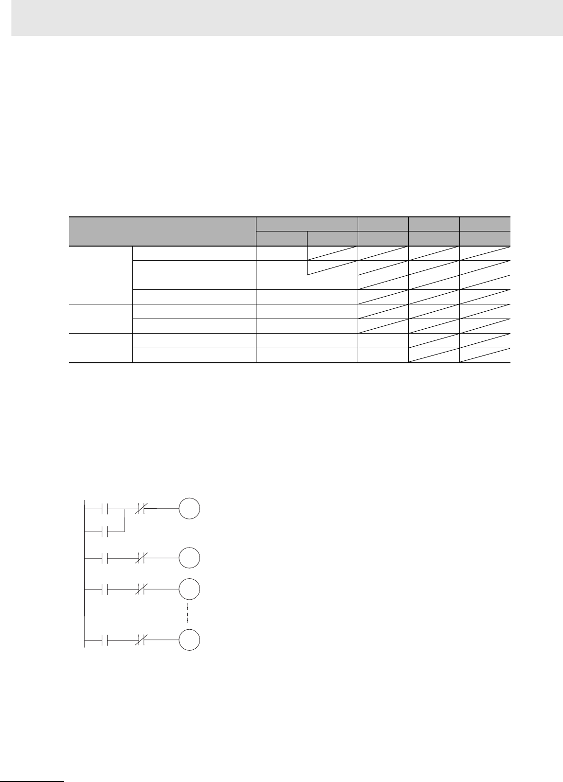
Appendices
A-152 CJ2 CPU Unit Hardware User’s Manual
zRestrictions
If a short-circuit occurs in an external load, immediately turn OFF the corresponding output and
remove the cause. An alarm output bit that corresponds to the external load output number is turned
ON. There is an alarm output bit for every common.
When an alarm output bit turns ON, use a self-holding bit for the alarm in the user program and turn
OFF the corresponding output.
The alarm output bit is allocated in the Basic I/O Unit Information Area (A050 to A069) for every Unit
mounting slot.
The following table shows the correspondence between output bits and bits in the Basic I/O Unit
Information Area.
For example, when the CJ1W-OD212 is mounted in slot 0 on Rack 0, A50.00 will turn ON if the out-
put 8 is short-circuited. When the CJ1W-OD232 is mounted in slot 1 of Rack 0, A50.09 will turn ON
if the output m+1 is short-circuited.
zProgramming Example
In this example, CJ1W-OD212 is mounted in slot 0 of the Rack 0.
This example shows how to turn OFF output bits CIO 0.00 to CIO 0.07 immediately if the alarm out-
put bit A50.00 turns ON and how to keep the output bits OFF until the cause is removed and the bit
is reset using work bit W0.01.
Output bit mm+1 m+2 m+3
0 to 7 8 to 15 0 to 15 0 to 15 0 to 15
CJ1W-OD204 Mounted in even slot 0
Mounted in odd slot 8
CJ1W-OD212 Mounted in even slot 0
Mounted in odd slot 8
CJ1W-MD232 Mounted in even slot 0
Mounted in odd slot 8
CJ1W-OD232 Mounted in even slot 0 1
Mounted in odd slot 8 9
A
0.00
W0.00
B
0.01
W0.00
H
0.07
W0.00
A50.00
W0.00
W0.01
W0.00
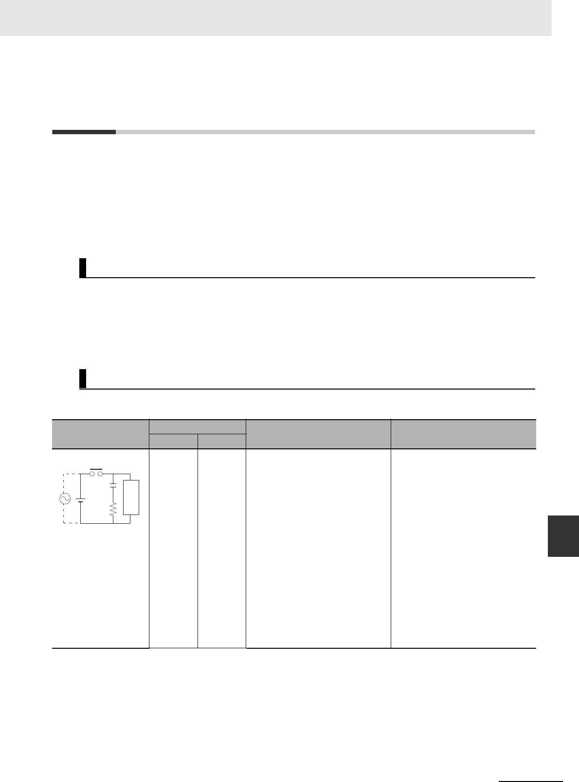
A-153
Appendices
CJ2 CPU Unit Hardware User’s Manual
A-7 Relay Output Noise Reduction Methods App A-6-2 Load Short-circuit Protection for CJ1W-
OD204/OD212/OD232/MD232
A-7 Relay Output Noise Reduction
Methods
The CJ-series PLCs conforms to the Common Emission Standards (EN61000-6-4) of the EMC Direc-
tives. However, noise generated by relay output switching may not satisfy these Standards. In such a
case, a noise filter must be connected to the load side or other appropriate countermeasures must be
provided external to the PLC.
Countermeasures taken to satisfy the standards vary depending on the devices on the load side, wir-
ing, configuration of machines, etc. Following are examples of countermeasures for reducing the gener-
ated noise.
(Refer to EN61000-6-4 for more details.)
Countermeasures are not required if the frequency of load switching for the whole system with the PLC
included is less than 5 times per minute.
Countermeasures are required if the frequency of load switching for the whole system with the PLC
included is more than 5 times per minute.
When switching an inductive load, connect an surge protector, diodes, etc., in parallel with the load or
contact as shown below.
Countermeasures
Countermeasure Examples
Circuit Current Characteristic Required element
AC DC
Yes Yes If the load is a relay or solenoid,
there is a time lag between the
moment the circuit is opened and
the moment the load is reset.
If the supply voltage is 24 or 48 V,
insert the surge protector in parallel
with the load. If the supply voltage
is 100 to 200 V, insert the surge
protector between the contacts.
The capacitance of the capacitor
must be 1 to 0.5 µF per contact cur-
rent of 1 A and resistance of the
resistor must be 0.5 to 1 Ω per con-
tact voltage of 1 V. These values,
however, vary with the load and the
characteristics of the relay. Decide
these values from experiments, and
take into consideration that the
capacitance suppresses spark dis-
charge when the contacts are sep-
arated and the resistance limits the
current that flows into the load
when the circuit is closed again.
The dielectric strength of the
capacitor must be 200 to 300 V. If
the circuit is an AC circuit, use a
capacitor with no polarity.
CR method
Power
supply
Inductive
load
C
R
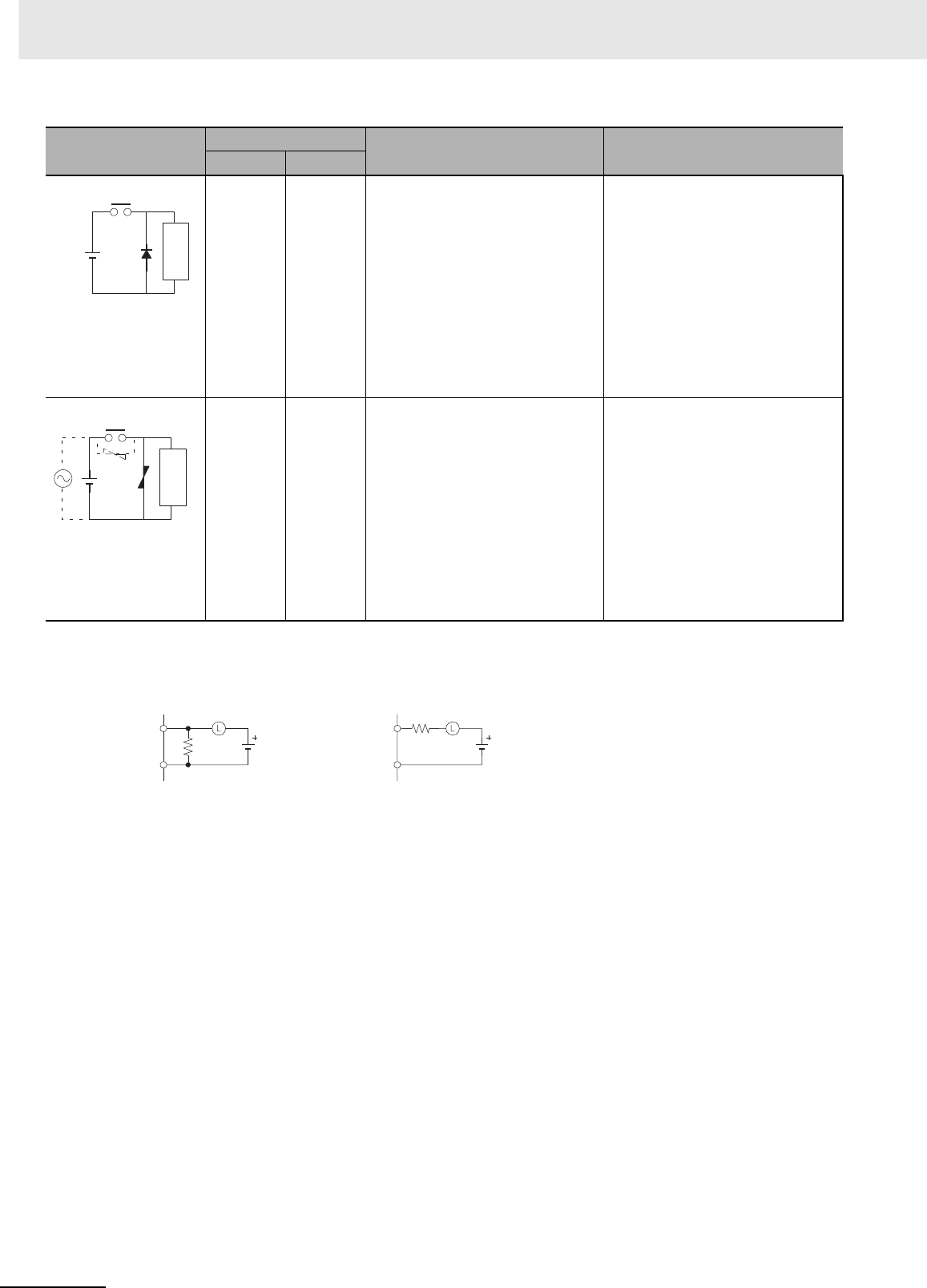
Appendices
A-154 CJ2 CPU Unit Hardware User’s Manual
When switching a load with a high inrush current such as an incandescent lamp, suppress the inrush
current as shown below.
No Yes The diode connected in parallel
with the load changes energy accu-
mulated by the coil into a current,
which then flows into the coil so
that the current will be converted
into Joule heat by the resistance of
the inductive load.
This time lag, between the moment
the circuit is opened and the
moment the load is reset, caused
by this method is longer than that
caused by the CR method.
The reversed dielectric strength
value of the diode must be at least
10 times as large as the circuit volt-
age value. The forward current of
the diode must be the same as or
larger than the load current.
The reversed dielectric strength
value of the diode may be two to
three times larger than the supply
voltage if the surge protector is
applied to electronic circuits with
low circuit voltages.
Yes Yes The varistor method prevents the
imposition of high voltage between
the contacts by using the constant
voltage characteristic of the varis-
tor. There is time lag between the
moment the circuit is opened and
the moment the load is reset.
If the supply voltage is 24 or 48 V,
insert the varistor in parallel with
the load. If the supply voltage is
100 to 200 V, insert the varistor
between the contacts.
---
Circuit Current Characteristic Required element
AC DC
Diode method
Power
supply
Inductive
load
Power
supply
Varistor method
Inductive
load
OUT
COM
R
OUT
COM
R
Countermeasure 1 Countermeasure 2
Providing a dark current of
a
pprox. one-third of the rated
v
alue through an incandescent
lamp
Providing a limiting resisto
r

A-155
Appendices
CJ2 CPU Unit Hardware User’s Manual
A-8 Functions Supported for Unit Versions App A-8-1 CJ2H CPU Units
A-8 Functions Supported for Unit
Versions
CX-Programmer version 9.1 or higher must be used to enable using the functions added for unit ver-
sion 1.3.
CX-Programmer version 8.3 or higher must be used to enable using the functions added for unit ver-
sion 1.2.
Note User programs that use functions of CJ2H CPU Units with unit version 1.2 or later cannot be used with CJ2H
CPU Units with unit version 1.1 or earlier. If an attempt is made to transfer a program that uses any of these
functions from the CX-Programmer to a CPU Unit with unit version 1.1 or earlier, an error will be displayed
and it will not be possible to download to the CPU Unit.
A-8-1 CJ2H CPU Units
Functions Supported for Unit Version 1.3 or Later
Units CJ2H CPU Units
Models CJ2H-CPU6@-EIP and CJ2H-CPU6@
Unit version
Function
Unit version
1.3 or later
Unit version
1.2
Unit version
1.1
Unit version
1.0
Special instructions
for certain Special I/O
Units
CJ1W-NC281/NC481/NC881
Position Control Units: PCU
HIGH-SPEED POSITIONING
(NCDMV(218))
Supported. Not supported. Not supported. Not supported.
CJ1W-NC281/NC481/NC881
Position Control Units: PCU
POSITIONING TRIGGER
(NCDTR(219))
Supported. Not supported. Not supported. Not supported.
New special instruc-
tions
SIGNED AREA RANGE COM-
PARE: ZCPS(088)
Supported. Not supported. Not supported. Not supported.
DOUBLE SIGNED AREA
RANGE COMPARE:
ZCPSL(116)
Supported. Not supported. Not supported. Not supported.
Unit Version 1.2 or Later
Unit CJ2H CPU Units
Model CJ2H-CPU6@-EIP
CJ2H-CPU6@
Unit version Unit version 1.2 or later Unit versions earlier than 1.2
EM Area Force-setting/resetting Supported. Not supported.
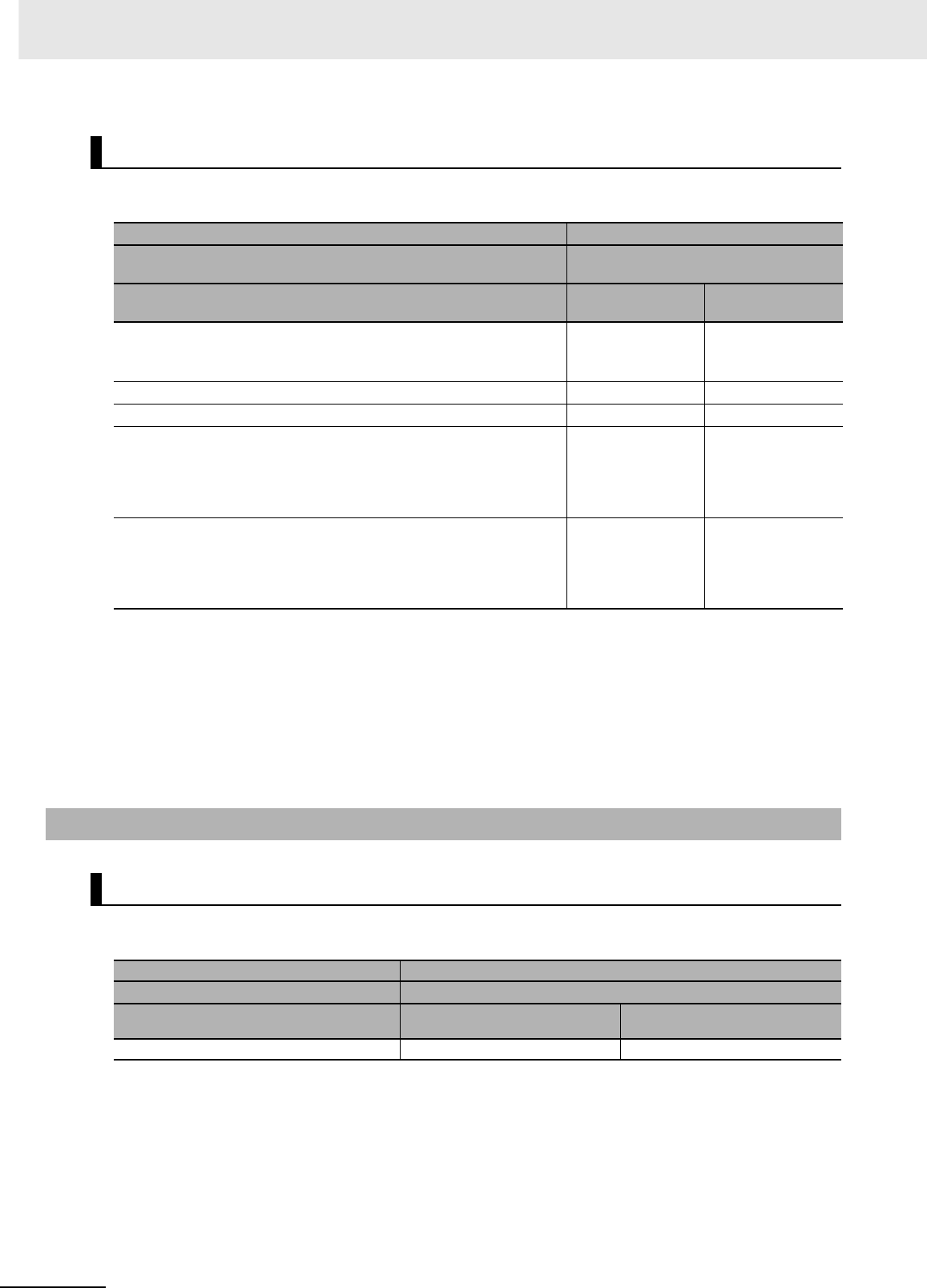
Appendices
A-156 CJ2 CPU Unit Hardware User’s Manual
CX-Programmer version 8.1* or higher must be used to enable using the functions added for unit ver-
sion 1.1.
* CX-Programmer version 8.02 or higher is required to use the high-speed interrupt function and the function to
change the minimum cycle time setting during operation.
Note User programs that use functions of CJ2H CPU Units with unit version 1.1 or later cannot be used with CJ2H
CPU Units with unit version 1.0 or earlier. If an attempt is made to transfer a program that uses any of these
functions from the CX-Programmer to a CPU Unit with unit version 1.0, an error will be displayed and it will
not be possible to download to the CPU Unit. If a program file (extension: .OBJ) that uses any of these func-
tions is transferred to a CPU Unit with unit version 1.0, a program error will occur when operation starts or
when the function starts and operation of the CPU Unit will stop.
CX-Programmer version 9.12 or higher must be used to enable using the functions added for unit ver-
sion 2.0.
Functions Supported for Unit Version 1.1 or Later
Units CJ2H CPU Unit
Models CJ2H-CPU6@-EIP and
CJ2H-CPU6@
Unit version
Function Unit version 1.1 Unit version 1.0
High-speed interrupt function
Reduced overhead time for interrupt tasks
Minimum interval for scheduled interrupt task execution: 0.1 ms
Supported. Not supported.
Changing the minimum cycle time setting during operation Supported. Not supported.
Synchronous unit operation Supported. Not supported.
Addition of immediate refreshing instructions for certain Special I/O Units
CJ1W-AD042 High-speed Analog Input Unit:
ANALOG INPUT DIRECT CONVERSION (AIDC(216))
CJ1W-DA042V High-speed Analog Output Unit:
ANALOG OUTPUT DIRECT CONVERSION (AODC(217))
Supported. Not supported.
High-speed Serial Communications Units
CJ1W-SCU22/SCU32/SCU42 High-speed Serial Communications Units:
DIRECT RECEIVE VIA SERIAL COMMUNICATIONS UNIT (DRXDU(261))
and DIRECT TRANSMIT VIA SERIAL COMMUNICATIONS UNIT
(DTXDU(262)
Supported. Not supported.
A-8-2 CJ2M CPU Units
Functions Supported for Unit Version 2.0 or Later
Unit CJ2M CPU Unit
Model CJ2M-CPU@@
Unit version
Function Unit version 2.0 or later Unit versions earlier than 2.0
Pulse I/O Supported. Not supported.

Index-1
CJ2 CPU Unit Hardware User’s Manual
Index
A
alarm output ................................................................ 3-26
B
Basic I/O Units ............................................................ 2-15
Basic I/O Units specifications ........................................A-2
battery replacement procedure ..................................... 7-6
battery service life and replacement periods ................ 7-5
C
calculating power consumption ................................... 2-25
calculating unit current consumption ........................... 2-22
checking errors ............................................................. 6-2
Connector-Terminal Block Conversion Unit .......5-33, A-59
CPU Bus Units ............................................................ 2-21
CPU error .................................................................... 6-10
CPU error (WDT error) .................................................. 6-6
CPU Rack ..................................................................... 2-3
CPU reset ..................................................................... 6-9
CPU reset error ............................................................. 6-6
CPU standby error ................................................. 6-6, 6-8
current consumption .....................2-5, 2-6, 2-7, 2-12, 2-15
D
dimensions ...........................................................5-8, A-94
DIN Track ............................................................. 2-9, 5-15
DIP switch .............................................................. 3-3, 3-6
E
End Cover ..................................................................... 2-3
error log information ...................................................... 6-3
EtherNet/IP port ..................................................... 2-9, 4-9
Expansion Rack .......................................................... 2-11
F
fail-safe circuit ............................................................... 5-2
fatal errors ..........................................................6-6, A-103
cycle time exceeded error ...................6-6, 6-12, A-104
FALS(007) error ............................................6-6, A-107
I./O setting error .................................................. A-105
I/O bus error ........................................6-6, 6-13, A-104
I/O setting error .............................................. 6-6, 6-15
Memory Card transfer error ..........................6-6, A-107
memory error .......................................6-6, 6-16, A-107
program error ...............................................6-6, A-106
too many I/O points ................................................. 6-6
too many I/O points error .....................................A-105
Unit/Rack number duplication error .....................A-105
version error .................................................6-6, A-107
G
grounding .................................................................... 5-50
I
I/O Relay Terminal ...................................................... 5-33
I/O Relay Terminals connection patterns ....................A-60
I/O table verification ...................................................... 6-5
indicators ................................................................ 3-4, 6-2
Interrupt Input Unit ...................................................... 3-28
IP address ................................................................... 3-12
L
line disconnection detection ......................................A-149
M
Memory Card ....................................................... 3-3, 3-13
Memory Card connector ............................................... 3-3
Memory Card indicator .................................................. 3-5
Memory Card indicators ................................................ 3-3
Memory Card power supply switch ............................... 3-3
N
node address .............................................................. 3-12
non-fatal errors ...................................................6-6, A-108
backup memory error ...................................6-6, A-109
Basic I/O error ..............................................6-6, A-109
basic I/O error ........................................................ 6-18
battery error .........................................6-6, 6-20, A-109
CPU Bus Unit error ..............................6-6, 6-21, A-109
CPU Bus Unit setting error ...........................6-6, A-110
duplicated refreshing error ...........................6-6, A-109
FAL(006) error ..............................................6-6, A-110
PLC Setup error ...........................................6-6, A-109
Special I/O Unit error ...........................6-6, 6-22, A-109
Special I/O Unit setting error ........................6-6, A-110
tag memory error ..........................................6-6, A-109
O
Option Board error ............................................... 6-6, 6-19
P
periodic inspection ........................................................ 7-2
peripheral (USB) port ....................................3-3, 4-5, 6-11
PLC Backup Tool ........................................................... 8-2
Power supply error ........................................................ 6-6
power supply error ........................................................ 6-7
Power Supply Unit replacement time .......................... 7-10
Power Supply Units ..................................................... 3-21
program capacity ................................................... 2-5, 2-6
Pulse I/O Module .............................................3-17, A-101

Index-2 CJ2 CPU Unit Hardware User’s Manual
R
replacement notification .............................................. 7-10
rotary switch ................................................................3-11
RS-232C ...................................................................... 6-11
RS-232C interface .....................................................A-111
RS-232C Option Board
specifications .......................................................A-112
RS-232C port communications error ............................. 6-6
RS-422A/485 Option Board
specifications .......................................................A-113
RUN output .................................................................. 3-26
S
Serial Option Board ......................................... 3-20, A-102
serial port ...............................................................2-9, 3-3
serial port (RS-232C) ....................................................4-8
seven-segment display .........................................3-9, 6-26
short-circuit protection ...............................................A-149
simple backup ...............................................................8-7
Special I/O Units .......................................................... 2-18
Support Software .......................................................... 4-2
U
unit address ................................................................. 8-14
USB driver .................................................................A-139
USB port .................................................................2-9, 4-5
USB port communications error .................................... 6-6
W
weight .................................................... 2-5, 2-6, 2-7, 2-15
wiring duct ..................................................................... 5-7

Revision-1
CJ2 CPU Unit Hardware User’s Manual
Revision History
A manual revision code appears as a suffix to the catalog number on the front cover of the manual.
The following table outlines the changes made to the manual during each revision. Page numbers refer to the
previous version.
Revision code Date Revised content
01 July 2008 Original production
02 December 2008 Added the CJ2H-CPU6@.
Added information on unit version 1.1 of the CJ2 CPU Units.
Added the following Basic I/O Units: CJ1W-ID212, CJ1W-ID233, CJ1W-OD213,
and CJ1W-OD234.
03 February 2009 Added information on the synchronous unit operation function.
Added the CJ1W-NC214/234/414/434 Position Control Units.
04 July 2009 Added the CJ1W-AD042 Analog Input Unit.
Added the CJ1W-DA042V Analog Output Unit.
05 November 2009 Added the CJ1W-SCU22/32/42 Serial Communications Units.
Added information on the EM Area force-setting/resetting function.
Corrected mistakes.
06 February 2010 Added the CJ2M-CPU@@.
07 July 2010 Added information on CJ2M-MD21@ Pulse I/O Modules.
Corrected mistakes.
08 October 2010 Added information on unit version 2.1 of the built-in EtherNet/IP section on
CJ2M-CPU3@ CPU Units.
Corrected mistakes.
Cat. No. W472-E1-08
Revision code

Revision-2 CJ2 CPU Unit Hardware User’s Manual
