WEG Specification Of Electric Motors 50039409 Manual English
User Manual:
Open the PDF directly: View PDF ![]() .
.
Page Count: 68
--
Motors | Automation | Energy | Transmission & Distribution | Coatings
Motors
Specification of Electric Motors
Specification of Electric Motors 2
Specification of Electric Motors
www.weg.net

Specification of Electric Motors 3
WEG, which began in 1961 as a small factory
of electric motors, has become a leading global
supplier of electronic products for different
segments. The search for excellence has resulted
in the diversification of the business, adding to
the electric motors products which provide from
power generation to more efficient means of use.
This diversification has been a solid foundation
for the growth of the company which, for offering
more complete solutions, currently serves its
customers in a dedicated manner. Even after
more than 50 years of history and continued
growth, electric motors remain one of WEG’s main
products. Aligned with the market, WEG develops
its portfolio of products always thinking about the
special features of each application.
In order to provide the basis for the success of
WEG Motors, this simple and objective guide was
created to help those who buy, sell and work with
such equipment. It brings important information for
the operation of various types of motors.
Enjoy your reading.
www.weg.net

Specification of Electric Motors 4
Table of Contents
1. Fundamental Concepts ......................................6
1.1 Electric Motors ..........................................................6
1.2 Basic Concepts ......................................................... 7
1.2.1 To rqu e ....................................................................... 7
1.2.2 Mechanical Energy & Power ......................................7
1.2.3 Electrical Energy & Power ......................................... 7
1.2.4 Apparent, Active and Reactive Power ....................... 8
1.2.5 Power Factor ............................................................. 9
1.2.6 Efficiency ................................................................. 11
1.2.7 Torque Versus Power Ratio ..................................... 11
1.3 Single-Phase AC Systems ....................................... 11
1.3.1 Connection: Parallel and Series .............................. 11
1.4.2 Star Connection ..................................................... 12
1.4 Three-Phase AC System ......................................... 12
1.4.1 Delta Connection .................................................... 12
1.5 Three-Phase Induction Motor .................................. 13
1.5.1 Working Principle - Rotating Field ........................... 13
1.5.2 Synchronous Speed ( ns ) ....................................... 14
1.5.3 Slip ( s ).................................................................... 15
1.5.4 Rated Speed ........................................................... 15
1.6 Insulation Materials and Insulation Systems ............ 15
1.6.1 Insulation Material ................................................... 15
1.6.2 Insulation System .................................................... 15
1.6.3 Thermal Classes ..................................................... 15
1.6.4 Insulating Materials in Insulation Systems ................ 16
1.6.5 WEG Insulation System .......................................... 16
2. Power Supply Characteristics ........................18
2.1 Power Supply System ............................................. 18
2.1.1 Three-Phase System ............................................... 18
2.1.2 Single-Phase System .............................................. 18
3. Characteristics of the Electric Motor Power
Supply..............................................................18
3.1 Rated Voltage .......................................................... 18
3.1.1 Multiple Rated Voltage ............................................ 18
3.2 Rated Frequency ( Hz ) ............................................ 19
3.2.1 Connection to Different Frequencies ....................... 19
3.3 Voltage and Frequency Variation Tolerance ............. 20
3.4 Three-Phase Motor Starting Current Limitation ......20
3.4.1 D.O.L Starting .......................................................... 20
3.4.2 Starting with Star-Delta Switch ( Y - Δ ) ................... 21
3.4.3 Compensating Switch ............................................. 23
3.4.4 Comparing Star-Delta Starters and ........................ 24
3.4.5 Series-Parallel Starting ............................................ 24
3.4.6 Electronic Start ( Soft-Starter ) ................................ 25
3.5 Direction of Rotation of Three-Phase
Induction Motors ..................................................... 25
4. Acceleration Characteristics ..........................25
4.1 To rqu e ..................................................................... 25
4.1.1 Torque X Speed Curve ............................................ 25
4.1.2 Designs - Minimum Standardized Torque Values .... 26
4.1.3 Characteristics of WEG Motors ............................... 28
4.2 Load Inertia ............................................................. 28
4.3 Acceleration Time ................................................. 28
4.4 Duty Cycles............................................................ 29
4.5 Locked Rotor Current ............................................29
4.5.1 Standardized Maximum Values .............................. 29
5. Speed Regulation of Asynchronous
Motors ................................................................30
5.1 Changing the Number of Poles .............................. 30
5.1.1 Two Speed Motors with Independent Windings .....30
5.1.2 Dahlander ..............................................................30
5.1.3 Motors with Two or More Speeds .......................... 31
5.2 Slip Variation .......................................................... 31
5.2.1 Rotor Resistance Variation ..................................... 31
5.2.2 Stator Voltage Variation ......................................... 31
5.3 Frequency Inverters ............................................... 31
6. Brake Motor .......................................................31
6.1 Brake Operation ..................................................... 32
6.2 Connection Diagram .............................................. 32
6.3 Brake Coil Power Supply .......................................33
6.4 Brake Torque .........................................................33
6.5 Air Gap Adjustment ................................................33
7. Operating Characteristics ..............................34
7.1.1 Winding Heating Up ............................................... 34
7.1.2 Motor Lifetime ........................................................ 35
7.1.3 Insulation Classes ..................................................35
7.1.4 Winding Temperature Rise Measurement ..............35
7.1.5 Electric Motor Application ..................................... 36
7.2 Thermal Protection of Electric Motors .................... 36
7.2.1 Resistance Temperature Detector ( Pt-100 )........... 36
7.2.2 Thermistors ( PTC and NTC ) .................................36
7.2.3 Bimetal Thermal Protectors - Thermostats ............ 37
7.2.4 Phenolic Thermal Protection System .....................38
7.3 Service Duty .........................................................39
7.3.1 Standardized Service Duties ..................................39
7.3.2 Duty Type Designation ........................................... 42
7.3.3 Rated Output ......................................................... 43
7.3.4 Equivalent Power Ratings for Low Inertia Loads .... 43
7.4 Service Factor ( SF ) ............................................... 44
8. Environment Characteristics ..........................44
8.1 Altitude ...................................................................44
8.2 Ambient Temperature ............................................44
8.3 Determining Useful Motor Output at Different
Temperature and Altitude Conditions .....................44
8.4 Environment ........................................................... 45
8.4.1 Aggressive Environments ....................................... 45
8.4.2 Environments Containing Dusts and Fibers ........... 45
8.4.3. Explosive Atmospheres .........................................45
8.5 Degree of Protection .............................................. 45
8.5.1 Identification Codes ...............................................45
8.5.2 Usual Degrees of Protection .................................. 46
8.5.3 Weather Protected Motors ..................................... 46
8.6 Space Heater ......................................................... 46
8.7 Noise Levels ........................................................... 47
www.weg.net
Specification of Electric Motors 5
--
9. Explosive Atmosphere .....................................48
9.1 Hazardous Area.................................................48
9.2 Explosive Atmosphere .......................................48
9.3 Classification of Hazardous Areas .....................48
9.3.1 Classes and Groups of the Hazardous Areas .... 48
9.3.2 Protection by Enclosure .....................................49
9.4 Temperature Classes .........................................50
9.5 Equipment for Explosive Atmospheres ..............50
9.6 Increased Safety Equipment ..............................50
9.7 Explosion-Proof Equipment ............................... 51
10. Mounting Arrangements ................................ 51
10.1 Dimensions ........................................................ 51
10.2 Standardized Type of Construction and Mounting
Arrangement .....................................................52
10.3 Painting .............................................................54
10.3.1 Tropicalized Painting .......................................... 54
11. Three-Phase Electric Motor Selection
and Application ..............................................54
11.1 Motor Type Selection for Different Loads ........... 56
11.2 WMagnet Drive System® ................................... 58
11.3 Application of Induction Motors with Variable
Frequency Drives ............................................... 58
11.3.1 Normative Aspects ............................................ 58
11.3.2 Induction Machine Speed Variation by Frequency
Inverter .............................................................. 58
11.3.3 Characteristics of the Frequency Inverter ......... 59
11.3.3.1 Control Types ...................................................59
11.3.3.2 Harmonics ........................................................ 60
11.3.4 Inverter Influencing Motor Performance ............. 60
12. Environmental Information............................63
12.1 Packaging .........................................................63
12.2 Product..............................................................63
13. Tests .................................................................63
13.1 Variable Frequency Drive Motors ....................... 63
14. Appendix ..........................................................64
14.1. International System of Units .............................64
14.2 Unit Convertion ..................................................65
14.3 Standards ..........................................................66
www.weg.net
Specification of Electric Motors 6
SPLIT-PHASE
START CAPACITOR
ASYNCHRONOUS
SQUIRREL CASE
SINGLE PHASE
THREE PHASE
AC MOTOR
DC MOTOR
SERIE EXCITATION
INDEPENDENT
EXCITATION
COMPOUND
EXCITATION
PERMANENT
MAGNET
PARALLEL
EXCITATION
PERMANENT
CAPACITOR
SHADED POLES
TWO-VALUE
CAPACITOR
REPULSIONWOUND ROTOR
SYNCHRONOUS
ASYNCHRONOUS
SYNCHRONOUS
LINEAR
UNIVERSAL
MANUFACTURED BY WEG
RELUCTANCE
PERMANENT
MAGNET
INDUCTION
PERMANENT
MAGNET
SQUIRREL CASE
WOUND ROTOR
PEMANENT
MAGNET
NON-SALIENT
POLE
RELUCTANCE
SALIENT POLES
1.1 Electric Motors
The electric motor is a machine capable of converting
electrical energy into mechanical energy. The induction motor
is the most widely used type of motor, because it combines
all the advantages offered by the electrical energy such as
low cost, easy of supply and distribution, clean handling and
simple controls - together with those of simple construction
and its great versatility to be adapted to wide ranges of loads
and improved efficiencies. The most common types of electric
motors are:
a ) Direct current motors
These motors are quite expensive requiring a direct current
source or a converting device to convert normal alternating
current into direct current. They are capable of operating with
adjustable speeds over a wide range and are perfectly suited
for accurate and flexible speed control. Therefore, their use is
restricted to special applications where these requirements
compensate the much higher installation and maintenance
costs.
b ) Alternating current motors
These are the most frequently used motors because electrical
power is normally supplied as alternating current. The most
common types are:
Synchronous motors: synchronous motors are three-phase
AC motors which run at fixed speed, without slip, and are
generally applied for large outputs ( due to their relatively high
costs in smaller frame sizes ).
Induction motor: these motors generally run at a constant
speed which changes slightly when mechanical loads are
applied to the motor shaft. Due to its simplicity, robustness
and low cost, this type of motor is the most widely used
and, in practical terms, is quite suitable for almost all types
of machines. Currently it is possible to control the speed of
induction motors by frequency inverters.
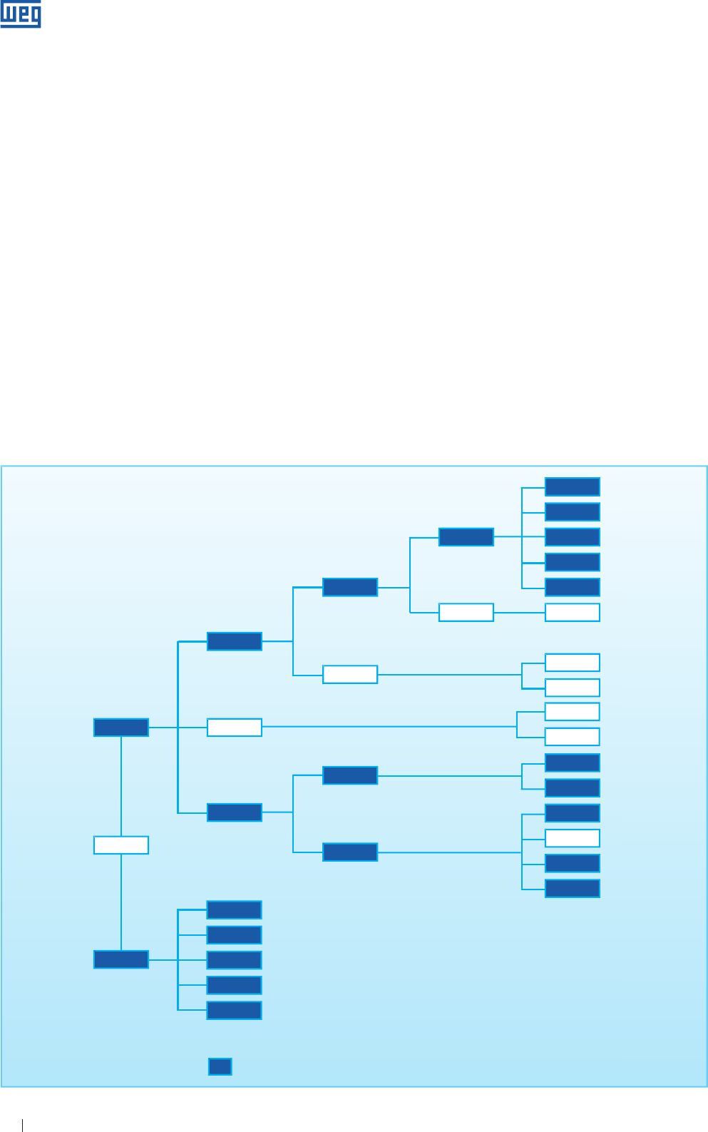
Technolical Universe of Electric Motors
Table 1.1
1. Fundamental Concepts
This Classification Diagram shows the most widely used
types of motors. Motors for specific use and with reduced
application are not shown
www.weg.net
Specification of Electric Motors 7
1.2 Basic Concepts
For better understanding of the following sections we will
now review some principles of Physics concerning energy
and forces.
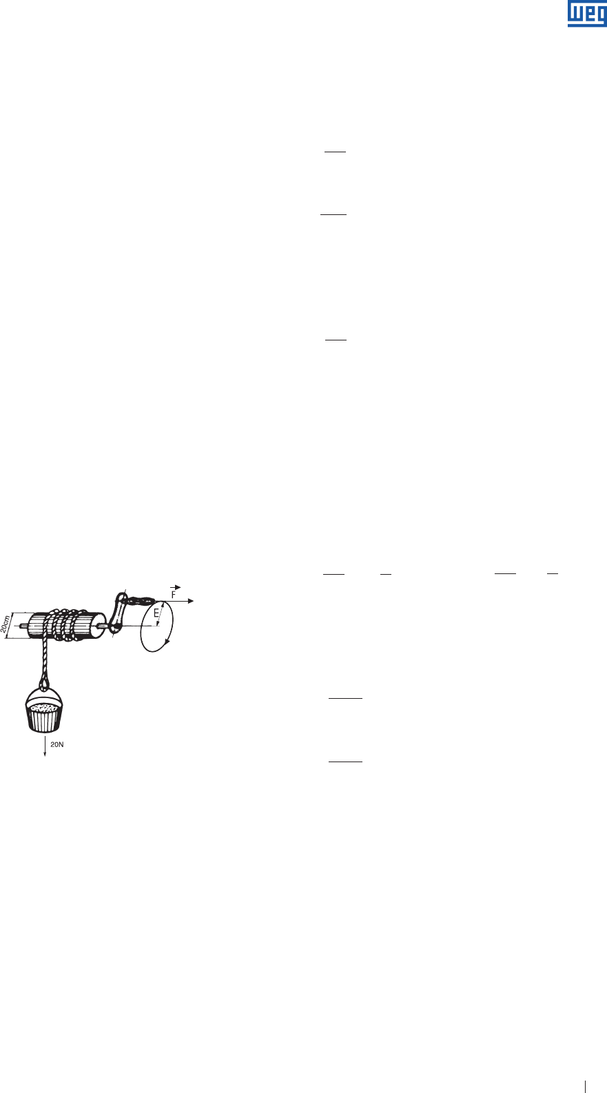
1.2.1 Torque
Torque, also known as moment of force, is the measure
of energy required to rotate a shaft. Through practical
experience we can note that for lifting a weight similar to the
one used in water wells ( see fig. 1.1 ). the required force “F”
to be applied on the winch depends on the length “E” of the
crank handle. The longer the crank handle the less force is
required. By doubling the length “E” of the crank handle, the
required force “F” is reduced by half.
Figure 1.2.1 a shows that the bucket weights 20 N while the
diameter of the drum is 0.20 m, thus permitting the rope to
transmit a force of 20 N on the drum’s surface, i.e. at 0.10 m
from the axis centre. In order to counterbalance this force,
10 N is must be applied on the crank handle if “E” has a
length of 0.20 m. If “E” is twice as much, i.e. 0.40 m, force
“F” becomes half, or 5 N. As you can see, to measure the
“energy” required to make the shaft rotate, it is not sufficient
to define the force applied but it is also necessary to indicate
at what distance from the shaft center the force is applied.
You must also inform at what distance from the shaft center
the force is applied. The “energy” is measured by the torque.
that is the result of “F” ( force ) x “E” ( distance ). F x E. In the
given example, the torque is:
C = 20 N x 0.10 m = 10 N x 0.20 m = 5 N x 0.40 m = 2.0 Nm
C = F . E ( N . m )
1.2.2 Mechanical Energy & Power
Power is a measure of how fast energy is applied or
consumed. In the previous example, if the well is 24.5 m
deep the work or energy ( W ) spent to lift the bucket from
the bottom of the well up to the wellhead will always be the
same: 20 N x 24.6 m = 490 Nm
Note: the measuring unit for the mechanical energy. Nm, is the same that
is used for torque - however the values are of different nature and
therefore should not be confused.
W = F . d ( N . m )
OBS.: 1 Nm = 1 J = Power x time = Watts x second
Power expresses how quick the energy is applied, it is
calculated by dividing the total energy or work by the time in
which it is done.
Therefore by using an electric motor to lift a water bucket in
2.0 seconds, the required Power will be:
F . d
Pmec = ( W )
t
490
P1 = = 245 W
2.0
If we use a higher power rating motor, able to do this work in
1.3 seconds, the required power will be:
490
P2 = = 377 W
1.3
The most common used unit in Brazil for measuring the
mechanical power is HP ( horsepower ), equivalent to
0.736 kW ( measuring unit used internationally for the same
purpose ).
Relationship between power units
P ( kW ) = 0.736 . P ( cv )
P ( cv ) = 1.359 P ( kW )
In this case the outputs of the above mentioned motors will be:
245 1 377 1
P1 = = cv P2 = = cv
736 3 736 2
For circular movements
C = F . r ( N.m )
π . d. n
v = ( m/s )
60
F . d
Pmec = ( cv )
736 . t
Where: C = torque ( Nm )
F = force ( N )
r = pulley radius ( m )
v = angular speed ( m/s
d = part diameter ( m )
n = speed ( rpm )
1.2.3 Electrical Energy & Power
Although energy is always one and the same thing, it can
be presented in several forms. By connecting a resistance
to a voltage supply, an electric current will flow through
the resistance that will be heated. The resistance absorbs
energy, transforming it into heat which is also a form of
energy. An electric motor absorbs electric energy from
the power supply, transforming it into mechanical energy
available at the end of the shaft.
Figure 1.1
www.weg.net
Specification of Electric Motors 8
DC Circuits
The “electric power” on DC circuits can be obtained by the
ratio among voltage ( U ), current ( I ) and resistance ( R )
involved in such circuit, that is:
P = U . I ( W )
or,
U 2
P = ( W )
R
or.
P = R . I² ( W )
Where: U = voltage ( V )
I = current ( Amps )
R = resistance ( Ω )
P = average Power ( W )
AC Circuits
a ) Resistance
In the case of “resistances”, the higher the supply voltage,
the higher the current that results in faster heating of the
resistance. This means that the electric power will be higher.
The electric energy absorbed from the line, in case of
resistance, is calculated by multiplying the line voltage by the
current, if the resistance ( load ) is single-phase.
P = Uf . If ( W )
In a three-phase system, the power in each phase of the load
is Pf = Uf x If as it were an independent single-phase system.
The total power is the sum of the power of the three-phases,
i.e.:
P = 3Pf = 3 . Uf . If
Considering that the three-phase system can be delta or star
connected, we will have following relationships:
Star-connection: U = 3 . Uf e I = If
Delta-connection: U = Uf e I = 3 . If
Thus, the total power for both connections will:
P = 3 . U . I ( W )
Note: this formula applies to resistive loads only, i.e. where there is no phase
shift of the current.
b ) Reactive loads
For “reactive” loads, i.e. where there is phase shifting in the
case of induction motors, the phase shift must be taken into
account and the formula then becomes
P = 3 . U . I . cos ϕ ( W )
Where: U = Line voltage
I = Line current
cos ϕ = Phase shift angle between voltage and current.
Electric power is normally measured in watts ( W )
corresponding to 1 volt x 1 ampere or its multiple kilowatt
( kW ) = 1000 watts. This unit may also be used to measure
the output of mechanical power. Electric energy is normally
measured by kilowatt-hour ( kWh ) corresponding to the
energy supplied by a power of 1 kW over a period of 1 hour
( this is the unit appearing on electricity bills ).
1.2.4 Apparent, Active and Reactive Power
Apparent power ( S )
It is the multiplication result of the voltage by the current
( S = U . I for single-phase systems and S = 3 . U . I, for
three-phase systems. This corresponds to the effective
power which exists when there is no phase displacement of
the current, i. e. for the resistive loads. Then,
P
S = ( VA )
Cos ϕ
Evidently, for resistive loads, cos ϕ = 1, and the effective
power can then be interpreted as apparent power. The
measuring unit for apparent power is volt-ampere ( VA ) or its
multiple, kilovolt-ampere ( kVA ).
Active power ( P )
It is the portion of apparent power that performs work, that
is, the portion that is converted into energy.
P = 3 . U . I . cos ϕ ( W ) ou P = S . cos ϕ ( W )
Reactive power ( Q )
It is the portion of apparent power that does “not” perform
work. It is only transferred and stored on passive elements
( capacitors and inductors ) of the circuit.
Q = 3 . U. I sen ϕ ( VAr ) ou Q = S . sen ϕ ( VAr )
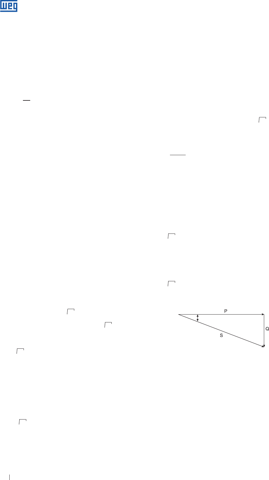
Power triangle
√
√
√
√
√
ϕ
Figure 1.2 - Power Triangle ( inductive load )
√
√
www.weg.net
Specification of Electric Motors 9
1.2.5 Power Factor
Power factor is indicated by cos ϕ, where ϕ is the angle
of voltage displacement relating to the current. It is the
relationship between active ( P ) and the apparent power
( S ): ( figure 1.2 ).
P P ( kW ) . 1000
cos ϕ = =
S 3 . U . I
Then we can state that,
g Resistive load: cos ϕ = 1
g Inductive load: cos ϕ ( delayed )
g Capacitive load: cos ϕ ( advanced )
Note: the terms “delayed” and “advanced” refers to the current angle relating
to the voltage angle.
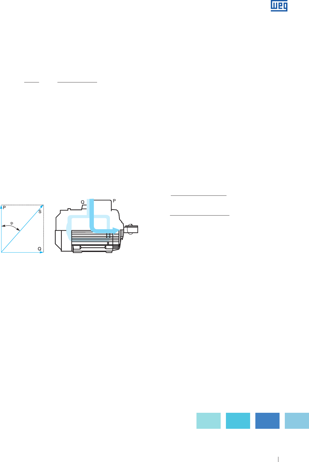
A motor does not draw only active power, transformed after
in mechanical power and heat ( losses ), but also absorbs
reactive power needed for magnetization, but that does not
produce work. On the diagram of figure 1.3, the vector P
represents the active power and Q the reactive Power, which
added results in the apparent power S.
Figure 1.3 - The Power factor is determined measuring the input power, the
voltage and the rated load
Where; kVAr = Three-phase power of the capacitor bank to be installed
P( hp ) = Motor rated output
F = Factor obtained in the Table 1.2
Eff. % = Motor efficiency
The electric motor plays a very important role in the
industry, since it represents more than 60% of the energy
consumption. Therefore, it is essential to apply motors with
outputs and features well adapted to its function since the
power factor changes with motor load.
Power factor correction
The increase of power factor is made by the connection of
a capacitive load, in general, a capacitor or a synchronous
motor with overexcitation, in parallel with the load.
For example:
A three-phase electric motor, 100 HP ( 75 kW ), IV poles,
running at 100% of the rated power, with original Power Factor
of 0.87 and efficiency of 93.5%. Now a reactive power should
be determined to raise the power factor to 0.95.
Solution:
Using the table 1.2, on the intersection of 0.87 line with the
column of 0.95, we get the value 0.238 that multiplied by the
motor absorbed power from the line in KW, gives the amount
of reactive power necessary to increase the power factor
from 0.87 to 0.95.
= 100 x 0.736 x 0.238 x 100%
93.5%
kVAr = P ( HP ) x 0.736 x F x 100%
Eff. %
kVAr =18.735 kVAr
www.weg.net
Specification of Electric Motors 10
Original Required Power Factor
Power
Factor 0.80 0.81 0.82 0.83 0.84 0.85 0.86 0.87 0.88 0.89 0.90 0.91 0.92 0.93 0.94 0.95 0.96 0.97 0.98 0.99 1.00
0.50 0.982 1.008 1.034 1.060 1.086 1.112 1.139 1.165 1.192 1.220 1.248 1.276 1.306 1.337 1.369 1.403 1.442 1.481 1.529 1.590 1.732
0.51 0.937 0.962 0.989 1.015 1.041 1.067 1.094 1.120 1.147 1.175 1.203 1.231 1.261 1.292 1.324 1.358 1.395 1.436 1.484 1.544 1.687
0.52 0.893 0.919 0.945 0.971 0.997 1.023 1.060 1.076 1.103 1.131 1.159 1.187 1.217 1.248 1.280 1.314 1.351 1.392 1.440 1.500 1.643
0.53 0.850 0.876 0.902 0.928 0.954 0.980 1.007 1.033 1.060 1.088 1.116 1.144 1.174 1.205 1.237 1.271 1.308 1.349 1.397 1.457 1.600
0.54 0.809 0.835 0.861 0.887 0.913 0.939 0.966 0.992 1.019 1.047 1.075 1.103 1.133 1.164 1.196 1.230 1.267 1.308 1.356 1.416 1.359
0.55 0.769 0.795 0.821 0.847 0.873 0.899 0.926 0.952 0.979 1.007 1.035 1.063 1.090 1.124 1.456 1.190 1.228 1.268 1.316 1.377 1.519
0.56 0.730 0.756 0.782 0.808 0.834 0.860 0.887 0.913 0.940 0.968 0.996 1.024 1.051 1.085 1.117 1.151 1.189 1.229 1.277 1.338 1.480
0.57 0.692 0.718 0.744 0.770 0.796 0.882 0.849 0.875 0.902 0.930 0.958 0.986 1.013 1.047 1.079 1.113 1.151 1.191 1.239 1.300 1.442
0.58 0.655 0.681 0.707 0.733 0.759 0.785 0.812 0.838 0.865 0.893 0.921 0.949 0.976 1.010 1.042 1.076 1.114 1.154 1.202 1.263 1.405
0.59 0.618 0.644 0.670 0.696 0.722 0.748 0.775 0.801 0.828 0.856 0.884 0.912 0.943 0.973 1.005 1.039 1.077 1.117 1.165 1.226 1.368
0.60 0.584 0.610 0.636 0.662 0.688 0.714 0.741 0.767 0.794 0.822 0.850 0.878 0.905 0.939 0.971 1.005 1.043 1.083 1.131 1.192 1.334
0.61 0.549 0.575 0.601 0.627 0.653 0.679 0.706 0.732 0.759 0.787 0.815 0.843 0.870 0.904 0.936 0.970 1.008 1.048 1.096 1.157 1.299
0.62 0.515 0.541 0.567 0.593 0.619 0.645 0.672 0.698 0.725 0.753 0.781 0.809 0.836 0.870 0.902 0.936 0.974 1.014 1.062 1.123 1.265
0.63 0.483 0.509 0.535 0.561 0.587 0.613 0.640 0.666 0.693 0.721 0.749 0.777 0.804 0.838 0.870 0.904 0.942 0.982 1.000 1.091 1.233
0.64 0.450 0.476 0.502 0.528 0.554 0.580 0.607 0.633 0.660 0.688 0.716 0.744 0.771 0.805 0.837 0.871 0.909 0.949 0.997 1.066 1.200
0.65 0.419 0.445 0.471 0.497 0.523 0.549 0576 0.602 0.629 0.657 0.685 0.713 0.740 0.774 0.806 0.840 0.878 0.918 0.966 1.027 1.169
0.66 0.388 0.414 0.440 0.466 0.492 0.518 0.545 0.571 0.598 0.26 0.654 0.692 0.709 0.742 0.755 0.809 0.847 0.887 0.935 0.996 1.138
0.67 0.358 0.384 0.410 0.436 0.462 0.488 0.515 0.541 0.568 0.596 0.624 0.652 0.679 0.713 0.745 0.779 0.817 0.857 0.906 0.966 1.108
0.68 0.329 0.355 0.381 0.407 0.433 0.459 0.486 0.512 0.539 0.567 0595 0.623 0.650 0.684 0.716 0.750 0.788 0.828 0.876 0.937 1.079
0.69 0.299 0.325 0.351 0.377 0.403 0.429 0.456 0.482 0.509 0.537 0.565 0.593 0.620 0.654 0.686 0.720 0.758 0.798 0.840 0.907 1.049
0.70 0.270 0.296 0.322 0.348 0.374 0.400 0.427 0.453 0.480 0.508 0.536 0.564 0.591 0.625 0.657 0.691 0.729 0.769 0.811 0.878 1.020
0.71 0.242 0.268 0.294 0.320 0.346 0.372 0.399 0.425 0.452 0.480 0.508 0.536 0.563 0.597 0.629 0.663 0.701 0.741 0.783 0.850 0.992
0.72 0.213 0.239 0.265 0.291 0.317 0.343 0.370 0.396 0.423 0.451 0.479 0.507 0.534 0.568 0.600 0.624 0.672 0.712 0.754 0.821 0.963
0.73 0.186 0.212 0.238 0.264 0.290 0.316 0.343 0.369 0.396 0.424 0.452 0.480 0.507 0.541 0.573 0.607 0.645 0.685 0.727 0.794 0.936
0.74 0.159 0.185 0.211 0.237 0.263 0.289 0.316 0.342 0.369 0.397 0.425 0.453 0.480 0.514 0.546 0.580 0.618 0.658 0.700 0.767 0.909
0.75 0.132 0.158 0.184 0.210 0.236 0.262 0.289 0.315 0.342 0.370 0.398 0.426 0.453 0.487 0.519 0.553 0.591 0.631 0.673 0.740 0.882
0.76 0.106 0.131 0.157 0.183 0.209 0.235 0.262 0.288 0.315 0.343 0.371 0.399 0.426 0.460 0.492 0.526 0.564 0.604 0.652 0.713 0.855
0.77 0.079 0.106 0.131 0.157 0.183 0.209 0.236 0.262 0.289 0.317 0.345 0.373 0.400 0.434 0.466 0.500 0.538 0.578 0.620 0.686 0.829
0.78 0.053 0.079 0.105 0.131 0.157 0.183 0.210 0.236 0.263 0.291 0.319 0.347 0.374 0.408 0.440 0.474 0.512 0.562 0.594 0.661 0.803
0.79 0.026 0.062 0.078 0.104 0.130 0.153 0.183 0.209 0.236 0.264 0.292 0.320 0.347 0.381 0.403 0.447 0.485 0.525 0.567 0.634 0.776
0.80 0.000 0.026 0.062 0.078 0.104 0.130 0.157 0.183 0.210 0.238 0.266 0.264 0.321 0.355 0.387 0.421 0.459 0.499 0.541 0.608 0.750
0.81 0.000 0.026 0.062 0.078 0.104 0.131 0.157 0.184 0.212 0.240 0.268 0.295 0.329 0.361 0.395 0.433 0.473 0.515 0.582 0.724
0.82 0.000 0.026 0.062 0.078 0.105 0.131 0.158 0.186 0.214 0.242 0.269 0.303 0.335 0.369 0.407 0.447 0.496 0.556 0.696
0.83 0.000 0.026 0.062 0.079 0.105 0.132 0.160 0.188 0.216 0.243 0.277 0.309 0.343 0.381 0.421 0.463 0.536 0.672
0.84 0.000 0.026 0.053 0.079 0.106 0.14 0.162 0.190 0.217 0.251 0.283 0.317 0.355 0.395 0.437 0.504 0.645
0.85 0.000 0.027 0.053 0.080 0.108 0.136 0.164 0.194 0.225 0.257 0.191 0.229 0.369 0.417 0.476 0.620
0.86 0.000 0.026 0.053 0.081 0.109 0.137 0.167 0.198 0.230 0.265 0.301 0.343 0.390 0.451 0.593
0.87 0.027 0.055 0.082 0.111 0.141 0.172 0.204 0.238 0.275 0.317 0.364 0.425 0.567
0.88 0.028 0.056 0.084 0.114 0.145 0.177 0.211 0.248 0.290 0.337 0.398 0.540
0.89 0.028 0.056 0.086 0.117 0.149 0.183 0.220 0.262 0.309 0.370 0.512
0.90 0.028 0.058 0.089 0.121 0.155 0.192 0.234 0.281 0.342 0.484
0.91 0.030 0.061 0.093 0.127 0.164 0.206 0.253 0.314 0.456
0.92 0.031 0.063 0.097 0.134 0.176 0.223 0.284 0.426
0.93 0.032 0.068 0.103 0.145 0.192 0.253 0.395
0.94 0.034 0.071 0.113 0.160 0.221 0.363
0.95 0.037 0.079 0.126 0.187 0.328
0.96 0.042 0.089 0.149 0.292
0.97 0.047 0.108 0.251
0.98 0.061 0.203
0.99 0.142
Table 1.2 - Power factor correction
www.weg.net
Specification of Electric Motors 11
1.2.6 Efficiency
The efficiency defines how efficient is made the conversion
of the line absorbed electric energy it into mechanical
energy available at the shaft end. The efficiency defines how
this transformation is made. By calling mechanical power
available at the shaft end “output” ( Pu ) and electric energy
absorbed by the motor from the supply “input” ( Pa ), the
efficiency is the ratio between these two, i.e.,
Pu ( W ) 736 . P ( cv ) 1000 . P ( kW )
η = = =
Pa ( W ) 3 . U . I. cos ϕ 3 . U . I . cos ϕ
ou
736 . P ( cv )
η% = . 100
3 . U . I cos ϕ
1.2.7 Torque Versus Power Ratio
When mechanical energy is applied in the form of a rotating
movement, the developed output depends on the torque C
and on the rotational speed n. The ratio is as follows:
C ( kgfm ) . n ( rpm ) C ( Nm ) . n ( rpm )
P ( cv ) = =
716 7024
C ( kgfm ) . n ( rpm ) C ( Nm ) . n ( rpm )
P ( kW ) = =
974 9555
Inversely
716 . P ( cv ) 974 . P ( kW )
C ( kgfm ) = =
n ( rpm ) n ( rpm )
7024 . P ( cv ) 9555 . P ( kW )
C ( Nm ) = =
n ( rpm ) n ( rpm )
1.3 Single-Phase AC Systems
Alternating current is distinguished by that voltage, which
( instead of being a steady one, as for instance between the
poles of a battery ) varies with time, alternately reversing its
direction.
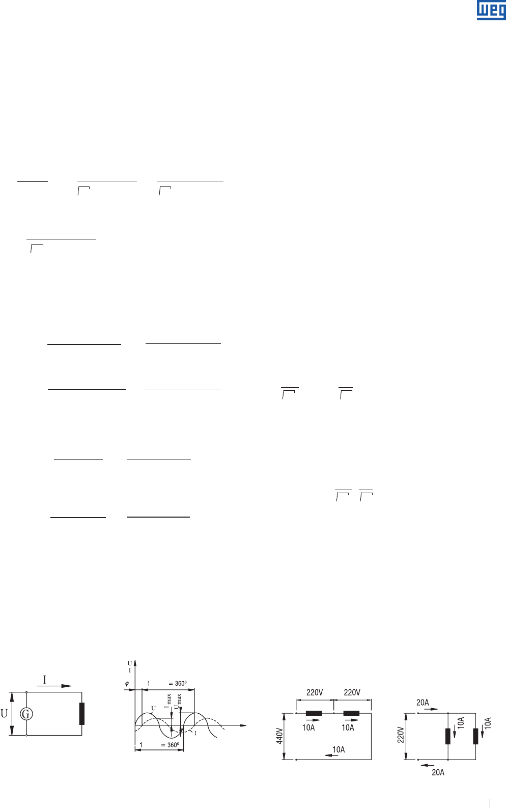
In the single-phase systems, the alternating voltage U ( Volts )
is generated and applied between two wires to which the load
absorbing current I ( amperes ) is connected - see Fig. 1.4a.
By representing the values U and I in a graph at successive
instants, we obtain Fig. 1.3.1.b. Fig. 14b also shows some
values which will be defined further on. It can be noted that
the voltage and current waves are not “in phase”, i.e. they do
not pass the zero point simultaneously, notwithstanding the
fact that they are of the same frequency. This occurs with
many types of electrical loads e.g. electric motors
( reactive loads ).
Frequency
Is the number of time per second the voltage changes its
direction and returns to the initial condition. It is expressed in
“cycle per second ” or “hertz”, and is represented by Hz.
Maximum voltage ( Umáx )
This is the “peak value” of the voltage, i.e. the instantaneous
crest value achieved by the voltage during one cycle ( one
half of the cycle being positive and the other half negative,
this is reached twice per cycle ).
Maximum current ( Imáx )
This is the “peak“ of the current.
Effective value of voltage and current ( U and I )
It is the value of the continuous voltage and current which
generate an output corresponding to that generated by the
alternated current. We can identify the effective value as:
U = Umáx / 2 e I = Imáx / 2 .
For example:
If we connect a “resistance” to an AC circuit
( cos ϕ = 1 ) with Umáx = 311 V and
Imáx = 14. 14 A.
the developed output power will be:
P = 2.200 Watts = 2.2 kW
Note: usually, when referring to voltage and current, for example, 220 V or 10
A, without mentioning any other factor, we are referring to voltage or
current effective values, which are normally applied.
Phase displacement ( ϕ )
Phase displacement means “delay” of the current wave with
respect to the voltage wave ( see fig. 1.4 ). Instead of being
measured in time ( seconds ), this delay is usually measured
in degrees, corresponding to the fraction of a complete
cycle, taking 1 cycle = 360º. However, phase displacement
is usually expressed by the angle cosine ( see Item 1.2.5 -
Power Factor ).
1.3.1 Connection: Parallel and Series
√ √
√
LOAD
TIME
cycle
cycle
√
√
Figure 1.5a Figure 1.5b
Figure 1.4a Figure 1.4b
P = U . I . COS ϕ = . 311 . 14.14 . 1
√ √
Umax Imax
2 2
.
U = e I =
√ √
Imax
2
Umax
2
www.weg.net
Specification of Electric Motors 12
Two equal loads can be connected, for example, to a single-
phase system, in two different ways:
g By making a series connection ( fig. 1.5a ), where the
total current flows through the two loads. In this case, the
voltage across each load is the half of the circuit voltage.
g By making a parallel connection ( fig. 1.5b ), where the voltage
is applied across each load. In this case, the current in each
load is half of the total circuit current.
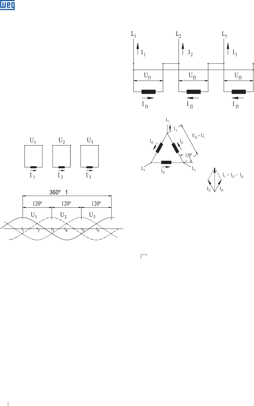
1.4 Three-Phase AC System
A three-phase system is formed by associating three single-
phase voltage system, U1, U2 and U3 which so the phase
displacement between any two of them ch is 120º, which
means, the “delays” of U2 relating to U1, U3 relating to U2,
relating to U3, are equal to 120º ( considering a complete
cycle = 360º ). The system is balanced if the three voltages
have the same effective value, U1 = U2 = U3, as shown
in Fig. 16
By interconnecting the three single-phase systems and by
eliminating the unnecessary wires, we have a three-phase
system: three balanced voltages U1, U2 and U3 the phases of
which are reciprocally displaced by 120º and applied between
the three wires of the system. There are two different ways of
making a connection, as shown in the following diagrams.
In these diagrams the voltage is usually shown by inclined
arrows or rotating vectors and maintaining between them
the angle corresponding to the phase displacement ( 120º ),
according to figures 1.7a, b and c, e figures 1.8a, b and c.
1.4.1 Delta Connection
By connecting the three single-phase systems, as shown
in fig.1.7a, b and c, we can eliminate the three wires, leaving
only one at each connecting point. Thus three-phase system
can be reduced to three-wires, L1, L2 and L3 .
Line voltage ( U )
Is the rated voltage of the three-phase system applied
between any two of these three wires L1, L2 and L3.
Cycle
Ti
me
Figure 1.6
Figure. 1.7a - Connections
Figure 1.7b - Electrical diagram
Line current ( I )
The current in any one of the three wires L1, L2 and L3.
Phase voltage and current ( Uf and If )
Is the voltage and current of each one of the considered
single-phase systems.
Looking at the diagram in fig. 1.7b, one can see that:
U = Uf
I = 3 . If = 1.732 If
I = If3 - If1 ( Figure 1.7c )
Example:
Consider a balanced three-phase system with a rated
voltage of 220 V. The measured line current is 10 amperes.
By connecting a three-phase load to this system, composed
of three equal loads connected in delta, what is the voltage
across, and the current in each load?
We have Uf = U1 = 220 V in each load.
if I = 1.732 . If. we have If = 0.577 . I = 0.577 . 10 = 5.77 A in
each one of the load.
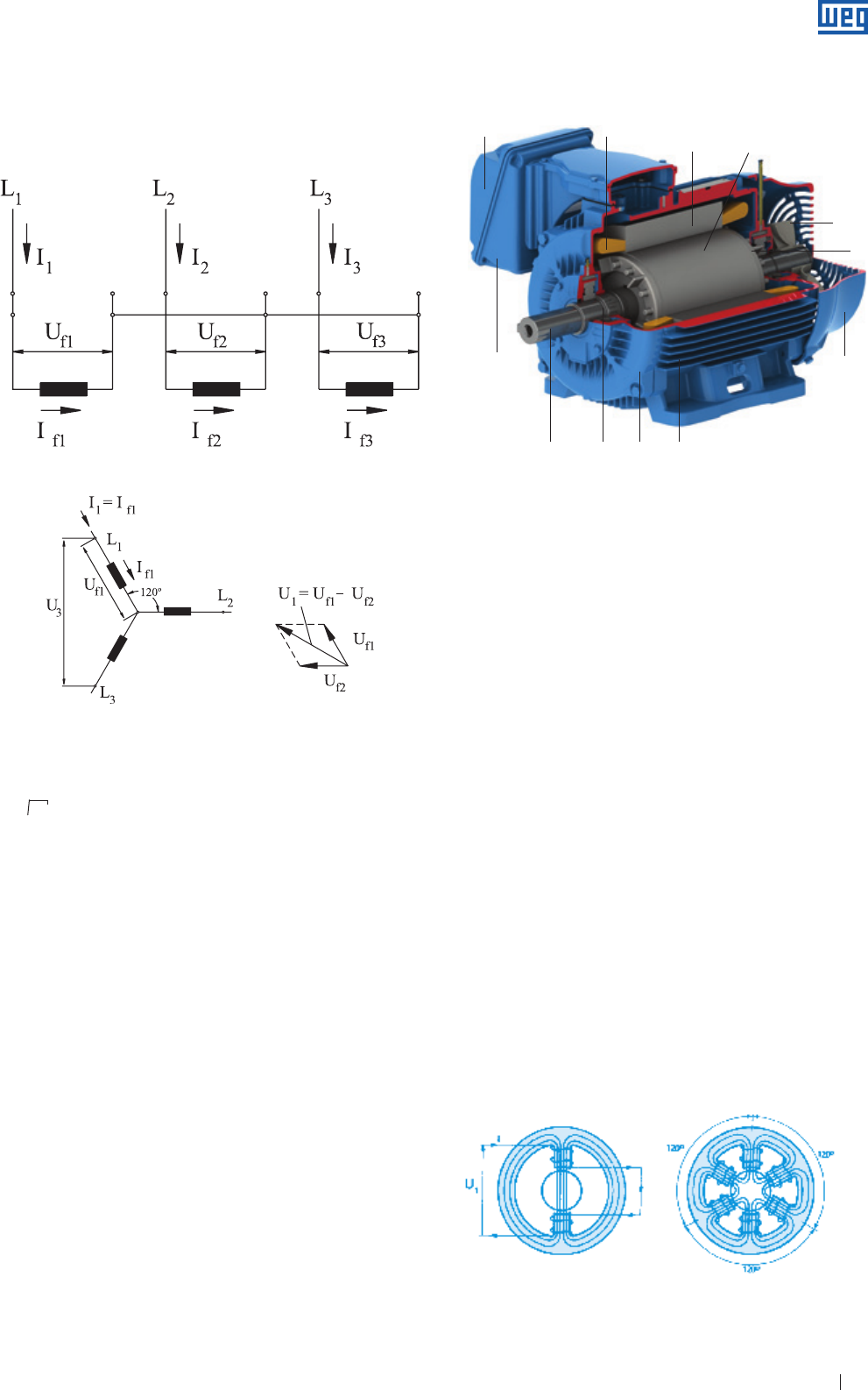
1.4.2 Star Connection
By connecting one of the wires of each single-phase system
to a common point, the three remaining wires will form
a three-phase star system ( see fig. 1.8 ). Sometime the
three-phase star system is made as a “four wire” or with the
“neutral wire” system. The fourth wire is connected to the
common point for the three-phases.
√
Figure 1.7c - Phasorial diagram
→ → →
→ → →
www.weg.net
Specification of Electric Motors 13
By analyzing the wiring diagram in Fig.1.8b, one can note that:
Example:
Consider a three-phase load composed of three equal loads.
Each load is connected to a voltage of 220 V, absorbing
5.77 A. What is the rated voltage of the three-phase system
feeding this load under normal conditions ( 220 and 5.77 A )?
What is the line current?
We have Uf = 220 V ( rated voltage for each load )
U = 1.732 . 220 = 380 V
I = If = 5.77 A
1.5 Three-Phase Induction Motor
Fundamentally a three-phase induction motor consist of two
parts: stator and rotor.
Stator Consists of
g
The frame ( 1 ) - is the supporting structure of the
assembly; manufactured of iron, steel, die-cast aluminum,
resistant to corrosion and with cooling fins.
g The lamination core ( 2 ) - constructed with magnetic steel plates.
g
The three-phase winding ( 8 ) - comprises three equal sets
of coils, one se set for each phase, forming a balanced
three-phase system when connected to a three-phase
power supply.
I = If
U = 3 . Uf = 1.732 . Uf
U = Uf1 - Uf2 ( figure 1.8c )
Figure 1.9
√
The line voltage, or rated voltage of the three-phase
system - and the line current - are defined in the same way
as for delta-connections.
Figure 1.8a - Connections
Figure 1.8b - Electrical wiring diagram Figure 1.8c - Phasor diagram
The rotor consists of:
g
The shaft ( 7 ) - which transmits the mechanical output
developed by the motor.
g
The laminated magnetic core ( 3 ) - the rotor laminations
have the same characteristics of the stator laminations.
g
Bars and short-circuit rings ( 12 ) - are aluminum die
castings formed as one piece.
Other components of the three-phase induction motor:
g End shields ( 4 )
g Fan ( 5 )
g Fan cover ( 6 )
g Terminal box ( 9 )
g Terminals ( 10 )
g Bearings ( 11 )
This manual covers “squirrel cage rotor motor” where
the rotor consists of a set of non-insulated bars that are
interconnected by short-circuit rings. What characterizes an
induction motor is the fact that only the stator is connected
to the power supply. The rotor is not power supplied
externally and the currents that flow through it are induced
electromagnetically by the stator from which comes the
induction motor name.
1.5.1 Working Principle - Rotating Field
When an electric current flows through a coil, a magnetic field
is generated, the direction of which is along the coil axis and
proportional in value to the current.
Figure 1.10a Figure 1.10b
1
2
810
3
5
12
6
4117
9
→ → →
→ → →
www.weg.net
Specification of Electric Motors 14
a ) Figure 1.10.a. shows a single-phase winding through
which flow the current I, and the field H, generated by the
current. The winding is composed of one pair of poles,
a North pole and a South pole, the effects of which are
added to produce field H. The magnetic flux passes
through the rotor, across both poles and links up with
itself by means of the stator core. When I is an alternating
current, field H is established in the same way, so that its
value is represented at every instant, by the same chart
shown in Fig.1.4b., also reversing its direction at every
half cycle. The field H is pulsating, its intensity “varies”
proportionally to the current, always in the same direction
- North-South.
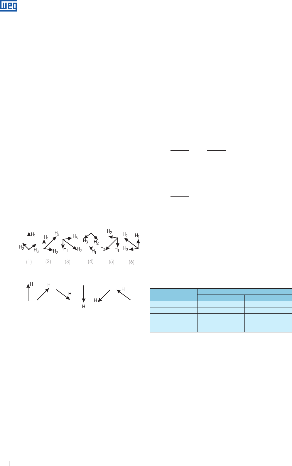
b ) Figure 1.10b shows a three-phase winding consisting of
three single-phase windings displaced 120º each other. If
this winding is fed from a three-phase system, currents I1,
I2 and I3 will generate their own magnetic fields H1, H2 and
H3 in a similar way. The displacement between these fields
is 120º; moreover, since they are proportional to the
respective currents, the phase displacement in time
between them will equally be 120º, which can be
represented in a chart similar to Fig. 1.6. At any instant,
the total resulting field H will be equal to the graphical sum
of field H1, H2 and H3.
Figure 1.11 shows this graphic sum for six successive steps
At instant ( 1 ), Fig. 1.11 shows that the field H1 is at its
maximum whereas fields H2 and H3 are negative and have
the same value: 0.5. The resulting field ( graphic sum ) is
shown in the upper part of Fig. 1.11( 1 ) and has the same
direction of the winding of the phase 1.
Repeating this procedure for the instants 2, 3, 4, 5 and 6
of Fig. 1.6 we can see that the resulting field H presents a
constant intensity, but its direction keeps rotating to complete
a whole turn at the end of a cycle.
We can therefore conclude that a three-phase winding fed
from three-phase currents generates a rotating field as if
one single pair of poles was present, rotating and fed with a
constant current. This rotating field, generated by the three-
phase stator winding, induces certain voltages into the rotor
bars ( magnetic flux lines go through the rotor bars ) which, being
short-circuited, generate currents and, as a consequence,
create a field on the rotor with reverse polarity if compared
with the rotating field polarity. Since opposite fields attract
each other and considering the stator field
Phasor diagram
Phasor / vector
Figure 1.11
( rotating field ) is rotative, the rotor tends to follow the speed
of this field. The result of this is that a motor torque is created
in the rotor that makes it rotate and then drive the load.
1.5.2 Synchronous Speed ( ns )
The synchronous speed of the motor is defined by the rotation
speed of the rotating field which depends on the number
of poles ( 2p ) of the motor and on the line frequency ( f ) in
Hertz. The field makes a complete revolution at each cycle
and “f” is the system frequency in cycles per second ( Hertz ).
Windings may have more than one pair of poles which can be
alternately distributed ( one “North” and one “South” ) along
the circumference of the magnetic core. Since the rotating field
runs through one pair of poles at each cycle and the winding
has poles or “p” pair of poles, the speed of the field is:
60 . f 120 . f
ns = = ( rpm )
p 2 p
Examples:
a ) What is the sybchronous speed of a six-pole motor, 50 Hz?
120 . 50
ns = = 1000 rpm
6
b ) A twelve-pole motor, 60 Hz?
120 . 60
ns = = 600 rpm
12
It must be remembered that the number of poles of a motor
must always be an even number in order to form pairs of
poles. The table below shows the synchronous speed of the
more common number of poles at 60 Hz and 50 Hz.
For 2-pole motors, as in item 1.5.1, the field turns by one
complete revolution at each cycle. Thus the electrical
degrees are equivalent to the mechanical degrees. For
motors with more than 2 poles, a smaller “geometrical”
rvolution is realized by the field.
For example:
For a 6-pole motor, we will have, in a complete cycle, a field
revolution of 360º x 2/6 = 120 geometrical degrees. This is
equivalent to 1/3 of the speed in 2 poles. We conclude, then,
that:
Geometrical degrees = Mechanical degrees x p
Number of poles Synchronous speed per minute
60 Hertz 50 Hertz
2 3.600 3.000
4 1.800 1.500
6 1.200 1.000
8 900 750
10 720 600
Table 1.3 - Synchronous speed
www.weg.net

Specification of Electric Motors 15
1.5.3 Slip ( s )
If the motor runs at a speed different from the synchronous
speed, i.e. differing from the speed of the rotating field, the
rotor windings “cut” the magnetic force lines of the field
and so, according to the electromagnetism laws, induced
currents will flow trhough the rotor windings. The heavier the
load the higher must be the required torque to move it.
To obtain a higher torque, the speed difference must be
greater so that induced current and generated field become
higher. Therefore, as the load increases, the motor speed
decreases. When the load is at zero ( motor at no-load ) the
rotor practically rotates at its synchronous speed.
The difference between motor speed ( n ) and synchronous
speed ( ns ) is called slip ( s ), expressed as rpm or fraction
of the synchronous speed or as a percentage of the
synchronous speed:
ns - n ns - n
s ( rpm ) = ns - n ; s = ; s ( % ) = . 100
ns ns
Therefore, for a given slip s ( % ), the motor speed will be:
s ( % )
n = ns . ( 1 - )
100
Example:
What is the slip of a 6-pole motor when the speed is
960 rpm?
1000 - 960
s ( % ) = . 100
1000
s ( % ) = 4%
1.5.4 Rated Speed
Is the motor speed ( rpm ) operating at rated power, at rated
voltage and frequency. As described in item 1.5.3, it depends
on the slip and on the synchronous speed.
s %
n = ns . ( 1 - ) rpm
100
1.6 Insulation Materials and Insulation Systems
Considering that an induction motor is a simple designed
and rugged construction machine, its life time will exclusively
depend on the quality level of the insulation materials. Motor
insulation is affected by several factors including moisture,
vibration, corrosive environments and others. Among
all these factors, operating temperature of the insulating
materials is the most critical.
The motor life time is reduced by half when subject 8% to
10 ºC in operation above the rated temperature of the class
of insulating material. To ensure a longer lifetime for the
electric motor, the use of thermal sensors is recommended
for the winding protection.
When we refer to motor life time reduction, we do not refer
specifically to excessively high temperatures resulting in
sudden insulation burn out. Insulation life time ( in terms of
operating temperature much below than the one affecting
the insulation ) refers to permanent aging of the insulation
material which becomes dry and loses its insulation
properties. As a result, it will not withstand the voltage
applied to it, thus causing short-circuit.
If operating temperature is kept below its limit, experiences
have proved that the motor insulation can practically last
for ever. Any increasing value above such limit will reduce
insulation life time proportionally. Such limit of temperature
is much lower that the temperature that causes insulation
burn out and it depends on the type of used material. This
limit of temperature refers to insulation hottest spot and not
necessarily to the whole insulation. On the other hand, a
single weak spot in the insulation is enough to damage the
winding completely.
With increasing use of frequency inverters for the speed
control of induction motors, other application criteria must
also be considered for the preservation of the insulation
system. For more details see “Influence of the frequency
inverter on the motor insulation”.
1.6.1 Insulation Material
The insulation material prevents, limits and directs the electric
current flux. Although the insulating material is primarily
intended to block the current flux from a cable to ground or
to the lowest potential, it also serves to provide mechanical
support, protect the cable from degradation caused by
environment influences and to transfer the heat to the
external environment.
Based on system requirements, gases, liquids and solid
materials are used to insulate electric equipment. Insulation
systems affect the quality of the equipment, and type and
quality of the insulation affect the cost, weight, performance
and its useful lifetime.
1.6.2 Insulation System
A combination of two or more insulation materials applied to
an electric equipment is designated insulation system. This
combination on an electric motor consists in magnet wire,
insulation of the slot, insulation of the slot closing, face to
face insulation, varnish and/or impregnation resin, insulation
of the connection leads and welding insulation. Any material
or component that is not in contact with the coil is not
considered as part of the insulation system.
1.6.3 Thermal Classes
Since the temperature of electro-mechanical products is
basically the predominant factor for the aging of the insulation
material and insulation system, certain basic thermal
classifications are recognized and applied all over the world.
www.weg.net
Specification of Electric Motors 16
Material Systems Material and System
UL 746B UL 1446 IEC 60085
IEC 60216 UL 1561 / 1562
IEC 60505
IEEE 117
The thermal classes defined for the materials and insulation
systems are the following:
IEC - International Electrotechnical Commission - non-governmental
organization for standards in the related electrical, electronic and technology
areas
UL - Underwriters Laboratories - American product certification body
It is understood that the thermal class represents the maximum
temperature that the electromechanical equipment can reach
on its hottest spot when operating at rated load without
reducing its lifetime. The thermal classification of a material or
system is based on a comparison with well-known reference
systems or materials. However, for those cases where there is
not any reference material, the thermal class can be obtained by
exploiting the damage curve ( Arhenius Graphic ) for a certain
time period ( IEC 216 specifies 20,000/hours ).
1.6.4 Insulating Materials in Insulation Systems
The specification of a product within a certain thermal class
does not mean that each insulating material used has the
same thermal capacity ( thermal class ). The temperature
limit for an insulation system can not be directly related
to the thermal capacity of the individual materials in this
system. In a system the thermal performance of a material
can be improved by protective characteristics of certain
material used with this material. For example: a 155 ºC class
material can have its performance improved when the set is
impregnated with varnish for class H ( 180 ºC ).
1.6.5 WEG Insulation System
In order to meet different market requirements and
specific applications, associated to an excellent technical
performance, nine insulation systems are used for
WEG motors.
The round enameled wire is one of the most important
components used in the motor since the electric current
flows through it and creates the magnetic field required for
motor operation. During the production process, the wires
are submitted to mechanical traction efforts, flexion and
abrasion electrical effects that also affect the wire insulating
material. During the operation, the thermal and electrical
effects act on the wire insulation material. For this reasons,
the wire requires an outstanding mechanical, thermal and
electrical insulation resistance.
The enamel used currently on the wire ensures such
properties, where the mechanical property is assured by
the outside enamel coat that resists to abrasion effects
while inserting it into the stator slots. The internal enamel
coat ensures high dielectric resistance and the set provides
thermal class 200 ºC to the wire ( UL File E234451 ). This wire
is used for all Class B, F and H motors. Smoke Extraction
Motors are built with special wire for extremely high
temperatures.
Films and laminated insulating materials are intended to
isolate thermally and electrically all motor winding parts. The
thermal class is indicated on the motor nameplate. These
films are aramid and polyester based films and also laminated
films are applied to the following areas:
g
between the coils and the slot ( slot bottom film ) to insulate
the lamination core ( ground ) from the enameled wire coil;
g
between phases: to isolate electrically one phase from the
other phase
g
Closing of the stator slot to insulate electrically that coil
placed on the top of the stator and for mechanical
purposes so as to keep the wires inside the stator slot.
Figure 1.12a - Wires and films used on the stator
Insulation materials and insulation system are classified
based on the resistance to temperature for a long period of
time. The standards listed below refers to the classification of
materials and insulation systems:
Table 1.4 - Standards for materials and insulation system
Table 1.5 - Thermal classes
Temperature Class
Temperature ( ºC ) IEC 60085 UL 1446
90 Y ( 90 ºC ) -
105 A ( 105 ºC ) -
120 E ( 120 ºC ) 120 ( E )
130 B ( 130 ºC ) 130 ( B )
155 F ( 155 ºC ) 155 ( F )
180 H ( 180 ºC ) 180 ( H )
200 N ( 200 ºC ) 200 ( N )
220 R ( 220 ºC ) 220 ( R )
240 - 240 ( S )
above 240ºC -above 240 ( ºC )
250 250
www.weg.net
Specification of Electric Motors 17
The impregnation varnishes and resins are mainly intended
to maintain all enameled wire coil as a block with all stator
components through agglutination of such materials and to
fill all voids inside the slot.
This agglutination avoids vibration and friction between the
wires. Such friction could cause failures on the wire enamel,
then resulting in a short-circuit.
The agglutination ( filling of voids ) also helps the heat
dissipation generated by the wire and mainly, when motors
are fed by frequency inverter, prevents/reduces the formation
of partial discharges ( corona effect ) inside the motor.
Two types of varnishes and two types of impregnation varnishes
are currently used; all of them are polyester varnishes so as to
meet motor construction and application requirements. Silicon
resin is only used for special motors designed for very high
temperatures.
Varnishes and resins usually improve thermal and electrical
characteristics of the impregnated materials in such a way to
classify these impregnated materials in higher thermal class if
compared to the same materials without impregnation.
The varnishes are applied by the immersion impregnation
process and then oven-dried. Solventless resins are applied
by the continuous flow process.
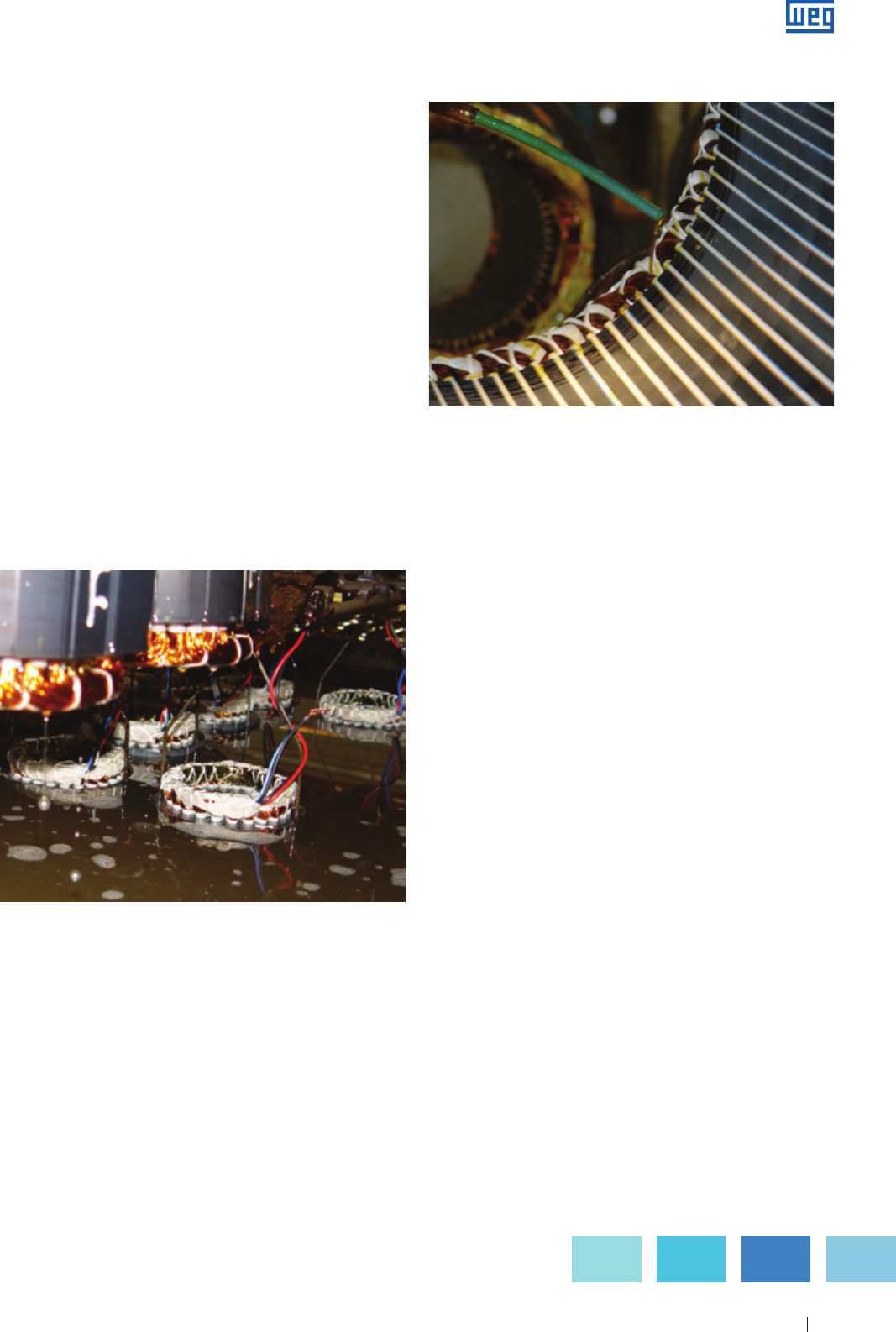
Figure 1.12.b - Immersion impregnation process
The connection leads consist of elastomeric insulation
materials that have the same thermal class as the motor.
These materials are exclusively used to insulate electrically
the lead from the external environment. They have high
electric resistance and proper flexibility to allow easy handling
during manufacturing process, installation and motor
maintenance.
For certain applications, such as submersible pumps, the
leads must be chemically resistant to the oil of the pump. The
flexible pipes are intended to cover and insulate electrically
the welded connections between the coils wires and the
leads and the connections between wires. They are flexible
to allow them to get shaped to welding points and to the coil
head tying. Three types of pipes are currently used:
g Heat-shrink polyester tubing - Class of 130 ºC
g Polyester tube coated with acrylic resin - Class of 155 ºC
g Fiberglass tube coated with silicon rubber - Class of 180 ºC
Figure 1.12.c - Resin applied by continuous flow process
www.weg.net

Specification of Electric Motors 18
2. Power Supply Characteristics
2.1 Power Supply System
The power supply system can be single or three-phase.
Single-phase system is mostly used in homes, commercial
centers, farms, while three-phase system is used in
industries. Both operate at 60 Hz or 50 Hz.
2.1.1 Three-Phase System
The three-phase voltages mostly used in industries are:
g Low voltage: 220 V, 380 V and 440 V
g High voltage: 2.300 V, 4.160 V and 6.600 V
The star connected three-phase low voltage system consists
of three phase leads ( L
1
, L
2
, L
3
) and a neutral conductor
( N ). The last one is connected to the generator star point
or to the transformer secondary winding ( as shown in figure
Figure 2.1 ).
2.1.2 Single-Phase System
Single phase motors are connected to two phases ( UL line
voltage ) or to one phase and to neutral conductor ( Uf phase
voltage ). So the single-phase motor rated voltage must be
equal to UL or Uf system voltage. When several single-phase
motors are connected to a three-phase system ( formed by
3 single-phase systems ), care must be taken in order to
distribute them uniformly so as to avoid unbalance between
phases.
Single wire earth return ( SWER )
The single-phase earth return ( SWER ) is na electric system
where the ground lead operates as return lead for the load
current. This is applied as solution for the use of single-phase
motors from power supply not having neutral available.
Depending on the available electric system and on the
characteristics of the soil where it will be installed ( usually on
farm power supply ), we have:
a ) Single cable system
The single wire earth return ( SWER ) system is considered
the practical and economical option. However, it can be used
only where the origin substation outlet is star grounded.
b ) Single cable system with insolation transformer
Besides requiring a transformer, this system has a few
disadvantages such as:
g
Link power limitation to isolation transformer rated power;
g
the grounding system of the isolation transformer must be
reinforced. Lack of this will resuklt in absence of energy to
the whole link.
c ) Single wire earth return ( SWER ) system with partial
neutral
It is applied as a solution of the use of single wire earth return
( SWER ) system in regions with land ( soil ) of high resistivity
when it is difficult to get ground resistance values of the
transformer within the maximum design limits.
3. Characteristics of the Electric Motor Power Supply
3.1 Rated Voltage
This is the line voltage for which the motor has been
designed.
3.1.1 Multiple Rated Voltage
Motors are generally supplied with sufficient terminals to
enable alternative connections. This means that they can
operate on at least two different voltages. The main types of
alternative terminal connections are:
a ) Series-parallel connection
The winding of each phase is divided into two equal parts
( halves ) ( please consider that the number of poles is
always a multiple of two, so this type of connection is always
possible ).
g
By connecting the two halves in series, each half will have a
voltage to the half rated phase voltage of the motor;
g
By connecting the two halves in parallel, the motor can be
supplied with a voltage equal to one half of the previous
voltage, without affecting the voltage applied to each coil.
( refer to examples given in figures 3.1a and b ).
Power
substation
Power
substation
Power
substation
Figure 2.1 - Three-phase system
Figure 2.2 - Single cable system
Figure 2.3 - Single cable system with isolation transformer
Figure 2.4 - Single wire earth return system with partial neutral
www.weg.net
Specification of Electric Motors 19
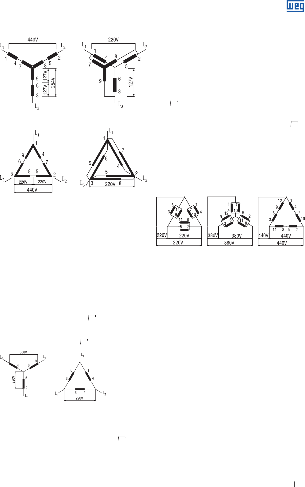
Figure 3.1b - Series-parallel connection Δ
Figure 3.1a - Series-parallel connection Y
This type of connection requires nine terminals on the motor.
The most common dual voltage system is 220/440 V, i. e.
the motor is parallel connected when supplied for 220 V, or
alternatively, it is series connected when supplied for 440 V.
Fig. 3.1a and 3.1b show normal terminal numbering, as well
as connection diagrams for this type of motor - both for star
or delta connected motors. The same diagrams apply to any
other two voltages, provided that one is the double of the
other, e.g. 230/460 V.
b ) Star-delta connection
Two ends of each phase winding are brought out to
terminals. By connecting the three-phases in delta, each
phase receives total line voltage, e.g. 220 volts ( Fig. 3.2 ).
By connecting the three-phases in star, the motor can be
connected to a line voltage of 220 x 3 = 380 V. The winding
voltage remains at 220 volts per phase.
Uf = U 3
This type of connection requires six terminals on the motor
and is suitable for any dual voltage provided that the second
voltage be equal to the first voltage multiplied by 3 ).
Examples: 220/380 V - 380/660 V - 440/760 V
In the example 440/760 V, the stated higher voltage is used
to indicate that the motor can be driven by star-delta switch.
c ) Triple rated voltage
The two previous alternative connection arrangements can
be obtained in one motor if the winding of each phase is
divided into two halves enabling series-parallel connection.
All terminals have to be accessible so that the three phases
can be connected in star or delta. This means that there can
be four alternatives for rated voltage:
1 ) Prallel-delta connection;
2 ) Star-parallel connection, being the rated voltage equal
to 3 x the first one;
3 ) Series-delta connection, i. e. the rated voltage being
twice the value of the first one;
4 ) Series-star connection, the rated voltage is equal to 3 x
the third one. However as this voltage would be higher
the 690 V, it is only indicated as reference for star-delta
connection.
Example: 220/380/440( 760 ) V
Note: 760 V ( only for starting )
This type of connection requires twelve terminals and
Fig. 2.7 shows the normal numbering on the terminals as
well as the connection diagram for the three rated voltages.
3.2 Rated Frequency ( Hz )
This is the network frequency for which the motor has been
designed.
3.2.1 Connection to Different Frequencies
Three-phase motors wound for 50 Hz can also be connected
to a 60 Hz network,
a ) By connecting a 50 Hz motor, of the same voltage, to
a 60 Hz network, the motor performance will be as
follows:
g same output;
g same rated current;
g starting current decreases 17%;
g starting torque decreases 17%;
g breakdown torque decreases 17%;
g rated speed increases 20%.
Note: please consider the required outputs for motors that drive machines
with variable torque and speed.
b ) If voltage changes proportionally to frequency, the
performance will be:
g motor output increase 20%;
g rated current is the same;
g starting current will be approximately the same;
g starting torque will be approximately the same;
g breakdown torque will be approximately the same;
g rated speed increases 20%.
√
√
√
√
Figure 3.2 - Star-delta connection Y - Δ
√
Figure 3.3
www.weg.net
Specification of Electric Motors 20
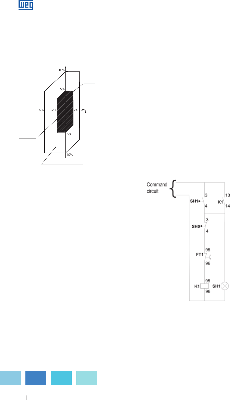
3.3 Voltage and Frequency Variation Tolerance
As per standard ABNT NBR 17094 ( 2008 ) and IEC
60034-1, for induction motors, the combinations of voltage
and frequency variations are classified as Zone A or Zone B
( figure 3.4 ).
Voltage
Zone
A
Frequency
Zone B (external to Zone A)
Standard
Features
Figure 3.4 - Limits of voltage and frequency variations under operation
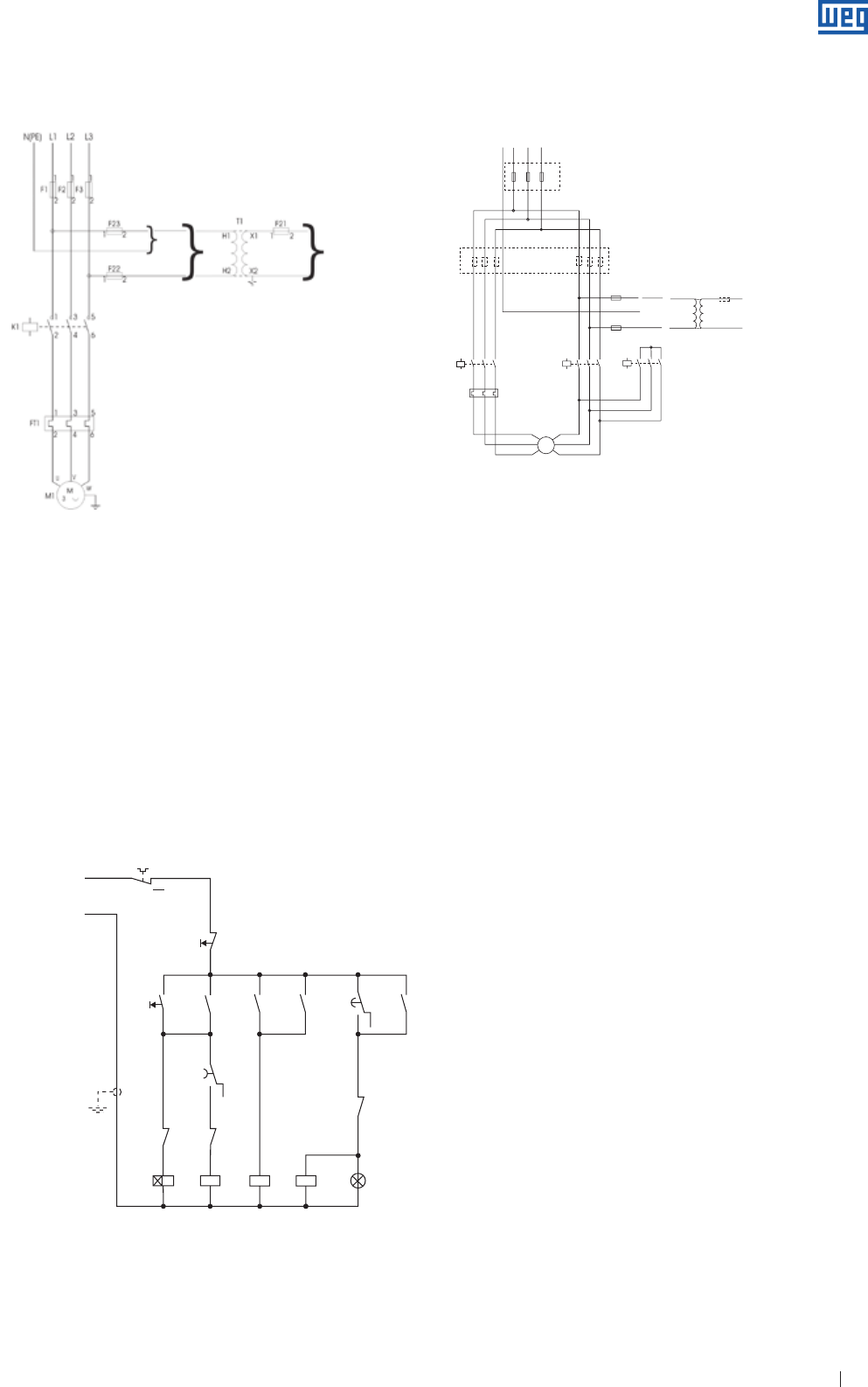
Figure 3.5 - Command circuit - direct starting
A motor must be capable of performing its main function
continuously at Zone A, however it may not develop
completely its performance characteristics at rated voltage
and frequency ( see rated characteristics point in figure 3.4.a )
showing few deviations. Temperature rises can be higher than
those at rated voltage and frequency.
A motor must be capable of performing its main function at
Zone B, however it may present higher deviations than those
of Zone A in reference to performance characteristics at rated
voltage and frequency. Temperature rises can be higher than
those at rated voltage and frequency and probably higher
than those of Zone A. The extended operation at Zone B is
not recommended.
3.4 Three-Phase Motor Starting Current Limitation
Whenever possible a squirrel cage three-phase motor should
be started direct-on-line ( D.O.L. ) by means of contactors.
It must be taken into account that for a certain motor the
torque and current values are fixed, irrespective the load, for
a constant voltage. In cases where the motor starting current
is excessively high, hamrful consequences may occur:
a ) High voltage drop in the power supply system. Due
to that, equipment connected to the system may be
affected;
b ) The protection system ( cables, contactors ) must be
overdesigned resulting in higher cost;
c ) Utilities regulations limiting the line voltage drop.
If D.O.L starting is not possible due to these problems, indirect
connection system can be used so as to reduce starting
current
g Star-delta switch
g Compensating switch
g Series-parallel switch
g Electronic start ( Soft-Starter )
3.4.1 D.O.L Starting
Source: ABNT NBR 17094 ( 2008 )
www.weg.net
Specification of Electric Motors 21
Figure 3.6 - Power circuit - direct starting
Figure 3.7 - Command circuit - starting with star-delta switch
Command
circuit
F1. F2. F3 - Power fuses
F21. F22. F23 - Control fuses
T1 - Control transformer
K1 - Contactors
FT1 - Overload relay
SH1 - Controllbutton
KT1 - Time relay
M1 - Motor
Optional accessories
- Phase fault relay
- Minimum/maximum voltage relay
- Ammeter
- Voltmeter
- Ohmmeter
3.4.2 Starting with Star-Delta Switch ( Y - Δ )
Figure 3.8 - Power circuit - starting with star-delta switch
Note: for outputs up to 75 HP ( 220 V ), 125 HP ( 380 V ) and 175 HP
( 440 V ) You must use connection "A" ( protection by 3 fuses ). For higher
outputs you must use the connection "B" ( protection by 6 fuses ), where the
fuse set F1, F2, F3 is equal to the fuse set F4, F5, F6.
F1. F2. F3 - Power fuse
( F1. F2. F3 and F4. F5. F6 ) - Power fuse
F21. F22. F23 - Control fuse
T1 - Control transformer
K1. K2. K3 - Contactors
FT1 - Overload relay
SH1 - Control button
KT1 - Time relay
M1 - Motor
Optional accessories
- Phase fault relay
- Minimum/maximum voltage relay
- Ammeter
- Voltmeter
- Ohmmeter
When starting by the Star-Delta method it is essential that the
motor windings are suitable for operating on a dual voltage,
e.g. 220/380 V, 380/660 V or 440/760 V. Motors must have at
least six connection terminals. Star-Delta starting can be used
if the torque is high enough to ensure the machine acceleration
with reduced current. When star-connected, the current is
reduced to 25-33% of the starting current reached when Delta
connected.
Electrical diagram
}
Command
circuit
FT1
95 96
98
SH1
21
22
13
SH1
14
KT1
KT1 K3 K1 K2 SH1 X1
X2
A1
A2
A1
A2
A1
A2
A1
A2
18
K2K2
K3
K3 K1K1 KT1
26
25
K2
13
1428
21
22
15
16
21
22
31
32
13
14
13
14
43
44
}
}}
L3L2L1
N(PE)
F1
F1
K1
FT1
1
222
222
A
B
11
1
1
246
35
K2 K3
H1
H2 X2
X1
T1
2
1
F21
1
1
2
2
4
4
6
6
3
3
5
5
1
246
Command
circuit
35
1
246
35
11
F2
F2
F3
F3 F1
22
2
2
1
1
11
F2 F3
F23
2
1
F22
M
3~
www.weg.net
Specification of Electric Motors 22
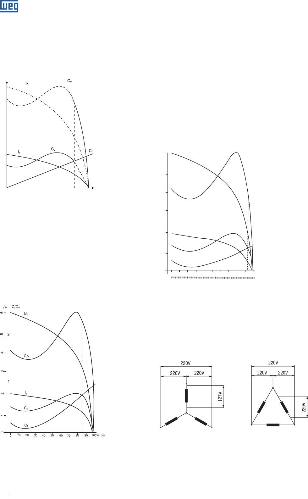
Torque
Speed
Figure 3.9 - Current and torque for star-delta starting of a squirrel cage motor
driving a load with resistive torque Cr.
IΔ - current in delta
I y - current in star
Cy - torque in star
CΔ - torque in delta
Cr - resistive torque
Fig. 3.11 shows a motor with the same characteristics,
however, the resistive torque CR is much lower. When
connected to Y the motor accelerates the load up to 95%
of the rated speed. When the starter is switched to Δ, the
Figure 3.10
Figure 3.11 shows a high resistive torque Cr.
If the motor is started in star connection it will accelerate the
load up to approximately 85% of the rated speed. At this
point the starter must be switched to delta. In this example,
the current ( which is close to its rated value - e.g. 100% )
jumps suddenly to 320% which is of no advantage since the
starting current was only 190%.
The resistive load torque can not exceed the motor starting
torque ( figure 3.9 ) and during the delta commutation process
the achieved values can not exceed the allowed one.
On the other hand, there are cases where this staring method
can not be used, as shown in Fig. 3.10.
6
4
5
2
1
3
2
1
0
0
10 20 30 40 50 60 70 80 90 100% rpm
I/I
n
C/C
n
I/∆
C∆
Iy
Cy
Cr
Y start ∆ run
Y start ∆ run
Figure 3.11
IΔ - current in delta
Iy - current in star
CΔ - torque in delta
Cy - torque in star
C/Cn - ratio between motor torque and rated torque
I/In - ratio between motor current and rated current
Cr - resistive torque
Figure 3.12
Figure 3.12 shows how to connect a motor for Star-Delta
starting on a 220 V power supply and indicates that voltage
per phase is reduced to 127 V during starting.
current, which was approximately 50%, increases to
170%, i. e., practically equal to the starting current in Y.
In this case, the star-delta connection has some advantages,
because if it was D.O.L. connected, it would absorb 600%
of the rated current. The Star-Delta starter can only be used
for starting machines at no loads. In the case of starting at
no load, the load can only be applied after the motor has
reached 90% of its rated speed. The commutation point
from star to delta connection must be determined carefully
in order to ensure that this starting method is effectively
advantageous in cases where D.O.L starting is not possible.
For triple rated voltage motors ( 220/380/440/760 V,
connection must be at 220/380 V or 440 ( 760 ) V, depending
on the power supply.
www.weg.net
Specification of Electric Motors 23
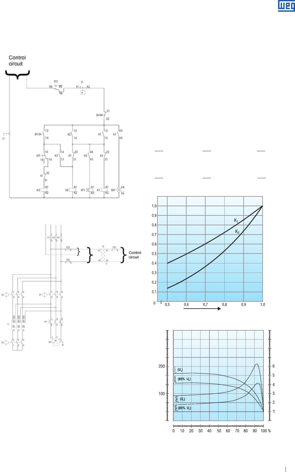
The compensating switch can be used to start motors under
load. This switch reduces the staring current preventing
overload on the circuit, however ensures that the motor has
sufficient torque to star and accelerate the load.
The voltage on the compensating switch is reduced by the
autotransformer which has taps of 50%, 65% and
80% of the rated voltage.
For motor starting with voltage below the rated one, starting
current and torque must be multiplied by factor K1 ( current
multiplying factor ) and K2 ( torque multiplying factors )
obtained on the chart of figure 3.15.
F1. F2. F3 - Power fuses
( F1. F2. F3 e F4. F5. F6 ) - Power fuses
F21. F22. F23 - Control fuses
T1 - Control transformer
K1. K2. K3 e K4 - Contactors
1FT1 e 2FT1 - Overload relay
SH1 - Control button
KT1 - Time relay
M1 - Motor
Optional accessories
- Phase fault relay
- Minimum/maximum voltage relay
- Ammeter
- Voltmeter
- Ohmmeter
3.4.3 Compensating Switch
( Autotransformer )
Figure 3.15 - K1 and K2 reduction factors as function of the motor and
power supply Um /Un ratios
Example: for 85% of the rated voltage
Ip Ip Ip
( ) 85% = K1. ( ) 100% = 0.8 ( ) 100%
In In In
Cp Cp Cp
( ) 85% = K2. ( ) 100% = 0.66 ( ) 100%
Cn Cn Cn
Figure 3.14 - Power circuit - starting by compensating switch
Figure 3.13 - Control circuit - starting by compensating switch
Figure 3.16 - Example performance characteristics of a 425 HP, VI pole
motor when starting with 85% of the rated voltage.
Torque in percent of the rated torque
Speed in percent of the synchronous speed
Current ratio
www.weg.net
Specification of Electric Motors 24
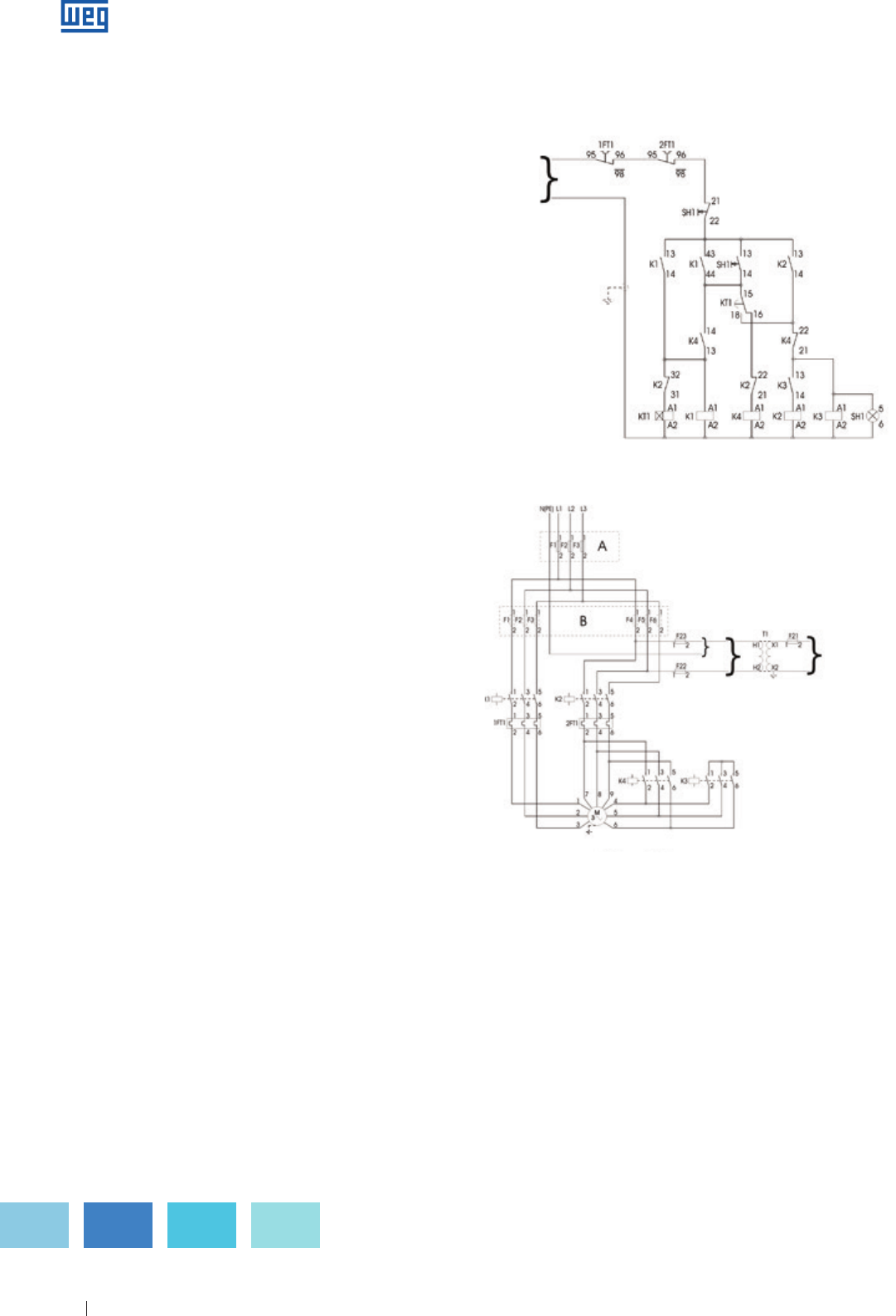
Figure 3.17 - Control circuit - series-parallel starter
Figure 3.18 - Power circuit - series-parallel starter
3.4.4 Comparing Star-Delta Starters and
“Automatic” Autotransformers
1 ) Star-delta ( automatic )
Advantages
a ) Star-Delta starters are widely used due to their relatively
low price.
b ) There are no limits to the number of times they can be
operated.
c ) The components require very little space.
d ) The starting current is reduced to approximately one-third.
Disadvantages
a ) The starter can only be applied to motors where the six
leads or terminals can be accessed.
b ) The supply voltage must be the same as the rated motor
voltage for Delta connection.
c ) Because the starting current is reduced to approximately
one-third of the rated current, the starting torque is also
reduced to one-third.
d ) If the motor does not reach at least 90% of its rated
speed at the time of switching from Star to Delta the
current peak will be as high as in a D.O.L. start, thus
causing harmful effects to the contacts of the contactors
and the connection system brings no advantage to the
electrical system.
2 ) Auto-transformer ( automatic )
Advantages:
a ) On the 65% tapping the line current is approximately
equal tp that of a Star-Delta starter, however, at the time of
switching from reduced voltage to the full supply voltage,
the motor is not disconnected so that the second peak is
very much reduced since the transformer is converted into
reactance for a short time.
b ) It is possible to vary the tapping from 65% to 80% or even
up to 90% of the supply voltage in order to ensure that the
motor starts satisfactorily.
Disadvantages:
a ) One of its great disadvantages is the limitation of its
operation frequency. It is always necessary to know the
operation frequency in order to determine a suitably rated
auto-transformer.
b ) The compensating switch is much more expensive than a
Star-Delta starter due to the auto-transformer.
c ) Due to the size of the auto-transformer starter, much
larger control panels are required which increases the
price.
Control
circuit
Command
circuit
F1. F2. F3 - Power fuses
F21. F22. F23 - Control fuses
T2 - Control transformer
K1. K2. K3 - Contactors
FT1 - Overload relay
T1 - Autotransformer
SH1 - Command button
KT1 - Time relay
M1 - Motor
Optional accessories
- Phase fault relay
- Minimum/maximum voltage relay
- Ammeter
- Voltmeter
- Ohmmeter
The series-parallel connection requires the motor to be
designed for two rated voltages, the lowest one is equal to
the power supply voltage and the other is two times higher.
For this starting method the most common voltage is
220/440 V, i. e., on starting the motor is series connected until
it reaches its rated speed and then it is switched to parallel
connection.
3.4.5 Series-Parallel Starting
Control
circuit
Command
circuit
www.weg.net
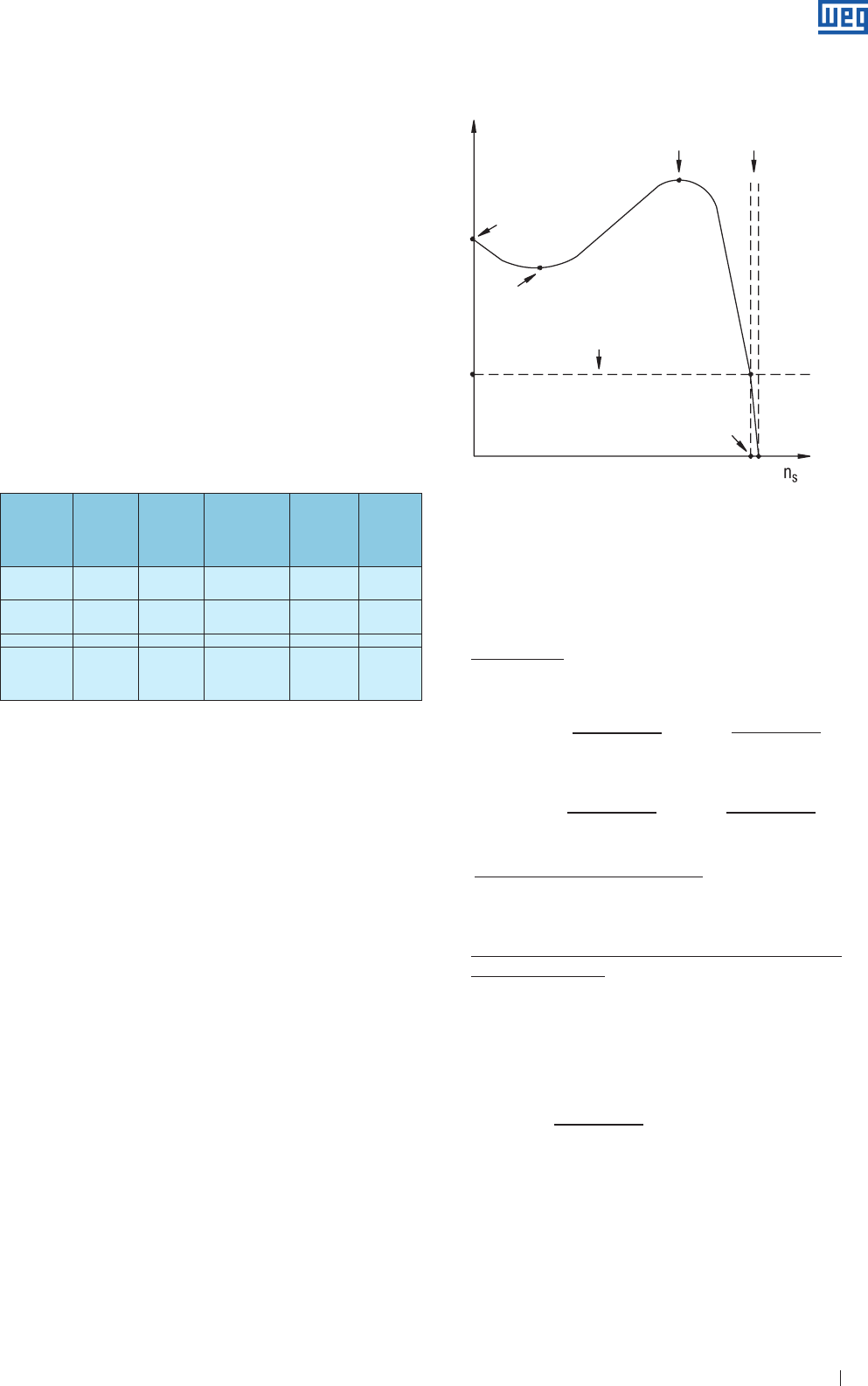
Specification of Electric Motors 25
Motor
voltage
Operating
voltage
Star-
Delta
Starter
Autotransformer
Starter
Series-
Parallel
Starter
Soft-Starter
220/380 V 220 V
380 V
YES
NO
YES
YES
NO
NO
YES
YES
220/440 V 220 V
440 V
NO
NO
YES
YES
YES
NO
YES
YES
380/660 V 380 V YES YES NO YES
220/380/
440 V
220 V
380 V
440 V
YES
NO
YES
YES
YES
YES
YES
YES
NO
YES
YES
YES
Table 3.1 - Starting methods x Motors
3.4.6 Electronic Start ( Soft-Starter )
New discoveries in electronics have allowed the creation of
the solid state starters consisting of a set of pairs of thyristors
( SCR ) or ( combination of thyristors / diodes ), one on each
motor power terminals.
The trigger angle of each pair of thyristors is controlled
electronically for applying a variable voltage to the motor
terminals during the “acceleration”. At the end of the start
period, adjustable typically between 2 and 30 seconds, the
voltage reaches its rated value with a smooth acceleration
ramp instead of being submitted to increments or sudden
peaks. Applying such starting method the starting current
( line current ) remains close to the rated current with only
smooth variation. Besides the advantage of the voltage
( current ) control during the start, the electronic switch also
has the advantage of not having movable parts or parts that
generate electric arcs as the mechanical switches. This is
one of the strengths of the electronic switches, since their
lifetime becomes longer.
Breakdown
torque (Cmax)
Locked rotor
torque (Cp)
Minimum torque (Cmin)
Full load torque (Cn)
Rated speed (Nn)
Speed
Torque %
Slip
(S)
Figure 4.1 - Torque x speed curve
Co: basic torque - This is the calculated torque relating to
the rated output and synchronous speed.
716 . P ( cv ) 974 . P ( kW )
Co ( Kgfm ) = =
ns ( rpm ) ns ( rpm )
7024 . P ( cv ) 9555 . P ( kW )
Co ( Nm ) = =
ns ( rpm ) ns ( rpm )
Cn : rated torque or full load torque - This is the torque
developed by the motor at rated output at rated voltage
and frequency.
Cp: locked rotor torque or starting torque, also called
breakaway torque - this is the minimum torque
developed by the locked rotor for different angular
positions of the rotor at rated voltage and frequency.
This torque can be indicatwed in Nm or more frequently as
percentage of the rated torque.
Cp ( Nm )
Cp ( % ) = . 100
Cn ( Nm )
In practice, the locked rotor torque should be as high as
possible to enable the rotor to overcome the initial load
inertia, and quickly accelerate it, especially when started with
reduced voltage.
4.1.1 Torque X Speed Curve
Definition
The induction motor has zero torque at synchronous speed.
As the load increases, the motor speed will decrease
gradually until the torque reaches the maximum value
which the motor is capable of developing at normal speed.
If the load torque continues to increase, the motor speed
will suddenly decrease and may even lock the rotor. By
graphically representing the torque variation with the speed
for a normal motor, we obtain a curve as shown in Figure 4.1.
3.5 Direction of Rotation of Three-Phase Induction
Motors
Depending on the electric connection conFiguretion, a
three-phase induction motor can operate at any direction
of rotation. The direction of rotation can be reversed by
exchanging the position of two of the connecting leads.
WEG motors are supplied with bi-directional fans unless
only one direction of rotation is informed on the data sheet
or on additional nameplates. In general the motor allow the
operation at any direction of rotation without affecting the
motor cooling. Motors without fan, but ventilated by the own
load ( the fan is the load ) must meet the cooling requirements
of the motor, independent of the direction of rotation. In case
of doubt, contact WEG
4. Acceleration Characteristics
4.1 Torque
Figure 4.1 highlights and defines some important points.
The torque values relative to these points are specified in
the standard ABNT NBR 17094 and IEC 60034-1, as shown
below:
www.weg.net
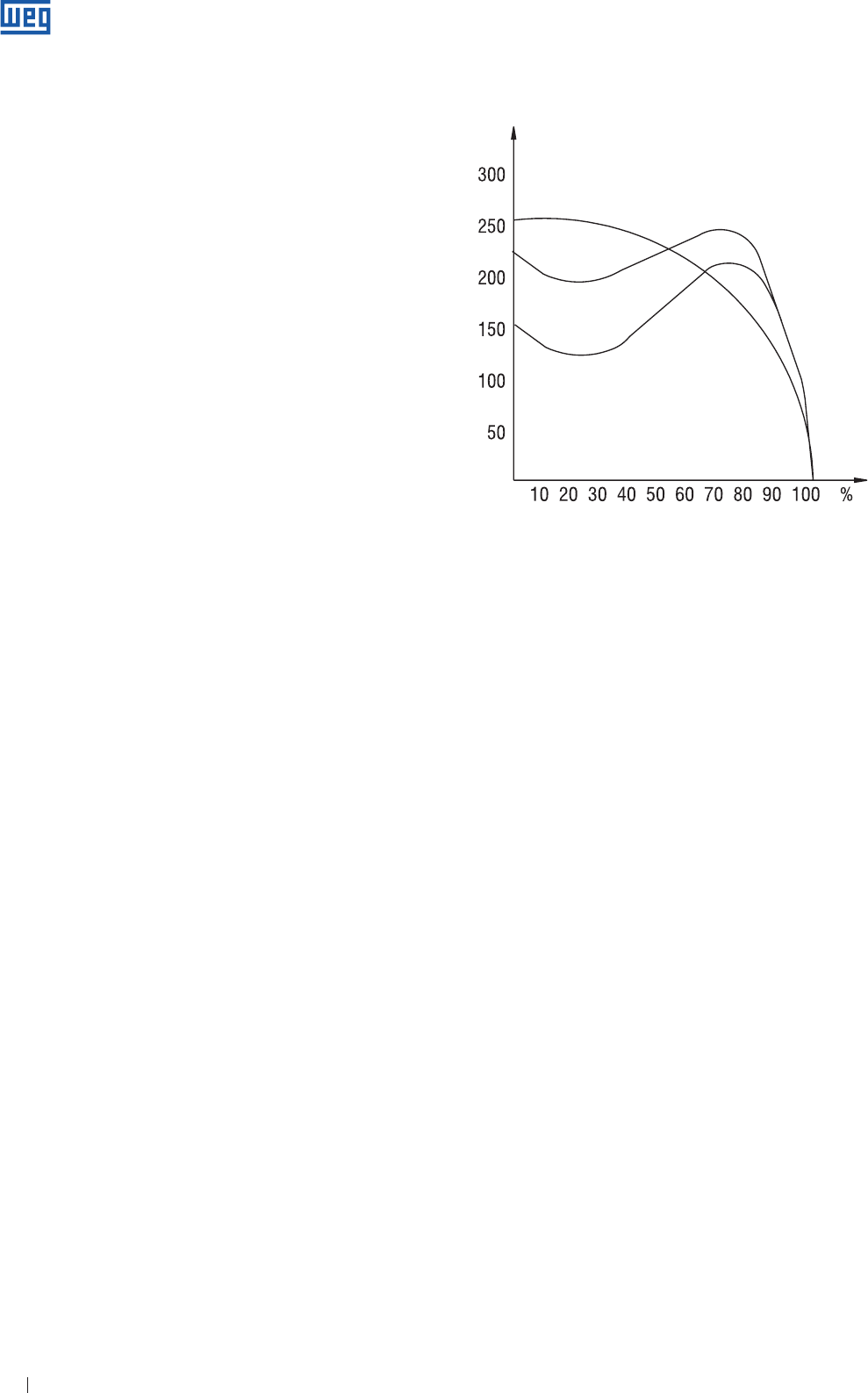
Specification of Electric Motors 26
Cmin: minimum torque or pull up torque: - This is the
smallest torque developed by the motor when accelerating
from rest or zero speed to the speed corresponding to
maximum torque. In practice this value must not be very
low, i.e. the speed torque curve should not have a strong
depression during acceleration otherwise starting time is too
long, resulting in overheating of the motor, especially in cases
of high inertia, or starting on reduced voltage.
Cmáx: maximum torque or breakdown torque - This is the
maximum torque developed by the motor at rated voltage
and frequency, without abrupt drop in speed.
In practice maximum torque must be as high as possible for
two reasons:
1 ) The motor must be able to easily overcome loading peaks
which can occasionally occur with crushers, calandering
machines, mixers, etc.
2 ) The motor speed should not oscillate, i. e., the speed
should not drop abruptly when momentary and excessive
voltage drops occur.
4.1.2 Designs - Minimum Standardized Torque Values
Based on their torque characteristics in relation to the speed
and starting current, three-phase squirrel cage induction
motors are classified into designs, each one complying with
a specific type of load. Defined by IEC 60034-1 Standard, the
designs are the following:
Design N
Regular locked rotor torque, regular locked rotor current, low
slip. These are the most common motors in the market and
are used in applications such as pumps, machine tools fans,
etc.
Design H
High locked rotor torque, regular locked rotor current, low
slip. The motors with this design are used on applications
that require high starting torques such as screens,
conveyors, high inertia loads, crushers, etc.
Design D
High locked rotor torque, regular locked rotor current, high
slip ( above 5% ). Used on applications such as eccentric
presses and similar machines that have periodic load peaks.
These motors are also used on elevators and loads that
require high starting torque and limited locked rotor current.
Figure 4.2 shows the torque curves x speed of the different
designs.
Desing D
Desing H
Desing N
Torque as porcentage of full load torque
Speed
Figure 4.2 - Torque x speed curves for the different designs
Design NY
This design includes motors similar to those of N design;
however they are designed for star-delta starting. For these
motors at star connection, the minimum torque values with
locked rotor and the pull-in torque values are equal to 25% of
the values indicated for Design N motors.
Design HY
This design includes motors similar to those of design N;
however they are designed for star-delta starting. For these
motors at star connection, the minimum torque values with
locked rotor and the pull-in torque values are equal to 25% of
the values indicated for H Design motors.
The minimum torque values required for design N and design
H motors, as specified in IEC 60034-1 standard, are shown
in tables 4.1and 4.2.
For 4, 6 and 8-pole design D motors and rated power of 150
HP and below, IEC 60034 -1 states that: the locked rotor
torque ( Cp ) shall not be lower than 2.75 of the motor rated
torque ( Cn, ). Pull-up torque ( Cmín ) and breakdown torque
( Cmáx ) are not regulated by this standard.
IEC 60034-1 does not specify minimum torque values
required for 2-poles, design H and design D motors.
www.weg.net
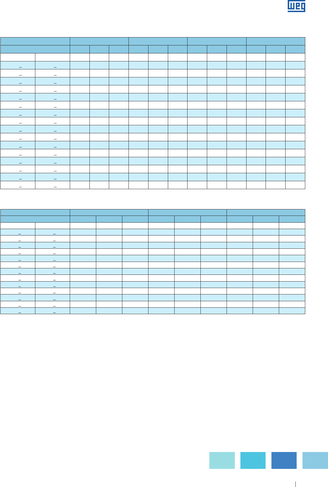
Specification of Electric Motors 27
Table 4.1 - Three-phase motors - Locked rotor torque ( Cp ), pull-in torque ( Cmin ) and breakdown torque ( Cmax ), for design N motors, relating to the rated torque
( Cn ).
Table 4.2 - Three-phase motors - Locked rotor torque ( Cp ), pull-in torque ( Cmin ) and breakdown torque ( Cmax ), for design H motors, relating to the rated torque ( Cn ).
Notes: a ) The locked rotor torques ( Cp / Cn ) are 1.5 times the corresponding values of design N; however, not below 2.0;
b ) The pull-up torques ( Cmin / Cn ) are1.5 times the corresponding values of design N; however, not below1.4;
c ) The breakdown torques ( Cmax / Cn ) are the same of corresponding values of design N; however, not below 1.9 or the corresponding values of pull-up
torques ( Cmin / Cn ).
Number of poles 4 6 8
Rated Power Range Cp /CnCmin /Cn Cmax /Cn Cp /CnCmin /Cn Cmax /Cn Cp /CnCmin /Cn Cmax /Cn
kW cv pu
> 0.4 < 0.63 > 0.54 < 0.86 3.0 2.1 2.1 2.55 1.8 1.9 2.25 1.65 1.9
> 0.63 < 1.0 > 0.86 < 1.4 2.85 1.95 2.0 2.55 1.8 1.9 2.25 1.65 1.9
> 1.0 < 1.6 > 1.4 < 2.2 2.85 1.95 2.0 2.4 1.65 1.9 2.1 1.5 1.9
> 1.6 < 2.5 > 2.2 < 3.4 2.7 1.8 2.0 2.4 1.65 1.9 2.1 1.5 1.9
> 2.5 < 4.0 > 3.4 < 5.4 2.55 1.8 2.0 2.25 1.65 1.9 2.0 1.5 1.9
> 4.0 < 6.3 > 5.4 < 8.6 2.4 1.65 2.0 2.25 1.65 1.9 2.0 1.5 1.9
> 6.3 < 10 > 8.6 < 14 2.4 1.65 2.0 2.25 1.65 1.9 2.0 1.5 1.9
> 10 < 16 > 14 < 22 2.25 1.65 2.0 2.1 1.5 1.9 2.0 1.4 1.9
> 16 < 25 > 22 < 34 2.1 1.5 1.9 2.1 1.5 1.9 2.0 1.4 1.9
> 25 < 40 > 34 < 54 2.0 1.5 1.9 2.0 1.5 1.9 2.0 1.4 1.9
> 40 < 63 > 54 < 86 2.0 1.4 1.9 2.0 1.4 1.9 2.0 1.4 1.9
> 63 < 100 >86 < 140 2.0 1.4 1.9 2.0 1.4 1.9 2.0 1.4 1.9
> 100 < 160 > 140 < 220 2.0 1.4 1.9 2.0 1.4 1.9 2.0 1.4 1.9
Number of Poles 2 4 6 8
Rated Power Range Cp /CnCmin /C n Cmax /CnCp /CnCmin /C n Cmax /CnCp /CnCmin /C n Cmax /CnCp /CnCmin /C n Cmax /Cn
kW cv pu
> 0.36 < 0.63 > 0.5 < 0.86 1.9 1.3 2.0 2.0 1.4 2.0 1.7 1.2 1.7 1.5 1.1 1.6
> 0.63 < 1.0 > 0.86 < 1.4 1.8 1.2 2.0 1.9 1.3 2.0 1.7 1.2 1.8 1.5 1.1 1.7
> 1.0 < 1.6 > 1.4 < 2.2 1.8 1.2 2.0 1.9 1.3 2.0 1.6 1.1 1.9 1.4 1.0 1.8
> 1.6 < 2.5 > 2.2 < 3.4 1.7 1.1 2.0 1.8 1.2 2.0 1.6 1.1 1.9 1.4 1.0 1.8
> 2.5 < 4.0 > 3.4 < 5.4 1.6 1.1 2.0 1.7 1.2 2.0 1.5 1.1 1.9 1.3 1.0 1.8
> 4.0 < 6.3 > 5.4 < 8.6 1.5 1.0 2.0 1.6 1.1 2.0 1.5 1.1 1.9 1.3 1.0 1.8
> 6.3 < 10 > 8.6 < 14 1.5 1.0 2.0 1.6 1.1 2.0 1.5 1.1 1.8 1.3 1.0 1.7
> 10 < 16 > 14 < 22 1.4 1.0 2.0 1.5 1.1 2.0 1.4 1.0 1.8 1.2 0.9 1.7
> 16 < 25 > 22 < 34 1.3 0.9 1.9 1.4 1.0 1.9 1.4 1.0 1.8 1.2 0.9 1.7
> 25 < 40 > 34 < 54 1.2 0.9 1.9 1.3 1.0 1.9 1.3 1.0 1.8 1.2 0.9 1.7
> 40 < 63 > 54 < 86 1.1 0.8 1.8 1.2 0.9 1.8 1.2 0.9 1.7 1.1 0.8 1.7
> 63 < 100 > 86 < 136 1.0 0.7 1.8 1.1 0.8 1.8 1.1 0.8 1.7 1.0 0.7 1.6
> 100 < 160 > 136 < 217 0.9 0.7 1.7 1.0 0.8 1.7 1.0 0.8 1.7 0.9 0.7 1.6
> 160 < 250 > 217 < 340 0.8 0.6 1.7 0.9 0.7 1.7 0.9 0.7 1.6 0.9 0.7 1.6
> 250 < 400 > 340 < 543 0.75 0.6 1.6 0.75 0.6 1.6 0.75 0.6 1.6 0.75 0.6 1.6
> 400 < 630 > 543 < 856 0.65 0.5 1.6 0.65 0.5 1.6 0.65 0.5 1.6 0.65 0.5 1.6
www.weg.net
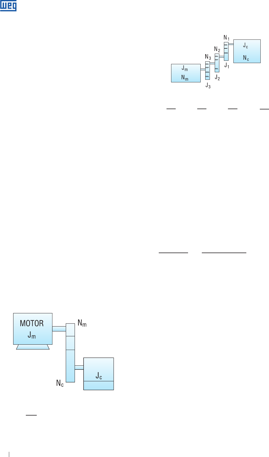
Specification of Electric Motors 28
4.1.3 Characteristics of WEG Motors
Although WEG states that their motors usually comply with
Design N, in many cases their typical actual torque values far
exceed the minimum required by the standard. In most cases
the values even exceed the minimum requirements of Design H.
This means a very high speed-torque curve, bringing the following
benefits:
1 ) Quick acceleration under heavy starting conditions, e.g.
for piston pumps, loaded conveyers, high inertia loads,
compressors with open valves, etc.
2 ) Quick responsiveness for special supplies such as those
mentioned since standard motors are always readily
available from stock, with price benefits and quick
delivery.
3 ) The possibility of using reduced voltage starting methods,
e.g. Star-Delta Starters, in normal cases, without affecting
perfect load acceleration.
4 ) Due to the high value of the breakdown torque,
momentary load peaks and temporary voltage drops
are accepted without any sudden speed loss. This
is a fundamental requirement for the performance of
machines which are subjected to heavy load peaks, such
as crushers, calender machines, etc.
4.2 Load Inertia
The driven load inertia is one of the most important
characteristics to be checked during the acceleration time
to ensure that the motor will be able to drive the load within
the ambient requirements or the thermal capabilities of the
insulation materials.
Inertia is the way how we measure the resistance of an
object to change its rotation movement around a shaft. It also
depends on the shaft around which it is rotating, the shape of
the object and the way its mass is distributed. The unit of the
inertia moment is given by kgm².
The total inertia of the system is given by the load inertia plus
motor inertia ( Jt = Jc + Jm ).
In cases where the machine has “different speed than the
motor” ( ex.: belt/pulley assembly or gearboxes ), inertia has
to be considered for the motor rated speed as indicated
below:
Nc
Jce = Jc ( ) 2 ( kgm2 )
Nm
LOAD
Figure 4.3 - Inertia at different speeds
Figure 4.4 - Inertia at different speeds
Nc N1 N2 N3
Jce = Jc ( )2 + J1 ( )2 + J2 ( )2 + J3( )2
Nm Nm Nm Nm
where:Jce - Load inertia related to the motor shaft
Jc - Load inertia
Nc - Load speed
Nm - Motor rated speed
Jt = Jm + Jce
The total inertia of the load is essential for determing the
acceleration time.
4.3 Acceleration Time
In order to check if the motor is suitable to drive the load, or
when designing the installation, starting or protection system,
the acceleration time must be known ( from the moment
the motor starts and acceleretaes up to the rated speed ).
The starting time can be determined approximately by the
average acceleration torque.
2 π . rps . Jt 2 π . rps . ( Jm + Jce )
ta = =
Ca ( Cmmed - Crmed )
ta - acceleration time in seconds
Jt - total load inertia in kgm2
rps - rated speed in revolutions per second
Cmmed - motor average acceleration torque in Nm.
Crmed - load average resistive torque related to the motor shaft in Nm.
Jm - Motor inertia
Jce - Load inertia related to the motor shaft
Ca - Average acceleration torque
The average acceleration torque can be obtained from the
difference of motor torque and the load torque. It should be
calculated for each rotation interval ( the sum of the intervals
would give the total acceleration time ). In practical terms, it
is enough to calculate graphically the average torque, i.e., the
difference between motor average torque and load average
torque. This average can be obtained graphically, by ensuring
that the sum of the areas A1 and A2 is the same of area A3 and
that the area B1 is the same of the area B2 ( see figure 4.5 ).
www.weg.net
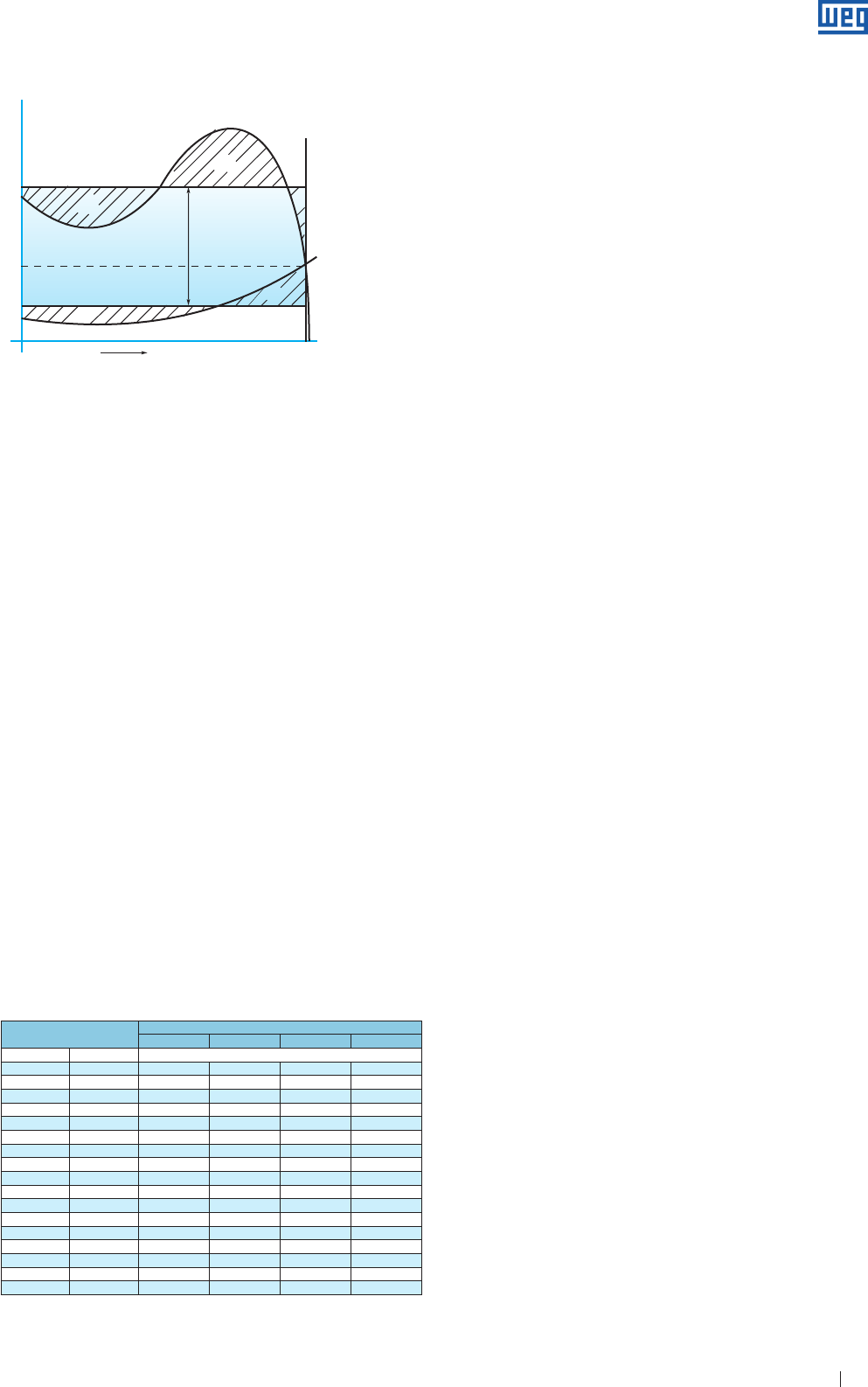
Specification of Electric Motors 29
Figure 4.5 - Graphic determination of the average acceleration torque
Cn = Rated torque
Cm = Motor torque
Cr = Load torque
Ca = Average acceleration torque
Nn = Rated speed
Conjugado
Cm
Cr
Nn
0
Cn
A1
A3
A2
B2
B1
Ca
M1
Rotação
Torque
Speed
4.4 Duty Cycles
Due to high starting currents on electric induction motors,
the time required to accelerate high inertia loads will result
in a sudden motor temperature rise. If the interval between
successive starts is very short, motor windings can
experience some overheating that will cause some damage
or reduce their lifetime. IEC 60034-1 Standard establishes
a minimum number of starts ( S1 ) that the motors should
withstand in the following conditions:
a ) Two consecutive starts: first start with the motor in cold
state, i.e., with the windings at ambient temperature and
the second start right after, but with de-energized motor
and at rest.
b ) One hot start, i.e., with the windings at running
temperature.
The first condition simulates the case when first start fails,
for example, the protection system trips, allowing a second
start right after. The second condition simulates the case of
an accidental motor shutdown during normal operation, for
example, due to a power supply fault, allowing to start the
motor again right after the power supply is re-established.
As the motor temperature rise depends on the inertia of the
driven load, the standard establishes the maximum load
inertia to which the motors should withstand in order to
comply with the conditions above. Table 4.3 shows the inertia
values for 2, 4, 6 and 8-pole motors.
Rated Power Number of Poles
2 4 6 8
kW cv kgm2
0.4 0.54 0.018 0.099 0.273 0.561
0.63 0.86 0.026 0.149 0.411 0.845
1.0 1.4 0.040 0.226 0.624 1.28
1.6 2.2 0.061 0.345 0.952 1.95
2.5 3.4 0.091 0.516 1.42 2.92
4.0 5.4 0.139 0.788 2.17 4.46
6.3 8.6 0.210 1.19 3.27 6.71
10 14 0.318 1.80 4.95 10.2
18 22 0.485 2.74 7.56 15.5
25 34 0.725 4.10 11.3 23.2
40 54 1.11 6.26 17.2 35.4
63 86 1.67 9.42 26.0 53.3
100 140 2.52 14.3 39.3 80.8
160 220 3.85 21.8 60.1 123
250 340 5.76 32.6 89.7 184
400 540 8.79 49.7 137 281
630 860 13.2 74.8 206 423
Table 4.3 - Moment of inertia ( J )
a ) The values are given as a function of the mass-radius
squared. They were calculated by the following formula:
J = 0.04 . P 0.9 . p 2.5
where: P - rated Power in kW
p - number of pole pairs
b ) For intermediate rated power ratings the external inertia
moment should be calculated by the formula above. For
loads with higher inertia than the reference values given in
table 4.3, which can happen mainly in higher rated power
ratings or for the determination of maximum number of
starts per hour, our Application Engineering Department
should be contacted informing the following application
data:
g Power required by the load. If the duty is intermittent, see
last last item: “Duty cycle”.
g Speed of the driven machine.
g
Transmission: direct, flat belts, V-belts, chain, etc.
g
Transmission ratio with dimensional sketches and
distances between pulleys, if transmission is realized by
pulley.
g
Abnormal radial loads applied to the shaft end:
belt traction in special transmissions, heavy parts
coupled to the shaft end, etc.
g
High axial loads applied to the shaft end: transmission by
helical gears, hydraulic thrusts of pumps, heavy rotating
parts mounted vertically, etc.
g Mounting different from B3D, indicate mounting code of
the application.
g Required starting torque and breakdown torque
g
Description of the driven equipment and operation.
g Moment of inertia or GD2 of the movable parts of the
equipment and the related speed.
g Duty cycle, if not continuous duty, provide detailed
description of the operation cycles and specify:
a ) Required power and the duration of each load period;
b ) Duration of the no-load periods ( motor at no-load or
de-energized );
c ) Reversals of the direction of rotation;
d ) Counter current braking.
The motors must have their number of starts per hour limited
according to their duty indicated on the nameplate and / or
as agreed for the design.
Excessive starts can cause overheating and consequent
burning of the electric motor.
In case of doubt, please contact WEG.
4.5 Locked Rotor Current
4.5.1 Standardized Maximum Values
The maximum limits for the locked rotor current, as function
of the rated motor output are valid for any number o poles,
are shown in Table 4.4, indicated in terms of apparent power
absorbed with locked rotor relating to the rated output, kVA /
HP or kVA / kW.
www.weg.net
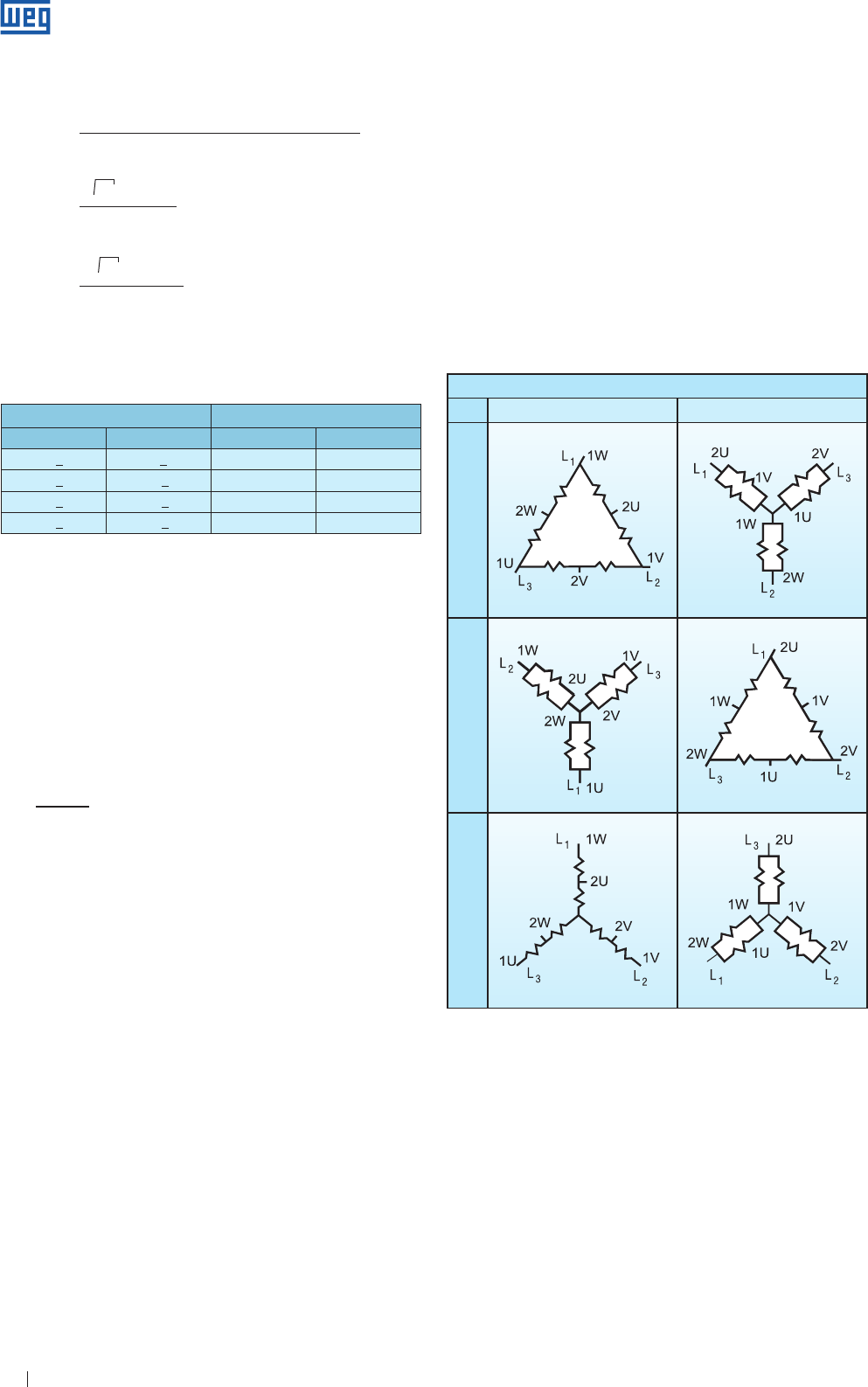
Specification of Electric Motors 30
3 Ip . U
kVA/cv =
P ( cv ) . 1000
3 Ip . U
kVA/kW =
P ( kW ) . 1000
where: Ip - Locked rotor current or starting current
U - Rated voltage ( V )
P - Rated power ( HP or kW )
√
√
Power range Sp / Pn
kW HP kVA/kW kVA/cv
> 0.37 < 6.3 > 0.5 < 8.6 13 9.6
> 6.3 < 25 > 8.6 < 34 12 8.8
> 25 < 63 > 34 < 86 11 8.1
> 63 < 630 > 86 < 856 10 7.4
Table 4.4 - Maximum values of the locked rotor apparent Power ( Sp / Pn ),
expressed as per unit value of the rated output ( Pn )
5. Speed Regulation of Asynchronous Motors
The relationship between speed, frequency, number of poles
and slip is given by:
2
n = . f . 60 . ( 1 - s )
( 2p )
where : n = rpm
f = frequency ( Hz )
2p = number of poles
s = slip
The formula shows that for the speed regulation of
asynchronous motors, we can change the following
parameters:
a ) 2p = number of poles
b ) s = slip
c ) f = frequency ( Hz )
5.1 Changing the Number of Poles
There are three ways to change the number of poles of an
asynchronous motor, as follows:
g separated stator windings;
g one winding with pole commutation;
g combination of the two options above.
In all these cases, the speed regulation will be smooth,
without losses, but frame size will be larger than for a single
speed motor.
Figure 5.1 - Summary of the Dahlander connection
Speed
Low
Type
Constant
Torque
Constant
Horse Power
Variable
Torque
High
g Constant torque
Torque is constant on both speeds and power ratio is 0.63:1.
In this case, the motor is D/YY connected.
Example:
0.63/1HP motor - 4/2 poles - D/YY.
This connection is suitable for applications where the load
torque curve remains constant with the speed variation.
g Constant power
In this case, the torque ratio is 2:1 and horse power remains
constant. The motor is YY/D connected.
Example: 10/10 HP - 4/2 poles - YY/Δ.
Locked rotor apparent power
kVA/cv =
Rated power
Note: to obtain the ratio Ip / In , multiply kVA/kW by the performance product
and by the Power factor at full load.
Ip = Locked rotor current;
In = Rated current
5.1.1 Two Speed Motors with Independent Windings
This type of motor has the advantage of combining windings
with any number of poles; however it is limited
by core dimensioning ( stator / rotor ) and by the frame size
that is usually far greater than the frame of a single speed
motor.
5.1.2 Dahlander
Two-speed motors with commutating pole windings is the
most used system, also called "Dahlander connection." This
connection provides a ratio of number poles ratio of 1:2 with
consequent speed ratio 2:1.
It can be connected as follows ( Figure 5.1 ):
www.weg.net
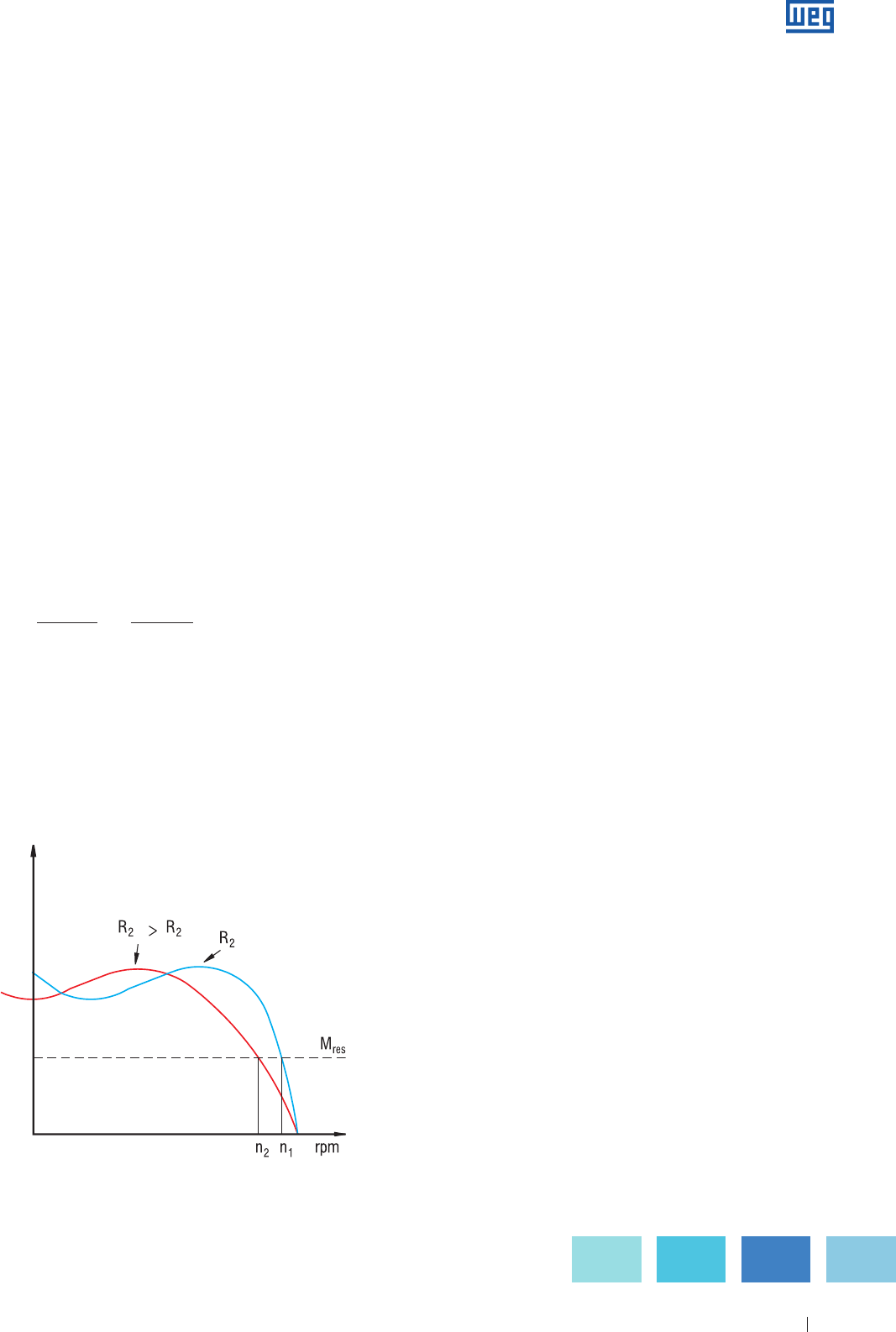
Specification of Electric Motors 31
'
Normal
Torque
Figure 5.2 - Torque curve with rotor resistance variation
5.2.2 Stator Voltage Variation
This is not an usual method, since it also generates rotor
losses and speed variation range is small.
5.3 Frequency Inverters
For further information about the use of frequency inverters
for speed control, see chapter "Application of induction
motors fed by frequency inverters".
6. Brake Motor
The brake motor consists of an induction motor coupled to
a single-disc brake, forming an integral, compact unit. The
induction motor is a totally enclosed fan cooled machine with
the same mechanical and electrical performance of WEG
general purpose motors.
The brake is built with few movable parts which gives long
life with reduced maintenance. The two faces of the brake
pads create a large contact area, requiring only little pressure
during the braking process, which reduces the brake heating
and the wear is minimum. Besides that, brake is cooled by
the motor cooling system. The electromagnet drive coil,
protected with epoxy resin, can be operated continuously
with voltages varying 10% above and below the rated
voltage.
The electromagnet drive coil is DC powered, supplied
by a bridge rectifier made of silicon diodes and varistors,
that suppress undesirable voltage spikes and allow a fast
current shutdown. The DC power supply provides faster and
smoother brake operation.
Typical application for brake motors:
g Machine-tools
g Looms
g Packing machines
g Conveyors
g Bottle washing and filling machines
g Winding machines
g Bending machines
g Hoists
g Cranes
g Lifts
g Roll adjustment of rolling machines
g Graphic machines
In general terms, brake motors are used on equipment requi-
ring quick stops based on safety, positioning and time saving
factors.
g Variable torque
In this case, the power ratio will be approximately 1:4. It is
applied to loads such as pumps and fans.
The connection in this case is Y/YY.
Example: 1/4 HP - 4/2 poles - Y/YY.
5.1.3 Motors with Two or More Speeds
It is possible to combine a Dahlander winding with a single
winding or more. However, this type of motor is not usual and
it used only for special applications.
5.2 Slip Variation
In this case, the rotating field speed is maintained constant,
and the rotor speed is changed according to
the conditions required by the load, which can be:
a ) rotor resistance variation
b ) stator voltage variation
c ) variation of both simultaneously.
These variation are achieved by increasing rotor losses which
limits the use of this system.
5.2.1 Rotor Resistance Variation
This method is used for slip ring motors and is based on
the following equation:
pj2 3 . R2 . I2
2
s = =
ωo . T ωo . T
where: pj2 = Rotor losses ( W )
ωo = Synchronous speed in rd/s
T = Rotor torque
R2
= Rotor resistance ( Ohms )
I2 = Rotor current ( A )
s = slip
The connection of an external resistance to the rotor
increases the motor slip ( s ) and results in speed variation.
Figure below shows the effect of the increase of R2.
www.weg.net
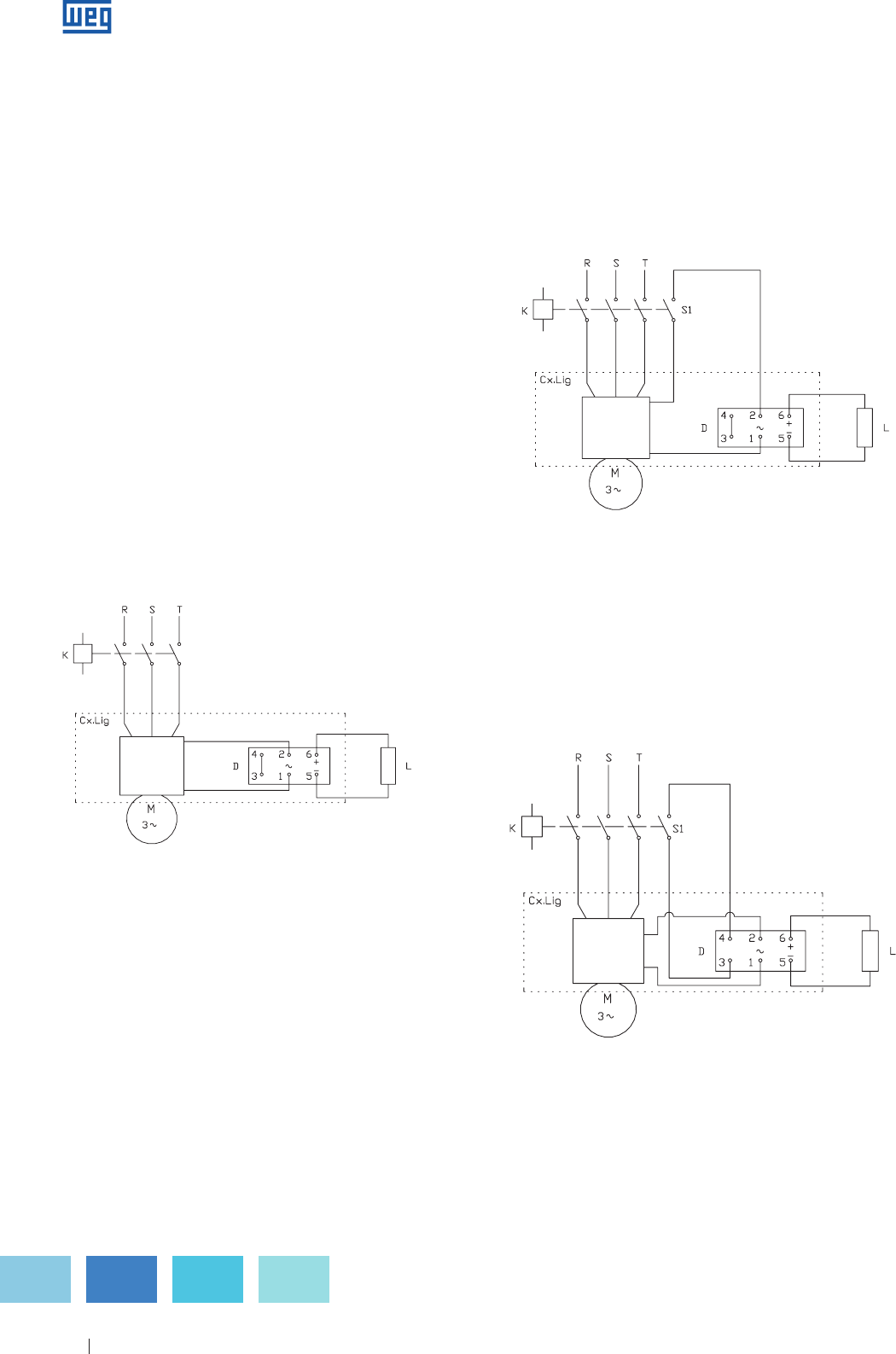
Specification of Electric Motors 32
6.1 Brake Operation
When motor isdisconnected from power supply, the control
also switches off the coil current and the electromagnet
stops operating. The pressure springs force the armature
towards the motor non drive-endshield. Fitted in the braking
disc, the braking pads are compressed between the two
friction surfaces, the armature and the endshield braking
the motor until it stops. When the motor is switched on,
the coil is powered and the armature is pulled against the
electromagnet frame by eliminating the spring force. Once
they are free, the braking pads move axially in their seatings
and they remain out of the friction area. Now the braking
process is ended and allows starting the motor freely.
As option, WEG can supply the motors with brake lining.
6.2 Connection Diagram
The WEG brake motor allows 3 types of connection diagrams
supplying slow, medium and quick braking.
a ) Slow braking
The power supply of the brake coil bridge rectifier is applied
directly from the motor terminals, without interruption, as
shown below:
Motor
Terminals
D - Bridge rectifier
L - Electromagnet coil
K - Contactor
Figure 6.1 - Connection diagram for slow braking
b ) Medium braking
In this case a contact for interruption of the bridge rectifier
supply current in the AC circuit is interconnected. It is
essential that this is a NO auxiliary contact ( S1 ) of the
contactor itself or of the motor magnetic switch in order
to allow switching on and off of the brake and motor
simultaneously.
D - Bridge rectifier
L - Electromagnet coil
K - Contactor
S1- NO auxiliary contact
Figure 6.2 - Connection diagram for medium braking
c ) Fast braking
A contact for interruption is directly connected to one of the
coil supply cables in the DC circuit. It is essential that this is
a NO auxiliary contact of the contactor itself or a magnetic
switch of the motor.
D - Bridge rectifier
L - Electromagnet coil
K - Contactor
S1 - NO auxiliary contact
Figure 6.3 - Connection diagram for fast braking
Motor
Terminals
Motor
Terminals
www.weg.net
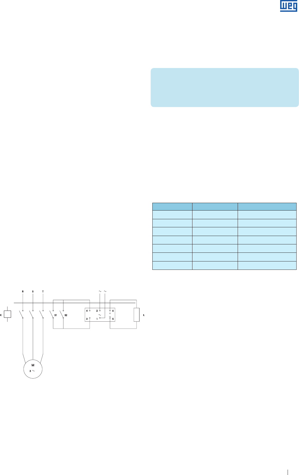
Specification of Electric Motors 33
6.3 Brake Coil Power Supply
The power supply of the bridge rectifier with AC-current, can
be obtained from an independent source or from the motor
terminals. This power supply may be in 110/220 V, 440 V or
575 V, according to the characteristics of the bridge rectifier /
brake coil set.
The brake coil can also be supplied for 24 V DC, but in this case
the power supply should be provided through an independent
source ( direct current ), eliminating the use of bridge rectifier
( RB ).
Through motor terminals
a ) Motor 220/380 V: connect motor terminal 1 and 2 of the
RB ( 220 V AC ) between the terminals 1 and 4 of the
motor.
b ) Motor 380/660 V: connect motor terminal 1 and 2 of the
RB ( 220 V AC ) between the terminal 2 and the neutral.
c ) Motor 220/380/440/760 V: connect the motor terminals 1
and 2 of the RB ( 220 V AC ) between the terminals 1 and
4 of the motor.
d ) Motor with 3 leads ( single voltage ): connect the terminals
1 and 2 of the RB between the 1 and 2 of the motor ( if
the RB has the Same voltage of the motor ).
e ) Two speed motor 220 V ( RB 220 V AC ):
1. High speed: connect between the motor terminals 4 and 6.
2. Low speed: connect between the motor terminals 1 and 2.
Motor 440 V: connect the terminals of the rectifier bridge
( 440 V AC ) to the motor terminals.
Independent power supply ( AC ):
For motor that are wound for other voltages, connect
the terminals of the rectifier bridge to the independent
220 V power supply; however, always with simultaneous
interruption when the motor power supply is switched off.
With independent power supply it is possible to electrically
release the brake, as shown in figure below.
D - Bridge rectifier
L - Electromagnet coil
K - Contactor
S1 - NO auxiliary contact
S2 - Electric release switch
Figure 6.4 - Connection diagram for independent power supply
Frame size Initial air gap ( mm ) Maximum air gap ( mm )
71 0.2 - 0.3 0.6
80 0.2 - 0.3 0.6
90S - 60L 0.2 - 0.3 0.6
100L 0.2 - 0.3 0.6
112M 0.2 - 0.3 0.6
132S - 132M 0.3 - 0.4 0.8
160M - 160L 0.3 - 0.4 0.8
6.4 Brake Torque
It is possible to obtain a smoother motor stop by reducing
the braking torque value. This is achieved by removing some
brake pressure springs.
Important!
The springs must be removed in such a way that the
remaining ones stay symmetrically disposed, avoiding in
this way any friction even after operating the motor and
thus avoid uneven wear of the braking pads.
6.5 Air Gap Adjustment
WEG brake motors are supplied with an initial factory set air
gap, that is, the gap between the armature and the frame
with the energized brake, is pre-adjusted at the factory to the
minimum value as indicated in Table 6.1.
As they are simple construction machines, brake motors
require low maintenance. Only a periodical air gap
adjustment is required. It is recommended to clean internally
the brake motor in cases of penetration of water, dust, etc. or
at the time motor when the periodical maintenance is carried
out.
Due to the natural wear of the braking pads, the size of the
air gap gradually increases without affecting the performance
of the brake until it reaches the maximum value shown on
Table 6.1. To adjust the air gap to its initial value, proceed as
follows:
a ) Unfasten the bolts and remove the fan cover;
b ) Remove the seal ring;
c ) Measure the air gap at three points, near the adjustment
screws, using a set of feeler gauges;
d ) If the gap width is equal to or greater than the maximum
indicated dimension, or if the three readings are not the
same, proceed the adjustment as follows:
1. loosen the locknuts and the adjustment screws;
2. adjust the air gap to the initial value indicated in
Table 6 .1 tightening by equally the three adjustment
screws. The value of the air gap must be uniform at the
three measured points, and must be such that the feeler
gauge corresponding to the minimum gap, moves freely
and the feeler gauge corresponding to the maximum
gap cannot be inserted into the measured points;
3. tighten the locking bolts screws until the ends touch the
motor endshield. Do not overtighten them;
Table 6.1
www.weg.net
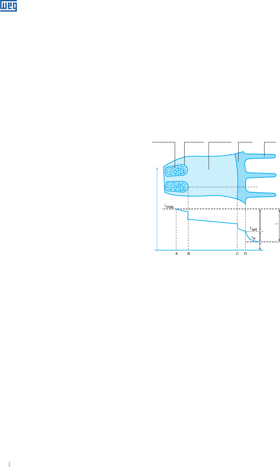
Specification of Electric Motors 34
4. Tighten the locknuts;
5. Re-check the air gap to ensure the measurements are
as per Item 2 above;
6. Remount the seal ring;
7. Remount the fan cover and fasten it with its fixing bolts.
The interval between periodical adjustments of the air gap,
i.e., the number of braking cycles until brake pads wear
to their maximum allowed value depends on the load, the
frequency of operations, and the cleanness of working
environment, etc. The ideal interval can only be determined
by closely following up the performance of the brake motor
during the first months of operation under actual working
conditions. The wear of the brake pads also depends on the
moment of inertia of the load.
WEG is also able to supply other brake options for more
severe applications ( e.g., cranes, tractioners, gear
boxes, etc. ). In case of doubt, please contact WEG.
7. Operating Characteristics
7.1.1 Winding Heating Up
Losses
The effective or useful power output supplied by the motor
at the shaft end is lower than the power input absorbed by
the motor from the power supply, i. e., the motor efficiency is
always below 100%. The difference between input and output
represents the losses that are transformed into heat. This
heat warms up the windings and therefore must be removed
from the motor to avoid excessive temperature rise. This
heat removal must be ensured for all types of motors. In the
automobile engine, for example, the heat generated by internal
losses has to be removed from the engine block by water flow
through radiator or by fan, in the case of air-cooled engines.
Heat dissipation
The heat generated by internal losses is dissipated to the
ambient air through the external surface of the frame. In totally
enclosed motors this dissipation is usually aided by a shaft
mounted fan. Good heat dissipation depends on:
g Efficiency of the ventilating system;
g Total heat dissipation area of the frame;
g
Temperature difference between the external surface of the
frame and the ambient air ( text - ta ).
a ) A well designed ventilation system, as well as having an
efficient fan capable of driving a large volume of air, must
direct this air over the entire circumference of the frame to
achieve the required heat exchange.
A large volume of air is absolutely useless if it is allowed to
spread out without dissipating the heat from the motor.
b ) The dissipation area must be as large as possible.
However, a motor with a very large frame require a very
large cooling area and consequently will become too
expensive, too heavy, and requires too much space for
installation. To obtain the largest possible area while at the
same time keeping the size and weight to a minimum ( an
economic requirement ), cooling fins are cast around the
frame.
Winding Insulation Laminations Frame Fins
Internal
temperature
drop
Air
Temperature
external
temperatura
drop
Ambient
Figure 7.1
A - The winding hottest spot is in the centre of the slots
where heat is generated as a result of losses in the
conductors.
AB - The drop in temperature is due to the heat transfer
from the hottest spot to the outer wires. As the air
is a very poor conductor of heat it is very important
prevent voids inside the slots, i.e. the windings must be
compact and perfectly impregnated with varnish.
B - The drop in temperature through the slot insulation and
through the contact of the insulation material with the
conductors and by contact with the core laminations.
By employing modern material far better heat transfer
is obtained through the insulation materials. Perfect
impregnation improves the contact of the inner side by
eliminating voids. Perfect alignment of the laminations
improves the contact to the outer side, eliminating
layers of air, which have a negative effect on heat
transfer.
c ) An efficient cooling system is one that is capable of
dissipating the largest possible amount of heat through
the smallest dissipation area. Therefore, it is necessary
that the internal drop in temperature, shown in figure 7.1, is
minimized. This means that a good heat transfer must take
place from the inside to the outer surface of the motor.
As explained, the objective is to reduce the internal drop in
temperature ( i.e. to improve the heat transfer ) in order to
obtain the largest possible drop of the outside temperature
necessary for good heat dissipation. Internal drop in
temperature depends on different factors which are indicated
in Fig. 7.1 where the temperatures of certain important areas
are shown and explained as follows:
www.weg.net
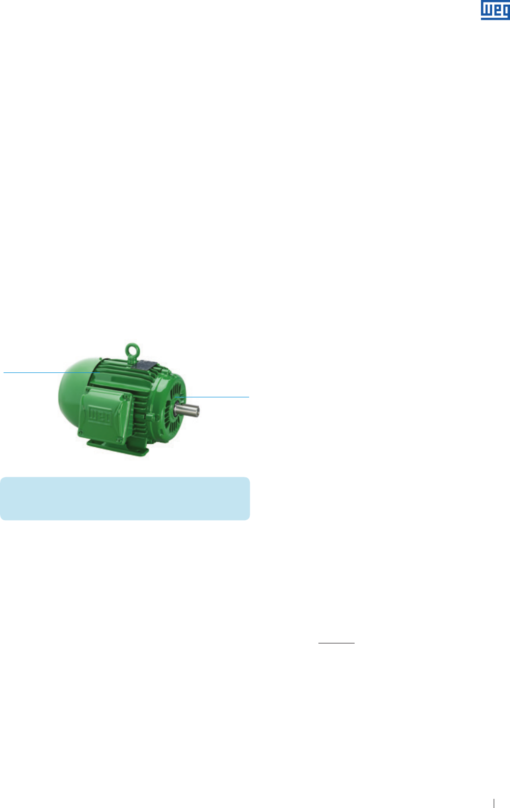
Specification of Electric Motors 35
Figure 7.2
BC - Drop in temperature by the transmission through the
stator lamination material.
C - Drop in temperature by contact between the stator
core and the frame. Heat transmission depends on the
perfect contact between the parts, good alignment
of the laminations, and accuracy in the machining
of the frame. Uneven surfaces leave empty spaces,
resulting in poor contact and consequently bad heat
transmission.
CD - Drop in temperature by the transmission through the
frame thickness.
Due to modern design, use of first class material, improved
manufacturing processes, and continuous quality control,
WEG motors ensure excellent heat transfer properties from the
motor inside to the outside thus eliminating “hot spots” in the
windings.
Outer surface temperature of the motor
Figure below shows the recommended places where the outer
surface temperature of an electric motor should be checked
with calibrated temperature measuring instruments:
Important!
Measure also the ambient temperature ( at a max. distance
of 1 m from the motor )
D-enshield,
near the bearing
Frame centre
7.1.2 Motor Lifetime
As already informed in the Item “Insulation materials and
insulation systems” its useful lifetime of the motor depends
almost exclusively on the life of the winding insulation. The
lifetime of a motor is affected by many factors, such as misture,
vibration, corrosive environments and others. Among all these
factors, the most important is the working temperature of the
employed insulation materials. An increase from 8 to 10 degrees
above the rated temperature class of the insulation system can
reduce the motor lifetime by half.
When speaking about decreasing the useful lifetime of the motor,
we are not talking about high temperatures where the insulation
system burns and the winding is suddenly destroyed. For the
insulation lifetime this means a gradual ageing of the insulation
material which becomes dry, losing its insulation properties
until it cannot withstand the applied voltage. This results in a
breakdown of the insulation system and a consequent short-
circuit of the windings. Experience shows that the insulation
system has practically an unlimited lifetime if the temperature is
kept below a certain limit if this temperature limit is exceeded,
the insulation lifetime will shorten as the temperature increases.
This temperature limit is well below the “burning” temperature of
the insulation system and depends on the type of used insulation
material.
This temperature limit refers to the hottest spot in the insulation
system, but not necessarily to the whole winding. One weak
point in the inner part of the windings will be enough to destroy
the insulation system.
It is recommended to use temperature sensors as additional
protection devices for the electric motor. These protection
devices will ensure a longer lifetime and more process reliability.
The alarm and / or shutdown setting should be performed
according to the motor temperature class. In case of doubt,
contact WEG.
7.1.3 Insulation Classes
Insulation class definition
As previously mentioned the temperature limit depends on
the type of used material used. In order to comply with the
standards the insulation material and insulation systems
( each one formed by a combination of several materials ) are
grouped in INSULATION CLASSES. Each one is defined
by the particular temperature limit, i.e. by the highest
temperature that the insulation material or system can
withstand continuously without affecting its useful life.
The insulation classes used for electrical machines and their
respective temperature limits is accordance with IEC 60034-1
are as follows:
Class A ( 105 ºC )
Class E ( 120 ºC )
Class B ( 130 ºC )
Class F ( 155 ºC )
Class H ( 180 ºC )
7.1.4 Winding Temperature Rise Measurement
It would be rather difficult to measure the temperature of
the winding with thermometers or thermocouples since
the temperature differs from one spot to another and it
is impossible to know if the measurement point is near
the hottest spot. The most accurate and reliable method
for determining the winding temperature is by measuring
the variation of the winding resistance as function of the
temperature.
The temperature rise mearurement by the resistance method,
for cooper conductors, is calculated according to the
following formula:
R2 - R1
Δt = t2 - ta = ( 235 + t1 ) + t1 - ta
R1
where: Δt = temperature rise;
t1 = winding temperature prior to testing, which should be practically
equal to the cooling medium, measured by thermometer;
t2 = winding temperature at the conclusion of the test;
ta = temperature of the cooling medium at the conclusion of the test;
R1 = winding resistance prior to testing;
R2 = winding resitance at the end of the test.
www.weg.net
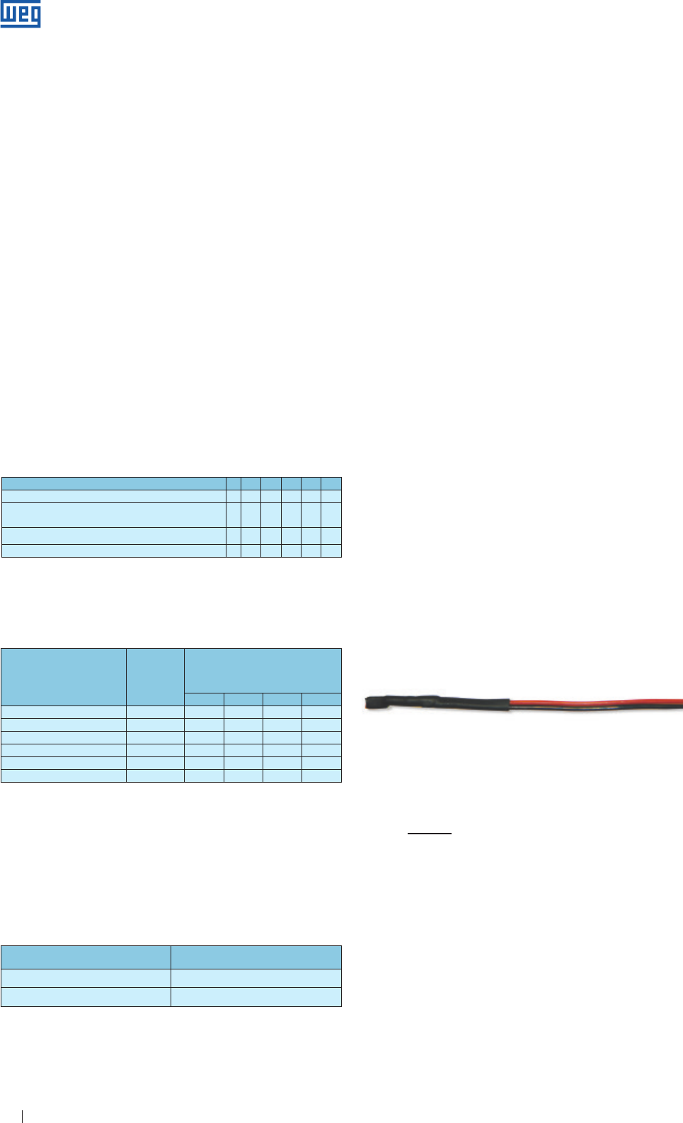
Specification of Electric Motors 36
Motor Service Factor ( SF ) Relay current setting
1.0 to 1.15 In.FS
≥ 1.15 ( In. FS ) - 5%
Insulation Class A E B F H
Ambient temperature oC 40 40 40 40 40
Δt = temperature rise
( resistance method )
oC 60 75 80 105 125
Difference between the hottest spot and average temp. oC 5 5 10 10 15
Total: temperature of the hottest spot oC 105 120 130 155 180
Table 7.1 - Temperature composition as function of the insulation class
Classification
societies for
marine motors
Maximum
ambient
temperature
( °C )
Maximum allowable temperature rise
for insulation class, Δt in ºC
( resistance variation method )
A E B F
Germanischer Lloyd 45 55 70 75 96
American Bureau of Shipping 50 55 65 75 95
Bureau Véritas 50 50 65 70 90
Norske Véritas 45 50 65 70 90
Lloyds Register of Shipping 45 50 65 70 90
RINa 45 50 70 75 —
For marine motors all requirements specified by the
classification societies must be considered, as shown in
Table 7.2.
7.2 Thermal Protection of Electric Motors
Motors used for continuous duty must be protected
against overloads by a device integrated to the motor, or an
independent device, usually fitted with a thermal relay having
rated or setting current equal to or below the value obtained
by multiplying the rated motor power supply current ( In ) by
the Service Factor ( SF ), as shown in table below:
Table 7.2 - Temperature correction for marine motors
Table 7.3 - Power supply current x Service Factor
7.1.5 Electric Motor Application
The hottest spot temperature in the winding should be
maintained below the maximum allowed temperature for
the insulation class. The total temperature is the sum of the
ambient temperature, plus temperature rise ( ∆t ), plus the
difference existing between the average winding temperature
and the hottest spot. Motor standards specify the maximum
temperature rise ∆t, so the temperature of the hottest spot
remains within the allowable limit based on the following
considerations:
a ) Ambient temperature should not exceed 40 ºC, as
per standard; above this value, working conditions are
considered as special operating conditions.
b ) The difference between the average temperature of the
winding and the hottest spot does not vary very much
from motor to motor and its value specified by standard,
is 5 ºC for Classes A and E, 10 ºC for Class B and F and
15 ºC for Class H.
Therefore, motor standards specify a maximum allowed
ambient temperature, as well as a maximum allowed
temperature rise for each insulation class. Thus, the
temperature of the hottest spot is indirectly limited.
The figures and the allowable temperature composition for
the hottest spot are shown on Table 7.1 below:
Figure 7.3 - Internal and external view of the thermoresistors
The temperature for the Pt-100 can be obtained from the
formula below or on tables provided by manufacturers.
r - 100
t ºC =
0.385
r - resistance measured in Ohms
7.2.2 Thermistors ( PTC and NTC )
Thermistors are temperature sensors consisting of
semiconductor materials that vary its resistance very fast
when reaching certain temperature.
PTC - positive temperature coefficient
NTC - negative temperature coefficient
The thermal protection is provided by means of
thermoresistances ( calibrated resistances ), thermistors,
thermostats or thermal protectors. The temperature detectors to
be used are defined in accordance with the temperature class of
the insulation materials used for each type of machine as well as
based on customer requirements.
7.2.1 Resistance Temperature Detector ( Pt-100 )
The temperature detectors operate on the principle that
the electrical resistance of a metallic conductor varies as
function of the temperature ( generally platinum, nickel or
copper conductors ). The temperature detectors are fitted
with calibrated resistance which varies linearly with the
temperature, allowing continuous follow up of motor heating
on the controller display, with high degree of accuracy and
response sensitivity.
The same detector can be used for alarm ( when motor is
operated above the normal working temperature ) and for
tripping operation ( usually set to the maximum temperature
of the insulation class ). The resistance of the cables,
contacts, etc. can interfere with the measurement so there
are different types of conFiguretions that can be carried out
to minimize these effects.
g The two-wire conFiguretion is usually satisfactory in places
where the cable length to the sensor instrument does not
exceed 3.0 m, using cables 20 AWG.
g For the three-wire conFiguretion ( commonly used in industry )
there will be a compensation of the electrical resistance by the
third wire.
g
For the four wire conFiguretion ( more accurate assembly )
there are two connections for each bulb terminal ( two cables
for voltage and two cables for current ), thus obtaining a total
balancing of the resistance ( this conFiguretion is used where
high accuracy is required ).
Disadvantage
High cost of the sensor elements and control circuits.
www.weg.net
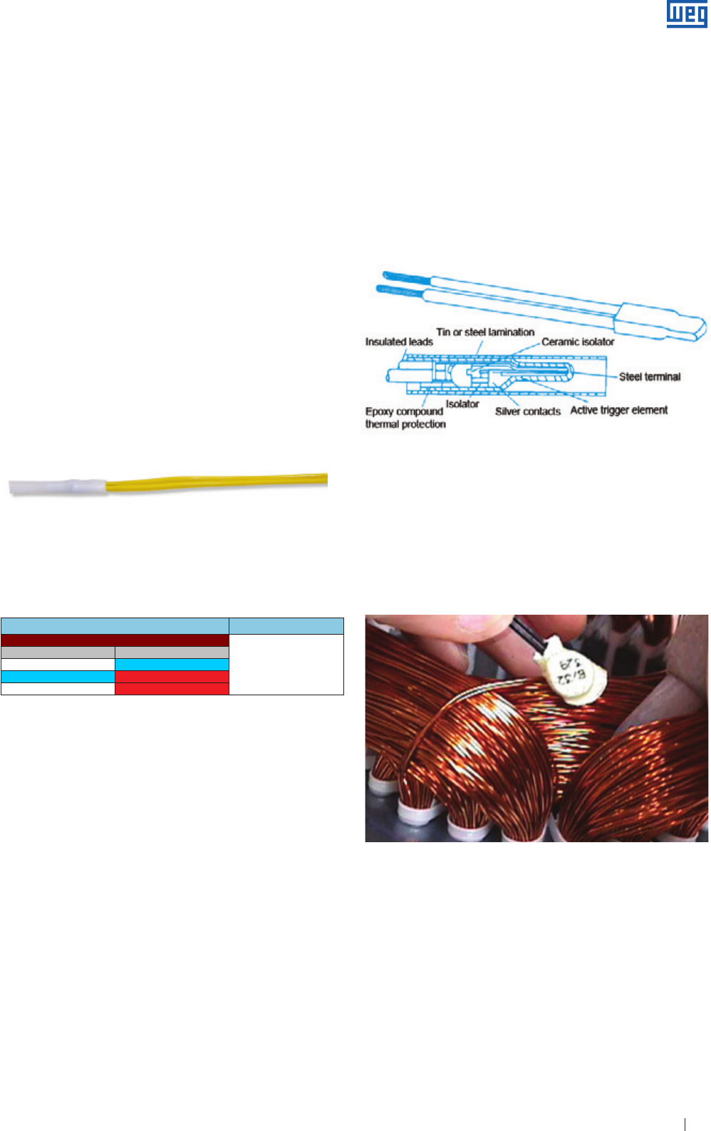
Specification of Electric Motors 37
Figure 7.4 - External view of a thermistor
Please find in the table below the main PTC types used for
electric motors. The table shows the colors of the PTC cables
with their respective activation temperature.
Cable colors Temperature ºC
110
120
140
160
180
WEG also supplies electronic relay RPW that has the specific
function to acquire the signal from the PTC and activates its
output relay. For further information, please contact WEG.
Figure 7.5 - Internal and external view of a thermostat
The thermostats are also used for special applications of
single-phase motors. In these applications, the thermostat
can be series connected with the motor power supply,
provided the motor current does not exceed maximum
current allowed for the thermostat. If this occurs, the
thermostat must be series-connected with the contactor coil.
The thermostats are installed in the winding heads of different
phases.
Note: WEG recommends the installation of temperature sensors to protect the windings and bearings of the electric motor and so increase its useful life during
operation.
7.2.3 Bimetal Thermal Protectors - Thermostats
These bimetal thermal protectors ( thermostat ) with NC
silver contacts open when pre-determined temperature rise
is reached. When the activation temperature of the bimetal
thermal protector decreases, the thermostat will return to its
original form instantaneously allowing to close the contacts
again. The thermostats can be used on three-phase electric
motors for alarm or tripping purposes or both ( alarm and
tripping ).
Figure 7.6 - Thermostat installation in the winding
Table 7.4 - Cable colors
The “PTC” thermistors increase their resistance very fast
with temperature increase and some are characterized by
the abrupt resistance increase which makes them useful for
thermal protection devices. The “NTC” thermistors reduce their
resistance when temperature increases. Thus these thermal
protection devices are used mostly to protect the motor against
overheating.
The sudden change in resistance interrupts the current in
PTC, activates an output relay, which turns off the main circuit.
Thermistors can be used for alarm and tripping purpose. For
this purpose two thermistors are required. They must be series
connected, per phase.
The thermistors have reduced size, do not have mechanical
wear, and provide faster response when compared to other
temperature sensors. However they do not allow continuous
monitoring of the motor heating process. Thermistors with
their electronic circuit controls ensure complete protection
against overheating caused by phase-fault, overload, under/
overvoltages or frequent reversals of direction of rotation or on-
off cycles. They have low cost, when compared to the Pt-100.
However, they require a relay to control the alarm or operation
activation.
These thermostats are inserted into the winding heads of
different phases and are series connected to the contactor
coil where, depending on the required protection and on the
customer specifications, three thermostats ( one per phase ) or
six thermostats ( two per phase ) can be used.
For alarm and tripping operation ( two per phase ), the alarm
thermostats should be suitable for the activation at the high
expected motor temperature, while the tripping thermostats
should activate at the maximum temperature allowed for the
insulation material.
www.weg.net
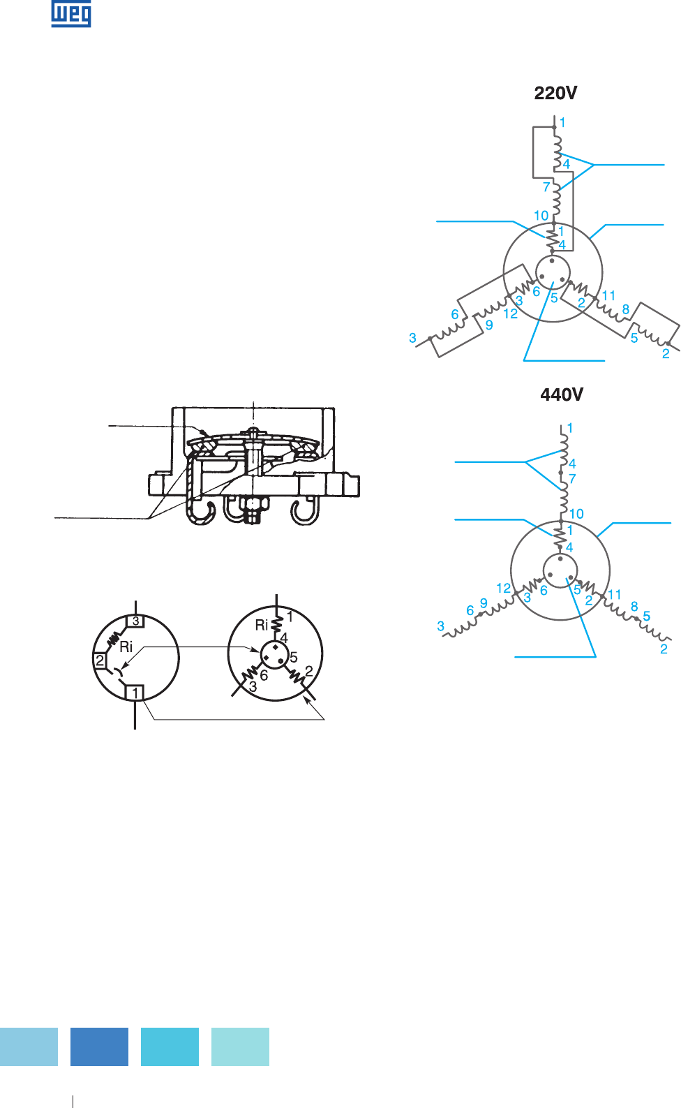
Specification of Electric Motors 38
Note: WEG recommends the installation of temperature sensors to protect the windings and bearings of the electric motor and so increase its useful life during
operation.
Protector
heater
Motor
winding
Protector
heater Thermal
protector
Bimetal
disc
Bimetal
disc
Thermal
protector
Motor
winding
Protector
heater
Motor
winding
Protector
heater Thermal
protector
Bimetal
disc
Bimetal
disc
Thermal
protector
Motor
winding
7.2.4 Phenolic Thermal Protection System
These bimetal temperature sensors are fitted with NC contacts
and are applied mainly for overheating protection of single-phase
induction motors, caused by overloads, locked rotor conditions,
voltage drops, etc.
The thermal protector is basically formed by one bimetallic disc
that has two moving contacts, one resistance and one pair of
fixed contacts. The thermal protector is series-connected with
the power supply and, due to the thermal dissipation caused
by the current flowing through its internal resistance, the disc is
submitted to a deformation that opens the contacts and motor
power supply is interrupted.
After the temperature drops below the specified one, the thermal
protector will reset. Depending on reset method, two types of
thermal protectors may be used:
a ) Auto-reset thermal protector
b ) Manual reset thermal protector
Disc
Single-phase Three-phase
Disc
Descriptive diagram
Contacts
Disc
Single-phase Three-phase
Disc
Descriptive diagram
Contacts
Figure 7.7 - Internal view of the thermal protector
Thermal protectors can also be used for three-phase motors,
but only when Y connected. The following connection
diagram can be used:
Figure 7.8 - Thermal protector connection diagram for three-phase motors
Advantages
g
Combination of a thermal protector sensitive to
temperature and current;
g Possibility of automatic reset.
Disadvantages
g
Current limitation, since the thermal protector is directly
connected to the winding of the single-phase motor;
g Application on three-phase motors only when star-
connected.
www.weg.net
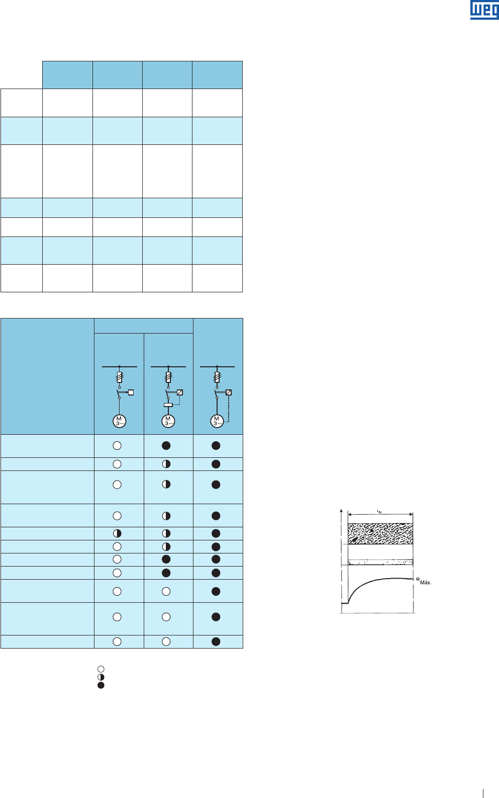
Specification of Electric Motors 39
Thermoresistor
( Pt-100 )
Thermistor
( PTC e NTC ) Thermostat
Phenolic
Thermal
protector
Protection
device
Calibrated
resistance Semiconductor
g Moving
contacts
g Bimetal cont.
Moving contacts
Disposition Winding head Winding head
g Inserted in the
g Inserted in the
winding head
Inserted in the
circuit
Operation
External control
of the protection
system
External control
of the protection
system
activation
g Direct
activation
g External
control of the
protection
system active.
Direct activation
Current
limitation
Control
current Control current g Motor current
g Control current Motor current
Type of
sensitivity Temperature Temperature Current and
temperature
Current and
temperature
Number of
Units per
motor
3 or 6 3 or 6 3 or 6
1 or 3 1
Type of
control
Alarm and/or
tripping
Alarm and/or
tripping
g Tripping
g Alarm and/or
tripping
Tipping
Causes of overheating
Current based protection Protection
with thermal
probes and
thermal realy
Only fuse or
Circuit breaker
Fuse and
thermal relay
Overload with 1.2 times
rated current
Duty cycles S1 to S10
Braking, reversals and
frequent starts
Operating with more than
15 starts per hour
Locked rotor
Phase fault
Excessive voltage oscillation
Line frequency oscillation
Excessive ambient
temperature
External heating caused
By bearing, belts, pulleys, etc
Obstructed ventilation
Table 7.6 - Comparison between motor protection systems
Caption: Unprotected
Partially protected
Totally protected
We do not recommend using “molded case circuit-breaks for
distribution and miniature circuit breakers for the protection
of electric motor starting since these devices do not meet the
electric motor protection standard due to the following reasons:
g
Usually these circuit-breakers do not have regulation/setting
possibilities for their thermal current/rated overload, having
only fixed values of this rated current and in most cases it is
not equal to the rated current of the motor.
g In case of three-phase systems, the thermal device of the
circuit-breakers does not have the protection against “phase
fault” as its thermal device does not have the “typical bipolar
overload” - 2 phases - provided on the normal and the
electronic overload relays.
7.3 Service Duty
According to IEC 60034-1, the service duty is the degree of
regularity of load to which the motor is submitted. Standard
motors are designed for continuous running duty. The load is
constant during an indefinite period of time, and it is equal to
the rated motor output. It is purchaser responsibility to state
the duty as accurately as possible. In cases where there are
no load variations or when variations can be predicted, the
duty can be indicated by numbers or by means of charts
representing the load variations over time. Whenever the actual
load variation in real time cannot be determined a fictitious
sequence, no less severe than the actual duty should be
indicated by the customer. When another starting duty is used
than the informed one on the motor nameplate this may result
in motor overheating and consequent motor damage. In case
of doubt, contact WEG.
7.3.1 Standardized Service Duties
According to IEC 60034-1, the duty types and the assigned
alphanumeric symbols are explained below:
a ) Duty type ( S1 ) - continuous running duty
Operation at a constant load maintained for sufficient time to allow
the machine to reach the thermal equilibrium, see Figure 7.9.
tN = operation time at constant load
θmáx = maximum temperature attained
b ) Duty type ( S2 ) - Short-time duty
Operation at constant load for a given time, less than that
required to reach thermal equilibrium, followed by a time
de-energized and at rest of sufficient duration to re-establish
machine temperature within +2 K of the coolant temperature,
see Figure 7.10.
Figure 7.9
Table 7.5 - Thermal protection
Load
Electrical losse
s
Temperature
Time
www.weg.net
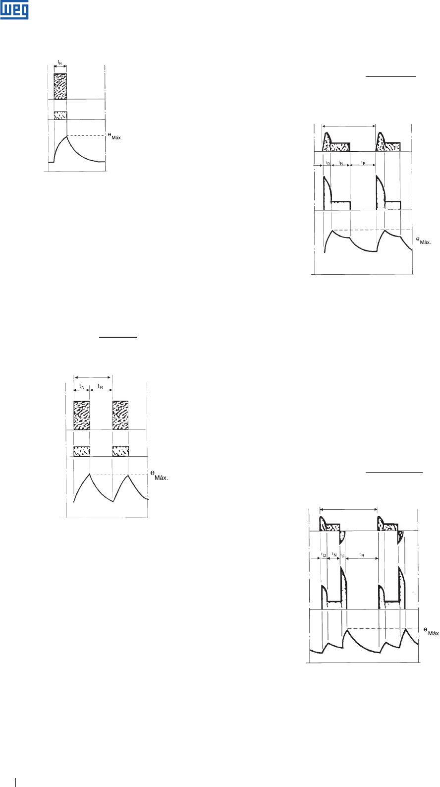
Specification of Electric Motors 40
Load
Electrical losse
s
Cycle duration
Time
Temperature
tD + tN
Cycle duration factor = . 100%
tD + tN + tR
Figure 7.12
e ) Duty Type S5 - Intermittent periodic duty with electric
braking
A sequence of identical duty cycles, each cycle consisting
of a starting time, A time of operation at constant load, a
time of electric braking and a time de-energized and at rest.
These periods are so short that the thermal equilibrium is not
reached, see Figure 7.13.
tD + tN + tF
Cycle duration factor = . 100%
tD + tN + tF + tR
Figure 7.10
Load
Electrical losse
s
Temperature
Time
c ) Duty type S3 - Intermittent periodic duty
A sequence of identical duty cycles, each including a time of
operation at constant load and a time de-energized and at rest.
These periods are so short that the thermal equilibrium is not
reached during one duty cycle and the starting current does not
significantly affect the temperature rise ( see Figure 7.11 )
tN
Cycle duration factor = . 100%
tN + tR
Load
Electrical losse
s
Temperature
Time
Cycle duration
d ) Duty type S4 - Intermittent periodic duty with starting
A sequence of identical duty cycles, each cycle consisting
of a starting, a time of operation at constant load and a time
de-energized and at rest. These periods are so short that the
thermal equilibrium is not reached, see Figure 7.12.
Figure 7.11
tN = operation time at constant load
θmáx = maximum temperature attained
tN = operation time at constant load
tR = time at rest
θmax = maximum temperature attained
tD = starting/accelerating time
tN = operation time at constant load
tR = time at rest
θmáx = maximum temperature attained
Load
Electrical losses
Cycle duration
Time
Temperature
Figure 7.13
tD = starting/acceleratiing time
tN = operation time at constant load
tF
= time of electric braking
tR = time at rest
θmáx = maximum temperature attained
www.weg.net
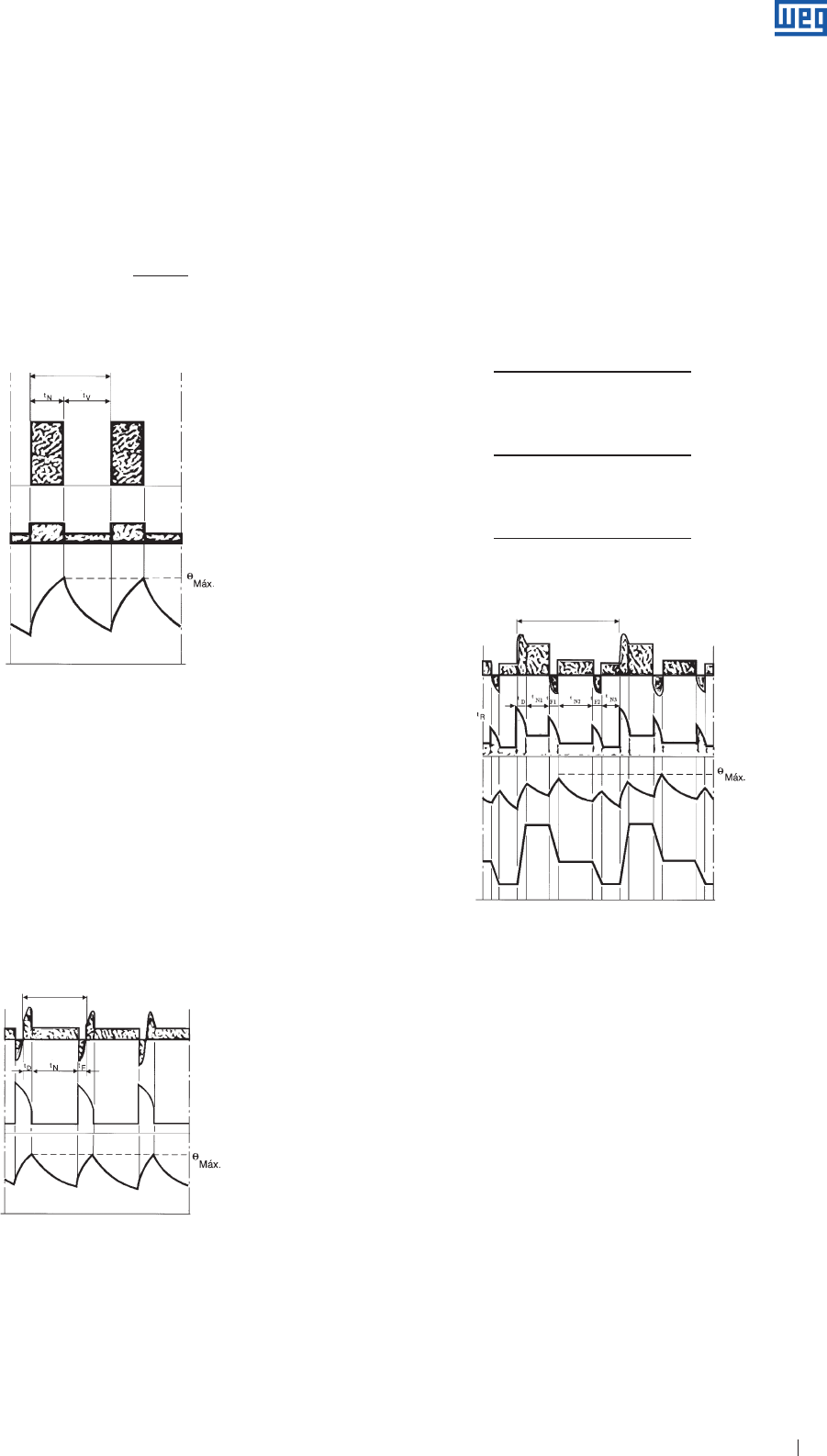
Specification of Electric Motors 41
Load
Cycle duration
Electrical losse
s
Temperature
Time
Figure 7.15
Figure 7.14
f ) Duty Type S6 - Continuous operation periodic duty
A sequence of identical duty cycles, each cycle consisting of
a time of operation at constant load and a time of operation
at no-load. There is no time de-energized and at rest, see
Figure 7.14.
tN
Cycle duration factor = . 100%
tN + tV
Load
Cycle duration
Time
Electrical losses
Temperature
g ) Duty type S7 - Continuous operation periodic duty
with electric braking
A sequence of identical duty cycles, each cycle consisting
of a starting time, a time of operation at constant load and a
time of electric braking. There is no time de-energized and at
rest, see Figure 7.15.
Cycle duration factor = 1
h ) Duty type S8 - Continuous operation periodic duty
with related load/speed changes
A sequence of identical duty cycles, each cycle consisting
of a time of operation at constant load corresponding to a
predetermined speed of rotation, followed by one or more
times of operation at other constant loads corresponding to
different speeds of rotation. There is no time de-energized
and at rest ( see Figure 7.16 ).
Cycle duration factor:
tD + tN1
. 100%
tD + tN1 + tF1 + tN2 + tF2 + tN3
tF1 + tN2
. 100%
tD + tN1 + tF1 + tN2 + tF2 + tN3
tF2 + tN3
. 100%
tD + tN1 + tF1 + tN2 + tF2 + tN3
g For N1 =
g For N2 =
g For N3 =
Figure 7.16
Load
Electrical losse
s
Cycle duration
Temperature
Speed
variation
Time
i ) Duty type S9 - Duty with non-periodic load
and speed variations
A duty in which generally load and speed vary
non=periodically within the permissible operating range. This
duty includes frequently applied overloads that may greatly
exceed the reference load ( see Figure 7.17 ).
tN
= operation time at Constant load
tV = operation time at no-load
θ máx = maximum temperature attained
tD = starting/acceleration time
tN = operation time at constant load
tF
= time of electric braking
θmáx = maximum temperature attained
tF1 - tF2 = time of electric braking
tD = starting/accelerating time
tN1 - tN2 - tN3 = operation time at constant load
θmáx = maximum temperature attained
www.weg.net
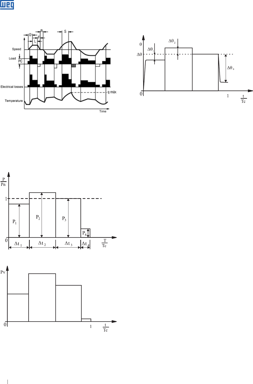
Specification of Electric Motors 42
Figure 7.18a
Figure 7.18b
Figure 7.17
j ) Duty type S10 - Duty with discrete constant loads and
speeds
A duty consisting of a specific number of discrete values of
loads ( or equivalent loading ) and if applicable, speed, each
load/speed being maintained for sufficient time to allow the
machine to reach thermal equilibrium, see Figures 7.18a, b
and c. The minimum load within a duty cycle may have the
zero value ( no-load or de-energized and at rest ).
Figure 7.18c
Note: with respect to duties S3 through to S8, the time of operation is generally
too short to reach the thermal equilibrium. The motor heats up partially
and cools down at every cycle. Only after a large number of cycles the
motor reaches the thermal equilibrium.
k ) Special duties
The load can vary during operation time or when reversal or
counter-current braking, etc. is activated. The proper motor
selection can only be ensured after contacting the factory
and providing a complete description of the cycle:
g Motor output required to drive the load. If the load varies
cyclically, provide a load x time diagram ( as example see
Figure 7.15 ).
g Resistive torque of the load.
g Total moment of inertia ( GD2 or J ) of the driven
machine with reference to its rated speed.
g Number of starts, reversals, countercurrent braking, etc.
g Operation time with load and time at rest/no-load.
7.3.2 Duty Type Designation
The duty type shall be designated by the symbol described
in item 7.3. The continuous running duty can be indicated
alternatively by the word “continuous”. Examples for the duty
type designation:
1 ) S2 60 seconds
The designation of the duties S2 to S8 is given by the
following indications:
a ) S2, operation time at constant load;
b ) S3 to S6, cycle duration factor;
c ) S8, each one of the rated speeds that are part of the
cycle, followed by its respective rated output and its
duration time.
For the duty types S4, S5, S7 and S8 other indications can
be added to the designation, however these indications
should be agreed previously between the manufacturer and
the customer.
Note: as example of the indications to be added, previously agreed relating
to the duty type designation different from the continuous running duty,
following indications can be made relating to the considered duty type:
a ) Number of start per hour;
b ) Number of braking per hour;
c ) Type of braking;
d ) Constant of kinetic energy ( H ), rated speed of motor and load. The
last one can be changed by the inertia factor ( FI ).
www.weg.net
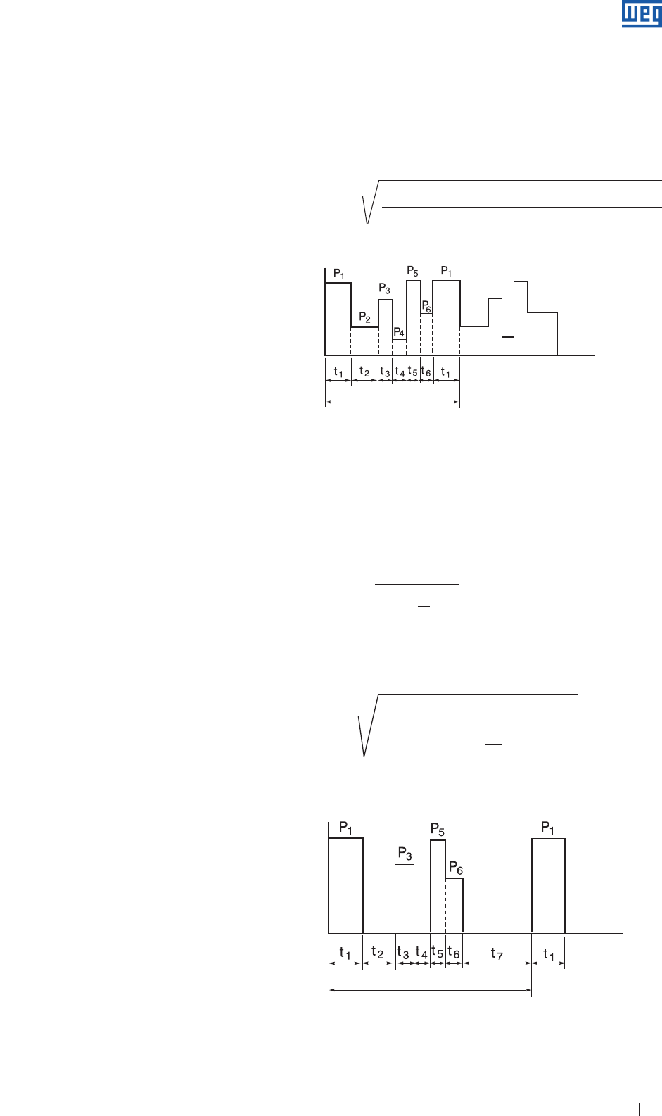
Specification of Electric Motors 43
Where: constant of kinetic energy is the ratio between the kinetic energy
( stored in the rotor at rated speed ) and the rated apparent power.
Inertia factor is the ratio between the sum of total inertia moment of
load ( referred to the motor shaft ) and the rotor moment of inertia.
2 ) S3 25%; S6 40%
3 ) S8 motor H.1 Fl. 10 33 cv 740rpm 3min
Where: - H.1 is a Constant of kinetic energy of 1s;
- Fl.10 is na inertia factor of 10.
4 ) S10 para Δt = 1.1/0.4; 1.0/0.3; 0.9/0.2; r/0.1; TL = 0.6.
Where: Δt is in p.u. ( per unit ) for the different loads and their respective
operations. The TL value is given p.u. for the expected lifetime of the
thermal insulation system. During the time at rest the load must be
indicated by the letter “r”.
7.3.3 Rated Output
Rated output is the mechanical power available at shaft end,
within its characteristics at continuous running duty. The
rated output concept, i. e., the mechanical power available
at shaft end, is directly related to the temperature rise of the
winding. As you know, the motors can drive much higher
power loads than its rated output, until it almost reaches the
breakdown torque. However, if the overload exceeds motor
output for which it has been designed, overheating will be
generated and the motor lifetime will be reduced significantly,
or may even result in motor burn out.
Consider that the required motor power is always defined
by the load characteristics, for example: a load of 90 HP
required from the motor, will be always 90 HP even if the
motor has been designed for 75 HP or 100 HP.
7.3.4 Equivalent Power Ratings for Low Inertia Loads
It is assumed that the electric motor must supply to the
driven machine the required power. It is also recommended
that the motor provides some extra power for eventual
overloads; depending on the duty cycle, the motor can
occasionally supply more or less power. Although there
are the many standardized ways to describe the running
conditions of a motor, it is often necessary to evaluate the
load conditions imposed on the motor by more complex duty
cycles than those described in the standards. The formula
below gives an usual method to calculate the equivalent
power rating:
Where: Pm = equivalent power required from the motor
P( t ) = power, variable with time, required from the motor
T = total cycle time ( period )
This method is based on the hypothesis that the effective
load applied to the motor will provide the same thermal
requirements than a fictitious equivalent load, that requires
continuously the power Pm.
It is also based on the fact that load losses vary according
to the square of the load, and that the temperature rise is
directly proportional to losses. This is true for motors that run
continuously but drive intermittent loads.
Power
Period
Ti
me
So:
P1
2 . t1 + P2
2 . t2 + P3
2 . t3 + P4
2 . t4 + P5
2 . t5 + P6
2 . t6
Pm =
t1 + t2 + t3 + t4 + t5 + t6
Figure 7.19 - Continuous running with intermittent loads
If the motor is at rest between the operation times, the motor
cooling will be reduced. Thus, for motors where the cooling
efficiency is directly related to motor operation ( for example,
TEFC motors ), the equivalent power is calculated by the
following formula:
Σ ( P2
i . ti )
( Pm )2 =
Σ ( ti + 1 tr )
3
where: ti = load time
tr = time at rest
Pi = correspnding loads
P1
2 . t1 + P3
2 . t3 + P5
2 . t5 + P6
2 . t6
Pm =
t1 + t3 +t5 + t6 + ( t2 + t4 + t7 )
1
3
Pm 2 = ∑ P ( t )2 Δt
1t
t=0
T
Power
Period
Ti
me
Figure 7.20 - Operation with variable load and at rest between the operations
times
www.weg.net
Specification of Electric Motors 44
7.4 Service Factor ( SF )
Service factor ( SF ) is the factor that, when applied to rated
output, represents the allowable load that can be applied to
motor continuously, under specified operating conditions.
Note that this refers to continuous overload conditions,
i.e., a power reserve that gives the motor a better capacity
to withstand adverse operating conditions. Service factor
should not be confused with momentary overload capacity
during few minutes. A service factor = 1.0 means that the
motor has not been designed for continuous operation above
its rated output. However, this does not change its capacity
to withstand instantaneous overloads. NBR 17094 specifies
the most common Service Factors per motor output.
8. Environment Characteristics
The selection of electric motor for particular applications
should consider some parameters such as:
g Altitude where motor will be installed;
g Temperature of the cooling medium.
According to ABNT NBR 17094 and IEC 60034-1, the usual
service conditions are:
a ) Altitude not exceeding 1.000 masl;
b ) Cooling medium ( in most case, the ambient air ) with
temperature not exceeding 40 ºC and free from harmful
substances.
Up to altitudes not exceeding 1.000 masl and ambient
temperatures not exceeding 40 ºC, the operating conditions
are considered normal and the motor must supply its rated
output without overheating.
8.1 Altitude
Motors operating at altitudes above 1000 m.a.s.l will have
overheating problems caused by the rarefaction of the air
which results in reduction of the cooling capacity. Poor heat
exchange between the motor and cooling air will require a
loss reduction which will also reduce the motor output.
The motor heating is directly proportional to losses and these
vary quadratically with the motor outputs.
There are some application alternatives to be evaluated:
a ) The installation of a motor at altitudes above 1000 masl
can be made by using insulating material of higher thermal
class;
b ) As per IEC 60034-1, temperature rise limits must be
reduced by 1% for every 100m of altitude above 1000
masl. This rule is valid for altitudes up to 4.000masl. For
higher altitudes, please contact WEG.
Example:
A class B, 100 HP motor, Δt 80 K, operating at an altitude
of 1500 masl, the ambient temperature of 40 ºC must be
reduced by 5 ºC, resulting in a maximum stable temperature
of 36 ºC. The ambient temperature may be evidently higher
provided that temperature rise is lower than the temperature
class of the insulating materials.
Tamb = 40 - 80 . 0.05 = 36 oC
8.2 Ambient Temperature
Motors operating at temperatures below 20ºC will have the
following problems:
a ) Excessive condensation, requiring additional condensed
water drains or installation of space heaters when motor
remains out of service for long periods;
b ) Bearing frosting which causes grease or lubricant
hardening requiring the use of special lubricants or
antifreezing grease ( please check our website ).
Motors operating continuously at ambient temperatures
above 40 ºC, their insulation system can be damaged. A
possible solution for this problem is to build the motor with
special design using special insulating materials or oversizing
the motor.
8.3 Determining Useful Motor Output at Different
Temperature and Altitude Conditions
Combining effects of temperature and altitude variation,
the dissipation capacity of motor output can be obtained
multiplying the useful output by the multiplying factor of table
8.1 bel ow:
T/H 1000 1500 2000 2500 3000 3500 4000
10 1.16 1.13 1.11 1.08 1.04 1.01 0.97
15 1.13 1.11 1.08 1.05 1.02 0.98 0.94
20 1.11 1.08 1.06 1.03 1.00 0.95 0.91
25 1.08 1.06 1.03 1.00 0.95 0.93 0.89
30 1.06 1.03 1.00 0.96 0.92 0.90 0.86
35 1.03 1.00 0.95 0.93 0.90 0.88 0.84
40 1.00 0.97 0.94 0.90 0.86 0.82 0.80
45 0.95 0.92 0.90 0.88 0.85 0.82 0.78
50 0.92 0.90 0.87 0.85 0.82 0.80 0.77
55 0.88 0.85 0.83 0.81 0.78 0.76 0.73
60 0.83 0.82 0.80 0.77 0.75 0.73 0.70
Table 8.1 Multiplying factor for the usefull output as function of the ambient
temperature ( T ) at “ºC” and altitude ( H ) in “m”
Example:
A Class F Insulation motor, 100 HP, operating at an altitude
of 2.000 masl and ambient temperature of 55 ºC.
Based in table 8.1 - α = 0.83 thus P” = 0.83 , Pn
The motor can only supply 83% of its rated output.
www.weg.net

Specification of Electric Motors 45
8.4 Environment
8.4.1 Aggressive Environments
Aggressive environment such as shipyards, port facilities, fish
industries, marine applications, chemical and petrochemical
industries require that all equipment operating at such
environments are suitable and reliable to withstand such
harsh conditions without presenting any problem.
For the application of electric motors in these aggressive
environments, WEG has a specific line for each motor type duly
designed to meet specific and standardized requirements for
the most adverse operating conditions. These motors can be
delivered with the following special characteristics:
g Double impregnated winding
g Anticorrosive alkyd paint ( inside and outside )
g Galvanized mounting bolts
g
Oil seal between shaft and endshield ( may be lip seal,
W3Seal, etc. )
g Additional protection by sealing joints.
For environments with temperature range between -16 ºC
and 40 ºC and relative air humidity ≤ 95%, anticorrosive
coating for internal surfaces is recommended. For
environments with temperatures between 40 ºC and
65 °C also anticorrosive coating for internal surfaces is
recommended, however, a derating factor to 40 ºC should be
considered.
Note: for environments with relative air humidity > 95%, anticorrosive coating for
internal surfaces with connection of space heater is recommended.
For marine motors, the specific operating characteristics are
defined by the type of driven load on board. However, all
motors offer the following special features:
g Reduced temperature rise for operation in ambient up to 50 ºC
g
Capacity to withstand without any problem, sudden
overload conditions of short duration up to 60% above
the rated torque, as specified in standards of Certification
Bodies.
WEG rigid control during production process ensures reliable
operation to the marine motors. They meet the construction
and inspection requirements as well as the tests specified in
the standards of the Certification Bodies, such as:
g AMERICAN BUREAU OF SHIPPING
g BUREAU VERITAS
g CHINA CERTIFICATION SOCIETY
g DET NORSKE VERITAS
g GERMANISCHER LLOYD
g LLOYD’S REGISTER OS SHIPPING
g RINA S.p.A.
8.4.2 Environments Containing Dusts and Fibers
To analyze whether motors are suitable to operate in these
environments, the following information should be available:
approximate size and amount of fibers present in the
environment. This information is since along the time, the
fibers can obstruct the ventilation system resulting in motor
overheating. If fiber content is excessive, air filters should be
applied or the motor must be cleaned frequently.
Prevent motor cooling impairment
For this case there are two solutions:
1 ) Use motors without ventilation system;
2 ) For motor with cooling by ducts, calculate the volume of
air to be displaced by the motor fan, by establishing the
airflow required for perfect the motor cooling.
8.4.3. Explosive Atmospheres
Explosion-proof, non-sparking, increased safety and dust-
proof motors are intended for use in explosive atmospheres
containing combustible gases, vapors, or explosive dusts or
fibers. Chapter 9 ( explosive atmospheres ) deals specifically
with this subject.
8.5 Degree of Protection
Enclosures of electrical equipment, according to
characteristics where they will be installed and their
maintenance accessibility, should offer a certain degree of
protection. Thus, for example, an equipment to be installed in
a location subjected to water jets must have housing capable
of withstanding the water jets under determined pressure and
angle of incidence, without water penetration.
8.5.1 Identification Codes
Standard IEC 60034-5 defines the degrees of protection of
electrical equipment by means of the characteristic letters IP,
followed by two characteristic numerals.
First characteristic numeral
1st charact.
numeral Definition
0No-protected machine
1 Machine protected against solid objects greater than 50 mm
2 Machine protected against solid objects greater than 12 mm
3 Machine protected against solid objects greater than 2,5 mm
4 Machine protected against solid objects greater than 1,0 mm
5Dust-protected machine
6Dust-tight machine
Table 8.2 - First characteristic numeral indicates the degree of protection
against the ingress of solid objects and accidental or inadvertent contact.
Second characteristic numeral
2nd charact.
numeral Definition
0No-protected machine
1Machine protected against dripping water
2Machine protected against dripping water when tilted up to 15º
3 Water falling as a spray at any angle up to 60º from the vertical
4Water splashing against the machine from any direction
5 Water protected by nozzle against the enclosure from any direction
6 Water from heavy seas or water projected in powerful jets
7 Machine protected against the effects of immersion
8 Machine protected against the effects of continuous submersion
Table 8.3 - Second characteristic numeral indicates the degree of protection
against the ingress ff water in the machine r
www.weg.net

Specification of Electric Motors 46
The combination of the two characteristic numerals, i. e., between
The two degrees of protection, is shown in Table 8.4. According
to standards the qualification of a motor is clearly defined for each
for each degree of protection by standardized testes which do
not leave any scope of misinterpretation.
Motor
Degree
of
Protection
First characteristic numeral Second char.
numeral
Protected against
Accidental contact
Protected against
solid object
Protected against
water
Open
motors
IP00 Non-protected Non-protected Non-protected
IP02 Non-protected Non-protected
Protection against
dripping water even
when tilted 15º
vertically
IP11
Protection against
accidental contact
with the hand
Ingress of solid
objects exceeding
50 mm in diameter
Protection against
dripping water
falling vertically
IP12
Protection against
accidental contact
with the hand
Ingress of solid
objects exceeding
50 mm in diameter
Protection against
dripping water even
when tilted 15º
IP13
Protection against
accidental contact
with the hand
Ingress of solid
objects exceeding
50 mm in diameter
Protection against
dripping water even
when tilted 60º
IP21
Protection against
the touching with
the finger
Ingress of solid
objects exceeding
12 mm in diameter
Protection against
dripping water
falling vertically
IP22
Protection against
the touching with
the finger
Ingress of solid
objects exceeding
12 mm in diameter
Protection against
dripping water even
when tilted 15º
IP23
Protection against
the touching with
the finger
Ingress of solid
objects exceeding
12 mm in diameter
Protection against
dripping water even
when tilted 60º
Closed
motors
IP44
Protection against
the touching
with tools
Ingress of solid
objects exceeding
1 mm in diameter
Protection against
splashing water
from any direction
IP54 Protection against
contacts
Protection against
accumulation of
harmful dust
Protection against
splashing water
from any direction
IP55 Protection against
touches
Protection against
accumulation of
harmful dust
Protection against
water jets from any
direction
Table 8.4 - Degree of Protection
8.5.2 Usual Degrees of Protection
Although some characteristic numerals to indicate the degree
of protection can be combined in different ways, only a few
degrees of protection are usually employed. They are: IP21,
IP22, IP23, IP44 and IP55.
The first three numerals apply to open motors and the other
two refer to enclosed motors. For special and more dangerous
areas there are other commonly used degrees of protection
such as IPW 55 ( weather protection ) IP56 ( protections against
water jets ), IP65 ( totally protected against dust ) and IP66
( totally protected against dust and water jets ).
Bearing sealing
Frame sizes 225S/M to 355A/B can be supplied with sealing
system WSeal®, as serial item This sealing system consists of
a V'Ring ring with double lips and metal cap mounted on this
ring.
Among the other available sealing systems for the line W22,
is the revolutionary sealing system W3 Seal®, formed by three
seals: V'Ring, O'Ring and Taconite Labyrinth. This sealing
system has been developed by WEG to protect the motor
against accumulation of solid and liquid impurities present
in environment, which provides to the motor the protection
degree IP66.
Other degrees of protection for motors are not so common.
Any of the above mentioned degree of protection fully meets
the lower requirements of the lower ( smaller figures ). Thus,
for example, an motor with degree of protection IP55 replaces
with advantages the motors with degree of protection IP12,
IP22 or IP23, ensuring higher protection against accidental
exposure to dust and water. This allows the production
standardization with a single type of motor that meets all the
cases, with an additional advantage for user in the case of less
demanding environments.
8.5.3 Weather Protected Motors
According to IEC 60034-5, the motor will be weather
protected when due to its design ( technical discussion
between customer and WEG ), the defined protections
provide a correct operation of the motor against rain, dust
and snow.
WEG also uses the letter W to indicate the degree of
protection of the motor to indicate that the motor has
a special paint plan ( weather protected ). The painting
plans may vary according to the environmental severity,
which should be informed by the customer during motor
specification/order.
Aggressive environments require that equipment be perfectly
suitable to support such conditions ensuring high reliability in
service without showing any problems.
WEG manufacturers a wide range of electric motors with
special characteristics, suitable for use in shipyards, ports,
fishing plants and several naval applications, as well as in
chemical and petrochemical industries and other aggressive
environments. So WEG motors are suitable to operate under
the most severe operational conditions.
8.6 Space Heater
The space heater are installed inside the motor when it
operates in high-humidity environments, ( humidity> 95% )
and / or when it remains out of operation for long periods
( longer than 24 h ), thus preventing water accumulation water
inside the motor by the condensation of humid air.
The space heater heats up the motor inside few degrees
above the ambient temperature ( 5-10 °C ), when the motor is
switched off. The supply voltage of the space heaters must be
specified by customer. The space heaters can be supplied for
following supply voltage: 110 V, 220 V and 440 V.
Depending on the frame size, following space heaters will be
installed. See Table 8.5:
www.weg.net
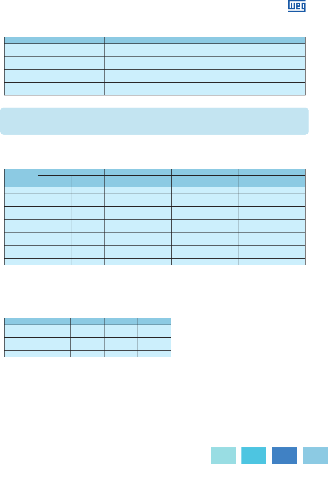
Specification of Electric Motors 47
Frame size Quantity Power ( W )
63 to 80 1 7.5
90 to 100 1 11
112 2 11
132 to 160 2 15
180 to 200 2 19
225 to 250 2 28
280 to 315 2 70
355 to 315B 2 87
Table 8.5 - Space heaters
WARNING: the space heaters should only be powered on when motor is off, otherwise the motor may overheat, resulting in
potential damages. Disconnect input power to the motor before performing any maintenance. Also space heaters must be
disconnected from input power.
Table 8.6 - Maximum sound power and sound pressure levels for three-phase motors ( IC411,IC511,IC611 ), at no-load, in dB( A ), 60 Hz.
Note 1: motors with cooling method IC01,IC11,IC21 may present higher sound Power levels: 2 and 4 poles +7dB( A ), - 6 and 8 poles +4dB( A ).
Note 2: the sound Power levels for 2 and 4 poles, frame size 355 are valid for unidirectional fans. The other sound Power levels are valid for bidirectional fans.
Note 3: the values for 50 Hz motors should be decreased by : 2 poles -5dB( A ) ; 4, 6 and 8 poles -3dB( A ).
Table 8.7 - Maximum estimated increment for the sound power and sound pressure levels,
in dB ( A )
Note 1: this table provides the maximum expected increment at rated load conditions.
Note 2: the values are valid for 50 Hz and 60 Hz.
8.7 Noise Levels
WEG Motors comply with NEMA and IEC standards which specify the maximum sound pressure levels in decibels. The values
of Table 8.6 comply with IEC 600034-9 standard.
Frame size
2 poles 4 poles 6 poles 8 poles
Sound
power level
Sound
pressure level
Sound
power level
Sound
pressure level
Sound
power level
Sound
pressure level
Sound
power level
Sound
pressure level
90 83 71 69 57 66 54 66 54
100 87 75 73 61 67 55 67 55
112 88 76 75 63 73 61 73 61
132 90 78 78 66 76 64 74 62
160 92 79 80 67 76 63 75 62
180 93 80 83 70 80 67 79 66
200 95 82 86 73 83 70 82 69
225 97 84 87 74 83 70 82 69
250 97 83 88 74 85 71 83 69
280 99 85 91 77 88 74 85 71
315 103 88 97 82 92 77 91 76
355 105 90 98 83 97 82 95 80
Frame size 2 poles 4 poles 6 poles 8 poles
90 to 160 2 5 7 8
180 to 200 2 4 6 7
225 to 280 2 3 6 7
315 2 3 5 6
355 2 2 4 5
Table 8.7 shows the increments to be considered for the sound power and sound pressure levels, in dB ( A ), for motors
operating at load conditions.
www.weg.net
Specification of Electric Motors 48
9. Explosive Atmosphere
9.1 Hazardous Area
An installation where inflammable products are continually
handled, processed or stored requires special care to ensure
the maintenance of property and the personnel safety.
Based on their characteristics, electric equipment can
become ignition sources causing sparks, when opening or
closing contacts or due to overheating of any component,
caused intentionally or originated by fault currents.
9.2 Explosive Atmosphere
An atmosphere is considered explosive when the proportion
of gas, vapor, dust, fibres, or flyings is such that after
sparking caused by short-circuit or overheating of one
component causes an ignition and explosion. Three elements
are required for an explosion to occur:
Fuel + oxygen + ignition = explosion
9.3 Classification of Hazardous Areas
According to IEC Standards, hazardous areas are classified
as follows:
Zone 0:
Area in which and explosive atmosphere is present
continuously, or for long periods of frequently. For example,
inside a fuel tank the explosive atmosphere is always present.
Zone 1:
Area in which an explosive gas atmosphere is likely to occur
in normal operation occasionally. The explosive atmosphere
is frequently present.
Zone 2:
Area in which an explosive gas atmosphere is not likely to
occur in normal operation, but if it does occur, will persist for
a short period only. This conditions associated with abnormal
operation of equipment and process, losses or negligent use.
The explosive atmosphere may accidentally be present.
According to NEC/API 500 Standards, the hazardous areas are
classified as follows:
g
Division 1 - Area where there is HIGH probability of
occurring an explosion.
g Division 2 - Area where there is lower explosion probability.
Standards
Occurrence of flammable mixtures
Continuously
present
Under normal
conditions
Under abnormal
conditions
IEC Zone 0 Zone 1 Zone 2
NEC/API Division 1 Division 2
Table 9.1 - Comparison between ABNT/IEC and NEC/API
The process of dust storage in confined spaces offers
potentially explosive atmospheres. This occurs when dust is
mixed with air in the form of a dust cloud or when the dust
is deposited on the electrical equipment. Areas where dust,
flyings and fibres in air occur in dangerous quantities are
classified , according to IEC 61241-10, as hazardous and are
divided into three zones according to the level of risk.
9.3.1. Classes and Groups of the Hazardous Areas
Classes - refer to the nature of the mixture. The concept of
classes is only adopted by the NEC standard.
Groups - The definition of groups is associated with the
composition of the mixture.
Class I
Explosive gases or steams. Based on the type of gas or
steam, we ill have following classification:
g GROUP A - acetylene
g GROUP B - hydrogen, butadiene, ethane oxide
g GROUP C - ethyl ether, ethylene
g GROUP D - gasoline, naphtha, solvents in general.
Class II
Combustible of conductive dust. Based on the type dust, we
ill have following classification:
g GROUP E
g GROUP F
g GROUP G
Class III
Light and flammable fibers and particles.
According to IEC 60079-0, Hazardous areas are divided into
three separate classifications:
g Group I - For mines containing methane gas.
g
Group II - For application in other areas with gass explosive
atmospheres. These areas are dived in IIA, IIB and IIC.
g
Group III - For application in explosive du st atmospheres.
These group is divided in:
g III A - Combustible fibres
g III B - Non-cnductive dust
g III C - Conductive dust
Zone 20:
Area in which an explosive atmosphere in the form of a cloud
of combustible dust in air is present continuously, or for long
periods or frequently.
Zone 21:
Area in which an explosive atmosphere in the form of a cloud
of combustible dust in air is likely to occur, occasionally, in
normal operation.
Zone 22:
Area in which an explosive atmosphere in the form of a cloud of
combustible dust in air is not likely to occur in normal operation
but, if it does occur, will persist for a short period only.
Among the products where their powders or dusts create
potentially explosive environments inside confined ambient
are the coal, wheat, cellulose, fibers and plastics in finely
divided particles, etc.
www.weg.net
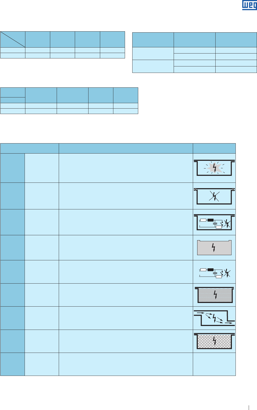
Specification of Electric Motors 49
Table 9.5 - Type of protection by enclosure
Table 9.2 - Comparison between IEC and NEC/API for gases
Table 9.3 - Comparison between Standards IEC and NEC/API for combustible
dust and fibers
Table 9.4 - Classification per area according to IEC and NEC
Gases
Standards
Group
of Acetylene
Group
of Hydrogen
Group
of ethane
Group
of propane
IEC II C II C II B II A
NEC/API Class I Gr A Class I Gr B Class I Gr C Class I Gr D
Explosive atmosphere ABNT / IEC NEC
Gases or steams Zone 0 and Zone 1 Class I Division 1
Zone 2 Class I Division 2
Combustible dusts Zone 20 and Zone 21 Class II Division 1
Zone 22 Class II Division 2
9.3.2 Protection by Enclosure
Symbol Description Representação
simplificada
"d" Explosion-proof
Type of protection in which the parts capable of igniting an explosive gas atmosphere are
provided with an enclosure which can withstand the pressure developed during an internal
explosion of an explosive mixture, and which prevents the transmission of the explosion to the
explosive gas atmosphere surrounding the enclosure.
UC
LR
"e" Increased safety
Type of protection applied to electrical apparatus in which additional measures are applied so
as to give increased security against the possibility of excessive temperatures and of the
occurrence of arcs and sparks in normal service or under specified abnormal conditions
UC
LR
"i" Intrinsic safety
“ia”, “ib”, “ic”
Type of protection, in which any spark or any thermal effect produced in the conditions
specified in the standard, including normal operation and specified fault conditions, are not
capable of causing ignition of a given explosive gas atmosphere.
UC
LR
"m" Encapsulation
“ma”, “mb”, “mc”
Type of protection whereby parts that are capable of igniting an explosive atmosphere by either
sparking or heating are enclosed in a compound in such a way that the explosive atmosphere
cannot be ignited under operating or installation condition.
UC
LR
“n” Tipo de proteção "n"
“nA”, “nC”, “nR”
Type of protection applied to electrical apparatus such that, in normal operation and in certain
specified abnormal conditions, it is not capable of igniting a surrounding explosive gas
atmosphere. There are three categories of materials: no spark generation ( nA ), spark generation
( nC ), encapsulated with limited breathing ( nR ).
UC
LR
“o” Oil immersion
Type of protection in which the electrical apparatus or parts of the electrical apparatus are
immersed in a protective liquid in such a way that an explosive gas atmosphere which may be
above the liquid or outside the enclosure cannot be ignited.
UC
LR
“p” Pressurization
“px”, “py”, “pz”,
Type of protection for guarding against the ingress of the external atmosphere into an enclosure
or room by maintaining a protective gas therein at a pressure above that of the external
atmosphere.
UC
LR
“q” Sand filling
Type of protection in which the parts capable of igniting an explosive gas atmosphere are fixed in
position and completely surrounded by filling material to prevent the ignition of an external
explosive atmosphere.
UC
LR
“t” Protection by
enclosure
Type of protection where parts that can cause ignition of an explosive atmosphere are
protected by an enclosure providing partially or totally protection against dust ingress and a
means to limit surface temperature
Dust and
fibres High
conductive dust
Light
conductive dust
Non-
conductive
dust
Combustible
fibers
Standards
NBR IEC III C III C III B III A
NEC/API Class II Gr E Class II Gr F Class II Gr G Class III
www.weg.net
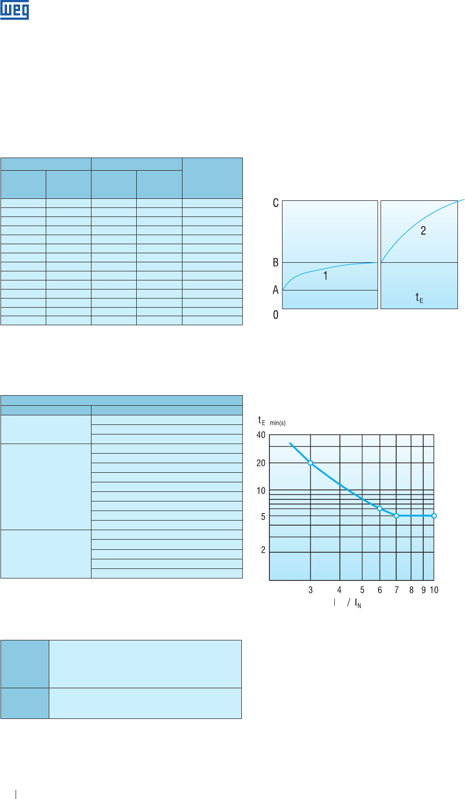
Specification of Electric Motors 50
9.4 Temperature Classes
The maximum temperature on the outer and/or inner surface
of an electric equipment must always be lower than the
ignition temperature of the gas or steam. Gases can be
classified for temperature classes based on their ignition
temperature, where the maximum surface temperature of the
corresponding class must be lower than the corresponding
temperature of the gases.
Table 9.6 - Temperature classes
IEC NEC
Ignition temperature
of gases and/or
steams
Temperature
classes
Maximum
surface
temperature
Temperature
classes
Maximum
surface
temperature
T1 450 T1 450 > 450
T2 300 T2 300 > 300
T2A 280 > 280
T2B 260 > 260
T2C 230 > 230
T2D 215 > 215
T3 200 T3 200 > 200
T3A 180 > 180
T3B 165 > 165
T3C 160 > 160
T4 135 T4 135 > 135
T4A 120 > 120
T5 100 T5 100 > 100
T6 85 T6 85 > 85
9.5 Equipment for Explosive Atmospheres
The tables below show the selection of equipment for
hazardous areas classified according to IEC 60079-14:
Table 9.7 - Types of protection for explosive atmospheres with inflammable
gases.
Table below shows the list of equipment according to
standard NEC:
DIVISION 1 Equipment with type of protection:
g explosion-proof Ex"d"
g presurization Ex"p"
g oil immersion Ex"o"
g intrinsic safety Ex"i"
DIVISION 2 g any equipment certified for Division 1
g equipment that do not generate sparks of hot surfaces on general
purpose enclosures
Table 9.8
9.6 Increased Safety Equipment
his electrical equipment, under normal operating conditions,
does not generate arcs, sparks or sufficient heat to cause
ignition of the explosive atmosphere for which it was
designed.
Time tE - time taken for an a.c. rotor or stator winding, when
carrying the initial starting current IA, to be heated up to the
limiting temperature from the temperature reached in rated
service at the maximum ambient temperature. Figures below
show how to proceed for correct time “tE” determination.
( Figures 9.1 and 9.2 ).
Temperature (ºC)
Time
P
Figure 9.1 - Schematic diagram explaining the method fot the time “tE”
determination
Figure 9.2 - Minimum time “tE” as function of the starting current ratio IP / IN
A - maximum ambient temperature
B - temperature at rated service condition
C - limit temperature
1 - service temperature rise
2 - locked rotor temperature rise
ABNT NBR IEC 60079-14
Zone Possible types of protection
Zone 0
Ex "iA"
Ex "mA"
Equipment specially approved for Zone 0
Zone 1
Equipment certified for Zone 0
Ex "d"
Ex "de"
Ex "e"
Ex "px". Ex "py"
Ex "iB"
Ex "q"
Ex "o"
Ex "mB"
Zone 2
Equipment certified for Zone 0 and Zone 1
Ex "pZ"
Ex "iC"
Ex "n"
Ex "mC"
www.weg.net
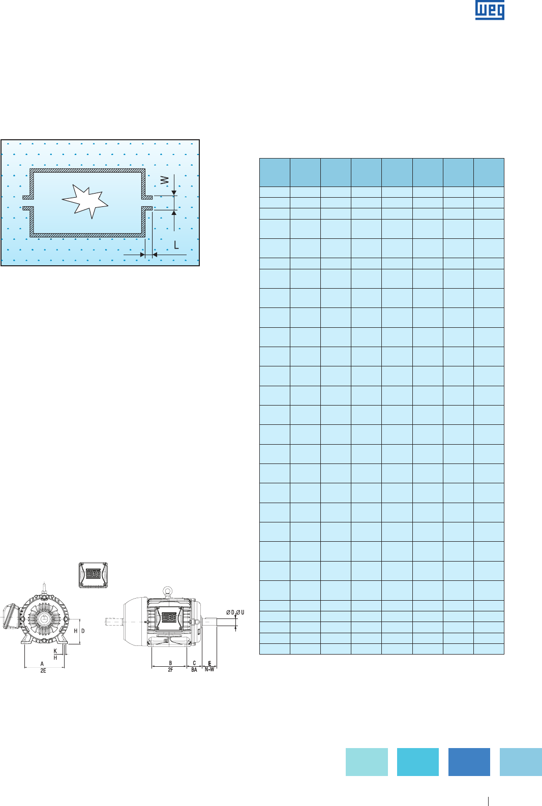
Specification of Electric Motors 51
10. Mounting Arrangements
10.1 Dimensions
Dimensions of WEG electric motors are standardized
according to the standard International Electrotechnical
Commission - IEC-60072. In these standards the basic
dimension for the standardization of the assembly
dimensions of electric machines is the height from the base
to the shaft end center, designated by the letter H ( se Figure
10.1 below ).
To each height of shaft end H, a C dimension is associated,
distance from the centerline of mounting hole in the nearest
foot to the shoulder on drive end shaft. However, to each H
dimension, several B dimension can be associated ( distance
between centerlines of mounting holes in feet ), allowing to
have either “longer” or “shorter” motors.
9.7 Explosion-Proof Equipment
It is a type of protection where the parts that may ignite an
explosive atmosphere are confined within enclosures that
can withstand the pressure caused by an internal explosion
of an explosive atmosphere and prevents the transmission of
the explosion to an explosive atmosphere.
Figure 9.3 - Protection principle
The induction motor ( with any type protection ) is not tight
protected, i. e., there is air exchange with the nvironment.
During operation, the motor heats up and the inside air will
have higher pressure than the outside ( air is then blown out );
when the power supply is turned off, motor cools down and,
as a consequence, the inside pressure decreases allowing
penetration of air ( which is contaminated ). The Ex-d enclosure
will not allow any eventual internal explosion to propagate to
the external environment. For the system safety, WEG controls
all air gaps - flame paths ( tolerances between joints ) and
the finishing joint since they are responsible for the volume of
gases exchanged between the inside and outside of the motor.
Figure 10.1
The A dimension, distance between centerlines of mounting
holes in the feet or base of machine, on the front side, is
unique for H values up to 315, however it can have multiple
values from frame size H equal to 35 mm. For those
customers who require standardized frames size according
to NEMA standard, table 10.1 makes a comparison between
dimensions H-A-B-C-K-D- E of IEC standard and D; 2E; 2F;
BA; H; U-N-W of NEMA standard.
ABNT
/ IEC
NEMA
H
D
A
2E
B
2F
C
BA
K
H
∅ D
∅ U
E
N-W
63 63 100 80 40 7 11j6 23
71 72 112 90 45 7 14j6 30
80 80 125 100 50 10 19j6 40
90 S
143 T
90
88.9
140
139.7
100
101.6
56
57.15
10
8.7
24j6
22.2
50
57.15
90 L
145 T
90
88.9
140
139.7
125
127
56
57.15
10
8.7
24j6
22.2
50
57.15
100L 100 160 140 63 12 28j6 60
112 S
182 T
112
114.3
190
190.5
140
114,3
70
70
12
10.3
28j6
28.6
60
69.9
112 M
184 T
112
114.3
190
190.5
140
139.7
70
70
12
10.3
28j6
28.6
60
69.9
132 S
213 T
132
133.4
216
216
140
139.7
89
89
12
10.3
38k6
34.9
80
85.7
132 M
215 T
132
133.4
216
216
178
177.8
89
89
12
10.3
38k6
34.9
80
85.7
160 M
254 T
160
158.8
254
254
210
209.6
108
108
15
13.5
42k6
41.3
110
101.6
160 L
256 T
160
158.8
254
254
254
254
108
108
15
13.5
42k6
41.3
110
101.6
180 M
284 T
180
180
279
279.4
241
241.3
121
121
15
13.5
48k6
47.6
110
117.5
180 L
286 T
180
177.8
279
279.4
279
279.4
121
121
15
13.5
48k6
47.6
110
117.5
200 M
324 T
200
203.2
318
317.5
267
266.7
133
133
19
16.7
55m6
54
110
133.4
200 L
326 T
200
203.2
318
317.5
305
304.8
133
133
19
16.7
55m6
54
110
133.4
225 S
364 T
225
228.6
356
355.6
286
285.8
149
149
19
19.0
60m6
60.3
140
149.2
250 S
404 T
250
254
406
406.4
311
311.2
168
168
24
20.6
65m6
73
140
184.2
250 M
405 T
250
254
406
406.4
349
349.2
168
168
24
20.6
65m6
73
140
184.2
280 S
444 T
280
279.4
457
457.2
368
368.4
190
190
24
20.6
65m6
73
140
184.2
280 M
445 T
280
279.4
457
457.2
419
419.1
190
190
24
20.6
75m6
85.7
140
215.9
315 S
504 Z
315
317.5
508
508
406
406.4
216
215.9
28
31.8
80m6
92.1
170
269.9
315 M
505 Z
315
317.5
508
508
457
457.2
216
215.9
28
31.8
80m6
92.1
170
269.9
355 M 355 610 560 254 28 100m6 210
586 368.3 584.2 558.8 254 30 98.4 295.3
355 L 355 610 630 254 28 100m6 210
355 L 355 610 630 254 28 100m6 210
587 368.3 584.2 635 254 30 98.4 295.3
Table 10.1 - Dimension comparison betwenn IEC and e NEMA
www.weg.net
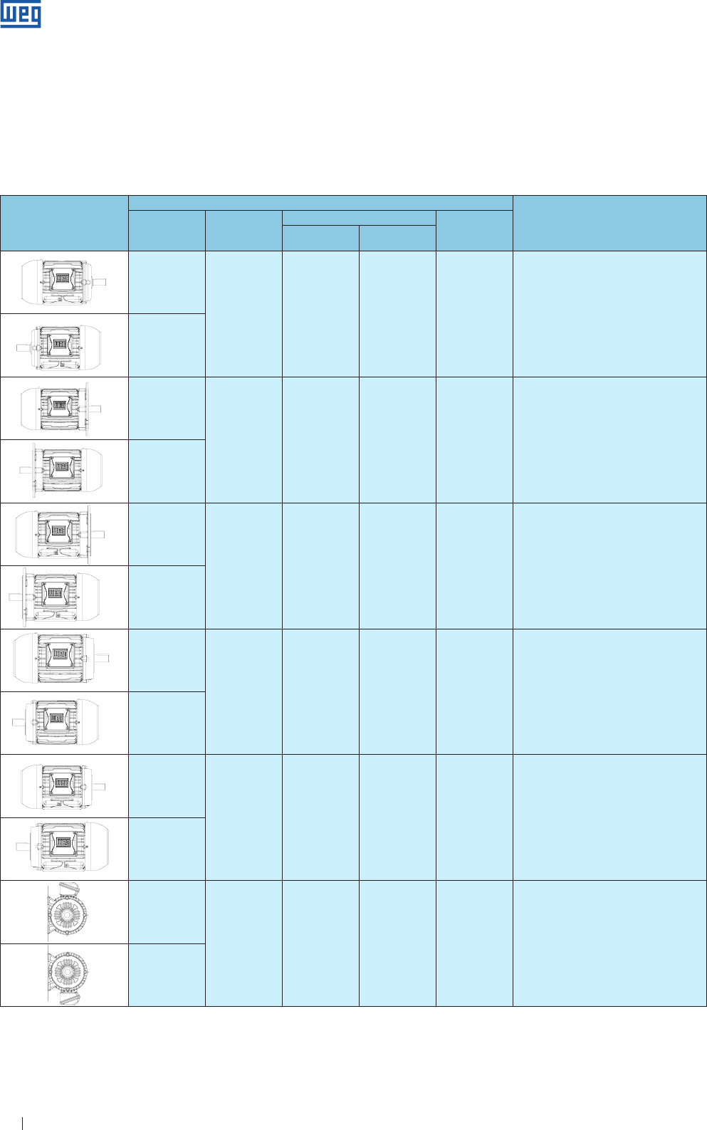
Specification of Electric Motors 52
Figure
Symbol for
Mounting conFiguretion
WEG Designation DIN 42950
IEC 60034-7
Frame
Code I Code II
B3D
B3 IM B3 IM 1001 with feet mounted on substrcture ( * )
B3E
B5D
B5 IM B5 IM 3001 footless fixed by “FF” flange
B5E
B35D
B3/B5 IM B35 IM 2001 with feet mounted on substructure by feet,
with additional fixation by “FF” flange
B35E
B14D
B14 IM B14 IM 3601 footless fixed by “C” flange
B14E
B34D
B3/B14 IM B34 IM 2101 with feet mounted on substructure by feet,
with additional fixation by “C” flange
B34E
B6D
B6 IM B6 IM 1051 with feet wall mounted, feet on the right side,
looking at the D-en of the motor
B6E
10.2 Standardized Type of Construction and Mounting Arrangement
The types of construction and mounting arrangements designate the arrangement of the machine components with regard
to fixings, bearing arrangement and shaft extension, as standardized in IEC 60034-7, DIN 42950 and NEMA MG 1-4.03.
Standard IEC 60072 determines the location of the terminal box on the motor that shall be situated with its centre-line within
a sector ranging from the top to 10º below the horizontal centre-line of the motor on the right-hand side, when looking at the
D-end of the motor.
Table 10.2a - Standardized mounting arrangements ( horizontal mounting )
( * ) Substructure: bases, base plate, foundation, rails, pedestals, etc.
B3EB3D B3TB5E B5DB5T B35E B35D B35T B14E
B14D B14T B34E B34D B34T V5 V6 V6EV6T V1 V3V5EV5T
V15V15EV36 V18V19V36E V36TV15T B6 B7 B8
B6E B7EB8E
B6T B7TB8T
B3EB3D B3TB5E B5DB5T B35E B35D B35T B14E
B14D B14T B34E B34D B34T V5 V6 V6EV6T V1 V3V5EV5T
V15V15EV36 V18V19V36E V36TV15T B6 B7 B8
B6E B7EB8E
B6T B7TB8T
B3EB3D B3TB5E B5DB5T B35E B35D B35T B14E
B14D B14T B34E B34D B34T V5 V6 V6EV6T V1 V3V5EV5T
V15V15EV36 V18V19V36E V36TV15T B6 B7 B8
B6E B7EB8E
B6T B7TB8T
B3EB3D B3TB5E B5DB5T B35E B35D B35T B14E
B14D B14T B34E B34D B34T V5 V6 V6EV6T V1 V3V5EV5T
V15V15EV36 V18V19V36E V36TV15T B6 B7 B8
B6E B7EB8E
B6T B7TB8T
B3EB3D B3TB5E B5DB5T B35E B35D B35T B14E
B14D B14T B34E B34D B34T V5 V6 V6EV6T V1 V3V5EV5T
V15V15EV36 V18V19V36E V36TV15T B6 B7 B8
B6E B7EB8E
B6T B7TB8T
B3EB3D B3TB5E B5DB5T B35E B35D B35T B14E
B14D B14T B34E B34D B34T V5 V6 V6EV6T V1 V3V5EV5T
V15V15EV36 V18V19V36E V36TV15T B6 B7 B8
B6E B7EB8E
B6T B7TB8T
B3EB3D B3TB5E B5DB5T B35E B35D B35T B14E
B14D B14T B34E B34D B34T V5 V6 V6EV6T V1 V3V5EV5T
V15V15EV36 V18V19V36E V36TV15T B6 B7 B8
B6E B7EB8E
B6T B7TB8T
B3EB3D B3TB5E B5DB5T B35E B35D B35T B14E
B14D B14T B34E B34D B34T V5 V6 V6EV6T V1 V3V5EV5T
V15V15EV36 V18V19V36E V36TV15T B6 B7 B8
B6E B7EB8E
B6T B7TB8T
B3EB3D B3TB5E B5DB5T B35E B35D B35T B14E
B14D B14T B34E B34D B34T V5 V6 V6EV6T V1 V3V5EV5T
V15V15EV36 V18V19V36E V36TV15T B6 B7 B8
B6E B7EB8E
B6T B7TB8T
B3EB3D B3TB5E B5DB5T B35E B35D B35T B14E
B14D B14T B34E B34D B34T V5 V6 V6EV6T V1 V3V5EV5T
V15V15EV36 V18V19V36E V36TV15T B6 B7 B8
B6E B7EB8E
B6T B7TB8T
B3EB3D B3TB5E B5DB5T B35E B35D B35T B14E
B14D B14T B34E B34D B34T V5 V6 V6EV6T V1 V3V5EV5T
V15V15EV36 V18V19V36E V36TV15T B6 B7 B8
B6E B7EB8E
B6T B7TB8T
B3EB3D B3TB5E B5DB5T B35E B35D B35T B14E
B14D B14T B34E B34D B34T V5 V6 V6EV6T V1 V3V5EV5T
V15V15EV36 V18V19V36E V36TV15T B6 B7 B8
B6E B7EB8E
B6T B7TB8T
www.weg.net
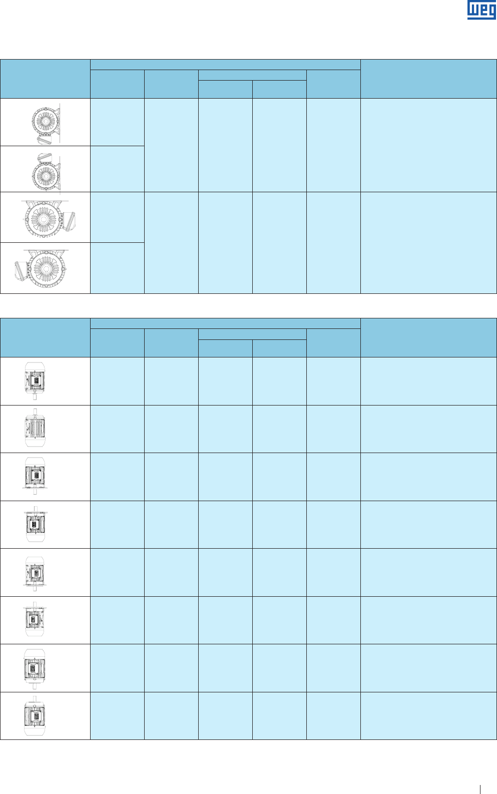
Specification of Electric Motors 53
Figure
Symbol for
Mounting conFiguretion
WEG Designation DIN 42950
IEC 60034-7
Frame
Code I Code II
V5 V5 IM V5 IM 1011 with feet wall mounted or
mounted n substructure
V6 V6 IM V6 IM 1031 with feet wall mounted or
mounted n substructure
V1 V1 IM V1 IM 3011 footless fixed by “FF” flange,
shaft end down
V3 V3 IM V3 IM 3031 footless fixed by “FF” flange
shaft end up
V15 V1/V5 IM V15 IM 2011 with feet wall mounted, with additional
fixation by “FF” flange shaft end down
V36 V3/V6 IM V36 IM 2031 with feet wall mounted, with additional
fixation by “FF” flange shaft end up
V18 V18 IM V18 IM 3611 footless fixed by the “C” flange - shaft end down
V19 V19 IM V19 IM 3631 footless fixed by the “C” flange - shaft end up
( * )
Figure
Symbol for
Mounting conFiguretion
WEG Designation DIN 42950
IEC 60034-7
Frame
Code I Code II
B7D
B7 B7 IM 1061 with feet wall mounted, feet on the right side,
looking at the D-en of the motor
B7E
B8D
B8 IM B8 IM 1071 with feet fixed to ceiling
B8E
( * )
( * )
( * )
Table 10.2b - Standardized mounting arrangements ( horizontal mounting )
Table 10.3 - Standardized mounting arrangements (vertical mounting)
Note: “We recommend to use drip cover for vertical mounted motors with shaft end down and non-weather protected”.
We recommend to use rubber slinger at the shaft end (coupling side for vertical mounted motors with shaft end up).
B3EB3D B3TB5E B5DB5T B35E B35D B35T B14E
B14D B14T B34E B34D B34T V5 V6 V6EV6T V1 V3V5EV5T
V15V15EV36 V18V19V36E V36TV15T B6 B7 B8
B6E B7EB8E
B6T B7TB8T
B3EB3D B3TB5E B5DB5T B35E B35D B35T B14E
B14D B14T B34E B34D B34T V5 V6 V6EV6T V1 V3V5EV5T
V15V15EV36 V18V19V36E V36TV15T B6 B7 B8
B6E B7EB8E
B6T B7TB8T
B3EB3D B3TB5E B5DB5T B35E B35D B35T B14E
B14D B14T B34E B34D B34T V5 V6 V6EV6T V1 V3V5EV5T
V15V15EV36 V18V19V36E V36TV15T B6 B7 B8
B6E B7EB8E
B6T B7TB8T
B3EB3D B3TB5E B5DB5T B35E B35D B35T B14E
B14D B14T B34E B34D B34T V5 V6 V6EV6T V1 V3V5EV5T
V15V15EV36 V18V19V36E V36TV15T B6 B7 B8
B6E B7EB8E
B6T B7TB8T
B3EB3D B3TB5E B5DB5T B35E B35D B35T B14E
B14D B14T B34E B34D B34T V5 V6 V6EV6T V1 V3V5EV5T
V15V15EV36 V18V19V36E V36TV15T B6 B7 B8
B6E B7EB8E
B6T B7TB8T
B3EB3D B3TB5E B5DB5T B35E B35D B35T B14E
B14D B14T B34E B34D B34T V5 V6 V6EV6T V1 V3V5EV5T
V15V15EV36 V18V19V36E V36TV15T B6 B7 B8
B6E B7EB8E
B6T B7TB8T
B3EB3D B3TB5E B5DB5T B35E B35D B35T B14E
B14D B14T B34E B34D B34T V5 V6 V6EV6T V1 V3V5EV5T
V15V15EV36 V18V19V36E V36TV15T B6 B7 B8
B6E B7EB8E
B6T B7TB8T
B3EB3D B3TB5E B5DB5T B35E B35D B35T B14E
B14D B14T B34E B34D B34T V5 V6 V6EV6T V1 V3V5EV5T
V15V15EV36 V18V19V36E V36TV15T B6 B7 B8
B6E B7EB8E
B6T B7TB8T
B3EB3D B3TB5E B5DB5T B35E B35D B35T B14E
B14D B14T B34E B34D B34T V5 V6 V6EV6T V1 V3V5EV5T
V15V15EV36 V18V19V36E V36TV15T B6 B7 B8
B6E B7EB8E
B6T B7TB8T
B3EB3D B3TB5E B5DB5T B35E B35D B35T B14E
B14D B14T B34E B34D B34T V5 V6 V6EV6T V1 V3V5EV5T
V15V15EV36 V18V19V36E V36TV15T B6 B7 B8
B6E B7EB8E
B6T B7TB8T
B3EB3D B3TB5E B5DB5T B35E B35D B35T B14E
B14D B14T B34E B34D B34T V5 V6 V6EV6T V1 V3V5EV5T
V15V15EV36 V18V19V36E V36TV15T B6 B7 B8
B6E B7EB8E
B6T B7TB8T
B3EB3D B3TB5E B5DB5T B35E B35D B35T B14E
B14D B14T B34E B34D B34T V5 V6 V6EV6T V1 V3V5EV5T
V15V15EV36 V18V19V36E V36TV15T B6 B7 B8
B6E B7EB8E
B6T B7TB8T
www.weg.net
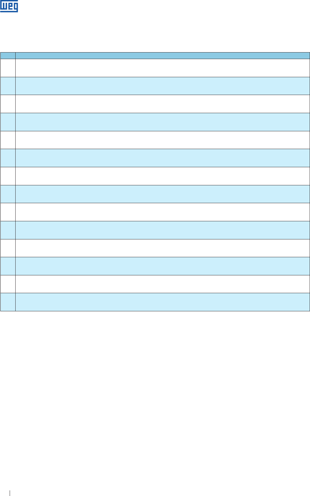
Specification of Electric Motors 54
10.3 Painting
The painting plan below shows the adopted solutions for each application.
Plan Recommended use
201 A Regular environment, not too severe, sheltered or not, for industrial purpose with low relative humidity, normal temperature variations and SO2 presence.
Note: not recommended for direct exposure to acid vapors, alkalis and solvents.
202 E
Severe industrial environment, sheltered or not. SO2, vapors and solid contaminants and high humidity may be present.
This painting plan is indicated for pulp and paper, mining and chemical industries.
*This painting plan is not recommended for coating of aluminum surface.
202 P
Severe industrial environments, sheltered or not. SO2, vapors and solid contaminants and high humidity may be present.
Specific use recommendations: Indicated for application on food processing motors - USA.
* This painting plan is not recommended for coating of aluminum surface.
203 A
Regular environment, not too severe, sheltered or not, for industrial purpose, with low relative humidity, normal temperature variations and SO2 presence.
Notes: 1- Not recommended for direct exposure to acid vapors, alkalis and solvents.
2- Do not apply this painting Plan on motors with steel plate frames.
205 E Severe industrial environment, sheltered or not. SO2, vapors and solid contaminants and high humidity may be present..
This painting plan is indicated for pulp and paper, mining and chemical industries.
205 P Severe industrial environments, sheltered or not. SO2, vapors and solid contaminants and high humidity may be present .
Specific use recommendations: Indicated for application on food processing motors - USA.
207 A
Regular environments, not too severe and sheltered, for industrial purpose, with low relative humidity, and normal temperature variations and SO2 presence.
Note: not recommended for direct exposure to acid vapors, alkalis and solvents.
Application: The Painting Plan 207 A is indicated for the motors of normal manufacturing line which require quick drying painting for the packaging process.
207 N
Regular environments, not too severe and sheltered, for domestic purpose, with low relative humidity, and normal temperature variations.
Note: not recommended for direct exposure to acid vapors, alkalis and solvents.
Specific use recommendation: For application on motors with steel plate frames, which packaging process demands quick drying painting.
211 E Severe industrial environment, sheltered, may have presence of SO2, vapors and solid contaminants, high humidity and alkalis and solvent spills.
It is indicated for motors destined to Petrobrás and its suppliers, for refineries purpose, as well as petrochemical industries that adopt the Petrobrás specifications.
211 P Severe industrial environment sheltered or not, may have presence of SO2, vapors and solid contaminants and high humidity and alkalis and solvent spills.
It is indicated for motors destined to Petrobras and its suppliers, for refineries purpose, as well as petrochemical industries that adopt the Petrobras specifications.
212 E Aggressive marine or naval industry environments, sheltered, may have high humidity and alkalis and solvents spills.
It is indicated for applications in pulp and paper, mining and petrochemical industries.
212 P Aggressive marine or naval industry environments, sheltered, may have high humidity and alkalis and solvents spills.
It is indicated for applications in pulp and paper, mining and petrochemical industries.
213 E Aggressive marine or naval industry environments, sheltered or not, may have high humidity.
It is indicated for oil exploration & production on platforms.
214 P Severe industrial environments, sheltered or not. SO2, vapors and solid contaminants and high humidity and alkalis and solvents spills may be present.
Table 10.4 - Painting Plan
Note: WEG Painting Plans meet the Petrobras standards
10.3.1 Tropicalized Painting
High humidity indexes can result in premature insulation
system deterioration which is the main component that
ensures the motor life time. Any ambient with up to 95%
of relative humidity does not require additional protection,
other than space heaters to avoid water condensation inside
the motor. However, for any ambient with relative humidity
above 95%, an epoxy painting is applied on all inside motor
components which is known as tropic-proof painting.
11. Three-Phase Electric Motor Selection and
Application
On application engineering of electric motors it is common to
compare load requirements with motor characteristics. A lot of
applications can be correctly driven by more than one type of
motor.
This means that selection of a specific type of motor does not
necessarily exclude other types.
Application of computers has improved significantly motor
calculation resulting in more accurate results along with more
economical designs of machines.
WEG induction motors, squirrel cage or slip rings, low or high
voltage, can be used on a wide range of applications, specially
in steel plants, mines, pulp and paper industries, sanitation,
chemical and petrochemical areas, cement plants, among
others, requiring more and more correct motor selection for
each particular application. Proper motor selection with respect
to the type, torque, power factor, efficiency, temperature rise,
insulation system, voltage and mechanical degree of protection
can only be made after careful overall analysis that takes into
consideration certain parameters such as:
g
Initial cost
g
Power supply capacity
g
Requirements for Power factor correction
g
Required torques
g
Effect of load inertia
g
Speed control requirements or not
g
Exposure of the machine to wet, polluted and/or aggressive
environments.
www.weg.net
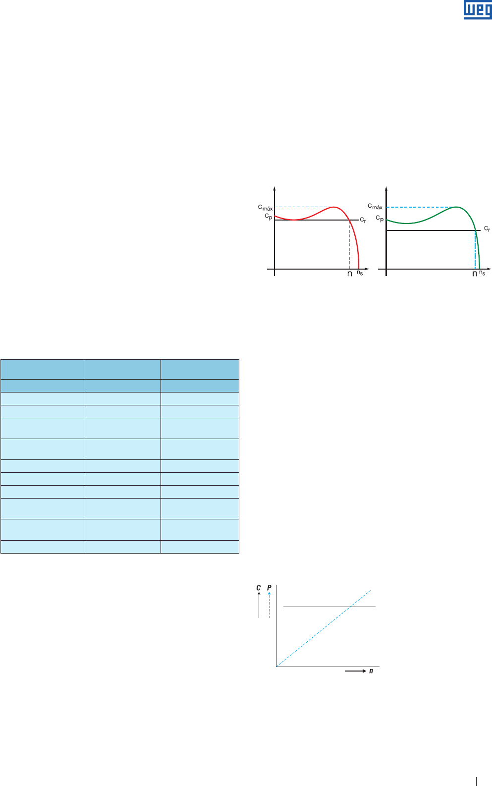
Specification of Electric Motors 55
b ) Acceleration torque
This torque is required to accelerate the load to the rated
speed. At all points between zero and rated speed, the motor
torque must always be higher than load torque. Right over the
intersection point of the two curves, acceleration torque is zero,
i.e., the balance point from which the speed remains constant is
reached.
This intersection point between the two curves should
correspond to the rated speed.
a ) Incorrect b ) Correct
where: Cmáx = breakdown torque
Cp
= starting torque
Cr
= resistive torque
ns = synchronous speed
n = rated speed
The acceleration torque assumes very different values during the
starting stage. The average acceleration torque ( Ca ) is obtained
from the difference between motor torque and resistive load
torque.
c ) Rated torque
It is the torque required to accelerate the load when operating at
a specific speed. The torque required for normal operation of a
machine can be constant or can vary between wide limits. For
variable torques, the breakdown torque should be sufficiently high
to withstand momentary overloads. The operating characteristics
of a machine, related to torque, can be divided into three classes:
g Constant torque
On this type of machine, torque remains constant during
speed variation and the output increases proportionally with
the speed.
----------- Torque required by the machine
- - - - - - - - - Output required by the machine
Squirrel cage asynchronous motor is the most commonly
used in any industrial application due to its rugged and simple
construction characteristics along with economical factors in
reference to the motor itself, as control and protection.
Using WEG Premium line motors is regarded the most
convenient current means to reduce energy consumption. It
has been proved by tests that these motors have 30% less
of losses representing a major energy saving. Designed and
manufactured with the state-of-the-art technology, these
motors are intended to reduce losses and increase efficiency
resulting in low energy consumption and reduced energy bills.
These motors are also highly recommended for applications
with voltage variation. They are tested in conformance with
IEC 60034-1 Standard and their efficiency is indicated on the
motor nameplate. The efficiency is determined by the test
method B of the IEEE STD 112. Efficiency values are obtained
through the loss separation method in accordance with IEC
60 034-1.
The Premium line motors are standardized according to
IEC standards, maintaining the power/frame ratio and are
therefore interchangeable with all standard motors available
on the market. Although more expensive than the squirrel
cage motors, the application of slip ring motors is necessary
for starting heavy loads ( high inertia ), or when variable speed
drives or starting current limitation is required while a high
starting torque must be maintained.
For correct motor selection it is essential to consider all technical
application characteristics, specially load, environment and power
supply characteristics allowing the designer to calculate the following:
a ) Starting torque
The starting torque required to move and overcome the static
inertia of the machine. For any load to be accelerated from zero
speed to its rated speed, motor torque must be always higher
than the load torque.
Type Squirrel Cage
induction motor
Slip ring
motor
Design Squirrel cage rotor Wound rotor
Starting current High Low
Starting torque Low High
Starting/rated
current High Low
Breakdown torque > 160% of the rated
torque
> 160% of the rated
torque
Efficiency High High
Starting switch Simple for DOL starting Relatively simple
Protection device Simple Simple
Required space Small Rheostat requires
large space
Maintenance Small For slip rings and
brushes
Cost Low High
Table 11.1 - Comparison between different types of machines
Figure 11.1 - Motor selection considering the resistive load torque
Figure 11.2
C = Constant resistive torque
P = Power: proportional to the speed ( n )
www.weg.net
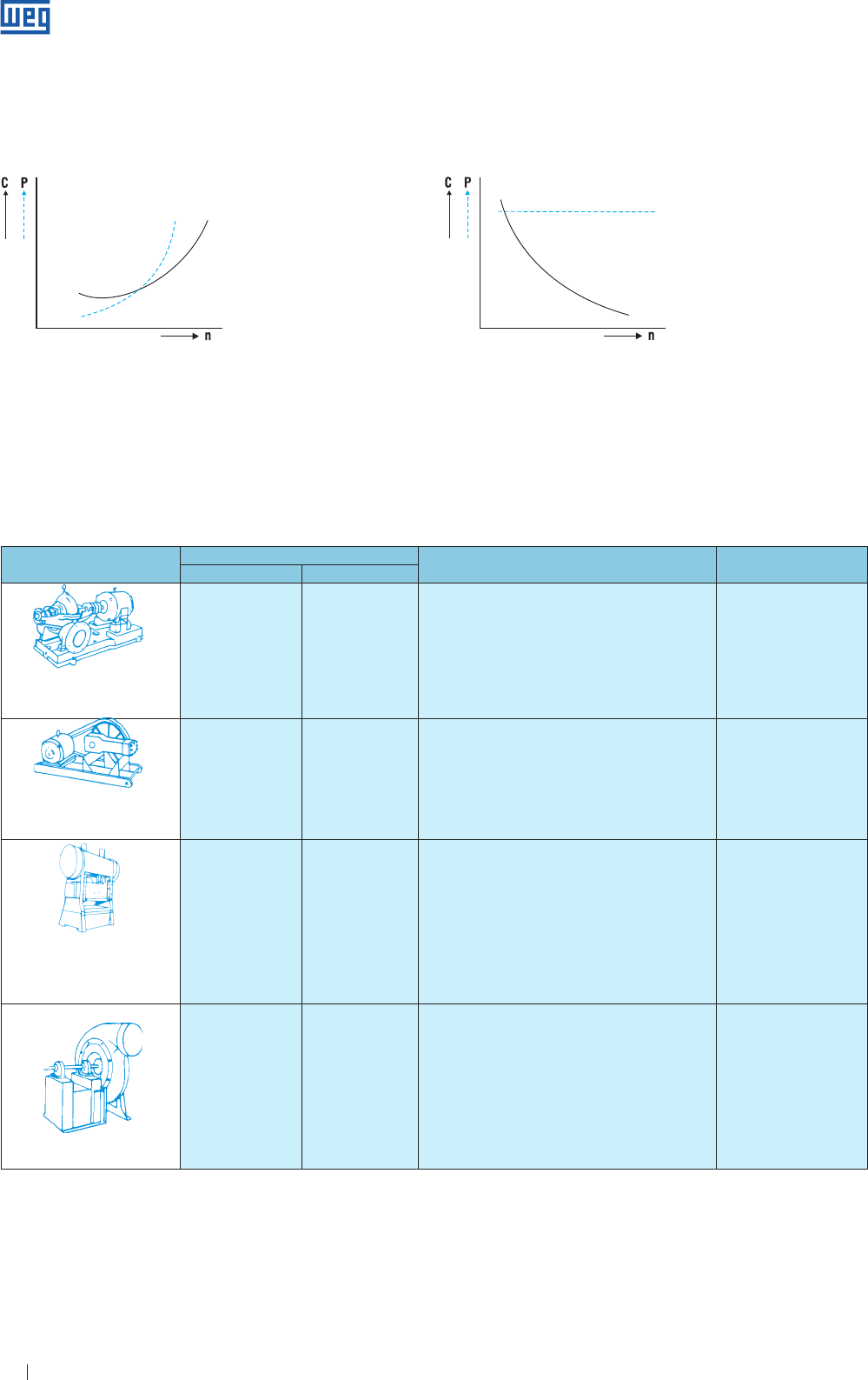
Specification of Electric Motors 56
Figure 11.3
Required torque Load characteristics Used motor type
Sarting Breakdown
Centrifugal pump, fans, drilling
machines, compressors,
milling machines, crushers.
Between 1 and 1,5
Times the rated torque
Maximum values
between 220% and
250% of the rated
torque.
g
Easy starting conditions such as intermediate gear boxes,
low inertia or application of special couplings simplify
starting.
g Centrifugal machines such as pumps where torque increases
with the square of the speed up to a maximum stage reached
at rated speed.
g
At rated speed it may be subject to slight overloads.
g Normal torque
g Normal starting current
g Design N
Alternating pumps, compressors,
conveyors, feeders,
bar milling machines
Between 2 and 3
Times the rated torque
Not higher than two
times rated torque
g High starting torque to overcome the high inertia, counter
pressure, stop friction, strict material process or similar
mechanical conditions.
g
During acceleration, required torque decreases to rated
torque.
g
It is inadvisable to subject the motor to overloads at rated
speed.
g High starting torque
g Normal starting current
g Design N
Punching presses, cranes, overhead
cranes, hoists, mechanical scissors,
oil well pumps
3 times the rated torque It requires two or three
times the rated torque.
They will be considered
as losses during load
peaks.
g
Intermittent loads requiring high or low starting torque.
g
They require frequent stops, starts and reversals.
g Driven machines like punching presses that may require fly
wheels to withstand the power peaks.
g Slight regulation may be required to smooth power peaks and
reduce mechanical forces on the driven machine.
g
Power supply must be protected from power peaks resulting
from load fluctuations.
g High starting torque
g Normal starting current
g High slip
g Design D
Fans, machine tools
Sometimes only part
of the rated torque is
required, and other
times the full rated
torque is required.
Once or twice the rated
torque at each speed.
g Two, three or four fixed speeds are sufficient.
g Speed control is not required.
g
Starting torque can be low ( fans ) or high ( conveyors )
g Operating characteristics at several speeds may vary between
constant power, constant torque or variable torque.
g
Metal cutting machines have constant output power
g
Friction loads are typical examples of constant torque.
g
Fans are typical examples of variable torque.
g
Normal or high torque
( multi-speed )
11.1 Motor Type Selection for Different Loads
Table 11.2 - Characteristics of different loads.
g Variable torque
Variable torques can be found in pumps and fans.
C = Resistive torque: proportional to the square of the speed ( n2 )
P = Output: proportional to the cube of the speed ( n3)
Figure 11.4
g Constant power
Constant Power applications require a power equal to the
rated Power for any speed.
C = Resistive torque: inversely proportional to the speed
P = Constant power
www.weg.net
Specification of Electric Motors 57
www.weg.net
Specification of Electric Motors 58
11.3 Application of Induction Motors with Variable
Frequency Drives
Inverter fed induction motor drives ( also called static
frequency converters ) are the most common solution used
in the industry and is currently the most efficient method for
the speed control of induction motors. These applications
provide several benefits when compared to other speed
control methods. However, these applications depend on a
suitable design to take advantage when compared between
energy efficiency and costs. Among the many benefits are
the cost reduction, remote control, versatility, increased
quality and productivity and better use of the energy
performance.
11.3.1 Normative Aspects
The breakthrough occurred in the electric motor application
with frequency inverters requires increasingly standards
development and standards adoption to standardize the
procedures for evaluating these drives.
The main International Standards that deal with this
subject are:
g
IEC: 60034-17 - Rotating Electrical Machines - Part
17: Cage induction motors when fed from converters -
application guide
g
IEC 60034-25 - Rotating Electrical Machines - Part 25:
Guide for the design and performance of cage induction
motors specifically designed for converter supply
g
NEMA MG1 - Application considerations for constant
speed motors used on a sinusoidal bus with harmonic
content and general purpose motors used with adjustable-
voltage or adjustable-frequency controls or both
g
NEMS MG1 - Part 31: Definite purpose inverter-fed
polyphase motor
11.3.2 Induction Machine Speed Variation by Frequency
Inverter
The relationship between the rotor speed, the supply
frequency, the number of poles and the slip of a induction
motor is given by the following equation: number of poles
and the slip of a induction motor is given by the following
equation:
120 . f1 . ( 1 - s )
n = --------------------------
p
where: n = mechanical speed [rpm]
f = line frequency [Hz]
p = number of poles
s = slip
The analysis of the formula shows that the best way to vary
the speed of an induction motor is by varying the supply
frequency. The frequency inverters transform the line voltage,
with constant amplitude and frequency, into a voltage with
variable amplitude and frequency. The speed of the rotating
field and consequently the mechanical speed of the motor is
changed by varying the frequency of the supply voltage. Thus,
the inverter operates as a source of variable frequency to
the motor. According to the induction motor theory, the
electromagnetic torque developed by the motor is given by the
following equation:
T = K1 . Φm . I2
When the voltage drop is neglected due to the impedance of
the stator winding, the magnetization flux will be:
V1
Φm = K2 .
f1
where: T : torque available on the shaft end ( N.m )
Φm : magnetization flux ( Wb )
I2 : rotor current ( A ) ( depends on the load )
V1 : rotor voltage ( V )
k1 e k2 : constants ( depend on the material and on the machine
design )
Figure 11.5
11.2 WMagnet Drive System®
WMagnet Drive System® consists of a three-phase
synchronous AC motor fitted with high energy magnets in
their rotor and driven by a variable frequency drive ( VFD )*.
The use of permanent magnets eliminates the Joule losses
in the rotor thus ensuring higher efficiency levels than the IE4
efficiency level. As the Joule losses are eliminated, the motor
operates colder enabling the use of smaller frame size and
increases its lifetime.
The use of frequency inverter enables a continuous control
of the motor speed and provides constant torque in the
whole speed range, including 0 rpm, without requiring forced
ventilation at low frequencies. Due to the rotor design, the
used balancing process and the frame size reduction, the
vibration and noise levels of WMagnet Motors could be
reduced when compared to the induction motors with the
same output.
*WMagnet motors must be driven only by the CFW-11 frequency inverter
line developed with specific software for this function.
www.weg.net
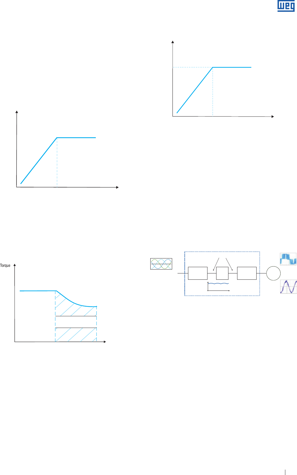
Specification of Electric Motors 59
Potência
Thus, the region above the base frequency is referred to as
field weakening, in which the flux decreases causing the
motor torque decrease. The torque supplied by the motor
remains constant up the base frequency of the operation,
decreasing gradually when operating frequencies are
increased.
However, to operate the motor in a speed range it is not
sufficient to change only the supply frequency. Also the
voltage amplitude must be proportionally changed to the
frequency variation. Thus, the current flux and consequently
the electromagnetic torque of the motor remain constant,
while the slip is maintained. The change of the V/f variation
rate is linear up to the base frequency ( rated ) of motor
operation. Above this value, the voltage, that is equal to the
rated motor voltage, remains constant and only the stator
frequency is changed.
Since the output is proportional to torque multiplied by
speed, the useful output power of the motor increases
linearly up to the base frequency and from that point upwards
it is maintained constant.
11.3.3 Characteristics of the Frequency Inverter
In order to obtain an output signal of desired voltage and
frequency, the input signal must accomplish three stages
within the frequency inverter:
g
Diode bridge - Rectification ( converting AC to DC ) -
voltage coming from the power supply;
g
Filter or DC Link - Regulation/smoothing of the rectified
signal with storage in a capacitor bank;
g
IGBT power transistors - Inversion ( converting AC to DC )
of the DC link voltage by the Pulse-Width Modulation
( PWM ) technique. This modulation technique allows the
output voltage/frequency variation by means of transistors
( electronic switches ) without interfering with the
DC-voltage link.
Figure 11.9
11.3.3.1 Control Types
There are basically two electronic inverter control types:
scalar and vector.
The scalar control is based on the original concept of a
frequency inverter: a signal of certain voltage/frequency ratio
is imposed onto the motor terminals and this ratio is kept
constant throughout a frequency range, in order to keep the
magnetizing flux of the motor practically unchanged. It is
generally applied when there is no need of fast responses to
torque and speed commands and is particularly interesting
when there are multiple motors connected to a single
drive. The control is by open loop and the obtained speed
precision is a function of the motor slip, which depends on
the motor load. To improve the performance of the motor
at low speeds, some drives use special functions such as
slip compensation ( attenuation of the speed variation as
function of the load ) and voltage boost ( increase of the V/f
ratio to compensate for the voltage drop due to the stator
resistance and maintain the torque capacity of the motor ) at
low speeds.
Tensão
Vb
fbFrequency
Figure 11.6
Figure 11.7
fb
Tb
Frequency
Field
Weakening
Retificador
Conversor Indireto de Frequencia
Filtro Inversor
Inpput Output
Variable voltage and frequency
50 / 60 Hz ( 1 Φ ou 3 Φ)
ca
cc
ca Motor
3Φ
Vrede
VPWM
VDC = 1,35 Vrede ou 1,41 Vrede
Imotor
~
Pb
Figure 11.8
Power
fbFrequency
www.weg.net
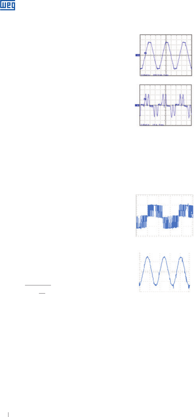
Specification of Electric Motors 60
Typical voltage waveform at input of
a PWM inverter with 6 pulses
( frequency: 50 Hz or 60 Hz )
Typical current waveform current at
input of a 6-pulse PWM inverter
where: Ah : are the rms values of the non-fundamental harmonic components
A1 : is the rms value of the fundamental component
h : harmonic order
The IEEE Std.512 recommends maximum values for
current harmonics generated by electric equipment. Most
manufacturers of inverters take care during the design of
their equipment to ensure that the THD limits established by
this standard are fulfilled.
11.3.4 Inverter Influencing Motor Performance
Induction motors driven by PWM inverter are subjected to
harmonics that can increase the losses and the temperature
as well as the noise and vibration levels, when compared
to the sinusoidal supply condition. The inverter influence on
the motor depends on several factors related to the control,
such as switching frequency, the effective pulse width, pulse
number, among others.
Typical current waveform current at
motor terminals fed by PWM voltage
Figure 11.10
THD = √2
Ah
A 1
h=2
∑
∞(
(
This is the most used control type owing to its simplicity and
also due to the fact that the majority of applications do not
require high precision or fast responses during the speed
control.
The vector control enables fast responses and high precision
levels on the motor speed and torque control. Essentially the
motor current is decoupled into two vectors: one to produce
the magnetizing flux and the other to produce the torque,
each one regulating the torque and the flux separately. The
vector control can be realized by open loop ( sensorless ) or
closed loop ( feedback ) control.
g
Speed feedback - a speed sensor ( for instance, an
incremental encoder ) is required on the motor. This control
mode provides great accuracy on both torque and speed of
the motor even at very low ( and zero ) speeds.
g
Sensorless control is simpler than the closed loop control, but
its action is limited particularly to very low speeds. At higher
speeds this control mode is practically as good as the feedback
vector control.
11.3.3.2 Harmonics
For the AC power line, the system ( frequency inverter +
motor ) is a non-linear load which current include harmonics.
The characteristic harmonics generally produced by the
rectifier are considered to be of order h = np±1 on the AC
side, thus, in the case of a 6 diode ( 6 pulses ) bridge, the
most pronounced generated harmonics are the 5th and the
7th ones, which magnitudes may vary from 10% to 40% of
the fundamental component, depending on the power line
impedance. In the case of rectifier bridges of 12 pulses ( 12
diodes ), the most harmful harmonics generated are the 11th
and the 13th ones. The higher the order of the harmonic, the
lower can be considered its magnitude.
So higher order harmonics can be filtered more easily.
The most commercially available drives have 6-pulses.
The harmonic distortion of the power system can be
quantified by the THD ( Total Harmonic Distortion ), which is
informed by the inverter manufacturer and is defined as:
Typical PWM voltage waveform at
inverter output
Figure 11.11
There are basically the following solutions to mitigate the
harmonics generated by a PWM frequency inverter:
Installation of output filters ( load reactance, dV/dt filters, sinusoidal
filters, etc. ), use of multi-level inverters ( more sophisticated
topology ), Pulse Width Modulation quality improvement
( optimization of pulse patterns ) and increase of the switching
frequency.
Furthermore other effects may appear when induction motors
are fed by inverters. Although not produced specifically by the
harmonics, other important effects may appear and should not
be neglected, such as dielectric stress of the insulation system
and shaft currents that reduce bearing life.
www.weg.net
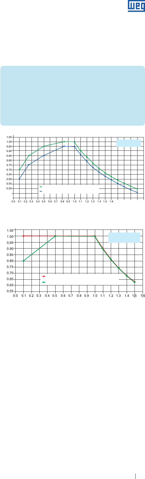
Specification of Electric Motors 61
Figure 11.12 - Constant flux condition
TR - Torque reduction (p.u.)
{F/fn – Frequency (p. u.)
Temperature rise for insulation class F (105 K)
Temperature rise for insulation class B (80 K)
Optimal flux
Optimal V/f
Considerations regarding energy efficiency
The lack of international standards that specify test procedures
to evaluate the system ( motor + inverter ) efficiency allows such
tests to be carried out in many different ways. Therefore, the
results obtained should not influence the acceptance ( or not ) of
the motor, except under mutual accordance between customer
and manufacturer, as specified by international standards.
Experience shows the effectiveness of the considerations below:
g An induction motor fed by PWM voltage provides a lower
efficiency level than when fed by purely sinusoidal voltage, due
to the losses increase caused by harmonics.
g In applications of motors with frequency inverters, the whole
system must be evaluated ( interverter + motor ), rather than the
motor efficiency only.
g Each case must be properly analyzed, taking into account
following characteristics: operating frequency, switching
frequency, load conditions, motor power, THD supplied by the
inverter, etc.
g Special measuring instruments must be used for the correct
evaluation of electrical quantities ( True RMS meters ).
g Higher switching frequencies increase the motor efficiency and
decrease the inverter efficiency.
Influence of the inverter on the temperature rise of the
windings
Induction motors may heat up more when fed by frequency
inverter than when fed by sinusoidal voltage supply. This higher
temperature rise results from the motor losses growth owing to
the high harmonic components of the PWM signal and the often
reduced heat transfer resulting from speed variation of self-
ventilated motors operating at low frequencies. Basically there are
following solutions to prevent motor overheating:
g
Rated torque derating ( frame oversize );
g
Use of independent cooling system;
g
Utilization of the “Optimal Flux Solution” ( exclusive to
applications using WEG drives and motors ).
Criteria for torque derating
In order to keep the temperature rise of WEG motors, when
supplied by PWM, within acceptable levels and the loadability,
limits shown in Fig. 11.13 and 11.14 must be met.
Note: motors rated for explosive atmospheres should be evaluated on a case
by case basis - in such case please contact WEG.
The incorporation of the solution obtained for WEG CFW09 and
CFW11 inverters allows a continuous mitigation of the motor
losses throughout the whole operating range, which is performed
automatically by the inverter.
Important!
This solution can only be used for variable torque loads or
when applied above the base frequency and when:
g
Class IE2 High-Efficiency or Class IE3 Premium Efficiency
motors are used;
g
The motor is fed by WEG frequency inverter
( CFW11 or CFW09 version 2.40 or above );
g Sensorless vector control is used.
Modern frequency inverters use power transistors ( typically
IGBTs ), whose switching process occurs at very high
speed - at kHz frequencies. To achieve such switching,
the transistors have very fast times for conducting initiation
and blocking which result in voltage pulses with a high dV/
dt ( rate of voltage change over time ). When squirrel cage
induction motors are fed by frequency, those pulses combined
with the cable and motor impedances may cause repetitive
overvoltages ( overshoots ) at the motor terminals. This pulse
train may degrade the motor insulation system and may hence
reduce the motor lifetime. The overshoots affect especially
the interturn isolation of random windings and its value is
determined primarily by following factors: rise time of the
voltage pulse, cable length and type, minimum time between
pulses, switching frequency and multimotor operation.
Figure 11.13 - Optimal flux condition
Optimal flux condition
The “Optimal Flux” solution was developed for the purpose of
making WEG induction motors able to operate at low speeds with
constant torque loads still keeping an acceptable temperature
rise level, without the need of neither oversizing the machine nor
blower cooling it.
The study of the composition of the motor losses and their
relation with the frequency, magnetic flux, current and the speed
variation allowed the determination of an optimal flux condition for
each speed.
TR - Torque reduction (p.u.)
{F/fn – Frequency (p. u.)
1.7 1.8 1.9 2.0 2.1
0.45
0.40
Temperature rise for insulation class F (105 K)
Temperature rise for insulation class B (80 K)
Constant Flux
Constant V/f
www.weg.net
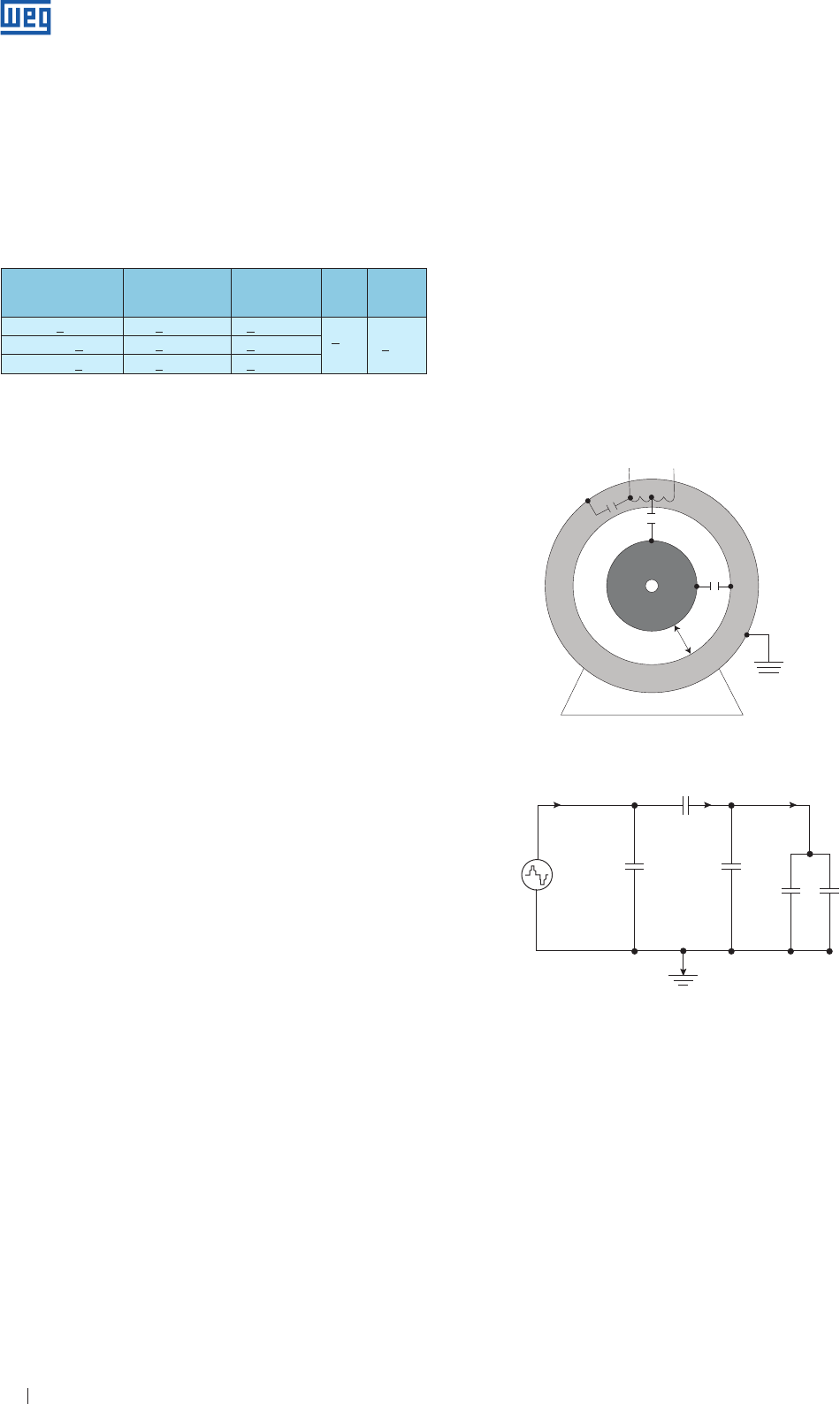
Specification of Electric Motors 62
The phenomenon of induced shaft voltage/current is caused
fundamentally due to unbalanced waveforms present in
the magnetic circuit of the motor. The usual causes of this
problem that primarily affect large machines are eccentricities
and other imperfection resulting from the manufacturing
process. The advent of PWM inverters aggravated this
problem, now occurring also with lower power machines,
since the motors are now fed with unbalanced waveforms
that have high frequency components. The causes of shaft
induced voltage owing to the PWM inverters supply is added
to those intrinsic voltages of the motor which also causes
current circulation through the bearings.
The basic reason for bearing currents to occur within a PWM
inverter fed motor is due to the common mode voltage. The
high frequency of the common mode voltage generated by
the frequency inverter ensures that the capacitive reactances
within the motor become low, allowing the current to pass
through the coupling formed by the rotor, shaft and bearing
toward the earth.
Common mode voltage and motor equivalent circuit
for high frequencies
The three-phase voltages supplied by the PWM inverter,
different than the pure sinusoidal voltage, is not balanced,
i.e., the vector sum of the instantaneous voltages at the three
phases of the frequency inverter output is not equal to zero,
but it is equal to an electric potential of high frequency.
This high frequency common mode voltage may result
in undesirable common mode currents. Existing stray
capacitances between motor and earth may allow current
flowing to the earth, passing through rotor, shaft and
bearings and reaching the end shield ( earthed ).
The high frequency model of the motor equivalent circuit, in
which the bearings are represented by capacitances shows
the paths through which the common mode currents flow. At
high speed operation there is no contact between the rotor
and the ( earthed ) outer bearing raceway, due to the plain
distribution of the grease.
Motor rated voltage
Voltage spikes at
motor terminals
( phase-phase )
dV/dt* at motor
terminals
( phase-phase )
Rise
Time* MTBP
VNOM <460 V < 1600 V < 5200 V/µs > 0.1
µs > 6 µs
460 V < VNOM < 575 V < 1800 V < 6500 V/µs
575 V < VNOM < 690 V < 2200 V < 7800 V/µs
* Definition in accordance with NEMA MG1- Part 30
Table 11.4
Criteria regarding the insulation system
When WEG low voltage induction motors are used with
frequency inverters, the following criteria must be met to
protect the insulation system of the motor: if any of the
conditions below are not met, filters must be installed
between the frequency inverter and the motor.
Note: motors rated for explosive atmospheres should be evaluated on a case
by case basis - in such case please contact WEG.
The electric potential of the rotor may then increase with
respect to the earth until the dielectric strength of the grease
film is disrupted, occurring voltage sparking and flow of
discharge current through the bearings. This current that
circulates whenever the grease film is momentarily broken
down is often referred to as the “capacitive discharge
component”.
These discontinuous electric discharges wear the raceways
and erode the rolling elements of the bearings, causing small
superimposing punctures. Long term flowing discharge
currents result in furrows ( fluting ), which reduce bearings life
and may cause the premature machine failure.
There is still another current component that circulates
permanently through the characteristic conducting loop
comprising the shaft, bearings, end shields and the housing/
frame, that is often called the conduction component.
Airgap
Crc
Cer
Stator
winding
Cec
Common
mode voltage
Stator
windingICM
ICM
Ier
Cer
Crc
Cmd Cmt
Cec
IcRotor
Bearing
Frame/Earth
Equivalent circuit for high frequencies:
Cer : capacitor formed by the stator winding and the rotor lamination
Crc : capacitor formed by rotor and stators cores
Cec : capacitor formed by the stator winding and the frame
Cmd/mt : capacitance of the DE/NDE bearings, formed by the inner and the outer
bearing raceways with the metallic rolling elements
ICM : total common mode current
Ier : capacitive discharge current flowing from the stator to the rotor
Ic : capacitive discharge current flowing through the bearings
Figure 11.14 - Capacitive discharge current.
Figure 11.16 - Motor capacitance.
www.weg.net
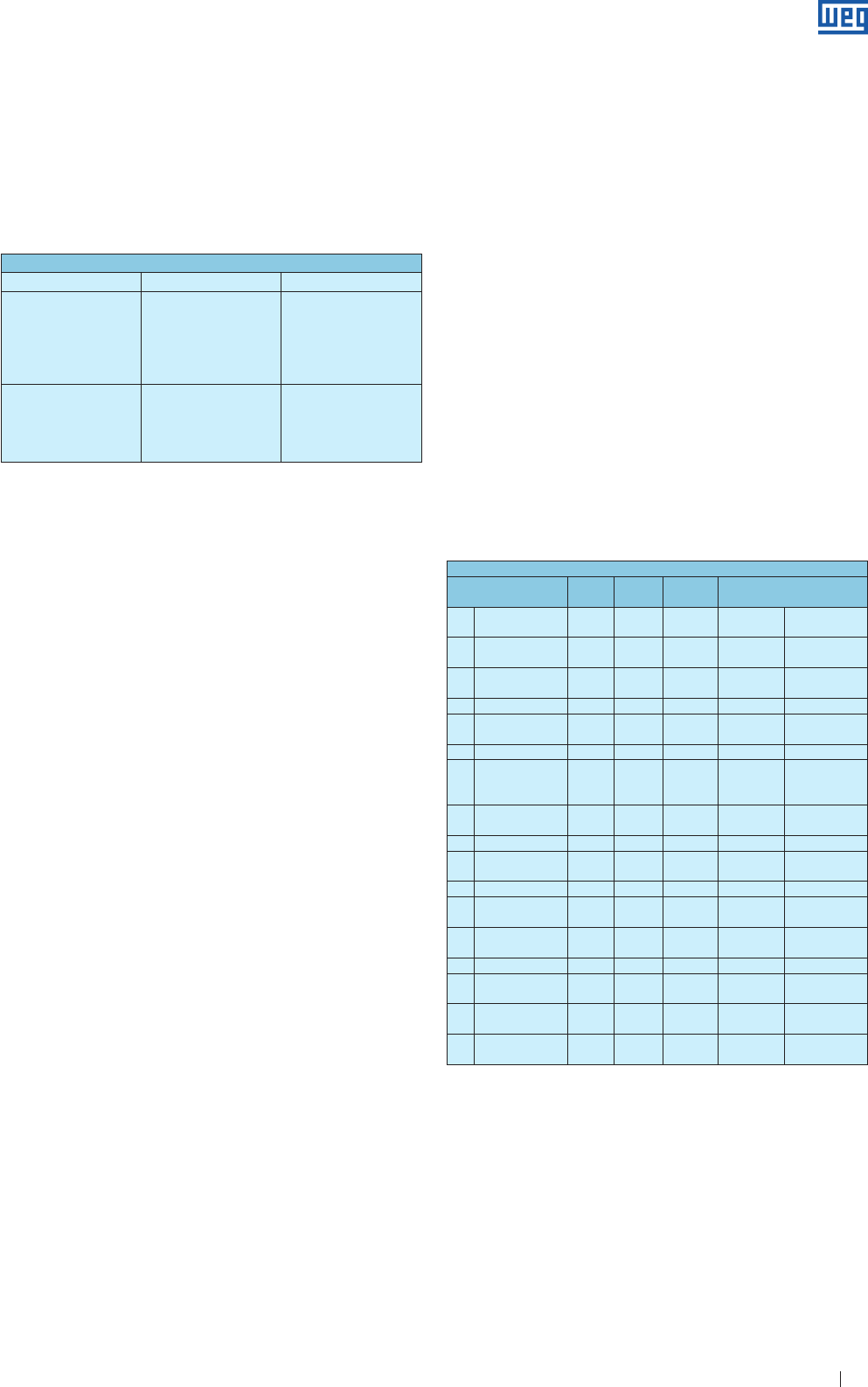
Specification of Electric Motors 63
The rotating electrical machines have basically three
noise sources: the ventilation system, the rolling bearings
and the electromagnetic excitation. Bearings in perfect
operating conditions produce practically despicable noise, in
comparison with other sources of the noise generated by the
motor.
In motor fed by sinusoidal supply, especially those with
reduced number of poles ( higher speeds ), the main noise
source is the ventilation system. On the other hand, in motors
with higher number of poles and lower operation speeds
often stands out the electromagnetic noise.
However, in variable speed drive systems, especially at low
operating speeds when ventilation is reduced, the
electromagnetically excited noise can be the main source
of noise whatever the motor polarity, owing to the harmonic
content of the voltage.
Criteria regarding the noise level generated by WEG
motors with VSD applications
Results of laboratory tests ( 4 point measurements
accomplished in semi-anechoic chamber with the
frequency inverter installed outside the chamber ) carried
out with several WEG motors and frequency inverters using
different switching frequencies have shown that WEG
three-phase induction motors, when fed by PWM frequency
inverters and operating at rated frequency ( typically 50 or 60
Hz ) present an increment in the sound pressure level of 11
dB( A ) at most.
Notes:
g O switching frequency increase tends to reduce the noise level of
electromagnetic origin generated by the motor.
g The noise criteria above apply only to motor frame sizes ≤ 355.
LINE W22
Frame size ( IEC ) Standard Opcional
225 ≤ mod < 315 g No protected
g Insulated NDE bearing
g Insulated DE bearing
g
Earthing system with
brush between frame and
NDE-shaft
315 and 355
g Insulated NDE bearing
g
Earthing system with
brush between frame and
DE-shaft
g
Both bearings are
insulated
Table 11.5 - Bearing protection
12. Environmental Information
12.1 Packaging
WEG electric motors are supplied in cardboard, plastic or
wooden packaging. These materials can be recycled or
reused. All wood used in the packaging of WEG motors
comes from reforestation.
Note: N.A. - Not applicable
Optional - upon request
13.1 Variable Frequency Drive Motors
When motors are driven by frequency inverters the tests
are performed directly on the power line ( sinusoidal voltage
source ) except for the temperature rise test that can be
carried out with PWM supply, on request.
13. Tests
This chapter defines the witnessed or unwitnessed tests that
can be performed by WEG upon customer request.
As defined by IEC 60034-1, the tests are grouped in
ROUTINE, TYPE and SPECIAL tests. The test procedures
are specified in IEC 60034-2. Other tests not listed below
can be performed by the manufacturer provided there is an
agreement between the parties.
Protection criteria against bearing currents of WEG
motors fed by VSD
When WEG low voltage three-phase induction motors are
fed by frequency inverters, following criteria must be met for
the bearing protection:
Note: motors rated for explosive atmospheres should be evaluated on a case
by case basis - in such case please contact WEG.
List of tests
Description Routine
Test
Type
test
Special
test According to Standard
1Winding
resistance - cold X X IEEE 112 IEC 60034-1
2Tests with
locked rotor X X IEEE 112 IEC 60034-1
3Temperature
rise test N.A. XIEEE 112 IEC 60034-1
4 Load test N.A. XIEEE 112 IEC 60034-2-1
5Breakdown torque
test N.A. XIEEE 112 IEC 60034-1
6No-load test X X IEEE 112 IEC 60034-2-1
7
Mechanical
Vibration
-measurement
Optional Optional XNE MA MG1
Part 7 IEC 60034-14
8Noise level-
measurement Optional Optional XNEMA MG1
Part 9 IEC 60034-9
9High-potential test X X IEEE 112 IEC 60034-1
10 Insulation
resistance test X X IEEE 43 IEC 60204-1
11 Polarization index Optional Optional XIEEE 43 IEC 60204-1
12 Speed-torque
curve N.A. Optional XIEEE 112 -
13 Overspeed Optional Optional XNEMA MG1
Part 12.52 IEC 60034-1
14 Shaft voltage Optional Optional XIEEE 112 -
15 Bearing insulation
resistance Optional Optional XIEEE 112 -
16 Momentary
excess torque Optional Optional X NEMA MG1 IEC60034-1
17 Occasional excess
current Optional Optional XNEMA MG1
Part 12.48 IEC60034-2-1
12.2 Product
As far as constructive aspects are concerned, electric
motors are basically manufactured with ferrous metals (
steel, cast iron ) non-ferrous metals ( copper, aluminum )
and plastic. In general, the electric motor has long life cycle,
however, when its disposal, WEG recommends that the
packaging and the product materials are properly separated
and sent for recycling. Non-recyclable materials should be
properly disposed in landfills, co-processed or incinerated.
Service providers of recycling, disposal, co-processing or
incineration must be properly licensed by local environmental
authorities to carry out these activities.
www.weg.net
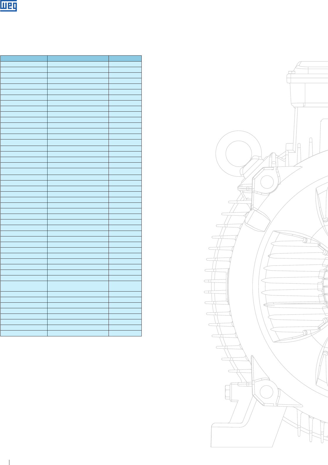
Specification of Electric Motors 64
--
14. Appendix
Table 14.1
Quantity Name Symbol
Acceleration Meter squared per second m/s2
Angular acceleration Radian per second squared rad/s2
Flat angle Radian rad
Solid angle Steradian sr
Area Square meter m2
Specific heat Joule per kilogram per kelvin J/kgK
Capacitance Farad
Flow Cubic meter per second m3/s
Conductance Siemens S
Thermal conductivity Watt per meter per kelvin W/mK
Conductivity Siemens per meter S/m
Energy flux density Watt per square meter W/m2
Absorbed dose Joule per kilogram J/kg
Energy Joule J
Entropy Joule per kelvin J/K
Mass flow Kilogram per second kg/s
Magnetic flux Weber Wb
Frequency Hertz Hz
Force Newton N
Temperature gradient Kelvin per meter K/m
Impulsion Newton-second Ns
Magnetic induction Tesla T
Inductance Henri H
Electric field intensity Volt per meter V/m
Magnetic field intensity Ampère per metro A/m
Current intensity Ampère A
Frequency interval Octave
Length Meter m
Mass Kilogram per cubic metre kg
Specific mass Kilogram/cubic meter kg/m3
Moment of force Newton-meter Nm
Moment of kinettic kilogram-square meter-second kgm2/s
Moment of inertia Kilogram/square meter kgm2
Power Watt W
Presssure Newton per square meter N/m2
Reluctance Ampère per Weber A/Wb
Elwectric resistance Ohm Ω
Mass resistivity Ohm-kilogram per sqaue meter Ωkg/m2
Resistivity Ohm-meter Ωm
Thermodynamic
temperature Kelvin K
Voltage Volt V
Surface tension Newton per meter N/m
Time Second s
Angular speed Radian per second rad/s
Speed Meter per second m/s
Dynamic viscosity Newton-second per square meter Ns/m2
Kinematic viscosity Square meter per second m3/s
Volume Cubic meter m3
14.1. International System of Units
www.weg.net
Specification of Electric Motors 65
--
Table 14.2
cm2 1.076.10
-3 pé2
cm2 0.1550 pol.2
cm/s 0.036 km/h
G
Degree Celsius F
Degree Celsius ( oC ) + 273.15 K
Degree Fahrenheit oC
Trigonometric degree 0.01745 radian
H
HP 42.44 BTU/min
HP 1.014 cv
HP ( boiler ) 33479 BTU/h
HP 10.68 kcal/min
HP 76.04 kg.m/s
HP 0.7457 kW
HP 550 pound/force-foot /s
HP.h 2.684.106 J
HP.h 0.7457 kW.h
HP.h 1.98.106 Pound/force-foot
HP.h 2.737.105 kgm
J
Yard3 0.7646 m3
Joule 9.480.10
-4 BTU
Joule 0.7376 Pound/force-foot kcal
Joule 2.389.10
-4 Pound
Joule 22.48 Pound
Joule 1 W
From Multiply by To obtain
K
oC oF
kcal/h.m2 ( ——— ) 0.671 BTU/h.pé2 ( ——— )
m Pie
kg 2.205 Pound
kgf/cm2 14.22 Pound/force-inch2
kgf/cm3 3.613.10
-5 Pound/pol3
km 1094 Yard
km 3281 Foot
km 0.6214 Mile
km2 0.3861 Mile2
km2 10.76.10
-6 Foot2
km/h 27.78 cm/s
km/h 0.6214 Mile/h
km/h 0.5396 Knot
km/h 0.9113 foot/s
kgf 9.807 J/m ( N )
kW 56.92 BTU/min
kW 1.341 HP
kW 14.34 kcal/min
kW/h 3413 BTU
kW/h 859850 Cal
kW/h 1.341 HP.h
kW/h 3.6.106 J
kW/h 2.655.106 Pound/foot
kW/h 3.671.105 kgm
L
Pound-force.foot/s 1.356.10-3 kW
Pound-force.foot/s 0.01602 g/cm3
Pound-force.foot2 16.02 kg/m3
Pound-force.inch 17.86 kg/m
Pound-force.inch2 0.07301 kg/cm2
Pound-force.foot /min 3.24.10-4 kcal/min
Pound-force.foot /min 2.260.10-5 kW
Pound-force-foot /s 0.07717 BTU/min
Pound-force 16 ounce
Liter 0.2642 gallon
Liter/min 5.886.10-4 foot/s
Pound-force/foot 3.24.10-4 kcal
Pound-force/foot 1.488 kg/m
Pound-force/foot 3.766.10-7 kW.h
Pound-force/foot 0.1383 kgfm
Pound-force.foot2 0.0421 kg/m2
Pound-square inch 2.93 x 10⁻⁴ Kilogram-squere meter
( sq.in.lb ) ( kgm2 )
M
m 1.094 Yard
m 5.396.10-4 Nautical mile
m 6.214.10-4 Land mile
m 39.37 Inch.
m3 35.31 Foot3
m3 61023 Inch3
m 1.667 cm/s
m/min 0.03238 Knot
m/min 0.05408 Foot/s
m2 10.76 Foot2
m2 1550 Inch2
m.kg 7.233 pound/force-foot
m/s 2.237 mile/h
m/s 196.8 Foot/min
Micrômetro 10-6 m
Milha/h 26.82 m/min
Milha/h 1467 foot
Milha quadrada 2.590 km2
Milha 0.001 inch
Milímetro 0.03937 inch
9
( oC —— ) + 32
5
5
( F - 32 ) ——
9
14.2 Unit Convertion
From Multiply by To obtain
BTU 3.94.10
-4 HP.h
BTU 2.928.10
-4 kW.h
BTU/h 107.5 kgm/s
BTU/h 0.2931 W
ºF ºC
BTU/h2. ( —— ) 0.0173 W/cm2. ( —— )
Pie cm
ºF ºF
BTU/h2. ( —— ) 0.0833 BTU/h.pé2 ( —— )
Pé Pie
BTU/h.Pé2.ºF 5.68.10
-4 W/cm2.ºC
BTU/h.Pé2.ºF 3.94.10
-4 HP/pé2. ºF
BTU/min 0.01758 kW
BTU/min 17.58 W
BTU/s 2.93.10
-4 kW
BTU/s 3.93.10
-4 HP
BTU/s 3.94.10
-4 cv
C
Calorie ( gram ) 3.9683.10 -3 BTU
Calorie ( gram ) 1.5596.10 -6 HP.h
Calorie ( gram ) 1.1630.10 -6 kW.h
Calorie ( gram ) 3600/860 Joule
ºC ºC
Cal/s.cm2 ( —— ) 4.19 W/cm2 ( —— )
cm cm
cv 75 kg.m/s
cv 735.5 W
cm 0.3937 pol.
cm3 1.308.10
-6 jarda3
cm3 3.531.10
-6 pé3
cm3 0.06102 pol.3
www.weg.net

Specification of Electric Motors 66
14.3 Standards
Table 14.2
From Multiply by To obtain
N
Newton 1.105 Dina
Knot 1.8532 km/h
Knot 1.689 foot
Newton 0.1019 kilogram-force ( kgf )
or kilopund ( kp )
Newton-meter 0.1019 kilogram-force ( mkgf )
or kilopound meter
( mkp )
Newton-meter 0.7376 Pound.force-foot ( lbf. ft )
O
Ounce 28.349 gram
P
Foot 0.3048 m
Foot/min 0.508 cm/s
Foot/min 0.01667 foot/s
Foots/s 18.29 m/min
Foot/s 0.6818 mile/h
Foot/s 0.5921 nó
Foot/s 1.097 km/h
Foot2 929 cm2
Foot 30.48 cm
Foot3 28.32 liter
Foot3/Lb 0.06242 m3/kg
Foot3/min 472 cm3/s
Inch 25.40 mm
Inch3 0.01639 liter
Inch3 1.639.10
-5 m3
Inch3 5.787.10
-4 foot3
Q
Kilocalorie 3.9685 BTU
Kilocalorie 1.560.10
-2 HP.h
Kilocalorie 4.186 J
Kilocalorie 426.9 kgm
Kilocalorie 3.088 Pound-force foot
Kilogram-meter 9.294.10
-3 BTU
Kilogram-meter 9.804 J
Kilogram-meter 2.342.10
-3 kcal
Kilogram-meter 7.233 Pound-force foot
Kilogram -force ( kgf ) 2.205 Pound-force ( lb )
or kilopound ( kp )
Kilogram-force meter 7.233 Pound-force foot ( ft.lb )
( mkgf ) or
Kilopound-meter ( mkp ) 1.358
Kilogram-square meter 23.73 Pound-squre foot
( kgm2 ) ( sq. ft. lb )
R
Radian 3438 min.
rpm 6.0 degree/s
rpm 0.1047 radian/s
Radian/s 0.1592 rpm
W
Watt 0.05688 BTU/min
Watt 1.341.10
-3 HP
Watt 0.01433 kcal/min
Watt 44.26 Pound-force foot/min
Watt 0.7378 Pound-force foot/s
Main standards used for Rotating Electrical Machines
IEC Title NEMA Title
IEC 60034-7
Rotating. Electrical
Machines: Part 7:
Classification types of
construction, mounting,
arrangements and
terminal box position
( IM Code )
NEMA MG 1
Part 4
Motor and Generators - Part 4:
Dimensions, tolerances, and
mounting
IEC 60034-6
Rotating. Electrical
Machines: Part 6: Methods
of cooling( IC Code )
NEMA MG 1
Part 6
Motor and Generators - Part 6:
Rotating electrical machines -
Method of cooling ( IC code )
IEC 60034-1
Rotating Electrical
Machines - Part 1: Rating
and Performance
IEEE 112 Test procedures for polyphase
induction motors and generators
IEC 60072-
1/2
Dimensions and output
series for rotating
electrical machines- Part 1
and Part 2
NEMA MG 1
Part 4
Motor and Generators - Part 4:
Dimensions, tolerances, and
mounting
IEC 60085
Electrical insulation -
Thermal evaluation and
designation
IEEE 1
General Principles for
Temperature Limits in the Rating
of Electric Equipment and for the
Evaluation Electrical Insulation
IEC 60034-9
Rotating Electrical
Machines:
Part 9: Noise limits
NEMA MG 1
Part 9
Motor and Generators - Part
9: Sound power limits and
measurement procedures
IEC 60034-1
Rotating Electrical
Machines:
Part 1: Rating and
performance
NEMA MG 1 Motor and Generators
IEC 60079
Safety standard series
applied to explosive
atmospheres
UL 60079
UL 674
CSA C22.2
N°145
Electrical Apparatus for Explosive
Gas Atmospheres Electric Motors
and Generators for Use in Division
1 Hazardous ( Classified ) Locations
Motors and Generators for Use in
Hazardous Locations
IEC 60529
Degrees of protection
provided by enclosures
( IP Code )
NEMA MG 1
Part 5
Motor and Generators - Part 5:
Classification of degrees of
protection provided by enclosures
for rotating machines
www.weg.net

Specification of Electric Motors 67
Notes
www.weg.net

WEG Worldwide Operations
WEG Group
Jaraguá do Sul - SC - Brazil
Phone: +55 47 3276 4000
info-br@weg.net
www.weg.net
Cod: 50039409 | Rev: 05 | Date (m/y): 12/2016
The values shown are subject to change without prior notice.
For those countries where there is not a WEG own operation, find our local distributor at www.weg.net.
ARGENTINA
San Francisco - Cordoba
Phone: +54 3564 421484
info-ar@weg.net
Cordoba - Cordoba
Phone: +54 351 4641366
weg-morbe@weg.com.ar
Buenos Aires
Phone: +54 11 42998000
ventas@pulverlux.com.ar
AUSTRALIA
Scoresby - Victoria
Phone: +61 3 97654600
info-au@weg.net
AUSTRIA
Markt Piesting - Wiener
Neustadt-Land
Phone: +43 2633 4040
watt@wattdrive.com
BELGIUM
Nivelles - Belgium
Phone: +32 67 888420
info-be@weg.net
BRAZIL
Jaraguá do Sul - Santa Catarina
Phone: +55 47 32764000
info-br@weg.net
CHILE
La Reina - Santiago
Phone: +56 2 27848900
info-cl@weg.net
CHINA
Nantong - Jiangsu
Phone: +86 513 85989333
info-cn@weg.net
Changzhou – Jiangsu
Phone: +86 519 88067692
info-cn@weg.net
COLOMBIA
San Cayetano - Bogota
Phone: +57 1 4160166
info-co@weg.net
ECUADOR
El Batan - Quito
Phone: +593 2 5144339
ceccato@weg.net
FRANCE
Saint-Quentin-Fallavier - Isère
Phone: +33 4 74991135
info-fr@weg.net
GERMANY
Türnich - Kerpen
Phone: +49 2237 92910
info-de@weg.net
Balingen - Baden-Württemberg
Phone: +49 7433 90410
info@weg-antriebe.de
Homberg (Efze) - Hesse
Phone: +49 5681 99520
info@akh-antriebstechnik.de
GHANA
Accra
Phone: +233 30 2766490
info@zestghana.com.gh
INDIA
Bangalore - Karnataka
Phone: +91 80 41282007
info-in@weg.net
Hosur - Tamil Nadu
Phone: +91 4344 301577
info-in@weg.net
ITALY
Cinisello Balsamo - Milano
Phone: +39 2 61293535
info-it@weg.net
JAPAN
Yokohama - Kanagawa
Phone: +81 45 5503030
info-jp@weg.net
MALAYSIA
Shah Alam - Selangor
Phone: +60 3 78591626
info@wattdrive.com.my
MEXICO
Huehuetoca - Mexico
Phone: +52 55 53214275
info-mx@weg.net
Tizayuca - Hidalgo
Phone: +52 77 97963790
NETHERLANDS
Oldenzaal - Overijssel
Phone: +31 541 571080
info-nl@weg.net
PERU
La Victoria - Lima
Phone: +51 1 2097600
info-pe@weg.net
PORTUGAL
Maia - Porto
Phone: +351 22 9477700
info-pt@weg.net
RUSSIA and CIS
Saint Petersburg
Phone: +7 812 363 2172
sales-wes@weg.net
SOUTH AFRICA
Johannesburg
Phone: +27 11 7236000
info@zest.co.za
SPAIN
Coslada - Madrid
Phone: +34 91 6553008
wegiberia@wegiberia.es
SINGAPORE
Singapore
Phone: +65 68589081
info-sg@weg.net
Singapore
Phone: +65 68622220
watteuro@watteuro.com.sg
SCANDINAVIA
Mölnlycke - Sweden
Phone: +46 31 888000
info-se@weg.net
UK
Redditch - Worcestershire
Phone: +44 1527 513800
info-uk@weg.net
UNITED ARAB EMIRATES
Jebel Ali - Dubai
Phone: +971 4 8130800
info-ae@weg.net
USA
Duluth - Georgia
Phone: +1 678 2492000
info-us@weg.net
Minneapolis - Minnesota
Phone: +1 612 3788000
VENEZUELA
Valencia - Carabobo
Phone: +58 241 8210582
info-ve@weg.net
