WS 800 Serial Protocol
User Manual: WS-800 - Serial Protocol
Open the PDF directly: View PDF ![]() .
.
Page Count: 7
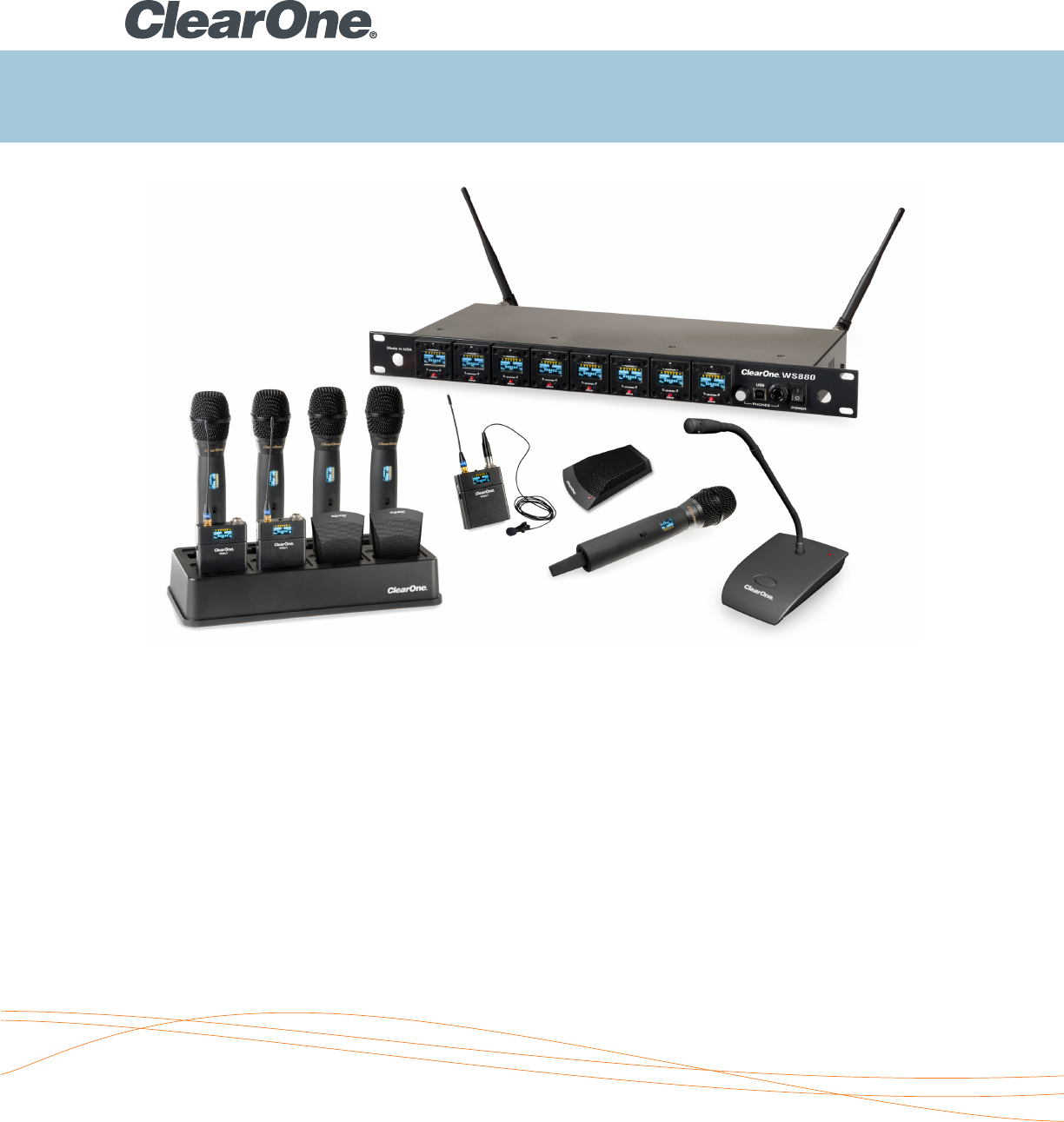
WS800 Wireless Microphone System
Serial Protocol Definition
Serial Protocol Definition

2
ClearOne WS800 Serial Protocol Definition
This document defines the serial commands available for control and monitoring of ClearOne WS8x
receivers. The serial commands may be snet using either USB or RS232 connections.
Port Setup
The USB port on the ClearOne receiver uses a RS232 to USB driver on the PC, so it appears as a COM port on
the computer. The settings for the communications are:
• BaudRate:115200
• DataBits:8
• StopBits:1
• Parity:None
• IE115200,8,N,1
Available Commands
1. Readsystemstatus(Audiolevel,Diversitystatus,TXBatterylevel,TXBatteryruntimehours,TXPAD,TXLow
cut,TXPowerswitchmode,TXButtonMode,Conference/Stagemode)
2. RF Channel change
3. Main output volume change
4. Headphone output volume change
5. Mute audio
6. ReadSysteminformation
7. Headphone output volume change
8. Settransmitterparameters(PAD,LowCut,RFPowerLevel,Channel,Powerswitchmode,ButtonLock,
ButtonMode,Conference/Stagemode)
9. Set transmitter name
10. Antennaphantompoweron/off
11. Setheadphonemode(balanced/unbalanced)
12. Loadpreset
13. Save preset
14. Read preset names
15. SetGPIOconfiguration
Serial Protocol Definition
AllcommunicationsstartwithacommandsentfromthePCtotheClearOnereceiver.Thegeneralformatfora
packetis:
• 0xFD :Startbyte
• 0xd :Deviceaddress(0-7)
• 0xs :Slotaddress(0-7)
• 0xC :Commandcode
• 0xd :Numberofdatabytesthatfollow
• 0xd0 :Databyte0
• :Databyten-2
• :Databyten-1
• 0xdn :Databyten
• 0xFE :Endbyte
The“0x”prefixindicatesahexvaluefollows.(Don’tactuallysendthe0xcharacters).Inotherwords,forthe
0xFD,theactualvaluethatissentis253,whichisFDinhex.
Forexample,thestringthePCsendstorequestthestatusis:
0xFD 0x0 0x0 0x1 0x0 0xFE
Start Device Slot Cmd Num End
byte addr addr code data byte
bytes
Sincetherearenodatabytes,theendbyteappearsdirectlyafterthedatabytecount.

3
1. Read System Status Command
ThePCsendstheReadStatusrequesttotheClearOneReceiverandthereceiverreturnsthestringdefinedbelow.
• Thecommandretrieves4channels(slots)ofstatusinfoatatime.
• Togetstatusofchannels0-3,use0fortheslotvalue.
• Togetstatusofchannels4-7,use4fortheslotvalue.
• Eachchannel’sinfouses14bytes,soall4channelsuseatotalof56databytes.Bytes6through19are
theblockofdataforthefirstchannel,bytes20through33areforthesecondchannel,etc.
Bytes 10, 11, and 18 are bit-mapped. The bits are defined as follows:
BYTE 11:
• Bit7:AESEncryptionon/off
• Bit6:Conferencemodeorstagemode
(1=Confmode)
• Bits5-4:Powerswitchmode(0=On/Off,1=On/
Mute,2=On/On)
• Bits3-2:TXRFPower(0=1mW,1=10 mW,
2=25mW,3=50mW)
• Bit1:LowCut
• Bit0:Pad
29 x HPoutputlevel2
30 x BERMSB
31 x BERLSB
32 x TXLock/logicmut/Model/btnmd
33 x reserved
34 x RSSI1a
35 x RSSI1b
36 x AUDIO3
37 x CHAN3
38 x diversity/TXstatus/batterytype/
39 x AES/conf/swmod/txpwr/lc/pad
40 x txrunhours3
41 x BAT3
42 x mainoutputlevel3
43 x HPoutputlevel3
44 x BERMSB
45 x BERLSB
46 x TXLock/logicmut/Model/btnmd
47 x reserved
48 x RSSI1a
49 x RSSI1b
50 x AUDIO4
51 x CHAN4
52 x diversity/TXstatus/batterytype/
53 x AES/conf/swmod/txpwr/lc/pad
54 x txrunhours4
55 x BAT4
56 x mainoutputlevel4
57 x HPoutputlevel4
BYTE 10:
• Bit7:diversitystatus(0=AntA,1=AntB)
• Bits6-5:TXstatus(0=Off,1=On,2=Mute)
• Bits4-3:BatteryType(0=NIMH,1=Alkaline)
• Bit1:AntennaARFclippingindicator
• Bit0:AntennaBRFclippingindicator
BYTE 18:
• Bit5-4:ButtonMode(0=Toggleon/off,
1=Pushtotalk,2=Pushtomute)
• Bit3-2:Model(0=Beltpack,1=Handheld,
2=Podium,3=Tabletop)
• Bit1:LogicMute(1=Enabled)
• Bit0:TXButtonLock
The PC sends:
• 0xFD startbyte
• 0 device
• 0 slot
The ClearOne receiver returns:
byte Receiver Returns:
1 0xFD startbyte
2 0 device
3 0 slot
4 1 command
5 58 databytes
6 x RSSI1a
7 x RSSI1b
8 x AudioLevel1
9 x RFChannel1
10 x diversity/TXstatus/batterytype/
11 x AES/conf/swmod/txpwr/lc/pad
12 x txrunhours1
13 x BAT1
14 x mainoutputlevel1
15 x HPoutputlevel1
16 x BERMSB
17 x BERLSB
18 x TXLock/logicmut/Model/btnmd
19 x reserved
20 x RSSI1a
21 x RSSI1b
22 x AUDIO2
23 x CHAN2
24 x diversity/TXstatus/batterytype/
25 x AES/conf/swmod/txpwr/lc/pad
26 x txrunhours2
27 x BAT2
28 x mainoutputlevel2
• 1 command
• 0 data#
• 0xFE endbyte

4
The Receiver responds:
byte drf Replies:
1 0xFD startbyte
2 0 device
3 0 channel
4 5 command
5 24 databytes
6 x #DRFinnetwork
7 x DRFserialnumberMSB
8 x DRFserialnumbermidB
byte Receiver Returns:
58 x BERMSB
59 x BERLSB
60 x TXLock/logicmut/Model/btnmd
61 x reserved
62 x mainmutebits/hpmutebits
63 0xFE endbyte
6. Read System Information Command
Thiscommandretrievesinformationaboutthereceiversuchastheserialnumber,datacode,model,#channels,
#ofreceivers,Firmwareversion,PCBversion,andtotalruntimehours.
The PC sends
• 0xFD startbyte
• devnum device
• 0 channel
4. Headphone Volume Change Command
ThePCsendsthedesiredvaluefortheanalogoutputvolumelevel.Therangeis0(off)to100(FullScale).The
stepsare0.5dB.
The PC sends
• 0xFD startbyte
• 0 device
• 0 slot
• 11 command
2. RF Channel Change Command
ThePCsendstheRFChannelChangecommandfortheselectedslot.Thechanvalisindexedstartingat0,soto
setaslottoRFchannel1,sendachanvalof0.
The PC sends
• 0xFD startbyte
• 0 device
• 0 slot
• 2 command
5. Mute Audio Command
ThePCsendsthedesiredmutestate(0=NOTmuted,1=muted)fortheselectedslot.
The PC sends
• 0xFD startbyte
• devnum device
• 0 slot
• 4 command
3. Main Output Volume Change Command
ThePCsendsthedesiredvaluefortheanalogoutputvolumelevel.Therangeis0(off)to100(FullScale).The
stepsare0.5dB.
The PC sends
• 0xFD startbyte
• 0 device
• 0 slot
• 3 command
• 1 data#
• chanval data
• 0xFE endbyte
• 1 data#
• volume data
• 0xFE endbyte
• 1 data#
• volume data
• 0xFE endbyte
• 1 data#
• 0or1 on/off
• 0xFE endbyte
• 5 command
• 0 data#
• 0xFE endbyte
9 x DRFserialnumberLSB
10 x model
11 x DRFFWVer
12 x DRF#1mfgyear/month
13 x reserved
14 x DRF#1mfgday
15 x DRFTotHoursMSB
16 x DRFTotHoursmidB

5
The Receiver responds:
byte drf Replies:
17 x DRFTotHoursLSB
18 x MasterSlaveslot0
19 x MasterSlaveslot1
20 x MasterSlaveslot2
21 x MasterSlaveslot3
22 x MasterSlaveslot4
23 x MasterSlaveslot5
24 x MasterSlaveslot6
25 x MasterSlaveslot7
26 x DRF1PCBREV
27 x DRF2PCBREV
28 x DRF3PCBREV
29 x DRF4PCBREV
30 0xFE endbyte
7. Set Transmitter Parameters Command
Thissetsallofthesyncabletransmitterparameters.Oncethisissent,syncingthetransmittertothereceivercard
viaIRwilltransferthevaluestothetransmitter.
Thevaluesarecontainedin2bitmappedbytes,Telem1andTelem2,definedbelow:
8. Set Transmitter Name Command
Thiscommandsendsupto10characters(lettersandnumbersonly)forthenamevaluedisplayedontheselected
transmitterOLEDdisplayandonthereceivercardOLEDdisplay.
ThetransmittermustbeIRsyncedtoupdatethenamevalueafterthiscommandissent.
Telem1:
• Bit7:AESon/off
• Bit6:Confmode/stagemode(0=confmode)
• Bits5-4:Powerswitchmode:(0=on/off,1=
on/mute,2=on/on)
• Bits3-2:TXPowerlevel(0=1mW,1=10mW,
2=25mW,3=50mW)
• Bit1:Lowcut
• Bit0:Pad
byte# PC Sends:
1 0xFD startbyte
2 0 device
3 0 channel
4 21 command
Telem2:
• Bit5:LogicMuteenable(1=logicmute
enabled,mutingwilltriggeraGPIObutnot
muteaudiooutput)
• Bits4-3:ButtonModeforpodium/tabletop
TX(0=Toggleon/off,1=Pushtotalk,2=push
tomute)
• Bit2:TXButtonlock
• Bits1-0:BatteryType(0=NiMh,1=alkaline)
5 2 data#
6 Telem1
7 Telem2
8 0xFE endbyte
byte# PC Sends:
1 0xFD startbyte
2 dev num device
3 0 slot#
4 9 command
5 12 data#
6 namebyte0
7 namebyte1
8 namebyte2
9 namebyte3
10 namebyte4
11 namebyte5
12 namebyte6
13 namebyte7
14 namebyte8
15 namebyte9
16 reserved
17 reserved
18 0xFE endbyte
9. Antenna Phantom Power On/Off Command
Thisturnsonorofftheantennajack3.3Vphantompowerforpoweringactiveantennas,liketheonesClearOne
provides.
byte# PC Sends:
1 0xFD startbyte
2 dev num device
3 0 slot
4 29 command
5 1 data#
6 on/off 0=off,1=on
7 0xFE endbyte

6
11. Load Preset Command
This preset loads the selected preset form eeprom into the current settings.
byte# PC Sends:
1 0xFD startbyte
2 dev num device
3 0 slot
4 21 command
12. Save Preset Command
Thissavesthecurrentsettingstoaselecteduserpreset.Italsoallowsa10characterpresetnametobesaved
withthepreset.ThisnameisdiplayedintheClearOneGUIinthelistofavailablepresets.Presets1-3arefactory
presetsandcannotbeoverwritten.Presets4-8areuserpresetsandcanbewritten.
ThenamecharactersshouldbesentinASCIIformat.
byte# PC Sends:
1 0xFD startbyte
2 0 device
3 0 channel
4 22 command
5 11 data#
6 presetnumber
7 namebyte0
8 namebyte1
9 namebyte2
10. Set Headphone Mode Command
Theheadphoneoutputjackonthefrontpanelcanoperatein2modes.Inthenormalheadphonemode,thetip
andringoftheTRSjackarein-phasesignalsformonitoringwithheadphones.Inbalancedmode,thetipand
ringare180degreesoutofphase.Thismodeisforconnectingthejacktotheinputofamixerorotherbalanced
input.Iftheheadphonejackisinnormalheadphonemode,therewillbenosoundifitisconnectedtoabalance
inputsincethe+and–signalswillbethesame.Ifthejackisinbalancedmodeanditismonitoredwith
headphones,theleftandrightearswillbeoutofphaseanditwillsoundabittweird.
byte# PC Sends:
1 0xFD startbyte
2 dev num device
3 0 slot#
4 30 command
5 1 data#
6 0or1 0=HPmode,1=balancedmode
7 0xFE endbyte
5 1 data#
6 Preset#
7 0xFE endbyte
10 namebyte3
11 namebyte4
12 namebyte5
13 namebyte6
14 namebyte7
15 namebyte8
16 namebyte9
17 0xFE endbyte
13. Read Preset Names
Thiscommandretrievesthepresetnamesforthe8presets.Itloadseitherthefirst4namesorthesecond4
names,dependingonthevalueoftheslotparameter.Thenamesare10characterslong,andthevaluesare
returnedinASCIIformat.ThenamecharactersshouldbesentinASCIIformat.
byte# PC Sends:
1 0xFD startbyte
2 0 device
3 0 slot(0for0-4,4for5-8)
4 31 command
5 0 data#
6 0xFE endbyte
The Receiver responds:
byte drf Replies:
1 FD startbyte
2 0 device
3 0 channel
4 31 command
5 40 databytes
6 preset1namechar1
7 preset1namechar2
8 preset1namechar3
9 preset1namechar4
10 preset1namechar5
11 preset1namechar6
12 preset1namechar7
13 preset1namechar8
14 preset1namechar9
15 preset1namechar10
16 preset2namechar1
17 preset2namechar2
18 preset2namechar3

7
14. Set GPIO Configuration Command
ThiscommandconfigurestheGPIOfortheDB25connectoronthebackofthereceiver.EachGPIOpincanbe
eitheraninput,anoutput,ordisabled.Whenconfiguredasanoutput,itisfloating/highimpedancewhennot
assertedanddrivenlowwhenasserted.Whenconfiguredasaninput,drivingitlowassertsit.Inaddition,pins
2and3aresharedwiththeRS232function.WhenconfiguredasRS232,thesepinsareonlyusedforTXandRX
andunavailableforGPIO.
Byte31determinesifpins2and3areGPIOpinsorRS232pins.Settingitto0enablesRS232,settingitto1
enablesGPIOonthesepins.Inthecommandstructure,eachpinhasabyteassociatedwithittoconfigureit.
• BITS6-5:pinfunction(0=mute,1=lowbattery;2,3reserved)
• BITS4-2:slot(0-7).Thisdetermineswhichreceiverslotisassociatedwiththepin.
• BIT1:inputoroutput.(0=input,1=output)
• BIT0:enableordisable.(0=disabled,1=enabled)
byte# PC Sends:
1 0xFD startbyte
2 0 device
3 0 channel
4 25 command
5 26 data#
6 pin1
7 pin2
8 pin3
9 pin4
10 pin5
11 pin6
12 pin7
13 pin8
14 pin9
15 pin10
16 pin11
17 pin12
18 pin13
19 pin14
20 pin15
21 pin16
22 pin17
23 pin18
24 pin19
25 pin20
26 pin21
27 pin22
28 pin23
29 pin24
30 pin25
31 RS232OFF
32 0xFE endbyte
The Receiver responds:
byte drf Replies:
19 preset2namechar4
20 preset2namechar5
21 preset2namechar6
22 preset 2 name char 7
23 preset2namechar8
24 preset 2 name char 9
25 preset2namechar10
26 preset3namechar1
27 preset 3 name char 2
28 preset3namechar3
29 preset 3 name char 4
30 preset3namechar5
31 preset3namechar6
32 preset 3 name char 7
33 preset3namechar8
34 preset 3 name char 9
35 preset3namechar10
36 preset4namechar1
37 preset 4 name char 2
38 preset4namechar3
39 preset 4 name char 4
40 preset4namechar5
41 preset4namechar6
42 preset 4 name char 7
43 preset4namechar8
44 preset 4 name char 9
45 preset4namechar10
46 FE endbyte
NorthAmerica
Tel: 801-975-7200
Toll Free: 800-945-7730
Sales: 800-707-6994
Fax:801-977-0087
sales@clearone.com
Europe&Oceania
Tel: +44 (0) 1189 036 053
global@clearone.com
AsiaPacific
Tel: +852 3590 4526
global@clearone.com
LatinAmerica
Tel: 801-974-3621
global@clearone.com
MiddleEast
Tel: +852 3590 4526
global@clearone.com
Other product names may be registered trademarks of their respective owners who do not necessarily endorse ClearOne or ClearOne’s products. All rights reserved. Information in
this document subject to change without notice. © 2012 ClearOne. DOC-0082-001 Revision 1.0 December 2012.
