Water Well Manual
User Manual: manual pdf -FilePursuit
Open the PDF directly: View PDF ![]() .
.
Page Count: 166 [warning: Documents this large are best viewed by clicking the View PDF Link!]
A project of Volunteers in Asia
er Well Manual
by : Ulric P. Gibson and Rexford D. Singer
Published by:
United States Agency for International
Development
Washington, DC 20532 USA
Paper copies are $ 9-00.
Available from:
Premier Press
P.G. Box 4428
Berkeley, CA 94704 USA
Reproduction of this microfiche document in
any
form is subject to the same restrictions as those
of the original document.
A PRAGTICAL GUIDE FOR LOCATI
CONSTRUCTING WELLS FOR INDIVIDUAL
AND SMALL COMMUNITY WATER SUPPLIES
GROUND WATER IS ONE OF MAN’S M’JST IMPORTANT
NATURAL RESOURCES. ITS PROPER UEVELOPMENT
BY MZ:ANS OF WELLS IS A MATTER OF INCREASING
IMPORY’ANCE. THIS BOOK DISCUSSE 5 THE LOCATION,
DESIGN, CONSTRUCTION, OPERATI~JN, AND MAINTE-
NANCE OF SMALL WELLS USED PI:,MARILY FOR
lNDlVlDUAL AND SMALL COMMUl’:ITY WATER
SUPPLIES.
THE AUTvlORS, WRITING IN A Cy,EAR AND EASY-TO-
READ MANNER, PRESENT THE f’:lJNDAMENTALS OF
WATER WELLS SO AS TO BE USEFUL TO INDIVIDUAL
HOME OWNERS, FARMERS, ANI.:) STUDENTS AS WELL
AS TO THOSE PRO’FESSIONALL Y INVOLVED SUCH AS
WELL DRILLING CONTRACTD!ZS, ENGINEERS, AND
GEOLOGISTS.
MODERN TECHNIQUES FOR I.,EVELOPING GROUND
WATER ARE COMPREHENSIVELY DESCRIBED -
WHETHER THE WATER SUPPkIES ARE FOR AGRI-
CULTURAL, INDUSTRIAL, Of,! HUMAN NEEDS. TO
AID UNDERSTANDING THE r”iUTHORS HAVE IN-
CLUDED MORE THAN 100 ILLUSTRATIONS THROUGH-
OUT THE BOQK.
THIS BOOK WAS ORIGINALLY PUBLISHED BY
THE AGENCY FOR INTERNATIONAL DEVELOPMENT
OF THE UNITED STATES GOVERNMENT TO ASSIST
THE PEPPLE LIVING IN THE DEVELOPING COUNTRIES
OF THE WORLD WHO ARE WITHOUT ADEQUATE
SUPPLIES OF GOOD QUALITY WATER. THIS NEW
EeblTlON HAS SEEN PREPARED SO THAT ALL PERSONS
INTERESTED IN WATER RESOURCES MAY BENEFIT
FROM THIS VALWABLE BOOK.
hmier Pwss
Editorial Advisory Boani
for Water Resources
Harvey 0. Bat&T
Charles E Meyer
David K. Todd
A PRACTICAL GUlDE FOR LOCATING AND CONSTRUCTING WELLS
FOR lNDh/lDUAL AND SMALL COMMUNITY WATER SUPPLIES
Uhic P. Gibson
Executive Engineer, Water Supply, Rural Areas
Ministry of Works & Hydraulics, Guyana
Rexford D. Singer
Associate Professor of Environmental Health
School of Public Health
University of Minnesota
PREMIER PRESS
Berkeley, California
WATER
EL1
MANUAL
Covers Copyright @ by Premier Press 197 !
Published by the
Agency for International
Development of the U.S.
Department of State under
the title Small Wells Mamai,
1969.
Text reprinted i971 by
PREMiER PRESS
P. 0. Box 4428
Berkeley, California 94704
Library of Congress
Catalog Card Number: 71-l 53696
Printed in the United States of America
Foul-t11 Printing, May 1977
ii
The authors wkh to express their appreciation to the Health Service,
Oftlce of Wt?r on Hunger. United States :lgtfi~q t‘or International Develop-
ment for making the publkation of this manual poss\lble. We art’ particularly
indebted to the UOP-Johnson Division, Universal Oil Products Company, St.
Paul. %Iinnesota for their advice and assistance in preparing the tnanuscript
and for their contribution of valuable inft)rmstion and illustrations and to Mr.
Arpad Rumy for the preparation of man
i’ of the illustrations. We also wish to
express sincere gratitude to ail pcrs:ns who have offered comments,
suggestions and assistance or who have given their time to critically review the
manuscript.
In preparing this manual. an attempt h;ts been made to bring together
information and material from a variety of sources. We have endeavored to
give proper credit for the direct use of material from these sources, and any
omission of such credit is unintentional.
It has been estimated that nearly two-thirds of the one and a half billion
people living in the developing countries are without adequate supplies of
safe water. The consequences of this deficiency are innumerable episodes of
the debilitating and incapacitating enteric diseases whrch annually affect an
estimated 500 million people and result in the deaths of as many as 10
million about half of whom are children.
Although there are many factors limiting the installation of small water
systems, the lack of know!edge in repdd to the availability of ground water
and effective means of extracting it fc-11 use by rural communities is a major
element. It is anticipated that this manual will make a major contribution
toward fiiling this need by providing the man in the field, not necessarily an
engineer or hydrologist, with the information needed to locate, construct and
operate a small well which can provide good quality water in adequate quan-
tities for small communities.
The Agency for International Development takes great pride in cooper-
ating with the University of Minnesota in making this manual available.
Arthur H. Holloway
Sanitary Engineer,
Health Service, Office of War on Hunger
Agency for International Development
. . .
111
Page
ACKNOWLEDGEMENTS
ii
FOREWORD . . .
111
1. INTRODUCTION 1
PURPOSE
1
SCOPE 1
PUBLIC HEALTH AND RELATED FACTORS 1
Importance of Water Supplies. Ground-Water’s Impor-
tance. Need for Proper Development and Management of
Ground Watt-b Resources.
*L.ORIGiN, OCCllRRENCE AND MOVEMENT OF
GROUND
WATER
4
THE HYDROLOGIC CYCLE 4
SUBSURFACE DISTRIBUTION OF WATER 4
Zone of Aeration. Zone of Saturation.
GEOLOGIC FORMATIONS AS AQUIFERS 7
Rock Classification. ‘Role nf Geologic Processes in
Aquifer Formation.
GROUND-WATER FLOW AND ELEMENTARY WELL HY-
DRAULICS 10
Types of Aquifers. A,quifer Functions. Factors Affecting
Permeability. Flow Toward Wells.
QUALITY OF GROUND WATER ;72
Physical Quality. Microbiological Quality. Chemical Qual-
ity.
3. GROUND-WATEREXPLORATION
EEOLOGIC DATA
Geologic Maps. Geologic Cross-Sections. Aerial Photo-
graphs.
INYENTORY OF EXISTING WELLS
SURFACE EVIDENCE
28
28
30
31
iv
4. WATER WELL DESIGN
CASED SECTION
BUTARE SECTlON
Type and Construction of Screen. Screen Length, Size of
Openings and Diameter.
SELECTION OF CASING AND SCREEN MATERIALS
Water Quality. Strer&h Requirements. Cost. Miscel-
laneous.
GRAVELPACKING AND FORMATION STABILIZATION
Gravel Packing. Formation Stabilization.
SANITARY PROTECTION
Upper Terminal. Lower Terminal of the Casing. Grouting
and Sealing Casing.
5. -#ELL CONSTRUCTION
WELL DRILLING METHODS
Boring. Driving. Jetting. Hydraulic Percussion. Sludger.
Hydraulic Rotary. Cable-Tool Percussion.
INSTALLING WELL CASING
GROUTING AND SEALING CASING
WELL ALIGNMENT
Conditions Affecting Well Alignment. Measurement of
Well Alignment.
INSTALLATION OF WELL SCXEENS
Pull-back Method. Open Hole Methr?d. Wash-down Meth-
od. Well Points. Artificially Gravel-Packed Wells. Re-
covering Well Screens.
FISHING OPERATIONS
Preventive Measures. Preparations for Fishing. Common
Fishing Jobs and Tools.
6. WELL COMPLETION
WELL DEVELOPMENT
Me&an&l Surging. Backwashing. Development of Grav-
el-Packed Wells. Dispersing Agents.
WELL DISINFECTION
Pi;ge
33
34
34
47
50
52
55
55
69
70
73
75
86
96
96
104
V
S. PUMPING EQUIPMENT 114
CONSTANT DISPLACE>lE?ZT PLhlPS
I17
Reciprocating Piston Pumps. Rotary Pumps. Helical
Rotor Pumps.
VARIABLE DISPl.A(‘EMENl- PUMPS 120
C’en trlfugal Ptuqx. Jet Pumps.
DEEP WELL PUMPS 11-l
Lineshaft Pumps. Subrnersibk P!lrnps.
PRIMING OF PUMPS I 10
PUMP SELECTION 137
SELECTION OF POWER SOLrRCE 11x
Man Power. Wind. Electricity. Internal Combustion
Engine.
4. SANITARY PROTECTION OF GROUND-WATER SUPPLIES 134
POLLUTION TRAVEL IN SOILS
WELL LOCATiON
SEALING ABANDONED WELLS
REFERENCES
CWEDI’i FOR ILLUSTRATIONS
APPENDICES
APPENDIX A. MEASUREMENT OF PERMEABILITY
138
139
14(!
APPENDIX B. USEFUL TABLES AND FORMULAS 111
INDEX 151
vi
C PTER ‘I
I CTI
PURPOSE
This manual is intended to serve as a basic introductory text book and to
provide instruction and guidance to field personnel engaged in the construc-
tion, operation and maintenance of small diameter, relatively shallow wells
used primarily for individual and small community water supplies.
it
is aimed particularly at those persons who have had little or no
experience in the subject. An attempt has been made to treat the subject
matter as simply as possible in order that this manual may bF: of benefit not
only to the engineer or other technically trained individual (inexperienced in
this field) but also the individual home owner, farmer or non-technically
trained community development officer. This manual should also prove
useful in the training of water well drillers, providing the complementary
background material for their field experience. The reader who is interested
in pursuing the subject further, and with reference to larger and deeper wells,
is referred to the list of references to be found at the end of this manual.
SCOPE
This. manual covers the exploration and development of ground-water
sources in unconsolidated formations, primarily for the provision of small
potabie water supplies. Its scope has been limited to the consideration of
small tube wells up to 4 inches in diameter, a maximum of approximately
100 feet in depth and with yields of up to about 50 U.S. gallons per minute
(All references are to U.S. units. Conversion tables are to be found in
Appendix B). The location, design, construction, maintenance and rehabilita-
tion of such wells are among the various aspects discussed. The above
limitation on well size (diameter) rules out the zonslderation of dug we!ls in
favor of the much more efficient and easier to protect bored, driven, jetted or
drilled tube wells. However, a method of converting existing dug wells to tube
wells is discussed.
PUBLIC HEALTH AND RELATED FACTORS
hportance of Water Supplies
Water is, with the exception of ai?, the most important single substance to
man’s survival. Man, like all other forms of biological life, is extremely
dependent upon water and can survive much longer without food than he can
without water. The quantities of water directly required for the proper
functioning of the body processes are relatively small but essential.
1
While man has always recognized ihe importance of water for his internal
bodily needs. his recognition of its importance to health is a more recent
development. dating back oniy a century or so. Since that time, much has
been learned about the role of inadequate and contaminated water supplies in
the spread of water-borne diseases. Among the first diseases recognized to be
water borne were cholera and typhoid fever. Later, dysentery, gastroenteritis
and other diarrhea1 diseases were added to the list. More recently, water has
also been shown to play an important role in the spread of certain viral
diseases such as infectious hepatitis.
Water is involved in the spread of conznunicable diseases in essentially two
ways. The first is the well known direct ingestion of the infectious agent
when drinking contaminated water (e.g. dysentery, typhoid and other
gastrointestinal diseases). The second is due to a lack of sufficient water for
personal hygiene purposes. Inadequate quantities of water for the mainte-
nance of personal hygiene and environmental sanitation have been shown to
be major contributing factors in the spread of such diseases as yaws and
typhus. Adequate supplies of water for personal hygiene also diminish the
probability of transmitting some of the gastrointestinal diseases mentioned
above. The
latter type of interaction between water and the spread of disease
has
been
recognized by various public health organizations in developing
countries which have been trying to provide adequate quantities of water of
reasonable, though not entirely satisfactory, quality.
Health problems related to the inadequacy of water supplies are universal
but, generally,
of greater magnitude and significance in the underdeveloped
and
developing nations. It has been estimated that about two-thirds of the
population of the developing countries obtain their water from contaminated
?111!3rees. The World Health Organization estimates that each year 500 million
people suffer from diseases associated with unsafe water supplies. Due largely
to poor water supplies, an estimated S,OOO,OOO infants die each year from
diarrheal diseases.
In
addition to the human consumption and health requirements, water is
a!so needed for agricultural, industrial and other purposes. Though all of
these needs are important, water for human consumption and sanitation is
considered to be of greater social and economic importance since the health
of the population influences all other activities.
Ground-Water’s Importance
It
can generally be said that ground water has played a much less
imporatnt role in the solution of the world’s water supply problems than its
relative availability would indicate. Its outaf-sight location and the associated
lack of knowledge with respect to its occurrence, movement and development
have no doubt contributed greatly to this situation. The increasing acquisition
and dissemination of knowledge pertaining to ground-water development will
gradually allow the use of this source of water to approach its rightful’degree
of importance and usefulness.
More than 97 percent of the fresh wn:lter on our planet (excluding that in
the polar ice-caps and glaciers) is to be found underground. While it is not
2
practicable to extract all of this water because of economic tend other re;lsons.
the recoverable quantities would. no
doubt,
esceed the available supplies of
fresh surface water found in rivers and lakes.
Ground-water sources also represent water that is essentially irl ;iorage
while the water in rivers and lakes is generally i.n transit, being replaced
several times a year. The available quantity of surface water at any given
location is also more subject to seasonal fluctuations than is ground water. In
many areas, the extraction of ground water can be continued long after
droughts have completely depleteil rivers. Ground-water sources are, there-
fore, more rehable sources of water in many instances.
As will be seen in Chapter 2. ground waters are usually of much better
quality than surface waters. due to the benefits of percolation through the
ground. Oftener than not, ground water is also mctre readily available where
needed, requiring less transportation and, generally, costir?.g less to develop.
Greater emphasis should, therefore, be placed on the development and use of
the very extensive ground-water sources to be found throughout the world.
Need for Proper Development and Management of Ground-Water Resources
While some ground-water reservoirs are being repienished year after year
by infiltration from precipitation, rivers, canals and so on, others are being
replenished to much lesser degrees or not at all. Extraction of water from
these latter reservoirs results in the continued depletion or mining of the
water.
Ground water aiso often seeps into streams, thus providing the low flow
(base flow) that is sustained through the driest period of the year. Conversely,
if the surface water levels in streams are higher than those in ground-water
reservoirs, then seepage takes place in the opposite direction, from the
streams into the ground-water reservoirs. Uncontrolled use of ground water
can, therefore, affect the levels of streams and Iakes and consequen.tly the
uses to which they are normally put.
Ground-water development presents special problems. The lack of solu-
tions to these problems have, in the past, contributed to the mystery that
surrounded ground-water development and the limited use to which ground
water has been put. The proper development and management of ground-
water resources requires a knowiedge of the extent of storage, the rates of
discharge from and recharge to underground reservoirs, and the use of
economical means of extraction. It may be necessary to devise artificial
means of recharging these reservoirs where no natural sources exist or to
supplement the natural recharge. Research has, in recent years, considerably
increased our knowledge of the processes involved in the origin and
movement of ground water and has provided us with better methods of
development and conservation of ground-water supplies. Evidence of this
increased knowledge is to be found in the greater emphasis being placed on
ground-water development.
An understanding of the processes and fxtors affecting the origin,
occurrence, and movement of ground water is essential to the proper
development and use of ground-water resources. Of importance in determin-
ing 2 satisfactory rate of extraction and suitable uses of the water are a
knowledge of the quantity of water present, its origin. the direction and rate
of movement to its poi:rt of discharge, the discharge rate and the rate at
which it is being replenished, and the quality of the water. These points are
considered in this chapter in as simplified and limited a form as the aims and
scope of this manual permit.
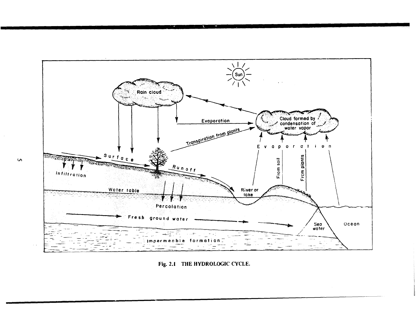
THE HYDROLQGIC CYCLE
The hydrologic cycle is the name given to the circulation of water in its
liquid, vapor, or solid state from the oceans to the air, air to land, over the
land surface or undergrountl, and back to the oceans (Fig. 2.1).
Evaporation, taking place at the water stirface of oceans and other open
bodies of water, results in the transfer of water vapor to the atmosphere.
Under certain conditions, this water vapor condenses to form clouds which
subsequently release their moisture as precipitation in the form of rain, hail.
sleet, or snow. Precipitation may xcur over the oceans retuning some of the
water directly to them or over land to which winds have previously
transported the moisture-laden air and clouds. Part of the rain falling to the
earth evaporates with immediate return of moisture to the atmosphere. Of
the remainder, some, upon reaching the ground surface, wets it and runs off
into surface streams finally discharging in the ocean while another part
infiltrates into the ground and then percolates to the ground-water flow
through which it later reaches the ocean. Evaporation returns some of the
water from the wet land surface to the atmosphere while plants extract some
of that portion in the soil through their roots and, by a process known as
transpiration, return it through their leaves to the atmosphere.
SUBSURFACE DISTRIBUTION OF WATER
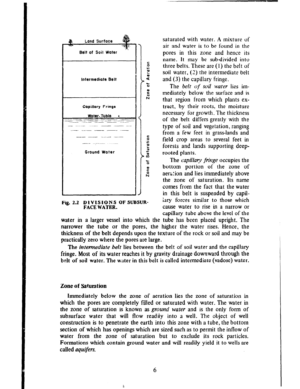
Subsurface water found in the interstices or pores of rocks may be divided
into two main zones (Fig . 2.2). These are the zvtle of aeration and the .zo/re
of saturation.
Zone of Aeration
The zone of aeration extends from the land surface to the level at which
all of the pores or open spaces in the earth’s materials are completely fiiled or
4
I
\I /
\ n /
- Sun -
. .
t-%rcolarlon
- -
V Fresh ground water ~-1.w
1,.-1
nrnnn
--
---_- _
_ - -; .-- -- -.
formotionr
--- -.- -
-
7 -- -c--
_
--- ..-_ IF --‘-- - - .--
- TJ
__ __ - -: tmpermeable
- -_._- z -- --- -
___ -z -..
- --
-- --
-
.- - -.
---_ --___ -a. - -~ - - ----
-- --- -~
Fig. 2.1 THE HYDROLOGIC CYCLE.
. Bsit of Soil Water
tntermediate Belt
Capillary Fringe
Water. Table t
-- -
Ground Water
Fig. 2.2 DIVISIONS OF SUBSUR-
FACE WATER.
saturated with water. A mixture of
air and water is to be found in the
pores in this zone and hence its
name. It may be subdivided into
three belts. These are (1) the belt of
soil water, (3) the intermediate belt
and (3) the capillary fringe.
The be/r of soil wafer lizs im-
mediately below the surface and is
that region from which plants ex-
tract, by their roots, the moisture
necessary for growth. The thickness
of the belt differs greatly with the
type of soil and vegetation, ranging
from a few feet in grass-lands and
field crop areas to several feet in
forests and lands supporting deep-
rooted plants.
The qdlary ftitlge occupies the
bottom portion of the zone of
aerh:ion and lies immediately above
the zone of saturation. Its name
comes from the fact that the water
in this belt is suspended by capil-
iary forces similar to those which
cause water to rise in a narrow or
capillary tube above the level of the
water in a larger vessel into which the tube has been placed upright. The
narrower the tube or the pores, the higher the water rises. Hence, the
thickness of the belt depends upon the texture of the rock or soil and may be
practically zero where the pores are large.
The intemrediute belt lies between the belt of soil water and the capillary
fringe. Most of its water reaches it by gravity drainage downward through the
belt of soil water. The wster in this belt is called intermediate (vadose) water.
Zone of Saturation
Immediately below the zone of aeration lies the zone of saturation in
which the pores are completely fdled or saturated with water. The water in
the zone of saturation is known as ground water and is the only form of
subsurface water that will flow readiiy into 3 well. The object of well
construction is to penetrate the earth into this zone with a tube, the bottorn
section of which has openings which are sized such as to permit the inflow of
water from the zone of saturation but to exclude its rock particles.
Formations which contain ground water and will readily yield it to wells are
called aquifers.
6
5
IC FQRXA~NMIIS AS AQUIFERS
For convenience, . :)iogists describe all earth materials as roclis. Rocks
may be of the ~~onti.J
‘,-refl type (held firntiy together by compaction,
cementation and otLe:, K A~.,P sut!~ :ts granite. sandr’,>r-* e;\d limestone or
rtrncomoiidated type (IL, .-:aterials) such as clay, sand Jnd gravel. The terms
hml and
soft are also usr,~: r.o describe consolidated and unconsolidated rocky
respectively.
Aquifers may be composed of consolidated or unconsolidated rocks. The
rock materiais must be sufficiently porous (contain a reasonably high
proportion of pores or other openings to solid material) and be sufficiently
permeable (the openings must be interconnected to permit the travei of water
through them).
Rock Classification
Rocks may be classified with respect to their or+;? into the three main
categories cf sedimentary rocks, igneous rocks, and lxidmorphic rocks.
Sedimentary rocks are the deposits of material derived from the
weathering and erosion of other rocks. Though constituti;.; only about 5
percent of the earth’s crust they contain an estimated 95 percent of the
available ground water.
Sedimentary rocks may be consolidated or unconsolidated depending
upon a number of ?‘zctors such as the type of parent rock, mode of
weathering, means of transport, mode of deposition, and the extent to which
packing, compactiorl, and cementation have taken place. Harder rocks
generally produce sediments of coarser texture than softer ones. Web;>erin;
by mechanical disintegration (e.g. rock fracture due to temperature varlu
tions) produces coarser sediments than those produced by chemical decom-
position. Deposition in water provides more sorting and better packing of
materials than does deposition directly onto land. Chemical constituents in
the parent rocks and the environment are responsible for the cemerltatioll of
unconsolidated rocks into hard, consolidated ones. These factors aiso
influence the water-bearing capacity of sedimentary rocks. Disintegrated shale
sediments are usually fine-grained and make poor aquifers while sediments
derived from granite or other crystalline rocks usually form good sand and
gravel aquifers, particularly when considerable water transportation has
resulted in well-rounded and sorted particles.
Sand, gravel, and mixtures of sand and gravel are among the unconsoli-
dated sedimentary rocks that form aquifers. Granular and unconsolidated,
they va.ry in particle size and in the degree of sorting and rounding of the
particies. Consequently, their water-yielding capabilities vary considerably.
However, they consitute the best water-bearing formations. They are widely
distributed throughout the world and produce very significant proportions of
the water used in many countries.
Other unconsolidated sedimentary aquifers include marine deposits,
alluvial or stream deposits (including deltaic deposits and alluviai fans), glacial
drifts and wind-blown deposits such as dune sand and loess [very fine silty
deposits). Great variations in the water-yielding capabilities of these forma-
tions can also be expected. For example, the yield from wells in sand dunes
7
and loess may be limited by both the fineness of the material and the limited
areal extent and thickness of the deposits.
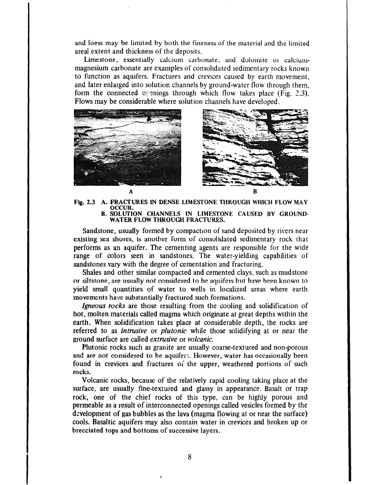
Limestone, essentially calcium carbonate. and dolomite or calcium-
magnesium carbonate are examples of consolidated sedimentary rocks known
to function as aquifers. Fractures and crevices caused by earth movement,
and later enlarged into solution channels by ground-water flow through them,
form the connected o:,enings through which flow takes place (Fig. 2.3).
Flows may be considerable where solution channels have developed.
A B
Fig.2.3 A.FRACXJRESlNDENSELIMESTONETHROUGHWHICHFLOWMAY
OCCUR.
B. SOLUTION CHANNELS IN LIMESTONE CAUSED BY GROUND-
WATERFLOWTHROUGHFRACTURES.
Sandstone, usually formed by compactron of sand deposited by rivers near
existing sea shores, is another form of consolidated sedimentary rock that
performs as an aquifer. The cementing agents are responsible for the wide
range of colors seen in sandstones. The water-yielding capabilities of
sandstones vary with the degree of cementation and fracturing.
Shales and other similar compacted and cemented clays, such as mudstone
or siltstone, are usually not considered to be aquifers but have been known to
yield small quantities of water to wells in localized areas where earth
movements have substantially fractured such formations.
Igneous rocks are those resulting from the cooling and solidification of
hot, molten materials called magma which originate at great depths within the
earth. When solidification takes place at considerable depth, the rocks are
referred to as intrusive or plutonic while those solidifying at or near the
ground surface are called extrusive or volcanic.
Plutonic rocks such as granite are usually coarse-textured and non-porous
and are not considered to be aquifer;. However, water has occasionally been
found in crevices and fractures ol the upper, weathered portions of such
rocks.
Volcanic rocks, because of the relatively rapid cooling taking place at the
surface, are usually fine-textured and glassy in appearance. Basalt or trap
rock, one of tlze chief rocks of this type, can be highly porous and
permeable as a result of interconnected openings called vesicles formed by the
development of gas bubbles as the lava (magma flowing at or near the surface)
cools.
Basaltic aquifers may also contain water in crevices and broken up or
brecciated tops and bottoms of successive layers.
8
Fragmental materials discharged by volcanos. such as ash and cinders, have
been known to form excellent aquifers where particle sizes are sufficiently
large. Their water-yielding capabilities vary considerably, depending on the
complexity of stratification, the range of particle sizes, and shape of the
particles. Examples of excellent aquifers of this type are to be found in
Central America.
Metanwrphic rock is the name given to rocks of all types, igneous or
sedimentary, which have been altered by beat and pressure. Examples of
these are quart&e or metamorphosed sandstone, slate and mica schist from
shale, and gneiss from granite. Generally, these form poor aquifers with water
obtained only from cracks and fractures. Marble, a metamorphosed lime-
stone, can be a good aquifer when fractured and containing solution channels.
With the above description of the three main rock types, it should now be
easier to understand why an estimated 95 percent of the available ground
water is to be found in sedimentary rocks which constitute only about 5
percent of the earth’s crust. The wells described in this manual will be those
constructed in unconsolidated sedimentary rocks which are undoubtedly the
most important sources of water for small community water supply systems.
Role of Geologic Processes in Aquifer Formation
Geologic processes are continually, though slowly, altering rocks and rock
formations. So slowly are these changes taking place that they are hardly
perceptible to the human eye and only barely measurable by the most
sensitive instruments now available. Undoubtedly, however, mountains are
being up-lifted and lowered, valleys filled or deepened and new ones created,
sea shores advancing and retreating, and aquifers created and destroyed.
These changes are more obvious when referred to a geologic timetable with
units measured in thousands and ,millions of years and to which reference can
be made .in almost any book on geology.
Geologically old as well as young rocks may form aquifers but generally
the younger ones which have been subjected to less compression and
cementation are the better producers. Geologic processes determine the
shape, extent, and hydraulic or flow characteristics of aquifers. Aquifers in
sedimentary rock formations for example vary considerably depending upon
whether the sediments are terrestrial or marine in nature.
Terrestrial sediments, or materials deposited on land, include stream, lake,
glacial, and wind-blown deposits. With but few exceptions they are usually of
limited extent and discontinuous, much more so than are marine deposits.
Texture variations both laterally and vertically are characteristic of these
formations.
AZZMaI or stream deposits are generally long and narrow. Usually
SUbSUrface,
or below the valley floor, they may also be in the form of terraces
indicating the existence of higher stream beds in the geologic past. The
material in such aquifers may range in size from fine sand to
gravel
and
boulders. Abandoned stream courses and their deposits are sometimes buried
under wind-home or glacial depos,ts with no visible evidence of their
existence. Where a rapidly flowing stream such as a mountain stream
encounters a rapid reduction of slope, the decrease in velocity causes a
9
deposition of large aprons of material known as alluvial fans. These sediments
range from coarser to finer material as one proceeds away from the
mountains.
Glacial deposits found in North Central U.S.A., Southern Canada, and
Northern Europe and Asia may bc extensive where they result from
continental glaciers as compared to the more localized deposits of mountain
glaciers. These deposits vary in shape and thickness and exhibit a lack of
interconnection because of the clay and silt accumulations within the sand,
gravel and boulders. Outwash deposits swept out of the melting glacier by
melt-water streams are granular in nature and similar to alluvial sands. The
swifter melt-water streams produce the best glacial drift aquifers.
Lake deposits are generally fine-textured, granular material deposited in
quiet water. They vary considerably in thickness, extent, and shape and make
good aquifers only when they are of substantial thickness.
GROUND-WATER FLOW AND ELEMENTARY WELL HYDRAULICS
Types of Aquifers
Ground-water aquifers may be classified as either water-table or artesian
aquifers.
A water-table aquifer is one which is not confined by an upper
impermeable layer. Hence, it is also called an unconfined aquifer. Water in
these aquifers is virtually at atmospheric pressure and the upper surface of the
zone of saturation is called the water table (Fig. 2.2). The water table marks
the highest level to which water will rise in a well constructed in a water-table
aquifer. The upper aquifer in Fig. 2.4 is an example of a water-table aquifer.
An artesian aquifer is one in which the water is confined under a pressure
greater than atmospheric by an overlying, relatively impermeable layer.
Hence, such aquifers are also called confined or pressure aquifers. The name
artesian owes its origin to Artois, the northernmost province of France, where
the first deep wells to tap confined aquifers were known to have been drilled.
Unlike water-table aquifers, water in artesian aquifers will rise in wells to
levels above the bottom of the upper confining layer. This is because of the
pressure created by that confining layer and is the distinguishing feature
between the two types of aquifers.
The imaginary surface to which water will rise in wells located throughout
an artesian aquifer is called the piezomettic surface. This surface may be
either above or below the ground surface at different parts of the same
aquifer as is shown in Fig. 2.4. Where the piezometric surface lies above the
ground surface, a well tapping the aquifer will flow at ground level and is
referred to as a flowing artesian well. Where the piezometric surface lies
below the ground surface, a non$owing artesiarl well results and some means
of lifting water, such as a pump, must be provided to obtain water from the
well. It is worthy of note here that the earlier usage of the term artesian well
referred only to the flowing type while current usage includes both flowing
and non-flowing wells, provided the water level in the well rises above the
bottom of the confming layer or the top of the aquifer.
10
Recharge area
Nonflowing
artesian
Ground
surfuce7
Woter-
Flowing
artesian
. .
at autc?opping
of formation
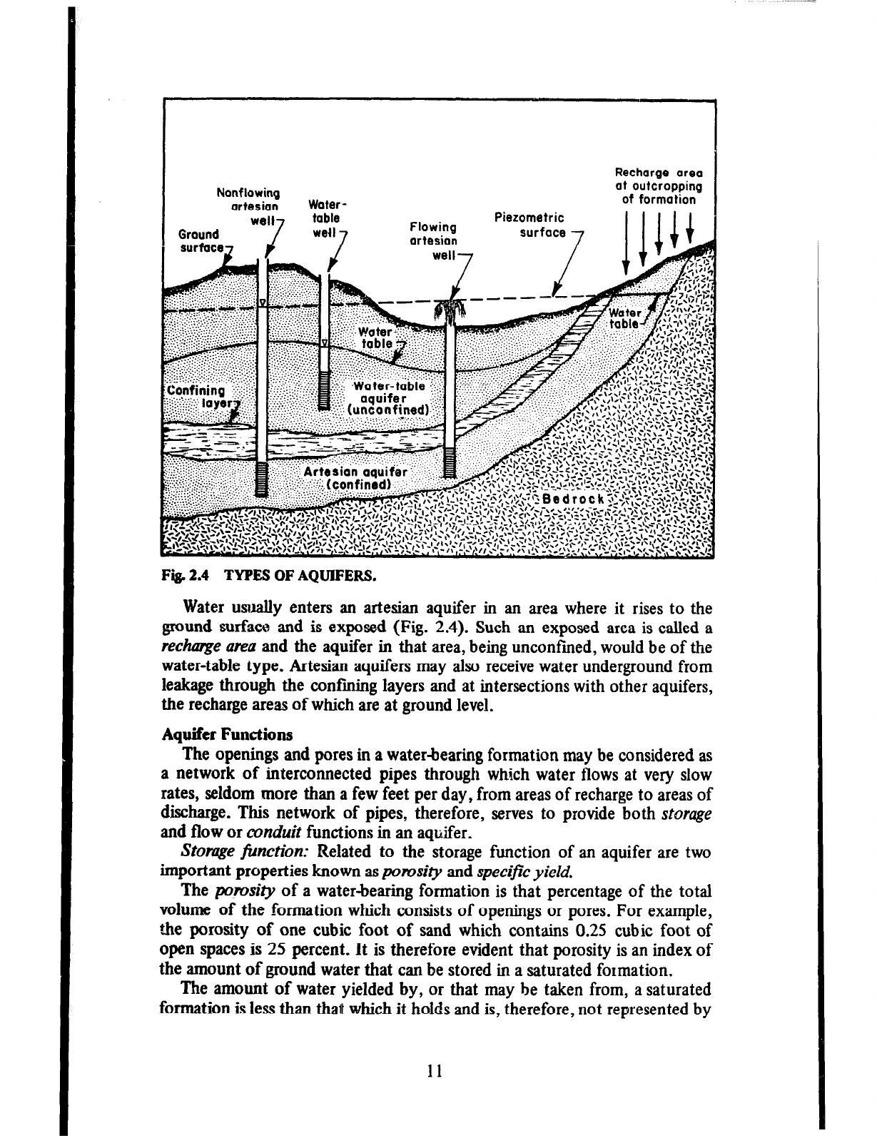
Fig. 2.4 TYPES OF AQUIFERS.
Water usually enters an artesian aquifer in an area where it rises to the
ground
surface and is exposed (Fig. 2.4). Such an exposed area is called a
rechmge area and the aquifer in that area, being unconfined, would be of the
water-table type. Artesian aquifers may also receive water underground from
leakage through the confining layers and at intersections with other aquifers,
the recharge areas of which are at ground level.
Aquifer Functions
The openings and pores in a water-bearing formation may be considered as
a network of interconnected pipes through which water flows at very slow
rates, seldom more than a few feet per day, from areas of recharge to areas of
discharge. This network of pipes, therefore, serves to provide both storage
and
flow or conduit functions in an aquifer.
Stooge fin&on: Related to the storage function of an aquifer are two
important properties known as porosity and specific yieZd.
The porosiZy of a water-bearing formation is that percentage of the total
volume of the formation which consists of openings or pores. For example,
the porosity of one cubic foot of sand which contains 0.25 cubic foot of
open spaces is 25 percent. It is therefore evident that porosity is an index of
the amount of ground water that can be stored in a saturated formation.
The amount of water yielded by, or that may be taken from, a saturated
formation is less than
that
which it holds and is, therefore, not represented by
11
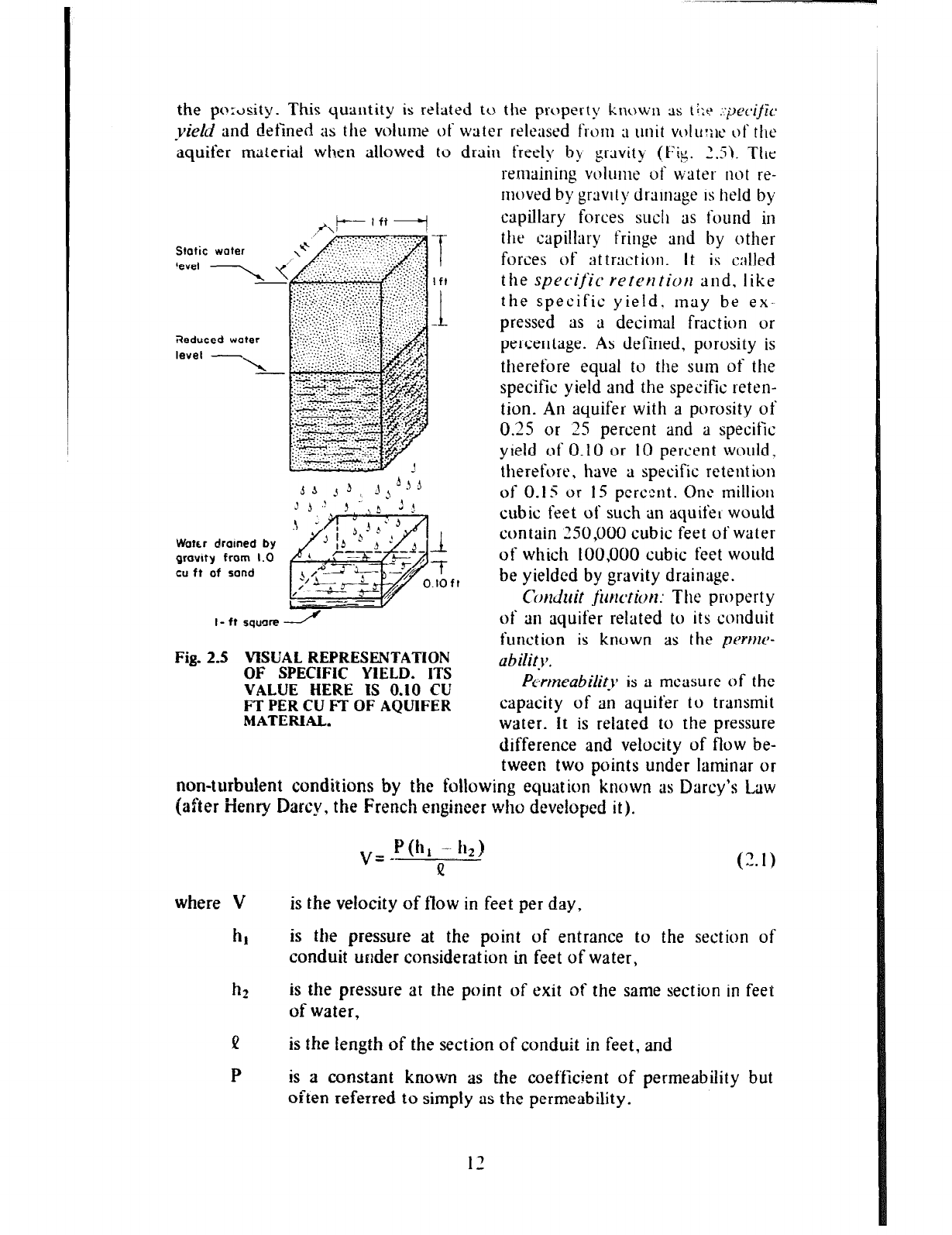
the pc>:ti,sity. This quautity is related tu the property known 9s t+e ::pec*ijk
yield and defined as the volume of water released front ;I unit volu:;~e of the
aquifer material when allowed to drain freely by gravity (Fig. 7.5). TIK
,,A!+-- ’ ft
. . . . . . . .
Static woter
,f
,“ ., .~::.~~:.~~~:~:
tese, - j’ .‘.‘. _._.(. 1:
‘C ..,.,., ::>:.:.
Water drotned by
growtty from 1.0
cu ft of sand
Fig. 2.5 VISUAL REPRESENTATION
OF SPECIFIC YIELD. ITS
VALUE HERE IS 0.10 CU
L’IXXCAFT OF AQUIFER
.
PL-meability is a measure of the
capacity of an aquifer to transmit
water. It is related to the pressure
difference and velocity of flow be-
tween two points under laminar or
non-turbulent canditions by the following equation known as Darcy’s Law
(after iierrry Darcy, the French engineer who developed it).
rennaining vulunte uf water not re-
moved by gravity drainage is held by
cupiktry forces sucl~ as found in
the capillary fringe and by other
forces of attraction. It is called
the specific’reterttiott and. like
the specific yield. may be ex-
pressed as a decimal fraction or
percentage. As defined, porosity is
therefore equal to the sum of the
specific yield and the specific reten-
tion. An aquifer with a porosity of
0.25 or 25 percent and a specific
yield of 0.10 or 10 percent would,
therefore, have a specific retcnt ion
of 0.1 S or IS percent. One million
cubic feet of such an aquifel would
contain 250,000 cubic feet ofwate~
of which 100,000
cubic
feet would
be yielded by gravity drainage.
Conduit jim.ticm: The property
of an aquifer related to its conduit
function is known as the perttw-
ubility.
where V
h,
hz
P
P
(2. I)
is the velocity of flow in feet per day,
is the pressure at the point of entrance to the section of
conduit unlder consideration in feet of water,
is the pressure at the point of exit of the same section in feet
of water,
is the length of the section of conduit in feet, and
is a constant known as the coefficient of permeability but
often referred to simply as the permeability.
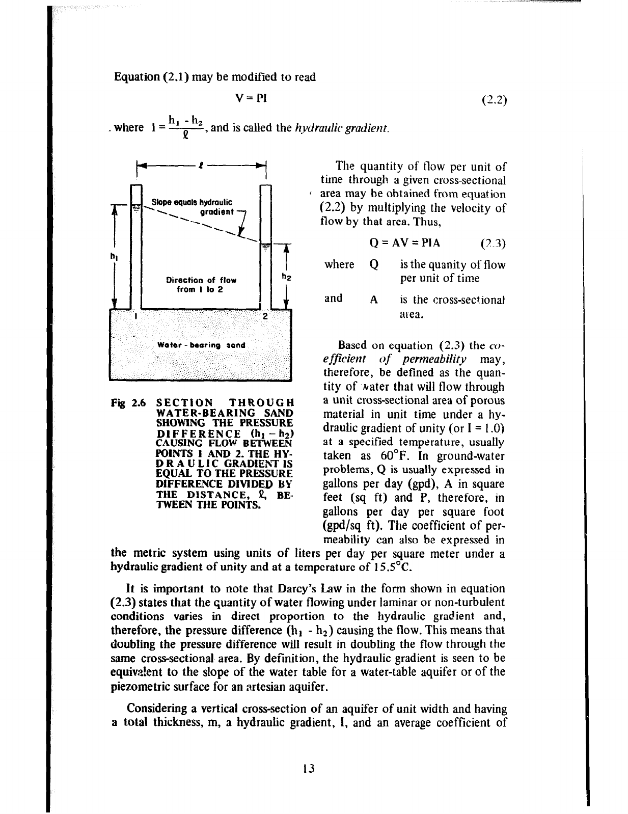
Equation (2.1) may be modified to read
v = PI
h1 - hz
. where I = -, P and is called the hydraulic gradient.
Slope equals hydmulic
. . . . gradient
.---. -7,
Direction of flow
from I to 2
- ‘.. ,, ,:.
,, _, ,. ..,‘, ‘.
. . :: .
‘. ;. . ...,.,. “.
c ,...;..~ :.-. ‘:.
. _ ‘.‘..‘...‘. ,: . ) .;. ., :::
Fig 2.6 SECTiON THROUGH
WATER-BEARING SAND
SHOWING THE PRESSURE
DIFFERENCE thl- hd
CAUSING FLOW BETWEEN
POINTS 1 AND 2. THE HY-
DRAULIC GRADIEhTIS
EQUAL TO TME PRESSURE
DIFFERENCE DIVIDED BY
THE DISTANCE, i!, BE-
TWEEN THE POINTS.
(2.2)
The quantity of flow per unit of
time through a given cross-sectional
area may be obtained from equation
(2.2) by multiplying the velocity of
flow by that area. Thus,
Q=AV=PIA (2.3)
where Q is the quanity of flow
per unit of time
and A is the cross-sectional
area.
Based on equation (2.3) the co-
efficient of perrneubility may,
therefore, be defined as the quan-
tity of hater that will flow through
a unit cross-sectional area of porous
material in unit time under a hy-
draulic gradient of unity (or I = 1 .O)
at a specified temperature, usually
taken as 60°F. In ground-water
problems, Q is usually expressed in
gallons per day (gpd), A in square
feet (sq ft) and P, therefore, in
gallons per day per square foot
(gpd/sq ft). The coefficient of per-
meability can also be expressed in
the metric system using units of liters per day per square meter under a
hydraulic gradient of unity and at a temperature of 15S”C.
It is important to note that Darcy’s Law in the form shown in equation
(2.3) states that the quantity of water flowing under iaminar or non-turbulent
conditions varies in direct proportion to the hydraulic gradient and,
therefore, the pressure difference (hI - h2) causing the flow. This means that
doubling the pressure difference will result in doubling the flow through the
same cross-sectional area. By definition, the hydraulic gradient is seen to be
equivalent to the slope of the water table for a water-table aquifer or of the
piezometric surface for an artesian aquifer.
Considering a vertical cross-section of an aquifer of unit width and having
a total thickness, m, a hydraulic gradient, I, and an average coefficient of
13
permeability, P, we see from equation (2.3) that the rate of flow, q, through
this cross section is given by
q=PmI (2.4)
The product Pm of equation (2.4) is termed the coejficient
of
transntissi-
bility or transmissivity, T, OI the aquifer. By further considering that the total
width of the aquifer is W, then the rate of flow, Q, through a vertical
cross-section of the aquifer is given by
Q=qW=TIW (2.5)
The coej@ient of trunsmissibility is, therefore, defined as the rate of flow
through a vertical cross-section of an aquifer of unit width and whose height
is the total thickness of the aquifer when the hydraulic gradient is unity. It is
expressed in gallons per day per foot (gpd/ft) and is equivalent to the product
of the coefficient of permeability and the thickness of the aquifer.
Factors Affecting Permeability
Porosity is an important factor affecting the permeability and, therefore,
the capacity of an aquifer for yielding water. This is clearly evident since an
aquifer can yield only a portion of the water that it contains and the higher
the porosity, the greater is the volume of water that can be stored. Porosity
must, however, be considered together with other related factors such as
particle size, arrangement and distribution, continuity of pores, and forma-
t ion stratification.
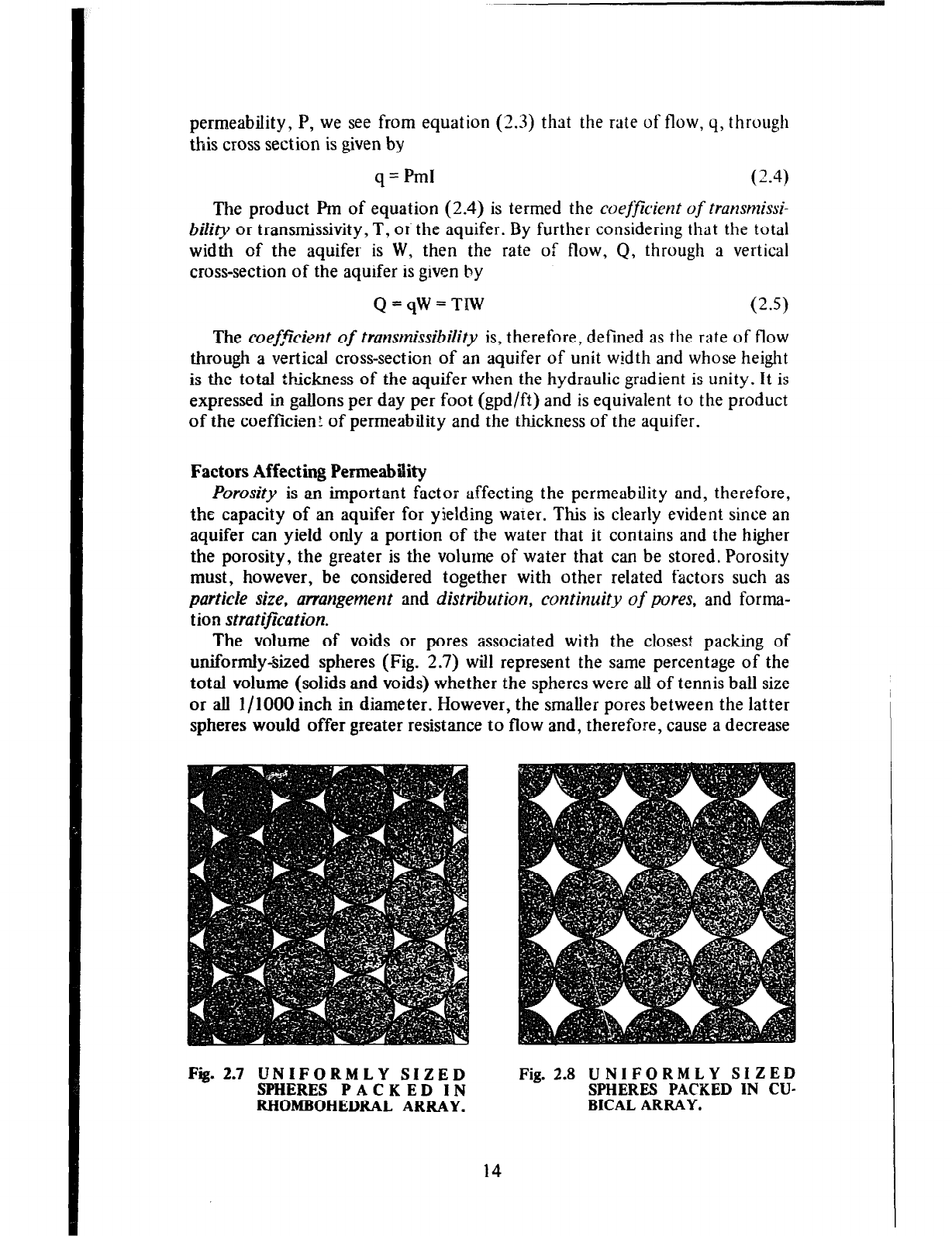
The volume of voids or pores associated with the closest packing of
uniformly&zed spheres (Fig. 2.7) will represent the same percentage of the
total volume (solids and voids) whether the spheres were all of tennis ball size
or all l/l000 inch in diameter. However, the smaller pores between the latter
spheres would offer greater resistance to flow and, therefore, cause a decrease
Fii. 2.7 UNIFORMLY SIZED
SPHERES PACKED IN
RHOMBOHEDRAL ARRAY.
Fig. 2.8 UNIFORMLY SIZED
SPHERES PACKED IN CU-
BICAL ARRAY.
14
in permeability even though the porosity is the same.
The packing of tile spheres displajred in Fig. 2.7 is referred to as the
rhombohedral packing. The porosity for such a packing can be shown to be
0.26 or 26 percent. The spheres may also assume a cubical array as shown in
Fig. 2.8 for which the porosity is 0.476 or 47.6 percent. These porosities
apply only to perfectly spherical particles and are included here to give the
order of magnitude of the porosities that naturally occurring uniform sands
and gravels may approach. A loose uniform sand may, for example. have a
porosity of 46 percent. Clays, on the other hand, exhibit much fligher
porosities ranging from about 37 percent for stiff glacial clays to as high as 84
percent for soft bentonite clays.
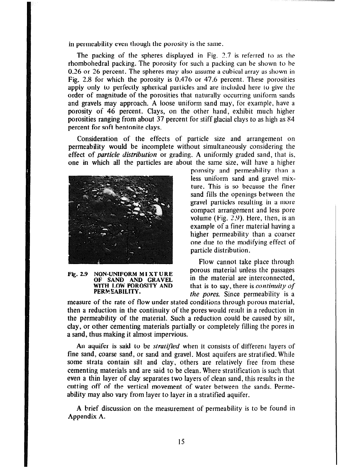
Consideration of the effects of particle size and arrangement on
permeability would be incomplete without simultaneously considering the
effect of particle distibution or grading. A uniformly graded sand, that is,
one in which all the particles are about the same size, wilt have a higher
porosity and permeability than a
less uniform sand and gravel mix-
ture. This is so because the finer
sand fills the openings between the
gravel particles resulting in a more
compact arrangement and fess pore
volume (Fig. 2.9). Here, then, is an
example of a finer material having a
higher permeability than a coarser
one due to the modifying effect of
particle distribution.
Flow cannot take place through
Fig. 2.9 NON-UNIFORM MI XT URE
porous material unless the passages
OF SAND AND GRAVEL
in the material are interconnected,
WITH LOW POROSITY AND
PERh%tBII.ITY.
that is to say, there is continuity of
the pores. Since permeability is a
measure of the rate of flow under stated conditions through porous material,
then a reduction in the continuity of the pores would result in a reduction in
the permeability of the material. Such a reduction could be caused by silt,
clay, or other cementing materials partially or completely filiing the pores in
a sand, thus making it almost impervious.
An aquifer is said to be stratiflied when it consists of different layers of
fine sand, coarse sand, or sand and gravel. Most aquifers are stratified. While
some strata contain silt and clay, others are relatively free from these
cementing materials and are said to be clean. Where stratification is such that
even a thin layer of clay separates two layers of clean sand, this results in the
cutting off of the vertical movement of water between the sands. Perme-
ability may also vary from layer to layer in a stratified aquifer.
A brief discussion on the measurement of permeability is to be found in
Appendix A.
15
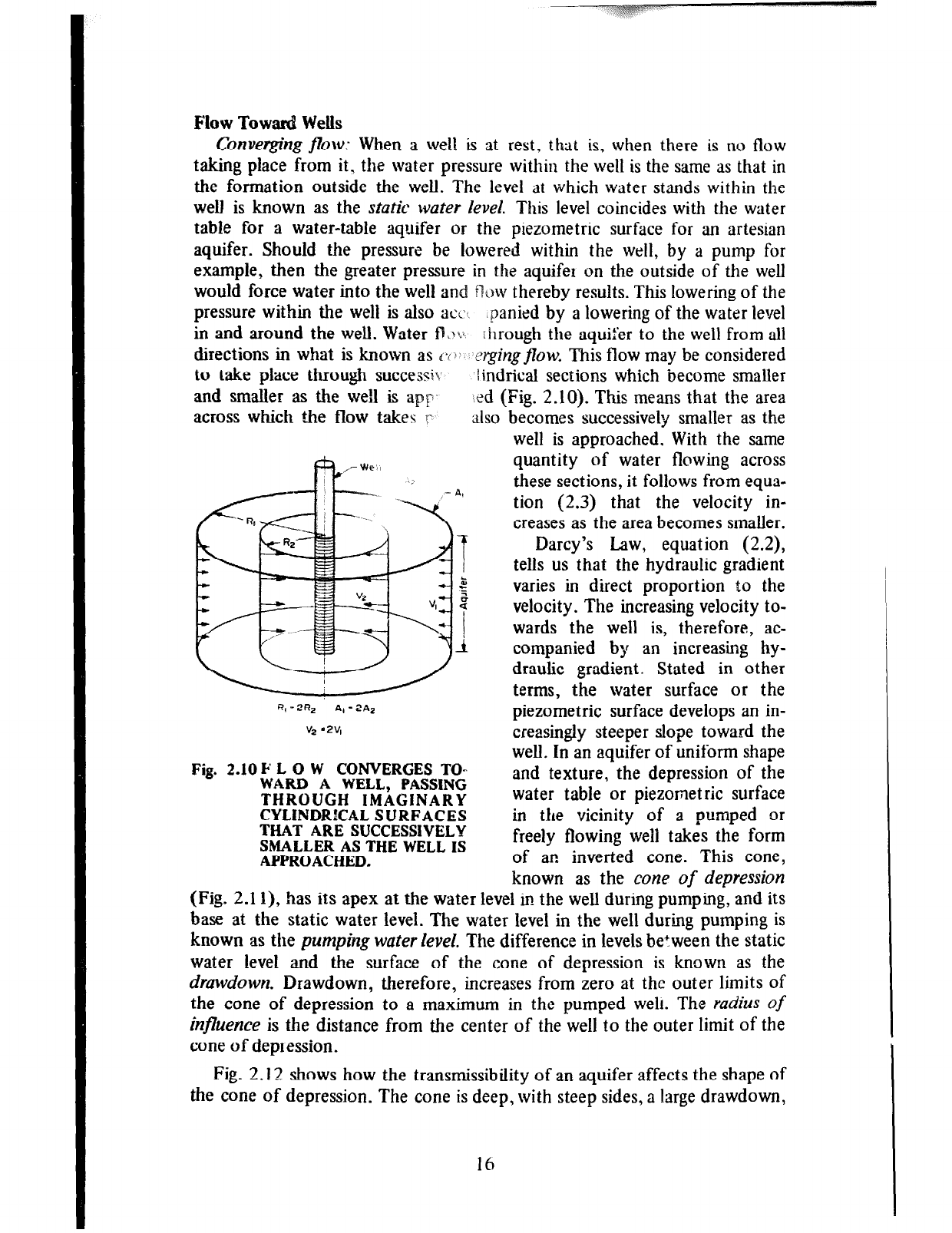
Flow Toward Wells
Converging j&w: When a well is at rest, that is, when there is no flow
taking place from it, the water pressure within the well is the same as that in
the formation outside the well. The level at which water stands within the
well is known as the static water level. This level coincides with the water
table for a water-table aquifer or the piezometric surface for an artesian
aquifer. Should the pressure be lowered within the well, by a pump for
example, then tire greater pressure in the aquifer on the outside of the well
would force water into the well and flak thereby results. This lowering of the
pressure within the well is also acz$ *nanied by a lowering of the water level
in and around the well. Water fl,j~ Through the aquifer to the well from all
directions in what is known as ~0 ergingflow. This flow may be considered
to take place through successit lindrical sections which become smaller
and smaller as the we!1 is ap y’ ied (Fig. 2.10). This means that the area
across which t&e flow takes r also becomes successively smaller as the
R, -2R, A, = 2A2
v, ‘2V,
Fig. 2.10 F L 0 W CONVERGES TO-
WARD A WELL, PASSING
THROUGH IMAGINARY
CYLINDRKAL SURFACES
THAT ARE SUCCESSIVELY
SMALLER AS THE WELL IS
APPROACHED.
Darcy’s Law, equation (2.2),
tells us that the hydraulic gradient
varies in direct proportion to the
velocity. The increasing velocity to-
wards the well is, therefore, ac-
companied by an increasing hy-
draulic gradient. Stated in other
terms, the water surface or the
piezometric surface develops an in-
creasingly steeper slope toward the
well. In an aquifer of uniform shape
and texture, the depression of the
water table or piezonetric surface
in the vicinity of a pumped or
freely flowing well takes the form
of an inverted cone. This cone,
known as the cone of depression
(Fig. 2.1 l), has its apex at the water level in the well during pumping, and its
base at the static water level. The water level in the well during pumping is
known as the pumping water level. The difference in levels between the static
water level and the surface of the cone of depression is known as the
drawdown. Drawdown, therefore, increases from zero at the outer limits of
the cone of depression to a maximum in the pumped weft. The radius
of
influence is the distance from the center of the well to the outer limit of the
cone of depression.
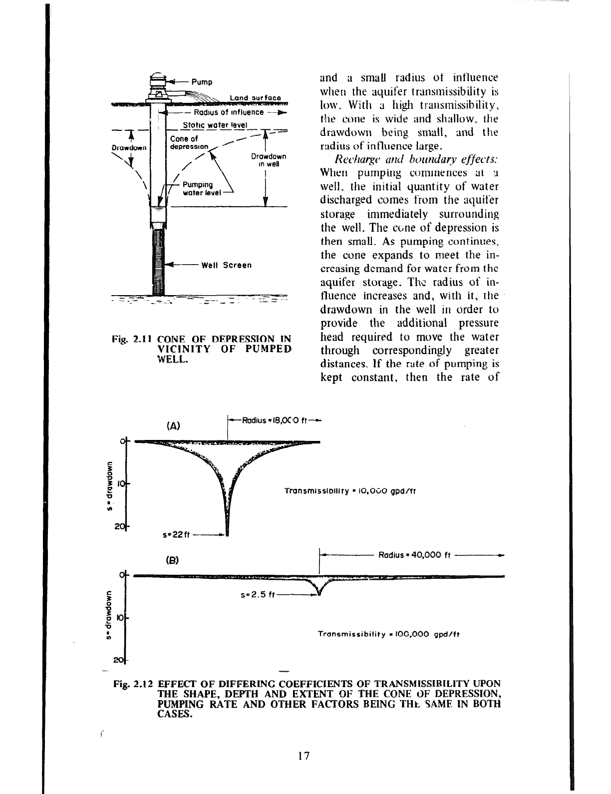
Fig. 2.12 shows how the transmissibility of an aquifer affects the shape of
the cone of depression. The cone is deep, with steep sides, a large drawdown,
well is approached. With the same
quantity of water flowing across
these sections, it follows from equa-
tion (2.3) that the velocity in-
creases as the area becomes smaller.
16
-- Rodlus of Influence --+
Static water level
_------ --
.--
T
Drowdown
in we8
C--Well Screen
Fig. 2.11 CONE OF DEPRESSION IN
VICINITY OF PUMPED
WELL.
and a small radius ot‘ influence
when the aquifer transmissibility is
low. With a high transmissibility,
the cone is wide and shallow, rhe
drawdown being small, and the
radius of influence large.
Rechg~ md bortndar-y ejfects:
When pumping commences at ‘I
well. the initial quantity of water
discharged comes from the aquifer
storage immediately surrounding
the well. The cbne of depression is
then small. As pumping continues,
the cone expands to meet the in-
creasing demand for water from the
aquifer storage. The radius of in-
fluence increases and, with it, the
drawdown in the well in order to
provide the additional pressure
head required to move the water
through correspondingly greater
distances. If the rate of pumping is
kept constant, then the rate of
FRadius =IS,OCO ft--
Transmissibility - IO.OCO gpd/ft
Radius = 40,000 ft
Transmissibi!ity - IOO.000 gpd/ft
- -
Fig. 2.12 EFFECT OF DIFFERING COEFFICIENTS OF TRANSMISSIRILITY UPON
THE SHAPE, DEPTH AND EXTENT OF THE CONE c)F DEPRESSION,
PUMPING RATE AND OTHER FACTORS BEING THC SAME IN BOTH
CASES.
17
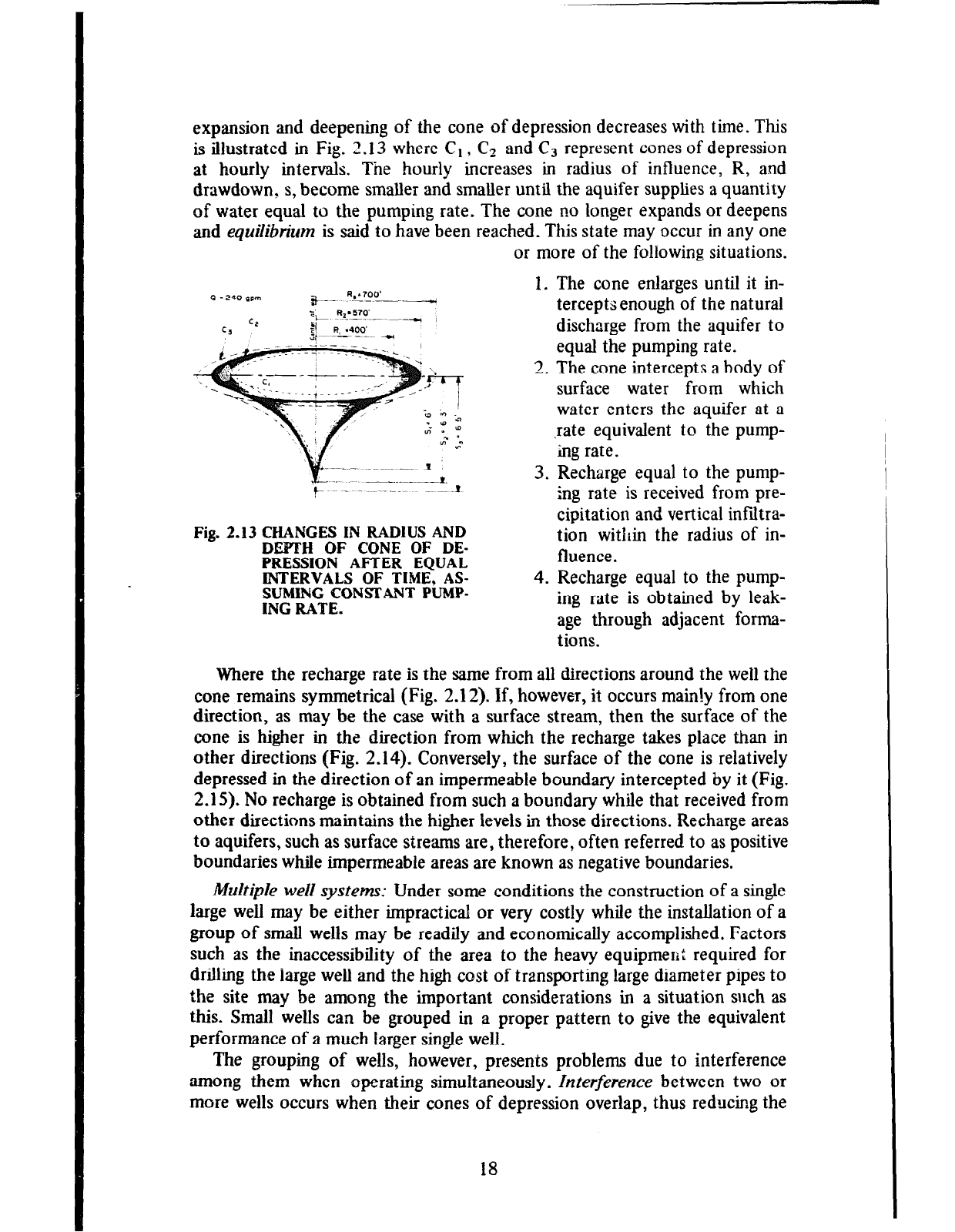
expansion and deepening of the cone of depression decreases with time. This
is illustrated in Fig. 2.13 where C1 , C2 and C3 represent cones of depression
at hourly intervals. The hourly increases in radius of influence, R, and
drawdown, s, become smaller and smaller until the aquifer supplies a quantity
of water equal to the pumping rate. The cone no longer expands or deepens
and equilibrium is said to have been reached. This state may occur in any one
or more of the following situations.
Fig. 2.13 CHANGES IN RADIUS AND
DEWTH OF CONE OF DE-
PRESSION AFTER EQUAL
INTERVALS OF TIME, AS-
~I$W&ONShUUT PUMP-
.
1. The cone enlarges until it in-
tercepts enough of the natural
discharge from the aquifer to
equal the pumping rate.
2. The cone intercepts a body of
surface water from which
water enters the aquifer at a
,rate equivalent to the pump-
ing rate.
3. Recharge equal to the pump-
ing rate is received from pre-
cipitation and vertical infiltra-
tion within the radius of in-
fluence.
4. Recharge equal to the pump-
ing rate is obtained by leak-
age through adjacent forma-
tions.
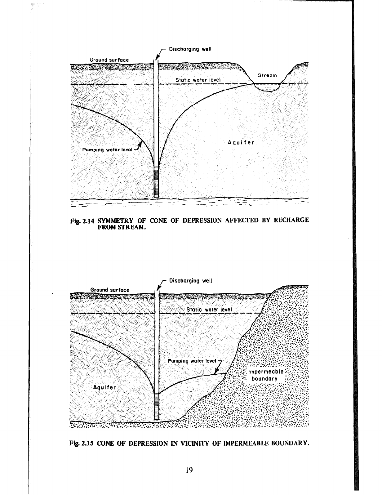
Where the recharge rate is the same from all directions around the well the
cone remains symmetrical (Fig. 2.12). If, however, it occurs main!y from one
direction, as may be the case with a surface stream, then the surface of the
cone is higher in the direction from which the recharge takes place than in
other directions (Fig. 2.14). Conversely, the surface of the cone is relatively
depressed in the direction of an imperrnea&le boundary intercepted by it (Fig.
2.15). No recharge is obtained from such a boundary while that received from
other directions maintains the higher levels in those directions. Recharge areas
to aquifers, such as surface streams are, therefore, often referred to as positive
boundaries while impermeable areas are known as negative boundaries.
Mdtiple well system: Under some conditions the construction of a single
large well may be either impractical or very costly while the installation of a
group of small wells may be readily and economically accomplished. Factors
such as the inaccessibility of the area to the heavy equipment required for
drilling the large well and the high cost of transporting large diameter pipes to
the site may be among the important considerations in a situation such as
this. Small wells can be grouped in a proper pattern to give the equivalent
performance of a much larger single well.
The grouping of wells, however, presents problems due to interference
among them when operating simultaneously. Interference between two or
more wells occurs when their cones of depression overlap, thus reducing the
18
r Discharging well
Fig. 2.14 SYMMETRY OF CONE OF DEPRESSION AFFECJ.‘ED BY RECHARGE
FROM STREAM.
r Discharging well
Fig. 2.15 CONE OF DEPRESSION IN VICINITY OF IMPERMEABLE BOUNDARY.
19
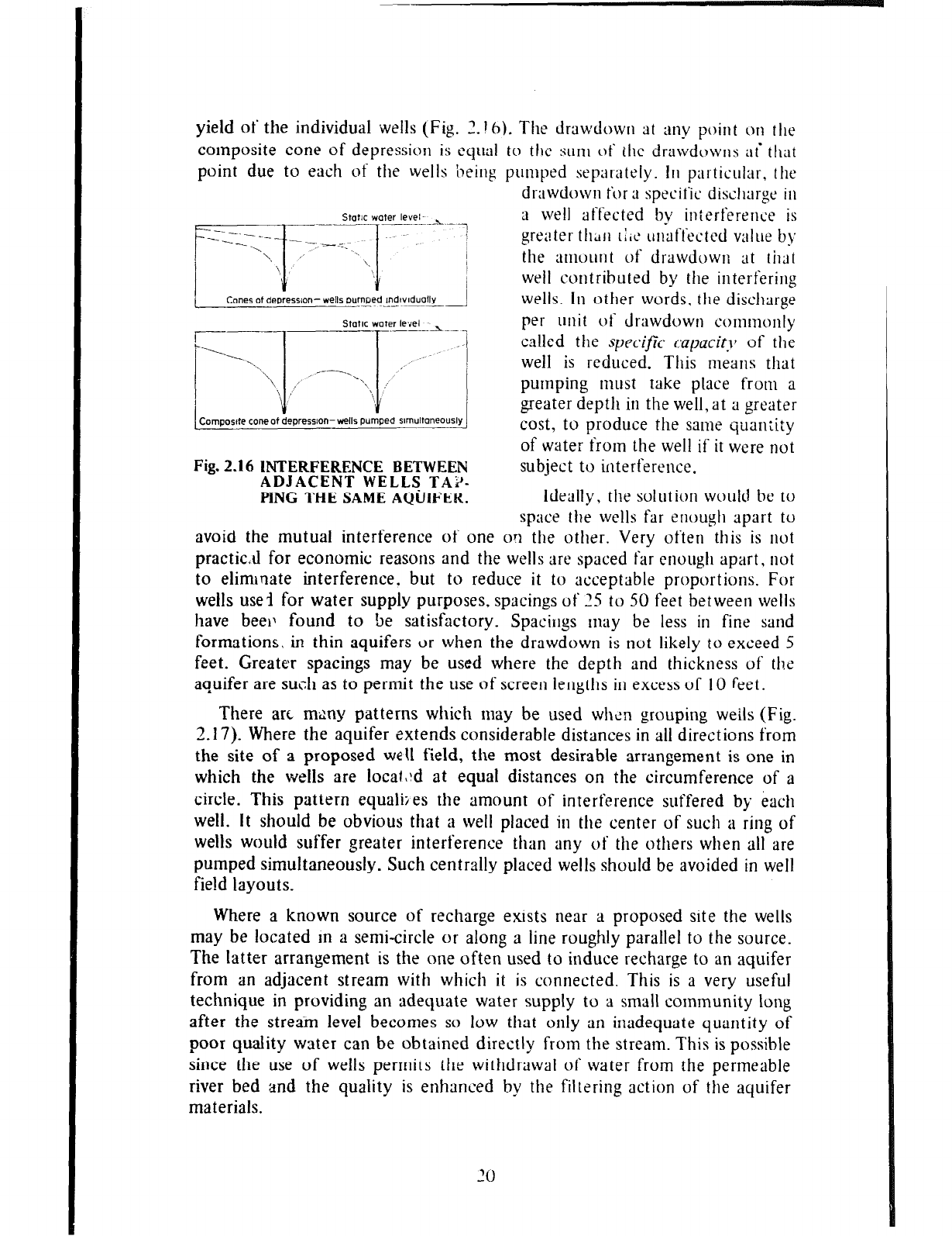
yield of the individual wells (Fig . 2.16). The drawdowrl at any point on tile
composite cone of depression is equal to the sum of ihe drawdowns ai that
point due to each of the wells being pumped separately. In particular, the
drawdown for ;I specific disclltlrge ill
Static water
level I -_ a well affected by interference is
greater fllA11
llit
unaffected value b?
the amount of drawdown ait that
well contributed by the interfering
wells. In other words, the discharge
per unit of drawdown commonly
called the
specific capacit), of
the
well is reduced. This means that
pumping must take place from a
greater depth in the well, at a greater
cost, to produce the same qaan:ity
of water from the well if it were not
Fig. 2.16 INTERFERENCE BETWEEN
ADJACENT WELLS TAi’-
subject to interference.
PING THE SAME AQUIFER.
Ideally, the solution would be to
space the wells far enough apart to
avoid the mutual interference of one ok the other. Very often this is not
practic,tJ for economic reasons and the wells are spaced far enough apart. not
to eliminate interference. but to reduce it to acceptable proportions. For
wells use3 for water supply purposes, spacings of 115 to 50 feet between wells
have bee11 found to be satisfactory. Spacings may be less in fine sand
formations, in thin aquifers or when the drawdowrt is not likely to exceed 5
feet. Greater spacings may be used where the depth and thickness of the
aquifer are such as to permit the use of screen lengths in excess of IO feet.
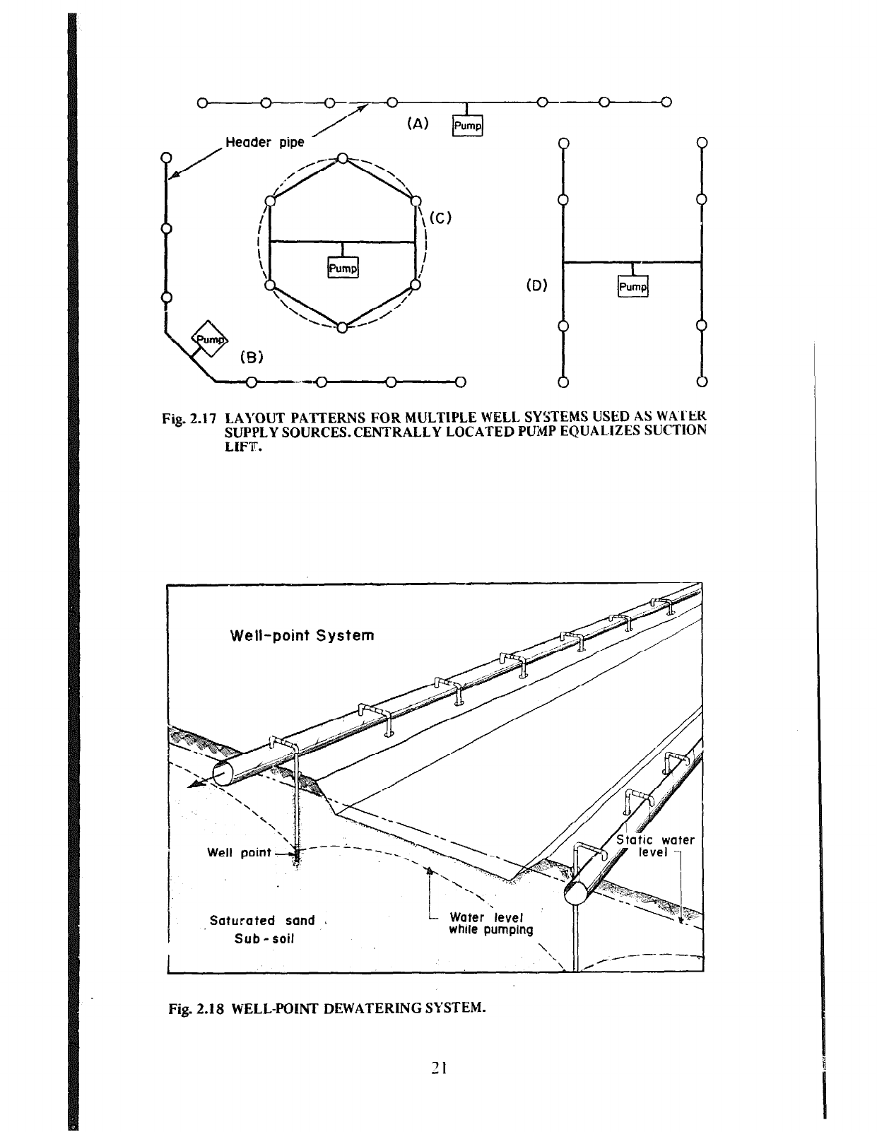
There arc many patterns which may be used when grouping weils (Fig.
2.17). Where the aquifer extends considerable distances in all directions from
the site of a proposed wetI field, the most desirable arrangement is one in
which the wells are locaf!:d at equal distances on the circumference of a
circle. This pattern equalizes the amount of interference suffered by each
well. It should be obvious that a well placed in the center of such a ring of
wells would suffer greater interference than any of the others when all are
pumped simultaneously. Such centrally placed wells should be avoided in well
field layouts.
Where a known source of recharge exists near a proposed site the wells
may be located m a semi-circle or along a line roughly parallel to the source.
The latter arrangement is the one often used to induce recharge to an aquifer
from an adjacent stream with which it is connected. This is a very useful
technique in providing an adequate water supply to a small community long
after the stream level becomes so low that only an inadequate quantity of
poor quality water can be obtained directly from the stream. This is possible
since the use of wells perrnirs the withdrawal of water from the permeable
river bed and the quality is enhanced by the filtering action of the aquifer
materials.
‘0
ID)
Fig. 2.17 LAI’OUT PATTERNS FOR MULTIPLE WELL SYSTEMS USED AS WATER
SUPPLY SOURCES. CENTRALLY LOCATED PUhlP EQUAL.iZES SUCTION
LIFT.
Well-point System
Saturated sand A
Sub-soil
I
Water level
while pumping
\ ‘\ \
Fig. 2.18 WELL-POINT DEWATERING SYSTEM.
‘I
Multiple well or well-point systems are also used
OJI
engineering construo-
tion sites for de-watering purposes, i.e. to extract water from an area to
provide dry working conditions (Fig. 2.18). The significant difference
between this use and that for water supplies is the fact that it is
JIOW
important to create interference in order to lower water levels as much as
possible. Closer well spacings than those recommended for water supply
purposes are, therefore, necessary. Well spacings for de-watering systems
usually range from 2 to 5 feet depending upon the permeability of the
saturated sand, the depth to which the water table is to be lowered and the
depth to which the well points can be installed in the formation. It is
important to note that the de-watering process may require as much as a day
of pumping before excavation can begin and must be continued throughout
the excavation. Nevertheless, de-watering has often proved more economical
than pumping from within a sheet pile surrounded working area.
QUALITY OF GROUND WATER
Generally, the openings through which water flows in the ground are very
small. This considerably restricts the rate of flow while at the same time
providing a filtering action against particles originally in suspension in the
water. These properties, it will be seen, considerably affect the physical,
chemical, and microbiological qualities of ground water.
Physical Quality
Physically, ground water is generally clear, colorless, with little or no
suspended matter, and has a relatively constant temperature. This is
attributable to its history of slow percolation through the ground and the
resulting effects earlier mentioned. In direct contrast, surface waters are very
often turbid and contain considerable quantiiies of suspended matter,
particularly when these waters are found near populous areas. Surface walers
are also subject to wide variations of iemperature. From the physical point of
view, ground water is, therefore, more readily usable than surface water,
seldom requiring treatment before use. The exceptions are those ground
waters which are hydraulically connected to nearby surface waters through
large openings such as fissures and solution chamlels and the interstices of
some gravels. These openings may permit suspended matter to enter into the
aquifer. In such cases, tastes and odors from decaying vegetation may also be
noticeable.
Microbiological Quality
Ground waters are generally free from the very minute organisms
(microbes) which cause disease and which are normally present in large
numbers in surface waters. This is another of the benefits that result from the
slow filtering action provided as the water flows through the ground. Also,
the lack of oxygen and nutrients in ground water makes it an unfavorable
environment for disease-producing organisms to grow and multiply. The
exceptions to this rule are again provided by the fissures and solution
channels found in some consolidated rocks and in those shallow sand and
73
--
gravel aquifers where water is extracted in close proximity to pollution
sources, such as privies and cesspools. This latter problem has been dealt with
in more detail in Chapter 9, where the sanitary protection of ground-water
supplies is discussed. Poor well construction can also result in the
contamination of ground waters. The reader is referred to the section in
Chapter 4 dealing with the sanitary protection of wells.
The solution of the potable water supply problems of Nebraska City,
Nebraska, U.S.A. in 1957 bears striking testimony to the benefits derived
from percolation of water through the ground and the general advantages of’a
ground-water supply over one from a surface source. For more than 100 years
prior to 1957, Nebraska City depended upon the Missouri River for its
domestic water supply. The quality of the water in the river deteriorated as
the years went by due to the use of the river for sewage and other forms of
waste disposal. To the old problems of high concentrations of suspended
matter, dark coloration from decayed vegetation and highly variable
temperatures (too warn in summer and too cold in winter) was added
bacterial pollution. So bad was this sittration that the Missouri River, in this
region, soon beczrre recognized as a virtual open sewer and the water no
longer met the requirements of the United States Public Health Service
Drinking Watei- Standards for waters suitable to be treated for municipal use.
The search for a new source of supply for Nebraska City led to the use of
wells drilled into the sands that underlie the flood plain of the Missouri River
at depths up to 100 feet. Wells drilled a mere 75 feet from the river’s edge
and drawing a considerable percentage of their water from the river yielded a
very high quality, clear water that showed no evidence of bacterial pollution
or noticeable temperature variation. The lessons of Nebraska City can be put
to beneficiai use in many other areas of the world.
Chemical Quality
The chemical quality of ground water is also considerably influenced by its
relatively slow rate of travel through the ground. Water has always been one
of the best solvents known to man. Its relatively slow rate of percolation
through the earth provides more than am<ple time for many of the minerals
that make up the earth’s crust to be taken into solution. These minerals have
varying rates of solution in water, depending upon a number of conditions
which themselves may vary widely within a small region. As a result, there
may be appreciably wide variations in the chemical quality of ground water
found in regions of relatively limited area1 extent.
The uses to which ground water can be put depend on its mineral content.
Where this content exceeds the recommended limit, treatment should be
provided to remove the excessive amounts of the mineral concerned. There
are satisfactory methods available for the removal of excessive quantities of
the important minerals usual1.y found in ground waters. Expert technical
advice should always be sought on the need for and use of these methods.
The mineral content of water is most commonly expressed in parts per
million (ppm) which means the number of parts, by weight, of the mineral
found in one million parts of the solution. For example, a concentration of
23
10 ppm of iron means that in every million pounds (or kilograms) c,i‘ the
water examined there will be found 10 pounds (or kilograms) of iron.
Another very common form of expression is that of milligrams per liter (mg/l
or mg per 1) which is the number of milligrams of the mineral found in one
liter of water. This latter unit differs so little from the former that ihey are,
for all practical purposes, considered equal and are ~on~n~only used
interchangeably.
The following are among the more important chemical substances and
properties of ground waters which are of interest to the owners of small
wells: iron, manganese, chloride, fluoride, nitrate, sulfate, hardness. total
dissolved solids, pH, and dissolved gases such as oxygen, hydrogen sulfide,
and carbon dioxide.
Zrorz and nlarzgarlese are usually considered together because of their
resemblances in chemical behavior and occurrence in ground water. It is
important to note that iron and manganese, in the quantities usually found in
ground water, are objectionable because of their nuisance values rather than
as a threat to man’s health. They both cause staining (reddish brown in the
case of iron and black in the case of manganese) of plumbing fixtures and
clothes during laundering. Iron deposits may accumulate in well screens and
pipes, restricting the flow oi water through them. Iron-containing waters also
have a characteristic taste which some people find unpleasant. Such waters,
when first drawn from a tap or pump, may be clear and colorless, but upon
allowing the water to stand, the iron settles out of solution giving a cloudy
appearance to the water and later accumulating in the bottom as a
rust-colored deposit.
Chlorides
occur in very high concentrations in sea water, usually of the
order of 20,000 mg/l. Rainwater, however, contains much less than I mg/l of
chloride. Aquifers containing large chioride concentrations are usually coastal
ones directly connected to the sea or which were so connected some time in
the past. Excessive pumping of wells in aquifers directly connected to the sea
or to brackish-water rivers will cause these high chloride-containing waters to
move into the otherwise fresh water zones of the aquifers. Expert technical
advice should be sought on the possibility of such an occurrence.
Water with a high chloride content usually has an unpleasant taste and
may be objectionable for some agricultural purposes. The level at which the
taste is noticeable varies from person to person but is generally of the order
of 350 mg/l. A great deal depends, however, on the extent to which people
have been accustomed to using such waters. Animals usuaily can drink water
with much more chloride than humans can tolerate. Cattle have, reportedly,
been known to consume water with a chloride content ranging from 3000
mg/l to 4000 mg/l.
FZunride
concentrations in ground water are usually small and mainly
derived from the leaching of igneous rocks. Notable among the few cases of
high concentrations is the reported 32 mg/l from a flowing well near San
Simon, Arizona, U.S.A. High concentrations have also been reported in some
parts of India, Pakistan and Africa.
24
dissolved solids content would therefore be expected to present rhe taste,
laxative and other problems associated with the individual minerals. Such
waters are usually corrosive to well screens and other parts of the well
structure.
pH is a measure of the hydrogen ion ccncentration in water and indicates
whether the water is acid or alkaline. It ranges in value from 0 to 14 with a
value of 7 indicating a neutral water, values between 7 and 0 increasingly acid
and between 7 and 14 increasingly alkaline waters. Most ground waters in the
United States have pH values ranging fr0.m about 5.5 to 8. Determination of
the pH value is important in the control of corrosion and many processes in
water treatment.
The
dissolved
ox-vgen content of ground wsters is usually low particularly
in waters found at great depths. Oxygen speeds up the corrosive attack of
water upon iron, steel, galvanized iron, and brass. The corrosive process is aLc,
more rapid when the pH is low.
Hydrogen sulfide
is recognizable by its characteristic odor of rotten eggs.
It is very often found in ground waters which also contain iron. In addition to
the odor, which is noticeable at as low a concentration as 0.5 mg/l, hydrogen
;r sulfide combines with oxygen to produce a corrosive condition in wells and
also combines with iron to form a scale deposit of iron sulfide in pipes. Most
of the hydrogen sulfide can be removed from ground water by spraying it
into the air or allowing it to cascade in thin layers over a series of trays.
Carbon dioxide
enters water in appreciable quantities as the water
percolates through soil in which plants are growing. Dissolved in water, it
forms carbonic acid which, together with the carbonates and bicarbonates,
controls the pH value of most ground waters. A reduction of pressure, such as
caused by the pumping of a well, results in the escape of carbon dioxide and
an increase in the pH value of the water. Testing of ground-water samples for
carbon dioxide content and pH, therefore, requires the use of special
techniques and should be done at the well site. The escape of carbon dioxide
from a water may also he accompanied by the settling out of calcium
carbonate deposits.
While the above list includes those chemical substances that are likely to
be of greatest general concern to owners of small wells, it is by no means an
exhaustive one nor intended to be such. Conditions peculiar to specific areas
may require analyses of ground waters for other substances. The group of
elements often referred to as the
trace elements
because of the very low
concentrations in which they are usually found in water are here worth
mentioning. Among these are arsenic, barium, cadmium, chromium, lead and
selenium, all of which are considered toxic to man at very low levels of intake
(the order of a fraction of 1 mg/l). Since the rate of passage of some of these
elements through the body is very slow, the effects of repeated doses are
additive and chronic poisoning occurs.
Trace elements generally are not present in objectionable concentrations in
ground waters but may be so in a few specific areas. It has been reported for
example, that arsenic has been found in sufficiently high concentrations in
26
ground waters in some parts of Argentina and Mexico to be considered
injurious to health. Problems are most likely to arise in areas where waste
discharges from industries, such as electro-plating, and overland runoff
containing high concentrations of pesticides (insecticides and herbicides)
enter aquifers.
‘The presence of these trace elements in drinking water are generally not
detectable by taste or smell or physical appearance of the water. Proper
chemical analyses are required for their detection. Health departments,
laboratories, geological survey departments, and other competent agencies
should be consulted in areas where waste disposal is likely to increase the
natural content of these elements in ground water or where the natural levels
are likely to be high because of the local geology.
27
Water can be found almost anywhere under the earth’s surface. There is,
however, much more to ground-water exploration than the mere location of
subsurface water. The water must be in large quantities, capable of sustained
flow to wells over long periods 7-t reasonable rates, and of good quality. To be
reliable, ground-water explorat!on must combine scientific knowledge with
experience and common sense. It cannot be achieved by the mere waving of a
magic forked stick as may be claimed by those who practrce what is variously
referred to as water witching, water dowsing, or water divining.
Finding the right location for a well that produces a good, steady water
supply all the year round is usually the job of scientists trained in hydrology.
These scientists are called hydrologists. Their help may be
sought
from
geological survey departments, governmental and private engineering organi-
zations. and universities if and when available. These experts should always be
consulted for large scale ground-water development schemes because of the
great capital expenditures usually involved. However, it should be apparent
from the remaining sections of this chapter
that a
sufficient number of the
tools of the hydrologist is based upon. the application of common sense,
intelligence and good judgement to permit their reasonably successful use by
the average individual interested in the location of small wells. The
interpretation of geologic data may present problems though, with some help,
these need not be totally insurmountable to some of our readers. The
use
of
well inventories and surface evidence of ground water location should be
much less difficult and find greater general application.
The following sections describe the simpler tools of the hydrologist and his
use of them. The more sophisticated methods of exploration involving the use
of geophysics are considered beyond the scope of this manual and, therefore,
have been excluded. It is sufficient to note that they are available to the
hydrologist to provide him with additional information on which to base his
selection.
GEOLOGIC DATA
Before visiting the area to be investigated, the hydrologist seeks out and
studies all available geologic data relating to it. These would include geologic
maps, cross-sections and aerial photographs.
Geologic Maps
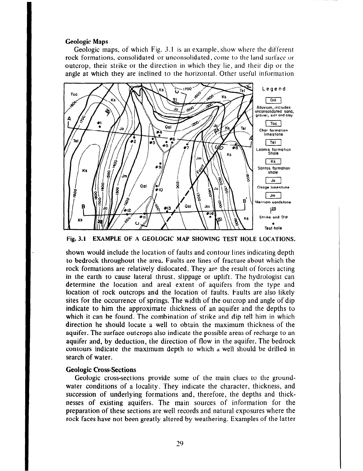
Geologic maps, of which Fig. 3.1 is an example, show where the different
rock formations, consolidated or unconsolidated, come to the land surface or
outcrop, their strike or the direction in which they lie, and their dip or the
angle at which they are inclined to the horizontal. Other useful information
Legend
Alluvwm, Includes
unconsolidated sand,
grovel, slit and cloy
Char formotlon
hmestone
j-q
Looml;bremotwx
I
Sontos formotlon
shale
I
Osoge hmest0ne
I
hternom sandstone
Strike and Dip
.
Test hole
Fig. 3.1 EXAMPLE OF A GEOLOGIC MAP SHOWING TEST HOLE LOCATIONS.
shown would include the location of faults and contour lines indicating depth
to bedrock throughout the area. Faults are lines of fracture about which the
rock formations are relatively dislocated. They are the result of forces acting
in the earth to cause lateral thrust, slippage or uplift. The hydrologist can
determine the location and area1 extent of aquifers from the type and
location of rock outcrops and the location of faults. Faults are also likely
sites for the occurrence of springs. The width of the outcrop and angle of dip
indicate to him the approximate thickness of an aquifer and the depths to
which it can be found. The combination of strike and dip tell him in which
direction he should locate a well to obtain the maximum thickness of the
aquifer. The surface outcrops also indicate the possible areas of recharge to an
aquifer and, by deduction, the direction of flow in the aquifer. The bedrock
contours indicate the maximum depth to which
d
well should be drilled in
search of water.
Geologic Cross-Sections
Geologic cross-sections provide some of the main clues to the ground-
water conditions of a locality. They indicate the character, thickness, and
succession of underlying formations and, therefore, the depths and thick-
nesses of existing aquifers. The main sources of information for the
preparation of these sections are well records and natural exposures where the
rock faces have not been greatly altered by weathering. Examples of the latter
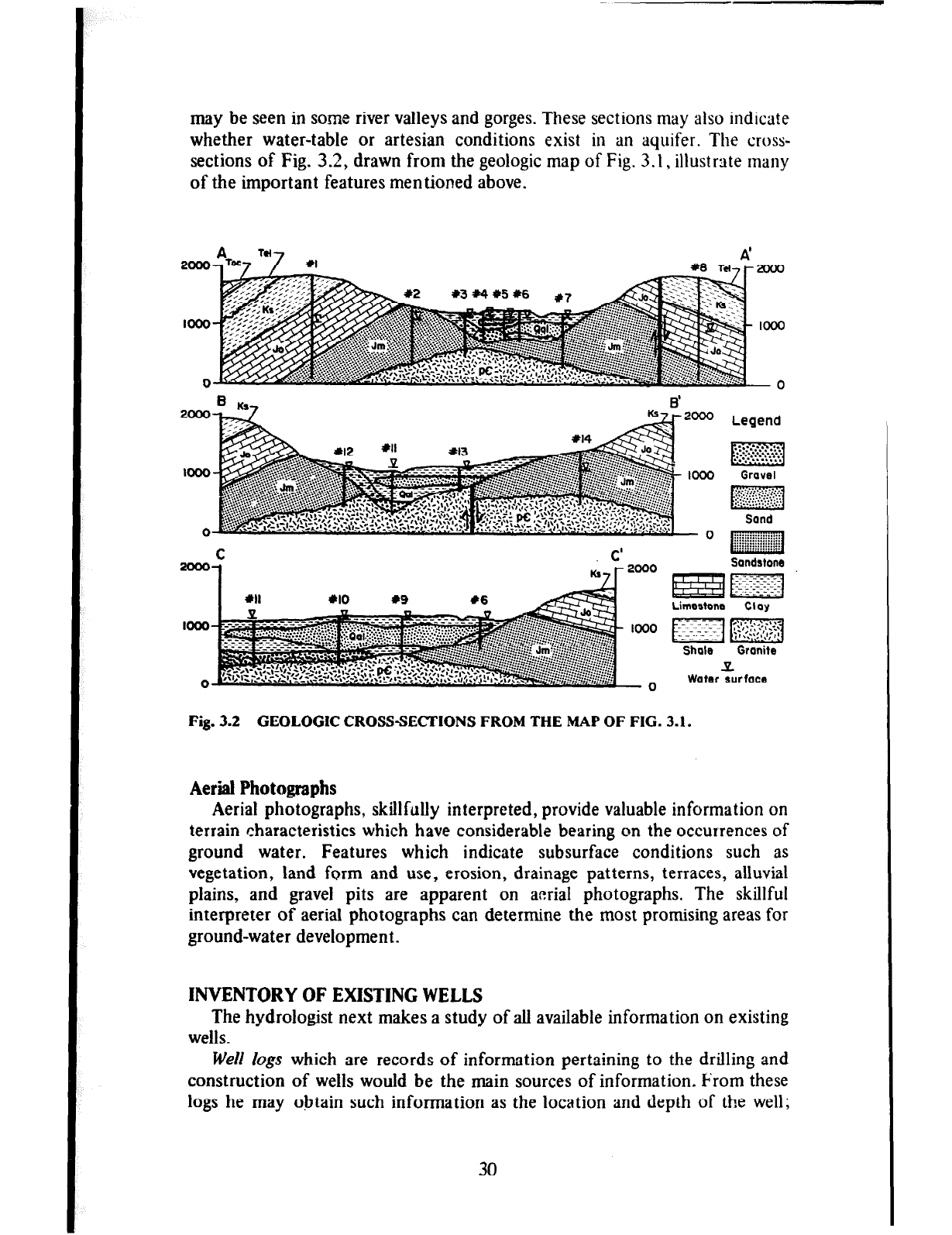
may be seen in some river valleys and gorges. These sections may also indicate
whether water-table or artesian conditions exist in an aquifer. The cross-
sections of Fig. 3.2, drawn from the geologic map of Fig. 3.1, illustrate many
of the important features mentioned above.
Water surface
Fig. 3.2 GEOLOGIC CROSSSECTIONS FROM THE MAP OF FIG. 3.1.
Aerial Photographs
Aerial photographs, skillfully interpreted, provide valuable information on
terrain characteristics which have considerable bearing on the occurrences of
ground water. Features which indicate subsurface conditions such as
vegetation, land form and use, erosion, drainage patterns, terraces, alluvial
plains, and gravel pits are apparent on aerial photographs. The skillful
interpreter of aerial photographs can determine the most promising areas for
ground-water development.
INVENTORY
OF EXISTING WELLS
The hydrologist next makes a study of all available information on existing
wells.
Well logs which are records of information pertaining to the drilling and
construction of wells would be the main sources of information. From these
logs he may obtain such information as the location and depth of the well;
30
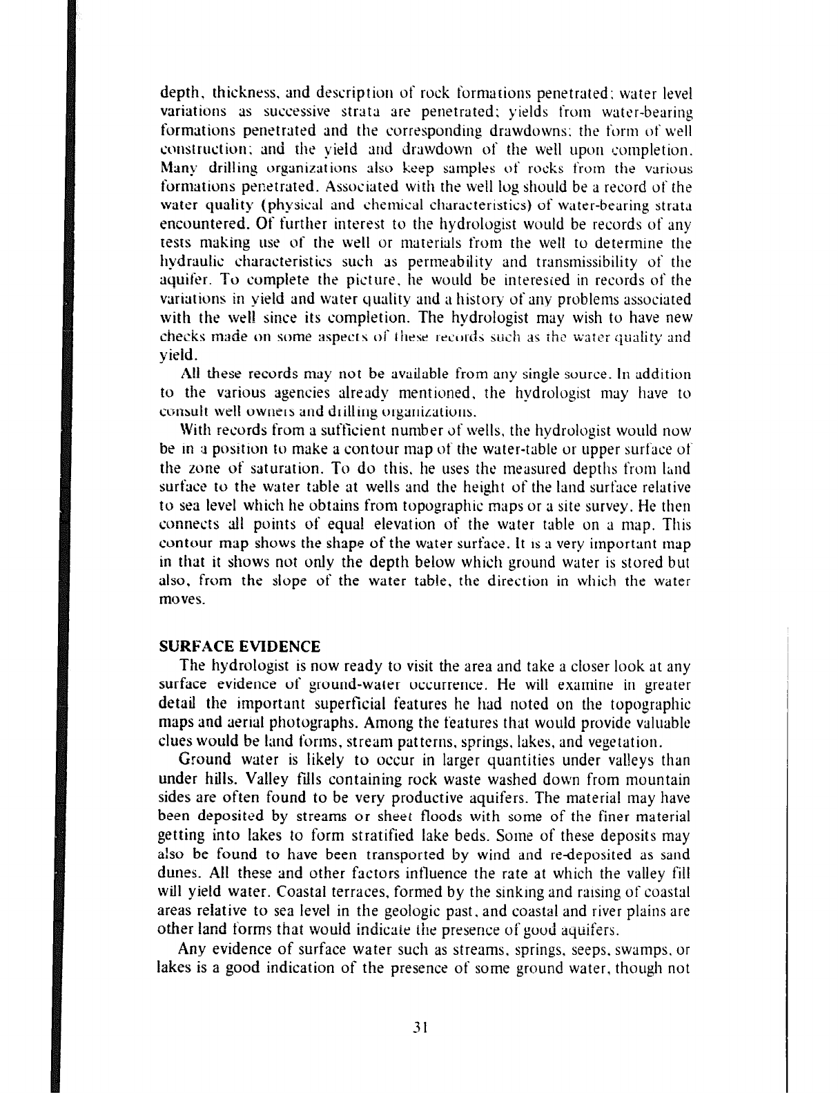
depth. thickness. and description of rock fornrarions penetrated: water level
variations as successive strata are penetrated; yields from water-bearing
formations penetrated and the corresponding drawdowns; the form of well
construction; and the vield and drawdown of the well upon completion.
Many drilling orgsnizaiions also keep samples of rocks from the various
formations penetrated. Associated with the well log should be a record of the
water quality (physical and chemical characteristics) of water-bearing strata
encountered. Of further interest to the hydrologist would be records of any
tests making use of the well or materials from the well to determine the
hydraulic characteristics such as permeability and transmissibility of the
aquifer. To compiete the picture. he would be interested in records of the
v&ations in yield and water quality and a history of any problems associated
with the well since its completion. The hydrologist may wish to have new
checks made on some aspecrs of ihese records sush as rhe water quality and
yield.
A!1 these records may not be available from any single source. In addition
to the various agencies already mentioned. the hydrologist may have to
consult well owners and drilling organizations.
With records from a sufficient number of wells, the hydrologist would now
be
in 3 position to make a contour map of the water-table or upper surface of
the zone of saturation. To do this. he uses the measured depths from Iihnd
surface to the water table at wells and the height of the land surf’ace relative
to sea level which he obtains front topographic maps or a site
survey.
He then
connects ail points of equa! elevation of the water table on a map. This
contour map shows the shape of the water surface. It is a very important map
in tltat it shows not only the depth below which ground water is stored but
also, from the slope of the water table, the direction in which the water
moves.
SURFACE EVIDENCE
The hydrologist is now ready to visit the area and take a closer look at any
surface evidence of ground-water occurrence. He will exantine in greater
detail the important superficial features hc had noted on the topographic
maps and aerial photographs. Among the features that would provide valuable
clues would be land forms, stream patterns. springs, lakes, and vegetation.
Ground
water is likely to occur in larger quantities under valleys than
under
hills. Valley fills containing rock waste washed down from mountain
sides are often found to be very productive aquifers. The material may have
been deposited by streams or sheet floods with some of the finer material
getting
into lakes to form stratified lake beds. Some of these deposits may
afso be found to have been transported by wind and redeposited as sand
dunes.
All these and other factors intluence the rate at which the valley fill
will yield water. Coastal terraces, formed by the sinking and raising of coastal
areas relative
to sea level in the geologic past. and coastal and river plains are
other land
forms that wouid indicaie the presence of good aquifers.
Any evidence of surface water such as streams. springs. seeps, swamps, or
lakes is a good indication of the presence of some ground water, though not
31
necessarily in usable quantity. The sand and gravel deposits found in river
beds may very often ext
.end laterally into the river bdanks which may be
penetrated by shallow. highly product&e wells.
Vegetation, particularly water-loving types when found in arid regions,
provides good clues to shallow ground-water occurrence. Evidence of
unusually thick overgrowth is generally a sure pointer to the presence of
streams and other surface waters, the vicinities of which would be likely sites
for ground-water investigations. Fig. 3.3 demonstrates the application of
some of the principles outlined above in the selection of possible well sites.
Fig. 3.3 SURFACE EVIDENCE OF GROUND-WATER OCCURRENCE.
(Adapted
from Fig. 4, Wafer Supply For Rural Areas And Small Communities.
WHO
Monograph Series No. 4.., 1959.)
I - Dense vegetation indicating possible shallow water table and proximity
to surface stream.
2 - River plains: possible sites for wells in water-table aquifer.
3 - Flowing spring where ground water outcrops. Springs may also be
found at the foot of hills and river banks.
4 - River beds cut into water-bearing sand formation. Indicate possibility
of river banks as good well sites.
In many areas, some of the records, maps, and other relevant information
so far discussed will not be available to the hydrologist. Where the size of the
project warrants it, he will arrange to fill in the information as far as is
practicabie.
in
other situations, very likely the case for the size of weiis herein
considered, he will simply use his best judgement based on the readily
available information.
32
CHAPTER 4
Generally, the aim of engineering design is to achieve the best possible
combination of performance, useful life and reasonable cost. The designer of
small wells will often find that his optimum solutions involve a variety of
compromises and that he must adopt a flexible approach to each problem.
Among these compromises is the need to sacrifice performance or efficiency
in order to reduce costs. For example, in the situation where a small yield is
required from a very thick and permeable aquifer, a less efficient type of
intake section such as slotted pipe may justifiably be used in a small well to
save the extra cost of a more efficient factory-manufactured screen. Here, the
limited yield relative to the highly productive nature of the aquifer makes
cost and availability of funds assume a more important role than hydraulic
efficiency. It may also be considered worthwhile to compromise the useful
life of a small well with respect to its cost. With stainless steel and other
non-corrosive materials costing two to three times as much as ordinary steel, a
designer may use well casing of the latter mat,,rial under corrosive conditions,
fully expecting to replace it, perhaps in one-half the time he would have had
he used stainless steel. He may very well have based his decision on the fact
that at the end of the shorter useful life, extra funds might be available for a
replacement of the existing well.
For design purposes, a well to be constructed in unconsolidated materials
may be considered as consisting of two main parts. The upper part or cased
section of the well serves as housing for the pumping equipment and as a
vertical conduit through which water flows from the aquifer to the pump or
to the discharge pipe of a flowing artesian well. It is usually of water-tight
construction and extends downward from the surface to the impervious
formation immediately above an artesian aquifer or to a safe depth below the
anticipated pumping water level (see the later section of this chapter dealing
with sanitary protection of wells). It is also referred IO as the well casing.
The lower or intake section of the well is that part of the well st-ucture
where water from the aquifer enters the well. The intake section may be
simply the open lower end of the well casing, though this would be a most
unsatisfactory arrangement in unconsolidated formations. The disadvantages
are the large well diameters required for the natural seepage of water into the
well and the tendency for aquifer material to heave into the well casing
as the well is being pumped. A screening devze known as a well screen
should be used instead. Such a screen permits the use of techniques aimed at
increasing the natural seepage rate into the we!! (see later section on well
33
development), thus making a much smaller well practicable. In addition to
ensuring the relatively free entry of water into the well at low velocity, the
screen must provide structural support against the collapse of the unconsoli-
dated formation material and prevent the entry of this material with water
into the well.
CASED SECTION
The selection of the well casing dimerer is usually controlled by the type
and size of the pump that is expected to be required for the desired of
potential yield of the well. The well casing must be large enough to
accommodate the pump with s)lfficient clearance for easy installation and
efficient opera?ion. For larger wells, such as those used for municipal and
industrial suppiies, the casing diameter should be chosen as two nominal sizes
(never :ess than one nominal size) larger than that of the pump bowls. For
wells of 4 inches and less in diameter it is satisfactory to select a casing
diameter which is one nominal size larger than that of the pump bowls, pump
cylinder or pump body. The above assumes the use of a deep-well type of
pump which is usually suspended by pipe column and/or shaft within the well
casing. A pump having a bowl diameter (see Fig. 8.11) greater than 3 inches
should not, according to this rule, be installed in a $-inch diameter casing.
In small wells where pumping water levels below ground surface are known
to be within the practical suction limits (15 feet or less) of most surface-type
pumps, such pumps are either directly connected to the top of the well casing
or connected to a suction pipe suspended inside the well casing. The well
casing diameter may then be selected in relation to the diameter of the
suction or inlet of the pump, bearing in mind that it is not good practice to
restrict the suction capacity of the pump by using pipe of a smaller diameter
than that of the suction side of the pump.
In larger and deeper wells than those being considered, it is sometimes
advantageous for economic and other reasons to reduce the casing diameter at
levels below the lowest anticipated pumping depth. This is done by
telescoping one or more smaller sized casing sections through the uppermost
one. This saves the extra cost of extending the large diameter casing all the
way down to the aquifer when a smaller size of pipe would be sufficient to
accommodate the anticipated flow with reasonable head loss. However, there
is little justification for this type of design in wells of 4 inches and less in
diameter and not more than 100 feet deep.
INTAKE SECTION
Type and Construction of Screen
The single factor with greatest influence on the efficient performance of a
well is the design and construction of the well screen. A properly designed
screen combines a high percentage of open area for relatively unobstructed
flow into the well with sufficient strength to resist the forces to which the
screen may be subjected both during and after installation in the well. The
screen openings should preferably be shaped so as to facilitate flow into the
well while making it difficult for small particles to become permanently
34
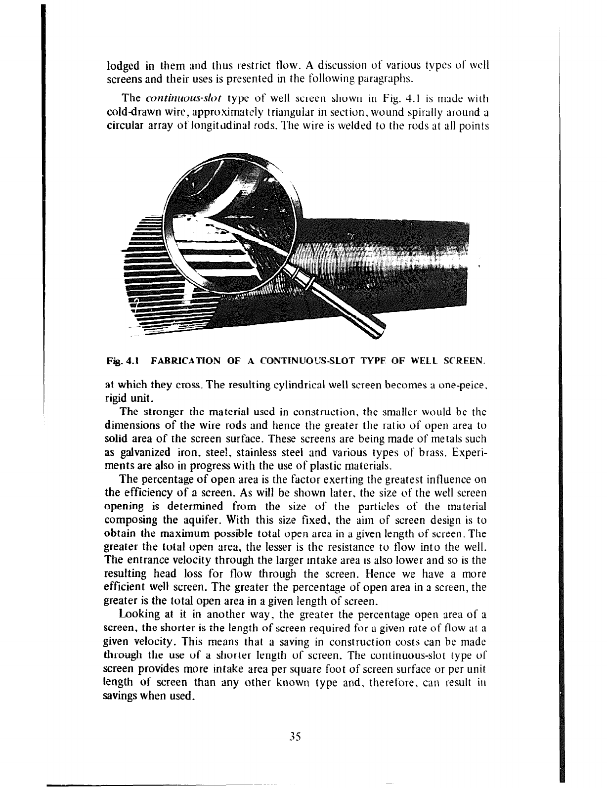
lodged
in them and thus restrict flow. A discussion of various types of WPII
screens and their uses is presented in the following paragraphs.
The corrtimmts-slot type of well screen shown in Fig. 4. I is made with
cold-drawn wire, appro,ximately triangular in section, wound spirally around a
circular array oflongitcldinal rods. The wire is welded to the rods at all points
Fig.4.1 FABRICATION OF A CONTINUOUS-SLOT TYPE OF WELL SCREEN.
at which they cross. The resulting cylindrical well screen becomes a one-peice.
rigid unit.
The stronger the material used in construction, the smaller would be the
dimensions of the wire rods and hence the greater the ratio of open area to
solid area of the screen surface. These screens are being made of metals such
as galvanized iron, steel, stainless steel and various types of brass. Experi-
.ments are also in progress with the use of plastic materials.
The percentage of open area is the factor exerting the greatest influence on
the efficiency of a screen. As will be shown later, the size of the well screen
opening is determined from the size of the particles of the material
composing the aquifer. With this size fixed, the aim of screen design is to
obtain the maximum possible total open area in a given length of screen, The
greater the total open area, the lesser is the resistance to flow into the well.
The entrance velocity through the larger intake area is also lower and so is the
resulting head loss for flow through the screen. Hence we have a more
efficient well screen. The greater the percentage of open area in a screen, the
greater is the total open area in a given length of screen.
Looking at it in another way, the greater the percentage open area of a
screen, the shorter is the length of screen required for a given rate of flow at a
given velocity. This means that a saving in construction costs can be made
throtigh the use of a shorter length of screen. The continuous-slot type of
screen provides more intake area per square foot of screen surface or per unit
length of screen than any other known type and, therefore, can result in
savings when used.
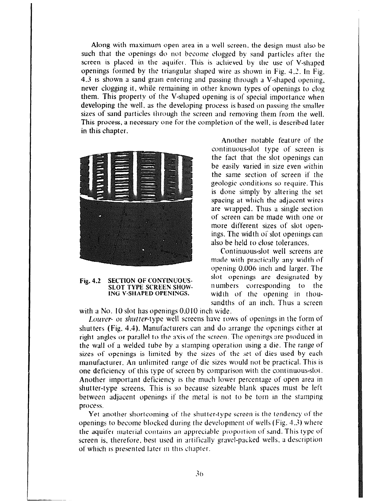
Along with maximum open area in a well screen, the design must also be
such that the openings do not become clogged by
smd
particles after the
screen is placed in the aquifer. This is achieved by the use of V-shaped
openings formed by the triangular shaped wire as shown in Fig. 4.2.
III
Fig.
4.3 is shown a sand grain entering and passing through a V-shaped opening,
never clogging it, while remaining in other known types of openings to clog
them. This property of the V-shaped opening is of special importance when
developing the well. as the developing process is based on passing the smaller
sizes of sand particles through the screen and removing them from the well.
This process, a necessary one for the completion of the well, is described later
in this chapter.
Fig. 4.2 SECTtON OF CONTLNSIOL6-
SLOT TYPE SCREEN SHOW-
ING V-SHAPED OPENINGS.
Another notable feature of the
continuous-slot type of screen is
the fact that the slot openings can
be easily varied in size even bvithin
the same section of screen if the
geologic conditions so require. This
is done simply by altering the set
spacing at which the adjacent wires
are wrapped. Thus a single section
of screen
can
be made with one or
more different sizes of siot open-
ings. The width oi‘ slot openings can
also be held to close tolerances.
Continuous-slot well screens are
made with practically any width of
(opening 0.006 inch and larger. The
slot openings are designated by
II
umbers corresponding to the
width of the opening in thou-
sandths of
911
inch. Thus a screen
with a No. IO slot has openings 0.0 IO inch wide.
I,oI~I~= or sl2uttcr-type well screens have rows of openings in the form of
shutter!; (Fig. 4.4). Manut’ucturers can and do arrange the optnings either at
right arlgles or parallel to the axis ot’ the
scrw1.
‘The openings arc produced in
the wal,l of a welded tube by ;I stamping operation using a die. The range of
sizes of openings is limited by the sizes of the set of dies used by each
manufacturer. An unlimited range of die sizes would not be practical. This is
one deficiency of this type of screen by comparison with the continuous-slot.
Another important deficiency is the much lower percentage of open area in
shutter-type screens. This is so because sizeable blank spaces must be left
between adjacent openings if the metal is not to be torn In the stamping
process.
Yet another shortcoming of the shutter-type screen is the tendency of the
openings to become blocked during the development of wells (Fig. 4.3) where
the aquifer material contains an appreciable proportion of sand. This type of
screen is. therefore, best used in artif‘ic;tlly gravel-packed wells. ;I description
of which is presented later iI1 this &pter.
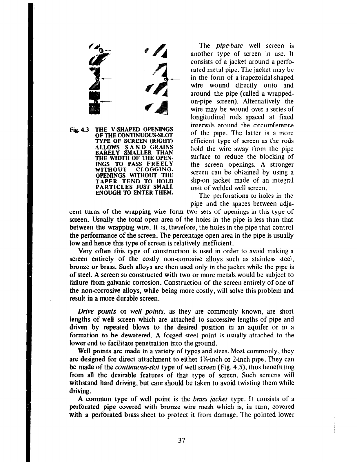
Fig. 4.3 THE Y-SHAPED OPENINGS
OFTHECONTINUOUSSLOT
TYPE OF SCREEN (RIGHT)
ALLOWS SAN D GRAINS
BARELY SMALLER THAN
THE WIDTH OF THE OPEN-
INGS TO PASS FREELY
WITHOUT CLOGGING.
OPENINGS WITHOUT THE
TAPER TEND TO HOLD
PARTICLES JUST SMALL
ENOUGH TO ENTER THEM.
-
The pipe-base well screen is
another type of screen in use. It
consists of a jacket around a perfo-
rated metal pipe. The jacket may be
in the form of a trapezoidal-shaped
wire wound directly onto and
around the pipe (called a wrapped-
on-pipe screen). Alternatively the
wire may be wound over a series of
longitudinal rods spaced at fixed
intervals around the circumference
of the pipe. The latter is a more
efficient type of screen as the rods
hold the wire away from the pipe
surface to reduce the blocking of
the screen openings. A stronger
screen can be obtained by using a
slip-on jacket made of an integral
unit of welded well screen.
The perforations or holes in the
pipe and the spaces between adja-
cent turns of the wrapping wire form two sets of openings in this type of
screen. Usuahy the total open area of the holes in the pipe is less than that
between the
wrapping wire. It is, therefore, the holes in the pipe that control
the performance of the screen. Tire percentage open area in the pipe is usually
low and hence this type of screen is relatively inefficient.
Very often this type of construction is used in order to avoid making a
screen entirely of the costly noncorrosive alloys such as stainless steel,
bronze or brass. Such alloys are then used only in the jacket while the pipe is
of steel. A screen so constructed with two or more metals would be subject to
failure from galvanic corrosion. Construction of the screen entirely of one of
the noncorrosive alloys, while being more costly, will solve this problem and
result in a more durable screen.
Drive points or well points, as they are commonly known, are short
lengths of well screen which are attached to successive lengths of pipe and
driven by repeated blows to the desired position in an aquifer or in a
formation to be dewatered. A forged steel point is usually attached to the
lower end to
facilitate penetration into the ground.
Well points are made in a variety of types and sizes. Most commonly, they
are designed for direct attachment to either l%inch or ‘L-inch pipe. They can
be made of the continuous-slot type of well screen (Fig. 4.9, thus benefitting
from all the desirable features of that type of screen. Such screens will
withstand hard driving, but care should be taken to avoid twisting them while
driving.
A common type
of well point is the brass jacket type. It consists of a
perforated pipe
covered with bronze wire mesh which is, in turn, covered
with a perforated brass sheet to protect it from damage. The pointed lower
37
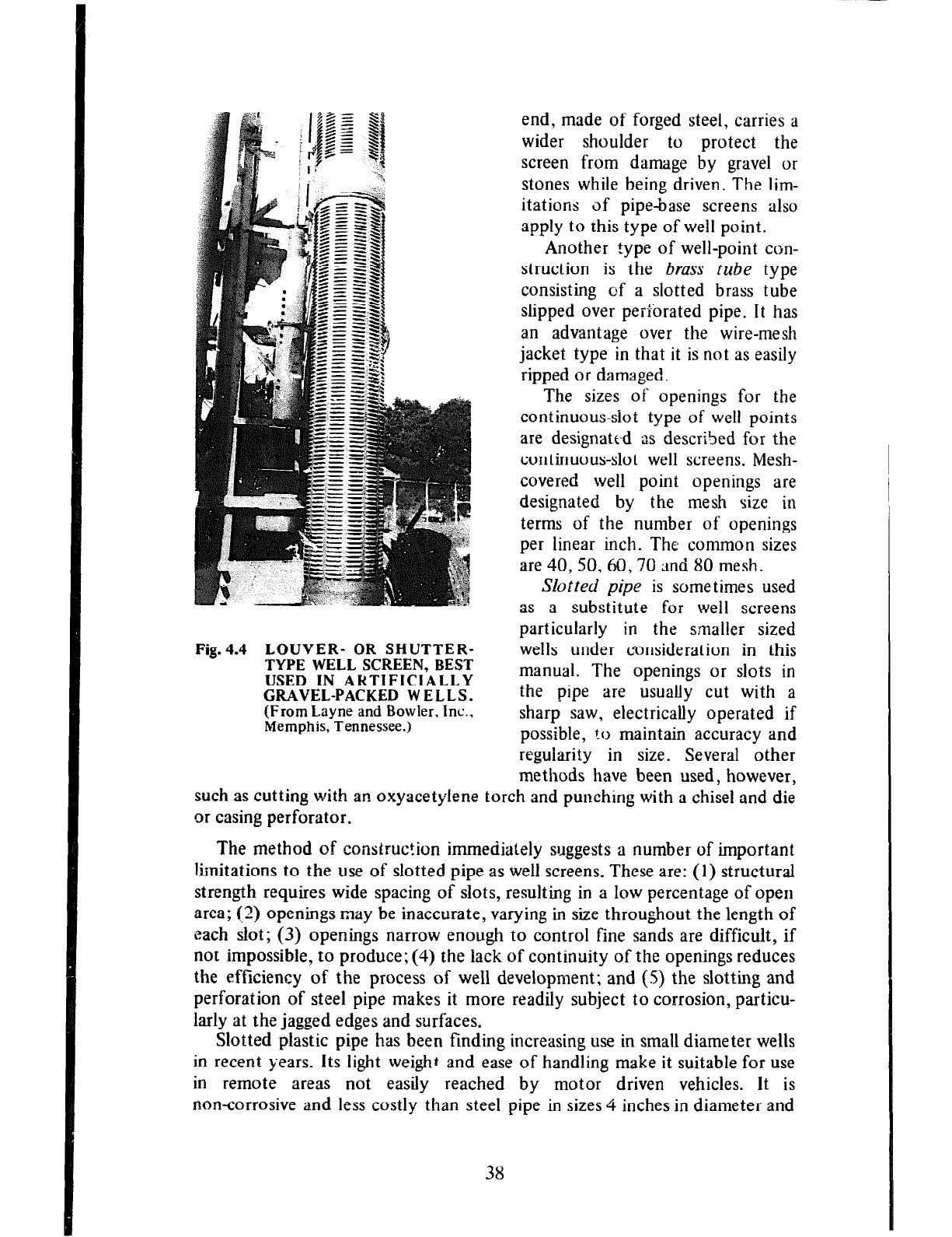
Fig.4.4 LOUVER- OR SHUTTER-
TYPE WELL SCREEN, BEST
USED IN ARTIFIClALLY
GRAVEL-PACKED WELLS.
(From Layne and Bowler, inc.,
Memphis, Tennessee.)
Slotted pipe
is sometimes used
as a substitute for well screens
particularly in the smaller sized
wells under consideration in this
manual. The openings or slots in
the pipe are usually cut with a
sharp saw, electrically operated if
possible, to maintain accuracy and
regularity in size. Several other
methods have been used, however,
such as cutting with an oxyacetylene torch and punching with a chisel and die
or casing perforator.
The method of construction immediately suggests a number of important
limitations to the use of slotted pipe as well screens. These are: (1) structural
strength requires wide spacing of slots, resulting in a low percentage of open
area; (2) openings may be inaccurate, varying in size throughout the length of
each slot; (3) openings narrow enough to control fine sands are difficult, if
not impossible, to produce; (4) the lack of continuity of the openings reduces
the efficiency of the process of well development; and (S) the slotting and
perforation of steel pipe makes it more readily subject to corrosion, particu-
larly at the jagged edges and surfaces.
Slotted plastic pipe has been finding increasing use in small diameter wells
in recent years. Its light weight and ease of handling make it suitable for use
in remote areas not easily reached by motor driven vehicles. It is
noncorrosive and less costly than steel pipe in sizes 4 inches in diameter and
end, made of forged steel, carries a
wider shoulder to protect the
screen from damage by gravel or
stones while being driven. The lim-
itations of pipe-base screens also
apply to this type of well point.
Another type of well-point con-
struction is the brass
tube
type
consisting of a slotted brass tube
slipped over perforated pipe. It has
an advantage over the wire-mesh
jacket type in that it is not as easily
ripped or damaged.
The sizes of openings for the
continuous-slot type of well points
are designated as described for the
continuous-slot well screens. Mesh-
covered well point openings are
designated by the mesh size in
terms of the number of openings
per linear inch. The common sizes
are 40,50,60,70 ;rnd 80 mesh.
38
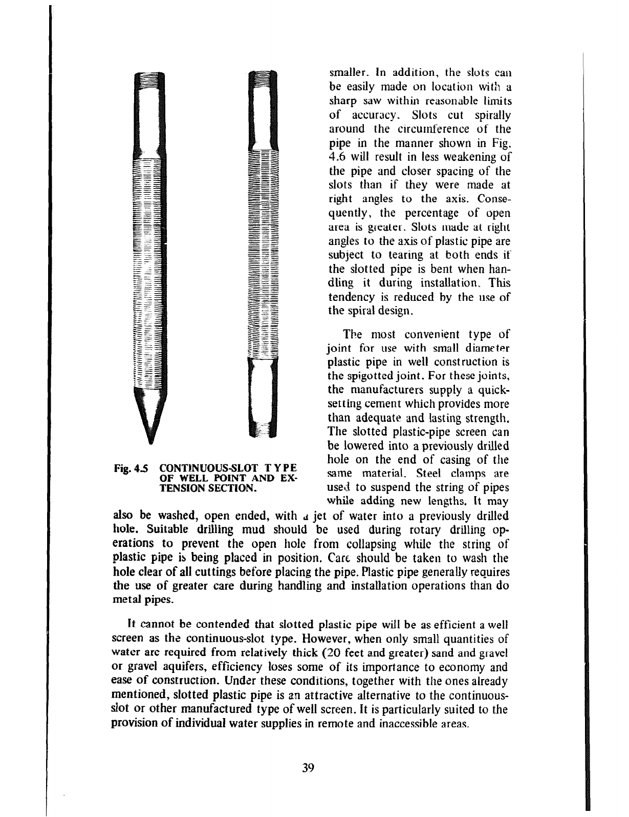
Fig. 45 CONTBNUOUSSLOT T Y P E
OF WELL POINT AND EX-
TENSION SECTION.
The most convenient type of
joint for
use
with small diameter
plastic pipe in well construct ion is
the spigotted joint. For these joints,
the manufacturers supply a quick-
setting cement which provides more
than adequate and lasting strength.
The slotted plastic-pipe screen can
be lowered into a previously drilled
hole on the end of casing of the
same material. Steel clamps are
used to suspend the string of pipes
while adding new lengths. It may
also be washed, open ended, with d jet of water into a previously drilled
hole. Suitable drilling mud should be used during rotary drilling op-
erations to prevent the open hole from collapsing while the string of
plastic pipe is being placed in position. Cart should be taken to wash the
hole clear of all cuttings before placing the pipe. Plastic pipe generally requires
the use of greater care during handling and installation operations than do
metal pipes.
It cannot be contended that slotted plastic pipe will be as efficient a well
screen as the continuous-slot type. However, when only small quantities of
water are required from relatively thick (20 feet and greater) sand and gravel
or gravel aquifers, efficiency loses some of its importance to economy and
ease of construction. Under these conditions, together with the ones already
mentioned, slotted plastic pipe is an attractive alternative to the continuous-
dot or other manufactured type of well screen. it is particularly suited to the
provision of individual water supplies in remote and inaccessible areas.
smaller. In addition, the slots can
be easily made on location with a
sharp saw within reasonable limits
of accuracy. Slots
cut
spirally
around the circumference of the
pipe in the manner shown in Fig.
4.6 will result in less weakening of
the pipe and closer spacing of the
slots than if they were made at
right angles to the axis. Conse-
quently, the percentage of open
area is greater. Slots made at right
angles to the a-xis of plastic pipe are
subject
to tearing at both ends if
the slotted pipe is bent when han-
dling it during installation, This
tendency is reduced by the
use
of
the spiral design.
39
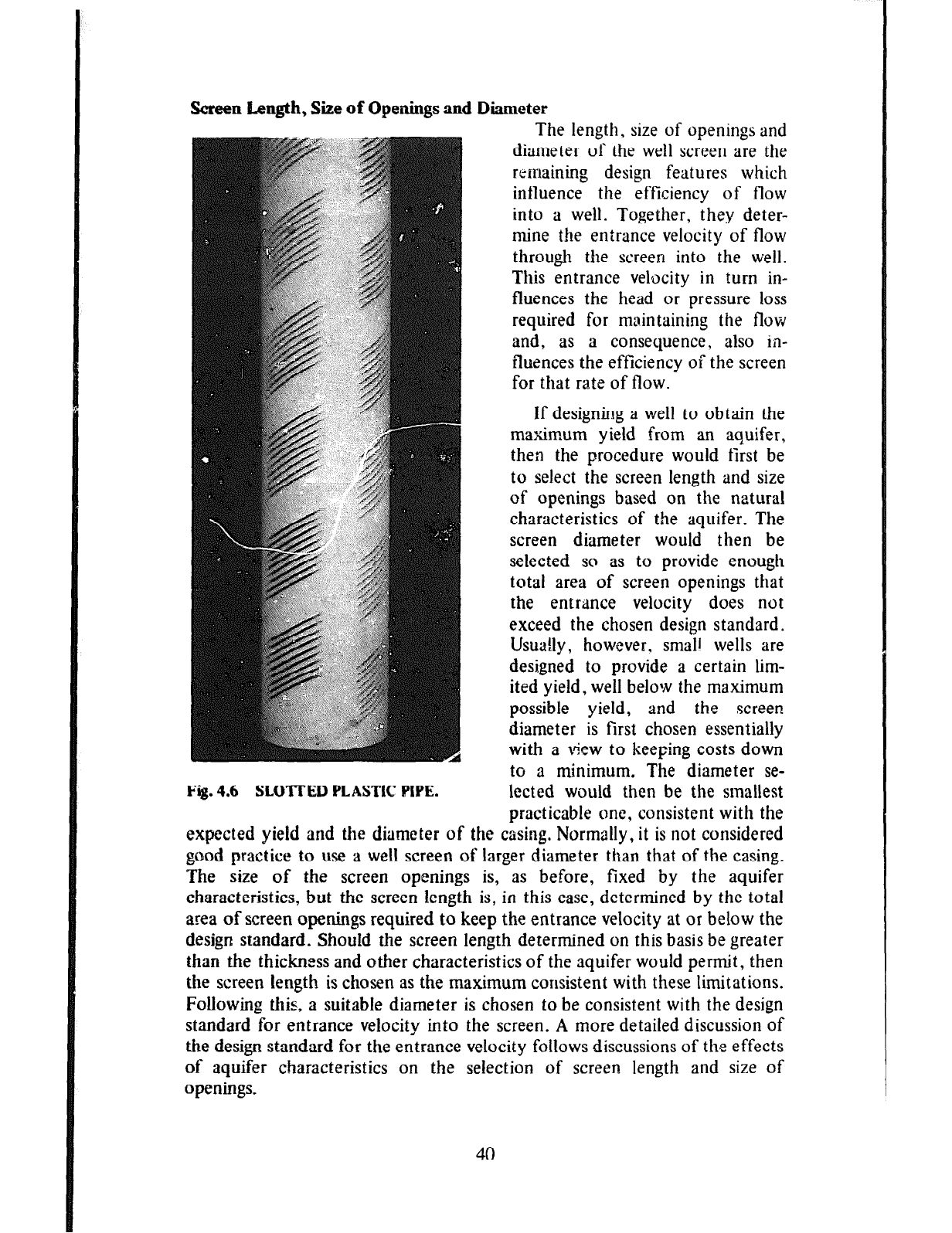
Screen Length, Size of Openings and
Fig. 4.6 SLOTTED E’LASTIC PIPE.
Diameter
The length, size of openings and
diameter of the well screen are the
remaining design features which
influence the efficiency of flow
into a well. Together, they deter-
mine the entrance velocity of flow
through the screen into the well.
This entrance velocity in turn in-
fluences the head or pressure loss
required for maintaining the flow
and, as a consequence, also in-
fluences the efficiency of the screen
for that rate of flow.
If designing a well to obtain the
maximum yield from an aquifer,
then the procedure would first be
to select the screen length and size
of openings based on the natural
characteristics of the aquifer. The
screen diameter would then be
selected so as to provide enough
total area of screen openings that
the entrance velocity does not
exceed the chosen design standard.
Usua!ly, however, small wells are
designed to provide a certain lim-
ited yield, well below the maximum
possible yield, and the screen
diameter is first chosen essentially
with a view to keeping costs down
to a minimum. The diameter se-
lected would then be the smallest
practicable one, consistent with the
expected yield and the diameter of the casing. Normally, it is not considered
good practice to use a well screen of larger diameter than that of the casing.
The size of the screen openings is, as before, fixed by the aquifer
characteristics, but the screen length is, in this case, determined by the total
area of screen openings required to keep the entrance velocity at or below the
design standard. Should the screen length determined on this basis be greater
than the thickness and other characteristics of the aquifer would permit, then
the screen length is chosen as the maximum consistent with these limitations.
Following this, a suitable diameter is chosen to be consistent with the design
standard for entrance velocity into the screen. A more detailed discussion of
the design standard for the entrance velocity follows discussions of the effects
of aquifer characteristics on the selection of screen length and size of
openings.
40
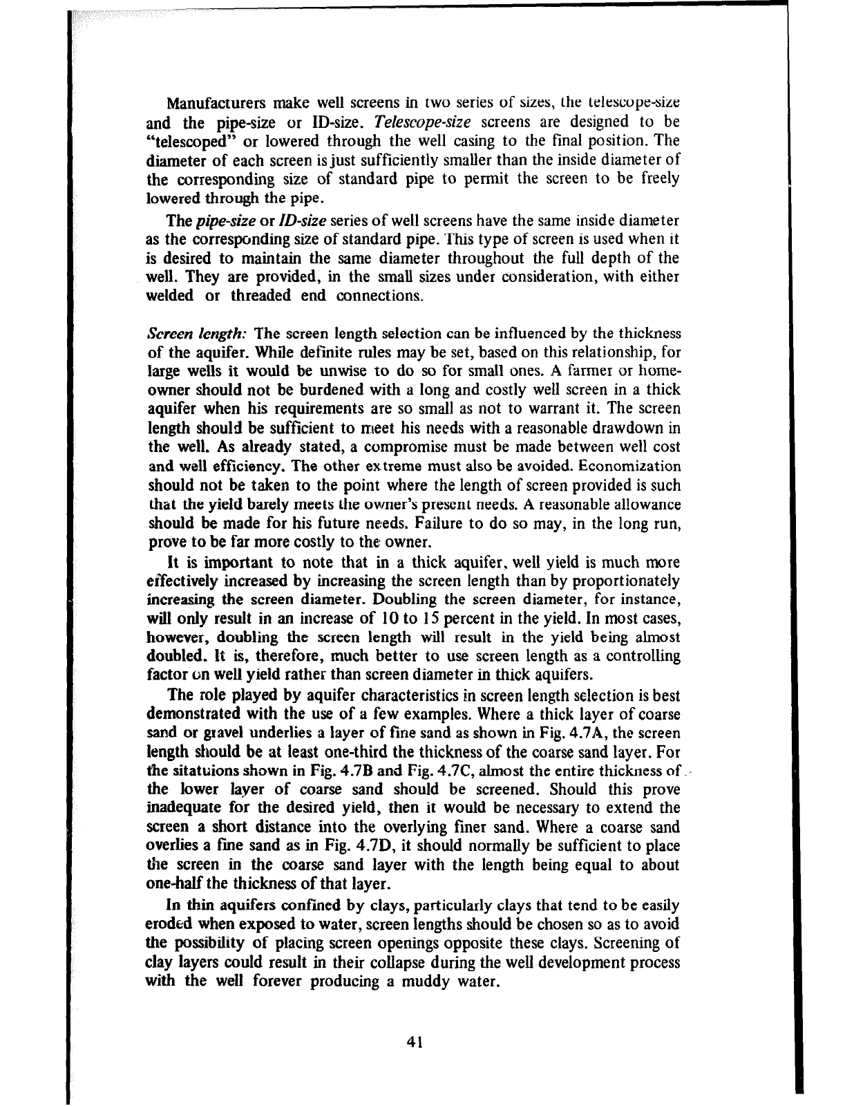
Manufacturers make well screens in two series of sizes, the telescope-size
and the pipe-size or ID-size. Telescope-size screens are designed to be
“telescoped” or lowered through the well casing to the final position. The
diameter of each screen is just sufficiently smaller than the inside diameter of
the corresponding size of standard pipe to permit the screen to be freely
lowered through the pipe.
The pipe-size or ID-size series of well screens have the same inside diameter
as the corresponding size of standard pipe. This type of screen is used when it
is desired to maintain the same diameter throughout the full depth of the
well. They are provided, in the small sizes under consideration, with either
welded or threaded end connections.
Screen length: The screen length selection can be influenced by the thickness
of the aquifer. While definite rules may be set, based on this relationship, for
large wells it would be unwise to do so for small ones. A farmer or home-
owner should not be burdened with a long and costly well screen in a thick
aquifer when his requirements are so small as not to warrant it. The screen
length should be sufficient to meet his needs with a reasonable drawdown in
the well. As already stated, a compromise must be made between well cost
and well efficiency. The other ex.treme must also be avoided. Economization
should not be taken to the point where the length of screen provided is such
that the yield barely meets the owner’s present needs. A reasonable allowance
should be made for his future ne:eds. Failure to do so may, in the long run,
prove to be far more costly to the: owner.
It is important to note that in a thick aquifer, well yield is much more
effectively increased by increasing the screen length than by proportionately
increasing the screen diameter. Doubling the screen diameter, for instance,
will only result in an increase of 10 to 15 percent in the yield. In most cases,
however, doubling the screen length will result in the yield being almost
doubled. It is, therefore, much better to use screen length as a controlling
factor on well yield rather than screen diameter in thick aquifers.
The role played by aquifer characteristics in screen length selection is best
demonstrated with the use of a few examples. Where a thick layer of coarse
sand or gravel underlies a layer of fine sand as shown in Fig. 4.714, the screen
length should be at least one-third the thickness of the coarse sand layer. For
the sitatuions shown in Fig. 4.7B and Fig. 4.7C, almost the entire thickness of .,
the lower layer of coarse sand should be screened. Should this prove
inadequate for the desired yield, then it would be necessary to extend the
screen a short distance into the overlying finer sand. Where a coarse sand
overlies a fine sand as in Fig. 4.7D, it should normally be sufficient to place
the screen in the coarse sand layer with the length being equal to about
one-half the thickness of that layer.
In thin aquifers confined by clays, particularly clays that tend to be easily
eroded when exposed to water, screen lengths should be chosen so as to avoid
the possibility of placing screen openings opposite these clays. Screening of
clay layers could result in their collapse during the well development process
with the well forever producing a muddy water.
41
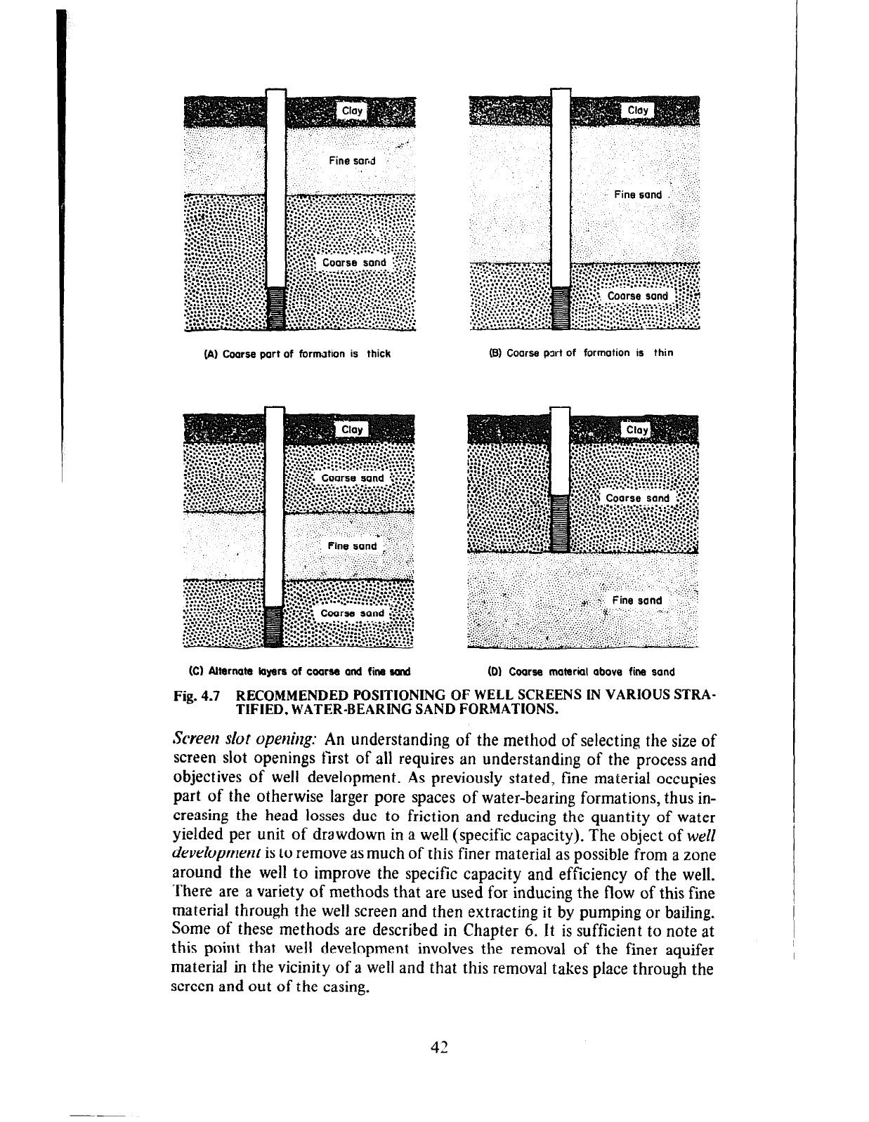
(A) Coarse port of form&ion is thick (8) Coarse pwt of formotion is thin
(Cl Alternate kyere of coaree and fine s4md (0) Coarse material obova fine sond
Fig. 4.7 RECOMMENDED POSITIONING OF WELL SCREENS IN VARIOUS STRA-
TIFIED, WATER-BEARING SAND
FORMATIONS.
Screen slot operzirzg: An understanding of the method of selecting the size of
screen slot openings first of all requires an understanding of the process and
objectives of well development. As previously stated, fine material occupies
part of the otherwise larger pore spaces of water-bearing formations, thus in-
creasing the head losses due to friction and reducing the quantity of water
yielded per unit of drawdown in a well (specific capacity). The object of well
devehpment is to remove as much of this finer material as possible from a zone
around the well to improve the specific capacity and efficiency of the well.
There are a variety of methods that are used for inducing the flow of this fine
material through the well screen and then extracting it by pumping or bailing.
Some of these methods are described in Chapter 6. It is sufficient to note at
this point that well development involves the removal of the finer aquifer
material in the vicinity of a well and that this removal takes place through the
screen and out of the casing.
42
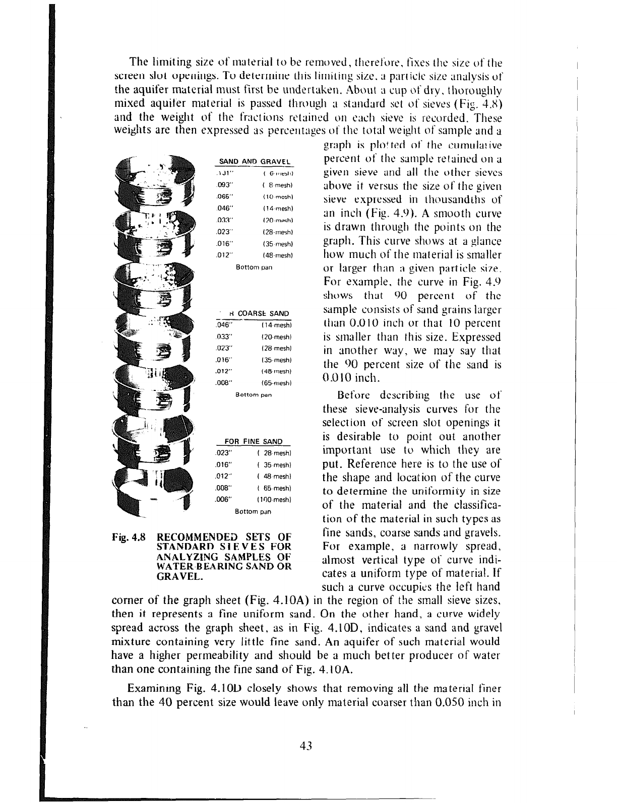
The limiting size of material to be removed, therelL)re, fixes the size of the
screen slot openings. To determine this limiting size. ;I particlc sir.e ;tnalysis of
the aquifer material must first be undertaken. About 3 cup ut‘ dry, thoroughly
mixed aquifer material is passed through
;I
st;indard set of sieves (Fig. 4.X)
and the weight of the fractions retained
OH each
sieve is recorded. These
wei&ts are then expressed as percerltages of the total weight of
sample
and a
SAND AND GRAVEL
---
.\Jl” t 6 mesh)
093” ( Bmesh)
,065” ( IO-mesh)
046” (14 mesh)
,033” I20 mesh)
,023” (28.mesh)
,016” (35 mesh1
,012” (48.mesh1
8ottom oan
tl COARSt SAND
--
,046” f 14 mesh)
033” (20.mesh)
.0X’ (28 mesh)
,016” (35.mesh)
,012” (48.mesh)
.OOB” 165mesh)
Bottom pan
FOR FINE SAND
.023” I 28.mesh)
.016” I 35 mesh)
,012” ( 48 mesh)
.008” ( 65.mesh)
.006” (100.mesh)
Bottom p.m
Fig.43 RECOMMENDED SETS OF
STANDARD SlEVES FOR
ANALYZING SAMPLES OF
WATEK-BEARING SAND OR
GRAVEL.
graph is plot ted of the cumula: ive
percent of tilt‘
sampk
retained
OII ;I
given sieve and all the other sieves
above it versus the size of the given
sieve expressed in th~~usandths of
an inch (Fig. 4.9). A smooth curve
is drawn througil the points
on
the
graph. This curve shows at a glance
how much of the material is smaller
or larger than 9 given particle size.
For example, the curve in Fig. 4.9
shws
tiut
90 percent of the
sample consists of sand grains larger
than 0.010 inch or that 10 percent
is smaller than this size. Expressed
in another way, we may say that
the 90 percent size of the sand is
0.010 inch.
Before describing the use of’
these sieve-analysis curves for the
selection of screen slot openings it
is desirable to point out another
important use to which they are
put. Reference here is to the use of
the shape and location of the curve
to determine the uniformity in size
of the material and the ciassifica-
tion of the material in such types as
fine sands, coarse sands and gravels.
For example, a narrowly spread,
almost vertical type of curve indi-
cates a uniform type of materia!. If
such a curve occupies the left hand
corner of the graph sheet (Fig. 4.10A) in the region of the small sieve sizes,
then it represents a fine uniform sand. On the other hand, a curve widely
spread across the graph sheet, as in Fig. 4.10D, indicates a sand and gravel
mixture containing very little fine sand. An aquifer of such material would
have a higher permeability and should be a much better producer of water
than one containing the fine sand of Fig. 4.1 OA.
Examinmg Fig. 4.1OD closely shows that removing all the material finer
than the 40 percent size would leave only material coarser than 0.050 inch in
43
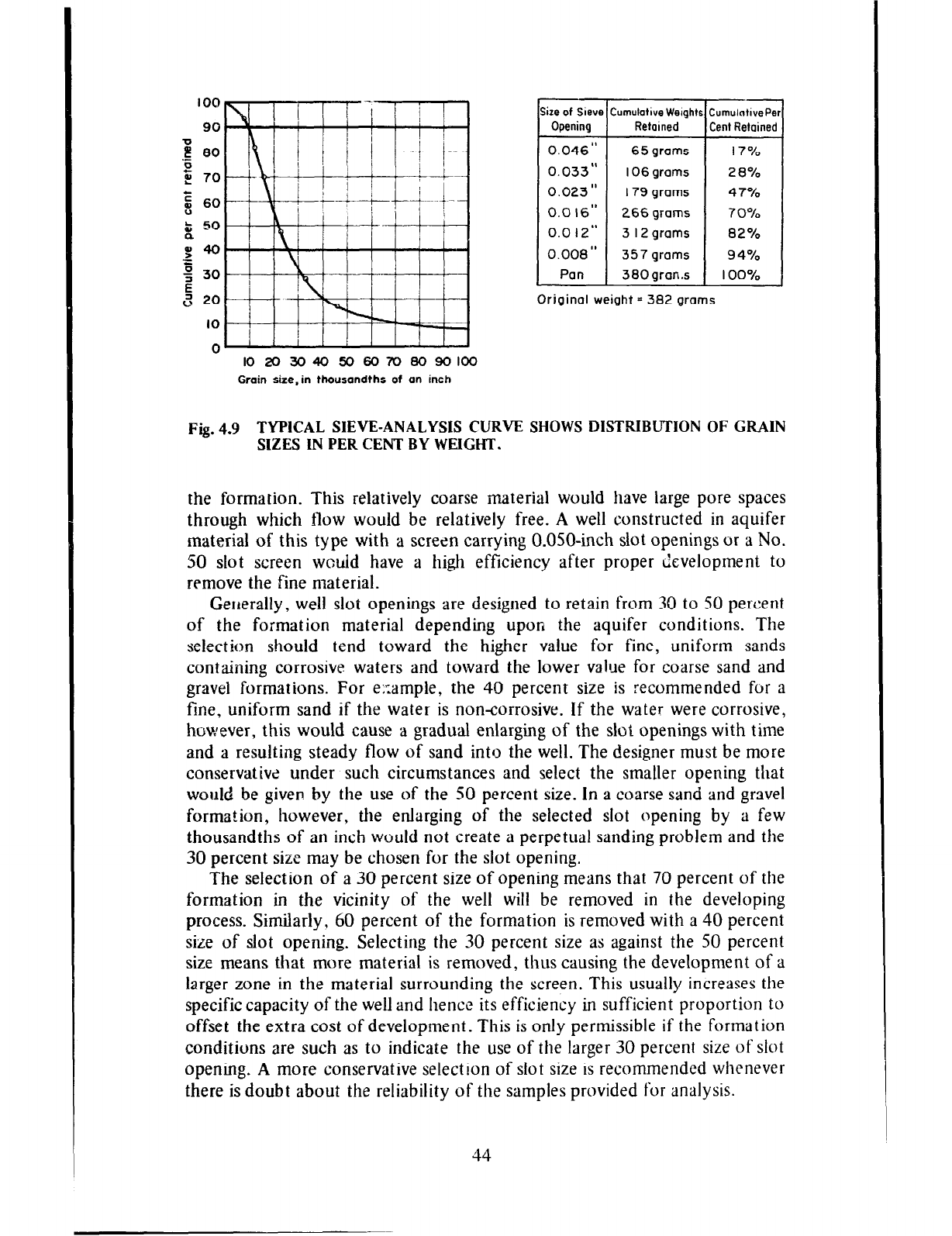
100
90
‘p
,ij 80
0
5 70
E
E
60
& 50
CL
em
=
; 30
E
a 20
IO
0
size of Sieve Cumulative Weights CumulotivePer
Opening Retained Cent Retained
0.046” 65 grams I 7%
0.033” IO6 grams 28%
0.023” 179 grams 47%
0.0 16” 266 grams 70%
0.0 12” 3 I2 grams 8 2 %
0.008” 357 grams 94%
Pan 380gran.s 100%
Original weight = 382 grams
102030405060708090100
Grain size-in thousandths of an inch
Fig. 4.9 TYPICAL SIEVE-ANALYSIS CURVE SHOWS DISTRIBUTION OF GRAIN
SIZES IN PER CENT BY WEIGHT.
the formation. This relatively coarse material would have large pore spaces
through which flow would be relatively free. A well constructed in aquifer
material of this type with a screen carrying 0.050-inch slot openings or a No.
50 slot screen would have a high efficiency after proper development to
remove the fine material.
Generally, well slot openings are designed to retain from 30 to SO percent
of the formation material depending upon the aquifer conditions. The
selection should tend toward the higher value for fine, uniform sands
containing corrosive waters and toward the lower value for coarse sand and
gravel formations. For e;:ample, the 40 percent size is recommended for a
fine, uniform sand if the water is noncorrosive. If the water were corrosive,
however, this would cause a gradual enlarging of the slot openings with time
and a resulting steady flow of sand into the well. The designer must be more
conservative under such circumstances and select the smaller opening that
would
be
given by the use of the 50 percent size. In a coarse sand and gravel
formation, however, the enlarging of the selected slot opening by a few
thousandths of an inch would not create a perpetual sanding problem and the
30 percent size may be chosen for the slot opening.
The selection of a 30 percent size of opening means that 70 percent of the
formation in the vicinity of the well will be removed in the developing
process. Similarly, 60 percent of the formation is removed with a 40 percent
size of slot opening. Selecting the 30 percent size as against the 50 percent
size means that more material is removed, thus causing the development of a
larger zone in the material surrounding the screen. This usually increases the
specific capacity of the well and hence its efficiency in sufficient proportion to
offset the extra cost of development. This is only permissible if the formation
conditions are such as to indicate the use of the larger 30 percent size of slot
opening. A more conservative selection of slot size is recommended whenever
there is doubt about the reliability of the samples provided for analysis.
44
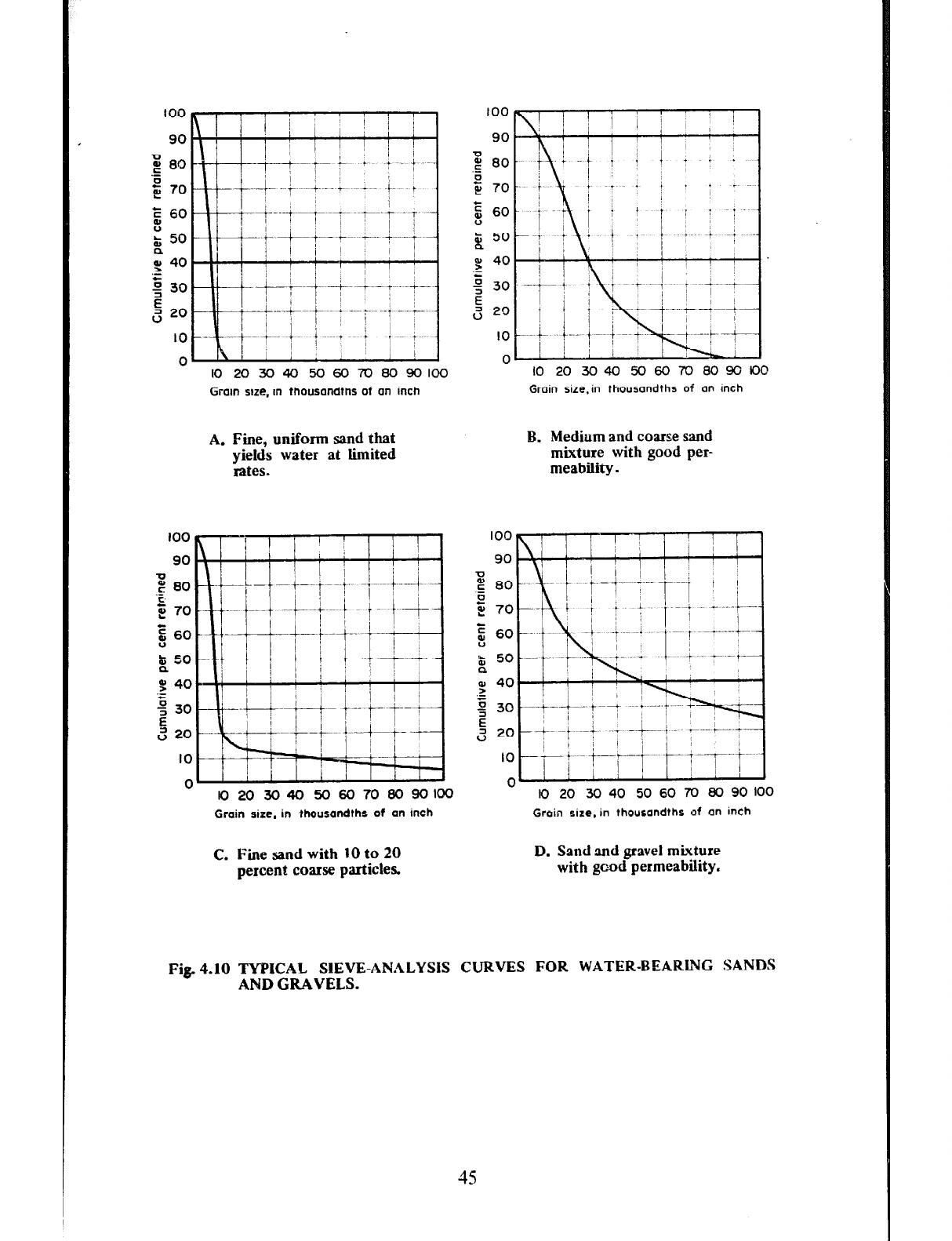
too
90
E 60
z
t 50
:
.L 40
2 30
E
(=j 20
10
0 IO 203040 5060708090100
Groin size, in thousondtns of on inch
10203040506070809010(?
Groin size.in thousondths of on inch
A. Fine, uniform sand that
yields water at limited
rates.
B. Medium and coarse sand
mixture with good per-
meability.
lO2030405060708090100
Grain size, in thousandths of an inch
”
IO 20 30 40 50 60 70 80 90 100
Grain size. in thousandths of on inch
C. Fine sand with 10 to 20 D. Sand aud gravel mixture
percent coarse particles with good permeability.
Fig. 4.10 WICAL SIEVE-ANALYSIS CURVES FOR WATER-BEARING SANDS
AND GRAVELS.
45
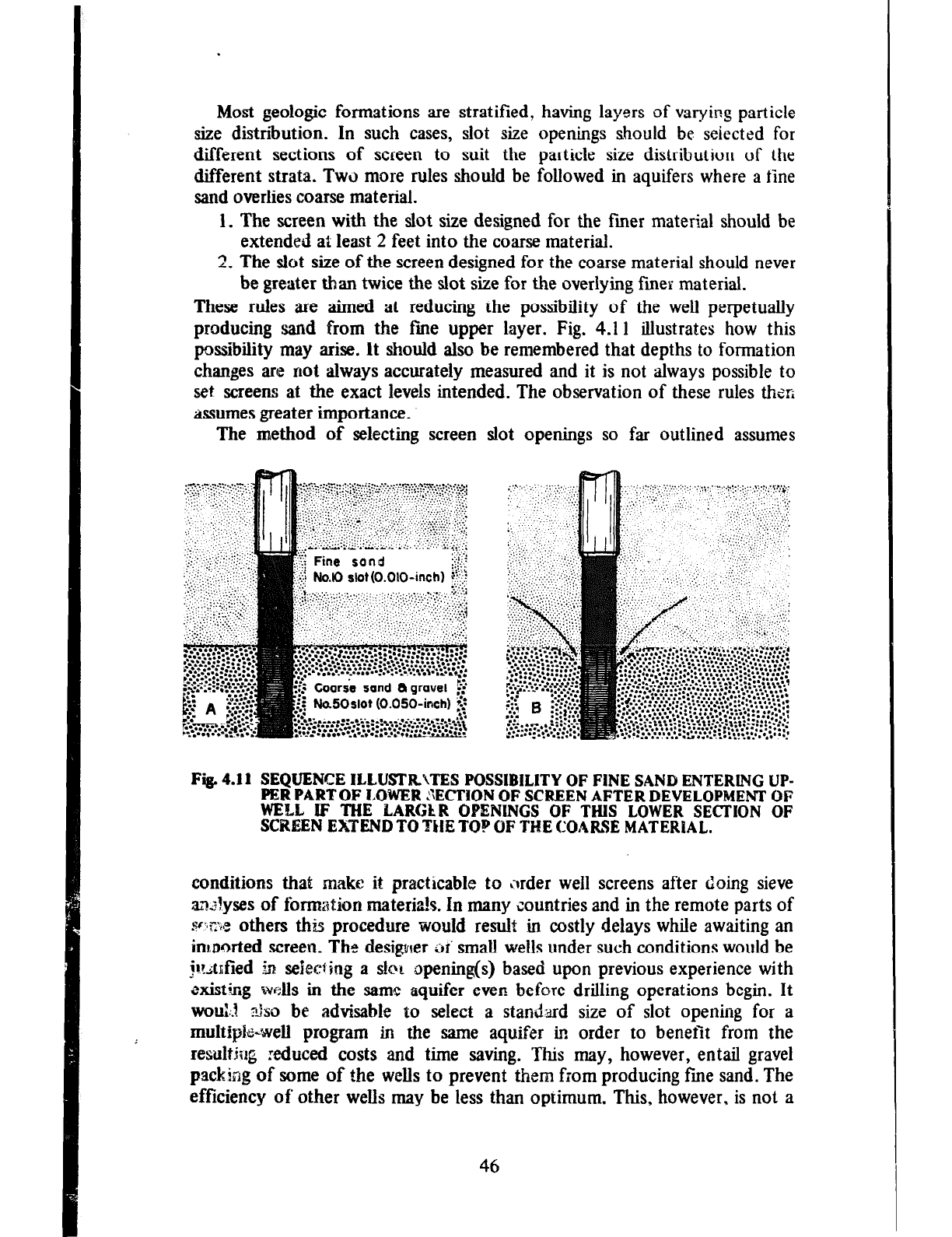
Most geologic formations are stratified, having layers of varying particle
size distribution. In such cases, slot size openings should be sejected for
different sections of screen to suit the particle size distribution of the
different strata.
TWO
more rules should be followed in aquifers where a fine
sand
overlies coarse material.
1. The screen
with the slot size designed for the finer material should be
extended at least 2 feet into the coarse material.
2.
The
slot size of the screen designed for the coarse material should never
be greater than twice the slot size for the overlying finer material.
These rules are
aimed at
reducing the possibility of the well perpetually
producing
sand from
the fine upper layer.
Fig.
4.11 illustrates how this
possiiility may arise. It
should
also be remembered that depths to formation
changes are not always accurately measured and it is not always possible to
set screens at the exact levels intended.
The
observation of these rules Thor;
assumes
greater importance.
The
method of
selecting screen slot openings so far outlined assumes
Fig. 4.11 SEQUENCE ILLUSTR’iTES POSSIBILITY OF FINE SAND ENTER&NC UP-
PERPARTOF LOWER :‘\ECI’ION OF SCREEN AFTER DEVELOPMENT
OF
WELL IF THE LARGLR OPENINGS OF THIS LOWER SECTION OF
SCREEN EXTEND TO THE TOP OF THE COARSE MATERIAL.
conditions that make
it
practicable to ;Irder well screens after doing sieve
ma?yses of formation materials. In many countries and in the remote parts of
~-xx others this procedure would result
in costly delays while awaiting an
imported screen.
The desigxrer
oi small wells under such conditions would be
$tnfied
jn seheciing a slot opening(s) based upon previous experience with
existing
roils in the
same
aquifer
even before drilling operations begin. It
WOU::J
~fi;lso be advisable to select a standyard
size of slot opening for a
multipk-well program in the same aquifer in order to benet from the
resultjug xduced costs and time saving. This may,
however, entail gravel
packing of some of the wells to prevent them from producing fine sand. The
efficiency of other wells
may be less than optimum. This, however, is not a
46
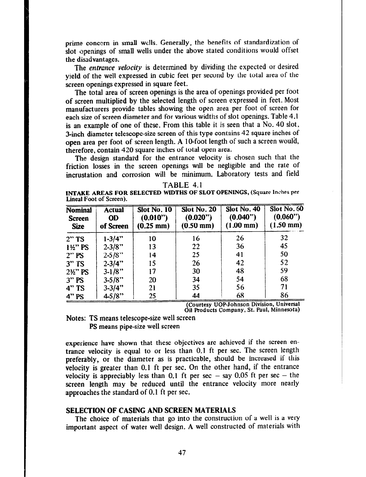
prime concern in small we!ls. Generally, the benefits of standardization of
slot openings of small wells under the above stated conditions would offset
the disadvantages.
The entrance velocity is determined by dividing the expected or desired
yield of the well expressed in cubic feet per second by the total area of the
screen openings expressed in square feet.
The total area of screen openings is the area of openings provided per foot
of screen multiplied by the selected length of screen expressed in feet. Most
manufacturers provide tables showing the open area per foot of screen for
each size of screen diameter and for various widths of slot openings. Table 4.1
is an example of one of these. From this table it is seen that a No. 40 slot,
3-inch diameter telescope-size screen of this type contains 42 square inches of
open area per foot of screen length.
A
IO-foot length of such a screen would,
therefore, contain 420 square inches of total open area.
The design standakd for the entrance velocity is chosen such that the
friction losses in the screen openings will be negligible and the rate of
incrustation and corrosion will be minimum. Laboratory tests and field
TABLE 4.1
INTAKE AREAS FOR SELECTED WIDTHS OF SLOT OPENINGS,
(Square Inches per
Lineal
Foot of Screen).
Nominal
Screen
Size
2” TS
I $4” PS
2” Ps
3” TS
2w Ps
3” Ps
4” TS
4”
PS
Actual Slot No. 10
OD (0.010”)
of Screen (0.25 mm)
l-3/4” 10
2-318” 13
2-5 18” 14
2-314”
15
3-l 18”
17
3-5 18” 20
3-314” 21
4-S IS” 25_
Slot No. 20
(0.020”)
(0.50 mm)
-
I
Slot No. 40
(0.040”)
(1 .OO mm)
-.
Slot No. 60
16
22
25
26
30
34
35
44
26
36
41
42
48
54
56
68
-
T
(0.060”)
(1 SO mm)
32’-. -
45
50
52
59
68
71
I
86
(Courtesy UOP-Johnson Division, Universal
Oil Products Company, St. Paul, Minnesota)
Notes: TS means telescope-size well screen
PS means pipe-size well screen
experience have shown that these objectives are achieved if the screen en-
trance velocity is equal to or less than 0.1 ft per sec. The screen length
preferably, or the diameter as is practicable, should be increased if this
velocity is greater than 0.1 ft per sec. On the other hand, if the entrance
velocity is appreciably less than 0.1 ft per set - say 0.05 ft per set - the
screen length may be reduced until the entrance velocity more nearly
approaches the standard of 0.1 ft per sec.
SELECTION OF CASING AND SCREEN MATERIALS
The choice of materials that go into the construction of a well is a very
important aspect of water well design. A well constructed of materials with
47
little or no resistance to corrosion can be destroyed beyond usefulness by Y
highly corrosive water within a few months of completion. This will be the
case no matter
how cxceknt
the other aspects of design. A poor seiec‘tion
1Jf
materials can also result in collapse ot‘ the well due to inadequate strength.
The above are factors which hrive considerable intluence urn what is cAled the
useful life of a well. In addition to these influences, the selection of materials
also has considerabie bearing on the cvst of a well. The corrusic!n resistant
met& for example. are much mure costly than ordinary steel. The choice of
a suitable metal or the provision of a greater thickness of the same metal to
meet strength requirements invuriably results in higher costs. These considera-
tions. therefore. indicate that the designer must exercise great cart’ in the
selection of materials for a well.
The designer usually makes his decision on the choice of materials after
considering three main Factors. These are brtater qrtalirrr, strmgth reqrtirements
and cyst.
Water Quality
Water quality. in this context, refers primarily to the mim~ral corltwt of
the water that will be produced by the well. Its effects on metal may be of
two basic types. It may cause wrrc~sim or iwmstatic~t~. Some waters cause
both corrosion tend incrustaticln. Chemical analyses of water samples can
indicate to the skilied interpreter whether a water is likely to be corrosive,
incrusting, or both. Unless knowledge is already available on the nature of the
water in the aquifer, it would be wise to seek the advice of a chemist with
relevant experience before selecting materials for use in a welt.
Grrusic~ is a process which results in the destruction of metals. Corrosive
waters are usually acid and mdy contain relatively high concentrations of
dissolved oxygen which is often necessary for and increases the rate of
corrosion. Higll concentrations of carbon dioxide, total dissolved solids and
hydrogen sulfid e with its characteristic odor of rotten eggs are other
indications of a likely corrosive water.
Besides water quality, there are other factors such as velocity offlow and
dissirr&ritmv oj‘metn[s which contribute to the corrosion process. The greater
the velocity of flow, the greater is the removal of the protective corrosion end
products from the surface of’ the metal and hericc the cxposurc of that
surf~e to further corrosion. This is another important reason for Xeeping the
velocity through screen openings within acceptable limits. The use of two or
more different types of metals such as stainless steel and ordinary steel, or
steel and brass or bronze should be avoided whenever possible. Corrosion is
usually greatest at the points of contact or closest proximity of the metals.
Corrosion may occur in well screens as welt as casings. It can bc tnore
critical in screens because it can reach damaging proportions much earlier
than in casings. This is because only LI small enlargement of the screen
openings is required for t!ie entry of sand through the screen, while the full
thickness of the casing metal must be penetrated for failure of a well through
corrosion of the casing. This is. however, no reason for ignoring the effect 01
corrosion in casings. Casing frtiture by corrosion equally ruins a well as does
failure of the screen. It c;tn cause the intrc~duction of clay and potjilted or
otherwise unsatisfactory water into the well. Corrosive well waters have been
observed to destroy steel casings in less than c3 months in Guyana, thus
ruining many wells.
Ordinary stee! and iron are not corrosion resistant. There are. however, a
number of metal alloys available with varying degrees
of corrosion resistance.
Among these are the stainless steels which combine nickel and chromium
with steel and also the various copper-based alloys such as brass and bronze
which combine traces of silicon, zinc and manganese with copper. Manu-
facturers, supplied with water analyses, can be expected to provide advice on
the type of metal or metal alloys to be used.
Plastic pipe of the polyvtilyl chloride (pvc) type is an attractive alternative
to the use of metals in small wells, partickllarly under corrosive conditions. It
combines corrosion resistance with adequate strength and economy.
Irzcnrsration,
unlike corrosion. results not in the destruction of metal,
but
in the deposition of minerals on it and in the aquifer immediately around a
well. Physical and chemical changes in the water in the well and the adjacent
formation cause dissolved minerals to change to their insoluble states and
settle out as deposits. These deposits cause the blocking
of
screen openings
and the formation pore spaces immediately around the screen with a resulting
reduction in the yield of the well.
Incrusting wsters are usually alkaline or the opposite to corrosive waters,
which are acid. Excessive carbonate hardness is a common source of
incrustation in wells. Scale deposits of calcium carbonate (lime scale) occur in
pipes carrying hard waters. Iron and manganese, to a lesser extent, are other
common sources of incrustation in wells. Iron causes characteristic reddish-
brown deposits while those of manganese are black.
Often associated with ironcontaining ground waters are iron bacteria.
These minute ‘living organisms are non-injurious to health, but, while aiding
the deposition of iron, produce accumulations of slimy, jelly-like material
which block well screen openings and aquifer pore spaces.
Strong solutions of hydrochloric acid are often used in treatment processes
for the removal of all the above-mentioned incrusting deposits. The corrosive
effect of this acid treatment, which must be repeated as the need. arises,
makes it necessary to use screens made of corrosion-resistant materials.
Unplasticized polyvinyl chioride pipe would &o withstand such treatment .
Further discussion on rehabilitating incrusted wells is presented in Chapter 7.
Strength Requirements
Strength requirements are important in both casing and screens but are
generally of mor e concern in screens. Screens must be strong enough to
withstand the external radial pressures that could cause their collapse as well
as the vertical loading due to the weight of the casing above them.
Some metals have greater strength characteristics than others. Stainless
steel, for example, can be twice as strong as some copper alloys. Screens and
casings of adequate strength can be made from any of the metals and alloys
commonly used in well construction. Manufacturers usually specify condi-
tions under which their pipes and screens can be satisfactorily used. It is often
49
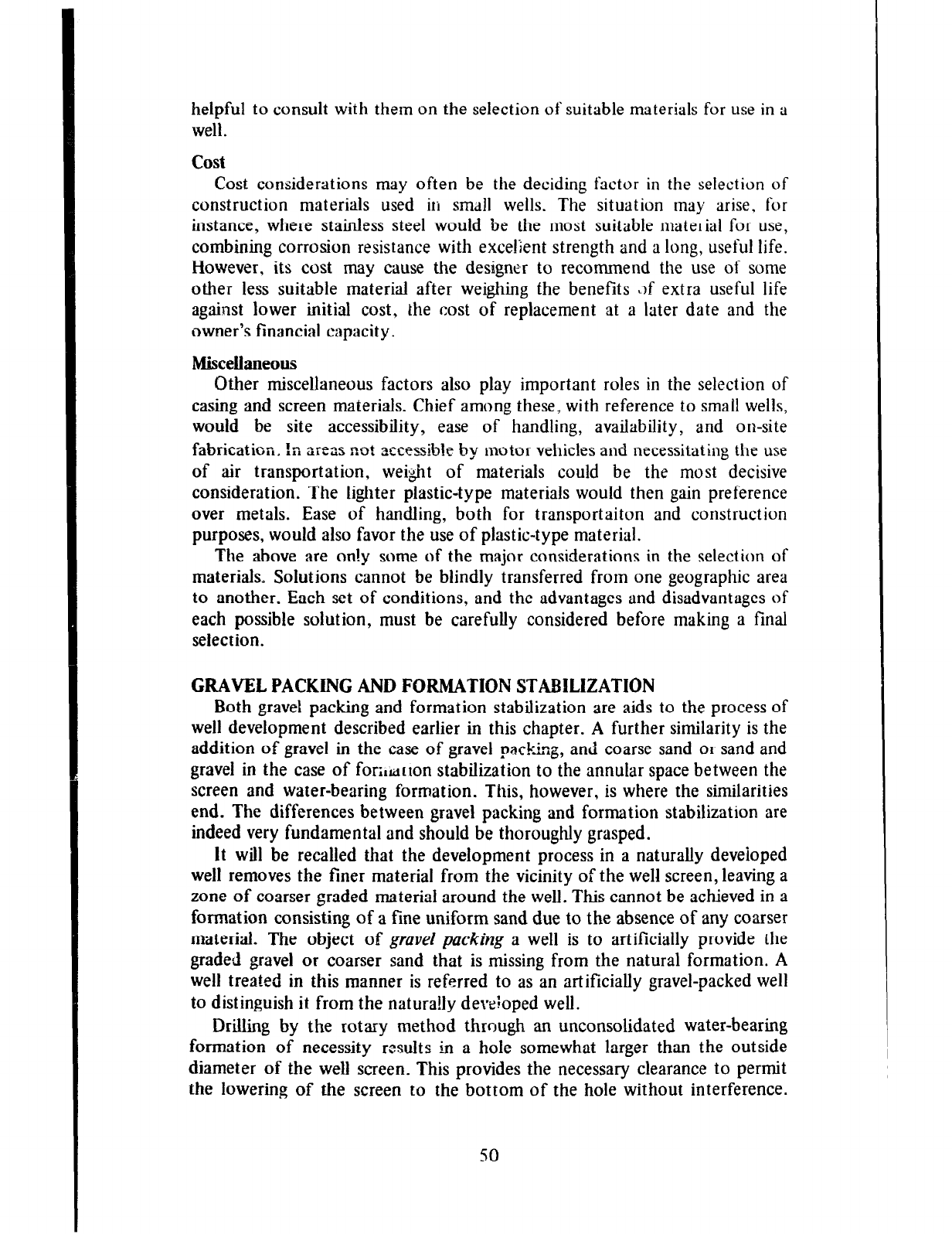
helpful to consult with them on the selection of suitable materials for use in a
well.
cost
Cost considerations may often be the deciding factor in the selection of
construction materials used in small wells. The situation may arise, for
instance, where stainless steel would be the most suitable material for use,
combining corrosion resistance with excellent strength and a long, useful life.
However, its cost may cause the designer to recommend the use of some
other less suitable material after weighing the benefits *.>f extra useful life
against lower initial cost, the cost of replacement at a later date and the
owner’s financial capacity.
h%scelianeous
Other miscellaneous factors also play important roles in the selection of
casing and screen materials. Chief among these, with reference to small wells,
would be site accessibility, ease of handling, availability, and on-site
fabrication. !n areas not accessible by motor vehicles and necessitating the use
of air transportation, wei$t of materials could be the most decisive
consideration. The lighter plastic-type materials would then gain preference
over metals. Ease of handling, both for transportaiton and construction
purposes, would also favor the use of plastic-type material.
The above are on!y some of the major considerations in the selection of
materials, Solutions cannot be blindly transferred from one geographic area
to another. Each set of conditions, and the advantages and disadvantages of
each possible solution, must be carefully considered before making a final
selection.
GRAVEL PACKING AND FORMATION STABILIZATION
Both gravel packing and formation stabilization are aids to the process of
well development described earlier in this chapter. A further similarity is the
addition of gravel in the case of gravel packing, and coarse sand 01 sand and
gravel in the case of fori,tirton stabilization to the annular space between the
screen and water-bearing formation. This, however, is where the similarities
end. The differences between gravel packing and formation stabilization are
indeed very fundamental and should be thoroughly grasped.
It will be recalled that the development process in a naturally deveioped
well removes the finer material from the vicinity of the well screen, leaving a
zone of coarser graded material around the well. This cannot be achieved in a
formation consisting of a fine uniform sand due to the absence of any coarser
material. The object of
gravel packing
a well is to artificially provide the
graded gravel or coarser sand that is missing from the natural formation. A
well treated in this manner is referred to as an artificially gravel-packed well
to distinguish it from the natura!ly developed well.
Drilling by the rotary method through an unconsolidated water-bearing
formation of necessity results in a hole somewhat larger than the outside
diameter of the well screen. This provides the necessary clearance to permit
the lowering of the screen to the bottom of the hole without interference.
50
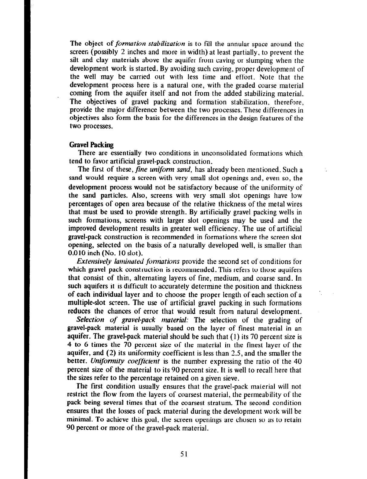
The object of formation stabilization is to fill the annuiar space around the
screen (possibly 2 inches and more in width) at least partially, to prevent the
silt and clay materials above the aquifer from caving or slumping when the
development work is started. By avoiding such caving, proper development of
the well may be carried out with less time and effort. Note that the
development process here is a natural one, with the graded coarse material
coming from the aquifer itself and not from the added stabilizing material.
The objectives of gravel packing and formation stabilization, therefore,
provide the major difference between the two processes. These differences in
objectives also form the basis for the differences in the design features of the
two processes.
Gravel Packing
There are essentially two conditions in unconsolidated formations which
tend to favor artificial gravel-pack construction.
The first of these, fine uniform sand, has already been mentioned. Such a
sand would require a screen with very small slot openings and, even so, the
development process would not be satisfactory because of the uniformity of
the sand particles. Also, screens with very small slot openings have low
percentages of open area because of the relative thickness of the metal wires
that must be used to provide strength. By artificially gravel packing wells in
such formations, screens with larger slot openings may be used and the
improved development results in greater well efficiency. The use of artificial
gravel-pack construction is recommended in formations where the screen slot
opening, selected on the basis of.a naturally developed well, is smaller than
0.010 inch (No. 10 slot).
Extensively laminated for&ions provide the second set of conditions for
which gravel pack construction is recommended. This refers to those aquifers
that consist of thin, alternating layers of fine, medium, and coarse sand. In
such aquifers it is difficult to accurately determine the position and thickness
of each individual layer and to choose the proper length of each section of a
multiple-slot screen. The use of artificial gravel packing in such formations
reduces the chances of error that would result from natural development.
.
Selection of gravel-pack material: The selection of the grading of
gravel-pack material is usually based on the layer of finest material in an
aquifer. The gravel-pack material should be such that (1) its 70 percent size is
4 to 6 times the 70 percent size of the material in the finest layer of the
aquifer, and (2) its uniformity coefficient is less than 2.5, and the smaller the
better. Unifurmi@ coefficient is the number expressing the ratio of the 40
percent size of the material to its 90 percent size. it is well to recall here that
the sizes refer to the percentage retained on a given sieve.
The first condition usually ensures that the gravel-pack material will not
restrict the flow from the layers of coarsest material, the permeability of the
pack being several times that of the coarsest stratum. The second condition
ensures that the losses of pack material during the development work will be
minimal. To achieve this goal. the screen openings are chosen so as to retain
90 percent or more of the gravel-pack material.
51
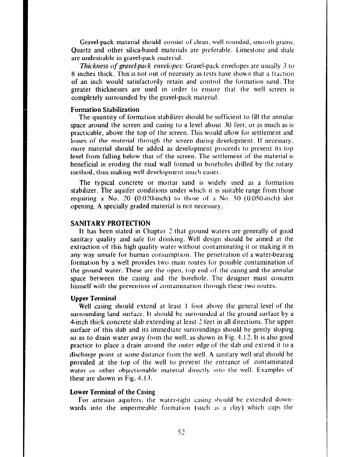
Gravel-pack material should consist of clean, well rounded, smooth grains.
Quartz and other silica-based materials are preferable. Lirnestorle and shale
are undesirable in gravel-pack material.
Tlzickrzess
of
gravel-pack ewelopes:
Gravel-pack envelopes ltre usually 3 to
8 inches thick. This is not out of necessity as tests lime shown that ~1 fraction
of an ~IX!I would satisfactorily retain and control the formation sand. The
greater thicknesses are used in order to ensure tllat the well screen is
completely surrounded by the gravel-pack material.
Forzdor. Stabilization
The quantity of formation stabilizer should be sufficient to fill the annular
space around the screen and casin, u to a level about 30 feet. or as much as is
practicable, above the top of the screen. Ttlis would allow for settlement and
losses of the materia! +h-
ItlIou~ the screen during development. If necessary,
more material should be added as development proceeds to prevent its top
level from falling below that of the screen. The settlement of the material is
beneficial in eroding the mud wall formed in boreholes drilled by the rotary
method, thus making well development much easier.
The typical concrete or mortar sand is widely used as a formation
stabilizer. The aquifer conditions under which it IS suitable range from those
requiring a No. 20 (0.020-inch) to those of a No. SO (O.OSO-incll) slot
opening. A specially graded material is not necessary.
SANITARY PROTECTION
It has been stated in Chapter 2 that ground waters are generally of good
sanitary quality and safe for drinking. Well design should be aimed at the
extraction of this high quality water without contaminating it or making it in
any way unsafe for human consumption. The penetration of a water-bearing
formation by a well provides two main routes for possible contamination of
the ground water. These are the open. top end of the casing and the annular
space between the casing and the borellole. The designer must concern
himself with the prevention of contamination througli tliese two routes.
Upper Terminal
Well casing should extend at least I foot above the general level of the
surrounding land surface. It sflould be surrounded at the ground surt’ace by a
4-inch thick concrete slab extending at least 2 feet in all directions. The upper
surface of this slab and its immediate surroundings should be gently sloping
so as to drain water away from the well. as shown in Fig. 4.12. It is also good
practice to place a drain around the outer edge of the sldb and extend it to a
discharge point at some distance from the well. A sanitary well seal should be
provided at the top of the well to prevent the entrance of contaminated
water or other objectionable material directly into the well. Examples of
these are shown in Fig. 4.13.
Lower Terminal of the Casing
For artesian aquifers. the water-tight casing should be extended down-
wards into tlie impermeable formation (sucl1 ;f~ a clay) which caps the
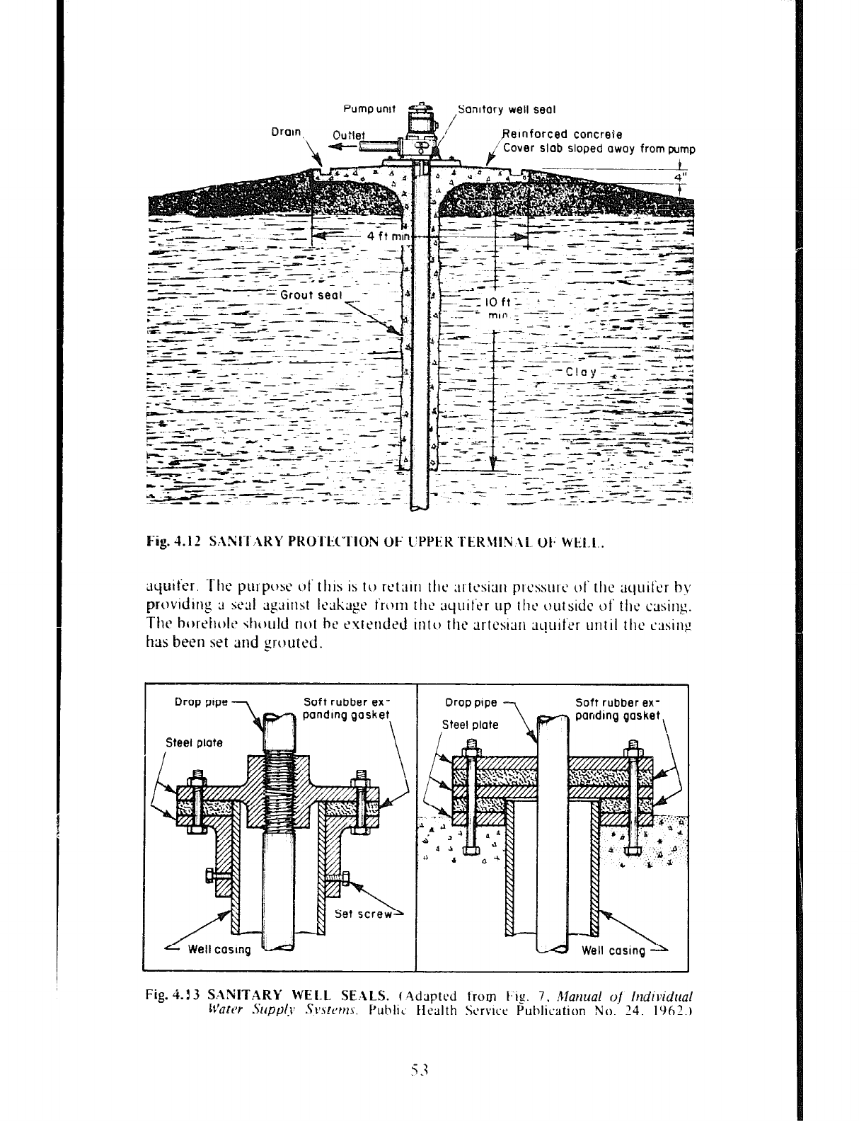
Pump unit
/
Sanitary well seal
I ,Relnfarced concrete
‘Cover slab sloped away from pump
-%
--- -
-- -
L-I:
. - --
- -1 -
--,r
-L-F
I -
- --
- ---- -_
---
Fig.
4.12 S:\NlThKY PKO’I‘ti”fION OF l’PPt;.K ‘i‘ER31IN~\tL. Ok WCI.1..
Drop pope Soft rubber ex-
pandlng gasket
\
Well casing k.A
I OroDtme -7
Soft rubber ex-
panding gasket \
Well casing
In water-table aquifers the casing should be extended at least 5 feet below
the lowest expected pumping level. This limiting distance should be increased
to 10 feet where the pumping level is less than 25 feet from the surface.
The above are general rules which should be applied with some flexibility
where geologic conditions so require.
Grouting and Sealiug Casii
The drilled hole must of necessity be larger than the pipe used for the well
casing. This results in the creation of an ®ularly shaped annular space
around the casing after it has been placed in position. It is important to fill
this space in order to prevent the seepage of contaminated surface water
down along the outside of the casing into the well and also to seal out water
of unsuitable quality in strata above the desirable water-bearing formation.
In caving material, such as sand or sand and gravel, the annular space is
soon filled as a result of caving. In such cases, therefore, no special
arrangements need be made for filling the annular space. However, where the
material overlying the water-bearing formation is of the non-caving type, such
as clay or shale, then the annular space should be grouted with a cement or
clay slurry to a minimum depth of 10 feet below the sirface. Where the
thickness of the clayey materials permit it, increasing the depth of grout to
about 15 feet would provide added safety. The diameter of the drilled hole
should be 3 to 6 inches larger than the permanent well casing to facilitate the
placing of the grout. It is important to remove temporary casing when
grouting rather than simply filing the space between the two casings as
vertical seepage can readily occur down the outside of any unsealed casing.
Methods
of mixing and placing the grout are discussed in Chapter 5.
54
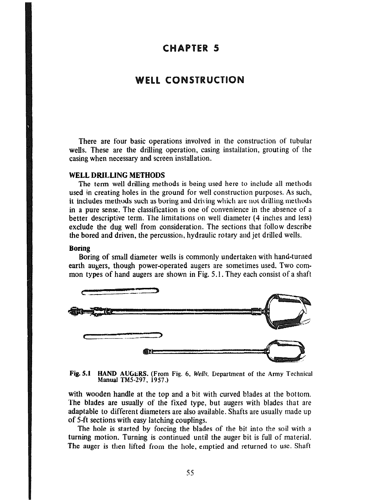
There are four basic operations involved in the construction of tubular
wells. These are the drilling operation, casing instailation, grouting of the
casing when necessary and screen installation.
WELL DRILLING METHODS
The term well drilling methods is being used here to include ail methods
used in creating holes in the ground for well construction purposes. As such,
it includes methods such as boring and driving which are not drilling methods
in a pure sense. The classification is one of convenience in the absence of a
better descriptive term. The limitations on well diameter (4 inches and less)
exclude the dug well from consideration. The sections that follow describe
the bored and driven, the percussion, hydraulic rotary and jet drilled wells.
Boring
Boring of small diameter wells is commonly undertaken with hand-turned
earth augers, though power-operated augers are sometimes used. Two com-
mon types of hand augers are shown in Fig. 5.1. They each consist of a shaft
Fig. 5.1 HAND AUGLRS. (From Fig. 6, Wello. Department of the Army Technical
Manual TM5297, 1957.)
with wooden handle at the top and a bit with curved blades at the bottom.
The blades are usually of the fixed type, but augers with blades that are
adaptabie to different diameters are also available. Shafts are usually made up
of S-ft sections with easy latching couplings.
The hole is started by forcing the blades of the bit into the soil with a
turning motion. Turning is continued until the auger bit is full of material.
The auger is then lifted from the hole, emptied and returned to use. Shaft
s5
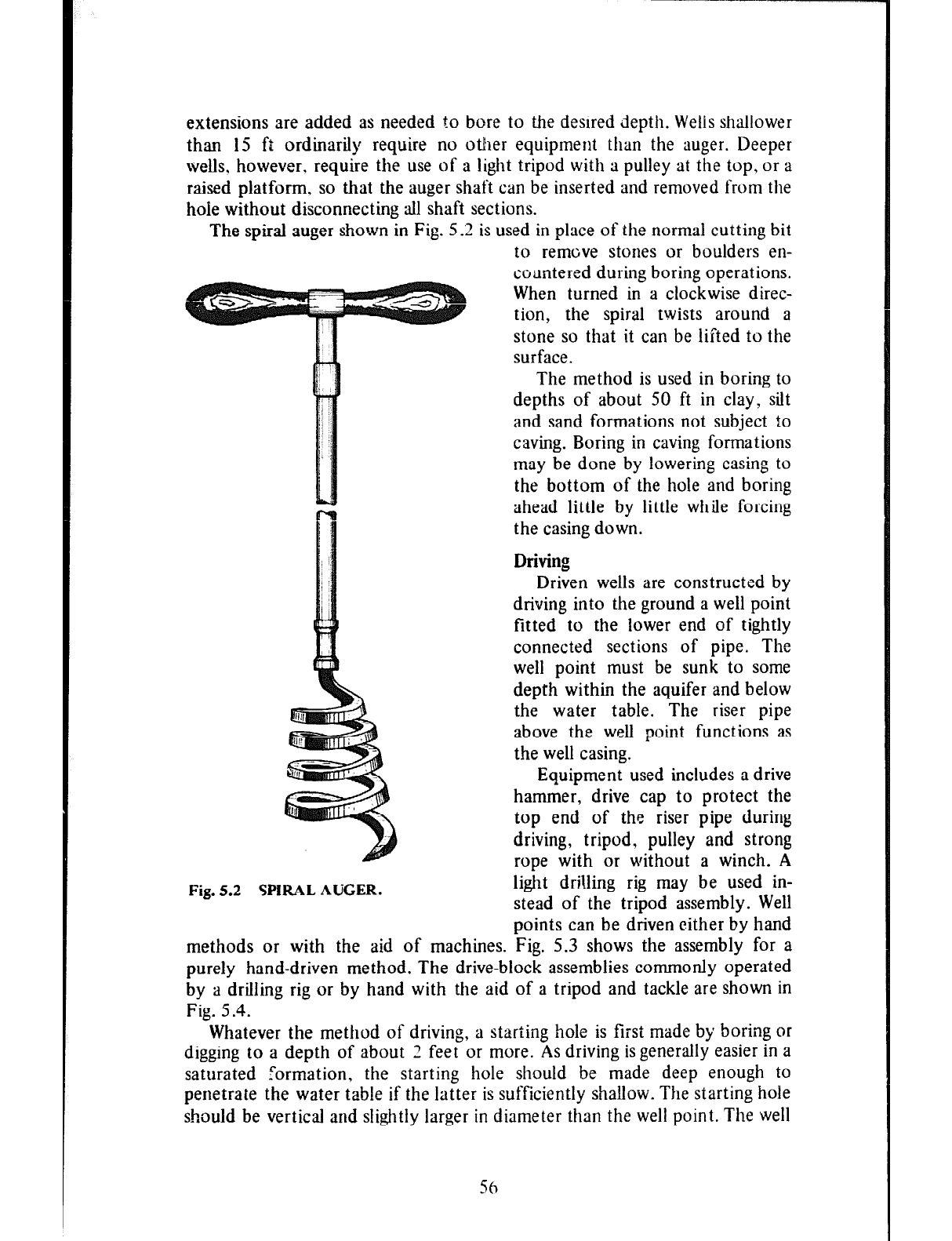
extensions are added as needed to bore to the desired depth. Wells shallower
than 15 ft ordinarily require no other equipment than the auger. Deeper
wells. however. require the use of a light tripod with a pulley at the top, or a
raised platform, so that the auger shaft can be inserted and removed from the
hole without disconnecting all shaft sections.
The spiral auger shown in Fig. 5.2 is used in place of the normal cutting bit
to remove stones or boulders en-
countered during boring operations.
When turned in a clockwise direc-
tion, the spiral twists around a
Fig. 5.2 SPIRAL AUGER.
stone so that it can be lifted to the
surface.
The method is used in boring to
depths of about 50 ft in clay, sift
and sand formations not subject to
caving. Boring in caving formations
may be done by lowering casing to
the bottom of the hole and boring
ahead little by little while forcing
the casing down.
Driving
Driven wells are constructed by
driving into the ground a well point
fitted to the lower end of tightly
connected sections of pipe. The
well point must be sunk to some
depth within the aquifer and below
the water table. The riser pipe
above the well point functions as
the well casing.
Equipment used includes a drive
hammer, drive cap to protect the
top end of the riser pipe during
driving, tripod, pulley and strong
rope with or without a winch. A
light drilling rig may be used in-
stead of the tripod assembly. Well
points can be driven either by hand
methods or with the aid of machines. Fig. 5.3 shows the assembly for a
purely hand-driven method. The drive-block assemblies commonly operated
by a drilling rig or by hand with the aid of a tripod and tackle are shown in
Fig. 5.4.
Whatever the method of drivin g, a starting hole is first made by boring or
digging to a depth of about Z feet or more. As driving is generally easier in a
saturated formation, the starting hole should be made deep enough to
penetrate the water table if the latter is sufficiently shallow. The starting hoie
should be vertical and slightly larger in diameter than the well point. The well
56
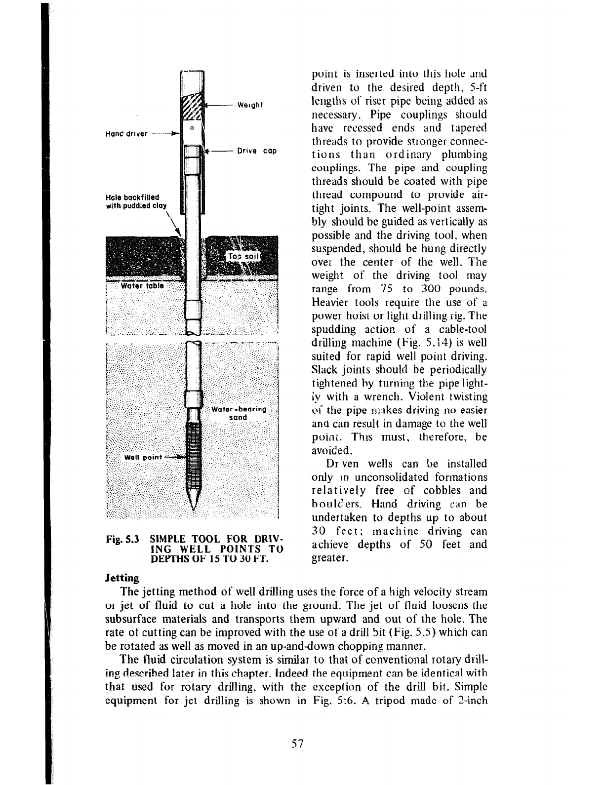
Ham? driver ----k-
- Drive cap
Htle backfilled
with pudd.ed clay
Fig. 5.3 SlMPLE TOOL FOR DRIV-
ING WELL POINTS TO
DEPTHS OF 15 TO 30 FT.
Jetting
point is inserted into this hole dnd
driven to the desired depth, S-ft
lengths of riser pipe being added as
necessary. Pipe couplings should
have recessed ends and tapered
threads to provide stronger connec-
tions than ordinary plumbing
couplings. The pipe and coupling
threads should be coated with pipe
thread compound to provide air-
tight joints. The well-point assem-
bly should be guided as vertically as
possible and the driving tool, when
suspended, should be hung directly
over the center of the well. The
weight of the driving tool may
range from 75 to 300 pounds.
Heavier tools require the use of a
power hoist or light drilling rig. The
spudding action of a cable-tool
drilling machine (Fig. 5.14) is well
suited for rapid well point driving.
Slack joints should be periodically
tightened by turning the pipe light-
iy with a wrench. Violent twisting
oi‘ the pipe mikes driving no easier
and can result in damage to the well
point. Thus must, therefore, be
avoided.
Dr%en wells can be installed
only ln unconsolidated formations
relatively free of cobbles and
boulders. Hand driving can be
undertaken to depths up to about
30 feet; machine driving can
achieve depths of 50 feet and
greater.
The jetting method of well drilling uses the force of a high velocity stream
or jet of fluid to cui a hole into the grourrd. The jet of fluid loosens the
subsurface materials and transports them upward and out of the hole. The
rate of cutting can be improved with the use of a drill Si.t (Fig. 5.5) which can
be rotated as well as moved in an up-anddown chopping manner.
The fhrid circulation system is similar to that of conventional rotary drill-
ing described later in this chapter. indeed the equipment can be identical with
that used for rotary drilling, with the exception of the drill bit. Simple
equipment for jet drilling is shown in Fig. 5%. A, tripod made of ‘I-inch
57
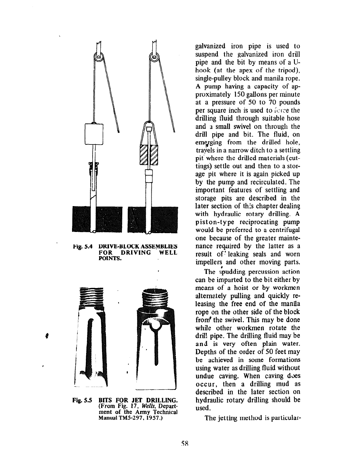
Fig. 5.4 DRIVE-BLOCK ASSEMBLIES
FOR DRIVING WELL
POINTS.
Fig.55 BITS FOR JET DRILLING.
(From Fig. 17, We&s, Depart-
ment of the Army Technical
Manual TMS-297, 1957.)
galvanized iron pipe is used to
suspend the galvanized iron drill
pipe and the bit by means of a U-
hook (at the apex of the tripod),
single-pulley block and manila rope.
A pump having a capacity of ap-
proximately 150 gallons per minute
at a pressure of 50 to 70 pounds
per square inch is used to Li-;:e the
drilling tluid through suitable hose
and ;1 small swivel on through the
drill pipe and bit. The fluid, on
emsrging from the drilled hole,
tra:iels in a narrow ditch to a settling
pit where the drilled materials (cut-
tings) settle out and then to a stor-
age pit where it is again picked up
by the pump and recirculated. The
important features of settling and
storage pits are described in the
later section of this chapter dealing
with hydraulic rotary drilling. A
piston-type reciprocating pump
would be preferred to a centrifugal
one because of the greater mainte-
nance required by the latter as a
result of! leaking seals and worn
impellers and other moving parts.
The ::pudding percussion act ion
can be imparted to the bit either by
means of a hoist or by workmen
alternately pulling and quickly re-
leasing the free end of the manila
rope on the other side of the block
from’ the swivel. This may be done
while other workmen rotate the
drib pipe. The drilling fluid may be
and is very often plain water.
Depths of the order of 50 feet may
be achieved in some formations
using water as drilling ff uid without
undue caving. When caving d3es
occur, then a drilling mud as
described in the later section on
hydraulic rotary drilling should be
used.
The jetting method is particular-
58
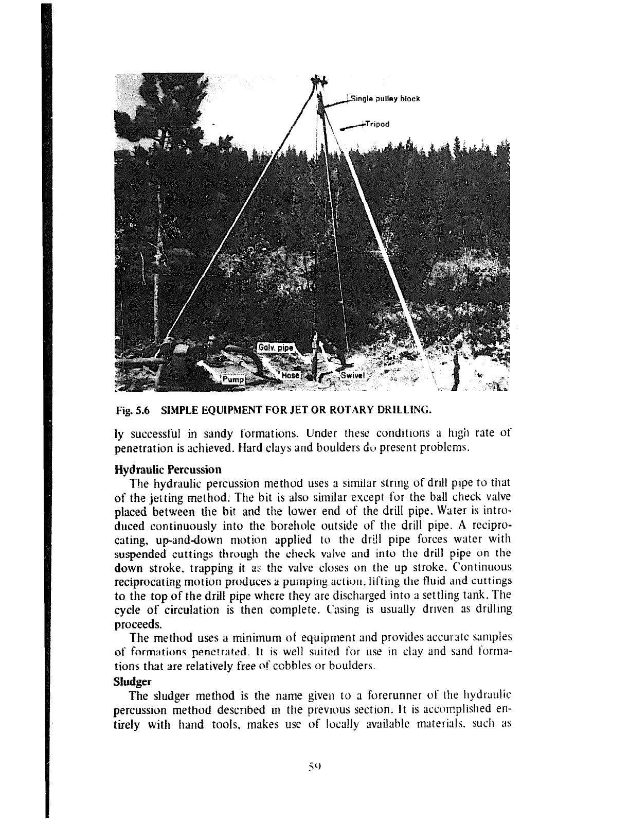
single wlley block
: /Tripod
Fig. 5.6 SIMPLE EQUIPMENT FOR JET OR ROTARY DRILLING.
ly successful in sandy formations. Under these conditions a high rate of
penetration is achieved. Hard clays and boulders dv present problems.
Hydraulic Percussion
The hydraulic percussion method uses a similar string of drill pipe to that
of the jelting method; The bit is also similar except for the ball check valve
placed between the bit and the lower end of the drill pipe. Water is intro-
duced continuously into the borehole outside of the drill pipe. A recipro-
cating, up-and-clown motion applied to the drill pipe forces water with
suspended cuttings through the check vaPvc and into the drill pipe on the
down stroke. trapping it a~ the valve closes on the up stroke. Continuous
reciprocating motion produces a pumping action, lifting the fluid and cuttings
to the top of the drill pipe where they are discharged into a settling tank. The
cycle of circulation is then complete. Casing is usually driven as drilling
proceeds.
The method uses a minimum of equipment and provides accurstc samples
of formations penetrated. It is well suited for use in clay and sand forma-
tions that are relatively free of ccbbles or boulders.
Sludger
The sludger method is the name given to a forerunner of the hydraulic
percussion method described in the previous section. It is accomplished en-
tirely with hand tools. makes use of locally available materials. such as
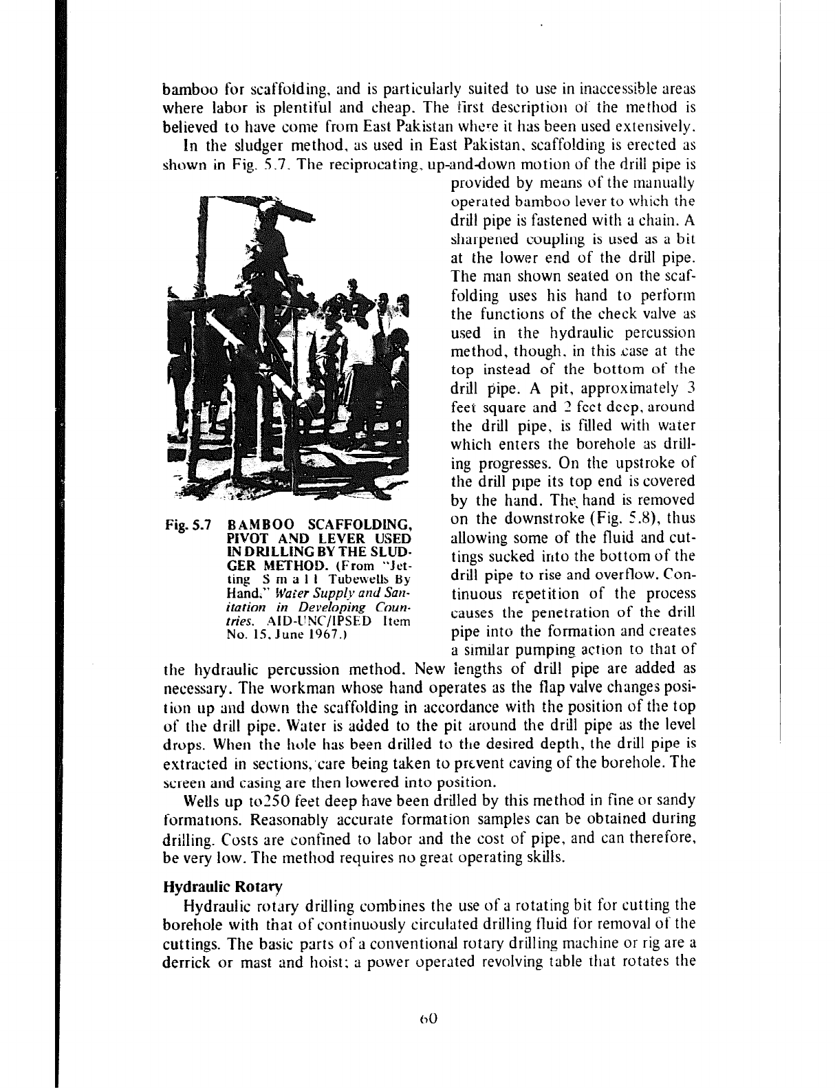
bamboo for scaffoiding, and is particularly suited to use in inaccessible areas
where labor is plentiful and cheap. The first description of the method is
believed to have come from East Pakistan where it has been used extensively.
In the sludger method, as used in East Pakistan. scaffolding is erected as
shown in Fig. 5.7. The reciprocating, up-anddown motion of the driil pipe is
provided by means of the manually
operated bamboo lever to which the
drill pipe is fastened with a chain. A
sharpened coupling is used as a bit
at the lower end of the drill pipe.
The man shown seated on the scaf-
folding uses his hand to perfortn
the functions of the check valve as
used in the hydraulic percussion
method, though. in this .case at the
top instead of the bottom of t!le
drill pipe. A pit, approximately 3
feet square and 2 feet deep, around
the drill pipe, is filled with water
which enters the borehole as drill-
ing progresses. On the upstroke of
the drill pipe its top end is covered
by the hand. The. hand is removed
Fig. 5.7 BAMBOO SCAFFOLDING,
on the downstroke (Fig. C.8), thus
PIVOT AND LEVER USED
IN DRILLING BY THE SLUD-
allowing some of the fluid and cut-
GER METHOD. (From “Jct-
tings sucked into the bottom of the
ting S m a I 1 Tubewells By
drill pipe to rise and overflow. Con-
Hand.”
Wafer Supple and
San-
itaiion in Develop& Coun-
tinuous repetition of the process
fries.
AID-LiNC/IPSED Item
causes the penetration of the drill
No. IS. June 1967.)
pipe into the formation and creates
a similar pumping action to that of
the hydraulic percussion method. New iengths of drill pipe are added as
necessary. The workman whose hand operates as the flap valve changes posi-
tion up md down the scaffolding in accordance with the position of the top
of the drill pipe. Water is added to the pit around the drill pipe as the level
drops. When the hole has been drilled to the desired depth, the drill pipe is
extracted in sections;care being taken to prevent caving of the borehole. The
screen and casing are then lowered into position.
Wells up to250 feet deep have been drilled by this method in fine or sandy
formations. Reasonably accurate formation samples can be obtained during
drilling. Costs are confined to labor and the cost of pipe, and can therefore,
be very low. The method requires no great operating skills.
Hydraulic Rotary
Hydraulic rotary drilling combines the use of a rotating bit for cutting the
borehole with that of continuously circulated drilling fluid for removal of the
cuttings. The basic parts of a conventional rotary drilling machine or rig are a
derrick or mast and hoist: a power operllted revolving table rhat rotates the
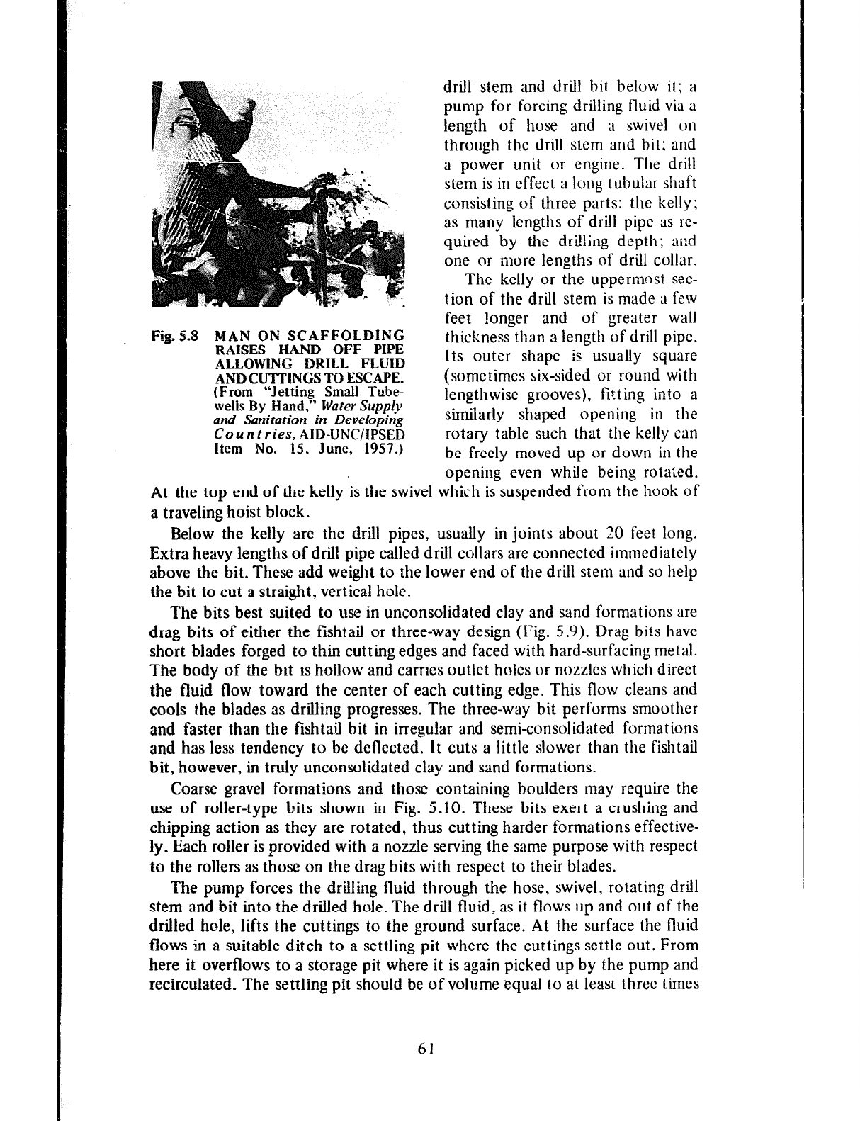
Fig,..8 MAN ON SCAFFOLDING
RAISES HAND OFF PIPE
ALLOWING DRILL FLUID
AND CUTTINGS TO ESCAPE.
(From “Jetting Small Tube-
weiis
By Hand,”
Water Supply
and Sanitation in Developing
Countries, AID-UNC/IPSED
Item No. 15, June, 1957.)
drill stem and drill bit below it; a
pump for forcing drilling fluid via a
length of hose and a swivel on
through the drill stem and bit: and
a power unit or engine. The drill
stem is in effect a long tubular
shaft
consisting of three parts: the kelly;
as many lengths of drill pipe as re-
quired by the drilling depth; and
one or more lengths of drill collar.
The kelly or the uppermost sec-
tion of the drill stem is made a few
feet longer and of greater wall
thickness than a length of drill pipe.
Its outer shape is usually square
(sometimes six-sided or round with
lengthwise grooves), fitting into a
similarly shaped opening in the
rotary table such that the kelly can
be freely moved up or down in the
opening even while being rotated.
At the top end of the kelly is the swivel which is suspended from the hook of
a traveling hoist block.
Below the kelly are the drill pipes, usually in joints about 20 feet long.
Extra heavy lengths of drill pipe called drill collars are connected immediately
above the bit. These add weight to the lower end of the drill stem and so help
the bit to cut a straight, vertical hole.
The bits best suited to use in unconsolidated clay and sand formations are
drag bits
of either the fishtail or three-way design (Fig. 5.9). Drag bits have
short blades forged to thin cutting edges and faced with hard-surfacing metal.
The body of the bit is hollow and carries outlet holes or nozzles which direct
the fluid flow toward the center of each cutting edge. This flow cleans and
cools the blades as drilling progresses. The three-way bit performs smoother
and faster than the fishtail bit in irregular and semi-consolidated formations
and has less tendency to be deflected. It cuts a little slower than the fishtail
bit, however, in truly unconsolidated clay and sand formations.
Coarse gravel formations and those containing boulders may require the
use of roller-type bits shown in Fig. 5.10. These bits exert a crushing and
chipping action as they are rotated, thus cutting harder formations effective-
ly. Each roller is provided with a nozzle serving the same purpose with respect
to the rollers as those on the drag bits with respect to their blades.
The pump forces the drilling fluid through the hose, swivel, rotating drill
stem and bit into the drilled hole. The drill fluid, as it flows up and out of the
drilled hole, lifts the cuttings to the ground surface. At the surface the fluid
flows in a suitable ditch to a settling pit where the cuttings settle out. From
here it overflows to a storage pit where it is again picked up by the pump and
recirculated. The settling pit should be of volume equal to at least three times
61
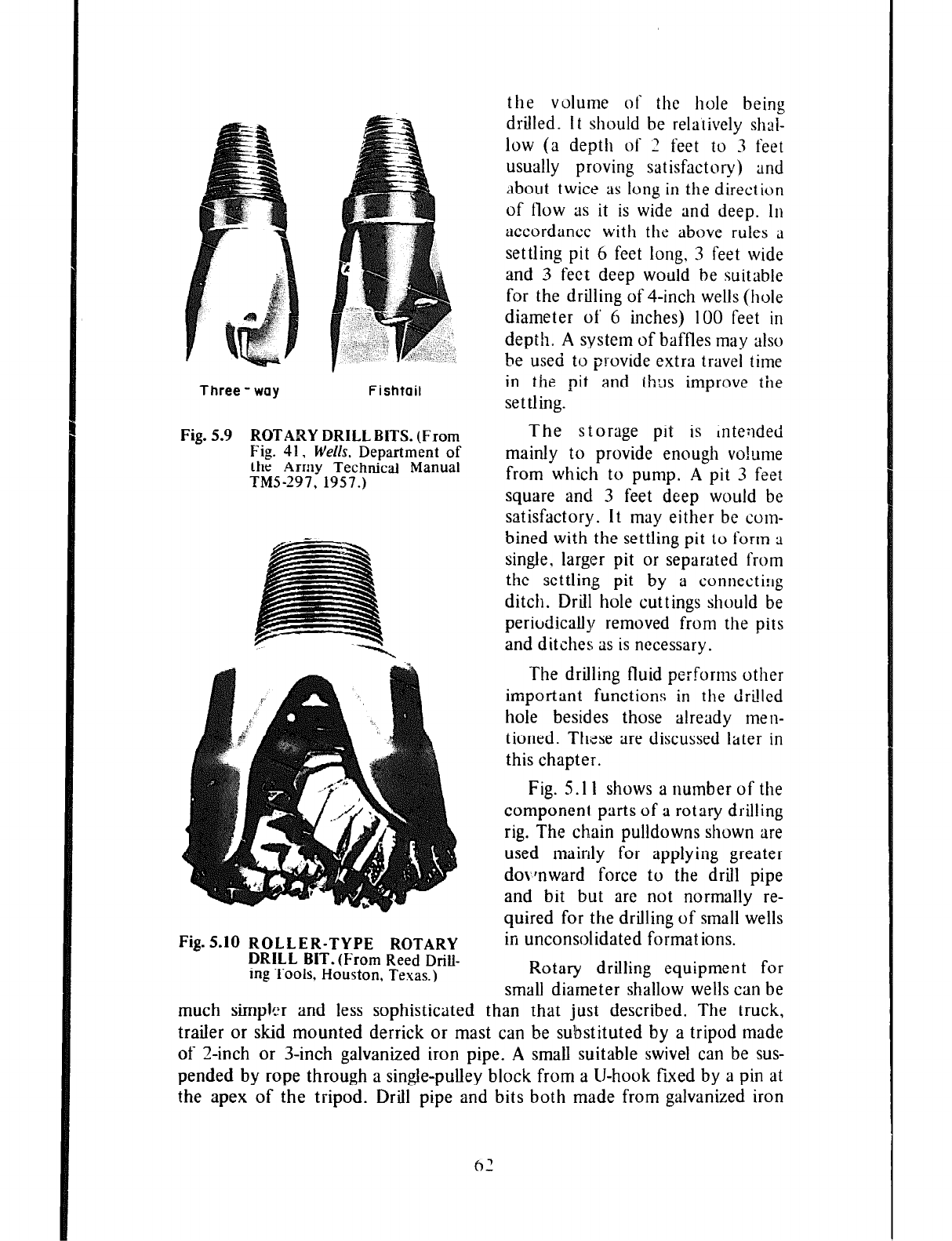
Three-way
Fishtail
Fig. 5.9 ROTARY DRILL BITS. (From
Fig. 41, Wells. Department of
the Army Technical Manual
TMS-297, 1957.)
Fig. 5.10 ROLLER-TYPE ROTARY
DRILL BIT.(From
Reed
Drill-
ing
Tools. Houston, Texas.)
Fig. 5.1 I shows a number of the
component parts of a rotary drilling
rig. The ch,ain pulldowns shown are
used mainly for applying greater
do\,lnward force to the drill pipe
and bit but are not normally re-
quired for the drilling of small wells
in unconsolidated format ions.
Rotary drilling equipment for
small diameter shallow wells can be
than that
just
described. The truck,
.
much simpler and less sophisticated
trailer or skid mounted derrick or mast can be substituted by a tripod made
of Z-inch or 3-inch galvanized iron pipe. A small suitable swivel can be sus-
pended by rope through a single-pulley block from a (J-hook fLved by a pin at
the apex of the tripod. Drill pipe and bits both made from galvanized iron
the
volume
of the hole being
drilled. 1 t should be relatively shai-
low (a depth of 2 feet to 3 feet
usually proving satisfactory) and
About twice
as long in the direction
of flow 3s it is wide and deep. In
accordance with fhe above rules a
settling pit 6 feet long, 3 feet wide
and 3 feet deep would be suitable
for the drilling of 4-inch wells (hole
diameter of’ 6 inches) 100 feet in
depih, A system of baffles may also
be used to provide extra travel time
in the pit and ih:ls improve the
settling.
The storage pit is inteilded
mainly to provide enough vo!ume
from which to pump. A pit 3 feet
square and 3 feet deep would be
satisfactory. It may either be com-
bined with the settling pit to form a
single, larger pit or separated from
the settling pit by a connecti!lg
ditch. Drill hole cuttings should be
periodically removed from the pits
and ditches as is necessary.
The drilling fluid performs other
important functions in the drilled
hole besides those already men-
tioned. These are discussed later in
this chapter.
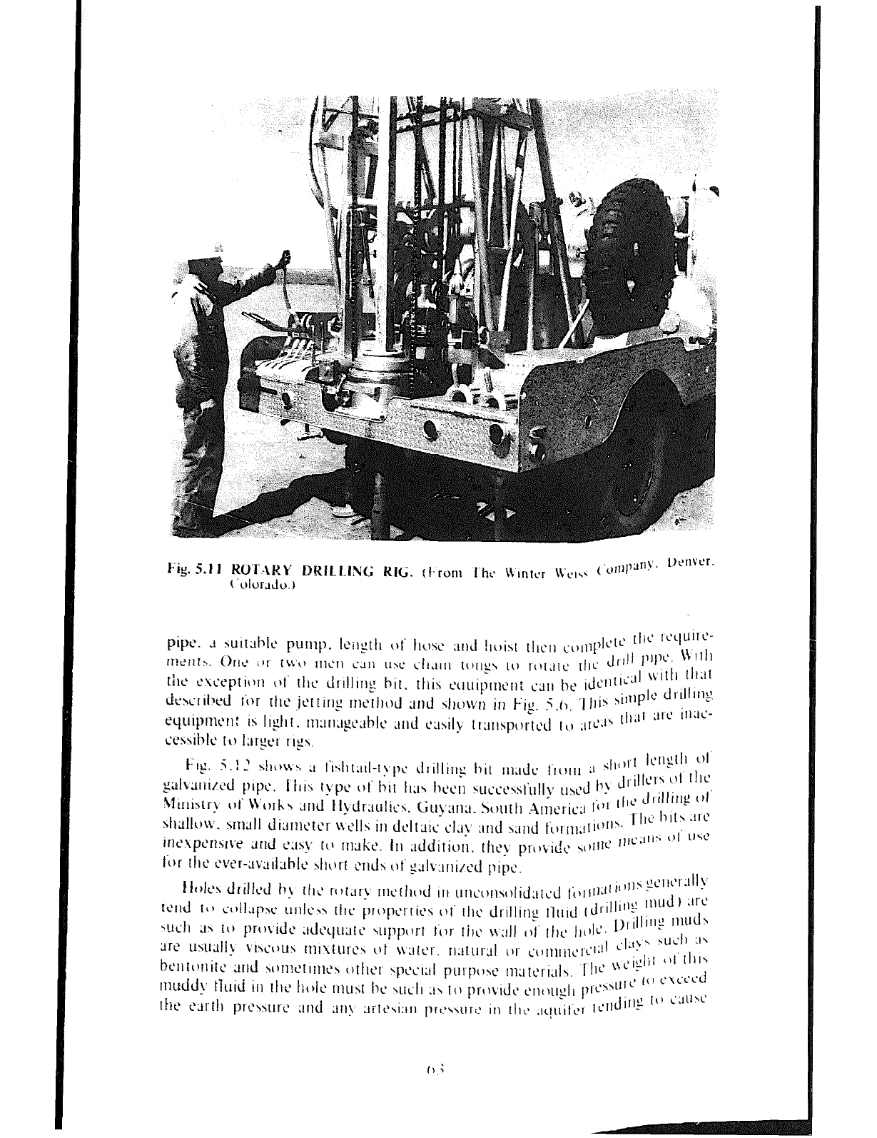
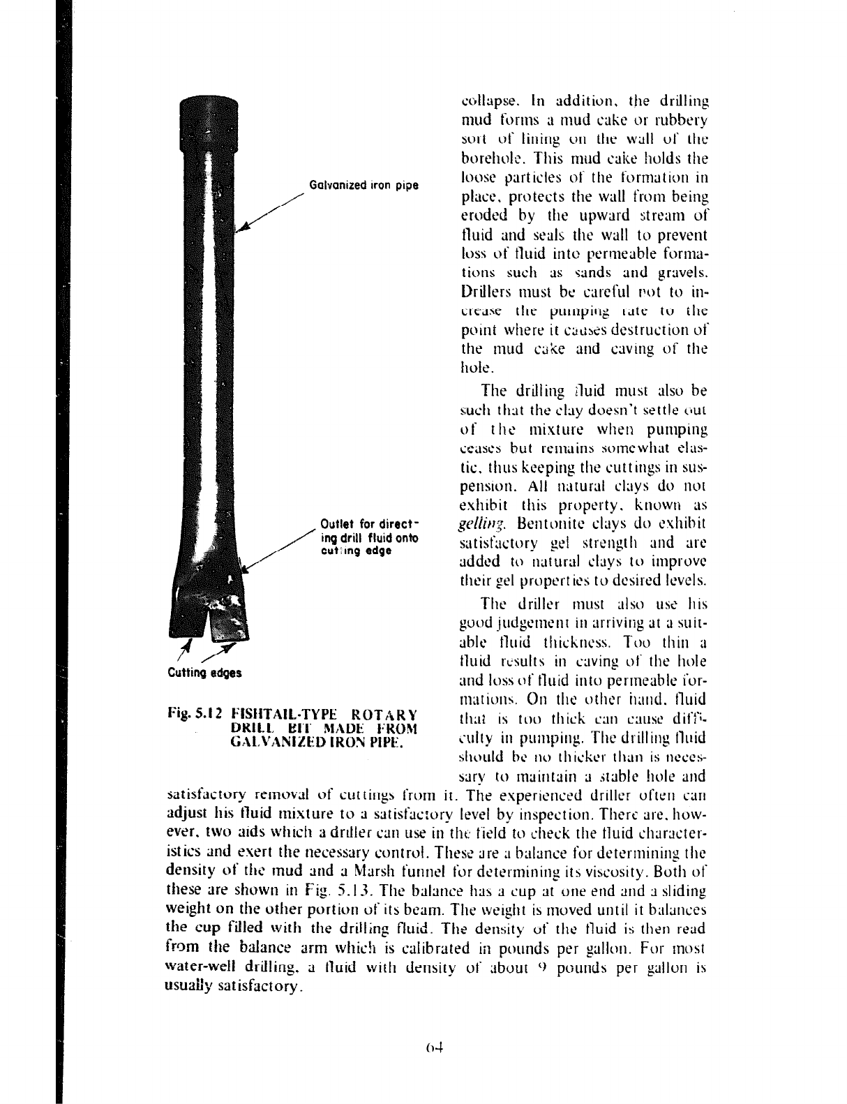
Cutting edges
collapse. In addition, tjle drilling
mud forms ;I mud cake or rubbery
sort of lining on the wail of the
borehoic. This mud aice holds the
Galvanized
iron pipe loose
part icies of the forma tioti in
place, protects the wail from being
eroded by the upward strem uf
fluid and scais the wall tu prevent
ic~ss c)f fluid into permeable forma-
tions such ;1s sands and gravels.
Drillers must be careful mt to in-
crease the pumpirig rate to the
puint where it c;lcszs destruction ot
the mud czke and cming of the
hole.
Outlet for
direct-
ing drill fluid
onto
cutlmg edge
The drilling rluid must aisv be
such that the clay doesn’t sett!e c~ut
of t he mixture when pumping
ce;mx but rcmins somewhat eias-
tic, thus keeping the Cuttings in sus-
pensm. Ail rlaturul clays do nut
exhibit this property. k ncwtl ;is
gdirr:.
Beiitonitc clays do cxiiihit
satisfuctory gel strength and tire
added to uaturltl clays to improve
their gel properties to desired Icvcis.
The driller must 111so use his
good judgernerlt iu arrivilig tit ;i suit-
ubie tluid thickness. TW thin ;I
tluid rc-suits in caving 01 tile hole
und loss of tluid into permeable i‘or-
maths. 011 tilt‘ other hand. tluid
slmuid bc no rilickcr rhn is IICWS-
sary to nlairltrtin 3 .<tabie !loic and
satisfactory rernovrti c)f wttings frmn it. The esperiewed driller uf‘terl can
adjust his fluid mixture to 3 satisfx:ory level by inspcctiun. There are. huw-
ever. two aids wilicfl ;f driller WI use
in the
field to check the fluid cilarxter-
istics and exert the neceswy control. These are ;I bairtnce for determining the
density of fhr‘ mud and 3 Mursh furlnei tur determining its viscosity. Both ot
these are shown in Fig. 5.13. The bhlce has 3 cup at one end and a sliding
weight on the other portion ot‘ its beam. The weight is moved until it baiarwcs
the cup filled witfl the drilling fluid. The density of the tluid is tiler1 read
frcm the brrlance arm whic!i is calibrated
in
pounds per gallon. For most
water-well driiiing. a tluid with density of itbout 0 pc;unds per gallon is
USUai:
j!
sat isfact oty _
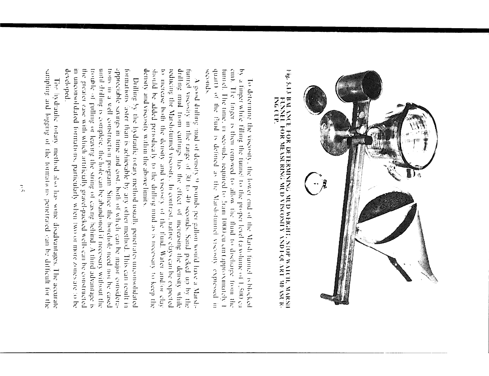
-.
- -
-^ - - z-
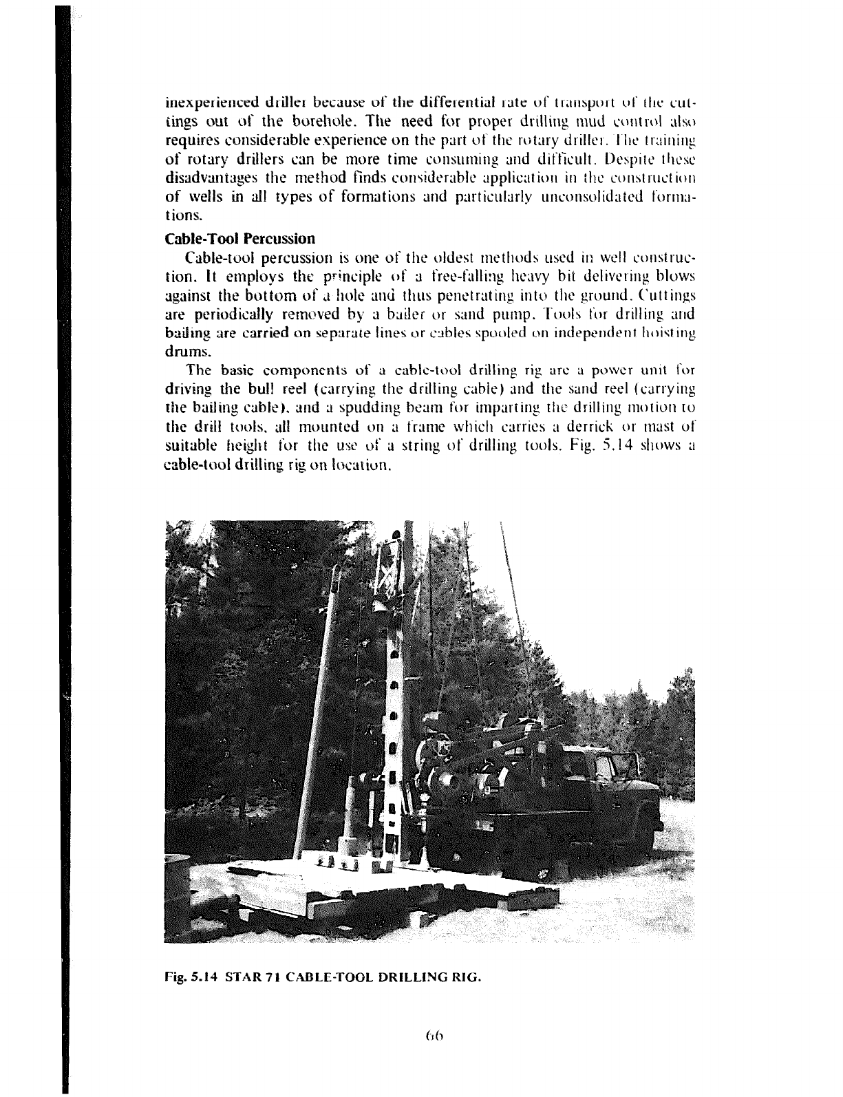
inexperienced driller because of the differential rate of tr;insport 01‘ tht~ cut-
tings out of the borehole. The need for proper drilling mud c‘or\trcA ~1s~~
requires considertlbie experience on the part of the rotary driilcr. Ti~c training
of rotary drillers can be more time consuming und dit‘tkult. lkspitc ~hcsc‘
disadvantages
the method finds considtx~bic appiic;lt iorl in the coust ruct ioll
of wells in al! types of formations tend p;lrticuiarly url~ollsolidvttd t‘orma-
t ions.
Cable-Tool Percussion
Cable-tool percussion is one of the oldest methods used il: well construe-
tion. It employs the pfincipie of 3 frtx-fulii:lg heavy bit delivering blows
against the bottom of ri hole auci thus penetrating inttj the ground. C’uttings
are periodically rerncved by rt bailer or s:md punlp. ‘I‘ool~ ti)r drillin:: aid
bairing tire carried
on separate fines or cttblcs spuoied cjn independent hoisting
drums.
The basic components of ;t cable-tool drilling rig are ;1 power unit for
driving the bull reel
(carrying the drilling csbie) and the sand reel (carrying
the bailing cable).
2nd ;I spudding btxm tar impart in,
(1 the drilling motiuu tu
the drill
tools. alf mounted on ;I t‘r;mx which carries ;I derrick or mat ut
suitable height
for the USC of ;I striug of drilling tools. Fig. 5.14 shahs ;I
cable-tool drilling
rig on ioctttiun.
Fig. 5.14 STAR 7 1 CABLE-TOOL DRILLING RIG.
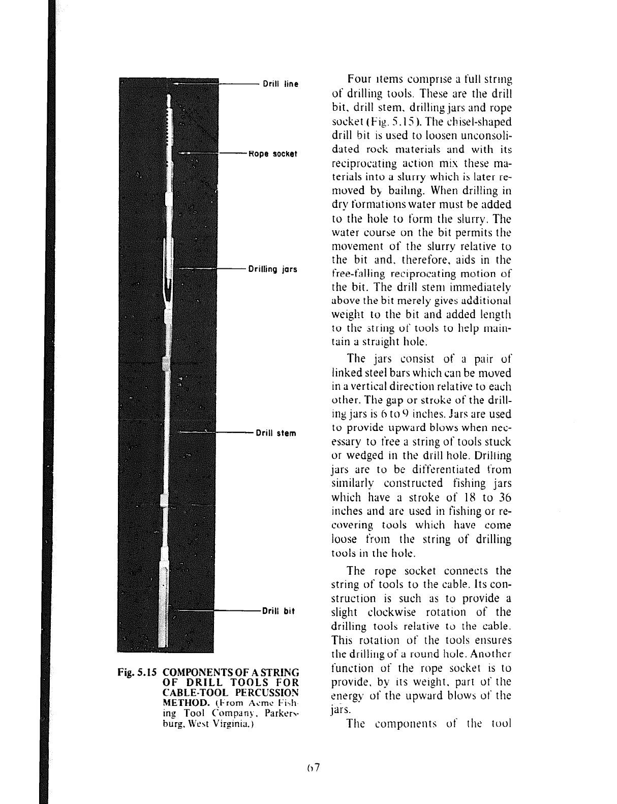
- Drill line
.Rope et hzket
Drilling jars
- Drill s
item
-Drill bit
Fig. 5.15 COMPONENTS OF A STRING
OF DRILL TOOLS FOR
CABLE-TOOL PERCUSSION
METHOD.
(-From
Ac‘mt‘ Fib
ing Tool Cornpan)-. Parkrr~
burg. We\t Virginia.)
Four items comprise ;1 full string
of drilling tools. These are the drill
bit. drill stem. drilling jars and rope
socket (Fig. 5.15 ). The chisel-shaped
drill bit is used to loosen unconsoli-
dated rock materials and with its
reciprocating action mis these ma-
terials into a slurry which is later re-
moved by baiimg. When drilling in
dry formations water must be added
to the hole to form the slurry. The
water course on the bit permits the
movement of the slurry relative to
the bit and. therefore, aids in the
free-failing reciprocating motion of
the bit. The drill stem immediately
above the bit merely gives additional
weight to the bit and added length
The jars consist of a pair ot
1 inked steel bars which can be moved
il
n avertical direction relative to each
other. The gap or stroke of the drill-
ing jars is 6 to 0 inches. Jars are used
to provide upward blows when nec-
essary to free a string of tools stuck
or wedged in the drill hole. Drilling
jars are to be differentiated t’rom
similarly constructed fishing jars
which have ;1 stroke of 18 to 36
inches and art‘ used in fishing or re-
covering tools which have come
loose from the string of drilling
tools in Ihe hole.
0 the ;tring of tools to help main-
ain a straight hole.
The rope socket connects the
string of tools to the cable. its con-
struction is such as to provide a
slight clockwise rotation of the
drilling tools relative to the cable.
This rotation of the tools ensures
the drilling of ;1 round hole. Another
function of the rope socket is to
provide. by its weight. part of the
energy of the upward blows of the
jars.
The components of the tool
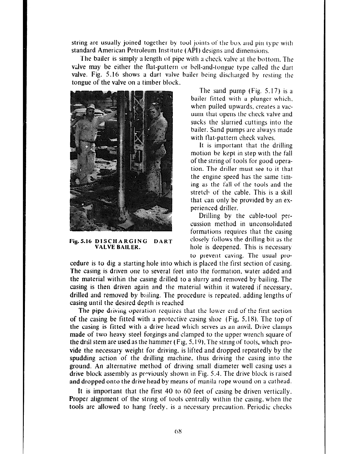
string are usually joined together by tool joints of the box and pin type with
standard American Petroleum institute (API) designs and dimensions.
The bailer is simply a length elf pipe with ;I check valve at the bottom. The
v&e may be either the tlat-pattern or bell-and-tongue type called the dart
valve. Fig. 5.16 shows a dart valve bailer being discharged by resting the
tongue of the valve on a timber block. The sand
pump
(Fig. 5.17) is a
bailer fitted with a plunger whicfl,
when puiled upwards, creates a vac-
uum that opens the check valve and
sucks the slurried cuttings into the
bailer. Sand pumps are always made
with flat-pattern check valves.
it is important that the drilling
motion be kept in step with tile fail
of the string of tools for good opera-
tion. The driller must see to it that
the engine speed has the same tim-
ing as the I’41 of the tools and the
stretch of the cable. This is a skill
that can only be provided by an ex-
perienced driller.
Drilling by the cable-tool Fer-
cussion method in unconsolidated
format ions requires that the casing
Fig.5.16 DISCHARGING DART
cfosefy follows the drilling bit as tile
VALVE BAILER.
hole is deepened. This is necessary
to prevent caving. The usual pro-
cedure is to dig a starting hole into which is placed the first section of casing.
The casing is driven one to several feet into the formation. water added and
the material within the casing drilled to a slurry and removed by bailing. The
casing is then driven again and the material within it watered if necessary.
drifted and removed by
b:tifing. The procedure is repeated, adding lengths ot
casing until the desired depth is reached
The pipe dliviug op
i-iiiiiiiii iCcjLiiiCS ikit iI12
IoWcr
C;:d
of the first section
of
the casing be fitted wit11 a protective casing shoe (Fig. 5.18). Tile top of
the casing is fitted with a drive head which serves as an anvil. Drive clamps
made
of two heavy steel forgings and clamped to the upper wrench square of
the
drill stem are used as the hammer (Fig. 5.19). The string of tools. which pro-
vide the necessary weight for drivin g. is lifted and dropped repeatedly by the
spudding
action of the drilling machine. thus driving the casing into the
ground. An
alternative method of driving small diameter well casing uses a
drive block
assembly as prL>viousfy shown in Fig. 5.4. The drive block is raised
and dropped
onto the drive head by means of manila rope wound on a cat head.
It is important that the first 40 to 60 feet of casing be driven vertically.
Proper aiignment of the string of tools centrally within the casing. when the
tools are allowed to hang freely. is a necessary precaution. Periodic checks
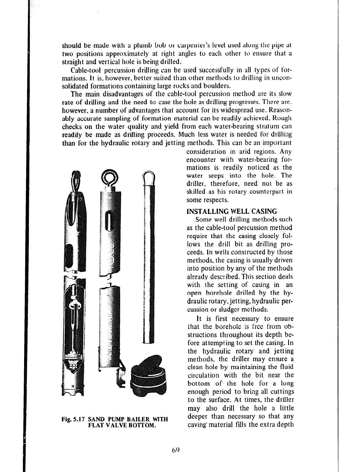
should be made with a plumb bob or carpenter’s level used along the pipe at
two positions approximately at right angles to each other to ensure that a
straight and vertical hole is being drilled.
Cable-tool percussion drilling can be used successfully in all types of for-
mations. It is. however. better suited than other methods to drilling in uncon-
solidated formations containing large rocks and boulders.
The main disadvantages of the cable-tool percussion method are its slow
rate of drilling and the need to case the hole as drilling progresses. There are.
however, a number of advantages that account for its widespread use. Reason-
ably accurate sampling of formation material can be readily achieved. Rough
checks on the water quality and yield from each water-bearing stratum can
readily be made as drilling proceeds. Much less water is needed for drilling
than for the hydraulic rotary and jetting methods. This can be an important
Fig. 5.17 SAND PUMP BAILER WITH
FLAT VALVE BOTTOM.
consideration in arid regions. Any
encounter with water-bearing for-
mations is readily noticed as the
water seeps into the hole. The
driller, therefore, need not be as
skilled as his rotary counterpart in
some respects.
INSTALLING WELL CASING
Some well drilling methods such
as the cable-tool percussion method
require that the casing closely fol-
lows the drill bit as drilling pro-
ceeds. In wells constructed by those
methods, the casing is usually driven
into position by any of the methods
already described. This section deals
with the setting of casing in an
open borehole drilled by the hy-
draulic rotary, jetting, hydraulic per-
cussion or sludger methods.
It is first necessary to ensure
that the borehole is free from ob-
structions throughout its depth be-
fore attempting to set the casing. In
the hydraulic rotary and jetting
methods, the driller may ensure a
clean hole by maintaining the fluid
circulation with the bit near the
bottom of the hole for a long
enough period to bring all cuttings
to the surface. At times, the driller
may also drill the hole a little
deeper than necessary so that any
caving-material fills the extra depth
69
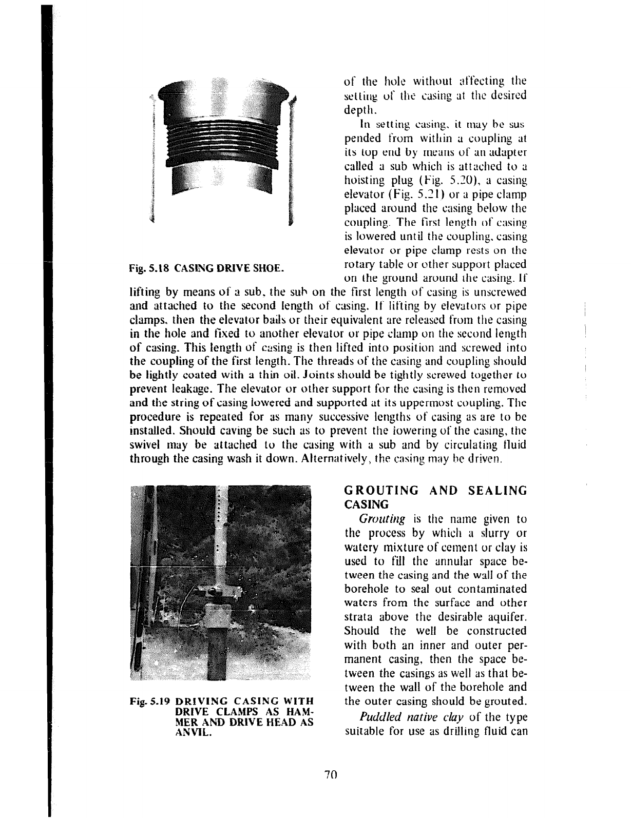
of the hole without affecting the
settirkg
ui‘ the casing at the dcsircd
depth.
In setting casing.
it may be
sus-
pended from witllin a coupling at
its top end by means of an adapter
called a sub which is attached to a
hoisting plug (Fig. 5.X), a casing
elevator (Fig. 5.2 1) or a pipe clamp
placed around the casing below the
coupling. The first length of casing
is lowered until the coupling. casing
elevator or pipe clamp rests on the
rotary table or other support placed
on the ground around the casing. If
.I
Fig. 5.18 CAStbiG DRIVE SHOE.
lifting
by means of a sub. the sub on the first length of casing is unscrewed
and attached to the second
length of casing. If lifting by elevators or pipe
clamps, then
the elevator bails or their equivalent are released from the casing
in the hole and fixed
to another elevator or pipe clamp on the second length
of casing. This length of casing is then lifted into position and screwed into
the coupling of the first length.
The
threads
of the casing
and
coupling should
be lightly coated
with a thin oil. Joints should be tightly screwed together to
prevent
leakage. The elevator or otfler support for the casing is then removed
and the string
of casing lowered
and
supported at its uppermost coupling. The
procedure is repeated for as
many successive lengths of casing as are to bc
installed. Should caving
be such as to prevent the lowering of the casing, the
swivel may be attached to the casing with a sub and by circulating tluid
through the casing
wash it down. Alternatively, the c:~ing may be driven.
GROUTING AND SEALING
CASING
;#j$$
”
,,__ _,‘ ,/Y, _
Fig.219 DRIVING CASING WITH
DRIVE CLAMPS AS HAM-
MER AEiD DRIVE HEAD AS
ANVIL.
Grolitil2g is the name given to
the process by which a slurry or
watery mixture of cement or clay is
used to fill the annular space be-
tween the casing and the wall of the
borehole to seal out contaminated
waters from the surface and other
strata above the desirable aquifer.
Should the well be constructed
with both an inner and outer per-
manent casing, then the space be-
tween the casings as well as that be-
tween the wall of the borehole and
the outer casing should be grouted.
Puddled native cluy of the type
suitable for
use
as drilling fluid can
70
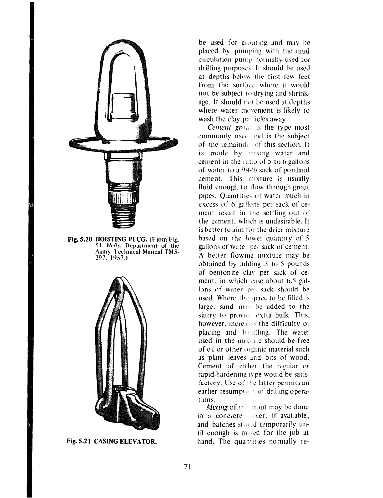
Fig. 5.20 HOKTING PLUG.
(From Fig.
5 1 Wk. Dcpartmcnt of the
Army I cchnical Manual TM5-
297. 19.57.)
Fig. 5.2 I CASING ELEVATOR.
be used for glcruting and may be
placed by pumicing with the mud
circulation pundit nvrmally used for
drifting purpose\ 1 I should he used
at depths belt)\\ the first few feet
from the surtlli< where it would
not be subject to drying and shrink-
age. It should 11kbt he used at depths
where water nncjc,ement is likely to
wash the clay p,;!iicfes away.
ctv?ltw t
p-t ) i l is the type most
commonly ust.~~ irld is the subject
of the renisind~ 01‘ this section. It
is made by rlxslng water and
cement in the I;I~IO of 5 to
6 gaitons
of water to a cU-tb sack of portland
cement. This mixture is usually
fluid enough to tlvw through grout
pipes. Quant ir Ic’\ ot‘ water 1nuc11 in
excess of h gallons per sack of ce-
nient result in the settling out ot
the cement. wll1~11 is undesirable. It
is better toaim t‘or the drier mixture
based on the Io~ver quurltity of‘ 5
gallons of water peg- sack ot‘ c‘ement.
A better tloiving tnisture may be
obtained by uddtng 3 to 5 pounds
of bentonite cla>. per sack ot‘ ce-
ment. in which case about 6.5 gal-
lons of water 1’;‘;’ sack should be
used. Where tl1.i ,!~ce to be filled is
large. sand 111.l he added to the
slurry to provli cstra bulk. This,
however. incrc.t \ the difficulty 01
placing and 11. iifirlg. The water
used in tfle m~\~l.~rc should be free
of oil or other oIg2nic material sucfi
as plant leaves dnd bits of wood.
Cement of either the regular or
rapid-hardening r>.pe would be satis-
factory. llse ot‘ r/12 latter perrnits an
earlier resump’ of drilling opera-
t ions.
Mi3iug of rl~ I out may be done
in a concietc hxr, if available,
and batches stir’ _i temporarily un-
til enough is nli ted for the job at
hand. The quanlit ies normally re-
71
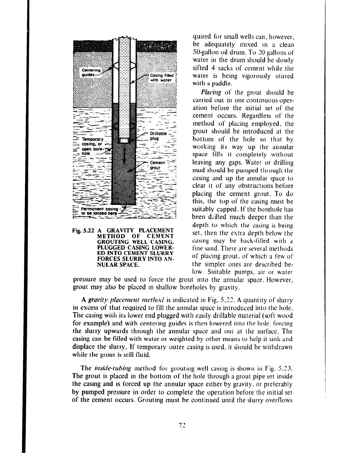
quired for small wells can, however,
be adequately mixed in a clean
SO-gallon oil drum. To 20 gallons of
water in the drum should be slowly
sifted 4 sacks of cetnent while the
water is being vigorously stirred
with a paddle.
Placirzg of the grout should be
carried out in one continuous oper-
ation before the initial set of the
cement occurs. Regardless of the
method of placing employed, the
grout should be introduced at the
bottom of the hole so that bY
working its way up the annular
space fil!s it completely without
leaving any gaps. Water or drilling
mud should be pumped through the
casing and up the annular space to
clear it of any obstructions before
placing the cement grout. To do
this. the top of the casing must be
suitably capped. If the borehole has
been drilled much deeper than the
depth to which the casing is being
set. then the extra depth below the
casing tnlty be back-filled with a
fine sand. There are several methods
of placing grout. of which ;1 few of
the simpler ones are described be-
low. Suitable pumps. air or water
Fig. 5.22 A GRAVITY PLACEMENT
METHOD OF CEMENT
GROUTING WELL CASING.
PLUGGED CASING LOWER-
ED INTO CEMENT SLURRY
FORCES SLURRY lNT0 AN-
NULAR SPACE.
pressure may be used to force the grout into the annular space. However,
grout may also be placed in shallow boreholes by gravity.
A gruvit~~ p~accrmwt m~tiwd is indicated in Fig. 5.22. A quantity of slurry
in excess of that required to fill the annular space is introduced into the hole.
The casing with its lower end plugged with easily drillable material (soft wood
for example) and with centering guides is then lowered into the hole, forcing
the slurry upwards through the annular space and out at the surface. The
casing can be filled with water or weighted by other means to help it sink and
displace the slurry. If temporary outer casing is used. it should be withdrawn
while the grout is still fluid.
The imide-trrbir~g method for grouting well casing is shown in Fig. 5.23.
The grout is placed in the bottom of the hole through ;1 grout pipe set inside
the casing and is forced up the annular space either by gravity. or preferably
by pumped pressure in order to complete the operation before the initial set
of the cement occurs. Grouting must be continued until the slurry overflows
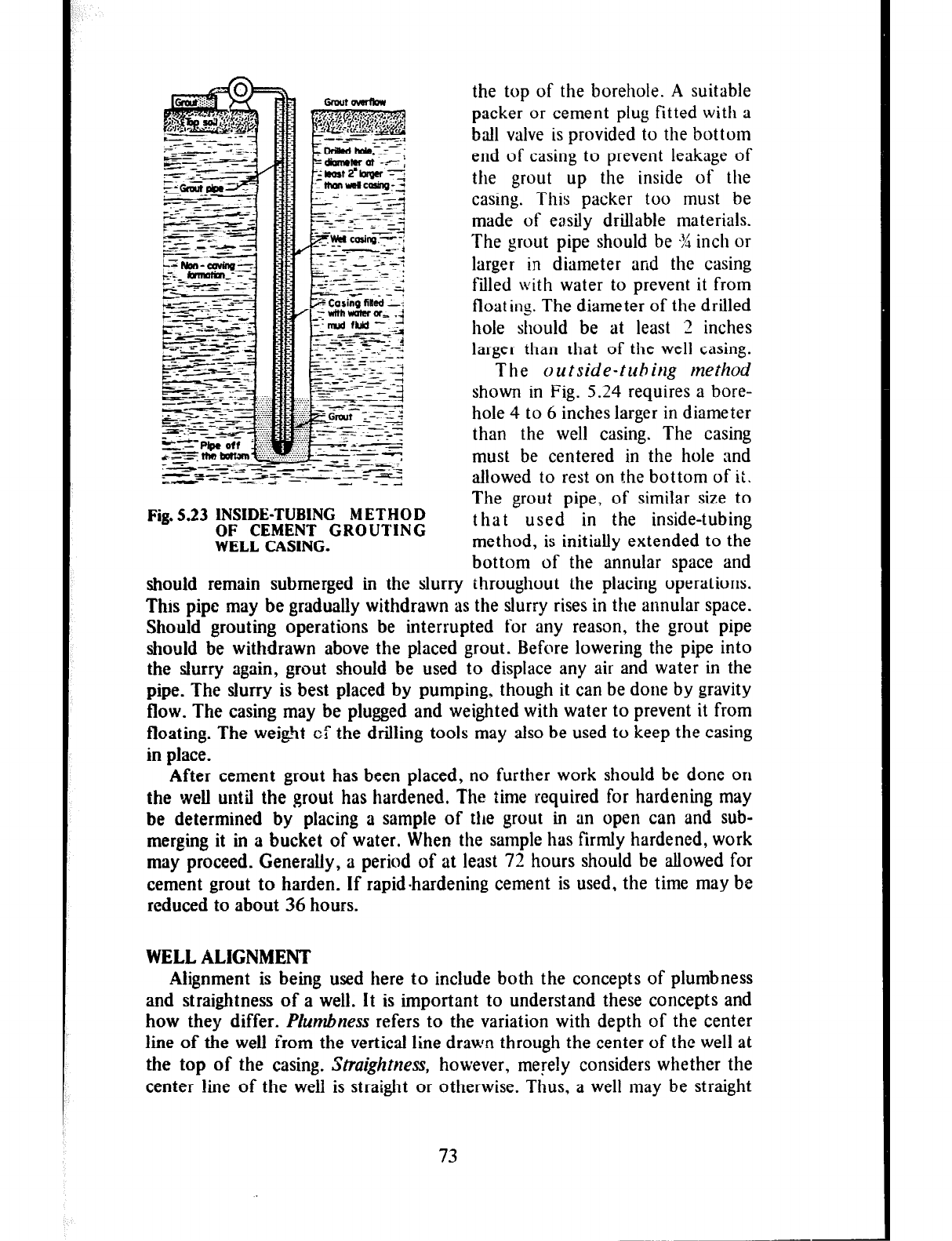
the top of the borehole. A suitable
packer or cement plug fitted with a
ball valve is provided to the bottom
end of casing to prevent leakage of
the grout up the inside of the
casing. This packer too must be
made of easily drillable materials.
The grout pipe should be -% inch or
larger in diameter and the casing
filled with water to prevent it from
float in:. The diameter of the drilled
hole should be at least 2 inches
larger than that of the well casing.
The
outside-tuhitzg method
Fig. 5.23 INSIDE-TUBING METHOD
OF CEMENT GROUTING
WELL CASING.
shown in Fig. 5.24 requires a bore-
hole 4 to 6 inches larger in diameter
than the well casing. The casing
must be centered in the hole and
allowed to rest on the bottom of it.
The grout pipe, of similar size to
that used in the inside-tubing
method, is initially extended to the
bottom of the annular space and
should remain submerged
in
the
slurry throughout the placing operations.
This pipe may be gradually withdrawn
as the slurry rises in the annular space.
Should grouting operations be interrupted
for any reason, the grout pipe
should be withdrawn above the placed grout.
Before
lowering the pipe into
the slurry again, grout should be used to displace any
air and water in the
pipe. The slurry is best placed by pumping,
though it can be done by gravity
flow. The casing may be plugged and weighted
with water to prevent it from
floating. The we@ of the drilling tools may also be used to keep the casing
in place.
After cement grout has been placed, no further work should be done on
the weIl until the grout has hardened.
The
time required for hardening may
be determined by placing a sample of the grout in
an
open can and sub-
merging it in a bucket of water. When
the sample
has firmly hardened, work
may proceed. Generally, a period of at least 72 hours should be allowed for
cement grout to harden. If rapid-hardening cement is used,
the time may be
reduced to about 36 hours.
WELL ALIGNMENT
Alignment is being used here to include both the concepts of plumbness
and straightness of a well. It is important to understand these concepts and
how they differ. Plumbness
refers to the variation with depth of the center
line of the well from the vertical line drawn through the center of the well at
the top of the casing. Straightness, however, melely considers whether the
center line of the weli is straight or otherwise.
Thus, a well may be straight
73
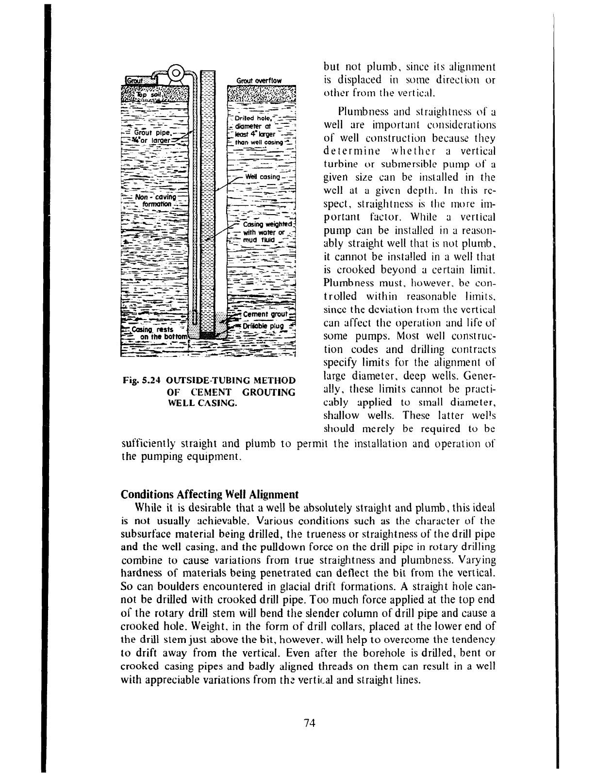
Fig. 5.24 OUI’SIDE-TUBING METHOD
OF CEMENT GROUTING
WELL CASING.
but not plumb, since its alignment
is displaced in some direction or
other from the vertic;il.
Plumbness and straightness of a
well are important cr)nsiderations
of well construction because they
determine whether a vertical
turbine or subtnersible put~ip of a
givert size can be installed in the
well at a given depth. In this re-
spect, straightness is the more im-
portant fsctor. While 3 vertical
pump can be installed in a reason-
ably straight well that is not plumb,
it cannot be insta!led in a well that
is crooked beyond a certain limit.
Plumbness must, however. be con-
trolled within reasonable limits.
since the deviation tram the vertical
can affect the operation and life of
some pumps. Most well construc-
tion codes and drilling contracts
specify limits for the alignment of
large diameter, deep wells. Gener-
ally, these limits cannot be practi-
cably applied to stnall diameter,
shallow wells. These latter wells
should merely be required to be
sufficiently straight and piumb to permit the installation and operation of
the pumping equipment.
Conditions Affecting Well Alignment
While it is desirable that a well be absolutely straight and plumb, this ideal
is not usually achievable. Various conditions such as the character of the
subsurface material being drilled, the trueness or straightness of the drill pipe
and the well casing, and the pulldown force on the drill pipe in rotary drilling
combine to cause variations from true straightness and plutnbness. Varying
hardness of materials being penetrated can deflect the bit from the vertical.
So can boulders encountered in glacial drift formations. A straight hole can-
not be drilled with crooked drill pipe. Too much force applied at the top end
of the rotary drill stem will bend the slender column of drill pipe and cause a
crooked hole. Weight. in the form of drill collars, placed at the lower end of
the drill stem just above the bit, however. will help to overcome the tendency
to drift away from the vertical. Even after the borehole is drilled, bent or
crooked casing pipes and badly aligned threads on them can result in a well
with appreciable variations from thz vertical and straight lines.
74
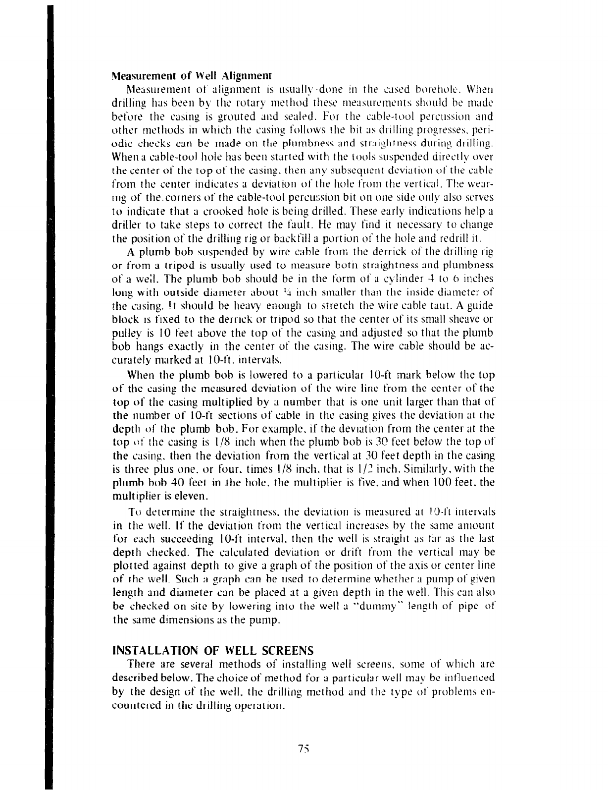
Measurement of Well .4lignment
hleasurement of alignment is usuall>~ .dune in the cased b~~rehc~it;. Wll~r~
drilling has been b>, the rotary method these
1ne;1surc1nc1~ts
sh~~uld be made
before the casing is grouted dl:d sealrd. For the txbl~-tool pcrcnssion and
orhcr methods in which the casing follows the bit as drilling progresses. peri-
odic checks can be made on tfle plurnbrress and strsiglltness during drilling.
Whena
cable-tool hole has been started with the pools suspended directly ovei
the center of the top of the c‘;lsin
g. then any subsequent deviation ot‘ the cable
from the center indicates 3 deviation of the hole from the vertical. The wear-
irlg of the.corners of the cable-tool percussion bit on one side only also serves
to indicate that 3 crooked hole is being drilled. These early indications help a
driller to take steps to correct the fault. He may find it necessary to change
the position of the drillilig rig or backfill ;t portion of the hole and redrill it.
A plumb bob suspended by wire cable from the derrick of the drilling rig
or from ;1 tripod is usually used to measure both straightness and plumbness
of ;L weit. The plumb bob should be in the form of 3 cvlinder 4 to h inches
long with outside diameter about ‘4 inc*h smaller than t-he inside dittmeter of
the casing. !t should be heave enough to stretch the wire cable taut. A guide
block is fixed to the derrick ;r tripod so that the center of its small sheave L)I
pulley is 10 feet above the top of the asin g and adjusted so that the plumb
bob hangs exactly in the center of tile casing. The wire cable should be ac-
curately marked at IO-ft. intervals.
When the
plumb bob is lowered to ;I particular IO-ft mark below the top
of the casing the measured deviation of the wire line from the center of the
top of the casing multiplied by 3 number that is one unit larger than that of
the number of IO-ft sections of able in the casing gives the deviation at the
depth 01‘ the plumb bob. For example. if the deviation from the center at the
lop c:t rhe casing is !/X inch when the plumb bob is 3C feet be!ow the top of
the casing. then the deviation from the vertical at 30 feet depth in the casing
is three plus one. or four. times l/S inch. that is I/J inch. Similarly. with the
plumb bob 40 feet in .the hole. the multiplier is five, and when 100 feet, the
multiplier is eleven.
7‘0 determine the straightness. the deviation is measured at I ‘3-ft intervals
in the wc1I. If the deviation from the vertical increases by the UIIIC amount
for each succeeding IO-ft interval. then the well is straight as CJr as the last
depth checked. The calculated deviation or drift from the vertical may be
plotted against depth to give a graph of the position of the axis or center line
of the well. Such a graph can be used to determine whether ;I pump of given
length and diameter can be placed at a given depth in the well. This can also
be checked on site by lowering inro rhe well a “dummy” length of pipe ot
the same dimensions ;IS the pump.
INSTALLATION OF WELL SCREENS
There are several methods of installing well screens, some of which are
described below. The choice of method for ;1 pxficular well Inay be intluenced
by the design of the well, the drillin g method and the tvpe of problems en-
countered in the drilling operrltion.
75
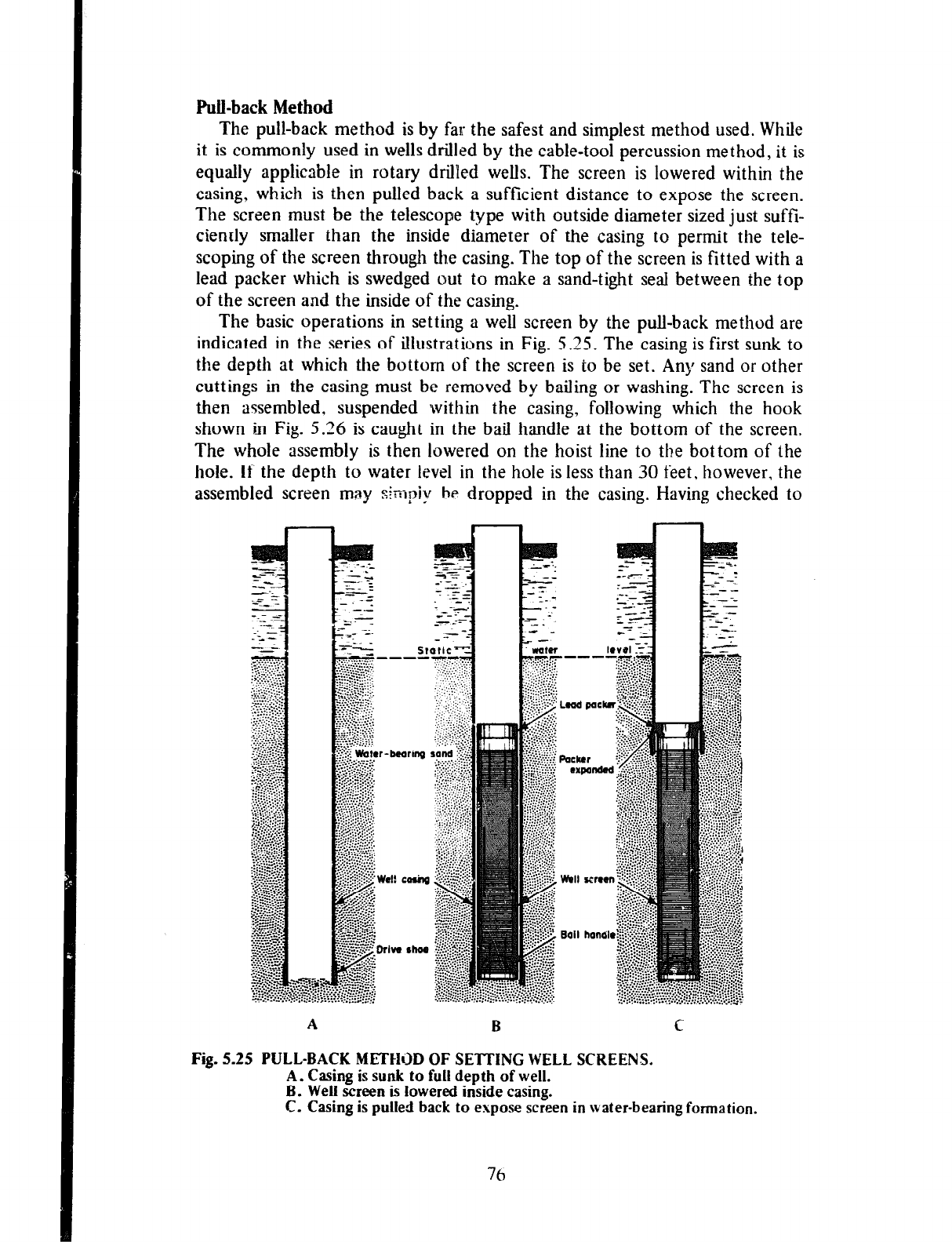
Pull-back Method
The pull-back method is by far the safest and simplest method used. While
it is commonly used in wells drilled by the cable-tool percussion method, it is
equally applicable in rotary drilled wells. The screen is lowered within the
casing, which is then pulled back a sufficient distance to expose the screen.
The screen must be the telescope type with outside diameter sized just suffi-
ciently smaller than the inside diameter of the casing to permit the tele-
scoping of the screen through the casing. The top of the screen is fitted with a
lead packer which is swedged out to make a sand-tight seal between the top
of the screen and the inside of the casing.
The basic operations in setting a well screen by the pull-back method are
indicated in the series of illustrations in Fig. 5.25. The casing is first sunk to
the depth at which the bottorn of the screen is to be set. Any sand or other
cuttings in the casing must be removed by bailing or washing. The screen is
then assembled. suspended within the casing, following which the hook
shown in Fig. 5.26 is
caught
in the bail handle at the bottom of the screen.
The whole assembly is then lowered on the hoist line to the bottom of the
hole. If the depth to water level in the hole is less than 30 feet, however, the
assembled screen may simpi,w he dropped in the casing. Having checked to
_
Fig. 5.25 PULL-BACK METIIGD OF SETTING WELL SCREENS.
A. Casing is sunk to full depth of well.
B. Well screen is lowered inside casing.
C. Casing is pulied back to expose screen in water-bearing formation.
76
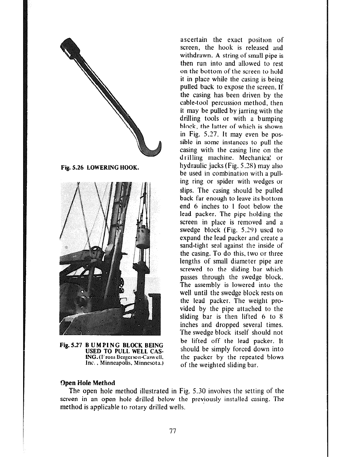
Fig. 5.26 LOWERING HOOK.
Fig. 5.27 B U M PI N G BLOCK BEING
USED TO PULL WELL CAS-
ING.(From Bergerson-Caswell,
Inc. , Minneapolis, Minnesota.)
Open Hole Method
ascertain the exact positron of
screen, the hook is released and
withdrawn.
A
string of small pipe is
then run into and allowed to rest
on the bottom of the screen to hold
it in place white the casing is being
pulled back to expose the screen. If
the casing has been driven by the
cable-tool percussion method, then
it may be pulled by jarring with the
drilling tools or with a bumping
block, the latter of which is shown
in Fig. 5.27. It may even be pos-
sible in some instances to pull the
casing with the casing line on the
drilling machine. I’vlechanicd or
hydraulic jacks (Fig. 5.38) may also
be used in combination with a pull-
ing ring or spider with wedges or
slips. The casing should be pulled
back far enough to leave its bottom
end 6 inches to 1 foot below the
lead packer. The pipe holding the
screen in place is removed and a
swedge block (Fig. 5.29) used to
expand the lead packer and create a
sand-tight seal against the inside of
the casing. To do this. two or three
iengths of small diameter pipe are
screwed to the sliding bar which
passes through the swedge block.
The assembly is lowered into the
well until the swcdge block rests on
the lead packer. The weight pro-
vided by the pipe attached to the
sliding bar is then lifted 6 to 8
inches and dropped several times.
The swedge block itself should not
be lifted off the lead packer. It
should be simply forced down into
the packer by the repeated blows
of the weighted sliding bar.
The open hole method illustrated in Fig. 5.30 involves the setting of the
screen in an open hole drilled below the previously installed casing. The
.
method is applicable to rotary drilled wells.
77
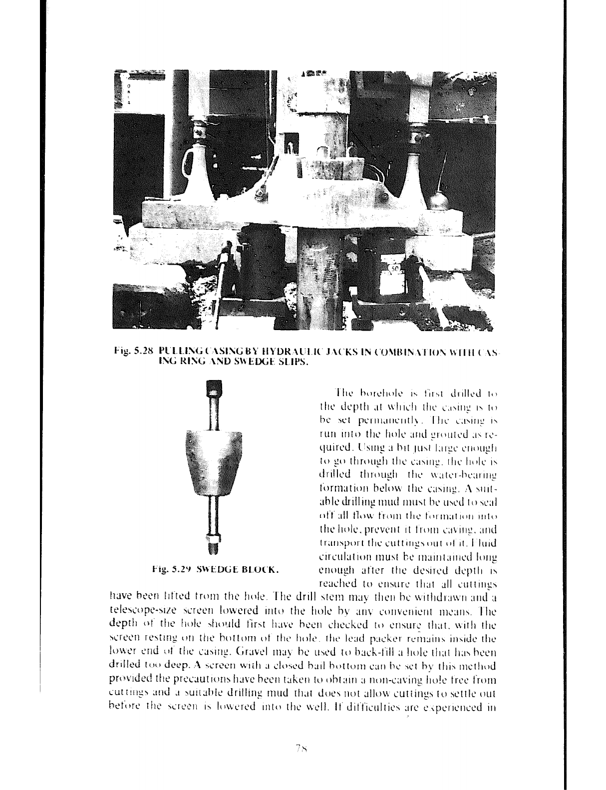
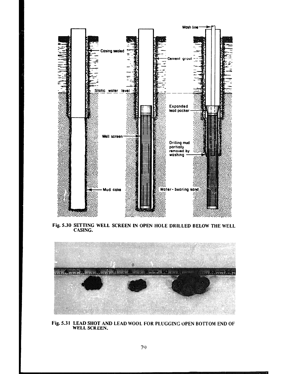
Wash line-
r
.Cemsnt grout ,’
Exoanded .?:i
leab pucker
Drilling mud
Wrtially
washing L
Fig. 5.30 SETTING WELL SCREEN IN OPEN HOLE DRILLED BELOW THE WELL
CASING.
Fig. 5.31 LEAD SHOT AND LEAD WOOL FOR PLUGGING OPEN BOTTOM END OF
WELL SCREEN.
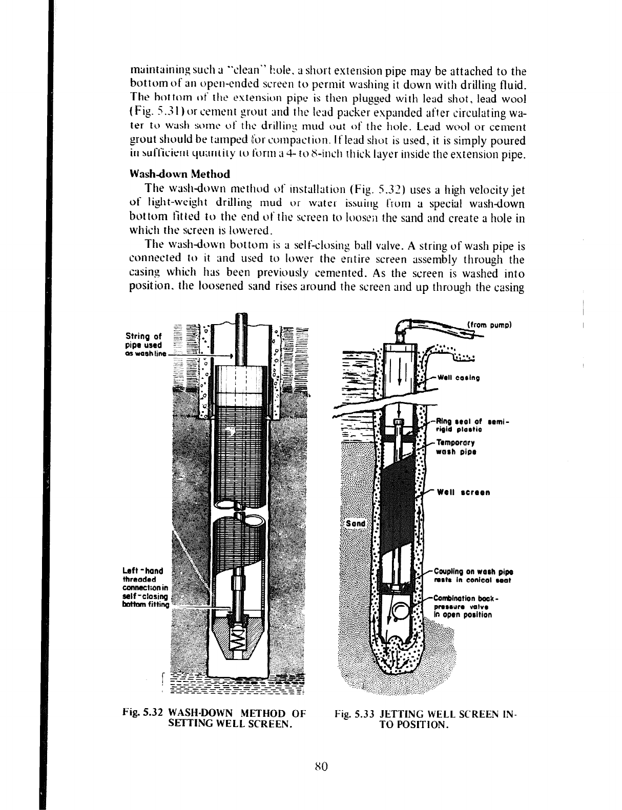
maintaining such 3 “dean”
hole. ;1 short extension pipe may be attached to the
bottom of 311 open-ended screen to permit washing it down with drilling fluid.
The bottom of the extension pipt’ is then plugged with lead shot, lead wool
( Fig. 5.3 I ) or cement grout and the lead pucker expanded after circulating wa-
ter to wash some of the drillins mud out of the hole. Lead wool or cement
grout should be tamped ifor comprtction. If lead shot is used. it is simply poured
in sufficient qu:tntity to form ;I 4 to ti-inch thick layer inside the extension pipe.
Wash&w Method
The wash-down method of instttllation (Fig. 5.32) uses a high velocity jet
of Ii&t-weight drilling mud or water issuing from a special washdown
bottom fit ted to the end of the screen to loosen the sand :md create ;1 hole in
which the screen is lowered.
The washdown bottom is a self-closing ball valve.
A
string of wash pipe is
connected to it and used to lower the entire screen assembly through the
casing which has been previously cemented.
As
the screen is washed into
position. the loosened sand rises around the screen and up through the asing
Fig. 5.32 WASH-DOWN METHOD OF
SETTING WELL SCREEN.
X0
Well rcrrrn
Coupling on uaah pipe
fun18 In conkot aoat
Combination back-
Fig.
5.33 JETTING WELL SCREEN IN-
TO POSITION.
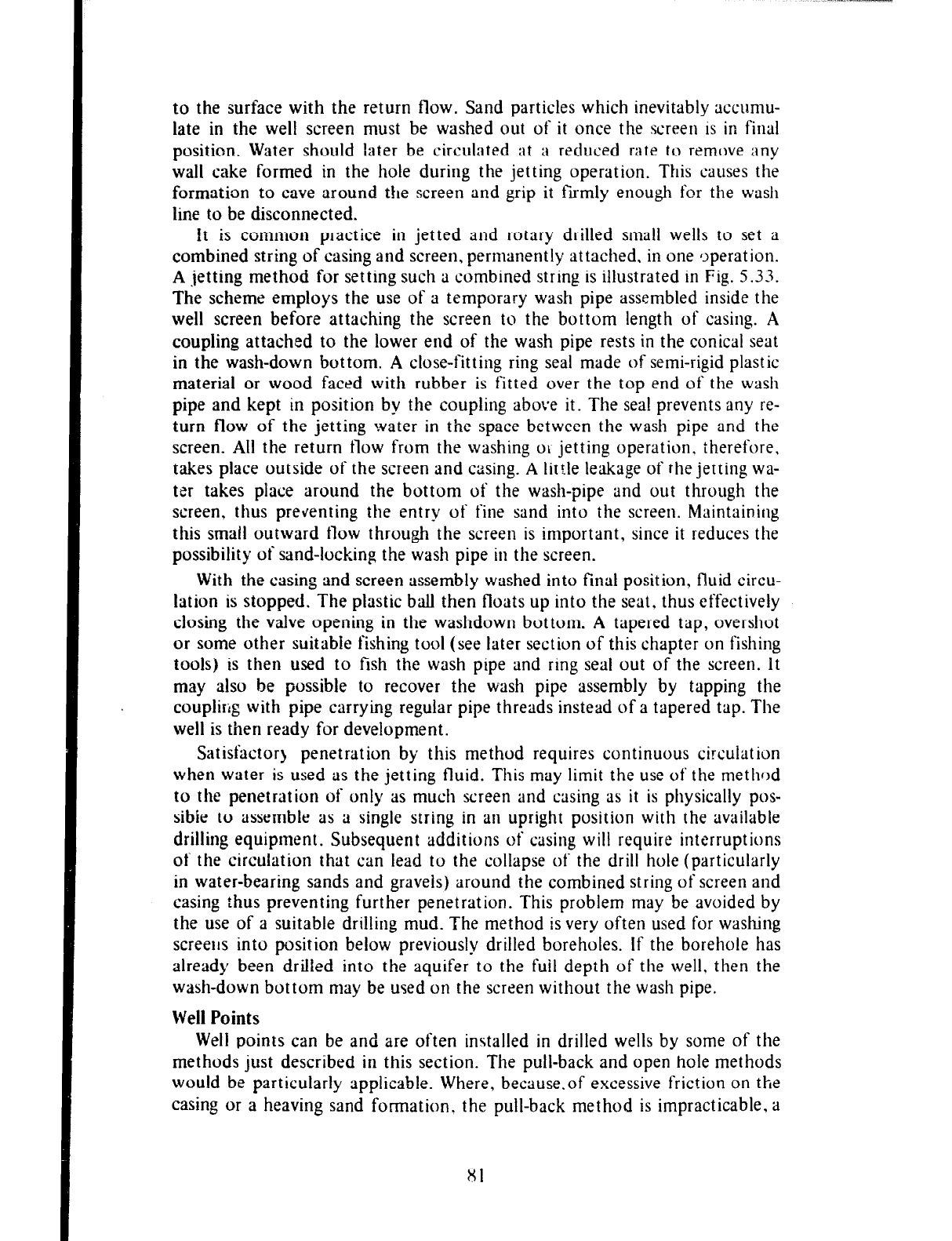
to the surface with the return flow. Sand particles which inevitably accumu-
late in the well screen must be washed out of it once the screen is in final
position. Water should later be circulated at a reduced rate to remove any
wall cake formed in the hole during the jetting operation. This causes the
formation to cave around the screen and grip it firmly enough for the wash
line to be disconnected.
it is common practice in jetted and rotary drilled small wells to set a
combined string of casing and screen, permanently attached. in one IJperation.
A jetting method for setting such a combined string is illustrated in Fig. 5.33.
The scheme employs the use of a temporary wash pipe assembled inside the
well screen before attaching the screen to the bottom length of casing. A
coupling attached to the lower end of the wash pipe rests in the conical seat
in the wash-down bottom. A close-fitting ring seal made of semi-rigid plastic
material or wood faced with rubber is fitted over the top end of the wash
pipe and kept in position by the coupling above it. The seal prevents any re-
turn flow of the jetting water in the space between the wash pipe and the
screen. All the return flow from the washing OL jetting operation, therefore,
takes place outside of the screen and casing. A little leakage of the jetting wa-
ter takes place around the bottom of the wash-pipe and out through the
screen, thus preventing the entry of fine sand into the screen. Maintaining
this small outward flow through the screen is important, since it reduces the
possibility of sand-locking the wash pipe in the screen.
With the casing and screen assembly washed into final position, fluid circu-
lation is stopped. The plastic ball then floats up into the seat, thus effectively
closing the valve opening in the washdown bottom. A tapered tap, overshot
or some other suitable fishing tool (see later section of this chapter on fishing
tools) is then used to fish the wash pipe and ring seal out of the screen. It
may also be possible to recover the wash pipe assembly by tapping the
coupling with pipe carrying regular pipe threads instead of a tapered tap. The
well is then ready for development.
Satisfactor> penetration by this method requires continuous circulation
when water is used as the jetting fluid. This may limit the use of the method
to the penetration of only as much screen and casing as it is physically pos-
sibie to assemble as a single string in an upright position with the available
drilling equipment. Subsequent additions of casing will require interruptions
of the circulation that can lead to the collapse of the drill hole (particularly
in water-bearing sands and gravels) around the combined string of screen and
casing thus preventing further penetration. This problem may be avoided by
the use of a suitable driIling mud. The method is very often used for washing
screens into position below previously drilled boreholes. If the borehole has
already been drilled into the aquifer to the full depth of the well, then the
wash-down bottom may be u3ed on the screen without the wash pipe.
Well Points
Well
points can be and are often installed in drilled wells by some of the
methods just described in this section. The pull-back and open hole methods
would be particularly applicable. Where, because.of excessive friction on the
casing or a heaving sand formation. the pull-back method is impracticable, a
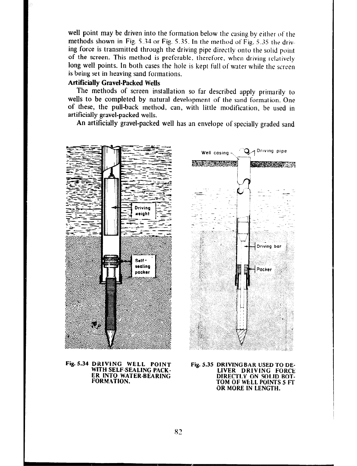
well point may be driven into the formation below the casing by either of the
methods shown in Fig. 5.34 or Fig. 5.35. In the method of Fig. 5.35 the driv-
ing force is transmitted through the driving pipe directly onto the solid poitlt
of the screen. This method is preferable, therefore, when driving relatively
long well points. In both cases the hole is kept full of water while the screen
is being set in heaving sand formations.
ttrtificially Gravel-Packed Wells
The methods of screen installation so far described apply primarily to
wells to be completed by natural development of the sand formation. One
of &ese, the pull-back method, can, with little modification, be used in
artificiaiiy gravel-packed wells.
An
artificidil!y
gravel-packed well has an envelope of specially graded sand
Fig.5.34 DRIVING WELL POINT
WITH SELF-SEALING PACK-
ER INTO WATER-BEARING
FORMATION.
Well casing -\ ’ ‘Q/I Drlvlng pipe
Fig. 5.35 DRIVING BAR USED TO DE-
LIVER DRIVING FORCE
DIRECTLY ON SOLID BOT-
TOM OF WELL POINTS 5 Fi-
OR MORE IN LENGTH.
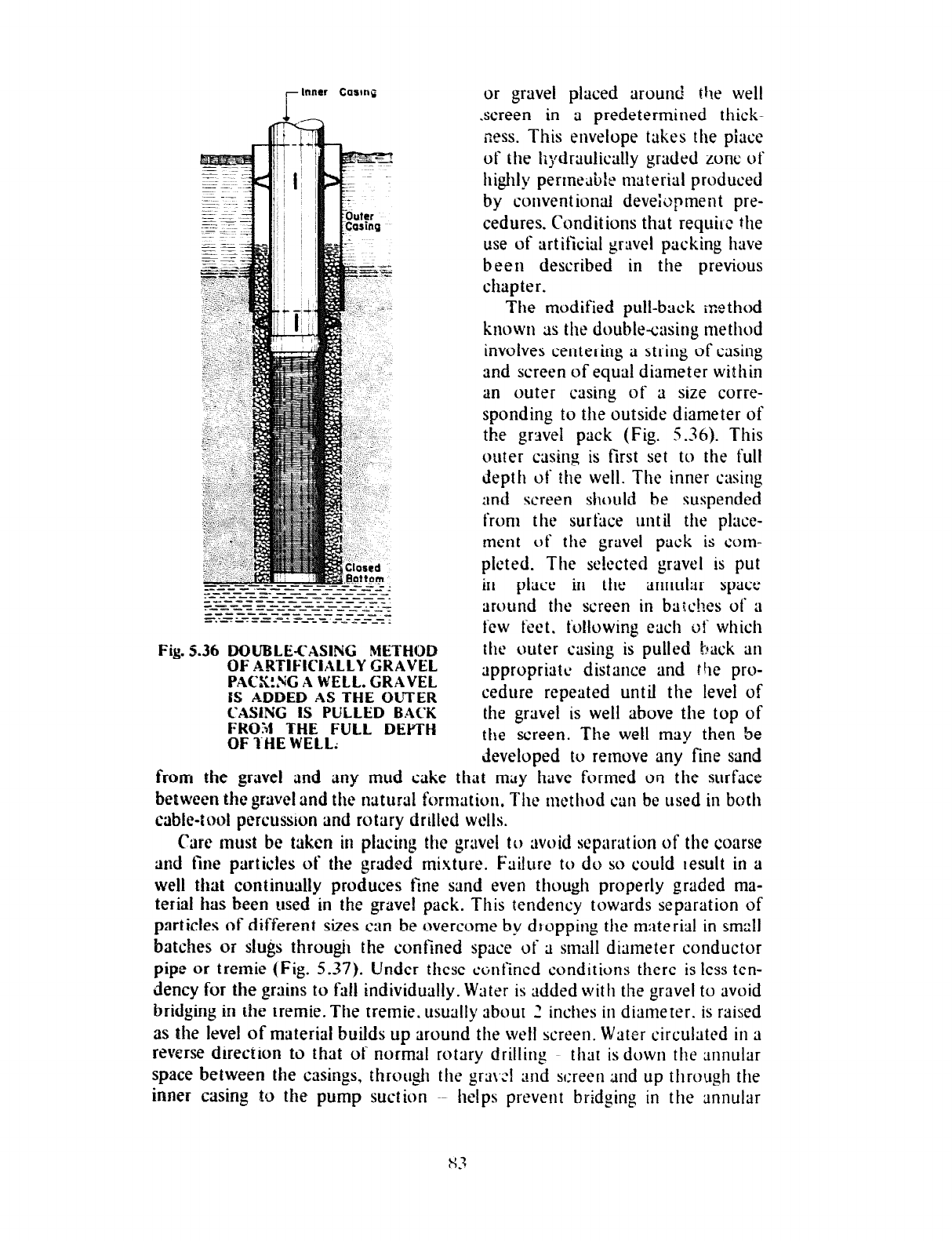
-Inner Carm~
Fig. 5.36 DOUBLE-CASING METHOD
OF ARTIFICIALLY GRAVEL
PACK!,% A WELL. GRAVEL
IS ADDED AS THE OUTER
CASING IS PULLED BACK
FRO:4 THE FULL DEPTH
OF I-HE WELL;
or gravel placed around the well
screen in a predetermined thick-
zess. This envelope takes the piace
of the hydraulically graded zone of
highly permeable material produced
by conventionti development pre-
cedures. Conditions that requil-c the
use of artificial gravel packing have
been described in the previous
chapter.
The modified pull-back method
known as the double-casing method
involves centering a string of casing
and screen of equal diameter within
an outer casing of a size corre-
sponding to the outside diameter of
the gravel pack (Fig. 5.36). This
outer casing is first set to the full
depth of the well. The inner casing
and screen should be suspended
from the surface until the place-
ment of the gravel pack is com-
plcted. The selected gravel is put
in place in the annular space
around the screen in bax!?es of a
few feet. following each of which
the outer casing is pulled hack an
appropriate distance and the pro-
cedure repeated until the level of
the gravel is well above the top of
the screen. The well may then be
developed to remove any fine sand
from the gravel
and
any mud cake that may have formed on the surface
between the gravel and the natural formation, The method can be used in both
cable-tool percussion and rotary drilled wells.
Care must be taken in placing the gravel to avoid separation of the coarse
and fine particles of the graded mixture. Failure to do so could result in a
well that continually produces fine sand even though properly graded ma-
terial has been used in the gravel pack. This tendency towards separation of
particles of different sizes can be overcome by dropping the material in small
batches or slugs through the confined space of a small diameter conductor
pipe or tremie (Fig. 5.37). Under these confined conditions there is less ten-
dency for the grains to fAl individually. Water is added with the gravel to avoid
bridging in the tremie. The tremie. usually about _ ’ inches in diameter. is raised
as the level of material builds up around the well screen. Water circulated in a
reverse direction to that of normal rotary drilling that is down the annular
space between the casings, through the gra\A and screen and up through the
inner casing to the pump suction ~~ helps prevent bridging in the annular
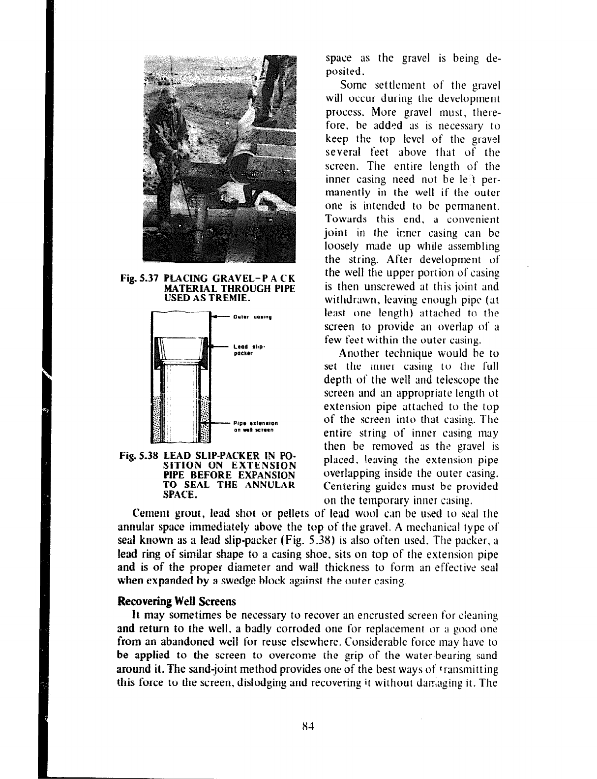
Fig. 5.37 PLACING GRAVEL-PACK
MATERiAL THROUGH PIPE
USEDASTREMIE.
Fig.538 LEAD SLIP-PACKER IN PO-
SITION ON EXTENSION
PIPE BEFORE EXPANSION
TO SEAL THE ANNULAR
SPACE.
Another technique would be to
set the inner casing to the full
depth of the well and telescope the
screen and
an
appropriate length of
extension pipe attached to the top
of the screen into? that casing. The
entire string of inner casing nrrly
then be removed as ths gravel is
placed. !eaving the extension pipe
overlapping inside the outer casing.
Centering guides must be provided
on the temporary inner casing.
Cement
grout, lead shot or
pellets of lead wool can be
llscd to
seal the
annular space immediately above the top of the gravel. A
mechanical type ot
seal known as a
lead
slip-packer (Fig. 5.38) is also often
used.
The packer. a
lead ring
of similar shape to a casing shoe, sits on top of the extension pipe
and is of the proper diameter
and wall thickness to form an effective seal
when expanded by a swedge block against the outer
casing.
Recovering Well Screens
It may sometimes be
necessary to recover an encrusted screen for cleaning
and return to the well, a badly
corroded one for replacement or a good one
from an abandoned weil for
reuse elsewhere.
C‘onsiderable force
may have to
be applied to the screen to overcome the grip
of the water-bearing sand
around it. The sand-joint
method provides one of the best ways of transmitting
this force to the screen, dislodging and recovering it without daE,aging it. The
space
as the gravel is being de-
posited.
Some settlement of the gravel
will occur during the development
process. More gravel must, there-
fore. be added as is necessary to
keep the top level of the gravel
several feet
above that of the
screen. The entire length of the
inner casing need not be le ‘t per-
manently in the well if the outer
one is intended to be permanent.
Towards this
end, a convenient
joint in the inner casing can be
loosely made up while assembling
the string. After development of
the well the upper portion of casing
is then unscrewed at this joint and
withdrawn, leaving enough pipe (at
least one length) attached to the
screen to provide an overlap of a
few feet within the outer
CilSillg.
x4
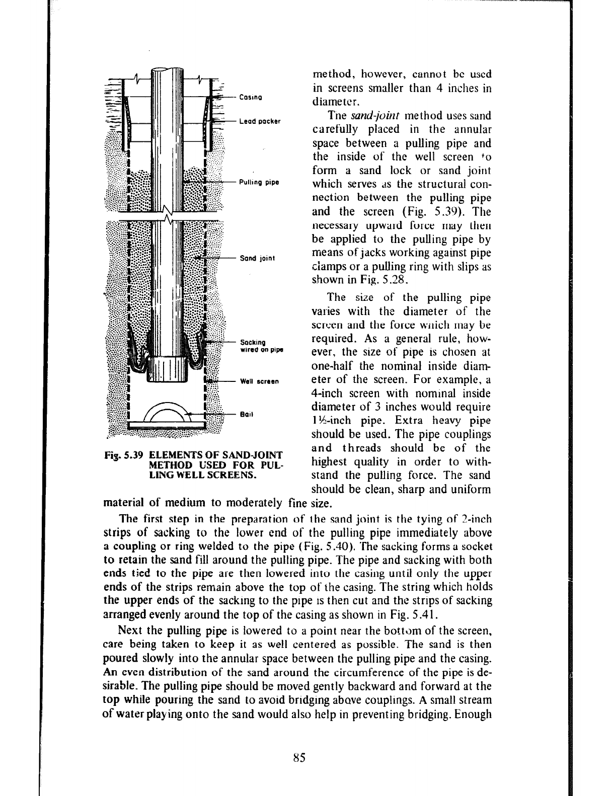
Lead packer
Pulhg pipe
Sand join1
Sacking
wired on pipe
Well screen
Ball
Fig. 5.39 ELEMENTS OF SAND-JOINT
METHOD USED FOR PUL-
LiNG WELL SCREENS.
method, however, cannot be used
in screens smaller than 4 inches in
diameter.
The
sand-joint
method uses sand
carefully placed in the annular
space between a pulling pipe and
the inside of the well screen +o
form a sand lock or sand joint
which serves ‘is the structural con-
nection between the pulling pipe
and the screen (Fig. 5.39). The
necessary upward force may then
be applied to the pulling pipe by
means of jacks working against pipe
ciamps or a pulling ring with slips as
shown in Fig. 5 28.
The size of the pulling pipe
varies with the diameter of the
scrl:en and the force wnich may be
required. As a general rule, how-
ever, the size of pipe is chosen at
one-half the nominal inside diam-
eter of the screen. For example, a
4-inch screen with nominal inside
diameter of 3 inches would require
1 ?&inch pipe. Extra heavy pipe
should be used. The pipe couplings
and threads should be of the
highest quality in order to with-
stand the pullin, 0 force. The sand
should be clean, sharp and uniform
material of medium to moderately tine size.
The first step in the preparation of the sand joint is the tying of Z-inch
strips of sacking to the lower end of the pulling pipe immediately above
a coupling or ring welded to the pipe (Fig. 5.40). The sacking forms a socket
to retain the sand fill around the pulling pipe. The pipe and sacking with both
ends tied to the pipe are then lowered into the casing until only the upper
ends of the strips remain above the top of the casing. The string which holds
the upper ends of the sacking to the pipe is then cut and the strips of sacking
arranged evenly around the top of the casing as shown in Fig. 5.41.
Next the pulling pipe is towered to a point near the botttim of the screen,
care being taken to keep it as well centered as possible. The sand is then
poured slowly into the annular space between the pulling pipe and the casing.
An even distribution of the sand around the circumference of the pipe is de-
sirable. The pulling pipe should be moved gently backward and forward at the
top while pouring the sand to avoid bridging above couplings. A small stream
of water playing onto the sand would also help in preventing bridging. Enough
85
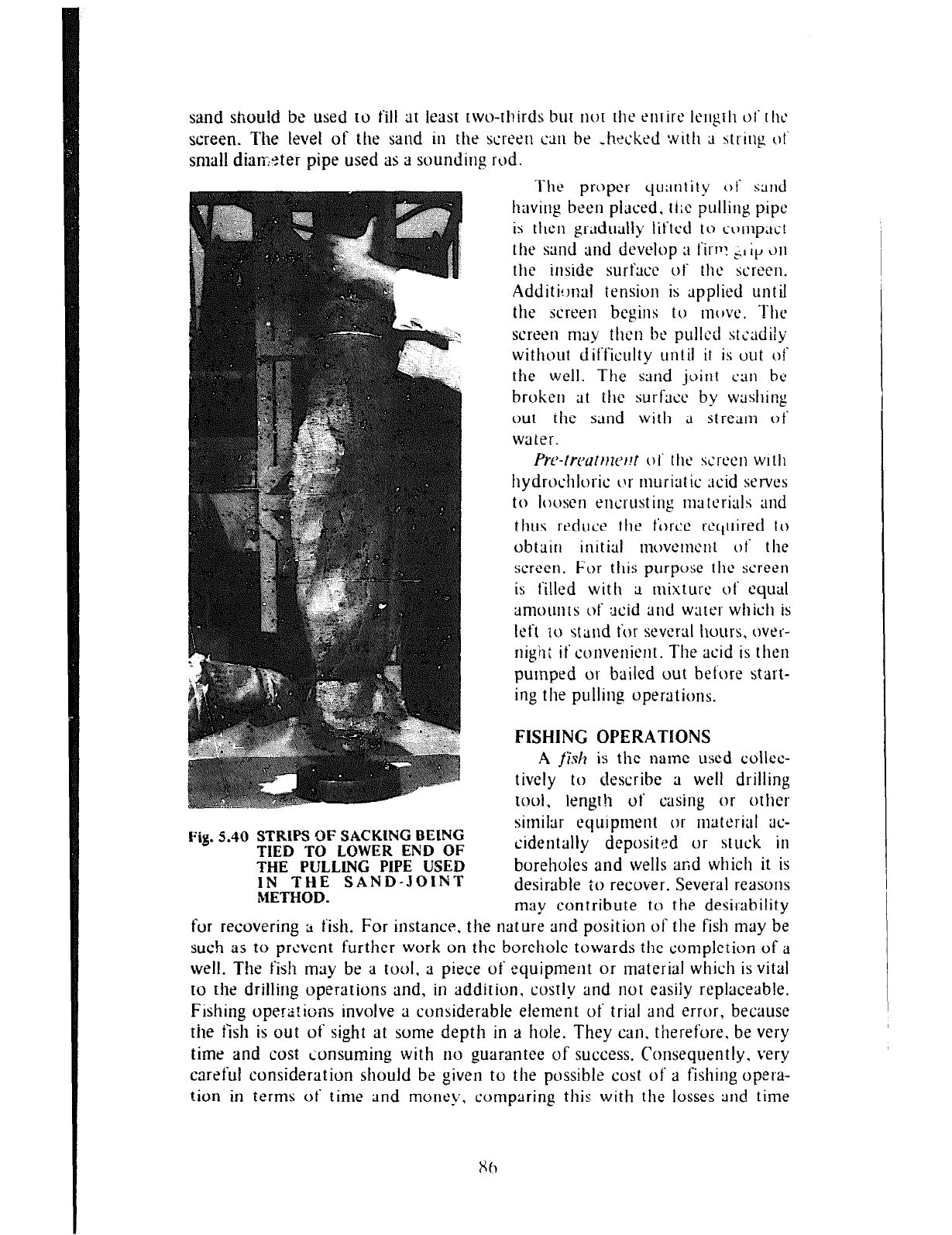
sand sflould be used to fill at least two-thirds bur not the entire IcIlgth oft hi\
screen. The level of the sand in the screen an he ,hxked with ;I string ot‘
small dismcter pipe used as a sounding rod.
The proper clu;intity of
sdnd
having been piaced, tt:e pulling pipe
is then gradually lifted to a~rnpaut
the sand and develop ;I fit-t*: + it, ~)II
the inside surface of the screen.
Additi!mal tension is applied until
the screen begins tu
mc)ve.
The
screen may then he pulled steadily
without difficulty until it is out ot
the well. The sand joint can be
broken at the surfxc by washing
out the sand with a stream ot
waler.
Prc-fwatrtwt!t
01‘ the szrt‘cn with
hydrochluric or muriut ic acid serves
to loosen encrusting materials and
thus reduce the force rcctuired to
obtain initial movement of the
screen. Fur this purpose the sc‘reen
is filled with a mixture of cqual
amounts of acid
ard
water which is
left IO stand for several hours, eve<-
nigili if convenient. The acid is then
pumped OI- bailed out before start-
ing the pulling operations.
FISHING OPERATIONS
A fi’slr is the name used colleo-
tively to describe a well drilling
tool. length of casing or othct
I:$. 5.40 STRlPS OF SACKlNG BElNG
TIED TO LOWER END OF
THE PULLING PIPE USED
IN THE SAND-JOINT
METHOD.
similar equipment or material x-
cidentally depositt:d or stuck in
boreholes and wells and which it is
desirable to recover. Several reasons
may contribute to the desirability
for recovering ;t fish. For instance, the nature and position of the fish may be
such as to prevent further work on the borehole towards the completion of a
well. The fish may be a tool, ;1 piece of equipment or material which is vital
to the drilling operations and, in addition, costly and not easiiy replaceable.
Fishing operations involve ;1 considerable element of trial and error, because
the fish is out ot’ sight at some depth in a hole. They can. therefore, be very
time and cost Lonsuming with no guarantee of success. Consequently. very
careful consideration should be given to the possible cost of a fishing opera-
tion in terms of time and money. comparing this with the losses and time
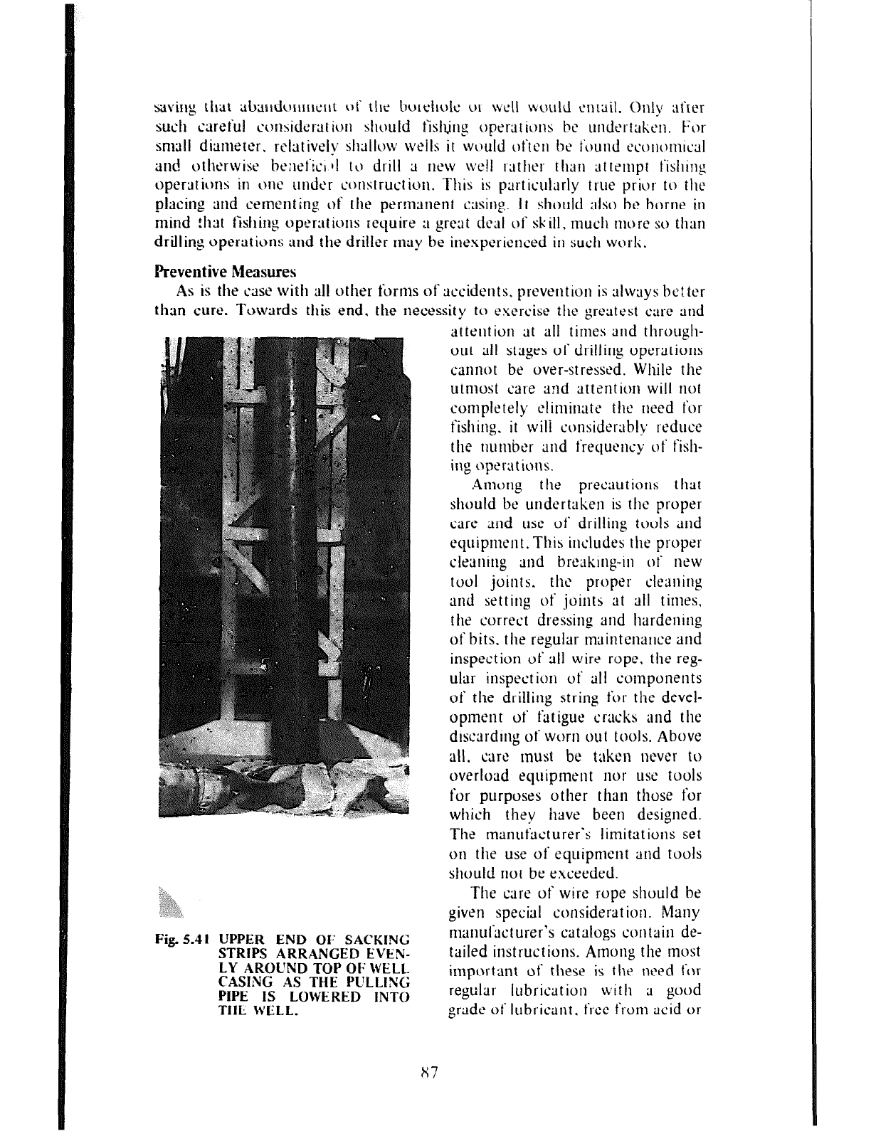
saving that sbandunmcnt ot‘ the borehole or well \vuuld altail.
Only :tf’ter
such careful cctnsidcrtlt ion should
t’islljrl~
operations be undcrtakcn.
For
smttll dirimeter, rclativelv shallow wells it wtbuld
often be t’wnd t’co~~o~~wd
and othcxwise bexitci 11 tLj drill 3
I~CW ~vell
rather than attempt fislling
opcrtltions in
OIW
under construction. This is particul;lrly true prior to the
placing and cement Eng of the permtlnent casing. It should also bc borne in
mind that fishing operations require :I great deal of skill,
rnucl~
more so than
drilling operation s and the driller
rnrty
be inexperienced in such work.
Preventive Measures
As is the crtst’ with all other forms ofxcidents. prevention is always bc: ter
than curt. Towards this end, the necessity to exercise the greatest care and
attention at all times and through-
out all stages of drilling operations
cannot be over-stressed. While the
utmost
cat-e
and attention will not
completely eliminate the need for
fishing. it will consider;rbly reduce
the number and frequency of fish-
ing optxrt ions.
Among
the precautions that
should be undertaken is the propel
care and use of drilling touls and
equipment. This includes the propel
cleuning und brtxking-in of
new
tool
joints. the proper cleaning
and setting of joints at all times,
the correct dressing and hardening
of bits. the regular maintenance and
inspection of all wire rope. the reg-
ular inspection of all components
of’ the drilling string for the devel-
opment uf fatigue cracks and the
discarding of worn out tools. Above
all. cart! tnust be taken nevc’r tu
overload equipment nor
LLSC
tools
for purposes other than those for
which they have been designed.
The manut‘Hcturer’s limitations set
011
the use of equipment and tools
should not be exceeded.
UPPER END OF SACKING
STRIPS ARRANGED EVEN-
LY AROUND TOP OF WELL
CASING AS THE PULLING
PIPE IS LOWERED INTO
THE. WELL.
The care of wire rope should be
given special considerat ion.
Many
manufacturer’s catalogs contain de-
tailed instructions. Among the most
import ant of these is the need t,r
regular lubrication with a good
grade of lubricant. free from acid or
x7
alkali and which will penetrate and adhere to the rope. The ust’ ot‘ crude
oil or other material likely to be injurious to steel or ruse deterioratiorl
or brittleness of the wires must be avoided. Failure to properly lubric’utt’
wire rope results in the wires becomm~ brittle. corroded, subject to excessive
friction wear and ultimatt4y the sud& fracturmg of the rope. The rope
should be tightly and evenly wound
on
winding drums and should not be
allowed to stand in mud. dirt or other such medium which is h~rmt‘ul to steel.
Only proper P&sterling clamps that do nut kink. flatten or crush the rope
should be used. The fracturing
CJf
loaded wire rope, it should be remem-
bered, can cause serious injury tu workmen as well as create fishing problems.
lrnscrewed tool joints are ihe causes of many fishing operations. These
can
be avoided by the proper matirlg of the box and pin components of the
joints. Both the pin shoulder and the box fi!ce should be thoroughly cleaned
and free of imperfections that prevent a full and even contact. The threads
and shoulders of the component parts should be thinly coated with a light
machine oil before mttking up the joint. Joints should be firmly made up
though not with excessive pressure as this
cm
result in broken boxes and
pins.
Tools. carelessly left on the rotary table or at some such point.
nwy
be
accidentally tipped into a borehole. One half of 9 pipe clamp entering ;I well
in this manner has been known to become wedged iu the well sc’recn
just above a juint in the wash pipe being used in the development pr~xxss
and result not only in the abandonment of the well but also the loss
of several hundred feet of drill stern with it. All tools should be removed
immediately after use to a convenient point of storage at ;I safe distance t’rom
the borehole or well.
Certain conditions such as slanting or caving formations. crooked holes
and the presence of boulders often contribute to drilling troubles that may
result in fishing operations. The utmost care must be exercised by drillers
operating under these conditions.
Prepmat ions for Fishing
The nature of all operations (construction and maintenance)
or1
wells is
such that accidents do occur even under the supervision of the most capable
and careful drillers. Therefore, the driller in anticipation of the inevitable
fishing job should record or have access to the exact dimensions of everything
used in or around the well. This facilitates the selection and design of a
suitable fishing tooi when necessary. All tools brought to the site should be
accurately measured and the measurements properly recorded. Some of the
important measurements are: the outside diameter and length of the rope
socket; the diameter, length and stroke of the drill jars; the diameter and
length of the drill stem; the size of tool joints and the outside diameter and
length of the pin and box collars; the body size and length of bits; the length
of pin collars on the bits. A careful record of the depth or the hole and the
ovemil length of the drilling string is also essential for successful fishing
operations.
The drill hole must of necessity be larger than any tools placed in it. As a
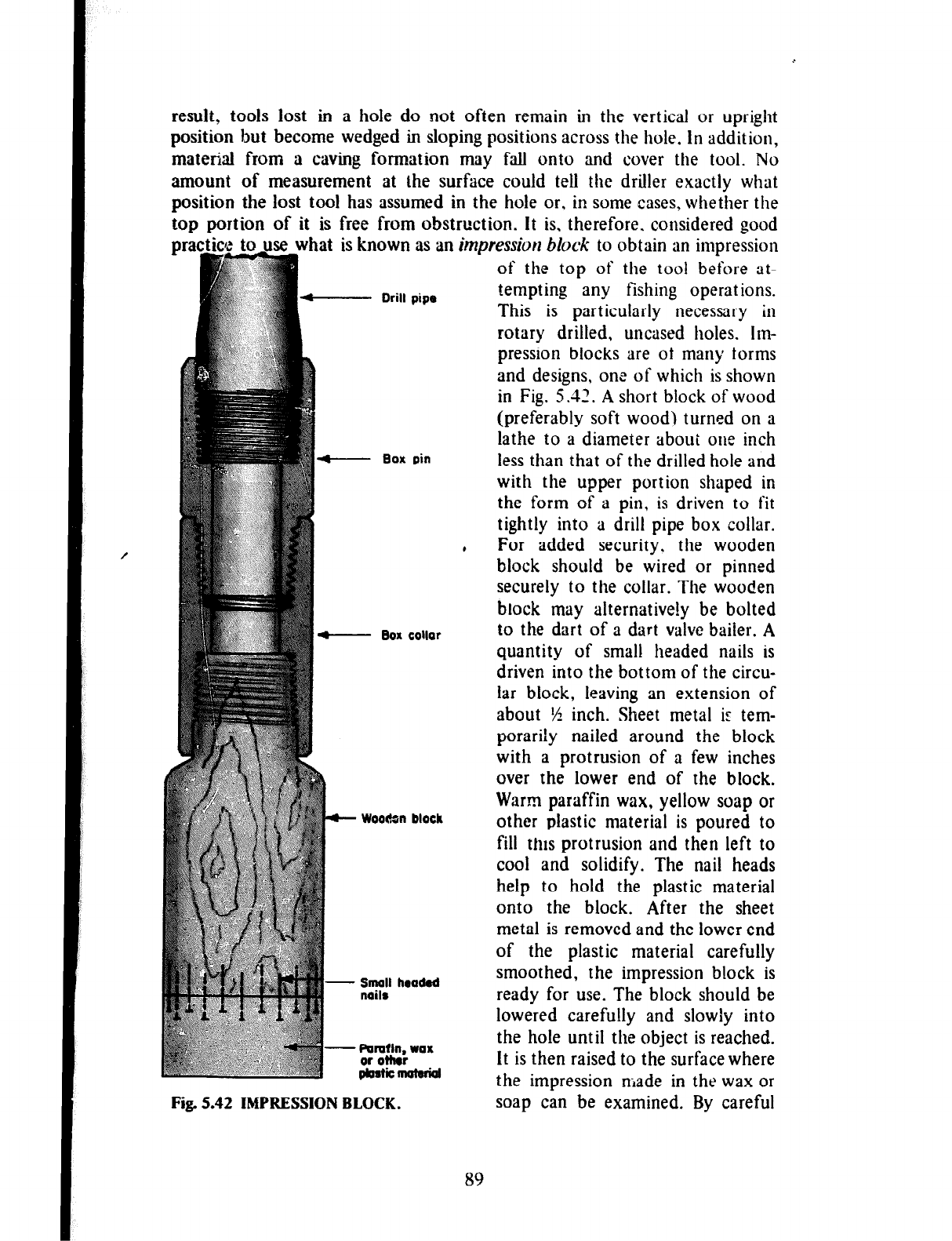
result, tools lost in a hole do not often remain in the vertical or upright
position but become wedged in sloping positions across the hole. In addition,
material from a caving formation may fall onto and cover the tool. No
amount of measurement at the surface could teli the driller exactly what
position the lost tool has assumed in the hole or. in some cases, whether the
top portion of it is free from obstruction. It is, therefore. considered good
practice to use what is known as a
- Drill pipe
f-- Box pin
Fig. 5.42 IMPRESSION BLOCK.
n
impression block
to obtain an impression
of the top of the tool before at-
tempting any fishing operations.
This is particularly necessary in
rotary drilled, uncased holes. Im-
pression blocks are of many forms
and designs, one of which is shown
in Fig. 5.32. A short block of wood
(preferably soft wood) turned on a
lathe to a diameter about one inch
less than that of the drilled hole and
with the upper portion shaped in
the form of a pin, is driven to fit
tightly into a drill pipe box collar.
For added security. the wooden
block should be wired or pinned
securely to the collar. The wooden
block may aiternative!y be bolted
to the dart of a dart valve bailer. A
quantity of small headed nails is
driven into the bottom of the circu-
lar block, leaving an extension of
about */4 inch. Sheet metal ir tem-
porarily nailed around the block
with a protrusion of a few inches
over the lower end of the block.
Warm paraffin wax, yellow soap or
other plastic material is poured to
fill thus protrusion and then left to
cool and solidify. The nail heads
help to hold the plastic material
onto the block. After the sheet
metal is removed and the lower end
of the plastic material carefully
smoothed, the impression block is
ready for use. The block should be
lowered carefully and slowly into
the hole until the object is reached.
It is then raised to the surface where
the impression made in the wax or
soap can be examined. By careful
89
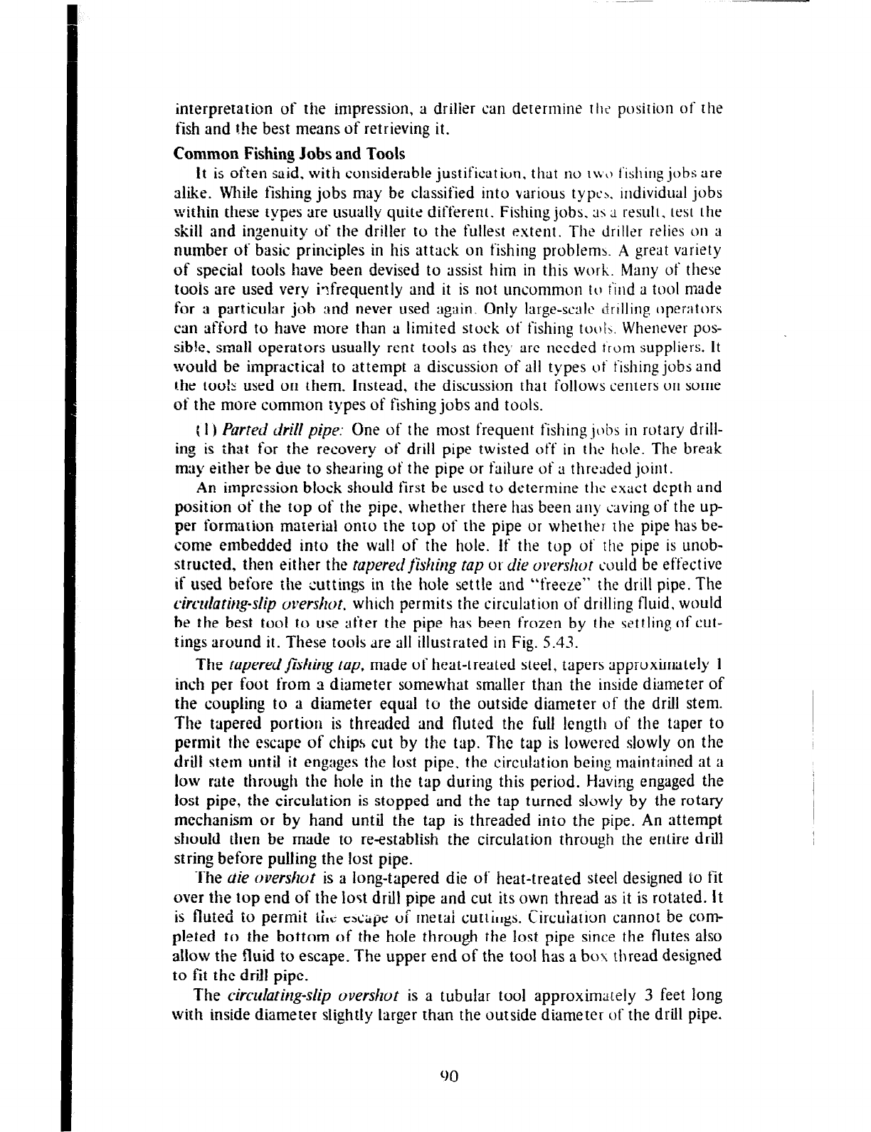
interpretation of the impression, a driller can determine fhc’ position of the
fish and the best means of retrieving it.
Common Fishing Jobs and Tools
It is often said, with considerable justificatiun. that no IIVO fishing jobs are
alike. While fishing jobs may be classified into various type-\, individual jobs
within these types are usually quite different. Fishing jobs. ;IS ;L result. test the
skill and ingenuity of the driller to the fullest extent. The driller relies on a
number of basic principles in his attack on fishing problemh. A great variety
of special tools have been devised to assist him in this work. Many of these
toois are used very infrequently and it is not uncommon to i‘ind a tvol made
for a particular job and never used again. Only large-scale drilling operators
can afford to have more than a limited stock of fishing tooI>. Whenever pos-
sible. small operators usually rent took as the>, are needed Q‘rum suppliers. It
would be impractical to attempt a discussion of all types ot‘ fishing jobs and
the too!5 used on them. Instead, the discussion that follows centers on some
of the more common types of fishing jobs and tools.
t I ) Parted &ill pipe: One of the most frequent fishingjc&s in rotary drill-
ing is that for the recovery of drill pipe twisted off in the hole. The break
may either be due to shearing of the pipe or failure of a threaded joint.
An impression block should first be used to determine the exact depth and
position of the top of the pipe. whether there has been any caving of the up-
per formation material onto the top of the pipe or whether the pipe has be-
come embedded into the wall of the hole. If the top of rhe pipe is unob-
structed. then either the rapereclfishiqg tap or die o~~slzor could be effective
if used before
the
cuttings in the hole settle and “freeze” the drill pipe. The
kwlatitg-slip overshot. which permits the circulation of drilling fluid, would
be
the
best tooi to use after the pipe has been frozen by the settling of cut-
tings around it. These tools dre all illustrated in Fig. 5.43.
The tapered fishing rap, made of heat-treated steel, tapers approximately 1
inch per foot from a diameter somewhat smaller than the inside diameter of
the coupling to a diameter equal to the outside diameter of the drill stem.
The tapered portion is threaded and fluted the full length of the taper to
permit the escape of chips cut by the tap. The tap is lowered slowly on the
drill stem until it engages the lost pipe. the circulation being maintained at a
low rate through the hole in the tap during this period. Having engaged the
lost pipe, the circulation is stopped and the tap turned sltiwly by the rotary
mechanism or by hand until the tap is threaded inio the pipe. An attempt
should then be made to reestablish the circulation through the entire drill
string before pulling the lost pipe.
The
de over&t is a long-tapered die of heat-treated steel designed to fit
over the top end of the lost drill pipe and cut its own thread as it is rotated. It
is fluted to permit iiIr: ~SLL~Z UT merai cu~ti~~gs. Circuiation cannot be corn-
pleted to the bottom of the hole through the lost pipe since the flutes also
allow the fluid to escape. The upper end of the tool has a box thread designed
to fit the drill pipe.
The circrdatirzg-slip overshot is a tubular tool approximately 3 feet long
with inside diameter slightly larger than the outside diameter of the drill pipe.
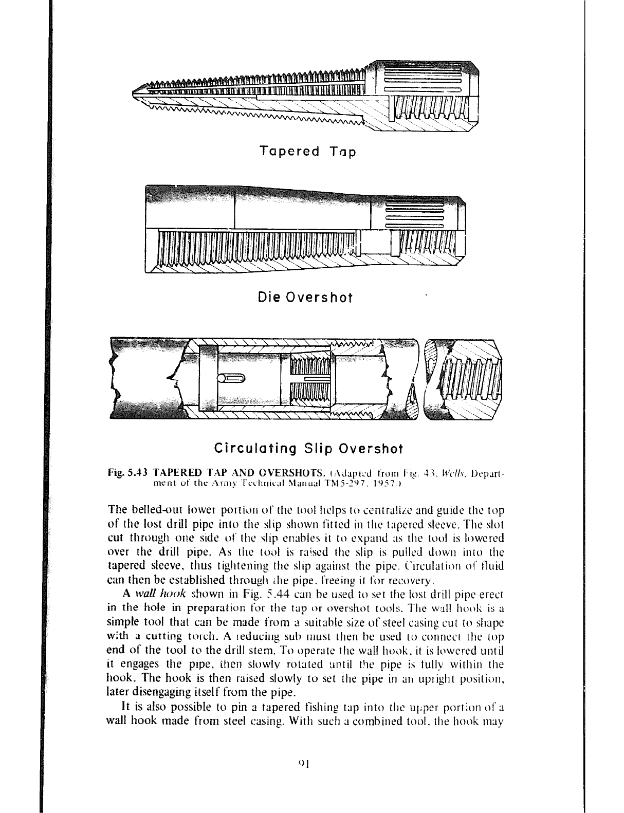
Tapered Tap
Die Overshot
Circulating Slip Overshot
The belled+ut lower portinjn ot‘ the tool helps to icntruliz and guide the top
of the lost drill pipe into the slip shown fitted in tllc tapcrcd slcevc. The slot
cut through one side ot‘ the slip cnahlcs it to ~syarld ;IS the tucrl is II)wered
over the drill pipe. As the tol,l is raised the slip is pu!M rlowtl into the
tapered sleeve, thus tightening tllc slop against the pipe. i’iruulatiorl ot’ tluid
can then be established
through
~he pipe. freeing it for recovery.
A wall Izooli shown in Fig. 5.44 cm be used to set the lost drill pipe erect
in the hole in preparation for the trip or overshot tools. Tile wall ho~~k is ;I
simple tool that can be made from 2 suitable size of steel casing cut to shape
with a cutting torch. A reducing sub must then be used to connect the top
end of the tool to the drill stem. To operate the wall h~\jk, it is lowered until
it engages the pipe. ,then slowly rotated until the pipe is fully within the
hook. The hook is then raised slowly to set the pipe in art uptight positicjn.
later disengaging itself from the pipe.
It is also possible to pin a tapered fishing tap into the upper portion of 3
wall hook made from steel casing. With such a combined tool. the hook may
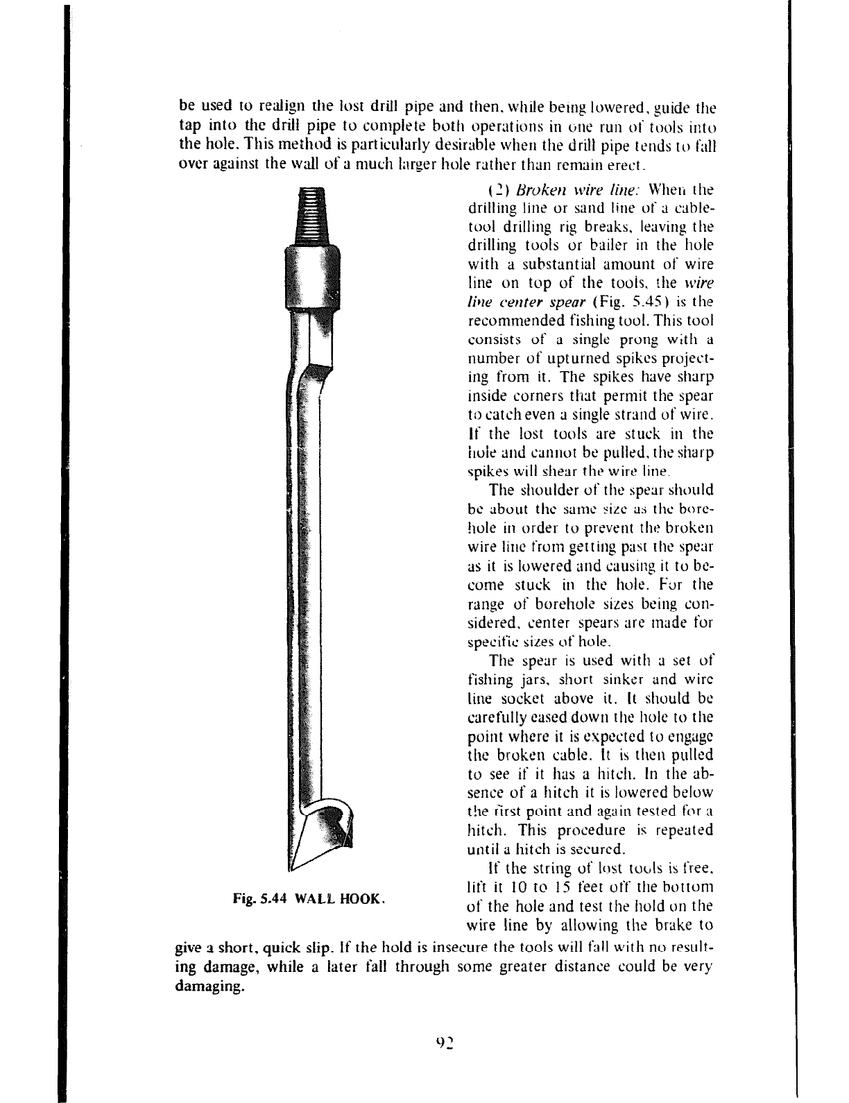
be used to realign the lost drill pipe and then. while being lowered, guide the
tap into the drill pipe to cunlpkte both operations in tine run ot‘ tools into
the hole. This method is particularly desirable when the drill
pipe ttm& to fall
over against the wall of a much Larger hole rather than remain erect.
(1) &chken wire Ike:
Wheli the
drilling line or
sand line of ;i
cable-
tool drilling rig breaks, leaving the
drilling tools or bailer in the hole
with a substantial amount of wire
line on top of the t00is, the wire
live cerrter spew ( Fig. 5.4.5 ) is the
recommended fishing tool. This tool
consists of a single prong with a
number of upturned spikes project-
ing from it. The spikes have sharp
inside corners that permit the spear
to catch even a single strand of wire.
If the lost tools are stuck in the
ide md cltnrwt be pulled, the sharp
spikes will shear the win! line.
The shoulder of the spear should
be about the same sire as the bore-
!lole in order to prevent the broken
wiie line from getting past the spear
as it is lowered and causing it to bc-
come stuck in the hole. Far the
range of boreholc sizes being con-
sidered, center spears are tnade for
specific siLes of hole.
The spear is used with a set of
fishing jars. short sinker and wire
line socket above it. It should be
carefully eased down the Me to the
point where it is expected to cngagc
the broken cable. It is then pulled
to see if it has a hitch. In the ab-
sence of a hitch it is lowered below
t!le first point and again tested f<jr a
hitch. This procedure is repeated
until a hitch is secured.
Fig. 5.44 WALL HOOK.
If the string of lost toclls is free.
lift it IO to IS feet off the bottom
of the hole and test the hold on the
wire line by allowing that brake to
give 3 short. quick slip. If the hold is insecure the tools will fall with no result-
ing damage, while a later faii through some greater distance could be very
damaging.
Fig. 5.45 CENTER SPEAR.
If the hold is secure, continue
lifting the tools out of the hole until
the broken wiresappear. Stop lifting
and tie the wires together and then
to the prongs of the grab to prevent
the loose ends from unfolding and
causing the hold to break. The tie
itself does not carry the load but
holds the broken lines in position.
Continue lifting until the lost tools
are recovered.
If the string of lost tools is not
free, then sufficient line should be
let out to bring the jars into use.
Jarring should be continued until
the lost tools come loose or the
broken cable parts.
(3) Fishing for the neck
of
a
rope socket, 0 t her cy Iindrical
object or the pin
of
a tool: The
combination socket (Fig. 5.46) is
one of several tools used to catch
the neck of a wire-line socket after
broken line has been cleared away,
or the pin of a bit or drill stem that
has become unscrewed in the hole.
The tool can also be used to fish for
any cyhndrical object such as a drill
stem or tubing standing upright in
the hole, providing the bore of the
socket is at least l/8 inch larger
than the diameter of the fish. The
fishing string should consist of a
rope socket, stem, long-stroke
fishing jars and combination socket.
Combination sockets are pro
vided with two sets of slips, one set
of which is used to engage the
threads of the pin on a bit, stem or
other tool and the second set to
take hold of the neck of the rope
socket. The proper set of slips must
be selected for the particular fishing
job in accordance with knowledge of
the exact size of the fish. It is also
good practice to determine if the socket can go over the fish by first running
the socket with its inner parts removed. The re-loaded combination socket is
93
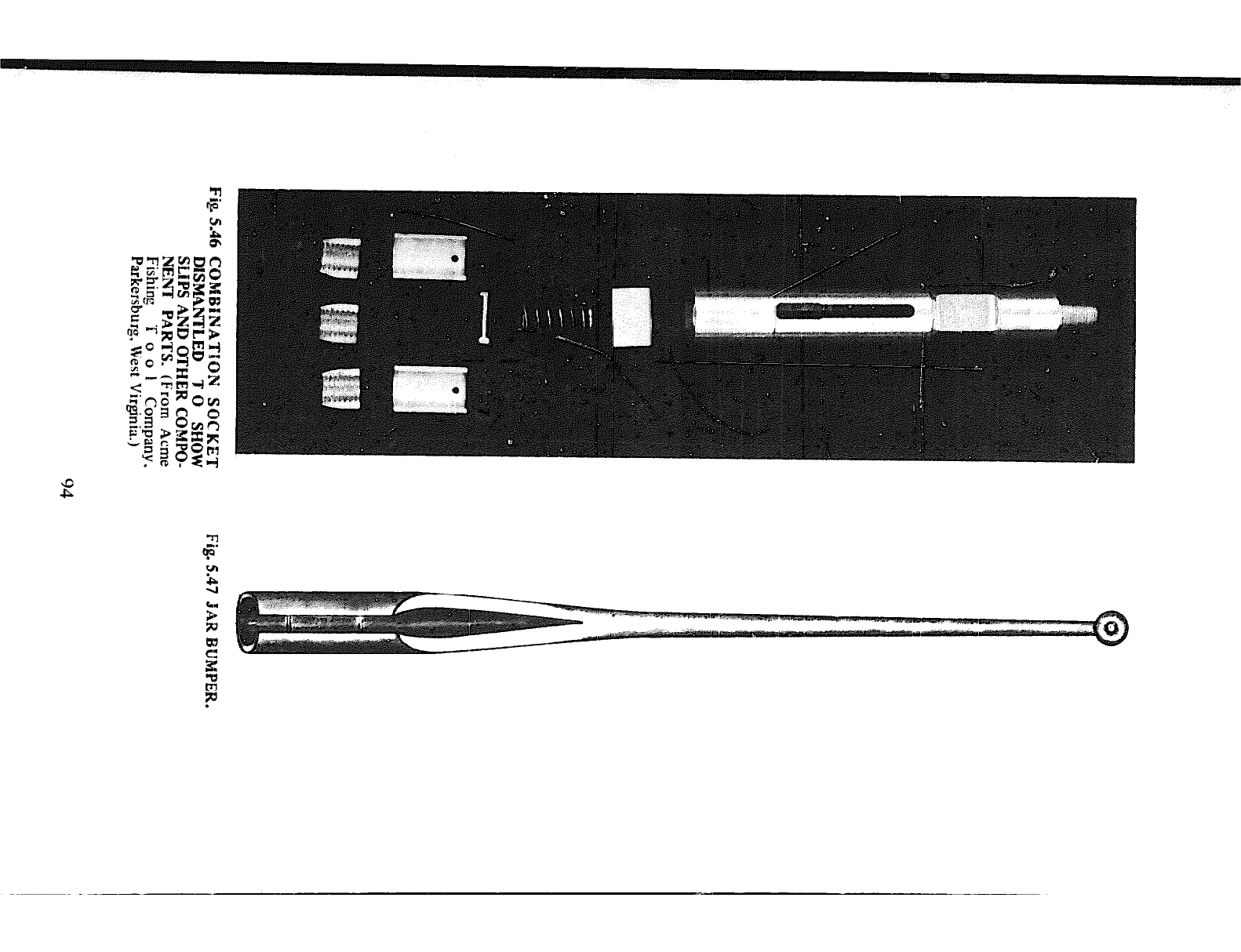
then slowly iowered on the fishing string with the fishing jars adjusted for
shortest stroke.
Upon
contact with the-fish. a light downward jar is used to
secure a hitch. Tension is then taken on the line and the fishing job completed
if the tools are not stuck.
If the tools are stuck, then a slow spudding action should first be tried to
release them. Should this fail. then sufficient line is let out to bring the jars ill-
to use. Short and rapid jarring should cause
the
freeing of the tools and is pre-
ferabie to hard long-stroke jarring even ihoaug!~ several hours of work my be
necessary-. Long-stroke jarring could result in break.ing of the hitch on the lost
tools or in broken fishing tools. Alternate up-jarring and down-jarring would
release the hitch on the lost tools, should it become obvious that they cannot
be freed and recovered.
After successful completion of a fishing job. the hitch is broken by remov-
ing the wooden block above the spring in the combination socket and so re-
lieving the pressure on the spring and slips.
(4) Releasijrg locked jars: Jars sometimes becorxe stuck or tools above the
jars wedged in the hole by a piece of rock or other material. A
jar bumper
(Fig.
5.47) is the tool normally used under such circumstances. The following pro-
cedure should be followed. A strain is first taken on the drilling cable. The jar
bumper is then lowered on the sand line, using the drilling cable as a guide,
until the bumper reaches the string of tools. The bumper is then raised IO or
12 feet and dropped. repeating this as often as necessary to loosen the jars or
string of tools. A few blows are usually sufficient for this purpose. Too many
blows might batter the neck of the rope socket and should be avoided. Should
the bumper fail to release the tools, cut the cable and use a combination
socket.
95
CHAPTER 6
WE11 C6MPLETION
Well completion is the term u\ed to describe the two basic processes which
are undertaken after a well has been constructed in order to ensure a good
yield of water that is clear and relatively free of suspended matter and dis-
ease-producing organisms. These processes are called well development and
well disinfection.
WELLDEVELOPMENT
The object of well development is the removal of silt, fine sand and other
such materials from a zone immediately around the well screen, thereby
creating larger passages in the formation through which water can tlow more
freely towards the well.
In addition to the above, well development produces two other beneficial
results. Firstly, it corrects any clogging or compacting of the water-bearing
formation which has occurred during drilling. Clogging is particularly evident
in wells drilled by the, rotary method where the drilling mud effectively seals
the face of the borehole. Driving casing in the cable-tool percussion method
vibrates the unconsolidated particles, thus compacting them. These are not
the only drilling methods that damage the formation in one way or the other.
All drilling methods do to different degrees of magnitude, and well develop-
ment is needed to correct this damage.
Secondly, well development grades the material in the water-bearing for-
mation immediately around the screen in
such
a way that a stable condition
in which the welt yields sand-free water at maximum capacity is achieved. In
a zone just outside the screen, ail particles smaller than tl-:e size of the screen
openings are removed by development, thus leaving only ihe coarsest material
in place.
A
little farther away some medium-sized grains remain mixed with
the coarser ones. This grading of coarse through successively less coarse ma-
terial continues as distance from the screen increases until material of the
original character of the water-bearing formation is reached. This marks the
end of the developed zone around the well. The succession of graded zones of
material around the screen stabilizes the formstion so that no further sand
movement will take place. Tlie extent of the envelope depends upon the
formation characteristics, the well screen design and the skill of the well
driller. Fig. 6.1 illustrates the principle of well development described above
and which applies to naturally developed wells. Gravel-packed wells present a
somewhat different problem which is discussed later in the chapter.
96
4
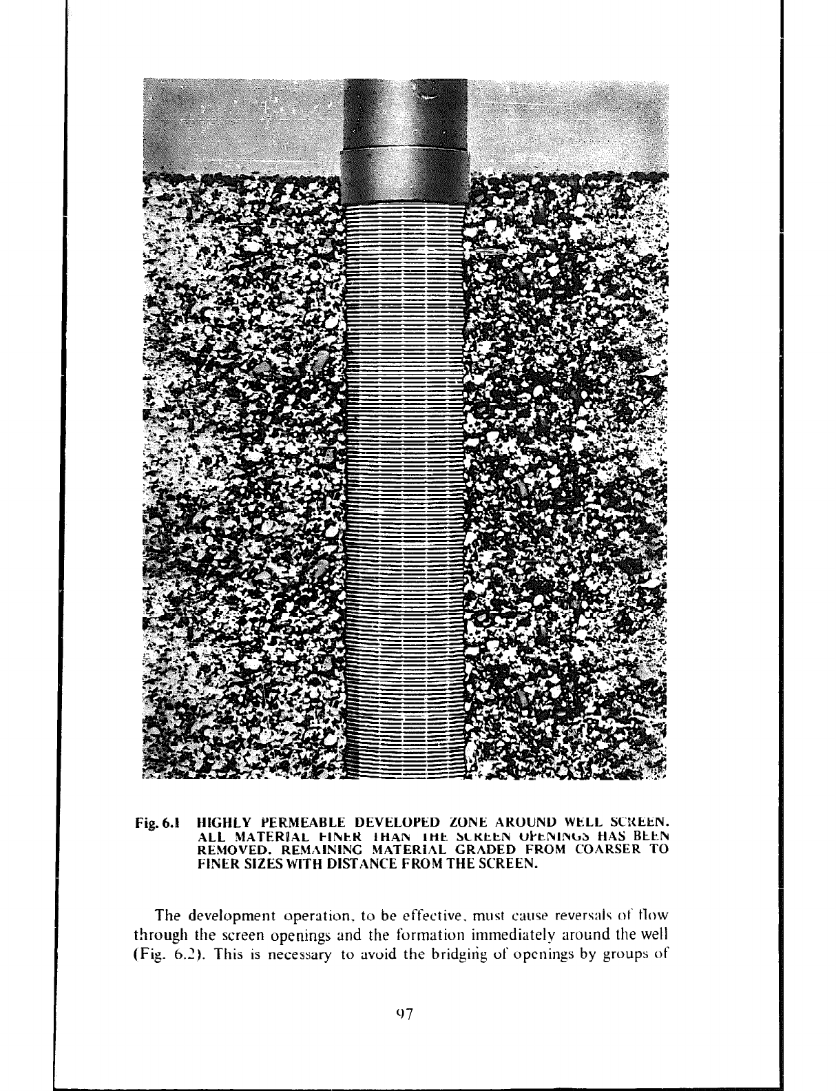
Fig.6.t HIGHLY YEIEMEABLE DEVELOPED ZONE AROUND WELL SCREEN.
ALL !~IATERL(AL I-1kk.K
IHAN Ikit SCKttN Wk’tl\rlNbS
HAS BLkl\r
REMOVED. REMAINING MATERiAL GRADED FROM COARSER TO
FINER SIZES WITH DISTANCE FROM THE SCREEN.
The development operation, to be effective. must cause reversais ot‘ tlow
t!trough the screen openings and the furmatiun immediately around the well
(Fig. 6.2). This is necessary to rtvuid the bridgirig of openings by groups of
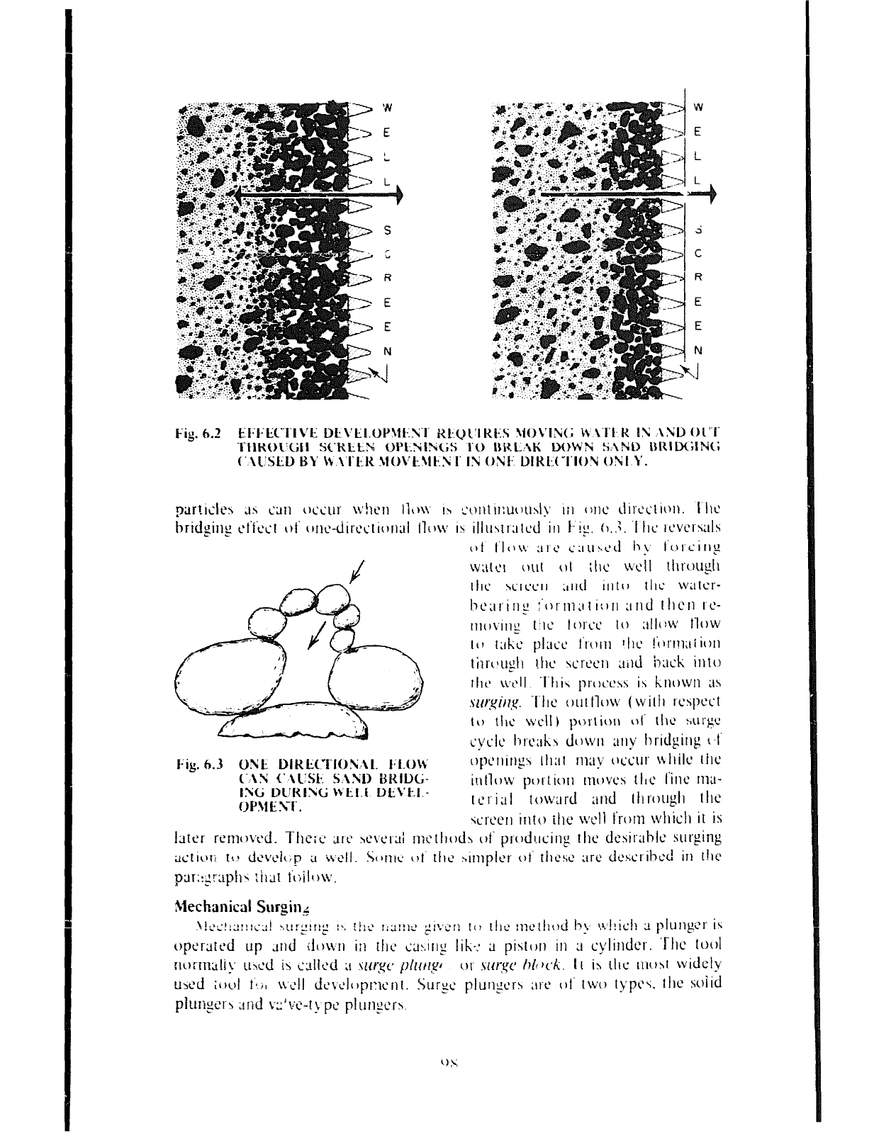
‘N
E
L
VI
E
L
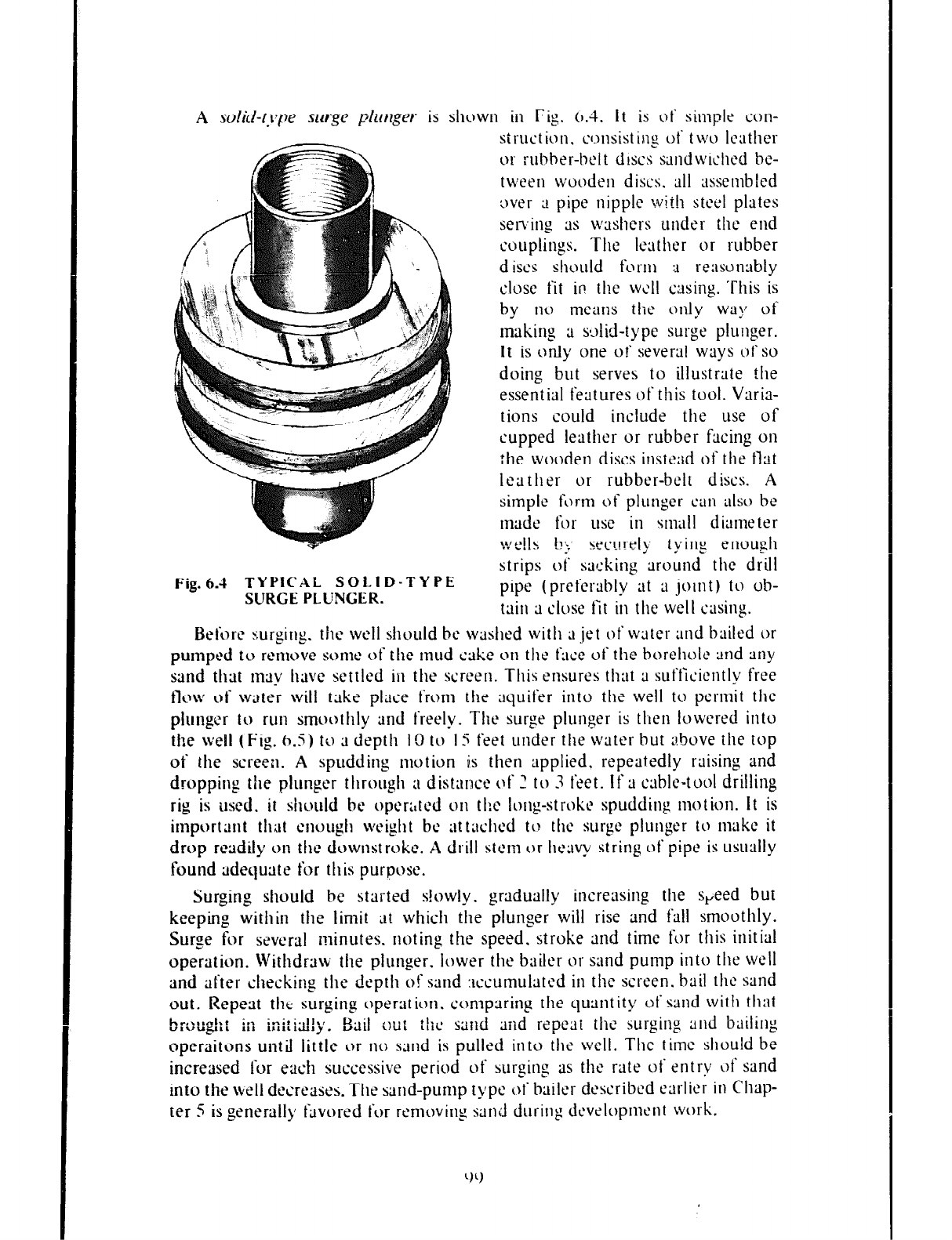
A solid-fj*pe surge plwger
is shown in Fig. 0.4. it is of simple
WII-
strut
ion. consisting ut‘ two Icather
or rubber-belt discs sandwiched be-
tween wooden discs. all assembled
3ver ;L pipe nipple with steel plates
selxing ;IS washers under the end
couplings. The leather or rubber
discs shuuld fc)rm :J reasc,nubly
close fit in the well casing. This is
by
no
means the only way of
making ;t s4id-type surge plunger.
It is only one of several ways of so
doing but serves to illustrate the
essential features of this tool. Vuris-
tions could include the use of
cupped leather or rubber fazing
on
the wooden discs instead of the flat
leuther or rubber-belt discs. A
simple
form of
plunger
can also
be
made for use in small diameter
fW”l]< b;,
. . . . . -. securely tying enough
strips of sacking around the drill
Fig.6.4
TYPICAL SOLID-TYPE
SURGE PLUNGER.
pipe (preferably at ;I joint) to ob-
tain ;1 close fit in the well casing.
Before surging. the weI1 should bc washed with ;I jet of water and bailed or
pumped to remove some
of the mud cake
w the face of the borehoic and any
sand that may have settled in the screen. This ensures that ;I sufficiently free
flow of water will take place from the aquifer into the well to permit the
plunger to run smoothly and freely. The surge plunger is then lowered into
the well (Fig. (3.5) to 3 depth It) tu I4 feet under the water but zbuve the top
of the screen. A spudding motion is then applied. repeatedly raising and
dropping the plunger through ;I distance of 2 to 3 feet. If ;t cable-tool drilling
rig is used. it should be oper:,ted on
tk
Ion,
(I-stroke spudding motion. It is
important that enough weight bc at txhcd to the surge plunger to make it
drop readily on the downstroke . A drill stem or hc~y string of pipe is usu;~IIy
found adequate for this purpose.
Surging should be started s!owly. gradually increasing the s,eed but
keeping within the limit at which the plunger will rise and fill smoothly.
Surge for several minutes. noting the speed. stroke and time for this initial
operation. Withdraw the plunger. lower the bailer or sand pump into the well
and after checking the depth of sand xxumulatcd in the screen. bail the sand
out. Repeat the surging operation. compxin, u the quantity of sand with that
hr,\,.nirt
v.\tui;l., in
ini:ial!y. Bail W: the sand and repeat the surging and bdiling
operaitons until little or IIU sand is pulled into the well. The time should be
increased for each successive period of surging as the rate of entry ~)t‘ sand
into the well decreases. The sand-pump typt‘ of bailer dcscribcd earlier in Chap-
ter 5 is generally Pdvored fix rt‘movin, _
~1 sand during dcvrtopment work.
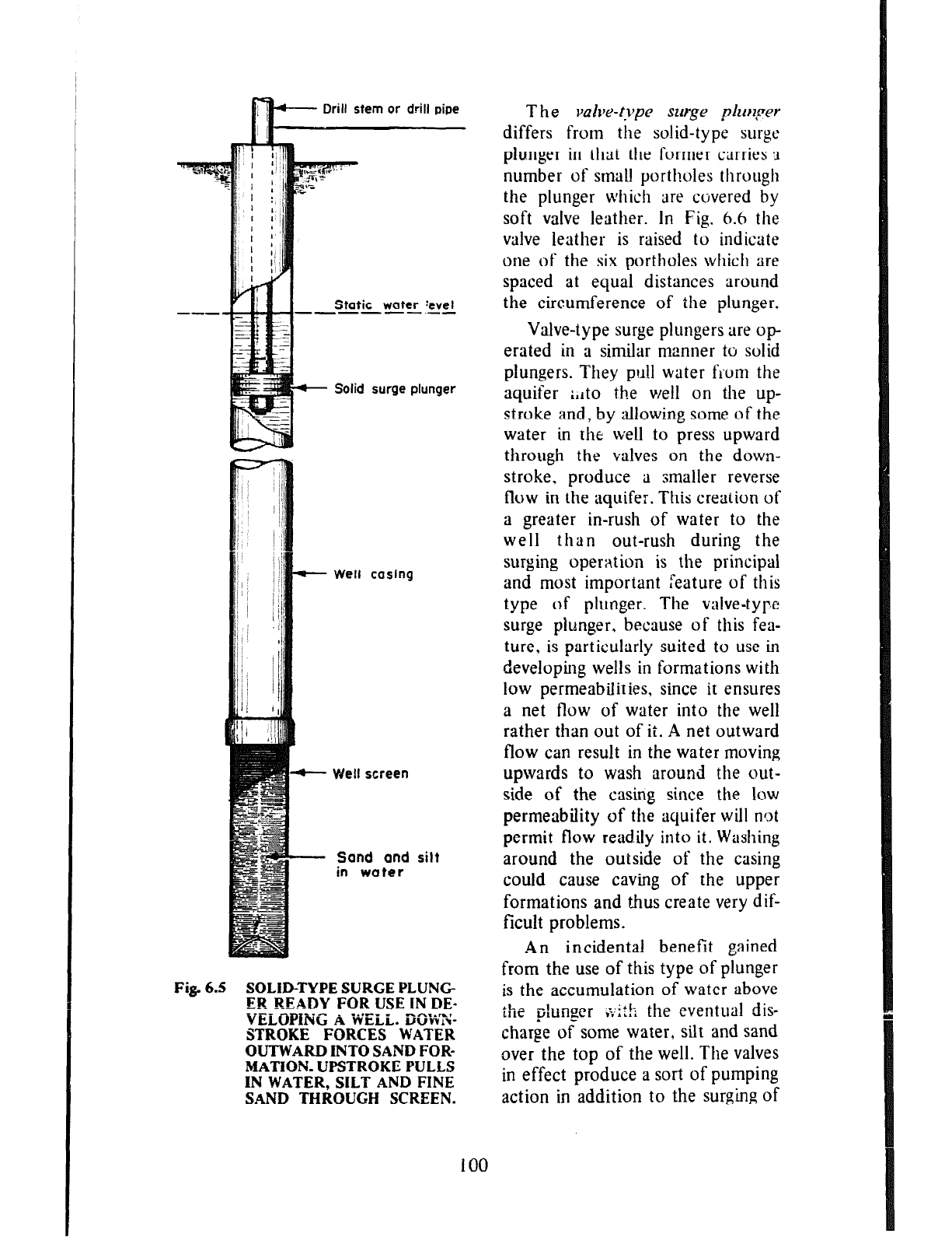
Static water :evel
-m----.-e
Solid surge plunger
+- Well casing
+- Well screen
- Sand and
silt
in water
Fig. 6.5 SOLID-TYPE SURGE PLUNG
ER READY FOR USE IN DE-
VELOPING A -gELi.. D&X
STROKE FORCES WATER
OUTWARD INTO SAND FOR-
MATION. UPSTROKE PULLS
IN WATER, SILT AND FINE
SAND THROUGH SCREEN.
T he valve-type surge phryer
differs from the solid-type surge
plunger in that the former carries 2
number of small portholes through
the plunger which are covered by
soft valve leather. In Fig. 6.6 the
valve leather is raised to indicate
one of the six portholes which are
spaced at equal distances around
the circumference of the plunger.
Valve-type surge plungers are op
erated in a similar manner to solid
plungers. They pull water frum the
aquifer ;,lto the well on the up-
stroke and, by allowing some of the
water in the well to press upward
through the valves on the down-
stroke. produce a smaller reverse
flow in the aquifer. This creation of
a greater in-rush of water to the
well than out-rush during the
surging operation is the principal
and most important feature of this
type of plunger. The valve-type
surge plunger. because of this fea-
ture, is particularly suited to use in
developing wells in formations with
low permeabilities, since it ensures
a net flow of water into the well
rather than out of it. A net outward
flow can result in the water moving
upwards to wash around the out-
side of the casing since the low
permeability of the aquifer will not
permit flow read.ily into it. Washing
around the outside of the casing
could cause caving of the upper
formations and thus create very dif-
ficult problems.
An incidental benefit gained
from the
use
of this type of plunger
is the accumulation of water above
the plunger ;;:ith the eventual dis-
charge of some water, silt and sand
over the top of the well. The valves
in effect produce a sort of pumping
action in addition to the surging of
100
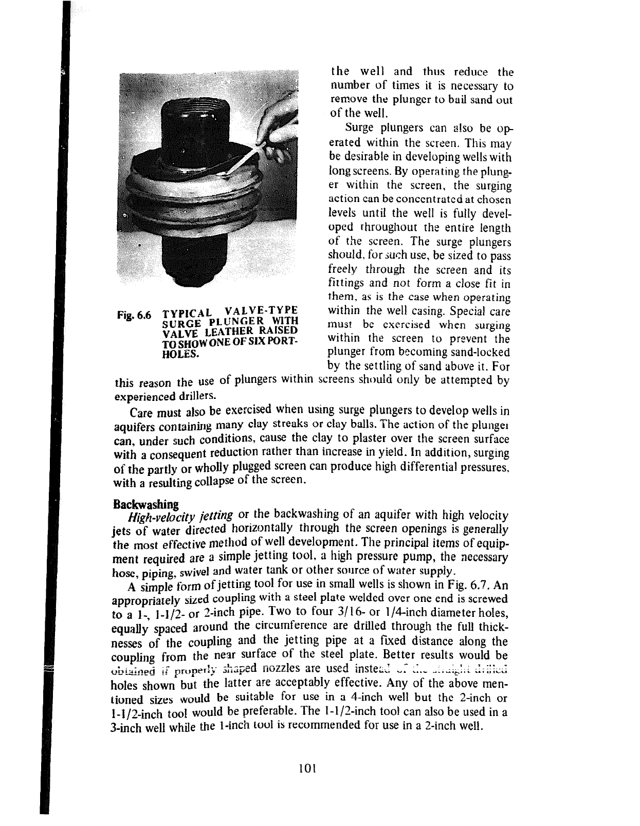
Fig. 6.6 TYPICAL ?!!!z!~-T~!$
SURGE PL!
JNtiEK
WIIH
VALVE LEATHER RAISED
TO SHOW ONE OF SIX PORT-
HOLES.
the well and thus reduce the
number of times it is necessary to
remove the plunger to bail sand out
of the well.
Surge plungers can also be op
erated within the screen. This may
be desirable in developing wells with
long screens. By operating the phmg-
er within the screen, the surging
action can be concentrated at chosen
levels until the well is fully devel-
oped throughout the entire length
of the screen. The surge plungers
should. for iuch use, be sized to pass
freely through the screen and its
fittings and not form a close fit in
them, as is the case when operating
within the well casing. Special care
must be exercised when surging
within the screen to prevent the
plunger from becoming sand-locked
by the settling of sand above it. For
this reason the use of plungers within screens should only be attempted by
experienced drillers.
Care must also be exercised when using surge plungers to develop wells in
aquifers
containing many clay streaks or clay balls. The action of the plunger
can, under such conditions, cause the clay to plaster over the screen surface
with a
consequent
reduction rather than increase in yield. In addition, surging
of the part]y or wholly plugged screen can produce high differential pressures,
with a resulting collapse of the screen.
Backwashing
Hjg~-ve/~city
jetting or the backwashing of an aquifer with high velocity
jets of water directed horizontally through the screen openings is generally
the most effective method of well development. The principal items of
equip-
ment required are
a simple jetting tool . a high pressure pump, the necessary
hose,
piping,
swivel and water tank or other source of water supply.
A
simple
form ofjetting tool for use in small
Web
is shown in Fig. 6.7, An
appropriately
sized coupling with a steel plate welded over one end is screwed
to a I-, l-1/2- or
2-inch pipe. Two to four 3/ 16- or l/4-inch diameter holes,
equally spaced
around the circumference are drilled through the full thick-
nesses of the coupling and the jetting pipe at a fixed distance along the
coupling
from the near surface of the steel plate. Better results would be
i,;iir:,lp~ $I nn,LJerl-b~ =ixy-
-‘---gd nozzles are used instep,’ + .’
-c.,---- _- ‘~ ‘ +
* “. l ..W “.Laih.,L u.v,ru
.I_*.: ‘.I::...:
ho& shown but the latter are acceptably effective. Any of the above men-
tioned sizes -would be suitable for use in a 4-inch well but the 2-inch or
T-T/2$rch tooi would be preferable. The I-l/Zinch tool can also be used in a
3~mch web while the l-inch tool is recommended for use in a 2-inch well.
101
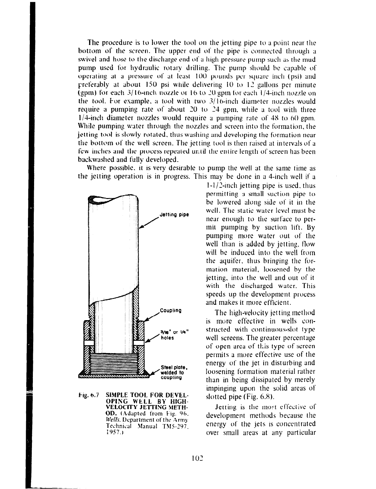
The procedure is to lower the tool on the jetting pipe to a poini near the
botrom of the screen.
The
upper end of the pipe is c’onnt’cttxl through a
swivel and host to the dis&ttrge end of a high prtxure pump
such 2s the mud
pump
used for hydrtmlic rotary drilling. The pump should hc capable of
opsratin~ at 3 pressure of at least IW pounds per squart‘ inch (psi) and
preferably at about 150 psi while delivering II) to 12 gallons per minute
(gpm) for each Z/ 1 h-inch nozr.te or lh tu 20 gpm for each I /it-inch nuzzle on
the tool. For example. :L tool with two .S/ I Gnch diamttter nozzles would
require a pumping rate of
about 20 to 24 gprn.
while ;i tr;ol with three
l/4-inch diameter nozzles would require ;i pumping rate of 4X to hO gpm.
While pumpin, u water through the nozzles and screen into the formation, t hc
jetting tiara is slowly
rotttted.
thus washing
;mcl developing the formation near
the bottum of the well screen. The jet tin,
0 tool is then raised at intervals of a
few inches and the process repeated ur?til the entire length of screen has been
backwashed and fully developed.
Where possible. it is very desirable to pump the well at the same time as
the jetting operation is in progress. This may be
done
in a 4-inch well if ;I
/
Jetting pipe
Coupling
sja!i” or IA”
holes
. Steel plate,
welded to
coupling
i-g* 6:7 SIMPLE TOOL FOR DEVEL-
OPING WELL BY HICH-
VELOCITY JETTING METH-
I-I/_‘-inch jetting pipe is used.
thus
permitting 9 small suet ion pipe to
be lowered alc:ng side of it in
the
well. The static water level must bc
near enough :o the
surface to per-
mit pumping by suction lift. By
pumping more water out ~1‘ the
well than is added by jetting. flow
will bt induced into the well from
the aquifer,
thus
bringing the for-
marion material. loosened by the
jetting, into the well and out of it
with the discharged water. This
speeds up the development process
and makes it more efficient.
The
high-velocity jetting method
is more effective in
wells con-
structcd with continuous-slol type
well screens. The greater percentage
of open area of tl;is type of screen
permits a more effective use of the
energy of the jet in disturbing and
loosening formation material rather
than in being dissipated by merely
impinging upon the solid areas of
slotted pipe (Fig. 6.X).
Jetting is the inoFt cl‘l‘t&ive of
development methods because the
energy of the jets is concentrated
over small areas at any particular
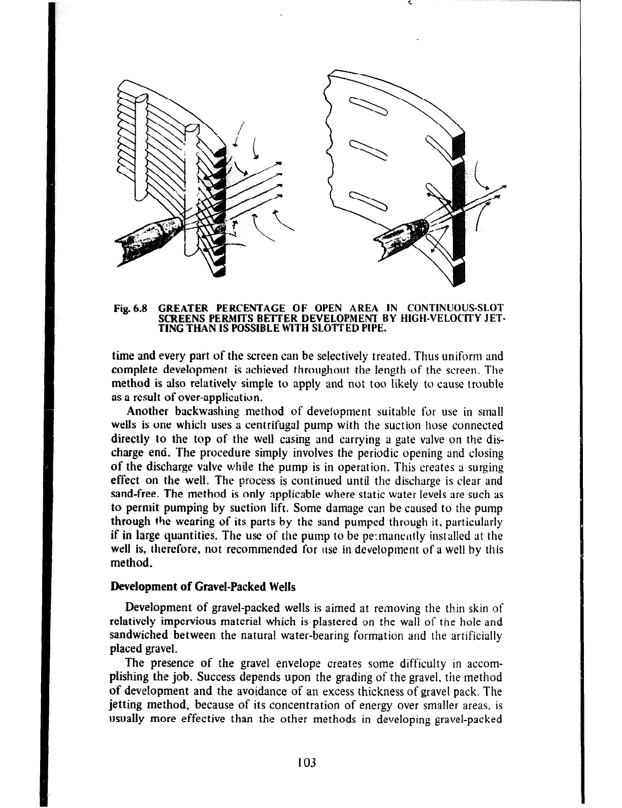
Fig.6.8 GREATER PERCENTAGE OF OPEN AREA IN CONTINUOUS-SLOT
SCREENS PERMIT3 BETTER DEVELOPMENT BY HIGH-VELOCITY JET-
TING THAN IS POSSIBLE WITH SLO’ITED PIPE.
time and
every part of the screen can be selectively treated.
Thus
uniform and
complete development is achieved throughout the length of the screen. The
method is also relatively simple to apply and not too likely to cause trouble
as a
result of
over-application.
Another backwashing method ojf deveiopment suitable for use in small
wells
is
one which uses a centrifugal pump with the suction hose connected
directly to the top of the well casing and carrying a gate valve on the dis-
charge
end. The procedure simply involves the periodic opening and closing
of the discharge valve while the pump is in operation. This creates a surging
effect on
the
well. The process is continued until the discharge is clear and
sand-free. The method is only applicable where static water levels are such as
to permit pumping by suction lift. Some damage can be caused to the pump
through the wearing of its parts by the sand pumped through it. particularly
if in large quantities. The use of the pump to be pe:manently installed at the
well is, therefore, not recommended for use in development of a well by this
method.
Development of Gravel-Packed
Wells
Development of gravel-packed wells is aimed at removing the thin skin of
relatively impervious material which is plastered on the wall of the hole and
sandwiched between the natural water-bearing formation and the artificially
placed gravel.
The presence of the gravel envelope creates some difficulty in accom-
plishing the job. Success depends upon the grading of the gravel, the method
of development and the avoidance of an excess thickness of gravel pack. The
jetting method, because of its concentration of energy over smaller areas, is
usually
more effective than the other methods in developing gravel-packed
I03
wells. The thinner the gratlel pack, the more likely is the removal of all of the
undesirable material, including any fine sand and silt. The use of dispersing
agents (described immediately below) such as polyphosphates effectively
assist in loosening sift and clay.
Dispersing Agents
Dispersing agents, mainly polyphosphates, are added to the drilling fluid,
backwashing or jetting water, or water standing in the well to counteract the
tendency of mud to stick to sand grams. These agents act by destroying the
gel-like properties of the drilling mud and dispersing the clay particles, thus
making their removal easier. Sodium hexametaphosphate is probably the best
known of these chemical agents. though tetra sodium pyrophosphate, sodium
tripolyphosphate and sodium septaphosphate are also effectively used in
well development. These agents work effectively when applied at the rate of
half a pound of the chemical to every LOO gallons of water in the well. The
mixture should be allowed to stand for about one hour before starting devel-
opment operations.
WELL DISINFEC-HON
Disinfection is the fmal step in the completion of a well. Its aim is the
destruction of ah disease-producing organisms introduced into the well during
the variotis construction operations. Entry of these organisms into the well
can occur through contaminated drilling water, on equipment, materials or
through surface drainage into the well. All newly constructed wells with the
possible exception uf flowing artesian wells should. therefore, be disinfected.
WeIls should also be disinfected after repair and before being returned to use.
The water from flowing artesian wells is generally free from contamination by
disease-producing organisms after being allowed to flow to waste for a short
while. If. however, analyses show persistent contamination, then the well
should be disinfected as described later in this chapter.
Because of the problems of testmb for specific disease-producing orga-
nisms, of which there may be several types present in water, coliform bacteria
are used as indicators of the possible presence of disease-producing organisms
of human or animal origin in water. Disinfection is, therefore, considered
complete when sampling :tnd testing of water show the presence of no
coliform bacteria. Sampling and testing should be undertaken by experienced
personnel from a health agency or recognized laboratory.
The well should be cleaned. as thoroughly as possible, of foreign sub-
stances such as soil, grease and oi! before disinfection. Disinfection is most
conveniently achieved by the addition of a strong solution of chlorine to the
well. The contents of the weLl should then be thoroughly agitated and al-
lowed to stand for several hours and preferably overnight. Care should also be
taken io wash all surfaces above the water level in the well with the disin-
fecting solution. Foliowing this. the
well
zhould be pumped icrtg enough to
change its contents several times and so flush the excess chlorine out of it.
Calcium hypochlorite is the most popular source of chlorine used in the
disinfection of wells. It is sold in chemical supply and some hardware stores
in the granular and tablet form containing 70 percent of available chlorine by
104
weight. It is fairiy siable when dry, retaining 90 percent of its original
chlorine content after one year’s storage. When moist, it loses its strength and
becomes quite corrosive. It should, therefore, be stored under cool, dry con-
ditions. Enough calcium hypochlorite should be added to the water standing
in the well to produce a solution of strength ranging from 50 to 200 parts per
million (ppmj by weight and usually about 100 ppm. A solution of approx-
imately 100 ppm chlorine can bc obtained by adding 2
ounces
or 4 heaped
tablespoons of calcium hypochlorite (containing 70 percent of available
chlorine) to every 100 gallons of water standing in the well. Usually for
convenience of application, a stock solution is made by mixing the caicium
hypochlorite with a small amount of water to form a smooth paste and then
adding the remainder of 2
quarts
of water for every ounce of the chemical.
Stir the mixture thoroughly for 10 to 15 minutes before allowing to settle.
The clearer liquid is then poured off for use in the well. A gallon of this
solution. when added to 100 gallons of water in the well, produces a solution
of strength approximately
equal
to 100 ppm of chlorine. The stock solution
should be prepared i!~ a thoroughly cleaned glass, crockery or rubber lined
container. Metd containers become corroded and should be avoided. Stock
solutions should be prepared to meet immediate needs only since they lose
strength rapidly
unless
properly stored in tightly covered dark glass or plastic
containers. Storage of the chemical in the dry form is much more desirable.
Sodium hypochlorite may be used in the absence of calcium hypochlorite.
This chemical is available only in liquid form and can be bought in strengths
of
up
to about
20 percent available chlorine. In its most common form,
household laundry bleach, it has a stJ-c?ngth of about 5 percent of available
chlorine. A
stock
solution of equivalent strengh to that made from calcium
hypochlorite and described in the previous paragraph can be made by dilcting
commercial bleach with twice as much water. This stock
solution
should also
be added to the well at the rate of one gallon to every 100 gallons of water in
the well.
Flowing artesian wells are disinfected, when necc;zT, hy !cJwering a per-
forated container, such as a short length of tubing capped at both ends, Zlzi?
with an adequate quantity of dry calcium hypochlorite to the bottom of the
well. The natural up flow of water in the well will distribute the dissolved
chlorine throughout the full depth of the well. A stuf’ig box can be used at
the top of the well to partially or completely restrict the flow and so reduce
the chiorine losses.
105
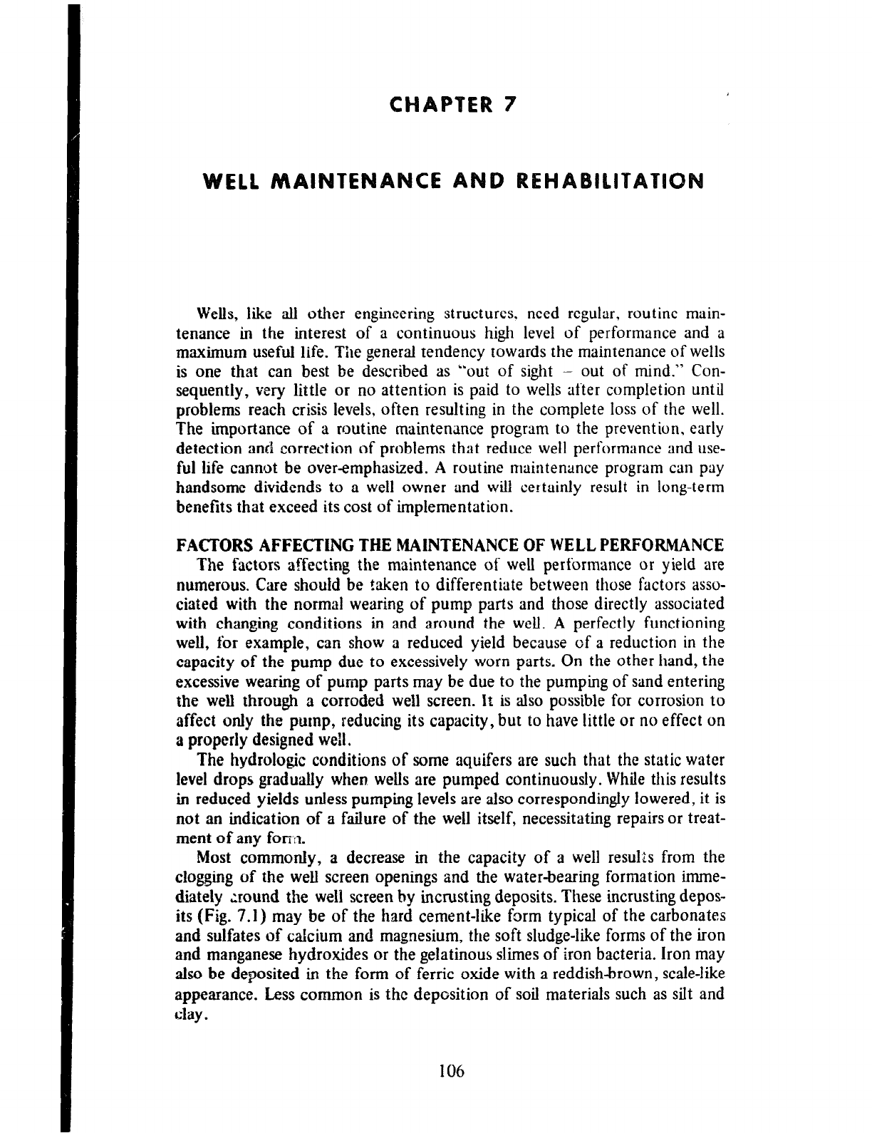
Wells, like all other engineering structures. need regular, routine main-
tenance in the interest of a continuous high level of performance and a
maximum useful life. The general tendency towards the maintenance of wells
is one that can best be described as “out of sight - out of mind.” Con-
sequently, very little or no attention is paid to wells after completion until
problems reach crisis levels, often resulting in the complete loss of the well.
The importance of a routine maintenance program to the prevention, early
detection and correction of problems that reduce well performance and use-
ful life cannot be overemphasized. A routine maintenance program can pay
handsome dividends to a well owner and will certainly result in long-term
benefits that exceed its cost of implementation.
FACTORS AFFECTING THE MAINTENANCE OF WELL PERFORMANCE
The
factors affecting the maintenance of well performance or yield are
numerous. Care should
be taken to differentiate between those factors asso-
ciated with the normal wearing of pump parts and those directly associated
with changing conditions in and around the well. A perfectly functioning
well, for example, can show a reduced yield because of a reduction in the
capacity of the pump due to excessively worn parts. On the other hand, the
excessive wearing of pump parts may be due to the pumping of sand entering
the weII through a corroded weli screen. It is also possible for corrosion to
affect only the pump, reducing its capacity, but to have little or no effect on
a properly designed well.
The hydrologic conditions of some aquifers are such that the static water
level drops graduaIly when. wells are pumped continuously. While this results
in reduced
yields
unless
pumping levels are also correspondingly lowered, it is
not
an indication of a failure of the well itself, necessitating repairs or treat-
ment of any forin.
Most commonIy, a decrease in the capacity of a well results from the
clogging of
the
well screen openings and the water-bearing formation imme-
diately xound
the well screen by incrusting deposits. These incrusting depos-
its (Fig. 7.1) may be of the hard cement-like form typical of the carbonates
and sulfates of calcium and magnesium, the soft sludge-like forms of the iron
and manganese hydroxides or the geIatinous slimes of iron bacteria. Iron may
also
be
deposited in the form of ferric oxide with a reddish-brown, scale-like
appearance. Less common is the deposition of soil materials such as silt and
cIay.
106
A B C
Fig. 7.1 FORMS OF INCRUSTATION.
__ L
A. Hard cement-like deposits of calcium and magnesium carbonates.
B. Gelatinous slime deposits typical of
iron b~t4~
C. Scale-like deposits of iron oxide completely plugging screen openings.
The deposition ot ctlrbomrtes and the compounds of iron and munganese
can often be traced to the release of carbon dioxide from the water. The
capacity of water to frofd carbon dioxide varies directly with the pressure
the higher the pressure. the greater tfre quantity of carbon dioxide fleld.
Pumping of a we11 reduces the pressure in and near the well. thus allowing the
escape of carbon dioxide to the atmosphere and altering tire chemical quality
of the water in such ;t manner as to cause the precipitation of carbonate and
iron deposits.
A change in velocity is another factor that can result in the precipitation
of iron and manganese hydroxides. This too occurs at 2nd near the well
screen where the velocity of the slowly flowing water is suddenly increased
on entry to the well.
PLANNING
The pianning of well maintenance procedures should be based on a system
of good record keeping. The preceding paragraphs have indicated that the
problems that result in reduced well yields occur at and around the well
screen and very much out of sight. The analysis of good records must, there-
fore, be relied upon as the source of problem detection in weflc. There can be
no substitute for the keeping of good records.
Among the records kept sfroufd be pumping rates. drawdown. total hours
-_-._
d
opcrztion,
puwt~r
consumption and water quafity analyses. Pumping rates
and drawdown are particularly useful in determining the specific capacity (dis-
charge per foot of drawdown) which is the best indicator of existing problems
in a well. The specific capacities of wells should be checked periodically and
compared with previous values including those immediately after completion
107
of the wells to determine whether significant reductions have taken place. A
significant reduction in the specific capacity of a well could often be traced to
blockage of the well screen and the formation around it, most likely by
incrusting deposits. As stated earlier. a reduction in the pump discharge
would not by itself be evidence of a reduced capacity of the well. If, however,
the drawdown in the well does not show an equal reduction, then the specific
capacity will be reduced, thus indicating the probability of an incrustation
problem.
Power consumption records also provide valuable evidence of the existence
of problems in wells. Should there be an increase in power consumption, not
accompanied by a corresponding increase in the quantity of water pumped,
then a problem is possible in either the pump or the well. Should an mvesti-
gation show no problems in the pump nor appreciable increase in the dynam-
ic head against which the pump has been operating, then it is most likely that
a problem exists in the well and that the problem is causing an increased
drawdown. A check on the drawdown should then be undertaken to verify
the deduction and the well checked for incrustation.
Since there would be no incrustation in the absence of incrusting chem-
icals in the water. the value of chemical analyses of well water is self-evident.
Such analyses are more useful as problem indicators if undertaken regularly.
They indicate the type of incrustation that might occur and the expected rate
of deposition in the well and its vicinity. The quality of some well waters
changes slowly with time and orl!y regular routine analyses would indicate
such changes.
In wells, the waters of which are known to be incrusting, the frequency of
observations of all types should be as high as possible and consistent with the
use to which the water is being put. Observations should be made muzh more
frequently at wells serving a community than at a private home-owner’s well,
since more people are dependent on the community wells. Power con-
sumption. well discharge, drawdown, operating hours and other such observa-
tions are often made daily on community wells and may even be done on a
continuous basis. Chemical analyses on such wells may be done on an annual,
semi-annual or quarterly basis, as conditions warrant them. Observations on
home-owner’s weils are usually much less frequent but should, nevertheless,
be undertaken regularly.
MAINTENANCEOPERATIONS
Maintenance operations should not be deferred until problems assume
major proportions as rehabilitation then becomes more difficult and some-
times impossible or impracticable. incrustation not treated early enough can
so clog the well screeri and the formation around it that it becomes extremely
difficult and even impossible to diffuse a chemical solution to all affected
points in the formation. Any attempts at rehabilitation would then prove
unsuccessful.
No methods have yet tzen developed for the complete prevention of
incrustation in wells. Various steps 2zn be taken to delay the process and
reduce the magnitude of its effects. Among these are the proper design of
well screens and the reduction of pumping
rates, both aimed at reducing
entrance velocities into screens and drawdown in wells. For
example, it may
be worthwhile to share the pumping load among
a larger number of wells in
order to reduce the rate of incrustation. Howel:er, the
ultimate or fmal solu-
tion will be in a regular cleaning program. incrusting wells are usually treated
with chemicals which either dissolve the incrusting deposits
or loosen them
from the surfaces of the well screen and formation materials so that the
deposits may be easily removed by bailing.
Acid Treatment
Acid treatment refers to the treatment
of a well with an acid, usually
hydrochloric (muriatic) acid or sulfamic acid for the removal
of incrusting
deposits. Both of these acids readily dissolve calcium and
magnesium carbon-
ate, though hydrochloric acid does so at a faster
rate. Strong hydrochloric
acid solutions also dissolve iron and manganese hydroxides. The simultaneous
use of an inhiiitor serves to slow up the tendency of the acid to attack steel
casing.
Wells are sometimes treated with acid in preparation for the withdrawal of
a screen either for re-use elsewhere or in the same well. For example, it may
be desirable to recover a screen that is in good condition from a well whose
casing has been corroded beyond usefulness. Or, a screen may be recovered
for more effective treatment against incrustation thBn can be achieved in the
well. In either case, a preliminary acid treatment to dissolve some of the
incrusting deposits will make it much easier to pull the screen.
Hydrochloric acid is usually available in three grades from chemical supply
shops. The strongest grade, designated as the 27.92 percent grade, should be
used. It is sold in either glass or plastic carboys containing about 12 gallons
each. If inhibited acid cannot be obtained, unflavored gelatin added at the
rate of 5 to 6 pound? ?o every 100 gallons of acid will prevent serious damage
to steel casing.
Hydrochloric acid should be used at full strength. Each treatment us&&y
requires l-112 to 2 times the volume of water in the screen. This provides
enough acid to fill the screen and additional acid to maintain adequate
strength as the chemical reacts with the incrusting materials. Fig. 7.2 illus-
trates a method of placing acid in a well. Acid is introduced within the screen
by means of a wide-mouthed funnel and 3/4- or l-inch black iron or plastic
pipe. Acid is heavier than water which it tends to displace but with which it
also mixes readily to become diluted. When used in long screens, acid should
be added in quantities sufficient to fill 5 feet of the screen and the conductor
pipe raised 5 feet after pouring each quantity.
The acid solution in the well should be agitated by means of a surge
plunger or other suitable means for 1 to 2 hours following which the well
should be bailed until the water is relatively clear. The driller usually can
detect an improvement in the yield of the well while running the bailer. The
well may, however, be pumped to determine the
extent
of improvement. If
this is not as expected, then the treatment may be repeated using a longer
period of agitation before bailing. A third treatment may even be undertaken.
The procedure is sometimes varied to alternate acid
treatment and
chlorine
109
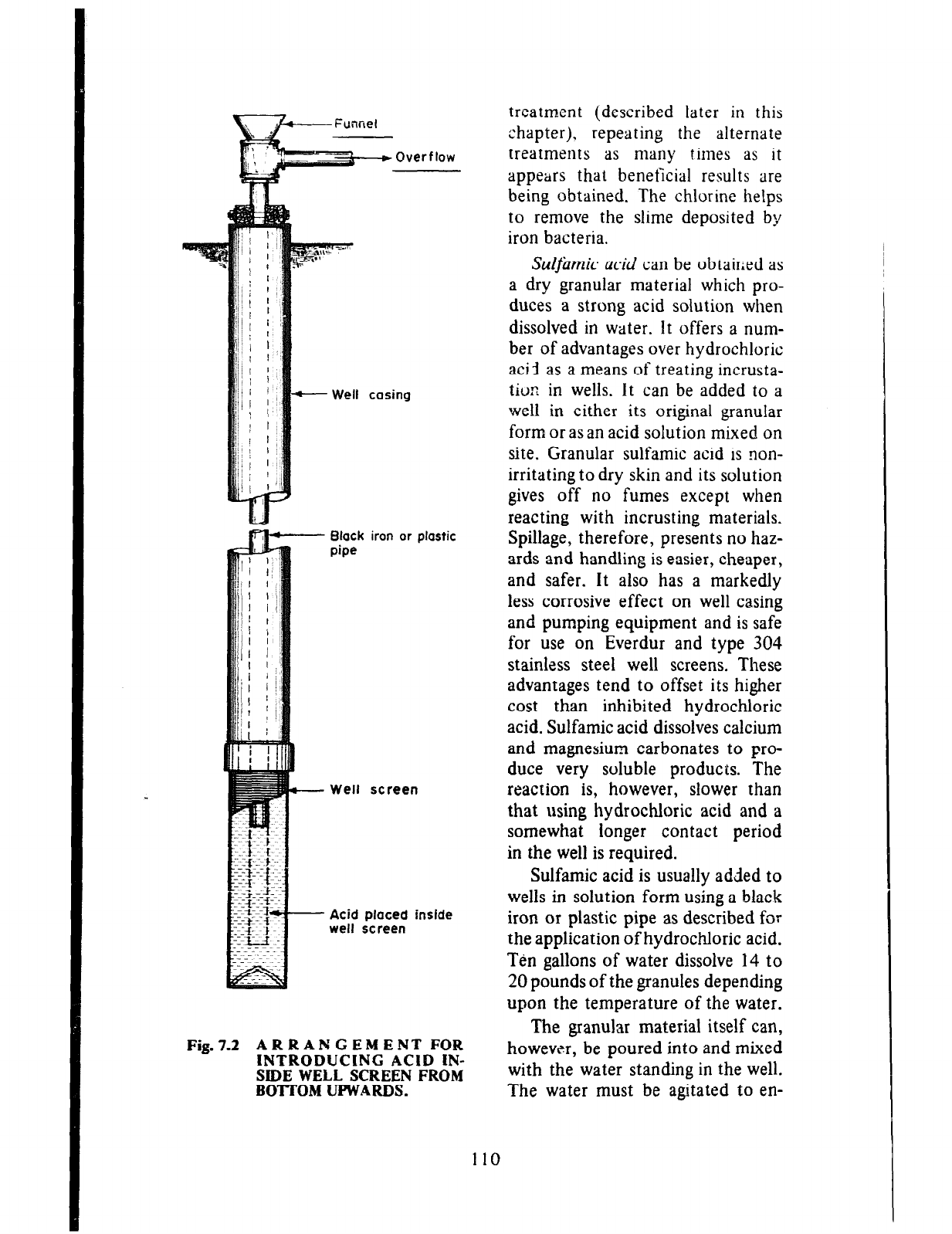
Black iron or plastic
pipe
Well screen
Acid placed inslde
well screen
Fig.7.2 ARRANGEMENT FOR
INTRODUCING ACID IN-
SIDE WELL SCREEN FROM
BOTTOM UPWARDS.
treatment (described later in this
chapter,), repeating the alternate
treatments as many times as it
appears that beneficial results are
being obtained. The chlorine helps
to remove the slime deposited by
iron bacteria.
Sulj~mk acid can be obtained as
a dry granular material which pro-
duces a strong acid solution when
dissolved in water. It offers a num-
ber of advantages over hydrochloric
acid as a means of treating incrusta-
tion in wells. It can be added to a
well in either its original granular
form or as an acid solution mixed on
site. Granular sulfamic acid is non-
irritating to dry skin and its solution
gives off no fumes except when
reacting with incrusting materials.
Spillage, therefore, presents no haz-
ards and handling is easier, cheaper,
and safer. It also has a markedly
less corrosive effect on well casing
and pumping equipment and is safe
for use on Everdur and type 304
stainless steel well screens. These
advantages tend to offset its higher
cost than inhibited hydrochloric
acid. Sulfamic acid dissolves calcium
and magnesium carbonates to pro-
duce very soluble products. The
reaction is, however, slower than
that using hydrochloric acid and a
somewhat longer contact period
in the well is required.
Sulfamic acid is usually added to
wells in solution form using a black
iron or plastic pipe as described for
the application of hydrochloric acid.
Ten gallons of water dissolve 14 to
20 pounds of the granules depending
upon the temperature of the water.
The granular material itself can,
however, be poured into and mixed
with the water standing in the well.
The water must be agitated to en-
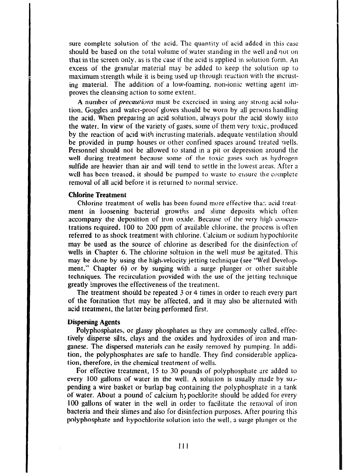
sure complete solution of the acid. The quantity of acid added in this case
should be based on the total volume of-water standing in the well and not on
that in the screen only. as is the case if the acid is applied in solution form. An
excess of the granular material may be added to keep the solution up to
maximum strength while it is being used up through reaction with the tncrust-
mg material. The addition of a low-foaming, non-ionic wetting agent im-
proves the cleansing action to some extent.
A number of precatctims must be exercised in using any strong acid solu-
tion. Goggles and water-proof gloves should be worn by all persons handling
the acid. When preparing an acid solution, always pour the acid slowly into
the water. In view of the variety of gases, some of them very to.xic, produced
by the reaction of acid with incrusting materials, adequate ventilation should
be provided in pump houses or other confined spaces around treated wells.
Personnel should not be allowed to stand in a pit or depression around the
well during treatment because some of the toxic gases such as hydrogen
sulfide are heavier than air and will tend to settle in the lowest areas. ,Zfter a
well has been treated, it should be pumped to waste to ensure the complete
removal of all acid before it is returned to normal service.
Chlorine Treatment
Chlorine treatment of wells has been found more effective tha:: acid treat-
ment in loosening bacterial growths and slime deposits which often
accompany the deposition of iron oxide. Because of the very high concen-
trations required. 100 to 200 ppm of available chlorine, the process is often
referred to as shock treatmetrt with chlorine. Calcium or sodium hypochlorite
may
be used as
the source of cfllorine as described for the disinfection of
wells in Chapter 6. The chlorin e soltuion in the well must be agitated. This
may
be
done by using the high-velocity jetting technique (see “Well Develop
ment,” Chapter 6) or by surging with a surge plunger or other suitable
techniques. The recirculation provided with the use of the jetting technique
greatly
Improves the effectiveness of the treatment.
The treatment shotild be repeated 3 or 4 times in order to reach every part
of the formation thet may be affected, and it may also be alternated with
acid
treatmeni, the latter being performed first.
Dispersing Agents
Polyphosphates, or glassy phosphates as they are commonly called, effec-
tively disperse silts, clays and the oxides and hydroxides of iron and man-
ganese. The dispersed materials can be easily removed by pumping. In addi-
tion,
the polyphosphates are safe to handle. They find considerable applica-
tion, therefore, in the chemical treatment of wells.
For effective treatment, 15 to 30 pounds of polyphosphate are added lo
every 100 gallons of water in the well. A solution is usually made by SUJ-
pending a wire basket or burlap bag containing the polyphosphate in a tank
of water. Abo,ut a pound of calcium h; pochlorite should be added for every
IOU gallons
of
water in the well in order to facilitate the removal of iron
bacteria and their slimes and also for disinfection purposes. After pouring this
polyphosphate and Eypochlorite solution into the well, a surge plunger or the
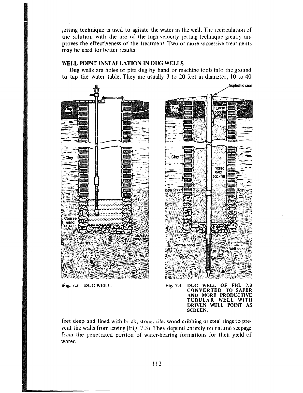
,&ting technique is used to agitate the water in the well. The recirculation of
the solution with the use of the high-velocity jetting technique greatly im-
proves the effectiveness of the treatment. Two or more successive treatments
may be used for better results.
WELLPOINTINSTALLATPONINDUGWELLS
Dug wells are holes or pits dug by hand or machine tools into the ground
to tap the water table. They are ususclly 3 to 20 feet in diameter, IO to 40
/
Asphaltic seal
Fig. 7.3 DUG WELL. Fig. 7.4 DUG WELL OF FIG. 7.3
CONVERTED TO SAFER
AND MORE PRODUCTIVE
TUBULAR WELL WlTH
DRIVEN WELL POINT AS
SCREEN.
feet deep and lined with brick, jiune, tile. wood cribbing or steel rings to pre-
vent the walls from caving (Fig. 7.3). They depend entirely on natural seepage
from the penetrated portion of water-bearing formations for their yield of
water.
This type of well is at a disadvantage on two scores when compared with
tubular wells of the type so far described. Firstly, dug wells are much more
diffcu!t to maintain in a sanitary condition. Secondly, their yields are very
low, because they do not penetrate very far into the water-bearing formation
and cannot be developed in a similar manner to screened wells.
Dug wells usually can be made much safer and more productive by driving
well points into the water-bearing formation and thus converting them into
tubular wells. A properly developed well with a short length of 2” drive-
point screen will usually produce water at
3
much higher rate than can be had
from a dug well several feet in diameter. The annular space between the casing
of the driven well and the wall of the existing well shouid be back-filled with
a puddled clay or other suitable material. The sanitary precautions with re-
spect to the completion of the upper terminal of
3
well (described in Chapter
4) should be observed. The wall of the existing dug well may be cemented
prior to back-filling. A converted dug well is illustrated in Fig. 7.4.
113
Drilling and completing a well form only part of a solution to the
problem of getting water in sufficient quantity where it is desired for use.
Small wells are generally used for supplying water to a horn&:, a group of
homes or other such limited consumers of water as a small factory. The water
is usually required for use at elevations somewhat higher than tkose at which
the water is found in the well and, often, some appreciable distance from the
well. Therefore, some means must be found of lifting the water from a well
and forcing it through pipes at suitable velocities to the points and elevations
of use. Tfke exception to this general statement is the case of the flowing
artesian well, which has a sufficiently high discharge at an adequate pressure
to meet the limited demands of one or a few small holmes without any
external help. Generally, however, help is needed, and this is provided in the
form of a suitable pump. It is important that the pump be a suitable cjne,
selected on the basis of the demand to be fulfilled and the capacity of the
well to yield water. It cannot and must not be just any pump, as it is then
unlikely that the needs will be met. Pump selection is discussed later in this
chapter.
Pumps do not develop power of their own. Some ex!ernal source of power
must be provided to drive a pump and so
cause
it to lift and force water from
one point to another. The source of power may be the man who uses his hand
to operate
3
lever upward and downward or forward and backward or who
turns a wheel connected to the pump. In this case, the pump is said to be
manually operated or hand driven. The power source may also be a windmill,
an electric motor or an engine which burns a fuel such as gasoline or diesel
oil.
A very common error is not being able to distinguish between a pump and
its motive or driving force, particularly when that force is an engine or motor
directly coupled to the pump. Care should be taken to avoid this,
3s
the
problems of pumps, engines and motors are very different and need different
approaches to solve them.
The action of most pumps can be divided into two parts. The first is the
lifting of the water from some lower level to the pump intake or suction side
of the pump. The second is concerned with applying pressure to the water in
the pump to force the water to its destination,
SU&MZ
lift:
Consider an openended tube which is suspended vertically in
a large container of water (Fig. 8.IA). Since the water both within and
without the tube is exposed to the atmosphere, the only external force acting
114
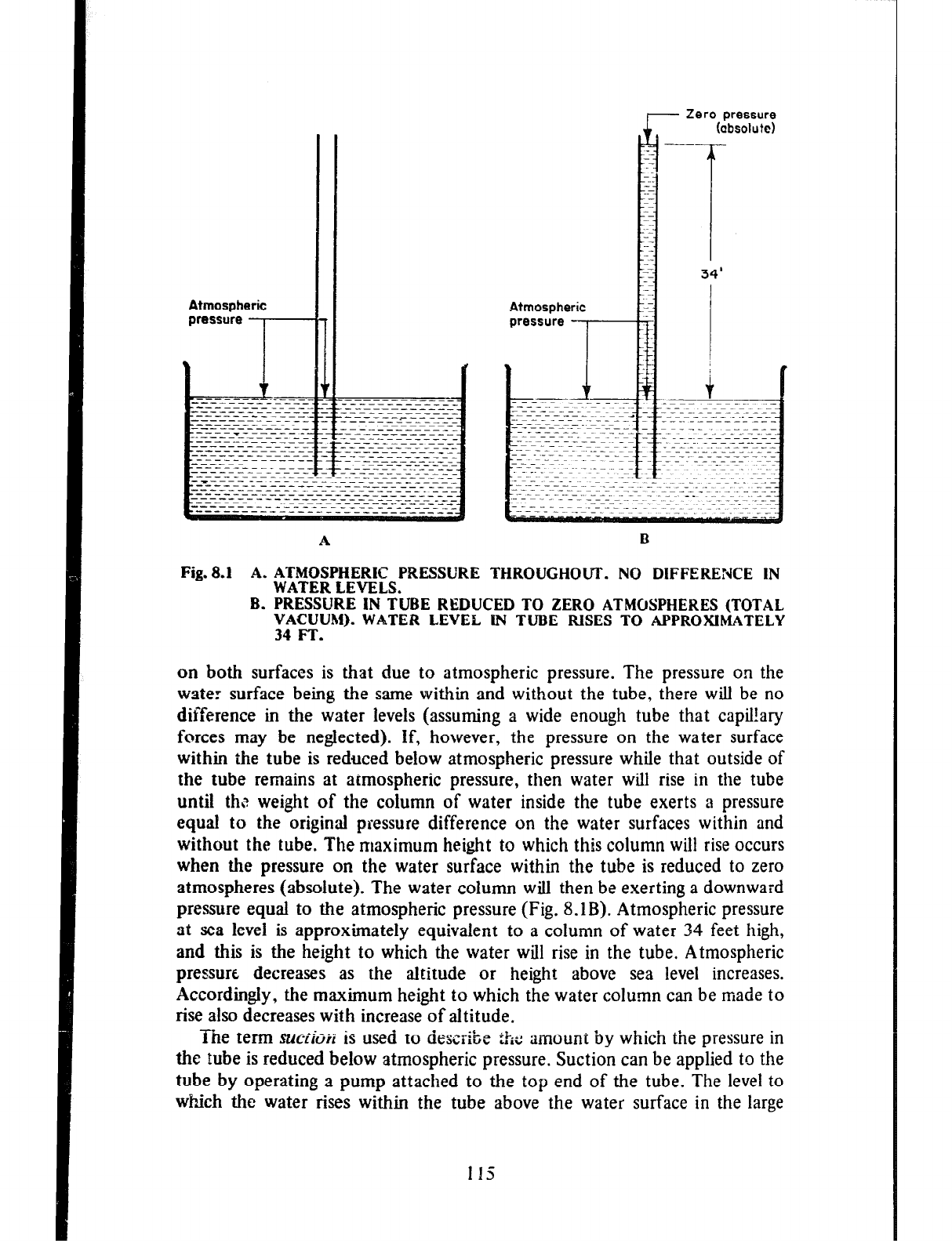
Atmospheric
pressure
?-
A
Zero pressure
(absolute)
Atmospheric
Fig. 8.1 A. ATMOSPHERIC PRESSURE THROUGHOUT. NO DIFFERENCE IN
WATER LEVELS.
B. PRESSURE IN TUBE REDUCED TO ZERO ATMOSPHERES (TOTAL
VACUUM). WATER LEVEL W TUBE RISES TO APPROXIMATELY
34 FT.
on both surfaces is that due to atmospheric pressure. The pressure on the
water surface being the same within and without the tube, there will be no
difference in the water levels (assuming a wide enough tube that capil!ary
forces may be neglected). if, however, the pressure on the water surface
within the tube is reduced below atmospheric pressure while that outside of
the tube remains at atmospheric pressure, then water will rise in the tube
until th,? weight of the column of water inside the tube exerts a pressure
equal to the original pressure difference on the water surfaces within and
without the tube. The maximum height to which this column wilt rise occurs
when the pressure on the water surface within the tube is reduced to zero
atmospheres (absolute). The water column will then be exerting a downward
pressure equal to the atmospheric pressure (Fig. 8.1B). Atmospheric pressure
at
sea
level is approximately equivalent to a column of water 34 feet high,
and this is the height to which the water will rise in the tube. Atmospheric
pressure decreases as the altitude or height above sea level increases.
Accordingly, the maximum height to which the water column can be made to
rise
also
decreases with increase of altitude.
The term SUCY~M is used to describe ihc amount by which the pressure in
the tube is reduced below atmospheric pressure. Suction can be applied to the
tube by operating a pump attached to the top end of the tube. The level to
which the water rises within the tube above the water surface in the large
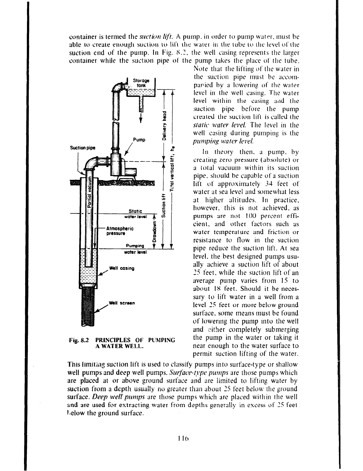
container is termed the
srrctiorl hji. AL
pump. in order to pump water. must be
able to create enough suction to lift the water in the tube to the level of the
suction end of the pump. In Fig. 8.2, t!le well casing represents the larger
container while the suction pipe of the pump takes the place of the tube.
Pump
/ 4 I
Note- that the lifting of the water in
the suet ion pipe must be ;ICCOII~-
parlied by ;1 lowering of the water
level in the well casing. The water
level within the casing :lild the
suction pipe before the pump
created the suction lift is called the
stuck rryater IwA
The level in the
well txing during pumping is the
privrpirlg bvater level.
I-
Atmospheric w
PI I
water bfsl
./ Wall casing
Well screen
Fig.8.2 PRINCIPLES OF PL'MPINC
AWATERWELL.
In theory then, a pump, by
creating zero pressure (absolute) or
9 total vacuum within its suction
pipe. should be capable of ;1 suction
lift of ~ppruximately 34 feet of
water at sea level and somewhat less
3t higher altitudes. In practice,
however. this is not achieved. as
pumps are not 101) percent effi-
cient. and other fxtors such ;LS
water temperature and friction or
resistance to flow in the suction
pipe reduce the suction lift. At sea
level. the best designed pu171ps usu-
ally achieve ;I suction lift of about
‘5 feet. while the suction lift of an --
average pump varies from 15 to
about IX feet. Should it be neces-
sary to lift water in ;t well from a
level 25 feet or more below ground
surfxe. some mc;ms must bc found
of lowering the pump into the well
and ::ither completely submerging
the pump in the water or taking it
near enough to the water surface to
pertnit suction lifting of the water.
This iimitiq suction lift is used to classify pumps into surface-type or shalPow
well pumps and deep well pumps.
SurjIzce-type pumps
are those pumps which
are placed at or above ground jurfrtce rind are iimited to lifting water by
suction fronl a dzpth . . ..-...II-. -.. .---
l L . .._. . .
uxkmy IIU ;;lvdtCi iihui LL
b
iiiit 25
fe?i
belo’* the ground
surface.
Deep
\treI!
prmps
are those pumps which arc placed within the well
and are used for extracting water frotn depths generally in L’XWSS of 25 feet
I.elow the ground surface.
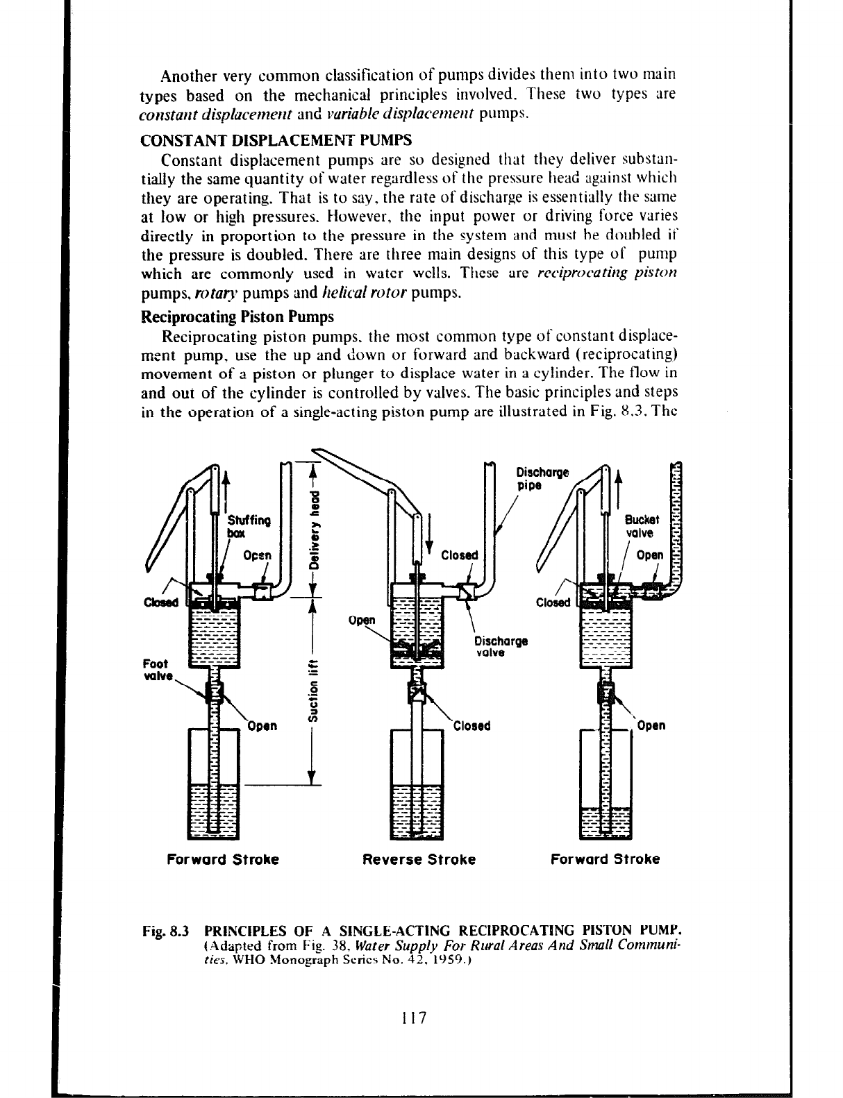
.4nother very common classification of pumps divides them into two main
types based on the mechanical principles involved. These two types are
comtant dispkemertt
tend
wriable displacemerlt pumps.
CONSTANT DISPLACEMENT PUMPS
Constant displacement pumps are so designed that they deliver substan-
tially the same quantity of water regardless of the pressure head against which
they are operating. That is to say. the rate of discharge is essentially the same
at low or high pressures. However, the input power or driving force varies
directly in proportion to the pressure in the system and must be doubled ii
the pressure is doubled. There are three main designs of this type of pump
which are commonly used in water wells. These are reciprocatirlg piston
pumps, rotaop pumps and helical rotor pumps.
Reciprocating Piston Pumps
Reciprocating piston pumps, the most common type of constant displace-
mcnt pump.
use the
up and down or forward and backward (reciprocating)
movement of a piston or plunger to displace water in a cylinder. The flow in
and out of the cylinder is controlled by valves. The basic principles and steps
in the operation of a single-acting piston pump are illustrated in Fig. 8.3. The
Forward Stroke
II
Dischargei
Closed
Reverse Stroke
‘Open
Forward Stroke
Fig. 8.3 PRlNCIPLES OF A SINGLE-ACTING RECIPROCATING PISTON PUMP.
(Adapted
from Fig. 38, Water Supply For Rural Areas And Small Communi-
fies,
WHO
!+Ionograph
Series No.
42,
1959.)
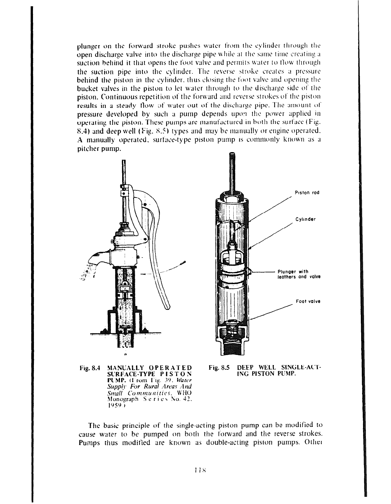
plunger on the tijrward stroke p~~shes writer t‘rw~~ the c‘ylittdcr through tllc
open dischye vltlve into the dischxge pipt‘ u tlilc at 111~ suw timt’ crcatins ;I
suction behind it thttr ~~p~nj the foot valw ;md pc’rmits water to tlobv tllrou$1
the suction pipe into the cylinder. ‘l‘hc ~‘t’vt’rst St:-ohc ctwtes ;I prcssurt2
behind the piston in the cylinder. thus chin, 11 the foot valve and opcnilig the
bucket vrtlves in the piston tu let water through to ttlt‘ discharge side ot‘ tllc
piston. Continuous repetition of the for\i,xd and rcvc’lsc strokes of the piston
results in 9 steady tlow at watt‘r out of the dishargc pipe. ‘fhc amount 01’
pressure developed by such ;t pump depetlds upw the power applied in
operating the piston. Tht~se pumps art‘ manufxtured irl both the surt’vce (Fig.
S-4) and deep well (Fig. S.5) typ t‘s and may be manually or enpinc operated.
.4 m;~nutllly operated. surP>c+type piston pump is c~~rnnnc~nly known ;1s ;I
pitcher pump.
Fig. 8.5 DEEP WELL SINGLE-ACT-
ING PISTON PUMP.
The basic principle of the single-acting piston pump can be modified to
cause water to be pumped on both the forward and the reverse strokes.
Pumps thus modified are known a:$ double-acting piston pumps. 0 ther
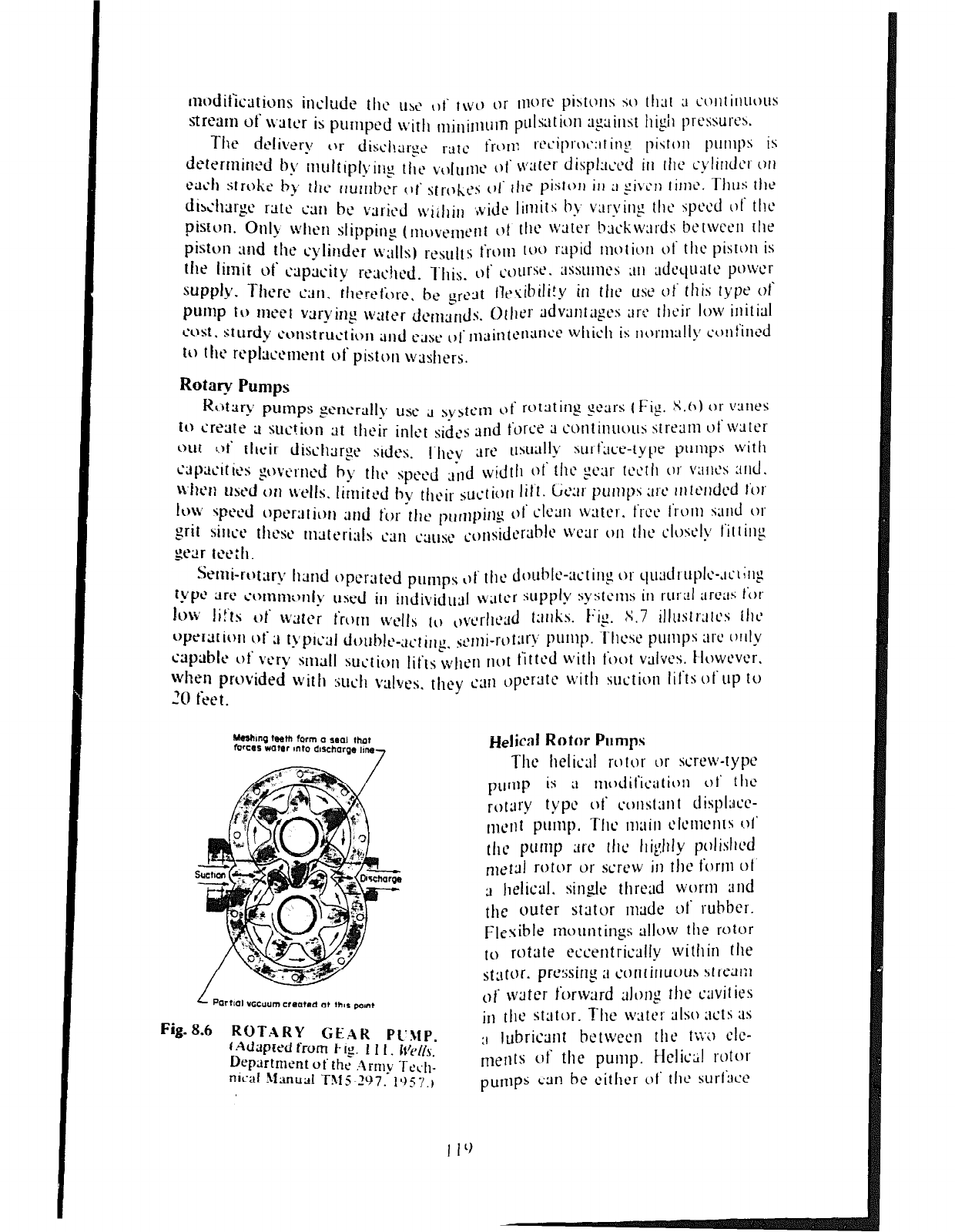
Helical Rotor Pumps
Tilt helical rcjtor
or screw-type
purup is
;I Itlc~~it’i~a~i~~Il 01’ tilt2
rotary type i)t’ cotlslaII t dispiscc-
111cnt purrlp. The Iil;iitl
clcllIctIls 01’
tllc purllp
;trc lllc IIiglIly !~~~iisitcd
nletlli rotor or screw it1 the fort11 ot
3 Ileiicai. sin& thread worr11 and
the outer stritor nlade of rubber.
Flexible
171ountinps allow tile rotor
to rotate eccentrically within the
st:ltor. prthng ;I corltitluc)us !;trel,r:I
01 water forward alo~lg rhc cavities
jr1 tilt2 stator. The water ;1iso acts as
3 lubricant bctwecn the ti:‘;) clc-
melItS of tile pump. Hclic;;! rotor
puIllpS cm hc citficr 01’ tllc surt’licc
I I‘)
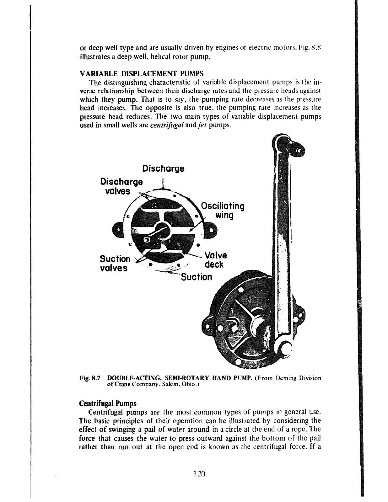
or deep well type and are usually driven by engines or electric motors. Fig. 8.8
illustrates a deep well, helical rotor pump.
VARIABLE DISPLACEMENT PUMPS
The distinguishing characteristic of variable displacement pumps is the
in-
verse relationship between their discharge rates and the pressure heads against
which they pump. That is to say, the pumping rate decreases as the pressure
head increases. The opposite is also true, the pumping rate increases as the
pressure head reduces. The two main types ot’ variable displacemer:t pumps
used in small wells .are
centrif~rlgal
and@ pumps.
Discharge
Discharga 1
Fig. 8.7 DOUBLE-ACTING, SEMI-ROTARY HAND PUMP.
(From Deming Division
of Crane Company. Salem. Ohio.)
Centrifugal Pumps
Centrifugal pumps are the most common types of pumps in general use.
The basic principles of their operation can be illustrated by considering the
effect of swinging a pail of water around in a circle at the end of a rope. The
force that causes the water to press outward against the bottom of the pail
rather than run out at the open end is known as the centrifugal force. If a
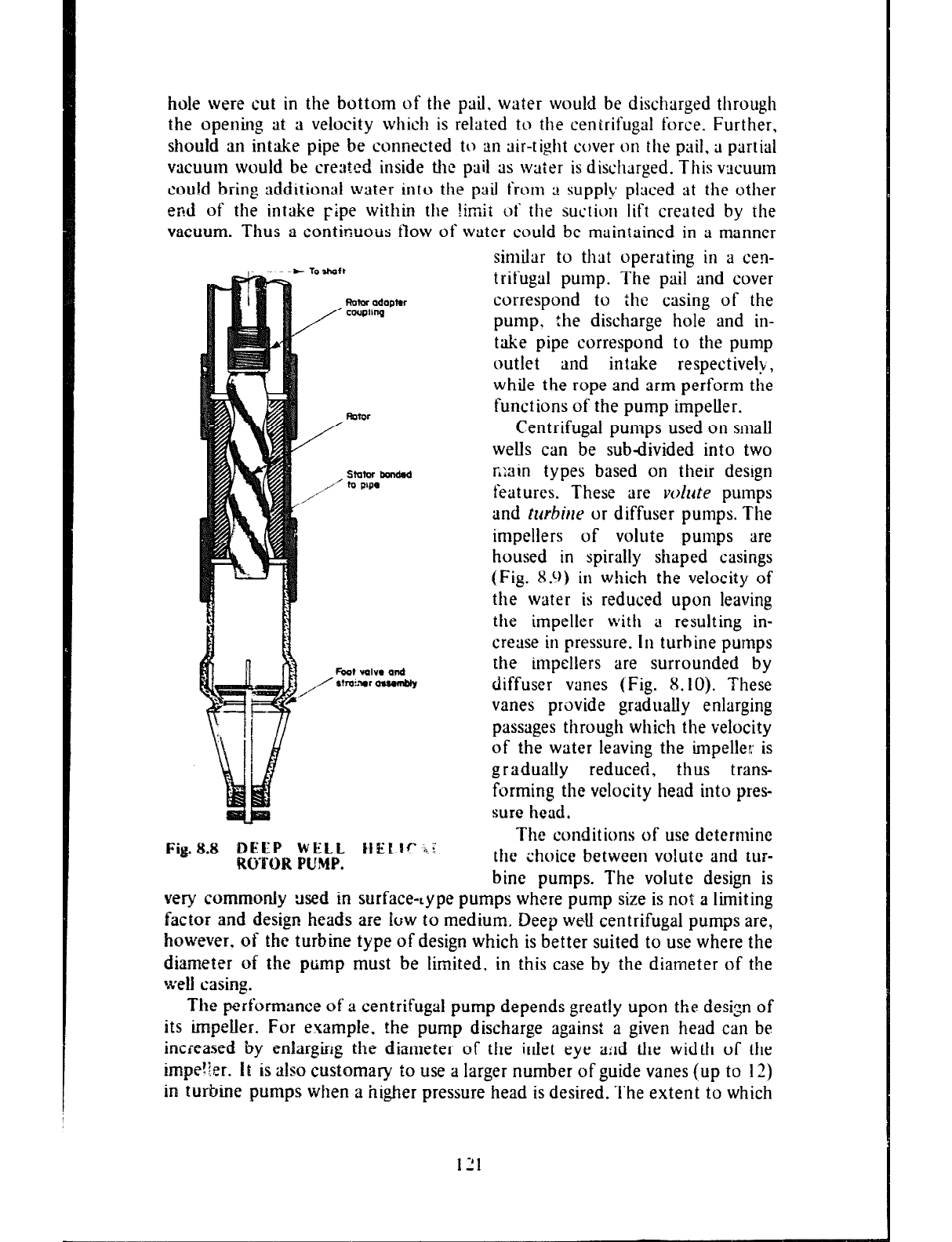
hole were cut in the bottom of the pail. water would be discharged through
the opening at a velocity which is related to the centrifugal force. Further,
should an intake pipe be connected to an air-tight cover on the pail, a partial
vacuum would be created inside the pail as waier is discharged. This vacuum
could bring additional water into the pail from ;! supply placed at the other
end of the intake Flpe within the 1imii of the suction lift created by the
vacuum. Thus a continuous ilow of water could be maintained in a manner
similar to that operating in a cen-
trifugal pump. The pail and cover
correspond to ihe casing of the
pump, the discharge hole and in-
take pipe correspond to the pump
outlet and intake respective&,
while the rope and arm perform the
functions of the pump impeller.
Centrifugal pumps used on small
weUs can be subdivided into two
statw bmldod r,;ain types based on their design
features. These are volute pumps
and
tttrbirte
or diffuser pumps. The
impellers of volute pumps are
housed in spirally shaped casings
(Fig. X.9) in which the velocity of
the water is reduced upon leaving
the impeller with a resulting in-
crease in pressure. In turbine pumps
the impellers are surrounded by
diffuser vanes (Fig. 8.
IO).
These
vanes provide gradually enlarging
passages through whic!l the velocity
of the water leaving the impeller is
gradually reduced, thus trans-
forming the velocity head into pres-
sure head.
The conditions of use dcterminc
Fig.8.8 BEEP WELL ttEL.lc ;$?.
‘ROTOR PUMP.
the choice between volute and tur-
bine pumps. The volute design is
very commonly
x+ed
in surface-Lype pumps where pump size is not a limiting
factor and design heads are low to medium. Deep wetl centrifugal pumps are,
however, of the turbine type of design which is better suited to use where the
diameter of the pump must be limited, in this case by the diameter of the
well casing.
The performance
of a centrifugal pump depends greatly upon the design of
its impeller. For example. the pump discharge against a given head can be
increased by
enlarging the diameter of the inlet eye agd the width of the
impe%x. it is
also customary to use a larger number of guide vanes (up to 12)
in turbine pumps when a higher pressure head is desired. The extent to which
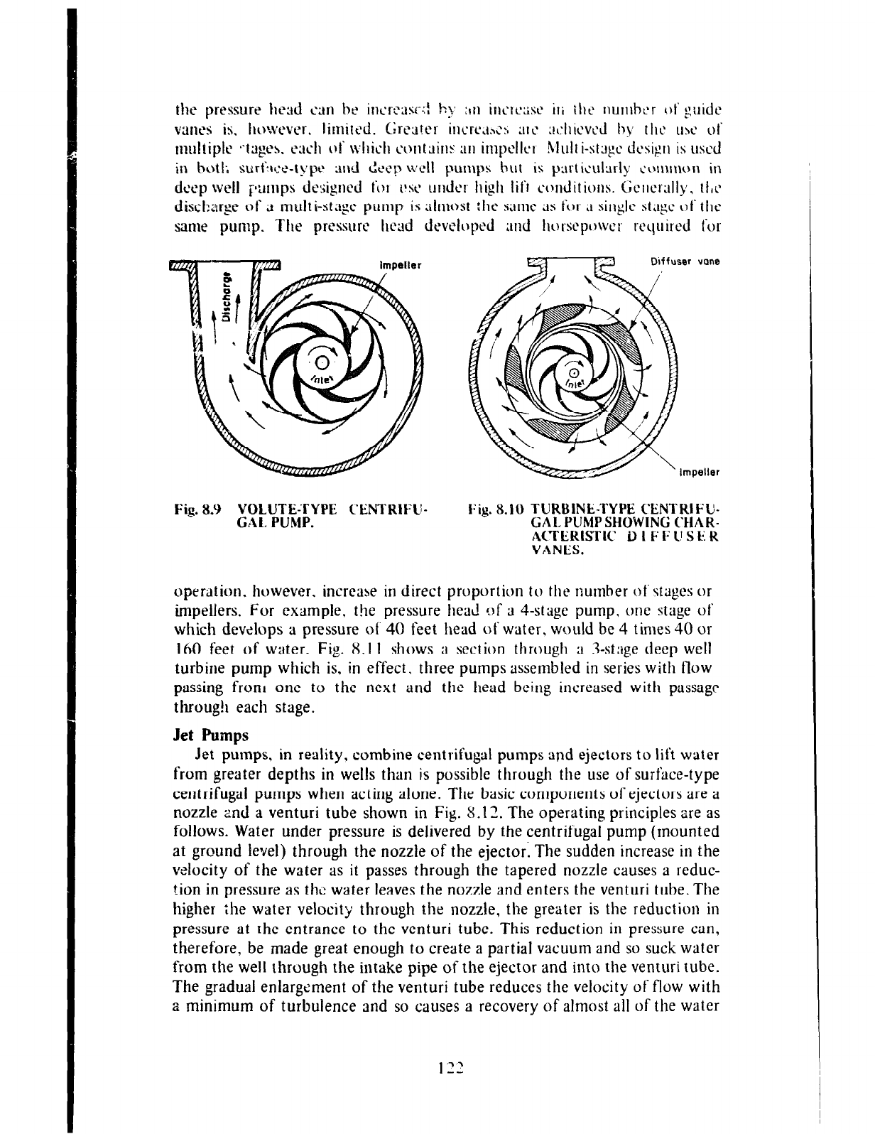
Dtffuser vane
Fig. 8.9 VOLUTE-TYPE C’ENTRIFU-
CAL PUMP. k:ig. 8.10 TURBINE-TYPE C’ENTRIFU-
CAL PlJMP SHOWING (‘HAR-
A~TERISTIC D I F 1; I! SE R
VANES.
operation. however. increase in direct proportion to the number of stages or
impellers. For fxampte. the pressure
tied
uf
3
4-stage
pump, me
stage ot
which devztops a pressure ot. 40 feet head of water, would be 4 times 40 or
IhO feet of water. Fig. X.1 I shows a section through a Sstage deep well
turbine pump which is, in effect. three pumps assembled in series with flow
passing from one to the next and the head being increased with passage
throug!i each stage.
Jet Pumps
Jet pumps, in reality. combine centrifugal pumps and ejectors to lift water
from greater depths in wells than is possible through the use of surface-type
centrifugal pumps when acting alone. The basic components of ejectors are a
nozzle 2nd a venturi tube shown in Fig. S.l 2. The operating principles are as
follows. Water under pressure is delivered by the centrifugal pump (mounted
at ground level) through the nozzle of the ejector. The sudden increase in the
velocity of the water as it passes through the tapered nozzle causes a reduc-
tion in pressure as the water leaves the nozzle and enters the venturi tube. The
higher the water velocit y through the nozzle, the greater is the reduction in
pressure at the entrance to the venturi tube. This reduction in pressure can,
therefore, be made great enough to create a partial vacuum and so suck water
from the welt through the intake pipe of the ejector and into the venturi tube.
The gradual enlargement of the venturi tube reduces the velocity of flow with
a minimum of turbulence and so causes a recovery of almost all of the water
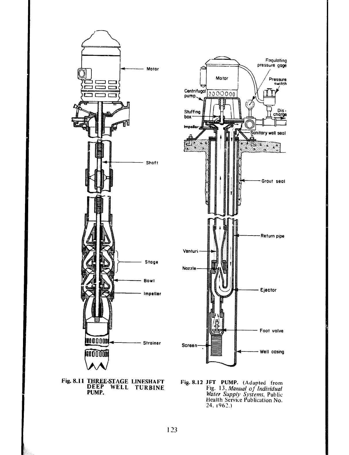
Sboft
Stage
Impeller
Strainer
Fig. 8.1 I THREE-STAGE LINESHAFT
DEEP WELL TURBINE
PUMP.
Venturi -
Screen-
-
I-
Grout seal
-Return pipe
- Ejector
~ Foot valve
t------Well casing
Fig. 8.12
JFT PUMP. (Adapted from
Fig. 13.
MQFZUQ~
of Individual
Water Supply Systems.
Pub lit
Health Service Publication No.
24. 1962.)
I 23
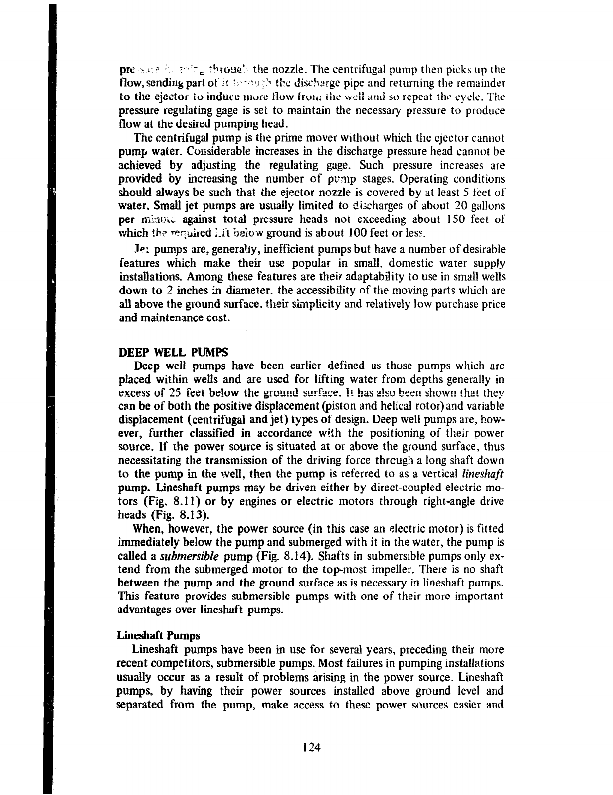
pre y.,,:~ 1; +-.b to,
rourT the nozzle. The centrifugal pump then picks up the
flow,sendirlgpart ot’i! :1,-::<j.:!x the disc?large pip
e and returning the remainder
to the ejector to induce mwre GW trolij tilti t\eii and so repeat thr cycle. The
pressure regulating gage is set to maintain the necessary pressure to produce
flow al the desired pumping head.
The centrifugal pump is the prime mover without which the ejector camlot
pump water. Considerable increases in the discharge pressure head cannot be
achieved by adjusting the regulating gage. Such pressure increases are
provided by increasing the number of pump stages. Operating conditions
should always be such that the ejector nozzle is covered by at least 5 feet of
water. Small jet pumps are usually limited to dixharges of about 20 gallons
per rnlnr~;, against total pressure heads not exceeding about 150 feet of
which tb
p ~tq&xzd Xt beioilv ground is about 100 feet or lesz.
Jp: pumps are, generajjy, inefficient pumps but have a number of desirable
features which make their use popular in small, domestic water supply
ir&allations. Among these features are their adaptability to use in small wells
down to 2 inches h diameter. the accessibility of the moving parts which are
all above the ground surface, their Gnplicity and relatively low purchase price
and maintenance cost.
DEEP WELL PUMPS
Deep well pumps have been earlier defined as those pumps which are
placed within wells and are used for lifting water from depths generally in
excess of 25 feet below the ground surface. !t has a!so been shown that they
can be of both the positive displacement (piston and helical rotor) and variable
displacement (centrifugal and jet) types of design. Deep well pumps are, how-
ever, further classified in accordance with the positioning of their power
source. If the power source is situated at or above the ground surface, thus
necessitating the transmission of the driving force thrcugh a long shaft down
to the pump in the lvell, then the pump is referred to as a vertical
lineshaft
pump. Lineshaft pumps may be driven either by direct-coupled electric mo-
tors (Fig. 8.11) or by engines or electric motors through right-angle drive
heads (Fig. 8.13).
When, however, the power source (in this case an electric motor) is fitted
immediately below the pump and submerged with it in the water, the pump is
called a submersible pump (Fig. 8.14). Shafts in submersible pumps only ex-
tend from the submerged motor to the topmost impeller. There is no shaft
between the pump and the ground surface as is necessary in lineshaft pumps.
This feature provides submersible pumps with one of their more important
advantages over lineshaft pumps.
Line&&t Pumps
Lineshaft pumps have been in use for several years, preceding their more
recent competitors, submersble pumps. Most failures in pumping installations
usually occur as a result of problems &sing in the power source. Lineshaft
pumps, by having their power sources installed above ground level and
separated from the pump, make access to these power sources easier and
124
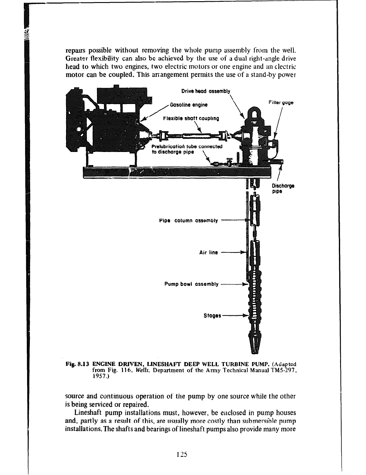
repas possible without removing the whole pump assembly from the well.
Greater flexibility can also be achieved by the use of a dual right-angle drive
head to which two engines, two electric motors or one engine and an electric
motor can be coupled. This arrangement permits the use of a stand-by power
Drive head assembly
\
, Gasoline engine \ Filler gage
/ Flexible shaft coupling
Prelubricatiori tube connected I
to dimharoa
aim \
u
Discharge
pipe
Pipe column assembly
Air line
Pump bowl assembly
Stages
Fig. 8.13 ENGINE DRIalEN, LINESHAFT DEEP WELL TURBINE PUMP.
(Adapted
y;5..Pig.
116,
Wells,
Deptiment
of the Army Technical Manual TMS-297,
source and continuous operation of the pump by one source while the other
is being serviced or repaired.
Lineshaft pump installations must, however, be enclosed in pump houses
and, partly as a result of this, are usually more costly than submersible pump
installations. The shafts and bearings of lineshaft pumps also provide many more
125
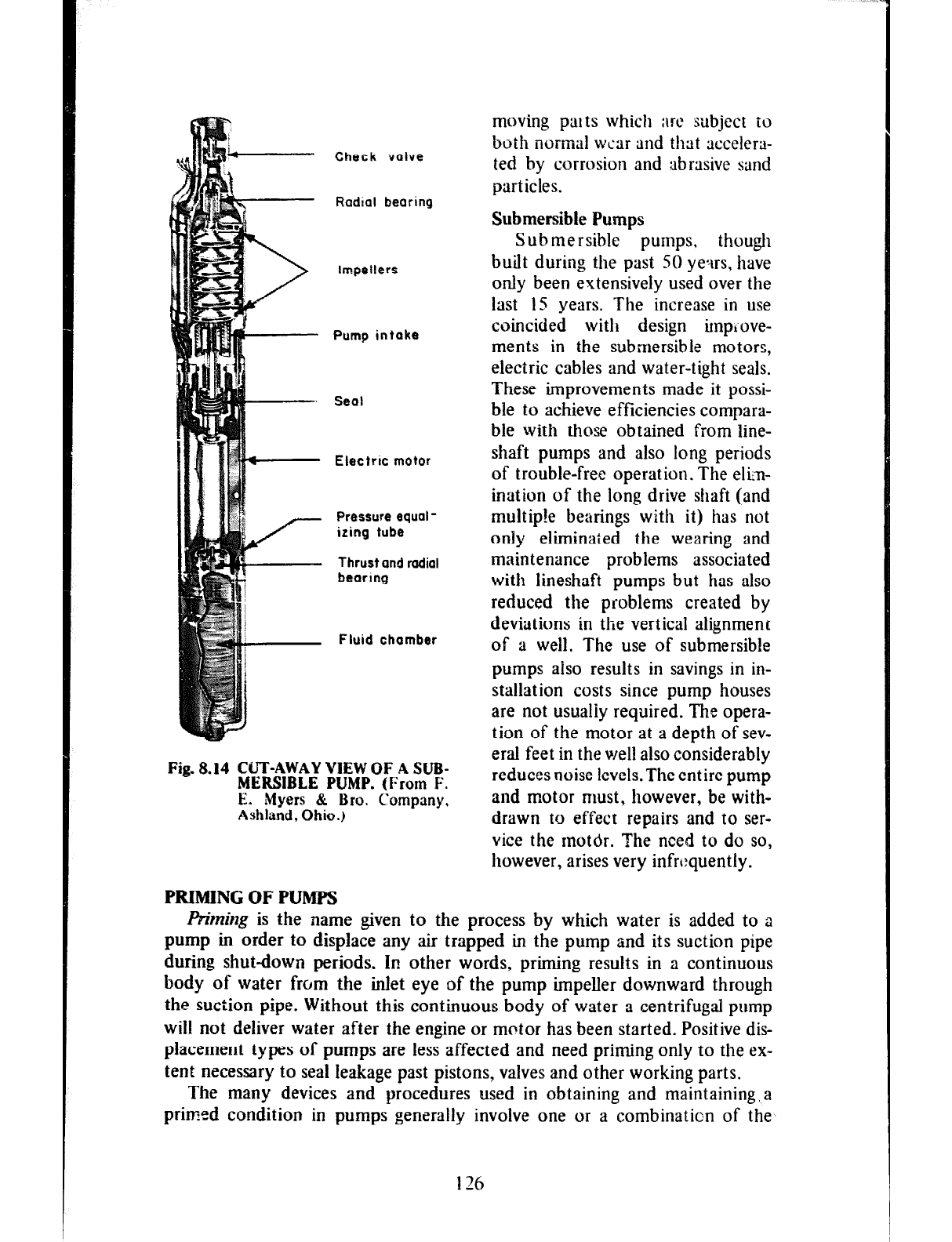
Check valve
Radial bearing
lmpetfers
Pump intake
Seat
Electric motor
Pressure equal-
izing tube
Thrust and radial
bearing
Fluid chamber
Fig.8.14 CLJT-AWAYVIEWOFASUB-
MERSIBLE PUMP.
Wrorn F.
E. Myers & Bra. Company.
Ashland, Ohio.)
moving parts which are subject to
both normal wear and that xcelera-
ted by corrosion and abrasive sand
particles.
Submersible Pumps
Submersible pumps, though
built during the past SO yetus. have
only been extensively used over the
last IS years. The increase in use
coincided with design impLove-
ments in the submersible motors,
electric cables and water-tight seals.
These improvements made it possi-
ble to achieve efficiencies compara-
ble with those obtained from hne-
shaft pumps and also long periods
of trouble-free operation. The elin-
ination of the long drive shaft (and
multip!e bearings with it) has not
only eliminated the wearing and
maintenance problems associated
with lineshaft pumps but has also
reduced the problems created by
deviations in the vertical alignment
of a well. The use of submersible
pumps also results in savings in in-
stallation costs since pump houses
are not usualiy required. The opera-
tion of the motor at a depth of sev-
eral feet in the well also considerably
reduces noise levels. The entire pump
and motor must, however, be with-
drawn to effect repairs and to ser-
vice the motor. The riced to do so,
however, arises very infmquently.
PRIMING OF PUMPS
Friming is the name given to the process by which water is added to a
pump in order to displace any air trapped in the pump and its suction pipe
during shutdown periods. In other words, priming results in a continuous
body of water from the inlet eye of the pump impeller downward through
the suction pipe. Without this continuous body of water a centrifugal pump
will not deliver water after the engine or motor has been started. Positive dis-
placement types of pumps are less affected and need priming only to the ex-
tent necessary to seal Ieakage past pistons, valves and other working parts.
The many devices and procedures used in obtaining and maintaining, a
primed condition in pumps generally involve one or a combinaticn of the
126
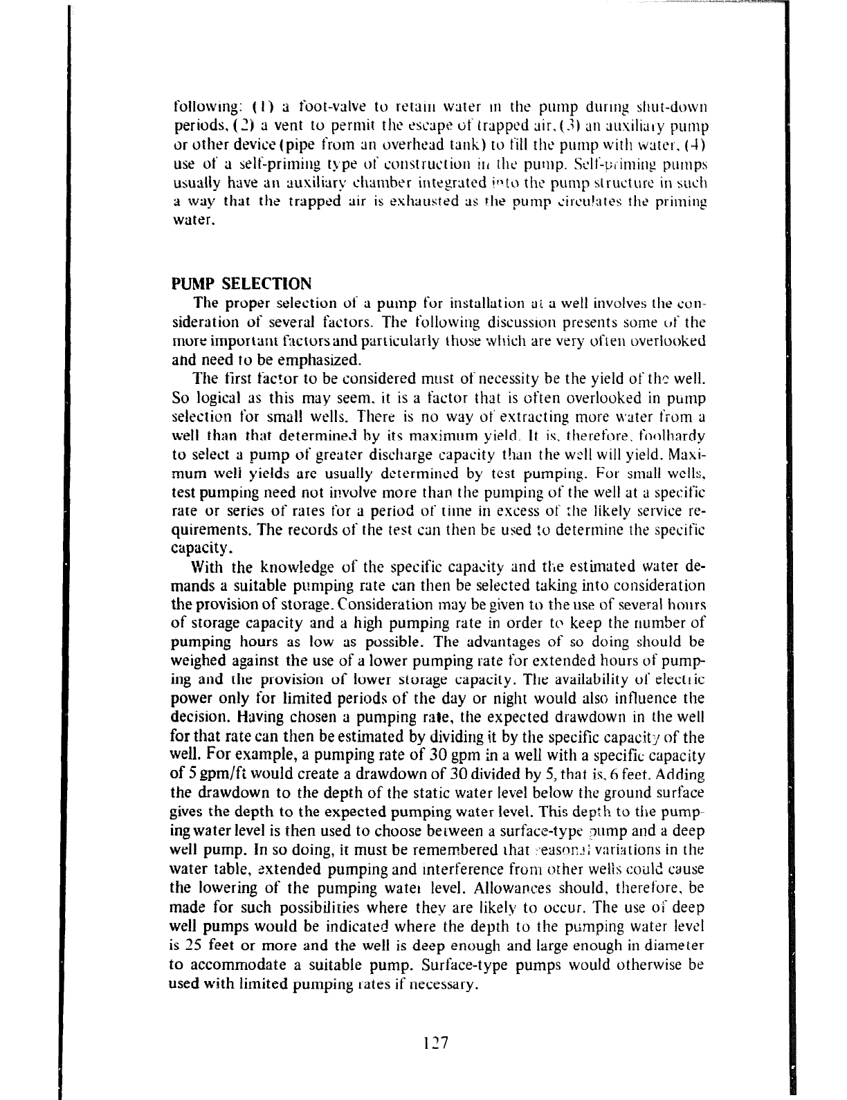
following: ( I) a foot-valve to retair water in the pump during shut-down
periods, (2) a vent to perntit the t~aptt tit‘ trapped air. (-3) an ausilialy pump
or other devics( pipe front an overhead tank) to fill the pump with water. (-I)
use of a self-primin g tj,pe o1‘ construction
ill the
pump.
Self-pl’inlirlg
pumps
usually have an ausiliary chamber integrated itlt~ the pump structure in selctt
a way
that the
trapped air is exhausted as flte pump circulates the priming
water.
PUMP SELECTION
The proper selection of a pump for installation ai a well involves the con-
sideration of several factors. The followittg discusslon presents some c,f the
more important factorsand particularly those which are very often overlooked
ahd need to be emphasized.
The first factor to be considered must of necessity be the yield of the well.
So logical as this may seem. it is a Factor that is often overlooked in pbntp
selection for small wells. Tltere is no way ot’ extracting more M2ter fiOlll a
well than that determined by its maximum yield. It is, therefore. foolhardy
to select a pump of greater discharge capacity t!tatl the w:ll will yield. Maxi-
mum we/i yields are usually determined by test pumping. For small wells,
test pumping need not involve more than tlte pumping of the well at a specific
rate or series of rates for a period of time in excess of :lte likely service re-
quirements. The records of the test catt then be used :u determine the specific
capacity.
With the knowledge of the specific capacity and tlie
estimated water de-
mands a suitable pumping rate can then be selected taking into consideration
the provision of storage. Consideration may be given to the use of several hours
of storage capacity and a high pumping rate in order to keep the number of
pumping hours as low as possible. The advantages of so doing should be
weighed against the use of a lower pumping rate for extended hours of pump-
ing and the provision of lower storage capacity. The availability of electric
power only for limited periods of the day or night would also influettce the
decision. Having chosen a pumping rate, the expected drawdowtt in the well
for that rate can then be estimated by dividing it by the specific capacit;l of the
well.
For example, a pumping rate of 30 gpm in a well with a specific capacity
of 5 gpm/ft would create a drawdown of 30 divided by 5, that is. 6 feet. Adding
the drawdown to the depth of the static water level below the ground surface
gives the depth to the expected pumping water level. This dey:h to
the
pump
ing water level is then used to choose between a surface-type ;Tump and a deep
well pump. In so doing, it must be remembered Ihat :*easr)r-?; vari:ltions in the
water table, extended pumping and interference from orher welis could cause
the lowering of the pumping water level. Allowances should, therefore, be
made for such possibilities where they are likely to occur. The
use oi‘
deep
well pumps would be indicated where the depth
to the
ptimping water level
is 25 feet or more and the well is deep enough and large enough in diameter
to accommodate a suitable pump. Surface-type pumps would otherwise be
used with limited pumping rates if necessary.
197
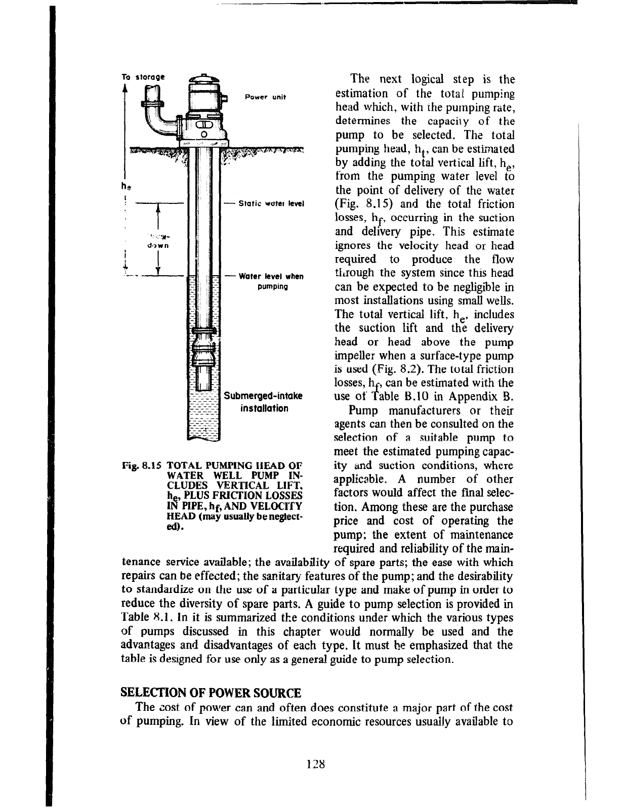
To storage
ha
I
3
Power unit
- Static udtkt level
- Water kvel when
pumping
Submerged-intake
installation
Fig. 8.15 TOTAL PUMPING HEAD OF
WATER WELL PUMP IN-
CLUDES VERTICAL LIFT,
h , PLUS FRICTION LOSSES
IIt PIPE, hf, AND VELOCITY
HIAD (may usually be neglect-
.
The next logical step is the
estimation of the total pumping
head which, with the pumping rate,
determines the capaciry of the
pump to be selected. The total
pumping head, ht, can be estimated
by adding the total vertical lift, he,
from the pumping water level to
the point of delivery of the water
(Fig. 8.15) and the total friction
losses, hf, occurring in the suction
and delivery pipe. This estimate
ignores the velocity head or head
required to produce the flow
through the system since this head
can be expected to be negligible in
most installations using small wells.
The total vertical lift, he, includes
the suction lift and the delivery
head or head above the pump
impeller when a surface-type pump
is used (Fig. 8.2). The total friction
losses, h , can be estimated with the
use of f able B.10 in Appendix B.
Pump manufacturers or their
agents can then be consulted on the
selection of a suitable pump to
meet the estimated pumping capac-
ity and suction conditions, where
applicable. A number of other
factors would affect the final selec-
tion. Among these are the purchase
price and cost of operating the
pump; the extent of maintenance
required and reliability of the main-
tenance service available; the availability of spare parts; the ease with which
repairs can be effected; the sanitary features of the pump; and the desirability
to standardize on the use of a particular type and make of pump in order to
reduce the diversity of spare parts. A guide to pump selection is provided in
Table 8.1. In it is summarized the conditions under which the various types
of pumps discussed in this chapter would normally be used and the
advantages and disadvantages of each type. It must be emphasized that the
table is designed for use only as a general guide to pump selection.
SELECTION OF POWER SOURCE
The zest of power can and often does constitute a major part of the cost
of pumping. In view of the limited economic resources usually available to
128
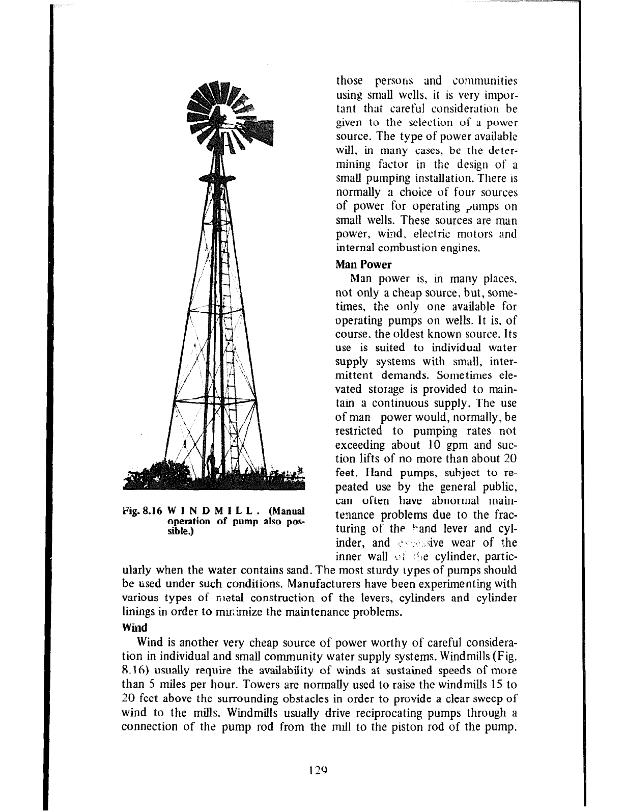
Fin. 8.16 W I N D M I L L . (Manual
operation of pump also pos-
sible.)
those persoIls and communities
using small wells, it is very impor-
tant that careful considerutioll be
given to the selection of a power
source. The type of power available
will, in many cases, be the deter-
mining factor in the design of a
small pumping installation. There is
normally a choice of four sources
of power for operating Puntps on
small wells. These sources are man
power, wind. electric motors and
internal combustion engines.
Man Power
Man power is. in many places,
not only a cheap source, but, some-
times, the only one available for
operating pumps on wells. It is, of
course, the oldest known source. Its
use is suited to individual water
supply systems with small, inter-
mittent demands. Sometimes ele-
vated storage is provided to main-
tain a continuous supply. The use
of man power would, normally, be
restricted to pumping rates not
exceeding about 10 gpm and suc-
tion lifts of no more than about 20
feet. Hand pumps, subject to re-
peated use by the general public,
can often have abnormal main-
tenance problems due to the frac-
turing of thP !:and lever and cyl-
inder, and 1:~ .,,,.,:,ive wear of the
inner wall s.: i i !
!e cylinder, partic-
ularly when the water contains sand. The most sturdy Lypes of pumps should
be used under such conditions. Manufacturers have been experimenting with
various types of nletal construction of the levers, cylinders and cylinder
linings in order to mlr;;mize the maintenance problems.
Wind
Wind is another very cheap source of power worthy of careful considera-
tion in individual and small community water supply systems. Windmills (Fig.
8.16) usually require the availability of winds at sustained speeds of more
than 5 miles per hour. Towers are normally used to raise the windmills 15 to
20 feet above the surrounding obstacles in order to provide a clear sweep of
wind to the mills. Windmills usually drive reciprocating pumps through a
connection of the pump rod from the mill to the piston rod of the pump.
Provision may also be made for pumping by hand during long periods of relti-
tive calm. It is good prsctice to provide adequate clevrtted storage tu maintain
the water supply during periods when there is insufficient wind. Windmills
are normally manufxtured
in
siLes expressed in terms ot‘ the diameters ot
their wheels. When ordering a windmill
t‘wrn ;f mnut‘tlcturer. he must
be
supplied with information
on the
average wind velocity in addition to the
required capacity and other relevant informut ion NI the
pump.
The operation
and maintenance costs of windmills ;Lre usutllly very negiigible and strongly
influence their use in communities wiiose financitil resources are inadequate
to operate and maintain motor or engine driven pumps.
Electricity
Electricity. where available from a central supply at reasonable cost.
is to be preferred over other sources of power. It would, however, be unwise
tb mstall electric generators simply to provide a supply for operating a small
pump. Electricity‘s great advantage is the fact that it can be used to provide a
continuous. automatically controlled supply of water. The power source must
be reliable and not subject to significant vol;age variations. Small electric
motors are usually low in initial cost. require little maintenance and are cheap
to operate.
lnternd Combustion Engine
Internal combustion engines (gasoline, diesel or kerosene) are o!‘ten used in
areas where electric power is not available and winds are Infrequent or
inadequate to meet the water supply demands. Qiesel engines, though usually
the most costly to purchas c, are generally the best from the point of view of
operation and maintenance. Internal combustion engines require more
maintenance than electric motors and must always be attended by an
operator. Good service is obtained if a regular routine tnaintenancc program is
followed and a supply of spare parts always available.
130
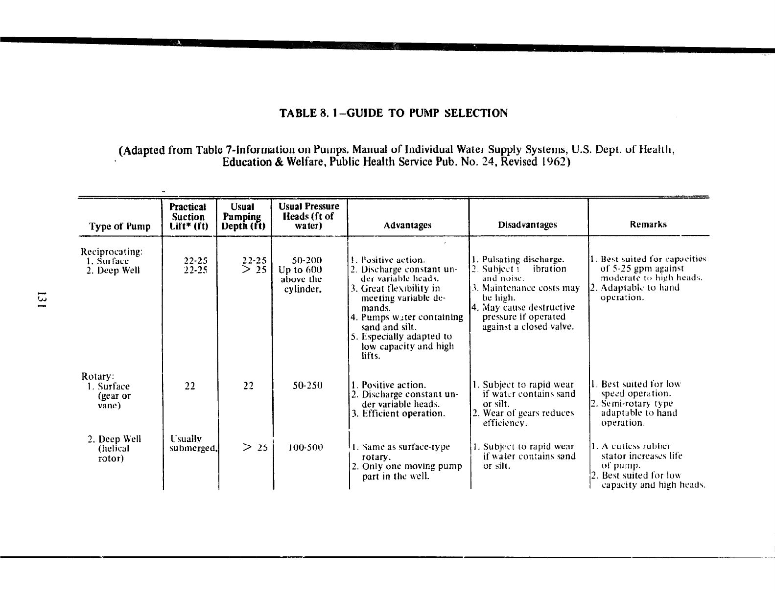
TABLE8.1~GUIDE TO PUMP SELECTION
(Adapted from Table 7hforrnation on Pumps. Manual of Individual Water Supply Systems, U.S. Dept. of Health,
Education
& Welfare, Public Health Service Pub. No. 24, Revised 1962 j
Type of Pump
Reciprocating:
1. Surface
2. Deep Well
Rotary:
1. Surface
(gear or
vane)
2. Deep Well
(helical
zotor)
Practical
Suction
lift* (CO
21
L~suallv
submerged
Usual
Pumpin P lcpth I t)
Usual Pressure
Heads .!ft of
water)
50-200
Up to 600
above the
cylinder.
50-150
100-500
Advantages
1. Positive action.
2. Discharge constam un-
der variahlc hcadr.
3. &cat fltxbility in
mecling variable de-
mands.
1. Pumps wlter containing
sand and silt..
5. Especially adapted to
low capacity and high
lifts.
I. Positive action.
2. Discharge constant un-
der variable heads.
3. Efficient operation.
I. Same as surface-type
rotary.
2. Only one moving pump
part in the well.
Disadvantages
I. Pulsating discharge.
! Subject I ibration
;rllJlloirc.
I. Maintenance cost5 may
be high.
I. Llay cause destructive
pressure if operated
againht a closed valve.
I. Subject to rapid \vear
if wat:r contains sand
or silt.
1. Wear of gears reduces
efficiency.
1. Subject to rapid wear
if waler contains sand
or silt.
Remarks ,-
. Best suited for capacities
of S-25 gpni against
modcratc to high head\.
. AdaptablL to IlllIld
operation.
Best stnled for ION
sprtd operation.
. Semi-rotary type
adaptahlc to hand
operation.
. A cutless rubber
stator incrcastis life
of pump.
I. Best suited for IOH,
capacity and high hcadr.
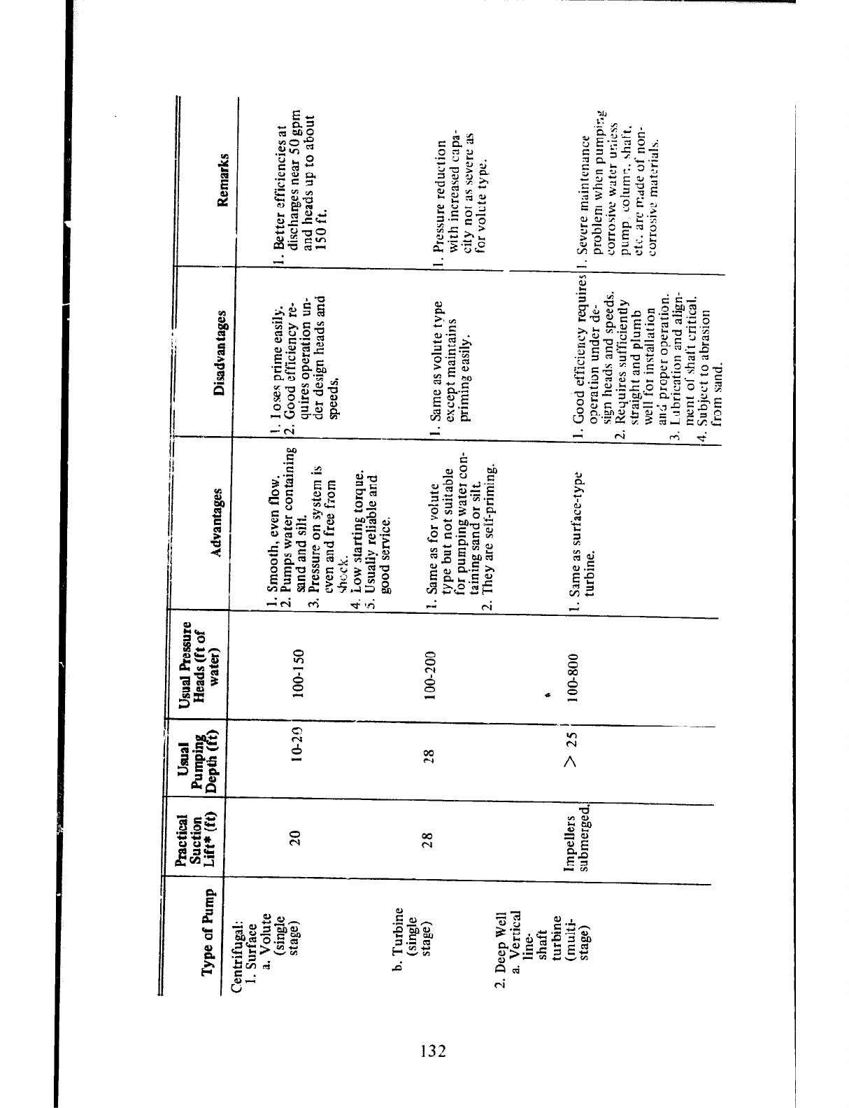
132
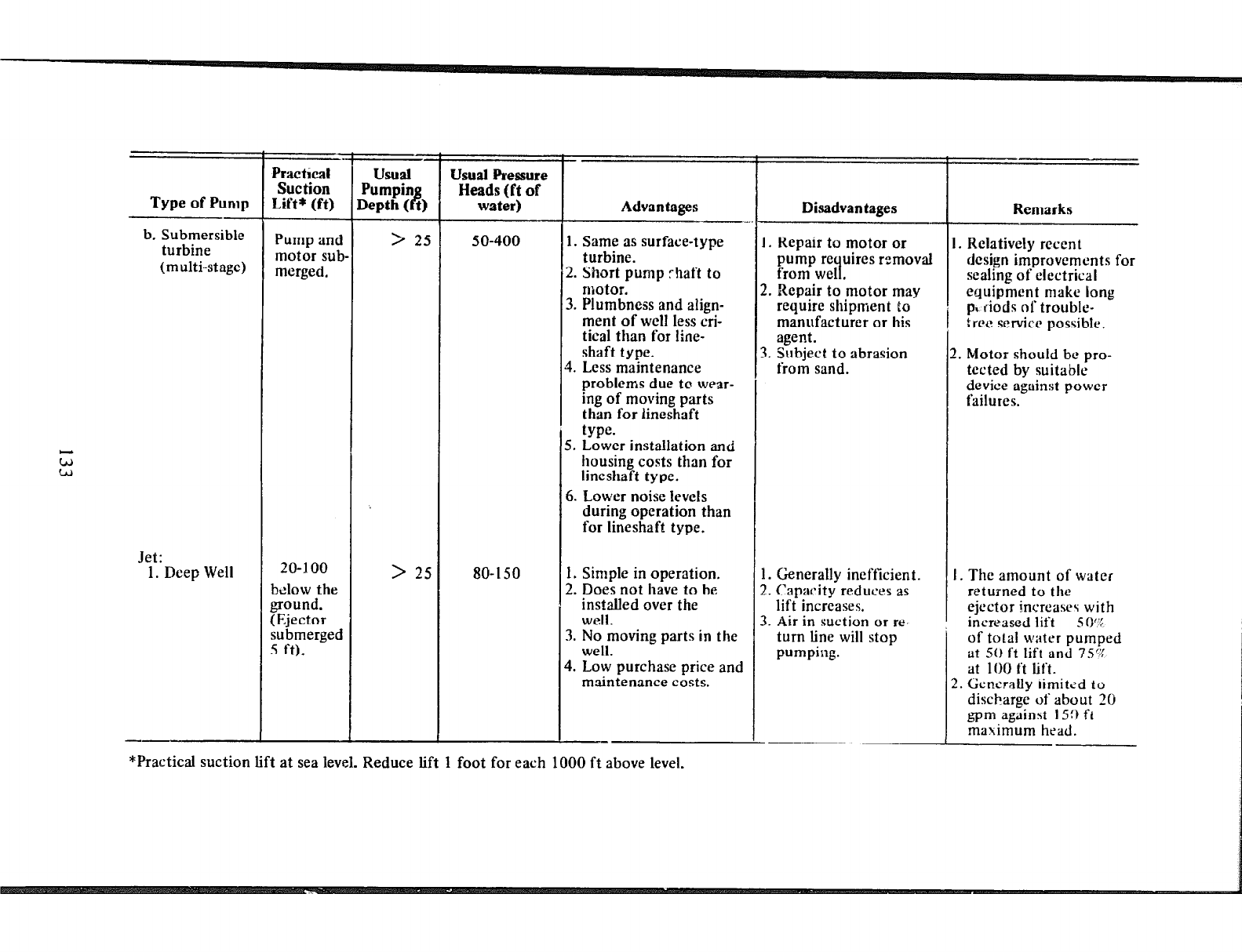
Type of Pump
b. Submersible
turbine
(multi-stage)
Jet:
1. Deep Well
Practical
sue tion
Lift* (ft)
Pump and
motor sub.
merged.
20-I 00
below the
ground.
(Ejector
submerged
5 t-t).
usual
Pumpin
Depth (
B
t)
> 25
> 25
Usual Pressure
Heads (ft of
water)
so-150
Advantages --
1. Same as surface-type
turbine.
2. Short pump shaft to
motor.
3. Plumbness and align-
ment of well less cri-
tical than for line-
shaft type.
4. Less maintenance
problems due to wear-
ing of moving parts
than for lineshaft
type.
5. Lower installation and
housing costs than for
lineshaft type.
6. Lower noise levels
during operation than
for lineshaft type.
1. Simple in operation.
2. Does not have to be
installed over the
well.
3. No moving parts in the
well.
4. Low purchase price and
maintenance costs.
Disadvantages -
I. Repair to motor or
pump requires removal
from well.
2. Repair to motor may
require shipment to
manufacturer
or his
agent.
3. Subject to abrasion
from sand.
I. Generally inefficient.
!. Capacity reduces as
lift increases.
3. Air in suction or re-
turn line will stop
pumping.
Remarks
2. Motor should be pro-
tected by suitable
device against power
failures.
I. The amount of water
returned to the
ejector mcreases with
_. .
Increased lit t 5 I)“:
of total water pumped
at 51) ft lift and 7S?G
at 100 ti lift.
2. Generally rimitzd to
discharge of about 20
gpm against 159 ft
maximum head.
I. Relatively recent
design improvements for
sealing of electrical
equipment make long
p% ciods of trouble-
tree service possible.
*Practical suction lift at sea level. Reduce lift 1 foot for each 1000 ft above level.
OF
Too great stress can never be placed on the need to provide sanitary
protection for all known ground-water sources, whether in immediate use or
not, since such sources may some time in the future be of great importance to
the development of their 1o;alities.
Small wells, of the type being considered in this manual, very often have
relatively shallow aquifers as their sources of water. These sources, in many
cases, are merely a few feet below the ground surface and can often be
reached without great difficulty by pollution from privies, cesspools, septic
tanks, barnyard manure. and industrial and agricultural waste disposal. It also
very often happens that privies and septic tanks are the only economically
practicable means of sewage disposal in a small and sparse community which
must for various reasons depend entirely upon a shallow ground-water source
for its potable water supply. Such dependence may be due to the inability of
a small community to meet the costs of
3
sophisticated treatment plant for
available surface water. Many rural areas are also subjected to annual
extended periods of drought when strearrs become completely dry and
shallow ground-water aquifers provide the only reliable sources of potable
water. It is, therefore, of great importance that such sources be adequately
protected.
POLLUTION TRAVEL IN SOILS
The sanitary protection of ground-water supplies must be based on an
understanding of the basic facts relating to the travel of polluted substances
thiough soils and water-bearing formations. It must be remembered that all
water seeping into the ground is polluted to some degree, yet this water can
later be retrieved in
3
completely satisfactory condition for domestic and
other human uses. Some purifying processes must be taking place within the
soil
3s
the water travels through il. Several studies have been made of
“nature’s purifying action” by research workers in many
parts
of the world,
particularly in Europe, India and the United States of America. These studies
have contributed very much to our knowledge of the processes involved in
the natural purification of ground waters and the patterns and extent of flow
of pollution in them. The basic findings are summarized in the succeeding
paragraphs.
The natural processes occurring in soils to purify water travelling through
them are essentially three in number. The first two of these are the
134
I
mechanical removal of microorganisms (including disease-producing bacteria)
and other suspended matter by fi‘ltration and sedimentation or settling.
Filtration depends upon the relative sizes of the pore spaces of the soil
particles and those of the microorganisms and other filterable material. The
finer the soil particles and the smaller the pore spaces between them, the
more effective is the filtration process. Filtered material also tends to clog the
pore spaces and thus help to improve the filtration process. Sedimentatron
depends upon the size of the suspended material and the rate of flow of the
water through the pore spaces. The larger the particles of suspended matter
and the slower the rate of flow through the soil, the more efficient would be
the sedimentation process. It is, therefore, seen that the porosity and
permeability of the soil are very important factors in the operation of the
fdtration and sedimentation processes and,
3s 3
result, in the extent of travel
of bacterial pollution in soils.
The third factor is what is often termed the natural die-away of bacteria in
soils. Bacteria which produce disease in man live for only limited periods of
time outside of their natural host which is generally man or animals. Their life
spans are usually short in the unfavorable conditions found in soils. This
property contributes considerably to the self-purification of ground water
during its movement and storage in sand and gravel aquifers.
The effect of filtration is, of course, completely lost and sedimentation
somewhat reduced in ground waters travelling through large crevices and
solution channels in limestone and other such consolidated rocks, This
explains the generally better microbiological quality of ground water
obtained from sands, gravels and other unconsolidated formations
3s
against
those obtained from the larger crevices, fissures and solution channels in
consolidated rocks.
While the above mentioned processes are effective against the travel of
bacterial pollution in ground water and usually within short distances and
periods of time, they are not nearly
3s
effective against the travel of chemical
pollution. Chemical pollution, it will be seen later, persists much longer and
travels much faster in ground waters than does bacterial pollution. Chemical
reactions with soil material do play some part in restricting the travel of
chemical pollution but require more time than the other processes do in
controlling bacterial pollution.
Pollution (bacterial and chemical) in soils usually moves downward from
the source until it reaches the water table and then along with the
ground-water flow in a path which first gradually increases in width to
3
limited extent and then reduces to final disappearance. Downward travel of
bacteria through homogeneous soil above the water table has seldom been
found to be more than about 5 feet. Upon reaching the water table, no
pollution travel takes place against the natural direction of ground-water flow
unless induced by the pumping of a well upstream of the pollution source and
with a circle of influence (upper surface of the cone of depression) that
includes the pollution source. The horizontal path of the flow of bacterial
pollution in sand formations from a point source, such as
3
well used to
recharge an aquifer, has been found to reach
3
maximum width of about 6
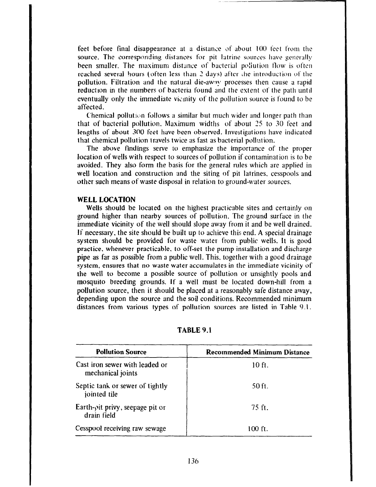
feet before final disappearance at a distance \jf about 101) feet from the
source. The corresponding distances for pit latrine sources have per~rally
been smaller. The maximum distance of bacterial po:iution tlow is ot‘tcn
reached several !lours (often less than 2 days) after ihe introduction of the
pollution. Filtration and the natural die-aw:jy processes then cause a rapid
reduction in the numbers of bacteria found and the extent of the path until
eventually only the immediate vic-nity of the pollution source is found to be
affected.
Chemical poliutkrn follows a similar but much b;ider and longer path than
that of bacterial pollution. Maximum widths of about 25 to XI feet and
lengths of about 300 feet flave been observed. Investigations have indicated
that chemicsl pollution travels twice as fast as bacterial pollution.
The above fmdings serve to emphasize the importance of the proper
location of wells with respect to sources of pollution if contamination is to be
avoided. They also form the basis for the general rules which are applied in
well location and construction and the siting of pit latrines. cesspools and
other such means of waste disposal in relation to ground-water sources.
WELL LOCATION
Wells should be located on the highest practicable sites and certainly on
ground higher than nearby sources of pollution. The ground surface in the
immediate vicinity of the well should slope away from it and be well drained.
If necessary, the site should be built up to achieve this end. A special drainage
system should be provided for waste water from public weils. It is good
practice, whenever practicable, to off-set the pump installation and discharge
pipe as far as possible from
3
public well. This. together with a good drainage
system, ensures that no waste water accumulates in the immediate vicinity of
the well to become
3
possible source of pollution or unsightly pools and
mosquito breeding grounds. if a well must be located down-hill from
3
pollution source, then it should be placed at a reasonably safe distance away,
depending upon the source and the soil conditions. Recommended minimum
distances from various types of pollution sources are listed in Table 9.1.
TABLE 9.1
Pollution Source I Recommended Minimum Distance
Cast iron sewer with leaded or I 10 ft.
mechanical joints
Septic tank or sewer of tightly
join ted tile so ft.
Earth-blit privy, seepage pit or
drain field 75 ft.
Cesspool receiving
r3w sewage
100 ft.
136
These minimum distances are meant to be no more than guides to good
practice and may be varied its soil and other conditions require. They should
be applied only where the soil has filtering capacity equal to, or better than
that of sand.
WeiS location should also take into consideration accessibility for pump
repair. cleanin g. treatment, testing and inspection. Wells located adjacent to
buildings should be at least 2 feet clear of any projections such as
over-hanging eaves.
Chapters 4: 5 and 6 should be consulted for information concerning the
design, construction and compietion aspects, respectively. of the sanitary
protection of wells.
SEALING ABANDONED WELLS
The objectives of sealing abandoned wells are ( i) the prevention of the
contamination of the aquifer by the entry of poor quality water and other
foreign substances through the well, (2) the conservation of the aquifer yield
and artisean head where there is one, and (3j the elimination of physical
hazard.
The basic concept of proper seaiing of an abandoned well is the
restoration, as far as practicable, of the exis5ng geologic conditions. IJnder
water-table conditions sealing must be effective to prevent the percolation of
surface water through the well bore or along the outside of the casing to the
water table. Sealing under artesian conditions must be effective in confining
water to the aquifer in which it occurs.
Sealing is usually achieved by grouting with puddled clay, cement or
concrete. When grouting under water, the grouting material should be placed
from the bottom 11p by methods that would avoid segregation or excessive
dilution of the material. Grouting methods have been described in Chapter 5.
It may be necessary; in some cases, to remove well casing opposite
water-bearing zones to assure an effective seal. Where the upper 15 or 20 feet
of the well casing was not carefully cemented during the original con-
struction, this portion of the casing should be removed before final grouting
for abandonment.
137
REFERENCES
Acme Fishing Tool Company.
Ac772e.
Greutest IVUl?li’ irl Cubltj ‘Tools Sirm
IYOU. Catalog. Parkersburg, West Virginia.
American Water Works Association. National Water Well Association. .4 Ct’lt’A
Standard j&- Deep Wells. AWWA AIOO-hh. New York:
AWA 111~~. lC)hb.
Anderson. Keith E. (ed.).
Water
lt’e11 Harrdhook. Rolla, Missouri: Missouri
Water Well Drillers Association. 1966.
Baldwin. Helene L.. and C. L. McGuinness. A Primer ml Grourlti Water.
United States De artment
Government Prin P of the Interior, Geological Survey. Washington:
ing Office. 1963.
Bowman, Isaiah. Well-Driliitlg Methods. Geological Survey Water-Supply Paper
257. Washington: Government Printing Office. 191 1.
Decker. Merle G. Cable Tool FiMzg. Water Well Journal. Series of articles
commencing Vol . 21,No. l.(Jan., 1967). pp. 14-lh,S9.
Departments of the Army and the Air Force. Wells. TMS-297. AFM X5-23.
Washington: Government Printing Office, 1957.
Edward E. Johnson, Inc. Ground Water and Weils. St. Paul. Minnesota. 1906.
Gordon, Raymond W. Water Well Drillirlg \tYth Cuhle Tools. Sourly Milwau-
kee, Wisconsin: Bucyrus-El-ie Company, 195X.
Harr, M. E. Groundwater aHd Seepage. New York: McGraw-Hill Book
Company Inc., 1962.
Livingston, Vern. Frown: Too-Thin-to-Plough Missouri. To: Just-Right-to-
Drink Well Water, Water Works Engineering (May, 1957), pp. 493495,
521.
McJunkin, Frederick E. (ed.). International Program in Sanitary Engineering
Design. Jetting Small Tubewells b-y Hand. AID-UNC/IPSED Series Item
No. 15. University of North Carolina, 1967.
Meinzer, 0. E. Occurrence
of
Ground Water in the United States. Geological
Survey Water-Supply Paper 4S9. Washington: Government Printing Office,
1959.
Outline of Ground-Water Hydrology. Geological Survey Water-
Supply Paper 494. Washington: Government Printing Office, 1965.
Miller, Arthur P. Water and Man’s Health. Washington: Department of State,
Agency for International Development, 1962.
New York State Department of Health. Rural Water Supply. Albany, New
York, 1966.
13s
f
State of Illinois. Department of Public Health, Division of Sanitary
Engineering. I,‘lirmis li’afer WcN Cousfnrc-tiorl Cih. Springfield, Illinois,
19h7.
Todd, David Keith. Crort~lci I4’~rrr H_rxi~o/o~~. New York: John Wiley & S,ms,
Inc., 1960.
U. S. Department of Health. Education, and Welt‘tlre. Dri~lkiug h’arer
Standards. Public Health Service Publication No. 956. Washington:
Government Printing Office. 19h2.
. hlarrual of htlividual Water Supp[v LSystenls. Public Health
Service Publication No. J-1. Washington: Government Printing Office.
1963.
U. S. Department of the Interior. lnterdepartmenlal Committee on Water for
Peace. Water fur Peace. A Report
of
Backgrotmd Consideratiorzs and
Recol?lr)ZelldatiOtls on the Water
for
Peace Program Washington : Govern-
ment Printing Office. 1967.
Wagner, E. G., and J. N. Lanoix. Water Supp[v jiu Rural Areas and Small
C~mtwmities. Geneva: World Health Organkation. 19s~).
Wisconsin State Board of Health. Wisconsitl Well Corastntctiorl ami Pump
tnsrallatim C&e. Madison, Wisconsin, I95 1.
CREDIT FOR ILLUSTRATIObJS
The authors wish to give credit to UOP-Johnson Division, Universal Oil
Products Company. St. Paul, Minnesota for the use and adaptation of the fol-
lowing illustrations: Figures 2.3.2.5,2.9,2.10,~.12.2.13,2.17.3.1.3.2.4.1.
4.2, 4.3, 4.5, 4.7, 4.8, 4.10, 4.1 1, 5.16, 5.22, 5.23, 5.24, 5.25, 5.26. 5.29,
5.30, 5.31, 5.32, 5.33, 5.34, 5.35, 5.36, 5.37, 5.38, 5.39, 5.40, 5.41, 6.1, 6.2,
6.4, 6.5, 6.6,6.8, 7.1, 7.2, 8.2, and A.l.
139
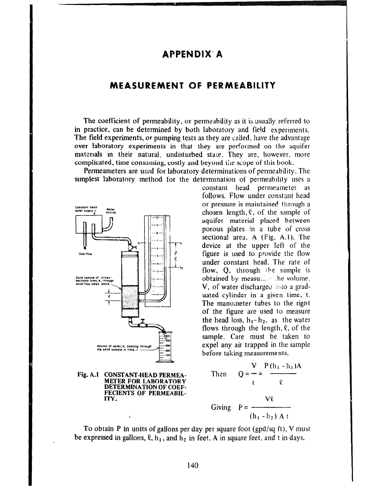
T OF PE ICITY
The coefficient of permeability, or permeability as it is usually referred to
in practice, can be determined by both laboratory and fie!d experiments.
The field experiments, or pumping tests as they are called, have the advantage
over laboratory experiments in that they are performed on the aquifer
matcrlals in their natural, undisturbed state. They are, however, more
complicated, time consuming, costly and beyond iLe scope of this book.
Permeameters are used for laboratory determinations of permeability. The
simplest laboratory method for the determination of permeability uses a
-1o-
ir:z
-I-
-s-
-57
.i
-.-
:,-L
fz-.
-a-
-0
--
Fig. A.1
f”’
;
.e
r=.*
constant head permeameter
iiS
follows.
Flow
under constant head
or pressure is maintained through a
chosen length, C, of the sample of
aquifer material placed between
porous plates !.n a tube of cross
sectiona! area. A (Fig. A.l). The
device at the upper left of the
figure is used to provide the flow
under constant head. The rate of
flow, Q, through ibe sample is
obtained by measu.;. ,:, .he volume,
V, of water discharged I:iio a grad-
uated cylinder in a given time. t.
The manometer tubes to the riglIt
of the figure are used to measure
the head loss, hI- h2, as the water
flows through the length, f, of the
sample. Care must be taken to
expel any air trapped in the satnple
before taking measurements.
V P(hl -h2)A
CONSTANT-HEAD PERMEA-
METER FOR LABORATORY
DETERMINATlON OF COEF-
FECIENTS QF PERMEABIL-
ITY.
Then
Qz-=
t
II
VV
Giving P =
\ (h, -h2) A t
To obtain P in units of gallons per day per square foot (gpd/sq ft), V must
be expressed in gallons, II, hl , and h2 in feet, A in square feet, and t in days.
140
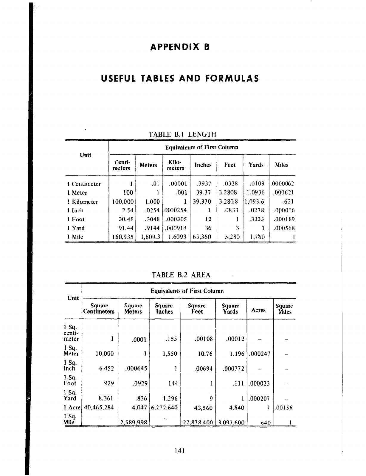
USEFUL TABLES A
TABLE B.l LENGTH
-
T
Equivaleuts of First Column
Unit -*-
:
.(
1
-
I
Centi-
meters Meters Kilo-
meters
1 Centimeter
1
1 hleter
100
1 Kilometer
100,000
1 Inch 2.54
1 Foot 30.48
1 Yard 91.44
1 Mile 160,935
.9144 .00091-?
1,609.3 1.6093
Inches
Feet
Yards
.3937 .0328 .u109
39.37 3.2808 1.0936
39,370 3,280.8 1,093.6
1 .c)833 .0278
12 1 .3333
36 3 1
63,360 5,280 1,7&o
Miles
DO00062
.000621
.621
.05)0016
.000189
.0010568
1
TABLE B-2 AREA
-
r
Equivdents of First Column
Unit
I
I
-
Square
Zentimeters Square
Feet
Square Square
Meters Inches
.155
1,550
1
144
1,296
5,272,640
-
Square
Yards Acres Square
Miles
- -
.000247
-
-
-
.000023
-
.000207
-
1 30156
1 sq.
centi-
meter
1 sq.
Meter
1 sq.
Inch
1 sq.
Foot
1 sq.
Yard
1 Acre
1 sq.
Mile
- 640
1
10,000
6.452
929
8,361
40,465,284
-
.00012
1.196
.00077 2
.I1 1
1
4,840
3,097.600
.00108
10.76
.!I0694
1
‘9
43,560
27,878,400
.OOOl
1
.000645
.0929
.836
4,047
!,5 89,998
141
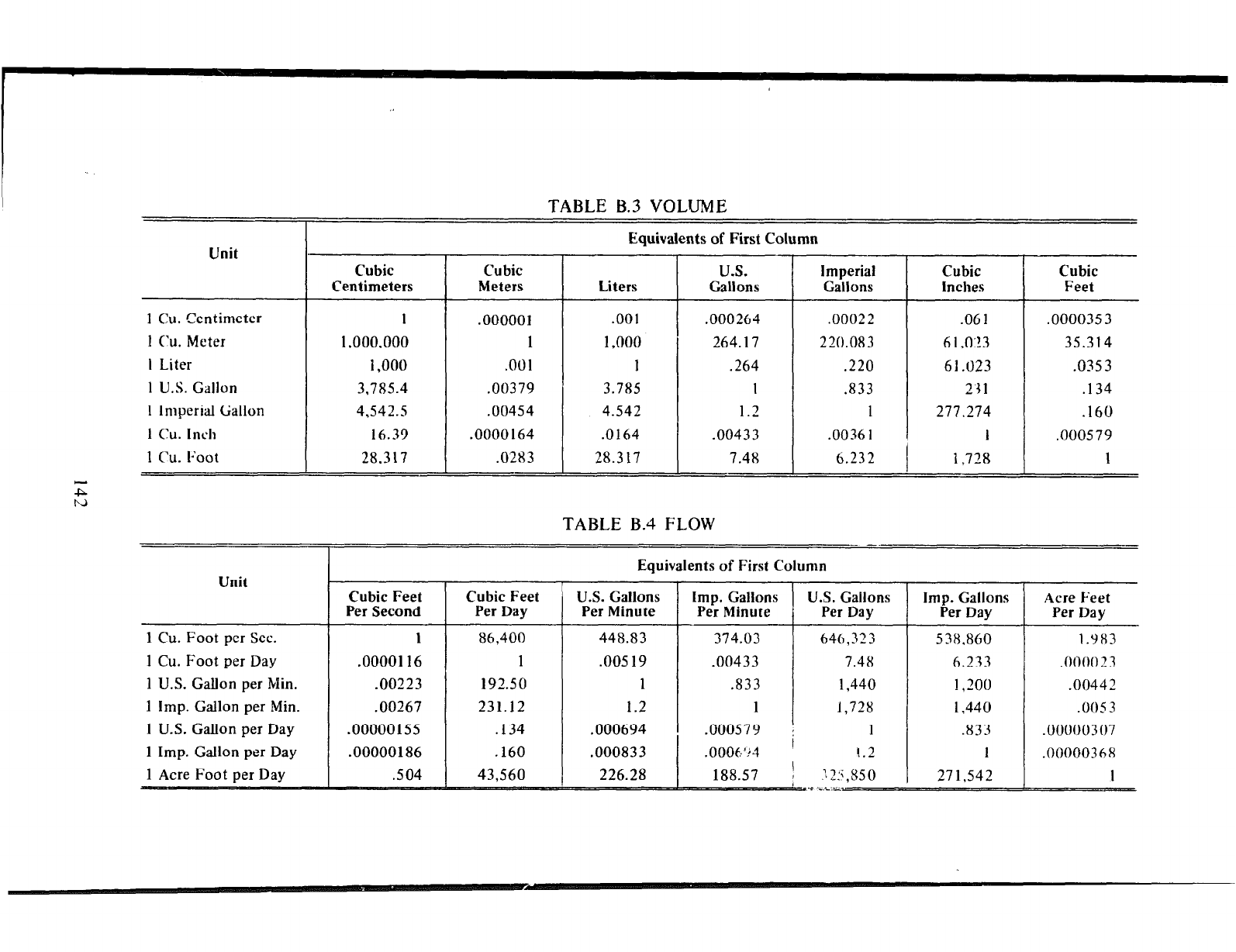
TABLE B.3 VOLUME
Equivalents of First Column
Unit Cubic Cubic U.S. Imperial Cubic Cubic
Centimeters Meters Liters Gallons Gallons Inches Feet
1 Cu. Centimeter 1 .000001 .OOl
.000264 .00022 .061 .0000353
1 Cu.
Meter
1 ,ooo.ooo 1 1,000
264.17 220.083 61.0:!3 35.314
I Liter 1,000 .OOl 1
.264 .220 61.023 .0353
1
U.S. Gallon
3.785.4 .00379 3.785 I .833 231 .I34
1 Imperial Gallon
4,542.5 .00454 4.542
1.2 1
277.274 .I60
1 cu. Inch 16.39 .0000164 .0164 .00433 .00361 I .000579
1 Cu. 12oot
28,317 .0283 28.317 7.48 6.232 1,728 1
TABLE B.4 FLOW -. -
1 Cu. Foot per Day
1 U.S. Gallon per Min.
1 Imp. Gallon per Min.
1 U.S. Gallon per Day
1 Imp. Gallon per Day
Equivalents of First Column
U.S. Gallons
Per Minute
448.83
.00519
1
1.2
.000694
.000833
226.28
Imp. Gallons U.S. Gallons
Per Minute Per Day
374.03 646,323
.00433 7.48
.833 1,440
1
1,728
.000579
: 1
.0006”3 ’ !.2
188.57
j 125,850
.c i.C:-~~
538.860 1.983
6.233 .00002 3
1,200
.00442
1,440 .oos3
.833 .00000307
1
.0000036,8
271,542
I
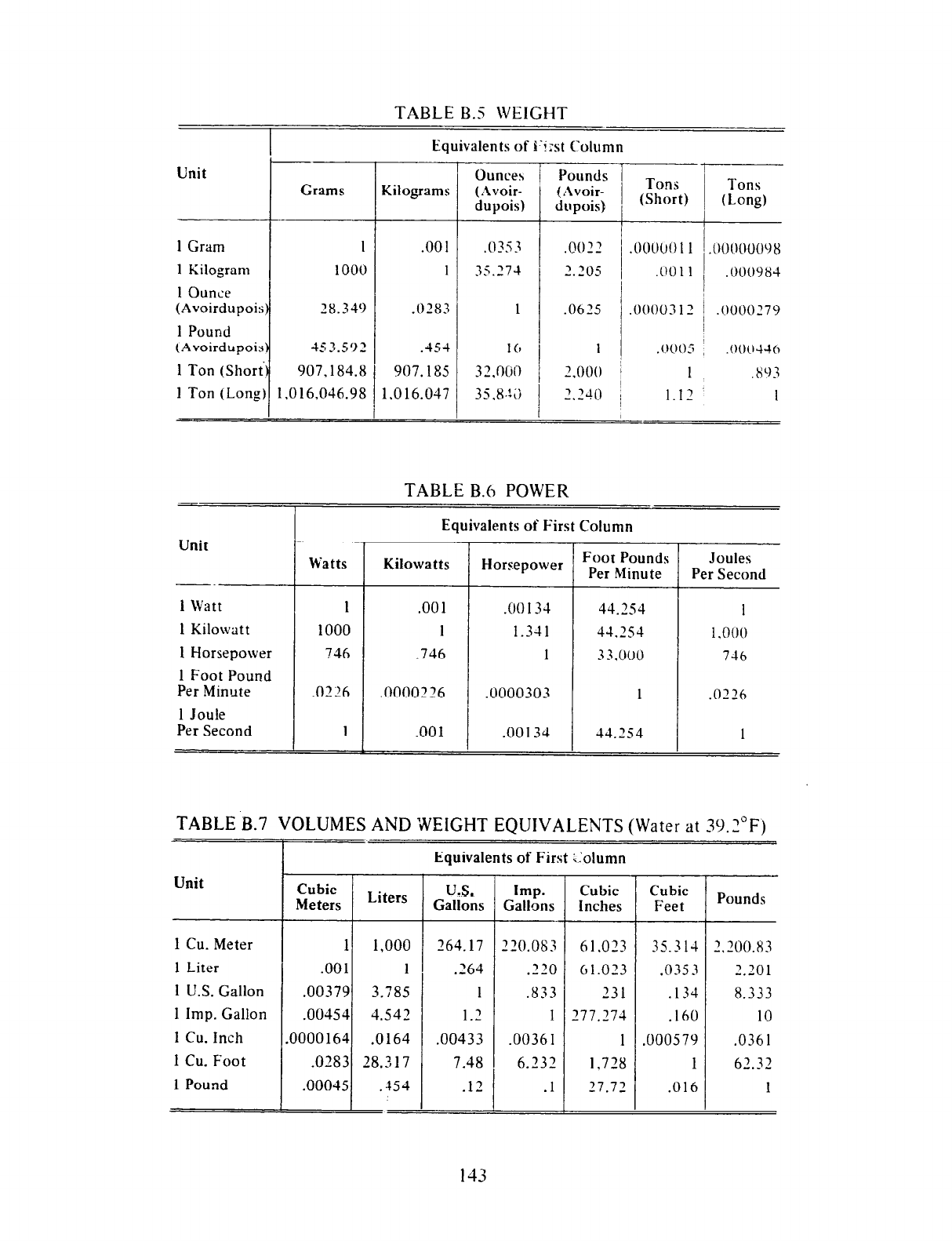
TABLE B.5 WEIGHT
Equivalents of I‘izst Column
Unit Grams Kilograms
1
Gram 1 .oo 1
1 Kilogram 1000 1
1Ounce
(Avoirdupois)
28.349 .0283
1 Pound
(Avoirdupois)
453.592 .454
1 Ton (Short) 907.184.8
907.185
1 Ton (Long) 1.016.046.98 1.016.047
Unit
1
Watt
1 Kilowatt
1 Horsepower
1 Foot Pound
Per Minute
1 Joule
Per Second
Ounces
/ Pounds /
(Avoir-
dupois)
I
=i=
TABLEB.6 POWER
Watts
1
1000
746
Equivalents of First
Column
!
Kilowatts Horsepower Foot Pounds Joules
Per Minute Per Second
1
1,000
746
.0226
1
TABLEB.7 VOLUMESANDWEIGHT EQUIVALENTS(Waterat39.2"F)
Unit
1 Cu. Meter 1 1,000
1 Liter .OOl 1
1 U.S. Gallon
.00379 3.785
1 Imp. Gallon
.00454 4.542
1 Cu. inch
.0000164 .0164
1 Cu. Foot
.0183 28.317
1
Pound .00045 .154
1=
I-
-
Cubic
Meters Liters
I
Equivalents of First ::olumn
UIS.
Gallons
264.17
.264
1
I’
.-
.00433
7.48
17
. -
Imp.
Gallons
-.-
220.083
“0
.--
.833
1
.00361
6.232
.I
-
Cubic Cubic
Inches Feet
61.033 35.314
61.023 .035 3
‘31 .I34
177.774
.I60
1
.000579
1,728
1
17.72 .016
Pounds
' 700.83
-.-
’ ‘01
-.-
8.333
IO
.0361
62.32
1
143
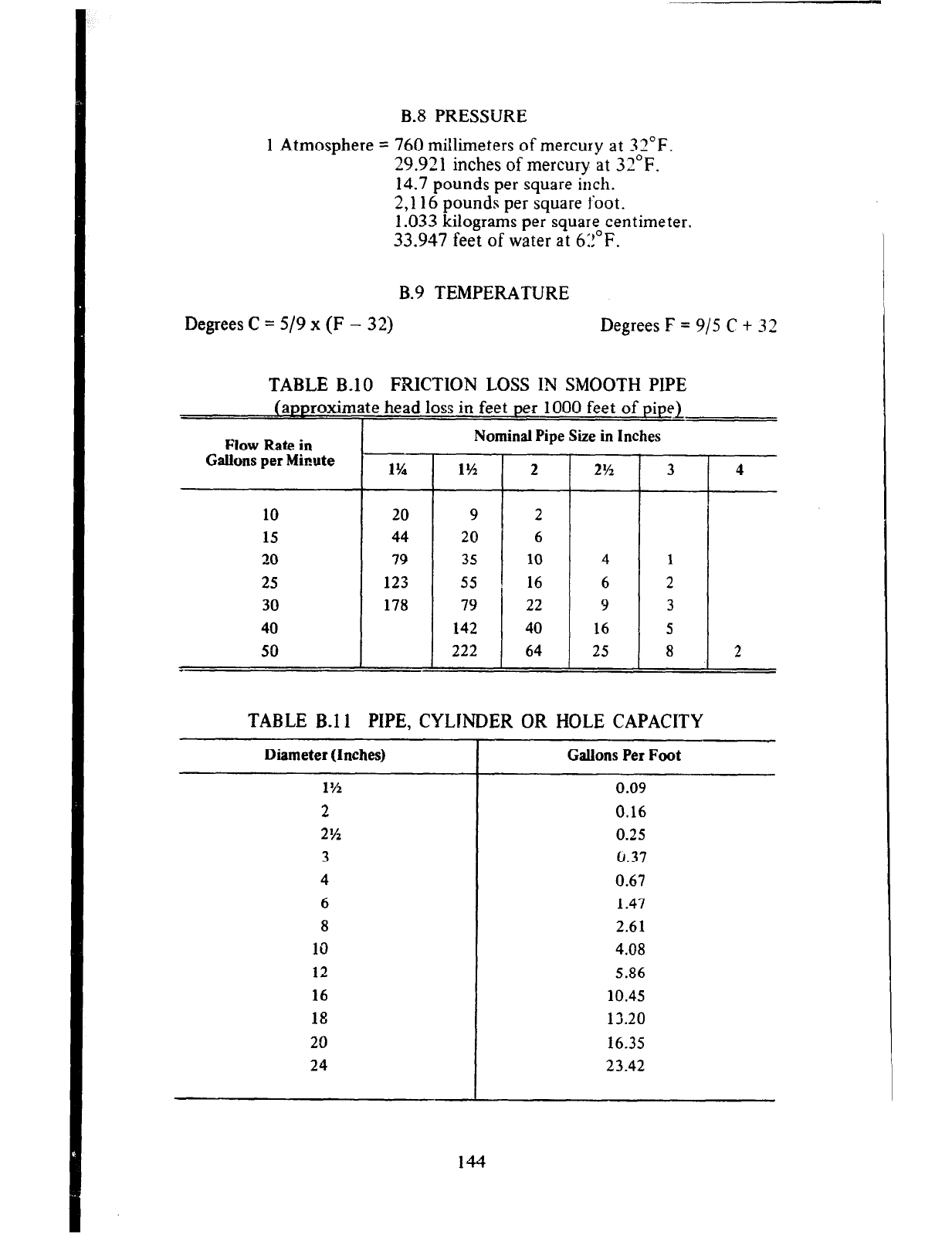
B-8 PRESSURE
1 Atmosphere = 760 mibreters of mercury at 32°F.
29.921 inches of mercury at 32°F.
14.7 pounds per square inch.
2,116 pounds per square foot.
1.033 kilograms per square centimeter.
33.947 feet of water at 6:!“F.
B.9 TEMPERATURE
Degrees C = 5/9 x (F - 32) Degrees F = 9/5 C t 32
TABLE B-10 FRICTION LOSS IN SMOOTH PIPE
(approximate head loss in feet
per
1000 feet of pipe1
I
Flow Rate in
Gallons per Miwte 1%
Nominal Pipe Size in Inches
10 20
15 44
20 79
25 123
30 178
40
50
-
2%
4
6
9
16
25 I
TABLE B-11 PIPE, CYLINDER OR HOLE CAPACITY
Diameter (Inches) Gallons Per Foot
1% 0.09
2 0.16
2% 0.25
3 0.37
4 0.67
6 1.47
8 2.61
10 4.08
12 5.86
16 10.45
18 12.20
20 16.35
24 23.42
2
144
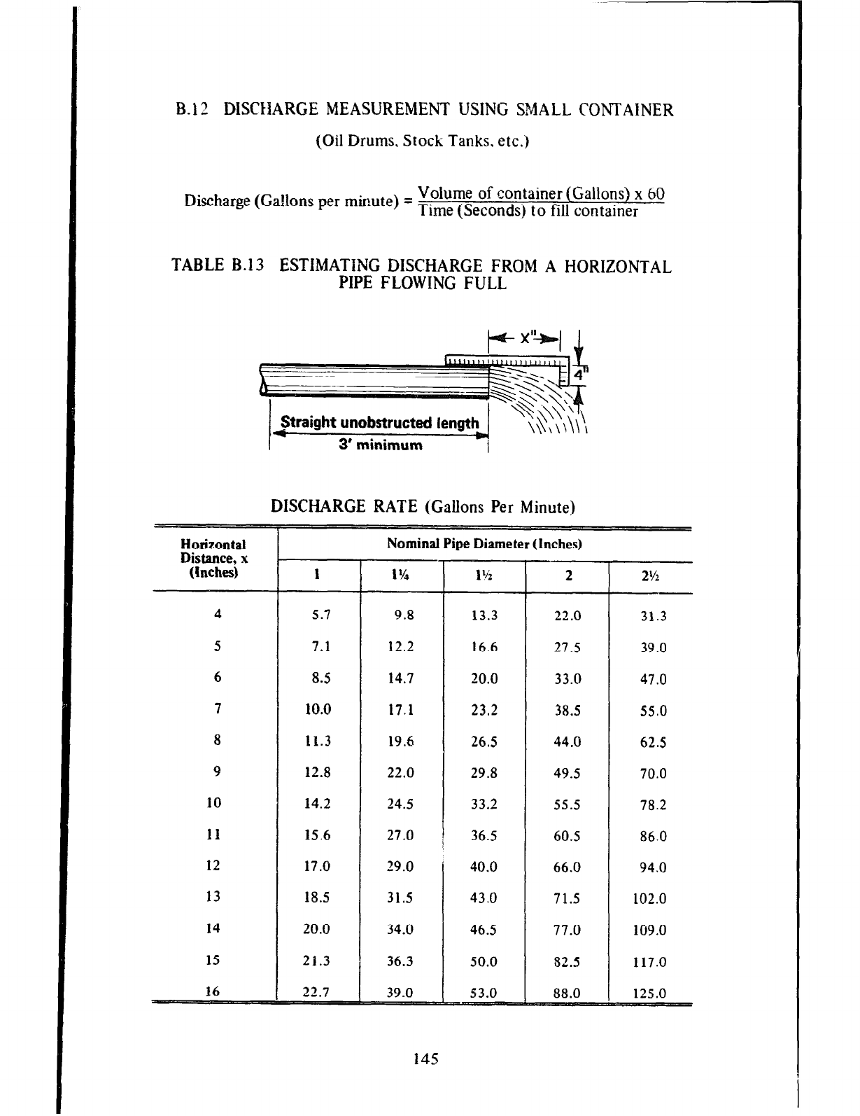
B-1 2 DISCHARGE MEASUREMENT USING SMALL CONTAINER
(Oil Drums. Stock Tanks. etc.)
Discharge (Gallons per minute) = Volume of container (Gallons) x 60
Time (Seconds) to fill container
TABLE B.13 ESTIMATING DISCHARGE FROM A HORIZONTAL
PIPE FLOWING FULL
DISCHARGE RATE (Gallons Per Minute)
Horizontal
Distance, x
(Inches)
4
5
6
7
8
9
10
11
12
13
14
15
16
- 4
1 1% 1 ‘h 2
5.7 9.8 13.3 22.0
7.1 12.2 16.6 27.5
8.5 14.7 20.0 33.0
10.0 17.1 23.2 38.5
11.3 19.6 26.5 44.0
12.8 22.0 29.8 49.5
14.2 24.5 33.2 55.5
15.6 27.0 36.5 60.5
17.0 29.0 40.0 66.0
18.5 31.5 43.0 71.5
20.0 34.0 46.5 77.0
21.3 36.3 50.0 82.5
22.7 39.0 53.0 88.0
Nominal Pipe Diameter (Inches)
145
2Y2
31.3
39.0
47.0
55.0
62.5
70.0
78.2
86.0
94.0
102.0
109.0
117.0
125.0
-
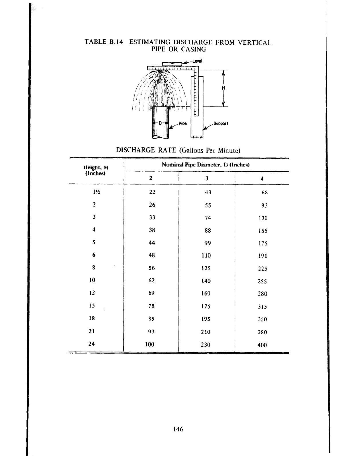
TABLE B-14 ESTIMATING DISCHARGE FROM VERTICAL
PIPE OR CASING
DISCHARGE RATE (Gallons Per Minute)
Height, H
(Inches)
1%
2
3
4
5
6
8
10
12
15 .
18
21
24
Nominal Pipe Diameter, D (Inches)
2 3 4
23 43 68
26 55 9?
33 74 130
38 88 155
44 99 175
48 110 190
56 125 225
62 140 255
69 160 280
78 175 315
85 195 350
93 210 380
100 230 400
146
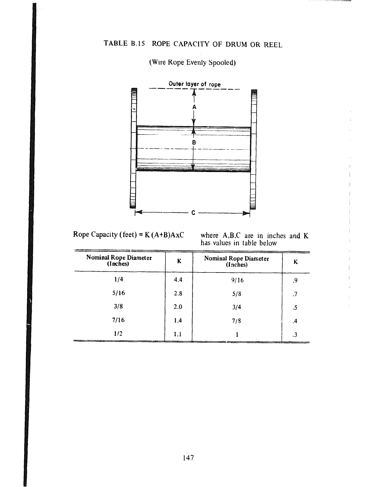
TABLE B.15 ROPE CAPACITY OF DRUM OR REEL
(Wire Rope Evenly Spooled)
Outer layer of rope
Rope Capacity (feet) = K (A+B)AxC
Nominal Rope Diarnet er
(IncheyF
i/4 4.4
I
2.8
2.0
1.4
i/2 1.1
where A,B,C are in inches and K
has. values in table below
--
Nominal Rope Diameter
(Inches) K
9116 .9
147
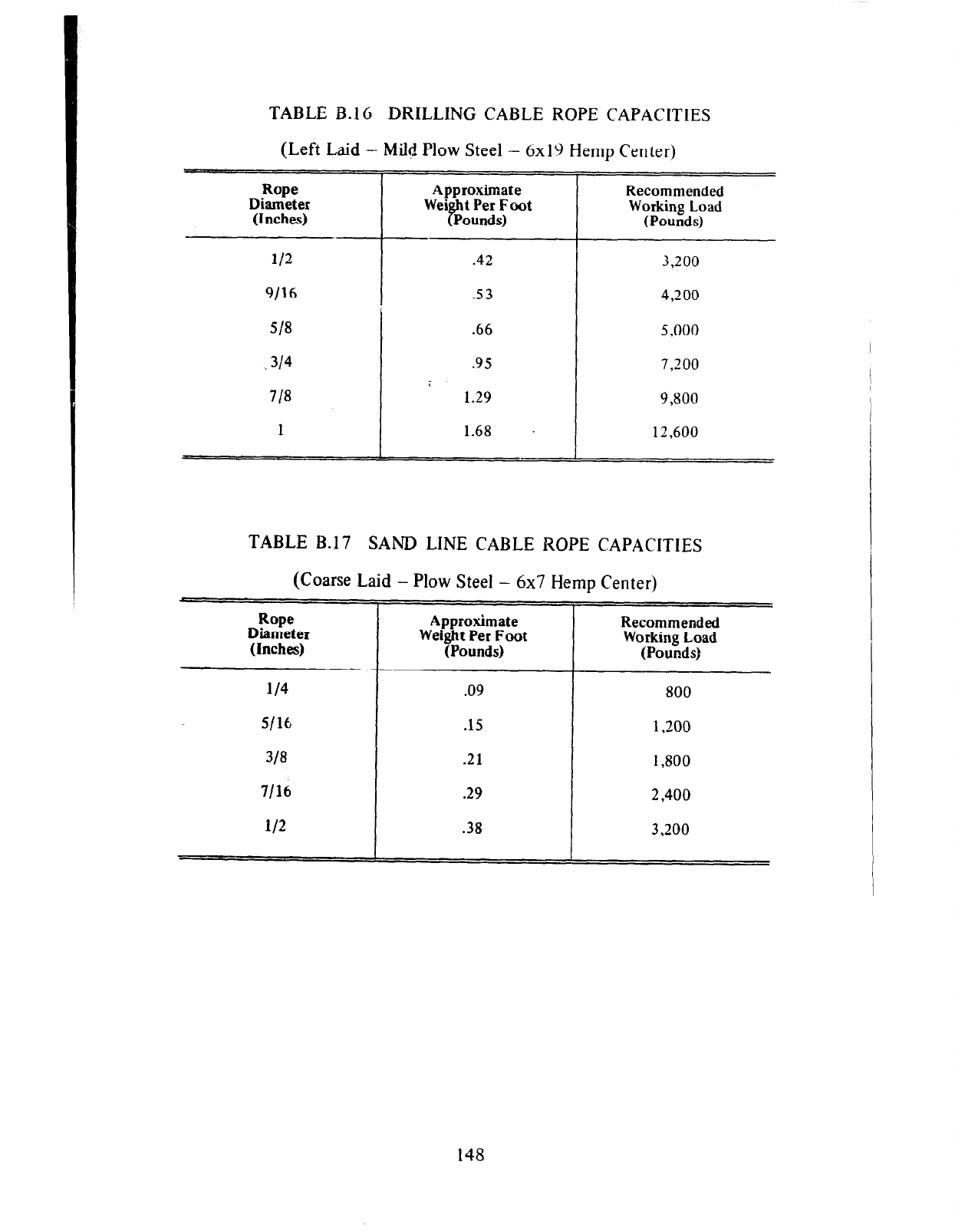
TABLE B.16 DRILLING CABLE ROPE CAPACITIES
(Left Laid - Mild Plow Steel - 6x19 Hemp Center)
Rope
Diameter
(Inches)
Approximate Recommended
Working Load
(Pounds)
112 3,200
9/16 4,200
513 .66 5,000
-314 .95 7,200
;
713 1.29 9,800
1 1.68 - 12,600
TABLE B.17 SAND LINE CABLE ROPE CAPACITIES
(Coarse Laid - Plow Steel - 6x7 Hemp Center)
Rope
Diameter Approximate
(Inches) Weight Per Foot
(Pounds)
Recommended
Working Load
(Pounds)
114 .09 800
S/l6 .15 1,200
313 .21 1,800
7/16 .29 2,400
112 .38 3,200
-z-
148
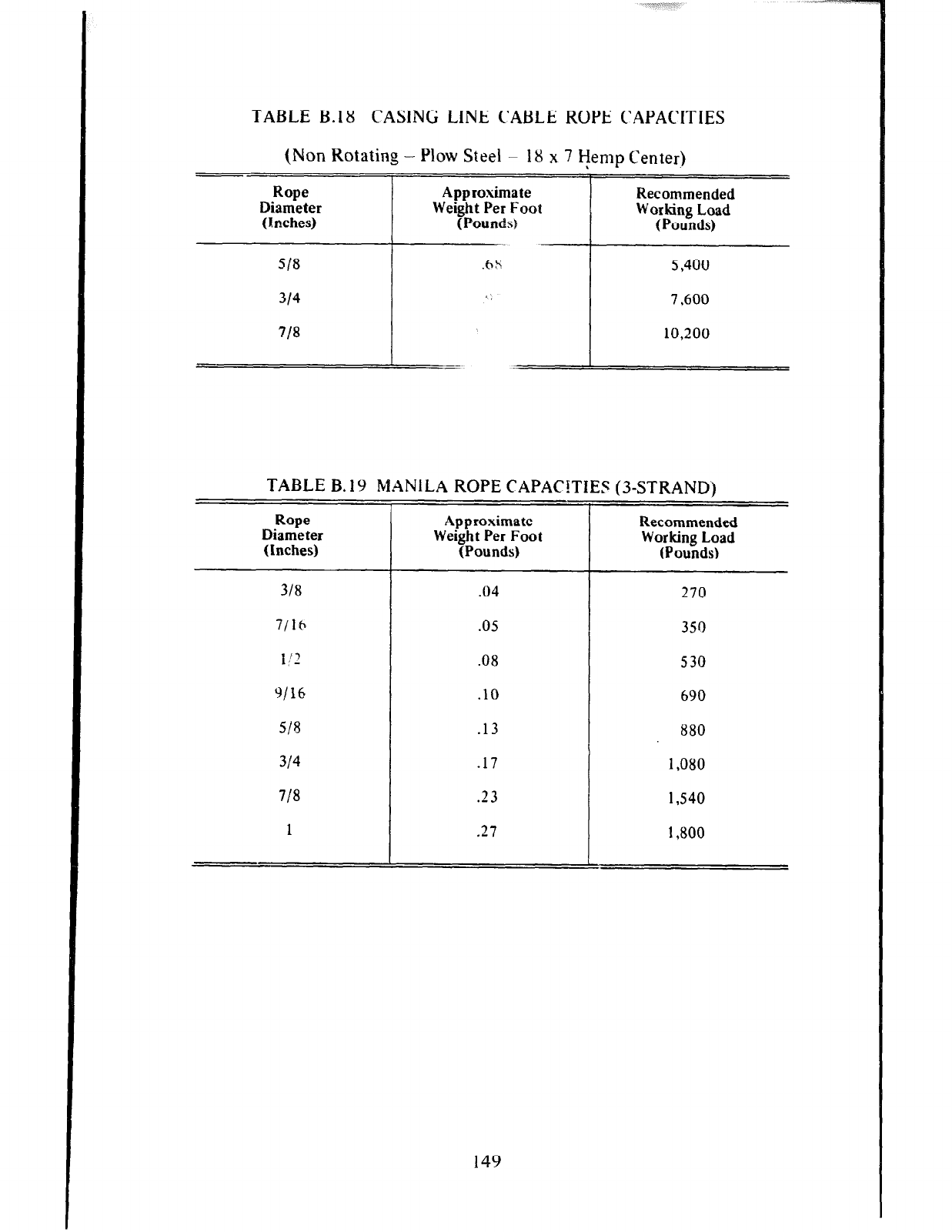
TABLE B.18 CASING LINE CABLE ROPE CAPACITIES
(Non Rotating - Plow Steel - 18 x 7
Hemp Center)
Rope Approximate
Diameter Weight Per Foot
(Inches) (Pounds)
Recommended
Working
Load
(Pounds)
513 .hS 5,400
314 1; 7,600
713 10,200
TABLE B. 19 MANILA ROPE CAPACITIES (3-STRAND)
Rope
Diameter
(Inches)
318
7116
1:‘2
!a/16
518
314
7/3
1
Approximate
Recommended
Weight Per Foot
(Pounds) Working Load
(Pounds)
.04 270
.05 350
.08 530
.lO 690
.13 880
.17
1,080
.23
1,540
.27
1,800
149
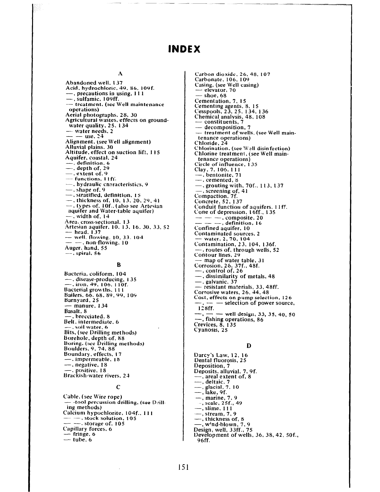
A
Abandoned well, I37
Acid. hydrochloric. 49, 86, 109f.
-, precautions in using, I I 1
-, sulfamic, 109ff.
- treatment, (see Well maintenance
operations)
Aerial photographs. 28. 30
Agricultural wastes. effects on ground-
water quality. 25. I34
- water needs. 2
- - use. 24
Alignment. (see Well alignment)
Alluvial plains, 30
Altitude, effect on suction lift, I I s
Aquifer, coastal, 24
-, definition, 6
-, depth of, 29
-. extent of. 9
- functions. I Ift’.
-. hydrltulic cnnracteristics, 9
-. shape of. 9
-. stratified, definition, IS
-. thickness of, IO. 13, 20. 29, 41
-, t,ypes of. I Of.. (also see Artesian
aquifer and Water-table aquifer)
-m. width of, I4
Area. cross-sectional. I3
Artesian aquifer. 10. 13. 16. 30, 33. 52
- head. I37
- well, flowing, IO, 33. IO4
- -.. non-flowing, IO
Auger. hand, SS
-, spiral. 56
B
Bacteria, coliform. 104
-. disease-producing, I 35
-. iron, 49, 106. I IOf.
bacterial growths, I I 1
Bailers, 66. 68, 89, 99, 104
Barnyard, 2S
- manure, 134
Basalt, 8
-, breociated. 8
Belt. intermediate. 6
--, soil water, 6
bits. (see Drilling methods)
borehole. depth of, 88
boring. (see Drilling methods)
boulders. 9. 74, 88
Boundary. effects. I7
-, impermeable. 18
-, negative. 18
-. positive, 18
Brackish-water rivers, 2-1
C
Cable. (see Wire rope)
- -tool percussion drilling, (see Drill-
ing methods)
Calcium hypochlorite, l04f., I1 I
- -. stock solution, POS
- -. storage of. 105
Capillary forces, 6
- fringe, 6
- tube, 6
151
Carbon dioxide. 26, 48, 107
Carbonate. 106, 109
Casing, (see Well casing)
- elevator, 70
-shoe 68
Cementation, 7, 1 S
Cementing agents, 8. 1 S
Cesspools, 23. 25, 134, 136
Chemical analysis, 48, 108
- constituents, 7
- decomposition, 7
- treatment of wells, (see Well main-
tenance operations)
Chloride, 24
Chlorination, (see Well disinfection)
Chlorine treatment, (see Well main-
tenance operations)
Circle of influence, 135
Clay, 7, 106, 11 1
-, bentonite, 7 1
cemented, 8
=: grouting with, 7Of.. I 13, I37
-, screening of, 41
Compaction, 7f.
Concrete, 52, 137
Conduit functiou of aquifers, I I ff.
Cone of depression, 16ff., 135
--- composite, 20
--- : definition, 16
Confined aquifer, 10
Contaminated sources, 2
- water, 2.70, 104
Contamination, 23. 104, 136f.
-+ routes of, through wells, 52
Contour lines, 29
- map of water table, 31
Corrosion. 26, 37f.. 48f.
-, control of, 26
-, dissimilarity of metals, 48
-., galvanic, 37
- resistant materials, 33, 48ff.
Corrosive waters, 26, 44, 48
Cost, effects on pump selection, 126
--
-2 8ff. selection of power source,
- - well design, 33, 35. 40, so
=: fishing operations, 86
Crevices, 8. 135
Cyanosis. 25
D
Darcy’s Law, 12. 16
Dental fluorosis, 25
Deposition, 7
Deposits, alluvial, 7, 9f.
-, area1 extent of, 8
-, deltaic. 7
-, glacial, 7, 10
-, lake, 9f.
-, marine, 7, 9
-, scale, 2Sf., 49
-, slime, 11 I
-, stream, 7,9
-, thickness of, 8
-, w%d-blown, 7, 9
Design, well, 33ff., 75
Development of wells, 36, 38, 42, SOf.,
96ff.
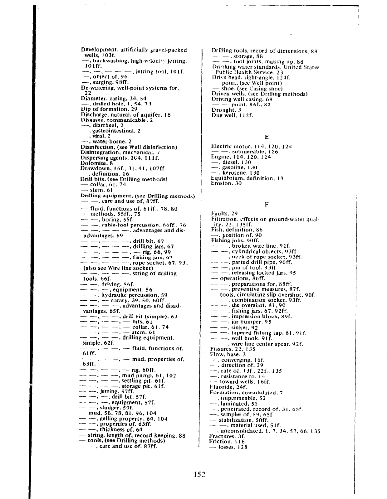
Development, artificially gravel-pazked
wells, 103f.
-, backwashing, high-vehxif” jetting,
10lff.
-. -, --- jetting tool, IOlf.
-7 object of, 96 ’
-, surging, 98ff.
De-watering, well-point systems for,
22
Diameter, casing, 34, ~4
-, driiled hole. 1, 54. 7 3
Dip of formation. 29
Discharge, natural, of aquifer. 18
f&eases, communicable, 2
-, diarrheal, 2
-. gastrointestinal, 2
-, viral.
2
-, water-borne. 2
Disinfection, (see Well disinfection)
Disintegration. mechanical, 7
Dispersing agents, 164, 1 11 f.
Dolomite, 8
Drawdown, 16f.. 31. 41, 107ff.
-. definition, 16
Drill bits, (see Drilling methods)
- col!ar. 6 1. 74
- stem. 61
Drilling equipment, (see Drilling methods)
- -, care and use of. 87ff.
- fluid, functions of, blff., 78,
80
- methods, SSff., 75
- -, boring, SSf.
- -. cable-tool percussion. 66ff.. 76
-- -_--
advantages.
69 ’
advantages and dis-
-- -_-
.
, drill bit, 67
--.-.--- 9
drilling jr&r,, 67
-- -_- - rig, 66, 99
c- ----
l
: fishing jars, 67
- -, - - --. rope socket, 67, 93,
(also see Wire line socket)
--t---- ’ tools. 66f. string of drilling
-- , driving, SSf.
-- -. equipment, 56
- ---I hydraulic percussion, ~9
-- , - rotary, 39, SO, 60ff.
--.--
vantages, 65f.’ advantages and disad-
-- %
- -, drill bit (simple), 63
- -* -- -, - ms, 61
-- -- . - collar. 6 I, 74
- -, - -. - stem, 61
--.- -, drilling equipment,
simule. 62f.
-- --
61ff: ’ -- fluid, functions of,
-_ --
63ff.’ ’ - mud, properties of,
- -. - - - rig, 6Off.
-- -_
7 : mud pump. 61, 102
-- , - -, settling pit, 61f.
-- -- storage pit. 6 1 f.
- --I jetting,’ 57ff.
-- , -, drill bit, 57f.
--,--- equipment, S7f.
- -, sludger, 59f.
-- mud, 58,78. 81,96, 104
- -, gelling property. 64, 104
- -, properties of, 63ff.
- -. thickness of, 64
- string, length of, record keeping. 88
- tools, (see Drilling methods)
- -, care and use of, g?ff.
Drilling tools, record of dimensions, 88
- ---, storage, 88
- -. tool joints, making up, 88
Dti*:king water standards, United States
Pu3lic Health Service. 2 3
Dri;,e head, right-angle, 124f.
- point, (see Well point)
- shoe, (see Casing shoe)
Driven wells, (see Drilling methods)
Driving well casing, 68
- - point, 56f., 82
Drought, 3
Dug well, 1 l2f.
E
Electric motor, I 14,
120.
124
- -, submersible, 126
Engine. 114. 120, 124
-, diesel. 130
-, gasoline, 130
-, kerosene, 130
Equilibrium, definition. IS
Erosion, 30
F
Faults. 29
Filtration, effects on ground-water qual-
ity, 22, r35ff.
Fish, definition, 85
-. position of, 90
Fishing jobs, 90ff.
- -. broken wire line, 92f.
- -, cylindrical objects, 93ff.
- -, neck of rope socket. 93ff.
- -, parted drill pipe, 90ff.
- -, pin of tool, 93ff.
-- , releasing locked jars, 95
- operations, 86ff. -
- --, preparations for. 88ff.
- --.-preventive measures, 87f.
- tools, circulating-slip overshot, 90f.
- -, combination socket, 93ff.
- - , die overshot. 81, 90
- -, fishing jars, 67, 92ff.
- -, imoression block. 89f.
- -, jar’bumper. 95
- -, sinker, 92
- -. tapered fishing tap, 8 I, 9 I f.
- --. wall hook, 9 I f.
- -, wire line center spear. 92f.
Fissures, 22, I35
Flow, base, 3
-, converging. I6f.
-, direction of, 29
-, rate of, 13f., 22f., 135
-. resistance to, 14
- toward wells. I6ff.
Fluoride, 24f.
Formation. consolidated, 7
-, impermeable, 52
-, laminated, 5 1
-. penetrated, record of. 3 I, 6Sf.
-. samples of. 59, 65f.
- stabilization, 50ff.
- -, material used, Slf.
-, unconsolidated. I, 7, 34. 57, 66. I35
Fractures, 8f.
Friction, I I6
- lossrs, I 28
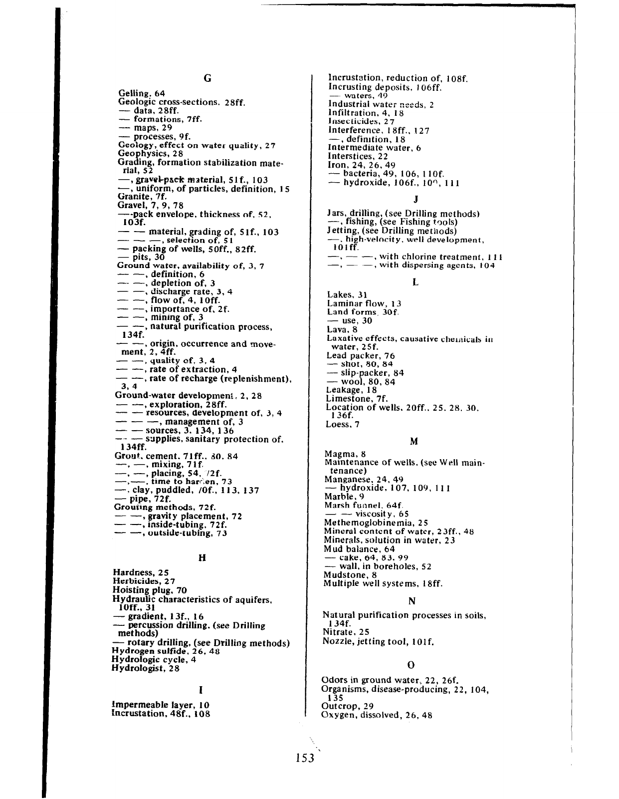
c
Gelling, 64
Geologic cross-sections. 2aff.
- data, 28ff.
- formations, 7ff.
- maps, 29
- processes, 9f.
Geology, effect on water quality, 27
Geo hysics, 28
c,:“,, 12% formation stabilization mate-
-g.
-, haveI-pack material, Slf., 103
-, uniform, of particles. definition, 1 s
Granite, 7f.
Gravel, 7, 9, 78
--pack envelope, thickness of, 52,
103f.
- - material. grading of, Slf., 103
--- , selection of, 5 1
- packing of wells, soff., szff.
- pits, 30
Ground water, availability of, 3. 7
- -, definition, 6
-- -, depletion of, 3
- -, discharge rate, 3,4
- -, flow of, 4, 1Off.
- -. importance of, 2f.
- -, mining of, 3
- -, natural purification process,
134f.
- -, origin, occurrence and move-
ment, 2. 4ff.
- -. quality of, 3. 4
- -, rate of extraction, 4
- -. rate of recharge (replenishment),
3.4
Ground-water development. 2, 2 8
- --, exploration, 28ff.
- - resources, development of, 3, 4
- - --I management of, 3
- - sources, 3. 134, 136
-- - sapplies. sanitary protection of.
134ff.
Grout, cement, 7lff.. do, 84
-7 -7 mixing, 7 1 f.
-. -, placing, 54, I2f.
-,--, time to hari;en, 73
-. clay, puddled, /Of., 113. 137
- pipe, 72f.
Grouimg methods, 72f.
- -, gravity placement, 72
- -, inside-tubing, 72f.
- -, outside-tubing, 73
H
Hardness, 2 5
Herbicides. 27
Hoisting p&, 70
Hydraulic characteristics of aquifers,
IOff.. 31
- gradient, 13f., 16
- percussion drilling, (see Drilling
met hods)
- rotary drilling, (see Drilling methods)
Hydrogen sulfide, 26, 48
Hydrologic cycle, 4
Hydrologist, 28
I
Impermeable layer, 10
Incrustation, 48f., 108
Incrustation, reduction of, 1 osf.
Incrusting deposits. I06ff.
- waters, 49
Industrial water heeds, 2
Infiltration, 4. 18
Insecticides, 27
Interference, 18ff.. 127
- , defimtion, 18
Intermediate water, 6
Interstices, 22
Iron. 24, 26, 49
- bacteria, 49, 106, I 10f.
- hydroxide, 106f., 100, 11 I
.I
Jars, drilling, (see Drilling met hods)
-, fishing, (see Fishing tools)
Jetting, (see Drilling methods)
-, high-velocity, well development,
10 1 ff.
-3 - -, with chlorine treatment. I 11
-7 - -, with dispersing agents, 104
L L
Lakes, 31 Lakes, 31
Laminar flow, 13 Laminar flow, 13
Land forms, 30f. Land forms, 30f.
- use. 30 - use. 30
Lava. 8’
Laxative effects. causative chemicals in
water, 25f.
Lead packer, 76
- shot, 80, 84
- slip-packer, 84
- wool, 80, 84
Leakage, 18
Limestone, 7f.
Location of wells. 2Off.. 25, 28, 30.
136f.
Loess. 7
Magma, 8
M
Maintenance of wells, (see Well main-
tenance)
Manganese, 24,49
- hydroxide, 107. 109, 11 1
Marble I 9
Marsh funnel, 64f.
- - viscosity, 65
Methemoglobinemia, 25
Mineral content of water, 23ff.. 48
Minerals, solution in water, 23
Mud balance. 64
- cake, 64, 83. 99
- wall, in boreholes, 52
Mudstone, 8
Multiple well systems, 18ff.
N
Natural purification processes in soils,
134f.
Nitrate, 25
Nozzle, jetting tool, 10lf.
0
Odors in ground water., 22, 26f.
Organisms, disease-producmg, 22, 104,
135
Outcrop, 29
Oxygen, dissolved, 26, 48
153
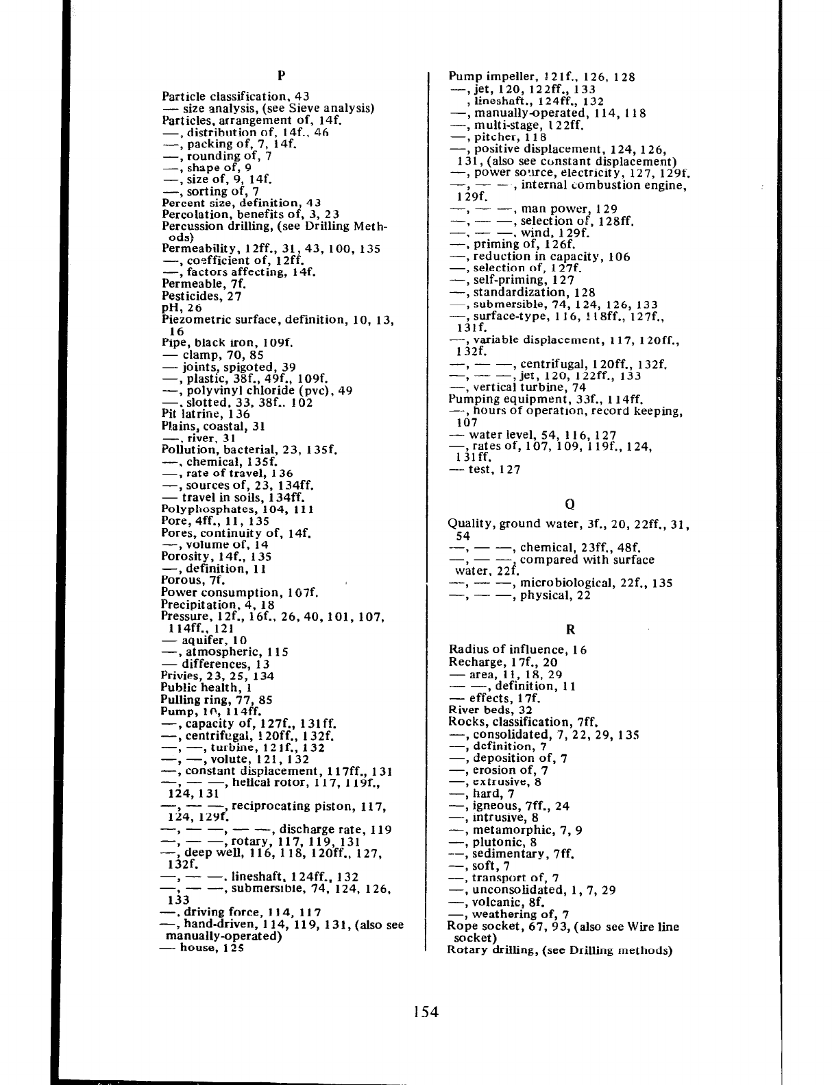
P
Particle classification, 43
size analysis, (see Sieve analysis)
Gicles, arrangement of, 14f.
-, distribution of, 14f., 46
-, packing of, 7, 14f.
-, rounding of, 7
-9 shape of, 9
-, size of, 9, 14f.
sorting of, 7
¢ size, definition, 43
Percolation, benefits of, 3, 2 3
Percussion drilling, (see Drilling Met h-
P%?eabiIity 12ff 31
-, coefficiem of,“1 2ff. 43, 100. 135
-. factors affecting. 14f.
Permeable, 7f. -
Pesticides. 27
pII,
PyTmetric surface, definition, 10, 13,
Pipe, black iron, l09f.
- clamp, 70, 85
- joints, spigoted, 39
-, plastic, 38f., 49f., 109f.
-, polyvinyl chloride (PVC), 49
- , slotted, 33, 38f.. 102
Pit latrine, 136
Pl.ains, coast al, 3 1
-, river, 31
Pollution, bacterial, 23, 135f.
-, chemical, 135f.
-. rate of travel, 136
-, sources of, 23, 134ff.
- travel in soils, 134ff.
Polyphosphates, 104, 111
Pore, 4ff., 11, 135
Pores, continuity of, 14f.
-, volume of, 14
Porosity, 14f., 135
-, definition, 11
Porous, 7f.
Power consumption, 107f.
Precipitation, 4, 18
Pressure, 12f., 16f., 26, 40, 101, 107,
114ff., 121
- aquifer, 10
-. atmospheric, 1 15
- differences, 13
Privies, 23, 25, 134
Public health, l
Pulling ring, 77, 85
Pump, 1 o, 114ff.
-, capacity of, 127f., 13lff.
-, centrifugal, 120ff.. 132f.
-, -, turbine, l?lf., 132
-, volute, 12l. 132
=I constant displacement, 117ff., 131
- -, helical rotor, 117, 1 19f.,
TS4.131
- -, reciprocating piston, 117,
li4, 129f.
-, --s--
discharge rate, 119
- -,rotary,‘ll7 119 131
=: deep well, 116, 1 18: 1 Zdff., 127,
132f.
-1 - -$ lineshaft, 124ff., 132
-3 - -, submersrble, 74, 124, 126,
133
-. driving force, 114, 117
-) hand-driven, 114, 119, 13 1, (also see
manually-operated)
- house, 125
154
Pump impeller, 12 If., 126, 128
-, jet, 120, 122ff., 133
-, Iineshaft., 124ff., 132
-, manually-operated, 114, 118
-, multi-stage, l22ff.
-, pitcher, 118
-, positive displacement, 124, 126,
131, (also see constant displacement)
-, power so:uce, electricity, 127, 129f.
-¶ --9
129f. internal combustion engine,
-9 - -, man power, 129
-9 - -, selection of, 128ff.
-1 - -, wind, 129f.
-, priming of? 126f.
-, reduction m capacity, 106
-, selection of, 127f.
-, self-priming, 127
-, standardization, 128
-, submersible, 74, 124, 126, 133
---I surface-type, 1 16, l 1 Sff., 127f.,
13lf.
--, variable displacement, 117, 1 ZOff.,
132f.
-1 - -, centrifugal, 1 ZOff., 132f.
-,-- -, jet, 120, 122ff., 133
-, vertical turbine, 74
Pumping equipment, 33f., 114ff.
-, hours of operation, record keeping,
107
- water level, 54, 116, 127
Tif;;es of, 107, 109, 119f., 124,
- test., 127
Q
Quality, ground water, 3f., 20, 22ff., 31,
54
_- 7 - -, chemical, 23ff., 48f.
--
Gter, 22f. compared with surface
--9 - -> microbiological, 22f., 135
-1 - -, physical, 22
R
Radius of influence, 16
Recharge. 17f.. 20
-area, il, 18, 29
- -, definition, 11
- effects, 17f.
River beds, 32
Rocks, classification, 7ff.
-, consolidated, 7, 22, 29, 135
-, definition, 7
-, deposition of, 7
-, erosion of, 7
-, extrusive, 8
-, hard, 7
-, igneous, 7ff., 24
-, intrusive, 8
-, metamorphic, 7, 9
-, plutonic, 8
--, sedimentary, 7ff.
-, soft, 7
-, transport of, 7
-, unconsolidated,
1, 7, 29
-, volcanic, 8f.
-, weathermg of, 7
Rope socket, 67, 93, (also see Wire line
socket)
Rotary drilling, (see Drilling methods)
s
Sand, 7,9? 119, 126, 129, 137
-- anaylsn, (see Sieve analysis)
- dune, 7, 31
- pump, 68
- pumping from a well, 46
Sandstone, 7f.
Sanitary protection, ground-water
supplies, 134ff.
-- -, wells, S2ff.. 136f.
- well seal, 52
Screen, (see Well screen)
Sediments, terrestrial, 9
!%$II tganks, I34
Sieve inalysis, 43, 46
Sieve-analysis curves, 43ff.
Sieves, standard sets of, 43
Silt, 106, 111
Siltstone, 8
Site accessibility, effect on selection
of well materials, 50
Slotted pipe, 33, 38f., 102
Sludger, drilling method, 59f.
Sodium hypochlorite, 105, 111
Solution channels, 8f., 22, 135
Solvent, water as, 2 3
Spacing of wells, 20ff.
Specific capacity, 20, 42, 44, 107f., 127
- retention, 12
- yield, 12
Spring, 29, 31
Static water level, 16, 103, 106, 116
Storage, aquifer, 3, 17
- function of aquifers, 1 If.
Stratification, 9, 14f., 46
Stream patterns, 31f.
Strike of formation, 29
Subsurface water, 4ff.
Suction, 11 Sf., 128
- lift, 103, 114ff., 121, 128
- -, definition, 114ff.
Sulfate, 25, 106
Surface drainage, contamination of
wells, 104
- evidence, ground-water exploration,
28, 31f.
- water, 3, 18, 134
Surge block, 98
- plunger, 98ff.. 109, 111
- -. operation within well screen,
101
- -. solid-type, 99
- -. valve-type, lOOf.
Surging, chlorine treatment, 11 1
-, well development, 98ff.
Suspended matter in ground water, 22
Swamps, 31
Swedge block, 77, 84
T
Tastes in ground water, 22, 24, 26f.
Temperature, 13, 2 2f., 116
Terraces, 9, 30f.
Texture of rocks, 7f.
Total dissolved solids, 25f., 48
Toxic chemicals in water, 26f.
Trace elements, 26f.
Transmissibility-, 14, 16f., 31
coefficient of, definition 14
Tra;lsmissivity, coefficient of: 14
Transport, rock, 7
Treatment, water, 22f., 26
U
Unconfined aquifer, 10
Uniform grading of particles, IS
Uniformity coefficient, definition, 5 1
V
Vacuum, 116, 121f.
Vadose water, 6
Valley fill, 31
Valleys, 9, 30f.
Vegetation, 6, 30ff.
Velocity, 12f., 16, 34,48, 107, 114,
121f.
- head, 128
Vesicles, 8
Volcanic rocks, 8f.
W
Wash-down bottom, 80f.
Wastes, effects on ground-water quality,
agricultural, 25, 134
-, ----- , animal. 25, 134
-9 - - - - -, human, 25
-9 ----- , industrial, 27,
134
Water analysis, 48
--bearing capacity, 7
- - formation, clogging of, 96, 106
-- - -9 compaction of, 96
- - -9 pollution travel in, 134ff.
- - -, stabilization by well develop-
ment, 96
- level, pumpirg, 54, 116, I27
- ‘-1-P definition, 16
- -1 -I estimation of, 127
- -, static, 16, 103, 106, 116
- -9 ,, definition, 16
- quahty, (see Quality)
- supplies, importance of, If.
- table, 13, 16, 56, 112, 127, 135,
137
- - contour map, 31
- 2, definition, 10
---table aquifer, 1 Of.., 13, 16, 30, 54
--yielding capabilittes of rocks, 7ff.
Weat hering of rocks, 2 9f.
Well alignment, 73ff., 126
- -9 checks on, 75
- -, conditions affecting, 74
- --, measurement of, 71
- -, plumbness, 73ff.
- -, straightness, 73ff.
artificially gravel-packed, 36, 46,
<;ff., 82ff.
-, - - --9 conditions favoring use,
51 --- development of, 103f.
E’capacity, 1 i 4, 127
- -, decrease in, 106
--9 cased section of, 33f.
-- casing, diameter of, 34, 40
- -, grouting and sealing, 54, 70ff.
- -9 installing, 69f.
- -, lower terminal of, 52ff.
- -, pulling, 77
- -, sealing abandoned wells, 137
-. --, shoe, 68
- -, temporary, 54
- completion, 96ff.
- construction, 6, 23, 31, 55ff.
-, depth of, 1, 30
- design, 33ff., 75
155
Well development, (see Development of
wells)
- disinfection. 96. 104f.. 1 11
-- --I
chlorine solution for, 104f.
- -, flowing artesian wells, 105
- drilling methods, (see Drilling
rret hods)
1: %%ia~~~of, 42. 44, 46, 51
- hydraulics, IOff.
-, intake section of, 33ff.
- inventories, 28, 30f.
- location, 2Off., 25, 28, 30
--, relative to pollution sources,
136f.
- logs, 30f.
- maintenance, 106ff.
- - operations, 108ff.
- - -, acid treatment, 109ff.
- - -3 - -, placing acid, 109
--- - -, precautions, 111
’ chlorine treatment, 109ff.
- - -%
--- dispersing agents, I 1 lf.
- -, plrLning of, 107f.
- -, record keeping, 107f.
--. - -, frequency of observa-
tions, 108
- materials, corrosion resistant, 33,
48ff.
- -. selection of, J7ff.
- -, strength requirements, 48, 49f.
- performance, 33, 106
- -, maintenance of, 106f.
- point, installing. driving, 56f.. 82
- -9 - in dug well, 112f.
--.- . open hole method. 81
-- -9 -9
pull-back method,‘81
- -, types of, 37f.
- pumd,-(see Pump)
- rehabilitation, 106ff.
-, sand producmg, 46
- screen,
33ff., 102f.
- -, continuous-slot type, 35f., 102f.
- ---, design, influence of aquifer char-
actertstics, 40ff.
- - -9
102 - on well development, 96,
- -, oiameter of, 4Of., 47
Well screen, entrance velocity, 35, 40,
47f.. 109
-- l, installina. 75ff.
- -9
-- in gr&el-packed wells, pull-
back mtr hod. 82ff.
-- -. -
‘etting method for setting
COT
’ ,
..
,.i
:dsing and screen, 8 1
- -, - iowering hook, 76f.
- -, -, open hole method, 77ff.
- -, -, pull-back method. 76f.. 81f.
- -* -, wash-down met hod, SO’f.
- -, length of, 4Of., 47
- -, louver- or shutter-type, 36
- -, open area, 34ff., 47
- - openings, clogging of, 106
- - -9 shape of, 34ff.
- - -9 size of, 42ff.
- - -9 standardization of sizes, 46
- --, pipe-base, 37
- -, pipe-size, 41, 47
- -, recovering, sand-joint method,
84ff.
- - slots, plastic pipe, 38f.
- -, telescope-size, 41, 47, 76
- spacing, 20ff.
-, upper terminal of, 52, 113
-, useful life of, 33, 106
Wells, arrangement of, 20ff.
Wetting agent, 111
Wind, 31, 129f.
Windmill, 114, 129f. a
-, wind speed requirement, 129
Wire line socket, 9 2 (also see RcJpe
socket)
- rope, care of, 87f.
Y
Y;::“; 8i X&, 31, 40f., 49, 106, 109, 113,
.I
-, specific: 1 If.
-9 -, definition, 12
Z
Zone of aeration, 4ff.
- - saturation, 4ff.
156
