Uoe7240 Welding Technical Manual TM 5 805 7
User Manual: manual pdf -FilePursuit
Open the PDF directly: View PDF ![]() .
.
Page Count: 96

TM 5-805-7
TECHNICAL MANUAL
WELDING
DESIGN, PROCEDURES AND INSPECTION
HEADQUARTERS, DEPARTMENT OF THE ARMY
20 MAY 1985
TM 5-805-7
REPRODUCTION AUTHORIZATION/RESTRICTIONS
This manual has been prepared by or for the Government and is public prop-
erty and not subject to copyright.
Reprints or republications of this manual should include a credit substantially
as follows: “Department of the Army Technical Manual TM 5-805-7, Welding:
Design, Procedures and Inspection. ”

TM 5-805-7
WELDING: DESIGN, PROCEDURES AND INSPECTION
Chapter
1.
INTRODUCTION
Purpose and scope
. . . . . . . . . . . . . . . . . . . . . . . . . . . . . . . . . . . . . . . . . . . . . . . . . . . . . . . . . . . . . . . . . . . . . . . . . . . . . . . . . . . . . . . . . . . . . . . . . . . . . . . . . . . . . . . . . . . . . . . . .
Welding applications
. . . . . . . . . . . . . . . . . . . . . . . . . . . . . . . . . . . . . . . . . . . . . . . . . . . . . . . . . . . . . . . . . . . . . . . . . . . . . . . . . . . . . . . . . . . . . . . . . . . . . . . . . . . . . . . . . . . . .
Chapter 2..
DESIGN AND INSPECTION RESPONSIBILITIES
Designer responsibilities
. . . . . . . . . . . . . . . . . . . . . . . . . . . . . . . . . . . . . . . . . . . . . . . . . . . . . . . . . . . . . . . . . . . . . . . . . . . . . . . . . . . . . . . . . . . . . . . . . . . . . . . . . . . . . . . .
Contractor responsibilities
. . . . . . . . . . . . . . . . . . . . . . . . . . . . . . . . . . . . . . . . . . . . . . . . . . . . . . . . . . . . . . . . . . . . . . . . . . . . . . . . . . . . . . . . . . . . . . . . . . . . . . . . . . . . .
Inspection requirements
. . . . . . . . . . . . . . . . . . . . . . . . . . . . . . . . . . . . . . . . . . . . . . . . . . . . . . . . . . . . . . . . . . . . . . . . . . . . . . . . . . . . . . . . . . . . . . . . . . . . . . . . . . . . . . . .
Chapter 3. WELDING PROCESSES
General
. . . . . . . . . . . . . . . . . . . . . . . . . . . . . . . . . . . . . . . . . . . . . . . . . . . . . . . . . . . . . . . . . . . . . . . . . . . . . . . . . . . . . . . . . . . . . . . . . . . . . . . . . . . . . . . . . . . . . . . . . . . . . . . .
Processes
. . . . . . . . . . . . . . . . . . . . . . . . . . . . . . . . . . . . . . . . . . . . . . . . . . . . . . . . . . . . . . . . . . . . . . . . . . . . . . . . . . . . . . . . . . . . . . . . . . . . . . . . . . . . . . . . . . . . . . . . . . . . . . . .
Shielded metal-arc (SMAW)
. . . . . . . . . . . . . . . . . . . . . . . . . . . . . . . . . . . . . . . . . . . . . . . . . . . . . . . . . . . . . . . . . . . . . . . . . . . . . . . . . . . . . . . . . . . . . . . . . . . . . . . . . . .
Gas metal-arc (GMAW)
. . . . . . . . . . . . . . . . . . . . . . . . . . . . . . . . . . . . . . . . . . . . . . . . . . . . . . . . . . . . . . . . . . . . . . . . . . . . . . . . . . . . . . . . . . . . . . . . . . . . . . . . . . . . . . . . . .
Flux-cored arc welding (FCAW)
. . . . . . . . . . . . . . . . . . . . . . . . . . . . . . . . . . . . . . . . . . . . . . . . . . . . . . . . . . . . . . . . . . . . . . . . . . . . . . . . . . . . . . . . . . . . . . . . . . . .
Gas tungsten-arc (GTAW)
. . . . . . . . . . . . . . . . . . . . . . . . . . . . . . . . . . . . . . . . . . . . . . . . . . . . . . . . . . . . . . . . . . . . . . . . . . . . . . . . . . . . . . . . . . . . . . . . . . . . . . . . . . . . . .
Submerged arc (SAW)
. . . . . . . . . . . . . . . . . . . . . . . . . . . . . . . . . . . . . . . . . . . . . . . . . . . . . . . . . . . . . . . . . . . . . . . . . . . . . . . . . . . . . . . . . . . . . . . . . . . . . . . . . . . . . . . . . . . .
Exothermic welding
. . . . . . . . . . . . . . . . . . . . . . . . . . . . . . . . . . . . . . . . . . . . . . . . . . . . . . . . . . . . . . . . . . . . . . . . . . . . . . . . . . . . . . . . . . . . . . . . . . . . . . . . . . . . . . . . . . . . . . .
Arc-stud welding
. . . . . . . . . . . . . . . . . . . . . . . . . . . . . . . . . . . . . . . . . . . . . . . . . . . . . . . . . . . . . . . . . . . . . . . . . . . . . . . . . . . . . . . . . . . . . . . . . . . . . . . . . . . . . . . . . . . . . . . . . . .
Process selection
. . . . . . . . . . . . . . . . . . . . . . . . . . . . . . . . . . . . . . . . . . . . . . . . . . . . . . . . . . . . . . . . . . . . . . . . . . . . . . . . . . . . . . . . . . . . . . . . . . . . . . . . . . . . . . . . . . . . . . . . . . . .
Chapter 4. WELDING OF STAINLESS STEEL
General
. . . . . . . . . . . . . . . . . . . . . . . . . . . . . . . . . . . . . . . . . . . . . . . . . . . . . . . . . . . . . . . . . . . . . . . . . . . . . . . . . . . . . . . . . . . . . . . . . . . . . . . . . . . . . . . . . . . . . . . . . . . . . . .
Weldability of stainless steels
. . . . . . . . . . . . . . . . . . . . . . . . . . . . . . . . . . . . . . . . . . . . . . . . . . . . . . . . . . . . . . . . . . . . . . . . . . . . . . . . . . . . . . . . . . . . . . . .
Joint design
. . . . . . . . . . . . . . . . . . . . . . . . . . . . . . . . . . . . . . . . . . . . . . . . . . . . . . . . . . . . . . . . . . . . . . . . . . . . . . . . . . . . . . . . . . . . . . . . . . . . . . . . . . . . . . . . . . . . . . . . . . . . . . . ..
Methods of welding stainless steels
. . . . . . . . . . . . . . . . . . . . . . . . . . . . . . . . . . . . . . . . . . . . . . . . . . . . . . . . . . . . . . . . . . . . . . . . . . . . . . . . . . . . . . . . . . . . . . . . .
Shielded metal-arc (SMAW)
. . . . . . . . . . . . . . . . . . . . . . . . . . . . . . . . . . . . . . . . . . . . . . . . . . . . . . . . . . . . . . . . . . . . . . . . . . . . . . . . . . . . . . . . . . . . . . . . . . . . . . . . . . .
Gas
metal-arc
(GMAW)
. . . . . . . . . . . . . . . . . . . . . . . . . . . . . . . . . . . . . . . . . . . . . . . . . . . . . . . . . . . . . . . . . . . . . . . . . . . . . . . . . . . . . . . . . . . . . . . . . . . . . . . . . . . . . . . . . .
Flux-cored arc welding (FCAW)
. . . . . . . . . . . . . . . . . . . . . . . . . . . . . . . . . . . . . . . . . . . . . . . . . . . . . . . . . . . . . . . . . . . . . . . . . . . . . . . . . . . . . . . . . . . . . . . . . . . .
Submerged arc (SAW)
. . . . . . . . . . . . . . . . . . . . . . . . . . . . . . . . . . . . . . . . . . . . . . . . . . . . . . . . . . . . . . . . . . . . . . . . . . . . . . . . . . . . . . . . . . . . . . . . . . . . . . . . . . . .
Special considerations in welding stainless
steels
. . . . . . . . . . . . . . . . . . . . . . . . . . . . . . . . . . . . . . . . . . . . . . . . . . . . . . . . . . . . . . . . . .. . . . . .
Chapter 5. WELDING CARBON STEEL AND LOW-ALLOY STEELS
General
. . . . . . . . . . . . . . . . . . . . . . . . . . . . . . . . . . . . . . . . . . . . . . . . . . . . . . . . . . . . . . . . . . . . . . . . . . . . . . . . . . . . . . . . . . . . . . . . . . . . . . . . . . . . . . . . . . . . . . . . . . . .
Weldability of carbon and low-alloy steels
. . . . . . . . . . . . . . . . . . . . . . . . . . . . . . . . . . . . . . . . . . . . . . . . . . . . . . . . . . . . . . . . . . . .
. . . . . . . . . . . . . . . . . .
Joint design
. . . . . . . . . . . . . . . . . . . . . . . . . . . . . . . . . . . . . . . . . . . . . . . . . . . . . . . . . . . . . . . . . . . . . . . . . . . . . . . . . . . . . . . . . . . . . . . . . . . . . . . . . . . . . . . . . . . . . . . . . . . . .
Methods
of welding carbon steels and low-alloy steels
. . . . . . . . . . . . . . . . . . . . . . . . . . . . . . . . . . . . .. . . . . . ..
Shielded metal-arc (SMAW)
. . . . . . . . . . . . . . . . . . . . . . . . . . . . . . . . . . . . . . . . . . . . . . . . . . . . . . . . . . . . . . . . . . . . . . . . . . . . . . . . . . . . . . . . . . . . . . . . . . .
&metal-arc (GMAW)
. . . . . . . . . . . . . . . . . . . . . . . . . . . . . . . . . . . . . . . . . . . . . . . . . . . . . . . . . . . . . . . . . . . . . . . . . . . . . . . . . . . . . . . . . . . . . . . . . . . . . . . . . . . . . . . . . .
Flux-cored arc welding (FCAW)
. . . . . . . . . . . . . . . . . . . . . . . . . . . . . . . . . . . . . . . . . . . . . . . . . . . . . . . . . . . . . . . . . . . . . . . . . . . . . . . . . . . . . . . . . . . . . . . . . . . .
Submerged arc (SAW)
. . . . . . . . . . . . . . . . . . . . . . . . . . . . . . . . . . . . . . . . . . . . . . . . . . . . . . . . . . . . . . . . . . . . . . . . . . . . . . . . . . . . . . . . . . . . . . . . . . . . . . . . . . . . . . . . . . . . .
Paragraph Page
1-1
1-2
2-1
2-2
2-3
3-1
3-2
3-3
3-4
3-5
3-6
3-7
3-8
3-9
3-10
4-1
4-2
4-3
4-4
4-5
4-6
4-7
4-8
4-9
5-1
5-2
5-3
5-4
5-5
5-6
5-7
5-8
1-1
1-1
2-1
2-3
2-5
3-1
3-1
3-2
3-12
3-21
3-22
3-23
3-26
3-28
3-30
4-1
4-1
4-5
4-5
4-5
4-6
4-6
4-7
4-7
5-1
5-1
5-3
5-3
5-3
5-4
5-4
5-5
TM 5-805-7
Paragraph Page
.
Chapter 6.
Chapter 7.
Chapter 8.
Chapter 9.
Appendix A.
Appendix B.
Bibliography
Figure
3-1.
3-2.
3-3.
3-4.
3-5.
3-6.
3-7.
3-8.
3-9.
3-10.
3-11.
3-12.
3-13.
3-14.
3-15.
3-16.
WELDING ALUMINUM ALLOYS
General
. . . . . . . . . . . . . . . . . . . . . . . . . . . . . . . . . . . . . . . . . . . . . . . . . . . . . . . . . . . . . . . . . . . . . . . . . . . . . . . . . . . . . . . . . . . . . . . . . . . . . . . . . . . . . . . . . . . . . . . . . . . . . . . . Ôñ}H
Weldability of aluminum alloys
. . . . . . . . . . . . . . . . . . . . . . . . . . . . . . . . . . . . . . . . . . . . . . . . . . . . . . . . . . . . . . . . . . . . . . . . . . . . . . . . . . . . . . . . . . . . . . . . . . . . . .
Joint design
. . . . . . . . . . . . . . . . . . . . . . . . . . . . . . . . . . . . . . . . . . . . . . . . . . . . . . . . . . . . . . . . . . . . . . . . . . . . . . . . . . . . . . . . . . . . . . . . . . . . . . . . . . . . . . . . . . . . . . . . . . . . . . . .
Methods of welding aluminum alloys
. . . . . . . . . . . . . . . . . . . . . . . . . . . . . . . . . . . . . . . . . . . . . . . . . . . . . . . . . . . . . . . . . . . . . . . . . . . . . . . . . . . . . . . . . . . . . .
Gas metal-arc (GMAW)
. . . . . . . . . . . . . . . . . . . . . . . . . . . . . . . . . . . . . . . . . . . . . . . . . . . . . . . . . . . . . . . . . . . . . . . . . . . . . . . . . . . . . . . . . . . . . . . . . . . . . . . . . . . . . . . . . .
Gas tungsten-arc (GTAW)
. . . . . . . . . . . . . . . . . . . . . . . . . . . . . . . . . . . . . . . . . . . . . . . . . . . . . . . . . . . . . . . . . . . . . . . . . . . . . . . . . . . . . . . . . . . . . . . . . . . . . . . . . . . . . .
WELDING FOR SPECIAL APPLICATIONS
General
. . . . . . . . . . . . . . . . . . . . . . . . . . . . . . . . . . . . . . . . . . . . . . . . . . . . . . . . . . . . . . . . . . . . . . . . . . . . . . . . . . . . . . . . . . . . . . . . . . . . . . . . . . . . . . . . . . . . . . . . . . . . ........Ôñ
Reinforcing steel bars
. . . . . . . . . . . . . . . . . . . . . . . . . . . . . . . . . . . . . . . . . . . . . . . . . . . . . . . . . . . . . . . . . . . . . . . . . . . . . . . . . . . . . . . . . . . . . . . . . . . . . . . . . . . . . . . . . . . .
Rail
. . . . . . . . . . . . . . . . . . . . . . . . . . . . . . . . . . . . . . . . . . . . . . . . . . . . . . . . . . . . . . . . . . . . . . . . . . . . . . . . . . . . . . . . . . . . . . . . . . . . . . . . . . . . . . . . . . . . . . . . . . . . . . . . Ôñ}Hæ¨üw
Steel castings
. . . . . . . . . . . . . . . . . . . . . . . . . . . . . . . . . . . . . . . . . . . . . . . . . . . . . . . . . . . . . . . . . . . . . . . . . . . . . . . . . . . . . . . . . . . . . . . . . . . . . . . . . . . . . . . . . . . . . . . . . . . . . . . .
Dissimilar combinations
. . . . . . . . . . . . . . . . . . . . . . . . . . . . . . . . . . . . . . . . . . . . . . . . . . . . . . . . . . . . . . . . . . . . . . . . . . . . . . . . . . . . . . . . . . . . . . . . . . . . . . . . . . . . . . . . .
Coated and clad materials
. . . . . . . . . . . . . . . . . . . . . . . . . . . . . . . . . . . . . . . . . . . . . . . . . . . . . . . . . . . . . . . . . . . . . . . . . . . . . . . . . . . . . . . . . . . . . . . . . . . . . . . . . . . . . .
INSPECTION PROCEDURES
General
. . . . . . . . . . . . . . . . . . . . . . . . . . . . . . . . . . . . . . . . . . . . . . . . . . . . . . . . . . . . . . . . . . . . . . . . . . . . . . . . . . . . . . . . . . . . . . . . . . . . . . . . . . . . . . . . . . . . . . . . . . . . . . . . Ôñ}H
Qualification of personnel
. . . . . . . . . . . . . . . . . . . . . . . . . . . . . . . . . . . . . . . . . . . . . . . . . . . . . . . . . . . . . . . . . . . . . . . . . . . . . . . . . . . . . . . . . . . . . . . . . . . . . . . . . . . . . .
Inspectors
. . . . . . . . . . . . . . . . . . . . . . . . . . . . . . . . . . . . . . . . . . . . . . . . . . . . . . . . . . . . . . . . . . . . . . . . . . . . . . . . . . . . . . . . . . . . . . . . . . . . . . . . . . . . . . . . . . . . . . . . . . . . . . . . Ôñ}
Inspection
. . . . . . . . . . . . . . . . . . . . . . . . . . . . . . . . . . . . . . . . . . . . . . . . . . . . . . . . . . . . . . . . . . . . . . . . . . . . . . . . . . . . . . . . . . . . . . . . . . . . . . . . . . . . . . . . . . . . . . . . . . . . . . . . Ô
Visual inspection
. . . . . . . . . . . . . . . . . . . . . . . . . . . . . . . . . . . . . . . . . . . . . . . . . . . . . . . . . . . . . . . . . . . . . . . . . . . . . . . . . . . . . . . . . . . . . . . . . . . . . . . . . . . . . . . . . . . . . . . . . . . .
Magnetic particle inspection
. . . . . . . . . . . . . . . . . . . . . . . . . . . . . . . . . . . . . . . . . . . . . . . . . . . . . . . . . . . . . . . . . . . . . . . . . . . . . . . . . . . . . . . . . . . . . . . . . . . . . . . . . .
Penetrant inspection
. . . . . . . . . . . . . . . . . . . . . . . . . . . . . . . . . . . . . . . . . . . . . . . . . . . . . . . . . . . . . . . . . . . . . . . . . . . . . . . . . . . . . . . . . . . . . . . . . . . . . . . . . . . . . . . . . . . . . .
Radiographic inspection
. . . . . . . . . . . . . . . . . . . . . . . . . . . . . . . . . . . . . . . . . . . . . . . . . . . . . . . . . . . . . . . . . . . . . . . . . . . . . . . . . . . . . . . . . . . . . . . . . . . . . . . . . . . . . . . . .
Ultrasonic inspection
. . . . . . . . . . . . . . . . . . . . . . . . . . . . . . . . . . . . . . . . . . . . . . . . . . . . . . . . . . . . . . . . . . . . . . . . . . . . . . . . . . . . . . . . . . . . . . . . . . . . . . . . . . . . . . . . . . . . .
Destructive testing
. . . . . . . . . . . . . . . . . . . . . . . . . . . . . . . . . . . . . . . . . . . . . . . . . . . . . . . . . . . . . . . . . . . . . . . . . . . . . . . . . . . . . . . . . . . . . . . . . . . . . . . . . . . . . . . . . . . . . . . .
Leak testing
. . . . . . . . . . . . . . . . . . . . . . . . . . . . . . . . . . . . . . . . . . . . . . . . . . . . . . . . . . . . . . . . . . . . . . . . . . . . . . . . . . . . . . . . . . . . . . . . . . . . . . . . . . . . . . . . . . . . . . . . . . . . . . . .
SAFETY
General
. . . . . . . . . . . . . . . . . . . . . . . . . . . . . . . . . . . . . . . . . . . . . . . . . . . . . . . . . . . . . . . . . . . . . . . . . . . . . . . . . . . . . . . . . . . . . . . . . . . . . . . . . . . . . . . . . . . . . . . . . . . . . . . . Ôñ}H
Hazards
. . . . . . . . . . . . . . . . . . . . . . . . . . . . . . . . . . . . . . . . . . . . . . . . . . . . . . . . . . . . . . . . . . . . . . . . . . . . . . . . . . . . . . . . . . . . . . . . . . . . . . . . . . . . . . . . . . . . . . . . . . . . . . . . Ôñ}H
REFERENCES
QUALIFICATION TESTING
LIST OF FIGURES
6-1
6-2
6-3
6-4
6-5
6–6
7-1
7-2
7-3
7-4
7-5
7-6
8-1
8-2
8-3
8-4
8-5
8-6
8-7
8-8
8-9
8–10
8-11
9-1
9-2
Schematic drawing of SMAW equipment.
Schematic drawing of the SMAW process.
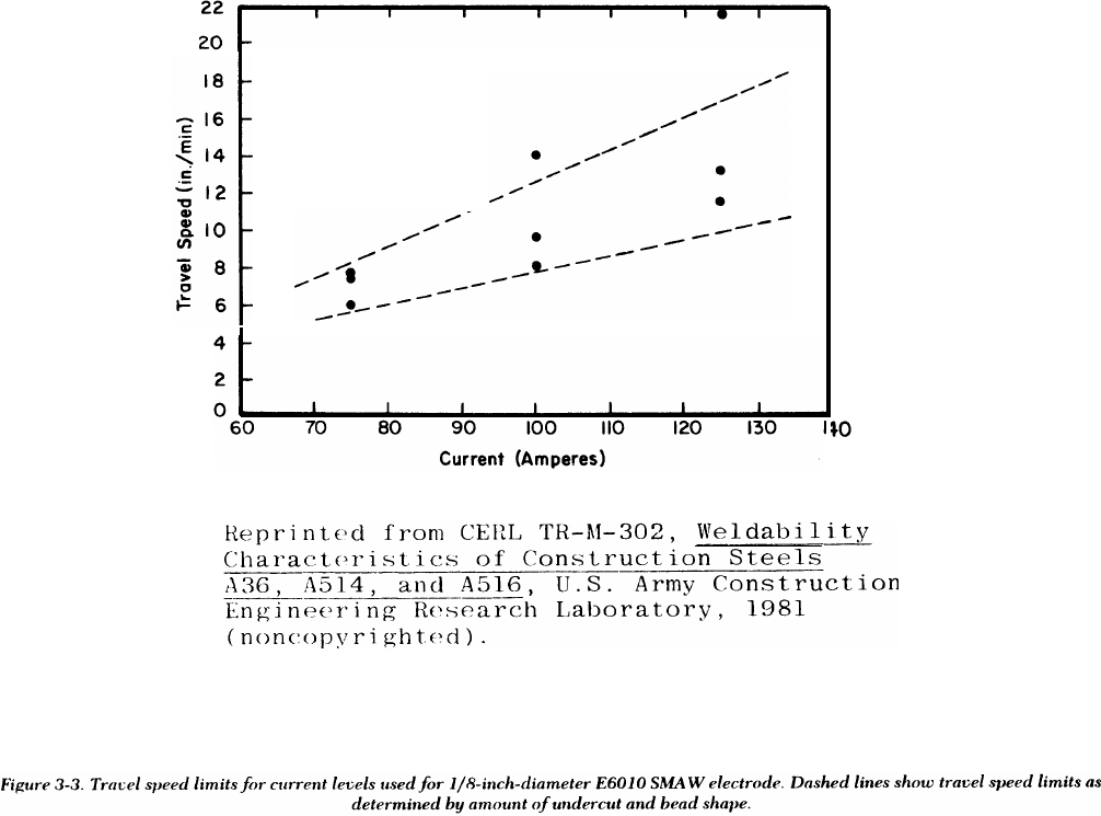
Travel speed limits for current levels used for l/8-inch-diameter E601O SMAW electrode.
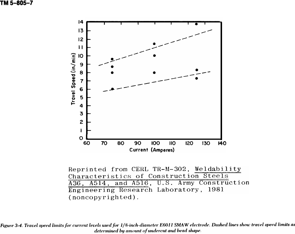
Travel speed limits for current levels used for l/8-inch-diameter E6011 SMAW electrode.
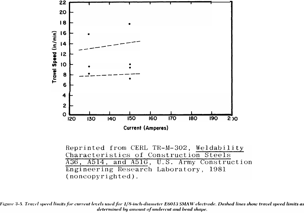
Travel speed limits for current levels for l/8-inch-diameter E6013 SMAW electrode.
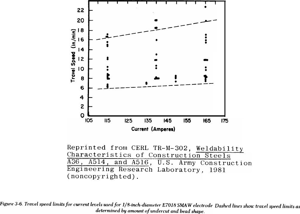
Travel speed limits for current levels used for l/8-inch-diameter E7018 SMAW electrode.
Travel speed limits for current levels used for l/8-inch-diameter E7024 SMAW electrode.
Travel speed limits for current levels used for 5/32-inch-diameter E8018 SMAW electrode.
Travel speed limits for current levels used for l/8-inch-diameter El 1018 SMAW electrode.
Three types of free-flight metal transfer in a welding arc.
The GMAW processes.
Voltage versus current for E70S-2 l/16-inch-diameter electrode and shield gas of argon with 2 percent oxygen
addition.
Voltage versus current for E70S-2 l/16-inch-diameter electrode and carbon dioxide shield gas.
Voltage versus current for E70S-3 l/16-inch-diameter electrode and shield gas of argon with 2 percent oxygen
addition.
Voltage versus current for E70S-3 l/16-inch-diameter electrode and carbon dioxide shield gas.
Voltage versus current for E70S-4 l/16-inch-diameter electrode and carbon dioxide shield gas.
6-1
6-1
6-3
6-3
6-3
6-4
7-1
7-1
7-2
7-2
7-3
7-3
8-1
8-1
8-1
8-1
8-2
8-3
8-6
8-8
8-12
8-19
8-24
9-1
9-1
A-1
B-1
BIBLIO-1
Page
3-1
3-2
3-3
3-4
3-5
3-6
3-7
3-8
3-9
3-10
3-11
3-13
3-14
3-15
3-16
3-17
ii

TM 5-805-7
Page
3-17.
3-18.
3-19.
3-20.
3-21.
3-22.
3-23.
3-24.
3-25.
3-26.
3-27.
4-1.
8-1.
8-2.
8-3.
8-4.
8-5.
8-6.
8-7.
8-8.
8-9.
8-10.
8-11.
8-12.
8-13.
8-14.
8-15.
8-16.
8-17.
Table
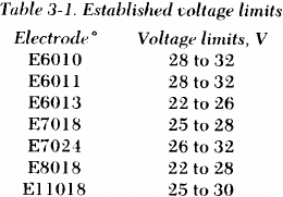
3-1.
3-2.
4-1.
8-1.
8-2v
8-3.
8-4.
Voltage versus current for E70S-6 1/16-inch-diameter electrode and carbon dioxide shield gas.
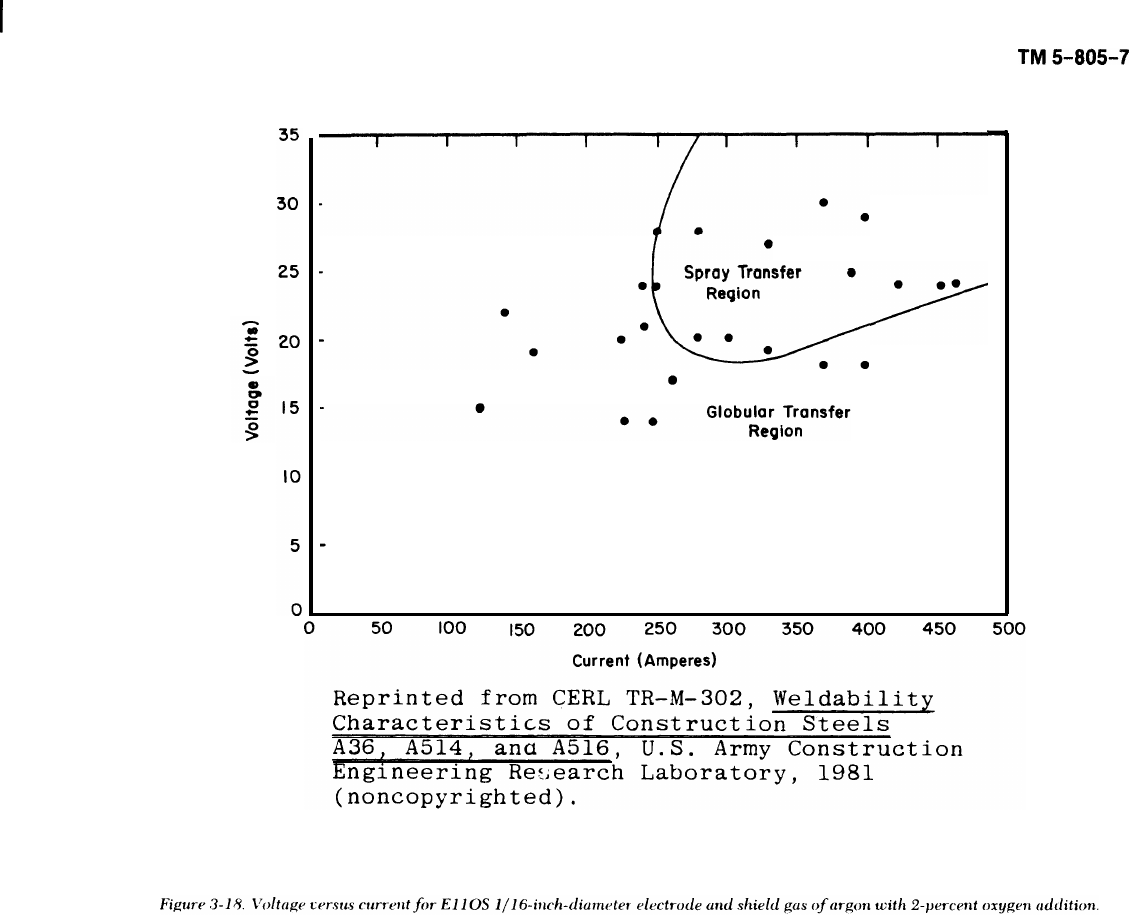
Voltage versus current for E110S 1/16-inch-diameter electrode and shield gas of argon with 2 percent oxygen
addition.
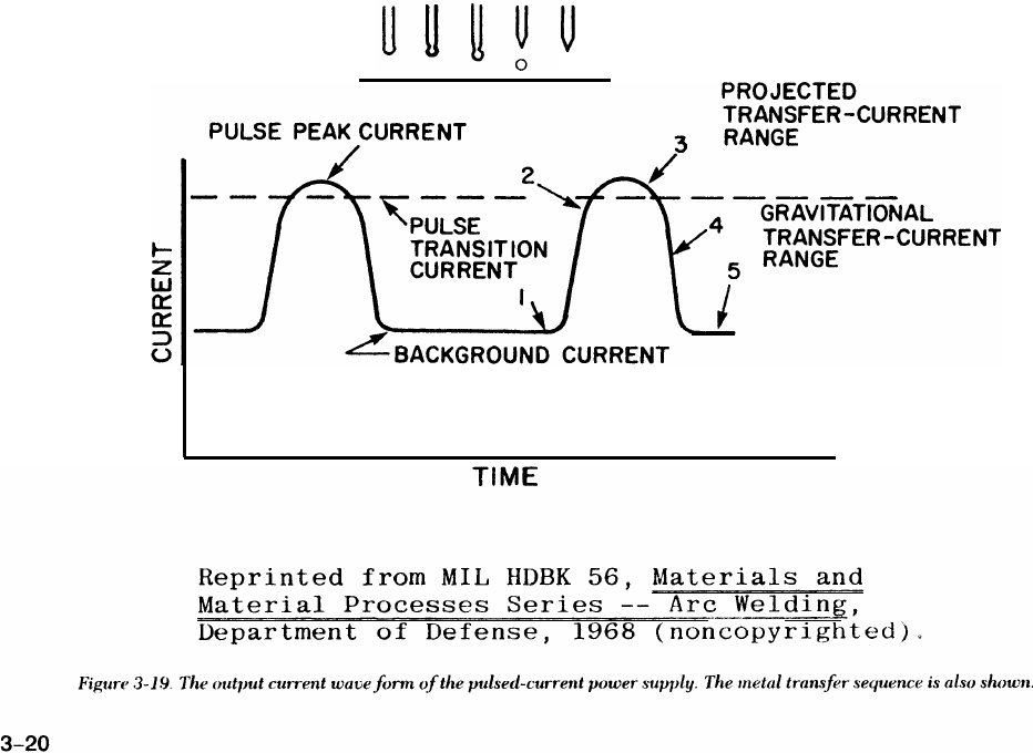
The output current wave form of the pulsed-current power supply.
Steps in short-circuiting metal transfer.
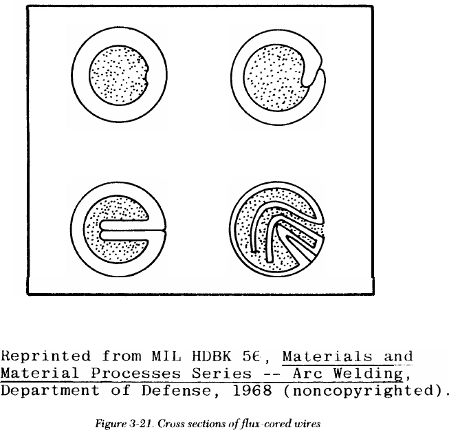
Cross sections of flux-cored wires.
The CTAW process.
The SAW process.
Automatic SAW equipment and controls for automatic welding in the flat position.
Thermit welding crucible and mold.
Steps in stud welding operation.
Stud welding equipment.
Schaeffler’s diagram for the microstructure of stainless steel welds.
Gages for measuring fillet weld contour.
Weld nomenclature.
Disruption of magnetic field by weld-metal defect.
Magnetic field created around a weld as current is passed between two test prods.
Major steps of fluorescent penetrant inspection.
Radiographic setup.
Details of penetrameters.
A scan presentation on cathode ray tube.
Straight beam inspection techniques used in scanning a tee weld.
Scanning procedure using angle beam and straight beam on a corner weld.
Several uses of the IIW block.
Scanning procedures for welds not ground flush.
Scanning procedures for welds ground flush.
Tensile test specimens.
Guided bend test jig.
Free bend test.
Transverse fillet-weld shear specimen.
LIST OF TABLES
Established voltage limits.
Summary of welding processes and application.
Austenitic stainless steels most commonly used for cryogenic and vacuum environment equipment.
Uses of various inspection techniques.
Characteristics of radioisotope sources.
Comparison of ultrasonics with other techniques.
Frequency-application chart.
3-18
3-19
3-20
3-21
3-22
3-24
3-25
3-26
3-27
3-28
3-29
4-3
8-3
8-4
8-5
8-7
8-8
8-10
8-11
8-14
8-15
8-16
8-17
8-18
8-18
8-20
8-21
8-22
8-23
Page
3-12
3-31
4-8
8-2
8-9
8-13
8-14

TM 5-805-7
CHAPTER 1
INTRODUCTION
1-1. Purpose and scope
This manual contains criteria and basic data for
welded construction design, construction methods,
and inspection procedures for Army construction.
This manual covers only the following welding pro-
cesses and materials commonly used for field con-
struction projects: shielded metal-arc, gas metal-arc,
gas tungsten-arc,flux-cored arc, submerged arc,
exothermic, and arc stud welding processes. Discus-
sions of physics, chemistry, and metallurgy are lim-
ited to areas helpful in selecting welding processes,
materials, and inspection procedures for the applica-
tions listed in paragraph 1-3. For supplemental
information, see the American Welding Society
(AWS) Welding Handbook (available in five sections)
and TM 9-237. Appendix A lists other works, codes,
and specifications which are referenced in this man-
ual; designers should note that there are differences
among the documents’ requirements. Therefore,
when this material is used, the editions which apply
to a given design must be specified.
1-2. Welding applications
This manual discusses the following materials.
a. Steel.
(1) Structural carbon steel welded to structural
carbon steel.
(2) Structural carbon steel welded to high-
strength, low-alloy steel.
(3) High-strength, low-alloy steel welded to
high-strength, low-alloy steel.
(4) Carbon or high-strength, low-alloy steels for
all types of piping systems.
(5) Concrete reinforcing steel.
(6) Rails.
(7) Steel castings, either carbon or high-
strength, low-alloy.
b. Stainless steels.
(1) Cryogenic vessels and piping materials used
for storage and transport of extremely low-tempera-
ture liquids.
(2) Vacuum chambers.
(3) All other uses.
c. Nickel steels and nickel alloys for cryogenic
vessels and piping systems.
d. Aluminum alloys for cryogenic vessels, piping
systems, and other uses.
e. Carbon and high-strength, low-alloy steels
welded to stainless steels. An example of this use is
when steel supports or stiffeners are attached to
stainless steel vessels.
1-1

I
TM 5-805-7
CHAPTER 2
DESIGN AND INSPECTION RESPONSIBILITIES
2-1. Designer responsibilities
a. The designer must specify the base metal for
the structure, according to design and service
requirements and provide essential metallurgical
and design information in the specifications. Weld-
ing process and filler metals are selected by the
fabricator or, in some cases, specified by the design
office to fit the material requirements; these items
should be included in the specifications and indi-
cated on the drawings. The joint designs must be
shown on the drawings by a standard welding sym-
bol or by detailed drawings of the weld joints.
b. The designer must determine the welding
requirements, and must develop or select the appro-
priate welding sections of the contract for each proj-
ect. These decisions are based on instructions from
the using agency. The designer must develop con-
tract specifications that ensure the contractor knows
the welding quality that must be maintained. The
designer uses the following criteria to determine the
required degree of control over welding quality.
(1) Strict control over welding procedures and
operations is required in five cases (listed in order of
increasing importance):
(a) Distress in one member could cause at
least partial collapse or failure with some hazard to
life and property; application of the design load may
approach 10,000 cycles over many years.
(b) Some of the welds required for structural
integrity are highly stressed; application of the
design load may exceed 10,000 cycles over many
years.
(c) Empirical design requirements compen-
sate for overloads, abuse, mishandling, “acts of
God,” and similar hazards; application of the design
load may be on the order of 100,000 cycles.
(d) Failure of welds or components could be
catastrophic, as in structures such as bridges or high-
-pressure gas piping systems;fatigue of materials
must be carefully considered or application of
design load is on the order of 2 million cycles.
(e) Applications require the highest quality of
material and workmanship throughout, such as for
nuclear, space, and ballistic applications and for sys-
tems subjected to hazardous chemicals, or extreme
pressures or temperatures.
(2) Less control over welding procedures and
operations is needed where:
(a) Stress levels are low.
(b) WeIds are subjected only occasionally to
design loads.
(c) The structure is composed of multiple
components, and distress in one member will cause
inconvenience rather than collapse or catastrophic
failure.
c. The designer must establish the inspection pro-
cedures needed to determine the weld quality. The
designer must be familiar with the destructive and
nondestructive methods of evaluating weld quality
and must know their capabilities and limitations.
Procedures to qualify inspectors must be specified.
d. The designer must establish the acceptance
requirements for the welded joints, and must iden-
tify the applicable military standards, specifications,
and codes for meeting these requirements. When
standards, codes, and other specifications are cited,
the contract specification must list the paragraphs or
parts of the publications which are applicable or
excluded. The designer must use only the most
recent codes and specifications.
e. The designer must indicate on the plans or
specifications the extent of inspection and testing
required for the various applications and conditions.
Although the inspection and testing needed depend
primarily on the design requirements, the following
general guidelines should be considered.
(1) Apply value engineering — in short, do not
specify unnecessary testing.
(2) Follow design criteria and codes that specify
the extent of inspection and testing required relative
to working stresses, joint efficiencies, or conditions
of use.
(3) Inspect visually in noncritical applications or
conditions; very little other testing should be
required.
(4) Identify the critical joints and welds and
choose those to be tested. The criticality of each
weld should determine the extent of nondestructive
and destructive tests; these tests supplement the
quality control provided by qualified procedures,
qualified welders and operators, and visual inspec-
tion. The weld can be critical because of high
stresses, impact, vibration, temperature, safety,
insurance against operational failure, hard-to-weld
material, or a combination of these factors. In a mul-
tistory office or warehouse building with structural
2-1
TM 5-805-7
steel framing, for example, testing would be done
mainly at the highly stressed joints. In a critical pip-
ing system, however, either all joints would be
nondestructively tested or a uniformly applied ran-
dom test procedure would be used.
(5) Determine the extent of random testing in
piping, tanks, and other elements that have uniform
joints and design levels. This number can be
expressed as a percentage of all welds in the system,
coupled with a finite test increment. However, the
extent of random testing in large steel structures
with a variety of welds and widely varying design
stresses should not be expressed this way. The
designer is responsible for specifying the appropri-
ate tests for critical and noncritical welds. To insure
clarity in bidding and inspection documents, the
location, numbers, and minimum increment lengths
of the random tests should be clearly outlined.
f. The designer must indicate in the specification
what to do when welds fail to meet acceptance
requirements.
g. The designer must design the weld so that the
operator can reach the weld joint easily. If the joint
is located so that the welder cannot observe the
welding operation easily or position the welding gun
or electrode properly, a poor weld may result. In
such cases, it may be hard or impossible to repair
any weld defects.
(1) The dimensions and shape of the joint sur-
faces should allow the weld metal to penetrate the
joint fully. If pieces of different thicknesses are to be
joined, the edge of the thicker piece should be
tapered to the thickness of the thinner piece. The
tapered transitions must conform to the require-
ments of the following publications, as applicable:
AWS D1.1; the American Society of Mechanical
Engineers (ASME) Boiler and Pressure Vessel Code,
Section III or Section VIII; or the American National
Standards Institute (ANSI) Standard B 31.1.
(2) Good joint design practices for vessels are
shown in section VIII of the ASME Boiler and Pres-
sure Vessel Code; for piping in appendix D of ANSI
B31.1; and for structural work in the American Insti-
tute of Stee] Construction’s (AISC) Manual of Steel
Construction and AWS Dl.1.
(3) In some welding operations, some type of
weld joint backing is used to support the molten
weld metal and prevent excessive penetration. Back-
ing strips, when used, must be of material similar to
the base metals which are penetrated by the weld
metal. Nonconsumable” ‘backing rings in piping sys-
tems should not
essary. Instead, be permitted unless absolutely nec-
penetration can be controlled by
altering the joint design (increasing
decreasing the root opening) or by
ble insert rings.
(4) If the joint is welded from
the root face or
using consuma-
both sides, the
reverse side of the root pass (the side opposite that
on which the weld was deposited) should be
chipped, ground, or gouged out to sound metal
before any welding is done from the second side.
This operation will prevent lack of fusion at the root
of the joint. The reverse side of single “V” weld
joints may also be ground out and rewelded to
improve the contour. Complete penetration groove
welds must be welded from both sides unless a
proper backup plate is used.
h. The designer must decide which welds are to
be peened and which are not and indicate them on
the drawings. Peening is the mechanical working of
metals by hammer blows. This technique is useful
for reducing distortion and residual stresses caused
by shrinkage of the weld metal as it cools. However,
the technique can be harmful if extreme care is not
used. Since it can cause cracking, overlapping, or
other defects, peening is not permitted on surface
passes of the weld joints. Intermediate passes may
be peened only with the contracting officer’s per-
mission. Peening of stainless steel welds is not per-
mitted because it causes hardening of the weld
metal. Care should be taken to prevent peening
when slag is removed from the surface pass with
chipping hammers.
i. The designer must determine if the shape of the
weld surface and its height above the base metal
(reinforcement) are important and indicate the
shape on the drawings. An abrupt change in contour
between the weld surface and the base metal may
result in stress concentrations high enough to cause
failure under service loadings. Therefore, the weld
surface should blend smoothly into the surface of
the base metal. If necessary, the edges of the weld
should be ground to achieve a smooth blend of
surfaces.
(1) Undercut at the edge of the weld can be
repaired by grinding if the depth of undercut does
not exceed 1/1 6 inch. If undercut is deeper than
1/16 inch, it should be repaired by adding weld
metal to this area and then grinding the surface to a
smooth, even contour.
(2) Grinding also should be used to remove
overlap at the weld edges and any abrupt ridges or
valleys in the weld surface.
(3) The maximum amount of weld reinforce-
ment should be between 1/32 and 1/8 inch.
2-2

TM 5-805-7
2-2. Contractor responsibilities
a. The contractor must develop a qualified weld-
.
ing procedure, provide qualified welders and weld-
ing operators, and produce satisfactory weldment.
(1) The construction drawings and specifica-
tions ordinarily indicate the location of the weld
joints and the type of joint required, but the con-
tractor must handle the details of producing the
weld — for example, the equipment used, number
of passes, choice of electrode, and welding process.
Therefore, the contractor must understand the
objective of the plans and, if necessary, seek guid-
ance from the contracting officer and the welding
engineer or metallurgist assigned to the project.
Those concerned should meet to discuss the status of
the welding program as work progresses.
(2) All welding procedures used for any of the
,
applications covered by this manual and all welders
and welding operators assigned to these construc-
tion operations must be qualified before production
welding is begun. The contractor must conduct all
qualification, testing and maintain records showing
the testing procedures used and the results of these
tests. These records must always be available to the
inspector and the contracting officer or his
representative.
b. The contractor must make sure the welding
equiprnent is serviced and maintained properly to
produce the required current output, voltage con-
trol, and filler wire feed rate for automatic and semi-
automatic processes. Storage and handling of flux
and coated electrodes must also be done properly.
(1) Flux must be kept free of dirt, mill scale, and
other foreign material. Flux fused during previous
welding operations should not be reused. If there is
no moisture in the flux or on the work during weld-
ing, the quality of submerged-arc weld metal is com-
parable to that obtained with low-hydrogen
electrodes. Packaged flux must be stored in a warm,
dry room. Loose flux stored in open containers
should be subject to the same drying conditions as
low-hydrogen electrodes.
(2) Excessive moisture in the electrode coatings
releases hydrogen during welding, and therefore
adversely affects the quality of the weld. Since this
moisture may be absorbed from the atmosphere,
packaged electrodes should be stored in a dry, warm
room, and loose electrodes should be stored in dry-
ing bins or a holding oven kept at the manufacturer’s
recommended temperature.
(a) With low-hydrogen electrodes, the coat-
ings have few hydrogen-producing constituents.
Special care is taken in manufacturing and packaging
these electrodes to maintain a low content of free
and combined moisture. If these electrodes absorb
much moisture from the atmosphere, they no longer
function as low-hydrogen electrodes. The rate of
moisture absorption depends on the coating compo-
sition and the relative humidity.
(b) The electrode manufacturer should be
asked for recommendations about bake time, hold-
ing oven temperature, and maximum allowable
exposure time for the particular electrode type,
quality of weld required, and relative humidity. If
this information is unavailable, a general rule is to
limit atmospheric exposure to 4 hours for electrodes
removed from the bake oven, from holding ovens, or
from hermetically sealed metal containers. In criti-
cal welding applications or when the relative humid-
ity is 75 percent or higher, the exposure time may
have to be reduced to as little as 1/2 hour. Elec-
trodes which have been wet must not be used.
c. The contractor must ensure tack welding and
jigging is done properly. Parts to be welded must be
held in position before, during, and after welding to
keep them correctly aligned and to minimize distor-
tion caused by shrinkage of the weld metal as it
cools. To do this, tack welding is frequently used
either alone or as a supplement to various jigs, fix-
tures, and clamps. Tack welds, which are subject to
cracking if they are too small, can be a source of
defects when subsequent welds are made. There-
fore, tack welds should always be inspected and, if
cracked, ground out before subsequent welding.
Sound tack welds should be ground to a smooth con-
tour that blends evenly into the base metal. This will
ease complete melting of the tack weld into the sub-
sequent weld. Before welding is begun, the pieces
should be aligned so that afterward the abutting
edges of the parts are within the offset tolerances
specified in the contract.
d. The contractor must take precautions against
adverse weather conditions.
(1) Welding should not be done if the surfaces
are wet or covered with snow, ice, or frost. Local
preheating of the joint area can be used to dry the
joint surfaces. If rain or snow is falling, the joint will
have to be sheltered so that the area will stay dry
during welding.
(2) Welding will not be done in windy or drafty
locations unless curtains or protective screens are
used. Most arc welding processes incorporate a
shield of gas or vaporized electrode coating to pro-
tect the arc and molten weld metal from the air. If
the welding is done in a windy or drafty location,
this shield can be blown away, and an unsatisfactory
weld will result.
(3) Welding should not be done if the tempera-
ture at the weld site is below 00 F. If the tempera-
ture is between O and 32°F, the joint area should be
2-3
TM 5-805-7
preheated to 70oF or higher for welding and kept at
this temperature throughout the welding operation.
preheating of structural steel must conform to AWS
D1.1.
e. The contractor must insure proper repair weld-
ing. Defective welds must be repaired by removing
the defects from the weld joint and rewelding the
joints. Defects may be removed mechanically by
grinding, chipping, or machining, or by arc or flame
gouging. A combination of methods is often
required. For example, if the defects are removed
by flame or arc gouging, the cut surface may need to
be cleaned mechanically and smoothed before the
repair weld is made.
(1) Flame- or arc-cut surfaces of stainless steel
and nickel steel have a heavy scale or oxide coating
that must be removed before welding to keep it
from affecting the quality of the repair weld. Also,
heat from the gouging operation can affect strength
by causing metallurgical changes in the weld metal
adjacent to the cut surfaces. Therefore, an addi-
tional 1/8 inch of metal should be mechanically
removed from these cut surfaces.
(2) Defects in aluminum alloys must be removed
only by mechanical means.
(3) Extra care must be used when removing
cracks from welds. Nondestructive inspection may
not indicate the true length of the crack, which may
be too narrow to be detected with the test method
being used. So, one should remove not only the weld
metal in the crack, but also some sound metal at
each end of the crack. The amount removed should
be twice the base metal thickness or 2 inches,
whichever is less at each end of the crack. After the
metal is taken out and before repairs, welds should
be inspected again to insure that the full length of
the crack has been removed.
(4) Repair welding must be done by a qualified
welder using only qualified welding procedures.
The repair work might be easier with a smaller
diameter electrode or filler wire than was used to
make the original weld.
f. On critical welds or when requested by inspec-
tors or the contracting officer, the contractor must
have a welder or welding operator apply a predeter-
mined identification mark to the completed weld
joint. This mark is normally made on the base metal
next to the weld metal. Materials may be marked by
any method acceptable to the inspector as long as it
does not cause notches or sharp discontinuities that
could fail under service loading. The identifying
mark must remain legible until acceptance of the
weld metals or the structure in which the weld is
contained. When requested, the welder should
apply a mark that will remain legible for the life of
the structure.
g. The contractor must set up procedures for
preheating, postheating, and stress relieving. The
conditions to which a weldment will be exposed dur-
ing service operations determine the thermal treat-
ment necessary. For a broad coverage of thermal
treatment, see the AWS Welding Handbook, Volume
1, “Fundamentals of Welding.” Since preheating
and post-weld heat treatment affect the physical
properties of the weld, the procedures must be set
up in detail by the contractor or fabricator and
included in the welding procedure qualification.
(1) Preheating is the application of heat to a
base metal before welding or cutting. Preheating
may be used during welding to help complete the
welded joint. The need for and temperature of
preheating depend on several factors, such as the
chemical analysis of the material, degree of restraint
of the parts being joined, physical properties at ele-
vated temperatures, material thickness, and ambient
temperature.
(a) Preheating may be required or recom-
mended for welding performed under codes or spec-
ifications such as those of AWS, ASME, or the
American Petroleum Institute (API). However,
preheating does not necessarily assure satisfactory
completion of the welded joint, and requirements
must be suited to the individual materials and
applications.
(b) Preheating may vary from a temperature
which is warm to the touch of the hand when weld-
ing outdoors in winter, to as high as 6000 F when
welding highly hardenable steels. When the ambient
temperature is less than 32 “F, local preheat of the
weld joint area to 700 F is recommended.
(2) Post-weld heat treatment (or postheating) is
a general term covering treatments done after weld-
ing to restore the properties of the base metal and to
produce the desired microstructure in the base and
filler metals. Post-weld heat treatment may require
normalizing, full annealing, quenching and temper-
ing, or solution and precipitation treatments.
(3) Stress relief heat treatment is the uniform
heating of a structure (or part of it) to a temperature
below the critical range, but high enough to relieve
most of the residual stresses; this is followed by uni-
form cooling. Stress relieving should not be con-
fused with other post-weld heat treatment
processes, which may or may not prevent the need
for stress relieving, depending on the maximum
temperature attained in the post-weld heat treat-
ment and the rate of cooling from this temperature.
2-4
TM 5-805-7
2-3. Inspection requirements
Inspection is done to meet contract quality specifi-
cations and to maintain quality control on the weld-
ers and welding operators. Effective inspection
requires cooperation between the welder or welding
operator and the inspector. Inspectors should always
encourage the welders and welding operator to
check their own work and to report questionable
welds or welding procedures. There must also be a
mutual understanding between contractor and gov-
ernment supervisory personnel. Inspection costs
money, but good inspection often saves more than it
costs by reducing expensive, time–consuming
rejects or repairs, and by detecting promptly unsat-
isfactory welding procedures or poor workmanship.
Most inspections are to be done by the contractors
(fabricators) since they will gain or lose from the
quality of the product. They can also take immediate
corrective action when defective weldments are
found. When contractors do their own inspections,
the inspection personnel should be organizationally
separate from the production personnel; inspection
personnel should answer not to the project superin-
tendent but to a quality control element of the orga-
nization. Contractors may employ independent
commercial inspection and testing laboratories to
perform these services, especially when the contrac-
tor’s production or quality requirements vary
widely. If the contractor has provided reliable
inspectors, the government can simply spot check to
make sure the inspection methods were adequate.
Government inspection can be done either by gov-
ernment personnel or by an independent commer-
cial inspection or testing laboratory. The choice will
depend on a number of factors, such as availability
of qualified personnel and equipment, length of the
project, cost of inspection, location of the project,
and criticality of inspection or testing requirements.
When qualified government personnel are available,
they should do the inspection and testing. This is
desirable from the standpoints of administrative con-
trol, maintenance of qualified government inspec-
tion personnel, and personal interest in the quality
of the product. When circumstances require work
by a commercial laboratory, these inspectors act as
agents for the government.
a. Contractual relations.
(1) Designers, contractors, inspectors, welders,
and welding operators should cooperate. The qual-
ity of the welding depends largely on the skill of the
contractor’s personnel, the proper choice of materi-
als, and the adequacy of the welding procedure. The
contractor depends on the inspectors for decisions
about whether the completed welds are acceptable.
(2) Inspectors should develop a clear under-
standing of the specified requirements, interpret
contract provisions consistently, and avoid either
favoring the contractor or making unreasonable
demands. In short, they should be absolutely fair to
both the government and the contractor.
(3) Although inspectors usually make the final
decision about the quality of a weld, they should not
take over the role of supervisors for the contractor.
Acceptability of welds should not be left to discre-
tion, but be based on meeting the specified require-
ments. Competent contractor supervision should be
provided to see that the welding procedures are
being followed and that the requests made by the
inspectors are carried out. As much as possible, the
inspector should ask the contractor’s supervisory
personnel to regulate operations, and should not
give orders directly to workmen.
(4) A thorough knowledge of the work is the
best assurance of a satisfactory job and a good work-
ing relationship between the government and the
contractor. The inexperienced inspector may unwit-
tingly penalize both contracting parties by unduly
emphasizing insignificant but costly details of the
work, thus imposing a needless hardship on the con-
tractor with little benefit to the government. At the
same time, the inspector might overlook other oper-
ations that may be vitally important to the job — for
example, overemphasis on the strength of the weld
when appearance is most important, and vice versa.
b. Inspection force. On a large project, govern-
ment inspection of welding operations is assigned to
an inspection section headed by an experienced
supervisor. This differs from an isolated job of weld-
ing where inspection may be the responsibility of
one or two individuals. On a large project where the
inspection of all welding is given to a specialized
team, assignments in the early stages of construction
may be arranged so that inexperienced inspectors
can watch the actions and decisions of experienced
personnel. This procedure will help train a compe-
tent team that will operate efficiently at a later stage
of work. This approach is not possible, however, on
small projects with only one inspector. Only exper-
ienced construction personnel should be assigned in
such cases.
c. Inspector’s duties. The inspector must examine
in detail each phase of the welding operation to
make sure the work is being done right. The inspec-
tor must observe such requirements as procedure
and welder qualifications, joint design and prepara-
tion, alignment, electrode size and type, welding
equipment, and technique. When an assignment is
rotated, a new inspector must learn about the proce-
dures being followed and the status of welding and
2-5

TM 5-805-7
inspection before assuming inspection
responsibility.
d. Supervision. Good supervision of inspectors is
important to satisfactory welding operations on a
large project. Even the most experienced inspector
can do little unless properly instructed in the work
and given the fullest support in dealings with weld-
ing personnel. The supervisor must clarify the
responsibilities of each part of the organization and
outline the limits of each inspector’s authority. The
supervisor should tell the inspector about all deci-
sions on acceptance requirements and other issues.
It is good supervisory practice to circulate memo-
randa outlining all project decisions made by those
in authority and summarizing matters which inspec-
tors can still decide with some flexibility. Before
decisions are made about construction methods, the
opinions of the inspectors assigned to the work
should be considered. Occasional meetings between
inspectors and supervisors to discuss any job
problems, practices, and requirements are helpful
and often necessary.
TM 5-805-7
CHAPTER 3
WELDING PROCESSES
3-1. General
This chapter contains general requirements for
welding processes that may be used for the applica-
tions covered in paragraph 1-2.
3-2. Processes
a. The welding processes covered by this design
.
manual are as follows:
(1) Shielded metal-arc (SMAW)
(2) Gas metal-arc (GMAW)
(a) Free-flight transfer
(b) Pulsed-current out-of-position welding
(c) Short circuiting
(3) Flux-cored arc welding (FCAW)
(4) Gas tungsten-arc (GTAW)
(5) Submerged-arc (SAW)
(6) Exothermic (Thermit)
(7) Arc stud (STUD)
b. Basically, in the electric welding processes, an
arc is produced between an electrode and the work
piece (base metal). The arc is formed by passing a-
current from the electrode to the work piece
through a gap. The current melts the base metal and
the electrode if it is a consumable type, creating a
molten pool. On solidifying, the weld is formed. An
alternate method employs a nonconsumable elec-
trode such as a tungsten rod. In this case, the weld is
formed by melting and solidifying the base metal at
the joint. In some instances, additional metal is
required and is added to the molten pool from a
filler rod.
c. Electrodes which become the deposited weld
metal are available in various diameters and lengths.
In welding, the molten pool must be protected from
the ambient atmosphere to prevent contamination.
There are three ways to do this. Two involve a flux;
in one, the flux is part of the electrode, either as a
coating on the wire or as the core of a hollow wire.
The second method uses a granulated flux that is
applied separately before welding. The third
method involves a gas such as helium, argon, or car-
bon dioxide. In addition to shielding, the flux may
3-1
TM 5-805-7
function as a deoxidizer to purify the deposited
metal or to form slag to protect the weld metal from
oxidation. The flux may contain ionizing elements to
provide smoother operation, alloying elements to
provide higher strength, and iron powder to
increase production rates. The selection of elec-
trodes for a specific job can be based on the follow-
ing eight factors:
(1) Base metal strength properties
(2) Base metal composition
(3) Welding position
(4) Welding current
(5) Joint design and fit-up
(6) Thickness and shape of base metal
(7) Service conditions and/or specifications
(8) Production efficiency and job conditions
The AWS publishes a group of specifications for fil-
ler metals (electrodes) and recommends the welding
process for which they are to be used. In addition,
AWS D1.1 describes the welding procedures to be
used with the various welding processes.
d. Welding material — electrodes, welding wire,
and fluxes — must produce satisfactory welds when
used by a qualified welder or welding operator using
qualified welding procedures. Welding materials
must comply with the applicable requirements of
AWS D1.1, ASME Boiler and Pressure Vessel Code,
Section II, or other requirements in the contract
specifications.
3-3. Shielded metal-arc (SMAW)
This is the most widely used method for general –
welding application; it may also be referred to as
metallic-arc, manual metal-arc, or stick-electrode
welding.
a. Advantages. The SMAW process can be used for
welding most structural and alloy steels. These
include low-carbon or mild steels; low-alloy, heat-
treatable steels; and high-alloy steels such as stain-
less steels. SMAW is used for joining common nickel
alloys and can be used for copper and aluminum
alloys. This welding process can be used in all posi-
tions — flat, vertical, horizontal, or overhead — and
requires only the simplest equipment. Thus, SMAW
lends itself very well to field work (fig 3-l).
b. Disadvantages. SMAW is clearly inferior to
GMAW if one compares the cost of the time and
materials needed to deposit the weld metal. SMAW
deposits the weld more slowly than does GMAW. In
addition, slag removal, unused electrode stubs, and
spatter add a lot to the cost of SMAW; the latter two
items account for about 44 percent of the consumed
electrodes. Another potential cost is the entrapment
of slag in the form of inclusions which may have to
be removed.
c. Process principles. The SMAW process pro-
duces an arc between the base metal and the elec-
trode. The electrode, put in a hand-held clamp, is
3-2
TM 5-805-7
“
3-3
3-4
TM5-805-7
3-5
TM 5-805-7
24
3-6
28
-26
24
22
20
8
6
4
2
TM 5-505-7
3-7
TM 5-805-7
3-8
TM 5-805-7
struck against the base metal and withdrawn to cre-
ate a gap. The molten portion of the electrode fuses
into the molten pool of the base metal, producing
the weld (fig 3-2). Since SMAW is a manual process,
the operator is primarily responsible for quality of
the weld. Most of the melted electrode metal is
transferred to the work piece; the rest is thrown free
of the weld as spatter or is vaporized. Of that
vaporized, some escapes into the surrounding air,
becomes oxidized, and appears as smoke or fumes.
The electrode used for SMAW has a special covering
which serves several purposes. Part of the covering
contains gas-producing compounds that, when
heated, produce a gaseous envelope around the arc
that displaces air and stabilizes the arc. The covering
also protects the molten weld metal from contamina-
tion by air. Without this stabilization, the arc would
be erratic, would often short out, and generally
would be hard to control. Different gas-producing
compounds are used in the coating, depending on
the type of current — alternating (AC) or direct
(DC). The covering also contains slag-forming mate-
rials that mix with the molten weld metal and pick
up impurities from the weld metal. This cleaning
action improves the quality of the weld. Most of the
electrode coating does not become vaporized but
instead is melted by the arc heat and forms a molten
slag cover over the top of the weld bead. This mol-
ten slag cover helps to control the shape of the weld
bead. It also helps to hold the molten weld metal in
place during out-of-position welding (i.e., welding in
the overhead, vertical, or horizontal positions).
Chapters 4 and 5 discuss the numbering system,
color coding, flux composition, and other data con-
cerning welding electrodes. In shielded metal-arc
welding, five distinct forces are responsible for the
transfer of molten filler metal and molten slag to the
base metal.
(1) Gravity. Gravity is the principal force which
.
accounts for the transfer of filler metal in flat posi-
tion welding. In other positions, the surface tension
is unable to retain much molten metal and slag in the
3-9
crater. Therefore, smaller electrodes must be used
to avoid excessive loss of weld metal and slag.
(2) Gas expansion. Gases are produced by the
burning and volatilization of the electrode coating
and are expanded by the heat of the boiling elec-
trode tip. The coating extending beyond the metal
tip of the electrode controls the direction of the
rapid gas expansion and directs the molten metal
globule into the weld metal pool formed in the base
metal.
(3) Electromagnetic forces. The electrode tip is
an electrical conductor, as is the molten metal glob-
ule at the tip. Therefore, the globule is affected by
magnetic forces acting at 90 degrees to the direction
of the current flow. These forces produce a pinching
effect on the metal globules and speed up the sepa-
ration of the molten metal from the end of the elec-
trode. This is particularly helpful in transferring
metal in horizontal, vertical, and overhead position
welding.
(4) Electrical forces. The force produced by the
voltage across the arc pulls the small, pinched-off
globule of metal, regardless of the position of weld-
ing. This force is especially helpful when one uses
direct-current, straight-polarity, mineral-coated
electrodes, which do not produce large volumes of
gas.
(5) Surface tension. The force which keeps the
filler metal and slag globules in contact with molten
base or weld metal in the crater is known as surface
tension. It helps to retain the molten metal in hori-
zontal, vertical, and overhead welding, and to deter-
mine the shape of weld contours.
d. Equipment, The equipment needed for
shielded metal-arc welding is much less complex
than that needed for other arc welding processes.
Manual welding equipment includes a power source
(transformer, DC generator, AC generator, or DC
rectifier), electrode holder, cables, connectors,
chipping hammer, wire brush, and electrodes.
e. Welding parameters. Welding voltage, current,
and travel speed are very important to the quality of
the deposited SMAW bead. Table 3-1 shows voltage
limits for some SMAW electrodes. The current limits
are shown in the appendix to AWS A5.1. Figures 3-3
through 3-9 show the travel speed limits for the
electrodes listed in table 3-1.
3-10
TM 5-805-7
WIRE DRIVE MAY BE LOCATED
IN WELDING GUN HANDLE
OR AT WIRE REEL
3-11
TM 5-805-7
“Note all electrodes 1/8-inch diameter except E8018, which is
5/32-inch diameter.
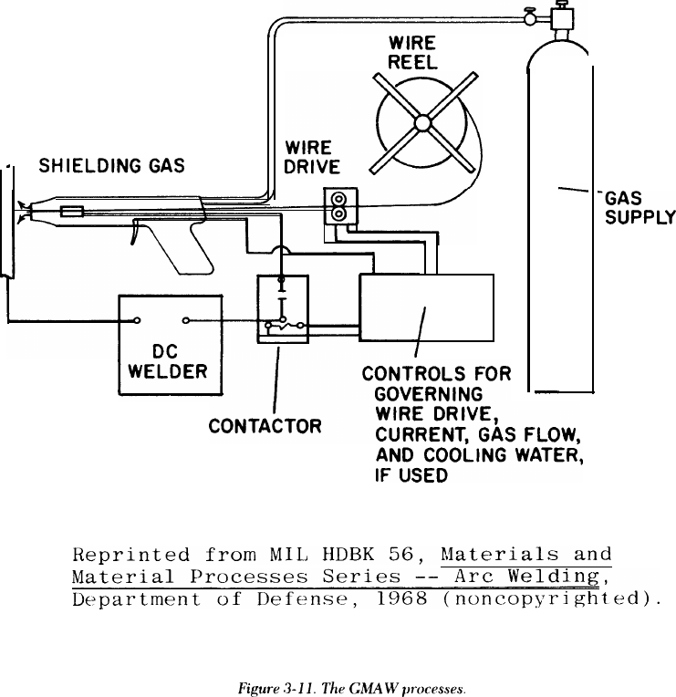
3-4. Gas metal-arc (GMAW)
GMAW is a process in which an electric arc is estab-
lished between a solid, consumable, spool-fed elec-
trode and the work piece. The arc, electrode tip,
and molten weld metal are shielded from the atmos-
phere by a gas. This welding process has been com-
monly called metal-inert-gas welding (MIG). There
are two main types of metal transfer: free flight and
short circuiting. Free-flight transfer can be pro-
jected or spray, repelled, and gravitational or globu-
lar. These three forms of free-flight transfer are
basically for flat position welding (fig 3-10). A modi-
fication of free-flight transfer is pulsed current,
which can be used in all welding positions. The
short-circuiting transfer, sometimes called short-arc,
uses a low current and is for welding thin materials
in all positions. All the GMAW processes use basi-
cally the same equipment, as shown in figure 3-11.
AWS D1.1 describes electrodes, shielding gas, and
welding procedures for GMAW using single
electrodes.
a. Free-flight transfer gas metal-arc welding.
(1) Advantages. The major advantage of free-
flight transfer welding is that high-quality welds can
be produced much faster than with SMAW or
GTAW. Since a flux is not used, there is no chance
for the entrapment of slag in the weld metal. The gas
shield protects the arc so that there is very little loss
of alloying elements as the metal transfers across the
arc. Only minor weld spatter is produced, and this is
easily removed. The free-flight process is versatile
and can be successfully used with a wide variety of
metals and alloys: aluminum, copper, magnesium,
nickel, and many of their alloys, as well as iron and
most of its alloys. The process can be operated in
several ways, including semi- and fully automatic.
GMAW is widely used by many industries for weld-
ing a broad variety of materials, parts, and
structures.
(2) Disadvantages. The major disadvantage of
free-flight transfer is that it cannot be used in verti-
cal or overhead welding due to the high heat input
and the fluidity of the weld puddle. In addition, the
3-12
equipment is complex compared with that for the
SMAW process.
(3) Process principles. In free-flight transfer, –
the liquid drops that form at the tip of the consuma-
ble electrode are detached and travel freely across
the space between the electrode and work piece
before plunging into the weld pool (fig 3-l0). When
the transfer is gravitational, the drops are detached
by gravity alone and fall slowly through the arc col-
umn, In the projected type of transfer, other forces
give the drop an initial acceleration and project it
independently of gravity toward the weld pool, Dur-
ing repelled transfer, forces act on the liquid drop
and give it an initial velocity directly away from the
weld pool. The gravitational and projected modes of
free-flight metal transfer may occur in the gas metal-
arc welding of steel, nickel alloys, or aluminum
alloys using a direct-current, electrode-positive
(reverse polarity) arc and properly selected types of
shielding gases. At low currents, wires of these
alloys melt slowly. A large spherical drop forms at
the tip and is detached when the force due to gravity
exceeds that of surface tension. As the current
increases, the electromagnetic force becomes signif-
icant and the total separating force increases. The
rate at which drops are formed and detached also
increases. At a certain current, a change occurs in
the character of the arc and metal transfer. The arc
column, previously bell-shaped or spherical and
having relatively low brightness, becomes narrower
and more conical and has a bright central core. The
droplets that form at the wire tip become elongated
due to magnetic pressure and are detached at a
much higher rate. When carbon dioxide is used as
the shielding gas, the type of metal transfer is much
different. At low and medium reversed-polarity cur-
rents, the drop appears to be repelled from the work
electrode and is eventually detached while moving
away from the work piece and weld pool, This
causes an excessive amount of spatter. At higher cur-
rents, the transfer is less irregular because other
forces, primarily electrical, overcome the repelling
forces. Direct current reversed-polarity is recom-
mended for the GMAW process. Straight polarity
and alternating current can be used, but require pre-
cautions such as a special coating on the electrode
wire or special shield gas mixtures.
(4) Equipment. The equipment needed for
solid-wire, free-flight transfer welding includes a
power supply, a welding gun, a mechanism for feed-
ing the electrode filler wire, and a set of controls (fig
3-11). Two types of power sources are used for free-
flight transfer welding –- constant current or con-
stant voltage. Motor generator or DC rectifier
power sources of either type may be used. Both
TM 5-805-7
3-13
TM 5-805-7
3-14
TM 5-805-7
3-15
3-16
TM 5-805-7
3-17
3-18
manual and automatic welding guns are available.
The manual welding guns have many designs. All the
manual guns have a nozzle for directing the shield-
ing gas around the arc and over the weld puddle.
The filler wire passes through a copper contact tube
in the gun, where it picks up the welding current.
Some manual welding guns contain the wire-driving
mechanism within the gun itself. other guns require
that the wire-feeding mechanism be located at the
spool of wire, which is some distance from the gun.
In this case, the wire is driven through a flexible
conduit to the welding gun. Another manual gun
design combines feed mechanisms within the gun
and at the wire supply itself’. Argon is the shielding
gas used most often. Small amounts of oxygen (2 to 5
percent) frequently are added to the shielding gas
when steel is welded. This stabilizes the arc and
promotes a better wetting action, producing a more
uniform weld bead and reducing undercut. Carbon
dioxide is also used as a shielding gas because it is
cheaper than argon and argon-oxygen mixtures.
Electrodes designed to be used with carbon dioxide
shielding gas require extra deoxidizers in their for-
mulation because in the heat of the arc, the carbon
dioxide dissociates to carbon monoxide and oxygen,
which can cause oxidation of the weld metal.
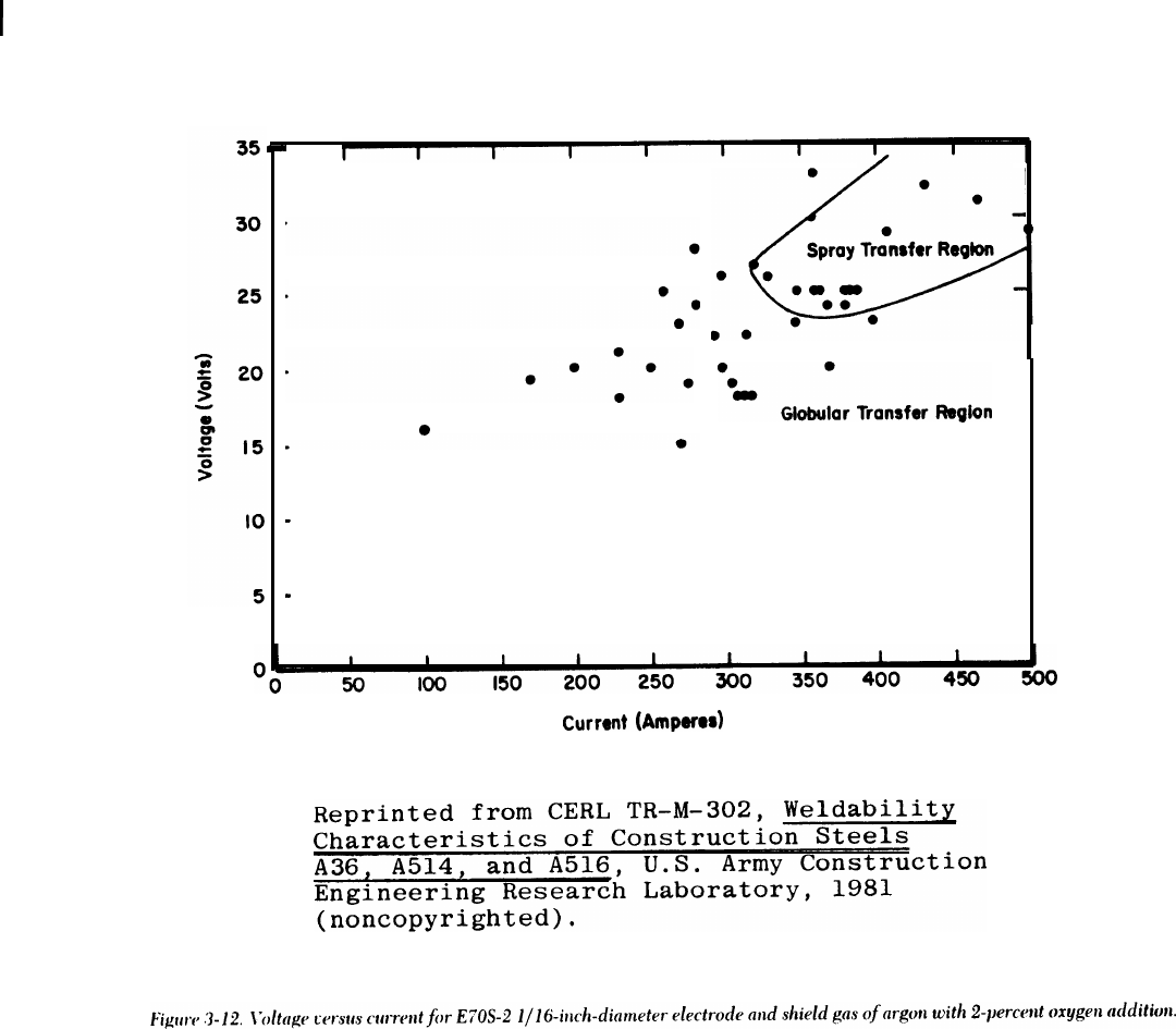
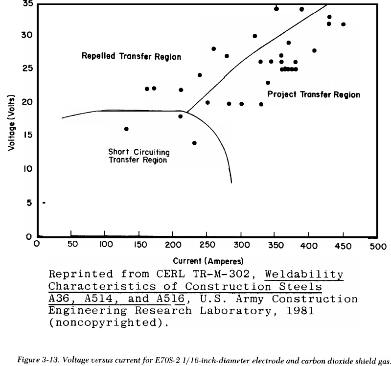
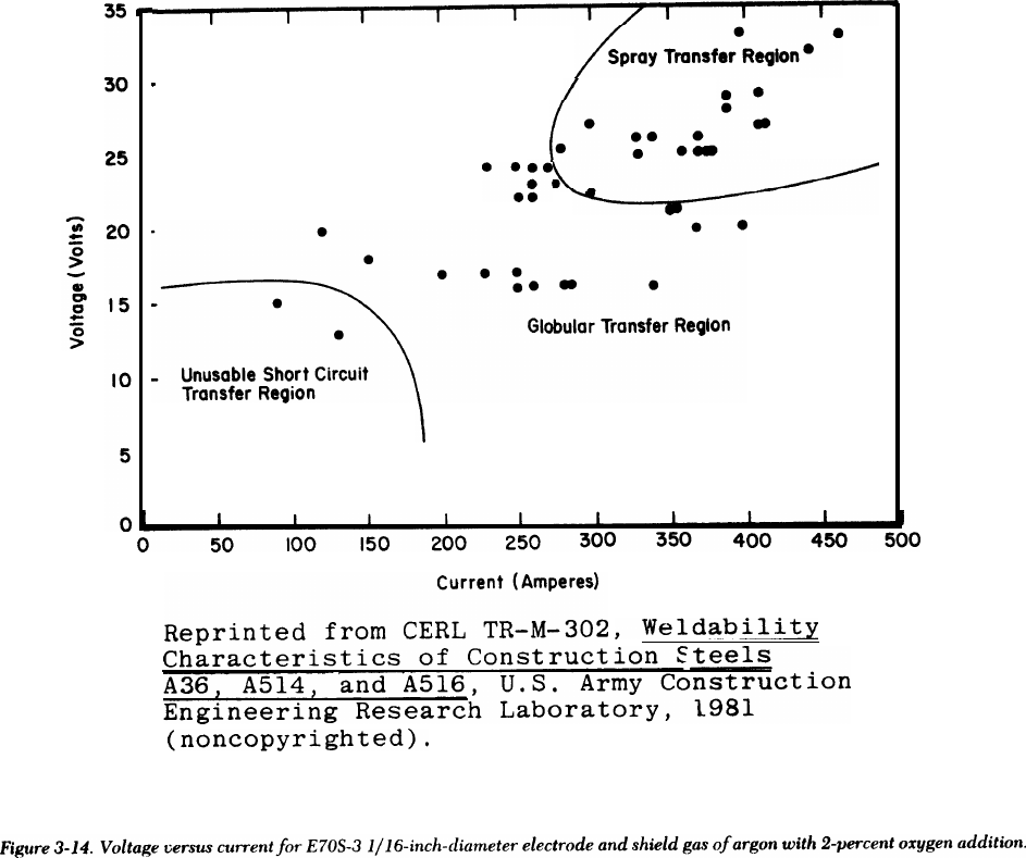
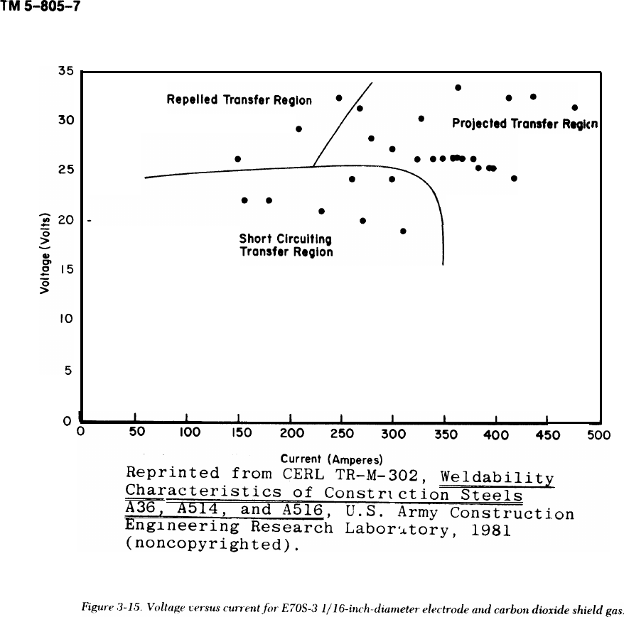
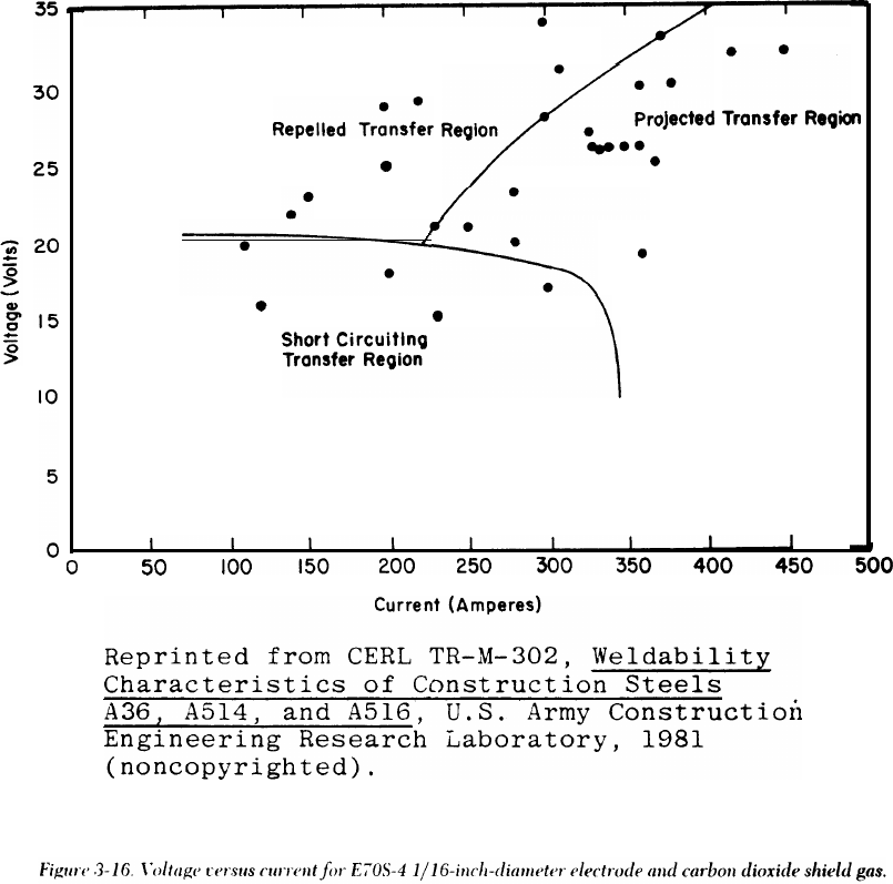
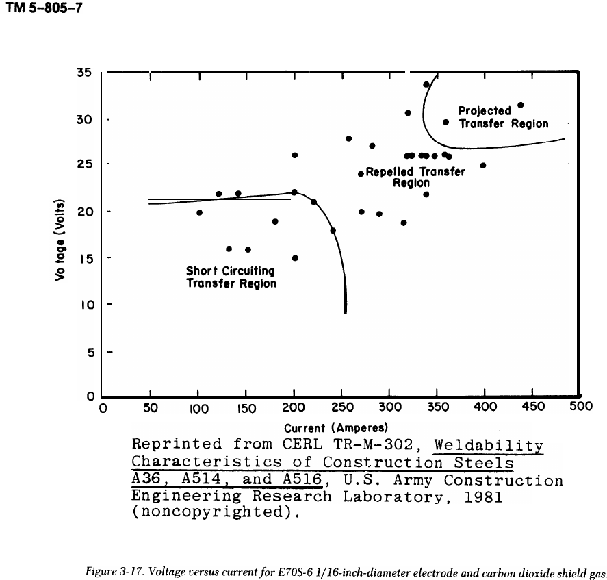
(5) Welding parameters. Figures 3-12 through
3-18 show the relationship between the voltage and
current levels, and the type of transfer across the
arcs.
b. Pulsed-current GMAW process.
(1) Advantages. This process is useful when low
heat input is required — when one is working with
thin materials or doing out-of-position welding, for
example. In the lower heat-input range, pulsed cur-
rent has the advantage of the continous projected
spray-transfer process. High-quality welds can be
produced in mild and low-alloy steels. In the weld-
ing of aluminum, larger diameter wires can be used;
welds with less porosity are produced because there
is less hydrogen and oxygen pickup on the wire
surface.
3-19
TM 5-805-7
(2) Disadvantages. The major disadvantage of
this process is the complex power supply required in
addition to the GMAW wire feeder and welding
torch.
(3) Process principles. Pulsed-current GMAW is
a modification of the process used to obtain spray-
type transfer with average current levels in the glob-
ular-transfer range. This process provides a higher
ratio of heat input to metal deposition rate than the
short-circuiting process. Pulsed-current GMAW
operates at heat inputs between those used for spray
transfer and short-circuiting transfer, with some
overlap in the ranges. In this process, the current is
pulsed back and forth between projected-transfer
and gravitational-transfer ranges by electronically
switching the current level back and forth between
them. Figure 3-19 shows the current output-wave
form and metal-transfer sequence. Pulsed-current
welding is also known by the trade name “pulsed-
arc. ”
(4) Equipment. The power sources for pulsed
current combine a three-phase, full-wave trans-
former-rectifier power supply, and a single-phase,
half-wave pulse unit. These units are connected in
parallel, but are electronically switched in operation
to give the output waveform shown in figure 3-19.
I 2 34
Standard GMAW
in this process.
wire feeder and torches are used
c. Short-circuiting transfer GMAW welding.
(1) Advantages. The short-circuiting process is
widely used for quickly welding thin materials (up to
1/4 inch) in all positions; it causes little distortion
and few metallurgical defects. This process is used
on carbon and low-alloy steels, and less often on
stainless steel and aluminum; it is also used for out-
of-position welding of thicker materials.
(2) Disadvantages. Generally, welds made with
the short-circuiting process are of slightly poorer
quality than those produced by the spray-transfer
method. This may not cause trouble if high-quality
welds are not required.
(3) Process principles. The short-circuiting
transfer variation of the GMAW process is generally
similar to spray-transfer welding. The main differ-
ence is the way the molten metal is transferred from
the end of the electrode wire to the weld puddle. In
spray-transfer welding, droplets are transferred
through the arc. With the short-circuiting process,
metal transfer occurs during repetitive short circuits
caused when the molten metal from the electrode
contacts the weld puddle. The welding current is
well below the transition level required for spray
5
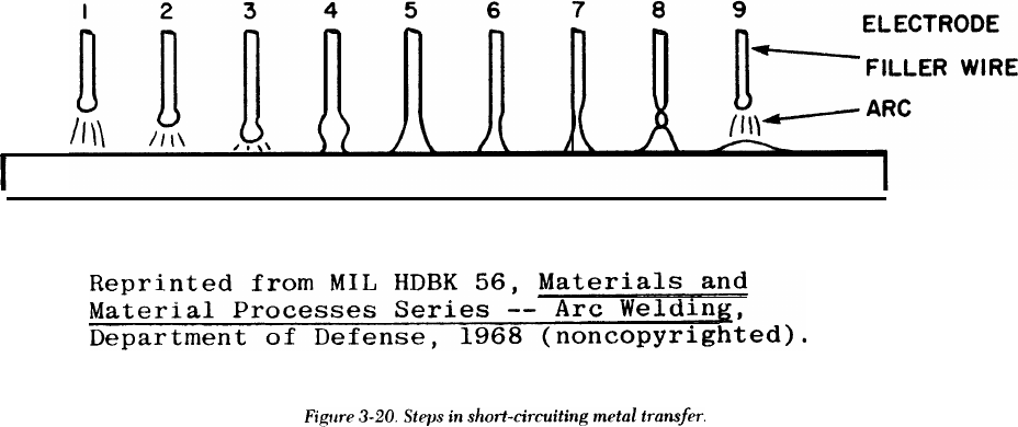
TM 5-805-7
transfer. As the end of the filler wire melts, it forms
a ball (fig 3-20). This becomes larger until it touches
the weld puddle, extinguishing the arc and creating
a short circuit. The arc length is deliberately kept
short so that the metal ball touches the puddle
before it separates from the end of the filler wire.
When the short circuit occurs, the welding current
increases rapidly, causing the drop of molten metal
to be “pinched” from the end of the filler wire. The
arc is reinitiated and the process repeated. The
short-circuiting action is very rapid; as many as 200
short circuits per second may occur. This process is
also known as “short arc, ” dip-transfer, or fine wire
welding,
(4) Equipment. Short-circuiting transfer weld-
ing uses the same constant voltage equipment as
does spray transfer. The power source must have a
device that inserts a variable but controlled amount
of inductance into the electrical circuit. This induc-
tance controls the rate of current increase when the
short circuit occurs and permits the arc to restart
without weld-metal spatter.
(a) Short-circuiting welding requires a smaller
diameter filler wire (0.030-inch diameter, for exam-
ple) than is generally used for spray-transfer
welding.
(b) The shielding gas used for short-circuiting
welding depends on the metal being welded. Argon,
helium, or mixtures of these are used for welding
aluminum. Carbon dioxide, a mixture of carbon
dioxide and argon, or argon with a small oxygen
addition is used when welding mild or low-alloy
steel. For stainless steel, argon with oxygen or car-
bon dioxide additions is used.
3-5. Flux-cored arc welding (FCAW)
Flux-cored, tubular-electrode welding has evolved
from the GMAW process to improve arc action,
metal transfer, weld-metal properties, and weld
appearance.
a. Advantages. The major advantages of flux-cored
welding are reduced cost and higher deposition
rates than either SMAW or solid wire GMAW. The
cost is less for flux-cored electrodes because the
alloying agents are in the flux, not in the steel filler
wire as they are with solid electrodes. Flex-cored
welding is ideal where bead appearance is important
and no machining of the weld is required. Flex-
cored welding without carbon dioxide shielding can
be used for most mild steel construction applica-
tions, The resulting welds have higher strength but
less ductility than those for which carbon dioxide
shielding is used. There is less porosity and greater
penetration of the weld with carbon dioxide shield-
ing, The flux-cored process has increased tolerances
for scale and dirt; there is less weld spatter than with
solid-wire GMAW.
b. Disadvantages. Most low-alloy or mild-steel
electrodes of the flux-cored type are more sensitive
to changes in welding conditions than are SMAW
electrodes. This sensitivity, called voltage tolerance,
can be decreased if a shielding gas is used, or if the
slag-forming components of the core material are
increased. A constant-potential power source and
constant-speed electrode feeder are needed to main-
tain a constant arc voltage.
c. Process principles. The flux-core welding wire,
or electrode, is a hollow tube filled with a mixture of
deoxidizers, fluxing agents, metal powders, and
ferro alloys, as shown in figure 3-21. The closure
seam, which appears as a fine line, is the only visible
I
23456
3-21
TM 5-805-7
difference between flux-cored wires and solid cold-
drawn wire. Flux-cored electrode welding can be
done in two ways: carbon dioxide gas can be used
with the flux to provide additional shielding, or the
flux core alone can provide all the shielding gas and
slagging materials. The carbon dioxide gas shield
produces a deeply penetrating arc and usually pro-
vides better weld than is possible without an exter-
nal gas shield.
d. Equipment. The equipment and controls for the
flux-core process are similar to, and sometimes the
same as, those used in the stray-transfer method.
The unit consists of a constant-speed wire-drive sys-
tem, water- or air-cooled welding torch, and a con-
stant-potential DC unit with a 100-percent duty
cycle.
3-6. Gas tungsten-arc (GTAW)
The GTAW process uses a nonconsumable electrode
and an inert shielding gas. This process is also known
as TIG (tungsten inert gas) and by the trade name
“Heliarc.” GTAW is similar to other arc-welding
processes in that the heat is generated by an arc
between a nonconsumable electrode and the work
piece, but the equipment and the electrode type
distinguish GTAW from the other arc welding
processes.
a. Advantages. The GTAW process is the most
popular method for welding aluminum, stainless _
steel, and nickel base alloys. It produces top quality
welds in almost all metals and alloys used in indus-
try. The process provides more precise control of
the weld than any other arc welding method
because the arc heat and filler metal are indepen-
dently controlled, Visibility is excellent because no
smoke or fumes are produced during welding; there
is no slag or splatter that must be cleaned between
passes or on a completed weld, GTAW is usually
considered one of the most versatile processes
because it produces the highest quality welds in any
position or configuration, The final major advantage
is reduced distortion in the weld joint because of the
concentrated heat source. This is one of the best
precautions that can be taken to prevent weld crack-
ing or locked-up stresses.
b. Disadvantages. The GTAW process is expensive
because the arc travel speed and weld metal deposi-
tion rates are lower than with some other methods.
In addition, it is less advantageous to use GTAW on
heavy, thick materials.
c. Process principles. In the GTAW process, the
tungsten alloy electrode is mounted in a special
electrode holder designed to furnish a flow of inert
gas around the electrode and the arc. The arc is
CROSS-SECTIONS
OF FLUX-CORED WIRES
3-22
TM 5-805-7
struck between the base metal and the electrode by
one of two methods. In the first, called a scratch
start, the operator actually touches the work piece
with the tungsten and withdraws slightly. The sec-
ond method uses high-frequency discharge from the
electrode to the work piece to establish the arc. This
is better for welds that have to be very clean; a
scratch start could leave particles of tungsten in the
weld, causing brittle spots. After the arc is started,
the filler metal, if required, is fed into the weld pool
near the arc, as shown in figure 3-22. The molten
weld metal, the adjacent base metal, and the elec-
trodes are protected by a flowing gaseous envelope
of inert gas: generally argon, helium, or a mixture of
the two. Most GTAW is done manually, but for pro-
duction or assembly type welds such as long butt
welds, the system can be entirely automated. AC is
used generally for aluminum and magnesium, while
DC straight polarity is used for all other metals.
d. Equipment. The equipment includes an electri-
cal power source, electrode holder (torch), tungsten
or tungsten alloy electrodes, gas flow regulating
equipment, and usually a remote rheostat for off-on
switching and current control (fig 3-22).
(1) There are AC and DC power units with
built-in high frequency generators designed specifi-
cally for GTAW. These automatically control gas
and water flow when welding begins and ends. How-
ever, power supplies without these controls can also
be used.
(2) If the electrode holder (torch) is water-
cooled, a supply of cooling water is needed. Elec-
trode holders are made so that electrodes and gas
nozzles can be readily changed, either for different
sizes or for replacement.
(3) Mechanized GTAW equipment may include
electronic devices for checking and adjusting the
welding torch level, equipment for work handling,
provisions for initiating the arc and controlling gas
and water flow, and filler metal feed mechanisms.
3-7. Submerged arc (SAW)
In the SAW process, the arc is not visible, but is
submerged under a layer of granulated flux (fig 3-
23). This process can be used with either a single
electrode wire or many. AWS D1.1 describes the
procedure, equipment, electrodes, and flux used
with SAW.
a. Advantages. SAW is an efficient process that
can be used on nearly all ferrous metals. Welds of
very good quality are produced in a wide range of
metals thicker than 1/1 6 inch. Carbon, alloy, or
stainless steels up to l/2-inch thick are welded in
one pass, while thicker materials require more
passes. Weld metal deposition rates, arc travel
speeds, and weld completion rates are better than
those for other processes. There is no visible arc and
no weld spatter, and the deep penetrating effect of
concentrated heat allows narrow welding grooves.
Thus, it takes less filler metal to make a joint with
SAW than with other welding processes, The
unfused flux can be recovered and recycled when
the welding is finished.
b. Disadvantages. The basic limitation of SAW is
that it can only be used in the flat position and for
horizontal fillet welds. Welds can be made in the
horizontal position, but since the granular flux
needed to shield the weld metal must be in place in
front of the electrode, complicated dams and sup-
ports may be required to contain the flux. The
equipment used in this process can be hand-held,
but is usually mechanized, making it heavy and cum-
bersome and thereby limiting its use to fabrication
shops. The fused flux must be removed by chipping
and wire brushing.
c. Process principles. SAW takes place beneath
the flux covering without sparks, spatter, smoke, or
flash. The electrode and weld pool are completely
covered at all times during welding. The flux makes
possible these special operating conditions, which
distinguish SAW from other processes. When cold,
the flux does not conduct electricity; therefore, the
welder must establish a conductive path for starting
the arc. This can be done by scratch starting where
the electrode touches the base plate or by burying
some steel wool in the flux at the starting point. In
the molten state, the flux becomes highly conduc-
tive. Once the arc is started, the heat produced by
the current causes the surrounding flux to become
molten. This forms a conductive path, which is kept
molten by the continued flow of welding current.
The buried part of the flux is melted; the visible part
remains unchanged in both appearance and proper-
ties, and can be reused. All currents and polarities
are used, depending on the desired penetration and
bead shape, Reverse polarity provides the best bead
shape and penetration, while straight polarity gives
higher deposition rates but less penetration. Alter-
nating current provides penetration somewhere
between the two and is preferred for multi-wire
welding. The fused flux is chipped off the weld and
discarded.
(1) The welding electrodes must be positioned
properly. Flux is fed in front of and around the elec-
trode by a hopper. The arc is struck and the elec-
trodes moved along the weld. The operator watches
the ammeter and voltmeter readings to control cur-
rent and voltage adjustments. A variable-speed
motor controls the electrode feed; a power-operated
3-23
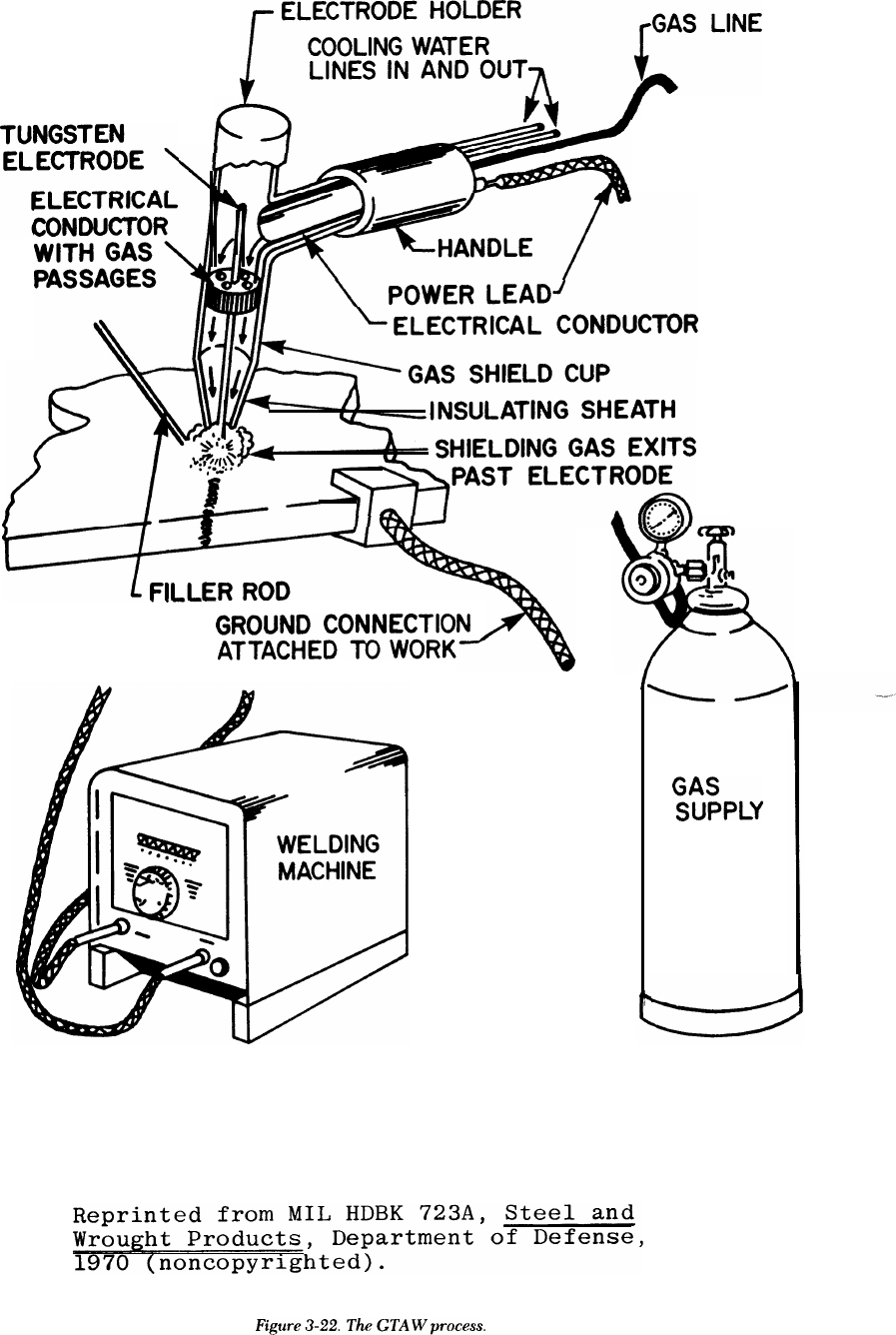
TM 5-805-7
3-24
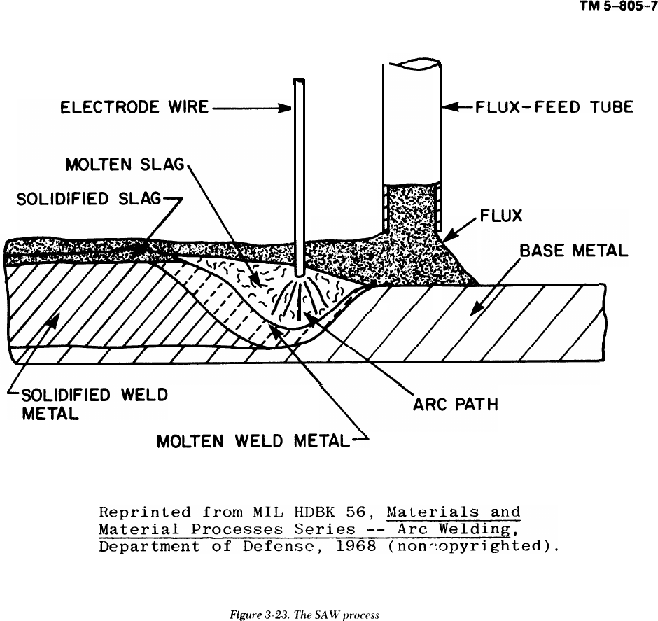
carriage controls the travel rate. Unused flux is fed
back into the hopper.
(2) Moderately thick sections of material (up to
1 inch) with a carbon content up to 0.35 percent can
be welded without precautions such as preheating
and postweld heat treatment. Preheating is gener-
ally needed when the carbon content is over 0.35
percent.
(3) Low-alloy steels maybe welded if the weld
.
area is preheated to slow the rate of cooling. This
must be done to avoid cracking in the weld and heat-
affected zone.
(4) When certain quenched and tempered struc-
tural steels (ASTM A 514 and A 517) are welded,
the heat input must be closely controlled to make
sure strength and notch toughness are retained in
the heat-affected zone. To keep a high level of
strength and notch toughness, heat must dissipate
rapidly so that desirable microstructure form. Any-
thing that delays cooling, such as preheating or high
welding heat inputs, should be avoided.
d. Equipment. Both semi-automatic and automatic
SAW equipment is available; the type used generally
depends on the work to be done, and on economic
factors. Semi-automatic equipment is better for
repair welding and for welding that cannot be done
automatically because of the geometry of the part.
Figure 3-24 shows the equipment needed for auto-
matic SAW; included are a power source, wire feed-
ing system, flux feeding system, and a welding torch.
(1) The power supply may be DC constant cur-
rent, DC constant voltage, or AC. The power supply
and wire-drive mechanism must be designed to
operate together so that the arc length can be con-
trolled effectively. SAW generally is done at higher
currents (500 to 1000 amperes) than other types of
arc welding, so the power supply must have a high
current rating at high duty cycles.
3-25
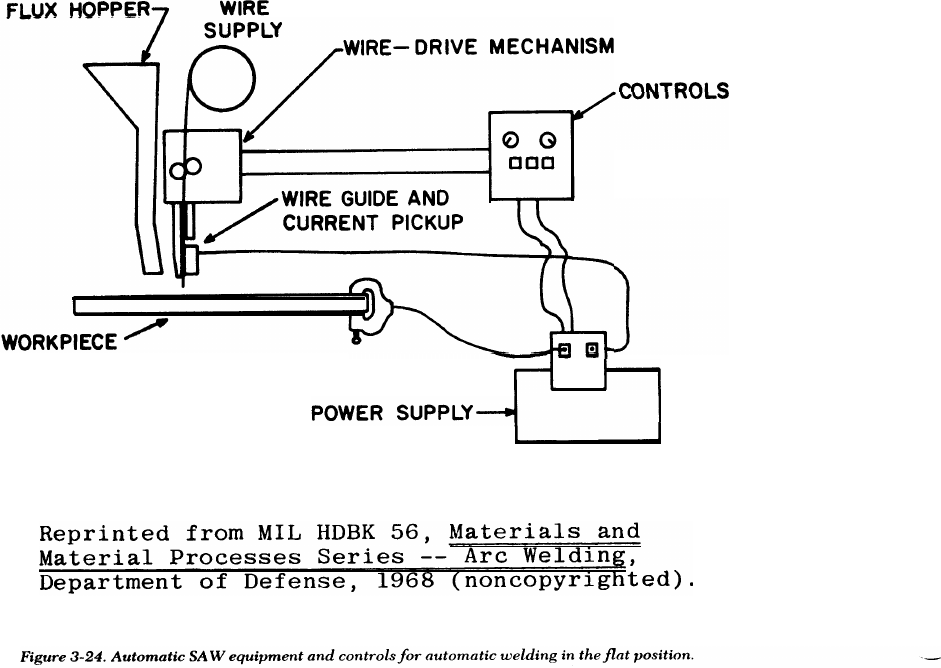
TM 5-805-7
(2) The electrodes used with SAW are generally
bare rods or wire in coils. The choice of electrode
depends on the way the alloying elements are intro-
duced into the weld. One method is to use mild-
steel electrodes with fluxes containing the alloy.
Another method often used requires special alloy
steel electrodes and neutral flux, and includes low-
carbon steel, low-carbon alloy steel, special alloy
steels, high-carbon steels, stainless steels, and non-
ferrous alloys.
(3) The fluxes are granulated, fusible mineral
materials of various compositions and particle sizes.
The choice of flux depends on the welding proce-
dure, joint configuration, and composition of the
base metal to be welded. The flux may include
alloying elements.
3-8. Exothermic welding
In exothermic welding, heat is generated by the
chemical reaction between a combination of alumi-
num and iron oxide. This mixture is placed in a hop-
per above a mold which surrounds the joint, and is
then ignited. A chemical reaction occurs, and the
molten metal and slag drop through the hopper.
Since the molten metal is heavier than the slag, it
settles to the bottom of the mold and touches the
3-26
steel joint. The molten metal melts the surface of the
metal and fuses with it, forming the weld. This pro-
cess, commonly referred to as “thermit welding, ” is
used for joining reinforcing rods, rails, large castings
or forgings, and for repairing large structural shapes.
Historically, thermit welding was largely confined to
structures made of iron and steel. But recently, the
substitution of a copper oxide for iron oxide has led
to many applications within the electrical industry
such as joining or repairing electrical connectors,
cables, bus bars, and bus tubes. Thermit welding is
also used for welding pipe. In this application the
thermit does not mix with the pipe metal, but
merely furnishes the heat to melt the pipe ends,
which are then butted together as they melt.
a. Advantages.
(1) The welder needs very little instruction or
experience to produce good welds rapidly.
(2) Large sections may be fusion welded, and
large quantities of filler metal may be deposited
quickly. Thermit welding can be roughly compared
to a foundry casting operation. The one difference is
that the metal being poured is considerably hotter
than when melted in a furnace. The completed weld
left in the mold cools slowly, reducing residual
stress.
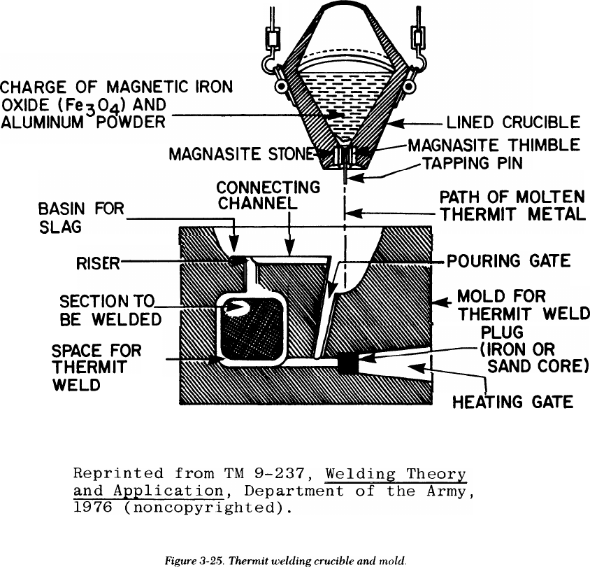
TM 5-805-7
b. Disadvantages. Molds are needed to hold the
molten metal around the weld joint. For one-of-a-
kind jobs, such as repairs, the molds must be con-
structed individually, and a suitable wax or plastic
form filler materials must be inserted in the gap to
insure
proper clearance between the parts.
Preformed permanent molds are used for repetitive
jobs — welding rails or reinforcing rods, for
example.
c. Process principles. Thermit welding is based on
the fundamental principle that aluminum is more
chemically active than iron. The welding process
consists of mixing the iron oxide and aluminum, both
in powder form, and placing them in a hopper or
crucible above a mold which surrounds the joint
area. (The joint to be welded must be cleaned, prop-
erly spaced, and preheated. ) An ignition powder,
such as a mixture of barium peroxide and aluminum
powder, is placed on top of the thermit, and a fuse is
inserted into the powder. The reaction starts after
the fuse ignites the mixture; this happens at about
2000 “F. The reaction is nonexplosive and takes
about 30 seconds; once the mixture starts to burn, it
is self-propagating. When the reaction is complete,
the molten metal has reached a temperature of
approximately 4500oF, which is nearly 1600oF
higher than the temperature of ordinary molten
steel. The metal is poured into the mold to form the
weld (fig 3-25). The mold is allowed to remain in
position for several hours to permit solidification
and to anneal the weld. The deposited metal cools
uniformly and is comparatively free from stresses.
The mold is then removed and the gates and risers
are cut away, Excess weld can be ground or
machined. Although the principal application of
thermit welding has been with the aluminum and
iron oxide mixture on steel structures, other metals
or their oxides may be included in the thermit mix-
ture. Chromium, nickel, manganese, tungsten, tita-
nium, molybdenum, and cobalt can be used. These
3-27
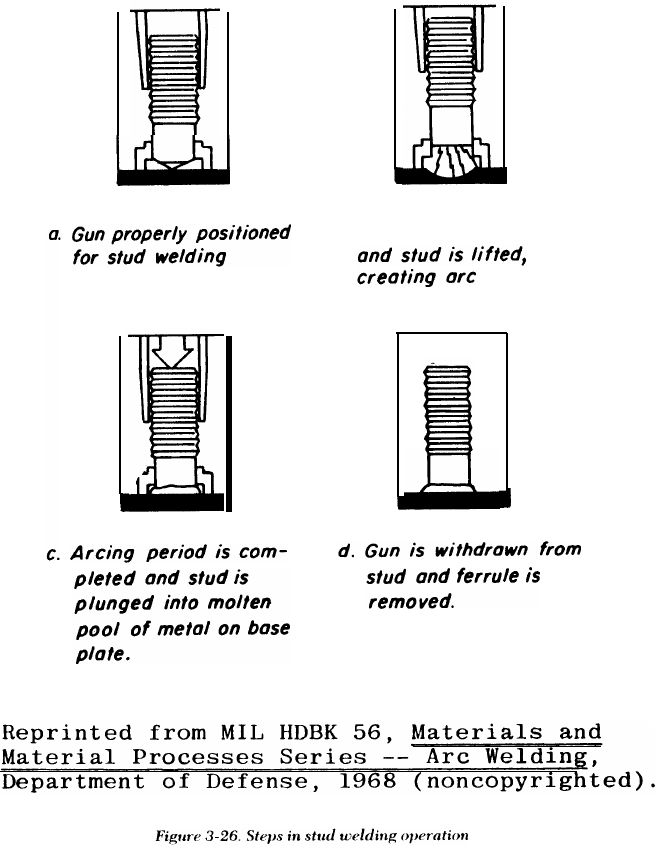
TM 5-805-7
elements alloy with iron and are used when higher
strength, ductility, or hardness is required. They
also permit control of the temperature and time of
the reaction. Cast iron can be welded with a special
thermit mixture.
d. Equipment. Thermit welding kits are available.
They consist of a permanent mold, prepackaged
thermit charges, consumable tapping discs, charges
of ignition powder, and fuses. An individually con-
structed mold requires wax or foam filler, sand mold
(a special mixture of silica sand and plastic clay), and
gates, risers, pouring gates, and a slag basin (fig 3-
25).
3-9. Arc-stud welding
Arc-stud welding is an arc welding process in which
an electric arc is struck between a metal stud and
another piece of metal. When the surfaces to be
jointed are properly heated, they are brought
together under pressure. A ceramic ferrule sur-
rounding the stud can provide partial shielding. The
process is generally referred to as “stud welding. ”
AWS D1.1 describes stud welding procedures,
equipment, workmanship, quality control, and
inspection requirements.
a. Advantages. Arc-stud welding has many advan-
tages and uses. With this process, there is no need to
drill or punch holes, nor to fasten an object mechan-
ically to a main structure with bolts, rivets, or
screws. Arc-stud welding is widely accepted by all
the metal-working industries. Since virtually every
phase of the operation is automatic, no previous
welding experience is necessary. Inexperienced
operators can be trained quickly, and once the
equipment is set for a particular job, high-quality
welds are quickly and easily made. The welding gun
b. Trigger is depressed
3-28
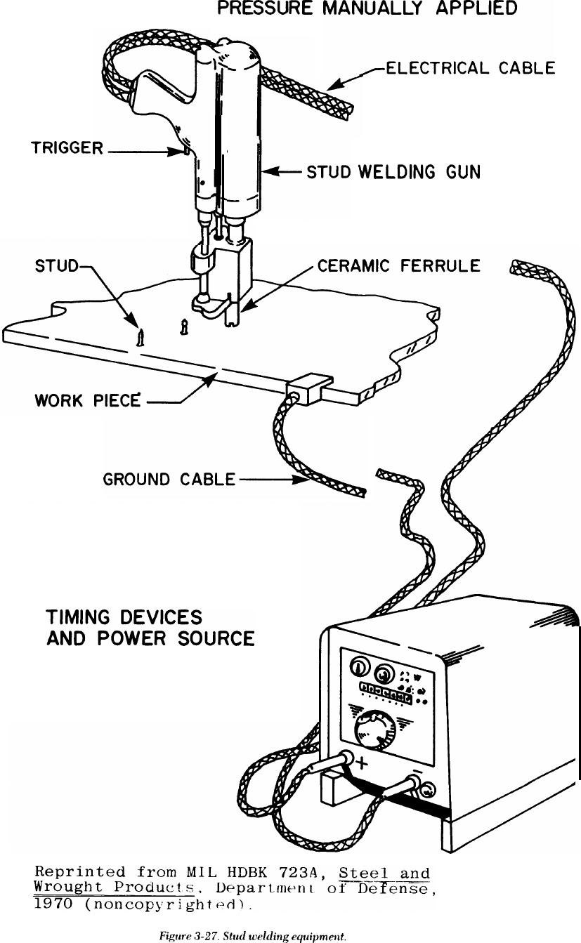
TM 5-805-7
CONTROL
3-29
TM 5-805-7
is light and easy to handle, making the equipment
very portable.
b. Disadvantages. Since this is a versatile process,
there are no real disadvantages; however, there are
some limitations on its use. Stud welding is approved
for use on low-pressure heating boilers built under
the ASME Boiler and Pressure Vessel Code for all
applications except stay bolts. This includes cover
plates, clean-out or access doors, and studded open-
ings for boiler-tubing water-heater coils. Stud weld-
ing is approved for use on nonpressure parts on
power boilers and unfired vessels.
c. Process principles. In the arc-stud welding pro-
cess, the flux-coated stud is inserted into a collet or
chuck which is an integral part of the gun. A porce-
lain ferrule surrounds each stud to shield the arc,
hold the molten pool in place, and help form an
acceptable fillet shape. The flux on the end of the
stud helps the operator control the arc and make
stud welds in any position. The operator places the
gun in the proper position, and spring pressure from
the gun holds the stud against the work piece. When
the trigger is depressed, it completes an electric cir-
cuit, causing the collet to withdraw the stud from
the work piece a preset distance, creating a gap and
an electric arc. At the end of an automatically timed
interval, the molten end of the stud is plunged into
the molten pool which has formed on the surface of
the plate. The process is similar to conventional
metallic-arc welding because, in effect, the stud
serves as a consumable electrode while the current
is flowing. The molten metal quickly solidifies and
the collet releases the stud (fig 3-26). The operator
removes the gun and is ready for the next welding
operation, all within seconds. Stainless steel, magne-
sium, and aluminum can be welded with basically
the same equipment as that used for steel — except
inert gas must be fed through the gun to protect the
weld.
(2) Low-alloy steels may be satisfactorily stud
,
welded without preheating if the carbon content is
held to 0.15 percent maximum. To prevent cracking
in the heat-affected zone, preheating is necessary
when the carbon content exceeds 0.15 percent.
(3) The heat-treatable, high-strength, low-alloy
structural steels require more attention since they
usually are hardenable enough to form martensite in
the heat-affected zone. These steels are quite sensi-
tive to underbead cracking, and the weld area is
usually low in ductility. Preheating to about 700°F
is recommended when steels of this category are
stud welded.
d. Equipment. The equipment for stud welding
consists of a DC power source; stud welding gun;
welding cables; ferrules for shielding the arc; and
controls, including timing devices. The equipment is
usually portable, but stationary equipment for large-
scale operations is used widely.
(1) The power source is a normal welding
machine adapted for stud welding. The cables are
made the same way as standard welding cables. The
gun is designed to assure correct alignment and hold
the stud. This gun has a trigger to start current flow
and a timing device that withdraws the stud at the
proper time to create the arc, moves the stud into
the molten pool, and holds it until the molten pool
solidifies (fig 3-27).
(2) A ferrule is used with each stud. It shields ‘--
the arc, protects the welder, and eliminates the need
for a full face helmet. The ferrule concentrates heat
during welding and confines molten metal to the
weld area. It helps prevent both oxidation of the
molten metal during the arcing cycle and charring of
the work piece.
(3) Studs are available in a variety of shapes,
sizes, and diameters. Some are designed for thread-
ing or riveting, others serve as nails. Studs are avail-
able as straight and bent shapes, hooks, or eyebolts.
(1) In practice, the same restrictions apply both
to the metal-arc welding of carbon steels and to stud 3-10. Process selection
welding. Carbon steels with a carbon content up to Table 3-2 is a selection guide for the welding pro-
0.30 percent may be welded without preheating. cesses discussed in this chapter. This table is based
When the carbon content exceeds 0.30 percent, on the particular applications encountered in field
particularly in heavy sections, preheating is advisa- welding.
ble to prevent cracking in the heat-affected zone. In
some cases, a combination of preheating and post-
heating has proven helpful.
3-30
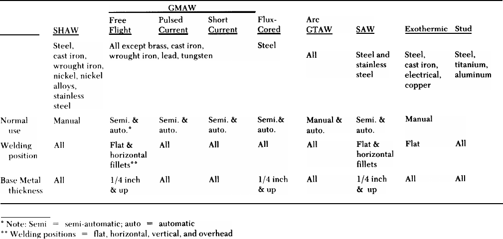
TM 5-805-7
Table 3-2. Summary of welding processes and application
Conditions
Materials
commonly
welded
3-31

TM 5-805-7
CHAPTER 4
WELDING OF STAINLESS STEEL
4-1. General
Stainless steels were originally developed because of
their outstanding resistance to corrosion. They also
exhibit good mechanical properties, which can be as
important to the life of the structure as the corrosion
resistance. There are four types of stainless steel:
martensitic, ferritic, austenitic, and precipitation
hardened. These steels exhibit a wide range of
mechanical properties both at room temperatures
and at cryogenic temperatures (below – 150
degrees F). The stainless steels commonly used are
covered in specifications of ASTM, the American
Iron and Steel Institute (AISI), the Society of Auto-
motive Engineers (SAE), ASME, API, and the mili-
tary or other Federal agencies. Commonly used
stainless steels are the austenitic class that meet
specifications for AISI grades in the 200 and 300
series. Martensitic stainless steels in the AISI 400
series are also used. When designing for 400 series
stainless steels, one must use extra care because of
their sensitivity in heat treating. Stainless steels that
conform to other specifications can be used where
particular requirements must be met. Stainless steel
welding electrodes are specified by AWS or military
documents. Commonly used welding electrodes for
fabrication meet specifications AWS A5.4, A5.9,
A5.11, A5.14, and A5.22.
4-2. Weldability of stainless steels
The austenitic chromium-nickel steels are often
used for cryogenic and vacuum systems. These steels
are characterized by their corrosion resistance, low-
magnetic permeability, good high-temperature
strength, and excellent low-temperature ductility
and notch toughness. Some of the austenitic steels,
however, do have characteristics that restrict their
use in cryogenic applications (table 4-1). But the
austenitic steels are considered the most weldable of
the high alloy steels. Three basic factors affect the
weldability of stainless steels: (1) the chemical com-
position of the base metal and the weld metal, (2)
the microstructure of the base metal and the weld
metal, and (3) the use of the correct welding proce-
dures and techniques
a. Chemical composition. The major constituents
in stainless steels are iron,carbon, manganese,
silicon, chromium, and nickel. The chromium is pri-
marily responsible for the stain and corrosion resis-
tance of these steels. It has an affinity for oxygen and
forms a thin, impervious, protective, oxide layer.
Chromium also has an affinity for carbon and forms
chromium-carbides rapidly between 800 and
1600°F.
(1) When chromium-carbides are formed, they
tie up much of the chromium and severely reduce
the corrosion resistance of the steel. Typically, this
can happen in a zone next to and on either side of
the weld joint. This phenomenon, known as sensiti-
zation, occurs because a region next to the weld is
heated to between 800 and 1600 “F by the welding
arc. If the weld joint is subjected to a corrosive
environment, knife-line attack results. Three tech-
niques are used to mitigate sensitization. These
methods can be expensive and should be used only
when sensitization is a problem.
(a) Extra-low carbon (less than 0.03 percent
carbon) grades of steel can be used. This carbon
content is the maximum amount that is soluble in
stainless steels and does not easily come out of
solution.
(b) Stabilizing elements such as columbium
and tantalum can be used. These form carbides pref-
erentially over chromium, thereby tying up the
carbon.
(c) A post-weld heat treatment can be used.
The most common heat treatment technique is to
solution anneal at 1900°F, then water quench. This
technique puts all the carbon in solution and keeps it
there by rapidly cooling through the 1600 to 800oF
range.
(2) In a fully austenitic stainless steel weld (such
as a type 310), the ductility and soundness of the
weld depend on the carbon to silicon ratio. Ideally,
this ratio should be about 1:2. An increase in silicon
above this ratio causes fissuring (microcracking) in
the weld metal and a rapid loss of ductility. An
increase in the carbon ratio causes a less severe
decrease in ductility without affecting weld sound-
ness. With fully austenitic stainless steels, the car-
bon to silicon ratio must be closely controlled. This
tends to limit the use of such steels when weld joints
with the best quality and ductility are required.
b. Microstructural effects. Two microstructural
factors affect the quality of austenitic stainless steel
4-1
TM 5-805-7
weld joints: ferrite content in weld metal and base
metal, and grain growth in weld metal and the heat-
affected zone. The following discussion describes
methods of controlling these factors. Designers can
use this information to specify the proper base mate-
rials, and welding procedures and materials.
(1) Ferrite content.
(a) Fully austenitic weld joints often tend to
develop microcracks and fissures during welding. To
prevent this, designers should select filler metals or
electrodes that will form an austenitic weld deposit
containing a small percentage of ferrite. Such welds
are highly resistant to cracking. However, if the fer-
rite content becomes too high in cryogenic applica-
tions, the weld metal’s impact strength at service
temperatures can be seriously reduced. For these
applications. the ferrite content of the weld metal
should be within the range of 4 to 10 percent.
(b) The actual ferrite content depends on the
compositions of the base metal and filler metal or
electrode, and the extent to which the weld metal
deposit is diluted by the welded parent metal. A
Schaeffler diagram (fig 4-1) can help designers esti-
mate both the percentage of ferrite in the weld
deposit and the filler metal composition necessary to
form the required ferrite in the weld metal. This
diagram is used to predict the amount of ferrite in
stainless steel weld metal on the basis of weld metal
composition. The diagram shows how the micro-
structure of the weld deposit is affected by the alloy
elements in stainless steel that act like nickel, and
those that act like chromium. The nickel equivalent
group which is the austenite former includes nickel,
--
carbon, and manganese; an allowance is also made
for the nitrogen content. The chromium equivalent
group which is the ferrite former includes chro-
mium, molybdenum, silicon, and columbium. The
nickel equivalent is the ordinate of the diagram, and
the chromium is the abscissa.
(c) To estimate the microstructure of the weld
metal, the designer uses the following formulas to
calculate the nickel and chromium equivalents:
nickel equivalent = % nickel + 30 X %
carbon + 0.5 X %
manganese
chromium equivalent = 70 chromium + %
molybdenum + 1.5
X % silicon + 0.5
X % columbium.
The nickel and chromium equivalents are calculated
for both the base and weld metal. The values
obtained are then plotted on the Schaeffler diagram,
and a line is drawn between the two points to indi-
cate the possible ferrite percentages that could be in
the weld metal because of base metal dilution. For
example, if type 302 stainless steel is welded using
type 308 electrode, then the nickel equivalent for
the 302 stainless is 12, and the chromium equivalent
is 18.25. When this point is plotted, it is totally in
the austenitic region, so there will be no ferrite. The
type 308 electrode will have a nickel equivalent of
12, and a chromium equivalent of 21, thus putting it
close to the 10 percent ferrite line.
(d) The Schaeffler diagram can predict not
only the amount of ferrite in the microstructure, but
also the electrode composition that will prevent
excessive ferrite or martensite content in stainless
steel weld metal. In addition, the diagram is helpful
in estimating the trend of the microstructure devel-
oped when dissimilar steels are welded. If pieces of
carbon steel and stainless steel are to be welded
together, the compositions of the two can be marked
on the diagram; the tie line drawn between them
indicates the microstructure that may be
encountered.
(2) Grain growth. The toughness and ductility of
the heat-affected zone and the weld metal may be
reduced somewhat because of grain growth caused
by the welding heat. However, unless extremely
high welding heats are used or very heavy weld
passes are deposited, the problem of decreased
toughness and ductility resulting from grain growth
is not serious. If impact testing of sample weld joints
indicates that the notch toughness of the weld metal
or heat-affected zone has suffered, the welding pro-
cess should be modified to decrease the heat input
to the joint and thus restrict the amount of grain
growth.
c. Preweld and postweld heat treating. Weld
joints in stainless steel are neither preheated nor
postheated. These techniques make the joints cool
slowly and could cause sensitization, with a resulting
loss of notch toughness. However, rapid cooling
after welding prevents sensitization of the weld
metal and heat-affected zone. In multipass welds,
the maximum interpass temperature should be
300 “F. Stress relieving of austenitic stainless steel
weld joints also should be avoided because it seldom
works and sensitization can occur easily.
d. Weld cracking.
(1) Weld cracking in austenitic stainless steels
can be divided into four types: crater cracks, star
cracks, hot cracks or microfissures, and root cracks.
All four types of cracking are believed to be mani-
festations of the same basic kind of cracking —
namely hot cracking, or in its earliest stage, microfis-
suring. Hot cracking presented many difficulties
some years ago, but now it can be prevented in
4-2
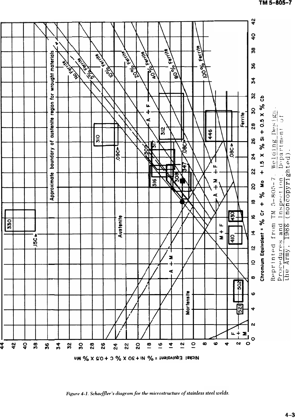
TM 5-805-7
weldments. Hot cracks occur intergranularly; appar-
ently, the segregation of low melting constituents in
the grain boundaries induces fissuring susceptibility.
(a) The formation of microfissures seems to
depend on five factors: the microstructure of the
weld metal; the composition of the weld metal, par-
ticularly the level of residual elements; the amount
of stress imposed on the weld as it cools through the
high temperature range; the ductility of the weld
metal at high temperatures; and the presence of
notches that form incipient cracks at the edge of the
weld.
(b) For many years,
.
it was believed that
microfissures only developed in the as-deposited
weld metal shortly after solidification. However,
more recent work has clearly shown that microfis-
sures can occur in the heat-affected zones of previ-
ously deposited sound weld beads.
(2) The microstructure of the weld metal
strongly affects microfissuring susceptibility. Weld
metal having a wholly austenitic micro-structure is a
lot more sensitive to conditions that promote
microfissuring than weld metal containing some
delta or free ferrite in the austenitic matrix. As dis-
cussed in a above, the chemical composition —— both
alloy content and residual element content —
strongly influences rnicrofissuring susceptibility of
the wholly austenitic stainless steel weld metals.
Microfissuring is reduced by a small increase in car-
bon content, a substantial increase in manganese, or
an increase in the nitrogen content. The residual
elements that influence cracking most often are
boron, phosphorus, sulfur, selenium, silicon, colum-
bium, and tantalum.
(3) In welding austenitic stainless steels, two dif-
ferent practices are now used, depending on the
microstructure expected in the weld metal.
(a) Whenever possible, ferrite-containing aus-
tenitic weld structure is used. The filler metal must
be selected carefully and the welding procedure
planned in detail to secure the small, but important,
amount of delta ferrite. The Schaeffler diagram, dis-
cussed in b above, has been used frequently for
determining whether a specified weld composition
will contain enough ferrite.
(b) When a wholly austenitic weld structure
must be used, welding materials containing the low-
est possible amount of recognized crack promoters
should be selected. In addition, the amount of alloy
elements known to improve crack resistance should
be increased. Even with the best materials and the
most favorable welding procedure, wholly austenitic
deposits are more crack sensitive than the ferrite-
containing types. Therefore, all phases of welding
and inspection need greater care.
(4) Base metal heat-affected zone cracking in
welded austenitic stainless steels can be a problem
in heavier sections (more than 1-inch thick). Such
cracking can have two causes. One is an intergranu-
lar form of hot shortness in a heat-affected zone
during welding. The weld metal cracks because of
grain boundary liquation or embrittlement at or near
welding temperatures. The other cause for cracking
is a complex phenomenon involving strain-induced
precipitation in the heat-affected zone during post-
weld heat treatments or service at high tempera-
tures (above 450oF). A change in mechanical
properties thus results in stress-rupture failure
under certain conditions. In this form of failure, the
key to the problem is the precipitation of colum-
bium carbides in the stressed heat-affected zones. As
little as 0.1 percent columbium as a residual element
can produce strain-induced precipitation and cause
welded heavy sections to fail by cracking during ser-
vice at high temperatures. A titanium-stabilized
stainless steel, such as type 347, can be used to help
keep a nonstabilized stainless steel from cracking.
e. Other weld defects. Defects besides cracking
occur in the weld metal if an incorrect weld process
or technique is used. These defects include porosity,
slag inclusions, incomplete fusion, inadequate joint
penetration, and undercutting.
(1) Porosity is a cavity-type discontinuity
formed by gas entrapped during solidification. The
gases that form porosity are either driven from solu-
tion in the weld metal because of low volubility at
lower temperatures, or are produced by chemical
reactions in the molten weld pool. These gases are
trapped in the weld metal because solidification
occurs before the gases have time to rise to the sur-
face of the pool. Porosity will form less often if very
high currents or long arc lengths are avoided. The
welding contractor must make sure these variables
are taken into account when the procedure is devel-
oped and the welder qualification tests are con-
ducted. This is especially true for the SMAW
process because high currents and long arc lengths
consume large amounts of deoxidants in the elec-
trode covering, leaving little to combine with the
excess gases in the weld pool. Moreover, the type
and distribution of porosity will give some indica-
tions of its cause. The types of porosity arc classified
in the acceptance standards of the various codes
(ASME, API, or AWS, as applicable). Generally, the
types of porosity depend on the distance between
individual pores or groups of pores.
(a) Uniforrnly scattered porosity can be found
in many weldments and is of little concern because
there is usually enough sound metal between the
pores.
4-4

TM 5-805-7
(b) Clustered porosity is often associated with
changes in arc conditions. For instance, areas where
the arc has been started or stopped frequently con-
tain cluster porosity.
(c) Linear porosity is usually found in the root
pass and is considered a special case of inadequate
joint penetration.
(2) Slag inclusions are oxides or nonmetallic
solids that become trapped in solidifying metal. The
inclusions either can be completely surrounded by
weld metal or can be between the weld metal and
the base plate. In the SMAW process, chemical reac-
tions between the weld metal and the coating mate-
rials produce a nonmetallic slag that has low
volubility in the weld metal and generally will float
to the surface. Sometimes, the slag is forced into the
weld metal by the stirring action of the arc, or flows
ahead of the arc and is covered by the weld metal.
Proper cleaning and preparation of the weld joint or
proper manipulation of the electrode will reduce the
number of slag inclusions. The welding contractor
can make sure these precautions are included when
welding procedures are developed and welder quali-
fication tests are conducted.
(3) Incomplete fusion occurs when two weld
beads, or the base metal and a weld bead, have not
fused together. This is caused by failure to raise the
adjoining material to the fusion temperature or fail-
ure to dissolve any oxides or other foreign material
on the surface to which the new weld bead must
fuse. Incomplete fusion can be prevented by follow-
ing the approved welding procedure, which should
include cleaning of the preceding bead and contigu-
ous base metal in the weld joint. Particular care
should be used in welding stainless steel because the
high temperature increases the amount of chromium
oxide formed and the steel becomes hard to weld
with the increased oxide layer.
(4) Inadequate joint penetration occurs when
the fusion of the weld and the base metal at the root
of the joint is less than specified by design. Poor
penetration affects weld joints that will be stressed
in service; the root forms a notch that acts as a stress
concentrator, which leads to early failure of the
joint. Although a poorly cleaned joint may cause
inadequate penetration, poor heat transfer condi-
tions in the joint are more often at fault. Heat trans-
fer can be increased by using wider angles for V-
grooves or a larger root opening.
(5) Undercutting refers to either a sharp recess
in the side wall of a weld joint or reduced thickness
of the base plate at the toe of the last weld bead on
high voltages, as well as low current and fast travel
speeds, may increase the tendency to undercut. If
undercutting is a sharp recess in the joint side wall,
it should be smoothed out by grinding or chipping
before the next weld bead is placed. AWS specifica-
tions and the ASME Boiler and Pressure Vessel Code
impose limitations on undercutting.
4-3. Joint design
Weld joints are prepared either by plasma-arc cut-
ting or by machining or grinding, depending on the
alloy. Before welding, the joint surfaces must be
cleaned of all foreign material, such as paint, dirt,
scale, or oxides. Cleaning may be done with suitable
solvents (e. g., acetone or alcohol) or light grinding.
Care should be taken to avoid nicking or gouging
the joint surface since such flaws can interfere with
the welding operation.
4-4. Methods of welding stainless steels
Stainless steels are readily weldable in the field by
SMAW, GMAW, FCAW, and SAW processes.
GTAW can be used for field fabrication, but it is a
slow process. SMAW is used most often because the
equipment is portable and easy to use. GMAW,
FCAW, and SAW are being used more often in the
field because they are economical and produce high-
quality welds. Manufacturers’ recommendations for
welding stainless steel should be followed. These
include recommendations on joint designs, preheat
temperatures, any associated post-weld heat treat-
ment, and shielding gas.
4-5. Shielded metal-arc (SMAW)
SMAW has been the preferred method of welding
because of its versatility, simplicity of equipment,
and wide selection of electrodes available — all of
which are important for field welding applications.
AWS A5.4 is the specification for stainless steel
SMAW electrodes.
a. Electrode classification system. The SMAW
electrode classification code contains an E and three
numbers, followed by a dash and either a 15 or 16
(EXXX-15), The E designates that the material is an
electrode, and the three digits indicate composition.
Sometimes there are letters following the three dig-
its; these letters indicate a modification of the stan-
dard composition. The 15 or 16 specify the type of
current with which these electrodes may be used.
Both designations indicate that the electrode is usa-
ble in all positions: flat, horizontal, overhead, and
vertical.
(1) The 15 indicates that the covering of this
electrodes are usable with DC reverse-polarity only.
4-5
TM 5-805-7
(2) The designation 16 indicates electrodes that
have a lime- or titania-type covering with a large
proportion of titanium-bearing minerals. The cover-
ings of these electrodes also contain readily ionizing
elements — such as potassium — to stabilize the arc
for AC welding.
b. Chemical requirements. The SMAW electrode
requirements for the nickel-chromium austenitic
stainless steels are included in AWS A5.4. The
chemical requirements are based on the as-depos-
ited weld metal chemistry. Chemical requirements
do not change when a 15 or 16 electrode is used.
c. Weld metal mechanical properties. The AWS
requires the deposited weld metal to have a mini-
mum tensile strength of 60,000 to 100,000 psi, with
minimum elongations of 20 to 35 percent. The
detailed requirements are in AWS A5.4.
d. Recommended filler metals for austenitic stain-
less steels. The Welding Handbook, section 4, “Met-
als and Their Weldability, ” chapter 64, “The 4-10
Percent Chromium-Molybdenum Steels and the
Straight Chromium Stainless Steels, ” has a table giv-
ing a complete list of base metals by AISI number
and recommended filler metals to join the base met-
als. This table lists not only the chromium stainless
steels, but also heat-resisting stainless steels and all
the austenitic stainless steels. If the type of stainless
steel is not listed, then manufacturers’ recommenda-
tions should be followed. An appendix to AWS A5.4
describes the intended uses of the electrodes.
4-6. Gas metal-arc (GMAW)
GMAW is being used more often for shop and field
Applications because it offers much less downtime
for electrode changes, less loss resulting from stub
ends and spatter, and minimal interpass cleaning
compared to the SMAW process. GMAW can be
done in all positions by using either short-circuiting
transfer or a pulsed voltage power supply. GMAW
has slightly less versatility than SMAW because the
welding gun is bulkier than the electrode holder for
the SMAW; furthermore, the equipment is more
complex and expensive, and requires somewhat
more skill by the operator,
a. Electrode classification system. The classifica-
tion code for GMAW electrode wire consists of an E,
an R, and three digits: ERXXX. The letter E indi-
cates that this is an electrode material, and the R
indicates that it is a welding rod. Since these filler
metals are used for the atomic hydrogen and GTAW
method as well as for SAW and GMAW, both letters
are used. The three-digit number, such as 308 in
ER308, designates the chemical composition of the
filler metal. An “Si” after the classification indicates
that the rod or electrode contains between 0.5 and 1
percent silicon rather than the standard 0.25 to 0.60
percent silicon. An “L” indicates that this electrode
has a carbon content not exceeding 0.03 percent.
The specifications for these electrodes are contained
in AWS A5.9.
b. Chemical requirements. The chemical require-
ments for the GMAW electrodes are in AWS A5.9.
The proportions of elements are similar in elec-
trodes and base metal with the same designation. All
chemical analyses are based on the as-manufactured
electrode wire.
c. Weld metal mechanical properties. The all-weld
metal tensile properties for the chromium-nickel
austenitic stainless steel electrodes are presented in
the appendix of AWS A5.9. These mechanical
properties are the same as those required for the
SMAW electrodes.
d. Shielding gas. Two types of shield gas are used
with the GMAW process: pure argon and argon plus
2 percent oxygen. The minimum thickness which
can be welded using this process is about 1/8 to 3/16
inch.
e. Recommended filler metals for chromium-
nickel stainless steels. The austenitic stainless steels
are listed by AISI specification numbers in the table
“Covered Electrodes Recommended for Welds
Between Stainless and Heat-Resisting Steels” in the
Welding Handbook, section 4, chapter 64. If steels
other than those listed are used, then the manufac-
turer’s recommendation for weld metals and preheat
temperatures should be followed. An appendix to
AWS A5.9 describes the intended uses of the elec-
trode types.
4-7, Flux-cored arc welding (FCAW)
FCAW uses equipment similar to that of GMAW,
and offers the advantages of high deposition and
fluxing ingredients. This process is used primarily in
the flat and horizontal positions, but can be used in
other positions if the proper electrode diameter and
welding currents are selected. Flux-cored, corro-
sion-resisting chromium and chromium-nickel steel
electrodes are specified by AWS A5.22.
a. Electrode classification system. The FCAW
electrodes are classified similarly to the GMAW
electrodes. In the code EXXXT-Y, the EXXX desig-
nation is the same as for the GMAW electrodes and
can be any of the material classification numbers
previously noted. The letter T indicates a continu-
ous tubular electrode with a powdered flux within
the tube. The suffix Y can be any number from 1 to 3
or the letter G. The numbers indicate the external
shielding medium to be used during welding. A “ 1”
4-6

designates an electrode using carbon dioxide shield-
ing gas. A “ 2“ designates an electrode using a mix-
ture of argon plus 2 percent oxygen. A “3”
designates an electrode using no external shielding
gas because the shielding is provided by the core
material. The “G” indicates an electrode with an
unspecified method of shielding; no requirements
are imposed on it.
b. Chemical requirements. A table in AWS A5.22
presents the deposited weld metal’s chemical analy-
sis for austenitic chromium-nickel stainless steel
FCAW electrodes. All classifications of the FCAW
electrodes have chemical requirements except the G
classification, and those requirements are only as
agreed on between the supplier and the purchaser.
c. Weld metal mechanical properties. The
all–weld metal tensile requirements for the austen-
itic chromium-nickel stainless steel FCAW elec-
trodes are presented in a table in AWS A5.22. The
tensile strength minimums vary from 60,000 to
80,000 psi, with a minimum elongation between 20
and 35 percent. The G classification of the elec-
trodes does not have any requirements except those
the supplier and purchaser agree on.
d. Shielding gas. The FCAW electrodes can use
three types of shielding: carbon dioxide, argon plus
2 percent oxygen, or inner shield. The inner shield
method uses gas-producing materials within the core
of the electrode. The shielding gas for the G desig-
nation electrode is not specified.
e. Recommended filler metals for austenitic chro-
mium-nickel stainless steeIs. The recommended fil-
ler metal/base metal combinations for the AISI-
designated stainless steels are in a table in the Weld-
ing Handbook, section 4, chapter 64. If stainless
steels other than those listed are to be used, then
manufacturers’ recommendations for weld metal
should be followed. An appendix to AWS A5.22 for
FCAW electrodes lists the intended uses of the
electrodes.
4-8. Submerged arc (SAW)
The SAW process is limited to flat position and hori-
zontal fillet welds because a granulated flux is used
to protect the arc and the molten weld metal. SAW
electrodes are specified by AWS A5.9. This is the
same specification for the GMAW electrodes. For
SAW, DC reverse polarity or AC may be used. Basic
fluxes are generally recommended to minimize
silicon pickup and the oxidation of chromium and
other elements. In general, electrodes having a
silicon content of 0.6 percent or less are desirable
for submerged arc welding since the fluxes usually
result in some silicon pickup. The material classifica-
tion, chemical requirements, and mechanical prop-
erty requirements are the same as those for the
GMAW electrodes in the as-welded condition. The
recommended filler metals for the austenitic chro-
mium-nickel stainless steel are the same as those for
the GMAW electrode and are listed in the table in
the Welding Handbook, section 4, chapter 64, as
noted in the above discussion of the recommended
filler metals for other processes.
4-9. Special considerations in welding
stainless steels
a. Effects of thermal properties of stainless steel
on welding conditions and distortion. The thermal
properties (coefficients of thermal conductivity and
expansion, and melting point) of stainless steel differ
somewhat from those of carbon steels. The differ-
ences affect the welding operations, and steps must
be taken to compensate for the effects of these ther-
mal properties. These steps are discussed in para-
graph 7-5.
b. Welding characteristics.
(1) Generally, austenitic stainless steel can be
welded with about 20 percent less heat input than
carbon steels. There are several reasons for this.
Stainless steels have a higher electrical resistivity
than do carbon steels. As a result, stainless steels get
hotter than carbon steels when the same welding
current is used. Thus, a given amount of stainless
steel can be melted with less current than the same
amount of carbon steel. In addition, less heat or cur-
rent is needed to melt austenitic stainless steels
because they have lower melting points than carbon
steel. Finally, the heat conductivity y of these stainless
steels is lower than that of other steels. Therefore,
the heat built up in the metal from the welding
operation flows away from the weld at a slower rate.
The result is that during welding, higher tempera-
tures are reached in a shorter time.
(2) When welded, austenitic stainless steels
tend to warp and buckle more than carbon steel.
This is because the coefficient of thermal expansion
of austenitic stainless steel is about 1-1/2 times as
large as that of carbon steel. This problem is further
aggravated by stainless steel’s lower thermal con-
ductivity, which tends to concentrate welding heat
in a smaller area. To keep warping and buckling to a
minimum, jigs and fixtures, carefully selected weld-
ing sequences, and accurate fitup generally have to
be used. Preheating to reduce distortion should be
avoided when welding austenitic stainless steel since
this could lead to sensitization of portions of the
weld joint.
4-7
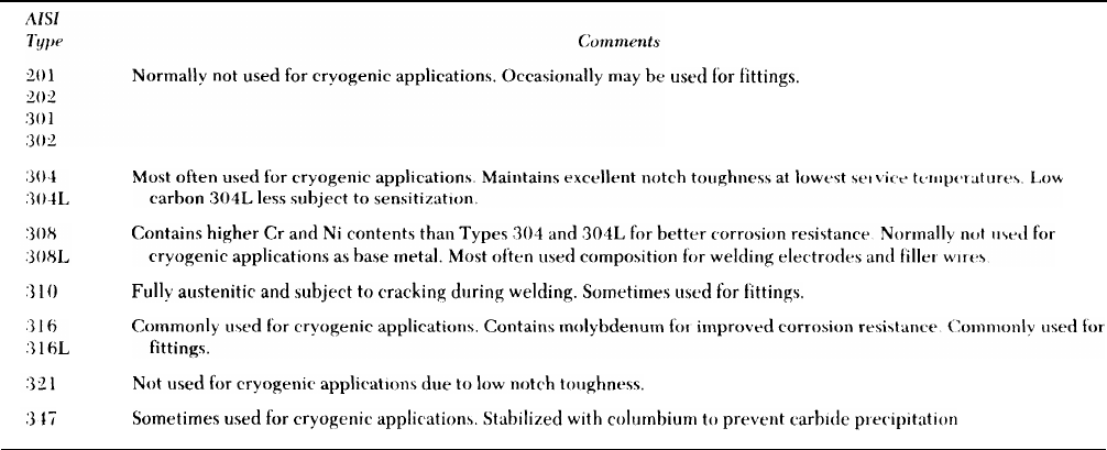
TM 5-805-7
(3) Special precautions are required if tack of the weld. It should be inspected to ensure that it
welding is used to control distortion and maintain is sound and does not contain tiny cracks or porosity,
joint alignment. If these precautions are not taken, The surface of the tack weld should be ground to a
tack welds can be a source of weldmetal cracking, smooth, concave contour so that it will be com-
porosity, incomplete penetration, or lack of fusion. pletely melted into the final weld.
A tack weld must be of the same quality as the rest
Table 4-1. Austenitic stainless steels most commonly used for cryogenic and uacuurn environmcnt equipment
4--8

CHAPTER 5
WELDING CARBON STEEL AND LOW-ALLOY STEELS
5-1. General
The steels commonly used in constructing buildings,
bridges, and piping systems are covered in specifica-
tions of ASTM, AISI, ASME, SAE, and APL These
specifications often refer to the same types of steels,
although they put different restrictions on the chem-
ical analysis and mechanical properties. Commonly
used materials for welded construction in buildings
and bridges meet specifications ASTM A 36, A 203,
A 242, A 440, A 441, A 514, A 517, A 572, or
A 588; and for piping systems, specifications ASTM
A 53, A 106, A 134, A 139, A 671, A 672 or A 691
or API 5L, 5LX, or 2H. Carbon or low-alloy steels
which conform to any of many other specifications
(including military and Federal) can be used where
particular requirements must be met. Welding elec-
trodes for steel are specified by MIL-E-22200. Com-
monly used welding electrodes for construction
meet specifications AWS A5.1, A5.5, A5.17, A5.18,
and A5.20, and A5.23.
5-2. Weldability of carbon and low-alloy
steels
The AWS defines weldability as “the capacity of a
metal to be welded under the fabrication conditions
imposed into a specific, suitably designed structure
and to perform satisfactorily in the intended ser-
vice” (AWS A3.0, p. 55). Given this definition, it is
clear that many things affect the weldability of a
specific steel, including joint design, welding pro-
cess, base metal chemistry, weld metal chemistry,
mechanical properties, and impact properties. Gen-
erally, steels specified for welded building and
bridge construction and for piping systems are weld-
able, with good mechanical properties obtained by
proper attention to welding procedures and elec-
trode selection. AWS D1.1 contains a selection
guide in the Technique section that matches elec-
trode types with various ASTM and API steels. Man-
ufacturers’ recommendations should be followed in
developing welding procedures, including heat
treatment and stress relief for high-strength/low-
alloy steels conforming to ASTM A 514, A 517, or
A 710.
a. Welding procedures The welding procedure to
use is governed by the base plate, the structure
being welded, the position of the weld (i.e., flat,
overhead, horizontal, or vertical), and the chemical
composition of the metal. Carbon levels in the base
metal govern the level of preheat temperature used.
As a rule, the higher the carbon level, the higher the
preheat temperature used. Recommended preheat
practices are given in AWS D1.1. Improper welding
can introduce into the weld joint defects such as
porosity, slag inclusions, incomplete fusion, inade-
quate joint penetration, undercutting, and cracking.
Limitations on these various defects are governed by
AWS D1.1, the ASME Boiler and Pressure Vessel
Code, or MIL-R-11468, where the acceptance level
depends on the application.
b. Cracking. Cracking is one of the flaws that
occurs most often in weldments. Cracks occur when
the temperature of the cooling weld and base plate
is within either of two ranges. One is at or slightly
below the solidification temperature of the weld
metal, and the other is from about 4000 F to ambient
temperature. The high temperature cracking is
called hot tearing and occurs because the metal is
weak and has limited plasticity at this temperature.
Fillet welds, weld craters, and the heat-affected
zone display this type of cracking. Low-temperature
cracking, or cold cracking, occurs in root passes of
butt welds and in the heat-affected zone, and is
invariably associated with the presence of hydrogen
as a dissolved impurity.
(1) Hot tearing. High-temperature cracks are
intercrystalline tears that occur at or near the range
of solidification for the metal. They are attributed to
the presence of low-freezing compounds such as
iron sulfide, or solid impurities that have little or no
tensile strength or plasticity at high temperatures.
These tears are in the metal that is last to freeze in
the weld deposit. Sulfur contributes significantly to
hot tearing, while silicon, phosphorus, carbon, cop-
per, and nickel have a lesser role. Manganese, on the
other hand, has a beneficial effect on hot ductility
because it has a greater affinity to sulfur than iron
does. Manganese sulfides form; these have a higher
melting temperature than steel and produce globu-
lar inclusions rather than the intergranular film that
iron sulfide forms. If the ratio of manganese to sulfur
in steel is 60 or greater, then hot tearing is not likely
to occur. Electrodes recommended by AWS D1.1 or
the ASME Boiler and Pressure Vessel Code, as
5-1
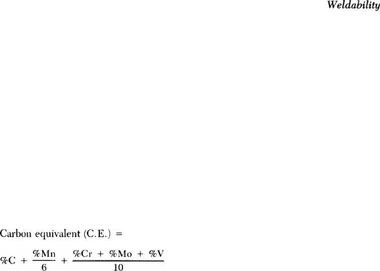
TM 5-805-7
appropriate, will produce a weld deposit with mini-
mum hot cracking tendencies. Preheating, control-
ling interpass temperature, and welding with as little
restraint as possible are other ways to control hot
cracking, particularly in a section thickness greater
than 1/2 inch.
(2) Cold cracking.
(a) Cold cracking occurs in the heat-affected
zone and weld metal. This may be caused by
mechanical effects, alloy content, or hydrogen
pickup from moisture in the electrode flux or on
surfaces of the weld joint. Mechanically, high
shrinkage stresses are induced in the weld metal by
the cooling weld and the restraining action of the
base metal. These stresses act in directions parallel
and perpendicular to the weld and their magnitude
may be great enough to cause cracking.
(b) In any thickness of steel, cold cracking
may also occur ‘in the heat-affected zone because of
alloy content. This is called underbead cracking.
The higher the alloy content, the greater the ten-
dency. Susceptibility to underbead cracking maybe
estimated from a steel’s “carbon equivalent, ” which
is determined from the formula:
As the C.E. increases, so does the susceptibility of
the steel to cold cracking. As a steel’s alloy content,
or C. E., increases, its capability to form a hardened
microstructure such as martensite when cooled rap-
idly also increases. Certain areas of the weld joint,
particularly those next to the base metal heat-
affected zone, may cool rapidly enough to produce a
hardened structure which becomes a “metallurgical
notch. ” This hardened zone may be brittle, with a
characteristic low notch toughness. Increasing the
heat input or the preheat/interpass temperature will
slow the cooling rate. However, high-strength, low-
alloy steels should be preheated carefully so the
steel in the heat-affected zone will not be weakened.
This precaution also applies to the use of interpass
temperature, air-arc gouging, post weld heating, and
heat input during welding. Removal of defects,
when repair is permitted, should be by grinding or
air-arc gouging followed by grinding to limit the
heat input effects of the gouging. Steel manufactur-
ers should be consulted for recommendations about
weld repairs. Few of the steels used in bridge or
building construction and piping systems have
enough alloying elements to create a problem with
hardening in the heat-affected zone. Occasionally,
however, a designer might specify a steel that can
harden quickly enough to require preheating.
Preheat temperatures for many of the steels are
listed in the following documents: structural steels
— AWS D1.1; piping materials — ANSI B31.1; fer-
rous materials — ASME Boiler and Pressure Vessel
Code, section HI, appendix III, “Other Applica-
tions, ” and the text Weldability of Steels, edited by
Stout and Doty (1971).
(c) Hydrogen also contributes to cold crack-
ing. Three factors act simultaneously in hydrogen-
induced cracking: dissolved hydrogen, tensile
stresses, and a low-ductility microstructure such as
martensite. The source of hydrogen is the shield gas,
flux, or surface contamination. The hydrogen is car-
ried as a diatomic molecule to the arc and is con-
verted to the monatomic or ionized state. The
monatomic hydrogen readily dissolves in the molten
weld metal. The exact mechanism by which hydro-
gen causes cold cracking has not been fully
explained. But many investigators believe that as the
weld metal cools, it becomes supersaturated, and
the hydrogen diffuses to a highly stressed area such
as the heat-affected zone or the atmosphere. Once
in the heat-affected zone, it is theorized that the
hydrogen embrittles the metal. Some low-alloy
steels, such as ASTM A 514 or A 517, will transform
to martensite under rapid cooling conditions, and at
the same time will entrap some or all of the hydro-
gen present. However, hydrogen has low volubility
in the martensitic structure and tends to migrate to
any neighboring discontinuities. Along with external
forces, the hydrogen enlarges these flaws to a criti-
cal size. Regardless of the mechanism by which
hydrogen embrittles the carbon and low-alloy steels,
however, precautions should be taken against its
entrainment. Joint design and attention to joint fit-
up can reduce the chances of cold cracking. To con-
trol hydrogen-induced cracking, a post-weld tem-
perature of 300 to 400 “F for up to 10 hours
(depending on weld thickness) is recommended.
This technique should be specified with caution
because of the risks noted in (3) below. Cleaning
joints to remove hydrogen-containing materials such
as oil and grease, and using of low hydrogen elec-
trodes are also recommended to limit the source of
hydrogen.
(3) Reheat cracking. Reheat cracking occurs in
steels containing carbide-forming alloy elements
such as vanadium or molybdenum. When a post-
weld heat treatment is used, these materials often
exhibit precipitation of alloy carbides that make the
grains of the heat-affected zone stronger than the
grain boundaries. If there are stresses, the grain
5-2
TM 5-805-7
boundary region must adjust to relieve them. Exten-
sive deformation in the grain boundary region may
induce cracking, especially in the heat-affected
zone. The risk of reheat cracking can be reduced by
using electrodes that do not have yield strengths
much higher than that of the base plate, by avoiding
highly rigid joint details in thick plate, by grinding
butt welds flush, and by smoothing the contour of
fillet welds, especially the toe of the weld. The AWS
D1.1 section “Workmanship — Stress Relief Heat
Treatment,” and ASME Boiler and Pressure Vessel
Code, section VIII, “Procedures on Post-Weld Heat
Treatment” contain recommended practices for
heat-treating welds for stress relief. The stress-relief
heat treatment of quenched and tempered ASTM A
514 and A 517 steels is not usually recommended
but may be required to maintain dimensional stabil-
ity during machining.
c. Other defects. Other defects can be introduced
into the weld metal if the proper weld process or
technique is not used. These defects include poros-
ity, slag inclusions, incomplete fusion, inadequate
joint penetration, and undercut. Each of these is
described in paragraph 4-2e.
5-3. Joint design
Weld joints are prepared either by flame cutting or
mechanically by machining or grinding, depending
on the joint details. Before welding, the joint sur-
faces must be cleared of all foreign materials such as
paint, dirt, scale, or rust. Suitable solvents or light
grinding can be used for cleaning. The joint surface
should not be nicked or gouged since they can inter-
fere with the welding operation.
5-4. Methods of welding carbon steels
and low-alloy steels
Carbon and low-alloy steels are readily welded in
the field by SMAW, GMAW, FCAW or SAW.
SMAW is used most often because the equipment is
simple and portable. GMAW, FCAW, and SAW are
being used more often in the field because of weld
quality and economics. Standard joint designs for
these processes are in the AWS D1.1 section
“Design of Welded Connections,” and ASME Boiler
and Pressure Vessel Code, subsection B, “Joint
Details for Pressure Vessels. ” Recommended
preheat temperatures for commonly used steels are
also given in the codes; these figures are based on
plate thickness and the ambient temperature. Rec-
ommended preheat temperatures for
are listed in the AWS D1.1 section,
and appendix R of the ASME Boiler
Vessel Code.
various steels
“Technique,”
and Pressure
5-5. Shielded metal-arc (SMAW)
SMAW has been the preferred method of welding
because of its versatility, the simplicity of its equip-
ment, and the wide selection of electrodes, All of
these characteristics are important for field weld
applications. AWS A5.1 and A5.5 specify mild steel
and low-alloy steel SMAW electrodes.
a. Electrode classification system. The AWS has
developed a classification system which describes
some of the characteristics of steel welding elec-
trodes. The SMAW classification codes are made up
of an E and four and five numbers (EXXYZ). The E
indicates that the material is an electrode. The first
two digits, xX, give the minimum tensile strength of
the weld deposit in 1000 pounds per square inch
(psi); that is, an electrode with an E70YZ classifica-
tion would have a minimum tensile strength of
70,000 psi. The tensile strength designation starts at
60 and increases by 10 to 120. The number repre-
sented by Y can be either 1 or 2 and designates the
proper welding positions for this electrode type. A 1
means that the electrode can be used in all positions:
flat, horizontal, vertical, and overhead; a 2 indicates
that it can be used only on flat or horizontal fillet
welds, The last term in the classification, Z, can be
any number from O through 8. These numbers, iden-
tified in AWS A5.1, indicate major coating constitu-
ents and welding current types.
b. Chemical requirements. The AWS divides
SMAW electrodes into two groups: mild steel (AWS
A5.1) and low-alloy steel (AWS A5.5). The E60XX
and E70XX electrodes are in the mild steel specifi-
cation. The chemical requirements for E70XX elec-
trodes are listed in AWS A5.1 and allow for wide
variations of composition of the deposited weld
metal. There are no specified chemical require-
ments for the E60XX electrodes. The low-alloy
specification contains electrode classifications
E70XX through El 20XX. These codes have a suffix
indicating the chemical requirements of the class of
electrodes — for example, E7010-A1 or E8018-C1.
The composition of low-alloy E70XX electrodes is
controlled much more closely than that of mild steel
E70XX electrodes. Low-alloy electrodes of the low-
hydrogen classification (EXX15, EXX16, EXX18)
require special handling to help the coatings from
picking up water. Manufacturers’ recommendations
about storage and rebaking must be followed for
these electrodes. AWS A5.5 provides a specific list-
ing of chemical requirements.
c. Weld metal mechanical property requirements.
The AWS requires the deposited weld metal to have
minimum tensile and impact strengths. The detailed
requirements for mild steel electrodes are listed in
5-3

TM 5-805-7
AWS A5.1, and for low-alloy steel electrodes in
AWS A5.5.
d. Recommended filler metals for commonly used
steels. Commonly used ASTM and API steels, and
matching filler metal requirements are listed in the
table “Matching Filler Metal Requirements” of AWS
D1.1. This document lists the steel and minimum
preheat and interpass temperatures for different
plate thicknesses and welding processes. If a steel is
not listed, manufacturers’ recommendations should
be followed. AWS A5.1 contains the intended use of
the electrodes as an appendix. Chemical composi-
tion also should be considered when low-alloy elec-
trodes are specified.
5-6. Gas metal-arc (GMAW)
GMAW is being used more often for shop and field
applications because it is more economical than
SMAW. With GMAW, there is much less downtime
for electrode changes, much less loss due to stub
ends and spatter, and much less interpass cleaning
required. GMAW is also slightly less versatile
because the welding gun is bulkier than the elec-
trode holder for SMAW. However, GMAW can be
used in all positions with either short-circuiting
transfer or a pulsed voltage power supply. The
equipment is more complex and more expensive
than that for SMAW, and requires more skill on the
part of the operator.
a. Electrode classification system. The classifica-
tion codes for GMAW electrode wire consist of an E
and four digits in the configuration EXXY-Z. As with
SMAW, the E indicates an electrode, and XX gives
the deposited tensile strength in 10,000-psi incre-
ments. The tensile strength designations range from
70 to 110. The next digit, Y, can be either an S or a
U. The S indicates a solid bare wire, while U means
that the solid wire has an emissive coating that
allows the use of DC straight polarity. The final
digit, Z, can be any number from 1 through 6 or the
letter G. The numbers indicate chemical analysis,
particularly carbon and silicon. The G classification
has no chemical requirements. The letter B at the
end of the code, such as E70S-1B, indicates a low-
alloy steel electrode. Only the E70S-X and E70U-1
electrodes are specified by AWS AS.18.
b. Chemical requirements. The chemical require-
ments for the GMAW electrodes are presented in
AWS AS. 18. The E70S-G and E70S-GB electrodes
have no chemical requirements, except that no addi-
tions of nickel, chromium, molybdenum, or vana-
dium are allowed. Chemical requirements for the
higher-strength low-alloy electrodes are in MIL-E-
18193, MIL-E-19822, MIL-E-23765/1, and MIL-E-
23765/2. All chemical analyses are based on the as-
manufactured electrode wire.
c. Weld metal mechanical properties. The all-weld
metal tensile properties for the E70 electrodes are
presented in AWS A5.18.
d. Shielding gas. Two shield gasses are used with
GMAW—carbon dioxide, and argon plus 1 to 5 per-
cent oxygen addition. Carbon dioxide is used for
short-circuiting transfer and for flat-position weld-
ing. Argon-oxygen shield gas is used with pulsed
voltage out-of-position welding and spray transfer
welding. The GMAW electrodes and recommended
shield gases are listed in AWS A5.18.
e. Recommended filler metals for commonly used
steels. The table “Matching Filler Metal Require-
ments” in AWS D1.1 lists commonly used steels by
ASTM and API specification numbers, and gives
matching filler metal requirements and classifica-
tions. In addition, AWS D1.1 lists the steels and the
minimum preheat and interpass temperatures for
different plate thicknesses and welding processes. If
steels other than those listed are used, manufactur-
ers’ recommendations for weld metals and preheat
temperature should be followed. The intended uses
of the electrode types are indicated in an appendix
to AWS A5.18.
5-7. Flux-cored arc welding (FCAW)
FCAW which uses equipment similar to that of
GMAW, is advantageous because it provides high
deposition and fluxing ingredients. This process is
primarily for flat and horizontal welds, but can be
used in other positions if the proper electrode diam-
eter and welding currents are selected. Mild steel
FCAW electrodes are specified by AWS A5.20.
Low-alloy FCAW electrodes are available; manufac-
turers’ recommendations for their use should be
followed.
a. Electrode classification system. The FCAW
electrodes are classified similarly to the GMAW
electrodes. In the code EXXT-Y, the EXX designa-
tion is the same as for SMAW and GMAW electrodes
and can be either E60T-Y or E70T-Y. The letter T
indicates a continuous tubular electrode with a pow-
dered flux filling the tube. The suffix Y, which can
be any number from 1 through 8 or the letter G,
indicates the deposited weld metal chemistry and
shielding gas used.
b. Chemical requirements. The deposited weld
metal chemical analysis for mild steel FCAW elec-
trodes is in AWS A5.20. There are no chemical
requirements for E70T-2, E70T-3, and E70T-G
electrodes.
c. Weld metal mechanical properties. The all-weld —
metal tensile and impact requirements for the mild
5-4
TM 5-805-7
steel FCAW electrodes are presented in AWS
A5.20.
d. Shielding gas. The FCAW electrodes use car-
bon dioxide for shielding gas or contain in the flux
gas-producing compounds that protect the arc from
atmospheric contamination. The E60T-7, E60T-8,
E70T-4, and E70T-6 electrodes need no external
shield gas. The E70T-1 and E70T-2 electrodes need
additional shielding from carbon dioxide. The E70T-
5 electrode can be used with or without carbon
dioxide as a separate shield gas. The shielding gas
for the E70T-G electrode is not specified.
e. Recommended filler metals for commonly used
steels. Commonly used steels are listed by ASTM
and API specification numbers in the table “Match-
ing Filler Metal Requirements” of AWS D1.1. This
specification also gives the matching filler metal
requirements and the electrode classifications that
meet those requirements. Electrodes E70T-2 and
E70T-3 are not recommended by the AWS Code.
The table “Minimum Preheat and Interpass Temper-
ature” in AWS D1.1 categorizes commonly used
steels, plate thicknesses, and welding processes with
their associated preheat and interpass temperatures.
If steels other than those listed are to be used, manu-
facturer’s recommendations for weld metal and
preheat temperatures should be followed. AWS
A5.20 for FCAW electrodes contains an appendix
that lists the intended use of the electrodes.
5-8. Submerged arc (SAW)
SAW is limited to flat and horizontal fillet welding
because a granulated flux is used to protect the arc
and the molten weld metal. SAW electrodes and flux
for mild steel are specifed by AWS A5.17. Low-alloy
weld metal is specified in AWS A5.23.
a. Material classification. The classification system
for submerged arc electrodes and fluxes has two
parts; the first refers to the flux and the second to
the electrode. Thus, the classification has the follow-
ing: FXX-EXXX. The F indicates that the material is
a flux. The first number indicates the minimum
deposited weld metal tensile strength in l0,000-psi
increments. This digit can be any number from 6 to
12. The last number of this part indicates the impact
requirements of the deposited weld metal. Examples
of flux designations are F61, F86, or F128. The next
part of the classification begins with an E and
designates an electrode. For mild steel, a three- to
five-digit code is used. The first digit, either an L,
M, or H, indicates the relative manganese content of
the electrode wire. The next one or two digits give
the nominal carbon content of the electrode wire.
The code may be followed by a K, which shows the
wire was made from a silicon-killed heat of steel.
Examples of mild steel codes would be EL8K or
EM 12. Low-alloy electrodes have similar coding sys-
tems, with the E again indicating an electrode. The
next two or three digits indicate the as-manufac-
tured wire chemistry. The final part indicates the
deposited weld metal chemistry. This part of the
coding system applies to low-alloy classification
only; the suffix N indicates the material is nuclear
grade. Examples of SAW classifications are F70-
EL12-Al, combination for carbon-molybdenum
low-alloy steels; F86-EB2-B2, combination for chro-
mium-molybdenum low-alloy steels; or F61-
EM12K, combination for mild steel.
b. Chemical requirements. The electrode chemi-
cal composition requirements are presented in AWS
A5.17 for mild steel and AWS A5.23 for low-alloy
steels. The deposited weld metal chemical require-
ments are presented in AWS A5.23 for alloy steels.
The only chemical composition requirement for
fluxes is that the combination of a flux and low-alloy
steel electrode produce a specified deposited weld
metal chemistry.
c. Weld metal mechanical properties. The all-weld
metal tensile and impact requirements for mild and
low-alloy steel welds are presented in AWS A5.17
and A5.23, respectively. The EXXX after the flux
designation means that the flux will produce these
strengths when used in combination with any
electrode.
d. Recommended filler metal for commonly used
steels. The table “Matching Filler Metal Require-
ments” in AWS D1.1 lists the ASTM and API classifi-
cations of commonly used steels, the matching filler
metal requirements, and the electrode classifications
that meet these requirements. The table “Minimum
Preheat and Interpass” in AWS D1.1 lists the steels,
the minimum preheat and interpass temperatures
for a range of plate thicknesses, and the various
welding processes. If steels other than those listed
are to be used, then manufacturer’s recommenda-
tions for weld metals and preheat temperatures
should be followed. The appendices of AWS A5.17
and A5.23 list usages and choice of fluxes for the
SAW process.
5-5

TM 5-805-7
CHAPTER 6
WELDING ALUMINUM ALLOYS
6-1. General
The aluminum alloys commonly used in constructing
pressure vessels, cryogenic vessels, piping systems,
and accessories are specified by the Aluminum Asso-
ciation, Inc. (AA), ASTM, and military or other Fed-
eral specifications.Aluminum welding electrodes
and filler rods are specified in AWS A5.10 or mili-
tary documents.
6-2. Weldability of aluminum alloys
a. Introduction. Most aluminum alloys can be
joined by either GMAW or the GTAW processes.
The weldability of aluminum alloys is essentially the
same for both processes. The most easily welded
alloys are those of the non-heat-treatable lXXX,
3XXX, and 5XXX series, and the heat-treatable
6XXX series; of the 7XXX series, only two alloys
(7005 and 7039) were developed specifically for
welding.
(1) Non-heat-treatable alloys. The composition
of non-heat-treatable aluminum alloys determines
their relative mechanical strength, which increases
with cold work (H temper) or strain hardening.
Alloys in the annealed (O temper) condition have the
weakest mechanical properties. Magnesium-contain-
ing alloys (5XXX) are typically given a low-tempera-
ture stabilization treatment. This lowers the
strength slightly but increases ductility and pro-
duces some precipitation. Reheating or annealing
weakens strain-hardened material.
(2) Heat-treatable alloys. Appropriate solution,
quenching, and precipitation reactions produce
heat-treatable alloys with maximum strength. This
age-hardening mechanism requires an alloying ele-
ment with appreciable solid volubility in aluminum
at elevated temperatures, but with limited solubili-
ties at lower temperatures. Typically, thermal treat-
ments first involve solution heat treatment; that is,
heating to the 900 to 1000oF range but below the
eutectic melting temperature. At these tempera-
tures, the maximum amount of solute is taken into
solution (W temper). By quenching from the solu-
tion treating temperature, a nonequilibrium, super-
saturated solid solution is obtained. Quenching rate
is critical for some alloy compositions, particularly
through the 550 to 750 ‘F range. The degree of
quench sensitivity depends on alloy composition.
Some precipitation from the supersaturated solid
solution at room temperature strengthens the alloy.
However, this natural aging will approach a maxi-
mum strength in time (T4 temper). Of course, the
rate of natural aging and the strengths produced
vary with alloy composition. Holding at reduced
temperatures will slow precipitation of the material
undergoing natural aging. If the material which has
been solution heat treated and quenched is heated
typically to the 300 to 500oF range, desirable pre-
cipitation occurs. This markedly increases the alloy’s
mechanical properties (T6 temper). Heating at
higher temperatures (500 to 800 “F) results in non-
strengthening precipitation of the solute element.
This annealing treatment tends to produce an equi-
librium structure with high ductility and low
strength (O temper).
b. Welding procedures. Welding procedures
should be qualified before work proceeds on the
structure (chapter 2). The welding procedures
depend on the base plate, the structure being
welded, the position of the weld (i.e., flat, overhead,
horizontal, or vertical), and the chemical composi-
tion of the metal. For proper welding, aluminum
must be clean. All foreign matter must be removed
from the joint area so that the contaminants do not
become fluid from the heat of welding and flow into
the joint. Cleaning is most effective just before
welding; however, the welding supervisor can set a
suitable time limit based on shop conditions and
requirements of the product. Three methods are
commonly used to clean aluminum: solvent decreas-
ing, mechanical cleaning, and chemical etch
cleaning.
(1) Solvent decreasing to remove grease, oil,
dirt, and loose particles is most effective when the
metal surface is smooth and when contaminants are
not tightly adhered. Solvents include a wide range of
commercial products — e.g., acetone and cloro-
thene NU. But one should not use hydrocarbons
such as carbon tetrachloride and trichloroethylene;
these break down in the presence of the welding arc
to form highly toxic gases such as phosgene. Safety
precautions should be observed when using all
solvents.
(2) Mechanical methods of cleaning include
wire brushing, scraping, filing, planing, grinding,
and rubbing with steel wool. Because these methods
are costly, they should be used only for the weld
6-1
TM 5-805-7
areas. wire brushing may be done with a hard brush
or power rotary brush. Both types should have stain-
less steel bristles. These brushes must be kept clean;
when the bristles become dirty, they must be
degreased with solvents like those discussed above.
Before brushing, the joint area should be degreased.
If this is done, the brush will stay clean and will not
drive contaminants into the aluminum surface. Bur
nishing the aluminum surface can also entrap con-
taminants; therefore, only light pressure should be
used for power brushing. Cleaning by grinding is
best done with an open-coat aluminum oxide disk
(80 grit). This process is especially useful for remov
ing the heavy oxide film associated with water stain-
ing; wire brushing and chemical etching are not
effective. After mechanical cleaning, the metal
should be degreased.
(3) Chemical etching, which is useful for batch
cleaning, produces a surface free from contaminants
and heavy oxide films. However, etched surfaces
tend to be more absorptive than before. Thus, they
can be recontaminated if not protected and should
be cleaned just before welding.
(4) Following improper procedures — particu-
larly when cleaning — can produce defects in the
weld joint. These include porosity, tungsten inclu-
sions, incomplete fusion, inadequate joint penetra-
tion, undercutting, and cracking. Limitations on
various defects are governed by the ASME Boiler
and Pressure Vessel Code or military specifications;
whether a defect is severe enough to be unaccept-
able depends on the function of the finished
product.
c. Cracking. Sensitivity to weld cracking largely
depends on the weld metal’s composition. Both base
metal and filler alloy composition affect the result-
ing weld bead composition, and the welding heat
input affects the relative percentages of base metal
and filler metal in the weld bead. Furthermore, joint
design can significantly influence the relative per-
centage of base metal melted. In most alloy systems,
there are one or more regions of maximum crack
sensitivity. If the base metal composition has a high
cracking sensitivity, then filler alloys containing
high percentages of magnesium are used. This
changes the composition so that the weld metal is
less sensitive to cracking. Minor alloying elements
also change weld crack sensitivity. In particular,
grain-refining elements such as Titanium and Zirco-
nium are frequently added to reduce the cracking
tendencies of filler alloys. Minor amounts of copper
in an aluminum-magnesium-zinc alloy greatly
increase crack sensitivity. The copper contributes to
the formation of low-melting phases that segregate
at grain boundaries. Shrinkage stresses during weld
solidification can then cause boundary separation
before this low-melting phase solidifies.
(1) Crater cracks. Crater cracks are most often
encountered in aluminum welding. These are small
checks or crow’s foot defects which occur during
solidification after the welding arc has been broken
Such cracks may be small but are very serious since
they are usually at the end of a weld, where stress
concentration or “end effect” is most pronounced.
The number of crater cracks can be limited with
good welding practice. This usually involves proper
manipulation of the torch or filler, or both. The
technique most often used is to break and restart the
arc several times so that the shrinkage pipe in the
center is filled. In addition, run-out tabs are often
used to prevent crater cracks. The welder should
check carefully for these cracks, and should remove
them before rewelding. It is very hard to remove a
crater crack by remelting the weld.
(2) Longitudinal cracking. Cold longitudinal
cracks are not usually found in aluminum welds, but
hot cracks can sometimes occur when the metal is
passing between the liquidus and solidus tempera-
tures. These cracks usually are caused by incorrect
filler alloy, too low or too high a welding rate, and
incorrect edge preparation or joint spacing. Cold
cracks which occur below the solidus temperature
usually result w-hen too small a weld bead is laid
down. Cold cracks can be eliminated by a weld bead
large enough to withstand the cooling stresses
encountered during solidification.
d. Other defects. Other defects can be introduced
into the weld metal if an improper weld process or
technique is used. These defects include porosity,
tungsten inclusions, incomplete fusion, inadequate
joint penetration, and undercut. Paragraph 4-2e dis-
cusses incomplete fusion, inadequate joint penetra-
tion, and undercutting. This information applies to
aluminum as well as stainless steel.
(1) Porosity. Shrinkage porosity, associated with
overheating, and gas porosity are common defects in
welds. Spherical gas pores are found most often:
hydrogen is accepted as the major cause of porosity
in aluminum welds. Hydrogen usually results from
water or hydrocarbon contamination of the base
plate, filler wire, shielding gas, or arc column. The
size and number of gas pores for an existing hydro-
gen concentration vary with the weld metal’s solidi-
fication rate. Porosity formation is a nucleation and
growth process. At fast solidification rates, there is
not enough time for the nucleation step, and no
pores can be seen -- even at high hydrogen concen-
trations. At slower solidification rates, pore nuclea-
tion and some growth occur, but the bubbles are
trapped in the freezing metal before escaping. At
6-2
TM 5-805-7
slower and slower solidification rates, more time is
available for pores to grow and for gas to escape
from the molten pool. When solidification rates are
slow enough, all gas escapes and no porosity remains
in the weld bead. Random, scattered porosity that is
usually detected radiographically has little effect on
the mechanical properties. Of course, larger
amounts of gross porosity reduce the metal’s cross-
sectional area and lower the weld’s strength.
Aligned or layered porosity has a greater effect on
mechanical properties. Microporosity, too small to
be detected by standard radiographic techniques,
typically occurs in layers along the weld fusion line.
This defect lowers mechanical properties
considerably.
(2) Tungsten inclusions. Tungsten inclusions
occur only when the GTAW process is used. The
tungsten becomes trapped in the molten weld metal
because of two transfer processes. If the electrode’s
diameter is too small, the welding current melts too
much of the end, and any mechanical jostling of the
torch will cause a droplet of tungsten to be trans-
ferred to the weld puddle. Tungsten also can be
transferred if the electrode is touched to the weld
metal. To prevent tungsten inclusions, electrodes
with the correct diameter and with the proper taper
ground on the end should be used.
6-3. Joint design
Weld joints are prepared mechanically by machin-
ing, grinding, or plasma cutting. Before welding, the
joint surfaces must be cleared of all foreign materials
such as paint, dirt, scale, or oxide; solvent cleaning,
light grinding, or etching can be used. The joint
surfaces should not be nicked or gouged since this
can hinder welding. The AWS Welding Handbook,
Chapter 69, “Aluminum and Aluminum Alloys” has
a section on designing joints for welding. The theory
and practice of designing aluminum structures are
discussed; joint accessibility, edge preparation, and
stress distribution are covered.
6-4. Methods of welding aluminum alloys
The best welds result from careful cleaning of the
joint, proper selection of filler wire, and good weld-
ing practice. Aluminum alloys can be welded by sev-
eral processes. The choice depends on conditions
such as thickness and size of parts, location and posi-
tion of weld, number of similar welds, production
rate required, finish and appearance desired, and
type of aluminum alloy. The welding processes
which have been successful are gas, carbon arc,
atomic hydrogen, GTAW, and GMAW. The inert
shielded-arc welding process can be used in all posi-
tions, including overhead. Aluminum alloys for cryo-
genic applications are welded by either the GTAW
or the GMAW processes. This manual discusses only
the inert shielded-arc welding processes, the most
versatile and commonly used for field fabrication.
Preheating the weld joint before welding is not rec-
ommended. But if ambient temperatures are low, a
preheat of not more than 300 “F can be applied to
the joint before welding. The properties and metal-
lurgy of aluminum alloys are almost always affected
adversely by elevated temperatures, Therefore
preheating is not recommended, and welding heat
should be applied as briefly as possible.
6-5. Gas metal-arc (GMAW)
Use of GMAW is increasing for shop and field appli-
cations because of the economics of the process.
There is less downtime for electrode changes, much
less loss due to stub ends and spatter, and much less
interpass cleaning required. GMAW can be used in
all positions, with either short circuiting transfer or a
pulsed voltage power supply. No flux is required for
welding aluminum with the GMAW process. This
eliminates costly flux removal and the possibility of
post-weld corrosion due to flux residue. Another
outstanding characteristic of the GMAW process is
its use of high welding current densities. Current
densities on the wire commonly range from 60,000
to 300,000 amperes per square inch. These high
current densities, coupled with a very efficient heat
transfer in the arc, result in higher welding speeds,
less distortion, lower welding costs, better mechani-
cal strength, and better corrosion resistance than
can be obtained with any other arc welding process
on aluminum. High current densities and the effi-
cient heat transfer in the arc also produce deep pen-
etration. This makes the process good for fillet welds
and reduces the need for edge preparation. For
more details, refer to chapter 3.
a. Electrode classification system. The classifica-
tion codes for GMAW electrode wire consist of an E,
an R, and four digits in the configuration ERXXXX.
The prefix R indicates that the material is suitable
for use as a welding rod, and the prefix E indicates
suitability as an electrode. These filler metals can be
used as electrodes in GMAW and as welding rods in
GTAW; both letters (ER) indicate suitability either
as a welding rod or an electrode. So, an electrode
which meets the test prescribed in AWS A5.10
always can be used as either an electrode or a weld-
ing rod. The four numbers in the electrode classifi-
cation system refer to the alloy chemistry of the rod
or electrode. For example, an ER1100 classification
6-3
TM 5-805-7
would be an electrode or rod having a chemical
make-up equivalent to the 1100 alloy of aluminum.
b. Chemical requirements. AWS A5.10 contains
the chemical requirements for GMAW electrodes.
The proportions - of elements are similar in elec-
trodes and base metals with the same designation.
All chemical analyses are based on the as-manufac-
tured electrode wire.
c. Weld metal mechanical properties. For alumi-
num weld metal, AWS A5.10 specifies only ductility
as measured by the bend test, but not strength or
impact resistance levels.
d. Shielding gas. Helium and argon are the shield
gases for the CMAW process. Argon is used more
often now, but the availability and use of helium are
increasing rapidly. Because of helium’s low density,
a greater volume is required to produce the neces-
sary shielding. But deeper weld penetration is possi-
ble because of helium’s higher ionization potential.
Argon is better for manual welding because of the
arc instability y with pure helium. Helium/argon mix-
tures are being used more for semiautomatic weld-
ing, while both mixtures and pure helium are widely
used for automatic welding. To obtain adequate
weld penetration, helium alone — or a mixture of
helium and argon — may be preferred for welding
very heavy sections (more than 2 inches), This mix-
ture, 75 percent helium and 25 percent argon, is
commonly used and is available premixed.
e. Recommended filler metals for aluminum alloy
welding. The aluminum alloys are listed by the AA
specification numbers in the table entitled “Guide to
the Choice of Filler Metal for General Purpose
Welding,” appendix 1 of AWS A5.10. They are also
in the AWS Welding Handbook, Chapter 69, “Alu-
minum and Aluminum Alloys” and ASM Metals
Handbook, Volume 6, Arc Welding of Aluminum
Alloys.
6-6. Gas tungsten-arc (GTAW)
GTAW of aluminum is done with AC and superim-
posed high frequency in an atmosphere of argon gas.
In some industries, GTAW with DC straight polarity
and helium gas is receiving increased attention. DC
GTAW is done only with very low currents because
of overheating in the electrode. However, this pro-
cess is seldom used because of the accumulation of
tungsten inclusions noted in paragraph 6-2. As with
the GMAW process, GTAW does not use fluxes; the
welding arc in argon gas removes the aluminum
oxide film from the surface of the metal, and the
argon shield prevents it from reforming. GTAW
welds have good appearance and require little, if
any, grinding or finishing. The GTAW process can
produce X-ray quality welds in all the weldable alu-
minum alloys. Under proper conditions, GTAW
welds may have a sounder structure than welds
made with most other processes. Excellent penetra-
tion is easily obtained on butt welds that have been
properly prepared. However, care and experience
are required to obtain adequate penetration on fillet
and lap welds since there is a tendency to bridge the
root unless adequate current and a short arc are
maintained, AC GTAW is usually confined to thick-
nesses below 1/4 inch. The GMAW process or DC
straight polarity GTAW is generally for thicker sec-
tions. GTAW welding is normally used for most pipe
welding, for joints where abrupt changes in direc-
tion of the weld are encountered, and almost always
for welding aluminum less than 1/16-inch thick.
High quality welds can be made in all positions. For
additional information on welding process, see chap-
ter 3.
a. Electrode classification system. The classifica-
tion code for the GTAW filler rod consists of an E,
an R, and four digits in the configuration ERXXXX.
The letter E indicates that this is an electrode mate-
rial, and the R indicates that it is a welding rod.
Since these filler metals can be used as GMAW elec-
trodes as well as filler rods for GTAW, both letters
are used. The four-digit number, such as 1100 in
ER1100, designates the chemical composition of the
filler metal. The specification for these electrodes is
in AWS A5.10.
b. Chemical requirements. The chemical composi-
tions for GTAW welding rods are listed in AWS
A5.10. The proportions of elements are similar in
electrodes and base metals with the same four-digit
designation. All chemical analyses are based on the
as-manufactured welding rod.
c. Weld metal mechanical properties. For alumi-
num weld metal, AWS A5.10 specifies only ductility
as measured by the bend test, but not strength or
impact resistance levels.
d. Shielding gas. Two shield gases are used with
the GTAW process: pure argon and pure helium.
Argon is for thicknesses of 1/4 inch and less. Pure
helium is for thicker material when DC straight
polarity is used, and for machine welds.
e. Recommended filler metals for aluminum
alloys. The aluminum alloys are listed by AA specifi-
cation numbers in the table entitled “Guide to the
Choice of Filler Metal for General Purpose Weld-
ing” in AWS A5.10, Appendix 1. A comprehensive
list is also in the AWS Welding Handbook, Chapter
69, “Aluminum and Aluminum Alloys” and ASM
Handbook, Volume 6, “Arc Welding of Aluminum
Alloys.”
6-4

TM 5-805-7
CHAPTER 7
WELDING FOR SPECIAL APPLICATIONS
7-1. General
This chapter discusses welding applications for con-
crete reinforcing steel bars, railroad and crane rails,
castings, and composite materials. For these applica-
tions welding procedures must be qualified by suit-
able tests (appendix B), and persons skilled in the
specific process being used must do the welding.
7-2. Reinforcing steel bars
The widespread use of large-diameter and high-
strength reinforcing bars has made welded splices
very important. Welding is required where it is hard
or impractical to overlap bars and rely on the sur-
rounding concrete to transmit the load from one bar
to the other. Yet many of the reinforcing steels are
classified as hard to weld because of unfavorable
chemical composition (a high carbon equivalent).
Some specifications prohibit arc welding of reinforc-
ing steels whose carbon contents exceed 0.50
-- percent.
a. Procedures. Welded splices in reinforcing steel
bars have been used successfully since the middle
1930s. SMAW and thermit welding have been the
most popular methods of joining reinforcing bars for
field construction; the pressure gas and SAW pro-
cesses are for shop welding. GMAW and FCAW also
have been used successfully in the past few years,
(1) When reinforcing bars for concrete are to be
welded, one must determine the steel’s composition
and matching welding procedures, However, it is
hard to positively identify new and used reinforcing
bars, especially those to which splices are being
made so that a structure can be enlarged or modi-
fied. Even after positive identification of the rein-
forcing bar, the question of steel chemistry may
remain; reinforcing bars usually conform to ASTM
standards, which base the requirements on physical
properties and often do not specify steel chemistry.
(2) Welding should conform to AWS D12.1.
This specification deals with permissible stresses,
including unit stresses in welds; effective weld areas,
lengths, and throat thicknesses; structural details for
welding transitions in bar sizes, splice qualifications,
indirect butt splice details, and lap welded splice
details; and interconnections of precast members.
AWS D12.1 also discusses workmanship, technique,
qualification, and inspection of the joints.
b. Strength requirement, The strength of welded
splices in reinforcing steel bars can be determined
by the ultimate strength method or the working
stress method. AWS D12.1, table 2-2, describes the
type of joint and weld, the base metal used, and the
two methods of determining strength for both direct
and indirect butt splices. The requirement for transi-
tion strength levels is also discussed in American
Concrete Institute (ACI) 318.
c. Welding processes. Joints in reinforcing steel
bars can be made in several ways: SMAW, GMAW,
FCAW, thermit welding, or pressure gas welding.
AWS D12.1, section 5, details the procedures to be
used with the various welding processes. AWS
D12.1, table 5.1, shows the various types of elec-
trode materials to be used with the three arc weld-
ing processes. Thermit and pressure gas welding do
not require these filler metals. AWS D12.1, table
5.2, shows the preheat temperatures to be used for
various carbon equivalents for reinforcing bars of
different sizes.
d. Mechanical butt splices. Butt splices in rein-
forcing steel bars can also be made mechanically. A
splicing method has been developed which uses the
exothermic process; molten filler metal is put in the
annular space between the bar and high-strength
steel sleeve with an inside diameter larger than the
overall diameter of the bar. Since the strength of the
joint does not depend on fusion of the filler metal to
the reinforcing steel or the sleeve, this is classified as
a mechanical joint rather than a welded splice,
e. Contract specifications. Contract specifications
should include requirements for procedure qualifi-
cation, welder or welding operator qualification, and
inspection. The inspection should cover the materi-
als, the equipment necessary to conduct the welding
procedure, the qualifications of the welder or weld-
ing operator, and the completed work and records,
The qualification tests must be conducted on the
same material that will be used in the actual con-
struction. Requirements for the welding procedure
should cover the material specification, the welding
process to be used, the position of the weld, the
filler metal classification, and the type of pass (sin-
gle- or multi-pass). The procedure should also
include requirements for a preheat-interpass tem-
perature and a post-weld heat treatment, if
required.
7-1
TM 5-805-7
7-3. Rail intervals along the track, allow 3/8-inch movement
a. Advantages of welding. Welding railroad and of each rail end without bending the joint bolts.
These buffer rails make adjustments easier when ‘-
crane rail joints offers several advantages. Continu-
ous rails need less maintenance and wear less than continuously welded rail is laid at temperatures
rails that have joint ends with bolted connections. above or below the mean.
Loads roll smoothly from joint to joint. Most railroad
rail is welded in-shop in l/4-mile lengths by either
pressure gas welding or flash welding. Welding in
the field can be done using the exothermic process
described in the AWS Welding Handbook, section 2.
b. Exothermic welding. Exothermic welding is the
only rail welding process covered in this manual,
since the other processes are primarily limited to
shop welding. For exothermic welding, the ends of
the rails must be clean; the joint faces parallel, prop-
erly gapped, and aligned; and the joint preheated.
However, production joints made in the shop or in
the field do not necessarily produce consistent
strength, so the following precautions should be
taken.
(1) Detailed welding procedures must be pre-
pared. All procedures for production welding must
be qualified before welding starts. Completed welds
should be visually inspected. If there are blowouts
or voids, the welded joint should be replaced.
(2) Visual inspection must not be used for
acceptance of the completed weld. Internal defects
such as lack of fusion, slag inclusion, porosity, and
cracks might not be visible. Unfortunately, no meth-
ods are entirely suitable for inspecting rail welds
made by the exothermic process.
(3) Radiographic and ultrasonic inspection must
be included in contract specifications. However,
these approaches are not completely satisfactory. In
radiographic examination, excess metal must be
removed from the web of the rail and the joint
ground smooth. However, since varying thicknesses
are still involved, this method is hard to use and
results may be inconclusive. portable ultrasonic
inspection equipment is commercially available; but
it is very sensitive if improperly set up and may
indicate nonexistent or insignificant defects. Mag-
netic particle inspection is used for gas-pressure-
welded and flash-welded rail but is not as suitable
for rail welds made by the exothermic process. Rail-
road personnel generally use Sperry Rail Detector
cars to inspect rails when the track is being used.
(4) Room for thermal expansion must be pro-
vided when continuously welded rail is designed and
constructed. This is normally done by restraining
the rail by joint-bar friction at the ends and then
subjecting it to accumulated restraint from succes-
sive ties. Rails are usually laid so as to give zero
restraint at the anticipated mean temperature. Short
buffer rails, which are frequently installed at regular
7-4. Steel castings
Generally, the weldability of steel castings is compa-
rable to that of wrought steels. Cast steels are usu-
ally welded in order to join one cast item to another
or to a wrought steel item, and to repair defects in
damaged castings. The weldability of steels is pri-
marily a function of composition and heat treatment.
Therefore, the procedures and precautions required
for welding wrought steel also apply to cast steels of
similar composition, heat treatment, and strength.
Welding cast steels can sometimes be simplified by
first considering the load in the area being welded
and the actual strength needed in the weld. Castings
are often complex; a specific analysis may be
required only for part of the entire structure. When
welding a section of steel casting that does not
require the full strength of the casting, one can
sometimes use lower-strength weld rods or wires, or
the part being welded to the casting can be of lower
strength and leaner analysis than the cast steel part.
Under such conditions, the deposited weld metal
usually has to match only the strength of the lower-
strength member. With heat-treatable electrodes,
the necessary welding sometimes can be done
before final heat-treating. After being subjected to
an austenitizing treatment (heating above the upper
critical temperature), weld deposits with carbon
contents less than 0.12 percent usually have lower
mechanical properties than they have in the as-
welded or stress-relieved condition.
a. Weld joint design for structural welds. Joint
designs for cast steel weldments are similar to those
used for wrought steel. AWS D1.1, Section 2 con-
tains design criteria for welded connections and a
list of prequalified joint designs. Any other type of
joint design must be qualified before being used in
the structure. When designing a welded connection,
one should consider the type of weld process that
will be used, the strength of the filler metal, and the
welder’s access to the joint,
b. Recommended filler metals. The choice of elec-
trode filler metal is based on the type of cast steel
being used, the strength needs of the joint, and the
post-weld heat treatment. When welding carbon or
low-alloy cast steels, the electrodes recommended
for comparable wrought steel plate should be used,
When cast austenitic stainless steels are joined to
either cast or wrought ferritic materials, the proper
filler metal depends on the service conditions. If the
7-2
TM 5-805-7
service temperature is low (below 600oF) and the
stresses are moderate, a high-alloy austenitic stain-
less steel, such as Type 309 or 310, is generally
used. For service conditions under higher tempera-
tures and stress, the high-nickel welding materials
(70 percent Nickel-15 percent Chromium) are bet-
ter because their thermal expansion is closer to that
of the ferritic materials. High-nickel weld metal
retards carbon migration; and this weld metal should
be used with a technique to reduce nickel’s dilution
of the ferritic material.
7-5. Dissimilar combinations
Fabrication procedures often combine cast austen-
itic and ferritic steels, or cast austenitic materials
and wrought ferritic materials. Each combination
presents distinct problems. Dissimilar metals are
often used for surfacing cast carbon steels. Here the
problem is to select a process and technique causing
minimum dilution. This insures freedom from
underbead and weld cracking and improves the
quality of the surfacing deposit. The proper tech-
niques and materials are similar to those for wrought
materials. AWS, sources of welding equipment, and
metal suppliers can provide more information about
the successful welding and satisfactory services of
weldments of many of these combinations. Data not
available from these sources may have to be
obtained by testing.
7-6. Coated and clad materials
a. Composite materials. Composite materials are
often used in structures to obtain special properties.
Generally, a thick supporting layer of base metal is
bonded to a thin layer of another metal, often more
expensive, which has the desirable properties.
These may include corrosion resistance, thermal or
electrical conductivity, abrasion resistance, or deco-
rative appeal. The composites may be obtained by
several processes, such as plating, cladding, lining,
and weld overlay. When welding before coating,
one must consider how the weld metal and coating
metal can affect each other. For example, the weld-
ing operation may damage the coating, or the coat-
ing may adversely affect the weld. When welding
cladplate and applied-liner construction, the opera-
tor must control the dilution of weld metal where
the two metals meet. Joint penetration, electrode
selection, welding process, and welding techniques
are important considerations in welding clad materi-
als and applied liners. Detailed information is in the
AWS Welding Handbook, section 5.
b. Galvanized steel. When possible, welding
should be done first, since galvanizing over welds is
easy. Steel already galvanized can be welded with
either the electric arc or gas welding processes, but
the zinc coating next to the weld maybe damaged so
much that it will not protect the steel. Thus, a coat-
ing must be applied to the welded joint to protect it
from corrosion. The joint might be designed so that
the galvanized steel is subjected to tensile stresses
during welding or upon cooling. The stressed metal
could fracture when the molten zinc or zinc vapor
penetrates into the welded joint. Before welding,
therefore, the zinc should be removed from all joints
and surfaces of strength members. This should be
done far enough from the expected toes of the weld
to prevent such embrittlement. Light-gauge galva-
nized sheet metal may be welded by GMAW with-
out substantially damaging the galvanized coating;
this can be done with phosphor-bronze filler metal,
or the carbon arc process can be used with or with-
out silicon-bronze filler metal. More information on
welding zinc-coated steel is in AWS D19.0.
7-3

CHAPTER 8
INSPECTION PROCEDURES
8-1. General
Weld joints are inspected for two reasons. First,
inspection is used to determine the quality of spe-
cific joints and to insure this quality meets the appli-
cable specifications. Weld defects are detected and
their location noted, so the unacceptable part of the
weld can be removed and replaced with sound weld
metal. The second need for weld inspection is just as
important but is less frequently recognized. Weld
inspection serves as a quality control on the welding
operators or welding procedures. Records of how
often various types of defects occur can show when
changes in welding procedures are needed, when
poor welding practices are being used, or when the
welders or welding operators should be requalified.
A responsible fabricator will depend on inspection
records to provide advance notice that the welding
operations need attention. The fabricator will be
able to correct problems soon enough to prevent the
lost time and high costs of frequent repairs.
8-2. Qualification of personnel
Personnel doing nondestructive testing must be
qualified according to the current requirements of
the ASNT SNT-TC-1A. If applicable, nondestructive
testing personnel can be certified under MIL-STD-
410, or MIL-STD-271.
8-3. Inspectors
The inspector must uphold all quality criteria as
defined in applicable specifications and standards
and must judge whether the weldments inspected
conform in all respects to the specifications. The
inspector must know the limitations of the testing
methods, the material, and the welding process. Ide-
ally, the inspector also must have integrity and be
willing to accept the responsibilities of the position.
8-4. Inspection
Virtually every inspection method available has
been used to examine welds: visual, magnetic parti-
cle, liquid penetrant and ultrasonic, destructive,
leak testing, and radiographic --- X-rays and radio-
isotopes. Acoustic emission and eddy current
inspection have been used in production testing, but
are not yet being used in field inspections. Table 8-1
lists the advantages and disadvantages of various
inspection techniques. The method and extent of the
inspection vary with the nature of the work and the
criticality of certain joints. The following factors
should be considered in selecting nondestructive
test methods for weldments:
—Material to be tested.
—Joining process.
—Geometry of material.
—Possible or expected defects and their
orientation,
—Economic considerations.
Some weldments may require combinations of two
or more inspection methods to provide adequate
evaluation. Questionable results from one method
often may be verified by another method. Destruc-
tive testing is used primarily for the qualification of
welding procedures,welders, welding operators,
and sometimes for quality control.
a. Inspection procedures. The quality, integrity,
properties, and dimensions of materials and compo-
nents can be inspected with methods that do not
cause damage. The following are nondestructive test
methods:
—Visual inspection.
—Penetrant inspection.
—Magnetic particle inspection.
—Radiographic inspection.
—Ultrasonic inspection.
—Leak testing.
It is particularly important to inspect tank welds and
root passes of multi-pass welds before more weld
metal is deposited. These welds are thinner than the
subsequent weld passes and therefore more likely to
crack. If there is a crack, it may propagate with
subsequent passes. If this happens, the entire weld
must be removed and the joint rewelded. It is less
expensive and quicker to replace defective tack
welds and root passes before more weld metal is
added. Thus, these welds should be inspected as
soon as they are made. Follow-up inspection of root
passes is important because subsequent passes may
seal a crack so tightly that it cannot be detected by
visual inspection. Inspection of the completed weld
would indicate it is sound.
8-1
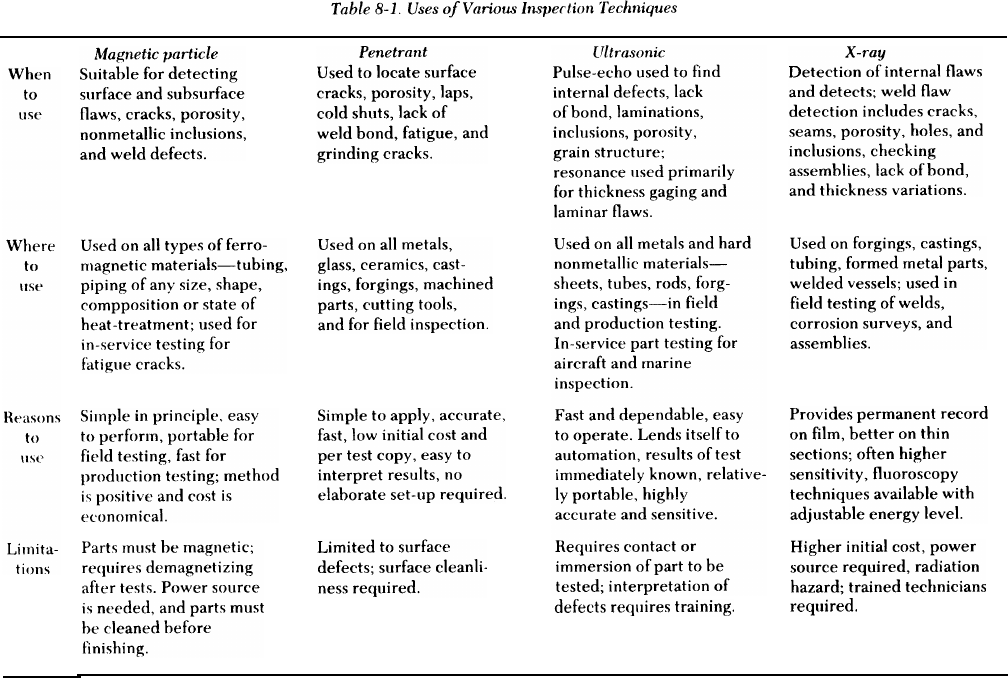
TM 5-805-7
b. Repair of defective welds. When a defective
weld is removed and the joint rewelded, the repair
weld should be inspected in the same way as the
original weld. The surfaces of the joint from which
the defective metal was removed should be
inspected to make sure the defect is completely
gone. Cracks should be checked very carefully. If
part of a crack is allowed to remain, it may propa-
gate through a repair weld; this must be avoided. A
series of inspections and metal removals may be
needed.
8-5. Visual inspection
Visual inspection, which is the most widely used
inspection method, is also the quickest, easiest, and
cheapest. The only equipment commonly used is a
magnifying glass (1 OX or less) and a flashlight or
extension. Other tools, such as a borescope and den-
tal mirrors, are useful for inspection inside vessels,
pipe, or confined areas. Visual inspection is always
required in weld evaluation. However, it will not
reveal interval defects or minute surface defects.
a. Examination prior to welding. Before welding,
the faces and edges should be examined for lamina-
tions, blisters, scabs, and seams. Heavy scale, oxide
films, grease, paint, oil, and dirt should be removed.
8-2
Edge preparation, alignment of parts, and fit-up
should be checked. Welding specifications should
be specific and state that all weld joints must be
inspected for compliance with requirements for
preparation, placement of consumable inserts, align-
ment, fit-up, and cleanliness.
b. Examination of welds during welding. Specifi-
cations should state that welds must be examined for
conformance to the qualified welding procedure,
detection of cracks in root pass, weld bead thick-
ness, slag and flux removal, and preheat and
interpass temperatures, where applicable.
c. Examination of welds after welding. Specifica-
tions should state that welds must ‘be examined for
cracks, contour and finish, bead reinforcement,
undercutting, overlap, and size of fillet welds. A
weld is considered acceptable by visual inspection
if:
(1) The weld has no surface flaws such as cracks,
porosity, unfilled craters, and crater cracks, particu-
larly at the end of welds.
(2) The weld metal and base metal are fused.
The edges of the weld metal should blend smoothly
and gradually into the adjacent base metal. There
should be no unacceptable overlap or undercut. —
(3) The weld profiles conform to referenced
standards and specifications. The faces of fillet welds
may be slightly convex, flat, or slightly concave, as
determined by use of suitable gages or templates (fig
8-1). The minimium size of each fillet leg is speci-
fied on the applicable drawings or welding proce-
dure. For butt welds, the amount of weld bead
reinforcement or the height of the surface of the
weld above the base metal surface should be no
greater than the welding specification allows (fig
8-2). (These standards should be developed early in
a job, and should represent acceptable, borderline,
and rejectable conditions. When there are several
critical joints, a separate standard may be prepared
for each.) The objective of all inspection methods is
to reveal any flaws or defects that may affect a part’s
service performance. Therefore, a joint should be
cleaned to remove anything that would hinder
inspection; e.g., slag and oxide films. Care should be
taken when a cleaning method such as shot-blasting
is used. Fine cracks and similar imperfections may
be sealed on the surface and made invisible. In vis-
ual inspection, it is essential to correctly interpret
and evaluate discrepancies in the appearance of
welds. Thus, the inspector needs to understand the
welding process in order to evaluate the quality of a
weld.
8-6. Magnetic particle inspection
Magnetic particle inspection is a nondestructive
method of detecting cracks, seams, inclusions, segre-
gations, porosity, lack of fusion, and similar flaws in
ferromagnetic materials such as steels and some
stainless steel alloys. This method of inspection can
detect discontinuities which may be too fine to be
seen with the naked eye; it can also detect some
subsurface defects, depending on the depth of flaw
cle inspection is advantageous because it can be
used on any magnetic material and is a rapid, inex-
pensive, and very reliable method when used by
trained inspectors. The main disadvantage is that it
applies only to magnetic materials and is not suited
for very small, deep-seated defects. The deeper the
defect is, the larger it must be for detection. Subsur-
face defects are easier to find when they have a
crack-like shape, such as lack of fusion in welds.
Welds with rough surfaces may present difficulties.
The process’ sensitivity is decreased by this rough-
ness, which mechanically interferes with the pattern
formed by iron oxide particles (see a below).
a. Principles of magnetic particle inspection. The
part to be inspected is magnetized by passing
through it a low-voltage, high-amperage electric
current, or by placing it in a magnetic field. Any
discontinuities such as cracks or lack of fusion dis-
rupt the magnetic field that has been established.
Electrical poles form at the ends of the flaws (fig
8-3). Fine magnetic particles applied to the surface
of the part are attracted to these electrical poles.
The concentration of particles can be seen and the
flaw located.
(1) The ease with which a magnetic flux can be
developed in a material is known as its permeability.
The property of any magnetic material to keep or
retain a magnetic field after the magnetizing current
is removed is called retentivity. Metals which lose
most of their magnetism as soon as the magnetizing
current is removed have low retentivity. Usually a
magnetized metal that has high permeability has low
retentivity, while a metal with a low permeability
has high retentivity. Construction steels generally
have low retentivity.
TM 5-805-7
I
TOE
(SIZE
8-4
TM 5-805-7
MAGNETIC
OF
LINES
FORCE
(2) DC, AC, and half-wave rectified current
may be used for magnetization. High-amperage,
low-voltage current is usually employed. If only sur-
face defects are to reinspected, AC can be used.
DC isused for the detection of subsurface disconti-
nuities because the current penetrates throughout
the part. Maximum sensitivity is provided by using
half-wave rectified, single-phase current. The pul-
sating field increases the particle mobility and
enables the particles to lineup more readily in weak
(3) The magnetic particles may be applied to
the weld either as a dry powder or as a suspension in
a light oil. The particles used are carefully selected
iron oxide particles of the proper size, shape, mag-
netic permeability, and retentivity. Dry particles are
in powder form and may be obtained in gray, red, or
black for contrast. These particles are applied using
hand shakers, spray bulbs, shaking screens, or an
airstream. Wet particles consist of particles sus-
pended in a light petroleum oil or kerosene. They
leakage fields. The pulse peaks also produce a can be applied- by
higher magnetizing force, which is needed in the from aerosol cans.
inspection of welds.
dipping, immersing, or spraying
The particles can be colored or
8-5

TM 5-805-7
have a fluorescent coating for viewing with ultravio-
let light. Wet particles provide better control and
standardization of the concentration of magnetic
particles through control of the concentration of sus-
pension. The wet procedure is more sensitive for the
detection of extremely small discontinuities below
the surface. Excess powder should be removed with
a stream of air of just enough force to carry the
excess away without disturbing lightly held powder
patterns.
(4) A method of applying the bath or particles
after the magnetizing current has been turned off is
called the “residual method. ” This method of apply-
ing the particles is effective on materials that will
retain their magnetism, i.e., those having high reten-
tivity. Steel that is relatively high in carbon and
other alloys responds most favorably to this method.
Most construction steels, however, have low reten-
tivity and will not hold a strong enough magnetic
field for this method. The recommended method for
construction steels is the “continuous method”; mag-
netizing is done at the same time the inspection
medium or particles are applied. This method is par-
ticularly useful when inspecting low carbon or alloy
steels. Because of their low retentivity, the parts
cannot maintain enough residual magnetism to hold
the particles needed to indicate a defect. Whether
wet or dry continuous methods are used, the inspec-
tor must be careful not to wash or shake off the
magnetic particle indications. Excessive current
must not be used during magnetizing because this
may produce irrelevant indications. Because of the
strong field produced, the continuous method is
especially useful in locating subsurface defects.
(5) When current is passed through a coil which
is wrapped around a material, a magnetic field is
produced in that material. This is called longitudinal
magnetization. When clamps or prods are used to
pass the current through the material, the procedure
is called circular magnetization. The two methods
produce magnetic fields in different directions,
thereby permitting the inspector to examine a mate-
rial for discontinuities in all directions.
b. Equipment. Various types of magnetizing
equipment are available. Units with electromagnets
and permanent magnets are commonly used, but are
designed for locating surface cracks. Although such
a unit can locate some subsurface defects, its depth
of penetration is severely limited. Direct current
equipment provides the great depth of penetration
needed to detect subsurface flaws. Some equipment
has both full-wave and half-wave rectified direct
current (HWDC). HWDC is particularly suitable for
use with dry particles because the pulsating field
provides excellent mobility to the powder particles,
Since most construction steels have low retentivity,
demagnetization is generally not required; however,
most magnetic particle inspection units can demag-
netize after inspection.
c. Inspection procedures. The procedures
decribed substantially conform to ASTM E 138 and
ASTM E 709. MIL-I-6868 and the ASME Boiler and
Pressure Vessel Code, section V, also outline inspec-
tion procedures. The surface of the weld usually
does not require grinding or smoothing before test-
ing. However, if the edges of the weld are undercut
or-if the bead surface is extremely rough, the weld
should be ground smooth and the edges blended
into the base metal surface before magnetic particle
inspection. The surface should be cleaned of all
grease, oil, loose rust, or water because such materi-
als interfere with the particles which indicate
defects.
(1) The “prod method” of weld inspection is
widely used. Portable prod-type electrical contacts
are pressed against the surface of the material next
to the weld, as shown in figure 8-4. The prods
should not be spaced more than 8 inches apart. A
shorter prod spacing with a minimum of 3 inches
may be used to increase sensitivity. When the prods
are positioned, the operator turns the current on
and applies the magnetic particle powders. The cur-
rent is turned off before the prods are removed in
order to prevent arcing. At least two separate exami-
nations should be done for each area. The prods are
repositioned so that the lines of flux from one opera-
tion are approximately perpendicular to the lines of
flux from the previous operation. Contact clamps
sometimes can be used instead of prods.
(2) The weld must be examined immediately
after the excess powder has been removed and
before the position of the prods is changed. Surface
defects appear as sharp indications, while subsurface
indications are broad, diffuse patterns.
(3) Acceptance standards are written based on
the object’s intended use. Standards vary, but most
specify similar limits for possible defects.
8-7. Penetrant inspection
Penetrant inspection is a sensitive, nondestructive
method of locating minute flaws open to the surface
— for example, cracks, pores, and leaks. It is partic-
ularly valuable for examining nonmagnetic materi-
als, on which magnetic particle inspection cannot be
used. Penetrant inspection is used extensively for
exposing surface defects in aluminum, magnesium,
and austenitic stainless steel weldments, and for
locating leaks in all welds. Dye penetrant proce-
dures usually require ground surfaces, although
some “as-welded” surfaces can be inspected. —
8-6
TM 5-805-7
(Improper grinding can smear the surface and close
surface openings of the defects.) The efficiency of
the method depends on the inspector’s ability to
recognize and evaluate the visual indications of
flaws.
a. Principles of liquid penetrant inspection. In liq-
uid penetrant inspection, both visible and fluores-
cent, the surface of a material is coated with a film of
penetrating liquid (fig 8-5). The liquid is allowed to
seep into any flaws that are open to the surface, and
the excess surface film is removed. A developer is
then applied; it draws the penetrant from a disconti-
nuity to the surface so the inspector can see the
flaw.(1) Liquid penetrant inspection can be done
quickly and easily; it costs less per foot of weld
inspected than any other nondestructive method
except visual inspection. The initial cost of training,
equipment, materials, and supplies is much less than
that of any other inspection method. However, sur-
face porosity and improper surface cleanliness
reduce the sensitivity of the inspection technique;
contaminants such as water, oil, and grease can
cover or fill discontinuities so the penetrant does not
enter. Penetrant inspection methods are used to
check nonporous materials for defects open to the
surface. The following surface defects can be found
with penetrant inspection: all types of cracks in con-
nection with welding, grinding, fatigue, forging,
etc.; porosity; seams; laps; cold shuts; or lack of
bond between two metals. Since penetrant methods
can locate only surface defects, cleanliness is
extremely important.
(2) penetrant inspection is equally applicable to
both large and small weldments. In the petrochemi-
cal industries, pressure vessels and piping, which are
often made of nonmagnetic materials, can be
inspected for surface cracks and porosity by this
method. Penetrant inspection can be used to detect
cracks, pores, and leaks through the lining in clad
vessels. This method can be applied to all types of
welded linings. Shallow cracks and porosity can be
distinguished from those that extend through the
lining (leakers). The indications for all cracks and
porosity bleed out rapidly or spread upon applica-
tion of dry developer.
b. Equipment. The equipment used in penetrant
inspection is portable: aerosol cans of cleaner, dye,
and developer. When fluorescent penetrant is used,
a black light source in the 36-angstrom unit range
and a hood or dark area are required. Portable
inspection kits for field use are commercially
available.
Inspection procedures. The procedure
described substantially conforms to ASTM E 165.
(1) Either the visible or fluorescent dye pene-
trant method can be used between a series of
stringer welds or on a completed weld. There are
three types of penetrant: water washable, post emul-
sifying, and solvent removable. Intermixing these
penetrant materials is not permitted. Procedures for
inspection depend on the specific type of penetrant
and the method used; therefore, only a general
approach is outlined in this manual.
8-7
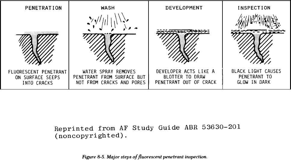
TM 5-805-7
(2) The surface must be clean and dry. The dis-
continuity must be free of oil, water, or other con-
taminants so that the void is open and the penetrant
can enter. The method of cleaning the weld area is
unimportant part of the test procedure.
(3) The penetrant is applied to the surface by
spraying or brushing. The inspector must allow
enough time for the penetrant to enter all disconti-
nuities. A minimum time of 10 minutes at a tempera-
ture of 60 to 125 degrees F is normally
recommended. The smaller the defect or the higher
the sensitivity required, the longer the penetrating
time must be.
(4) Excess penetrant can be removed from the
surface by wiping with an absorbent cloth, either
dry or moistened with a solvent. Removing the sur-
face penetrant by spraying with solvents gives a
clean surface; however, penetrant can be washed
out of defects if the spraying is not done very care-
fully. Therefore, this technique is not
recommended.
(5) The developer should be applied carefully
so it does not produce a coat so thick that indications
are masked. The developer acts as a blotter to draw
the penetrant to the surface, where it can be seen
with the naked eye or viewed under an ultraviolet
light (in fluorescent penetrant inspection). The
developer must be applied as soon as possible after
the penetrant removal operation; the time between
the application of the developer and interpretation
should be controlled ((6) below). The true size and
type of defect are difficult to appraise if the dye
diffuses too much in the developer. The recom-
mended practice is to observe the surface during the
application of the developer in order to see certain
indications which might tend to bleed out quickly. —
(6) Interpretation must be done within a speci-
fied time. The specification might indicate, for
example, that interpretation must be done no sooner
than 7 minutes and no later than 30 minutes after
application of the developer.
(7) Most acceptance standards specify similar
limits on cracks and linear indications, rounded indi-
cations of a specific size and quantity, or number of
indications in a given area.
8-8. Radiographic inspection
Radiographic inspection is a nondestructive testing
technique which involves taking a picture of the
internal condition of a material. This picture is pro-
duced by directing a beam of short wave-length
radiation (X-rays or gamma rays) through a material
that would be opaque to ordinary light. This radia-
tion exposes a film which is placed on the opposite
side of the material. When developed, the film
(called a radiograph) shows the presence or absence
of internal defects. Radiographic inspection is called
for in many specifications because it provides a per-
manent record. Different types of internal defects
can be identified, and flaws such as cracks, porosity,
lack of fusion, and entrapped slag can be differenti-
ated. Radiographic inspection has its limitations,
8-8
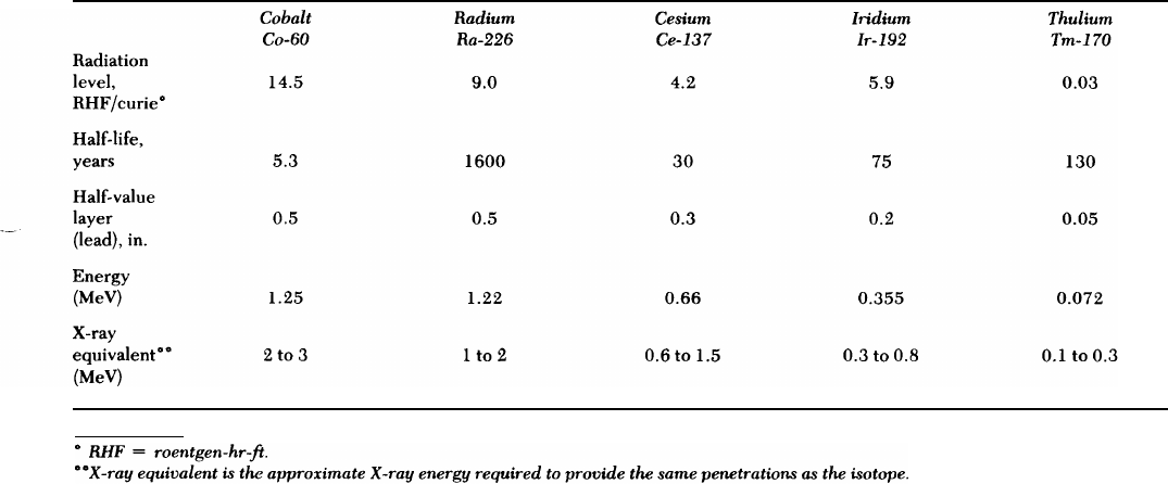
however. These include high initial cost, radiation
hazards, the need for highly trained technicians, and
the requirement that certain defects, particularly
cracks and lack of fusion, be correctly oriented with
respect to the beam of radiation (if the orientation is
incorrect, the defects will not be recorded on the
film).
a. Principles of radiographic inspection. Radiogra-
phy uses the penetrating power of radiation to
reveal the interior of a material. Radiation from a
source passes through an object and causes a change
in the film emulsion when the film is developed. The
amount of darkening of the film, referred to as den-
sity, depends on the amount of film exposure caused
by radiation penetrating the thick or thin sections of
the object. The procedure for radiographic testing is
shown schematically
TM 5-805-7
in figure 8-6. The cone of radi-
—
ation could also represent a gamma-ray capsule con-
taining radioactive material such as those listed in
table 8-2. Not all of the radiation penetrates the
weld. Some is absorbed, the amount depending on
the density and thickness of the weld and on the
material being inspected. A cavity, such as a blow-
hole in the weld interior, leaves less metal for the
radiation to pass through, so that the amount
absorbed by the weld will vary in the defective
region. These variations, if measured or recorded on
a radiation-sensitive film, produce an image that will
indicate the presence of the defect. In applying radi-
ographic inspection, care is required to insure that
the procedure is carried out properly. Inadequate
technique can result in poor sensitivity, irrelevant
indications, or other problems.
Table 8-2. Characteristics of Radioisotope Sources
b. Equipment. The equipment required for radio-
graphic inspection is either an X-ray machine or
gamma source, film, penetrameters, film developing
equipment, and viewing equipment, as described
below. In ASTM E 94, the table “Type of Industrial
Radiographic Film” lists film characteristics; the
table “Guide for Selection of Film” lists recommen-
dations for radiation sources and film types to be
used with a variety of alloys in different section
thicknesses.
(1) X-ray machines are available in a wide range
of sizes and voltage ratings. The kilovoltage rating
required depends on the thickness and type of metal
to be radiographed.
(2) Radioactive sources and x-radiation have
similar effects on radiation-sensitive film. The differ-
ence between the rays is the origin. X-ray radiation
is generated in an X-ray tube, while gamma radia-
tion is emitted from a radioactive isotope. Table 8-2
gives some of the more important characteristics of
radioisotopes. These figures are rough estimates,
but do show the relative positions of the sources in
order of their energy.
(3) Gamma radiography is used frequently in
construction work because no external power is
required, which makes it suitable for inspection in
remote areas; the cost of the equipment and source
is much less than that of X-ray equipment with a
comparable kilovolt range; the isotope equipment is
more easily transported; the equipment is rugged
8-9
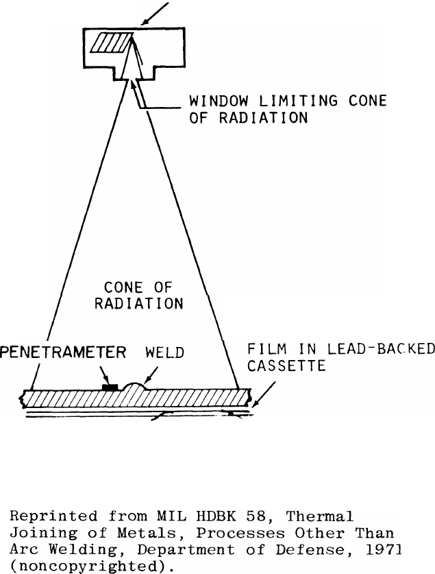
TM 5-805-7
SOURCE OF X-RAYS
Figure 8-6. Radiographic setup.
and simple to operate and maintain; and confined
spaces can reinspected because of the small source
size. However, there are several disadvantages to
isotope sources. Among these is a severe radiation
hazard. These sources must be stored in locked,
shielded cases, and handled very carefully when
used. Personnel performing radiography must be
highly trained and must relicensed by the Nuclear
Regulatory Commission. The radiographs generally
have considerably less contrast than films exposed
by X-radiation. The cost and trouble of replacing
isotopes with short half-lives can be a factor in
deciding whether to use X-ray or gamma radiogra-
phy on a project.
(4) The image quality of a radiograph can be
shown by using a penetrameter. This is a piece of
metal similar to that being inspected. It is placed
near the weld on the source side during radiography
to determine the degree of sensitivity disclosed in a
radiograph. For example, if a penetrameter with a
thickness of 2 percent of the material to be
inspected can be seen on the radiograph, it means
that the radiograph contrast sensitivity is 2 percent
or better, since the radiographic technique
employed can show an object thickness difference of
2 percent or more. In most cases, 2 percent contrast
sensitivity is considered satisfactory. However, for
critical purposes such as nuclear components, pres-
sure vessels, and piping for compressed gasses and
8-10
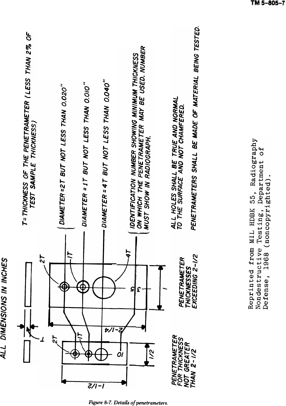
TM 5-805-7
bridges, a lower percentage is desired. In other clas-
ses of work, a higher percentage maybe acceptable.
To demonstrate detail sensitivity, holes in the pene-
trameter are used; their diameters are, in terms of
effect, artificial flaws of known dimensions. The
holes are usually expressed in the thickness of the
penetrameter. Construction details of penetrame-
ters are shown in figure 8-7.
(5) The radiographic film must be Class 1, extra
fine grain, and Class 2, fine grain. Both classes of
film give high contrast. Extra fine grain film has
greater sensitivity than fine grain (i.e., reveal
smaller discontinuities). However, exposure times
may be as much as 50 percent longer since more
exposure to radiation is needed to develop an image.
Film holders must be flexible, and intensification
screens must be made of lead. Front screens should
be 0.005 inch and back screens 0.010 inch.
(6) Film processing equipment can be either
manual or automatic. Processing systems should con-
tain separate tanks for developing, short stop or
washing, fixing, and final washing. Film driers must
not cause processing defects.
(7) A densitometer or a density strip is needed
to make sure film density requirements have been
met. Density, a measure of the degree of blackness,
is a function of exposure time and intensity of the
radiation to which film is subjected. The radiogra-
pher controls these variables.
c. Inspection procedure. The procedure described
substantially conforms to ASTM E 94, ASTM E 142,
and AWS D1.1. Procedures are also outlined in
MIL-R-11470, MIL-STD-453, and the ASME Boiler
and Pressure Vessel Code, section V.
(1) Radiographs must be made by either the X-
ray or isotope radiation methods. If the level 2-2T
radiography- is required, all radiographs should
reveal discontinuities with thicknesses equal to or
greater than 2 percent of the thickness of the thin-
ner part joined by the weld being examined. In the
“2-2T” designation, the first digit 2 means 2 percent
sensitivity and 2T the diameter of the hole in the
penetrameter which must be clearly visible in the
radiograph. Class 1 or 2 film must be used. The film
must be clean and free of processing defects. It must
have a density of not less than 1.5 nor more than
4.0, although densities within the range of 2.5 to 3.5
are preferred. Radiographs will show:
(a) The smallest hole in each penetrameter as
specified in the specification.
(b) The radiograph identification and
location.
(2) Welds that are to be radiographed need not
be ground or otherwise smoothed for radiographic
testing unless the surface irregularities interfere
with the desired radiographic image. When weld
reinforcement or backing is not removed, shims of
the material being radiographed must be placed _
under the penetrameter. These shims must make the
total thickness of material between the penetrame-
ter and the film at least equal to the average thick-
ness of the weld measured through its reinforcement
and backing.
(3 Pnetrameters must be placed on the side of
the work near the radiation source adjacent and par-
allel to the weld, A radiograph identification mark
and two location identification marks, all of which
are to show in the radiograph, must be placed on the
material at each radiograph location.
(4) Film holders must be placed tightly against
the test item whenever possible. Shielding beyond
the film holder should be provided when practical.
The operator must use radiation detection devices,
including survey meters, film badges, and
dosimeters.
(5) Film must be processed so that the radi-
ographs are of high quality. Films containing
mechanical, chemical, or other processing defects
that could interfere with proper interpretation of
the radiograph are not acceptable.
(6) Radiographs are viewed using a high-inten-
sity light source that has adjustable levels from dim
to a brightness that penetrates without difficulty
radiographs with a density of 4.0. Radiographs must
be checked for proper placement of identification
numbers and penetrameters. All indications must be
interpreted and marked.
(7) The interpreter must be familiar with the
standards for acceptance or rejection. Most stan-
dards agree about the types of discontinuities which
are not acceptable, but there are some differences.
Defects such as cracks or zones of incomplete fusion
or penetration would be cause for rejection. Poros-
ity of one size or aggregate lengths might also be
cause for rejection, while other sizes or lengths
would be acceptable. Reference radiographs are
indicated in ASTM E 94, MIL-STD-779, and MIL-R-
45774.
8-9. Ultrasonic inspection
Ultrasonic inspection is a rapid, efficient, nonde-
structive method of detecting, locating, and measur-
ing both surface and subsurface defects in
weldments and/or base materials. An ultrasonic is an
energy wave form with frequencies above 20,000
Hertz. The ultrasonic wave is introduced into the
material being tested by a piezoelectric transducer
placed in contact with the test specimen. The ultra-
sound enters the specimen and is reflected back to
the transducer when it encounters an interface that
8-12
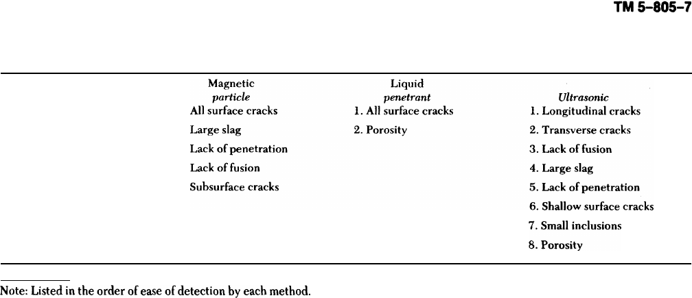
Table 8-3. Comparison of Ultrasonics With Other Techniques
Radiography
1.
Porosity
1.
2. Inclusions 2.
3. Large cracks 3.
4. Lack of fusion 4.
5. Lack of penetration 5.
6. Small cracks
could be a flaw or the back surface of the material.
These vibrations are converted to electric signals,
amplified, and displayed on a cathode ray tube
(CRT) screen as indications. Because of the high fre-
quency (above the range for the human ear), the
short wave-length allows small flaws to be detected.
Ultrasonics is one of the most commonly used tech-
niques for subsurface flaw detection in weldments.
Ultrasonic inspection is specified to detect both
internal and surface flaws in all types of welded
joints. Defects such as slag inclusions, porosity, lack
of fusion (cold shuts), lack of penetration (root
defects), and longitudinal and transverse cracks can
be detected. Since only one inspection surface is
usually required, many types of welded joints can be
satisfactorily inspected. When a flaw is found, it can
be measured and evaluated. Dimensions such as
depth, width, and length can be measured if one
surface is accessible.
a. Principles of ultrasonic inspection. Most
ultrasonic testing is performed with a single straight
or angle beam transducer depending on the design
of the weld joint to be inspected. The transducer,
sometimes referred to as a crystal or search unit, can
transform electrical voltage generated by the
ultrasonic unit into mechanical vibrations or ultra-
sound. The transducer also can convert the
returning vibrations from a test specimen into elec-
trical energy; they are displayed in this form on the
ultrasonic unit’s CRT. This capability to convert
from electrical energy to mechanical vibrations and
back again is called the piezoelectric effect. The
electrical signal striking the transducer, usually not
more than 1 microsecond in duration, makes the
transducer vibrate during the driving period. The
duration of the pulse is short, so that returning or
reflected echoes from defects or boundaries lying
close to the surface will appear as a separate indica-
tion, as shown in figure 8-8. Such a presentation is
called an A-scan and is a “time versus amplitude
display.” From the pip or pulse location on the CRT
time line and its height of amplitude, the relative
depth and size of the discontinuity can be estimated.
(1) Ultrasonic inspection has many advantages
over other methods. It is fast, and the equipment is
compact and portable. Unlike radiographic inspec-
tion, it involves no time delay while film is being
processed and poses no radiation hazard to persons
working in the inspection area. Indications of flaws
can be seen immediately on the CRT. Both internal
and surface flaws can be detected (though shallow
surface cracks are more easily and reliably detected
with magnetic particle or liquid penetrant). Since
there are no expandable materials, the inspection
can be performed faster and at a lower cost than
radiography. Certain types of defects not readily
detectable by other inspection methods can be
found by ultrasonics. By using calibrated standards
and a few calculations, the inspector can classify he
indications as irrelevant, acceptable, or unaccept-
able. Ultrasonic inspection has a higher sensitivity
level than does radiographic inspection. Ultrasonic
inspection is more sensitive to crack detection as the
material thickness increases; for radiographic
inspection, the opposite is true. Table 8-3 compares
ultrasonics and radiographic, magnetic particle, and
liquid penetrant inspection.
(2) Ultrasonic inspection has some limitations
that have restricted its use. Chief among these are
the difficulty in interpreting the oscilloscope pat-
terns and the need for standards to calibrate the
instrument. This procedure produces no permanent
records showing flaws and their location. A high
degree of operator skill and training is required to
interpret the oscilloscope patterns reliably. Flaws,
such as cracks, oriented parallel to the sound beam
may not be detected. This means a different
ultrasonic inspection technique must be used. The
8-13
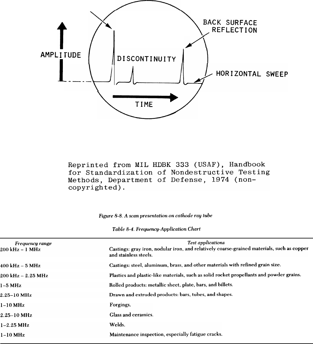
TM 5-805-7
INITIAL
PULSE
8-14
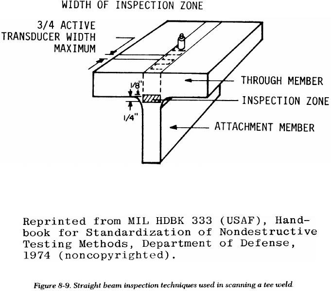
TM 5-805-7
surface of the material must be free from weld spat-
ter and must be smooth enough to allow effective
coupling between the transducer and the material.
Surface roughness can cause scattering and absorp-
tion of the sound. Also, a rough surface will create
undue wear on the crystal surface of the transducer,
causing premature failure. A viscous coupling agent
such as glycerine is necessary to eliminate the com-
pressible air which prevents sound (mechanical
vibrations) from entering the material from the
transducer. The coupling agent can be any liquid,
grease, or paste which fills surface depressions or
pits.
(3) Two important considerations in selecting a
transducer are its diameter and operating frequency.
The higher the frequency, the greater the sensitivity
will be. This advantage may be offset if lower fre-
quencies are needed to penetrate coarse-grained or
very thick materials. Table 8-4 shows the ultrasonic
frequency ranges that may be used on various
applications.
(4) Transducers generally fall into three groups:
straight beam, angle beam, and surface wave.
(a) Longitudinal wave, sometimes called
straight beam, directs the sound waves into the
material in a direction perpendicular to the surface
of the part. This method is used mainly to detect
subsurface defects in base metals, but should be
specified for some weld inspection, as shown in fig-
ure 8-9.
(b) The angle beam method, sometimes called
shear wave, is usually the required procedure for
weld inspection. The vibrational wave is introduced
into the material at an angle of 30 to 80 degrees
from the perpendicular to the material surface. This
angle will vary with the material’s thickness. A lon-
gitudinal transducer is mounted on plastic wedges
cut at specific angles, usually 70, 60, or 45 degrees.
By varying the position of the angle beam search
unit with respect to the weld, flaws at any location in
the weld joint can be detected, as shown in figure
8-10.
(c) Surface waves are generated by mode con-
version so that the refracted wave will travel along
the surface. Surface waves follow curved surfaces
and detect surface and near-surface defects. This
technique has many applications in industry, but is
seldom used for weld inspection.
b. Equipment. The equipment for ultrasonic weld
inspection is a pulse-echo-type ultrasonic test unit
that can generate, receive, and present on a CRT
screen pulses in the frequency range from 0.2 to 10
megahertz.
8-15
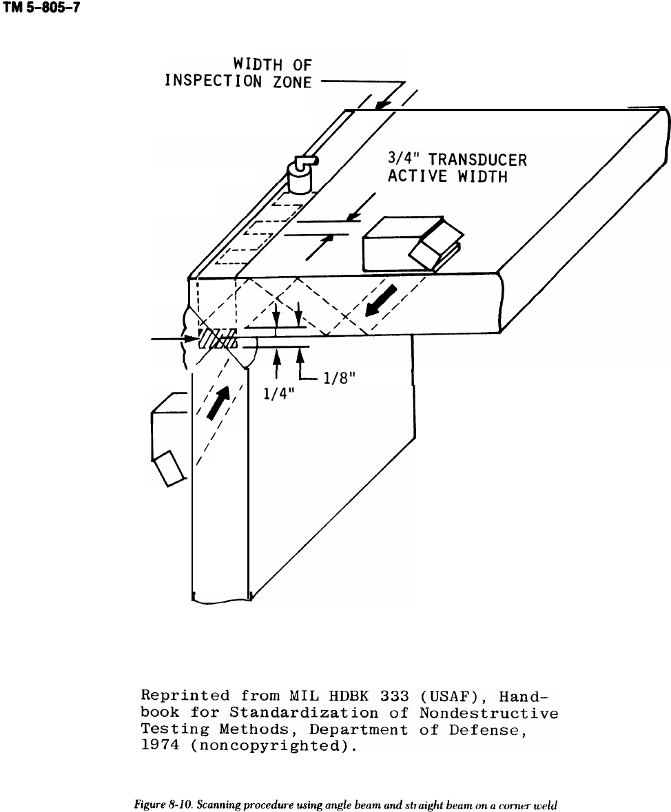
INSPECTION
ZONE
8-16
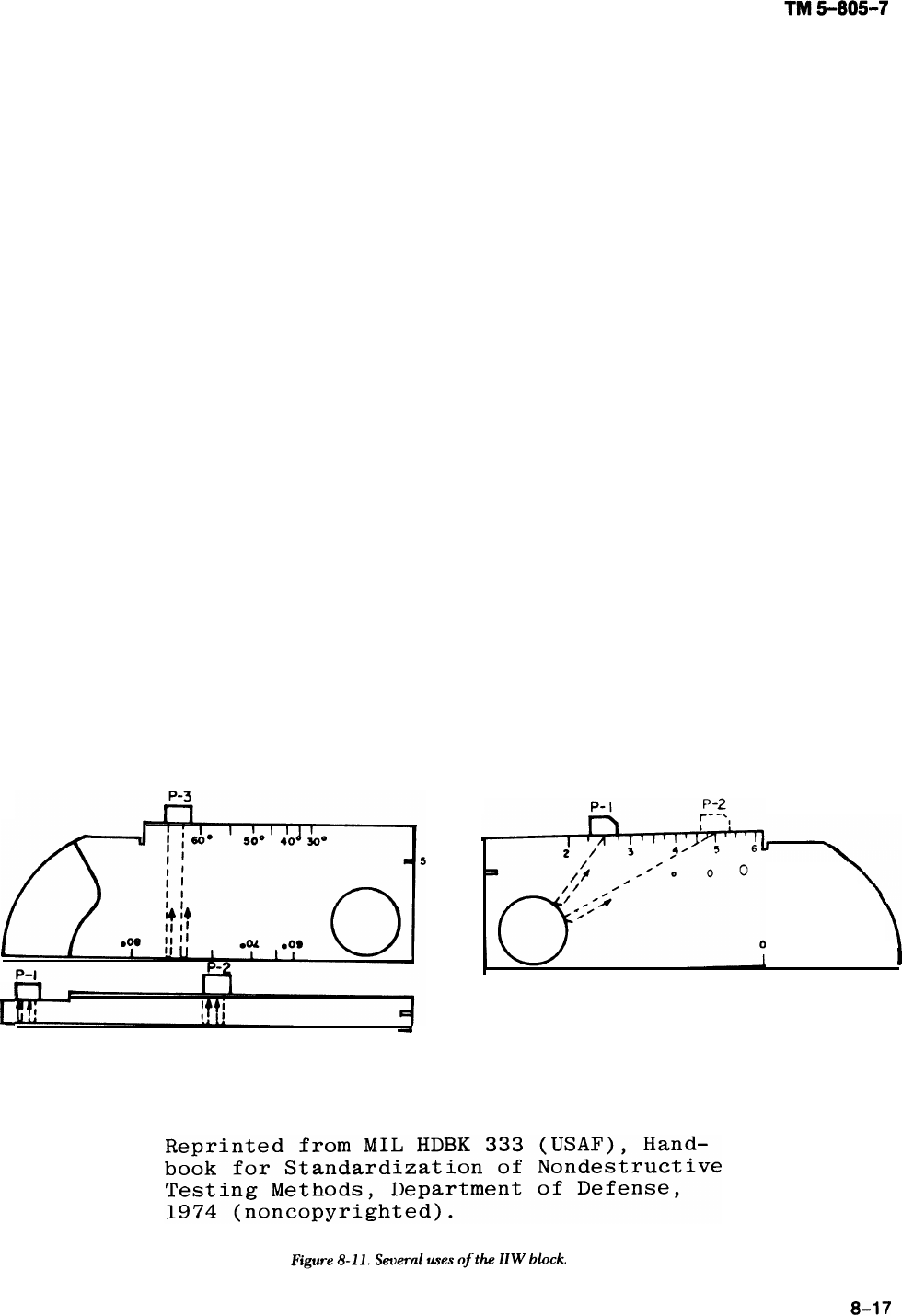
(1) Transducers will consist of straight beam and
angle beam types in the frequency range of 2 to 2.4
megahertz. Angle beam transducer angles of 70, 60,
and 45 degrees are to be used.
(2) A coupling material is needed to exclude air.
Typical coupling materials include water, oil,
grease, pastes, and glycerine. Generally, the
rougher the surface, the more viscous the coupling
agent required.
(3) Ultrasonic reference blocks are usually
needed to check the sensitivity and performance of
ultrasonic instrumentation and transducers for
inspecting critical welds. Most standards are manu-
factured with artificial defects in the form of drilled
holes with flat, round, or conical bottoms or slots
machined into the surface. AWS D1.1 recommends
several standards, the most common being the Inter-
national Institute of Welding (IIW) reference block
shown in figure 8-11.
Inspection procedures. The procedures
described conform to ASTM E 164 and AWS D1.1.
Ultrasonic inspection procedures are also outlined in
appendix U to the ASME Boiler and Pressure Vessel
Code, Section VIII, Division 1, and in Section V,
Article 5. In ultrasonic inspection, the most impor-
tant phase is the interpretation of indications. In
preparing for an ultrasonic inspection, an operator
must consider certain parameters: type and size of
transducer, couplant, scanning procedures, peaking
techniques, frequency, pulse length, linearity of
indications, distance/time relationship, and sensitiv-
ity/time relationship. Other parameters are speci-
men properties, such as material sound/velocity;
specific acoustic impedance; part geometry; mate-
rial attenuation; and noise level. Each signal peak
along the scan line represents a place in time where
the acoustic energy has encountered an interface or
a multiple of a previously generated signal. By
knowing the beam path and spread, the operator can
interpret the signal and separate relevant from irrel-
evant indications. The operator must consider
amplitude/distance response and amplitude/area
response when determining flaw size. The shape and
orientation of the flaw also affect the signal ampli-
tude. In attempting to determine flaw size, an opera-
tor must watch both the flaw signal amplitude and
the loss of amplitude of the back reflection.
(1) Before any inspection, the ultrasonic unit
must be calibrated for sensitivity and horizontal
sweep (distance); a calibration block or other recog-
nized method must be used.
(2) The surface of the weld area to be inspected
must be free of weld spatter (which will cause rapid
wear of the transducer), grease, dirt, oil, and loose
scale (which will cause scattering and attenuation).
Tight layers of paint need not be removed unless the
thickness exceeds 10 roils.
(3) A coupling agent must be used between the
search unit and the metal. The base metal is first
examined for lamella flaws using a straight beam
search unit, and then is inspected using the angle
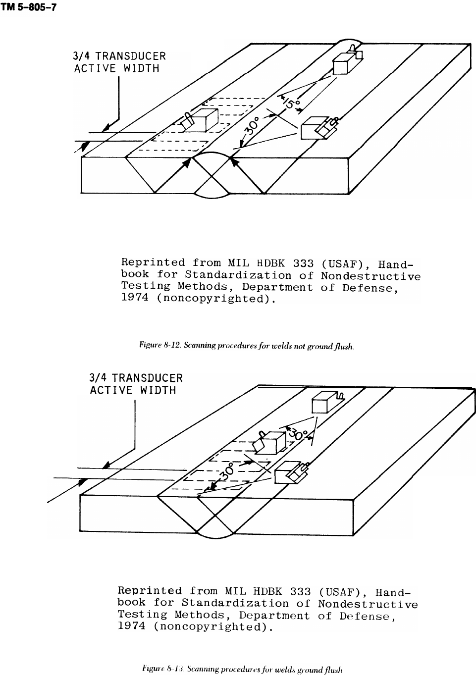
8-18

TM 5-805-7
beam. Where possible, all welds should be scanned
from both sides on the beam face for longitudinal
and transverse discontinuities. The search unit must
be placed on the surface with the sound beam aimed
about 90 degrees to the weld and manipulated later-
ally and longitudinally so that the ultrasonic beam
passes through all of the weld metal.
(4) For welds not ground flush (fig 8-12), shear
wave is used in four different scans. For longitudinal
flaws, sound is directed into the weld from each
side. The transducer is oscillated to the left and right
with an included angle of about 30 degrees. To
detect transverse defects, the transducer is placed
on the base metal at the edge of the weld. It is then
positioned so that the sound beam makes about a 15-
degree angle to the longitudinal axis of the weld. To
scan, the search is moved along the weld edge from
both sides. For welds ground flush (fig 8-13), scan-
ning is done similarly. However, to detect longitudi-
nal flaws the transducer is moved across the weld.
And for transverse defects, the transducer is oscil-
lated left and right through a 30-degree angle while
continuously advancing along the top of the weld.
(5) When an indication of a flaw appears on the
CRT, the location and position of the transducer are
recorded. By using graphs, calculators, or guides,
the operator can accurately locate the position of
the defect in the weld. By using applicable charts
and attenuation factors, the weld discontinuity can
be accepted or rejected.
8-10. Destructive testing
In procedure qualification testing and welding
development work, metallographic specimens are
sometimes removed from a structure to check the
quality of the weldment. These tests are used to
determine visually the characteristics of the welds.
Metallographic test samples are sections cut through
the welds in any desired plane, then polished and
etched to reveal the structure. These specimens may
be examined with the naked eye or with various
magnifications,
including microscopic, Among the
characteristics that can be checked are the sound-
ness, location, and depth of penetration of the
welds; the metallurgical structures of the weld,
fusion zone, and heat affected zone; the extent and
distribution of undesirable inclusions in the weld;
hardness gradients; and the number of weld passes.
When metallographic specimens are removed from
any part of a structure, repairs must be made by
qualified welders or welding operators
using
accepted welding procedures. Peening or heat treat
ment may be required to develop the full strength of
a. Test methods. There are three categories of
destructive tests: chemical, hardness, and mechani-
cal tests.
(1) Chemical tests. Chemical tests are generally
used to validate the chemical composition or the
corrosion resistance of the base and weld metals.
Particular compositions of the metals involved, for
example, may be examined for conformance to
specifications. In addition, chemical analysis of the
weld metal can show whether welding produced the
expected results, or whether it introduced undesir-
able constituents into the weld metal. corrosion
tests demonstrate a weldment’s capability to with-
stand the corrosive environment to be encountered in
service. Because of the cost and time involved, a
weldment usually cannot be tested for corrosion
resistance by actual use under service conditions.
Therefore, accelerated corrosion tests that can be
conducted under laboratory conditions have been
developed.
(2) Hardness tests. Hardness tests measure the
resistance of materials to wear. For most metals,
ductility and corrosion resistance decrease as the
hardness increases. Since each operation during
welding has metallurgical effects, some specifica-
tions call for an upper limit to the acceptable hard-
ness of various areas of weld. Hardness testing is
done with equipment which, under a specific load,
forces a small hardened steel ball or diamond point
into the. surface of the metal. The depth of penetra-
tion is either measured directly by the machine, or
inferred from the dimensions of the impression. By
associating a number with each possible impression
depth, the inspector can develop a hardness scale.
This testing approach is used by the three most com-
mon hardness measuring devices: the Brinell,
Rockwell, and Vickers hardness testers. Hardness
numbers may vary from method to method because
of differences in the formulas used to define hard-
ness numbers, in the material type and shape used to
make the impression, and in the imposed load. How-
ever, tables of approximately equivalent hardness
numbers have been constructed.
(3) Mechanical tests. Mechanical tests (exclusive
of hardness) have been designed to test several weld
properties.
(a) Tensile tests are conducted on specimens
machined from a test weld and are used to measure
the strength of the weld joint. Specimens are usually
taken perpendicular to the weld, which is centered
in the specimen (fig 8-14). However, specimens are
sometimes taken along the weld and consist entirely
of weld metal. Specimens may have round or rectan-
gular cross sections, depending on the requirements
of the applicable welding code. The testing machine

TM 5-805-7
applies a tensile force until the specimen ruptures.
From readings on the machine and measurements of
the specimen before and after the test, properties
such as yield point or yield strength, ultimate
strength, and ductility are calculated. The primary
purpose of the test is to demonstrate that the weld
metal deposited by the selected procedures meets
or exceeds the minimum values specified in the
applicable code or specifications.
(b) Guided bend tests indicate a weld’s ductil-
ity. Test specimens are described as root-bend, face-
bend, or side-bend, depending on the surface
stretched in bending. Rectangular test specimens
similar to those prepared for tensile tests are
machined or ground to remove any weld reinforce-
ment. A test jig, such as that shown in figure 8-15, is
used to make the bend. with the plunger removed,
the specimen is placed across the shoulders of the
jig with the weld centered. The plunger is then
forced down until the specimen is bent into a U-
shape. The elongation of the tension surface is
determined by the relationship between the thick-
ness of the specimen and the radius of the die. The
specimen fails if it has cracks or other open defects
greater than a specified number and size, or if it
fractures.
(c) Free bend tests, also for ductility, use
specimens similar to those for guided bend tests.
Before the test, gage lines are inscribed across the
width of the sample of deposited weld metal. These
lines mark off a distance about 1/8 inch less than the
width of the weld. The sample is given an initial
bend (fig 8-1 6) by supporting the ends or shoulders
on rollers, then forcing the center down until the
specimen takes a permanent set. Next, a testing
machine or device (fig 8-16) is used to compress the
sample longitudinally until a crack or depression
appears on the convex face of the specimen, or until
the specimen is bent double. The load is removed
immediately if a defect appears before the specimen
is bent double. Percent elongation is calculated from
the initial and final distances between the gage
marks.
(d) Shear tests of fillet welds are conducted by
pulling specimens apart in a testing machine. The
dimensions of the specimens make it easy to use the
8-20
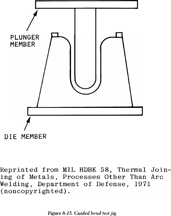
TM 5-805-7
FORCE
+
test results to obtain shear strength in pounds per
linear inch of weld. Figure 8-17 shows the shear test
specimen and indicates where to machine specimens
from test weldment.
(e) Nick-break tests are required in some
welding codes to detect weld defects. The nick-
break test specimens similar to a rectangular ten-
sile-test specimen, except that notches are cut at the
center of the weld. The specimen is then broken
either by pulling in tension or by bending. The spec-
imen is forced to break in the weld metal because of
the notches. After the specimen has been broken,
the fracture surfaces are examined for weld-metal
defects. If there are more than the minimum
allowed, the weld is rejected.
(f) Various types of impact tests are some-
times used to test the fracture toughness of the weld
metal when low-alloy, high-strength steels are being
welded. These tests measure the weld metal’s capa-
bility to resist crack propagation under low stress.
b. Sampling technique, Removal of samples by
sectioning is an accepted method of weld inspection
approved by various pressure-vessel codes. Because
the cavity must later be repaired by rewelding, the
method is sometimes considered a destructive test.
Samples may be taken for chemical analysis, etch
tests, subsize tension, or impact tests. The specific
method of removing samples depends on the size of
specimen needed; hole saws, bolt cutters, cold
chisels, or trepanning tools — a special power tool
with a hemispherical saw — are often used for sam-
ple removal. The samples must be carefully selected
to be representative of the weld or base metal being
checked.
8-21
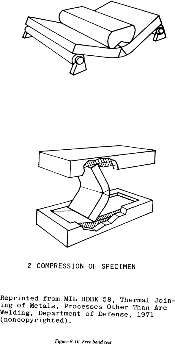
TM 5-805-7
1 INITIAL SET
8-22
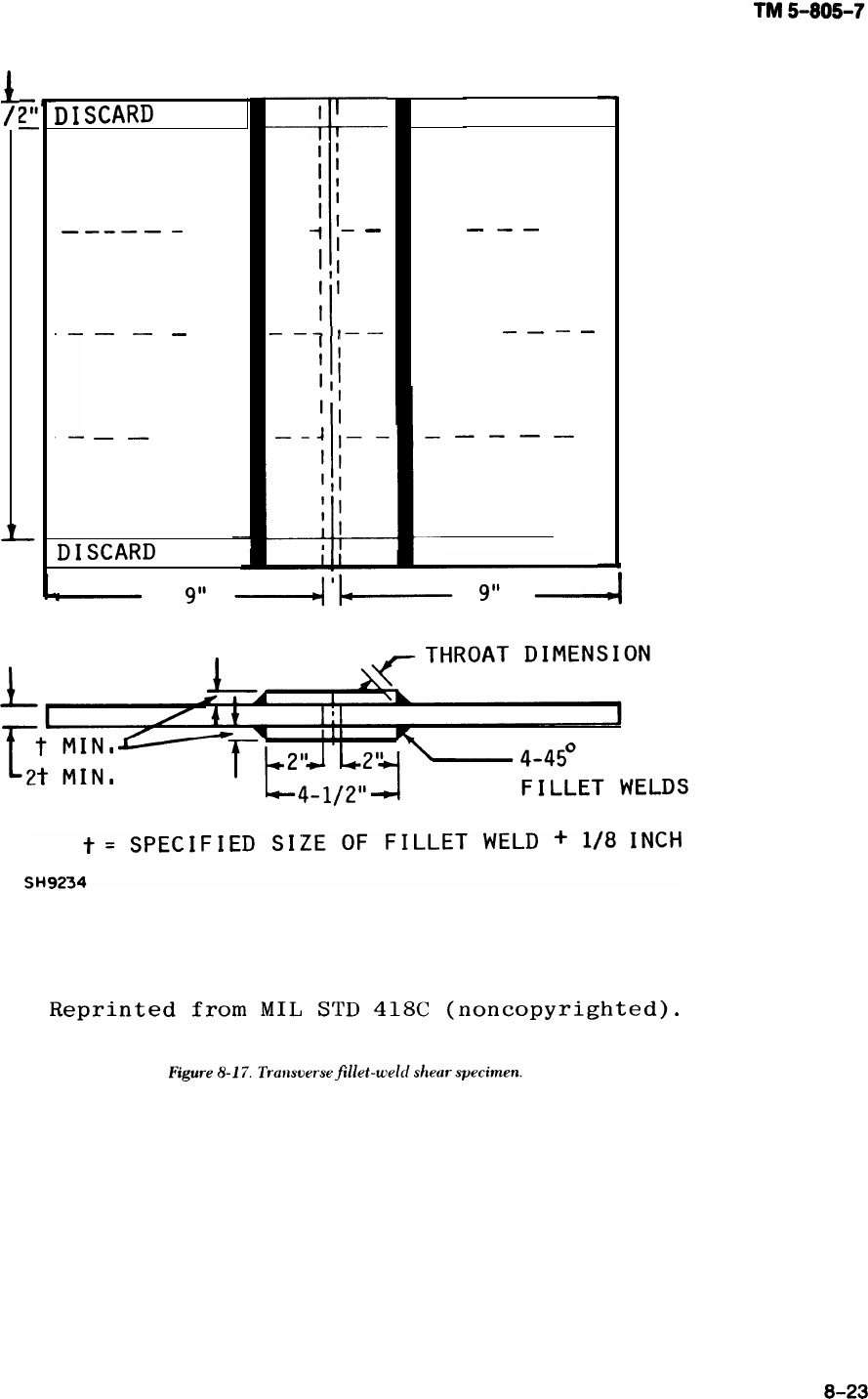
1
1/2”
r
TM 5-805-7
8-11. Leak testing
Leak tests are similar to proof tests for closed pres-
sure vessels; the container being tested is filled with
a fluid at a specified pressure. The choice of liquid
or gas depends on the purpose of the container and
the leakage that can be tolerated. For example, con-
tainers that are watertight may not be oiltight or
gastight. Leaks can be detected in several ways. For
oil or water, visual inspection of the outside of the
pressure vessel may suffice. Leaking air or gas can
be detected by the sound of the escaping gas, by use
of a soap film that forms bubbles as gas escapes
beneath it, or by immersion in a liquid in which the
escaping gas forms bubbles. For hydrostatic or gas
tests, a pressure gage attached to the vessel indicates
leaks by the drop in pressure after the tests begin.
Dyes introduced into liquids and tracers introduced
into gases can also indicate leakage. Weld defects
that cause leakage are not always detected by the
usual nondestructive testing methods. A tight crack
or fissure may not appear on a radiograph, yet will
form a leak path. A production operation, such as
forming or a proof test, may make leaks develop in
an otherwise acceptable weld joint. A leak test is
usually done on the completed vessel if all of the
weld joints can be inspected; at this stage there will
be no more fabricating operations after the inspec-
tion. Inspection is easier if the vessel is empty, The
most common types of leak testing are discussed
below.
a. The pressure-rise test method is used to see
whether any leaks exist. In this test, the part being
inspected is attached to a vacuum pump and evacu-
ated to a pressure of ().5 psi absolute. when this
pressure is reached, the connections to the vacuum
pump are sealed off, and the internal pressure of the
part is measured immediately. The pressure is mea-
sured again after at least 5 minutes (with the item
still sealed off from the vacuum pump). If the pres-
sure in the evacuated space remains essentially con-
stant, the welds are free of leaks. If there is a
pressure rise, at least one leak is present, and the
helium-leak test described in b below must be used,
b. The helium-leak test is more precise than the
pressure-rise method and is used to find the exact
location of these leaks. Helium-leak testing is slow,
however, so it normally is not used to inspect large
items unless a leak definitely exists. This inspection
method requires the use of a helium mass spectrom-
eter to detect the presence of helium gas. The mass
spectrometer is connected to the pumping system
between the vacuum pump and the item being
inspected. Then the item is evacuated by a vacuum
pump to a pressure of less than 50 microns of mer-
cury. The mass spectrometer can detect helium in
the evacuated
directed at the
atmosphere. If
space. A small jet of helium gas is
side of the weld joint exposed to the
there is a leak, some of the helium is
sucked through it into the evacuated space, and the
mass spectrometer immediately indicates the pres-
ence of helium. Of course, if no leak is present, no
helium will enter the evacuated space and no indica-
tion will appear on the mass spectrometer. To deter-
mine the exact location of leaks, the jet of helium is
moved along the surface of the weld joint. At the
same time, an inspector carefully watches the mass
spectrometer. If there is an indication, the leak is at
the point where the helium jet is hitting the surface
of the weld joint.
c. To detect leaks, the ultrasonic translator detec-
tor uses the ultrasonic sounds of gas molecules
escaping from a vessel under pressure or vacuum.
The sound created is in the frequency range of
35,000 and 45,000 Hertz, which is above the range
of human hearing and is therefore classified as
ultrasonic. Certain characteristics of these frequen-
cies are useful for detections. They are outside the
range of most plant and machine noise, and the short
wave length of these frequencies permits the use of
highly directional microphones. Any system or ves-
sel that can be pressurized or evacuated to a pres-
sure of 3 psi can be inspected. The operator simply
listens to the translated ultrasonic sounds while
moving a hand-held probe along the weld (in the
same way that a flashlight. is used to illuminate the
suspected leak locations). The detectors are simple
to operate and require minimum operator training.
d. Some of the following tests — particularly the
air-soap solution test — can be conducted on a ves-
sel during or after assembly. The inspector can
locate large defects in order to reduce the time
needed for final leak testing. After testing, vessels
should be thoroughly cleaned to remove all traces of
soap solution.
(1) Hydrostatic test. This test should conform to
the applicable requirements of a particular vessel or
system. only distilled or deionized (demineralized)
water having a pH of 6 to 8 and an impurity content
not greater than 5 ppm is used. Traces of water
should be removed from the inside before final leak
testing is begun.
(2) Water submersion test. In this test, the ves-
sel is completely submerged in clean water. The
interior is pressurized with gas, but the design pres-
sure must not be exceeded. The size and number of
any gas bubbles indicates the size of leaks,
(3) Soap solution test, In this test, the vessel is
subjected to an internal gas pressure not exceeding
the design pressure. A soap or equivalent solution is
8-24
applied so that connections and welded joints can be
examined for leaks.
(4) Air-ammonia test. This test involves intro-
ducing air into the vessel until so percent of the
design pressure is needed. Anhydrous ammonia is
then introduced into the vessel until 55 percent of
the design pressure is reached; air is then reintro-
duced until the design pressure is reached. Each
joint is carefully examined by using as a probe either
a swab wetted with 10N solution of muriatic acid
(HCL), a sulphur candle, or sulphur dioxide. A wisp
of white smoke indicates a leak.
(5) Halide torch test. In this test, the vessel is
pressurized to a value not exceeding the design
pressure; a mixture of SO percent Freon and carbon
dioxide or 50 percent Freon and nitrogen is used.
Each joint is carefully probed with a halide torch to
detect leaks, which are indicated by a change in the
color of the flame.
(6) Halogen snifter test. A Freon inert gas mix-
ture is introduced into the vessel until the design
pressure is reached. About 1 ounce of Freon for
every 30 cubic feet of vessel volume is required.
The inspector passes the probe of a halogen vapor
analyzer over the area to be explored. This probe is
held about 1/2 inch from the surface being tested
and is moved at about 1/2 inch per second. Since the
instrument is responsive to cigarette smoke and
vapor from newly dry-cleaned clothing, the air
should be kept clean where the test is being done. In
addition, the test should be done in a substantially
draft-free enclosure.
8-25

CHAPTER 9
SAFETY
9-1. General
The safety of the welding operators, foreman, and
inspectors at the construction job site is a primary
consideration. All precautions must be taken to
ensure the safe completion of the construction proj-
ect. The Occupational Safety and Health Adminis-
tration (OSHA) of the U.S. Department of Labor has
issued Health and Safety Standards covering such
topics as radiation protection, welding, cutting and
heating, use of ladders and scaffolds, steel erection,
and hearing and head protection. Most of the stan-
dards for welding are in Code of Federal Regula-
tions, Title 29, Chapter XVII, Part 1910.
9-2. Hazards
a. Welding and cutting. When welding and cutting
is being done, three major safety hazards must be
considered and adequate precautions taken. First,
the eyes and exposed skin must be protected from
the intense light radiation and the heat of the weld-
ing arc and flames. Second, welding, cutting, and
grinding operations must be prevented from causing
fires. Third, care must be taken in handling, weld-
ing, and cutting containers that have held combusti-
ble or toxic materials. Cutting or welding also must
be done carefully if materials in the fluxes, coatings,
and base metals produce explosive or toxic fumes
when heated. There are other safety considerations
for welding and cutting operations; all personnel
involved should be familiar with the requirements of
the OSHA safety standards. The AWS also publishes
and distributes information on safe welding and cut-
ting practices.
b. Radiographic inspection. Radiographic inspec-
tion involves ionizing radiation. Individuals can be
protected from this radiation primarily by shielding
and distance. For information on safe procedures
and practices for radiography, refer to Title 10,
Code of Federal Regulations; the American Society
for Non-Destructive Testing; and AWS.
c. Noise levels. Hearing loss, either partial or
total, is a direct result of working without proper ear
protection at steel construction sites. Contractors
must conform to OSHA standards for permissible
noise levels and time durations.
d. Air quality. Welding and cutting operations
increase dust and ozone levels near the construc-
tion. Welding galvanized steel also releases zinc
oxide, which can be very hazardous to welding oper-
ators and their assistants. Therefore, proper ventila-
tion should be provided for all personnel at the
welding site. Particular attention should be paid to
safety when personnel are welding inside large
tanks. There should always be ventilation for such an
operation.
9-1

TM 5-805-7
APPENDIX A
REFERENCES
‘----
Government Publications
Department of Defense.
MIL-C-15726E Copper-Nickel Alloy, Rod, Flat Products (Flat Wire, Strip, Sheet, Bar and Plate),
and Forgings.
MIL-E-22200F General Specification for Electrodes, Welding Covers.
MIL-E-18193 Electrode, Welding, Carbon Steel and Alloy Steel, Bare, Coiled.
MIL-E-19822A Electrodes, Welding, Bare, High-Yield Steel.
MIL-E-23765/lD Electrodes and Rods-Welding, Bare, Solid, Mild and Alloy Steel.
MIL-E-23765/2B Electrode and Rod-Welding, Bare, Solid, Low Alloy Steel.
MIL-I-6868 Inspection Process, Magnetic Particle.
MIL-R-11468 Radiographic Inspection, Soundness Requirements for Arc and Gas Welds in Steel,
MIL-R-11470 Radiographic Inspection, Qualification of Equipment, Operators and Procedures.
MIL-R-45774(2) Radiographic Inspection, Soundness Requirements for Fusion Welds in Aluminum
and Magnesium Missile Components.
MIL-STD-00453B Radiographic Inspection.
MIL-STD-271E Nondestructive Testing Requirement for Metals.
MIL-STD-410D Nondestructive Testing Personnel Qualification and Certification (Eddy Current,
Liquid Penetrant, Magnetic Particle, Radiographic and Ultrasonic).
MIL-STD-779 Reference Radiographic for Steel Fusion Welds, Vol. I, Vol. II, Vol. III.
Department of the Army.
TM 9-237 Welding Theory and Application.
Nuclear Regulatory Commission.
1717 H St., NW, Washington, D.C. 20555
General Services Administration (GSA).
18th and F Streets, NW, Washington, D.C. 20405 Code of Federal Regulations, Title 10, Chapter I, Parts
20 and 34, and Title 29, Chapter XVII, Part 1910, published by the Office of the Federal Register,
National Archives and Records Service (Updated Annually)
Occupational Safety and Health Administration (OSHA),
Bureau of National Affairs, 1231 25th St., NW, Washington, D.C. 20037
Nongovernment Publications
Aerospace Materials Specification (AMS), Society of Automotive Engineers, 400 Commonwealth Drive,
Warrendale, PA 15096
AMS 2635B Radiographic Inspection (updated periodically).
AMS 2640H Magnetic Particle Inspection (updated periodically).
AMS 2645G Fluorescent Penetrant Inspection (updated periodically).
AMS 2646B Contrast Dye Penetrant Inspection (updated periodically).
American Institute of Steel Construction (AISC), 400 N. Michigan Ave., 8th Floor, Chicago, IL 60611
Manual of Steel Construction
Aluminum Association, inc. (AA), 818 Connecticut Avenue, NW Washington, DC 20006
American Concrete Institute (ACI), P.O. Box 19150, Detroit, MI 48219
ACI 318-77 Building Code Requirements for Reinforced Concrete.
American Iron and Steel Institute (AISI), 1000 16th Street, NW, Washington, DC 20036
Industry Practices for Ultrasonic Nondestructive Testing of Steel Tubular Products.
Ultrasonic Inspection of Steel Products.
American National Standards institute (ANSI,, 1430 Broadway, New York, NY 10018
ANSI B31.1-80 Power Piping.
A-1

TM 5-805-7
American Petroleum Institute (API), 1801 K Street, Washington, DC 20006
API-STD-1104 API Specification for Field Welding of Pipelines.
American Society for Metals (ASM), Metals park, OH 44073
Metals Handbook, ASM Handbook Committee, Volume 6: Welding and Brazing (9th
Ed., 1983).
American Society for Nondestructive Testing (ASNT), 3200 Riverside Drive, Columbus, OH 43221
ASNT-TC-lA Recommended Practice Nondestructive Testing Personnel Qualification and
Certification (updated periodically).
Nondestructive Testing Handbook, Vols. I and II, Robert McMaster, cd., The Ronald
Press Co.
American Society for Testing and Materials (ASTM), 1916 Race Street, Philadelphia, PA 19103
ASTM A514-82
ASTM A517/
A517M-82
ASTM A36-81
ASTM A242-81
ASTM A441-81
ASTM A572-82
ASTM A53-82
ASTM A106-82
ASTM A139-74
ASTM A691-81
ASTM A203-81
ASTM A588-81
ASTM A134-80
ASTM A671-80
ASTM A672-81
ASTM A710-79
ASTM E390-75
ASTM E709-80
ASTM E94-77
ASTM E138-81
ASTM E142-77
ASTM E164-81
ASTM E165-80
Specification for High-Yield Strength, Quenched and-Tempered Alloy Steel Plate,
Suitable for Welding. (Rev. A)
Specification for Pressure Vessel Alloy Steel, High-Strength, Quenched and Tem-
pered.
Specification for Structural Steel. (Rev. A)
Specification for High-Strength Low-Alloy Structural Steel.
Specification for High-Strength Low-Alloy Structural Manganese Vanadium Steel.
Specification for High-Strength Low-Alloy Columbium-Vanadium Steels of
Structural Quality.
Specification for Pipe, Steel, Black and Hot-Dipped Zinc-Coated Welded and
Seamless.
Specification for Seamless Carbon Steel Pipe for High-Temperature Service.
Specification for Electric-Fusion (Arc) -Welded Steel Pipe (Sizes 4 in. and over) (R
1980).
Specification for Carbon and Alloy Steel Pipe, Electric-Fusion-Welded for High-
Pressure Services at High Temperatures.
Specification for Pressure Vessel Plates Alloy Steel, Nickel.
Specification for High-Strength Low-Alloy Structural Steel with 50,000 psi
Minimum Yield Point to 4 in. Thick.
Specification for Pipe, Steel, Electric-Fusion (Arc) -Welded (Sizes NPS16 and over).
Specification for Electric-Fusion-Welded Steel Pipe for Atmospheric and Lower
Temperatures.
Specification for Electric-Fusion-Welded Steel Pipe for High-Pressure Service at
Moderate Temperatures.
Specification for Low Carbon Age-Hardening Nickel-Copper-Chromium-
Molybdenum-Columbium and Nickel-Copper-Columbium Alloy Steels.
Radiographs for Steel Fusion Welds.
Practice for Magnetic Particle Examination.
Radiographic Testing, Standard for Recommended Practice.
Standard Method for Wet Magnetic Particle Inspection.
Standard Method for Controlling Quality of Radiographic Testing.
Standard Recommended Practice for Ultrasonic Contact Examination of Weldments.
Standard Recommended Practice for Liquid Penetrant Inspection Method.
American Society of Mechanical Engineers (ASME), United Engineering Center, 345 East Forty-Seventh
Street, New York, NY 10017
Boiler and Pressure Vessel Code (1974). Section II, Material Specification. Section
III, Nuclear Power Plant Components.
Section V, Nondestructive Examination. Section VIII, Pressure Vessels. Section IX,
Welding Qualification.
American Welding Society (AWS), P.O. Box 351040,550 LeJeune Road, Miami, FL 33135
AWS A3.0-80 Welding Terms and Definitions Including Terms for Brazing, Soldering, Thermal
Spraying, and Thermal Cutting.
AWS A5.1-81 Specifications for Carbon Steel Covered Arc Welding Electrodes.

TM 5-805-7
AWS A5.4-81
-AWS A5.5-81
AWS A5.9-81
AWS A5.14-76
AWS A5.17-80
AWS A5.18-79
AWS A5.20-79
AWS A5.22-80
AWS A5.23-80
AWS D1.1-83
AWS A5.11-76
AWS A5.10-80
AWS D12.1-75
AWS D19.0-72
Specification for Corrosion-Resisting Chromium and Chromium-Nickel Steel
Covered Electrodes.
Specification for Low-Alloy Steel Covered Arc-Welding Electrodes.
Specification for Corrosion-Resisting and Chromium-Nickel Steel Bare and
Composite Metal Cored and Stranded Arc Welding Electrodes and Welding Rods.
Specification for Nickel and Nickel Alloy Bare Welding Rods and Electrodes.
Specification for Bare Carbon Steel Electrodes and Fluxes for Submerged Arc
Welding.
Specification for Carbon Steel Filler Metals Gas Shielded Arc Welding.
Specification for Carbon Steel Electrodes for Flux Cored Arc Welding.
Specification for Flux-Cored Corrosion-Resisting Chromium and Chromium-Nickel
Steel Electrodes.
Specification for Bare Low-Alloy Steel Electrodes and Fluxes for Submerged Arc
Welding.
Structural Welding Code—Steel.
Specifications for Nickel and Nickel Alloy Covered Welding Electrodes.
Specification for Aluminum and Aluminum Alloy Bare Welding Rods and Electrodes.
Reinforcing Steel Welding Codes. (superseded by AWS D1.4-79)
Welding Zinc-Coated Material (superseded by AWS C2.2)
American Welding Society (AWS), P. O. Box 351040,550 LeJeune Road, Miami, FL 33135
Welding Handbook
Volume 1, Fundamentals of Welding, 6th Edition (1968)
Volume 2, Welding Processes, 7th Edition (1978)
Volume 3, Welding Processes, 7th Edition (1980)
Volume 4, Metals and Their Weldability, 6th Edition (1968)
Volume 5, Application of Welding, 6th Edition (1968)
Welding Research Council, 345 E. 47th Street, New York, NY 10017
Weldability of Steels, Robert D. Stout and W. D’Orville Doty, 1971

TM 5-805-7
APPENDIX B
QUALIFICATION TESTING
B-1. General
A project manager must determine the ability of a
manufacturer, contractor, fabricator, or erector to
produce quality welds consistently. Qualification
requirements insure that properly trained welding
personnel use approved procedures and adequate
equipment. The qualification requirement includes
a wide range of materials, procedures, processes,
equipment, and personnel. For a construction proj-
ect, a weld quality assurance program uses qualifica-
tion testing for the welding procedure and the
welding personnel.
B-2. Procedure qualification
a. Purpose. The purpose of the procedure qualifi-
cation test is to demonstrate that certain procedures
produce welds of suitable mechanical properties and
soundness.
b. Method. Small test plates with the same chemi-
cal composition as the production weldments are
welded with the proposed production procedure.
The joint geometry, welding process, welding
parameters, filler metals, shielding materials, and
welding position used to make the test plates are
also the same as or equivalent to those for the actual
production weldment. The plates are then tested to
see whether the weld’s soundness and mechanical
properties meet the acceptance standards of the
production weld. The requirements for qualifying a
welding procedure are governed by the codes con-
cerning the weld’s specific application.
c. Testing.
(1) The procedure qualification plates are usu-
ally tested nondestructively, with the same tests
required for the production weld. The plate must
meet the nondestructive test acceptance standards
of the code applicable to the weld’s specified use,
(2) Tensile and bend tests are normally used for
procedure qualification plates. Some welds also
require the nick-break test, impact tests, and metal-
lographic examination.
(3) Tensile test specimens are removed so that
the long axis of the specimen is transverse to the
welding direction and is centered on the weld’s cen-
terline. The actual specimen geometry varies widely
to meet requirements of various welding codes. The
specimens may be round or flat and may have a
reduced section; the flat specimen may have the
weld reinforcement removed. To be acceptable, the
tensile specimens must exceed the minimum
requirements in the welding code for the type of
material being used. The primary purpose of the
tensile test is to demonstrate that the weld metal
deposited by the selected procedure is strong
enough to meet the design requirements.
(4) Three types of bend tests are used for proce-
dure qualification. Root-bend and face-bend tests
are used on materials up to 3/8-inch thick. Side-
bend tests are used for thicker materials. The names
of these procedures refer to the surface that is
stretched in tension during bending. In the root-
bend test, the root of the weld is placed in tension.
In the face-bend and side-bend tests, the weld
crown and a transverse cross section, respectively,
are put in tension during bending. The specimens
are machined or ground to remove the weld rein-
forcement and then bent around a die of specified
radius. The amount of elongation of the tension sur-
face is usually about 20 percent. The bend test indi-
cates the ductility of the weld metal and detects the
small defects in the weld that tend to open up and
become readily visible. The acceptance criterion for
bend tests is that no fissures exceeding a specified
length (usually 1/8 inch) be present on the tension
surface after bending.
(5) Some welding codes require nick-break tests
to detect weld defects. The nick-break test specimen
is similar to a rectangular tensile-test specimen,
except that notches are cut at the center of the weld.
The specimen is then broken either by pulling it in
tension or by bending it. The notches cause the
specimen to break in the weld metal. After this, the
fracture surfaces are examined for weld metal
defects. If there are too many defects, the weld is
rejected.
(6) Various types of impact tests are sometimes
used to test the fracture toughness of the weld metal
when low-alloy, high-strength steels are being
welded. These tests are designed to measure the
capability of the weld metal to resist crack propaga-
tion under low-stress conditions.
(7) Metallographic examination involves polish-
ing, etching, and examining weld sections under low
magnification to detect porosity, cracks, or other
defects in the weld metal. This test maybe required
for certain applications, particularly when the weld

TM 5-805-7
configuration does not allow meaningful test results
to be obtained by the mechanical property test
methods discussed above.
d. Usefulness of procedure qualification. The pro-
cedure qualification test is useful for demonstrating
the quality and properties of the weld before its
production. Since it is almost impossible to duplicate
actual production welding conditions, this test is
conducted under simulated conditions. In an actual
welding situation, conditions arise that could not
have been anticipated when the procedure was
being qualified (e.g., abrupt weather changes).
Therefore, the production phase must be closely
supervised so that such conditions are noticed as
they occur. If these factors can alter the quality of
the weld, they should be evaluated.
B-3. Welder and welding operator
qualification
a. General. Weld quality is determined by the spe-
cific welding procedure and by the ability of the
welder or welding operator to apply that procedure.
Welder qualification tests determine the operator’s
ability to produce sound welds that conform to the
procedure specification. The tests indicate whether
the welder or welding operator can produce accept-
able welds, but do not indicate whether he/she will
produce acceptable welds during actual production.
Consequently, during the construction process, the
welds must be inspected before and after
completion.
b. Method. In personnel qualification testing, the
welder or welding operator is required to weld a
small test plate in a material which is the same as or
similar to that of the actual production weldment.
The qualified procedure for that weldment must be
used. The qualification plate is then nondestruc-
tively examined and destructively tested. These
steps insure that the weld soundness meets the mini-
mum acceptance standards of the welding code gov-
erning the particular application.
c. Testing. Testing methods used for personnel
qualification tests usually include the nondestructive
examinations applicable to the specific job and any
combination of the bend tests described previously.
In some instances, nick-break tests may also be
required because they examine weld soundness
rather than weld metal properties. Tensile tests are
usually not required for examining personnel
qualifications.
d. Usefulness of personnel qualifications. The per-
sonnel qualification tests assure a customer that the
welders have been screened and are capable of pro-
ducing welds that conform to procedure and specifi-
cation requirements. These tests do not guarantee
that the welder will produce satisfactory welds each
time, but do tend to eliminate welders whose work
is never acceptable. As with procedure qualifica-
tions, the value of personnel qualifications increases
when the production welding conditions are simu-
lated as closely as possible.