WinPV User Guide Version 06 DJM 3 Win PVUser
User Manual: DJM-3
Open the PDF directly: View PDF ![]() .
.
Page Count: 143 [warning: Documents this large are best viewed by clicking the View PDF Link!]
- Cover
- Copyright
- Table of Contents
- 1 - Welcome to Dynojet WinPV Software
- 2 - Getting Started
- 3 - Working with WinPV
- 4 - Working with Power Vision
- 5 - Working with Power Vision Log Tuner
- Index

©2010-2011 Dynojet Research, Inc. All Rights Reserved.
User Guide for the Power Vision and WinPV Software.
This manual is copyrighted by Dynojet Research, Inc., hereafter referred to as Dynojet,
and all rights are reserved. This manual is furnished under license and may only be used
or copied in accordance with the terms of such license. This manual is furnished for
informational use only, is subject to change without notice, and should not be construed
as a commitment by Dynojet. Dynojet assumes no responsibility or liability for any error
or inaccuracies that may appear in this manual. Except as permitted by such license, no
part of this manual may be reproduced, stored in a retrieval system, or transmitted, in any
form or by any means, electronic, mechanical, recording, or otherwise, without the prior
written permission of Dynojet.
The Dynojet logo is a trademark of Dynojet Research, Inc.
Any trademarks, trade names, service marks, or service names owned or registered by any
other company and used in this guide are the property of their respective companies.
Dynojet Research, Inc., 2191 Mendenhall Drive, North Las Vegas, Nevada 89081, USA.
Printed in USA.
Part Number: 2011.08.23.06 Version 6 (08/2011)

WinPV User Guide
i
T
ABLE
OF
C
ONTENTS
Chapter 1 Welcome to Dynojet WinPV Software
Notice . . . . . . . . . . . . . . . . . . . . . . . . . . . . . . . . . . . . . . . . . 1-1
Contacting Dynojet . . . . . . . . . . . . . . . . . . . . . . . . . . . . . . . 1-1
Conventions . . . . . . . . . . . . . . . . . . . . . . . . . . . . . . . . . . . . 1-2
Chapter 2 Getting Started
Power Vision Driver Installation . . . . . . . . . . . . . . . . . . . . . . . 2-2
Windows XP Driver Installation . . . . . . . . . . . . . . . . . . . . . . . 2-2
Windows Vista and Windows 7 Driver Installation . . . . . . . . . . 2-4
Checking the WinPV Update Client . . . . . . . . . . . . . . . . . . . . . 2-5
Installing the Power Vision on the Motorcycle . . . . . . . . . . . . . 2-9
Power Vision Tune File Management . . . . . . . . . . . . . . . . . . . 2-11
Flashing a Dynojet Pre-Configured Tune File . . . . . . . . . . . . . 2-13
Flashing a Custom Tune File . . . . . . . . . . . . . . . . . . . . . . . . 2-16
Loading a Copy of the Original Tune File or a Copy
of the Current Tune File . . . . . . . . . . . . . . . . . . . . . . . . . . . 2-18
Chapter 3 Working with WinPV
WinPV User Interface . . . . . . . . . . . . . . . . . . . . . . . . . . . . . . . 3-2
WinPV Menus . . . . . . . . . . . . . . . . . . . . . . . . . . . . . . . . . . . . . 3-3
File Menu. . . . . . . . . . . . . . . . . . . . . . . . . . . . . . . . . . . . . . . . . 3-5
To Open a Power Vision Tune File (.PVT) . . . . . . . . . . . . . . . . . 3-5
To Save a Power Vision Tune File (.PVT) . . . . . . . . . . . . . . . . . 3-6
To Import a Power Commander Map File (.pvm;.djm) . . . . . . . 3-7
To Save All Values . . . . . . . . . . . . . . . . . . . . . . . . . . . . . . . . 3-9
To Save Selected Values . . . . . . . . . . . . . . . . . . . . . . . . . . . 3-10
To Save Selected Values—Append . . . . . . . . . . . . . . . . . . . . 3-11
To Load All Values . . . . . . . . . . . . . . . . . . . . . . . . . . . . . . . 3-12
To Load Selected Values . . . . . . . . . . . . . . . . . . . . . . . . . . . 3-14
To Exit the WinPV Software . . . . . . . . . . . . . . . . . . . . . . . . . 3-15

WinPV User Guide
TABLE OF CONTENTS
ii
Edit Menu . . . . . . . . . . . . . . . . . . . . . . . . . . . . . . . . . . . . . . . 3-16
To Undo . . . . . . . . . . . . . . . . . . . . . . . . . . . . . . . . . . . . . . 3-16
To Redo . . . . . . . . . . . . . . . . . . . . . . . . . . . . . . . . . . . . . . 3-16
To Cut/Copy/Paste Selected Values . . . . . . . . . . . . . . . . . . . 3-16
To Smooth Selected Values . . . . . . . . . . . . . . . . . . . . . . . . . 3-16
To Interpolate Selected Values . . . . . . . . . . . . . . . . . . . . . . 3-16
To Interpolate Selected Horizontal Values . . . . . . . . . . . . . . . 3-16
To Interpolate Selected Vertical Values . . . . . . . . . . . . . . . . . 3-16
PowerVision Menu . . . . . . . . . . . . . . . . . . . . . . . . . . . . . . . . . 3-17
To View the PowerVision Information . . . . . . . . . . . . . . . . . . 3-17
To Get a Tune from the Power Vision . . . . . . . . . . . . . . . . . . 3-17
To Send a Tune to the Power Vision . . . . . . . . . . . . . . . . . . 3-18
To Get ECM Data from the Power Vision . . . . . . . . . . . . . . . . 3-19
To Send the Original Tune to the Power Vision . . . . . . . . . . . 3-21
To Send a Stock File to the Power Vision . . . . . . . . . . . . . . . 3-21
To Get a Log from the Power Vision . . . . . . . . . . . . . . . . . . . 3-22
To Exit PC Link Mode . . . . . . . . . . . . . . . . . . . . . . . . . . . . . 3-23
Compare Menu . . . . . . . . . . . . . . . . . . . . . . . . . . . . . . . . . . . 3-24
To Load a Compare File . . . . . . . . . . . . . . . . . . . . . . . . . . . 3-24
To Close the Compare File . . . . . . . . . . . . . . . . . . . . . . . . . 3-24
To View the Active File . . . . . . . . . . . . . . . . . . . . . . . . . . . . 3-24
To View the Compare File . . . . . . . . . . . . . . . . . . . . . . . . . . 3-25
To View Delta . . . . . . . . . . . . . . . . . . . . . . . . . . . . . . . . . . 3-25
To Choose Cell Colors . . . . . . . . . . . . . . . . . . . . . . . . . . . . 3-25
Setup Menu. . . . . . . . . . . . . . . . . . . . . . . . . . . . . . . . . . . . . . 3-26
To Setup the Options . . . . . . . . . . . . . . . . . . . . . . . . . . . . . 3-26
To Apply the License . . . . . . . . . . . . . . . . . . . . . . . . . . . . . 3-29
View Menu. . . . . . . . . . . . . . . . . . . . . . . . . . . . . . . . . . . . . . . 3-30
To View the Standard Toolbar . . . . . . . . . . . . . . . . . . . . . . . 3-30
To View the Cell Math Toolbar . . . . . . . . . . . . . . . . . . . . . . . 3-30
To View the PowerVision Toolbar . . . . . . . . . . . . . . . . . . . . . 3-30
To View the Compare Toolbar . . . . . . . . . . . . . . . . . . . . . . . 3-30
To Reset the User Interface . . . . . . . . . . . . . . . . . . . . . . . . . 3-30
Help Menu . . . . . . . . . . . . . . . . . . . . . . . . . . . . . . . . . . . . . . . 3-31
To View the About Window . . . . . . . . . . . . . . . . . . . . . . . . . 3-31
To View the Power Vision Help Files . . . . . . . . . . . . . . . . . . . 3-31
WinPV Toolbar . . . . . . . . . . . . . . . . . . . . . . . . . . . . . . . . . . . 3-32
Standard Toolbar . . . . . . . . . . . . . . . . . . . . . . . . . . . . . . . . 3-32
PowerVision Toolbar . . . . . . . . . . . . . . . . . . . . . . . . . . . . . . 3-33
Cell Math Toolbar . . . . . . . . . . . . . . . . . . . . . . . . . . . . . . . . 3-34
Compare Toolbar . . . . . . . . . . . . . . . . . . . . . . . . . . . . . . . . 3-35
Customizing the Toolbars . . . . . . . . . . . . . . . . . . . . . . . . . . 3-36

TABLE OF CONTENTS
Version 6 WinPV User Guide
iii
Tune Items . . . . . . . . . . . . . . . . . . . . . . . . . . . . . . . . . . . . . . 3-37
Tune Info . . . . . . . . . . . . . . . . . . . . . . . . . . . . . . . . . . . . . 3-40
Airflow . . . . . . . . . . . . . . . . . . . . . . . . . . . . . . . . . . . . . . . 3-40
Environment . . . . . . . . . . . . . . . . . . . . . . . . . . . . . . . . . . . 3-41
Fuel . . . . . . . . . . . . . . . . . . . . . . . . . . . . . . . . . . . . . . . . . 3-42
Closed Loop . . . . . . . . . . . . . . . . . . . . . . . . . . . . . . . . . . . . 3-43
Gear . . . . . . . . . . . . . . . . . . . . . . . . . . . . . . . . . . . . . . . . . 3-43
Limits and Switches . . . . . . . . . . . . . . . . . . . . . . . . . . . . . . 3-44
Spark . . . . . . . . . . . . . . . . . . . . . . . . . . . . . . . . . . . . . . . . 3-45
Table . . . . . . . . . . . . . . . . . . . . . . . . . . . . . . . . . . . . . . . . . . 3-46
Status Bar . . . . . . . . . . . . . . . . . . . . . . . . . . . . . . . . . . . . . . 3-47
Chapter 4 Working with Power Vision
Power Vision Menus . . . . . . . . . . . . . . . . . . . . . . . . . . . . . . . . 4-2
Program Vehicle Menu. . . . . . . . . . . . . . . . . . . . . . . . . . . . . . . 4-4
To Load a Dynojet Pre-Configured Tune File . . . . . . . . . . . . . . 4-4
To Load a Custom Tune File . . . . . . . . . . . . . . . . . . . . . . . . . 4-8
To Load a Copy of Original Tune File . . . . . . . . . . . . . . . . . . . 4-9
To Load a Copy of Current Tune File . . . . . . . . . . . . . . . . . . . 4-12
To Edit a Tune File . . . . . . . . . . . . . . . . . . . . . . . . . . . . . . . 4-15
To Check the ECM Status . . . . . . . . . . . . . . . . . . . . . . . . . . 4-16
Datalog Menu . . . . . . . . . . . . . . . . . . . . . . . . . . . . . . . . . . . . 4-17
To View Gauges . . . . . . . . . . . . . . . . . . . . . . . . . . . . . . . . . 4-17
To Create Gauge Limits and Visual Warnings . . . . . . . . . . . . . 4-19
To Playback a Log . . . . . . . . . . . . . . . . . . . . . . . . . . . . . . . 4-23
To View Signals . . . . . . . . . . . . . . . . . . . . . . . . . . . . . . . . . 4-24
To Reset Trip/Economy A . . . . . . . . . . . . . . . . . . . . . . . . . . 4-24
To Reset Trip/Economy B . . . . . . . . . . . . . . . . . . . . . . . . . . 4-25
To Create a Log with Power Vision . . . . . . . . . . . . . . . . . . . . 4-25
To Return to the Power Vision Main Menu . . . . . . . . . . . . . . . 4-25
Vehicle Tools Menu . . . . . . . . . . . . . . . . . . . . . . . . . . . . . . . . 4-26
To View Vehicle Info . . . . . . . . . . . . . . . . . . . . . . . . . . . . . . 4-26
To View Stored DTC’s . . . . . . . . . . . . . . . . . . . . . . . . . . . . . 4-27
To Reset Trims . . . . . . . . . . . . . . . . . . . . . . . . . . . . . . . . . 4-28
To Read ECM . . . . . . . . . . . . . . . . . . . . . . . . . . . . . . . . . . . 4-29
To Restore Original Tune . . . . . . . . . . . . . . . . . . . . . . . . . . . 4-30
To Return to the Power Vision Main Menu . . . . . . . . . . . . . . . 4-30
Settings Menu . . . . . . . . . . . . . . . . . . . . . . . . . . . . . . . . . . . . 4-31
To Select the Units . . . . . . . . . . . . . . . . . . . . . . . . . . . . . . . 4-31
To Change the Brightness . . . . . . . . . . . . . . . . . . . . . . . . . . 4-31
To Enter a Code . . . . . . . . . . . . . . . . . . . . . . . . . . . . . . . . . 4-32
To Calibrate the Touch Screen . . . . . . . . . . . . . . . . . . . . . . . 4-32
To Flip the Power Vision Screen . . . . . . . . . . . . . . . . . . . . . . 4-32
To Return to the Power Vision Main Menu . . . . . . . . . . . . . . . 4-32
Device Info Menu. . . . . . . . . . . . . . . . . . . . . . . . . . . . . . . . . . 4-33
To View Information About the Power Vision . . . . . . . . . . . . . 4-33
Dealer Info Menu. . . . . . . . . . . . . . . . . . . . . . . . . . . . . . . . . . 4-34
To View Information About the Dealer . . . . . . . . . . . . . . . . . 4-34

WinPV User Guide
TABLE OF CONTENTS
iv
Chapter 5 Working with Power Vision Log Tuner
Theory of Operation . . . . . . . . . . . . . . . . . . . . . . . . . . . . . . . . 5-2
Log Tuner Software Installation . . . . . . . . . . . . . . . . . . . . . . . 5-3
Tuning Method . . . . . . . . . . . . . . . . . . . . . . . . . . . . . . . . . . . . 5-6
Retrieving the Tune File from the Power Vision . . . . . . . . . . . . 5-6
Basic Tuning Method with Log Tuner . . . . . . . . . . . . . . . . . . . 5-9
Pro Tuning Method with Log Tuner . . . . . . . . . . . . . . . . . . . . 5-12
Configure the WinPV Value File . . . . . . . . . . . . . . . . . . . . . . . 5-16
Saving the Modified Tune File . . . . . . . . . . . . . . . . . . . . . . . 5-17
Sending the Tune to the Power Vision . . . . . . . . . . . . . . . . . . 5-17
Configure the Power Vision . . . . . . . . . . . . . . . . . . . . . . . . . . 5-18
Loading the Custom Tune . . . . . . . . . . . . . . . . . . . . . . . . . . 5-18
Setting up the Power Vision to Log Channels . . . . . . . . . . . . . 5-18
Creating a Datalog File . . . . . . . . . . . . . . . . . . . . . . . . . . . . 5-19
Retrieving a Log File from the Power Vision . . . . . . . . . . . . . . 5-20
Log Tuner . . . . . . . . . . . . . . . . . . . . . . . . . . . . . . . . . . . . . . . 5-21
Setting Up Log Tuner . . . . . . . . . . . . . . . . . . . . . . . . . . . . . 5-21
Using Log Tuner . . . . . . . . . . . . . . . . . . . . . . . . . . . . . . . . . 5-23
Apply the Corrected Value File to the Tune . . . . . . . . . . . . . . 5-26
Applying the Corrected Value File . . . . . . . . . . . . . . . . . . . . . 5-26
Applying the Corrected Value File to the Original Tune . . . . . . 5-26
Sending the Tune to the Motorcycle ECM . . . . . . . . . . . . . . . 5-27
Index . . . . . . . . . . . . . . . . . . . . . . . . . . . . . . . . . . . . . Index-i

WinPV User Guide
1-1
CHAPTER
1
W
ELCOME
TO
D
YNOJET
W
IN
PV S
OFTWARE
The Software Engineers at Dynojet understand your need to attain the maximum
performance from the Harley Davidson motorcycles you evaluate and tune. For this reason,
they have developed a user-friendly interface which will allow you to easily develop new fuel
and ignition maps, record and download log files, and increase performance with the click of
a button. Whether you are new to the benefits of dyno testing and tuning or an experienced
performance leader, the Power Vision in conjunction with the WinPV software will give you
the professional results you are looking for.
WinPV Help provides information and step-by-step guidance for common tasks, as well as
descriptions of each field on each window.
Notice
Copyright ©2010-2011 Dynojet Research, Inc. All Rights Reserved.
The Dynojet logo is a trademark of Dynojet Research, Inc.
The Power Vision is approved for racing vehicle use only.
WinPV Help 2011.08.23.06
Contacting Dynojet
Please contact us with your questions and comments. If you need assistance with an issue,
please contact Dynojet Technical Support.
Telephone
800.992.4993
Email
pvtech@dynojet.com
Website
www.dynojet.com
www.dynojetpowervision.com

WinPV User Guide
CHAPTER 1
1-2
Write to us
2191 Mendenhall Drive
North Las Vegas, NV 89081
Conventions
WinPV Software documentation uses consistent conventions to help you identify items. The
following table summarizes these conventions.
example of convention description
Bold Highlights items you can select on in the software
interface, including buttons and menus.
>The arrow indicates a menu choice. For example,
“select File >Open” means “select the File
menu, then select the Open choice on the File
menu.”
Blue Words highlighted in blue indicate a link.

WinPV User Guide
2-1
CHAPTER
2
G
ETTING
S
TARTED
This section will guide you through installing the Power Vision drivers, checking the WinPV
Update Client, installing the Power Vision on your motorcycle, and saving a stock calibration.
This section is divided into the following categories:
• Power Vision Driver Installation, page 2-2
• Checking the WinPV Update Client, page 2-5
• Installing the Power Vision on the Motorcycle, page 2-9
• Power Vision Tune File Management, page 2-11
WinPV User Guide
CHAPTER 2
Power Vision Driver Installation
2-2
Power Vision Driver Installation
Windows XP Driver Installation
Windows Vista and Windows 7 Driver Installation
Windows XP Driver Installation
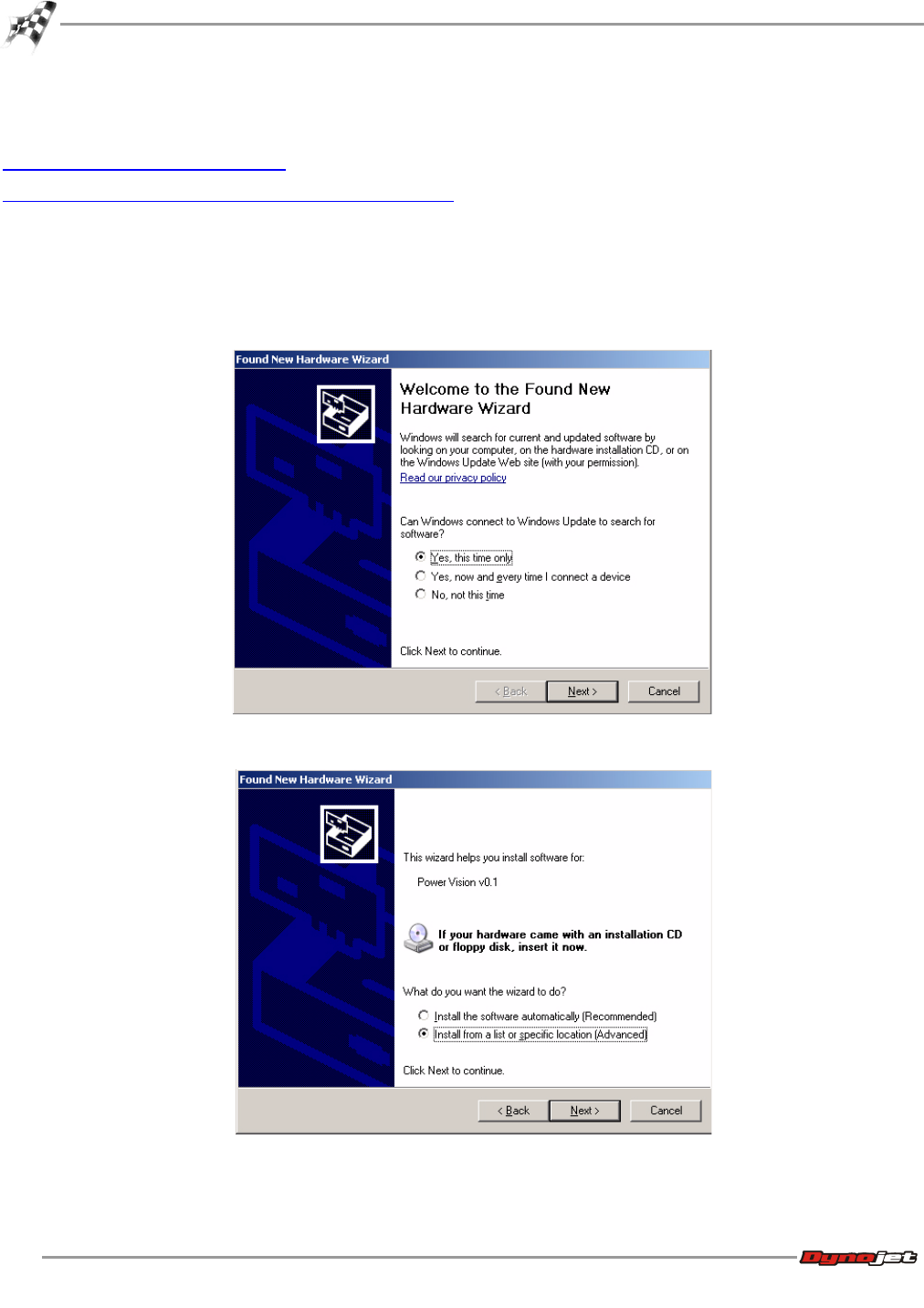
1Using the USB cable, connect the Dynojet Power Vision to your computer.
The Found New Hardware window will open.
2Select Yes, this time only and click Next.
3Select Install from a list or specific location and click Next.
WinPV User Guide
CHAPTER 2
Power Vision Driver Installation
2-4
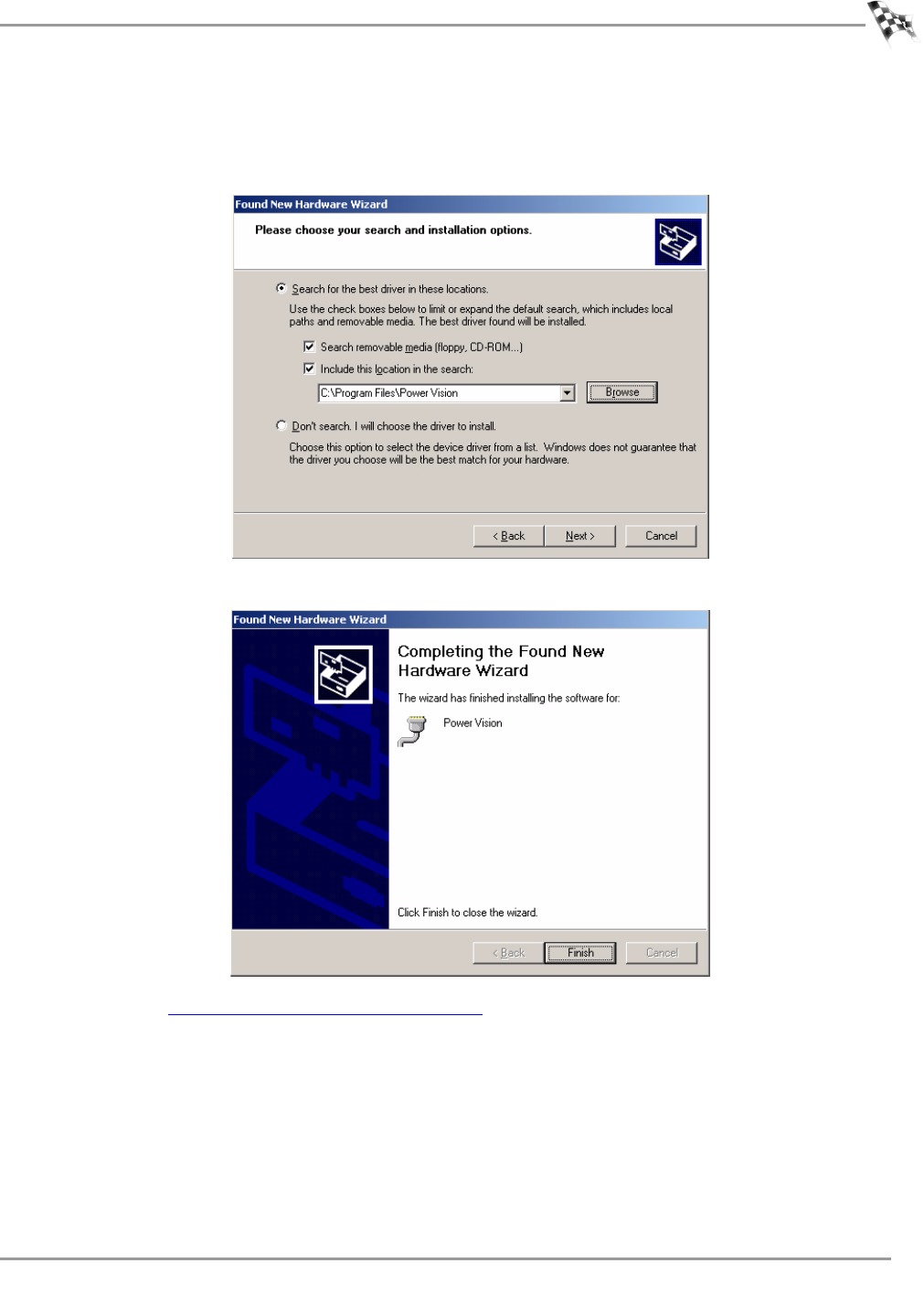
Windows Vista and Windows 7 Driver Installation
Power Vision Device Drivers will be installed during software installation.
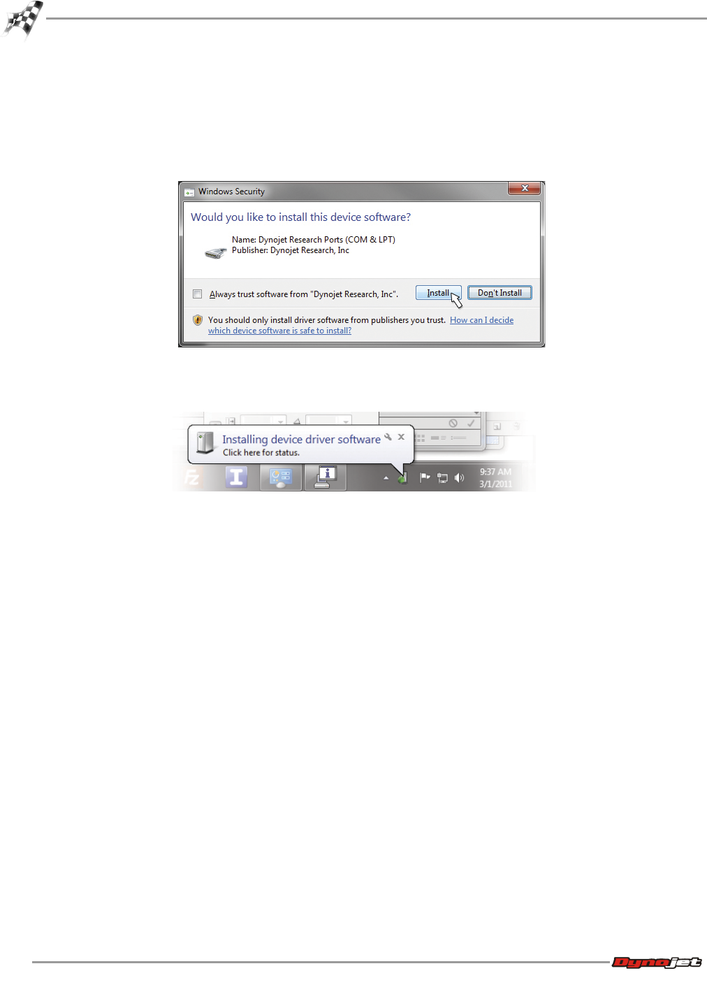
A Windows Security warning will pop up during this process.
Click Install to continue.
Note:During the installation, a notice on the bottom of your screen will appear letting
you know the status of the device driver installation progress.
GETTING STARTED
Checking the WinPV Update Client
Version 6 WinPV User Guide
2-5
Checking the WinPV Update Client
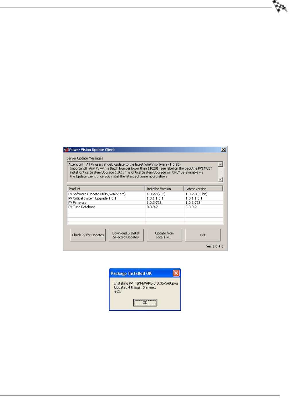
The PV Update Client automatically checks for any applicable updates. The latest versions of
the Firmware, Software, Tune Database, and any Critical Updates will be displayed in the
Latest Version column. Your currently installed versions will be displayed in the Installed
Version column.
Note:Please read the Update Messages on the top of the Update Client window for any
critical updates and follow any directions given there first.
1Using the USB cable, connect the Dynojet Power Vision to your computer.
2Click Start on the Windows® task bar, and click All Programs.
3Select PowerVision >PV Update Client.
4Click Check For Updates.
5Select the desired update to install.
6Click Download & Install Selected Updates.
7As the firmware and tune database downloads are completed, click OK to complete.
8As the software and update client downloads are completed, click OK to begin the
software download.
Note:The Update Client needs to be restarted for any further updates.
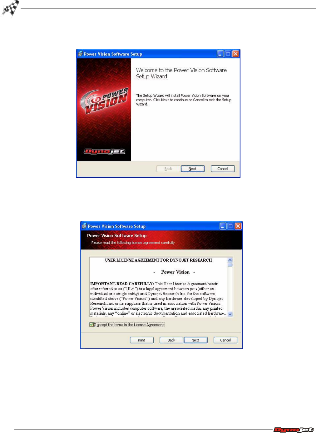
The Welcome to the Power Vision Software Setup Wizard window will appear.
WinPV User Guide
CHAPTER 2
Checking the WinPV Update Client
2-6
9Click Next to continue.
10 Carefully read the Power Vision software license agreement, check the accept box, and
click Next to continue.
To install the Power Vision software, you must accept this agreement. If you do not,
Setup will close.
GETTING STARTED
Checking the WinPV Update Client
Version 6 WinPV User Guide
2-7
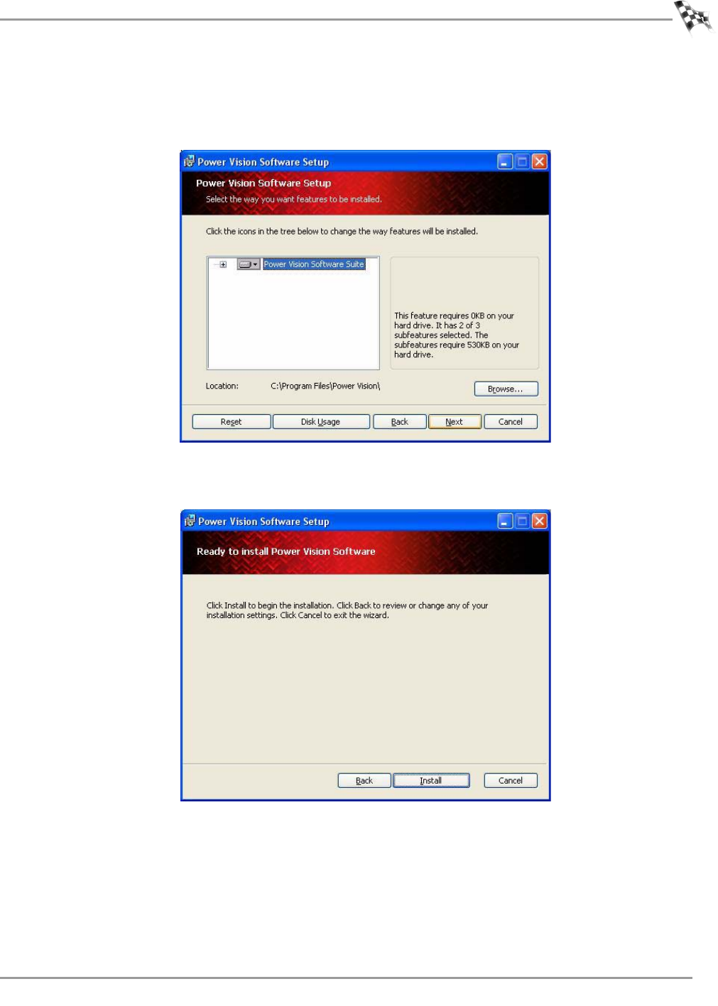
The Power Vision Software Feature window will appear.
11 Click Next to continue. Dynojet recommends you do not make any changes in this
window.
Setup is ready to install the Power Vision Software.
12 Click Install to begin installation.
WinPV User Guide
CHAPTER 2
Checking the WinPV Update Client
2-8
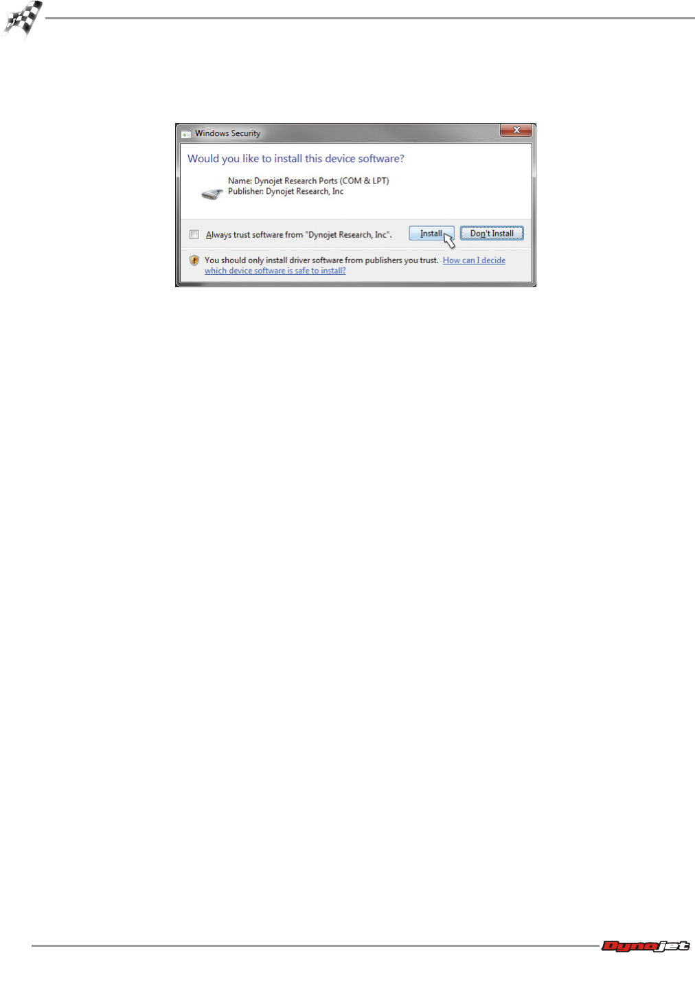
Note:Windows Vista and Windows 7 users—A Windows Security warning will pop up
during the installation process; this is normal. Click Install to continue.
13 The Power Vision Software update is now complete. Click Finish to exit the Setup Wizard.
GETTING STARTED
Installing the Power Vision on the Motorcycle
Version 6 WinPV User Guide
2-9
Installing the Power Vision on the Motorcycle
The following installation was performed on a 2008 Harley-Davidson Night Rod. Your bike and
set-up may vary.
Note:The Power Vision may be damaged if installed improperly. To ensure safety and
accuracy in the procedures, perform the procedures as they are described.
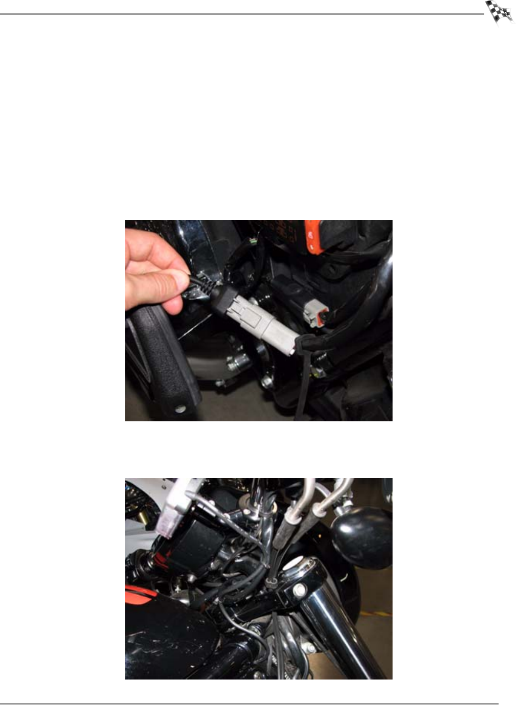
1Connect the PowerVision to the ECM’s diagnostic port.
The location of the diagnostic port varies depending on the model. Please refer to the
service manual or contact Dynojet for the exact location.
Note:Many models use the same style connector for accessories. The Power Vision must
be connected to the diagnostic port.
2Route the PowerVision cable away from any moving or hot parts.
Dynojet recommends using zip ties to secure the cable to existing non-moving
components.
WinPV User Guide
CHAPTER 2
Installing the Power Vision on the Motorcycle
2-10
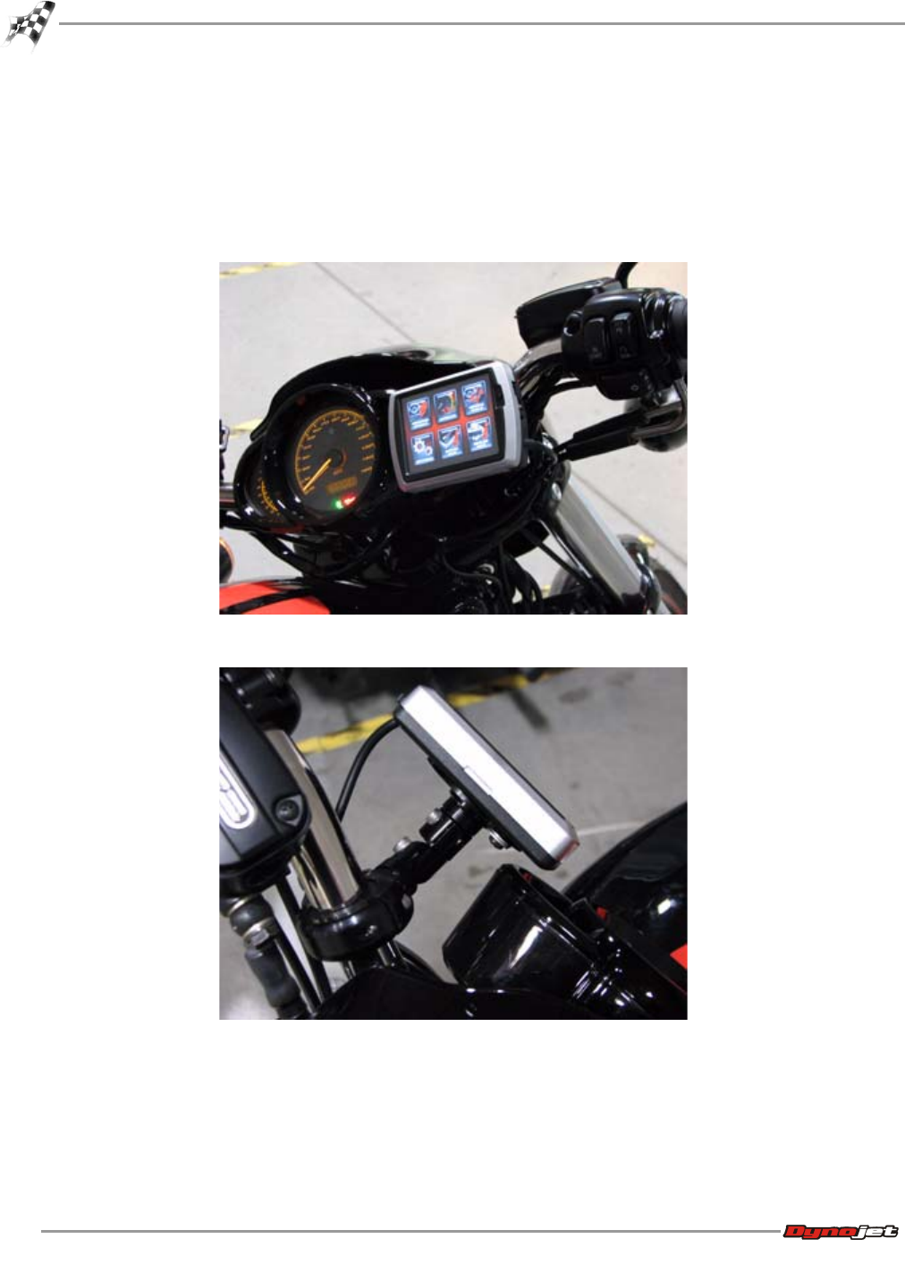
3The PowerVision module may be mounted to the bike’s handlebars using Techmount
hardware.
Note:The Power Vision does not need to remain on the bike.
In this example, the Power Vision module is mounted to a 2008 Night Rod using the
Techmount bracket.
For more information on available mounting accessories visit: www.techmounts.com.
GETTING STARTED
Power Vision Tune File Management
Version 6 WinPV User Guide
2-11
Power Vision Tune File Management
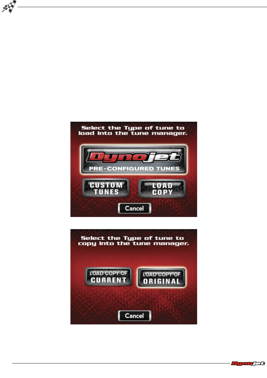
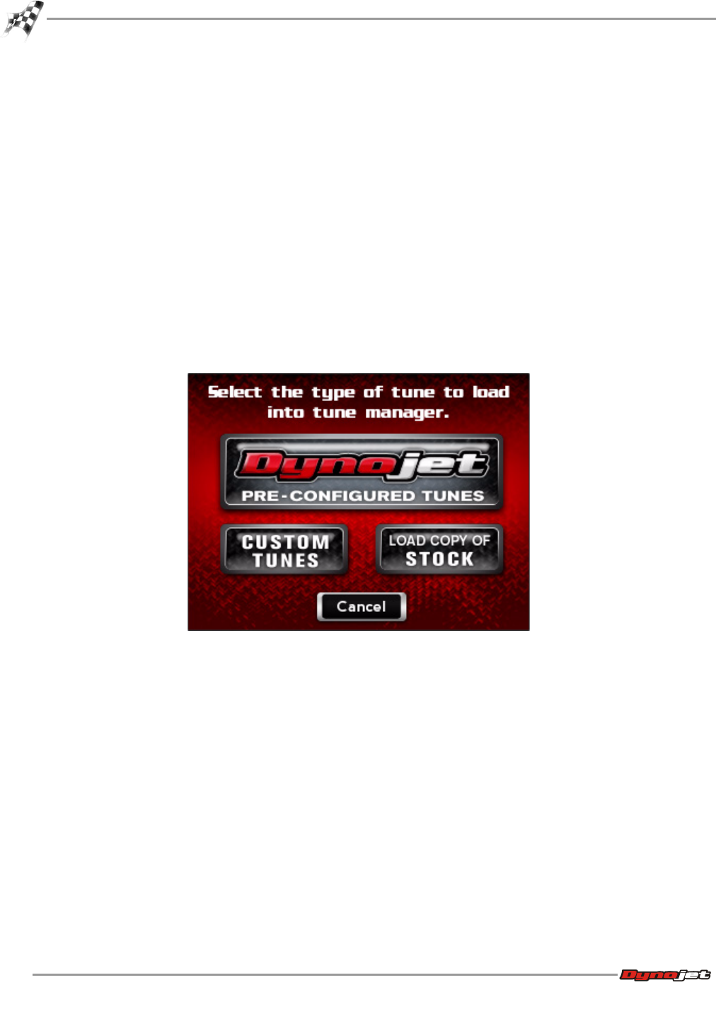
There are three types of tunes that can be flashed to your ECM with the Power Vision:
• Dynojet Pre-Configured Tunes—refer to Flashing a Dynojet Pre-Configured Tune File
• Custom Tunes—refer to Flashing a Custom Tune File
• Load Copy—refer to Loading a Copy of the Original Tune File or a Copy of the Current Tune
File
Flashing your ECM with any one of these types of tunes will automatically save a backup of
your Original Tune and will permanently lock the Power Vision to your bike’s ECM.
You can flash your ECM with tunes as many times as you like, but the Power Vision will only
be permitted to flash tunes to the ECM it’s locked to. The Power Vision’s other features, like
data logging/monitoring, diagnostics, clearing adaptive values, etc. will still be available to be
used on any bike it was designed for, as well as the bike it’s locked to.
WinPV User Guide
CHAPTER 2
Power Vision Tune File Management
2-12
Any combination of the three types of tune files can be placed in the Tune Manager. There are
six slots in the Tune Manager and you can occupy a single slot or all six if you choose.
For example, you could have a Dynojet Pre-Configured Tune in Slot 1, a Custom Tune in Slot
2, and a Copy of Original Tune in Slot 3. You can think of the Tune Manager as an area that
holds the tunes, or stages them, prior to the Power Vision flashing them to your ECM. You
can overwrite the tunes that occupy the various slots at any time, or manage your tune files
in the Tune Manager by using the WinPV software.
GETTING STARTED
Power Vision Tune File Management
Version 6 WinPV User Guide
2-13
Flashing a Dynojet Pre-Configured Tune File
The Power Vision is loaded with Pre-Configured Tunes developed by Dynojet when it leaves
our facility. Dynojet makes every effort to have a tune file available for your specific
combination when you receive your Power Vision (pre-loaded in the device), but in some
cases you’ll need to use the Update Client to ensure you have the latest tunes available from
Dynojet. Refer to Checking the WinPV Update Client.
You can also visit http://www.flashyourharley.com to search our tune database and download
a tune for your combination.
Use the following steps to flash a Dynojet Pre-Configured Tune to the ECM.
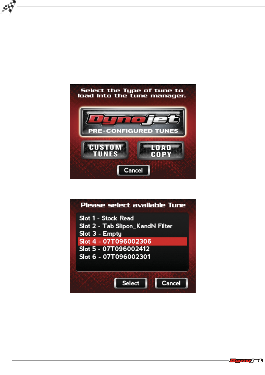
1Touch Program Vehicle >Load Tune >Dynojet Pre-Configured Tunes.
The Power Vision will automatically search for compatible tunes.
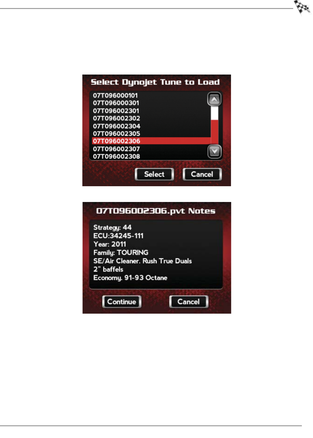
2Select a Dynojet Pre-Configured Tune File to flash.
3Touch Select.
WinPV User Guide
CHAPTER 2
Power Vision Tune File Management
2-14
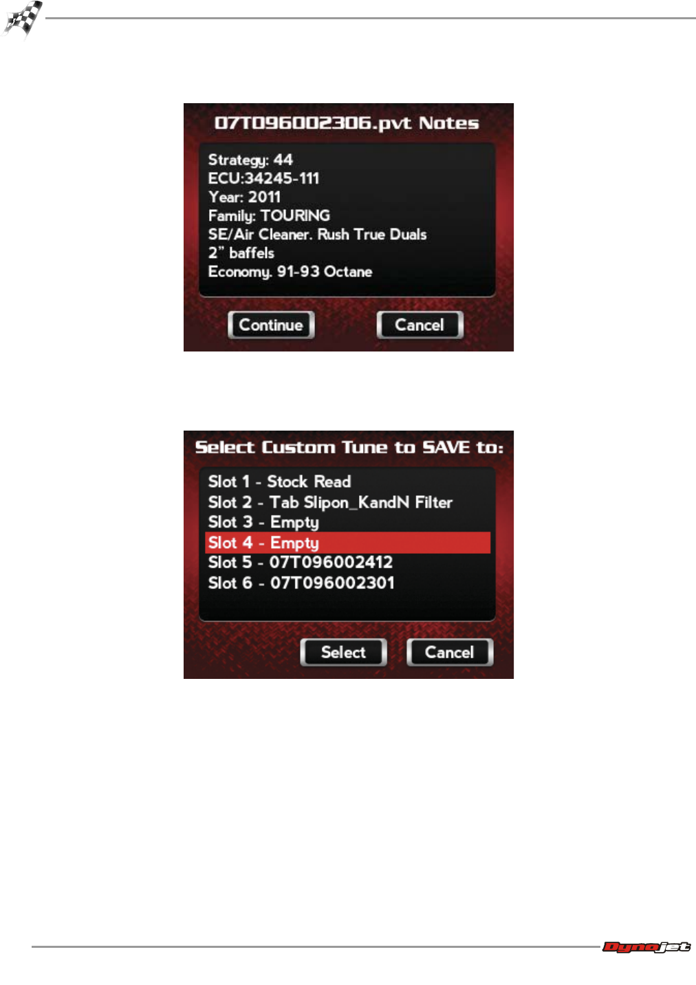
4Verify the tune information. If the tune information is correct, touch Continue.
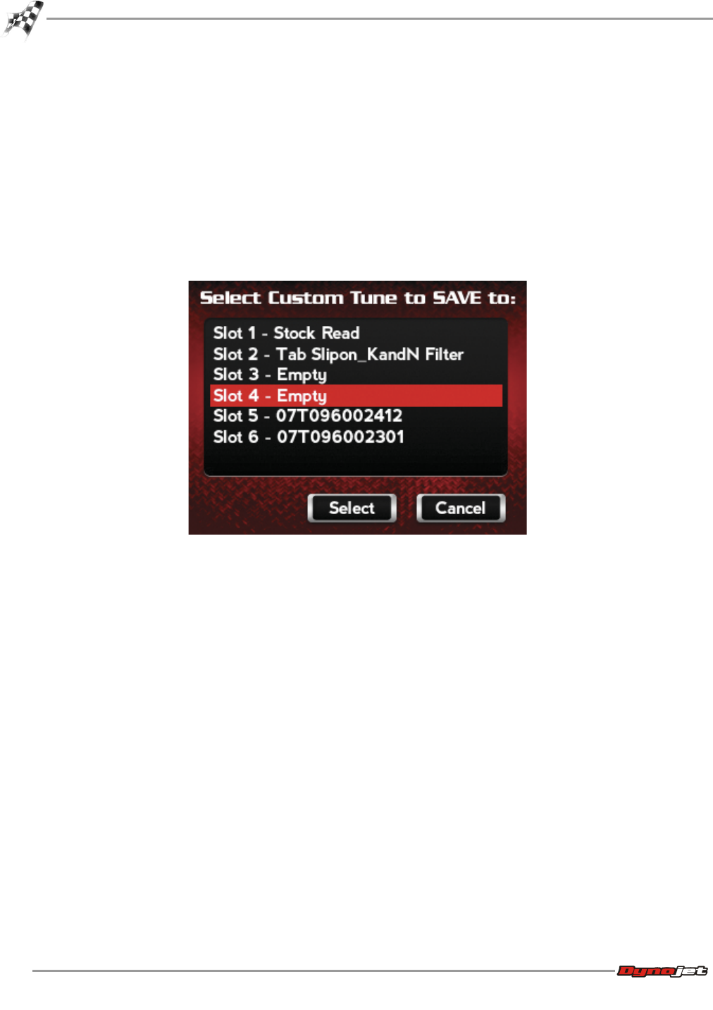
5Select a slot to save the selected tune file.
Note:If there is any data in the selected slot, it will be overwritten.
6Touch Select.
The tune is now ready.
GETTING STARTED
Power Vision Tune File Management
Version 6 WinPV User Guide
2-15
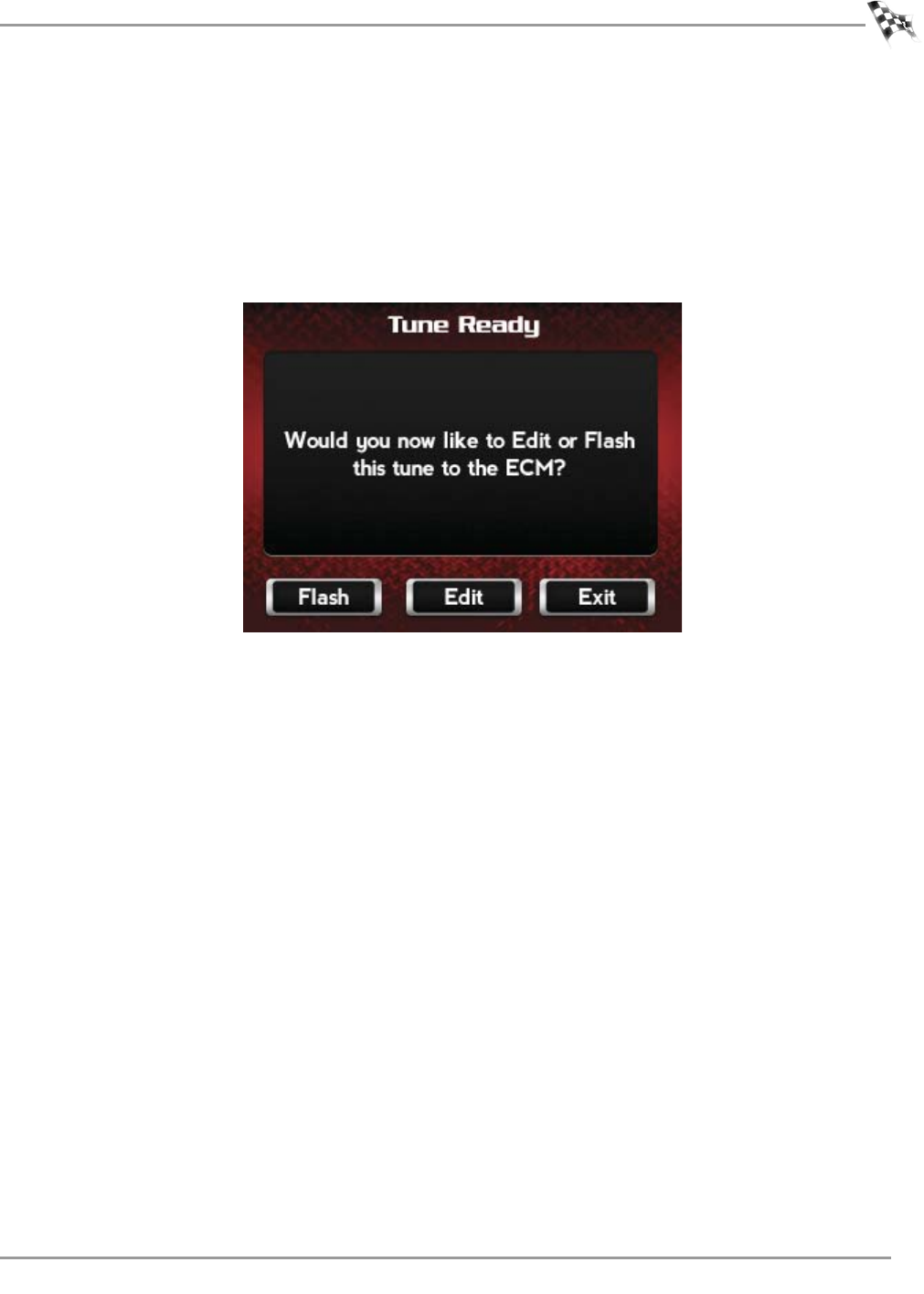
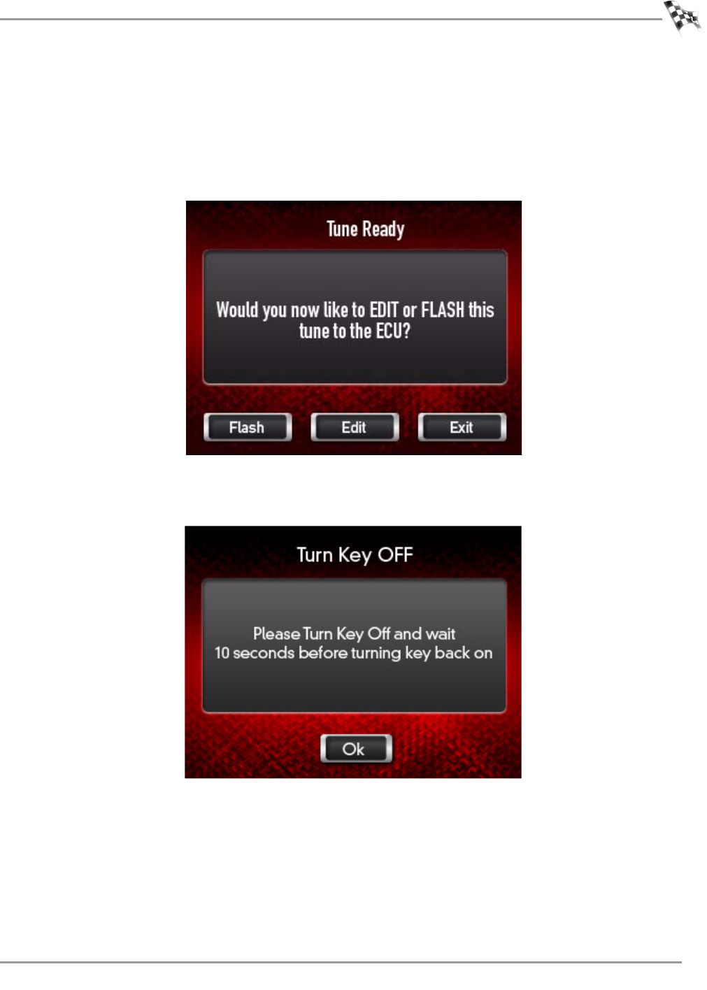
7Touch Flash to flash this tune to the ECM.
Note:During the flash process, do not turn off the bike. Once complete, you will be
prompted to turn the bike off for 10 seconds.
Or
Touch Edit to edit this tune.
Or
Touch Exit to exit the screen without any changes.
Note:You can edit any tune that’s loaded in the Tune Manager prior to flashing your ECM.
The Power Vision allows you to make basic adjustments to your tunes directly on the
device without using a computer. In order to gain full access to your tune files, you’ll need
to download them from the Power Vision to WinPV, our custom tuning software.
WinPV User Guide
CHAPTER 2
Power Vision Tune File Management
2-16
Flashing a Custom Tune File
Custom Tunes may or may not be pre-loaded from a reseller that specializes in custom
tuning. Dynojet does NOT load custom tunes in the Power Vision when it leaves our facility
(we load Dynojet Pre-Configured Tunes). You may also receive Custom Tunes via email that
can be uploaded to the Power Vision using WinPV, our custom tuning software.
Use the following steps to flash a Custom Tune file to the ECM.
1Touch Program Vehicle >Load Tune >Custom Tunes.
2Select a Custom Tune File to flash.
3Touch Select.
GETTING STARTED
Power Vision Tune File Management
Version 6 WinPV User Guide
2-17
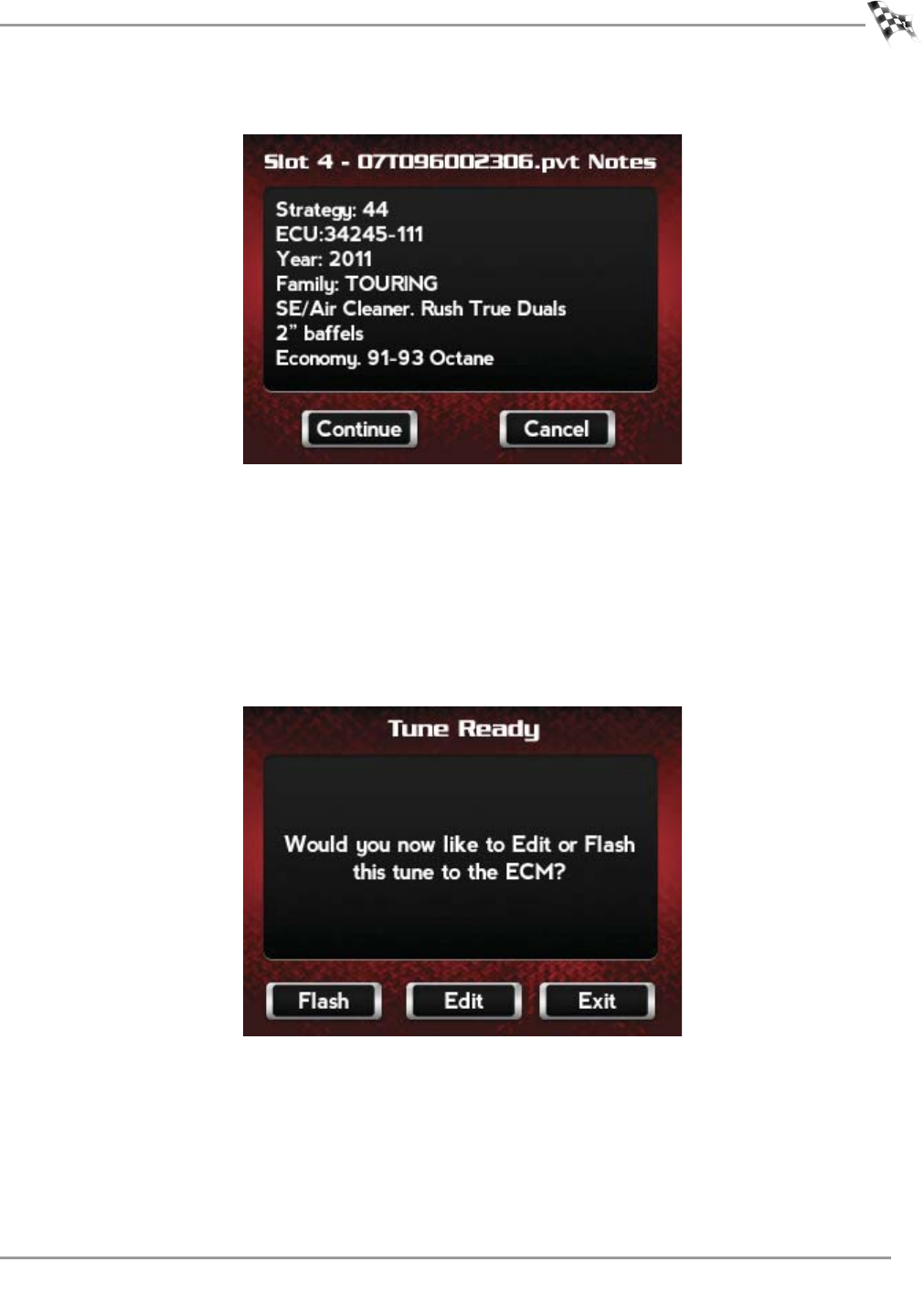
4Verify the tune information. If the tune information is correct, touch Continue.
The Tune is now ready.
5Touch Flash to flash this tune to the ECM.
Note:During the flash process, do not turn off the bike. Once complete, you will be
prompted to turn the bike off for 10 seconds.
Or
Touch Edit to edit this tune.
Or
Touch Exit to exit the screen without any changes.
Note:You can edit any tune that’s loaded in the Tune Manager prior to flashing your ECM.
The Power Vision allows you to make basic adjustments to your tunes directly on the
device without using a computer. In order to gain full access to your tune files, you’ll need
to download them from the Power Vision to WinPV, our custom tuning software.
WinPV User Guide
CHAPTER 2
Power Vision Tune File Management
2-18
Loading a Copy of the Original Tune File or a Copy of the Current Tune File
The Power Vision will allow you to load either a Copy of Current tune or a Copy of Original
tune files.
The Copy of Original tune file is a copy of the tune that was present in your ECM when the
Power Vision first locked to your ECM. In other words, it is a copy of the backup file that was
created and stored in the Power Vision. This is a great way for those who are happy with the
way their bike runs, but want access to their existing tune in order to make a few
adjustments.
The Copy of Current tune file is a copy of the current tune that has been flashed to your ECM.
Use the following steps to load and flash either a Copy of Original tune or a Copy of Current
tune file to the ECM.
1Touch Program Vehicle >Load Tune >Load Copy.
2Touch Load Copy of Current or Load Copy of Original.

GETTING STARTED
Power Vision Tune File Management
Version 6 WinPV User Guide
2-19
3Select a slot to save the tune file.
Note:If there is any data in the selected slot, it will be overwritten.
4Touch Select to continue.
The Tune is now ready.
5Select Flash to flash this tune to the ECM.
Note:During the flash process, do not turn off the bike. Once complete, you will be
prompted to turn the bike off for 10 seconds.
Or
Touch Edit to edit this tune.
Or
Touch Exit to exit the screen without any changes.
Note:You can edit any tune that’s loaded in the Tune Manager prior to flashing your ECM.
The Power Vision allows you to make basic adjustments to your tunes directly on the
device without using a computer. In order to gain full access to your tune files, you’ll need
to download them from the Power Vision to WinPV, our custom tuning software.

WinPV User Guide
3-1
CHAPTER
3
W
ORKING
WITH
W
IN
PV
WinPV Software is a user-friendly interface which will allow you to easily develop new fuel
and ignition maps, record and download log files, and increase performance with the click of
a button.
This section is divided into the following categories:
• WinPV User Interface, page 3-2
• WinPV Menus, page 3-3
• WinPV Toolbar, page 3-32
• Tune Items, page 3-37
• Table, page 3-46
• Status Bar, page 3-47
WinPV User Guide
CHAPTER 3
WinPV User Interface
3-2
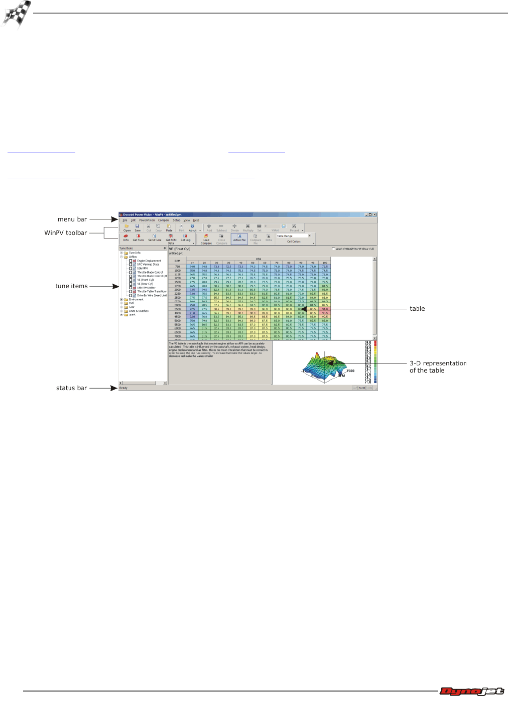
WinPV User Interface
WinPV is designed to be user-friendly and intuitive. Once you understand the basic layout, it
will be easy to obtain information and navigate the software efficiently.
The main elements of the WinPV User Interface are:
WinPV Menus Tune Items
WinPV Toolbar Table
WORKING WITH WINPV
WinPV Menus
Version 6 WinPV User Guide
3-3
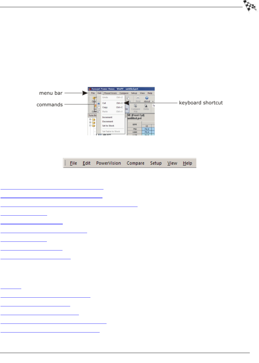
WinPV Menus
The menu bar displays the seven menus available in WinPV: File, Edit, PowerVision,
Compare, Setup, View, and Help. Each menu contains groups of related commands. Many
commands are followed by keyboard shortcuts.
As you use WinPV, you will develop your own working style. Maybe you will prefer to use the
mouse and menu commands or you may find that you prefer the quick access to features
provided by keyboard commands.
Use the following menus and commands with WinPV.
File Menu
To Open a Power Vision Tune File (.PVT)
To Save a Power Vision Tune File (.PVT)
To Import a Power Commander Map File (.pvm;.djm)
To Save All Values
To Save Selected Values
To Save Selected Values—Append
To Load All Values
To Load Selected Values
To Exit the WinPV Software
Edit Menu
To Undo
To Cut/Copy/Paste Selected Values
To Smooth Selected Values
To Interpolate Selected Values
To Interpolate Selected Horizontal Values
To Interpolate Selected Vertical Values
WinPV User Guide
CHAPTER 3
WinPV Menus
3-4
PowerVision Menu
To View the PowerVision Information
To Get a Tune from the Power Vision
To Send a Tune to the Power Vision
To Get ECM Data from the Power Vision
To Send the Original Tune to the Power Vision
To Send a Stock File to the Power Vision
To Get a Log from the Power Vision
To Exit PC Link Mode
Compare Menu
To Load a Compare File
To Close the Compare File
To View the Active File
To View the Compare File
To View Delta
To Choose Cell Colors
Setup Menu
To Setup the Options
To Apply the License
View Menu
To View the Standard Toolbar
To View the Cell Math Toolbar
To View the PowerVision Toolbar
To View the Compare Toolbar
To Reset the User Interface
Help Menu
To View the About Window
To View the Power Vision Help Files
WORKING WITH WINPV
WinPV Menus
Version 6 WinPV User Guide
3-5
File Menu
To Open a Power Vision Tune File (.PVT)
If the Tune File directory does not exist, or if you haven’t already created the Tune File
directory, you will need to create a Tune File directory in C:\Program Files\Power Vision. Once
the Tune File directory is created, you must map this folder in Setup Options. Refer to To
Setup the Options.
To open a Power Vision tune file from the Power Vision, refer to To Get a Tune from the Power
Vision.
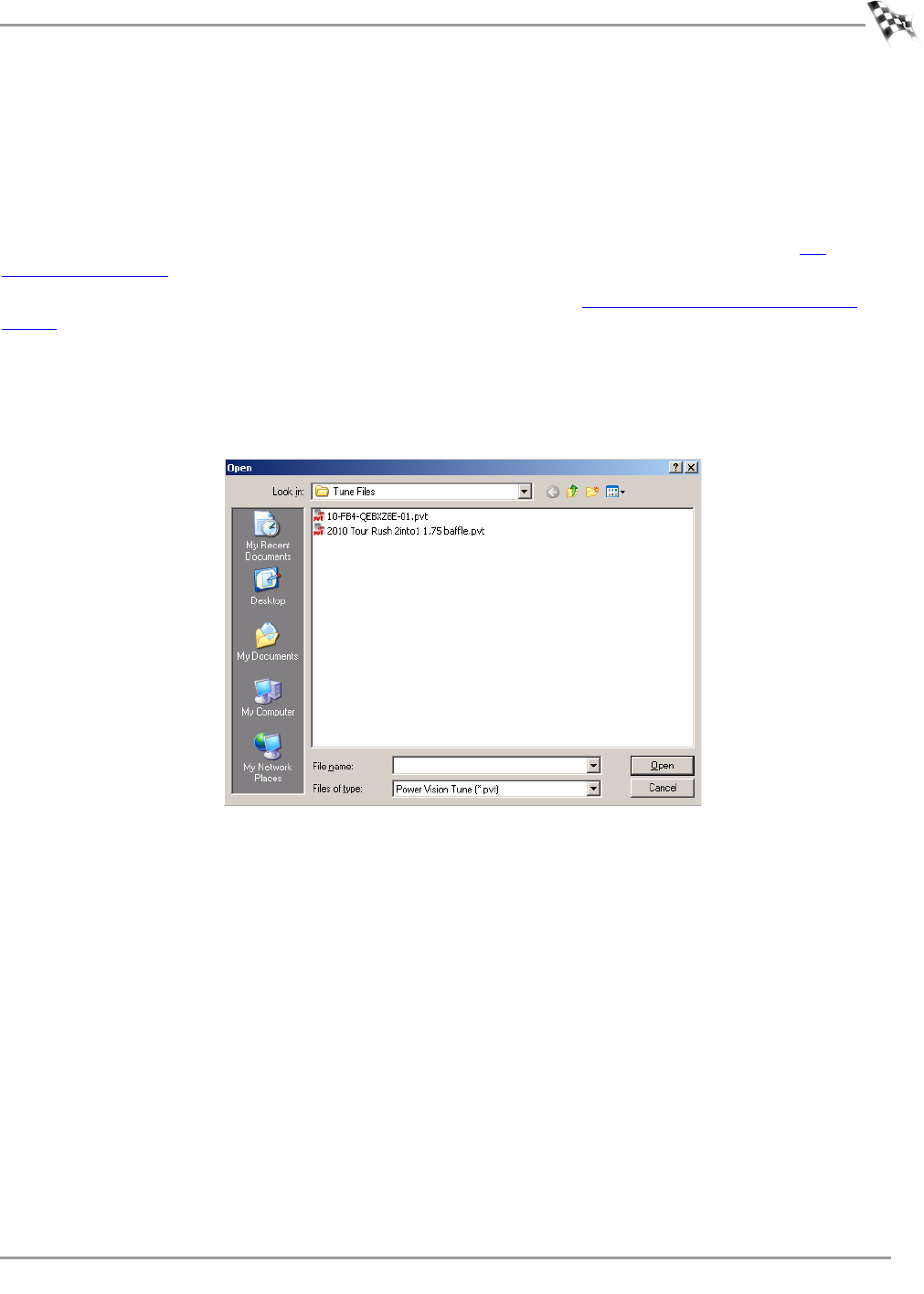
Use the following steps to open a Power Vision tune file from your computer.
1Select File >Open.
2Select a .pvt file to open.
3Click Open.
WinPV User Guide
CHAPTER 3
WinPV Menus
3-6
To Save a Power Vision Tune File (.PVT)
If the Tune File directory does not exist, or if you haven’t already created the Tune File
directory, you will need to create a Tune File directory in C:\Program Files\Power Vision. Once
the Tune File directory is created, you must map this folder in Setup Options. Refer to To
Setup the Options.
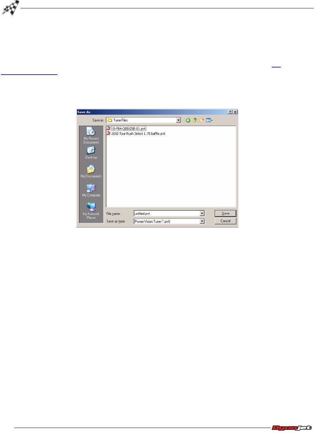
1Select File >Save As.
2Enter a name for your tune file.
3Click Save.
WORKING WITH WINPV
WinPV Menus
Version 6 WinPV User Guide
3-7
To Import a Power Commander Map File (.pvm;.djm)
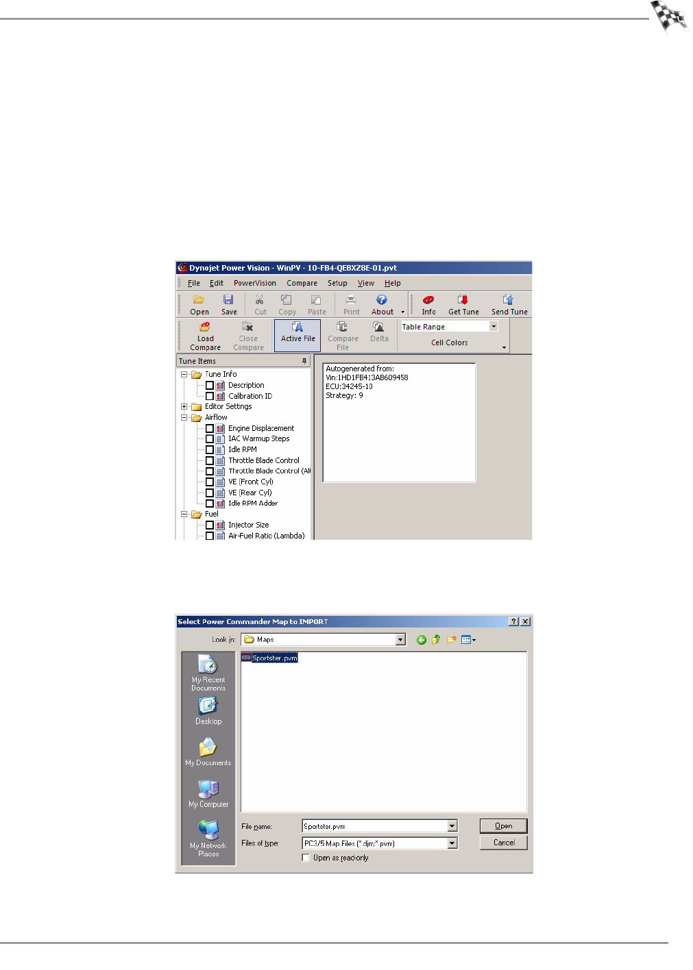
1Make sure you have a tune loaded.
You must have a copy of the original tune loaded before importing a Power Commander
map file.
2Select Tune Info from the Tune Items manager and click Description.
If the Strategy is 9, 44, or 218, the Power Commander map file will not import. When the
existing VE tables are RPM versus MAP (KPA), you will not be able to import Power
Commander map files. The example below shows a strategy of 9 and will not work when
importing a Power Commander map file.
3Select File >Import Power Commander Map.
4Select a file to open.
5Click Open.
WinPV User Guide
CHAPTER 3
WinPV Menus
3-8
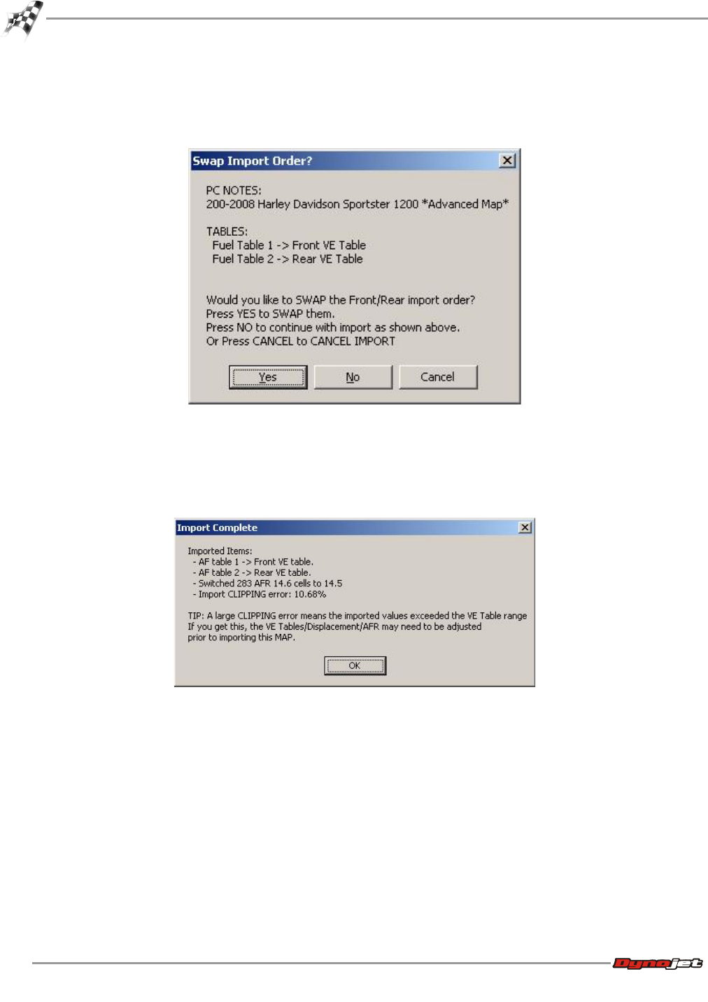
6Click Yes to swap the Front/Rear import order.
Or
Click No to import as shown in the window.
The Import Complete window will appear. This window will explain which tables were
imported where, how many cells were switched to 14.5, and how many imported values
exceeded the VE Table range.The maximum value in a cell is 127.5. If you see 127.5 in a
cell, you know the imported Power Commander map tried to exceed that value.
7Click OK.
WORKING WITH WINPV
WinPV Menus
Version 6 WinPV User Guide
3-9
To Save All Values
Value Files are one or more tables that are selected in WinPV. Save All Values will save all of
the value files in the open tune file into a Value File for later use.
If the Value File directory does not exist, or if you haven’t already created the Value File
directory, you will need to create a Value File directory in C:\Program Files\Power Vision.
Once the Value File directory is created, you must map this folder in Setup Options. Refer to
To Setup the Options.
1Make sure you have a tune loaded.
You must have a tune loaded before saving values.
2Select File >Save All Values.
3Enter a name for your value file.
4Click Save.
WinPV User Guide
CHAPTER 3
WinPV Menus
3-10
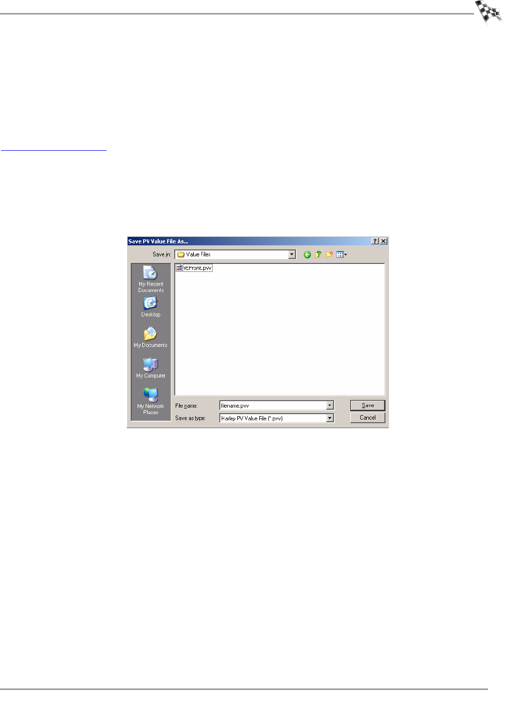
To Save Selected Values
Value Files are one or more tables that are selected in WinPV. Save Selected Values will save
only the parameters selected into a Value File for later use.
If the Value File directory does not exist, or if you haven’t already created the Value File
directory, you will need to create a Value File directory in C:\Program Files\Power Vision.
Once the Value File directory is created, you must map this folder in Setup Options. Refer to
To Setup the Options.
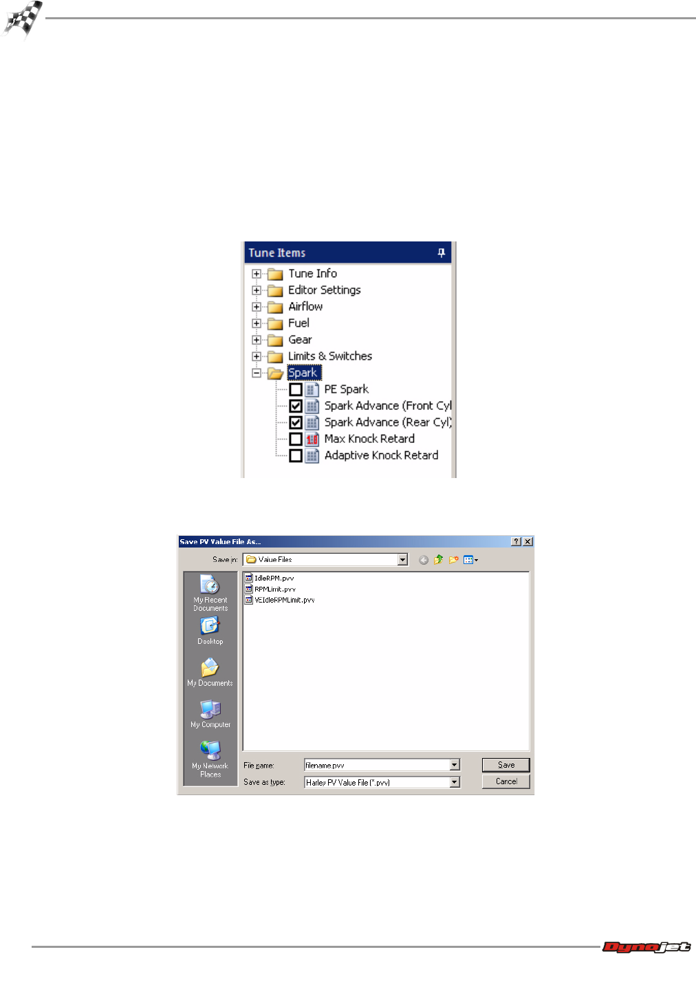
1Click the box next to the table or tables you would like to save.
2Select File >Save Selected Values.
3Enter a file name and click Save.
WORKING WITH WINPV
WinPV Menus
Version 6 WinPV User Guide
3-11
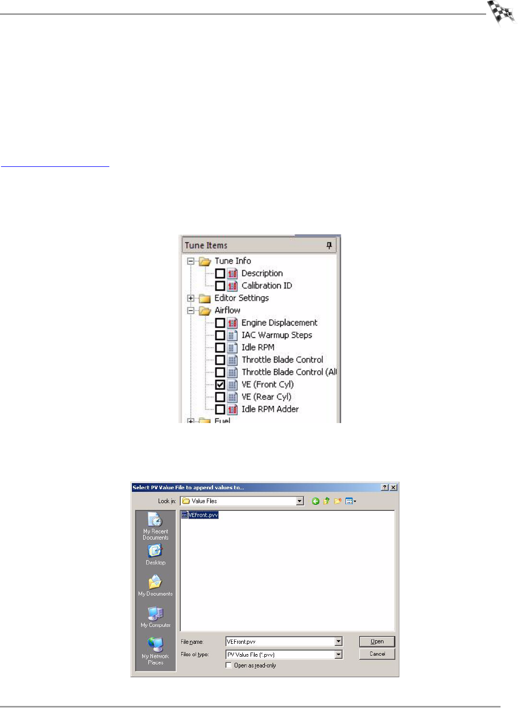
To Save Selected Values—Append
Value Files are one or more tables that are selected in WinPV. Save Selected Values Append
creates a new value file using an existing value file as a base. The value file you select
changes the cell values in the base file to any cell values that are different in the selected file.
If the Value File directory does not exist, or if you haven’t already created the Value File
directory, you will need to create a Value File directory in C:\Program Files\Power Vision.
Once the Value File directory is created, you must map this folder in Setup Options. Refer to
To Setup the Options.
Save Selected Values—Append creates a new value file using an existing value file as a base.
The value file you select changes the cell values in the base file to any cell values that are
different in the selected file.
1Click the box next to the table you would like to save.
2Select File >Save Selected Values—Append.
3Browse to your Value File folder and select the value file you wish to append values to.
4Click Open.
WinPV User Guide
CHAPTER 3
WinPV Menus
3-12
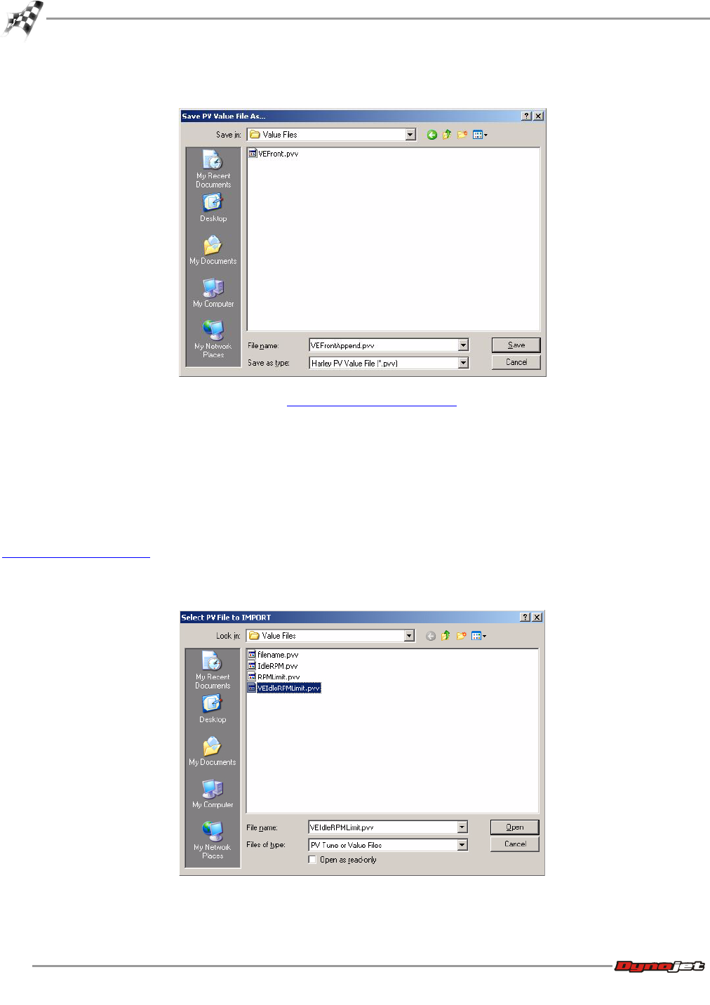
5Enter a name for the new value file and click Save.
6To load the file you created, refer to To Load Selected Values.
To Load All Values
Load All Values is used for loading in all of the changes in a Value File.
If the Value File directory does not exist, or if you haven’t already created the Value File
directory, you will need to create a Value File directory in C:\Program Files\Power Vision.
Once the Value File directory is created, you must map this folder in Setup Options. Refer to
To Setup the Options.
1Select File >Load All Values.
2Select the .pvv file you would like to use and click Open.
WORKING WITH WINPV
WinPV Menus
Version 6 WinPV User Guide
3-13
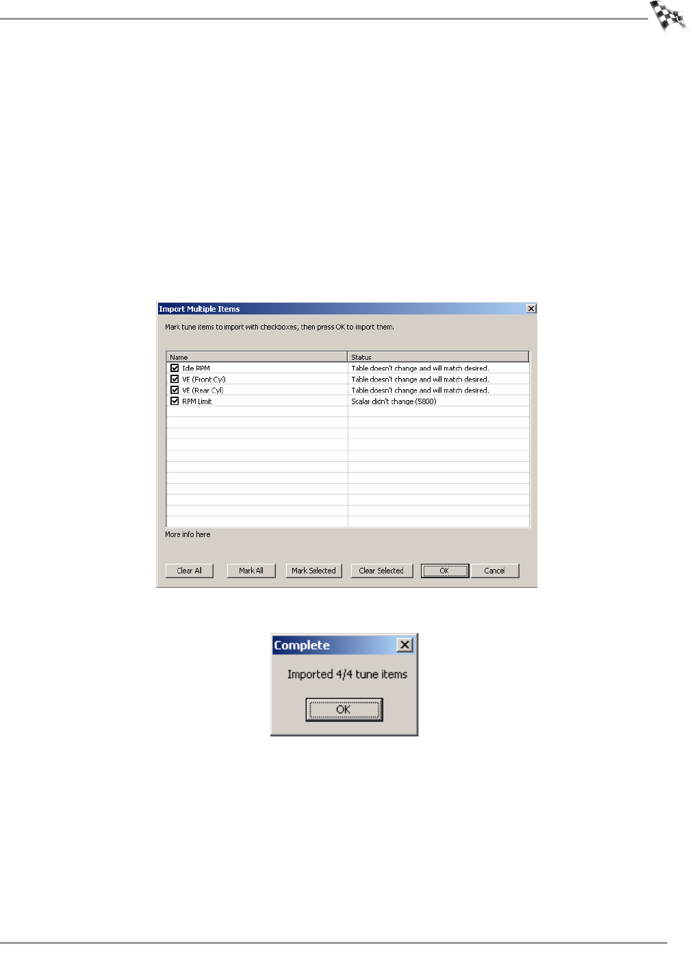
3Click the box next to the tune items you would like to import.
Or
Click Mark All to select all the tune items in the list.
Or
Click Mark Selected to place a check mark next to the tune items you have selected.
Or
Click Clear Selected to clear all of the check boxes.
4Click OK to accept the changes.
Or
Click Cancel to close the window.
5Click OK to complete the import.
WinPV User Guide
CHAPTER 3
WinPV Menus
3-14
To Load Selected Values
Load Selected Values loads only the values from a value file that are selected in the open
tune.
If the Value File directory does not exist, or if you haven’t already created the Value File
directory, you will need to create a Value File directory in C:\Program Files\Power Vision.
Once the Value File directory is created, you must map this folder in Setup Options. Refer to
To Setup the Options.
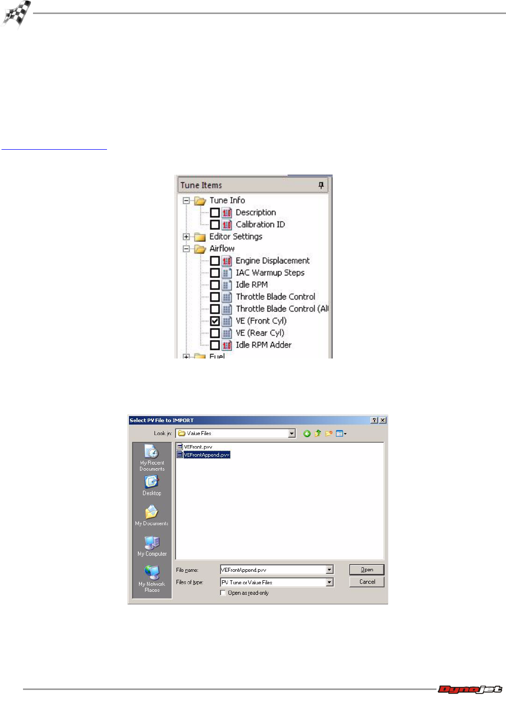
1Click the box next to the table you would like to load a new value file into.
2Select File >Load Selected Values.
3Browse to your Value File folder and select the value file you wish to load.
4Click Open.
WORKING WITH WINPV
WinPV Menus
Version 6 WinPV User Guide
3-15
5Click the box next to the tune items you would like to import.
Or
Click Mark All to select all the tune items in the list.
Or
Click Mark Selected to place a check mark next to the tune items you have selected.
Or
Click Clear Selected to clear all of the check boxes.
6Click OK to accept the changes.
Or
Click Cancel to close the window.
7Click OK to complete the import.
To Exit the WinPV Software
Select File >Exit to exit the WinPV software.

WinPV User Guide
CHAPTER 3
WinPV Menus
3-16
Edit Menu
To Undo
Select Edit >Undo to take a step back and undo the last changes made to the tune.
To Redo
Select Edit >Redo to reverse an action you undid.
To Cut/Copy/Paste Selected Values
1Select the desired values.
2Select Edit >Cut to cut the selected values.
3Select Edit >Copy to copy the selected values.
4Select Edit >Paste to paste the copied values.
To Smooth Selected Values
Smoothing is a process that removes the sharp peaks and troughs from a data series or
surface map. Smoothing is designed to smooth data after modifications have been made.
1Select the desired values. You must select at least two cells.
2Select Edit >Smooth to smooth the selected values.
To Interpolate Selected Values
Interpolate is a function that applies a linear interpolation to the values within the range of
selected cells. This function will also construct new values within the range of selected cells
when surrounded by valid values (positive or negative integers).
1Select the desired values. You must select at least three cells.
2Select Edit >Interpolate to interpolate the selected values.
To Interpolate Selected Horizontal Values
1Select the desired values. You must select at least three cells that are horizontal.
2Select Edit >Interpolate Horizontal to interpolate the selected values.
To Interpolate Selected Vertical Values
1Select the desired values. You must select at least three cells that are vertical.
2Select Edit >Interpolate Vertical to interpolate the selected values.
WORKING WITH WINPV
WinPV Menus
Version 6 WinPV User Guide
3-17
PowerVision Menu
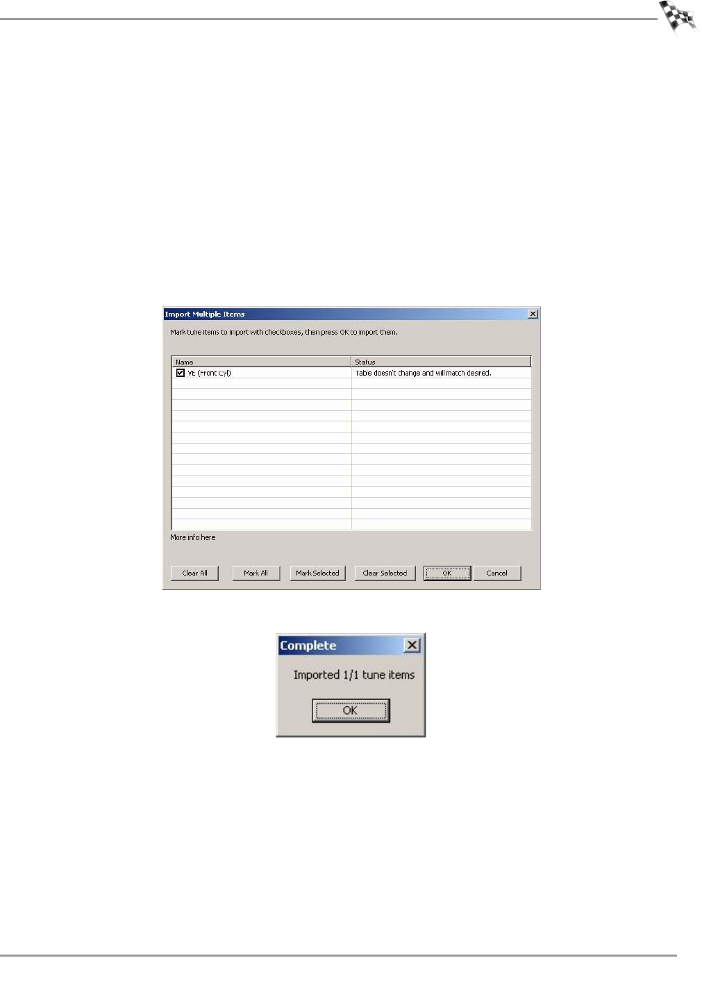
To View the PowerVision Information
1Select PowerVision >PV Info or click the Info button .
2Click Refresh to refresh the information displayed.
3Click Exit to exit the PV Info window.
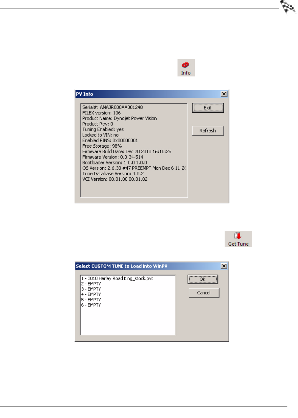
To Get a Tune from the Power Vision
1Select PowerVision >Get Tune from PV or click the Get Tune button .
2Select a tune to load.
3Click OK.
WinPV User Guide
CHAPTER 3
WinPV Menus
3-18
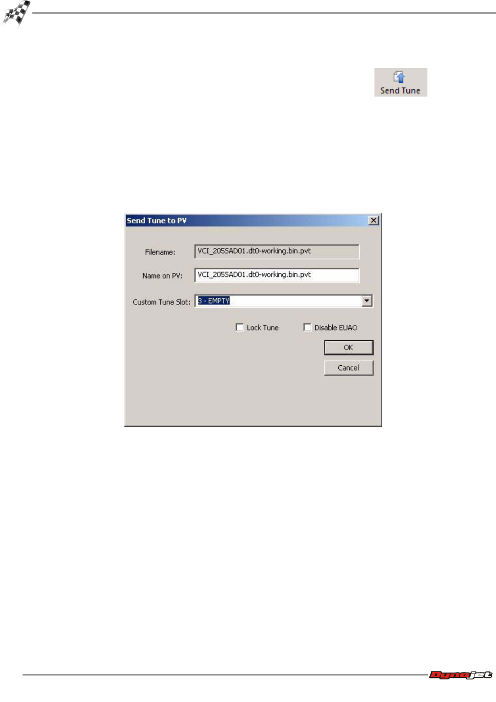
To Send a Tune to the Power Vision
1Select PowerVision >Send Tune to PV or click the Send Tune button .
2Using the drop-down arrow, select a Custom Tune Slot on the Power Vision to send the
tune to.
3Click Lock Tune to prevent a tune from being retrieved using Get Tune.
4Click Disable EUAO to disable the End User Adjustable Options. This will prevent a tune
from being edited on the Power Vision.
5Click OK to send the tune to the Power Vision.
Or
Click Cancel to close the window without changes.
WORKING WITH WINPV
WinPV Menus
Version 6 WinPV User Guide
3-19
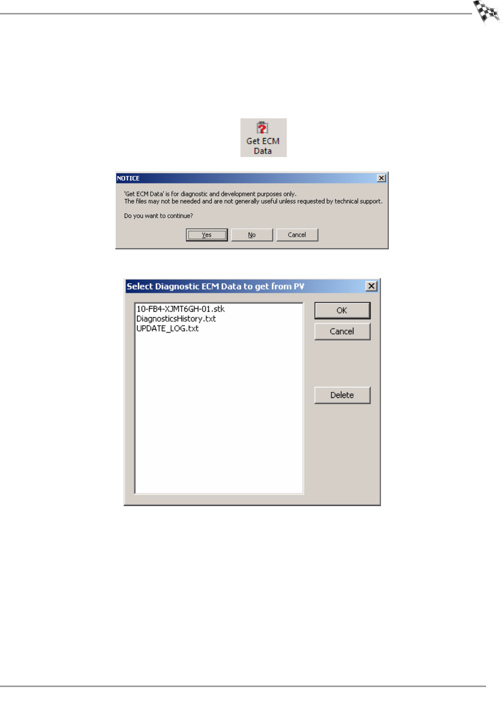
To Get ECM Data from the Power Vision
Get ECM Data is for diagnostic and development purposes only. The files may not be needed
and are not generally useful unless requested by technical support.
1Select PowerVision >Diagnostic/Test Functions >Get ECM Data (Diagnostic)
from PV or click the Get ECM Data button .
2Click Yes to continue.
3Select the diagnostic ECM data to get from the Power Vision and click OK.
WinPV User Guide
CHAPTER 3
WinPV Menus
3-20
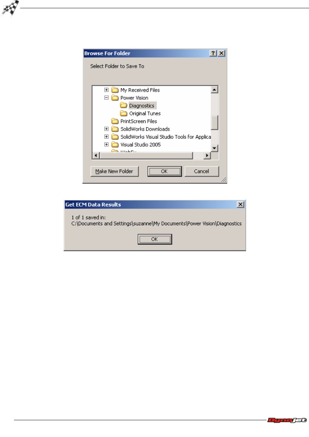
4Browse to the folder you want to save the diagnostic file to and click OK.
5The Get ECM Data Results have been saved. Click OK.
WORKING WITH WINPV
WinPV Menus
Version 6 WinPV User Guide
3-21
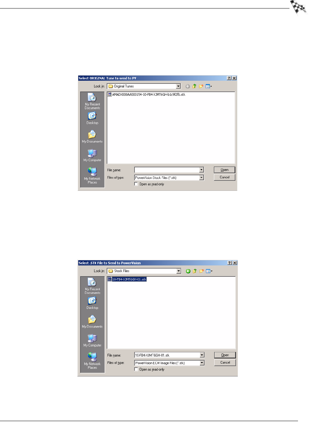
To Send the Original Tune to the Power Vision
1Select PowerVision >Diagnostic/Test Functions >Send Original Tune to PV.
2Browse to the location of the original tune you would like to send to the Power Vision.
3Select the tune file and click Open.
4Click OK.
To Send a Stock File to the Power Vision
1Select PowerVision >Diagnostic/Test Functions >Send .STK File to PV.
2Browse to the location of the stock file you would like to send to the Power Vision.
3Select the stock file and click Open.
4Click OK.
WinPV User Guide
CHAPTER 3
WinPV Menus
3-22
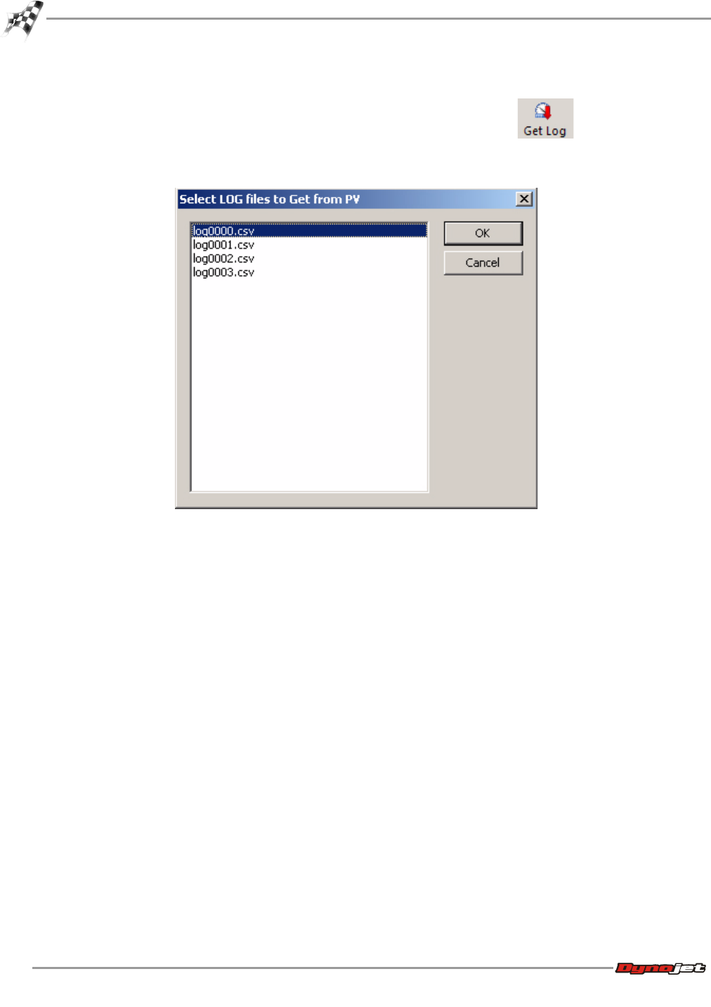
To Get a Log from the Power Vision
1Select PowerVision >Get Log from PV or click the Get Log button .
2Select the log file you wish to get from the Power Vision.
3Click OK.
WORKING WITH WINPV
WinPV Menus
Version 6 WinPV User Guide
3-23
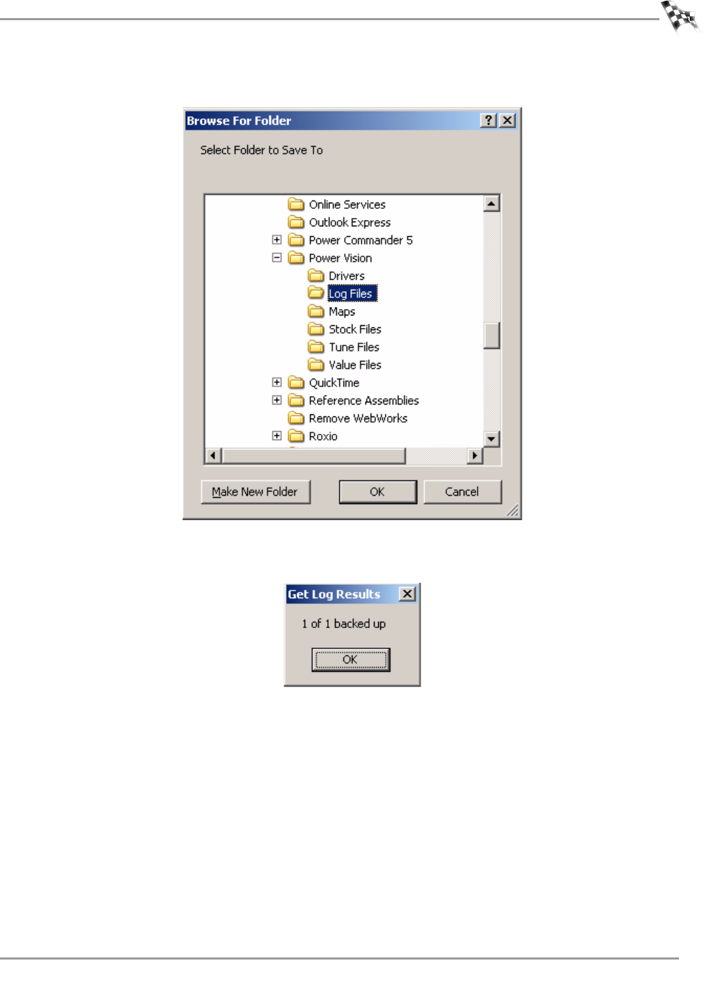
4Browse to the location you wish to save your log file and click OK.
5Click OK.
The log file is now ready to be opened with Excel.
To Exit PC Link Mode
Exit PC Link Mode allows you to edit gauge features while plugged into the PC using the
supplied USB cable.
Select PowerVision >Diagnostic/Test Functions >Exit PC Link Mode.
WinPV User Guide
CHAPTER 3
WinPV Menus
3-24
Compare Menu
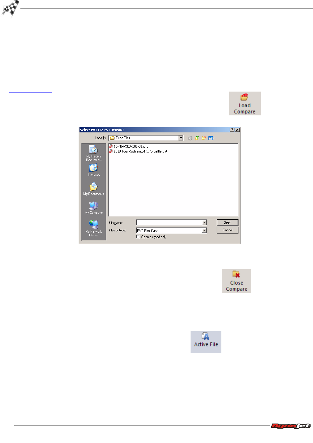
To Load a Compare File
Compare file allows the individual tune items of two different tune files to be compared. The
Active file can be edited, cell values can be copied from the Compare file, and the Delta
feature can be used to change the Active file. For more information about the Delta file, refer
to To View Delta.
1Select Compare >Load Compare or click the Load Compare button .
2Select a tune file to Compare.
3Click Open.
To Close the Compare File
Select Compare >Close Compare or click the Close Compare button . This will
close the Compare File and return to a single active tune file.
To View the Active File
Active File allows you to view the active file when comparing two tune files.
Select Compare >Active File or click the Active File button .
WORKING WITH WINPV
WinPV Menus
Version 6 WinPV User Guide
3-25
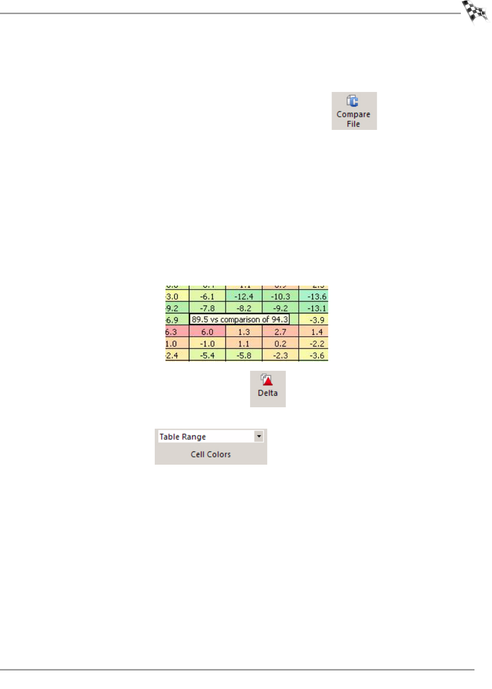
To View the Compare File
Compare File allows you to view the loaded compare file when comparing two tune files. The
Compare File cannot be edited.
Select Compare >Compare File or click the Compare File button .
To View Delta
Delta shows the difference between the active file and the compare file for the tune item you
have selected.
By editing the delta file, you can change the active file. For example, if one of the cells in the
delta file is 10 and you change it to 15, the corresponding cell in the active file will change by
5.
In Delta, a positive number indicates the value in the compare file is larger than the value in
the active file.
Hover the mouse pointer over a cell to view the comparison of the numbers. Active number is
first then the compare number.
Select Compare >Delta or click the Delta button .
To Choose Cell Colors
1Click the Cell Colors button .
2Using the drop-down arrow, select the cell color option from the list.
None—uses no colors.
Table Range—uses colors from blue to red based on lowest to highest numbers in the
table.
Modified—must have a compare file loaded to use.
Compare High/Low—uses colors to represent the differences between the compare files.
White is no difference while blue is the largest difference. Compare High/Low is only
available when a compare file is loaded.
WinPV User Guide
CHAPTER 3
WinPV Menus
3-26
Setup Menu
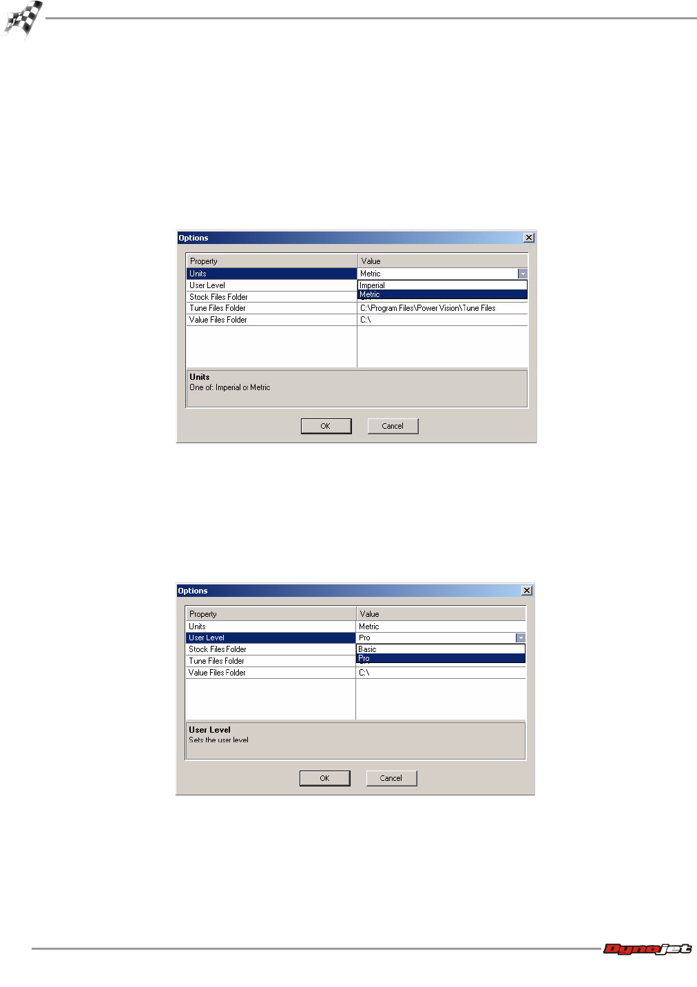
To Setup the Options
1Select Setup >Options.
2To change the Units:
2a Using the drop-down arrow, select either Metric or Imperial.
2b Click OK to accept the changes.
3To change the User Level:
3a Using the drop-down arrow, select either Basic or Pro.
3b Click OK to accept the changes.
Pro User Level will expose additional tune items and parameters which can affect the
operating condition of the vehicle.
WORKING WITH WINPV
WinPV Menus
Version 6 WinPV User Guide
3-27
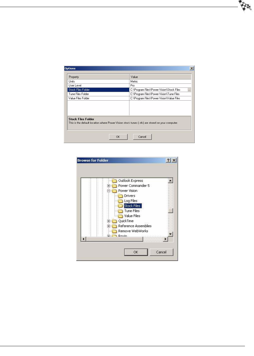
4To create the default location where the Power Vision stock files (.stk) are stored on your
computer:
4a Create a Stock Files directory in C:\Program Files\Power Vision.
4b Click . . . to browse to the Stock Files folder you created.
4c Click OK to save the location.
WinPV User Guide
CHAPTER 3
WinPV Menus
3-28
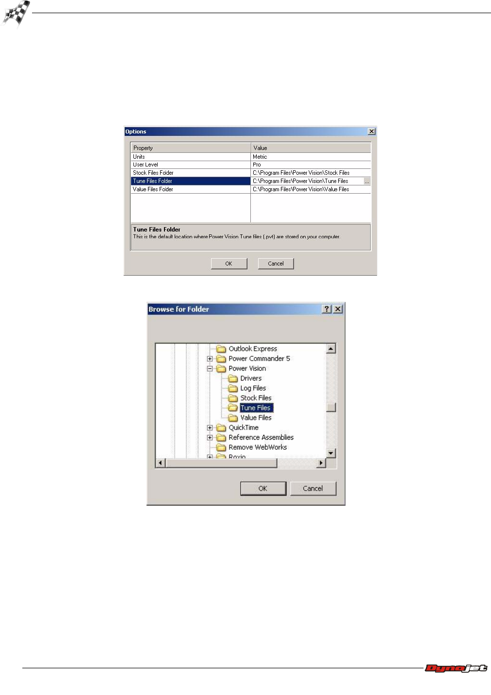
5To create the default location where the Power Vision tune files (.pvt) are stored on your
computer:
5a Create a Tune Files directory in C:\Program Files\Power Vision.
5b Click . . . to browse to the Tune Files folder you created.
5c Click OK to save the location.
WORKING WITH WINPV
WinPV Menus
Version 6 WinPV User Guide
3-29
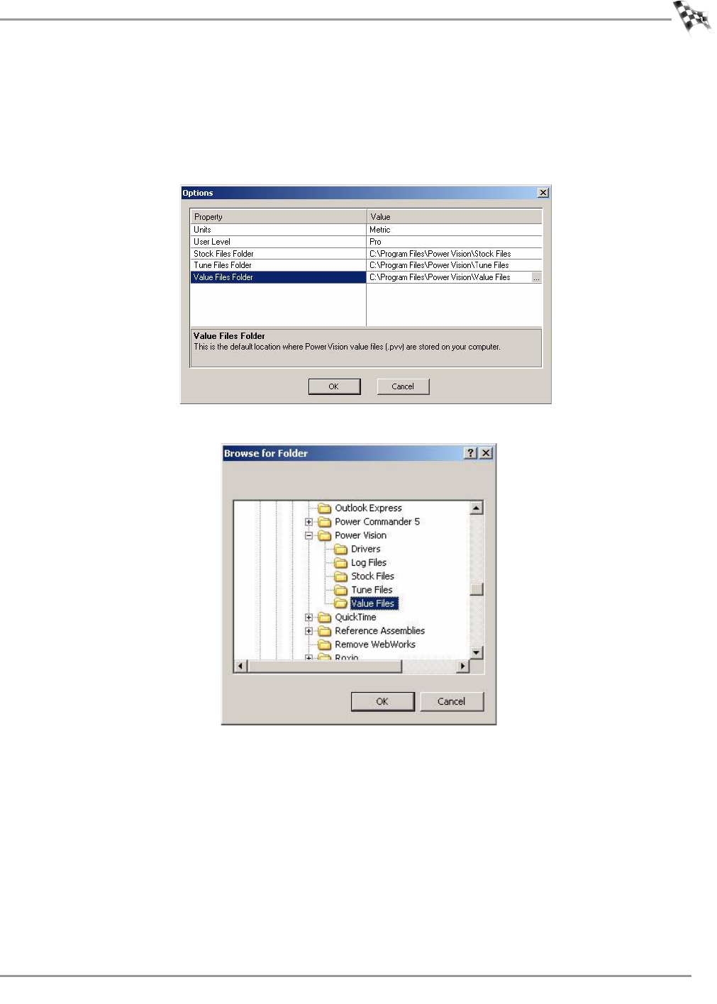
6To create the default location where the Power Vision value files (.pvv) are stored on your
computer:
6a Create a Value Files directory in C:\Program Files\Power Vision.
6b Click . . . to browse to the Value Files folder you created.
6c Click OK to save the location.
To Apply the License
Apply License is used to enable features in the Power Vision and WinPV software that have
been provided to you by Dynojet.
Select Setup >Apply License.
WinPV User Guide
CHAPTER 3
WinPV Menus
3-30
View Menu
To View the Standard Toolbar
Select View >Standard Toolbar or right-click to turn the toolbar on and off.
For more information about the Standard Toolbar, refer to Standard Toolbar.
To View the Cell Math Toolbar
Select View >Cell Math Toolbar or right-click to turn the toolbar on and off.
For more information about the Cell Math Toolbar, refer to Cell Math Toolbar.
To View the PowerVision Toolbar
Select View >PV Toolbar or right-click to turn the toolbar on and off.
For more information about the PV Toolbar, refer to PowerVision Toolbar.
To View the Compare Toolbar
Select View >Compare Toolbar or right-click to turn the toolbar on and off.
For more information about the Compare Toolbar, refer to Compare Toolbar.
To Reset the User Interface
Select View >Reset UI.
WORKING WITH WINPV
WinPV Menus
Version 6 WinPV User Guide
3-31
Help Menu
To View the About Window
Select Help >About.
To View the Power Vision Help Files
Select Help >Contents.
WinPV User Guide
CHAPTER 3
WinPV Toolbar
3-32
WinPV Toolbar
The following toolbar is always shown contains the WinPV tools. The WinPV toolbar is
grouped into four sections and each toolbar can be customized.
Standard Toolbar
PowerVision Toolbar
Cell Math Toolbar
Compare Toolbar
Customizing the Toolbars
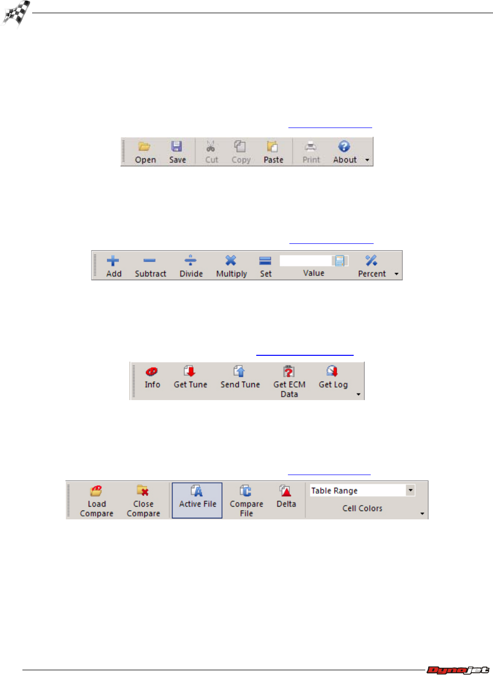
Standard Toolbar
A description of the standard toolbar buttons and functions follows.
press this button to
Open previously saved or stored tunes. Refer to To
Open a Power Vision Tune File (.PVT).
Save the current tune to your computer. Refer to To
Save a Power Vision Tune File (.PVT).
Cut the highlighted cell values.
Copy the highlighted cell values.
Paste the copied values.
About allows you to view information about WinPV.
WORKING WITH WINPV
WinPV Toolbar
Version 6 WinPV User Guide
3-33
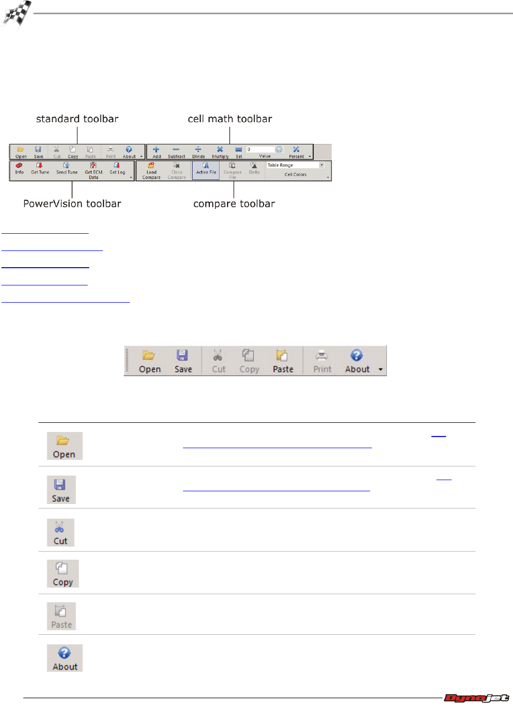
PowerVision Toolbar
A description of the Power Vision toolbar buttons and functions follows.
press this button to
Display the Power Vision information. Refer to To View
the PowerVision Information.
Retrieve a tune from the Power Vision. The tune
information will be shown in the Tune Items. Refer to To
Get a Tune from the Power Vision.
Sends the current tune to the Power Vision. Refer to To
Send a Tune to the Power Vision.
Get ECM Data is for diagnostic and development
purposes only. The files may not be needed and are not
generally useful unless requested by technical support.
Refer to To Get ECM Data from the Power Vision.
Retrieve the log files on the Power Vision. Refer to To
Get a Log from the Power Vision.
WinPV User Guide
CHAPTER 3
WinPV Toolbar
3-34
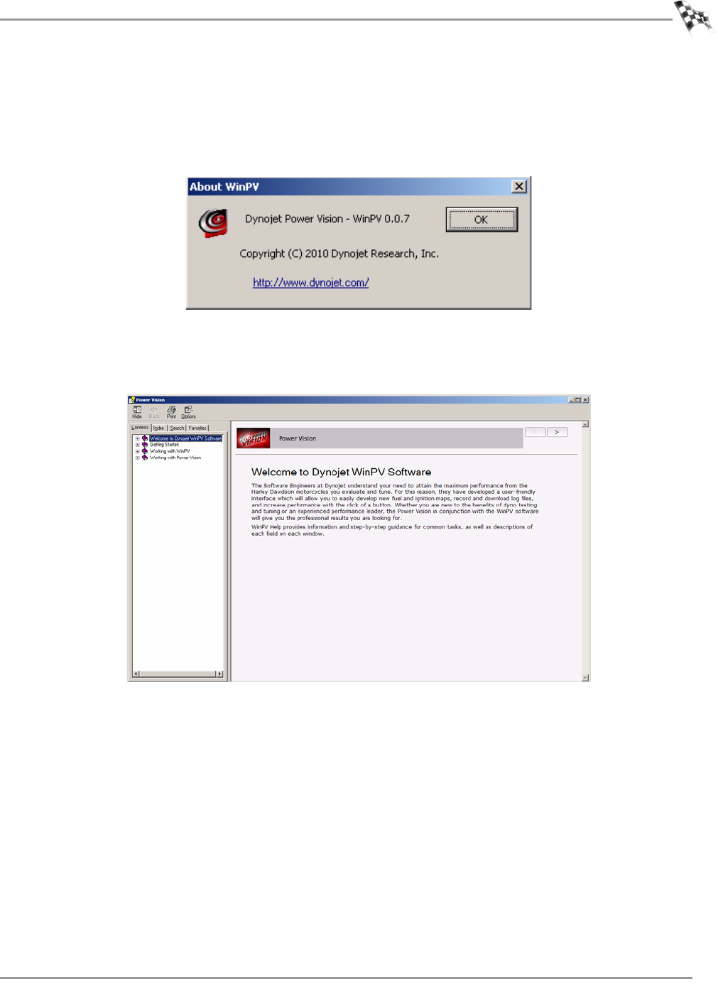
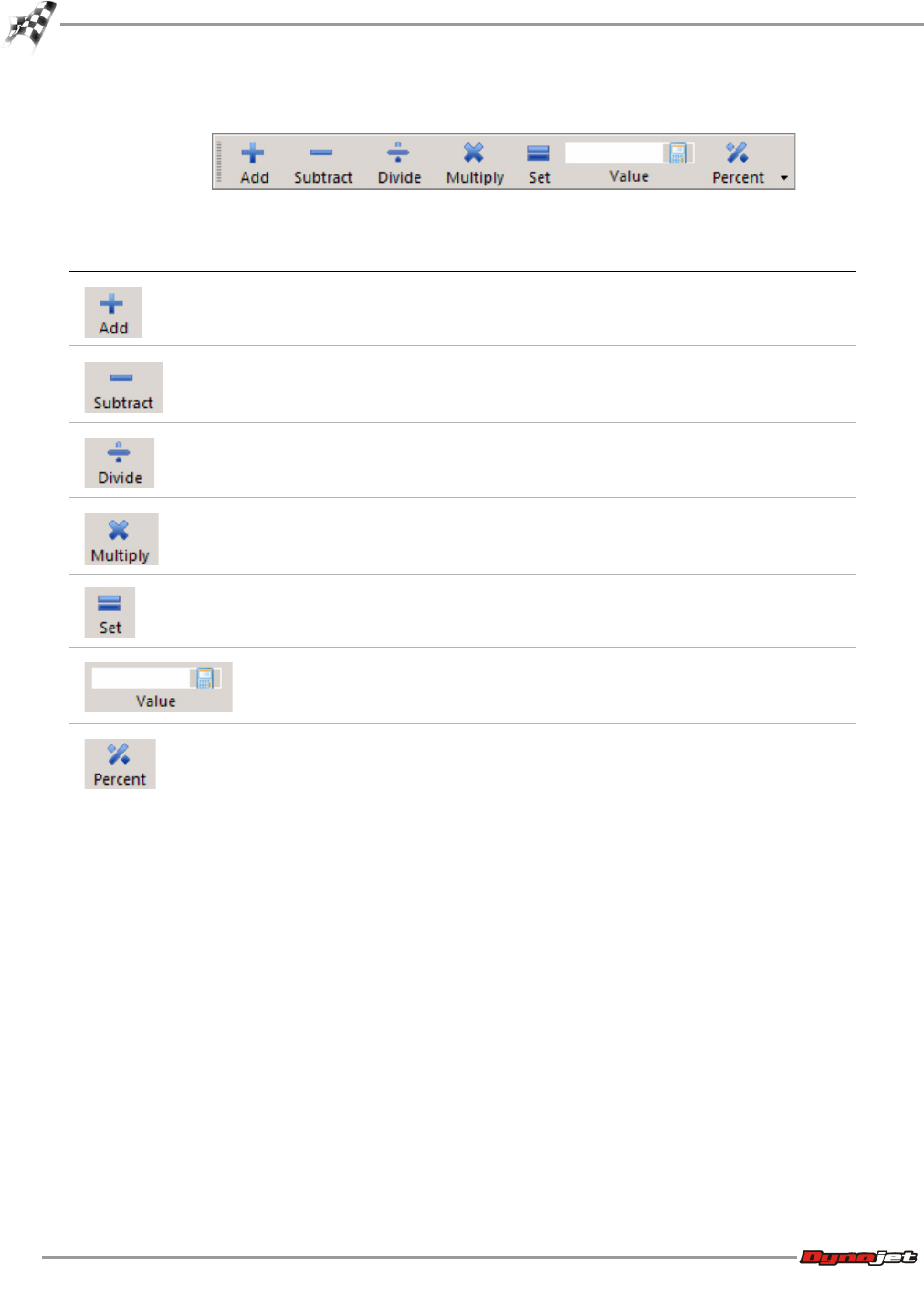
Cell Math Toolbar
A description of the cell math toolbar buttons and functions follows.
press this button to
Add the numbered entered into the Value field to the
selected cells.
Subtract the numbered entered into the Value field from
the selected cells.
Divide the selected cells by the numbered entered into
the Value field.
Multiply the selected cells by the numbered entered into
the Value field.
Set changes the selected cells to the numbered entered
into the Value field.
Use the Value field to enter the number you wish to
change the selected cells by.
Percent changes the selected cells by the numbered
entered into the Value field.
WORKING WITH WINPV
WinPV Toolbar
Version 6 WinPV User Guide
3-35
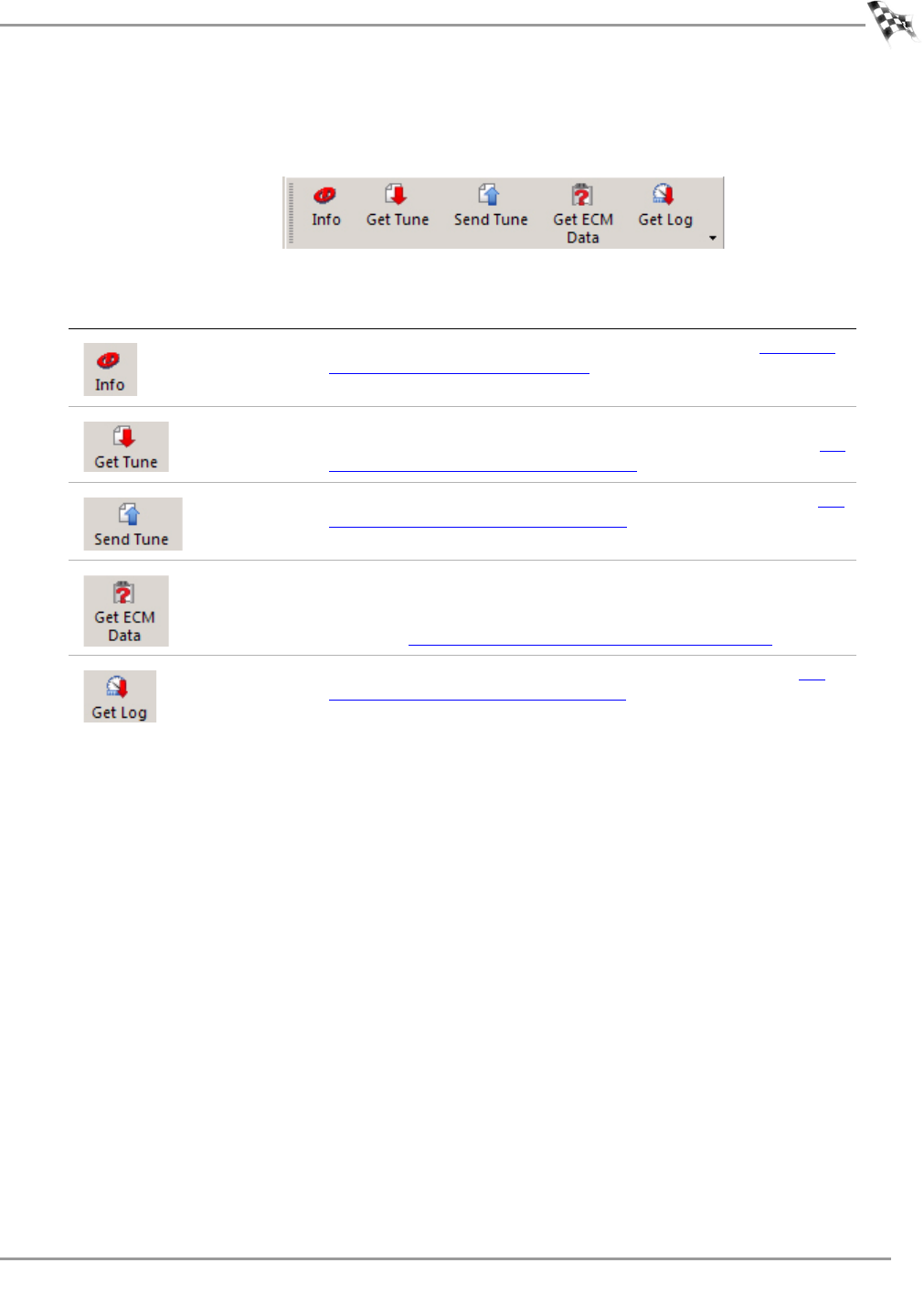
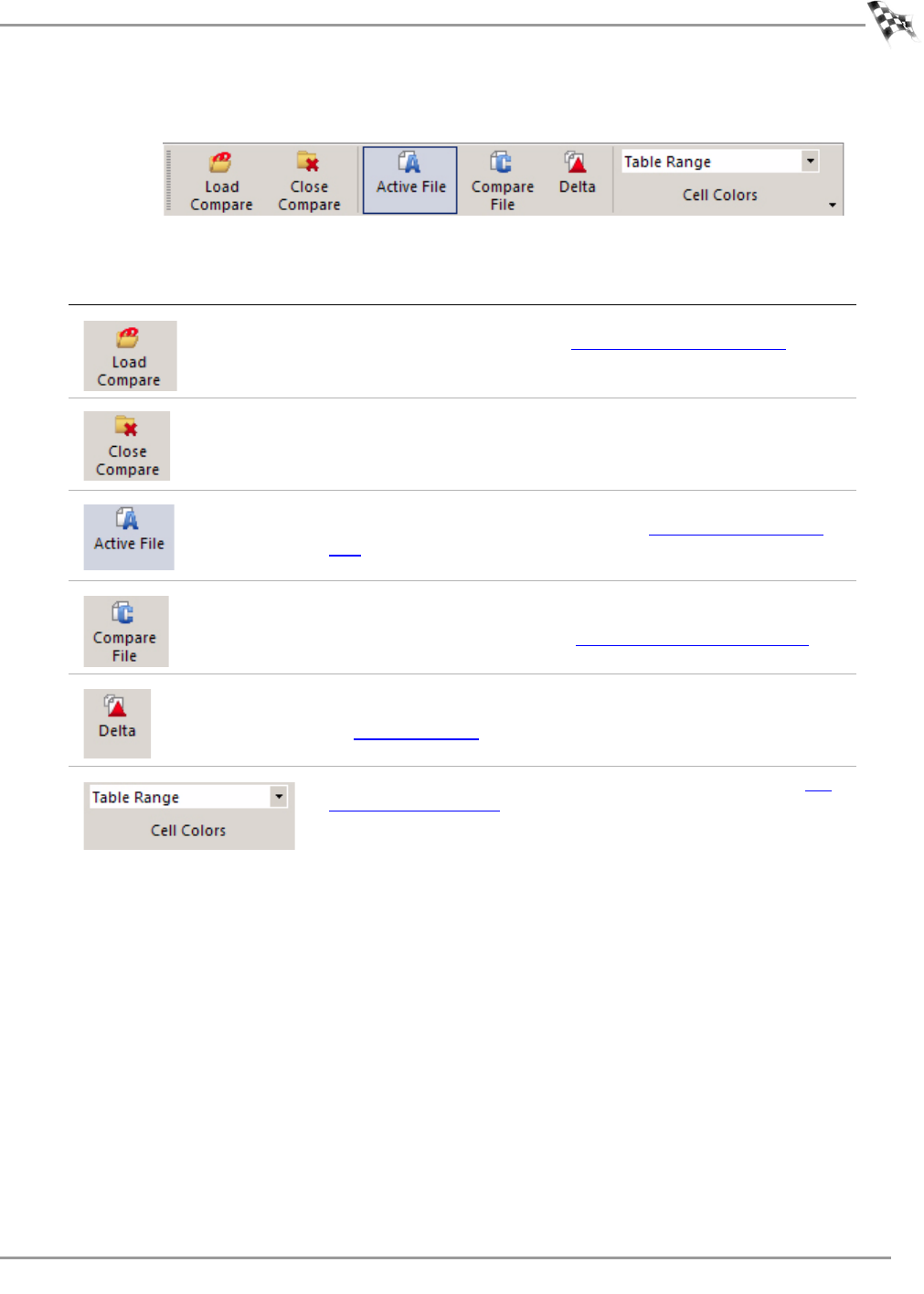
Compare Toolbar
A description of the compare toolbar buttons and functions follows.
press this button to
Load a tune file previously saved on your computer as
the compare file. Refer to To Load a Compare File.
Close the compare file and return to a single active tune
file.
Active File allows you to view the active file when
comparing two tune files. Refer to To View the Active
File.
Compare File allows you to view the loaded compare file
when comparing two tune files. The Compare File
cannot be edited. Refer to To View the Compare File.
Show the difference between the active file and the
compare file for the tune item you have selected. Refer
to To View Delta.
Change the colors of the cells in the table. Refer to To
Choose Cell Colors.
WinPV User Guide
CHAPTER 3
WinPV Toolbar
3-36
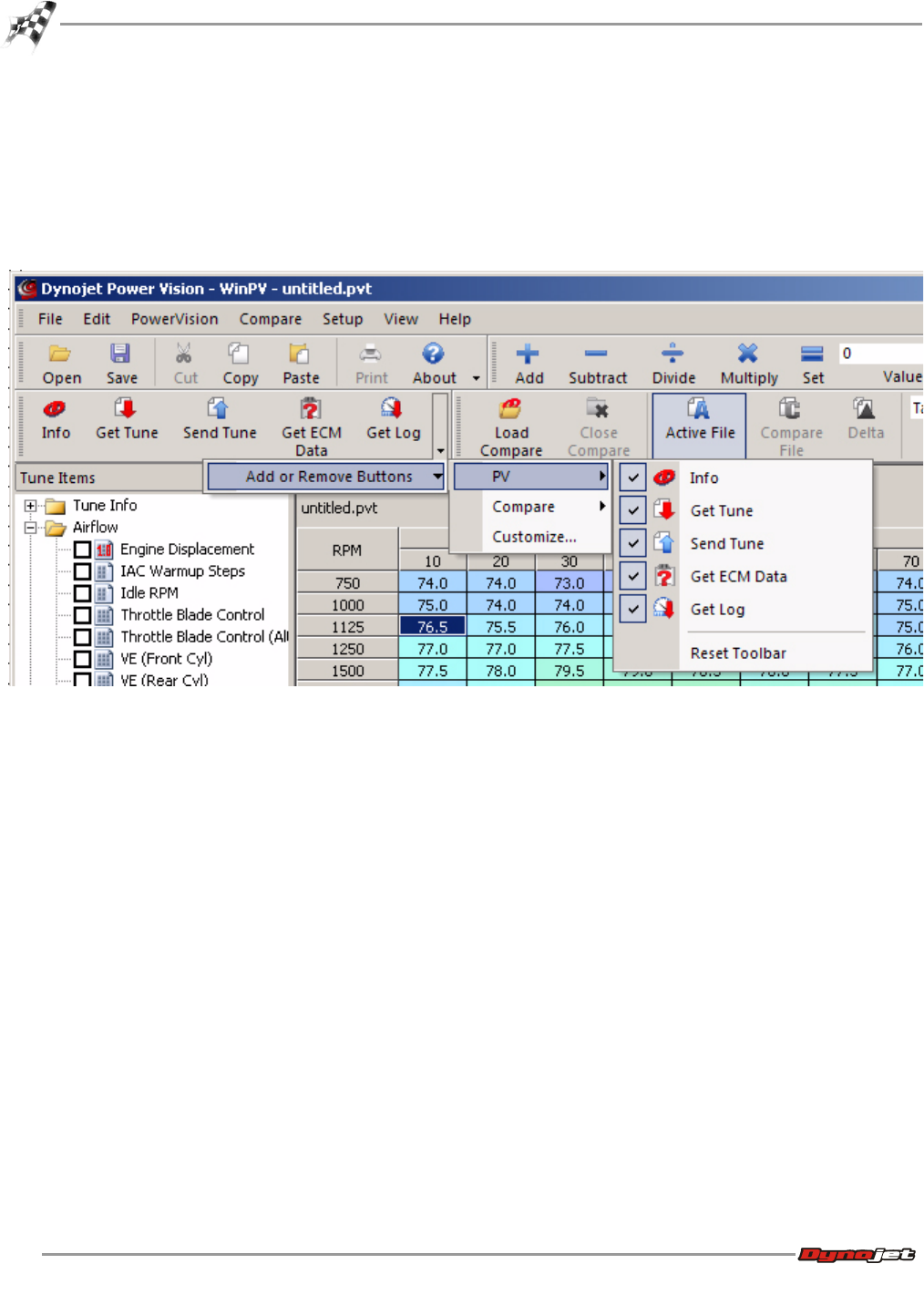
Customizing the Toolbars
The buttons on each toolbar can be customized to suit your individual needs.
1Click the arrow found at the end of a toolbar.
2Select which toolbar you wish to customize.
3Select which buttons you wish to appear or not appear on the toolbar.
WORKING WITH WINPV
Tune Items
Version 6 WinPV User Guide
3-37
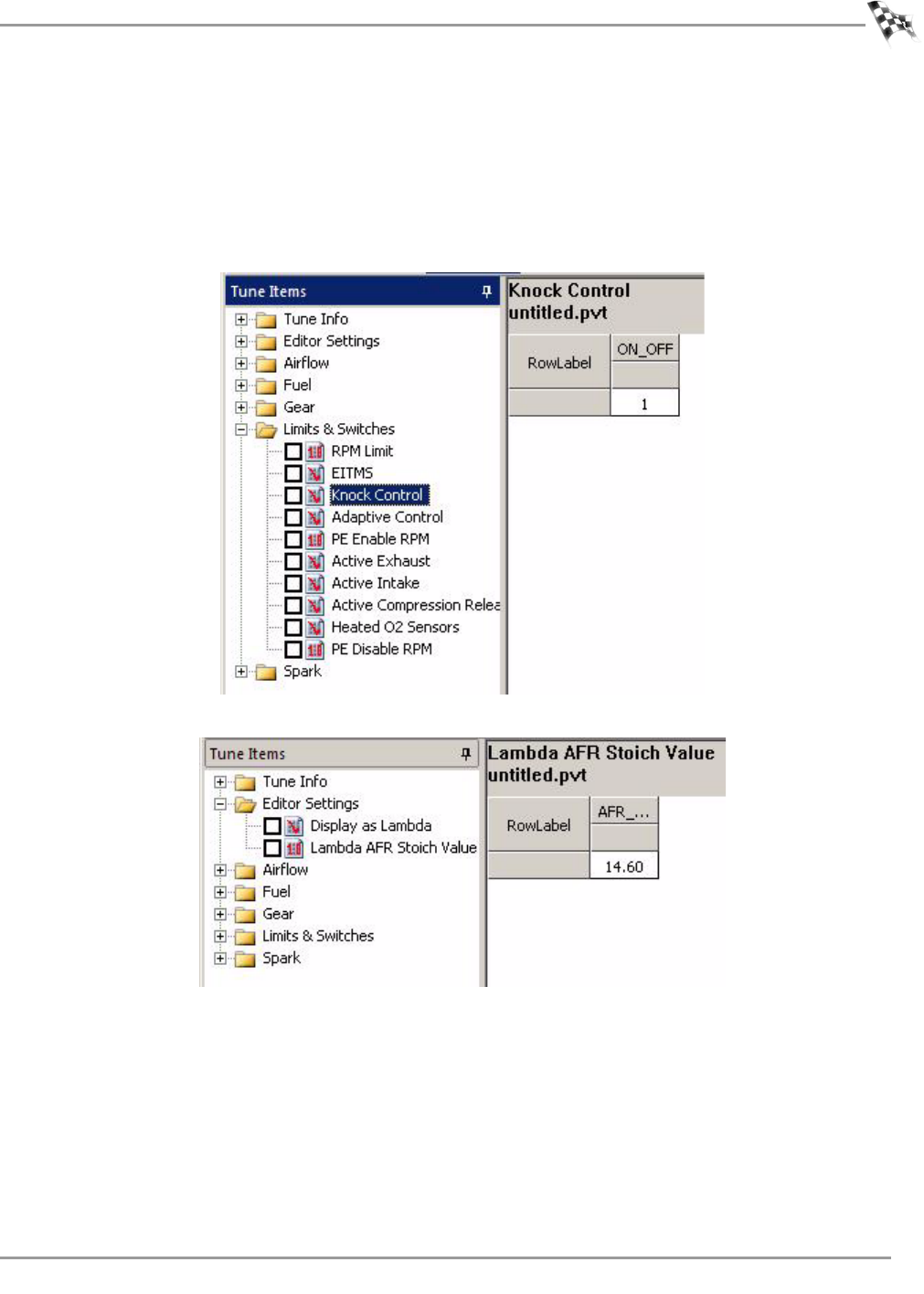
Tune Items
Tune Items shows the available values, parameters, and tables. All of these values affect the
way the vehicle performs.
Tune Items fall into one of the three categories:
• Switch—values that are either on/off, yes/no, true/false, 0/1, etc.
• Scalar—values that are a single number.
WinPV User Guide
CHAPTER 3
Tune Items
3-38
• Tables—values that are displayed in multiple columns and/or rows.
Click the plus sign (+) to expand the items; click the minus sign (-) to compress the items.
Click on the desired tune item to view that item. Many tune items are described in this
section.
WORKING WITH WINPV
Tune Items
Version 6 WinPV User Guide
3-39
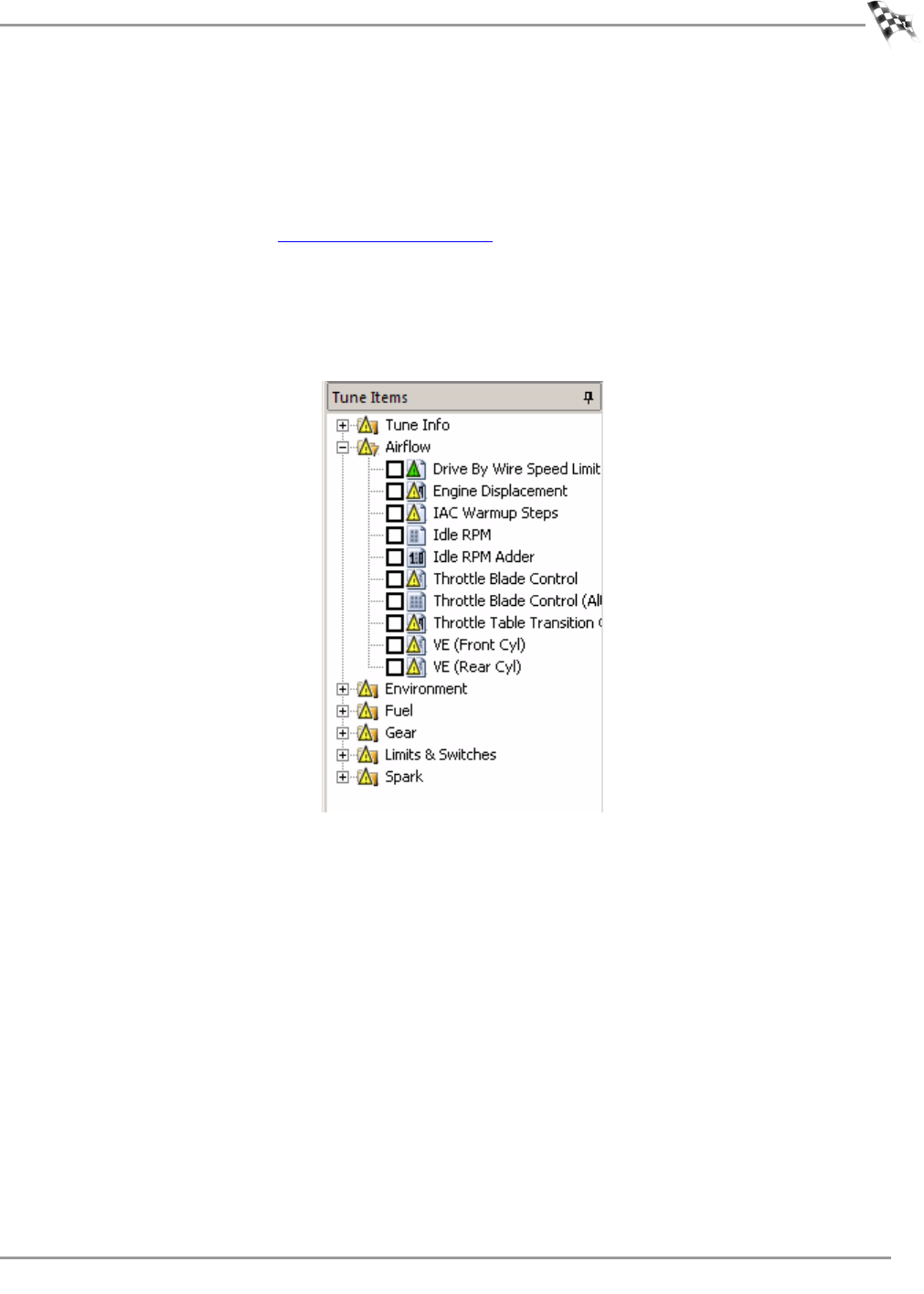
When using the compare feature, a colored flag may be visible next to certain tune items.
These visual identifiers helps you distinguish parameters that don’t match when using the
compare feature. Visual identifiers offer a quick and easy way to identify where the tune has
changed.
You must have a compare file open to use the visual identifiers. For more information about
the compare feature, refer to To Load a Compare File.
There are three visual identifiers:
• Yellow Flag—different.
• Green Flag—does not exist in the compare file, but does exist in the active file.
• Red Flag—exists in the compare file, but does not exist in the active file.

WinPV User Guide
CHAPTER 3
Tune Items
3-40
Tune Info
Airflow
tune item description
Description This is the vehicle and ECM description. Displays Year, Make,
Model, Vin and ECM part number.
Calibration ID This is the stock ECM calibration ID number.
tune item description
Engine Displacement This value is the displacement of both cylinders. When
changing engine size it's easier to ratio this value up and down
by the difference in displacement. Input the actual engine
displacement into this field. Available in pro user level only.
IAC Warm-up Steps The Intake Air Control Warm-up Steps table is used to
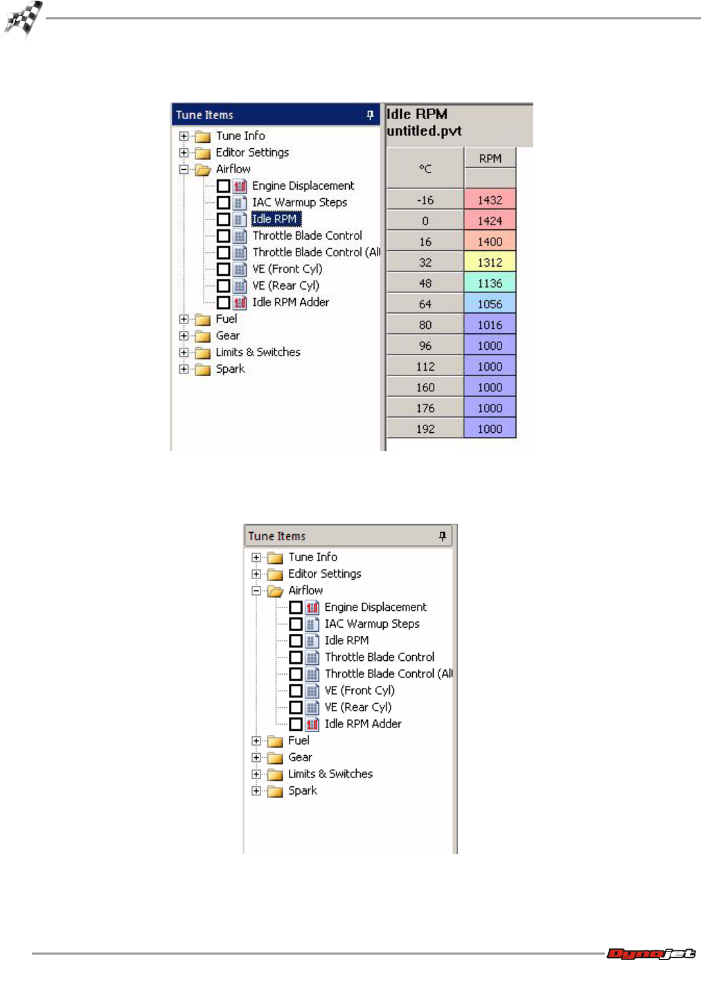
maintain a stable idle during warm-up. This table determines
the initial position of the IAC motor to maintain RPM at a given
temperature. The closer this table is to the actual IAC opening
the better the idle will be. Available in pro user level only.
Idle RPM The Idle speed is controlled by the idle RPM table as a function
of engine temp. To increase idle make these values larger. To
decrease idle make these values smaller. Available in pro user
level only.
Setting Idle RPM below 900 RPM can cause oil pressure to
drop.
Throttle Blade Control
(Stage II) This is used in drive by wire systems. This table represents
the desired throttle percent as a function of RPM. Throttle
Blade Control (Stage II) is used once the throttle transition
gear has been reached. Drive by wire Harleys use two throttle
blade control tables. To use Throttle Blade Control (Stage II)
exclusively, set Throttle Transition Gear to 0.
Throttle Blade Control
(Stage I) This is used in drive by wire systems. This table represents
the desired throttle percent as a function of RPM. Throttle
Blade Control (Stage I) is used until the throttle transition
gear has been reached. Drive by wire Harleys use two throttle
blade control tables. To use Throttle Blade Control (Stage I)
exclusively set Throttle Transition Gear to 6.
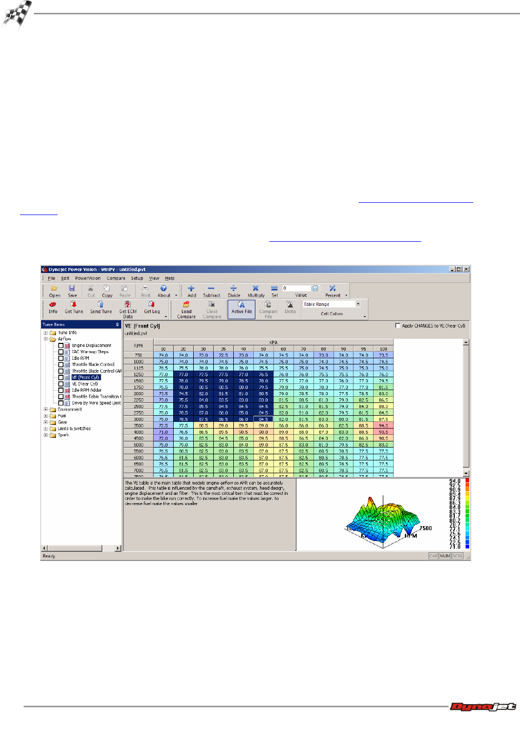
VE (Front) The Volumetric Efficiency (Front) table is for the front cylinder
and is the table that models engine airflow so AFR can be
accurately calculated. The values in this table are influenced
by the camshaft, exhaust system, head design, engine
displacement and air filter. This is the most critical item that
must be correct in order to make the bike run correctly. To
increase fuel make the values larger. To decrease fuel make
the values smaller.

WORKING WITH WINPV
Tune Items
Version 6 WinPV User Guide
3-41
Environment
VE (Rear) The Volumetric Efficiency (Rear) table is for the rear cylinder
and is the table that models engine airflow so AFR can be
accurately calculated. The values in this table are influenced
by the camshaft, exhaust system, head design, engine
displacement and air filter. This is the most critical item that
must be correct in order to make the bike run correctly. To
increase fuel make the values larger. To decrease fuel make
the values smaller.
Idle RPM Adder This is an idle speed RPM adder. Positive values will add RPM
to the entire IDLE RPM Function, while negative values will
reduce RPM.
Throttle Table Transition
Gear This is the gear that Throttle Blade Control Table (Stage I) will
transition to Throttle Blade Control. To use the throttle blade
control table only, change this value to 0.
Drive By Wire Speed Limit
vs Gear This is the speed limit for vehicle protection based on gear.
Set this to what you want the vehicle speed limit to be in
gears one through six.
tune item description
EITMS On Temperature The Engine Idle Temperature Management System (EITMS)
On Temp is activated at temperatures greater than this
setting. The EITMS shuts off the fuel to the rear cylinder
allowing the head to cool. Available in pro user level only.
EITMS Off Temperature The Engine Idle Temperature Management System (EITMS)
Off Temperature is activated at temperatures below this
setting. The EITMS shuts off the fuel to the rear cylinder
allowing the head to cool. Available in pro user level only.
Knock Control Enable
Temperature Knock Control will be activated at temperatures greater than
this setting. Available in pro user level only.
Knock Control Disable
Temperature Knock Control will be de-activated at temperatures lower than
this setting. Available in pro user level only.
Adaptive Control Enable
Temperature Adaptive Control will be enabled at temperatures greater than
this setting. Available in pro user level only.
tune item description

WinPV User Guide
CHAPTER 3
Tune Items
3-42
Fuel
tune item description
Injector Size Fuel injector flow base value in grams per second. This value
will need to be changed for larger injectors. 1 gram per
second equals 7.94 pounds per hour. 1 pound per hour equals
0.126 grams per second. Available in pro user level only.
Example 1: injectors that are 4.35 grams per second are 34.5
pounds per hour. Multiply 4.35 x 7.94 = 34.5.
Example 2: injectors that are 42 pounds per hour are 5.29
grams per second. Multiply 42 x 0.126 = 5.29.
Air-Fuel Ratio (Lambda) The Air-Fuel Ratio Lambda table directly controls closed-loop
AFR from idle to red line. This is a value of Lambda. A value of
1 represents 1 times 14.64 for an AFR ratio of 14.64. A value
of 0.90 means 0.90 times 14.64 for a commanded AFR ratio of
13.1.
Acceleration Enrichment Acceleration Enrichment mode can be triggered by a sudden
change in throttle position or an increase in MAP pressure. To
increase the fuel delivered, increase the values.
Air-Fuel Ratio (Stoich) The Air-Fuel Ratio Stoich table directly controls closed-loop
AFR from idle to red line. This is a value of AFR Ratio.
Cranking Fuel Cranking Fuel is a multiplier based on engine temperature. A
larger number will supply more fuel during the cranking cycle.
A smaller number will reduce the amount of cranking fuel
during the cranking cycle. Cranking Fuel only applies to
starting the engine (when the starter is active).
Deceleration Enleanment Deceleration Enleanment mode can be triggered by a sudden
decrease in throttle position or MAP pressure. To increase the
fuel delivered on deceleration, decrease the value. To reduce
the amount of fuel delivered increase the value.
PE Air Fuel Ratio
(Lambda/Stoich) Power Enrichment mode is active at higher RPMs and when
the throttle position is greater than 95 percent. The purpose
of PE mode is to operate the engine at maximum torque AFR
and spark values for a short time, then adjust to more
conservative values to reduce engine temperature. Available
in pro user level only.
Warmup Enrichment
(Lambda) The warm up enrichment table adds additional fuel after start
up. The fuel from this table decays out over time. The table is
activated only once per key-on. If the engine stalls and is
restarted without cycle in the ignition, enrichment continues
from its value when the stall occurred.
Warmup Enrichment
(Stoich) The warm up enrichment table adds additional fuel after start
up. The fuel from this table decays out over time, and it is
only active for 20 to 30 seconds. The table is activated only
once per key-on. If the engine stalls and is restarted without
cycle in the ignition, enrichment continues from its value when
the stall occurred.

WORKING WITH WINPV
Tune Items
Version 6 WinPV User Guide
3-43
Closed Loop
Gear
Acceleration Enrichment
Multiplier This will determine the total amount of fuel to add during
rapid changes in acceleration. To "globally" increase the
amount of fuel added during acceleration enrichment increase
this vale. To reduce the amount of fuel delivered decrease this
value. Available in pro user level only.
Deceleration Enrichment
Multiplier This will determine the total amount of fuel to add or reduce
during rapid changes in acceleration. To "globally" increase
the amount of fuel added during deceleration enrichment
decrease this vale. To reduce the amount of fuel delivered
increase this value. Available in pro user level only.
MPG Adjustment This adjusts the MPG readout for the bike. Higher values show
a higher MPG, lower values show lower MPG.
Injector Gas Constant This is a constant used internally for fuel injector calculations.
Usually set to 1.000.
tune item description
Closed Loop Bias Front The closed loop bias table is used to adjust the closed loop
AFR. Setting the value in this table to 450 mV will result in a
closed loop AFR of 14.68; increasing the value will give a
richer mixture and decreasing the value will give a leaner
mixture. Available in pro user level only.
Closed Loop Bias Rear The closed loop bias table is used to adjust the closed loop
AFR. Setting the value in this table to 450 mV will result in a
closed loop AFR of 14.68; increasing the value will give a
richer mixture and decreasing the value will give a leaner
mixture. Available in pro user level only.
tune item description
Speedometer Calibration This is the ratio the bike has in it from the factory. This must
be changed to the new ratio when changing tire size. Available
in pro user level only.
Gear Ratios Description not available at this time.
tune item description

WinPV User Guide
CHAPTER 3
Tune Items
3-44
Limits and Switches
tune item description
RPM Limit Set these values to the RPM at which the rev limiter will
engage. 6200 RPM is common for most 96ci to 103ci
combinations; 10250 RPM for VROD.
EITMS This tells the ECM if the vehicle has a Engine Idle Temperature
Management System. A value of zero means this vehicle does
not have this feature, or shuts off the input to the ECM.
Available in pro user level only.
Knock Control This tells the ECM if the vehicle has Knock Control. A value of
zero means this vehicle does not have this feature, or shuts
off the knock control to the ECM. A value of one means this
vehicle does have this feature and the ECM will attempt to
control knock.
Adaptive Control When in closed loop the ECM will adapt to engine and
environmental changes to maintain a consistent AFR. This
works by the ECM first using the VE table to calculate how
much fuel to deliver to hit the targeted AFR value. It then uses
the O2 sensors to determine what the AFR actually is. If there
is a difference, the ECM makes an adjustment and stores the
difference in the adaptive fuel table. The Adaptive Fuel table
will develop a correction profile that is applied to the fuel
calculation for each load region. These values are saved in the
ECM's memory and will be reloaded each time the bike is
started. Available in pro user level only.
PE Enable RPM Power Enrichment Mode will be activated at RPMs greater than
this setting. To disable PE, set this value to your RPM limit or
greater than your RPM limit.
Active Exhaust This tells the ECM if the vehicle has active exhaust control. A
value of zero means this vehicle does not have this feature, or
shuts off the input to the ECM. Available in pro user level only.
Active Intake This tells the ECM if the vehicle has active intake. A value of
zero means this vehicle does not have this feature, or shuts
off the input to the ECM. Available in pro user level only.
Active Compression
Release This tells the ECM if the vehicle has active compression
release. A value of zero means this vehicle does not have this
feature, or shuts off the input to the ECM. Available in pro
user level only.
Heated O2 Sensors This tells the ECM if the vehicle has heated O2 sensors. A
value of zero means this vehicle does not have this feature, or
shuts off the input to the ECM. Available in pro user level only.
PE Enable TPS Power Enrichment Mode will be activated if TPS is greater than
this setting. Available in pro user level only.
PE Disable TPS Power Enrichment Mode will be disabled if TPS is less than this
setting. Available in pro user level only.

WORKING WITH WINPV
Tune Items
Version 6 WinPV User Guide
3-45
Spark
PE Disable RPM Power Enrichment Mode will be disabled at RPMs less than this
setting. Available in pro user level only.
Closed Loop For closed-Loop capable calibration, set this to off to disable
closed-loop control.
tune item description
PE Spark Power Enrichment mode is active at higher RPMs and when
the throttle position is greater than 95 percent. This table is
desired spark over time. The purpose of PE mode is to operate
the engine at maximum torque AFR and spark values for a
short time, then adjust to more conservative values to reduce
engine temperature. Available in pro user level only.
Spark Advance (Front) There are two spark tables, one for each cylinder. This is
because the rear cylinder runs hotter than the front and
therefore has different timing requirements. The X-axis is KPA
the Y-Axis is RPM. Set these values to the spark advance you
would like the bike to operate at. Available in pro user level
only.
Spark Advance (Rear) There are two spark tables, one for each cylinder. This is
because the rear cylinder runs hotter than the front and
therefore has different timing requirements. The X-axis is KPA
the Y-Axis is RPM. Set these values to the spark advance you
would like the bike to operate at. Available in pro user level
only.
Max Knock Retard This is the maximum amount of knock retard the ECM will
allow. Available in pro user level only.
Adaptive Knock Retard The Delphi ECM utilizes Adaptive Spark Control based on
information received from the knock detection system. This
system learns retard values to apply when knock is detected.
At each key-on the remembered values will be reduced
towards zero. This gradually clears out the learned knock
value to adapt changes in conditions. Available in pro user
level only.
Closed Throttle Spark
(Front) This is the spark to run when the throttle is closed. This table
can be modified to allow the engine to run at different spark
values when the throttle is closed. This table will replace the
spark advance table and any temperature corrections when
the throttle is closed.
Closed Throttle Spark
(Rear) This is the spark to run when the throttle is closed. This table
can be modified to allow the engine to run at different spark
values when the throttle is closed. This table will replace the
spark advance table and any temperature corrections when
the throttle is closed.
tune item description
WinPV User Guide
CHAPTER 3
Table
3-46
Table
The Table displays the item chosen in Tune Items.
The table is also displayed as a 3-D representation below the table.
1Click one cell to select it.
2Click and hold the mouse button while dragging to select multiple cells.
Selected cells will appear with cross-hairs in the graphical display in the 3-D
representation below the table.
3Select a cell or group of cells, copy those values, and paste those values in different
cell(s). For more information about changing cell values, refer to To View the Cell Math
Toolbar.
4You may also select a cell or group of cells and type values into those cells. For more
information about changing cell values, refer to To View the Cell Math Toolbar.

WORKING WITH WINPV
Status Bar
Version 6 WinPV User Guide
3-47
Status Bar
The Status Bar shows the status of the connected device.

WinPV User Guide
4-1
CHAPTER
4
W
ORKING
WITH
P
OWER
V
ISION
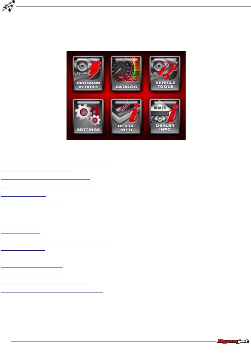
The Power Vision incorporates a very sophisticated, yet simple touch screen display that does
not require the use of a computer to flash your bike. Simply select the tune and follow the
on-screen prompts to download the tune, and if you'd like, edit your tune without ever
touching a computer! Anyone of the three types of tunes outlined below is able to be edited
on the device, or in the WinPV Tuning Application. Power Vision downloads and stores the
stock calibration, allows you to select up to five different tunes that are stored on the device,
and can be flashed to your bike. The types of tunes include:
Dynojet Pre-configured Tunes—Tunes for YOUR bike pre-loaded on the device…….ready to go,
right out of the box! Power Vision identifies your bike's information and automatically sorts
hundreds of applicable dyno proven tunes for you to choose from.
Custom Tunes - loaded by a custom tuning shop, or received via email and loaded on the
device.
Copy of Stock - a version of the stock calibration that is editable.
Power Vision provides insightful, valuable information on how your bike is running.
• Display all J1850 H-D vehicle data, H-D CAN vehicle data, as well as wideband AFR and
various calculated channels (such as MPG instant and trip MPG).
• Customizable virtual gauges allow data to be monitored live, and/or logged while
riding.
• User defined visual alarms for any data channel (example, if knock exceeds two
degrees, or if Cylinder Head Temp exceeds 280°F, enable visual alarm).
• AutoTune Basic and Pro—calculates and stores fuel trims to optimize fuel curve.
• Check and clear diagnostic codes.
• Reset adaptive fuel trims and idle offset.
WinPV User Guide
CHAPTER 4
Power Vision Menus
4-2
Power Vision Menus
Program Vehicle Menu
To Load a Dynojet Pre-Configured Tune File
To Load a Custom Tune File
To Load a Copy of Original Tune File
To Load a Copy of Current Tune File
To Edit a Tune File
To Check the ECM Status
Datalog Menu
To View Gauges
To Create Gauge Limits and Visual Warnings
To Playback a Log
To View Signals
To Reset Trip/Economy A
To Reset Trip/Economy B
To Create a Log with Power Vision
To Return to the Power Vision Main Menu

WORKING WITH POWER VISION
Power Vision Menus
Version 6 WinPV User Guide
4-3
Vehicle Tools Menu
To View Vehicle Info
To View Stored DTC’s
To Reset Trims
To Read ECM
To Restore Original Tune
To Return to the Power Vision Main Menu
Settings Menu
To Select the Units
To Change the Brightness
To Enter a Code
To Calibrate the Touch Screen
To Flip the Power Vision Screen
To Return to the Power Vision Main Menu
Device Info Menu
To View Information About the Power Vision
Dealer Info Menu
To View Information About the Dealer
WinPV User Guide
CHAPTER 4
Power Vision Menus
4-4
Program Vehicle Menu
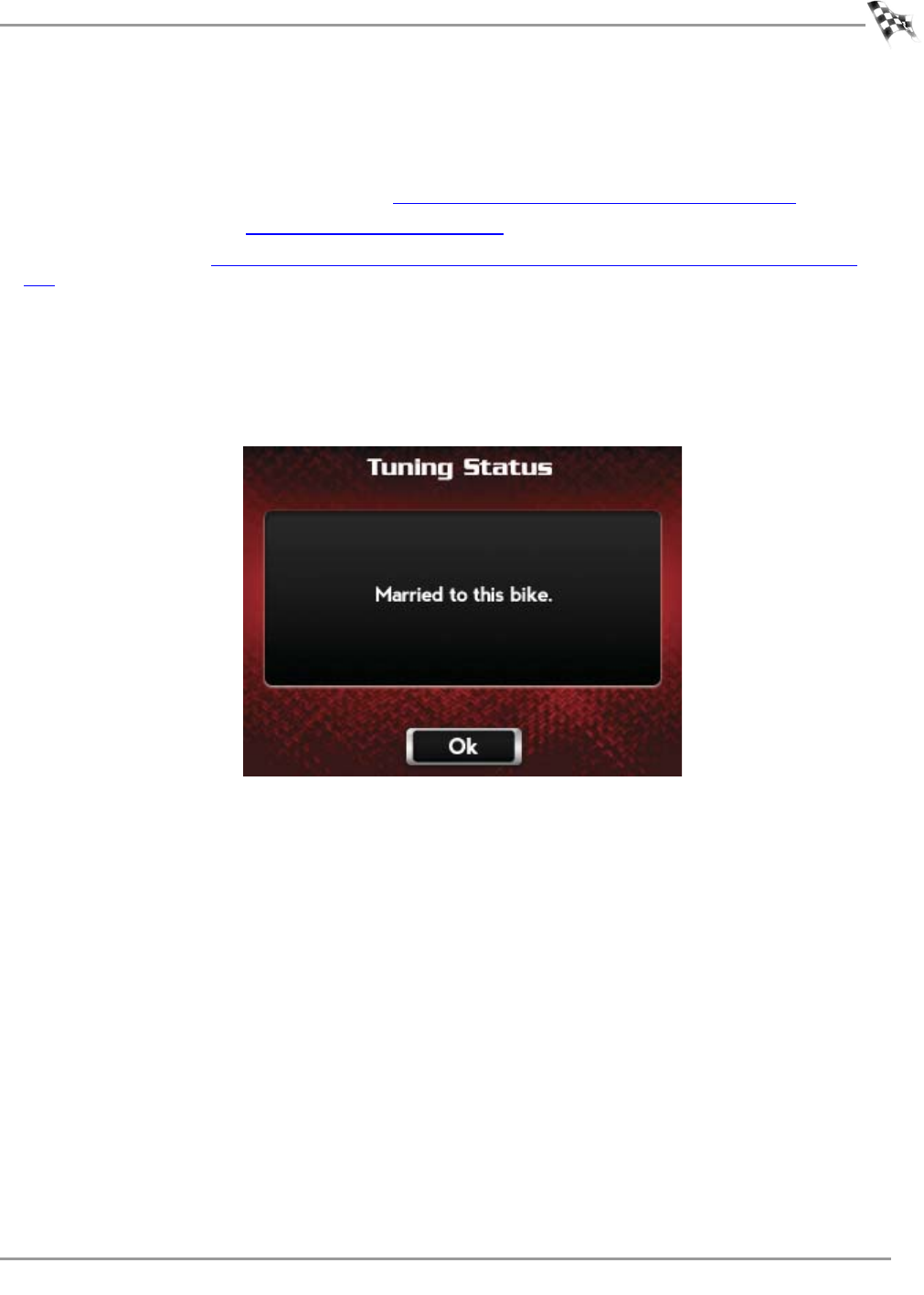
The Power Vision accepts custom tune files created in WinPV and pre-loaded Dynojet tunes
installed in the Power Vision memory from Dynojet Research. To flash or edit tune files, the
Power Vision must be married to the ECM. Marrying the Power Vision to the ECM locks the
Power Vision module to that ECM and prevents a single device from being used on multiple
ECMs. You cannot unlock a Power Vision from a married ECM. Once the marriage process is
complete, you can open the stored calibration in the WinPV software to edit all parameters or
change Dynojet specific functions on the device.
To Load a Dynojet Pre-Configured Tune File
Use the following steps to load a Dynojet pre-configured tune file to the ECM.
1Turn the ignition key to the On position.
2Verify the Run/Off switch is in the Run position.
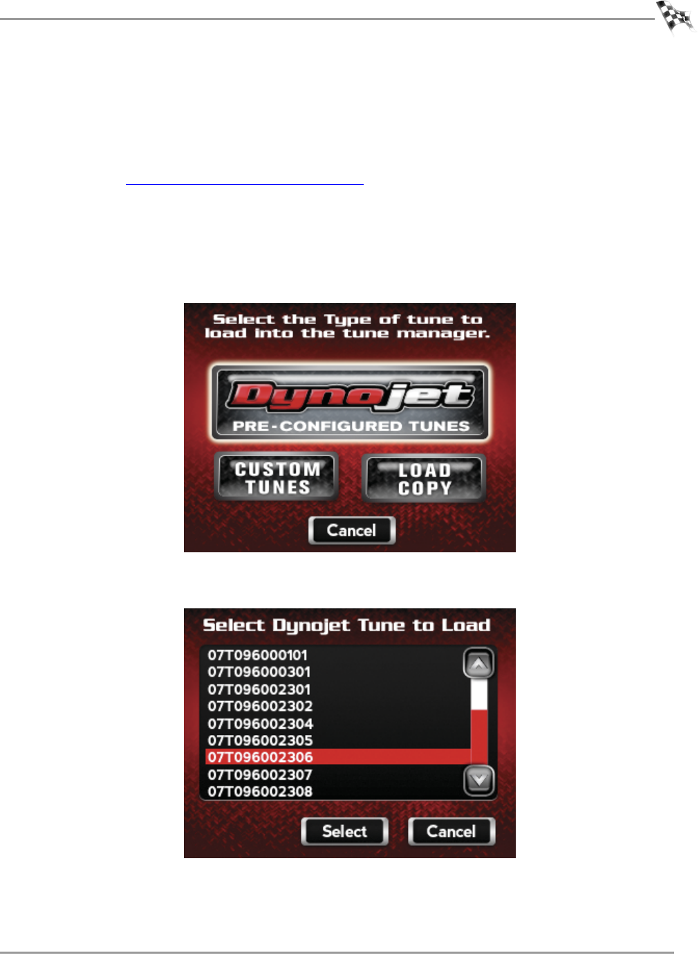
3Touch Program Vehicle >Load Tune >Dynojet Pre-Configured Tunes.
WORKING WITH POWER VISION
Power Vision Menus
Version 6 WinPV User Guide
4-5
4Touch a Dynojet tune file to load.
5Touch Select to continue with the selected Dynojet tune file.
Or
Touch Cancel to abort the process and return to the load tune screen.
6Verify the Tune information. If the Tune information is correct, touch Continue.
WinPV User Guide
CHAPTER 4
Power Vision Menus
4-6
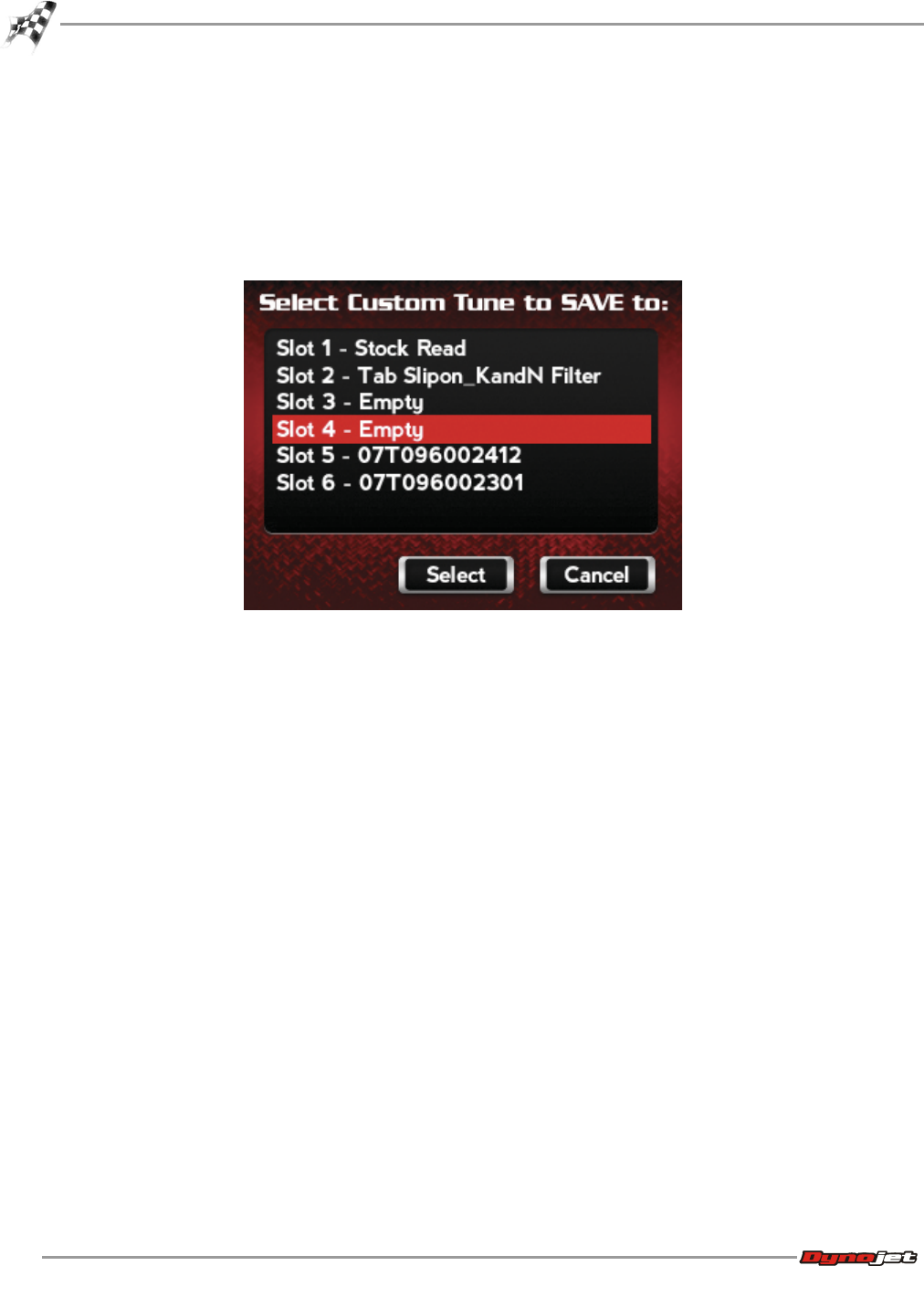
7Touch a slot to save the selected tune file.
Note:If there is any data in the selected slot, it will be overwritten.
8Touch Select to continue with the selected slot.
Or
Touch Cancel to abort the process and return to the tune manager.
9Touch OK to continue.
A copy of the Dynojet tune will be saved.
Or
Touch Cancel to abort the process and return to the tune manager.
The tune is now ready.
WORKING WITH POWER VISION
Power Vision Menus
Version 6 WinPV User Guide
4-7
10 Touch Flash to send the file to the ECM.
Or
Touch Edit to edit the tune file on the Power Vision.
Or
Touch Exit to exit the screen without any changes.
11 Touch OK.
12 Turn the ignition key off and wait ten seconds.

WinPV User Guide
CHAPTER 4
Power Vision Menus
4-8
To Load a Custom Tune File
The Power Vision accepts custom tune files created in the WinPV software or by Dynojet
dealers.
Use the following steps to load a custom tune file to the ECM.
1Turn the ignition key to the On position.
2Verify the Run/Off switch is in the Run position.
3Touch Program Vehicle >Load Tune >Custom Tunes.
4Touch a Custom tune file to load.
5Touch Select to continue with the selected Custom tune file.
Or
Touch Cancel to abort the process and return to the tune file screen.
6Touch a slot to save the selected tune file.
Note:If there is any data in the selected slot, it will be overwritten.
7Touch Select to continue with the selected slot.
Or
Touch Cancel to abort the process and return to the tune manager.
8Touch OK to continue.
Or
Touch Cancel to abort the process and return to the tune manager.
The tune is now ready.
9Touch Flash to send the file to the ECM.
Or
Touch Edit to edit the tune file on the Power Vision.
Or
Touch Exit to exit the screen without any changes.
10 Touch OK.
11 Turn the ignition key off and wait ten seconds.
12 Turn the ignition key back on.
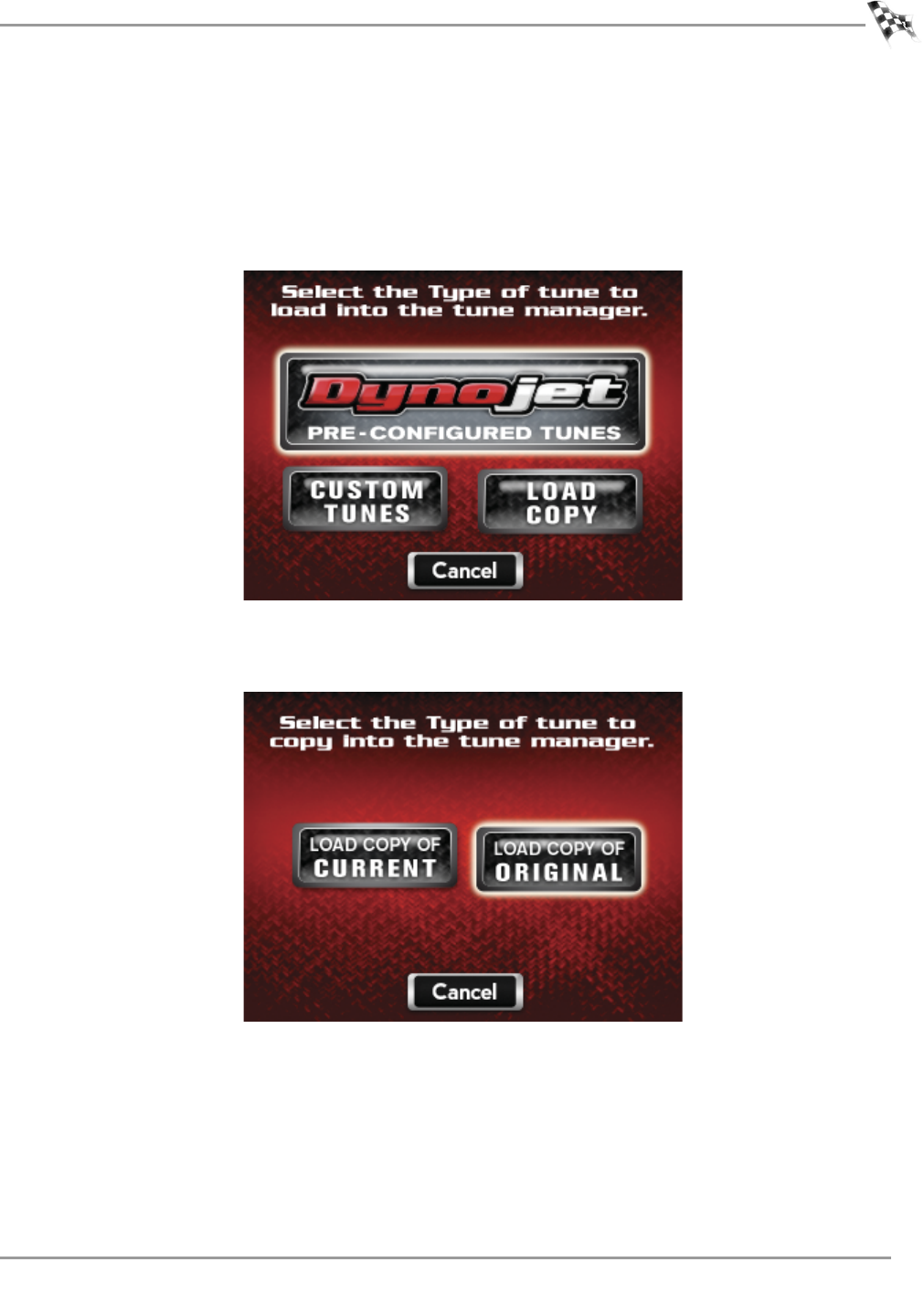
WORKING WITH POWER VISION
Power Vision Menus
Version 6 WinPV User Guide
4-9
To Load a Copy of Original Tune File
Use the following steps to load a copy of the original tune file to the Power Vision. The
original tune file is the tune that was saved when the Power Vision married to the ECM.
1Turn the ignition key to the On position.
2Verify the Run/Off switch is in the Run position.
3Touch Program Vehicle >Load Tune >Load Copy.
4Touch Load Copy of Original.
This will load a copy of the original tune into the Tune Manager. Once loaded into a slot, it
will be converted into a custom tune which can be edited and/or flashed to the ECM.
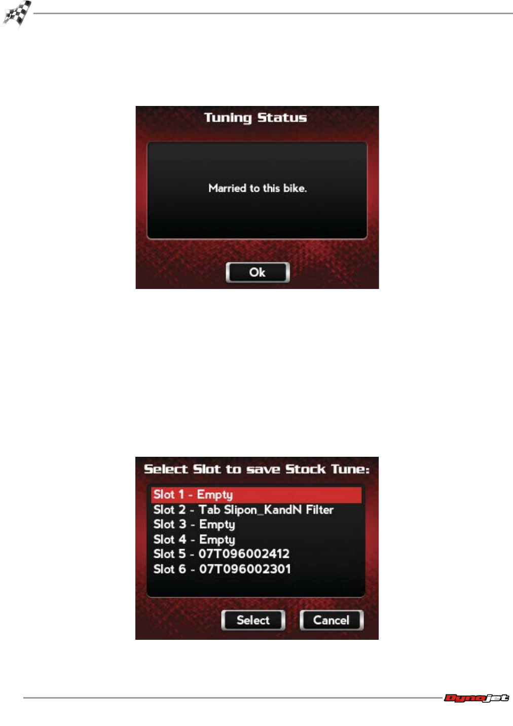
WinPV User Guide
CHAPTER 4
Power Vision Menus
4-10
5Touch OK.
The Power Vision and the bike are now married.
6Touch OK.
7Touch a slot to save the selected tune file.
Note:If there is any data in the selected slot, it will be overwritten.
8Touch Select to continue with the selected slot.
Or
Touch Cancel to abort the process and return to the tune manager.
9Touch OK.
A copy of the stock tune will be saved.
10 Touch OK to continue.
Or
Touch Cancel to abort the process and return to the tune manager.
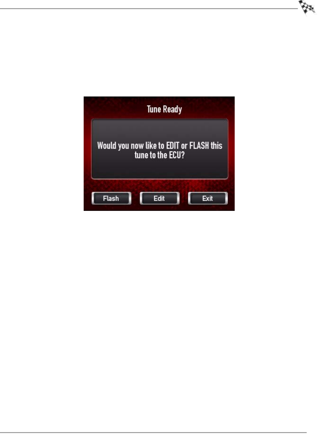
WORKING WITH POWER VISION
Power Vision Menus
Version 6 WinPV User Guide
4-11
The tune is now ready.
11 Touch Flash to send the file to the ECM.
Or
Touch Edit to edit the tune file on the Power Vision.
Or
Touch Exit to exit the screen without any changes.
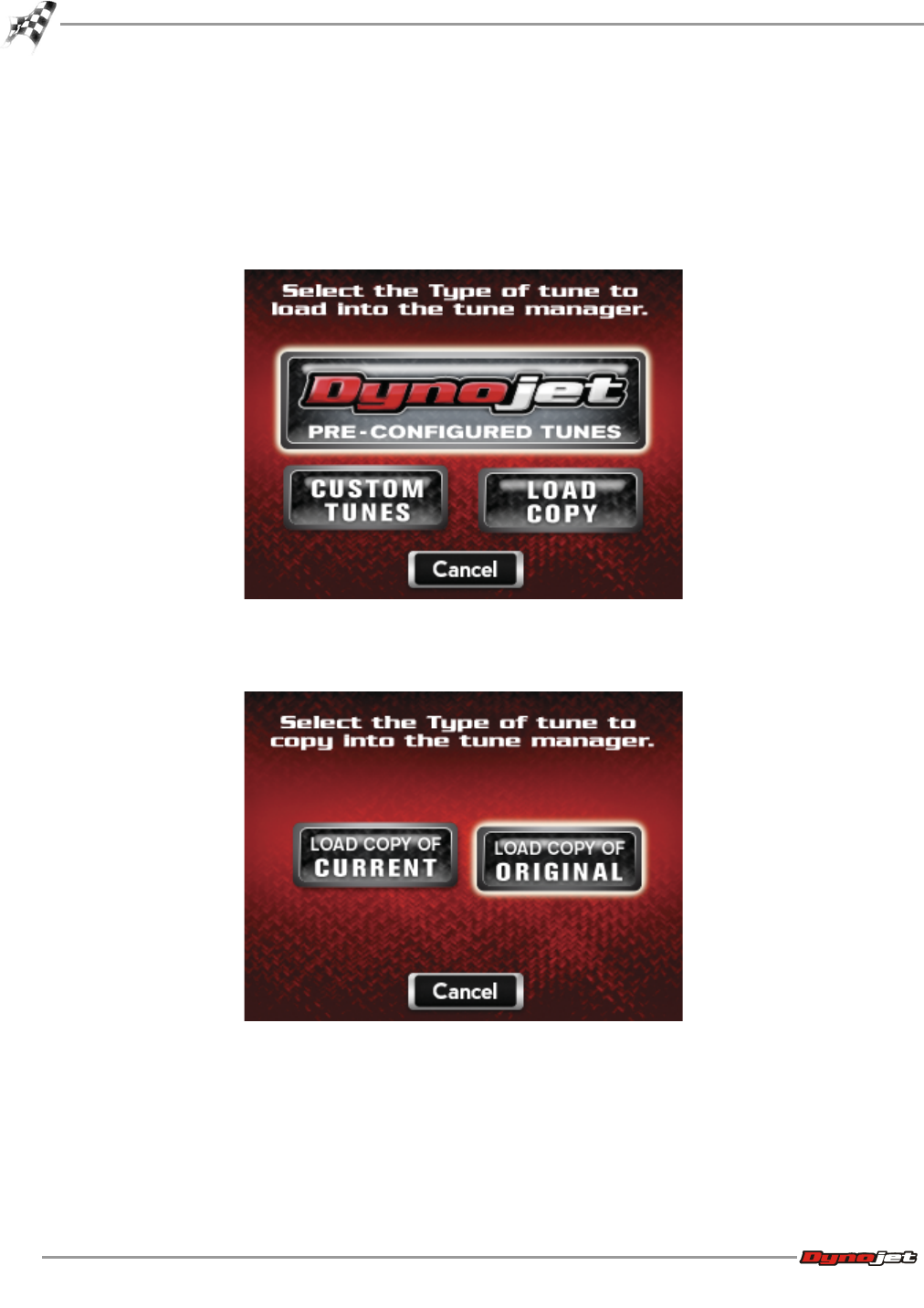
WinPV User Guide
CHAPTER 4
Power Vision Menus
4-12
To Load a Copy of Current Tune File
Use the following steps to load a copy of the current tune file to the Power Vision. The current
tune file is the tune that is currently in the ECM.
1Turn the ignition key to the On position.
2Verify the Run/Off switch is in the Run position.
3Touch Program Vehicle >Load Tune >Load Copy.
4Touch Load Copy of Current.
This will load a copy of the current tune into the Tune Manager. Once loaded into a slot, it
will be converted into a custom tune which can be edited and/or flashed to the ECM.
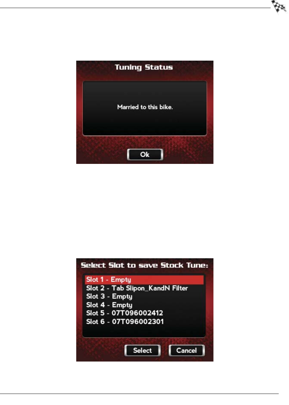
WORKING WITH POWER VISION
Power Vision Menus
Version 6 WinPV User Guide
4-13
5Touch OK.
The Power Vision and the bike are now married.
6Touch OK.
7Touch a slot to save the selected tune file.
Note:If there is any data in the selected slot, it will be overwritten.
8Touch Select to continue with the selected slot.
Or
Touch Cancel to abort the process and return to the tune manager.
9Touch OK.
A copy of the current tune will be saved.
10 Touch OK to continue.
Or
Touch Cancel to abort the process and return to the tune manager.
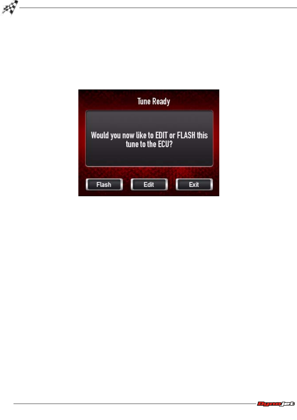
WinPV User Guide
CHAPTER 4
Power Vision Menus
4-14
The tune is now ready.
11 Touch Flash to send the file to the ECM.
Or
Touch Edit to edit the tune file on the Power Vision.
Or
Touch Exit to exit the screen without any changes.

WORKING WITH POWER VISION
Power Vision Menus
Version 6 WinPV User Guide
4-15
To Edit a Tune File
Edit Tune allows you to edit Dynojet Tune, Custom Tune, or Copy of Stock Tune files directly
on the Power Vision.
Use the following steps to edit a tune on the Power Vision.
1Turn the ignition key to the On position.
2Verify the Run/Off switch is in the Run position.
3Touch Program Vehicle >Edit Tune.
4Touch a tune slot to edit.
5Touch Select to use the selected slot.
Or
Touch Cancel to abort the process and return to the tune manager.
6Touch parameters to edit.
7Touch Select to edit a parameter.
Or
Touch Cancel to abort the process and return to the tune manager.
8Enter a new value in field.
9Touch Save to save the new value.
Or
Touch Cancel to abort the process and return to the tune manager.
10 Touch Yes to confirm the change.
Or
Touch No to cancel the change.
11 Touch Yes to save the changes.
Or
Touch No to cancel the change.
12 Touch OK to complete the procedure.
Note:For changes to be applied you must flash the edited tune file to the ECM.
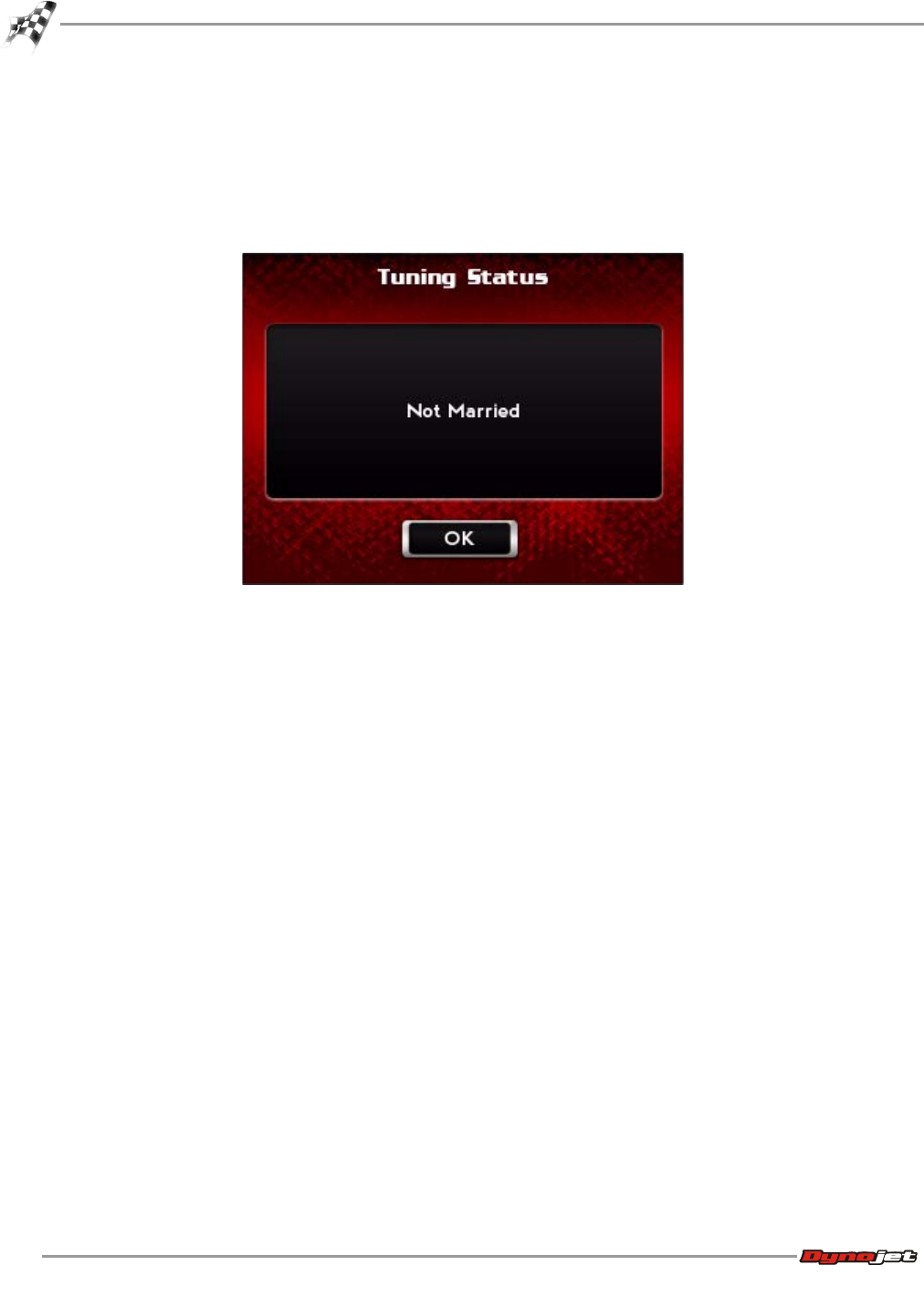
WinPV User Guide
CHAPTER 4
Power Vision Menus
4-16
To Check the ECM Status
Status allows you to verify the connection status between the Power Vision and the ECM.
Use the following steps to check the status.
1Touch Program Vehicle >Status.
2Touch Back to return to the Power Vision main menu.
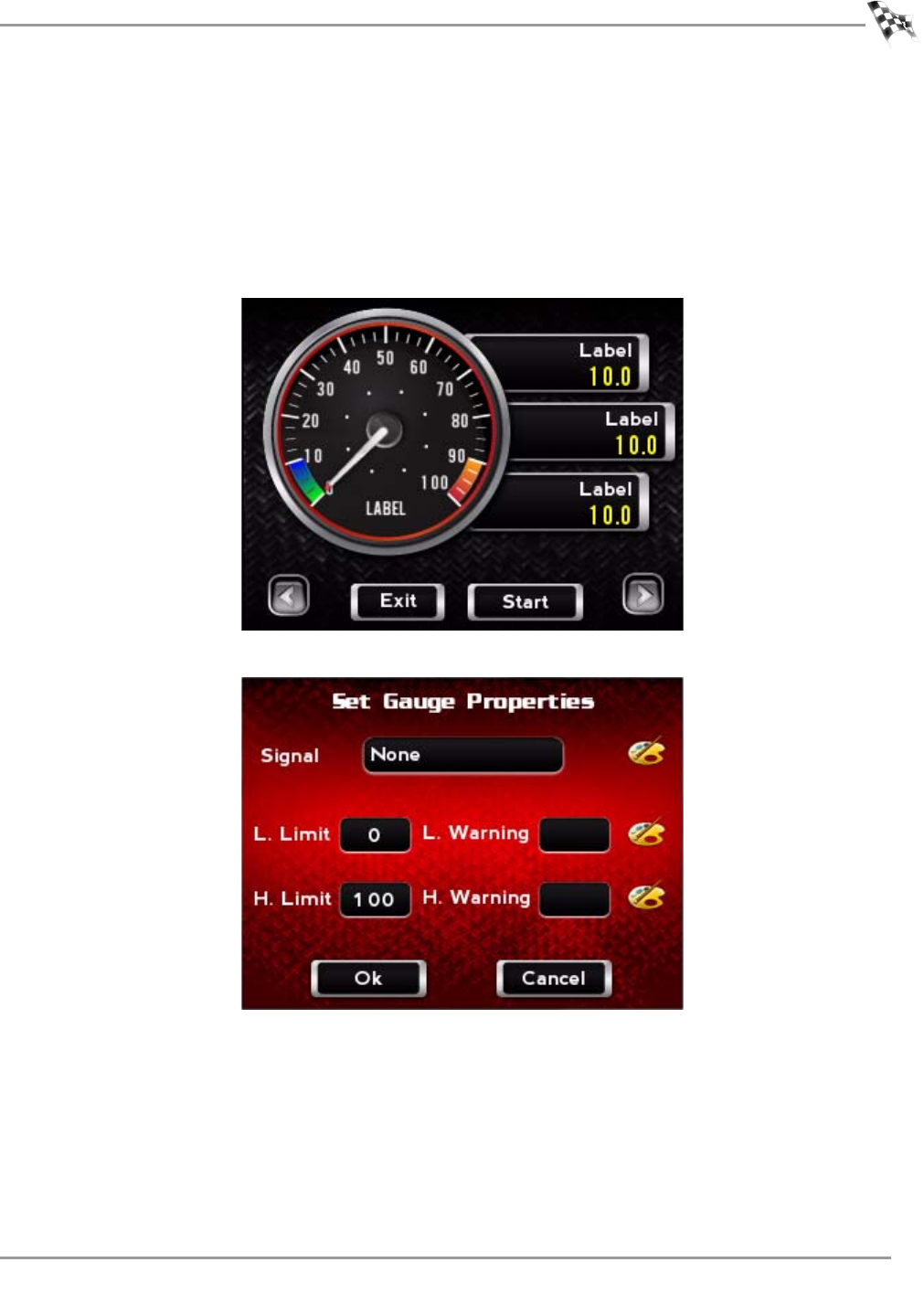
WORKING WITH POWER VISION
Power Vision Menus
Version 6 WinPV User Guide
4-17
Datalog Menu
To View Gauges
1Touch Datalog >Gauges.
2Using the left or right arrows at the bottom of the screen, select your desired gauge
template.
3Touch None, or the current gauge label, to edit the gauge properties.
4Select None, or the current gauge label, (in the space located to the right of Signal).
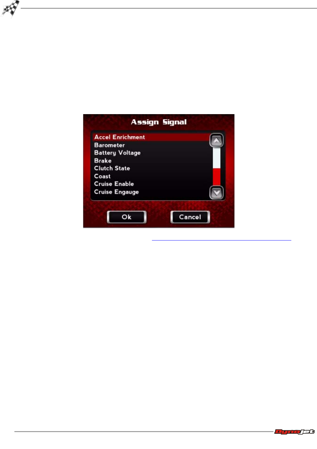
WinPV User Guide
CHAPTER 4
Power Vision Menus
4-18
5From the device list, choose Harley or DJ Wideband2.
6Touch Select to confirm your choice.
Or
Touch Cancel to return to the Set Gauge Properties screen.
7From the Signal list, assign a signal.
8Touch OK to confirm your selection.
Or
Touch Cancel to return to the Set Gauge Properties screen.
To edit additional gauge properties, refer to To Create Gauge Limits and Visual Warnings.
9Touch OK to confirm the gauge properties.
10 Touch Exit to exit the Datalog menu.
11 Touch Back to return to the Power Vision main menu.
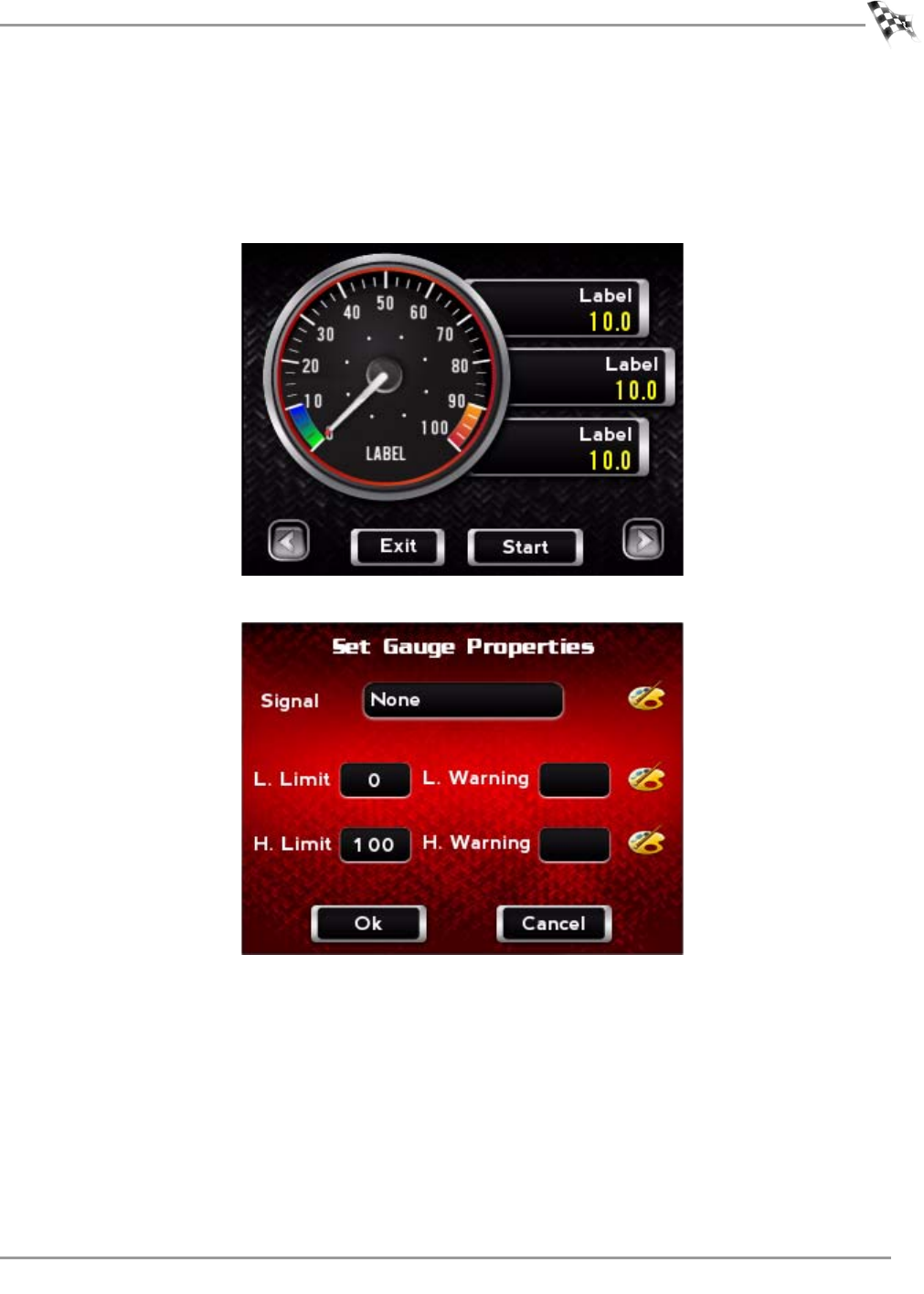
WORKING WITH POWER VISION
Power Vision Menus
Version 6 WinPV User Guide
4-19
To Create Gauge Limits and Visual Warnings
1Touch Datalog >Gauges.
2Using the left or right arrows at the bottom of the screen, select your desired gauge
template.
3Touch None, or the current gauge label, to edit the gauge properties.
4Touch None, or the current gauge label, (in the space located to the right of Signal).
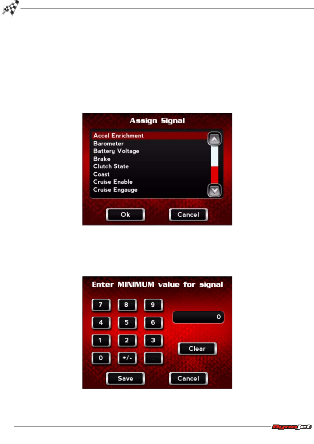
WinPV User Guide
CHAPTER 4
Power Vision Menus
4-20
5From the device list, choose Harley or DJ Wideband2.
6Touch Select to confirm your choice.
Or
Touch Cancel to return to the Set Gauge Properties screen.
7From the Signal list, assign a signal.
8Touch OK to confirm your selection.
Or
Touch Cancel to return to the Set Gauge Properties screen.
9To set the minimum value for the signal:
9a Touch L. Limit.
9b Using the number pad, enter the minimum value for the signal.
9c Touch Save to confirm the value or Cancel to return to the Set Gauge Properties
screen.
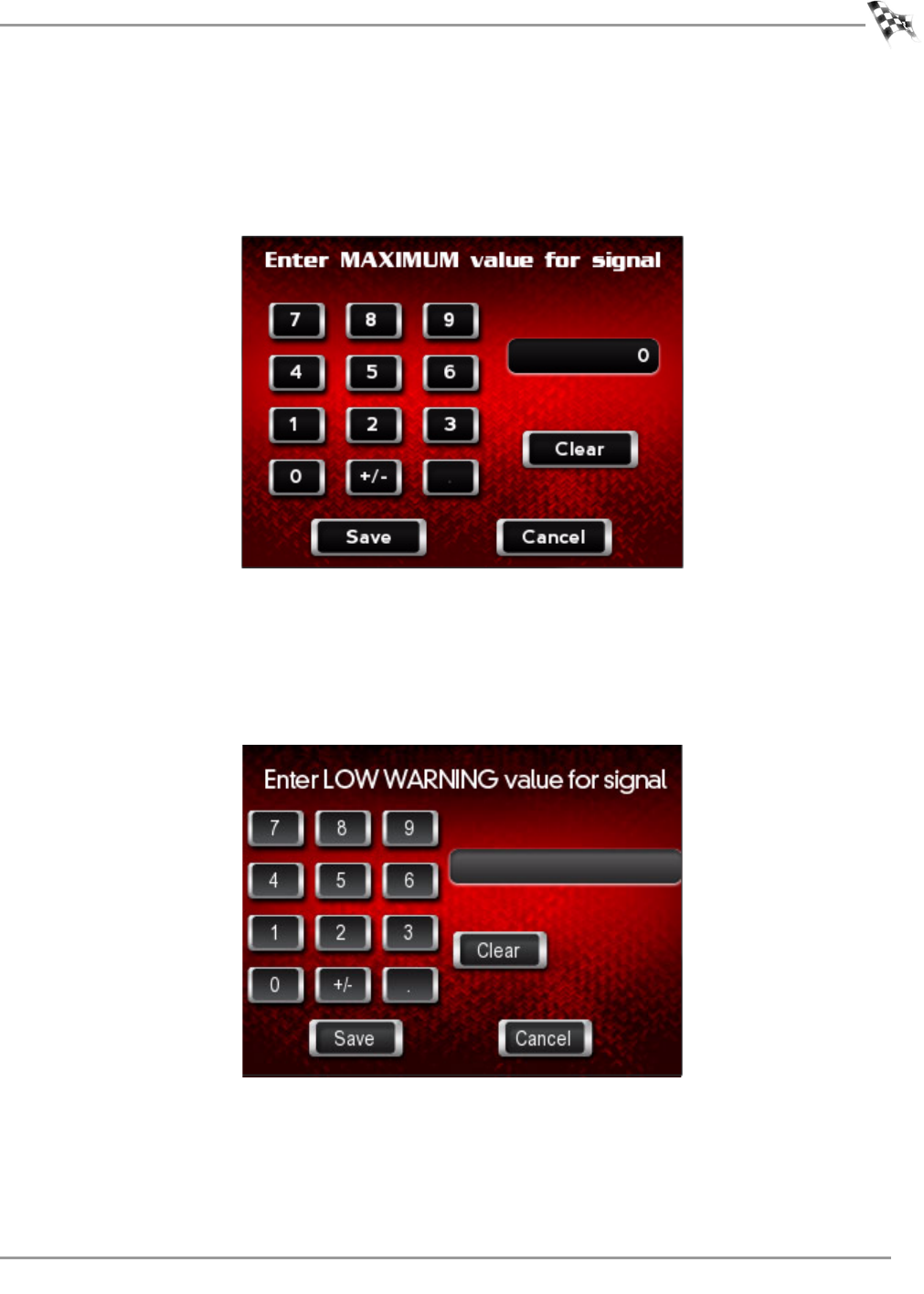
WORKING WITH POWER VISION
Power Vision Menus
Version 6 WinPV User Guide
4-21
10 To set the maximum value for the signal:
10a Touch H. Limit.
10b Using the number pad, enter the maximum value for the signal.
10c Touch Save to confirm the value or Cancel to return to the Set Gauge Properties
screen.
11 To set the low warning value for the signal:
11a Touch L. Warning.
11b Using the number pad, enter the low warning value for the signal.
11c Touch Save to confirm the value or Cancel to return to the Set Gauge Properties
screen.
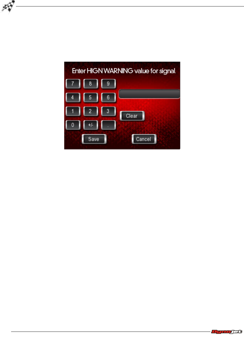
WinPV User Guide
CHAPTER 4
Power Vision Menus
4-22
12 To set the high warning value for the signal:
12a Touch H. Warning.
12b Using the number pad, enter the high warning value for the signal.
12c Touch Save to confirm the value or Cancel to return to the Set Gauge Properties
screen.
13 Touch OK to confirm your changes.
Or
Touch Cancel to return to the gauge screen.
14 Touch Exit to exit the Datalog menu.
15 Touch Back to return to the Power Vision main menu.
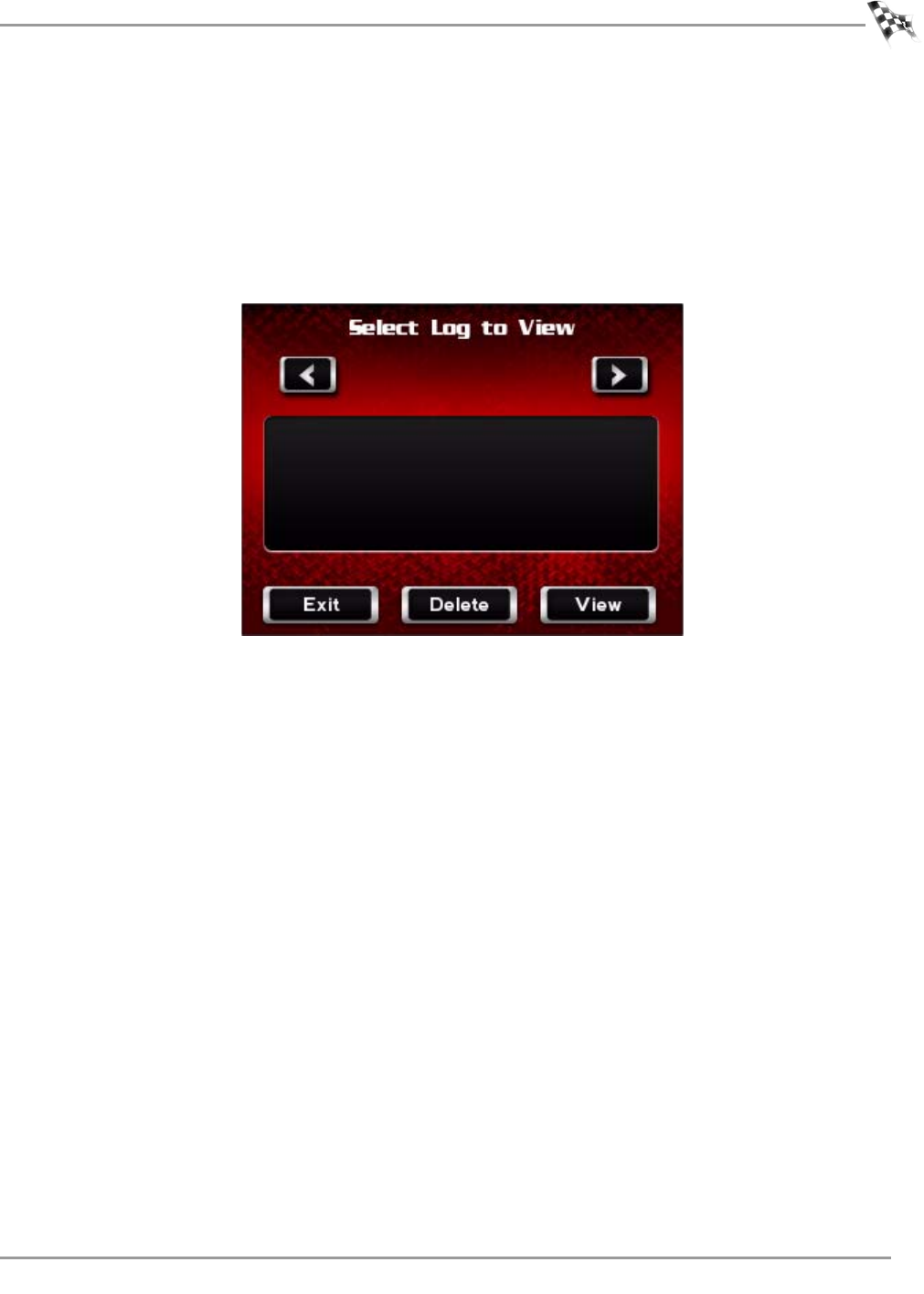
WORKING WITH POWER VISION
Power Vision Menus
Version 6 WinPV User Guide
4-23
To Playback a Log
Playback allows you to play back recorded log files saved on the Power Vision.
1Touch Datalog >Playback.
2Touch a log to view.
3Touch View to view the log.
4Touch Delete to delete the log.
5Touch Exit to return to the Datalog menu.
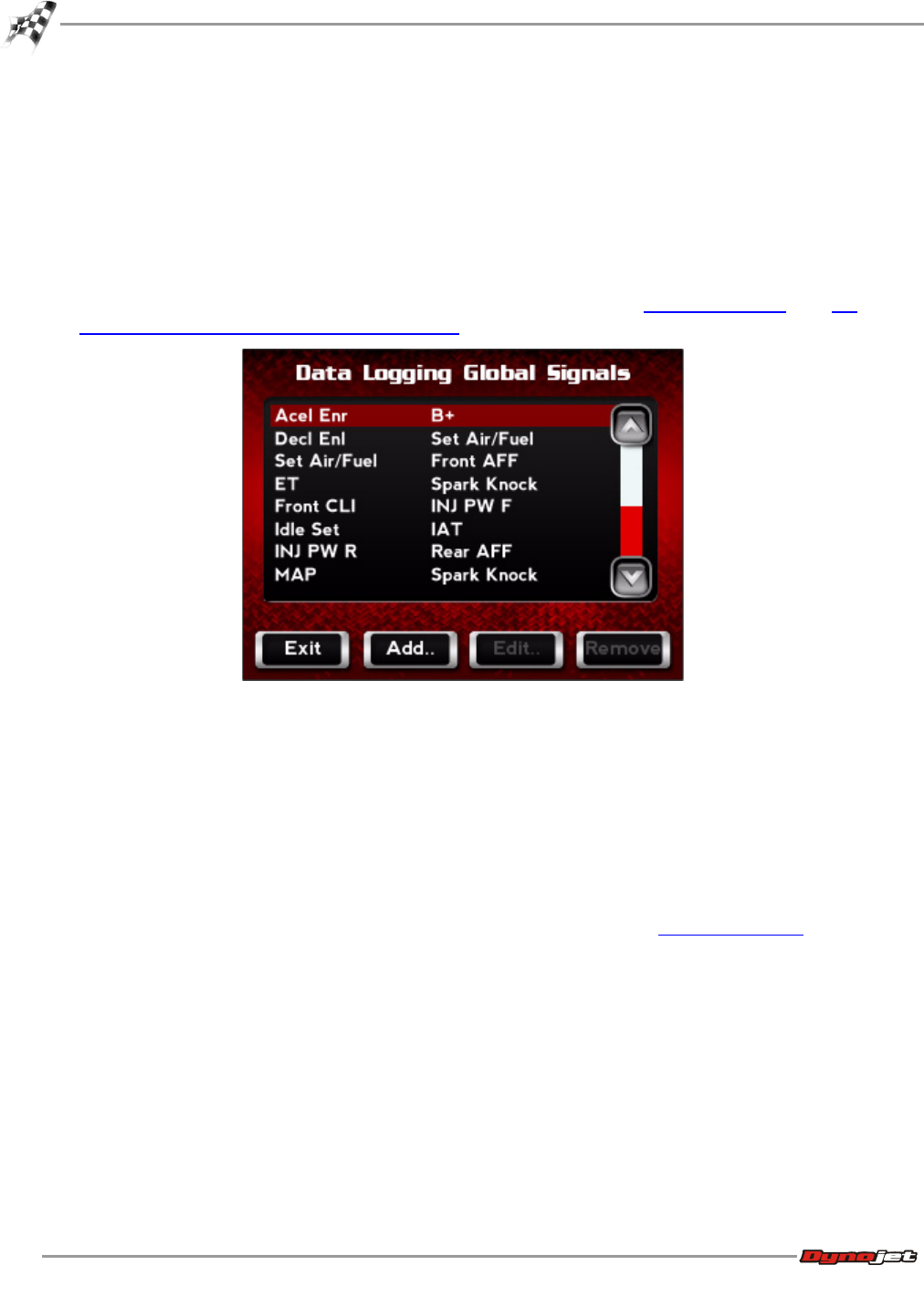
WinPV User Guide
CHAPTER 4
Power Vision Menus
4-24
To View Signals
Signals are channels that can be logged on the Power Vision. You can add, edit, or delete
channels that are data logged.
1Touch Datalog >Signals.
2To edit one of the channels from the list:
2a Select a channel from the list.
2b Touch Edit to change the gauge properties for the selected channel.
For more information about editing gauge properties, refer to To View Gauges and To
Create Gauge Limits and Visual Warnings.
3To remove a channel from the list:
3a Select a channel from the list.
3b Touch Remove to delete the channel from the data logging global signal list.
4To add a channel to the current list:
4a Touch Add to add a channel not in the current list.
4b Use the Set Global Signal Properties screen to select and set up a channel.
For more information about creating a gauge channel, refer to To View Gauges.
4c Touch OK to return to the Data Logging Global Signals screen.
5Touch Exit to return to the Datalog menu.
To Reset Trip/Economy A
Reset Trip/Economy A resets the tripometer and fuel economy meter in the Power Vision.
Touch Datalog >Reset Trip/Eco A.
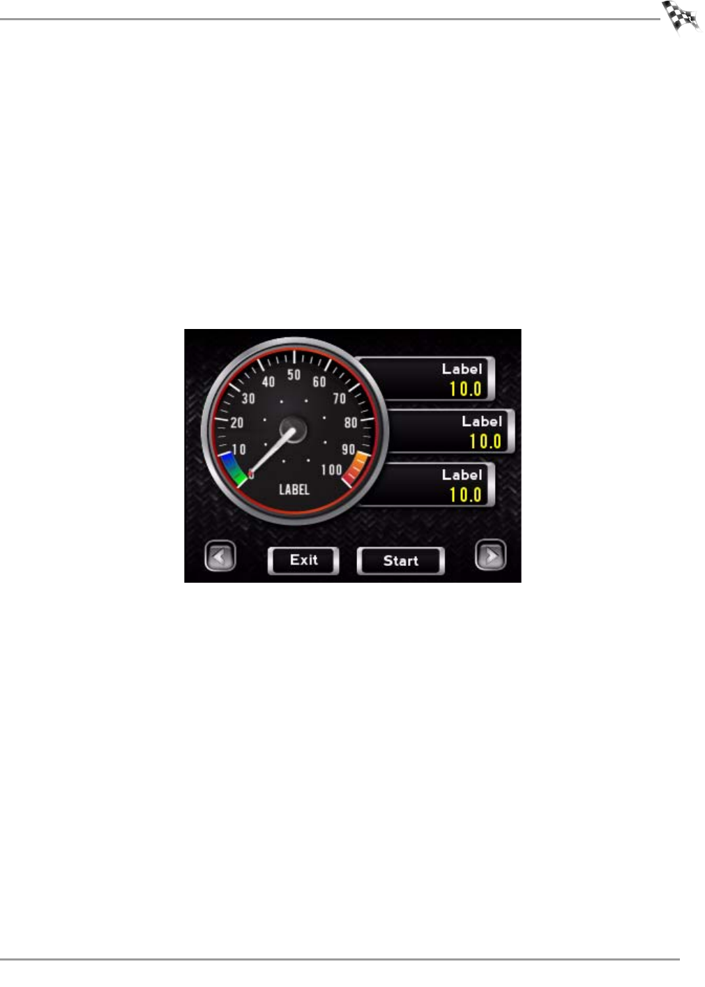
WORKING WITH POWER VISION
Power Vision Menus
Version 6 WinPV User Guide
4-25
To Reset Trip/Economy B
Reset Trip/Economy A resets the tripometer and fuel economy meter in the Power Vision.
Touch Datalog >Reset Trip/Eco B.
To Create a Log with Power Vision
The Dynojet Power Vision has internal logging capabilities when monitoring gauges.
1Touch Datalog >Gauges.
2Using the left or right arrows at the bottom of the screen, select gauge you would like to
use.
3Touch Start Log to begin logging.
4Touch End Log to stop logging.
5Touch Exit to return to the Datalog menu.
To Return to the Power Vision Main Menu
Touch Back.
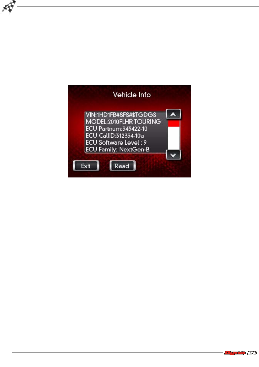
WinPV User Guide
CHAPTER 4
Power Vision Menus
4-26
Vehicle Tools Menu
To View Vehicle Info
Vehicle Info stores VIN data, ECM family information, model number, ECM part number, and
other vehicle specific information.
1Touch Vehicle Tools >Vehicle Info.
2Touch Exit to return to the Vehicle Tools menu.
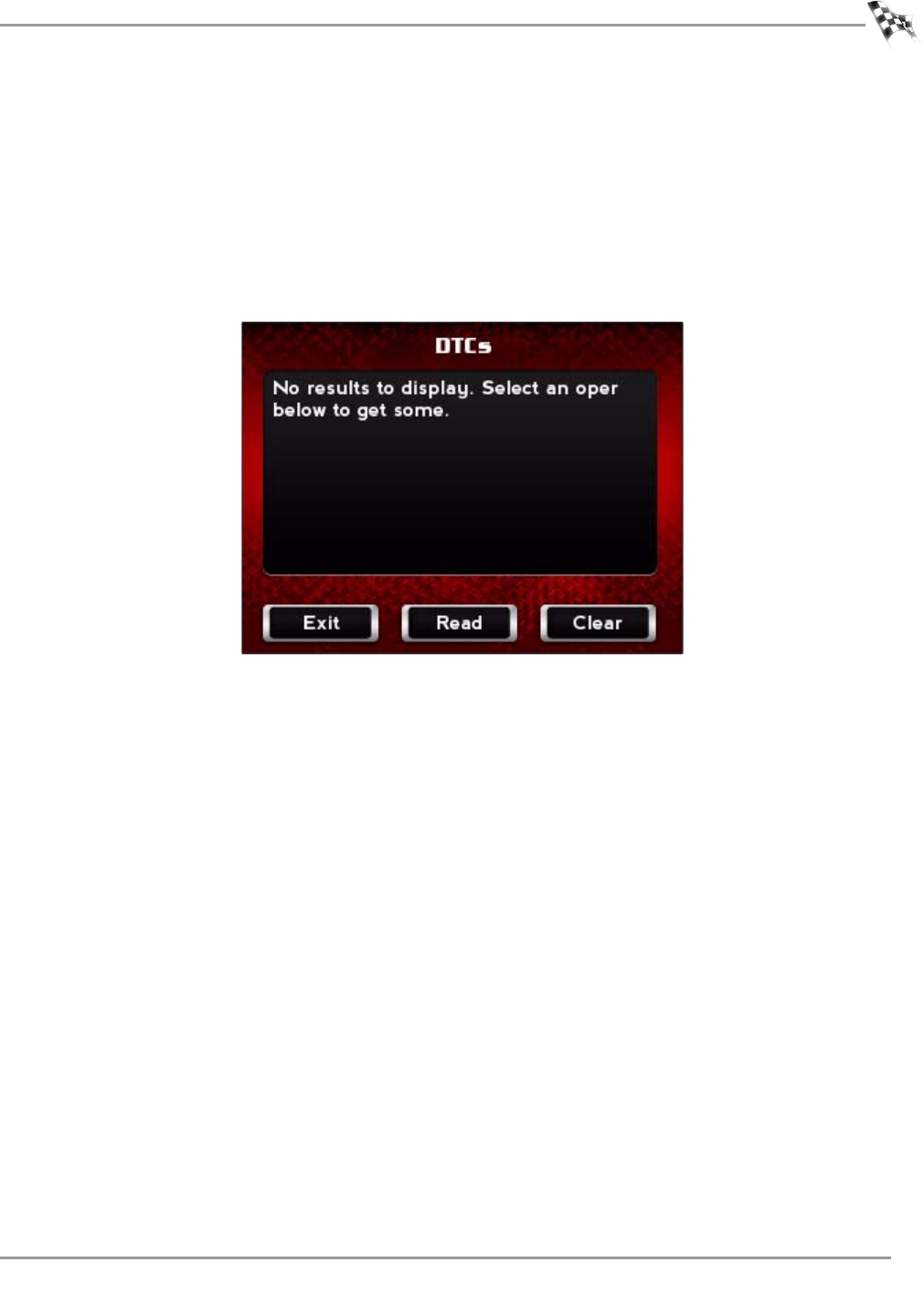
WORKING WITH POWER VISION
Power Vision Menus
Version 6 WinPV User Guide
4-27
To View Stored DTC’s
Stored DTC’s displays and allows you to clear Dealer Trouble Codes. Stored DTC’s can be
used on multiple Delphi equipped Harley-Davidson Motorcycles, even after the Power Vision
is married to one specific ECM.
1Touch Vehicle Tools >Stored DTC’s.
2Touch Read to view stored DTC’s.
3Touch Clear to erase stored DTC’s.
4Touch Exit to return to the Vehicle Tools menu.
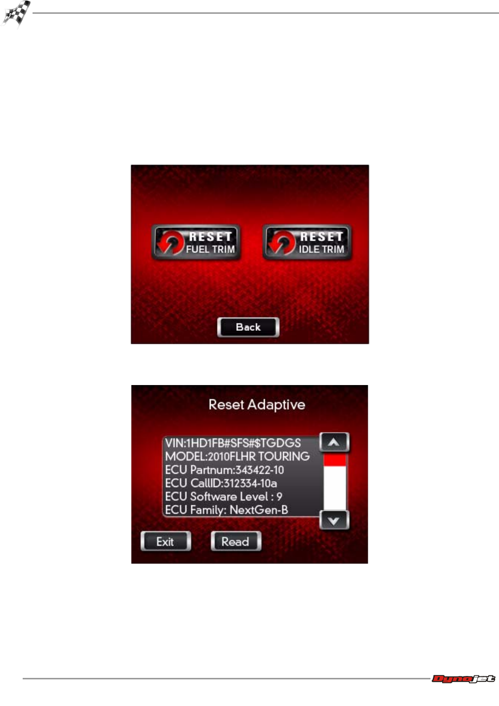
WinPV User Guide
CHAPTER 4
Power Vision Menus
4-28
To Reset Trims
Reset Trims resets adaptive fuel or idle trims that have been learned by the ECM. Resetting
these trims before a tune session is recommended.
1Touch Vehicle Tools >Reset Trims.
2Touch Reset Fuel Trim to reset the fuel trims.
Or
Touch Reset Idle Trim to reset the idle trims.
3Touch Read to view the current information.
4Touch Exit to return to the Reset Trims screen.
5Touch Back to return to the Vehicle Tools menu.
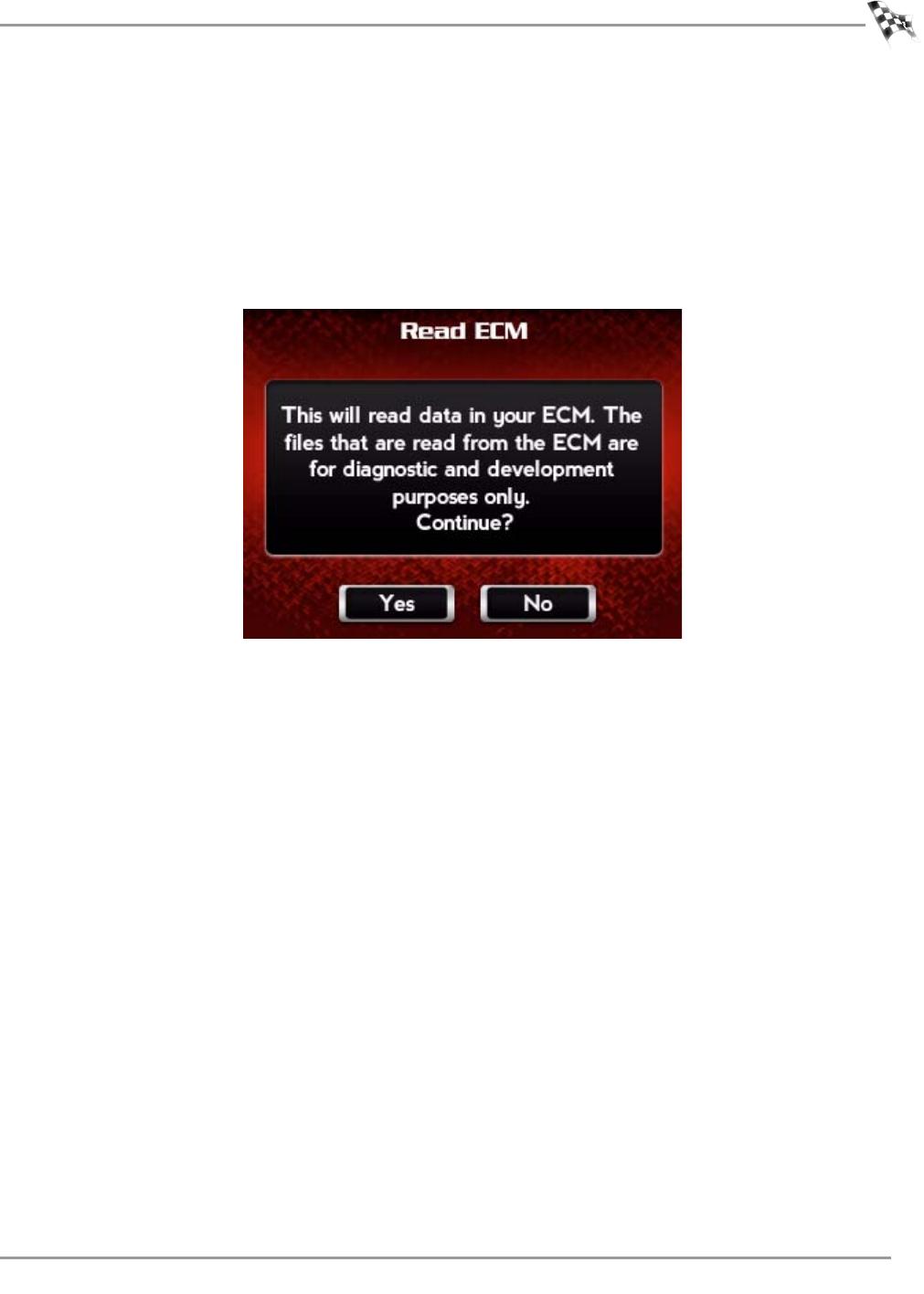
WORKING WITH POWER VISION
Power Vision Menus
Version 6 WinPV User Guide
4-29
To Read ECM
Read ECM is for development purposes only and should only be selected when instructed by
a Dynojet Technician.
1Touch Vehicle Tools >Read ECM.
2Touch Yes to continue.
Or
Touch No to return to the Vehicle Tools menu.
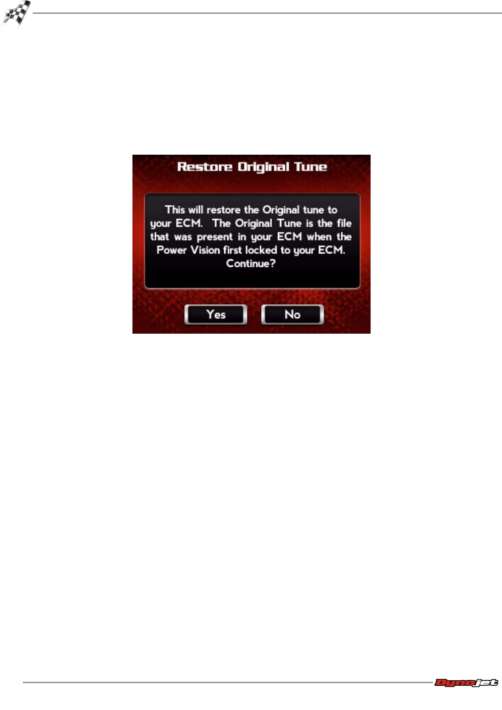
WinPV User Guide
CHAPTER 4
Power Vision Menus
4-30
To Restore Original Tune
Restore Original Tune allows you to restore the factory ECM calibration.
1Touch Vehicle Tools >Restore Original Tune.
2Touch Yes to restore the original tune to your ECM.
Or
Touch No to return to the Vehicle Tools menu.
To Return to the Power Vision Main Menu
Touch Back.
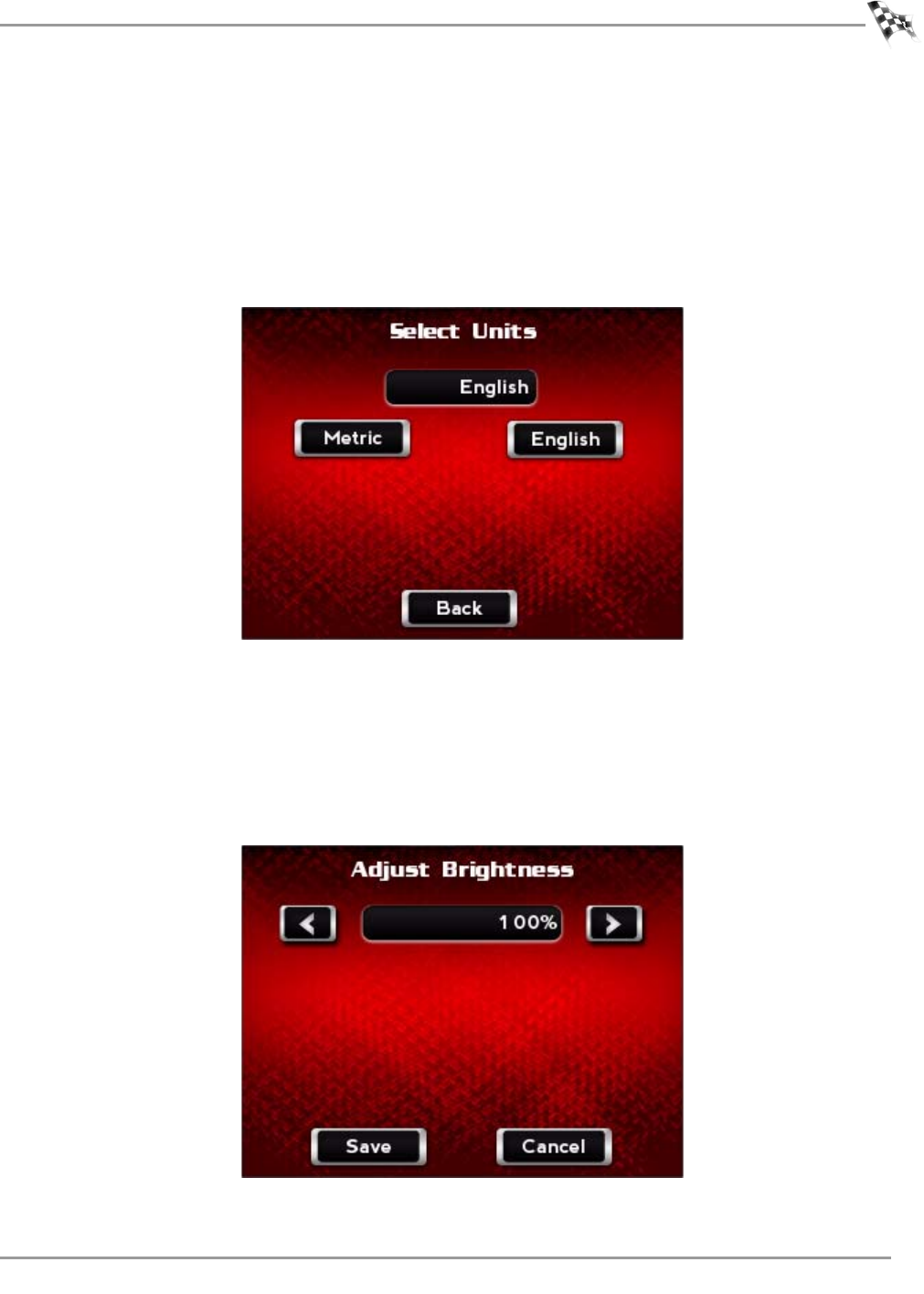
WORKING WITH POWER VISION
Power Vision Menus
Version 6 WinPV User Guide
4-31
Settings Menu
To Select the Units
Units sets all Power Vision units to either Metric or English.
1Touch Settings >Units.
2Touch English or Metric.
3Touch Back to return to the Setting menu.
To Change the Brightness
1Touch Settings >Brightness.
2Use the arrows to increase or decrease the brightness of the Power Vision screen.
3Touch Save to confirm the changes.
Or
Touch Cancel to return to the Settings menu.
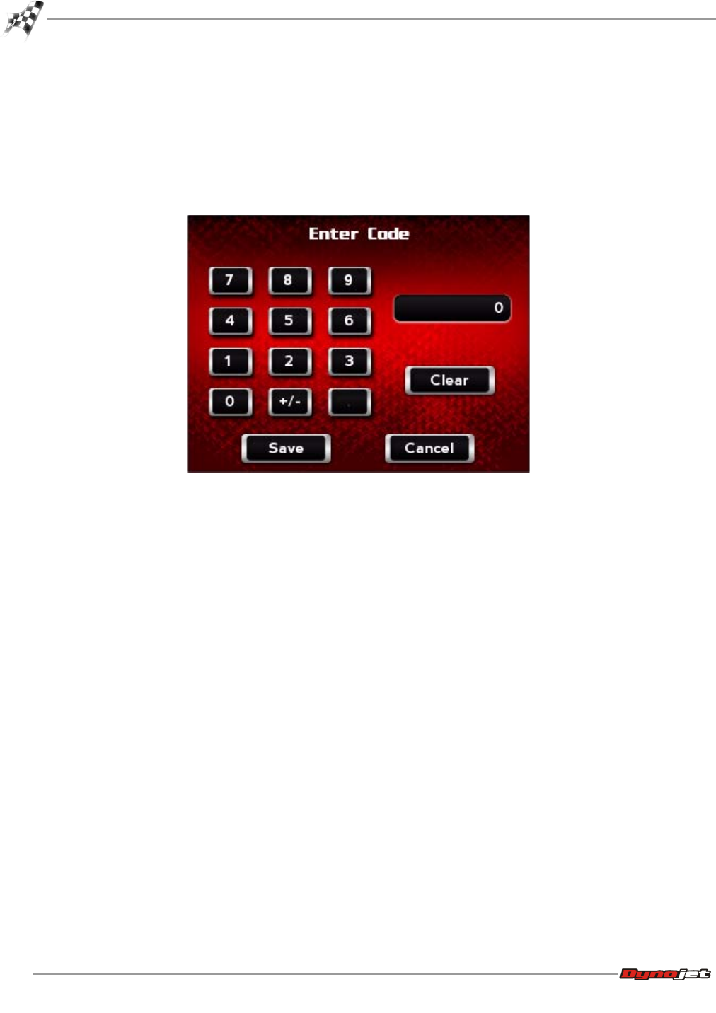
WinPV User Guide
CHAPTER 4
Power Vision Menus
4-32
To Enter a Code
1Touch Settings >Enter Code.
2Using the number pad, enter a code.
3Touch Save to save the code.
Or
Touch Cancel to return to the Settings menu.
To Calibrate the Touch Screen
Use the following steps to calibrate the Power Vision touch screen.
1Touch Settings >Touch Calibrate.
2Touch the plus (+) signs as they appear.
The calibration process will complete once all points have been touched.
To Flip the Power Vision Screen
Flip Screen rotates the Power Vision screen orientation 180 degrees.
Touch Settings >Flip Screen.
To Return to the Power Vision Main Menu
Touch Back.
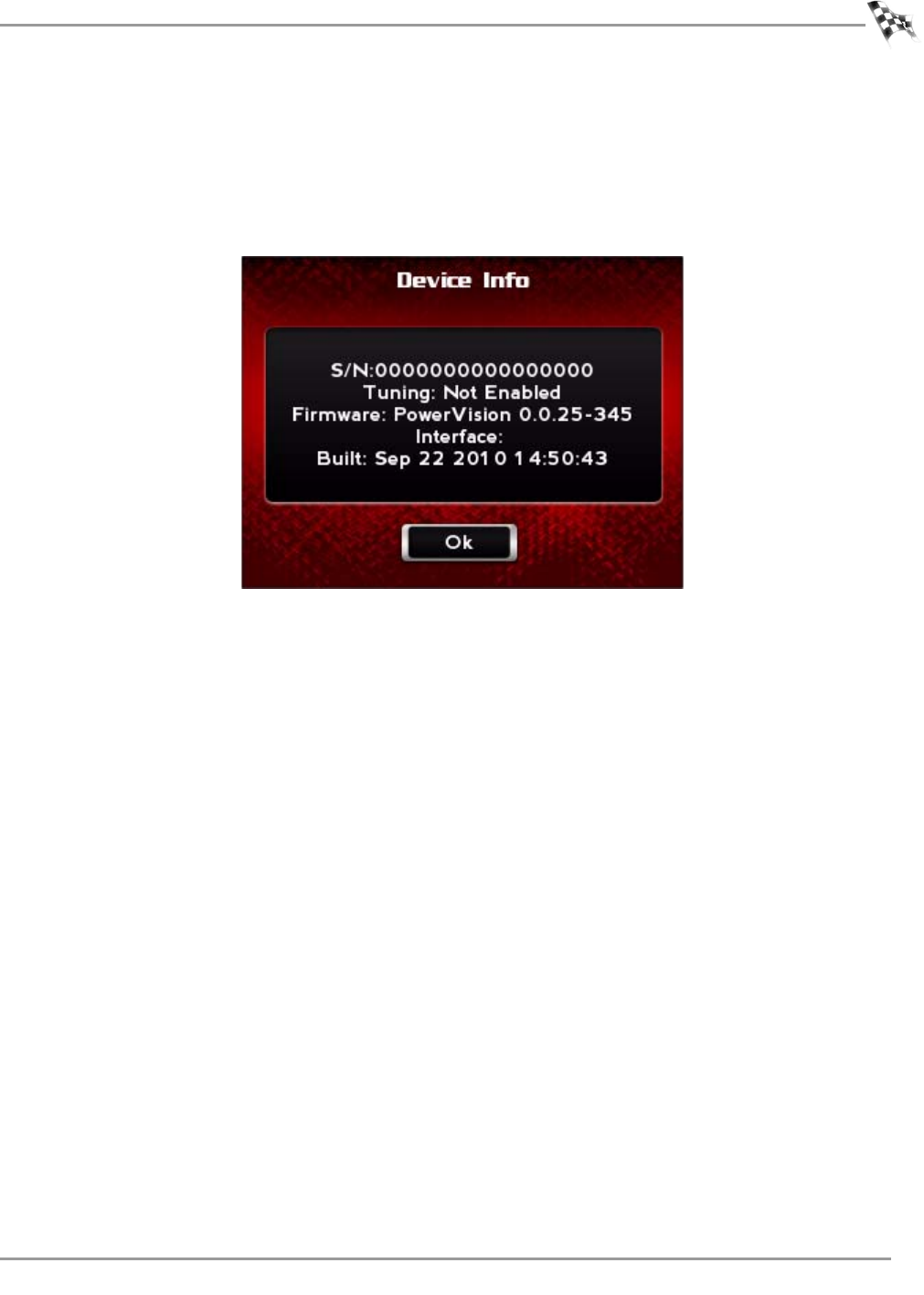
WORKING WITH POWER VISION
Power Vision Menus
Version 6 WinPV User Guide
4-33
Device Info Menu
To View Information About the Power Vision
Device Info displays information about the Power Vision.
Touch Device Info.
WinPV User Guide
CHAPTER 4
Power Vision Menus
4-34
Dealer Info Menu
To View Information About the Dealer
Dealer Info displays dealer information.
Touch Dealer Info.

WinPV User Guide
5-1
CHAPTER
5
W
ORKING
WITH
P
OWER
V
ISION
L
OG
T
UNER
Power Vision Log Tuner (Log Tuner) is an easy to use program developed by Dynojet to use
data logs from the Power Vision to generate a tune specifically for your bike. You don't need
to have a vast understanding of the Harley EFI system to use Log Tuner. We've made tuning
your bike easier than ever. Log Tuner can tune your EFI equipped Harley Davidson using two
methods: basic method using the motorcycles OEM O2 sensors and pro method using the
Dynojet AutoTune module.
This section is divided into the following categories:
• Theory of Operation, page 5-2
• Log Tuner Software Installation, page 5-3
• Tuning Method, page 5-6
• Configure the WinPV Value File, page 5-16
• Configure the Power Vision, page 5-18
• Log Tuner, page 5-21
• Apply the Corrected Value File to the Tune, page 5-26

WinPV User Guide
CHAPTER 5
Theory of Operation
5-2
Theory of Operation
This section describes the theory of operation for Log Tuner.
Basic Tuning with Log Tuner
Basic Tuning with Log Tuner utilizes the factory narrow band O2 sensors to make the
necessary corrections needed to properly calibrate your ECM using the Dynojet Power Vision.
Basic tuning method requires you to extend the closed loop operating range, reduce ignition
timing advance, and allow the factory narrowband oxygen sensors make the corrections for
you. Factory narrowband O2 sensors are extremely accurate at or very near to stoichiometric
(14.6 AFR or lambda 1) air fuel ratio. Stoichiometric air fuel ratio is great for fuel economy
and light load, but when it comes time to tune for best power and torque (wide open throttle)
the pro tuning method should be used.
Prior to logging, you should set up your calibration (tune) to allow Log Tuner and its process
to work more efficiently. Refer to Retrieving the Tune File from the Power Vision.
Pro Tuning with Log Tuner
Pro tuning method utilizes the Dynojet Auto Tune module which uses wideband oxygen
sensor technology. This is the most accurate way to calibrate your ECM. By utilizing wideband
O2 sensors, you can tune for best economy and best power/torque. The wideband sensors
used in our Auto Tune module are extremely accurate at all of the operating ranges of your
motorcycle. The Auto Tune module will plug into a Power Vision and allow you to monitor and
log front cylinder and rear cylinder lambda (based on wideband sensors).
The H-D data bus broadcasts Desired AFR (or Set AFR) along with the other required data
channels such as MAP, RPM, TP, and Lambda 1, Lambda 2, front and rear VE; these values
can be logged by the Power Vision. Log Tuner will use this logged data to make correcting
your (lambda/AFR) easier.
Log Tuner will analyze two files: a log file created from a Power Vision that is equipped with
the Auto Tune device and .pvv file (Power Vision Value File from the WinPV tuning software).
Log Tuner will create a corrected Power Vision Value File to adjust the difference between
desired AFR and actual AFR.
You will need one of the following Dynojet Auto Tune kits to utilize pro tuning:
• AT-110—Auto Tune, HD-J1850, Power Vision
• AT-110B—Auto Tune, HD-J1850,Power Vision with exhaust bungs
• AT-120—Auto Tune, HD-CAN, Power Vision
• AT-120B—Auto Tune, HD-CAN, Power Vision with exhaust bungs
Prior to logging, you should set up your calibration (tune) to allow Log Tuner and its process
to work more efficiently. Refer to Retrieving the Tune File from the Power Vision.
Log Tuner can also use the factory narrow band O2 sensors to create the corrections needed
to properly calibrate your ECM at idle and light load ranges, then utilize the Dynojet Auto
Tune module's wideband oxygen sensors to tune for best power and torque. Log Tuner's use
of data natively on board the H-D ECM and Dynojet wideband technology provides you with
the best of both features.
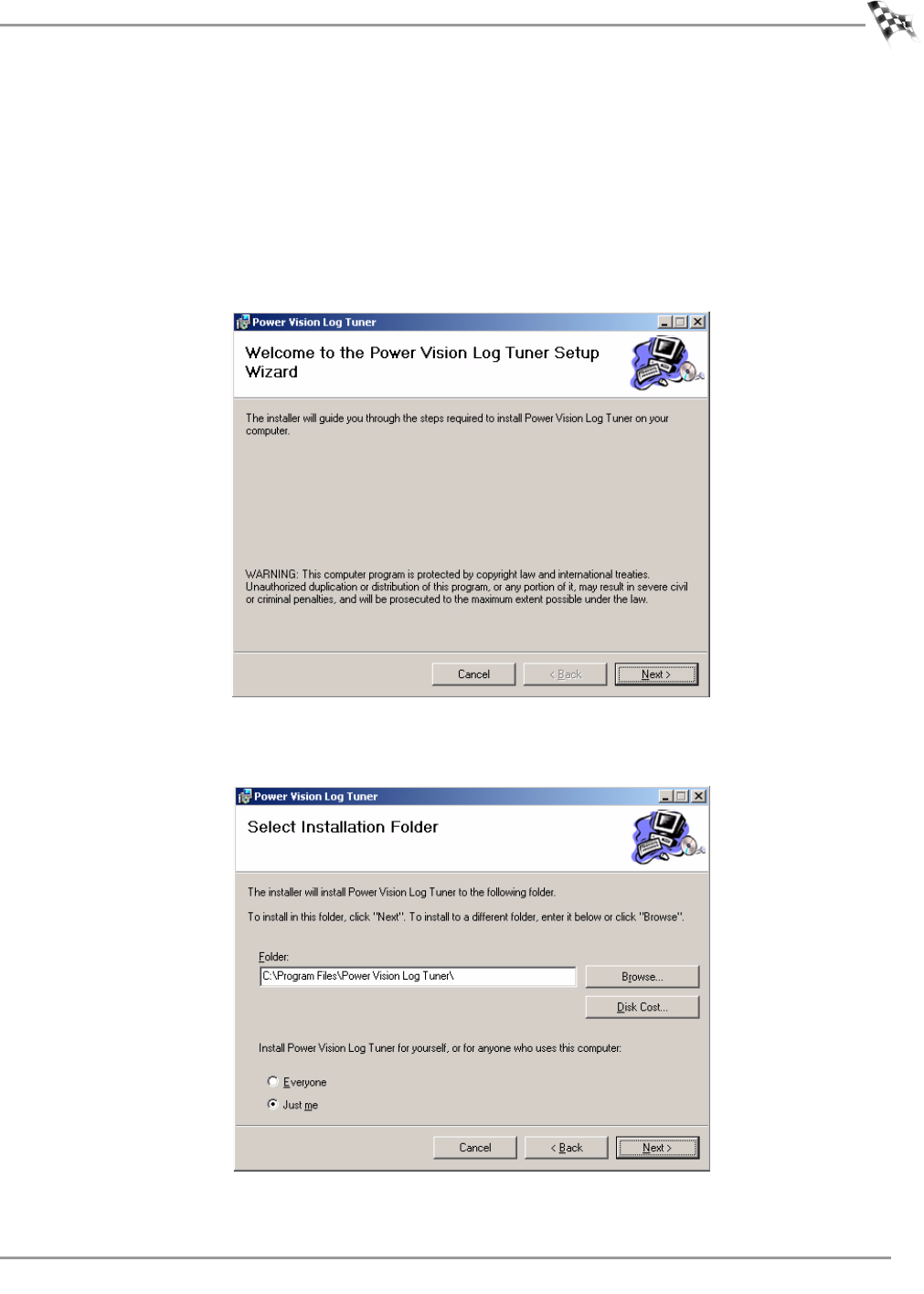
WORKING WITH POWER VISION LOG TUNER
Log Tuner Software Installation
Version 6 WinPV User Guide
5-3
Log Tuner Software Installation
1Insert the Log Tuner CD into your CD-ROM drive. The launch program will run
automatically showing the Setup Wizard.
If auto-run is disabled on your computer, click Start on the Windows® task bar, and click
Run. Type D:\setup.exe, where D is the letter that corresponds to your CD-ROM drive, or
the appropriate directory in order to access the setup.exe on the CD-ROM.
2Read the Welcome window and click Next to continue.
3Select a destination location where the Log Tuner software will be installed and click Next
to continue.
Note:Dynojet recommends that you do not change the default destination folder.
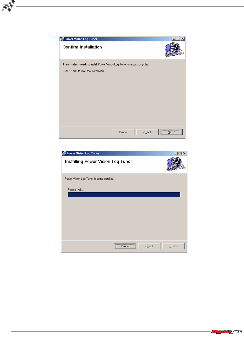
WinPV User Guide
CHAPTER 5
Log Tuner Software Installation
5-4
4Click Next to begin the installation. Click Back to change the folder location.
5Click Next when the installation is complete.
WORKING WITH POWER VISION LOG TUNER
Log Tuner Software Installation
Version 6 WinPV User Guide
5-5
6Click Close to complete the installation.
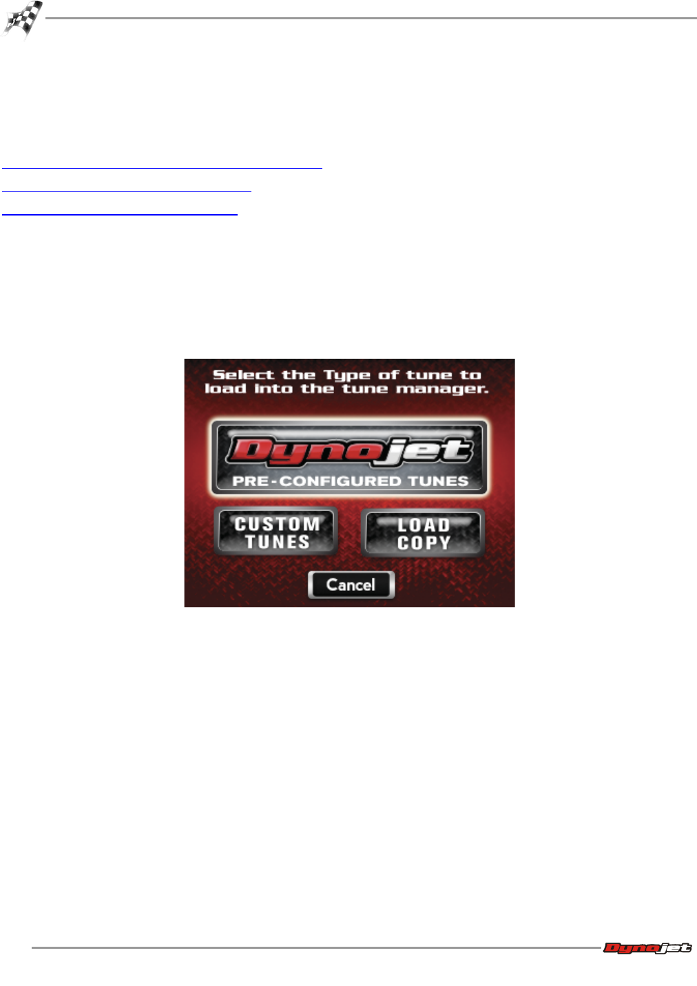
WinPV User Guide
CHAPTER 5
Tuning Method
5-6
Tuning Method
This section provides instructions for retrieving the tune file from the Power Vision and
making changes needed for using Log Tuner.
Retrieving the Tune File from the Power Vision
Basic Tuning Method with Log Tuner
Pro Tuning Method with Log Tuner
Retrieving the Tune File from the Power Vision
Before using Log Tuner you will need to set up the ECM's tune file. The instructions below will
guide you through retrieving the tune file from the Power Vision.
1Turn the ignition to the on position.
2Verify the Run/Off switch is in the Run position (key on, kill switch to on, engine off).
3Using the Power Vision, touch Program Vehicle >Load Tune >Load Copy.
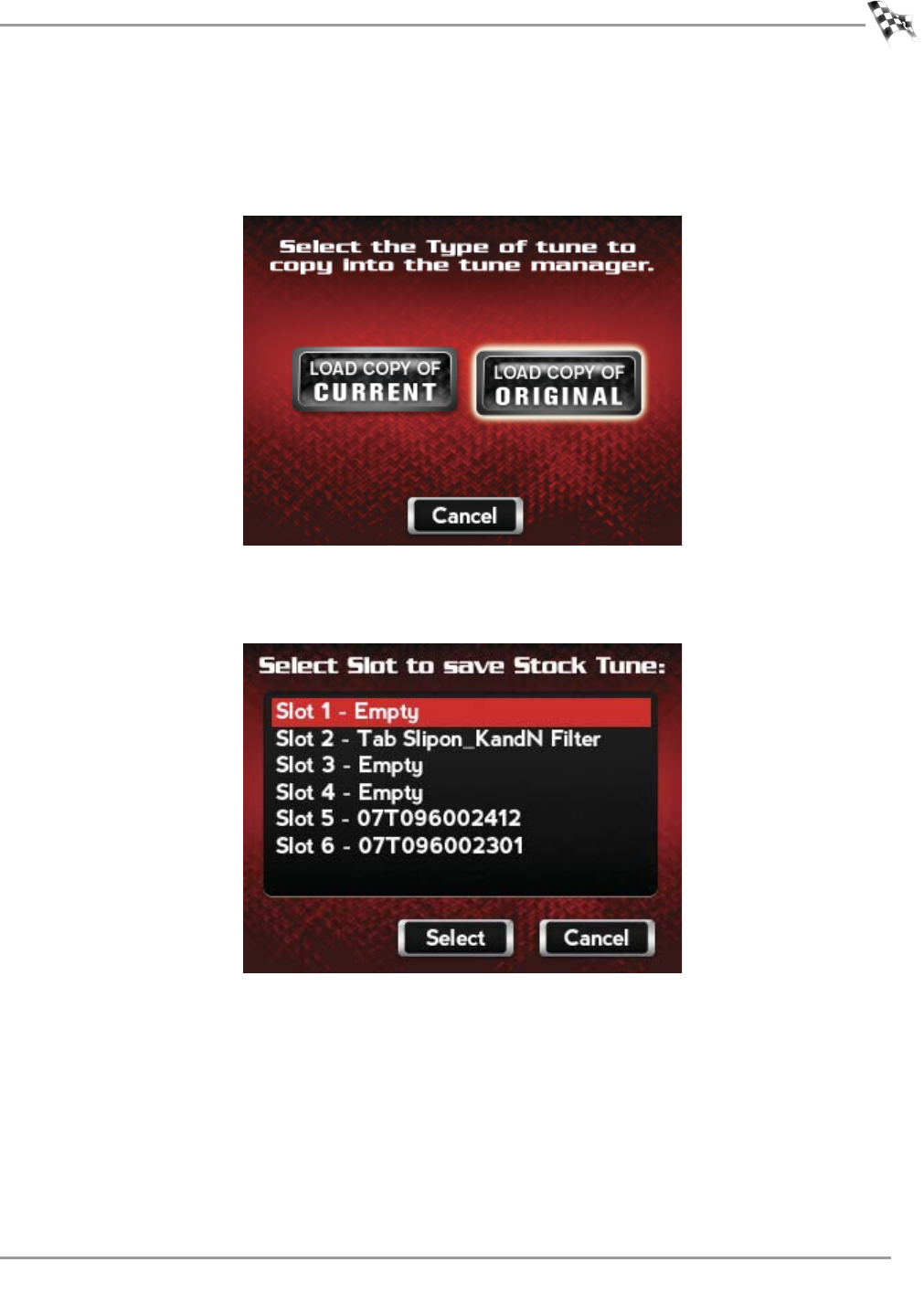
WORKING WITH POWER VISION LOG TUNER
Tuning Method
Version 6 WinPV User Guide
5-7
4Touch Load Copy of Current or Load Copy of Original.
Load Copy of Current—loads a copy of the current tune file in the ECM.
Load Copy of Original—loads a copy of the original file that was saved when the Power
Vision married itself to the ECM.
5Touch a slot to save the tune file.
6Touch Select to continue with the selected slot.
7Touch OK to continue.
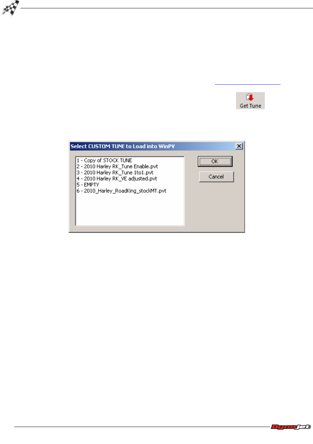
WinPV User Guide
CHAPTER 5
Tuning Method
5-8
8Turn the key off.
9Remove the Power Vision.
10 Using the USB cable, connect the Power Vision to your computer.
11 Verify the Power Vision boots up and says PC Link Mode Active.
12 Launch the WinPV software application.
13 Verify the Power Vision software user level is set to Pro. Refer to To Setup the Options.
14 Select PowerVision >Get Tune from PV or click the Get Tune button .
15 Select the Copy of Original or Copy of Current tune file.
16 Click OK.
This is the file that your tune will be built from. Use Save As to save this tune file to your
computer for safe keeping. In our example, we named the file OriginalTuneFile.pvt.
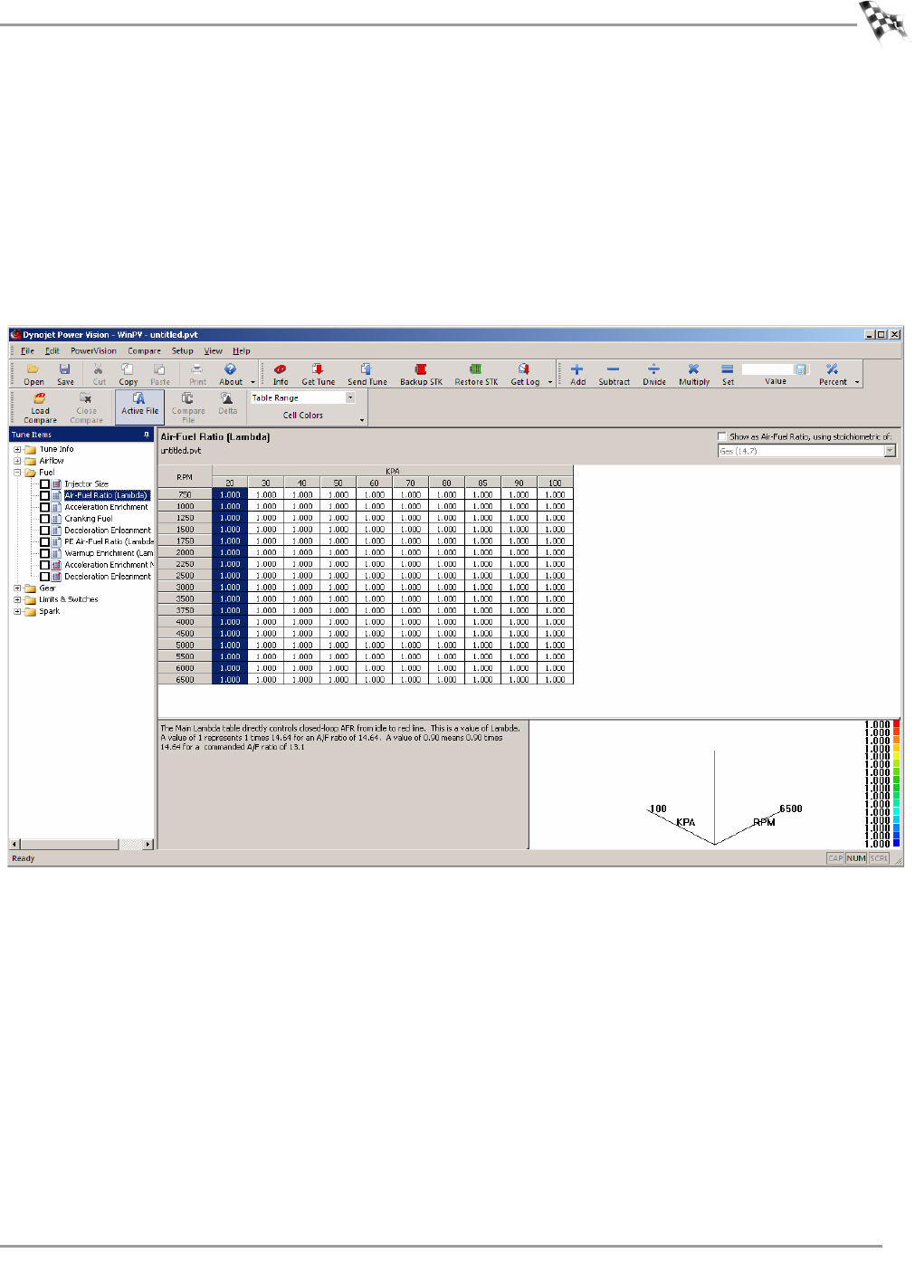
WORKING WITH POWER VISION LOG TUNER
Tuning Method
Version 6 WinPV User Guide
5-9
Basic Tuning Method with Log Tuner
1Open the WinPV software.
2Under Tune Items, click Fuel >Air Fuel Ratio (Lambda or AFR).
3Extend the closed loop operating range by changing the values in the table to 14.6 for
AFR or 1 for lambda.
This disables the ECM's ability to transition to open loop.
Note:Basic tuning method is not recommended for high horse power applications or
throttle positions/KPA above 70%/80KPA.
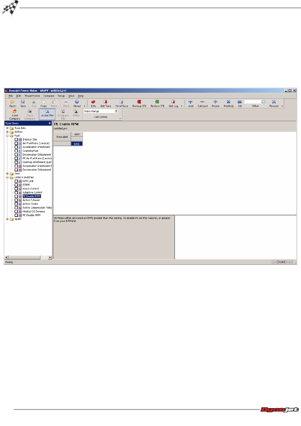
WinPV User Guide
CHAPTER 5
Tuning Method
5-10
4If present, change the closed loop bias.
4a Under Tune Items, click Closed Loop >Closed Loop Bias.
4b Change the closed loop bias to 750 mV.
5Under Tune Items, click Limits & Switches >PE Enable RPM.
6Raise the PE Enable RPM limit above the current rev limiter.
This will effectively disable Power Enrichment.
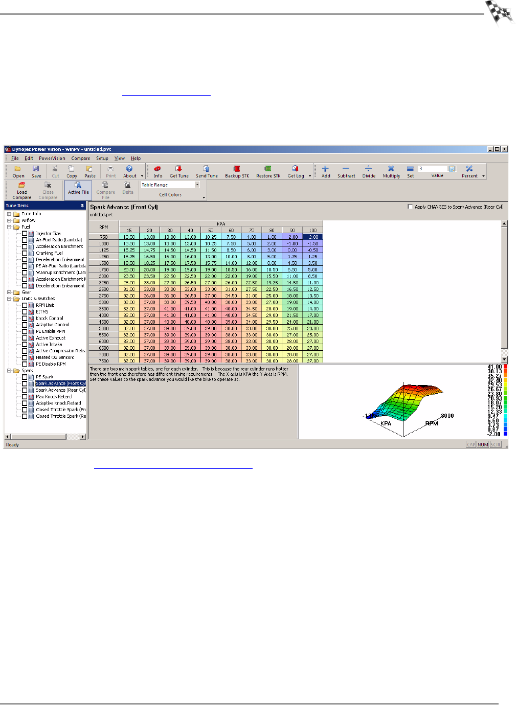
WORKING WITH POWER VISION LOG TUNER
Tuning Method
Version 6 WinPV User Guide
5-11
7Under Tune Items, click Spark >Spark Advance Front and Rear.
8Remove at least four to six degrees of spark advance from the front and rear cylinder
tables. Refer to the Cell Math Toolbar.
This is necessary because we are commanding a leaner AFR/lambda for Log Tuner Basic,
which can increase the possibility of detonation/engine knock. Pulling timing allows you
to operate at leaner AFR/lambda with less possibility of detonation.
9Continue with Configure the WinPV Value File.
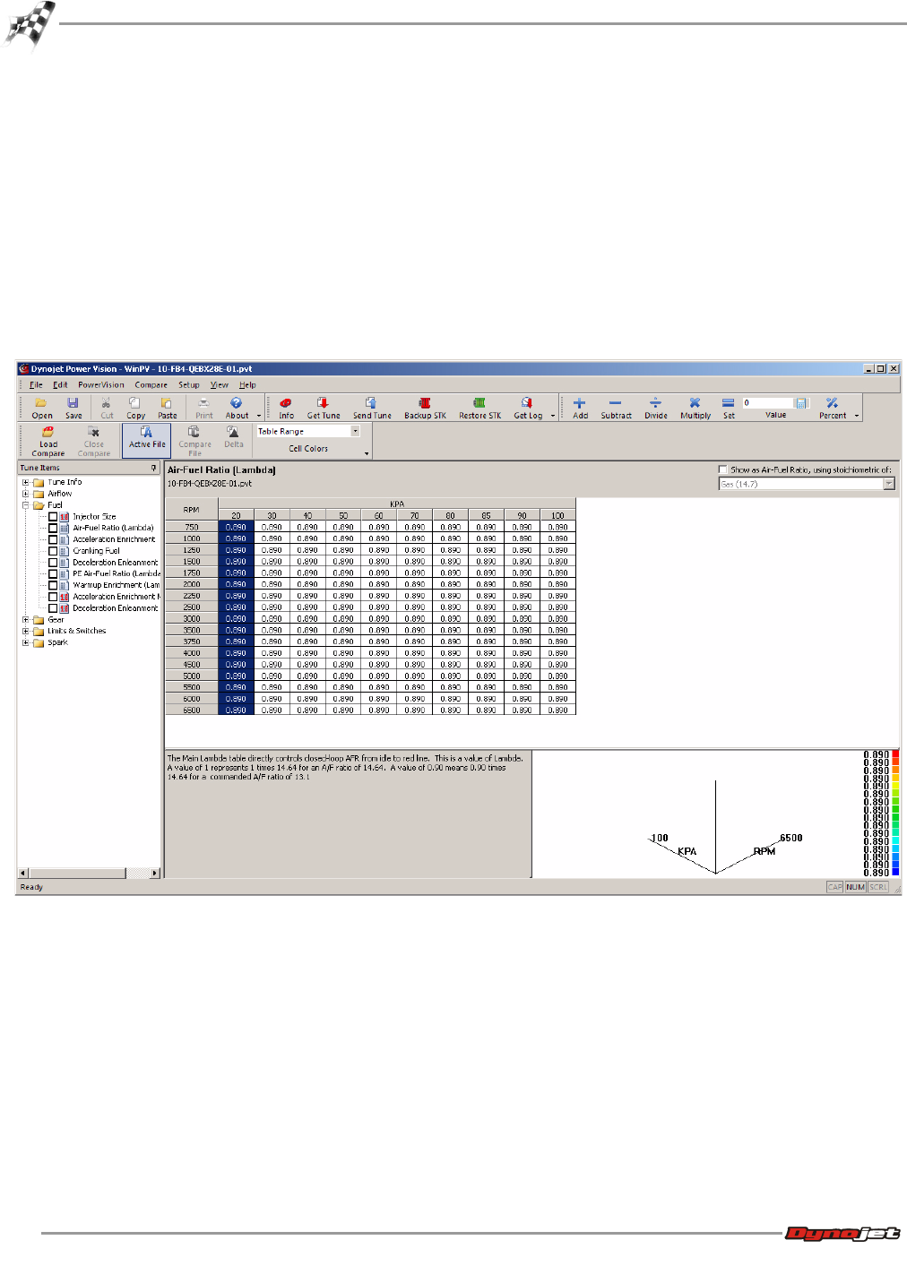
WinPV User Guide
CHAPTER 5
Tuning Method
5-12
Pro Tuning Method with Log Tuner
1Open the WinPV software.
2Under Tune Items, click Fuel >Air Fuel Ratio (lambda or AFR).
3Log Tuner can use the factory narrow band O2 sensors to create the corrections needed
to properly calibrate your ECM at idle and light load ranges, then utilize the Dynojet Auto
Tune module's wideband oxygen sensors to tune for best power and torque. To use this
method, leave the set AFR table as is.
Or
Alternatively, you can utilize the AutoTune module for all operating ranges. To use this
method, set the entire table to one value; for example, AFR 13 or 0.89 lambda.
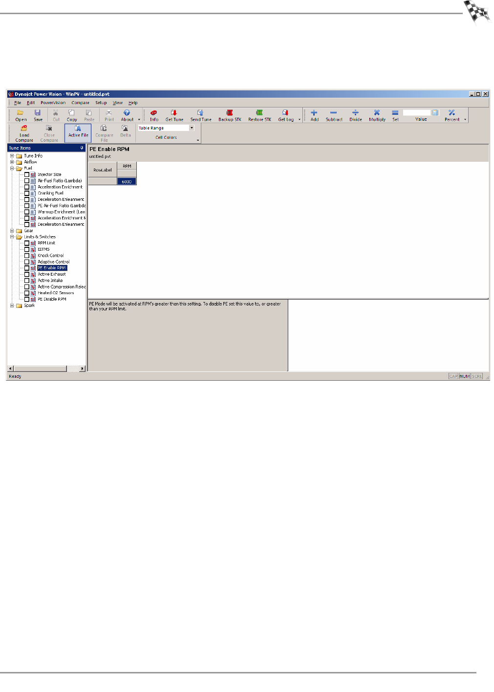
WORKING WITH POWER VISION LOG TUNER
Tuning Method
Version 6 WinPV User Guide
5-13
4Raise the PE Enable RPM limit above the current rev limiter.
This will effectively disable Power Enrichment.
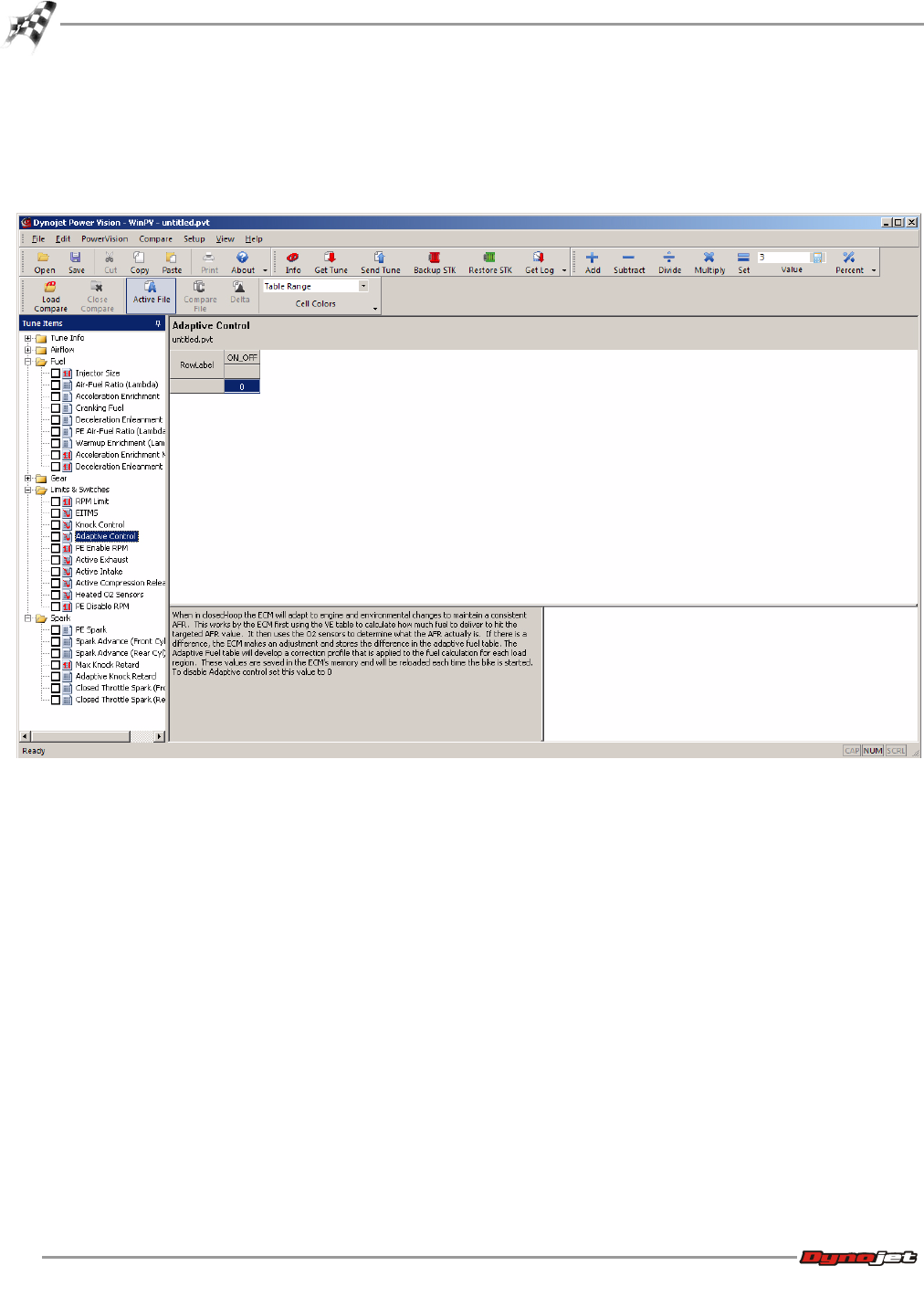
WinPV User Guide
CHAPTER 5
Tuning Method
5-14
5Under Tune Items, click Limits & Switches >Adaptive Control.
6Disable Adaptive Control by changing 1 to 0.
Adaptive fuel control takes the O2 trims that are learned over time and applies them to
the final fuel calculation.
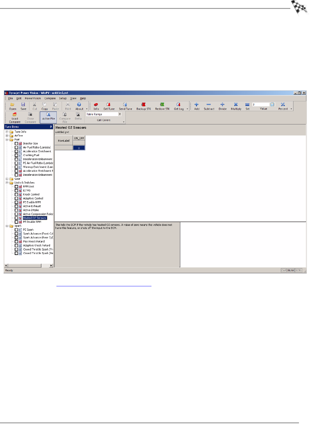
WORKING WITH POWER VISION LOG TUNER
Tuning Method
Version 6 WinPV User Guide
5-15
7Under Tune Items, click Limits & Switches >Heated O2 Sensors.
8Disable the Heated O2 Sensors by changing 1 to 0.
This will allow you to change multiple pipes without having to reinstall the factory O2
sensors every time.
Note:Skip this step if you are using the factory O2 sensors for idle and light load
operating ranges.
9Continue with Configure the WinPV Value File.
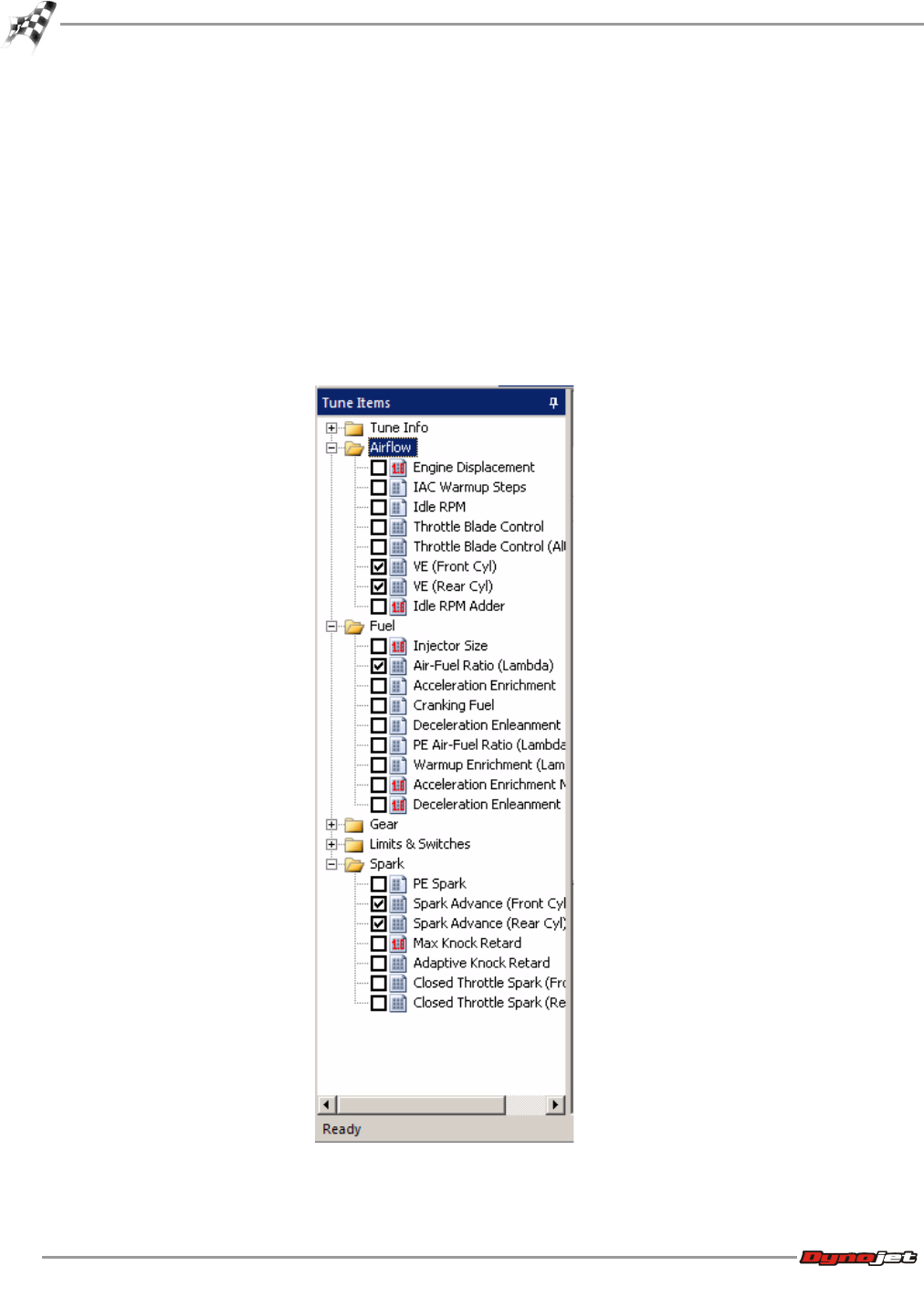
WinPV User Guide
CHAPTER 5
Configure the WinPV Value File
5-16
Configure the WinPV Value File
Once the tune file is complete, you will need a Power Vision Value File (.pvv). The .pvv file
needs to contain tables that directly affect fuel and spark. Follow the instructions below to
configure the value file.
1Click the box next to the following tables:
•VE Front
•VE Rear
• Spark Advance Front
•Spark Advance Rear
• Set AFR table (Lambda/Stoich)
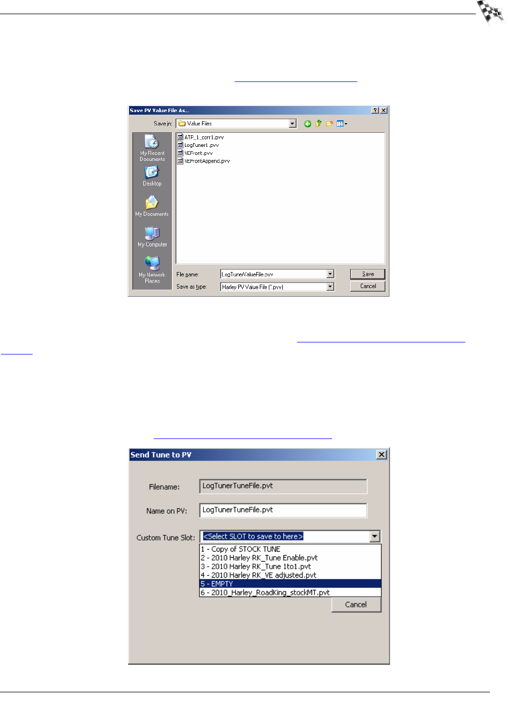
WORKING WITH POWER VISION LOG TUNER
Configure the WinPV Value File
Version 6 WinPV User Guide
5-17
2Select File >Save Selected Values.
3Enter a file name and click Save. Refer to To Save Selected Values.
In our example, we named the file LogTunerValueFile.pvv.
Saving the Modified Tune File
Save the modified tune file with a new file name. Refer to To Save a Power Vision Tune File
(.PVT).
In our example, we named the file LogTunerTuneFile.pvt.
Sending the Tune to the Power Vision
1Verify the Power Vision is connected to your computer using the USB cable.
2Send the tune (in our example, LogTunerTuneFile.pvt) to an empty custom tune slot on
the Power Vision. Refer to To Send a Tune to the Power Vision.

WinPV User Guide
CHAPTER 5
Configure the Power Vision
5-18
Configure the Power Vision
Log Tuner software requires logs to be generated with the Power Vision in order to create the
corrections needed for the tune.
This section provides instructions to set up the Power Vision to creating log files for Log
Tuner.
Loading the Custom Tune
Setting up the Power Vision to Log Channels
Creating a Datalog File
Retrieving a Log File from the Power Vision
Loading the Custom Tune
Load the tune file sent to the Power Vision (refer to Sending the Tune to the Power Vision) to
your motorcycle ECM. Refer to To Load a Custom Tune File.
In our example, choose the tune file named LogTunerTuneFile.pvt.
Setting up the Power Vision to Log Channels
For detailed information on adding channels to the data logging list, refer to To View Signals.
1Connect the Power Vision to your motorcycle. Refer to Installing the Power Vision on the
Motorcycle.
2Add the following channels to the Data Logging Global Signals list:
•MAP*
•Engine Temp*
• Warm-up AFR or Lambda*
•TP*
•RPM*
•VE New Front*
•VE New Rear*
• Lambda 1**
• Lambda 2 **
• Accel Enrich*
•Spark Knock F*
• Spark Knock R*
• Desired Air/Fuel (Ratio)*
• Desired Air/Fuel (Lambda)*
* From H-D data bus
** From Auto Tune (when equipped)
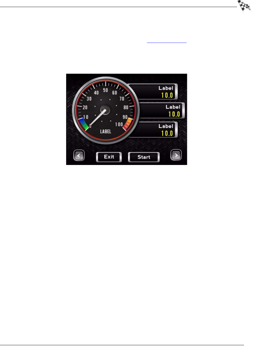
WORKING WITH POWER VISION LOG TUNER
Configure the Power Vision
Version 6 WinPV User Guide
5-19
Creating a Datalog File
1To view any of the signals that will be logged, refer to To View Gauges.
2On the Gauges screen, touch Start Log to begin logging.
3On the Gauges screen, touch Stop Log to save the log to the Power Vision.
Note:In order to log enough data to use Log Tuner, the vehicle must be run in all
operating ranges for a period of time. You can use multiple log files in Log Tuner.
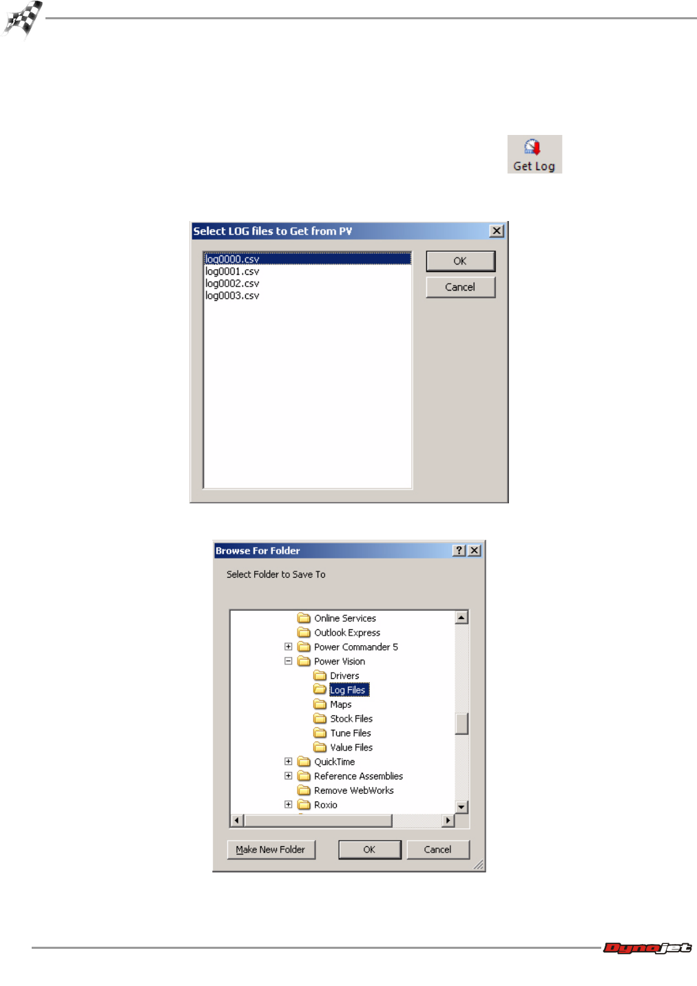
WinPV User Guide
CHAPTER 5
Configure the Power Vision
5-20
Retrieving a Log File from the Power Vision
1Remove the Power Vision.
2Using the USB cable, connect the Power Vision to your computer.
3Select PowerVision >Get Log from PV or click the Get Log button .
4Select the log file or files you wish to get from the Power Vision.
5Click OK.
6Browse to the location you wish to save your log file and click OK.
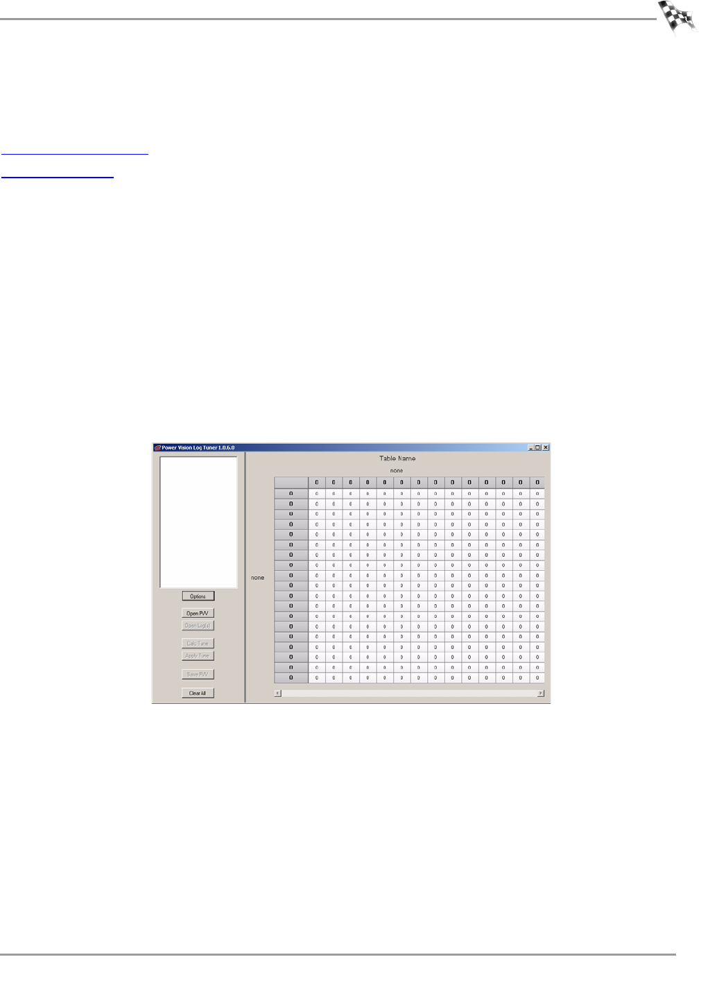
WORKING WITH POWER VISION LOG TUNER
Log Tuner
Version 6 WinPV User Guide
5-21
Log Tuner
This section provides instructions for setting up and using Log Tuner.
Setting Up Log Tuner
Using Log Tuner
Setting Up Log Tuner
1Click Start on the Windows® task bar, and click All Programs.
2Select Power Vision Log Tuner >PV Log Tuner.
Or
Double-click the PV Log Tuner desktop icon.
Note:Before using Log Tuner, identify the bike’s communication protocol by checking the
DLC connector. Harley’s use two different types of communication protocol: CAN which
has a 6-pin DLC connector or J1850 which has a 4-pin DLC connector.
PV-1 uses the J1850 communication protocol while PV-2 uses the CAN communication
protocol. For CAN based ECMs, hold down CTRL and press E to put Log Tuner into CAN
mode.
3Click Options.
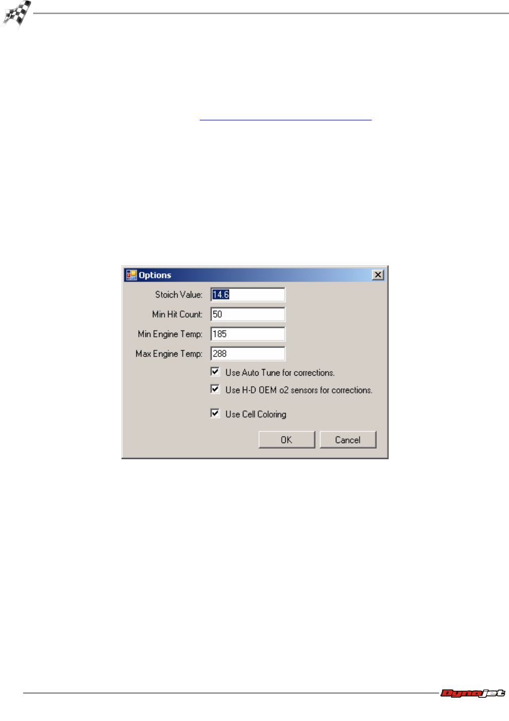
WinPV User Guide
CHAPTER 5
Log Tuner
5-22
4Select from one of the following correction options:
• Select Use H-D OEM O2 sensors for corrections for Basic Tuning with Log Tuner.
• Select Use Auto Tune for corrections for Pro Tuning with Log Tuner.
• Select both for Pro Tuning with Log Tuner if when you set up your value file you left the
desired AFR table as is. Refer to Pro Tuning Method with Log Tuner.
• Select Use Cell Coloring to enable cell colors.
5Verify the following values:
• Stoich Value—the stoichiometric air fuel value for the fuel the vehicle is using during
logging.
• Min Hit Count—any cell with less than the minimum hit count will not be tuned. 50 is
the recommended value.
• Min Engine Temp—below the minimum engine temperature, there will be no tuning.
Note:When using DegC you will need to lower this value.
• Max Engine Temp—above the maximum engine temperature, there will be no tuning.
Note:When using DegC you will need to lower this value.
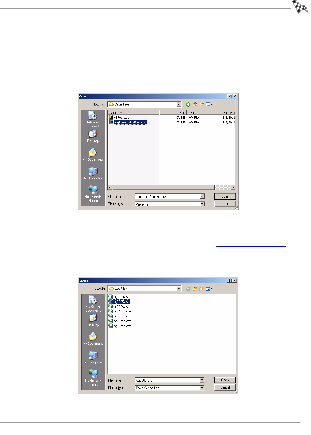
WORKING WITH POWER VISION LOG TUNER
Log Tuner
Version 6 WinPV User Guide
5-23
Using Log Tuner
1Click Open PVV.
2Browse to the location you saved the value file. In our example, select
LogTunerValueFile.pvv.
This value file was created in Configure the WinPV Value File.
3Click Open.
4Click Open Log(s).
5Browse to your Log File folder and select the log file or files you created with the Power
Vision.
To save the logs from the Power Vision to your computer, refer to To Get a Log from the
Power Vision.
Note:Loading the same log file multiple times can cause Log Tuner to process inaccurate
data. Do not load the same log file twice.
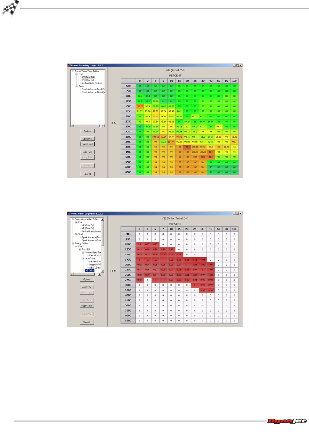
WinPV User Guide
CHAPTER 5
Log Tuner
5-24
6Click Calc Tune.
This will calculate the new VE and Spark values for the running conditions and AFR that
were data logged. Click on the tree view to see each calculated table.
7In the Log Tuner tree, click VE Delta for both the front and the rear cylinder.
The numbers shown in these tables represent the percent difference between the original
VE table and the new VE table.
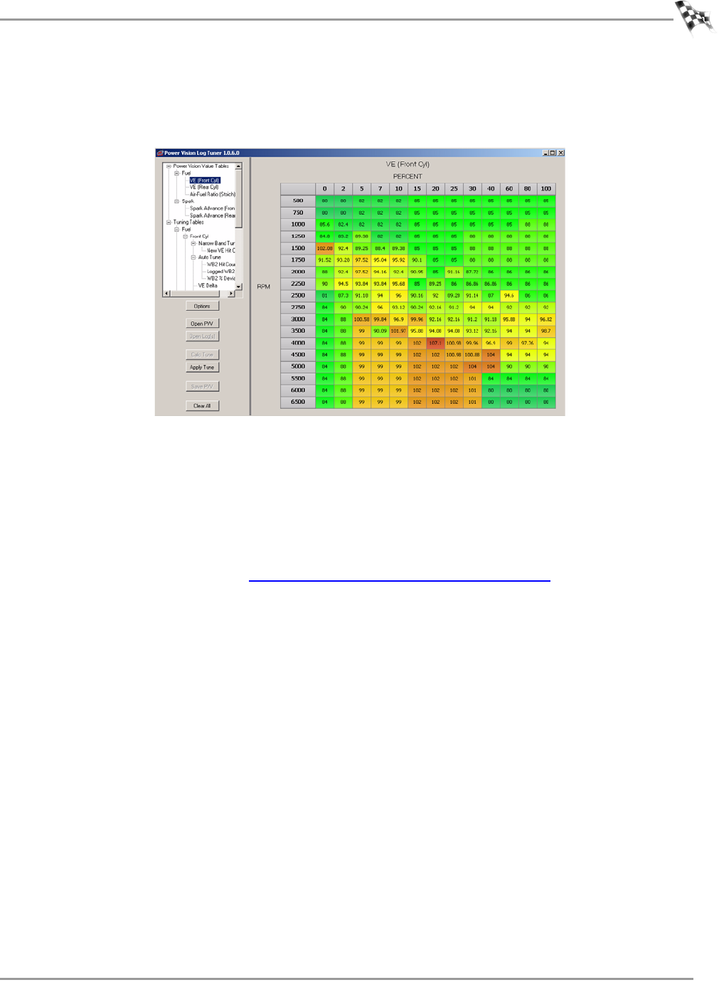
WORKING WITH POWER VISION LOG TUNER
Log Tuner
Version 6 WinPV User Guide
5-25
8Click Apply Tune.
This will copy the new calculated VE and Spark values to the VE and Spark tables from
the original Power Vision value file. In our example, the LogTunerValueFile.pvv.
9Click Save PVV.
10 Browse to the location where the LogTunerValueFile.pvv is stored
11 Select LogTunerValueFile.pvv, and click OK.
This will save the new calculated value file with the new VE values.
Log Tuner has corrected the front and rear cylinder VE tables based on actual AFR data
collected while riding the motorcycle. Log Tuner also will apply corrections to the spark
tables if knock was detected. The next step is to load the corrected .pvv file into your
tune file using WinPV. Refer to Apply the Corrected Value File to the Tune.

WinPV User Guide
CHAPTER 5
Apply the Corrected Value File to the Tune
5-26
Apply the Corrected Value File to the Tune
Applying the Corrected Value File
Applying the Corrected Value File to the Original Tune
Sending the Tune to the Motorcycle ECM
Applying the Corrected Value File
1Open the WinPV software.
2Open the LogTunerTuneFile.pvt file.
This file was created in Configure the WinPV Value File.
3Select File >Load All Values. Refer to To Load All Values.
4Browse to the folder with the LogTunerValueFile.pvv file.
This file was created in Using Log Tuner.
5Select LogTunerValueFile.pvv and click OK.
This will apply the corrected tables to your tune file.
6Save the tune file to your computer as LogTunerTuneFile.pvt. Refer to To Save a Power
Vision Tune File (.PVT).
For best tune results, the VE Delta percentage should be less than five percent. If your VE
Delta is greater than five percent, repeat the tuning process. Once the VE Delta
percentage is satisfactory, continue with Applying the Corrected Value File to the Original
Tune.
Applying the Corrected Value File to the Original Tune
1Open the original stock tune file, OriginalTuneFile.pvt, created in Retrieving the Tune File
from the Power Vision.
2Under Tune Items, select Air Flow >VE Front and VE Rear.
Note:If you want spark advance changes to apply, check Spark Advance Front and Spark
Advance Rear.
3Select File >Load Selected Values.
4Browse to the folder with the LogTunerValueFile.pvv file.
This file was created in Using Log Tuner.
5Select LogTunerValueFile.pvv and click OK.
The Import Multiple Items window will appear.
6Confirm your selections and click OK.
7Select File >Save As.
8Save the tune file with a file name appropriate for your motorcycle and this tune.

WORKING WITH POWER VISION LOG TUNER
Apply the Corrected Value File to the Tune
Version 6 WinPV User Guide
5-27
Sending the Tune to the Motorcycle ECM
1Send the tune to an empty custom tune slot on your Power Vision. Refer to To Send a
Tune to the Power Vision
2Remove the Power Vision from your computer.
3Connect the Power Vision to your motorcycle.
4Load the tune file sent to the Power Vision (refer to Sending the Tune to the Power Vision)
to your motorcycle ECM. Refer to To Load a Custom Tune File.

WinPV User Guide
Index-i
I
NDEX
A
about window 3-31
acceleration enrichment 3-42
acceleration enrichment multiplier 3-43
active compression release 3-44
active exhaust 3-44
active file 3-24, 3-35
active intake 3-44
adaptive control 3-44
adaptive control enable temp 3-41
adaptive knock retard 3-45
add 3-34
air flow
drive by wire speed limit vs gear 3-41
engine displacement 3-40
IAC warm-up steps 3-40
idle rpm 3-40
idle rpm adder 3-41
throttle blade control stage I 3-40
throttle blade control stage II 3-40
throttle table transition gear 3-41
VE front 3-40
VE rear 3-41
air fuel ratio, lambda 3-42
air fuel ratio, stoich 3-42
airflow 3-40
apply license 3-29
B
backup stk 3-33
basic tuning method 5-9
brightness 4-31
C
calibrate touch screen 4-32
calibration ID 3-40
cell colors 3-25, 3-35
compare high/low 3-25
table range 3-25
cell math toolbar 3-30, 3-34
add 3-34
customizing 3-36
divide 3-34
multiply 3-34
percent 3-34
set 3-34
subtract 3-34
value 3-34
cells
copy 3-16
paste 3-16
close compare 3-24, 3-35
closed loop 3-43, 3-45
closed loop bias front 3-43
clossed loop bias rear 3-43
closed loop bias front 3-43
closed loop bias rear 3-43
closed throttle spark front 3-45
closed throttle spark rear 3-45
code 4-32
compare file 3-25, 3-35
visual identifiers 3-39
compare high/low 3-25
compare menu 3-24
active file 3-24
cell colors 3-25
close compare 3-24
compare file 3-25
delta 3-25
load compare 3-24
compare toolbar 3-30, 3-35
active file 3-35
cell colors 3-35
close compare 3-35
compare file 3-35
customizing 3-36
delta 3-35
load compare 3-35
contact
email 1-1
phone 1-1
conventions 1-2
copy 3-32

WinPV User Guide
INDEX
Index-ii
copy cells 3-16
copy of current tune file 4-12
copy of original tune file 4-9
cranking fuel 3-42
create a log 4-25
custom tune 5-18
custom tune file 4-8
customizing the toolbars 3-36
cut 3-32
D
datalog menu
create a log 4-25
gauge limits 4-19
gauges 4-17
playback a log 4-23
reset trip/economy A 4-24
reset trip/economy B 4-25
signals 4-24
visual warnings 4-19
dealer info 4-34
dealer info menu 4-34
dealer info 4-34
deceleration enleanment 3-42
deceleration enrichment multiplier 3-43
delta 3-25, 3-35
description 3-40
device info 4-33
device info menu 4-33
device info 4-33
disable EUAO 3-18
divide 3-34
drive by wire speed limit vs gear 3-41
drivers 2-2
DTCs 4-27
dynojet tune file 4-4
E
ecm status 4-16
edit 3-16
copy 3-16
cut 3-16
interpolate 3-16
interpolate, horizontal 3-16
redo 3-16
smooth 3-16
undo 3-16
edit a tune file 4-15
edit menu 3-16
edit tune 4-15
EITMS 3-44
EITMS off temp 3-41
EITMS on temp 3-41
email, contact 1-1
engine displacement 3-40
environment 3-41
adaptive control enable temp 3-41
EITMS off temp 3-41
EITMS on temp 3-41
knock control disable temp 3-41
knock control enable temp 3-41
exit pc link mode 3-23
F
file
import power commander map file 3-7
load all values 3-12
load selected values 3-14
open 3-5
save all values 3-9
save as 3-6
save selected values 3-10
save selected values append 3-11
file menu 3-5
flip screen 4-32
fuel 3-42
acceleration enrichment 3-42
acceleration enrichment multiplier 3-43
air fuel ratio, lambda 3-42
air fuel ratio, stoich 3-42
cranking fuel 3-42
deceleration enleanment 3-42
deceleration enrichment multiplier 3-43
injector gas constant 3-43
injector size 3-42
mpg adjustment 3-43
PE air fuel ration, lambda stoich 3-42
warmup enrichment lambda 3-42
warmup enrichment stoich 3-42
G
gauge limits 4-19
gauges 4-17
gear 3-43
gear ratios 3-43
speedometer calibration 3-43
gear ratios 3-43
get ECM data 3-19
get log 3-22, 3-33
get log from pv 3-22
get tune 3-17, 3-33
get tune from pv 3-17
H
heated O2 sensors 3-44
help menu 3-31
about window 3-31
I
IAC warm-up steps 3-40
idle rpm 3-40
idle rpm adder 3-41
import .djm, .pvm 3-7
import power commander map file 3-7
info 3-33
injector gas constant 3-43
injector size 3-42

INDEX
Version 6 WinPV User Guide
Index-iii
interpolate 3-16
interpolate, horizontal 3-16
K
knock control 3-44
knock control disable temp 3-41
knock control enable temp 3-41
L
limits and switches 3-44
active compression release 3-44
active exhaust 3-44
active intake 3-44
adaptive control 3-44
closed loop 3-45
EITMS 3-44
heated O2 sensors 3-44
knock control 3-44
PE disable rpm 3-45
PE disable tps 3-44
PE enable rpm 3-44
PE enable tps 3-44
rpm limit 3-44
load a copy of current tune file 4-12
load a copy of original tune file 4-9
load a custom tune file 4-8
load all values 3-12
load compare 3-24, 3-35
load selected values 3-14
lock tune 3-18
log file 5-20
log tuner 5-1
basic tuning method 5-9
configure power vision 5-18
configure value file 5-16
custom tune 5-18
installation 5-3
log channels 5-18
log file 5-20
max engine temp 5-22
min engine temp 5-22
min hit count 5-22
options 5-22
pro tuning method 5-12
set up 5-21
stoich value 5-22
theory of operation 5-2
tune file 5-6
tuning method 5-6
using 5-23
ve delta 5-24
M
max engine temp 5-22
max knock retard 3-45
min engine temp 5-22
min hit count 5-22
mpg adjustment 3-43
multiply 3-34
O
open 3-5, 3-32
options 3-26
stock files 3-27
tune files 3-28
units 3-26
value files 3-29
P
paste 3-16, 3-32
paste cells 3-16
PE air fuel ration, lambda stoich 3-42
PE disable rpm 3-45
PE disable tps 3-44
PE enable rpm 3-44
PE enable tps 3-44
PE spark 3-45
percent 3-34
phone, contact 1-1
playback a log 4-23
power vision drivers, installing 2-2
power vision information 3-17
power vision menus 4-2
datalog menu 4-17
dealer info menu 4-34
device info menu 4-33
program vehicle menu 4-4
settings menu 4-31
vehicle tools menu 4-26
power vision toolbar 3-30
power vision tune file
open 3-5
save as 3-6
power vision, installing 2-9
powervision menu 3-17
exit pc link mode 3-23
get ECM data 3-19
get log from pv 3-22
get tune from pv 3-17
pv info 3-17
send original tune to pv 3-21
send stock file to pv 3-21
send tune to pv 3-18
powervision toolbar 3-33
backup stk 3-33
customizing 3-36
get log 3-33
get tune 3-33
info 3-33
send tune 3-33
pro tuning method 5-12
program vehicle menu
ecm status 4-16
edit a tune file 4-15
load a copy of current tune file 4-12
load a copy of original tune file 4-9
load a custom tune file 4-8
load a dynojet tune file 4-4
pv info 3-17
pv toolbar 3-30

WinPV User Guide
INDEX
Index-iv
R
read ecm 4-29
redo 3-16
reset trims 4-28
reset trip/economy A 4-24
reset trip/economy B 4-25
reset ui 3-30
reset user interface 3-30
restore original tune 4-30
rpm limit 3-44
S
save 3-32
save all values 3-9
save as 3-6
save selected values 3-10
save selected values append 3-11
scalar 3-37
send original tune to pv 3-21
send stock file to pv 3-21
send tune 3-18, 3-33
send tune to pv 3-18
disable EUAO 3-18
lock tune 3-18
set 3-34
settings menu 4-31
brightness 4-31
code 4-32
flip screen 4-32
touch calibrate 4-32
units 4-31
setup menu 3-26
apply license 3-29
options 3-26
signals 4-24
smooth 3-16
spark 3-45
adaptive knock retard 3-45
closed throttle spark front 3-45
closed throttle spark rear 3-45
max knock retard 3-45
PE spark 3-45
spark advance front 3-45
spark advance rear 3-45
spark advance front 3-45
spark advance rear 3-45
speedometer calibration 3-43
standard toolbar 3-30, 3-32
copy 3-32
customizing 3-36
cut 3-32
open 3-32
paste 3-32
save 3-32
status bar 3-47
stock files 3-27
stoich value 5-22
stored DTCs 4-27
subtract 3-34
switch 3-37
T
table range 3-25
tables 3-38
technical support 1-1
theory of operation, log tuner 5-2
throttle blade control stage I 3-40
throttle blade control stage II 3-40
throttle table transition gear 3-41
touch calibrate 4-32
touch screen 4-32
tune file 4-5
tune files 3-28
tune info 3-40
calibration ID 3-40
description 3-40
tune items 3-37, 3-46
airflow 3-40
closed loop 3-43
environment 3-41
fuel 3-42
gear 3-43
limits and switches 3-44
scalar 3-37
spark 3-45
switch 3-37
tables 3-38
tune info 3-40
visual identifiers 3-39
U
undo 3-16
units 3-26, 4-31
update client 2-5
user level 3-26
options 3-26
V
value 3-34
value file 5-16
value files 3-29
ve delta 5-24
VE front 3-40
VE rear 3-41
vehicle info 4-26
vehicle tools menu
read ecm 4-29
reset trims 4-28
restore original tune 4-30
stored DTCs 4-27
vehicle info 4-26
view gagues 4-17
view menu 3-30
cell math toolbar 3-30
compare toolbar 3-30

INDEX
Version 6 WinPV User Guide
Index-v
pv toolbar 3-30
reset ui 3-30
standard toolbar 3-30
visual identifiers 3-39
visual warnings 4-19
W
warmup enrichment lambda 3-42
warmup enrichment stoich 3-42
WinPV menus 3-3
compare menu 3-24
edit menu 3-16
file menu 3-5
help menu 3-31
powervision menu 3-17
setup menu 3-26
view menu 3-30
WinPV toolbar 3-32
cell math toolbar 3-34
compare toolbar 3-35
powervision toolbar 3-33
standard toolbar 3-32
WinPV update client 2-5
WinPV user interface 3-2
