Workshop_Manual Workshop Manual
User Manual: Workshop_Manual
Open the PDF directly: View PDF ![]() .
.
Page Count: 1187 [warning: Documents this large are best viewed by clicking the View PDF Link!]
- Return to main menu
- GI General Information
- B Engine
- D Lubrication System
- E Cooling System
- F Fuel and Emission Control Systems
- G Engine Electrical System
- H Clutch
- J Manual Transaxle
- K Automatic Transaxle
- M Front and Rear Axles
- N Steering System
- P Braking System
- R Suspension
- S Body
- T Body Electrical System
- U Heater and Air Conditioner Systems
- TD Technical Data
- ST Special Tools

CONTENTS
Mazda6
Workshop
Manual
FOREWORD
This manual contains on-vehicle service
and diagnosis for the Mazda6.
For proper repair and maintenance,
a thorough familiarization with this manual
is important, and it should always be kept
in a handy place for quick and easy
reference.
All the contents of this manual, including
drawings and specifications, are the latest
available at the time of printing.
As modifications affecting repair or
maintenance occur, relevant information
supplementary to this volume will be made
available at Mazda dealers. This manual
should be kept up-to-date.
Mazda Motor Corporation reserves
the right to alter the specifications and
contents of this manual without obligation
or advance notice.
All rights reserved. No part of this book
may be reproduced or used in any form or
by any means, electronic or
mechanicalincluding photocopying and
recording and the use of any kind of
information storage and retrieval
systemwithout permission in writing.
Mazda Motor Corporation
HIROSHIMA, JAPAN
APPLICATION:
This manual is applicable to vehicles
beginning with the Vehicle Identification
Numbers (VIN), and related materials shown
on the following page.
© 2002 Mazda Motor Corporation
PRINTED IN The Netherlands, MARCH 2002
17301E02C
Title Section
General Information GI
Engine B
Lubrication System D
Cooling System E
Fuel and Emission Control Systems F
Engine Electrical System G
Clutch H
Manual Transaxle J
Automatic Transaxle K
Front and Rear Axles M
Steering System N
Braking System P
Suspension R
Body S
Body Electrical System T
Heater and Air Conditioner Systems U
Technical Data TD
Special Tools ST
VEHICLE IDENTIFICATION NUMBERS (VIN)
U.K. specs.
JMZ GG12820# 100001
JMZ GG14320# 100001
JMZ GG14820# 100001
JMZ GG12F20# 100001
JMZ GG12F50# 100001
JMZ GG14F20# 100001
JMZ GG14F50# 100001
European (L.H.D.) specs.
JMZ GG1232✻
✻✻
✻# 100001
JMZ GG1282✻
✻✻
✻# 100001
JMZ GG1432✻
✻✻
✻# 100001
JMZ GG1482✻
✻✻
✻# 100001
JMZ GG12F2✻
✻✻
✻# 100001
JMZ GG12F5✻
✻✻
✻# 100001
JMZ GG14F2✻
✻✻
✻# 100001
JMZ GG14F5✻
✻✻
✻# 100001
GCC specs.
JM7 GG32F✻✻
✻✻✻✻
✻✻# 100001
JM7 GG34F✻✻
✻✻✻✻
✻✻# 100001
JM7 GG42F✻✻
✻✻✻✻
✻✻# 100001
JM7 GG44F✻✻
✻✻✻✻
✻✻# 100001
RELATED MATERIALS
Mazda6 Training Manual
(European (L.H.D.), GCC Specs.) . . . . . . . . . . . . . . . . 33591*02C
Engine Workshop Manual L8, LF, L3 . . . . . . . . . . . . . . 17311*02C
Manual Transaxle Workshop Manual
G35MR . . . . . . . . . . . . . . . . . . . . . . . . . . . . . . . . . . . . 17321*02C
Automatic Transaxle Workshop Manual
FN4AEL. . . . . . . . . . . . . . . . . . . . . . . . . . . . . . . . . . . . 16231098E
Automatic Transaxle Workshop Manual
Supplement FN4AEL . . . . . . . . . . . . . . . . . . . . . . . . . 17461*02C
Mazda6 Wiring Diagram
(European (L.H.D.), GCC specs.) . . . . . . . . . . . . . . . . 55391*02C
Mazda6 Wirinig Diagram
(U.K. specs.) . . . . . . . . . . . . . . . . . . . . . . . . . . . . . . . . . 55401*02C
Mazda6 Bodyshop Manual
(European (L.H.D. U.K.), GCC specs.) . . . . . . . . . . . . 33601*02C
* : Indicates the printing location
E: Europe
0: Japan

WARNING
Servicing a vehicle can be dangerous. If you have not received
service-related training, the risks of injury, property damage, and
failure of servicing increase. The recommended servicing procedures
for the vehicle in this workshop manual were developed with
Mazda-trained technicians in mind. This manual may be useful to
non-Mazda trained technicians, but a technician with our
service-related training and experience will be at less risk when
performing service operations. However, all users of this manual are
expected to at least know general safety procedures.
This manual contains "Warnings" and "Cautions" applicable to risks
not normally encountered in a general technician's experience.
They should be followed to reduce the risk of injury and the risk that
improper service or repair may damage the vehicle or render it unsafe.
It is also important to understand that the "Warnings" and "Cautions"
are not exhaustive. It is impossible to warn of all the hazardous
consequences that might result from failure to follow the procedures.
The procedures recommended and described in this manual are
effective methods of performing service and repair. Some require tools
specifically designed for a specific purpose. Persons using procedures
and tools which are not recommended by Mazda Motor Corporation
must satisfy themselves thoroughly that neither personal safety nor
safety of the vehicle will be jeopardized.
The contents of this manual, including drawings and specifications, are
the latest available at the time of printing, and Mazda Motor Corporation
reserves the right to change the vehicle designs and alter the contents
of this manual without notice and without incurring obligation.
Parts should be replaced with genuine Mazda replacement parts or
with parts which match the quality of genuine Mazda replacement
parts. Persons using replacement parts of lesser quality than that of
genuine Mazda replacement parts must satisfy themselves thoroughly
that neither personal safety nor safety of the vehicle will be
jeopardized.
Mazda Motor Corporation is not responsible for any problems which
may arise from the use of this manual. The cause of such problems
includes but is not limited to insufficient service-related training, use of
improper tools, use of replacement parts of lesser quality than that of
genuine Mazda replacement parts, or not being aware of any revision
of this manual.

GI1
GI
GIGENERAL INFORMATION
HOW TO USE THIS MANUAL ..............................GI-2
RANGE OF TOPICS ...........................................GI-2
SERVICE PROCEDURE ....................................GI-2
SYMBOLS...........................................................GI-4
ADVISORY MESSAGES ....................................GI-4
TROUBLESHOOTING PROCEDURE ................GI-5
UNITS ..................................................................GI-11
UNITS ...............................................................GI-11
FUNDAMENTAL PROCEDURES .......................GI-12
PROTECTION OF VEHICLE ............................GI-12
PREPARATION OF TOOLS AND
MEASURING EQUIPMENT...........................GI-12
SPECIAL SERVICE TOOLS.............................GI-12
OIL LEAKAGE INSPECTION ...........................GI-12
DISCONNECTION OF THE NEGATIVE
BATTERY CABLE..........................................GI-13
REMOVAL OF PARTS .....................................GI-13
DISASSEMBLY.................................................GI-13
INSPECTION DURING REMOVAL,
DISASSEMBLY..............................................GI-14
ARRANGEMENT OF PARTS ...........................GI-14
CLEANING OF PARTS.....................................GI-14
REASSEMBLY..................................................GI-14
ADJUSTMENT..................................................GI-15
RUBBER PARTS AND TUBING.......................GI-15
HOSE CLAMPS ................................................GI-16
TORQUE FORMULAS......................................GI-16
VISE..................................................................GI-16
DYNAMOMETER..............................................GI-17
SST ...................................................................GI-17
INSTALLATION OF RADIO SYSTEM ............... GI-17
INSTALLATION OF RADIO SYSTEM ............. GI-17
ELECTRICAL SYSTEM...................................... GI-18
ELECTRICAL PARTS ...................................... GI-18
CONNECTORS................................................ GI-18
ELECTRICAL TROUBLESHOOTING
TOOLS .......................................................... GI-22
PRECAUTIONS BEFORE WELDING.............. GI-23
JACKING POSITIONS ,VEHICLE LIFT
(2 SUPPORTS),SAFETY STANDS
(RIGID RACK) POSITIONS................................ GI-24
JACKING POSITIONS, VEHICLE LIFT
(2 SUPPORTS) AND SAFETY STAND
(RIGID RACK) POSITIONS .......................... GI-24
TOWING ............................................................. GI-26
TOWING .......................................................... GI-26
TOWING HOOKS ............................................ GI-26
IDENTIFICATION NUMBER LOCATIONS ........ GI-28
VEHICLE IDENTIFICATION
NUMBER(VIN) .............................................. GI-28
ENGINE IDENTIFICATION NUMBER ............. GI-28
NEW STANDARDS ............................................ GI-29
NEW STANDARDS.......................................... GI-29
ABBREVIATIONS .............................................. GI-31
ABBREVIATIONS ............................................ GI-31
PRE-DELIVERY INSPECTION........................... GI-32
PRE-DELIVERY INSPECTION........................ GI-32
SCHEDULED MAINTENANCE .......................... GI-33
SCHEDULED MAINTENANCE TABLE ........... GI-33
GI2
HOW TO USE THIS MANUAL
RANGE OF TOPICS A6E201000001W01
•This manual contains procedures for performing all required service operations. The procedures are divided
into the following five basic operations:
Removal/Installation
Disassembly/Assembly
Replacement
Inspection
Adjustment
•Simple operations which can be performed easily just by looking at the vehicle (i.e., removal/installation of
parts, jacking, vehicle lifting, cleaning of parts and visual inspection) have been omitted.
End Of Sie
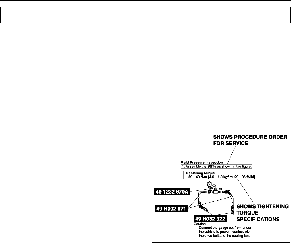
SERVICE PROCEDURE A6E201000001W02
Inspection, adjustment
•Inspection and adjustment procedures are divided into steps. Important points regarding the location and
contents of the procedures are explained in detail and shown in the illustrations.
HOW TO USE THIS MANUAL
XME2010001
HOW TO USE THIS MANUAL
GI3
GI
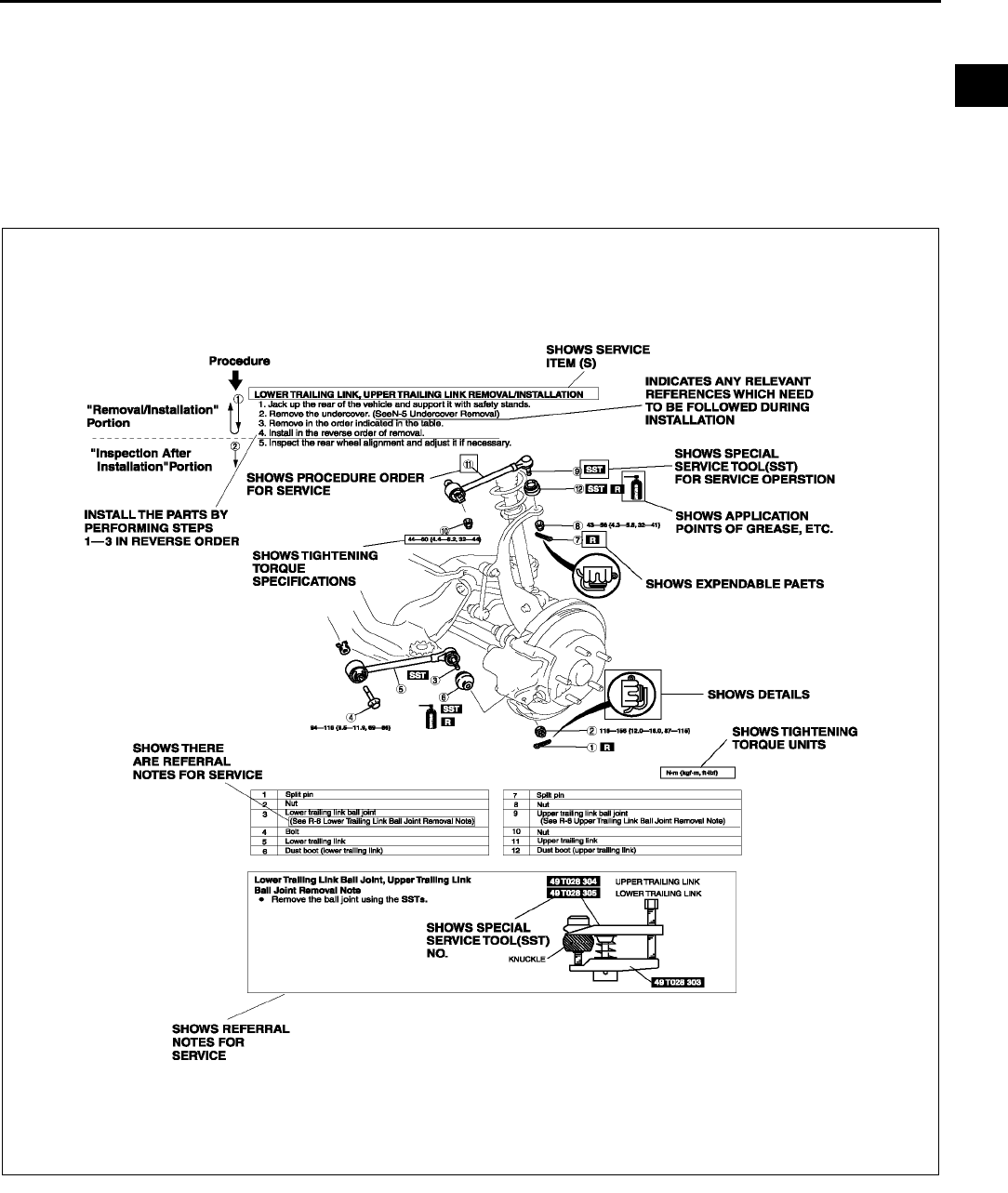
Repair procedure
1. Most repair operations begin with an overview illustration. It identifies the components, shows how the parts fit
together and describes visual part inspection. However, only removal/installation procedures that need to be
performed methodically have written instructions.
2. Expendable parts, tightening torques and symbols for oil, grease, and sealant are shown in the overview
illustration. In addition, symbols indicating parts requiring the use of special service tools or equivalent are also
shown.
3. Procedure steps are numbered and the part that is the main point of that procedure is shown in the illustration
with the corresponding number. Occasionally, there are important points or additional information concerning a
procedure. Refer to this information when servicing the related part.
End Of Sie
XME2010010
GI4
HOW TO USE THIS MANUAL
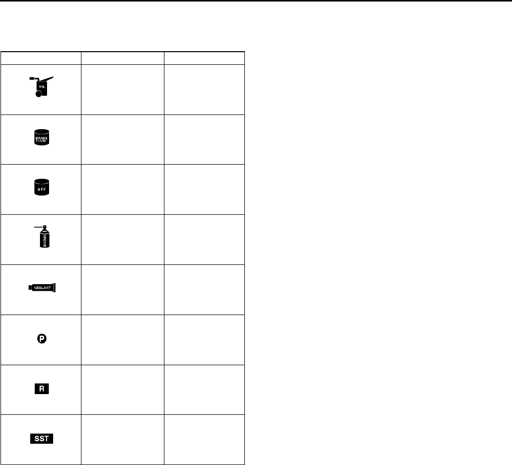
SYMBOLS A6E201000001W03
•There are eight symbols indicating oil, grease, fluids, sealant, and SST or equivalent use. These symbols show
application points or use of these materials during service.
End Of Sie
ADVISORY MESSAGES A6E201000001W04
•You'll find several Warnings, Cautions, Notes, Specifications and Upper and Lower Limits in this manual.
Warning
•A Warning indicates a situation in which serious injury or death could result if the warning is ignored.
Caution
•A Caution indicates a situation in which damage to the vehicle or parts could result if the caution is ignored.
Note
•A Note provides added information that will help you to complete a particular procedure.
Specification
•The values indicate the allowable range when performing inspections or adjustments.
Upper and lower limits
•The values indicate the upper and lower limits that must not be exceeded when performing inspections or
adjustments.
End Of Sie
Symbol Meaning Kind
Apply oil
New appropriate
engine oil or gear
oil
Apply brake fluid New appropriate
brake fluid
Apply automatic
transaxle/
transmission fluid
New appropriate
automatic
transaxle/
transmission fluid
Apply grease Appropriate
grease
Apply sealant Appropriate
sealant
Apply petroleum
jelly
Appropriate
petroleum jelly
Replace part O-ring, gasket,
etc.
Use SST or
equivalent Appropriate tools
HOW TO USE THIS MANUAL
GI5
GI
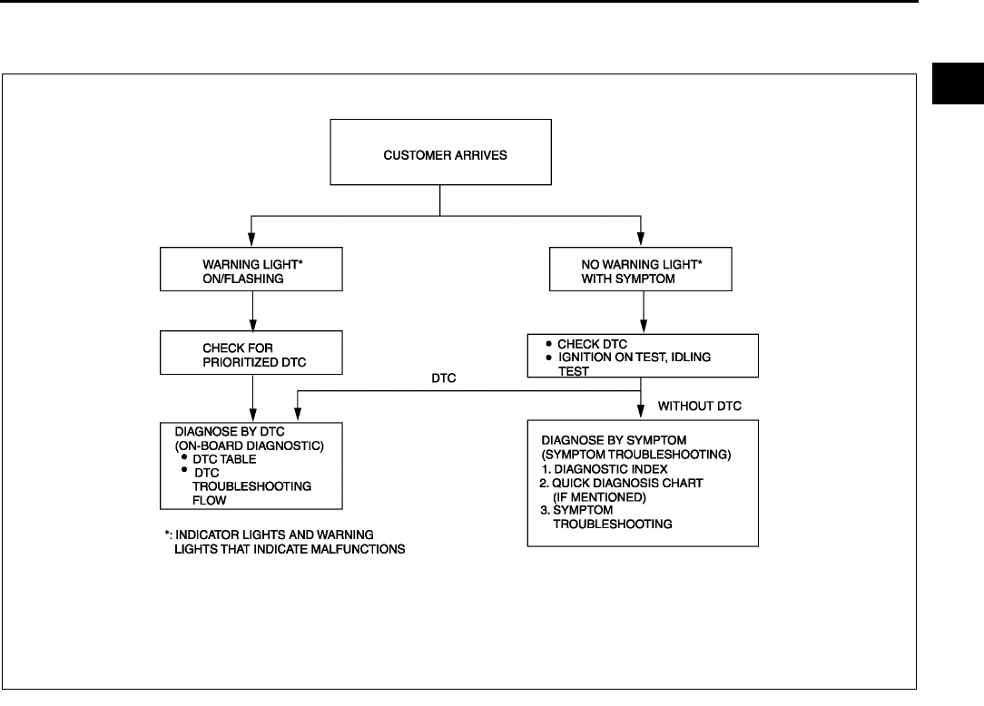
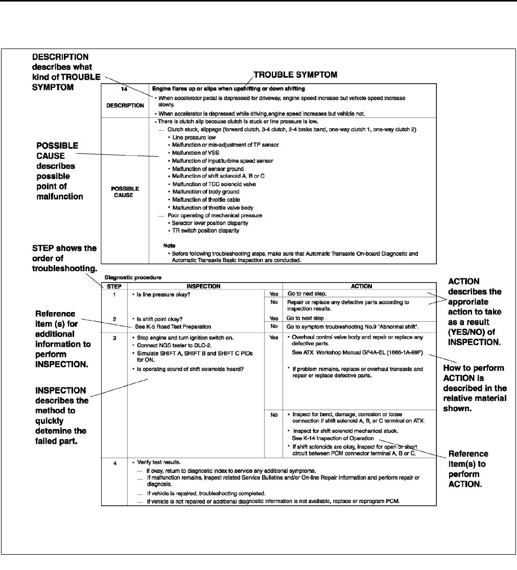
TROUBLESHOOTING PROCEDURE A6E201000001W05
Basic flow of troubleshooting
DTC troubleshooting flow (on-board diagnostic)
•Diagnostic trouble codes (DTCs) are important hints for repairing malfunctions that are difficult to simulate.
Perform the specific DTC diagnostic inspection to quickly and accurately diagnose the malfunction.
•The on-board diagnostic function is used during inspection. When a DTC is shown specifying the cause of a
malfunction, continue the diagnostic inspection according to the items indicated by the on-board diagnostic
function.
Diagnostic index
•The diagnostic index lists the symptoms of specific malfunctions. Select the symptoms related or most closely
relating to the malfunction.
Quick diagnosis chart (If mentioned)
•The quick diagnosis chart lists diagnosis and inspection procedures to be performed specifically relating to the
cause of the malfunction.
Symptom troubleshooting
•Symptom troubleshooting quickly determines the location of the malfunction according to symptom type.
XME2010002
GI6
HOW TO USE THIS MANUAL
Procedures for Use
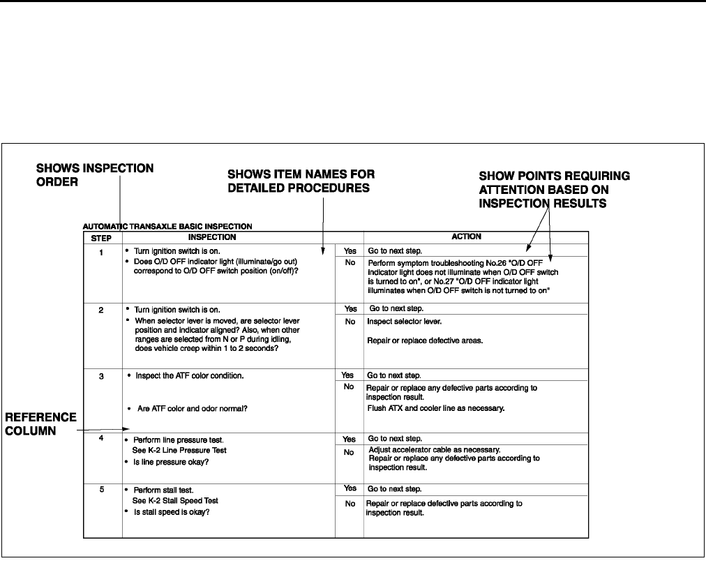
Using the basic inspection (section K)
•Perform the basic inspection procedure before symptom troubleshooting.
•Perform each step in the order shown.
•The reference column lists the location of the detailed procedure for each basic inspection.
•Although inspections and adjustments are performed according to the reference column procedures, if the
cause of the malfunction is discovered during basic inspection, continue the procedures as indicated in the
remarks column.
XME2010003
HOW TO USE THIS MANUAL
GI7
GI
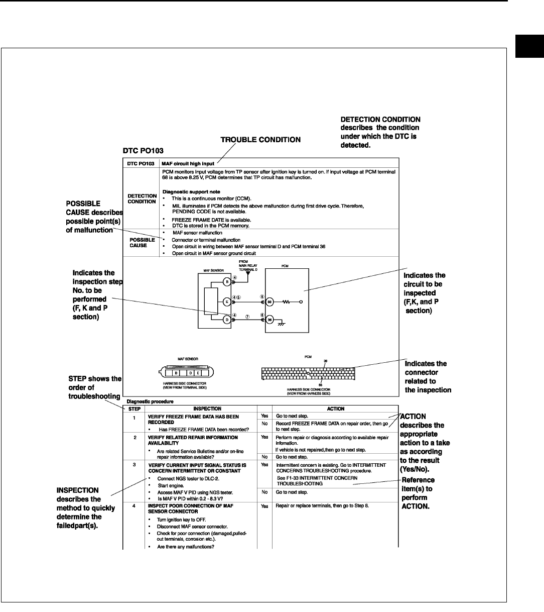
Using the DTC troubleshooting flow
•DTC troubleshooting flow shows diagnostic procedures, inspection methods, and proper action to take for each
DTC.
XME2010004
GI8
HOW TO USE THIS MANUAL
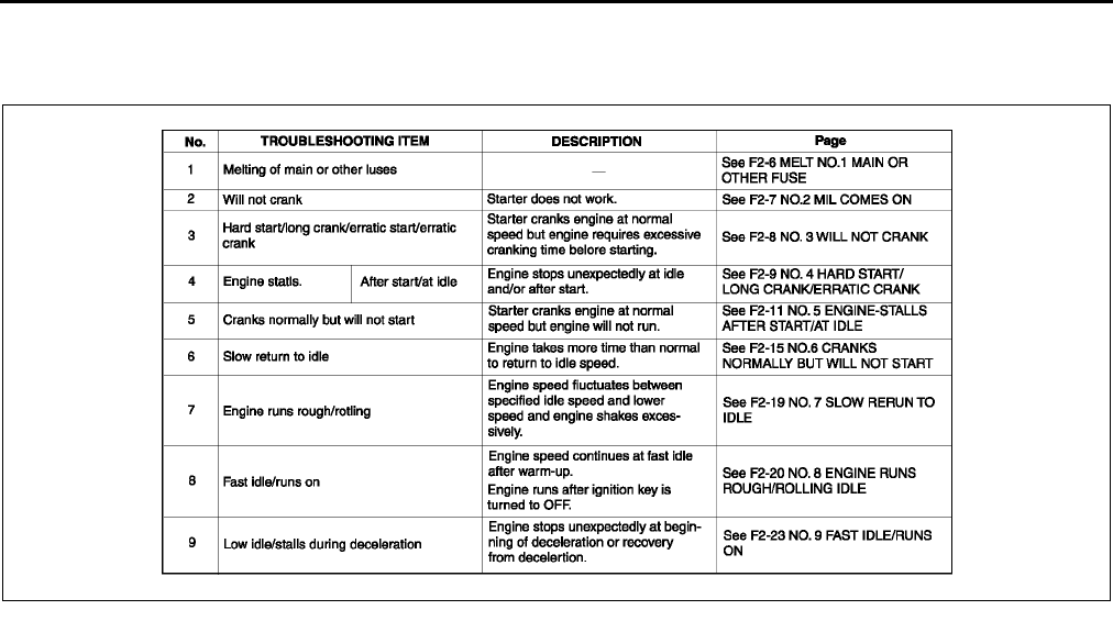
Using the diagnosis index
•The symptoms of the malfunctions are listed in the diagnostic index for symptom troubleshooting.
•The exact malfunction symptoms can be selected by following the index.
XME2010006
HOW TO USE THIS MANUAL
GI9
GI
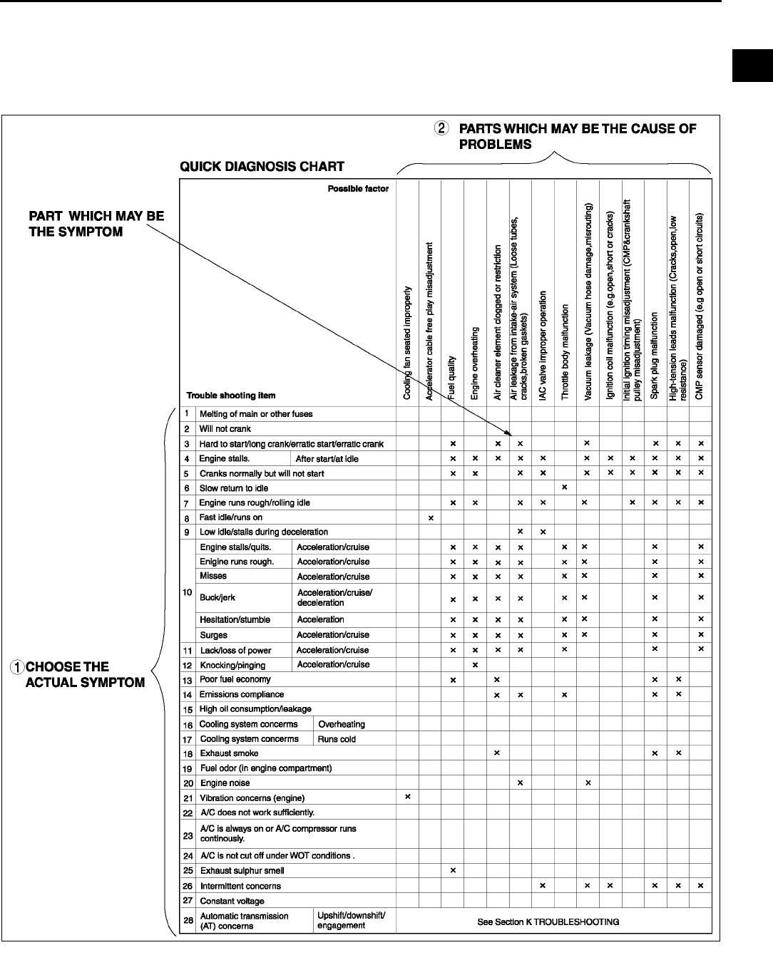
Using the quick diagnosis chart
•The chart lists the relation between the symptom and the cause of the malfunction.
•The chart is effective in quickly narrowing down the relation between symptom and cause of the malfunction. It
also specifies the area of the common cause when multiple malfunction symptoms occur.
•The appropriate diagnostic inspection relating to malfunction cause as specified by the symptoms can be
selected by looking down the diagnostic inspection column of the chart.
XME2010011
GI10
HOW TO USE THIS MANUAL
Using the symptom troubleshooting
•Symptom troubleshooting shows diagnostic procedures, inspection methods, and proper action to take for
each trouble symptom.
End Of Sie
XME2010007
UNITS
GI11
GI
UNITS A6E201200002W01
Conversion to SI Units (Système International d'Unités)
•All numerical values in this manual are based on SI units. Numbers shown in conventional units are converted
from these values.
Rounding Off
•Converted values are rounded off to the same number of places as the SI unit value. For example, if the SI unit
value is 17.2 and the value after conversion is 37.84, the converted value will be rounded off to 37.8.
Upper and Lower Limits
•When the data indicates upper and lower limits, the converted values are rounded down if the SI unit value is
an upper limit and rounded up if the SI unit value is a lower limit. Therefore, converted values for the same SI
unit value may differ after conversion. For example, consider 2.7 kgf/cm2 in the following specifications:
210260 kPa {2.12.7 kgf/cm2, 3038 psi}
270310 kPa {2.73.2 kgf/cm2, 3945 psi}
•The actual converted values for 2.7 kgf/cm2 are 264 kPa and 38.4 psi. In the first specification, 2.7 is used as
an upper limit, so the converted values are rounded down to 260 and 38. In the second specification, 2.7 is
used as a lower limit, so the converted values are rounded up to 270 and 39.
End Of Sie
UNITS
Electrical current A (ampere)
Electric power W (watt)
Electric resistance Ω (ohm)
Electric voltage V (volt)
Length mm (millimeter)
in (inch)
Negative pressure
kPa (kilo pascal)
mmHg (millimeters of mercury)
inHg (inches of mercury)
Positive pressure
kPa (kilo pascal)
kgf/cm2 (kilogram force per square
centimeter)
psi (pounds per square inch)
Torque
N·m (Newton meter)
kgf·m (kilogram force meter)
kgf·cm (kilogram force centimeter)
ft·lbf (foot pound force)
in·lbf (inch pound force)
Volume
L (liter)
US qt (U.S. quart)
Imp qt (Imperial quart)
ml (milliliter)
cc (cubic centimeter)
cu in (cubic inch)
fl oz (fluid ounce)
Weight g (gram)
oz (ounce)
GI12
FUNDAMENTAL PROCEDURES
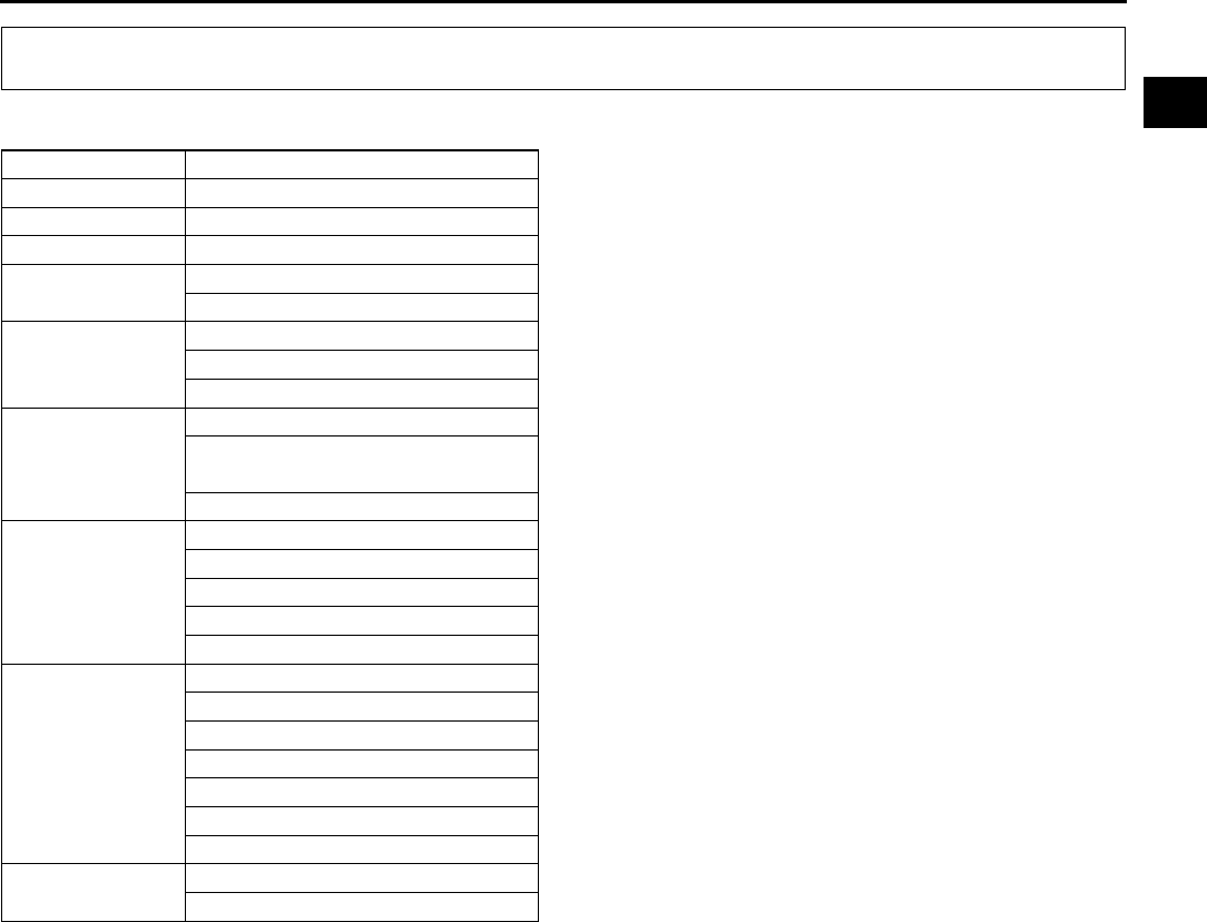
PROTECTION OF VEHICLE A6E201400004W01
•Always be sure to cover fenders, seats and floor
areas before starting work.
End Of Sie
PREPARATION OF TOOLS AND MEASURING EQUIPMENT A6E201400004W02
•Be sure that all necessary tools and measuring
equipment are available before starting any work.
End Of Sie
SPECIAL SERVICE TOOLS A6E201400004W03
•Use special service tools or equivalent when they
are required.
End Of Sie
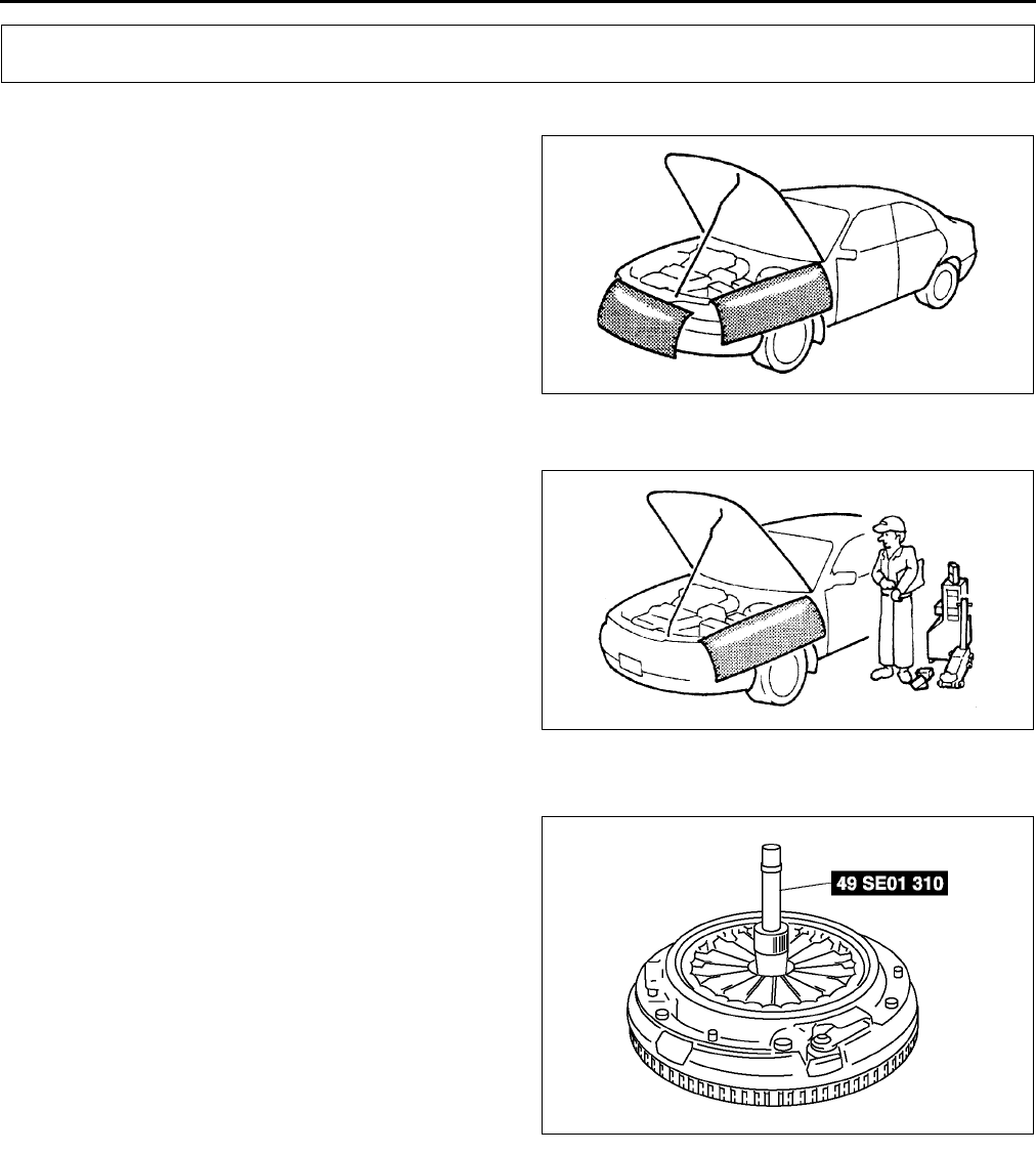
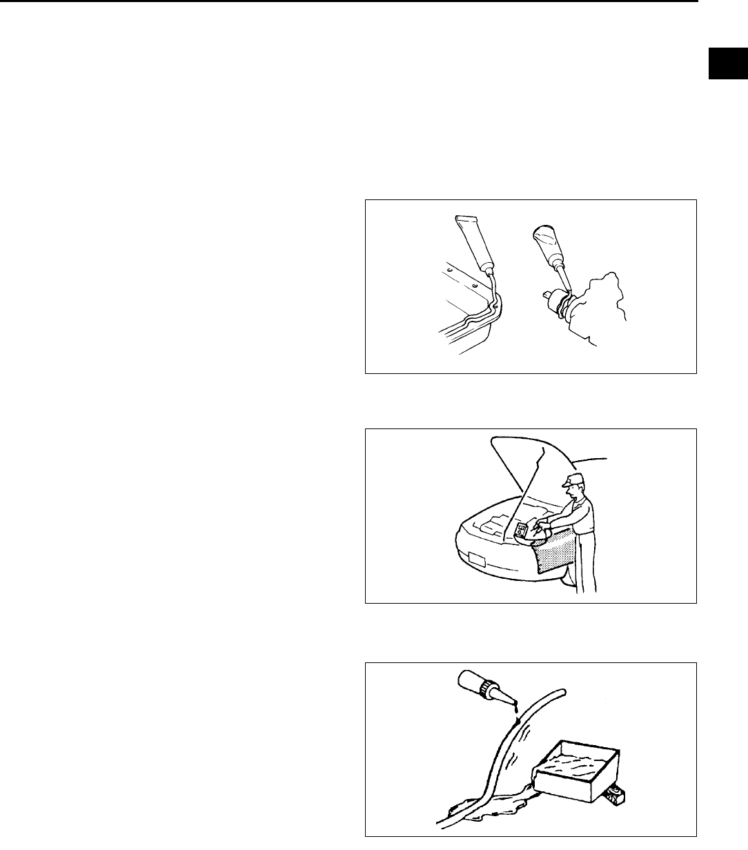
OIL LEAKAGE INSPECTION A6E201400004W04
•Use either of the following procedures to identify the type of oil that is leaking:
Using UV Light (Black Light)
1. Remove on the engine or transaxle.
Note
•Referring to the fluorescent dye instruction manual, mix the specified amount of dye into the engine oil or
ATF (or transaxle oil).
2. Pour the fluorescent dye into the engine oil or ATF (or transaxle oil).
3. Allow the engine to run for 30 minutes.
4. Inspect for dye leakage by irradiating with UV light (black light), and identify the type of oil that is leaking.
FUNDAMENTAL PROCEDURES
X3U000WAG
X3U000WAH
X3U000WAJ
FUNDAMENTAL PROCEDURES
GI13
GI
5. If no dye leakage is found, allow the engine to run for another 30 minutes or drive the vehicle then reinspect.
6. Find where the oil is leaking from, then make necessary repairs.
Note
•To determine whether it is necessary to replace the oil after adding the fluorescent dye, refer to the
fluorescent dye instruction manual.
Not Using UV Light (Black Light)
1. Gather some of the leaking oil using an absorbent white tissue.
2. Take samples of engine oil and ATF (or transaxle oil), both from the dipstick, and place them next to the leaked
oil already gathered on the tissue.
3. Compare the appearance and smell, and identify
the type of oil that is leaking.
4. Remove any oil on the engine or transaxle/
transmission.
5. Allow the engine to run for 30 minutes.
6. Check the area where the oil is leaking, then
make necessary repairs.
End Of Sie
DISCONNECTION OF THE NEGATIVE BATTERY CABLE A6E201400004W05
•Before beginning any work, turn the ignition switch to LOCK position, then disconnect the negative battery
cable and wait for more than 1 minute to allow the backup power supply of the SAS unit to deplete its stored
power. Disconnecting the battery cable will delete the memories of the clock, audio, and DTCs, etc. Therefore,
it is necessary to verify those memories before disconnecting the cable.
•If the battery had been disconnected during vehicle maintenance or for other reasons, the window will not fully
close automatically.Carry out the power window main switch initial setting. (See S23 INITIAL SETTING.)
End Of Sie
REMOVAL OF PARTS A6E201400004W06
•While correcting a problem, also try to determine
its cause. Begin work only after first learning
which parts and subassemblies must be removed
and disassembled for replacement or repair. After
removing the part, plug all holes and ports to
prevent foreign material from entering.
End Of Sie
DISASSEMBLY A6E201400004W07
•If the disassembly procedure is complex,
requiring many parts to be disassembled, all parts
should be marked in a place that will not affect
their performance or external appearance and
identified so that reassembly can be performed
easily and efficiently.
End Of Sie
XME2014003
X3U000WA
K
X3U000WAL
GI14
FUNDAMENTAL PROCEDURES
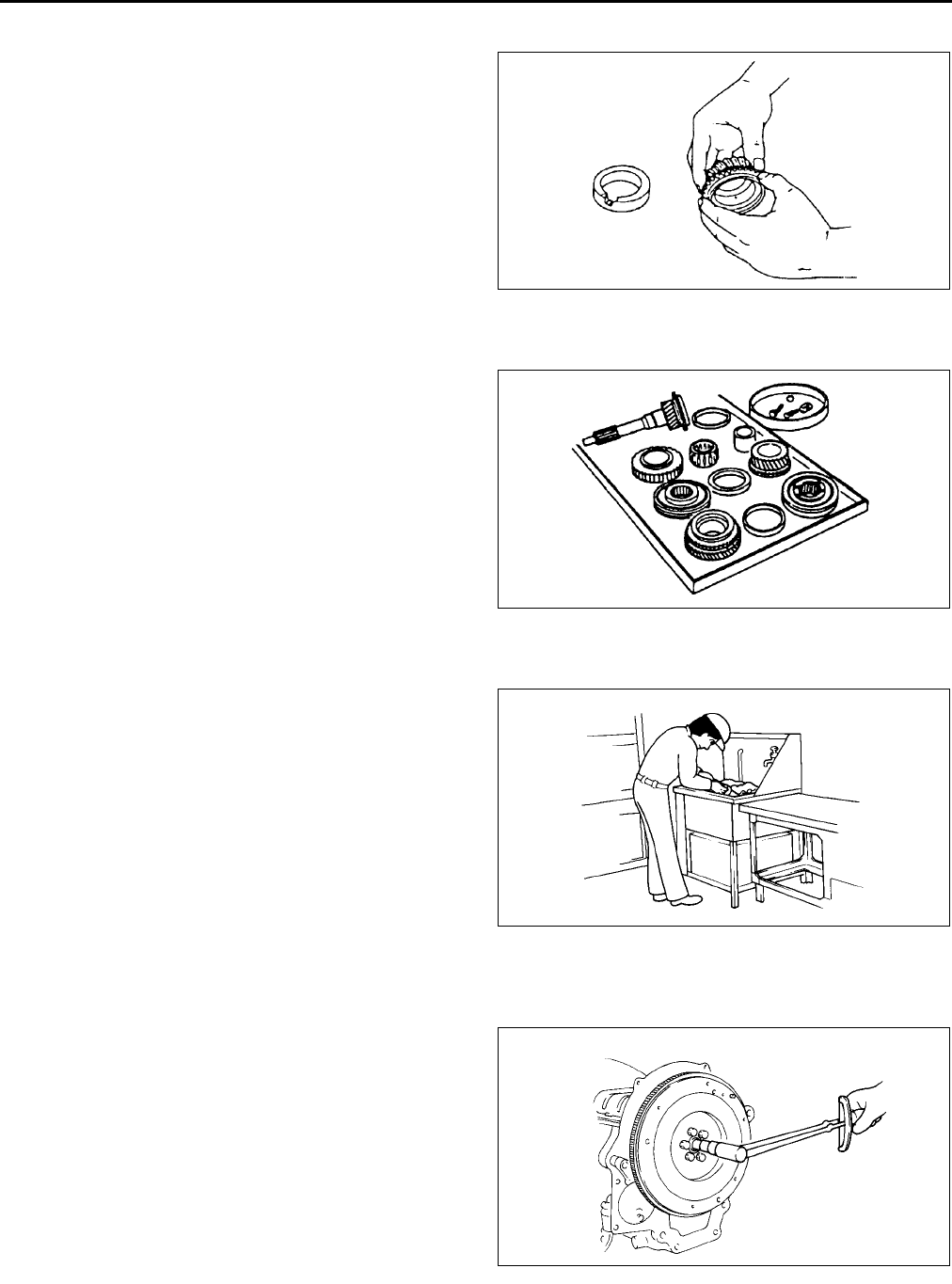
INSPECTION DURING REMOVAL, DISASSEMBLY A6E201400004W08
•When removed, each part should be carefully
inspected for malfunction, deformation, damage,
and other problems.
End Of Sie
ARRANGEMENT OF PARTS A6E201400004W09
•All disassembled parts should be carefully
arranged for reassembly.
•Be sure to separate or otherwise identify the parts
to be replaced from those that will be reused.
End Of Sie
CLEANING OF PARTS A6E201400004W10
•All parts to be reused should be carefully and
thoroughly cleaned in the appropriate method.
Warning
•
••
•Using compressed air can cause dirt and
other particles to fly out causing injury to
the eyes. Wear protective eye wear
whenever using compressed air.
End Of Sie
REASSEMBLY A6E201400004W11
•Standard values, such as torques and certain
adjustments, must be strictly observed in the
reassembly of all parts.
X3U000WAM
X3U000WAN
WGIWXX0030J
WGIWXX0031J
FUNDAMENTAL PROCEDURES
GI15
GI
•If removed, these parts should be replaced with new ones:
Oil seals
Gaskets
O-rings
Lockwashers
Cotter pins
Nylon nuts
•Depending on location:
Sealant and gaskets, or both, should be applied to specified locations. When sealant is applied, parts
should be installed before sealant hardens to prevent leakage.
Oil should be applied to the moving components of parts.
Specified oil or grease should be applied at the prescribed locations (such as oil seals) before reassembly.
End Of Sie
ADJUSTMENT A6E201400004W12
•Use suitable gauges and/or testers when making
adjustments.
End Of Sie
RUBBER PARTS AND TUBING A6E201400004W13
•Prevent gasoline or oil from getting on rubber
parts or tubing.
End Of Sie
WGIWXX0032J
X3U000WAS
WGIWXX0034E
GI16
FUNDAMENTAL PROCEDURES
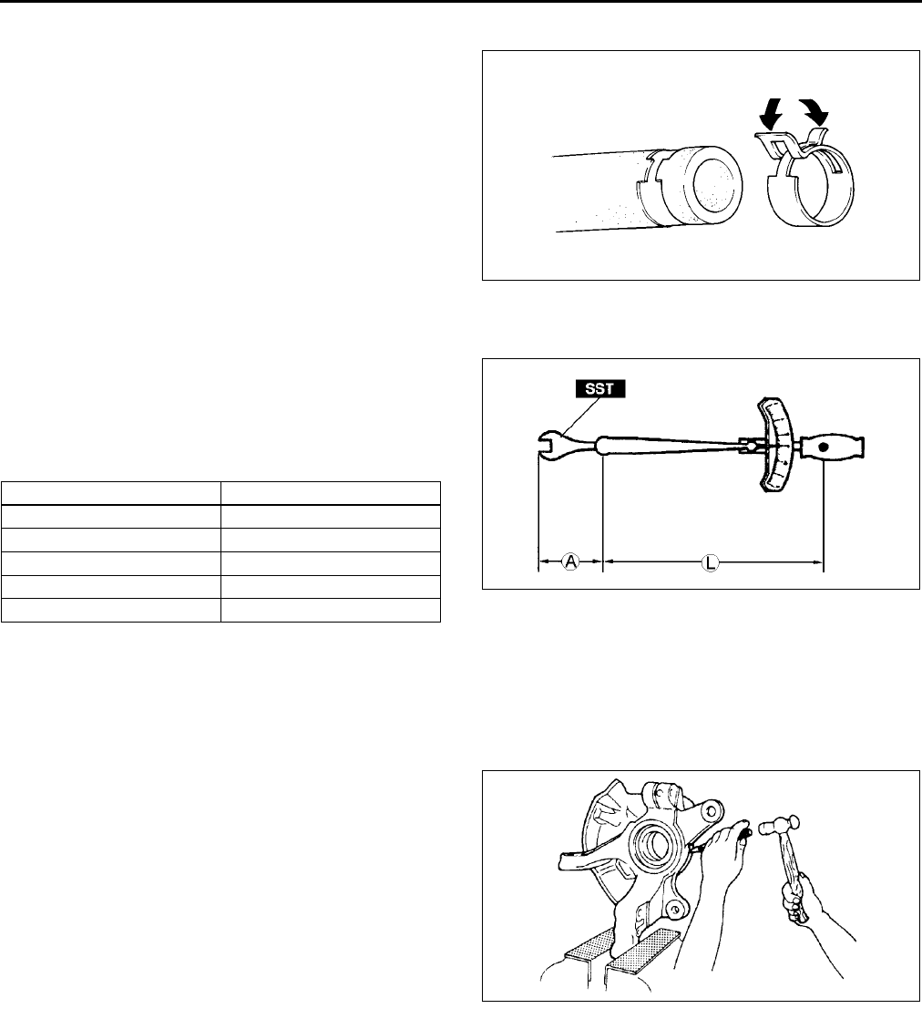
HOSE CLAMPS A6E201400004W14
•When reinstalling, position the hose clamp in the
original location on the hose and squeeze the
clamp lightly with large pliers to ensure a good fit.
End Of Sie
TORQUE FORMULAS A6E201400004W19
•When using a torque wrench-SST or equivalent
combination, the written torque must be
recalculated due to the extra length that the SST
or equivalent adds to the torque wrench.
Recalculate the torque using the following
formulas. Choose the formula that applies to you.
A : The length of the SST past the torque wrench drive
L : The length of the torque wrench
End Of Sie
VISE A6E201400004W16
•When using a vise, put protective plates in the jaws of the vise to prevent damage to parts.
End Of Sie
WGIWXX0035J
Torque Unit Formula
N·m N·m × [L/(L+A)]
kgf·m kgf·m × [L/(L+A)]
kgf·cm kgf·cm × [L/(L+A)]
ft·lbf ft·lbf × [L/(L+A)]
in·lbf in·lbf × [L/(L+A)] WGIWXX0036E
X3U000WAW
FUNDAMENTAL PROCEDURES, INSTALLATION OF RADIO SYSTEM
GI17
GI
DYNAMOMETER A6E201400004W17
•When inspecting and servicing the power train on the dynamometer or speed meter tester, pay attention to the
following:
Place a fan, preferably a vehicle-speed proportional type, in front of the vehicle.
Make sure the vehicle is in a facility with an exhaust gas ventilation system.
Since the rear bumper might deform from the heat, cool the rear with a fan. (Surface of the bumper must be
below 70 degrees.)
Keep the area around the vehicle uncluttered so that heat does not build up.
Watch the water temperature gauge and dont overheat the engine.
Avoid added load to the engine and maintain normal driving conditions as much as possible.
Note
•When only the front wheels are being rotated on the dynamometer, the ABS warning light could illuminate.
If the ABS warning light illuminates, turn the ignition switch to the LOCK position, then turn it back to the
ON position, run the vehicle at 10km/h and check that the ABS warning light goes off. (In this case, a DTC
will be stored in the memory. To delete this data from the memory, follow the procedure for deleting DTCs
(ABS) from memory.) (See P6 PRECAUTION (BRAKES) ) to turn off the warning light.)
End Of Sie
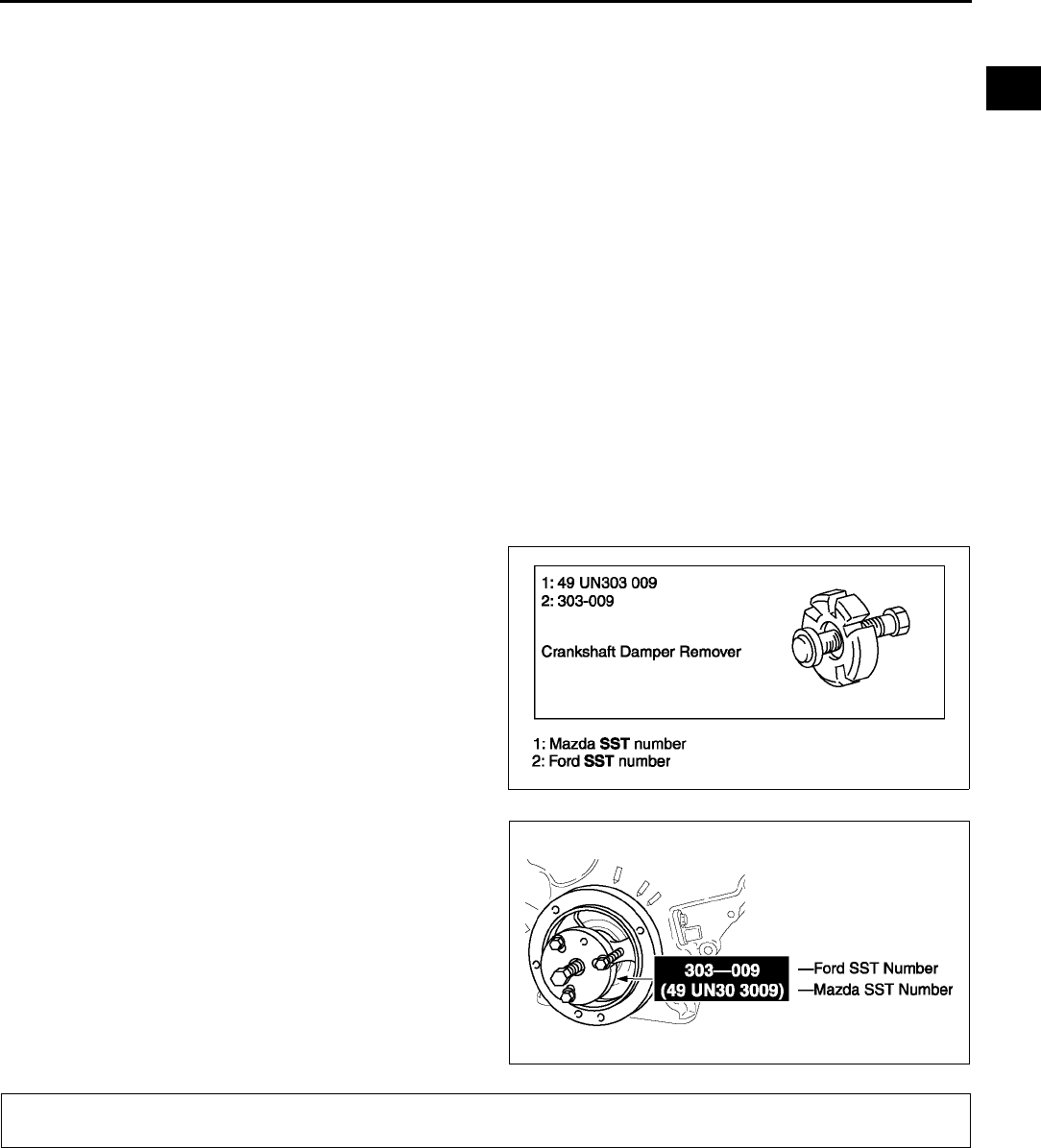
SST A6E201400004W18
•Some Ford SST or equivalent are used as SSTs necessary for engine repair. Note that these SSTs are
marked with Ford SST numbers.
•Note that a Ford SST number is written together with a corresponding Mazda SST number as shown below.
Example (section ST)
Example (except section ST)End Of Sie
INSTALLATION OF RADIO SYSTEM A6E201600005W01
If a radio system is installed improperly or if a high-powered type is used, the CIS and other systems may be
affected. When the vehicle is to be equipped with a radio, observe the following precautions:
•Install the antenna at the farthest point from control modules.
•Install the antenna feeder as far as possible from the control module harnesses.
•Ensure that the antenna and feeder are properly adjusted.
•Do not install a high-powered radio system.
End Of Sie
XME2014002
XME2014001
INSTALLATION OF RADIO SYSTEM
GI18
ELECTRICAL SYSTEM
ELECTRICAL PARTS A6E201700006W01
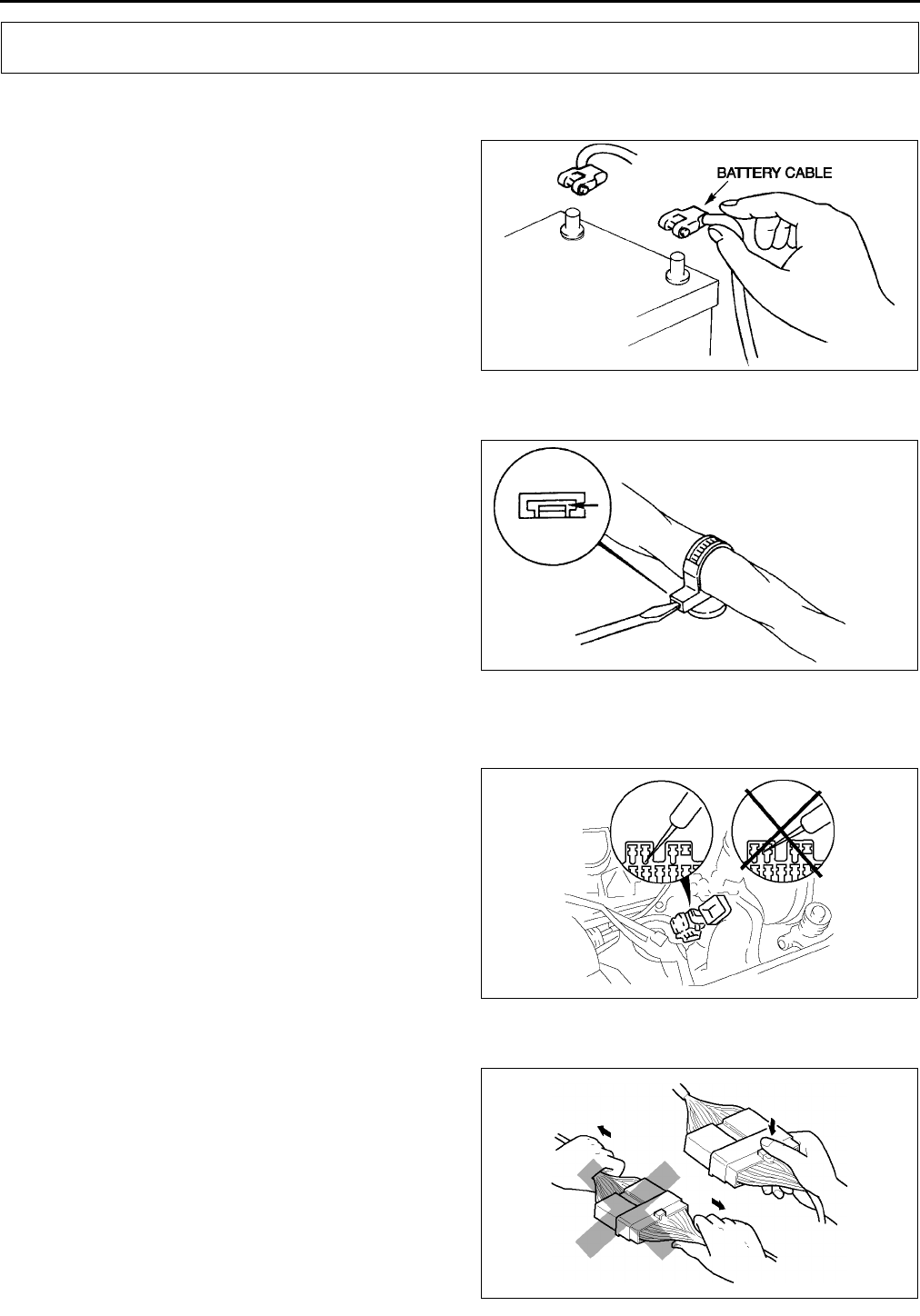
Battery cable
•Before disconnecting connectors or removing
electrical parts, disconnect the negative battery
cable.
Wiring Harness
•To remove the wiring harness from the clip in the
engine room, pry up the hook of the clip using a
flathead screwdriver.
End Of Sie
CONNECTORS A6E201700006W02
Data link connector
•Insert the probe into the terminal when
connecting a jumper wire to the data link
connector.
Caution
•
••
•Inserting a jumper wire probe into the
data link connector terminal may damage
the terminal.
Disconnecting connectors
•When disconnecting connector, grasp the
connectors, not the wires.
ELECTRICAL SYSTEM
WGIWXX0007E
X3U000WBU
X3U000WAY
WGIWXX0041E
ELECTRICAL SYSTEM
GI19
GI
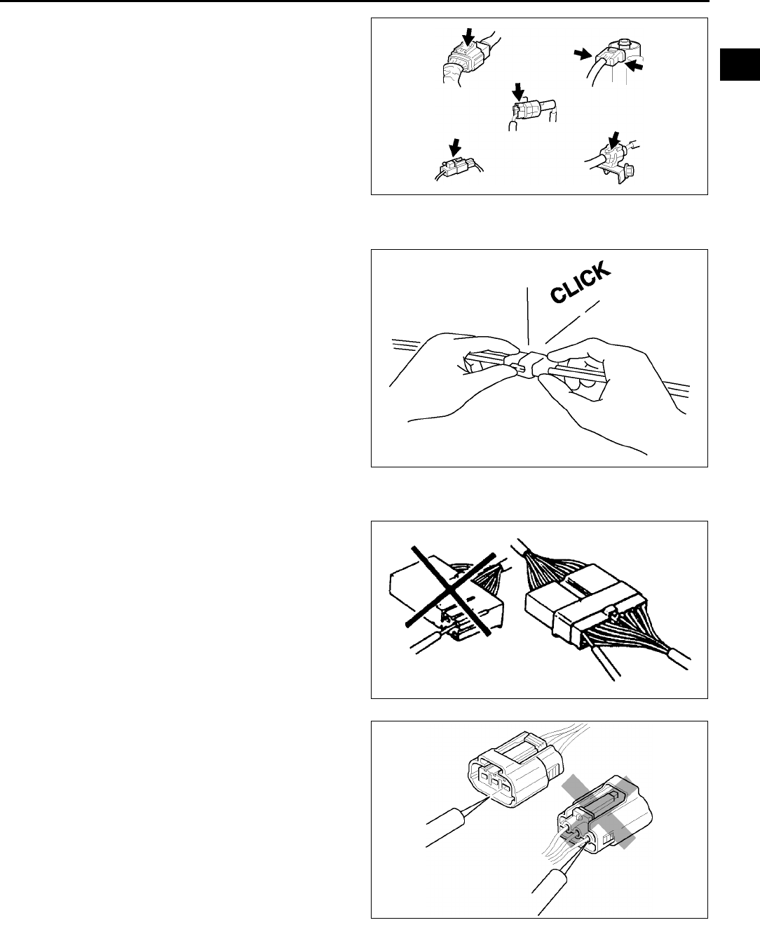
•Connectors can be disconnected by pressing or
pulling the lock lever as shown.
Locking connector
•When locking connectors, listen for a click
indicating they are securely locked.
Inspection
•When a tester is used to inspect for continuity or
measuring voltage, insert the tester probe from
the wiring harness side.
•Inspect the terminals of waterproof connectors
from the connector side since they cannot be
accessed from the wiring harness side.
Caution
•
••
•To prevent damage to the terminal, wrap
a thin wire around the tester probe before
inserting into terminal.
WGIWXX0042E
X3U000WB1
X3U000WB2
WGIWXX0045E
GI20
ELECTRICAL SYSTEM
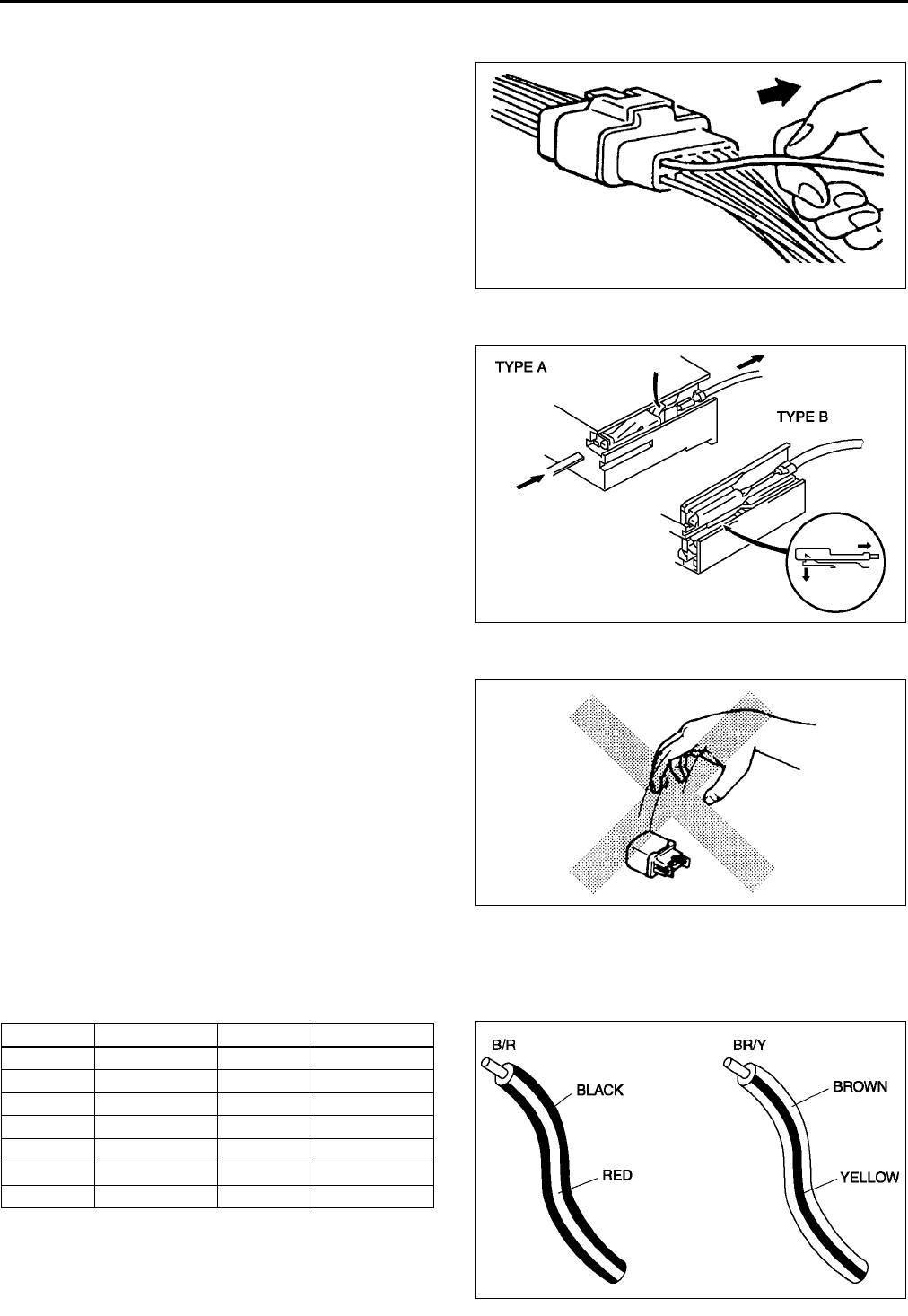
Terminals
Inspection
•Pull lightly on individual wires to verify that they
are secured in the terminal.
Replacement
•Use the appropriate tools to remove a terminal as
shown. When installing a terminal, be sure to
insert it until it locks securely.
•Insert a thin piece of metal from the terminal side
of the connector and with the terminal locking tab
pressed down, pull the terminal out from the
connector.
Sensors, Switches, and Relays
•Handle sensors, switches, and relays carefully.
Do not drop them or strike them against other
objects.
Wiring Harness
Wiring color codes
•Two-color wires are indicated by a two-color code symbol.
•The first letter indicates the base color of the wire and the second the color of the stripe.
X3U000WB4
X3U000WB5
X3U000WB6
CODE COLOR CODE COLOR
B Black O Orange
BR Brown P Pink
G Green R Red
GY Gray V Violet
LBlueWWhite
LB Light Blue Y Yellow
LG Light Green
X3U000WB7
ELECTRICAL SYSTEM
GI21
GI
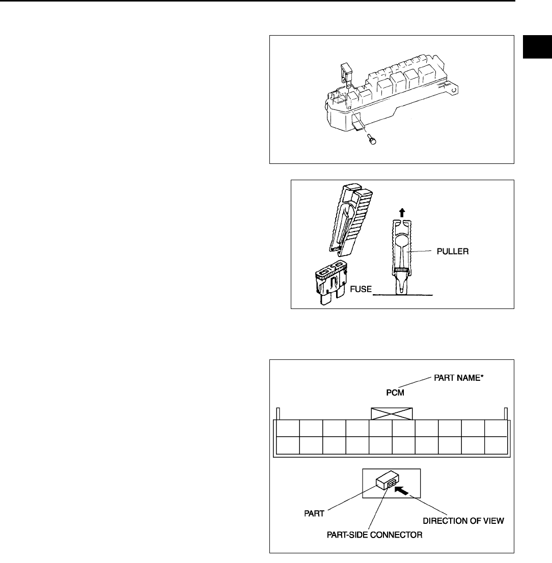
Fuse
Replacement
•When replacing a fuse, be sure to replace it with
one of the same capacity. If a fuse fails again, the
circuit probably has a short and the wiring should
be inspected.
•Be sure the negative battery terminal is
disconnected before replacing a main fuse.
•When replacing a pullout fuse, use the fuse
puller.
Direction of View for Connector
Part-side connector
Direction of view is from the terminal side.
* : Part names are shown only when there are
multiple connector drawings.
YMU000WA1
YMU000WA
K
WGIWXX0100E
GI22
ELECTRICAL SYSTEM
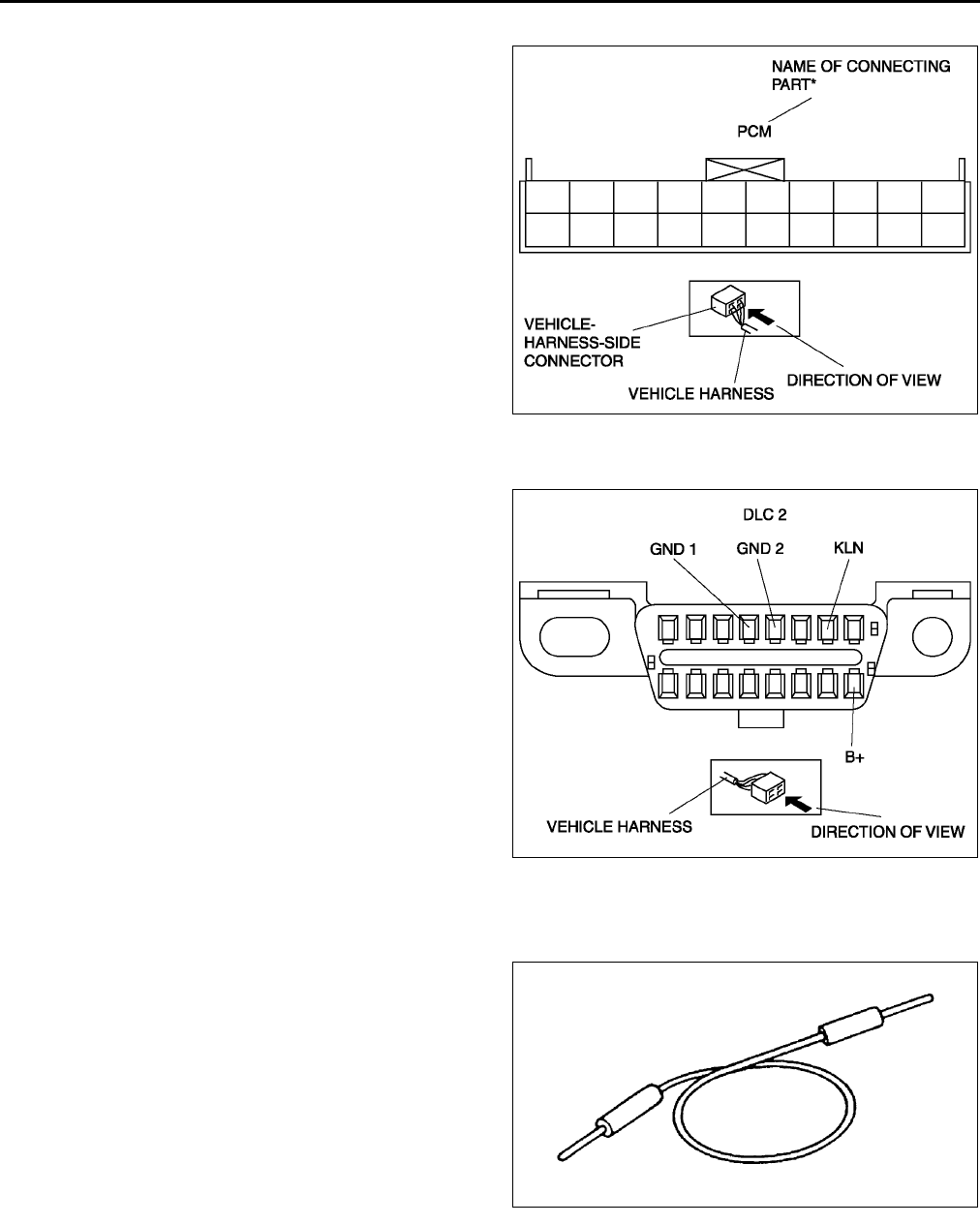
Vehicle-harness-side connector
Direction of view is from the harness side.
* : Part names are shown only when there are
multiple connector drawings.
Other
Because vehicle-harness-side connectors, such as
the DLC 2, have to be viewed from the terminal side,
the direction of view is from the terminal side.
End Of Sie
ELECTRICAL TROUBLESHOOTING TOOLS A6E201700006W03
Jumper wire
•A jumper wire is used to create a temporary
circuit. Connect the jumper wire between the
terminals of a circuit to bypass a switch.
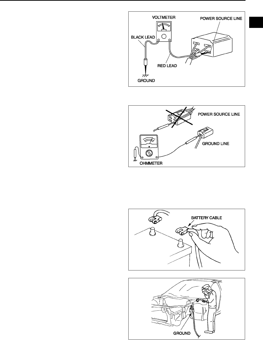
Caution
•
••
•Do not connect a jumper wire from the
power source line to a body ground. This
may cause burning or other damage to
wiring harnesses or electronic
components.
WGIWXX0101E
WGIWXX0102E
X3U000WBB
ELECTRICAL SYSTEM
GI23
GI
Voltmeter
•The DC voltmeter is used to measure circuit
voltage. A voltmeter with a range of 15 V or more
is used by connecting the positive (+) probe (red
lead wire) to the point where voltage will be
measured and the negative (-) probe (black lead
wire) to a body ground.
Ohmmeter
•The ohmmeter is used to measure the resistance
between two points in a circuit and to inspect for
continuity and short circuits.
Caution
•
••
•Do not connect the ohmmeter to any
circuit where voltage is applied. This will
damage the ohmmeter.
End Of Sie
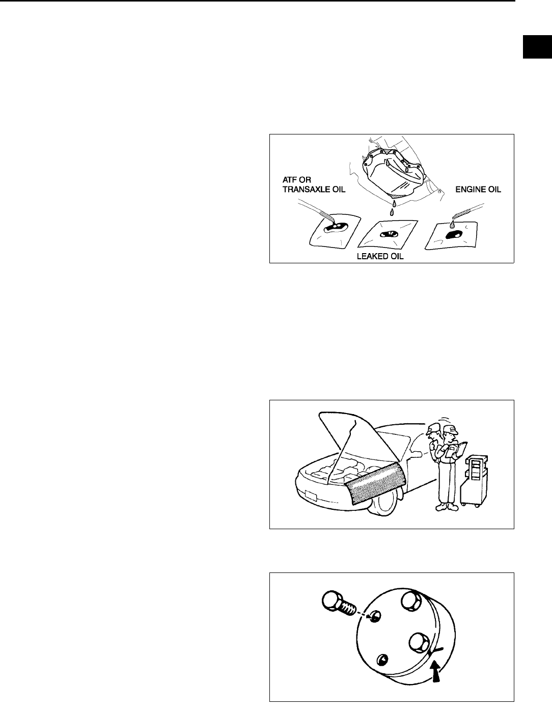
PRECAUTIONS BEFORE WELDING A6E201700006W04
Vehicles have various electrical parts. To protect the parts from excessive current generated when welding, be
sure to perform the following procedure.
1. Turn the ignition switch to the LOCK position.
2. Disconnect the battery cables.
3. Securely connect the welding machine to the
ground near the welding area.
4. Cover the peripheral parts of the welding area to
protect them from weld spatter.
End Of Sie
X3U000WBC
YMU000WAL
WGIWXX0007E
WGIWXX0008E

GI24
JACKING POSITIONS, VEHICLE LIFT (2 SUPPORTS),
SAFETY STANDS (RIGID RACK) POSITIONS
JACKING POSITIONS, VEHICLE LIFT (2 SUPPORTS) AND SAFETY STAND (RIGID RACK) POSITIONS
A6E202200019W01
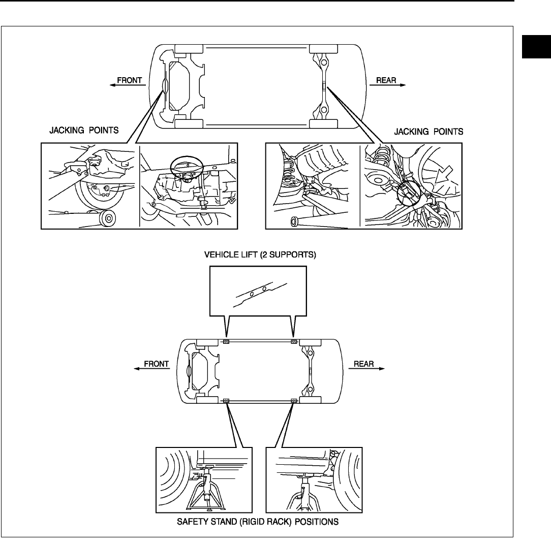
Jacking Positions
Warning
•
••
•Improperly jacking a vehicle is dangerous. The vehicle can slip off the jack and cause serious
injury. Use only the correct front and rear jacking points and block the wheels.
•Use safety stands to support the vehicle after it has been lifted.
Front
•At the jacking plate of the engine support member.
Rear
•At the center of torsion beam axle.
Vehicle Lift Positions
Front and rear
Warning
•
••
•Unstably lifting a vehicle is dangerous. The vehicle can slip off the lift and cause serious injury
and/or vehicle damage. Make sure that the vehicle is on the lift horizontally by adjusting the height
of support at the end of the arm of the lift.
Safety Stand Positions
Front
•Both sides of the vehicle, on side sills.
Rear
•Both sides of the vehicle, on side sills.
JACKING POSITIONS ,VEHICLE LIFT (2 SUPPORTS),
SAFETY STANDS (RIGID RACK) POSITIONS
JACKING POSITIONS ,VEHICLE LIFT (2 SUPPORTS), SAFETY STANDS (RIGID
GI25
GI
Jacking positions, vehicle lift (2 supports) and safety stand (rigid rack) positions view
End Of Sie
A6E2021W001
GI26
TOWING
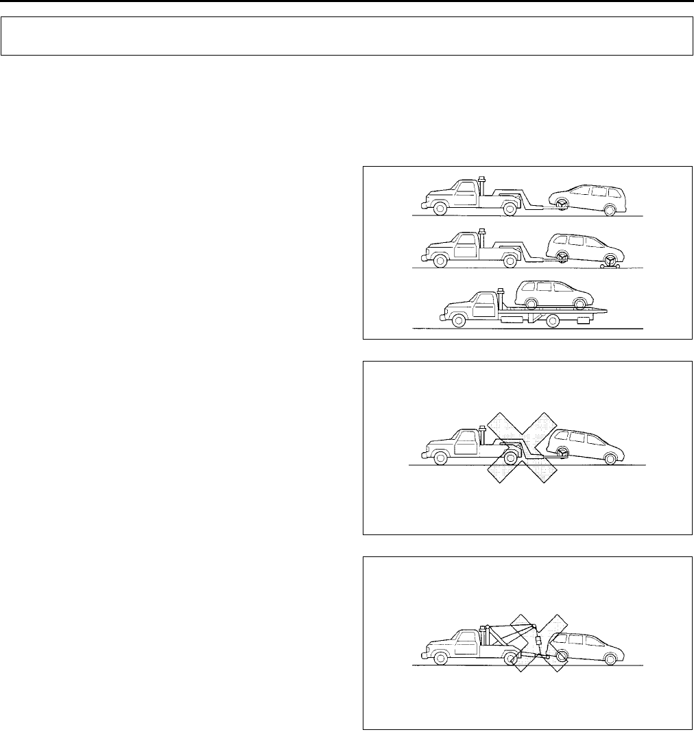
TOWING A6E202400009W01
•Proper lifting and towing are necessary to prevent damage to the vehicle. Government and local laws must be
followed.
•A towed vehicle should have its front wheels off the ground. If excessive damage or other conditions prevent
this, use wheel dollies.
•When towing with the rear wheels on the ground, release the parking brake.
Caution
•
••
•Do not tow the vehicle backward with
driving wheels on the ground. This may
cause internal damage to the transaxle.
Caution
•
••
•Do not tow with sling-type equipment.
This could damage your vehicle. Use
wheel-lift or flatbed equipment.
Caution
•
••
•Do not use the hook loops under the
front and rear for towing. They are
designed ONLY for tying down the
vehicle when it is being transported.
Using them for towing will damage the
bumper.
End Of Sie
TOWING HOOKS A6E202400009W02
Caution
•
••
•The towing hooks should be used only in an emergency (to get the vehicle out of a ditch or a snow
bank, for example).
•
••
•When using the towing hooks, always pull the cable or chain in a straight direction with respect to
the hook. Apply no sideways force.
TOWING
YMU000WA3
YMU000WA4
YMU000WA5
TOWING
GI27
GI
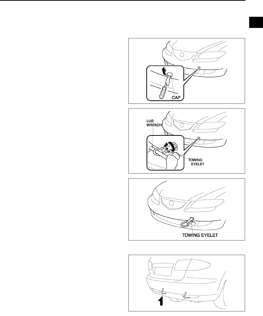
FRONT
1. Remove the towing eyelet and the lug wrench from the trunk.
2. Wrap a screwdriver or similar tool with a soft cloth to prevent damage to the painted bumper and open the cap
located on the front bumper, below the left headlight.
Caution
•
••
•The cap cannot be completely removed.
Do not use excessive force as it may
damage the cap or scratch the painted
bumper surface.
3. Securely install the towing eyelet using the lug
wrench.
4. Hook the towing rope to the towing eyelet.
Caution
•
••
•If the towing eyelet is not securely
tightened, it may loosen or disengage
from the bumper when towing the
vehicle. Make sure that the towing eyelet
is securely tightened to the bumper.
REAR
End Of Sie
A6E2024W004
A6E2024W002
A6E2024W003
A6E2024W001
GI28
IDENTIFICATION NUMBER LOCATIONS
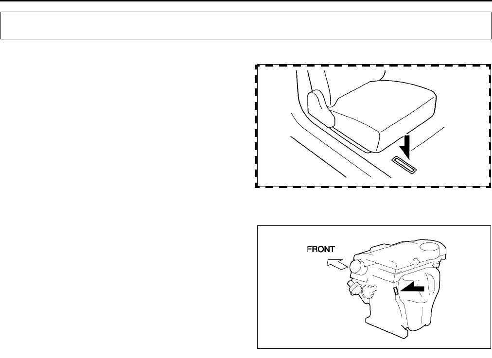
VEHICLE IDENTIFICATION NUMBER(VIN) A6E202600010W01
End Of Sie
ENGINE IDENTIFICATION NUMBER A6E202600010W02
End Of Sie
IDENTIFICATION NUMBER LOCATIONS
A6E2026W004
A6E2026W001

NEW STANDARDS
GI29
GI
NEW STANDARDS A6E202800020W01
•Following is a comparison of the previous standard and the new standard.
NEW STANDARDS
New Standard Previous Standard
Remark
Abbrevi-
ation Name Abbrevi-
ation Name
AP Accelerator Pedal Accelerator Pedal
ACL Air Cleaner Air Cleaner
A/C Air Conditioning Air Conditioning
BARO Barometric Pressure Atmospheric Pressure
B+ Battery Positive Voltage Vb Battery Voltage
Brake Switch Stoplight Switch
Calibration Resistor Corrected Resistance #6
CMP sensor Camshaft Position Sensor Crank Angle Sensor
CAC Charge Air Cooler Intercooler
CLS Closed Loop System Feedback System
CTP Closed Throttle Position Fully Closed
CPP Clutch Pedal Position Idle Switch
CIS Continuous Fuel Injection System Clutch Position
CS sensor Control Sleeve Sensor CSP sensor Control Sleeve Position Sensor #6
CKP sensor Crankshaft Position Sensor Crank Angle Sensor 2
DLC Data Link Connector Diagnosis Connector
DTM Diagnostic Test Mode Test Mode #1
DTC Diagnostic Trouble Code(s) Service Code(s)
DI Distributor Ignition Spark Ignition
DLI Distributorless Ignition Direct Ignition
EI Electronic Ignition Electronic Spark Ignition #2
ECT Engine Coolant Temperature Water Thermo
EM Engine Modification Engine Modification
Engine Speed Input Signal Engine RPM Signal
EVAP Evaporative Emission Evaporative Emission
EGR Exhaust Gas Recirculation Exhaust Gas Recirculation
FC Fan Control Fan Control
FF Flexible Fuel Flexible Fuel
4GR Fourth Gear Overdrive
Fuel Pump Relay Circuit Opening Relay #3
FSO
solenoid Fuel Shut Off Solenoid FCV Fuel Cut Valve #6
GEN Generator Alternator
GND Ground Ground/Earth
HO2S Heated Oxygen Sensor Oxygen Sensor With heater
IAC Idle Air control Idle Speed Control
IDM Relay Spill Valve Relay #6
Incorrect Gear Ratio
Injection Pump FIP Fuel Injection Pump #6
Input/Turbine Speed Sensor Pulse Generator
IAT Intake Air Temperature Intake Air Thermo
KS Knock Sensor Knock Sensor
MIL Malfunction Indicator Lamp Malfunction Indicator Light
MAP Manifold Absolute Pressure Intake Air Pressure
MAF sensor Mass Air Flow Sensor Airflow Sensor
MFL Multiport Fuel Injection Multiport Fuel Injection
OBD On-Board Diagnostic Diagnosis/SelfDiagnosis
OL Open Loop Open Loop

GI30
NEW STANDARDS
#1 : Diagnostic trouble codes depend on the diagnostic test mode
#2 : Controlled by the PCM
#3 : In some models, there is a fuel pump relay that controls pump speed. That relay is now called the fuel pump
relay (speed).
#4 : Device that controls engine and powertrain
#5 : Directly connected to exhaust manifold
#6 : Part name of diesel engine
End Of Sie
Output Speed Sensor Vehicle Speed Sensor 1
OC Oxidation Catalytic Converter Catalytic Converter
O2S Oxygen Sensor Oxygen Sensor
PNP Park/Neutral Position Park/Neutral Range
PCM Control Relay Main Relay #6
PSP Power Steering Pressure Power Steering Pressure
PCM Powertrain Control Module ECU Engine Control Unit #4
Pressure Control Solenoid Line Pressure Solenoid Valve
PAIR Pulsed Secondary Air Injection Secondary Air Injection System Pulsed
injection
Pump Speed Sensor NE Sensor #6
AIR Secondary Air Injection Secondary Air Injection System
Injection
with air
pump
SAPV Secondary Air Pulse Valve Reed Valve
SFI Sequential Multipoint Fuel Injection Sequential Fuel Injection
Shift Solenoid A 12 Shift Solenoid Valve
Shift A Solenoid Valve
Shift Solenoid B 23 Shift Solenoid Valve
Shift B Solenoid Valve
Shift Solenoid C 34 Shift Solenoid Valve
3GR Third Gear 3rd Gear
TWC Three Way Catalytic Converter Catalytic Converter
TB Throttle Body Throttle Body
TP sensor Throttle Position Sensor Throttle Sensor
TCV Timer Control Valve TCV Timing Control Valve #6
TCC Torque Converter Clutch Lockup Position
TCM Transmission (Transaxle) Control
Module ECAT Control Unit
Transmission (Transaxle) Fluid
Temperature Sensor ATF Thermosensor
TR Transmission (Transaxle) Range Inhibitor Position
TC Turbocharger Turbocharger
VSS Vehicle Speed Sensor Vehicle Speed Sensor
VR Voltage Regulator IC Regulator
VAF sensor Volume Air Flow Sensor Air flow Sensor
WUTWC Warm Up Three Way Catalytic
Converter Catalytic Converter #5
WOT Wide Open Throttle Fully Open
New Standard Previous Standard
Remark
Abbrevi-
ation Name Abbrevi-
ation Name
ABBREVIATIONS
GI31
GI
ABBREVIATIONS A6E203000011W01
End Of Sie
ABBREVIATIONS
A/C Air conditioner
ABS Antilock brake system
ACC Accessories
ALR Automatic locking retractor
ATF Automatic transaxle fluid
ATX Automatic transaxle
CAN Controller area network
CM Control module
DIS Drive information system
DSC Dynamic stability control
ELR Emergency locking retractor
ESA Electronic spark advance
EX Exhaust
GPS Global positioning system
HI High
IAC Idle air control
IG Ignition
IN Intake
INT Intermittent
KOEO Key on engine off
KOER Key off engine running
LCD Liquid crystal display
LED Light emitting diode
LF Left front
LH Left hand
L.H.D. Left hand drive
LO Low
LR Left rear
M Motor
MAX Maximum
MTX Manual transaxle
O/D Overdrive
OCV Oil control valve
OFF Switch off
ON Switch on
P/S Power steering
P/W CM Power window control module
PATS Passive anti-theft system
PCV Positive crankcase ventilation
PID Parameter identification
REC Recirculate
RF Right front
RH Right hand
R.H.D. Right hand drive
RR Right rear
SAS Sophisticated air bag sensor
SST Special service tool
SW Switch
TDC Top dead center
TFT Transaxle fluid temperature
TNS Tail number side lights
TP Throttle position
TR Transaxle range
TWC Three way catalytic converter
VAD Variable air duct
VIS Variable intake-air system
VTCS Variable tumble control system
VVT Variable valve timing
WDS Worldwide diagnostic system
4SD 4 door sedan
5HB 5 door hatchback

GI32
PRE-DELIVERY INSPECTION
PRE-DELIVERY INSPECTION A6E203200012W01
PRE-DELIVERY INSPECTION TABLE
EXTERIOR
•INSPECT and ADJUST, if necessary, the
following items to specification:
❏Glass, exterior bright metal and paint for damage
❏All weatherstrips for damage or detachment
❏Door operation and alignment including side door
and back door
❏Wheel lug nuts
❏Tire pressures
❏Headlight aiming
❏Headlight cleaner and fluid level (if equipped)
❏Operation of bonnet release and lock
❏Operation of liftgate and fuel lid opener
•INSTALL the following parts:
❏Flap (front and rear)
❏Wheel caps or rings (if equipped)
UNDER BONNETENGINE OFF
•INSPECT and ADJUST, if necessary, the
following items to specification:
❏Fuel, engine coolant, and hydraulic lines, fittings,
connections, and components for leaks
❏Accelerator cable and linkage for free movement
❏Tension of drive belts
❏Tightness of water hose clamps
❏Tightness of battery terminals, electrolyte level and
specific gravity
❏Radiator coolant level and specific gravity
❏Engine oil level
❏Oil level in steering gearbox
❏Windshield washer tank fluid level
❏Brake master cylinder fluid level
❏Clutch master cylinder fluid level (MTX only)
❏Power steering fluid level
❏Manual transaxle oil level (MTX only)
CLEAN the spark plugs
INTERIOR
•INSTALL the following parts:
❏Fuse for accessories
•CHECK the operations of the following items:
❏All lights including warning, and indicator lights
❏Cigarette lighter and clock
❏Ignition switch and steering lock
❏Transaxle range switch (ATX only)
❏Warning buzzers
❏Seat belts warning system
❏Ignition key reminder alarm
❏Seat controls (sliding and reclining) and headrests
❏Seat belt warning system
❏Door locks, including childproof door locks
❏Power door lock
❏Power windows (if equipped)
❏Horn, wipers, and washers
❏Wiper blades performance
Clean the wiper blades and windshield, if necessary
❏Antenna
•CHECK the following items:
❏Presence of spare fuse
❏Upholstery and interior finish
•CHECK and ADJUST, if necessary, the following
items:
❏Operation and fit of windows
❏Parking brake
❏Pedal height and free play of brake pedal
UNDER BONNETENGINE RUNNING AT
OPERATING TEMPERATURE
•CHECK the following items:
❏Operation of idle-up system for electrical load, air
conditioner
❏Idle speed
❏Automatic transaxle fluid level (ATX only)
❏Initial ignition timing
❏Operation of throttle position sensor
❏Operation of EGR valve
ON HOIST
•CHECK the following items:
❏Underside fuel, coolant and hydraulic lines, fittings,
connections, and components for leaks
❏Tires for cuts or bruises
❏Steering linkage, suspension, exhaust system, and
all underside hardware for looseness or damage
ROAD TEST
•CHECK the following items:
❏Brake operation
❏Clutch operation
❏Steering control
❏Operation of meters and gauges, squeaks, rattles,
and abnormal noises
❏Engine general performance
❏Emergency locking retractors
AFTER ROAD TEST
•REMOVE the seat and floor mat protective covers
CHECK for the necessary owner information
materials, tools, and spare tire in vehicle
End Of Sie
PRE-DELIVERY INSPECTION
SCHEDULED MAINTENANCE
GI33
GI
SCHEDULED MAINTENANCE TABLE A6E203400013W01
For Europe (L.H.D. U.K.)
Chart symbols:
I : Inspect and repair, clean, adjust, or replace if necessary. (Oil-permeated air cleaner elements cannot be
cleaned using the air-blow method.)
R : Replace
T:Tighten
L : Lubricate
Remarks:
SCHEDULED MAINTENANCE
•To ensure efficient operation of the engine and all systems related to emission control, the ignition and fuel systems must
be serviced regularly. It is strongly recommended that all servicing related to these systems be done by an authorized
Mazda Dealer.
•After the described period, continue to follow the described maintenance at the recommended intervals.
•Refer below for a description of items marked* in the maintenance chart.
*1: Also inspect and adjust the power steering and air conditioner drive belts, if installed.
*2: If the vehicle is operated under any of the following conditions, change the engine oil and oil filter every 10,000 km
(6,250 miles) or shorter.
a. Driving in dusty conditions.
b. Extended periods of idling or low speed operation.
c. Driving for long period in cold temperatures or driving regularly at short distance only.
*3: If the vehicle is operated in very dusty or sandy areas, clean and if necessary, replace the air cleaner element more
often than the recommended intervals.
*4: If the brakes are used extensively (for example, continuous hard driving or mountain driving) or if the vehicle is
operated in extremely humid climates, change the brake fluid annually.
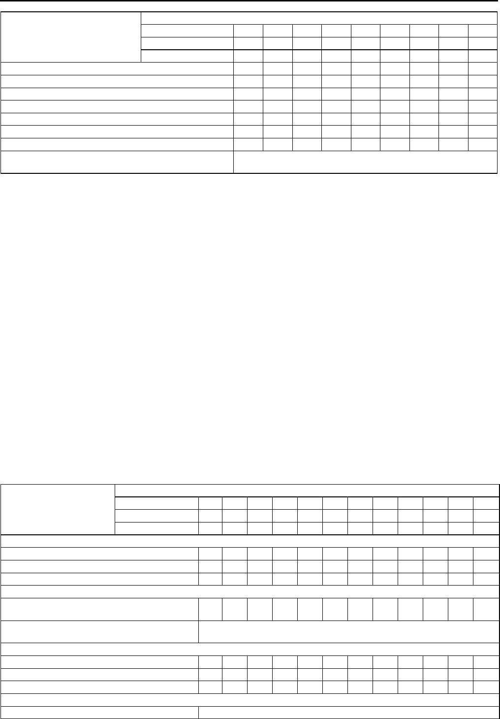
Maintenance Item
Maintenance Interval (Number of months or km (miles), whichever comes first)
Months 1224364860728496108
×
××
×1000 km 20 40 60 80 100 120 140 160 180
×
××
×1000 miles 12.5 25 37.5 50 62.5 75 87.5 100 112.5
ENGINE
Drive belts *1 I I I
Engine oil *2RRRRRRRRR
Oil filter *2RRRRRRRRR
COOLING SYSTEM
Cooling system (including coolant level adjustment) I I I I
Engine coolant Replace at first 4 years or 100,000 km (62,500 miles);
after that, every 2 years
FUEL SYSTEM
Air cleaner element *3 R R R
Fuel lines & hoses I I I I
IGNITION SYSTEM
Spark plugs Replace every 100,000 km (62,500 miles)
EMISSION CONTROL SYSTEM
E.G.R. system I I
ELECTRICAL SYSTEM
Battery electrolyte level & specific gravity IIIIIIIII
CHASSIS & BODY
Brake lines, hoses & connections IIIIIII I
Brake fluid *4 R R R R
Parking brake IIIIIIIII
Power brake unit & hoses IIIIIIIII
Disc brakes IIIIIIIII
Power steering fluid, lines, hoses, and connections IIIIIIIII
Steering operation & linkages I I I I
Manual transaxle oil R
GI34
SCHEDULED MAINTENANCE
For Israel
Chart symbols:
I : Inspect and clean, repair, adjust, or replace if necessary. (Oil-permeated air cleaner elements cannot be
cleaned using the air-blow method.)
R:Replace
L : Lubricate
C : Clean
Remarks:
Automatic transaxle/transmission fluid level I I I
Front & rear suspension & ball joints I I I I
Driveshaft dust boots I I I I
bolts & nuts on seats I I I I
Exhaust system heat shields I I I I
Cabin air filter (if installed) (aldehyde filter) R R R R R R R R R
Cabin air filter (if installed)(pollen filter) R R R R
Body condition
(for rust, corrosion & perforation) Inspect annually
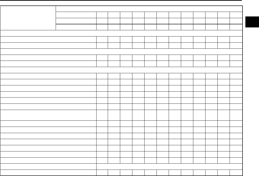
Maintenance Item
Maintenance Interval (Number of months or km (miles), whichever comes first)
Months 1224364860728496108
×
××
×1000 km 20 40 60 80 100 120 140 160 180
×
××
×1000 miles 12.5 25 37.5 50 62.5 75 87.5 100 112.5
•To ensure efficient operation of the engine and all systems related to emission control, the ignition and fuel systems must
be serviced regularly. It is strongly recommended that all servicing related to these systems be done by an authorized
Mazda Dealer.
•After the described period, continue to follow the described maintenance at the recommended intervals.
•Refer below for a description of items marked* in the maintenance chart.
*1: Also inspect and adjust the power steering and air conditioner drive belts, if installed.
*2: If the vehicle is operated under any of the following conditions, change the engine oil and oil filter every 10,000 km
(6,000 miles) or shorter.
a. Driving in dusty conditions.
b. Extended periods of idling or low speed operation.
c. Driving for long period in cold temperatures or driving regularly at short distance only.
*3: If the vehicle is operated in very dusty or sandy areas, inspect and if necessary, clean or replace the air cleaner
element more often than the recommended intervals.
*4: This is a full function check of electrical systems such as lights, wiper and washer systems (including wiper blades),
and power windows.
*5: If the brakes are used extensively (for example, continuous hard driving or mountain driving) or if the vehicle is
operated in extremely humid climates, change the brake fluid annually.
Maintenance Item
Maintenance Interval (Number of months or km (miles), whichever comes first)
Months 1224364860728496108120132144
×
××
×1000 km 15 30 45 60 75 90 105 120 135 150 165 180
×
××
×1000 miles 9 18 27 36 45 54 63 72 81 90 99 108
ENGINE
Drive belts *1IIIIIIIIIIII
Engine oil *2RRRRRRRRRRRR
Oil filter *2RRRRRRRRRRR R
COOLING SYSTEM
Cooling system
(Including coolant level adjustment) IIIIII
Engine coolant Replace at first 4 years or 90,000 km;
after that, every 2 years
FUEL SYSTEM
Air cleaner element *3CCCRCCCRCCCR
Fuel filter R R
Fuel lines & hoses IIIIII
IGNITION SYSTEM
Spark plugs Replace every 90,000 km (54,000 miles)
SCHEDULED MAINTENANCE
GI35
GI
For GCC
Chart symbols:
I : Inspect and repair, clean, adjust, or replace if necessary. (Oil-permeated air cleaner elements cannot be
cleaned using the air-blow method.)
R : Replace
T:Tighten
C : Clean
Remarks:
EMISSION CONTROL SYSTEM
Evaporative system I I I
E.G.R. system (if installed) I I I
ELECTRICAL SYSTEM
Battery electrolyte level & specific gravity I I I I I I I I I I I I
All electrical system *4IIIIIIIIIIII
CHASSIS & BODY
Brake & clutch pedals IIIIIIIIIIII
Brake lines, hoses & connections I I I I I I I I I I I I
Brake fluid *5IRIRIRIRIRIR
Parking brake IIIIIIIIIIII
Power brake unit & hoses I I I I I I I I I I I I
Disc brakes IIIIIIIIIIII
Power steering fluid, lines, hoses, and
connections IIIIIIIIIIII
Steering operation & linkages IIIIII
Manual transaxle oil R R
Automatic transaxle/transmission fluid level IIIIII
Front & rear suspension & ball joints IIIII
Driveshaft dust boots I IIII
Exhaust system & heat shields IIIIII
Bolts & nuts on seats IIIIII
Body condition (for rust, corrosion & perforation) Inspect annually
Cabin air filter (if installed) R R R R R R R R R R R R
Maintenance Item
Maintenance Interval (Number of months or km (miles), whichever comes first)
Months 12 24 36 48 60 72 84 96 108 120 132 144
×
××
×1000 km 15 30 45 60 75 90 105 120 135 150 165 180
×
××
×1000 miles 9 18273645546372819099108
•To ensure efficient operation of the engine and all systems related to emission control, the ignition and fuel systems must
be serviced regularly. It is strongly recommended that all servicing related to these systems be done by an authorized
Mazda Dealer.
•After the described period, continue to follow the described maintenance at the recommended intervals.
•Refer below for a description of items marked* in the maintenance chart.
*1: Also inspect and adjust the power steering and air conditioner drive belts, if installed.
*2: If the vehicle is operated under any of the following conditions, change the engine oil and oil filter more often than
recommended intervals.
a. Driving in dusty conditions.
b. Extended periods of idling or low speed operation.
c. Driving for long period in cold temperatures or driving regularly at short distance only.
*3: If the vehicle is operated in very dusty or sandy areas, inspect and if necessary, clean or replace the air cleaner
element more often than the recommended intervals.
*4: This is a full function check of electrical systems such as lights, wiper and washer systems (including wiper blades),
and power windows.
*5: If the brakes are used extensively (for example, continuous hard driving or mountain driving) or if the vehicle is
operated in extremely humid climates, change the brake fluid annually.

GI36
SCHEDULED MAINTENANCE
Maintenance Item
Maintenance Interval (Number of months or km (miles), whichever comes first)
Months 6 12 18 24 30 36 42 48 54 60 66 72 78 84 90 96
×
××
×1000 km 10 20 30 40 50 60 70 80 90 100 110 120 130 140 150 160
×
××
×1000 miles 6.25 12.5 18.75 25 31.25 37.5 43.75 50 56.25 62.5 68.75 75 81.25 87.5 93.75 100
ENGINE
Drive belts *1IIIIIIIIIIIIIIII
Engine oil *2RRRRRRRRRRRRRRRR
Oil filter *2RRRRRRRRRRRRRRRR
COOLING SYSTEM
Cooling system I I I I I I I I
Engine coolant Replace every 2 years
FUEL SYSTEM
Air cleaner element *3CCRCCRCC
Fuel filter R R R R
Fuel lines & hoses I I I I I I I I
IGNITION SYSTEM
Spark plugs Replace every 100,000 km (62,500 miles)
EMISSION CONTROL SYSTEM
Evaporative system (if intalled) I I I I I I I I
E.G.R. system (if installed) I I I I I I I I
ELECTRICAL SYSTEM
Battery electrolyte level & specific
gravity IIIIIIII
All electrical system *4 I I I I I I I I
CHASSIS & BODY
Brake & clutch pedal IIIIIIIIIIIIIIII
Brake lines, hoses & connections I I I I I I I I
Brake fluid *5IIIRIIIRIIIRIIIR
Parking brake IIIIIIIIIIIIIIII
Power brake unit & hoses I I I I I I I I
Disc brakes IIIIIIIIIIIIIIII
Power steering fluid, lines, hoses and
connections IIIIIIIIIIIIIIII
Steering operation & linkages I I I I I I I I
Manual transaxle oil R
Automatic transmission / transaxle fluid
level IIII III
Automatic transmission / transaxle fluid R R R
Front & rear suspension & ball joints I I I I
Driveshaft dust boots I I I I
Bolts & nuts on chassis & body T T T T T T T T
Exhaust system heat shields I I I I
Cabin air filter (if installed) R R R R R R R R
Body condition
(for rust, corrosion & perforation) Inspect annually

SCHEDULED MAINTENANCE
GI37
GI
Scheduled Maintenance Service (Specific Work Required)
For Europe (L.H.D. U.K.)
Maintenance Item Specific Work Required
ENGINE
Engine valve clearance Measure clearance.
Drive belts Inspect for wear, cracks and fraying, and check tension.
Replace drive belt.
Engine timing belt Replace engine timing belt.
Engine oil Replace engine oil and inspect for leakage.
Oil filter Replace oil filter and inspect for leakage.
Oil by-pass filter Replace oil by-pass filter and inspect for leakage.
COOLING SYSTEM
Cooling system
(including coolant level adjustment) Check coolant level and quality, and inspect for leakage.
Engine coolant Replace coolant.
FUEL SYSTEM
Idle speed Check engine idle rpm.
Idle mixture
(for CIS & carburetor leaded fuel) Check the CO and HC concentrations (see W/M).
Choke system (for carburetor) Check system operation.
Air cleaner element
Inspect for dirt, oil and damage.
Clean air cleaner element (by blowing air).
Replace air cleaner element.
Fuel filter Replace fuel filter.
Fuel lines & hoses Inspect for cracks, leakage and loose connection.
IGNITION SYSTEM (FOR GASOLINE)
Initial ignition timing Check initial ignition timing.
Spark plugs
Inspect for wear, damage, carbon, high-tension lead condition and measure
plug gap.
Replace spark plugs.
EMISSION CONTROL SYSTEM (FOR GASOLINE)
Evaporative system Check system operation (see W/M), vapor lines, vacuum fitting hoses and
connection.
Throttle positioner system Check the diaphragm and system operation, vacuum fitting hoses and
connection.
Dash pot (for carburetor) Check system operation.
E.G.R. system Check system operation (see W/M), vacuum fitting hoses and connection.
ELECTRICAL SYSTEM
Battery electrolyte level & specific gravity Check level and specific gravity.
Battery condition Check the battery for corroded or loose connections and cracks in the case
(for maintenance free type).
All electrical system Check function of lighting system, windshield wiper (including wiper blade
condition) and washer and power windows.
Headlight alignment Check headlight alignment
CHASSIS & BODY
Brake & clutch pedals Check pedal height and free play.
Brake fluid Check fluid level and inspect for leakage.
Replace brake fluid.
Clutch fluid Check fluid level and inspect for leakage.
Brake lines, hoses & connections Inspect for cracks, damage, chafing, corrosion, scars, swelling and fluid
leakage.
Parking brake Check lever stroke.
Power brake unit & hoses Check vacuum lines, connections and check valve for improper attachment,
air tightness, cracks chafing and deterioration.
Disc brakes Test for judder and noise. Inspect caliper for correct operation and fluid
leakage, brake pads for wear. Check disc plate condition and thickness.
Drum brakes Test for judder and noise. Inspect brake drum for wear and scratches; brake
lining for wear, peeling and cracks; and wheel cylinder for fluid leakage.
Manual steering gear oil Check gear oil level.
Power steering fluid, lines, hoses & connections Check fluid level and condition. Inspect for loose connection, routing,
damage, and leaks.

GI38
SCHEDULED MAINTENANCE
End Of Sie
Steering operation & linkages Check steering wheel free play, hard steering, and operation noise. Check
linkages, boots and ball joints condtion. Check grease or gear oil.
Power steering fluid & lines Check fluid level and lines for improper attachment, leakage, cracks,
damage, loose connections, chafing and deterioration.
Power steering fluid Check fluid level.
Power steering system & hoses Check lines for improper attachment, leakage, cracks, damage, loose
connections, chafing and deterioration.
Steering & front suspension
Check free play of steering system, inspect shock absorbers for correct
damping force, oil leakage, damage and looseness, and inspect coil
springs, arms, links and stabilizer for damage and looseness.
Steering operation & gear housing
Check that the steering wheel has the specified play. Be sure to check for
changes, such as excessive play, hard steering or strange noises.
Check gear housing and boots for looseness, damage and grease/gear oil
leakage.
Steering linkages tie rod ends & arms Check ball joint, dust cover and other components for looseness, wear,
damage and grease leakage.
Front & rear suspension ball joints Inspect for grease leakage, cracks, damage and looseness.
Manual transmission/transaxle oil Check oil level and inspect for leakage.
Replace manual transmission/transaxle oil.
Automatic transaxle oil level Check oil level.
Automatic transmission/transaxle fluid level Check fluid level.
Automatic transmission/transaxle fluid Replace automatic transmission/transaxle fluid.
Front & rear differential oil Check oil level and inspect for leakage.
Replace front & rear differential oil.
Rear differential oil Check oil level and inspect for leakage.
Replace rear differential oil.
Transfer oil Check oil level and inspect for leakage.
Replace transfer oil.
Upper arm shafts (for B-Series) Lubricate the upper arm shafts for looseness or damage.
Front & rear wheel bearing grease Remove wheel bearing and replace the grease.
Propeller shaft joints (with grease nipple) Lubricate propeller shaft joints.
Driveshaft dust boots Inspect for grease leakage, cracks, damage and looseness.
Wheel nuts Tighten wheel nuts.
Bolts & nuts on chassis & body Tighten bolts and nuts fastening suspension components, members and
seat frames.
Bolts & nuts on seats Move the seat back and forth and side to side to check for squeeking or
rattling. If there is any squeeking or rattling, retorque bolts and nuts
fastening seat frames.
Body condition
(for rust, corrosion & perforation) Inspect body surface for paint damage, rust, corrosion and perforation.
Exhaust system heat shields Inspect for damage, corrosion, looseness of connections and gas leakage.
Tires
(including spare tire)
(with inflation pressure adjustment)
Check air pressure and inspect tires for tread wear, damage and cracks;
and wheels for damage and corrosion.
Hinges & catches Lubricate hinges and catches of doors, trunk lid and hood.
Seat belts Inspect seat belt webbing for scratches, tears and wear, and check anchor
bolt tightness.
Rear suspension uni-ball & sliding rubber
bushing (for RX-7) Inspect for cracks, damage and looseness.
Underside of vehicle Inspect underside of vehicle (floor pans, frames, fuel lines, around exhaust
system, etc.) for damage and corrosion.
Road test
Check brake operation/clutch operation/steering control/operation of meters
and gauges/squeaks, rattles or unusual noises/engine general
performance/emergency locking retractors.
AIR CONDITIONER SYSTEM
Refrigerant amount Check refrigerant amount.
Compressor operation Check compressor operation, and inspect for noise, oil leakage, cracks and
refrigerant leakage.
Cabin air filter Replace cabin air filter.
Maintenance Item Specific Work Required

B1
B
BENGINE
LOCATION INDEX .................................................B-2
MECHANICAL LOCATION INDEX ......................B-2
DRIVE BELT........................................................... B-3
DRIVE BELT INSPECTION .................................B-3
DRIVE BELT REPLACEMENT ............................ B-3
DRIVE BELT AUTO TENSIONER
INSPECTION .......................................................B-4
VALVE CLEARANCE............................................. B-4
VALVE CLEARANCE INSPECTION.................... B-4
VALVE CLEARANCE ADJUSTMENT .................B-5
COMPRESSION PRESSURE ................................ B-9
COMPRESSION INSPECTION ...........................B-9
TIMING CHAIN ..................................................... B-10
TIMING CHAIN REMOVAL/INSTALLATION .....B-10
CYLINDER HEAD GASKET................................. B-18
CYLINDER HEAD GASKET REPLACEMENT ..B-18
FRONT OIL SEAL ................................................ B-21
FRONT OIL SEAL REPLACEMENT.................. B-21
REAR OIL SEAL .................................................. B-25
REAR OIL SEAL REPLACEMENT .................... B-25
ENGINE ................................................................ B-26
ENGINE REMOVAL/INSTALLATION ................ B-26
ENGINE DISASSEMBLY/ASSEMBLY...............B-31
VARIABLE VALVE TIMING ................................. B-32
VARIABLE VALVE TIMING ACTUATOR
INSPECTION .................................................. B-32
VARIABLE VALVE TIMING ACTUATOR
REMOVAL/INSTALLATION ............................ B-32
OIL CONTROL VALVE (OCV) ............................. B-33
OIL CONTROL VALVE (OCV)
REMOVAL/INSTALLATION ............................ B-33
OIL CONTROL VALVE (OCV) INSPECTION ....B-33
B2
LOCATION INDEX
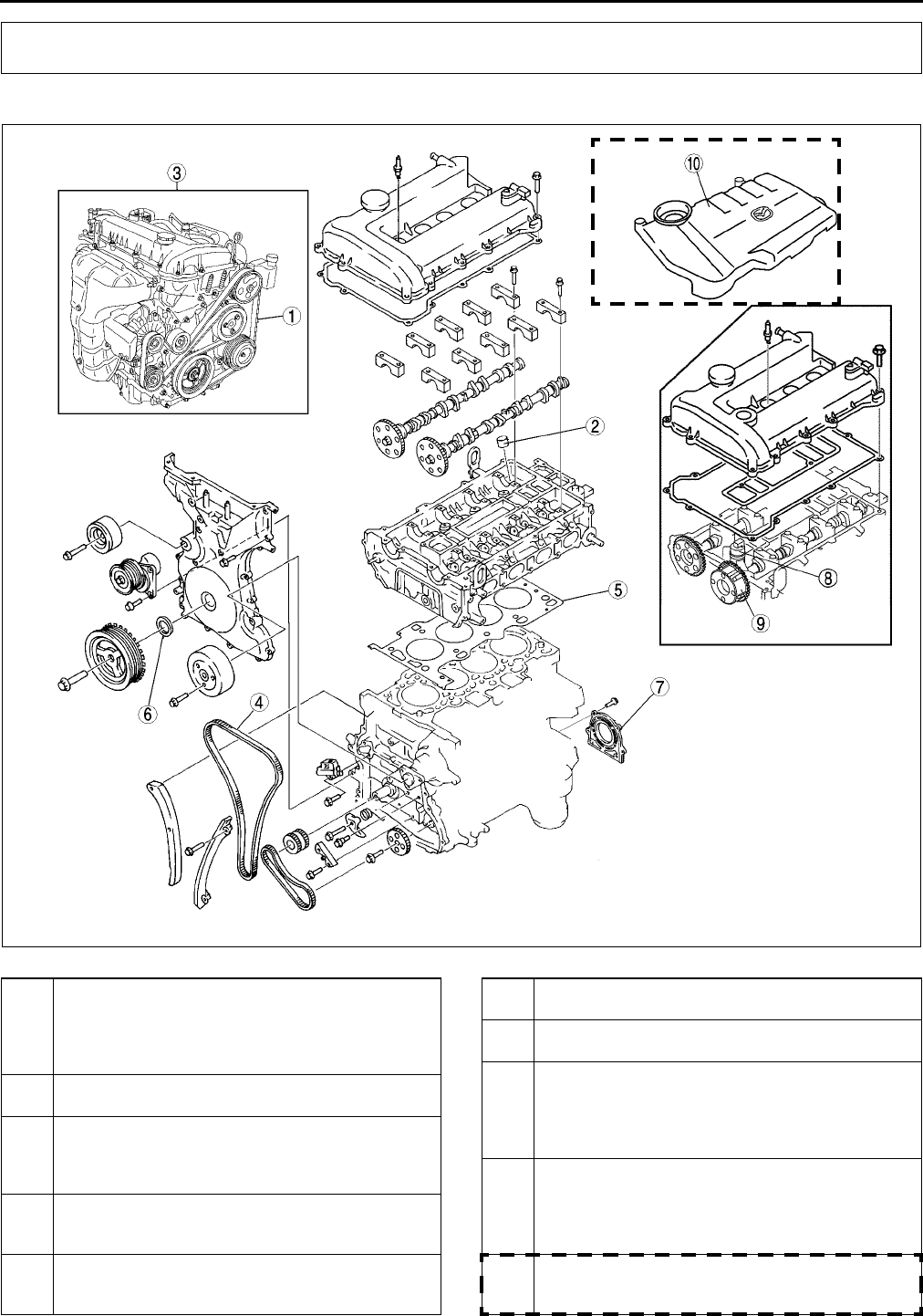
MECHANICAL LOCATION INDEX A6E220001002W01
.
LOCATION INDEX
A6E2200W300
1Drive belt
(See B3 DRIVE BELT INSPECTION)
(See B3 DRIVE BELT REPLACEMENT)
(See B4 DRIVE BELT AUTO TENSIONER
INSPECTION)
2 Tappet
(See B4 VALVE CLEARANCE INSPECTION)
3 Engine
(See B9 COMPRESSION INSPECTION)
(See B26 ENGINE REMOVAL/INSTALLATION)
(See B31 ENGINE DISASSEMBLY/ASSEMBLY)
4 Timing Chain
(See B10 TIMING CHAIN REMOVAL/
INSTALLATION)
5 Cylinder head gasket
(See B18 CYLINDER HEAD GASKET
REPLACEMENT)
6 Front oil seal
(See B21 FRONT OIL SEAL REPLACEMENT)
7 Rear oil seal
(See B25 REAR OIL SEAL REPLACEMENT)
8 Oil control valve (OCV) (L3)
(See B33 OIL CONTROL VALVE (OCV)
REMOVAL/INSTALLATION)
(See B33 OIL CONTROL VALVE (OCV)
INSPECTION)
9 Variable valve timing actuator (L3)
(See B32 VARIABLE VALVE TIMING ACTUATOR
REMOVAL/INSTALLATION)
(See B32 VARIABLE VALVE TIMING ACTUATOR
INSPECTION)
10 Plug hole plate
(See G10 SPARK PLUG REMOVAL/
INSTALLATION)
DRIVE BELT
B3
B
End Of Si e
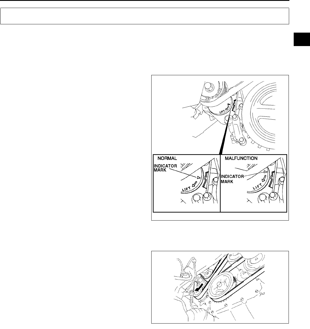
DRIVE BELT INSPECTION A6E221015800W01
Note
•Front and water pump drive belt deflection/tension inspection is not necessary because of the use of the
front drive belt auto tensioner.
Front Drive Belt
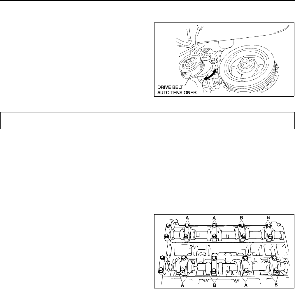
1. Verify that the drive belt auto tensioner indicator
mark does not exceeds the limit.
•If it exceeds the limit, replace the drive belt.
(SeeB3 DRIVE BELT REPLACEMENT.)
End Of Sie
DRIVE BELT REPLACEMENT A6E221015800W03
1. Remove the splash shield (RH).
2. Turn the center of the tensioner pulley clockwise
to release tension to the drive belt.
3. Remove the drive belt.
4. Reinstall the drive belt or install a new drive belt.
5. Verify that the drive belt auto tensioner indicator
mark does not exceeds the limit. (See B3 DRIVE
BELT INSPECTION.)
•If it exceeds the limit, replace the drive belt.
6. Install the splash shield (RH).
End Of Sie
DRIVE BELT
AME2210W001
AME2210W002
B4
DRIVE BELT, VALVE CLEARANCE
DRIVE BELT AUTO TENSIONER INSPECTION A6E221015980W01
1. Remove the drive belt. (See B3 DRIVE BELT REPLACEMENT.)
2. Verify that the drive belt auto tensioner moves
smoothly in the operational direction.
•Replace the drive belt auto tensioner if
necessary.
3. Turn the drive belt auto tensioner pulley by hand
and verify that it rotates smoothly.
•Replace the drive belt auto tensioner if
necessary.
4. Install the drive belt. (See B3 DRIVE BELT
REPLACEMENT.)
End Of Sie
VALVE CLEARANCE INSPECTION A6E221212111W01
1. Disconnect the negative battery cable.
2. Remove the tire (RH).
3. Remove the splash shield (RH).
4. Remove the spark plugs. (See G10 SPARK PLUG REMOVAL/INSTALLATION.)
5. Remove the high-tension lead.
6. Remove the oil control valve (OCV) connector.
7. Remove the ventilation hose.
8. Remove the cylinder head cover.
9. Verify that the engine is in cold condition.
10. Measure the valve clearance.
(1) Turn the crankshaft clockwise so that the No.1 piston is at TDC of the compression stroke.
(2) Measure the valve clearance at A in the
figure.
•If the valve clearance exceeds the space
the tappet. (See B5 VALVE
CLEARANCE ADJUSTMENT.)
Note
•Make sure to note the measured values for
choosing the suitable replacement tappets.
Standard [Engine cold]
IN: 0.220.28 mm {0.00870.0110 in}
(0.25±
±±
±0.03 mm {0.0098±
±±
±0.0011 in})
EX: 0.270.33 mm {0.01060.0130 in}
(0.30±
±±
±0.03 mm {0.0118±
±±
±0.0011 in})
(3) Turn the crankshaft 360°
°°
° clockwise so that the No.4 piston is at TDC of the compression stroke.
(4) Measure the valve clearance at B in the figure.
•If the valve clearance exceeds the standard, replace the tappet. (See B5 VALVE CLEARANCE
ADJUSTMENT.)
Note
•Make sure to note the measured values for choosing the suitable replacement tappets.
Standard [Engine cold]
IN: 0.220.28 mm {0.00870.0110 in} (0.25±
±±
±0.03 mm {0.0098±
±±
±0.0011 in})
EX: 0.270.33 mm {0.01060.0130 in} (0.30±
±±
±0.03 mm {0.0118±
±±
±0.0011 in})
11. Install the cylinder head cover. (See B17 Cylinder Head Cover Installation Note.)
12. Install the ventilation hose.
13. Install the oil control valve connector.
14. Install the high-tension lead. (See G11 HIGH-TENSION LEAD REMOVAL/INSTALLATION.)
15. Install the spark plugs. (See G10 SPARK PLUG REMOVAL/INSTALLATION.)
AME2210W003
VALVE CLEARANCE
AME2212W001
VALVE CLEARANCE
B5
B
16. Install the splash shield (RH).
17. Install the tire (RH).
End Of Sie
VALVE CLEARANCE ADJUSTMENT A6E221212111W02
1. Disconnect the negative battery cable.
2. Remove the tire (RH).
3. Remove the splash shield (RH).
4. Remove the spark plugs. (See G10 SPARK PLUG REMOVAL/INSTALLATION.)
5. Remove the high-tension lead.
6. Remove the oil control valve (OCV) connector.
7. Remove the ventilation hose.
8. Remove the cylinder head cover.
9. Remove the drive belt. (See B3 DRIVE BELT REPLACEMENT.)
10. Remove the joint shaft from the front drive shaft (RH). (See M17 DRIVE SHAFT REMOVAL/INSTALLATION.)
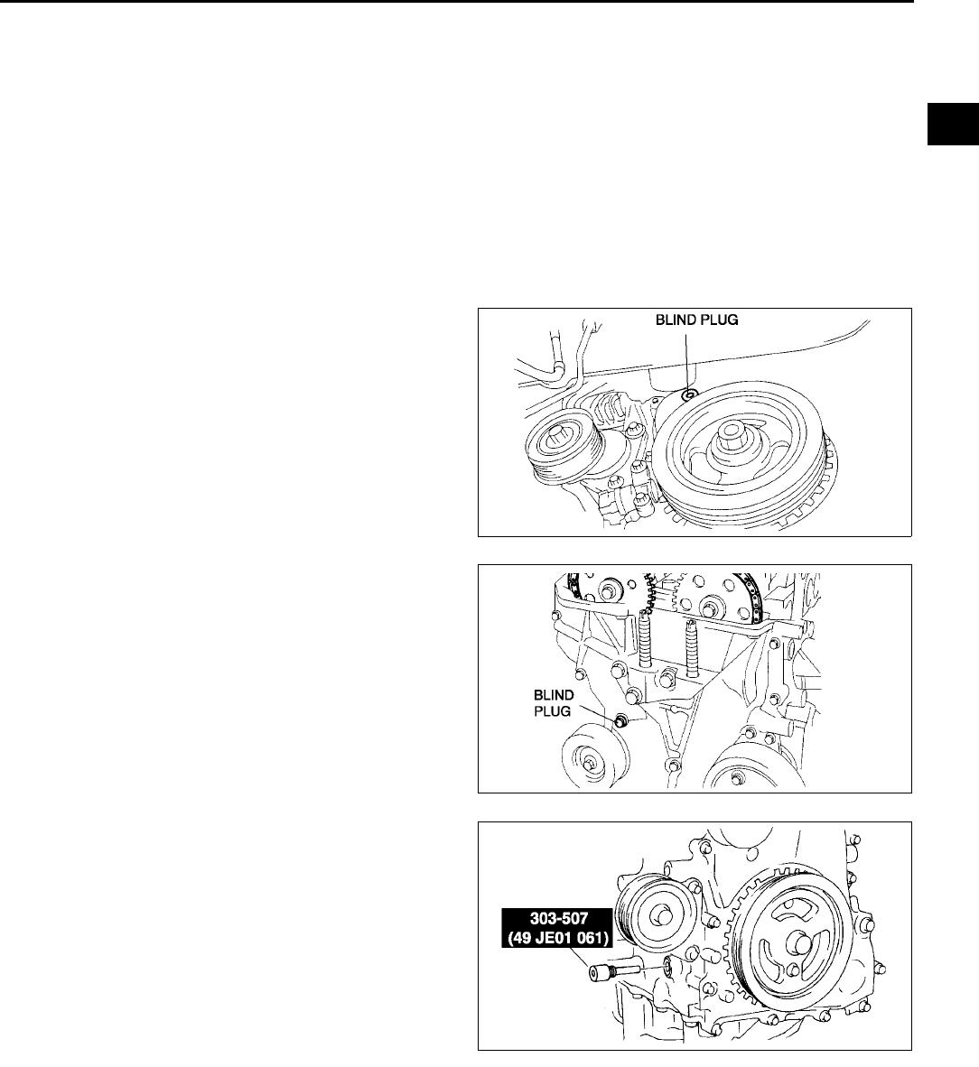
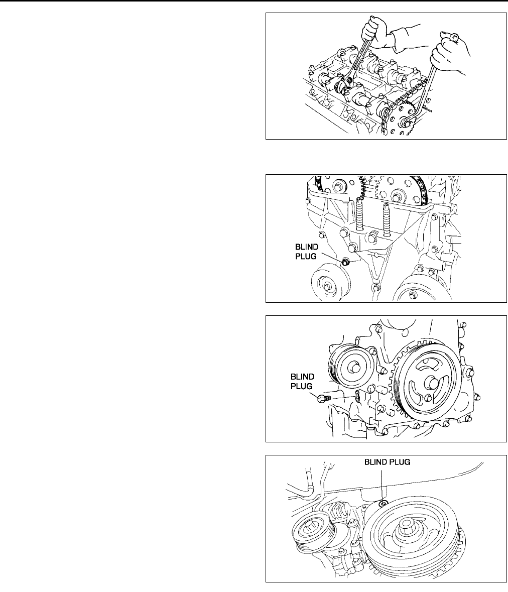
11. Remove the engine front cover lower blind plug.
12. Remove the engine front cover upper blind plug.
13. Remove the cylinder block lower blind plug.
14. Install the SST as shown.
15. Turn the crankshaft clockwise the crankshaft is in
the No.1 cylinder TDC position.
AME2212W002
AME2212W003
AME2212W004
B6
VALVE CLEARANCE
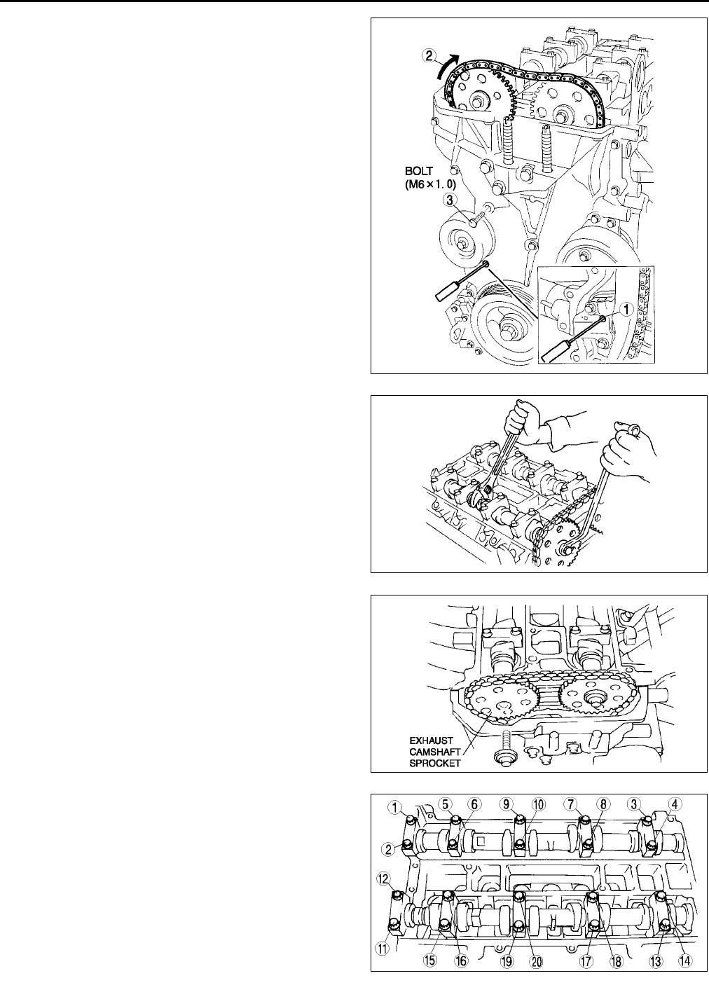
16. Loosen the timing chain.
(1) Using a suitable screwdriver or equivalent
tool, unlock the chain tensioner ratchet.
(2) Turn the exhaust camshaft clockwise using a
suitable wrench on the cast hexagon and
loosen the timing chain.
(3) Placing the suitable bolt (M6 X 1.0 length
25mm35mm {0.99in1.37in}) at the
engine front cover upper blind plug, secure
the chain guide at the position where the
tension is released.
17. Hold the exhaust camshaft using a suitable
wrench on the cast hexagon as shown.
18. Remove the exhaust camshaft sprocket.
19. Loosen the camshaft cap bolts in several passes
in the order shown.
Note
•The cylinder head and the camshaft caps
are numbered to make sure they are
reassembled in their original position. When
removed, keep the caps with the cylinder
head they were removed from. Do not mix
the caps.
20. Remove the camshaft.
21. Remove the tappet.
22. Select proper adjustment shim.
AME2212W005
AME2212W006
AME2212W007
AME2212W008
VALVE CLEARANCE
B7
B
New adjustment shim
= Removed shim thickness + Measured valve clearance - Standard valve clearance (IN: 0.25 mm
{0.0098 in}, EX: 0.30 mm {0.0118 in})
Standard [Engine cold]
IN: 0.220.28 mm {0.00870.0110 in} (0.25±
±±
±0.03 mm {0.0098±
±±
±0.0011 in})
EX: 0.270.33 mm {0.01060.0130 in} (0.30±
±±
±0.03 mm {0.0118±
±±
±0.0011 in})
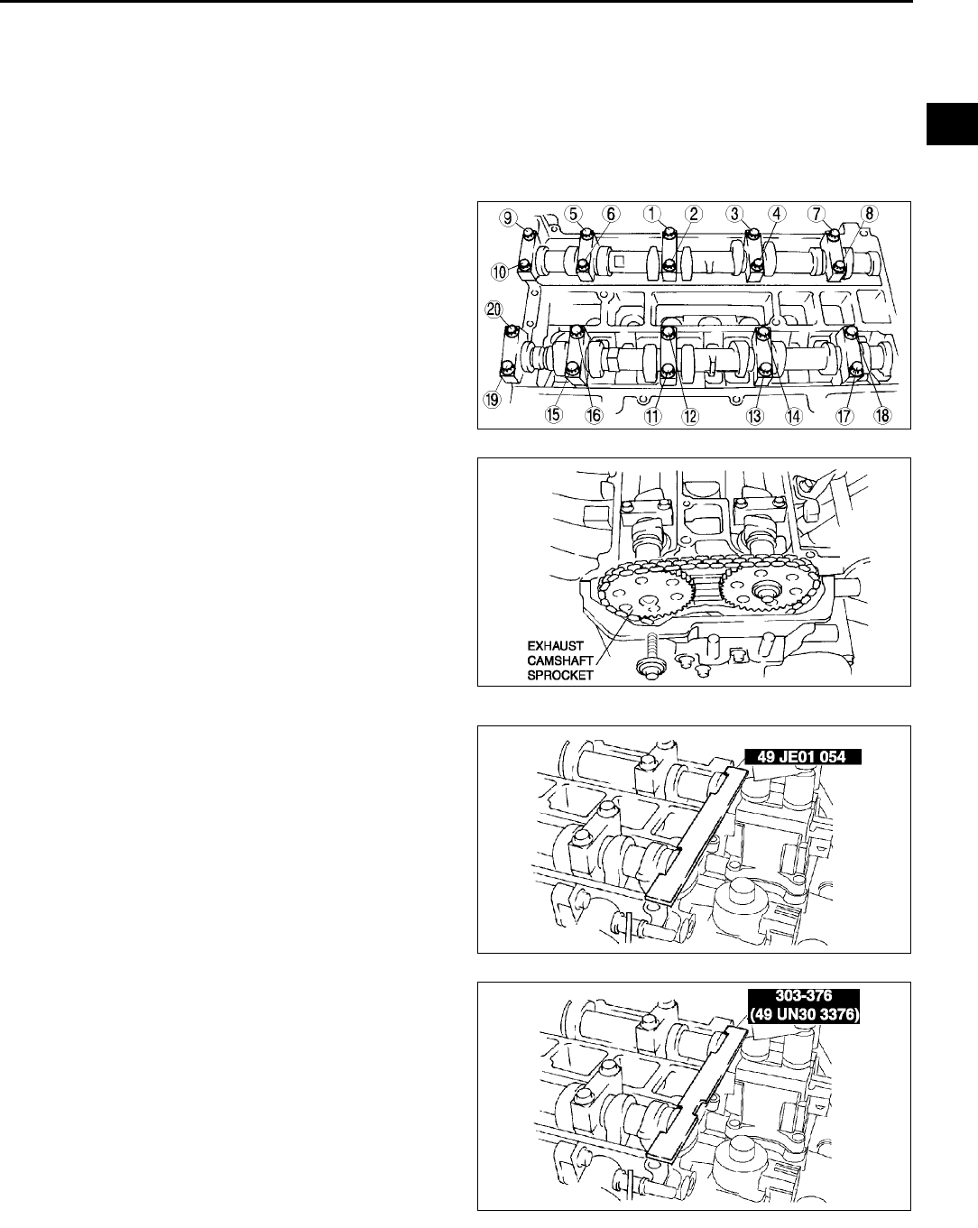
23. Install the camshaft with No.1 cylinder aligned with the TDC position.
24. Tighten the camshaft cap bolt using the following
two steps.
(1) Tighten to 5.09.0 N·m {51.091.7 kgf·cm,
44.379.5 in·lbf}.
(2) Tighten to 14.017.0 N·m {1.51.7 kgf·m,
10.412.5 ft·lbf}.
25. Install the exhaust camshaft sprocket.
Note
•Do not tighten the bolt for the camshaft
sprocket during this step. First confirm the
valve timing, then tighten the bolt.
26. Install the SST to the camshaft as shown.
European countries
Except European countries
27. Remove the M6 x 1.0 bolt (length 25mm
35mm {0.99in1.37in}) from the engine front
cover to apply tension to the timing chain.
28. Turn the crankshaft clockwise the crankshaft is in
the No.1 cylinder TDC position.
AME2212W009
AME2212W007
AME2212W010
AME2212W011
B8
VALVE CLEARANCE
29. Hold the exhaust camshaft using a suitable
wrench on the cast hexagon as shown.
30. Tighten the exhaust camshaft sprocket lock bolt.
Tightening torque:
6975 N·m {7.107.6 kgf·m, 50.955.3 ft·lbf}
31. Remove the SST from the camshaft.
32. Remove the SST from the block lower blind plug.
33. Rotate the crankshaft clockwise two turns until
the TDC position.
•If not aligned, loosen the crankshaft pulley
lock bolt and repeat from Step 14.
34. Apply silicone sealant to the engine front cover
upper blind plug.
35. Install the engine front cover upper blind plug.
Tightening torque:
10 N·m {1.0 kgf·m, 7.4 ft·lbf}
36. Install the cylinder block lower blind plug.
Tightening torque:
1822 N·m {1.92.2 kgf·m, 13.316.2 ft·lbf}
37. Install the new engine front cover lower blind
plug.
Tightening torque:
12 N·m {1.2 kgf·m, 8.9 ft·lbf}
38. Connect the front drive shaft (RH) and the joint
shaft. (See M17 DRIVE SHAFT REMOVAL/
INSTALLATION)
39. Install the drive belt. (See B3 DRIVE BELT
REPLACEMENT.)
40. Install the cylinder head cover. (See B17
Cylinder Head Cover Installation Note.)
41. Install the ventilation hose.
42. Install the oil control valve (OCV) connector.
43. Install the high-tension lead. (See G11 HIGH-TENSION LEAD REMOVAL/INSTALLATION.)
44. Install the spark plugs. (See G10 SPARK PLUG REMOVAL/INSTALLATION.)
45. Install the splash shield (RH).
46. Install the tire (RH).
End Of Si e
AME2212W006
AME2212W003
AME2212W012
AME2212W002
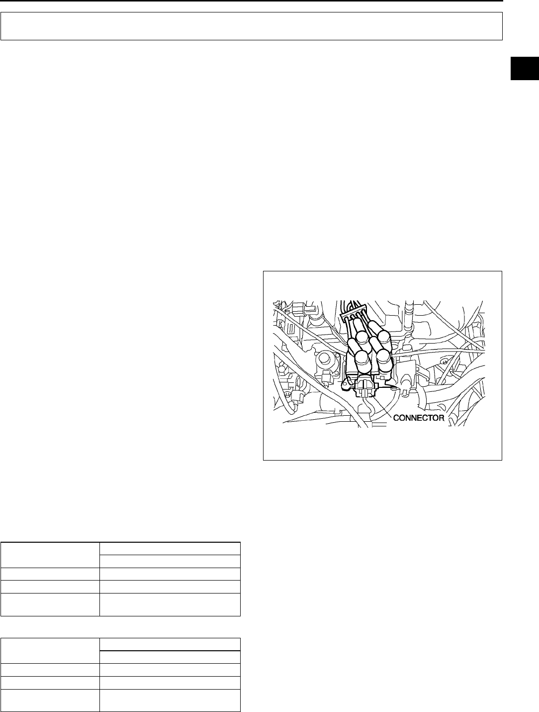
COMPRESSION PRESSURE
B9
B
COMPRESSION INSPECTION A6E221402000W01
Warning
•
••
•Hot engines and oil can cause severe burns. Be careful not to burn yourself during removal/
installation of each component.
1. Verify that the battery is fully charged.
•Recharge it if necessary. (See G4 BATTERY INSPECTION.)
2. Warm up the engine to the normal operating temperature.
3. Stop the engine and allow it to cool off for about 10 min.
4. Perform Fuel Line Safety Procedures. Leave the fuel pump relay removed. (See F17 BEFORE REPAIR
PROCEDURE.)
Warning
•
••
•Fuel vapor is hazardous. It can very easily ignite, causing serious injury and damage. Always keep
sparks and flames away from fuel.
•
••
•Fuel line spills and leakage are dangerous. Fuel can ignite and cause serious injuries or death and
damage. Fuel can also irritate skin and eyes. To prevent this, always complete the Fuel Line
Safety Procedure. (See F17 Fuel Line Safety Procedure.)
5. Remove the ignition coil connector.
6. Remove the spark plugs. (See G10 SPARK
PLUG REMOVAL/INSTALLATION.)
7. Connect a compression gauge into the spark plug
hole.
8. Fully depress the accelerator pedal and crank the
engine.
9. Note the maximum gauge reading.
10. Inspect each cylinder as above.
•If the measured value is less than the limited
value, or there is a cylinder whose
compression value varies from that of other
cylinders by 196.1 kPa {1.999 kgf/cm2, 28.44
psi} or more, add a small amount of engine oil
through the spark plug hole. Then measure
the compression pressure and perform the
respective operations for the following cases.
If the compression increases, the piston,
the piston rings, or cylinder wall may be
worn and overhaul is required.
If the compression stays low, a valve may be stuck or improperly seated and overhaul is required.
If the compression in adjacent cylinders stays low, the cylinder head gasket may be damaged or the
cylinder head distorted and overhaul is required.
Compression
kPa {kgf/cm2, psi} [rpm]
kPa {kgf/cm2, psi} [rpm]
COMPRESSION PRESSURE
Item Engine type
L8
Standard 1,750 {17.845, 253.816} [300]
Minimum 1,225 {12.492, 177.64} [300]
Maximum difference
between cylinders 196.1 {1.999, 28.44}
Item Engine type
LF
Standard 1,720 {17.5391, 249.465} [300]
Minimum 1,204 {12.277, 174.58} [300]
Maximum difference
between cylinders 196.1 {1.999, 28.44}
AME2214W001
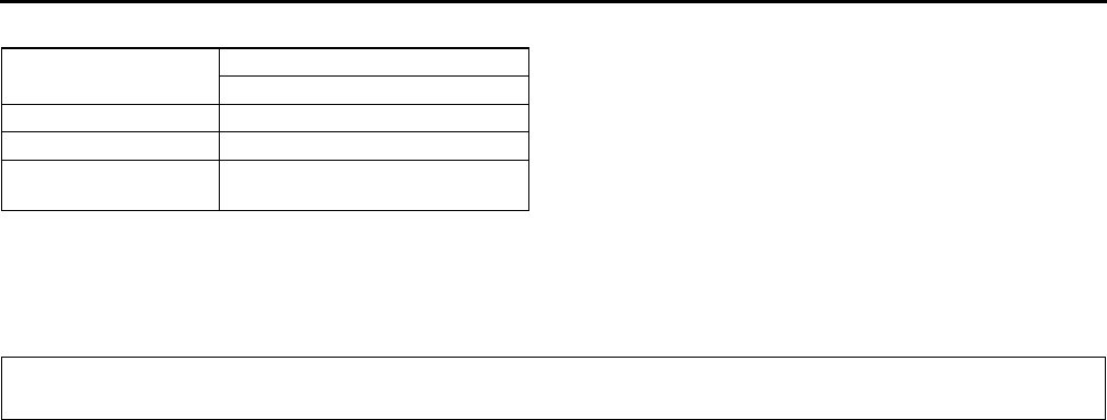
B10
COMPRESSION PRESSURE, TIMING CHAIN
kPa {kgf/cm2, psi} [rpm]
11. Disconnect the compression gauge.
12. Install the spark plugs. (See G10 SPARK PLUG REMOVAL/INSTALLATION.)
13. Connect the ignition coil connector.
14. Install the fuel pump relay. (See F17 BEFORE REPAIR PROCEDURE.)
End Of Sie
TIMING CHAIN REMOVAL/INSTALLATION A6E221512201W01
Warning
•
••
•Fuel vapor is hazardous. It can very easily ignite, causing serious injury and damage. Always keep
sparks and flames away from fuel.
•
••
•Fuel line spills and leakage are dangerous. Fuel can ignite and cause serious injures or death and
damage. Fuel can also irritate skin and eyes. To prevent this, always complete the Fuel Line
Safety Procedure. (See F17 Fuel Line Safety Procedure.)
1. Disconnect the negative battery cable.
2. Remove the spark plugs. (See G10 SPARK PLUG REMOVAL/INSTALLATION.)
3. Remove the tire (RH).
4. Remove the under cover.
5. Loosen the water pump pulley bolt and removal the drive belt. (See B3 DRIVE BELT REPLACEMENT.)
6. Remove the CKP sensor. (See F54 CRANKSHAFT POSITION (CKP) SENSOR REMOVAL/INSTALLATION.)
7. Drain the engine oil. (See D4 ENGINE OIL REPLACEMENT.)
8. Remove the P/S oil pump with the oil hose still connected and position the P/S oil pump so that it is out of the
way. (See N22 POWER STEERING OIL PUMP REMOVAL/INSTALLATION.)
9. Remove the front drive shaft (RH) from the joint shaft. (See M12 JOINT SHAFT REMOVAL/INSTALLATION.)
10. Remove in the order indicated in the table.
11. Install in the reverse order of removal.
12. Start the engine and:
•Inspect for the engine oil, engine coolant, transaxle oil and fuel leakage.
•Verify the ignition timing, idle speed and idle mixture. (See F8 IGNITION TIMING INSPECTION.) (SeeF
9 IDLE MIXTURE INSPECTION.)
13. Perform a road test.
Item Engine type
L3
Standard 1,430 {14.5819, 207.404} [290]
Minimum 1,000 {10.197, 145.00} [290]
Maximum difference
between cylinders 196.1 {1.999, 28.44}
TIMING CHAIN
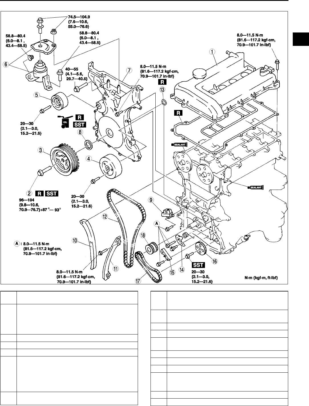
TIMING CHAIN
B11
B
.
AME2215W001
1 Cylinder head cover
(See B17 Cylinder Head Cover Installation Note)
2 Crankshaft pulley lock bolt
(See B12 Crankshaft Pulley Lock Bolt Removal
Note)
(See B16 Crankshaft Pulley Lock Bolt Installation
Note)
3 Crankshaft pulley
4 Water pump pulley
5 Drive belt idler pulley
6 No.3 engine mount rubber and No.3 engine joint
bracket
(See B12 No.3 Engine Mount Rubber and No.3
Engine Joint Bracket Removal Note)
(See B16 No.3 Engine Mount Rubber and No.3
Engine Joint Bracket Installation Note)
7 Engine front cover
(See B14 Engine Front Cover Installation Note)
8Front oil seal
(See B13 Engine Front Cover Removal Note)
(See B15 Front Oil Seal Installation Note)
9 Chain tensioner
(See B12 Chain Tensioner Removal Note)
10 Tensioner arm
11 Chain guide
12 Timing chain
(See B14 Timing Chain Installation Note)
13 Seal
14 Oil pump chain tensioner
15 Oil pump chain guide
16 Oil pump sprocket
(See B13 Oil Pump Sprocket Removal Note)
(See B13 Oil Pump Sprocket Installation Note)
17 Oil pump chain
18 Camshaft sprocket
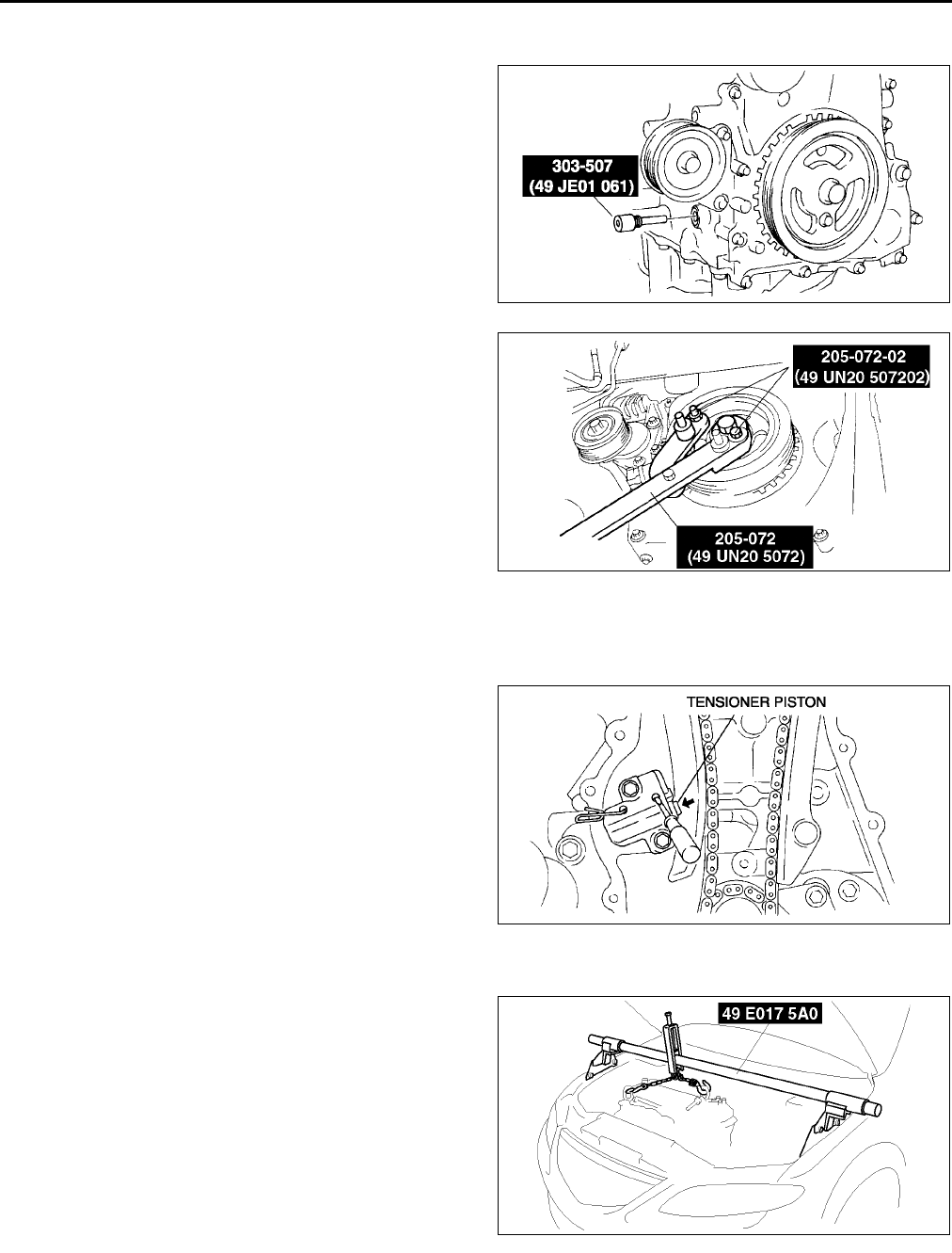
B12
TIMING CHAIN
Crankshaft Pulley Lock Bolt Removal Note
1. Remove the cylinder block lower blind plug.
2. Install the SST.
3. Turn the crankshaft clockwise the crankshaft is in
the No.1 cylinder TDC position.
4. Hold the crankshaft pully by using the SSTs.
Chain Tensioner Removal Note
1. Using a thin screwdriver, hold the chain tensioner ratchet lock mechanism away from the ratchet stem.
2. Slowly compress the tensioner piston.
3. Hold the tensioner piston using a 1.5 mm {0.059
in} wire or paper clip.
No.3 Engine Mount Rubber and No.3 Engine Joint Bracket Removal Note
1. Suspend the engine using the SSTs.
AME2212W004
AME2215W002
AME2215W003
AME2215W004
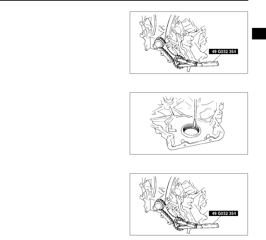
TIMING CHAIN
B13
B
Oil Pump Sprocket Removal Note
1. Hold the oil pump sprocket by using the SST.
Engine Front Cover Removal Note
1. Remove the oil seal using a screwdriver as
shown.
Oil Pump Sprocket Installation Note
1. Hold the oil pump sprocket by using the SST.
AME2215W005
AME2215W006
AME2215W005
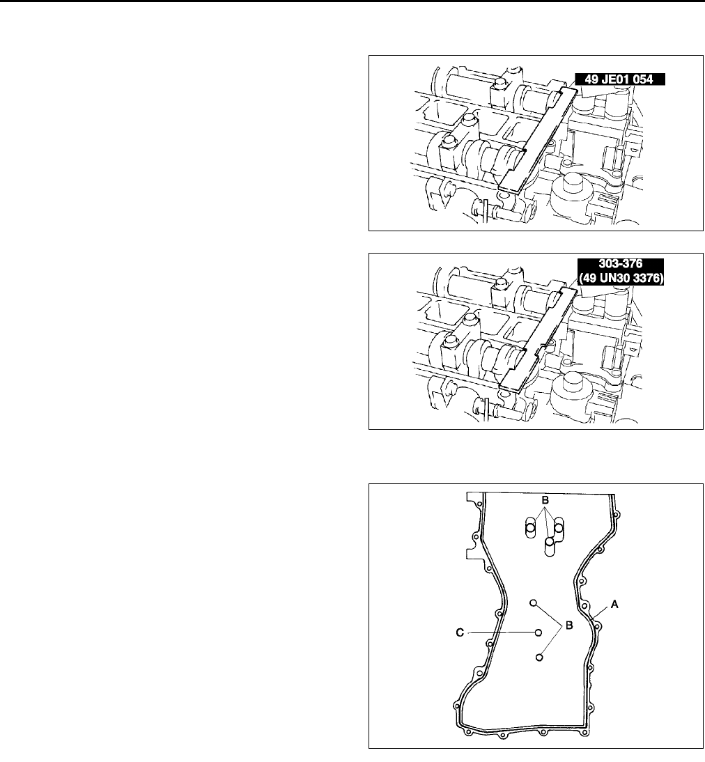
B14
TIMING CHAIN
Timing Chain Installation Note
1. Install the SST to the camshaft as shown.
European countries
Except European countries
2. Install the timing chain.
3. Remove the retaining wire or paper clip from the
auto tensioner to apply tension to the timing
chain.
Engine Front Cover Installation Note
1. Apply silicone sealant to the engine front cover as
shown.
Caution
•
••
•Install the cylinder head cover within 10
minutes of applying the silicone sealant.
•
••
•Silicone sealant is not need in area C as
indicated below due to an existing. (L3)
Thickness
A: 2.03.0 mm {0.0790.118 in}
B: 1.52.5 mm {0.0590.098 in}
AME2212W010
AME2212W011
AME2215W007
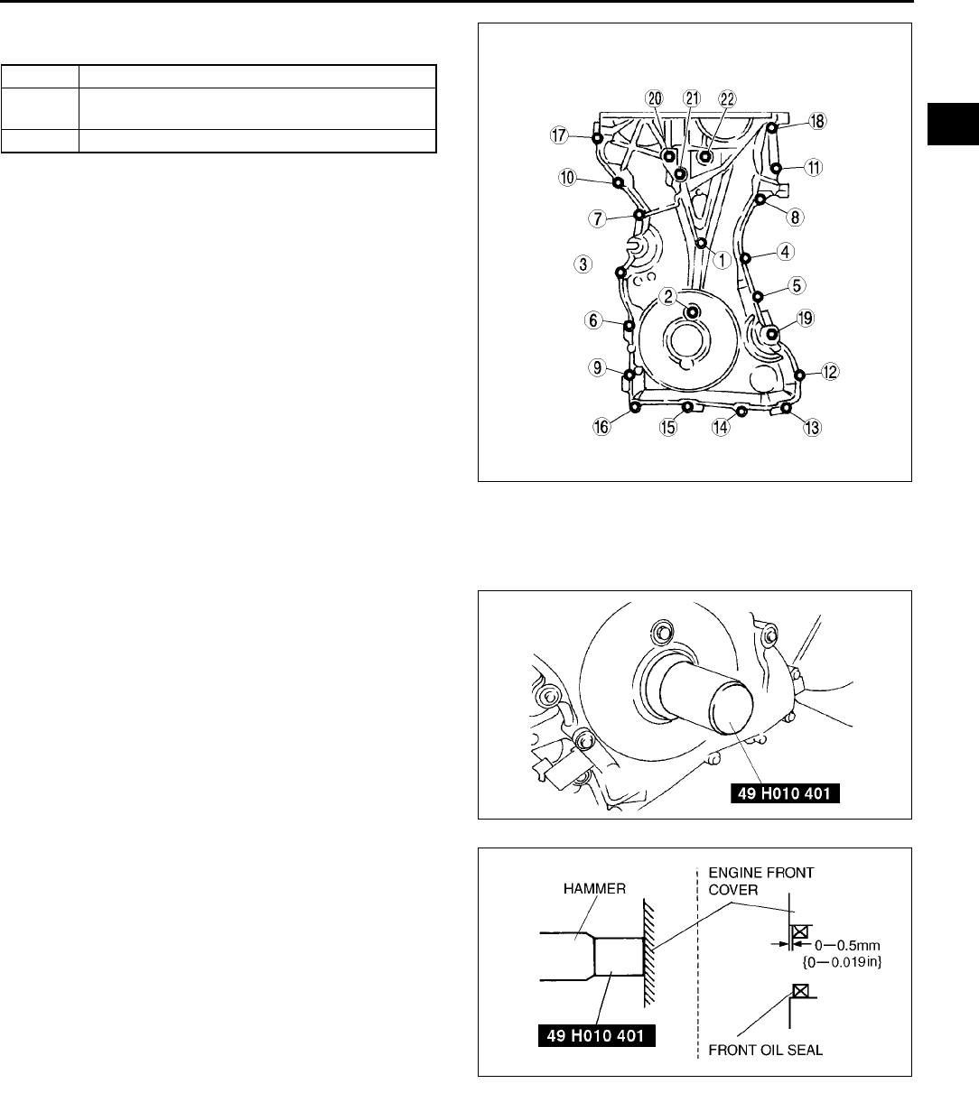
TIMING CHAIN
B15
B
2. Install the cylinder head cover bolts in the order
as shown.
Front Oil Seal Installation Note
1. Apply clean engine oil to the oil seal.
2. Push the oil seal slightly in by hand.
3. Compress the oil seal using the SST and a
hammer.
Bolt No. Tightening torque
118 8.011.5 N·m {81.6117.2 kgf·cm,
70.9101.7 in·lbf}
1922 4055 N·m {4.15.6 kgf·m, 29.740.5 ft·lbf}
AME2215W008
AME2215W009
AME2215W010
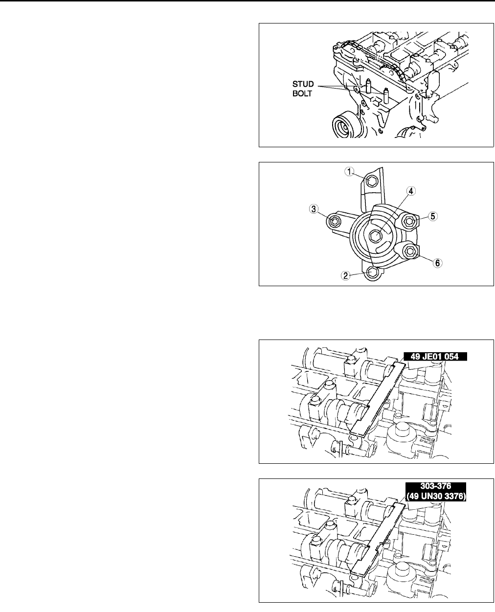
B16
TIMING CHAIN
No.3 Engine Mount Rubber and No.3 Engine Joint Bracket Installation Note
1. Tighten the stud bolt of the No.3 engine mount
bracket.
Tightening torque:
7.013 N·m {71.4132.5 kgf·cm, 62.0115.0
in·lbf}
2. Install the No.3 engine mount rubber hand-
tighten.
3. Tighten the No.3 engine joint bracket is attached
and bolts, nuts in the order shown.
Crankshaft Pulley Lock Bolt Installation Note
1. Install the SST to the camshaft as shown.
European countries
Except European countries
AME2215W011
AME2215W012
AME2212W010
AME2212W011
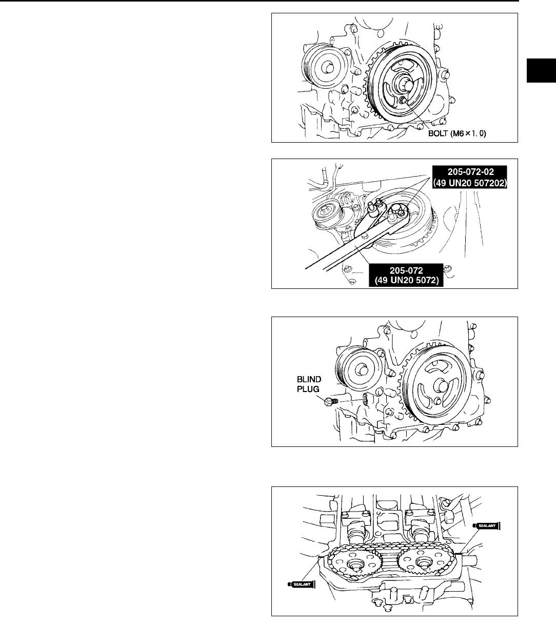
TIMING CHAIN
B17
B
2. Install the M6 x 1.0 bolt in by hand.
3. Turn the crankshaft clockwise the crankshaft is in
the No.1 cylinder TDC position.
4. Hold the crankshaft pully by using the SST.
5. Tighten the crankshaft pulley lock bolt using the
following two steps.
(1) Tighten to 96104 N·m {9.810.6 kgf·m,
70.976.7 ft·lbf}
(2) Tighten 87°
°°
°93°
°°
°
6. Remove the M6 x 1.0 bolt.
7. Remove the SST from the camshaft.
8. Remove the SST from the cylinder block lower
blind plug.
9. Rotate the crankshaft clockwise two turns until
the TDC position.
•If not aligned, loosen the crankshaft pulley
lock bolt and repeat from Step 1.
10. Install the cylinder block lower blind plug.
Tightening torque:
1822 N·m {1.92.2 kgf·m, 13.316.2 ft·lbf}
Cylinder Head Cover Installation Note
1. Apply silicone sealant to the mating faces as
shown.
Caution
•
••
•Install the cylinder head cover within 10
minutes of applying the silicone sealant.
Dot diameter:
4.06.0 mm {0.160.23 in}
2. Install the cylinder head cover with a new gasket.
AME2215W013
AME2215W002
AME2212W012
AME2215W014
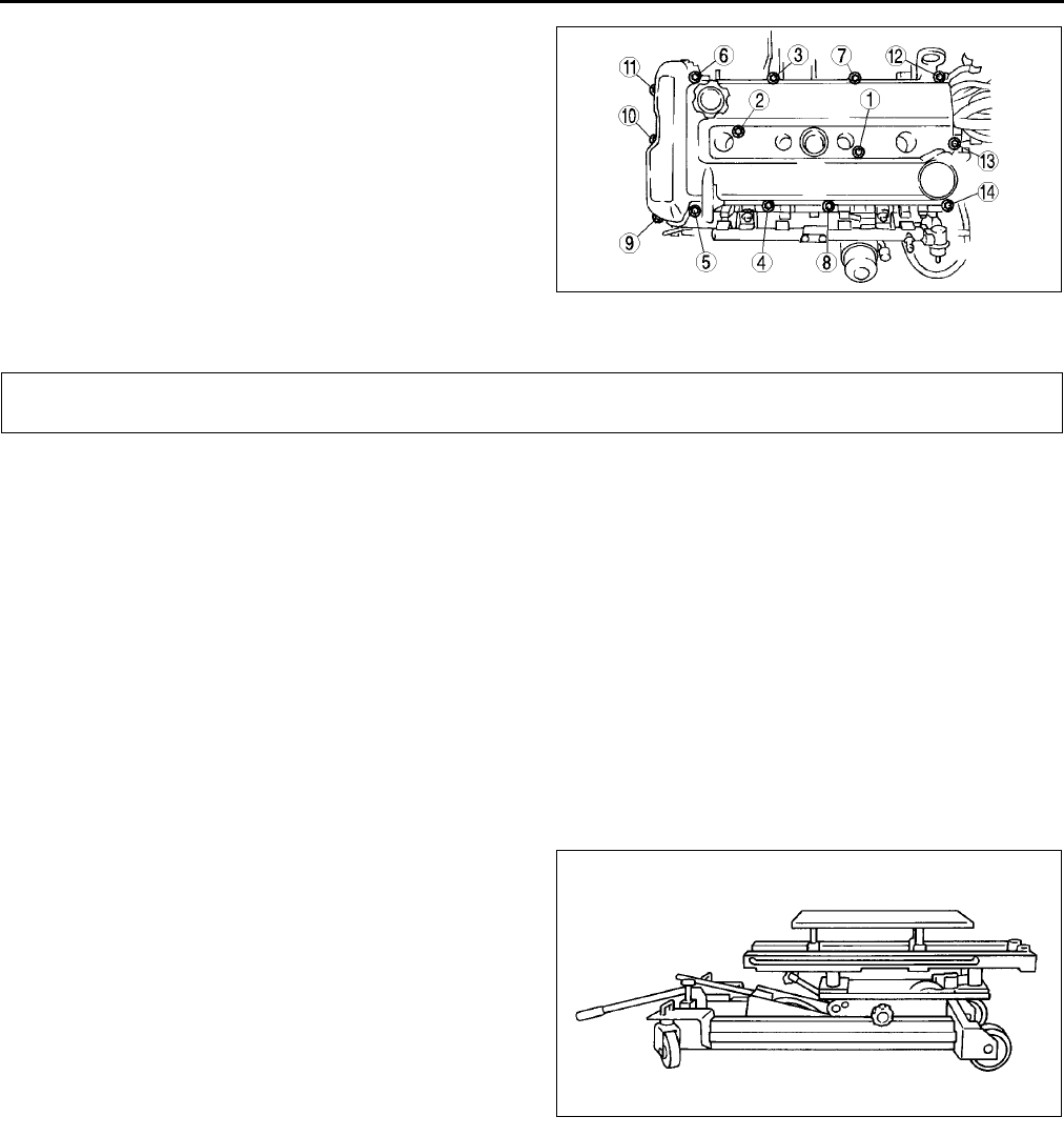
TIMING CHAIN, CYLINDER HEAD GASKET
B18
3. Tighten the bolts in the order shown.
Tightening torque:
8.011.5 N·m {81.6122.3 kgf·cm, 70.9
106.2 in·lbf}
End Of Sie
CYLINDER HEAD GASKET REPLACEMENT A6E221810271W01
Warning
•
••
•Fuel vapor is hazardous. It can very easily ignite, causing serious injury and damage. Always keep
sparks and flames away from fuel.
•
••
•Fuel line spills and leakage are dangerous. Fuel can ignite and cause serious injuries or death and
damage. Fuel can also irritate skin and eyes. To prevent this, always complete the Fuel Line
Safety Procedure. (See F17 Fuel Line Safety Procedure.)
1. Remove the timing chain. (See B10 TIMING CHAIN REMOVAL/INSTALLATION.)
2. Remove the ignition coil. (See G8 IGNITION COIL REMOVAL/INSTALLATION.)
3. Remove the high-tension lead. (See G11 HIGH-TENSION LEAD REMOVAL/INSTALLATION.)
4. Disconnect the generator, but do not remove it from the vehicle. After disconnection, fix the generator using a
rope to prevent it from falling. (See G6 GENERATOR REMOVAL/INSTALLATION.)
5. Remove the front pipe. (See F35 EXHAUST SYSTEM REMOVAL/INSTALLATION.)
6. Remove the intake manifold. (See F10 INTAKE-AIR SYSTEM REMOVAL/INSTALLATION.)
7. Disconnect the heater hose, bypass hose, radiator hose.
8. To firmly support the engine, first set the engine
jack and attachment to the oil pan.
Note
•A: MA-1
•B: M18MA
9. Remove in the order indicated in the table.
10. Install in the reverse order of removal.
11. Inspect the compression. (See B9
COMPRESSION INSPECTION.)
AME2215W015
CYLINDER HEAD GASKET
AME2218W001
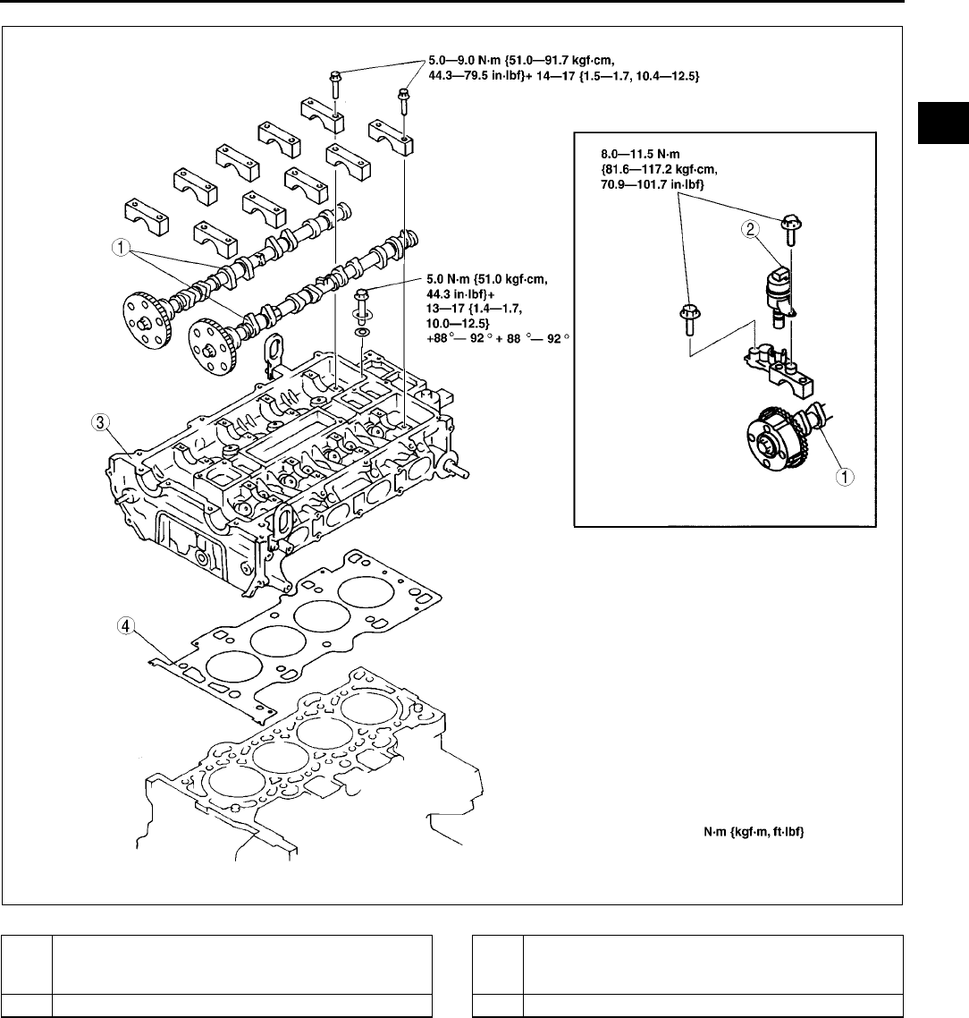
CYLINDER HEAD GASKET
B19
B
.
Camshaft Removal Note
Note
•The cylinder head and the camshaft caps are numbered to make sure they are reassembled in their
original position. When removed, keep the caps with the cylinder head they were removed from. Do not
mix the caps.
AME2218W002
1 Camshaft
(See B19 Camshaft Removal Note)
(See B21 Camshaft Installation Note)
2 Oil control valve (OCV) (L3)
3 Cylinder head
(See B20 Cylinder Head Removal Note)
(See B20 Cylinder Head Installation Note)
4 Cylinder head gasket
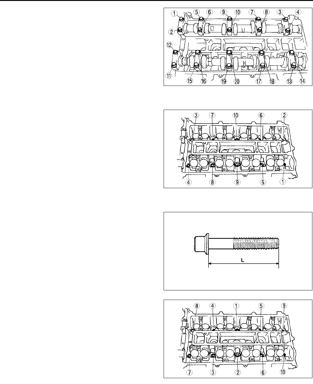
B20
CYLINDER HEAD GASKET
1. Loosen the camshaft cap bolts in several passes
in the order shown.
Cylinder Head Removal Note
1. Loosen the cylinder head bolts in several passes
in the order shown.
Cylinder Head Installation Note
1. Measure the length of each cylinder head bolt.
•Replace any that exceed maximum length.
Length L:
149.0150.0 mm {5.8675.905 in}
Maximum:
150.5 mm {5.965 in}
2. Tighten the cylinder head bolts in the order shown
using the following 5 steps.
(1) Tighten to 5.0 N·m {51.0 kgf·cm, 44.2 in·lbf}
(2) Tighten 1317 N·m {1.41.7 kgf·m, 10.0
12.5 ft·lbf}
(3) Tighten 4446 N·m {4.54.6 kgf·m, 32.5
33.9 ft·lbf}
(4) Tighten 88°
°°
°92°
°°
°
(5) Tighten 88°
°°
°92°
°°
°
AME2212W008
AME2218W003
AME2218W004
AME2218W005
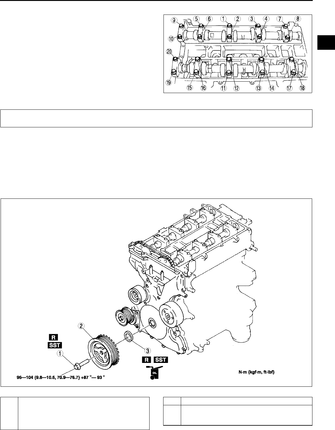
CYLINDER HEAD GASKET, FRONT OIL SEAL
B21
B
Camshaft Installation Note
1. Set the cam position of the No.1 cylinder at the
top dead center (TDC) and install the camshaft.
2. Temporarily tighten the camshaft bearing caps in
two or three even movements.
3. Tighten the camshaft cap bolts in the order shown
using the following two steps.
(1) Tighten to 5.09.0 N·m {51.091.7 kgf·cm,
44.679.5 in·lbf}
(2) Tighten to 14.017.0 N·m {1.51.7 kgf·m,
10.412.5 ft·lbf}
End Of Sie
FRONT OIL SEAL REPLACEMENT A6E222010602W01
1. Disconnect the negative battery cable.
2. Remove the spark plugs. (See G10 SPARK PLUG REMOVAL/INSTALLATION.)
3. Remove the Cylinder head cover. (See B17 Cylinder Head Cover Installation Note.)
4. Remove the drive belt. (See B3 DRIVE BELT REPLACEMENT.)
5. Remove the front drive shaft (RH) from the joint shaft. (See M17 DRIVE SHAFT REMOVAL/INSTALLATION.)
6. Remove the CKPsensor.(See F54 CRANKSHAFT POSITION (CKP) SENSOR REMOVAL/INSTALLATION.)
7. Remove in the order indicated in the table.
8. Install in the reverse order of removal.
.
AME2212W009
FRONT OIL SEAL
AME2220W001
1 Crankshaft pulley lock bolt
(See B22 Crankshaft Pulley Lock Bolt Removal
Note)
(See B23 Crankshaft Pulley Lock Bolt Installation
Note)
2 Crankshaft pulley
3Front oil seal
(See B22 Front Oil Seal Removal Note)
(See B23 Front Oil Seal Installation Note)
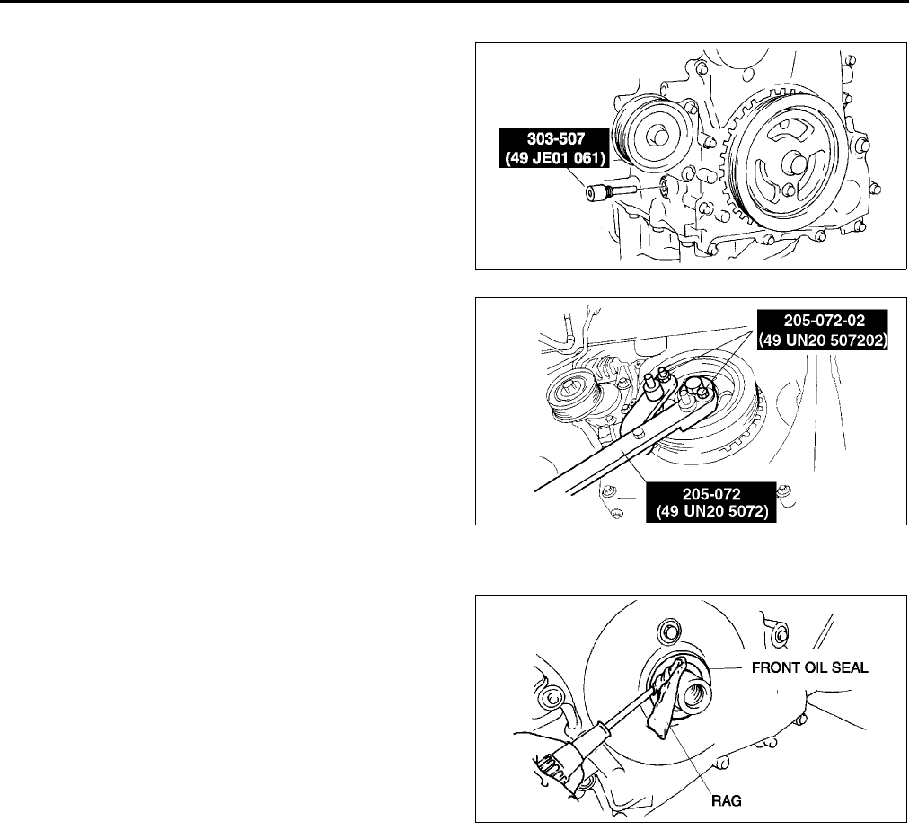
B22
FRONT OIL SEAL
Crankshaft Pulley Lock Bolt Removal Note
1. Remove the cylinder block lower blind plug.
2. Install the SST.
3. Turn the crankshaft clockwise the crankshaft is in
the No.1 cylinder TDC position.
4. Hold the crankshaft pulley by using the SSTs.
Front Oil Seal Removal Note
1. Cut the oil seal lip using a razor knife.
2. Remove the oil seal using a screwdriver protected
with a rag.
AME2212W004
AME2215W002
AME2220W002
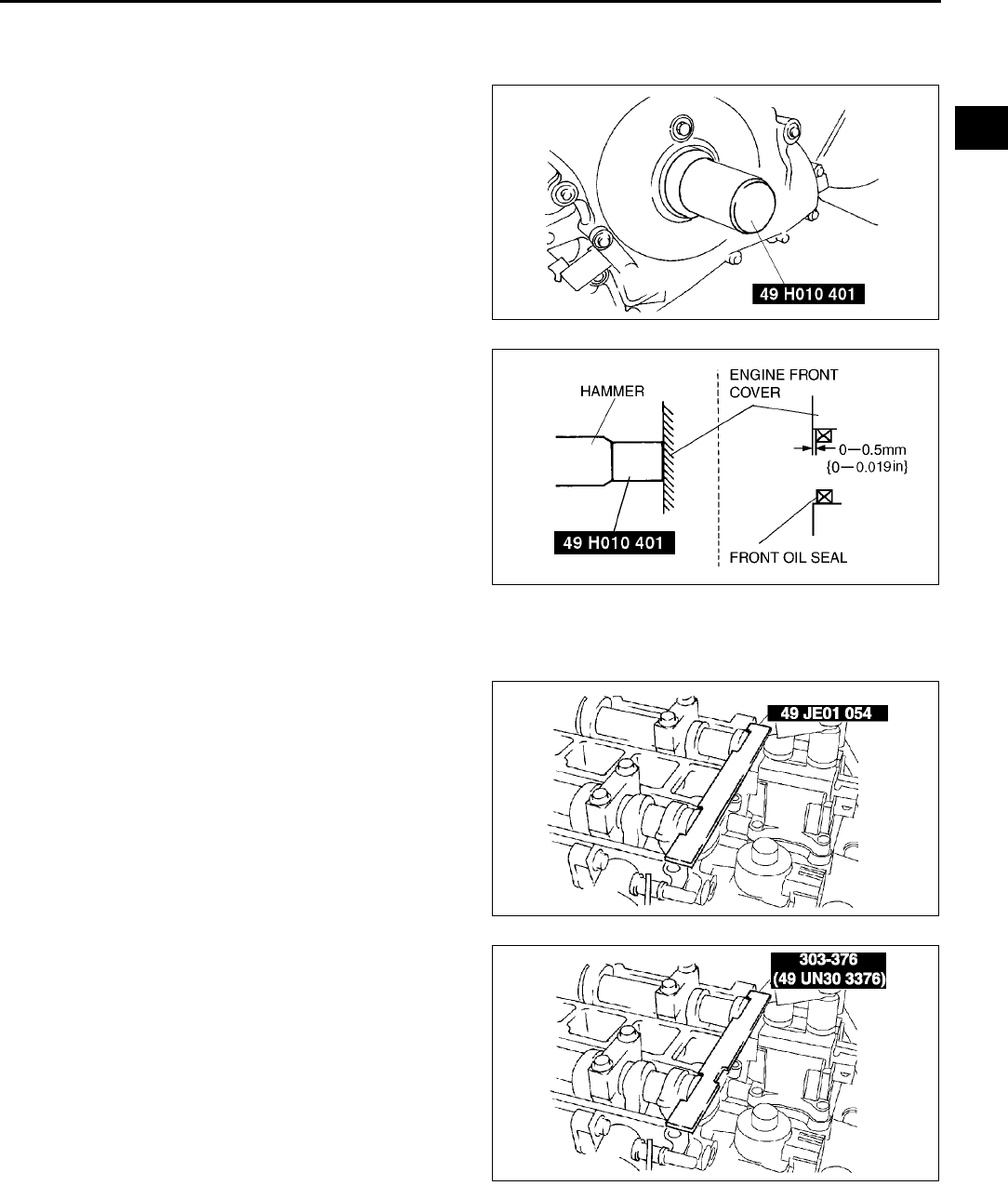
FRONT OIL SEAL
B23
B
Front Oil Seal Installation Note
1. Apply clean engine oil to the oil seal lip.
2. Push the oil seal slightly in by hand.
3. Tap the oil seal in evenly using the SST and a
hammer.
Crankshaft Pulley Lock Bolt Installation Note
1. Install the SST to the camshaft as shown.
European countries
Except European countries
AME2215W009
AME2215W010
AME2212W010
AME2212W011
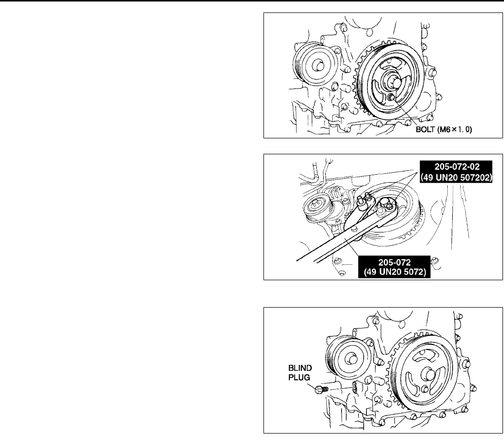
B24
FRONT OIL SEAL
2. Install the M6 x 1.0 bolt in by hand.
3. Turn the crankshaft clockwise the crankshaft is in
the No.1 cylinder TDC position.
4. Hold the crankshaft pulley by using the SSTs.
5. Tighten the crankshaft pulley lock bolt in the order
shown using the following two steps.
(1) Tighten to 96104 N·m {9.810.6 kgf·m,
70.976.7 ft·lbf}
(2) Tighten 87°
°°
°93°
°°
°
6. Remove the M6 x 1.0 bolt.
7. Remove the SST from the camshaft.
8. Remove the SST from the cylinder block lower
blind plug.
9. Rotate the crankshaft clockwise two turns until
the TDC position.
•If not aligned, loosen the crankshaft pulley
lock bolt and repeat from Step 1.
10. Install the cylinder block lower blind plug.
Tightening torque:
1822 N·m {1.92.2 kgf·m, 13.316.2 ft·lbf}
End Of Sie
AME2215W013
AME2215W002
AME2212W012
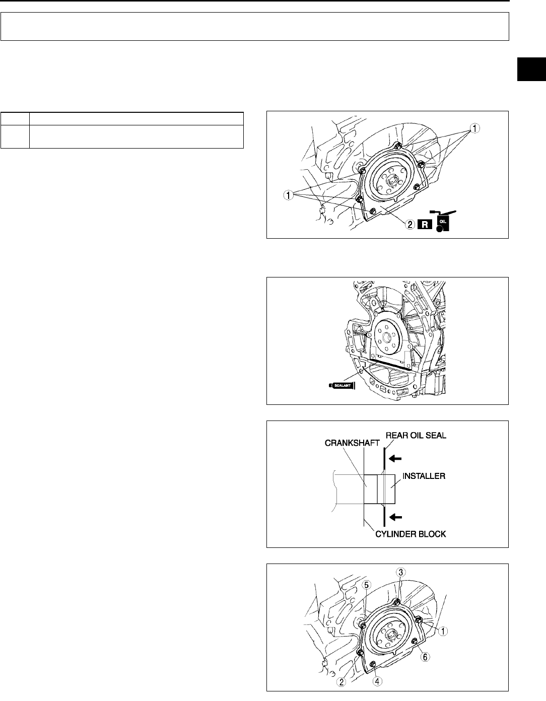
REAR OIL SEAL
B25
B
REAR OIL SEAL REPLACEMENT A6E222211399W01
1. Remove the flywheel. (MTX) (See H11 CLUTCH UNIT REMOVAL/INSTALLATION)
2. Remove the drive plate. (ATX) (See K43 DRIVE PLATE REMOVAL/INSTALLATION)
3. Remove in the order indicated in the table.
4. Install in the reverse order of removal.
.
Rear Oil Seal Installation Note
1. Apply silicone sealant to the mating faces as
shown.
Dot diameter:
4.06.0 mm {0.160.23 in}
2. Apply clean engine oil to the new oil seal lip.
3. Install the rear oil seal using the installer as
shown.
4. Tighten the rear oil seal bolts in the order as
shown.
Tightening torque:
8.011.5 N·m {81.6117.2 kgf·m, 70.9
101.7 in·lbf}
End Of Sie
REAR OIL SEAL
1Bolt
2 Rear oil seal
(See B25 Rear Oil Seal Installation Note)
AME2222W001
AME2222W002
AME2224E326
AME2222W004

B26
ENGINE
ENGINE REMOVAL/INSTALLATION A6E222401001W01
Warning
•
••
•Fuel vapor is hazardous. It can very easily ignite, causing serious injury and damage. Always keep
sparks and flames away from fuel.
•
••
•Fuel line spills and leakage are dangerous. Fuel can ignite and cause serious injures or death and
damage. Fuel can also irritate skin and eyes. To prevent this, always complete the Fuel Line
Safety Procedure. (See F17 Fuel Line Safety Procedure.)
1. Remove the battery. (See G3 BATTERY REMOVAL/INSTALLATION.)
2. Remove the battery tray. (See G3 BATTERY REMOVAL/INSTALLATION.)
3. Remove the radiator. (See E6 RADIATOR REMOVAL/INSTALLATION.)
4. Drain the missions oil.
5. Remove the P/S oil pump with the oil hose still connected and position the P/S oil pump so that it is out of the
way. (SeeN22 POWER STEERING OIL PUMP REMOVAL/INSTALLATION)
6. Remove the A/C compressor with the pipes still connected. Position the A/C compressor so that it is out of the
way. Use wire or rope to secure.
7. Remove the joint shaft from the front drive shaft. (See M17 DRIVE SHAFT REMOVAL/INSTALLATION.)
8. Remove the air cleaner, intake air duct, accelerator cable and bracket, and vacuum hose. (See F10
INTAKE-AIR SYSTEM REMOVAL/INSTALLATION.)
9. Remove the ATF filter and selector cable. (ATX) (See K29 AUTOMATIC TRANSAXLE REMOVAL/
INSTALLATION.)
10. Remove the vacuum hose and heater hose.
11. Remove the release cylinder and control cable. (MTX) (See J5 MANUAL TRANSAXLE REMOVAL/
INSTALLATION.)
12. Remove the plastic fuel hose. (See F23 Plastic Fuel Hose Removal Note.) (See F24 Plastic Fuel Hose
Installation Note.)
13. Disconnect the wiring harness from the engine side.
14. Remove the front pipe. (See F35 EXHAUST SYSTEM REMOVAL/INSTALLATION.)
15. Remove in the order indicated in the table.
16. Install in the reverse order of removal.
17. Start the engine and:
•Inspect for the engine oil, engine coolant, transaxle oil and fuel leakage.
•Verify the ignition timing, idle speed and idle mixture. (See F8 IGNITION TIMING INSPECTION.) (SeeF
9 IDLE MIXTURE INSPECTION.)
18. Perform a road test.
ENGINE
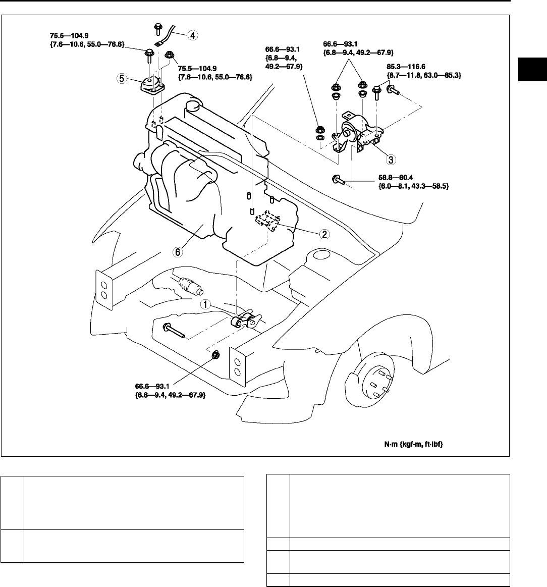
ENGINE
B27
B
.
AME2213W001
1 No.1 Engine mount rubber
(See B28 No.1 Engine Mount Rubber Removal
Note)
(See B31 No.1 Engine Mount Rubber Installation
Note)
2 No.1 Engine mount bracket
(See B31 No.1 Engine Mount Bracket Installation
Note)
3 No.4 Engine mount bracket and No.4 Engine mount
rubber
(See B28 No.4 Engine Mount Bracket and No.4
Engine Mount Rubber Removal Note)
(See B30 No.4 Engine Mount Bracket and No.4
Engine Mount Rubber Installation Note)
4 Engine ground
5 No.3 Engine joint bracket (See B29 No.3 Engine
Joint Bracket Installation Note)
6 Engine, transaxle
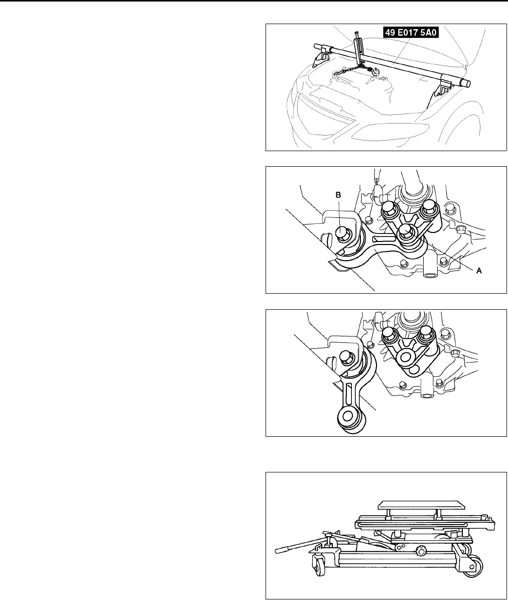
B28
ENGINE
No.1 Engine Mount Rubber Removal Note
1. Suspend the engine using the SSTs.
2. Remove the through bolt A on the No.1 engine
mount bracket side.
3. Loosen the through bolt B on the chassis side
until approximately three pitches are showing.
Note
•Do not remove the No.1 engine mount
rubber from the vehicle.
No.4 Engine Mount Bracket and No.4 Engine Mount Rubber Removal Note
1. Secure the engine and the transaxle using an
engine jack and attachment as shown.
AME2215W004
AME2213W002
AME2213W003
AME2218W001
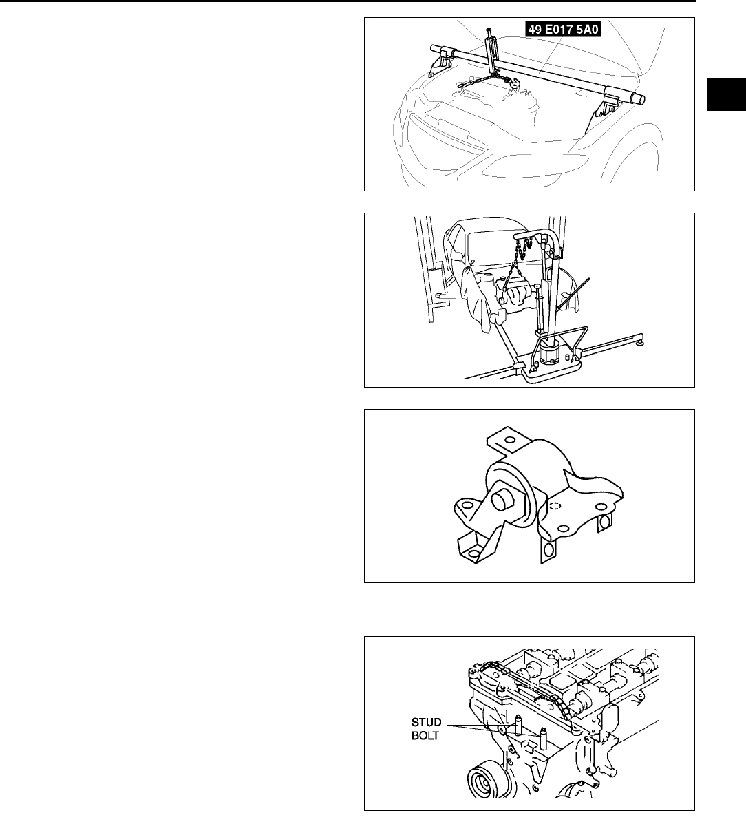
ENGINE
B29
B
2. Remove the SST.
3. Secure the engine and the transaxle using a
hoist.
4. No.4 engine mount bracket and engine mount
rubber together in one piece.
No.3 Engine Joint Bracket Installation Note
1. Tighten the No.3 engine mount bracket stud bolt.
Tightening torque:
7.013 N·m {71.4132.5 kgf·cm, 62.0115.0
in·lbf}
AME2215W004
AME2213W004
AME2213W005
AME2215W011
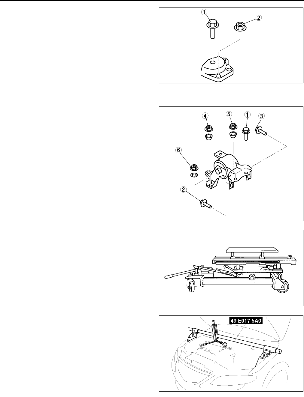
B30
ENGINE
2. Tighten the No.3 engine joint bracket bolt and nut
in the order shown.
No.4 Engine Mount Bracket and No.4 Engine Mount Rubber Installation Note
1. Tighten the No.4 engine mount bracket and No.4
engine mount rubber bolt and nut in the order as
shown.
2. Secure the engine and the transaxle using an
engine jack and attachment as shown.
3. Remove the hoist and secure the engine and
transaxle using SST.
AME2213W010
AME2213W011
AME2218W001
AME2215W004
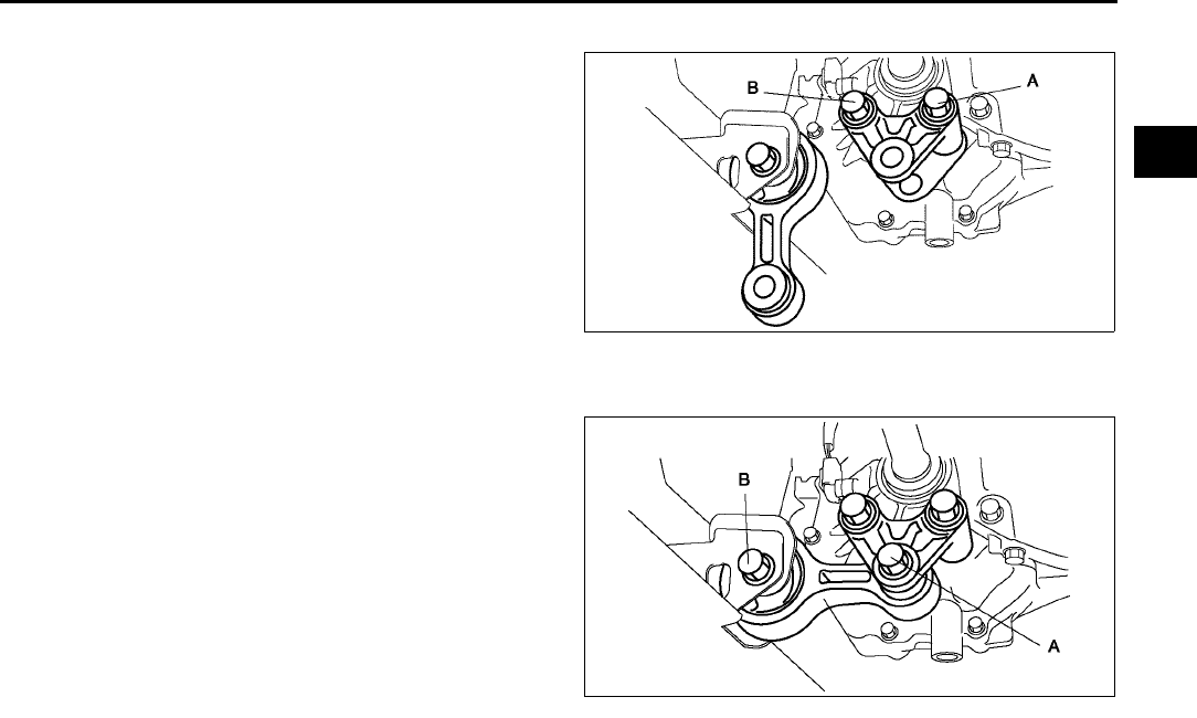
ENGINE
B31
B
No.1 Engine Mount Bracket Installation Note
1. Tighten No.1 engine mount bracket bolt A.
Tightening torque:
93.1116.6 N·m {9.5011.88 kgf·m, 68.72
85.92 ft·lbf}
2. Tighten No.1 engine mount bracket bolt B.
Tightening torque:
93.1116.6 N·m {9.5011.88 kgf·m, 68.72
85.92 ft·lbf}
No.1 Engine Mount Rubber Installation Note
1. Tighten through bolt A on No.1 engine mount
bracket.
Tightening torque:
85.3116.6 N·m {8.711.88 kgf·m, 62.93
85.92 ft·lbf}
2. Tighten through bolt B on chassis side.
Tightening torque:
93.1116.6 N·m {9.5011.88 kgf·m, 68.72
85.92 ft·lbf}
End Of Sie
ENGINE DISASSEMBLY/ASSEMBLY A6E222401001W02
1. Disconnect the engine and automatic transaxle. (ATX) (See K29 AUTOMATIC TRANSAXLE REMOVAL/
INSTALLATION.)
2. Disconnect the engine and manual transaxle. (MTX) (See J5 MANUAL TRANSAXLE REMOVAL/
INSTALLATION.)
3. Remove the intake-air system. (See F10 INTAKE-AIR SYSTEM REMOVAL/INSTALLATION.)
4. Remove the exhaust system. (See F35 EXHAUST SYSTEM REMOVAL/INSTALLATION.)
5. Remove the generator.
6. Remove the ignition coils. (See G8 IGNITION COIL REMOVAL/INSTALLATION.)
7. Remove the CKP sensor. (See F54 CRANKSHAFT POSITION (CKP) SENSOR REMOVAL/INSTALLATION.)
8. Assemble in the reverse order of disassembly.
End Of Sie
AME2213W008
AME2213W009
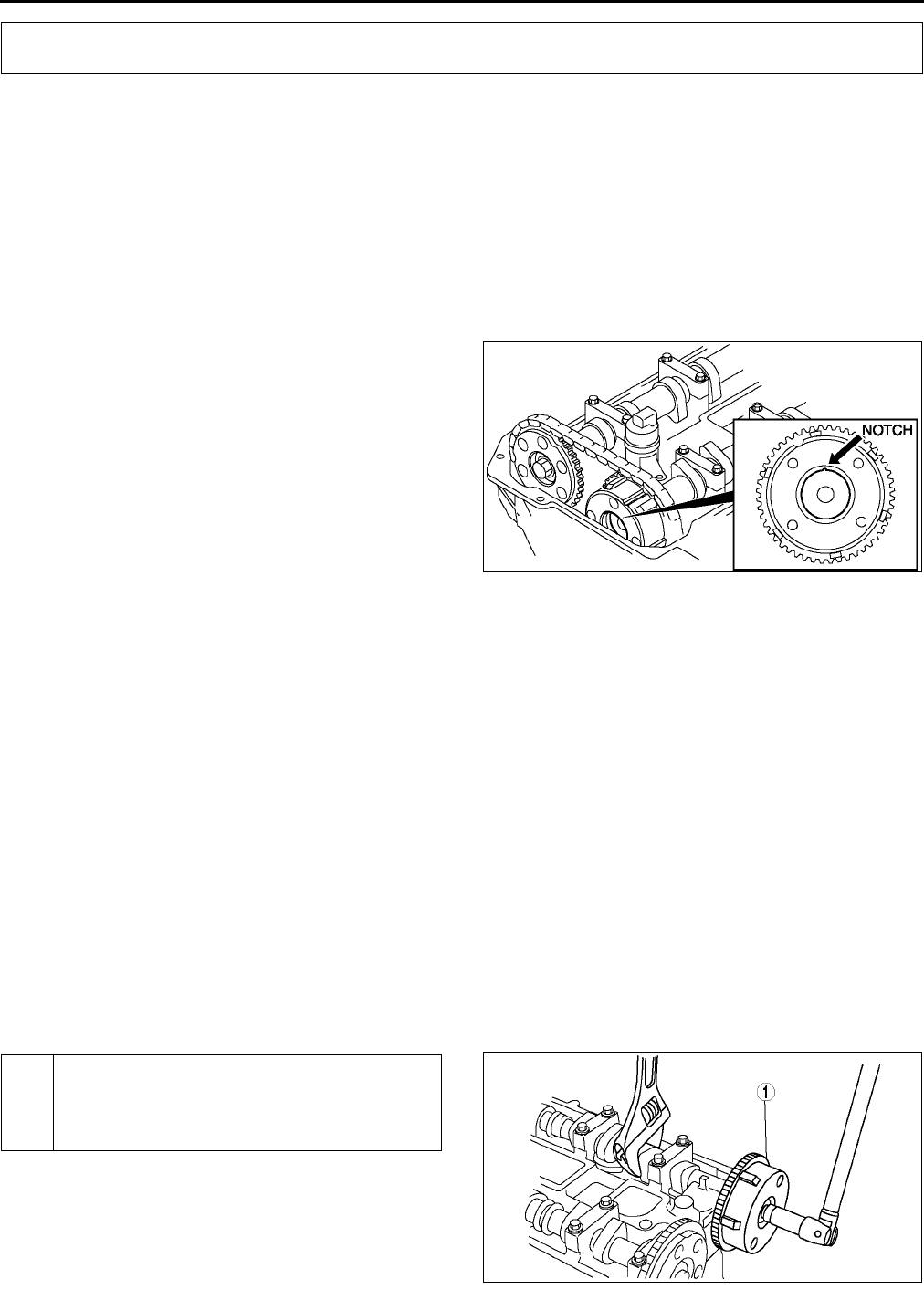
B32
VARIABLE VALVE TIMING
VARIABLE VALVE TIMING ACTUATOR INSPECTION A6E222500142W01
L3
Caution
•
••
•Variable valve timing actuator can not be disassembled it is a precision unit.
1. Disconnect the negative battery cable.
2. Remove the plug hole plate.
3. Remove the high-tension lead.
4. Remove the oil control valve connector.
5. Remove the ventilation hose.
6. Remove the cylinder head cover.
7. Confirm that notch of the rotor and bump of the
cover at the variable valve timing actuator are
aligned and fitted.
•If the notch and the bump are not aligned,
turn the crankshaft clockwise two rotations.
Verify that the bump and the notch are
aligned.
•If the bump and notch are still not aligned,
replace the variable valve timing actuator.
•If, when turning the crankshaft, there is a
hitting noise from the variable valve timing
actuator each time the cam passes the fully
lifted position, it means that the actuator is not
secured. Replace the actuator.
8. Install the cylinder head cover. (See B17 Cylinder Head Cover Installation Note.)
9. Install the ventilation hose.
10. Install the oil control valve connector.
11. Install the high-tension lead. (See G11 HIGH-TENSION LEAD REMOVAL/INSTALLATION.)
12. Install the spark plugs. (See G10 SPARK PLUG REMOVAL/INSTALLATION.)
13. Installs plug hole plate.
End Of Sie
VARIABLE VALVE TIMING ACTUATOR REMOVAL/INSTALLATION A6E222500142W02
L3
Caution
•
••
•Variable valve timing actuator can not be disassembled because it is a precision unit.
Note
•Variable valve timing actuator camshaft sprocket is integrated with the variable valve timing actuator and
cannot be disassembled.
1. Follow the timing chain removal/installation procedure from 1 to 13 and remove the timing chain. (See B10
TIMING CHAIN REMOVAL/INSTALLATION.)
2. Remove in the order indicated in the table.
3. Install in the reverse order of removal.
.
VARIABLE VALVE TIMING
AME2225W002
1 Variable valve timing actuator
(See B33 Variable Valve Timing Actuator Removal
Note)
(See B33 Variable Valve Timing Actuator
Installation Note)
AME2225W001
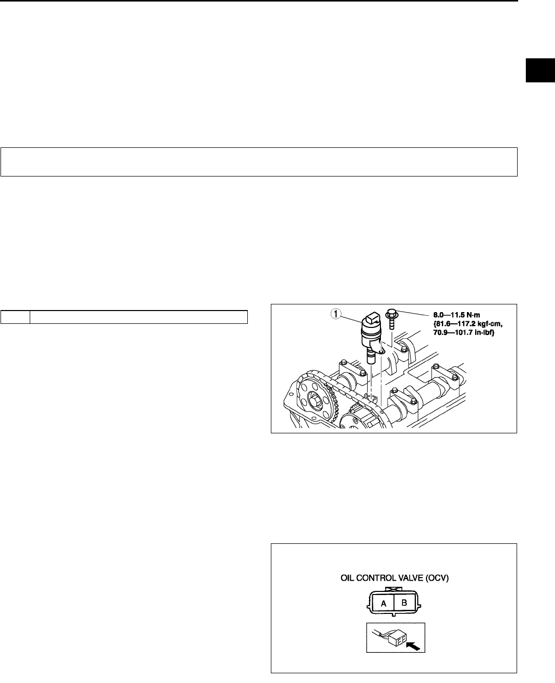
VARIABLE VALVE TIMING, OIL CONTROL VALVE (OCV)
B33
B
Variable Valve Timing Actuator Removal Note
1. Set a wrench or equivalent tool at the hexagonal part of the camshaft to prevent rotation.
2. Loosen the variable valve timing actuator tightening bolts.
Variable Valve Timing Actuator Installation Note
1. Set a wrench or equivalent tool at the hexagonal part of the camshaft to prevent rotation.
2. Tighten variable valve timing actuator tightening bolts.
Tightening torque
6975N·m {7.107.6 kgf·m, 50.955.3 ft·lbf}
End Of Sie
OIL CONTROL VALVE (OCV) REMOVAL/INSTALLATION A6E222614420W01
L3
1. Disconnect the negative battery cable.
2. Remove the plug hole plate.
3. Remove the high-tension lead. (See G11 HIGH-TENSION LEAD REMOVAL/INSTALLATION.)
4. Remove the oil control valve (OCV) connector.
5. Remove the ventilation hose.
6. Remove the cylinder head cover. (See B17 Cylinder Head Cover Installation Note.)
7. Remove in the order indicated in the table.
8. Install in the reverse order of removal.
.
End Of Sie
OIL CONTROL VALVE (OCV) INSPECTION A6E222614420W02
L3
Coil Resistance Inspection
1. Disconnect the negative battery cable.
2. Disconnect the oil control valve connector.
3. Measure the resistance between terminals A and
B using an ohmmeter.
•If not as specified, replace the oil control
valve.
Specification
6.97.9 ohms
4. Connect the oil control valve connector.
OIL CONTROL VALVE (OCV)
1 Oil control valve (OCV)
AME2226W001
AME2226W002
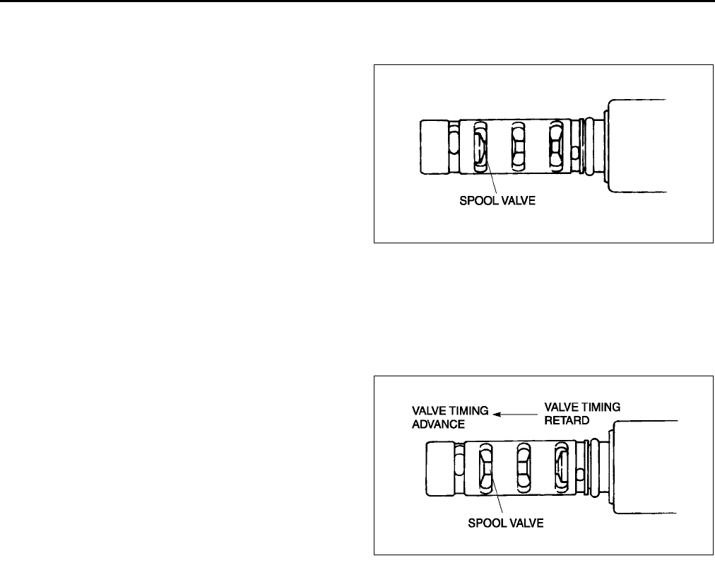
B34
OIL CONTROL VALVE (OCV)
Spool Valve Operation Inspection
1. Disconnect the negative battery cable.
2. Remove the oil control valve.
3. Verify that the spool valve in the oil control valve
is in the maximum valve timing retard position as
indicated in the figure.
•If not as specified, replace the oil control
valve.
4. Verify that the battery is fully charged.
•If not as specified, recharge the battery.
5. Apply battery positive voltage between the oil
control valve terminals and verify that the spool
valve operates and moves to the maximum valve
timing advance position.
•If not as specified, replace the oil control
valve.
Note
•When applying battery positive voltage between the oil control valve terminals, the connection can be
either of the following:
Positive battery cable to terminal A, negative battery cable to terminal B
Positive battery cable to terminal B, negative battery cable to terminal A
6. Stop applying battery positive voltage and verify
that the spool valve returns to the maximum valve
timing retard position.
•If not as specified, replace the oil control
valve.
End Of Sie
AME2226W003
AME2226W004

D1
D
DLUBRICATION SYSTEM
LOCATION INDEX .................................................D-2
LOCATION INDEX...............................................D-2
OIL PRESSURE INSPECTION ..............................D-3
OIL PRESSURE INSPECTION............................D-3
ENGINE OIL ...........................................................D-4
ENGINE OIL INSPECTION..................................D-4
ENGINE OIL REPLACEMENT.............................D-4
OIL FILTER.............................................................D-6
OIL FILTER REPLACEMENT ..............................D-6
OIL COOLER..........................................................D-7
OIL COOLER REMOVAL/INSTALLATION ..........D-7
OIL PAN..................................................................D-8
OIL PAN REMOVAL/INSTALLATION..................D-8
OIL PUMP.............................................................D-10
OIL PUMP REMOVAL/INSTALLATION.............D-10
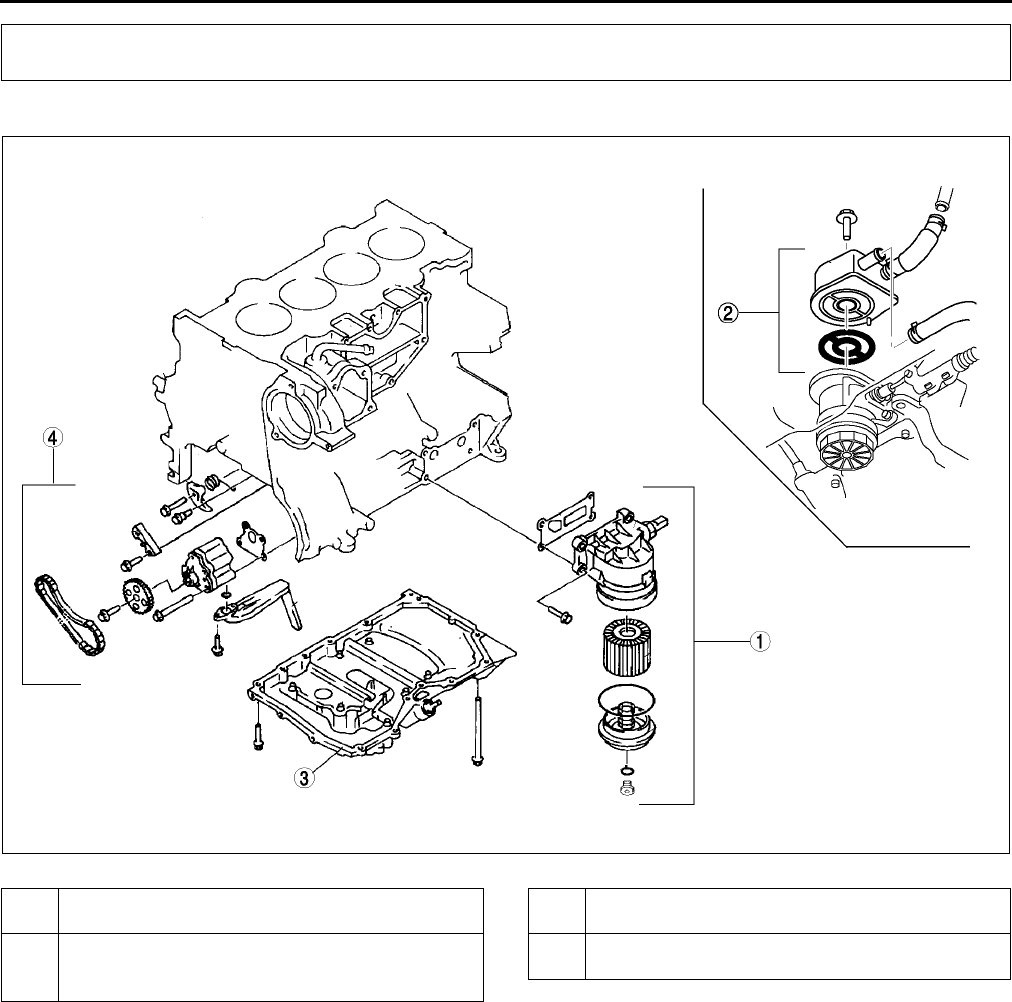
D2
LOCATION INDEX
LOCATION INDEX A6E330001002W01
.
End Of Sie
LOCATION INDEX
AME3300W001
1 Oil filter
(See D6 OIL FILTER REPLACEMENT)
2Oil cooler (LF and L3 engine models)
(See D7 OIL COOLER REMOVAL/
INSTALLATION)
3 Oil pan
(See D8 OIL PAN REMOVAL/INSTALLATION)
4 Oil pump
(See D10 OIL PUMP REMOVAL/INSTALLATION)
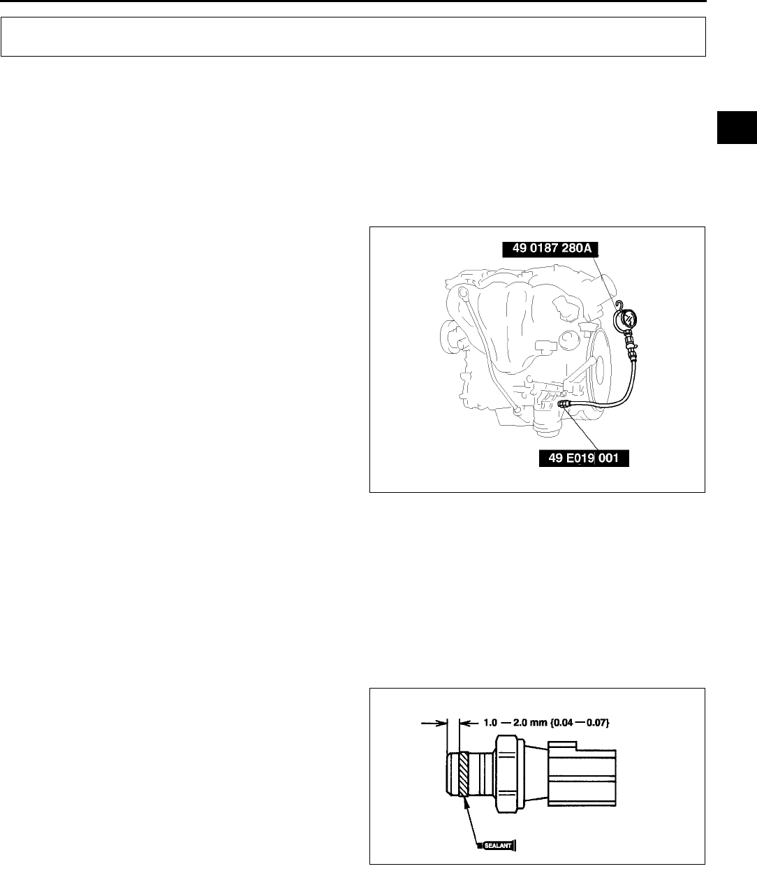
OIL PRESSURE INSPECTION
D3
D
OIL PRESSURE INSPECTION A6E331001003W01
Warning
•
••
•Continuous exposure to USED engine oil has caused skin cancer in laboratory mice. Protect your
skin by washing with soap and water immediately after working with engine oil.
•
••
•Hot engines and engine oil can cause severe burns. Turn off the engine and wait until it and the
engine oil have cooled.
1. Remove the under cover.
2. Remove the oil pressure switch.
3. Screw the SST into the oil pressure switch
installation hole.
4. Warm up the engine to normal operating
temperature.
5. Run the engine at the specified speed, and note
the gauge readings.
•If the pressure is not as specified, inspect for
the cause and repair or replace as necessary.
Note
•The oil pressure can vary with oil viscosity
and temperature.
Oil pressure [Oil temperature: 100 °
°°
°C{212°
°°
°F}]:
L8, LF :
234521 kPa {2.395.31 kgf/cm2,33.9
75.5 psi} min. [ 3,000rpm]
L3 :
395649 kPa {4.036.61 kgf/cm2, 57.3
94.1 psi} min. [ 3,000rpm]
6. Stop the engine and wait until it is cool.
7. Remove the SST.
Caution
•
••
•Any sealant stuck at the end of the oil pressure switch can cause operation malfunction of the oil
pressure switch.
Be sure there is no sealant at the end of the oil pressure switch.
8. Apply silicone sealant to the oil pressure switch
threads as shown.
9. Install the oil pressure switch.
Tightening torque:
1218 N·m {1.21.8 kgf·m, 913 ft·lbf}
10. Install the under cover.
11. Start the engine and inspect for oil leakage.
•If the oil leaks, specify the faulty part and
repair or replace it.
End Of Sie
OIL PRESSURE INSPECTION
AME3310W001
AME3310W002
D4
ENGINE OIL
ENGINE OIL INSPECTION A6E331214001W01
1. Position the vehicle on level ground.
2. Warm up the engine to normal operating temperature.
3. Stop the engine and wait for 5 min.
4. Remove the dipstick.
5. Verify that the oil level is between the F and L marks on the dipstick and check the engine oil condition.
•If the oil level is below the L mark, add the oil.
End Of Sie
ENGINE OIL REPLACEMENT A6E331214001W02
Warning
•
••
•Hot engines and engine oil can cause severe burns. Turn off the engine and wait until it and the
engine oil has cooled.
•
••
•A vehicle that is lifted but not securely supported on safety stands is dangerous. It can slip or fall,
causing death or serious injury. Never work around or under a lifted vehicle if it is not securely
supported on safety stands.
•
••
•Continuous exposure to USED engine oil has caused skin cancer in laboratory mice. Protect your
skin by washing with soap and water immediately after working with engine oil.
Caution
•
••
•In case you spill engine oil on the front pipe, wipe it off completely. If you fail to wipe the spilled
oil, it will produce a white smoke because of the heat.
1. Position the vehicle on level ground.
2. Remove the oil filler cap and the oil pan drain plug and oil filter drain.
3. Drain the engine oil into a container.
4. Install the oil filter drain plug with the new O-ring.
Tightening torque (oil filter drain plug):
910 N·m {91.8101.9 kgf·cm, 79.788.4 in·lbf}
5. Clean the flange surface (seal rubber) of the oil pan drain plug, then install the oil pan drain plug.
Tightening torque (oil pan drain plug):
2530 N·m {2.63.0 kgf·m, 18.821.6 ft·lbf}
Note
•The amount of residual oil in the engine can vary according to the replacement method, oil temperature,
etc. Verify the oil level after engine oil replacement.
6. Refill the engine with the specified type and amount of engine oil.
Oil capacity (Approximate quantity)
L {US qt, Imp qt}
Note
•The maintenance intervals on scheduled maintenance table (See GI33 SCHEDULED MAINTENANCE
TABLE) can only be supported by the use of following oils.
ENGINE OIL
Item Engine
L8 LF L3
Total
(dry engine)
4.6
{4.8, 4.0}
4.6
{4.8, 4.0}
4.2
{4.4, 3.6}
Oil replacement 3.9
{4.0, 3.4}
3.9
{4.0, 3.0}
3.1
{3.3, 2.7}
Oil and oil filter
replacement
4.3
{4.5, 3.8}
4.3
{4.5, 3.8}
3.5
{3.7, 3.1}

ENGINE OIL
D5
D
Recommended engine oil
7. Refit the oil filler cap.
8. Run the engine and inspect for oil leakage.
9. Inspect the oil level.
•If necessary, add oil. (See D4 ENGINE OIL INSPECTION.)
10. Start the engine and inspect for oil leakage.
•If the oil leaks, specify the faulty part and repair or replace it.
End Of Sie
Item Market
Europe Except Europe
Grade API SJ
ACEA A1 or A3
API SL
ILSAC GF-3
API SG, SH, SJ, SL
ILSAC GF-2, GF-3
Viscosity (SAE) 5W-30 5W-20
40, 30, 20,
20W-20, 10W-30,
10W-40, 10W-50,
20W-40, 15W-40,
20W-50, 15W-50,
5W-20, 5W-30
Remarks Mazda genuine
DEXELIA oil
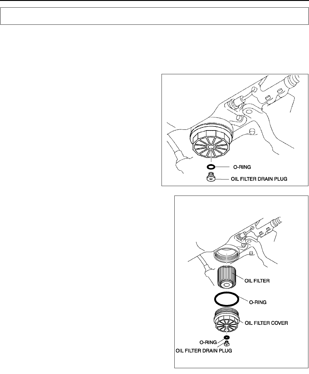
D6
OIL FILTER
OIL FILTER REPLACEMENT A6E331414300W01
For Europe (LF and L3 engine models)
Caution
•
••
•To avoid damage to the oil filter, use only specified oil filter.
1. Remove the oil filter drain plug.
2. Untighten the oil filter cover for 2 turns and drain
the engine oil.
Note
•Oil could be easily drained when the air is in
the filter.
3. Remove the oil filter.
4. Use a clean rag to wipe off the mounting surface on
the oil filter adapter and the oil filter cover.
5. Apply clean oil to new O-ring of a new oil filter and a
new oil filter drain plug.
6. Install the oil filter, oil filter drain plug, and oil filter
cover.
7. Tighten the oil filter cover and oil filter drain plug.
Tightening torque:
Oil filter cover: 3035 N·m {30.53.56 kgf·cm,
22.225.8 in·lbf}
Oil filter drain plug: 9.011 N·m {91.8112.1
kgf·cm, 79.697.3 in·lbf}
8. Start the engine and inspect for oil leakage.
9. Inspect the oil level.
•If necessary, add oil. (See D4 ENGINE OIL
INSPECTION.)
End Of Sie
OIL FILTER
AME3314W001
AME3314W002
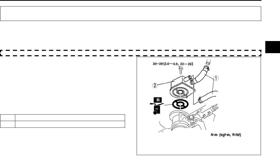
OIL COOLER
D7
D
OIL COOLER REMOVAL/INSTALLATION A6E331819900W01
LF, L3
1. Remove the under cover.
2. Drain the engine coolant. (See E3 ENGINE COOLANT REPLACEMENT.)
3. Remove the oil filter cover, and drain the engine oil into a container. (See D6 OIL FILTER REPLACEMENT.)
4. Remove in the order indicated in the table.
5. Use a clean rag to wipe off the mounting surface
on the oil cooler.
6. Install in the reverse order of removal.
7. Inspect the oil level.
•If necessary, add oil. (See D4 ENGINE OIL
INSPECTION.)
8. Start the engine and inspect for oil leakage.
•If the oil leaks, specify the faulty part and
repair or replace it.
End Of Sie
OIL COOLER
1 Water hose
2 Oil cooler
AME3318W002
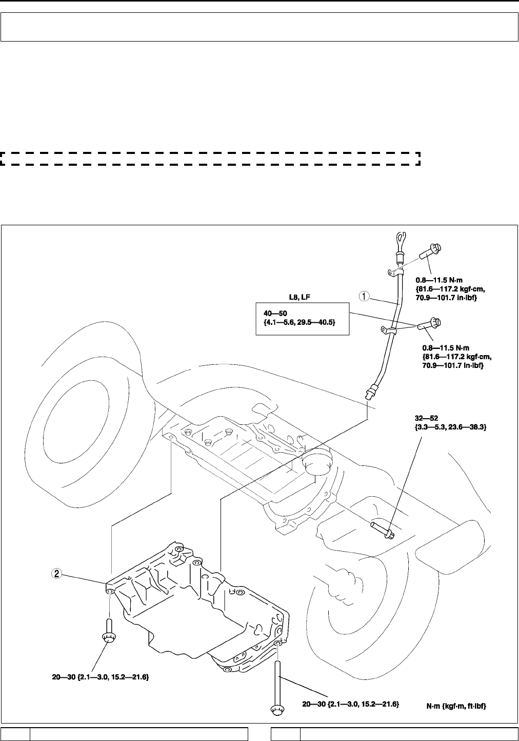
D8
OIL PAN
OIL PAN REMOVAL/INSTALLATION A6E332010040W01
Warning
•
••
•Hot engine and engine oil can cause severe burns. Turn off the engine and wait until it and the
engine oil have cooled.
1. Disconnect the negative battery cable.
2. Remove the under cover.
3. Drain the engine oil. (See D4 ENGINE OIL REPLACEMENT.)
4. Remove the engine front cover. (See B10 TIMING CHAIN REMOVAL/INSTALLATION.)
5. Remove in the order indicated in the table.
6. Install in the reverse order of removal.
7. Inspect the oil level. (See D4 ENGINE OIL INSPECTION.)
8. Start the engine and inspect for oil leakage.
•If the oil leaks, specify the faulty part and repair or replace it.
.
OIL PAN
AME3320W001
1 Oil level gauge pipe 2 Oil pan (See D9 Oil Pan Installation Note)
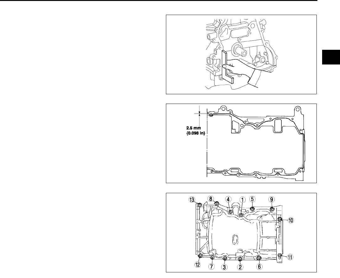
OIL PAN
D9
D
Oil Pan Installation Note
1. Use a square ruler to unite the oil pan and the
cylinder block junction side on the engine front
cover side.
2. Apply silicone sealant to the oil pressure switch
threads as shown.
3. Tighten the bolts in the order shown.
End Of Sie
AME3320W002
AME3320W003
AME3320W004
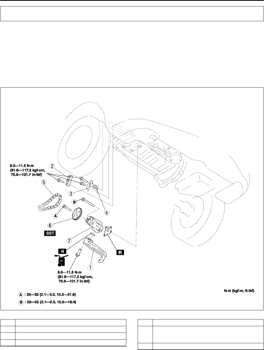
D10
OIL PUMP
OIL PUMP REMOVAL/INSTALLATION A6E332214100W01
1. Disconnect the negative battery cable.
2. Drain the engine oil. (See D4 ENGINE OIL REPLACEMENT.)
3. Remove the oil pan. (See D8 OIL PAN REMOVAL/INSTALLATION.)
4. Remove in the order indicated in the table.
5. Install in the reverse order of removal.
6. Inspect the engine oil level. (See D4 ENGINE OIL INSPECTION.)
7. Start the engine and inspect for oil leakage.
•If the oil leaks, specify the faulty part and repair or replace it.
8. Inspect the oil pressure. (See D3 OIL PRESSURE INSPECTION.)
.
OIL PUMP
AME3322W001
1 Oil strainer
2 Oil pump chain guide
3 Oil pump chain tensioner
4 Oil pump chain tensioner spring
5 Oil pump chain
6 Oil pump sprocket
(See D11 Oil Pump Sprocket Removal /
Installation Note)
7 Oil pump
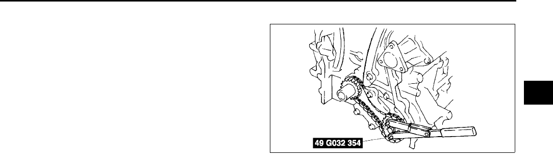
OIL PUMP
D11
D
Oil Pump Sprocket Removal / Installation Note
1. Install the SST to the oil pump sprocket to stop
the oil pump from turn in.
End Of Sie
AME3322W002

E1
E
ECOOLING SYSTEM
LOCATION INDEX .................................................E-2
LOCATION INDEX..............................................E-2
COOLING SYSTEM SERVICE WARNINGS ..........E-3
COOLING SYSTEM SERVICE WARNINGS ....... E-3
ENGINE COOLANT................................................E-3
ENGINE COOLANT LEVEL INSPECTION..........E-3
ENGINE COOLANT REPLACEMENT .................E-3
ENGINE COOLANT LEAKAGE INSPECTION ....E-4
RADIATOR CAP.....................................................E-5
RADIATOR CAP INSPECTION ...........................E-5
RADIATOR .............................................................E-6
RADIATOR REMOVAL/INSTALLATION .............E-6
THERMOSTAT .......................................................E-7
THERMOSTAT REMOVAL/INSTALLATION ....... E-7
THERMOSTAT INSPECTION .............................E-8
WATER PUMP........................................................E-8
WATER PUMP REMOVAL/INSTALLATION........E-8
FAN MOTOR .......................................................... E-9
COOLING FAN REMOVAL/INSTALLATION ....... E-9
COOLING FAN MOTOR REMOVAL/
INSTALLATION............................................... E-10
COOLING FAN MOTOR INSPECTION ............. E-11
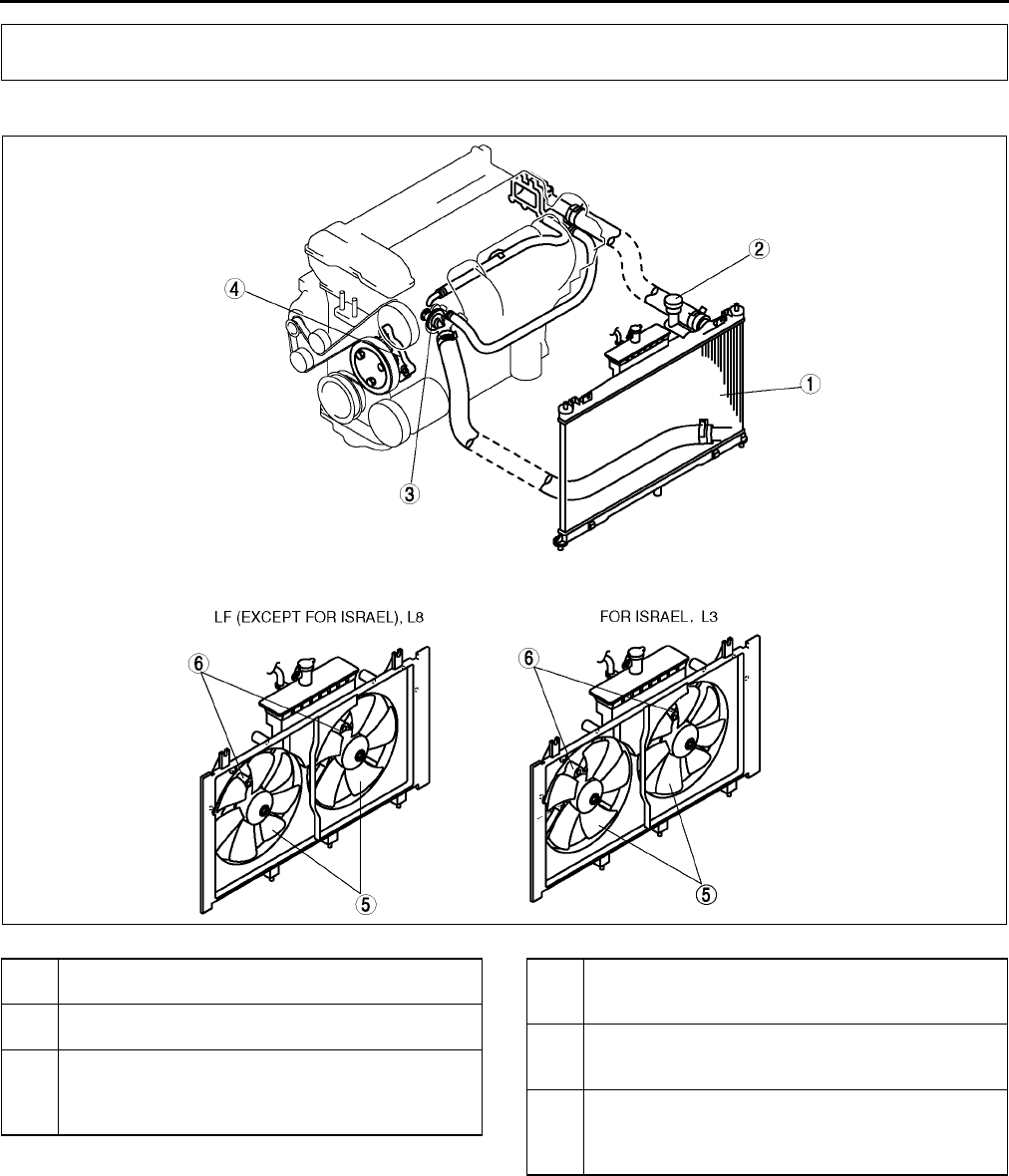
E2
LOCATION INDEX
LOCATION INDEX A6E360001002W01
.
End Of Sie
LOCATION INDEX
AME3602N001
1 Radiator
(See E6 RADIATOR REMOVAL/INSTALLATION)
2 Radiator cap
(See E5 RADIATOR CAP INSPECTION)
3Thermostat
(See E7 THERMOSTAT REMOVAL/
INSTALLATION)
(See E8 THERMOSTAT INSPECTION)
4 Water pump
(See E8 WATER PUMP REMOVAL/
INSTALLATION)
5 Cooling fan
(See E9 COOLING FAN REMOVAL/
INSTALLATION)
6 Cooling fan motor
(See E10 COOLING FAN MOTOR REMOVAL/
INSTALLATION)
(See E11 COOLING FAN MOTOR INSPECTION)
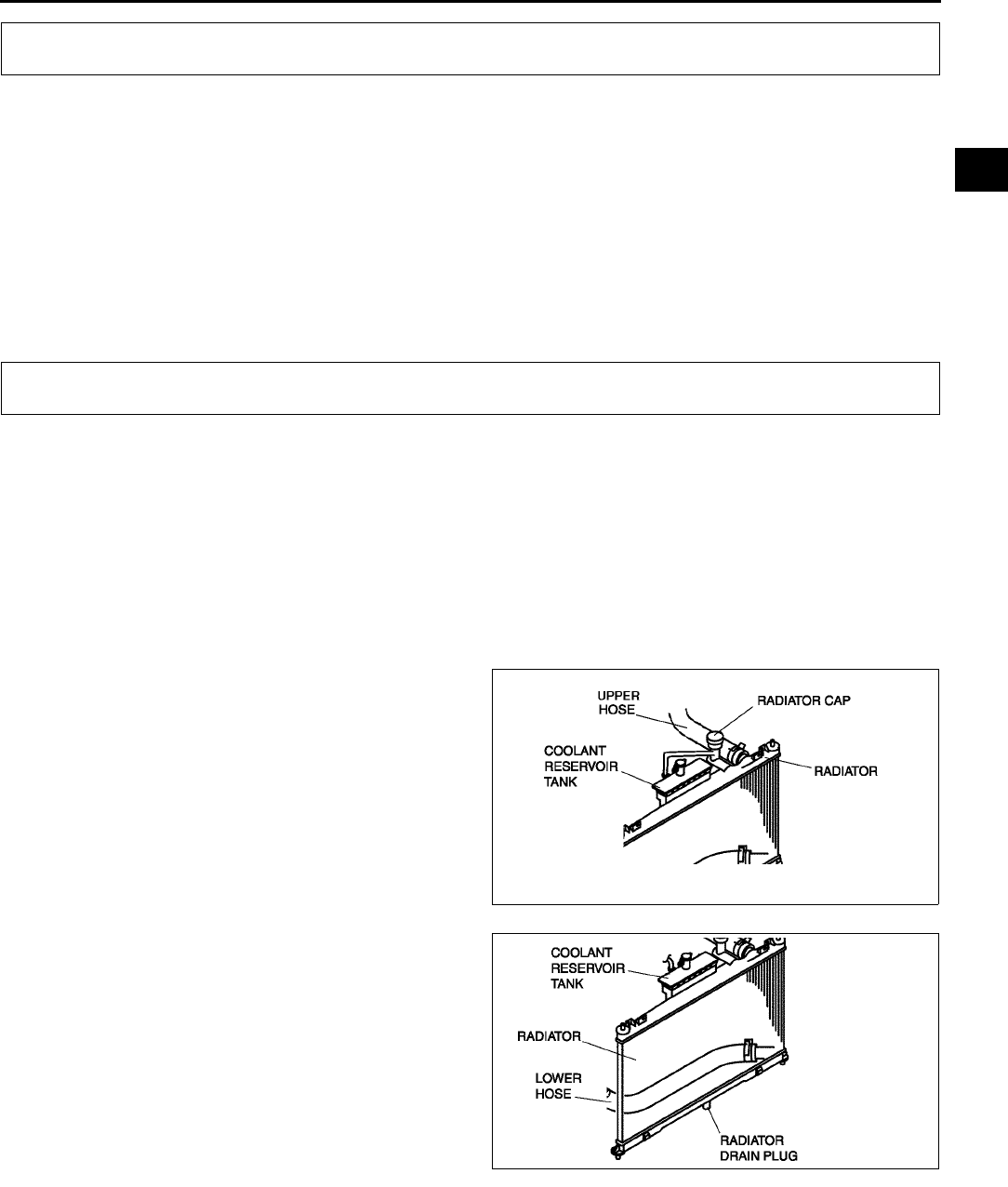
COOLING SYSTEM SERVICE WARNINGS , ENGINE COOLANT
E3
E
COOLING SYSTEM SERVICE WARNINGS A6E361001004W01
Warning
•
••
•Never remove the radiator cap or loosen the radiator drain plug while the engine is running, or
when the engine and radiator are hot. Scalding coolant and steam may shoot out and cause
serious injury. It may also damage the engine and cooling system.
•
••
•Turn off the engine and wait until it is cool. Even then, be very careful when removing the cap.
Wrap a thick cloth around it and slowly turn it counterclockwise to the first stop. Step back while
the pressure escapes.
•
••
•When you are sure all the pressure is gone, press down on the cap using the cloth, turn it, and
remove it.
End Of Sie
ENGINE COOLANT LEVEL INSPECTION A6E361215001W01
1. Verify that the coolant level in the coolant reservoir is between the F and L marks.
•If the engine coolant level is below L, remove the radiator cap and add coolant. (See E3 COOLING
SYSTEM SERVICE WARNINGS.)
End Of Sie
ENGINE COOLANT REPLACEMENT A6E361215001W03
Warning
•
••
•Drain the engine coolant while the engine is cold, otherwise it may burn you and cause serious
injury.
1. Remove the radiator cap.
2. Remove the radiator drain plug.
3. Drain the coolant into a container.
4. Flush the cooling system with water until all
traces of color are gone.
5. Let the system drain completely.
6. Tighten the radiator drain plug.
7. Fill the coolant into the reservoir up to the FULL
mark on the coolant reservoir.
8. Fully install the radiator cap.
Caution
•
••
•If the coolant temperature becomes too
high, stop the engine to prevent it from
overheating.
COOLING SYSTEM SERVICE WARNINGS
ENGINE COOLANT
AME3612W001
AME3612W002
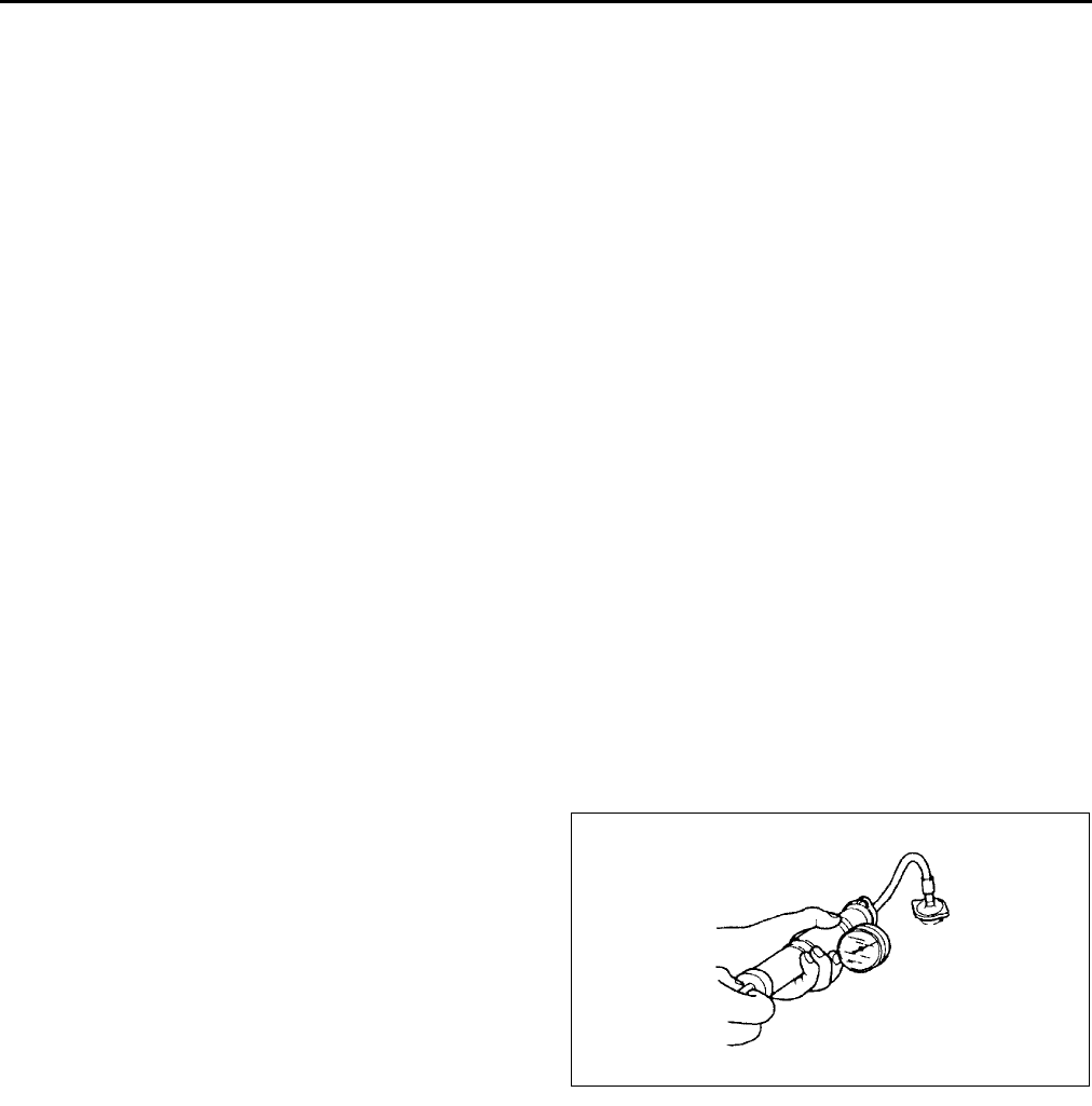
E4
ENGINE COOLANT
9. Start the engine and let it idle until the cooling fan operates.
10. After engine warms up, perform the following steps.
(1) Run the engine at 2,500 rpm for 5 min.
(2) Run the engine at 3,000 rpm for 5 s, then return to idling.
(3) Repeat Step (2) several times.
(4) Run the engine at idle for 1 min.
11. Stop the engine and wait until it is cool.
12. Remove the radiator cap.
13. Check the coolant level.
•If It is low, repeat Steps 69.
14. Install the radiator cap.
15. Inspect for coolant leakage.
•If not as specified, repair or replace the radiator cap.
End Of Sie
ENGINE COOLANT LEAKAGE INSPECTION A6E361215001W04
Warning
•
••
•Never remove the radiator cap while the engine is running, or when the engine and radiator are
hot. Scalding coolant and steam may shoot out and cause serious injury. It may also damage the
engine and cooling system.
•
••
•Turn off the engine and wait until it is cool. Even then, be very careful when removing the cap.
Wrap a thick cloth around it and slowly turn it counterclockwise to the first stop. Step back while
the pressure escapes.
•
••
•When you are sure all the pressure is gone, press down on the cap using the cloth, turn it, and
remove it.
1. Inspect the coolant level.
2. Remove the radiator cap.
3. Clean the mounting surface of the rediator cap and the upper radiator hose.
4. Connect a radiator cap tester and the radiator cap tester to the reservoir filler port.
5. Apply specified pressure to the radiator.
Pressure
127 kPa { 1.3 kgf/cm2, 18 psi}
6. Verify that the pressure is held.
•If not, inspect the system for coolant leakage.
If the coolant leaks from the upper hose
attachment part, replace the upper hose
and the clamp.
If the coolant leaks from the main body of
the radiator (caulking part), replace the
radiator.
End Of Sie
AME3612W003
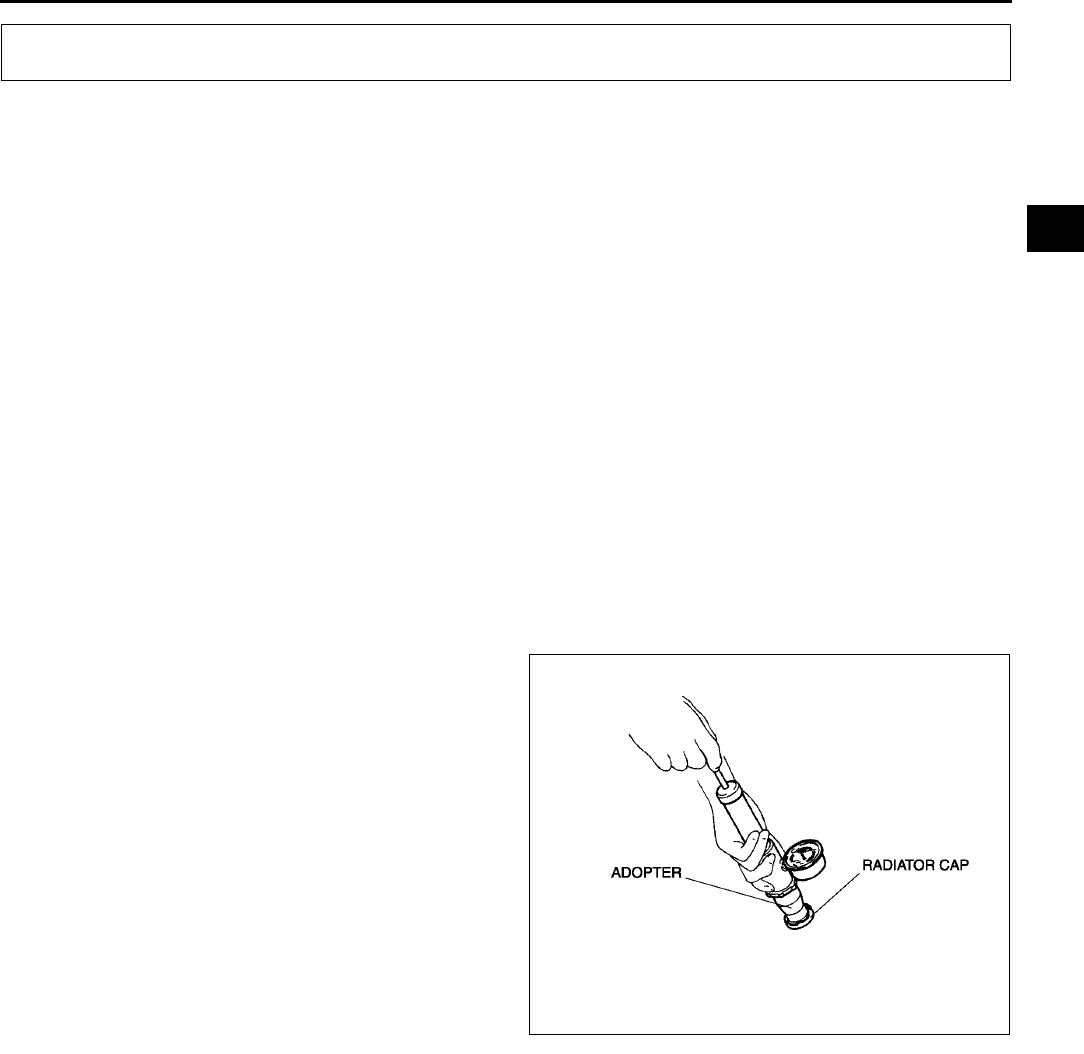
RADIATOR CAP
E5
E
RADIATOR CAP INSPECTION A6E361415201W01
Warning
•
••
•Never remove the radiator cap while the engine is running, or when the engine and radiator are
hot. Scalding coolant and steam may shoot out and cause serious injury. It may also damage the
engine and cooling system.
•
••
•Turn off the engine and wait until it is cool. Even then, be very careful when removing the cap.
Wrap a thick cloth around it and slowly turn it counterclockwise to the first stop. Step back while
the pressure escapes.
•
••
•When you are sure all the pressure is gone, press down on the cap using the cloth, turn it, and
remove it.
1. Clean the radiator cap negative pressure valve and tha sealed part.
2. Inspect the crack or turn over on sealed of the radiator cap.
•If not as specified, repace the radiator cap.
3. Fill the radiator cap test adopter with the water or the engine coolant to the full level and attach the radiator cap
to the adapter.
4. Hold the radiator cap downward and apply pressure gradually. Verify that the pressure become held for 10 s
within the specification.
•If the pressure will not stable within the specification, replace the radiator cap.
Pressure
113142 kPa
{ 1.11.4 kgf/cm2, 1520 psi}
End Of Sie
RADIATOR CAP
AME3614W001
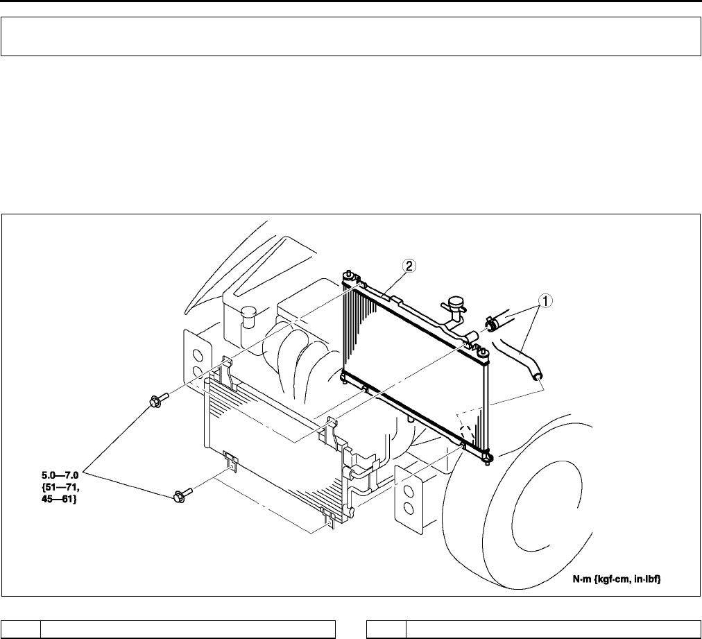
E6
RADIATOR
RADIATOR REMOVAL/INSTALLATION A6E361615200W01
1. Disconnect the negative battery cable.
2. Drain the engine coolant. (See E3 ENGINE COOLANT REPLACEMENT.)
3. Remove the cooling fan. (See E9 COOLING FAN REMOVAL/INSTALLATION.)
4. Remove the oil hose. (ATX)
5. Remove in the order indicated in the table.
6. Install in the reverse order of removal.
7. Refill the engine coolant. (See E3 ENGINE COOLANT REPLACEMENT.)
8. Inspect the engine coolant leakage. (See E4 ENGINE COOLANT LEAKAGE INSPECTION.).
End Of Sie
RADIATOR
AME3616W001
1 Water hose 2Radiator
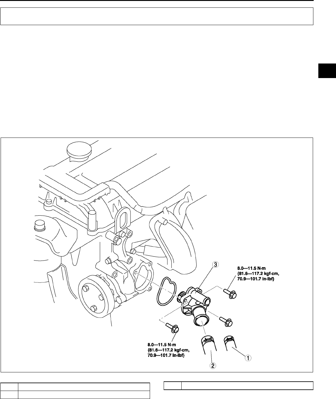
THERMOSTAT
E7
E
THERMOSTAT REMOVAL/INSTALLATION A6E361815171W01
1. Remove the plug hole plate.
2. Disconnect the negative battery cable.
3. Drain the engine coolant. (See E3 COOLING SYSTEM SERVICE WARNINGS.)
4. Remove the drive belt. (See B3 DRIVE BELT REPLACEMENT.)
5. Remove the washer tank.
6. Remove the P/S oil pump.
Note
•Remove the P/S oil pump with hoses and pipe still connected.
7. Remove in the order indicated in the table.
8. Install in the reverse order of removal.
9. Refill the engine coolant. (See E3 ENGINE COOLANT REPLACEMENT.)
10. Inspect the engine coolant leakage. (See E4 ENGINE COOLANT LEAKAGE INSPECTION.)
11.
End Of Sie
THERMOSTAT
AME3618W001
1 Bypass hose
2 Lower hose
3 Thermostat assembly
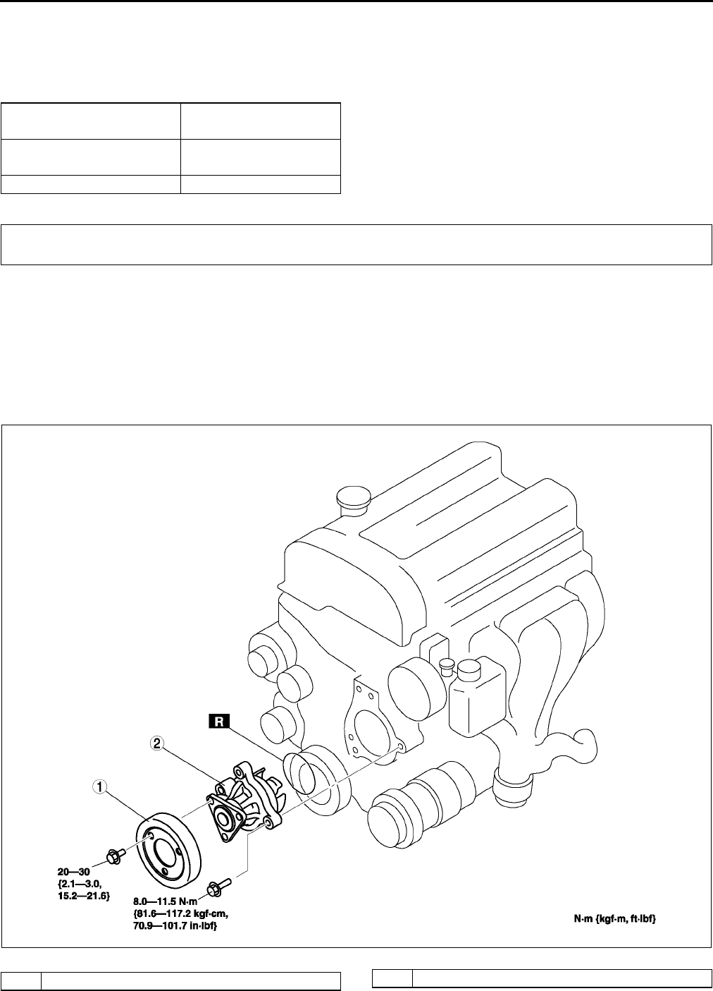
E8
THERMOSTAT, WATER PUMP
THERMOSTAT INSPECTION A6E361815171W02
1. Inspect the thermostat for the following.
•Closed valve in room temperature
•Opening temperature and lift of the valve
If not as specified, replace the thermostat.
End Of Sie
WATER PUMP REMOVAL/INSTALLATION A6E362015010W01
1. Disconnect the negative battery cable.
2. Drain the engine coolant. (See E3 COOLING SYSTEM SERVICE WARNINGS.) (See E3 ENGINE
COOLANT REPLACEMENT.)
3. Loosen the water pump pulley bolt to remove the drive belt. (See B3 DRIVE BELT REPLACEMENT.)
4. Remove in the order indicated in the table.
5. Install in the reverse order of removal.
6. Refill the engine coolant. (See E3 ENGINE COOLANT REPLACEMENT.)
7. Inspect the engine coolant leakage. (See E4 ENGINE COOLANT LEAKAGE INSPECTION.)
Initial-opening temperature 80.084.0 {176183.2}
(°C {°F})
Full-open temperature 97 {206.6}
(°C {°F})
Full-open lift (mm {in}) More than 8.0 {0.31}
WATER PUMP
AME3620W001
1 Water pump pulley 2 Water pump
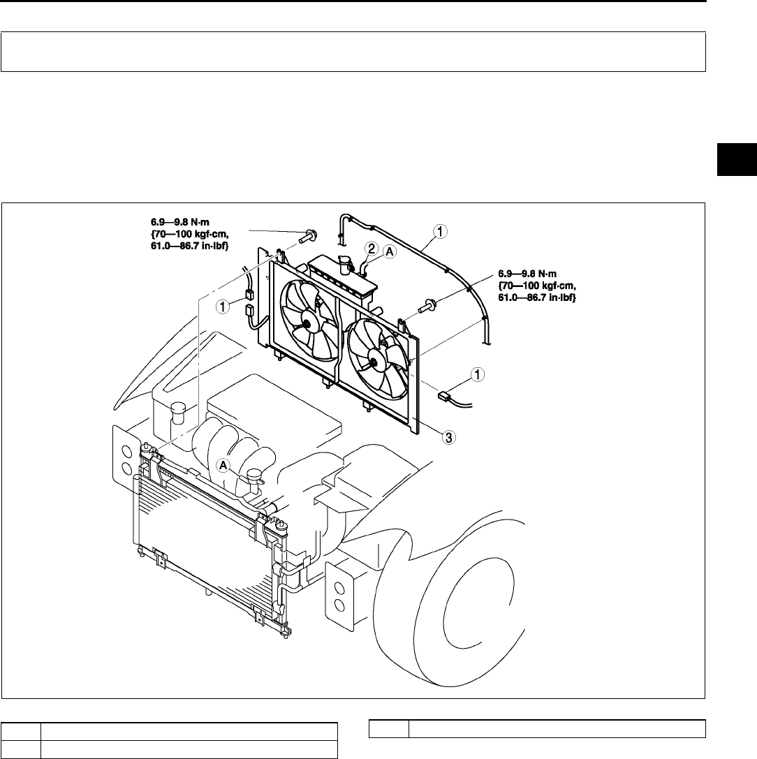
FAN MOTOR
E9
E
End Of Sie
COOLING FAN REMOVAL/INSTALLATION A6E362215025W01
1. Disconnect the negative battery cable.
2. Remove the shroud panel. (See S119 SHROUD PANEL REMOVAL/INSTALLATION.)
3. Remove the A/C pipe stay.
4. Remove the ATX pipe stay (ATX).
5. Remove in the order indicated in the table.
6. Install in the reverse order of removal.
7.
End Of Sie
FAN MOTOR
AME3621W001
1 Cooling fan harness, connector
2 Coolant reservoir hose
3 Cooling fan assembly
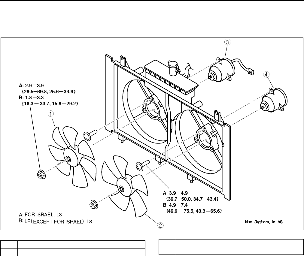
E10
FAN MOTOR
COOLING FAN MOTOR REMOVAL/INSTALLATION A6E362215025W02
1. Remove the cooling fan. (See E9 COOLING FAN REMOVAL/INSTALLATION.)
2. Remove in the order indicated in the table.
3. Install in the reverse order of removal.
4.
End Of Sie
AME3621W002
1 Cooling fan No.2
2 Cooling fan No.1
3 Cooling fan motor No.2
4 Cooling fan motor No.1
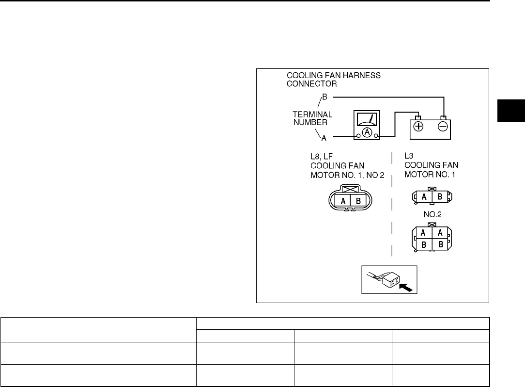
FAN MOTOR
E11
E
COOLING FAN MOTOR INSPECTION A6E362215025W03
1. Verify that the battery is fully charged.
2. Connect battery positive voltage and an ammeter to the fan motor connector.
3. Verify that the fan motor operates smoothly at the standard current draw.
•If not as spcifid, replace the fan motor.
End Of Sie
AME3621W003
Part name Current (A)
L8 LF L3
Cooling fan motor No.1 6.6 6.6 (Except Israel)
10 (For Israel)
5.9 (Except Israel)
10 (For Israel)
Cooling fan motor No.2 6.6 6.6(Except Israel)
10 (For Israel) 10

F1
F
FFUEL AND EMISSION CONTROL SYSTEMS
LOCATION INDEX ................................................. F-3
INTAKE-AIR SYSTEM ......................................... F-3
FUEL SYSTEM .................................................... F-4
EMISSION SYSTEM............................................ F-6
CONTROL SYSTEM............................................ F-7
ENGINE TUNE-UP ................................................. F-8
IGNITION TIMING INSPECTION ........................ F-8
IDLE SPEED INSPECTION................................. F-8
IDLE MIXTURE INSPECTION............................. F-9
INTAKE-AIR SYSTEM.......................................... F-10
VACUUM HOSE ROUTING DIAGRAM............. F-10
INTAKE-AIR SYSTEM
REMOVAL/INSTALLATION............................ F-10
VARIABLE AIR DUCT (VAD)
SHUTTER VALVE INSPECTION (L3) ............ F-12
VARIABLE AIR DUCT (VAD) CONTROL
SOLENOID VALVE INSPECTION (L3) .......... F-13
VARIABLE AIR DUCT (VAD) CHECK VALVE
(ONE-WAY) INSPECTION (L3) ...................... F-13
IDLE AIR CONTROL (IAC) VALVE
INSPECTION .................................................. F-13
VARIABLE INTAKE-AIR SYSTEM (VIS)
SHUTTER VALVE ACTUATOR
INSPECTION (L3)........................................... F-14
VARIABLE INTAKE-AIR SYSTEM (VIS)
CONTROL SOLENOID VALVE
INSPECTION (L3)........................................... F-14
VARIABLE TUMBLE CONTROL SYSTEM (VTCS)
SHUTTER VALVE ACTUATOR
INSPECTION .................................................. F-15
VARIABLE TUMBLE CONTROL
SOLENOID VALVE INSPECTION.................. F-15
ACCELERATOR PEDAL
REMOVAL/INSTALLATION............................ F-16
ACCELERATOR CABLE
INSPECTION/ADJUSTMENT......................... F-16
FUEL SYSTEM ..................................................... F-17
BEFORE REPAIR PROCEDURE...................... F-17
AFTER REPAIR PROCEDURE......................... F-17
FUEL TANK REMOVAL/INSTALLATION .......... F-18
FUEL TANK INSPECTION ................................ F-19
NONRETURN VALVE INSPECTION ................ F-20
FUEL LINE PRESSURE INSPECTION ............. F-20
FUEL PUMP UNIT
REMOVAL/INSTALLATION............................ F-22
FUEL PUMP UNIT
DISASSEMBLY/ASSEMBLY .......................... F-24
FUEL PUMP UNIT INSPECTION ...................... F-25
FUEL INJECTOR
REMOVAL/INSTALLATION............................ F-28
FUEL INJECTOR INSPECTION........................ F-31
PRESSURE REGULATOR INSPECTION......... F-34
PULSATION DAMPER
REMOVAL/INSTALLATION............................ F-34
PULSATION DAMPER INSPECTION ............... F-34
EXHAUST SYSTEM ............................................. F-35
EXHAUST SYSTEM INSPECTION ................... F-35
EXHAUST SYSTEM
REMOVAL/INSTALLATION ............................ F-35
EMISSION SYSTEM............................................. F-38
CHARCOAL CANISTER INSPECTION ............. F-38
EVAPORATIVE GAS CHECK VALVE
(ONE-WAY) INSPECTION (L.H.D.)................ F-38
PURGE SOLENOID VALVE
REMOVAL/INSTALLATION ............................ F-38
PURGE SOLENOID VALVE INSPECTION ....... F-39
EGR VALVE REMOVAL/INSTALLATION.......... F-39
EGR VALVE INSPECTION................................ F-40
PCV VALVE INSPECTION ................................ F-41
THREE-WAY CATALYTIC CONVERTER (TWC)
INSPECTION .................................................. F-41
CONTROL SYSTEM............................................. F-43
PCM REMOVAL/INSTALLATION ...................... F-43
PCM INSPECTION ............................................ F-45
PCM CONFIGURATION .................................... F-50
INTAKE AIR TEMPERATURE (IAT) SENSOR
INSPECTION .................................................. F-50
MASS AIR FLOW (MAF) SENSOR
INSPECTION .................................................. F-51
THROTTLE POSITION (TP) SENSOR
INSPECTION .................................................. F-51
MANIFOLD ABSOLUTE PRESSURE (MAP)
SENSOR INSPECTION .................................. F-52
ENGINE COOLANT TEMPERATURE (ECT)
SENSOR REMOVAL/INSTALLATION............ F-53
ENGINE COOLANT TEMPERATURE (ECT)
SENSOR INSPECTION .................................. F-53
CRANKSHAFT POSITION (CKP)
SENSOR INSPECTION .................................. F-54
CRANKSHAFT POSITION (CKP)
SENSOR REMOVAL/INSTALLATION............ F-54
CAMSHAFT POSITION (CMP)
SENSOR INSPECTION .................................. F-55
KNOCK SENSOR INSPECTION ....................... F-56
KNOCK SENSOR
REMOVAL/INSTALLATION ............................ F-56
HEATED OXYGEN SENSOR (HO2S)
INSPECTION .................................................. F-56
POWER STEERING PRESSURE (PSP)
SWITCHINSPECTION .................................... F-58
CLUTCH SWITCH INSPECTION ...................... F-59
NEUTRAL SWITCH INSPECTION .................... F-59
BAROMETRIC PRESSURE (BARO)
SENSOR INSPECTION .................................. F-60
ON-BOARD DIAGNOSTIC ................................... F-61
FOREWORD...................................................... F-61
OBD PENDING TROUBLE CODES .................. F-62
OBD FREEZE FRAME DATA ............................ F-62
OBD ON-BOARD SYSTEM READINESS TESTF-62
OBD DIAGNOSTIC MONITORING TEST
RESULTS........................................................ F-62
OBD READ/CLEAR DIAGNOSTIC TEST
RESULTS........................................................ F-62
OBD PARAMETER IDENTIFICATION (PID)
ACCESS ......................................................... F-62
ON-BOARD DIAGNOSTIC TEST ...................... F-62

F2
OBD DRIVE MODE............................................ F-64
DIAGNOSTIC MONITORING TEST RESULTS. F-65
DTC CONFIRMATION PROCEDURE ............... F-66
KOEO/KOER SELF-TEST ................................. F-66
AFTER REPAIR PROCEDURE ......................... F-66
DTC TABLE ....................................................... F-67
DTC P0010 ........................................................ F-70
DTC P0011 ........................................................ F-72
DTC P0012 ........................................................ F-73
DTC P0031 ........................................................ F-74
DTC P0032 ........................................................ F-76
DTC P0037 ........................................................ F-78
DTC P0038 ........................................................ F-80
DTC P0101 ........................................................ F-81
DTC P0102 ........................................................ F-83
DTC P0103 ........................................................ F-85
DTC P0107 ........................................................ F-86
DTC P0108 ........................................................ F-88
DTC P0111 ........................................................ F-90
DTC P0112 ........................................................ F-91
DTC P0113 ........................................................ F-92
DTC P0117 ........................................................ F-94
DTC P0118 ........................................................ F-96
DTC P0121 ........................................................ F-98
DTC P0122 ...................................................... F-100
DTC P0123 ...................................................... F-102
DTC P0125 ...................................................... F-104
DTC P0131, P0132 .......................................... F-105
DTC P0133 ...................................................... F-108
DTC P0134 ...................................................... F-110
DTC P0138 ...................................................... F-112
DTC P0140 ...................................................... F-114
DTC P0171 ...................................................... F-116
DTC P0172 ...................................................... F-119
DTC P0300 ...................................................... F-121
DTC P0301, P0302, P0303, P0304 ................. F-124
DTC P0327 ...................................................... F-126
DTC P0328 ...................................................... F-128
DTC P0335 ...................................................... F-130
DTC P0340 ...................................................... F-132
DTC P0403 ...................................................... F-134
DTC P0420 ...................................................... F-137
DTC P0443 ...................................................... F-138
DTC P0480 ...................................................... F-140
DTC P0500 ...................................................... F-142
DTC P0505 ...................................................... F-144
DTC P0506 ...................................................... F-145
DTC P0507 ...................................................... F-147
DTC P0511 ...................................................... F-148
DTC P0550 ...................................................... F-150
DTC P0602 ...................................................... F-152
DTC P0610 ...................................................... F-152
DTC P0661 ...................................................... F-153
DTC P0662 ...................................................... F-154
DTC P0703 ...................................................... F-156
DTC P0704 ...................................................... F-158
DTC P0850 ...................................................... F-160
DTC P1410 ...................................................... F-162
DTC P1562 ...................................................... F-164
DTC P2006 ...................................................... F-166
DTC P2009 ...................................................... F-168
DTC P2010 ...................................................... F-170
DTC P2228 ...................................................... F-172
DTC P2229 ...................................................... F-174
DTC P2502 ...................................................... F-176
DTC P2503....................................................... F-177
DTC P2504....................................................... F-178
TROUBLESHOOTING........................................ F-181
ENGINE SYMPTOM TROUBLESHOOTING ... F-181
QUICK DIAGNOSTIC CHART ......................... F-182
NO.1 MELTING OF MAIN OR OTHER
FUSES .......................................................... F-186
NO.2 MIL ILLUMINATES ................................. F-186
NO.3 WILL NOT CRANK ................................. F-187
NO.4 HARD TO START/LONG CRANK/
ERRATIC START/ERRATIC CRANK ........... F-189
NO.5 ENGINE STALLS-AFTER
START/AT IDLE ............................................ F-191
NO.6 CRANKS NORMALLY BUT WILL
NOT START.................................................. F-195
NO.7 SLOW RETURN TO IDLE ...................... F-198
NO.8 ENGINE RUNS ROUGH/ROLLING
IDLE .............................................................. F-199
NO.9 FAST IDLE/RUNS ON ............................ F-201
NO.10 LOW IDLE/STALLS DURING
DECELERATION .......................................... F-202
NO.11 ENGINE STALLS/QUITS, ENGINE
RUNS ROUGH, MISSES, BUCK/JERK,
HESITATION/STUMBLE, SURGES ............. F-204
NO.12 LACK/LOSS OF POWER-
ACCELERATION/CRUISE............................ F-207
NO.13 KNOCKING/PINGING-
ACCELERATION/CRUISE............................ F-210
NO.14 POOR FUEL ECONOMY...................... F-211
NO.15 EMISSION COMPLIANCE.................... F-213
NO.16 HIGH OIL CONSUMPTION/
LEAKAGE ..................................................... F-214
NO.17 COOLING SYSTEM
CONCERNS-OVERHEATING ...................... F-215
NO.18 COOLING SYSTEM
CONCERNS-RUNS COLD ........................... F-216
NO.19 EXHAUST SMOKE ............................... F-217
NO.20 FUEL ODOR
(IN ENGINE COMPARTMENT) .................... F-218
NO.21 ENGINE NOISE .................................... F-219
NO.22 VIBRATION CONCERNS (ENGINE).... F-220
NO.23 A/C DOES NOT WORK
SUFFICIENTLY............................................. F-220
NO.24 A/C IS ALWAYS ON OR A/C
COMPRESSOR RUNS CONTINUOUSLY ... F-221
NO.25 A/C IS NOT CUT OFF UNDER
WIDE OPEN THROTTLE CONDITIONS ...... F-221
NO.26 EXHAUST SULPHUR SMELL .............. F-222
NO.27 CONSTANT VOLTAGE ........................ F-223
NO.28 SPARK PLUG CONDITION.................. F-225
INTERMITTENT CONCERN
TROUBLESHOOTING .................................. F-227
ENGINE CONTROL SYSTEM
OPERATION INSPECTION .......................... F-229
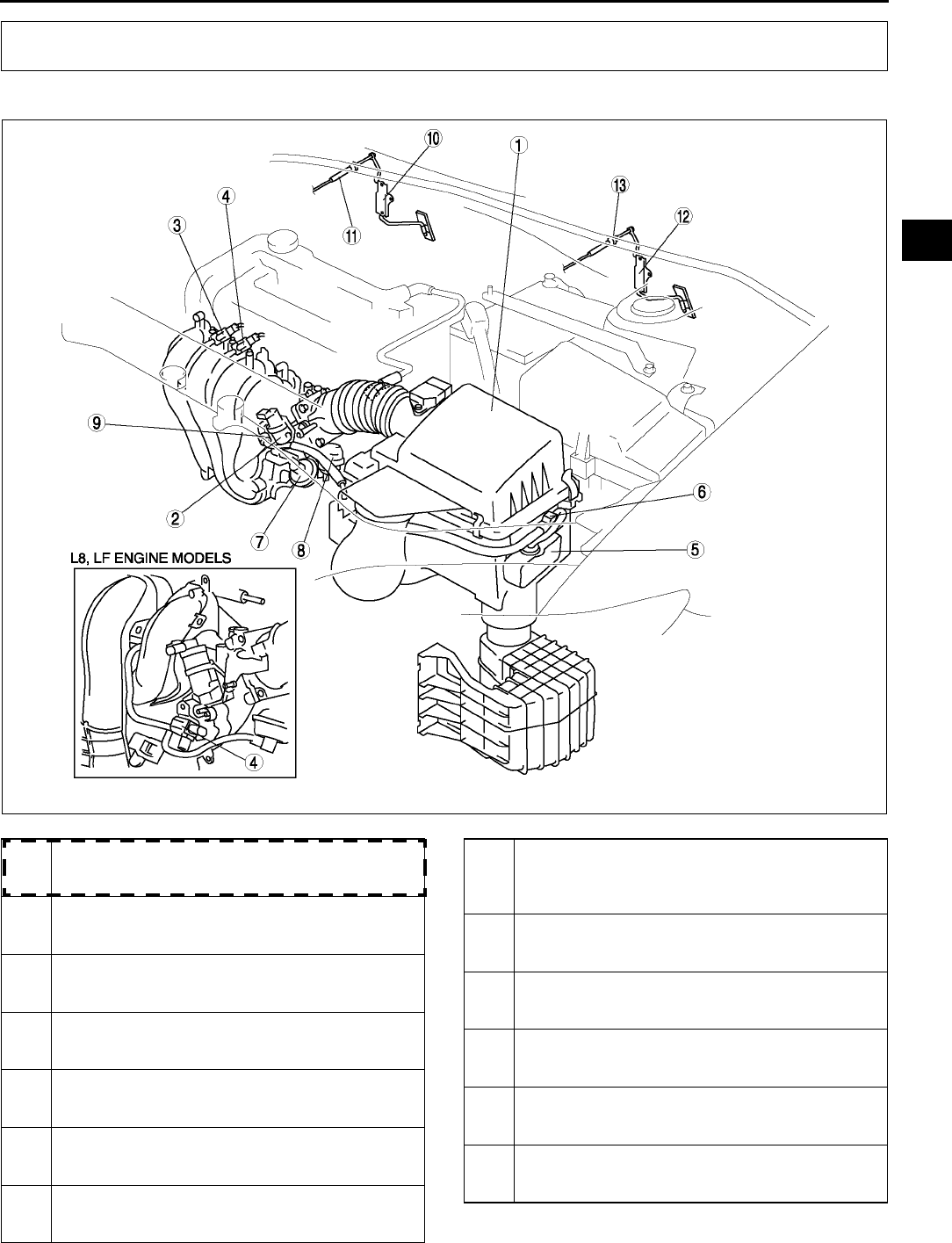
LOCATION INDEX
F3
F
INTAKE-AIR SYSTEM A6E390013000W01
.
LOCATION INDEX
A6E3910W018
1 Air cleaner
(See F10 INTAKE-AIR SYSTEM REMOVAL/
INSTALLATION)
2IAC valve
(See F13 IDLE AIR CONTROL (IAC) VALVE
INSPECTION)
3 VIS control solenoid valve (L3)
(See F14 VARIABLE INTAKE-AIR SYSTEM (VIS)
CONTROL SOLENOID VALVE INSPECTION (L3))
4 Variable tumble control solenoid valve
(See F15 VARIABLE TUMBLE CONTROL
SOLENOID VALVE INSPECTION)
5 VAD shutter valve (L3)
(See F12 VARIABLE AIR DUCT (VAD) SHUTTER
VALVE INSPECTION (L3))
6 VAD control solenoid valve (L3)
(See F13 VARIABLE AIR DUCT (VAD) CONTROL
SOLENOID VALVE INSPECTION (L3))
7 VIS shutter valve actuator (L3)
(See F14 VARIABLE INTAKE-AIR SYSTEM (VIS)
SHUTTER VALVE ACTUATOR INSPECTION (L3))
8 VTCS shutter valve actuator
(See F15 VARIABLE TUMBLE CONTROL
SYSTEM (VTCS) SHUTTER VALVE ACTUATOR
INSPECTION)
9 VAD Check valve (one-way) (L3)
(See F13 VARIABLE AIR DUCT (VAD) CHECK
VALVE (ONE-WAY) INSPECTION (l3))
10 Accelerator pedal (R.H.D.)
(See F16 ACCELERATOR PEDAL REMOVAL/
INSTALLATION)
11 Accelerator cable (R.H.D.)
(See F16 ACCELERATOR PEDAL REMOVAL/
INSTALLATION)
12 Accelerator pedal (L.H.D.)
(See F16 ACCELERATOR PEDAL REMOVAL/
INSTALLATION)
13 Accelerator cable (L.H.D.)
(See F16 ACCELERATOR PEDAL REMOVAL/
INSTALLATION)
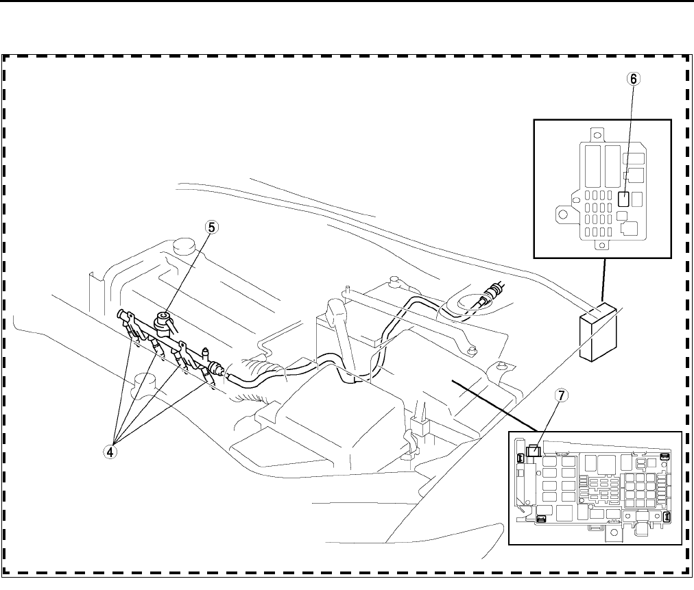
F4
LOCATION INDEX
End Of Sie
FUEL SYSTEM A6E390001006W01
Engine Room Side
A6E3912W015
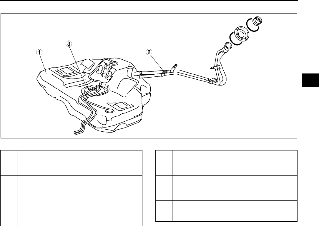
LOCATION INDEX
F5
F
Fuel tank side
.
End Of Sie
A6E3912W045
1 Fuel tank
(See F18 FUEL TANK REMOVAL/
INSTALLATION)
(See F19 FUEL TANK INSPECTION)
2 Nonreturn valve
(See F20 NONRETURN VALVE INSPECTION)
3 Fuel pump unit
(See F22 FUEL PUMP UNIT REMOVAL/
INSTALLATION)
(See F24 FUEL PUMP UNIT DISASSEMBLY/
ASSEMBLY)
(See F25 FUEL PUMP UNIT INSPECTION)
4 Fuel injector
(See F28 FUEL INJECTOR REMOVAL/
INSTALLATION)
(See F31 FUEL INJECTOR INSPECTION)
5 Pulsation damper
(See F34 PULSATION DAMPER REMOVAL/
INSTALLATION)
(See F34 PULSATION DAMPER INSPECTION)
6 Fuel pump relay
(See T24 RELAY INSPECTION)
7 Check connector
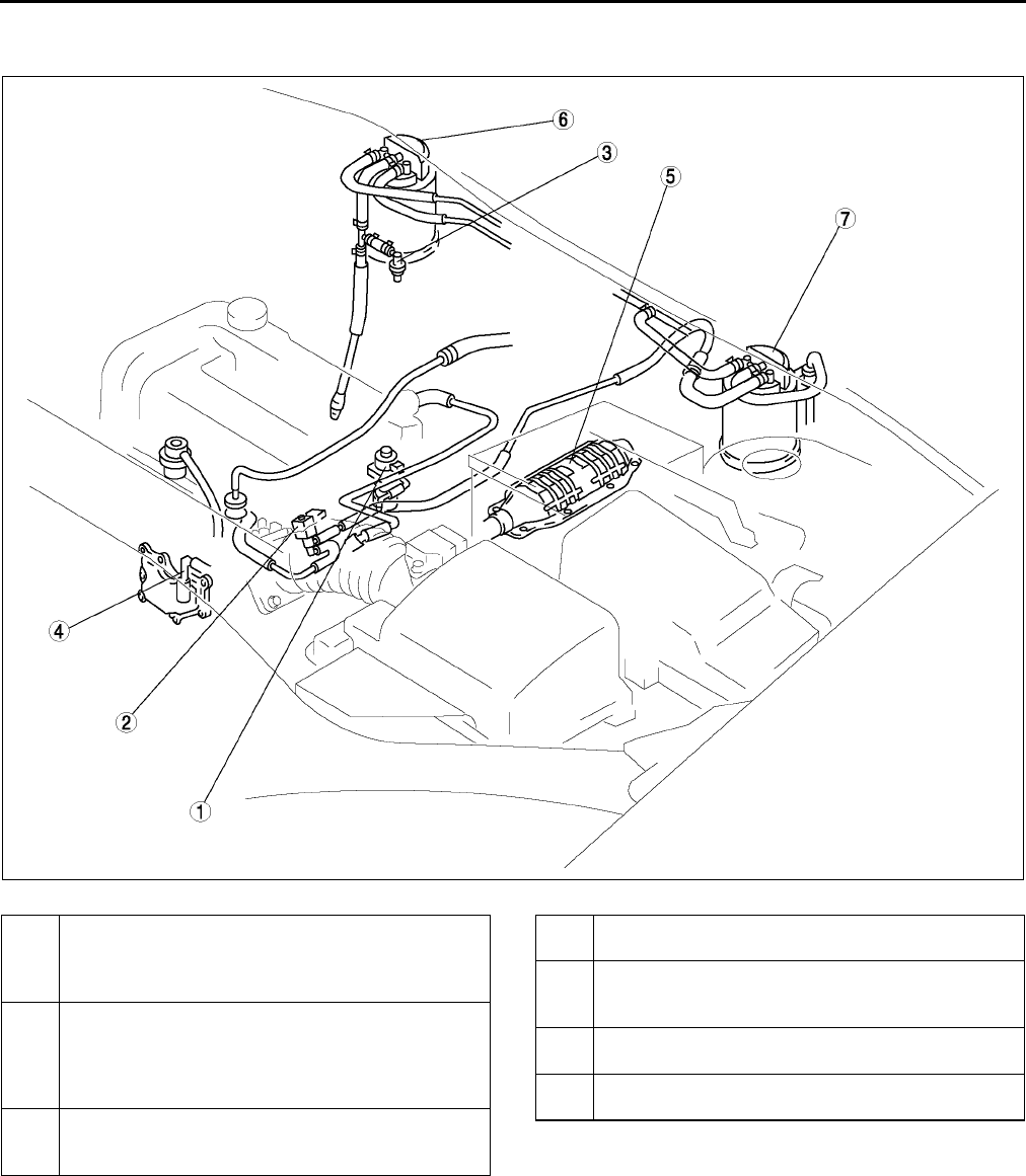
F6
LOCATION INDEX
EMISSION SYSTEM A6E390001074W01
Engine room side
.
End Of Sie
A6E3916W017
1
EGR valve
(See F39 EGR VALVE REMOVAL/
INSTALLATION)
(See F40 EGR VALVE INSPECTION)
2
Purge solenoid valve
(See F38 PURGE SOLENOID VALVE REMOVAL/
INSTALLATION)
(See F39 PURGE SOLENOID VALVE
INSPECTION)
3
Evaporative gas check valve (one-way) (L.H.D.)
(See F38 EVAPORATIVE GAS CHECK VALVE
(ONE-WAY) INSPECTION (L.H.D.))
4PCV valve
(See F41 PCV VALVE INSPECTION)
5
TWC
(See F41 THREE-WAY CATALYTIC
CONVERTER (TWC) INSPECTION)
6Charcoal canister (L.H.D.)
(See F38 CHARCOAL CANISTER INSPECTION)
7Charcoal canister (R.H.D.)
(See F38 CHARCOAL CANISTER INSPECTION)
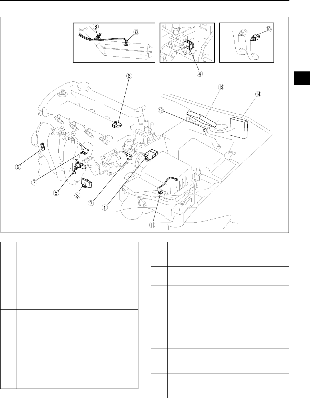
LOCATION INDEX
F7
F
CONTROL SYSTEM A6E390001074W02
.
A6E3940W500
1 MAF/IAT sensor
(See F50 INTAKE AIR TEMPERATURE (IAT)
SENSOR INSPECTION)
(See F51 MASS AIR FLOW (MAF) SENSOR
INSPECTION)
2 TP sensor
(See F51 THROTTLE POSITION (TP) SENSOR
INSPECTION)
3 MAP sensor
(See F52 MANIFOLD ABSOLUTE PRESSURE
(MAP) SENSOR INSPECTION)
4ECT sensor
(See F53 ENGINE COOLANT TEMPERATURE
(ECT) SENSOR REMOVAL/INSTALLATION)
(See F53 ENGINE COOLANT TEMPERATURE
(ECT) SENSOR INSPECTION
5 CKP sensor
(See F54 CRANKSHAFT POSITION (CKP)
SENSOR INSPECTION)
(See F54 CRANKSHAFT POSITION (CKP)
SENSOR REMOVAL/INSTALLATION)
6CMP sensor
(See F55 CAMSHAFT POSITION (CMP)
SENSOR INSPECTION)
7 Knock sensor
(See F56 KNOCK SENSOR INSPECTION)
(See F56 KNOCK SENSOR REMOVAL/
INSTALLATION)
8 Heated oxygen sensor
(See F56 HEATED OXYGEN SENSOR (HO2S)
INSPECTION)
9 PSP switch
(See F58 POWER STEERING PRESSURE (PSP)
SWITCH INSPECTION)
10 Clutch switch
(See F59 CLUTCH SWITCH INSPECTION)
11 Neutral switch
(See F59 NEUTRAL SWITCH INSPECTION)
12 BARO sensor
(See F60 BAROMETRIC PRESSURE (BARO)
SENSOR INSPECTION)
13 PCM (U.K. specs.)
(See F43 PCM REMOVAL/INSTALLATION)
(See F45 PCM INSPECTION)
(See F50 PCM CONFIGURATION)
14 PCM (L.H.D.)
(See F43 PCM REMOVAL/INSTALLATION)
(See F45 PCM INSPECTION)
(See F50 PCM CONFIGURATION)
F8
ENGINE TUNE-UP
End Of Sie
IGNITION TIMING INSPECTION A6E390802000W01
Note
•Ignition timing is not adjustable.
•Ignition timing verification requires WDS or equivalent.
1. Turn off the electrical loads.
2. Warm up the engine as follows.
(1) Start the engine.
(2) Maintain the engine speed at approx. 3,000 rpm until the cooling fans start to operate.
(3) Release the accelerator pedal.
(4) Wait until the cooling fans stop.
3. Verify that the ignition timing (WDS: SPARKADV PID) is within the specification using WDS or equivalent.
Ignition timing
Approx. BTDC 10 degree
4. Verify that ingestion timing advances when the engine speed increases gradually.
End Of Sie
IDLE SPEED INSPECTION A6E390802000W02
Note
•Ignition timing is not adjustable.
•Ignition timing verification requires WDS or equivalent.
1. Turn off the electrical loads.
2. Warm up the engine as follows.
(1) Start the engine.
(2) Maintain the engine speed at approx. 3,000 rpm until the cooling fans start to operate.
(3) Release the accelerator pedal.
(4) Wait until the cooling fans stop.
3. Verify that the idle speed (WDS: RPM PID) is within the specification using WDS or equivalent.
Idle speed (L8 engine model)
Idle speed (LF engine MTX model)
ENGINE TUNE-UP
Condition Engine speed (rpm)*1
No load 650750
Electrical loads*2 ON 650750
P/S ON 700800
A/C ON and refrigerant
pressure switch (middle) OFF 700800
A/C ON and refrigerant
pressure switch (middle) ON 700800
Condition Engine speed (rpm)*1
No load 600700
Electrical loads*2 ON 650750
P/S ON 650750
A/C ON and refrigerant
pressure switch (middle) OFF 700800
A/C ON and refrigerant
pressure switch (middle) ON 700800

ENGINE TUNE-UP
F9
F
Idle speed (LF engine ATX model)
Idle speed (L3 engine model)
*1 : Excludes temporary idle speed drop just after the electrical loads are turned on.
*2 : Blower motor is operating at high speed. Headlight switch is turned on. Rear window defroster switch is turned
on. Cooling fans are operating.
End Of Sie
IDLE MIXTURE INSPECTION A6E390802000W03
1. Turn off the electrical loads.
2. Warm up the engine as follows.
(1) Start the engine.
(2) Maintain the engine speed at approx. 3,000 rpm until the cooling fans start to operate.
(3) Release the accelerator pedal.
(4) Wait until the cooling fans stop.
3. Verify that the idle speed and ignition timing are within the specification. (See F8 IDLE SPEED INSPECTION.)
(See F8 IGNITION TIMING INSPECTION.)
4. Insert an exhaust gas analyzer to the tailpipe.
5. Verify that the CO and HC concentrations are within the regulation.
End Of Sie
Condition Engine speed (rpm)*1
No load 650750
Electrical loads*2 ON 650750
P/S ON 650750
A/C ON and refrigerant
pressure switch (middle) OFF 650750
A/C ON and refrigerant
pressure switch (middle) ON 700800
Condition Engine speed (rpm)*1
No load 600700
Electrical loads*2 ON 650750
P/S ON 650750
A/C ON and refrigerant
pressure switch (middle) OFF 700800
A/C ON and refrigerant
pressure switch (middle) ON 700800
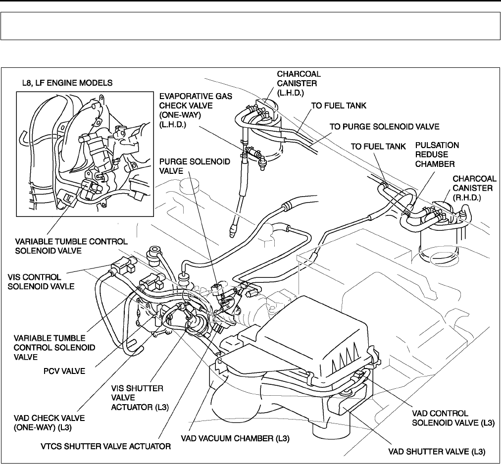
F10
INTAKE-AIR SYSTEM
VACUUM HOSE ROUTING DIAGRAM A6E391020030W01
End Of Sie
INTAKE-AIR SYSTEM REMOVAL/INSTALLATION A6E391013000W01
Warning
•
••
•When the engine and intake-air system are hot, they can badly burn. Turn off the engine and wait
until they are cool before removing the intake-air system.
•
••
•Fuel vapor is hazardous. It can easily ignite, causing serious injury and damage. Always keep
sparks and flames away from fuel.
•
••
•Fuel line spills and leakage are dangerous. Fuel can ignite and cause serious injuries or death and
damage. Fuel can also irritate skin and eyes. To prevent this, always complete the Fuel Line
Safety Procedure. (See F17 BEFORE REPAIR PROCEDURE.)
1. Disconnect the negative battery cable.
2. Remove in the order indicated in the table.
3. Install in the reverse order of removal.
INTAKE-AIR SYSTEM
A6E3910W034
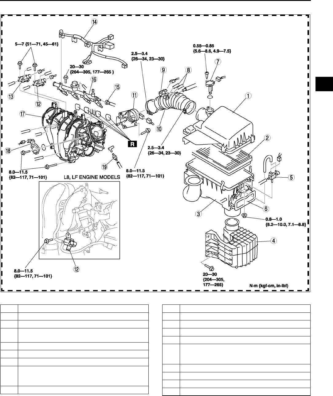
INTAKE-AIR SYSTEM
F11
F
4. Complete the AFTER REPAIR PROCEDURE. (See F17 AFTER REPAIR PROCEDURE.).
A6E3910W019
1 Air cleaner cover
2 Air cleaner element
3 Air cleaner case
4 Resonance chamber
(See F12 Resonance Chamber Removal Note)
5 VAD control solenoid valve (L3)
6 VAD shutter valve (L3)
7 Mass air flow sensor
8 Vacuum hose (purge solenoid valve)
(See F12 Vacuum Hose (Purge Solenoid Valve)
Installation Note)
9 Purge solenoid valve
10 Air hose
11 Throttle body
12 Variable tumble control solenoid valve
13 VIS control solenoid valve (L3)
14 Fuel injector connector
15 Plastic fuel hose
(See F28 Plastic Fuel Hose Removal Note)
(See F30 Plastic Fuel Hose Installation Note)
16 Fuel distributor
17 Intake manifold
18 IAC valve
19 VAD check valve (L3)
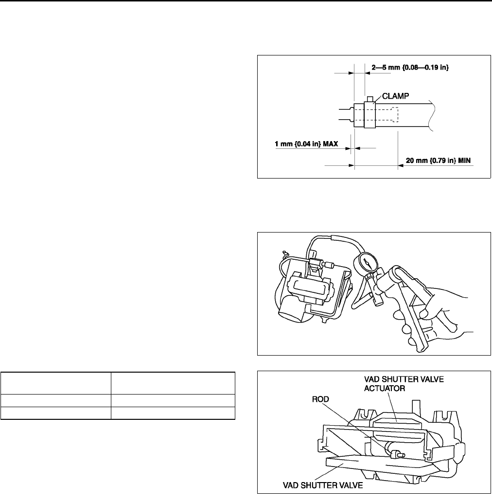
F12
INTAKE-AIR SYSTEM
Resonance Chamber Removal Note
1. Remove the front mudguard (LH) before removing the resonance chamber.
Vacuum Hose (Purge Solenoid Valve) Installation Note
1. Fit the vacuum hose (purge solenoid valve) onto
the respective fittings, and install clamps as
shown.
End Of Sie
VARIABLE AIR DUCT (VAD) SHUTTER VALVE INSPECTION (L3) A6E391013000W02
1. Remove the air cleaner case. (See F10 INTAKE-AIR SYSTEM REMOVAL/INSTALLATION.)
2. Disconnect the vacuum hose from the VAD shutter valve actuator.
3. Connect a vacuum pump to the VAD shutter
valve actuator.
4. Apply vacuum and verify that the rod moves.
•If the rod dose not move, replace the air
cleaner.
End Of Sie
A6E3910W021
Vacuum
kPa {mmHg, inHg} Rod movement
Below 10 {75, 3.0} Starts to move
Above 35 {263, 10.4} Fully pulled
A6E3910W031
A6E3910W032
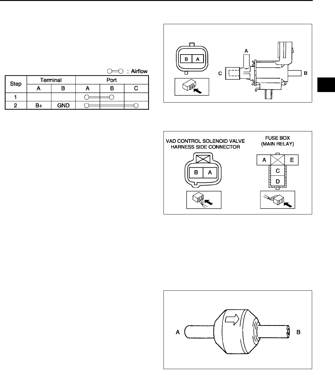
INTAKE-AIR SYSTEM
F13
F
VARIABLE AIR DUCT (VAD) CONTROL SOLENOID VALVE INSPECTION (L3) A6E391013000W03
1. Remove the VAD control solenoid valve. (See F10 INTAKE-AIR SYSTEM REMOVAL/INSTALLATION.)
2. Inspect airflow between the ports under the
following conditions.
•If not as specified, replace the VAD control
solenoid valve.
•If as specified, carry out the Circuit Open/
Short Inspection.
Circuit Open/Short Inspection
1. Disconnect the PCM connector. (See F43 PCM REMOVAL/INSTALLATION.)
2. Inspect the following wiring harness for open or
short (continuity check).
Open circuit
•If there is no continuity, the circuit is open. Repair
or replace the harness.
VAD control solenoid valve terminal B
(harness-side) and PCM terminal 4C
VAD control solenoid valve terminal A
(harness-side) and main relay terminal C
(harness-side)
Short circuit
•If there is continuity, the circuit is shorted. Repair
or replace the harness.
VAD control solenoid valve terminal B
(harness-side) and body GND
VAD control solenoid valve terminal A (harness-side) and power supply
End Of Sie
VARIABLE AIR DUCT (VAD) CHECK VALVE (ONE-WAY) INSPECTION (L3) A6E391013000W04
1. Remove the VAD check valve (one-way). (See F10 INTAKE-AIR SYSTEM REMOVAL/INSTALLATION
2. Blow through A and verify that air flows from B.
3. Blow through B and verify that air does not flow from A.
•If not as specified, replace the VAD check valve (one-way).
End Of Sie
IDLE AIR CONTROL (IAC) VALVE INSPECTION A6E391020661W01
Note
•Perform the following inspection only when directed.
Operation Test
1. Carry out the Idle Air Control Inspection. (See F229 Idle Air Control System Inspection.)
•If not as specified, perform the further inspection for the IAC valve.
Resistance Inspection
1. Disconnect the negative battery cable.
A6E3910W036
A6E3910W037
A6E3910W038
A6E3910W039
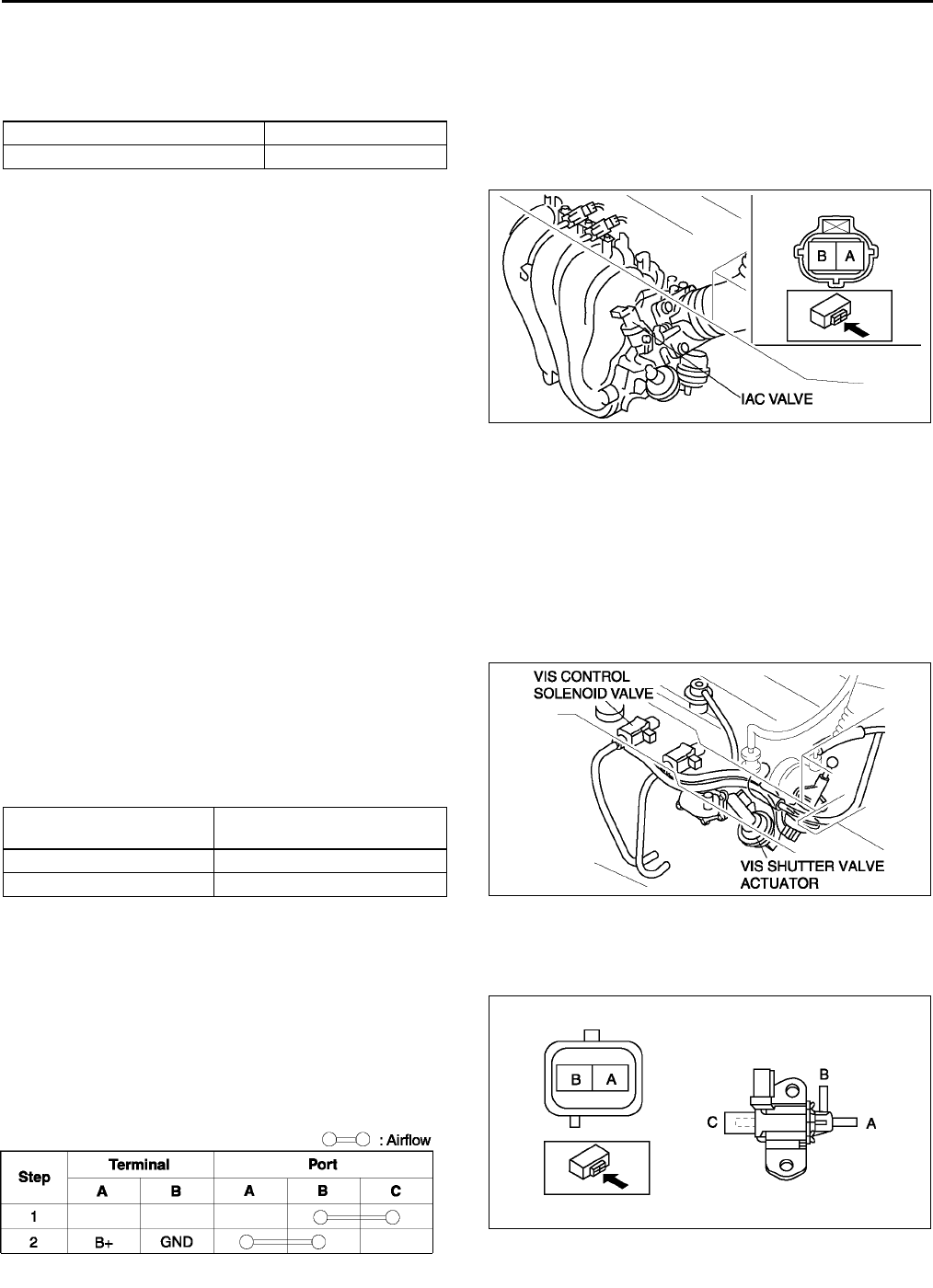
F14
INTAKE-AIR SYSTEM
2. Disconnect the IAC valve connector.
3. Measure the resistance between the IAC valve terminals using an ohmmeter.
•If not as specified, replace the IAC valve. (See F10 INTAKE-AIR SYSTEM REMOVAL/INSTALLATION.)
•If as specified but the Operation Test is failed, carry out the Circuit Open/Short Inspection.
Specification
Circuit Open/Short Inspection
1. Disconnect the PCM connector. (See F43 PCM
REMOVAL/INSTALLATION.)
2. Inspect the following wiring harnesses for open or
short (continuity check).
Open circuit
•If there is no continuity, the circuit is open. Repair
or replace the harness.
IAC valve terminal A (harness-side) and PCM
terminal 4G
IAC valve terminal B (harness-side) and PCM
terminal 4J
Short circuit
•If there is continuity, the circuit is shorted. Repair or replace the harness.
IAC valve terminal A (harness-side) and power supply
IAC valve terminal A (harness-side) and GND
IAC valve terminal B (harness-side) and power supply
IAC valve terminal B (harness-side) and GND
End Of Sie
VARIABLE INTAKE-AIR SYSTEM (VIS) SHUTTER VALVE ACTUATOR INSPECTION (L3) A6E391013000W05
1. Remove the air hose. (See F10 INTAKE-AIR SYSTEM REMOVAL/INSTALLATION.)
2. Disconnect the vacuum hose from the VIS shutter
valve actuator.
3. Connect a vacuum pump to the VIS shutter valve
actuator.
4. Apply vacuum and verify that the rod moves.
•If the rod dose not move, replace the intake
manifold.
End Of Sie
VARIABLE INTAKE-AIR SYSTEM (VIS) CONTROL SOLENOID VALVE INSPECTION (L3) A6E391013000W06
1. Remove the VIS control solenoid valve. (See F10 INTAKE-AIR SYSTEM REMOVAL/INSTALLATION.)
2. Inspect airflow between the ports under the
following conditions.
•If not as specified, replace the VIS control
solenoid valve.
•If as specified, carry out the Circuit Open/
Short Inspection.
Ambient temperature (°
°°
°C {°
°°
°F}) Resistance (ohms)
23 {73} 8.810.6
A6E3910W003
Vacuum
kPa {mmHg, inHg} Rod movement
Below 2.7 {20, 0.7 } Starts to move
Above 34.7 {260, 10.2 } Fully pulled
A6E3910W008
A6E3910W010
A6E3910W009
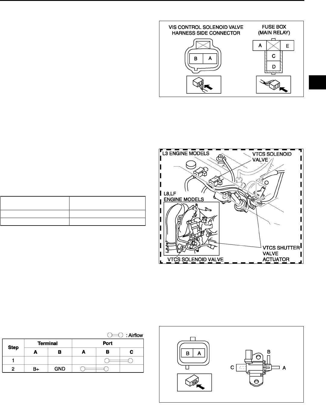
INTAKE-AIR SYSTEM
F15
F
Circuit Open/Short Inspection
1. Disconnect the PCM connector. (See F43 PCM REMOVAL/INSTALLATION.)
2. Inspect the following wiring harness for open or
short (continuity check).
Open circuit
•If there is no continuity, the circuit is open. Repair
or replace the harness.
VIS control solenoid valve terminal A
(harness-side) and PCM terminal 4R
VIS control solenoid valve terminal B
(harness-side) and main relay terminal C
(harness-side)
Short circuit
•If there is continuity, the circuit is shorted. Repair
or replace the harness.
VIS control solenoid valve terminal A (harness-side) and body GND
VIS control solenoid valve terminal B (harness-side) and power supply
End Of Sie
VARIABLE TUMBLE CONTROL SYSTEM (VTCS) SHUTTER VALVE ACTUATOR INSPECTION A6E391013000W07
1. Remove the air hose. (See F10 INTAKE-AIR SYSTEM REMOVAL/INSTALLATION.)
2. Disconnect the vacuum hose from the VTCS
shutter valve actuator.
3. Connect a vacuum pump to the VTCS shutter
valve actuator.
4. Apply vacuum and verify that the rod moves.
•If the rod dose not move, replace the intake
manifold.
End Of Sie
VARIABLE TUMBLE CONTROL SOLENOID VALVE INSPECTION A6E391013000W08
1. Remove the variable tumble control solenoid valve. (See F10 INTAKE-AIR SYSTEM REMOVAL/
INSTALLATION.)
2. Inspect airflow between the ports under the following conditions.
•If not as specified, replace the variable tumble control solenoid valve.
•If as specified, carry out the Circuit Open/Short Inspection.
Circuit Open/Short Inspection
1. Disconnect the PCM connector. (See F43 PCM REMOVAL/INSTALLATION.)
A6E3910W011
Vacuum
kPa {mmHg, inHg} Rod movement
Below 2.7 {20, 0.7 } Starts to move
Above 34.7 {260, 10.2 } Fully pulled
A6E3910W015
A6E3910W009
A6E3910W016
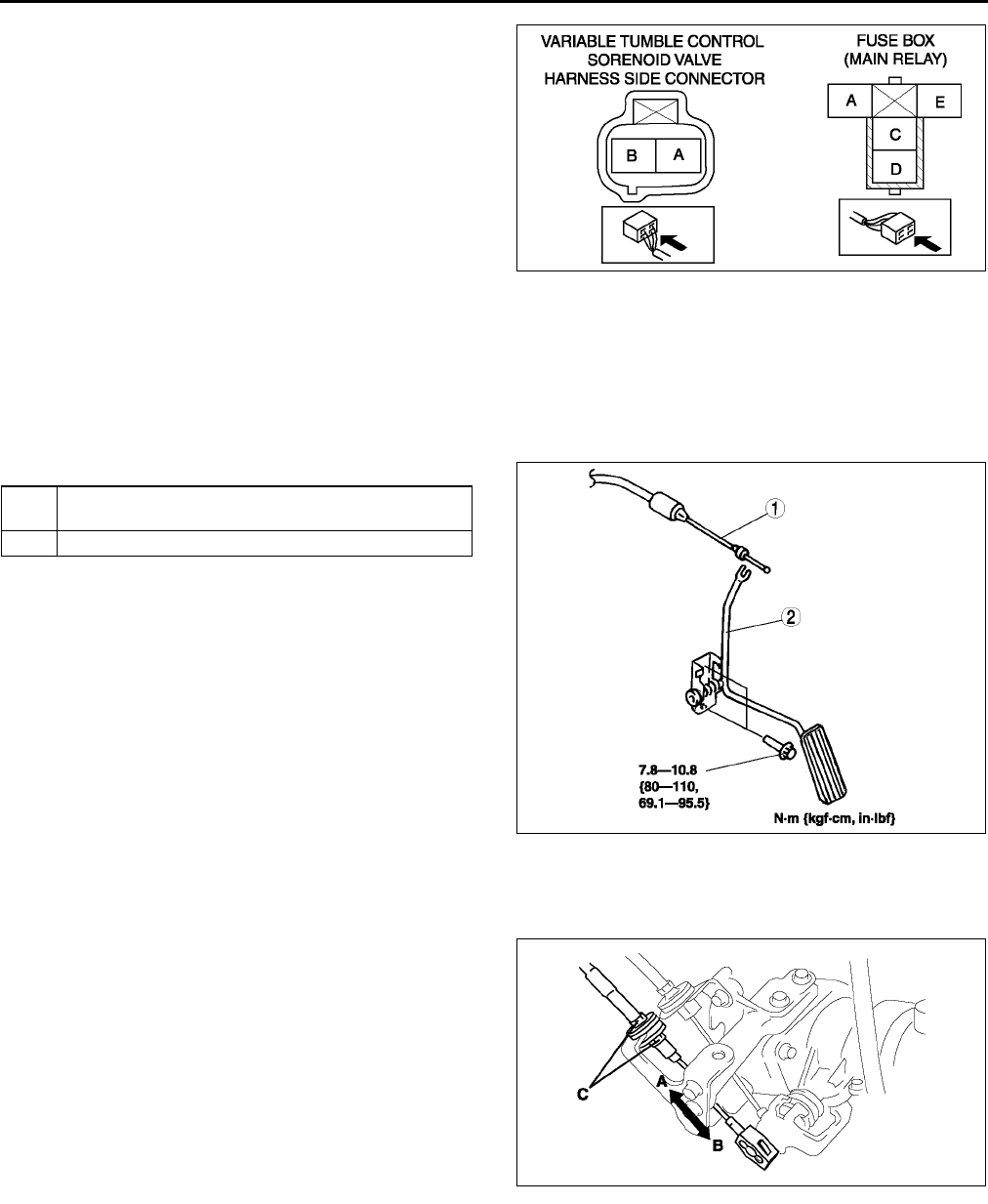
F16
INTAKE-AIR SYSTEM
2. Inspect the following wiring harness for open or
short (continuity check).
Open circuit
•If there is no continuity, the circuit is open. Repair
or replace the harness.
Variable tumble control solenoid valve
terminal B (harness-side) and PCM terminal
4T
Variable tumble control solenoid valve
terminal A (harness-side) and main relay
terminal C (harness-side)
Short circuit
•If there is continuity, the circuit is shorted. Repair
or replace the harness.
Variable tumble control solenoid valve terminal B (harness-side) and body GND
Variable tumble control solenoid valve terminal A (harness-side) and power supply
End Of Sie
ACCELERATOR PEDAL REMOVAL/INSTALLATION A6E391041600W01
1. Remove in the order indicated in the table.
2. Install in the reverse order of removal..
Accelerator Cable Installation Note
1. Carry out the ACCELERATOR CABLE
INSTALLATION/ADJUSTMENT procedure after
installing the accelerator cable. (See F16
ACCELERATOR CABLE INSPECTION/
ADJUSTMENT.)
End Of Sie
ACCELERATOR CABLE INSPECTION/ADJUSTMENT A6E391041660W01
1. Verify that the throttle valve is closed.
2. Pull the accelerator cable in the directions of A
and B, and measure the free play.
•If not as specified, adjust by turning locknut C.
Free play
1.03.0 mm {0.040.11 in}
Tightening torpue
9.814.7 N·m {100150 kgf·cm, 87130
in·lbf}
End Of Sie
A6E3910W017
1 Accelerator cable
F16 Accelerator Cable Installation Note)
2 Accelerator pedal
A6E3910W033
A6E3910W030
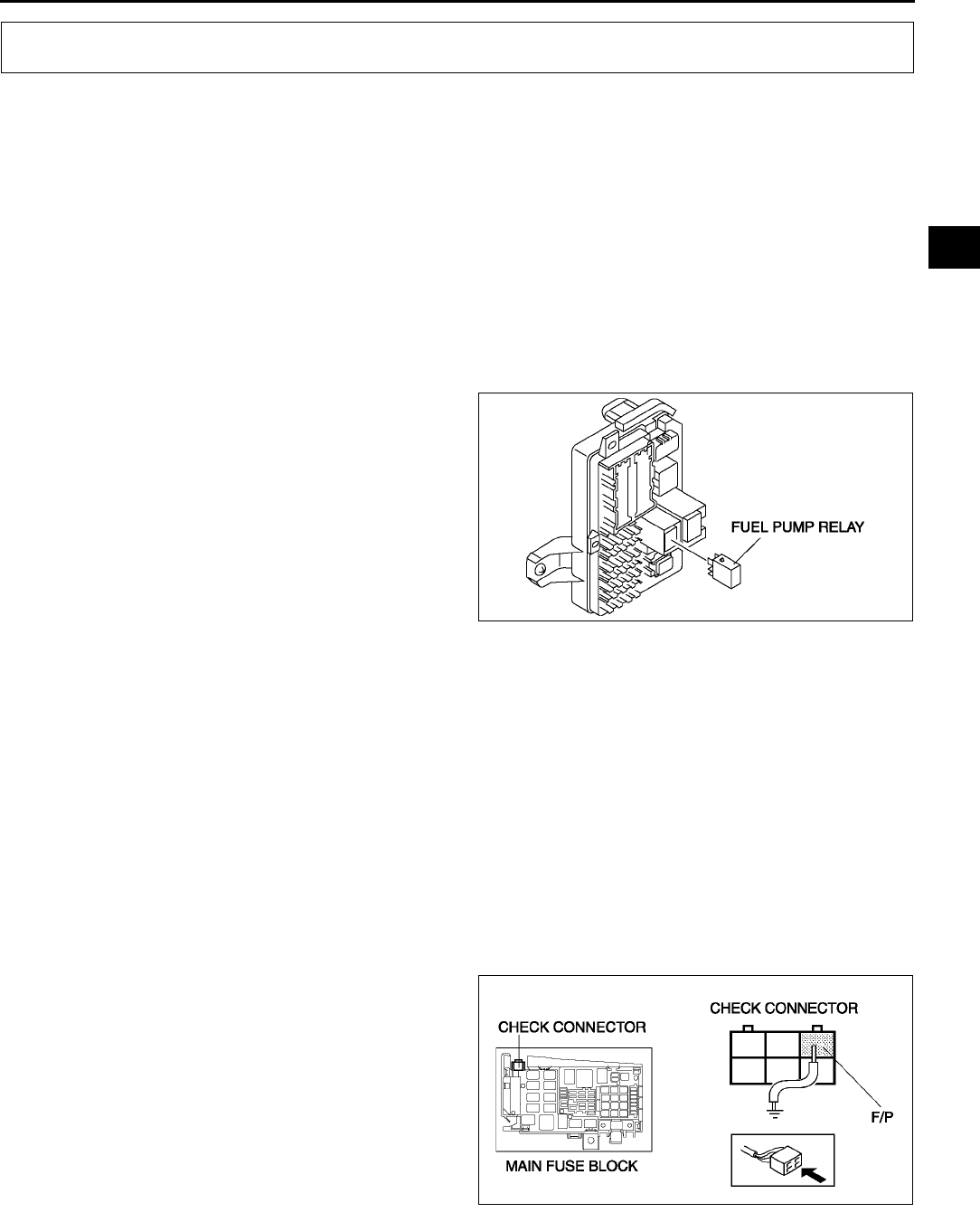
FUEL SYSTEM
F17
F
BEFORE REPAIR PROCEDURE A6E391201006W01
Warning
•
••
•Fuel vapor is hazardous. It can easily ignite, causing serious injury and damage. Always keep
sparks and flames away from fuel.
•
••
•Fuel line spills and leakage are dangerous. Fuel can ignite and cause serious injuries or death and
damage. Fuel can also irritate skin and eyes. To prevent this, always complete the following Fuel
Line Safety Procedure.
Fuel Line Safety Procedure
Note
•Fuel in the fuel system is under high pressure also when the engine is not running.
1. Remove the fuel-filler cap and release the pressure in the fuel tank.
2. Remove the fuel pump relay.
3. Start the engine.
4. After the engine stalls, crank the engine several
times.
5. Turn the ignition switch to LOCK position.
6. Install the fuel pump relay.
End Of Sie
AFTER REPAIR PROCEDURE A6E391201006W02
Warning
•
••
•Fuel line spills and leakage are dangerous. Fuel can ignite and cause serious injuries or death and
damage. When installing the fuel hose, observe Fuel Leakage Inspection described below.
Fuel Leakage Inspection
Warning
•
••
•Fuel line spills and leakage are dangerous. Fuel can ignite and cause serious injuries or death and
damage. Always carry out the following procedure with the engine stopped.
Caution
•
••
•Connecting the wrong check connector terminal may possibly cause malfunction. Carefully
connect the specified terminal only.
1. Short the check connector terminal F/P to body
GND using a jumper wire.
2. Turn the ignition switch to ON position to operate
the fuel pump.
3. Pressurize the system in this way for at least 5
minutes to be sure of no leakage.
•If there is fuel leakage, inspect the fuel hoses,
hose clamps, and fuel pipe sealing surface,
and replace as necessary.
4. After repair, assemble the system and repeat
Steps 1 to 3.
End Of Sie
FUEL SYSTEM
A6E3912W014
A6E3912W037
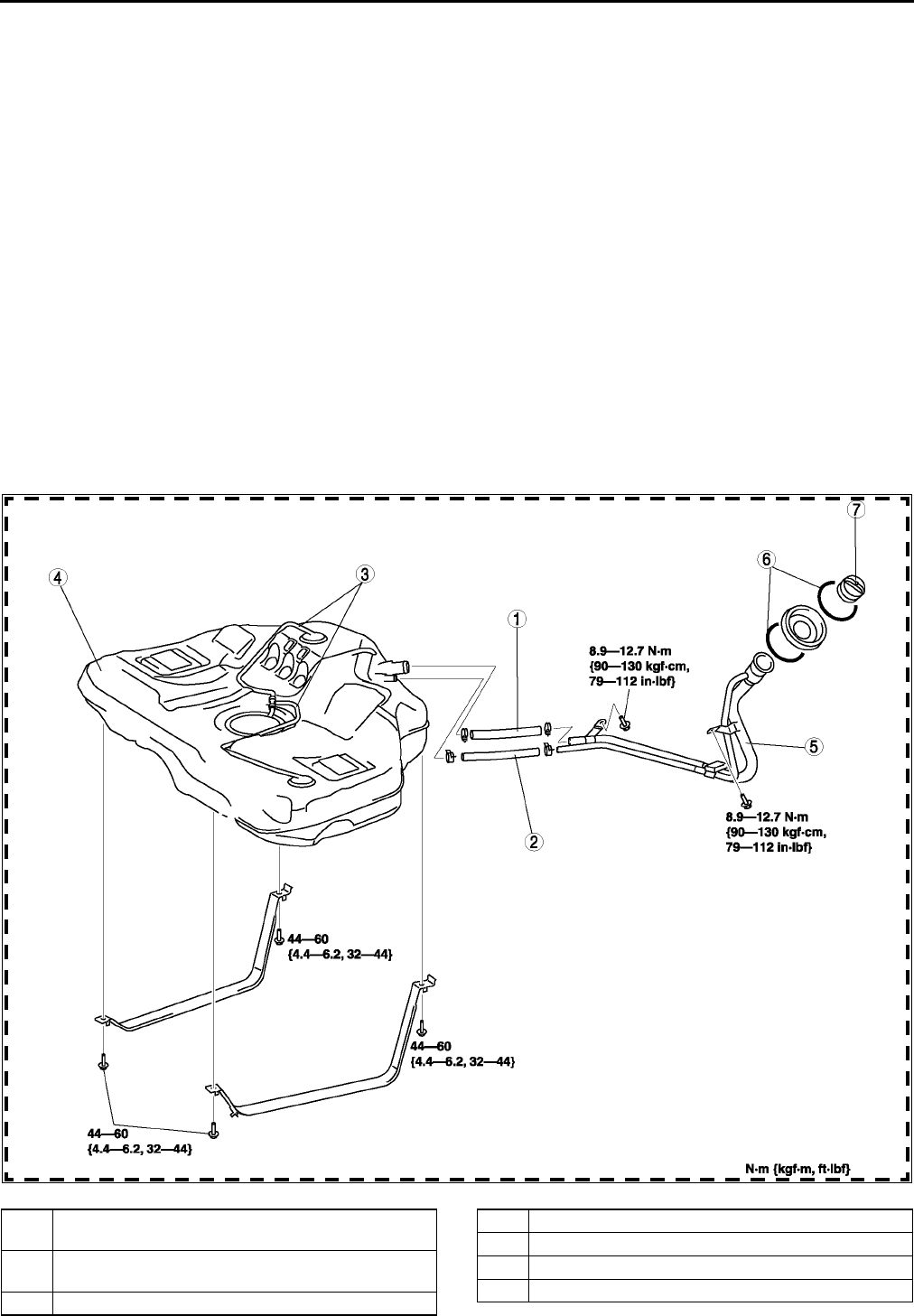
F18
FUEL SYSTEM
FUEL TANK REMOVAL/INSTALLATION A6E391242110W01
Warning
•
••
•Repairing a fuel tank that has not been properly steam cleaned can be dangerous. Explosion or
fire may cause death or serious injury. Always properly steam clean a fuel tank before repairing it.
•
••
•Fuel line spills and leakage are dangerous. Fuel can ignite and cause serious injuries or death and
damage. Fuel can also irritate skin and eyes. To prevent this, do not damage the sealing surface of
the fuel pump unit when removing or installing.
Caution
•
••
•Disconnecting/connecting the quick release connector without cleaning it may possibly cause
damage to the fuel pipe and quick release connector. Always clean the quick release connector
joint area before disconnecting/connecting using a cloth or soft brush, and make sure that it is
free of foreign material.
1. Level the vehicle.
2. Complete the BEFORE REPAIR PROCEDURE. (See F17 BEFORE REPAIR PROCEDURE.)
3. Disconnect the negative battery cable.
4. Remove the fuel pump unit. (See F22 FUEL PUMP UNIT REMOVAL/INSTALLATION.)
5. Siphon the fuel from the fuel tank.
6. Remove the middle pipe. (See F35 EXHAUST SYSTEM REMOVAL/INSTALLATION.)
7. Remove in the order indicated in the table.
8. Install in the reverse order of removal.
9. Complete the AFTER REPAIR PROCEDURE. (See F17 AFTER REPAIR PROCEDURE.)
.
A6E3912W013
1 Joint hose
(See F19 Joint Hose Installation Note)
2 Breather hose
(See F19 Breather Hose Installation Note)
3 Evaporative hose
4 Fuel tank
5 Fuel-filler pipe
6 C-ring
7 Filler cap
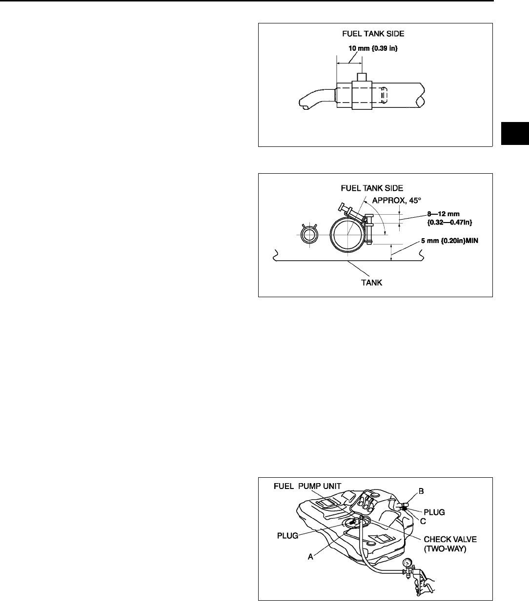
FUEL SYSTEM
F19
F
Breather Hose Installation Note
1. Fit the breather hose onto the respective fittings,
and install clamps as shown.
Joint Hose Installation Note
1. Fit the joint hose onto the respective fittings, and
install clamps as shown.
End Of Sie
FUEL TANK INSPECTION A6E391242110W02
Caution
•
••
•Disconnecting/connecting the quick release connector without cleaning it may possibly cause
damage to the fuel pipe and quick release connector. Always clean the quick release connector
joint area before disconnecting/connecting using a cloth or soft brush, and make sure that it is
free of foreign material.
Note
•This inspection is for two rollover valves integrated in the fuel tank.
1. Disconnect the plastic fuel hose and the fuel pump unit connector. (See F22 FUEL PUMP UNIT REMOVAL/
INSTALLATION.)
2. Remove the fuel tank with the fuel pump unit. (See F18 FUEL TANK REMOVAL/INSTALLATION.)
3. Plug the fuel pipe of the fuel pump unit.
4. Connect the pump to port A.
5. Level the fuel tank.
6. Apply pressure of 2.0 kpa {34 mmHg, 1.3
inHg} to port A.
(1) Plug port C and verify there is vacuum from
port B.
•If there is no vacuum, replace the fuel
tank.
7. Apply pressure of +5.9 kPa {+44 mmHg, +1.7
inHg} to port A.
•If there is no airflow, replace the fuel tank.
•If there is airflow, turn the fuel tank
upside-down and proceed to next step.
A6E3912W038
A6E3912W034
A6E3912W047
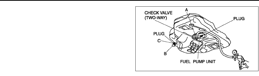
F20
FUEL SYSTEM
8. Turn the fuel tank upside-down and apply
pressure of 2.0 kPa {15 mmHg, 0.6 inHg} to
port A.
(1) Plug port C and verify there is no vacuum
from port B.
•If there is vacuum, replace the fuel tank.
End Of Sie
NONRETURN VALVE INSPECTION A6E391242270W01
1. Remove the fuel pump unit. (See F22 FUEL PUMP UNIT REMOVAL/INSTALLATION.)
2. Siphon the fuel from the fuel tank.
Note
•Nonreturn valve is integrated in the fuel tank.
•The nonreturn valve is normally closed by the spring force.
3. Verify that the nonreturn valve is closed.
•If the nonreturn valve is stuck open and dose not open even when pulled up by a finger, replace the fuel
tank.
End Of Sie
FUEL LINE PRESSURE INSPECTION A6E391201006W03
Warning
•
••
•Fuel line spills and leakage are dangerous. Fuel can ignite and cause serious injuries or death.
Fuel can also irritate skin and eyes. To prevent this, always complete the BEFORE REPAIR
PROCEDURE. (See F17 BEFORE REPAIR PROCEDURE.)
Caution
•
••
•Disconnecting/connecting the quick release connector without cleaning it may possibly cause
damage to the fuel pipe and quick release connector. Always clean the quick release connector
joint area before disconnecting/connecting using cloth or soft brush, and make sure that it is free
of foreign material.
1. Complete the BEFORE REPAIR PROCEDURE.
(See F17 BEFORE REPAIR PROCEDURE)
2. Disconnect the negative battery cable.
Caution
•
••
•The quick release connector may be damaged if the tab is turned too far. Do not turn the tab over
the stopper.
3. Disconnect the quick release connector from the fuel tank as follows:
(1) Push the tab on the locking coupler 90 degrees until it stops.
(2) Pull the fuel hose straight back.
A6E3912W046
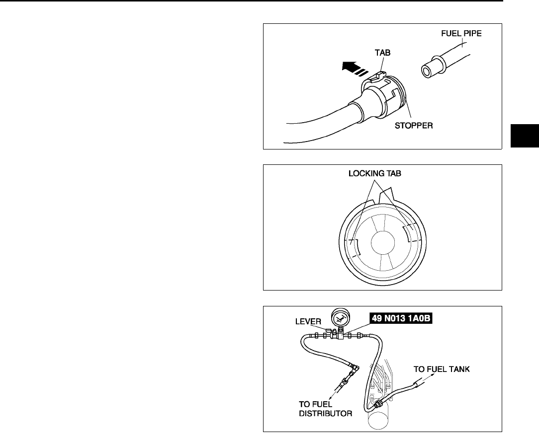
FUEL SYSTEM
F21
F
Note
•The stopper may be removed from the quick
connector. Take care not to loose it.
Reinstall it to the quick release connector
before reconnecting the fuel line.
•The locking coupler has two internal locking
tabs which retain the pulsation damper pipe.
Be sure that the tab on the locking coupler is
rotated until it stops to release two internal
locking tabs.
4. Push the SST quick release connector into the
fuel pipe and plastic fuel hose into the SST until a
click is heard.
5. Turn the lever parallel to the hose of the SST as
shown.
6. Connect the negative battery cable.
7. Verify that the vehicles for AT is at N range and
MT is at neutral position.
8. Start the engine and let it idle. Measure the fuel
line pressure.
•If not as specified, inspect the following:
Zero or low
FP circuit
FP
Fuel line (clogged)
Fuel leakage inside pressure regulator
High
Pressure regulator for high pressure cause
Fuel line pressure
375450 kPa {3.94.5 kgf/cm2, 5565 psi}
9. Observe the fuel pressure gauge indicator during heavy acceleration.
10. Verify that the fuel pressure fluctuation is within the specification during the test.
•If not as specified, inspect the following:
PCM
FP
Pulsation damper
Fuel line for improper routing, kinks or leakage
Fuel pressure fluctuation
365450 kPa {3.84.5 kgf/cm2, 5365 psi}
11. Turn the ignition switch to the LOCK position.
12. Measure the fuel hold pressure after 5 min.
•If not as specified, inspect the following:
FP hold pressure
Fuel injector for leakage
Fuel line for improper routing, kinks or leakage
Fuel hold pressure
More than 200 kPa {2.0 kgf/cm2, 29 psi}
A6E3912W001
A6E3912W002
A6E3912W003
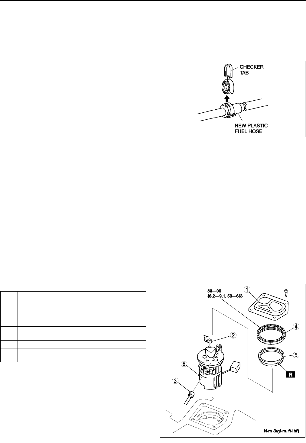
F22
FUEL SYSTEM
13. Complete the BEFORE REPAIR PROCEDURE.
(See F17 BEFORE REPAIR PROCEDURE)
14. Disconnect the SST.
Note
•A checker tab is integrated with quick release connector for new plastic fuel hoses. The checker tab will
be released from the quick release connector after it is completely engaged with the fuel pipe.
15. Inspect the plastic fuel hose and fuel pipe sealing
surface for damage and deformation, and replace
as necessary.
•If the quick release connector O-ring is
damaged or has slipped, replace the plastic
fuel hose.
16. Apply a small amount of clean engine oil to the
sealing surface of the fuel pipe.
17. Reconnect the fuel main hose to the fuel
distributor until a click is heard.
18. Lightly pull and push the quick release connector
a few times by hand and verify that it can move
2.03.0 mm {0.080.11 in} and it is connected
securely.
•If quick release connector does not move at all, verify that O-ring is not damaged and slipped, and
reconnect the quick release connector.
19. Complete the AFTER REPAIR PROCEDURE. (See F17 AFTER REPAIR PROCEDURE.)
End Of Sie
FUEL PUMP UNIT REMOVAL/INSTALLATION A6E391213350W01
Warning
•
••
•Fuel line spills and leakage are dangerous. Fuel can ignite and cause serious injuries or death and
damage. Fuel can also irritate skin and eyes. To prevent this, do not damage the sealing surface of
the fuel pump unit when removing or installing.
Caution
•
••
•Disconnecting/connecting the quick release connector without cleaning it may possibly cause
damage to the fuel pipe and quick release connector. Always clean the quick release connector
joint area before disconnecting/connecting using a cloth or soft brush, and make sure that it is
free of foreign material.
1. Complete the BEFORE REPAIR PROCEDURE. (See F17 BEFORE REPAIR PROCEDURE.)
2. Disconnect the negative battery cable.
3. Remove the rear seat cushion.
4. Remove in the order indicated in the table..
5. Install in the reverse order of removal.
6. Complete the AFTER REPAIR PROCEDURE.
(See F17 AFTER REPAIR PROCEDURE.)
A6E3912W004
1 Service hole cover
2 Connector
3 Plastic fuel hose
(See F23 Plastic Fuel Hose Removal Note)
(See F24 Plastic Fuel Hose Installation Note)
4 Fuel pump cap
(See F23 Fuel Pump Cap Removal Note)
5 Packing
6 Fuel pump unit
(See F24 Fuel Pump Unit Installation Note)
A6E3912W030
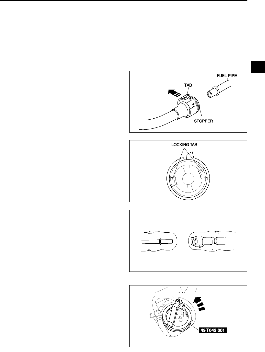
FUEL SYSTEM
F23
F
Plastic Fuel Hose Removal Note
Caution
•
••
•The quick release connector may be damaged if the tab is bent excessively. Do not expand the tab
over the stopper.
1. Disconnect the quick release connector.
(1) Push the tab on the locking coupler 90 degrees until it stops.
(2) Pull the fuel hose straight back.
Note
•The stopper may be removed from the quick connector. Take care not to lose it.
Reinstall it to the quick release connector
before reconnecting the fuel line.
•The locking coupler has two internal locking
tabs which retain the fuel pipe. Be sure that
the tab on the locking coupler is rotated until
it stops to release two internal locking tabs.
2. Cover the disconnected quick release connector
and fuel pipe with vinyl sheets or the like to
prevent them from being scratched or
contaminated with foreign material.
Fuel Pump Cap Removal Note
1. Using the SST, remove the fuel pump unit.
A6E3912W001
A6E3912W002
A6E3912W039
A6E3912W036
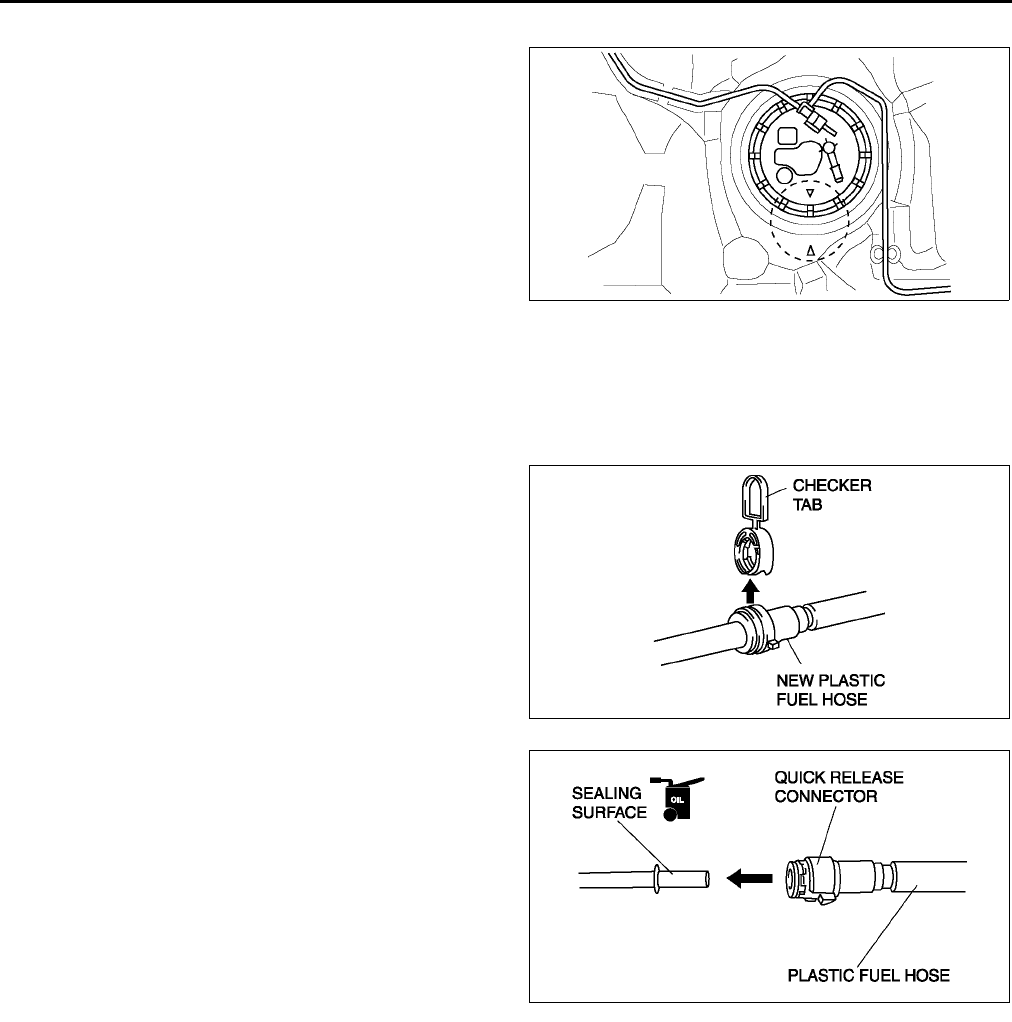
F24
FUEL SYSTEM
Fuel Pump Unit Installation Note
1. Verify that the fuel tank mark is aligened with the
fuel pump mark as shown.
Plastic Fuel Hose Installation Note
Note
•A checker tab is integrated with quick release connector for new plastic fuel hoses. The checker tab will
be released from the quick release connector after it is completely engaged with the fuel pipe.
1. When the retainer is not removed, perform the
following procedure.
(1) Inspect the fuel pump unit sealing surface for
damage and deformation, and replace as
necessary.
•If the quick release connector O-ring is
damaged, replace the plastic fuel hose.
(2) Slightly apply clean engine oil to the sealing
surface of the fuel pump unit.
(3) Align the fuel pipe on the fuel pump unit and
quick release connector so that the tabs of the
retainer are correctly fitted into the quick
release connector. Push the quick release
connector straight into the retainer until a click
is heard.
(4) Lightly pull and push the quick release
connector a few times by hand and verify that
it can move 2.03.0 mm {0.080.11 in} and
it is connected securely.
•If quick release connector does not move
at all, verify that O-ring is not damaged
and slipped, and reconnect the quick release connector.
2. When the retainer is removed, perform the following procedure.
End Of Sie
FUEL PUMP UNIT DISASSEMBLY/ASSEMBLY A6E391213350W02
Warning
•
••
•Fuel line spills and leakage are dangerous. Fuel can ignite and cause serious injuries or death and
damage. Fuel can also irritate skin and eyes. To prevent this, do not damage the sealing surface of
the fuel pump unit when removing or installing.
1. Disassemble in the order indicated in the table.
A6E3912W026
A6E3912W004
A6E3912W006
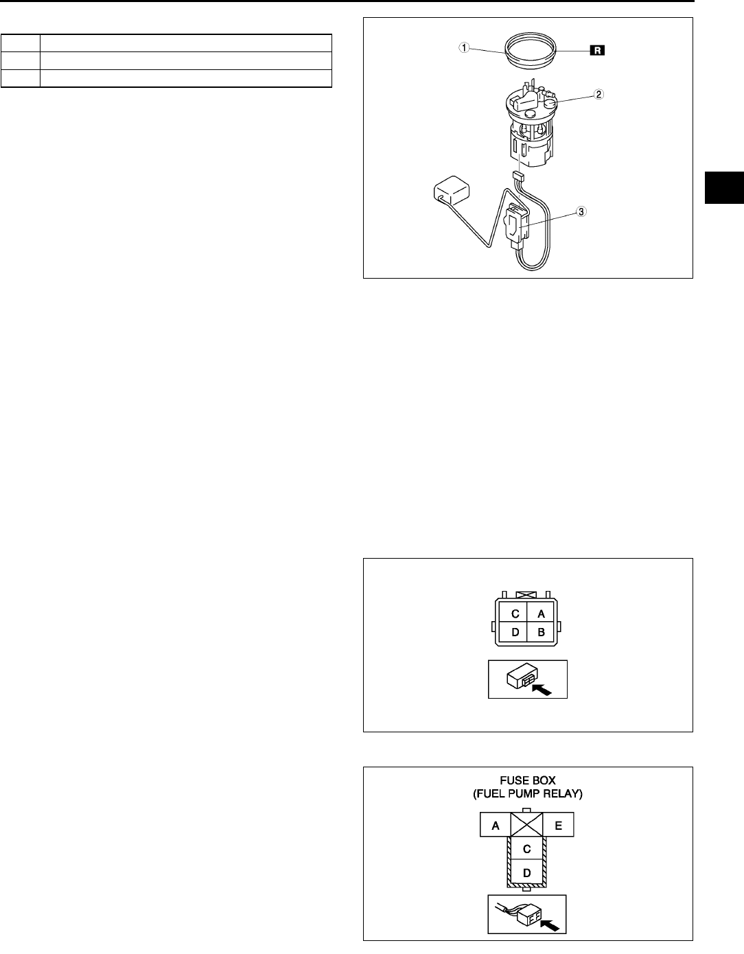
FUEL SYSTEM
F25
F
2. Assemble in the reverse order of disassembly..
End Of Sie
FUEL PUMP UNIT INSPECTION A6E391213350W03
Caution
•
••
•It is normal to hear the fuel pump operating when the ignition switch is turned to the ON position.
Note
•To improve startability, the fuel pump control operates the fuel pump unit when the ignition switch is
turned to the ON position. Due to this, fuel pressure is rapidly increased and fuel control is stabilized.
Continuity Inspection
Note
•Perform the following inspection only when directed.
1. Disconnect the negative battery cable.
2. Remove the service hole cover. (See F22 FUEL PUMP UNIT REMOVAL/INSTALLATION.)
3. Disconnect the fuel pump unit connector.
4. Inspect for continuity between fuel pump unit
connector terminals B and D.
•If there is no continuity, replace the fuel pump
body.
•If as specified carry out the Circuit Open/
Short Inspection.
Circuit Open/Short Inspection
1. Inspect the following wiring harnesses for open or
short circuit (continuity check).
Open circuit
•If there is no continuity, the circuit is open. Repair
or replace the harness.
Fuel pump unit terminal D (harness-side) and
body GND.
Fuel pump relay terminal D (harness-side)
and fuel pump unit terminal B (harness-side).
Short circuit
•If there is continuity, the circuit is short. Repair or
replace the harness.
Fuel pump unit terminal D (harness-side) and
power supply.
Fuel pump unit terminal B (harness-side) and body GND.
1 Packing
2 Fuel pump unit
3 Fuel gauge sender unit
A6E3912W025
A6E3912W018
A6E3912W019
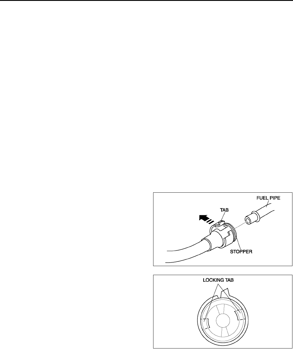
F26
FUEL SYSTEM
Fuel Pump Hold Pressure Inspection
Warning
•
••
•Fuel line spills and leakage are dangerous. Fuel can ignite and cause serious injuries or death and
damage. Always carry out the following procedure with the engine stopped.
Caution
•
••
•Disconnecting/connecting the quick release connector without cleaning it may possibly cause
damage to the fuel pipe and quick release connector. Always clean the quick release connector
joint area before disconnecting/connecting using a cloth or soft brush, and make sure that it is
free of foreign material.
Note
•Perform the following test only when directed.
1. Complete the BEFORE REPAIR PROCEDURE. (See F17 BEFORE REPAIR PROCEDURE.)
2. Disconnect the negative battery cable.
3. Remove the air cleaner.
Caution
•
••
•The quick release connector may be damaged if the tab is turned too far. Do not turn the tab over
the stopper.
4. Disconnect the quick release connector from the fuel tank as follows:
(1) Push the tab on the locking coupler 90°
°°
° until it stops.
(2) Pull the fuel hose straight back.
Note
•The stopper may be removed from the quick connector. Take care not to loose it.
Reinstall it to the quick release connector
before reconnecting the fuel line.
•The locking coupler has two internal locking
tabs which retain the pulsation damper pipe.
Be sure that the tab on the locking coupler is
rotated until it stops to release two internal
locking tabs.
A6E3912W020
A6E3912W002
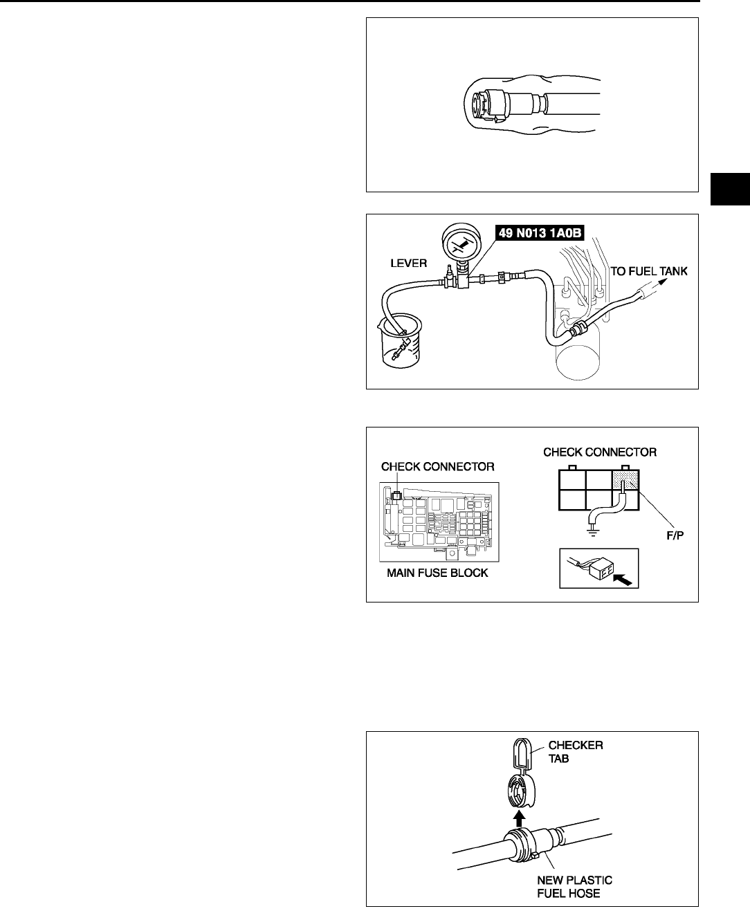
FUEL SYSTEM
F27
F
5. Cover the disconnected quick release connector
with vinyl sheet or the like to prevent it from being
scratched or contaminated with foreign material.
6. Turn the lever 90 degrees against the hose of the
SST to plug the SST outlet.
7. Push the SST quick release connector into the
fuel pipe until a click is heard.
8. Set the fuel hose into a container to avoid fuel
spills.
9. Connect the negative battery cable.
Caution
•
••
•Connecting to the wrong check
connector terminal may possibly cause
malfunction. Carefully connect to the
specified terminal only.
10. Short the check connector terminal F/P to body
GND using a jumper wire.
11. Turn the ignition switch to ON to operate the fuel
pump.
12. Turn the ignition switch to LOCK position.
13. Measure the fuel pump hold pressure after 5
minutes.
•If not as specified, replace the fuel pump after
inspecting the following:
Fuel line for clogging or leakage
Fuel pump hold pressure
More than 200 kPa {2.0 kgf/cm2, 29 psi}
14. Disconnect the jumper wire.
15. Disconnect the SST.
Note
•A checker tab is integrated with the quick release connector for new plastic fuel hoses. The checker tab
will be released from the quick release connector after it is completely engaged with the fuel pipe.
16. Inspect the plastic fuel hose and fuel pipe sealing
surface for damage and deformation, and replace
as necessary.
•If the quick release connector O-ring is
damaged or has slipped, replace the plastic
fuel hose.
17. Apply a small amount of clean engine oil to the
sealing surface of the fuel pipe.
18. Reconnect the plastic fuel hose straight to the fuel
pipe until a click is heard.
19. Lightly pull and push the quick release connector
a few times by hand and verify that it can move
2.03.0 mm {0.080.11 in} and it is connected
securely.
•If quick release connector does not move at all, verify that O-ring is not damaged and slipped, and
reconnect the quick release connector.
20. Complete the AFTER REPAIR PROCEDURE. (See F17 AFTER REPAIR PROCEDURE.)
A6E3912W021
A6E3912W022
A6E3912W037
A6E3912W004
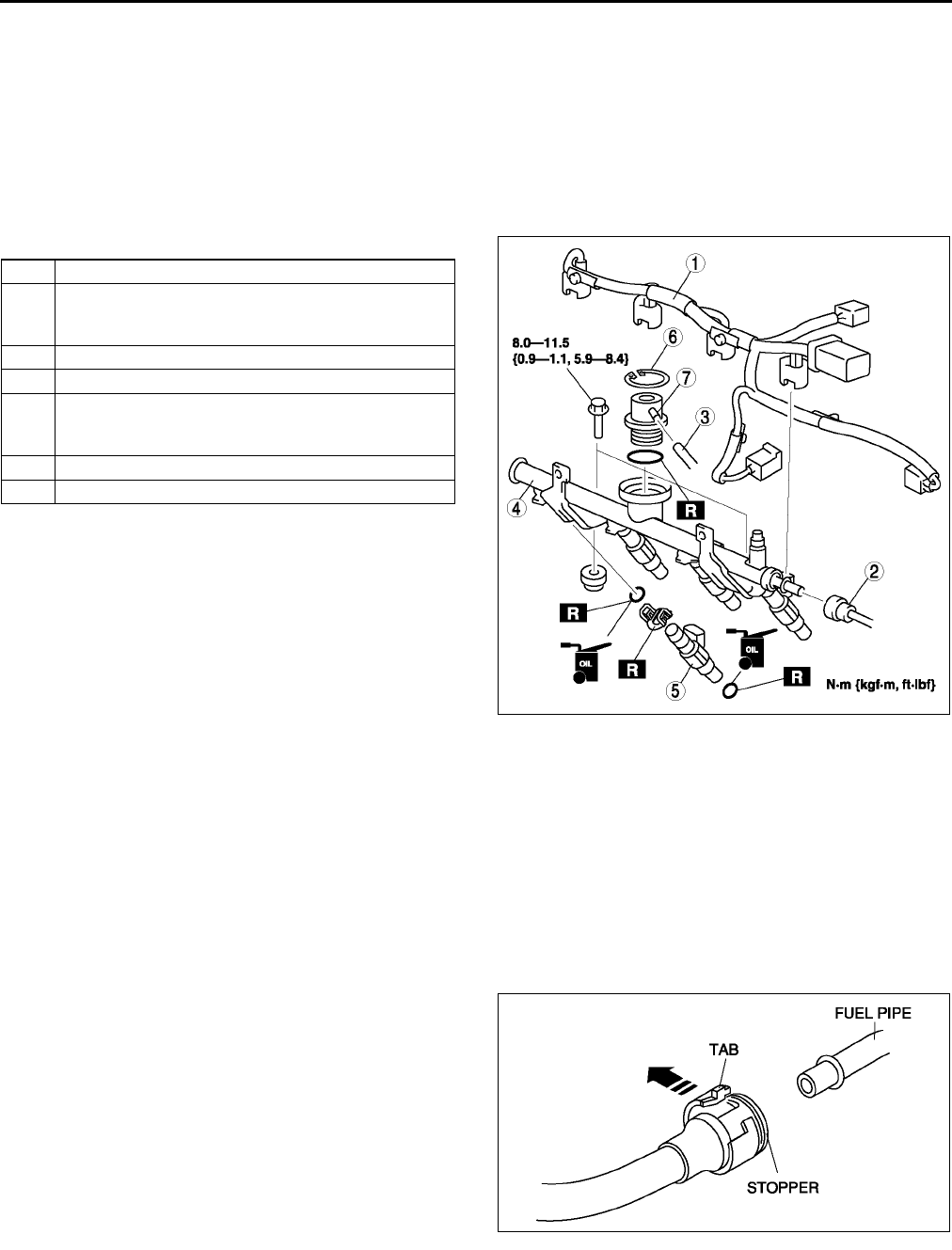
F28
FUEL SYSTEM
End Of Sie
FUEL INJECTOR REMOVAL/INSTALLATION A6E391213250W01
Caution
•
••
•Disconnecting/connecting the quick release connector without cleaning it may possibly cause
damage to the fuel pipe and quick release connector. Always clean the quick release connector
joint area before disconnecting/connecting using a cloth or soft brush, and make sure that it is
free of foreign material.
1. Complete the BEFORE REPAIR PROCEDURE. (See F17 BEFORE REPAIR PROCEDURE.)
2. Disconnect the negative battery cable.
3. Remove in the order indicated in the table..
4. Install in the reverse order of removal.
5. Complete the AFTER REPAIR PROCEDURE.
(See F17 AFTER REPAIR PROCEDURE.)
Plastic Fuel Hose Removal Note
Caution
•
••
•The quick release connector may be damaged if the tab is bent excessively. Do not expand the tab
over the stopper.
1. Disconnect the quick release connector.
(1) Push the tab on the locking coupler 90 degrees until it stops.
(2) Pull the fuel hose straight back.
Note
•The stopper may be removed from the quick connector. Take care not to lose it.
Reinstall it to the quick release connector
before reconnecting the fuel line.
1 Fuel injector connectors
2 Plastic fuel hose
(See F28 Plastic Fuel Hose Removal Note)
(See F30 Plastic Fuel Hose Installation Note)
2Hose
4 Fuel distributor
5 Fuel injector
(See F29 Fuel Injector Removal Note)
(See F30 Fuel Injector Installation Note)
6 Snap ring
7 Pulsation damper
A6E3912W005
A6E3912W001
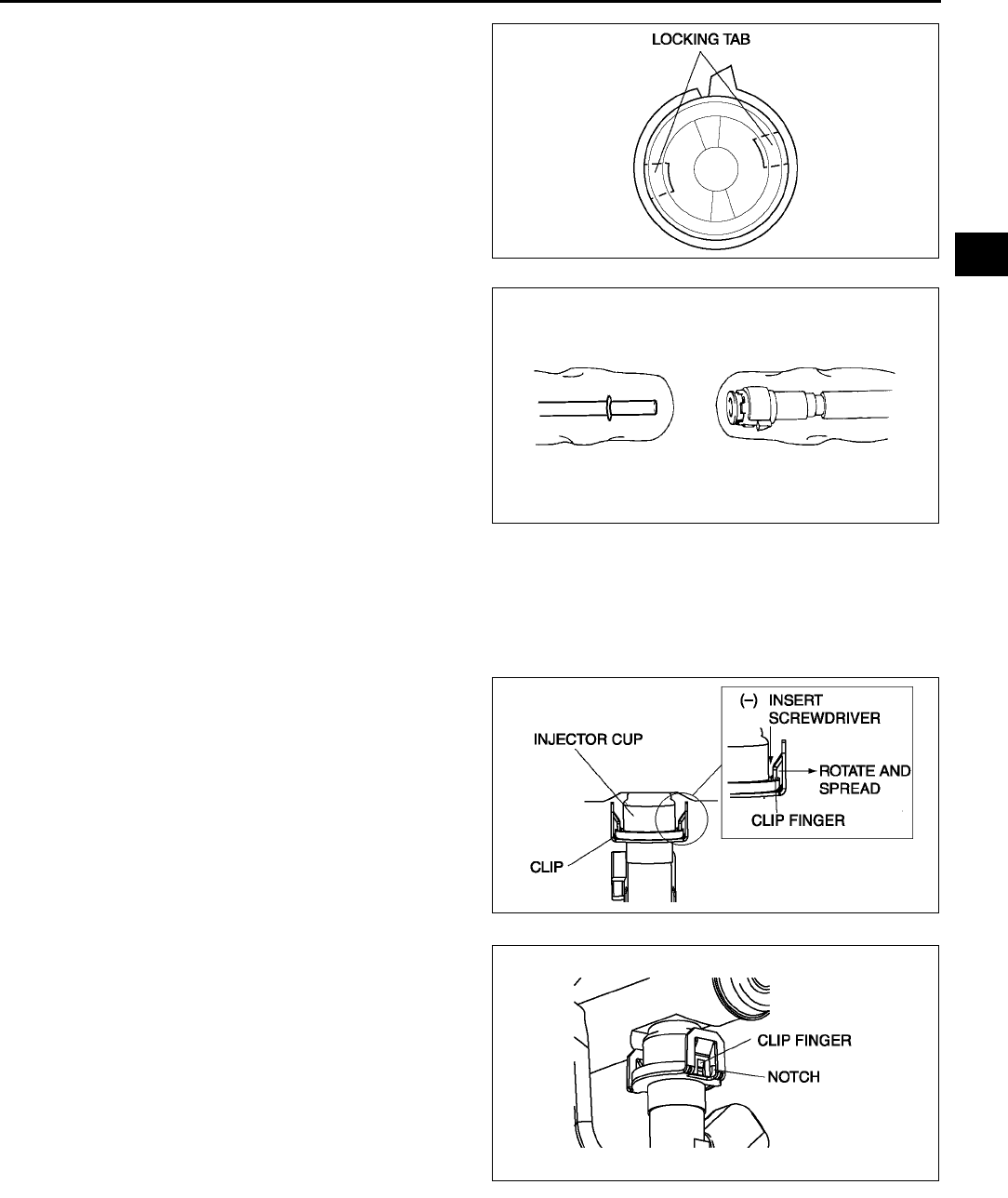
FUEL SYSTEM
F29
F
•The locking coupler has two internal locking
tabs which retain the fuel pipe. Be sure that
the tab on the locking coupler is rotated until
it stops to release two internal locking tabs.
2. Cover the disconnected quick release connector
and fuel pipe with vinyl sheets or the like to
prevent them from being scratched or
contaminated with foreign material.
Fuel Injector Removal Note
Caution
•
••
•Use of a deformed injector retaining clip will cause the injector to not engage correctly. Always
use a new clip when reattaching the injector, otherwise it may cause the injector to rotate.
1. Insert a screwdriver between the injector cup and
the clip fingers.
Note
•When rotating the screwdriver to spread the
clip fingers, deform them sufficiently to make
sure they release from the notched edge of
the injector cup.
2. Rotate the screwdriver to spread the clip fingers
and remove them from the injector cup.
3. Pull the injector and clip out of the rail.
4. Remove the clip from the injector according to the
following:
(1) Grasp the clip with a pair of pliers.
A6E3912W002
A6E3912W039
A6E3912W040
A6E3912W041
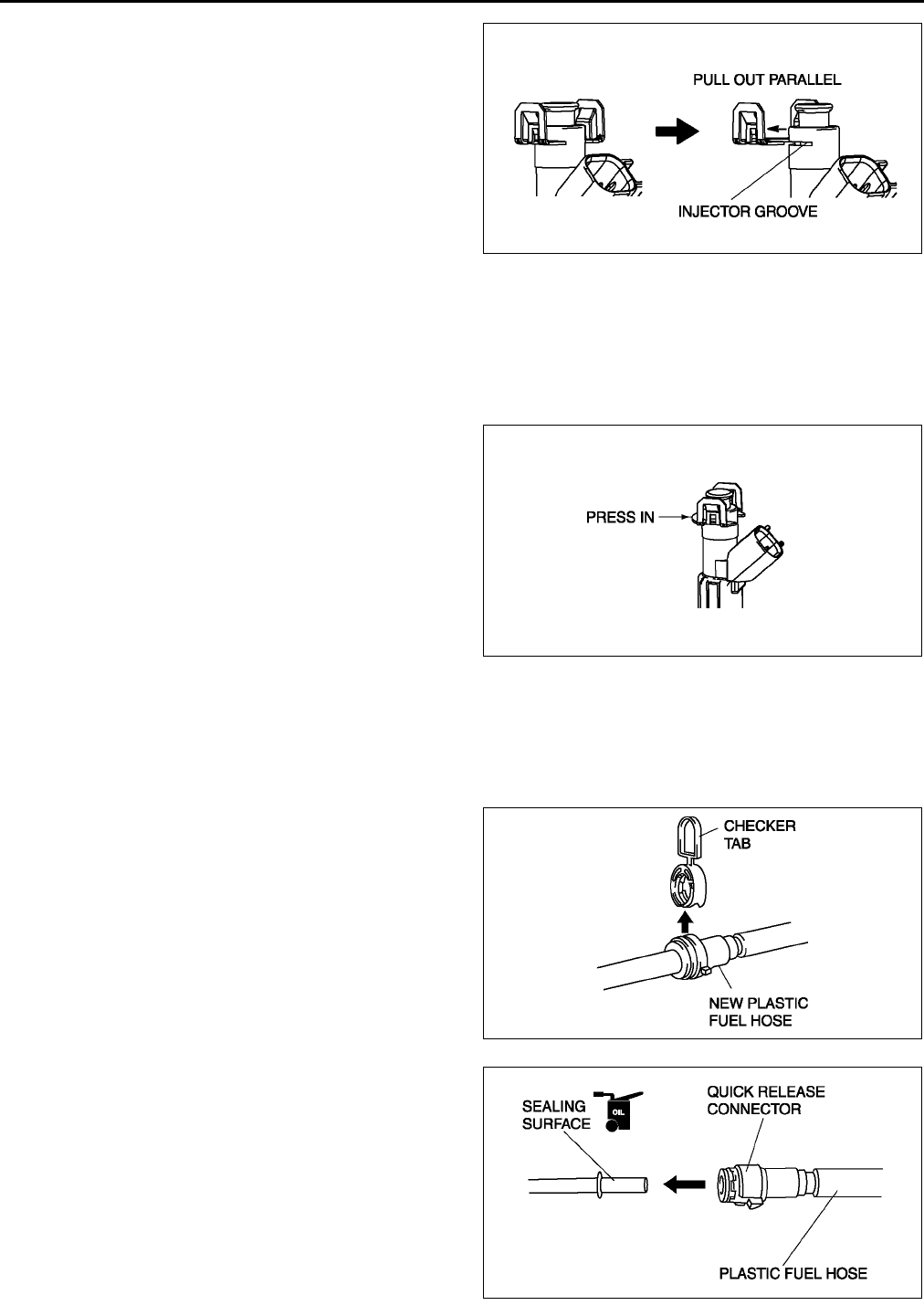
F30
FUEL SYSTEM
(2) Pull the clip parallel to the injector groove, and
remove it from the injector.
(3) Discard the clip.
Fuel Injector Installation Note
1. Lightly lubricate the injector groove and O-ring.
2. Pre-attach a new clip in the injector groove.
Note
•When the clip is attached correctly, the central area of the injector and the clip finger positions are aligned.
3. Hold the injector firmly, push the clip into the
injector until the clip stops sliding.
4. Verify that the injector connector position is
correct, and press the injector and clip into the
injector cup. Continue pressing until the clip
contacts the lower surface of the injector cup.
5. Verify that the injector and clip are correctly
attached with the clip locked onto the injector cup
notch.
Plastic Fuel Hose Installation Note
Note
•A checker tab is integrated with quick release connector for new plastic fuel hoses. The checker tab will
be released from the quick release connector after it is completely engaged with the fuel pipe.
1. When the retainer is not removed, perform the
following procedure.
(1) Inspect the fuel pump unit sealing surface for
damage and deformation, and replace as
necessary.
•If the quick release connector O-ring is
damaged, replace the plastic fuel hose.
(2) Slightly apply clean engine oil to the sealing
surface of the fuel pump unit.
(3) Align the fuel pipe on the fuel pump unit and
quick release connector so that the tabs of the
retainer are correctly fitted into the quick
release connector. Push the quick release
connector straight into the retainer until a click
is heard.
A6E3912W042
A6E3912W043
A6E3912W004
A6E3912W006
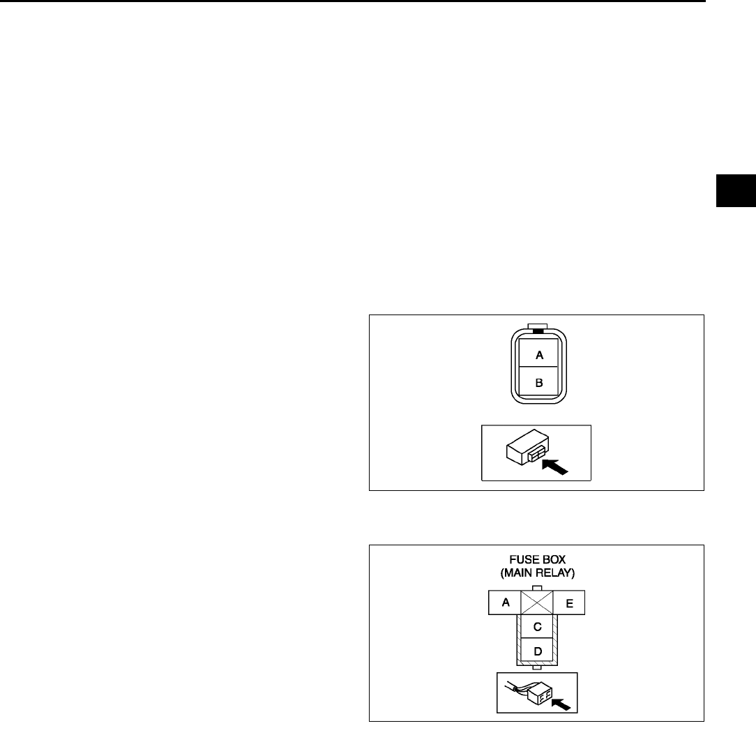
FUEL SYSTEM
F31
F
(4) Lightly pull and push the quick release connector a few times by hand and verify that it can move 2.03.0
mm {0.080.11 in} and it is connected securely.
•If quick release connector does not move at all, verify that O-ring is not damaged and slipped, and
reconnect the quick release connector.
2. When the retainer is removed, perform the following procedure.
End Of Sie
FUEL INJECTOR INSPECTION A6E391213250W02
Operation Test
1. Carry out the Fuel Injector Operation Inspection. (See F231 Fuel Injector Operation Inspection.)
•If not as specified, perform the further inspection for the fuel injectors.
Resistance Inspection
Note
•Perform the following test only when directed.
1. Turn the ignition switch to LOCK position.
2. Disconnect the negative battery cable.
3. Disconnect the fuel injector connectors.
4. Measure the resistance of the fuel injector using
an ohmmeter.
•If not as specified, replace the fuel injector.
(See F28 FUEL INJECTOR REMOVAL/
INSTALLATION.)
•If as specified but Operation Test is failed,
carry out the Circuit Open/Short Inspection.
Inspect for open or short circuit.
Resistance
11.412.6 ohms [20 °
°°
°C {68 °
°°
°F}]
Circuit Open/Short Inspection
1. Disconnect the PCM connector. (See F43 PCM
REMOVAL/INSTALLATION.)
2. Inspect the following wiring harness for open or
short (continuity check).
Open circuit
•If there is no continuity, the circuit is open. Repair
or replace the harness.
No.1 cylinder fuel injector terminal B
(harness-side) and PCM terminal 4Z.
No.2 cylinder fuel injector terminal B
(harness-side) and PCM terminal 4W.
No.3 cylinder fuel injector terminal B
(harness-side) and PCM terminal 4AD.
No.4 cylinder fuel injector terminal B (harness-side) and PCM terminal 4AA.
No.1 cylinder fuel injector terminal A (harness-side) and main relay (harness-side) terminal C through
common connector.
No.2 cylinder fuel injector terminal A (harness-side) and main relay (harness-side) terminal C through
common connector.
No.3 cylinder fuel injector terminal A (harness-side) and main relay (harness-side) terminal C through
common connector.
No.4 cylinder fuel injector terminal A (harness-side) and main relay (harness-side) terminal C through
common connector.
Short circuit
• If there is continuity, the circuit is short. Repair or replace the harness.
No.1 cylinder fuel injector terminal B (harness-side) and body GND.
No.2 cylinder fuel injector terminal B (harness-side) and body GND.
No.3 cylinder fuel injector terminal B (harness-side) and body GND.
No.4 cylinder fuel injector terminal B (harness-side) and body GND.
No.1 cylinder fuel injector terminal A (harness-side) and power supply.
A6E3912W007
A6E3912W008
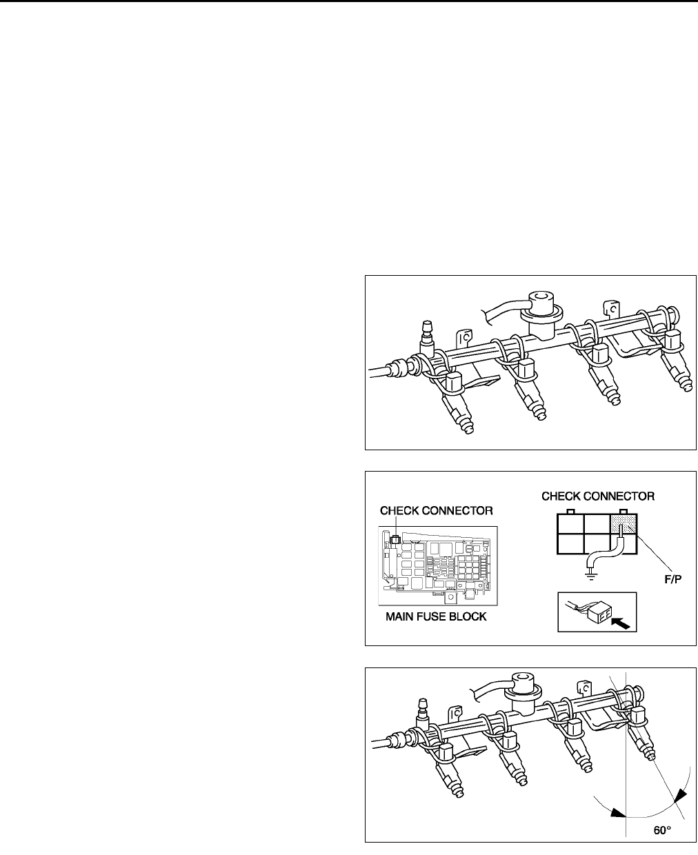
F32
FUEL SYSTEM
No.2 cylinder fuel injector terminal A (harness-side) and power supply.
No.3 cylinder fuel injector terminal A (harness-side) and power supply.
No.4 cylinder fuel injector terminal A (harness-side) and power supply.
Fuel Leakage Inspection
Warning
•
••
•Fuel line spills and leakage are dangerous. Fuel can ignite and cause serious injuries or death and
damage. Always carry out the following procedure with the engine stopped.
Note
•Perform the following test only when directed.
1. Complete the BEFORE REPAIR PROCEDURE. (See F17 BEFORE REPAIR PROCEDURE.)
2. Disconnect the negative battery cable.
3. Remove the fuel injectors together with the fuel distributor with the fuel hose connected. (See F28 FUEL
INJECTOR REMOVAL/INSTALLATION.)
4. Fasten the fuel injectors firmly to the fuel
distributor with wire.
5. Connect the negative battery cable.
Caution
•
••
•Connecting the wrong check connector
terminal may possibly cause
malfunction. Carefully connect the
specified terminal only.
6. Short the check connector terminal F/P to body
GND using a jumper wire.
7. Turn the ignition switch to ON position to operate
the fuel pump.
8. Tilt the fuel injectors approx. 60 degrees.
9. Verify that fuel leakage from the fuel injector
nozzles is within the specification.
•If not as specified, replace the fuel injector.
Fuel leakage
Less than 1 drop/2 minutes
10. Turn the ignition switch to LOCK position and
remove the jumper wire.
11. Complete the AFTER REPAIR PROCEDURE.
(See F17 AFTER REPAIR PROCEDURE.)
A6E3912W009
A6E3912W037
A6E3912W010
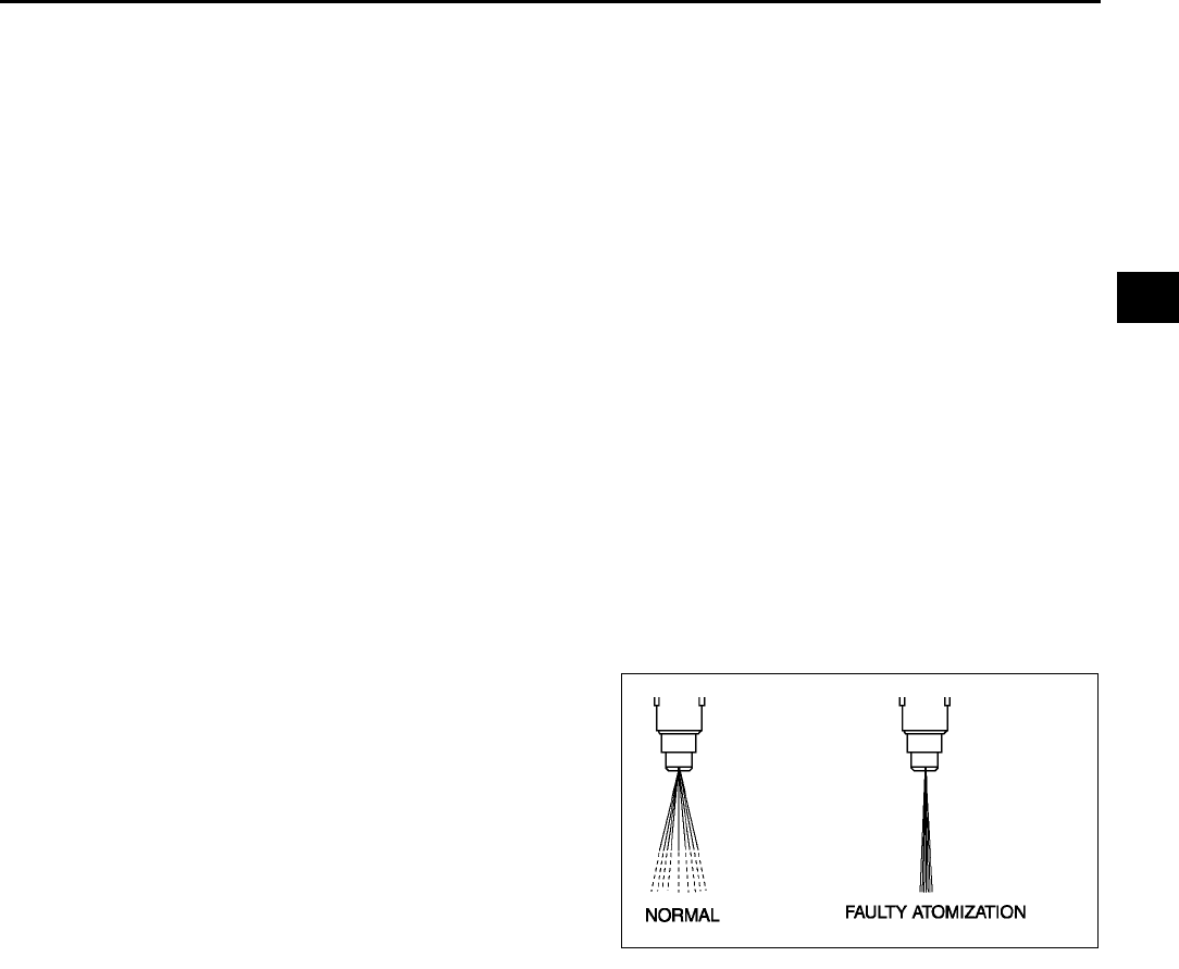
FUEL SYSTEM
F33
F
Volume Inspection
Warning
•
••
•Fuel line spills and leakage are dangerous. Fuel can ignite and cause serious injuries or death and
damage. Always carry out the following procedure with the engine stopped.
Note
•If there is an after market fuel injector tester, perform the following test.
•If there is no an after market fuel injector tester, perform Operation Test, Resistance Inspection, and
Fuel Leakage Test to verify the fuel injector is okay or not.
1. Complete the BEFORE REPAIR PROCEDURE. (See F17 BEFORE REPAIR PROCEDURE.)
2. Disconnect the negative battery cable.
3. Remove the fuel injectors. (See F28 FUEL INJECTOR REMOVAL/INSTALLATION.)
4. Connect the fuel injector to the fuel injector tester.
5. Measure the injection volume of each fuel injector using a graduated container.
•If not as specified, replace the fuel injector.
Injection volume
L3: 6171 ml {6179 cc, 2.22.7 fl oz}/15 sec.
LF: 5369 ml {5369 cc, 1.92.4 fl oz}/15 sec.
L8: 4863 ml {4863 cc, 1.72.2 fl oz}/15 sec.
6. Turn the ignition switch to LOCK position and disconnect the jumper wire.
7. Complete the AFTER REPAIR PROCEDURE. (See F17 AFTER REPAIR PROCEDURE.)
Atomization
1. Inspect atomization pattern.
•If the atomization is faulty, replace the fuel injector.
End Of Sie
A6E3912W011

F34
FUEL SYSTEM
PRESSURE REGULATOR INSPECTION A6E391213280W01
Note
•Due to the adoption of the mechanical returnless fuel system, the pressure regulator cannot be inspected
separately.
1. Perform FUEL LINE PRESSURE INSPECTION. (See F20 FUEL LINE PRESSURE INSPECTION.)
End Of Sie
PULSATION DAMPER REMOVAL/INSTALLATION A6E391220180W01
1. Remove and install the pressure regulator.(See F28 FUEL INJECTOR REMOVAL/INSTALLATION.)
End Of Sie
PULSATION DAMPER INSPECTION A6E391220180W02
1. Complete the BEFORE REPAIR PROCEDURE. (See F17 BEFORE REPAIR PROCEDURE.)
2. Remove the pulsation damper. (See F34 PULSATION DAMPER REMOVAL/INSTALLATION.)
3. Visually inspect the pulsation damper for damage and cracks. Also verify that there is no extreme rust which
will cause fuel leakage.
•If either is observed, replace the pulsation damper.
4. Complete the AFTER REPAIR PROCEDURE. (See F17 AFTER REPAIR PROCEDURE.)
End Of Sie

EXHAUST SYSTEM
F35
F
EXHAUST SYSTEM INSPECTION A6E391440000W01
1. Start the engine and inspect each exhaust system component for exhaust gas leakage.
•If leakage is found, repair or replace as necessary.
End Of Sie
EXHAUST SYSTEM REMOVAL/INSTALLATION A6E391440000W02
Warning
•
••
•When the engine and exhaust system are hot, they can badly burn. Turn off the engine and wait
until they are cool before removing the exhaust system.
1. Disconnect the negative battery cable.
2. Remove in the order indicated in the table.
3. Install in the reverse order of removal.
EXHAUST SYSTEM
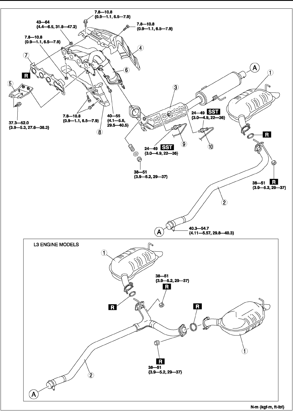
F36
EXHAUST SYSTEM
.
A6E3914W002
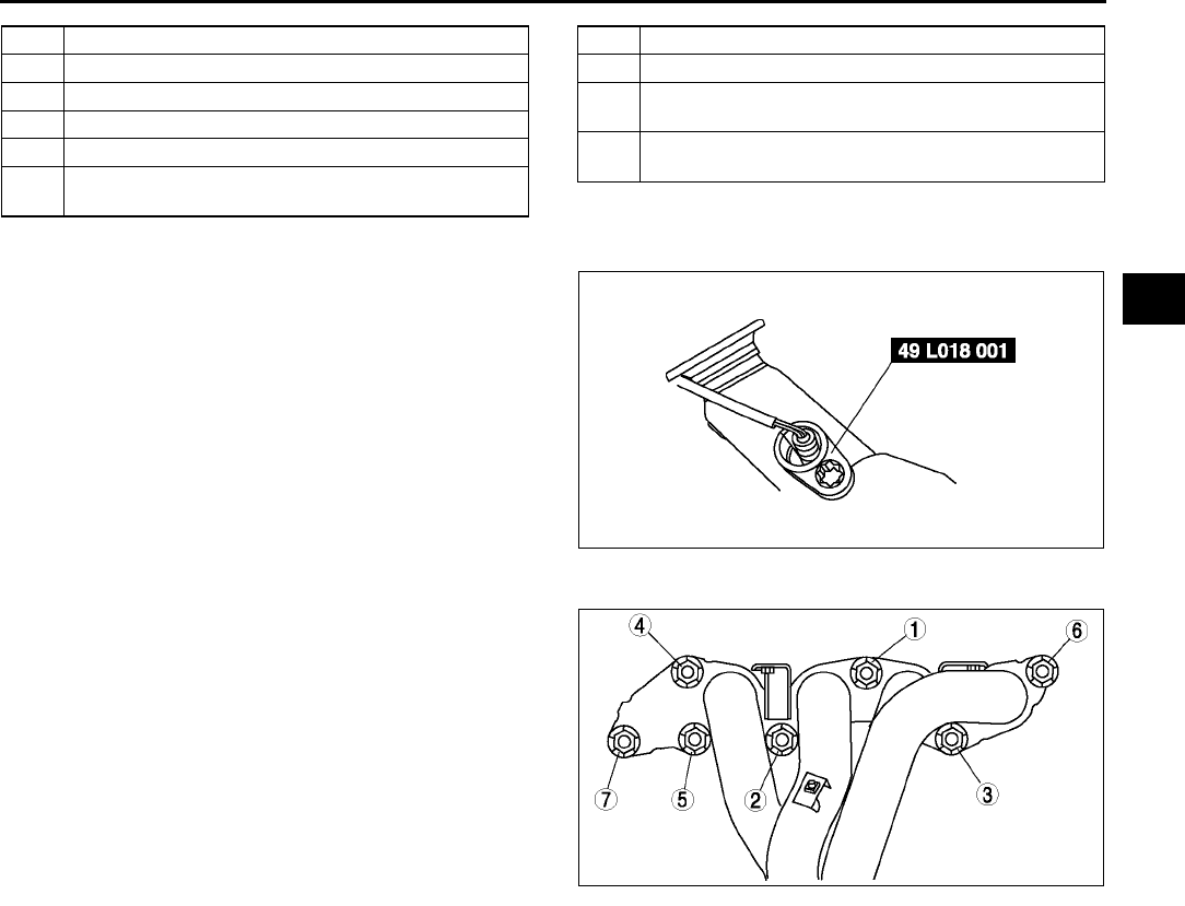
EXHAUST SYSTEM
F37
F
HO2S Removal Note
1. Remove the HO2S using the SST before
removing the exhaust manifold.
Exhaust Manifold Installation Note
1. Tighten the exhaust manifold installation nuts in
the order shown.
End Of Sie
1 Main silencer
2 Middle pipe
3TWC
4 Exhaust manifold insulator (upper)
5Bracket
6 Exhaust manifold
(See F37 Exhaust Manifold Installation Note)
7 Exhaust manifold gasket
8 Exhaust manifold insulator (lower)
9 HO2S (front)
(See F37 HO2S Removal Note)
10 HO2S (rear)
(See F37 HO2S Removal Note)
A6J3914W004
A6E3914W003
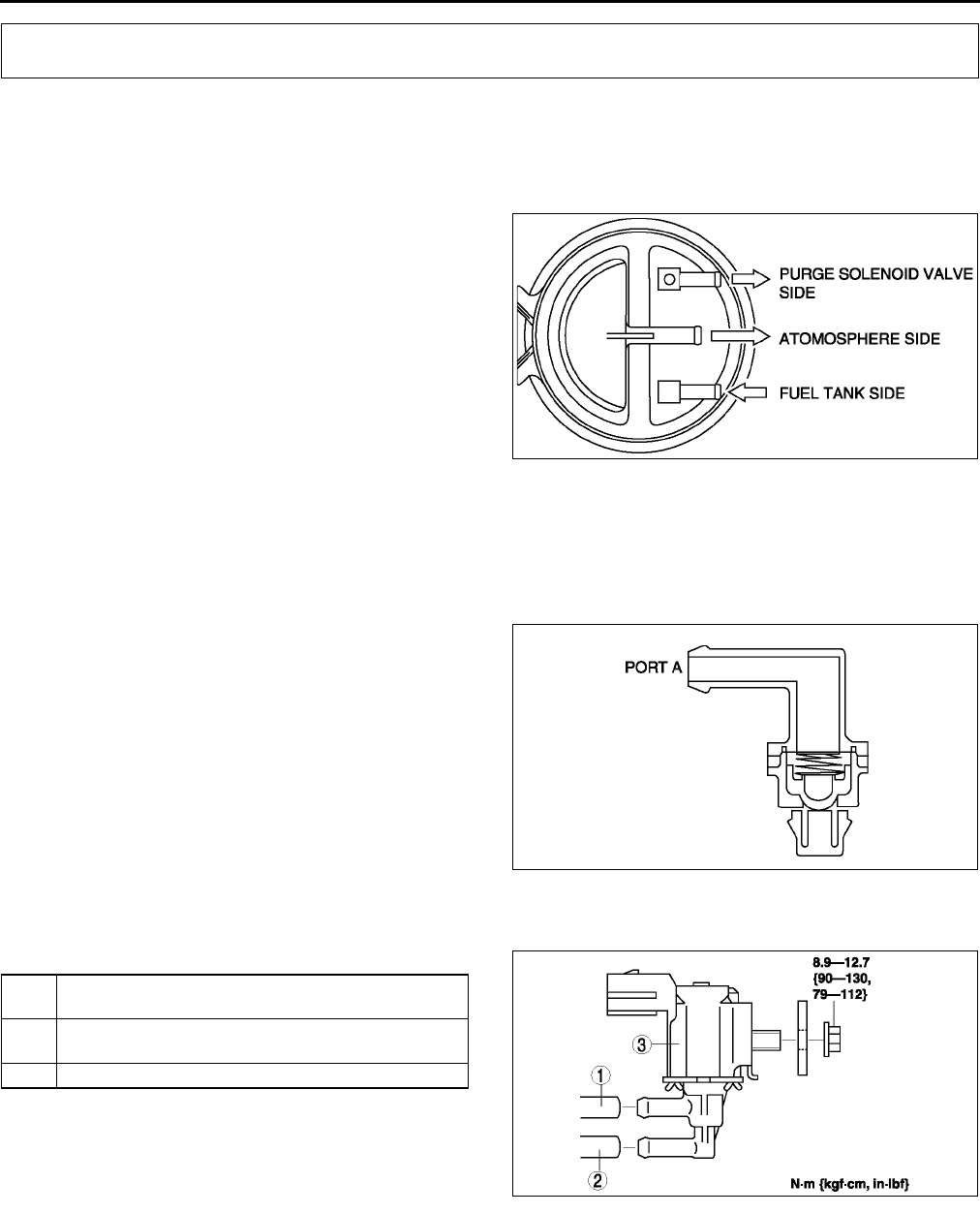
F38
EMISSION SYSTEM
CHARCOAL CANISTER INSPECTION A6E391613970W01
1. Remove the charcoal canister.
2. Plug the atmosphere side port and purge solenoid valve side port of the charcoal canister.
3. Blow air into the charcoal canister from the fuel tank side port and verify that there is no air leakage.
•If there is air leakage, replace the charcoal canister.
End Of Sie
EVAPORATIVE GAS CHECK VALVE (ONE-WAY) INSPECTION (L.H.D.) A6E391613988W01
1. Remove the evaporative gas check valve (one-way).
2. Apply pressure to port A, and verify that there is no airflow.
•If there is airflow, replace the evaporative gas check valve (one-way).
3. Apply negative pressure to port A, and verify that there is air flow.
•If there is no airflow, replace the evaporative gas check valve (one-way).
End Of Sie
PURGE SOLENOID VALVE REMOVAL/INSTALLATION A6E391618740W01
1. Disconnect the negative battery cable.
2. Remove in the order indicated in the table.
3. Install in the reverse order of removal.
Vacuum Hose Installation Note
1. Attach the vacuum hose onto the purge solenoid valve until it contacts the stopper.
Evaporative Hose Installation Note
1. Attach the evaporative hose onto the purge solenoid valve until it contacts the stopper.
End Of Sie
EMISSION SYSTEM
A6E3916W002
A6E3916W001
1 Evaporative hose (to charcoal canister)
(See F38 Evaporative Hose Installation Note)
2 Vacuum hose (to intake manifold)
(See F38 Vacuum Hose Installation Note)
3 Purge solenoid valve
A6E3916W024
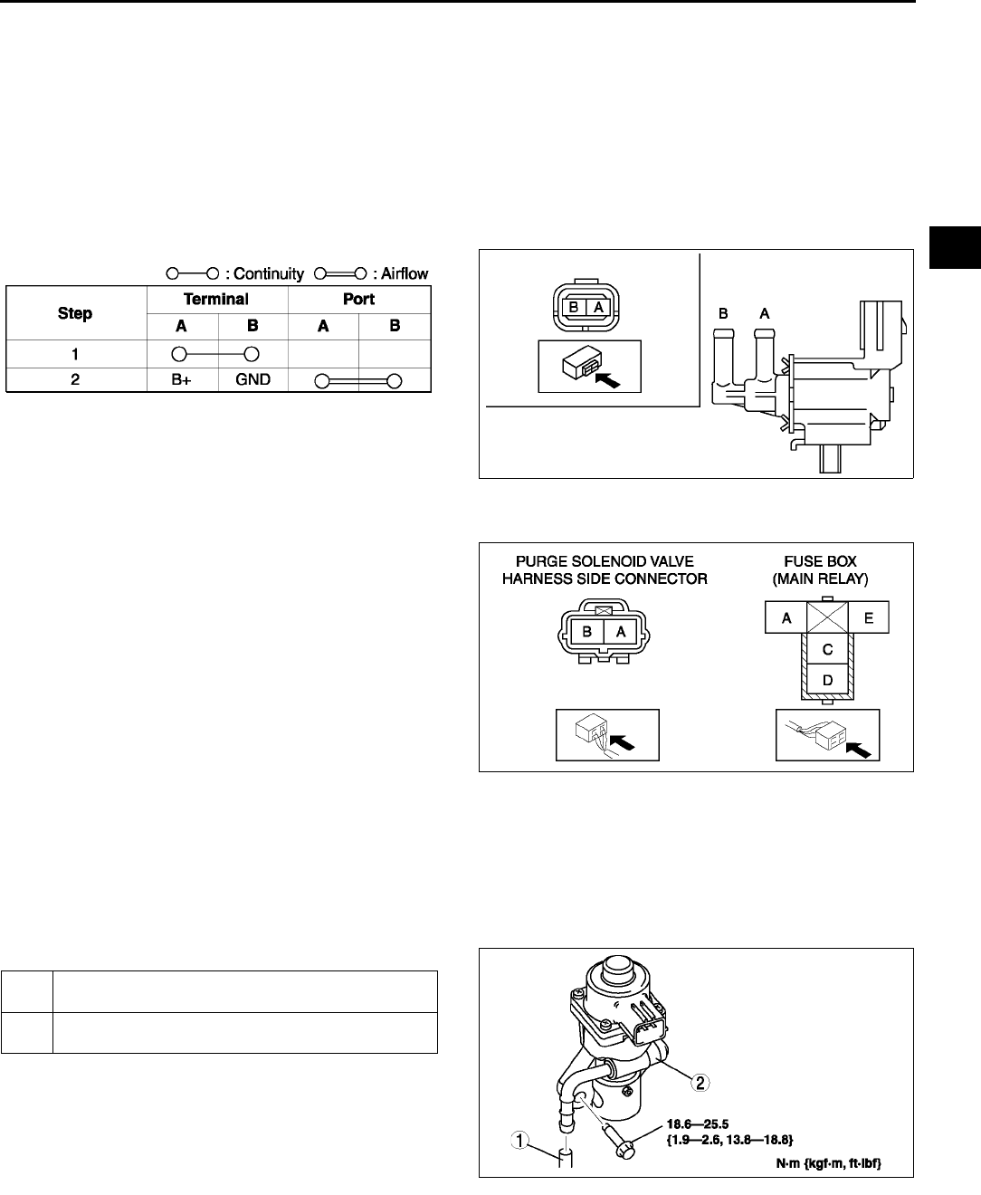
EMISSION SYSTEM
F39
F
PURGE SOLENOID VALVE INSPECTION A6E391618740W02
Airflow Inspection
Note
•Perform the following test only when directed.
1. Disconnect the negative battery cable.
2. Remove the purge solenoid valve. (See F38 PURGE SOLENOID VALVE REMOVAL/INSTALLATION.)
3. Inspect airflow between the ports under the following conditions.
•If not as specified, replace the purge solenoid valve.
•If as specified, carry out the Circuit Open/Short Inspection.
Circuit Open/Short Inspection
1. Disconnect the PCM connector. (See F43 PCM REMOVAL/INSTALLATION.)
2. Inspect the following wiring harness for open or
short (continuity check).
Open circuit
•If there is no continuity, the circuit is open.
Repair or replace the harness.
Purge solenoid valve terminal A
(harness-side) and PCM terminal 4U
Purge solenoid valve terminal B
(harness-side) and main relay terminal C
(harness-side)
Short circuit
•If there is continuity, the circuit is shorted.
Repair or replace the harness.
Purge solenoid valve terminal A
(harness-side) and body GND
Purge solenoid valve terminal B (harness-side) and power supply
End Of Sie
EGR VALVE REMOVAL/INSTALLATION A6E391620300W01
1. Disconnect the negative battery cable.
2. Disconnect the EGR valve connector.
3. Remove in the order indicated in the table.
4. Install in the reverse order of removal.
Water Hose Removal Note
•Drain the engine coolant. (See E3 ENGINE
COOLANT REPLACEMENT.)
EGR Valve Removal Note
1. Remove the air hose. (See F10 INTAKE-AIR
SYSTEM REMOVAL/INSTALLATION)
2. Remove the upper radiator hose. (See E6 RADIATOR REMOVAL/INSTALLATION.)
End Of Sie
A6E3916W004
A6E3916W005
A6E3916W006
1 Water hose
(See F39 Water Hose Removal Note)
2EGR valve
(See F39 EGR Valve Removal Note)
A6E3916W008
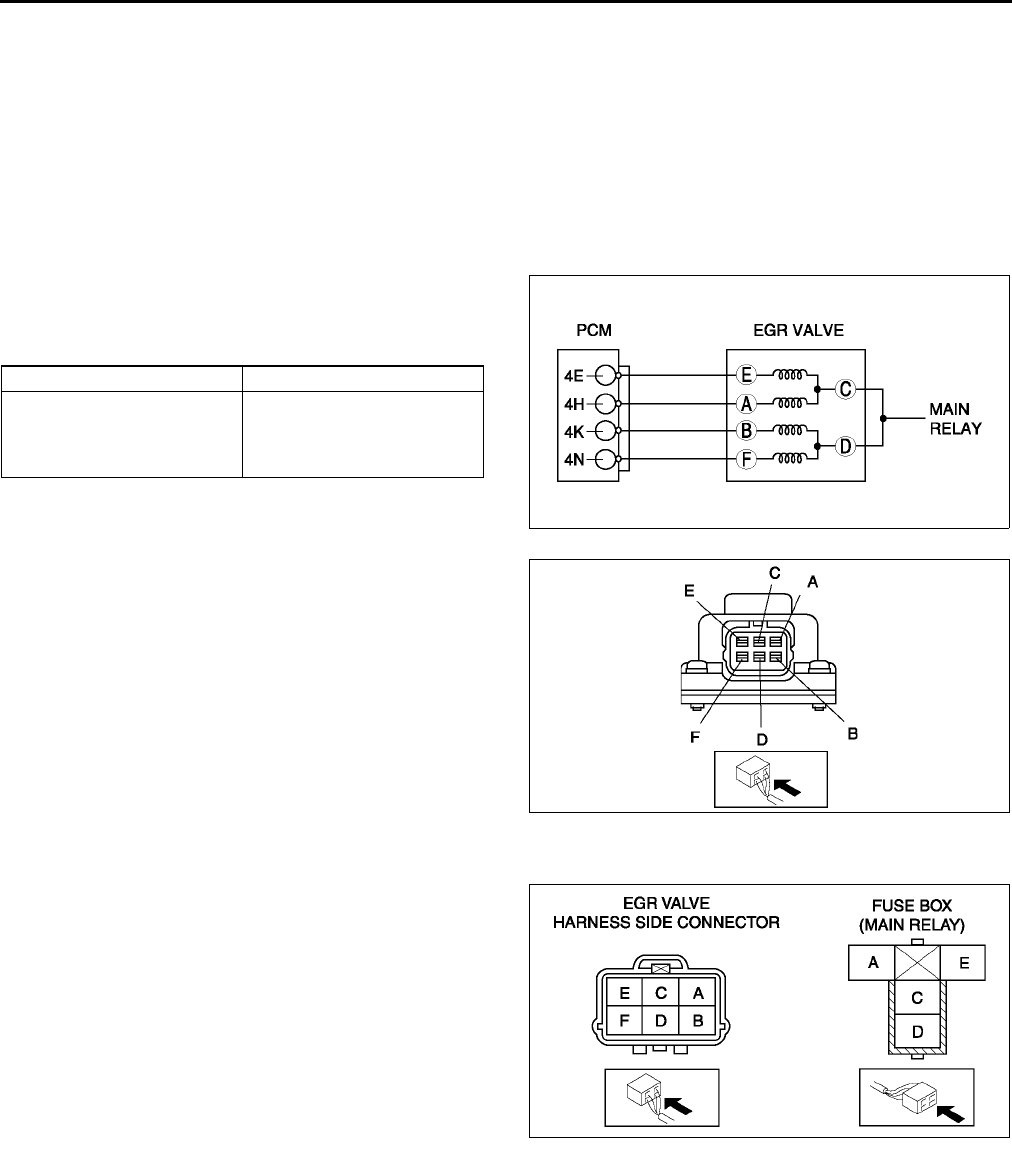
F40
EMISSION SYSTEM
EGR VALVE INSPECTION A6E391620300W02
Operation Test
1. Carry out the EGR Control Inspection. (See F233 EGR Control System Inspection.
•If not as specified, perform the further inspection for the EGR valve.
Resistance Inspection
Note
•Perform the following test only when directed.
1. Disconnect the negative battery cable.
2. Inspect resistance of the EGR valve coils.
•If not as specified, replace the EGR valve.
•If as specified, carry out the Circuit Open/
Short Inspection.
Circuit Open/Short Inspection
1. Disconnect the PCM connector. (See F43 PCM REMOVAL/INSTALLATION.)
2. Inspect the following wiring harness for open or
short (continuity check).
Open circuit
•If there is no continuity, the circuit is open.
Repair or replace the harness.
EGR valve terminal E (harness-side) and
PCM terminal 4E
EGR valve terminal A (harness-side) and
PCM terminal 4H
EGR valve terminal B (harness-side) and
PCM terminal 4K
EGR valve terminal F (harness-side) and
PCM terminal 4N
EGR valve terminal C or D (harness-side)
and main relay terminal C (harness-side)
Short circuit
•If there is continuity, the circuit is shorted. Repair or replace the harness.
EGR valve terminal E (harness-side) and GND
EGR valve terminal A (harness-side) and GND
EGR valve terminal B (harness-side) and GND
EGR valve terminal F (harness-side) and GND
EGR valve terminal C or D (harness-side) and power supply
3. Remove the EGR valve, and inspect for any damage or clogging.
•If there is no damage or no clogging, replace the EGR valve.
End Of Sie
Terminals Resistance (ohms)
CE
CA
DB
DF
1216
A6E3916W009
A6E3916W011
A6E3916W010
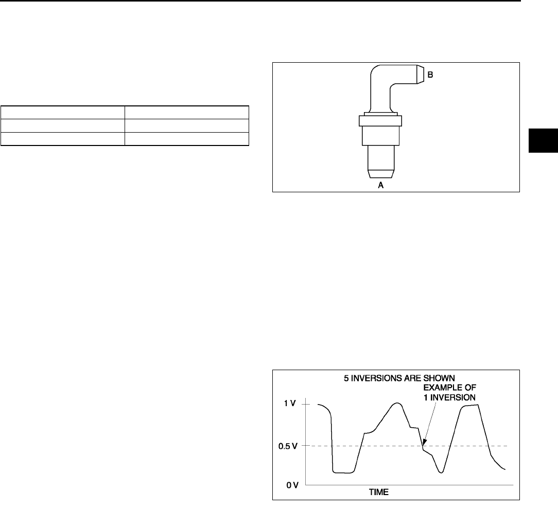
EMISSION SYSTEM
F41
F
PCV VALVE INSPECTION A6E391613890W01
1. Disconnect the negative battery cable.
2. Remove the intake maniforld.(see F10 INTAKE-AIR SYSTEM REMOVAL/INSTALLATION.)
3. Remove the PCV valve.
4. Blow through the valve and verify that air flows as
specified.
•If not as specified, replace the PCV valve.
Specification
End Of Sie
THREE-WAY CATALYTIC CONVERTER (TWC) INSPECTION A6E391620500W01
Note
•Make sure that no HO2S DTCs have been detected. If detected, this inspection is not applicable for TWC
inspection.
1. Connect the WDS or equivalent and monitor PIDs as following.
•Monitor the right TWC using O2S11 PID for upstream HO2S and O2S12 PID for downstream HO2S.
2. Begin to monitor the appropriate PIDs.
3. Drive the vehicle for 10 min at 6596 km/h {4060 mph} to allow the front catalytic converter to reach
operating temperature.
4. Stop the vehicle and leave it in a safe place.
5. Let the engine idle.
6. Record PIDs for 1 min.
7. Select the appropriate PIDs and read the graph.
8. Count the number of times (inversions) that the
upstream HO2S graph line actually crosses the
0.5 V line.
9. Count the number of times (inversions) that the
downstream HO2S graph line actually crosses
the 0.5 V line.
Note
•Do not count the number of peaks. Refer to
the graph.
10. Using the following equation, calculate the value
of ratio.
Equation
RATIO = Upstream HO2S inversion ÷
÷÷
÷ downstream HO2S inversion
•If the ratio is 5.5 or more or there is no downstream HO2S inversion, the TWC is functioning properly.
•If the ratio is less than 1.125, the TWC is not functioning properly. Replace the TWC.
Condition Airflow
Air applied from port A to B Yes
Air applied from port B to A No
A6E3916W007
A6E3916W013
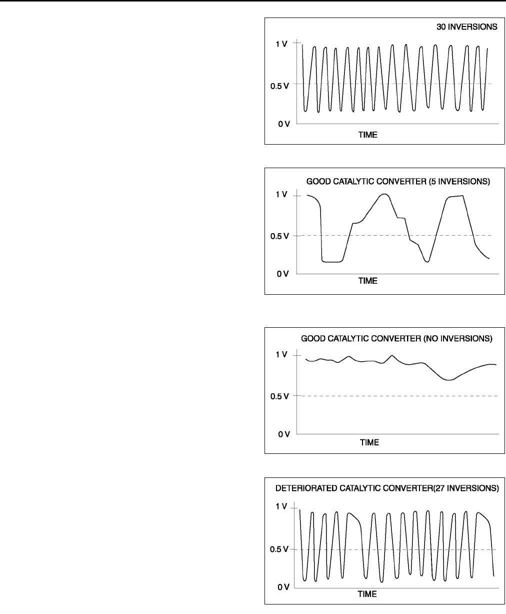
F42
EMISSION SYSTEM
Upstream HO2S graph line example
Downstream HO2S graph line example 1
Equation
RATIO = 30 inversions (upstream HO2S
inversions) ÷
÷÷
÷ 5 inversions (downstream
HO2S inversions) = 6.0 (good WU-TWC)
Downstream HO2S graph line example 2
Downstream HO2S graph line example 3
Equation
RATIO = 30 inversions (upstream HO2S
inversions) ÷
÷÷
÷ 27 inversions (downstream
HO2S inversions) = 1.1 (bad converter)
End Of Sie
A6E3916W021
A6E3916W012
A6E3916W014
A6E3916W015
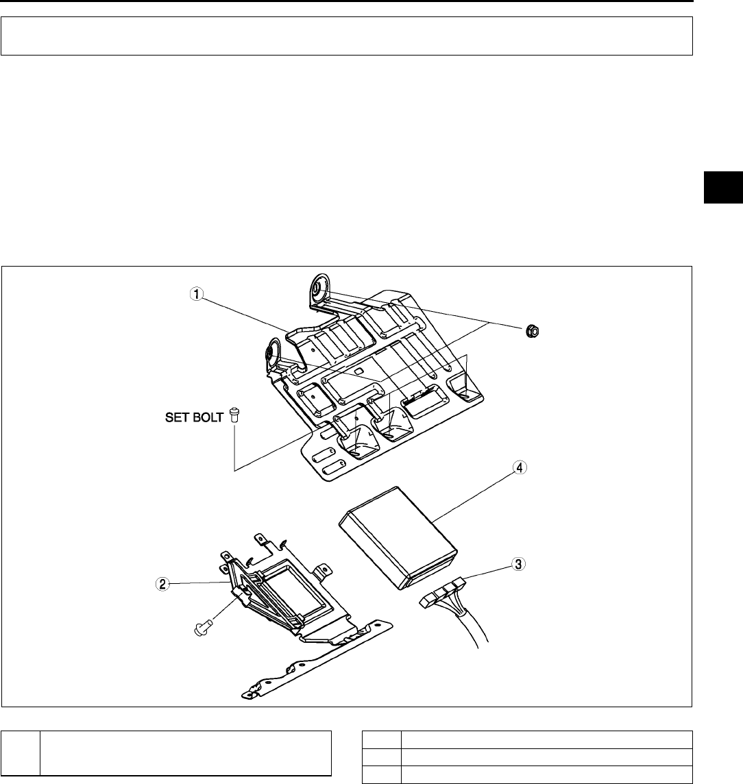
CONTROL SYSTEM
F43
F
PCM REMOVAL/INSTALLATION A6E394018880W01
Note
•For replace the PCM, Setup the WDS and perform the PCM configuration. (See F50 PCM
CONFIGURATION.)
1. Disconnect the negative battery cable.
2. For R.H.D, perform the following procedures.
(1) Remove the front side trim (left-side).
(2) Partially peel back the flower covering.
3. Remove in the order indicated in the table.
4. Install in the reverse order of removal.
U.K. specs.
.
CONTROL SYSTEM
A6E3940W002
1 PCM cover No. 1
(See F44 Set Nut/bolt Removal Note)
(See F44 Set Nut/bolt Installation Note)
2 PCM cover No. 2
3 PCM connector
4PCM
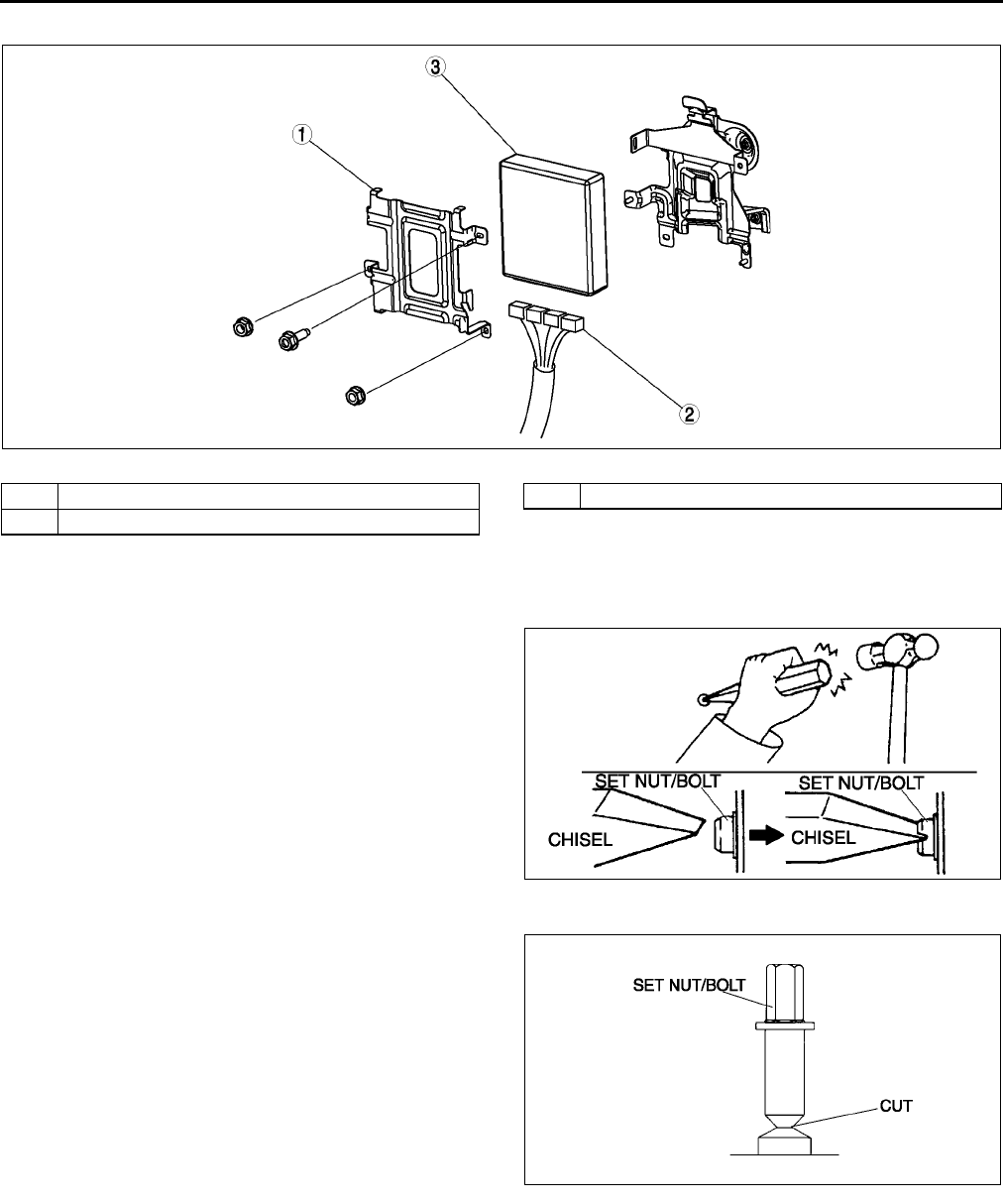
F44
CONTROL SYSTEM
European (L.H.D.) specs.
.
Set Nut/bolt Removal Note
1. Using a chisel and a hammer, cut a groove on the head of the set nut/bolt so that a screwdriver can be
inserted.
2. Loose the set nut/bolt using an impact
screwdriver or pliers.
Set Nut/bolt Installation Note
1. Install a new set nut/bolt and tighten it until the
neck of the nut/bolt is cut.
End Of Sie
A6E3940W001
1 PCM cover
2 PCM connector
3PCM
A6E3940W003
A6E3940W004
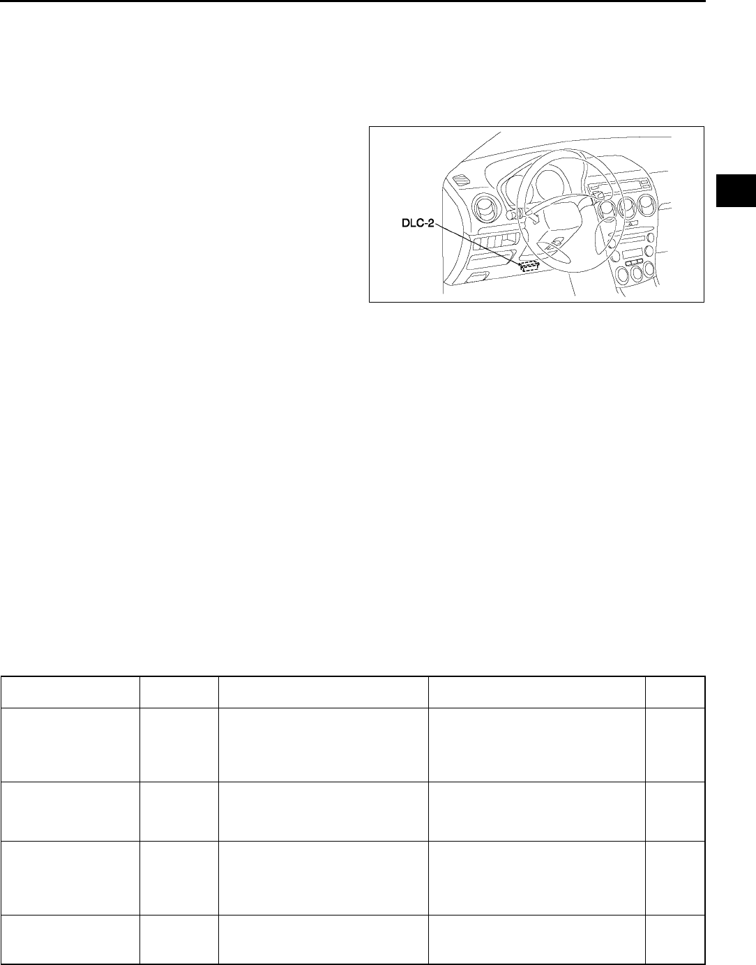
CONTROL SYSTEM
F45
F
PCM INSPECTION A6E394018880W02
Note
•PIDs for the following parts are not available on this model. Go to the appropriate part inspection page.
CMP sensor (See F55 CAMSHAFT POSITION (CMP) SENSOR INSPECTION.)
Main relay (See T24 RELAY INSPECTION.)
1. Connect the SST (WDS or equivalent) to the
DLC-2.
2. Turn the ignition switch to ON position.
3. Measure the PID value.
•If PID value is not within the specification,
follow the instructions in Action column.
Note
•The PID/DATA MONITOR function monitors
the calculated value of the input/output
signals in the PCM. Therefore, an output
device malfunction is not directly indicated
as a malfunction of the monitored value for
the output device. If a monitored value of an
output device is out of specification, inspect the monitored value of the input device related to the output
control.
•For input/output signals except those of the monitoring items, use a voltmeter to measure the PCM
terminal voltage.
•The simulation items that are used in the ENGINE CONTROL SYSTEM OPERATION INSPECTION are
as follows.
ACCS
ALTF
EVAPCP
FAN1
FAN2
FAN3
FP
HTR11
HTR12
IAC
IASV
IMRC
IMTV
VT DUTY1
PID/DATA monitor table (reference)
A6E3970W002
Monitor item
(Definition)
Unit/
Condition
Condition/Specification
(Reference) Action PCM
terminal
ACCS (A/C relay) ON/OFF
Ignition switch ON: OFF
A/C switch ON and fan switch ON at
idle: ON
Inspect following PIDs: RPM, TP,
ECT, ACSW, TR.
Inspect A/C relay.
(See U47 CLIMATE CONTROL
UNIT INSPECTION)
4O
ACSW (A/C switch) ON/OFF
A/C switch and fan switch ON at
ignition switch ON: OFF
A/C switch OFF at ignition switch
ON: OFF
Inspect A/C switch.
(See U47 CLIMATE CONTROL
UNIT INSPECTION)
1AC
ALTF (Generator field
coil control duty value) %
Ignition switch ON: 0%
Idle: 0100%
Just after A/C switch ON and fan
switch ON at idle: Duty value rises
Inspect following PIDs: IAT, ECT,
RPM, VPWR, ALTT V.
Inspect generator.
(See G7 GENERATOR
INSPECTION)
1AD
ALTT V (Generator
output voltage) V
Ignition switch ON: 0 V
Idle: Approx. 14.9 V*1 (E/L not
operating)
Inspect generator.
(See G7 GENERATOR
INSPECTION)
1AA

F46
CONTROL SYSTEM
ARPMDES
(Target engine speed) RPM
L8
No load: 700 rpm
E/L operating: 700 rpm
P/S operating: 750 rpm
A/C ON: 750 rpm
LF MTX and L3 MTX
No load: 650 rpm
E/L operating: 700 rpm
P/S operating: 700 rpm
A/C ON: 750 rpm
LF ATX
No load: 700 rpm
E/L operating: 700 rpm
P/S operating: 700 rpm
A/C ON: 700 rpm*2, 750 rpm*3
Inspect following PIDs: IAT, RPM,
MAP, ECT, MAF, TP, INGEAR,
ACSW, TR, PSP, ALTT V.
Inspect IAC valve.
(See F13 IDLE AIR CONTROL
(IAC) VALVE INSPECTION)
Inspect CKP sensor.
(See F54 CRANKSHAFT POSITION
(CKP) SENSOR INSPECTION)
AST (After start timer) Time
BARO
(Barometric pressure)
Pressure Ignition switch ON (at sea level):
approx 101 kPa
Inspect BARO sensor.
(See F60 BAROMETRIC
PRESSURE (BARO) SENSOR
INSPECTION)
1G
VIgnition switch ON (at sea level):
approx 4.1 V
BOO
(Brake switch) ON/OFF Brake pedal depressed: ON
Brake pedal released: OFF
Inspect brake switch.
(See P8 BRAKE SWITCH
INSPECTION)
1K
CHRGLMP (Generator
warning light) ON/OFF Ignition switch ON: ON
Idle: OFF
Perform applicable DTC
troubleshooting.
(See F67 DTC TABLE)
COLP (Refrigerant
pressure switch
(middle))*4ON/OFF
Refrigerant pressure switch (middle)
ON *2 at idle: ON
Refrigerant pressure switch (middle)
OFF*3 at idle: OFF
Inspect refrigerant pressure switch.
(See U43 REFRIGERANT
PRESSURE SWITCH INSPECTION)
1Q
CPP
(Clutch pedal position) ON/OFF Clutch pedal depressed: ON
Clutch pedal released: OFF
Inspect clutch switch.
(See F59 CLUTCH SWITCH
INSPECTION)
1R
CPP/PNP (Shift lever
position) ON/OFF Neutral position: ON
Others: OFF
Inspect neutral switch.
(See F59 NEUTRAL SWITCH
INSPECTION)
1W
DTCCNT (Number of
DTC detected)
Perform applicable DTC
troubleshooting.
(See F67 DTC TABLE)
ECT (Engine coolant
temperature)
°C°FECT 20 °C {68 °F}: 20 °C {68 °F}
ECT 60 °C {140 °F}: 60 °C {140 °F} Inspect ECT sensor.
(See F53 ENGINE COOLANT
TEMPERATURE (ECT) SENSOR
INSPECTION)
1M
VECT 20 °C {68 °F}: 3.043.14 V
ECT 60 °C {140 °F}: 1.291.39 V
EVAPCP (Purge
solenoid valve duty
value)
%Ignition switch ON: 0%
Idle: 0%
Inspect following PIDs: IAT, RPM,
ECT, MAF, O2S11,BARO, INGEAR,
TR, VPWR.
(See F39 PURGE SOLENOID
VALVE INSPECTION)
4U
FAN1
(Cooling fan control) ON/OFF ECT below 100 °C {212 °F}: OFF
Others: ON
Inspect following PIDs: RPM, TP,
ECT, ACSW, COLP, TEST.
Inspect cooling fan relay.
(See T24 RELAY INSPECTION)
4L
FAN2
(Cooling fan control) ON/OFF
ECT below 108 °C {226 °F}: OFF
A/C operating, refrigerant pressure
switch (middle) is OFF, and ECT
below 108 °C {226 °F}: OFF
Others: ON
Inspect following PIDs: RPM, TP,
ECT, ACSW, COLP, TEST.
Inspect cooling fan relay.
(See T24 RELAY INSPECTION)
4F
FAN3
(Cooling fan control) ON/OFF
ECT below 100 °C {212 °F}: OFF
A/C operating, refrigerant pressure
switch (middle) is ON, and ECT
below 108 °C {226 °F}: OFF
Other: ON
Inspect following PIDs: RPM, TP,
ECT, ACSW, COLP, TEST.
Inspect cooling fan relay.
(See T24 RELAY INSPECTION)
4B
Monitor item
(Definition)
Unit/
Condition
Condition/Specification
(Reference) Action PCM
terminal
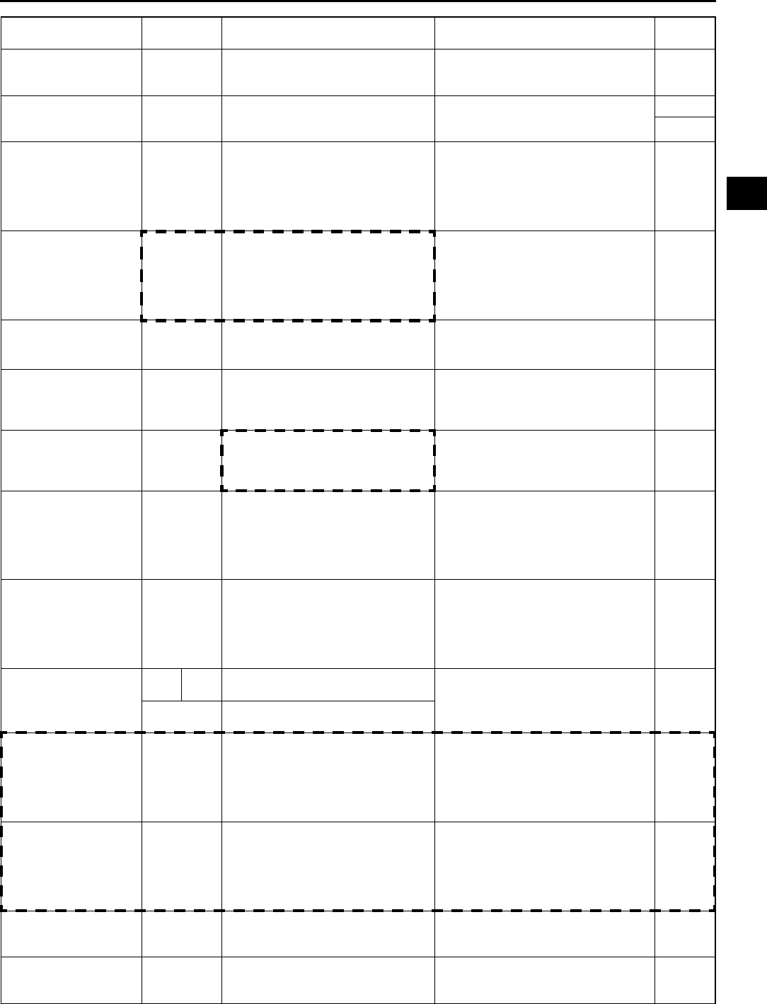
CONTROL SYSTEM
F47
F
FDPDTC
(Pending code caused
FFD storage)
Perform applicable DTC
troubleshooting.
(See F67 DTC TABLE)
FP (Fuel pump relay) ON/OFF
Ignition switch ON: OFF
Idle: ON
Cranking: ON
Inspect following PIDs: RPM.
Inspect fuel pump relay.
(See T24 RELAY INSPECTION)
4P*5
4Q*6
FUELPW (Fuel injector
duration) TIME Ignition switch ON: 0 ms
Idle (after warm up): approx. 2.5 ms
Inspect following PIDs: IAT, MAF, TP,
MAP, ECT, RPM, O2S11, O2S12,
INGEAR, TR, PSP, ACSW, VPWR,
ALTT V.
Inspect fuel injector.
(See T24 RELAY INSPECTION)
4W, 4Z,
4AA,
4AD
FUELSYS
(Fuel system status)
Open loop/
Closed loop
Ignition switch ON: Open loop
Idle (after warm up): Closed loop
Inspect following PIDs: IAT, MAF, TP,
MAP, ECT, RPM, O2S11, O2S12,
INGEAR, TR, PSP, ACSW, VPWR,
ALTT V.
Inspect fuel injector.
(See T24 RELAY INSPECTION)
GENVDSD
(Generator voltage
desired)
V
Ignition switch ON: 0 V
Idle: Approx. 14.9 V*1 (E/L not
operating)
Perform applicable DTC
troubleshooting.
(See F67 DTC TABLE)
HTR11
(HO2S heater (front)) ON/OFF Idle (after warm up): ON⇔OFF
Inspect following PIDs: IAT, MAF, TP,
ECT, RPM, ACSW.
(See F56 HEATED OXYGEN
SENSOR (HO2S) INSPECTION)
4A
HTR12
(HO2S heater (rear)) ON/OFF
Ignition switch ON: OFF (HO2S
heater not operating)
Idle: ON (HO2S heater operating)
Inspect following PIDs: IAT, MAF,
ECT, RPM, ACSW.
(See F56 HEATED OXYGEN
SENSOR (HO2S) INSPECTION)
4D
IAC (IAC valve) %
Ignition switch ON: 0%
Idle: Approx. 60% (ECT 90°C {194
°F} and E/L not operating)
Inspect following PIDs: IAT, RPM,
MAP, ECT, MAF, TP, INGEAR, TR,
PSP, ACSW.
Inspect IAC valve.
(See F13 IDLE AIR CONTROL
(IAC) VALVE INSPECTION)
4G
4J
IASV (Variable air duct
control solenoid valve) ON/OFF
ECT is above 70 °C {158 °F}, engine
speed is above 5,800 rpm, and TP
opening angle is above 50%: ON
Others: OFF
Inspect following PIDs: ECT, RPM,
TP.
Inspect VAD control solenoid valve.
(See F13 VARIABLE AIR DUCT
(VAD) CONTROL SOLENOID
VALVE INSPECTION (L3)
4C
IAT
(Intake air temperature)
°C°FIAT 20 °C {68 °F}: 20 °C {68 °F}
IAT 30 °C {86 °F}: 30 °C {86 °F}
Inspect IAT sensor.
(See F50 INTAKE AIR
TEMPERATURE (IAT) SENSOR
INSPECTION)
2E
VIAT 20 °C {68 °F}: 2.42.6 V
IAT 30 °C {86 °F}: 1.71.9 V
IMRC (Variable tumble
control solenoid valve) ON/OFF
Engine speed is below approx.
3,750 rpm: ON
Others: OFF
Inspect following PIDs: TP, ECT,
RPM.
Inspect VTCS solenoid valve.
(See F15 VARIABLE TUMBLE
CONTROL SOLENOID VALVE
INSPECTION)
4T
IMTV (Variable Intake-
air control solenoid
valve)
ON/OFF
Engine speed is below approx.
4,500 rpm: ON
Others: OFF
Inspect following PIDs: RPM.
Inspect VIS control solenoid valve.
(See F14 VARIABLE INTAKE-AIR
SYSTEM (VIS) CONTROL
SOLENOID VALVE INSPECTION
(L3))
4R
INGEAR (Load/no load
condition) ON/OFF CPP or CPP/PNP is ON: OFF
Others: ON
Perform applicable DTC
troubleshooting.
(See F67 DTC TABLE)
1R, 1W
IVS (CTP condition) ON/OFF CTP: ON
Others: OFF
Perform applicable DTC
troubleshooting.
(See F67 DTC TABLE)
2A
Monitor item
(Definition)
Unit/
Condition
Condition/Specification
(Reference) Action PCM
terminal

F48
CONTROL SYSTEM
KNOCKR (Knocking
retard) ANGLE Ignition switch ON: 0 DEG
Idle: 0 DEG
Inspect knock sensor.
(See F56 KNOCK SENSOR
INSPECTION)
2P, 2S
LOAD (Engine load) % Ignition switch ON: 0%
Idle (after warm up): approx.19%
Inspect MAF sensor.
(See F51 MASS AIR FLOW (MAF)
SENSOR INSPECTION)
LONGFT1 (long term
fuel trim) %Idle (after warm up): approx.14
14%
Perform applicable DTC
troubleshooting.
(See F67 DTC TABLE)
MAF (Mass airflow)
g/s Ignition switch ON: approx. 0 g/s
Idle (after warm up): 1.5 g/s Inspect MAF sensor.
(See F51 MASS AIR FLOW (MAF)
SENSOR INSPECTION
1P
VIgnition switch ON: approx. 0.7 V
Idle (after warm up): 1.3 V
MAP (Manifold
absolute pressure)
Pressure Ignition switch ON (at sea level):
approx 101 kPa
Inspect MAP sensor.
(See F52 MANIFOLD ABSOLUTE
PRESSURE (MAP) SENSOR
INSPECTION)
1J
VIgnition switch ON (at sea level):
approx 4.1 V
MIL (Malfunction
indicator lamp) ON/OFF Ignition switch ON: ON
Idle: OFF
Perform applicable DTC
troubleshooting.
(See F67 DTC TABLE)
MIL_DIS (Trabelled
distance since the MIL
illuminated)
Distance No DTC: 0 km {0 mph}
DTC detected: Not 0 km {0 mph}
Perform applicable DTC
troubleshooting.
(See F67 DTC TABLE)
O2S11 (Front oxygen
sensor) V
Ignition switch ON: 01.0 V
Idle (After warm up): 01.0 V
Acceleration (After warm up):
0.51.0 V
Deceleration (After warm up):
00.5 V
Inspect HO2S (front).
(See F56 HEATED OXYGEN
SENSOR (HO2S) INSPECTION)
1AB
O2S12 (Rear oxygen
sensor) V Idle (After warm up): approx 0.6 V
Inspect HO2S (rear).
(See F56 HEATED OXYGEN
SENSOR (HO2S) INSPECTION)
1Y
PSP (Power steering
pressure switch) ON/OFF
Steering wheel in straight ahead
position: OFF
Others: ON
Inspect PSP switch.
(See F58 POWER STEERING
PRESSURE (PSP) SWITCH
INSPECTION)
1Z
RFCFLAG (Readness
function code) ON/OFF
Before running PCM adaptive
memory procedure drive mode: ON
After running PCM adaptive memory
procedure drive mode: OFF
Run PCM adaptive memory
procedure drive mode.
(See F67 DTC TABLE)
RO2FT1 (Rear oxygen
sensor fuel trim) %Idle (after warm up): approx.14
14%
Perform applicable DTC
troubleshooting.
(See F67 DTC TABLE)
RPM (Engine speed) rpm
L8
No load: 650750 rpm
E/L operating: 650750 rpm
P/S operating: 700800 rpm
A/C ON: 700800 rpm
LF MTX and L3 MTX
No load: 600700 rpm
E/L operating: 650750 rpm
P/S operating: 650750 rpm
A/C ON: 700800 rpm
LF ATX
No load: 650750 rpm
E/L operating: 650750 rpm
P/S operating: 650750 rpm
A/C ON: 650750 rpm*2, 700
800 rpm*3
Inspect CKP sensor.
(See F54 CRANKSHAFT POSITION
(CKP) SENSOR INSPECTION)
2D, 2G
Monitor item
(Definition)
Unit/
Condition
Condition/Specification
(Reference) Action PCM
terminal

CONTROL SYSTEM
F49
F
*1: Calculated value; differs from terminal voltage
*2: Refrigerant pressure switch (middle) turns on when the refrigerant pressure is 1.691.84 MPa {17.318.7
kgf/cm2, 247265 psi}
*3: Refrigerant pressure switch (middle) turns off when the refrigerant pressure is 1.261.49 MPa {12.915.1
kgf/cm2, 184214 psi}
*4: L3 and L8, LF (Intensely hot area) models
*5: Immobilizer system equipped
*6: Immobilizer system not equipped
•Following PIDs are for the ATX models. If inspects for following PIDs, see K110 PID/DATA MONITOR
INSPECTION.
PIDs for the ATX models
GEAR
LINEDES
LPS
OP_SW_B
SSA/SS1
SSB/SS2
SSC/SS3
TCS
TFT
TFTV
THOP
TR
TR_SENS
TSS
End Of Sie
SEGRP (EGR valve
(stepping motor)
position)
STP
Ignition switch ON: 0 step
Idle: 0 step
Cranking: 060 steps
Inspect following PIDs: MAF, TP,
ECT, RPM, VSS.
Inspect EGR valve.
(See F40 EGR VALVE
INSPECTION)
4E
4H
4K
4N
SHRTFT1 (Short term
fuel trim) %Idle (after warm up): approx.30
25%
Perform applicable DTC
troubleshooting.
(See F67 DTC TABLE)
SPARKADV (Ignition
timing) BTC Ignition switch ON: BTDC 0°
Idle: BTDC approx. 10°
Inspect following PIDs: MAF, TP,
ECT, RPM, INGEAR, TR, PSP,
ACSW, VPWR.
Inspect ignition timing.
(See F8 IGNITION TIMING
INSPECTION)
2J
2M
TEST (Test mode) ON/OFF
TP (TP)
%CTP: 1323%
WOT: 8696% Inspect TP sensor.
(See F51 THROTTLE POSITION
(TP) SENSOR INSPECTION)
2A
VCTP: 0.651.15 V
WOT: 4.34.8 V
TPCT
(TP sensor voltage at
CTP )
V 0.651.15 V
Inspect TP sensor.
(See F51 THROTTLE POSITION
(TP) SENSOR INSPECTION)
2A
VPWR (Battery positive
voltage) V Ignition switch ON: B+
Inspect main relay.
(See T24 RELAY INSPECTION)
Inspect battery.
(See G4 BATTERY INSPECTION)
2Y, 2Z
VSS (Vehicle speed) km/h MPH
Vehicle speed 20 km/h {12 mph}:
20 km/h {12 mph}
Vehicle speed 40 km/h {25 mph}:
20 km/h {12 mph}
Perform applicable DTC
troubleshooting.
(See F67 DTC TABLE)
VT DUTY1
ANGLE Idle: 0°Inspect following PIDs: TP, ECT,
RPM.
Inspect OCV.
(See B33 OIL CONTROL VALVE
(OCV) INSPECTION)
2I, 2L
% Idle: 0%
Monitor item
(Definition)
Unit/
Condition
Condition/Specification
(Reference) Action PCM
terminal
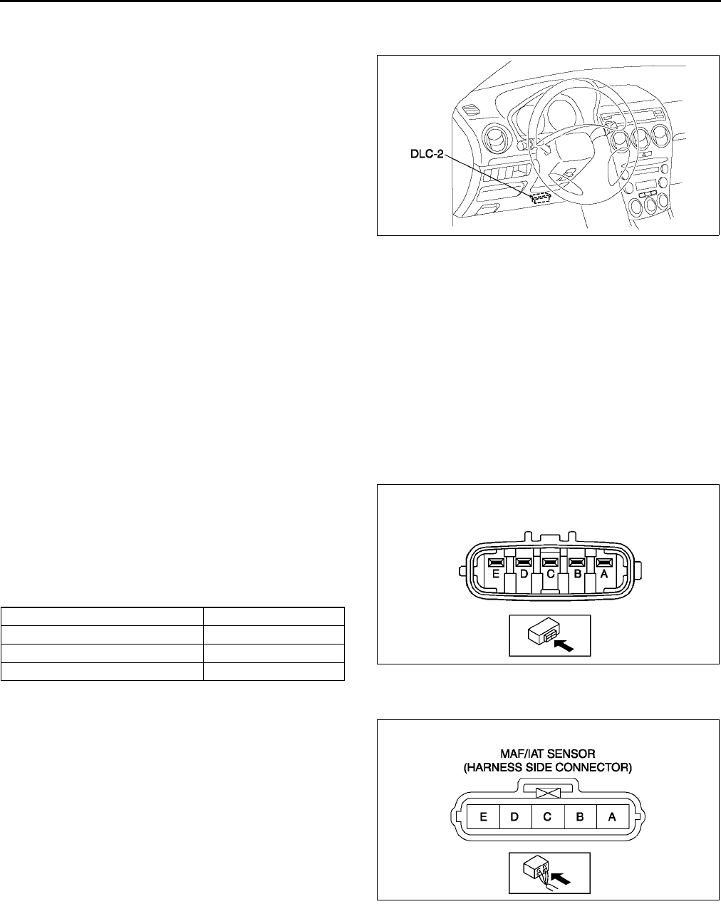
F50
CONTROL SYSTEM
PCM CONFIGURATION A6E394018880W03
1. Connect the WDS to DLC-2.
2. Set up the WDS (including the vehicle
recognition.)
3. Select Module programming.
4. Select Programmable module installation.
5. Select PCM and perform procedures according
to directions on the WDS screen.
Note
•If PCM CONFIGURATION is successful,
the PCM stores the DTC P0602 and
illuminates the MIL. (System is normal.)
Clear the DTC P0602 using WDS or
equivalent after PCM CONFIGURATION.
Note
•MIL goes off after three drive cycles with no failure. (DTCs remain in PCM.)
6. Retrieve DTCs by the WDS or equivalent, then verify that there in no DTC present.
•If DTC is present, perform applicable DTC inspection.
End Of Sie
INTAKE AIR TEMPERATURE (IAT) SENSOR INSPECTION A6E394018845W01
Resistance Inspection
Note
•Perform the following inspection only when directed.
1. Disconnect MAF/IAT sensor.
2. Measure the resistance between the MAF/IAT
sensor terminals D and E using an ohmmeter.
•If not as specified, replace the MAF/IAT
sensor.
•If the MAF/IAT sensor is okay, but the IAT
PID are out of specification, perform the
Circuit Open/Short Inspection.
Specification
Circuit Open/Short Inspection
1. Disconnect the PCM connector. (See F43 PCM
REMOVAL/INSTALLATION.)
2. Inspect the following wiring harnesses for open or
short. (Continuity check)
Open circuit
•If there is no continuity, the circuit is open. Repair
or replace the harness.
MAF/IAT sensor terminal D (harness-side)
and PCM terminal 2E (harness-side)
MAF/IAT sensor terminal E (harness-side)
and PCM terminal 2H (harness-side)
Short circuit
•If there is continuity, the circuit is shorted. Repair
or replace the harness.
MAF/IAT sensor terminal E (harness-side) and power supply
MAF/IAT sensor terminal D (harness-side) and power supply
MAF/IAT sensor terminal D (harness-side) and body GND
End Of Sie
A6E3970W002
Ambient temperature (°
°°
°C {°
°°
°F}) Resistance (kilohm)
20 {4} 13.618.4
20 {68} 2.212.69
60 {140} 0.4930.667 A6E3940W005
A6E3940W006
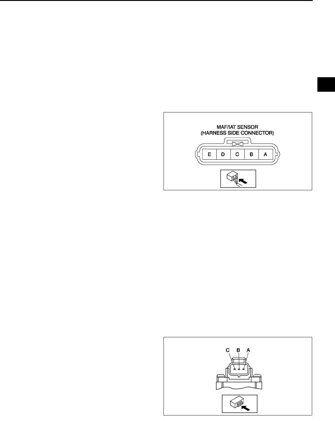
CONTROL SYSTEM
F51
F
MASS AIR FLOW (MAF) SENSOR INSPECTION A6E394013210W01
Voltage Inspection
Note
•Perform the following inspection only when directed.
1. Visually inspect for the following on the MAF sensor.
•Damage
•Cracks
•Terminal bends
•Terminal rust
If any of the above are found, replace the MAF sensor.
If the MAF PID value is out of specification, carry out the Circuit Open/Short Inspection.
Circuit Open/Short Inspection
1. Disconnect the PCM connector. (See F43 PCM
REMOVAL/INSTALLATION.)
2. Disconnect the MAF sensor connector.
3. Inspect the following wiring harnesses for open or
short. (Continuity check)
Open circuit
•If there is no continuity, the circuit is open. Repair
or replace the harness.
MAF sensor terminal A (harness-side) and
main relay terminal C (harness-side)
MAF sensor terminal B (harness-side) and
PCM terminal 2AC (harness-side)
MAF sensor terminal C (harness-side) and
PCM terminal 1P (harness-side)
Short circuit
•If there is continuity, the circuit is shorted. Repair or replace the harness.
MAF sensor terminal A (harness-side) and body GND
MAF sensor terminal C (harness-side) and power supply
MAF sensor terminal C (harness-side) and body GND
MAF sensor terminal B (harness-side) and power supply
End Of Sie
THROTTLE POSITION (TP) SENSOR INSPECTION A6E394018910W01
Note
•Perform the following inspection only when directed.
Resistance Inspection
1. Perform the following test only when directed.
•If as specified but TP PID value is out of specification, inspect resistance of TP sensor.
•If not as specified, inspect the following:
Accelerator cable free play (See F16 ACCELERATOR CABLE INSPECTION/ADJUSTMENT.)
2. Disconnect the TP sensor connector.
3. Verify that the resistance between TP sensor
terminals A and B changes smoothly while
opened and closed the throttle valve slowly.
•If not verified, replace TP sensor.
4. Measure the resistance between TP sensor
terminals A and C using an ohmmeter.
•If not as specified, replace the TP sensor.
•If as specified, but TP PID value is out of
specification, perform the Circuit Open/Short
Inspection.
Specification
3.24.8 kilohms
A6E3940W006
A6E3940W007
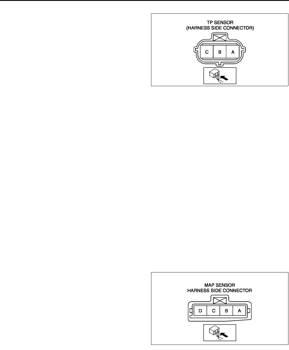
F52
CONTROL SYSTEM
Circuit Open/Short Inspection
1. Disconnect the PCM connector. (See F43 PCM
REMOVAL/INSTALLATION.)
2. Inspect the following wiring harnesses for open or
short. (Continuity check)
Open circuit
•If there is no continuity, the circuit is open. Repair
or replace the harness.
TP sensor terminal A (harness-side) and
PCM terminal 2H (harness-side)
TP sensor terminal B (harness-side) and
PCM terminal 2A (harness-side)
TP sensor terminal C (harness-side) and
PCM terminal 2K (harness-side)
Short circuit
•If there is continuity, the circuit is shorted. Repair or replace the harness.
TP sensor terminal C (harness-side) and power supply
TP sensor terminal C (harness-side) and body GND
TP sensor terminal B (harness-side) and power supply
TP sensor terminal B (harness-side) and body GND
TP sensor terminal A (harness-side) and power supply
End Of Sie
MANIFOLD ABSOLUTE PRESSURE (MAP) SENSOR INSPECTION A6E394018211W01
Note
•Perform the following inspection only when directed.
•The following vacuum values are indicated by relative pressure from the MAP sensor.
1. Connect the SSTs (WDS or equivalent) to the DLC-2.
2. Turn the ignition switch to ON (Engine OFF).
3. Select MAP PID on the SSTs (WDS or equivalent).
4. Verify that the MAP PID (pressure) and barometric pressure are practically equal.
•If not as verified, perform the Circuit Open/Short Inspection.
If there is no open or short circuit, replace the MAP sensor.
•If as verified, go to next step.
5. Apply vacuum of 25.0 kPa {187 mmHg, 7.38 inHg} to the MAP sensor, and verify that the MAP variation
from that of Step 4 is approx. 25.0 kPa {187 mmHg, 7.38 inHg}.
•If not as verified, perform the Circuit Open/Short inspection.
If there is no open or short circuit, replace the barometric pressure sensor.
Circuit Open/Short Inspection
1. Disconnect the PCM connector. (See F43 PCM
REMOVAL/INSTALLATION.)
2. Inspect the following wiring harness for open or
short. (Continuity check)
Open circuit
•If there is no continuity, the circuit is open. Repair
or replace the harness.
MAP sensor terminal A (harness-side) and
PCM terminal 2H
MAP sensor terminal D (harness-side) and
PCM terminal 1J
MAP sensor terminal C (harness-side) and
PCM terminal 2K
Short circuit
•If there is continuity, the circuit is shorted. Repair or replace the harness.
MAP sensor terminal C (harness-side) and power supply.
MAP sensor terminal C (harness-side) and body GND.
MAP sensor terminal D (harness-side) and power supply.
MAP sensor terminal D (harness-side) and body GND
End Of Sie
A6E3940W008
A6E3940W009
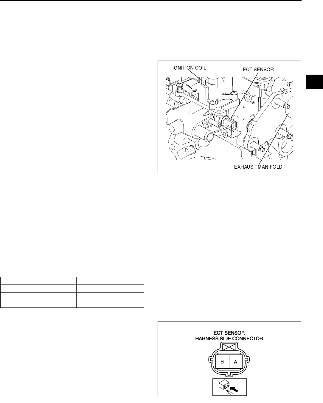
CONTROL SYSTEM
F53
F
ENGINE COOLANT TEMPERATURE (ECT) SENSOR REMOVAL/INSTALLATION A6E394018840W01
Warning
•
••
•When the engine is hot, it can badly burn. Turn off the engine and wait until it is cool before
removing the ECT sensor.
1. Drain the engine coolant. (See E3 COOLING SYSTEM SERVICE WARNINGS.)
2. Disconnect the ECT sensor connector.
3. Remove the ECT sensor.
4. Install in the reverse order of removal.
Tightening torque
1014 N·m
{1.021.42 kgf·m, 7.3810.32 ft·lbf}
5. Refill the engine coolant. (See E3 COOLING
SYSTEM SERVICE WARNINGS.)
End Of Sie
ENGINE COOLANT TEMPERATURE (ECT) SENSOR INSPECTION A6E394018840W02
Note
•Perform the following inspection only when directed.
ECT Sensor Resistance Inspection
1. Drain the engine coolant. (See E3 COOLING SYSTEM SERVICE WARNINGS.)
2. Remove the ECT sensor (located above the starter).
3. Place the ECT sensor in water with a thermometer, and heat the water gradually.
4. Measure the resistance between the ECT sensor terminals A and B using an ohmmeter.
•If not as specified, replace the ECT sensor.
•If the ECT sensor is okay, but ECT PID value is out of specification, perform the Circuit Open/Short
Inspection.
Specification
Circuit Open/Short Inspection
1. Disconnect the PCM connector. (See F43 PCM
REMOVAL/INSTALLATION.)
2. Inspect the following wiring harnesses for open or
short. (Continuity check)
Open circuit
•If there is no continuity, the circuit is open. Repair
or replace the harness.
ECT sensor terminal A (harness-side) and
PCM terminal 1M (harness-side)
ECT sensor terminal B (harness-side) and
PCM terminal 2H (harness-side)
Short circuit
•If there is continuity, the circuit is shorted. Repair
or replace the harness.
ECT sensor terminal A (harness-side) and power supply
ECT sensor terminal A (harness-side) and body GND
A6E3940W010
Water temperature (°
°°
°C {°
°°
°F}) Resistance (kilohms)
20 {68} 35.4839.20
70 {158} 5.075.60
80 {176} 3.654.02
A6E3940W011
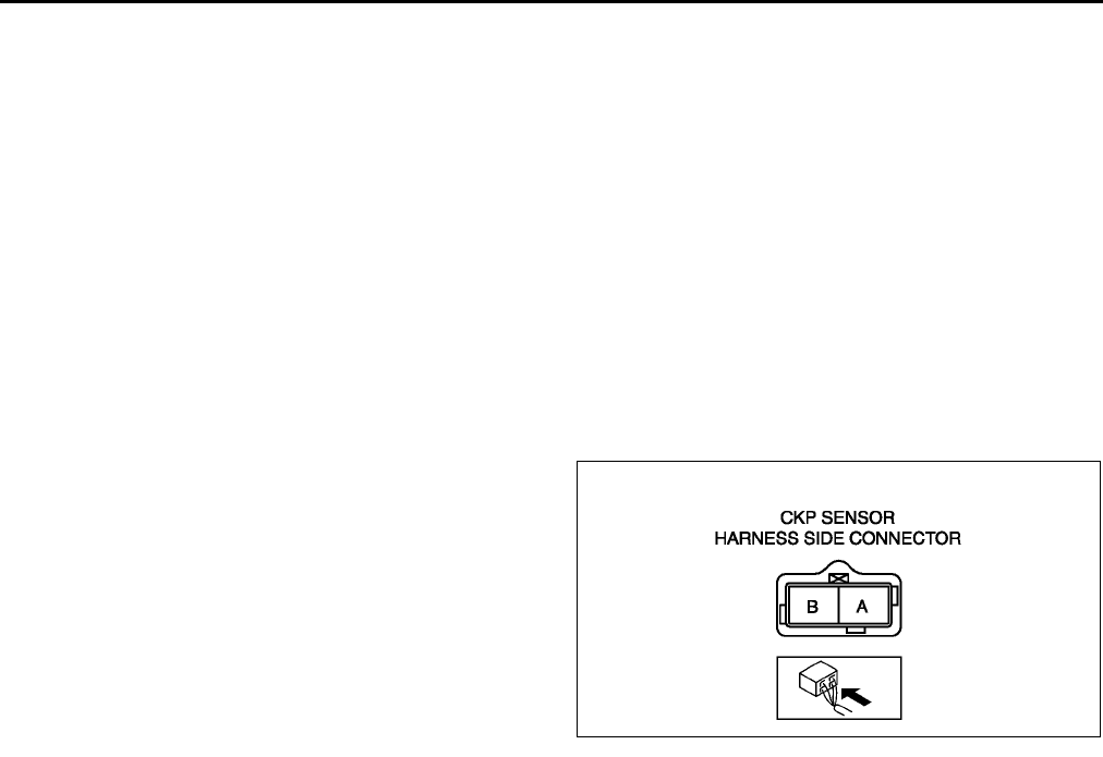
F54
CONTROL SYSTEM
ECT sensor terminal B (harness-side) and power supply
End Of Sie
CRANKSHAFT POSITION (CKP) SENSOR INSPECTION A6E394018230W01
Note
•Perform the following inspection only when directed.
Resistance Inspection
1. Disconnect the CKP sensor connector.
2. Measure the resistance between CKP sensor terminals A and B using an ohmmeter.
•If not as specified, replace the CKP sensor.
•If CKP sensor resistance is okay, but RPM PID value is out of specification, perform the Circuit Open/Short
Inspection.
Specification
400550 ohms
Circuit Open/Short Inspection
1. Disconnect the PCM connector. (See F43 PCM
REMOVAL/INSTALLATION.)
2. Inspect the following wiring harnesses for open or
short. (Continuity check)
Open circuit
•If there is no continuity, the circuit is open. Repair
or replace the harness.
CKP sensor terminal A (harness-side) and
PCM terminal 2D (harness-side)
CKP sensor terminal B (harness-side) and
PCM terminal 2G (harness-side)
Short circuit
•If there is continuity, the circuit is shorted. Repair
or replace the harness.
CKP sensor terminal A (harness-side) and power supply
CKP sensor terminal A (harness-side) and body GND
CKP sensor terminal B (harness-side) and power supply
CKP sensor terminal B (harness-side) and body GND
End Of Sie
CRANKSHAFT POSITION (CKP) SENSOR REMOVAL/INSTALLATION A6E394018230W02
Removal
1. Perform the following procedure to making the working space.
(1) Remove the Front wheel (RH).
(2) Remove the splash shield.
2. Disconnect the CKP sensor connector.
3. Remove the installation bolts to remove the CKP sensor.
Installation
Caution
•
••
•When foreign material such as an iron chip is on the CKP sensor, it can cause abnormal output
from the sensor because of flux turbulence and adversely affect the engine control. Be sure there
is no foreign material on the CKP sensor when replacing.
1. Perform the following procedure so that piston No.1 is at the top dead center.
(1) Remove the front driveshaft (RH). (See M17 DRIVE SHAFT REMOVAL/INSTALLATION.)
A6E3940W012
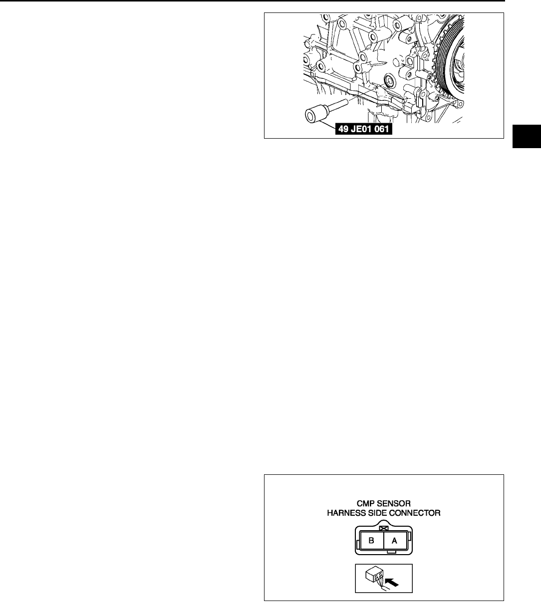
CONTROL SYSTEM
F55
F
(2) Remove the cylinder block lower blind plug
and install the SST.
(3) Turn the crankshaft pulley to the clockwise
until it stops.
2. Install the CKP sensor to the CKP sensor
installer.
3. Fit the forked part of the CKP sensor installer with
the ninth tooth (counting counterclockwise from
the empty space) of the pulse wheel.
4. Install the CKP sensor fitting bolts.
Tightening torque
5.57.5 N·m {5676 kgf·cm, 4.15.5 ft·lbf}
5. Remove the CKP sensor installer
6. Remove the SST then install the cylinder block lower blind plug.
Tightening torque
20 N·m {2.0 kgf·m, 15 ft·lbf}
7. Install the front driveshaft (RH). (See M17 DRIVE SHAFT REMOVAL/INSTALLATION.)
End Of Sie
CAMSHAFT POSITION (CMP) SENSOR INSPECTION A6E394018200W01
Caution
•
••
•When foreign material such as an iron chip is on the CMP sensor, it can cause abnormal output
from the sensor because of flux turbulence and adversely affect the engine control. Be sure there
is no foreign material on the CMP sensor when replacing.
Note
•Perform the following inspection only when directed.
Resistance Inspection
1. Disconnect the CMP sensor connector.
2. Measure the resistance between CMP sensor terminals A and B using an ohmmeter.
•If not as specified, replace the CMP sensor.
•If CMP sensor resistance is okay, perform the Circuit Open/Short Inspection.
Specification
400550 ohms
Circuit Open/Short Inspection
1. Disconnect the PCM connector. (See F43 PCM
REMOVAL/INSTALLATION.)
2. Inspect the following wiring harnesses for open or
short. (Continuity check)
Open circuit
•If there is no continuity, the circuit is open. Repair
or replace the harness.
CMP sensor terminal A (harness-side) and
PCM terminal 2M (harness-side)
CMP sensor terminal B (harness-siede) and
PCM terminal 2J (harness-side)
Short circuit
•If there is continuity, the circuit is shorted. Repair
or replace the harness.
CMP sensor terminal A (harness-side) and power supply
CMP sensor terminal A (harness-side) and body GND
CMP sensor terminal B (harness-side) and power supply
CMP sensor terminal B (harness-side) and body GND
End Of Sie
A6E3940W013
A6E3940W014
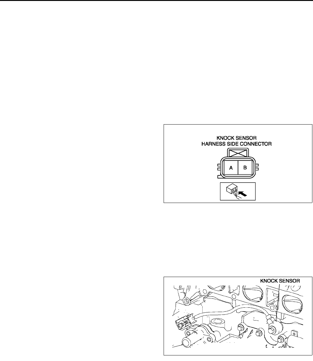
F56
CONTROL SYSTEM
KNOCK SENSOR INSPECTION A6E394018921W01
Note
•Perform the following test only when directed.
Resistance Inspection
1. Turn the ignition switch to LOCK.
2. Disconnect the knock sensor connector.
3. Measure the resistance between the knock sensor terminals A and B using an ohmmeter.
•If not as specified, replace the knock sensor.
•If the knock sensor is okay, but PID value is out of specification, perform the Circuit Open/Short
Inspection.
Specification
Approx. 4.87 megohms
Circuit Open/Short Inspection
1. Disconnect the PCM connector. (See F43 PCM
REMOVAL/INSTALLATION.)
2. Inspect the following wiring harnesses for open or
short. (Continuity check)
Open circuit
•If there is no continuity, the circuit is open. Repair
or replace the harness.
Knock sensor terminal A (harness-side) and
PCM terminal 2S (harness-side)
Knock sensor terminal B (harness-side) and
PCM terminal 2P (harness-side)
Short circuit
•If there is continuity, the circuit is shorted. Repair
or replace the harness.
Knock sensor terminal A (harness-side) and power supply
Knock sensor terminal A (harness-side) and body GND
Knock sensor terminal B (harness-side) and power supply
Knock sensor terminal B (harness-side) and body GND
End Of Sie
KNOCK SENSOR REMOVAL/INSTALLATION A6E394018921W02
1. Remove the intake manifold. (See F10 INTAKE-AIR SYSTEM REMOVAL/INSTALLATION.)
2. Remove the knock sensor attachment bolt to
remove the knock sensor.
3. Install in the reverse order of removal.
Tightening torque
16.223.8 N·m
{1.662.42 kgf·m, 12.017.5 ft·lbf}
End Of Sie
HEATED OXYGEN SENSOR (HO2S) INSPECTION A6E394018861W01
HO2S Voltage Inspection
Note
•Perform the following inspection only when directed.
1. Warm up the engine and run it at idle.
2. Disconnect the HO2S connector.
A6E3940W015
A6E3940W016
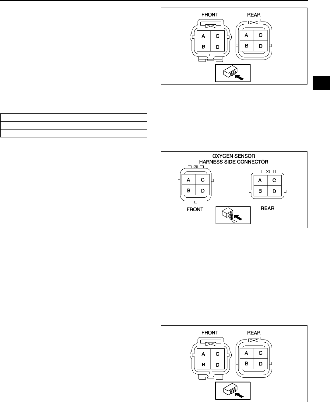
CONTROL SYSTEM
F57
F
3. Connect the voltmeter test leads to the following
HO2S terminals:
•HO2S (front and rear)
(+) leadterminal A
() leadterminal B
4. With the vehicle stopped, run the engine at 3,000
rpm until the voltmeter moves between 0.5 and
0.7 V.
5. Verify that the measurement voltage changes
when the engine speed increases and decreases
suddenly several times.
•If not as specified, replace the HO2S.
•If the HO2S is okay, but O2S11 or O2S12 PID
value is out of specification, perform the
Circuit Open/Short Inspection.
Specification
Circuit Open/Short Inspection (Sensor)
1. Disconnect the PCM connector. (See F43 PCM
REMOVAL/INSTALLATION.)
2. Inspect the following wiring harnesses for open or
short. (Continuity check)
Open circuit
•If there is no continuity, the circuit is open. Repair
or replace the harness.
Front
HO2S terminal A (harness-side) and PCM
terminal 1AB (harness-side)
HO2S terminal B (harness-side) and PCM
terminal 2H (harness-side)
Rear
HO2S terminal A (harness-side) and PCM
terminal 1Y (harness-side)
HO2S terminal B (harness-side) and PCM terminal 2H (harness-side)
Short circuit
•If there is continuity, the circuit is shorted. Repair or replace the harness.
Front and Rear
HO2S terminal A (harness-side) and body GND
HO2S terminal A (harness-side) and power supply
HO2S terminal B (harness-side) and power supply
HO2S Heater Resistance Inspection
1. Disconnect the HO2S connector.
2. Measure the resistance between the HO2S
terminals C and D.
•If not as specified, replace the HO2S.
•If the HO2S heater is okay, but PID value is
out of specification, perform the Circuit Open/
Short Inspection.
Specification
Front : 3.03.6 ohms
Rear : 57 ohms
Engine speed Voltage (V)
Acceleration 0.51.0
Deceleration 00.5
A6E3940W017
A6E3940W018
A6E3940W017
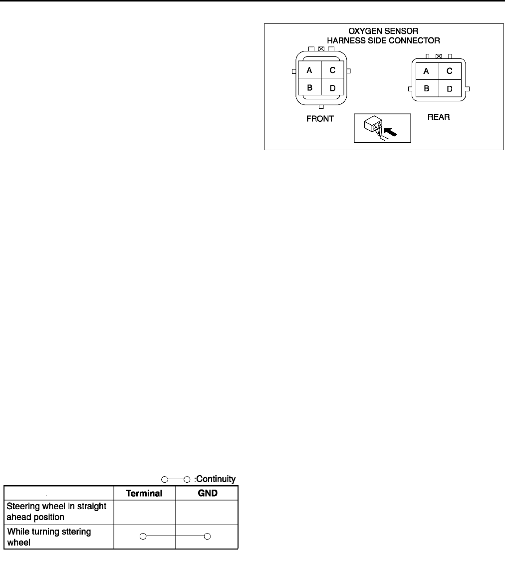
F58
CONTROL SYSTEM
Circuit Open/Short Inspection (Heater)
1. Disconnect the PCM connector. (See F43 PCM
REMOVAL/INSTALLATION.)
2. Inspect the following wiring harnesses for open or
short. (Continuity check)
Open circuit
•If there is no continuity, the circuit is open. Repair
or replace the harness.
Front
HO2S terminal C (harness-side) and ignition
switch
HO2S terminal D (harness-side) and PCM
terminal 4A (harness-side)
Rear
HO2S terminal C (harness-side) and ignition
switch
HO2S terminal D (harness-side) and PCM terminal 4D (harness-side)
Short circuit
•If there is no continuity, the circuit is shorted. Repair or replace the harness.
Front and rear
HO2S terminal C (harness-side) and body GND
HO2S terminal D (harness-side) and power supply
HO2S terminal D (harness-side) and body GND
End Of Sie
POWER STEERING PRESSURE (PSP) SWITCH INSPECTION A6E394032230W01
Note
•Perform the following inspection only when directed.
Continuity Inspection
1. Inspect the following if the power steering is inoperative (See N4 POWER STEERING FLUID INSPECTION.):
•Power steering fluid level
•Power steering fluid leakage
•Power steering fluid pressure
2. Disconnect the PSP switch connector.
3. Start the engine.
4. Inspect for continuity between the PSP switch terminal and GND using an ohmmeter.
•If not as specified, replace the PSP switch.
•If the PSP switch is okay, but PSP PID value is out of specification, perform the Circuit Open Inspection.
Specification
Circuit Open Inspection
1. Disconnect the PCM connector. (See F43 PCM REMOVAL/INSTALLATION.)
2. Inspect the following harness for open or short. (Continuity check)
Open circuit
•If there is no continuity, the circuit is open. Repair or replace the harness.
PSP switch terminal (harness-side) and PCM terminal 1Z (harness-side)
Short circuit
•If there is continuity, the circuit is shorted. Repair or replace the harness.
PSP switch terminal (harness-side) and body GND
End Of Sie
A6E3940W018
A6E3940W019
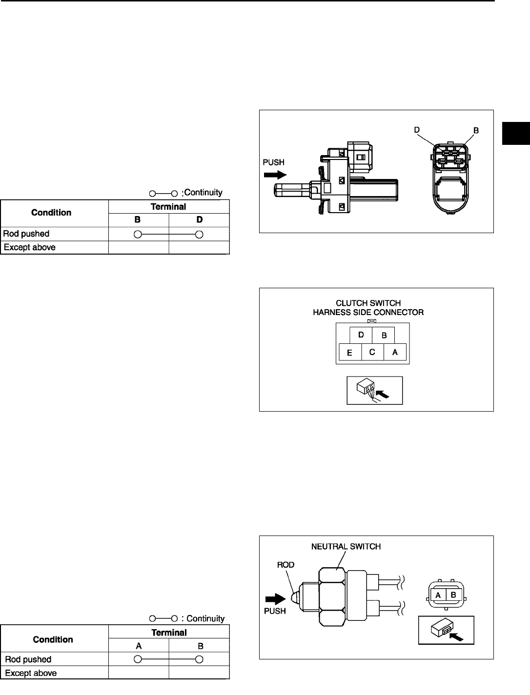
CONTROL SYSTEM
F59
F
CLUTCH SWITCH INSPECTION A6E394018660W01
Note
•Perform the following inspection only when directed.
Continuity Inspection
1. Verify that the clutch switch is installed properly.
2. Disconnect the negative battery cable.
3. Remove the clutch switch.
4. Inspect for continuity between the clutch switch
terminals using an ohmmeter.
•If the clutch switch is okay, but CPP PID value
is out of specification, carry out of the Clutch
Switch Circuit Open/Short Inspection.
•If not as specified, replace the clutch switch.
Specification
Circuit Open/Short Inspection
1. Disconnect the PCM connector. (See F43 PCM
REMOVAL/INSTALLATION.)
2. Inspect the following harness for open or short.
(Continuity check)
Open circuit
•Clutch switch terminal B (harness-side) and PCM
terminal 1R
•Clutch switch terminal D and body GND
Short circuit
•Clutch switch terminal B (harness-side) and
power supply
•Clutch switch terminal B (harness-side) and body
GND
End Of Sie
NEUTRAL SWITCH INSPECTION A6E394017640W01
Note
•Perform the following inspection only when directed.
Continuity Inspection
1. Disconnect the negative battery cable.
2. Remove the neutral switch.J5 MANUAL TRANSAXLE REMOVAL/INSTALLATION.)
3. Inspect for continuity between the neutral switch
terminals using an ohmmeter.
•If the neutral switch is okay, but CPP/PNP
PID value is out of specification, carry out of
the Circuit Open/Short Inspection.
•If not as specified, replace the neutral switch.
Specification
A6E3940W020
A6E3940W022
A6E3940W021
A6E3940W023
A6E3940W025
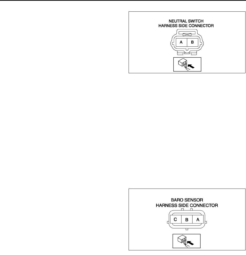
F60
CONTROL SYSTEM
Circuit Open/Short Inspection
1. Disconnect the PCM connector. (See F43 PCM
REMOVAL/INSTALLATION.)
2. Inspect the following harness for open or short.
(Continuity check)
Open circuit
•Neutral switch terminal B (harness-side) and
PCM terminal 1W (harness-side)
•Neutral switch terminal A (harness-side) and
body GND
Short circuit
•Neutral switch terminal B (harness-side) and
body GND
End Of Sie
BAROMETRIC PRESSURE (BARO) SENSOR INSPECTION A6E394018211W02
Note
•Perform the following inspection only when directed.
•The following vacuum values are indicated by relative pressure from the barometric pressure sensor.
1. Connect the SSTs (WDS or equivalent) to the DLC-2.
2. Turn the ignition switch to ON.
3. Select BARO on the SSTs (WDS or equivalent).
4. Verify that the BARO PID (pressure) and barometric pressure are practically equal.
•If not as verified, perform the Circuit Open/Short Inspection.
If there is no open or short circuit, replace the barometric pressure sensor.
•If as verified, go to next step.
5. Apply vacuum of 25.0 kPa {187 mmHg, 7.38 inHg} to the barometric pressure sensor, and verify that the
BARO variation from that of Step 4 is approx. 25.0 kPa {187 mmHg, 7.38 inHg}.
•If not as verified, perform the Circuit Open/Short inspection.
If there is no open or short circuit, replace the barometric pressure sensor.
Circuit Open/Short Inspection
1. Disconnect the PCM connector. (See F43 PCM
REMOVAL/INSTALLATION.)
2. Inspect the following wiring harness for open or
short. (Continuity check)
Open circuit
•If there is no continuity, the circuit is open. Repair
or replace the harness.
Barometric pressure sensor terminal A
(harness-side) and PCM terminal 1G
Barometric pressure sensor terminal B
(harness-side) and PCM terminal 2H
Barometric pressure sensor terminal C
(harness-side) and PCM terminal 2K
Short circuit
•If there is continuity, the circuit is shorted. Repair or replace the harness.
Barometric pressure sensor terminal C (harness-side) and power supply.
Barometric pressure sensor terminal C (harness-side) and body GND.
Barometric pressure sensor terminal A (harness-side) and power supply.
Barometric pressure sensor terminal A (harness-side) and body GND
End Of Sie
A6E3940W024
A6E3940W026
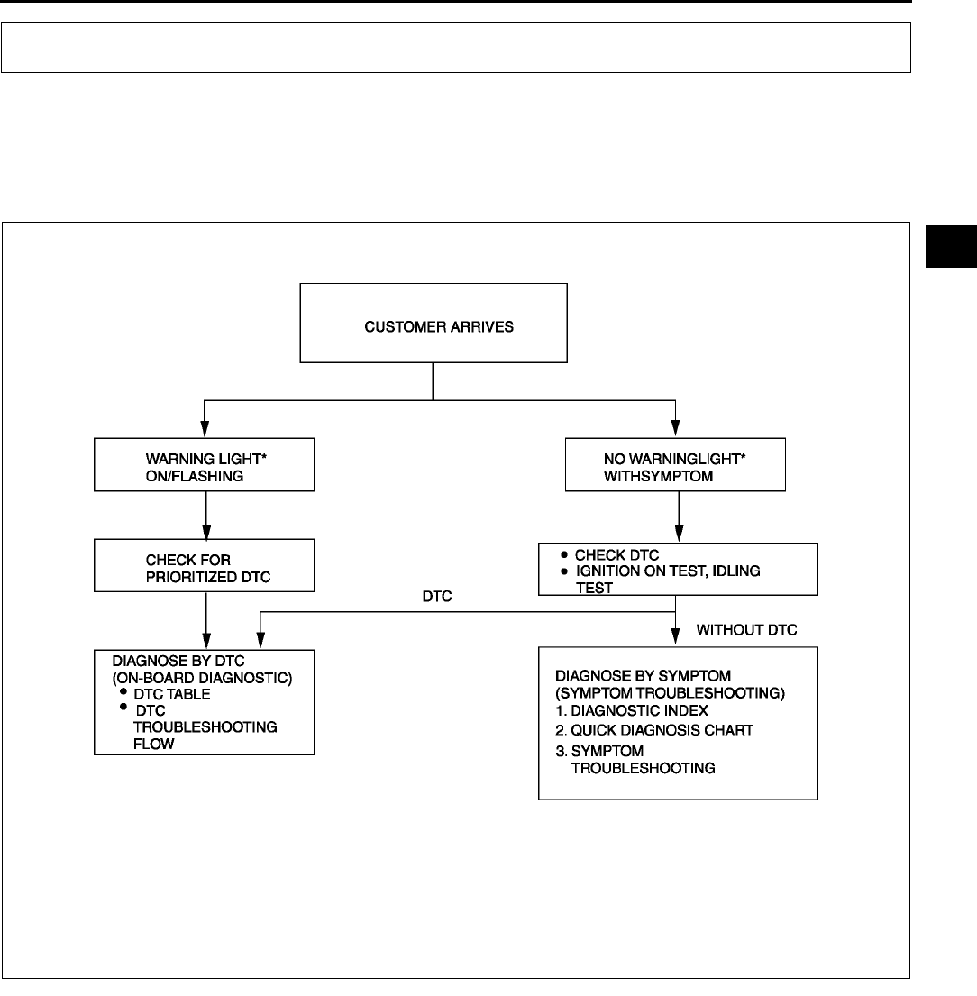
ON-BOARD DIAGNOSTIC
F61
F
FOREWORD A6E397018881W01
•When the customer reports a vehicle malfunction, check the malfunction indicator lamp (MIL) indication and
diagnostic trouble code (DTC), then diagnose the malfunction according to following flowchart.
If a DTC exists, diagnose the applicable DTC inspection. (See F67 DTC TABLE.)
If no DTC exists and the MIL does not illuminate or flash, diagnose the applicable symptom
troubleshooting. (See F181 ENGINE SYMPTOM TROUBLESHOOTING.)
*: Malfunction Indicator lamp (MIL), Generator Warning Light, Security Light
End Of Sie
ON-BOARD DIAGNOSTIC
A6E3970W001

F62
ON-BOARD DIAGNOSTIC
OBD PENDING TROUBLE CODES A6E397018881W02
•These appear when a problem is detected in a monitored system.
2 Drive Cycle Type
•The code for a failed system is stored in the PCM memory in the first drive cycle. If the problem is not found in
the second drive cycle, the PCM judges that the system returned to normal or the problem was mistakenly
detected, and deletes the pending code. If the problem is found in the second drive cycle too, the PCM judges
that the system has failed, and stores the pending codes, and the DTCs.
•After pending codes are stored, if the PCM judges that the system is normal in any future drive cycle, the PCM
deletes the pending codes.
1 Drive Cycle Type
•If any problems are detected in the first drive cycle, pending codes will be stored in the PCM memory, as well
as DTCs.
•After pending codes are stored, if the PCM judges that the system is normal in any future drive cycle, the PCM
deletes the pending codes.
End Of Sie
OBD FREEZE FRAME DATA A6E397018881W03
•This is the technical data which indicates the engine condition at the time of the first malfunction. This data will
remain in the memory even if another emission-related DTC is stored, with the exception of the Misfire or Fuel
System DTCs. Once freeze frame data for the Misfire or Fuel System DTC is stored, it will overwrite any
previous data and the freeze frame will not be overwritten again.
End Of Sie
OBD ON-BOARD SYSTEM READINESS TEST A6E397018881W04
•This shows OBD system operating status. If any monitor function is incomplete, WDS or equivalent will identify
which monitor function has not been completed. Misfires, Fuel System and Comprehensive Components
(CCM) are continuous monitoring-type functions. The catalyst, EGR system and oxygen sensor will be
monitored under drive cycles. The OBD diagnostic system is initialized by performing the DTC cancellation
procedure or disconnecting the negative battery cable.
End Of Sie
OBD DIAGNOSTIC MONITORING TEST RESULTS A6E397018881W05
•These results from the intermittent monitor systems technical data, which are used to determine whether the
system is normal or not. They also display the system thresholds and diagnostic results. The intermittent
monitor system monitors the oxygen sensorand the catalyst.
End Of Sie
OBD READ/CLEAR DIAGNOSTIC TEST RESULTS A6E397018881W06
•This retrieves all stored DTCs in the PCM and clears the DTCs, Freeze Frame Data, On-Board Readiness Test
Results, Diagnostic Monitoring Test Results and Pending Trouble Codes.
End Of Sie
OBD PARAMETER IDENTIFICATION (PID) ACCESS A6E397018881W07
•The PID mode allows access to certain data values, analog and digital inputs and outputs, calculated values
and system status information. Since PID values for output devices are PCM internal data values, inspect each
device to identify which output devices are malfunctioning.
End Of Sie
ON-BOARD DIAGNOSTIC TEST A6E397018881W08
DTCs Reading Procedure
1. Perform the necessary vehicle preparation and visual inspection.
2. Connect WDS or equivalent to the vehicle DLC-2
16-pin connector located as shown in the figure.
3. Retrieve DTCs by WDS or equivalent.
A6E3970W002
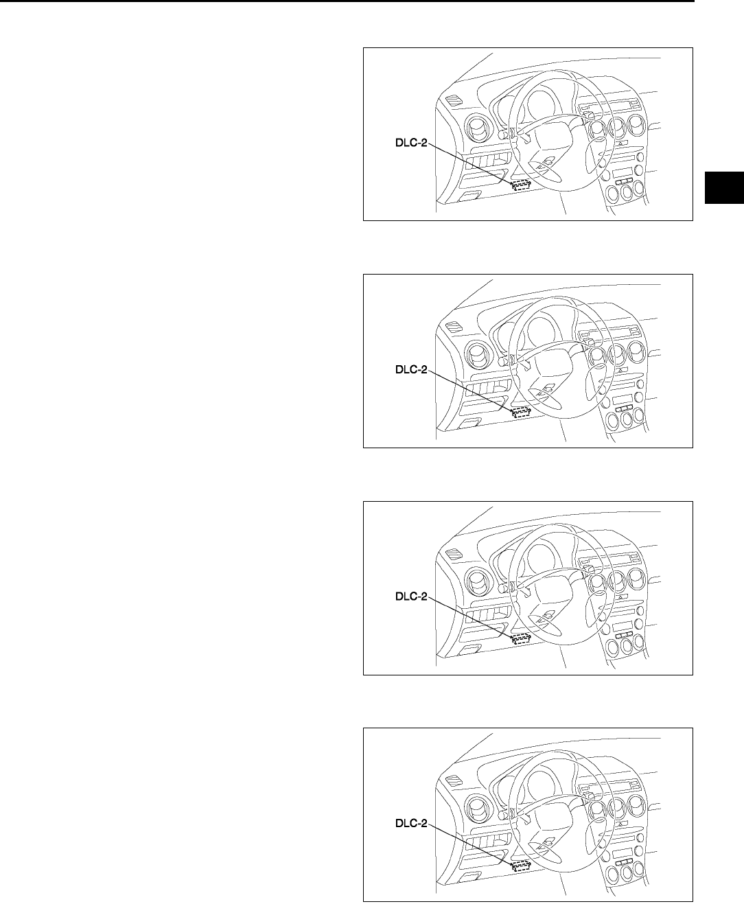
ON-BOARD DIAGNOSTIC
F63
F
Pending Trouble Code Access Procedure
1. Perform the necessary vehicle preparation and visual inspection.
2. Connect WDS or equivalent to the vehicle DLC-2
16-pin connector located as shown in the figure.
3. Retrieve PENDING TROUBLE CODES by WDS
or equivalent.
Freeze Frame PID Data Access Procedure
1. Perform the necessary vehicle preparation and visual inspection.
2. Connect WDS or equivalent to the vehicle DLC-2
16-pin connector located as shown in the figure.
3. Record the FREEZE FRAME DATA by WDS or
equivalent.
On-Board System Readiness Tests Access Procedure
1. Perform the necessary vehicle preparation and visual inspection.
2. Connect WDS or equivalent to the vehicle DLC-2
16-pin connector located as shown in the figure.
3. Monitor the OBD systems operating status by
WDS or equivalent.
Diagnostic Monitoring Test Results Access Procedure
1. Perform the necessary vehicle preparation and visual inspection.
2. Connect WDS or equivalent to the vehicle DLC-2
16-pin connector located as shown in the figure.
3. Access to the DIAGNOSTIC MONITORING
TEST RESULTS and read the test results by
WDS or equivalent.
End Of Sie
A6E3970W002
A6E3970W002
A6E3970W002
A6E3970W002
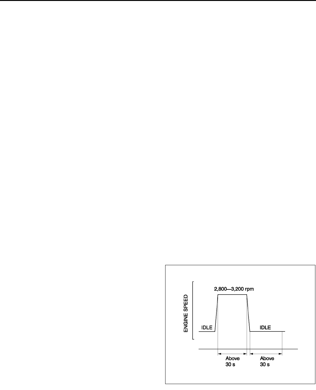
F64
ON-BOARD DIAGNOSTIC
OBD DRIVE MODE A6E397018881W09
•Performing the Drive Mode inspects the OBD system for proper operation. The Drive Mode must be performed
to ensure that no additional DTCs are present.
•During Drive Mode, the following systems are inspected:
Oxygen sensor (HO2S)
Oxygen sensor heater
Catalytic converter (TWC)
Caution
•
••
•While performing the Drive Mode, always operate the vehicle in a safe and lawful manner.
•
••
•When the WDS or equivalent is used to observe monitor system condition while driving, be sure to
have another technician with you, or record the data in the WDS or equivalent using the PID/DATA
MONITOR AND RECORD function and inspect later.
Note
•Vehicle speed and engine speed detected by the PCM may differ from that indicated by the speedometer
and tachometer. Use the WDS or equivalent to monitor vehicle speed.
•If the OBD system inspection is not completed during the Drive Mode, the following causes are
considered:
1. The OBD system detects the malfunction.
2. The Drive Mode procedure is not completed correctly.
•Disconnecting the battery will reset the memory. Do not disconnect the battery during and after Drive
Mode.
•The WDS or equivalent can be used at anytime through the course of Drive Mode to monitor the
completion condition. Monitoring can be done by viewing the ON-BOARD SYSTEM READINESS menu.
PCM Adaptive Memory Procedure Drive Mode
Note
•The PCM adaptive memory condition can be confirmed with RFCFLAG PID.
•If RFCFLAG PID is ON, PCM Adaptive Memory Procedure Drive Mode is not necessary, because PCM
already has adaptive memory.
•If RFCFLAG PID is OFF, PCM Adaptive Memory Procedure Drive should be performed before HO2S
Heater, HO2S, and TWC Repair Verification Drive Mode.
1. Start the engine and warm it up completely.
2. Verify all accessory loads (A/C, headlights, blower fan, rear window defroster) are off.
3. Perform no load racing at the engine speed
shown in the graph, then idle the engine for more
than 30 s after the cooling fan is stopped. If
possible, monitor RPM PID for engine speed and
FAN1 PID for cooling fan condition during this
procedure.
4. Turn ignition key off then on again.
5. Access to RFC FLAG PID to confirm PCM
adaptive memory condition. If RFCFLAG PID is
ON, PCM Adaptive Memory Procedure Drive is
completed.
6. If RFCFLAGPID is still OFF, go back to Step 1.
HO2S Heater, HO2S, and TWC Repair Verification Drive Mode
1. Access to RFCFLAG PID to confirm PCM adaptive memory condition. If RFCFLAG PID is OFF, perform PCM
Adaptive Memory Procedure Drive first.
2. If RFCFLAG PID is ON, start the engine and warm it up completely.
3. Verify all accessory loads (A/C, headlights, blower fan, rear window defroster) are off.
4. Drive the vehicle as shown in the graph; first drive in zone O, then A or B, followed by C or D, finally E or F.
Driving condition before the constant speed driving is not specified.
A6E3970W003
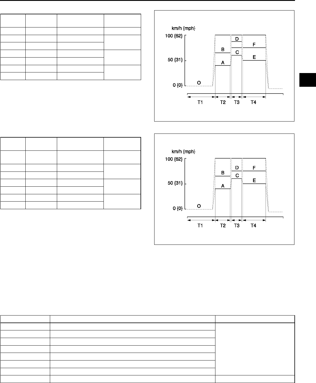
ON-BOARD DIAGNOSTIC
F65
F
For MTX
For ATX
5. Stop vehicle and access to ON BOARD SYSTEM
READINESS menu of GENERIC OBD
FUNCTION to inspect the Drive Mode completion
condition. If completed, RFC changes from NO to
YES.
6. If not completed, turn the ignition key to OFF,
then go back to Step 4.
7. Access DIAGNOSTIC MONITORING TEST RESULTS menu of GENERIC OBD FUNCTIONS to inspect the
monitor results. If MEAS are not within the specification, repair has not completed.
8. Verify no DTC is available.
End Of Sie
DIAGNOSTIC MONITORING TEST RESULTS A6E397018881W10
•The purpose of this test mode is to confirm the result of OBD monitor diagnostic test results. The result values
stored when particular monitor is completed are displayed. If the monitor is not completed, initial value is
displayed.
End Of Sie
Zone Shift
Position
Vehicle Speed
km/h {mph}
Time
Sec.
O Neutral 0 {0} T1: Above 455
A 2nd 4050 {2532} T2: Above 30
B 3rd 6575 {4147}
C 2nd 6075 {3846} T3: Above 20
D 3rd 75100 {4762}
E 4th 5075 {3146} T4: Above 120
F 5th 75100 {4762}
A6E3970W004
Zone Range Vehicle Speed
km/h {mph}
Time
Sec.
O P or N 0 {0} T1: Above
455
A S (HOLD) 4065 {2541} T2: Above 30
B D (HOLD) 65100 {4062}
C S (HOLD) 6075 {3846} T3: Above 20
D D (HOLD) 85100 {5262}
E D (HOLD) 5075 {3147} T4: Above
120
F D 75100 {4662}
A6E3970W005
TEST ID Description Related system
10:01:0A Rich to lean sensor threshold voltage
HO2S
10:02:0A Lean to rich sensor threshold voltage
10:03:0A Low sensor voltage for switching time calculation
10:04:0A High sensor voltage for switching time calculation
10:05:10 Rich to lean sensor switching time
10:06:10 Lean to rich sensor switching time
10:0A:10 Sensor period
10:80:20 Front and rear HO2S switching time ratio TWC
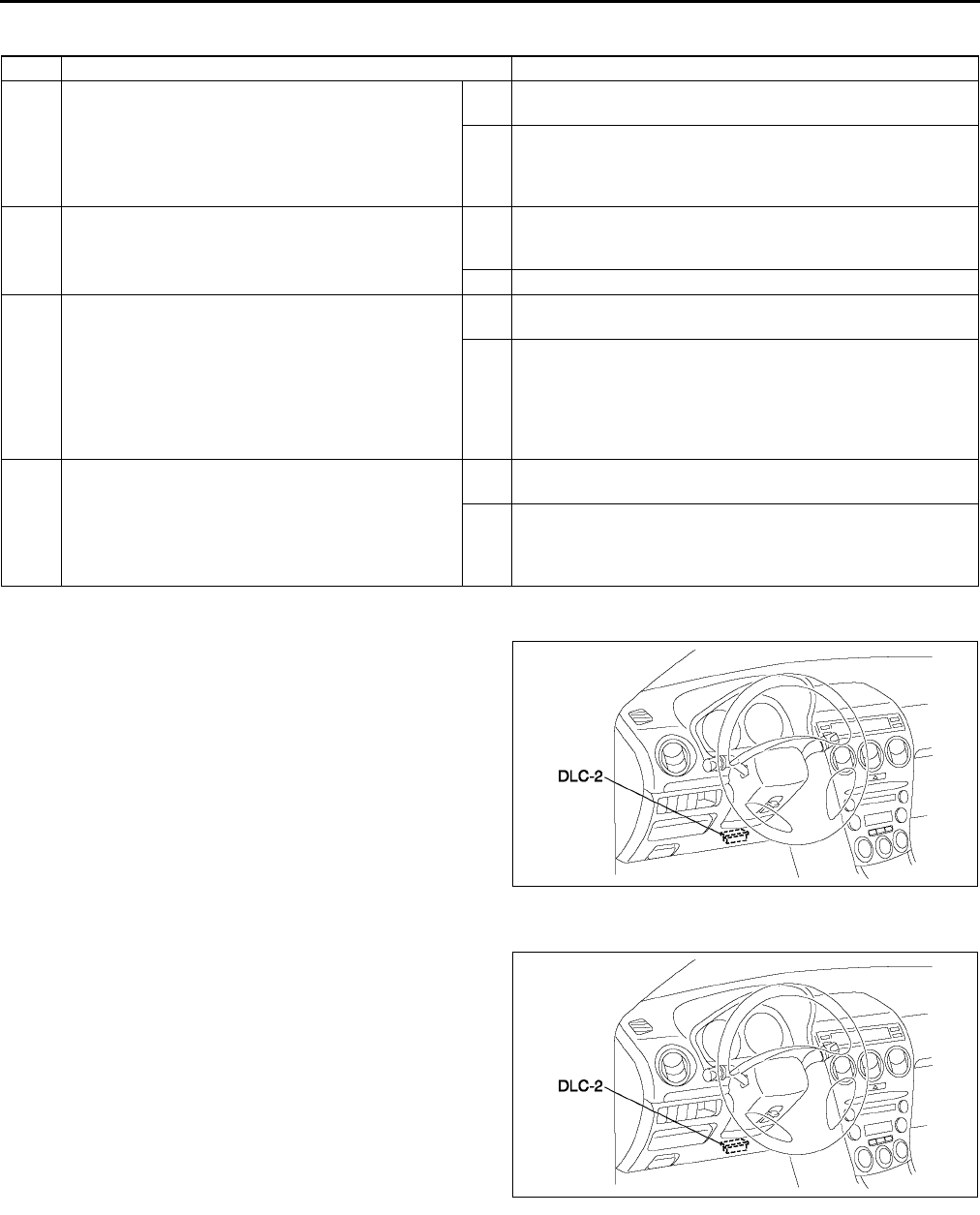
F66
ON-BOARD DIAGNOSTIC
DTC CONFIRMATION PROCEDURE A6E397018881W11
End Of Sie
KOEO/KOER SELF-TEST A6E397018881W12
1. Connect WDS or equivalent to the vehicle DLC-2
16-pin connector located as shown in the figure.
2. Perform KOEO/KOER self-test.
End Of Sie
AFTER REPAIR PROCEDURE A6E397018881W13
1. Connect WDS or equivalent to the vehicle DLC-2
16-pin connector located as shown in the figure.
2. Turn the ignition key from OFF to ON.
3. Record DTC if retrieved.
4. Erase all diagnostic data by WDS or equivalent.
End Of Sie
STEP INSPECTION ACTION
1RECORD CONTINUOUS MEMORY DTC AND
FREEZE FRAME DATA
•Turn ignition key to ON (Engine OFF).
•Connect WDS or equivalent to DLC.
•Retrieve all stored DTCs.
•Are there any DTCs present?
Yes Record all stored DTCs (Continuous Memory DTC) and
Freeze Frame Data on repair order, then go to next step.
No Go to next step.
2VERIFY RELATED REPAIR INFORMATION
•Check for related Service information
availability.
•Is any related repair information available?
Yes Perform repair or diagnosis according to available Service
information.
•If vehicle is not repaired, go to next step.
No Go to next step.
3PERFORM KEY ON ENGINE OFF (KOEO)
SELF-TEST
•Start engine.
•Warm up engine completely.
•Turn off all electrical loads.
•Perform KOEO SELF-TEST PROCEDURE.
(See F66 KOEO/KOER SELF-TEST)
•Are there any KOEO DTCs present?
Yes Repair KOEO DTC.
(See F67 DTC TABLE)
No Go to next step.
4PERFORM KEY ON ENGINE RUNNING (KOER)
SELF-TEST
•Start engine.
•Perform KOER SELF-TEST PROCEDURE.
(See F66 KOEO/KOER SELF-TEST)
•Are there any KOER DTCs present?
Yes Repair KOER DTC.
(See F67 DTC TABLE
No •If Continuous Memory DTC is present at Step 1, return
to applicable DTC troubleshooting procedure step.
•If Continuous Memory DTC is not present at Step 1, go
to symptom troubleshooting.
A6E3970W002
A6E3970W002

ON-BOARD DIAGNOSTIC
F67
F
DTC TABLE A6E397018881W14
DTC table
×: Applicable
: Not applicable
DTC No. Condition MIL DC Monitor item Memory
function Page
P0010 CMP actuator circuit
malfunction ON 1 CCM ×(See F70 DTC P0010)
P0011 CMP timing over-advanced ON 1 CCM ×(See F72 DTC P0011)
P0012 CMP timing over-retarded ON 1 CCM ×(See F73 DTC P0012)
P0031 Front HO2S heater circuit low
input ON 2 O2 sensor heater ×(See F74 DTC P0031)
P0032 Front HO2S heater circuit high
input ON 2 O2 sensor heater ×(See F76 DTC P0032)
P0037 Rear HO2S heater circuit low
input ON 2 O2 sensor heater ×(See F78 DTC P0037)
P0038 Rear HO2S heater circuit high
input ON 2 O2 sensor heater ×(See F80 DTC P0038)
P0101 MAF sensor inconsistent with
TP sensor ON 2 CCM ×(See F81 DTC P0101)
P0102 MAF circuit low input ON 1 CCM ×(See F83 DTC P0102)
P0103 MAF circuit high input ON 1 CCM ×(See F85 DTC P0103)
P0107 MAP sensor circuit low input ON 1 CCM ×(See F86 DTC P0107)
P0108 MAP sensor circuit high input ON 1 CCM ×(See F88 DTC P0108)
P0111 IAT circuit performance problem ON 2 CCM ×(See F90 DTC P0111)
P0112 IAT circuit low input ON 1 CCM ×(See F91 DTC P0112)
P0113 IAT circuit high input ON 1 CCM ×(See F92 DTC P0113)
P0117 ECT circuit low input ON 1 CCM ×(See F94 DTC P0117)
P0118 ECT circuit high input ON 1 CCM ×(See F96 DTC P0118)
P0121 TP stuck closed ON 2 CCM ×(See F98 DTC P0121)
P0122 TP circuit low input ON 1 CCM ×(See F100 DTC P0122)
P0123 TP circuit high input ON 1 CCM ×(See F102 DTC P0123)
P0125 Excessive time to enter closed
loop fuel control ON 2 CCM ×(See F104 DTC P0125)
P0131 Front HO2S no inversion (stuck
low) ON 2 CCM ×(See F105 DTC P0131,
P0132)
P0132 Front HO2S no inversion (stuck
high) ON 2 CCM ×(See F105 DTC P0131,
P0132)
P0133 Front HO2S circuit malfunction ON 2 O2 sensor ×(See F108 DTC P0133)
P0134 Front HO2S circuit no activity
detected ON 2 CCM ×(See F110 DTC P0134)
P0138 Rear HO2S circuit high input ON 2 CCM ×(See F112 DTC P0138)
P0140 Rear HO2S circuit no activity
detected ON 2 CCM ×(See F114 DTC P0140)
P0171 Fuel trim system too lean ON 2 Fuel ×(See F116 DTC P0171)
P0172 Fuel trim system too rich ON 2 Fuel ×(See F119 DTC P0172)
P0300 Random misfire detected Flash / ON 1 or 2 Misfire ×(See F121 DTC P0300)
P0301 Cylinder No.1 misfire detected Flash / ON 1 or 2 Misfire ×
(See F124 DTC P0301,
P0302, P0303, P0304)
P0302 Cylinder No.2 misfire detected Flash / ON 1 or 2 Misfire ×
P0303 Cylinder No.3 misfire detected Flash / ON 1 or 2 Misfire ×
P0304 Cylinder No.4 misfire detected Flash / ON 1 or 2 Misfire ×
P0327 Knock sensor circuit low input ON 1 CCM ×(See F126 DTC P0327)
P0328 Knock sensor circuit high input ON 1 CCM ×(See F128 DTC P0328)
P0335 CKP sensor circuit malfunction ON 1 CCM ×(See F130 DTC P0335)
P0340 CMP sensor circuit malfunction ON 1 CCM ×(See F132 DTC P0340)
P0403 EGR valve motor coils open or
short ON 2 CCM ×(See F134 DTC P0403)
P0420 Catalyst system efficiency
below threshold ON 2 Catalyst ×(See F137 DTC P0420)

F68
ON-BOARD DIAGNOSTIC
P0443
Evaporative emission control
system purge control valve
circuit malfunction
ON 2 CCM ×(See F138 DTC P0443)
P0480 Fan relay control circuit
malfunction OFF 2 Other ×(See F140 DTC P0480)
P0500
Vehicle speed sensor (VSS)
circuit malfunction (MTX) ON 2 CCM ×(See F142 DTC P0500)
Vehicle speed sensor (VSS)
circuit malfunction (ATX) (See K53 DTC TABLE)
P0505 Idle control system malfunction OFF Other (See F144 DTC P0505)
P0506 Idle control system RPM lower
than expected ON 2 CCM ×(See F145 DTC P0506)
P0507 Idle control system RPM higher
than expected ON 2 CCM ×(See F147 DTC P0507)
P0511 Idle control system circuit
malfunction ON 1 CCM ×(See F148 DTC P0511)
P0550 PSP switch circuit malfunction ON 2 CCM ×(See F150 DTC P0550)
P0602 PCM programming error ON 1 CCM ×(See F152 DTC P0602)
P0610 Control module vehicle options
error ON 1 CCM ×(See F152 DTC P0610)
P0661 VIS control circuit low input OFF 2 Other ×(See F153 DTC P0661)
P0662 VIS control circuit high input OFF 2 Other ×(See F154 DTC P0662)
P0703 Brake switch input malfunction ON 2 CCM ×(See F156 DTC P0703)
P0704 Clutch switch input malfunction ON 2 CCM ×(See F158 DTC P0704)
P0706 Transaxle range (TR) switch
circuit range/performance (See K53 DTC TABLE)
P0707 Transaxle range (TR) switch
circuit low input (See K53 DTC TABLE)
P0708 Transaxle range (TR) switch
circuit high input (See K53 DTC TABLE)
P0711
Transaxle fluid temperature
(TFT) sensor circuit range/
performance (Stuck)
(See K53 DTC TABLE)
P0712
Transaxle fluid temperature
(TFT) sensor circuit malfunction
(short to ground)
(See K53 DTC TABLE)
P0713
Transaxle fluid temperature
(TFT) sensor circuit malfunction
(open circuit)
(See K53 DTC TABLE)
P0715 Input/turbine speed sensor
circuit malfunction (See K53 DTC TABLE)
P0731 Gear 1 incorrect (Incorrect Gear
Ratio Detected) (See K53 DTC TABLE)
P0732 Gear 2 incorrect (Incorrect Gear
Ratio Detected) (See K53 DTC TABLE)
P0733 Gear 3 incorrect (Incorrect Gear
Ratio Detected) (See K53 DTC TABLE)
P0734 Gear 4 incorrect (Incorrect Gear
Ratio Detected) (See K53 DTC TABLE)
P0741 Torque converter clutch (TCC)
(stuck OFF) (See K53 DTC TABLE)
P0742 Torque converter clutch (TCC)
(stuck ON) (See K53 DTC TABLE)
P0745 Pressure control solenoid
malfunction (See K53 DTC TABLE)
P0751 Shift solenoid A stuck OFF (See K53 DTC TABLE)
P0752 Shift solenoid A stuck ON (See K53 DTC TABLE)
P0753 Shift solenoid A malfunction
(electrical) (See K53 DTC TABLE)
P0756 Shift solenoid B stuck OFF (See K53 DTC TABLE)
DTC No. Condition MIL DC Monitor item Memory
function Page

ON-BOARD DIAGNOSTIC
F69
F
End Of Sie
P0757 Shift solenoid B stuck ON (See K53 DTC TABLE)
P0758 Shift solenoid B malfunction
(electrical) (See K53 DTC TABLE)
P0761 Shift solenoid C stuck OFF (See K53 DTC TABLE)
P0762 Shift solenoid C stuck ON (See K53 DTC TABLE)
P0763 Shift solenoid C malfunction
(electrical) (See K53 DTC TABLE)
P0766 Shift solenoid D stuck OFF (See K53 DTC TABLE)
P0767 Shift solenoid D stuck ON (See K53 DTC TABLE)
P0768 Shift solenoid D malfunction
(electrical) (See K53 DTC TABLE)
P0771 Shift solenoid E stuck OFF (See K53 DTC TABLE)
P0772 Shift solenoid E stuck ON (See K53 DTC TABLE)
P0773 Shift solenoid E malfunction
(electrical) (See K53 DTC TABLE)
P0841 Oil pressure switch circuit
malfunction (See K53 DTC TABLE)
P0850 Neutral switch input malfunction ON 2 CCM ×(See F160 DTC P0850)
P1410 Variable air duct valve circuit
malfunction OFF 2 Other ×(See F162 DTC P1410)
P1562 PCM +BB voltage low ON 1 CCM ×(See F164 DTC P1562)
P2006 Variable tumble control system
shutter valve stuck closed ON 2 CCM ×(See F166 DTC P2006)
P2009 Variable tumble control solenoid
valve circuit low input ON 2 CCM ×(See F168 DTC P2009)
P2010 Variable tumble control solenoid
valve circuit high input ON 2 CCM ×(See F170 DTC P2010)
P2228 BARO sensor circuit low input ON 1 CCM ×(See F172 DTC P2228)
P2229 BARO sensor circuit high input ON 1 CCM ×(See F174 DTC P2229)
P2502 Generator output voltage signal
no electricity OFF 1 Other (See F176 DTC P2502)
P2503 Battery overcharge OFF 1 Other (See F177 DTC P2503)
P2504 Generator terminal B circuit
open OFF 1 Other (See F178 DTC P2504)
U0073 CAN bus off OFF 1 Other
(See T141 MULTIPLEX
COMMUNICATION
SYSTEM)
U0121
PCM cannot receive any
signals from ABS, ABS/TCS or
DSC HU/CM
ON 1 Other ×
(See T141 MULTIPLEX
COMMUNICATION
SYSTEM)
U0155 PCM cannot receive any
signals from combination meter ON 1 Other ×
(See T141 MULTIPLEX
COMMUNICATION
SYSTEM)
DTC No. Condition MIL DC Monitor item Memory
function Page
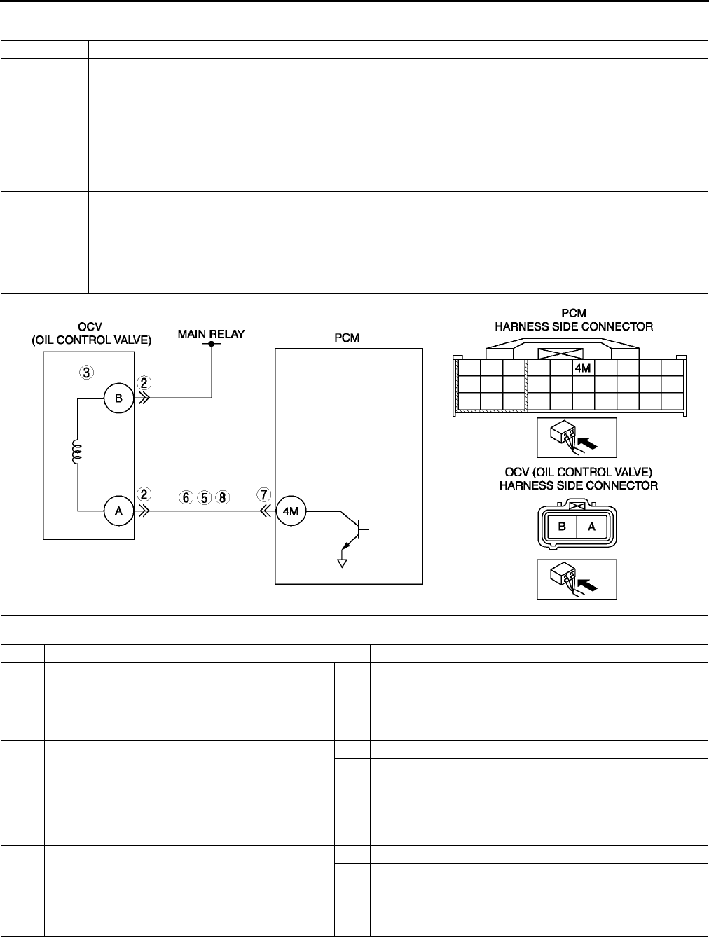
F70
ON-BOARD DIAGNOSTIC
DTC P0010 A6E397001084W01
Diagnostic procedure
DTC P0010 CMP actuator circuit
DETECTION
CONDITION
•PCM monitors OCV voltage. If PCM detects OCV control voltage (calculated from OCV) is above or below
the threshold voltage (calculated from battery positive voltage), PCM determines that OCV circuit has
malfunction.
Diagnostic support note
•This is a continuous monitor (CCM).
•MIL illuminates if PCM detects the above malfunction condition during first drive cycle.
•PENDING CODE is available if PCM detects the above malfunction.
•FREEZE FRAME DATA is available.
•DTC is stored in PCM memory.
POSSIBLE
CAUSE
•OCV circuit malfunction
•Open circuit between OCV terminal B and main relay
•Short to GND between OCV terminal A and PCM terminal 4M
•Short to power between OCV terminal A and PCM terminal 4M
•Open circuit between OCV terminal A and PCM terminal 4M
•Poor connection of OCV connector or PCM connector
•PCM malfunction
STEP INSPECTION ACTION
1PERFORM DTC CONFIRMATION PROCEDURE
•Perform DTC CONFIRMATION PROCEDURE.
(See F66 DTC CONFIRMATION
PROCEDURE.)
•Is same DTC present?
Yes Go to next step.
No Intermittent concern exists. Go to INTERMITTENT
CONCERN TROUBLESHOOTING procedure.
(See F227 INTERMITTENT CONCERN
TROUBLESHOOTING.)
2INSPECT OCV CONNECTOR FOR POOR
CONNECTION
•Turn ignition key to OFF.
•Disconnect OCV connector.
•Inspect for poor connection (damaged, pulled-
out terminals, corrosion, etc.).
•Are there any malfunctions?
Yes Repair or replace terminal, then go to Step 9.
No Go to next step.
3INSPECT OCV (OIL CONTROL VALVE)
ELECTRICAL MALFUNCTION
•Inspect OCV.
(See B33 OIL CONTROL VALVE (OCV)
INSPECTION.)
•Is OCV okay?
Yes Go to next step.
No Replace OCV, then go to Step 9.

ON-BOARD DIAGNOSTIC
F71
F
End Of Sie
4CLASSIFY MALFUNCTION AT POWER
SUPPLY CIRCUIT OR CONTROL CIRCUIT
•Turn ignition key to ON (Engine OFF).
•Measure voltage between OCV terminal B
(harness-side) and body GND.
•Is voltage B+?
Yes Malfunction at control circuit.
Go to next step.
No Malfunction at power supply circuit.
Repair or replace harness for open circuit, then go to Step
9.
5INSPECT CONTROL CIRCUIT FOR SHORT TO
POWER
•Turn ignition key to ON (Engine OFF).
•Measure voltage between OCV terminal A
(harness-side) and body GND.
•Is voltage B+?
Yes Repair or replace harness for short to power, then go to
Step 9.
No Go to next step.
6INSPECT CONTROL CIRCUIT FOR SHORT TO
GND
•Turn ignition key to OFF.
•Inspect for continuity between OCV terminal A
(harness-side) and body GND.
•Is there continuity?
Yes Repair or replace harness for short to GND, then go to Step
9.
No Go to next step.
7INSPECT PCM CONNECTOR FOR POOR
CONNECTION
•Turn ignition key to OFF.
•Disconnect PCM connector.
•Inspect for poor connection at terminal 4M
(damaged, pulled-out terminals, corrosion,
etc.).
•Are there any malfunctions?
Yes Repair terminal, then go to Step 9.
No Go to next step.
8INSPECT CONTROL CIRCUIT FOR OPEN
CIRCUIT
•Turn ignition key to OFF.
•Inspect for continuity between OCV (oil control
valve) terminal A (harness-side) and PCM
terminal 4M (harness-side).
•Is there continuity?
Yes Go to next step.
No Repair or replace harness for open, then go to next step.
9VERIFY TROUBLESHOOTING OF DTC P0010
COMPLETED
•Make sure to reconnect all disconnected
connectors.
•Clear DTC from PCM memory using WDS or
equivalent.
•Perform KOEO/KOER self-test.
(See F66 KOEO/KOER SELF-TEST.)
•Is same DTC present?
Yes Replace PCM, then go to next step.
(See F43 PCM REMOVAL/INSTALLATION.)
No Go to next step.
10 VERIFY AFTER REPAIR PROCEDURE
•Perform After Repair Procedure.
(See F66 AFTER REPAIR PROCEDURE.)
•Is there any DTC present?
Yes Go to applicable DTC troubleshooting.
(See F67 DTC TABLE.)
No Troubleshooting completed.
STEP INSPECTION ACTION

F72
ON-BOARD DIAGNOSTIC
DTC P0011 A6E397001084W02
Diagnostic procedure
End Of Sie
DTC P0011 CMP - Timing over-advanced
DETECTION
CONDITION
•Actual valve timing is over-advanced by 30 deg. from target valve timing when the OCV is controlled in the
maximum valve timing retard condition.
Diagnostic support note
•This is a continuous monitor (CCM).
•MIL illuminates if PCM detects the above malfunction condition during first drive cycles.
•PENDING CODE is available if PCM detects the above malfunction condition.
•FREEZE FRAME DATA is available.
•DTC is stored in PCM memory.
POSSIBLE
CAUSE
•OCV malfunction
•Spool valve in OCV is stuck in advance position.
•Variable valve timing actuator is stuck in advance position.
•Loose timing belt or improper valve timing due to timing belt slippage
•PCM malfunction
STEP INSPECTION ACTION
1PERFORM DTC CONFIRMATION PROCEDURE
•Perform DTC CONFIRMATION PROCEDURE.
(See F66 DTC CONFIRMATION
PROCEDURE.)
•Is same DTC present?
Yes Go to next step.
No Intermittent concern exists. Go to INTERMITTENT
CONCERN TROUBLESHOOTING procedure.
(See F227 INTERMITTENT CONCERN
TROUBLESHOOTING.)
2INSPECT OCV FOR MALFUNCTION
•Start engine.
•Increase engine speed.
•Stop engine.
•Remove the OCV.
•Inspect the position of spool valve in OCV.
•Is spool valve located at valve retard position?
Yes Go to next step.
No Replace OCV, then go to Step 5.
3INSPECT STOPPER PIN MECHANISM
•Remove timing belt.
•Inspect stopper pin.
(See B32 VARIABLE VALVE TIMING
ACTUATOR INSPECTION.)
•Is stopper pin mechanism okay?
Yes Go to next step.
No Replace variable valve timing actuator, then go to Step 5.
4INSPECT ROTOR POSITION
•Remove variable valve timing actuator.
•Is rotor position at maximum valve timing
retard?
Yes VARIABLE VALVE TIMING MECHANISM IS NORMAL
Note
•This DTC detected by intermittent concern.
•Intermittent concern might be removed by cleaning
mode of variable valve timing control function.
Go to next step.
No Replace variable valve timing actuator, go to next step.
5VERIFY TROUBLESHOOTING OF DTC P0011
COMPLETED
•Make sure to reconnect all disconnected
connectors.
•Clear DTC from PCM memory using WDS or
equivalent.
•Perform KOER self-test.
(See F66 KOEO/KOER SELF-TEST.)
•Is same DTC present?
Yes Replace PCM, then go to next step.
(See F43 PCM REMOVAL/INSTALLATION.)
No Go to next step.
6VERIFY AFTER REPAIR PROCEDURE
•Perform After Repair Procedure.
(See F66 AFTER REPAIR PROCEDURE.)
•Is there any DTC present?
Yes Go to applicable DTC troubleshooting.
(See F67 DTC TABLE.)
No Troubleshooting completed.
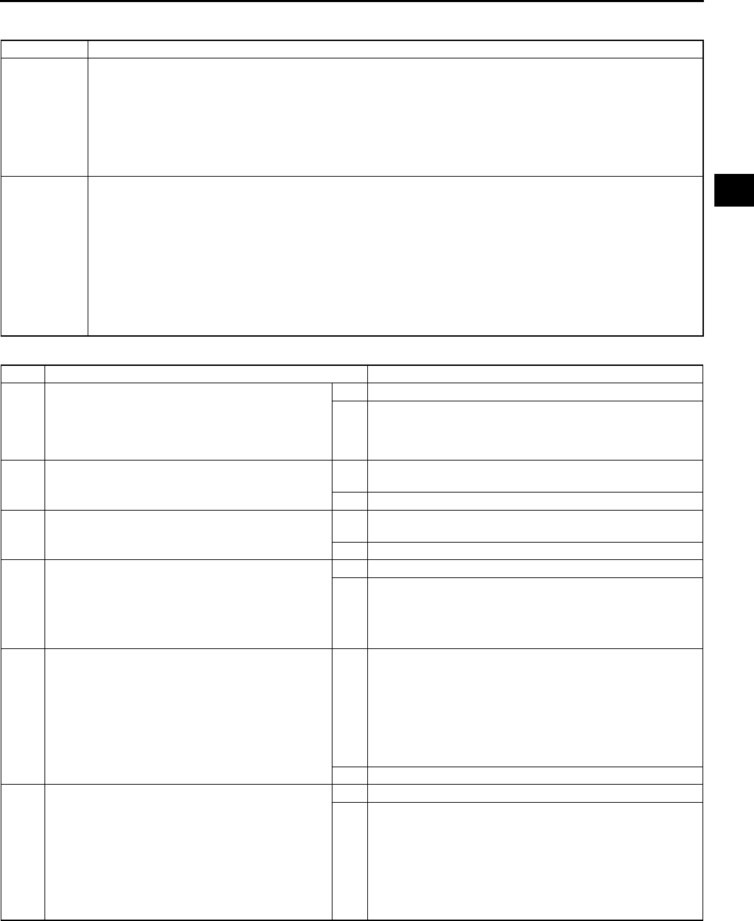
ON-BOARD DIAGNOSTIC
F73
F
DTC P0012 A6E397001084W03
Diagnostic procedure
DTC P0012 CMP - Timing over-retarded
DETECTION
CONDITION
•Actual valve timing is over-retarded by 5 deg. from target valve timing for 5 s when the OCV system control
is within feed-back range.
Diagnostic support note
•This is a continuous monitor (CCM).
•MIL illuminates if PCM detects the above malfunction condition during first drive cycles.
•PENDING CODE is available if PCM detects the above malfunction condition.
•FREEZE FRAME DATA is available.
•DTC is stored in PCM memory.
POSSIBLE
CAUSE
•OCV (oil control valve) malfunction
•Low engine oil pressure
•Spool valve in OCV (oil control valve) is stuck in retard position.
•Vriable valve timing actuator is stuck in retard position.
•Following oil runners are clogged or have leakage.
Oil runners
•Between oil pressure switch and OCV (oil control valve)
•Between OCV (oil control valve) and variable valve timing actuator
•In variable valve timing actuator
•Loose timing belt or improper valve timing due to timing belt slippage
•PCM malfunction
STEP INSPECTION ACTION
1PERFORM DTC CONFIRMATION PROCEDURE
•Perform DTC CONFIRMATION PROCEDURE.
(See F66 DTC CONFIRMATION
PROCEDURE.)
•Is same DTC present?
Yes Go to next step.
No Intermittent concern exists. Go to INTERMITTENT
CONCERN TROUBLESHOOTING procedure.
(See F227 INTERMITTENT CONCERN
TROUBLESHOOTING.)
2VERIFY RELATED PENDING CODE OR
STORED DTCS
•Is DTC P0010 present?
Yes Go to DTC P0010 troubleshooting procedure.
(See F70 DTC P0010)
No Go to next step.
3VERIFY ENGINE OIL PRESSURE
•Start engine.
•Does oil pressure warning light illuminate?
Yes Inspect engine oil pressure.
(See D3 OIL PRESSURE INSPECTION)
No Go to next step.
4VERIFY TIMING BELT INSTALLATION
•Stop engine.
•Remove timing belt cover.
•Is camshaft timing mark at correct point?
(See B10 TIMING CHAIN REMOVAL/
INSTALLATION.)
Yes Go to next step.
No Reinstall timing belt, then go to Step 7.
5INSPECT OCV FOR MALFUNCTION
•Stop engine.
•Remove OCV.
•Inspect position of spool valve in OCV.
•Is spool valve located at valve retard position?
Yes VARIABLE VALVE TIMING MECHANISM IS NORMAL
Note
•This DTC detected by intermittent concern.
•Intermittent concern might be removed by cleaning
mode of variable valve timing control function.
Go to next step.
No Replace OCV, then go to Step 7.
6INSPECT ENGINE OIL RUNNER
•Inspect following engine oil runners for
clogging or leakage.
Beetween oil pressure switch and OCV
Between OCV and variable valve timing
actuator
In variable valve timing actuator
•Is there any clogging or leakage?
Yes Repair or replace suspected runner, then go to next step.
No VARIABLE VALVE TIMING MECHANISM IS NORMAL
Note
•This DTC is detected by intermittent concern.
•Intermittent concern might be removed by cleaning
mode of variable valve timing control function.
Go to next step.
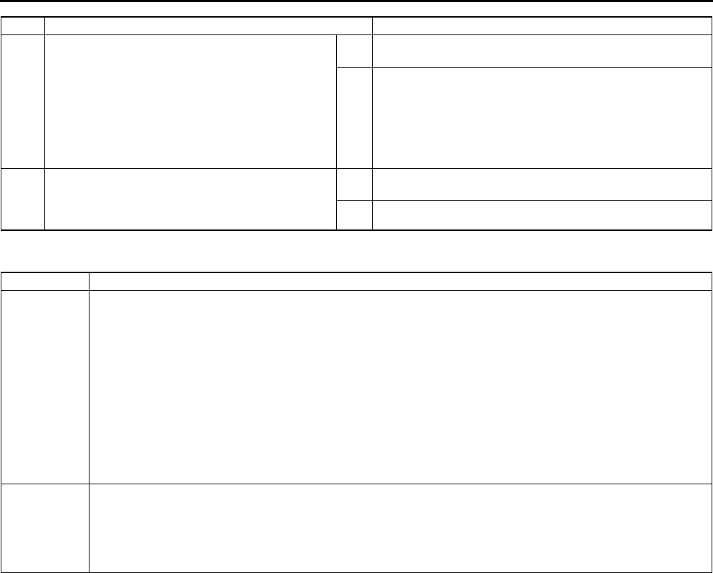
F74
ON-BOARD DIAGNOSTIC
End Of Sie
DTC P0031 A6E397001084W04
7VERIFY TROUBLESHOOTING OF DTC P0012
COMPLETED
•Make sure to reconnect all disconnected
connectors.
•Clear DTC from PCM memory using WDS or
equivalent.
•Perform KOER self-test.
(See F66 KOEO/KOER SELF-TEST.)
•Is same DTC present?
Yes Replace PCM, then go to next step.
(See F43 PCM REMOVAL/INSTALLATION.)
No Go to next step.
8VERIFY AFTER REPAIR PROCEDURE
•Perform After Repair Procedure.
(See F66 AFTER REPAIR PROCEDURE.)
•Is there any DTC present?
Yes Go to applicable DTC troubleshooting.
(See F67 DTC TABLE.)
No Troubleshooting completed.
STEP INSPECTION ACTION
DTC P0031 Front HO2S heater circuit low input
DETECTION
CONDITION
•PCM monitors front HO2S heater control signal at PCM terminal 4A. If PCM turns front HO2S heater off but
front HO2S heater circuit has low voltage, PCM determines that front HO2S heater circuit has malfunction.
Note
•Front HO2S heater is controlled by duty signal.
Diagnostic support note
•This is a continuous monitor (O2 sensor heater).
•MIL illuminates if PCM detects above malfunction condition in two consecutive drive cycles or in one drive
cycle while DTC for the same malfunction has been stored in PCM.
•PENDING CODE is available if PCM detects above malfunction condition during first drive cycle.
•FREEZE FRAME DATA is available.
•DTC is stored in PCM memory.
POSSIBLE
CAUSE
•Front HO2S malfunction
•Open circuit between ignition switch and front HO2S terminal C
•Open circuit between front HO2S terminal D and PCM terminal 4A
•Short to ground circuit between front HO2S terminal D and PCM terminal 4A
•Poor connection at front HO2S or PCM connector
•PCM malfunction
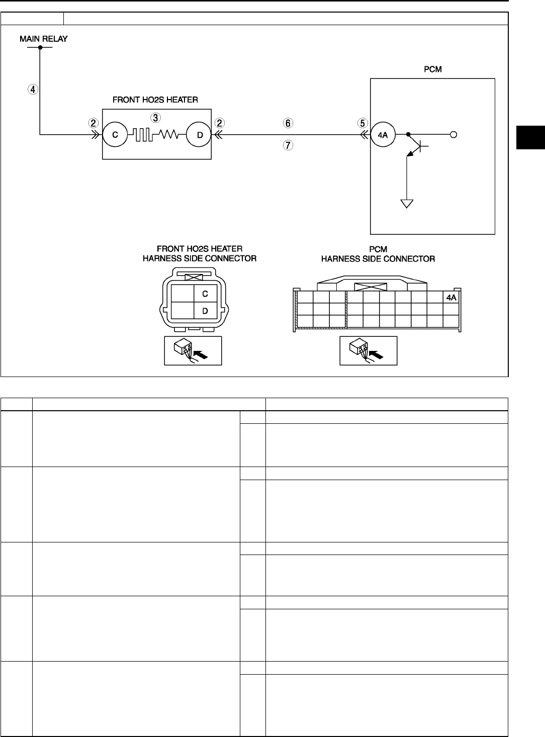
ON-BOARD DIAGNOSTIC
F75
F
Diagnostic procedure
STEP INSPECTION ACTION
1PERFORM DTC CONFIRMATION PROCEDURE
•Perform DTC CONFIRMATION PROCEDURE.
(See F66 DTC CONFIRMATION
PROCEDURE.)
•Is same DTC present?
Yes Go to next step.
No Intermittent concern exists. Go to INTERMITTENT
CONCERN TROUBLESHOOTING procedure.
(See F227 INTERMITTENT CONCERN
TROUBLESHOOTING.)
2INSPECT POOR CONNECTION OF FRONT
HO2S CONNECTOR
•Turn ignition key to OFF.
•Disconnect front HO2S connector.
•Inspect for poor connection (damaged, pulled-
out pins, corrosion, etc.).
•Are there any malfunctions?
Yes Repair or replace terminal, then go to Step 8.
No Go to next step.
3INSPECT FRONT HO2S HEATER
•Inspect front HO2S heater.
(See F56 HEATED OXYGEN SENSOR
(HO2S) INSPECTION.)
•Is front HO2S heater okay?
Yes Go to next step.
No Replace front HO2S, then go to Step 8.
4INSPECT POWER CIRCUIT OF FRONT HO2S
HEATER FOR OPEN CIRCUIT
•Turn ignition key to ON (Engine OFF).
•Measure voltage between front HO2S terminal
C (harness-side) and body ground.
•Is voltage B+?
Yes Go to next step.
No Repair or replace harness for open circuit, then go to Step
8.
5INSPECT POOR CONNECTION OF PCM
CONNECTOR
•Turn ignition key to OFF.
•Disconnect PCM connector.
•Inspect for poor connection (damaged, pulled-
out pins, corrosion, etc.).
•Are there any malfunctions?
Yes Repair terminal, then go to Step 8.
No Go to next step.
DTC P0031 Front HO2S heater circuit low input

F76
ON-BOARD DIAGNOSTIC
End Of Sie
DTC P0032 A6E397001084W05
6INSPECT CONTROL CIRCUIT OF FRONT HO2S
HEATER FOR SHORT TO GROUND
•Inspect continuity between front HO2S terminal
D (harness-side) and body ground.
•Is there continuity?
Yes Repair or replace harness for short to ground, then go to
Step 8.
No Go to next step.
7INSPECT CONTROL CIRCUIT OF FRONT HO2S
HEATER FOR OPEN CIRCUIT
•Remove PCM with PCM connector connected.
•Inspect continuity between front HO2S terminal
D (harness-side) and PCM terminal 4A.
•Is there continuity?
Yes Go to next step.
No Repair or replace harness for open circuit, then go to Step
8.
8VERIFY TROUBLESHOOTING OF DTC P0031
COMPLETED
•Make sure to reconnect all disconnected
connectors.
•Clear DTC from PCM memory using WDS or
equivalent.
•Perform KOEO/KOER self-test.
(See F66 KOEO/KOER SELF-TEST.)
•Is same DTC present?
Yes Replace PCM, then go to next step.
(See F43 PCM REMOVAL/INSTALLATION.)
No Go to next step.
9VERIFY AFTER REPAIR PROCEDURE
•Perform After Repair Procedure.
(See F66 AFTER REPAIR PROCEDURE.)
•Is there any DTC present?
Yes Go to applicable DTC troubleshooting.
(See F67 DTC TABLE.)
No Troubleshooting completed.
STEP INSPECTION ACTION
DTC P0032 Front HO2S heater circuit high input
DETECTION
CONDITION
•PCM monitors front HO2S heater control signal at PCM terminal 4A. If PCM turns front HO2S heater on but
front HO2S heater circuit has high voltage, PCM determines that front HO2S heater circuit has malfunction.
Note
•Front HO2S heater is controlled by a duty signal.
Diagnostic support note
•This is a continuous monitor (O2 sensor heater).
•MIL illuminates if PCM detects the above malfunction condition in two consecutive drive cycles or in one
drive cycle while the DTC for the same malfunction has been stored in the PCM.
•PENDING CODE is available if PCM detects the above malfunction condition.
•FREEZE FRAME DATA is available.
•DTC is stored in PCM memory.
POSSIBLE
CAUSE
•Short to power circuit between front HO2S terminal D and PCM terminal 4A
•Front HO2S or PCM terminal is shorted
•Front HO2S heater malfunction
•PCM malfunction
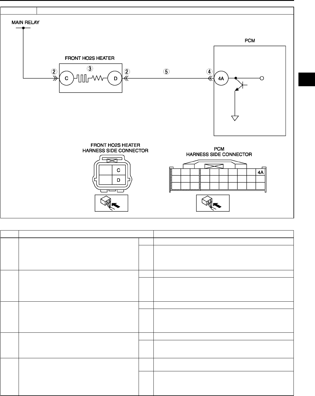
ON-BOARD DIAGNOSTIC
F77
F
Diagnostic procedure
STEP INSPECTION ACTION
1PERFORM DTC CONFIRMATION PROCEDURE
•Perform DTC CONFIRMATION PROCEDURE.
(See F66 DTC CONFIRMATION
PROCEDURE.)
•Is same DTC present?
Yes Go to next step.
No Intermittent concern exists. Go to INTERMITTENT
CONCERN TROUBLESHOOTING procedure.
(See F227 INTERMITTENT CONCERN
TROUBLESHOOTING.)
2INSPECT FRONT HO2S TERMINALS
•Turn ignition key to OFF.
•Disconnect front HO2S connector.
•Inspect for bent terminals.
•Is there any malfunction?
Yes Repair or replace terminal, then go to Step 6.
No Go to next step.
3INSPECT FRONT HO2S HEATER
•Inspect front HO2S heater.
(See F56 HEATED OXYGEN SENSOR
(HO2S) INSPECTION.)
•Is front HO2S heater okay?
Yes Go to next step.
No Replace the front HO2S, then go to Step 6.
4INSPECT PCM TERMINAL
•Disconnect PCM connector.
•Inspect for bent terminals.
•Are there any malfunctions?
Yes Repair terminal, then go to Step 6.
No Go to next step.
5INSPECT FRONT HO2S HEATER CONTROL
CIRCUIT FOR SHORT TO POWER CIRCUIT
•Turn ignition key to ON (Engine OFF).
•Measure voltage between front HO2S terminal
D (harness-side) and body ground.
•Is there voltage B+?
Yes Repair or replace harness for shot to power circuit, then go
to next step.
No Go to next step.
DTC P0032 Front HO2S heater circuit high input
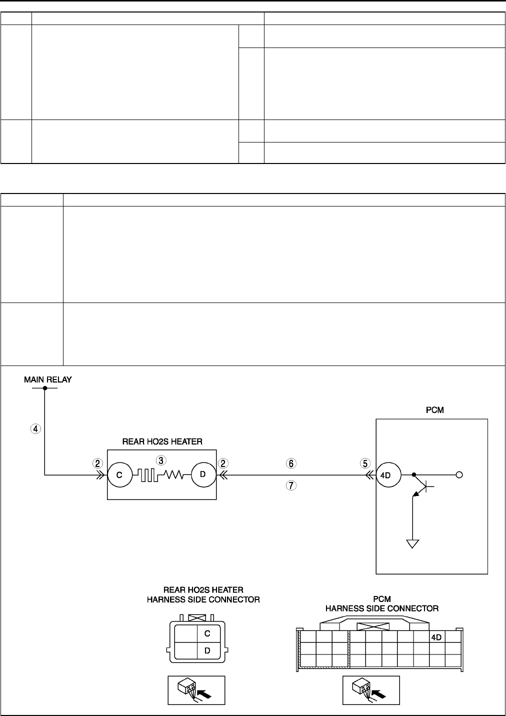
F78
ON-BOARD DIAGNOSTIC
End Of Sie
DTC P0037 A6E397001084W06
6VERIFY TROUBLESHOOTING OF DTC P0032
COMPLETED
•Make sure to reconnect all disconnected
connectors.
•Clear DTC from PCM memory using WDS or
equivalent.
•Perform KOEO/KOER self-test.
(See F66 KOEO/KOER SELF-TEST.)
•Is same DTC present?
Yes Replace PCM, then go to next step.
(See F43 PCM REMOVAL/INSTALLATION.)
No Go to next step.
7VERIFY AFTER REPAIR PROCEDURE
•Perform After Repair Procedure.
(See F66 AFTER REPAIR PROCEDURE.)
•Is there any DTC present?
Yes Go to applicable DTC troubleshooting.
(See F67 DTC TABLE.)
No Troubleshooting completed.
STEP INSPECTION ACTION
DTC P0037 Rear HO2S heater circuit low input
DETECTION
CONDITION
•PCM monitors rear HO2S heater control signal at PCM terminal 4D. If PCM turns rear HO2S heater off but
rear HO2S heater circuit has low voltage, PCM determines that rear HO2S heater circuit has malfunction.
Diagnostic support note
•This is a continuous monitor (O2 sensor heater).
•MIL illuminates if PCM detects the above malfunction condition in two consecutive drive cycles or in one
drive cycle while DTC for the same malfunction has been stored in PCM.
•PENDING CODE is available if PCM detects the above malfunction condition during first drive cycle.
•FREEZE FRAME DATA is available.
•DTC is stored in PCM memory.
POSSIBLE
CAUSE
•Rear HO2S malfunction
•Open circuit between the ignition switch and rear HO2S terminal C
•Open circuit between the rear HO2S terminal D and PCM terminal 4D
•Short to ground circuit between rear HO2S terminal D and PCM terminal 4D
•Poor connection at rear HO2S or PCM connector
•PCM malfunction

ON-BOARD DIAGNOSTIC
F79
F
Diagnostic procedure
End Of Sie
STEP INSPECTION ACTION
1PERFORM DTC CONFIRMATION PROCEDURE
•Perform DTC CONFIRMATION PROCEDURE.
(See F66 DTC CONFIRMATION
PROCEDURE.)
•Is same DTC present?
Yes Go to next step.
No Intermittent concern exists. Go to INTERMITTENT
CONCERN TROUBLESHOOTING procedure.
(See F227 INTERMITTENT CONCERN
TROUBLESHOOTING.)
2INSPECT POOR CONNECTION OF REAR HO2S
CONNECTOR
•Turn ignition key to OFF.
•Disconnect rear HO2S connector.
•Inspect for poor connection (damaged, pulled-
out pins, corrosion, etc.).
•Are there any malfunctions?
Yes Repair or replace terminal, then go to Step 8.
No Go to next step.
3INSPECT REAR HO2S HEATER
•Inspect rear HO2S heater.
(See F56 HEATED OXYGEN SENSOR
(HO2S) INSPECTION.)
•Is rear HO2S heater okay?
Yes Go to next step.
No Replace rear HO2S, then go to Step 8.
4INSPECT REAR HO2S HEATER POWER
CIRCUIT FOR OPEN CIRCUIT
•Turn ignition key to ON (Engine OFF).
•Measure voltage between rear HO2S terminal
C (harness-side) and body ground.
•Is there voltage B+?
Yes Go to next step.
No Repair or replace harness for open circuit, then go to Step
8.
5INSPECT POOR CONNECTION OF PCM
CONNECTOR
•Turn ignition key to OFF.
•Disconnect PCM connector.
•Inspect for poor connection (damaged, pulled-
out pins, corrosion, etc.).
•Are there any malfunctions?
Yes Repair terminal, then go to Step 8.
No Go to next step.
6INSPECT REAR HO2S HEATER CONTROL
CIRCUIT FOR SHORT TO GROUND
•Inspect continuity between rear HO2S terminal
D (harness-side) and body ground.
•Is there any continuity?
Yes Repair or replace harness for short to ground, then go to
Step 8.
No Go to next step.
7INSPECT HREAR HO2S HEATER CONTROL
CIRCUIT FOR OPEN CIRCUIT
•Remove PCM with PCM connector connected.
•Inspect continuity between rear HO2S terminal
D (harness-side) and PCM terminal 4D.
•Is there any continuity?
Yes Go to next step.
No Repair or replace harness for open circuit, then go to Step
8.
8VERIFY TROUBLESHOOTING OF DTC P0037
COMPLETED
•Make sure to reconnect all disconnected
connectors.
•Clear DTC from PCM memory using WDS or
equivalent.
•Perform KOEO/KOER self-test.
(See F66 KOEO/KOER SELF-TEST.)
•Is same DTC present?
Yes Replace PCM, then go to next step.
(See F43 PCM REMOVAL/INSTALLATION.)
No Go to next step.
9VERIFY AFTER REPAIR PROCEDURE
•Perform After Repair Procedure.
(See F66 AFTER REPAIR PROCEDURE.)
•Is there any DTC present?
Yes Go to applicable DTC troubleshooting.
(See F67 DTC TABLE.)
No Troubleshooting completed.
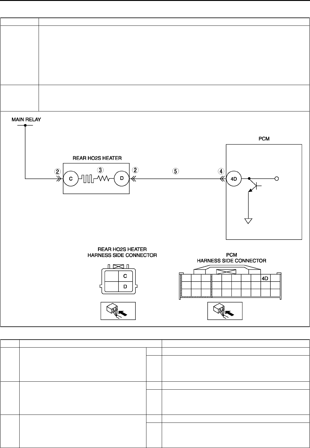
F80
ON-BOARD DIAGNOSTIC
DTC P0038 A6E397001084W07
Diagnostic procedure
DTC P0038 Rear HO2S heater circuit high input
DETECTION
CONDITION
•PCM monitors rear HO2S heater control signal at PCM terminal 4D. If PCM turns rear HO2S heater on but
rear HO2S heater circuit has high voltage, PCM determines that rear HO2S heater circuit has malfunction.
Diagnostic support note
•This is a continuous monitor (O2 sensor heater).
•MIL illuminates if PCM detects the above malfunction condition in two consecutive drive cycles or in one
drive cycle while the DTC for the same malfunction has been stored in the PCM.
•PENDING CODE is available if PCM detects the above malfunction condition during first drive cycle.
•FREEZE FRAME DATA is available.
•DTC is stored in PCM memory.
POSSIBLE
CAUSE
•Short to power circuit between rear HO2S terminal D and PCM terminal 4D
•Rear HO2S or PCM terminal is shorted
•Rear HO2S heater malfunction
•PCM malfunction
STEP INSPECTION ACTION
1PERFORM DTC CONFIRMATION PROCEDURE
•Perform DTC CONFIRMATION PROCEDURE.
(See F66 DTC CONFIRMATION
PROCEDURE.)
•Is same DTC present?
Yes Go to next step.
No Intermittent concern exists. Go to INTERMITTENT
CONCERN TROUBLESHOOTING procedure.
(See F227 INTERMITTENT CONCERN
TROUBLESHOOTING.)
2INSPECT REAR HO2S TERMINAL
•Turn ignition key to OFF.
•Disconnect rear HO2S connector.
•Inspect for bent terminals
•Is there any malfunction?
Yes Repair or replace terminal, then go to Step 6.
No Go to next step.
3INSPECT REAR HO2S HEATER
•Inspect rear HO2S heater.
(See F56 HEATED OXYGEN SENSOR
(HO2S) INSPECTION.)
•Is rear HO2S heater okay?
Yes Go to next step.
No Replace the rear HO2S, then go to Step 6.
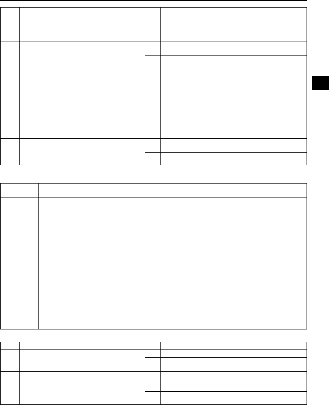
ON-BOARD DIAGNOSTIC
F81
F
End Of Sie
DTC P0101 A6E397001084W08
Diagnostic procedure
4INSPECT PCM TERMINAL
•Disconnect PCM connector.
•Inspect for bent terminals.
•Is there any malfunctions?
Yes Repair terminal, then go to Step 6.
No Go to next step.
5INSPECT REAR HO2S HEATER CONTROL
CIRCUIT FOR SHORT TO POWER
•Turn ignition key to ON (Engine OFF).
•Measure voltage between rear HO2S terminal
D (harness-side) and body ground.
•Is there voltage B+?
Yes Repair or replace harness for shot to power circuit, then go
to next step.
No Go to next step.
6VERIFY TROUBLESHOOTING OF DTC P0038
COMPLETED
•Make sure to reconnect all disconnected
connectors.
•Clear DTC from PCM memory using WDS
or equivalent.
•Perform KOEO/KOER self-test.
(See F66 KOEO/KOER SELF-TEST.)
•Is same DTC present?
Yes Replace PCM, then go to next step.
(See F43 PCM REMOVAL/INSTALLATION.)
No Go to next step.
7VERIFY AFTER REPAIR PROCEDURE
•Perform After Repair Procedure.
(See F66 AFTER REPAIR PROCEDURE.)
•Is there any DTC present?
Yes Go to applicable DTC troubleshooting.
(See F67 DTC TABLE.)
No Troubleshooting completed.
STEP INSPECTION ACTION
DTC P0101 MAF sensor inconsistent with TP sensor (lower than expected) or engine speed (greater than
expected)
DETECTION
CONDITION
•The PCM compares actual input signal from MAF sensor with expected input signal from MAF sensor
(calculated by input voltage from throttle position sensor or engine speed).
If mass intake air flow amount is below 5.0 g/sec. {0.66 lb/min.} for 5 s and throttle opening angle is
above 50% with engine running, the PCM determines that detected mass intake air flow amount is too
low.
If mass intake air flow amount is above 96.0 g/sec. {12.7 lb/min.} for 5 s and engine speed is below
2,000 rpm with engine running, the PCM determines that detected mass intake air flow amount is too
high.
Diagnostic support note
•This is a continuous monitor (CCM).
•MIL illuminates if PCM detects the above malfunction condition in two consecutive drive cycles or in one
drive cycle while the DTC for the same malfunction has been stored in the PCM.
•PENDING CODE is available if PCM detects the above malfunction condition during first drive cycle.
•FREEZE FRAME DATA is available.
•DTC is stored in the PCM memory.
POSSIBLE
CAUSE
•MAF sensor malfunction
•TP sensor malfunction
•Electrical corrosion in MAF signal circuit
•Electrical corrosion in MAF RETURN circuit
•Voltage drops in MAF signal circuit
•Voltage drops in ground circuit
STEP INSPECTION ACTION
1VERIFY FREEZE FRAME DATA HAS BEEN
RECORDED
•Has FREEZE FRAME DATA been recorded?
Yes Go to next step.
No Record FREEZE FRAME DATA on repair order, then go to
next step.
2VERIFY RELATED SERVICE INFORMATION
AVAILABILITY
•Check for related Service Information
availability.
•Is any related Service Information available?
Yes Perform repair or diagnosis according to available Service
Information.
•If vehicle is not repaired, go to next step.
No Go to next step.

F82
ON-BOARD DIAGNOSTIC
3VERIFY CURRENT INPUT SIGNAL STATUS-IS
CONCERN INTERMITTENT OR CONSTANT
•Connect WDS or equivalent to DLC-2.
•Start the engine.
•Access ECT, TP and MAF PIDs.
•Warm up the engine until ECT PID is above 80
°
°°
°C {176 °
°°
°F}.
•Drive the vehicle.
•Read MAF PID while TP PID is above 50%.
•Is MAF PID reading below 4.8 g/s {0.63 lb/
min.}?
Yes Make sure that throttle position sensor resistance changes
smoothly while gradually opening throttle valve.
•If not, replace throttle position sensor and go to Step 7.
•For others, go to next step.
No Go to next step.
4VERIFY CURRENT INPUT SIGNAL STATUS-IS
CONCERN INTERMITTENT OR CONSTANT
•Connect WDS or equivalent to DLC-2.
•Start the engine.
•Access ECT, MAF and RPM PIDs.
•Warm up engine until ECT PID is above 80°
°°
°C
{176 °
°°
°F}.
•Read MAF PID while RPM PID is below 1,000
rpm.
•Is MAF PID reading above 66.5 g/s {8.8 lb/
min.}?
Yes Go to Step 8.
No Intermittent concern exists. Go to INTERMITTENT
CONCERNS TROUBLESHOOTING procedure.
(See F227 INTERMITTENT CONCERN
TROUBLESHOOTING.)
5INSPECT POOR CONNECTION OF MAF
SENSOR CONNECTOR
•Turn ignition key to OFF.
•Disconnect MAF/IAT sensor connector.
•Inspect for poor connection (damaged, pulled-
out terminals, corrosion, etc.).
•Is there any malfunction?
Yes Repair or replace suspected terminal or MAF/IAT sensor,
then go to Step 7.
No Go to next step.
6INSPECT POOR CONNECTION OF PCM
CONNECTOR
•Disconnect PCM connector.
•Inspect for poor connection (damaged/pulled-
out pins, corrosion, etc.).
•Is there any malfunction?
Yes Repair terminal, then go to next step.
No Replace MAF/IAT sensor, then go to next step.
7VERIFY TROUBLESHOOTING OF DTC P0101
COMPLETED
•Make sure to reconnect all disconnected
connectors.
•Turn ignition key to ON (Engine OFF).
•Clear DTC from memory using WDS or
equivalent.
•Start the engine.
•Access ECT, TP and RPM PIDs.
•Warm up the engine until ECT PID is reading
above 80°
°°
°C {176°
°°
°F}.
•Drive the vehicle while TP PID above 50% for
50 s.
•Is same DTC present?
Yes Replace PCM, then go to Step 11.
No Go to Step 11.
8INSPECT MAF SENSOR TERMINALS FOR
ELECTRICAL CORROSION
•Turn ignition key to OFF.
•Disconnect MAF/IAT sensor connector.
•Inspect for poor connection (damaged, pulled-
out terminals, corrosion, etc.).
•Is any problem corrosion found?
Yes Repair or replace suspected terminal or MAF/IAT sensor,
then go to Step 10.
No Go to next step.
9INSPECT POOR CONNECTION OF PCM
CONNECTOR
•Disconnect PCM connector.
•Inspect for poor connection (damaged, pulled-
out pins, corrosion, etc.).
•Is there any malfunction?
Yes Repair terminal, then go to next step.
No Go to next step.
STEP INSPECTION ACTION
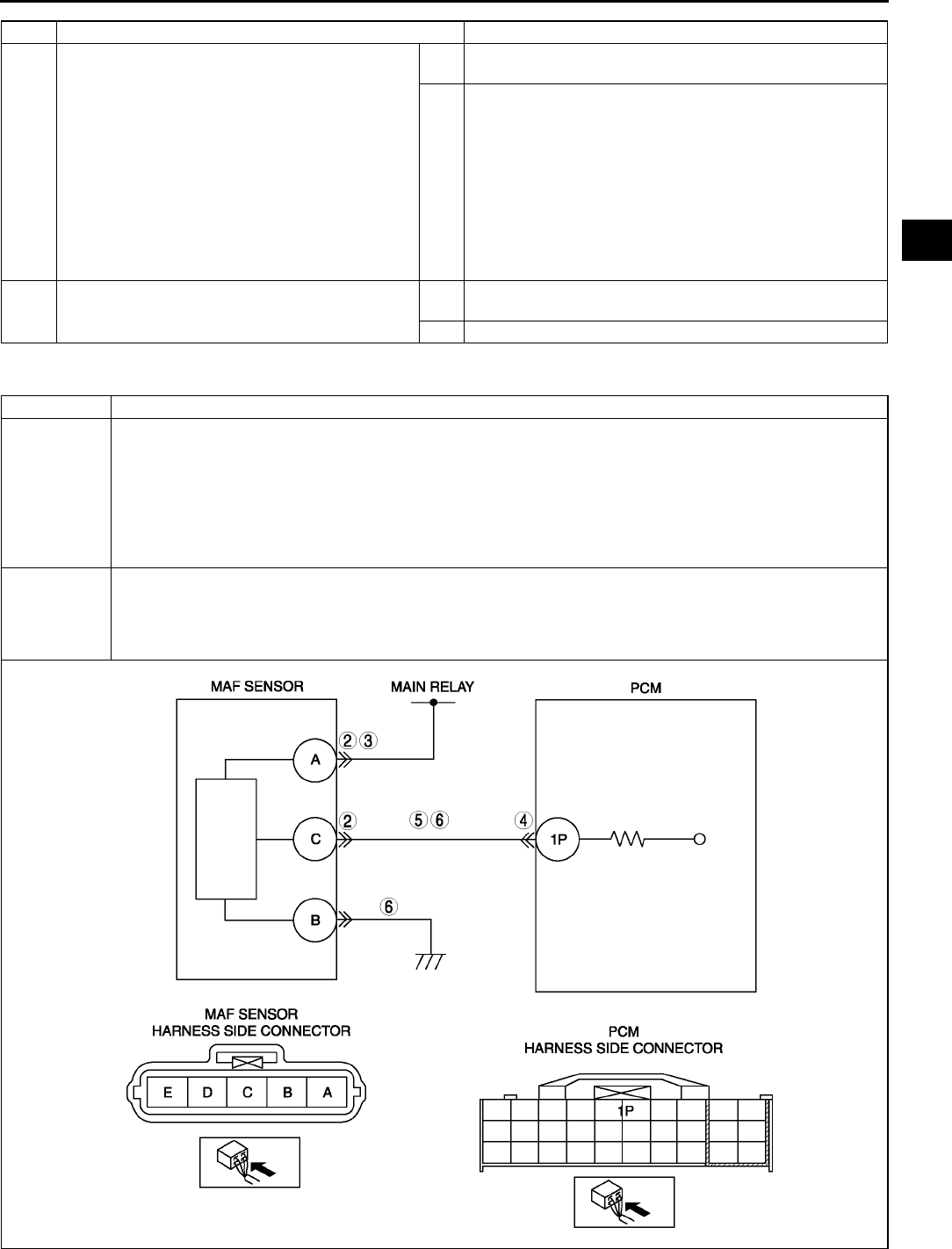
ON-BOARD DIAGNOSTIC
F83
F
End Of Sie
DTC P0102 A6E397001084W09
10 VERIFY TROUBLESHOOTING OF DTC P0101
COMPLETED
•Make sure to reconnect all disconnected
connectors.
•Turn ignition key to ON (Engine OFF).
•Clear DTC from memory using WDS or
equivalent.
•Start the engine.
•Warm up engine until ECT PID is above 80 °
°°
°C
{176 °
°°
°F}.
•Drive the vehicle while RPM PID 2,000 rpm for
50 s.
•Is pending code the same as DTC present?
Yes Replace PCM, then go to next step.
(See F43 PCM REMOVAL/INSTALLATION.)
No Go to next step.
11 VERIFY AFTER REPAIR PROCEDURE
•Is there any DTC present?
Yes Go to applicable DTC troubleshooting.
(See F67 DTC TABLE.)
No Troubleshooting completed.
STEP INSPECTION ACTION
DTC P0102 MAF circuit low input
DETECTION
CONDITION
•PCM monitors input voltage from MAF sensor when engine running. If input voltage at PCM terminal 1P is
below 0.21 V, PCM determines that MAF circuit has malfunction.
Diagnostic support note
•This is a continuous monitor (CCM).
•MIL illuminates if PCM detects the above malfunction condition during first drive cycle.
•PENDING CODE is available if PCM detects the above malfunction condition.
•FREEZE FRAME DATA is available.
•DTC is stored in the PCM memory.
POSSIBLE
CAUSE
•MAF sensor malfunction
•Connector or terminal malfunction
•Short to ground in wiring between MAF/IAT sensor terminal C and PCM terminal 1P
•Open circuit in wiring between MAF/IAT sensor terminal C and PCM terminal 1P
•Open circuit in wiring between main relay and MAF/IAT sensor terminal A

F84
ON-BOARD DIAGNOSTIC
Diagnostic procedure
End Of Sie
STEP INSPECTION ACTION
1PERFORM DTC CONFIRMATION PROCEDURE
•Perform DTC CONFIRMATION PROCEDURE.
(See F66 DTC CONFIRMATION
PROCEDURE.)
•Is same DTC present?
Yes Go to next step.
No Intermittent concern exists. Go to INTERMITTENT
CONCERN TROUBLESHOOTING procedure.
(See F227 INTERMITTENT CONCERN
TROUBLESHOOTING.)
2INSPECT POOR CONNECTION OF MAF
SENSOR CONNECTOR
•Turn ignition key to OFF.
•Disconnect the MAF/IAT sensor connector.
•Inspect for poor connection (damaged, pulled-
out terminals, corrosion, etc.).
•Is there any malfunction?
Yes Repair or replace terminals, then go to Step 7.
No Go to next step.
3INSPECT POWER SUPPLY CIRCUIT FOR OPEN
CIRCUIT
•Turn ignition key to ON (Engine OFF).
•Inspect voltage at MAF/IAT sensor terminal B
(harness-side).
•Is there voltage B+?
Yes Go to next step.
No Inspect for open circuit in wiring harness between MAF/IAT
sensor terminal B (harness-side) and main relay.
Repair or replace harness, then go to Step 7.
4INSPECT POOR CONNECTION OF PCM
CONNECTOR
•Turn ignition key to OFF.
•Disconnect PCM connector.
•Inspect for poor connection (damaged, pulled-
out terminals, corrosion, etc.).
•Is there any malfunction?
Yes Repair terminal, then go to Step 7.
No Go to next step.
5INSPECT MAF SENSOR SIGNAL CIRCUIT FOR
OPEN CIRCUIT
•Remove PCM with PCM connector connected.
•Inspect for continuity between MAF/IAT sensor
terminal C (harness-side) and PCM terminal
1P (harness-side).
•Is there any continuity?
Yes Go to next step.
No Repair or replace suspected harness, then go to Step 7.
6INSPECT MAF SENSOR SIGNAL CIRCUIT FOR
SHORTS
•Inspect continuity between following circuits:
MAF/IAT sensor terminal C (harness-side)
and body ground
MAF/IAT sensor connector terminal C
(harness-side) and B (harness-side)
•Are there any continuity?
Yes Repair or replace suspected harness, then go to next step.
No Replace MAF/IAT sensor, then go to next step.
7VERIFY TROUBLESHOOTING OF DTC P0102
COMPLETED
•Make sure to reconnect all disconnected
connectors.
•Clear DTC from memory using WDS or
equivalent.
•Perform KOEO/KOER self-test.
(See F66 KOEO/KOER SELF-TEST.)
•Is same DTC present?
Yes Replace PCM, then go to next step.
(See F43 PCM REMOVAL/INSTALLATION.)
No Go to next step.
8VERIFY AFTER REPAIR PROCEDURE
•Perform After Repair Procedure.
(See F66 AFTER REPAIR PROCEDURE.)
•Is there any DTC present?
Yes Go to applicable DTC troubleshooting.
(See F67 DTC TABLE.)
No Troubleshooting completed.
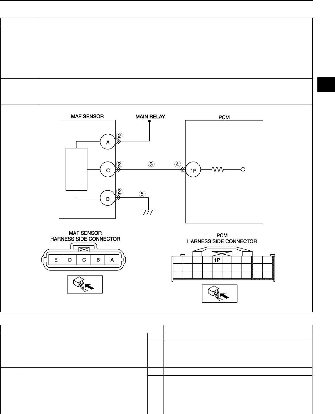
ON-BOARD DIAGNOSTIC
F85
F
DTC P0103 A6E397001084W10
Diagnostic procedure
DTC P0103 MAF circuit high input
DETECTION
CONDITION
•PCM monitors input voltage from MAF sensor when engine running. If input voltage at PCM terminal 1P is
above 4.9 V, PCM determines that MAF circuit has malfunction.
Diagnostic support note
•This is a continuous monitor (CCM).
•MIL illuminates if PCM detects the above malfunction condition during first drive cycle.
•PENDING CODE is available if PCM detects the above malfunction condition.
•FREEZE FRAME DATA is available.
•DTC is stored in the PCM memory.
POSSIBLE
CAUSE
•MAF sensor malfunction
•Connector or terminal malfunction
•Short to power in wiring between MAF/IAT sensor terminal C and PCM terminal 1P.
•Open circuit in MAF/IAT sensor ground circuit
STEP INSPECTION ACTION
1PERFORM DTC CONFIRMATION PROCEDURE
•Perform DTC CONFIRMATION PROCEDURE.
(See F66 DTC CONFIRMATION
PROCEDURE.)
•Is same DTC present?
Yes Go to next step.
No Intermittent concern exists. Go to INTERMITTENT
CONCERN TROUBLESHOOTING procedure.
(See F227 INTERMITTENT CONCERN
TROUBLESHOOTING.)
2INSPECT POOR CONNECTION OF MAF
SENSOR CONNECTOR
•Turn ignition key to OFF.
•Disconnect the MAF/IAT sensor connector.
•Inspect for poor connection (damaged, pulled-
out terminals, corrosion, etc.).
•Is there any malfunction?
Yes Repair or replace terminals, then go to Step 6.
No Go to next step.

F86
ON-BOARD DIAGNOSTIC
End Of Sie
DTC P0107 A6E397001084W11
3INSPECT MAF SIGNAL CIRCUIT FOR SHORT
TO POWER CIRCUIT
•Turn ignition key to ON (Engine OFF).
•Measure voltage between MAF/IAT sensor
terminal C (harness-side) and body ground.
•Is there voltage 0 V?
Yes Go to next step.
No Repair or replace suspected harness, then go to Step 6.
4INSPECT POOR CONNECTION OF PCM
CONNECTOR
•Turn ignition key to OFF.
•Disconnect PCM connector.
•Inspect for poor connection (damaged, pulled-
out terminals, corrosion, etc.).
•Is there any malfunction?
Yes Repair terminal, then go to Step 6.
No Go to next step.
5INSPECT MAF SENSOR GROUND CIRCUIT
FOR OPEN CIRCUIT
•Remove PCM with PCM connector connected.
•Inspect for continuity between MAF/IAT sensor
terminal B (harness-side) and GND.
•Is there any continuity?
Yes Replace MAF/IAT sensor, then go to next step.
No Repair or replace suspected harness, then go to next step.
6VERIFY TROUBLESHOOTING OF DTC P0103
COMPLETED
•Make sure to reconnect all disconnected
connectors.
•Clear DTC from memory using WDS or
equivalent.
•Perform KOEO/KOER self-test.
(See F66 KOEO/KOER SELF-TEST.)
•Is same DTC present?
Yes Replace PCM, then go to next step.
(See F43 PCM REMOVAL/INSTALLATION.)
No Go to next step.
7VERIFY AFTER REPAIR PROCEDURE
•Perform After Repair Procedure.
(See F66 AFTER REPAIR PROCEDURE.)
•Is there any DTC present?
Yes Go to applicable DTC troubleshooting.
(See F67 DTC TABLE.)
No Troubleshooting completed.
STEP INSPECTION ACTION
DTC P0107 MAP sensor circuit low input
DETECTION
CONDITION
•PCM monitors input voltage from MAP sensor when intake air temperature is above 10 °
°°
°C {50 °
°°
°F}. If input
voltage at PCM terminal 1J is below 0.1V, PCM determines that MAP sensor circuit has a malfunction.
Diagnostic support note
•This is a continuous monitor (CCM).
•MIL illuminates if PCM detects the above malfunction condition during first drive cycle.
•PENDING CODE is available if PCM detects the above malfunction condition.
•FREEZE FRAME DATA is available.
•DTC is stored in the PCM memory.
POSSIBLE
CAUSE
•MAP sensor malfunction
•Connector or terminal malfunction
•Short to ground in wiring between MAP sensor terminal D and PCM terminal 1J
•Open circuit in wiring between MAP sensor terminal C and PCM terminal 2K
•MAP sensor signal circuit and MAP sensor ground circuit are shorted each other
•PCM malfunction
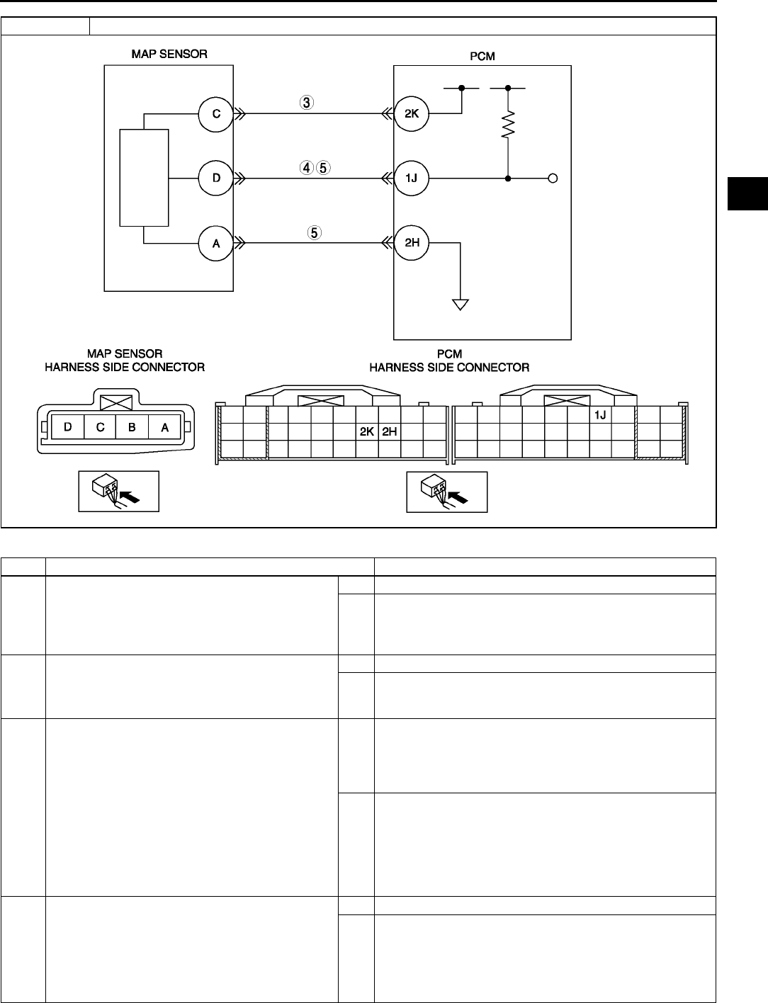
ON-BOARD DIAGNOSTIC
F87
F
Diagnostic procedure
STEP INSPECTION ACTION
1PERFORM DTC CONFIRMATION PROCEDURE
•Perform DTC CONFIRMATION PROCEDURE.
(See F66 DTC CONFIRMATION
PROCEDURE.)
•Is same DTC present?
Yes Go to next step.
No Intermittent concern exists. Go to INTERMITTENT
CONCERN TROUBLESHOOTING procedure.
(See F227 INTERMITTENT CONCERN
TROUBLESHOOTING.)
2VERIFY MAP PID WHEN MAP SENSOR
CONNECTOR IS DISCONNECTED
•Disconnect MAP sensor connector.
•Is voltage above 4.9 V?
Yes Go to next step.
No Go to step 4.
3INSPECT POWER SUPPLY CIRCUIT VOLTAGE
AT MAP SENSOR CONNECTOR
Note
•If DTC P0122 and P2228 are also retrieved
with P0107, go to CONSTANT VOLTAGE
troubleshooting procedure.
•Turn ignition key to ON (Engine OFF).
•Measure voltage between MAP sensor
terminal C (harness-side) and body ground.
•Is voltage within 4.55.5 V?
Yes Check for poor connection of MAP sensor terminal C
(harness-side).
•Repair or replace terminal if necessary.
•If okay, replace MAP sensor.
Then go to Step 6.
No Check for open circuit between PCM terminal 2K (harness-
side) and MAP sensor terminal C (harness-side).
Repair or replace suspected harness, then go to Step 6.
4INSPECT MAP SENSOR SIGNAL CIRCUIT FOR
SHORT TO GROUND
•Turn ignition key to OFF.
•Disconnect PCM connector.
•Inspect continuity between MAP sensor
terminal D (harness-side) and body ground.
•Is there continuity?
Yes Repair or replace suspected harness, then go to Step 6.
No Go to next step.
DTC P0107 MAP sensor circuit low input

F88
ON-BOARD DIAGNOSTIC
End Of Sie
DTC P0108 A6E397001084W12
5INSPECT MAP SENSOR SIGNAL AND
GROUND CIRCUIT FOR SHORT EACH OTHER
•Check continuity between MAP sensor
terminals D and A (harness-side).
•Is there continuity?
Yes Repair or replace suspected harness, then go to next step.
No Go to next step.
6VERIFY TROUBLESHOOTING OF DTC P0107
COMPLETED
•Make sure to reconnect all disconnected
connectors.
•Turn ignition key to ON (Engine OFF).
•Clear DTC from memory using WDS or
equivalent.
•Perform KOEO/KOER self-test.
(See F66 KOEO/KOER SELF-TEST.)
•Is same DTC present?
Yes Replace PCM, then go to next step.
(See F43 PCM REMOVAL/INSTALLATION.)
No Go to next step.
7VERIFY AFTER REPAIR PROCEDURE
•Perform After Repair Procedure.
(See F66 AFTER REPAIR PROCEDURE.)
•Is there any DTC present?
Yes Go to applicable DTC troubleshooting.
(See F67 DTC TABLE.)
No Troubleshooting completed.
STEP INSPECTION ACTION
DTC P0108 MAP sensor circuit high input
DETECTION
CONDITION
•PCM monitors input voltage from MAP sensor when intake air temperature is above 10 °
°°
°C {50 °
°°
°F}. If input
voltage at PCM terminal 1J is above 4.9V, PCM determines that MAP sensor circuit has malfunction.
Diagnostic support note
•This is a continuous monitor (CCM).
•MIL illuminates if PCM detects the above malfunction condition during first drive cycle.
•PENDING CODE is available if PCM detects the above malfunction condition.
•FREEZE FRAME DATA is available.
•DTC is stored in the PCM memory.
POSSIBLE
CAUSE
•MAP sensor malfunction
•Connector or terminal malfunction
•Open circuit in wiring between MAP sensor terminal A and PCM terminal 2H
•Open circuit in wiring between MAP sensor terminal D and PCM terminal 1J
•MAP sensor signal circuit shorts to constant voltage supply circuit
•PCM malfunction
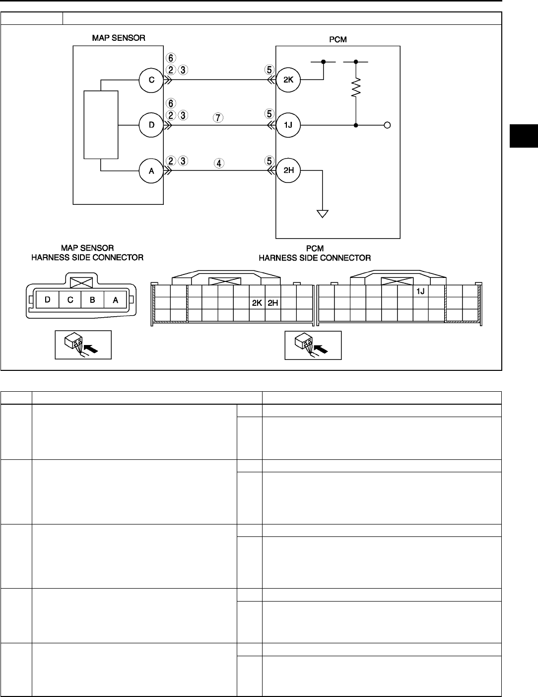
ON-BOARD DIAGNOSTIC
F89
F
Diagnostic procedure
STEP INSPECTION ACTION
1PERFORM DTC CONFIRMATION PROCEDURE
•Perform DTC CONFIRMATION PROCEDURE.
(See F66 DTC CONFIRMATION
PROCEDURE.)
•Is same DTC present?
Yes Go to next step.
No Intermittent concern exists. Go to INTERMITTENT
CONCERN TROUBLESHOOTING procedure.
(See F227 INTERMITTENT CONCERN
TROUBLESHOOTING.)
2INSPECT CONNECTION OF MAP SENSOR
CONNECTOR
•Turn ignition key to OFF.
•Verify that the MAP sensor connector is
connected securely.
•Is connection okay?
Yes Go to next step.
No Reconnect the connector, then go to Step 8.
3INSPECT POOR CONNECTION OF MAP
SENSOR CONNECTOR
•Disconnect the MAP sensor connector.
•Inspect for poor connection (damaged, pulled-
out pins, corrosion, etc.).
•Is there any malfunction?
Yes Repair or replace suspected terminal, then go to Step 8.
No Go to next step.
4VERIFY MAP SENSOR GROUND CIRCUIT FOR
OPEN CIRCUIT
•Inspect continuity between MAP sensor
terminal A (harness-side) and body ground.
•Is there continuity?
Yes Go to next step.
No Inspect for open circuit between PCM terminal 2H
(harness-side) and MAP sensor terminal A (harness-side).
Repair or replace suspected harness, then go to Step 8.
5INSPECT PCM CONNECTOR
•Disconnect PCM connector.
•Inspect for poor connection at terminal 2H
(damaged, pulled-out pins, corrosion, etc.).
•Is there any malfunction?
Yes Repair terminal, then go to Step 8.
No Go to next step.
DTC P0108 MAP sensor circuit high input

F90
ON-BOARD DIAGNOSTIC
End Of Sie
DTC P0111 A6E397001084W13
Diagnostic procedure
6VERIFY MAP SENSOR SIGNAL CIRCUIT FOR
SHORT TO CONSTANT VOLTAGE CIRCUIT
•Inspect for continuity between MAP sensor
terminal D and C (harness-side).
•Is there any continuity?
Yes Repair or replace suspected harness, then go to Step 8.
No Go to next step.
7VERIFY MAP SENSOR SIGNAL CIRCUIT FOR
OPEN CIRCUIT
•Inspect continuity between MAP sensor
terminal D (harness-side) and PCM terminal 1J
(harness-side).
•Is there any continuity?
Yes Go to next step.
No Repair or replace suspected harness, then go to next step.
8VERIFY TROUBLESHOOTING OF DTC P0108
COMPLETED
•Make sure to reconnect all disconnected
connectors.
•Turn ignition key to ON (Engine OFF).
•Clear DTC from memory using WDS or
equivalent.
•Perform KOEO/KOER self-test.
(See F66 KOEO/KOER SELF-TEST.)
•Is same DTC present?
Yes Replace PCM, then go to next step.
(See F43 PCM REMOVAL/INSTALLATION.)
No Go to next step.
9VERIFY AFTER REPAIR PROCEDURE
•Perform After Repair Procedure.
(See F66 AFTER REPAIR PROCEDURE.)
•Is there any DTC present?
Yes Go to applicable DTC troubleshooting.
(See F67 DTC TABLE.)
No Troubleshooting completed.
STEP INSPECTION ACTION
DTC P0111 IAT circuit performance problem
DETECTION
CONDITION
•If intake air temperature is higher than engine coolant temperature by 40 °
°°
°C {104 °
°°
°F} with ignition key on,
the PCM determines that there is a IAT sensor performance problem.
Diagnostic support note
•This is a continuous monitor (CCM).
•MIL illuminates if PCM detects the above malfunction condition in two consecutive drive cycles or in one
drive cycle while the DTC for the same malfunction has been stored in the PCM.
•PENDING CODE is available if PCM detects the above malfunction condition during first drive cycle.
•FREEZE FRAME DATA is available.
•DTC is stored in PCM memory.
POSSIBLE
CAUSE
•IAT sensor malfunction
•Poor connection at MAF/IAT sensor or PCM connector
•PCM malfunction
STEP INSPECTION ACTION
1VERIFY FREEZE FRAME DATA HAS BEEN
RECORDED
•Has FREEZE FRAME DATA been recorded?
Yes Go to next step.
No Record FREEZE FRAME DATA on repair order, then go to
next step.
2VERIFY RELATED SERVICE INFORMATION
AVAILABILITY
•Check for related Service Information
availability.
•Is any related Service Information available?
Yes Perform repair or diagnosis according to available Service
Information.
•If vehicle is not repaired, go to next step.
No Go to next step.
3INSPECT POOR CONNECTION OF MAF/IAT
SENSOR CONNECTOR
•Turn ignition key to OFF.
•Disconnect MAF/IAT sensor connector.
•Inspect for poor connection (damaged, pulled-
out pins, corrosion, etc.).
•Are there any malfunctions?
Yes Repair or replace terminal, then go to Step 6.
No Go to next step.
4INSPECT IAT SENSOR
•Inspect IAT sensor.
(See F50 INTAKE AIR TEMPERATURE (IAT)
SENSOR INSPECTION)
•Is IAT sensor okay?
Yes Replace MAF/IAT sensor, then go to Step 6.
No Go to next step.
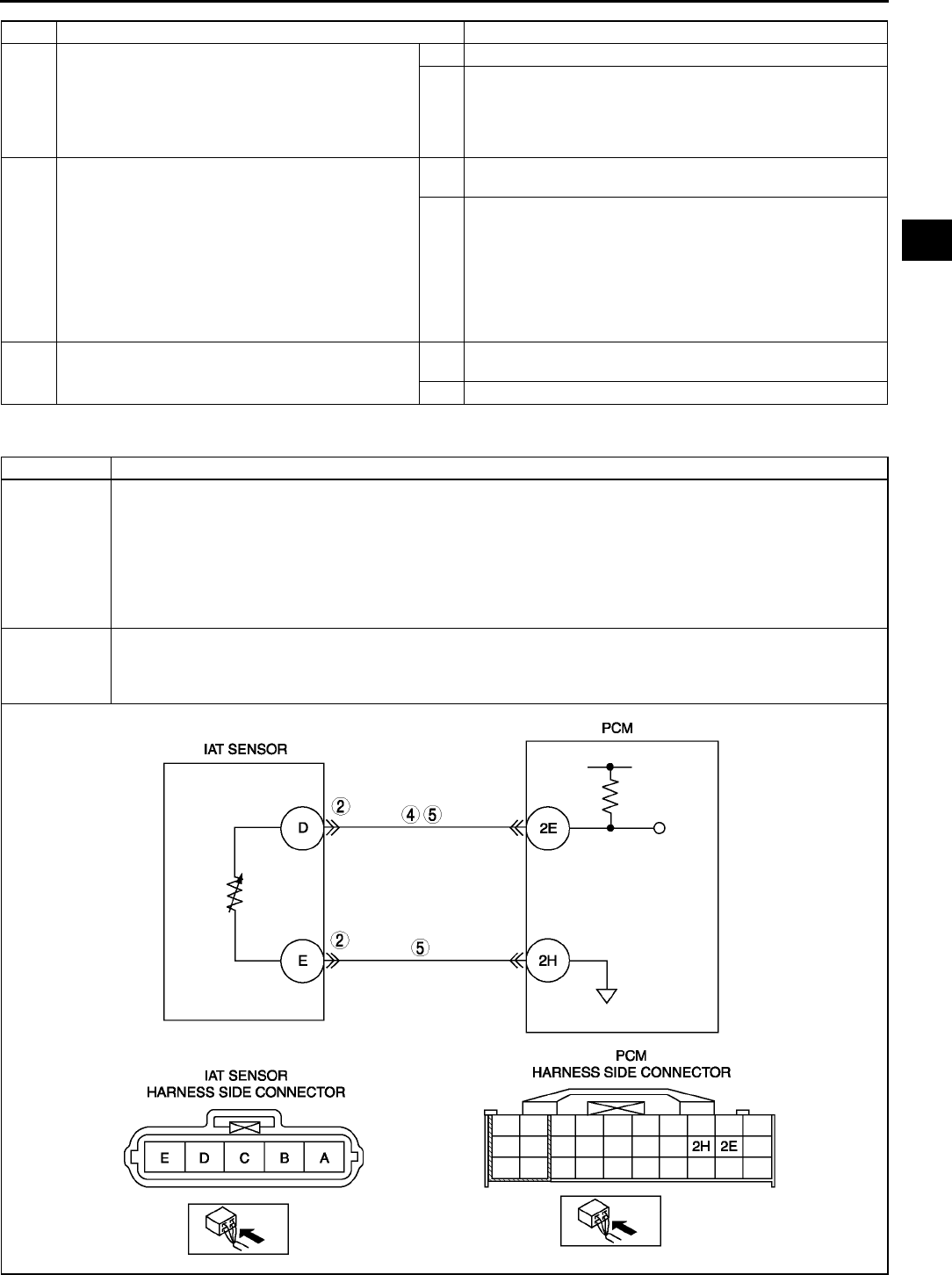
ON-BOARD DIAGNOSTIC
F91
F
End Of Sie
DTC P0112 A6E397001084W14
5INSPECT POOR CONNECTION OF PCM
CONNECTOR
•Disconnect PCM connector.
•Inspect for poor connection (damaged, pulled-
out pins, corrosion, etc.).
•Are there any malfunction?
Yes Repair or replace terminal, then go to Step 6.
No Go to next step.
6VERIFY TROUBLESHOOTING OF DTC P0111
COMPLETED
•Make sure to reconnect all disconnected
connectors.
•Clear DTC from PCM memory using WDS or
equivalent.
•Start engine and run engine under FREEZE
FRAME DATA condition.
•Is PENDING CODE the same as DTC
present?
Yes Replace PCM, then go to next step.
(See F43 PCM REMOVAL/INSTALLATION.)
No Go to next step.
7VERIFY AFTER REPAIR PROCEDURE
•Is there any DTC present?
Yes Go to applicable DTC troubleshooting.
(See F67 DTC TABLE.)
No Troubleshooting completed.
STEP INSPECTION ACTION
DTC P0112 IAT circuit low input
DETECTION
CONDITION
•PCM monitors IAT sensor signal at PCM terminal 2E. If PCM detects IAT sensor voltage below 0.15 V,
PCM determines that IAT sensor circuit has malfunction.
Diagnostic support note
•This is a continuous monitor (CCM).
•MIL illuminates if PCM detects the above malfunction condition during first drive cycle.
•PENDING CODE is available if PCM detects the above malfunction condition.
•FREEZE FRAME DATA is available.
•DTC is stored in the PCM memory.
POSSIBLE
CAUSE
•IAT sensor malfunction
•Short to ground circuit between MAF/IAT sensor terminal D and PCM terminal 2E
•Short each harness IAT signal circuit and IAT ground circuit.
•PCM malfunction

F92
ON-BOARD DIAGNOSTIC
Diagnostic procedure
End Of Sie
DTC P0113 A6E397001084W15
STEP INSPECTION ACTION
1PERFORM DTC CONFIRMATION PROCEDURE
•Perform DTC CONFIRMATION PROCEDURE.
(See F66 DTC CONFIRMATION
PROCEDURE.)
•Is same DTC present?
Yes Go to next step.
No Intermittent concern exists. Go to INTERMITTENT
CONCERN TROUBLESHOOTING procedure.
(See F227 INTERMITTENT CONCERN
TROUBLESHOOTING.)
2INSPECT IAT SENSOR TERMINAL
•Turn ignition key to OFF.
•Disconnect MAF/IAT sensor connector.
•Inspect for bent terminal of MAF/IAT sensor
terminals D and E (part-side).
•Is there any malfunction?
Yes Repair or replace terminal, then go to Step 6.
No Go to next step.
3CLASSIFY IAT SENSOR MALFUNCTION OR
HARNESS MALFUNCTION
•Connect WDS or equivalent to DLC-2.
•Access IAT PID.
•Verify IAT value when disconnecting MAF/IAT
sensor connector.
•Does IAT value change?
Yes Replace MAF/IAT sensor, then go to Step 6.
No Go to next step.
4INSPECT IAT SIGNAL CIRCUIT FOR SHORT TO
GROUND
•Turn ignition key to OFF.
•Disconnect PCM connector.
•Inspect continuity between MAF/IAT sensor
terminal D (harness-side) and body ground.
•Is there any continuity?
Yes Repair or replace harness for short to ground, then go to
Step 6.
No Go to next step.
5INSPECT IAT CIRCUITS FOR SHORT
•Inspect continuity between MAF/IAT sensor
terminals D and E (harness-side).
•Is there continuity?
Yes Repair or replace harness for short, then go to Step 6.
No Go to next step.
6VERIFY TROUBLESHOOTING OF DTC P0112
COMPLETED
•Make sure to reconnect all disconnected
connectors.
•Clear DTC from PCM memory using WDS or
equivalent.
•Perform KOEO/KOER self-test.
(See F66 KOEO/KOER SELF-TEST.)
•Is same DTC present?
Yes Replace PCM, then go to next step.
(See F43 PCM REMOVAL/INSTALLATION.)
No Go to next step.
7VERIFY AFTER REPAIR PROCEDURE
•Perform After Repair Procedure.
(See F66 AFTER REPAIR PROCEDURE.)
•Is there any DTC present?
Yes Go to applicable DTC troubleshooting.
(See F67 DTC TABLE.)
No Troubleshooting completed.
DTC P0113 IAT circuit high input
DETECTION
CONDITION
•PCM monitors input voltage from IAT sensor If input voltage at PCM terminal 2E is above 4.9 V, PCM
determines that IAT sensor circuit has malfunction.
Diagnostic support note
•This is a continuous monitor (CCM).
•MIL illuminates if PCM detects the above malfunction condition during first drive cycle.
•PENDING CODE is available if PCM detects the above malfunction condition.
•FREEZE FRAME DATA is available.
•DTC is stored in the PCM memory.
POSSIBLE
CAUSE
•IAT sensor malfunction
•Open circuit between MAF/IAT sensor terminal D and PCM terminal 2E
•Short to power circuit between MAF/IAT sensor terminal D and PCM terminal 2E
•Open circuit between MAF/IAT sensor terminal E and PCM terminal 2H
•Poor connection at MAF/IAT sensor or PCM connector.
•PCM malfunction
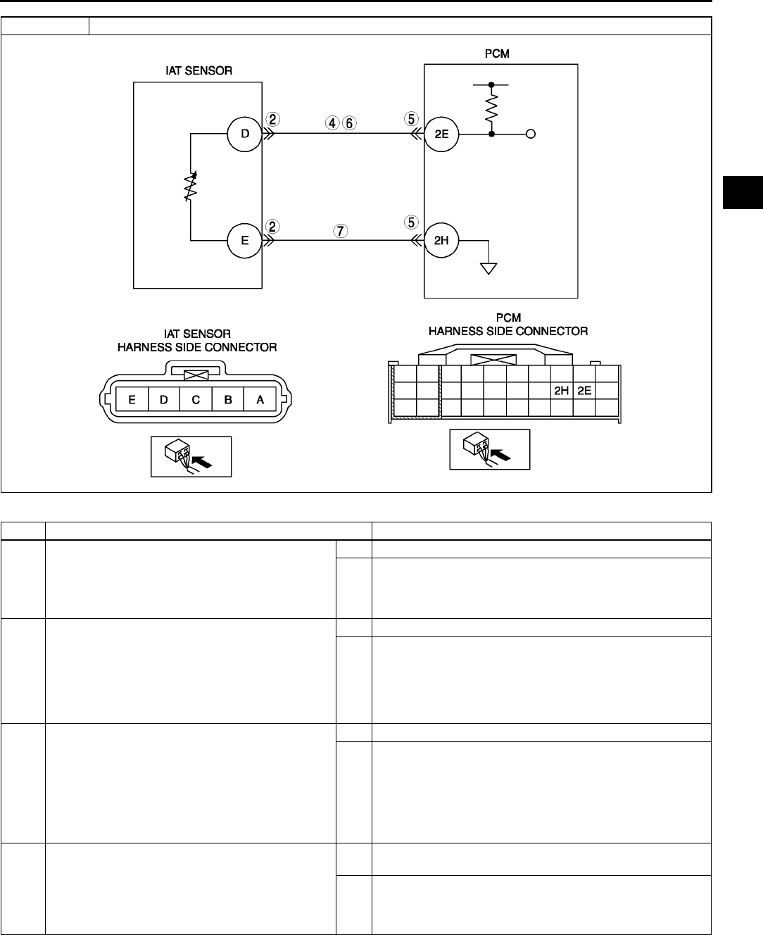
ON-BOARD DIAGNOSTIC
F93
F
Diagnostic procedure
STEP INSPECTION ACTION
1PERFORM DTC CONFIRMATION PROCEDURE
•Perform DTC CONFIRMATION PROCEDURE.
(See F66 DTC CONFIRMATION
PROCEDURE.)
•Is same DTC present?
Yes Go to next step.
No Intermittent concern exists. Go to INTERMITTENT
CONCERN TROUBLESHOOTING procedure.
(See F227 INTERMITTENT CONCERN
TROUBLESHOOTING.)
2INSPECT POOR CONNECTION OF IAT
SENSOR CONNECTOR
•Turn ignition key to OFF.
•Disconnect MAF/IAT sensor connector.
•Inspect for poor connection (damaged, pulled-
out pins, corrosion, etc.).
•Are there any malfunctions?
Yes Repair or replace terminal, then go to Step 8.
No Go to next step.
3CLASSIFY IAT SENSOR MALFUNCTION OR
HARNESS MALFUNCTION
•Connect WDS or equivalent to DLC-2.
•Access IAT PID.
•Connect a jumper wire between MAF/IAT
sensor terminals D and E.
•Verify IAT value
•Is voltage below 4.9 V?
Yes Replace MAF/IAT sensor, then go to Step 8.
No Go to next step.
4INSPECT IAT SENSOR SIGNAL CIRCUIT FOR
SHORT TO POWER
•Turn ignition key to ON (Engine OFF).
•Measure voltage between MAF/IAT sensor
terminal D (harness-side) and body ground.
•Is voltage B+?
Yes Repair or replace harness for short to power, then go to
Step 8.
No Go to next step.
DTC P0113 IAT circuit high input

F94
ON-BOARD DIAGNOSTIC
End Of Sie
DTC P0117 A6E397001084W16
5INSPECT POOR CONNECTION OF PCM
CONNECTOR
•Turn ignition key to OFF.
•Disconnect PCM connector.
•Inspect PCM terminals 2E and 2H (harness-
side) for tightness using feeler tool.
•Are there any malfunction?
Yes Repair or replace terminal, then go to Step 9.
No Go to next step.
6INSPECT IAT SENSOR SIGNAL CIRCUIT FOR
OPEN CIRCUIT
•Inspect continuity between MAF/IAT sensor
terminal D (harness-side) and PCM terminal
2E.
•Is there any continuity?
Yes Go to next step.
No Repair or replace harness for open, then go to Step 9.
7INSPECT IAT SENSOR GROUND CIRCUIT FOR
OPEN CIRCUIT
•Inspect continuity between MAF/IAT sensor
terminal E (harness-side) and PCM terminal
2H.
•Is there continuity?
Yes Go to next step.
No Repair or replace harness for open, then go to next step.
8VERIFY TROUBLESHOOTING OF DTC P0113
COMPLETED
•Make sure to reconnect all disconnected
connectors.
•Clear DTC from PCM memory using WDS or
equivalent.
•Perform KOEO/KOER self-test.
(See F66 KOEO/KOER SELF-TEST.)
•Is same DTC present?
Yes Replace PCM, then go to next step.
(See F43 PCM REMOVAL/INSTALLATION.)
No Go to next step.
9VERIFY AFTER REPAIR PROCEDURE
•Perform After Repair Procedure.
(See F66 AFTER REPAIR PROCEDURE.)
•Is there any DTC present?
Yes Go to applicable DTC troubleshooting.
(See F67 DTC TABLE.)
No Troubleshooting completed.
STEP INSPECTION ACTION
DTC P0117 ECT circuit low input
DETECTION
CONDITION
•PCM monitors ECT sensor signal at PCM terminal 1M. If PCM detects ECT sensor voltage below 0.2 V,
PCM determines that the ECT sensor circuit has malfunction.
Diagnostic support note
•This is a continuous monitor (CCM).
•MIL illuminates if PCM detects the above malfunction condition during first drive cycle.
•PENDING CODE is available if PCM detects the above malfunction condition.
•FREEZE FRAME DATA is available.
•DTC is stored in the PCM memory.
POSSIBLE
CAUSE
•ECT sensor malfunction
•Connect or terminal malfunction
•Short to ground circuit between ECT sensor terminal A and PCM connector terminal 1M.
•Short each harness ECT signal circuit and ECT ground circuit.
•PCM malfunction
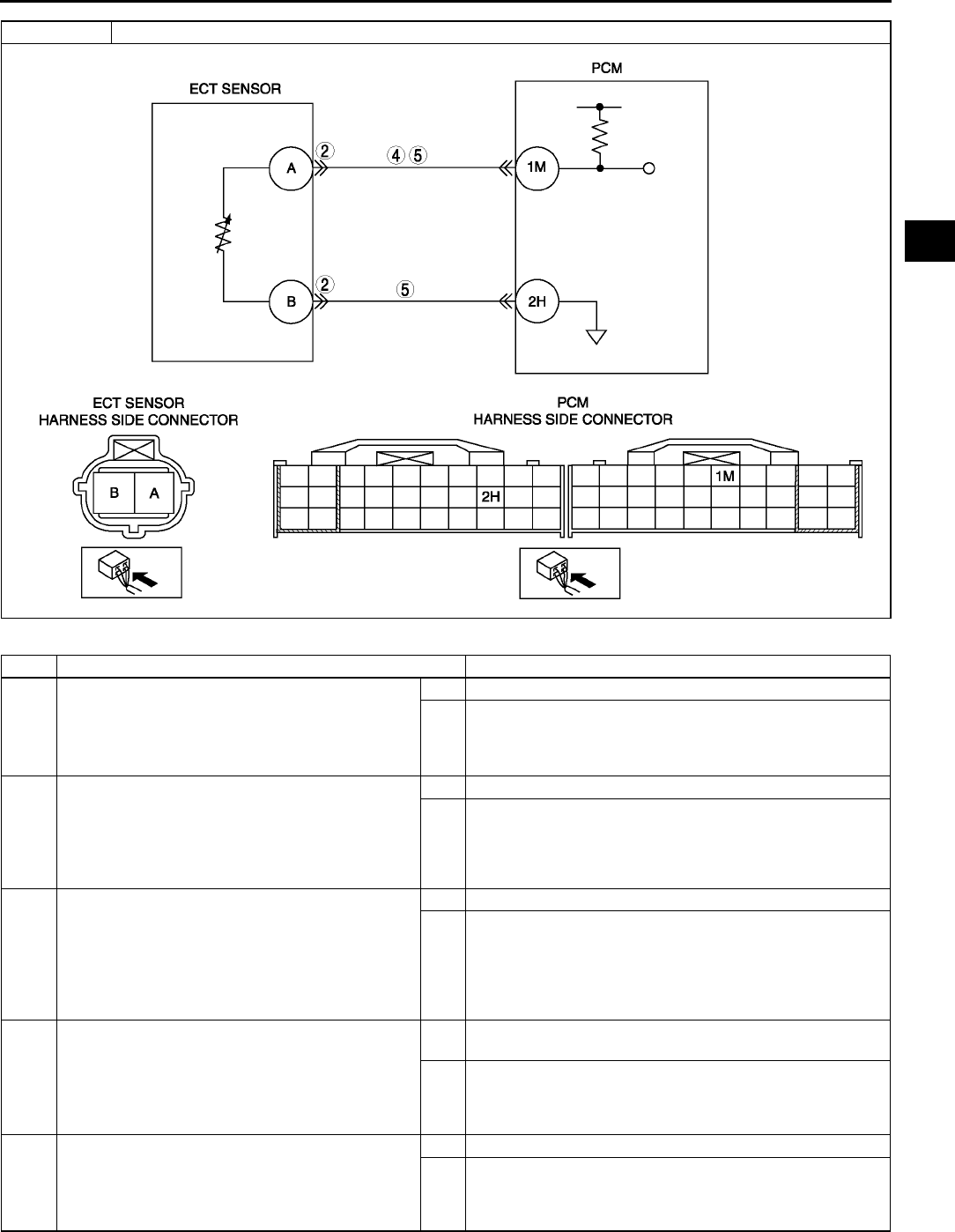
ON-BOARD DIAGNOSTIC
F95
F
Diagnostic procedure
STEP INSPECTION ACTION
1PERFORM DTC CONFIRMATION PROCEDURE
•Perform DTC CONFIRMATION PROCEDURE.
(See F66 DTC CONFIRMATION
PROCEDURE.)
•Is same DTC present?
Yes Go to next step.
No Intermittent concern exists. Go to INTERMITTENT
CONCERN TROUBLESHOOTING procedure.
(See F227 INTERMITTENT CONCERN
TROUBLESHOOTING.)
2INSPECT TERMINAL BENT
•Turn ignition key to OFF.
•Disconnect ECT sensor connector.
•Inspect for bent of ECT sensor terminals A and
B (part-side).
•Is there any malfunction?
Yes Repair or replace terminal, then go to Step 6.
No Go to next step.
3CLASSIFY ECT SENSOR MALFUNCTION OR
HARNESS MALFUNCTION
•Connect WDS or equivalent to DLC-2.
•Access ECT PID.
•Verify ECT value when disconnecting ECT
sensor connector.
•Does ECT value change?
Yes Replace ECT sensor, then go to Step 6.
No Go to next step.
4INSPECT ECT SIGNAL CIRCUIT FOR SHORT
TO GROUND
•Turn ignition key to OFF.
•Inspect continuity between ECT sensor
terminal A (harness-side) and body ground.
•Is there any continuity?
Yes Repair or replace harness for short to ground, then go to
Step 6.
No Go to next step.
5INSPECT IAT CIRCUIT FOR SHORT
HARNESSES
•Inspect continuity between ECT sensor
terminal A and B (harness-side).
•Is there any continuity?
Yes Repair or replace harness for short, then go to next step.
No Go to next step.
DTC P0117 ECT circuit low input
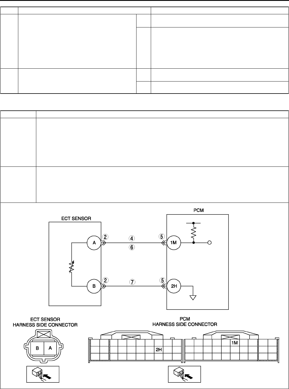
F96
ON-BOARD DIAGNOSTIC
End Of Sie
DTC P0118 A6E397001084W17
6VERIFY TROUBLESHOOTING OF DTC P0117
COMPLETED
•Make sure to reconnect all disconnected
connectors.
•Clear DTC from PCM memory using WDS or
equivalent.
•Perform KOEO/KOER self-test.
(See F66 KOEO/KOER SELF-TEST.)
•Is same DTC present?
Yes Replace PCM, then go to next step.
(See F43 PCM REMOVAL/INSTALLATION.)
No Go to next step.
7VERIFY AFTER REPAIR PROCEDURE
•Perform After Repair Procedure.
(See F66 AFTER REPAIR PROCEDURE.)
•Is there any DTC present?
Yes Go to applicable DTC troubleshooting.
(See F67 DTC TABLE.)
No Troubleshooting completed.
STEP INSPECTION ACTION
DTC P0118 ECT circuit high input
DETECTION
CONDITION
•PCM monitors ECT sensor signal at PCM terminal 1M. If PCM detects ECT sensor voltage above 4.6 V,
PCM determines that ECT sensor circuit has malfunction.
Diagnostic support note
•This is a continuous monitor (CCM).
•MIL illuminates if PCM detects the above malfunction condition during first drive cycle.
•PENDING CODE is available if PCM detects the above malfunction condition.
•FREEZE FRAME DATA is available.
•DTC is stored in the PCM memory.
POSSIBLE
CAUSE
•ECT sensor malfunction
•Open circuit between ECT sensor terminal A and PCM terminal 1M
•Short to power circuit between ECT sensor terminal A and PCM terminal 1M
•Open circuit between ECT sensor terminal B and PCM terminal 2H
•Poor connection of ECT sensor or PCM connectors
•PCM malfunction

ON-BOARD DIAGNOSTIC
F97
F
Diagnostic procedure
End Of Sie
STEP INSPECTION ACTION
1PERFORM DTC CONFIRMATION PROCEDURE
•Perform DTC CONFIRMATION PROCEDURE.
(See F66 DTC CONFIRMATION
PROCEDURE.)
•Is same DTC present?
Yes Go to next step.
No Intermittent concern exists. Go to INTERMITTENT
CONCERN TROUBLESHOOTING procedure.
(See F227 INTERMITTENT CONCERN
TROUBLESHOOTING.)
2INSPECT POOR CONNECTION OF ECT
SENSOR CONNECTOR
•Turn ignition key to OFF.
•Disconnect ECT sensor connector.
•Inspect for poor connection (damaged, pulled-
out pins, corrosion, etc.).
•Are there any malfunctions?
Yes Repair or replace terminal, then go to Step 8.
No Go to next step.
3CLASSIFY ECT SENSOR MALFUNCTION OR
HARNESS MALFUNCTION
•Connect WDS or equivalent to DLC-2.
•Access ECT PID.
•Connect a jumper wire between ECT sensor
terminals A and B.
•Verify ECT value
•Is voltage below 4.5 V?
Yes Replace ECT sensor, then go to Step 8.
No Go to next step.
4INSPECT ECT SENSOR SIGNAL CIRCUIT FOR
SHORT TO POWER
•Turn ignition key to ON (Engine OFF).
•Measure voltage between ECT sensor terminal
A (harness-side) and body ground.
•Is there voltage B+?
Yes Repair or replace harness for short to power, then go to
Step 8.
No Go to next step.
5INSPECT POOR CONNECTION OF PCM
CONNECTOR
•Disconnect PCM connector.
•Inspect for poor connection (damaged, pulled-
out pins, corrosion, etc.).
•Are there any malfunction?
Yes Repair or replace terminal, then go to Step 8.
No Go to next step.
6INSPECT ECT SENSOR SIGNAL CIRCUIT FOR
OPEN CIRCUIT
•Inspect continuity between ECT sensor
terminal A (harness-side) and PCM terminal
1M.
•Is there any continuity?
Yes Go to next step.
No Repair or replace harness for open, then go to Step 8.
7INSPECT ECT SENSOR GROUND CIRCUIT
FOR OPEN CIRCUIT
•Inspect continuity between ECT sensor
terminal B (harness-side) and PCM terminal
2H.
•Is there any continuity?
Yes Go to next step.
No Repair or replace harness for open, then go to next step.
8VERIFY TROUBLESHOOTING OF DTC P0118
COMPLETED
•Make sure to reconnect all disconnected
connectors.
•Clear DTC from PCM memory using WDS or
equivalent.
•Perform KOEO/KOER self-test.
(See F66 KOEO/KOER SELF-TEST.)
•Is same DTC present?
Yes Replace PCM, then go to next step.
(See F43 PCM REMOVAL/INSTALLATION.)
No Go to next step.
9VERIFY AFTER REPAIR PROCEDURE
•Perform After Repair Procedure.
(See F66 AFTER REPAIR PROCEDURE.)
•Is there any DTC present?
Yes Go to applicable DTC troubleshooting.
(See F67 DTC TABLE.)
No Troubleshooting completed.

F98
ON-BOARD DIAGNOSTIC
DTC P0121 A6E397001084W18
Diagnostic procedure
DTC P0121 Throttle position stuck close (lower than expected)/open (higher than expected)
DETECTION
CONDITION
•If PCM detects that throttle valve opening angle is below 12.5% for 5 s after following conditions are met,
PCM determines that TP is stuck closed:
MONITORING CONDITION
Engine coolant temperature above 80 °
°°
°C {176 °
°°
°F}
MAF sensor signal above 32.0 g/s {4.2 lb/minutes}
•If PCM detects that throttle valve opening angle is above 50% for 5 seconds after following conditions are
met, the PCM determines that TP is stuck open:
MONITORING CONDITION
Engine speed above 500 rpm
MAF sensor signal 5 g/s {0.7 lb/min.}
Diagnostic support note
•This is a continuous monitor (CCM).
•MIL illuminates if PCM detects the above malfunction condition in two consecutive drive cycles or in one
drive cycle while the DTC for the same malfunction has been stored in the PCM.
•PENDING CODE is available if PCM detects the above malfunction condition.
•FREEZE FRAME DATA is available.
•DTC is stored in the PCM memory.
POSSIBLE
CAUSE
•TP sensor malfunction
•Electrical corrosion in TP signal circuit
•Voltage drops in constant voltage supply circuit
•Voltage drops in ground circuit
•MAF sensor malfunction
•PCM malfunction
STEP INSPECTION ACTION
1VERIFY FREEZE FRAME DATA HAS BEEN
RECORDED
•Has FREEZE FRAME DATA been recorded?
Yes Go to next step.
No Record FREEZE FRAME DATA on repair order, then go to
next step.
2VERIFY RELATED PENDING CODE OR
STORED DTC
•Turn ignition key to ON (Engine OFF).
•Retrieve pending or stored DTC using WDS or
equivalent.
•Is DTC P0101 also retrieved?
Yes Go to DTC P0101 troubleshooting procedure.
No Go to next step.
3VERIFY RELATED SERVICE INFORMATION
AVAILABILITY
•Check for related Service Information
availability.
•Is any related Service Information available?
Yes Perform repair or diagnosis according to available Service
Information.
•If vehicle is not repaired, go to next step.
No Go to next step.
4VERIFY CURRENT INPUT SIGNAL STATUS - IS
CONCERN INTERMITTENT OR CONSTANT
•Start the engine.
•Access ECT, TP and MAF PIDs using WDS or
equivalent.
•Warm up the engine until ECT PID is above 80
°
°°
°C {176 °
°°
°F}
•Drive the vehicle.
•Read TP PID while MAF PID is above 32.0 g/s
{4.2 lb/min.}.
•Is TP PID reading above 12.5%?
Yes Go to Step 7.
No Go to next step.
5VERIFY TP PID
•Start engine.
•Access TP, MAF and RPM PIDs using WDS or
equivalent.
•Read TP PID while MAF PID is below 4.8 g/s
{0.6 lb/min.} and RPM PID is above 500 rpm.
•Is TP PID reading above 50%?
Yes Go to Step 12.
No Go to next step.

ON-BOARD DIAGNOSTIC
F99
F
6VERIFY CURRENT INPUT SIGNAL STATUS - IS
CONCERN INTERMITTENT OR CONSTANT
•Drive the vehicle and read MAF PID.
•Does MAF PID change in compliance with
driving condition?
Yes Intermittent concern exists. Go to INTERMITTENT
CONCERNS troubleshooting procedure.
No Inspect Mass airflow sensor and related circuits and
terminals.
(See F51 MASS AIR FLOW (MAF) SENSOR
INSPECTION.)
Repair or replace as necessary, then go to Step 16.
7INSPECT TP SENSOR TERMINALS FOR
ELECTRICAL CORROSION
•Turn ignition key to OFF.
•Disconnect TP sensor connector
•Inspect for electrical corrosion on male and
female TP sensor terminals.
•Is any electrical corrosion found?
Yes Repair or replace suspected terminal or TP sensor, then go
to Step 11.
No Go to next step.
8VERIFY TP SENSOR
•Does TP sensor resistance smoothly change
while gradually opening throttle valve?
Yes Go to next step.
No Replace TP sensor, then go to Step 11.
9INSPECT PCM TERMINALS FOR ELECTRICAL
CORROSION
•Disconnect PCM connector.
•Inspect for electrical corrosion on PCM male
and female terminals.
•Is any electrical corrosion found?
Yes Repair terminal, then go to Step 11.
No Go to next step.
10 INSPECT CONSTANT VOLTAGE SUPPLY AND
TP SIGNAL CIRCUITS FOR VOLTAGE DROP
•Turn ignition key to ON (Engine OFF).
•Inspect voltage between following terminals:
TP sensor connector terminal C (harness-
side) and PCM terminal 2K
TP sensor connector terminal B (harness-
side) and PCM terminal 2A
•Is voltage approx. 0 V?
Yes Go to next step.
No Inspect for rust or corrosion on PCM terminals 2A and 2K
(harness-side).
•Repair or replace suspected terminal then go to next
step.
11 VERIFY TROUBLESHOOTING OF DTC P0121
COMPLETED
•Make sure to reconnect all disconnected
connectors.
•Start the engine.
•Clear DTC from PCM memory using WDS or
equivalent.
•Access ECT, TP and MAF PIDs using WDS or
equivalent.
•Warm up the engine until ECT PID is reading
above 80 °
°°
°C {176°
°°
°F}.
•Drive the vehicle and read TP and MAF PIDs.
•Verify PIDs reading are within specifications
MAF PID: above 32.0 g/s {4.2 lb/min.}
TP PID: above 12.5% above 5 s
•Is PENDING CODE of same DTC present?
Yes Replace PCM, then go to Step 17.
No Go to Step 17.
12 INSPECT TP SENSOR TERMINALS FOR
ELECTRICAL CORROSION
•Turn ignition key to OFF.
•Disconnect TP sensor connector.
•Inspect for electrical corrosion on male and
female TP sensor terminals.
•Is any electrical corrosion found?
Yes Repair or replace suspected terminal or TP sensor, then go
to Step 16.
No Go to next step.
13 INSPECT GROUND CIRCUIT FOR VOLTAGE
DROP
•Inspect resistance between TP sensor terminal
A (harness-side) and body ground.
•Is resistance approx. 0 ohm?
Yes Go to next step.
No Repair or replace for rust or corrosion on PCM terminal 2H
(harness-side).
•Repair or replace suspected terminal.
Go to Step 16.
14 VERIFY TP SENSOR
•Does resistance smoothly change while
gradually opening throttle valve?
Yes Go to next step.
No Replace TP sensor, then go to Step 16.
STEP INSPECTION ACTION

F100
ON-BOARD DIAGNOSTIC
End Of Sie
DTC P0122 A6E397001084W19
15 INSPECT PCM TERMINALS FOR ELECTRICAL
CORROSION
•Disconnect PCM connector.
•Inspect for electrical corrosion on PCM and
PCM connector male and female terminals.
•Is any electrical corrosion found?
Yes Repair terminal, then go to next step.
No Go to next step.
16 VERIFY TROUBLESHOOTING OF DTC P0121
COMPLETED
•Make sure to reconnect all disconnected
connectors.
•Start engine.
•Clear DTC from PCM memory using WDS or
equivalent.
•Access RPM, TP and MAF PIDs using WDS or
equivalent.
•Verify TP PID is reading below 50% while MAF
PID is below 4.8 g/s {0.6 lb/min.} and RPM
PID is above 500 rpm.
•Is pending code the same as DTC present?
Yes Replace PCM, then go to next step.
(See F43 PCM REMOVAL/INSTALLATION.)
No Go to next step.
17 VERIFY AFTER REPAIR PROCEDURE
•Is there any DTC present?
Yes Go to applicable DTC troubleshooting.
(See F67 DTC TABLE.)
No Troubleshooting completed.
STEP INSPECTION ACTION
DTC P0122 TP circuit low input
DETECTION
CONDITION
•If PCM detects TP sensor voltage at PCM terminal 2A is below 0.1 V while engine running, PCM
determines that TP circuit has malfunction.
Diagnostic support note
•This is a continuous monitor (CCM).
•MIL illuminates if PCM detects the above malfunction conditions in first drive cycles.
•PENDING CODE is available if PCM detects the above malfunction condition.
•FREEZE FRAME DATA is available.
•DTC is stored in the PCM memory.
POSSIBLE
CAUSE
•TP sensor malfunction
•Connector or terminal malfunction
•Open circuit between TP sensor terminal B and PCM terminal 2A
•Short to ground circuit between TP sensor terminal B and PCM terminal 2A
•Open circuit between TP sensor terminal C and PCM terminal 2K

ON-BOARD DIAGNOSTIC
F101
F
Diagnostic procedure
STEP INSPECTION ACTION
1PERFORM DTC CONFIRMATION PROCEDURE
•Perform DTC CONFIRMATION PROCEDURE.
(See F66 DTC CONFIRMATION
PROCEDURE.)
•Is same DTC present?
Yes Go to next step.
No Intermittent concern exists. Go to INTERMITTENT
CONCERN TROUBLESHOOTING procedure.
(See F227 INTERMITTENT CONCERN
TROUBLESHOOTING.)
2CLASSIFY TP SENSOR OR HARNESS
MALFUNCTION
•Connect WDS or equivalent.
•Access TP PID.
•Disconnect TP sensor connector.
•Connect a jumper wire between TP sensor
terminals B and C (harness-side).
•Is voltage above 4.9 V?
Yes Go to next step.
No Go to step 4.
3INSPECT TP SENSOR
•Perform TP sensor inspection.
(See F51 THROTTLE POSITION (TP)
SENSOR INSPECTION.)
•Is TP sensor okay?
Yes Inspect for poor TP sensor connector terminal C
connection. Repair or replace as necessary, then go to
Step 7.
No Replace TP sensor, then go to Step 7.
4INSPECT POWER SUPPLY CIRCUIT VOLTAGE
AT TP SENSOR CONNECTOR
Note
•If DTC P0107 and P2228 are also retrieved
with P0122, go to CONSTANT VOLTAGE
troubleshooting procedure.
•Turn ignition key to ON (Engine OFF).
•Inspect voltage at TP sensor terminal 2k
(harness-side).
•Is there voltage within 4.55.5 V?
Yes Go to next step.
No Repair or replace open circuit between TP sensor
connector terminal C and PCM connector terminal 2K
(harness-side).
Then, then go to Step 7.
DTC P0122 TP circuit low input

F102
ON-BOARD DIAGNOSTIC
End Of Sie
DTC P0123 A6E397001084W20
5VERIFY TP SIGNAL CIRCUIT FOR OPEN
CIRCUIT
•Turn ignition key to OFF.
•Inspect continuity between TP sensor terminal
B (harness-side) and PCM terminal 2A.
•Is there continuity?
Yes Go to next step.
No Repair or replace suspected harness, then go to Step 7.
6VERIFY TP SIGNAL CIRCUIT FOR SHORT TO
GROUND
•Inspect continuity between TP sensor terminal
B (harness-side) and body ground.
•Is there continuity?
Yes Repair or replace suspected harness, then go to Step 7.
No Go to next step.
7VERIFY TROUBLESHOOTING OF DTC P0122
COMPLETED
•Make sure to reconnect all disconnected
connectors.
•Clear DTC from PCM memory using WDS or
equivalent.
•Perform KOEO/KOER self-test.
(See F66 KOEO/KOER SELF-TEST.)
•Is same DTC present?
Yes Replace PCM, then go to next step.
(See F43 PCM REMOVAL/INSTALLATION.)
No Go to next step.
8VERIFY AFTER REPAIR PROCEDURE
•Perform After Repair Procedure.
(See F66 AFTER REPAIR PROCEDURE.)
•Is there any DTC present?
Yes Go to applicable DTC troubleshooting.
(See F67 DTC TABLE.)
No Troubleshooting completed.
STEP INSPECTION ACTION
DTC P0123 TP circuit high input
DETECTION
CONDITION
•If PCM detects TP sensor voltage at PCM terminal 2A is above 4.9 V after ignition key to on, the PCM
determines that TP circuit has malfunction.
Diagnostic support note
•This is a continuous monitor (CCM).
•MIL illuminates if PCM detects the above malfunction condition in first drive cycles.
•PENDING CODE is available if PCM detects the above malfunction condition.
•FREEZE FRAME DATA is available.
•DTC is stored in the PCM memory.
POSSIBLE
CAUSE
•TP sensor malfunction
•Connector or terminal malfunction
•Open circuit between TP sensor terminal A and PCM terminal 2H
•Short to constant voltage supply circuit between TP sensor terminal B and PCM terminal 2A
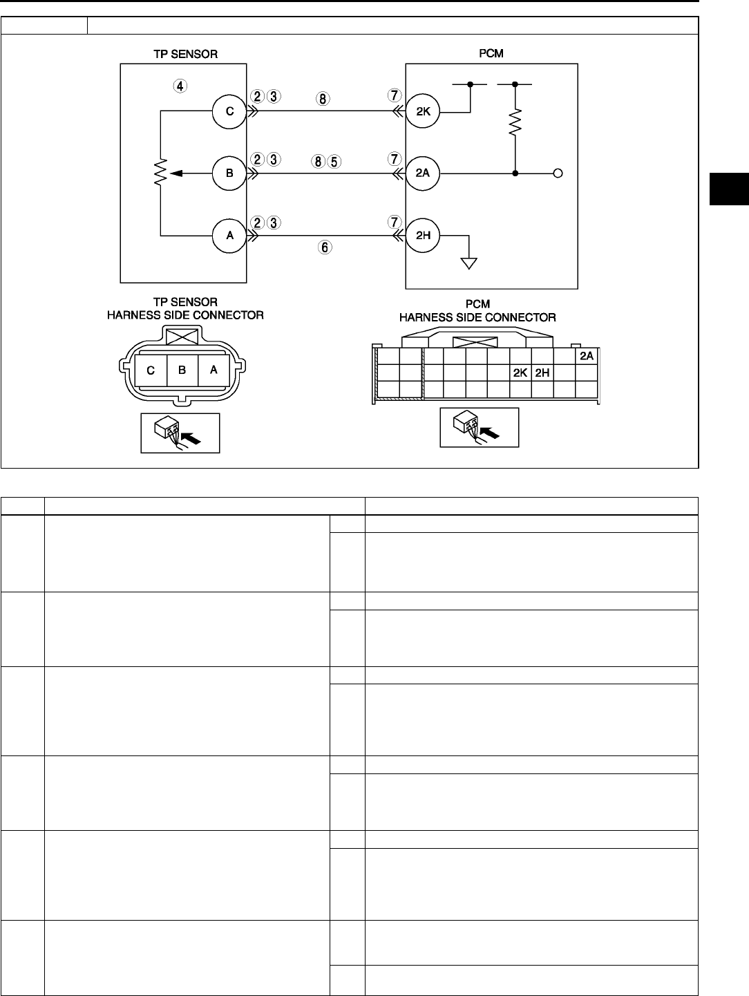
ON-BOARD DIAGNOSTIC
F103
F
Diagnostic procedure
STEP INSPECTION ACTION
1PERFORM DTC CONFIRMATION PROCEDURE
•Perform DTC CONFIRMATION PROCEDURE.
(See F66 DTC CONFIRMATION
PROCEDURE.)
•Is same DTC present?
Yes Go to next step.
No Intermittent concern exists. Go to INTERMITTENT
CONCERN TROUBLESHOOTING procedure.
(See F227 INTERMITTENT CONCERN
TROUBLESHOOTING.)
2INSPECT TP SENSOR CONNECTOR
•Turn ignition key to OFF.
•Verify that the TP sensor connector is
connected securely.
•Is connector okay?
Yes Go to next step.
No Connect the connector securely, then go to Step 9.
3INSPECT POOR CONNECTION OF TP SENSOR
CONNECTOR
•Disconnect TP sensor connector.
•Inspect for poor connection (damaged, pulled-
out terminals, corrosion, etc.).
•Is there any malfunction?
Yes Repair or replace suspected terminal, then go to Step 9.
No Go to next step.
4INSPECT TP SENSOR
•Perform TP sensor inspection.
(See F51 THROTTLE POSITION (TP)
SENSOR INSPECTION)
•Is TP sensor okay?
Yes Go to next step.
No Replace TP sensor, then go to Step 9.
5INSPECT TP SENSOR SIGNAL CIRCUIT FOR
SHORT TO POWER
•Turn ignition key to ON (Engine OFF).
•Measure voltage between terminal B and body
ground.
•Is voltage above 4.9?
Yes Repair or replace short to power circuit. Then, go to Step 9.
No Go to next step.
6VERIFY TP SENSOR GROUND CIRCUIT FOR
OPEN CIRCUIT
•Inspect continuity between TP sensor
connector terminal A and body ground.
•Is there continuity?
Yes Repair or replace open circuit between TP sensor
connector terminal A (harness-side) and PCM connector
terminal 2H (harness-side). Then, go to Step 9.
No Go to next step.
DTC P0123 TP circuit high input

F104
ON-BOARD DIAGNOSTIC
End Of Sie
DTC P0125 A6E397001084W21
Diagnostic procedure
7INSPECT PCM CONNECTOR
•Disconnect PCM connector.
•Inspect for poor connection (damaged, pulled-
out terminals, corrosion, etc.).
•Is there any malfunction?
Yes Repair terminal, then go to Step 9.
No Go to Step 9.
8VERIFY TP SIGNAL CIRCUIT FOR SHORT TO
CONSTANT VOLTAGE CIRCUIT
•Inspect continuity between TP sensor
connector terminals B and C.
•Is there continuity?
Yes Repair or replace suspected harness, then go to next step.
No Go to next step.
9VERIFY TROUBLESHOOTING OF DTC P0123
COMPLETED
•Make sure to reconnect all disconnected
connectors.
•Clear DTC from PCM memory using WDS or
equivalent.
•Perform KOEO/KOER self-test.
(See F66 KOEO/KOER SELF-TEST.)
•Is same DTC present?
Yes Replace PCM, then go to next step.
(See F43 PCM REMOVAL/INSTALLATION.)
No Go to next step.
10 VERIFY AFTER REPAIR PROCEDURE
•Perform After Repair Procedure.
(See F66 AFTER REPAIR PROCEDURE.)
•Is there any DTC present?
Yes Go to applicable DTC troubleshooting.
(See F67 DTC TABLE.)
No Troubleshooting completed.
STEP INSPECTION ACTION
DTC P0125 Excessive time to enter closed loop fuel control
DETECTION
CONDITION
•PCM monitors ECT sensor signal at PCM terminal 1M after engine is started while engine is cold. If engine
coolant temperature does not reach the expected temperature for specified period, PCM determines that it
has taken an excessive amount of time for the engine coolant temperature to reach the temperature
necessary to start closed-loop fuel control.
Diagnostic support note
•This is a continuous monitor (CCM).
•MIL illuminates if PCM detects the above malfunction condition in two consecutive drive cycles or in one
drive cycle while the DTC for the same malfunction has been stored in the PCM.
•PENDING CODE is available if PCM detects the above malfunction condition during first drive cycle.
•FREEZE FRAME DATA is available.
•DTC is stored in PCM memory.
POSSIBLE
CAUSE
•ECT sensor malfunction
•Poor connection of connectors
•PCM malfunction
STEP INSPECTION ACTION
1VERIFY FREEZE FRAME DATA HAS BEEN
RECORDED
•Has FREEZE FRAME DATA been recorded?
Yes Go to next step.
No Record FREEZE FRAME DATA on repair order, then go to
next step.
2VERIFY RELATED SERVICE INFORMATION
AVAILABILITY
•Check for related Service Information
availability.
•Is any related Service Information available?
Yes Perform repair or diagnosis according to available Service
Information.
•If vehicle is not repaired, go to next step.
No Go to next step.
3VERIFY CURRENT INPUT SIGNAL STATUS-IS
CONCERN INTERMITTENT OR CONSTANT
•Start engine.
•Warm up engine completely.
•Access ECT PID using WDS or equivalent.
•Is ECT PID above 60 °
°°
°C {140 °
°°
°F}?
Yes Intermittent concern exists. Go to INTERMITTENT
CONCERNS TROUBLESHOOTING procedure.
(See F227 INTERMITTENT CONCERN
TROUBLESHOOTING.)
No Go to next step.
4INSPECT POOR CONNECTION OF ECT
SENSOR CONNECTOR
•Turn ignition key to OFF.
•Disconnect ECT sensor connector.
•Inspect for poor connection (damaged, pulled-
out pins, corrosion, etc.).
•Are there any malfunctions?
Yes Repair or replace terminal, then go to Step 7.
No Go to next step.

ON-BOARD DIAGNOSTIC
F105
F
End Of Sie
DTC P0131, P0132 A6E397001084W22
Diagnostic procedure
5INSPECT ECT SENSOR
•Inspect ECT sensor.
(See F53 ENGINE COOLANT
TEMPERATURE (ECT) SENSOR
INSPECTION.)
•Is it okay?
Yes Go to next step.
No Replace ECT sensor, then go to Step 7.
6INSPECT POOR CONNECTION OF PCM
CONNECTOR
•Disconnect PCM connector.
•Inspect for poor connection (damaged, pulled-
out pins, corrosion, etc.).
•Are there any malfunctions?
Yes Repair or replace terminal, then go to next step.
No Go to next step.
7VERIFY TROUBLESHOOTING OF DTC P0125
COMPLETED
•Make sure to reconnect all disconnected
connectors.
•Clear DTC from PCM memory using WDS or
equivalent.
•Turn ignition key to ON (Engine OFF).
•Access ECT PID using WDS or equivalent.
•Wait until ECT PID below 20 °
°°
°C {68 °
°°
°F}.
•Start engine and warm it up completely.
•Is PENDING CODE the same as DTC stored?
Yes Replace PCM, then go to next step.
(See F43 PCM REMOVAL/INSTALLATION.)
No Go to next step.
8VERIFY AFTER REPAIR PROCEDURE
•Perform After Repair Procedure.
(See F66 AFTER REPAIR PROCEDURE.)
•Is there any DTC present?
Yes Go to applicable DTC troubleshooting.
(See F67 DTC TABLE.)
No Troubleshooting completed.
STEP INSPECTION ACTION
DTC P0131
DTC P0132
Front HO2S stuck low
Front HO2S stuck high
DETECTION
CONDITION
•PCM monitors input voltage from front HO2S when the following monitoring conditions are met. If input
voltage from sensor remains below or above 0.45 V for 41.2 s, PCM determines that there is no front
HO2S inversion.
MONITORING CONDITIONS
Engine speed is above 1,500 rpm.
Engine coolant temperature is above 80 °
°°
°C {176°
°°
°F}.
Diagnostic support note
•This is a continuous monitor (CCM).
•MIL illuminates if PCM detects the above malfunction condition in two consecutive drive cycles or in one
drive cycle while the DTC for the same malfunction has been stored in the PCM.
•PENDING CODE is available if PCM detects the above malfunction condition during first drive cycle.
•FREEZE FRAME DATA is available.
•DTC is stored in the PCM memory.
POSSIBLE
CAUSE
•Front HO2S malfunction
•Front HO2S heater malfunction
•Fuel injector malfunction
•Pressure regulator malfunction
•Fuel pump malfunction
•Fuel delivery hose clogging or leakage
•Fuel filter clogging
•Fuel return hose clogging or leakage
•Air suction or leakage
•PCV valve malfunction
•Purge solenoid valve malfunction
•Purge solenoid hoses are hooked up incorrectly.
•Ignition coil malfunction
•Insufficient compression
•Engine malfunction
STEP INSPECTION ACTION
1VERIFY FREEZE FRAME DATA HAS BEEN
RECORDED
•Has FREEZE FRAME DATA been recorded?
Yes Go to next step.
No Record FREEZE FRAME DATA on repair order, then go to
next step.

F106
ON-BOARD DIAGNOSTIC
2VERIFY RELATED SERVICE INFORMATION
AVAILABILITY
•Check for related Service Information
availability.
•Is any related Service Information available?
Yes Perform repair or diagnosis according to available Service
Information.
•If vehicle is not repaired, go to next step.
No Go to next step.
3VERIFY RELATED PENDING AND STORED
DTCs
•Turn ignition key to OFF, then ON (Engine
OFF).
•Verify pending and stored DTCs using WDS or
equivalent.
•Is other DTC present?
Yes Go to appropriate DTC troubleshooting procedures.
No Go to next step.
4IDENTIFY TRIGGER DTC FOR FREEZE FRAME
DATA
•Is DTC P0131 and P0132 on FREEZE FRAME
DATA?
Yes Go to next step.
No Go to troubleshooting procedures for DTC on FREEZE
FRAME DATA.
5VERIFY CURRENT INPUT SIGNAL STATUS - IS
CONCERN INTERMITTENT OR CONSTANT
•Warm-up engine.
•Access O2S11 for P0131 and P0132 PID using
WDS or equivalent.
•Verify PID while racing engine (in PARK (ATX)
or NEUTRAL (MTX)).
•Is PID reading okay?
More than 0.45 V when suddenly depress
accelerator pedal (rich condition)
Less than 0.45 V just after release of
accelerator pedal (lean condition)
Yes Go to next step.
No Replace front HO2S, then go to Step 19.
6INSPECT LONG TERM FUEL TRIM
•Access LONGFT1 for P0131 and P0132 PID
using WDS or equivalent.
•Compare it with FREEZE FRAME DATA
recorded at Step1.
•Was it decreased?
Yes Engine is driven under rich condition. Go to next step.
No Engine is driven under lean condition. Go to step 9.
7INSPECT FUEL LINE PRESSURE (EXCESSIVE
FUEL LINE PRESSURE)
•Turn ignition key to OFF.
•Inspect fuel line pressure.
(See F20 FUEL LINE PRESSURE
INSPECTION.)
•Is fuel line pressure okay?
Yes Go to next step.
No Inspect following parts and repair or replace if necessary:
•Fuel pump maximum pressure
•Fuel return pipe for clogged
If all items above are okay, replace pressure
regulator. Then, go to Step 19.
8INSPECT PURGE SOLENOID VALVE FOR
STUCK OPEN
•Turn ignition key to OFF.
•Disconnect both hoses from purge solenoid
valve.
•Blow air through purge solenoid valve.
•Does air blow through?
Yes Replace purge solenoid valve.
No Go to Step 13.
9INSPECT PCV VALVE OPERATION
• Inspect PCV valve operation.
(See F41 PCV VALVE INSPECTION.)
•Is PCV valve okay?
Yes Go to next step.
No Replace PCV, then go to Step 19.
10 INSPECT FUEL LINE PRESSURE (LOW FUEL
LINE PRESSURE)
•Turn ignition key to OFF.
•Inspect fuel line pressure.
(See F20 FUEL LINE PRESSURE
INSPECTION.)
•Is fuel line pressure okay?
Yes Go to step 13.
No Go to next step.
11 INSPECT FUEL PUMP MAXIMUM PRESSURE
•Stop engine.
•Turn ignition key to ON (Engine OFF).
•Perform fuel pump maximum pressure test.
(See F20 FUEL LINE PRESSURE
INSPECTION.)
•Is fuel pump maximum pressure okay?
Yes Go to next step.
No Inspect fuel pump circuit for open or poor connection.
•Repair or replace suspected circuit.
•If circuit is okay, replace fuel pump.
Then go to Step 19.
STEP INSPECTION ACTION

ON-BOARD DIAGNOSTIC
F107
F
12 INSPECT FUEL LINE FROM FUEL PUMP TO
FUEL DELIVERY PUMP
•Visually inspect fuel line for any leakage.
•Is any fuel leakage found?
Yes Replace suspected fuel line, then go to Step 19.
No Inspect fuel filters for following:
•Restriction or clogging at fuel filter (high-pressure side).
•Foreign materials or stain inside fuel filter (low-pressure
side)
If restriction or clogging is found at fuel filter (high-
pressure side), replace fuel filter.
If foreign materials or stain is found inside fuel filter
(low-pressure side), clean of fuel tank and filter.
If all items above are okay, replace pressure
regulator. Then, go to Step 19.
13 CHECK IGNITION COIL OPERATION
•Perform spark test.
(See F232 Spark Test)
•Do all cylinders show blinking condition?
Yes Go to step 16.
No Go to next step.
14 INSPECT POWER SUPPLY TERMINAL AT
IGNITION COIL CONNECTOR
•Disconnect ignition coil connector.
•Turn ignition key to ON (Engine OFF).
•Measure voltage between ignition coil
connector terminal D (harness-side) and body
ground.
•Is the voltage reading B+?
Yes Go to next step.
No Check for open circuit between ignition coil connector and
ignition switch.
Repair or replace wiring harness, then go to Step 19.
15 INSPECT IGNITION COIL RESISTANCE
•Check ignition coil resistance.
(See G9 IGNITION COIL INSPECTION.)
•Is coil resistance okay?
Yes Go to next step.
No Replace ignition coil, then go to Step 19.
16 INSPECT ENGINE COMPRESSION
•Inspect engine compression.
(See B9 COMPRESSION INSPECTION.)
•Is it okay?
Yes Go to next step.
No Implement engine overhaul for repairs, then go to next
step.
17 INSPECT FUEL INJECTOR OPERATION
•Turn ignition key to OFF.
•Inspect injector.
(See F31 FUEL INJECTOR INSPECTION.)
•Is injector okay?
Yes Go to next step.
No Replace injector, then go to Step 19.
18 INSPECT SEALING OF ENGINE COOLANT
PASSAGE
Warning
•
••
•Removing radiator cap when radiator is
hot is dangerous. Scalding coolant and
steam may shoot out and cause serious
injury.
•
••
•When removing radiator cap, wrap a
thick cloth around and turn it slowly.
•Remove radiator cap.
•Implement procedure to bleed air from engine
coolant, then run engine at idle.
•Is there any small bubble, which makes engine
coolant white at filling opening?
Note
•Large bubbles are normal since they are
remaining air coming out from engine
coolant passage.
Yes Air gets in from poor sealing to head gasket or other areas
between combustion chamber and engine coolant
passage.
Repair or replace faulty parts, then go to next step.
No Go to next step.
STEP INSPECTION ACTION

F108
ON-BOARD DIAGNOSTIC
End Of Sie
DTC P0133 A6E397001084W23
Diagnostic procedure
19 VERIFY TROUBLESHOOTING OF DTC P0131 or
P0132 COMPLETED
•Make sure to reconnect all disconnected
connectors.
•Turn ignition key to ON (Engine OFF).
•Clear DTC from memory using WDS or
equivalent.
•Start engine.
•Access ECT and RPM PIDs using WDS or
equivalent.
•Make sure that ECT PID is above 80 °
°°
°C {176
°
°°
°F}.
•Increase and keep engine speed above 1,500
rpm for at least 1 min.
•Is pending code the same as DTC present?
Yes Replace PCM, then go to next step.
(See F43 PCM REMOVAL/INSTALLATION.)
No Go to next step.
20 VERIFY AFTER REPAIR PROCEDURE
•Perform After Repair Procedure.
(See F66 AFTER REPAIR PROCEDURE.)
•Is there any DTC present?
Yes Go to applicable DTC troubleshooting.
(See F67 DTC TABLE.)
No Troubleshooting completed.
STEP INSPECTION ACTION
DTC P0133 Front HO2S circuit malfunction
DETECTION
CONDITION
•PCM monitors inversion cycle period, lean-to-rich response time and rich-to-lean response time of the
sensor. PCM calculates the average of the inversion cycle period-specified inversion cycles, average
response time from lean-to-rich, and from rich-to-lean when following conditions are met. If any exceeds
threshold, PCM determines that circuit has malfunction.
MONITORING CONDITIONS
Drive mode 3
Following conditions are met:
•Calculation load 14.859.4 % (at 2,000 rpm).
•Engine speed 1,4104,000 rpm (MTX)
•Engine speed 1,1904,000 rpm (ATX)
•Vehicle speed is above 3.76 km/h
•Engine coolant temperature is above -10 °
°°
°C {14 °
°°
°F}
•Front HO2S signal inversion cycle is above 10 cycles
Diagnostic support note
•This is an intermittent monitor. (OXYGEN SENSOR)
•MIL illuminates if PCM detects the above malfunction condition in two consecutive drive cycles or in one
drive cycle while the DTC for the same malfunction has been stored in the PCM.
•DIAGNOSTIC MONITORING TEST RESULTS is available.
•PENDING CODE is available if PCM detects the above malfunction condition during first drive cycle.
•FREEZE FRAME DATA is available.
•DTC is stored in the PCM memory.
POSSIBLE
CAUSE
•Front HO2S deterioration
•Front HO2S heater malfunction
•Pressure regulator malfunction
•Fuel pump malfunction
•Fuel filter clogged or restricted
•Fuel leakage on fuel line from fuel distribution pipe and fuel pump
•Leakage exhaust system
•Purge solenoid valve malfunction
•Purge solenoid hoses improper connection
•Insufficient compression
•Engine malfunction
STEP INSPECTION ACTION
1VERIFY FREEZE FRAME DATA HAS BEEN
RECORDED
•Has FREEZE FRAME DATA been recorded?
Yes Go to next step.
No Record FREEZE FRAME DATA on repair order, then go to
next step.
2VERIFY RELATED SERVICE INFORMATION
AVAILABILITY
•Check for related Service Information
availability.
•Is any related Service Information available?
Yes Perform repair or diagnosis according to available Service
Information.
•If vehicle is not repaired, go to next step.
No Go to next step.

ON-BOARD DIAGNOSTIC
F109
F
3VERIFY RELATED PENDING AND STORED
DTCS
•Turn ignition key to OFF, then ON (Engine
OFF).
•Verify pending and /or stored DTCs using WDS
or equivalent.
•Is DTC P0443 also present?
Yes Go to DTC P0443 troubleshooting procedures, then go to
Step 13.
No Go to next step.
4IDENTIFY TRIGGER DTC FOR FREEZE FRAME
DATA
•Is DTC P0133 on FREEZE FRAME DATA?
Yes Go to next step.
No Go to troubleshooting procedures for DTC on FREEZE
FRAME DATA.
(See F67 DTC TABLE.)
5VERIFY CURRENT INPUT SIGNAL STATUS
•Warm up engine.
•Access O2S11 PID using WDS or equivalent.
•Inspect PID under following accelerator pedal
conditions (in PARK (ATX) or NEUTRAL
(MTX)).
•Is PID reading okay?
More than 0.55 V when suddenly depress
accelerator pedal (rich condition).
Less than 0.55 V just after release of
accelerator pedal (lean condition).
Yes Go to step 8.
No Go to next step.
6INSPECT INSTALLATION OF FRONT HO2S
•Inspect if front HO2S is loosely installed.
•Is sensor installed securely?
Yes Go to next step.
No Retighten sensor, then go to Step 13.
7INSPECT GAS LEAKAGE FROM EXHAUST
SYSTEM
•Visually check if any gas leakage is found
between exhaust manifold and front HO2S.
•Is there any gas leakage?
Yes Repair or replace any faulty exhaust parts, then go to Step
13.
No Replace sensor, then go to Step 13.
8INSPECT LONG TERM FUEL TRIM
•Access LONGFT1 PIDs
•Compare it with FREEZE FRAME DATA
recorded at Step 1.
•Is it below FFD value?
Yes Engine is driven under rich condition. Go to next step.
No Engine is driven under lean condition. Go to step 10.
9INSPECT FUEL LINE PRESSURE (Excessive
fuel line pressure)
•Turn ignition key to OFF.
•Inspect fuel line pressure while engine running.
(See F20 FUEL LINE PRESSURE
INSPECTION.)
•Is fuel line pressure okay?
Yes Go to next step.
No Inspect fuel pump maximum pressure and fuel return pipe
for clogging.
(See F25 FUEL PUMP UNIT INSPECTION.)
•If any problem is found, repair or replace suspected
parts.
•If all items above are okay, replace fuel pump unit.
Then go to Step 13.
10 INSPECT FUEL LINE PRESSURE (Low fuel line
pressure)
•Turn ignition key to OFF.
•Inspect fuel line pressure while engine running.
(See F20 FUEL LINE PRESSURE
INSPECTION.)
•Is fuel line pressure okay?
Yes Go to step 13.
No Go to next step.
11 INSPECT FUEL LINE FROM FUEL PUMP TO
FUEL DELIVERY PIPE
•Visually inspect fuel line for any leakage.
•Is any fuel leakage found?
Yes Replace suspected fuel line, then go to Step 13.
No Inspect fuel filters for following:
•Restriction or clogging at fuel filter (high-pressure side)
•Foreign materials or stain inside fuel filter (low-pressure
side)
Perform following actions according to result.
•If restriction or clogging is found at fuel filter (high-
pressure side), replace fuel filter.
•If foreign material or stain is found inside fuel filter (low-
pressure side), clean of fuel tank and filter.
•If all items above are okay, replace pressure regulator.
Then go to Step 13.
STEP INSPECTION ACTION

F110
ON-BOARD DIAGNOSTIC
End Of Sie
DTC P0134 A6E397001084W24
12 INSPECT SEALING OF ENGINE COOLANT
PASSAGE
Warning
•
••
•Removing radiator cap when radiator is
hot is dangerous. Scalding coolant and
steam may shoot out and cause serious
injury.
•
••
•When removing radiator cap, wrap a
thick cloth around and turn it slowly.
•Remove radiator cap.
•Implement procedure to bleed air from engine
coolant, then run engine at idle.
•Is there any small bubble, which makes engine
coolant white at filling opening?
Note
•Large bubbles are normal since they are
remaining air coming out from engine
coolant passage.
Yes Air gets in from poor sealing on head gasket or other areas
between combustion chamber and engine coolant
passage.
Repair or replace faulty parts, then go to next step.
No Go to next step.
13 VERIFY TROUBLESHOOTING OF DTC P0133
COMPLETED
•Make sure to reconnect all disconnected
connectors.
•Turn ignition switch to ON (Engine OFF)
•Clear DTC from memory using WDS or
equivalent generic OBD function.
•Run OBD drive mode.
•Is PENDING CODE the same as DTC
present?.
Yes Replace PCM, then go to next step.
(See F43 PCM REMOVAL/INSTALLATION.)
No Go to next step.
14 VERIFY AFTER REPAIR PROCEDURE
•Perform After Repair Procedure.
(See F66 AFTER REPAIR PROCEDURE.)
•Is there any DTC present?
Yes Go to applicable DTC troubleshooting.
(See F67 DTC TABLE.)
No Troubleshooting completed.
STEP INSPECTION ACTION
DTC P0134 Front HO2S circuit no activity detected
DETECTION
CONDITION
•PCM monitors input voltage from front HO2S when the following conditions are met. If input voltage from
sensor never exceed 0.55 V for 83.2 s, PCM determines that sensor circuit is not activated.
MONITORING CONDITIONS
HO2S, HO2S heater and TWC repair verification drive mode
Following conditions are met
•Engine speed is above 1,500 rpm.
•Engine coolant temperature is above 80 °
°°
°C {176 °
°°
°F}.
Diagnostic support note
•This is a continuous monitor (CCM).
•MIL illuminates if PCM detects the above malfunction condition in two consecutive drive cycles or in one
drive cycle while the DTC for the same malfunction has been stored in the PCM.
•PENDING CODE is available if PCM detects the above malfunction condition during first drive cycle.
•FREEZE FRAME DATA is available.
•DTC is stored in the PCM memory.
POSSIBLE
CAUSE
•Front HO2S deterioration
•Front HO2S heater malfunction
•Leakage exhaust system
•Open or short to ground circuit between front HO2S terminal A and PCM terminal 1AB
•Insufficient compression
•Engine malfunction
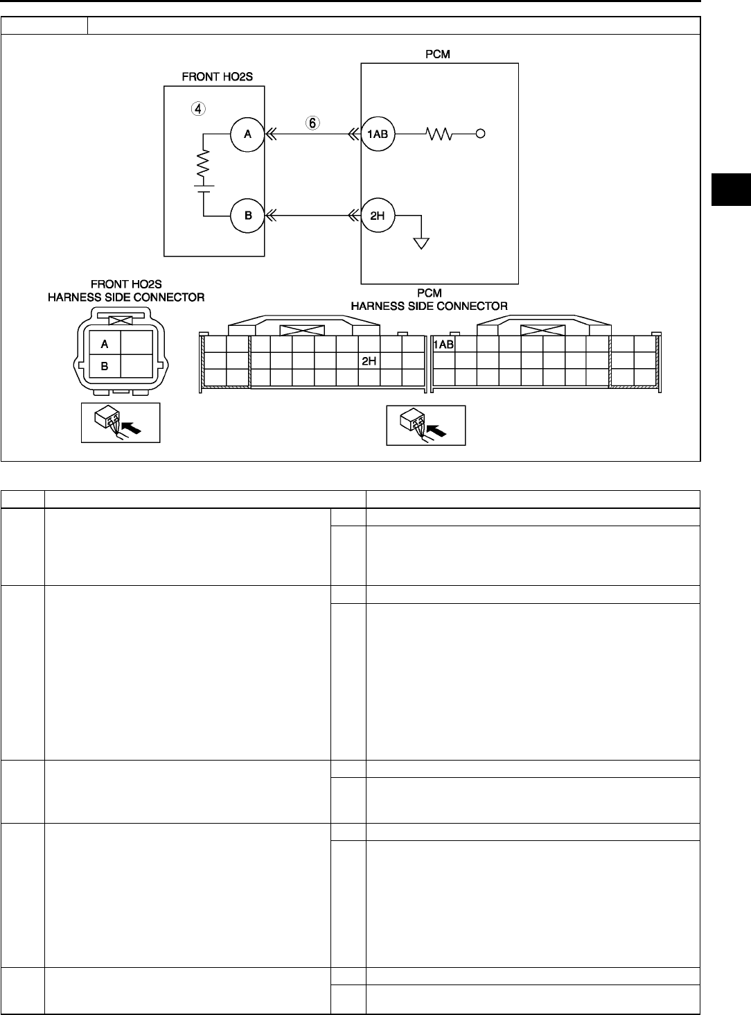
ON-BOARD DIAGNOSTIC
F111
F
Diagnostic procedure
STEP INSPECTION ACTION
1PERFORM DTC CONFIRMATION PROCEDURE
•Perform DTC CONFIRMATION PROCEDURE.
(See F66 DTC CONFIRMATION
PROCEDURE.)
•Is same DTC present?
Yes Go to next step.
No Intermittent concern exists. Go to INTERMITTENT
CONCERN TROUBLESHOOTING procedure.
(See F227 INTERMITTENT CONCERN
TROUBLESHOOTING.)
2VERIFY RELATED PENDING AND STORED
DTCS
Note
•If fuel monitor DTC, DTC P0131or P0132 is
retrieved, ignore it until P0134 is fixed.
•Turn ignition key to OFF, then ON (Engine
OFF).
•Verify pending and stored DTCs using WDS or
equivalent.
•Is other DTC present?
Yes Go to appropriate DTC troubleshooting procedures.
No Go to next step.
3IDENTIFY TRIGGER DTC FOR FREEZE FRAME
DATA
•Is DTC P0134 on FREEZE FRAME DATA?
Yes Go to next step.
No Go to troubleshooting procedures for DTC on FREEZE
FRAME DATA.
(See F67 DTC TABLE.)
4VERIFY CURRENT INPUT SIGNAL STATUS
•Warm up engine.
•Access O2S11 PID using WDS or equivalent.
•Verify PID while racing engine (in NEUTRAL
(MTX) or PARK (ATX)).
•Is PID reading okay?
More than 0.55 V when suddenly depress
accelerator pedal (rich condition).
Less than 0.55 V just after release of
accelerator pedal (lean condition)
Yes Go to step 7.
No Go to next step.
5INSPECT INSTALLATION OF FRONT HO2S
•Check if front HO2S is loosely installed.
•Is sensor installed securely?
Yes Go to next step.
No Install sensor securely, then go to Step 9.
DTC P0134 Front HO2S circuit no activity detected

F112
ON-BOARD DIAGNOSTIC
End Of Sie
DTC P0138 A6E397001084W25
6INSPECT GAS LEAKAGE FROM EXHAUST
SYSTEM
•Visually check if any gas leakage is found
between exhaust manifold and front HO2S.
•Is there any gas leakage?
Yes Repair or replace any faulty exhaust parts, then go to Step
9.
No •Inspect the following harnesses for open or short to
ground circuit, repair or replace harness if necessary
Front HO2S terminal A (harness-side) to PCM
terminal 1AB (harness-side)
•Repair or replace harness if necessary.
•If all items above are okay, replace faulty sensor.
Then go to Step 9.
7INSPECT SEALING OF ENGINE COOLANT
PASSAGE
Warning
•
••
•Removing radiator cap when radiator is
hot is dangerous. Scalding coolant and
steam may shoot out and cause serious
injury.
•
••
•When removing radiator cap, wrap a
thick cloth around and turn it slowly.
•Remove radiator cap.
•Implement procedure to bleed air from engine
coolant, then run engine at idle.
•Is there any small bubble, which makes engine
coolant white at filling opening?
Note
•Large bubbles are normal since they are
remaining air coming out from engine
coolant passage.
Yes Air gets in from poor sealing on head gasket or other areas
between combustion chamber and engine coolant
passage.
Repair or replace faulty parts, then go to Step 9.
No Go to next step.
8INSPECT ENGINE COMPRESSION
•Inspect engine compression.
(See B9 COMPRESSION INSPECTION.)
•Is it okay?
Yes Go to next step.
No Implement engine overhaul for repairs, then go to next
step.
9VERIFY TROUBLESHOOTING OF DTC P0134
COMPLETED
•Make sure to reconnect all disconnected
connectors.
•Turn ignition key to ON (Engine OFF).
•Clear DTC from memory using WDS or
equivalent.
•Perform KOER self-test.
(See F66 KOEO/KOER SELF-TEST.)
•Is same DTC present?
Yes Replace PCM, then go to next step.
(See F43 PCM REMOVAL/INSTALLATION.)
No Go to next step.
10 VERIFY AFTER REPAIR PROCEDURE
•Perform After Repair Procedure.
(See F66 AFTER REPAIR PROCEDURE.)
•Is there any DTC present?
Yes Go to applicable DTC troubleshooting.
(See F67 DTC TABLE.)
No Troubleshooting completed.
STEP INSPECTION ACTION
DTC P0138 Rear HO2S circuit high input
DETECTION
CONDITION
•PCM monitors input voltage from rear HO2S. If input voltage from rear HO2S sensor is above 0.45 V for 7
s during deceleration fuel cut, PCM determines that circuit input is high.
Diagnostic support note
•This is a continuous monitor (CCM).
•MIL illuminates if PCM detects the above malfunction condition in two consecutive drive cycles or in one
drive cycle while the DTC for the same malfunction has been stored in the PCM.
•PENDING CODE is available if PCM detects the above malfunction condition during first drive cycle.
•FREEZE FRAME DATA is available.
•DTC is stored in the PCM memory.
POSSIBLE
CAUSE
•Rear HO2S malfunction
•Short to power circuit in wiring between rear HO2S terminal A and PCM terminal 1Y
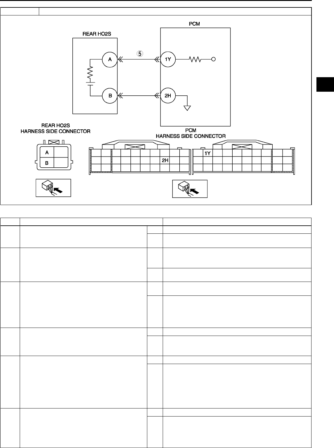
ON-BOARD DIAGNOSTIC
F113
F
Diagnostic procedure
STEP INSPECTION ACTION
1VERIFY FREEZE FRAME DATA HAS BEEN
RECORDED
•Has FREEZE FRAME DATA been recorded?
Yes Go to next step.
No Record FREEZE FRAME DATA on repair order, then go to
next step.
2VERIFY RELATED SERVICE INFORMATION
AVAILABILITY
•Check for related Service Information
availability.
•Is any related Service Information available?
Yes Perform repair or diagnosis according to available Service
Information.
•If vehicle is not repaired, go to next step.
No Go to next step.
3VERIFY RELATED PENDING OR STORED
DTCS
•Turn ignition key to OFF, then ON (Engine
OFF).
•Verify pending code or stored DTCs using
WDS or equivalent.
•Is other DTC present?
Yes Go to appropriate DTC troubleshooting procedures.
(See F67 DTC TABLE.)
No Go to next step.
4IDENTIFY TRIGGER DTC FOR FREEZE FRAME
DATA
•Is DTC P0138 on FREEZE FRAME DATA?
Yes Go to next step.
No Go to troubleshooting procedures for DTC on FREEZE
FRAME DATA.
(See F67 DTC TABLE.)
5INSPECT REAR HO2S SIGNAL CIRCUIT FOR
SHORT TO POWER SUPPLY CIRCUIT
•Turn ignition key to OFF.
•Disconnect rear HO2S connector.
•Turn ignition key to ON (Engine OFF).
•Measure voltage between rear HO2S terminal
A (harness-side) and body ground.
•Is any voltage reading?
Yes Replace short to power supply circuit, then go to Step 7.
No Go to next step.
6VERIFY CURRENT INPUT SIGNAL STATUS
•Start engine.
•Access O2S12 PID using WDS or equivalent.
•Verify PID while racing engine at least 10
times (in NEUTRAL (MTX) or PARK (ATX)).
•Does PID reading stay above 0.45 V?
Yes Repair or replace sensor, then go to next step.
No Go to next step.
DTC P0138 Rear HO2S circuit high input

F114
ON-BOARD DIAGNOSTIC
End Of Sie
DTC P0140 A6E397001084W26
7VERIFY TROUBLESHOOTING OF DTC P0138
COMPLETED
•Make sure to reconnect all disconnected
connectors.
•Turn ignition key to ON (Engine OFF).
•Clear DTC from memory using WDS or
equivalent.
•Run PCM adaptive memory procedure drive
mode and HO2S heater, HO2S, and TWC
repair verification drive mode.
(See F64 OBD DRIVE MODE.)
•Is PENDING CODE the same as DTC
present?
Yes Replace PCM, then go to next step.
(See F43 PCM REMOVAL/INSTALLATION.)
No Go to next step.
8VERIFY AFTER REPAIR PROCEDURE
•Perform After Repair Procedure.
(See F66 AFTER REPAIR PROCEDURE.)
•Is there any DTC present?
Yes Go to applicable DTC troubleshooting.
(See F67 DTC TABLE.)
No Troubleshooting completed.
STEP INSPECTION ACTION
DTC P0140 Rear HO2S circuit no activity detected
DETECTION
CONDITION
•PCM monitors input voltage from rear HO2S when the following conditions are met. If input voltage from
sensor never exceed 0.55 V for 30.4 s, PCM determines that sensor circuit is not activated.
MONITORING CONDITIONS
HO2S, HO2S heater and TWC repair verification drive mode
Following conditions are met:
•Engine speed is above 1,500 rpm.
•Engine coolant temperature is above 80 °
°°
°C {158 °
°°
°F}.
Diagnostic support note
•This is a continuous monitor (CCM).
•MIL illuminates if PCM detects the above malfunction condition in two consecutive drive cycles or in one
drive cycle while the DTC for the same malfunction has been stored in the PCM.
•PENDING CODE is available if PCM detects the above malfunction condition during first drive cycle.
•FREEZE FRAME DATA is available.
•DTC is stored in the PCM memory.
POSSIBLE
CAUSE
•Rear HO2S deterioration
•Rear HO2S heater malfunction
•Leakage exhaust system
•Open or short to ground circuit between rear HO2S terminal A and PCM terminal 1Y
•Insufficient compression
•Engine malfunction
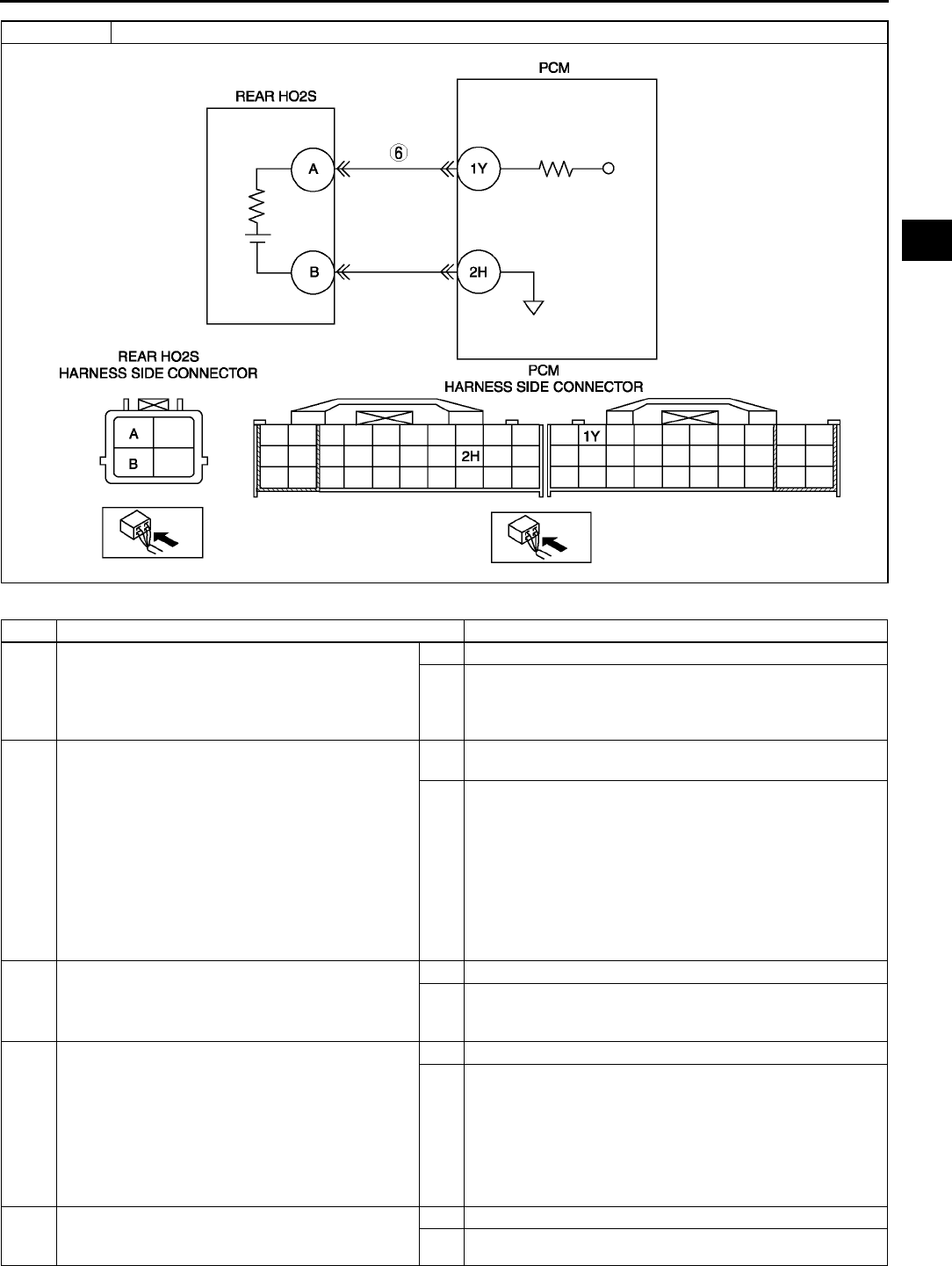
ON-BOARD DIAGNOSTIC
F115
F
Diagnostic procedure
STEP INSPECTION ACTION
1PERFORM DTC CONFIRMATION PROCEDURE
•Perform DTC CONFIRMATION PROCEDURE.
(See F66 DTC CONFIRMATION
PROCEDURE.)
•Is same DTC present?
Yes Go to next step.
No Intermittent concern exists. Go to INTERMITTENT
CONCERN TROUBLESHOOTING procedure.
(See F227 INTERMITTENT CONCERN
TROUBLESHOOTING.)
2VERIFY RELATED PENDING AND STORED
DTCS
Note
•If fuel monitor DTC, DTC P0131or P0132 is
retrieved, ignore it until P0140 is fixed.
•Turn ignition key to OFF, then ON (Engine
OFF).
•Verify pending and stored DTCs using WDS or
equivalent.
•Is other DTC present?
Yes Go to appropriate DTC troubleshooting procedures.
(See F67 DTC TABLE.)
No Go to next step.
3IDENTIFY TRIGGER DTC FOR FREEZE FRAME
DATA
•Is DTC P0140 on FREEZE FRAME DATA?
Yes Go to next step.
No Go to troubleshooting procedures for DTC on FREEZE
FRAME DATA.
(See F67 DTC TABLE.)
4VERIFY CURRENT INPUT SIGNAL STATUS
•Warm up engine.
•Access O2S12 for P0140 or O2S22 for P0160
PID using WDS or equivalent.
•Verify PID while racing engine at least 10
times (in NEUTRAL (MTX) or PARK (ATX)).
•Is PID reading okay?
More than 0.55 V at least once during
engine racing.
Yes Go to step 7.
No Go to next step.
5INSPECT INSTALLATION OF REAR HO2S
•Check if rear HO2S is loosely installed.
•Is sensor installed securely?
Yes Go to next step.
No Install sensor securely, then go to Step 9.
DTC P0140 Rear HO2S circuit no activity detected

F116
ON-BOARD DIAGNOSTIC
End Of Sie
DTC P0171 A6E397001084W27
6INSPECT GAS LEAKAGE FROM EXHAUST
SYSTEM
•Visually check if any gas leakage is found
between exhaust pipe and rear HO2S.
•Is there any gas leakage?
Yes Repair or replace any faulty exhaust parts, then go to Step
9.
No •Inspect the following harnesses for open or short to
ground circuit, repair or replace harness if necessary.
Rear HO2S terminal A (harness-side) to PCM
terminal 1Y (harness-side)
•Repair or replace harness if necessary.
•If all items above are okay, replace faulty sensor.
Then go to Step 9.
7INSPECT SEALING OF ENGINE COOLANT
PASSAGE
Warning
•
••
•Removing radiator cap when radiator is
hot is dangerous. Scalding coolant and
steam may shoot out and cause serious
injury.
•
••
•When removing radiator cap, wrap a
thick cloth around and turn it slowly.
•Remove radiator cap.
•Implement procedure to bleed air from engine
coolant, then run engine at idle.
•Is there any small bubble, which makes engine
coolant white at filling opening?
Note
•Large bubbles are normal since they are
remaining air coming out from engine
coolant passage.
Yes Air gets in from poor sealing on head gasket or other areas
between combustion chamber and engine coolant
passage.
Repair or replace faulty parts, then go to Step 9.
No Go to next step.
8INSPECT ENGINE COMPRESSION
•Inspect engine compression.
(See B9 COMPRESSION INSPECTION.)
•Is it okay?
Yes Go to next step.
No Implement engine overhaul for repairs, then go to next
step.
9VERIFY TROUBLESHOOTING OF DTC P0140
COMPLETED
•Make sure to reconnect all disconnected
connectors.
•Turn ignition key to ON (Engine OFF).
•Clear DTC from memory using WDS or
equivalent.
•Perform KOER self-test.
(See F66 KOEO/KOER SELF-TEST.)
•Is same DTC present?
Yes Replace PCM, then go to next step.
(See F43 PCM REMOVAL/INSTALLATION.)
No Go to next step.
10 VERIFY AFTER REPAIR PROCEDURE
•Perform After Repair Procedure.
(See F66 AFTER REPAIR PROCEDURE.)
•Is there any DTC present?
Yes Go to applicable DTC troubleshooting.
(See F67 DTC TABLE.)
No Troubleshooting completed.
STEP INSPECTION ACTION
DTC P0171 Fuel trim system too lean
DETECTION
CONDITION
•PCM monitors short term fuel trim (SHRTFT) and long term fuel trim (LONGFT) values during closed loop
fuel control. If fuel trim exceeds preprogrammed criteria, PCM determines that fuel system is too lean.
Diagnostic support note
•This is a continuous monitor. (FUEL SYSTEM)
•MIL illuminates if PCM detects the above malfunction condition in two consecutive drive cycles or in one
drive cycle while the DTC for the same malfunction has been stored in the PCM.
•PENDING CODE is available if PCM detects the above malfunction conditions during first drive cycle.
•FREEZE FRAME DATA is available.
•DTC is stored in the PCM memory.
ON-BOARD DIAGNOSTIC
F117
F
Diagnostic procedure
POSSIBLE
CAUSE
•Misfire
•Front HO2S deterioration
•Front HO2S heater malfunction
•Pressure regulator malfunction
•Fuel pump malfunction
•Fuel filter clogged or restricted
•Fuel leakage on fuel line from fuel delivery pipe and fuel pump
•Fuel return hose clogged
•Leakage exhaust system
•Purge solenoid valve malfunction
•Purge solenoid hoses improper connection
•Insufficient compression
•Variable valve timing control system improper operation (L3-VE)
STEP INSPECTION ACTION
1PERFORM DTC CONFIRMATION PROCEDURE
•Perform DTC CONFIRMATION PROCEDURE.
(See F66 DTC CONFIRMATION
PROCEDURE.)
•Is same DTC present?
Yes Go to next step.
No Intermittent concern exists. Go to INTERMITTENT
CONCERN TROUBLESHOOTING procedure.
(See F227 INTERMITTENT CONCERN
TROUBLESHOOTING.)
2VERIFY RELATED PENDING CODE OR
STORED DTCS
•Turn ignition key to OFF, then ON (Engine
OFF).
•Verify related PENDING CODE or stored
DTCs.
•Is other DTCs present?
Yes If misfire DTC is present, go to step 7.
If other DTC is present, go to appropriate DTC
troubleshooting procedures.
(See F67 DTC TABLE.)
No If drive ability concern is present, go to Step 7.
If not, go to next step.
3IDENTIFY TRIGGER DTC FOR FREEZE FRAME
DATA
•Is DTC P0171 on FREEZE FRAME DATA?
Yes Go to next step.
No Go to troubleshooting procedures for DTC on FREEZE
FRAME DATA.
4VERIFY CURRENT INPUT SIGNAL STATUS
(IGNITION KEY TO ON/IDLE)
•Access ECT, MAF, TP and VSS PIDs using
WDS or equivalent.
(See F45 PCM INSPECTION.)
•Is there any signal that is far out of
specification when ignition key is ON and
engine runs?
Yes Inspect suspected sensor and excessive resistance in
related wiring harnesses. Repair or replace if necessary.
Then go to Step 18.
No Go to next step.
5VERIFY CURRENT INPUT SIGNAL STATUS
UNDER TROUBLE CONDITION
•Inspect same PIDs as Step 4 while simulating
FREEZE FRAME DATA condition.
•Is there any input signal which causes drastic
changes?
Yes Inspect suspected sensor and related wiring harnesses,
and repair or replace it. Then go to Step 18.
No Go to next step.
6VERIFY CURRENT INPUT SIGNAL STATUS OF
FRONT HO2S
•Access O2S11 for P0171 PID using WDS or
equivalent.
•Check PID under following accelerator pedal
condition (in PARK (ATX) or NEUTRAL
(MTX)).
•Is PID reading okay?
Above 0.55 V when accelerator pedal is
suddenly depressed (rich condition).
Below 0.55 V just after release of
accelerator pedal (lean condition)
Yes Inspect for air suction at followings due to cracks, damages
and loosening parts:
•From air cleaner to throttle body
•From throttle body to dynamic chamber
•From dynamic chamber to intake manifold
•Vacuum hoses
Note
•Engine speed may change when rust penetrating
agent is sprayed on the air suction area.
Repair or replace any faulty part, then go to Step 18.
No Visually inspect for any gas leakage between exhaust
manifold and front HO2S.
•If there is no leakage, replace FRONT HO2S.
Then go to Step 18.
DTC P0171 Fuel trim system too lean

F118
ON-BOARD DIAGNOSTIC
7INSPECT MAF PID
•Start engine.
•Access MAF PID using WDS or equivalent.
•Verify that MAF PID changes quickly according
to race engine RPM.
•Is MAF PID response okay?
Yes Go to next step.
No Replace Mass air flow sensor, then go to Step 18.
8INSPECT FOR EXCESSIVE AIR SUCTION OF
INTAKE AIR SYSTEM
•Visually inspect for loosen, cracks or damages
hoses on intake air system.
•Is there any malfunction?
Yes Repair or replace source of air suction, then go to Step 18.
No Go to next step.
9INSPECT FUEL LINE PRESSURE
•Turn ignition key to OFF.
Note
•If engine wont start, inspect fuel line
pressure with ignition key ON.
•Inspect fuel line pressure while engine running.
(See F20 FUEL LINE PRESSURE
INSPECTION.)
•Is fuel line pressure okay?
Yes Go to step 11.
No •If fuel line pressure is too high: Replace fuel pump unit,
then go to Step 18.
•If fuel line pressure is too low: Go to next step.
10 INSPECT FUEL LINE FROM FUEL PUMP TO
FUEL DELIVERY PIPE
•Visually inspect fuel line for any leakage.
•Is any fuel leakage found?
Yes Replace suspected fuel line, then go to Step 18.
No Inspect fuel filters for follows:
•Restriction or clogging at fuel filter (high-pressure side).
•Foreign materials or stain inside fuel filter (low-pressure
side)
Perform following actions as result.
•If restriction or clogging is found at fuel filter (high-
pressure side), replace fuel pump unit.
•If foreign materials or stain is found inside fuel filter
(low-pressure side), clean of fuel tank and filter.
•If all items above are okay, replace fuel pump unit.
Then go to Step 18.
11 CHECK IGNITION COIL OPERATION AND
HIGH-TENSION LEAD WITH TIMING LIGHT
•Verify blinking condition on each cylinders
using timing light at idle.
•Do all cylinders show blinking condition?
Yes Go to Step 15.
No Go to next step.
12 CHECK HIGH-TENSION LEADS OF NO
BLINKING CYLINDER
•Turn ignition key to OFF.
•Inspect high-tension leads for installation
condition, corrosion on terminal, open lead and
damaged cover.
•Is condition of high-tension lead okay?
Yes Go to next step.
No Replace faulty high-tension lead, then go to Step 18.
13 INSPECT POWER SUPPLY TERMINAL AT
IGNITION COIL CONNECTOR
•Disconnect ignition coil connector.
•Turn ignition key to ON (Engine OFF).
•Check voltage at ignition coil connector
terminal B (harness-side) and body ground.
•Is voltage B+?
Yes Go to next step.
No Check for open circuit between ignition coil connector and
ignition switch. Repair or replace wiring harness, then go to
Step 18.
14 INSPECT IGNITION COIL RESISTANCE
•Check ignition coil resistance.
(See G9 IGNITION COIL INSPECTION.)
•Is coil resistance okay?
Yes Go to next step.
No Replace ignition coil, then go to Step 18.
15 INSPECT ENGINE COMPRESSION
•Inspect engine compression.
(See B9 COMPRESSION INSPECTION.)
•Is it okay?
Yes Go to next step.
No Implement engine overhaul for repairs, then go to Step 18.
STEP INSPECTION ACTION
ON-BOARD DIAGNOSTIC
F119
F
End Of Sie
DTC P0172 A6E397001084W28
Diagnostic procedure
16 INSPECT VARIABLE VALVE TIMING CONTROL
SYSTEM OPERATION
Note
•The following test should be performed for
variable valve timing control system. Go to
next step for vehicles without variable valve
timing control system.
•Inspect variable valve timing control system
operation.
(See F239 Variable Valve Timing Control
System Operation Inspection.)
•Does variable valve timing control system work
properly?
Yes Go to next step.
No Repair or replace malfunctioning part according to variable
valve timing control system inspection results, then go to
Step 18.
17 INSPECT FUEL INJECTOR OPERATION
•Remove fuel injector.
•Inspect injector operation.
•Is fuel injector okay?
Yes Go to next step.
No Replace injector, then go to next step.
18 VERIFY TROUBLESHOOTING OF DTC P0171
COMPLETED
•Make sure to reconnect all disconnected
connectors.
•Clear DTC from PCM memory using WDS or
equivalent.
•Perform KOER self-test.
(See F66 KOEO/KOER SELF-TEST.)
•Is same DTC present?
Yes Replace PCM, then go to next step.
(See F43 PCM REMOVAL/INSTALLATION.)
No Go to next step.
19 VERIFY AFTER REPAIR PROCEDURE
•Perform After Repair Procedure.
(See F66 AFTER REPAIR PROCEDURE.)
•Is there any DTC present?
Yes Go to applicable DTC troubleshooting.
(See F67 DTC TABLE.)
No Troubleshooting completed.
STEP INSPECTION ACTION
DTC P0172 Fuel trim system too rich
DETECTION
CONDITION
•PCM monitors short fuel trim (SHRTFT) and long fuel trim (LONGFT) values during closed loop fuel
control. If fuel trim exceeds preprogrammed criteria, PCM determines that fuel system is too rich.
Diagnostic support note
•This is a continuous monitor. (FUEL SYSTEM)
•MIL illuminates if PCM detects the above malfunction condition in two consecutive drive cycles or in one
drive cycle while the DTC for the same malfunction has been stored in the PCM.
•PENDING CODE is available if PCM detects the above malfunction condition during first drive cycle.
•FREEZE FRAME DATA is available.
•DTC is stored in the PCM memory.
POSSIBLE
CAUSE
•Misfire
•Front HO2S deterioration
•Front HO2S heater malfunction
•Pressure regulator malfunction
•Fuel pump malfunction
•Fuel return hose clogged
•Purge solenoid valve malfunction
•Purge solenoid hoses improper connection
•PCV valve malfunction
STEP INSPECTION ACTION
1PERFORM DTC CONFIRMATION PROCEDURE
•Perform DTC CONFIRMATION PROCEDURE.
(See F66 DTC CONFIRMATION
PROCEDURE.)
•Is same DTC present?
Yes Go to next step.
No Intermittent concern exists. Go to INTERMITTENT
CONCERN TROUBLESHOOTING procedure.
(See F227 INTERMITTENT CONCERN
TROUBLESHOOTING.)

F120
ON-BOARD DIAGNOSTIC
End Of Sie
2VERIFY RELATED PENDING CODE OR
STORED DTCS
•Turn ignition key to OFF, then ON (Engine
OFF).
•Verify related pending code or stored DTCs.
•Is other DTCs present?
Yes Go to appropriate DTC troubleshooting procedures.
No If drive ability concern is present, go to Step 8.
If not, go to next step.
3IDENTIFY TRIGGER DTC FOR FREEZE FRAME
DATA
•Is DTC P0172 on FREEZE FRAME DATA?
Yes Go to next step.
No Go to troubleshooting procedures for DTC on FREEZE
FRAME DATA.
4VERIFY CURRENT INPUT SIGNAL STATUS
(IGNITION KEY TO ON/IDLE)
•Access ECT, MAF, TP and VSS PIDs using
WDS or equivalent.
•Is there any signal that is far out of
specification when ignition key is ON and
engine runs?
Yes Inspect suspected sensor and excessive resistance in
related wiring harnesses. Repair or replace if necessary.
Then go to Step 10.
No Go to next step.
5VERIFY CURRENT INPUT SIGNAL STATUS
UNDER TROUBLE CONDITION
•Inspect PID data while simulating FREEZE
FRAME DATA condition.
•Is there any input signal which causes drastic
changes?
Yes Inspect suspected sensor and related wiring harnesses,
and repair or replace it. Then go to Step 10.
No Go to next step.
6VERIFY CURRENT INPUT SIGNAL STATUS OF
FRONT HO2S
•Access O2S11 PID using WDS or equivalent.
•Verify PID while racing engine (in PARK (ATX)
or NEUTRAL (MTX)).
•Is PID reading okay?
Above 0.55 V when accelerator pedal is
suddenly depress (rich condition).
Below 0.55 V just after release of
accelerator pedal (lean condition)
Yes Go to next step.
No Replace suspected front HO2S.
Then go to Step 10.
7INSPECT FUEL LINE PRESSURE
•Turn ignition key to OFF.
•Inspect fuel line pressure while engine running.
(See F20 FUEL LINE PRESSURE
INSPECTION.)
•Is fuel line pressure okay?
Yes Go to next step.
No Replace fuel pump unit, then go to Step 10.
8INSPECT PURGE SOLENOID VALVE FOR
STUCK OPEN
•Turn ignition key to OFF.
•Disconnect both hoses from purge solenoid
valve.
•Blow air through purge solenoid valve.
•Does air blow through?
Yes Replace purge solenoid valve.
Then go to Step 10.
No Go to next step.
9INSPECT PCV VALVE OPERATION
•Inspect PCV valve operation.
(See F41 PCV VALVE INSPECTION.)
•Is PCV valve okay?
Yes Go to next step.
No Replace PCV valve, then go to next step.
10 VERIFY TROUBLESHOOTING OF DTC P0172
COMPLETED
•Make sure to reconnect all disconnected
connectors.
•Turn ignition key to ON (Engine OFF).
•Clear DTC from memory using WDS or
equivalent.
•Perform KOER self-test.
(See F66 KOEO/KOER SELF-TEST.)
•Is same DTC present?
Yes Replace PCM, then go to next step.
(See F43 PCM REMOVAL/INSTALLATION.)
No Go to next step.
11 VERIFY AFTER REPAIR PROCEDURE
•Perform After Repair Procedure.
(See F66 AFTER REPAIR PROCEDURE.)
•Is there any DTC present?
Yes Go to applicable DTC troubleshooting.
(See F67 DTC TABLE.)
No Troubleshooting completed.
STEP INSPECTION ACTION
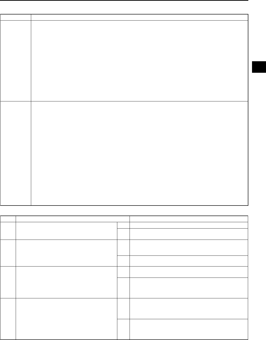
ON-BOARD DIAGNOSTIC
F121
F
DTC P0300 A6E397001085W01
Diagnostic procedure
DTC P0300 Random misfire detection
DETECTION
CONDITION
•PCM monitors CKP sensor input signal interval time. PCM calculates change of interval time for each
cylinder. If change of interval time exceeds preprogrammed criteria, PCM detects misfire in the
corresponding cylinder. While the engine is running, the PCM counts number of misfires that occurred at
200 crankshaft revolutions and 1,000 crankshaft revolutions and calculates misfire ratio for each
crankshaft revolution. If the ratio exceeds the preprogrammed criteria, PCM determines that a misfire,
which can damage catalytic converter or affect emission performance, has occurred.
Diagnostic support note
•This is a continuous monitor (MISFIRE).
•MIL illuminates if PCM detects the misfire which affects emission performance in two consecutive drive
cycles or in one drive cycle while the DTC for the same malfunction has been stored in the PCM.
•MIL flashes if PCM detects the misfire which can damage the catalytic converter during first drive cycle.
Therefore, PENDING CODE is not available while MIL flashes.
•PENDING CODE is available if PCM detects the misfire which affects emission performance during first
drive cycle.
•FREEZE FRAME DATA is available.
•DTC is stored in the PCM memory.
POSSIBLE
CAUSE
•CKP sensor malfunction
•CMP sensor malfunction
•Ignition coil malfunction
•High-tension lead malfunction
•MAF sensor contamination
•Excess air suction in intake air system (between MAF sensor and intake manifold)
•Fuel pump malfunction
•Fuel pressure regulator malfunction
•Fuel line clogged
•Fuel filter clogged
•Fuel leakage in fuel line
•Fuel runout
•Poor quality fuel
•Purge control solenoid valve malfunction
•PCV valve malfunction
•EGR valve malfunction
•Vacuum hoses damages or improper connection
•Related connector and terminal malfunction
•Related wiring harness malfunction
•Insufficient compression
•Variable valve timing control system improper (L3-VE)
STEP INSPECTION ACTION
1VERIFY FREEZE FRAME DATA HAS BEEN
RECORDED
•Has FREEZE FRAME DATA been recorded?
Yes Go to next step.
No Record FREEZE FRAME DATA on repair order, then go to
next step.
2VERIFY RELATED SERVICE INFORMATION
AVAILABILITY
•Check for related Service Information
availability.
•Is any related Service Information available?
Yes Perform repair or diagnosis according to available Service
Information.
•If vehicle is not repaired, go to next step.
No Go to next step.
3VERIFY RELATED PENDING CODE OR
STORED DTCs
•Turn ignition key to OFF then ON (Engine
OFF).
•Verify related pending code or stored DTCs.
•Are other DTCs present?
Yes Go to appropriate DTC troubleshooting.
(See F67 DTC TABLE.)
No Go to next step.
4VERIFY CURRENT INPUT SIGNAL STATUS
(IGNITION KEY TO ON/IDLE)
•Access BOO, ECT, IAT, MAF, RPM, TP, and
VSS PIDs using WDS or equivalent.
(See F45 PCM INSPECTION.)
•Is there any signal that is far out of
specification when ignition switch is ON and
engine runs at idle?
Yes Inspect suspected circuit and/or part according to
inspection results.
(See F45 PCM INSPECTION.)
Then go to Step 22.
No Go to next step.

F122
ON-BOARD DIAGNOSTIC
5VERIFY CURRENT INPUT SIGNAL STATUS
UNDER TROUBLE CONDITION
•Inspect same PIDs as in Step 4 while
simulating FREEZE FRAME DATA condition.
•Is there any signal which causes drastic
changes?
Yes Inspect suspected circuit and/or part according to
inspection results.
(See F45 PCM INSPECTION.)
Then go to Step 22.
No Go to next step.
6INSPECT CMP SENSOR
•Inspect CMP sensor.
(See F55 CAMSHAFT POSITION (CMP)
SENSOR INSPECTION.)
•Is CMP sensor okay?
Yes Go to next step.
No Inspect installation condition and damages on timing belt
and gears, repair faulty parts.
•If it is okay, replace CMP sensor.
Then go to Step 22.
7VERIFY CKP SENSOR INSTALLATION
CONDITION
•Inspect for CKP sensor looseness.
•Is CKP sensor loosen?
Yes Retighten CKP sensor, then go to Step 22.
No Go to next step.
8INSPECT IGNITION COIL OPERATION AND
HIGH-TENSION LEAD WITH TIMING LIGHT
•Verify blinking condition on each cylinders
using timing light at idle.
•Do all cylinders show blinking condition?
Yes Go to Step 12.
No Go to next step.
9INSPECT HIGH-TENSION LEADS OF NO
BLINKING CYLINDER
•Turn ignition key to OFF.
•Inspect high-tension leads for improper
installation, corrosion on terminal, open lead
and damaged cover.
•Is condition of high-tension lead okay?
Yes Go to next step.
No Replace faulty high-tension lead, then go to Step 22.
10 INSPECT POWER SUPPLY TERMINAL AT
IGNITION COIL CONNECTOR
•Disconnect ignition coil connector.
•Turn ignition key to ON (Engine OFF).
•Measure voltage between ignition coil terminal
B (harness-side) and body ground.
•Is there voltage reading B+?
Yes Go to next step.
No Inspect for open circuit between ignition coil connector and
ignition switch. Repair or replace wiring harness, then go to
Step 22.
11 INSPECT IGNITION COIL RESISTANCE
•Inspect ignition coil resistance.
(See G9 IGNITION COIL INSPECTION.)
•Is coil resistance okay?
Yes Go to step 22.
No Replace ignition coil, then go to Step 22.
12 INSPECT MAF PID
•Start engine.
•Access MAF PID using WDS or equivalent.
•Verify that MAF PID changes quickly according
to race engine RPM.
•Is MAF PID response okay?
Yes Go to next step.
No Replace MAF sensor, then go to Step 22.
13 INSPECT EXCESSIVE AIR SUCTION IN INTAKE
AIR SYSTEM
•Inspect for air leakage at following:
Between MAF sensor and throttle body
Between throttle body and intake manifold
•Is there any malfunction?
Yes Repair or replace suspected part, then go to Step 22.
No Go to next step.
14 INSPECT FUEL LINE PRESSURE
•Inspect fuel line pressure.
(See F20 FUEL LINE PRESSURE
INSPECTION.)
•Is fuel line pressure okay?
Yes Go to step 16.
No If fuel line pressure is too low, go to next step.
If fuel line pressure is excess high, replace fuel pump unit,
then go to Step 22.
STEP INSPECTION ACTION

ON-BOARD DIAGNOSTIC
F123
F
15 INSPECT FUEL LINE FROM FUEL PUMP TO
FUEL DELIVERY PIPE
•Visually inspect for fuel leakage in fuel line for
any leakage.
•Is any fuel leakage found?
Yes Replace suspected fuel line, then go to Step 22.
No Inspect fuel filters for following:
•Restriction or clogging at fuel filter (high-pressure side).
•Foreign materials or stain inside fuel filter (low-pressure
side)
Perform following actions depend on the result above.
•If restriction or clogging is found at fuel filter (high-
pressure side), replace fuel pump unit.
•If foreign materials or stain is found inside fuel filter
(low-pressure side), clean of fuel tank and filter (low-
pressure side).
•If all items above are okay, replace fuel pump unit.
Then, go to Step 22.
16 INSPECT ENGINE COMPRESSION
•Inspect engine compression.
(See B9 COMPRESSION INSPECTION.)
•Is it okay?
Yes Go to next step.
No Implement engine overhaul for repairs, then go to Step 22.
17 INSPECT VARIABLE VALVE TIMING CONTROL
SYSTEM OPERATION
Note
•The following test should be performed for
variable valve timing control system. Go to
next step for vehicles without variable valve
timing control system.
•Inspect variable valve timing control system
operation.
•Does variable valve timing control system?
Yes Go to next step.
No Repair or replace malfunctioning part according to variable
valve timing control system inspection results, then go to
Step 22.
18 INSPECT OPERATION OF PURGE CONTROL
SOLENOID VALVE
•Turn ignition key to OFF.
•Connect vacuum pump to purge control
solenoid valve and apply vacuum to solenoid.
•Verify that solenoid holds vacuum.
•Turn ignition key to ON (Engine OFF).
•Access EVAPCP PID in SIMULATION TEST
using WDS or equivalent.
•Set duty value to 100% for EVAPCP PID.
•Apply vacuum while turning solenoid from OFF
to ON and simulating EVAPCP PID with 100%
duty value.
•Verify that solenoid releases vacuum while
solenoid is turned ON.
•Is purge control solenoid valve operation okay?
Yes Go to next step.
No Replace purge control solenoid valve, then go to Step 22.
19 INSPECT PCV VALVE OPERATION
•Turn ignition key to OFF.
•Remove PCV valve and inspect valve
operation.
(See F41 PCV VALVE INSPECTION.)
•Is PCV valve operation okay?
Yes Replace PCV valve, then go to Step 22.
No Go to next step.
20 INSPECT OPERATION OF EGR VALVE
•Remove EGR valve.
•Visually inspect for stuck to open.
•Does EGR valve stuck to open?
Yes Repair or replace EGR valve, then go to Step 22.
No Go to next step.
STEP INSPECTION ACTION

F124
ON-BOARD DIAGNOSTIC
End Of Sie
DTC P0301, P0302, P0303, P0304 A6E397001085W02
21 INSPECT SEALING OF ENGINE COOLANT
PASSAGE
Warning
•
••
•Removing radiator cap when radiator is
hot is dangerous. Scalding coolant and
steam may shoot out and cause serious
injury.
•
••
•When removing radiator cap, wrap thick
cloth around and turn it slowly.
•Remove radiator cap.
•Implement procedure to bleed air from engine
coolant, then run engine at idle.
•Is there any small bubble which makes engine
coolant white at filling opening?
Note
•Large bubbles are normal since they are
remaining air coming out from engine
coolant passage.
Yes Air gets in from poor sealing on head gasket or other areas
between combustion chamber and engine coolant
passage. Repair or replace faulty parts, then go to next
step.
No Go to next step.
22 VERIFY TROUBLESHOOTING OF MISFIRE DTC
COMPLETED
•Make sure to reconnect all disconnected
connectors.
•Turn ignition key to ON (Engine OFF).
•Clear DTC from memory using WDS or
equivalent.
•Run PCM adaptive memory procedure drive
mode.
(See F64 OBD DRIVE MODE.)
•Is PENDING CODE the same as DTC
present?
Yes Replace PCM, then go to next step.
(See F43 PCM REMOVAL/INSTALLATION.)
No Go to next step.
23 VERIFY AFTER REPAIR PROCEDURE
•Perform After Repair Procedure.
(See F66 AFTER REPAIR PROCEDURE.)
•Is there any DTC present?
Yes Go to applicable DTC troubleshooting.
(See F67 DTC TABLE.)
No Troubleshooting completed.
STEP INSPECTION ACTION
DTC P0301
DTC P0302
DTC P0303
DTC P0304
Cylinder No.1 misfire detection
Cylinder No.2 misfire detection
Cylinder No.3 misfire detection
Cylinder No.4 misfire detection
DETECTION
CONDITION
•PCM monitors CKP sensor input signal interval time. PCM calculates the change of interval time for each
cylinder. If the change of interval time exceeds the preprogrammed criteria, PCM detects a misfire in the
corresponding cylinder. While the engine is running, PCM counts number of misfires that occurred at 200
crankshaft revolutions and 1,000 crankshaft revolutions and calculates misfire ratio for each
crankshaft revolution. If the ratio exceeds the preprogrammed criteria, PCM determines that a misfire,
which can damage catalytic converter or affect emission performance, has occurred.
Diagnostic support note
•This is a continuous monitor (MISFIRE).
•MIL illuminates if PCM detects the misfire which affects emission performance in two consecutive drive
cycles or in one drive cycle while the DTC for the same malfunction has been stored in the PCM.
•MIL flashes if PCM detects the misfire which can damage the catalytic converter during first drive cycle.
Therefore, PENDING CODE is not available while MIL flashes.
•PENDING CODE is available if PCM detects the misfire which affects emission performance during first
drive cycle.
•FREEZE FRAME DATA is available.
•DTC is stored in the PCM memory.
POSSIBLE
CAUSE
•Spark plug malfunction
•High-tension lead malfunction
•Fuel injector malfunction
•Air suction in intake air system (between dynamic chamber and cylinder head)
•Inadequate engine compression due to engine internal malfunction
•Related connector or terminal malfunction
•Related wiring harness malfunction

ON-BOARD DIAGNOSTIC
F125
F
Diagnostic procedure
STEP INSPECTION ACTION
1VERIFY FREEZE FRAME DATA HAS BEEN
RECORDED
•Has FREEZE FRAME DATA been recorded?
Yes Go to next step.
No Record FREEZE FRAME DATA on repair order, then go to
next step.
2VERIFY RELATED SERVICE INFORMATION
AVAILABILITY
•Check for related Service Information
availability.
•Is any related Service Information available?
Yes Perform repair or diagnosis according to available Service
Information.
•If vehicle is not repaired, go to next step.
No Go to next step.
3VERIFY RELATED PENDING CODE OR
STORED DTCS
•Turn ignition key to OFF then ON (Engine
OFF).
•Verify related pending code or stored DTCs.
•Is other DTCs present?
Yes Go to appropriate DTC troubleshooting.
(See F67 DTC TABLE.)
No Go to next step.
4VERIFY CURRENT INPUT SIGNAL STATUS
(IGNITION KEY TO ON /IDLE)
•Access BOO, ECT, IAT, MAF, RPM, TP and
VSS PIDs using WDS or equivalent.
(See F45 PCM INSPECTION.)
•Is there any signal that is far out of
specification when ignition switch is ON and
engine runs at idle?
Yes Inspect suspected circuit and/or part according to
inspection results. Then go to Step 12.
(See F45 PCM INSPECTION.)
No Go to next step.
5VERIFY CURRENT INPUT SIGNAL STATUS
UNDER TROUBLE CONDITION
•Inspect same PIDs as in Step 4 while
simulating FREEZE FRAME DATA condition.
•Is there any signal which causes drastic
changes?
Yes Inspect suspected circuit and/or part according to
inspection results. Then go to Step 12.
(See F45 PCM INSPECTION.)
No Go to next step.
6INSPECT SPARK PLUG CONDITION
•Turn ignition key to OFF.
•Remove spark plug from suspected cylinder.
•Inspect spark plug condition:
Cracks
Excess wear
Gap
Wet
•Is any problem found on spark plug?
Yes •If spark plug is wet, fuel flooding is suspected. Go to
step 12.
•If spark plug has a cracks, excessive wear or improper
gap, replace faulty spark plug. Then go to Step 12.
No Go to next step.
7VERIFY HIGH-TENSION LEAD CONDITION
•Remove high-tension lead.
•Inspect high-tension lead condition and
resistance.
Cracks
Spark shorts to cylinder head through high-
tension lead insulator
•Is high-tension lead okay?
Yes Go to next step.
No Replace high-tension lead, then go to Step 12.
8INSPECT FOR AIR SUCTION AT INTAKE-AIR
SYSTEM
•Inspect for air leakage at following:
Around connection of dynamic chamber and
intake manifold
Around connection of intake manifold and
cylinder head
•Is air leakage found?
Yes Repair or replace suspected part, then go to Step 12.
No Go to next step.
9INSPECT FUEL INJECTOR HARNESS
•Remove intake air system parts.
•Disconnect fuel injector connector on
suspected cylinder.
•Connect NOID LIGHT to fuel injector connector
terminals.
•Inspect dim of light during cranking.
•Does noid light illuminate?
Yes Go to next step.
No Inspect for fuel injector harnesses.
Repair or replace it if necessary, then go to Step 12.

F126
ON-BOARD DIAGNOSTIC
End Of Sie
DTC P0327 A6E397001085W03
10 INSPECT SEALING OF ENGINE COOLANT
PASSAGE
Warning
•
••
•Removing radiator cap when radiator is
hot is dangerous, Scalding coolant and
steam may shoot out and cause serious
injury.
•
••
•When removing radiator cap, wrap thick
cloth around and turn it slowly.
•Remove radiator cap.
•Implement procedure to bleed air from engine
coolant, then run engine at idle.
•Is there any small bubble which makes engine
coolant white at filling opening?
Note
•Large bubbles are normal since they are
remaining air coming out from engine
coolant passage.
Yes Air gets in from poor sealing on head gasket or other areas
between combustion chamber and engine coolant
passage. Repair or replace faulty parts, then go to Step 12.
No Go to next step.
11 INSPECT ENGINE COMPRESSION
•Inspect engine compression.
(See B9 COMPRESSION INSPECTION.)
•Is engine compression okay?
Yes Go to next step.
No Overhaul the engine, then go to next step.
12 INSPECT FUEL INJECTOR OPERATION
•Remove fuel injector from suspected cylinder.
•Swap injector with injector on other cylinder.
•Start engine and run it at idle.
•Is misfire DTC for cylinder which has a
suspected fuel injector?
Yes Replace injector, then go to step 13.
No Go to next step.
13 VERIFY TROUBLESHOOTING OF MISFIRE DTC
COMPLETED
•Make sure to reconnect all disconnected
connectors.
•Start engine.
•Clear DTC from PCM memory using WDS or
equivalent.
•Run PCM adaptive memory procedure drive
mode.
(See F64 OBD DRIVE MODE.)
•Is same PENDING CODE or stored code the
same as DTC present?
Yes Replace PCM, then go to next step.
(See F43 PCM REMOVAL/INSTALLATION.)
No Go to next step.
14 VERIFY AFTER REPAIR PROCEDURE
•Perform After Repair Procedure.
(See F66 AFTER REPAIR PROCEDURE.)
•Is there any DTC present?
Yes Go to applicable DTC troubleshooting.
(See F67 DTC TABLE.)
No Troubleshooting completed.
STEP INSPECTION ACTION
DTC P0327 Knock sensor circuit low input
DETECTION
CONDITION
•PCM monitors input signal from knock sensor when engine is running. If input voltage at PCM terminals
between 2P and 2S is below 0.9 V, PCM determines that knock sensor circuit has malfunction.
Diagnostic support note
•This is a continuous monitor (CCM).
•MIL illuminates if PCM detects the above malfunction condition during first drive cycle.
•PENDING CODE is available if PCM detects the above malfunction condition.
•FREEZE FRAME DATA is available.
•DTC is stored in the PCM memory.
POSSIBLE
CAUSE
•Knock sensor malfunction
•Connector or terminal malfunction
•Open or short to ground circuit between knock sensor connector terminal A and PCM terminal 2S
•Open or short to ground circuit between knock sensor connector terminal B and PCM terminal 2P
•Short knock sensor two wires
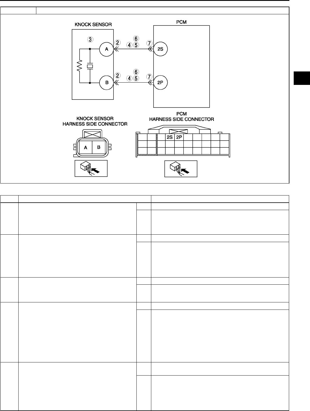
ON-BOARD DIAGNOSTIC
F127
F
Diagnostic procedure
STEP INSPECTION ACTION
1PERFORM DTC CONFIRMATION PROCEDURE
•Perform DTC CONFIRMATION PROCEDURE.
(See F66 DTC CONFIRMATION
PROCEDURE.)
•Is same DTC present?
Yes Go to next step.
No Intermittent concern exists. Go to INTERMITTENT
CONCERN TROUBLESHOOTING procedure.
(See F227 INTERMITTENT CONCERN
TROUBLESHOOTING.)
2INSPECT KNOCK SENSOR CONNECTOR
TERMINAL
•Turn ignition key to OFF.
•Disconnect knock sensor connector.
•Check for poor connection at terminals A and B
(damaged, pulled-out pins, corrosion, etc.).
•Is there any malfunction?
Yes Repair terminal, then go to Step 8.
No Go to next step.
3INSPECT KNOCK SENSOR
•Perform knock sensor inspection.
(See F56 KNOCK SENSOR INSPECTION)
•Is knock sensor okay?
Yes Go to next step.
No Replace knock sensor, then go to next step.
4INSPECT KNOCK SENSOR CIRCUITS FOR
OPEN CIRCUIT
•Disconnect knock sensor connector.
•Inspect continuity between the following
circuits:
Knock sensor female terminal A (harness-
side) and PCM terminal 2S (harness-side)
Knock sensor female terminal B (harness-
side) and PCM terminal 2P (harness-side)
•Are there continuities?
Yes Go to next step.
No Repair or replace suspected wiring harness, then go to
Step 8.
5INSPECT KNOCK SENSOR CIRCUITS FOR
SHORT TO GROUND
•Inspect continuity between following circuits:
Knock sensor female terminal A (harness-
side) and body ground
Knock sensor female terminal B (harness-
side) and body ground
•Are there continuities?
Yes Repair or replace suspected wiring harness, then go to
Step 8.
No Go to next step.
DTC P0327 Knock sensor circuit low input

F128
ON-BOARD DIAGNOSTIC
End Of Sie
DTC P0328 A6E397001085W04
6INSPECT FOR SHORT CIRCUITS
•Inspect continuity between knock sensor
female terminals A and B (harness-side).
•Is there continuity?
Yes Repair or replace suspected harness, then go to Step 8.
No Go to next step.
7INSPECT PCM CONNECTOR TERMINAL
•Turn ignition key to OFF.
•Disconnect PCM connector.
•Inspect for poor connection at terminals 2P and
2S (damaged, pulled-out pins, corrosion, etc.).
•Is there any malfunction?
Yes Repair terminal, then go to Step 8.
No Go to next step.
8VERIFY TROUBLESHOOTING OF DTC P0327
COMPLETED
•Make sure to reconnect all disconnected
connectors.
•Clear DTC from memory using WDS or
equivalent.
•Perform KOEO/KOER self-test.
(See F66 KOEO/KOER SELF-TEST.)
•Is same DTC present?
Yes Replace PCM, then go to next step.
(See F43 PCM REMOVAL/INSTALLATION.)
No Go to next step.
9VERIFY AFTER REPAIR PROCEDURE
•Perform After Repair Procedure.
(See F66 AFTER REPAIR PROCEDURE.)
•Is there any DTC present?
Yes Go to applicable DTC troubleshooting.
(See F67 DTC TABLE.)
No Troubleshooting completed.
STEP INSPECTION ACTION
DTC P0328 Knock sensor circuit high input
DETECTION
CONDITION
•PCM monitors input signal from knock sensor when engine is running. If input voltage at PCM terminals
between 2P and 2S is above 4.9 V, PCM determines that knock sensor circuit has a malfunction.
Diagnostic support note
•This is a continuous monitor (CCM).
•MIL illuminates if PCM detects the above malfunction conditions during first drive cycle.
•PENDING CODE is available if PCM detects the above malfunction condition.
•FREEZE FRAME DATA is available.
•DTC is stored in PCM memory.
POSSIBLE
CAUSE
•Knock sensor malfunction
•Connector or terminal malfunction
•Short to power circuit in wiring between knock sensor terminal A and PCM terminal 2S
•Short to power circuit in wiring between knock sensor terminal B and PCM terminal 2P
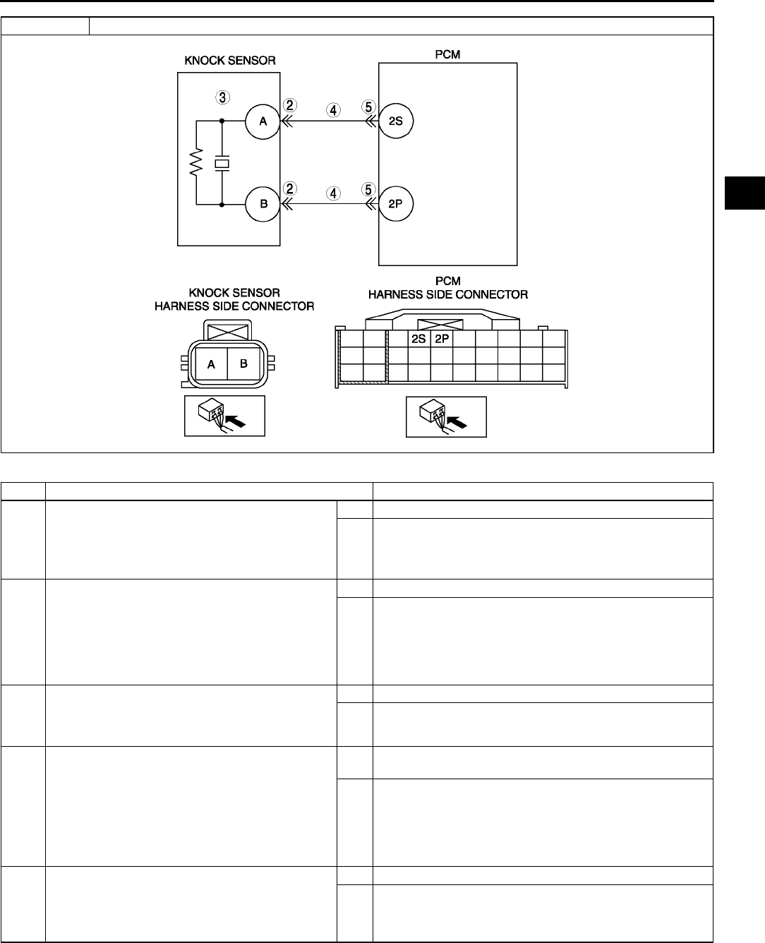
ON-BOARD DIAGNOSTIC
F129
F
Diagnostic procedure
STEP INSPECTION ACTION
1PERFORM DTC CONFIRMATION PROCEDURE
•Perform DTC CONFIRMATION PROCEDURE.
(See F66 DTC CONFIRMATION
PROCEDURE.)
•Is same DTC present?
Yes Go to next step.
No Intermittent concern exists. Go to INTERMITTENT
CONCERN TROUBLESHOOTING procedure.
(See F227 INTERMITTENT CONCERN
TROUBLESHOOTING.)
2INSPECT KNOCK SENSOR CONNECTOR
TERMINAL
•Turn ignition key to OFF.
•Disconnect knock sensor connector.
•Inspect for poor connection at terminals A and
B (damaged, pulled-out pins, corrosion, etc.).
•Is there any malfunction?
Yes Repair terminal, then go to step 6.
No Go to next step.
3INSPECT KNOCK SENSOR
•Perform knock sensor inspection.
(See F56 KNOCK SENSOR INSPECTION)
•Is knock sensor okay?
Yes Go to next step.
No Replace knock sensor, then go to step 6.
4INSPECT KNOCK SIGNAL CIRCUIT FOR
SHORT TO POWER
•Turn ignition key ON (Engine OFF).
•Measure voltage between knock sensor
terminal A (harness-side) and body GND and
knock sensor terminal B (harness-side) and
body GND.?
•Is any voltage reading?
Yes Repair or replace harness for short to power, then go to
step 6.
No Go to next step.
5INSPECT PCM CONNECTOR
•Disconnect PCM connector.
•Inspect for poor connection (damaged, pulled-
out terminals, corrosion, etc.).
•Is there any malfunction?
Yes Repair or replace terminal, then go to step 6.
No Go to next step.
DTC P0328 Knock sensor circuit high input
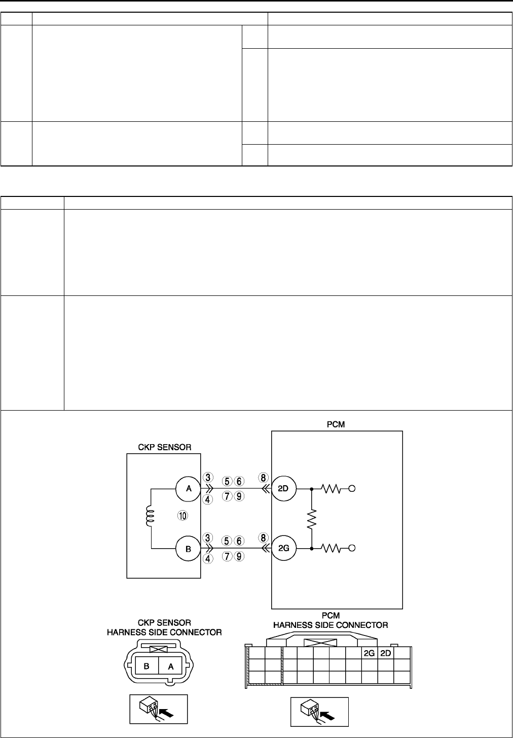
F130
ON-BOARD DIAGNOSTIC
End Of Sie
DTC P0335 A6E397001085W05
6VERIFY TROUBLESHOOTING OF DTC P0328
COMPLETED
•Make sure to connect all disconnected
connectors.
•Clear DTC from PCM memory using WDS or
equivalent.
•Perform KOEO/KOER self-test.
(See F66 KOEO/KOER SELF-TEST.)
•Is same DTC present?
Yes Replace PCM, then go to next step.
(See F43 PCM REMOVAL/INSTALLATION.)
No Go to next step.
7VERIFY AFTER REPAIR PROCEDURE
•Perform After Repair Procedure.
(See F66 AFTER REPAIR PROCEDURE.)
•Is there any DTC present?
Yes Go to applicable DTC troubleshooting.
(See F67 DTC TABLE.)
No Troubleshooting completed.
STEP INSPECTION ACTION
DTC P0335 CKP sensor circuit malfunction
DETECTION
CONDITION
•If PCM does not receive input voltage from CKP sensor for 4.2 s while MAF is 2.0 g/s {0.26 lb/min.} or
above, PCM determines that CKP sensor circuit has malfunction.
Diagnostic support note
•This is a continuous monitor (CCM).
•MIL illuminates if PCM detects the above malfunction conditions during first drive cycle.
•PENDING CODE is available if PCM detects the above malfunction condition.
•FREEZE FRAME DATA is available.
•DTC is stored in the PCM memory.
POSSIBLE
CAUSE
•CKP sensor malfunction
•Connector or terminal malfunction
•CKP sensor is dirty.
•Short to power between CKP sensor terminal A to PCM terminal 2D
•Short to power between CKP sensor terminal B to PCM terminal 2G
•Short to ground between CKP sensor terminal A to PCM terminal 2D
•Short to ground between CKP sensor terminal B to PCM terminal 2G
•Open circuit between CKP sensor terminal A to PCM terminal 2D
•Open circuit between CKP sensor terminal B to PCM terminal 2G
•CKP sensor pulse wheel malfunction
•Both CKP sensor wires are shorted each other

ON-BOARD DIAGNOSTIC
F131
F
Diagnostic procedure
STEP INSPECTION ACTION
1VERIFY FREEZE FRAME DATA HAS BEEN
RECORDED
•Has FREEZE FRAME DATA been recorded?
Yes Go to next step.
No Record FREEZE FRAME DATA on repair order, then go to
next step.
2VERIFY RELATED SERVICE INFORMATION
AVAILABILITY
•Check for related Service Information
availability.
•Is any related Service Information available?
Yes Perform repair or diagnosis according to available Service
Information.
•If vehicle is not repaired, go to next step.
No Go to next step.
3VERIFY CKP SENSOR VOLTAGE
•Disconnect CKP sensor connector.
•Connect voltmeter between CKP sensor
connector terminals A and B (sensor-side).
•Inspect the voltage in AC range while cranking
the engine.
•Is any voltage reading?
Yes Go to next step.
No Go to step 10.
4INSPECT POOR CONNECTION OF CKP
SENSOR CONNECTOR
•Verify that the CKP sensor connector is
connected securely.
•Is connector okay?
Yes Go to next step.
No Reconnect the connector, then go to Step 11.
5INSPECT CKP CIRCUIT FOR SHORT TO
POWER
•Turn ignition key OFF
•Disconnect CKP sensor connector.
•Turn ignition key ON (Engine OFF).
•Measure voltage between following terminals
CKP sensor terminal A
CKP sensor terminal B
•Is any voltage reading?
Yes Repair or replace suspected harness, then go to Step 11.
No Go to next step.
6INSPECT CKP CIRCUIT FOR SHORT TO
GROUND
•Inspect continuity between following terminal
and body ground:
CKP sensor connector terminal A (harness-
side)
CKP sensor connector terminal B (harness-
side)
•Is there any continuity?
Yes Repair or replace suspected harness, then go to Step 11.
No Go to next step.
7INSPECT CKP CIRCUITS FOR SHORTS
•Inspect continuity between CKP sensor
connector terminals A and B (harness-side).
•Is there any continuity?
Yes Repair or replace suspected harness, then go to Step 11.
No Go to next step.
8INSPECT POOR CONNECTION OF PCM
CONNECTOR
•Disconnect PCM connector.
•Inspect for poor connection (damaged, pulled-
out terminals, corrosion, etc.).
•Is there any malfunction?
Yes Repair terminal, then go to Step 11.
No Go to next step.
9INSPECT CKP CIRCUIT FOR OPEN
•Inspect continuity between following circuits:
CKP sensor terminal A (harness-side) and
PCM terminal 2D (harness-side)
CKP sensor terminal B (harness-side) and
PCM terminal 2G (harness-side)
•Is there continuity?
Yes Go to Step 11.
No Repair or replace suspected harness, then go to Step 11.
10 INSPECT CKP SENSOR
•Turn ignition key to OFF.
•Perform CKP sensor inspection.
(See F54 CRANKSHAFT POSITION (CKP)
SENSOR INSPECTION)
•Is CKP sensor okay?
Yes Go to next step.
No Inspect CKP sensor pulse wheel for damage. Replace CKP
sensor pulse wheel and go to next step.
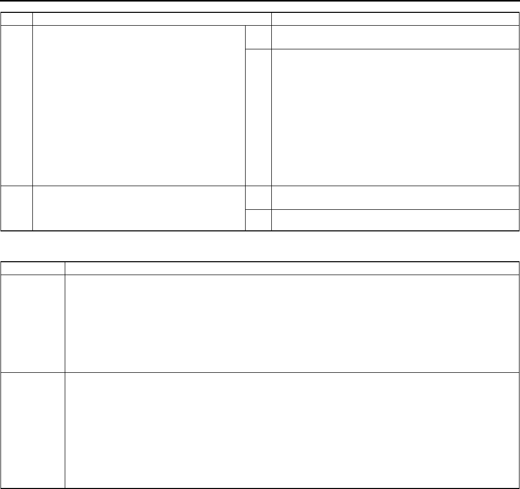
F132
ON-BOARD DIAGNOSTIC
End Of Sie
DTC P0340 A6E397001085W06
11 VERIFY TROUBLESHOOTING OF DTC P0335
COMPLETED
•Make sure to reconnect all disconnected
connectors.
•Turn ignition key to ON (Engine OFF).
•Clear DTC from PCM memory using WDS or
equivalent.
•Start engine.
•Access MAF PID using WDS or equivalent.
Note
•MAF PID should indicate 2.0 g/s {0.26
lb/min.} or above during this test
•Is same DTC present?
Yes Replace PCM, then go to next step.
(See F43 PCM REMOVAL/INSTALLATION.)
No Go to next step.
12 VERIFY AFTER REPAIR PROCEDURE
•Perform After Repair Procedure.
(See F66 AFTER REPAIR PROCEDURE.)
•Is there any DTC present?
Yes Go to applicable DTC troubleshooting.
(See F67 DTC TABLE.)
No Troubleshooting completed.
STEP INSPECTION ACTION
DTC P0340 Camshaft position (CMP) sensor circuit malfunction
DETECTION
CONDITION
•PCM monitors input voltage from CMP sensor when engine is running. If PCM does not receive input
voltage from CMP sensor while PCM receives input signal from CKP sensor, PCM determines that CMP
circuit has malfunction.
Diagnostic support note
•This is a continuous monitor (CCM).
•MIL illuminates if PCM detects the above malfunction condition during first drive cycle.
•PENDING CODE is available if PCM detects the above malfunction condition.
•FREEZE FRAME DATA is available.
•DTC is stored in the PCM memory.
POSSIBLE
CAUSE
•CMP sensor malfunction
•Connector or terminal malfunction
•CMP sensor is dirty
•Short to power circuit between CMP sensor terminal A and PCM terminal 2M
•Short to power circuit between CMP sensor terminal B and PCM terminal 2J
•Short to ground circuit between CMP sensor terminal A and PCM terminal 2M
•Short to ground circuit between CMP sensor terminal B and PCM terminal 2J
•Open circuit between CMP sensor terminal A and PCM terminal 2M
•Open circuit between CMP sensor terminal B and PCM terminal 2J
•CKP sensor pulse wheel malfunction
•Both CMP sensor wires are shorted each other
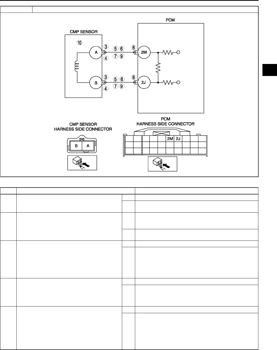
ON-BOARD DIAGNOSTIC
F133
F
Diagnostic procedure
STEP INSPECTION ACTION
1VERIFY FREEZE FRAME DATA HAS BEEN
RECORDED
•Has FREEZE FRAME DATA been recorded?
Yes Go to next step.
No Record FREEZE FRAME DATA on repair order, then go to
next step.
2VERIFY RELATED SERVICE INFORMATION
AVAILABILITY
•Check for related Service Information
availability.
•Is any related Service Information available?
Yes Perform repair or diagnosis according to available Service
Information.
•If vehicle is not repaired, go to next step.
No Go to next step.
3VERIFY CMP SENSOR VOLTAGE
•Disconnect CMP sensor connector.
•Connect voltmeter between CMP sensor
connector terminals A and B (sensor-side).
•Inspect the voltage in AC range while cranking
the engine.
•Is any voltage reading?
Yes Go to next step.
No Go to step 10.
4INSPECT POOR CONNECTION OF CMP
SENSOR CONNECTOR
•Verify that the CMP sensor connector is
connected securely.
•Is connector okay?
Yes Go to next step.
No Reconnect the connector, then go to Step 11.
5INSPECT CMP CIRCUIT FOR SHORT TO
POWER
•Turn ignition key OFF.
•Disconnect CMP sensor connector.
•Turn ignition key ON (Engine OFF)
•Measure voltage at CMP sensor terminals A
and B.
•Is any voltage reading?
Yes Repair or replace suspected harness, then go to Step 11.
No Go to next step.
DTC P0340 Camshaft position (CMP) sensor circuit malfunction

F134
ON-BOARD DIAGNOSTIC
End Of Sie
DTC P0403 A6E397001086W01
6INSPECT CMP CIRCUIT FOR SHORT TO
GROUND
•Inspect continuity between following terminal
and body ground:
CMP sensor connector terminal A (harness-
side)
CMP sensor connector terminal B (harness-
side)
•Is there any continuity?
Yes Repair or replace suspected harness, then go to Step 11.
No Go to next step.
7INSPECT CMP CIRCUITS FOR SHORTS
•Inspect continuity between CMP sensor
connector terminals A and B (harness-side).
•Is there any continuity?
Yes Repair or replace suspected harness, then go to Step 11.
No Go to next step.
8INSPECT POOR CONNECTION OF PCM
CONNECTOR
•Disconnect PCM connector.
•Inspect for poor connection (damaged, pulled-
out terminals, corrosion, etc.).
•Is there any malfunction?
Yes Repair terminal, then go to Step 11.
No Go to next step.
9INSPECT CMP CIRCUIT FOR OPEN CIRCUIT
•Inspect continuity between following circuits:
CMP sensor terminal A (harness-side) and
PCM terminal 2M (harness-side)
CMP sensor terminal B (harness-side) and
PCM terminal 2J (harness-side)
•Is there continuity?
Yes Go to Step 11.
No Repair or replace suspected harness, then go to Step 11.
10 INSPECT CMP SENSOR
•Turn ignition key to OFF.
•Perform CMP sensor inspection.
(See F55 CAMSHAFT POSITION (CMP)
SENSOR INSPECTION.)
•Is CMP sensor okay?
Yes Go to next step.
No Inspect CMP sensor pulse wheel for damage. Replace
CMP sensor pulse wheel and go to step 10.
11 VERIFY TROUBLESHOOTING OF DTC P0335
COMPLETED
•Make sure to reconnect all disconnected
connectors.
•Turn ignition key to ON (Engine OFF).
•Clear DTC from PCM memory using WDS or
equivalent.
•Start engine.
•Access MAF PID using WDS or equivalent.
Note
•MAF PID should indicate 1.95 g/s {0.25
lb/min.} or above during this test
•Is same DTC present?
Yes Replace PCM, then go to next step.
(See F43 PCM REMOVAL/INSTALLATION.)
No Go to next step.
12 VERIFY AFTER REPAIR PROCEDURE
•Perform After Repair Procedure.
(See F66 AFTER REPAIR PROCEDURE.)
•Is there any DTC present?
Yes Go to applicable DTC troubleshooting.
(See F67 DTC TABLE.)
No Troubleshooting completed.
STEP INSPECTION ACTION
DTC P0403 EGR valve (stepper motor) circuit malfunction
DETECTION
CONDITION
•PCM monitors input voltage from EGR valve. If voltage at PCM terminals 4E, 4H, 4K and/or 4N remain low
or high, PCM determines that EGR valve circuit has malfunction.
Diagnostic support note
•This is a continuous monitor (CCM).
•MIL illuminates if PCM detects the above malfunction conditions in two consecutive drive cycles or in one
drive cycle while the DTC for the same malfunction has been stored in the PCM.
•PENDING CODE is available if PCM detects the above malfunction condition during first drive cycle.
•FREEZE FRAME DATA is available.
•DTC is stored in the PCM memory.
ON-BOARD DIAGNOSTIC
F135
F
Diagnostic procedure
POSSIBLE
CAUSE
•EGR valve malfunction
•Connector or terminal malfunction
•Short to power circuit in wiring between EGR valve terminal E and PCM terminal 4E
•Short to power circuit in wiring between EGR valve terminal A and PCM terminal 4H
•Short to power circuit in wiring between EGR valve terminal B and PCM terminal 4K
•Short to power circuit in wiring between EGR valve terminal F and PCM terminal 4N
•Short to ground circuit in wiring between EGR valve terminal E and PCM terminal 4E
•Short to ground circuit in wiring between EGR valve terminal A and PCM terminal 4H
•Short to ground circuit in wiring between EGR valve terminal B and PCM terminal 4K
•Short to ground circuit in wiring between EGR valve terminal F and PCM terminal 4N
•Open circuit in wiring between EGR valve terminal E and PCM terminal 4E
•Open circuit in wiring between EGR valve terminal A and PCM terminal 4H
•Open circuit in wiring between EGR valve terminal B and PCM terminal 4K
•Open circuit in wiring between EGR valve terminal F and PCM terminal 4N
•Open circuit in wiring between main relay terminal D and EGR valve terminal C
•Open circuit in wiring between main relay terminal D and EGR valve terminal D
•PCM malfunction
STEP INSPECTION ACTION
1PERFORM DTC CONFIRMATION PROCEDURE
•Perform DTC CONFIRMATION PROCEDURE.
(See F66 DTC CONFIRMATION
PROCEDURE.)
•Is same DTC present?
Yes Go to next step.
No Intermittent concern exists. Go to INTERMITTENT
CONCERN TROUBLESHOOTING procedure.
(See F227 INTERMITTENT CONCERN
TROUBLESHOOTING.)
2INSPECT POOR CONNECTION OF EGR VALVE
•Turn ignition key to OFF.
•Disconnect EGR valve connector.
•Inspect for poor connection (damaged, pulled-
out terminals, corrosion, etc.).
•Is there any malfunctions?
Yes Repair or replace terminals and/or connector, then go to
Step 9.
No Go to next step.
DTC P0403 EGR valve (stepper motor) circuit malfunction

F136
ON-BOARD DIAGNOSTIC
End Of Sie
3INSPECT POWER CIRCUIT FOR OPEN
CIRCUIT
• Turn ignition key to ON (Engine OFF).
• Measure voltage following terminal and body
ground.
EGR valve terminal C
EGR valve terminal D
• Is voltage B+?
Yes Go to next step.
No Repair or replace harness for open circuit then go to Step
9.
4INSPECT EGR VALVE
•Perform EGR valve inspection.
(See F40 EGR VALVE INSPECTION.)
• Is EGR valve okay?
Yes Go to next step.
No Replace EGR valve, then go to Step 9.
5INSPECT FOR CONTROL CIRCUIT FOR SHORT
TO GROUND
• Turn ignition key to OFF.
•Inspect continuity following terminal and body
ground:
EGR valve terminal E
EGR valve terminal A
EGR valve terminal B
EGR valve terminal F
•is there continuity?
Yes Repair or replace harness for short to ground, then go to
Step 9.
No Go to next step.
6INSPECT FOR CONTROL CIRCUIT FOR SHORT
TO POWER
•Turn ignition switch key to ON (Engine OFF).
•Measure voltage following terminal and body
ground:
EGR valve terminal E
EGR valve terminal A
EGR valve terminal B
EGR valve terminal F
•Is voltage B+?
Yes Repair or replace harness for short to power, then go to
Step 9.
No Go to next step.
7INSPECT POOR CONNECTION OF PCM
•Turn ignition key to OFF.
•Disconnect PCM connector.
•Inspect for poor connection (damaged, pulled-
out terminals, corrosion, etc.).
•Is there any malfunctions?
Yes Repair or replace terminals and/or connector, then go to
Step 9.
No Go to next step.
8INSPECT CONTROL CIRCUIT FOR OPEN
CIRCUIT
•Remove PCM with PCM connector connected.
•Inspect continuity following terminals:
Between EGR valve terminal E and PCM
terminal 4E
Between EGR valve terminal A and PCM
terminal 4H
BetweenEGR valve terminal B and PCM
terminal 4K
Between EGR valve terminal F and PCM
terminal 4N
•Is there continuity?
Yes Go to next step.
No Repair or replace harness for open circuit then go to next
step.
9VERIFY TROUBLESHOOTING OF DTC P0403
COMPLETED
•Make sure to reconnect all disconnected
connectors.
•Clear DTC from PCM memory using WDS or
equivalent.
•Perform KOEO/KOER self-test.
(See F66 KOEO/KOER SELF-TEST.)
•Is same DTC present?
Yes Replace PCM, then go to next step.
(See F43 PCM REMOVAL/INSTALLATION.)
No Go to next step.
10 VERIFY AFTER REPAIR PROCEDURE
•Perform After Repair Procedure.
(See F66 AFTER REPAIR PROCEDURE.)
•Is there any DTC present?
Yes Go to applicable DTC troubleshooting.
(See F67 DTC TABLE.)
No Troubleshooting completed.
STEP INSPECTION ACTION
ON-BOARD DIAGNOSTIC
F137
F
DTC P0420 A6E397001086W02
Diagnostic procedure
DTC P0420 Catalyst system efficiency below threshold
DETECTION
CONDITION
•PCM compares number of front HO2S and rear HO2S inversions for a predetermined time. PCM monitors
number of inversions rear side performs while front side inverts for a specified number of times when the
following monitoring conditions are met. PCM detects inversion ratio. If inversion ratio is below threshold,
PCM determins that catalyst system has deteriorated.
MONITORING CONDITION
Engine speed 1,4103,000 rpm (MTX)
Engine speed 1,2813,000 rpm (ATX)
Calculated load 1550%(*1)
*1: Maximum calculated load value varies depending on engine speed.
Diagnostic support note
•This is a intermittent monitor. (CATALYST)
•MIL illuminates if PCM detects the above malfunction conditions in two consecutive drive cycles or in one
drive cycle while the DTC for the same malfunction has been stored in the PCM.
•DIAGNOSTIC MONITORING TEST RESULTS and PENDING CODE are stored if PCM detects the above
malfunction condition during first drive cycle.
•FREEZE FRAME DATA is available.
•DTC is stored in the PCM memory.
POSSIBLE
CAUSE
•TWC deterioration or malfunction
•Exhaust gas leakage
•Looseness of front HO2S
•Looseness of rear HO2S
•Front HO2S malfunction
STEP INSPECTION ACTION
1VERIFY FREEZE FRAME DATA HAS BEEN
RECORDED
•Has FREEZE FRAME DATA been recorded?
Yes Go to next step.
No Record FREEZE FRAME DATA on repair order, then go to
next step.
2VERIFY RELATED SERVICE INFORMATION
AVAILABILITY
•Check for related Service Information
availability.
•Is any related Service Information available?
Yes Perform repair or diagnosis according to available Service
Information.
•If vehicle is not repaired, go to next step.
No Go to next step.
3VERIFY RELATED PENDING CODE OR
STORED DTCS
•Turn ignition key to OFF then ON (Engine
OFF).
•Verify related pending code or stored DTCs.
•Are other DTCs present?
Yes Go to appropriate DTC troubleshooting.
No Go to next step.
4INSPECT GAS LEAKAGE OF EXHAUST
SYSTEM
•Visually inspect exhaust gas leakage in
exhaust system.
•Is there any gas leakage?
Yes Repair or replace faulty exhaust parts, then go to Step 7.
No Go to next step.
5INSPECT INSTALLATION OF FRONT AND
REAR OXYGEN SENSORS
•Inspect for looseness of front and rear oxygen
sensors.
•Is it okay?
Yes Go to next step.
No Retighten sensor, then go to Step 7.
6INSPECT TWC
•Clear DTC using WDS or equivalent generic
OBD function.
•Cycle ignition key to OFF then back to ON.
•Inspect TWC.
(See F41 THREE-WAY CATALYTIC
CONVERTER (TWC) INSPECTION)
•Is it okay?
Yes Replace suspected oxygen sensor, then go to next step.
No Replace TWC, then go to next step.

F138
ON-BOARD DIAGNOSTIC
End Of Sie
DTC P0443 A6E397001086W03
7VERIFY TROUBLESHOOTING OF DTC P0420
OR P0431 COMPLETED
•Make sure to reconnect all disconnected
connectors.
•Turn ignition key to ON (Engine OFF).
•Clear DTC from memory using WDS or
equivalent.
•Run PCM adaptive memory procedure drive
mode and HO2S heater, HO2S, and EGR
system repair verification drive mode.
(See F64 OBD DRIVE MODE.)
•Is PENDING CODE the same as DTC
present?
Yes Replace PCM, then go to next step.
(See F43 PCM REMOVAL/INSTALLATION.)
No Go to next step.
8VERIFY AFTER REPAIR PROCEDURE
•Perform After Repair Procedure.
(See F66 AFTER REPAIR PROCEDURE.)
•Is there any DTC present?
Yes Go to applicable DTC troubleshooting.
(See F67 DTC TABLE.)
No Troubleshooting completed.
STEP INSPECTION ACTION
DTC P0443 Evaporative emission control system purge control valve circuit malfunction
DETECTION
CONDITION
•PCM monitors input voltages from purge solenoid valve. If voltage at PCM terminal 4U remains low or high,
PCM determines that purge solenoid valve circuit has malfunction.
Diagnostic support note
•This is a continuous monitor (CCM).
•MIL illuminates if PCM detects the above malfunction condition in two consecutive drive cycles or in one
drive cycle while the DTC for the same malfunction has been stored in the PCM.
•PENDING CODE is available if PCM detects the above malfunction condition.
•FREEZE FRAME DATA is available.
•DTC is stored in the PCM memory.
POSSIBLE
CAUSE
•Purge solenoid valve malfunction
•Connector or terminal malfunction
•Short to ground in wiring between purge solenoid valve terminal A and PCM terminal 4U
•Open circuit in wiring between main relay and purge solenoid valve terminal B
•Open circuit in wiring between purge solenoid valve terminal A and PCM terminal 4U
•Short to power circuit between purge solenoid valve terminal A and PCM terminal 4U
•PCM malfunction

ON-BOARD DIAGNOSTIC
F139
F
Diagnostic procedure
STEP INSPECTION ACTION
1PERFORM DTC CONFIRMATION PROCEDURE
•Perform DTC CONFIRMATION PROCEDURE.
(See F66 DTC CONFIRMATION
PROCEDURE.)
•Is same DTC present?
Yes Go to next step.
No Intermittent concern exists. Go to INTERMITTENT
CONCERN TROUBLESHOOTING procedure.
(See F227 INTERMITTENT CONCERN
TROUBLESHOOTING.)
2CLASSIFY OPEN CIRCUIT OR SHORT TO
GROUND MALFUNCTION
•Disconnect purge solenoid valve tube that is
connected to intake manifold.
•Connect vacuum pump to purge solenoid
valve.
•Pump vacuum pump several times and stop.
•Wait a few seconds.
•Is vacuum maintained?
Yes Go to Step 4.
No Go to next step.
3INSPECT PASSAGE CONTROL OF PURGE
SOLENOID VALVE
•Turn ignition key to OFF.
•Disconnect purge solenoid valve connector.
•Pump vacuum pump several times and wait a
few seconds.
•Is vacuum maintained?
Yes Repair or replace harness for short to ground, then go to
Step 9.
No Replace purge solenoid valve, then go to Step 9.
4INSPECT PURGE SOLENOID VALVE
CONNECTOR FOR POOR CONNECTION
•Turn ignition key to OFF.
•Inspect for poor connection (damaged/pulled-
out pins, corrosion, etc.).
•Is there malfunction?
Yes Repair or replace terminal, then go to Step 9.
No Go to next step.
5INSPECT PURGE SOLENOID VALVE
•Perform purge solenoid valve inspection.
(See F39 PURGE SOLENOID VALVE
INSPECTION)
•Is purge solenoid valve okay?
Yes Go to next step.
No Replace purge solenoid valve, then go to Step 9.
6INSPECT PURGE SOLENOID VALVE POWER
SUPPLY CIRCUIT FOR OPEN CIRCUIT
•Turn ignition key to ON (Engine OFF).
•Measure voltage between purge solenoid valve
connector terminal B and body ground.
•Is voltage B+?
Yes Go to next step.
No Repair or replace harness for open, then go to Step 9.
7INSPECT PCM CONNECTOR FOR POOR
CONNECTION
•Turn ignition key to OFF.
•Disconnect PCM connector.
•Inspect for poor connection (damaged/pulled-
out pins, corrosion, etc.).
•Is there malfunction?
Yes Repair or replace terminal, then go to Step 9.
No Go to next step.
8INSPECT PURGE SOLENOID VALVE
CONTROL CIRCUIT
•Turn ignition key to ON (Engine OFF).
•Measure voltage between purge solenoid valve
terminal A (harness-side) and body ground.
•Is voltage B+?
Yes Repair or replace harness for short to power, then go to
next step.
No Inspect for continuity between purge solenoid valve
terminal A (harness-side) and PCM terminal 4U (harness-
side).
•If there is continuity, go to next step.
•If there is no continuity, repair or replace harness for
open, then go to next step.
9VERIFY TROUBLESHOOTING OF DTC P0443
COMPLETED
•Make sure to reconnect all disconnected
connectors.
•Perform KOER self-test.
(See F66 KOEO/KOER SELF-TEST.)
•Is same DTC present?
Yes Replace PCM, then go to next step.
(See F43 PCM REMOVAL/INSTALLATION.)
No Go to next step.
10 VERIFY AFTER REPAIR PROCEDURE
•Perform After Repair Procedure.
(See F66 AFTER REPAIR PROCEDURE.)
•Is there any DTC present?
Yes Go to applicable DTC troubleshooting.
(See F67 DTC TABLE.)
No Troubleshooting completed.
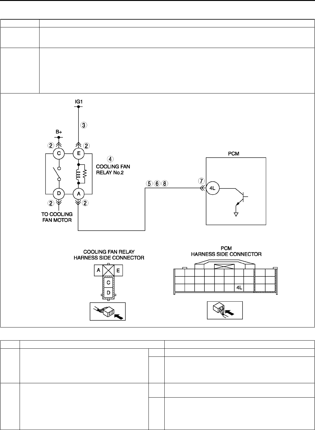
F140
ON-BOARD DIAGNOSTIC
End Of Sie
DTC P0480 A6E397001086W04
Diagnostic procedure
DTC P0480 Fan relay control circuit malfunction
DETECTION
CONDITION
•PCM monitors cooling fan relay No.2 control signal at PCM terminal 4L. if PCM detects cooling fan relay
No.2 control signal does not change coolant temperature above 100 °
°°
°C {212 °
°°
°F}, PCM determines that
cooling fan relay No.2 control has malfunction.
POSSIBLE
CAUSE
•cooling fan relay No.2 malfunction
•Connector or terminal malfunction
•Open circuit in wiring between METER fuse and cooling fan relay No.2 terminal E
•Open circuit in wiring between cooling fan relay No.2 terminal A and PCM terminal 4L
•Short to ground in wiring between cooling fan relay No.2 terminal A and PCM terminal 4L
•Short to power circuit between cooling fan relay No.2 terminal A and PCM terminal 4L
•PCM malfunction
STEP INSPECTION ACTION
1PERFORM DTC CONFIRMATION PROCEDURE
•Perform DTC CONFIRMATION PROCEDURE.
(See F66 DTC CONFIRMATION
PROCEDURE.)
•Is same DTC present?
Yes Go to next step.
No Intermittent concern exists. Go to INTERMITTENT
CONCERN TROUBLESHOOTING procedure.
(See F227 INTERMITTENT CONCERN
TROUBLESHOOTING.)
2INSPECT COOLING FAN RELAY NO.2
CONNECTOR FOR POOR CONNECTION
•Turn ignition key to OFF.
•Disconnect cooling fan relay No.2 connector.
•Inspect for poor connection (damaged/pulled-
out pins, corrosion, etc.).
•Is there malfunction?
Yes Repair or replace terminal and/or connector, then go to
Step 9.
No Go to next step.

ON-BOARD DIAGNOSTIC
F141
F
End Of Sie
3INSPECT COOLING FAN RELAY NO.2 POWER
CIRCUIT FOR OPEN
•Turn ignition switch to ON (Engine OFF).
•Measure voltage between cooling fan relay
No.2 terminal E (harness side) and body
ground.
•Is voltage B+?
Yes Go to next step.
No Replace or replace harness for open, then go to Step 9.
4INSPECT COOLING FAN RELAY NO.2
•Inspect cooling fan relay No.2.
(See T24 RELAY INSPECTION)
•Is cooling fan relay No.2 okay?
Yes Go to next step.
No Replace cooling fan relay No.2, then go to Step 9.
5INSPECT COOLING FAN RELAY NO.2
CONTROL CIRCUIT FOR SHORT TO POWER
•Measure voltage between cooling fan relay
No.2 terminal A (harness side) and body
ground.
•Is voltage B+?
Yes Repair or replace harness for short to power, then go to
Step 9.
No Go to next step.
6INSPECT COOLING FAN RELAY NO.2
CONTROL CIRCUIT FOR SHORT TO GROUND
•Inspect continuity between cooling fan relay
No.2 terminal A (harness side) and body
ground.
•Is there continuity?
Yes Repair or replace harness for open, then go to Step 9.
No Go to next step.
7INSPECT PCM CONNECTOR FOR POOR
CONNECTION
•Turn ignition key to OFF.
•Disconnect PCM connector.
•Inspect for poor connection (damaged/pulled-
out pins, corrosion, etc.).
•Is there malfunction?
Yes Repair or replace terminal and/or connector, then go to
Step 9.
No Go to next step.
8INSPECT COOLING FAN RELAY NO.2
CONTROL CIRCUIT FOR OPEN CIRCUIT
•Inspect continuity between cooling fan relay
No.2 terminal A and PCM terminal 4L.
•Is there continuity?
Yes Go to next step.
No Repair or replace harness for open, then go to next step.
9VERIFY TROUBLESHOOTING OF DTC P0480
COMPLETED
•Make sure to reconnect all disconnected
connectors.
•Clear DTC from PCM memory using WDS or
equivalent.
•Perform KOEO/KOER self-test.
(See F66 KOEO/KOER SELF-TEST.)
•Is same DTC present?
Yes Replace PCM, then go to next step.
(See F43 PCM REMOVAL/INSTALLATION.)
No Go to next step.
10 VERIFY AFTER REPAIR PROCEDURE
•Perform After Repair Procedure.
(See F66 AFTER REPAIR PROCEDURE.)
•Is there any DTC present?
Yes Go to applicable DTC troubleshooting.
(See F67 DTC TABLE.)
No Troubleshooting completed.
STEP INSPECTION ACTION
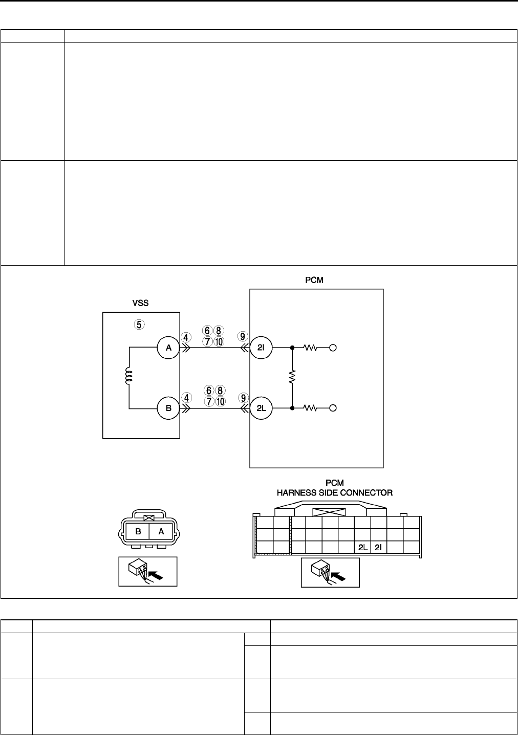
F142
ON-BOARD DIAGNOSTIC
DTC P0500 A6E397001087W01
Diagnostic procedure
DTC P0500 Vehicle speed sensor (VSS) circuit malfunction (MTX vehicles without ABS)
DETECTION
CONDITION
•Vehicle speed signal does not input after following conditions are met:
Gear is in other than neutral position
Load is above 40%
Engine speed is 2,000 rpm or above
Diagnostic support note:
•This is a continuous monitor (CCM).
•MIL illuminates if PCM detects the above malfunction conditions in two consecutive drive cycles or in one
drive cycle while the DTC for the same malfunction has been stored in the PCM.
•PENDING CODE is available if PCM detects the above malfunction condition during first drive cycle.
•FREEZE FRAME DATA is available.
•DTC is stored in PCM memory.
POSSIBLE
CAUSE
•VSS malfunction
•ABS/TCS/DCS malfunction
•Connector or terminal malfunction
•Open circuit between PCM terminal 2I and VSS terminal A
•Open circuit between PCM terminal 2L and VSS terminal B
•Short to ground between PCM terminal 2I and VSS terminal A
•Short to ground between PCM terminal 2L and VSS terminal B
•Short to power between PCM terminal 2I and VSS terminal A
•Short to power between PCM terminal 2L and VSS terminal B
•PCM malfunction
STEP INSPECTION ACTION
1VERIFY FREEZE FRAME DATA HAS BEEN
RECORDED
•Has FREEZE FRAME PID DATA been
recorded?
Yes Go to next step.
No Record FREEZE FRAME PID DATA on repair order, then
go to next step.
2VERIFY RELATED SERVICE INFORMATION
AVAILABILITY
•Check for related Service Information
availability.
•Is any related Service Information available?
Yes Perform repair or diagnosis according to available Service
Information.
•If vehicle is not repaired, go to next step.
No Go to next step.

ON-BOARD DIAGNOSTIC
F143
F
3VERIFY CURRENT INPUT SIGNAL STATUS-IS
CONCERN INTERMITTENT OR CONSTANT
•Connect WDS or equivalent to DLC-2.
•Start engine.
•Access VSS PID using WDS or equivalent.
Vehicle speed 20 km/h {12.4 mph}: 20km/
h {12.4 mph}
Vehicle speed 40 km/h {24.8 mph}: 40km/
h {24.8 mph}
•Are PID readings within specification?
Yes Go to intermittent concern troubleshooting procedure.
(See F227 INTERMITTENT CONCERN
TROUBLESHOOTING.)
No Go to next step.
4INSPECT POOR CONNECTION OF VSS
CONNECTOR
•Verify that the VSS connector is connected
securely.
•Is connector okay?
Yes Go to next step.
No Reconnect the connector, then go to Step 11.
5INSPECT VSS
•Perform VSS inspection.
(See J5 VEHICLE SPEEDOMETER
SENSOR INSPECTION)
•Is VSS okay?
Yes Go to next step.
No Replace VSS, then go to Step 11.
6INSPECT VSS CIRCUIT FOR SHORT TO
POWER
•Turn ignition key OFF
•Disconnect VSS connector.
•Turn ignition key ON (Engine OFF)
•Measure voltage following terminals:
VSS terminal A
VSS terminal B
•Is any voltage reading?
Yes Repair or replace suspected harness, then go to Step 11.
No Go to next step.
7INSPECT VSS CIRCUIT FOR SHORT TO
GROUND
•Inspect continuity between following terminal
and body ground:
VSS terminal A
VSS terminal B
•Is there any continuity?
Yes Repair or replace suspected harness, then go to Step 11.
No Go to next step.
8INSPECT VSS CIRCUITS FOR SHORTS
•Inspect continuity between VSS connector
terminals A and B.
•Is there any continuity?
Yes Repair or replace suspected harness, then go to Step 11.
No Go to next step.
9INSPECT POOR CONNECTION OF PCM
CONNECTOR
•Disconnect PCM connector.
•Inspect for poor connection (damaged, pulled-
out terminals, corrosion, etc.).
•Is there any malfunction?
Yes Repair terminal, then go to Step 11.
No Go to next step.
10 INSPECT VSS CIRCUIT FOR OPEN CIRCUIT
•Inspect continuity between following circuits:
VSS terminal A and PCM terminal 2I
VSS terminal B and PCM terminal 2L
•Is there continuity?
Yes Inspect VSS pulse wheel for damage. Replace VSS pulse
wheel and go to next step.
No Repair or replace suspected harness, then go to next step.
STEP INSPECTION ACTION

F144
ON-BOARD DIAGNOSTIC
End Of Sie
DTC P0505 A6E397001087W02
Diagnostic procedure
11 VERIFY TROUBLESHOOTING OF DTC P0500
COMPLETED
•Make sure to reconnect all disconnected
connectors.
•Turn ignition key to ON (Engine OFF).
•Clear DTC from PCM memory using WDS or
equivalent.
•Warm up engine.
•Access RPM and LOAD PID using WDS or
equivalent.
•Drive vehicle under following conditions for
18s.
Engine speed: 2,000 rpm or above
Gear: Gear is in other than NEUTRAL
Load: 40% or above
•Is PENDING CODE the same as DTC
present?
Yes Replace PCM, then go to next step.
(See F43 PCM REMOVAL/INSTALLATION.)
No Go to next step.
12 VERIFY AFTER REPAIR PROCEDURE
•Perform After Repair Procedure.
(See F66 AFTER REPAIR PROCEDURE.)
•Is there any DTC present?
Yes Go to applicable DTC troubleshooting.
(See F67 DTC TABLE.)
No Troubleshooting completed.
STEP INSPECTION ACTION
DTC P0505 IAC valve circuit malfunction
DETECTION
CONDITION •PCM cannot control idle speed toward target idle speed while KOER self test.
POSSIBLE
CAUSE
•IAC valve circuit malfunction
•Air cleaner element clogged
•Air intake passage clogged
•A/C relay control circuit malfunction
•Generator control circuit malfunction
•Low engine compression (Over capacity of blow-by gas)
•PCM malfunction
STEP INSPECTION ACTION
1VERIFY RELATED SERVICE INFORMATION
AVAILABILITY
•Check for related Service Information
availability.
•Is any related Service Information available?
Yes Perform repair or diagnosis according to available Service
Information.
•If vehicle is not repaired, go to next step.
No Go to next step.
2VERIFY RELATED PENDING OR STORED
DTCS
•Turn ignition switch to OFF, then ON. (Engine
OFF)
•verify pending code or stored DTCs using
WDS or equivalent.
•Does DTC P0511,P2502, P2503 or P2504
present?
Yes Perform applicable DTC troubleshooting.
(See F67 DTC TABLE.)
No Go to next step.
3INSPECT IAC VALVE MALFUNCTION
•Start engine.
•Disconnect IAC valve connector.
•Is engine speed decreased?.
Yes Go to next step.
No Repair IAC valve, then go to Step 9.
4INSPECT A/C MAGNETIC CLUTCH
OPERATION
Note
•The following test should be performed for
A/C.go to next step for vehicles without A/C
•Turn blower motor switch to off.
•Is magnetic clutch still on?
Yes Go to A/C ALWAYS ON / A/C COMPRESSOR RUNS
CONTINUOUSLY. of ENGINE SYMPTOM
TROUBLESHOOTING then go to step 9.
(See F181 ENGINE SYMPTOM TROUBLESHOOTING.)
No Go to next step.

ON-BOARD DIAGNOSTIC
F145
F
End Of Sie
DTC P0506 A6E397001087W03
Diagnostic procedure
5INSPECT GENERATOR CONTROL CIRCUIT
MALFUNCTION
•Apply electrical load.
•Is engine speed increased?
Yes Go to next step.
No Repair short to power circuit in generator control circuit,
then go to Step 9.
6INSPECT AIR CLEANER ELEMENT
•remove air cleaner element with engine
running.
•Is engine speed increased?
Yes Clean or replace air cleaner element, then go to Step 9.
No Go to next step.
7INSPECT THROTTLE BODY PASSAGE
•Is throttle body clogged?
Yes Clean or replace throttle body passage, then go to Step 9.
No Go to next step.
8INSPECT ENGINE COMPRESSION
•Inspect engine compression.
(See B9 COMPRESSION INSPECTION.)
•Is engine compression okay?
Yes Go to next step.
No Overhaul engine, then go to next step.
9VERIFY TROUBLESHOOTING OF DTC P0505
COMPLETED
•Make sure to reconnect all disconnected
connectors.
•Clear DTC using WDS or equivalent.
•Perform KOER self-test.
(See F66 KOEO/KOER SELF-TEST.)
•Is same DTC present?
Yes Replace PCM, then go to next step.
(See F43 PCM REMOVAL/INSTALLATION.)
No Go to next step.
10 VERIFY AFTER REPAIR PROCEDURE
•Perform After Repair Procedure.
(See F66 AFTER REPAIR PROCEDURE.)
•Is there any DTC present?
Yes Go to applicable DTC troubleshooting.
(See F67 DTC TABLE.)
No Troubleshooting completed.
STEP INSPECTION ACTION
DTC P0506 Idle control system RPM lower than expected
DETECTION
CONDITION
•Actual idle speed is lower than expected by 100 rpm for 14 s, when brake pedal is depressed (brake
switch is on) and steering wheel is held straight ahead (power steering pressure switch is off).
Note
•If atmospheric pressure is less than 72.3 kPa {542 mmHg, 21.3 inHg} or intake air temperature is
below -10 °
°°
°C {14 °
°°
°F}, PCM cancels diagnosis of P0506.
Diagnostic support note
•This is a continuous monitor (CCM).
•MIL illuminates if PCM detects the above malfunction conditions in two consecutive drive cycles or in one
drive cycle while the DTC for the same malfunction has been stored in the PCM.
•PENDING CODE is available if PCM detects the above malfunction condition during first drive cycle.
•FREEZE FRAME DATA is available.
•DTC is stored in PCM memory.
POSSIBLE
CAUSE
•IAC valve malfunction
•Air cleaner element clogged
•Air intake passage clogged
•A/C relay control circuit malfunction
•Generator malfunction
•Purge solenoid valve malfunction
•Low engine compression (Over capacity of blow-by gas)
•PCM malfunction
STEP INSPECTION ACTION
1VERIFY FREEZE FRAME DATA HAS BEEN
RECORDED
•Has FREEZE FRAME DATA been recorded?
Yes Go to next step.
No Record FREEZE FRAME DATA on repair order, then go to
next step.
2VERIFY RELATED SERVICE INFORMATION
AVAILABILITY
•Check for related Service Information
availability.
•Is any related Service Information available?
Yes Perform repair or diagnosis according to available Service
Information.
•If vehicle is not repaired, go to next step.
No Go to next step.

F146
ON-BOARD DIAGNOSTIC
End Of Sie
3VERIFY RELATED PENDING OR STORED
DTCS
•Turn ignition key to OFF, then ON (Engine
OFF).
•Verify pending code or stored DTCs using
WDS or equivalent.
•Is other DTC present?
Yes Repair applicable DTCs.
(See F67 DTC TABLE.)
No Go to next step.
4INSPECT IAC VALVE MALFUNCTION
•Perform IAC valve inspection.
(See F13 IDLE AIR CONTROL (IAC) VALVE
INSPECTION.)
•Is IAC valve okay?
Yes Go to next step.
No Replace IAC valve, then go to Step 11.
5INSPECT A/C MAGNET CLUTCH OPERATION
•Turn blower motor switch off.
•Is magnet clutch still on?
Yes Refer to A/C is always on or A/C compressor runs
continuously. of ENGINE SYMPTOM
TROUBLESHOOTING, then go to Step 11.
(See F181 ENGINE SYMPTOM TROUBLESHOOTING.)
No Go to next step.
6INSPECT PURGE SOLENOID VALVE
MALFUNCTION
•Perform purge solenoid valve inspection.
(See F39 PURGE SOLENOID VALVE
INSPECTION.)
•Is purge solenoid valve okay?
Yes Go to next step.
No Replace purge solenoid valve, then go to Step 11.
7INSPECT AIR CLEANER ELEMENT
•Remove air cleaner element with engine
running.
•Is engine speed increased?
Yes Replace air cleaner element, then go to Step 11.
No Go to next step.
8INSPECT THROTTLE BODY PASSAGE
•Is throttle body clogged?
Yes Clean or replace throttle body passage, then go to Step 11.
No Go to next step.
9INSPECT ENGINE COMPRESSION
•Inspect engine compression.
(See B9 COMPRESSION INSPECTION.)
•Is engine compression okay?
Yes Go to next step.
No Overhaul engine, then go to Step 11.
10 INSPECT GENERATOR
•Perform generator inspection.
(See G7 GENERATOR INSPECTION.)
•Is generator okay?
Yes Go to next step.
No Repair or replace related part, then go to next step.
11 VERIFY TROUBLESHOOTING OF DTC P0506
COMPLETED
•Make sure to reconnect all disconnected
connectors.
•Start engine.
•Clear DTC from PCM memory using WDS or
equivalent.
•Depress brake pedal for 14 s or more.
•Is PENDING CODE the same as DTC
present?
Yes Replace PCM, then go to next step.
(See F43 PCM REMOVAL/INSTALLATION.)
No Go to next step.
12 VERIFY AFTER REPAIR PROCEDURE
•Perform After Repair Procedure.
(See F66 AFTER REPAIR PROCEDURE.)
•Is there any DTC present?
Yes Go to applicable DTC troubleshooting.
(See F67 DTC TABLE.)
No Troubleshooting completed.
STEP INSPECTION ACTION
ON-BOARD DIAGNOSTIC
F147
F
DTC P0507 A6E397001087W04
Diagnostic procedure
DTC P0507 Idle control system RPM higher than expected
DETECTION
CONDITION
•Actual idle speed is higher than expected by 200 rpm for 14 s, when brake pedal is depressed (brake
switch is on) and steering wheel is held straight ahead (power steering pressure switch is off).
Note
•If atmospheric pressure is less than 72.3 kPa {542 mmHg, 21.3 inHg} or intake air temperature is
below -10 °
°°
°C {14 °
°°
°F}, PCM cancels diagnosis of P0507.
Diagnostic support note
•This is a continuous monitor (CCM).
•MIL illuminates if PCM detects the above malfunction conditions in two consecutive drive cycles or in one
drive cycle while the DTC for the same malfunction has been stored in the PCM.
•PENDING CODE is available if PCM detects the above malfunction condition during first drive cycle.
•FREEZE FRAME DATA is available.
•DTC is stored in PCM memory.
POSSIBLE
CAUSE
•IAC valve malfunction
•Accelerator cable misadjusting
•Actuator cable misadjusting
•Throttle valve malfunction
•Vacuum hose misconnection
•PCM malfunction
STEP INSPECTION ACTION
1VERIFY FREEZE FRAME DATA HAS BEEN
RECORDED
•Has FREEZE FRAME DATA been recorded?
Yes Go to next step.
No Record FREEZE FRAME DATA on repair order, then go to
next step.
2VERIFY RELATED SERVICE INFORMATION
AVAILABILITY
•Check for related Service Information
availability.
•Is any related Service Information available?
Yes Perform repair or diagnosis according to available Service
Information.
•If vehicle is not repaired, go to next step.
No Go to next step.
3VERIFY RELATED PENDING OR STORED
DTCS
•Turn ignition key to OFF, then ON (Engine
OFF).
•Verify pending code or stored DTCs using
WDS or equivalent.
•Is other DTC present?
Yes Repair applicable DTCs.
(See F67 DTC TABLE.)
No Go to next step.
4INSPECT IAC VALVE MALFUNCTION
•Perform IAC valve inspection.
(See F13 IDLE AIR CONTROL (IAC) VALVE
INSPECTION.)
•Is IAC valve okay?
Yes Go to next step.
No Replace IAC valve, then go to Step 9.
5INSPECT ACCELERATOR CABLE FREE PLAY
•Turn ignition key to OFF.
•Is accelerator cable free play okay?
(See F16 ACCELERATOR CABLE
INSPECTION/ADJUSTMENT.)
Yes Go to next step.
No Adjust accelerator cable free play, then go to Step 9.
(See F16 ACCELERATOR CABLE INSPECTION/
ADJUSTMENT.)
6INSPECT ACTUATOR CABLE FREE PLAY
•Is actuator cable adjustments okay?
Yes Go to next step.
No Adjust actuator cable free play, then go to Step 9.
7INSPECT VACUUM HOSE CONNECTION
•Are vacuum hoses connecting accurately?
(See F10 VACUUM HOSE ROUTING
DIAGRAM.)
Yes Go to next step.
No Reconnect vacuum hose accurately, then go to step 9.
8VISUAL INSPECT THROTTLE VALVE
•Remove throttle body.
•Is throttle valve fully closed?
Yes Go to next step.
No Clean or replace throttle body, then go to next step.
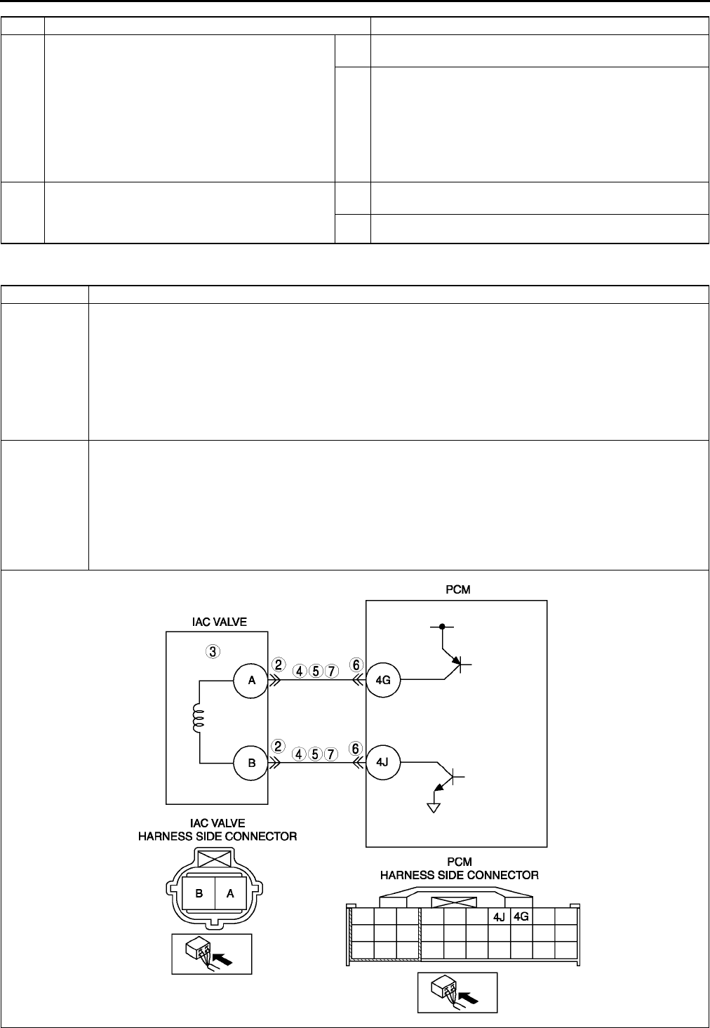
F148
ON-BOARD DIAGNOSTIC
End Of Sie
DTC P0511 A6E397001087W05
9VERIFY TROUBLESHOOTING OF DTC P0507
COMPLETED
•Make sure to reconnect all disconnected
connectors.
•Start engine.
•Clear DTC from PCM memory using WDS or
equivalent.
•Depress brake pedal for 14 s or more.
•Is PENDING CODE the same as DTC
present?
Yes Replace PCM, then go to next step.
(See F43 PCM REMOVAL/INSTALLATION.)
No Go to next step.
10 VERIFY AFTER REPAIR PROCEDURE
•Perform After Repair Procedure.
(See F66 AFTER REPAIR PROCEDURE.)
•Is there any DTC present?
Yes Go to applicable DTC troubleshooting.
(See F67 DTC TABLE.)
No Troubleshooting completed.
STEP INSPECTION ACTION
DTC P0511 IAC valve circuit malfunction
DETECTION
CONDITION
•If PCM detects that PCM terminal 4G voltage is above or below threshold* when IAC control duty target is
within 1670%, PCM determines that IAC valve circuit has malfunction.
*: Detected threshold value depends on battery voltage and IAC control signal duty value.
Diagnostic support note
•This is a continuous monitor (CCM).
•MIL illuminates if PCM detects the above malfunction conditions in first consecutive drive cycles.
•PENDING CODE is available if PCM detects the above malfunction condition.
•FREEZE FRAME DATA is available.
•DTC is stored in PCM memory.
POSSIBLE
CAUSE
•IAC valve circuit malfunction
•Short to ground between IAC valve terminal A (harness-side) and PCM terminal 4G (harness-side)
•Short to ground between IAC valve terminal B (harness-side) and PCM terminal 4J (harness-side)
•Open circuit between IAC valve terminal A (harness-side) and PCM terminal 4G (harness-side)
•Open circuit between IAC valve terminal B (harness-side) and PCM terminal 4J (harness-side)
•Short to power between IAC valve terminal A (harness-side) and PCM terminal 4G (harness-side)
•Short to power between IAC valve terminal B (harness-side) and PCM terminal 4J (harness-side)
•Poor connection of IAC valve connector or PCM connector
•PCM malfunction

ON-BOARD DIAGNOSTIC
F149
F
Diagnostic procedure
End Of Sie
STEP INSPECTION ACTION
1PERFORM DTC CONFIRMATION PROCEDURE
•Perform DTC CONFIRMATION PROCEDURE.
(See F66 DTC CONFIRMATION
PROCEDURE.)
•Is same DTC present?
Yes Go to next step.
No Intermittent concern exists. Go to INTERMITTENT
CONCERN TROUBLESHOOTING procedure.
(See F227 INTERMITTENT CONCERN
TROUBLESHOOTING.)
2INSPECT POOR CONNECTION OF IAC VALVE
CONNECTOR
•Turn ignition key to OFF.
•Disconnect IAC valve connector.
•Inspect for poor connection (damaged, pulled-
out terminals, corrosion, etc.).
•Are there any malfunctions?
Yes Repair or replace terminal, then go to Step 8.
No Go to next step.
3INSPECT IAC VALVE ELECTRICAL
MALFUNCTION
•Inspect IAC valve.
(See F13 IDLE AIR CONTROL (IAC) VALVE
INSPECTION.)
•Is IAC valve okay?
Yes Go to next step.
No Replace IAC valve, then go to Step 8.
4INSPECT CONTROL CIRCUIT FOR SHORT TO
POWER
•Turn ignition key to ON (Engine OFF).
•Measure voltage between following terminal
and body ground:
IAC valve terminal A
IAC valve terminal B
•Is there voltage B+?
Yes Repair or replace harness, then go to Step 8.
No Go to next step.
5INSPECT CONTROL CIRCUIT FOR SHORT TO
GROUND
•Turn ignition key to OFF.
•Inspect continuity between following terminals
and body ground:
IAC valve terminal A
IAC valve terminal B
•Is there any continuity?
Yes Repair or replace harness, then go to Step 8.
No Go to next step.
6INSPECT POOR CONNECTION OF PCM
CONNECTOR
•Turn ignition key to OFF
•Disconnect PCM connector.
•Inspect for poor connection (damaged, pulled-
out terminals, corrosion, etc.).
•Are there any malfunctions?
Yes Repair terminal, then go to Step 8.
No Go to next step.
7INSPECT CONTROL CIRCUIT MALFUNCTION
FOR OPEN CIRCUIT
•Inspect continuity following terminals:
Between IAC valve terminal A and PCM
terminal 4G
Between IAC valve terminal B and PCM
terminal 4J
•Is there any continuity?
Yes Repair or replace harness, then go to next step.
No Go to next step.
8VERIFY TROUBLESHOOTING OF DTC P0511
COMPLETED
•Make sure to reconnect all disconnected
connectors.
•Clear DTC using WDS or equivalent.
•Perform KOEO/KOER self-test.
(See F66 KOEO/KOER SELF-TEST.)
•Is same DTC present?
Yes Replace PCM, then go to next step.
(See F43 PCM REMOVAL/INSTALLATION.)
No Go to next step.
9VERIFY AFTER REPAIR PROCEDURE
•Perform After Repair Procedure.
(See F66 AFTER REPAIR PROCEDURE.)
•Is there any DTC present?
Yes Go to applicable DTC troubleshooting.
(See F67 DTC TABLE.)
No Troubleshooting completed.
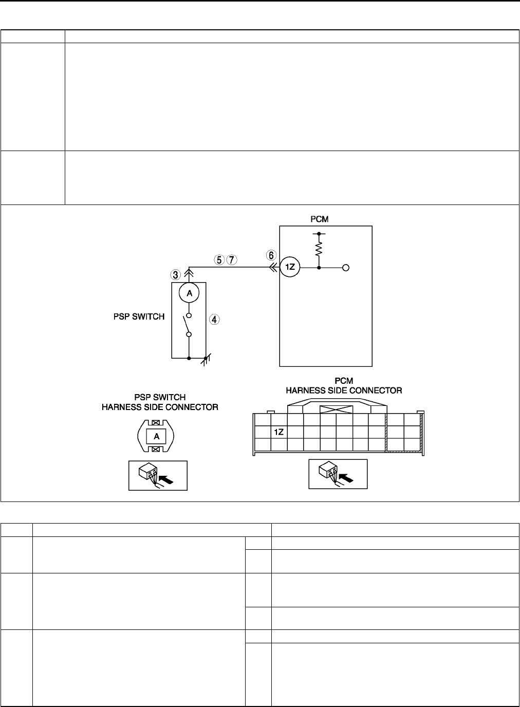
F150
ON-BOARD DIAGNOSTIC
DTC P0550 A6E397001087W06
Diagnostic procedure
DTC P0550 PSP switch circuit malfunction
DETECTION
CONDITION
•PCM monitors PSP switch signal at PCM terminal 1Z. If input voltage is low (switch stays on) for 1 minute
when VSS is above 60 km/h {37.3 mph} and ECT is above 60 °
°°
°C {140 °
°°
°F}, PCM determines that PSP
switch circuit has malfunction.
Diagnostic support note
•This is a continuous monitor (CCM).
•MIL illuminates if PCM detects the above malfunction conditions in two consecutive drive cycles or in one
drive cycle while the DTC for the same malfunction has been stored in the PCM.
•PENDING CODE is available if PCM detects the above malfunction condition during first drive cycle.
•FREEZE FRAME DATA is available.
•DTC is stored in PCM memory.
POSSIBLE
CAUSE
•PSP switch malfunction
•Connector or terminal malfunction
•Short to ground in wiring between PSP switch terminal and PCM terminal 1Z
•Open circuit in wiring between PSP switch terminal and PCM terminal 1Z
•PCM malfunction
STEP INSPECTION ACTION
1VERIFY FREEZE FRAME DATA HAS BEEN
RECORDED
•Has FREEZE FRAME DATA been recorded?
Yes Go to next step.
No Record FREEZE FRAME DATA on repair order, then go to
next step.
2VERIFY RELATED SERVICE INFORMATION
AVAILABILITY
•Check for related Service Information
availability.
•Is any related Service Information available?
Yes Perform repair or diagnosis according to available Service
Information.
•If vehicle is not repaired, go to next step.
No Go to next step.
3INSPECT POOR CONNECTION OF PSP
CONNECTOR
•Turn ignition key to OFF.
•Disconnect PSP connector.
•Inspect for poor connection (damaged, pulled-
out terminals, corrosion, etc.).
•Are there any malfunctions?
Yes Repair or replace terminal, then go to Step 8.
No Go to next step.

ON-BOARD DIAGNOSTIC
F151
F
End Of Sie
4INSPECT PSP SWITCH
•Perform PSP switch inspection.
(See F58 POWER STEERING PRESSURE
(PSP) SWITCH INSPECTION.)
•Is PSP switch okay?
Yes Go to next step.
No Replace PSP switch, then go to Step 8.
5INSPECT PSP SWITCH SIGNAL CIRCUIT FOR
SHORT TO GROUND
•Disconnect PCM connector.
•Inspect continuity between PSP switch
terminal (harness-side) and body ground.
•Is there any continuity?
Yes Repair or replace harness for short to ground, then go to
Step 8.
No Go to next step.
6INSPECT POOR CONNECTION OF PCM
CONNECTOR
•Turn ignition key to OFF
•Disconnect PCM connector.
•Inspect for poor connection (damaged, pulled-
out terminals, corrosion, etc.).
•Are there any malfunctions?
Yes Repair terminal, then go to Step 8.
No Go to next step.
7INSPECT SIGNAL CIRCUIT MALFUNCTION
FOR OPEN CIRCUIT
•Inspect continuity between PSP terminal A
(harness-side) and PCM terminal 1Z.
•Is there any continuity?
Yes Repair or replace harness, then go to next step.
No Go to next step.
8VERIFY TROUBLESHOOTING OF DTC P0550
COMPLETED
•Make sure to reconnect all disconnected
connectors.
•Start engine.
•Clear DTC from PCM memory using WDS or
equivalent.
•Drive vehicle above 60 km/h {37.3 mph} for 1
min.
•Verify that ECT PID above 60 °
°°
°C {140 °
°°
°F}
using WDS or equivalent.
•Is PENDING CODE the same as DTC
present?
Yes Replace PCM, then go to next step.
(See F43 PCM REMOVAL/INSTALLATION.)
No Go to next step.
9VERIFY AFTER REPAIR PROCEDURE
•Perform After Repair Procedure.
(See F66 AFTER REPAIR PROCEDURE.)
•Is there any DTC present?
Yes Go to applicable DTC troubleshooting.
(See F67 DTC TABLE.)
No Troubleshooting completed.
STEP INSPECTION ACTION

F152
ON-BOARD DIAGNOSTIC
DTC P0602 A6E397001088W01
Diagnostic procedure
End Of Sie
DTC P0610 A6E397001088W02
Diagnostic procedure
DTC P0602 PCM programming error
DETECTION
CONDITION
•No configuration data in PCM
Note
•If PCM CONFIGURATION is successful, the PCM stored DTC P0602 and illuminates the MIL
(System i s normal) Clear the DTC P0602 using WDS or equivalent after PCM CONFIGURATION.
•MIL goes off after three drive cycles with no failure (DTCs remain in PCM).
POSSIBLE
CAUSE
•Complete configuration has not been completed.
•PCM malfunction
STEP INSPECTION ACTION
1PERFORM DTC CONFIRMATION PROCEDURE
•Perform DTC CONFIRMATION PROCEDURE.
(See F66 DTC CONFIRMATION
PROCEDURE.)
•Is same DTC present?
Yes Perform PCM configuration procedure, then go to next
step.
(See F50 PCM CONFIGURATION.)
No Intermittent concern exists. Go to INTERMITTENT
CONCERN TROUBLESHOOTING procedure.
(See F227 INTERMITTENT CONCERN
TROUBLESHOOTING.)
2VERIFY TROUBLESHOOTING OF DTC P0602
COMPLETED
•Make sure to reconnect all disconnected
connectors.
•Turn ignition key to ON (Engine OFF).
•Clear DTC from PCM memory using WDS or
equivalent.
•Perform KOEO/KOER self-test.
(See F66 KOEO/KOER SELF-TEST.)
•Is same DTC present?
Yes Replace PCM, then go to next step.
(See F43 PCM REMOVAL/INSTALLATION.)
No Go to next step.
3VERIFY AFTER REPAIR PROCEDURE
•Perform After Repair Procedure.
(See F66 AFTER REPAIR PROCEDURE.)
•Is there any DTC present?
Yes Go to applicable DTC troubleshooting.
(See F67 DTC TABLE.)
No Troubleshooting completed.
DTC P0610 Control module vehicle options error
DETECTION
CONDITION •PCM data configuration error
POSSIBLE
CAUSE
•Configuration procedure has not been completed
•PCM malfunction
STEP INSPECTION ACTION
1PERFORM DTC CONFIRMATION PROCEDURE
•Perform DTC CONFIRMATION PROCEDURE.
(See F66 DTC CONFIRMATION
PROCEDURE.)
•Is same DTC present?
Yes Perform PCM configuration procedure, then go to next
step.
(See F50 PCM CONFIGURATION.)
No Intermittent concern exists. Go to INTERMITTENT
CONCERN TROUBLESHOOTING procedure.
(See F227 INTERMITTENT CONCERN
TROUBLESHOOTING.)
2VERIFY TROUBLESHOOTING OF DTC P0610
COMPLETED
•Make sure to reconnect all disconnected
connectors.
•Turn ignition key to ON (Engine OFF).
•Clear DTC from PCM memory using WDS or
equivalent.
•Perform KOEO/KOER self-test.
(See F66 KOEO/KOER SELF-TEST.)
•Is same DTC present?
Yes Replace PCM, then go to next step.
(See F43 PCM REMOVAL/INSTALLATION.)
No Go to next step.
3VERIFY AFTER REPAIR PROCEDURE
•Perform After Repair Procedure.
(See F66 AFTER REPAIR PROCEDURE.)
•Is there any DTC present?
Yes Go to applicable DTC troubleshooting.
(See F67 DTC TABLE.)
No Troubleshooting completed.
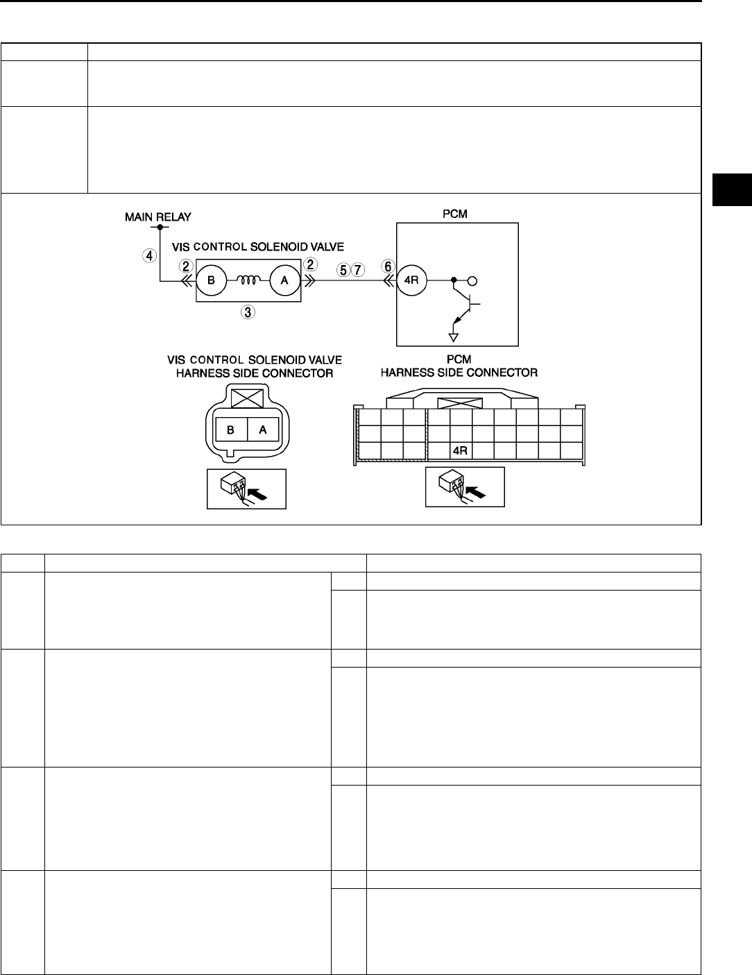
ON-BOARD DIAGNOSTIC
F153
F
End Of Sie
DTC P0661 A6E397001088W03
Diagnostic procedure
DTC P0661 Variable intake-air system (VIS) contol solenoid valve circuit low input
DETECTION
CONDITION
•PCM monitors VIS control solenoid valve control signal at PCM terminal 4R. If PCM turns VIS control
solenoid valve off but voltage at PCM terminal 4R still remains low, PCM determines that VIS control
solenoid valve circuit has malfunction.
POSSIBLE
CAUSE
•VIS control solenoid valve malfunction
•Open circuit in wiring between main relay and VIS control solenoid valve terminal B
•Open circuit in wiring between VIS control solenoid valve terminal A and PCM terminal 4R
•Short to ground in wiring between VIS control solenoid valve terminal A and PCM terminal 4R
•Connector or terminal malfunction
•PCM malfunction
STEP INSPECTION ACTION
1PERFORM DTC CONFIRMATION PROCEDURE
•Perform DTC CONFIRMATION PROCEDURE.
(See F66 DTC CONFIRMATION
PROCEDURE.)
•Is same DTC present?
Yes Go to next step.
No Intermittent concern exists. Go to INTERMITTENT
CONCERN TROUBLESHOOTING procedure.
(See F227 INTERMITTENT CONCERN
TROUBLESHOOTING.)
2INSPECT VIS CONTROL SOLENOID VALVE
CONNECTOR FOR POOR CONNECTION
•Turn ignition key to OFF.
•Disconnect VIS control solenoid valve
connector.
•Inspect for poor connection (damaged/pulled-
out pins, corrosion, etc.).
•Is there malfunction?
Yes Repair or replace terminal, then go to Step 8.
No Go to next step.
3INSPECT VIS CONTROL SOLENOID VALVE
MALFUNCTION
•Perform VIS control solenoid valve inspection.
(See F14 VARIABLE INTAKE-AIR SYSTEM
(VIS) CONTROL SOLENOID VALVE
INSPECTION (L3).)
•Is VIS solenoid valve okay?
Yes Go to next step.
No Replace VIS control solenoid valve, then go to step 8.
4INSPECT VIS CONTROL SOLENOID VALVE
POWER SUPPLY CIRCUIT FOR OPEN CIRCUIT
•Turn ignition key to ON (Engine OFF).
•Measure voltage between VIS control solenoid
valve terminal B (harness-side) and body
ground.
•Is voltage B+?
Yes Go to next step.
No Repair or replace harness for open, then go to Step 8.
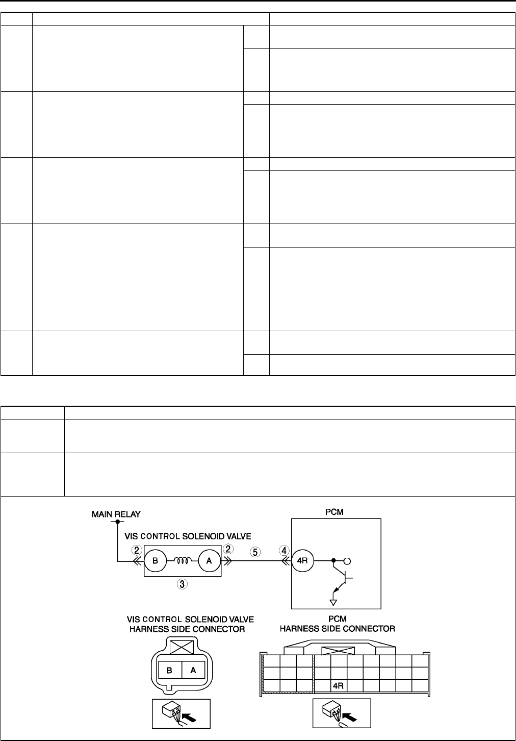
F154
ON-BOARD DIAGNOSTIC
End Of Sie
DTC P0662 A6E397001088W04
5INSPECT VIS CONTROL SOLENOID VALVE
CONTROL CIRCUIT FOR SHORT TO GROUND
•Inspect continuity between VIS control
solenoid valve terminal A (harness-side) and
body ground.
•Is there continuity?
Yes Repair or replace harness for short to ground, then go to
Step 8.
No Go to next step.
6INSPECT PCM CONNECTOR FOR POOR
CONNECTION
•Disconnect PCM connector.
•Inspect for poor connection at terminal 4R.
(damaged/pulled-out pins, corrosion, etc.).
•Is there malfunction?
Yes Repair terminal, then go to Step 8.
No Go to next step.
7INSPECT VIS CONTROL SOLENOID VALVE
CONTROL CIRCUIT FOR OPEN
•Inspect for continuity between VIS control
solenoid valve terminal B (harness-side) and
PCM terminal 4R (harness-side).
•Is there continuity?
Yes Go to next step.
No Repair or replace harness for open, then go to next step.
8VERIFY TROUBLESHOOTING OF DTC P0661
COMPLETED
•Make sure to reconnect all disconnected
connectors.
•Turn ignition key to ON (Engine OFF).
•Clear DTC from PCM memory using WDS or
equivalent.
•Perform KOEO/KOER self-test.
(See F66 KOEO/KOER SELF-TEST.)
•Is same DTC present?
Yes Replace PCM, then go to next step.
(See F43 PCM REMOVAL/INSTALLATION.)
No Go to next step.
9VERIFY AFTER REPAIR PROCEDURE
•Perform After Repair Procedure.
(See F66 AFTER REPAIR PROCEDURE.)
•Is there any DTC present?
Yes Go to applicable DTC troubleshooting.
(See F67 DTC TABLE.)
No Troubleshooting completed.
STEP INSPECTION ACTION
DTC P0662 Variable intake-air system (VIS) control solenoid valve circuit high input
DETECTION
CONDITION
•PCM monitors VIS control solenoid valve control signal at PCM terminal 4R. If PCM turns VIS control
solenoid valve on but voltage at PCM terminal 4R still remains high, PCM determines that VIS control
solenoid valve circuit has malfunction.
POSSIBLE
CAUSE
•VIS control solenoid valve malfunction
•Short to power circuit between VIS control solenoid valve terminal B and PCM terminal 4R
•Shorted VIS control solenoid valve or PCM connector
•PCM malfunction

ON-BOARD DIAGNOSTIC
F155
F
Diagnostic procedure
End Of Sie
STEP INSPECTION ACTION
1PERFORM DTC CONFIRMATION PROCEDURE
•Perform DTC CONFIRMATION PROCEDURE.
(See F66 DTC CONFIRMATION
PROCEDURE.)
•Is same DTC present?
Yes Go to next step.
No Intermittent concern exists. Go to INTERMITTENT
CONCERN TROUBLESHOOTING procedure.
(See F227 INTERMITTENT CONCERN
TROUBLESHOOTING.)
2INSPECT VIS CONTROL SOLENOID VALVE
CONNECTOR FOR POOR CONNECTION
•Turn ignition key to OFF.
•Disconnect VIS control solenoid valve
connector.
•Inspect for poor connection (damaged/pulled-
out pins, corrosion, etc.).
•Is there malfunction?
Yes Repair or replace terminal, then go to Step 6.
No Go to next step.
3INSPECT VIS CONTROL SOLENOID VALVE
MALFUNCTION
•Perform VIS control solenoid valve inspection.
(See F14 VARIABLE INTAKE-AIR SYSTEM
(VIS) CONTROL SOLENOID VALVE
INSPECTION (L3))
•Is VIS solenoid valve okay?
Yes Go to next step.
No Replace VIS control solenoid valve, then go to Step 6.
4INSPECT PCM CONNECTOR FOR POOR
CONNECTION
•Turn ignition key to OFF.
•Disconnect PCM connector.
•Inspect for poor connection at terminal 4R.
(damaged/pulled-out pins, corrosion, etc.).
•Is there malfunction?
Yes Repair terminal, then go to Step 6.
No Go to next step.
5INSPECT VIS CONTROL SOLENOID VALVE
CONTROL CIRCUIT SHORT TO POWER
•Turn ignition key to ON (Engine OFF).
•Measure voltage between VIS control solenoid
valve terminal B (harness-side) and body
ground.
•Is voltage B+?
Yes Repair or replace harness for open, then go to next step.
No Go to next step.
6VERIFY TROUBLESHOOTING OF DTC P0662
COMPLETED
•Make sure to reconnect all disconnected
connectors.
•Turn ignition key to ON (Engine OFF).
•Clear DTC from PCM memory using WDS or
equivalent.
•Perform KOEO/KOER self-test.
(See F66 KOEO/KOER SELF-TEST.)
•Is same DTC present?
Yes Replace PCM, then go to next step.
(See F43 PCM REMOVAL/INSTALLATION.)
No Go to next step.
7VERIFY AFTER REPAIR PROCEDURE
•Perform After Repair Procedure.
(See F66 AFTER REPAIR PROCEDURE.)
•Is there any DTC present?
Yes Go to applicable DTC troubleshooting.
(See F67 DTC TABLE.)
No Troubleshooting completed.
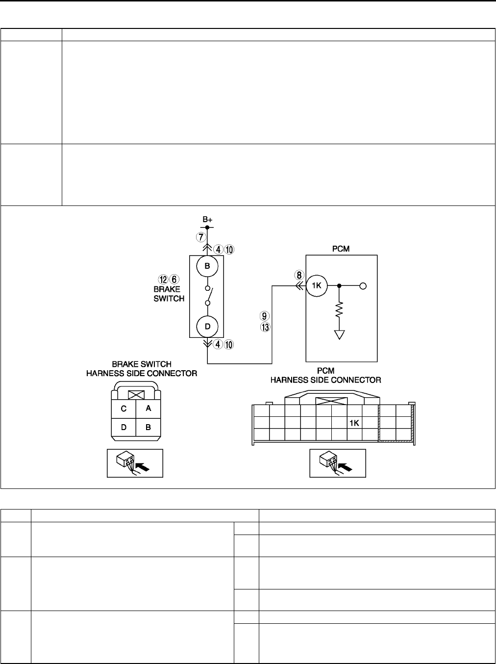
F156
ON-BOARD DIAGNOSTIC
DTC P0703 A6E397001089W01
Diagnostic procedure
DTC P0703 Brake switch input malfunction
DETECTION
CONDITION
•PCM monitors changes in input voltage from brake switch. If PCM does not detect PCM terminal 1K
voltage changes while alternately accelerating and decelerating 8 times, PCM determines that neutral
switch circuit has malfunction.
Diagnostic support note
•This is a continuous monitor (CCM).
•MIL illuminates if PCM detects the above malfunction condition in two consecutive drive cycles or in one
drive cycle while the DTC for the same malfunction has been stored in the PCM.
•PENDING CODE is available if PCM detects the above malfunction condition during first drive cycle.
•FREEZE FRAME DATA is available.
•DTC is stored in PCM memory.
POSSIBLE
CAUSE
•Brake switch malfunction
•Poor connection of brake switch connector or PCM connector.
•Short to power between brake switch terminal D and PCM connector terminal 1K.
•Open harness between brake switch terminal D and PCM connector terminal 1K.
•Open harness between battery positive terminal and brake switch terminal B.
•PCM malfunction
STEP INSPECTION ACTION
1VERIFY FREEZE FRAME DATA HAS BEEN
RECORDED
•Has FREEZE FRAME DATA been recorded?
Yes Go to next step.
No Record FREEZE FRAME DATA on repair order, then go to
next step.
2VERIFY RELATED SERVICE INFORMATION
AVAILABILITY
•Check for related Service Information
availability.
•Is any related Service Information available?
Yes Perform repair or diagnosis according to available Service
Information.
•If vehicle is not repaired, go to next step.
No Go to next step.
3CLASSIFY HIGH INPUT OR LOW INPUT
•Connect WDS or equivalent to DLC-2.
•Access BOO PID.
•Verify BOO PID during brake pedal operation.
•Is BOO PID always OFF?
Yes Go to Next step.
No Go to Step 10.

ON-BOARD DIAGNOSTIC
F157
F
4INSPECT BRAKE SWITCH CONNECTOR FOR
POOR CONNECTION
•Turn ignition switch to OFF.
•Disconnect brake switch connector.
•Inspect for poor connection (damaged/pulled-
out terminals, corrosion, etc.).
•Is there malfunction?
Yes Repair or replace terminal, then go to Step 14.
No Go to next step.
5CLASSIFY BRAKE SWITCH OR CIRCUIT
•Connect WDS or equivalent to DLC-2.
•Access BOO PID.
•Connect a jumper wire between brake switch
terminal A and B.
•Is BOO PID on?
Yes Go to next step.
No Go to Step 7.
6INSPECT BRAKE SWITCH
•Perform brake switch inspection.
(See P8 BRAKE SWITCH INSPECTION.)
•Is brake switch okay?
Yes Go to Step 14.
No Replace brake switch, then go to Step 14.
7INSPECT BRAKE SWITCH POWER CIRCUIT
FOR OPEN CIRCUIT
•Measure voltage between brake switch
connector terminal B and body ground.
•Is voltage B+?
Yes Go to next step.
No Repair or replace brake switch power circuit for open, then
Go to Step 14.
8INSPECT PCM CONNECTOR FOR POOR
CONNECTION
•Turn ignition switch to OFF.
•Disconnect PCM connector.
•Inspect for poor connection (damaged/pulled-
out terminals, corrosion, etc.).
•Is there malfunction?
Yes Repair or replace terminal, then go to Step 14.
No Go to next step.
9INSPECT BRAKE SWITCH SIGNAL CIRCUIT
FOR OPEN CIRCUIT
•Inspect continuity between brake switch
terminal D and PCM terminal 1K.
•Is there any continuity?
Yes Repair or replace harness for open, then go to Step 14.
No Go to Step 14.
10 INSPECT BRAKE SWITCH CONNECTOR FOR
POOR CONNECTION
•Turn ignition switch to OFF.
•Disconnect brake switch connector.
•Inspect for poor connection (damaged/pulled-
out terminals, corrosion, etc.).
•Is there malfunction?
Yes Repair or replace terminal, then go to Step 14.
No Go to next step.
11 CLASSIFY BRAKE SWITCH OR CIRCUIT
•Connect WDS or equivalent to DLC-2.
•Access BOO PID.
•Verify that BOO PID changes from ON to OFF
when brake switch connector disconnected.
•Does BOO PID change from ON to OFF?
Yes Go to next step.
No Go to Step 13.
12 INSPECT BRAKE SWITCH
•Perform brake switch inspection.
(See P8 BRAKE SWITCH INSPECTION.)
•Is brake switch okay?
Yes Go to Step 14.
No Replace brake switch, then go to Step 14.
13 INSPECT BRAKE SWITCH SIGNAL CIRCUIT
FOR SHORT TO POWER
•Measure voltage between brake switch
connector terminal D and body ground.
•Is voltage B+?
Yes Repair or replace harness for short to power, then go to
Step 14.
No Go to next step.
STEP INSPECTION ACTION
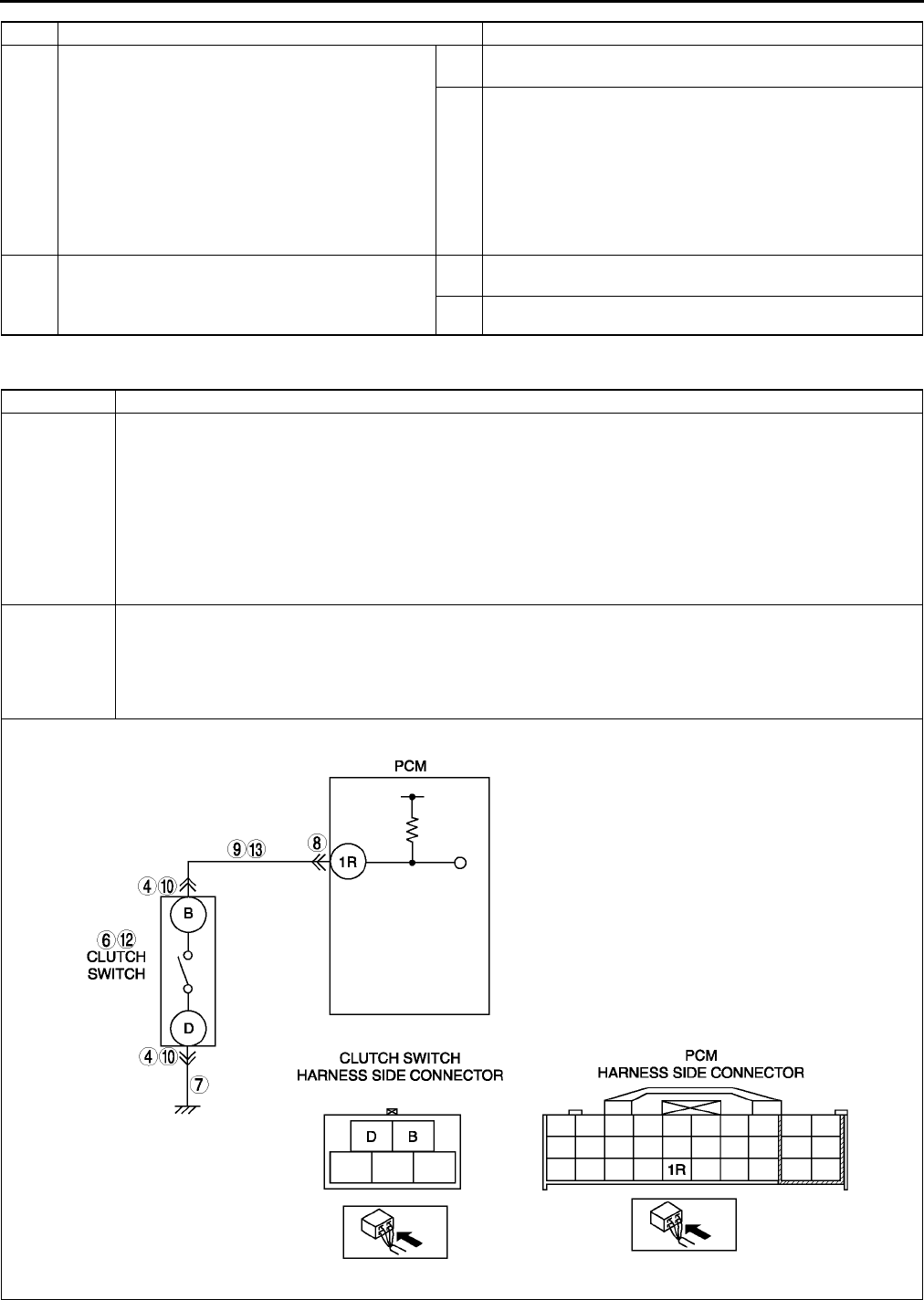
F158
ON-BOARD DIAGNOSTIC
End Of Sie
DTC P0704 A6E397001089W02
14 VERIFY TROUBLESHOOTING OF DTC P0703
COMPLETED
•Make sure to reconnect all disconnected
connectors.
•Clear DTC from memory using WDS or
equivalent.
•Drive vehicle 30 km/h {18.6 mph} or more.
•Depress and release brake pedal more than 8
times while driving vehicle.
•Is PENDING CODE the same as DTC
present?
Yes Replace PCM, then go to next step.
(See F43 PCM REMOVAL/INSTALLATION.)
No Go to next step.
15 VERIFY AFTER REPAIR PROCEDURE
•Perform After Repair Procedure.
(See F66 AFTER REPAIR PROCEDURE.)
•Is there any DTC present?
Yes Go to applicable DTC troubleshooting.
(See F67 DTC TABLE.)
No Troubleshooting completed.
STEP INSPECTION ACTION
DTC P0704 Clutch switch circuit malfunction
DETECTION
CONDITION
•PCM monitors changes in input voltage from clutch switch. If PCM does not detect PCM terminal 1R
voltage changes while running vehicle with vehicle speed below 30 km/h {19mph} 8 times alternately,
PCM determines that clutch switch circuit has malfunction.
Diagnostic support note
•This is a continuous monitor (CCM).
•MIL illuminates if PCM detects the above malfunction condition in two consecutive drive cycles or in one
drive cycle while the DTC for the same malfunction has been stored in the PCM.
•PENDING CODE is available if PCM detects the above malfunction condition during first drive cycle.
•FREEZE FRAME DATA is available.
•DTC is stored in PCM memory.
POSSIBLE
CAUSE
•Clutch switch malfunction
•Poor connection of clutch switch connector or PCM connector.
•Short to ground between clutch switch terminal B and PCM connector terminal 1R.
•Open harness between clutch switch terminal B and PCM connector terminal 1R.
•Open harness between ground and clutch switch terminal D.
•PCM malfunction

ON-BOARD DIAGNOSTIC
F159
F
Diagnostic procedure
STEP INSPECTION ACTION
1VERIFY FREEZE FRAME DATA HAS BEEN
RECORDED
•Has FREEZE FRAME DATA been recorded?
Yes Go to next step.
No Record FREEZE FRAME DATA on repair order, then go to
next step.
2VERIFY RELATED REPAIR INFORMATION
AVAILABILITY
•Check for related Service information
availability.
•Is any related Service information available?
Yes Perform repair or diagnosis according to available Service
information.
•If vehicle is not repaired, go to next step.
No Go to next step.
3CLASSIFY HIGH INPUT OR LOW INPUT
•Connect WDS or equivalent to DLC-2.
•Access CPP PID.
•Verify CPP PID during clutch pedal operation.
•Is CPP PID always OFF?.
Yes Go to Next step.
No Go to Step 10.
4INSPECT CLUTCH SWITCH CONNECTOR FOR
POOR CONNECTION
•Turn ignition switch to OFF.
•Disconnect clutch switch connector.
•Inspect for poor connection (damaged/pulled-
out terminals, corrosion, etc.).
•Is there malfunction?
Yes Repair or replace terminal, then go to Step 14.
No Go to next step.
5CLASSIFY CLUTCH SWITCH OR CIRCUIT
•Connect WDS or equivalent to DLC-2.
•Access CPP PID.
•Connect a jumper wire between clutch switch
terminal B and D.
•Is CPP PID on?
Yes Go to next step.
No Go to Step 7.
6INSPECT CLUTCH SWITCH
•Perform clutch switch inspection.
(See F59 CLUTCH SWITCH INSPECTION.)
•Is clutch switch okay?
Yes Go to Step 14.
No Replace clutch switch, then go to Step 14.
7INSPECT CLUTCH SWITCH GROUND CIRCUIT
FOR OPEN CIRCUIT
•Inspect continuity between clutch switch
terminal D and ground.
•Is there any continuity?
Yes Go to next step.
No Repair or replace clutch switch power circuit for open, then
Go to Step 14.
8INSPECT PCM CONNECTOR FOR POOR
CONNECTION
•Turn ignition switch to OFF.
•Disconnect PCM connector.
•Inspect for poor connection (damaged/pulled-
out terminals, corrosion, etc.).
•Is there malfunction?
Yes Repair or replace terminal, then go to Step 14.
No Go to next step.
9INSPECT CLUTCH SWITCH SIGNAL CIRCUIT
FOR OPEN CIRCUIT
•Inspect continuity between clutch switch
terminal B and PCM terminal 1R.
•Is there any continuity?
Yes Repair or replace harness for open, then go to Step 14.
No Go to Step 14.
10 INSPECT CLUTCH SWITCH CONNECTOR FOR
POOR CONNECTION
•Turn ignition switch to OFF.
•Disconnect clutch switch connector.
•Inspect for poor connection (damaged/pulled-
out terminals, corrosion, etc.).
•Is there malfunction?
Yes Repair or replace terminal, then go to Step 14.
No Go to next step.
11 CLASSIFY CLUTCH SWITCH OR CIRCUIT
•Connect WDS or equivalent to DLC-2.
•Access CPP PID.
•Verify that CPP PID changes from ON to OFF
when clutch switch connector disconnected.
•Does CPP PID change from ON to OFF?
Yes Go to next step.
No Go to Step 13.
12 INSPECT CLUTCH SWITCH
•Perform clutch switch inspection.
(See F59 CLUTCH SWITCH INSPECTION.)
•Is clutch switch okay?
Yes Go to Step 14.
No Replace clutch switch, then go to Step 14.

F160
ON-BOARD DIAGNOSTIC
End Of Sie
DTC P0850 A6E397001089W03
13 INSPECT CLUTCH SWITCH SIGNAL CIRCUIT
FOR SHORT TO GROUND
•Inspect continuity between clutch switch
terminal B and ground.
•Is there any continuity?
Yes Repair or replace harness for short to ground, then go to
Step 14.
No Go to Next step.
14 VERIFY TROUBLESHOOTING OF DTC P0704
COMPLETED
•Make sure to reconnect all disconnected
connectors.
•Start engine.
•Clear DTC from PCM memory using WDS or
equivalent.
•Operate clurch pedal during drive vehicle
below 30 km/h {19 mph} 8 times altemetely.
•Is same DTC present?
Yes Replace PCM, then go to next step.
(See F43 PCM REMOVAL/INSTALLATION.)
No Go to next step.
15 VERIFY AFTER REPAIR PROCEDURE
•Perform After Repair Procedure.
(See F66 AFTER REPAIR PROCEDURE.)
•Is there any DTC present?
Yes Go to applicable DTC troubleshooting.
(See F67 DTC TABLE.)
No Troubleshooting completed.
STEP INSPECTION ACTION
DTC P0850 Neutral switch circuit malfunction
DETECTION
CONDITION
•PCM monitors changes in input voltage from neutral switch. If PCM does not detect PCM terminal 1W
voltage changes while running vehicle with vehicle speed above 30 km/h {19 mph} and clutch pedal turns
press and depress 10 times repeatedly, PCM determines that neutral switch circuit has malfunction
Diagnostic support note
•This is a continuous monitor (CCM).
•MIL illuminates if PCM detects the above malfunction condition in two consecutive drive cycles or in one
drive cycle while the DTC for the same malfunction has been stored in the PCM.
•PENDING CODE is available if PCM detects the above malfunction condition during first drive cycle.
•FREEZE FRAME DATA is available.
•DTC is stored in PCM memory.
POSSIBLE
CAUSE
•Neutral switch malfunction
•Poor connection of neutral switch connector or PCM connector.
•Short to ground between neutral switch terminal B and PCM connector terminal 1W.
•Open harness between neutral switch terminal B and PCM connector terminal 1W.
•Open harness between ground and brake switch terminal A.
•PCM malfunction
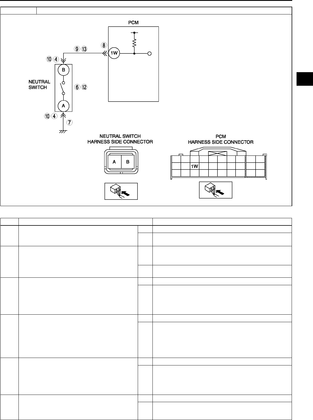
ON-BOARD DIAGNOSTIC
F161
F
Diagnostic procedure
STEP INSPECTION ACTION
1VERIFY FREEZE FRAME DATA HAS BEEN
RECORDED
•Has FREEZE FRAME DATA been recorded?
Yes Go to next step.
No Record FREEZE FRAME DATA on repair order, then go to
next step.
2VERIFY RELATED SERVICE INFORMATION
AVAILABILITY
•Check for related Service Information
availability.
•Is any related Service Information available?
Yes Perform repair or diagnosis according to available Service
Information.
•If vehicle is not repaired, go to next step.
No Go to next step.
3CLASSIFY HIGH INPUT OR LOW INPUT
•Connect WDS or equivalent to DLC-2.
•Access CPP/PNP PID.
•Verify CPP/PNP PID when gear is neutral
position.
•Is CPP/PNP PID always OFF?.
Yes Go to Next step.
No Go to Step 10.
4INSPECT NEUTRAL SWITCH CONNECTOR
FOR POOR CONNECTION
•Turn ignition switch to OFF.
•Disconnect neutral switch connector.
•Inspect for poor connection (damaged/pulled-
out terminals, corrosion, etc.).
•Is there malfunction?
Yes Repair or replace terminal, then go to Step 14.
No Go to next step.
5CLASSIFY NEUTRAL SWITCH OR CIRCUIT
•Connect WDS or equivalent to DLC-2.
•Access CPP/PNP PID.
•Connect a jumper wire between neutral switch
terminal A and B.
•Is CPP/PNP PID on?
Yes Go to next step.
No Go to Step 7.
6INSPECT NEUTRAL SWITCH
•Perform neutral switch inspection.
(See F59 NEUTRAL SWITCH INSPECTION.)
•Is neutral switch okay?
Yes Go to Step 14.
No Replace neutral switch, then go to Step 14.
DTC P0850 Neutral switch circuit malfunction

F162
ON-BOARD DIAGNOSTIC
End Of Sie
DTC P1410 A6E397001083W01
7INSPECT NEUTRAL SWITCH GROUND
CIRCUIT FOR OPEN CIRCUIT
•Inspect continuity between neutral switch
terminal A and ground.
•Is there any continuity?
Yes Go to next step.
No Repair or replace neutral switch power circuit for open, then
Go to Step 14.
8INSPECT PCM CONNECTOR FOR POOR
CONNECTION
•Turn ignition switch to OFF.
•Disconnect PCM connector.
•Inspect for poor connection (damaged/pulled-
out terminals, corrosion, etc.).
•Is there malfunction?
Yes Repair or replace terminal, then go to Step 14.
No Go to next step.
9INSPECT NEUTRAL SWITCH SIGNAL CIRCUIT
FOR OPEN CIRCUIT
•Inspect continuity between neutral switch
terminal B and PCM terminal 1W.
•Is there any continuity?
Yes Repair or replace harness for open, then go to Step 14.
No Go to Step 14.
10 INSPECT NEUTRAL SWITCH CONNECTOR
FOR POOR CONNECTION
•Turn ignition switch to OFF.
•Disconnect neutral switch connector.
•Inspect for poor connection (damaged/pulled-
out terminals, corrosion, etc.).
•Is there malfunction?
Yes Repair or replace terminal, then go to Step 14.
No Go to next step.
11 CLASSIFY NEUTRAL SWITCH OR CIRCUIT
•Connect WDS or equivalent to DLC-2.
•Access CPP/PNP PID.
•Verify that CPP/PNP PID changes from ON to
OFF when neutral switch connector
disconnected.
•Does CPP/PNP PID change from ON to OFF?
Yes Go to next step.
No Go to Step 13.
12 INSPECT NEUTRAL SWITCH
•Perform neutral switch inspection.
(See F59 NEUTRAL SWITCH INSPECTION.)
•Is neutral switch okay?
Yes Go to Step 14.
No Replace neutral switch, then go to Step 14.
13 INSPECT NEUTRAL SWITCH SIGNAL CIRCUIT
FOR SHORT TO GROUND
•Inspect continuity between neutral switch
terminal B and ground.
•Is there any continuity?
Yes Repair or replace harness for short to ground, then go to
Step 14.
No Go to Next step.
14 VERIFY TROUBLESHOOTING OF DTC P0850
COMPLETED
•Make sure to reconnect all disconnected
connectors.
•Start engine.
•Clear DTC from PCM memory using WDS or
equivalent.
•Drive vehicle above 30 km/h {19 mph} and
stop vehicle.
•Depress and release clutch pedal more than
10 times during drive cycle.
•Is same DTC present?
Yes Replace PCM, then go to next step.
(See F43 PCM REMOVAL/INSTALLATION.)
No Go to next step.
15 VERIFY AFTER REPAIR PROCEDURE
•Perform After Repair Procedure.
(See F66 AFTER REPAIR PROCEDURE.)
•Is there any DTC present?
Yes Go to applicable DTC troubleshooting.
(See F67 DTC TABLE.)
No Troubleshooting completed.
STEP INSPECTION ACTION
DTC P1410 Variable air duct (VAD) control system circuit malfunction
DETECTION
CONDITION
•PCM monitors VAD solenoid control signal at PCM terminal 4C. If PCM detects VAD solenoid control
signal does not change when VAD solenoid valve is switched to ON or OFF, PCM determines that VAD
solenoid control circuit has malfunction.
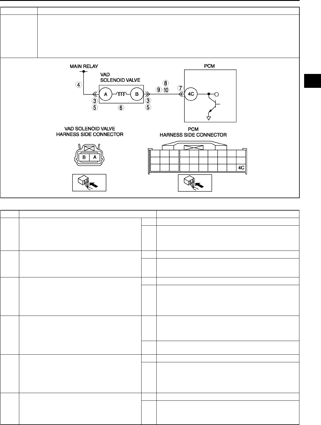
ON-BOARD DIAGNOSTIC
F163
F
Diagnostic procedure
POSSIBLE
CAUSE
•VAD solenoid valve malfunction.
•Connector or terminal malfunction.
•Short to ground in wiring between VAD solenoid valve terminal B and PCM terminal 4C
•Open circuit in wiring between main relay and VAD solenoid valve terminal A
•Open circuit in wiring between VAD solenoid valve terminal B and PCM terminal 4C
•Short to power in wiring between VAD solenoid valve terminal B and PCM terminal 4C
•PCM malfunction
STEP INSPECTION ACTION
1PERFORM DTC CONFIRMATION PROCEDURE
•Perform DTC CONFIRMATION PROCEDURE.
(See F66 DTC CONFIRMATION
PROCEDURE.)
•Is same DTC present?
Yes Go to next step.
No Intermittent concern exists. Go to INTERMITTENT
CONCERN TROUBLESHOOTING procedure.
(See F227 INTERMITTENT CONCERN
TROUBLESHOOTING.)
2CLASSIFY POWER CIRCUIT OR CONTROL
CIRCUIT MALFUNCTION
•Is the same DTC and P0102, P0103, P0403,
P0661, P0662, P2009 or P2010 present?
Yes Malfunction at power circuit, then go to next step
No Malfunction at VAD solenoid valve or control circuit, then go
to Step 5
3INSPECT POOR CONNECTION OF VAD
SOLENOID VALVE CONNECTOR
•Disconnect VAD solenoid valve connector.
•Inspect for poor connection (damaged, pulled-
out terminals, corrosion, etc.).
•Are there any malfunctions?
Yes Repair terminals, then go to Step 11.
No Go to next step.
4INSPECT VAD SOLENOID VALVE POWER
CIRCUIT FOR OPEN CIRCUIT
•Turn ignition switch to ON (Engine OFF).
•Measure voltage between VAD solenoid valve
connector terminal A and body ground.
•Is voltage B+?
Yes Inspect VAD solenoid valve.
•If there is a malfunction, replace VAD solenoid valve,
then go to Step 11
•If there is no malfunction, go to Step 12
No Repair or replace VAD solenoid valve power circuit for
open, then Go to Step 11.
5INSPECT POOR CONNECTION OF VAD
SOLENOID VALVE CONNECTOR
•Disconnect connector.
•Inspect for poor connection (damaged, pulled-
out terminals, corrosion, etc.).
•Are there any malfunctions?
Yes Repair or replace terminals, then go to Step 11.
No Go to next step.
6INSPECT VAD SOLENOID VALVE
•Perform VAD solenoid valve inspection.
(See F12 VARIABLE AIR DUCT (VAD)
SHUTTER VALVE INSPECTION (L3).)
•Is clutch switch okay?
Yes Go to Step 11.
No Replace VAD solenoid valve, then go to Step 11.
DTC P1410 Variable air duct (VAD) control system circuit malfunction

F164
ON-BOARD DIAGNOSTIC
End Of Sie
DTC P1562 A6E397001083W02
7INSPECT POOR CONNECTION OF PCM
CONNECTOR
•Disconnect PCM connector.
•Inspect for poor connection (damaged, pulled-
out terminals, corrosion, etc.).
•Are there any malfunctions?
Yes Repair terminals, then go to Step 11.
No Go to next step.
8INSPECT CONTROL CIRCUIT FOR SHORT TO
GROUND
•Disconnect battery cables.
•Inspect continuity between VAD solenoid valve
terminal B and body ground.
•Is there continuity?
Yes Repair or replace harness for short to ground, then go to
Step 11.
No Go to next Step.
9INSPECT VAD SOLENOID VALVE CONTROL
CIRCUIT FOR SHORT TO POWER
•Measure voltage between brake switch
connector terminal B and body ground.
•Is voltage B+?
Yes Repair or replace harness for short to power, then go to
Step 11.
No Go to next step.
10 INSPECT CONTROL CIRCUIT FOR OPEN
CIRCUIT
•Inspect continuity between VAD solenoid valve
terminal B and PCM terminal 4C.
•Is there any continuity?
Yes Go to next step.
No Repair or replace harness for open, then go to next step.
11 VERIFY TROUBLESHOOTING OF DTC P1410
COMPLETED
•Make sure to reconnect all disconnected
connectors.
•Clear DTC from PCM memory using WDS or
equivalent.
•Perform KOEO/KOER self-test.
(See F66 KOEO/KOER SELF-TEST.)
•Is same DTC present?
Yes Replace PCM, then go to next step.
(See F43 PCM REMOVAL/INSTALLATION.)
No Go to next step.
12 VERIFY AFTER REPAIR PROCEDURE
•Perform After Repair Procedure.
(See F66 AFTER REPAIR PROCEDURE.)
•Is there any DTC present?
Yes Go to applicable DTC troubleshooting.
(See F67 DTC TABLE.)
No Troubleshooting completed.
STEP INSPECTION ACTION
DTC P1562 PCM +BB (back-up battery) voltage low
DETECTION
CONDITION
•PCM monitors voltage of back-up battery positive at PCM terminal 2Z. If PCM detects battery positive
terminal voltage below 2.5V for 2 s, PCM determines that backup voltage circuit has malfunction.
Diagnostic support note
•This is a continuous monitor (CCM).
•MIL illuminates if PCM detects the above malfunction condition during first drive cycle.
•PENDING CODE is available if PCM detects the above malfunction condition.
•FREEZE FRAME DATA is available.
•DTC is stored in the PCM memory.
POSSIBLE
CAUSE
•Melt down EEC fuse.
•Open circuit in wiring between EEC fuse and PCM terminal 2Z
•Short to ground between EEC fuse and PCM terminal 2Z
•Poor connection of PCM connector.
•PCM malfunction
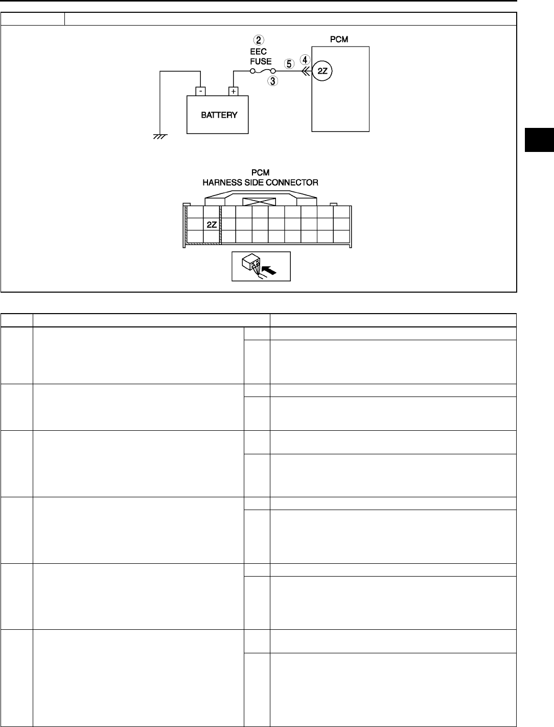
ON-BOARD DIAGNOSTIC
F165
F
Diagnostic procedure
STEP INSPECTION ACTION
1PERFORM DTC CONFIRMATION PROCEDURE
•Perform DTC CONFIRMATION PROCEDURE.
(See F66 DTC CONFIRMATION
PROCEDURE.)
•Is same DTC present?
Yes Go to next step.
No Intermittent concern exists. Go to INTERMITTENT
CONCERN TROUBLESHOOTING procedure.
(See F227 INTERMITTENT CONCERN
TROUBLESHOOTING.)
2INSPECT EEC FUSE
•Turn ignition key to OFF.
•Inspect EEC fuse for failure and proper.
•Is it okay?
Yes Go to step 5.
No •If EEC fuse has been melt down, then go to next step.
•If EEC fuse is not installed correctly, install it correctly
then go to Step 6.
3INSPECT MONITOR CIRCUIT FOR SHORT TO
GROUND
•Disconnect battery cables.
•Inspect continuity between EEC fuse terminal
and body ground.
•Is there continuity?
Yes Repair or replace harness for short to ground and install
new fuse, then go to Step 6.
No Go to step 6.
4INSPECT POOR CONNECTION OF PCM
CONNECTOR
•Disconnect PCM connector.
•Inspect for poor connection (damaged, pulled-
out terminals, corrosion, etc.).
•Are there any malfunctions?
Yes Repair terminals, then go to Step 6.
No Go to next step.
5INSPECT MONITOR CIRCUIT FOR OPEN
CIRCUIT
•Disconnect battery cables.
•Inspect continuity between EEC fuse terminal
and PCM terminal 2Z (harness side).
•Is there any continuity?
Yes Go to next step.
No Repair or replace harness for open, then go to next step.
6VERIFY TROUBLESHOOTING OF DTC P1562
COMPLETED
•Make sure to reconnect all disconnected
connectors.
•Clear DTC from PCM memory using WDS or
equivalent.
•Perform KOEO/KOER self-test.
(See F66 KOEO/KOER SELF-TEST.)
•Is same DTC present?
Yes Replace PCM, then go to next step.
(See F43 PCM REMOVAL/INSTALLATION.)
No Go to next step.
DTC P1562 PCM +BB (back-up battery) voltage low
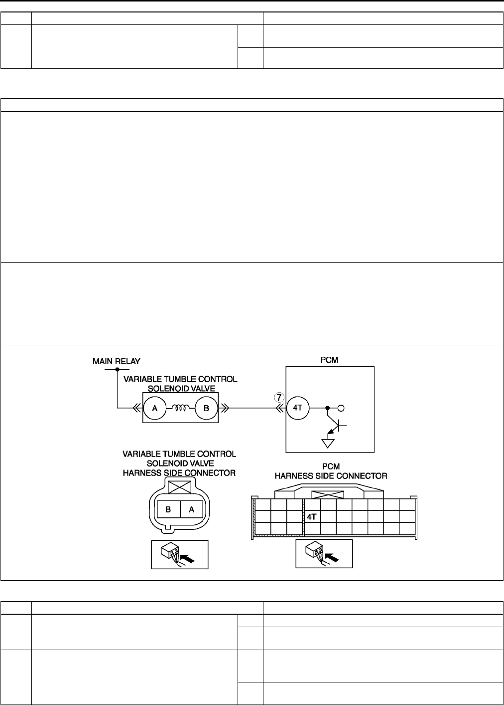
F166
ON-BOARD DIAGNOSTIC
End Of Sie
DTC P2006 A6E397001083W03
Diagnostic procedure
7VERIFY AFTER REPAIR PROCEDURE
•Perform After Repair Procedure.
(See F66 AFTER REPAIR PROCEDURE.)
•Is there any DTC present?
Yes Go to applicable DTC troubleshooting.
(See F67 DTC TABLE.)
No Troubleshooting completed.
STEP INSPECTION ACTION
DTC P2006 Variable tumble control system (VTCS) shutter valve stuck closed
DETECTION
CONDITION
•PCM monitors mass air amount. If actual air flow amount is below estimated air flow amount when the
following monitoring conditions are met. PCM determines that VTCS shutter valve has been stuck closed.
MONITORING CONDITIONS
Engine coolant temperature is above 63 °
°°
°C {145 °
°°
°F}.
Engine speed is below 3,750 rpm.
Throttle valve opening angle is above threshold*.
*: Maximum calculated load valve varies depending on engine speed.
Diagnostic support note
•This is a continuous monitor (CCM).
•MIL illuminates if PCM detects the above malfunction condition in two consecutive drive cycles or in one
drive cycle while the DTC for the same malfunction has been stored in the PCM.
•PENDING CODE is available if PCM detects the above malfunction condition during first drive cycle.
•FREEZE FRAME DATA is available.
•DTC is stored in PCM memory.
POSSIBLE
CAUSE
•ECT sensor malfunction
•TP sensor malfunction
•CKP sensor malfunction
•Variable tumble control solenoid valve malfunction
•VTCS shutter valve malfunction (stuck closed)
•VTCS shutter valve actuator malfunction (stuck closed).
•Short to ground circuit between variable tumble control solenoid valve terminal B and PCM terminal 4T
•PCM malfunction
STEP INSPECTION ACTION
1VERIFY FREEZE FRAME DATA HAS BEEN
RECORDED
•Has FREEZE FRAME DATA been recorded?
Yes Go to next step.
No Record FREEZE FRAME DATA on repair order, then go to
next step.
2VERIFY RELATED SERVICE INFORMATION
AVAILABILITY
•Check for related Service Information
availability.
•Is any related Service Information available?
Yes Perform repair or diagnosis according to available Service
Information.
•If vehicle is not repaired, go to next step.
No Go to next step.

ON-BOARD DIAGNOSTIC
F167
F
End Of Sie
3CLASSIFY INTERMITTENT CONCERN OR
CONTINUOUS CONCERN
•Clear DTC from PCM memory using WDS or
equipment.
•Drive vehicle under following conditions:
Engine coolant temperature is above 63 °
°°
°C
{145 °
°°
°F}.
Engine speed: below 3,750 rpm
Throttle opening angle is below as
followings
•Engine speed below 1,500 rpm: above
35 %
•Engine speed between 1,5002,500
rpm: between 2535%
•Engine speed above 2,500: below 25 %
•Is pending code the same as DTC present?
Yes Go to next step.
No Intermittent concern exists. Go to INTERMITTENT
CONCERN TROUBLESHOOTING procedure.
(See F227 INTERMITTENT CONCERN
TROUBLESHOOTING.)
4VERIFY STORED OTHER DTCS
•Verify stored DTCs using WDS or equipment.
•Is other DTC present except P0117, P0118,
P0121, P0122, P0123 and/or P0335?
Yes Go to appropriate DTC troubleshooting procedures.
No Go to next step.
5INSPECT VTCS SHUTTER VALVE ACTUATOR
•Carry out VTCS operation inspection.
(See F231 Variable Tumble Control System
(VTCS) Operation Inspection.)
•Is VTCS shutter valve actuator okay?
Yes Go to next step.
No Replace VTCS shutter valve actuator, then go to Step 8.
6INSPECT VARIABLE TUMBLE CONTROL
SOLENOID VALVE
•Carry out Variable tumble control solenoid
valve airflow inspection.
(See F15 VARIABLE TUMBLE CONTROL
SOLENOID VALVE INSPECTION.)
•Is variable tumble control solenoid valve okay?
Yes Go to next step.
No Replace variable tumble control solenoid valve, then go to
Step 8.
7INSPECT PCM FOR POOR CONNECTION
•Inspect for poor connection at PCM terminal 4T
(damaged/pulled-out terminals, corrosion,
etc.).
•Is there malfunction?
Yes Repair terminal, then go to next step.
No Go to next step.
8VERIFY TROUBLESHOOTING OF DTC P2006
COMPLETED
•Make sure to reconnect all disconnected
connectors.
•Start engine.
•Clear DTC from PCM memory using WDS or
equipment.
•Start engine.
•Drive vehicle under following conditions:
Engine coolant temperature is above 63 °
°°
°C
{145 °
°°
°F}.
Engine speed: below 3,750 rpm
Throttle opening angle is below as
followings
•Engine speed below 1,500 rpm: above
35 %
•Engine speed between 1,5002,500
rpm: between 2535%
•Engine speed above 2,500: below 25 %
•Is pending code the same as DTC present?
Yes Replace PCM, then go to next step.
(See F43 PCM REMOVAL/INSTALLATION.)
No Go to next step.
9VERIFY AFTER REPAIR PROCEDURE
•Perform After Repair Procedure.
(See F66 AFTER REPAIR PROCEDURE.)
•Is there any DTC present?
Yes Go to applicable DTC troubleshooting.
(See F67 DTC TABLE.)
No Troubleshooting completed.
STEP INSPECTION ACTION
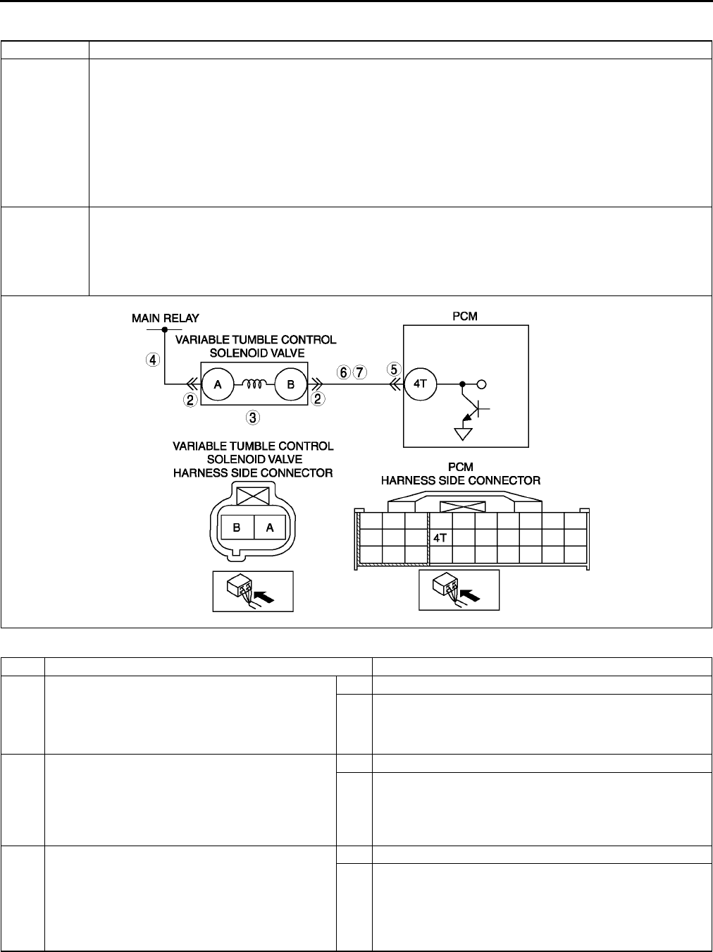
F168
ON-BOARD DIAGNOSTIC
DTC P2009 A6E397001083W04
Diagnostic procedure
DTC P2009 Variable tumble control solenoid valve circuit low input
DETECTION
CONDITION
•PCM monitors variable tumble control solenoid valve control signal at PCM terminal 4T. If PCM turns
variable tumble control solenoid valve off but voltage at PCM terminal 4T still remains low, PCM
determines that VTCS solenoid valve circuit has malfunction.
Diagnostic support note
•This is a continuous monitor (CCM).
•MIL illuminates if PCM detects the above malfunction condition in two consecutive drive cycles or in one
drive cycle while the DTC for the same malfunction has been stored in the PCM.
•PENDING CODE is available if PCM detects the above malfunction condition during first drive cycle.
•FREEZE FRAME DATA is available.
•DTC is stored in PCM memory.
POSSIBLE
CAUSE
•Poor connection of connectors at PCM and/or variable tumble control solenoid valve
•Short to ground in wiring between variable tumble control solenoid valve terminal B and PCM terminal 4T
•Open circuit in wiring between main relay and variable tumble control solenoid valve terminal A
•Open circuit in wiring between variable tumble control solenoid valve terminal B and PCM terminal 4T
•Variable tumble control solenoid valve malfunction
•PCM malfunction
STEP INSPECTION ACTION
1PERFORM DTC CONFIRMATION PROCEDURE
•Perform DTC CONFIRMATION PROCEDURE.
(See F66 DTC CONFIRMATION
PROCEDURE.)
•Is same DTC present?
Yes Go to next step.
No Intermittent concern exists. Go to INTERMITTENT
CONCERN TROUBLESHOOTING procedure.
(See F227 INTERMITTENT CONCERN
TROUBLESHOOTING.)
2INSPECT VTCS SOLENOID VALVE
CONNECTOR FOR POOR CONNECTION
•Turn ignition key to OFF.
•Inspect for poor connection (damaged/pulled-
out pins, corrosion, etc.).
•Is there malfunction?
Yes Repair or replace terminal, then go to Step 8.
No Go to next step.
3INSPECT VARIABLE TUMBLE CONTROL
SOLENOID VALVE
•Perform variable tumble control solenoid valve
inspection.
(See F15 VARIABLE TUMBLE CONTROL
SOLENOID VALVE INSPECTION.)
•Is variable tumble control solenoid valve okay?
Yes Go to next step.
No Replace variable tumble control solenoid valve, then go to
Step 8.

ON-BOARD DIAGNOSTIC
F169
F
End Of Sie
4INSPECT VARIABLE TUMBLE CONTROL
SOLENOID VALVE POWER SUPPLY CIRCUIT
FOR OPEN CIRCUIT
•Disconnect variable tumble control solenoid
valve connector.
•Turn ignition key to ON (Engine OFF).
•Measure voltage between variable tumble
control solenoid valve terminal A (harness-
side) and body ground.
•Is voltage B+?
Yes Go to next step.
No Repair or replace harness for open, then go to Step 8.
5INSPECT PCM CONNECTOR FOR POOR
CONNECTION
•Turn ignition key to OFF.
•Disconnect PCM connector.
•Inspect for poor connection at PCM terminal
4T. (damaged/pulled-out pins, corrosion, etc.).
•Is there malfunction?
Yes Repair terminal, then go to Step 8.
No Go to next step.
6INSPECT VARIABLE TUMBLE CONTROL
SOLENOID VALVE CONTROL CIRCUIT FOR
SHORT TO GROUND
•Inspect continuity between variable tumble
control solenoid valve terminal B (harness-
side) and body ground.
•Is there continuity?
Yes Repair or replace harness for short to ground, then go to
Step 8.
No Go to next step.
7INSPECT VARIABLE TUMBLE CONTROL
SOLENOID VALVE CONTROL CIRCUIT FOR
OPEN CIRCUIT
•Connect variable tumble control solenoid valve
connector.
•Turn ignition key to ON (Engine OFF).
•Measure voltage between PCM terminal 4T
(harness side) and body ground.
•Is voltage B+?
Yes Go to next step.
No Repair or replace harness for open or short to ground
circuit, then go to next step.
8VERIFY TROUBLESHOOTING OF DTC P2009
COMPLETED
•Make sure to reconnect all disconnected
connectors.
•Clear DTC from PCM memory using WDS or
equipment.
•Perform KOEO/KOER self-test.
(See F66 KOEO/KOER SELF-TEST.)
•Is same DTC present?
Yes Replace PCM, then go to next step.
(See F43 PCM REMOVAL/INSTALLATION.)
No Go to next step.
9VERIFY AFTER REPAIR PROCEDURE
•Perform After Repair Procedure.
(See F66 AFTER REPAIR PROCEDURE.)
•Is there any DTC present?
Yes Go to applicable DTC troubleshooting.
(See F67 DTC TABLE.)
No Troubleshooting completed.
STEP INSPECTION ACTION
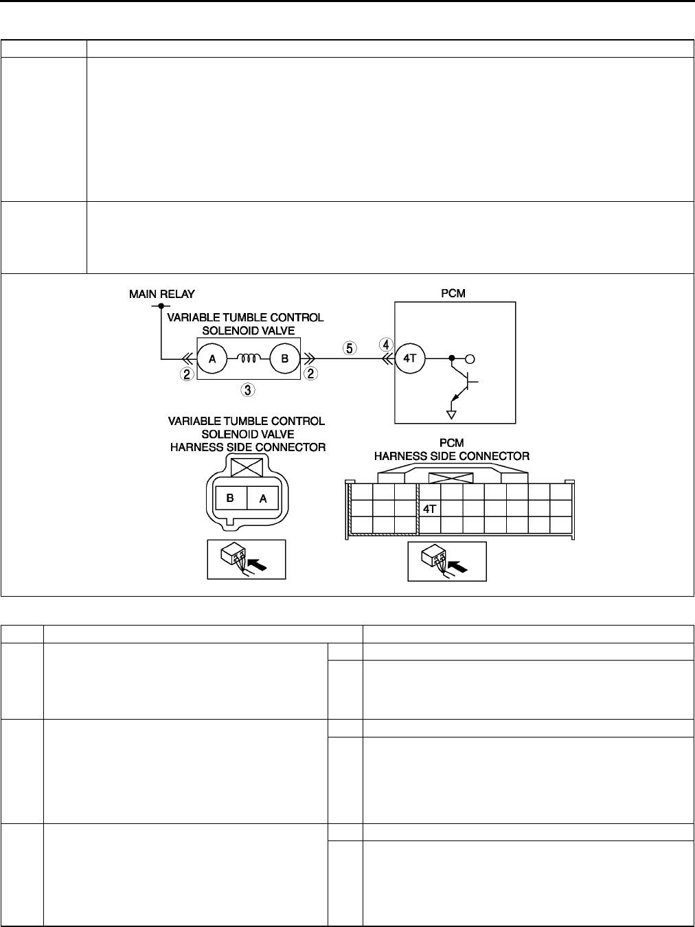
F170
ON-BOARD DIAGNOSTIC
DTC P2010 A6E397001083W05
Diagnostic procedure
DTC P2010 Variable tumble control solenoid valve circuit high input
DETECTION
CONDITION
•PCM monitors variable tumble control solenoid valve control signal at PCM terminal 4T. If PCM turns
variable tumble control solenoid valve on but voltage at PCM terminal 4T still remains high, PCM
determines that variable tumble control solenoid valve circuit has malfunction.
Diagnostic support note
•This is a continuous monitor (CCM).
•MIL illuminates if PCM detects the above malfunction condition in two consecutive drive cycles or in one
drive cycle while the DTC for the same malfunction has been stored in the PCM.
•PENDING CODE is available if PCM detects the above malfunction condition during first drive cycle.
•FREEZE FRAME DATA is available.
•DTC is stored in PCM memory.
POSSIBLE
CAUSE
•Poor connection of connectors at PCM and/or variable tumble control solenoid valve
•Short to power circuit in wiring between variable tumble control solenoid valve terminal B and PCM terminal
4T
•Variable tumble control solenoid valve malfunction
•PCM malfunction
STEP INSPECTION ACTION
1PERFORM DTC CONFIRMATION PROCEDURE
•Perform DTC CONFIRMATION PROCEDURE.
(See F66 DTC CONFIRMATION
PROCEDURE.)
•Is same DTC present?
Yes Go to next step.
No Intermittent concern exists. Go to INTERMITTENT
CONCERN TROUBLESHOOTING procedure.
(See F227 INTERMITTENT CONCERN
TROUBLESHOOTING.)
2INSPECT POOR CONNECTION OF VARIABLE
TUMBLE CONTROL SOLENOID VALVE
CONNECTOR
•Turn ignition key to OFF.
•Inspect for poor connection (damaged/pulled-
out pins, corrosion, etc.).
•Is there malfunction?
Yes Repair or replace terminal, then go to Step 6.
No Go to next step.
3INSPECT VARIABLE TUMBLE CONTROL
SOLENOID VALVE
•Perform variable tumble control solenoid valve
inspection.
(See F15 VARIABLE TUMBLE CONTROL
SOLENOID VALVE INSPECTION.)
•Is variable tumble control solenoid valve okay?
Yes Go to next step.
No Replace variable tumble control solenoid valve, then go to
Step 6.

ON-BOARD DIAGNOSTIC
F171
F
End Of Sie
4INSPECT PCM CONNECTOR FOR POOR
CONNECTION
•Turn ignition key to OFF.
•Disconnect PCM connector.
•Inspect for poor connection at PCM terminal
4T. (damaged/pulled-out pins, corrosion, etc.).
•Is there malfunction?
Yes Repair terminal, then go to Step 6.
No Go to next step.
5INSPECT VARIABLE TUMBLE CONTROL
SOLENOID VALVE CONTROL CIRCUIT FOR
SHORT TO POWER
•Remove variable tumble control solenoid
valve.
•Turn ignition key to ON (Engine OFF).
•Measure voltage between PCM terminal 4T
and body ground.
•Is voltage B+?
Yes Repair or replace harness for short to power circuit, then go
to next step.
No Go to next step.
6VERIFY TROUBLESHOOTING OF DTC P2010
COMPLETED
•Make sure to reconnect all disconnected
connectors.
•Clear DTC from PCM memory using WDS or
equipment.
•Perform KOEO/KOER self-test.
(See F66 KOEO/KOER SELF-TEST.)
Yes Replace PCM, then go to next step.
(See F43 PCM REMOVAL/INSTALLATION.)
No Go to next step.
7VERIFY AFTER REPAIR PROCEDURE
•Perform After Repair Procedure.
(See F66 AFTER REPAIR PROCEDURE.)
•Is there any DTC present?
Yes Go to applicable DTC troubleshooting.
(See F67 DTC TABLE.)
No Troubleshooting completed.
STEP INSPECTION ACTION
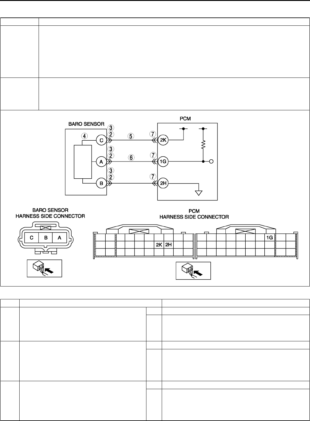
F172
ON-BOARD DIAGNOSTIC
DTC P2228 A6E397001083W06
Diagnostic procedure
DTC P2228 BARO sensor circuit low input
DETECTION
CONDITION
•PCM monitors input voltage from BARO sensor. If input voltage at PCM terminal 1G is below 0.35 V, PCM
determines that BARO sensor circuit has malfunction.
Diagnostic support note
•This is a continuous monitor (CCM).
•MIL illuminates if PCM detects the above malfunction condition during first drive cycle.
•PENDING CODE is available if PCM detects the above malfunction condition.
•FREEZE FRAME DATA is available.
•DTC is stored in PCM memory.
POSSIBLE
CAUSE
•BARO sensor malfunction
•Connector or terminal malfunction
•Short to ground in wiring between BARO sensor terminal A and PCM terminal 1G
•Open circuit in wiring between BARO sensor terminal C and PCM terminal 2K
•PCM malfunction
STEP INSPECTION ACTION
1PERFORM DTC CONFIRMATION PROCEDURE
•Perform DTC CONFIRMATION PROCEDURE.
(See F66 DTC CONFIRMATION
PROCEDURE.)
•Is same DTC present?
Yes Go to next step.
No Intermittent concern exists. Go to INTERMITTENT
CONCERN TROUBLESHOOTING procedure.
(See F227 INTERMITTENT CONCERN
TROUBLESHOOTING.)
2INSPECT CONNECTION OF BARO SENSOR
CONNECTOR
•Turn ignition key to OFF.
•Verify that BARO sensor connector is
connected securely.
•Is connection okay?
Yes Go to next step.
No Reconnect the connector, then go to Step 8.
3INSPECT BARO SENSOR CONNECTOR FOR
POOR CONNECTION
•Disconnect the BARO sensor connector.
•Inspect for poor connection (damaged/pulled-
out pins, corrosion, etc.).
•Is there malfunction?
Yes Repair or replace suspected terminal, then go to Step 8.
No Go to next step.

ON-BOARD DIAGNOSTIC
F173
F
End Of Sie
4INSPECT BARO SENSOR MALFUNCTiON
•Perform BARO sensor inspection.
(See F60 BAROMETRIC PRESSURE
(BARO) SENSOR INSPECTION.)
•Is BARO sensor okay?
Yes Go to next step.
No Replace BARO sensor, then go to Step 8.
5INSPECT POWER SUPPLY CIRCUIT VOLTAGE
AT BARO SENSOR CONNECTOR
Note
•If DTCs P0107 and P0122 are also retrieved
with P2228, go to REFERENCE VOLTAGE
troubleshooting procedure.
•Measure voltage between BARO sensor
terminal C (harness-side) and body ground.
•Is voltage within 4.55.5 V?
Yes Go to next step.
No Inspect for open circuit between PCM terminal 2K
(harness-side) and BARO sensor terminal C (harness-
side).
Repair or replace suspected harness, then go to Step 8.
6INSPECT BARO SENSOR SIGNAL CIRCUIT
FOR SHORT TO GROUND
•Turn ignition key to OFF.
•Disconnect PCM connector.
•Inspect for continuity between BARO sensor
terminal B (harness-side) and body ground.
•Is there continuity?
Yes Repair or replace suspected harness, then go to Step 8.
No Go to next step.
7INSPECT PCM CONNECTOR FOR POOR
CONNECTION
•Disconnect PCM connector.
•Inspect for poor connection at terminal 2H
(damaged/pulled-out pins, corrosion, etc.).
•Is there malfunction?
Yes Repair terminal, then go to Step 8.
No Go to next step.
8VERIFY TROUBLESHOOTING OF DTC P2228
COMPLETED
•Make sure to reconnect all disconnected
connectors.
•Turn ignition key to ON (Engine OFF).
•Clear DTC from memory using WDS or
equivalent.
•Perform KOEO/KOER self-test.
(See F66 KOEO/KOER SELF-TEST.)
•Is same DTC present?
Yes Replace PCM, then go to next step.
(See F43 PCM REMOVAL/INSTALLATION.)
No No concern is detected. Go to next step.
9VERIFY AFTER REPAIR PROCEDURE
•Perform After Repair Procedure.
(See F66 AFTER REPAIR PROCEDURE.)
•Is there any DTC present?
Yes Go to applicable DTC troubleshooting.
(See F67 DTC TABLE.)
No Troubleshooting completed.
STEP INSPECTION ACTION
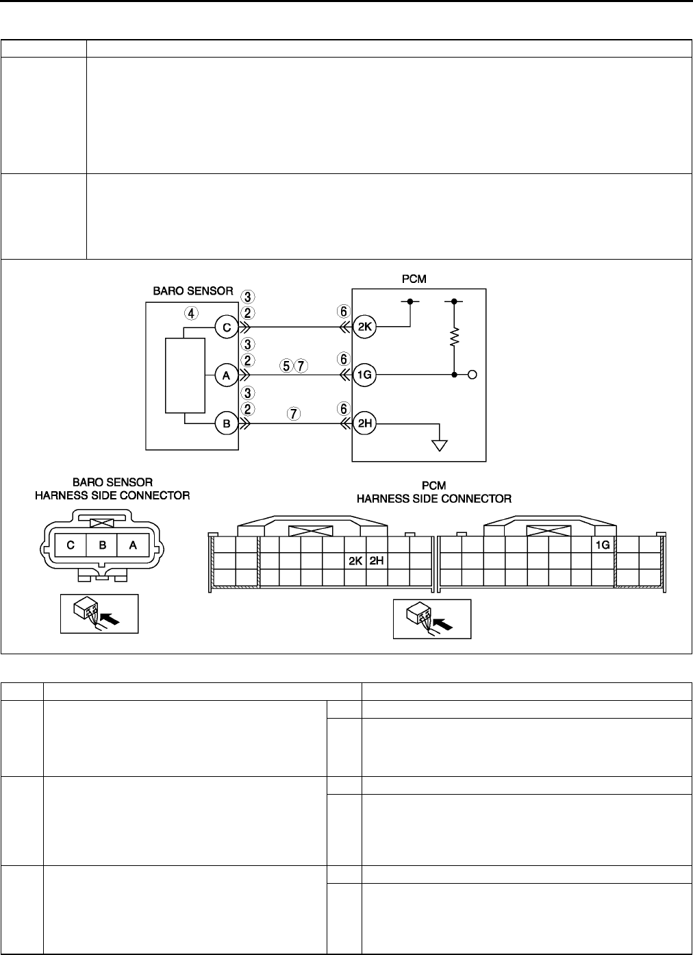
F174
ON-BOARD DIAGNOSTIC
DTC P2229 A6E397001083W07
Diagnostic procedure
DTC P2229 BARO sensor circuit high input
DETECTION
CONDITION
•PCM monitors input voltage from BARO sensor. If input voltage at PCM terminal 1G is above 4.92 V, PCM
determines that BARO sensor circuit has malfunction.
Diagnostic support note
•This is a continuous monitor (CCM).
•MIL illuminates if PCM detects the above malfunction condition during first drive cycle.
•PENDING CODE is available if PCM detects the above malfunction condition.
•FREEZE FRAME DATA is available.
•DTC is stored in PCM memory.
POSSIBLE
CAUSE
•BARO sensor malfunction
•Connector or terminal malfunction
•Open circuit in wiring between BARO sensor terminal A and PCM terminal 1G
•Open circuit in wiring between BARO sensor terminal B and PCM terminal 2H
•Short to power circuit in wiring between BARO sensor terminal A and PCM terminal 1G
•PCM malfunction
STEP INSPECTION ACTION
1PERFORM DTC CONFIRMATION PROCEDURE
•Perform DTC CONFIRMATION PROCEDURE.
(See F66 DTC CONFIRMATION
PROCEDURE.)
•Is same DTC present?
Yes Go to next step.
No Intermittent concern exists. Go to INTERMITTENT
CONCERN TROUBLESHOOTING procedure.
(See F227 INTERMITTENT CONCERN
TROUBLESHOOTING.)
2INSPECT CONNECTION OF BARO SENSOR
CONNECTOR
•Turn ignition key to OFF.
•Verify that BARO sensor connector is
connected securely.
•Is connection okay?
Yes Go to next step.
No Reconnect the connector, then go to Step 8.
3INSPECT BARO SENSOR CONNECTOR FOR
POOR CONNECTION
•Disconnect the BARO sensor connector.
•Inspect for poor connection (damaged/pulled-
out pins, corrosion, etc.).
•Is there malfunction?
Yes Repair or replace suspected terminal, then go to Step 8.
No Go to next step.

ON-BOARD DIAGNOSTIC
F175
F
End Of Sie
4INSPECT BARO SENSOR MALFUNCTiON
•Perform BARO sensor inspection.
(See F60 BAROMETRIC PRESSURE
(BARO) SENSOR INSPECTION.)
•Is BARO sensor okay?
Yes Go to next step.
No Replace BARO sensor, then go to Step 8.
5VERIFY BARO SENSOR SIGNAL CIRCUIT FOR
SHORT TO REFERENCE VOLTAGE CIRCUIT
•Measure voltage between BARO sensor
terminal A and body ground.
•Is voltage above 4.92 V?
Yes Repair or replace short to power harness, then go to Step
8.
No Go to next step.
6INSPECT PCM CONNECTOR FOR POOR
CONNECTION
•Disconnect PCM connector.
•Inspect for poor connection at terminal 2H
(damaged/pulled-out pins, corrosion, etc.).
•Is there malfunction?
Yes Repair terminal, then go to Step 8.
No Go to next step.
7VERIFY BARO SENSOR GROUND CIRCUIT
FOR OPEN CIRCUIT
•Inspect for continuity following terminals:
Between BARO sensor terminal A and PCM
terminal 1G
Between BARO sensor terminal B and PCM
terminal 2H
•Is there continuity?
Yes Go to next step.
No Repair or replace open harness, then go to Step 8.
8VERIFY TROUBLESHOOTING OF DTC P2229
COMPLETED
•Make sure to reconnect all disconnected
connectors.
•Turn ignition key to ON (Engine OFF).
•Clear DTC from memory using WDS or
equivalent.
•Perform KOEO/KOER self-test.
(See F66 KOEO/KOER SELF-TEST.)
•Is same DTC present?
Yes Replace PCM, then go to next step.
(See F43 PCM REMOVAL/INSTALLATION.)
No No concern is detected. Go to next step.
9VERIFY AFTER REPAIR PROCEDURE
•Perform After Repair Procedure.
(See F66 AFTER REPAIR PROCEDURE.)
•Is there any DTC present?
Yes Go to applicable DTC troubleshooting.
(See F67 DTC TABLE.)
No Troubleshooting completed.
STEP INSPECTION ACTION
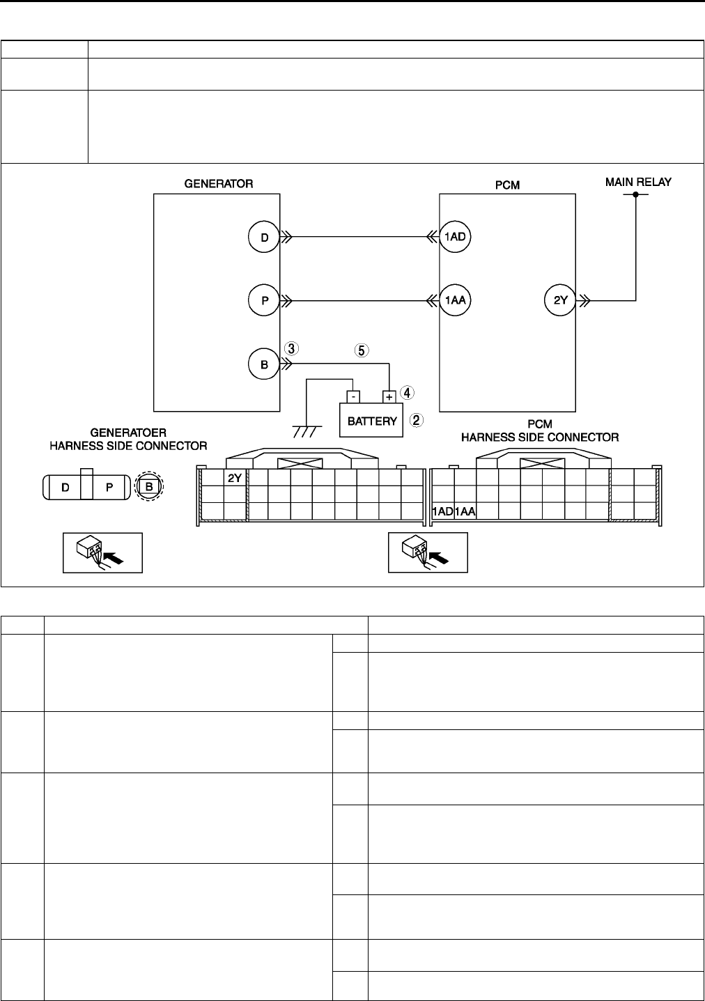
F176
ON-BOARD DIAGNOSTIC
DTC P2502 A6E397001083W08
Diagnostic procedure
DTC P2502 Generator terminal B circuit open
DETECTION
CONDITION
•PCM judges generator output voltage is above 17 V or battery voltage is below 11 V during engine
running.
POSSIBLE
CAUSE
•Open circuit between generator terminal B and battery positive terminal
•Battery malfunction
•Generator malfunction
•PCM is poorly connected.
•PCM, generator and/or battery are poorly connected.
STEP INSPECTION ACTION
1PERFORM DTC CONFIRMATION PROCEDURE
•Perform DTC CONFIRMATION PROCEDURE.
(See F66 DTC CONFIRMATION
PROCEDURE.)
•Is same DTC present?
Yes Go to next step.
No Intermittent concern exists. Go to INTERMITTENT
CONCERN TROUBLESHOOTING procedure.
(See F227 INTERMITTENT CONCERN
TROUBLESHOOTING.)
2INSPECT BATTERY
•Turn ignition key to OFF.
•Inspect battery.
•Is battery okay?
Yes Replace battery, then go to Step 6.
No Go to next step.
3INSPECT POOR INSTALLATION OF
GENERATOR TERMINAL
•Turn ignition key to OFF.
•Inspect for looseness of generator terminal B
installation nut.
•Is nut loose?
Yes Tighten generator terminal B installation nut, then go to
Step 6.
No Go to next step.
4INSPECT POOR INSTALLATION OF BATTERY
POSITIVE TERMINAL
•Inspect for looseness of battery positive
terminal.
•Is terminal loose?
Yes Connect battery positive terminal correctly, then go to Step
6.
No Go to next step.
5INSPECT BATTERY CHARGING CIRCUIT
•Start engine.
•Disconnect battery positive terminal.
•Does engine stall?
Yes Repair or replace harness between generator terminal B
and battery positive terminal, then go to next step.
No Go to next step.
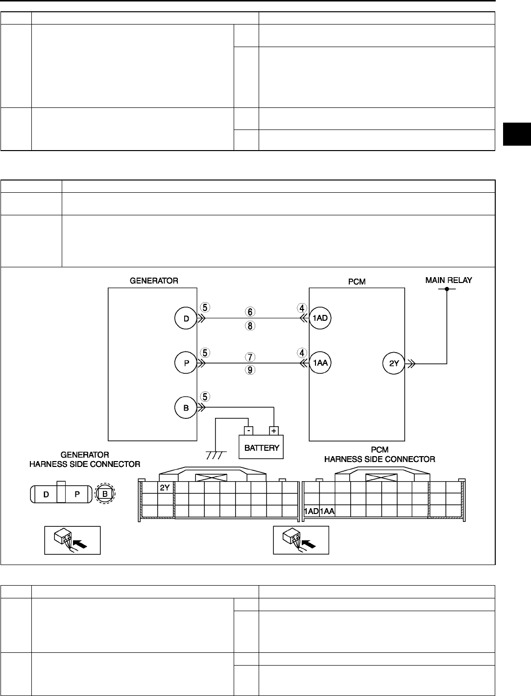
ON-BOARD DIAGNOSTIC
F177
F
End Of Sie
DTC P2503 A6E397001083W09
Diagnostic procedure
6VERIFY TROUBLESHOOTING OF DTC P2502
COMPLETED
•Make sure to reconnect all connectors.
•Clear DTC from memory using WDS or
equivalent.
•Perform KOER self-test.
(See F66 KOEO/KOER SELF-TEST.)
•Is same DTC present?
Yes Replace PCM, then go to next step.
(See F43 PCM REMOVAL/INSTALLATION.)
No Go to next step.
7VERIFY AFTER REPAIR PROCEDURE
•Perform After Repair Procedure.
(See F66 AFTER REPAIR PROCEDURE.)
•Is there any DTC present?
Yes Go to applicable DTC troubleshooting.
(See F67 DTC TABLE.)
No Troubleshooting completed.
STEP INSPECTION ACTION
DTC P2503 Generator output voltage signal no electricity
DETECTION
CONDITION
•PCM needs more than 20 A from generator, and judges generator output voltage to be below 8.5 V during
engine running.
POSSIBLE
CAUSE
•Generator malfunction
•PCM and/or generator are poorly connected.
•Open and/or short to GND in wiring from between generator terminal P and PCM terminal 1AA
•Open and/or short to GND in wiring from between generator terminal D and PCM terminal 1AD
•Drive belt misadjustment
STEP INSPECTION ACTION
1PERFORM DTC CONFIRMATION PROCEDURE
•Perform DTC CONFIRMATION PROCEDURE.
(See F66 DTC CONFIRMATION
PROCEDURE.)
•Is same DTC present?
Yes Go to next step.
No Intermittent concern exists. Go to INTERMITTENT
CONCERN TROUBLESHOOTING procedure.
(See F227 INTERMITTENT CONCERN
TROUBLESHOOTING.)
2INSPECT DRIVE BELT CONDITION
•Verify that drive belt auto tensioner indicator
mark does not exceed limit.
•Is front drive belt okay?
Yes Go to next step.
No Replace and/or adjust drive belt, then go to Step 9.

F178
ON-BOARD DIAGNOSTIC
End Of Sie
DTC P2504 A6E397001083W10
3INSPECT POOR CONNECTION OF PCM
CONNECTOR
•Turn ignition key to OFF.
•Disconnect PCM connector.
•Inspect for poor connection (damaged, pulled-
out terminals, corrosion, etc.).
•Is there a malfunction?
Yes Repair terminals, then go to Step 9.
No Go to next step.
4INSPECT POOR CONNECTION OF
GENERATOR CONNECTOR
•Disconnect generator connector.
•Inspect for poor connection (damaged, pulled-
out terminals, corrosion, etc.).
•Is there a malfunction?
Yes Repair or replace terminals, then go to Step 9.
No Go to next step.
5INSPECT GENERATOR CONTROL CIRCUIT
FOR SHORT TO GROUND
•Inspect for continuity between generator
terminal D (harness-side) and body ground.
•Is there continuity?
Yes Repair or replace harness for short to ground, then go to
Step 9.
No Go to next step.
6INSPECT GENERATOR OUTPUT VOLTAGE
MONITOR CIRCUIT FOR SHORT TO GROUND
•Inspect for continuity between generator
terminal P (harness-side) and body ground.
•Is there continuity?
Yes Repair or replace harness for short to ground, then go to
Step 9.
No Go to next step.
7INSPECT GENERATOR CONTROL CIRCUIT
FOR OPEN
•Measure resistance between generator
terminal D (harness-side) and PCM terminal
1AD (harness-side).
•Is there continuity?
Yes Go to next step.
No Repair or replace harness for open circuit, then go to Step
9.
8INSPECT GENERATOR OUTPUT VOLTAGE
MONITOR CIRCUIT FOR OPEN CIRCUIT
•Measure resistance between generator
terminal P (harness-side) and PCM terminal
1AA (harness-side).
•Is there continuity?
Yes Repair or replace generator, then go to next step.
No Repair or replace harness for open, then go to next step.
9VERIFY TROUBLESHOOTING OF DTC P2503
COMPLETED
•Make sure to reconnect all connectors.
•Clear DTC from PCM memory using WDS or
equivalent.
•Perform KOER self-test.
(See F66 KOEO/KOER SELF-TEST.)
•Is the same DTC present?
Yes Replace PCM, then go to next step.
(See F43 PCM REMOVAL/INSTALLATION.)
No Go to next step.
10 VERIFY AFTER REPAIR PROCEDURE
•Perform After Repair Procedure.
(See F66 AFTER REPAIR PROCEDURE.)
•Is there any DTC present?
Yes Go to applicable DTC troubleshooting.
(See F67 DTC TABLE.)
No Troubleshooting completed.
STEP INSPECTION ACTION
DTC P2504 Battery overcharge
DETECTION
CONDITION
•PCM judges generator output voltage is above 18.5 V or battery voltage is above 16.0 V during engine
running.
POSSIBLE
CAUSE
•Short to power circuit between generator connector terminal D and PCM connector terminal 1AD
•Generator malfunction
•PCM and/or generator are poorly connected.

ON-BOARD DIAGNOSTIC
F179
F
Diagnostic procedure
STEP INSPECTION ACTION
1PERFORM DTC CONFIRMATION PROCEDURE
•Perform DTC CONFIRMATION PROCEDURE.
(See F66 DTC CONFIRMATION
PROCEDURE.)
•Is same DTC present?
Yes Go to next step.
No Intermittent concern exists. Go to INTERMITTENT
CONCERN TROUBLESHOOTING procedure.
(See F227 INTERMITTENT CONCERN
TROUBLESHOOTING.)
2INSPECT POOR CONNECTION OF
GENERATOR CONNECTOR
•Turn ignition key to OFF.
•Disconnect generator connector.
•Inspect for poor connection
(damaged, pulled-out terminals, corrosion,
etc.).
•Is there a malfunction?
Yes Repair or replace terminals, then go to Step 7.
No Go to next step.
3CLASSIFY GENERATOR MALFUNCTION OR
OTHER MALFUNCTION
•Turn ignition key to ON (Engine OFF).
•Measure voltage between generator terminal D
(harness-side) and body ground.
•Is voltage B+?
Yes Go to next step.
No Malfunction at generator.
Go to Step 6.
4INSPECT POOR CONNECTION OF PCM
CONNECTOR
•Turn ignition key to OFF.
•Disconnect PCM connector.
•Inspect for poor connection
(damaged, pulled-out terminals, corrosion,
etc.).
•Is there a malfunction?
Yes Repair or replace pins, then go to Step 7.
No Go to next step.
5INSPECT GENERATOR CONTROL CIRCUIT
FOR SHORT TO POWER
•Turn ignition key to ON (engine OFF).
•Measure voltage between generator terminal D
(harness-side) and body ground.
•Is voltage B+?
Yes Repair or replace harness for short to power, then go to
Step 7.
No Go to Step 7.
DTC P2504 Battery overcharge

F180
ON-BOARD DIAGNOSTIC
End Of Sie
6INSPECT GENERATOR CONTROL TERMINAL
FOR SHORT TO POWER
•Measure resistance between generator
terminal D (part-side) and body ground.
•Is voltage B+?
Yes Repair or replace generator, then go to Step 7.
No Go to next step.
7VERIFY TROUBLESHOOTING OF DTC P2504
COMPLETED
•Make sure to reconnect all connectors.
•Clear DTC from PCM memory using WDS or
equivalent.
•Perform KOER self-test.
(See F66 KOEO/KOER SELF-TEST.)
•Is same DTC present?
Yes Replace PCM, then go to next step.
(See F43 PCM REMOVAL/INSTALLATION.)
No Go to next step.
8VERIFY AFTER REPAIR PROCEDURE
•Perform After Repair Procedure.
(See F66 AFTER REPAIR PROCEDURE.)
•Is there any DTC present?
Yes Go to applicable DTC troubleshooting.
(See F67 DTC TABLE.)
No Troubleshooting completed.
STEP INSPECTION ACTION

TROUBLESHOOTING
F181
F
ENGINE SYMPTOM TROUBLESHOOTING A6E398018881W01
•Confirm trouble symptom using the following diagnostic index, then go to appropriate troubleshooting chart.
Diagnostic Index
End Of Sie
TROUBLESHOOTING
No. TROUBLESHOOTING ITEM DESCRIPTION
1 Melting of main or other fuses
2 MIL illuminates MIL is illuminated incorrectly.
3 Will not crank Starter does not work.
4Hard to start/long crank/erratic start/erratic
crank
Starter cranks engine at normal speed but engine requires excessive
cranking time before starting.
5 Engine stalls. After start/at idle Engine stops unexpectedly at idle and/or after start.
6 Cranks normally but will not start Starter cranks engine at normal speed but engine will not run.
7 Slow return to idle Engine takes more time than normal to return to idle speed.
8 Engine runs rough/rolling idle Engine speed fluctuates between specified idle speed and lower
speed and engine shakes excessively.
9 Fast idle/runs on Engine speed continues at fast idle after warm-up.
Engine runs after ignition switch is turned to off.
10 Low idle/stalls during deceleration Engine stops unexpectedly at beginning of deceleration or recovery
from deceleration.
11
Engine stalls/quits. Acceleration/cruise
Engine stops unexpectedly at beginning of acceleration or during
acceleration.
Engine stops unexpectedly while cruising.
Engine runs rough. Acceleration/cruise Engine speed fluctuates during acceleration or cruising.
Misses Acceleration/cruise Engine misses during acceleration or cruising.
Buck/jerk Acceleration/cruise/
deceleration Vehicle bucks/jerks during acceleration, cruising, or deceleration.
Hesitation/stumble Acceleration Momentary pause at beginning of acceleration or during acceleration
Surges Acceleration/cruise Momentary minor irregularity in engine output
12 Lack/loss of power Acceleration/cruise Performance is poor under load.
(e.g., power down when climbing hills)
13 Knocking/pinging Acceleration/cruise Sound is produced when air/fuel mixture is ignited by something other
than spark plug. (e.g., hot spot in combustion chamber)
14 Poor fuel economy Fuel economy is unsatisfactory.
15 Emission compliance Fails emissions test.
16 High oil consumption/leakage Oil consumption is excessive.
17 Cooling system
concerns Overheating Engine runs at higher than normal temperature/overheats.
18 Cooling system
concerns Runs cold Engine does not reach normal operating temperature.
19 Exhaust smoke Blue, black, or white smoke from exhaust system
20 Fuel odor (in engine compartment) Gasoline fuel smell or visible leakage
21 Engine noise Engine noise from under hood
22 Vibration concerns (engine) Vibration from under hood or driveline
23 A/C does not work sufficiently. A/C compressor magnetic clutch does not engage when A/C is turned
on.
24 A/C is always on or A/C compressor runs
continuously. A/C compressor magnetic clutch does not disengage.
25 A/C is not cut off under WOT conditions. A/C compressor magnetic clutch does not disengage under WOT.
26 Exhaust sulphur smell Rotten egg smell (sulphur) from exhaust
27 Constant voltage Incorrect constant voltage
28 Spark plug condition Incorrect spark plug condition
29 ATX concerns Upshift/downshift/
engagement ATX concerns not related to engine performance
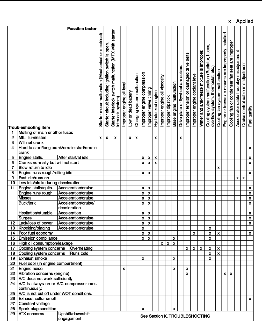
F182
TROUBLESHOOTING
QUICK DIAGNOSTIC CHART A6E398018881W02
A6E3980W001
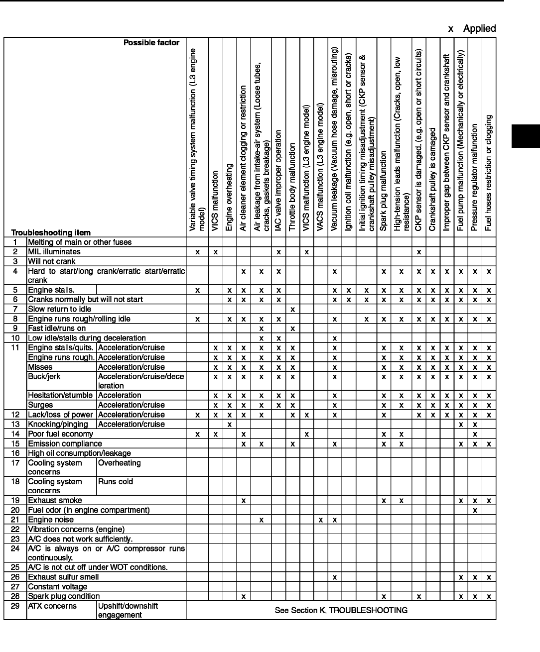
TROUBLESHOOTING
F183
F
A6E3980W002
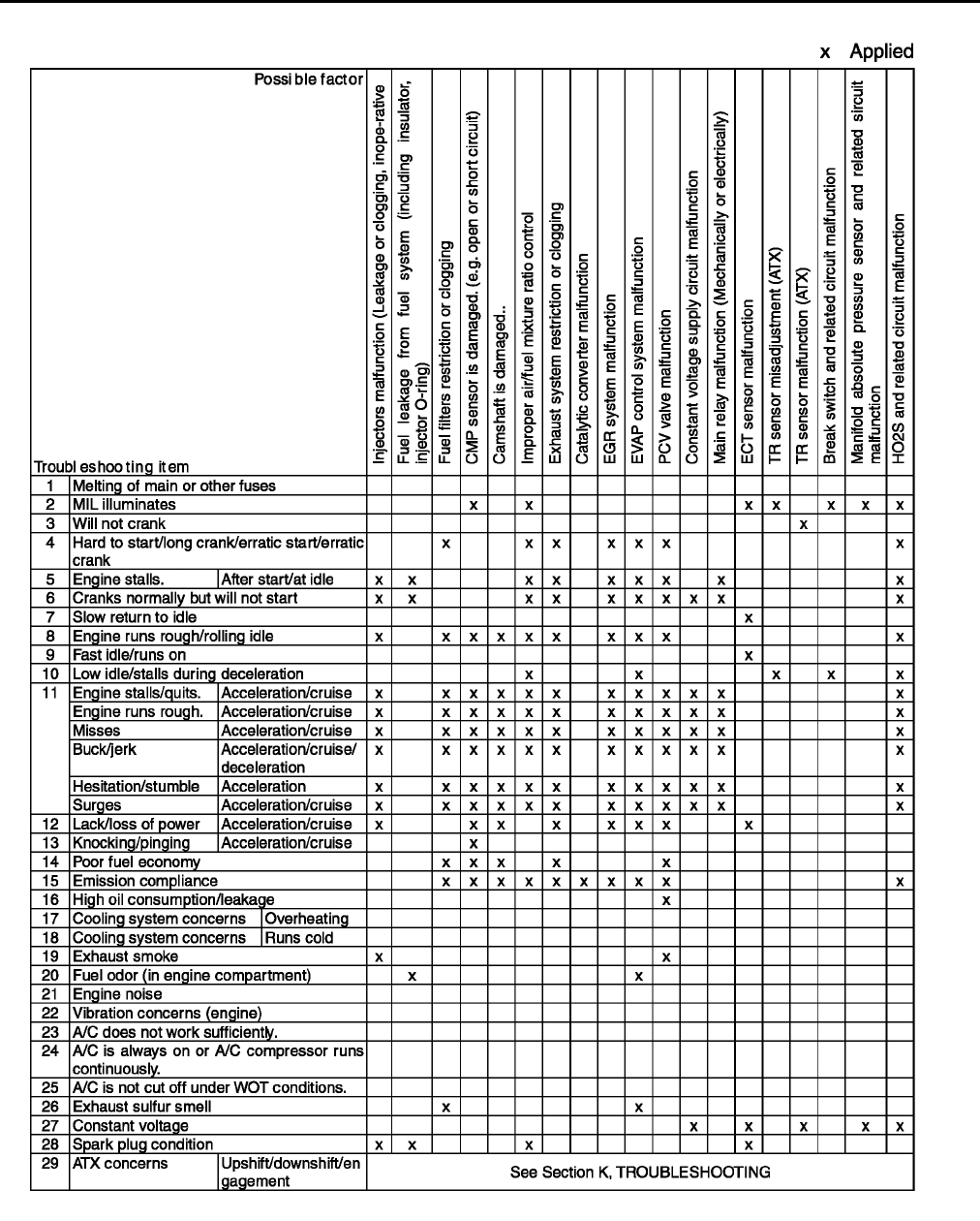
F184
TROUBLESHOOTING
A6E3980W003
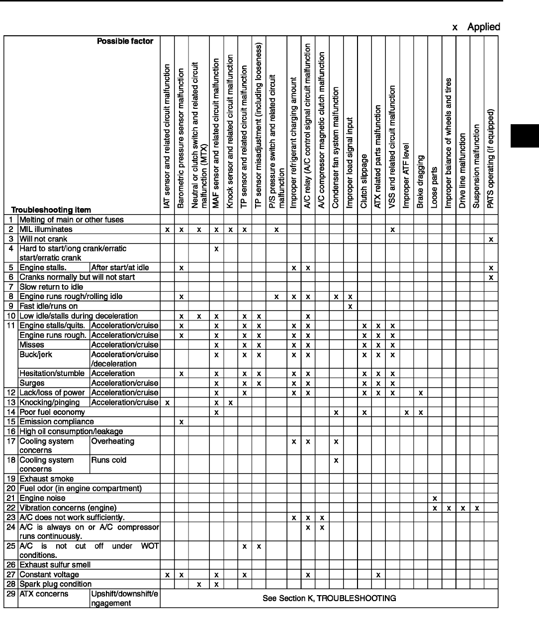
TROUBLESHOOTING
F185
F
End Of Sie
A6E3980W004
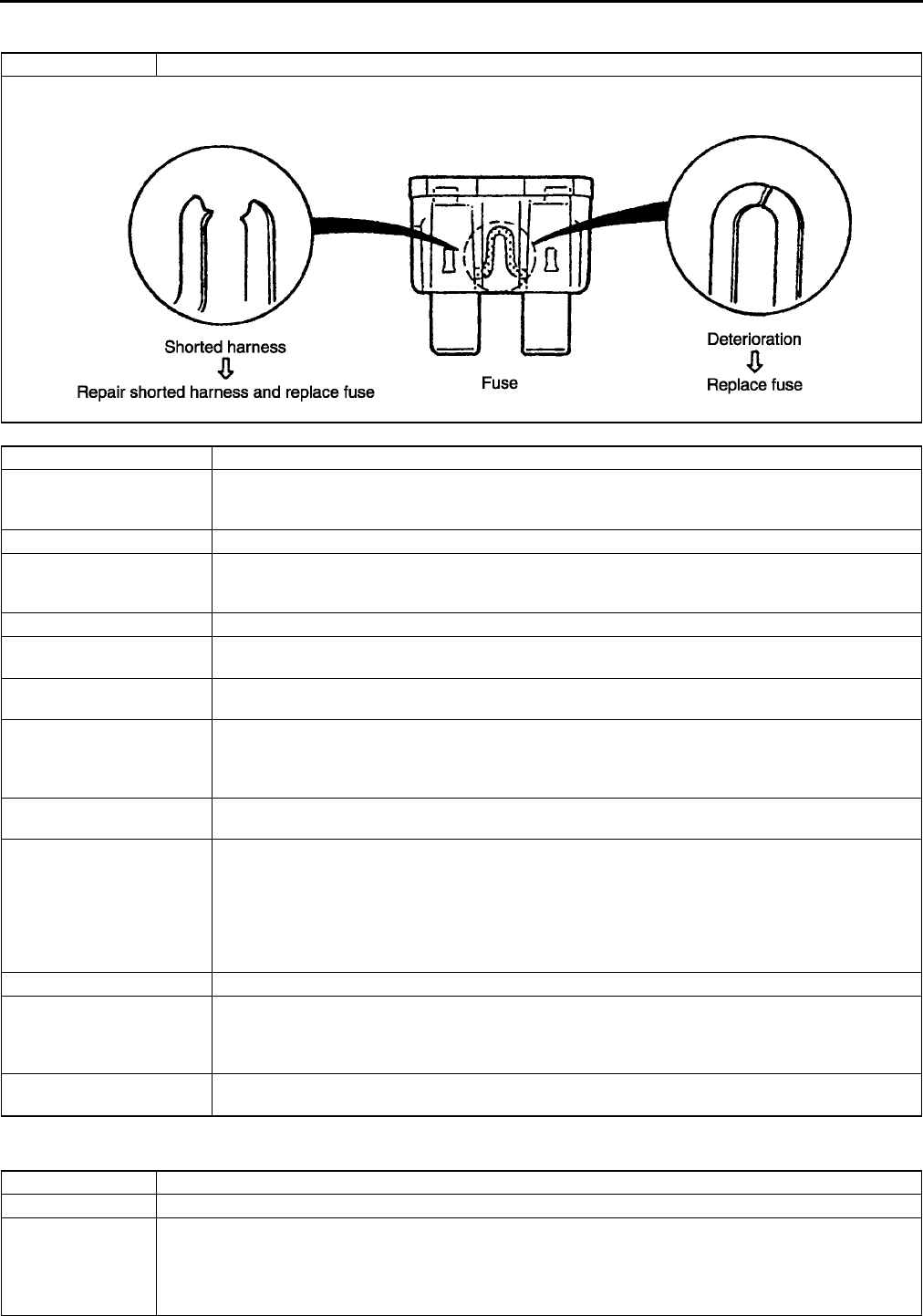
F186
TROUBLESHOOTING
NO.1 MELTING OF MAIN OR OTHER FUSES A6E398018881W03
End Of Sie
NO.2 MIL ILLUMINATES A6E398018881W04
1 MELTING OF MAIN OR OTHER FUSES
[TROUBLESHOOTING HINTS]
Inspect condition of fuse.
Damaged fuse Related wiring harness
MAIN •IG KEY2 fuse
•AD FAN fuse
•FAN fuse
ENG +B •PCM
IG KEY1 •Ignition switch
ENGINE IG fuse
METER IG fuse
IG KEY2 •Ignition switch
AD FAN •Cooling fan relay
Cooling fan motor
FAN •Cooling fan relay (L8-DE, LF-DE (except G.C.C. specs.)
Cooling fan motor
ENGINE IG •Main relay
PCM
•Ignition coil
•Condenser
METER IG •Cooling fan relay
PCM
ENG BAR •VSS (ATX)
•OCV
•VIS solenoid valve
•VAD control solenoid valve
•Purge solenoid valve
•EGR valve
•MAF/IAT sensor
ENG BAR2 •Heated oxygen sensor heater
INJ •PCM
•Fuel pump relay
PCM
•Fuel injector
FUEL PUMP •Fuel pump relay
Fuel pump
2 MIL ILLUMITATES
DESCRIPTION MIL is illuminated incorrectly.
POSSIBLE CAUSE
•PCM illuminates for emission-related concern (DTC is stored in PCM)
•Instrument cluster malfunction
Note
•If MIL blinks at steady rate, misfire condition could possibly exist.
TROUBLESHOOTING
F187
F
Diagnostic procedure
End Of Sie
NO.3 WILL NOT CRANK A6E398018881W05
Diagnostic procedure
STEP INSPECTION RESULTS ACTION
1 Connect WDS or equivalent to DLC-2.
Retrieve any DTC.
Are there DTC displayed?
Yes DTC is displayed:
•Go to appropriate DTC test.
No No DTC is displayed:
•Inspect instrument cluster operation.
See Section T.
2 Verify test results.
•If okay, return to diagnostic index to service any additional symptoms.
•If malfunction remains, replace PCM.
3 WILL NOT CRANK
DESCRIPTION Starter does not work.
POSSIBLE CAUSE
•Open starter circuit between ignition switch and starter
•TR switch malfunction (ATX)
•TR switch misadjustment (ATX)
•Low or dead battery.
•Charging system malfunction.
•Starter interlock switch malfunction (MTX with starter interlock system).
•Starter malfunction
•Seized/hydrolocked engine, flywheel or drive plate
•Immobilizer system (PATS) and/or circuit malfunction (if equipped).
STEP INSPECTION RESULTS ACTION
1Note
•The following test should be perform for
vehicles with immobilizer system. Go to
Step 10 for vehicles without immobilizer
system.
Connect WDS or equivalent to DLC-2.
Do following conditions appear?
•Engine is not completely started.
•DTC B1681 is displayed.
Yes Both conditions appear:
Go to Step 4.
No Either or other condition appears:
Go to next step.
2 Is coil connector securely connected to coil? Yes Go to next step.
No Connect coil connector securely.
Return to Step 1.
3 Does security light illuminate? Yes Go to next step.
No Inspect instrument cluster and wiring harness.
4 Connect WDS or equivalent to DLC-2 and
retrieve DTC.
DTC
B1213, B1342, B1600, B1601, B1602, B1681,
B2103, B2431
Yes Go to appropriate DTC test.
No Go to next step.
5 Is there continuity between PCM GND terminals
4X, 2AB, 2AC and GND?
Yes Go to next step.
No Repair or replace wiring harness.
6 Measure voltage between PCM GND terminals
4X, 2AB, 2AC and coil terminal C.
Is the voltage below 1.0?
Yes Go to next step.
No Repair or replace wiring harness.
7 Turn ignition switch ON position.
Access VPWR PID.
Is VPWR PID okay?
Specification
Battery voltage
Yes Go to next step.
No Repair or replace wiring harness.
8 Disconnect coil connector.
Turn ignition switch to ON position.
Is there battery voltage at coil connector terminal
D (harness-side)?
Yes Inspect for following:
•Open or short circuit between coil terminal A and
PCM terminal 2Q.
•Open or short circuit between coil terminal B and
PCM terminal 2T.
No Repair or replace wiring harness between coil
connector terminal D and fuse panel.

F188
TROUBLESHOOTING
End Of Sie
9 Is there continuity between PCM terminal 4I and
starter relay with clutch pedal depressed (MTX
with starter interlock system), P or N position
(ATX)?
Yes Go to next step.
No Repair replace wiring harness.
10 Inspect following:
•Battery connection
•Battery condition
•Transaxle is in Park or Neutral. (ATX)
•Clutch is fully depressed. (MTX with starter
interlock system)
•Fuses
Are all items okay?
Yes Go to next step.
No Service as necessary.
Repeat Step 10.
11 Is clicking sound heard from starter when
ignition switch is turned to START?
Yes Go to next step.
No Go to Step 13.
12 Inspect starting system.
(See G13 STARTER INSPECTION.)
Is starting system okay?
Yes Inspect for seized/hydrolocked engine, flywheel or
drive plate.
(See H15 FLYWHEEL INSPECTION.)
No Repair or replace components as required.
13 Do any other electrical accessories work? Yes Go to next step.
No Inspect charging system.
(See G4 BATTERY INSPECTION.)
(See G7 GENERATOR INSPECTION.)
14 Note
•Following test should be performed on
ATX only. For MTX, go to next step.
Connect WDS or equivalent to DLC-2.
Access TR PID.
Turn ignition switch to ON position.
Is TR PID indicated P/N when selecting P or N
position?
Yes Go to next step.
No Inspect adjustment of TR switch.
If TR switch is adjusted properly, inspect for open
circuit between TR switch and PCM terminal 1W or
starter.
15 Connect WDS or equivalent to DLC-2.
Retrieve any continuous memory DTCs.
Are there any continuous memory DTCs
displayed?
Yes DTC is displayed:
Go to appropriate DTC test.
Communication error message is displayed:
Inspect for following:
•Open circuit between main relay and PCM terminal
2Y or 4V
•Open circuit between main relay terminal E and
PCM terminal 2X
•Main relay is stuck open.
•Open or poor GND circuit (PCM terminal 4X, 2AB
or 2AC)
•Poor connection of vehicle body GND
No No DTC is displayed:
Inspect following:
•START circuit in ignition switch
•Open circuit between ignition switch and starter
•Starter interlock switch (MTX with stater interlock
system)
16 Retrieve any KOEO DTCs.
Are there DTCs displayed during KOEO
inspection?
Yes DTC is displayed:
Go to appropriate DTC test.
No No DTC is displayed:
Inspect following:
•START circuit in ignition switch
•Open circuit between ignition switch and starter
•Starter interlock switch (MTX with stater interlock
system)
17 Verify test results.
•If okay, return to diagnostic index to service any additional symptoms.
•If malfunction remains, replace PCM.
STEP INSPECTION RESULTS ACTION

TROUBLESHOOTING
F189
F
NO.4 HARD TO START/LONG CRANK/ERRATIC START/ERRATIC CRANK A6E398018881W06
Diagnostic procedure
4 HARD TO START/LONG CRANK/ERRATIC START/ERRATIC CRANK
DESCRIPTION •Starter cranks engine at normal speed but engine requires excessive cranking time before starting.
•Battery is in normal condition.
POSSIBLE CAUSE
•Spark leakage from high-tension leads
•Vacuum leakage
•Poor fuel quality
•Starting system malfunction
•Spark plug malfunction
•Air leakage from intake-air system
•Erratic signal from CKP sensor
•Erratic signal from CMP sensor
•Improper air/fuel mixture ratio control
•Air cleaner restriction
•IAC valve malfunction
•PCV valve malfunction
•Inadequate fuel pressure
•Purge solenoid valve malfunction
•MAF sensor contamination
•Restriction in exhaust system
•EGR valve malfunction
•Pressure regulator malfunction
Warning
The following troubleshooting flow chart contains the fuel system diagnosis and repair
procedures. Read the following warnings before performing the fuel system services:
•
••
•Fuel vapor is hazardous. It can easily ignite, causing serious injury and damage. Always
keep sparks and flames away from fuel.
•
••
•Fuel line spills and leakage are dangerous. Fuel can ignite and cause serious injuries or
death and damage. Fuel can also irritate skin and eyes. To prevent this, always complete
"BEFORE REPAIR PROCEDURE" and "AFTER REPAIR PROCEDURE" described in this
manual.
(See F17 BEFORE REPAIR PROCEDURE.)
(See F17 AFTER REPAIR PROCEDURE.)
Caution
•
••
•Disconnecting/connecting quick release connector without cleaning it may possibly cause
damage to fuel pipe and quick release connector. Always clean quick release connector
joint area before disconnecting/connecting, and make sure that it is free of foreign material.
STEP INSPECTION RESULTS ACTION
1 Inspect for following:
•Vacuum leakage
•Proper fuel quality (e.g. proper octane,
contamination, winter/summer blend)
•Loose bands on intake-air system
•Cracks on intake-air system parts
•Air cleaner restriction
Are all items okay?
Yes Go to next step.
No Service as necessary.
Repeat Step 1.
2 Connect WDS or equivalent to DLC-2.
Retrieve any KOEO and KOER DTC.
Is any KOEO or KOER DTC displayed?
Yes DTC is displayed:
Go to appropriate DTC test.
No No DTC is displayed:
Go to next step.
3 Is engine overheating? Yes Go to symptom troubleshooting No.17 Cooling system
concerns Overheating.
No Go to next step.
4 Inspect for cracks on high-tension leads.
Are there any cracks on high-tension leads?
Yes Repair suspected high-tension leads.
No Go to next step.
5 Inspect spark plug conditions.
Is spark plug wet, covered with carbon or
grayish white?
Yes Spark plug is wet or covered with carbon:
Inspect for fuel leakage from fuel injector.
Spark plug is grayish white:
Inspect for clogged fuel injector.
No Install spark plugs on original cylinders.
Go to next step.

F190
TROUBLESHOOTING
End Of Sie
6 Visually inspect CKP sensor and teeth of
crankshaft pulley.
Are CKP sensor and teeth of crankshaft pulley
okay?
Yes Go to next step.
No Replace malfunctioning parts.
7 Measure gap between CKP sensor and teeth of
crankshaft pulley.
Specification
0.51.9 mm {0.0200.75 in}
Is gap within specification?
Yes Go to next step.
No Adjust CKP sensor.
8 Remove and shake PCV valve.
Does PCV valve rattle?
Yes Go to next step.
No Replace PCV valve.
9 Install fuel pressure gauge between fuel pipe
and fuel distributor.
Connect a jumper wire between F/P terminal at
DLC-2 in engine compartment and GND.
Turn ignition switch to ON position.
Is fuel line pressure correct with ignition switch
ON?
(See F20 FUEL LINE PRESSURE
INSPECTION)
Yes Go to next step.
No Zero or low:
Inspect for clogged fuel line.
If okay, replace fuel pump unit.
High:
Replace fuel pump unit.
10 Is fuel line pressure held after ignition switch is
turned off?
(See F20 FUEL LINE PRESSURE
INSPECTION)
Yes Go to next step.
No Inspect fuel injector.
If fuel injector is okay, replace fuel pump unit.
11 Disconnect a vacuum hose from purge solenoid
valve and plug opening end of vacuum hose.
Attempt to start engine.
Is starting condition improved?
Yes Inspect if purge solenoid valve sticks open.
No Go to next step.
12 Inspect MAF sensor for contamination.
Is there any contamination?
Yes Replace MAF sensor.
No Go to next step.
13 Is there restriction in exhaust system? Yes Inspect exhaust system.
No Go to next step.
14 Inspect engine condition while tapping EGR
valve housing. Does engine condition improve?
Yes Replace EGR valve.
No Go to next step.
15 Inspect starting system.
(See G13 STARTER INSPECTION.)
Is starting system normal?
Yes Inspect for loose connectors or poor terminal contact. If
okay, remove EGR valve and visually inspect for
mechanically stuck EGR valve.
No Repair or replace components as required.
16 Verify test results.
•If okay, return to diagnostic index to service any additional symptoms.
•If malfunction remains, replace PCM.
STEP INSPECTION RESULTS ACTION
TROUBLESHOOTING
F191
F
NO.5 ENGINE STALLS-AFTER START/AT IDLE A6E398018881W07
Diagnostic procedure
5 ENGINE STALLSAFTER START/AT IDLE
DESCRIPTION •Engine stops unexpectedly.
POSSIBLE CAUSE
•A/C system operation is improper
•Air leakage from intake-air system parts
•Purge solenoid valve malfunction
•Improper operation of IAC valve
•EGR valve malfunction
•No signal from CKP sensor due to sensor, related wire or wrong installation
•Vacuum leakage
•Engine overheating
•Low engine compression
•Spark leakage from high-tension leads
•Poor fuel quality
•PCV valve malfunction
•Air cleaner restriction
•Restriction in exhaust system
•Electrical connector disconnection
•Open or short circuit in fuel pump body and related harness
•No battery power supply to PCM or poor GND
•Inadequate fuel pressure
•Fuel pump body mechanical malfunction
•Fuel leakage from fuel injector
•Fuel injector clogging
•Ignition coil malfunction
•Improper air/fuel mixture ratio control
•Improper valve timing
•Improper operation variable valve timing control system (L3-VE)
•Immobilizer system (PATS) and/or circuit malfunction (if equipped)
•Pressure regulator malfunction
Warning
The following troubleshooting flow chart contains the fuel system diagnosis and repair
procedures. Read the following warnings before performing the fuel system services:
•
••
•Fuel vapor is hazardous. It can easily ignite, causing serious injury and damage. Always
keep sparks and flames away from fuel.
•
••
•Fuel line spills and leakage are dangerous. Fuel can ignite and cause serious injuries or
death and damage. Fuel can also irritate skin and eyes. To prevent this, always complete
BEFORE REPAIR PROCEDURE and AFTER REPAIR PROCEDURE described in this
manual.
(See F17 BEFORE REPAIR PROCEDURE.)
(See F17 AFTER REPAIR PROCEDURE.)
Caution
•
••
•Disconnecting/connecting quick release connector without cleaning it may possibly cause
damage to fuel pipe and quick release connector. Always clean quick release connector
joint area before disconnecting/connecting, and make sure that it is free of foreign material.
STEP INSPECTION RESULTS ACTION
1Note
•The following test should be performed for
vehicles with immobilizer system. Go to
Step 10 for vehicles without immobilizer
system.
Connect WDS or equivalent to DLC-2.
Do following conditions appear?
•Engine is not completely started.
•DTC B1681 is displayed.
Yes Both conditions appear:
Go to Step 3.
No Either or other condition appears:
Go to next step.
2 Does engine stall after approx. 2 seconds since
engine is started?
Yes Go to next step.
No Immobilizer systemis okay.
Go to Step 10.
3 Is coil connector securely connected to coil? Yes Go to next step.
No Connect coil connector securely.
Return to Step 2.

F192
TROUBLESHOOTING
4 Does security light illuminate? Yes Go to next step.
No Inspect instrument cluster and wiring harness.
5 Connect WDS or equivalent to DLC-2 and
retrieve DTC.
Are any of following DTCs displayed?
DTC
B1213, B1342, B1600, B1602, B1681, B2103,
B2431
Yes Go to appropriate DTC test.
No Go to next step.
6 Is there continuity between PCM GND terminals
4X, 2AB, 2AC and GND?
Yes Go to next step.
No Repair or replace wiring harness.
7 Measure voltage between PCM GND terminals
4X, 2AB, 2AC and coil terminal C.
Is voltage below 1.0 V?
Yes Go to next step.
No Repair or replace wiring harness.
8 Turn ignition switch to ON position.
Access VPWR PID.
Is VPWR PID okay?
VPWR PID
Battery voltage
Yes Go to next step.
No Repair or replace wiring harness.
9 Disconnect coil connector.
Turn ignition switch to ON position.
Is there battery voltage at coil connector terminal
D?
Yes Inspection for following:
•Open or short circuit between coil terminal A and
PCM terminal 2Q.
•Open or short circuit between coil terminal B and
PCM terminal 2T.
No Repair or replace wiring harness between coil
connector terminal D and fuse panel.
10 Verify following:
•Vacuum connection
•Air cleaner element
•No air leakage from intake-air system
•No restriction of intake-air system
•Proper sealing of intake manifold and
components attached to intake manifold:
EGR valve, IAC valve
•Ignition wiring
•Fuel quality: proper octane, contamination,
winter/summer blend
•Electrical connections
•Smooth operation of throttle valve
Are all items okay?
Yes Go to next step.
No Service as necessary.
Repeat Step 10.
11 Turn ignition switch to ON position.
Disconnect TP sensor connector.
Measure voltage at TP sensor connector VREF
terminal with ignition switch ON.
Voltage
4.55.5 V
Is voltage okay?
Yes Go to next step.
No Go to troubleshooting "No.27 Constant voltage".
12 Connect WDS or equivalent to DLC-2.
Retrieve any continuous memory, KOEO and
KOER DTCs.
If engine stalls, retrieve continuous memory and
KOEO DTCs.
Are there any DTC displayed?
Yes DTC is displayed:
Go to appropriate DTC test.
Communication error message is displayed:
Inspect for following:
•Open circuit between main relay and PCM terminal
2Y or 4V
•Open main relay GND circuit
•Main relay is stuck open.
•Open or poor GND circuit (PCM terminal 4X, 2AB
or 2AC)
•Poor connection of vehicle body GND
No No DTC is displayed:
Go to next step.
13 Attempt to start engine at part throttle.
Does engine run smoothly at part throttle?
Yes Inspect IAC valve and wiring harness.
No Go to next step.
STEP INSPECTION RESULTS ACTION

TROUBLESHOOTING
F193
F
14 Connect WDS or equivalent to DLC-2.
Access RPM PID.
Is RPM PID indicating engine speed during
engine cranking?
Yes Go to next step.
No Inspect for following:.
•Open or short circuit in CKP sensor
•Open or short circuit between CKP sensor and
PCM terminal 2C or 2D
•Open or short circuit in CKP sensor harnesses
If CKP sensor and harness are okay, go to next step.
15 Visually inspect CKP sensor and teeth of
crankshaft pulley.
Are CKP sensor and teeth of crankshaft pulley
okay?
Yes Go to next step.
No Replace malfunctioning parts.
16 Measure gap between CKP sensor and teeth of
crankshaft pulley.
Specification
0.51.9 mm {0.0200.075 in}
Is gap within specification?
Yes Go to next step.
No Adjust CKP sensor.
17 Inspect for cracks on high-tension leads.
Are there any cracks on high-tension leads?
Yes Repair suspected high-tension leads.
No Go to next step.
18 Is strong blue spark visible at each disconnected
high-tension lead while cranking engine?
Yes Go to next step.
If symptom occurs with A/C on, go to Step 24.
No Inspect for following:
•Open or short circuit in ignition coil
•Open circuit in high-tension leads
•Open circuit between ignition coil connector GND
terminal and body GND
•Open circuit between ignition switch and ignition
coil
•Open circuit between ignition coil and PCM
terminal 1A or 1B
19 Inspect spark plug condition.
Is spark plug wet, covered with carbon or
grayish white?
Yes Spark plug is wet or covered with carbon:
Inspect for fuel leakage from injector.
Spark plug is grayish white:
Inspect for clogged fuel injector.
No Install spark plugs on original cylinders.
Go to next step.
20 Remove and shake PCV valve.
Does PCV valve rattle?
Yes Go to next step.
No Replace PCV valve.
21 Inspect for restriction in the exhaust system.
Is there any restriction?
Yes Inspect exhaust system.
No Go to next step.
22 Install fuel pressure gauge between fuel pipe
and fuel distributor.
Connect jumper wire between F/P terminal at
DLC-2 in engine compartment and GND.
Turn ignition switch to ON position.
Is fuel line pressure correct with ignition switch
ON?
(See F20 FUEL LINE PRESSURE
INSPECTION)
Yes Go to next step.
No Zero or low:
Inspect for clogged fuel line.
If okay, replace fuel pump unit.
High:
Replace fuel pump unit.
23 Visually inspect for fuel leakage at fuel injector
O-ring and fuel line. Service as necessary.
Is fuel line pressure held after ignition switch is
turned off?
(See F20 FUEL LINE PRESSURE
INSPECTION)
Yes Go to next step.
No Inspect fuel injector.
If fuel injector is okay, replace fuel pump unit.
STEP INSPECTION RESULTS ACTION

F194
TROUBLESHOOTING
End Of Sie
24 Note
•Following test is for stall concerns with A/
C on. If other symptoms exist, go to next
step.
Connect pressure gauges to A/C low and high
pressure side lines.
Turn A/C on and measure low side and high side
pressures.
Are pressures within specifications?
(See U12 REFRIGERANT PRESSURE
CHECK.)
Yes Go to next step.
No If A/C is always on, go to symptom troubleshooting
"No.24 A/C is always on or A/C compressor runs
continuously".
For other symptoms, inspect following:
•Refrigerant charging amount
•Condenser fan operation
25 Disconnect vacuum hose between purge
solenoid valve and intake manifold from purge
solenoid side.
Plug opening end of vacuum hose.
Start engine.
Is engine stall now eliminated?
Yes Inspect if purge solenoid valve sticks open.
Inspect evaporative emission control system.
No Go to next step.
26 Is air leakage felt or heard at intake-air system
components while racing engine to higher
speed?
Yes Repair or replace.
No Go to next step.
27 Inspect engine condition while tapping EGR
valve housing.
Does engine condition improve?
Yes Replace EGR valve.
No Go to next step.
28 Note
•The following test should be performed for
vehicles with variable valve timing control
system. Go to next step for vehicles
without variable valve timing control
system.
Inspect variable valve timing control system
operation.
(See F239 Variable Valve Timing Control
System Operation Inspection.)
Does variable valve timing control work
properly?
Yes Go to next step.
No Repair or replace malfunctioning parts.
29 Is engine compression correct? Yes Inspect valve timing.
No Inspect for cause.
30 Verify test results.
•If okay, return to diagnostic index to service any additional symptoms.
•If malfunction remains, replace PCM.
STEP INSPECTION RESULTS ACTION

TROUBLESHOOTING
F195
F
NO.6 CRANKS NORMALLY BUT WILL NOT START A6E398018881W08
Diagnostic procedure
6 CRANKS NORMALLY BUT WILL NOT START
DESCRIPTION
•Starter cranks engine at normal speed but engine will not run.
•Refer to symptom troubleshooting "No.5 Engine stalls" if this symptom appears after engine stall.
•Fuel is in tank.
•Battery is in normal condition.
POSSIBLE CAUSE
•No battery power supply to PCM
•Air leakage from intake-air system
•Open PCM GND or vehicle body GND
•Improper operation of IAC valve
•EGR valve malfunction
•No signal from CKP sensor due to sensor, related wire or incorrect installation
•No signal from CMP sensor due to sensor, related wire or incorrect installation
•Low engine compression
•Engine overheating
•Vacuum leakage
•Spark leakage from high-tension leads
•Improper air/fuel mixture ratio control
•Poor fuel quality
•PCV valve malfunction
•Air cleaner restriction
•Restriction in exhaust system
•Disconnected electrical connector
•Open or short circuit in fuel pump body and related harness
•Inadequate fuel pressure
•Fuel pump mechanical malfunction
•Fuel leakage from injector
•Fuel injector is clogged.
•Purge solenoid valve malfunction
•Spark plug malfunction
•Ignition coil malfunction
•Improper variable valve timing control system operation (L3)
•Improper valve timing
•Immobilizer system (PATS) and/or circuit malfunction (if equipped)
•Pressure regulator malfunction
Warning
The following troubleshooting flow chart contains the fuel system diagnosis and repair
procedures. Read the following warnings before performing the fuel system services:
•
••
•Fuel vapor is hazardous. It can easily ignite, causing serious injury and damage. Always
keep sparks and flames away from fuel.
•
••
•Fuel line spills and leakage are dangerous. Fuel can ignite and cause serious injuries or
death and damage. Fuel can also irritate skin and eyes. To prevent this, always complete
"BEFORE REPAIR PROCEDURE" and "AFTER REPAIR PROCEDURE" described in this
manual.
(See F17 BEFORE REPAIR PROCEDURE.)
(See F17 AFTER REPAIR PROCEDURE.)
Caution
•
••
•Disconnecting/connecting quick release connector without cleaning it may possibly cause
damage to fuel pipe and quick release connector. Always clean quick release connector
joint area before disconnecting/connecting, and make sure that it is free of foreign material.
STEP INSPECTION RESULTS ACTION
1Note
•Following test should be performed for
vehicles with immobilizer system. Go to
Step 10 for vehicles without immobilizer
system.
Connect WDS or equivalent to DLC-2.
Do any of following conditions appear?
•Engine is not completely started.
•DTC B1681 is displayed.
Yes Both conditions appear:
Go to Step 3.
No Either or other condition appears:
Go to next step.
2 Does engine stall after approx. 2 seconds since
engine is started?
Yes Go to next step.
No Immobilizer system is okay.
Go to Step 10.

F196
TROUBLESHOOTING
3 Is coil connector securely connected to coil? Yes Go to next step.
No Connect coil connector securely.
Return to Step 2.
4 Does security light illuminate? Yes Go to next step.
No Inspect instrument cluster and wiring harness.
5 Connect WDS equivalent to DLC-2 and retrieve
DTC.
Are any of following DTCs displayed?
DTC
B1213, B1342, B1600, B1601, B1602, B1681,
B2103, B2431
Yes Go to appropriate DTC test.
No Go to next step.
6 Is there continuity between PCM GND terminals
4X, 2AB, 2AC and GND?
Yes Go to next step.
No Repair or replace wiring harness.
7 Measure voltage between PCM GND terminals
4X, 2AB, 2AC and coil terminal C.
Is voltage below 1.0 V?
Yes Go to next step.
No Repair or replace wiring harness.
8 Turn ignition switch to ON position.
Access VPWR PID.
Is VPWR PID okay?
VPWR PID
Battery voltage
Yes Go to next step.
No Repair or replace wiring harness.
9 Disconnect coil connector.
Turn ignition switch to ON position.
Is there battery voltage at coil connector terminal
D?
Yes Inspect for following:
•Open or short circuit between coil terminal A and
PCM terminal 2Q
•Open or short circuit between coil terminal B and
PCM terminal 2T
No Repair or replace wiring harness between coil
connector terminal D and fuse panel.
10 Verify following:
•Vacuum connection
•External fuel shut off or accessory (kill
switch, alarm etc.)
•Fuel quality: proper octane, contamination,
winter/summer blend
•No air leakage from intake-air system
•Proper sealing of intake manifold and
components attached to intake manifold:
EGR valve, IAC valve
•Ignition wiring
•Electrical connections
•Fuses
•Smooth operation of throttle valve
Are all items okay?
Yes Go to next step.
No Service as necessary.
Repeat Step 10.
11 Connect WDS or equivalent to DLC-2.
Retrieve any continuous memory and KOEO
DTC.
Are there any DTCs displayed?
Yes DTC is displayed:
Go to appropriate DTC test.
Communication error message is displayed:
Inspect for following:
•Open circuit between main relay and PCM terminal
2Y or 4V
•Open main relay GND circuit
•Main relay is stuck open.
•Open or poor GND circuit (PCM terminal 4X, 2AB,
or 2AC)
•Poor connection of vehicle body GND
No No DTC is displayed:
Go to next step.
12 Turn ignition switch to ON position.
Disconnect TP sensor connector.
Measure voltage at TP sensor connector VREF
terminal with ignition switch to ON position.
Voltage
4.55.5 V
Is voltage okay?
Yes Go to next step.
No Go to troubleshooting "No.27 Constant voltage".
13 Does engine start with throttle closed? Yes Go to Step 29.
No Go to next step.
STEP INSPECTION RESULTS ACTION

TROUBLESHOOTING
F197
F
14 Will engine start and run smoothly at part
throttle?
Yes Inspect IAC valve and wiring harness.
No Go to next step.
15 Connect WDS or equivalent to DLC-2.
Access RPM PID.
Is RPM PID indicating engine speed when
cranking engine?
Yes Go to next step.
No Inspect for following:
•Open or short circuit in CKP sensor
•Open or short circuit between CKP sensor and
PCM terminal 1A or 1B
•Open or short circuit in CKP sensor harnesses
If CKP sensor and harness are okay, go to next step.
16 Visually inspect CKP sensor and teeth of
crankshaft pulley.
Are CKP sensor and teeth of crankshaft pulley
okay?
Yes Go to next step.
No Replace malfunctioning parts.
17 Measure gap between CKP sensor and teeth of
crankshaft pulley.
Specification
0.51.9 mm {0.0200.075 in}
Is gap within specification?
Yes Go to next step.
No Adjust CKP sensor.
18 Inspect for cranks on high-tension leads.
Is there any crank on high-tension leads?
Yes Repair suspected high-tension leads.
No Go to next step.
19 Is strong blue spark visible at each disconnected
high-tension lead while cranking engine?
Yes Go to next step.
No Inspect for following:
•Open or short circuit in ignition coil
•Open circuit in high-tension leads
•Open circuit between ignition coil connector GND
terminal and GND
•Open circuit between ignition switch and ignition
coil
•Open circuit between ignition coil and PCM
terminal 1A or 1B
20 Inspect spark plug conditions.
Is spark plug wet, covered with carbon or
grayish white?
Yes Spark plug is wet or covered with carbon:
Inspect for fuel leakage from injector.
Spark plug is grayish white:
Inspect for clogged fuel injector.
No Install spark plugs on original cylinders.
Go to next step.
21 Remove and shake PCV valve.
Does PCV valve rattle?
Yes Go to next step.
No Replace PCV valve.
22 Inspect for restriction in exhaust system. Yes Inspect exhaust system.
No Go to next step.
23 Install fuel pressure gauge between fuel pipe
and fuel distributor.
Connect a jumper wire between F/P terminal at
DLC-2 in engine compartment and GND.
Turn ignition switch to ON position.
Is fuel line pressure correct when ignition switch
is turned on/off five times?
(See F20 FUEL LINE PRESSURE
INSPECTION)
Yes Go to next step.
No Zero or low:
Inspect for clogged fuel line.
If okay, replace fuel pump unit.
High:
Replace fuel pump unit.
24 Visually inspect for fuel leakage at fuel injector
O-ring and fuel line.
Service as necessary.
Is fuel line pressure held after ignition switch is
turned off?
(See F20 FUEL LINE PRESSURE
INSPECTION)
Yes Go to next step.
No Inspect fuel injector.
If fuel injector is okay, replace fuel pump unit.
25 Disconnect vacuum hose between purge
solenoid valve and intake manifold from purge
solenoid valve side.
Plug opening end of vacuum hose.
Attempt to start engine.
Is starting condition improved?
Yes Inspect if purge solenoid valve sticks open
mechanically.
Inspect evaporative emission control system.
No Go to next step.
STEP INSPECTION RESULTS ACTION

F198
TROUBLESHOOTING
End Of Sie
NO.7 SLOW RETURN TO IDLE A6E398018881W09
Diagnostic procedure
End Of Sie
26 Is air leakage felt or heard at intake-air system
components while racing engine to higher
speed?
Yes Repair or replace.
No Go to next step.
27 Inspect engine condition while tapping EGR
valve housing.
Is engine condition improved?
Yes Replace EGR valve.
No Go to next step.
28 Note
•The following test should be performed for
vehicles with variable valve timing control
system. Go to next step for vehicles
without variable valve timing control
system.
Inspect variable valve timing control system
operation.
(See F239 Variable Valve Timing Control
System Operation Inspection.)
Does variable valve timing control work
properly?
Yes Go to next step.
No Repair or replace malfunctioning parts.
29 Is engine compression correct? Yes Inspect valve timing.
No Inspect for causes.
30 Verify test results.
•If okay, return to diagnostic index to service any additional symptoms.
•If malfunction remains, replace PCM.
STEP INSPECTION RESULTS ACTION
7 SLOW RETURN TO IDLE
DESCRIPTION Engine takes more time than normal to return to idle speed.
POSSIBLE CAUSE
•ECT sensor malfunction
•Thermostat is stuck open.
•Throttle body malfunction
•Air leakage from intake-air system
STEP INSPECTION RESULTS ACTION
1 Connect WDS or equivalent to DLC-2.
Retrieve any continuous memory, KOEO and
KOER DTCs.
Are there DTCs displayed?
Yes DTC is displayed:
Go to appropriate DTC test.
No No DTC is displayed:
Go to next step.
2 Remove thermostat and inspect operation.
(See E7 THERMOSTAT REMOVAL/
INSTALLATION.)
(See E8 THERMOSTAT INSPECTION.)
Is thermostat okay?
Yes ECT and thermostat are okay.
Go to next step.
No Access ECT PID on WDS or equivalent.
Inspect for both ECT PID and temperature gauge on
instrument cluster readings.
If temperature gauge on instrument cluster indicates
normal range but ECT PID is not same as temperature
gauge reading, inspect ECT sensor.
If temperature gauge on instrument cluster indicates
cold range but ECT PID is normal, inspect temperature
gauge and heat gauge unit.
3 Is throttle body free of contaminations? Yes Inspect for air leakage from intake-air system
components while racing engine to higher speed.
No Clean or replace throttle body.
4 Verify test results.
•If okay, return to diagnostic index to service any additional symptoms.
•If malfunction remains, replace PCM.
TROUBLESHOOTING
F199
F
NO.8 ENGINE RUNS ROUGH/ROLLING IDLE A6E398018881W10
Diagnostic procedure
8 ENGINE RUNS ROUGH/ROLLING IDLE
DESCRIPTION
•Engine speed fluctuates between specified idle speed and lower speed and engine shakes
excessively.
•Idle speed is too slow and engine shakes excessively.
POSSIBLE CAUSE
•Air leakage from intake-air system parts
•A/C system operation is improper
•Spark leakage from high-tension leads
•Spark plug malfunction
•Purge solenoid valve malfunction
•IAC valve improper operation
•EGR valve malfunction
•Erratic or no signal from CMP sensor
•Low engine compression
•Improper valve timing
•Improper variable valve timing control system operation (L3-VE)
•Erratic signal from CKP sensor
•Poor fuel quality
•PCV valve malfunction
•Air cleaner restriction
•Restriction in exhaust system
•Disconnected electrical connectors
•Inadequate fuel pressure
•Fuel pump body mechanical malfunction
•Improper load signal input
•Fuel line restriction or clogging
•Improper fuel injection control operation
•Fuel leakage from fuel injector
•Fuel injector clogging
•Engine overheating
•Vacuum leakage
•Pressure regurator malfunction
Warning
The following troubleshooting flow chart contains fuel system diagnosis and repair
procedures. Read following warnings before performing the fuel system services:
•
••
•Fuel vapor is hazardous. It can easily ignite, causing serious injury and damage. Always
keep sparks and flames away from fuel.
•
••
•Fuel line spills and leakage are dangerous. Fuel can ignite and cause serious injuries or
death and damage. Fuel can also irritate skin and eyes. To prevent this, always complete
BEFORE REPAIR PROCEDURE and AFTER REPAIR PROCEDURE described in this
manual.
(See F17 BEFORE REPAIR PROCEDURE.)
(See F17 AFTER REPAIR PROCEDURE.)
Caution
•
••
•Disconnecting/connecting quick release connector without cleaning it may possibly cause
damage to fuel pipe and quick release connector. Always clean quick release connector
joint area before disconnecting/connecting, and make sure that it is free of foreign material.
STEP INSPECTION RESULTS ACTION
1 Verify following:
•External fuel shut off or accessory (kill
switch, alarm etc.)
•Fuel quality (e.g. proper octane,
contamination, winter/summer blend)
•No air leakage from intake-air system
•Proper sealing of intake manifold and
components attached to intake manifold:
EGR valve, IAC valve
•Ignition wiring
•Electrical connections
•Fuses
•Smooth operation of throttle valve
Are all items okay?
Yes Go to next step.
No Service as necessary.
Repeat Step 1.

F200
TROUBLESHOOTING
2 Connect WDS or equivalent to DLC-2.
Retrieve any continuous memory, KOEO and
KOER.
Are there any DTCs displayed?
Yes DTC is displayed:
Go to appropriate DTC test.
No No DTC is displayed:
Go to next step.
3 Is engine overheating? Yes Go to symptom troubleshooting "No.17 Cooling system
concerns - Overheating".
No Go to next step.
4Note
•Following test is for engine running rough
idle with A/C on concerns. If other
symptoms exist, go to next step.
Connect pressure gauge to A/C low and high
pressure side lines.
Start engine and run it at idle.
Turn A/C switch on.
Measure low side and high side pressures.
Are pressures within specifications?
(See U12 REFRIGERANT PRESSURE
CHECK.)
Yes Go to next step.
No If A/C is always on, go to symptom troubleshooting
"No.24 A/C is always on or A/C compressor runs
continuously".
For other symptoms, inspect following:
•Refrigerant charging amount
•Condenser fan operation
5Note
•Following test is for engine running rough
with P/S on. If other symptoms exist, go to
next step.
Start engine and run it at idle.
Access PSP PID.
Inspect if PSP PID is on while turning steering
wheel right to left.
Is PSP PID okay?
Yes Inspect power steering pressure switch operation and
wiring harness between P/S pressure switch connector
and PCM connector terminal 1Z.
No Go to next step.
6 Visually inspect CKP sensor and teeth of
crankshaft pulley.
Are CKP sensor and teeth of crankshaft pulley
okay?
Yes Go to next step.
No Replace malfunctioning parts.
7 Measure gap between CKP sensor and teeth of
crankshaft pulley.
Specification
0.51.5 mm {0.0200.075 in}
Is gap within specification?
Yes Go to next step.
No Adjust CKP sensor.
8 Inspect for cracks on high-tension leads.
Are there any cracks on high-tension leads?
Yes Repair suspected high-tension leads.
No Go to next step.
9 Inspect spark plug condition.
Is spark plug wet, covered with carbon or
grayish white?
Yes Spark plug is wet or covered with carbon:
Inspect for fuel leakage from injector.
Spark plug is grayish white:
Inspect for clogged fuel injector.
No Install spark plugs on original cylinders.
Go to next step.
10 Start engine and disconnect IAC valve
connector.
Does rpm drop or engine stall?
Yes Go to next step.
No Inspect IAC valve and wiring harness.
11 Install fuel pressure gauge between fuel pipe
and fuel distributor.
Start engine and run it at idle.
Measure fuel line pressure at idle.
Is fuel line pressure correct at idle?
(See F20 FUEL LINE PRESSURE
INSPECTION)
Yes Go to next step.
No Zero or low:
Inspect for clogged fuel line.
If okay, replace fuel pump unit.
High:
Replace fuel pump unit.
12 Visually inspect for fuel leakage at fuel injector,
O-ring, and fuel line.
Service as necessary.
Does fuel line pressure hold after ignition switch
is turned off?
(See F20 FUEL LINE PRESSURE
INSPECTION)
Yes Go to next step.
No Inspect fuel injector.
If fuel injector is okay, replace fuel pump unit.
STEP INSPECTION RESULTS ACTION

TROUBLESHOOTING
F201
F
End Of Sie
NO.9 FAST IDLE/RUNS ON A6E398018881W11
Diagnostic procedure
13 Connect WDS or equivalent to DLC-2.
Start the engine and run it at idle.
Access O2S11 PID.
Is O2S11 PID okay?
•More than 0.45 V when accelerator pedal is
suddenly depressed: rich condition
•Less than 0.45 V during fuel cut: lean
condition
Yes Go to next step.
No Inspect and repair or replace faulty HO2S, harness,
connector or terminal, then go to next step.
14 Disconnect vacuum hose between purge
solenoid valve and intake manifold from purge
solenoid valve side.
Plug opening end of vacuum hose. Start engine.
Does engine condition improve?
Yes Inspect if purge solenoid valve sticks open
mechanically.
Inspect EVAP control system.
No Go to next step.
15 Remove and shake PCV valve.
Does PCV valve rattle?
Yes Go to next step.
No Replace PCV valve.
16 Inspect for restriction in exhaust system.
Is there any restriction?
Yes Inspect exhaust system.
No Go to next step.
17 Visually inspect CMP sensor and teeth of
camshaft.
Are CMP sensor and teeth of camshaft okay?
Yes Go to next step.
No Replace malfunctioning parts.
18 Inspect engine condition while tapping EGR
valve housing.
Does engine condition improve?
Yes Replace EGR valve.
No Go to next step.
19 Note
•The following test should be performed for
vehicles with variable valve timing control
system. Go to next step for vehicles witout
variable valve timing control system.
Inspect variable valve timing control system
operation.
(See F239 Variable Valve Timing Control
System Operation Inspection.)
Does variable valve timing control system work
properly?
Yes Go to next step.
No Repair or replace malfunctioning parts.
20 Is engine compression correct? Yes Inspect valve timing.
No Inspect for causes.
21 Verify test results.
•If okay, return to diagnostic index to service any additional symptoms.
•If malfunction remains, replace PCM.
STEP INSPECTION RESULTS ACTION
9 FAST IDLE/RUNS ON
DESCRIPTION •Engine speed continues at fast idle after warm-up.
•Engine runs after ignition switch is turned off.
POSSIBLE CAUSE
•ECT sensor malfunction
•Air leakage from intake-air system
•Throttle body malfunction
•Accelerator cable free play misadjustment
•Cruise control cable misadjustment
•Improper load signal input
STEP INSPECTION RESULTS ACTION
1 Connect WDS or equivalent to DLC-2.
Access ECT PID.
Start and warm up engine to normal operating
temperature.
Is ECT PID reading between 82112°
°°
°C {180
234°
°°
°F}?
Yes Go to next step.
No ECT PID is higher than 112°
°°
°C {234°
°°
°F}:
Go to symptom troubleshooting "No.17 Cooling system
concerns - Overheating".
ECT PID is less than 82°
°°
°C {180°
°°
°F}:
Go to symptom troubleshooting "No.18 Cooling system
concerns - Runs cold".

F202
TROUBLESHOOTING
End Of Sie
NO.10 LOW IDLE/STALLS DURING DECELERATION A6E398018881W12
Diagnostic procedure
2 Connect WDS or equivalent to DLC-2.
Retrieve any continuous memory DTCs.
Are there any DTCs displayed?
Yes DTC is displayed:
Go to appropriate DTC test.
No No DTC is displayed:
Go to next step.
3 Connect WDS or equivalent to DLC-2.
Access ACSW, COLP, CPP, CPP/PNP, TR and
PSP PIDs.
Monitor each PID.
(See F45 PCM INSPECTION.)
Are PIDs okay?
Yes Go to next step.
No ACSW PID: Inspect A/C switch, refrigerant pressure
switch and fan switch.
COLP PID: Inspect refrigerant pressure switch (middle
pressure).
CPP PID: Inspect clutch switch (MTX).
CPP/PNP PID: Inspect neutral switch (MTX)
TR PID: TR switch (ATX).
PSP PID: Inspect P/S pressure switch.
4 Is there air leakage felt or heard at intake-air
system components while racing engine to
higher speed?
Yes Repair or replace parts if necessary.
No Verify accelerator cable free play.
(See F16 ACCELERATOR CABLE INSPECTION/
ADJUSTMENT.)
5 Verify test results.
•If okay, return to diagnostic index to service any additional symptoms.
•If malfunction remains, replace PCM.
STEP INSPECTION RESULTS ACTION
10 LOW IDLE/STALLS DURING DECELERATION
DESCRIPTION •Engine stops unexpectedly at beginning of deceleration or recovery from deceleration.
POSSIBLE CAUSE
•Vacuum leakage
•IAC valve malfunction
•Air leakage from intake-air system
•Improper air/fuel mixture ratio control
•Evaporative emission control system malfunction
•TP sensor misadjustment
•TP sensor or related circuit malfunction
•MAF sensor or related circuit malfunction
•Brake switch or related circuit malfunction
•Neutral/clutch switch or related circuit malfunction (MTX)
•TR switch or related circuit malfunction (ATX)
•Improper A/C magnetic clutch operation
STEP INSPECTION RESULTS ACTION
1•Does engine idle rough? Yes Go to symptom troubleshooting "No.8 Engine runs
rough/rolling idle".
No Go to next step.
2 Turn off A/C switch and fan switch.
Does A/C magnetic clutch engauge?
Yes Go to symptom troubleshooting No.24 A/C is always
on or A/C compressor runs continuously.
No Go to next step.
3 Verify following:
•Proper routing and no damage of vacuum
lines
•IAC valve is connected properly.
•No air leakage from intake-air system
Are all items okay?
Yes Go to next step.
No Service as necessary.
Repeat Step 3.
4 Connect WDS or equivalent to DLC-2.
Retrieve any continuous memory, KOEO and
KOER DTCs.
Are there any DTCs displayed?
Yes DTC is displayed:
Go to appropriate DTC test.
No No DTC is displayed:
Go to next step.
5 Does idle speed drop or stall when
disconnecting IAC valve?
Yes Go to next step.
No Inspect following:
•Circuit from IAC valve to PCM connector terminal
4G or 4J for open and short
•IAC valve for sticking
If okay, go to next step.
TROUBLESHOOTING
F203
F
End Of Sie
6 Disconnect vacuum hose between purge
solenoid valve and intake manifold from purge
solenoid valve side.
Plug opening end of vacuum hose.
Drive vehicle.
Does engine condition improve?
Yes Inspect evaporative emission control system.
No Go to next step.
7 Connect WDS or equivalent to DLC-2.
Access TP, MAF, VSS, BOO, CPP, CPP/PNP
and TR PIDs.
Monitor each PID while driving vehicle.
(See F45 PCM INSPECTION.)
Are PIDs okay?
Yes Intermittent concern exists.
(See INTERMITTENT CONCERN
TROUBLESHOOTING.)
No TP PID: Inspect TP sensor.
MAF PID: Inspect MAF sensor.
VSS PID: Inspect VSS.
BOO PID: Inspect brake switch.
CPP PID: Inspect clutch switch (MTX).
CPP/PNP PID: Inspect neutral switch (MTX).
TR PID: Inspect TR switch (ATX) switch.
8 Verify test results.
•If okay, return to diagnostic index to service any additional symptoms.
•If malfunction remains, replace PCM.
STEP INSPECTION RESULTS ACTION

F204
TROUBLESHOOTING
NO.11 ENGINE STALLS/QUITS, ENGINE RUNS ROUGH, MISSES, BUCK/JERK, HESITATION/STUMBLE,
SURGES A6E398018881W13
11
ENGINE STALLS/QUITS ACCELERATION/CRUISE
ENGINE RUNS ROUGH ACCELERATION/CRUISE
MISSES ACCELERATION/CRUISE
BUCK/JERK ACCELERATION/CRUISE/DECELERATION
HESITATION/STUMBLE ACCELERATION
SURGES ACCELERATION/CRUISE
DESCRIPTION
•Engine stops unexpectedly at beginning of acceleration or during acceleration.
•Engine stops unexpectedly while cruising.
•Engine speed fluctuates during acceleration or cruising.
•Engine misses during acceleration or cruising.
•Vehicle bucks/jerks during acceleration, cruising, or deceleration.
•Momentary pause at beginning of acceleration or during acceleration
•Momentary minor irregularity in engine output
POSSIBLE CAUSE
•A/C system operation is improper.
•Erratic signal or no signal from CMP sensor
•Air leakage from intake-air system parts
•Purge solenoid valve malfunction
•IAC valve improper operation
•EGR valve malfunction
•Erratic signal from CKP sensor
•Low engine compression
•Vacuum leakage
•Poor fuel quality
•Main relay intermittent malfunction
•Throttle body malfunction
•Engine overheating
•Spark plug malfunction
•Improper air/fuel mixture ratio control operation
•Improper VTCS operation
•Spark leakage from high-tension leads
•Air cleaner restriction
•PCV valve malfunction
•Improper valve timing due to jumping out timing belt
•Restriction in exhaust system
•Intermittent open or short in fuel body pump circuit
•Inadequate fuel pressure
•Fuel pump mechanical malfunction
•Fuel leakage from fuel injector
•Fuel injector clogging
•Fuel line restriction or clogging
•Pressure regulator malfunction
•TP sensor misadjustment
•Intermittent open or short of MAF sensor, TP sensor and VSS
•ATX malfunction (ATX)
•Clutch slippage (MTX)
•Improper VTCS operation
Warning
The following troubleshooting flow chart contains the fuel system diagnosis and repair
procedures. Read the following warnings before performing the fuel system services:
•
••
•Fuel vapor is hazardous. It can easily ignite, causing serious injury and damage. Always
keep sparks and flames away from fuel.
•
••
•Fuel line spills and leakage are dangerous. Fuel can ignite and cause serious injuries or
death and damage. Fuel can also irritate skin and eyes. To prevent this, always complete
"BEFORE REPAIR PROCEDURE" and "AFTER REPAIR PROCEDURE" described in this
manual.
(See F17 BEFORE REPAIR PROCEDURE.)
(See F17 AFTER REPAIR PROCEDURE.)
Caution
•
••
•Disconnecting/connecting quick release connector without cleaning it may possibly cause
damage to fuel pipe and quick release connector. Always clean quick release connector
joint area before disconnecting/connecting, and make sure that it is free of foreign material.

TROUBLESHOOTING
F205
F
Diagnostic procedure
STEP INSPECTION RESULTS ACTION
1 Verify for following:
•Vacuum connection
•Air cleaner element
•No air leakage from intake-air system
•No restriction of intake-air system
•Proper sealing of intake manifold and
components attached to intake manifold:
such as EGR valve, IAC valve
•Ignition wiring
•Fuel quality (e.g. proper octane,
contamination, winter/summer blend)
•Electrical connections
•Smooth operation of throttle valve
Are all items okay?
Yes Go to next step.
No Service as necessary.
Repeat Step 1.
2 Connect WDS or equivalent to DLC-2.
Retrieve any continuous memory, KOEO and
KOER DTCs.
If stall, condition exists retrieve continuous
memory and KOEO DTCs.
Are there any DTCs displayed?
Yes DTC is displayed:
Go to appropriate DTC test.
No No DTC is displayed:
Go to next step.
3 Is engine overheating? Yes Go to symptom troubleshooting "No.17 Cooling system
concerns - Overheating".
No Go to next step.
4 Connect WDS or equivalent to DLC-2.
Access RPM, VPWR, MAF, TP and VSS PIDs.
Drive vehicle with monitoring PIDs.
Are PIDs within specifications?
(See F45 PCM INSPECTION.)
Yes Go to next step.
No RPM PID:
Inspect CKP sensor and related harness for such as
vibration, intermittent open/short circuit.
VPWR PID:
Inspect for open circuit intermittently.
MAF PID:
Inspect for open circuit of MAF sensor and related wire
harness intermittently.
TP PID:
Inspect if output signal from TP sensor changes
smoothly.
VSS PID:
Inspect for open circuit of VSS and related wire
harness intermittently.
5 Visually inspect CKP sensor and teeth of
crankshaft pulley.
Are CKP sensor and teeth of crankshaft pulley
okay?
Yes Go to next step.
No Replace malfunctioning parts.
6 Measure gap between CKP sensor and teeth of
crankshaft pulley.
Specification
0.51.9 mm {0.0200.075 in}
Is gap within specification?
Yes Go to next step.
No Adjust CKP sensor.
7 Inspect spark plug conditions.
Is spark plug wet, covered with carbon or
grayish white?
Yes Spark plug is wet or covered with carbon:
Inspect for fuel leakage from fuel injector.
Spark plug is grayish white:
Inspect for clogged fuel injector.
No Install spark plugs on original cylinders.
Go to next step.
8 Remove and shake PCV valve.
Does PCV valve rattle?
Yes Go to next step.
No Replace PCV valve.
9 Verify that throttle lever is resting on throttle
valve stop screw and/or throttle valve orifice
plug.
Is lever in correct position?
Yes Go to next step.
No Adjust if necessary.
10 Inspect for restriction in the exhaust system.
Is there any restriction?
Yes Inspect exhaust system.
No Go to next step.

F206
TROUBLESHOOTING
End Of Sie
11 Install fuel pressure gauge between fuel pipe
and fuel distributor.
Connect jumper wire between F/P terminal at
DLC-2 in engine compartment and GND.
Turn ignition switch to ON position.
Is fuel line pressure correct with ignition switch
to ON position?
(See F20 FUEL LINE PRESSURE
INSPECTION)
Yes Go to next step.
No Zero or low:
Inspect for clogged fuel line.
If okay, replace fuel pump unit.
High:
Replace fuel pump unit.
12 Visually inspect for fuel leakage at fuel injector
O-ring and fuel line.
Service as necessary.
Is fuel line pressure held after ignition switch is
turned off?
(See F20 FUEL LINE PRESSURE
INSPECTION)
Yes Go to next step.
No Inspect fuel injector.
If fuel injector is okay, replace fuel pump unit.
13 Note
•Following test is for engine stalling with A/
C on. If other symptom exists, go to next
step.
Connect a pressure gauge to A/C low and high
pressure side lines.
Turn A/C on and measure low side and high side
pressure.
Are pressure within specifications?
(See U12 REFRIGERANT PRESSURE
CHECK.)
Yes Go to next step.
No If A/C is always on, go to symptom troubleshooting
"No.24 A/C is always on or A/C compressor runs
continuously".
For other symptoms, inspect following:
•Refrigerant charging amount
•Condenser fan operation
14 Note
•The following test should be performed for
symptom with cruise control ON. If other
symptoms exist, go to next step.
Inspect cruise control system.
Is cruise control system okay?
Yes Go to next step.
No Repair or replace malfunctioning parts.
15 Disconnect vacuum hose between purge
solenoid valve and intake manifold from purge
solenoid valve side.
Plug opening end of vacuum hose.
Drive vehicle.
Does engine condition improve?
Yes Go to next step.
Inspect if purge solenoid valve sticks open
mechanically.
Inspect evaporative emission control system.
No Go to next step.
16 Visually inspect CMP sensor and projections of
camshaft pulley.
Are CMP sensor and projections of camshaft
pulley okay?
Yes Go to next step.
No Replace malfunctioning parts.
17 Inspect VTCS operation.
(See F231 Variable Tumble Control System
(VTCS) Operation Inspection.)
Is VTCS okay?
Yes Go to next step.
No Replace or replace malfunctioning parts.
18 Inspect EGR system.
(See F233 EGR Control System Inspection.)
Is EGR system okay?
Yes Go to next step.
No Replace malfunctioning parts.
19 Is engine compression correct? Yes Inspect following:
•Valve timing
•Internal transaxle part (ATX)
•Clutch (MTX)
No Inspect for cause.
20 Verify test results.
•If okay, return to diagnostic index to service any additional symptoms.
•If malfunction remains, replace PCM.
STEP INSPECTION RESULTS ACTION
TROUBLESHOOTING
F207
F
NO.12 LACK/LOSS OF POWER-ACCELERATION/CRUISE A6E398018881W14
Diagnostic procedure
12 LACK/LOSS OF POWER ACCELERATION/CRUISE
DESCRIPTION Performance is poor under load (e.g., power down when climbing hills).
POSSIBLE CAUSE
•Improper A/C system operation
•Erratic signal or no signal from CMP sensor
•Air leakage from intake-air system parts
•Improper VIS operation (if equipped)
•Improper VTCS operation
•Purge control solenoid malfunction
•EGR valve malfunction
•Brake dragging
•Erratic signal from CKP sensor
•Low engine compression
•Vacuum leakage
•Poor fuel quality
•Spark leakage from high-tension leads
•Engine overheating
•Throttle body malfunction
•Spark plug malfunction
•Air cleaner restriction
•PCV valve malfunction
•Improper valve timing due to jumping out of timing belt
•Improper variable valve timing control operation (if equipped)
•Restriction in exhaust system
•Intermittent open or short in fuel pump related circuit
•Inadequate fuel pressure
•Fuel pump mechanical malfunction
•Fuel line restriction or clogging
•Fuel leakage from fuel injector
•Fuel injector clogging
•Intermittent open or short of MAF sensor, TP sensor and VSS
•ATX malfunction (ATX)
•Clutch slippage (MTX)
Warning
The following troubleshooting flow chart contains the fuel system diagnosis and repair
procedures. Read the following warnings before performing the fuel system services:
•
••
•Fuel vapor is hazardous. It can easily ignite, causing serious injury and damage. Always
keep sparks and flames away from fuel.
•
••
•Fuel line spills and leakage are dangerous. Fuel can ignite and cause serious injuries or
death and damage. Fuel can also irritate skin and eyes. To prevent this, always complete
"BEFORE REPAIR PROCEDURE" and "AFTER REPAIR PROCEDURE" described in this
manual.
(See F17 BEFORE REPAIR PROCEDURE.)
(See F17 AFTER REPAIR PROCEDURE.)
Caution
•
••
•Disconnecting/connecting quick release connector without cleaning it may possibly cause
damage to fuel pipe and quick release connector. Always clean quick release connector
joint area before disconnecting/connecting, and make sure that it is free of foreign material.
STEP INSPECTION RESULTS ACTION
1 Verify following:
•Vacuum connection
•Air cleaner element
•No air leakage from intake-air system
•No restriction of intake-air system
•Proper sealing of intake manifold and
components attached to intake manifold;
such as EGR valve, IAC valve
•Fuel quality (e.g. proper octane,
contamination, winter/summer blend)
Are all items okay?
Yes Go to next step.
No Service as necessary.
Repeat Step 1.

F208
TROUBLESHOOTING
2 Connect WDS or equivalent to DLC-2.
Retrieve any continuous memory, KOEO and
KOER DTCs.
If engine stall condition exists, retrieve
continuous memory and KOEO DTCs.
Are there any DTCs displayed?
Yes DTC is displayed:
Go to appropriate DTC test.
No No DTC is displayed:
Go to next step.
3 Is engine overheating? Yes Go to symptom troubleshooting "No.17 Cooling system
concerns - Overheating".
No Go to next step.
4 Connect WDS or equivalent to DLC-2.
Access RPM, MAF, TP and VSS PIDs.
Drive vehicle while monitoring PIDs.
Are PIDs within specifications?
(See F45 PCM INSPECTION.)
Yes Go to next step.
No RPM PID:
Inspect CKP sensor and related wiring harness for
vibration and/or intermittent open/short circuit.
MAF PID:
Inspect for intermittent open circuit of MAF sensor and
related wiring harness.
TP PID:
Inspect if TP sensor output increases smoothly.
VSS PID:
Inspect for intermittent open circuit of VSS and related
wiring harness.
5 Visually inspect CKP sensor and teeth of
crankshaft pulley.
Are CKP sensor and teeth of crankshaft pulley
okay?
Yes Go to next step.
No Replace malfunctioning parts.
6 Measure gap between CKP sensor and teeth of
crankshaft pulley.
Specification
0.51.9 mm {0.0200.075 in}
Is gap within specification?
Yes Go to next step.
No Adjust CKP sensor.
7 Inspect spark plug condition.
Is spark plug wet, covered with carbon or
grayish white?
Yes Spark plug is wet or covered with carbon:
Inspect for fuel leakage from fuel injector.
Spark plug is grayish white:
Inspect for clogged fuel injector.
No Install spark plugs on original cylinders.
Go to next step.
8 Remove and shake PCV valve.
Does PCV valve rattle?
Yes Go to next step.
No Replace PCV valve.
9 Inspect for restriction in exhaust system.
Is there any restriction?
Yes Inspect exhaust system.
No Go to next step.
10 Install fuel pressure gauge between fuel pipe
and fuel distributor.
Connect jumper wire between F/P terminal at
DLC-2 in engine compartment and GND.
Turn ignition switch to ON position.
Is fuel line pressure correct with ignition switch
to ON position?
(See F20 FUEL LINE PRESSURE
INSPECTION)
Yes Go to next step.
No Zero or low:
Inspect for clogged fuel line.
If okay, replace fuel pump unit.
High:
Replace fuel pump unit.
11 Inspect VTCS operation.
(See F231 Variable Tumble Control System
(VTCS) Operation Inspection.)
Does VTCS work properly?
Yes Go to next step.
No Repair or replace malfunctioning parts.
12 Note
•The following test should be performed for
vehicles with VIS. Go to next step for
vehicles without VIS.
Inspect VIS operation.
(See F230 VIS Operation Inspection.)
Does VIS work properly?
Yes Go to next step.
No Repair or replace malfunctioning parts.
STEP INSPECTION RESULTS ACTION

TROUBLESHOOTING
F209
F
End Of Sie
13 Note
•Following test is for engine stalling with A/
C on concern. If other symptoms exist, go
to next step.
Connect pressure gauge to A/C low and high
side pressure lines.
Turn A/C on and measure low side and high side
pressures.
Are pressures within specifications?
(See U12 REFRIGERANT PRESSURE
CHECK.)
Yes Go to next step.
No If A/C is always on, go to symptom troubleshooting
"No.24 A/C is always on or A/C compressor runs
continuously".
For other symptoms, inspect following:
•Refrigerant charging amount
•Condenser fan operation
14 Inspect for A/C cut-off operation.
(See F234 A/C Cut-off Control System
Inspection.)
Does A/C cut-off work properly?
Yes Go to next step.
No Inspect A/C cut-off system components.
15 Disconnect vacuum hose between purge
solenoid valve and intake manifold from purge
solenoid valve side.
Plug opening end of vacuum hose.
Drive vehicle.
Does engine condition improve?
Yes Inspect if purge solenoid valve is sticks open
mechanically.
Inspect evaporative emission control system.
No Go to next step.
16 Visually inspect CMP sensor and projections of
camshaft pulley.
Are CMP sensor and projections of camshaft
pulley okay?
Yes Go to next step.
No Replace malfunctioning parts.
17 Inspect EGR system.
(See F233 EGR Control System Inspection.)
Is EGR system okay?
Yes Go to next step.
No Replace malfunctioning parts.
18 Note
•The following test should be performed for
vehicles with variable valve timing control
system. Go to next step for vehicles
without variable valve timing control
system.
Inspect variable valve timing control system
operation.
(See F239 Variable Valve Timing Control
System Operation Inspection.)
Does variable valve timing control system work
properly?
Yes Go to next step.
No Repair or replace malfunctioning parts.
19 Is engine compression correct? Yes Inspect following:
•Valve timing
•Internal transaxle components (ATX)
•Clutch (MTX)
•Brake system for dragging
No Inspect for cause.
20 Verify test results.
•If okay, return to diagnostic index to service any additional symptoms.
•If malfunction remains, replace PCM.
STEP INSPECTION RESULTS ACTION

F210
TROUBLESHOOTING
NO.13 KNOCKING/PINGING-ACCELERATION/CRUISE A6E398018881W15
Diagnostic procedure
End Of Sie
13 KNOCKING/PINGING - ACCELERATION/CRUISE
DESCRIPTION Sound is produced when air/fuel mixture is ignited by something other than spark plug (e.g., hot spot in
combustion chamber).
POSSIBLE CAUSE
•Engine overheating due to cooling system malfunction
•ECT sensor malfunction
•IAT sensor malfunction
•MAF sensor malfunction
•Knock sensor malfunction
•Erratic signal from CMP sensor
•Inadequate engine compression
•Inadequate fuel pressure
Warning
The following troubleshooting flow chart contains the fuel system diagnosis and repair
procedures. Read the following warnings before performing the fuel system services:
•
••
•Fuel vapor is hazardous. It can easily ignite, causing serious injury and damage. Always
keep sparks and flames away from fuel.
•
••
•Fuel line spills and leakage are dangerous. Fuel can ignite and cause serious injuries or
death and damage. Fuel can also irritate skin and eyes. To prevent this, always complete
"BEFORE REPAIR PROCEDURE" and "AFTER REPAIR PROCEDURE" described in this
manual.
(See F17 BEFORE REPAIR PROCEDURE.)
(See F17 AFTER REPAIR PROCEDURE.)
Caution
•
••
•Disconnecting/connecting quick release connector without cleaning it may possibly cause
damage to fuel pipe and quick release connector. Always clean quick release connector
joint area before disconnecting/connecting, and make sure that it is free of foreign material.
STEP INSPECTION RESULTS ACTION
1 Connect WDS or equivalent to DLC-2.
Access ECT PID.
Verify ECT PID is less than 116°
°°
°C {241°
°°
°F}
during driving.
Is ECT PID less than specification?
Yes Go to next step.
No Inspect cooling system for cause of overheating.
2 Connect WDS or equivalent to DLC-2.
Access IAT, MAF and SPARKADV PIDs.
Monitor each PID.
(See F45 PCM INSPECTION.)
Are PIDs okay?
Yes Go to next step.
No IAT PID: Inspect IAT sensor
MAF PID: Inspect MAF sensor
SPARKADV PID: Inspect CMP sensor and knock
sensor.
3 Connect WDS or equivalent to DLC-2.
Retrieve any continuous memory, KOEO and
KOER DTCs.
Are there any DTCs displayed?
Yes DTC is displayed:
Go to appropriate DTC test.
No No DTC is displayed:
Go to next step.
4 Is engine compression correct? Yes Go to next step.
No Inspect for cause.
5 Install fuel pressure gauge between fuel pipe
and fuel distributor.
Start engine and run it at idle.
Measure fuel line pressure at idle.
Is fuel line pressure correct at idle?
(See F20 FUEL LINE PRESSURE
INSPECTION)
Yes Inspect ignition timing.
No Zero or low:
Inspect for clogged fuel line.
If okay, replace fuel pump unit.
High:
Replace fuel pump unit.
6 Verify test results.
•If okay, return to diagnostic index to service any additional symptoms.
•If malfunction remains, replace PCM.
TROUBLESHOOTING
F211
F
NO.14 POOR FUEL ECONOMY A6E398018881W16
Diagnostic procedure
14 POOR FUEL ECONOMY
DESCRIPTION Fuel economy is unsatisfactory.
POSSIBLE CAUSE
•Contaminated air cleaner element
•VIS malfunction (if equipped)
•Engine cooling system malfunction
•Improper ATF level (ATX)
•Weak spark
•Poor fuel quality
•Erratic or no signal from CMP sensor
•Clutch slippage (MTX)
•VTCS malfunction
•Improper variable valve timing control system operation (if equipped)
•Improper coolant level
•Inadequate fuel pressure
•Spark plug malfunction
•PCV valve malfunction
•Brake dragging
•Improper valve timing due to jumping out of timing belt
•Contaminated MAF sensor
•Improper engine compression
•Exhaust system clogging
Warning
The following troubleshooting flow chart contains fuel system diagnosis and repair
procedures. Read following warnings before performing fuel system services:
•
••
•Fuel vapor is hazardous. It can easily ignite, causing serious injury and damage. Always
keep sparks and flames away from fuel.
•
••
•Fuel line spills and leakage are dangerous. Fuel can ignite and cause serious injuries or
death and damage. Fuel can also irritate skin and eyes. To prevent this, always complete
BEFORE REPAIR PROCEDURE" and AFTER REPAIR PROCEDURE described in this
manual.
(See F17 BEFORE REPAIR PROCEDURE.)
(See F17 AFTER REPAIR PROCEDURE.)
Caution
•
••
•Disconnecting/connecting quick release connector without cleaning it may possibly cause
damage to fuel pipe and quick release connector. Always clean quick release connector
joint area before disconnecting/connecting, and make sure that it is free of foreign material.
STEP INSPECTION RESULTS ACTION
1 Inspect for following:
•Air cleaner element for contamination
•ATF level
•Fuel quality
•Coolant level
•Brake dragging
•Clutch slippage
Are all items okay?
Yes Go to next step.
No Service as necessary.
Repeat Step 1.
2 Connect WDS or equivalent to DLC-2.
Retrieve any continuous memory, KOEO and
KOER DTCs.
Are there any DTCs displayed?
Yes DTC is displayed:
Go to appropriate DTC test.
No No DTC is displayed:
Go to next step.
3 Access ECT PID.
Drive vehicle while monitoring PID.
(See F45 PCM INSPECTION.)
Is PID within specification?
Yes Go to next step.
No Inspect for coolant leakage, cooling fan and condenser
fan operations or thermostat operation.

F212
TROUBLESHOOTING
End Of Sie
4 Is strong blue spark visible at each disconnected
high-tension lead while cranking engine?
Yes Inspect for following:
•Spark plugs malfunction
•CMP sensor is improperly installed.
•Trigger wheel damage on camshaft
•Open or short circuit on CMP sensor
•Open or short circuit between CMP sensor and
PCM terminal 2J or 2M
Repair or replace malfunctioning parts.
If okay, go to next step.
No Inspect following:
•High-tension leads
•Ignition coil and connector
5 Install fuel pressure gauge between fuel pipe
and fuel distributor.
Start engine and run it at idle.
Measure fuel line pressure at idle.
Is fuel line pressure correct at idle?
(See F20 FUEL LINE PRESSURE
INSPECTION)
Yes Go to next step.
No Zero or low:
Inspect for clogged fuel line.
If okay, replace fuel pump unit
High:
Replace fuel pump unit.
6 Inspect for VTCS operation.
(See F231 Variable Tumble Control System
(VTCS) Operation Inspection.)
Does VTCS work properly?
Yes Go to next step.
No Repair or replace malfunctioning parts.
7Note
•The following test should be performed for
vehicles with variable valve timing control
system. Go to next step for vehicles
without variable valve timing control
system.
Inspect for variable valve timing control system
operation.
(See F239 Variable Valve Timing Control
System Operation Inspection.)
Does variable valve timing control system work
properly?
Yes Go to next step.
No Repair or replace malfunctioning parts.
8Note
•The following test should be performed for
vehicles with VIS. Go to next step for
vehicles without VIS.
Inspect for VIS operation.
(See F230 VIS Operation Inspection.)
Does VIS work properly?
Yes Go to next step.
No Repair or replace malfunctioning parts.
9 Remove and shake PCV valve.
Does PCV valve rattle?
Yes Go to next step.
No Replace PCV valve.
10 Inspect for restriction in the exhaust system.
Is there any restriction?
Yes Inspect exhaust system.
No Go to next step.
11 Inspect for contaminated MAF sensor.
Is there any contamination?
Yes Go to next step.
No Inspect for cause.
12 Inspect MAF sensor for contamination.
Is there any contamination?
Yes Replace MAF sensor.
No Go to next step.
13 Is engine compression correct? Yes Inspect valve timing.
No Inspect for cause.
14 Verify test results.
•If okay, return to diagnostic index to service any additional symptoms.
•If malfunction remains, replace PCM.
STEP INSPECTION RESULTS ACTION
TROUBLESHOOTING
F213
F
NO.15 EMISSION COMPLIANCE A6E398018881W17
Diagnostic procedure
15 EMISSION COMPLIANCE
DESCRIPTION Fails emissions test.
POSSIBLE CAUSE
•Vacuum lines leakage or blockage
•Cooling system malfunction
•Spark plug malfunction
•Leakage from intake manifold
•Erratic or no signal from CMP sensor
•Inadequate fuel pressure
•PCV valve malfunction or incorrect valve installation
•EGR valve malfunction
•Exhaust system clogging
•Fuel tank ventilation system malfunction
•Charcoal canister damage
•Air cleaner element clogging or restriction
•Throttle body malfunction
•Spark leakage from high-tension leads
•Improper air/fuel mixture ratio control operation
•Catalyst converter malfunction
•Engine internal parts malfunction
•Excessive carbon is built up in combustion chamber
•Improper engine compression
•Improper valve timing
Warning
The following troubleshooting flow chart contains fuel system diagnosis and repair
procedures. Read following warnings before performing fuel system services:
•
••
•Fuel vapor is hazardous. It can easily ignite, causing serious injury and damage. Always
keep sparks and flames away from fuel.
•
••
•Fuel line spills and leakage are dangerous. Fuel can ignite and cause serious injuries or
death and damage. Fuel can also irritate skin and eyes. To prevent this, always complete
BEFORE REPAIR PROCEDURE and AFTER REPAIR PROCEDURE described in this
manual.
(See F17 BEFORE REPAIR PROCEDURE.)
(See F17 AFTER REPAIR PROCEDURE.)
Caution
•
••
•Disconnecting/connecting quick release connector without cleaning it may possibly cause
damage to fuel pipe and quick release connector. Always clean quick release connector
joint area before disconnecting/connecting, and make sure that it is free of foreign material.
STEP INSPECTION RESULTS ACTION
1 Inspect for following:
•Vacuum lines for leakage or blockage
•Electrical connections
•Proper maintenance schedule followed
•Intake-air system and air cleaner element
concerns: obstructions, leakage or dirtiness
Are all items okay?
Yes Go to next step.
No Service as necessary.
Repeat Step 1.
2 Connect WDS or equivalent to DLC-2.
Retrieve any continuous memory, KOEO and
KOER DTCs.
Are there any DTCs displayed?
Yes DTC is displayed:
Go to appropriate DTC test.
No No DTC is displayed:
Go to next step.
3 Is any other drivability concern present? Yes Go to appropriate symptom troubleshooting.
No Go to next step.
4 Connect WDS or equivalent to DLC-2.
Access ECT PID.
Warm up engine and run it at idle.
Verify ECT PID is correct.
(See F45 PCM INSPECTION.)
Is ECT PID correct?
Yes Go to next step.
No Inspect for coolant leakage, cooling fan and condenser
fan operation or thermostat operation.

F214
TROUBLESHOOTING
End Of Sie
NO.16 HIGH OIL CONSUMPTION/LEAKAGE A6E398018881W18
Diagnostic procedure
End Of Sie
5 Is strong blue spark visible at each disconnected
high-tension lead while cranking engine?
Yes Inspect for following:
•Spark plugs malfunction
•Improperly installed CMP sensor
•Damage of trigger wheel on camshaft
•Open or short circuit on CMP sensor
•Open or short circuit between CMP sensor and
PCM terminal 2J or 2M
Repair or replace malfunctioning parts.
If okay, go to next step.
No Inspect following:
•High-tension leads
•Ignition coil and connector
6 Install fuel pressure gauge between fuel pipe
and fuel distributor.
Start engine and run it at idle.
Measure fuel line pressure at idle.
Is fuel line pressure correct at idle?
(See F20 FUEL LINE PRESSURE
INSPECTION)
Yes Go to next step.
No Zero or low:
Inspect for clogged fuel line.
If okay, replace fuel pump unit.
High:
Replace fuel pump unit.
7 Remove and shake PCV valve.
Does PCV valve rattle?
Yes Go to next step.
No Replace PCV valve.
8 Inspect for fuel saturation inside charcoal
canister.
Is excess amount of liquid fuel present in
canister?
Yes Replace charcoal canister.
No Inspect fuel tank vent system.
Then, go to next step.
9 Is there restriction in exhaust system? Yes Inspect exhaust system.
No Inspect EGR system.
(See F233 EGR Control System Inspection.)
10 Inspect threeway catalytic converter.
(See F41 THREE-WAY CATALYTIC
CONVERTER (TWC) INSPECTION.)
Is threeway catalytic converter okay?
Yes Inspect EGR system.
(See F233 EGR Control System Inspection.)
No Replace threeway catalytic converter.
11 Verify test results.
•If okay, return to diagnostic index to service any additional symptoms.
•If malfunction remains, replace PCM.
STEP INSPECTION RESULTS ACTION
16 HIGH OIL CONSUMPTION/LEAKAGE
DESCRIPTION Oil consumption is excessive.
POSSIBLE CAUSE
•PCV valve malfunction
•Improper dipstick
•Improper engine oil viscosity
•Engine internal parts malfunction
STEP INSPECTION RESULTS ACTION
1 Remove and shake PCV valve.
Does PCV valve rattle?
Yes Go to next step.
No Replace PCV valve.
2 Inspect for following:
•External leakage
•Proper dipstick
•Proper engine oil viscosity
Are all items okay?
Yes Inspect internal engine parts such as valves, valve
guides, valve stem seals, cylinder head drain passage,
and piston rings.
No Service as necessary.
Repeat Step 2.
3 Verify test results.
•If okay, return to diagnostic index to service any additional symptoms.
•If malfunction remains, replace PCM.

TROUBLESHOOTING
F215
F
NO.17 COOLING SYSTEM CONCERNS-OVERHEATING A6E398018881W19
Diagnostic procedure
17 COOLING SYSTEM CONCERNS -OVERHEATING
DESCRIPTION Engine runs at higher than normal temperature/overheats.
POSSIBLE CAUSE
•Improper coolant level
•Blown fuses
•Coolant leakage
•Excessive A/C system pressure
•A/C system operation is improper
•Improper water/anti-freeze mixture
•Fans reverse rotation
•Poor radiator condition
•Thermostat malfunction
•Radiator hoses damage
•Condenser fan is inoperative.
•Improper or damaged radiator cap
•Cooling fan is inoperative.
•Coolant overflow system malfunction
•Improper tension of drive belt
•Drive belt damage
STEP INSPECTION RESULTS ACTION
1 Inspect following:
•Engine coolant level
•Coolant leakage
•Water and anti-freeze mixture
•Radiator condition
•Collapsed or restricted radiator hoses
•Radiator pressure cap
•Overflow system
•Fan rotational direction
•Fuses
Are all items okay?
Yes Go to next step.
No Service as necessary.
Repeat Step 1.
2 Connect WDS or equivalent to DLC-2.
Retrieve any continuous memory, KOEO and
KOER DTCs.
Are there any DTCs displayed?
Yes DTC is displayed:
Go to appropriate DTC test.
No No DTC is displayed:
Go to next step.
3 Start engine and run it at idle speed.
Turn A/C switch on.
Does A/C compressor engage?
Yes Go to Step 5.
No Inspect for following and repair or replace as
necessary:
•Refrigerant charging amount
•Open circuit between A/C relay and PCM terminal
4O
•Seized A/C magnetic clutch
•A/C magnetic clutch malfunction
If all items are okay, go to next step.
4 Connect WDS or equivalent to DLC-2.
Access ACSW PID.
Start engine and run it at idle speed.
Turn A/C switch on.
Does ACSW PID read ON?
Yes Go to next step.
No Inspect following:
•Refrigerant pressure switch operation
•A/C switch is stuck open.
•Open or short circuit between refrigerant pressure
switch and PCM terminal 1AC
•Open circuit of blower motor fan switch and resistor
(if blower motor does not operate)
•Evaporator temperature sensor and A/C amplifier
5 Inspect cooling fan control system operation.
(See F234 Cooling Fan Control System
Inspection.)
Does cooling fan control system work properly?
Yes Go to next step.
No Repair or replace malfunctioning parts.
6 Is drive belt okay? Yes Go to next step.
No Replace drive belt.
7 Is there any leakage around heater unit in
passenger compartment?
Yes Inspect and service heater for leakage.
No Go to next step.
8 Is there any leakage at coolant hoses and/or
radiator?
Yes Replace malfunctioning part.
No Go to next step.

F216
TROUBLESHOOTING
End Of Sie
NO.18 COOLING SYSTEM CONCERNS-RUNS COLD A6E398018881W20
Diagnostic procedure
End Of Sie
9 Cool down the engine.
Remove thermostat and inspect operation.
(See E7 THERMOSTAT REMOVAL/
INSTALLATION.)
(See E8 THERMOSTAT INSPECTION.)
Is thermostat okay?
Yes Engine coolant temperature and thermostat are okay,
inspect engine block for leakage or blockage.
No Access ECT PID.
Inspect for both ECT PID and temperature gauge
readings.
If temperature gauge on instrument cluster indicates
normal range but ECT PID is not same as temperature
gauge reading, inspect ECT sensor.
If temperature gauge on instrument cluster indicates
overheating but ECT PID is normal, inspect
temperature gauge and heat gauge unit.
10 Verify test results.
•If okay, return to diagnostic index to service any additional symptoms.
•If malfunction remains, replace PCM.
STEP INSPECTION RESULTS ACTION
18 COOLING SYSTEM CONCERNS -RUNS COLD
DESCRIPTION Engine takes excessive period for reaching normal operating temperature.
POSSIBLE CAUSE
•Thermostat malfunction
•Condenser fan system malfunction
•Cooling fan system malfunction
STEP INSPECTION RESULTS ACTION
1 Is customer complaint "Lack of passenger
compartment heat" only?
Yes Inspect A/C and heater system.
No Go to next step.
2 Does engine speed continue at fast idle? Yes Go to symptom troubleshooting "No.9 Fast idle/runs
on".
No Go to next step.
3 Remove thermostat and inspect operation.
(See E7 THERMOSTAT REMOVAL/
INSTALLATION.)
(See E8 THERMOSTAT INSPECTION.)
Is thermostat okay?
Yes Go to next step.
No Replace thermostat.
4 Inspect cooling fan control system operation.
(See F234 Cooling Fan Control System
Inspection.)
Does cooling fan control system work properly?
Yes Access ECT PID.
Inspect for both ECT PID and temperature gauge on
instrment cluster readings.
If temperature gauge on instrument cluster indicates
normal range but ECT PID is not same as temperature
gauge reading, inspect ECT sensor.
If temperature gauge on instrument cluster indicates
cold range but ECT PID is normal, inspect temperature
gauge and heat gauge unit.
No Repair or replace malfunctioning part.
5 Verify test results.
•If okay, return to diagnostic index to service any additional symptoms.
•If malfunction remains, replace PCM.
TROUBLESHOOTING
F217
F
NO.19 EXHAUST SMOKE A6E398018881W21
Diagnostic procedure
19 EXHAUST SMOKE
DESCRIPTION Blue, black, or white smoke from exhaust system
POSSIBLE CAUSE
Blue smoke (Burning oil):
•PCV valve malfunction
•Engine internal oil leakage
White smoke (Water in combustion):
•Cooling system malfunction (coolant loss)
•Engine internal coolant leakage
Black smoke (Rich fuel mixture):
•Air cleaner restriction
•Intake-air system is collapsed or restricted.
•Fuel return line is restricted.
•Excessive fuel pressure
•Improper engine compression
•Injector fuel leakage
•Ignition system malfunction
Warning
The following troubleshooting flow chart contains fuel system diagnosis and repair
procedures. Read following warnings before performing fuel system services:
•
••
•Fuel vapor is hazardous. It can easily ignite, causing serious injury and damage. Always
keep sparks and flames away from fuel.
•
••
•Fuel line spills and leakage are dangerous. Fuel can ignite and cause serious injuries or
death and damage. Fuel can also irritate skin and eyes. To prevent this, always complete
BEFORE REPAIR PROCEDURE and AFTER REPAIR PROCEDURE described in this
manual.
(See F17 BEFORE REPAIR PROCEDURE.)
(See F17 AFTER REPAIR PROCEDURE.)
Caution
•
••
•Disconnecting/connecting quick release connector without cleaning it may possibly cause
damage to fuel pipe and quick release connector. Always clean quick release connector
joint area before disconnecting/connecting, and make sure that it is free of foreign material.
STEP INSPECTION RESULTS ACTION
1 What color is smoke coming from exhaust
system?
Blue Burning oil is indicated.
Go to next step.
White Water in combustion is indicated.
Go to Step 3.
Black Rich fuel mixture is indicated.
Go to Step 4.
2 Remove and shake PCV valve.
Does PCV valve rattle?
Yes Inspect for following:
•Damaged valve guide, stems or valve seals
•Blocked oil drain passage in cylinder head
•Piston ring is not seated, seized or worn.
•Damaged cylinder bore
If other drivability symptoms are present, return to
diagnostic index to service any additional symptoms.
No Replace PCV valve.
3 Does cooling system hold pressure? Yes Inspect for following:
•Cylinder head gasket leakage
•Intake manifold gasket leakage
•Cracked or porous engine block
If other drivability symptoms are present, return to
diagnostic index to service any additional symptoms.
No Inspect for cause.
4 Inspect for following:
•Air cleaner restriction
•Collapsed or restricted intake-air system
•Restricted fuel return line
Are all items okay?
Yes Go to next step.
No Service as necessary.
Repeat Step 4.
5 Connect WDS or equivalent to DLC-2.
Retrieve any continuous memory, KOEO and
KOER DTCs.
Are there any DTCs displayed?
Yes DTC is displayed:
Go to appropriate DTC test.
No No DTC is displayed:
Go to next step.

F218
TROUBLESHOOTING
End Of Sie
NO.20 FUEL ODOR (IN ENGINE COMPARTMENT) A6E398018881W22
Diagnostic procedure
6 Install fuel pressure gauge between fuel pipe
and fuel distributor.
Start engine and run it at idle.
Measure fuel line pressure at idle.
Is fuel line pressure correct at idle?
(See F20 FUEL LINE PRESSURE
INSPECTION)
Yes Go to next step.
No Zero or low:
•Inspect for clogged fuel line.
•If okay, replace fuel pump unit.
High:
•Replace fuel pump unit.
7 Is strong blue spark visible at each disconnected
high-tension lead while cranking engine?
Yes Inspect spark plugs and CMP sensor.
No Inspect following:
•High-tension leads
•Ignition coil and connector
8 Verify test results.
•If okay, return to diagnostic index to service any additional symptoms.
•If malfunction remains, replace PCM.
STEP INSPECTION RESULTS ACTION
20 FUEL ODOR (IN ENGINE COMPARTMENT)
DESCRIPTION Gasoline fuel smell or visible leakage
POSSIBLE CAUSE
•Excessive fuel pressure
•Purge solenoid valve malfunction
•Fuel tank vent system blockage
•Charcoal canister malfunction
•Fuel leakage from fuel system
Warning
The following troubleshooting flow chart contains fuel system diagnosis and repair
procedures. Read following warnings before performing fuel system services:
•
••
•Fuel vapor is hazardous. It can easily ignite, causing serious injury and damage. Always
keep sparks and flames away from fuel.
•
••
•Fuel line spills and leakage are dangerous. Fuel can ignite and cause serious injuries or
death and damage. Fuel can also irritate skin and eyes. To prevent this, always complete
BEFORE REPAIR PROCEDURE and AFTER REPAIR PROCEDURE described in this
manual.
(See F17 BEFORE REPAIR PROCEDURE.)
(See F17 AFTER REPAIR PROCEDURE.)
Caution
•
••
•Disconnecting/connecting quick release connector without cleaning it may possibly cause
damage to fuel pipe and quick release connector. Always clean quick release connector
joint area before disconnecting/connecting, and make sure that it is free of foreign material.
STEP INSPECTION RESULTS ACTION
1 Visually inspect for fuel leakage at fuel injector
O-ring and fuel line.
Service as necessary.
Install fuel pressure gauge between fuel pipe
and fuel distributor.
Start engine and run it at idle.
Measure fuel line pressure at idle.
Is fuel line pressure correct at idle?
(See F20 FUEL LINE PRESSURE
INSPECTION)
Yes Go to next step.
No Replace fuel pump unit.
2 Inspect for blockage/restriction or open between
engine vacuum port and charcoal canister.
Inspect for blockage in fuel tank vent system.
Is fault indicated?
Yes Replace vacuum hose.
No Go to next step.
3 Inspect purge solenoid valve.
(See F39 PURGE SOLENOID VALVE
INSPECTION.)
Is solenoid operating properly?
Yes Go to next step.
No Replace purge solenoid valve.
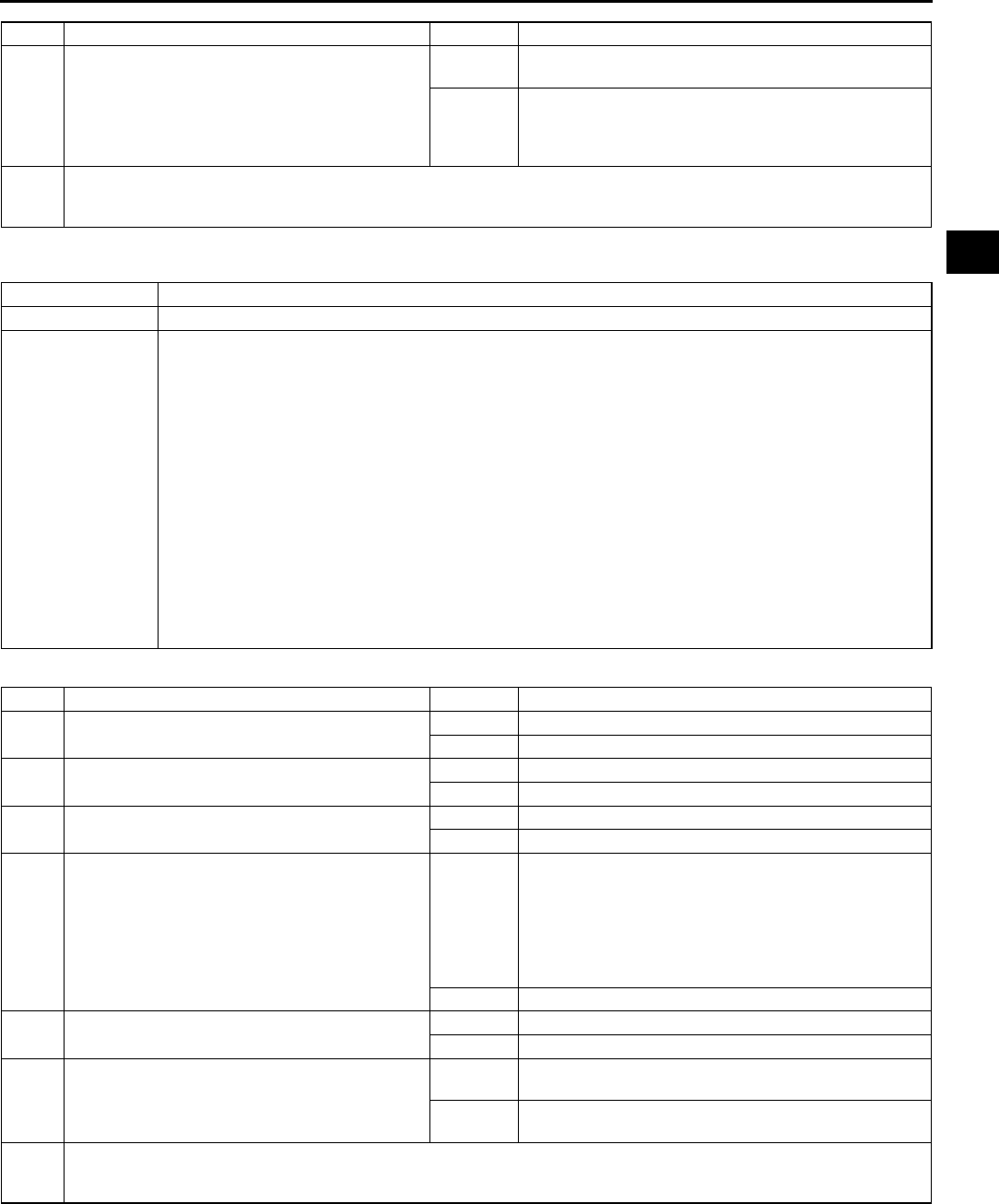
TROUBLESHOOTING
F219
F
End Of Sie
NO.21 ENGINE NOISE A6E398018881W23
Diagnostic procedure
End Of Sie
4 Connect WDS or equivalent to DLC-2.
Retrieve any continuous memory, KOEO and
KOER DTCs.
Are there any DTCs displayed?
Yes DTC is displayed:
Go to appropriate DTC test.
No No DTC is displayed:
Inspect charcoal canister for fuel saturation.
If excess amount of liquid fuel is present, replace
charcoal canister.
5 Verify test results.
•If okay, return to diagnostic index to service any additional symptoms.
•If malfunction remains, replace PCM.
STEP INSPECTION RESULTS ACTION
21 ENGINE NOISE
DESCRIPTION Engine noise from under hood
POSSIBLE CAUSE
Squeal, click or chirp noise:
•Improper engine oil level
•Improper drive belt tension
Rattle sound noise:
•Loose parts
Hiss sound noise:
•Vacuum leakage
•Loose spark plug
•Air leakage from intake-air system
•Improper variable air duct (VAD) control system operation
Rumble or grind noise:
•Improper drive belt tension
Rap or roar sound noise:
•Exhaust system looseness
Other noise:
•Camshaft friction gear noise or MLA noise
•Timing chain noise
STEP INSPECTION RESULTS ACTION
1 Is squeal, click or chirp sound present? Yes Inspect engine oil level or drive belts.
No Go to next step.
2 Is rumble or grind sound present? Yes Inspect drive belts.
No Go to next step.
3 Is rattle sound present? Yes Inspect location of rattle for loose parts.
No Go to next step.
4 Is hiss sound present? Yes Inspect for following:
•Vacuum leakage
•Spark plug looseness
•Intake-air system leakage
•Variable air duct (VAD) control system operation
(See F238 Variable Air Duct (VAD) Control System
Operation Inspection (L3 Engine Models).)
No Go to next step.
5 Is rap or roar sound present? Yes Inspect exhaust system for loose parts.
No Go to next step.
6 Is knock sound present? Yes Go to symptom troubleshooting "No.11 Knocking/
pinging".
No If noise comes from engine internal, inspect for friction
gear, timing chain or MLA noise.
7 Verify test results.
•If okay, return to diagnostic index to service any additional symptoms.
•If malfunction remains, replace PCM.

F220
TROUBLESHOOTING
NO.22 VIBRATION CONCERNS (ENGINE) A6E398018881W24
Diagnostic procedure
End Of Sie
NO.23 A/C DOES NOT WORK SUFFICIENTLY A6E398018881W25
Diagnostic procedure
22 VIBRATION CONCERNS (ENGINE)
DESCRIPTION •Vibration from under hood or driveline
POSSIBLE CAUSE •Loose attaching bolts or worn parts
•Components malfunction such as worn parts
STEP INSPECTION RESULTS ACTION
1 Inspect following components for loose attaching
bolts or worn parts:
•Cooling fan
•Condenser fan
•Drive belt and pulleys
•Engine mounts
All items okay?
Yes Inspect following systems:
•Wheels
•ATX
•Driveline
•Suspension
No Readjust or retighten engine mount installation
position.
Service if necessary for other parts.
2 Verify test results.
•If okay, return to diagnostic index to service any additional symptoms.
•If malfunction remains, replace PCM.
23 A/C DOES NOT WORK SUFFICIENTLY.
DESCRIPTION A/C compressor magnetic clutch does not engage when A/C switch is turned on.
POSSIBLE CAUSE
•Improper refrigerant charging amount
•Open A/C magnetic clutch
•Open circuit between A/C relay and A/C magnetic clutch
•Poor GND of A/C magnetic clutch
•Refrigerant pressure switch is stuck open.
•A/C relay is stuck open.
•Seized A/C compressor
•Open circuit between A/C switch and PCM through both refrigerant pressure switch and A/C amplifier
STEP INSPECTION RESULTS ACTION
1 Connect WDS or equivalent to DLC-2.
Retrieve any continuous memory, KOEO and
KOER DTCs.
Are there any DTCs displayed?
Yes DTC is displayed:
Go to appropriate DTC test.
No No DTC is displayed:
Go to next step.
2 Disconnect A/C compressor connector.
Start engine and turn A/C switch on.
Is there correct voltage at terminal of A/C
compressor magnetic clutch connector?
Specification
More than 10.5 V
Yes Inspect for GND condition of magnetic clutch on A/C
compressor.
If GND condition is okay, inspect for open circuit
magnetic clutch coil.
No Go to next step.
3 Disconnect refrigerant pressure switch
connector.
Connect jumper wire between terminals of A/C
high pressure switch connector.
Connect jumper wires between terminals of
refrigerant pressure switch connector.
Connect WDS or equivalent to DLC-2.
Access ACSW PID.
Turn ignition switch to ON position.
Turn A/C switch on and set blower fan at any
speed.
Does ACSW PID read ON?
Yes Inspect refrigerant pressure switch operation.
If switch is okay, go to next step.
No Inspect for following:
•A/C switch is stuck open.
•Open circuit between refrigerant pressure switch
and PCM terminal 1AC
•Open circuit of blower motor fan switch and resistor
(if blower motor does not operate)
•Evaporator temperature sensor and A/C amplifier
4 Remove jumper wire from switch connector.
Reconnect connector to refrigerant pressure
switch.
Start engine and turn A/C switch on.
Does fan operate?
Yes Inspect for stuck open A/C relay.
Replace if necessary.
No Inspect following and repair or replace as necessary:
•Refrigerant charging amount
•A/C compressor for being seized
5 Verify test results.
•If okay, return to diagnostic index to service any additional symptoms.
•If malfunction remains, replace PCM.
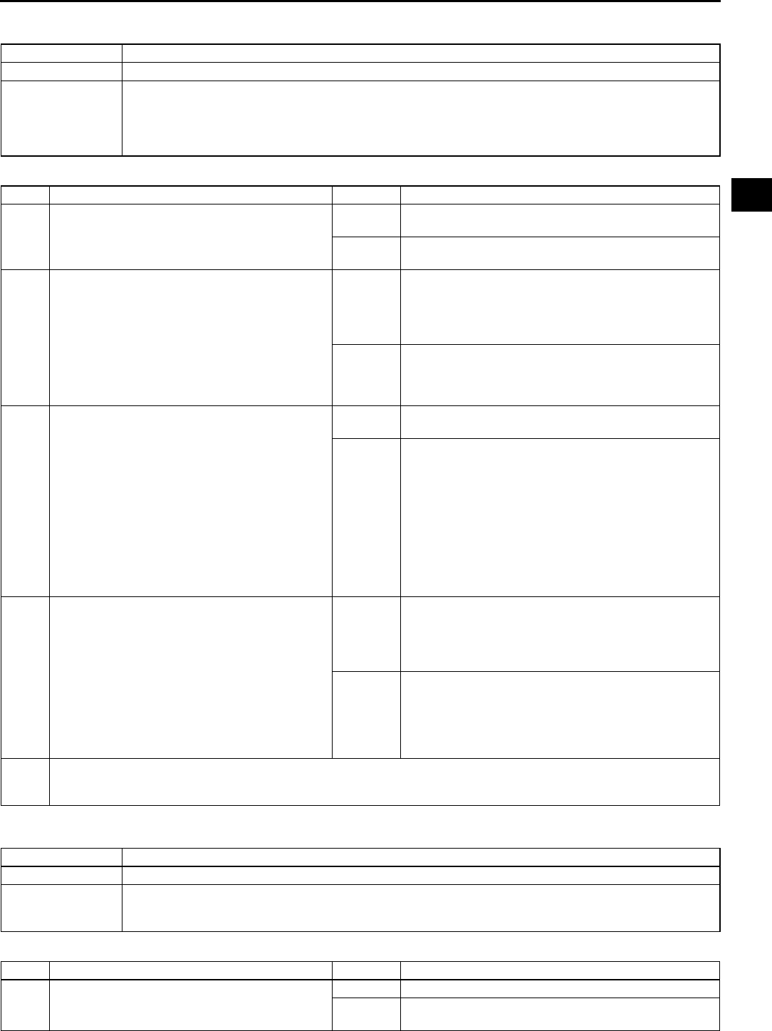
TROUBLESHOOTING
F221
F
End Of Sie
NO.24 A/C IS ALWAYS ON OR A/C COMPRESSOR RUNS CONTINUOUSLY A6E398018881W26
Diagnostic procedure
End Of Sie
NO.25 A/C IS NOT CUT OFF UNDER WIDE OPEN THROTTLE CONDITIONS A6E398018881W27
Diagnostic procedure
24 A/C IS ALWAYS ON OR A/C COMPRESSOR RUNS CONTINUOUSLY.
DESCRIPTION A/C compressor magnetic clutch does not disengage.
POSSIBLE CAUSE
•Stuck engagement A/C compressor magnetic clutch
•A/C relay is stuck closed.
•Short to GND between A/C switch and PCM
•Short to GND circuit between A/C relay and PCM
•A/C relay to magnetic clutch circuit shorted to battery power
STEP INSPECTION RESULTS ACTION
1 Connect WDS or equivalent to DLC-2.
Retrieve any continuous memory, KOEO and
KOER DTCs.
Are there any DTCs displayed?
Yes DTC is displayed:
Go to appropriate DTC test.
No No DTC is displayed:
Go to next step.
2 Start engine and run it at idle.
Turn A/C switch on.
Remove A/C relay.
Does A/C magnetic clutch disengage?
Yes Inspect for following:
•A/C relay is stuck closed.
•Short to GND circuit between A/C relay and PCM
terminal 4O.
If both items okay, go to next step.
No Inspect if circuit between A/C relay and magnetic
clutch shorts to battery power circuit.
If circuit is okay, inspect magnetic clutch stuck
engagement or clearance.
3 Connect WDS or equivalent to DLC-2.
Access ACSW PID.
Start engine and turn A/C switch on.
Read ACSW PID while disconnecting refrigerant
pressure switch connector.
Note
•ACSW PID should read OFF when
disconnecting connector. If ACSW PID
reading remains ON, short to GND circuit
may be present.
Does ACSW PID reading remain ON?
Yes Inspect for short to GND circuit between refrigerant
pressure switch and PCM terminal 1AC.
No Go to next step.
4 Reconnect refrigerant pressure switch
connector.
Read ACSW PID while turning off A/C switch.
Note
•ACSW PID should read OFF when turning
A/C switch off. If ACSW PID reading
remains ON, short to GND circuit may be
present.
Does ACSW PID reading remain ON?
Yes Inspect following:
•Short to GND circuit between A/C switch and A/C
amplifier
•Short to GND circuit between A/C amplifier and
refrigerant pressure switch
No Inspect for stuck closed A/C switch.
5 Verify test results.
•If okay, return to diagnostic index to service any additional symptoms.
•If malfunction remains, replace PCM.
25 A/C IS NOT CUT OFF UNDER WOT CONDITIONS.
DESCRIPTION A/C compressor magnetic clutch does not disengage under WOT.
POSSIBLE CAUSE
•TP sensor malfunction
•TP sensor misadjustment
•Loosely installed TP sensor.
STEP INSPECTION RESULTS ACTION
1 Does A/C compressor disengage when A/C
switch is turned off?
Yes Go to next step.
No Go to symptom troubleshooting "No.24 A/C is always
on or A/C compressor runs continuously".

F222
TROUBLESHOOTING
End Of Sie
NO.26 EXHAUST SULPHUR SMELL A6E398018881W28
Diagnostic procedure
2 Connect WDS or equivalent to DLC-2.
Retrieve any continuous memory, KOEO and
KOER DTCs.
Are there any DTCs displayed?
Yes DTC is displayed:
Go to appropriate DTC test.
No No DTC is displayed:
Inspect TP sensor for proper adjustment.
3 Verify test results.
•If okay, return to diagnostic index to service any additional symptoms.
•If malfunction remains, replace PCM.
STEP INSPECTION RESULTS ACTION
26 EXHAUST SULPHUR SMELL
DESCRIPTION Rotten egg smell (sulphur) from exhaust
POSSIBLE CAUSE
•Electrical connectors are disconnected or connected poorly
•Charcoal canister malfunction
•Vacuum lines are disconnected or connected improperly.
•Improper fuel pressure
•Poor fuel quality
Warning
The following troubleshooting flow chart contains fuel system diagnosis and repair
procedures. Read following warnings before performing fuel system services:
•
••
•Fuel vapor is hazardous. It can easily ignite, causing serious injury and damage. Always
keep sparks and flames away from fuel.
•
••
•Fuel line spills and leakage are dangerous. Fuel can ignite and cause serious injuries or
death and damage. Fuel can also irritate skin and eyes. To prevent this, always complete
BEFORE REPAIR PROCEDURE and AFTER REPAIR PROCEDURE described in this
manual.
(See F17 BEFORE REPAIR PROCEDURE.)
(See F17 AFTER REPAIR PROCEDURE.)
Caution
•
••
•Disconnecting/connecting quick release connector without cleaning it may possibly cause
damage to fuel pipe and quick release connector. Always clean quick release connector
joint area before disconnecting/connecting, and make sure that it is free of foreign material.
STEP INSPECTION RESULTS ACTION
1 Are any driveability or exhaust smoke concerns
present?
Yes Go to appropriate flow chart.
No Go to next step.
2 Inspect following:
•Electrical connections
•Vacuum lines
•Fuel quality
Are all items okay?
Yes Go to next step.
No Service as necessary.
Repeat Step 2.
3 Connect WDS or equivalent to DLC-2.
Retrieve any continuous memory, KOEO and
KOER DTCs.
Are there any DTCs displayed?
Yes DTC is displayed:
Go to appropriate DTC test.
No No DTC is displayed:
Go to next step.
4 Install fuel pressure gauge between fuel pipe
and fuel distributor.
Start engine and run it at idle.
Is fuel line pressure correct at idle?
(See F20 FUEL LINE PRESSURE
INSPECTION)
Yes Go to next step.
No Zero or low:
Inspect for clogged fuel line.
If okay, replace fuel pump unit.
High:
Replace fuel pump unit.
5 Inspect charcoal canister for fuel saturation.
Is excess amount of liquid fuel present in
canister?
Yes Replace charcoal canister.
No Inspect fuel tank vent system.
If fuel tank vent system is okay, since sulfur content
can vary in different fuels, suggest trying a different
brand.
If fuel tank vent system is not okay, repair or replace
malfunctioning parts.
6 Verify test results.
•If okay, return to diagnostic index to service any additional symptoms.
•If malfunction remains, replace PCM.
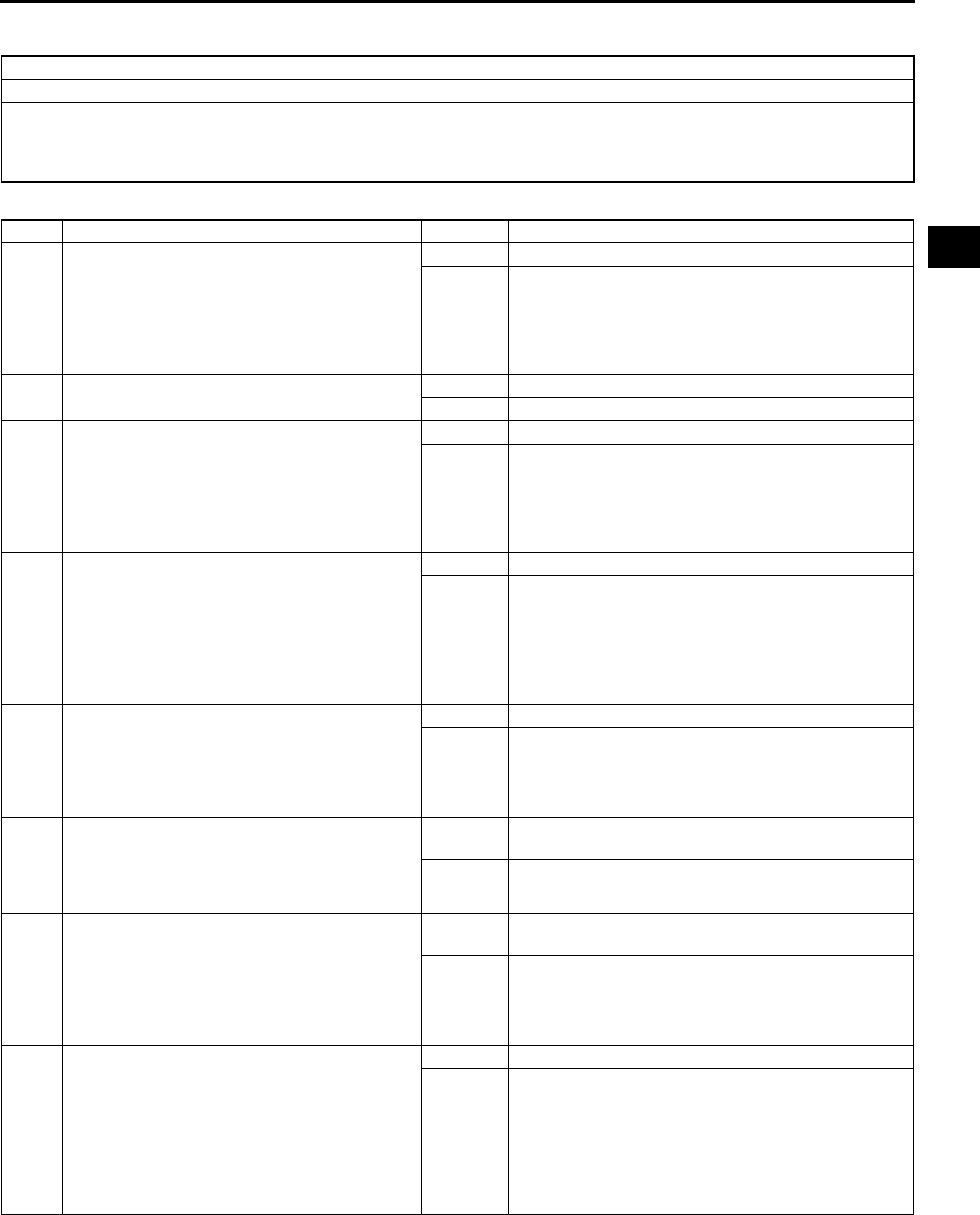
TROUBLESHOOTING
F223
F
End Of Sie
NO.27 CONSTANT VOLTAGE A6E398018881W29
Diagnostic procedure
27 CONSTANT VOLTAGE
DESCRIPTION Incorrect constant voltage
POSSIBLE CAUSE
•Constant voltage circuit malfunction
Note
•TP sensor uses constant voltage.
STEP INSPECTION RESULTS ACTION
1 Disconnect TP sensor connector where constant
voltage circuit inspection failed.
Turn ignition switch to ON position.
Measure voltage between following TP sensor
connector terminals:
•Constant voltage terminal - GND terminal
Is constant voltage greater than 6.0 V?
Yes Go to Step 13.
No Go to next step.
2 Is voltage across battery terminals greater than
10.5 V?
Yes Go to next step.
No Inspect charging system.
3 Turn ignition switch off.
Leave TP sensor connector disconnected.
Measure voltage between battery positive
terminal and GND (between PCM and TP
sensor) circuit at appropriate sensor connector.
Is voltage greater than 10.5 V and within 1.0 V
of battery voltage?
Yes Go to next step.
No Go to Step 8.
4Note
•Purpose of this step is to determine if
WDS or equivalent is communicating with
PCM.
Turn ignition switch to ON position.
Attempt to access ECT PID.
Can ECT PID be accessed?
Yes Go to Step 7.
No Go to next step.
5 Turn ignition switch off.
Disconnect TP sensor and PCM connectors.
Turn ignition switch to ON position.
Measure voltage between PCM connector
terminals 2Y and 2AB.
Is voltage greater than 10.5 V?
Yes Go to next step.
No Repair open circuit between PCM terminal 2Y and
main relay.
6 Leave TP sensor and PCM connectors
disconnected.
Measure resistance between PCM connector
terminals 2Y and 2AB.
Is resistance greater than 10,000 ohms?
Yes Inspect for constant voltage at suspect sensor
connector again.
No Repair constant voltage circuit short to GND.
7 Turn ignition switch off.
Leave TP sensor disconnected.
Disconnect PCM connector.
Measure resistance between PCM connector
terminal 2K and constant voltage circuit at
appropriate sensor connector.
Is resistance less than 5.0 ohms?
Yes Inspect for constant voltage at suspect sensor
connector again.
No Repair open constant voltage circuit.
8Note
•Purpose of this step is to determine if
WDS or equivalent is communicating with
PCM.
Reconnect TP sensor connector.
Turn ignition switch to ON position.
Attempt to access ECT PID.
Can ECT PID be accessed?
Yes Go to next step.
No Go to Step 11.

F224
TROUBLESHOOTING
End Of Sie
9 Are DTCs present for two or more sensors
connected to PCM terminal 2H?
Sensor connected to PCM terminal 2H:
•IAT sensor (P0112, P0113)
•FHO2S (P0131, P0132)
•RHO2S (P0138)
•Barometric pressure sensor (P2228, P2229)
•Manifold absolute pressure sensor (P0107,
P0108)
•ECT sensor (P0117, P0118)
•TP sensor (P0122, P0123)
•TR switch (P0707, P0708)
•TFT sensor (P0712, P0713)
Yes Go to next step.
No Repair open GND circuit to sensor where constant
voltage circuit inspection failed.
10 Turn ignition switch off.
Disconnect WDS or equivalent from DLC-2.
Disconnect PCM connector.
Measure resistance between GND circuit at
appropriate sensor connector and PCM
connector terminal 2H.
Is resistance less than 5.0 ohms?
Yes Reconnect sensor connector.
Go to appropriate DTC test.
No Repair open GND circuit.
11 Turn ignition switch off.
Disconnect PCM connector.
Measure resistance between battery negative
terminal and PCM terminals 4X, 2AB, and 2AC.
Is each resistance less than 5.0 ohms?
Yes Go to next step.
No Repair open GND circuit.
12 Turn ignition switch off.
Measure resistance between GND circuit at
following sensor connector and GND:
•IAT sensor (integated in MAF sensor)
•FHO2S
•RHO2S
•Barometric pressure sensor
•Manifold absolute pressure sensor
•ECT sensor
•TP sensor
•TR switch
•TFT sensor
Yes GND circuits are okay.
Inspect for constant voltage at suspect sensor
connector again.
No Inspect for open GND circuit.
13 Turn ignition switch off.
Disconnect TP sensor and PCM connectors.
Turn ignition switch to ON position.
Measure voltage between constant voltage
circuit at TP sensor connector and battery
negative terminal.
Is voltage less than 0.5 V?
Yes Inspect for constant voltage at suspect sensor
connector again.
No Repair constant voltage circuit shorted to power in
harness.
14 Verify test results.
•If okay, return to diagnostic index to service any additional symptoms.
•If malfunction remains, replace PCM.
STEP INSPECTION RESULTS ACTION
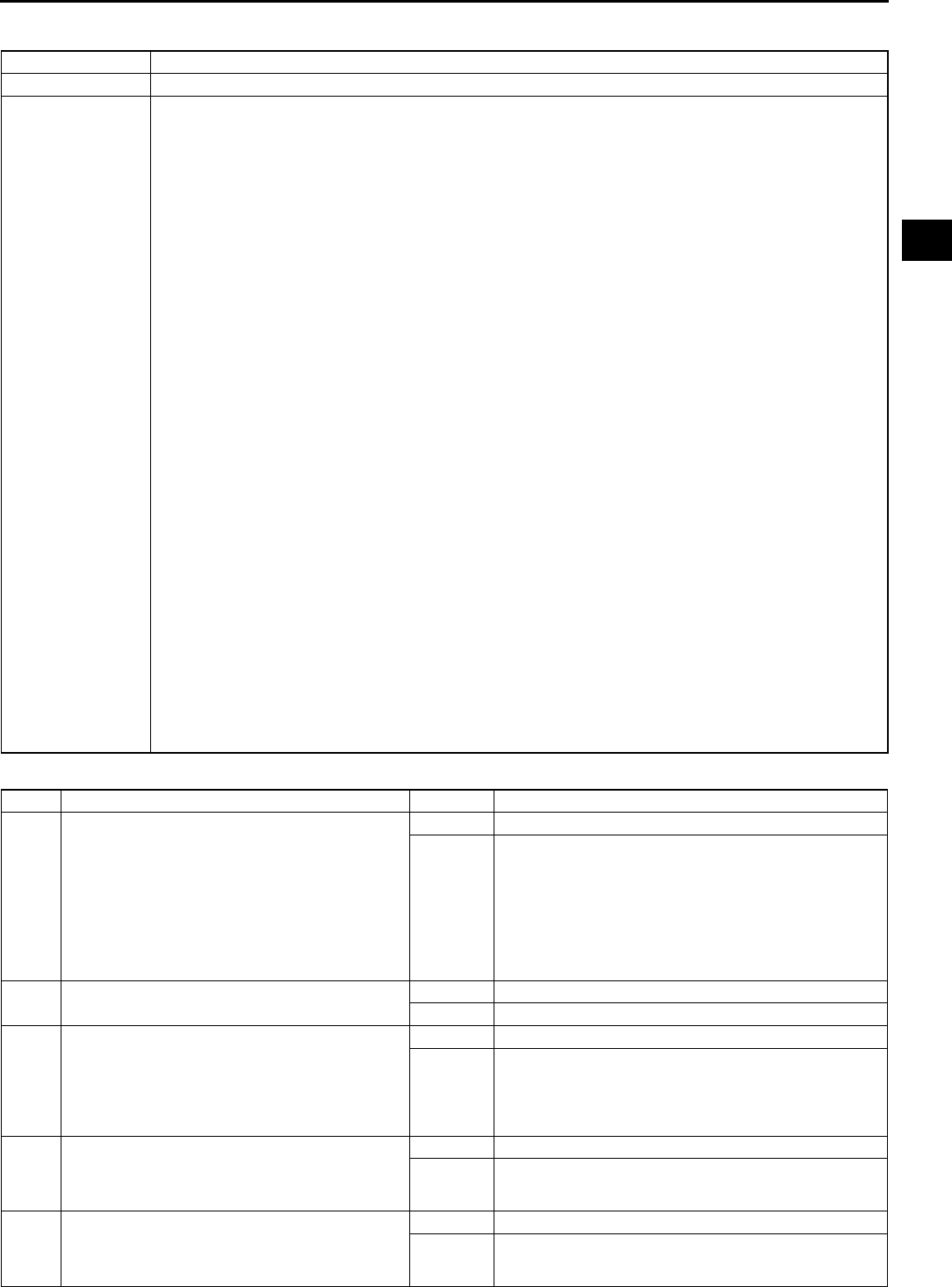
TROUBLESHOOTING
F225
F
NO.28 SPARK PLUG CONDITION A6E398018881W30
Diagnostic procedure
28 SPARK PLUG CONDITION
DESCRIPTION Incorrect spark plug condition
POSSIBLE CAUSE
Note
•Inspecting spark plugs condition can determine whether problem is related to a specific cylinder
possibly all cylinders.
Wet/carbon stuck on specific plug:
•SparkWeak, not visible
•Air/fuel mixtureExcessive fuel injection volume
•CompressionNo compression, low compression
•Faulty spark plug
Grayish white with specific plug:
•Air/fuel mixtureInsufficient fuel injection volume
•Faulty spark plug
Wet/carbon is stuck on all plugs:
•SparkSpark weak
•Air/fuel mixtureToo rich
•CompressionLow compression
•Clogging in intake/exhaust system
Grayish white with all plugs:
•Air/fuel mixtureToo lean
Warning
The following troubleshooting flow chart contains the fuel system diagnosis and repair
procedures. Read the following warnings before performing the fuel system services:
•
••
•Fuel vapor is hazardous. It can easily ignite, causing serious injury and damage. Always
keep sparks and flames away from fuel.
•
••
•Fuel line spills and leakage are dangerous. Fuel can ignite and cause serious injuries or
death and damage. Fuel can also irritate skin and eyes. To prevent this, always complete
BEFORE REPAIR PROCEDURE and AFTER REPAIR PROCEDURE described in this
manual.
(See F17 BEFORE REPAIR PROCEDURE.)
(See F17 AFTER REPAIR PROCEDURE.)
Caution
•
••
•Disconnecting/connecting quick release connector without cleaning it may possibly cause
damage to fuel pipe and quick release connector. Always clean quick release connector
joint area before disconnecting/connecting, and make sure that it is free of foreign material.
STEP INSPECTION RESULTS ACTION
1 Remove all spark plugs.
Inspect spark plug condition.
Is spark plug condition okay?
Yes Troubleshooting completed.
No Specific plug is wet or covered with carbon:
Go to next step.
Specific plug looks grayish white:
Go to Step 7.
All plugs are wet or covered with carbon:
Go to Step 9.
All plugs look grayish white:
Go to Step 15.
2 Is spark plug wet/covered with carbon by engine
oil?
Yes Working up and down inspect all areas related to oil.
No Go to next step.
3 Inspect spark plug for following:
•Cracked insulator
•Heat range
•Air gap
•Worn electrode
Is spark plug okay?
Yes Go to next step.
No Replace spark plug.
4 Inspect compression pressure at suspected
faulty cylinder.
Is compression pressure correct?
(See B9 COMPRESSION INSPECTION.)
Yes Go to next step.
No Repair or replace malfunctioning parts.
5 Install all spark plugs.
Carry out spark test at suspected faulty cylinder.
Is strong blue spark visible?
(Compare with normal cylinder.)
Yes Go to next step.
No Repair or replace malfunctioning parts.

F226
TROUBLESHOOTING
6 Carry out fuel line pressure inspection.
Is fuel line pressure correct?
Yes Inspect fuel injector for following:
•Open or short in injector
•Leakage
•Injection volume
No Zero or low:
Inspect fuel pump circuit.
Inspect for fuel pump relief valve open.
Inspect for fuel leakage inside pressure regulator.
Inspect for clogged main fuel line.
High:
Inspect pressure regulator for high pressure cause.
Inspect for clogged fuel return line.
7 Inspect spark plug for following.
•Heat range
•Air gap
Is spark plug okay?
Yes Go to next step.
No Replace spark plug.
8 Remove suspected fuel injector.
Inspect following:
•Resistance
(See F31 FUEL INJECTOR INSPECTION.)
•Fuel injection volume
(See F31 FUEL INJECTOR INSPECTION.)
Are all above items okay?
Yes Inspect for open circuit between suspected fuel injector
connector terminal and PCM connector following
terminals:
•For #1 or #4 cylinder: 1A
•For #2 or #3 cylinder: 1B
No Replace fuel injector.
9 Is air cleaner element free of restrictions? Yes Go to next step.
No Replace air cleaner element.
10 Carry out spark test.
Is strong blue spark visible at each cylinder?
Yes Go to next step.
No Repair or replace malfunctioning parts.
11 Carry out fuel line pressure inspection.
Is fuel line pressure correct?
(See F20 FUEL LINE PRESSURE
INSPECTION)
Yes Go to next step.
No Zero or low:
Inspect for clogged fuel line.
If okay, replace fuel pump unit.
High:
Replace fuel pump unit.
12 Inspect following PIDs.
•ECT
•O2S11 (When engine can be started)
•MAF
(See F45 PCM INSPECTION.)
Are PIDs okay?
Yes Go to next step.
No Repair or replace malfunctioning parts.
13 Carry out purge control inspection.
(When engine can be started)
(See F233 Purge Control System Inspection.)
Is purge control correct?
Yes Go to next step.
No Repair or replace malfunctioning parts.
14 Carry out compression inspection.
Is compression correct?
Yes Inspect for clogging in exhaust system.
No Repair or replace malfunctioning parts.
15 When engine cannot be started, inspect intake-
air system for air leakage.
When engine can be started, carry out intake
manifold vacuum inspection.
Is air sucked in from intake-air system?
Yes Repair or replace malfunctioning part.
No Go to next step.
16 Carry out fuel line pressure inspection.
Is fuel line pressure correct?
(See F20 FUEL LINE PRESSURE
INSPECTION)
Yes Inspect following PIDs.
•ECT
•O2S11
•MAF
(See F45 PCM INSPECTION.)
Inspect PCM GND condition.
No Zero or low:
Inspect for clogged fuel line.
If okay, replace fuel pump unit.
High:
Replace fuel pump unit.
17 Verify test results.
•If okay, return to diagnostic index to service any additional symptoms.
•If malfunction remains, replace or reprogram PCM.
STEP INSPECTION RESULTS ACTION
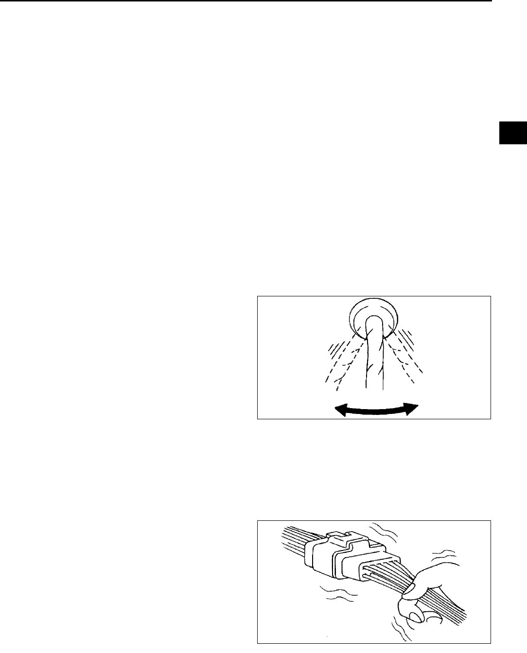
TROUBLESHOOTING
F227
F
End Of Sie
INTERMITTENT CONCERN TROUBLESHOOTING A6E398018881W31
Vibration Method
1. If malfunction occurs or becomes worse while driving on a rough road or when engine is vibrating, perform the
steps below.
Note
•There are several reasons vehicle or engine vibration could cause an electrical malfunction. Some of the
things to check for are:
Connectors not fully seated.
Wire harnesses not having full play.
Wires laying across brackets or moving parts.
Wires routed too close to hot parts.
•An improperly routed, improperly clamped, or loose harness can cause wiring to become pinched
between parts.
•The connector joints, points of vibration, and places where wire harnesses pass through the fire wall, body
panels, etc. are the major areas to be checked.
Inspection Method for Switch Connectors or Wires
1. Connect WDS or equivalent to DLC-2.
2. Turn ignition key to ON position (Engine OFF).
Note
•If engine starts and runs, perform the following steps at idle.
3. Access PIDs for the switch you are inspecting.
4. Turn switch on manually.
5. Shake each connector or wire harness a bit
vertically and horizontally while monitoring the
PID.
•If PID value is unstable, check for poor
connection.
Inspection Method for Sensor Connectors or Wires
1. Connect WDS or equivalent to DLC-2.
2. Turn ignition switch to ON position (Engine OFF).
Note
•If engine starts and runs, perform the following steps at idle.
3. Access PIDs for the switch you are inspecting.
4. Shake each connector or wire harness a bit
vertically and horizontally while monitoring the
PID.
•If PID value is unstable, check for poor
connection.
Y3U103WN3
Y3U103WN4
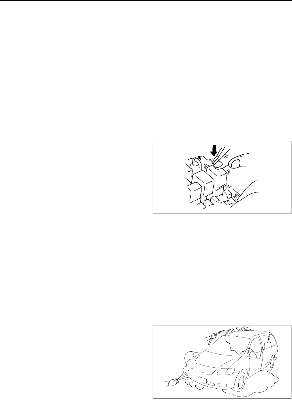
F228
TROUBLESHOOTING
Inspection Method for Sensors
1. Connect WDS or equivalent to DLC-2.
2. Turn ignition switch to ON position (Engine OFF).
Note
•If engine starts and runs, perform the following steps at idle.
3. Access PIDs for the switch you are inspecting.
4. Vibrate the sensor slightly with your finger.
•If PID value is unstable or malfunction occurs, check for poor connection and/or poorly mounted sensor.
Inspection Method for Actuators or Relays
1. Connect WDS or equivalent to DLC-2.
2. Turn ignition switch to ON position (Engine OFF).
Note
•If engine starts and runs, perform the following steps at idle.
3. Prepare the Output State Control for actuators or relays that you are inspecting.
4. Vibrate the actuator or relay with your finger for 3 seconds are Output State Control is activated.
•If variable click sound is heard, check for poor connection and/or poorly mounted actuator or relay.
Note
•Vibrating relays too strongly may result in
open relays.
Water Sprinkling Method
Caution
•
••
•Indirectly change the temperature and humidity by spraying water onto the front of the radiator.
•
••
•If a vehicle is subject to water leakage, the leakage may damage the control module. When testing
a vehicle with a water leakage problem, special caution must be used.
If malfunction occurs only during high humidity or rainy/snowy weather, perform the following steps.
1. Connect WDS or equivalent to DLC-2 if you are inspecting sensors or switches.
2. Turn ignition switch to ON position (Engine OFF).
Note
•If engine starts and runs, perform the following steps at idle.
3. Access PIDs for sensor or switch if you are inspecting sensors or switches.
4. If you are inspecting the switch, turn it on manually.
5. Spray water onto the vehicle or run it through a
car wash.
•If PID value is unstable or malfunction occurs,
repair or replace part as necessary.
End Of Sie
Y3U103WN5
YMU103WC3

TROUBLESHOOTING
F229
F
ENGINE CONTROL SYSTEM OPERATION INSPECTION A6E398018881W32
Main Relay Operation Inspection
1. Verify that the main relay clicks when the ignition switch is turned to ON position and off.
•If there is no operation sound, inspect the following.
Main relay (See T24 RELAY INSPECTION.)
Harness and connector between ignition switch and main relay terminal A.
Harness and connector between PCM terminal 2X and main relay terminal E.
Intake Manifold Vacuum Inspection
1. Verify air intake hoses are installed properly.
2. Start the engine and run it at idle.
3. Disconnect the vacuum hose between the intake manifold and purge solenoid valve from the intake manifold
side.
4. Connect a vacuum gauge to the intake manifold and measure the intake manifold vacuum.
•If not as specified, inspect the following.
Specification
More than 60 kPa {450 mmHg, 18 inHg}
Note
•Air suction can be located by engine speed change when lubricant is sprayed on the area where suction is
occurring.
Air suction at throttle body, intake manifold and PCV valve installation points
Accelerator cable free play
Fuel injector insulator
Engine compression
(See B9 COMPRESSION INSPECTION.)
Idle Air Control System Inspection
Engine coolant temperature compensation inspection
1. Connect WDS or equivalent to the DLC-2.
2. Select the following PIDs.
•ECT
•IAT
•RPM
3. Verify that the engine is in cold condition, then start the engine.
4. Verify that the engine speed decreases as the engine warms up.
•If the engine speed does not decrease or decreases slowly, inspect the following.
ECT sensor and related harness
(See F53 ENGINE COOLANT TEMPERATURE (ECT) SENSOR INSPECTION.)
IAC valve and related harness
(See F13 IDLE AIR CONTROL (IAC) VALVE INSPECTION.)
Load compensation inspection
1. Start the engine and run is at idle.
2. Connect WDS or equivalent to the DLC-2.
3. Verify that P0506, P0507 or P0511 not displayed.
•If P0506, P0507 or P0511 shown, carry out DTC inspection.
(See F67 DTC TABLE.)
4. Change the duty value of the IAC valve to 100% using the IAC PID.
5. Verify that the idle speed increases.
•If the idle speed does not change, inspect the following.
IAC valve air passage
Open or short circuit between IAC valve connector terminals and PCM connector terminals 4G and 4J
6. Select the following PIDs.
•ACSW
•IAC
•PSP
•RPM
Note
•Excludes temporary idle speed drop just after the loads are turned on.
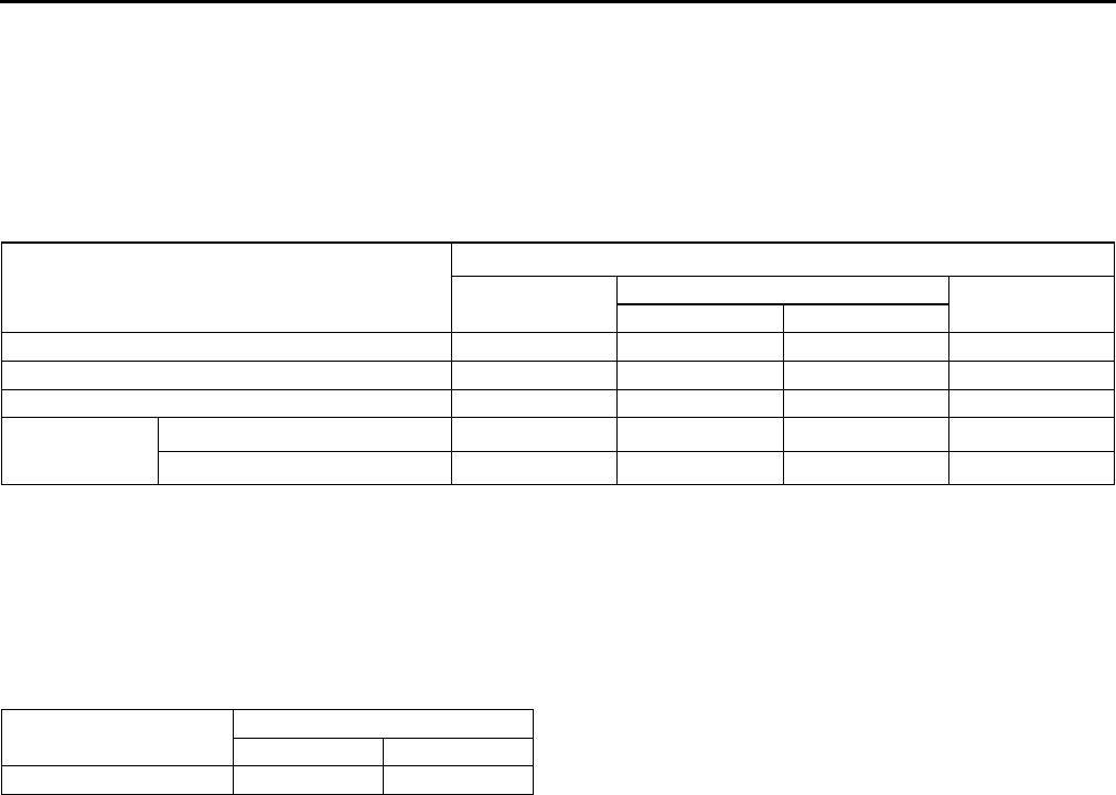
F230
TROUBLESHOOTING
7. Verify that the engine speed is within the specification under each load condition.
•If not as specified specific load condition, inspect the following.
A/C switch and related harness
(See U47 CLIMATE CONTROL UNIT INSPECTION.)
Fan switch and related harness
(See U47 CLIMATE CONTROL UNIT INSPECTION.)
PSP switch and related harness
(See F58 POWER STEERING PRESSURE (PSP) SWITCH INSPECTION.)
Engine speed
*1 : Neutral or P position
*2 : A/C switch and fan switch are on.
*3 : Refrigerant pressure switch (middle pressure) is off.
*4 : Refrigerant pressure switch (middle pressure) is on.
VIS Operation Inspection
1. Start the engine.
2. Inspect the rod operation under the following condition.
Rod operation
•If the rod operation is not as specified, inspect as follows.
(1) Stop the engine.
(2) Connect WDS or equivalent to the DLC-2.
(3) Verify that DTC P0661 or P0662 is not displayed.
•If DTC P0661 or P0662 is shown, carry out DTC inspection.
(See F67 DTC TABLE.)
(4) Turn ignition switch to ON.
(5) Turn the VIS control solenoid valve from on to off using the IVC PID and verify that operation sound of the
solenoid valve is heard.
•If the operation sound is heard, inspect the following.
Vacuum hose and vacuum chamber for looseness or damage
Shutter valve actuator
(See F14 VARIABLE INTAKE-AIR SYSTEM (VIS) SHUTTER VALVE ACTUATOR INSPECTION
(L3).)
Shutter valve stuck open or close
•If the operation sound is not heard, inspect the following.
VIS control solenoid valve
(See F14 VARIABLE INTAKE-AIR SYSTEM (VIS) CONTROL SOLENOID VALVE INSPECTION
(L3).)
Load condition
Engine speed (rpm)*1
L8 LF L3
MTX ATX
No load 650750 600700 650750 600700
E/L operating 650750 650750 650750 650750
P/S operating 700800 650750 650750 650750
A/C operating*2 Refrigerant pressure low*3 700800 700800 650750 700800
Refrigerant pressure high*4 700800 700800 700800 700800
Engine speed Approx. 4,400 rpm
Below Above
Shutter valve actuator Operate Not operate
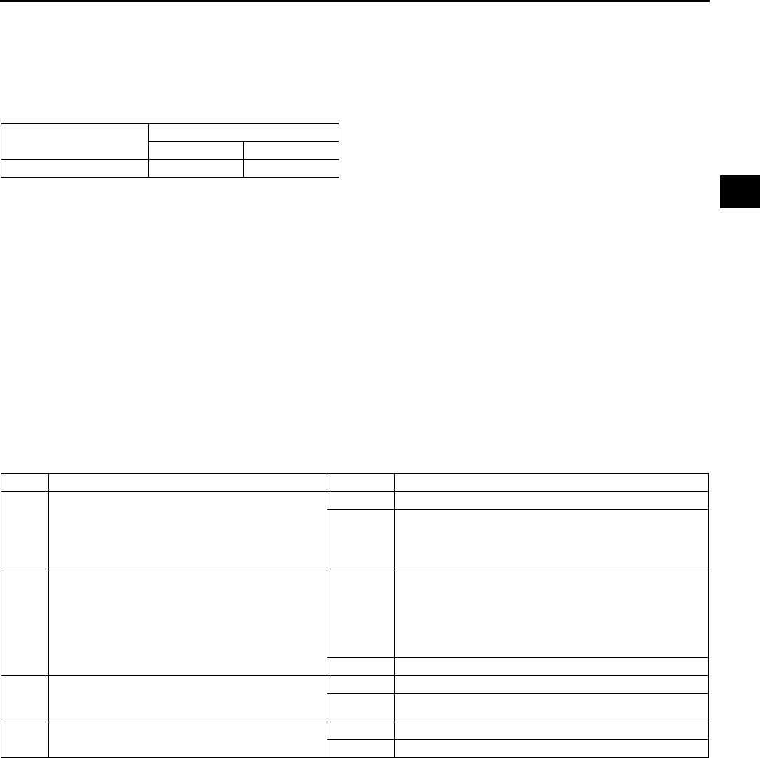
TROUBLESHOOTING
F231
F
Variable Tumble Control System (VTCS) Operation Inspection
1. Connect the WDS or equivalent to the DLC-2.
2. Access ECT PID.
3. Verify that ECT PID is between 63°
°°
°C {145°
°°
°F} and 67°
°°
°C {152°
°°
°F}.
4. Start the engine.
5. Inspect rod operation under the following condition.
Rod operation
•If the rod operation is not specified, inspect as follows.
(1) Verify that DTC No. P2009 or P2010 is not displayed.
•If DTC No. P2009 or P2010 are shown, carry out DTC inspection.
(See F67 DTC TABLE.)
(2) Turn ignition switch to ON.
(3) Turn the VTCS solenoid valve from on to off using the IMRC PID and verify that operation sound of the
solenoid valve is heard.
•If the operation sound is heard, inspect the following.
Vacuum hose and vacuum chamber for looseness or damage
Shutter valve actuator
(See F15 VARIABLE TUMBLE CONTROL SYSTEM (VTCS) SHUTTER VALVE ACTUATOR
INSPECTION.)
Shutter valve stuck open or close
•If the operation sound is not heard, inspect the following.
VIS control solenoid valve
(See F15 VARIABLE TUMBLE CONTROL SOLENOID VALVE INSPECTION.)
Fuel Injector Operation Inspection
Fuel Cut Control System Inspection
1. Warm up engine and let it idle.
2. Turn off the electrical loads and A/C switch.
3. Connect WDS or equivalent to the DLC-2.
4. Select RPM and FUELPW1 PIDs.
5. Monitor both PIDs while performing the following steps.
(1) Depress the accelerator pedal and increase the engine speed to 4,000 rpm.
(2) Release the accelerator pedal (brake pedal is not depressed) and verify that the fuel injector duration time
is 0 msec., and 25 msec. when the engine speed drops below 1,200 rpm.
•If not as specified, inspect the following.
ECT sensor and related harness
(See F53 ENGINE COOLANT TEMPERATURE (ECT) SENSOR INSPECTION.)
Neutral/clutch switch and related harness (MTX)
(See F59 CLUTCH SWITCH INSPECTION.)
TR switch and related harness (ATX)
(See K14 TRANSAXLE RANGE (TR) SWITCH INSPECTION.)
Engine speed 3,750 rpm
Below Above
Shutter valve actuator Operate Not operate
STEP INSPECTION RESULTS ACTION
1 While cranking engine, inspect for fuel injector
operation sound at each cylinder using a
soundscope.
Is operation sound heard?
Yes Fuel injector operation is okay.
No All cylinders no heard:
Go to next step.
Some cylinders no heard:
Go to Step 3.
2 Carry out main relay operation inspection.
Is main relay operation normal?
Yes Inspect following:
•Fuel injector power system related wiring harness
and connectors
•PCM connectors
•Fuel injector GND and related wiring harness and
connectors
No Repair or replace malfunctioning parts.
3 Change fuel injector connector of not operating
fuel injector and operating fuel injector.
Is operation sound heard?
Yes Go to next step.
No Replace fuel injector.
4 Are wiring harness and connectors of not
operation fuel injector okay? (Open or short)
Yes Inspect PCM terminal voltage of fuel injector signal.
No Repair or replace malfunctioning parts.

F232
TROUBLESHOOTING
Fuel Pump Operation Inspection
1. Connect WDS or equivalent to the DLC-2.
2. Remove the fuel-filler cap.
3. Turn the ignition switch to ON position.
4. Turn the fuel pump relay from off to on using the FP PID and inspect if the operation sound is heard.
•If no operation sounds is heard, proceed to next step.
5. Measure the voltage at harness side fuel pump connector terminal B.
Specification
B+ (Ignition switch is on)
•If the voltage is as specified, inspect the following.
Fuel pump continuity
Fuel pump GND
Wiring harness between fuel pump relay and PCM terminal 4P (without immobilizer system), 4Q (with
immobilizer system)
•If not as specified, inspect the following.
Fuel pump relay (See T24 RELAY INSPECTION.)
Wiring harness and connector (Main relay-fuel pump relay-fuel pump)
Fuel Pump Control System Inspection
1. Connect WDS or equivalent to the DLC-2.
2. Turn the ignition switch to ON position.
3. Select FP PID.
4. Turn the fuel pump relay from off to on and inspect if the operation sound of the fuel pump relay is heard.
•If no operation sound is heard, inspect the fuel pump relay.
•If the fuel pump relay is normal, inspect the following.
Wiring harnesses and connectors (Main relay-fuel pump relay-PCM)
Spark Test
1. Remove the fuel pump relay.
2. Verify that each high-tension lead and connector is connected properly.
3. Inspect the ignition system in the following procedure.
Warning
•
••
•High voltage in the ignition system can cause strong electrical shock which can result in serious
injury. Avoid direct contact to the vehicle body during the following spark test.
STEP INSPECTION RESULTS ACTION
1Note
•No.1 and No.4 cylinders and No.2 and
No.3 cylinders are ignited simultaneously.
Disconnect high-tension lead from spark plugs.
Remove spark plugs.
Reconnect spark plugs to high-tension lead.
Ground spark plugs to engine.
Is strong blue spark visible at each cylinder while
cranking?
Yes Ignition system is okay.
No Some cylinders do not spark:
Go to next step.
All cylinders do not spark:
Go to Step 5.
2 Inspect spark plugs for damage, wear, carbon
deposits and proper plug gap.
Are spark plugs okay?
Yes Go to next step.
No Replace spark plugs, then go to Step 1.
3 Inspect high-tension leads for insulation
damage, looseness, shorting or other damage.
Are high-tension leads okay?
Yes Go to next step.
No Replace high-tension leads, then go to Step 1.
4 Inspect following wiring harnesses for open or
short:
•Ignition coil terminal C-PCM terminal 1A
•Ignition coil terminal A-PCM terminal 1B
Are wiring harnesses okay?
Yes Inspect and replace ignition coil.
See G9 IGNITION COIL INSPECTION.
No Repair or replace malfunctioning parts, then go to Step
1.
5 Measure voltage at terminal B in ignition coil.
Is voltage reading B+?
Yes Go to next step.
No Inspect power supply circuit of ignition coil.
6 Does PCM connector or ignition coil connector
have poor connection?
Yes Repair or replace connector, then go to Step 1.
No Go to next step.
TROUBLESHOOTING
F233
F
EGR Control System Inspection
1. Verify that EGR valve operation (initial operation) sound is heard when the ignition switch is turned to ON
position.
•If the operation sound is not heard, connect WDS or equivalent to the DLC-2 and verify that the DTC P0403
is shown. Carry out DTC inspection. (See F67 DTC TABLE.)
2. Start the engine and run it at idle.
3. Increase the step value of EGR valve from 0 to 40 using SEGRP PID.
4. Operate the EGR valve and inspect if the engine speed becomes unstable or the engine stalls.
•If the engine speed will not change, proceed to following.
(1) Stop the engine.
(2) Remove the EGR valve.
(3) Connect the EGR valve connector.
(4) Turn the ignition switch to ON.
(5) Increase the step value of EGR valve from 0 to 40 using SEGRP PID.
(6) Inspect the EGR operation.
•If the EGR valve is operated, clean the EGR valve and reinspect from Step 2.
•If the EGR valve will not operate, replace the EGR valve and reinspect from Step 2.
5. Warm up the engine to normal operating temperature.
6. Select the following PIDs.
•ECT
•RPM
•SEGRP
•TP
•VSS
7. Let the vehicle idle and verify that the SEGRP value is 0.
8. Put the vehicle in drive.
9. Depress the accelerator pedal and verify that the SEGRP value is increased.
•If the SEGRP value will not increase, inspect the VSS, TP and ECT PIDs. (See F45 PCM INSPECTION.)
10. Stop the vehicle and verify that the SEGRP value is returned 0.
Purge Control System Inspection
1. Start the engine.
2. Disconnect the vacuum hose between the purge solenoid valve and the charcoal canister.
3. Put a finger to the purge solenoid valve and verify that there is no vacuum applied when the engine is cold.
•If there is a vacuum, inspect the following.
Wiring harness and connectors (Purge solenoid valve-PCM terminal 4U)
Purge solenoid valve
4. Warm up the engine to the normal operating temperature.
5. Stop the engine.
6. Connect WDS or equivalent to the DLC-2 and verify that the DTC P0443 is shown. Carry out DTC inspection.
(See F67 DTC TABLE.)
7. Turn the ignition switch to ON position.
8. Select ECT PID.
9. Verify that the engine coolant temperature is above 60°
°°
°C {140°
°°
°F}.
•If WDS or equivalent indicates below 60°
°°
°C {140°
°°
°F}, carry out the ECT sensor inspection.
10. Select EVAPCP PID.
11. Increase the duty value of the purge solenoid valve to 50% and inspect if the operation sound of the valve is
heard.
•If the operation sound is heard, inspect for the loose or damaged vacuum hose. (Intake manifold-purge
solenoid valve-charcoal canister)
•If the operation sound is not heard, carry out the purge solenoid valve inspection.
7 Are following item okay?
•CKP sensor and crankshaft pulley
•PCM terminal 1A/1B voltage
Specification
Approx. 1.5 V
Yes Inspect for open or short in wiring harness and
connector of CKP sensor.
No Repair or replace malfunctioning parts, then go to Step
1.
STEP INSPECTION RESULTS ACTION

F234
TROUBLESHOOTING
A/C Cut-off Control System Inspection
1. Start the engine.
2. Turn the A/C switch and fan switch on.
3. Verify that the A/C compressor magnetic clutch actuates.
•If it does not actuate, go to symptom troubleshooting No.23 A/C does not work sufficiently.
4. Fully open the throttle valve and verify that the A/C compressor magnetic clutch does not actuate for 25
seconds.
•If it actuates, inspect as follows.
(1) Connect WDS or equivalent to the DLC-2.
(2) Turn the A/C switch off.
(3) Turn the ignition switch to ON position.
(4) Select ACCS PID.
(5) Turn the A/C relay from off to on and inspect if the operation sound of the relay is heard.
•If the operation sound is heard, inspect TP PID.
•If the operation sound is not heard, inspect following.
A/C relay
Open or short to GND circuit in wiring harness and connectors (Ignition switch-A/C relay-PCM
terminal 4O)
A/C related parts
Cooling Fan Control System Inspection
L8, LF (General area) engine model
Cooling fan system operation
Cooling fan relay No.1
1. Connect WDS or equivalent to DLC-2.
2. Verify that ECT PID is below cooling fan operating temperature.
3. Verify that A/C switch and fan switch are off.
4. Turn the ignition switch to ON position.
5. Verify that the cooling fan is not operating.
•If the cooling fan No.1 is operating:
(1) Select FAN3 PID.
(2) Send OFF and verify the cooling fan is off.
•If the cooling fan is on, inspect the following.
Cooling fan relay stuck in closed position
Short to GND circuit between cooling fan relay and PCM terminal 4L
Short to power in circuit at cooling fan relay
DTC for ECT sensor (P0117, P0118)
•If the cooling fan is off, inspect the following.
Short to GND circuit between refrigerant pressure switch and PCM terminal 1AC
DTC for ECT sensor (P0117, P0118)
6. Start the engine.
7. Verify that the cooling fan is operating when engine is hot.
•If the cooling fan does not operate, perform the following.
1. Connect WDS or equivalent to the DLC-2.
2. Select FAN3 PID.
3. Operate cooling fan by sending ON command.
Engine condition Cooling fan
relay No.1
Cooling fan
relay No.2
ECT below 100°C
{212°F} OFF OFF
ECT above 100°C
{212°F} (until below
97°C {207°F})
ON OFF
ECT above 108°C
{228°F} (until below
105°C {230°F})
ON ON
A/C and fan switches
are on. ON ON
ECT sensor
malfunction ON ON

TROUBLESHOOTING
F235
F
4. Inspect if the operation sound is heard from the cooling fan relay.
•If the operation sound is heard, inspect the wiring harness, connectors and cooling fan motor.
•If the operation sound is not heard, inspect cooling fan relay and open circuit wiring harness and
connectors.
8. Turn the A/C switch and fan switch on.
9. Verify that cooling fan is operating.
•If fan does not operate, inspect A/C system.
Cooling fan relay No.2
1. Verify that A/C switch and fan switch are off.
2. Start the engine and let it idle.
3. Verify that the cooling fan No.2 is not operating.
•If condenser fan is operating, inspect for the following.
Cooling fan relay No.2 is stuck in closed position.
Short to power in circuit between condenser fan relay and condenser fan
Short to GND in circuit between refrigerant pressure switch and PCM terminal 1AC
Short to GND circuit between condenser fan relay and PCM terminal 4B
4. Turn the A/C switch and fan switch on.
5. Verify that the cooling fan No.2 is operating and operation sound of A/C compressor magnetic clutch is heard.
6. Turn the A/C switch and fan switch off.
•If the cooling fan No.2 does not operate but operation sound of A/C compressor magnetic clutch is heard,
inspect for the following.
Open circuit between ignition switch and cooling fan relay No.2
Open circuit between battery and cooling fan relay No.2
Open circuit between cooling fan relay No.2 and PCM terminal 4B
Open circuit between cooling fan relay No.2 and cooling fan motor No.2 or fan motor GND
Cooling fan relay No.2 is stuck open.
Cooling fan motor No.2
•If both cooling fan No.2 and A/C compressor do not operate, inspect the following.
TP PID
A/C system
L3 engine models
Cooling fan system operation (at idle)
1. Connect WDS or equivalent to DLC-2.
2. Verify that ECT PID is below cooling fan operating temperature.
3. Verify that the A/C switch and fan switch are off.
4. Start the engine and let it at idle.
5. Verify that the cooling fan and condenser fan are not operating.
•If the cooling fan and condenser fan are operating low speed, inspect for following:
Short to GND circuit between PCM terminal 4L and cooling fan relay No.2
Cooling fan relay No.2 stuck in closed position
•If the cooling fan and condenser fan are operating high speed, inspect for following:
DTC for ECT sensor (P0117, P0118)
Engine condition Cooling fan
relay No.1
Cooling fan
relay No.2
Cooling fan
relay No.3
Cooling fan
relay No.4
Cooling fan
motor No.1
Cooling fan
motor No.2
Engine coolant temperature below
100°C {212°F} OFF OFF OFF OFF OFF OFF
Engine coolant temperature above
100°C {212°F} (until below 97°C
{208°F})
OFF ON OFF OFF Low speed Low speed
Engine coolant temperature above
108°C {233°F} (until below 105°C
{208°F})
ON ON ON ON High speed High speed
A/C and fan
switches are
on.
Refrigerant pressure
switch (middle
pressure) is off.
OFF ON ON OFF Low speed High speed
Refrigerant pressure
switch (middle
pressure) is on.
ON ON OFF ON High speed Low speed
ECT sensor malfunction ON ON ON ON High speed High speed

F236
TROUBLESHOOTING
•If the cooling fan is not operating and condenser fan is operating, inspect for following:
Short to GND circuit between PCM terminal 4F and transfer relay
Transfer relay stuck ON position
Short to GND circuit between PCM terminal 4B and cooling fan relay No.3
Condenser fan relay stuck ON
6. Start the engine.
7. Verify that the cooling fan and condenser fan are operating low speed when ECT PID is above 100°
°°
°C {212°
°°
°F}.
•If the cooling fans does not operate, perform the following:
1. Select FAN3 PID.
2. Operate cooling fan relay No.2 by sending ON command.
3. Inspect the operation sound is heard from cooling fan relay No.2.
If the operation sound is heard, inspect wiring harnesses, connectors, transfer relay and cooling
and condenser fan motor.
If the operation sound is not heard, inspect cooling fan relay No.2 and open circuit between PCM
terminal 4L and cooling fan relay No.2 wiring harness and connectors.
•Inspect the cooling fan is operating high speed, inspect the following:
Short to GND circuit between PCM terminal 4F and cooling fan relay No.4/cooling fan relay No.1.
Cooling fan relay stuck closed position
•If the condenser fan is operating high speed, inspect the following:
Short to GND circuit between PCM terminal 4F and cooling fan relay No.4/cooling fan relay No.1
cooling fan relay No.1 stuck ON position
8. Turn A/C switch and fan switch are on.
9. Verify that the ACCS PID is ON.
•If the ACCS PID is not ON, inspect for following:
A/C switch
Fan switch
Refrigerant pressure switch
Open circuit PCM 1AC related harnesses and connectors
10. Access the COLP PID.
11. Verify that the cooling fan is operating high speed an condenser fan is operating low speed, while the COLP
PID is ON.
•If the cooling fan and condenser fan are operating low speed, perform the following:
1. Select FAN1 PID.
2. Operate cooling fan relay No.4 and transfer relay by sending ON command.
3. Inspect the operation sound is heard from cooling fan relay No.4 and cooling fan relay No.1.
If the operation sound is not heard from cooling fan relay No.4, inspect cooling fan relay No.4 and
open circuit between PCM 4F and cooling fan relay No.4 wiring harnesses and connectors.
If the operation sound is not heard from cooling fan relay No.1, inspect cooling fan relay No.1 and
between PCM terminal 4F and cooling fan relay No.1 wiring harnesses and connector.
If the operation sound is heard from cooling fan relay No.4 and cooling fan relay No.1, inspect
wiring harnesses and connectors.
•If the cooling fan motor No.2 does not operate, perform the following:
Cooling fan motor No.2 and related wiring harnesses and connectors
12. Verify that the cooling fan motor No.1 is operating low speed and the cooling fan motor No.1 is operating high
speed, while the COLP PID is OFF.
•If the cooling fan motor No.1 and cooling fan motor No.2 are operating low seed, perform the following:
1. Select FAN1 PID.
2. Operate cooling fan relay 3 by sending ON command.
3. Inspect the operation sound is heard from cooling fan relay No.3.
If the operation sound is heard, inspect wiring harnesses and connectors.
If the operation sound is not heard, inspect coooling fan relay No.3 and open circuit wiring
harnesses and connectors between PCM terminal 4B and coooling fan relay No.3.

TROUBLESHOOTING
F237
F
L8, LF (Intensely hot area) engine models
Cooling fan system operation (at idle)
1. Connect WDS or equivalent to DLC-2.
2. Verify that ECT PID is below cooling fan operating temperature.
3. Verify that the A/C switch and fan switch are off.
4. Start the engine and let it at idle.
5. Verify that the cooling fans fan are not operating.
•If the cooling fan is operating low speed, inspect for following:
Short to GND circuit between PCM terminal 4L and cooling fan relay No.2
Cooling fan relay No.2 stuck in closed position
•If the cooling fans are operating high speed, inspect for following:
DTC for ECT sensor (P0117, P0118)
•If the cooling fan motor No.1 is not operating and cooling fan motor No.2 is operating, inspect for following:
Short to GND circuit between PCM terminal 4F and cooling fan relay No.1
Cooling fan relay No.1 stuck ON
Short to GND circuit between PCM terminal 4B and cooling fan relay No.3
Cooling fan relay No.3 stuck ON
6. Start the engine.
7. Verify that the cooling fans are operating low speed when ECT PID is above 100°
°°
°C {212°
°°
°F}.
•If the cooling fan motor No.1 does not operate, perform the following:
1. Select FAN3 PID.
2. Operate cooling fan relay No.2 by sending ON command.
3. Inspect the operation sound is heard from cooling fan relay No.2.
If the operation sound is heard, inspect wiring harnesses, connectors and cooling fan motor No.1.
If the operation sound is not heard, inspect cooling fan relay No.2 and open circuit between PCM
terminal 4L and cooling fan relay No.2 wiring harness and connectors.
•Inspect the cooling fan is operating high speed, inspect the following:
Short to GND circuit between PCM terminal 4F and cooling fan relay No.1/cooling fan relay No.4.
8. Turn A/C switch and fan switch are on.
9. Verify that the ACCS PID is ON.
•If the ACCS PID is not ON, inspect for following:
A/C switch
Fan switch
Refrigerant pressure switch
Open circuit PCM 1AC related harnesses and connectors
10. Access the COLP PID.
11. Verify that the cooling fan motor No.1 is operating high speed and cooling fan motor No.2 is operating low
speed, while the COLP PID is ON.
•If the cooling fan motor No.1 does not operate high speed, perform the following:
1. Select FAN1 PID.
2. Operate cooling fan relay No.1 and cooling fan relay No.4 by sending ON command.
Engine condition Cooling fan
relay No.2
Cooling fan
relay No.4
Cooling fan
relay No.1
Cooling fan
relay No.3
Cooling fan
motor No.1
Cooling fan
motor No.2
Engine coolant temperature below
100°C {212°F} OFF OFF OFF OFF OFF OFF
Engine coolant temperature above
100°C {212°F} (until below 97°C
{208°F})
ON OFF OFF OFF Low speed OFF
Engine coolant temperature above
108°C {233°F} (until below 105°C
{208°F})
ON ON ON ON High speed High speed
A/C and fan
switches are
on.
Refrigerant pressure
switch (middle
pressure) is off.
ON OFF OFF ON Low speed OFF
Refrigerant pressure
switch (middle
pressure) is on.
ON ON ON OFF High speed Low speed
ECT sensor malfunction ON ON ON ON High speed High speed
F238
TROUBLESHOOTING
3. Inspect the operation sound is heard from cooling fan relay No.1 and cooling fan relay No.4.
If the operation sound is not heard from cooling fan relay No.4, inspect cooling fan relay No.4 and
open circuit between PCM 4F and cooling fan relay No.4 wiring harnesses and connectors.
If the operation sound is not heard from cooling fan relay No.1, inspect cooling fan relay No.1 and
between PCM terminal 4F and cooling fan relay No.1 wiring harnesses and connector.
If the operation sound is heard from cooling fan relay No.1 and cooling fan relay No.4, inspect
wiring harnesses and connectors.
•If the cooling fan motor No.2 does not operate, perform the following:
Inspect cooling fan motor No.2 and related wiring harnesses and connectors
•If the cooling fan motor No.2 does not operate, perform the following:
1. Select FAN2 PID.
2. Operate cooling fan relay No.3 by sending ON command.
3. Inspect the operation sound is heard from cooling fan relay No.3.
If the operation sound is heard, inspect wiring harnesses and connectors.
If the operation sound is not heard, inspect cooling fan relay No.3 and open circuit wiring harnesses
and connectors between PCM terminal 4B and cooling fan relay No.3.
Variable Air Duct (VAD) Control System Operation Inspection (L3 Engine Models)
1. Connect WDS or equivalent to DLC-2.
2. Access ECT, TP and RPM PIDs.
3. Start the engine.
4. Verify ECT PID is 70°
°°
°C {158°
°°
°F} or over.
5. Inspect shutter valve operation following condition.
VAD shutter valve operation
•If the shutter valve operation is not specified, inspect as follows.
(1) Verify that DTC P1410 is not displayed.
•If DTC P1410 is shown, carry out DTC inspection.
(See F67 DTC TABLE.)
(2) Turn ignition switch to ON.
(3) Turn the VAD control solenoid valve from on to off using the VAD PID and verify that operation sound of the
solenoid valve is heard.
•If the operation sound is heard, inspect the following.
Vacuum hose looseness or damage
Vacuum chamber crack or damage
Shutter valve actuator.
(See F12 VARIABLE AIR DUCT (VAD) SHUTTER VALVE INSPECTION (L3).)
•Shutter valve stuck open or close
If the operation sound is not heard, inspect following.
VAD control solenoid valve.
(See F13 VARIABLE AIR DUCT (VAD) CONTROL SOLENOID VALVE INSPECTION (L3).)
Engine speed 5,800 rpm with TP PID 50% or over
Below Above
Shutter valve Close Open

TROUBLESHOOTING
F239
F
Variable Valve Timing Control System Operation Inspection
When idling cannot be continued
1. Remove the oil control valve (OCV) and verify that the spool valve is at maximum retard position.
2. If the spool valve is stuck in advance direction, replace the oil control valve (OCV).
3. Connect the oil control valve (OCV).
4. Turn the ignition switch on.
5. Verify that the spool valve is at maximum retard position.
6. If the spool valve is stuck in advance direction, inspect for the following.
•Short circuit in harnesses or connectors between the oil control valve (OCV) and the PCM.
7. Inspect the variable valve timing actuator.
When idling can be continued
1. Warn up the engine.
2. Connect WDS or equivalent to DLC-2.
3. Idle the engine.
4. Select VT DUTY1 PID.
5. Set the oil control valve (OCV) duty valve to 100% and verify that the engine idles roughly or stalls.
•If as specified, inspect the timing belt component (valve timing deviation).
•If not as specified, go to next step.
6. Remove the oil control valve (OCV) and connect the oil control valve (OCV) connector to the oil control valve
(OCV).
7. Turn ignition switch to ON.
8. Select VT DUTY1 PID.
9. Set the oil control valve (OCV) duty value to 100% and verify that the spool valve operates in the advance
direction.
10. If not as specified, inspect the following.
•Oil control valve (OCV) operation.
•Harnesses and connectors between the oil control valve (OCV) and the PCM for open or short.
11. Inspect the following hydraulic passages for clogging and/or leakage.
•Oil pressure switchoil control valve (OCV)
•Oil control valve (OCV)camshaft
•Camshaft internal passage
12. If they are okay, replace the intake camshaft pulley (with a built-in variable valve timing actuator).
End Of Sie

G1
G
GENGINE ELECTRICAL SYSTEM
LOCATION INDEX ................................................ G-2
LOCATION INDEX............................................. G-2
CHARGING SYSTEM............................................ G-3
BATTERY REMOVAL/INSTALLATION .............. G-3
BATTERY INSPECTION..................................... G-4
BATTERY RECHARGING .................................. G-5
GENERATOR REMOVAL/INSTALLATION ........ G-6
GENERATOR INSPECTION .............................. G-7
IGNITION SYSTEM ............................................... G-8
IGNITION COIL REMOVAL/INSTALLATION...... G-8
IGNITION COIL INSPECTION............................ G-9
SPARK PLUG REMOVAL/INSTALLATION ...... G-10
SPARK PLUG INSPECTION ............................ G-11
HIGH-TENSION LEAD
REMOVAL/INSTALLATION ........................... G-11
STARTING SYSTEM ........................................... G-12
STARTER REMOVAL/INSTALLATION ............ G-12
STARTER INSPECTION .................................. G-13
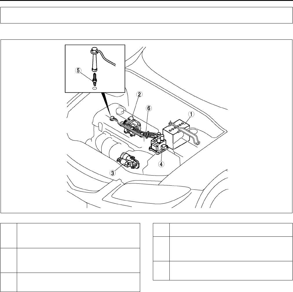
G2
LOCATION INDEX
LOCATION INDEX A6E470001002W01
.
End Of Sie
LOCATION INDEX
AME4700W001
1 Battery
(See G3 BATTERY REMOVAL/INSTALLATION)
(See G4 BATTERY INSPECTION)
(See G5 BATTERY RECHARGING)
2 Generator
(See G6 GENERATOR REMOVAL/
INSTALLATION)
(See G7 GENERATOR INSPECTION)
3Starter
(See G12 STARTER REMOVAL/INSTALLATION)
(See G13 STARTER INSPECTION)
4 Ignition coil
(See G9 IGNITION COIL INSPECTION)
5Spark plug
(See G10 SPARK PLUG REMOVAL/
INSTALLATION)
(See G11 SPARK PLUG INSPECTION)
6 High-tension lead
(See G11 HIGH-TENSION LEAD REMOVAL/
INSTALLATION)
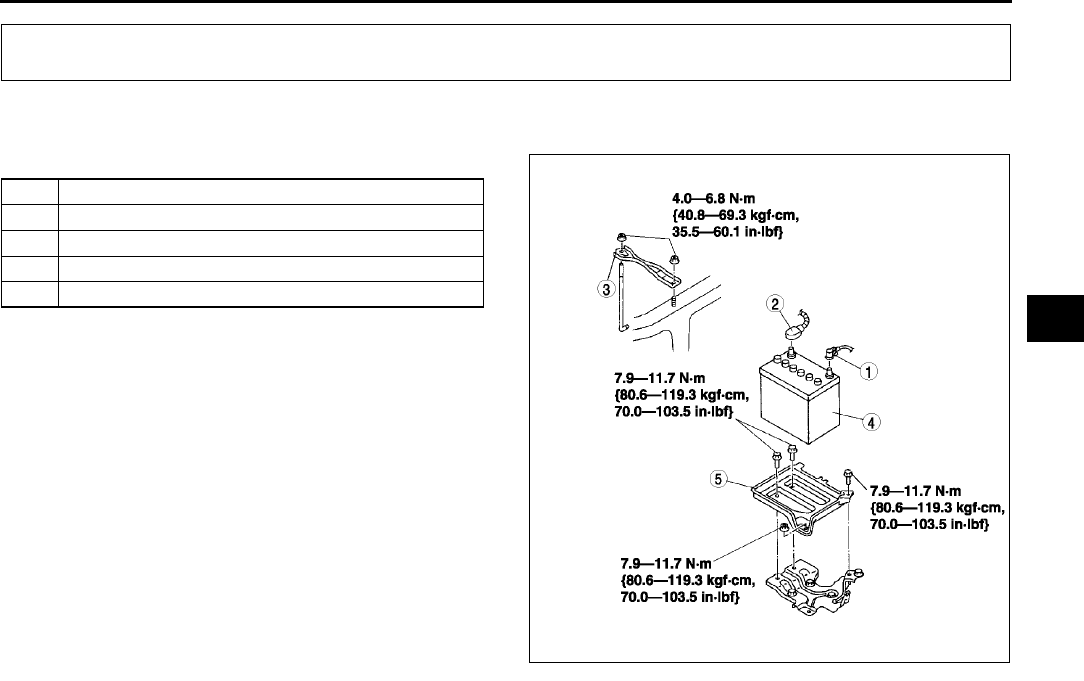
CHARGING SYSTEM
G3
G
BATTERY REMOVAL/INSTALLATION A6E471018520W01
1. Remove in the order indicated in the table.
2. Install in the reverse order of removal.
End Of Sie
CHARGING SYSTEM
1 Negative battery cable
2Battery cable
3Battery clamp
4Battery
5 Battery tray
A6E4710W002
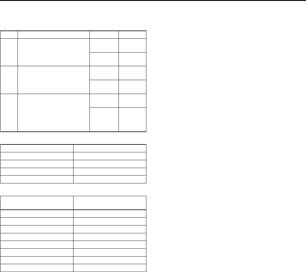
G4
CHARGING SYSTEM
BATTERY INSPECTION A6E471018520W02
Battery
1. Inspect the battery in the following procedure.
Test load chart
Battery positive voltage with load
Back-up Current
1. Verify that the engine switch is at OFF and that the key has been removed.
2. Disconnect the negative battery cable.
3. Measure the back-up current between the negative battery terminal and the negative battery cable.
•If the current exceeds the maximum, remove the fuses in the main fuse block and the fuse block one by
one while measuring the back-up current.
Inspect and repair harnesses and connectors of the fuse at which the current decreases.
Back-up current
20 mA max.
Caution
•
••
•Operating electrical loads while measuring the back-up current can damage the circuit tester.
End Of Sie
Step Inspection Result Action
1Measure open circuit
voltage of battery.
More than
12.4 V
Go to
Step 3.
Less than
12.4 V
Go to
next step.
2Quick charge for 30 min.
and recheck voltage.
More than
12.4 V
Go to
next step.
Less than
12.4 V
Replace
battery.
3
Apply load current (see load
test chart) to battery using a
battery load tester and
record battery voltage after
15 s. Is voltage more than
specification?
Yes Battery is
okay.
No Replace
battery.
Battery Load (A)
46B24DLS 135
50D20L 150
75D26L 195
80D26L 195
Approximate battery
temperature Min. voltage (V)
21 °C {70 °F} 9.6
16 °C {61 °F} 9.5
10 °C {50 °F} 9.4
4 °C {39 °F} 9.3
1 °C {30 °F} 9.1
7 °C {19 °F} 8.9
12 °C {10 °F} 8.7
18 °C {0 °F} 8.5

CHARGING SYSTEM
G5
G
BATTERY RECHARGING A6E471018520W03
Warning
•
••
•Keep any flammable away from the battery, otherwise evaporated gas of the battery fluid may
catch fire, and cause serious injury or death.
Caution
•
••
•When removing the battery, disconnect the negative battery cable first and install it last to prevent
damage to electrical components or the battery.
1. Place a battery in a pan of water to prevent it from overheating.
2. The water level should come up about halfway on the battery.
3. Remove the battery plugs while charging the battery.
4. Keep water off the top of the battery.
Caution
•
••
•To prevent damage to electrical components or the battery, turn all accessories off and stop the
engine before performing maintenance or recharging the battery.
5. Connect a battery charger to the battery.
6. Adjust the charging current as follows.
End Of Sie
Battery type
(5-hour rate) Slow charge (A) Quick charge
(A / 30 min.)
46B24LS (36) 3.54.5 25
50D20L (40) 4.05.0 25
75D26L (52) 5.06.0 35
80D26L (55) 5.56.5 35
AME4710W001
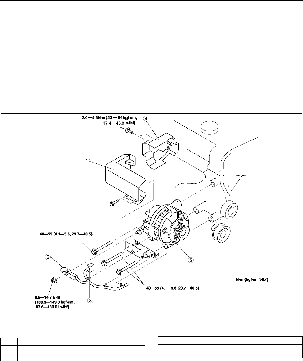
G6
CHARGING SYSTEM
GENERATOR REMOVAL/INSTALLATION A6E471018300W01
Warning
•
••
•When the battery cables are connected, touching the vehicle body with generator terminal B will
generate sparks. This can cause personal injury, fire, and damage to the electrical components.
Always disconnect the battery negative cables before performing the following operation.
Caution
•
••
•The generator can be damaged by the heat from the exhaust manifold. Make sure the generator
duct and the generator heat insulator are installed securely.
1. Disconnect the negative battery cable.
2. Remove the under cover.
3. Remove the drive belt. (See B3 DRIVE BELT REPLACEMENT.)
4. Remove in the order indicated in the table.
5. Install in the reverse order of removal.
Generator Removal Note
1. Remove the generator from above.
End Of Sie
AME4710W002
1 Generator duct
2 B terminal cable
3 Generator connector
4 Generator heat insulator
5 Generator
(See G6 Generator Removal Note)
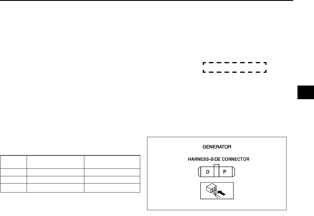
CHARGING SYSTEM
G7
G
GENERATOR INSPECTION A6E471018300W02
Generator Warning Light
1. Verify that the battery is fully charged.
•Charge if necessary.
2. Verify that the drive belt deflection/tension is correct. (See B3 DRIVE BELT INSPECTION.)
•If not as specified, replace the drive belt.
3. Turn the ignition switch to ON and verify that the generator warning light illuminates.
•If not as specified, inspect the generator warning light.
4. Verify that the generator warning light turns off after the engine is started.
•If not specifed, inspect if any of the DTCs are displayed: P0112, P0113, P2502, P2503, P2504.
Generator
Voltage
1. Verify that the battery is fully charged.
2. Verify that the drive belt deflection/tension is correct. (See B3 DRIVE BELT INSPECTION.)
•If not as specified, replace the drive belt.
3. Turn off all electrical loads.
4. Turn the engine switch to start the engine and verify that the generator rotates smoothly without any noise
while the engine is running.
5. Measure the voltage at the terminals shown in the table.
•If not as specified, repair or replace the
generator as necessary.
Standard voltage
*: Turn the following electrical loads on and verify that
the voltage reading increases.
Headlights
Blower motor
Rear window defroster
Current
1. Verify that the battery is fully charged.
•If the battery is not fully charged, charge the battery.
2. Verify that the drive belt deflection/tension is correct. (See B3 DRIVE BELT INSPECTION.)
•If not as specified, replace the drive belt.
3. Disconnect the negative battery cable.
4. Connect an ammeter, capable of reading 120 A or above, between generator terminal B and the wiring
harness.
5. Connect the negative battery cable.
6. Turn off all electrical loards.
7. Start the engine and increase the engine speed to 2,0002,500 rpm.
8. Turn the following electrical loads on and verify that the current reading increases.
•Headlights
•Blower motor
•Rear window defroster
If generator terminal B current will not increase, repair or replace the generator as necessary.
Note
•Current required for generating power varies with electrical loads applied.
Terminal Ignition switch ON (V) Idle (V)
[20 °
°°
°C {68 °
°°
°F}]
B B+ 1315
P Approx. 1 Approx. 38
D Approx. 0 *
A6E4710W003
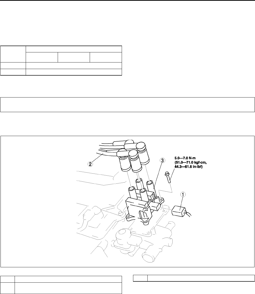
CHARGING SYSTEM , IGNITION SYSTEM
G8
Standard current (Reference)
Measuring conditions
Room temperature: 20 °
°°
°C {68 °
°°
°F}
Voltage: 13.5 V
Engine hot
* : Must not be 0 A
End Of Sie
IGNITION COIL REMOVAL/INSTALLATION A6E471218110W01
1. Disconnect the negative battery cable.
2. Remove the plug hole plate.
End Of Sie
Engine
speed
(rpm)
Terminal B current (A)
L8 LF L3
1,000 0*80
2,000 0*90
IGNITION SYSTEM
A6E4712W012
1 Connect
2 High-tension lead (See G11 HIGH-TENSION
LEAD REMOVAL/INSTALLATION )
3 Ignition coil
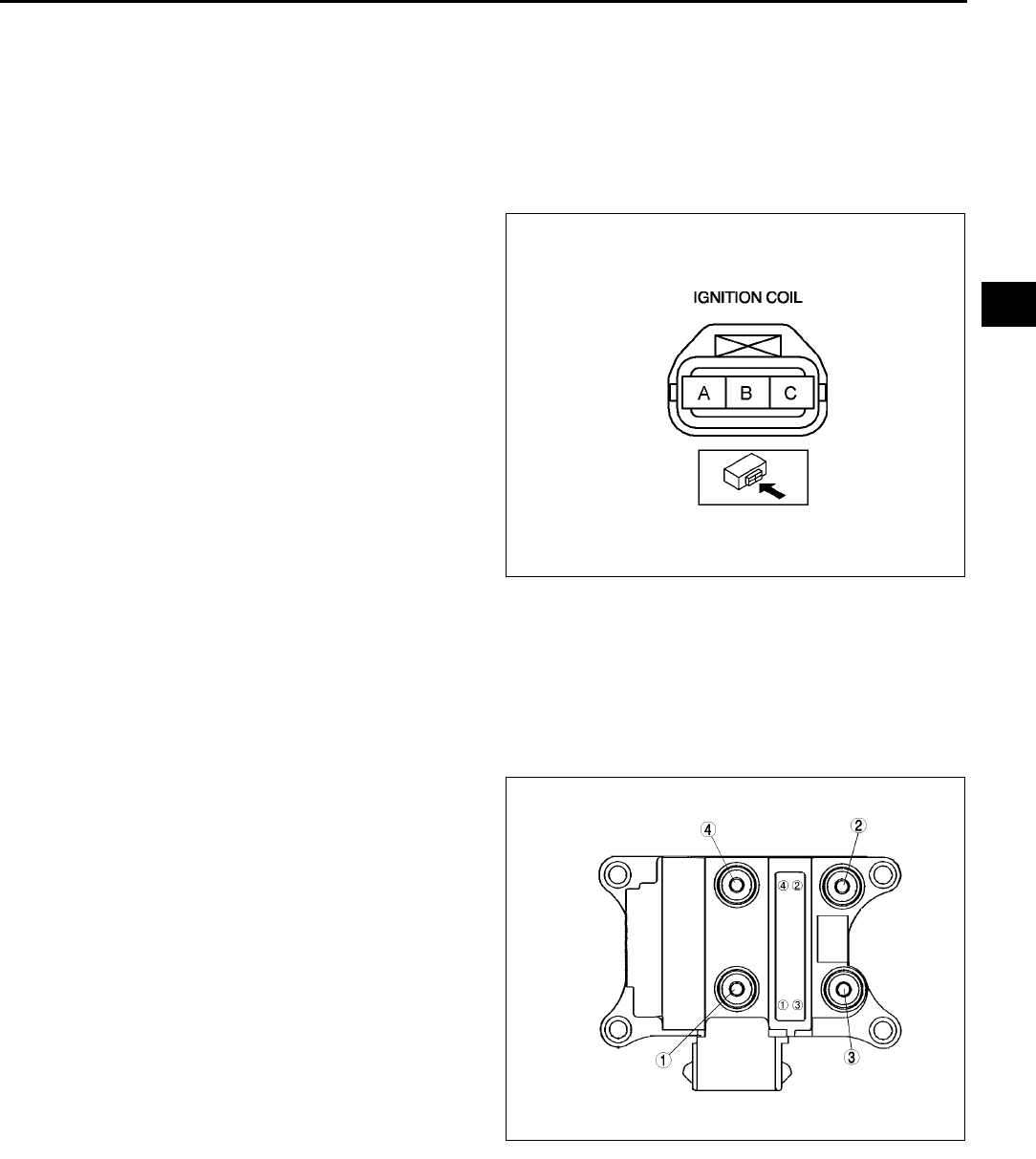
IGNITION SYSTEM
G9
G
IGNITION COIL INSPECTION
Primary Coil Winding
1. Remove the ignition coil.
2. Measure the resistance between the following lead holes using an ohmmeter.
•A and B, B and C
If not specified, replace the ignition coil.
Specification
0.490.57 ohms [20°
°°
°C {68°
°°
°F}]
Secondary Coil Winding
1. Remove the ignition coil.
•1 and 4
•2 and 3
If not specified, replace the ignition coil.
Specification
9.511.1kilohms
A6E4712W003
A6E4712W001
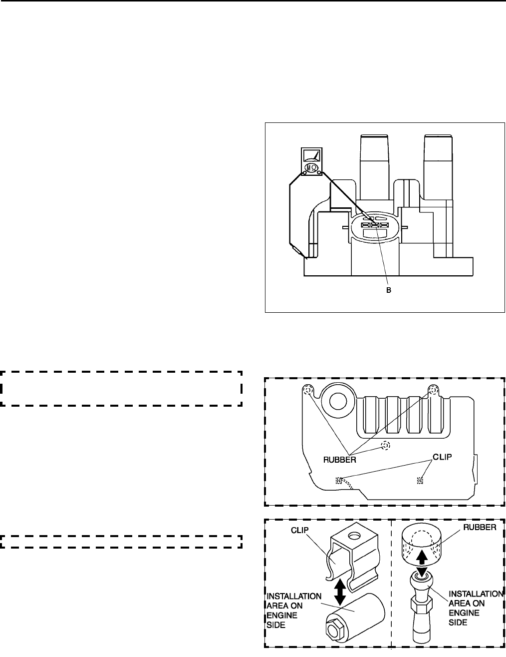
G10
IGNITION SYSTEM
Insulation Resistance of Case
1. Disconnect the high-tension lead.
2. Disconnect the ignition coil connector.
3. Measure the insulation resistance between the following terminals and ignition coil case using an ohmmeter.
•Terminal B and ignition coil case.
If not specified, replace the ignition coil.
Specification
Above 10 Megohm
4.
End Of Sie
SPARK PLUG REMOVAL/INSTALLATION A6E471218110W03
1. Disconnect the negative battery cable.
2. Remove the plug hoie plate.
•Lift off and remove the plug hole plate from
the installation areas (rubber and clips) as
shown in the figure.
3. Disconnect the high-tension lead.
4. Remove the spark plugs using the plug-wrench.
5. Install the spark plugs using a plug-wrench.
Tightening torque:
1024 N·m {1.12.4kgf·m, 817ft·lbf}
A6E4712W002
A6E4712W201
A6E4712W202
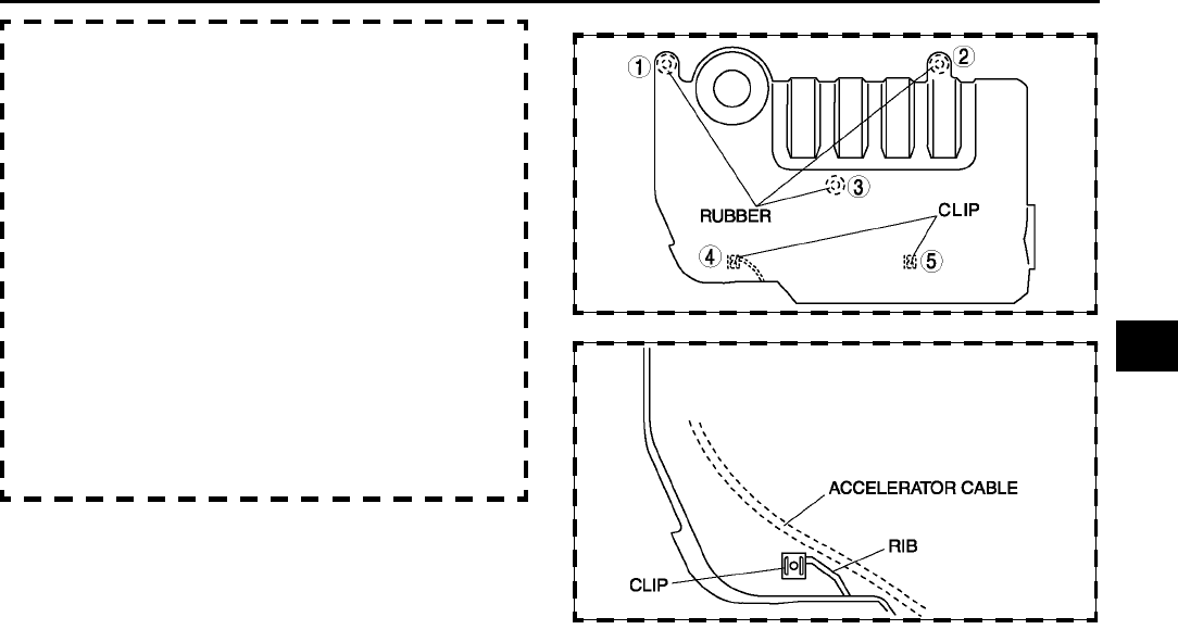
IGNITION SYSTEM
G11
G
6. Install the plug hole plate.
Caution
•
••
•If the plug hole plate interferes with metal
clips and the accelerator cable, the cable
could be damaged, so when installing
follow the procedure below.
(1) To position the plug hole plate, grasp the
rubber 1 and 2, as shown in the figure, with
your hands and press them in.
(2) Route the accelerator cable more towards the
center of the plug hole plate underside to
avoid the rib area as shown in the figure.
(3) Grasp rubber 3 with your hand and press it in.
(4) Grasp clips 4 and 5 with your hands and
press them in.
7. Connect the negative battery cable.
End Of Sie
SPARK PLUG INSPECTION A6E471218110W04
Caution
•
••
•Do not inspect, adjust, or clean the plug gap with a wire brush. Doing so can damage the platinum
tip.
•
••
•When cleaning a spark plug with a plug clear, clean the plug quickly for less than 20 seconds with
air pressure below 58.8 kpa {6.0 kgf/cm, 8.5 psi}. Verify that there is no carbon, sand, etc. in the
spark plug after cleaning.
End Of Sie
HIGH-TENSION LEAD REMOVAL/INSTALLATION A6E471218110W05
Caution
•
••
•The high-tension leads must be reinstalled to their original position.Incorrect installation can
damage the leads and cause power loss, and negatively affect the electronic components.
1. Disconnect the negative battery cable.
2. Remove the plug hole plate.
3. Remove the high-tension lead.
4. Install the high-tension lead.
End Of Sie
A6E4712W203
A6E4712W204
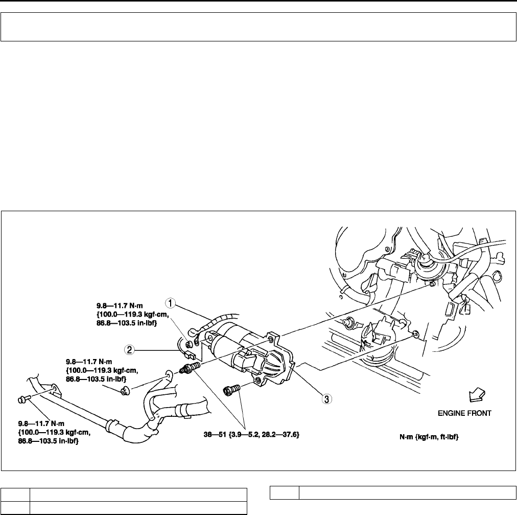
G12
STARTING SYSTEM
STARTER REMOVAL/INSTALLATION A6E471418400W01
Warning
•
••
•When the battery cables are connected, touching the vehicle body with starter terminal B will
generate sparks. This can cause personal injury, fire, and damage to the electrical components.
Always disconnect the battery negative cables before performing the following operation.
1. Disconnect the negative battery cable.
2. Remove the under cover.
3. Remove the air cleaner assembly.(See F10 INTAKE-AIR SYSTEM REMOVAL/INSTALLATION.)
4. Remove the clutch release cylinger.(MTX) (See H9 CLUTCH RELEASE CYLINDER REMOVAL/
INSTALLATION.)
5. Remove in the order indicated in the table.
6. Install in the reverse order of removal.
End Of Sie
STARTING SYSTEM
AME4714W001
1Terminal B wire
2Terminal S wire
3Starter
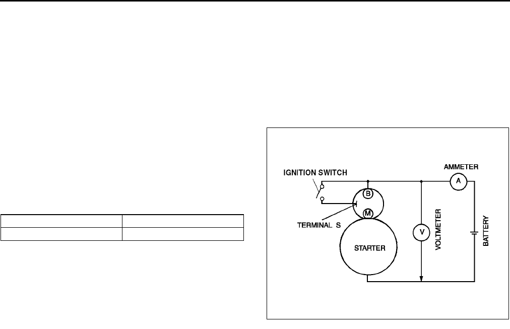
STARTING SYSTEM
G13
STARTER INSPECTION A6E471418400W02
On-vehicle Inspection
1. Verify that the battery is fully charged.
2. Crank the engine and verify that the starter rotates smoothly without any noise.
•If not, inspect the following.
Remove the starter and inspect the magnetic switch and the starter.
Inspect the related wiring harness and the ignition switch.
No Load Test
1. Verify that the battery is fully charged.
2. Connect the starter, battery, voltmeter and
ammeter as shown.
3. Operate the starter and verify that it rotates
smoothly.
4. Measure the voltage and current while the starter
is operating.
•If not as specified, replace the starter.
Specification
End Of Sie
Voltage (V) Current (A)
11 Less than 90
AME4714W002

H1
H
HCLUTCH
LOCATION INDEX .................................................H-2
CLUTCH LOCATION INDEX ...............................H-2
GENERAL PROCEDURES ....................................H-3
PRECAUTION (CLUTCH)....................................H-3
CLUTCH FLUID......................................................H-4
CLUTCH FLUID INSPECTION ............................H-4
CLUTCH FLUID REPLACEMENT .......................H-4
CLUTCH PEDAL ....................................................H-5
CLUTCH PEDAL ADJUSTMENT.........................H-5
CLUTCH PEDAL REMOVAL/INSTALLATION.....H-6
CLUTCH MASTER CYLINDER..............................H-7
CLUTCH MASTER CYLINDER REMOVAL/
INSTALLATION.................................................H-7
CLUTCH MASTER CYLINDER DISASSEMBLY/
ASSEMBLY.......................................................H-8
CLUTCH RELEASE CYLINDER ............................H-9
CLUTCH RELEASE CYLINDER REMOVAL/
INSTALLATION.................................................H-9
CLUTCH RELEASE CYLINDER DISASSEMBLY/
ASSEMBLY.....................................................H-10
CLUTCH UNIT ......................................................H-11
CLUTCH UNIT REMOVAL/INSTALLATION ......H-11
CLUTCH COVER INSPECTION........................H-13
CLUTCH DISC INSPECTION ............................H-14
CLUTCH RELEASE COLLAR INSPECTION.....H-14
FLYWHEEL ..........................................................H-15
FLYWHEEL INSPECTION.................................H-15
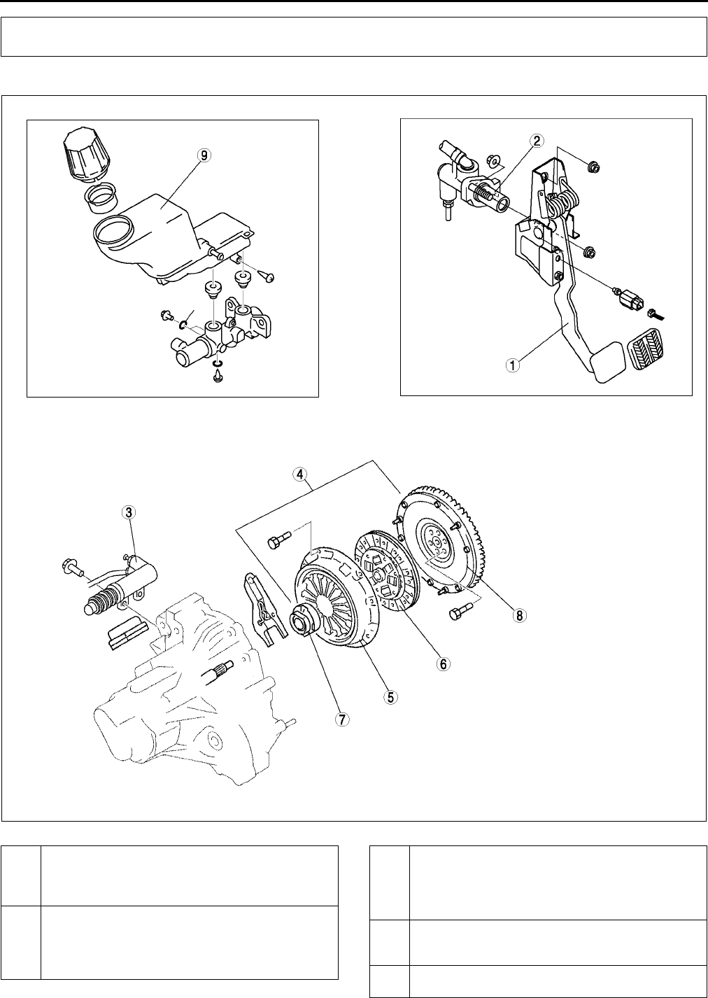
H2
LOCATION INDEX
CLUTCH LOCATION INDEX A6E490001036W01
.
LOCATION INDEX
A6E4900W001
1 Clutch pedal
(See H5 CLUTCH PEDAL ADJUSTMENT)
(See H6 CLUTCH PEDAL REMOVAL/
INSTALLATION)
2 Clutch master cylinder
(See H7 CLUTCH MASTER CYLINDER
REMOVAL/INSTALLATION)
(See H8 CLUTCH MASTER CYLINDER
DISASSEMBLY/ASSEMBLY)
3 Clutch release cylinder
(See H9 CLUTCH RELEASE CYLINDER
REMOVAL/INSTALLATION)
(See H10 CLUTCH RELEASE CYLINDER
DISASSEMBLY/ASSEMBLY)
4 Clutch unit
(See H11 CLUTCH UNIT REMOVAL/
INSTALLATION)
5 Clutch cover
(See H13 CLUTCH COVER INSPECTION)
LOCATION INDEX, GENERAL PROCEDURES
H3
H
End Of Sie
PRECAUTION (CLUTCH) A6E491016003W01
Clutch Pipe Removal/Installation
Note
•A common reservoir is used for the clutch and brake system fluid.
1. If clutch pipes have been disconnected any time during the procedure, add clutch fluid (brake fluid), bleed the
air, and inspect for leakage after the procedure has been completed.
2. Remove the clutch pipe using the SST (49 0259 770B). Install the clutch pipe using torque wrench SST
combination. (See GI16 TORQUE FORMULAS.)
End Of Sie
6Clutch disc
(See H14 CLUTCH DISC INSPECTION)
7 Clutch release collar
(See H14 CLUTCH RELEASE COLLAR
INSPECTION)
8Flywheel
(See H15 FLYWHEEL INSPECTION)
9 Clutch fluid
(See H4 CLUTCH FLUID INSPECTION)
(See H4 CLUTCH FLUID REPLACEMENT)
GENERAL PROCEDURES
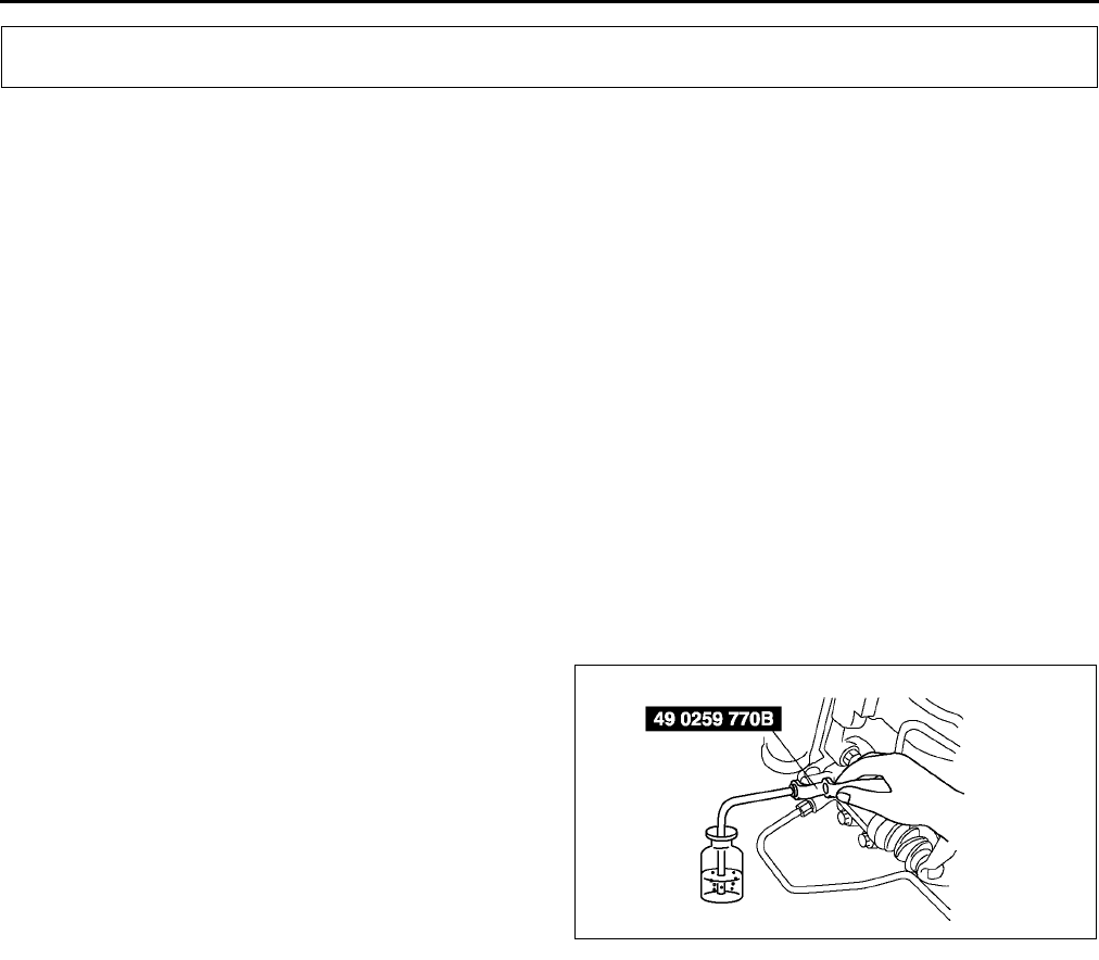
H4
CLUTCH FLUID
CLUTCH FLUID INSPECTION A6E491216010W01
Note
•A common reservoir is used for the clutch and brake system fluid.
•The fluid in the reservoir must be maintained between the MIN/MAX level during replacement.
End Of Sie
CLUTCH FLUID REPLACEMENT A6E491216010W02
Caution
•
••
•Be careful not to spill clutch fluid on a painted surface. If this should happen, wash it off
immediately.
Note
•Do not mix different brands of clutch fluid.
•Do not reuse the clutch fluid that was drained out.
1. Remove the under cover.
2. Draw the fluid from the reservoir with a suction pump.
3. Remove the bleeder cap from the clutch release cylinder and attach a vinyl hose to the bleeder plug.
4. Place the other end of the vinyl hose into a container.
5. Slowly pump the clutch pedal several times.
6. With the clutch pedal depressed, loosen the bleeder screw using the SST to let fluid escape.
7. Tighten the bleeder screw using the SST to stop
the fluid.
8. Repeat Steps 4 and 5 until only clean fluid is
seen.
9. Tighten the bleeder screw.
Tightening torque
5.98.8 N·m {6090 kgf·cm, 5378 in·lbf}
10. Add fluid to the MAX mark.
11. Install the under cover.
12. Verify the correct clutch operation.
End Of Sie
CLUTCH FLUID
A6E4912W001
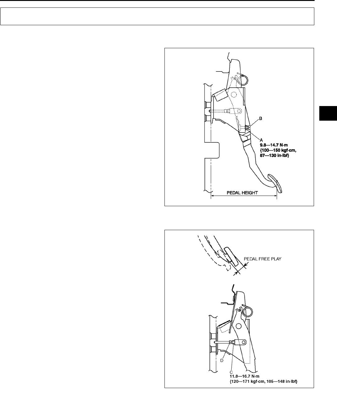
CLUTCH PEDAL
H5
H
CLUTCH PEDAL ADJUSTMENT A6E491441030W01
Clutch Pedal Height
1. Measure the distance from the upper surface of
the pedal pad to the carpet.
•If not as specified, adjust the pedal height by
turning adjustment bolt B and locknut A.
Pedal height(with carpet)
L.H.D.: 210216 mm {8.278.50 in}
R.H.D.: 209215 mm {8.238.46 in}
Clutch Pedal Free Play
1. Depress the clutch pedal by hand until clutch
resistance is felt, and measure the pedal free
play.
•If not as specified, adjust the pedal free play
by loosening locknut C and turning push rod
D as necessary.
Pedal free play
1.03.0 mm {0.040.11 in}
Push rod free play at clutch pedal
0.10.5 mm {0.0040.02 in} (Reference
value)
Clutch Pedal Disengagement Point
1. Apply the parking brake and fix the front and rear of the wheels with the wheel chocks.
2. Start the engine at idle.
3. Without depressing the clutch pedal, move the
shift lever slowly to the reverse position.
4. Hold the lever when the gear noise is heard.
5. Depress the clutch pedal slowly.
CLUTCH PEDAL
A6E4914W001
A6E4914W002
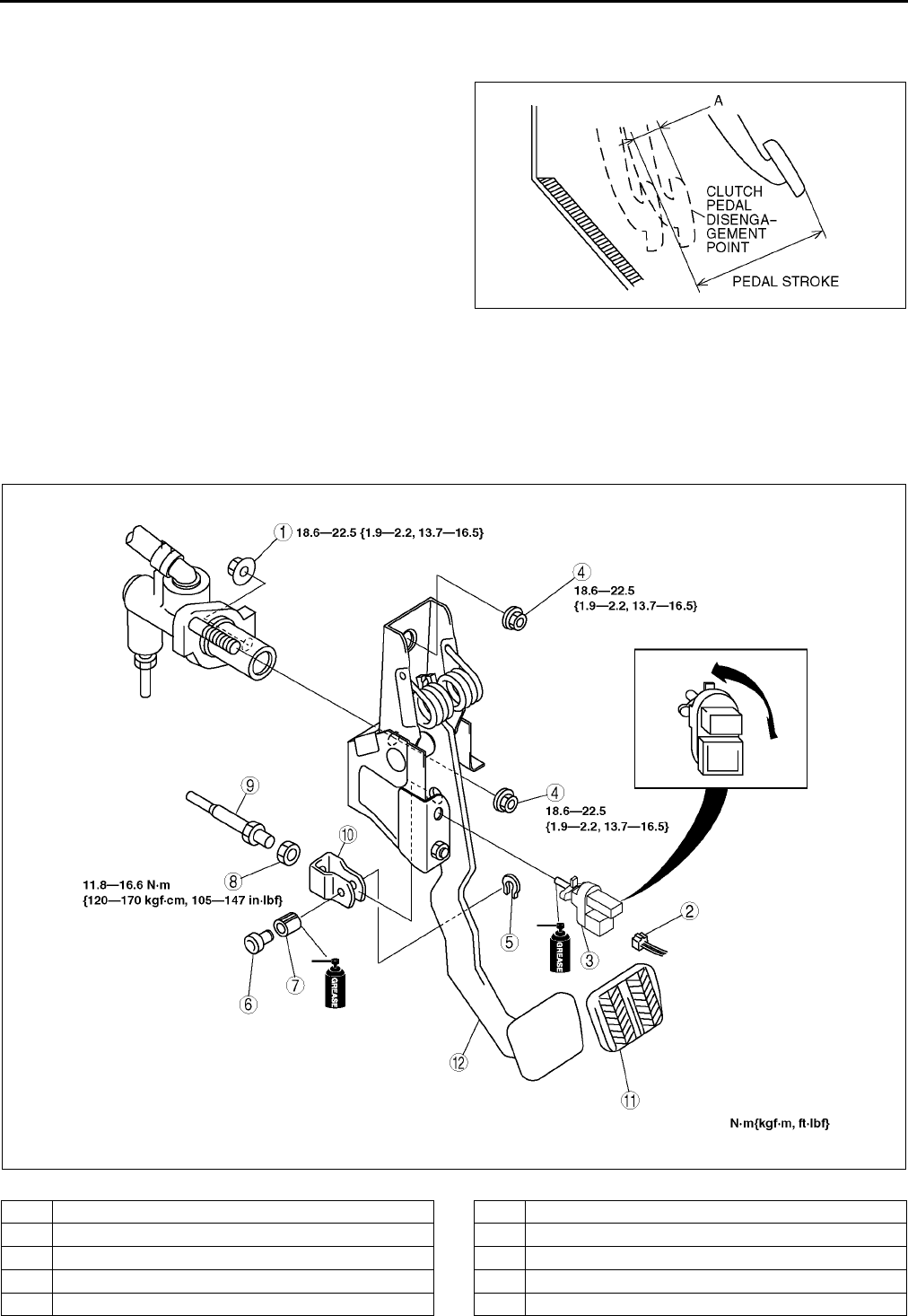
H6
CLUTCH PEDAL
6. Hold the pedal when the gear noise stops (clutch pedal disengagement point).
7. Measure distance A (the distance from the clutch pedal disengagement point to the fully depressed position)
and the pedal stroke.
8. Verify that they are within specification.
•If distance A or the pedal stroke is out of
specification, adjust the pedal height or the
clutch pedal free play to specification.
Clutch pedal disengagement stroke
Minimum: 20 mm {0.79 in} (Reference value)
Pedal stroke
140.0 mm {5.51 in} (Reference value)
End Of Sie
CLUTCH PEDAL REMOVAL/INSTALLATION A6E491441030W02
1. Remove the battery and battery tray. (European (L.H.D.) and GCC specs.)
2. Remove in the order indicated in the table.
3. Install in the reverse order of removal.
4. After installation, adjust the clutch pedal. (See H5 CLUTCH PEDAL ADJUSTMENT.).
A6E4914W003
A6E4914W004
1Nut
2 Clutch switch connector
3 Clutch switch
4Nut
5E-clip
6Pin
7 Bushing
8Nut
9 Push rod
10 Clevis
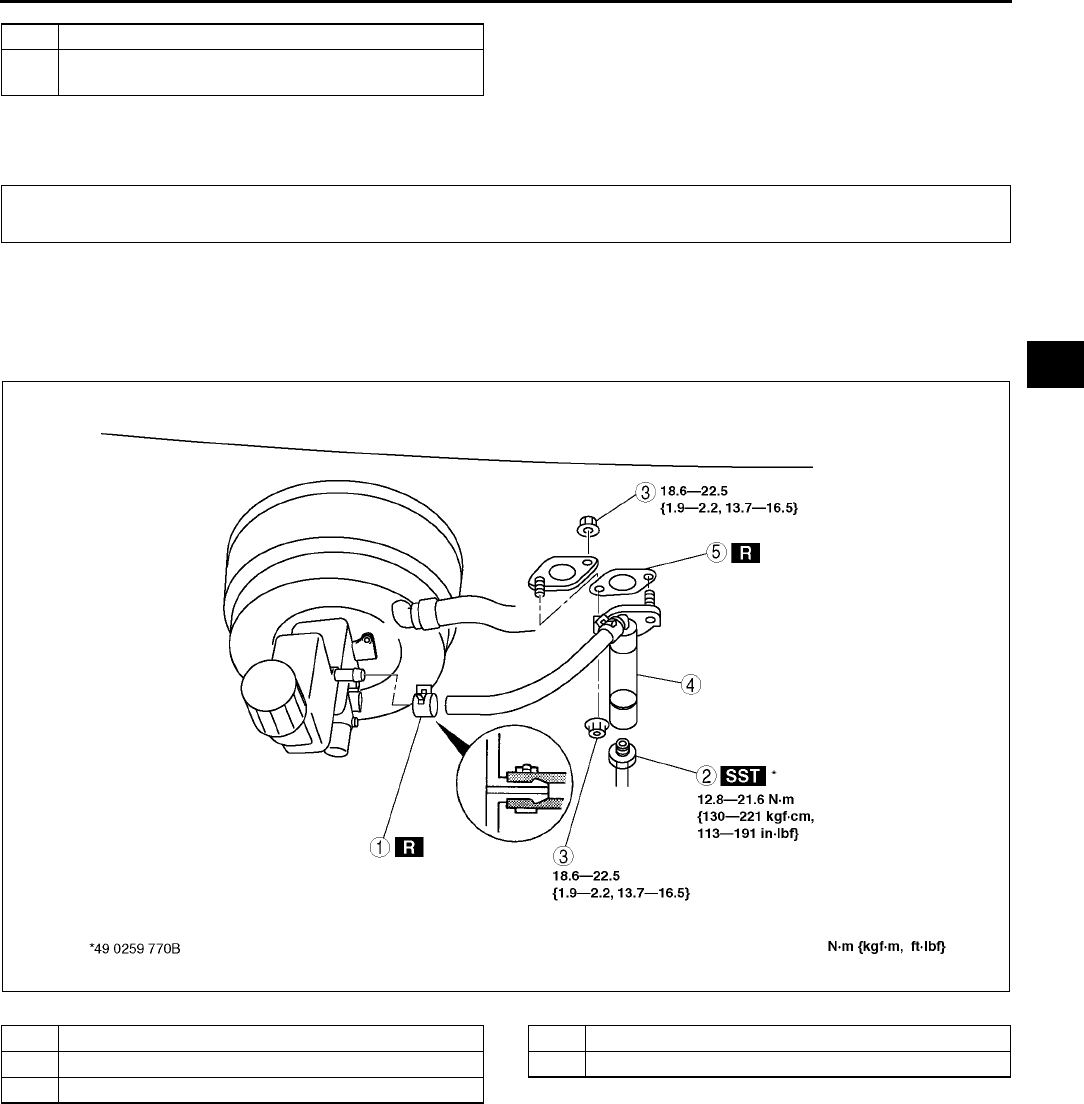
CLUTCH PEDAL, CLUTCH MASTER CYLINDER
H7
H
Clutch Pedal Installation Note
1. After installation, adjust the pedal height and free play. (See H5 CLUTCH PEDAL ADJUSTMENT.)
End Of Sie
CLUTCH MASTER CYLINDER REMOVAL/INSTALLATION A6E491641990W01
1. Remove the battery and battry tray. (European (L.H.D.), GCC. specs.)
2. Remove in the order indicated in the table.
3. Plug the clutch pipe after removing it to avoid leakage.
4. Install in the reverse order of removal..
End Of Sie
11 Pedal pad
12 Clutch pedal
(See H7 Clutch Pedal Installation Note)
CLUTCH MASTER CYLINDER
A6E4916W001
1Clip
2 Clutch pipe
3Nut
4 Clutch master cylinder
5Gasket
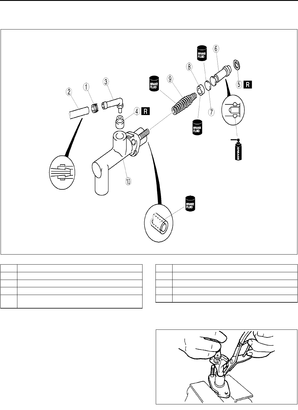
H8
CLUTCH MASTER CYLINDER
CLUTCH MASTER CYLINDER DISASSEMBLY/ASSEMBLY A6E491641990W02
1. Disassemble in the order indicated in the table.
2. Assemble in the reverse order of disassembly..
Snap Ring Disassembly/Assembly Note
1. Hold the piston down using a cloth-wrapped pin
punch.
•If disassembling, remove the snap ring; if
assembling, install it.
End Of Sie
A6E4916W002
1 Clip
2Hose
3Joint
4 Bushing
5 Snap ring
(See H8 Snap Ring Disassembly/Assembly Note)
6 Piston and secondary cap component
7Spacer
8 Primary cap
9 Return spring
10 Clutch master cylinder body
XME4916W003
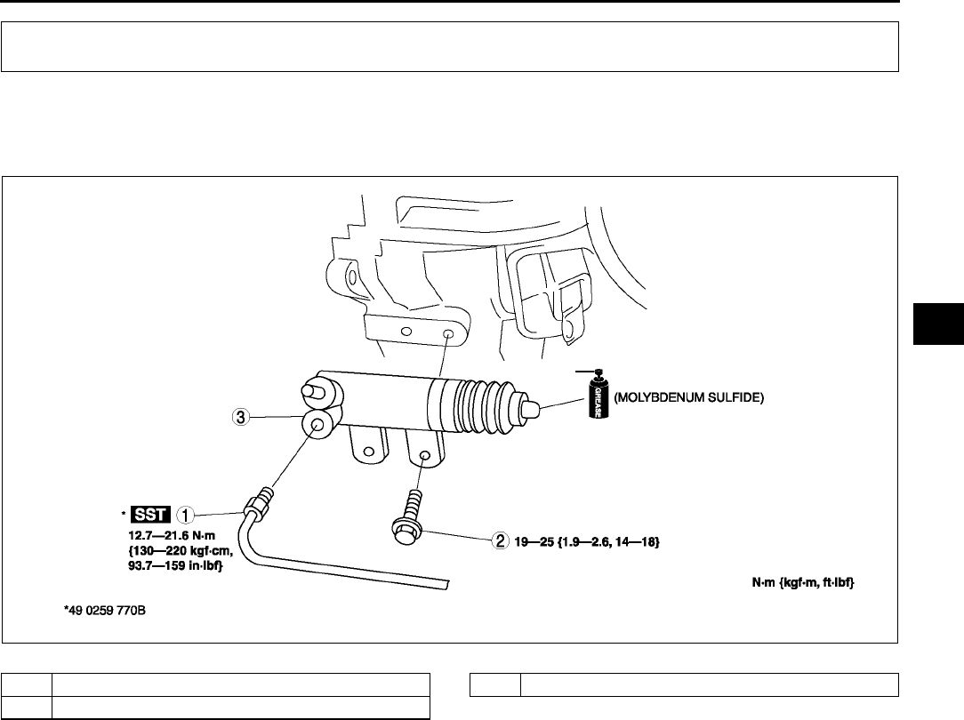
CLUTCH RELEASE CYLINDER
H9
H
CLUTCH RELEASE CYLINDER REMOVAL/INSTALLATION A6E491841920W01
1. Remove the under cover.
2. Remove in the order indicated in the table.
3. Install in the reverse order of removal..
End Of Sie
CLUTCH RELEASE CYLINDER
A6E4918W001
1 Clutch pipe
2Bolt
3 Clutch release cylinder
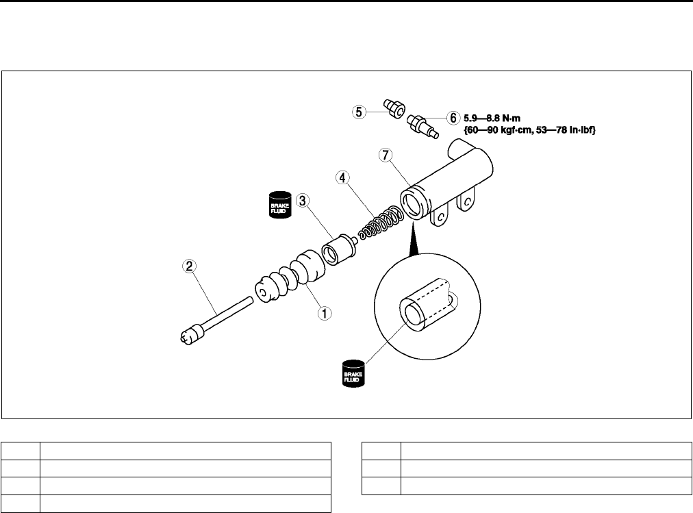
H10
CLUTCH RELEASE CYLINDER
CLUTCH RELEASE CYLINDER DISASSEMBLY/ASSEMBLY A6E491841920W02
1. Disassemble in the order indicated in the table.
2. Assemble in the reverse order of disassembly.
.
End Of Sie
A6E4918W002
1 Boot
2 Push rod
3 Piston and cap
4 Return spring
5 Bleeder cap
6 Bleeder screw
7 Release cylinder body
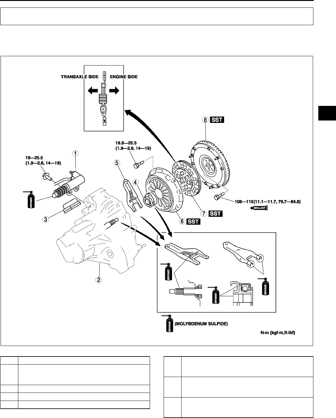
CLUTCH UNIT
H11
H
CLUTCH UNIT REMOVAL/INSTALLATION A6E492016000W01
1. Remove in the order indicated in the table.
2. Install in the reverse order oremoval.
.
CLUTCH UNIT
A6E4920W001
1 Clutch release cylinder
2 Manual transaxle
(See J5 MANUAL TRANSAXLE REMOVAL/
INSTALLATION)
3Boot
4 Clutch release collar
5 Clutch release fork
6 Clutch cover
(See H12 Clutch Cover and Disc Removal Note)
(See H13 Clutch Cover Installation Note)
7 Clutch disc
(See H12 Clutch Cover and Disc Removal Note)
(See H13 Clutch Disc Installation Note)
8 Flywheel
(See H12 Flywheel Removal Note)
(See H12 Flywheel Installation Note)
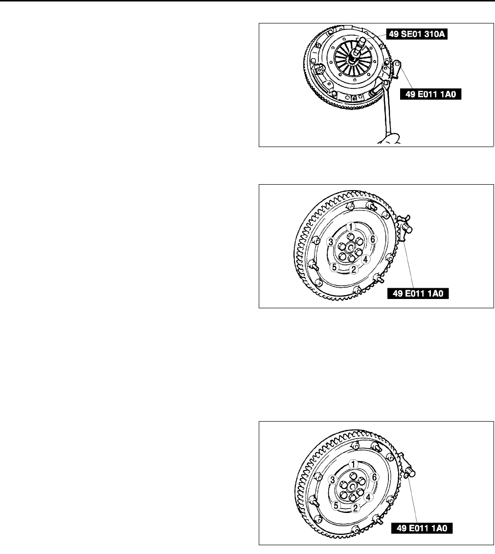
H12
CLUTCH UNIT
Clutch Cover and Disc Removal Note
1. Install the SSTs.
2. Loosen each bolt one turn at a time in a
crisscross pattern until spring tension is released.
3. Remove the clutch cover and disc.
Flywheel Removal Note
1. Hold the flywheel using the SST.
2. Remove the bolts evenly and gradually in a
crisscross pattern.
3. Remove the flywheel.
Flywheel Installation Note
1. Install the flywheel to the crankshaft.
2. When reusing the bolts, clean threads and hole, then apply locking compound to the threads.
Note
•No locking compound is needed when using new bolts.
3. Hand-tighten the flywheel lock bolts.
4. Install the SST to the flywheel.
5. Gradually tighten the flywheel lock bolts in a
crisscross pattern.
Tightning torque
108115 N·m {11.111.7 kgf·m, 79.784.8
ft·lbf}
A6E4920W002
A6E4920W003
A6E4920W004
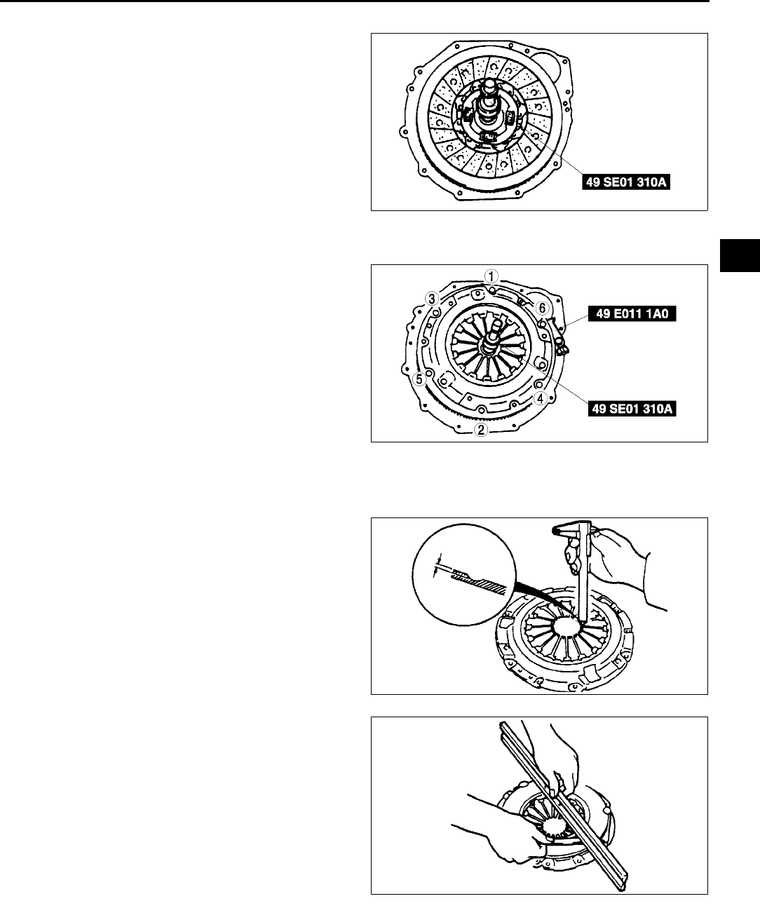
CLUTCH UNIT
H13
H
Clutch Disc Installation Note
1. Hold the clutch disc position using the SST.
Clutch Cover Installation Note
1. Install the SSTs.
2. Tighten the bolts evenly and gradually in a
crisscross pattern.
Tightening torque
18.625.5 N·m {1.92.6 kgf·m, 1419 ft·lbf}
End Of Sie
CLUTCH COVER INSPECTION A6E492016410W01
1. Measure the wear of the diaphragm spring
fingers.
•If not as specified, replace the clutch cover.
Depth
0.6 mm {0.024 in} max.
2. Measure the flatness of the pressure plate with a
straight edge and a feeler gauge.
•If not as specified, replace the clutch cover.
Maximum clearance
0.5 mm {0.020 in}
3. When checking the diaphragm spring fingers,
mount a dial indicator on the cylinder block.
A6E4920W005
A6E4920W006
XME4920W010
XME4920W011
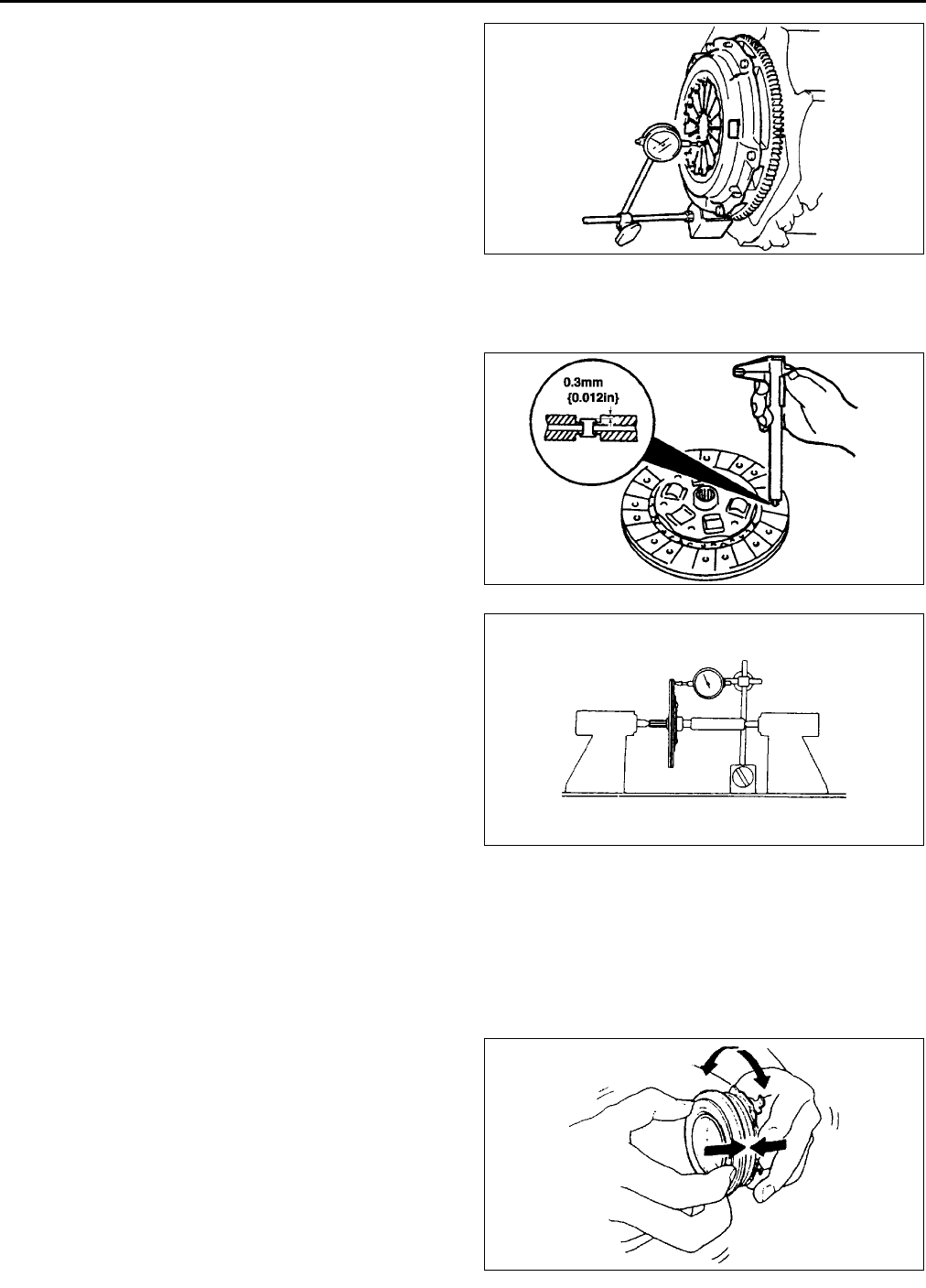
H14
CLUTCH UNIT
4. Rotate the flywheel and check for misaligned
diaphragm spring fingers.
•If not as specified, replace the clutch cover.
Misalignment
0.6 mm {0.024 in} max.
End Of Sie
CLUTCH DISC INSPECTION A6E492016460W01
1. Using vernier calipers, measure the thickness of
the lining at a rivet head on both sides.
•Replace the clutch disc if its thickness is less
than the minimum.
Thickness
0.3 mm {0.012 in} min.
2. Measure the clutch disc runout using a dial
indicator.
•If the runout is excessive, replace the clutch
disc.
Runout
0.7 mm {0.028 in} max.
End Of Sie
CLUTCH RELEASE COLLAR INSPECTION A6E492016510W01
Caution
•
••
•Cleaning the clutch release collar with cleaning fluids or a steam cleaner can
wash the grease out of the sealed bearing.
1. Turn the collar while applying force in the axial
direction.
•If the collar sticks or has excessive
resistance, replace the clutch release collar.
End Of Sie
XME4920W012
A6E4920W007
XME4920W014
XME4920W015
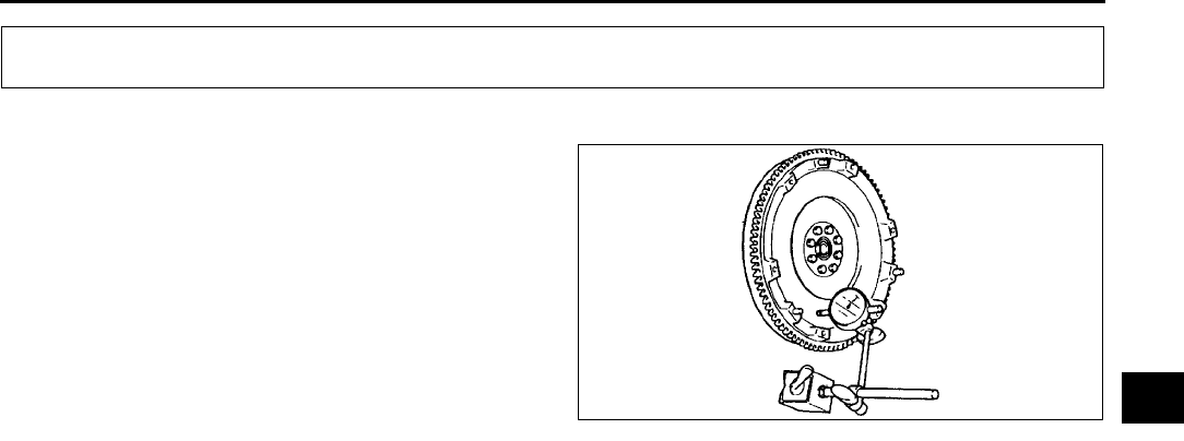
FLYWHEEL
H15
H
FLYWHEEL INSPECTION A6E492211500W01
1. Install a dial gauge on the cylinder block.
2. Measure the flywheel runout using a dial
indicator.
•If the runout is excessive, replace the
flywheel.
Runout
0.1 mm {0.004 in} max.
End Of Sie
FLYWHEEL
XME4922W001

J1
J
JMANUAL TRANSAXLE
LOCATION INDEX ................................................. J-2
MANUAL TRANSAXLE LOCATION INDEX ........ J-2
MANUAL TRANSAXLE.......................................... J-3
TRANSAXLE OIL INSPECTION .......................... J-3
TRANSAXLE OIL REPLACEMENT ..................... J-3
OIL SEAL (DIFFERENTIAL) REPLACEMENT .... J-4
VEHICLE SPEEDOMETER SENSOR
REMOVAL/INSTALLATION .............................. J-4
VEHICLE SPEEDOMETER SENSOR
INSPECTION .................................................... J-5
MANUAL TRANSAXLE REMOVAL/
INSTALLATION................................................. J-5
SHIFT MECHANISM............................................... J-9
SHIFT MECHANISM
REMOVAL/INSTALLATION .............................. J-9
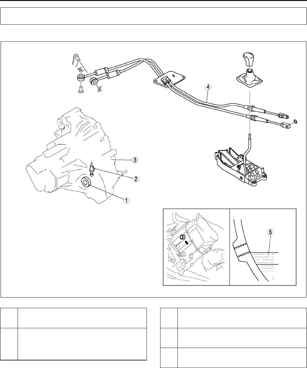
J2
LOCATION INDEX
MANUAL TRANSAXLE LOCATION INDEX A6E510001036W01
.
End Of Sie
LOCATION INDEX
A6E5100W001
1 Oil seal (differential)
(See J4 OIL SEAL (DIFFERENTIAL)
REPLACEMENT)
2 Vehicle speedometer sensor
(See J4 VEHICLE SPEEDOMETER SENSOR
REMOVAL/INSTALLATION)
(See J5 VEHICLE SPEEDOMETER SENSOR
INSPECTION)
3 Manual transaxle
(See J5 MANUAL TRANSAXLE REMOVAL/
INSTALLATION)
4 Shift mechanism
(See J9 SHIFT MECHANISM REMOVAL/
INSTALLATION)
5Transaxle oil
(See J3 TRANSAXLE OIL INSPECTION)
(See J3 TRANSAXLE OIL REPLACEMENT)
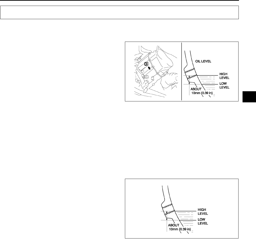
MANUAL TRANSAXLE
J3
J
TRANSAXLE OIL INSPECTION A6E511227001W01
1. Park the vehicle on level ground.
2. Remove the oil level plug and washer.
3. Verify that the oil is near the brim of the plug port.
•If the oil level is lower than the low level, add
the specified amount and type of oil through
the oil level plug hole.
Specified oil grade
API Service GL-4 or GL-5
Specified oil viscosity
All-season: SAE 75W-90
Above 10 °
°°
°C {50 °
°°
°F}: SAE 80W-90
4. Install a new washer and the oil level plug.
Tightening torque
4058 N·m {4.06.0 kgf·m, 2943 ft·lbf}
End Of Sie
TRANSAXLE OIL REPLACEMENT A6E511227001W02
1. Remove the drain plug with the washer.
2. Drain the oil into a suitable container.
3. Install a new washer and the drain plug.
Tightening torque
4058 N·m {4.06.0 kgf·m, 2943 ft·lbf}
4. Remove the oil level plug with washer and add
the specified amount and type of oil through the
oil level plug hole until the level reaches the
bottom of the oil level plug hole.
Specified oil viscosity
All-season: SAE 75W-90
Above 10 °
°°
°C {50 °
°°
°F}: SAE 80W-90
Capacity (approximate quantity)
2.87 L {3.03 US qt, 2.53 lmp qt}
5. Install a new washer and the oil level plug.
Tightening torque
4058 N·m {4.06.0 kgf·m, 2943 ft·lbf}
End Of Sie
MANUAL TRANSAXLE
A6E5112W007
A6E5112W008
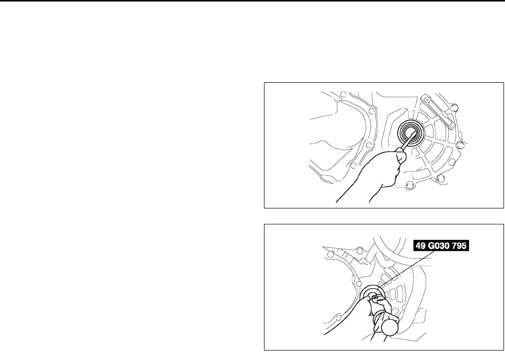
J4
MANUAL TRANSAXLE
OIL SEAL (DIFFERENTIAL) REPLACEMENT A6E511219240W01
1. On level ground, jack up the vehicle and support it evenly on safety stands.
2. Drain the oil from the transaxle.
3. Remove the front wheels and splash shields.
4. Separate the drive shaft and joint shaft from the transaxle. (See M17 DRIVE SHAFT REMOVAL/
INSTALLATION.) (See M12 JOINT SHAFT REMOVAL/INSTALLATION.)
5. Remove the oil seals using a screwdriver.
6. Using the SST and a hammer, tap each new oil
seal in evenly until the SST contacts the transaxle
case.
7. Coat the lip of each oil seal with transaxle oil.
8. Insert the drive shaft and joint shaft to the
transaxle. (See M17 DRIVE SHAFT REMOVAL/
INSTALLATION.) (See M12 JOINT SHAFT
REMOVAL/INSTALLATION.)
9. Install the wheels and splash shields.
10. Add the specified amount and type of oil. (See J
3 TRANSAXLE OIL REPLACEMENT.)
End Of Sie
VEHICLE SPEEDOMETER SENSOR REMOVAL/INSTALLATION A6E511217400W01
Without ABS
1. Disconnect the negative battery cable.
2. Remove the battery and battery tray.
3. Remove the air cleaner compornent. (See F10 INTAKE-AIR SYSTEM REMOVAL/INSTALLATION.)
4. Disconnect the vehicle speedometer sensor connector.
5. Remove the vehicle speedometer sensor.
6. Apply transmission oil to a new O-ring and install it on a vehicle speedometer sensor.
7. Install the vehicle speedometer sensor.
Tightening torque
7.811.3 N·m
{80115 kgf·cm, 57.683.3 in·lbf}
8. Connect the vehicle speedometer sensor connector.
9. Install the air cleaner compornent. (See F10 INTAKE-AIR SYSTEM REMOVAL/INSTALLATION.)
10. Install the battery and battery tray.
11. Connect the negative battery cable.
End Of Sie
A6E5112W009
A6E5112W001
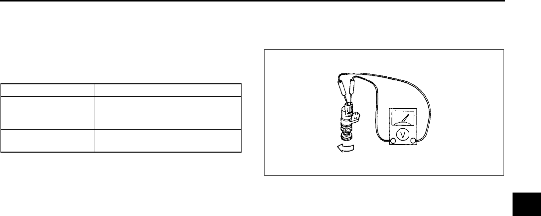
MANUAL TRANSAXLE
J5
J
VEHICLE SPEEDOMETER SENSOR INSPECTION A6E511217400W02
Without ABS
1. Remove the vehicle speedometer sensor.
2. Measure voltage (AC range) between terminals of
the vehicle speedometer sensor while the gear is
turning.
3. Install the vehicle speedometer sensor.
End Of Sie
MANUAL TRANSAXLE REMOVAL/INSTALLATION A6E511201029W01
1. Remove the battery, battery tray and battery bracket.
2. Remove the air cleaner compornent. (See F10 INTAKE-AIR SYSTEM REMOVAL/INSTALLATION.)
3. Remove the wheels, tires and splash shields.
4. Remove the under cover.
5. Remove the steering gear and power steering pipe. (See N10 STEERING GEAR AND LINKAGE REMOVAL/
INSTALLATION.)
6. Remove the front auto leveling sensor. (See T32 FRONT AUTO LEVELING SENSOR REMOVAL/
INSTALLATION.)
7. Drain the transaxle oil into a suitable container.
8. Remove in the order indicated in the table.
9. Install in the reverse order of removal.
10. Adjust the headlight zeroset. (See T31 HEADLIGHT ZEROSET.)
11. Add the specified amount of specified transaxle oil.
12. Install the air cleaner compornent. (See F10 INTAKE-AIR SYSTEM REMOVAL/INSTALLATION.)
13. Warm up the engine and transaxle, inspect for oil leakage, and inspect the transaxle operation.
Meter needle Action
Moves slightly under
5 V (AC range)
Repair wiring harness between
instrument cluster and vehicle
speedometer sensor.
Does not move Replace vehicle speedometer
sensor.
W6U515WA4
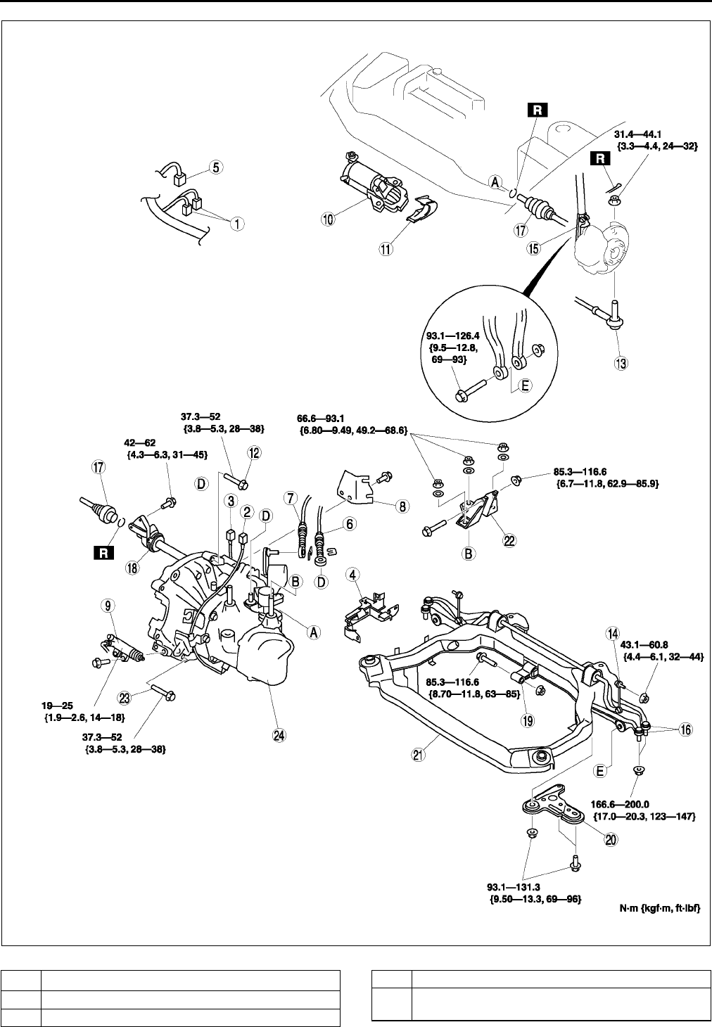
J6
MANUAL TRANSAXLE
.
A6E5112W012
1O2 sensor connector
2 Back-up light switch connector
3 Neutral switch connector
4 Harness bracket
5Vehicle speedometer sensor connector
(GCC specs.)
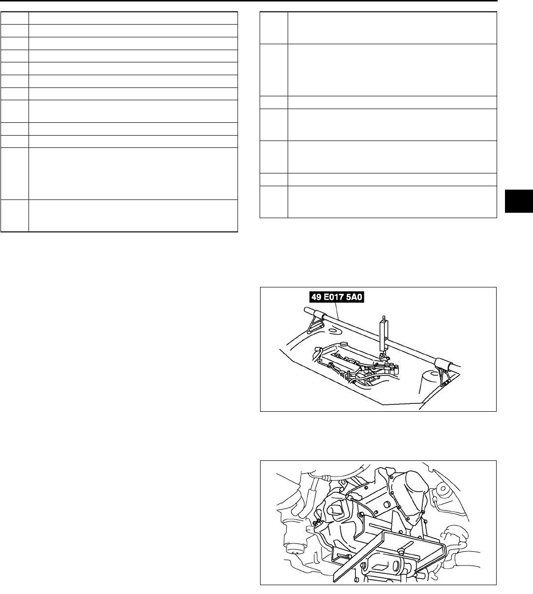
MANUAL TRANSAXLE
J7
J
No.1 Engine Mount Bracket Removal Note
1. Support the engine using the SST before
removing the No.1 engine mount.
2. Remove the No.1 engine mount.
Manual Transaxle Removal Note
1. Loosen the SST (49 E017 5A0)and lean the engine toward the transaxle.
2. Support the transaxle on a jack.
3. Remove the transaxle mounting bolts.
4. Remove the transaxle.
6 Selector cable
7 Shift cable
8 Selector cable bracket
9 Clutch release cylinder
10 Starter
11 Endplate cover
12 Transaxle mounting bolt (upper side)
13 Tie-rod end ball joint
(See N11 Tie-rod End Ball Joint Removal Note)
14 Stabilizer control link
15 Damper fork
16
Lower arm (front, rear) ball joint
(See R19 Front Lower Arm (Rear) Ball Joint
Removal Note)
(See R16 Front Lower Arm (Front) Ball Joint
Removal Note)
17
Drive shaft
(See M17 DRIVE SHAFT REMOVAL/
INSTALLATION.)
18
Joint shaft
(See M12 JOINT SHAFT REMOVAL/
INSTALLATION.)
19
No.1 engine mount
(See J7 No.1 Engine Mount Bracket Removal
Note)
(See J8 No.1 Engine Mount and No.4 Engine
Mount Bracket Installation Note)
20 Crossmember bracket
21
Crossmember component
(See R23 FRONT CROSSMEMBER REMOVAL/
INSTALLATION)
22
No.4 engine mount
(See J8 No.1 Engine Mount and No.4 Engine
Mount Bracket Installation Note)
23 Transaxle mounting bolt (lower side)
24
Manual transaxle
(See J7 Manual Transaxle Removal Note)
(See J8 Manual Transaxle Installation Note)
A6E5614W049
A6E5112W003
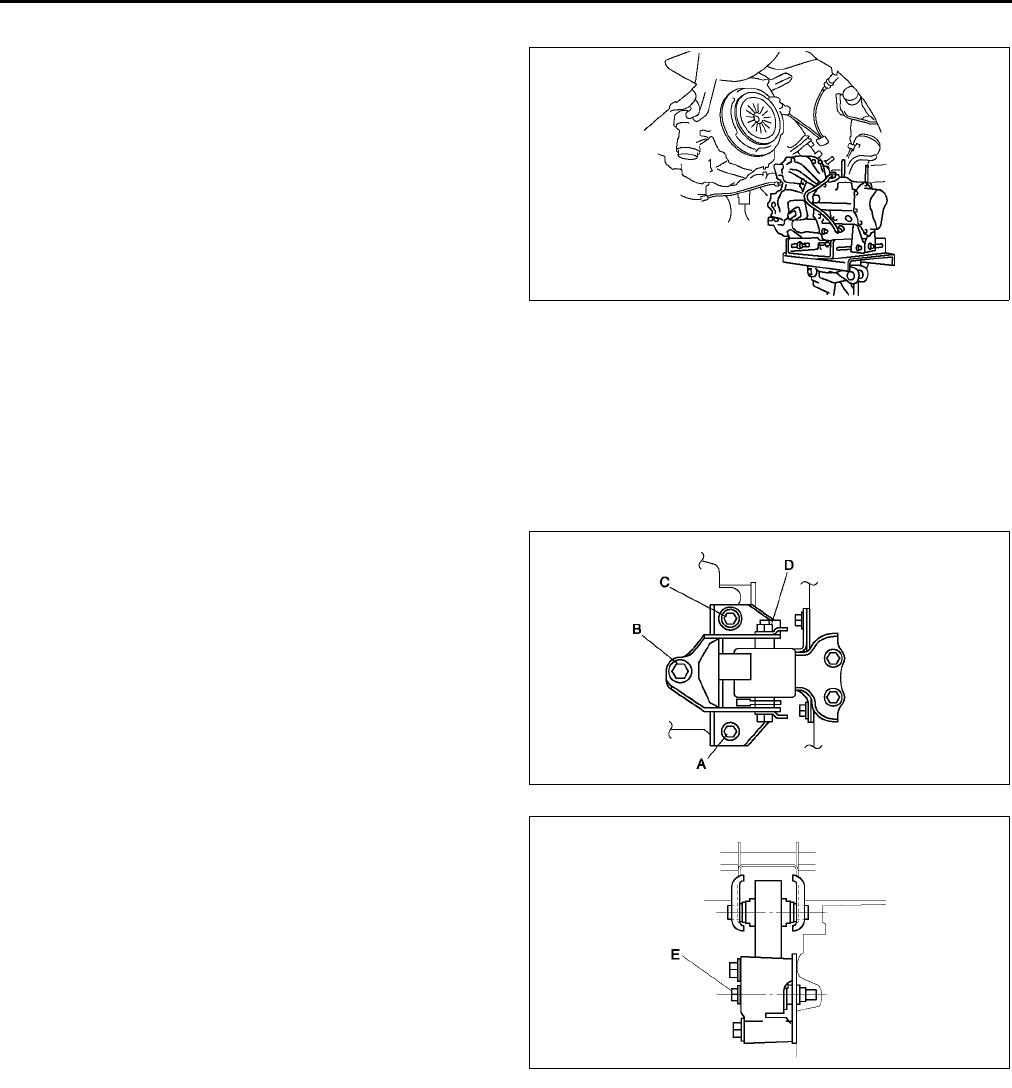
J8
MANUAL TRANSAXLE
Manual Transaxle Installation Note
1. Set the transaxle on a jack and lift into place.
2. Install the transaxle mounting bolts.
3. Tighten the SST (49 E017 5A0)so that the engine
is located at the specified position.
No.1 Engine Mount and No.4 Engine Mount Bracket Installation Note
1. Verify that the engine mount rubbers are installed as shown.
2. By aligning the holes with the stud bolts, install the No.4 engine mount bracket to the transaxle.
3. By aligning the holes with the stud bolts, install the No.1 engine mount to the transaxle.
4. Align the hole of the No.4 engine mount bracket with the No.4 engine mount rubber on vehicle, and temporarily
tighten the bolt D.
5. Tighten the nut B,C in order of B→C, then bolt A.
6. Tighten the bolt D.
7.
Tightening torque
A, B, C: 66.693.1 N·m {6.89.4 kgf·m, 50
68 ft·lbf}
D: 85.3116.6 N·m {8.711.8 kgf·m, 6385
ft·lbf}
8. Tighten the bolt D to the No.1 engine mount.
Tightening torque
E: 85.3116.6 N·m {8.711.8 kgf·m, 6385
ft·lbf}
9. Remove the SST (49 E017 5A0).
End Of Si e
A6E5112W004
A6E5112W005
A6E5112W006
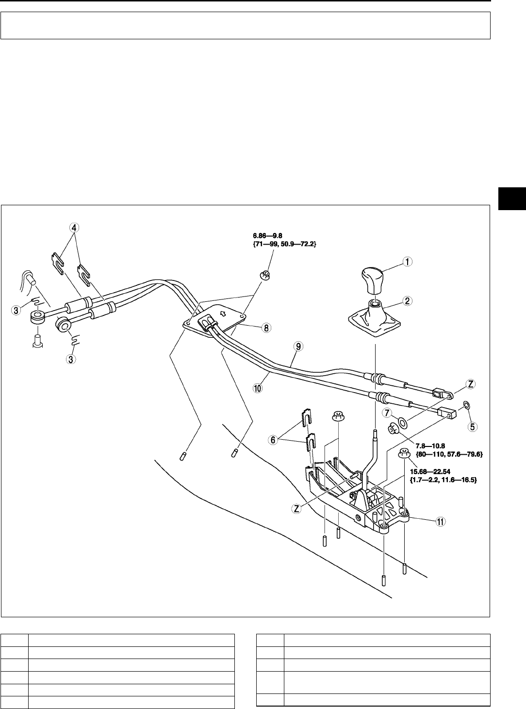
SHIFT MECHANISM
J9
J
SHIFT MECHANISM REMOVAL/INSTALLATION A6E511446010W01
1. Remove the battery, battery tray and battery bracket.
2. Remove the air cleaner component. (See F10 INTAKE-AIR SYSTEM REMOVAL/INSTALLATION.)
3. Remove the dashboard compleat.
(See S82 DASHBOARD REMOVAL/INSTALLATION.)
4. Remove the SAS control module.
(See T124 SAS UNIT REMOVAL/INSTALLATION.)
5. Remove the climate control unit. (See U44 CLIMATE CONTROL UNIT REMOVAL.) (See U45 CLIMATE
CONTROL UNIT INSTALLATION.)
6. Remove the rear heat duct. (See U23 REAR HEAT DUCT REMOVAL/INSTALLATION.)
7. Remove in the order indicated in the table.
8. Install in the reverse order of removal.
9. Install the air cleaner component.
10. After installation, verify that the shift lever can be shifted smoothly into each position.
.
SHIFT MECHANISM
A6E5114W001
1 Shift lever knob
2 Boot panel
3Clip
4Clip
5Clip
6Clip
7 Plain Washer
8 Seal plate
9 Main shift cable
10 Main select cable
(See J10 Select Cable Installation Note)
11 Sift lever assembly
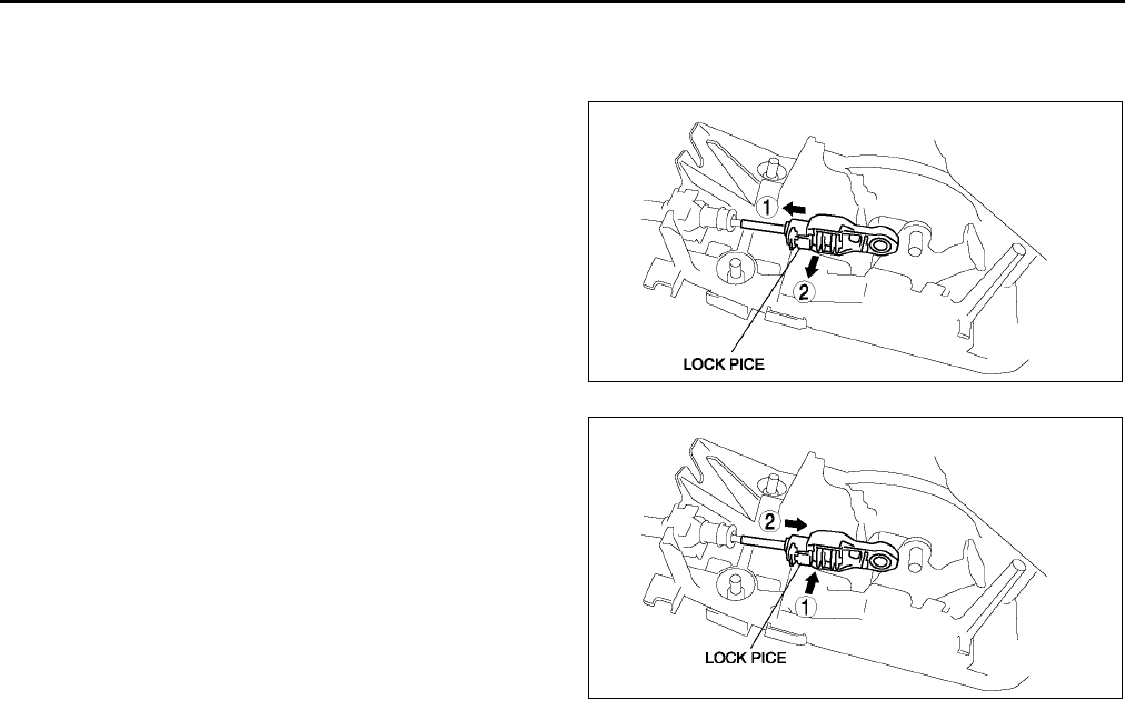
J10
SHIFT MECHANISM
Select Cable Installation Note
1. Remove the center console.
2. Make sure that the shift lever (transaxle side) is in neutral.
3. Unlock the lock pice of the select cable (shift lever
side) in the order shown in the figure.
4. Shift the sift lever to neutral.
5. Lock the lock pice of the selector cable (shift
cable side) in the order shown in the figure.
6. Install the center console.
7. Shift the shift lever from neutral to other position,
and make sure that there are no other
components in that area to interfere with the
lever.
End Of Sie
A6E5114W002
A6E5114W003

K1
K
KAUTOMATIC TRANSAXLE
LOCATION INDEX ................................................. K-4
AUTOMATIC TRANSAXLE
LOCATION INDEX............................................ K-4
AUTOMATIC TRANSAXLE.................................... K-6
MECHANICAL SYSTEM TEST ........................... K-6
ROAD TEST ........................................................ K-9
AUTOMATIC TRANSAXLE FLUID (ATF)
INSPECTION .................................................. K-12
AUTOMATIC TRANSAXLE FLUID (ATF)
REPLACEMENT ............................................. K-13
HOLD SWITCH INSPECTION........................... K-13
HOLD SWITCH
REMOVAL/INSTALLATION............................ K-14
TRANSAXLE RANGE (TR) SWITCH
INSPECTION .................................................. K-14
TRANSAXLE RANGE (TR) SWITCH
REMOVAL/INSTALLATION............................ K-15
TRANSAXLE RANGE (TR) SWITCH
ADJUSTMENT................................................ K-18
TRANSAXLE FLUID TEMPERATURE
(TFT) SENSOR INSPECTION........................ K-19
TRANSAXLE FLUID TEMPERATURE
(TFT) SENSOR
REMOVAL/INSTALLATION............................ K-21
OIL PRESSURE SWITCH INSPECTION .......... K-21
OIL PRESSURE SWITCH
REMOVAL/INSTALLATION............................ K-23
INPUT/TURBINE SPEED SENSOR
INSPECTION .................................................. K-23
INPUT/TURBINE SPEED SENSOR
REMOVAL/INSTALLATION............................ K-24
VEHICLE SPEEDOMETER SENSOR
(VSS) INSPECTION ....................................... K-24
VEHICLE SPEEDOMETER SENSOR
(VSS) REMOVAL/INSTALLATION ................. K-26
SOLENOID VALVE INSPECTION..................... K-26
SOLENOID VALVE
REMOVAL/INSTALLATION............................ K-28
PCM INSPECTION ............................................ K-29
PCM REMOVAL/INSTALLATION ...................... K-29
AUTOMATIC TRANSAXLE
REMOVAL/INSTALLATION............................ K-29
OIL SEAL REPLACEMENT ............................... K-33
CONTROL VALVE BODY REMOVAL ............... K-34
CONTROL VALVE BODY
INSTALLATION .............................................. K-35
OIL COOLER FLUSHING.................................. K-36
OIL COOLER REMOVAL/INSTALLATION........ K-39
OIL COOLER DISASSEMBLY/ASSEMBLY ...... K-41
DRIVE PLATE REMOVAL/INSTALLATION ...... K-43
AUTOMATIC TRANSAXLE SHIFT
MECHANISM ........................................................ K-45
SHIFT-LOCK INSPECTION............................... K-45
KEY INTERLOCK INSPECTION ....................... K-45
INTERLOCK CABLE INSPECTION................... K-45
SELECTOR LEVER INSPECTION.................... K-45
SELECTOR CABLE ADJUSTMENT.................. K-46
SELECTOR LEVER
REMOVAL/INSTALLATION ............................ K-46
SELECTOR LEVER
DISASSEMBLY/ASSEMBLY .......................... K-51
ON-BOARD DIAGNOSTIC ...................................K-52
FOREWORD......................................................K-52
AUTOMATIC TRANSAXLE ON-BOARD
DIAGNOSTIC FUNCTION .............................. K-52
AFTER REPAIR PROCEDURE ......................... K-52
DTC TABLE ....................................................... K-53
DTC P0500 ........................................................ K-55
DTC P0706 ........................................................ K-57
DTC P0707 ........................................................ K-58
DTC P0708 ........................................................ K-60
DTC P0711 ........................................................ K-63
DTC P0712 ........................................................ K-64
DTC P0713 ........................................................ K-65
DTC P0715 ........................................................ K-68
DTC P0731 ........................................................ K-70
DTC P0732 ........................................................ K-71
DTC P0733 ........................................................ K-73
DTC P0734 ........................................................ K-75
DTC P0741 ........................................................ K-77
DTC P0742 ........................................................ K-78
DTC P0745 ........................................................ K-80
DTC P0751 ........................................................ K-82
DTC P0752 ........................................................ K-83
DTC P0753 ........................................................ K-85
DTC P0756 ........................................................ K-87
DTC P0757 ........................................................ K-89
DTC P0758 ........................................................ K-90
DTC P0761 ........................................................ K-93
DTC P0762 ........................................................ K-95
DTC P0763 ........................................................ K-96
DTC P0766 ........................................................ K-99
DTC P0767 ...................................................... K-100
DTC P0768 ...................................................... K-102
DTC P0771 ...................................................... K-104
DTC P0772 ...................................................... K-105
DTC P0773 ...................................................... K-107
DTC P0841 ...................................................... K-109
PID/DATA MONITOR INSPECTION................ K-110
TROUBLESHOOTING........................................ K-112
FOREWORD.................................................... K-112
BASIC INSPECTION ....................................... K-112
SYMPTOM TROUBLESHOOTING
ITEM TABLE ................................................. K-113
QUICK DIAGNOSIS CHART ........................... K-115
NO.1 VEHICLE DOES NOT MOVE IN
D, S, L RANGES, OR IN R POSITION ......... K-117
NO.2 VEHICLE MOVES IN N POSITION ........ K-117
NO.3 VEHICLE MOVES IN P POSITION,
OR PARKING GEAR DOES NOT
DISENGAGE WHEN P IS DISENGAGED .... K-118
NO.4 EXCESSIVE CREEP .............................. K-118
NO.5 NO CREEP AT ALL ................................ K-118
NO.6 LOW MAXIMUM SPEED AND
POOR ACCELERATION............................... K-119

K2
NO.7 NO SHIFTING......................................... K-120
NO.8 DOES NOT SHIFT TO FOURTH
GEAR (4GR) ................................................. K-120
NO.9 ABNORMAL SHIFTING.......................... K-122
NO.10 FREQUENT SHIFTING ........................ K-122
NO.11 SHIFT POINT IS HIGH OR LOW ......... K-122
NO.12 TORQUE CONVERTER
CLUTCH (TCC) NON-OPERATION .............K-123
NO.13 NO KICKDOWN.................................... K-123
NO.14 ENGINE FLARES UP OR
SLIPS WHEN UPSHIFTING OR
DOWNSHIFTING .......................................... K-124
NO.15 ENGINE FLARES UP OR
SLIPS WHEN ACCELERATING
VEHICLE.......................................................K-124
NO.16 JUDDER UPON TORQUE
CONVERTER CLUTCH (TCC)
OPERATION ................................................. K-125
NO.17 EXCESSIVE SHIFT SHOCK
FROM N TO D OR N TO R
POSITION/RANGE .......................................K-126
NO.18 EXCESSIVE SHIFT SHOCK IS
FELT WHEN UPSHIFTING AND
DOWNSHIFTING .......................................... K-127
NO.19 EXCESSIVE SHIFT SHOCK
ON TORQUE CONVERTER
CLUTCH (TCC)............................................. K-127
NO.20 NOISE OCCURS AT IDLE
WHEN VEHICLE IS STOPPED IN
ALL POSITIONS/RANGES ...........................K-128
NO.21 NOISE OCCURS AT IDLE
WHEN VEHICLE IS STOPPED IN
D, S, L RANGES, OR IN R POSITION .........K-128
NO.22 NO ENGINE BRAKING IN
HOLD MODE ................................................K-129
NO.23 TRANSAXLE OVERHEATS ................. K-129
NO.24 ENGINE STALLS WHEN
SHIFTED TO D, S, L RANGES,
OR IN R POSITION ......................................K-130
NO.25 ENGINE STALLS WHEN
DRIVING AT SLOW SPEEDS
OR STOPPING .............................................K-130
NO.26 STARTER DOES NOT WORK ............. K-130
NO.27 HOLD INDICATOR LIGHT
DOES NOT ILLUMINATE WHEN
HOLD SWITCH IS TURNED TO ON ............ K-130
NO.28 HOLD INDICATOR LIGHT
ILLUMINATES WHEN HOLD
SWITCH IS NOT TURNED TO ON.....................K-131

K3
K
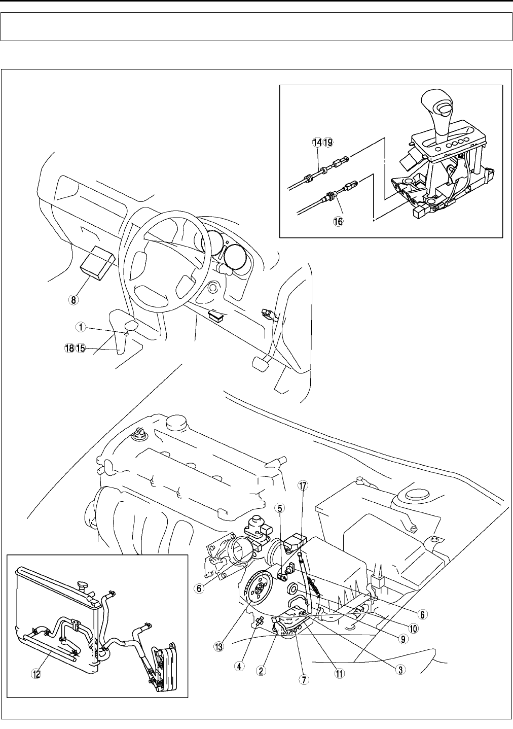
K4
LOCATION INDEX
AUTOMATIC TRANSAXLE LOCATION INDEX A6E560001074W01
.
LOCATION INDEX
A6E5600W001

LOCATION INDEX
K5
K
End Of Sie
1 HOLD switch
(See K13 HOLD SWITCH INSPECTION)
(See K14 HOLD SWITCH REMOVAL/
INSTALLATION)
2 Transaxle range (TR) switch
(See K14 TRANSAXLE RANGE (TR) SWITCH
INSPECTION)
(See K15 TRANSAXLE RANGE (TR) SWITCH
REMOVAL/INSTALLATION)
(See K18 TRANSAXLE RANGE (TR) SWITCH
ADJUSTMENT)
3 Transaxle fluid temperature (TFT) sensor
(See K19 TRANSAXLE FLUID TEMPERATURE
(TFT) SENSOR INSPECTION)
(See K21 TRANSAXLE FLUID TEMPERATURE
(TFT) SENSOR REMOVAL/INSTALLATION)
4 Oil pressure switch
(See K21 OIL PRESSURE SWITCH
INSPECTION)
(See K23 OIL PRESSURE SWITCH REMOVAL/
INSTALLATION)
5 Input/turbine speed sensor
(See K23 INPUT/TURBINE SPEED SENSOR
INSPECTION)
(See K24 INPUT/TURBINE SPEED SENSOR
REMOVAL/INSTALLATION)
6 Vehicle speedometer sensor
(See K24 VEHICLE SPEEDOMETER SENSOR
(VSS) INSPECTION)
(See K26 VEHICLE SPEEDOMETER SENSOR
(VSS) REMOVAL/INSTALLATION)
7 Solenoid valve
(See K26 SOLENOID VALVE INSPECTION)
(See K28 SOLENOID VALVE REMOVAL/
INSTALLATION)
8PCM
(See K29 PCM INSPECTION)
(See K29 PCM REMOVAL/INSTALLATION)
9 Automatic transaxle
(See K29 AUTOMATIC TRANSAXLE REMOVAL/
INSTALLATION)
10 Oil seal
(See K33 OIL SEAL REPLACEMENT)
11 Control valve body
(See K34 CONTROL VALVE BODY REMOVAL)
(See K35 CONTROL VALVE BODY
INSTALLATION)
12 Oil cooler
(See K36 OIL COOLER FLUSHING)
(See K39 OIL COOLER REMOVAL/
INSTALLATION)
(See K41 OIL COOLER DISASSEMBLY/
ASSEMBLY)
13 Drive plate
(See K43 DRIVE PLATE REMOVAL/
INSTALLATION)
14 Interlock cable
(See K45 INTERLOCK CABLE INSPECTION)
15 Selector lever
(See K45 SELECTOR LEVER INSPECTION)
(See K46 SELECTOR LEVER REMOVAL/
INSTALLATION)
(See K51 SELECTOR LEVER DISASSEMBLY/
ASSEMBLY)
16 Select cable
(See K46 SELECTOR CABLE ADJUSTMENT)
17 Automatic transaxle fluid (ATF)
(See K12 AUTOMATIC TRANSAXLE FLUID (ATF)
INSPECTION)
(See K13 AUTOMATIC TRANSAXLE FLUID (ATF)
REPLACEMENT)
18 Shift-lock
(See K45 SHIFT-LOCK INSPECTION)
19 Key interlock
(See K45 KEY INTERLOCK INSPECTION)
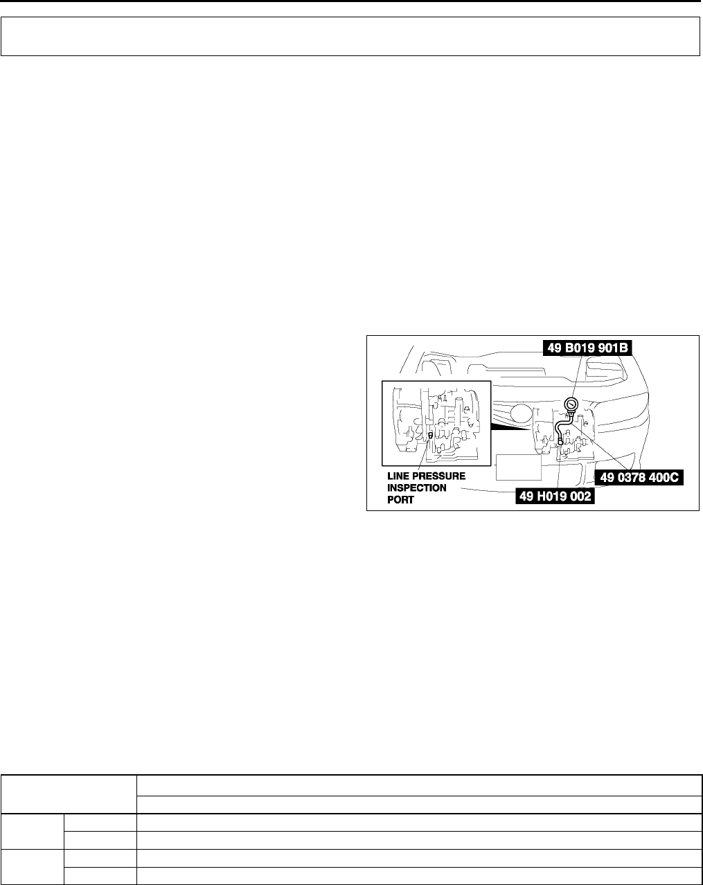
K6
AUTOMATIC TRANSAXLE
MECHANICAL SYSTEM TEST A6E561401030W01
Mechanical System Test Preparation
1. Engage the parking brake and use wheel chocks at the front and rear of the wheels.
2. Inspect the engine coolant. (See E3 ENGINE COOLANT LEVEL INSPECTION.)
3. Inspect the engine oil. (See D4 ENGINE OIL INSPECTION.)
4. Inspect the ATF levels. (See K12 AUTOMATIC TRANSAXLE FLUID (ATF) INSPECTION.)
5. Inspect the idle speed and ignition timing in P position. (See F8 IDLE SPEED INSPECTION.)(See F8
IGNITION TIMING INSPECTION.)
6. Bring up the engine and transaxle to normal operating temperature.
Line Pressure Test
1. Perform mechanical system test preparation. (See K6 Mechanical System Test Preparation.)
Warning
•
••
•Removing the square-head plug when the ATF is hot can be dangerous. Hot ATF can come out of
the opening and badly burn you. Before removing the square-head plug, allow the ATF to cool.
2. Connect the SSTs (49 H019 002 and, 49 0378
400C) to the line pressure inspection port, then
replace the gauge of the SST (49 0378 400C)
with the SST (49 B019 901B).
3. Start the engine, then warm up the automatic
transaxle.
4. Shift the selector lever to D range.
5. Read the line pressure at idle engine speed for
the D range.
6. Read the line pressure at idle engine speed for
the D (HOLD), S, S (HOLD), L, L (HOLD) ranges
and R positions in the same manner as in Steps
4-5.
7. Stop the engine, then replace the SST (49 B019
901B) with the gauge of the SST (49 0378 400C).
8. Start the engine.
9. Firmly depress the brake pedal with the left foot.
10. Shift the selector lever to D range position.
Caution
•
••
•If the accelerator pedal is pressed for longer than 5 seconds while the brake pedal is pressed, the
transaxle could be damaged. Therefore, perform Steps 11 and 12 within 5 seconds each.
11. Gradually depress the accelerator pedal with the right foot.
12. When the engine speed no longer increases, quickly read the line pressure and release the accelerator pedal.
13. Shift the selector lever to N position and let the engine idle for 1 minute or more to cool the ATF.
14. Read the line pressure at the engine stall speed for the D, D (HOLD), S, S (HOLD), L, L(HOLD) ranges and R
position in the same manner as in Steps 9-13.
Specified line pressure
* : Includes each HOLD mode
Warning
•
••
•Removing the square-head plug when the ATF is hot can be dangerous. Hot ATF can come out of
the opening and badly burn you. Before removing the square-head plug, allow the ATF to cool.
AUTOMATIC TRANSAXLE
A6E5614W002
Position/Range Line pressure (kPa {kgf/cm2, psi})
LF
D, S, L* idle 330470 {3.44.8, 4868}
Stall 1,1601,320 {11.812.5, 168191}
Ridle 490710 {5.07.2, 71102}
Stall 1,6001,820 {16.318.6, 232264}
AUTOMATIC TRANSAXLE
K7
K
15. Remove the SSTs.
16. Install a new square head plug in the inspection port.
Tightening torque
5.09.8 N·m {50100 kgf·cm, 4486 in·lbf}
Evaluation of line pressure test
Stall Test
1. Perform mechanical system test preparation. (See K6 Mechanical System Test Preparation.)
2. Start the engine.
3. Firmly depress the brake pedal with the left foot.
4. Shift the selector lever to D range.
Caution
•
••
•If the accelerator pedal is pressed for longer than 5 seconds while the brake pedal is pressed, the
transaxle could be damaged. Therefore, perform Steps 5 and 6 within 5 seconds of each other.
5. Gently depress the accelerator pedal with the right foot.
6. When the engine speed no longer increases, quickly read the speed and release the accelerator pedal. When
the engine speed no longer increases, quickly read the speed and release the accelerator pedal.
7. Shift the selector lever to N position and let the engine idle for 1 minute or more to cool the ATF.
8. Perform a stall test of D (HOLD), S, S (HOLD), L, L (HOLD) and R range positions in the same manner as in
Steps 37.
9. Turn the ignition switch off.
Engine stall speed
* : Includes each HOLD mode
Line pressure Possible cause
Low pressure in all ranges
Worn oil pump
Oil leaking from oil pump, control valve body, and/or transaxle case
Pressure regulator valve sticking
Pressure control solenoid malfunction
Pressure modulator valve sticking
Solenoid reducing valve sticking
Low pressure in D and S only Oil leaking from hydraulic circuit of forward clutch
Low pressure in L and R only Oil leaking from hydraulic circuit of low and reverse brake
Low pressure in R only Oil leaking from hydraulic circuit of reverse clutch
High pressure in all ranges
Pressure control solenoid malfunction
Pressure regulator valve sticking
Pressure modulator valve sticking
Pressure reducing valve sticking
Position/
Range
Engine stall speed (rpm)
LF
D, S, L* 2,0002,600
R

K8
AUTOMATIC TRANSAXLE
Evaluation of stall test
Time Lag Test
1. Perform mechanical system test preparation. (See K6 Mechanical System Test Preparation.)
2. Use a stopwatch to measure the time it takes from shifting until shock is felt when shifting the selector lever
from N position to D range (non-HOLD mode). Take three measurements for each test and take the average
from the results using the following formula.
Formula:
Average time lag = (Time 1 + Time 2 + Time 3) / 3
3. Perform the test for the following shifts in the same manner Step 2.
•N position → D range (HOLD mode)
•N position → R position
Time lag
N position →
→→
→ D range ... 0.40.7 s
N position →
→→
→ R position ... 0.40.7 s
Evaluation of time lag test
End Of Sie
Condition Possible cause
Above specification
In all forward ranges and R
position
Insufficient
line pressure
Worm oil pump
Oil leaking from oil pump, control valve, and/
or transaxle case
Pressure regulator valve sticking
Pressure control solenoid malfunction
Pressure modulator valve sticking
In forward ranges Forward clutch slippage
One-way clutch 1 slippage
In D ranges One-way clutch 2 slippage
In S ranges 2-4 brake band slippage
In L range and R position Low and reverse brake slippage
In R position
Low and reverse brake slippage
Reverse clutch slipping
Perform road test to determine whether problem is low and
reverse brake or reverse clutch
•Engine braking felt in L range: Reverse clutch
•Engine braking not felt in L range: Low and reverse brake
Below specification Engine out of tune
One-way clutch slipping within torque converter
Condition Possible Cause
N → D shift
More than specification
Insufficient line pressure
Forward clutch slipping
Oil leaking from forward clutch fluid circuit
Shift solenoid A not operating properly
Less than specification
Forward accumulator not operating properly
Shift solenoid A not operating properly
Excessive line pressure
N → D (HOLD) shift
More than specification
Insufficient line pressure
Forward clutch slipping
Shift solenoid A not operating properly
Less than specification
Forward accumulator not operating properly
Shift solenoid A not operating properly
Excessive line pressure
N → R shift
More than specification
Insufficient line pressure
Low and reverse brake slipping
Reverse clutch slipping
Shift solenoid B not operating properly
Less than specification
Servo apply accumulator not operating properly
Shift solenoid B not operating properly
Excessive line pressure
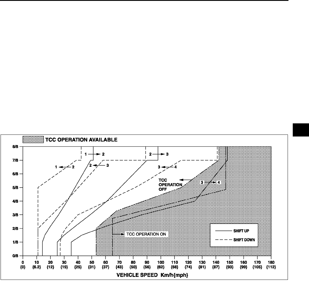
AUTOMATIC TRANSAXLE
K9
K
ROAD TEST A6E561401030W02
Warning
•
••
•When performing a road test, be aware of other vehicles, people, impediments, etc. to avoid an
accident.
Note
•When the legal speed limit must be exceeded, use a chassis dynamomenter instead of performing a road
test.
Road Test Preparation
1. Inspect the engine coolant levels. (See E3 ENGINE COOLANT LEVEL INSPECTION.)
2. Inspect the engine oil levels. (See D4 ENGINE OIL INSPECTION.)
3. Inspect the ATF levels. (See K12 AUTOMATIC TRANSAXLE FLUID (ATF) INSPECTION.)
4. Inspect the idle speed and ignition timing in P position. (See F8 IDLE SPEED INSPECTION.)(See F8
IGNITION TIMING INSPECTION.)
5. Bring up the engine and transaxle to normal operating temperature.
Shift Diagram
D range (normal mode)
D Range Test
1. Perform road test preparation. (See K9 Road Test Preparation.)
2. Shift the selector lever to D range.
3. Accelerate the vehicle with half and WOT, then verify that 1→2, 2→3, and 3→4 upshifts can be obtained. The
shift points must be as shown in the table below.
•If not as specified, inspect the PCM and ATX. (See K113 SYMPTOM TROUBLESHOOTING ITEM
TABLE.)
4. Drive the vehicle in 4GR, 3GR, and 2GR and verify that kickdown occurs for 4→3, 3→2, 2→1 downshifts, and
that the shift points are as shown in the table below.
•If not as specified, inspect the PCM and ATX.(See K113 SYMPTOM TROUBLESHOOTING ITEM
TABLE.)
5. Decelerate the vehicle and verify that engine braking effect is felt in 2GR, 3GR, and 4GR.
•If not as specified, inspect the PCM and ATX. (See K113 SYMPTOM TROUBLESHOOTING ITEM
TABLE.)
6. Drive the vehicle and verify that TCC operation is obtained. The operation points must be as shown in the table
below.
•If not as specified, inspect the PCM and ATX. (See K113 SYMPTOM TROUBLESHOOTING ITEM
TABLE.)
7. Select HOLD mode.
A6E5614W001

K10
AUTOMATIC TRANSAXLE
8. Accelerate the vehicle at half throttle and WOT, and verify that 4→3, 3→2, and 2→3 shift can be obtained. The
shift points must be as shown in the table below.
•If not as specified, inspect the PCM and ATX. (See K113 SYMPTOM TROUBLESHOOTING ITEM
TABLE.)
9. Drive the vehicle in 4GR, 3GR, 2GR and verify that kickdown does not occur.
•If not as specified, inspect the PCM and ATX. (See K113 SYMPTOM TROUBLESHOOTING ITEM
TABLE.)
10. Decelerate the vehicle and verify that engine braking effect is felt in 2GR, 3GR, and 4GR.
•If not as specified, inspect the PCM and ATX. (See K113 SYMPTOM TROUBLESHOOTING ITEM
TABLE.)
Shift point table
S Range Test
1. Perform road test preparation. (See K9 Road Test Preparation.)
2. Shift the selector lever to S range.
3. Accelerate the vehicle at half throttle and WOT, then verify that 1→2 and 2→3 upshifts can be obtained. The
shift points must be as shown in the table below.
•If not as specified, inspect the PCM and ATX. (See K113 SYMPTOM TROUBLESHOOTING ITEM
TABLE.)
4. Drive the vehicle in 2GR, 3GR, 4GR and verify that kickdown occurs for 4→3, 3→2, 2→1 downshift, and that
the shift point is as shown in the table below.
•If not as specified, inspect the PCM and ATX. (See K113 SYMPTOM TROUBLESHOOTING ITEM
TABLE.)
5. Decelerate the vehicle and verify that engine braking effect is felt in 2GR, 3GR and 4GR.
•If not as specified, inspect the PCM and ATX. (See K113 SYMPTOM TROUBLESHOOTING ITEM
TABLE.)
6. Select HOLD mode.
Range/Mode Throttle condition Shift Vehicle speed
(km/h {mph})
Turbine speed
(rpm)
D
NORMAL
WOT
D1→D25056 {3134} 5,4506,050
D2→D396104 {6064} 5,5505,950
D3→D4145155 {9096} 5,6005,950
TCC ON(D4)152162 {95100} 4,2504,500
Half throttle
D1→D22836 {1822} 3,0003,900
D2→D35268 {3342} 2,9503,950
D3→D4108136 {6784} 4,1505,200
TCC ON(D4)95129 {5979} 2,6503,600
CTP D4→D32430 {1518} 700800
D3→D1814 {58} 350500
Kickdown (WOT)
D4→D3136146 {8590} 3,8004,050
D3→D28593 {5357} 3,3003,550
D2→D13945 {2527} 2,2502,550
POWER
WOT
D1→D25056 {3134} 5,4506,050
D2→D396104 {6064} 5,5505,950
D3→D4145155 {9096} 5,6005,950
Half throttle
D1→D23544 {2227} 3,8004,750
D2→D37392 {4657} 4,2005,200
D3→D4111139 {6986} 4,2505,350
CTP D4→D33238 {2023} 9001,050
D3→D1814 {58} 350500
Kickdown (WOT)
D4→D3136146 {8590} 3,8004,050
D3→D28593{5357} 3,3003,550
D2→D13945 {2527} 2,2502,550
HOLD ALL round
D2→D31525 {1015} 9001,400
D4→D3145151 {9093} 4,0504,200
D3→D2713 {58} 300450
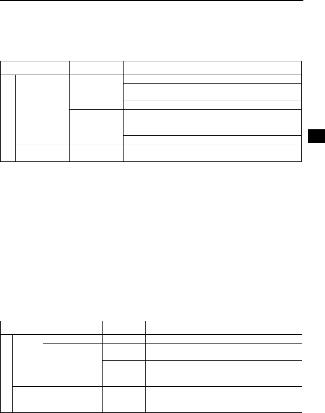
AUTOMATIC TRANSAXLE
K11
K
7. Accelerate the vehicle in 2GR at half throttle and WOT, and verify that 2GR is held.
•If not as specified, inspect the PCM and ATX. (See K113 SYMPTOM TROUBLESHOOTING ITEM
TABLE.)
8. Decelerate the vehicle and verify that engine braking effect is felt.
•If not as specified, inspect the PCM and ATX. (See K113 SYMPTOM TROUBLESHOOTING ITEM
TABLE.)
Shift point table
L Range Test
1. Perform road test preparation. (See K9 Road Test Preparation.)
2. Shift the selector lever to L range.
3. Accelerate the vehicle at half throttle and WOT, then verify that 1→2 upshift. The shift points must be as shown
in the table below.
•If not as specified, inspect the PCM and ATX.(See K113 SYMPTOM TROUBLESHOOTING ITEM
TABLE.)
4. Drive the vehicle in 2GR and verify that kickdown occurs for 2→1 downshift, and that the shift point is as shown
in the table below.
•If not as specified, inspect the PCM and ATX. (See K113 SYMPTOM TROUBLESHOOTING ITEM
TABLE.)
5. Decelerate the vehicle and verify that engine braking effect is felt in 1GR,2GR, 3GR and 4GR.
•If not as specified, inspect the PCM and ATX. (See K113 SYMPTOM TROUBLESHOOTING ITEM
TABLE.)
6. Select HOLD mode.
7. Accelerate the vehicle in 1GR at half throttle and WOT, and verify that 1GR is held.
•If not as specified, inspect the PCM and ATX. (See K113 SYMPTOM TROUBLESHOOTING ITEM
TABLE.)
8. Decelerate the vehicle and verify that engine braking effect is felt.
•If not as specified, inspect the PCM and ATX. (See K113 SYMPTOM TROUBLESHOOTING ITEM
TABLE.)
Shift point table
Range/
Mode Throttle condition Shift Vehicle speed
(km/h {mph})
Turbine speed
(rpm)
S
NORMAL
WOT S1→S25056 {3134} 5,4506,050
S2→S396104 {6064} 5,5505,950
Half throttle S1→S23544 {2227} 3,8004,750
S2→S37392 {4657} 4,2005,250
CTP S4→S3145151 {9093} 4,0504,200
S3→S1814 {58} 350500
Kickdown (WOT) S3→S28593 {5357} 3,3003,550
S2→S13945 {2527} 2,2502,550
HOLD ALL round S4→S3145151 {9093} 4,0504,200
S3→S295101 {5962} 3,6503,850
Range/Mode Throttle condition Shift Vehicle speed
(km/h {mph})
Turbine speed
(rpm)
L
NORMAL
WOT L1→L25056 {3134} 5,4506,050
Half throttle L1→L23544 {2227} 3,8004,750
CTP
L4→L3145151 {9093} 4,0504,200
L3→L295101 {5962} 3,6503,850
L2→L1814 {58} 500800
Kickdown (WOT) L4→L3143153 {8994} 4,0004,250
HOLD ALL round
L4→L3145151 {9093} 4,0504,200
L3→L295101 {5962} 3,6503,850
L2→L13945 {2527} 2,2502,500
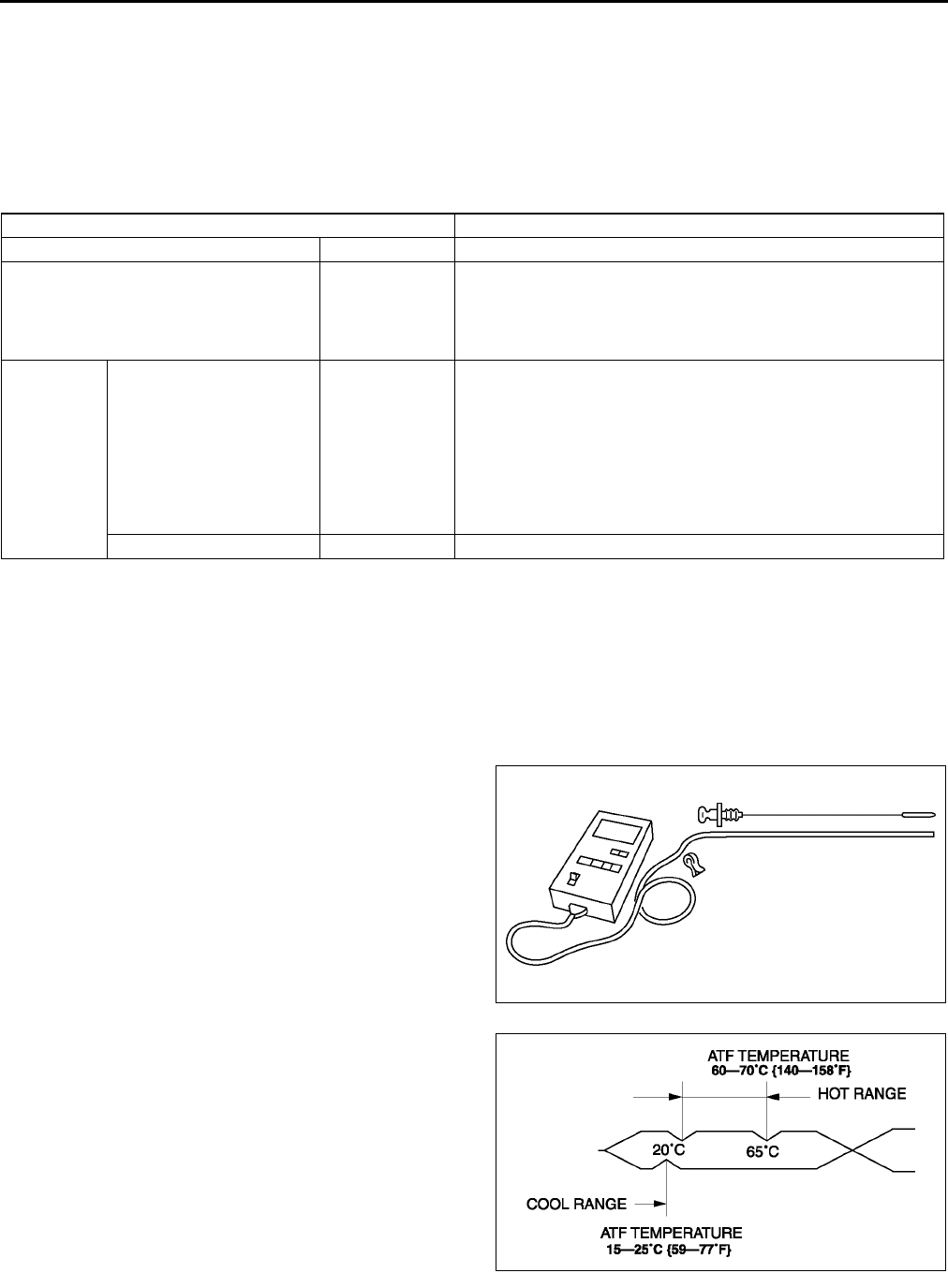
K12
AUTOMATIC TRANSAXLE
P Position Test
1. Shift into P position on a gentle slope. Release the brake and verify that the vehicle does not roll.
End Of Sie
AUTOMATIC TRANSAXLE FLUID (ATF) INSPECTION A6E561401030W03
Automatic Transaxle Fluid (ATF) Condition Inspection
1. One way of determining whether the transaxle should be disassembled is by noting:
•If the ATF is muddy or varnished.
•If the ATF smells strange or unusual.
ATF Condition
Automatic Transaxle Fluid (ATF) Level Inspection
Caution
•
••
•The ATF amount varies according to ATF's temperature. Therefore, when checking the ATF level
or replacing the ATF, use a thermometer to measure the temperature then adjust the ATF amount
to the specified level according to the specified temperature.
1. Park the vehicle on level ground.
2. Apply the parking brake and position wheel chocks securely to prevent the vehicle from rolling.
3. Adjust the length or thermistor probe to measure
the same depth as the depth gauge and hold the
probe with a paper holder. Insert into the filler
tube and measure the temperature.
•If necessary, inspect the ATF before warming
up the engine. In this case, use the cool
range.1525 °
°°
°C {5977 °
°°
°F}
4. Warm up the engine until the ATF reaches 60
70 °
°°
°C {140158 °
°°
°F}.
5. Shift the selector lever and pause momentarily in
each range (DL) while depressing the brake
pedal.
6. Shift the selector lever to P position.
7. Verify that the ATF level is in the HOT range (65
°C{149 °F}) while the engine is idling.
•If necessary, add ATF to the specification.
ATF type
ATF M-V
End Of Sie
Condition Possible cause
Clear red Normal
Light red: pink Contaminated
with water
•Broken oil cooler inside of radiator
•Poor filler tube installation:
Problem could be occurring to parts inside the transaxle by
water contamination. It is necessary to overhaul transaxle and
detect defected parts. If necessary, exchange transaxle.
Reddish
brown
Has burnt smell and metal
specks are found
Deteriorated
ATF
Defect powertrain components inside of transaxle: Specks
cause wide range of problems by plugging up in oil pipe, control
valve body and oil cooler in radiator.
•When large amount of metal specks are found, overhaul
transaxle and detect defected parts. If necessary, exchange
transaxle.
•Implement flushing operation as there is a possibility to have
specks plugging up oil pipe and/or oil cooler inside of
radiator.
Has no burnt smell Normal •Discoloration by oxidation
A6E5614W003
A6E5614W004
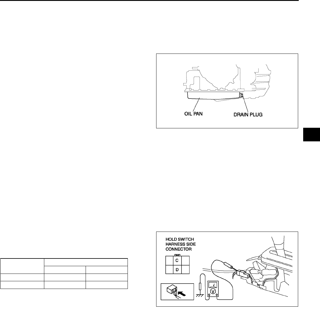
AUTOMATIC TRANSAXLE
K13
K
AUTOMATIC TRANSAXLE FLUID (ATF) REPLACEMENT A6E561401030W04
Warning
•
••
•When the transaxle and ATF are hot, they can badly burn you. Turn off the engine and wait until
they are cool before changing the ATF.
1. Remove the oil dipstick.
2. Remove the oil drain plug and washer.
3. Drain the ATF into a container.
4. Install a new washer and the drain plug.
Tightening torque
3041 N·m {3.04.2 kgf·m, 2230 ft·lbf}
5. Add the specified ATF until ATF level reaches
lower notch of dipstick type of ATF through the oil
filler tube.
ATF type
ATF M-V
6. Ensure that the ATF level is in the HOT range (65 °C{149 °F}).
•Add ATF to the specified level as necessary.
End Of Sie
HOLD SWITCH INSPECTION A6E561446030W01
Operating Inspection
1. Turn the ignition switch to ON (engine OFF).
2. Verify that the HOLD indicator light is not illuminated. Depress the HOLD switch and verify that the HOLD
indicator light illuminates.
•If not as specified, inspect the terminal voltage of the HOLD switch.
Voltage Inspection
1. Remove the console.
2. Turn the ignition switch to ON (engine OFF).
3. Measure the voltage at the HOLD switch
connector.
•If not as specified, inspect for continuity at the
HOLD switch.
A6E5614W005
HOLD switch
position
Connector terminal
CD
Normal B+ 0
Depressed 0 0
A6E5614W006
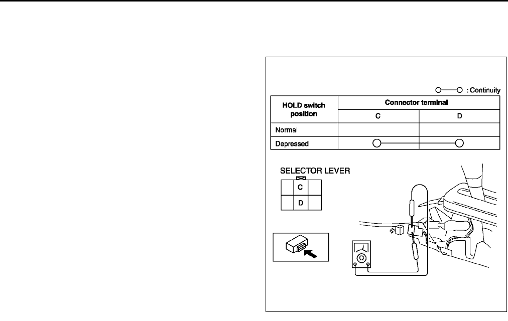
K14
AUTOMATIC TRANSAXLE
Continuity Inspection of
1. Disconnect the negative battery cable.
2. Remove the console.
3. Disconnect the HOLD switch connector.
4. Inspect continuity at the HOLD switch.
•If the switch is okay, inspect the wiring
harness. (HOLD switchPCM, HOLD
switchBody ground)
•If not as specified, replace the HOLD switch.
(See K14 HOLD SWITCH REMOVAL/
INSTALLATION.)
5. Connect the HOLD switch connector.
6. Install the console.
7. Connect the negative battery cable.
End Of Sie
HOLD SWITCH REMOVAL/INSTALLATION A6E561446030W02
1. Disconnect the negative battery cable.
2. Remove the console.
3. Disconnect the connector and remove the HOLD switch terminals. (See K51 SELECTOR LEVER
DISASSEMBLY/ASSEMBLY.)
4. Remove the selector lever knob component.
5. Remove the HOLD switch.
6. Install the HOLD switch to selector lever knob component.
7. Install selector lever knob component.
Tightening torque
15.6822.54 N·m {1.5992.298 kgf·m, 1216 ft·lbf}
8. Install the HOLD switch terminals and connect the connector.
9. Install the console.
10. Connect the negative battery cable.
End Of Sie
TRANSAXLE RANGE (TR) SWITCH INSPECTION A6E561419440W01
Operating Inspection
1. Verify that the starter operates only when the ignition switch is at the START position with the selector lever in
P or N position.
•If not as specified, adjust the TR switch.
2. Verify that the back-up lights illuminate when shifted to R position with the ignition switch at the ON position.
•If not as specified, adjust the TR switch.
Continuity Inspection
Caution
•
••
•Water or foreign objects entering the connector can cause a poor connection or corrosion. Be
sure not to drop water or foreign objects on the connector when disconnecting it.
1. Disconnect the negative battery cable.
2. Remove the air cleaner component. (See F10 INTAKE-AIR SYSTEM REMOVAL/INSTALLATION.)
A6E5614W007
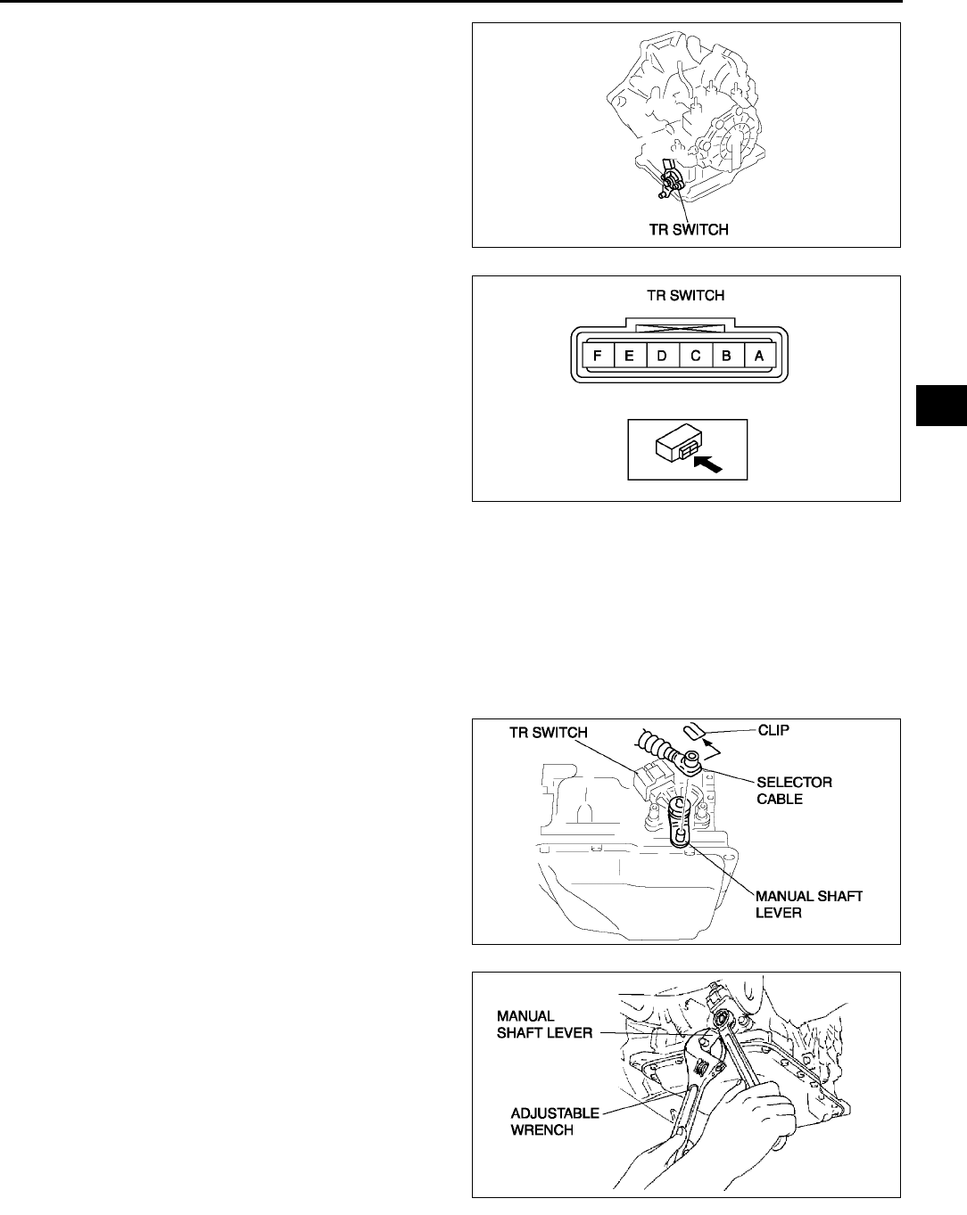
AUTOMATIC TRANSAXLE
K15
K
3. Disconnect the TR switch connector.
4. Inspect for continuity at the TR switch.
•If not as specified, adjust the TR switch and
go to Step 4.
5. Reinspect for continuity at TR switch.
•If not as specified, replace the TR switch.
(See K15 TRANSAXLE RANGE (TR)
SWITCH REMOVAL/INSTALLATION.)
6. Connect the TR switch connector.
7. Install the air cleaner component. (See F10
INTAKE-AIR SYSTEM REMOVAL/
INSTALLATION.)
8. Connect the negative battery cable.
End Of Sie
TRANSAXLE RANGE (TR) SWITCH REMOVAL/INSTALLATION A6E561419440W02
1. Disconnect the negative battery cable.
2. Remove the air cleaner component. (See F10 INTAKE-AIR SYSTEM REMOVAL/INSTALLATION.)
Caution
•
••
•Water or foreign objects entering the connector can cause a poor connection or corrosion. Be
sure not to drop water or foreign objects on the connector when disconnecting it.
3. Disconnect the TR switch connector.
4. Remove the clip and disconnect the selector
cable.
Caution
•
••
•Do not use an impact wrench. Hold the
manual shaft lever when removing the
manual shaft nut, or the transaxle may be
damaged.
5. Set the adjustable wrench as shown to hold the
manual shaft lever.
6. Remove the manual shaft nut and washer.
A6E5614W008
A6E5614W010
A6E5614W011
A6E5614W100
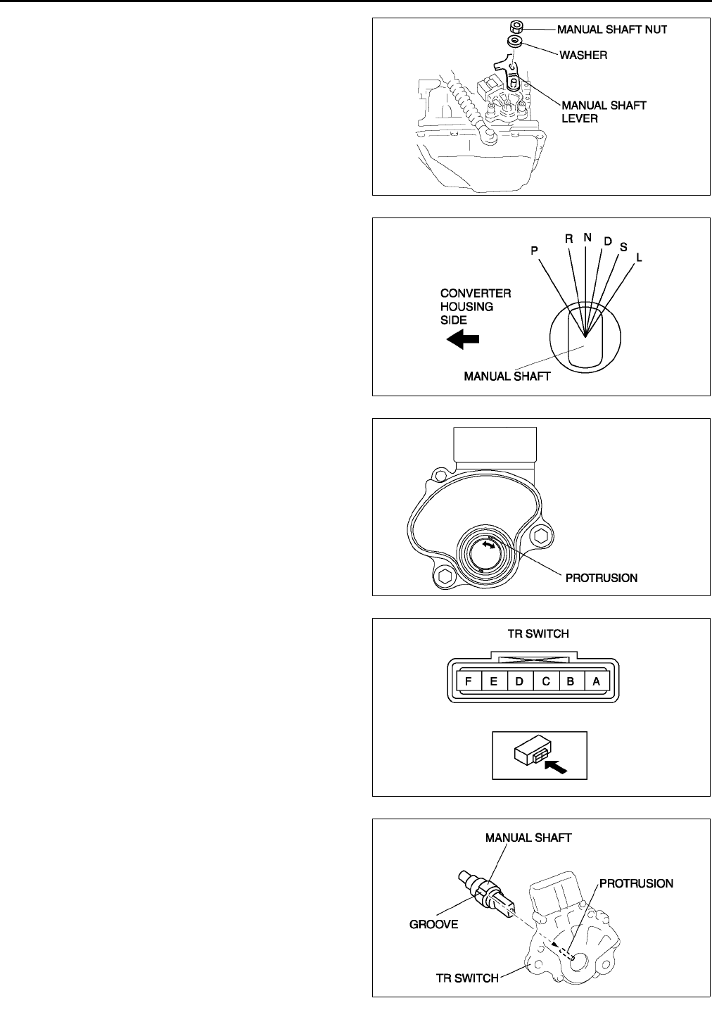
K16
AUTOMATIC TRANSAXLE
7. Remove the manual shaft lever.
8. Remove the TR switch.
9. Rotate the manual shaft to the converter housing
side fully, then return 2 notches to set the N
position.
10. Turn the protrusion at resistance between the
terminals B and C become 750 ohms.
11. Install the TR switch while aligning the protrusion
and groove as shown.
12. Hand-tighten the TR switch mounting bolts.
A6E5614W012
A6E5614W013
A6E5614W014
A6E5614W010
A6E5614W016
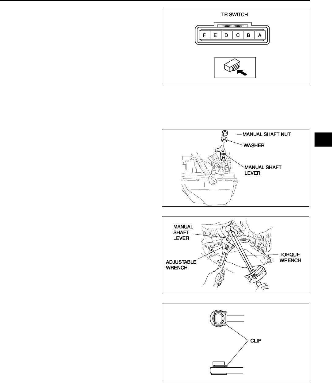
AUTOMATIC TRANSAXLE
K17
K
13. Inspect the resistance between the terminals B
and C.
•If not as specified, readjust the TR switch.
(See K18 TRANSAXLE RANGE (TR)
SWITCH ADJUSTMENT.)
Resistance
750 ohms
14. Tighten the TR switch mounting bolts.
Tightening torque
811 N·m {82112 kgf·cm, 7197 in·lbf}
Caution
•
••
•Do not use an impact wrench. Hold the manual shaft lever when removing the manual shaft nut, or
the transaxle may be damaged.
15. Install the manual shaft lever and the washer.
16. Set the adjustable wrench as shown to hold the
manual shaft lever, and tighten the manual shaft
nut.
Tightening torque
3246 N·m {3.24.7 kgf·m, 2433 ft·lbf}
17. Install the clip to the SELECTOR CABLE as
shown in the figure.
18. Shift the selector lever to P position.
19. Turn the manual shaft lever to P position.
A6E5614W010
A6E5614W012
A6E5614W101
A6E5614W018
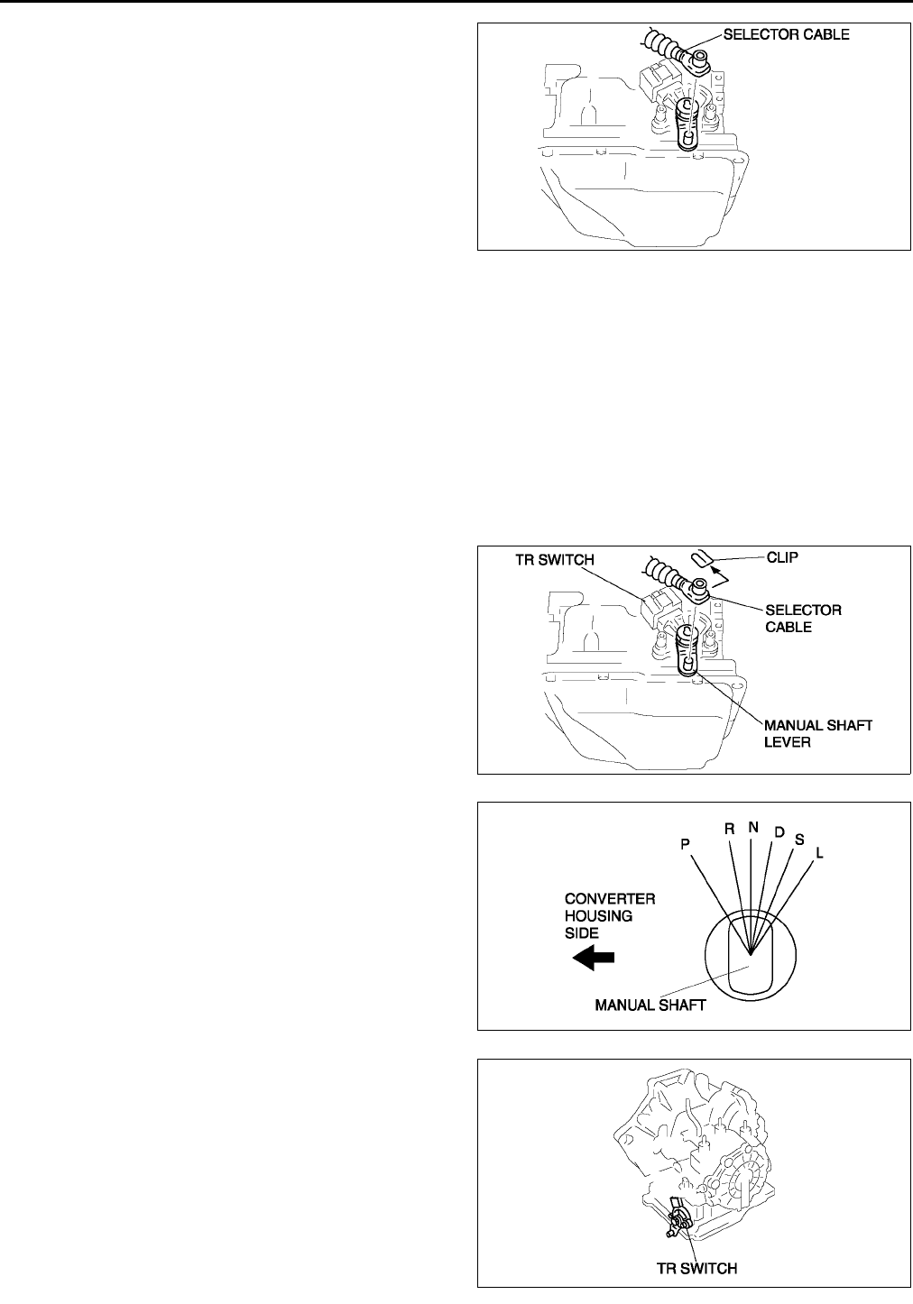
K18
AUTOMATIC TRANSAXLE
20. Connect the selector cable.
21. Inspect for continuity at the TR switch. (See K14
TRANSAXLE RANGE (TR) SWITCH
INSPECTION.)
•If not as specified, readjust the TR switch.
(See K18 TRANSAXLE RANGE (TR)
SWITCH ADJUSTMENT.)
22. Connect the TR switch connector.
23. Install the aircleaner component. (See F10
INTAKE-AIR SYSTEM REMOVAL/
INSTALLATION.)
24. Connect the negative battery cable.
25. Inspect operation of the TR switch. (See K14
TRANSAXLE RANGE (TR) SWITCH
INSPECTION.)
•If not as specified, readjust the TR switch. (See K18 TRANSAXLE RANGE (TR) SWITCH
ADJUSTMENT.)
End Of Sie
TRANSAXLE RANGE (TR) SWITCH ADJUSTMENT A6E561419440W03
1. Disconnect the negative battery cable.
2. Remove the air cleaner component. (See F10 INTAKE-AIR SYSTEM REMOVAL/INSTALLATION.)
Caution
•
••
•Water or foreign objects entering the connector can cause a poor connection or corrosion. Be
sure not to drop water or foreign objects on the connector when disconnecting it.
3. Remove the clip and disconnect the selector
cable.
4. Rotate the manual shaft to the converter housing
side fully, then return 2 notches to set the N
position.
5. Disconnect the TR switch connector.
A6E5614W019
A6E5614W011
A6E5614W013
A6E5614W008
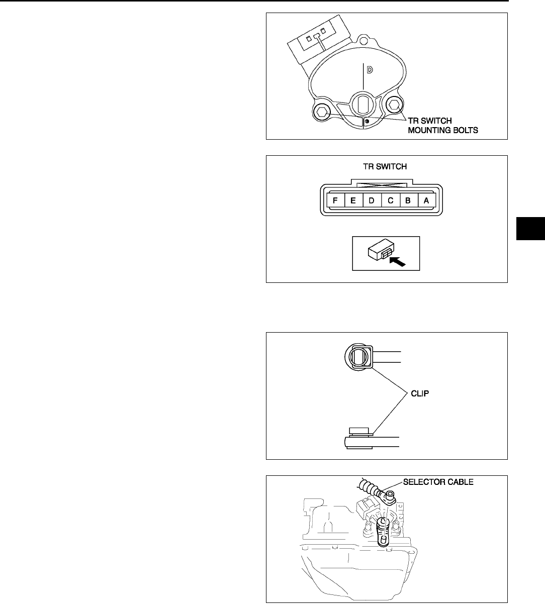
AUTOMATIC TRANSAXLE
K19
K
6. Loosen the TR switch mounting bolts.
7. Measure the resistance between the terminals B
and C.
8. Adjust the switch to the point as follow.
Resistance standard value
750 ohms
9. Tighten the TR switch mounting bolts.
Tightening torque
811 N·m {82112 kgf·cm, 7197 in·lbf}
10. Move the selector lever to N position.
11. Verify that the TR switch is aligned with N
position.
12. Connect the TR switch connector.
13. Install the clip to the selector cable as shown in
the figure.
14. Connect the selector cable to the manual shaft
lever as shown in the figure.
15. Inspect operation of the TR switch. (See K14
TRANSAXLE RANGE (TR) SWITCH
INSPECTION.)
•If not as specified, readjust the TR switch.
16. Install the air cleaner component. (See F10
INTAKE-AIR SYSTEM REMOVAL/
INSTALLATION.)
17. Connect the negative battery cable.
End Of Sie
TRANSAXLE FLUID TEMPERATURE (TFT) SENSOR INSPECTION A6E561419010W01
On-Vehicle Inspection
1. Disconnect the negative battery cable.
2. Remove the air cleaner component. (See F10 INTAKE-AIR SYSTEM REMOVAL/INSTALLATION.)
Caution
•
••
•Water or foreign objects entering the connector can cause a poor connection or corrosion. Be
sure not to drop water or foreign objects on the connector when disconnecting it.
A6E5614W020
A6E5614W010
A6E5614W018
A6E5614W019
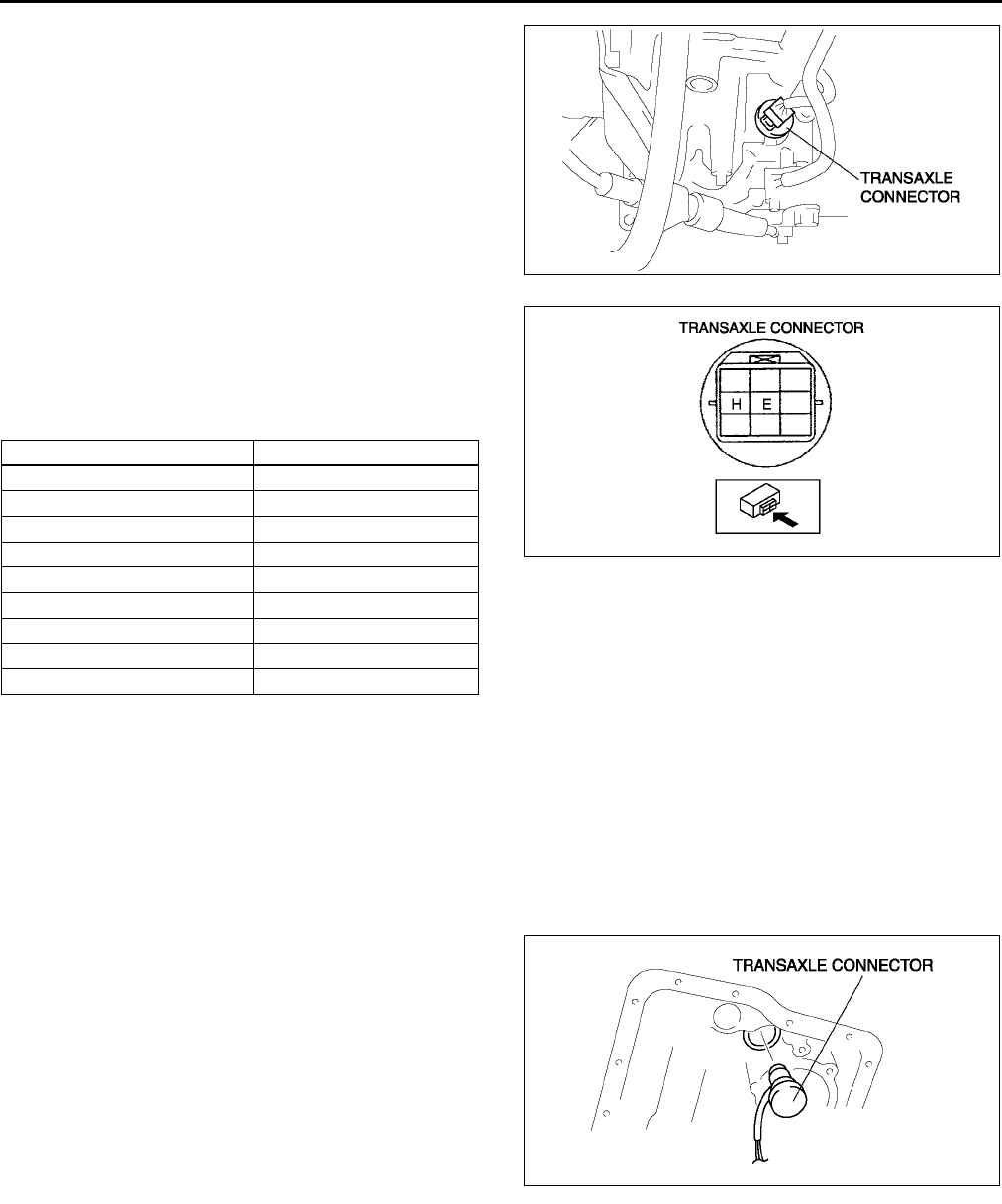
K20
AUTOMATIC TRANSAXLE
3. Disconnect the transaxle connector.
4. Measure the resistance between the terminals E
and H.
•If it is out of specification, perform the off-
vehicle inspection of TFT sensor. (See K21
TRANSAXLE FLUID TEMPERATURE (TFT)
SENSOR REMOVAL/INSTALLATION.)
5. Install the air cleaner component. (See F10 INTAKE-AIR SYSTEM REMOVAL/INSTALLATION.)
6. Connect the negative battery cable.
Off-Vehicle Inspection
Warning
•
••
•When the transaxle and ATF are hot, they can badly burn. Turn off the engine and wait until they
are cool before replacing ATF.
1. Remove the control valve body. (See K34 CONTROL VALVE BODY REMOVAL.)
2. Remove the transaxle connector.
3. Remove the TFT sensor from the strainer, and
connect it to the transaxle connector.
4. Place the TFT sensor and a thermometer in ATF
as shown, and heat the ATF gradually.
ATF temperature (°
°°
°C {°
°°
°F}) Resistance (kilohm)
20 {4} 236324
0 {32} 84.3110
20 {68} 33.542.0
40 {104} 14.717.9
60 {140} 7.088.17
80 {176} 3.614.15
100 {212} 1.962.24
120 {248} 1.131.28
130 {266} 0.870.98
A6E5614W021
A6E5614W022
A6E5614W023
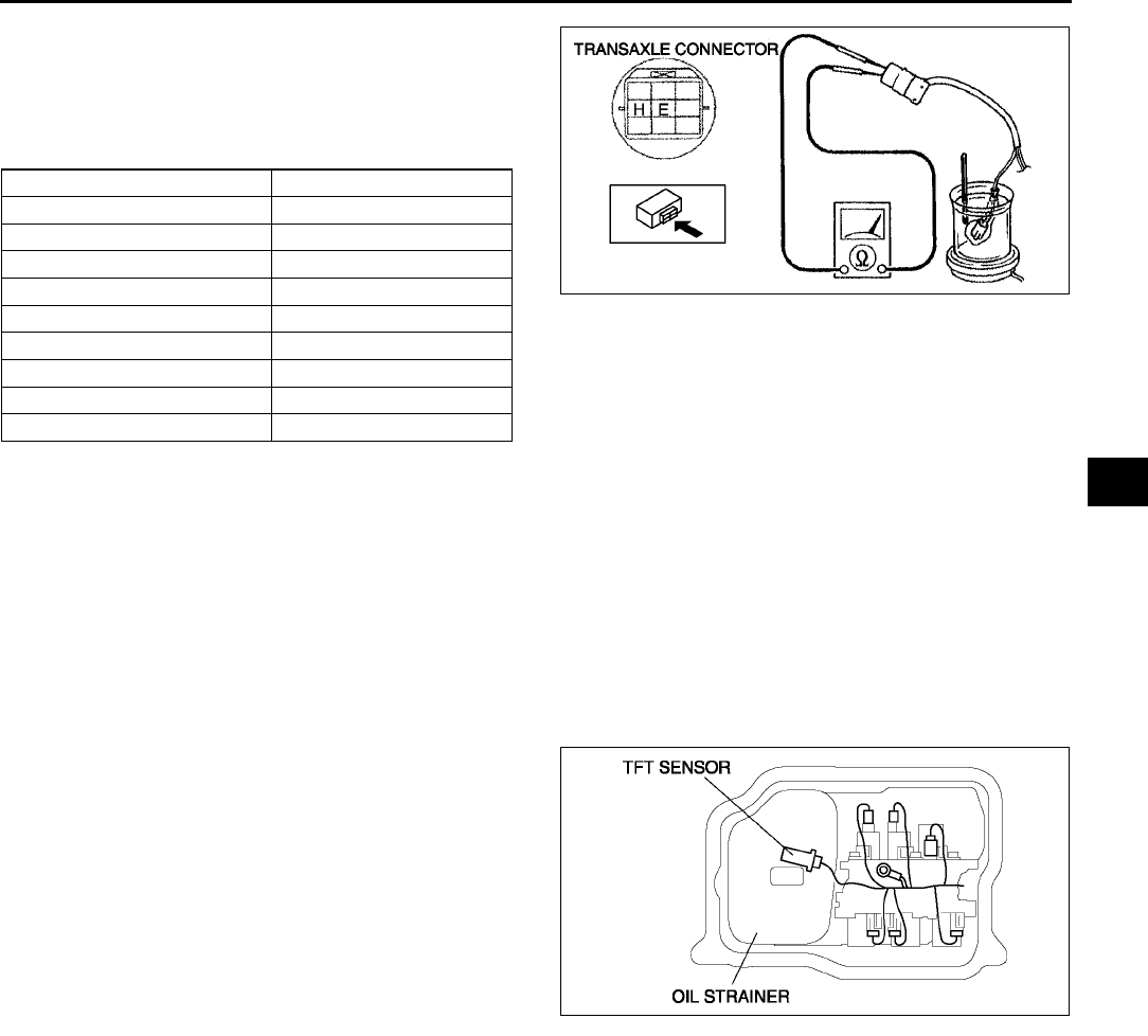
AUTOMATIC TRANSAXLE
K21
K
5. Measure resistance between the terminals of the
TFT sensor.
•If not as specified, replace the TFT sensor.
(See K21 TRANSAXLE FLUID
TEMPERATURE (TFT) SENSOR REMOVAL/
INSTALLATION.)
6. Disconnect the TFT sensor from the transaxle connector, and install it to the oil strainer.
7. Install the transaxle connector.
8. Install the control valve body. (See K35 CONTROL VALVE BODY INSTALLATION.)
End Of Sie
TRANSAXLE FLUID TEMPERATURE (TFT) SENSOR REMOVAL/INSTALLATION A6E561419010W02
Warning
•
••
•When the transaxle and ATF are hot, they can badly burn. Turn off the engine and wait until they
are cool before replacing the ATF.
1. Remove the oil pan. (See K34 CONTROL VALVE BODY REMOVAL.)
2. Disconnect the TFT sensor connector.
3. Remove the TFT sensor.
4. Install a TFT sensor.
5. Connect the TFT sensor connector.
6. Install the oil pan. (See K35 CONTROL VALVE
BODY INSTALLATION.)
7. Carry out the mechanical system test. (See K6
MECHANICAL SYSTEM TEST.)
End Of Sie
OIL PRESSURE SWITCH INSPECTION A6E561421550W01
Caution
•
••
•Water or foreign objects entering the connector can cause poor connection or corrosion. Be sure
not to drop water or foreign objects on the connector when disconnecting it.
On-vehicle Inspection (harness inspection)
1. Disconnect the negative battery cable.
2. Remove the under cover.
ATF temperature (°
°°
°C {°
°°
°F}) Resistance (kilohm)
-20 {-4} 236324
0 {32} 84.3110
20 {68} 33.542.0
40 {104} 14.717.9
60 {140} 7.088.17
80 {176} 3.614.15
100 {212} 1.962.24
120 {248} 1.131.28
130 {266} 0.870.98
A6E5614W024
A6E5614W025
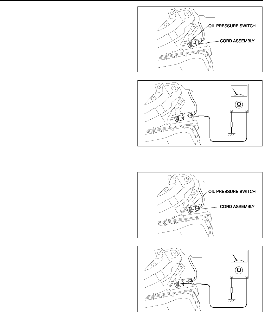
K22
AUTOMATIC TRANSAXLE
3. Disconnect the cord assembly connector.
4. Verify that there is no continuity between cord
assembly terminal and ground.
•If as continuity, inspect the cord assembly.
•If the cord assembly is okay, inspect the oil
pressure switch. (See K22 On-vehicle
Inspection (oil pressure switch inspection).)
5. Connect the cord assembly connector.
6. Install the under cover.
7. Connect the negative battery cable.
On-vehicle Inspection (oil pressure switch inspection)
1. Remove the under cover.
2. Disconnect the cord assembly connector.
3. Start the engine, with gear position in N or P.
4. Reaffirm that there is no continuity between cord
assembly terminal and ground.
5. Firmly depress the brake pedal with the left foot.
6. Shift the selector lever to D range.
7. Verify that there is no continuity between cord
assembly terminal and ground.
•If not as specified,replace the oil pressure
switch. (See K23 OIL PRESSURE SWITCH
REMOVAL/INSTALLATION.)
8. Connect the oil pressure switch connector.
9. Install the under cover.
10. Connect the negative battery cable.
A6E5614W026
A6E5614W027
A6E5614W026
A6E5614W094
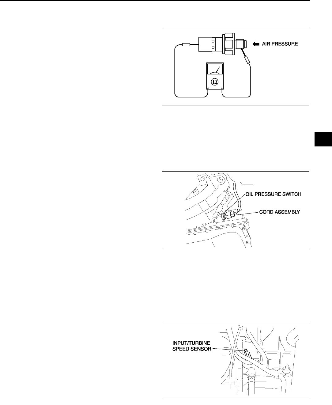
AUTOMATIC TRANSAXLE
K23
K
Off-vehicle inspection
1. Remove the oil pressure switch.
2. Apply air pressure at 400440 kPa {4.14.4kgf/cm2,5863psi}
3. Inspect continuity the between oil pressure switch
terminal and screw part.
•If not as continuity, replace the oil pressure
switch. (See K23 OIL PRESSURE SWITCH
REMOVAL/INSTALLATION.)
4. Install the oil pressure switch.
End Of Sie
OIL PRESSURE SWITCH REMOVAL/INSTALLATION A6E561421550W02
Warning
•
••
•When the transaxle and ATF are hot, they can badly burn. Turn off the engine and wait untill they
are cool before replacing ATF.
1. Disconnect the negative battery cable.
2. Remove the under cover.
3. Disconnect the cord assembly connector.
4. Remove the oil pressure switch.
5. Install the oil pressure switch.
Tightening torque
17.122.1N·m {1.752.25kgf·m, 13
16ft·lbf}
6. Connect the oil pressure switch connector.
7. Install the under cover.
8. Connect the negative battery cable.
End Of Sie
INPUT/TURBINE SPEED SENSOR INSPECTION A6E561421550W03
Caution
•
••
•Water or foreign objects entering the connector can cause a poor connection or corrosion. Be
sure not to drop water or foreign objects on the connector when disconnecting it.
1. Disconnect the negative battery cable.
2. Remove the battery and battery tray.
3. Remove the air cleaner component. (See F10 INTAKE-AIR SYSTEM REMOVAL/INSTALLATION.)
4. Disconnect the input/turbine speed sensor
connector.
A6E5614W028
A6E5614W026
A6E5614W030
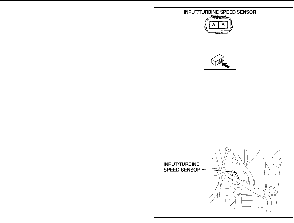
K24
AUTOMATIC TRANSAXLE
5. Measure resistance between the terminals of the
input/turbine speed sensor.
•If not as specified, replace the input/turbine
speed sensor.
Resistance
250600 ohms (ATF temperature: 40160
°
°°
°C {40320 °
°°
°F})
6. Connect the input/turbine speed sensor
connector.
7. Install the air cleaner component. (See F10
INTAKE-AIR SYSTEM REMOVAL/
INSTALLATION.)
8. Install the battery and battery tray.
9. Connect the negative battery cable.
End Of Sie
INPUT/TURBINE SPEED SENSOR REMOVAL/INSTALLATION A6E561421550W04
1. Disconnect the negative battery cable.
2. Remove the battery and battery tray.
3. Remove the air cleaner component. (See F10 INTAKE-AIR SYSTEM REMOVAL/INSTALLATION.)
4. Disconnect the input/turbine speed sensor
connector.
5. Remove the input/turbine speed sensor.
6. Apply ATF to a new O-ring and install it on a new
input/turbine speed sensor.
7. Install the input/turbine speed sensor.
Tightening torque
811 N·m {82112 kgf·cm, 7197 in·lbf}
8. Connect the input/turbine speed sensor
connector.
9. Install the air cleaner component. (See F10
INTAKE-AIR SYSTEM REMOVAL/
INSTALLATION.)
10. Install the battery and battery tray.
11. Connect the negative battery cable.
End Of Sie
VEHICLE SPEEDOMETER SENSOR (VSS) INSPECTION A6E561401030W05
Visual Inspection
1. Remove the VSS. (See K26 VEHICLE SPEEDOMETER SENSOR (VSS) REMOVAL/INSTALLATION.)
2. Make sure that the sensor is free of any metallic shavings or particles.
•If any are found on the sensor, clean them off.
3. Install the VSS. (See K26 VEHICLE SPEEDOMETER SENSOR (VSS) REMOVAL/INSTALLATION.)
Wave profile Inspection
1. Remove the PCM. (See F43 PCM REMOVAL/INSTALLATION.)
2. Connect WDS or equivalent to DLC connector.
3. Connect osilloscope test leads to the following PCM connector terminals.
•(+) lead: PCM terminal 3C
•(-) lead: PCM terminal 1D
4. Start the engine.
5. Monitor VSS PID.
A6E5614W031
A6E5614W030
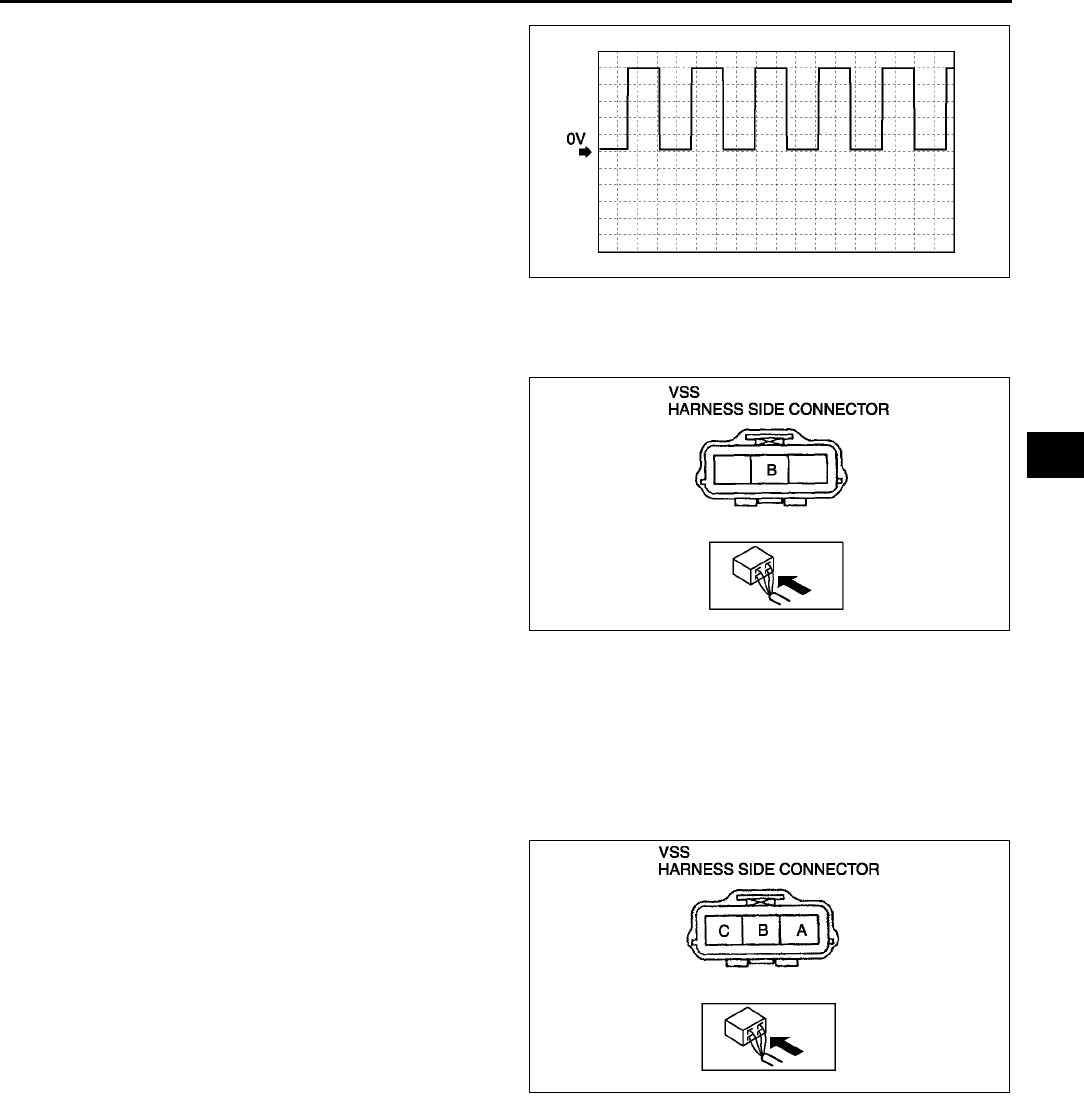
AUTOMATIC TRANSAXLE
K25
K
6. Inspect wave profile.
•PCM terminal: 3C (+) - 1D (-)
•Oscilloscope setting: 1 V/DIV (Y), 2.5 ms/DIV
(X), DC range
•Vehicle condition: drive the vehicle with 32
km/h{20 mph}
If wave profile or voltage are out of
specifications, carry out the Open Circuit
Inspection or Short Circuit Inspection
Power Supply Voltage Inspection
1. Disconnect the VSS connector.
2. Turn the ignition switch to ON.
3. Measure voltage at VSS connector terminal B
(wiring harness side).
Specification
4.55.5 V
•If voltage is okay, go to Open Circuit
Inspection and Short Circuit Inspection.
•If voltage is wrong, repair wiring harness
between VSS and PCM.
Open Circuit Inspection
1. Inspect the following circuit for open.
•Power circuit (VSS connector terminal A to main relay terminal D)
•Ground circuit (VSS connector terminal C to GND)
•If an open circuit or short circuit is found, repair the malfunctioning wiring harness.
•If there are no open or short circuits, perform the sensor rotor inspection.
Short Circuit Inspection
1. Inspect the following circuit for short.
•Power circuit (VSS connector terminal A to
main relay terminal D)
•If an open circuit or short circuit is found,
repair the malfunctioning wiring harness.
•If there are no open or short circuits, perform
the sensor rotor inspection.
Sensor Rotor Inspection
1. Remove the VSS. (See K26 VEHICLE SPEEDOMETER SENSOR (VSS) REMOVAL/INSTALLATION.)
2. Shift the selector lever to N position.
3. Inspect sensor rotor surface via VSS installation hole while rotating the front tire manually.
(1) Is sensor rotor free of damage and cracks?
(2) Is sensor rotor free of any metallic shavings or particles?
•If sensor rotor is okay, replace the VSS.
•If there is a problem, clean or replace the sensor rotor.
End Of Sie
A6E5614W102
A6E5614W033
A6E5614W035
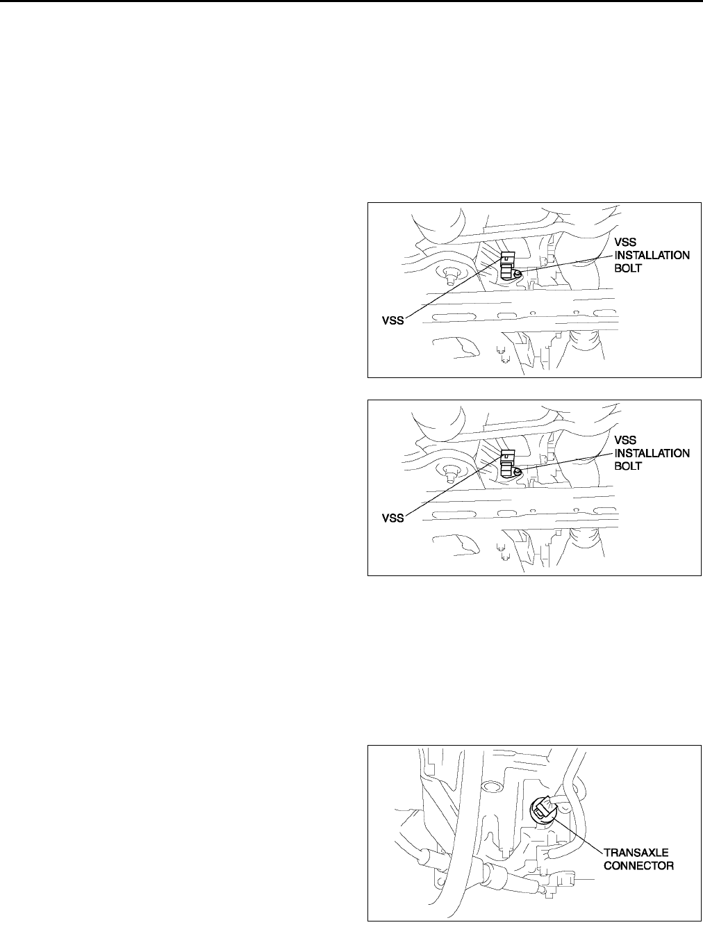
K26
AUTOMATIC TRANSAXLE
VEHICLE SPEEDOMETER SENSOR (VSS) REMOVAL/INSTALLATION A6E561401030W06
Caution
•
••
•Water or foreign objects entering the connector can cause a poor connection or corrosion. Be
sure not to drop water or foreign objects on the connector when disconnecting it.
•
••
•If foreign materials are stuck to the VSS, disturbance by magnetic flux can cause sensor output to
be abnormal and thereby negatively affect control. Make sure that foreign materials such as iron
filings are not stuck to the VSS during installation.
1. Disconnect the negative battery cable.
2. Remove the under cover.
3. Disconnect the VSS connector.
4. Remove the VSS.
5. Apply ATF to a new O-ring and install it on a new
VSS.
6. Install the VSS.
Tightening torque
811 N·m {82112 kgf·cm, 7197 in·lbf}
7. Connect the VSS connector.
8. Install the under cover.
9. Connect the negative battery cable.
End Of Sie
SOLENOID VALVE INSPECTION A6E561421280W01
Resistance Inspection (On-Vehicle Inspection)
Caution
•
••
•Water or foreign objects entering the connector can cause a poor connection or corrosion. Be
sure not to drop water or foreign objects on the connector when disconnecting it.
1. Disconnect the negative battery cable.
2. Remove the air cleaner component. (See F10 INTAKE-AIR SYSTEM REMOVAL/INSTALLATION.)
3. Disconnect the transaxle connector.
Note
•When inspecting the pressure control
solenoid, connect the ground connection to
the ground terminal (terminal I) of the
pressure control solenoid inside the solenoid
valve connector.
A6E5614W037
A6E5614W037
A6E5614W021
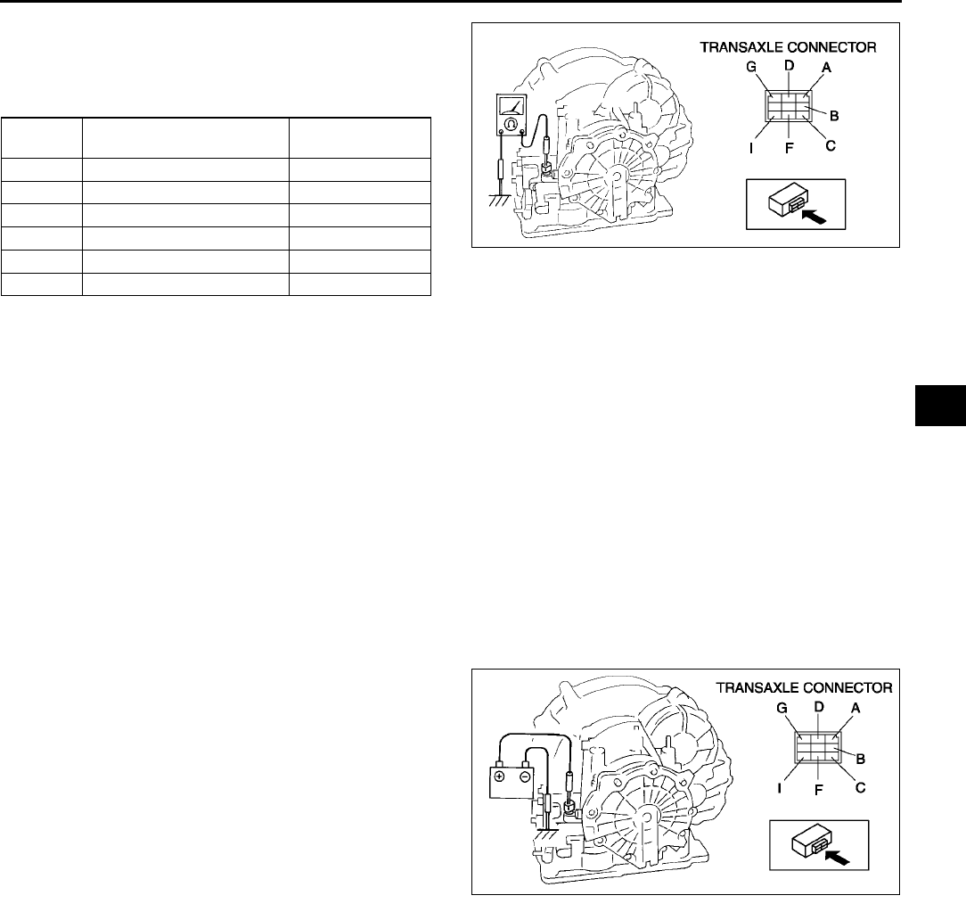
AUTOMATIC TRANSAXLE
K27
K
4. Measure the resistance between the following
terminals.
•If not as specified, inspect the ground, then
perform the operating inspection.
ATF temperature: 40150 °
°°
°C {40302 °
°°
°F}
5. Connect the transaxle connector.
6. Install the air cleaner component. (See F10 INTAKE-AIR SYSTEM REMOVAL/INSTALLATION.)
7. Connect the negative battery cable.
Operating Inspection
1. Disconnect the transaxle connector.
Caution
•
••
•Do not apply battery position voltage to terminals A, B, C, D, F and G for more than three seconds.
Note
•Because the operation sound of the valves is small, perform inspection in a quiet place.
2. Apply battery positive voltage to terminals A,B,C, F or G and battery negative voltage to GND, and verify that
operating sound is heard from solenoid.
•If the "click" is not heard, inspect the transaxle harness.
If the transaxle harness is okay, perform the resistance inspection (off-vehicle inspection).
If there is a problem, repair or replace the transaxle harness.
3. Apply battery positive voltage to terminal D and
battery negative voltage to terminal I, and verify
that operating sound is heard from solenoid.
•If the "click" is not heard, inspect the transaxle
harness.
If transaxle harness is okay, perform the
resistance inspection (off-vehicle
inspection)
If there is a problem, repair or replace the
transaxle harness.
Resistance Inspection (Off-Vehicle Inspection)
1. Remove the control valve body. (See K28 SOLENOID VALVE REMOVAL/INSTALLATION.)
2. Measure the resistance of each solenoid valve individually.
•If not as specified, replace the solenoid valve.
3. Install the control valve body. (See K28 SOLENOID VALVE REMOVAL/INSTALLATION.)
Terminal Solenoid valve Resistance
(ohm)
AGND Shift solenoid A 1.04.2
CGND Shift solenoid B 1.04.2
GGND Shift solenoid C 1.04.2
BGND Shift solenoid D 10.926.2
FGND Shift solenoid E 10.926.2
DI Pressure control 2.47.3
A6E5614W039
A6E5614W040
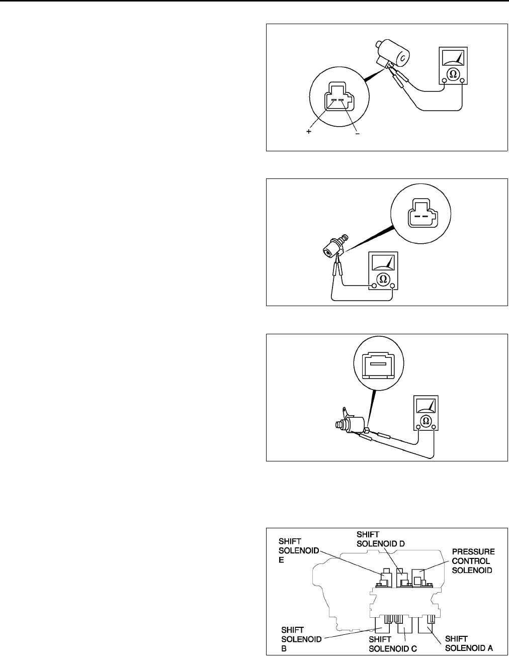
K28
AUTOMATIC TRANSAXLE
Pressure control solenoid
Resistance
2.47.3 ohms
(ATF temperature: 40150 °
°°
°C {40302
°
°°
°F})
Shift solenoid A, B, C
Resistance
1.04.2 ohms
(ATF temperature: 40150 °
°°
°C {40302
°
°°
°F})
Shift solenoid D, E
Resistance
10.926.2 ohms
(ATF temperature: 40150 °
°°
°C {40302
°
°°
°F})
End Of Sie
SOLENOID VALVE REMOVAL/INSTALLATION A6E561421280W02
1. Disconnect the negative battery cable.
2. Remove the under cover.
3. Remove the control valve body. (See K34 CONTROL VALVE BODY REMOVAL.)
4. Remove the solenoid valve(s).
5. Apply ATF to a new O-ring and install it on the
solenoid valve.
A6E5614W041
A6E5614W042
A6E5614W043
A6E5614W044
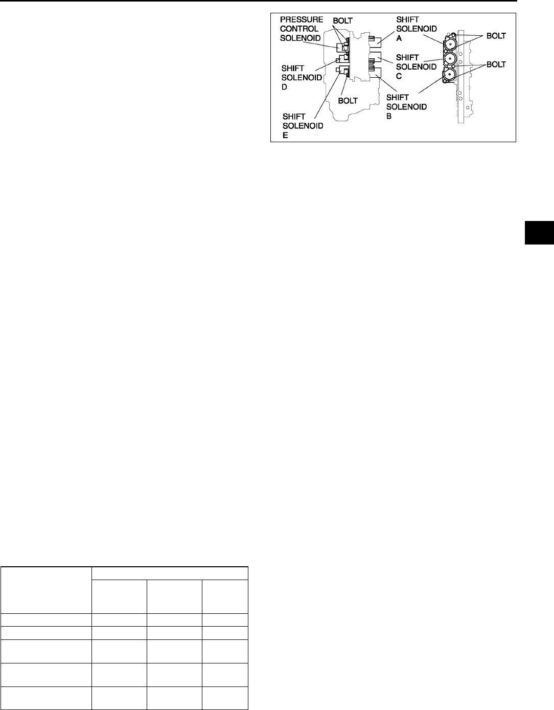
AUTOMATIC TRANSAXLE
K29
K
6. Install the solenoid valve in the control valve
body.
Tightening torque
7.810.8 N·m
{80110 kgf·cm, 7095.4 in·lbf}
7. Install the control valve body. (See K34
CONTROL VALVE BODY REMOVAL.)
8. Install the under cover.
9. Connect the negative battery cable.
10. Add ATF and, with the engine idling, inspect the
ATF level and inspect for leakage. (See K12
Automatic Transaxle Fluid (ATF) Level
Inspection.)
11. Carry out the mechanical system test. (See K6 MECHANICAL SYSTEM TEST.)
12. Carry out the road test. (See K9 ROAD TEST.)
End Of Sie
PCM INSPECTION A6E561418880W01
1. Inspect the PCM. (See F45 PCM INSPECTION.)
End Of Sie
PCM REMOVAL/INSTALLATION A6E561418880W02
1. Remove and install the PCM. (See F43 PCM REMOVAL/INSTALLATION.)
End Of Sie
AUTOMATIC TRANSAXLE REMOVAL/INSTALLATION A6E561401030W07
1. Disconnect the negative battery cable.
2. Remove the battery and battery tray.
3. Remove the aircleaner component. (See F10 INTAKE-AIR SYSTEM REMOVAL/INSTALLATION.)
4. Remove the front tires and splash shield.
5. Remove the under cover.
6. Remove the steering gear and power steering pipe. (See N10 STEERING GEAR AND LINKAGE REMOVAL/
INSTALLATION.)
7. Remove the front auto leveling sensor. (See T32 FRONT AUTO LEVELING SENSOR REMOVAL/
INSTALLATION.)
8. Drain the ATF. (See K13 AUTOMATIC TRANSAXLE FLUID (ATF) REPLACEMENT.)
Warning
•
••
•Improperly jacking a transaxle is dangerous. It can slip off the jack and may cause serious injury.
Caution
•
••
•To prevent the torque converter and transaxle from separating, remove the transaxle without
tilting it toward the torque converter.
9. Remove in the order shown in the figure.
10. Install in the reverse order of removal.
11. Adjust the headlight zeroset. (See T31 HEADLIGHT ZEROSET.)
12. Add ATF to the specified level. (See K13 AUTOMATIC TRANSAXLE FLUID (ATF) REPLACEMENT.)
13. Carry out the mechanical system test. (See K6 MECHANICAL SYSTEM TEST.)
×: Test to be performed after the service work
14. Carry out the road test. (See K9 ROAD TEST.)
A6E5614W045
Service item
Test item
Line
pressure
test
Stall test Time lag
test
ATX replacement ×
ATX overhaul ×××
Torque converter
replacement ××
Oil pump
replacement ×
Clutch system
replacement ××
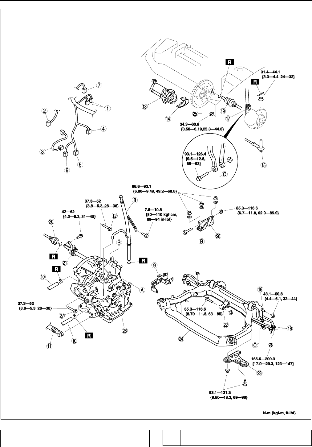
K30
AUTOMATIC TRANSAXLE
.
A6E5614W046
1O
2 sensor connector
2 Oil pressure switch connector (for oil filter)
3 Oil pressure switch connector (for ATX)
4 Input/turbin speed sensor connector
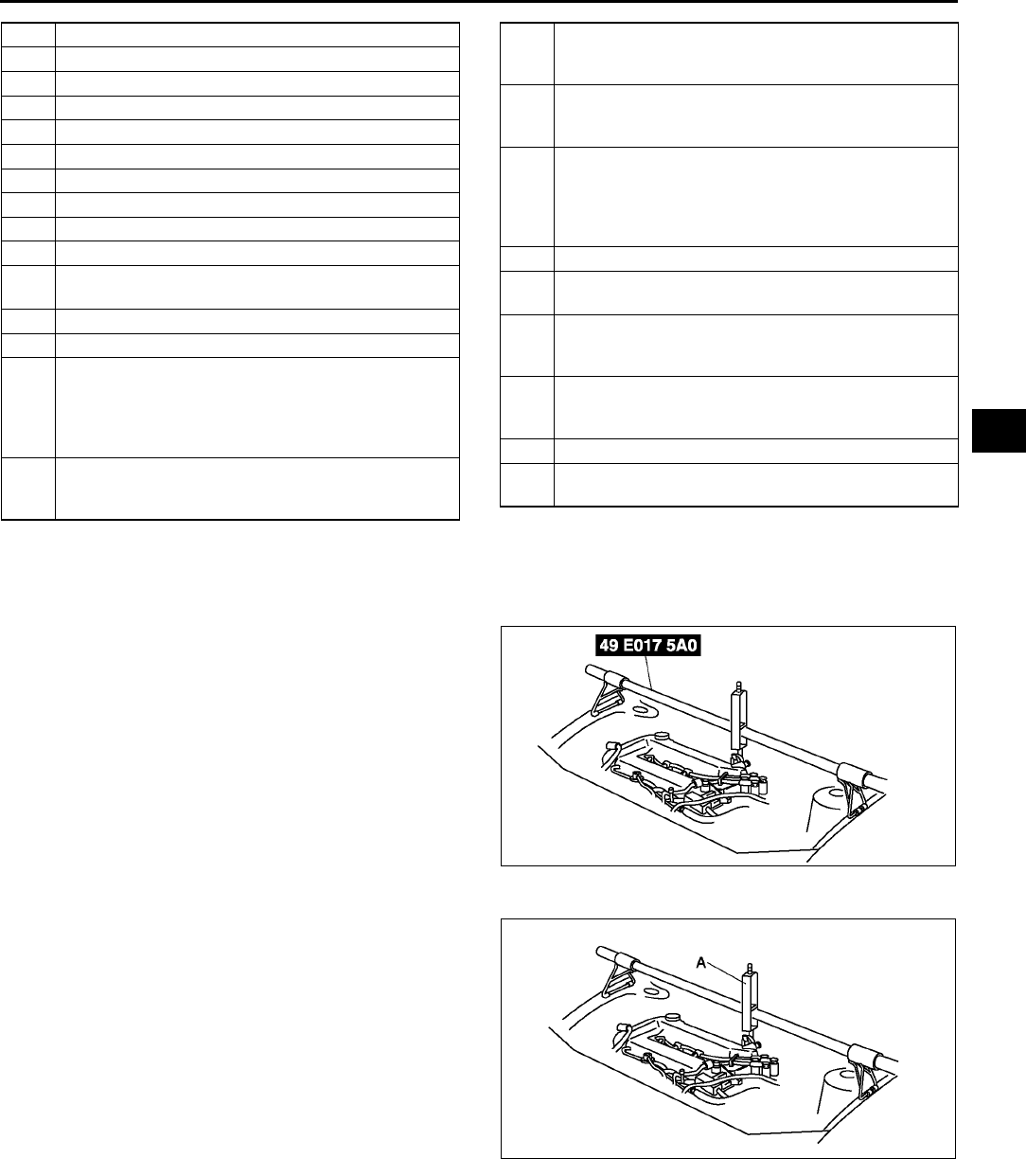
AUTOMATIC TRANSAXLE
K31
K
No.1 Engine Mount Bracket Removal Note
1. Support the engine using the SST before removing the No.1 engine mount.
2. Remove the No.1 engine mount.
Transaxle Removal Note
1. Loosen the part marked A and lean the engine
toward the transaxle.
2. Support the transaxle on a jack.
3. Remove the transaxle mounting bolts.
5 TR switch connector
6 Transaxle connector
7 VSS connector
8 Oil dipstick and filler tube
9 Harness bracket
10 Oil hose
11 Selector cable
12 Transaxle mounting bolt (upper side)
13 Starter
14 Endplate cover
15 Tie-rod end ball joint
(See N11 Tie-rod End Ball Joint Removal Note)
16 Stabilizer control link
17 Damper fork
18 Lower arm (front, rear) ball joint
(See R19 Front Lower Arm (Rear) Ball Joint
Removal Note)
(See R16 Front Lower Arm (Front) Ball Joint
Removal Note)
19 Drive shaft
(See M17 DRIVE SHAFT REMOVAL/
INSTALLATION)
20 Drive shaft
(See M17 DRIVE SHAFT REMOVAL/
INSTALLATION)
21 Joint shaft
(See M12 JOINT SHAFT REMOVAL/
INSTALLATION)
22 No.1 engine mount
(See K31 No.1 Engine Mount Bracket Removal
Note)
(See K33 No.1 Engine Mount and No.4 Engine
Mount Bracket Installation Note)
23 Crossmember bracket
24 Crossmember (See R23 FRONT
CROSSMEMBER REMOVAL/INSTALLATION.)
25 Torque converter installation nuts (See K32 Torque
Converter Nuts Removal Note)(SeeK33 Torque
Converter Nuts Installation Note)
26
No.4 engine mount
(See K33 No.1 Engine Mount and No.4 Engine
Mount Bracket Installation Note)
27 Transaxle mounting bolt (lower side)
28 Transaxle (See K31 Transaxle Removal Note)(K
32 Transaxle Installation Note)
A6E5614W049
A6E5614W050
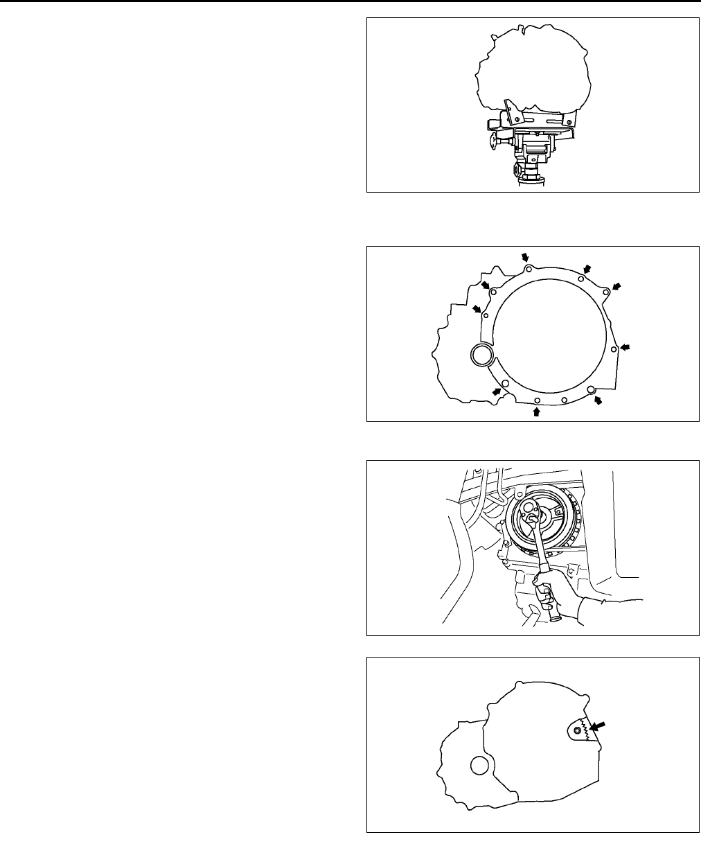
K32
AUTOMATIC TRANSAXLE
4. Remove the transaxle.
Transaxle Installation Note
1. Set the transaxle on a jack and lift it.
2. Install the transaxle mounting bolts.
Tightening torque
37.352 N·m {3.85.3 kgf·m, 2838 ft·lbf}
Torque Converter Nuts Removal Note
1. Hold the cankshaft pulley to prevent drive plate
from rotating.
2. Remove the torque converter nuts from the
starter installation hole.
A6E5614W051
A6E5614W052
A6E5614W091
A6E5614W092
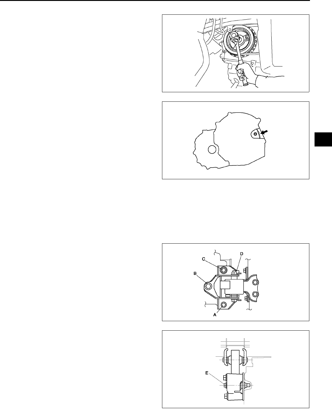
AUTOMATIC TRANSAXLE
K33
K
Torque Converter Nuts Installation Note
1. Hold the cankshaft pulley to prevent drive plate
from rotating.
Caution
•
••
•Loosely and equally tighten the torque
converter nuts, then further tighten them
to the specified tightening torque.
2. Tighten the torque converter mounting nuts.
Tightening torque
34.360.8 N·m {3.56.2 kgf·m, 2545 ft·lbf}
No.1 Engine Mount and No.4 Engine Mount Bracket Installation Note
1. Verify that the engine mount rubbers are installed as shown.
2. By aligning the holes with the stud bolts, install the No.4 engine mount bracket to the transaxle.
3. By aligning the holes with the stud bolts, install the No.1 engine mount to the transaxle.
4. Align the hole of the No.4 engine mount bracket with the No.4 engine mount rubber on vehicle, and temporarily
tighten the bolt D.
5. Tighten the nut B,C in order of B→C, then bolt A.
6. Tighten the bolt D.
7.
Tightening torque
A, B, C: 66.693.1 N·m {6.89.4 kgf·m, 50
68 ft·lbf}
D: 85.3116.6 N·m {8.711.8 kgf·m, 6385
ft·lbf}
8. Tighten the bolt D to the No.1 engine mount.
Tightening torque
E: 85.3116.6 N·m {8.711.8 kgf·m, 6385
ft·lbf}
9. Remove the SST (49 E017 5A0).
End Of Sie
OIL SEAL REPLACEMENT A6E561401032W01
1. Drain the ATF. (See K13 AUTOMATIC TRANSAXLE FLUID (ATF) REPLACEMENT.)
Caution
A6E5614W091
A6E5614W092
A6E5112W005
A6E5112W006
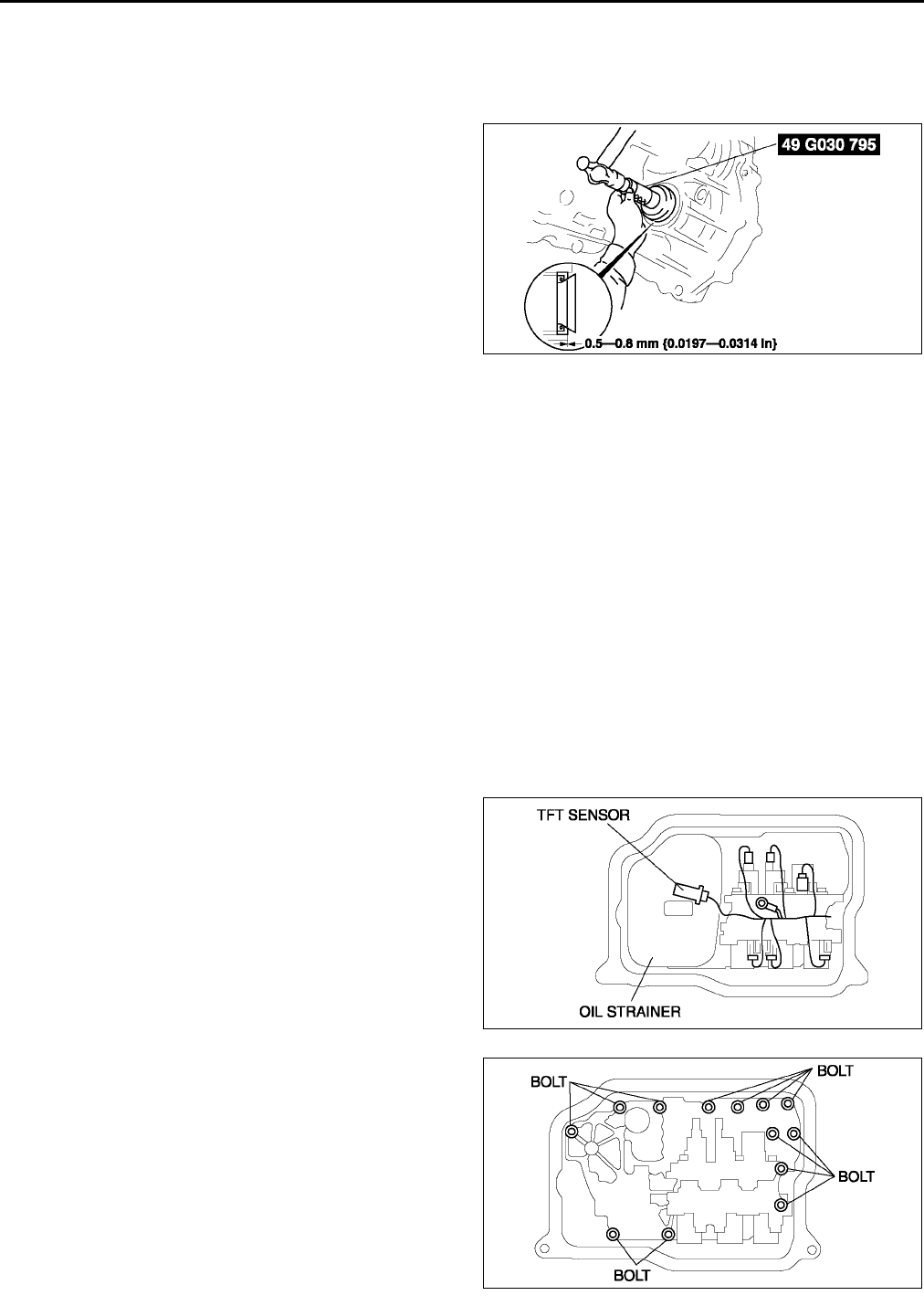
K34
AUTOMATIC TRANSAXLE
•
••
•The oil seal is easily damaged by the sharp edges of the drive shaft splines. Do not let the splines
contact the oil seal.
2. Remove the drive shaft. (See M17 DRIVE SHAFT REMOVAL/INSTALLATION.)
3. Remove the oil seal.
4. Using the SST and a hammer, tap a new oil seal
in evenly until the SST contacts the transaxle
case.
5. Coat the lip of the oil seal with transaxle oil.
6. Install the drive shaft. (See M17 DRIVE SHAFT
REMOVAL/INSTALLATION.)
7. Add ATF to the specified level. (See K13
AUTOMATIC TRANSAXLE FLUID (ATF)
REPLACEMENT.)
8. Carry out the mechanical system test. (See K6
MECHANICAL SYSTEM TEST.)
End Of Sie
CONTROL VALVE BODY REMOVAL A6E561421100W01
On-Vehicle Removal
Warning
•
••
•Using compressed air can cause dirt and other particles to fly out, causing injury to the eyes.
Wear protective eyes whenever using compressed air.
Caution
•
••
•Clean the transaxle exterior throughout with a steam cleaner or cleaning solvents before removal.
•
••
•If any old sealant gets into the transaxle during installation of the oil pan, trouble may occur in the
transaxle case and oil pan. Clean with cleaning fluids.
1. Disconnect the negative battery cable.
2. Drain the ATF into a separate suitable container. (See K13 AUTOMATIC TRANSAXLE FLUID (ATF)
REPLACEMENT.)
3. Remove the under cover.
4. Remove the front tires and splash shield.
5. Remove the crossmember. (See R23 FRONT CROSSMEMBER REMOVAL/INSTALLATION.)
6. Remove the oil pan.
7. Disconnect the transaxle connectors and transaxle fluid temperature (TFT) sensor connector.
8. Remove the oil strainer.
9. Remove the control valve body installation bolts A
as shown, then remove the control valve body
component as shown.
A6E5614W056
A6E5614W025
A6E5614W058
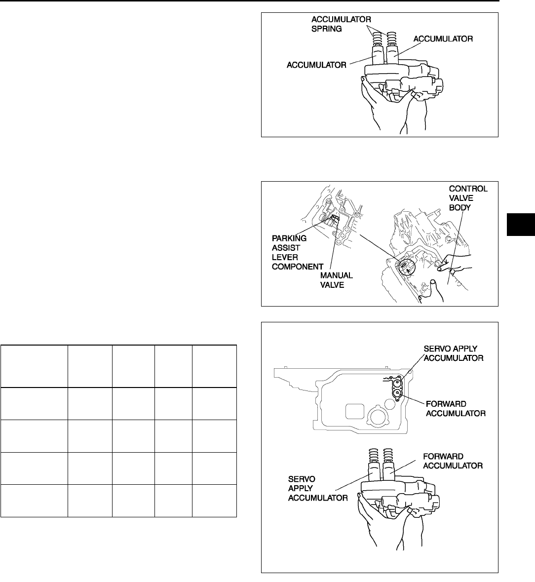
AUTOMATIC TRANSAXLE
K35
K
10. Remove the accumulators and accumulator
springs.
End Of Sie
CONTROL VALVE BODY INSTALLATION A6E561421100W02
On-Vehicle Installation
Caution
•
••
•Be sure to align the parking rod and the
manual valve.
1. Install the accumulator springs and accumulators
into the transaxle case.
A6E5614W059
Spring
Outer
diameter
(mm {in})
Free
Length
(mm
{in})
No. of
coils
Wire
diameter
(mm {in})
Servo apply
accumulator
large spring
21.0
{0.827}
67.8
{2.669} 10.3 3.5
{0.138}
Servo apply
accumulator
small spring
13.0
{0.512}
67.8
{2.669} 17.1 2.2
{0.087}
Forward
accumulator
small spring
21.0
{0.827}
75.0
{2.953} 10.7 2.3
{0.091}
Forward
accumulator
large spring
15.6
{0.614}
49.0
{1.929} 7.7 2.4
{0.094}
A6E5614W060
A6E5614W061
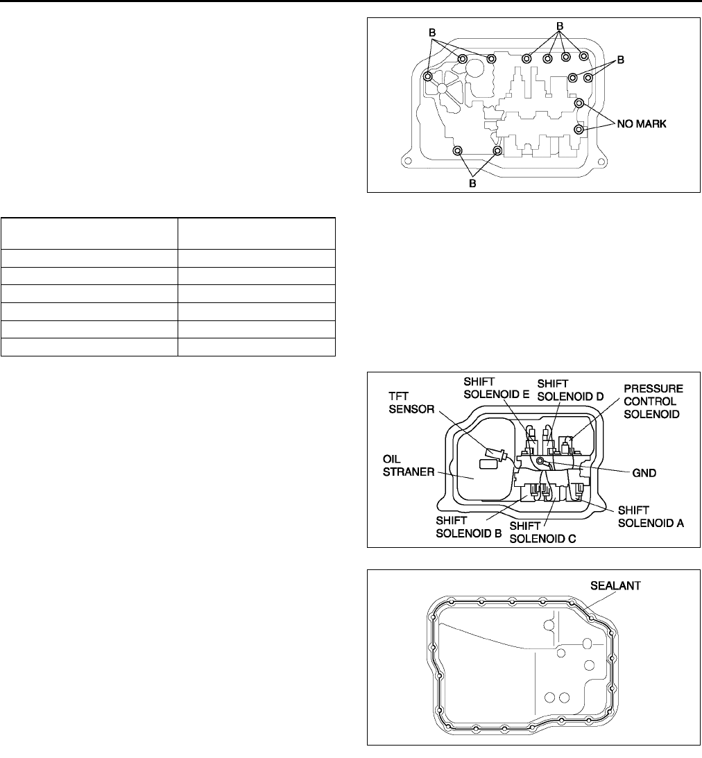
K36
AUTOMATIC TRANSAXLE
2. Install the control valve body component.
Tightening torque
7.810.8 N·m
{80110 kgf·cm, 7095 in·lbf}
Bolt length (measured from below the head)
B: 40 mm {1.575 in}
No mark: 70 mm {2.756 in}
3. Install the oil strainer.
4. Match the harness colors, then connect the
solenoid connector and TFT sensor connector.
5. Install the ground.
Tightening torque
7.810.8 N·m {80110 kgf·cm, 7095
in·lbf}
6. Apply a light coat of silicon sealant to the contact
surfaces of the oil pan and transaxle case.
7. Install the oil pan.
Tightening torque
68 N·m {6281 kgf·cm, 5370 in·lbf}
8. Install the crossmember. (See R23 FRONT
CROSSMEMBER REMOVAL/INSTALLATION.)
9. Install the front tires and splash shield.
10. Install the under cover.
11. Connect the negative battery cable.
12. Add ATF and with the engine idling, inspect the
ATF level. (See K13 AUTOMATIC TRANSAXLE
FLUID (ATF) REPLACEMENT.)
13. Carry out the mechanical system test. (See K6 MECHANICAL SYSTEM TEST.)
14. Carry out the road test. (See K9 ROAD TEST.)
End Of Sie
OIL COOLER FLUSHING A6E561419900W01
Note
•The contaminated cooler line (oil pipes and hoses) and auxiliary cooler must be flushed completely when
ATX is overhauled or replaced.
Spring Color of connector
(harness side)
Pressure control solenoid Black
Shift solenoid A White
Shift solenoid B Blue
Shift solenoid C Green
Shift solenoid D white
Shift solenoid E Black
A6E5614W062
A6E5614W063
A6E5614W064
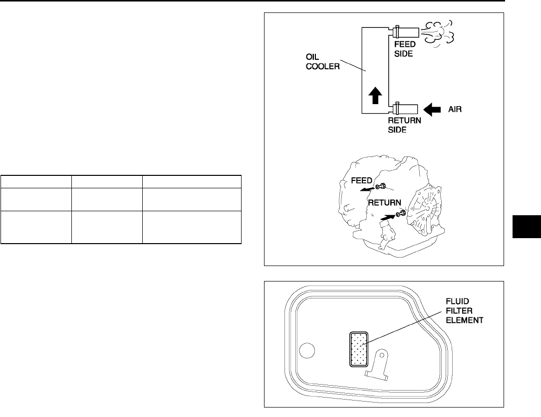
AUTOMATIC TRANSAXLE
K37
K
1. Remove the two oil cooler line hoses and apply
air pressure of 196 kPa {2.0 kgf/cm2, 28 psi}
from the return hose (pipe) side.
Caution
•
••
•Power flushing should be performed very
carefully when removing the
accumulated debris from the fluid baffle,
otherwise the debris cannot be removed
or the problem becomes even worse.
2. If there is no air blown out the feed side, flush the
oil cooler lines using the power-flushing tool. (See
K38 Power Flushing)
Recommended power-flushing manufacturer
3. If there is ventilation, carry out the following steps.
(1) Remove the oil pan and inspect the fluid filter
element from the front filter.
(2) If the element is covered with too much debris
or particles and cannot be seen, replace the
oil cooler. (See K39 OIL COOLER
REMOVAL/INSTALLATION.) (See K41 OIL
COOLER DISASSEMBLY/ASSEMBLY.)
(3) If the element can be seen, flush the oil cooler
lines using the power-flushing tool.
•Performing back and reverse power
flushing two times each does not work
because debris or particles flow out from
the feed pipe side of ATX.
Manufacturer Part number Description
Kent Moore J35944-AMAZ Flushing kit or
equivalent
OTC 60081
Portable torque
converter, oil cooler
cleaner or equivalent
A6E5614W065
A6E5614W066
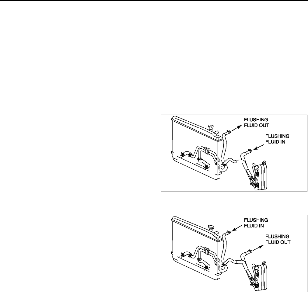
K38
AUTOMATIC TRANSAXLE
Power Flushing
Repair procedure
1. Before power flushing, inspect the hoses/lines and clamps. Power flushing must begin with back flushing
followed by forward flushing to quickly dislodge the restriction. If back flushing is not performed before forward
flushing, the restriction could further reduce the ATF flow through the internal mesh type baffle of the cooler
and flushing will not be effective or possible.
Inspecting oil lines and clamps
1. Be sure to inspect the lines (hoses/pipes) for cuts, crimps (pinched), cracks or any other damage before
reusing them.
•If any problems exist, replace lines and clamps.
Caution
•
••
•Always use new clamps when replacing hoses.
Back flushing
1. Using the power flushing equipment
manufacturer's instructions, connect equipment
so the flushing fluid flows in the opposite direction
of normal fluid flow.
2. Flush oil cooler/lines until discharge fluid is clean.
Caution
•
••
•If the cooler can not be properly flushed
using recommended equipment, send the
radiator out for sublet cleaning or
replace.
Forward flushing
1. Connect power flushing equipment so the flushing fluid flows in the direction of normal fluid flow.
2. Flush oil cooler/lines until discharge fluid is clean.
End Of Sie
A6E5614W067
A6E5614W068
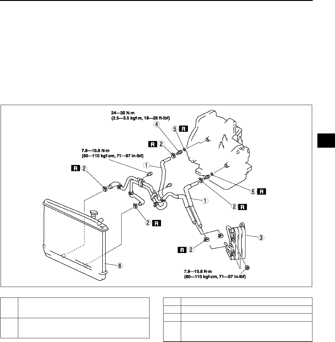
AUTOMATIC TRANSAXLE
K39
K
OIL COOLER REMOVAL/INSTALLATION A6E561419900W02
1. Disconnect the negative battery cable.
2. Drain the ATF into a container. (See K13 AUTOMATIC TRANSAXLE FLUID (ATF) REPLACEMENT.)
3. Remove the radiator. (See E6 RADIATOR REMOVAL/INSTALLATION.)
4. Remove in the order indicated in the table.
5. Install in the reverse order of removal.
6. Add ATF to the specified level. (See K13 AUTOMATIC TRANSAXLE FLUID (ATF) REPLACEMENT.)
7. Connect the negative battery cable.
8. Inspect for oil leakage from the oil pipes and oil hoses.
9. Inspect for coolant from the hoses.
10. Inspect the ATF level and condition. (See K12 AUTOMATIC TRANSAXLE FLUID (ATF) INSPECTION.)
11. Carry out the line pressure test. (See K6 MECHANICAL SYSTEM TEST.)
12. Carry out the road test. (See K9 ROAD TEST.)
WITH OIL COOLER
.
A6E5614W069
1 Oil hose
(See K40 Oil Pipe, Hose Clamp, Oil Hose
Installation Note.)
2 Hose clamp
(See K40 Oil Pipe, Hose Clamp, Oil Hose
Installation Note.)
3 Oil cooler
4 Connector bolt
5 O-ring
6 Radiator (in tank oil cooler)
(See K40 Radiator (In Tank Oil Cooler) Installation
Note.)
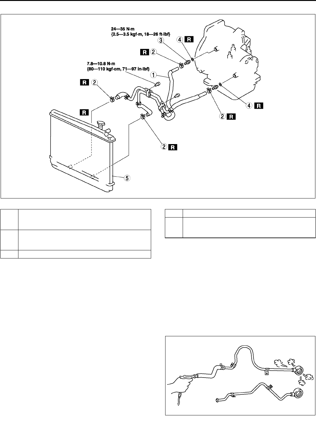
K40
AUTOMATIC TRANSAXLE
WITHOUT OIL COOLER
.
Radiator (In Tank Oil Cooler) Installation Note
1. The automatic transaxle oil cooler flushing must be performed whenever a transaxle is removed for service
because the existing fluid may be contaminated, and to prevent contamination of new fluid.
Note
• The flushing must be performed after installation of the overhauled or replacing transaxle.
2. Follow the instructions in the manufacturers publication for flushing operation.
Oil Pipe, Hose Clamp, Oil Hose Installation Note
1. Apply compressed air to cooler-side opening, and
blow any remaining grime and foreign material
from the cooler pipes. Compressed air should be
applied for no less than one minute.
A6E5614W080
1Oil hose
(See K40 Oil Pipe, Hose Clamp, Oil Hose
Installation Note.)
2 Hose clamp
(See K40 Oil Pipe, Hose Clamp, Oil Hose
Installation Note.)
3 Connector bolt
4 O-ring
5 Radiator (in tank oil cooler)
(See K40 Radiator (In Tank Oil Cooler) Installation
Note.)
A6E5614W070
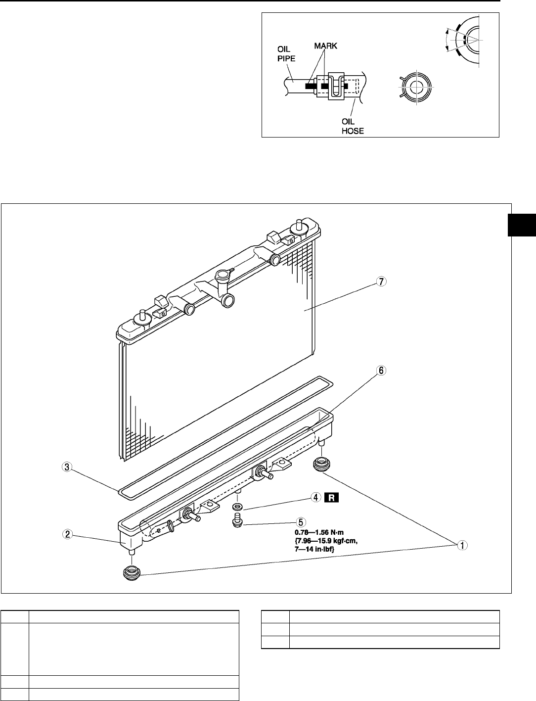
AUTOMATIC TRANSAXLE
K41
K
2. Align the marks, and slide the oil hose onto the oil
pipe until it is fully seated as shown.
Note
•If reusing the hose, install the new hose
clamp exactly on the mark left by the
previous hose camp.Then apply force to the
hose clamp in the direction of the arrow in
order to fit the clamp in the place.
3. Install the new hose clamp onto the hose.
4. Verify that the hose clamp does not interfere with
any other components.
End Of Sie
OIL COOLER DISASSEMBLY/ASSEMBLY A6E561419900W03
1. Disassemble in the order indicated in the table.
2. Assemble in the reverse order of disassembly.
.
A6E5614W071
A6E5614W072
1 Mount rubber
2 Radiator outer tank (in tank oil cooler)
(See K42 Radiator Outer Tank (In Tank Oil Cooler)
Removal Note.)
(See K42 Radiator Outer Tank (In Tank Oil Cooler)
Installation Note.)
3 O-ring
4 Washer
5 Drain plug
6 ATF cooler
7Radiator
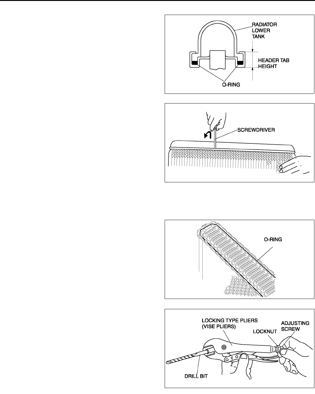
K42
AUTOMATIC TRANSAXLE
Radiator Outer Tank (In Tank Oil Cooler) Removal Note
1. Inspect the height of the header tabs.
2. Insert the end of a medium tip screwdriver
between the end of the header tab and the outer
tank.
Note
•Do not open more tabs than necessary for
tank removal.
3. Pivot the screwdriver to pry the tab away from the
tank and repeat the procedure for each tab.
4. Remove the radiator outer tank and O-ring
(gasket) from the core header when all of the tabs
are opened.
Note
•If any header tabs are missing from the core,
replace the radiator.
5. Inspect the gasket surface of the radiator core
header to ensure it is clean and free of foreign
material or damage.
6. Inspect the radiator outer tank for warping. If it is
warped, replace radiator tank.
Radiator Outer Tank (In Tank Oil Cooler) Installation Note
1. Install a new O-ring and ensure it is not twisted.
Note
•The old O-ring must be replaced.
2. Position the radiator tank in the original direction
to the core using care not to scratch the tank
sealing surface with the header tabs.
Note
•Step 3 will set jaw opening to the correct
specification.
3. With the jaws of locking-type pliers (vise grips)
closed and locked, turn the adjusting screw to
position the jaws against the drill bit with the
diameter measured (height) in removal procedure
1. Tighten the lock nut on the adjusting screw
against the handle to lock the adjustment in
place.
A6E5614W073
A6E5614W074
A6E5614W075
A6E5614W093
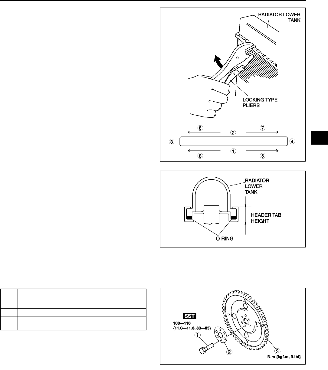
AUTOMATIC TRANSAXLE
K43
K
4. Squeeze the header tabs down in order as shown
against the lip of radiator outer tank base with
locking-type pliers while rotating the pliers toward
the tank.
5. Verify the height of the header tabs is same as
the height before removal.
6. Inspect for leakage from radiator. (See E4
ENGINE COOLANT LEAKAGE INSPECTION.)
End Of Sie
DRIVE PLATE REMOVAL/INSTALLATION A6E561419020W01
1. Remove the transaxle.(See K29 AUTOMATIC TRANSAXLE REMOVAL/INSTALLATION.)
2. Remove in the order indicated in the figure.
3. Install in the reverse order of removal.
.
A6E5614W076
A6E5614W073
1 Drive plate mounting bolts
(See K44 Drive Plate Mounting Bolts Removal
Note.)
2 Adapter
3Drive plate
(See K44 Drive Plate Installation Note.)
A6E5614W078
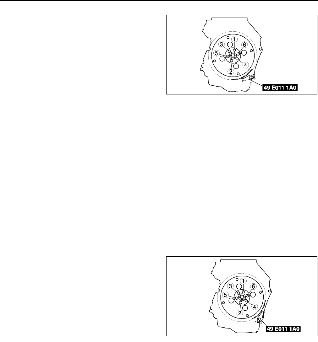
K44
AUTOMATIC TRANSAXLE
Drive Plate Mounting Bolts Removal Note
1. Set the SST or equivalent against the drive plate.
2. Remove the bolts and the drive plate.
Drive Plate Installation Note
Caution
•
••
•If the bolts are reused, remove the oil sealant from the bolt threads. Tightening a bolt that has old
sealant on it can cause thread damage.
1. Remove the sealant from the bolts hole in the crankshaft and from the drive plate mounting bolts.
Note
•If all the previous sealant cannot be removed from a bolt, replace the bolts.
•Do not apply sealant if a new bolts is used.
2. Install the drive plate.
3. Install the adapter.
4. Apply sealant to the drive plate mounting bolts and install them.
5. Set the SST or equivalent against the drive plate.
Caution
•
••
•When installing sealant covered bolts, tighten them immediately. Leaving these bolts in a half
installed condition could cause them to be stuck that way, due to the natural hardening or the
sealant.
6. Tighten the drive plate mounting bolts in two or
three steps in the order shown.
Tightening torque
1081116 N·m {11.011.8 kgf·m, 8085
ft·lbf}
7. Install the transaxle. (See K29 AUTOMATIC
TRANSAXLE REMOVAL/INSTALLATION.)
End Of Sie
A6E5614W079
A6E5614W081
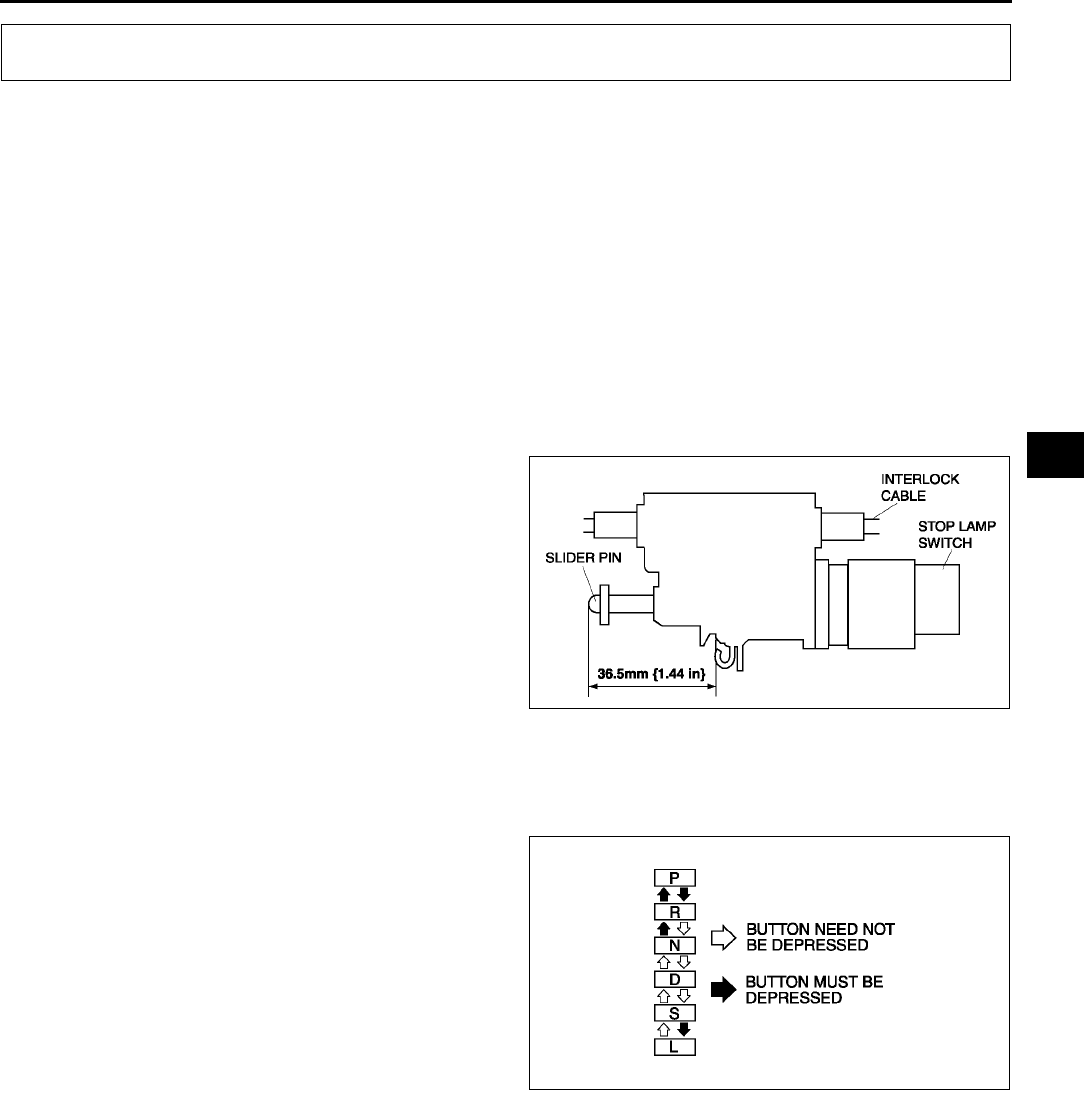
AUTOMATIC TRANSAXLE SHIFT MECHANISM
K45
K
SHIFT-LOCK INSPECTION A6E561630000W01
1. Turn the ignition switch to ON position.
2. Verify that the selector lever is in P position.
3. Depress the brake pedal and verify that the selector lever can be shifted from P position.
•If a malfunction is found, inspect the interlock cable.
(See K45 INTERLOCK CABLE INSPECTION.)
End Of Sie
KEY INTERLOCK INSPECTION A6E561609000W01
1. Verify that the ignition key cannot be pulled out except in P position.
•If a malfunction is found, inspect the interlock cable. (See K45 INTERLOCK CABLE INSPECTION.)
End Of Sie
INTERLOCK CABLE INSPECTION A6E561609000W02
1. Remove the interlock cable.
2. With the slider pin as shown in the figure, verify that the interlock cable moves freely.
•If a malfunction is found, replace the interlock cable.
End Of Sie
SELECTOR LEVER INSPECTION A6E561646102W01
1. Turn the ignition switch to ON (engine OFF).
2. With the brake pedal depressed, verify that there is a "click" at each range when shifted.
3. Verify that the selector lever can be shifted.
4. Verify that there is a "click" at each position when
shifted from P position to L range.
5. Verify that the positions of the selector lever and
the indicator are aligned.
•If not as specified, adjust the TR switch.(See
K18 TRANSAXLE RANGE (TR) SWITCH
ADJUSTMENT.)
6. Verify that the vehicle operates in each selected
range.
End Of Sie
AUTOMATIC TRANSAXLE SHIFT MECHANISM
A6E5616W001
A6E5616W002
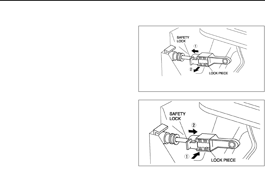
K46
AUTOMATIC TRANSAXLE SHIFT MECHANISM
SELECTOR CABLE ADJUSTMENT A6E561646102W02
1. Remove the center console.
2. Shift the selector lever to P position.
3. Unlock the lock piece of the selector cable
(selector lever side) in the order shown in the
figure.
4. Verify that the manual shaft is in P position.
5. Lock the lock piece of the selector cable (selector
lever side) in the order shown in the figure.
6. Install the center console.
7. Shift the selector lever from P position to L range,
and make sure that there are no other
components in that area to interfere with the
lever.
End Of Sie
SELECTOR LEVER REMOVAL/INSTALLATION A6E561646102W03
1. Disconnect the negative battery cable.
2. Remove battery and battery tray.
3. Remove the air cleaner compornent. (See F10 INTAKE-AIR SYSTEM REMOVAL/INSTALLATION.)
4. Remove the console.
5. Remove the dashboard compleat.
(See S82 DASHBOARD REMOVAL/INSTALLATION.)
6. Remove the SAS control module.
(See T124 SAS UNIT REMOVAL/INSTALLATION.)
7. Remove the climate control unit. (See U44 CLIMATE CONTROL UNIT REMOVAL.) (See U45 CLIMATE
CONTROL UNIT INSTALLATION.)
8. Remove the rear heat duct. (See U23 REAR HEAT DUCT REMOVAL/INSTALLATION.)
9. Remove in the order shown in the figure.
10. Remove the battery, battery tray and battery bracket.
A6E5616W003
A6E5616W004
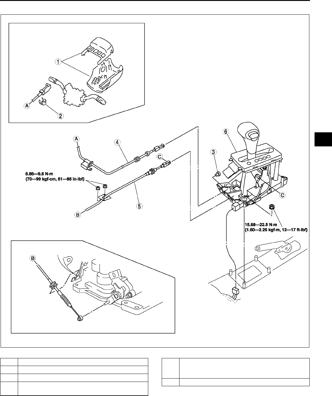
AUTOMATIC TRANSAXLE SHIFT MECHANISM
K47
K
11. Install in the reverse order of removal..
A6E5616W005
1 Column cover(with key interlock)
2 Clip(with key interlock)
3 Clip(with key interlock)
4 Interlock cable(with key interlock)
(See K49 Interlock Cable Installation Note.)
5 Selector cable
(See K48 Selector Cable Removal Note.)
(See K48 Selector Cable Installation Note.)
6Selector lever
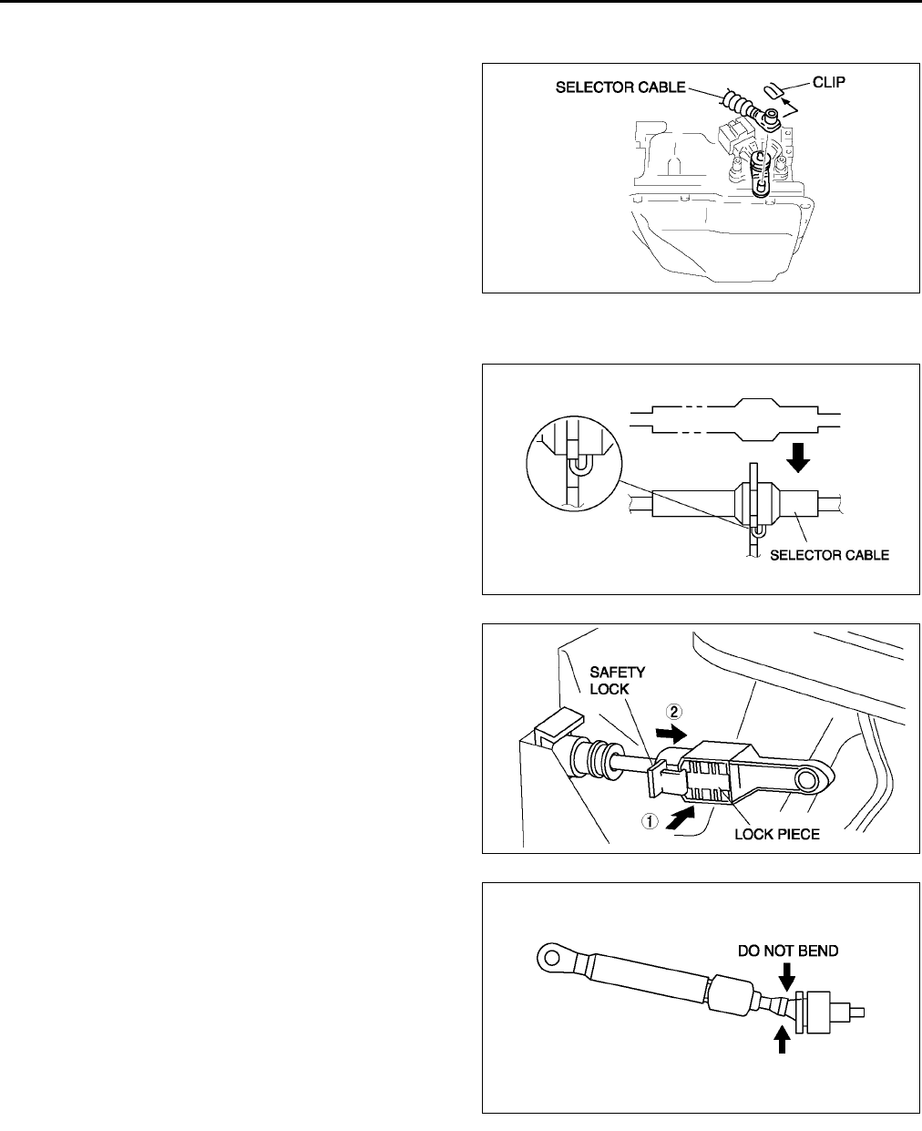
K48
AUTOMATIC TRANSAXLE SHIFT MECHANISM
Selector Cable Removal Note
1. Remove the clip.
2. Remove the selector cable.
Selector Cable Installation Note
1. Install the selector cable to the selector lever certainly.
2. Install the selector cable to the bracket certainly.
Note
•Step 3, 4 is for the selector cable
replacement only.
3. Verify that the selector lever is in P position.
4. Lock the lock piece of the selector cable (selector
lever side) in the order shown in the figure.
5. Verify that the manual shaft is in P position.
A6E5616W006
A6E5616W020
A6E5616W004
A6E5616W007
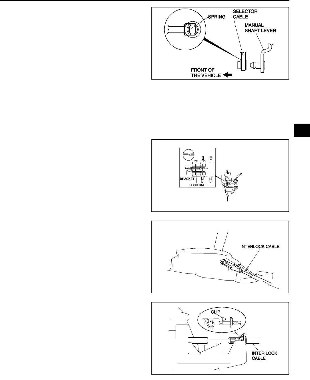
AUTOMATIC TRANSAXLE SHIFT MECHANISM
K49
K
Caution
•
••
•Bending the selector cable in the manner
shown in the figure will damage the cable
and it may become loose when shifted.
When installing the selector cable, hold it
straight.
Note
•Install the selector lever to the manual shaft
lever with the spring side of the selector
cable end facing the front of the vehicle.
6. Install the selector lever to the manual shaft lever
in such a way that the selector cable does not bear a load.
7. Confirm that the end of the manual shift lever sticks out of the end of the selector cable.
8. Install the selector cable to the selector cable securely bracket.
Interlock Cable Installation Note
1. Verify that the shift the selector lever in P position and ignition key is in LOCK position.
2. Press the lock unit onto the brake pedal stopper bracket.
3. From this position, slide the lock unit to fix the
lock unit hook into the bracket hole securely as
shown in the figure.
Caution
•
••
•Allowing the interlock cable to be bent or
twisted during installation can affect the
lock unit operation.
4. Install the interlock cable end onto the cam pin on
the selector lever.
5. Fit the interlock cable in the Ugroove in the
selector lever base plate, and install the clip.
Caution
•
••
•Applying a load to the interlock cable
while pressing the lock piece in can
affect the lock unit operation.
A6E5616W008
A6E5616W009
A6E5616W010
A6E5616W011
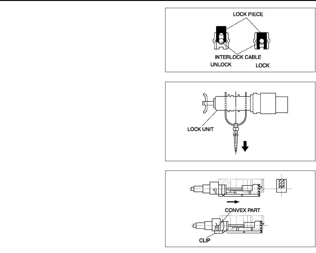
K50
AUTOMATIC TRANSAXLE SHIFT MECHANISM
6. Press the interlock cable lock piece in unitl it is
locked.
Note
•Step 7 is for the interlock cable replacement
only.
7. Remove the lock unit pin as shown in the figure.
8. Turn the ignition key in ACC position.
9. Install the interlock cable to the key cylinder.
10. Slide the outer casing to the key cylinder, and
insert the clip over the convex part of the outer
casing.
End Of Sie
A6E5616W012
A6E5616W013
A6E5616W014
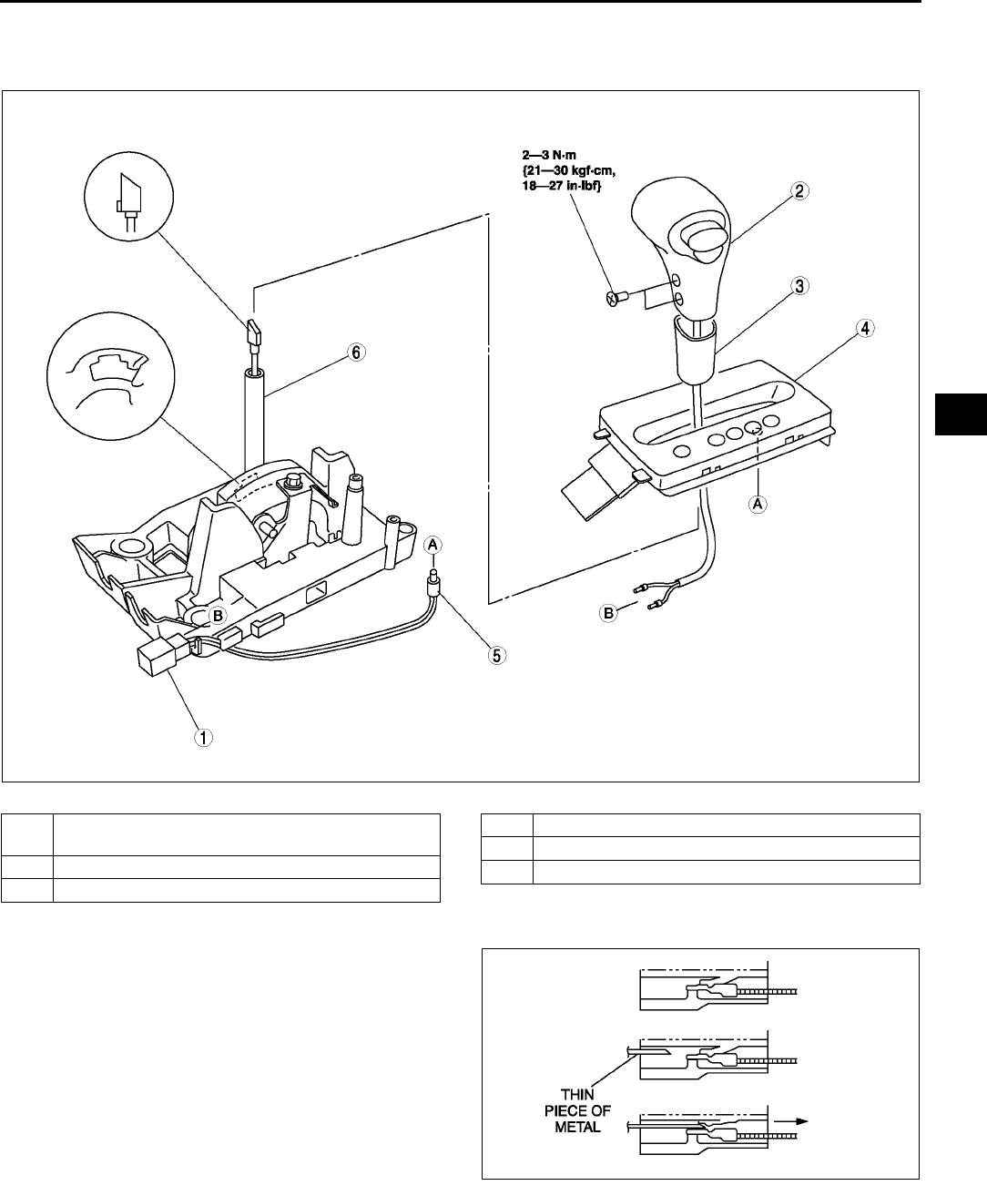
AUTOMATIC TRANSAXLE SHIFT MECHANISM
K51
K
SELECTOR LEVER DISASSEMBLY/ASSEMBLY A6E561646102W04
1. Disassemble in the order shown in the figure.
2. Assemble in the reverse order of disassembly..
Connector Disassembly Note
1. Insert a thin piece of metal from the terminal side
of the connector, and press down the terminal
locking tab.
2. Pull the terminal out of the connector.
End Of Sie
A6E5616W015
1 Connector
(See K51 Connector Disassembly Note.)
2 Selector lever knob component
3 Cover
4 Indicator panel
5 Selector illumination light
6Selector lever
A6E5616W016
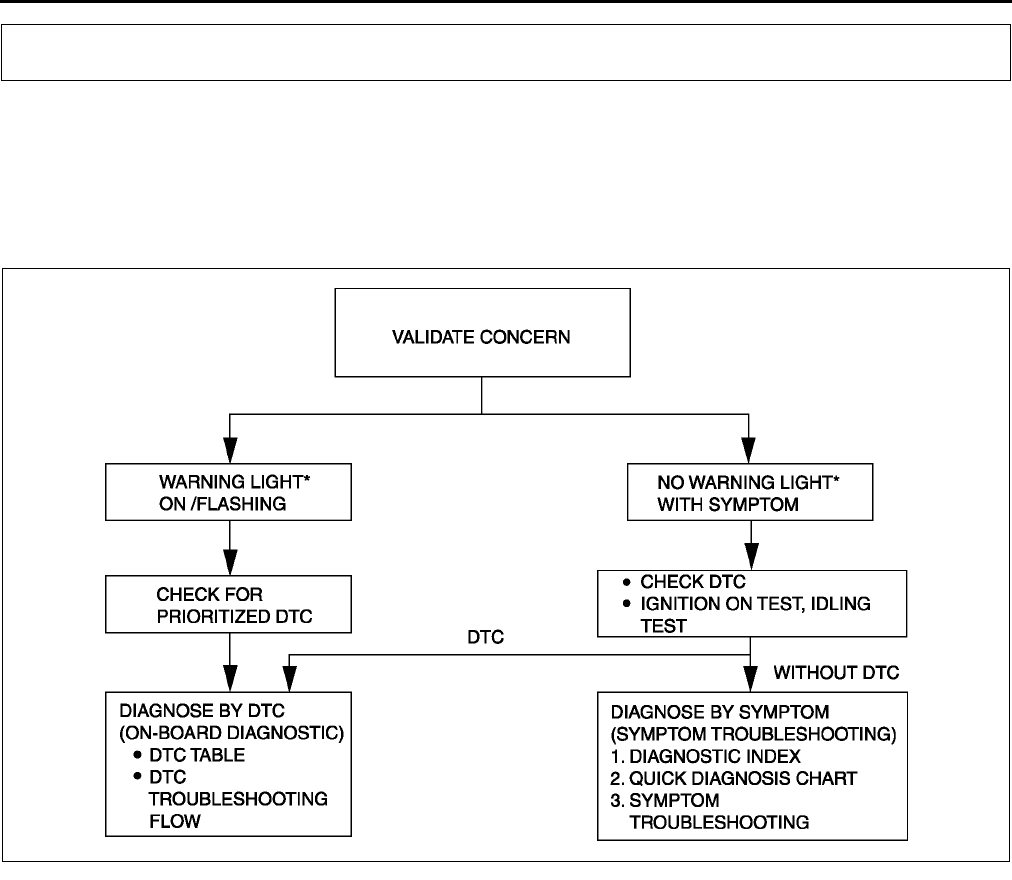
K52
ON-BOARD DIAGNOSTIC
FOREWORD A6E567001030W01
•When the customer reports a vehicle malfunction, check the malfunction indicator lamp (MIL), HOLD indicator
light flashing, and PCM memory for diagnostic trouble code (DTC), then diagnose the malfunction according to
following flowchart.
If the DTC exists, diagnose the applicable DTC. (See K53 DTC TABLE.)
If the DTC does not exist, MIL does not illuminate, and HOLD indicator light flashes, diagnose the
applicable symptom troubleshooting. (See K113 SYMPTOM TROUBLESHOOTING ITEM TABLE.)
*:Malfunction indicator lamp (MIL), HOLD indicator light
End Of Sie
AUTOMATIC TRANSAXLE ON-BOARD DIAGNOSTIC FUNCTION A6E567001030W02
DTC Reading Procedure
(See F62 ON-BOARD DIAGNOSTIC TEST.)
End Of Sie
AFTER REPAIR PROCEDURE A6E567001030W03
Caution
•
••
•After repairing a malfunction, perform this procedure to verify that the malfunction has been
corrected.
•
••
•When this procedure is carried out, be sure to drive the vehicle at lawful speed and pay attention
to the other vehicles.
1. Connect the WDS or equivalent to the DLC-2.
2. Turn the ignition key to ON (engine OFF).
3. Verify that DTCs are cleared from memory.
4. Decrease ATF temperature to 20 °
°°
°C {68 °
°°
°F} or below.
5. Start the engine then wait 180 seconds or more.
6. Warm up the engine and ATX.
•Engine coolant temperature: 60 °
°°
°C {140 °
°°
°F} or above.
•Transaxle fluid temperature: 20 °
°°
°C {68 °
°°
°F} or above.
7. Shift the selector lever between P position to L range while depressing brake pedal.
8. Drive the vehicle for 150 seconds or more at a vehicle speed between 25 and 59 km/h {15 and 36 mph},
then 60 km/h {37 mph} or more for 100 seconds or more.
ON-BOARD DIAGNOSTIC
A6E5670W013

ON-BOARD DIAGNOSTIC
K53
K
9. Drive the vehicle in D range and shift gears between 1st and 4th (TCC operation) gear.
10. Gradually slow down and stop the vehicle.
11. Make sure that the repaired DTC does not recur.
End Of Sie
DTC TABLE A6E567001030W04
DTC No. Condition MIL
HOLD
indicator
light
flashes
DC Monitor
item
Memory
function Page
P0010 CMP actuator circuit malfunction (See F67 DTC TABLE)
P0011 CMP timing over advanced (See F67 DTC TABLE)
P0012 CMP timing over retarded (See F67 DTC TABLE)
P0031 Front HO2S heater circuit low (See F67 DTC TABLE)
P0032 Front HO2S heater circuit high (See F67 DTC TABLE)
P0037 Rear HO2S heater circuit low (See F67 DTC TABLE)
P0038 Rear HO2S heater circuit high (See F67 DTC TABLE)
P0101 MAF sensor inconsistent with TP sensor (See F67 DTC TABLE)
P0102 MAF circuit low input (See F67 DTC TABLE)
P0103 MAF circuit high input (See F67 DTC TABLE)
P0107 MAP sensor circuit low input (See F67 DTC TABLE)
P0108 MAP sensor circuit high input (See F67 DTC TABLE)
P0111 IAT circuit performance problem (See F67 DTC TABLE)
P0112 IAT circuit low input (See F67 DTC TABLE)
P0113 IAT circuit high input (See F67 DTC TABLE)
P0117 ECT circuit low input (See F67 DTC TABLE)
P0118 ECT circuit high input (See F67 DTC TABLE)
P0121 Throttle position stuck close (See F67 DTC TABLE)
P0122 TP circuit low input (See F67 DTC TABLE)
P0123 TP circuit high input (See F67 DTC TABLE)
P0125 Excessive time to enter closed loop fuel control (See F67 DTC TABLE)
P0131 Front HO2S no inversion (low stuck) (See F67 DTC TABLE)
P0132 Front HO2S no inversion (high stuck)
P0133 Front HO2S circuit malfunction (See F67 DTC TABLE)
P0134 Front HO2S circuit no activity detected (See F67 DTC TABLE)
P0138 Rear HO2S circuit high input (See F67 DTC TABLE)
P0140 Rear HO2S circuit no activity detected (See F67 DTC TABLE)
P0171 Fuel trim system too lean (See F67 DTC TABLE)
P0172 Fuel trim system too rich (See F67 DTC TABLE)
P0300 Random misfire detected (See F67 DTC TABLE)
P0301 Cylinder No.1 misfire detected
(See F67 DTC TABLE)
P0302 Cylinder No.2 misfire detected
P0303 Cylinder No.3 misfire detected
P0304 Cylinder No.4 misfire detected
P0327 Knock sensor circuit low input (See F67 DTC TABLE)
P0328 Knock sensor circuit high input (See F67 DTC TABLE)
P0335 CKP sensor circuit malfunction (See F67 DTC TABLE)
P0340 CMP sensor circuit malfunction (See F67 DTC TABLE)
P0351 Ignition coil (No.1, No.4) circuit malfunction (See F67 DTC TABLE)
P0352 Ignition coil (No.2, No.3) circuit malfunction (See F67 DTC TABLE)
P0401 EGR flow insufficient detected (See F67 DTC TABLE)
P0402 EGR flow excessive detected (See F67 DTC TABLE)
P0403 EGR valve motor coils open or short (See F67 DTC TABLE)
P0420 Catalyst system efficiency below threshold (See F67 DTC TABLE)
P0443 Evaporative emission control system purge
control valve circuit malfunction (See F67 DTC TABLE)
P0480 Fan control module circuit malfunction (See F67 DTC TABLE)

K54
ON-BOARD DIAGNOSTIC
P0500
VSS circuit malfunction (MTX) (See F67 DTC TABLE)
VSS circuit malfunction (ATX) ON YES 2 CCM ×(See K55 DTC
P0500)
P0505 Idle control system malfunction (See F67 DTC TABLE)
P0506 Idle control system RPM lower than expected (See F67 DTC TABLE)
P0507 Idle control system RPM higher than expected (See F67 DTC TABLE)
P0511 IAC valve circuit malfunction (See F67 DTC TABLE)
P0550 PSP switch circuit malfunction (See F67 DTC TABLE)
P0602 PCM programming error (See F67 DTC TABLE)
P0610 Control module vehicle options error (See F67 DTC TABLE)
P0661 VICS circuit low input (See F67 DTC TABLE)
P0662 VICS circuit high input (See F67 DTC TABLE)
P0703 Brake switch input malfunction (See F67 DTC TABLE)
P0704 Clutch switch input malfunction (See F67 DTC TABLE)
P0706 Transaxle range (TR) switch circuit range/
performance ON YES 2 CCM ×(See K57 DTC
P0706)
P0707 Transaxle range (TR) switch circuit low input ON YES 1 CCM ×(See K58 DTC
P0707)
P0708 Transaxle range (TR) switch circuit high input ON YES 2 CCM ×(See K60 DTC
P0708)
P0711 Transaxle fluid temperature (TFT) sensor circuit
range/performance (Stuck) ON NO 2 CCM ×(See K63 DTC
P0711)
P0712 Transaxle fluid temperature (TFT) sensor circuit
malfunction (short to ground) ON YES 1 CCM ×(See K64 DTC
P0712)
P0713 Transaxle fluid temperature (TFT) sensor circuit
malfunction (open circuit) ON YES 1 CCM ×(See K65 DTC
P0713)
P0715 Input/turbine speed sensor circuit malfunction ON YES 1 CCM ×(See K68 DTC
P0715)
P0731 Gear 1 incorrect (Incorrect Gear Ratio Detected) OFF YES 1 CCM ×(See K70 DTC
P0731)
P0732 Gear 2 incorrect (Incorrect Gear Ratio Detected) OFF YES 1 CCM ×(See K71 DTC
P0732)
P0733 Gear 3 incorrect (Incorrect Gear Ratio Detected) OFF YES 1 CCM ×(See K73 DTC
P0733)
P0734 Gear 4 incorrect (Incorrect Gear Ratio Detected) OFF YES 1 CCM ×(See K75 DTC
P0734)
P0741 Torque converter clutch (TCC) (stuck OFF) OFF YES 1 CCM ×(See K77 DTC
P0741)
P0742 Torque converter clutch (TCC) (stuck ON) OFF YES 1 CCM ×(See K78 DTC
P0742)
P0745 Pressure control solenoid malfunction OFF YES 1 CCM ×(See K80 DTC
P0745)
P0751 Shift solenoid A stuck OFF ON YES 2 CCM ×(See K82 DTC
P0751)
P0752 Shift solenoid A stuck ON ON YES 2 CCM ×(See K83 DTC
P0752)
P0753 Shift solenoid A malfunction (electrical) ON YES 1 CCM ×(See K85 DTC
P0753)
P0756 Shift solenoid B stuck OFF ON YES 2 CCM ×(See K87 DTC
P0756)
P0757 Shift solenoid B stuck ON ON YES 2 CCM ×(See K89 DTC
P0757)
P0758 Shift solenoid B malfunction (electrical) ON YES 1 CCM ×(See K90 DTC
P0758)
P0761 Shift solenoid C stuck OFF ON YES 2 CCM ×(See K93 DTC
P0761)
DTC No. Condition MIL
HOLD
indicator
light
flashes
DC Monitor
item
Memory
function Page
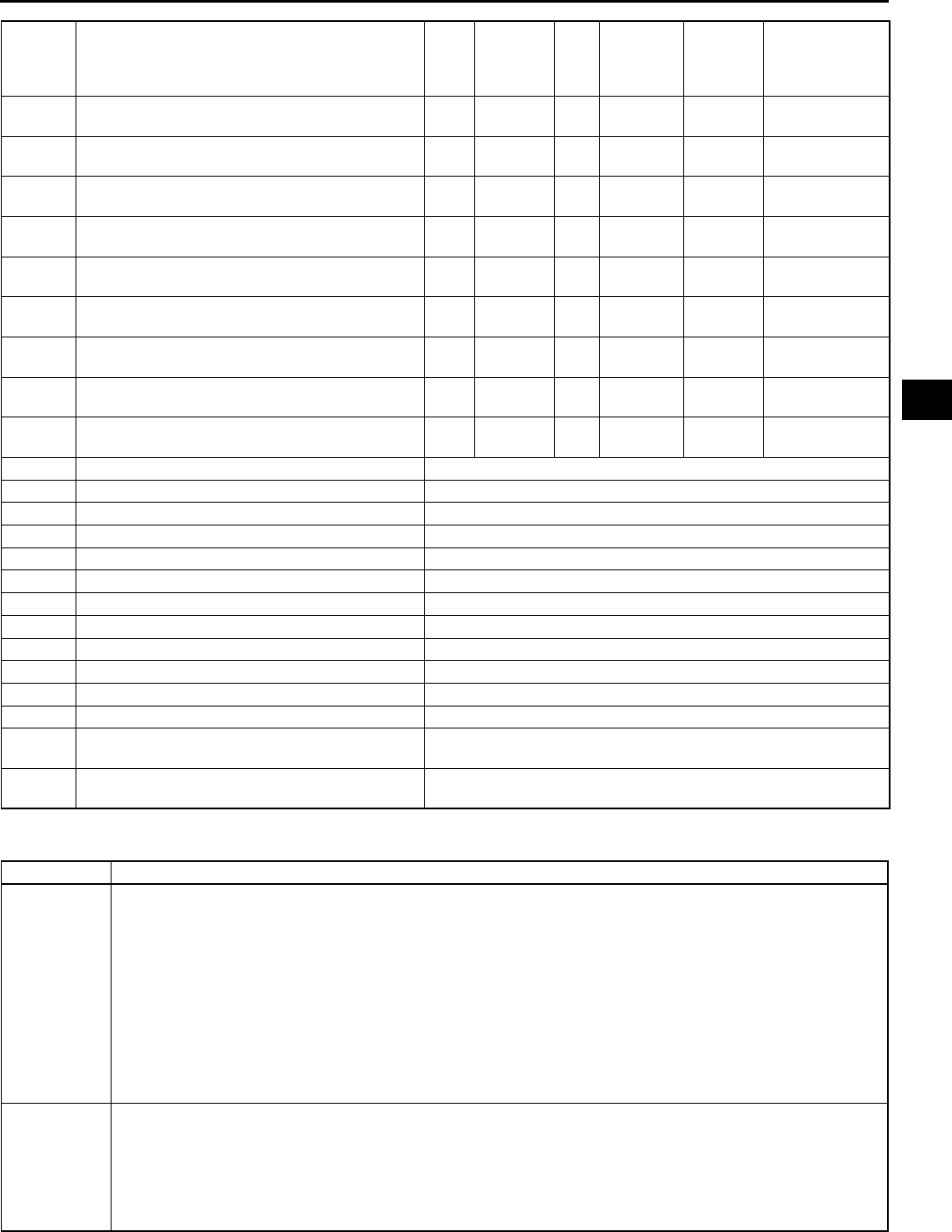
ON-BOARD DIAGNOSTIC
K55
K
End Of Sie
DTC P0500 A6E567001030W05
P0762 Shift solenoid C stuck ON ON YES 2 CCM ×(See K95 DTC
P0762)
P0763 Shift solenoid C malfunction (electrical) ON YES 1 CCM ×(See K96 DTC
P0763)
P0766 Shift solenoid D stuck OFF ON YES 2 CCM ×(See K99 DTC
P0766)
P0767 Shift solenoid D stuck ON ON YES 2 CCM ×(See K100
DTC P0767)
P0768 Shift solenoid D malfunction (electrical) ON YES 1 CCM ×(See K102
DTC P0768)
P0771 Shift solenoid E stuck OFF ON YES 2 CCM ×(See K104
DTC P0771)
P0772 Shift solenoid E stuck ON ON YES 2 CCM ×(See K105
DTC P0772)
P0773 Shift solenoid E malfunction (electrical) ON YES 1 CCM ×(See K107
DTC P0773)
P0841 Oil pressure switch circuit malfunction OFF NO 2 CCM ×(See K109
DTC P0841)
P0850 Neutral switch input malfunction (See F67 DTC TABLE)
P1410 Variable air duct valve circuit malfunction (See F67 DTC TABLE)
P1562 PCM +BB voltage low (See F67 DTC TABLE)
P2006 VTCS stuck close (See F67 DTC TABLE)
P2009 VTCS circuit low input (See F67 DTC TABLE)
P2010 VTCS circuit high input (See F67 DTC TABLE)
P2228 BARO sensor circuit low input (See F67 DTC TABLE)
P2229 BARO sensor circuit high input (See F67 DTC TABLE)
P2502 Generator output voltage signal no electricity (See F67 DTC TABLE)
P2503 Battery overcharge (See F67 DTC TABLE)
P2504 Generator terminal B circuit open (See F67 DTC TABLE)
U0073 CAN bus off (See F67 DTC TABLE)
U0121 PCM cannot receive any signals from ABS,
ABS/TCS or DSC HU/CM (See F67 DTC TABLE)
U0155 PCM cannot receive any signals from
combination meter (See F67 DTC TABLE)
DTC No. Condition MIL
HOLD
indicator
light
flashes
DC Monitor
item
Memory
function Page
DTC P0500 Vehicle speed sensor (VSS) circuit malfunction
DETECTION
CONDITION
•Vehicle speed signal not input after following conditions are met and 4.5 seconds or more have passed
D, L, or S range.
Engine coolant temperature 60 °
°°
°C {140 °
°°
°F} or above.
Turbine speed 1,500 rpm or above.
Diagnostic support note:
•This is a continuous monitor (CCM).
•MIL illuminates if PCM detects the above malfunction condition in two consecutive drive cycles or in one
drive cycle while the DTC for the same malfunction has been stored in the PCM.
•PENDING CODE is available if PCM detects the above malfunction condition during first drive cycle.
•FREEZE FRAME DATA is available.
•HOLD indicator light flashes.
•DTC is stored in the PCM memory.
POSSIBLE
CAUSE
•VSS malfunction
•Open circuit between VSS terminal B and PCM terminal 3C
•Short to ground between VSS terminal B and PCM terminal 3C
•Open circuit between VSS terminal A and fuse block connector (X-01) terminal AJ
•Open circuit between VSS terminal C and body ground
•Damaged connectors between VSS and PCM
•PCM malfunction
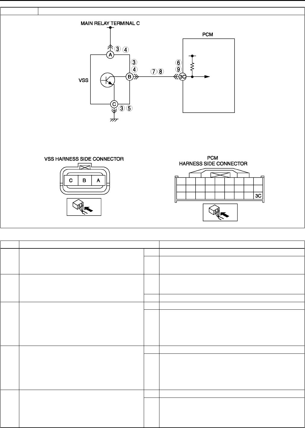
K56
ON-BOARD DIAGNOSTIC
Diagnostic procedure
STEP INSPECTION ACTION
1VERIFY FREEZE FRAME DATA HAS BEEN
RECORDED
•Has FREEZE FRAME PID DATA been
recorded?
Yes Go to next step.
No Record FREEZE FRAME PID DATA on repair order, then
go to next step.
2VERIFY RELATED SERVICE INFORMATION
AVAILABILITY
•Check for related Service Bulletins availability.
•Is any related repair Information available?
Yes Perform repair or diagnosis according to available repair
Information.
•If vehicle is not repaired, go to next step.
No Go to next step.
3INSPECT VSS CONNECTOR FOR POOR
CONNECTION
•Turn ignition key to OFF.
•Disconnect VSS connector.
•Check for poor connection (damaged/pulled-
out terminals, corrosion, etc.).
•Is connection okay?
Yes Go to next step.
No Repair or replace pin or connector, then go to Step 10.
4INSPECT VSS POWER CIRCUIT FOR OPEN
CIRCUIT
•Verify that VSS connector is disconnected.
•Turn ignition key to ON (Engine OFF).
•Check voltage between VSS terminal A
(harness-side) and ground
•Is voltage reading B+?
Yes Go to next step.
No Repair or replace harness, then go to Step 10.
5INSPECT VSS GROUND CIRCUIT FOR OPEN
•Turn ignition key to OFF.
•Verify that VSS connector is disconnected.
•Check for continuity between VSS terminal C
(harness-side) and ground
•Is there continuity?
Yes Go to next step.
No Repair or replace harness, then go to Step 10.
DTC P0500 Vehicle speed sensor (VSS) circuit malfunction

ON-BOARD DIAGNOSTIC
K57
K
End Of Sie
DTC P0706 A6E567001030W06
6INSPECT PCM CONNECTOR FOR POOR
CONNECTION
•Disconnect PCM connector.
•Check for poor connection (damaged/pulled-
out terminals, corrosion, etc.).
•Is connection okay?
Yes Go to next step.
No Repair or replace pin or connector, then go to Step 10.
7INSPECT VEHICLE SPEED SIGNAL CIRCUIT
FOR OPEN
•Disconnect PCM connector and VSS
connector.
•Inspect for continuity between VSS terminal B
and PCM terminal 3C.
•Is there continuity?
Yes Go to next step.
No Repair or replace harness, then go to Step 10.
8INSPECT VEHICLE SPEED SIGNAL CIRCUIT
FOR SHORT TO GROUND
•Verity that VSS connector and PCM connector
are disconnected.
•Inspect for continuity between PCM terminal
3C and body ground.
•Is there continuity?
Yes Repair or replace harness, then go to Step 10.
No Repair VSS, then go to Step 14.
9INSPECT PCM CONNECTOR FOR POOR
CONNECTION
•Disconnect PCM connector.
•Check for poor connection (damaged/pulled-
out terminals, corrosion, etc.).
•Is connection okay?
Yes Go to next step.
No Repair or replace pin or connector, then go to Step 10.
10 VERIFY TROUBLESHOOTING OF DTC P0500
COMPLETED
•Make sure to reconnect all disconnected
connectors.
•Clear DTC from memory using WDS or
equivalent.
•Warm up engine.
•Drive vehicle under following conditions for 4.5
seconds or more while monitoring PIDs.
Engine coolant temp: 60 °
°°
°C {140 °
°°
°F} or
above
Drive in L range
Frequency of input/turbine speed sensor:
800 Hz or above
•Is pending code present?
Yes Replace PCM, then go to next step.
(See F43 PCM REMOVAL/INSTALLATION.)
No No concern is detected. Go to next step.
11 VERIFY AFTER REPAIR PROCEDURE
•Perform After Repair Procedure.
(See K52 AFTER REPAIR PROCEDURE.)
•Are any DTCs present?
Yes Go to applicable DTC inspection.
No Troubleshooting completed.
STEP INSPECTION ACTION
DTC P0706 Transaxle range (TR) switch range/performance
DETECTION
CONDITION
•When all conditions below are satisfied and 100 seconds or more have passed.
Engine speed 530 rpm or above.
Vehicle speed 20 km/h {12 mph} or above.
voltage at PCM terminal 1W is 0.5 V or above.
P, R, N, D, S or L range/position not detected.
Diagnostic support note:
•This is a continuous monitor (CCM).
•MIL illuminates if PCM detects the above malfunction condition in two consecutive drive cycles or in one
drive cycle while the DTC for the same malfunction has been stored in the PCM.
•PENDING CODE is available if PCM detects the above malfunction condition during first drive cycle.
•FREEZE FRAME DATA is available.
•HOLD indicator light flashes.
•DTC is stored in the PCM memory.
POSSIBLE
CAUSE
•TR switch malfunction
•TR switch misadjustment
•PCM malfunction

K58
ON-BOARD DIAGNOSTIC
Diagnostic procedure
End Of Sie
DTC P0707 A6E567001030W07
STEP INSPECTION ACTION
1VERIFY FREEZE FRAME DATA HAS BEEN
RECORDED
•Has FREEZE FRAME PID DATA been
recorded?
Yes Go to next step.
No Record FREEZE FRAME PID DATA on repair order, then
go to next step.
2VERIFY RELATED REPAIR INFORMATION
AVAILABILITY
•Check for related Service Bulletins availability.
•Is any related repair information available?
Yes Perform repair or diagnosis according to available repair
information.
•If vehicle is not repaired, go to next step.
No Go to next step.
3INSPECT TR SWITCH
•Turn ignition key to OFF.
•Disconnect TR switch connector.
•Inspect for resistance between TR switch
terminals B and C (part-side).
•Is resistance okay?
(See K14 TRANSAXLE RANGE (TR) SWITCH
INSPECTION.)
Yes Go to next step.
No Adjust TR switch, then go to next step.
(See K18 TRANSAXLE RANGE (TR) SWITCH
ADJUSTMENT.)
4VERIFY TROUBLESHOOTING OF DTC P0706
COMPLETED
•Make sure to reconnect all disconnected
connectors.
•Clear DTC from memory using WDS or
equivalent.
•Drive vehicle in each range (D, S, L, and R) for
100 seconds or more under following
conditions.
Engine speed (RPM PID) 530 rpm or
above
Vehicle speed (VSS PID) 20 km/h {12 mph}
or above
•Is pending code present?
Yes Replace PCM, then go to next step.
(See F43 PCM REMOVAL/INSTALLATION.)
No No concern is detected. Go to next step.
5VERIFY AFTER REPAIR PROCEDURE
•Perform After Repair Procedure.
(See K52 AFTER REPAIR PROCEDURE.)
•Are any DTCs present?
Yes Go to applicable DTC inspection.
No Troubleshooting completed.
DTC P0707 Transaxle range (TR) switch circuit low input
DETECTION
CONDITION
•When all conditions below satisfied and 100 seconds or more have passed:
Vehicle speed 20 km/h {12 mph} or above.
Engine speed 530 rpm or above.
Voltage at PCM terminal 1W is below 0.5 V.
Diagnostic support note:
•This is a continuous monitor (CCM).
•MIL illuminates if PCM detects the above malfunction condition during first drive cycle.
•PENDING CODE is not available.
•FREEZE FRAME DATA is available.
•HOLD indicator light flashes.
•DTC is stored in the PCM memory.
POSSIBLE
CAUSE
•TR switch malfunction
•Short to ground between TR switch terminal C and PCM terminal 1W
•TR switch signal and TR switch ground circuits are shorted each other
•PCM malfunction
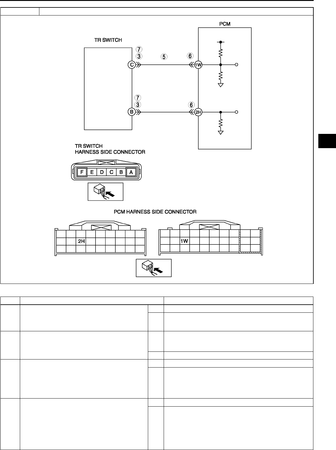
ON-BOARD DIAGNOSTIC
K59
K
Diagnostic procedure
STEP INSPECTION ACTION
1VERIFY FREEZE FRAME DATA HAS BEEN
RECORDED
•Has FREEZE FRAME PID DATA been
recorded?
Yes Go to next step.
No Record FREEZE FRAME PID DATA on repair order, then
go to next step.
2VERIFY RELATED REPAIR INFORMATION
AVAILABILITY
•Check for related Service Bulletins availability.
•Is any related repair information available?
Yes Perform repair or diagnosis according to available repair
information.
•If vehicle is not repaired, go to next step.
No Go to next step.
3INSPECT TR SWITCH CONNECTOR
•Turn ignition key OFF.
•Disconnect TR switch connector.
•Inspect for bent terminals of TR switch
terminals B and C (part-side).
•Are TR switch terminals okay?
Yes Go to next step.
No Repair terminals or replace TR switch, then go to Step 7.
(See K15 TRANSAXLE RANGE (TR) SWITCH
REMOVAL/INSTALLATION.)
4INSPECT TR SWITCH
•Turn ignition key to OFF.
•Disconnect TR switch connector.
•Inspect for resistance between TR switch
terminals B and C (part-side).
•Is resistance okay?
(See K14 TRANSAXLE RANGE (TR) SWITCH
INSPECTION.)
Yes Go to next step.
No Adjust TR switch, then go to Step 7.
(See K18 TRANSAXLE RANGE (TR) SWITCH
ADJUSTMENT.)
DTC P0707 Transaxle range (TR) switch circuit low input

K60
ON-BOARD DIAGNOSTIC
End Of Sie
DTC P0708 A6E567001030W08
5INSPECT TR SWITCH SIGNAL CIRCUIT FOR
SHORT TO GROUND
•Turn ignition key to OFF.
•Disconnect PCM connector
•Check for continuity between TR switch
terminal C (harness-side) and body ground.
•Is there continuity?
Yes Repair or replace harness for short to ground, then Go to
step 7.
No Go to next step.
6INSPECT PCM CONNECTOR FOR POOR
CONNECTION
•Disconnect PCM connector.
•Check for poor connection at terminals 1W and
2H (damaged/pulled-out pins, corrosion, etc.).
•Is there malfunction?
Yes Repair or replace terminal, then Go to step 9.
No Go to next step.
7INSPECT TR SWITCH CIRCUIT FOR SHORT
•Check for continuity between TR switch
terminals B and C (harness-side).
•Is there continuity?
Yes Repair or replace harness for short, then go to next step.
No Go to next step.
8VERIFY TROUBLESHOOTING OF DTC P0707
COMPLETED
•Make sure to reconnect all disconnected
connectors.
•Clear DTC from memory using WDS or
equivalent.
•Drive vehicle for 100 seconds or more under
following conditions.
Engine speed (RPM PID) 530 rpm or
above
Vehicle speed (VSS PID) 20 km/h {12 mph}
or above
•Is pending code present?
Yes Replace PCM, then go to next step.
(See F43 PCM REMOVAL/INSTALLATION.)
No No concern is detected. Go to next step.
9VERIFY AFTER REPAIR PROCEDURE
•Perform After Repair Procedure.
(See K52 AFTER REPAIR PROCEDURE.)
•Are any DTCs present?
Yes Go to applicable DTC inspection.
No Troubleshooting completed.
STEP INSPECTION ACTION
DTC P0708 Transaxle range (TR) switch circuit high input
DETECTION
CONDITION
•When all conditions below satisfied and 100 seconds or more have passed:
Vehicle speed 20 km/h {12 mph} or above.
Engine speed 530 rpm or above.
Voltage at PCM terminal 1W is 4.79 V or above.
Diagnostic support note:
•This is a continuous monitor (CCM).
•MIL illuminates if PCM detects the above malfunction condition in two consecutive drive cycles or in one
drive cycle while the DTC for the same malfunction has been stored in the PCM.
•PENDING CODE is not available.
•FREEZE FRAME DATA is available.
•HOLD indicator light flashes.
•DTC is stored in the PCM memory.
POSSIBLE
CAUSE
•TR switch malfunction
•Open circuit between TR switch terminal C and PCM terminal 1W
•Short to power circuit between TR switch terminal C and PCM terminal 1W
•Open circuit between TR switch terminal B and PCM terminal 2H
•Poor connection of TR switch or PCM connectors
•PCM malfunction
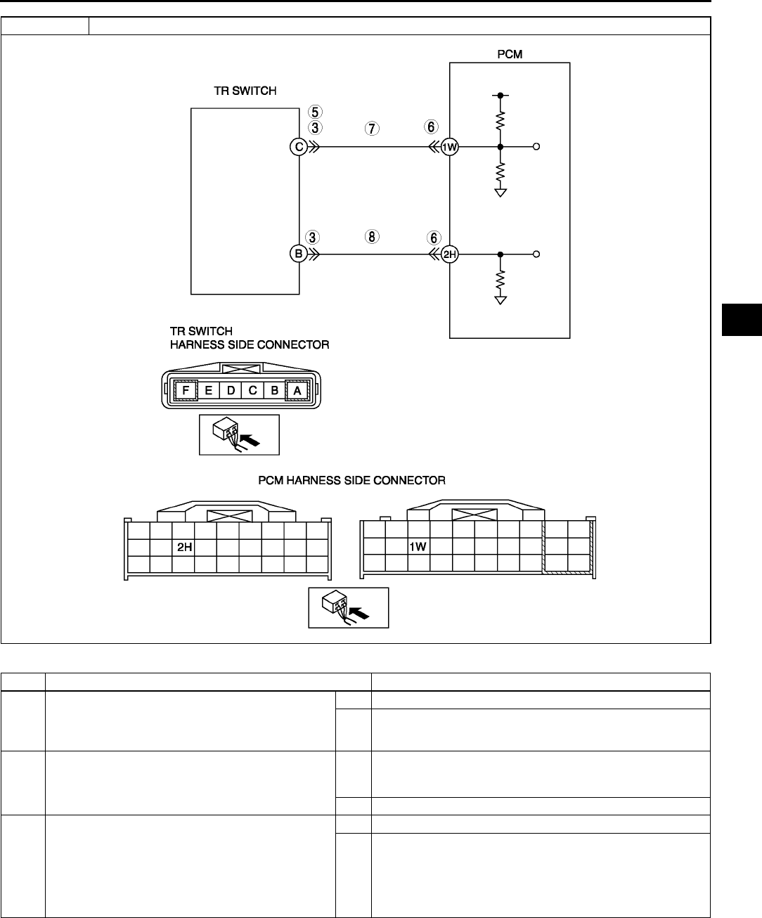
ON-BOARD DIAGNOSTIC
K61
K
Diagnostic procedure
STEP INSPECTION ACTION
1VERIFY FREEZE FRAME DATA HAS BEEN
RECORDED
•Has FREEZE FRAME PID DATA been
recorded?
Yes Go to next step.
No Record FREEZE FRAME PID DATA on repair order, then
go to next step.
2VERIFY RELATED REPAIR INFORMATION
AVAILABILITY
•Check for related Service Bulletins availability.
•Is any related repair information available?
Yes Perform repair or diagnosis according to available repair
information.
•If vehicle is not repaired, go to next step.
No Go to next step.
3INSPECT TR SWITCH CONNECTOR FOR POOR
CONNECTION
•Turn ignition key OFF.
•Disconnect TR switch connector.
•Check for poor connection (damaged/pulled-
out pins, corrosion, etc.).
•Are TR switch terminals okay?
Yes Go to next step.
No Repair terminals or replace TR switch, then go to Step 9.
(See K15 TRANSAXLE RANGE (TR) SWITCH
REMOVAL/INSTALLATION.)
DTC P0708 Transaxle range (TR) switch circuit high input

K62
ON-BOARD DIAGNOSTIC
End Of Sie
4INSPECT TR SWITCH
•Turn ignition key to OFF.
•Disconnect TR switch connector.
•Inspect for resistance between TR switch
terminals B and C (part-side).
•Is resistance okay?
(See K14 TRANSAXLE RANGE (TR) SWITCH
INSPECTION.)
Yes Go to next step.
No Adjust TR switch, then go to Step 9.
(See K18 TRANSAXLE RANGE (TR) SWITCH
ADJUSTMENT.)
5INSPECT TR SWITCH SIGNAL CIRCUIT FOR
SHORT TO POWER
•Turn ignition key to ON (engine OFF).
•Measure the voltage between TR switch
terminal C (harness-side) and body ground.
•Is there voltage B+?
Yes Repair or replace harness for short to power, then go to
step 9.
No Go to next step.
6INSPECT PCM CONNECTOR FOR POOR
CONNECTION
•Disconnect PCM connector.
•Check for poor connection at terminals 1W and
2H (damaged/pulled-out pins, corrosion, etc.).
•Is there malfunction?
Yes Repair or replace terminal, then Go to step 9.
No Go to next step.
7INSPECT TR SWITCH SIGNAL CIRCUIT FOR
OPEN CIRCUIT
•Check for continuity between TR switch
terminal C (harness-side) and PCM terminal
1W.
•Is there continuity?
Yes Go to next step.
No Repair or replace harness for open, then go to step 9.
8INSPECT TR SWITCH GROUND CIRCUIT FOR
OPEN CIRCUIT
•Check for continuity between TR switch
terminal B (harness-side) and PCM terminal
2H.
•Is there continuity?
Yes Go to next step.
No Repair or replace harness for open, then go to next step.
9VERIFY TROUBLESHOOTING OF DTC P0708
COMPLETED
•Make sure to reconnect all disconnected
connectors.
•Clear DTC from memory using WDS or
equivalent.
•Drive vehicle for 100 seconds or more under
following conditions.
Engine speed (RPM PID) 530 rpm or
above
Vehicle speed (VSS PID) 20 km/h {12 mph}
or above
•Is pending code present?
Yes Replace PCM, then go to next step.
(See F43 PCM REMOVAL/INSTALLATION.)
No No concern is detected. Go to next step.
10 VERIFY AFTER REPAIR PROCEDURE
•Perform After Repair Procedure.
(See K52 AFTER REPAIR PROCEDURE.)
•Are any DTCs present?
Yes Go to applicable DTC inspection.
No Troubleshooting completed.
STEP INSPECTION ACTION
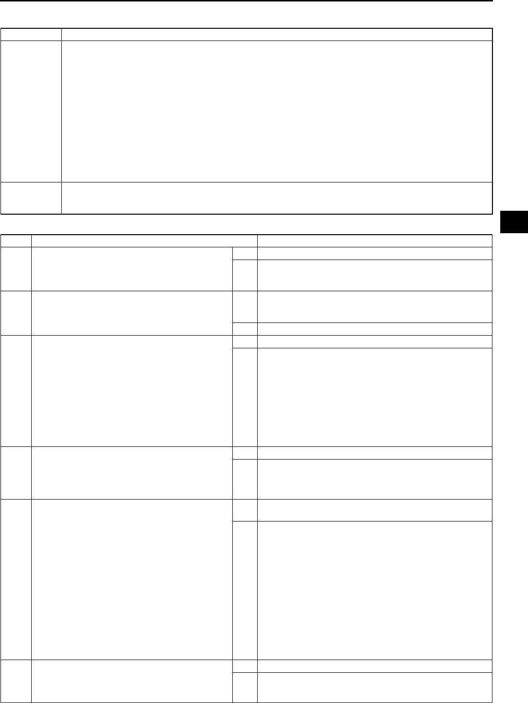
ON-BOARD DIAGNOSTIC
K63
K
DTC P0711 A6E567001030W09
Diagnostic procedure
DTC P0711 Transaxle fluid temperature (TFT) sensor circuit range/performance (stuck)
DETECTION
CONDITION
•When all conditions below are satisfied.
When 180 seconds have passed after engine is started, vehicle is driven for 150 seconds or more at
vehicle speed between 25 59 km/h {15 36 mph}, then 60 km/h {37 mph} or more for 100 seconds
or more.
P0712, P0713 not output.
Variation in ATF voltage below 0.06 V.
Diagnostic support note:
•This is a continuous monitor (CCM).
•MIL illuminates if PCM detects the above malfunction condition in two consecutive drive cycles or in one
drive cycle while the DTC for the same malfunction has been stored in the PCM.
•PENDING CODE is available if PCM detects the above malfunction condition during first drive cycle.
•FREEZE FRAME DATA is available.
•HOLD indicator light does not flash.
•DTC is stored in the PCM memory.
POSSIBLE
CAUSE
•TFT sensor malfunction
•Connector corrosion
•PCM malfunction
STEP INSPECTION ACTION
1VERIFY FREEZE FRAME DATA HAS BEEN
RECORDED
•Has FREEZE FRAME PID DATA been
recorded?
Yes Go to next step.
No Record FREEZE FRAME PID DATA on repair order, then
go to next step.
2VERIFY RELATED REPAIR INFORMATION
AVAILABILITY
•Check for related Service Bulletins availability.
•Is any related repair information available?
Yes Perform repair or diagnosis according to available repair
information.
•If vehicle is not repaired, go to next step.
No Go to next step.
3INSPECT TFT SENSOR VOLTAGE
•Turn ignition key to OFF.
•Connect breakout box to PCM.
•Turn ignition key to ON (engine OFF).
•Measure the voltage at PCM terminal 3D.
•Record terminal 3D voltage.
•Start engine.
•Drive vehicle at 60 km/h {37 mph} or above
for 430 seconds or more.
•Record terminal 3D voltage again.
•Is variation in voltage 0.06V or above?
Yes Go to Step 5.
No Go to next step.
4INSPECT TERMINAL CONDITION
•Turn ignition key to OFF.
•Disconnect ATX connector.
•Inspect terminals for corrosion.
•Are terminals okay?
Yes Go to next step.
No Repair or replace terminals, then go to next step.
5VERIFY TROUBLESHOOTING OF DTC P0711
COMPLETED
•Make sure to reconnect all disconnected
connectors.
•Clear DTC from memory using WDS or
equivalent.
•Decrease ATF temperature to 20 °
°°
°C {68 °
°°
°F} or
below.
•Start engine and wait for 180 seconds or
more.
•Drive vehicle at a vehicle speed between 25
59 km/h {15 36 mph} for 150 seconds or
more.
•Drive vehicle at vehicle speed 60 km/h {37
mph} or above for 100 seconds or more.
•Is pending code present?
Yes Replace PCM, then go to next step.
(See F43 PCM REMOVAL/INSTALLATION.)
No Go to next step.
6VERIFY AFTER REPAIR PROCEDURE
•Perform After Repair Procedure.
(See K52 AFTER REPAIR PROCEDURE.)
•Are any DTCs present?
Yes Go to applicable DTC inspection.
No Troubleshooting completed.
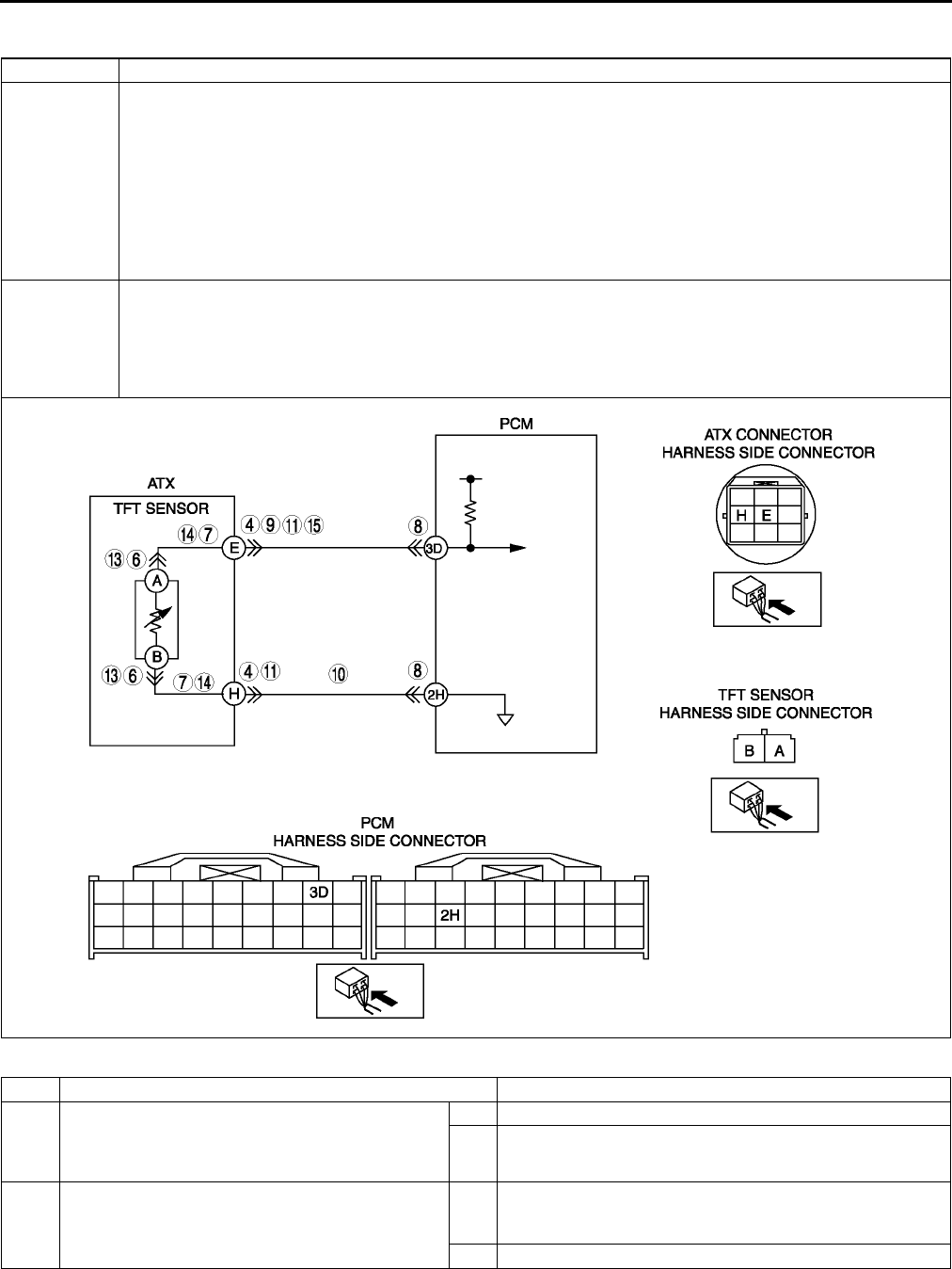
K64
ON-BOARD DIAGNOSTIC
End Of Sie
DTC P0712 A6E567001030W10
Diagnostic procedure
DTC P0712 Transaxle fluid temperature (TFT) sensor circuit malfunction (short to ground)
DETECTION
CONDITION
•If PCM detects either of following conditions for 150 seconds or more, PCM determines that TFT sensor
circuit has a malfunction.
TFT sensor voltage is 0.06 V or below and vehicle speed 20 km/h {12 mph} or above.
Diagnostic support note:
•This is a continuous monitor (CCM).
•MIL illuminates if PCM detects the above malfunction conditions during first drive cycle.
•PENDING CODE is not available.
•FREEZE FRAME DATA is available.
•HOLD indicator light flashes.
•DTC is stored in the PCM memory.
POSSIBLE
CAUSE
•TFT sensor malfunction
•Short to ground between TFT sensor terminal A and ATX connector terminal E
•Short to ground between TFT sensor terminal B and ATX connector terminal H
•Short to ground between ATX connector terminal E and PCM terminal 3D
•Damaged connectors between TFT sensor and PCM
•PCM malfunction
STEP INSPECTION ACTION
1VERIFY FREEZE FRAME DATA HAS BEEN
RECORDED
•Has FREEZE FRAME PID DATA been
recorded?
Yes Go to next step.
No Record FREEZE FRAME PID DATA on repair order, then
go to next step.
2VERIFY RELATED REPAIR INFORMATION
AVAILABILITY
•Check for related Service Bulletins availability.
•Is any related repair information available?
Yes Perform repair or diagnosis according to available repair
information.
•If vehicle is not repaired, go to next step.
No Go to next step.

ON-BOARD DIAGNOSTIC
K65
K
End Of Sie
DTC P0713 A6E567001030W11
3VERIFY CURRENT INPUT SIGNAL STATUS
•Turn ignition key to OFF.
•Connect breakout box to PCM.
•Turn ignition key to ON (engine OFF).
•Measure the voltage at PCM terminal 3D.
•Are voltage readings above 0.06 V?
Yes Go to intermittent concern troubleshooting procedure.
(See F227 INTERMITTENT CONCERN
TROUBLESHOOTING.)
No Go to next step.
4INSPECT TERMINAL CONDITION
•Turn ignition key to OFF.
•Disconnect ATX connector.
•Inspect for bent terminals.
•Are the terminals bent?
Yes Repair or replace terminals, then go to Step 9.
•If terminals cannot be repaired, replace harness, then
go to Step 9.
No Go to next step.
5INSPECT TFT SENSOR CIRCUIT
•Turn ignition key to ON (engine OFF).
•Verify if voltage changes to 4.67 V or above at
PCM terminal 3D when ATX connector
disconnected.
•Does voltage change?
Yes Go to next step.
No Go to Step 8.
6INSPECT TFT SENSOR TERMINALS
CONDITION
•Turn ignition key to OFF.
•Disconnect TFT sensor connector.
•Inspect for bent TFT sensor terminals.
•Are the terminals bent?
Yes Repair terminals or replace TFT sensor, then go to Step 9.
(See K21 TRANSAXLE FLUID TEMPERATURE (TFT)
SENSOR REMOVAL/INSTALLATION.)
No Go to next step.
7INSPECT TFT SENSOR CIRCUIT FOR SHORT
TO GROUND
•Inspect for continuity between TFT sensor
terminals (harness-side) and body ground.
A and body ground
B and body ground
•Is there continuity?
Yes Repair or replace harness, then go to Step 9.
No Replace TFT sensor, then go to step 9.
(See K21 TRANSAXLE FLUID TEMPERATURE (TFT)
SENSOR REMOVAL/INSTALLATION.)
8INSPECT ATX CONNECTOR CIRCUIT FOR
SHORT TO GROUND
•Turn ignition key to OFF.
•Inspect for continuity between ATX connector
terminal E (vehicle harness-side) and body
ground.
•Is there continuity?
Yes Repair or replace harness, then go to next step.
No Go to next step.
9VERIFY TROUBLESHOOTING OF DTC P0712
COMPLETED
•Make sure to reconnect all disconnected
connectors.
•Clear DTC from memory using WDS or
equivalent.
•Drive vehicle under following condition for 150
seconds or more.
Vehicle speed (VSS PID) 20 km/h {12 mph}
or above.
•Is same DTC present?
Yes Replace PCM, then go to next step.
(See F43 PCM REMOVAL/INSTALLATION.)
No Go to next step.
10 VERIFY AFTER REPAIR PROCEDURE
•Perform After Repair Procedure.
(See K52 AFTER REPAIR PROCEDURE.)
•Are any DTCs present?
Yes Go to applicable DTC inspection.
No Troubleshooting completed.
STEP INSPECTION ACTION
DTC P0713 Transaxle fluid temperature (TFT) sensor circuit malfunction (open circuit)
DETECTION
CONDITION
•If PCM detects either of following conditions for 150 seconds or more, PCM determines that TFT sensor
circuit has a malfunction.
TFT sensor voltage is 4.67 V or above and vehicle speed 20 km/h {12 mph} or above.
Diagnostic support note:
•This is a continuous monitor (CCM).
•MIL illuminates if PCM detects the above malfunction conditions during first drive cycle.
•PENDING CODE is not available.
•FREEZE FRAME DATA is available.
•HOLD indicator light flashes.
•DTC is stored in the PCM memory.
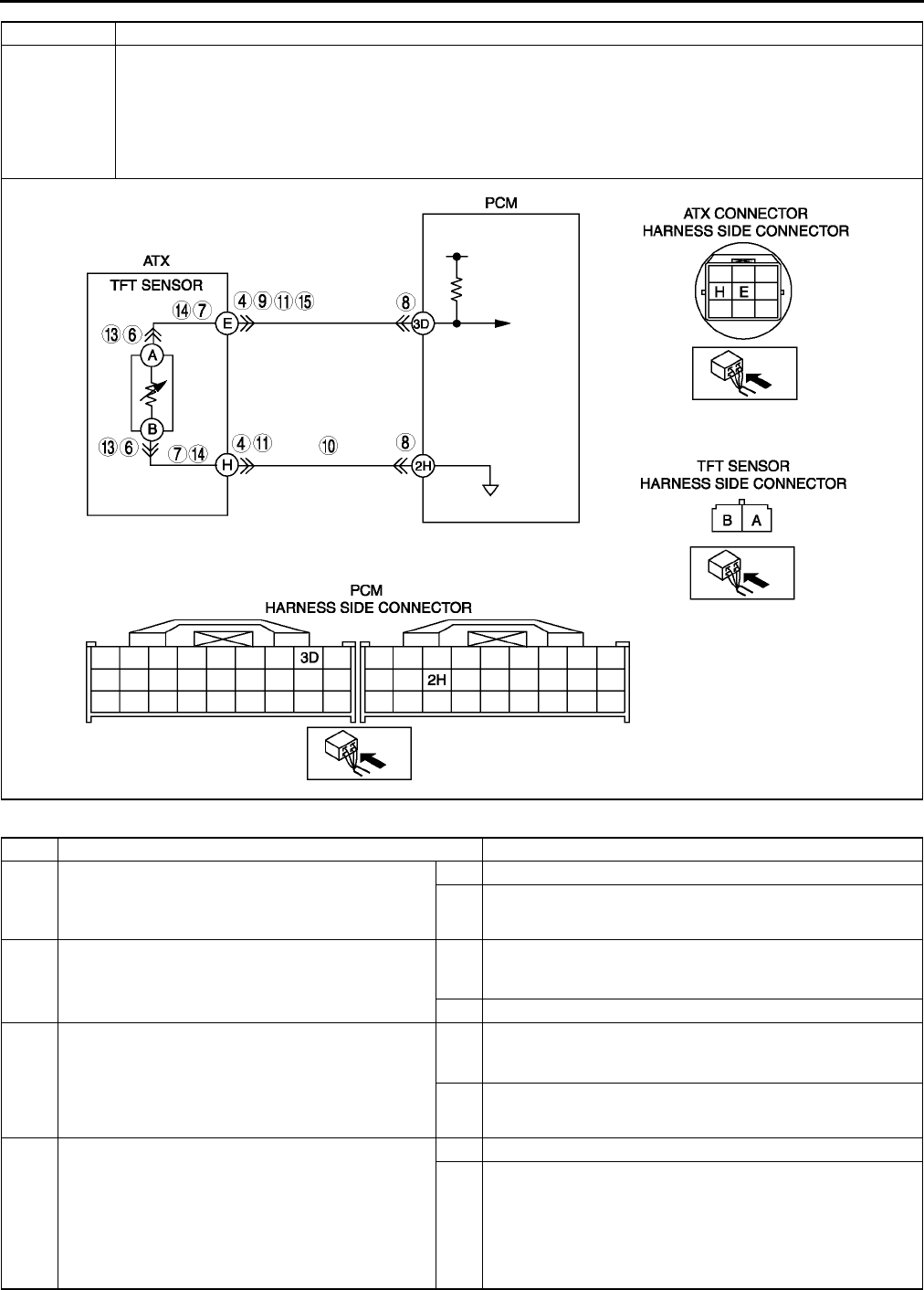
K66
ON-BOARD DIAGNOSTIC
Diagnostic procedure
POSSIBLE
CAUSE
•TFT sensor malfunction
•Open circuit between TFT sensor terminal A and ATX connector terminal E
•Open circuit between TFT sensor terminal B and ATX connector terminal H
•Open circuit between ATX connector terminal E and PCM terminal 3D
•Open circuit between ATX connector terminal H and PCM terminal 2H
•Damaged connectors between TFT sensor and PCM
•PCM malfunction
STEP INSPECTION ACTION
1VERIFY FREEZE FRAME DATA HAS BEEN
RECORDED
•Has FREEZE FRAME PID DATA been
recorded?
Yes Go to next step.
No Record FREEZE FRAME PID DATA on repair order, then
go to next step.
2VERIFY RELATED REPAIR INFORMATION
AVAILABILITY
•Check for related Service Bulletins availability.
•Is any related repair information available?
Yes Perform repair or diagnosis according to available repair
information.
•If vehicle is not repaired, go to next step.
No Go to next step.
3VERIFY CURRENT INPUT SIGNAL STATUS
•Turn ignition key to OFF.
•Connect breakout box to PCM.
•Turn ignition key to ON (engine OFF).
•Measure the voltage at PCM terminal 3D.
•Are voltage readings below 4.67 V?
Yes Go to intermittent concern troubleshooting procedure.
(See F227 INTERMITTENT CONCERN
TROUBLESHOOTING.)
No Go to next step.
4INSPECT ATX CONNECTOR FOR POOR
CONNECTION
•Turn ignition key to OFF.
•Inspect ATX connector connection.
•Disconnect ATX connector.
•Check for poor connection (damaged/pulled-
out terminals, corrosion etc.).
•Is connection okay?
Yes Go to next step.
No Repair or replace connector and/or terminal, then go to
Step 11.
DTC P0713 Transaxle fluid temperature (TFT) sensor circuit malfunction (open circuit)

ON-BOARD DIAGNOSTIC
K67
K
End Of Sie
5INSPECT TFT SENSOR CIRCUIT
•Turn ignition key to ON (engine OFF).
•Measure the voltage at PCM terminal 3D when
connect between ATX connector terminals E
and H (vehicle harness-side) using jumper
wire.
•Verify that voltage changes to 0.06 V or below.
•Does voltage change?
Yes Go to next step.
No Go to Step 8.
6INSPECT TFT SENSOR CONNECTOR FOR
POOR CONNECTION
•Turn ignition key to OFF.
•Remove valve body cover.
•Disconnect TFT sensor connector.
•Check for poor connection (damaged/pulled-
out terminals, corrosion, etc.).
•Is connection okay?
Yes Go to next step.
No Repair or replace connector and/or terminal or replace TFT
sensor, then go to Step 11.
(See K21 TRANSAXLE FLUID TEMPERATURE (TFT)
SENSOR REMOVAL/INSTALLATION.)
7INSPECT TFT SENSOR CIRCUIT FOR OPEN
•Check for continuity between TFT sensor
terminals (harness-side) and ATX connector
terminals (transaxle case side).
ATX connector terminal E and TFT sensor
terminal A
ATX connector terminal H and TFT sensor
terminal B
•Is there continuity?
Yes Replace TFT sensor, then go to Step 11.
(See K21 TRANSAXLE FLUID TEMPERATURE (TFT)
SENSOR REMOVAL/INSTALLATION.)
No Repair or replace harness, then go to Step 11.
8INSPECT PCM CONNECTOR FOR POOR
CONNECTION
•Turn ignition key to OFF.
•Disconnect PCM connector.
•Check for poor connection (damaged/pulled-
out terminals, corrosion, etc.).
•Is connection okay?
Yes Go to next step.
No Repair or replace connector and/or terminal, then go to
Step 11.
9INSPECT HARNESS FOR OPEN CIRCUIT
•Disconnect ATX connector.
•Connect the PCM connector.
•Turn ignition key to ON (engine OFF).
•Inspect voltage at ATX connector terminal E
(vehicle harness-side).
•Is voltage 5 V?
Yes Go to next step.
No Repair or replace harness, then go to Step 11.
10 INSPECT ATX CONNECTOR CIRCUIT FOR
OPEN
•Turn ignition key to OFF.
•Inspect continuity between ATX connector
terminal H (vehicle harness-side) and body
ground.
•Is there continuity?
Yes Go to next step.
No Repair or replace harness, then go to next step.
11 VERIFY TROUBLESHOOTING OF DTC P0713
COMPLETED
•Make sure to reconnect all disconnected
connectors.
•Clear DTC from memory using WDS or
equivalent.
•Drive vehicle under following condition for 150
seconds or more.
Vehicle speed (VSS PID) 20 km/h {12 mph}
or above.
•Is same DTC present?
Yes Replace PCM, then go to next step.
(See F43 PCM REMOVAL/INSTALLATION.)
No Go to next step.
12 VERIFY AFTER REPAIR PROCEDURE
•Perform After Repair Procedure.
(See K52 AFTER REPAIR PROCEDURE.)
•Are any DTCs present?
Yes Go to applicable DTC inspection.
No Troubleshooting completed.
STEP INSPECTION ACTION
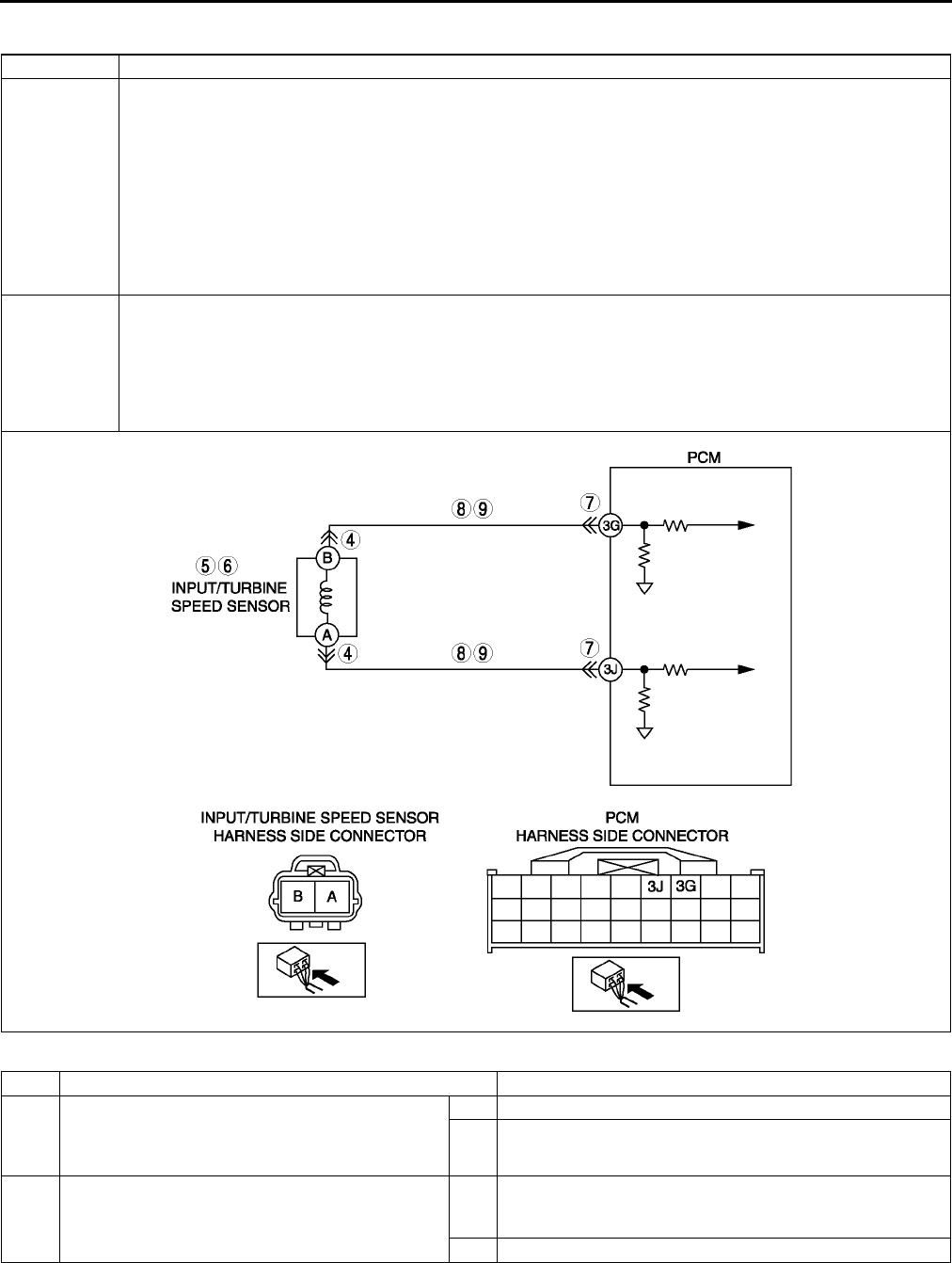
K68
ON-BOARD DIAGNOSTIC
DTC P0715 A6E567001030W12
Diagnostic procedure
DTC P0715 Input/turbine speed sensor circuit malfunction
DETECTION
CONDITION
•When all conditions below satisfied and 0.7 second or more have passed.
D, S or L range of TR switch input.
Driving vehicle with vehicle speed 40 km/h {25 mph} or above.
Input/turbine speed sensor signal not input.
Diagnostic support note:
•This is a continuous monitor (CCM).
•MIL illuminates if PCM detects the above malfunction conditions during first drive cycle.
•PENDING CODE is not available.
•FREEZE FRAME DATA is available.
•HOLD indicator light flashes.
•DTC is stored in the PCM memory.
POSSIBLE
CAUSE
•Input/turbine speed sensor malfunction
•Short to ground between input/turbine speed sensor terminal A and PCM terminal 3J
•Short to ground between input/turbine speed sensor terminal B and PCM terminal 3G
•Open circuit between input/turbine speed sensor terminal A and PCM terminal 3J
•Open circuit between input/turbine speed sensor terminal B and PCM terminal 3G
•Damaged connectors between input/turbine speed sensor and PCM
•PCM malfunction
STEP INSPECTION ACTION
1VERIFY FREEZE FRAME DATA HAS BEEN
RECORDED
•Has FREEZE FRAME PID DATA been
recorded?
Yes Go to next step.
No Record FREEZE FRAME PID DATA on repair order, then
go to next step.
2VERIFY RELATED REPAIR INFORMATION
AVAILABILITY
•Check for related Service Bulletins availability.
•Is any related repair information available?
Yes Perform repair or diagnosis according to available repair
information.
•If vehicle is not repaired, go to next step.
No Go to next step.

ON-BOARD DIAGNOSTIC
K69
K
End Of Sie
3VERIFY CURRENT INPUT SIGNAL STATUS
•Turn ignition key to OFF.
•Start engine.
•Measure frequency of input/turbine speed
sensor using a oscilloscope.
IG ON: 0 Hz
Idle: Within 320374 Hz (P, N position)
•Are frequency of input/turbine speed sensor
readings within specifications?
Yes Go to intermittent concern troubleshooting procedure.
(See F227 INTERMITTENT CONCERN
TROUBLESHOOTING.)
No Go to next step.
4INSPECT INPUT/TURBINE SPEED SENSOR
CONNECTOR FOR POOR CONNECTION
•Turn ignition key to OFF.
•Disconnect input/turbine speed sensor
connector.
•Check for poor connection (damaged/pulled-
out terminals, corrosion, etc.).
•Is connection okay?
Yes Go to next step.
No Repair or replace connector and/or terminals, then go to
Step 10.
5INSPECT INPUT/TURBINE SPEED SENSOR
RESISTANCE
•Measure resistance between input/turbine
speed sensor terminals (part-side).
•Is resistance within 250600 ohms between
input/turbine speed sensor terminals (part-
side)?
(See K23 INPUT/TURBINE SPEED SENSOR
INSPECTION.)
Yes Go to next step.
No Replace input/turbine speed sensor, then go to Step 10.
(See K24 INPUT/TURBINE SPEED SENSOR REMOVAL/
INSTALLATION.)
6INSPECT INPUT/TURBINE SPEED SENSOR
•Remove input/turbine speed sensor.
•Is there iron powder stuck on input/turbine
speed sensor?
(See K24 INPUT/TURBINE SPEED SENSOR
REMOVAL/INSTALLATION.)
Yes Clean input/turbine speed sensor, then go to Step 10.
No Go to next step.
7INSPECT PCM CONNECTOR FOR POOR
CONNECTION
•Disconnect PCM connector.
•Check for poor connection (damaged/pulled-
out terminals, corrosion, etc.).
•Is connection okay?
Yes Go to next step.
No Repair or replace connector and/or terminals, then go to
Step 10.
8INSPECT INPUT/TURBINE SPEED SENSOR
CIRCUIT FOR OPEN
•Inspect input/turbine speed sensor terminals
(harness-side) and PCM terminals (harness-
side).
A and 3J
B and 3G
•Is there continuity?
Yes Go to next step.
No Repair or replace harness, then go to Step 10.
9INSPECT INPUT/TURBINE SPEED SENSOR
CIRCUIT FOR SHORT TO GROUND
•Inspect input/turbine speed sensor terminal
(harness-side) and body ground.
A and body ground
B and body ground
•Is there continuity?
Yes Repair or replace harness, then go to next step.
No Go to next step.
10 VERIFY TROUBLESHOOTING OF DTC P0715
COMPLETED
•Make sure to reconnect all disconnected
connectors.
•Clear DTC from memory using WDS or
equivalent.
•Drive vehicle with vehicle speed 40 km/h {25
mph} or above for 0.7 second or more.
•Is same DTC present?
Yes Replace PCM, then go to next step.
(See F43 PCM REMOVAL/INSTALLATION.)
No Go to next step.
11 VERIFY AFTER REPAIR PROCEDURE
•Perform After Repair Procedure.
(See K52 AFTER REPAIR PROCEDURE.)
•Are any DTCs present?
Yes Go to applicable DTC inspection.
No Troubleshooting completed.
STEP INSPECTION ACTION

K70
ON-BOARD DIAGNOSTIC
DTC P0731 A6E567001030W13
Diagnostic procedure
DTC P0731 Gear 1 incorrect (Incorrect Gear Ratio Detected)
DETECTION
CONDITION
•PCM monitors revolution ratio of forward clutch drum revolution to differential gear case revolution when
the following monitoring conditions are met. If revolution ratio is below 2.157, PCM determines that there is
malfunction.
Monitoring condition:
ATF temperature 20 °
°°
°C {68 °
°°
°F} or above.
Driving in 1GR in D range.
Engine run.
Turbine speed within 2254,988 rpm.
Throttle opening angle 5.67% or above
Differential gear case (output) revolution speed 35 rpm or above.
Any of the following not generated: DTC P0500, P0706, P0707, P0708, P0712, P0713, P0715, P0751,
P0752, P0753, P0756, P0757, P0758, P0761, P0762, P0763, P0766, P0767, P0768, P0771, P0772,
P0773.
Diagnostic support note:
•This is a continuous monitor (CCM).
•MIL does not illuminate.
•HOLD indicator light flashes if PCM detects the above malfunction condition during first drive cycle.
•FREEZE FRAME DATA is not available.
•Pending code is not available.
•DTC stored in the PCM memory.
POSSIBLE
CAUSE
•ATF level low
•Deteriorated ATF
•Shift solenoid A stuck
•Pressure control solenoid stuck
•Line pressure low
•One-way clutch slipping
•Forward clutch slipping
•Control valve stuck
•Oil pump
•PCM malfunction
STEP INSPECTION ACTION
1VERIFY RELATED REPAIR INFORMATION
AVAILABILITY
•Check for related Service Bulletins availability.
•Is any related repair information available?
Yes Perform repair or diagnosis according to available repair
information.
No Go to next step.
2CHECK ATF CONDITION
•Check ATF condition.
(See K12 AUTOMATIC TRANSAXLE FLUID
(ATF) INSPECTION.)
•Is it okay?
Yes Go to next step.
No Replace ATF, then go to Step 8.
3CHECK ATF LEVEL
•Start engine.
•Warm up ATX.
•Is ATF level within specification?
(See K12 AUTOMATIC TRANSAXLE FLUID
(ATF) INSPECTION.)
Yes Go to next step.
No Adjust ATF level, then go to Step 8.
4INSPECT SHIFT SOLENOID VALVE A
•Perform inspection of operation. (See K26
SOLENOID VALVE INSPECTION.)
•Verify the click sound of shift solenoid A when
applying B+ to transaxle connector terminal A.
•Was click heard from solenoids?
Yes Go to next step.
No Replace solenoid that you could not hear click sound, then
go to Step 8.
(See K28 SOLENOID VALVE REMOVAL/
INSTALLATION.)
5INSPECT LINE PRESSURE
•Start engine.
•Measure line pressures.
Specification
Idle: 330470 kPa {3.44.7 kgf/cm2, 4966
psi}
Stall: 1,1601,320 kPa {11.913.4 kgf/cm2,
170190 psi}
•Is line pressure within specification?
(See K6 Line Pressure Test.)
Yes Go to next step.
No All ranges: Replace oil pump, then go to Step 8.
Any ranges: Replace control valve body, then go to Step 8.
(See K34 CONTROL VALVE BODY REMOVAL, K35
CONTROL VALVE BODY INSTALLATION.)

ON-BOARD DIAGNOSTIC
K71
K
End Of Sie
DTC P0732 A6E567001030W14
6INSPECT STALL SPEED
•Measure stall speed in D range.
(See K7 Stall Test.)
Specification
2,0002,600 rpm
•Is stall speed within specification?
Yes Go to next step.
No Replace automatic transaxle, then go to Step8.
(See K29 AUTOMATIC TRANSAXLE REMOVAL/
INSTALLATION.)
7INSPECT FREQUENCY OF INPUT/TURBINE
SPEED SENSOR WHEN DRIVING VEHICLE
•Turn ignition key to OFF.
•Connect WDS or equivalent.
•Start engine.
•Measure frequency of input/turbine speed
sensor while driving vehicle under the following
conditions:
Vehicle speed (VSS PID): 20 km/h {12
mph}
Drive in D range, 1st gear
Throttle opening angle (TP PID): about 25%
•Was frequency of input/turbine speed sensor at
approx. 1,100 Hz?
Yes Go to next step.
No Replace control valve body, then go to next step.
(See K34 CONTROL VALVE BODY REMOVAL, K35
CONTROL VALVE BODY INSTALLATION.)
8VERIFY REPAIR OF DTC P0731
•Make sure to reconnect all disconnected
connectors.
•Clear DTC using WDS or equivalent.
•Start engine.
•Warm up transaxle.
•Drive vehicle under the following conditions at
least 4 times for more than 1 second.
ATF temperature: 20 °
°°
°C {68 °
°°
°F} or above
Drive in D range, 1st gear
Throttle opening angle (TP PID): 5.67% or
above
Vehicle speed (VSS PID): 4 km/h {3 mph}
or above
•Are any DTCs present?
Yes Replace PCM, then go to next step.
No Go to next step.
9VERIFY AFTER REPAIR PROCEDURE
•Perform After Repair Procedure.
(See K52 AFTER REPAIR PROCEDURE.)
•Are any DTCs present?
Yes Go to applicable DTC inspection.
No Troubleshooting completed.
STEP INSPECTION ACTION
DTC P0732 Gear 2 incorrect (Incorrect Gear Ratio Detected)
DETECTION
CONDITION
•PCM monitors revolution ratio of forward clutch drum revolution to differential gear case revolution when
the following monitoring conditions are met. If revolution ratio is below 1.249 or above 2.157, PCM
determines that there is malfunction.
Monitoring condition:
ATF temperature 20 °
°°
°C {68 °
°°
°F} or above.
Driving in 2 GR in D range.
Engine run.
Turbine speed within 2254,988 rpm.
Differential gear case (output) revolution speed 35 rpm or above.
Any of the following not generated: DTC P0500, P0706, P0707, P0708, P0712, P0713, P0715, P0751,
P0752, P0753, P0756, P0757, P0758, P0761, P0762, P0763, P0766, P0767, P0768, P0771, P0772,
P0773.
Diagnostic support note:
•This is a continuous monitor (CCM).
•MIL does not illuminate.
•HOLD indicator light flashes if PCM detects the above malfunction condition during first drive cycle.
•FREEZE FRAME DATA is not available.
•Pending code is not available.
•DTC stored in the PCM memory.

K72
ON-BOARD DIAGNOSTIC
Diagnostic procedure
POSSIBLE
CAUSE
•ATF level low
•Deteriorated ATF
•Shift solenoids A, B or C stuck
•Pressure control solenoid stuck
•Line pressure low
•2-4 brake band slipping
•Forward clutch slipping
•Control valve stuck
•Oil pump
•PCM malfunction
STEP INSPECTION ACTION
1VERIFY RELATED REPAIR INFORMATION
AVAILABILITY
•Check for related Service Bulletins availability.
•Is any related repair information available?
Yes Perform repair or diagnosis according to available repair
information.
No Go to next step.
2CHECK ATF CONDITION
•Check ATF condition.
(See K12 AUTOMATIC TRANSAXLE FLUID
(ATF) INSPECTION.)
•Is it okay?
Yes Go to next step.
No Replace ATF, then go to Step 8.
3CHECK ATF LEVEL
•Start engine.
•Warm up ATX.
•Is ATF level within specification?
(See K12 AUTOMATIC TRANSAXLE FLUID
(ATF) INSPECTION.)
Yes Go to next step.
No Adjust ATF level, then go to Step 8.
4INSPECTION SHIFT SOLENOID VALVE A, B
AND C FOR CLICK SOUND
•Perform inspection of operation. (See K26
SOLENOID VALVE INSPECTION.)
•Verify the click sound of shift solenoid A, B,
and C when applying B+ to each transaxle
connector terminal.
•Was click heard from solenoids?
Yes Go to next step.
No Replace solenoid that you could not hear click sound, then
go to Step 8.
(See K28 SOLENOID VALVE REMOVAL/
INSTALLATION.)
5INSPECT LINE PRESSURE
•Start engine.
•Measure line pressures.
Specification
Idle: 330470 kPa {3.44.7 kgf/cm2, 4966
psi}
Stall: 1,1601,320 kPa {11.913.4 kgf/cm2,
170190 psi}
•Is line pressure within specification?
(See K6 Line Pressure Test.)
Yes Go to next step.
No All ranges: Replace oil pump, then go to Step 8.
Any ranges: Replace control valve body, then go to Step 8.
(See K34 CONTROL VALVE BODY REMOVAL, K35
CONTROL VALVE BODY INSTALLATION.)
6INSPECT STALL SPEED
•Measure stall speed in D range.
(See K7 Stall Test.)
Specification
2,0002,600 rpm
•Is stall speed within specification?
Yes Go to next step.
No Replace automatic transaxle, then go to Step8.
(See K29 AUTOMATIC TRANSAXLE REMOVAL/
INSTALLATION.)
7INSPECT FREQUENCY OF INPUT/TURBINE
SPEED SENSOR WHEN DRIVING VEHICLE
•Turn ignition key to OFF.
•Connect WDS or equivalent.
•Start engine.
•Measure frequency of input/turbine speed
sensor while driving vehicle under the following
conditions:
Vehicle speed: 40 km/h {24 mph} (VSS
PID)
Drive in D range, 2nd gear
Throttle opening angle: about 25% (TP PID)
•Was frequency of input/turbine speed sensor at
approx. 1,156 Hz?
Yes Go to next step.
No Replace control valve body, then go to next step.
(See K34 CONTROL VALVE BODY REMOVAL, K35
CONTROL VALVE BODY INSTALLATION.)
DTC P0732 Gear 2 incorrect (Incorrect Gear Ratio Detected)
ON-BOARD DIAGNOSTIC
K73
K
End Of Sie
DTC P0733 A6E567001030W15
Diagnostic procedure
8VERIFY REPAIR OF DTC P0732
•Make sure to reconnect all disconnected
connectors.
•Clear DTC using WDS or equivalent.
•Start engine.
•Warm up transaxle.
•Drive vehicle under the following conditions at
least 4 times for more than 1 seconds.
ATF temperature: 20 °
°°
°C {68 °
°°
°F} or above
Drive in D range, 2nd gear
Vehicle speed (VSS PID): 3.8 km/h {2.4
mph} or above
•Are any DTCs present?
Yes Replace PCM, then go to next step.
No Go to next step.
9VERIFY AFTER REPAIR PROCEDURE
•Perform After Repair Procedure.
(See K52 AFTER REPAIR PROCEDURE.)
•Are any DTCs present?
Yes Go to applicable DTC inspection.
No Troubleshooting completed.
STEP INSPECTION ACTION
DTC P0733 Gear 3 incorrect (Incorrect Gear Ratio Detected)
DETECTION
CONDITION
•PCM monitors revolution ratio of forward clutch drum revolution to differential gear case revolution when
the following monitoring conditions are met. If revolution ratio is below 0.863 or above 1.249, PCM
determines that there is malfunction.
Monitoring condition:
ATF temperature 20 °
°°
°C {68 °
°°
°F} or above.
Driving in 3 GR in D range.
Engine run.
Turbine speed within 2254,988 rpm.
Differential gear case (output) revolution speed 35 rpm or above.
Any of the following not generated: DTC P0500, P0706, P0707, P0708, P0712, P0713, P0715, P0751,
P0752, P0753, P0756, P0757, P0758, P0761, P0762, P0763, P0766, P0767, P0768, P0771, P0772,
P0773.
Diagnostic support note:
•This is a continuous monitor (CCM).
•MIL does not illuminate.
•HOLD indicator light flashes if PCM detects the above malfunction condition during first drive cycle.
•FREEZE FRAME DATA is not available.
•Pending code is not available.
•DTC stored in the PCM memory.
POSSIBLE
CAUSE
•ATF level low
•Deteriorated ATF
•Shift solenoids A or C stuck
•Pressure control solenoid stuck
•Line pressure low
•3-4 clutch slipping
•Forward clutch slipping
•Control valve stuck (Bypass, TCC or 3-4 shift valve)
•Oil pump
•PCM malfunction
STEP INSPECTION ACTION
1VERIFY RELATED REPAIR INFORMATION
AVAILABILITY
•Check for related Service Bulletins availability.
•Is any related repair information available?
Yes Perform repair or diagnosis according to available repair
information.
No Go to next step.
2CHECK ATF CONDITION
•Check ATF condition.
(See K12 AUTOMATIC TRANSAXLE FLUID
(ATF) INSPECTION.)
•Is it okay?
Yes Go to next step.
No Replace ATF, then go to Step 8.

K74
ON-BOARD DIAGNOSTIC
End Of Sie
3CHECK ATF LEVEL
•Start engine.
•Warm up ATX.
•Is ATF level within specification?
(See K12 AUTOMATIC TRANSAXLE FLUID
(ATF) INSPECTION.)
Yes Go to next step.
No Adjust ATF level, then go to Step 8.
4INSPECTION SHIFT SOLENOID VALVE A AND
C FOR CLICK SOUND
•Perform inspection of operation. (See K26
SOLENOID VALVE INSPECTION.)
•Verify the click sound of shift solenoid A and C
when applying B+ to each transaxle connector
terminal.
•Was click heard from solenoids?
Yes Go to next step.
No Replace solenoid that you could not hear click sound, then
go to Step 8.
(See K28 SOLENOID VALVE REMOVAL/
INSTALLATION.)
5INSPECT LINE PRESSURE
•Start engine.
•Measure line pressures.
Specification
Idle: 330470 kPa {3.44.7 kgf/cm2, 4966
psi}
Stall: 1,1601,320 kPa {11.913.4 kgf/cm2,
170190 psi}
•Is line pressure within specification?
(See K6 Line Pressure Test.)
Yes Go to next step.
No All ranges: Replace oil pump, then go to Step 8.
Any ranges: Replace control valve body, then go to Step 8.
(See K34 CONTROL VALVE BODY REMOVAL, K35
CONTROL VALVE BODY INSTALLATION.)
6INSPECT STALL SPEED
•Measure stall speed in D range.
(See K7 Stall Test.)
Specification
2,0002,600 rpm
•Is stall speed within specification?
Yes Go to next step.
No Replace automatic transaxle, then go to Step 8.
(See K29 AUTOMATIC TRANSAXLE REMOVAL/
INSTALLATION.)
7INSPECT FREQUENCY OF INPUT/TURBINE
SPEED SENSOR WHEN DRIVING VEHICLE
•Turn ignition key to OFF.
•Connect WDS or equivalent.
•Start engine.
•Measure frequency of input/turbine speed
sensor while driving vehicle under the following
conditions:
Vehicle speed (VSS PID): 60 km/h {37
mph}
Drive in D range, 3rd gear
Throttle opening angle (TP PID): about 25%
•Was frequency of input/turbine speed sensor at
approx. 1,200 Hz?
Yes Go to next step.
No Replace control valve body, then go to next step.
(See K34 CONTROL VALVE BODY REMOVAL, K35
CONTROL VALVE BODY INSTALLATION.)
8VERIFY REPAIR OF DTC P0733
•Make sure to reconnect all disconnected
connectors.
•Clear DTC using WDS or equivalent.
•Start engine.
•Warm up transaxle.
•Drive vehicle under the following conditions for
more than 2 seconds.
ATF temperature: 20 °
°°
°C {68 °
°°
°F} or above
Drive in D range, 3rd gear
Vehicle speed (VSS PID): 4 km/h {3 mph}
or above
•Are any DTCs present?
Yes Replace PCM, then go to next step.
No Go to next step.
9VERIFY AFTER REPAIR PROCEDURE
•Perform After Repair Procedure.
(See K52 AFTER REPAIR PROCEDURE.)
•Are any DTCs present?
Yes Go to applicable DTC inspection.
No Troubleshooting completed.
STEP INSPECTION ACTION
ON-BOARD DIAGNOSTIC
K75
K
DTC P0734 A6E567001030W16
Diagnostic procedure
DTC P0734 Gear 4 incorrect (Incorrect Gear Ratio Detected)
DETECTION
CONDITION
•PCM monitors revolution ratio of forward clutch drum revolution to differential gear case revolution when
the following monitoring conditions are met. If revolution ratio is below 0.6 or above 1.249, PCM
determines that there is malfunction.
Monitoring condition:
ATF temperature 20 °
°°
°C {68 °
°°
°F} or above.
Driving in 4 GR in D range.
Engine run.
Turbine speed within 2254,988 rpm.
Vehicle speed 50 km/h {31 mph} or above.
Closed throttle position.
Differential gear case (output) revolution speed 35 rpm or above.
Any of the following not generated: DTC P0500, P0706, P0707, P0708, P0712, P0713, P0715, P0751,
P0752, P0753, P0756, P0757, P0758, P0761, P0762, P0763, P0766, P0767, P0768, P0771, P0772,
P0773.
Diagnostic support note:
•This is a continuous monitor (CCM).
•MIL does not illuminate.
•HOLD indicator light flashes if PCM detects the above malfunction condition during first drive cycle.
•FREEZE FRAME DATA is not available.
•Pending code is not available.
•DTC stored in the PCM memory.
POSSIBLE
CAUSE
•ATF level low
•Deteriorated ATF
•Shift solenoids A, B or C stuck
•Pressure control solenoid stuck
•Line pressure low
•2-4 brake band slipping
•3-4 clutch slipping
•Forward clutch slipping
•Control valve stuck (Bypass or 3-4 shift valve)
•Oil pump
•PCM malfunction
STEP INSPECTION ACTION
1VERIFY RELATED REPAIR INFORMATION
AVAILABILITY
•Check for related Service Bulletins availability.
•Is any related repair information available?
Yes Perform repair or diagnosis according to available repair
information.
No Go to next step.
2CHECK ATF CONDITION
•Check ATF condition.
(See K12 AUTOMATIC TRANSAXLE FLUID
(ATF) INSPECTION.)
•Is it okay?
Yes Go to next step.
No Replace ATF, then go to Step 8.
3CHECK ATF LEVEL
•Start engine.
•Warm up ATX.
•Is ATF level within specification?
(See K12 AUTOMATIC TRANSAXLE FLUID
(ATF) INSPECTION.)
Yes Go to next step.
No Adjust ATF level, then go to Step 8.
4INSPECT SHIFT SOLENOID VALVE A AND D
FOR CLICK SOUND
•Perform inspection of operation. (See K26
SOLENOID VALVE INSPECTION.)
•Verify the click sound of shift solenoids A and
D when applying B+ to each transaxle
connector terminal.
Note
•Click from solenoid D is barely audible.
Remove solenoids to correctly inspect if
necessary.
•Was click heard from solenoids?
Yes Go to next step.
No Replace solenoid that you could not hear click sound, then
go to Step 8.
(See K28 SOLENOID VALVE REMOVAL/
INSTALLATION.)

K76
ON-BOARD DIAGNOSTIC
End Of Sie
5INSPECT LINE PRESSURE
•Start engine.
•Measure line pressures.
Specification
Idle: 330470 kPa {3.44.7 kgf/cm2, 4966
psi}
Stall: 1,1601,320 kPa {11.913.4 kgf/cm2,
170190 psi}
•Is line pressure within specification?
(See K6 Line Pressure Test.)
Yes Go to next step.
No All ranges: Replace oil pump, then go to Step 8.
Any ranges: Replace control valve body, then go to Step 8.
(See K34 CONTROL VALVE BODY REMOVAL, K35
CONTROL VALVE BODY INSTALLATION.)
6INSPECT STALL SPEED
•Measure stall speed in D range.
(See K7 Stall Test.)
Specification
2,0002,600 rpm
•Is stall speed within specification?
Yes Go to next step.
No Replace automatic transaxle, then go to Step 8.
(See K29 AUTOMATIC TRANSAXLE REMOVAL/
INSTALLATION.)
7INSPECT FREQUENCY OF INPUT/TURBINE
SPEED SENSOR WHEN DRIVING VEHICLE
•Turn ignition key to OFF.
•Connect WDS or equivalent.
•Start engine.
•Measure frequency of input/turbine speed
sensor while driving vehicle under the following
conditions:
Vehicle speed (VSS PID): 80 km/h {49
mph}
Drive in D range, 4th gear
Throttle opening angle (TP PID): about 25%
•Was frequency of input/turbine speed sensor at
approx. 1,200 Hz?
Yes Go to next step.
No Replace control valve body, then go to next step.
(See K34 CONTROL VALVE BODY REMOVAL, K35
CONTROL VALVE BODY INSTALLATION.)
8VERIFY REPAIR OF DTC P0734
•Make sure to reconnect all disconnected
connectors.
•Clear DTC using WDS or equivalent.
•Start engine.
•Warm up transaxle.
•Drive vehicle under the following conditions for
more than 5 seconds.
ATF temperature: 20 °
°°
°C {68 °
°°
°F} or above
Drive in D range, 4th gear
Throttle opening angle (TP PID): 0%
Vehicle speed (VSS PID): 50 km/h {31
mph} or above
•Are any DTCs present?
Yes Replace PCM, then go to next step.
No Go to next step.
9VERIFY AFTER REPAIR PROCEDURE
•Are any DTCs present?
•Perform After Repair Procedure.
(See K52 AFTER REPAIR PROCEDURE.)
Yes Go to applicable DTC inspection.
No Troubleshooting completed.
STEP INSPECTION ACTION
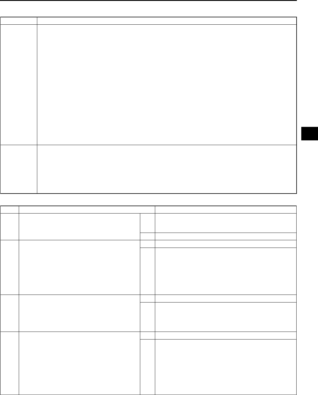
ON-BOARD DIAGNOSTIC
K77
K
DTC P0741 A6E567001030W17
Diagnostic procedure
DTC P0741 Torque converter clutch (TCC) stuck OFF
DETECTION
CONDITION
•When all conditions below satisfied.
ATF temperature 20 °
°°
°C {68 °
°°
°F} or above.
Driving in 4GR at D range.
Engine run.
Turbine speed within 2254,988 rpm.
Vehicle speed within 60100 km/h {3762 mph}.
TCC operation
Shift solenoid A duty value exceeds 99%
Power or normal mode
Difference between engine speed and turbine speed more than 100 rpm
Any of the following not generated: DTC P0500, P0706, P0707, P0708, P0712, P0713, P0715, P0751,
P0752, P0753, P0756, P0757, P0758, P0761, P0762, P0763, P0766, P0767, P0768, P0771, P0772,
P0773.
Diagnostic support note:
•This is a continuous monitor (CCM).
•MIL does not illuminate if PCM detects the above malfunction conditions during first drive cycle.
•PENDING CODE is not available.
•FREEZE FRAME DATA is not available.
•HOLD indicator light flashes.
•DTC is stored in the PCM memory.
POSSIBLE
CAUSE
•ATF level low
•Deteriorated ATF
•Shift solenoids A, B, C, D, E, and pressure control solenoid stuck
•Line pressure low
•2-4 brake band slipping
•3-4 clutch slipping
•Control valve stuck.
•PCM malfunction
STEP INSPECTION ACTION
1VERIFY RELATED REPAIR INFORMATION
AVAILABILITY
•Check for related Service Bulletins availability.
•Is any related repair information available?
Yes Perform repair or diagnosis according to available repair
information.
•If vehicle is not repaired, go to next step.
No Go to next step.
2CHECK ATF CONDITION
•Turn ignition key to OFF.
•Check ATF condition.
Clear red: Normal
Milky: Water mixed in fluid
Reddish brown: Deteriorated ATF
•Is it okay?
(See K12 Automatic Transaxle Fluid (ATF)
Condition Inspection.)
Yes Go to next step.
No If ATF color milky or reddish brown, replace ATF, then go to
Step 4.
(See K13 AUTOMATIC TRANSAXLE FLUID (ATF)
REPLACEMENT.)
3CHECK ATF LEVEL
•Start engine.
•Warm up ATX.
•Is ATF level within specification?
(See K12 Automatic Transaxle Fluid (ATF) Level
Inspection.)
Yes Go to next step.
No Adjust ATF level, then go to Step 6.
(See K12 Automatic Transaxle Fluid (ATF) Level
Inspection.)
4INSPECT LINE PRESSURE
•Start engine.
•Measure line pressure.
Specification
Idle: 330470 kPa {3.44.7 kgf/cm2, 4966
psi}
Stall: 1,1601,320 kPa {11.913.4 kgf/cm2,
170190 psi}
•Is line pressure within specification?
(See K6 Line Pressure Test.)
Yes Go to next step.
No •All ranges: Replace oil pump or control valve body, then
go to Step 6.
•Any ranges: Replace ATX, then go to Step 6.
(See K29 AUTOMATIC TRANSAXLE REMOVAL/
INSTALLATION.)
(See ATX Workshop Manual FN4A-EL (9999-95-FN4A-
99).)

K78
ON-BOARD DIAGNOSTIC
End Of Sie
DTC P0742 A6E567001030W18
5CHECK OPERATION OF EACH VALVE AND
EACH SPRING
•Turn ignition key to OFF.
•Remove control valve body.
•Disassemble control valve body.
•Is each valve operation okay and is return
spring okay?
(See K34 CONTROL VALVE BODY REMOVAL,
K35 CONTROL VALVE BODY INSTALLATION.)
(See ATX Workshop Manual FN4A-EL (9999-95-
FN4A-99).)
Yes Replace ATX, then go to next step
(See ATX Workshop Manual FN4A-EL (9999-95-FN4A-
99).)
No Repair or replace shift valve and return spring, then go to
next step.
(See K34 CONTROL VALVE BODY REMOVAL, K35
CONTROL VALVE BODY INSTALLATION.)
(See ATX Workshop Manual FN4A-EL (9999-95-FN4A-
99).)
6VERIFY TROUBLESHOOTING OF DTC P0741
COMPLETED
•Make sure to reconnect all disconnected
connectors.
•Clear DTC from memory using WDS or
equivalent.
•Start engine.
•Warm up engine and ATX.
•Drive vehicle under following conditions for 5
seconds or more.
ATF temperature: 20 °
°°
°C {68 °
°°
°F} or above
Drive in D range, 4th gear (TCC operation)
Vehicle speed (VSS PID): within 60100
km/h {3762 mph}
•Are any DTCs present?
Yes Replace PCM, then go to next step.
(See F43 PCM REMOVAL/INSTALLATION.)
No Go to next step.
7VERIFY AFTER REPAIR PROCEDURE
•Perform After Repair Procedure.
(See K52 AFTER REPAIR PROCEDURE.)
•Are any DTCs present?
Yes Go to applicable DTC inspection.
No Troubleshooting completed.
STEP INSPECTION ACTION
DTC P0742 Torque converter clutch (TCC) stuck ON
DETECTION
CONDITION
•All of following conditions satisfied under each of following throttle conditions.
ATF temperature 20 °
°°
°C {68 °
°°
°F} or above.
Driving in 4GR at D range.
Engine run.
Turbine speed within 2254,988 rpm.
Vehicle speed below 70 km/h {43 mph}.
Torque converter clutch (TCC) no operation
Difference between engine speed and turbine speed below 50 rpm
DTC P0734 not output
•Throttle conditions.
Throttle opening angle (TP PID) above 10.1% and 5 seconds or more have passed.
Throttle opening angle (TP PID) within 3.110.1% and 3 seconds or more have passed.
Throttle opening angle at closed throttle position and 5 seconds or more have passed.
Diagnostic support note:
•This is a continuous monitor (CCM).
•MIL does not illuminate if PCM detects the above malfunction conditions during first drive cycle.
•PENDING CODE is not available.
•FREEZE FRAME DATA is not available.
•HOLD indicator light flashes.
•DTC is stored in the PCM memory.
POSSIBLE
CAUSE
•ATF level low
•Deteriorated ATF
•Shift solenoids A, B, C, D, E, and pressure control solenoid stuck
•Line pressure low
•2-4 brake band slipping
•3-4 clutch slipping
•Control valve stuck
•PCM malfunction

ON-BOARD DIAGNOSTIC
K79
K
Diagnostic procedure
STEP INSPECTION ACTION
1VERIFY RELATED REPAIR INFORMATION
AVAILABILITY
•Check for related Service Bulletins availability.
•Is any related repair information available?
Yes Perform repair or diagnosis according to available repair
information.
•If vehicle is not repaired, go to next step.
No Go to next step.
2CHECK ATF CONDITION
•Turn ignition key to OFF.
•Check ATF condition.
Clear red: Normal
Milky: Water mixed in fluid
Reddish brown: Deteriorated ATF
•Is it okay?
(See K12 Automatic Transaxle Fluid (ATF)
Condition Inspection.)
Yes Go to next step.
No If ATF color milky or reddish brown, replace ATF, then go to
Step 4.
(See K13 AUTOMATIC TRANSAXLE FLUID (ATF)
REPLACEMENT.)
3CHECK ATF LEVEL
•Start engine.
•Warm up ATX.
•Is ATF level within specification?
(See K12 Automatic Transaxle Fluid (ATF) Level
Inspection.)
Yes Go to next step.
No Adjust ATF level, then go to Step 6.
(See K12 Automatic Transaxle Fluid (ATF) Level
Inspection.)
4INSPECT LINE PRESSURE
•Start engine.
•Measure line pressure.
Specification
Idle: 330470 kPa {3.44.7 kgf/cm2, 4966
psi}
Stall: 1,1601,320 kPa {11.913.4 kgf/cm2,
170190 psi}
•Is line pressure within specification?
(See K6 Line Pressure Test.)
Yes Go to next step.
No •All ranges: Replace oil pump or control valve body, then
go to Step 6.
•Any ranges: Replace ATX, then go to Step 6.
(See K29 AUTOMATIC TRANSAXLE REMOVAL/
INSTALLATION.)
(See ATX Workshop Manual FN4A-EL (9999-95-FN4A-
99).)
5CHECK OPERATION OF EACH VALVE AND
EACH SPRING
•Turn ignition key to OFF.
•Remove control valve body.
•Disassemble control valve body.
•Is each valve operation okay and is return
spring okay?
(See K34 CONTROL VALVE BODY REMOVAL,
K35 CONTROL VALVE BODY INSTALLATION.)
(See ATX Workshop Manual FN4A-EL (9999-95-
FN4A-99).)
Yes Replace ATX, then go to next step.
(See K29 AUTOMATIC TRANSAXLE REMOVAL/
INSTALLATION.)
(See ATX Workshop Manual FN4A-EL (9999-95-FN4A-
99).)
No Repair or replace shift valve and return spring, then go to
next step.
(See K34 CONTROL VALVE BODY REMOVAL, K35
CONTROL VALVE BODY INSTALLATION.)
(See ATX Workshop Manual FN4A-EL (9999-95-FN4A-
99).)
6VERIFY TROUBLESHOOTING OF DTC P0742
COMPLETED
•Make sure to reconnect all disconnected
connectors.
•Clear DTC from memory using WDS or
equivalent.
•Start engine.
•Warm up engine and ATX.
•Drive vehicle under following.
ATF temperature: 20 °
°°
°C {68 °
°°
°F} or above
Drive in D range, 4th gear (TCC not in
operation)
Vehicle speed: below 70 km/h {43 mph}.
•Throttle conditions
Throttle opening angle (TP PID) above
10.1% and 5 seconds or more have
passed.
Throttle opening angle (TP PID) within
3.110.1% and 3 seconds or more have
passed.
Throttle opening angle at closed throttle
position and 5 seconds or more have
passed.
•Are any DTCs present?
Yes Replace PCM, then go to next step.
(See F43 PCM REMOVAL/INSTALLATION.)
No Go to next step.
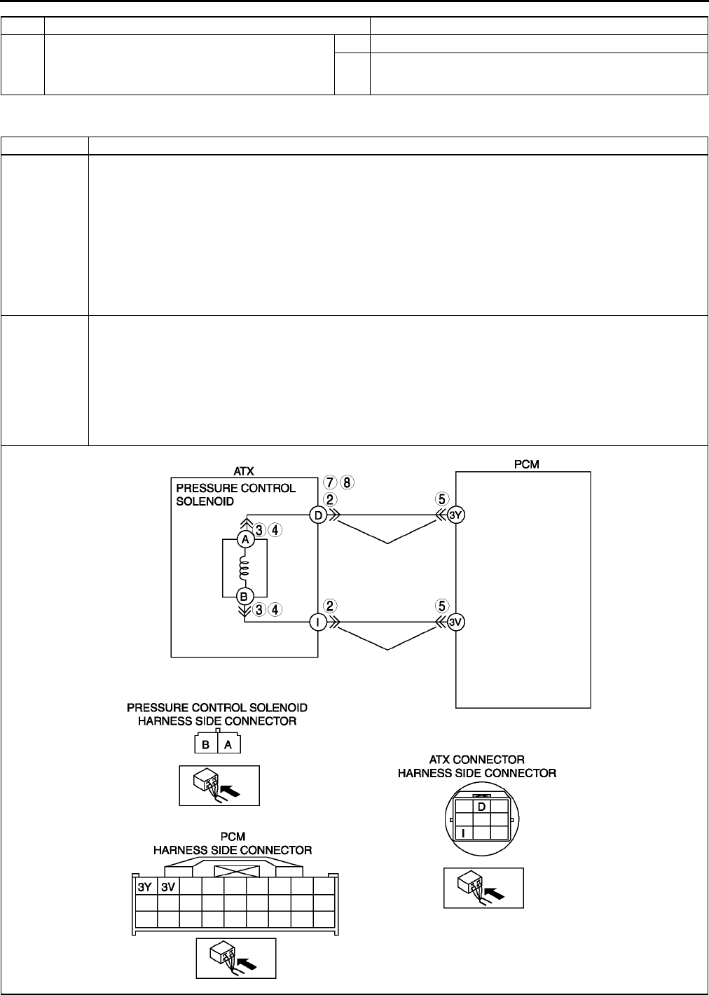
K80
ON-BOARD DIAGNOSTIC
End Of Sie
DTC P0745 A6E567001030W19
7VERIFY AFTER REPAIR PROCEDURE
•Perform After Repair Procedure.
(See K52 AFTER REPAIR PROCEDURE.)
•Are any DTCs present?
Yes Go to applicable DTC inspection.
No Troubleshooting completed.
STEP INSPECTION ACTION
DTC P0745 Pressure control solenoid malfunction
DETECTION
CONDITION
•If PCM detects either of following conditions, PCM determines that pressure control solenoid circuit has a
malfunction
Pressure control solenoid voltage stuck 0 V after engine start
Pressure control solenoid voltage stuck B+ after engine start
Diagnostic support note:
•This is a continuous monitor (CCM).
•MIL does not illuminate if PCM detects above malfunction conditions during first drive cycle.
•PENDING CODE is not available.
•FREEZE FRAME DATA is not available.
•HOLD indicator light flashes.
•DTC is stored in the PCM memory.
POSSIBLE
CAUSE
•Pressure control solenoid malfunction
•Open circuit between pressure control solenoid terminal B and ATX connector terminal I
•Open circuit between ATX connector terminal I and PCM terminal 3V
•Short to ground between ATX connector terminal D and PCM terminal 3Y
•Short to power between ATX connector terminal D and PCM terminal 3Y
•Open circuit between pressure control solenoid terminal A and ATX connector terminal D
•Open circuit between ATX connector terminal D and PCM terminal 3Y
•Damaged connector between pressure control solenoid and PCM
•PCM malfunction

ON-BOARD DIAGNOSTIC
K81
K
Diagnostic procedure
STEP INSPECTION ACTION
1VERIFY RELATED REPAIR INFORMATION
AVAILABILITY
•Check for related Service Bulletins availability.
•Is any related repair information available?
Yes Perform repair or diagnosis according to available repair
information.
•If vehicle is not repaired, go to next step.
No Go to next step.
2INSPECT ATX CONNECTOR FOR POOR
CONNECTION
•Turn ignition key to OFF.
•Disconnect ATX connector.
•Check for poor connection (damaged/pulled-
out terminal, corrosion, etc.).
•Is connection okay?
Yes Go to next step.
No Repair or replace connector and/or terminals, then go to
Step 10.
3INSPECT RESISTANCE
•Inspect resistance between ATX connector
(transaxle case side) terminals D and I.
•Is resistance within 2.47.3 ohms?
(See K26 Resistance Inspection (On-Vehicle
Inspection).)
Yes Go to Step 6.
No Go to next step.
4INSPECT PRESSURE CONTROL SOLENOID
CONNECTOR FOR POOR CONNECTION
•Disconnect pressure control solenoid
connector.
•Check for poor connection (damaged/pulled-
out terminal, corrosion, etc.).
•Is connection okay?
Yes Go to next step.
No Repair or replace connector and/or terminals, then go to
Step 10.
5INSPECT RESISTANCE
•Inspect resistance between pressure control
solenoid terminals A and B.
•Is resistance within 2.47.3 ohms?
(See K27 Resistance Inspection (Off-Vehicle
Inspection).)
Yes Replace solenoid harness, then go to Step 10.
No Verify pressure control solenoid installation.
•If solenoid installed correctly, replace pressure control
solenoid, then go to Step 10.
(See K28 SOLENOID VALVE REMOVAL/
INSTALLATION.)
6INSPECT PCM CONNECTOR FOR POOR
CONNECTION
•Disconnect PCM connector.
•Check for poor connection (damaged/pulled-
out terminals, corrosion, etc.).
•Is connection okay?
Yes Go to next step.
No Repair or replace connector and/or terminals, then go to
Step 10.
7INSPECT ATX CONNECTOR CIRCUIT FOR
OPEN
•Inspect for continuity between PCM (harness-
side) and ATX connector (vehicle harness-
side).
PCM terminal 3Y and ATX connector
terminal D
PCM terminal 3V and ATX connector
terminal I
•Is there continuity between terminals?
Yes Go to next step.
No Repair or replace harness, the go to Step 10.
8INSPECT ATX CONNECTOR CIRCUIT FOR
SHORT TO POWER
•Turn ignition key to ON (engine OFF).
•Inspect voltage at ATX connector terminal D
(vehicle harness-side).
•Is voltage 0 V?
Yes Go to next step.
No Repair or replace harness, then go to Step 10.
9INSPECT PCM CIRCUIT FOR SHORT TO
GROUND
•Turn ignition key to OFF.
•Inspect for continuity between ATX connector
terminal D (harness-side) and body ground.
•Is there continuity?
Yes Repair or replace harness, then go to next step.
No Go to next step.

K82
ON-BOARD DIAGNOSTIC
End Of Sie
DTC P0751 A6E567001030W20
Diagnostic procedure
10 VERIFY TROUBLESHOOTING OF DTC P0745
COMPLETED
•Make sure to reconnect all disconnected
connectors.
•Clear DTC from memory using WDS or
equivalent.
•Make sure to wait more than 1 second after
turning ignition key to ON.
•Are any DTCs present?
Yes Replace PCM, then go to next step.
(See F43 PCM REMOVAL/INSTALLATION.)
No No concern is detected. Go to next step.
11 VERIFY AFTER REPAIR PROCEDURE
•Perform After Repair Procedure.
(See K52 AFTER REPAIR PROCEDURE.)
•Are any DTCs present?
Yes Go to applicable DTC inspection.
No Troubleshooting completed.
STEP INSPECTION ACTION
DTC P0751 Shift solenoid A stuck OFF
DETECTION
CONDITION
•When any of P0731, P0732, and P0733 are not generated, and all conditions below satisfied.
ATF temperature 20 °
°°
°C {68 °
°°
°F} or above.
Driving in 4GR at D range.
Engine run.
Turbine speed within 225 4,988 rpm.
Differential gear case (output) revolution speed 35 rpm or above.
Torque converter clutch (TCC) not operating
Revolution ratio of forward clutch drum revolution to differential gear case revolution within 0.911.09.
Any of the following not generated: DTC P0500, P0706, P0707, P0708, P0712, P0713, P0715, P0751,
P0752, P0753, P0756, P0757, P0758, P0761, P0762, P0763, P0766, P0767, P0767, P0768, P0771,
P0772, P0773.
Diagnostic support note:
•This is a continuous monitor (CCM).
•MIL illuminates if PCM detects the above malfunction condition in two consecutive drive cycles or in one
drive cycle while the DTC for the same malfunction has been stored in the PCM.
•PENDING CODE is available if PCM detects the above malfunction condition during first drive cycle.
•FREEZE FRAME DATA is available.
•HOLD indicator light flashes.
•DTC is stored in the PCM memory.
POSSIBLE
CAUSE
•ATF level low
•Deteriorated ATF
•Shift solenoid A stuck
•Control valve stuck
•PCM malfunction
STEP INSPECTION ACTION
1VERIFY FREEZE FRAME DATA HAS BEEN
RECORDED
•Has FREEZE FRAME PID DATA been
recorded?
Yes Go to next step.
No Record FREEZE FRAME PID DATA on repair order, then
go to next step.
2VERIFY RELATED REPAIR INFORMATION
AVAILABILITY
•Check for related Service Bulletins availability.
•Is any related repair information available?
Yes Perform repair or diagnosis according to available repair
information.
•If vehicle is not repaired, go to next step.
No Go to next step.
3CHECK ATF CONDITION
•Turn ignition key to OFF.
•Check ATF condition.
Clear red: Normal
Milky: Water mixed in fluid
Reddish brown: Deteriorated ATF
•Is it okay?
(See K12 Automatic Transaxle Fluid (ATF)
Condition Inspection.)
Yes Go to next step.
No If ATF color milky or reddish brown, replace ATF, then go to
Step 5.
(See K13 AUTOMATIC TRANSAXLE FLUID (ATF)
REPLACEMENT.)
4CHECK ATF LEVEL
•Start engine.
•Warm up ATX.
•Is ATF level within specification?
(See K12 Automatic Transaxle Fluid (ATF) Level
Inspection.)
Yes Go to next step.
No Adjust ATF level, then go to Step 7.
(See K12 Automatic Transaxle Fluid (ATF) Level
Inspection.)

ON-BOARD DIAGNOSTIC
K83
K
End Of Sie
DTC P0752 A6E567001030W21
5INSPECT LINE PRESSURE
•Start engine.
•Measure line pressure.
Specification
Idle: 330470 kPa {3.44.7 kgf/cm2, 4966
psi}
Stall: 1,1601,320 kPa {11.913.4 kgf/cm2,
170190 psi}
•Is line pressure within specification?
(See K6 Line Pressure Test.)
Yes Go to next step.
No •All ranges: Replace oil pump or control valve body, then
go to Step 7.
•Any ranges: Replace ATX, then go to Step 7.
(See K29 AUTOMATIC TRANSAXLE REMOVAL/
INSTALLATION.)
(See ATX Workshop Manual FN4A-EL (9999-95-FN4A-
99).)
6CHECK OPERATION OF EACH VALVE AND
EACH SPRING
•Turn ignition key to OFF.
•Remove control valve body.
•Disassemble control valve body.
•Is each valve operation okay and is return
spring okay?
(See K34 CONTROL VALVE BODY REMOVAL,
K35 CONTROL VALVE BODY INSTALLATION.)
(See ATX Workshop Manual FN4A-EL (9999-95-
FN4A-99).)
Yes Replace ATX, then go to next step.
(See K29 AUTOMATIC TRANSAXLE REMOVAL/
INSTALLATION.)
(See ATX Workshop Manual FN4A-EL (9999-95-FN4A-
99).)
No Repair or replace shift valve and return spring, then go to
next step.
(See K34 CONTROL VALVE BODY REMOVAL, K35
CONTROL VALVE BODY INSTALLATION.)
(See ATX Workshop Manual FN4A-EL (9999-95-FN4A-
99).)
7VERIFY TROUBLESHOOTING OF DTC P0751
COMPLETED
•Make sure to reconnect all disconnected
connectors.
•Clear DTC from memory using WDS or
equivalent.
•Start engine.
•Warm up ATX.
•Drive the vehicle under the following conditions
and make sure that gears shift smoothly from
1GR to 4GR.
ATF temperature: 20 °
°°
°C {68 °
°°
°F} or above
Drive in D range
•Is pending code present?
Yes Replace PCM, then go to next step.
(See F43 PCM REMOVAL/INSTALLATION.)
No Go to next step.
8VERIFY AFTER REPAIR PROCEDURE
•Perform After Repair Procedure.
(See K52 AFTER REPAIR PROCEDURE.)
•Are any DTCs present?
Yes Go to applicable DTC inspection.
No Troubleshooting completed.
STEP INSPECTION ACTION
DTC P0752 Shift solenoid A stuck ON
DETECTION
CONDITION
•When P0734 is not generated, and all conditions below satisfied in 1GR and 2GR.
ATF temperature 20 °
°°
°C {68 °
°°
°F} or above.
Engine run.
Either of P0705 or P0706 output, or D range is selected.
Brake pedal depressed.
Throttle opening angle closed throttle position.
Vehicle speed 0 km/h {0 mph}.
Input/turbine speed sensor signal 187.5 rpm or above.
Any of the following not generated: DTC P0500, P0706, P0707, P0708, P0712, P0713, P0715, P0751,
P0752, P0753, P0756, P0757, P0758, P0761, P0762, P0763, P0766, P0767, P0767, P0768, P0771,
P0772, P0773.
Diagnostic support note:
•This is a continuous monitor (CCM).
•MIL illuminates if PCM detects the above malfunction condition in two consecutive drive cycles or in one
drive cycle while the DTC for the same malfunction has been stored in the PCM.
•PENDING CODE is available if PCM detects the above malfunction condition during first drive cycle.
•FREEZE FRAME DATA is available.
•HOLD indicator light flashes.
•DTC is stored in the PCM memory.
POSSIBLE
CAUSE
•ATF level low
•Deteriorated ATF
•Shift solenoid A stuck
•Control valve stuck
•PCM malfunction

K84
ON-BOARD DIAGNOSTIC
Diagnostic procedure
End Of Sie
STEP INSPECTION ACTION
1VERIFY FREEZE FRAME DATA HAS BEEN
RECORDED
•Has FREEZE FRAME PID DATA been
recorded?
Yes Go to next step.
No Record FREEZE FRAME PID DATA on repair order, then
go to next step.
2VERIFY RELATED REPAIR INFORMATION
AVAILABILITY
•Check for related Service Bulletins availability.
•Is any related repair information available?
Yes Perform repair or diagnosis according to available repair
information.
•If vehicle is not repaired, go to next step.
No Go to next step.
3CHECK ATF CONDITION
•Turn ignition key to OFF.
•Check ATF condition.
Clear red: Normal
Milky: Water mixed in fluid
Reddish brown: Deteriorated ATF
•Is it okay?
(See K12 Automatic Transaxle Fluid (ATF)
Condition Inspection.)
Yes Go to next step.
No If ATF color milky or reddish brown, replace ATF, then go to
Step 5.
(See K13 AUTOMATIC TRANSAXLE FLUID (ATF)
REPLACEMENT.)
4CHECK ATF LEVEL
•Start engine.
•Warm up ATX.
•Is ATF level within specification?
(See K12 Automatic Transaxle Fluid (ATF) Level
Inspection.)
Yes Go to next step.
No Adjust ATF level, then go to Step 7.
(See K12 Automatic Transaxle Fluid (ATF) Level
Inspection.)
5INSPECT LINE PRESSURE
•Start engine.
•Measure line pressure.
Specification
Idle: 330470 kPa {3.44.7 kgf/cm2, 4966
psi}
Stall: 1,2001,360 kPa {12.313.8 kgf/cm2,
175196 psi}
•Is line pressure within specification?
(See K6 Line Pressure Test.)
Yes Go to next step.
No •All ranges: Replace oil pump or control valve body, then
go to Step 7.
•Any ranges: Replace ATX, then go to Step 7.
(See K29 AUTOMATIC TRANSAXLE REMOVAL/
INSTALLATION.)
(See ATX Workshop Manual FN4A-EL (9999-95-FN4A-
99).)
6CHECK OPERATION OF EACH VALVE AND
EACH SPRING
•Turn ignition key to OFF.
•Remove control valve body.
•Disassemble control valve body.
•Is each valve operation okay and is return
spring okay?
(See K34 CONTROL VALVE BODY REMOVAL,
K35 CONTROL VALVE BODY INSTALLATION.)
(See ATX Workshop Manual FN4A-EL (9999-95-
FN4A-99).)
Yes Replace ATX, then go to next step.
(See K29 AUTOMATIC TRANSAXLE REMOVAL/
INSTALLATION.)
(See ATX Workshop Manual FN4A-EL (9999-95-FN4A-
99).)
No Repair or replace shift valve and return spring, then go to
next step.
(See K34 CONTROL VALVE BODY REMOVAL, K35
CONTROL VALVE BODY INSTALLATION.)
(See ATX Workshop Manual FN4A-EL (9999-95-FN4A-
99).)
7VERIFY TROUBLESHOOTING OF DTC P0752
COMPLETED
•Make sure to reconnect all disconnected
connectors.
•Clear DTC from memory using WDS or
equivalent.
•Start engine.
•Warm up ATX.
•Drive the vehicle under the following conditions
and make sure that gears shift smoothly from
1GR to 4GR.
ATF temperature: 20 °
°°
°C {68 °
°°
°F} or above
Drive in D range
•Is pending code present?
Yes Replace PCM, then go to next step.
(See F43 PCM REMOVAL/INSTALLATION.)
No Go to next step.
8VERIFY AFTER REPAIR PROCEDURE
•Perform After Repair Procedure.
(See K52 AFTER REPAIR PROCEDURE.)
•Are any DTCs present?
Yes Go to applicable DTC inspection.
No Troubleshooting completed.
ON-BOARD DIAGNOSTIC
K85
K
DTC P0753 A6E567001030W22
DTC P0753 Shift solenoid A malfunction (electrical)
DETECTION
CONDITION
•If PCM detects either of following conditions, PCM determines that shift solenoid A circuit has a
malfunction:
Shift solenoid A voltage is stuck at B+ after engine start.
Shift solenoid A voltage is stuck at 0 V after engine start.
Diagnostic support note:
•This is a continuous monitor (CCM).
•MIL illuminates if PCM detects the above malfunction conditions during first drive cycle.
•PENDING CODE is not available.
•FREEZE FRAME DATA is available.
•HOLD indicator light flashes.
•DTC is stored in the PCM memory.
POSSIBLE
CAUSE
•Shift solenoid A malfunction
•Short to ground between ATX connector terminal A and PCM terminal 4AB
•Short to power between ATX connector terminal A and PCM terminal 4AB
•Open circuit between shift solenoid A terminal B and ATX connector terminal A
•Open circuit between ATX connector terminal A and PCM terminal 4AB
•Open circuit between shift solenoid A terminal A and body ground point
•Damaged connector between shift solenoid A and PCM
•PCM malfunction

K86
ON-BOARD DIAGNOSTIC
Diagnostic procedure
STEP INSPECTION ACTION
1VERIFY FREEZE FRAME DATA HAS BEEN
RECORDED
•Has FREEZE FRAME PID DATA been
recorded?
Yes Go to next step.
No Record FREEZE FRAME PID DATA on repair order, then
go to next step.
2VERIFY RELATED REPAIR INFORMATION
AVAILABILITY
•Check for related Service Bulletins availability.
•Is any related repair information available?
Yes Perform repair or diagnosis according to available repair
information.
•If vehicle is not repaired, go to next step.
No Go to next step.
3INSPECT ATX CONNECTOR FOR POOR
CONNECTION
•Turn ignition key to OFF.
•Disconnect ATX connector.
•Check for poor connection (damaged/pulled-
out terminals, corrosion, etc.).
•Is connection okay?
Yes Go to next step.
No Repair or replace connector and/or terminals, then go to
Step 11.
4INSPECT RESISTANCE
•Check resistance between ATX connector
terminal A (transaxle case side) and body
ground.
•Is resistance within 1.04.2 ohms?
(See K26 Resistance Inspection (On-Vehicle
Inspection).)
Yes Go to Step 7.
No Go to next step.
5INSPECT SHIFT SOLENOID A CONNECTOR
FOR POOR CONNECTION
•Disconnect shift solenoid A connector.
•Check for poor connection (damaged/pulled-
out terminals, corrosion, etc.).
•Is connection okay?
Yes Go to next step.
No Repair or replace connector and/or terminal, then go to
Step 11.
6INSPECT RESISTANCE
•Inspect resistance between shift solenoid A
terminals A and B (part-side).
•Is resistance within 1.04.2 ohms?
(See K27 Resistance Inspection (Off-Vehicle
Inspection).)
Yes Replace solenoid harness, then go to Step 11.
No Verify shift solenoid A installation.
•If solenoid installed correctly, replace solenoid, then go
to Step 11.
(See K28 SOLENOID VALVE REMOVAL/
INSTALLATION.)
7INSPECT PCM CONNECTOR FOR POOR
CONNECTION
•Disconnect PCM connector.
•Check for poor connection (damaged/pulled-
out terminals, corrosion, etc.).
•Is connection okay?
Yes Go to next step.
No Repair or replace connector and/or terminals, then go to
Step 11.
8INSPECT ATX CONNECTOR CIRCUIT FOR
OPEN
•Inspect for continuity between PCM terminal
4AB (harness-side) and ATX connector
terminal A (vehicle harness-side).
•Is there continuity between terminals?
Yes Go to next step.
No Repair or replace harness, then go to Step 11.
9INSPECT ATX CONNECTOR CIRCUIT FOR
SHORT TO POWER
•Turn ignition key to ON (engine OFF).
•Inspect voltage at ATX connector terminal A
(vehicle harness-side).
•Is voltage 0 V?
Yes Go to next step.
No Repair or replace harness, then go to Step 11.
10 INSPECT PCM CIRCUIT FOR SHORT TO
GROUND
•Turn ignition key to OFF.
•Inspect for continuity between PCM terminal
4AB (harness-side) and body ground.
•Is there continuity?
Yes Repair or replace harness, then go to Step 11.
No Go to next step.
ON-BOARD DIAGNOSTIC
K87
K
End Of Sie
DTC P0756 A6E567001030W23
Diagnostic procedure
11 VERIFY TROUBLESHOOTING OF DTC P0753
COMPLETED
•Make sure to reconnect all disconnected
connectors.
•Clear DTC from memory using WDS or
equivalent.
•Drive vehicle in D range and make sure that
gears shift smoothly from 1GR to 4GR.
•Are any DTCs present?
Yes Replace PCM, then go to next step.
(See F43 PCM REMOVAL/INSTALLATION.)
No No concern is detected. Go to next step.
12 VERIFY AFTER REPAIR PROCEDURE
•Perform After Repair Procedure.
(See K52 AFTER REPAIR PROCEDURE.)
•Are any DTCs present?
Yes Go to applicable DTC inspection.
No Troubleshooting completed.
STEP INSPECTION ACTION
DTC P0756 Shift solenoid B stuck OFF
DETECTION
CONDITION
•When any of DTC P0732, P0733, and P0734 are not generated, and all conditions below satisfied.
ATF temperature 20 °
°°
°C {68 °
°°
°F} or above.
Driving in 1GR at D range.
Engine run.
Turbine speed within 2254,988 rpm.
Differential gear case (output) revolution speed 35 rpm or above
Throttle opening angle (TP PID) 5.67% or above.
Revolution ratio of forward clutch drum revolution to differential gear case revolution below 2.157.
Any of the following not generated: DTC P0500, P0706, P0707, P0708, P0712, P0713, P0715, P0751,
P0752, P0753, P0756, P0757, P0758, P0761, P0762, P0763, P0766, P0767, P0767, P0768, P0771,
P0772, P0773.
Diagnostic support note:
•This is a continuous monitor (CCM).
•MIL illuminates if PCM detects the above malfunction condition in two consecutive drive cycles or in one
drive cycle while the DTC for the same malfunction has been stored in the PCM.
•PENDING CODE is available if PCM detects the above malfunction condition during first drive cycle.
•FREEZE FRAME DATA is available.
•HOLD indicator light flashes.
•DTC is stored in the PCM memory.
POSSIBLE
CAUSE
•ATF level low
•Deteriorated ATF
•Shift solenoid B stuck
•Control valve stuck
•PCM malfunction
STEP INSPECTION ACTION
1VERIFY FREEZE FRAME DATA HAS BEEN
RECORDED
•Has FREEZE FRAME PID DATA been
recorded?
Yes Go to next step.
No Record FREEZE FRAME PID DATA on repair order, then
go to next step.
2VERIFY RELATED REPAIR INFORMATION
AVAILABILITY
•Check for related Service Bulletins availability.
•Is any related repair information available?
Yes Perform repair or diagnosis according to available repair
information.
•If vehicle is not repaired, go to next step.
No Go to next step.
3CHECK ATF CONDITION
•Turn ignition key to OFF.
•Check ATF condition.
Clear red: Normal
Milky: Water mixed in fluid
Reddish brown: Deteriorated ATF
•Is it okay?
(See K12 Automatic Transaxle Fluid (ATF)
Condition Inspection.)
Yes Go to next step.
No If ATF color milky or reddish brown, replace ATF, then go to
Step 5.
(See K13 AUTOMATIC TRANSAXLE FLUID (ATF)
REPLACEMENT.)
4CHECK ATF LEVEL
•Start engine.
•Warm up ATX.
•Is ATF level within specification?
(See K12 Automatic Transaxle Fluid (ATF) Level
Inspection.)
Yes Go to next step.
No Adjust ATF level, then go to Step 7.
(See K12 Automatic Transaxle Fluid (ATF) Level
Inspection.)

K88
ON-BOARD DIAGNOSTIC
End Of Sie
5INSPECT LINE PRESSURE
•Start engine.
•Measure line pressure.
Specification
Idle: 330470 kPa {3.44.7 kgf/cm2, 4966
psi}
Stall: 1,2001,360 kPa {12.313.8 kgf/cm2,
175196 psi}
•Is line pressure within specification?
(See K6 Line Pressure Test.)
Yes Go to next step.
No •All ranges: Replace oil pump or control valve body, then
go to Step 7.
•Any ranges: Replace ATX, then go to Step 7.
(See K29 AUTOMATIC TRANSAXLE REMOVAL/
INSTALLATION.)
(See ATX Workshop Manual FN4A-EL (9999-95-FN4A-
99).)
6CHECK OPERATION OF EACH VALVE AND
EACH SPRING
•Turn ignition key to OFF.
•Remove control valve body.
•Disassemble control valve body.
•Is each valve operation okay and is return
spring okay?
(See K34 CONTROL VALVE BODY REMOVAL,
K35 CONTROL VALVE BODY INSTALLATION.)
(See ATX Workshop Manual FN4A-EL (9999-95-
FN4A-99).)
Yes Replace ATX, then go to next step.
(See K29 AUTOMATIC TRANSAXLE REMOVAL/
INSTALLATION.)
(See ATX Workshop Manual FN4A-EL (9999-95-FN4A-
99).)
No Repair or replace shift valve and return spring, then go to
next step.
(See K34 CONTROL VALVE BODY REMOVAL, K35
CONTROL VALVE BODY INSTALLATION.)
(See ATX Workshop Manual FN4A-EL (9999-95-FN4A-
99).)
7VERIFY TROUBLESHOOTING OF DTC P0756
COMPLETED
•Make sure to reconnect all disconnected
connectors.
•Clear DTC from memory using WDS or
equivalent.
•Start engine.
•Warm up ATX.
•Drive the vehicle under the following conditions
and make sure that gears shift smoothly from
1GR to 4GR.
ATF temperature: 20 °
°°
°C {68 °
°°
°F} or above
Drive in D range
Engine speed: 450 rpm or above (RPM
PID)
Throttle opening angle (TP PID): 5.67% or
above
•Is pending code present?
Yes Replace PCM, then go to next step.
(See F43 PCM REMOVAL/INSTALLATION.)
No Go to next step.
8VERIFY AFTER REPAIR PROCEDURE
•Perform After Repair Procedure.
(See K52 AFTER REPAIR PROCEDURE.)
•Are any DTCs present?
Yes Go to applicable DTC inspection.
No Troubleshooting completed.
STEP INSPECTION ACTION

ON-BOARD DIAGNOSTIC
K89
K
DTC P0757 A6E567001030W24
Diagnostic procedure
DTC P0757 Shift solenoid B stuck ON
DETECTION
CONDITION
•When either of DTC P0731 and P0733 are not generated, and both the following conditions are satisfied.
When all conditions below satisfied while driving in 2GR.
•ATF temperature 20 °
°°
°C {68 °
°°
°F} or above.
•Driving in D range.
•Engine run.
•Turbine speed within 2254,988 rpm.
•Differential gear case (output) revolution speed 35 rpm or above.
•Revolution ratio of forward clutch drum revolution to differential gear case revolution below 1.249 or
more than 2.157.
•Any of the following not generated: DTC P0500, P0705, P0706, P0710, P0715,P0751, P0752,
P0753, P0756, P0757, P0758, P0761, P0762, P0763, P0766, P0767, P0768, P0771, P0772, P0773.
When all conditions below satisfied with driving in 4GR.
•ATF temperature 20 °
°°
°C {68 °
°°
°F} or above.
•Driving in D range.
•Engine run.
•Turbine speed within 2254,988 rpm.
•Differential gear case (output) revolution speed 35 rpm or above.
•Vehicle speed 50 km/h {31 mph}.
•Throttle opening angle closed throttle position.
•Revolution ratio of forward clutch drum revolution to differential gear case revolution below 0.6 or
1.249 or above.
•Any of the following not generated: DTC P0500, P0706, P0707, P0708, P0712, P0713, P0715,
P0751, P0752, P0753, P0756, P0757, P0758, P0761, P0762, P0763, P0766, P0767, P0767, P0768,
P0771, P0772, P0773.
Diagnostic support note:
•This is a continuous monitor (CCM).
•MIL illuminates if PCM detects the above malfunction condition in two consecutive drive cycles or in one
drive cycle while the DTC for the same malfunction has been stored in the PCM.
•PENDING CODE is available if PCM detects the above malfunction condition during first drive cycle.
•FREEZE FRAME DATA is available.
•HOLD indicator light flashes.
•DTC is stored in the PCM memory.
POSSIBLE
CAUSE
•ATF level low
•Deteriorated ATF
•Shift solenoid B stuck
•Control valve stuck
•PCM malfunction
STEP INSPECTION ACTION
1VERIFY FREEZE FRAME DATA HAS BEEN
RECORDED
•Has FREEZE FRAME PID DATA been
recorded?
Yes Go to next step.
No Record FREEZE FRAME PID DATA on repair order, then
go to next step.
2VERIFY RELATED REPAIR INFORMATION
AVAILABILITY
•Check for related Service Bulletins availability.
•Is any related repair information available?
Yes Perform repair or diagnosis according to available repair
information.
•If vehicle is not repaired, go to next step.
No Go to next step.
3CHECK ATF CONDITION
•Turn ignition key to OFF.
•Check ATF condition.
Clear red: Normal
Milky: Water mixed in fluid
Reddish brown: Deteriorated ATF
•Is it okay?
(See K12 Automatic Transaxle Fluid (ATF)
Condition Inspection.)
Yes Go to next step.
No If ATF color milky or reddish brown, replace ATF, then go to
Step 5.
(See K13 AUTOMATIC TRANSAXLE FLUID (ATF)
REPLACEMENT.)
4CHECK ATF LEVEL
•Start engine.
•Warm up ATX.
•Is ATF level within specification?
(See K12 Automatic Transaxle Fluid (ATF) Level
Inspection.)
Yes Go to next step.
No Adjust ATF level, then go to Step 7.
(See K12 Automatic Transaxle Fluid (ATF) Level
Inspection.)

K90
ON-BOARD DIAGNOSTIC
End Of Sie
DTC P0758 A6E567001030W25
5INSPECT LINE PRESSURE
•Start engine.
•Measure line pressure.
Specification
Idle: 330470 kPa {3.44.7 kgf/cm2, 4966
psi}
Stall: 1,2001,360 kPa {12.313.8 kgf/cm2,
175196 psi}
•Is line pressure within specification?
(See K6 Line Pressure Test.)
Yes Go to next step.
No •All ranges: Replace oil pump or control valve body, then
go to Step 7.
•Any ranges: Replace ATX, then go to Step 7.
(See K29 AUTOMATIC TRANSAXLE REMOVAL/
INSTALLATION.)
(See ATX Workshop Manual FN4A-EL (9999-95-FN4A-
99).)
6CHECK OPERATION OF EACH VALVE AND
EACH SPRING
•Turn ignition key to OFF.
•Remove control valve body.
•Disassemble control valve body.
•Is each valve operation okay and is return
spring okay?
(See K34 CONTROL VALVE BODY REMOVAL,
K35 CONTROL VALVE BODY INSTALLATION.)
(See ATX Workshop Manual FN4A-EL (9999-95-
FN4A-99).)
Yes Replace ATX, then go to next step.
(See K29 AUTOMATIC TRANSAXLE REMOVAL/
INSTALLATION.)
(See ATX Workshop Manual FN4A-EL (9999-95-FN4A-
99).)
No Repair or replace shift valve and return spring, then go to
next step.
(See K34 CONTROL VALVE BODY REMOVAL, K35
CONTROL VALVE BODY INSTALLATION.)
(See ATX Workshop Manual FN4A-EL (9999-95-FN4A-
99).)
7VERIFY TROUBLESHOOTING OF DTC P0757
COMPLETED
•Make sure to reconnect all disconnected
connectors.
•Clear DTC from memory using WDS or
equivalent.
•Start engine.
•Warm up ATX.
•Drive the vehicle under the following conditions
make sure that gears shift smoothly from 1GR
to 4GR.
ATF temperature: 20 °
°°
°C {68 °
°°
°F} or above
Drive in D range
Engine speed: 450 rpm or above (RPM
PID)
Throttle opening angle (TP PID): 0% (4th
gear only)
Vehicle speed (VSS PID): 50 km/h {31
mph} (4th gear only)
•Is pending code present?
Yes Replace PCM, then go to next step.
(See F43 PCM REMOVAL/INSTALLATION.)
No Go to next step.
8VERIFY AFTER REPAIR PROCEDURE
•Perform After Repair Procedure.
(See K52 AFTER REPAIR PROCEDURE.)
•Are any DTCs present?
Yes Go to applicable DTC inspection.
No Troubleshooting completed.
STEP INSPECTION ACTION
DTC P0758 Shift solenoid B malfunction (electrical)
DETECTION
CONDITION
•If PCM detects either of following conditions, PCM determines that shift solenoid B circuit has a
malfunction:
Shift solenoid B voltage is stuck at B+ after engine start.
Shift solenoid B voltage is stuck at 0 V after engine start.
Diagnostic support note:
•This is a continuous monitor (CCM).
•MIL illuminates if PCM detects the above malfunction conditions during first drive cycle.
•PENDING CODE is not available.
•FREEZE FRAME DATA is available.
•HOLD indicator light flashes.
•DTC is stored in the PCM memory.
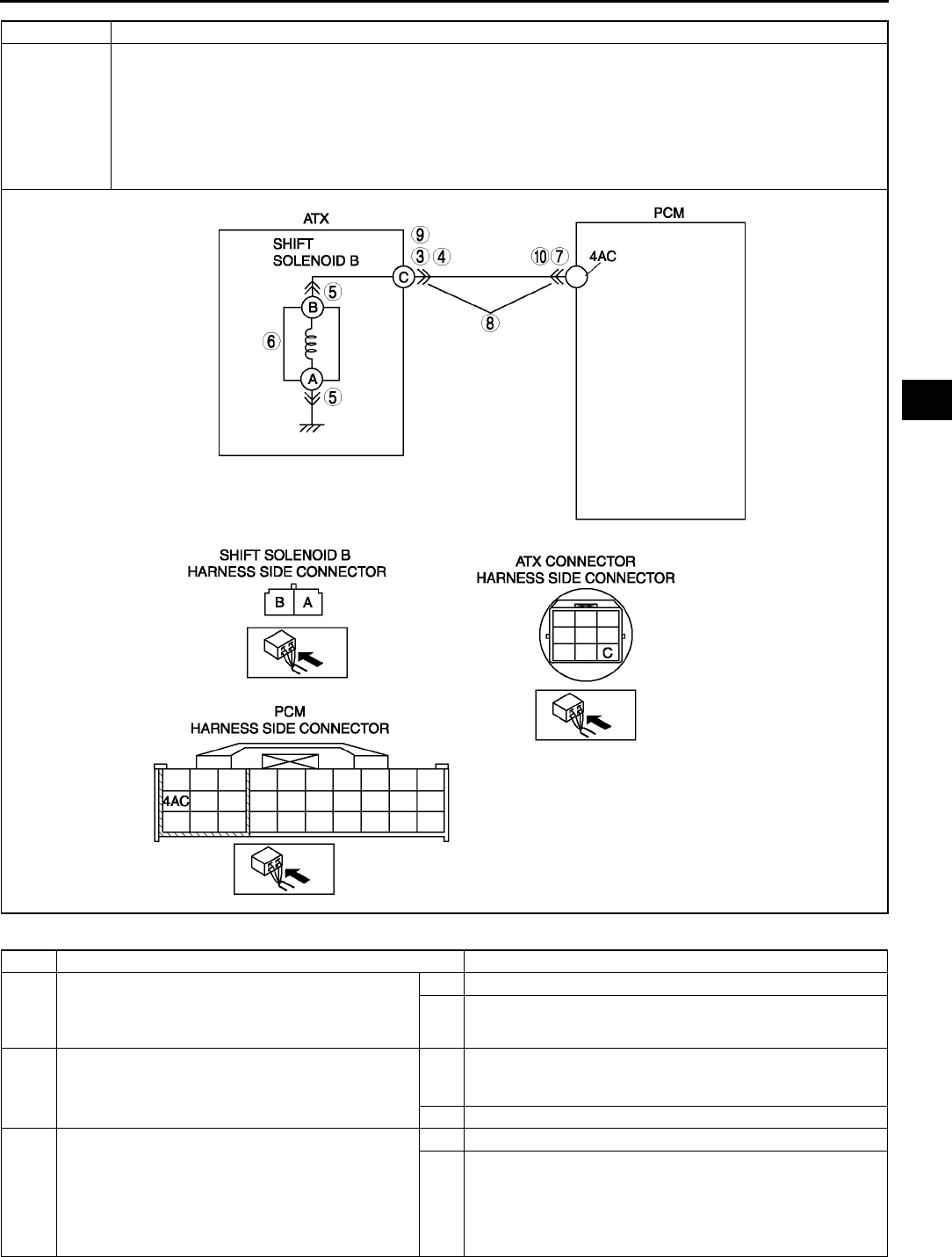
ON-BOARD DIAGNOSTIC
K91
K
Diagnostic procedure
POSSIBLE
CAUSE
•Shift solenoid B malfunction
•Short to ground between ATX connector terminal C and PCM terminal 4AC
•Short to power between ATX connector terminal C and PCM terminal 4AC
•Open circuit between shift solenoid B terminal B and ATX connector terminal C
•Open circuit between ATX connector terminal C and PCM terminal 4AC
•Open circuit between shift solenoid B terminal A and body ground point
•Damaged connector between shift solenoid B and PCM
•PCM malfunction
STEP INSPECTION ACTION
1VERIFY FREEZE FRAME DATA HAS BEEN
RECORDED
•Has FREEZE FRAME PID DATA been
recorded?
Yes Go to next step.
No Record FREEZE FRAME PID DATA on repair order, then
go to next step.
2VERIFY RELATED REPAIR INFORMATION
AVAILABILITY
•Check for related Service Bulletins availability.
•Is any related repair information available?
Yes Perform repair or diagnosis according to available repair
information.
•If vehicle is not repaired, go to next step.
No Go to next step.
3INSPECT ATX CONNECTOR FOR POOR
CONNECTION
•Turn ignition key to OFF.
•Disconnect ATX connector.
•Check for poor connection (damaged/pulled-
out terminals, corrosion, etc.).
•Is connection okay?
Yes Go to next step.
No Repair or replace connector and/or terminals, then go to
Step 11.
DTC P0758 Shift solenoid B malfunction (electrical)

K92
ON-BOARD DIAGNOSTIC
End Of Sie
4INSPECT RESISTANCE
•Inspect resistance between ATX connector
terminal C (transaxle case side) and body
ground.
•Is resistance within 1.04.2 ohms?
(See K26 Resistance Inspection (On-Vehicle
Inspection).)
Yes Go to Step 7.
No Go to next step.
5INSPECT SHIFT SOLENOID B CONNECTOR
FOR POOR CONNECTION
•Disconnect shift solenoid B connector.
•Check for poor connection (damaged/pulled-
out terminals, corrosion, etc.).
•Is connection okay?
Yes Go to next step.
No Repair or replace connector and/or terminal, then go to
Step 11.
6INSPECT RESISTANCE
•Inspect resistance between shift solenoid B
terminals A and B (part-side).
•Is resistance within 1.04.2 ohms?
(See K27 Resistance Inspection (Off-Vehicle
Inspection).)
Yes Replace solenoid harness, then go to Step 11.
No Verify shift solenoid B installation.
•If solenoid installed correctly, replace solenoid, then go
to Step 11.
(See K28 SOLENOID VALVE REMOVAL/
INSTALLATION.)
7INSPECT PCM CONNECTOR FOR POOR
CONNECTION
•Disconnect PCM connector.
•Check for poor connection (damaged/pulled-
out terminals, corrosion, etc.).
•Is connection okay?
Yes Go to next step.
No Repair or replace connector and/or terminals, then go to
Step 11.
8INSPECT ATX CONNECTOR CIRCUIT FOR
OPEN
•Inspect for continuity between PCM terminal
4AC (harness-side) and ATX connector
terminal C (vehicle harness-side).
•Is there continuity between terminals?
Yes Go to next step.
No Repair or replace harness, then go to Step 11.
9INSPECT ATX CONNECTOR CIRCUIT FOR
SHORT TO POWER
•Turn ignition key to ON (engine OFF).
•Check for voltage at ATX connector terminal C
(vehicle harness-side).
•Is voltage 0 V?
Yes Go to next step.
No Repair or replace harness, then go to Step 11.
10 INSPECT PCM CIRCUIT FOR SHORT TO
GROUND
•Turn ignition key to OFF.
•Check for continuity between PCM terminal
4AC (harness-side) and body ground.
•Is there continuity?
Yes Repair or replace harness, then go to Step 11.
No Go to next step.
11 VERIFY TROUBLESHOOTING OF DTC P0758
SHIFT SOLENOID B COMPLETED
•Make sure to reconnect all disconnected
connectors.
•Clear DTC from memory using WDS or
equivalent.
•Drive vehicle in D range and make sure that
gears shift smoothly from 1GR to 4GR.
•Are any DTCs present?
Yes Replace PCM, then go to next step.
(See F43 PCM REMOVAL/INSTALLATION.)
No Go to next step.
12 VERIFY AFTER REPAIR PROCEDURE
•Perform After Repair Procedure.
(See K52 AFTER REPAIR PROCEDURE.)
•Are any DTCs present?
Yes Go to applicable DTC inspection.
No Troubleshooting completed.
STEP INSPECTION ACTION
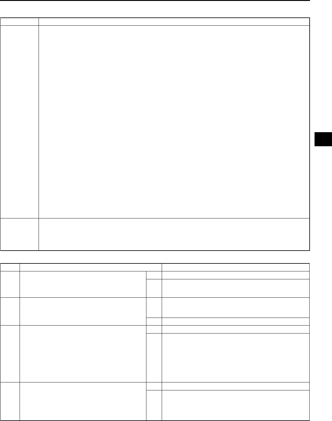
ON-BOARD DIAGNOSTIC
K93
K
DTC P0761 A6E567001030W26
Diagnostic procedure
DTC P0761 Shift solenoid C stuck OFF
DETECTION
CONDITION
•When either of DTC P0733 and P0734 are not generated, and both the following conditions are satisfied.
When all conditions below satisfied while driving in 1GR.
•ATF temperature 20 °
°°
°C {68 °
°°
°F} or above.
•Driving in D range.
•Engine run.
•Turbine speed within 2254,988 rpm.
•Throttle opening angle (TP PID) 5.67% or above.
•Differential gear case (output) revolution speed 35 rpm or above.
•Revolution ratio of forward clutch drum revolution to differential gear case revolution below 2.157.
•Any of the following not generated: DTC P0500, P0706, P0707, P0708, P0712, P0713, P0715,
P0751, P0752, P0753, P0756, P0757, P0758, P0761, P0762, P0763, P0766, P0767, P0767, P0768,
P0771, P0772, P0773.
When all conditions below satisfied while driving in 2GR.
•ATF temperature 20 °
°°
°C {68 °
°°
°F} or above.
•Driving in D range.
•Engine run.
•Turbine speed within 2254,988 rpm.
•Differential gear case (output) revolution speed 35 rpm or above.
•Revolution ratio of forward clutch drum revolution to differential gear case revolution below 1.249 or
2.157 or above.
•Any of the following not generated: DTC P0500, P0706, P0707, P0708, P0712, P0713, P0715,
P0751, P0752, P0753, P0756, P0757, P0758, P0761, P0762, P0763, P0766, P0767, P0767, P0768,
P0771, P0772, P0773.
Diagnostic support note:
•This is a continuous monitor (CCM).
•MIL illuminates if PCM detects the above malfunction condition in two consecutive drive cycles or in one
drive cycle while the DTC for the same malfunction has been stored in the PCM.
•PENDING CODE is available if PCM detects the above malfunction condition during first drive cycle.
•FREEZE FRAME DATA is available.
•HOLD indicator light flashes.
•DTC is stored in the PCM memory.
POSSIBLE
CAUSE
•ATF level low
•Deteriorated ATF
•Shift solenoid C stuck
•Control valve stuck
•PCM malfunction
STEP INSPECTION ACTION
1VERIFY FREEZE FRAME DATA HAS BEEN
RECORDED
•Has FREEZE FRAME PID DATA been
recorded?
Yes Go to next step.
No Record FREEZE FRAME PID DATA on repair order, then
go to next step.
2VERIFY RELATED REPAIR INFORMATION
AVAILABILITY
•Check for related Service Bulletins availability.
•Is any related repair information available?
Yes Perform repair or diagnosis according to available repair
information.
•If vehicle is not repaired, go to next step.
No Go to next step.
3CHECK ATF CONDITION
•Turn ignition key to OFF.
•Check ATF condition.
Clear red: Normal
Milky: Water mixed in fluid
Reddish brown: Deteriorated ATF
•Is it okay?
(See K12 Automatic Transaxle Fluid (ATF)
Condition Inspection.)
Yes Go to next step.
No If ATF color milky or reddish brown, replace ATF, then go to
Step 5.
(See K13 AUTOMATIC TRANSAXLE FLUID (ATF)
REPLACEMENT.)
4CHECK ATF LEVEL
•Start engine.
•Warm up ATX.
•Is ATF level within specification?
(See K12 Automatic Transaxle Fluid (ATF) Level
Inspection.)
Yes Go to next step.
No Adjust ATF level, then go to Step 7.
(See K12 Automatic Transaxle Fluid (ATF) Level
Inspection.)

K94
ON-BOARD DIAGNOSTIC
End Of Sie
5INSPECT LINE PRESSURE
•Start engine.
•Measure line pressure.
Specification
Idle: 330470 kPa {3.44.7 kgf/cm2, 4966
psi}
Stall: 1,2001,360 kPa {12.313.8 kgf/cm2,
175196 psi}
•Is line pressure within specification?
(See K6 Line Pressure Test.)
Yes Go to next step.
No •All ranges: Replace oil pump or control valve body, then
go to Step 7.
•Any ranges: Replace ATX, then go to Step 7.
(See K29 AUTOMATIC TRANSAXLE REMOVAL/
INSTALLATION.)
(See ATX Workshop Manual FN4A-EL (9999-95-FN4A-
99).)
6CHECK OPERATION OF EACH VALVE AND
EACH SPRING
•Turn ignition key to OFF.
•Remove control valve body.
•Disassemble control valve body.
•Is each valve operation okay and is return
spring okay?
(See K34 CONTROL VALVE BODY REMOVAL,
K35 CONTROL VALVE BODY INSTALLATION.)
(See ATX Workshop Manual FN4A-EL (9999-95-
FN4A-99).)
Yes Replace ATX, then go to next step.
(See K29 AUTOMATIC TRANSAXLE REMOVAL/
INSTALLATION.)
(See ATX Workshop Manual FN4A-EL (9999-95-FN4A-
99).)
No Repair or replace shift valve and return spring, then go to
next step.
(See K34 CONTROL VALVE BODY REMOVAL, K35
CONTROL VALVE BODY INSTALLATION.)
(See ATX Workshop Manual FN4A-EL (9999-95-FN4A-
99).)
7VERIFY TROUBLESHOOTING OF DTC P0761
COMPLETED
•Make sure to reconnect all disconnected
connectors.
•Clear DTC from memory using WDS or
equivalent.
•Start engine.
•Warm up ATX.
•Drive the vehicle under the following conditions
and make sure that gears shift smoothly from
1GR to 4GR.
ATF temperature: 20 °
°°
°C {68 °
°°
°F} or above
Drive in D range
Throttle opening angle (TP PID): 5.67% or
above
•Is pending code present?
Yes Replace PCM, then go to next step.
(See F43 PCM REMOVAL/INSTALLATION.)
No Go to next step.
8VERIFY AFTER REPAIR PROCEDURE
•Perform After Repair Procedure.
(See K52 AFTER REPAIR PROCEDURE.)
•Are any DTCs present?
Yes Go to applicable DTC inspection.
No Troubleshooting completed.
STEP INSPECTION ACTION

ON-BOARD DIAGNOSTIC
K95
K
DTC P0762 A6E567001030W27
Diagnostic procedure
DTC P0762 Shift solenoid C stuck ON
DETECTION
CONDITION
•When either of DTC P0731 and P0732 are not generated, and both the following conditions are satisfied.
When all conditions below satisfied while driving in 3GR.
•ATF temperature 20 °
°°
°C {68 °
°°
°F} or above.
•Driving in D range.
•Engine run.
•Turbine speed within 2254,988 rpm.
•Differential gear case (output) revolution speed 35 rpm or above.
•Revolution ratio of forward clutch drum revolution to differential gear case revolution below 0.863 or
1.249 or above.
•Any of the following not generated: DTC P0500, P0706, P0707, P0708, P0712, P0713, P0715,
P0751, P0752, P0753, P0756, P0757, P0758, P0761, P0762, P0763, P0766, P0767, P0767, P0768,
P0771, P0772, P0773.
When all conditions below satisfied while driving in 4GR.
•ATF temperature 20 °
°°
°C {68 °
°°
°F} or above.
•Driving in D range.
•Engine run.
•Turbine speed within 2254,988 rpm.
•Vehicle speed 50 km/h {31mph} or above.
•Differential gear case (output) revolution speed 35 rpm or above.
•Throttle opening angle at closed throttle position
•Revolution ratio of forward clutch drum revolution to differential gear case revolution below 0.6 or
1.249 or above.
•Any of the following not generated: DTC P0500, P0706, P0707, P0708, P0712, P0713, P0715,
P0751, P0752, P0753, P0756, P0757, P0758, P0761, P0762, P0763, P0766, P0767, P0767, P0768,
P0771, P0772, P0773.
Diagnostic support note:
•This is a continuous monitor (CCM).
•MIL illuminates if PCM detects the above malfunction condition in two consecutive drive cycles or in one
drive cycle while the DTC for the same malfunction has been stored in the PCM.
•PENDING CODE is available if PCM detects the above malfunction condition during first drive cycle.
•FREEZE FRAME DATA is available.
•HOLD indicator light flashes.
•DTC is stored in the PCM memory.
POSSIBLE
CAUSE
•ATF level low
•Deteriorated ATF
•Shift solenoid C and pressure control solenoid stuck
•Control valve stuck
•PCM malfunction
STEP INSPECTION ACTION
1VERIFY FREEZE FRAME DATA HAS BEEN
RECORDED
•Has FREEZE FRAME PID DATA been
recorded?
Yes Go to next step.
No Record FREEZE FRAME PID DATA on repair order, then
go to next step.
2VERIFY RELATED REPAIR INFORMATION
AVAILABILITY
•Check for related Service Bulletins availability.
•Is any related repair information available?
Yes Perform repair or diagnosis according to available repair
information.
•If vehicle is not repaired, go to next step.
No Go to next step.
3CHECK ATF CONDITION
•Turn ignition key to OFF.
•Check ATF condition.
Clear red: Normal
Milky: Water mixed in fluid
Reddish brown: Deteriorated ATF
•Is it okay?
(See K12 Automatic Transaxle Fluid (ATF)
Condition Inspection.)
Yes Go to next step.
No If ATF color milky or reddish brown, replace ATF, then go to
Step 5.
(See K13 AUTOMATIC TRANSAXLE FLUID (ATF)
REPLACEMENT.)
4CHECK ATF LEVEL
•Start engine.
•Warm up ATX.
•Is ATF level within specification?
(See K12 Automatic Transaxle Fluid (ATF) Level
Inspection.)
Yes Go to next step.
No Adjust ATF level, then go to Step 7.
(See K12 Automatic Transaxle Fluid (ATF) Level
Inspection.)

K96
ON-BOARD DIAGNOSTIC
End Of Sie
DTC P0763 A6E567001030W28
5INSPECT LINE PRESSURE
•Start engine.
•Measure line pressure.
Specification
Idle: 330470 kPa {3.44.7 kgf/cm2, 4966
psi}
Stall: 1,2001,360 kPa {12.313.8 kgf/cm2,
175196 psi}
•Is line pressure within specification?
(See K6 Line Pressure Test.)
Yes Go to next step.
No •All ranges: Replace oil pump or control valve body, then
go to Step 7.
•Any ranges: Replace ATX, then go to Step 7.
(See K29 AUTOMATIC TRANSAXLE REMOVAL/
INSTALLATION.)
(See ATX Workshop Manual FN4A-EL (9999-95-FN4A-
99).)
6CHECK OPERATION OF EACH VALVE AND
EACH SPRING
•Turn ignition key to OFF.
•Remove control valve body.
•Disassemble control valve body.
•Is each valve operation okay and is return
spring okay?
(See K34 CONTROL VALVE BODY REMOVAL,
K35 CONTROL VALVE BODY INSTALLATION.)
(See ATX Workshop Manual FN4A-EL (9999-95-
FN4A-99).)
Yes Replace ATX, then go to next step.
(See K29 AUTOMATIC TRANSAXLE REMOVAL/
INSTALLATION.)
(See ATX Workshop Manual FN4A-EL (9999-95-FN4A-
99).)
No Repair or replace shift valve and return spring, then go to
next step.
(See K34 CONTROL VALVE BODY REMOVAL, K35
CONTROL VALVE BODY INSTALLATION.)
(See ATX Workshop Manual FN4A-EL (9999-95-FN4A-
99).)
7VERIFY TROUBLESHOOTING OF DTC P0762
COMPLETED
•Make sure to reconnect all disconnected
connectors.
•Clear DTC from memory using WDS or
equivalent.
•Start engine.
•Warm up ATX.
•Drive the vehicle under the following conditions
and make sure that gears shift smoothly from
1GR to 4GR.
ATF temperature: 20 °
°°
°C {68 °
°°
°F} or above
Drive in D range
Throttle opening angle (TP PID): 0% (4GR
only)
Vehicle speed (VSS PID): 50 km/h {31
mph} or above (4GR only)
•Is pending code present?
Yes Replace PCM, then go to next step.
(See F43 PCM REMOVAL/INSTALLATION.)
No Go to next step.
8VERIFY AFTER REPAIR PROCEDURE
•Perform After Repair Procedure.
(See K52 AFTER REPAIR PROCEDURE.)
•Are any DTCs present?
Yes Go to applicable DTC inspection.
No Troubleshooting completed.
STEP INSPECTION ACTION
DTC P0763 Shift solenoid C malfunction (electrical)
DETECTION
CONDITION
•If PCM detects either of following conditions, PCM determines that shift solenoid C circuit has a
malfunction:
Shift solenoid C voltage is stuck at B+ after engine start.
Shift solenoid C voltage is stuck at 0 V after engine start.
Diagnostic support note:
•This is a continuous monitor (CCM).
•MIL illuminates if PCM detects the above malfunction conditions during first drive cycle.
•PENDING CODE is not available.
•FREEZE FRAME DATA is available.
•HOLD indicator light flashes.
•DTC is stored in the PCM memory.
POSSIBLE
CAUSE
•Shift solenoid C malfunction
•Short to ground between ATX connector terminal G and PCM terminal 4Y
•Short to power between ATX connector terminal G and PCM terminal 4Y
•Open circuit between shift solenoid C terminal B and ATX connector terminal G
•Open circuit between ATX connector terminal G and PCM terminal 4Y
•Open circuit between shift solenoid C terminal A and body ground point
•Damaged connector between shift solenoid C and PCM.
•PCM malfunction.
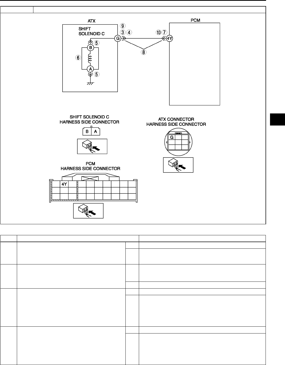
ON-BOARD DIAGNOSTIC
K97
K
Diagnostic procedure
STEP INSPECTION ACTION
1VERIFY FREEZE FRAME DATA HAS BEEN
RECORDED
•Has FREEZE FRAME PID DATA been
recorded?
Yes Go to next step.
No Record FREEZE FRAME PID DATA on repair order, then
go to next step.
2VERIFY RELATED REPAIR INFORMATION
AVAILABILITY
•Check for related Service Bulletins availability.
•Is any related repair information available?
Yes Perform repair or diagnosis according to available repair
information.
•If vehicle is not repaired, go to next step.
No Go to next step.
3INSPECT ATX CONNECTOR FOR POOR
CONNECTION
•Turn ignition key to OFF.
•Disconnect ATX connector.
•Check for poor connection (damaged/pulled-
out terminals, corrosion, etc.).
•Is connection okay?
Yes Go to next step.
No Repair or replace connector and/or terminals, then go to
Step 11.
4INSPECT RESISTANCE
•Inspect resistance between ATX connector
terminal G (transaxle case side) and body
ground.
•Is resistance within 1.04.2 ohms?
(See K26 Resistance Inspection (On-Vehicle
Inspection).)
Yes Go to Step 7.
No Go to next step.
DTC P0763 Shift solenoid C malfunction (electrical)

K98
ON-BOARD DIAGNOSTIC
End Of Sie
5INSPECT SHIFT SOLENOID C CONNECTOR
FOR POOR CONNECTION
•Disconnect shift solenoid C connector.
•Check for poor connection (damaged/pulled-
out terminals, corrosion, etc.).
•Is connection okay?
Yes Go to next step.
No Repair or replace connector and/or terminal, then go to
Step 11.
6INSPECT RESISTANCE
•Inspect resistance between shift solenoid C
terminals A and B (part-side).
•Is resistance within 1.04.2 ohms?
(See K27 Resistance Inspection (Off-Vehicle
Inspection).)
Yes Replace solenoid harness, then go to Step 11.
No Verify shift solenoid C installation.
•If solenoid installed correctly, replace solenoid, then go
to Step 11.
(See K28 SOLENOID VALVE REMOVAL/
INSTALLATION.)
7INSPECT PCM CONNECTOR FOR POOR
CONNECTION
•Disconnect PCM connector.
•Check for poor connection (damaged/pulled-
out terminals, corrosion, etc.).
•Is connection okay?
Yes Go to next step.
No Repair or replace connector and/or terminals, then go to
Step 11.
8INSPECT ATX CONNECTOR CIRCUIT FOR
OPEN
•inspect for continuity between PCM terminal
4Y (harness-side) and ATX connector terminal
G (vehicle harness-side).
•Is there continuity between terminals?
Yes Go to next step.
No Repair or replace harness, then go to Step 11.
9INSPECT ATX CONNECTOR CIRCUIT FOR
SHORT TO POWER
•Turn ignition key to ON (engine OFF).
•Check voltage at ATX connector terminal G
(vehicle harness-side).
•Is voltage 0 V?
Yes Go to next step.
No Repair or replace harness, then go to Step 11.
10 INSPECT PCM CIRCUIT FOR SHORT TO
GROUND
•Turn ignition key to OFF.
•Inspect for continuity between PCM terminal
4Y (harness-side) and body ground.
•Is there continuity?
Yes Repair or replace harness, then go to Step 11.
No Go to next step.
11 VERIFY TROUBLESHOOTING OF DTC P0763
COMPLETED
•Make sure to reconnect all disconnected
connectors.
•Clear DTC from memory using WDS or
equivalent.
•Drive vehicle in D range and make sure that
gears shift smoothly from 1GR to 4GR.
•Are any DTCs present?
Yes Replace PCM, then go to next step.
(See F43 PCM REMOVAL/INSTALLATION.)
No No concern is detected. Go to next step.
12 VERIFY AFTER REPAIR PROCEDURE
•Perform After Repair Procedure.
(See K52 AFTER REPAIR PROCEDURE.)
•Are any DTCs present?
Yes Go to applicable DTC inspection.
No Troubleshooting completed.
STEP INSPECTION ACTION

ON-BOARD DIAGNOSTIC
K99
K
DTC P0766 A6E567001030W29
Diagnostic procedure
DTC P0766 Shift solenoid D stuck OFF
DETECTION
CONDITION
•When any of DTC P0731, P0732, and P0733 not output (correct judgment), and all conditions below are
satisfied.
ATF temperature 20 °
°°
°C {68 °
°°
°F} or above.
Driving in 4GR at D range.
Engine run.
Turbine speed within 2254,988 rpm.
Differential gear case (output) revolution speed 35 rpm or above.
Vehicle speed 50 km/h {31 mph} or above.
Throttle opening angle closed throttle position.
Revolution ratio of forward clutch drum revolution to differential gear case revolution below 0.6 or 1.249
or above.
Any of the following not generated: DTC P0500, P0706, P0707, P0708, P0712, P0713, P0715, P0751,
P0752, P0753, P0756, P0757, P0758, P0761, P0762, P0763, P0766, P0767, P0767, P0768, P0771,
P0772, P0773.
Diagnostic support note:
•This is a continuous monitor (CCM).
•MIL illuminates if PCM detects the above malfunction condition in two consecutive drive cycles or in one
drive cycle while the DTC for the same malfunction has been stored in the PCM.
•PENDING CODE is available if PCM detects the above malfunction condition during first drive cycle.
•FREEZE FRAME DATA is available.
•HOLD indicator light flashes.
•DTC is stored in the PCM memory.
POSSIBLE
CAUSE
•ATF level low
•Deteriorated ATF
•Shift solenoid D stuck
•Control valve stuck
•PCM malfunction
STEP INSPECTION ACTION
1VERIFY FREEZE FRAME DATA HAS BEEN
RECORDED
•Has FREEZE FRAME PID DATA been
recorded?
Yes Go to next step.
No Record FREEZE FRAME PID DATA on repair order, then
go to next step.
2VERIFY RELATED REPAIR INFORMATION
AVAILABILITY
•Check for related Service Bulletins availability.
•Is any related repair information available?
Yes Perform repair or diagnosis according to available repair
information.
•If vehicle is not repaired, go to next step.
No Go to next step.
3CHECK ATF CONDITION
•Turn ignition key to OFF.
•Check ATF condition.
Clear red: Normal
Milky: Water mixed in fluid
Reddish brown: Deteriorated ATF
•Is it okay?
(See K12 Automatic Transaxle Fluid (ATF)
Condition Inspection.)
Yes Go to next step.
No If ATF color milky or reddish brown, replace ATF, then go to
Step 5.
(See K13 AUTOMATIC TRANSAXLE FLUID (ATF)
REPLACEMENT.)
4CHECK ATF LEVEL
•Start engine.
•Warm up ATX.
•Is ATF level within specification?
(See K12 Automatic Transaxle Fluid (ATF) Level
Inspection.)
Yes Go to next step.
No Adjust ATF level, then go to Step 7.
(See K12 Automatic Transaxle Fluid (ATF) Level
Inspection.)
5INSPECT LINE PRESSURE
•Start engine.
•Measure line pressure.
Specification
Idle: 330470 kPa {3.44.7 kgf/cm2, 4966
psi}
Stall: 1,2001,360 kPa {12.313.8 kgf/cm2,
175196 psi}
•Is line pressure within specification?
(See K6 Line Pressure Test.)
Yes Go to next step.
No •All ranges: Replace oil pump or control valve body, then
go to Step 7.
•Any ranges: Replace ATX, then go to Step 7.
(See K29 AUTOMATIC TRANSAXLE REMOVAL/
INSTALLATION.)
(See ATX Workshop Manual FN4A-EL (9999-95-FN4A-
99).)

K100
ON-BOARD DIAGNOSTIC
End Of Sie
DTC P0767 A6E567001030W30
6CHECK OPERATION OF EACH VALVE AND
EACH SPRING
•Turn ignition key to OFF.
•Remove control valve body.
•Disassemble control valve body.
•Is each valve operation okay and is return
spring okay?
(See K34 CONTROL VALVE BODY REMOVAL,
K35 CONTROL VALVE BODY INSTALLATION.)
(See ATX Workshop Manual FN4A-EL (9999-95-
FN4A-99).)
Yes Replace ATX, then go to next step.
(See K29 AUTOMATIC TRANSAXLE REMOVAL/
INSTALLATION.)
(See ATX Workshop Manual FN4A-EL (9999-95-FN4A-
99).)
No Repair or replace shift valve and return spring, then go to
next step.
(See K34 CONTROL VALVE BODY REMOVAL, K35
CONTROL VALVE BODY INSTALLATION.)
(See ATX Workshop Manual FN4A-EL (9999-95-FN4A-
99).)
7VERIFY TROUBLESHOOTING OF DTC P0766
COMPLETED
•Make sure to reconnect all disconnected
connectors.
•Clear DTC from memory using WDS or
equivalent.
•Start engine.
•Warm up ATX.
•Drive the vehicle under the following conditions
and make sure that gears shift smoothly from
1GR to 4GR.
ATF temperature: 20 °
°°
°C {68 °
°°
°F} or above
Drive in D range
Throttle opening angle (TP PID): 0% (4GR
only)
Vehicle speed: 50 km/h {31 mph} or
above. (4GR only) (VSS PID)
•Is pending code present?
Yes Replace PCM, then go to next step.
(See F43 PCM REMOVAL/INSTALLATION.)
No Go to next step.
8VERIFY AFTER REPAIR PROCEDURE
•Perform After Repair Procedure.
(See K52 AFTER REPAIR PROCEDURE.)
•Are any DTCs present?
Yes Go to applicable DTC inspection.
No Troubleshooting completed.
STEP INSPECTION ACTION
DTC P0767 Shift solenoid D stuck ON
DETECTION
CONDITION
•When any of DTC P0731, P0732, P0734, and P0741 are not generated, and all conditions below are
satisfied.
ATF temperature 20 °
°°
°C {68 °
°°
°F} or above.
Driving in D range.
Engine run.
Turbine speed within 2254,988 rpm.
Differential gear case (output) revolution speed 35 rpm or above.
Revolution ratio of forward clutch drum revolution to differential gear case revolution below 0.863 or
1.249 or above.
Any of the following not generated: DTC P0500, P0706, P0707, P0708, P0712, P0713, P0715, P0751,
P0752, P0753, P0756, P0757, P0758, P0761, P0762, P0763, P0766, P0767, P0767, P0768, P0771,
P0772, P0773.
Diagnostic support note:
•This is a continuous monitor (CCM).
•MIL illuminates if PCM detects the above malfunction condition in two consecutive drive cycles or in one
drive cycle while the DTC for the same malfunction has been stored in the PCM.
•PENDING CODE is available if PCM detects the above malfunction condition during first drive cycle.
•FREEZE FRAME DATA is available.
•HOLD indicator light flashes.
•DTC is stored in the PCM memory.
POSSIBLE
CAUSE
•ATF level low
•Deteriorated ATF
•Shift solenoid D stuck
•Control valve stuck
•PCM malfunction

ON-BOARD DIAGNOSTIC
K101
K
Diagnostic procedure
End Of Sie
STEP INSPECTION ACTION
1VERIFY FREEZE FRAME DATA HAS BEEN
RECORDED
•Has FREEZE FRAME PID DATA been
recorded?
Yes Go to next step.
No Record FREEZE FRAME PID DATA on repair order, then
go to next step.
2VERIFY RELATED REPAIR INFORMATION
AVAILABILITY
•Check for related Service Bulletins availability.
•Is any related repair information available?
Yes Perform repair or diagnosis according to available repair
information.
•If vehicle is not repaired, go to next step.
No Go to next step.
3CHECK ATF CONDITION
•Turn ignition key to OFF.
•Check ATF condition.
Clear red: Normal
Milky: Water mixed in fluid
Reddish brown: Deteriorated ATF
•Is it okay?
(See K12 Automatic Transaxle Fluid (ATF)
Condition Inspection.)
Yes Go to next step.
No If ATF color milky or reddish brown, replace ATF, then go to
Step 5.
(See K13 AUTOMATIC TRANSAXLE FLUID (ATF)
REPLACEMENT.)
4CHECK ATF LEVEL
•Start engine.
•Warm up ATX.
•Is ATF level within specification?
(See K12 Automatic Transaxle Fluid (ATF) Level
Inspection.)
Yes Go to next step.
No Adjust ATF level, then go to Step 7.
(See K12 Automatic Transaxle Fluid (ATF) Level
Inspection.)
5INSPECT LINE PRESSURE
•Start engine.
•Measure line pressure.
Specification
Idle: 330470 kPa {3.44.7 kgf/cm2, 4966
psi}
Stall: 1,2001,360 kPa {12.313.8 kgf/cm2,
175196 psi}
•Is line pressure within specification?
(See K6 Line Pressure Test.)
Yes Go to next step.
No •All ranges: Replace oil pump or control valve body, then
go to Step 7.
•Any ranges: Replace ATX, then go to Step 7.
(See K29 AUTOMATIC TRANSAXLE REMOVAL/
INSTALLATION.)
(See ATX Workshop Manual FN4A-EL (9999-95-FN4A-
99).)
6CHECK OPERATION OF EACH VALVE AND
EACH SPRING
•Turn ignition key to OFF.
•Remove control valve body.
•Disassemble control valve body.
•Is each valve operation okay and is return
spring okay?
(See K34 CONTROL VALVE BODY REMOVAL,
K35 CONTROL VALVE BODY INSTALLATION.)
(See ATX Workshop Manual FN4A-EL (9999-95-
FN4A-99).)
Yes Replace ATX, then go to next step.
(See K29 AUTOMATIC TRANSAXLE REMOVAL/
INSTALLATION.)
(See ATX Workshop Manual FN4A-EL (9999-95-FN4A-
99).)
No Repair or replace shift valve and return spring, then go to
next step.
(See K34 CONTROL VALVE BODY REMOVAL, K35
CONTROL VALVE BODY INSTALLATION.)
(See ATX Workshop Manual FN4A-EL (9999-95-FN4A-
99).)
7VERIFY TROUBLESHOOTING OF DTC P0767
COMPLETED
•Make sure to reconnect all disconnected
connectors.
•Clear DTC from memory using WDS or
equivalent.
•Start engine.
•Warm up ATX.
•Drive the vehicle under the following conditions
and make sure that gears shift smoothly from
1GR to 4GR.
ATF temperature: 20 °
°°
°C {68 °
°°
°F} or above
Drive in D range
•Is pending code present?
Yes Replace PCM, then go to next step.
(See F43 PCM REMOVAL/INSTALLATION.)
No Go to next step.
8VERIFY AFTER REPAIR PROCEDURE
•Perform After Repair Procedure.
(See K52 AFTER REPAIR PROCEDURE.)
•Are any DTCs present?
Yes Go to applicable DTC inspection.
No Troubleshooting completed.
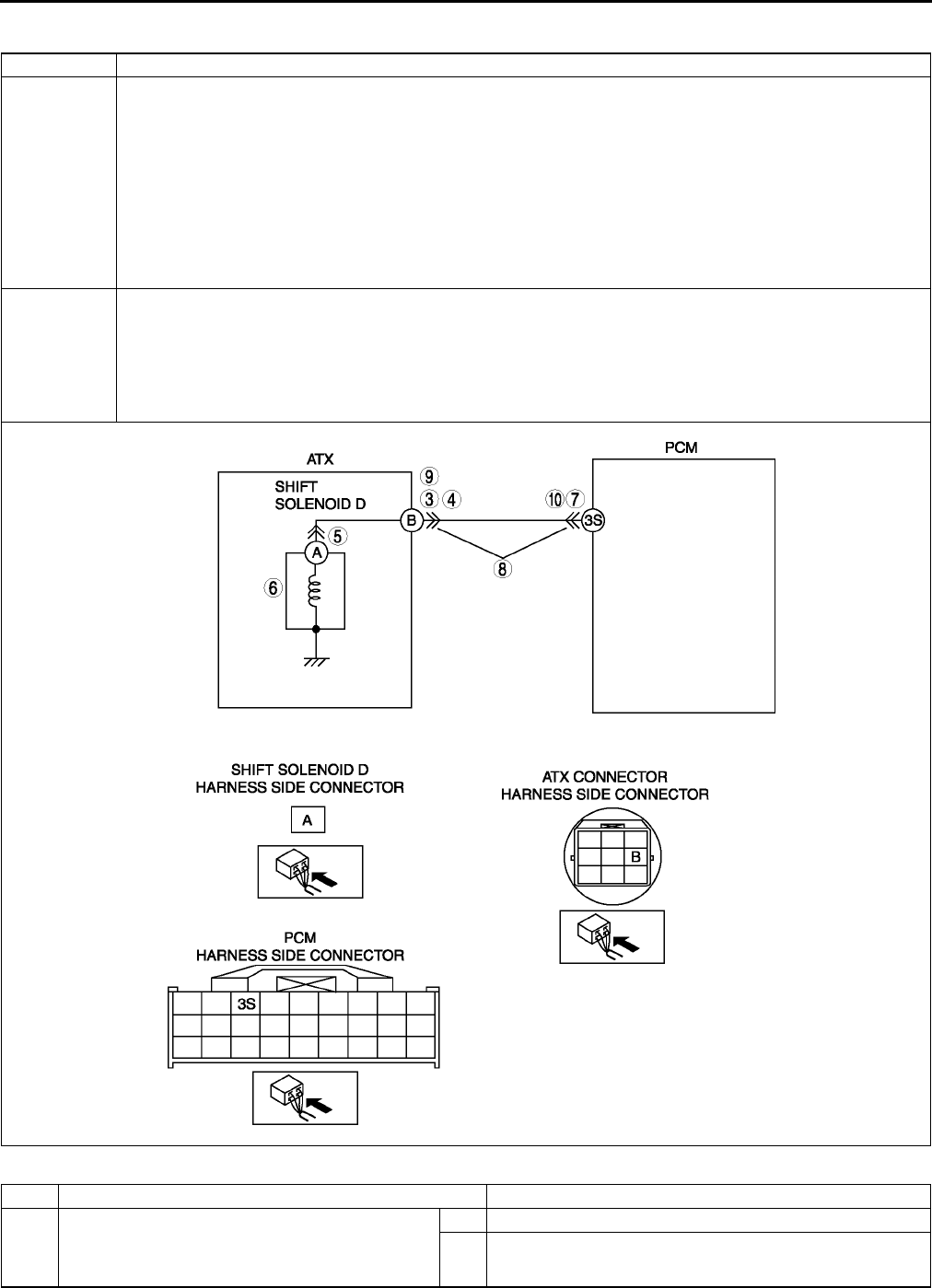
K102
ON-BOARD DIAGNOSTIC
DTC P0768 A6E567001030W31
Diagnostic procedure
DTC P0768 Shift solenoid D malfunction (electrical)
DETECTION
CONDITION
•If PCM detects either of following conditions while driving in 4GR at D range, PCM determines that shift
solenoid D circuit has a malfunction:
Shift solenoid D voltage is stuck at B+ after engine start.
Shift solenoid D voltage is stuck at 0 V after engine start.
Diagnostic support note:
•This is a continuous monitor (CCM).
•MIL illuminates if PCM detects the above malfunction conditions during first drive cycle.
•PENDING CODE is not available.
•FREEZE FRAME DATA is available.
•HOLD indicator light flashes.
•DTC is stored in the PCM memory.
POSSIBLE
CAUSE
•Shift solenoid D malfunction
•Short to ground between ATX connector terminal B and PCM terminal 3S
•Short to power between ATX connector terminal B and PCM terminal 3S
•Open circuit between shift solenoid D terminal A and ATX connector terminal B
•Open circuit between ATX connector terminal B and PCM terminal 3S
•Damaged connector between shift solenoid D and PCM
•PCM malfunction
STEP INSPECTION ACTION
1VERIFY FREEZE FRAME DATA HAS BEEN
RECORDED
•Has FREEZE FRAME PID DATA been
recorded?
Yes Go to next step.
No Record FREEZE FRAME PID DATA on repair order, then
go to next step.

ON-BOARD DIAGNOSTIC
K103
K
2VERIFY RELATED REPAIR INFORMATION
AVAILABILITY
•Check for related Service Bulletins availability.
•Is any related repair information available?
Yes Perform repair or diagnosis according to available repair
information.
•If vehicle is not repaired, go to next step.
No Go to next step.
3INSPECT ATX CONNECTOR FOR POOR
CONNECTION
•Turn ignition key to OFF.
•Disconnect ATX connector.
•Check for poor connection (damaged/pulled-
out terminals, corrosion, etc.).
•Is connection okay?
Yes Go to next step.
No Repair or replace connector and/or terminals, then go to
Step 11.
4INSPECT RESISTANCE
•Inspect resistance between ATX connector
terminal B (transaxle case side) and body
ground.
•Is resistance within 10.926.2 ohms?
(See K26 Resistance Inspection (On-Vehicle
Inspection).)
Yes Go to Step 7.
No Go to next step.
5INSPECT SHIFT SOLENOID D CONNECTOR
FOR POOR CONNECTION
•Disconnect shift solenoid D connector.
•Check for poor connection (damaged/pulled-
out terminals, corrosion, etc.).
•Is connection okay?
Yes Go to next step.
No Repair or replace connector and/or terminal, then go to
Step 11.
6INSPECT RESISTANCE
•inspect resistance between shift solenoid D
terminal A (part-side) and body ground.
•Is resistance within 10.926.2 ohms?
(See K26 Resistance Inspection (On-Vehicle
Inspection).)
Yes Replace solenoid harness, then go to Step 11.
No Verify shift solenoid D installation.
•If solenoid installed correctly, replace solenoid, then go
to Step 11.
(See K28 SOLENOID VALVE REMOVAL/
INSTALLATION.)
7INSPECT PCM CONNECTOR FOR POOR
CONNECTION
•Disconnect PCM connector.
•Check for poor connection (damaged/pulled-
out terminals, corrosion, etc.).
•Is connection okay?
Yes Go to next step.
No Repair or replace connector and/or terminals, then go to
Step 11.
8INSPECT ATX CONNECTOR CIRCUIT FOR
OPEN
•Inspect for continuity between PCM terminal
3S (harness-side) and ATX connector terminal
B (vehicle harness-side).
•Is there continuity between terminals?
Yes Go to next step.
No Repair or replace harness, then go to Step 11.
9INSPECT ATX CONNECTOR CIRCUIT FOR
SHORT TO POWER
•Turn ignition key to ON (engine OFF).
•Inspect voltage at ATX connector terminal B
(vehicle harness-side).
•Is voltage 0 V?
Yes Go to next step.
No Repair or replace harness, then go to Step 11.
10 INSPECT PCM CIRCUIT FOR SHORT TO
GROUND
•Turn ignition key to OFF.
•Inspect continuity between PCM terminal 3S
(harness-side) and body ground.
•Is there continuity?
Yes Repair or replace harness, then go to Step 11.
No Go to next step.
11 VERIFY TROUBLESHOOTING OF DTC P0768
COMPLETED
•Make sure to reconnect all disconnected
connectors.
•Clear DTC from memory using WDS or
equivalent.
•Drive vehicle in D range and make sure that
gears shift smoothly from 1GR to 4GR.
•Are any DTCs present?
Yes Replace PCM, then go to next step.
(See F43 PCM REMOVAL/INSTALLATION.)
No No concern is detected. Go to next step.
12 VERIFY AFTER REPAIR PROCEDURE
•Perform After Repair Procedure.
(See K52 AFTER REPAIR PROCEDURE.)
•Are any DTCs present?
Yes Go to applicable DTC inspection.
No Troubleshooting completed.
STEP INSPECTION ACTION

K104
ON-BOARD DIAGNOSTIC
End Of Sie
DTC P0771 A6E567001030W32
Diagnostic procedure
DTC P0771 Shift solenoid E stuck OFF
DETECTION
CONDITION
•When any of P0731, P0732, and P0734 are not generated, and all conditions below are satisfied.
ATF temperature 20 °
°°
°C {68 °
°°
°F} or above.
Driving in 4GR at D range.
Engine run.
Turbine speed within 2254,988 rpm.
Vehicle speed within 60100 km/h {3762 mph}.
TCC operation
Shift solenoid A duty value exceeds 99%
Power or normal mode
Difference between engine speed and turbine speed more than 100 rpm
Any of the following not generated: DTC P0500, P0706, P0707, P0708, P0712, P0713, P0715, P0751,
P0752, P0753, P0756, P0757, P0758, P0761, P0762, P0763, P0766, P0767, P0767, P0768, P0771,
P0772, P0773.
Diagnostic support note:
•This is a continuous monitor (CCM).
•MIL illuminates if PCM detects the above malfunction condition in two consecutive drive cycles or in one
drive cycle while the DTC for the same malfunction has been stored in the PCM.
•PENDING CODE is available if PCM detects the above malfunction condition during first drive cycle.
•FREEZE FRAME DATA is available.
•HOLD indicator light flashes.
•DTC is stored in the PCM memory.
POSSIBLE
CAUSE
•ATF level low
•Deteriorated ATF
•Shift solenoid E stuck
•Control valve stuck
•PCM malfunction
STEP INSPECTION ACTION
1VERIFY FREEZE FRAME DATA HAS BEEN
RECORDED
•Has FREEZE FRAME PID DATA been
recorded?
Yes Go to next step.
No Record FREEZE FRAME PID DATA on repair order, then
go to next step.
2VERIFY RELATED REPAIR INFORMATION
AVAILABILITY
•Check for related Service Bulletins availability.
•Is any related repair information available?
Yes Perform repair or diagnosis according to available repair
information.
•If vehicle is not repaired, go to next step.
No Go to next step.
3CHECK ATF CONDITION
•Turn ignition key to OFF.
•Check ATF condition.
Clear red: Normal
Milky: Water mixed in fluid
Reddish brown: Deteriorated ATF
•Is it okay?
(See K12 Automatic Transaxle Fluid (ATF)
Condition Inspection.)
Yes Go to next step.
No If ATF color milky or reddish brown, replace ATF, then go to
Step 5.
(See K13 AUTOMATIC TRANSAXLE FLUID (ATF)
REPLACEMENT.)
4CHECK ATF LEVEL
•Start engine.
•Warm up ATX.
•Is ATF level within specification?
(See K12 Automatic Transaxle Fluid (ATF) Level
Inspection.)
Yes Go to next step.
No Adjust ATF level, then go to Step 7.
(See K12 Automatic Transaxle Fluid (ATF) Level
Inspection.)
5INSPECT LINE PRESSURE
•Start engine.
•Measure line pressure.
Specification
Idle: 330470 kPa {3.44.7 kgf/cm2, 4966
psi}
Stall: 1,2001,360 kPa {12.313.8 kgf/cm2,
175196 psi}
•Is line pressure within specification?
(See K6 Line Pressure Test.)
Yes Go to next step.
No •All ranges: Replace oil pump or control valve body, then
go to Step 7.
•Any ranges: Replace ATX, then go to Step 7.
(See K29 AUTOMATIC TRANSAXLE REMOVAL/
INSTALLATION.)
(See ATX Workshop Manual FN4A-EL (9999-95-FN4A-
99).)
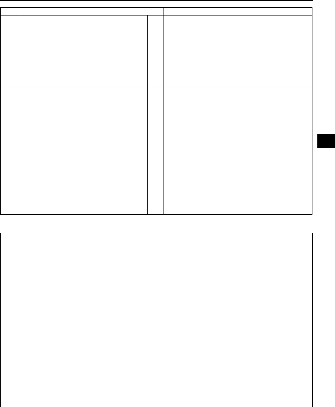
ON-BOARD DIAGNOSTIC
K105
K
End Of Sie
DTC P0772 A6E567001030W33
6CHECK OPERATION OF EACH VALVE AND
EACH SPRING
•Turn ignition key to OFF.
•Remove control valve body.
•Disassemble control valve body.
•Is each valve operation okay and is return
spring okay?
(See K34 CONTROL VALVE BODY REMOVAL,
K35 CONTROL VALVE BODY INSTALLATION.)
(See ATX Workshop Manual FN4A-EL (9999-95-
FN4A-99).)
Yes Replace ATX, then go to next step.
(See K29 AUTOMATIC TRANSAXLE REMOVAL/
INSTALLATION.)
(See ATX Workshop Manual FN4A-EL (9999-95-FN4A-
99).)
No Repair or replace shift valve and return spring, then go to
next step.
(See K34 CONTROL VALVE BODY REMOVAL, K35
CONTROL VALVE BODY INSTALLATION.)
(See ATX Workshop Manual FN4A-EL (9999-95-FN4A-
99).)
7VERIFY TROUBLESHOOTING OF DTC P0771
COMPLETED
•Make sure to reconnect all disconnected
connectors.
•Clear DTC from memory using WDS or
equivalent.
•Start engine.
•Warm up ATX.
•Drive the vehicle under the following conditions
and make sure that gears shift smoothly from
1GR to 4GR.
ATF temperature: 20 °
°°
°C {68 °
°°
°F} or above
Drive in D range
Vehicle speed: within 60100 km/h {37
62 mph} (4th gear only).
•Is pending code present?
Yes Replace PCM, then go to next step.
(See F43 PCM REMOVAL/INSTALLATION.)
No Go to next step.
8VERIFY AFTER REPAIR PROCEDURE
•Perform After Repair Procedure.
(See K52 AFTER REPAIR PROCEDURE.)
•Are any DTCs present?
Yes Go to applicable DTC inspection.
No Troubleshooting completed.
STEP INSPECTION ACTION
DTC P0772 Shift solenoid E stuck ON
DETECTION
CONDITION
•When any of DTC P0731, P0733, and P0734 are not generated, and all of following conditions satisfied
under each of following throttle conditions.
ATF temperature 20 °
°°
°C {68 °
°°
°F} or above.
Driving in 4GR at D range.
Engine run.
Turbine speed within 2254,988 rpm.
Vehicle speed below 70 km/h {43 mph}.
Torque converter clutch (TCC) no operation
Difference between engine speed and turbine speed below 50 rpm
•Throttle conditions.
Throttle opening angle (TP PID) above 10.1% and 5 seconds or more have passed.
Throttle opening angle (TP PID) within 3.110.1% and 3 seconds or more have passed.
Throttle opening angle at closed throttle position and 5 seconds or more have passed.
Diagnostic support note:
•This is a continuous monitor (CCM).
•MIL illuminates if PCM detects the above malfunction condition in two consecutive drive cycles or in one
drive cycle while the DTC for the same malfunction has been stored in the PCM.
•PENDING CODE is available if PCM detects the above malfunction condition during first drive cycle.
•FREEZE FRAME DATA is available.
•HOLD indicator light flashes.
•DTC is stored in the PCM memory.
POSSIBLE
CAUSE
•ATF level low
•Deteriorated ATF
•Shift solenoid E stuck
•Control valve stuck
•PCM malfunction

K106
ON-BOARD DIAGNOSTIC
Diagnostic procedure
End Of Sie
STEP INSPECTION ACTION
1VERIFY FREEZE FRAME DATA HAS BEEN
RECORDED
•Has FREEZE FRAME PID DATA been
recorded?
Yes Go to next step.
No Record FREEZE FRAME PID DATA on repair order, then
go to next step.
2VERIFY RELATED REPAIR INFORMATION
AVAILABILITY
•Check for related Service Bulletins availability.
•Is any related repair information available?
Yes Perform repair or diagnosis according to available repair
information.
•If vehicle is not repaired, go to next step.
No Go to next step.
3CHECK ATF CONDITION
•Turn ignition key to OFF.
•Check ATF condition.
Clear red: Normal
Milky: Water mixed in fluid
Reddish brown: Deteriorated ATF
•Is it okay?
(See K12 Automatic Transaxle Fluid (ATF)
Condition Inspection.)
Yes Go to next step.
No If ATF color milky or reddish brown, replace ATF, then go to
Step 5.
(See K13 AUTOMATIC TRANSAXLE FLUID (ATF)
REPLACEMENT.)
4CHECK ATF LEVEL
•Start engine.
•Warm up ATX.
•Is ATF level within specification?
(See K12 Automatic Transaxle Fluid (ATF) Level
Inspection.)
Yes Go to next step.
No Adjust ATF level, then go to Step 7.
(See K12 Automatic Transaxle Fluid (ATF) Level
Inspection.)
5INSPECT LINE PRESSURE
•Start engine.
•Measure line pressure.
Specification
Idle: 330470 kPa {3.44.7 kgf/cm2, 4966
psi}
Stall: 1,2001,360 kPa {12.313.8 kgf/cm2,
175196 psi}
•Is line pressure within specification?
(See K6 Line Pressure Test.)
Yes Go to next step.
No •All ranges: Replace oil pump or control valve body, then
go to Step 7.
•Any ranges: Replace ATX, then go to Step 7.
(See K29 AUTOMATIC TRANSAXLE REMOVAL/
INSTALLATION.)
(See ATX Workshop Manual FN4A-EL (9999-95-FN4A-
99).)
6CHECK OPERATION OF EACH VALVE AND
EACH SPRING
•Turn ignition key to OFF.
•Remove control valve body.
•Disassemble control valve body.
•Is each valve operation okay and is return
spring okay?
(See K34 CONTROL VALVE BODY REMOVAL,
K35 CONTROL VALVE BODY INSTALLATION.)
(See ATX Workshop Manual FN4A-EL (9999-95-
FN4A-99).)
Yes Replace ATX, then go to next step.
(See K29 AUTOMATIC TRANSAXLE REMOVAL/
INSTALLATION.)
(See ATX Workshop Manual FN4A-EL (9999-95-FN4A-
99).)
No Repair or replace shift valve and return spring, then go to
next step.
(See K34 CONTROL VALVE BODY REMOVAL, K35
CONTROL VALVE BODY INSTALLATION.)
(See ATX Workshop Manual FN4A-EL (9999-95-FN4A-
99).)
7VERIFY TROUBLESHOOTING OF DTC P0772
COMPLETED
•Make sure to reconnect all disconnected
connectors.
•Clear DTC from memory using WDS or
equivalent.
•Start engine.
•Warm up ATX.
•Drive the vehicle under the following conditions
and make sure that gears shift smoothly from
1GR to 4GR.
ATF temperature: 20 °
°°
°C {68 °
°°
°F} or above
Drive in D range
Vehicle speed (VSS PID): below 70 km/h
{43 mph} (4th gear only)
•Is pending code present?
Yes Replace PCM, then go to next step.
(See F43 PCM REMOVAL/INSTALLATION.)
No Go to next step.
8VERIFY AFTER REPAIR PROCEDURE
•Perform After Repair Procedure.
(See K52 AFTER REPAIR PROCEDURE.)
•Are any DTCs present?
Yes Go to applicable DTC inspection.
No Troubleshooting completed.
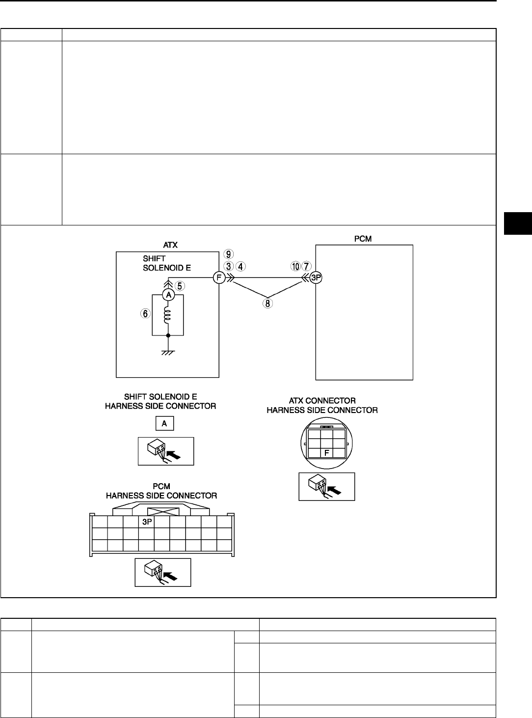
ON-BOARD DIAGNOSTIC
K107
K
DTC P0773 A6E567001030W34
Diagnostic procedure
DTC P0773 Shift solenoid E malfunction (electrical)
DETECTION
CONDITION
•If PCM detects either of following conditions while driving in 4GR at D range with TCC operation, PCM
determines that shift solenoid E circuit has a malfunction:
Shift solenoid E voltage is stuck at B+ after engine start.
Shift solenoid E voltage is stuck at 0 V after engine start.
Diagnostic support note:
•This is a continuous monitor (CCM).
•MIL illuminates if PCM detects the above malfunction conditions during first drive cycle.
•PENDING CODE is not available.
•FREEZE FRAME DATA is available.
•HOLD indicator light flashes.
•DTC is stored in the PCM memory.
POSSIBLE
CAUSE
•Shift solenoid E malfunction
•Short to ground between ATX connector terminal F and PCM terminal 3P
•Short to power between ATX connector terminal F and PCM terminal 3P
•Open circuit between shift solenoid E terminal A and ATX connector terminal F
•Open circuit between ATX connector terminal F and PCM terminal 3P
•Damaged connector between shift solenoid E and PCM
•PCM malfunction
STEP INSPECTION ACTION
1VERIFY FREEZE FRAME DATA HAS BEEN
RECORDED
•Has FREEZE FRAME PID DATA been
recorded?
Yes Go to next step.
No Record FREEZE FRAME PID DATA on repair order, then
go to next step.
2VERIFY RELATED REPAIR INFORMATION
AVAILABILITY
•Check for related Service Bulletins availability.
•Is any related repair information available?
Yes Perform repair or diagnosis according to available repair
information.
•If vehicle is not repaired, go to next step.
No Go to next step.

K108
ON-BOARD DIAGNOSTIC
End Of Sie
3INSPECT ATX CONNECTOR FOR POOR
CONNECTION
•Turn ignition key to OFF.
•Disconnect ATX connector.
•Check for poor connection (damaged/pulled-
out terminals, corrosion, etc.).
•Is connection okay?
Yes Go to next step.
No Repair or replace connector and/or terminals, then go to
Step 11.
4INSPECT RESISTANCE
•Inspect resistance between ATX connector
terminal F (transaxle case side) and body
ground.
•Is resistance within 10.926.2 ohms?
(See K26 Resistance Inspection (On-Vehicle
Inspection).)
Yes Go to Step 7.
No Go to next step.
5INSPECT SHIFT SOLENOID E CONNECTOR
FOR POOR CONNECTION
•Disconnect shift solenoid E connector.
•Check for poor connection (damaged/pulled-
out terminals, corrosion, etc.).
•Is connection okay?
Yes Go to next step.
No Repair or replace connector and/or terminal, then go to
Step 11.
6INSPECT RESISTANCE
•Inspect resistance between shift solenoid E
terminal A (part-side) and body ground.
•Is resistance within 10.926.2 ohms?
(See K27 Resistance Inspection (Off-Vehicle
Inspection).)
Yes Replace solenoid harness, then go to Step 11.
No Verify shift solenoid E installation.
•If solenoid installed correctly, replace solenoid, then go
to Step 11.
(See K28 SOLENOID VALVE REMOVAL/
INSTALLATION.)
7INSPECT PCM CONNECTOR FOR POOR
CONNECTION
•Disconnect PCM connector.
•Check for poor connection (damaged/pulled-
out terminals, corrosion, etc.).
•Is connection okay?
Yes Go to next step.
No Repair or replace connector and/or terminals, then go to
Step 11.
8INSPECT ATX CONNECTOR CIRCUIT FOR
OPEN
•Inspect for continuity between PCM terminal 1
(harness-side) and ATX connector terminal F
(vehicle harness-side).
•Is there continuity between terminals?
Yes Go to next step.
No Repair or replace harness, then go to Step 11.
9INSPECT ATX CONNECTOR CIRCUIT FOR
SHORT TO POWER
•Turn ignition key to ON (engine OFF).
•Inspect voltage at ATX connector terminal F
(vehicle harness-side).
•Is voltage 0 V?
Yes Go to next step.
No Repair or replace harness, then go to Step 11.
10 INSPECT PCM CIRCUIT FOR SHORT TO
GROUND
•Turn ignition key to OFF.
•Inspect for continuity between PCM terminal 1
(harness-side) and body ground.
•Is there continuity?
Yes Repair or replace harness, then go to Step 11.
No Go to next step.
11 VERIFY TROUBLESHOOTING OF DTC P0773
COMPLETED
•Make sure to reconnect all disconnected
connectors.
•Clear DTC from memory using WDS or
equivalent.
•Drive vehicle in D range and make sure that
gears shift smoothly from 1GR to 4GR.
•Are any DTCs present?
Yes Replace PCM, then go to next step.
(See F43 PCM REMOVAL/INSTALLATION.)
No No concern is detected. Go to next step.
12 VERIFY AFTER REPAIR PROCEDURE
•Perform After Repair Procedure.
(See K52 AFTER REPAIR PROCEDURE.)
•Are any DTCs present?
Yes Go to applicable DTC inspection.
No Troubleshooting completed.
STEP INSPECTION ACTION
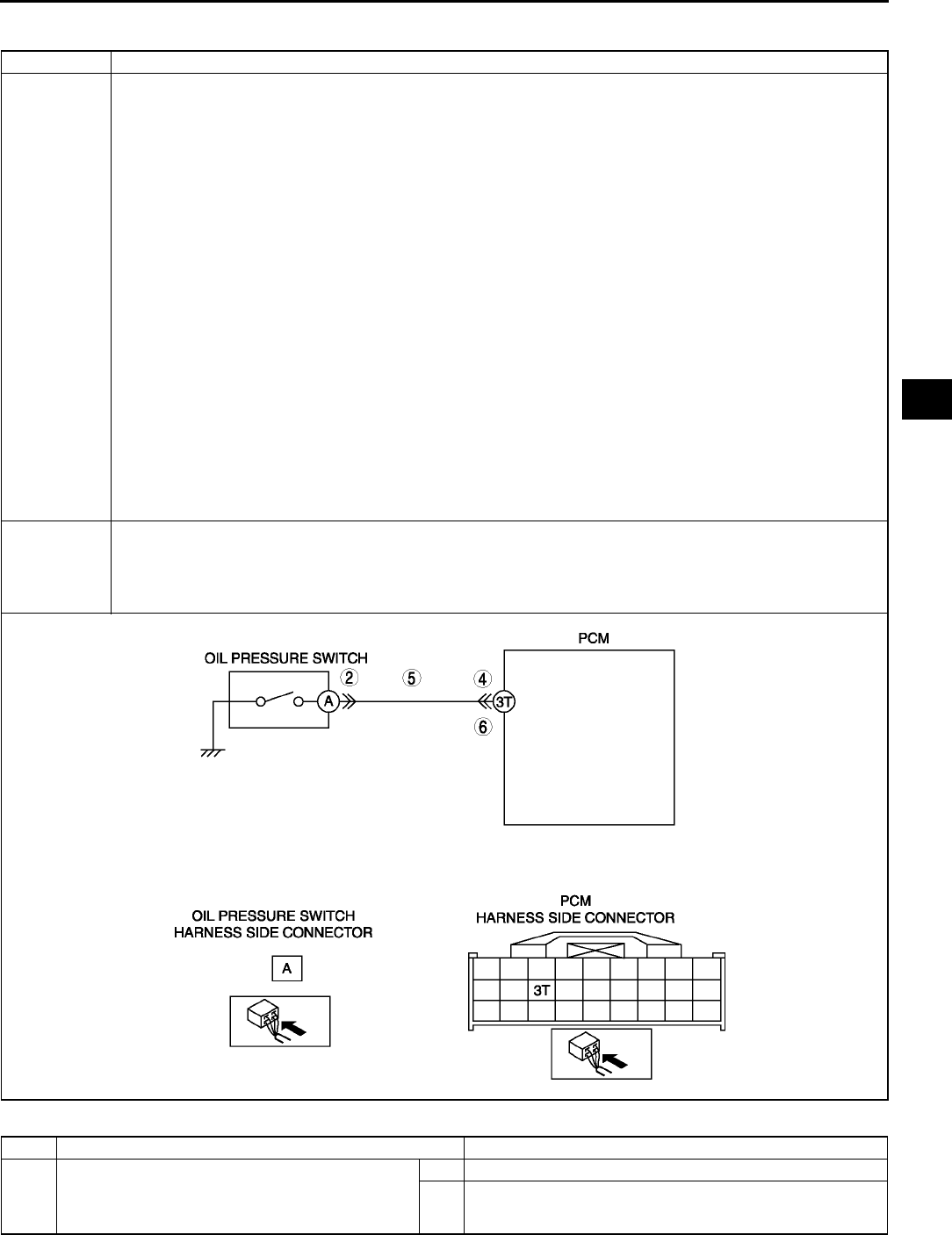
ON-BOARD DIAGNOSTIC
K109
K
DTC P0841 A6E567001030W35
Diagnostic procedure
DTC P0841 Oil pressure switch circuit malfunction
DETECTION
CONDITION
•When each of DTC P0731, P0732, P0733 and P0734 are not generated and 10 seconds or more passed.
When all conditions below satisfied while driving in 1GR, 2GR or 3GR.
•ATF temperature 20 °
°°
°C {68 °
°°
°F} or above.
•Oil pressure switch OFF
•Revolution ratio of forward clutch drum revolution to differential gear case revolution below 0.91 or
more than 3.08.
•Any of the following not generated: DTC P0500, P0706, P0707, P0708, P0712, P0713, P0715,
P0751, P0752, P0753, P0756, P0757, P0758, P0761, P0762, P0763, P0766, P0767, P0768, P0771,
P0772, P0773.
When all conditions below satisfied with driving in 4GR.
•ATF temperature 20 °
°°
°C {68 °
°°
°F} or above.
•Oil pressure switch ON
•Revolution ratio of forward clutch drum revolution to differential gear case revolution below 0.64 or
more than 0.82.
•Any of the following not generated: DTC P0500, P0706, P0707, P0708, P0712, P0713, P0715,
P0751, P0752, P0753, P0756, P0757, P0758, P0761, P0762, P0763, P0766, P0767, P0768, P0771,
P0772, P0773.
Diagnostic support note:
•This is a continuous monitor (CCM).
•MIL illuminates if PCM detects the above malfunction condition in two consecutive drive cycles or in one
drive cycle while the DTC for the same malfunction has been stored in the PCM.
•PENDING CODE is not available.
•FREEZE FRAME DATA is not available.
•HOLD indicator light flashes.
•DTC is stored in the PCM memory.
POSSIBLE
CAUSE
•Oil pressure switch malfunction
•Open circuit between oil pressure switch terminal A and PCM terminal 3T
•Short to ground between oil pressure switch terminal A and PCM terminal 3T
•Damaged connector between oil pressure switch and PCM
•PCM malfunction
STEP INSPECTION ACTION
1VERIFY FREEZE FRAME DATA HAS BEEN
RECORDED
•Has FREEZE FRAME PID DATA been
recorded?
Yes Go to next step.
No Record FREEZE FRAME PID DATA on repair order, then
go to next step.

K110
ON-BOARD DIAGNOSTIC
End Of Sie
PID/DATA MONITOR INSPECTION A6E567001030W36
1. Connect the WDS or equivalent to the DLC-2.
2. Measure the PID value.
Note
•Perform part inspection for the output device after PCM inspection.
•The PID/DATA MONITOR function monitors the calculated value of the input/output signals in the PCM.
Therefore, if a monitored value of an output device is out of specification, it is necessary to inspect the
monitored value of the input device related to the output device control. Since an output device
malfunction is not directly indicated as a malfunction of the monitored value for the output device, it is
necessary to inspect the output device individually using the simulation function, etc.
2INSPECT OIL PRESSURE SWITCH
CONNECTOR FOR POOR CONNECTION
•Disconnect shift oil pressure switch connector.
•Check for poor connection (damaged/pulled-
out terminals, corrosion, etc.).
•Is connection okay?
Yes Go to next step.
No Repair or replace connector and/or terminal, then go to
Step 7.
3INSPECT CONTINUITY
•inspect for continuity between oil pressure
switch terminal A (part-side) and body ground.
•Is there any continuity?
Yes Replace oil pressure switch, then go to Step 7.
(See K23 OIL PRESSURE SWITCH REMOVAL/
INSTALLATION.)
No Go to next step.
4INSPECT PCM CONNECTOR FOR POOR
CONNECTION
•Disconnect PCM connector.
•Check for poor connection (damaged/pulled-
out terminals, corrosion, etc.).
•Is connection okay?
Yes Go to next step.
No Repair or replace connector and/or terminals, then go to
Step 7.
5INSPECT OIL PRESSURE SWITCH CIRCUIT
FOR OPEN
•Inspect for continuity between PCM terminal
3T (harness-side) and ATX connector terminal
A (harness-side).
•Is there continuity between terminals?
Yes Go to next step.
No Repair or replace harness, then go to Step 7.
6INSPECT PCM CIRCUIT FOR SHORT TO
GROUND
•Turn ignition key to OFF.
•Inspect continuity between PCM terminal 3T
(harness-side) and body ground.
•Is there continuity?
Yes Repair or replace harness, then go to next step.
No Replace oil pressure switch, then go to next step.
(See K23 OIL PRESSURE SWITCH REMOVAL/
INSTALLATION.)
7VERIFY TROUBLESHOOTING OF DTC P0841
COMPLETED
•Make sure to reconnect all disconnected
connectors.
•Clear DTC from memory using WDS or
equivalent.
•Drive vehicle and make sure that gears shift
smoothly from 1GR to 4GR.
•Are any DTCs present?
Yes Replace PCM, then go to next step.
(See F43 PCM REMOVAL/INSTALLATION.)
No No concern is detected. Go to next step.
8VERIFY AFTER REPAIR PROCEDURE
•Perform After Repair Procedure.
(See K52 AFTER REPAIR PROCEDURE.)
•Are any DTCs present?
Yes Go to applicable DTC inspection.
No Troubleshooting completed.
STEP INSPECTION ACTION

ON-BOARD DIAGNOSTIC
K111
K
PID/DATA MONITOR AND RECORD function table
End Of Sie
Monitor item
(Definition)
Unit/
Condition Condition/Specification Action PCM
terminal
GEAR
1GR: 1
2GR: 2
3GR: 3
4GR: 4
Inspect following PIDs: SSA/SS1, SSB/
SS2, SSC/SS3, SSD/SS4, SSE/SS5 3P, 3S,
3Y, 4Y,
4AB, 4AC
LINEDES kPa inHg Indicates target line pressure Inspect following PIDs:
TFT, TFT V, VPWR, TP, TSS, VSS, TR 3V, 3Y
LPS
(Pressure
control
solenoid)
%Change current value according to
throttle opening angle
Inspect pressure control solenoid.
(See K26 SOLENOID VALVE
INSPECTION.) 3V, 3Y
OP SW B
(Oil pressure
switch)
ON/OFF 1, 2 or 3GR: ON
Other: OFF
Inspect oil pressure switch inspection.
(See K21 OIL PRESSURE SWITCH
INSPECTION.)
3T
SSA/SS1
(Shift solenoid
A)
%4GR: 99%
others: 0%
Inspect shift solenoid A.
(See K26 SOLENOID VALVE
INSPECTION.)
4AB
SSB/SS2
(Shift solenoid
B)
%1GR at D range: 99%
Others: 0%
Inspect shift solenoid B.
(See K26 SOLENOID VALVE
INSPECTION.)
4AC
SSC/SS3
(Shift solenoid
C)
%1GR/2GR: 99%
Others: 0%
Inspect shift solenoid C.
(See K26 SOLENOID VALVE
INSPECTION.)
4Y
TCS
(HOLD switch) ON/OFF HOLD switch pressed: ON
HOLD switch released: OFF
Inspect HOLD switch.
(See K13 HOLD SWITCH
INSPECTION.)
3Q
TFT
(Transaxle fluid
temperature)
°C°F Indicates transaxle fluid temperature
Inspect TFT sensor.
(See K19 TRANSAXLE FLUID
TEMPERATURE (TFT) SENSOR
INSPECTION.)
3D
TFTV
(Transaxle fluid
signal voltage)
VATF 20 °
°°
°C {68 °
°°
°F}: 3.43.6 V
ATF 130 °
°°
°C {266 °
°°
°F}: 0.40.5 V
Inspect TFT sensor.
(See K19 TRANSAXLE FLUID
TEMPERATURE (TFT) SENSOR
INSPECTION.)
3D
THOP
(Throttle
position
sensor)
%CTP: 0%
WOT:100%
Inspect TP sensor.
(See F51 THROTTLE POSITION (TP)
SENSOR INSPECTION.) 2A
TP
(Throttle
position sensor
signal voltage)
VCTP: 0.41.5 V
WOT: 4.05.0 V
Inspect TP sensor.
(See F51 THROTTLE POSITION (TP)
SENSOR INSPECTION.) 2A
TR
(Transaxle
range)
P position: P
R position: R
N position: N
D range: D
S range: S
L range: L
Inspect TR switch.
(See K14 TRANSAXLE RANGE (TR)
SWITCH INSPECTION.) 1W
TR SENS
(TR switch) V
P position: 4.344.79 V
R position: 3.834.18 V
N position: 3.053.50 V
D range: 2.232.66 V
S range: 1.461.84 V
L range: 0.801.09 V
Inspect TR switch.
(See K14 TRANSAXLE RANGE (TR)
SWITCH INSPECTION.) 1W
TSS
(Input/turbine
speed)
rpm
Ignition switch ON: 0 rpm
Idle: 700800 rpm (P, N position)
Indicates Input/turbine speed
Inspect input/turbine speed sensor.
(See K23 INPUT/TURBINE SPEED
SENSOR INSPECTION.)
3G, 3J
VPWR
(Battery
positive
voltage)
VIgnition switch ON: B+
Engine running: B+
Inspect main relay.
(See T24 RELAY INSPECTION.)
Inspect buttery.
(See G4 BATTERY INSPECTION.)
2Y, 2Z
VSS
(Vehicle
speed)
km/h mph Indicates vehicle speed
Inspect VSS.
(See K24 VEHICLE SPEEDOMETER
SENSOR (VSS) INSPECTION.)
3C

K112
TROUBLESHOOTING
FOREWORD A6E568001030W01
•Refer to Section GI and thoroughly read and understand the basic flow of troubleshooting in order to properly
perform the procedures.
End Of Sie
BASIC INSPECTION A6E568001030W02
End Of Sie
TROUBLESHOOTING
STEP INSPECTION ACTION
1 Perform the mechanical system test.
(See K6 MECHANICAL SYSTEM TEST.)
Is mechanical system okay?
Yes Go to next step.
No Repair or replace any defective parts according to
inspection result.
2 Turn IG SW to ON.
When selector lever is moved, dose the selector
illumination indicate synchronized position to
lever location? Also, when other ranges are
selected from N or P during idling, does vehicle
moves within 12 seconds?
Yes Go to next step.
No Inspect selector lever and TR switch. Repair or replace
defected areas.
(See K45 SELECTOR LEVER INSPECTION.)
(See K14 TRANSAXLE RANGE (TR) SWITCH
INSPECTION.)
If selector lever and TR switch are okay, go to next step.
3 Inspect ATF color and condition.
(See K12 AUTOMATIC TRANSAXLE FLUID
(ATF) INSPECTION.)
Are ATF color and ordor normal?
Yes Go to next step.
No Repair or replace any defective parts according to
inspection result.
Flush ATX and cooler line as necessary.
4 Perform line pressure test.
(See K6 Line Pressure Test.)
Is line pressure okay?
Yes Go to next step.
No Adjust accelerator cable as necessary.
Repair or replace any defective parts according to
inspection result.
5 Perform stall test.
(See K7 Stall Test.)
Is stall speed okay?
Yes Go to next step.
No Repair or replace any defective parts according to
inspection result.
6 Inspect the value at the following PIDs using the
WDS or equivalent.
(See F45 PCM INSPECTION.)
•TFT
•TFT V
•VPWR
•TR
•TR SENS
•ECT
•TCS
•RPM
•TP
•TSS
•VSS
Is PID value okay?
Yes Perform symptom troubleshooting and follow procedures.
No Repair or replace any defective parts according to
inspection result.

TROUBLESHOOTING
K113
K
SYMPTOM TROUBLESHOOTING ITEM TABLE A6E568001030W03
•Use the chart below to verify the symptoms of the trouble in order to diagnose the appropriate area.
No. TROUBLESHOOTING ITEM DESCRIPTION PAGE
1 Vehicle does not move in D, S, L
ranges, or in R position
Vehicle does not move when AP depressed. (See K117 NO.1 VEHICLE
DOES NOT MOVE IN D, S, L
RANGES, OR IN R
POSITION.)
2 Vehicle moves in N position Vehicle creeps in N position.
Vehicle creeps if brake pedal is not
depressed in N position.
(See K117 NO.2 VEHICLE
MOVES IN N POSITION.)
3 Vehicle moves in P position, or
parking gear does not disengage
when P position is disengaged
Vehicle rolls when on a downward slope and
tires do not lock in P position.
Tires locked when P position is disengaged,
vehicle does not move in D, S, L ranges,
and R position when AP depressed, and
engine remains in stall condition.
(See K118 NO.3 VEHICLE
MOVES IN P POSITION, OR
PARKING GEAR DOES NOT
DISENGAGE WHEN P IS
DISENGAGED.)
4 Excessive creep Vehicle accelerates in D, S, L ranges, and R
position without depressing accelerator
pedal.
(See K118 NO.4 EXCESSIVE
CREEP.)
5 No creep at all Vehicle does not move in D, S, L ranges, or
R position when idling on flat paved road.
(See K118 NO.5 NO CREEP
AT ALL.)
6 Low maximum speed and poor
acceleration
Vehicle acceleration poor at start.
Delayed acceleration when accelerator
pedal depressed while driving.
(See K119 NO.6 LOW
MAXIMUM SPEED AND
POOR ACCELERATION.)
7 No shifting Single shift range only.
Sometimes is shifts correctly.
(See K120 NO.7 NO
SHIFTING.)
8 Does not shift to fourth gear (4GR) Vehicle does not upshift from 3GR to 4GR
even though vehicle speed is increased.
Vehicle does not shift to 4GR even though
accelerator pedal is released in D range at
60 km/h {37 mph}.
(See K120 NO.8 DOES NOT
SHIFT TO FOURTH GEAR
(4GR).)
9 Abnormal shifting Shifts incorrectly (incorrect shift pattern). (See K122 NO.9 ABNORMAL
SHIFTING.)
10 Frequent shifting Downshifting occurs immediately even
when accelerator pedal depressed slightly in
D, S, L ranges except HOLD mode.
(See K122 NO.10
FREQUENT SHIFTING.)
11 Shift point is high or low Shift point considerably different from
automatic shift diagram.
Shift delays when accelerating.
Shift occurs quickly when accelerating and
engine speed does not increase.
(See K122 NO.11 SHIFT
POINT IS HIGH OR LOW.)
12 Torque converter clutch (TCC) non-
operation
TCC does not operate when vehicle
reaches TCC operation range.
(See K123 NO.12 TORQUE
CONVERTER CLUTCH (TCC)
NON-OPERATION.)
13 No kickdown Does not downshift when accelerator pedal
fully depressed within kickdown range.
(See K123 NO.13 NO
KICKDOWN.)
14 Engine flares up or slips when
upshifting or downshifting
When accelerator pedal is depressed for
driveway, engine speed increases but
vehicle speed increase slowly.
When accelerator pedal is depressed while
driving, engine speed increases but vehicle
speed does not.
(See K124 NO.14 ENGINE
FLARES UP OR SLIPS WHEN
UPSHIFTING OR
DOWNSHIFTING.)
15 Engine flares up or slips when
accelerating vehicle
Engine flares up when accelerator pedal is
depressed for upshifting.
Engine flares up suddenly when accelerator
pedal is depressed for downshifting.
(See K124 NO.15 ENGINE
FLARES UP OR SLIPS WHEN
ACCELERATING VEHICLE.)
16 Judder upon torque converter clutch
(TCC) operation
Vehicle jolts when TCC is engaged. (See K125 NO.16 JUDDER
UPON TORQUE
CONVERTER CLUTCH (TCC)
OPERATION.)
17 Excessive shift shock from N to D or N
to R position/range
Strong shock is felt when shifting from N to
D or N to R position/range at idle.
(See K126 NO.17
EXCESSIVE SHIFT SHOCK
FROM N TO D OR N TO R
POSITION/RANGE.)

K114
TROUBLESHOOTING
End Of Sie
18 Excessive shift shock is given when
upshifting and downshifting
Excessive shift shock is felt when
depressing accelerator pedal to accelerate
at upshifting.
During cruising, excessive shift shock is felt
when depressing accelerator pedal at
downshifting.
(See K127 NO.18
EXCESSIVE SHIFT SHOCK IS
FELT WHEN UPSHIFTING
AND DOWNSHIFTING.)
19 Excessive shift shock on torque
converter clutch (TCC)
Strong shock is felt when TCC engaged. (See K127 NO.19
EXCESSIVE SHIFT SHOCK
ON TORQUE CONVERTER
CLUTCH (TCC).)
20 Noise occurs at idle when vehicle is
stopped in all positions/ranges
Transaxle is noisy in all positions and
ranges when vehicle idling.
(See K128 NO.20 NOISE
OCCURS AT IDLE WHEN
VEHICLE IS STOPPED IN ALL
POSITIONS/RANGES.)
21 Noise occurs at idle when vehicle is
stopped in D, S, L ranges, or in R
position
Transaxle is noisy in driving ranges when
vehicle idling.
(See K128 NO.21 NOISE
OCCURS AT IDLE WHEN
VEHICLE IS STOPPED IN D,
S, L RANGES, OR IN R
POSITION.)
22 No engine braking in HOLD mode Engine speed drops to idle but vehicle
coasts when accelerator pedal is released
during cruising at medium to high speeds.
Engine speed drops to idle but vehicle
coasts when accelerator pedal is released
when in L range at low vehicle speed.
(See K129 NO.22 NO
ENGINE BRAKING IN HOLD
MODE.)
23 Transaxle overheats Burnt smell emitted from transaxle.
Smoke is emitted from transaxle.
(See K129 NO.23
TRANSAXLE OVERHEATS.)
24 Engine stalls when shifted to D, S, L
ranges, or in R position
Engine stalls when shifting from N or P
position to D, S, L ranges or R position at
idle.
(See K130 NO.24 ENGINE
STALLS WHEN SHIFTED TO
D, S, L RANGES, OR IN R
POSITION.)
25 Engine stalls when driving at slow
speeds or stopping
Engine stalls when brake pedal is
depressed while driving at low speed or
stopping.
(See K130 NO.25 ENGINE
STALLS WHEN DRIVING AT
SLOW SPEEDS OR
STOPPING.)
26 Starter does not work Starter does not work even when P or N
position is selected.
(See K130 NO.26 STARTER
DOES NOT WORK.)
27 HOLD indicator light does not
illuminate when HOLD switch is turned
ON
HOLD indicator light in dashboard does not
illuminate when HOLD switch is turned on
and IG SW at ON.
(See K130 NO.27 HOLD
INDICATOR LIGHT DOES
NOT ILLUMINATE WHEN
HOLD SWITCH IS TURNED
TO ON.)
28 HOLD indicator light illuminates when
HOLD switch is not turned ON
HOLD indicator light in dashboard
illuminates even though HOLD switch
turned off and IG SWat ON.
(See K131 NO.28 HOLD
INDICATOR LIGHT
ILLUMINATES WHEN HOLD
SWITCH IS NOT TURNED TO
ON.)
No. TROUBLESHOOTING ITEM DESCRIPTION PAGE
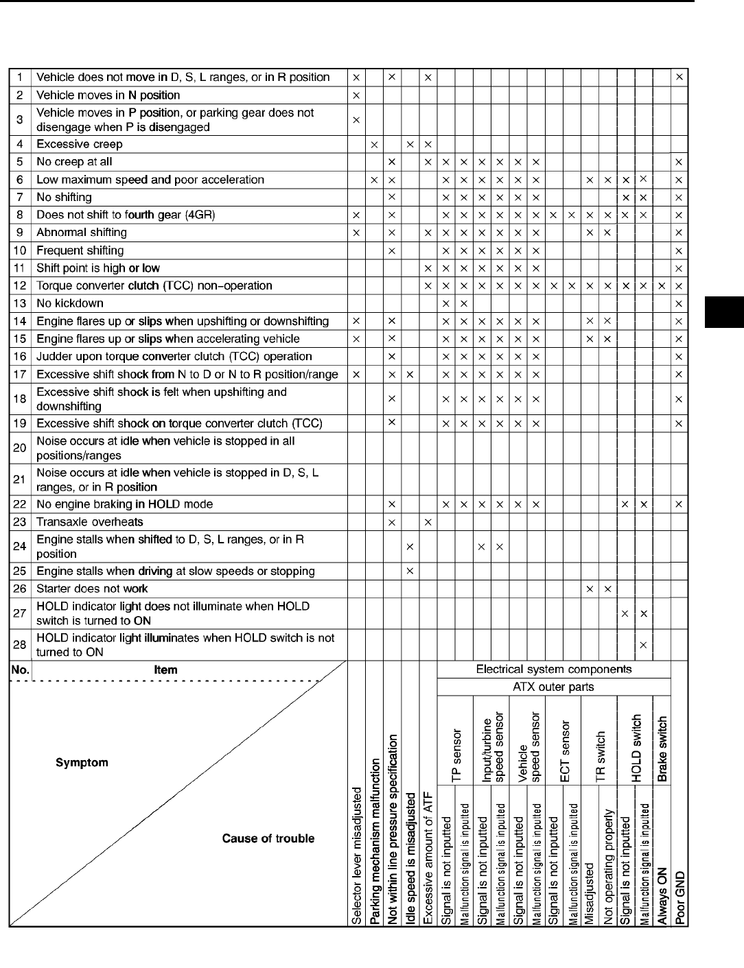
TROUBLESHOOTING
K115
K
QUICK DIAGNOSIS CHART A6E568001030W04
A6E5680W001
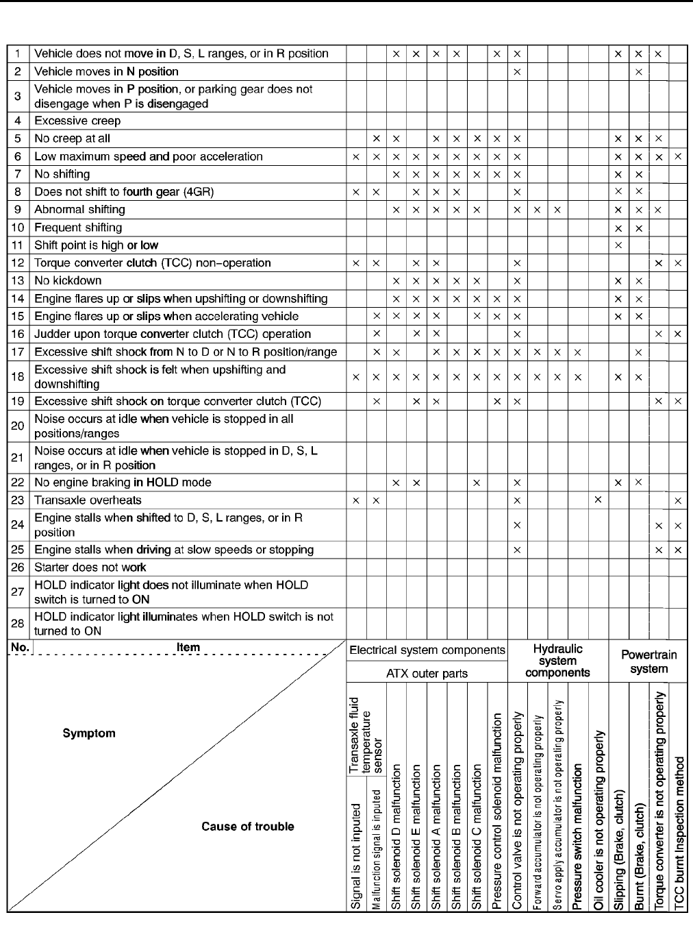
K116
TROUBLESHOOTING
End Of Sie
A6E5680W002
TROUBLESHOOTING
K117
K
NO.1 VEHICLE DOES NOT MOVE IN D, S, L RANGES, OR IN R POSITION A6E568001030W05
Diagnostic procedure
End Of Sie
NO.2 VEHICLE MOVES IN N POSITION A6E568001030W06
Diagnostic procedure
1 Vehicle does not move in D, S, L ranges, or in R position
DESCRIPTION •Vehicle does not move when AP depressed.
POSSIBLE
CAUSE
•If the vehicle does not move in D, S, L ranges or R position, basically, the malfunction is in the ATX.
(Vehicle will move even with a malfunction in the PCM.) Since a malfunction is in the sensor circuit or
output circuit is the cause of the malfunction in the ATX, inspect the sensors, output circuit, and the
related harnesses.
1. Clutch slipped, worn (D, S, L ranges-Forward clutch, R position-Reverse clutch, Low and reverse
brake)
•Line pressure low
•Shift solenoid D malfunction
•Shift solenoid E malfunction
•Shift solenoid A malfunction
•Shift solenoid B malfunction
•Pressure control solenoid malfunction
•Body GND malfunction
•Control valve body malfunction
2. Selector lever malfunction
3. Parking mechanism not properly operation
4. Torque converter malfunction
Note
•Before following troubleshooting steps, make sure that Automatic Transaxle On-Board Diagnostic
and Automatic Transaxle Basic Inspection are conducted.
STEP INSPECTION ACTION
1 When vehicle is stopped on a flat, level road and
engine is off, does vehicle move when pushed?
(in D, S ranges or N, R positions and brake is
released)
Yes Go to next step.
No Check for parking mechanism. (See ATX workshop manual
(FN4A-EL) [1623-10-98E].) (See ATX workshop manual
supplement (FN4A-EL) [1746-1*-02C].)
2 Disconnect PCM.
Is resistance between ground terminal at PCM
connector and body ground less than 5.0
ohms?
Yes Go to next step.
No Repair open ground circuit.
3 Check LPS PID value using WDS or equivalent.
Is LPS PID value okay?
(See F45 PCM INSPECTION.)
Yes Overhaul control valve body and repair or replace any
defective parts. If problem remains, overhaul transaxle and
repair or replace any defective parts. (See ATX workshop
manual (FN4A-EL) [1623-10-98E].) (See ATX workshop
manual supplement (FN4A-EL) [1746-1*-02C].)
No Repair or replace any defective parts.
2 Vehicle moves in N position
DESCRIPTION •Vehicle creeps in N position.
•Vehicle creeps if brake pedal is not depressed in N position.
POSSIBLE
CAUSE
•If the vehicle moves in N position, basically, the malfunction is in the ATX. Since a malfunction in the
sensor circuit or output circuit is the cause of the malfunction in the ATX, inspect the sensors, output
circuit, and the related harnesses.
1. Clutch burned (Forward clutch)
•Control valve body malfunction
2. Selector lever position disparity (Although the selector indicator shows N position, hydraulic circuit
shows D range or R position)
Note
•Before following troubleshooting steps, make sure that Automatic Transaxle On-Board Diagnostic
and Automatic Transaxle Basic Inspection are conducted.
STEP INSPECTION ACTION
1 Does vehicle creep when selector lever is
moved slightly in N position?
Yes Go to next step.
No Adjust selector lever. (See K46 SELECTOR CABLE
ADJUSTMENT.)

K118
TROUBLESHOOTING
End Of Sie
NO.3 VEHICLE MOVES IN P POSITION, OR PARKING GEAR DOES NOT DISENGAGE WHEN P IS
DISENGAGED A6E568001030W07
End Of Sie
NO.4 EXCESSIVE CREEP A6E568001030W08
End Of Sie
NO.5 NO CREEP AT ALL A6E568001030W09
Diagnostic procedure
2 Disconnect PCM.
Is resistance between ground terminal at PCM
connector and body ground less than 5.0
ohms?
Yes Go to next step.
No Repair open ground circuit.
Reconnect PCM.
3 Check LPS PID value using WDS or equivalent.
Is LPS PID value okay?
(See F45 PCM INSPECTION.)
Yes Overhaul control valve body and repair or replace any
defective parts.
If problem remains, overhaul transaxle and repair or replace
any defective parts.
(See ATX workshop manual (FN4A-EL) [1623-10-98E].)
(See ATX workshop manual supplement (FN4A-EL)
[1746-1*-02C].)
No Repair or replace any defective parts.
STEP INSPECTION ACTION
3 Vehicle moves in P position, or parking gear does not disengage when P is disengaged
DESCRIPTION
•Vehicle rolls on a downward slope in P position.
•Tires are locked when P is disengaged. Vehicle does not move in D, S, L ranges, and R position when
AP is depressed, and engine remains in stall condition.
POSSIBLE
CAUSE
1. Parking mechanism malfunction (May have effect on noise or shock from transaxle)
2. Improper adjustment of selector lever
3. If vehicle moves in N position, perform No.2 "Vehicle moves in N position"
4 Excessive creep
DESCRIPTION •Vehicle accelerates in D, S, L ranges, and R position without depressing accelerator pedal.
POSSIBLE
CAUSE
1. Engine idle speed high (transaxle system is not cause of problem)
2. Go to No.7 Fast idle/runs on (See F198 NO.7 SLOW RETURN TO IDLE.)
5 No creep at all
DESCRIPTION •Either the transaxle is stuck in 3GR position, or there is clutch circuit slippage
POSSIBLE
CAUSE
•Either transaxle is stuck in 3GR or 4GR position, or clutch circuit slippage due to a stuck 34 clutch is
stuck.
1. Clutch burned
•Line pressure low
•Shift solenoid D malfunction
•Shift solenoid A malfunction
•Shift solenoid B malfunction
•Shift solenoid C malfunction
•Pressure control solenoid malfunction
•Body GND malfunction
•Control valve body malfunction
2. Transaxle fixed in 3GR (Operation of fail-safe function)
•Short or open circuit in wiring
•Poor connection of connector
•The electronic parts of output and input system is malfunction
3. The engine torque is not start
•Torque converter is malfunction
Note
•Before following troubleshooting steps, make sure that Automatic Transaxle On-Board Diagnostic
and Automatic Transaxle Basic Inspection are conducted.
STEP INSPECTION ACTION
1•Does vehicle creep in any range/position? Yes Go to next step.
No Inspect or adjust selector lever.
(See K46 SELECTOR LEVER REMOVAL/
INSTALLATION.)

TROUBLESHOOTING
K119
K
End Of Sie
NO.6 LOW MAXIMUM SPEED AND POOR ACCELERATION A6E568001030W10
Diagnostic procedure
2 Check the value at the following PID using the
WDS or equivalent.
(See F45 PCM INSPECTION.)
•TP
Is PID value okay?
Yes Go to next step.
No Repair or replace any defective parts.
3 Disconnect PCM.
Is resistance between ground terminal at PCM
connector and body ground less than 5.0
ohms?
Yes Go to next step.
No Repair open ground circuit.
4 Check LPS PID value.
Is LPS PID value okay?
(See F45 PCM INSPECTION.)
Yes Overhaul control valve body and repair or replace any
defective parts.
If problem remains, overhaul transaxle and repair or replace
any defective parts. (See ATX workshop manual (FN4A-EL)
[1623-10-98E].) (See ATX workshop manual supplement
(FN4A-EL) [1746-1*-02C].)
No Repair or replace any defective parts.
STEP INSPECTION ACTION
6 Low maximum speed and poor acceleration
DESCRIPTION •Vehicle acceleration is poor at start.
•Delayed acceleration when accelerator pedal is depressed while driving.
POSSIBLE
CAUSE
•If the clutch is stuck or does not stay in 3GR, the malfunction is in engine circuit.
1. Clutch slipped, burned
•Line pressure low
•Shift solenoid D malfunction
•Shift solenoid E malfunction
•Shift solenoid A malfunction
•Shift solenoid B malfunction
•Shift solenoid C malfunction
•Pressure control solenoid malfunction
•Body GND malfunction
•Control valve body malfunction
2. Signal malfunction
•Vehicle speed sensor malfunction
•Sensor GND malfunction
•TP sensor malfunction
•Input/turbine speed sensor malfunction
3. Transaxle fixed in 3GR (Operation of fail-safe function)
•Short or open circuit in wiring
•Poor connection of connector
•The electronic parts of output and input system have malfunction
4. Insufficient starting torque (Suspected when in-gear condition, shift control and engine circuit are
normal)
•The torque converter have malfunction (Poor operation, stuck)
5. Engagement of TCC operation range (Operation of fail-safe function)
•Transaxle fluid temperature sensor malfunction (Short or open circuit)
6. Transaxle fixed in HOLD mode
•HOLD switch malfunction
7. TR switch adjustment incorrect
Note
•Before following troubleshooting steps, make sure that Automatic Transaxle On-Board Diagnostic
and Automatic Transaxle Basic Inspection are conducted.
STEP INSPECTION ACTION
1 With ignition switch at ON, does HOLD indicator
light indication correspond to HOLD switch
operation?
Yes Go to next step.
No Go to No.26 "HOLD INDICATOR LIGHT DOES NOT
ILLUMINATE WHEN HOLD SWITCH IS TURNED ON.".
No.27 "HOLD INDICATOR LIGHT ILLUMINATES WHEN
HOLD SWITCH IS NOT TURNED ON."
2 Go to No.12 "Lack/loss of power".
(See F207 NO.12 LACK/LOSS OF
POWER-ACCELERATION/CRUISE.) Does CIS
system okay?
Yes Go to next step.
No Repair or replace any defective parts.

K120
TROUBLESHOOTING
End Of Sie
NO.7 NO SHIFTING A6E568001030W11
End Of Sie
NO.8 DOES NOT SHIFT TO FOURTH GEAR (4GR) A6E568001030W12
3 Disconnect solenoid connector.
Does vehicle operate as follows?
D, S ranges: 3GR (fixed) L range: 1GR (fixed)
R position: Reverse
Yes Go to next step.
No Overhaul control valve body and repair or replace any
defective parts. If problem remains, overhaul transaxle and
repair or replace any defective parts.
(See ATX workshop manual (FN4A-EL) [1623-10-98E].)
(See ATX workshop manual supplement (FN4A-EL)
[1746-1*-02C].)
4 Drive vehicle in D, S, and L ranges except HOLD
mode. Does vehicle start from stop in first gear?
Yes Go to next step.
No Check the value at the following PIDs using the WDS or
equivalent.
(See F45 PCM INSPECTION.)
•TP
•VSS
•TSS
•TR
Repair or replace any defective parts.
5 Check the value at the following PIDs using the
WDS or equivalent.
(See F45 PCM INSPECTION.)
•SSA/SS1
•SSB/SS2
•SSC/SS3
Are PID values okay?
Yes Go to next step.
No Check the value at the following PIDs using the NGS tester.
(See F45 PCM INSPECTION.)
•TP
•VSS
•TSS
Repair or replace any defective parts.
6 Perform the stall test. (See K7 Stall Test.)
Is stall speed okay?
Yes Reverify symptoms of malfunction.
No Overhaul transaxle and repair or replace any defective
parts. (See ATX workshop manual (FN4A-EL)
[1623-10-98E].) (See ATX workshop manual supplement
(FN4A-EL) [1746-1*-02C].)
STEP INSPECTION ACTION
7 No shifting
DESCRIPTION •Single shift range only.
•Sometimes it shifts correctly.
POSSIBLE
CAUSE
•When the gear position is fixed in 3GR due to the fail-safe operation, the malfunction is in the ATX.
•Perform malfunction diagnosis according to No.6 "Low maximum speed and poor acceleration".
1. Clutch slippage, burned
•Line pressure low
•Shift solenoid D malfunction
•Shift solenoid E malfunction
•Shift solenoid A malfunction
•Shift solenoid B malfunction
•Shift solenoid C malfunction
•Pressure control solenoid malfunction
•Body GND malfunction
•Control valve body malfunction
2. Signal malfunction
•Vehicle speed sensor malfunction
•Sensor GND malfunction
•TP sensor malfunction
•Input/turbine speed sensor malfunction
3. Transaxle fixed in 3GR (Operation in fail-safe function)
•Short or open circuit in wiring
•Poor connection of connector
•Disconnected shift solenoid connector
•Poor ground of shift solenoid
4. Transaxle fixed in HOLD mode
•HOLD switch malfunction
8 Does not shift to fourth gear (4GR)
DESCRIPTION
•Vehicle does not upshift from 3GR to 4GR even though vehicle speed increased.
•Vehicle does not shift to 4GR even though accelerator pedal is released in D range at 60 km/h {37
mph}.
TROUBLESHOOTING
K121
K
Diagnostic procedure
End Of Sie
POSSIBLE
CAUSE
•Basically, TCC does not operate when fail-safe is operating. Verify the DTCs first. If the TCC operates
when driving at high speeds only, malfunction (improper adjustment) is in the HOLD switch circuit or TR
switch circuit.
Caution
•
••
•If the TCC is stuck, inspect it. In addition, inspect the oil cooler for foreign particles which
may have mixed in with the ATF.
1. TCC piston slipped, burned
•Line pressure low
•TP sensor malfunction
•Engine coolant temperature sensor malfunction
•Vehicle speed sensor malfunction
•Input/turbine speed sensor malfunction
•Sensor GND malfunction
2. Transaxle fluid temperature sensor malfunction
•Short or open circuit in wiring
•Poor connection of connector
•Sensor malfunction
3. TR switch malfunction
•Short or open circuit in wiring
•Poor connection of connector
•Sensor malfunction
•Selector lever adjustment incorrect
•TR switch adjustment incorrect
4. Shift solenoid A, shift solenoid B, shift solenoid D valve malfunction
•Short or open circuit in wiring
•Poor connection of connector
•Solenoid valve stuck
5. HOLD switch malfunction
6. Control valve body malfunction
Note
•Before following troubleshooting steps, make sure that Automatic Transaxle On-Board Diagnostic
and Automatic Transaxle Basic Inspection are conducted.
STEP INSPECTION ACTION
1 With indicator switch at ON, does HOLD
indicator light indication correspond to HOLD
switch operation?
Yes Go to next step.
No Go to No.26 "HOLD INDICATOR LIGHT DOES NOT
ILLUMINATE WHEN HOLD SWITCH IS TURNED ON.",
No.27 "HOLD INDICATOR LIGHT ILLUMINATES WHEN
HOLD SWITCH IS NOT TURNED ON."
2 Check the value at the following PID using the
WDS or equivalent. (See F45 PCM
INSPECTION.)
•TFT
•TFTV
Is PID value okay?
Yes Go to next step.
No Repair or replace any defective parts.
3 Check the value at the following PIDs using the
NGS tester. (See F45 PCM INSPECTION.)
•SSA/SS1
•SSB/SS2
•SSC/SS3
Are PID values okay?
Yes Overhaul control valve body and repair or replace any
defective parts. If problem remains, overhaul transaxle and
repair or replace any defective parts. (See ATX workshop
manual (FN4A-EL) [1623-10-98E].) (See ATX workshop
manual supplement (FN4A-EL) [1746-1*-02C].)
No Go to next step.
4 Disconnect PCM.
Is resistance between ground terminal at PCM
connector and body ground less than 5.0
ohms?
Yes Check the value at the following PIDs using the WDS or
equivalent. (See F45 PCM INSPECTION.)
•TR
•TSS
•VSS
Repair or replace any defective parts.
No Repair open ground circuit. Reconnect PCM.
K122
TROUBLESHOOTING
NO.9 ABNORMAL SHIFTING A6E568001030W13
Diagnostic procedure
End Of Sie
NO.10 FREQUENT SHIFTING A6E568001030W14
End Of Sie
NO.11 SHIFT POINT IS HIGH OR LOW A6E568001030W15
End Of Sie
9 Abnormal shifting
DESCRIPTION •Shift incorrectly (incorrect shift pattern).
POSSIBLE
CAUSE
•There is a malfunction in the signal circuit which controls shifting (TP sensor, input/turbine speed
sensor, vehicle speed sensor), the control valve is stuck, the accumulator (forward or servo apply) is
stuck, or the clutch circuit is stuck.
1. Clutch slipped, burned
•Line pressure low
•Control valve body malfunction
•Shift solenoid D malfunction
•Shift solenoid E malfunction
•Shift solenoid A malfunction
•Shift solenoid B malfunction
•Shift solenoid C malfunction
•Body GND malfunction
•Accelerator cable misadjustment
2. Signal malfunction
•Vehicle speed sensor malfunction
•Sensor GND malfunction
•TP sensor malfunction or mis-adjustment
•Input/turbine speed sensor malfunction
3. TR switch malfunction
•Selector lever adjustment incorrect
•TR sensor adjustment incorrect
Note
•Before following troubleshooting steps, make sure that Automatic Transaxle On-Board Diagnostic
and Automatic Transaxle Basic Inspection are conducted.
STEP INSPECTION ACTION
1 Disconnect PCM Is resistance between ground
terminal at PCM connector and body ground
less than 5.0 ohms?
Yes Go to next step.
No Repair open ground circuit. Reconnect PCM.
2 Check the value at the following PIDs using the
WDS or equivalent. (See 3940 PCM
INSPECTION.)
•TP
•TSS
•VSS
Is PID value okay?
Yes Overhaul control valve body and repair or replace any
defective parts. If problem remains, overhaul transaxle and
repair or replace any defective parts. (See ATX workshop
manual (FN4A-EL) [1623-10-98E].) (See ATX workshop
manual supplement (FN4A-EL) [1746-1*-02C].)
No Repair or replace any defective parts.
10 Frequent shifting
DESCRIPTION •Downshifting occurs immediately even when accelerator pedal is depressed slightly in D, S, L ranges
except HOLD mode.
POSSIBLE
CAUSE
•The circuit which is the cause is basically the same as No.9 Abnormal shifting. However, a
malfunction of the input signal to the TP sensor, input/turbine speed sensor, vehicle speed sensor
(including the sensor GND, sensor harness and connector), or clutch slippage (clutch stuck, low
pressure in line) may also be the cause.
11 Shift point is high or low
DESCRIPTION
•Shift point considerably different from automatic shift diagram.
•Shift delays when accelerating.
•Shift occurs quickly when accelerating and engine speed does not increase.
POSSIBLE
CAUSE
•If the transaxle does not shift abnormally, there is a malfunction of the input signal to the TP sensor,
input/turbine speed sensor, or vehicle speed sensor (including sensor GND).
•If the engine speed is high or low, regardless normal shifting, inspect the tachometer.
•Verify that the output signal of the TP sensor changes linearly.
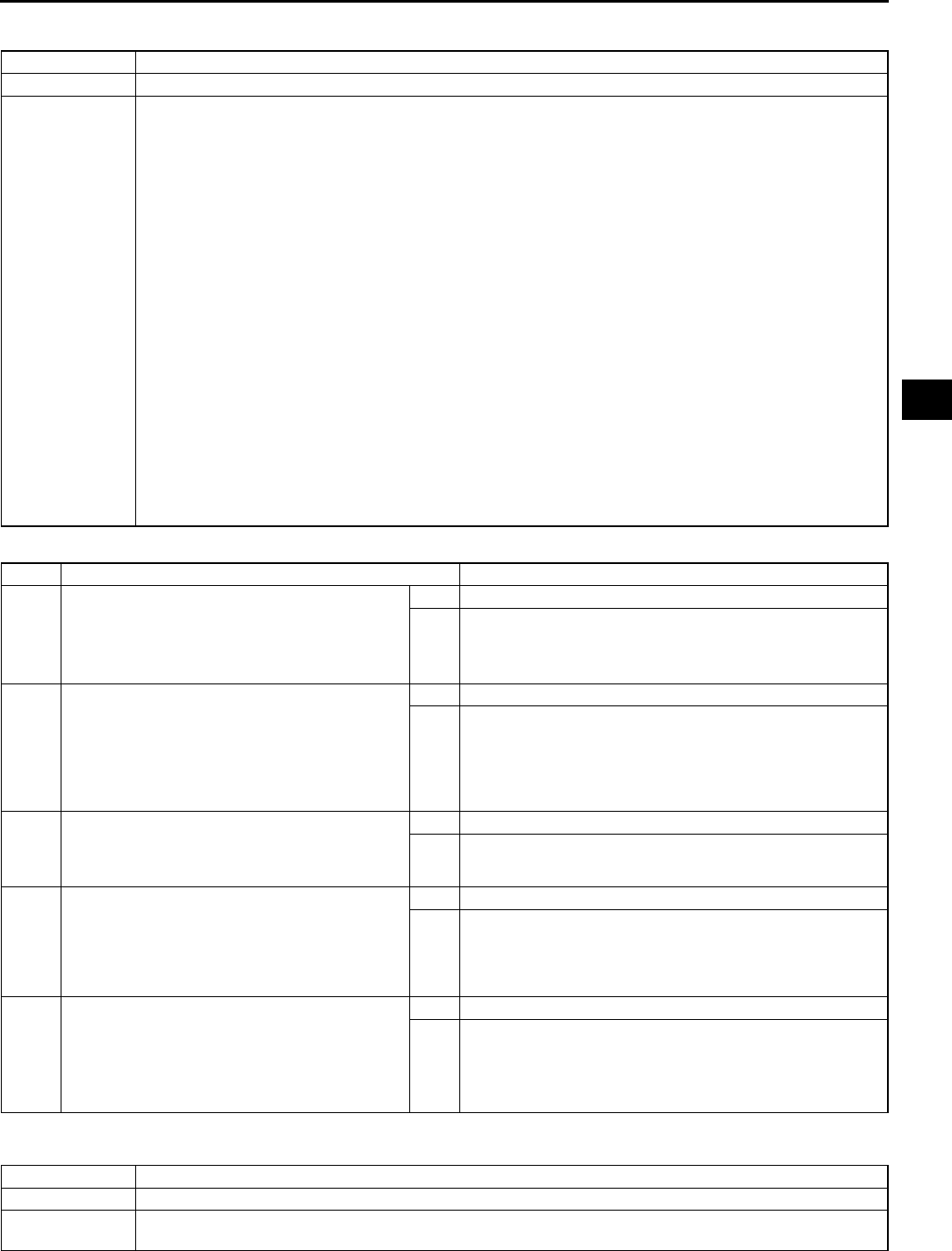
TROUBLESHOOTING
K123
K
NO.12 TORQUE CONVERTER CLUTCH (TCC) NON-OPERATION A6E568001030W16
Diagnostic procedure
End Of Sie
NO.13 NO KICKDOWN A6E568001030W17
12 Torque converter clutch (TCC) non-operation
DESCRIPTION •TCC does not operate when vehicle reaches TCC operation range.
POSSIBLE
CAUSE
•Basically, the TCC does not operate when the fail-safe is operating. Verify the DTC first.
Caution
•
••
•If the TCC is stuck, inspect it. In addition, inspect the oil cooler for foreign particles which
may have mixed in with the ATF.
1. TCC burned
(1) Input sensor system malfunction
•Transaxle fluid temperature sensor
•Vehicle speed sensor
•Input/turbine speed sensor
•Sensor GND
(2) Output solenoid valve system malfunction (Sticking)
•Shift solenoid E malfunction
•Shift solenoid A malfunction
(3) Control valve body malfunction system (Poor operation, stuck)
•TCC hydraulic pressure system
2. TP sensor malfunction (Not operating linear)
3. Input/turbine speed sensor or vehicle speed sensor malfunction
4. Brake switch malfunction (Always ON)
5. ECT sensor malfunction
Note
•Before following troubleshooting steps, make sure that Automatic Transaxle On-Board Diagnostic
and Automatic Transaxle Basic Inspection are conducted.
STEP INSPECTION ACTION
1 With indicator switch at ON, does HOLD
indicator light indication correspond to HOLD
switch operation?
Yes Go to next step.
No Go to No.26 "HOLD INDICATOR LIGHT DOES NOT
ILLUMINATE WHEN HOLD SWITCH IS TURNED ON.",
No.27 "HOLD INDICATOR LIGHT ILLUMINATES WHEN
HOLD SWITCH IS NOT TURNED ON."
2 Check the value at the following PIDs using the
WDS or equivalent. (See F45 PCM
INSPECTION.)
•TP
•VSS
•TSS
Are PID values okay?
Yes Go to next step.
No Repair or replace any defective parts.
3 Disconnect PCM.
Is resistance between ground terminal at PCM
connector and body ground less than 5.0
ohms?
Yes Go to next step.
No Repair open ground circuit.
4 Check resistance between shift solenoid A and
E control circuit at PCM connector and control
valve body connector. Check resistance
between shift solenoid A and E circuit at PCM
connector and control valve body connector. Are
the resistances less than 5.0 ohms?
Yes Go to next step.
No Repair shift solenoid A or E control. Reconnect PCM.
5 Inspect shift solenoid A and E. (See K26
SOLENOID VALVE INSPECTION.) Are the shift
solenoids operating properly?
Yes Replace PCM.
No Overhaul control valve body and repair or replace any
defective parts. If problem remains, overhaul transaxle and
repair or replace any defective parts.(See ATX workshop
manual (FN4A-EL) [1623-10-98E].) (See ATX workshop
manual supplement (FN4A-EL) [1746-1*-02C].)
13 No kickdown
DESCRIPTION •Does not downshift when accelerator pedal is fully depressed within kickdown range.
POSSIBLE
CAUSE
•If transaxle does not downshift though shifting is normal, malfunction is in TP sensor circuit (including
sensor GND, sensor harness and connector).

K124
TROUBLESHOOTING
End Of Sie
NO.14 ENGINE FLARES UP OR SLIPS WHEN UPSHIFTING OR DOWNSHIFTING A6E568001030W18
Diagnostic procedure
End Of Sie
NO.15 ENGINE FLARES UP OR SLIPS WHEN ACCELERATING VEHICLE A6E568001030W19
End Of Sie
14 Engine flares up or slips when upshifting or downshifting
DESCRIPTION
•When accelerator pedal is depressed for driveway, engine speed increases but vehicle speed
increases slowly.
•When accelerator pedal is depressed while driving, engine speed increases but vehicle does not.
POSSIBLE
CAUSE
•There is clutch slip because clutch is stuck or line pressure is low.
1. Clutch stuck, slippage (forward clutch, 34 clutch, 24 brake band, one-way clutch)
•Line pressure low
•Shift solenoid D malfunction
•Shift solenoid E malfunction
•Shift solenoid A malfunction
•Shift solenoid B malfunction
•Shift solenoid C malfunction
•Pressure control solenoid malfunction
•Body GND malfunction
•Accelerator cable misadjustment
•Control valve body malfunction
2. Signal malfunction
•Vehicle speed sensor malfunction
•Sensor GND malfunction
•TP sensor malfunction or mis-adjustment
•Input/turbine speed sensor malfunction
3. Poor operation of mechanical pressure
•Selector lever position disparity
•TR switch position disparity
Note
•Before following troubleshooting steps, make sure that Automatic Transaxle On-Board Diagnostic
and Automatic Transaxle Basic Inspection are conducted.
STEP INSPECTION ACTION
1 Is shift point okay? Yes Go to next step.
No Go to No.9 "ABNORMAL SHIFTING"
2 Check the value at the following PID using the
WDS or equivalent. (See F45 PCM
INSPECTION.)
•TP
Is PID value okay?
Yes Go to next step.
No Repair or replace any defective parts.
3 Disconnect PCM. Is resistance between ground
terminal at PCM connector and body ground
less than 5.0 ohms?
Yes Go to next step.
No Repair open ground circuit. Reconnect PCM.
4 Check LPS PID value.
Is LPS PID value okay?
(See F45 PCM INSPECTION.)
Yes Overhaul control valve body and repair or replace any
defective parts. If problem remains, overhaul transaxle and
repair or replace any defective parts. (See ATX workshop
manual (FN4A-EL) [1623-10-98E].) (See ATX workshop
manual supplement (FN4A-EL) [1746-1*-02C].)
No Repair or replace any defective parts.
15 Engine flares up or slips when accelerating vehicle
DESCRIPTION •Engine flares up when accelerator pedal is depressed for upshifting.
•Engine flares up suddenly when accelerator pedal is depressed for downshifting.
POSSIBLE
CAUSE
•The malfunction is basically the same as for No.14 "Engine flares up or slips when upshifting or
downshifting". If conditions for No.14 worsen, the malfunction will develop to No.15.
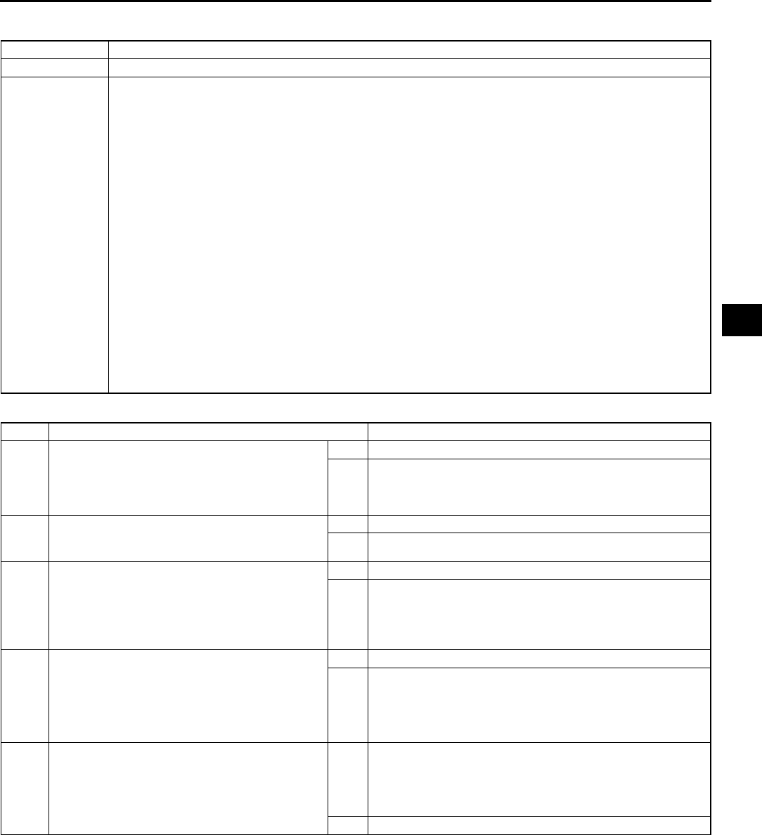
TROUBLESHOOTING
K125
K
NO.16 JUDDER UPON TORQUE CONVERTER CLUTCH (TCC) OPERATION A6E568001030W20
Diagnostic procedure
End Of Sie
16 Judder upon torque converter clutch (TCC) operation
DESCRIPTION •Vehicle jolts when TCC is engaged.
POSSIBLE
CAUSE
•Poor TCC engagement due to either slippage because the TCC is stuck or the line pressure is low
Caution
•
••
•If the TCC is stuck, inspect it. In addition, inspect the oil cooler for foreign particles which
may have mixed in with the ATF.
1. Torque converter clutch piston slipped, burned
•Line pressure high
•Shift solenoid A malfunction
•Control valve body malfunction
•Body GND malfunction
•Pressure control solenoid malfunction
2. Signal malfunction
•Vehicle speed sensor malfunction
•Sensor GND malfunction
•TFT sensor malfunction
•TP sensor malfunction or mis-adjustment
•Input/turbine speed sensor malfunction
3. Torque converter malfunction
Note
•Before following troubleshooting steps, make sure that Automatic Transaxle On-Board Diagnostic
and Automatic Transaxle Basic Inspection are conducted.
STEP INSPECTION ACTION
1 Check the value at the following PIDs using the
WDS or equivalent. (See F45 PCM
INSPECTION.)
•TSS
Are PID values okay?
Yes Go to next step.
No Repair or replace any defective parts.
2 Disconnect PCM. Is resistance between ground
terminal at PCM connector and body ground
less than 5.0 ohms?
Yes Go to next step.
No Repair open ground circuit.
3 Check resistance between shift solenoid A
control circuit at PCM connector and control
valve body connector. Check resistance
between shift solenoid A circuit at PCM
connector and control valve body connector. Are
the resistance less than 5.0 ohms?
Yes Go to next step.
No Repair shift solenoid A circuit.
4 Inspect Shfit solenoid. (See K26 SOLENOID
VALVE INSPECTION.) Is the solenoid valve
operating properly?
Yes Go to next step.
No Overhaul control valve body and repair or replace any
defective parts. If problem remains, overhaul transaxle and
repair or replace any defective parts. (See ATX workshop
manual (FN4A-EL) [1623-10-98E].) (See ATX workshop
manual supplement (FN4A-EL) [1746-1*-02C].)
5 Check LPS PID value.
Is LPS PID value okay?
(See F45 PCM INSPECTION.)
Yes Overhaul control valve body and repair or replace any
defective parts. If problem remains, overhaul transaxle and
repair or replace any defective parts. (See ATX workshop
manual (FN4A-EL) [1623-10-98E].) (See ATX workshop
manual supplement (FN4A-EL) [1746-1*-02C].)
No Replace PCM.

K126
TROUBLESHOOTING
NO.17 EXCESSIVE SHIFT SHOCK FROM N TO D OR N TO R POSITION/RANGE A6E568001030W21
Diagnostic procedure
17 Excessive shift shock from N to D or N to R position/range
DESCRIPTION •Strong shock felt when shifting from N to D or N to R position/range.
POSSIBLE
CAUSE
•Shift shock may worsen when the fail-safe is operating. If no DTC is output, the shift shock may worsen
due to poor operation of the control valve body or sticking of the clutch.
1. Clutch burned (N→D: Forward clutch, N→R: Reverse clutch or low and reverse brake)
•Line pressure low, high
•TP sensor malfunction
•Vehicle speed sensor malfunction
•Input/turbine speed sensor malfunction
•Shift solenoid B malfunction
•Shift solenoid D malfunction
•Shift solenoid A malfunction
•Shift solenoid C malfunction
•Pressure control solenoid malfunction
•Accelerator cable misadjustment
•Control valve body malfunction
•Sensor GND malfunction
•Body GND malfunction
2. Poor hydraulic operation (Malfunction in range change)
•Forward accumlator malfunction
•Servo apply accumulator malfunction
•Pressure switch malfunction
3. Idle speed high
4. Poor tightening torque of engine mount, exhaust mount
5. Poor operation of mechanical pressure
•Selector lever position disparity
Note
•Before following troubleshooting steps, make sure that Automatic Transaxle On-Board Diagnostic
and Automatic Transaxle Basic Inspection are conducted.
STEP INSPECTION ACTION
1 Does shift shock occur only when engine cold? Yes Go to next step.
No Go to Step 3.
2 Disconnect PCM. Is resistance between ground
terminal at PCM connector and body ground
less than 5.0 ohms?
Yes Check the value at the following PIDs using the WDS or
equivalent. (See F45 PCM INSPECTION.)
•TP
•TFT
•TFTV
Repair or replace any defective parts.
No Repair open ground circuit. Reconnect PCM.
3 Perform the stall test. (See K7 Stall Test.) Is
stall speed okay?
Yes Go to next step.
No Go to Step 5.
4 Check the value at the following PIDs using the
WDS or equivalent. (See F45 PCM
INSPECTION.)
•TR
Is PID value okay?
Yes Overhaul control valve body and repair or replace any
defective parts. If problem remains, overhaul transaxle and
repair or replace any defective parts. (See ATX workshop
manual (FN4A-EL) [1623-10-98E].) (See ATX workshop
manual supplement (FN4A-EL) [1746-1*-02C].)
No Repair or replace any defective parts.
5 Check the value at the following PID using the
WDS or equivalent. (See F45 PCM
INSPECTION.)
•TP
Is PID value okay?
Yes Go to next step.
No Repair or replace any defective parts.
6 Disconnect PCM. Is resistance between ground
terminal at PCM connector and body ground
less than 5.0 ohms?
Yes Go to next step.
No Repair open ground circuit. Reconnect PCM.
7 Check LPS PID value.
Is LPS PID value okay?
(See F45 PCM INSPECTION.)
Yes Overhaul control valve body and repair or replace any
defective parts. If problem remains, overhaul transaxle and
repair or replace any defective parts. (See ATX workshop
manual (FN4A-EL) [1623-10-98E].) (See ATX workshop
manual supplement (FN4A-EL) [1746-1*-02C].)
No Repair or replace any defective parts.
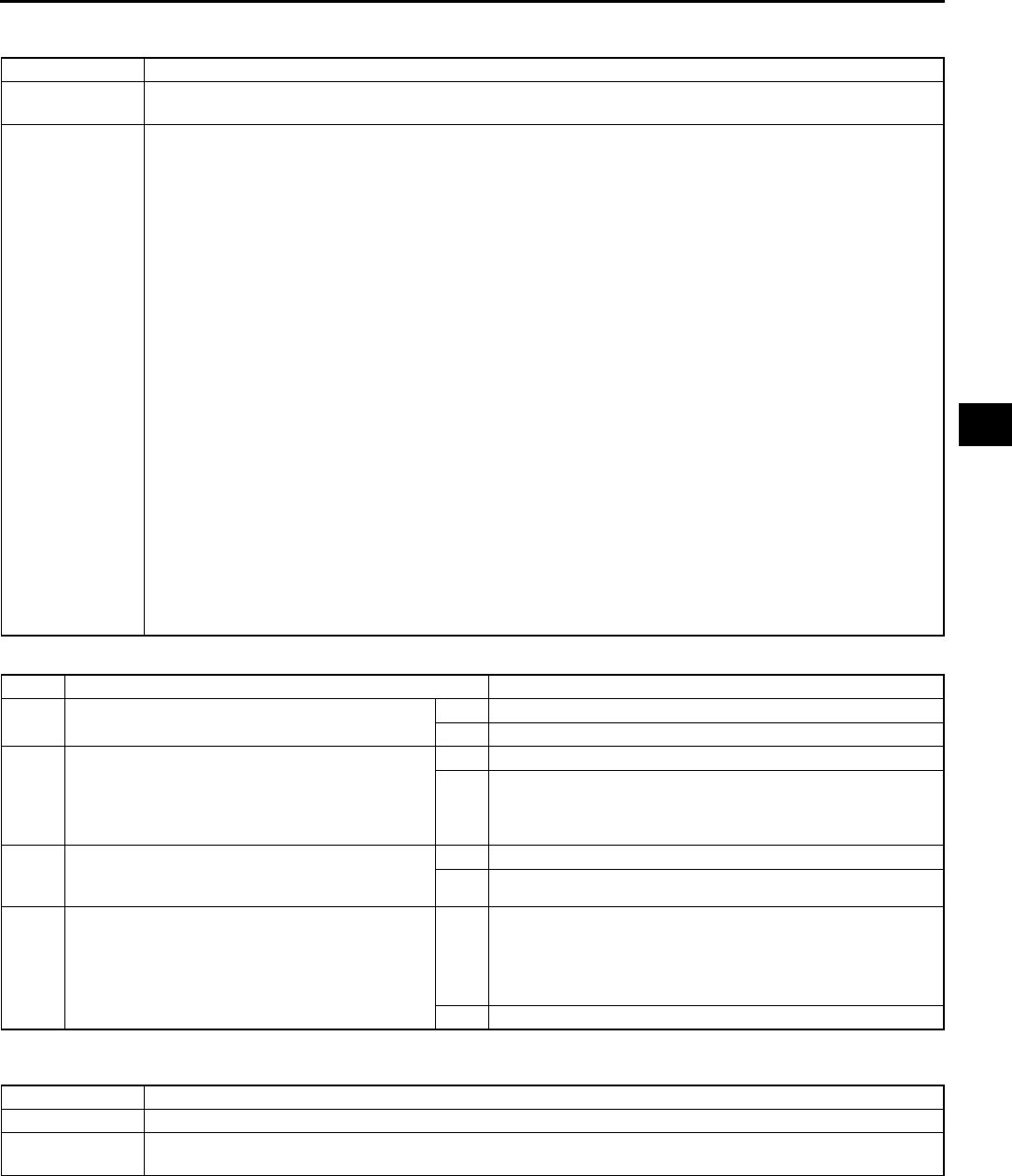
TROUBLESHOOTING
K127
K
End Of Sie
NO.18 EXCESSIVE SHIFT SHOCK IS FELT WHEN UPSHIFTING AND DOWNSHIFTING A6E568001030W22
Diagnostic procedure
End Of Sie
NO.19 EXCESSIVE SHIFT SHOCK ON TORQUE CONVERTER CLUTCH (TCC) A6E568001030W23
End Of Sie
18 Excessive shift shock is felt when upshifting and downshifting
DESCRIPTION •Excessive shift shock felt when depressing accelerator pedal to accelerate at upshifting. During
cruising, excessive shift shock is felt when depressing accelerator pedal at downshifting.
POSSIBLE
CAUSE
•Shift shock may worsen when fail-safe is operating. The shift shock has worsened if the TP sensor,
input/turbine speed sensor, or vehicle speed sensor signal malfunctions.
1. Clutch slipped, burned (Forward clutch, 24 brake band, 34 clutch)
•Line pressure low, high
•Shift solenoid D malfunction
•Shift solenoid E malfunction
•Shift solenoid A malfunction
•Shift solenoid B malfunction
•Shift solenoid C malfunction
•Pressure control solenoid malfunction
•Accelerator cable misadjustment
•Control valve body malfunction
•Body GND malfunction
2. Signal malfunction
•Transaxle temperature sensor malfunction
•Vehicle speed sensor malfunction
•Sensor GND malfunction
•TP sensor malfunction
•Input/turbine speed sensor malfunction
3. Poor hydraulic operation (Malfunction in range change)
•Pressure switch malfunction
•Forward accumulator malfunction
•Servo apply accumulator malfunction
Note
•Before following troubleshooting steps, make sure that Automatic Transaxle On-Board Diagnostic
and Automatic Transaxle Basic Inspection are conducted.
STEP INSPECTION ACTION
1 Perform the stall test. (See K7 Stall Test.) Is
stall speed okay?
Yes Go to next step.
No Repair or replace any defective parts.
2 Check the value at the following PIDs using the
WDS or equivalent. (See F45 PCM
INSPECTION.)
•TP V
Is PID value okay?
Yes Go to next step.
No Repair or replace any defective parts.
3 Disconnect PCM. Is resistance between ground
terminal at PCM connector and body ground
less than 5.0 ohms?
Yes Go to next step.
No Repair open ground circuit. Reconnect PCM.
4 Check LPS PID value.
Is LPS PID value okay?
(See F45 PCM INSPECTION.)
Yes Overhaul control valve body and repair or replace any
defective parts. If problem remains, overhaul transaxle and
repair or replace any defective parts. (See ATX workshop
manual (FN4A-EL) [1623-10-98E].) (See ATX workshop
manual supplement (FN4A-EL) [1746-1*-02C].)
No Repair or replace any defective parts.
19 Excessive shift shock on torque converter clutch (TCC)
DESCRIPTION •Strong shock is felt when TCC engaged.
POSSIBLE
CAUSE
•The troubleshooting flow is the same as No.16 Judder upon TCC operation.

K128
TROUBLESHOOTING
NO.20 NOISE OCCURS AT IDLE WHEN VEHICLE IS STOPPED IN ALL POSITIONS/RANGES A6E568001030W24
Diagnostic procedure
End Of Sie
NO.21 NOISE OCCURS AT IDLE WHEN VEHICLE IS STOPPED IN D, S, L RANGES, OR IN R POSITION
A6E568001030W25
End Of Sie
20 Noise occurs at idle when vehicle is stopped in all positions/ranges
DESCRIPTION •Transaxle noisy in all positions and ranges when vehicle is idling.
POSSIBLE
CAUSE
•The malfunction is in the oil pump which causes a high-pitched noise to be emitted from the transaxle at
idle.
Note
•If a noise is emitted during shifting only, the malfunction is in shift solenoid D, E or shift solenoid A, B,
C. If a noise is emitted during shifting at certain gears only or during deceleration only, it is gear
noise.
•Before following troubleshooting steps, make sure that Automatic Transaxle On-Board Diagnostic
and Automatic Transaxle Basic Inspection are conducted.
STEP INSPECTION ACTION
1 Inspect engine condition.
Is any engine concern (i. e. rough idle)?
Yes Go to appropriate symptom troubleshooting. (See Section
F.)
No Go to next step.
2 Does noise stop when solenoid connector is
disconnected?
Yes Go to next step.
No Overhaul control valve body and repair or replace any
defective parts. If problem remains, overhaul transaxle and
repair or replace any defective parts. (See ATX workshop
manual (FN4A-EL) [1623-10-98E].) (See ATX workshop
manual supplement (FN4A-EL) [1746-1*-02C].)
3 Check the value at the following PIDs using the
WDS or equivalent. (See F45 PCM
INSPECTION.)
•TP
•VSS
•TSS
Are PID values okay?
Yes Go to next step.
No Repair or replace any defective parts.
4 Disconnect PCM. Is resistance between ground
terminal at PCM connector and body ground
less than 5.0 ohms?
Yes Go to next step.
No Repair open ground circuit. Reconnect PCM.
5 Check LPS PID value.
Is LPS PID value okay?
(See F45 PCM INSPECTION.)
Yes Overhaul control valve body and repair or replace any
defective parts. If problem remains, overhaul transaxle and
repair or replace any defective parts. (See ATX workshop
manual (FN4A-EL) [1623-10-98E].) (See ATX workshop
manual supplement (FN4A-EL) [1746-1*-02C].)
No Repair or replace any defective parts.
21 Noise occurs at idle when vehicle is stopped in D, S, L ranges, or in R position
DESCRIPTION •Transaxle noisy in driving ranges when vehicle idling.
POSSIBLE
CAUSE
•Although the malfunction is basically the same as No.20 "Noise occurs at idle when vehicle is stopped
in all positions/ranges", other causes may be selector lever position disparity or TR switch position
disparity.
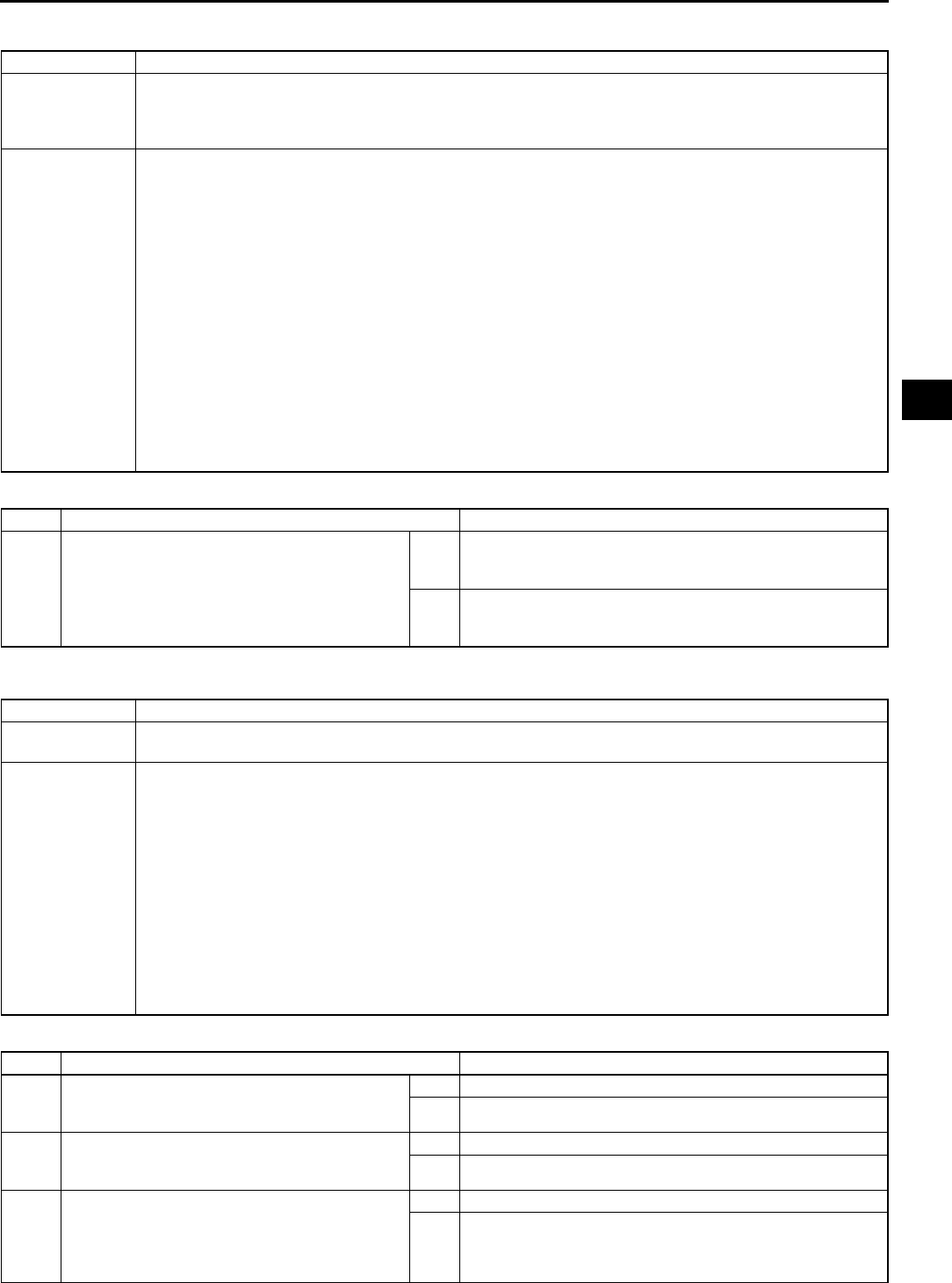
TROUBLESHOOTING
K129
K
NO.22 NO ENGINE BRAKING IN HOLD MODE A6E568001030W26
Diagnostic procedure
End Of Sie
NO.23 TRANSAXLE OVERHEATS A6E568001030W27
Diagnostic procedure
22 No engine braking in hold mode
DESCRIPTION
•Engine speed drops to idle but vehicle coasts when accelerator pedal is released during cruising at
medium to high speeds.
•Engine speed drops to idle but vehicle coasts when accelerator pedal is released when in L range at
low vehicle speed.
POSSIBLE
CAUSE
1. Clutch slippage, burned (low and reverse brake)
•Line pressure low
•Shift solenoid D malfunction
•Shift solenoid E malfunction
•Shift solenoid C malfunction
•Control valve body malfunction
•Body GND malfunction
2. Signal malfunction
•TP sensor malfunction
•Vehicle speed sensor malfunction
•Sensor GND malfunction
•Input/turbine speed sensor malfunction
3. HOLD switch ON not judged by PCM (short, or open circuit, poor operation)
•HOLD switch signal malfunction
Note
•Before following troubleshooting steps, make sure that Automatic Transaxle On-Board Diagnostic
and Automatic Transaxle Basic Inspection are conducted.
STEP INSPECTION ACTION
1•Do following symptoms concurrently occur?
Engine flares up or slips during
acceleration.
Engine flares up or slips when shifting.
Yes Go to symptom troubleshooting NO.14 "Engine flares up or
slips when upshifting or downshifting" or No.15 "Engine
flares up or slips when accelerating vehicle".
No Repeat basic inspection and repair or replace any defective
parts according to inspection result.
(See K112 BASIC INSPECTION.)
23 Transaxle overheats
DESCRIPTION •Burnt smell emitted from transaxle.
•Smoke emitted from transaxle.
POSSIBLE
CAUSE
•The malfunction is restricted to hindrance of coolant at the oil cooler. In addition, overheating of the
transaxle may be caused by a malfunction of the transaxle fluid temperature sensor.
1. Burned (TCC)
•Line pressure low
•Control valve body malfunction
•Accelerator cable misadjustment
2. Oil cooler malfunction (Foreign material mixed ATF)
3. Transaxle fluid temperature sensor malfunction
4. Excessive amount of ATF
5. Torque converter malfunction
Note
•Before following troubleshooting steps, make sure that Automatic Transaxle On-Board Diagnostic
and Automatic Transaxle Basic Inspection are conducted.
STEP INSPECTION ACTION
1•Inspect for bent, damage, corrosion or kinks
of oil cooler pipes.
•Are oil cooler pipes okay?
Yes Go to next step.
No Replace any defective parts.
2•Perform the stall test.
(See K7 Stall Test.)
•Is stall speed okay?
Yes Go to next step.
No Repair or replace any defective parts.
3•Check the value at the following PID using
the WDS or equivalent.
(See F45 PCM INSPECTION.)
TP
•Is PID value okay?
Yes Go to next step.
No Repair or replace any defective parts.

K130
TROUBLESHOOTING
End Of Sie
NO.24 ENGINE STALLS WHEN SHIFTED TO D, S, L RANGES, OR IN R POSITION A6E568001030W28
Diagnostic procedure
End Of Sie
NO.25 ENGINE STALLS WHEN DRIVING AT SLOW SPEEDS OR STOPPING A6E568001030W29
Diagnostic procedure
End Of Sie
NO.26 STARTER DOES NOT WORK A6E568001030W30
End Of Sie
NO.27 HOLD INDICATOR LIGHT DOES NOT ILLUMINATE WHEN HOLD SWITCH IS TURNED TO ON
A6E568001030W31
4•Disconnect PCM.
•Is resistance between ground terminal at
PCM connector and body ground less than
5.0 ohms?
Yes Go to next step.
No Repair open ground circuit.
Reconnect PCM.
5•Check LPS PID value.
•Is LPS PID value okay?
(See F45 PCM INSPECTION.)
Yes Overhaul control valve body and repair or replace any
defective parts.
If problem remains, overhaul transaxle and repair or replace
any defective parts.
(See ATX workshop manual (FN4A-EL) [1623-10-98E].)
(See ATX workshop manual supplement (FN4A-EL)
[1746-1*-02C].)
No Repair or replace any defective parts.
STEP INSPECTION ACTION
24 Engine stalls when shifted to D, S, L ranges, or in R position
DESCRIPTION •Engine stalls when shifting from N or P position to D, S, L ranges or R position at idle.
POSSIBLE
CAUSE
•The malfunction is on the engine control side (i.e. IAC system). Otherwise, the malfunction is in the
input/turbine speed sensor (engine sometimes starts) or TCC circuit (engine always stalls).
STEP INSPECTION ACTION
1•Go to symptom troubleshooting No.10 Low
idle/stalls during deceleration.
(See F202 NO.10 LOW IDLE/STALLS
DURING DECELERATION.)
•Is engine control system okay?
Yes Repeat basic inspection and repair or replace any defective
parts according to inspection result.
(See K112 BASIC INSPECTION.)
No Repair or replace any defective parts according to
inspection results.
25 Engine stalls when driving at slow speeds or stopping
DESCRIPTION •Engine stalls when brake pedal is depressed while driving at low speed or stopping.
POSSIBLE
CAUSE
•The malfunction on engine control side (e.g. Fuel injection control, IAC system) Otherwise, the
malfunction is in the control valve body, shift solenoid E or TCC.
STEP INSPECTION ACTION
1•Go to symptom troubleshooting No.9 Low
idle/stalls during deceleration.
(See F201 NO.9 FAST IDLE/RUNS ON.)
•Does engine control system okay?
Yes Go to next step.
No Repair or replace any defective parts according to
inspection results.
2•Go to symptom troubleshooting No.4
"Engine Stalls."
(See F189 NO.4 HARD TO START/LONG
CRANK/ERRATIC START/ERRATIC
CRANK.)
•Is engine control system okay?
Yes Repeat basic inspection and repair or replace any defective
parts according to inspection result.
(See K112 BASIC INSPECTION.)
No Repair or replace any defective parts according to
inspection results.
26 Starter does not work
DESCRIPTION •Starter does not work even when P or N position.
POSSIBLE
CAUSE
•Selector lever misadjustment
•TR switch misadjustment
•Open or short circuit in TR switch
27 HOLD indicator light does not illuminate when HOLD switch is turned to ON
DESCRIPTION •HOLD indicator light in dashboard does not illuminate when HOLD switch is turned on and IG SW at
ON.
POSSIBLE
CAUSE
•HOLD switch, HOLD indicator light or related wiring harness malfunction.

TROUBLESHOOTING
K131
K
Diagnostic procedure
End Of Sie
NO.28 HOLD INDICATOR LIGHT ILLUMINATES WHEN HOLD SWITCH IS NOT TURNED TO ON A6E568001030W32
Diagnostic procedure
End Of Sie
STEP INSPECTION ACTION
1•Are other indicator lights illuminated with
ignition switch is at ON?
Yes Inspect meter fuse.
No Go to next step.
2•Check the HOLD switch
(See K13 HOLD SWITCH INSPECTION.)
•Is HOLD switch okay?
Yes Go to next step.
No Repair or replace any defective parts.
3•Disconnect PCM.
•Turn ignition switch on.
•Is voltage between 3Q terminal at the PCM
connector and body ground greater than
10.5 V?
Yes Replace PCM.
No Reconnect PCM.
Go to next step.
4•Check the HOLD indicator light.
•Is HOLD indicator light okay?
Yes Inspect for open circuit or disconnected connector in
harness between the following:
•Ignition switch and HOLD indicator light
•HOLD indicator light and PCM
No Repair or replace any defective parts.
28 HOLD indicator light illuminates when HOLD switch is not turned to ON
DESCRIPTION •HOLD indicator light in dashboard illuminates even though HOLD switch is turned off and IG SW at ON.
POSSIBLE
CAUSE
•HOLD switch or related wiring harness malfunction.
STEP INSPECTION ACTION
1•Check the HOLD switch
(See K13 HOLD SWITCH INSPECTION.)
•Is HOLD switch okay?
Yes Go to next step.
No Repair or replace any defective parts.
2•Disconnect PCM.
•Turn ignition switch off.
•Is resistance between 3Q terminal at the
PCM connector and body ground greater
than 10 kilohms?
Yes Replace PCM.
No Repair short circuit between HOLD indecator light and PCM.
Reconnect PCM.

M1
M
MFRONT AND REAR AXLES
LOCATION INDEX ................................................ M-2
FRONT AXLE/DRIVE SHAFT
LOCATION INDEX........................................... M-2
REAR AXLE LOCATION INDEX......................... M-3
GENERAL PROCEDURES ................................... M-3
PRECAUTION (FRONT AND REAR AXLE) ....... M-3
FRONT AXLE ........................................................ M-4
WHEEL HUB, STEERING KNUCKLE
PRE-INSPECTION........................................... M-4
WHEEL HUB BOLT REPLACEMENT ................ M-4
WHEEL HUB, STEERING KNUCKLE
REMOVAL/INSTALLATION ............................. M-5
REAR AXLE .......................................................... M-9
WHEEL HUB, HUB SPINDLE
PRE-INSPECTION........................................... M-9
WHEEL HUB, HUB SPINDLE
REMOVAL/INSTALLATION ........................... M-10
DRIVE SHAFT ..................................................... M-12
JOINT SHAFT PRE-INSPECTION ................... M-12
JOINT SHAFT REMOVAL/INSTALLATION...... M-12
JOINT SHAFT DISASSEMBLY/ASSEMBLY .... M-14
DRIVE SHAFT PRE-INSPECTION................... M-16
DRIVE SHAFT REMOVAL/INSTALLATION ..... M-17
DRIVE SHAFT (ATX)
DISASSEMBLY/ASSEMBLY ......................... M-19
DRIVE SHAFT (MTX)
DISASSEMBLY/ASSEMBLY ......................... M-24
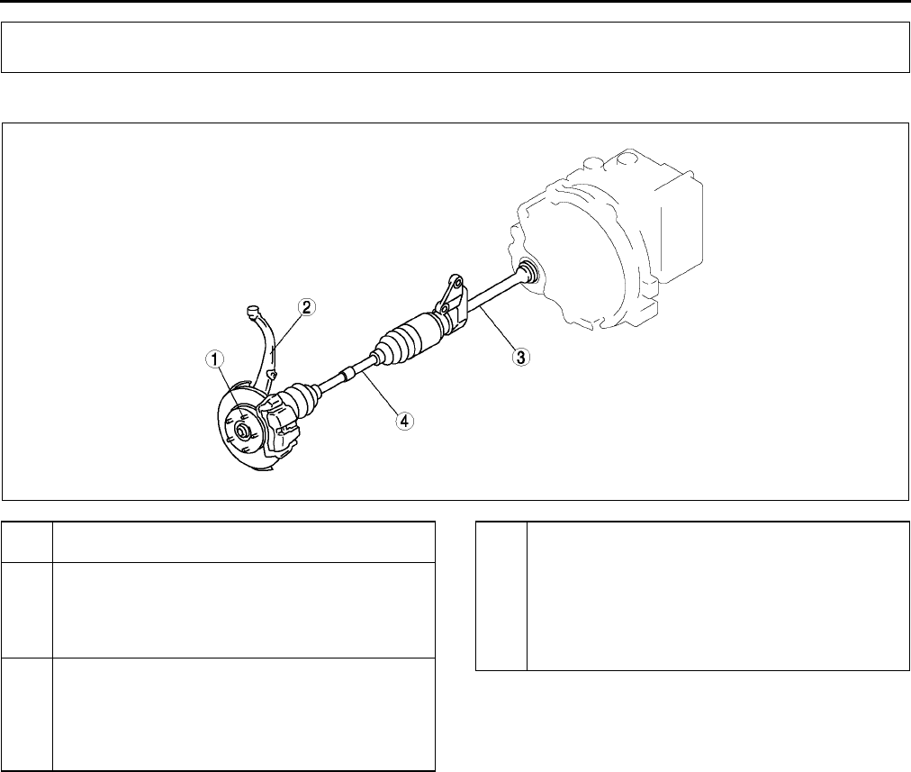
M2
LOCATION INDEX
FRONT AXLE/DRIVE SHAFT LOCATION INDEX A6E630004000W01
.
End Of Sie
LOCATION INDEX
A6E0612W106
1 Hub bolt
(See M4 WHEEL HUB BOLT REPLACEMENT)
2 Wheel hub, steering knuckle
(See M4 WHEEL HUB, STEERING KNUCKLE
PRE-INSPECTION)
(See M5 WHEEL HUB, STEERING KNUCKLE
REMOVAL/INSTALLATION)
3 Joint shaft
(See M12 JOINT SHAFT PRE-INSPECTION)
(See M12 JOINT SHAFT REMOVAL/
INSTALLATION)
(See M14 JOINT SHAFT DISASSEMBLY/
ASSEMBLY)
4 Drive shaft
(See M16 DRIVE SHAFT PRE-INSPECTION)
(See M17 DRIVE SHAFT REMOVAL/
INSTALLATION)
(See M19 DRIVE SHAFT (ATX) DISASSEMBLY/
ASSEMBLY)
(See M24 DRIVE SHAFT (MTX) DISASSEMBLY/
ASSEMBLY)
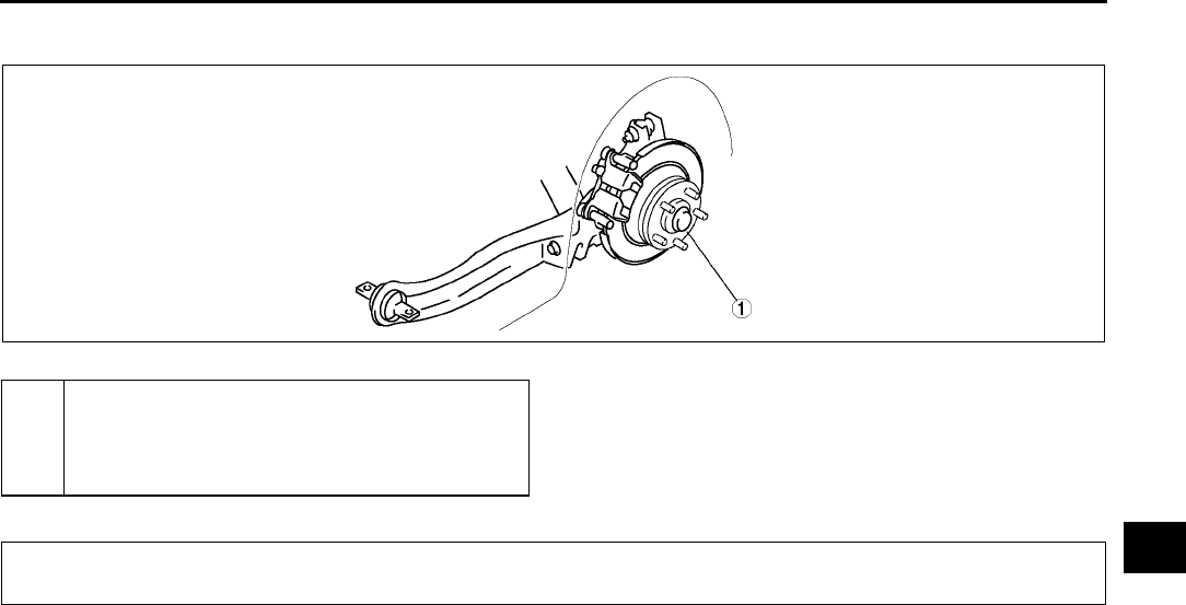
LOCATION INDEX, GENERAL PROCEDURES
M3
M
REAR AXLE LOCATION INDEX A6E630005000W01
.
End Of Sie
PRECAUTION (FRONT AND REAR AXLE) A6E631001018W01
Wheel and Tire Removal/Installation
1. The removal and installation procedures for the wheels and tires are not mentioned in this section. When a
wheel is removed, tighten it to 88118 N·m {9.012.0 kgf·m, 65.087.0 ft·lbf}
Brake Line Disconnection/Connection
Caution
•
••
•Brake fluid will damage painted surfaces. If brake fluid gets on a painted surface, wipe it off
immediately.
1. Tighten the brake pipe flare nut using the SST (49 0259 770B). Be sure to modify the brake pipe flare nut
tightening torque to allow for use of a torque wrench-SST combination. (See GI16 TORQUE FORMULAS.)
2. If any brake line has been disconnected any time during the procedure, add brake fluid, bleed the brakes, and
inspect for leakage after the procedure has been completed.
Suspension Arm Removal/Installation
1. Tighten any part of the suspension that uses rubber bushings only after vehicle has been lowered and
unloaded.
Note
•Unloaded: Fuel tank is full. Engine coolant and engine oil are at specified level. Spare tire, jack, and tools
are in designated position.
End Of Sie
A6E0312W016
1 Wheel hub, hub spindle
(See M9 WHEEL HUB, HUB SPINDLE PRE-
INSPECTION)
(See M10 WHEEL HUB, HUB SPINDLE
REMOVAL/INSTALLATION)
GENERAL PROCEDURES
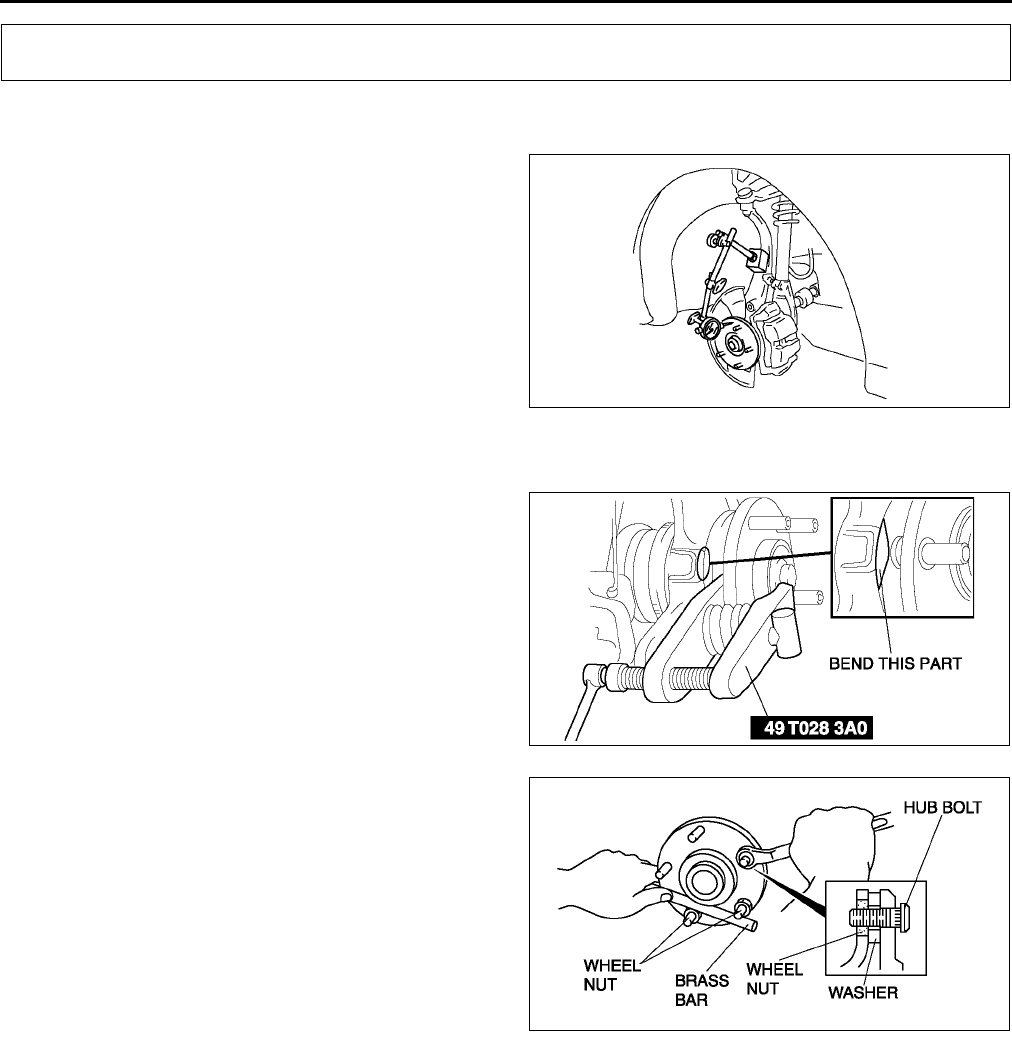
M4
FRONT AXLE
WHEEL HUB, STEERING KNUCKLE PRE-INSPECTION A6E631204000W01
Wheel Bearing Play Inspection
1. Position a dial indicator against the wheel hub.
2. Push and pull the wheel hub by hand in the axial
direction and measure the wheel bearing play.
Maximum wheel bearing play
0.05 mm {0.002 in}
3. If the bearing play exceeds the specification,
replace and tighten the locknut to the specified
torque and retest.
•Replace the wheel bearing as necessary.
End Of Sie
WHEEL HUB BOLT REPLACEMENT A6E631233060W01
1. Remove the hub bolt using the SSTs.
Note
•If the dust cover interferes with the wheel
hub bolt and the wheel hub bolt cannot be
removed, tap the part shown in the figure
with a chisel lightly and bend the processing
point back to the steering knuckle side.
2. Install the hub bolt into the wheel hub and install a
washer and hub nut on the hub bolt.
3. Tighten the hub nut while holding the wheel hub
using a brass bar.
End Of Sie
FRONT AXLE
A6E0311W010
A6E0311W011
A6E0311W012
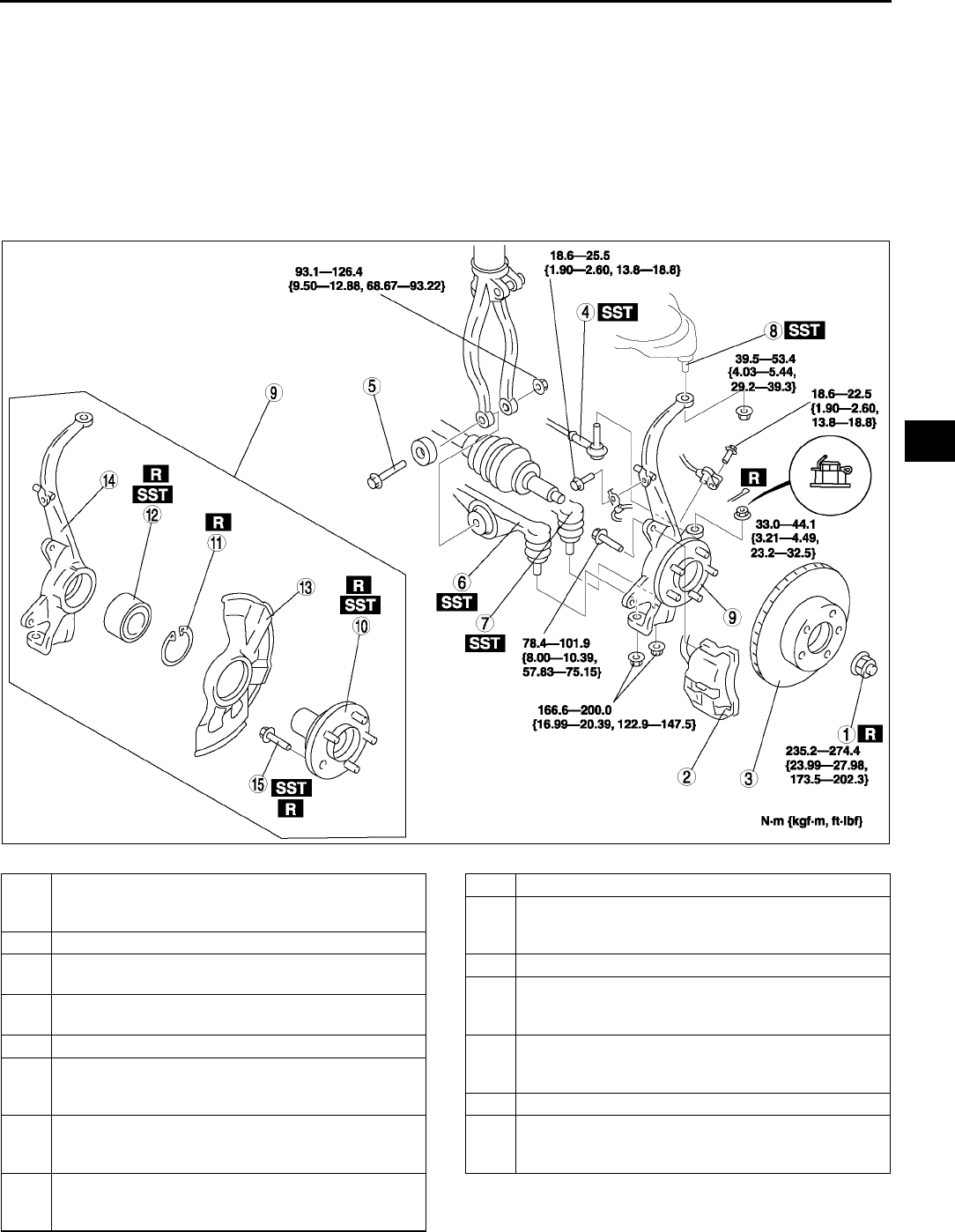
FRONT AXLE
M5
M
WHEEL HUB, STEERING KNUCKLE REMOVAL/INSTALLATION A6E631204000W02
Caution
•
••
•Performing the following procedures without first removing the ABS wheel-speed sensor may
possibly cause an open circuit in the harness if it is pulled by mistake. Before performing the
following procedures, remove the ABS wheel-speed sensor (axle side) and fix it to an appropriate
place where the sensor will not be pulled by mistake while the vehicle is being serviced.
1. Remove in the order indicated in the table.
2. Install in the reverse order of removal.
3. After installation, inspect the front wheel alignment. (See R5 FRONT WHEEL ALIGNMENT.)
.
A6E0612W075
1 Locknut
(See M6 Locknut Removal Note)
(See M9 Locknut Installation Note)
2 Brake caliper component
3 Disc plate
(See P20 Disc Plate Removal Note)
4 Tie-rod end ball joint
(See N11 Tie-rod End Ball Joint Removal Note)
5Bolt
6 Front lower arm (front) ball joint
(See R16 Front Lower Arm (Front) Ball Joint
Removal Note)
7 Front lower arm (rear) ball joint
(See R19 Front Lower Arm (Rear) Ball Joint
Removal Note)
8 Front upper arm ball joint
(See R13 Front Upper Arm Ball Joint Removal
Note)
9 Wheel hub, steering knuckle, dust cover
10 Wheel hub component
(See M6 Wheel Hub Component Removal Note)
(See M8 Wheel Hub Component Installation Note)
11 Retaining ring
12 Wheel bearing
(See M6 Wheel Bearing Removal Note)
(See M8 Wheel Bearing Installation Note)
13 Dust cover
(See M7 Dust Cover Removal Note)
(See M8 Dust Cover Installation Note)
14 Steering knuckle
15 Hub bolt
(See M7 Hub Bolt Removal Note)
(See M7 Hub Bolt Installation Note)
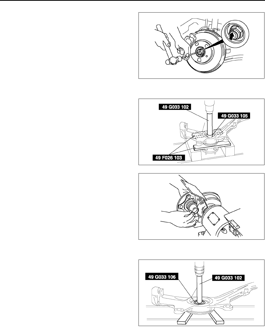
M6
FRONT AXLE
Locknut Removal Note
1. Knock the crimped portion of the locknut outward
using a small chisel and a hammer.
2. Lock the hub by applying the brakes.
3. Remove the locknut.
Wheel Hub Component Removal Note
1. Remove the wheel hub component using the
SSTs.
2. If the bearing inner race remains on the front
wheel hub component, grind a section of the
bearing inner race until approx. 0.5 mm {0.02 in}
remains. Then remove it using a chisel.
Wheel Bearing Removal Note
1. Remove the wheel bearing using the SSTs.
A6E6321W001
A6E0311W015
A6E6312W002
A6E0311W017
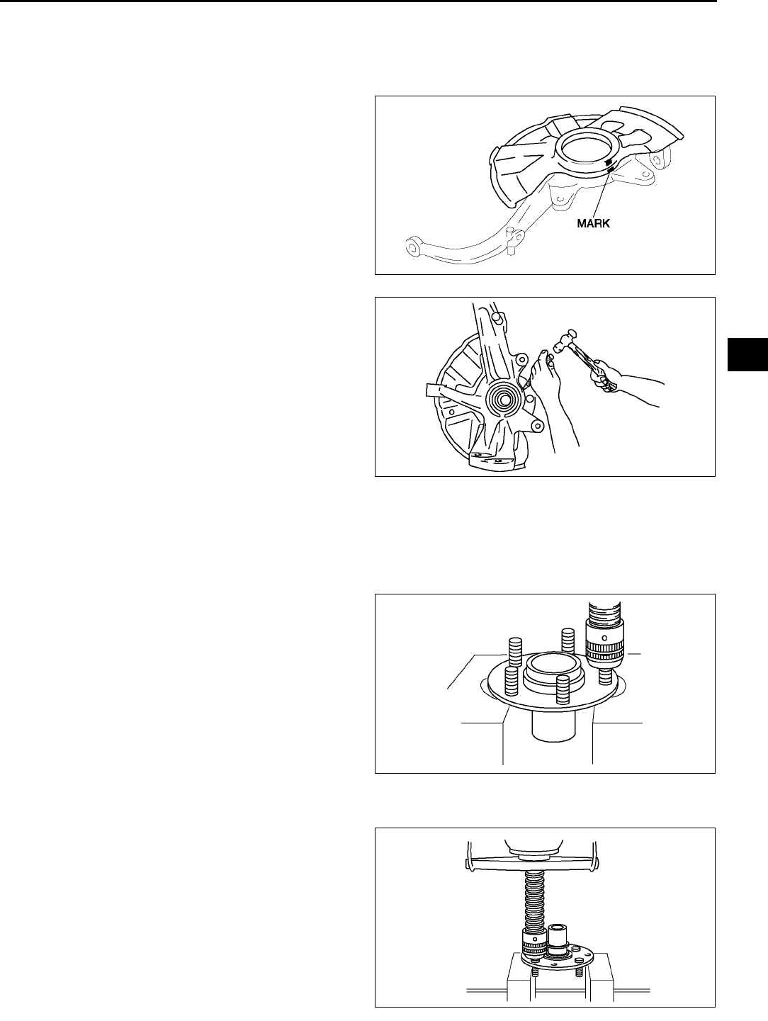
FRONT AXLE
M7
M
Dust Cover Removal Note
Note
•The dust cover does not need to be removed unless it is being replaced.
1. Mark the dust cover and steering knuckle for
proper installation.
2. Remove the dust cover using a chisel.
Hub Bolt Removal Note
Note
•The hub bolts do not need to be removed unless they are being replaced.
1. Remove the hub bolts using a press.
Hub Bolt Installation Note
1. Install the new hub bolts using a press.
A6E0311W018
A6E0311W019
A6E6312W003
A6E6312W004
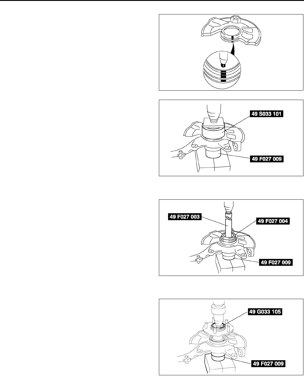
M8
FRONT AXLE
Dust Cover Installation Note
1. Mark the new dust cover in the same way as the
removed one.
2. Align the marks of the new dust cover and the
knuckle.
3. Install the new dust cover using the SSTs.
Wheel Bearing Installation Note
1. Install the new wheel bearing using the SSTs.
Wheel Hub Component Installation Note
1. Install the wheel hub component using the SSTs.
A6E0312W010
A6E0312W011
A6E0312W012
A6E0312W013
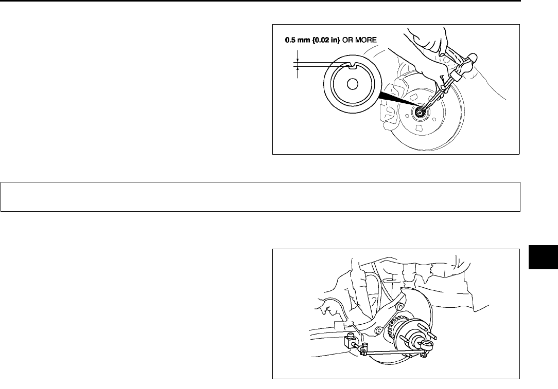
FRONT AXLE, REAR AXLE
M9
M
Locknut Installation Note
1. Install a new locknut and stake it as shown.
End Of Sie
WHEEL HUB, HUB SPINDLE PRE-INSPECTION A6E631405000W01
Wheel Bearing Play Inspection
1. Position a dial indicator against the wheel hub.
2. Push and pull the wheel hub by hand in the axial
direction and measure the wheel bearing play.
Maximum wheel bearing play
0.05 mm {0.002 in}
3. If the bearing play exceeds the specification,
replace and tighten the locknut to the specified
torque and retest.
•Replace the wheel hub component as
necessary.
End Of Sie
A6E0312W015
REAR AXLE
A6E0312W019
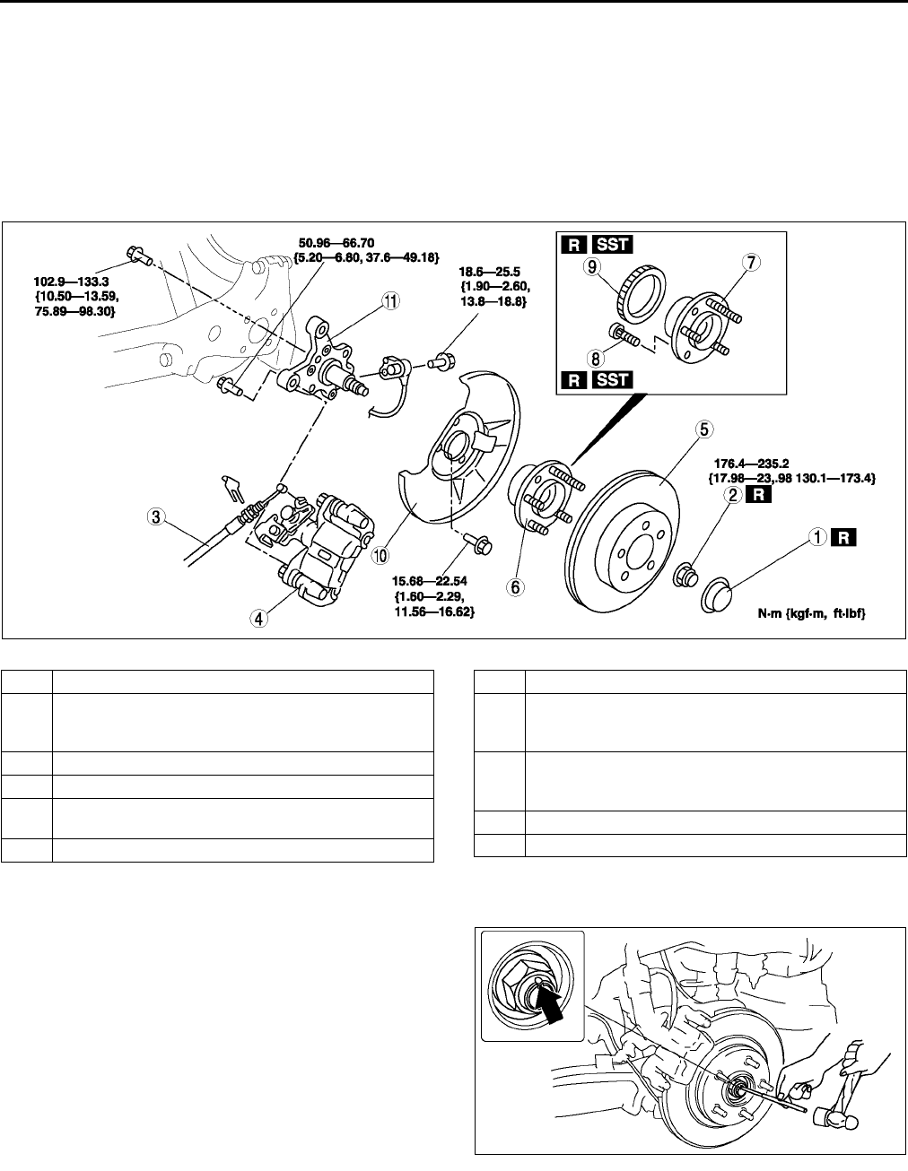
M10
REAR AXLE
WHEEL HUB, HUB SPINDLE REMOVAL/INSTALLATION A6E631405000W02
Caution
•
••
•Performing the following procedures without first removing the ABS wheel-speed sensor may
possibly cause an open circuit in the harness if it is pulled by mistake. Before performing the
following procedures, remove the ABS wheel-speed sensor (body side) and fix it to an appropriate
place where the sensor will not be pulled by mistake while the vehicle is being serviced.
1. Remove in the order indicated in the table.
2. Install in the reverse order of removal..
Locknut Removal Note
1. Knock the crimped portion of the locknut outward
using a small cape chisel and a hammer.
2. Lock the hub by applying the brakes.
3. Remove the locknut.
A6E0312W078
1 Hub cap
2 Locknut
(See M10 Locknut Removal Note)
(See M11 Locknut Installation Note)
3 Parking brake cable
4 Brake caliper component
5Disc plate
(See P20 Disc Plate Removal Note)
6 Wheel hub component
7 Wheel hub
8 Hub bolt
(See M7 Hub Bolt Removal Note)
(See M7 Hub Bolt Installation Note)
9 ABS sensor rotor (with ABS)
(See M11 ABS Sensor Rotor Removal Note)
(See M11 ABS Sensor Rotor Installation Note)
10 Dust cover
11 Hub spindle
A6E0312W021
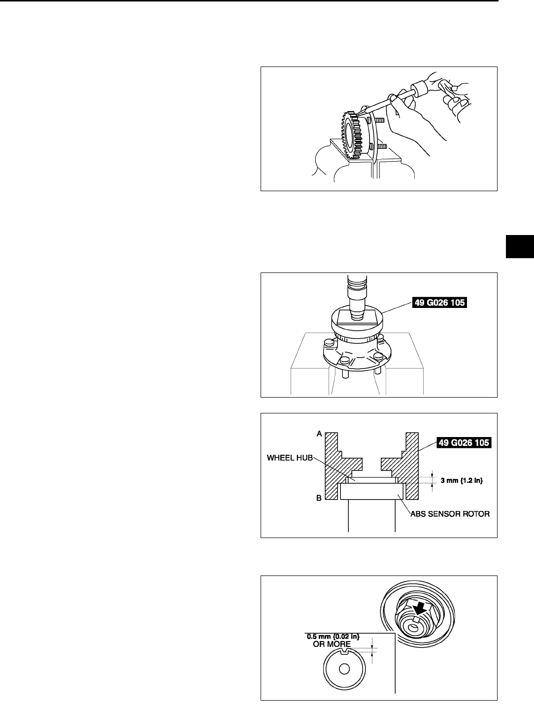
REAR AXLE
M11
M
ABS Sensor Rotor Removal Note
Note
•The sensor rotor does not need to be removed unless it is being replaced.
1. Remove the sensor rotor using a chisel.
ABS Sensor Rotor Installation Note
Caution
•
••
•Position the SST so that marking B faces the bottom.
1. Set the SST as shown in the figure.
2. Press on the new sensor rotor using the SST and
a press.
Locknut Installation Note
1. Install a new locknut and stake it as shown.
A6E6314W001
A6E0313W011
A6E0313W012
A6E0313W013
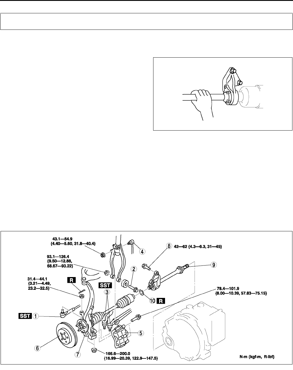
M12
DRIVE SHAFT
End Of Sie
JOINT SHAFT PRE-INSPECTION A6E631625700W01
1. Verify that the joint shaft is not twisted or cracked.
•Replace it as necessary.
2. Turn the joint shaft by hand and verify that the
bearing rotates smoothly and freely.
•Replace it as necessary.
End Of Sie
JOINT SHAFT REMOVAL/INSTALLATION A6E631625700W02
Caution
•
••
•Performing the following procedures without first removing the ABS wheel-speed sensor may
possibly cause an open circuit in the harness if it is pulled by mistake. Before performing the
following procedures, remove the ABS wheel-speed sensor and fix it to an appropriate place
where the sensor will not be pulled by mistake while the vehicle is being serviced.
1. Drain the transaxle oil. (See K13 AUTOMATIC TRANSAXLE FLUID (ATF) REPLACEMENT.)
(See J3 TRANSAXLE OIL REPLACEMENT.)
2. Remove the ABS sensor. (SeeP32 FRONT ABS WHEEL-SPEED SENSOR REMOVAL/INSTALLATION.)
3. Remove in the order indicated in the table.
4. Install in the reverse order of removal.
.
DRIVE SHAFT
A6E0313W015
A6E0313W016
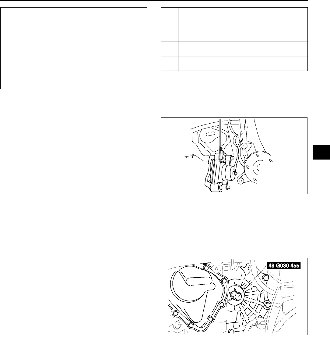
DRIVE SHAFT
M13
M
Brake Caliper Component Removal Note
1. Suspend the caliper aside with wire.
Wheel Hub, Steering Knuckle and Drive Shaft Removal Note
Caution
•
••
•The sharp edges of the joint shaft can slice or puncture the oil seal. Be careful when removing the
joint shaft from the transaxle.
1. Pull the joint shaft straight out.
2. Install the SST into the transaxle to hold the side
gears after the joint shaft is removed.
1 Tie-rod end ball joint
(See N11 Tie-rod End Ball Joint Removal Note)
2bolt
3 Lower arm (front, rear) ball joint
(See R15 FRONT LOWER ARM (FRONT)
REMOVAL/INSTALLATION)
(See R19 FRONT LOWER ARM (REAR)
REMOVAL/INSTALLATION)
4 Stabilizer control link
5 Brake caliper component
(See M13 Brake Caliper Component Removal
Note)
6 Disk plate
(See P20 Disc Plate Removal Note)
7 Wheel hub, steering knuckle and drive shaft
(See M13 Wheel Hub, Steering Knuckle and Drive
Shaft Removal Note)
8 Joint shaft bracket bolt
9 Joint shaft
10 Clip
(See M14 Clip Installation Note)
A6E0313W056
A6E0313W019
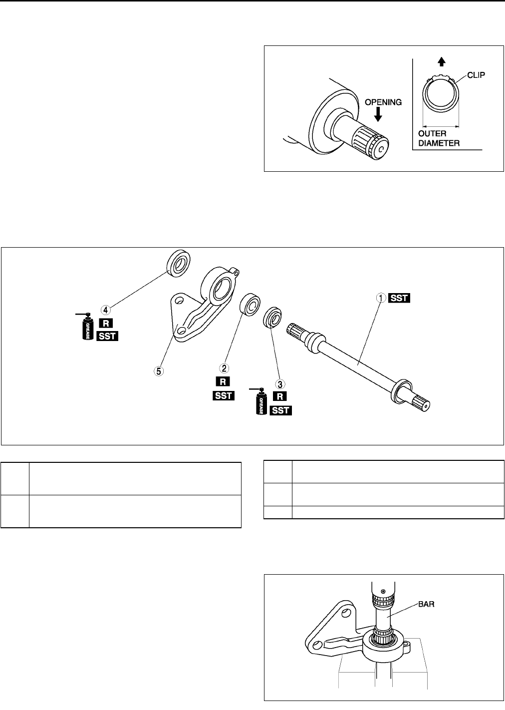
M14
DRIVE SHAFT
Clip Installation Note
1. Install a new clip onto the joint shaft with the opening facing upward. Ensure that the diameter of the clip does
not exceed the specification on installation.
2. After installation, measure the outer diameter. If it
exceeds the specification, repeat Step 1 using a
new clip.
Outer diameter specification
31.2 mm {1.23 in} max.
End Of Sie
JOINT SHAFT DISASSEMBLY/ASSEMBLY A6E631625700W03
1. Disassemble in the order indicated in the table.
2. Assemble in the reverse order of disassembly.
Joint Shaft Disassembly Note
1. Disassemble the joint shaft.
A6E0313W021
A6E0313W026
1 Joint shaft
(See M14 Joint Shaft Disassembly Note)
(See M16 Joint Shaft Assembly Note)
2 Bearing
(See M15 Bearing Disassembly Note)
(See M15 Bearing Assembly Note)
3 Dust seal (Left)
(See M16 Dust Seal (Left) Assembly Note)
4 Dust seal (Right)
(See M15 Dust Seal (Right) Assembly Note)
5Bracket
A6E0313W052
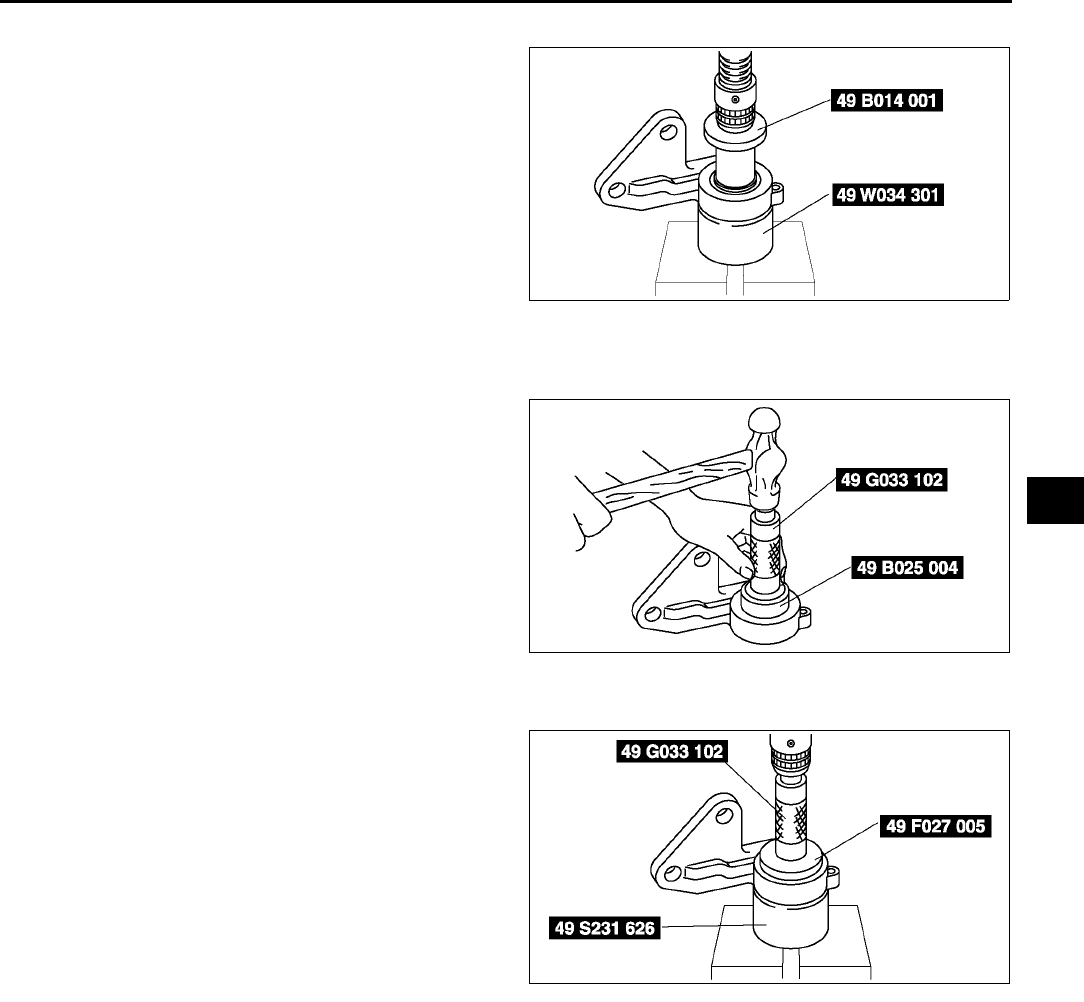
DRIVE SHAFT
M15
M
Bearing Disassembly Note
1. Remove the bearing using the SSTs.
Dust Seal (Right) Assembly Note
1. Apply grease to the new dust seal lip.
2. Install the new right side dust seal using the
SSTs.
Bearing Assembly Note
1. Install the new bearing using the SSTs.
A6E0313W053
A6E0313W028
A6E0313W027
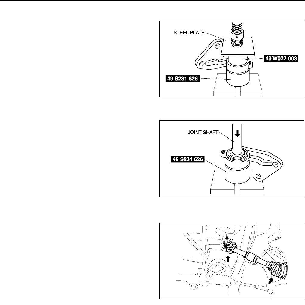
M16
DRIVE SHAFT
Dust Seal (Left) Assembly Note
1. Apply grease to the new dust seal lip.
2. Install the new left side dust seal using a steel
plate and the SSTs.
Joint Shaft Assembly Note
1. Assemble the joint shaft using a press and the
SST.
End Of Sie
DRIVE SHAFT PRE-INSPECTION A6E631625500W01
1. Inspect the dust boot on the drive shaft for cracks,
damage, leaking grease, and looseness in the
boot band.
2. Inspect the drive shaft for bends, cracks, and
wear in the joint or splines.
•Repair or replace the drive shaft or boot/band
as necessary.
End Of Sie
A6E0313W030
A6E0313W029
A6E0313W033
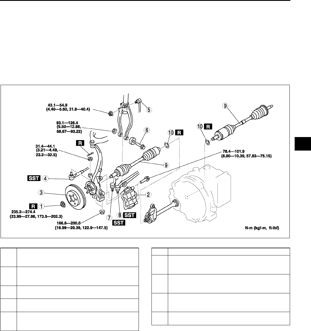
DRIVE SHAFT
M17
M
DRIVE SHAFT REMOVAL/INSTALLATION A6E631625500W02
Caution
•
••
•Performing the following procedures without first removing the ABS wheel-speed sensor may
possibly cause an open circuit in the harness if it is pulled by mistake. Before performing the
following procedures, remove the ABS wheel-speed sensor (axle side) and fix it to an appropriate
place where the sensor will not be pulled by mistake while the vehicle is being serviced.
1. Drain the transaxle oil (left side). (See K13 AUTOMATIC TRANSAXLE FLUID (ATF) REPLACEMENT.)
(SeeJ3 TRANSAXLE OIL REPLACEMENT.)
2. Remove in the order indicated in the table.
3. Install in the reverse order of removal.
.
A6E0313W055
1 Locknut
(See M6 Locknut Removal Note)
(See M9 Locknut Installation Note)
2 Brake caliper component
(See M13 Brake Caliper Component Removal
Note)
3 Disc plate
(See P20 Disc Plate Removal Note)
4 Tie-rod end ball joint
(See N11 Tie-rod End Ball Joint Removal Note)
5 Front stabilizer control link
(See R22 FRONT STABILIZER REMOVAL/
INSTALLATION)
6Bolt
7 Front lower arm (rear) ball joint
(See R19 Front Lower Arm (Rear) Ball Joint
Removal Note)
8 Front lower arm (front) ball joint
(See R16 Front Lower Arm (Front) Ball Joint
Removal Note)
9 Drive shaft
(See M18 Drive Shaft Removal Note)
(See M19 Drive Shaft Installation Note)
10 Clip
(See M18 Clip Installation Note)
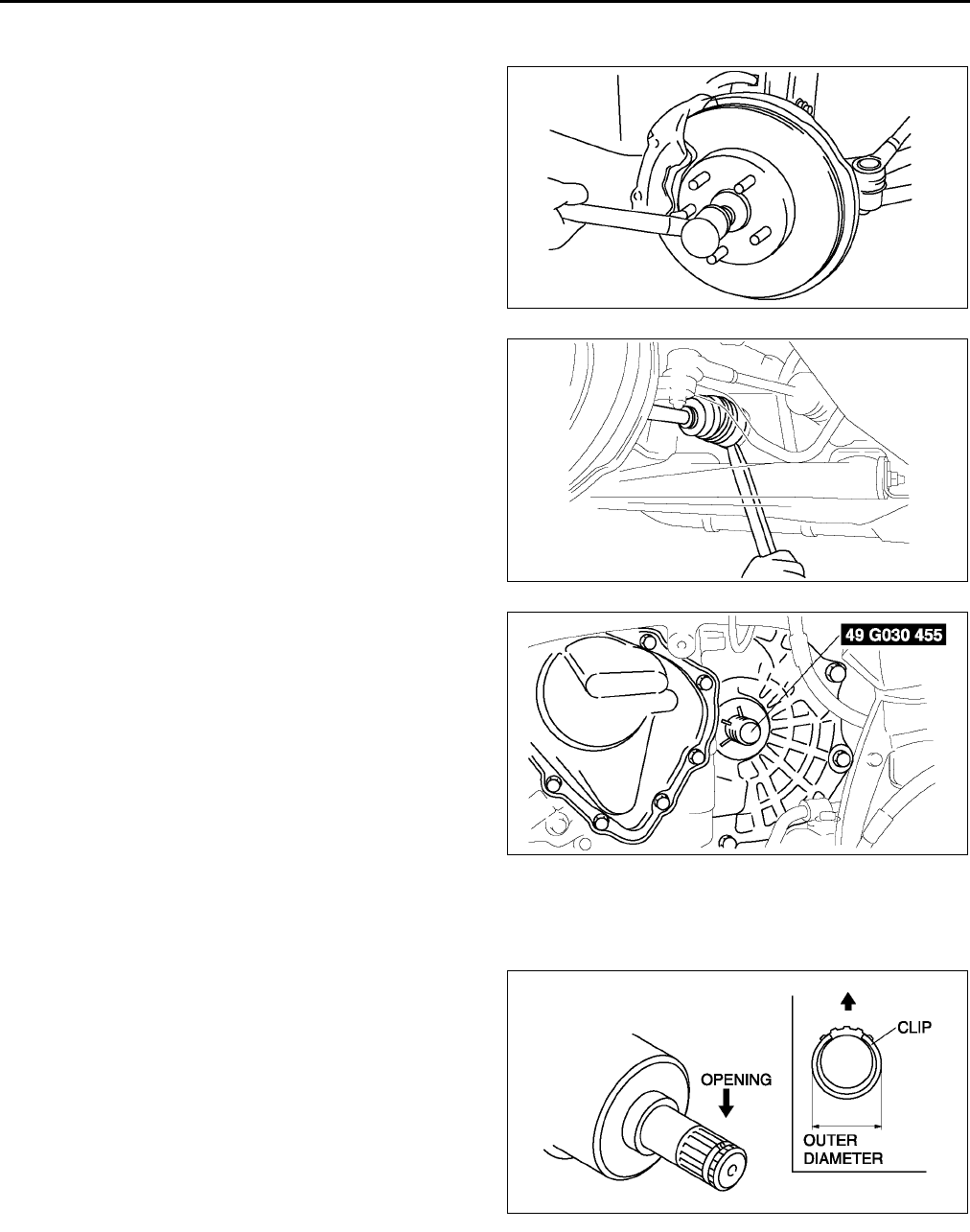
M18
DRIVE SHAFT
Drive Shaft Removal Note
1. Install a spare nut onto the drive shaft so that the nut is flush with the end of the drive shaft.
2. Tap the nut with a copper hammer to loosen the
drive shaft from the front wheel hub.
3. Separate the drive shaft from the wheel hub.
Caution
•
••
•The sharp edges of the drive shaft can
slice or puncture the oil seal. Be careful
when removing the drive shaft from the
transaxle.
4. Separate the left side drive shaft from the
transaxle by prying with a bar inserted between
the outer ring and the transaxle, as shown in the
figure.
5. Install the SST into the transaxle to hold the side
gears after the drive shaft is removed.
Clip Installation Note
1. Install a new clip onto the joint shaft with the opening facing upward. Ensure that the diameter of the clip does
not exceed the specification on installation.
2. After installation, measure the outer diameter. If it
exceeds the specification, repeat Steps 12
using a new clip.
Outer diameter specification
31.2 mm {1.23 in} max.
A6E6316W001
A6E6316W002
A6E0313W038
A6E0313W021
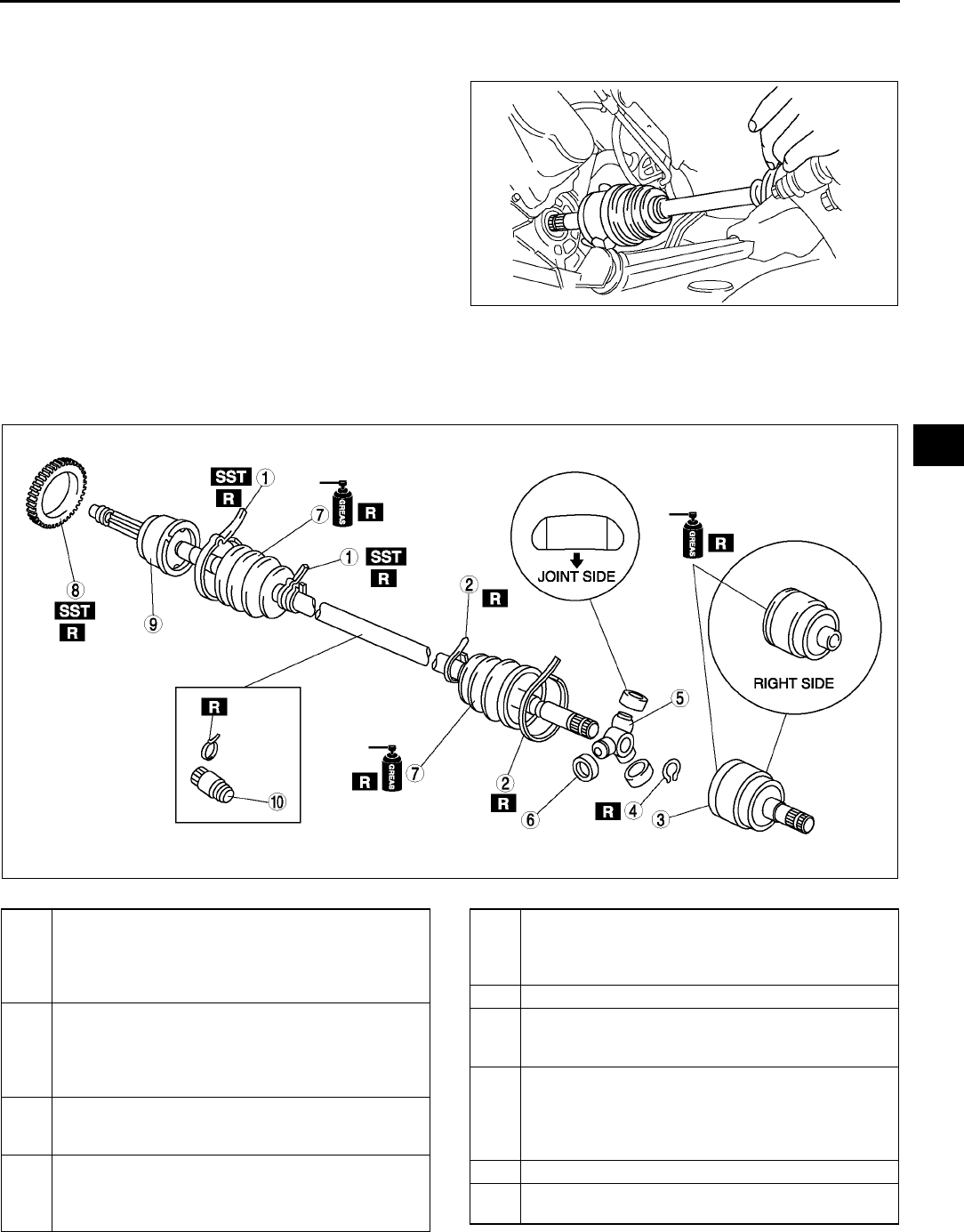
DRIVE SHAFT
M19
M
Drive Shaft Installation Note
Caution
•
••
•The sharp edges of the drive shaft can
slice or puncture the oil seal. Be careful
when installing the drive shaft to the
transaxle.
•
••
•The oil seals are damaged easily if this
procedure is not done correctly.
1. Insert the drive shaft into the wheel hub.
2. Apply transaxle oil to the oil seal lip.
3. Push the drive shaft into the transaxle.
4. After installation, pull the transaxle side outer ring
forward to confirm that the drive shaft is securely
held by the clip.
End Of Sie
DRIVE SHAFT (ATX) DISASSEMBLY/ASSEMBLY A6E631625500W03
1. Disassemble in the order indicated in the table.
2. Assemble in the reverse order of disassembly.
.
A6E6316W003
A6E0313W043
1 Boot band (wheel side)
(See M20 Boot Band (Wheel Side) Disassembly
Note)
(See M23 Boot Band (Wheel Side) Assembly
Note)
2 Boot band (transaxle side)
(See M20 Boot Band (Transaxle Side)
Disassembly Note)
(See M23 Boot Band (Transaxle Side) Assembly
Note)
3Outer ring
(See M20 Outer Ring Disassembly Note)
(See M22 Outer Ring Assembly Note)
4 Snap ring
(See M20 Snap Ring, Tripod Joint Disassembly
Note)
(See M22 Tripod Joint, Snap Ring Assembly Note)
5 Tripod joint
(See M20 Snap Ring, Tripod Joint Disassembly
Note)
(See M22 Tripod Joint, Snap Ring Assembly Note)
6 Free ring
7Boot
(See M21 Boot Disassembly Note)
(See M22 Boot Assembly Note)
8 ABS sensor rotor (with ABS)
(See M21 ABS Sensor Rotor (With ABS)
Disassembly Note)
(See M22 ABS Sensor Rotor (With ABS) Assembly
Note)
9 Shaft and ball joint component
10 Dynamic damper
(See M21 Dynamic Damper Assembly Note)

M20
DRIVE SHAFT
Boot Band (Wheel Side) Disassembly Note
Note
•The boot band does not need to be removed unless it is being replaced.
1. Remove the boot clamp with end clamp pliers as
shown and discard the clamp.
Boot Band (Transaxle Side) Disassembly Note
1. Pry up the locking clips using a screwdriver.
2. Pull back the end of the band.
Outer Ring Disassembly Note
1. Mark the outer ring and the shaft for proper
assembly.
2. Remove the outer ring.
Snap Ring, Tripod Joint Disassembly Note
1. Mark the shaft and tripod joint for proper assembly.
2. Remove the snap ring using snap-ring pliers.
3. Remove the tripod joint from the shaft.
Caution
•
••
•Do not tap the tripod joint with a hammer.
A6E6316W004
A6E6316W005
A6E0313W046
A6E0313W047
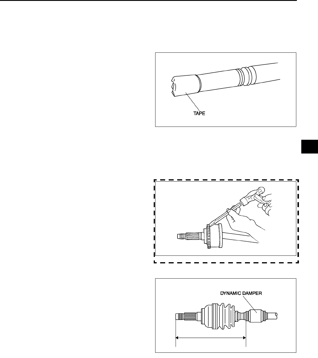
DRIVE SHAFT
M21
M
Boot Disassembly Note
Note
•The wheel side boot does not need to be removed unless replacing it or the ball joint and shaft
component.
•Do not strip the tape until the boot is assembled.
1. Wrap the shaft splines with tape.
2. Remove the boot.
ABS Sensor Rotor (With ABS) Disassembly Note
Caution
•
••
•Do not remove the sensor rotor unless it is necessary.
•
••
•Do not reuse the sensor rotor if removed.
1. Tap the ABS sensor rotor off the drive shaft using
a chisel.
Dynamic Damper Assembly Note
1. Install the dynamic damper as shown in the
figure.
Standard length
334.7340.7 mm {13.213.4 in}
2. Install the new boot band onto the dynamic
damper.
A6E0313W048
ZLU0313W105
A6E6316W006
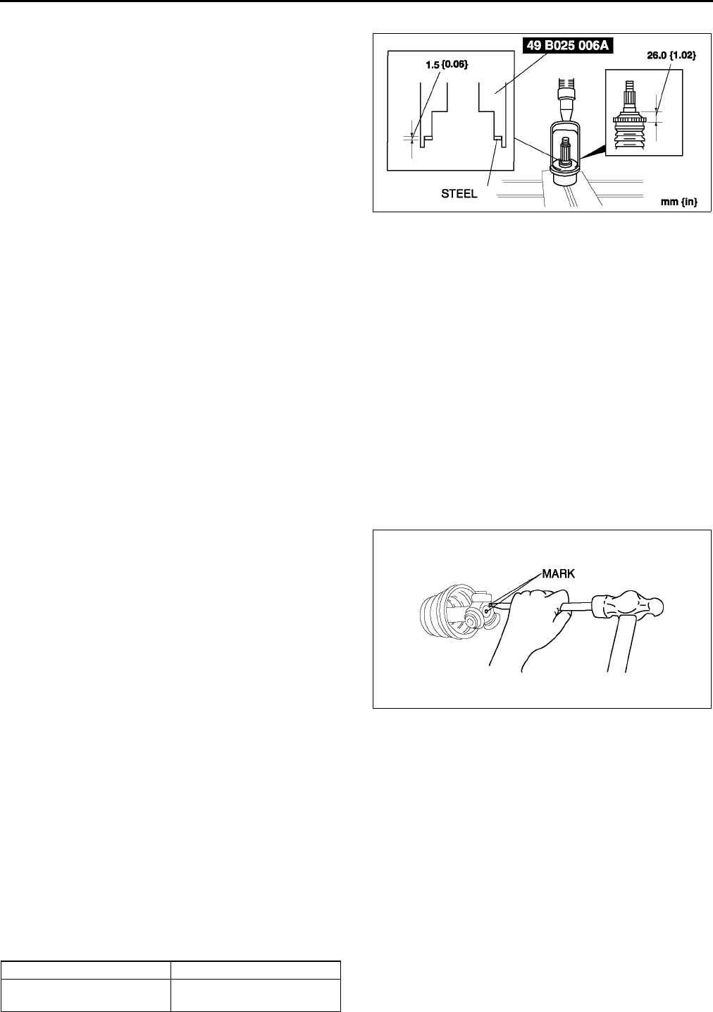
M22
DRIVE SHAFT
ABS Sensor Rotor (With ABS) Assembly Note
1. Set a new ABS sensor rotor on the drive shaft
and press it on using the SSTs.
Boot Assembly Note
Note
•The wheel side and transaxle side boots are different.
1. Fill the boot (wheel side) with the specified grease.
Caution
•
••
•Do not touch grease with your hand. Apply it from the tube to prevent foreign matter from entering
the boot.
Grease amount
90110 g {3.183.88 oz}
2. With the splines of the shaft still wrapped in tape from disassembly, install the boot.
3. Remove the tape.
Tripod Joint, Snap Ring Assembly Note
1. Align the marks and install the tripod joint using a
bar and a hammer.
Caution
•
••
•Do not damage the roller.
2. Install the new snap ring using snap-ring pliers.
Caution
•
••
•Be sure the snap ring engages correcting
in the groove of the shaft.
Outer Ring Assembly Note
1. Fill the outer ring and boot (transaxle side) with the specified grease.
Caution
•
••
•Do not touch grease with your hand. Apply it from the tube to prevent foreign matter from entering
the boot.
Grease amount
195215 g {6.887.58 oz}
2. Install the outer ring.
3. Set the drive shaft to the standard length.
Standard length
mm {in}
A6E0313W050
A6E0313W051
Left side Right side
674.5684.5
{26.5626.94}
631.2641.2
{24.8625.24}
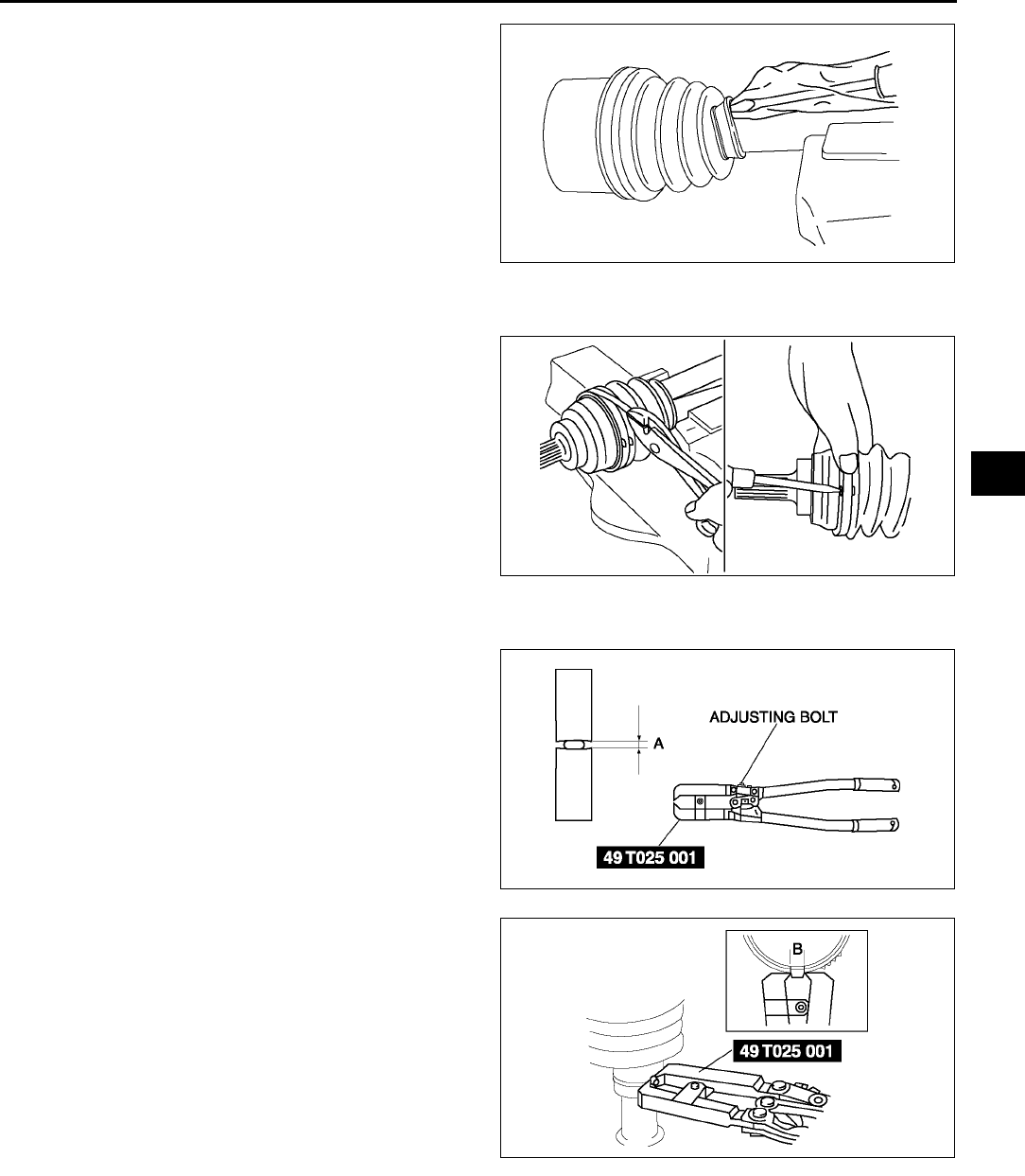
DRIVE SHAFT
M23
M
4. Release any trapped air from the boots by
carefully lifting up the small end of each boot with
a cloth wrapped screwdriver.
Caution
•
••
•Do not let grease leak.
•
••
•Do not damage the boot.
5. Verify that the drive shaft length is within the
standard.
Boot Band (Transaxle Side) Assembly Note
1. Fold the band in the direction opposite to the
forward revolving direction of the drive shaft and
use pliers to pull it tight.
2. Lock the end of the band by bending the locking
clips.
Caution
•
••
•Install the band into the groove securely.
Boot Band (Wheel Side) Assembly Note
1. Adjust clearance A by turning the adjusting bolt of
the SST.
Clearance A
2.9 mm {0.11 in}
2. Crimp the wheel side small boot band using the
SST. Verify that clearance B is within the
specification.
•If clearance B is more than the specification,
reduce clearance A of the SST and crimp the
boot again.
•If clearance B is less than the specification,
replace the boot band, increase clearance A
of the SST, and crimp the new boot.
Clearance B
2.42.8 mm {0.0950.110 in}
3. Verify that the boot band does not protrude from
the boot band installation area.
•If it does, replace the boot band and repeat Steps 2 and 3.
4. Fill the boot with the repair kit grease.
5. Adjust clearance A by turning the adjusting bolt of the SST.
Clearance A
3.2 mm {0.13 in}
A6E6316W007
A6E6316W008
A6E0350W012
A6E0350W013
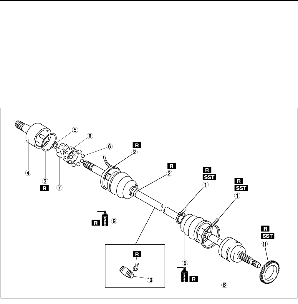
M24
DRIVE SHAFT
6. Crimp the wheel side big boot band using the SST.
7. Verify that clearance B is within the specification.
•If clearance B is more than the specification, reduce clearance A of the SST and crimp the boot again.
•If clearance B is less than the specification, replace the boot band, increase clearance A of the SST and
crimp the new boot.
Clearance B
2.42.8 mm {0.0950.110 in}
8. Verify that the boot band does not protrude from the boot band installation area.
•If it does, replace the boot band and repeat Steps 7 and 8.
End Of Sie
DRIVE SHAFT (MTX) DISASSEMBLY/ASSEMBLY A6E631625500W04
1. Disassemble in the order indicated in the table.
2. Assemble in the reverse order of disassembly.
.
A6E6316W009
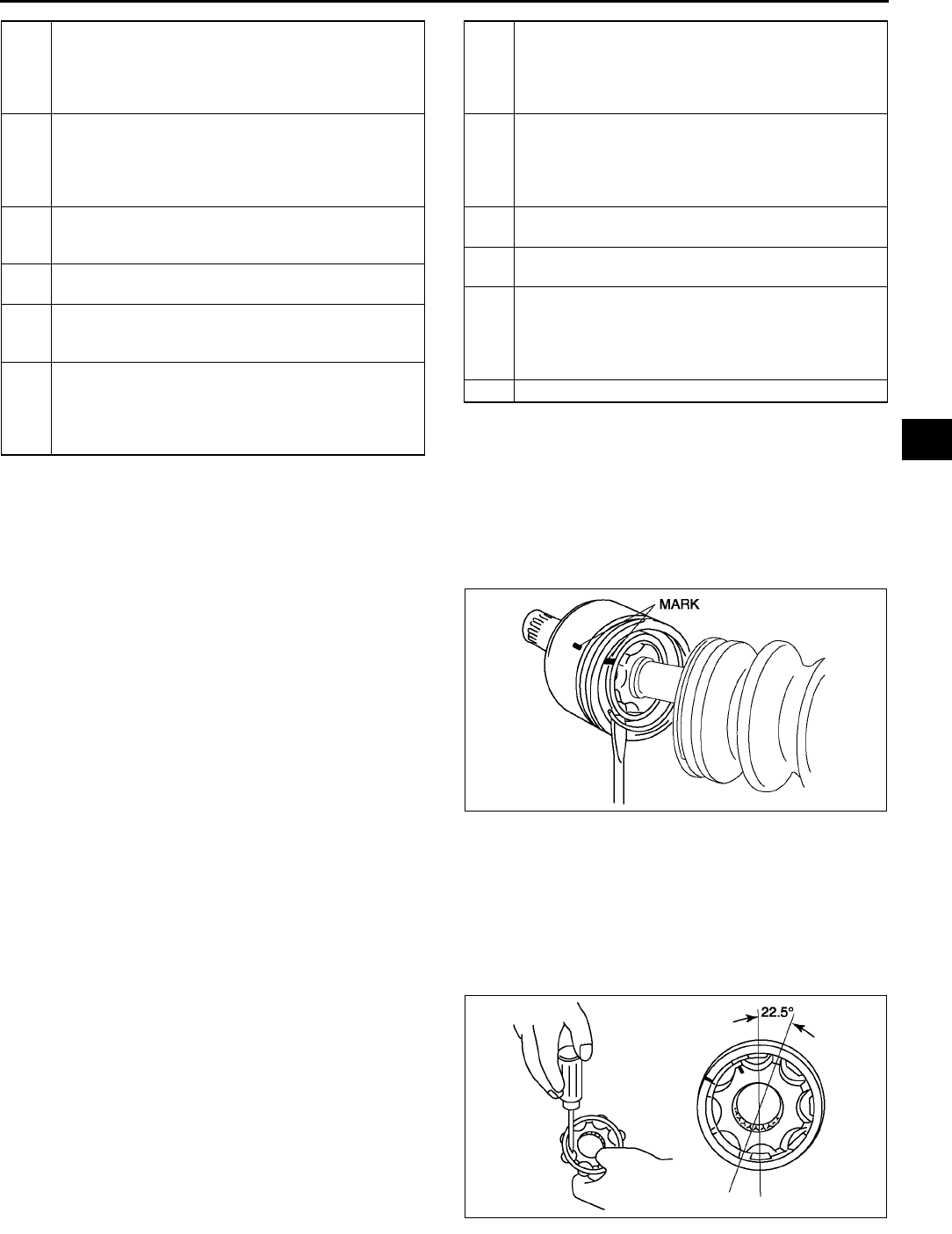
DRIVE SHAFT
M25
M
Clip Disassembly Note
1. Mark the drive shaft and outer ring for proper
assembly.
Caution
•
••
•Mark with paint; do not use a punch.
2. Remove the clip.
Balls, Inner Ring, Cage Disassembly Note
1. Mark the inner ring and cage.
Caution
•
••
•Mark with paint; do not use a punch.
2. Remove the snap ring using snap-ring pliers.
3. Turn the cage approximately 30 degree and pull
the cage and balls away from the inner ring.
1 Boot band (wheel side)
(See M20 Boot Band (Wheel Side) Disassembly
Note)
(See M23 Boot Band (Wheel Side) Assembly
Note)
2 Boot band (transaxle side)
See M20 Boot Band (Transaxle Side) Disassembly
Note
See M23 Boot Band (Transaxle Side) Assembly
Note
3Clip
See M25 Clip Disassembly Note
See M26 Outer Ring, Clip Assembly Note
4Outer ring
(See M26 Outer Ring, Clip Assembly Note)
5 Snap ring
(See M26 Cage, Inner Ring, Balls, Snap Ring
Assembly Note)
6Balls
(See M25 Balls, Inner Ring, Cage Disassembly
Note)
(See M26 Cage, Inner Ring, Balls, Snap Ring
Assembly Note)
7 Inner Ring
(See M25 Balls, Inner Ring, Cage Disassembly
Note)
(See M26 Cage, Inner Ring, Balls, Snap Ring
Assembly Note)
8Cage
(See M25 Balls, Inner Ring, Cage Disassembly
Note)
(See M26 Cage, Inner Ring, Balls, Snap Ring
Assembly Note)
9Boot
(See M26 Boot Assembly Note)
10 Dynamic damper
(See M26 Dynamic Damper Assembly Note)
11 ABS sensor rotor
(See M21 ABS Sensor Rotor (With ABS)
Disassembly Note)
(See M22 ABS Sensor Rotor (With ABS) Assembly
Note)
12 Shaft and ball joint component
A6E6316W010
A6E6316W015
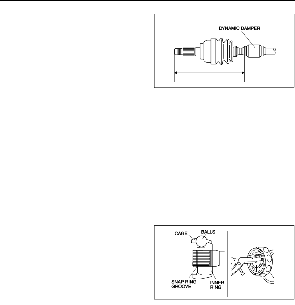
M26
DRIVE SHAFT
Dynamic Damper Assembly Note
1. Install the dynamic damper as shown in the
figure.
Standard length
334.7340.7 mm {13.213.4 in}
2. Install the new boot band onto the dynamic
damper.
Boot Assembly Note
Note
•The wheel side and transaxle side boots are different.
1. Fill the boot (wheel side) with the specified grease.
Caution
•
••
•Do not touch grease with your hand. Apply it from the tube to prevent foreign matter from entering
the boot.
Grease amount
90110 g {3.183.88 oz} (L8, LF left side)
105125 g {3.714.40 oz} (L8, LF right side and L3)
2. With the splines of the shaft still wrapped in tape from disassembly, install the boot.
3. Remove the tape.
Cage, Inner Ring, Balls, Snap Ring Assembly Note
1. Align the marks and install the balls and cage to
the inner ring in the direction shown in the figure.
Caution
•
••
•Install the cage with the offset facing the
snap ring groove. If incorrectly installed,
the drive shaft may become disengaged.
2. Install a new snap ring.
Outer Ring, Clip Assembly Note
1. Fill the outer ring and boot (transaxle side) with the specified grease.
Caution
•
••
•Do not touch grease with your hand. Apply it from the tube to prevent foreign matter from entering
the boot.
Grease amount
105125 g {3.714.40 oz} (L8, LF left side),
120140 g {4.244.93 oz} (L8, LF right side and L3)
2. Align the marks, and install the outer ring on to the shaft.
3. Install a new clip.
4. Install the boot.
5. Set the drive shaft to the standard length.
A6E6316W006
A6E6316W011
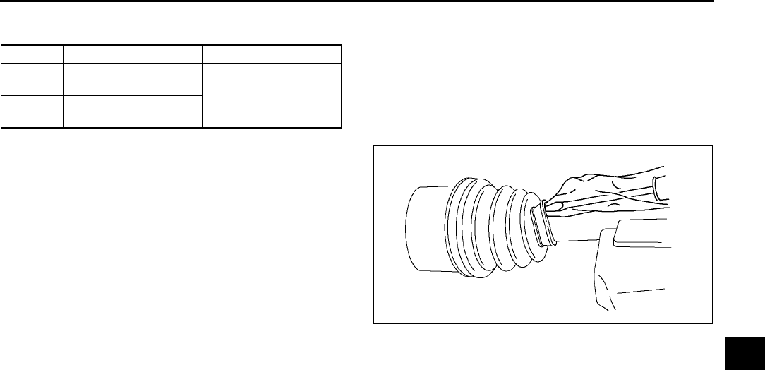
DRIVE SHAFT
M27
M
Standard length
mm {in}
6. Release any trapped air from the boots by
carefully lifting up the small end of each boot with
a cloth wrapped screwdriver.
Caution
•
••
•Be careful not to allow the grease to leak.
•
••
•Do not damage the boot.
7. Verify that the drive shaft length is within the
specification.
End Of Sie
Left side Right side
L8, LF 677.7687.7
{26.6927.07} 628.6638.6
{24.7525.14}
L3 676.6686.6
{26.6427.03}
A6E6316W007

N1
N
NSTEERING SYSTEM
LOCATION INDEX .................................................N-2
STEERING LOCATION INDEX ...........................N-2
GENERAL PROCEDURES ....................................N-3
PRECAUTION (STEERING)................................N-3
ENGINE SPEED SENSING POWER
STEERING ..............................................................N-3
AIR BLEEDING ....................................................N-3
POWER STEERING FLUID INSPECTION..........N-4
STEERING WHEEL AND COLUMN
INSPECTION ....................................................N-6
STEERING WHEEL AND COLUMN
REMOVAL/INSTALLATION ..............................N-7
STEERING SHAFT INSPECTION .......................N-9
STEERING GEAR AND LINKAGE
REMOVAL/INSTALLATION ............................N-10
STEERING GEAR AND LINKAGE
DISASSEMBLY...............................................N-12
STEERING GEAR AND LINKAGE
INSPECTION .....................................................N-16
STEERING GEAR AND LINKAGE
ASSEMBLY........................................................N-16
POWER STEERING OIL PUMP
REMOVAL/INSTALLATION ............................N-22
POWER STEERING OIL PUMP
DISASSEMBLY/ASSEMBLY ..........................N-22
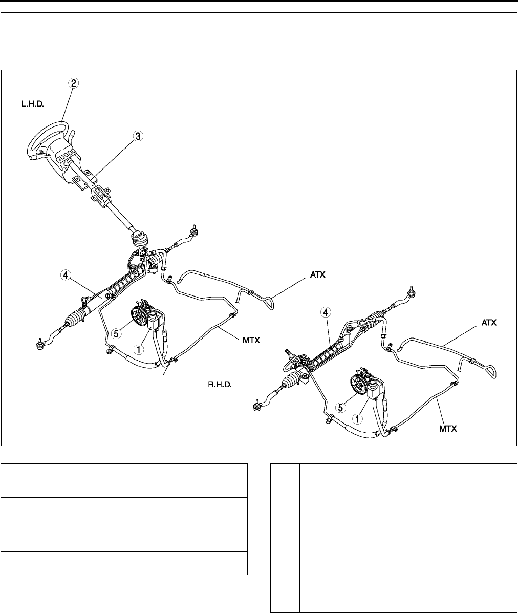
N2
LOCATION INDEX
STEERING LOCATION INDEX A6E660001036W01
.
End Of Sie
LOCATION INDEX
A6E0610W010
1 Power steering fluid
(See N4 POWER STEERING FLUID
INSPECTION)
2 Steering wheel and column
(See N6 STEERING WHEEL AND COLUMN
INSPECTION)
(See N7 STEERING WHEEL AND COLUMN
REMOVAL/INSTALLATION)
3 Steering shaft
(See N9 STEERING SHAFT INSPECTION)
4 Steering gear and linkage
(See N10 STEERING GEAR AND LINKAGE
REMOVAL/INSTALLATION)
(See N12 STEERING GEAR AND LINKAGE
DISASSEMBLY)
(See N16 STEERING GEAR AND LINKAGE
INSPECTION)
(See N16 STEERING GEAR AND LINKAGE
ASSEMBLY)
5 Power steering oil pump
(See N22 POWER STEERING OIL PUMP
REMOVAL/INSTALLATION)
(See N22 POWER STEERING OIL PUMP
DISASSEMBLY/ASSEMBLY)

GENERAL PROCEDURES , ENGINE SPEED SENSING POWER STEERING
N3
N
PRECAUTION (STEERING) A6E661001036W01
Wheels and Tires Removal/Installation
1. The removal and installation procedures for the wheels and tires are not mentioned in this section. When a
wheel is removed, tighten it to
88118 N·m {9.012.0 kgf·m, 65.087.0 ft·lbf}.
Power Steering Components Removal/Installation
1. If any power steering fluid line has been disconnected anytime during the procedure, add ATF M-III or
equivalent (e.g. Dexron®II), bleed the fluid lines, and inspect for leakage after the procedure has been
completed.
Connectors Disconnection/Connection
1. Disconnect the negative battery cable before doing any work that requires handling of connectors. Reconnect
the negative battery cable only after the work is completed.
Suspension Arm Removal/Installation
1. Tighten any part of the suspension that uses rubber bushings only after vehicle has been lowered and
unloaded.
Note
•Unloaded: Fuel tank is full. Engine coolant and engine oil are at specified level. Spare tire, jack, and tools
are in designated position.
End Of Sie
AIR BLEEDING A6E661401036W01
1. Inspect the fluid level. (See N4 POWER STEERING FLUID INSPECTION.)
2. Jack up the front of the vehicle and support it on safety stands.
3. Turn the steering wheel fully to the left and right several times with the engine not running.
4. Reinspect the fluid level.
•If it has dropped, add fluid.
5. Repeat Steps 3 and 4 until the fluid level stabilizes.
6. Lower the vehicle.
7. Start the engine and let it idle.
8. Turn the steering wheel fully to the left and right several times.
9. Verify that the fluid is not foamy and that the fluid level has not dropped.
•If the fluid level has dropped, add fluid as necessary and repeat Steps 8 and 9.
End Of Sie
GENERAL PROCEDURES
ENGINE SPEED SENSING POWER STEERING
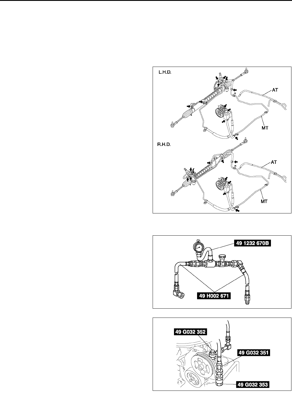
N4
ENGINE SPEED SENSING POWER STEERING
POWER STEERING FLUID INSPECTION A6E661432040W01
Fluid Level Inspection
1. Inspect the power steering fluid level.
•Add fluid to the specified level as necessary.
Fluid specification
ATF M-III or equivalent (e.g. Dexron®II)
Fluid Leakage Inspection
1. Start the engine and let it idle.
2. Turn the steering wheel fully to the left and right
to apply fluid pressure.
Caution
•
••
•If the steering wheel is kept in the fully
turned position for more than 5 seconds,
the fluid temperature will rise excessively
and adversely affect the oil pump.
3. Inspect for fluid leakage.
•If fluid leakage is found, replace related pipe
or hose.
Note
•The points where fluid leakage may occur
are indicated in the figure.
Fluid Pressure Inspection
1. Assemble the SSTs as shown in the figure.
2. Disconnect the pressure pipe from the oil pump,
and connect the SSTs.
Tightening torque
29.444.1 N·m {3.04.4 kgf·m, 2232 ft·lbf}
3. Bleed the air from the system.
4. Open the gauge valve fully.
5. Start the engine and turn the steering wheel fully
left and right to raise the fluid temperature to 50
60 °
°°
°C {122140 °
°°
°F}.
A6E0612W094
A6E0612W101
A6E0612W012
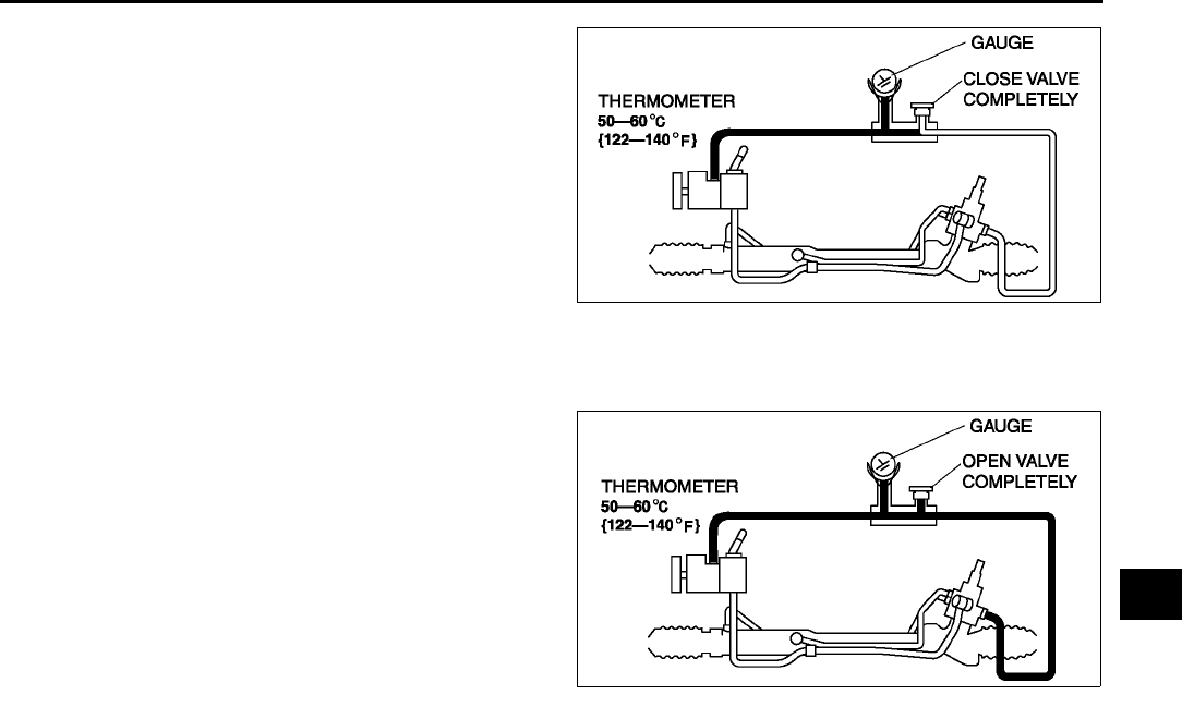
ENGINE SPEED SENSING POWER STEERING
N5
N
6. Close the gauge valve completely.
7. Increase the engine speed to 1,0001,500 rpm
and measure the fluid pressure generated by the
oil pump.
•If the pressure is not within the specification,
repair or replace the oil pump component.
Caution
•
••
•If the valve is left closed for more than 5
seconds, the fluid temperature will rise
excessively and adversely affect the oil
pump.
Oil pump fluid pressure
10.8011.29 MPa {110.2115.2 kgf/cm2, 15671637 psi}
8. Open the gauge valve fully and increase the
engine speed to 1,0001,500 rpm.
9. Turn the steering wheel fully to the left and right,
then measure the fluid pressure generated at the
gear housing.
•If the pressure is not within the specification,
repair or replace the steering gear
component.
Caution
•
••
•If the steering wheel is kept in the fully
turned position for more than 5 seconds,
the fluid temperature will rise excessively
and adversely affect the oil pump.
Gear housing fluid pressure
10.8011.29 MPa {110.2115.2 kgf/cm2, 15671637 psi}
10. Remove the SSTs. Install and tighten the pressure pipe to the specified torque.
Tightening torque
29.444.1 N·m {3.04.4 kgf·m, 2232 ft·lbf}
11. Bleed the air from the system.
End Of Sie
A6E0612W081
A6E0612W080
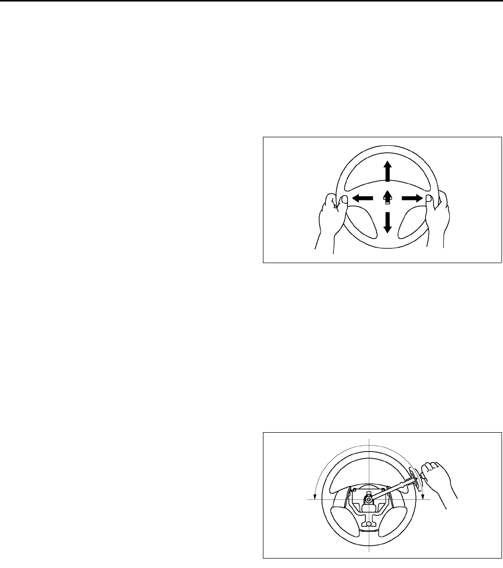
N6
ENGINE SPEED SENSING POWER STEERING
STEERING WHEEL AND COLUMN INSPECTION A6E661432010W01
Steering Wheel Play Inspection
1. With the wheels in the straight-ahead position, gently turn the steering wheel to the left and right and verify that
the play is within the specification.
•If the play exceeds the specification, either the steering joints are worn or the backlash of the steering gear
is excessive. Correct as necessary.
Play
030 mm {01.18 in}
Steering Wheel Looseness Inspection
1. Move the steering wheel as shown in the figure to
inspect for column bearing wear, steering shaft
joint play, steering wheel looseness, and column
looseness.
•Repair or replace as necessary.
Steering Wheel Effort Inspection
1. Inspect the following points:
•Tire size and tire pressure
•Fluid level
•Drive belt deflection
2. With the vehicle on a hard, level surface, put the wheels in the straight-ahead position.
3. Remove the air bag module.
Warning
•
••
•See DRIVER-SIDE AIR BAG MODULE REMOVAL/INSTALLATION for removal/installation of the air
bag module after inspection.
4. Start the engine and warm the power steering fluid to 5060 °
°°
°C {122140 °
°°
°F}.
5. Measure the steering wheel effort using a torque
wrench.
•If not within the specification, verify the
following:
No air in steering system
No fluid leakage at hose or connectors
Function of oil pump and steering gear
Steering wheel effort
7.8 N·m {80 kgf·cm, 58 in·lbf} max.
Note
•To determine whether the steering effort is
satisfactory or not, perform the inspection on
another vehicle of the same model and under the same conditions, and compare the results.
•The steering wheel effort varies with conditions as shown below.
Road conditions, such as dry or wet, and asphalt or concrete.
Tire conditions, such as brand, wear, and tire pressure.
End Of Sie
A6E0612W015
A6E0612W016
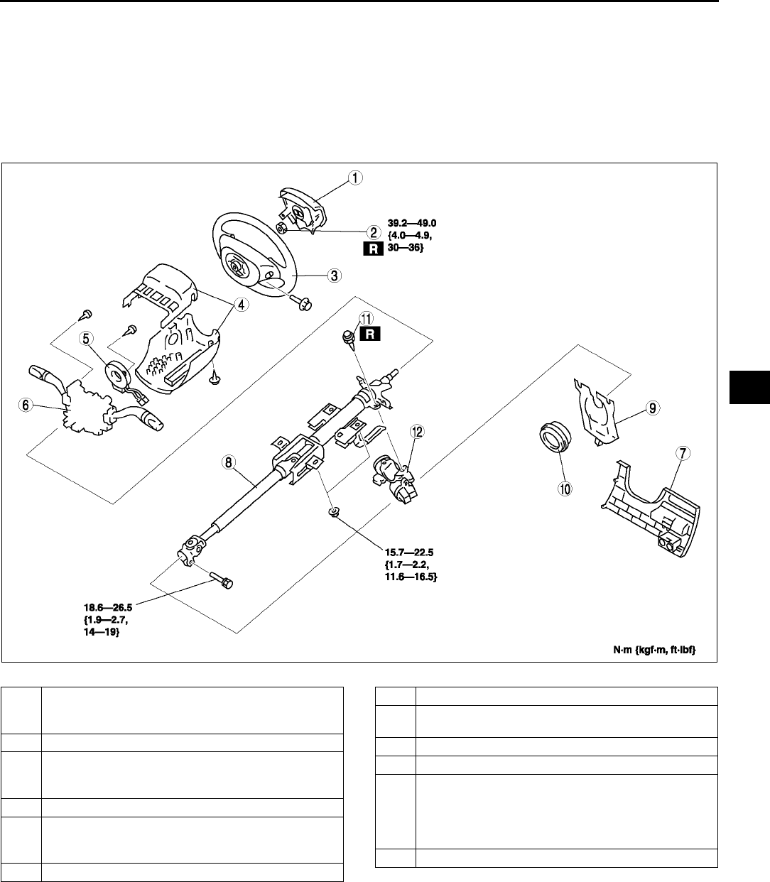
ENGINE SPEED SENSING POWER STEERING
N7
N
STEERING WHEEL AND COLUMN REMOVAL/INSTALLATION A6E661432010W02
Warning
•
••
•Handling the air bag module improperly can accidentally deploy the air bag module, which may
seriously injure you. Read AIR BAG SYSTEM WARNINGS before handling the air bag module. (See
T117 SERVICE WARNINGS.)
1. Remove in the order indicated in the table.
2. Install in the reverse order of removal.
3.
.
A6E0612W017
1 Air bag module
(See T120 DRIVER-SIDE AIR BAG MODULE
REMOVAL/INSTALLATION)
2 Locknut
3 Steering wheel
(See N8 Steering Wheel Removal Note)
(See N8 Steering Wheel Installation Note)
4 Column cover
5 Clock spring
(See T125 CLOCK SPRING REMOVAL/
INSTALLATION)
6 Combination switch
7 Lower panel
8 Steering shaft
(See N8 Steering Shaft Installation Note)
9 Joint cover
10 Dust cover
11 Steering lock mounting bolts
(See N8 Steering Lock Mounting Bolts Removal
Note)
(See N8 Steering Lock Mounting Bolts Installation
Note)
12 Steering lock component
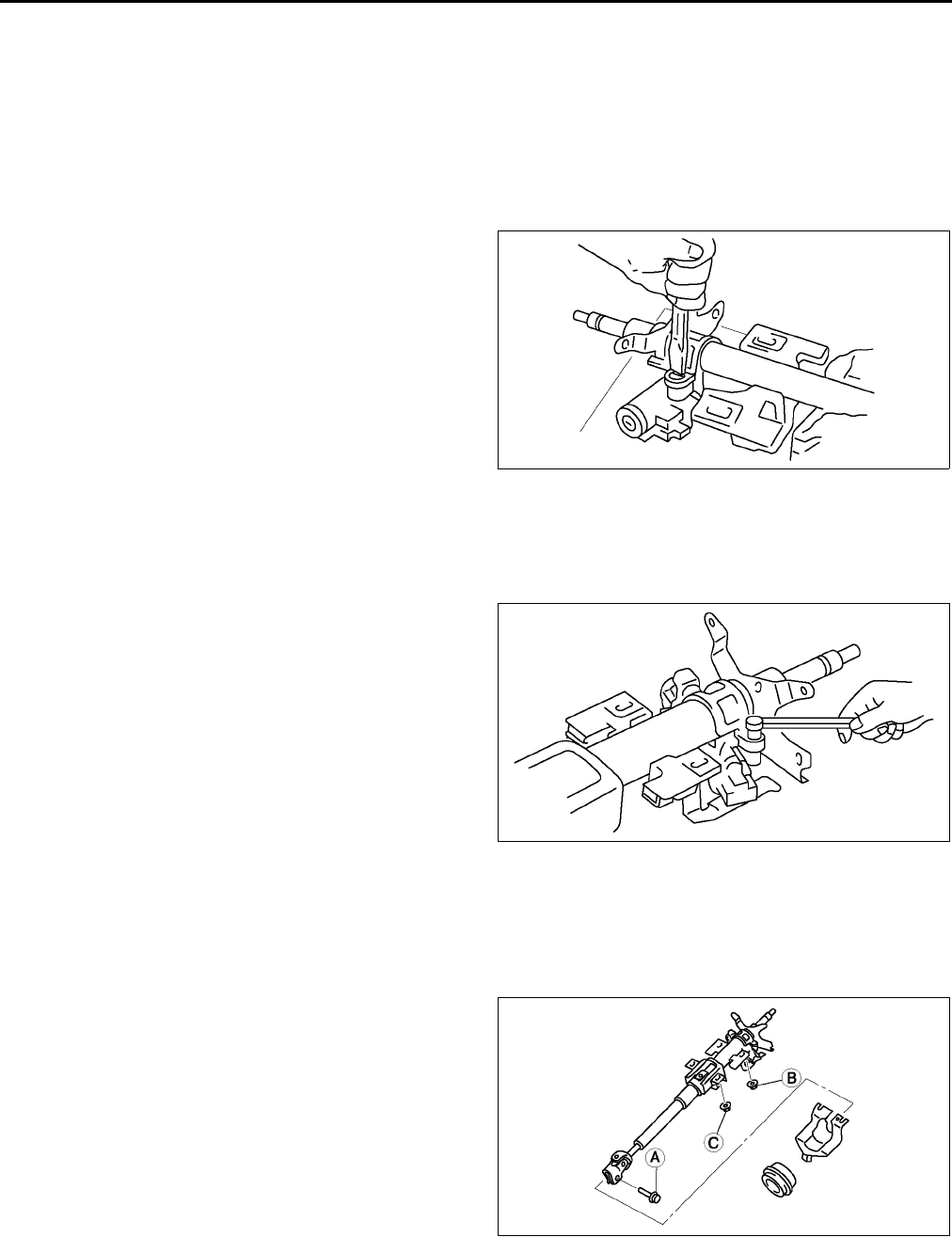
N8
ENGINE SPEED SENSING POWER STEERING
Steering Wheel Removal Note
Caution
•
••
•Do not try to remove the steering wheel by hitting the shaft with a hammer. The column will
collapse.
1. Set the vehicle in the straight-ahead position.
2. Remove the steering wheel using a suitable puller.
Steering Lock Mounting Bolts Removal Note
1. Make a groove in the heads of the steering lock
mounting bolts using a chisel and a hammer.
2. Remove the bolts using a screwdriver.
3. Disassemble the steering lock component.
Steering Lock Mounting Bolts Installation Note
1. Assemble the steering lock component to the steering shaft.
2. Verify that the lock operates correctly.
3. Install new steering lock mounting bolts.
4. Tighten the bolts until the heads break off.
Steering Shaft Installation Note
Caution
•
••
•Do not apply a shock in the axial direction of the shaft.
1. Lock the tilt lever.
2. Tighten bolt A.
3. Tighten nut B.
4. Tighten nut C.
Steering Wheel Installation Note
1. Set the wheels in the straight-ahead position, and install the steering wheel.
End Of Sie
A6E0612W018
A6E0612W020
A6E0612W103
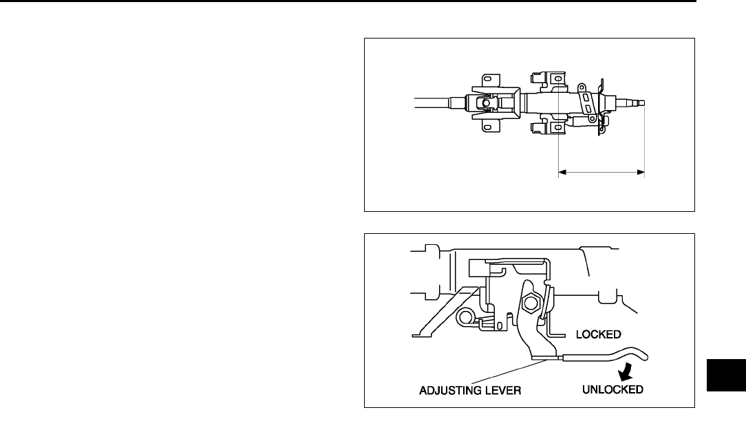
ENGINE SPEED SENSING POWER STEERING
N9
N
STEERING SHAFT INSPECTION A6E661432100W01
1. Inspect the following.
(1) Column bearing for damage
(2) Steering shaft length
•Replace the steering shaft component as
necessary.
Length
211.6 mm {8.3 in}
2. Inspect the tilt and telescope operation
(1) Verify that the adjusting lever moves smoothly
from unlock position to lock position.
(2) Verify that the steering shaft is fixed firmly
when the adjusting lever is locked.
•Replace the steering shaft component as
necessary.
End Of Sie
A6E0612W022
A6E0612W023
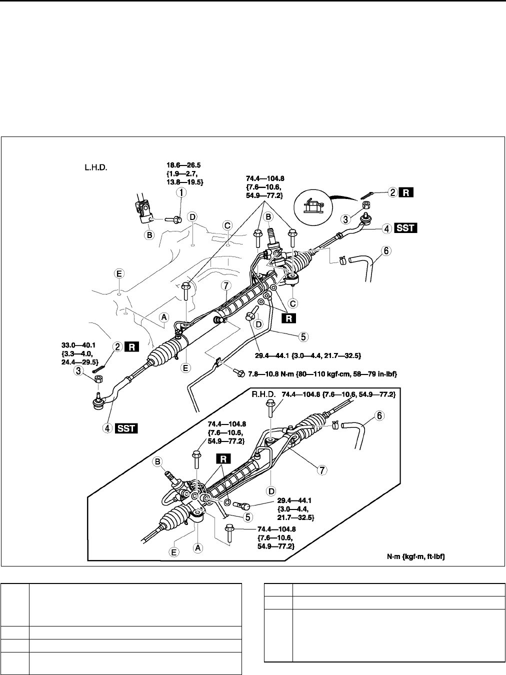
N10
ENGINE SPEED SENSING POWER STEERING
STEERING GEAR AND LINKAGE REMOVAL/INSTALLATION A6E661432960W01
Caution
•
••
•Performing the following procedures without first removing the ABS wheel-speed sensor may
possibly cause an open circuit in the harness if it is pulled by mistake. Before performing the
following procedures, remove the ABS wheel-speed sensor (axle side) and fix it to an appropriate
place where the sensor will not be pulled by mistake while servicing the vehicle.
1. Remove in the order indicated in the table.
2. Install in the reverse order of removal.
3. After installation, inspect the toe-in. (See R5 FRONT WHEEL ALIGNMENT.)
.
A6E0612W108
1 Bolt (intermediate shaft)
(See N11 Bolt (Intermediate Shaft) Removal Note)
(See N12 Bolt (Intermediate Shaft) Installation
Note)
2 Cotter pin
3 Nuts (tie-rod end ball joint)
4 Tie-rod end ball joint
(See N11 Tie-rod End Ball Joint Removal Note)
5 Pressure pipe
6 Return pipe
7 Steering gear and linkage
(See N11 Steering Gear and Linkage Removal
Note)
(See N12 Steering Gear and Linkage Installation
Note)
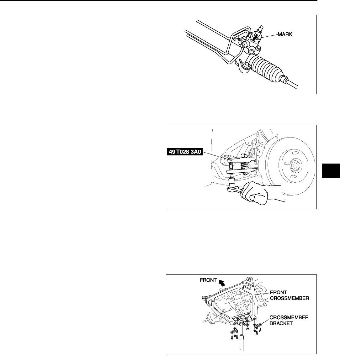
ENGINE SPEED SENSING POWER STEERING
N11
N
Bolt (Intermediate Shaft) Removal Note
1. Mark the pinion shaft and gear housing for proper
installation.
Tie-rod End Ball Joint Removal Note
1. Remove the tie rod-nut.
2. Separate the tie-rod end from the steering
knuckle using the SSTs.
Steering Gear and Linkage Removal Note
L.H.D.
Caution
•
••
•Excessively loosening the crossmember nuts may possibly cause the crossmember to fall off.
The crossmember nuts must remain threaded on the studs when loosening.
1. Support the crossmember using jack before
removing the crossmember bracket.
2. Loosen the jack and lower the crossmember.
3. Remove the steering gear and linkage by pulling
it from the left side.
R.H.D.
1. Remove the steering gear and linkage by pulling it from the right side.
A6E0612W084
A6E0612W085
A6E0612W107
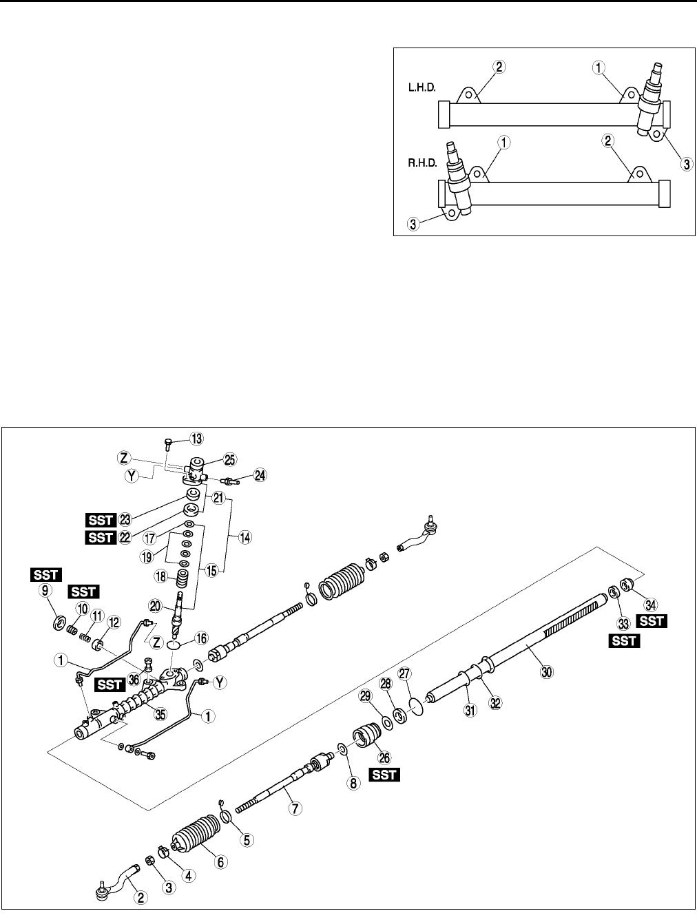
N12
ENGINE SPEED SENSING POWER STEERING
Steering Gear and Linkage Installation Note
1. Loosely tighten bolts.
2. Tighten the mounting bracket bolts to the specified
torque in the order shown.
Tightening torque
74.4104.8 N·m {7.610.6 kgf·m, 5577 ft·lbf}
3. Tighten the crossmember installation nuts. (L.H.D.)
Tightening torque
Nut: 119.6154.8 N·m {12.215.7 kgf·m, 89114
ft·lbf}
Bolt: 93.1131.3 N·m {9.513.3 kgf·m, 6996
ft·lbf}
Bolt (Intermediate Shaft) Installation Note
1. Align the marks and install the intermediate shaft and bolt.
End Of Sie
STEERING GEAR AND LINKAGE DISASSEMBLY A6E661432960W02
Caution
•
••
•Place copper plates, rag, or similar material in a vise, when securing the mounting bracket portion
of the steering gear.
1. Disassemble in the order indicated in the table..
A6E0612W027
A6E0612W028
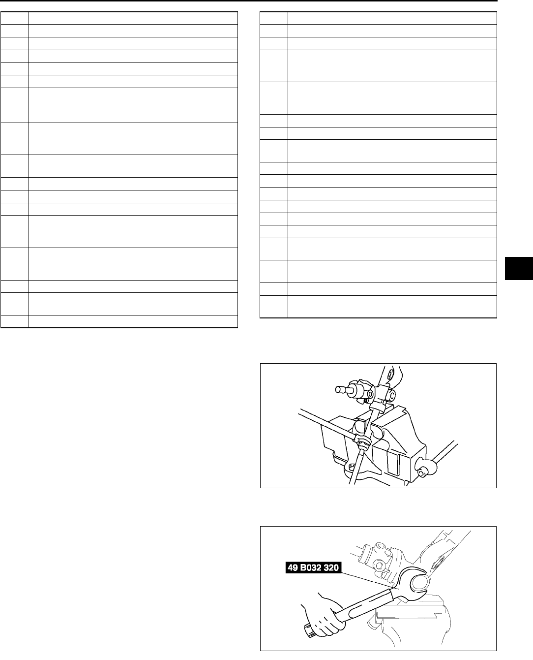
ENGINE SPEED SENSING POWER STEERING
N13
N
Tie Rod Disassembly Note
1. Unclamp the washer.
2. Remove the tie rod.
Locknut (Adjusting Cover) Disassembly Note
1. Remove the locknut using the SST.
1 Oil pipe
2 Tie-rod end
3 Locknut
4 Boot clamp
5 Boot band
6Boot
7Tie rod
(See N13 Tie Rod Disassembly Note)
8Washer
9 Locknut (adjusting cover)
(See N13 Locknut (Adjusting Cover) Disassembly
Note)
10 Adjusting cover
(See N14 Adjusting Cover Disassembly Note)
11 Yoke spring
12 Support yoke
13 Bolt
14 Pinion shaft and housing component
(See N14 Pinion Shaft and Housing Component
Disassembly Note)
15 Pinion shaft component
(See N14 Pinion Shaft Component Disassembly
Note)
16 O-ring
17 Snap ring
(See N14 Snap Ring Disassembly Note)
18 Control valve component
19 Seal ring
20 Pinion shaft
21 Valve housing component
22 Upper bearing
(See N15 Upper Bearing, Oil Seal Disassembly
Note)
23 Oil seal
(See N15 Upper Bearing, Oil Seal Disassembly
Note)
24 Return pipe
25 Valve Housing
26 Holder
(See N15 Holder Disassembly Note)
27 O-ring
28 U-gasket
29 Backup ring
30 Steering rack
31 Seal ring
32 O-ring
33 Oil seal
(See N15 Oil Seal, Inner Guide Disassembly Note)
34 Inner guide
(See N15 Oil Seal, Inner Guide Disassembly Note)
35 Gear housing
36 Mounting rubber
(See N15 Mounting Rubber Disassembly Note)
A6E0612W031
A6E0612W056
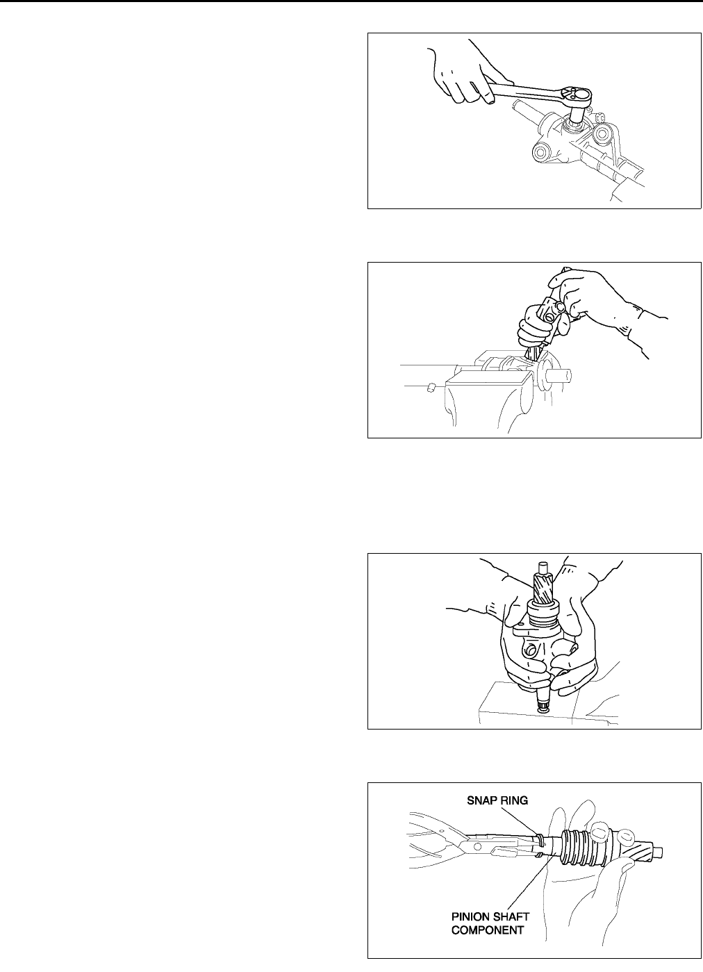
N14
ENGINE SPEED SENSING POWER STEERING
Adjusting Cover Disassembly Note
1. Remove the adjusting cover.
Pinion Shaft and Housing Component Disassembly Note
1. Hold the pinion shaft as shown, and pull out the
pinion shaft and housing component.
Pinion Shaft Component Disassembly Note
Note
•If the pinion shaft does not come out easily, remove it using a press.
1. Push out the pinion shaft componet from the
valve housing as shown.
Snap Ring Disassembly Note
1. Carefully remove the snap ring without damaging
the pinion shaft component.
A6E0612W033
A6E0612W038
A6E0612W034
A6E0612W074
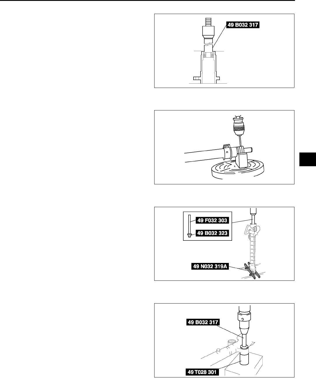
ENGINE SPEED SENSING POWER STEERING
N15
N
Upper Bearing, Oil Seal Disassembly Note
1. Set the SST as shown.
2. Using a press, remove the oil seal and upper
bearing without applying pressure to the edge of
the valve housing.
Holder Disassembly Note
1. Cut away the staked area by using a drill.
Caution
•
••
•Carefully pull out the holder without
damaging the U gasket.
2. Disassemble the holder.
Oil Seal, Inner Guide Disassembly Note
1. Set the SSTs into the valve side.
2. Install the SST to the gear housing.
3. Press out the oil seal and inner guide.
Mounting Rubber Disassembly Note
•Press the mounting rubber out from the gear
housing using the SSTs and a press.
End Of Sie
A6E0612W035
A6E0612W037
A6E0612W086
A6E0612W040
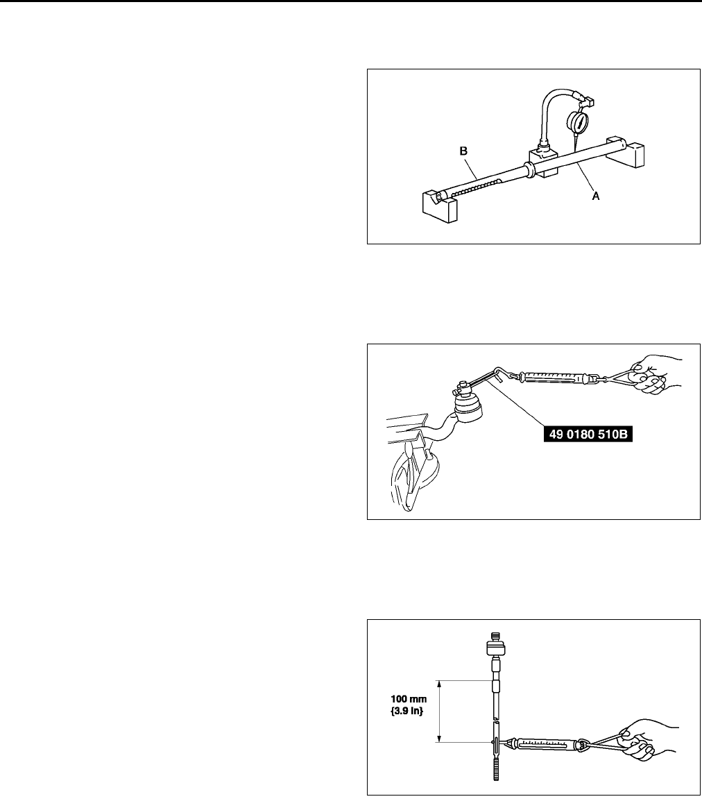
N16
ENGINE SPEED SENSING POWER STEERING
STEERING GEAR AND LINKAGE INSPECTION A6E661432960W03
Rack Inspection
1. Inspect the rack for cracking, damage, and tooth wear. Replace it as necessary.
2. Measure the runout of the rack.
Runout
Near point A: 0.15 mm {0.006 in} max.
Near point B: 0.20 mm {0.008 in} max.
3. If not within the specification, replace the rack.
Tie-rod End Inspection
1. Inspect the tie-rod end for damage and boot cracks. Replace it as necessary.
2. Inspect the ball joint for looseness. Replace the tie-rod end as necessary.
3. Rotate the ball joint five times.
4. Measure the rotation torque of the ball joint using
the SST and a pull scale.
Rotation torque
0.42.7 N·m {3.527.5 kgf·cm, 3.123.8
in·lbf}
Pull scale reading
3.425.5 N {0.352.60 kgf, 0.85.7 lbf}
5. If not within the specification, replace the tie-rod
end.
Tie rod Inspection
1. Inspect the tie rod for bending and damage. Replace it as necessary.
2. Inspect the ball joint for looseness. Replace the tie rod as necessary.
3. Swing the tie rod five times.
4. Measure the swinging torque using a pull scale.
Swinging torque
0.14.0 N·m {140.7 kgf·cm, 0.935.3
in·lbf}
Pull scale reading
0.624.5 N {0.062.49 kgf, 0.25.50 lbf}
5. If not within the specification, replace the tie-rod.
End Of Sie
STEERING GEAR AND LINKAGE ASSEMBLY A6E661432960W04
Caution
•
••
•Place copper plates, rag, or similar material in a vise, when secure the mounting bracket portion of
the steering gear.
A6E0612W041
A6E6316W100
A6E0612W043
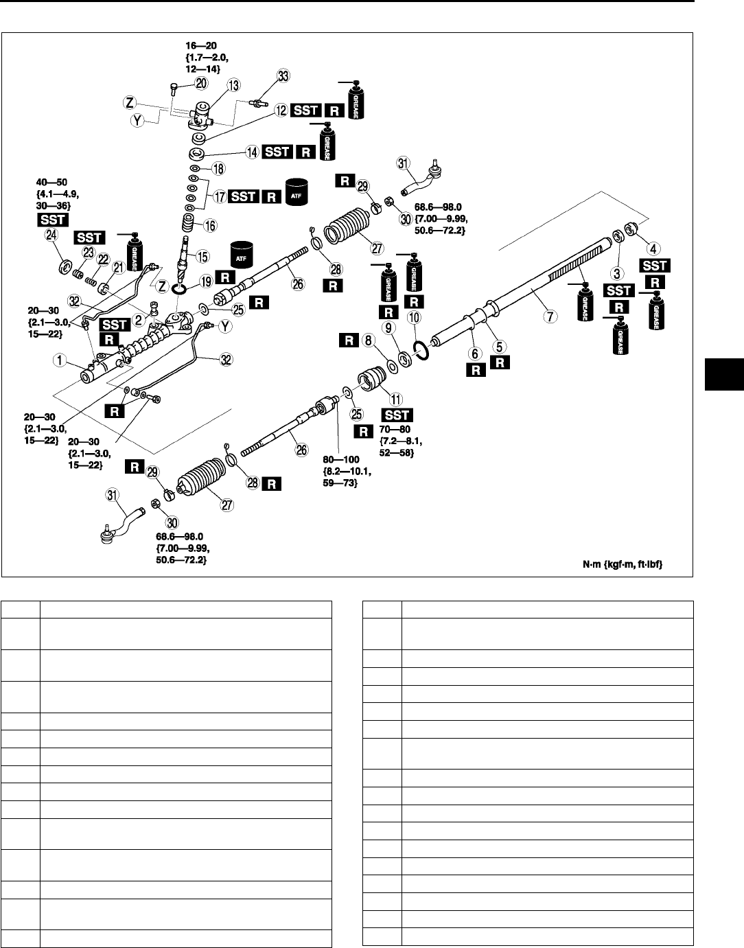
ENGINE SPEED SENSING POWER STEERING
N17
N
1. Assemble in the order indicated in the table..
A6E0612W044
1 Gear housing
2 Mounting rubber
(See N18 Mounting Rubber Assembly Note)
3 Oil seal
(See N18 Oil Seal, Inner Guide Assembly Note)
4 Inner guide
(See N18 Oil Seal, Inner Guide Assembly Note)
5 O-ring
6 Seal ring
7Steering rack
8 Backup ring
9U-gasket
10 O-ring
11 Holder
(See N19 Holder Assembly Note)
12 Oil seal
(See N20 Oil Seal Assembly Note)
13 Valve housing
14 Upper bearing
(See N20 Upper Bearing Assembly Note)
15 Pinion shaft
16 Control valve
17 Seal ring
(See N20 Seal Ring Assembly Note)
18 Snap ring
19 O-ring
20 Bolt
21 Support yoke
22 Yoke spring
23 Adjusting cover
(See N20 Adjusting Cover Assembly Note)
24 Locknut (adjusting cover)
25 Washer
26 Tie rod
27 Boot
28 Boot band
29 Boot clamp
30 Locknut
31 Tie-rod end
32 Oil pipe
33 Return pipe
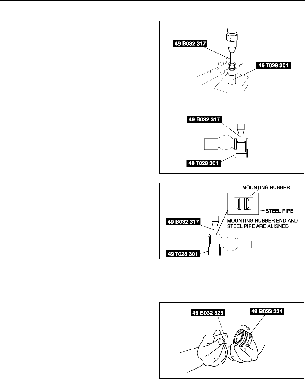
N18
ENGINE SPEED SENSING POWER STEERING
Mounting Rubber Assembly Note
1. Apply soapy water to the rubber part of the mounting rubber.
2. Press the mounting rubber until the mounting
rubber end comes out completely from the gear
housing using the SSTs and a press.
3. Reverse the gear housing, then press the
mounting rubber until the mounting rubber end
comes out completely from the other side. At this
time, mounting rubber end and steel pipe are
aligned.
Oil Seal, Inner Guide Assembly Note
1. Install a new O-ring and a new seal ring to the racks piston.
2. After installing the seal ring, seat it properly at the piston circumference.
3. Apply grease to a new oil seal and inner guide.
4. Install the oil seal to the SST.
A6E0612W087
A6E0612W088
A6E0612W048
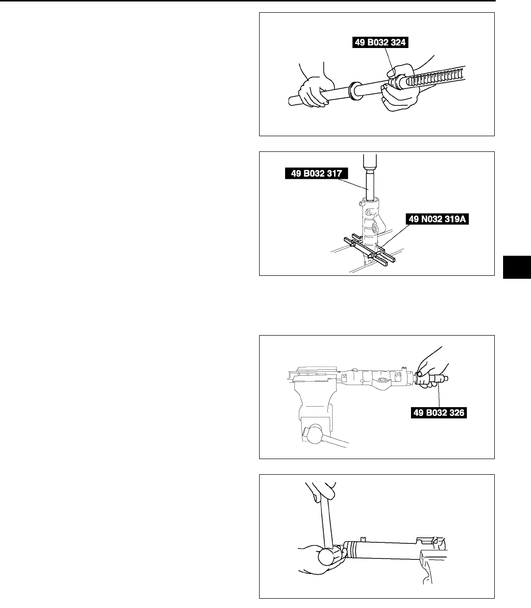
ENGINE SPEED SENSING POWER STEERING
N19
N
5. Using the SST, place the oil seal and inner guide
at the edge of the steering racks pinion, and
remove the SST.
6. After installing the steering rack to the gear
housing, press the oil seal and inner guide using
the SSTs until the force required suddenly
increases.
Holder Assembly Note
1. Apply grease to the U-gasket and O-ring.
2. Assemble the U-gasket, backup ring and O-ring into the holder.
3. Assemble the SST to the steering rack.
4. Stake the holder to the cylinder using a punch.
A6E0612W049
A6E0612W039
A6E0612W090
A6E6316W012
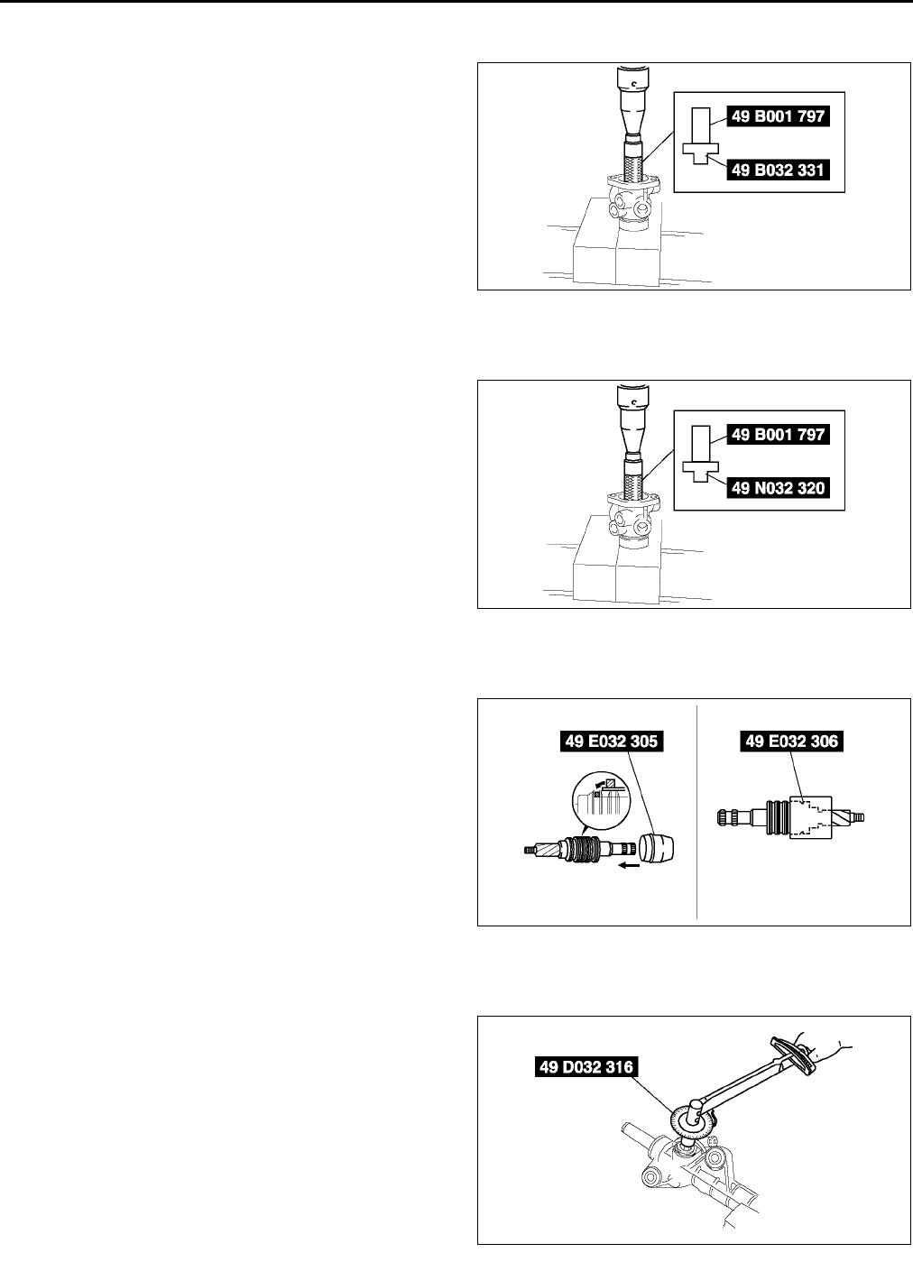
N20
ENGINE SPEED SENSING POWER STEERING
Oil Seal Assembly Note
1. Apply grease to a new oil seal.
2. Press in the new oil seal using the SSTs.
Upper Bearing Assembly Note
1. Apply grease to a new upper bearing.
2. Press in the upper bearing using the SST.
Seal Ring Assembly Note
1. Install a new seal ring to the valve part of the pinion shaft using the SST.
2. After installing it, seat it properly using the SST.
3. Install the snap ring.
Adjusting Cover Assembly Note
1. Set the rack to the center position.
2. Tighten the adjusting cover to 4.9 N·m {50
kgf·cm, 36 in·lbf} three times, then return it 25°
°°
°
using the SST.
3. Apply sealant to the threads of the locknut.
4. Attach the locknut.
A6E0612W036
A6E0612W051
A6E0612W052
A6E0612W062
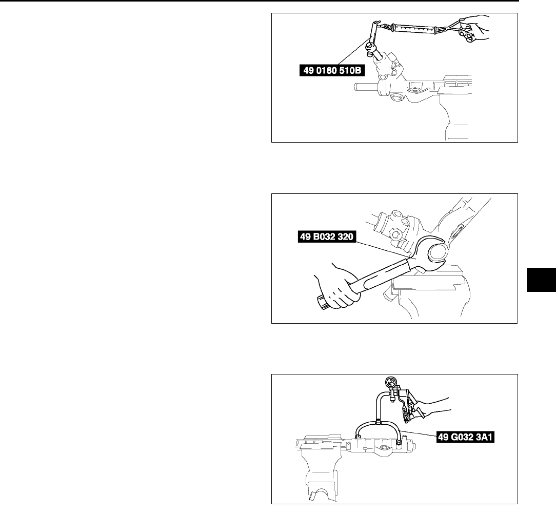
ENGINE SPEED SENSING POWER STEERING
N21
N
5. Measure the pinion torque using the SST and a
pull scale.
Standard
Center of rack ±
±±
±90°
°°
°
0.81.2 N·m
{8.212.2 kgf·cm, 5.88.8 in·lbf}
[Pull scale reading
812 N {0.91.2 kgf, 1.82.6 lbf}]
Except center of rack ±
±±
±90°
°°
°
Less than 1.6 N·m
{16.3 kgf·cm, 11.8 in·lbf}
[Pull scale reading
Less than 16.7 N {1.7 kgf, 3.8 lbf}]
6. If not as specified, repeat steps 2 through 5.
7. Install the locknut using the SST (49 B032 320).
Tightening torque
4049 N·m {4.14.9 kgf·m, 3036 ft·lbf}
Hermetic sealing inspection
1. Connect the SSTs to the power cylinder section of the gear housing.
2. Apply 53.3 kPa {400 mmHg, 15.7 inHg} vacuum
with a vacuum pump and verify that it is held for at
least 30 seconds.
3. If the vacuum is not held, replace the oil seal.
End Of Sie
A6E0612W042
A6E0612W056
A6E0612W054
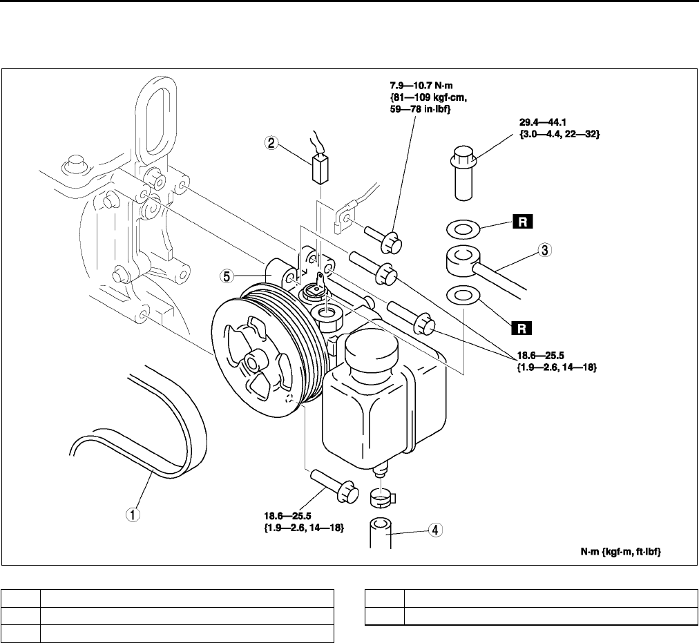
N22
ENGINE SPEED SENSING POWER STEERING
POWER STEERING OIL PUMP REMOVAL/INSTALLATION A6E661432650W01
1. Remove in the order indicated in the table.
2. Install in the reverse order of removal..
End Of Sie
POWER STEERING OIL PUMP DISASSEMBLY/ASSEMBLY A6E661432650W02
Note
•The following procedure is for replacement of the O-ring and oil seal only. Replace the pump component if
other repairs are necessary.
1. Disassemble in the order indicated in the table.
2. Assemble in the reverse order of disassembly.
A6E0612W092
1Drive belt
2 Pressure switch connector
3 Pressure pipe
4 Suction hose
5 Power steering oil pump
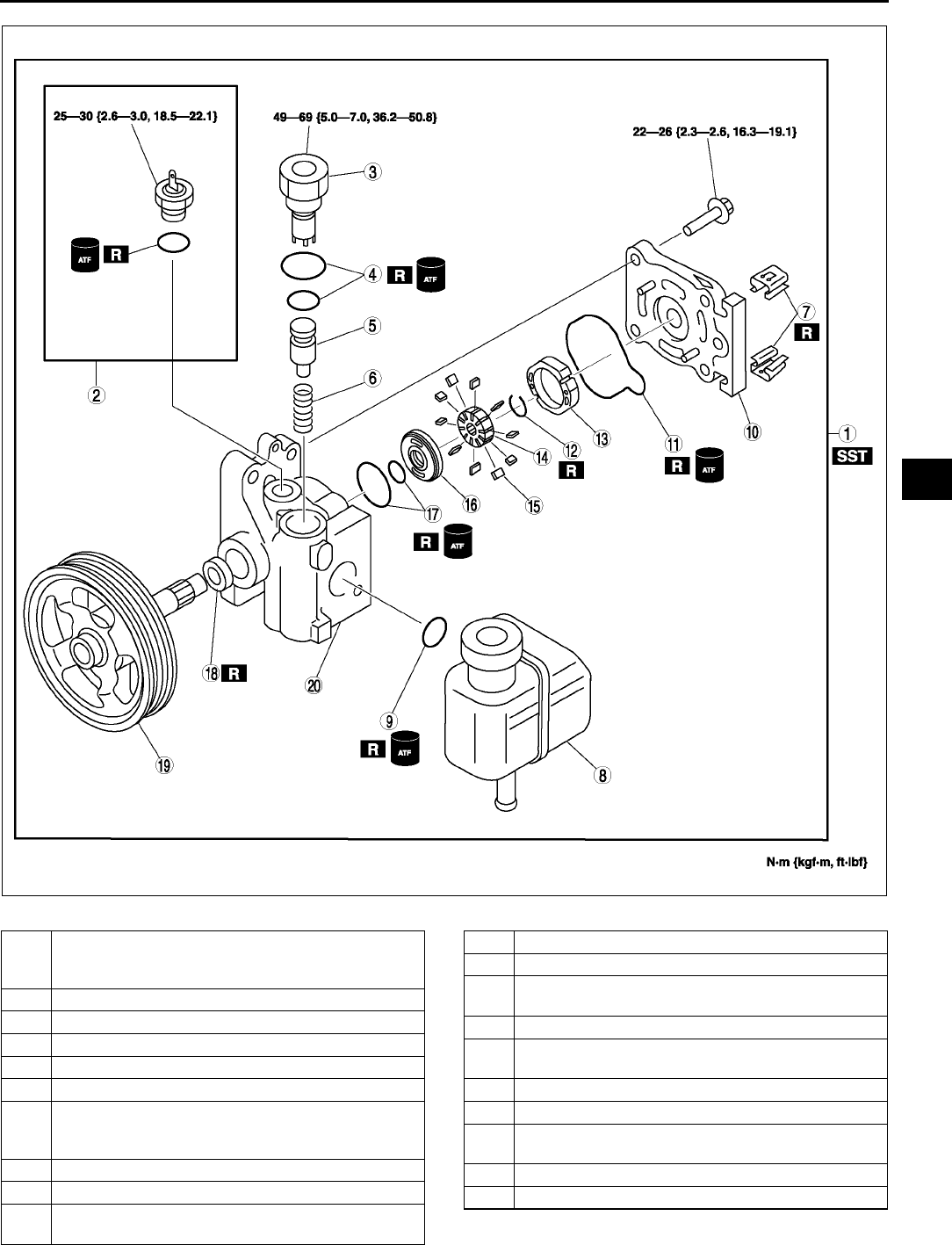
ENGINE SPEED SENSING POWER STEERING
N23
N
.
A6E0612W068
1 Power steering oil pump component
(See N24 Power Steering Oil Pump Component
Disassembly Note)
2 Pressure switch component
3 Connector
4 O-rings
5 Control valve
6Spring
7Clip
(See N24 Clip Disassembly Note)
(See N24 Clip Assembly Note)
8 Power steering reservoir tank
9 O-ring
10 Rear pump body
(See N25 Rear Pump Body Assembly Note)
11 O-ring
12 Clip
13 Cam ring
(See N25 Cam Ring Assembly Note)
14 Rotor
15 Vane
(See N25 Vane Assembly Note)
16 Side plate
17 O-ring
18 Oil seal
(See N25 Oil Seal Assembly Note)
19 Shaft component
20 Front pump body
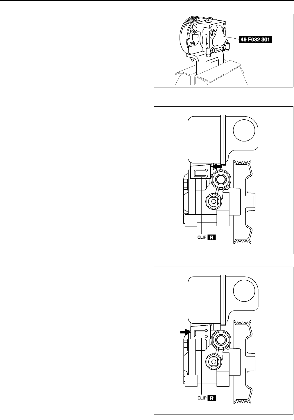
N24
ENGINE SPEED SENSING POWER STEERING
Power Steering Oil Pump Component Disassembly Note
1. Secure the power pressure oil pump using the
SST.
Caution
•
••
•Use the SST to prevent damage to the
pump when securing it in a vise.
Clip Disassembly Note
1. Lift up the clip tab using a flathead screwdriver.
2. Remove the clip pushing with a flathead
screwdriver and a hammer as shown in the figure.
Clip Assembly Note
1. Push the clip slowly to the direction shown in the
figure.
2. Confirm that the clip tab is caught correctly.
A6E0612W070
A6E0612W098
A6E0612W100
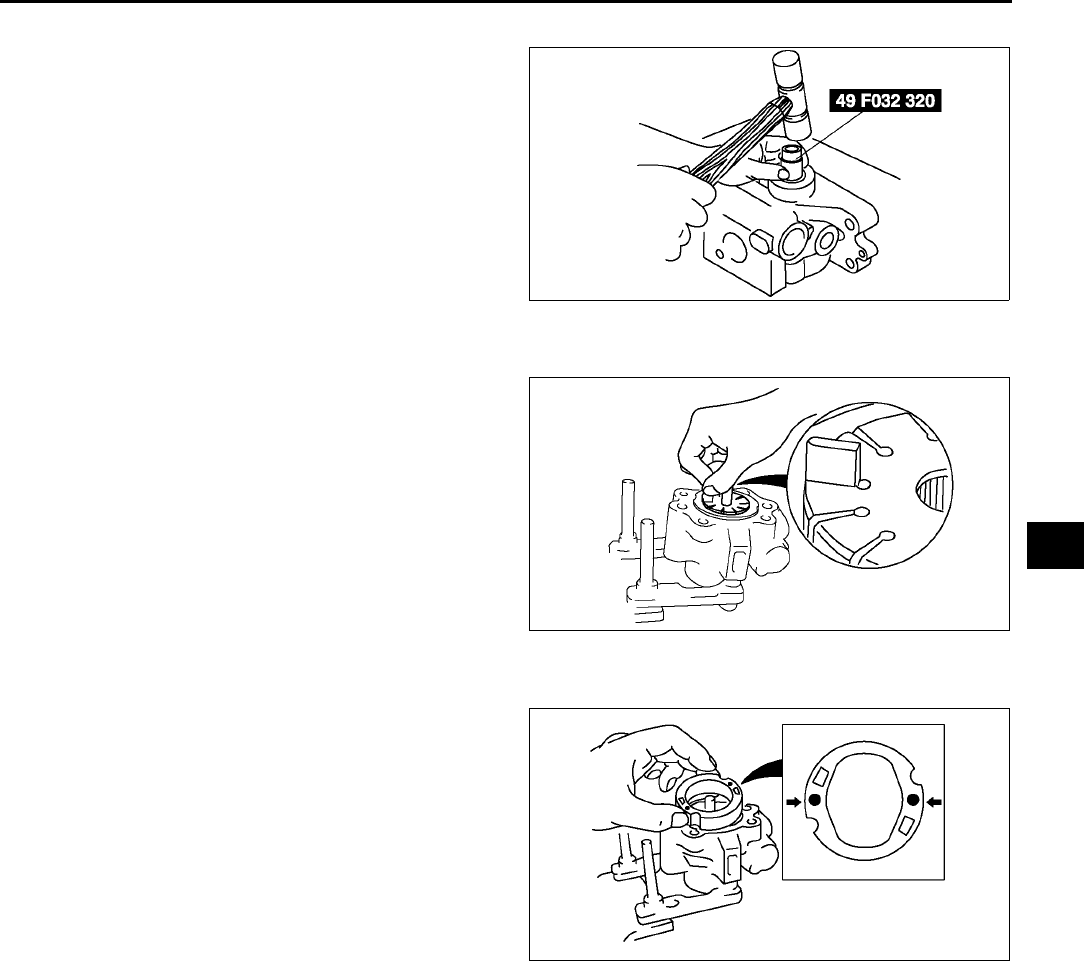
ENGINE SPEED SENSING POWER STEERING
N25
N
Oil Seal Assembly Note
1. Install the oil seal in the front pump body using
the SST and plastic hammer.
Vane Assembly Note
1. Place the vanes in the rotor with the rounded
edges contacting the cam.
Cam Ring Assembly Note
1. Install the cam ring in the front pump body with
the mark facing upward.
Rear Pump Body Assembly Note
1. After installing the rear body, manually turn the shaft to verify that it rotates smoothly.
End Of Sie
A6J6612W100
A6E6316W013
A6E6316W014

P1
P
PBRAKING SYSTEM
LOCATION INDEX ................................................. P-3
CONVENTIONAL BRAKE LOCATION INDEX ... P-3
PARKING BRAKE LOCATION INDEX ................ P-4
ABS/TCS LOCATION INDEX .............................. P-4
DSC LOCATION INDEX ...................................... P-5
GENERAL PROCEDURES .................................... P-6
PRECAUTION (BRAKES) ................................... P-6
CONVENTIONAL BRAKE SYSTEM...................... P-6
AIR BLEEDING.................................................... P-6
VACUUM HOSE CHECK VALVE INSPECTION
(POWER BRAKE UNIT) ................................... P-7
BRAKE PEDAL INSPECTION ............................. P-7
BRAKE SWITCH INSPECTION........................... P-8
BRAKE PEDAL REMOVAL/INSTALLATION....... P-9
MASTER CYLINDER
REMOVAL/INSTALLATION............................ P-10
FLUID LEVEL SENSOR INSPECTION ............. P-12
MASTER CYLINDER
DISASSEMBLY/ASSEMBLY .......................... P-12
POWER BRAKE UNIT
REMOVAL/INSTALLATION............................ P-14
POWER BRAKE UNIT INSPECTION................ P-14
DUAL PROPORTIONING VALVE
INSPECTION (WITHOUT ABS)...................... P-16
DUAL PROPORTIONING VALVE
REPLACEMENT (WITHOUT ABS)................. P-16
FRONT BRAKE (DISC) INSPECTION .............. P-17
FRONT BRAKE (DISC)
REMOVAL/INSTALLATION............................ P-20
DISC PAD (FRONT) REPLACEMENT .............. P-21
CALIPER (FRONT)
DISASSEMBLY/ASSEMBLY .......................... P-22
REAR BRAKE (DISC) INSPECTION................. P-23
REAR BRAKE (DISC)
REMOVAL/INSTALLATION............................ P-24
DISC PAD (REAR) REPLACEMENT................. P-25
PARKING BRAKE SYSTEM ................................ P-26
PARKING BRAKE (LEVER TYPE)
INSPECTION .................................................. P-26
PARKING BRAKE (LEVER TYPE)
ADJUSTMENT................................................ P-26
PARKING BRAKE (LEVER TYPE)
REMOVAL/INSTALLATION............................ P-26
ABS/TCS .............................................................. P-27
ABS (ABS/TCS) HU/CM SYSTEM
INSPECTION .................................................. P-27
ABS (ABS/TCS) HU/CM
REMOVAL/INSTALLATION............................ P-28
ABS (ABS/TCS) or DSC HU/CM
CONFIGURATION.......................................... P-29
ABS (ABS/TCS) HU/CM INSPECTION ............. P-29
TCS (DSC) OFF SWITCH
REMOVAL/INSTALLATION............................ P-31
TCS (DSC) OFF SWITCH INSPECTION........... P-32
FRONT ABS WHEEL-SPEED SENSOR
REMOVAL/INSTALLATION............................ P-32
FRONT/REAR ABS WHEEL-SPEED
SENSOR INSPECTION.................................. P-33
REAR ABS WHEEL-SPEED SENSOR
REMOVAL/INSTALLATION ............................ P-34
DYNAMIC STABILITY CONTROL ....................... P-35
DSC SYSTEM INSPECTION............................. P-35
DSC HU/CM REMOVAL/INSTALLATION.......... P-38
DSC HU/CM INSPECTION................................ P-40
COMBINE SENSOR
REMOVAL/INSTALLATION ............................ P-42
COMBINE SENSOR INSPECTION ................... P-43
COMBINE SENSOR INITIALIZATION
PROCEDURE ................................................. P-44
STEERING ANGLE SENSOR
REMOVAL/INSTALLATION ............................ P-44
STEERING ANGLE SENSOR INSPECTION .... P-44
DSC OFF SWITCH
REMOVAL/INSTALLATION ............................ P-44
DSC OFF SWITCH INSPECTION .....................P-44
ON-BOARD DIAGNOSTIC (ABS/TCS)................ P-45
ABS (ABS/TCS) SYSTEM WIRING
DIAGRAM ....................................................... P-45
ABS (ABS/TCS) ON-BOARD DIAGNOSIS........P-46
DTC B1318 ........................................................ P-50
DTC B1342 ........................................................ P-52
DTC C1095, C1096............................................ P-52
DTC C1119 ........................................................ P-54
DTC C1140 ........................................................ P-55
DTC C1145, C1155, C1165, C1175 .................. P-56
DTC C1148, C1158, C1168, C1178,
C1233, C1234, C1235, C1236........................... P-59
DTC C1186, C1266............................................ P-62
DTC C1194, C1198, C1210, C1214,
C1242, C1246, C1250, C1254........................ P-63
DTC C1414 ........................................................ P-64
DTC C1508 ........................................................ P-64
DTC C1510, C1511, C1512, C1513 .................. P-64
DTC U2021 ........................................................ P-65
ON-BOARD DIAGNOSTIC
(DYNAMIC STABILITY CONTROL)..................... P-66
DSC SYSTEM WIRING DIAGRAM.................... P-66
DSC ON-BOARD DIAGNOSIS .......................... P-67
DTC B1318 ........................................................ P-72
DTC B1342 ........................................................ P-74
DTC B1483, B1484, B1486................................ P-74
DTC B1627 ........................................................ P-76
DTC B2477 ........................................................ P-77
DTC C1095, C1096............................................ P-77
DTC C1119 ........................................................ P-79
DTC C1125 ........................................................ P-80
DTC C1140 ........................................................ P-81
DTC C1145, C1155, C1165, C1175 .................. P-81
DTC C1148, C1158, C1168, C1178,
C1233, C1234, C1235, C1236........................ P-83
DTC C1186, C1266............................................ P-86
DTC C1194, C1198, C1210, C1214,
C1242, C1246, C1250, C1254, C1400,
C1410, C1957, C1958 .................................... P-87
DTC C1280, C1730, C1951, C1952,
C1959.............................................................. P-88

P2
DTC C1414 ........................................................P-91
DTC C1507, C1508............................................P-91
DTC C1510, C1511, C1512, C1513 ..................P-92
DTC C1953, C1954............................................P-92
DTC C1955, C1956............................................P-93
DTC U2021 ........................................................P-96
TROUBLESHOOTING
(ABS/TCS/DYNAMIC STABILITY CONTROL) ....P-97
SYSTEM WIRING DIAGRAM ............................P-97
FOREWORD...................................................... P-99
PRECAUTION.................................................... P-99
SYMPTOM TROUBLESHOOTING.................. P-104
NO.1 ABS WARNING LIGHT,
BRAKE SYSTEM WARNING LIGHT,
TCS OFF LIGHT DO NOT ILLUMINATE
WITH IGNITION SWITCH ON ......................P-107
NO.2 NEITHER ABS WARNING LIGHT
NOR BRAKE SYSTEM WARNING
LIGHTILLUMINATE WITH IGNITION
SWITCH ON.................................................. P-108
NO.3 ABS WARNING LIGHT DOES NOT
ILLUMINATE WITH IGNITION
SWITCH ON.................................................. P-109
NO.4 BRAKE SYSTEM WARNING LIGHT
DOES NOT ILLUMINATE WITH IGNITION
SWITCH ON.................................................. P-109
No.5 TCS OFF LIGHT DOES NOT
ILLUMINATE WITH IGNITION
SWITCH ON.................................................. P-110
No.6 BOTH ABS WARNING LIGHT AND
BRAKE SYSTEM WARNING LIGHT
STAY ON MORE THAN 4 SECONDS
WITH IGNITION SWITCH ON ......................P-111
No.7 ABS WARNING LIGHT STAYS ON
MORE THAN 4 SECONDS WITH
IGNITION SWITCH ON.................................P-113
NO.8 BRAKE SYSTEM WARNING LIGHT
STAYS ON MORE THAN 4 SECONDS
WITH IGNITION SWITCH ON ......................P-114
NO.9 TCS OFF LIGHT STAYS ON MORE
THAN 4 SECONDS WITH IGNITION
SWITCH ON.................................................. P-116
NO.10 TCS DOES NOT WORK
CORRECTLY ................................................ P-117
NO.11 THERE IS MALFUNCTION IN
THE SYSTEM EVEN THOUGH ABS
WARNING LIGHT, BRAKE SYSTEM
WARNING LIGHT, TCS OFF LIGHT DO
NOT ILLUMINTE...........................................P-117
NO.1 ANY OF THE FOLLOWING LIGHTS
DO NOT ILLUMINATE WITH IGNITION
SWITCH ON: (ABS WARNING LIGHT,
BRAKE SYSTEM WARNING LIGHT,
DSC INDICATOR LIGHT AND/OR
TCS-OFF LIGHT).......................................... P-117
NO.2 ANY OF THE FOLLOWING LIGHTS
STAY ON: (ABS WARNING LIGHT,
BRAKE SYSTEM WARNING LIGHT,
DSC INDICATOR LIGHT AND/OR
TCS-OFF LIGHT).......................................... P-119
NO.3 THERE IS A MALFUNCTION IN THE
SYSTEM EVEN THOUGH ABS WARNING
LIGHT, BRAKE SYSTEM WARNING LIGHT,
DSC INDICATOR LIGHT AND TCS-OFF
LIGHT DO NOT ILLUMINATE ......................P-120
NO.4 ABS OR TCS*1 OPERATES
FREQUENTLY/TCS DOES NOT WORK
CORRECTLY*1: DSC SYSTEM
FUNCTION CONTAINs TRACTION
CONTROL FUNCTION, DSC INDICATOR
LIGHT GOES ON AND OFF WHILE DSC
OPERATES...................................................P-120
NO.5 DSC*2 OPERATES FREQUENTLY/DSC
DOES NOT WORK CORRECTLY*2: DSC
INDICATOR LIGHT GOES ON AND OFF
WHILE DSC OPERATES..............................P-121
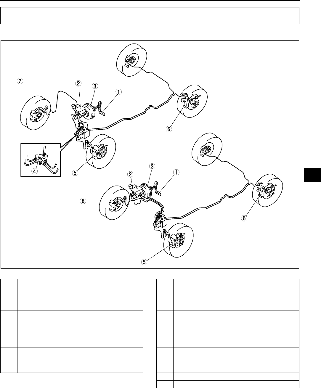
LOCATION INDEX
P3
P
CONVENTIONAL BRAKE LOCATION INDEX A6E690001015W01
.
End Of Si e
LOCATION INDEX
A6E6900W001
1 Brake pedal
(SeeP7 BRAKE PEDAL INSPECTION)
(SeeP9 BRAKE PEDAL REMOVAL/
INSTALLATION)
(SeeP8 BRAKE SWITCH INSPECTION)
2 Master cylinder
(SeeP10 MASTER CYLINDER REMOVAL/
INSTALLATION)
(SeeP12 FLUID LEVEL SENSOR INSPECTION)
(SeeP12 MASTER CYLINDER DISASSEMBLY/
ASSEMBLY)
3 Power brake unit
(SeeP14 POWER BRAKE UNIT INSPECTION)
(SeeP14 POWER BRAKE UNIT REMOVAL/
INSTALLATION)
4 Dual proportioning valve (without ABS)
(SeeP16 DUAL PROPORTIONING VALVE
INSPECTION (WITHOUT ABS))
(SeeP16 DUAL PROPORTIONING VALVE
REPLACEMENT (WITHOUT ABS))
5 Front brake (disc)
(SeeP17 FRONT BRAKE (DISC) INSPECTION)
(SeeP20 FRONT BRAKE (DISC) REMOVAL/
INSTALLATION)
(SeeP22 CALIPER (FRONT) DISASSEMBLY/
ASSEMBLY)
6 Rear brake (disc)
(SeeP23 REAR BRAKE (DISC) INSPECTION)
(SeeP24 REAR BRAKE (DISC) REMOVAL/
INSTALLATION)
7 L.H.D.
8 R.H.D.
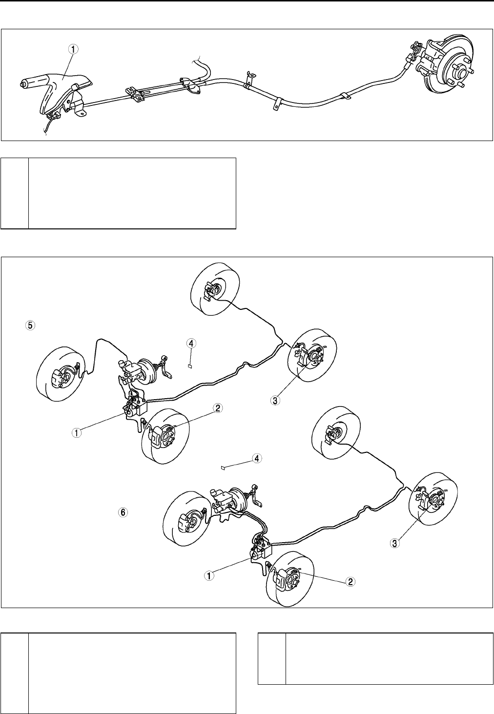
P4
LOCATION INDEX
PARKING BRAKE LOCATION INDEX A6E690001015W02
.
End Of Si e
ABS/TCS LOCATION INDEX A6E690001015W03
.
A6E6900W005
1 Parking bake lever
(SeeP26 PARKING BRAKE (LEVER TYPE)
INSPECTION)
(SeeP26 PARKING BRAKE (LEVER TYPE)
ADJUSTMENT)
(SeeP26 PARKING BRAKE (LEVER TYPE)
REMOVAL/INSTALLATION)
A6E6900W003
1 ABS (ABS/TCS) HU/CM
(SeeP27 ABS (ABS/TCS) HU/CM SYSTEM
INSPECTION)
(SeeP29 ABS (ABS/TCS) HU/CM INSPECTION)
(SeeP28 ABS (ABS/TCS) HU/CM REMOVAL/
INSTALLATION)
(SeeP29 ABS (ABS/TCS) or DSC HU/CM
CONFIGURATION)
2 Front ABS wheel-speed sensor
(SeeP32 FRONT ABS WHEEL-SPEED SENSOR
REMOVAL/INSTALLATION)
(SeeP33 FRONT/REAR ABS WHEEL-SPEED
SENSOR INSPECTION)
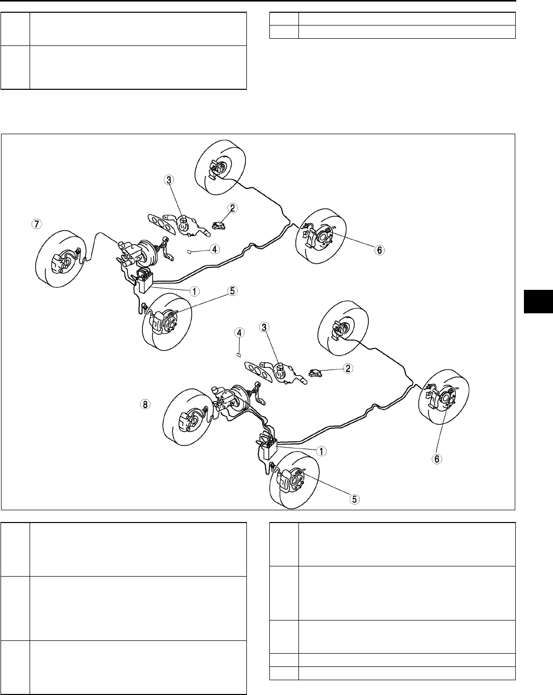
LOCATION INDEX
P5
P
End Of Sie
DSC LOCATION INDEX A6E690001015W04
.
End Of Si e
3 Rear ABS wheel-speed sensor
(SeeP34 REAR ABS WHEEL-SPEED SENSOR
REMOVAL/INSTALLATION)
4 TCS OFF switch
(SeeP31 TCS (DSC) OFF SWITCH REMOVAL/
INSTALLATION)
(SeeP32 TCS (DSC) OFF SWITCH INSPECTION)
5 L.H.D.
6 R.H.D.
A6E6900W004
1 DSC HU/CM
(SeeP40 DSC HU/CM INSPECTION)
(SeeP38 DSC HU/CM REMOVAL/
INSTALLATION)
(SeeP40 DSC HU/CM INSPECTION)
2 Combine sensor
(SeeP42 COMBINE SENSOR REMOVAL/
INSTALLATION)
(SeeP43 COMBINE SENSOR INSPECTION)
(SeeP44 COMBINE SENSOR INITIALIZATION
PROCEDURE)
3 Steering angle sensor
(SeeP44 STEERING ANGLE SENSOR
REMOVAL/INSTALLATION)
(SeeP44 STEERING ANGLE SENSOR
INSPECTION)
4 DSC OFF switch
(SeeP31 TCS (DSC) OFF SWITCH REMOVAL/
INSTALLATION)
(SeeP32 TCS (DSC) OFF SWITCH INSPECTION)
5 Front wheel-speed sensor
(SeeP32 FRONT ABS WHEEL-SPEED SENSOR
REMOVAL/INSTALLATION)
(SeeP33 FRONT/REAR ABS WHEEL-SPEED
SENSOR INSPECTION)
6 Rear wheel-speed sensor
(SeeP34 REAR ABS WHEEL-SPEED SENSOR
REMOVAL/INSTALLATION)
7 L.H.D.
8 R.H.D.
P6
GENERAL PROCEDURES, CONVENTIONAL BRAKE SYSTEM
PRECAUTION (BRAKES) A6E691001020W01
Wheels and Tires Removal/Installation
1. The removal and installation procedures for the wheels and tires are not mentioned in this section. When a
wheel is removed, tighten it to 88118 N·m {9.012.0 kgf·m, 65.087.0 ft·lbf}.
Brake Lines Disconnection/Connection
Caution
•
••
•Brake fluid will damage painted surfaces. If brake fluid does get on a painted surface, wipe it off
immediately.
1. Tighten the brake pipe flare nut using the SST (49 0259 770B). Be sure to modify the brake pipe flare nut
tightening torque to allow for use of a torque wrench-SST combination.
•If any brake line has been disconnected anytime during the procedure, add brake fluid, bleed the brakes,
and inspect for leakage after the procedure has been completed.
Connectors Disconnection
1. Disconnect the negative battery cable before doing any work that requires handling of connectors. Reconnect
the negative battery cable only after the work is completed.
ABS, ABS/TCS, or DSC Components Operations
1. Make sure that there are no DTCs in the ABS, ABS/TCS, or DSC memory after working on ABS, ABS/TCS or
DSC components.
•If there are any DTCs in the memory, clear them.
End Of Sie
AIR BLEEDING A6E691243001W01
Caution
•
••
•Maintain the fluid level in the reservoir tank properly while bleeding the air.
Specified fluid
Note
•The brakes should be bled whenever a brake line is disconnected. If a hydraulic line is disconnected at
the master cylinder, start at the slave cylinder farthest from the brake master cylinder, and move to the
next farthest slave cylinder until all four cylinders have been bled. If the disconnection point is anywhere
except the master cylinder, start at the point closest to the disconnection, and move to the next closest
slave cylinder until all four cylinders have been bled.
1. Remove the bleeder cap and attach a vinyl tube to the bleeder screw.
2. Place the other end of the vinyl tube in a clear, fluid-filled container.
3. One person should depress the brake pedal a few times, and then hold it in the depressed position.
GENERAL PROCEDURES
CONVENTIONAL BRAKE SYSTEM
European
(L.H.D. U.K.)
specs.
SAE J1703, FMVSS 116 DOT3 OR DOT4
GCC specs. SAE J1703, FMVSS 116 DOT3
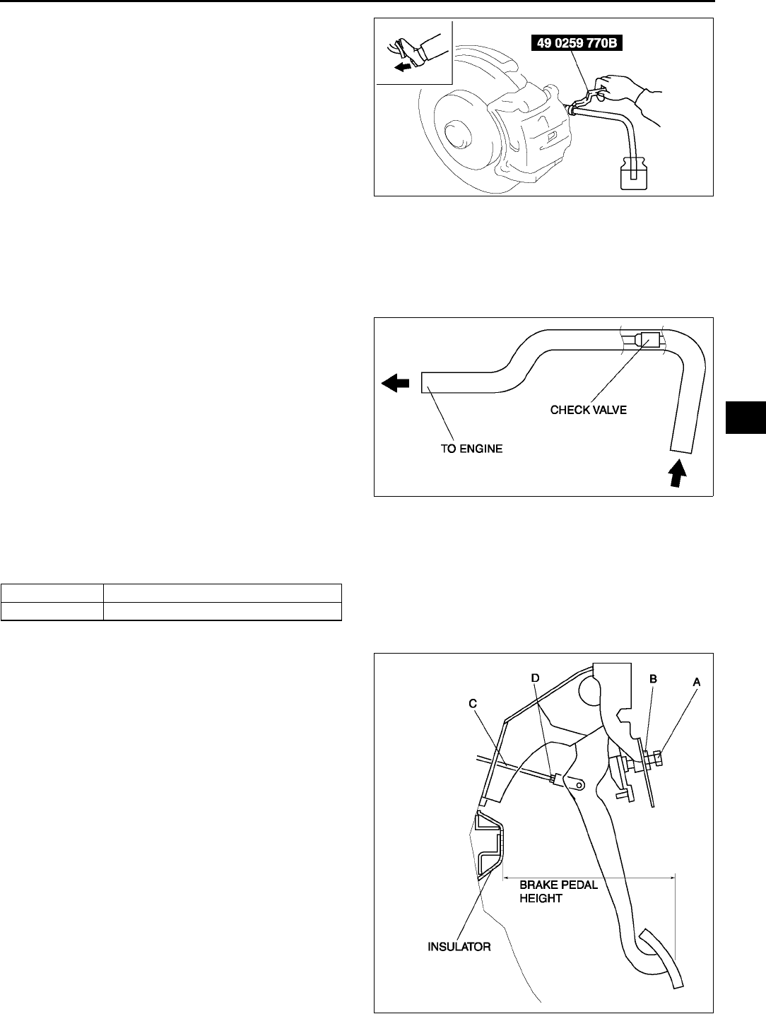
CONVENTIONAL BRAKE SYSTEM
P7
P
4. A second person should loosen the bleeder
screw, drain out the fluid and close the screw
using the SST.
Tightening torque
Front:6.99.8 N·m
{7199 kgf·cm, 6286 in·lbf}
Rear:5.98.8 N·m
{6189 kgf·cm, 5377 in·lbf}
5. Repeat steps 3 and 4 until no air bubbles are
seen.
6. Bleed air from each component by following the
procedure above.
7. After air bleeding, check the following:
•Brake operation
•fluid leakage
•fluid level
End Of Si e
VACUUM HOSE CHECK VALVE INSPECTION (POWER BRAKE UNIT) A6E691243980W01
1. Remove the clamps and vacuum hose.
2. Apply both suction and pressure to the engine-
side hose, and verify that air blows only toward
that side.
•If air flows in both directions or not at all,
replace the vacuum hose.
End Of Si e
BRAKE PEDAL INSPECTION A6E691243300W01
Brake Pedal Height Inspection
1. Verify that the distance from the carpet to the center of the upper surface of the pedal pad is as specified.
Pedal height (reference value)
Brake Pedal Height Adjustment
1. Loosen locknut B and turn the bolt A until it does
not contact the pedal.
2. Loosen locknut D and turn rod C to adjust the
height.
3. Tighten the bolt with locknut B .
Tightening torque
9.814.7 N·m
{100149 kgf·cm, 116130 in·lbf}
4. After adjustment, inspect the pedal play and the
brake light operation.
A6E6912W001
A6E6912W002
R.H.D. 172 mm {6.77 in}
L.H.D. 187 mm {7.36 in}
A6E6912W017
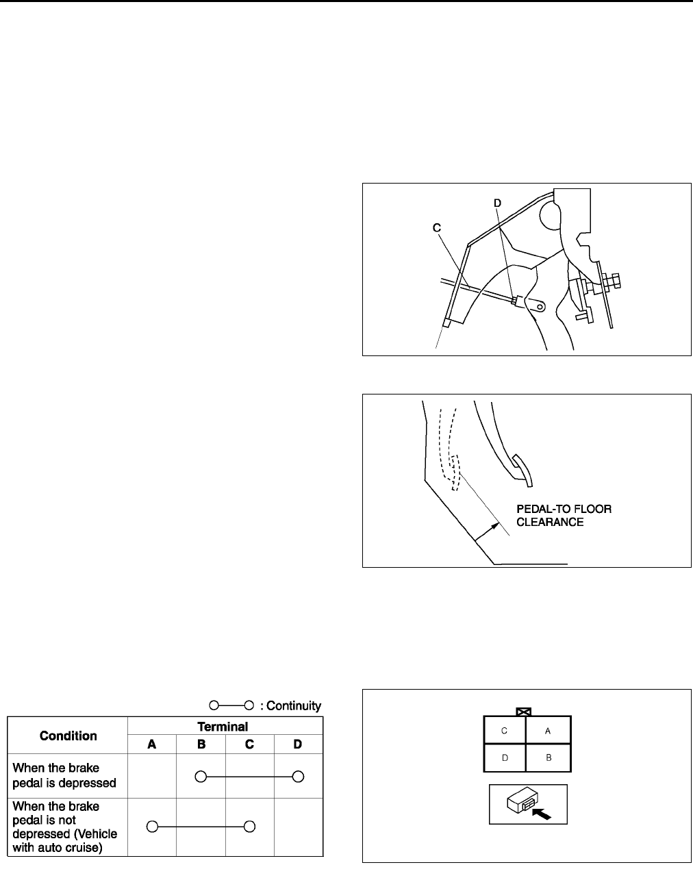
P8
CONVENTIONAL BRAKE SYSTEM
Brake Pedal Play Inspection
1. Depress the pedal a few times to eliminate the vacuum in the system.
2. Remove the spring pin, verify that the holes in the fork and in the pedal are aligned, and reinstall the pin. (See
P9 BRAKE PEDAL REMOVAL/INSTALLATION.)
3. Gently depress the pedal by hand until resistance is felt, and check the pedal play.
Pedal play
03 mm {00.1 in}
Brake Pedal Play Adjustment
1. Remove the spring pin and clevis pin. (See P9 BRAKE PEDAL REMOVAL/INSTALLATION.)
2. Loosen locknut D and turn rod C to align the
holes in the fork and in the pedal.
3. Install the clevis pin and the spring pin.
4. Tighten locknut D.
Tightening torque
15.721.6 N·m
{1.612.20 kgf·m, 11.615.9 ft·lbf}
5. Check the pedal height and the brake light
operation.
Pedal-to-floor Clearance Inspection
1. Start the engine and depress the brake pedal with
a force of 588 N {60 kgf, 132 lbf}
2. Verify that the distance from the floor panel to the
pedal pad center is as specified when the pedal is
depressed.
•If the distance is less than specified, check for
the air in brake system.
Specification
68 mm {2.7 in} min.
End Of Sie
BRAKE SWITCH INSPECTION A6E691266490W01
1. Disconnect the negative battery cable.
2. Disconnect the brake switch connector harness.
3. Inspect for continuity between the brake switch connector terminals.
•If not as specified, replace the brake switch.
End Of Sie
A6E6912W027
A6E6912W003
A6E6912W033 A6E6912W034
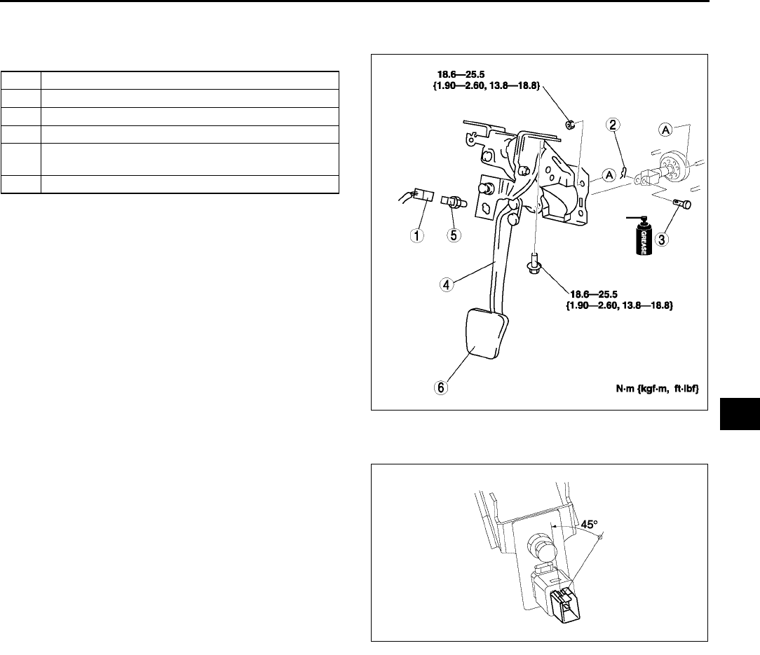
CONVENTIONAL BRAKE SYSTEM
P9
P
BRAKE PEDAL REMOVAL/INSTALLATION A6E691243300W02
1. For ATX model, remove the lock unit with brake switch (R.H.D. only).
2. Remove in the order indicated in the table.
3. Install in the reverse order of removal.
Brake switch Installation Note
1. Fix the brake switch on a bracket with pressing down at 50 N {5.1 kgf·m, 37 ft·lbf}.
2. Rotate the brake switch 45°
°°
° counterclockwise.
3. Verify that the brake switch is locked securely.
Note
•Stopper bolt and pedal stopper clearance
adjustment dose not need after the brake
switch is locked securely.
End Of Si e
1 Brake switch connector
2 Spring pin
3Clevis pin
4 Brake pedal
5 Brake switch
(See P9 Brake switch Installation Note)
6 Pedal pad
A6E6912W020
A6E6912W051
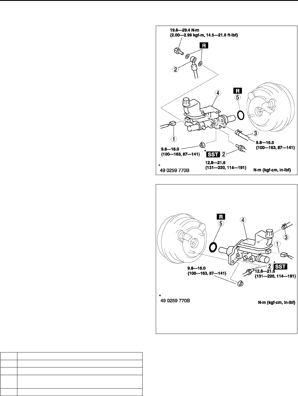
P10
CONVENTIONAL BRAKE SYSTEM
MASTER CYLINDER REMOVAL/INSTALLATION A6E691243400W01
1. Remove in the order indicated in the table.
R.H.D.
L.H.D.
2. Install in the reverse order of removal.
A6E6912W028
A6E6912W018
1 Brake fluid level sensor connector
2Brake pipe
3Hose (MTX)
4 Master cylinder
(See P11 Master Cylinder Installation Note
5 O-ring
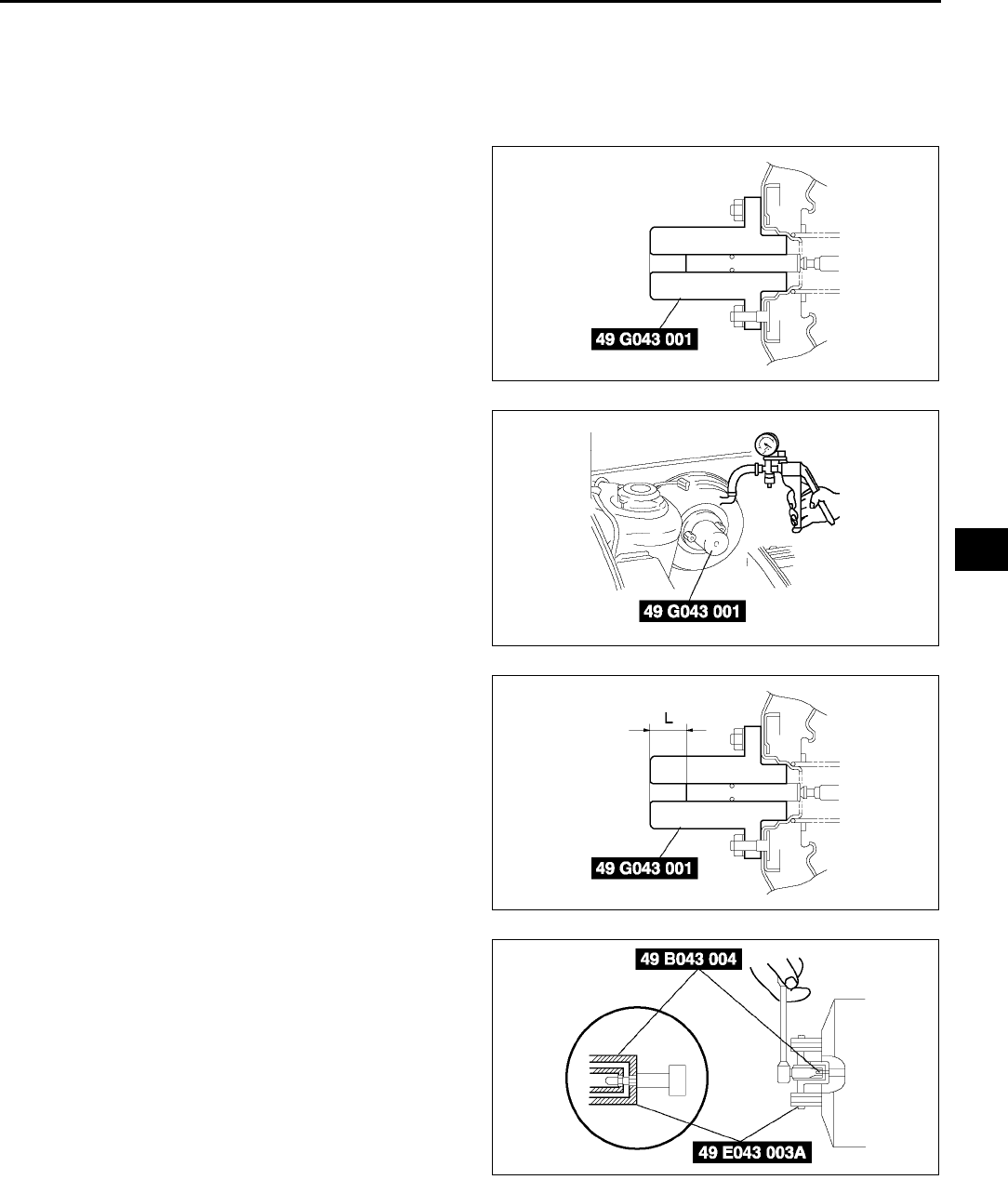
CONVENTIONAL BRAKE SYSTEM
P11
P
Master Cylinder Installation Note
Caution
•
••
•Always install the gasket of the power brake unit push rod before performing measurement
inspections or adjustments.
1. Install the SST to the power brake unit as shown,
and tighten within the specified torque.
Tightening torque
9.816.0 N·m {100163 kgf·cm, 87141
in·lbf}
2. Using a vacuum gauge, create a vacuum
pressure of 66.7 kPa {500 mmHg, 19.7 inHg} in
the power brake unit.
3. Using calipers, measure dimension L as shown.
Specification
22.7 mm{8.94 in}
4. If dimension L is not within the specification as
shown, remove SST (49 E043 001) and use SST
(49 B043 004) to adjust the length of the push rod
while using SST (E043 003A) to keep the push
rod from rotating.
5. Remove the SSTs, replace SST (49 E043 001)
and measure dimension L again.
A6E6912W042
A6E6912W029
A6E6912W030
A6E6912W031
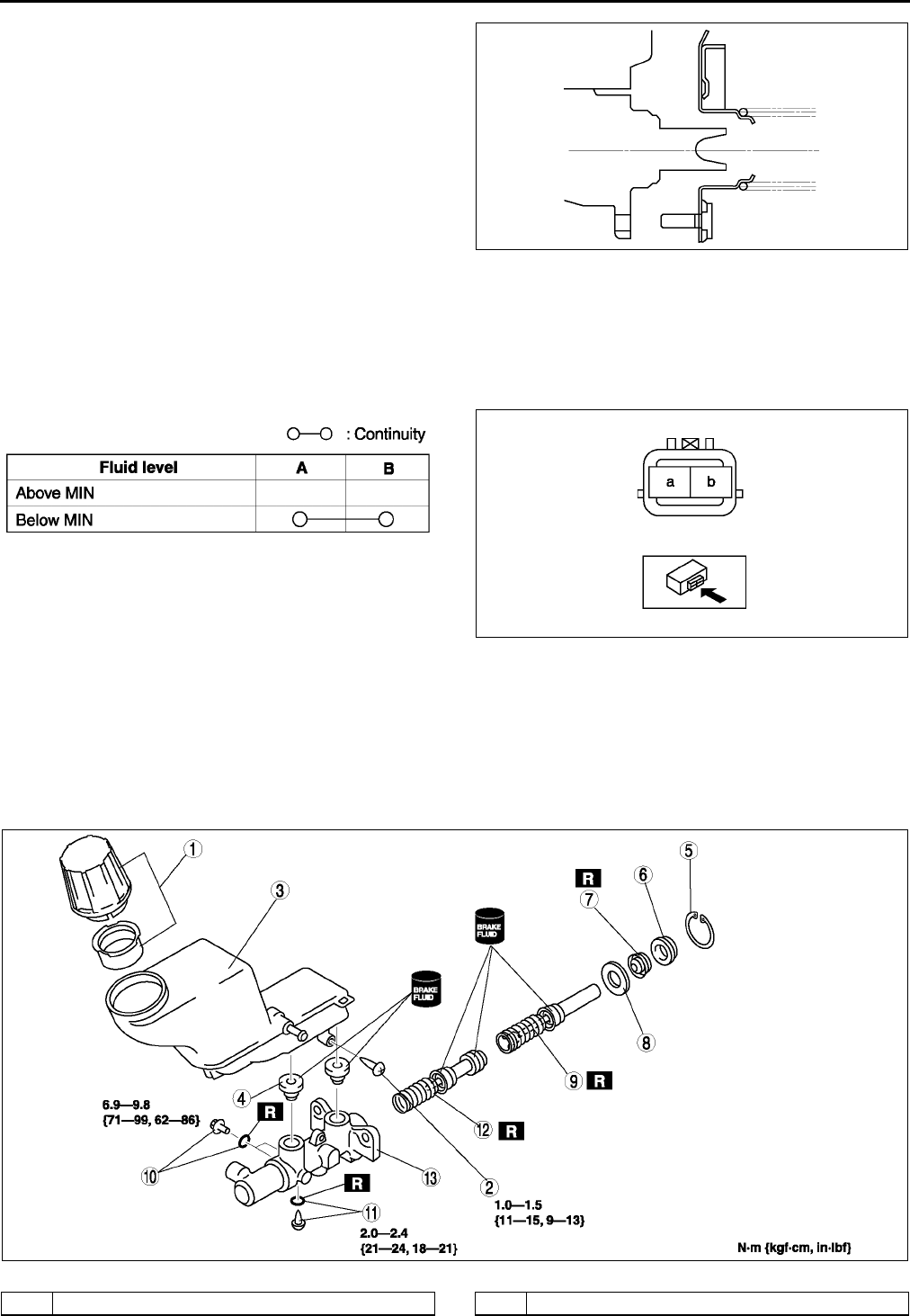
P12
CONVENTIONAL BRAKE SYSTEM
6. Install the master cylinder to the power brake unit.
Caution
•
••
•If after installing the master cylinder, air
does not bleed properly from the brake
lines even after performing air bleeding,
brake drag occurs or other
characteristics are present, it is possible
that the master cylinder piston is jammed
against the power brake unit. If air cannot
be bled properly, brake drag exists or
other malfunctions occur, remove the
master cylinder and reinstall properly.
End Of Si e
FLUID LEVEL SENSOR INSPECTION A6E691243540W01
1. Disconnect the negative battery cable.
2. Disconnect the sensor connector.
3. Inspect for continuity between terminals of fluid level sensor.
•If not as specified, replace the fluid level sensor.
End Of Sie
MASTER CYLINDER DISASSEMBLY/ASSEMBLY A6E691243400W02
Caution
•
••
•If the master cylinder body is damaged, replace the unit as a component. When securing the
master cylinder in a vise, tighten only the flange of the master cylinder.
1. Disassemble in the order indicated in the table.
2. Assemble in the reverse order of disassembly.
.
A6E6912W032
A6E6912W024
A6E6912W023
A6E6912W019
1 Cap set 2Screw
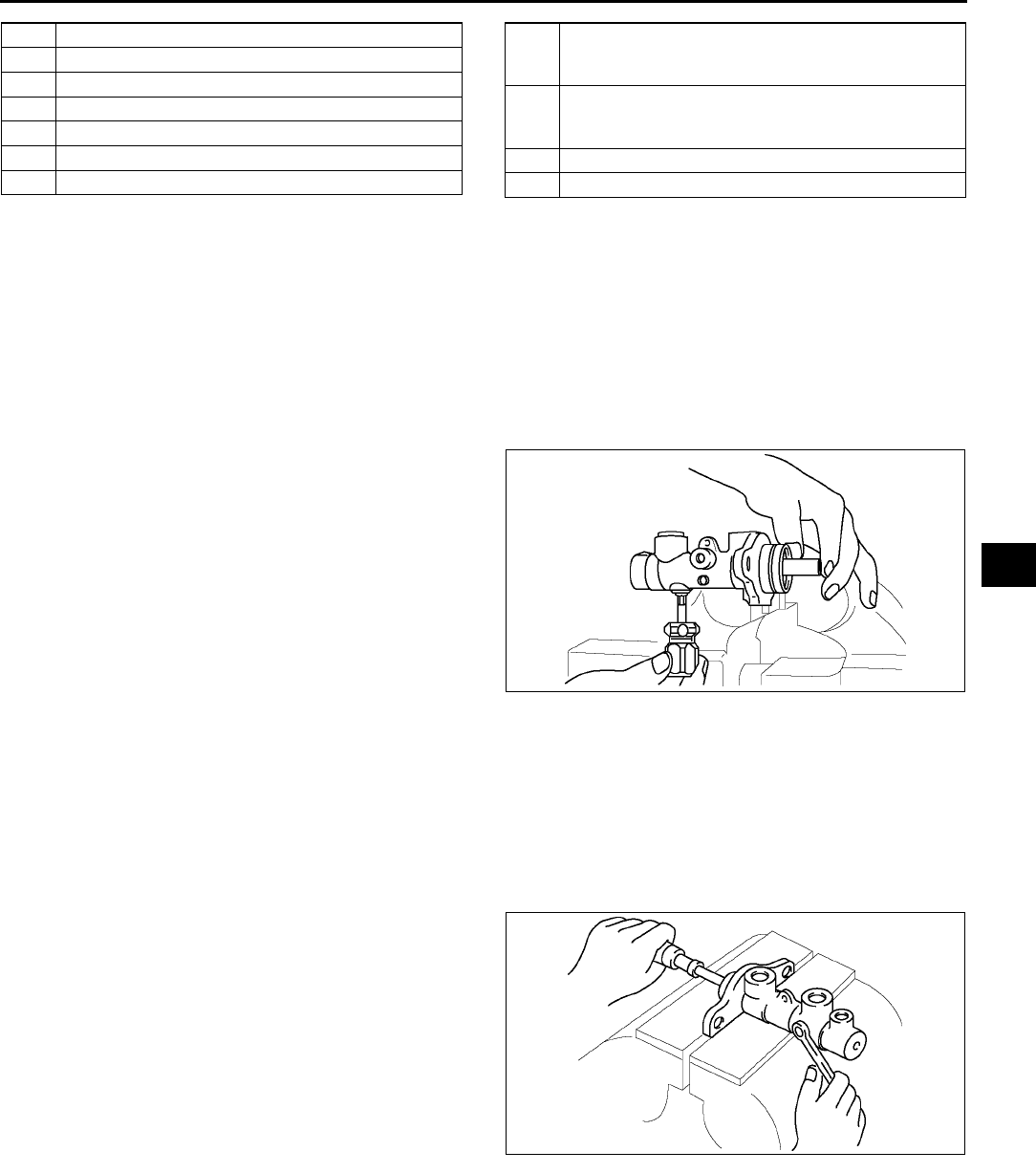
CONVENTIONAL BRAKE SYSTEM
P13
P
Stop Screw and O-ring (without ABS) Assembly Note
1. Install the secondary piston and primary piston.
2. Install the new O-ring onto the stop screw.
3. Push the primary piston assembly in full.
4. Install and tighten the stop screw.
Tightening torque
2.02.4 N·m {2124 kgf·cm, 1821 in·lbf}
5. Push and release the secondary piston
component to verify that it is held properly by the
stop screw.
Stop Pin and O-ring (with ABS) Assembly Note
1. Install the secondary piston with the piston hole facing the stop pin and primary piston.
2. Install the new O-ring onto the stop pin.
3. Push the primary piston assembly in full.
4. Install and tighten the stop pin.
Tightening torque
6.99.8 N·m {7199 kgf·cm, 6286 in·lbf}
5. Push and release the secondary piston
component to verify that it is held properly by the
stop pin.
End Of Sie
3 Reservoir
4 Joint bushing
5 Snap ring
6 Piston guide
7Cup
8 Stopper
9 Primary piston
10 Stop pin and O-ring (with ABS)
(See P13 Stop Pin and O-ring (with ABS)
Assembly Note)
11 Stop screw and O-ring (without ABS)
(SeeP13 Stop Screw and O-ring (without ABS)
Assembly Note)
12 Secondary piston
13 Master cylinder body
A6E6912W025
A6E6912W043
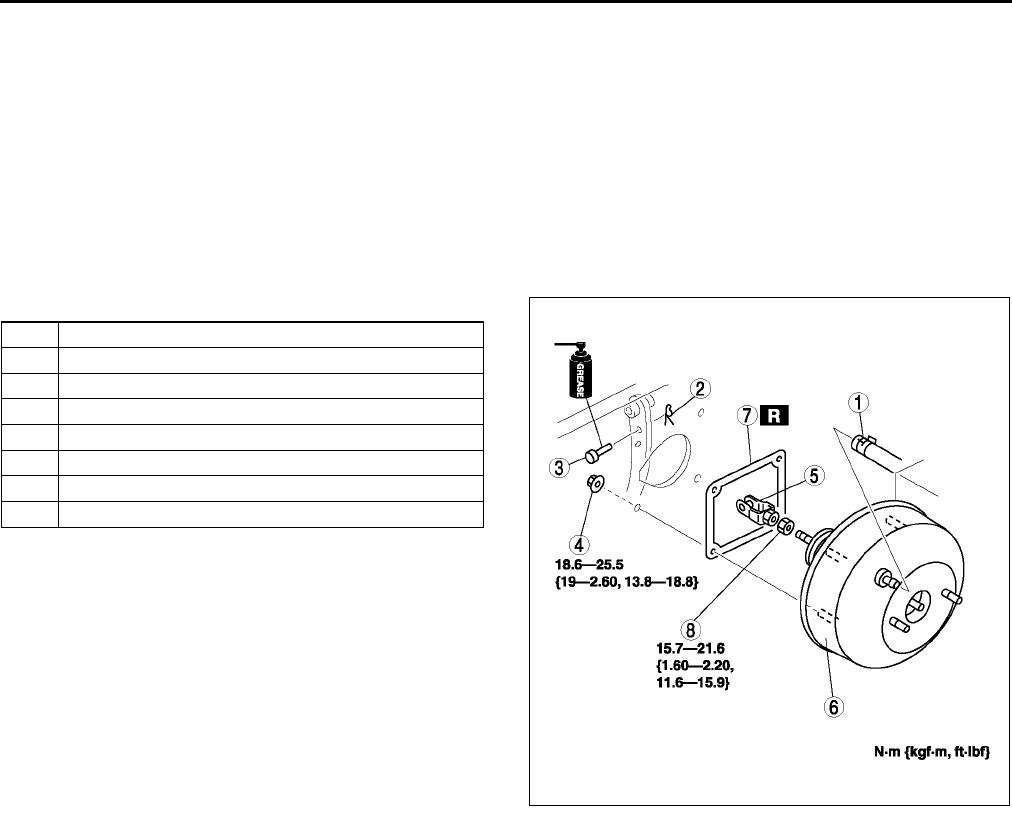
P14
CONVENTIONAL BRAKE SYSTEM
POWER BRAKE UNIT REMOVAL/INSTALLATION A6E691243800W02
1. Remove the master cylinder. (See P10 MASTER CYLINDER REMOVAL/INSTALLATION.)
2. Remove the wiper arm. (See T57 WINDSHIELD WIPER ARM AND BLADE REMOVAL/INSTALLATION.)
3. Remove the cowl grille. (See S50 COWL GRILLE REMOVAL/INSTALLATION.)
4. Remove the wiper motor. (See T56 WINDSHIELD WIPER MOTOR REMOVAL/INSTALLATION.)
5. Remove the cowl panel. (See S119 COWL PANEL REMOVAL/INSTALLATION.)
6. For L.H.D., remove the A/C bracket.
7. For L.H.D., remove the ABS/TCS HU/CM or DSC HU/CM . (See P28 ABS (ABS/TCS) HU/CM REMOVAL/
INSTALLATION.) (See P38 DSC HU/CM REMOVAL/INSTALLATION.
8. For R.H.D., remove the alternator cover.
9. For R.H.D., remove the insulator.
10. For R.H.D., remove the vacuum pipe bracket.
11. Remove in the order indicated in the table.
12. Install in the reverse order of removal.
End Of Sie
POWER BRAKE UNIT INSPECTION A6E691243800W01
Warning
•
••
•The following inspection methods are the simple inspection methods to judge the function of
power brake.
•
••
•If there is malfunction in power brake unit, replace the power brake unit as a component.
Power Brake Unit Function Check (Simple Method)
Step 1
1. With the engine stopped, depress the pedal a few times.
2. With the pedal depressed, start the engine.
3. If the pedal moves down slightly immediately after the engine starts, the unit is operating.
Step 2
1. Start the engine.
2. Stop the engine after it has run for 1 or 2 minutes.
3. Depress the pedal with the usual force.
4. If the first pedal stroke is long and becomes shorter with subsequent strokes, the unit is operating.
•If a problem is found, inspect for damage of the vacuum hose, and vacuum tank. Repair if necessary, and
inspect it again.
Step 3
1. Start the engine.
2. Depress the pedal with usual force.
3. If the pedal height does not change, the unit is operating.
4. Hold the pedal down for about 30 seconds.
5. If the pedal height does not change, the unit is operating.
1 Vacuum hose
2 Snap pin
3 Clevis pin
4Nut
5Fork
6 Power brake unit
7Gasket
8Nut
A6E6912W044
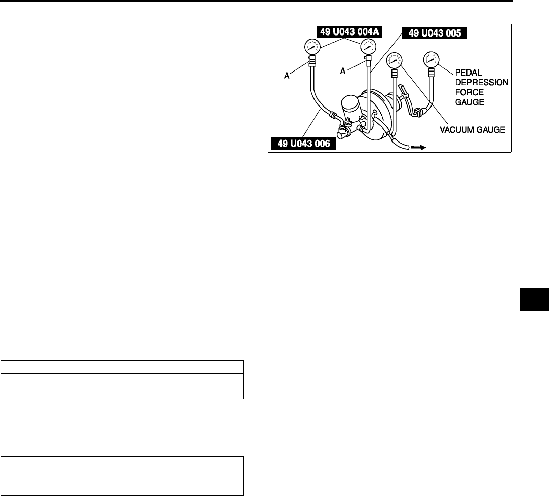
CONVENTIONAL BRAKE SYSTEM
P15
P
Power Brake Unit Function Check (Inspection Using The Testers)
1. Connect the SSTs, vacuum gauge, and pedal
depression force gauge as shown in the figure to
bleed the air from SSTs and brake line. (Bleed
the air from SSTs using a air bleed valve A.)
Checking for vacuum loss (unloaded condition)
1. Stop the engine when the vacuum gauge reading reaches 66.7 kPa {500 mmHg, 19.7 inHg}.
2. Observe the vacuum gauge for 15 seconds.
•If the gauge shows 63.366.7 kPa {475500 mmHg, 18.719.6 inHg}, the unit is operating.
•If not, inspect for damage on the check valve or vacuum hose, and examine the installation. Repair as
necessary, and inspect it again.
Checking for vacuum loss (loaded condition)
1. Start the engine.
2. Depress the brake pedal with a force of 196 N {20 kgf, 44 lbf}.
3. Stop the engine when the vacuum gauge reading reaches 66.7 kPa {500 mmHg, 19.7 inHg}.
4. Observe the vacuum gauge for 15 seconds.
5. If the gauge shows 63.366.7 kPa {475500 mmHg, 18.719.6 inHg}, the unit is operating.
Checking for hydraulic pressure
1. When the engine is stopped (vacuum 0 kPa {0 mmHg, 0 inHg}) and the fluid pressure is within the
specification, the unit is operating.
2. Start the engine. Depress the brake pedal when the vacuum reaches 66.7 kPa {500 mmHg, 19.7 inHg}.
•If the fluid pressure is within the specification, the unit is operating.
•If the fluid pressure is not as specified, inspect for damage to the check valve or vacuum hose, and fluid
leakage of the hydraulic line. Repair as necessary, and inspect again.
End Of Sie
A6E6912W005
Pedal force Fluid pressure
200 N {20 kgf, 44 lbf} 588 kPa {5.95 kgf/cm2, 84.7 psi}
min.
Pedal force Fluid pressure
200 N {20 kgf, 44 lbf} 8,787 kPa {89.60 kgf/cm2,
1,274 psi} min.
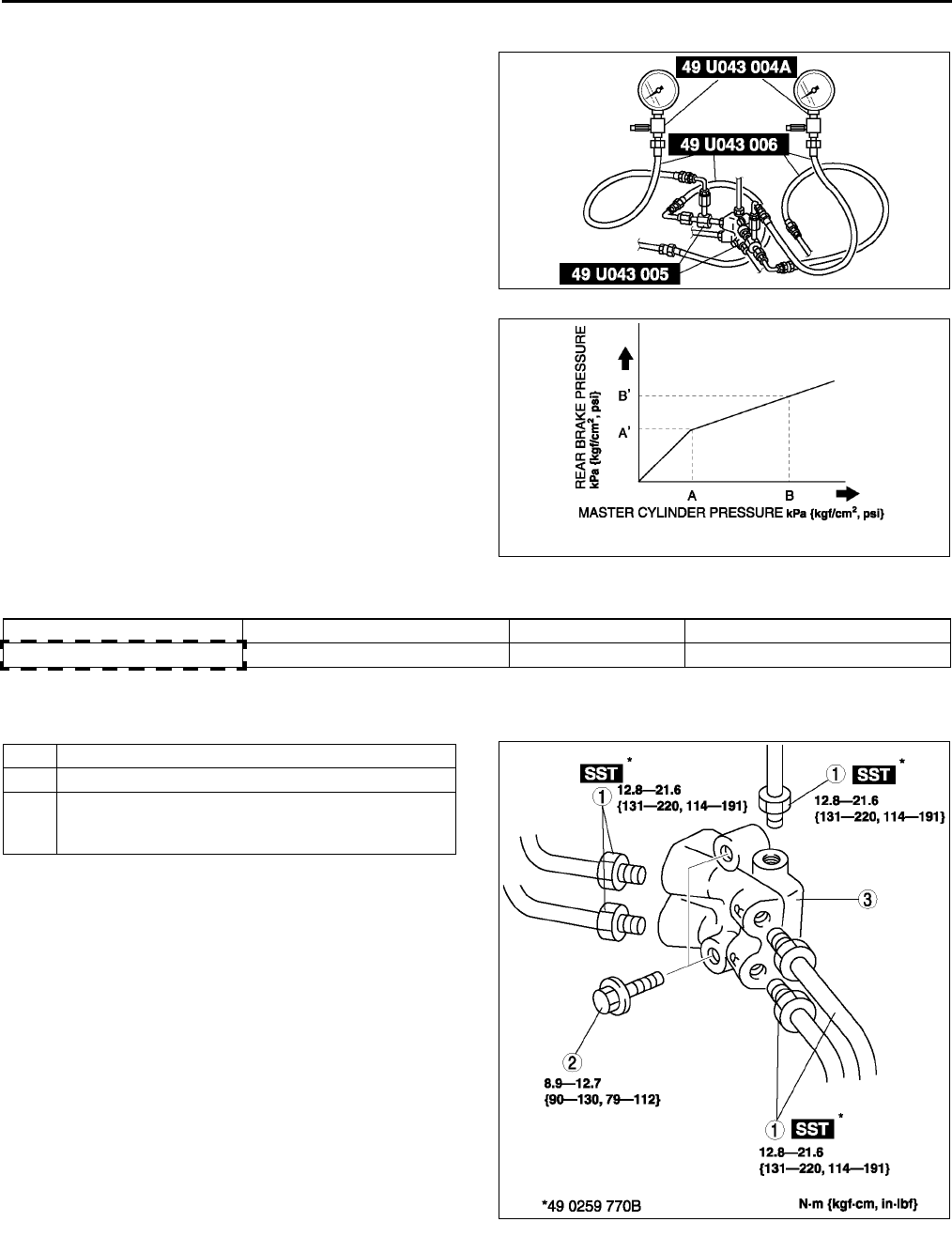
P16
CONVENTIONAL BRAKE SYSTEM
DUAL PROPORTIONING VALVE INSPECTION (WITHOUT ABS) A6E691243900W01
1. Connect the SSTs to the brake pipes as shown in
the figure.
2. Bleed the air from the brake system.
3. Measure the fluid pressure of the master cylinder
and the rear brake.
•If not within the specification, replace the dual
proportioning valve.
Fluid pressure
kPa {kgf/cm2, psi}
End Of Si e
DUAL PROPORTIONING VALVE REPLACEMENT (WITHOUT ABS) A6E691243900W02
1. Remove in the order indicated in the table.
2. Install in the reverse order of removal.
A6E6912W006
A6E6912W007
AA'BB'
2,450 {25, 355} 2,450 {25, 355} ± 200 {2, 29} 5,880 {60, 853} 3,480 {35.5, 505} ± 300 {3, 44}
1Brake pipe
2Bolt
3 Dual proportioning valve
(See P17 Dual Proportioning Valve Installation
Note)
A6E6912W035
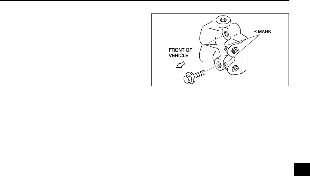
CONVENTIONAL BRAKE SYSTEM
P17
P
Dual Proportioning Valve Installation Note
1. Install the dual proportioning valve so that the R
mark faces the left side of the vehicle.
End Of Si e
FRONT BRAKE (DISC) INSPECTION A6E691233980W01
Brake Judder Repair Hint
Description
1. Brake judder concern has the following 3 characteristics:
Steering wheel vibration
1. Steering wheel vibrates in the direction of its rotation. This characteristic is most noticeable when applying
brakes at a vehicle speed of 100140 km/h {62.186.8 mph}.
Floor vibration
1. When applying brakes, the vehicle body shakes back and forth. The seriousness of shake is not influenced by
vehicle speed.
Brake pedal vibration
1. When applying brakes, a pulsating force tries to push the brake pad back occurs. The pulsation is transmitted
to the brake pedal.
2. The following are the main possible causes of brake judder:
Due to an excessive runout (side-to-side wobble) of disc plate, the thickness of disc plate is uneven.
1. If the runout is more than 0.05 mm {0.002 in} to 10 mm {0.39 in} from the disc plate edge, an uneven wear
occurs on the disc plate because the pad contacts the plate unevenly.
2. If the runout is less than 0.05 mm {0.002 in}, uneven wear does not occur.
The disc plate is deformed by heat.
1. Repeated panic braking may raise the temperature in some portions of disc plate by approximately 1,000 °
°°
°C
{1,832 °
°°
°F}. This results in deformed disc plate.
Due to corrosion, the thickness and friction coefficient of disc plate change.
1. If a vehicle is parked under damp conditions for a long time, corrosion occurs on the friction surface of disc
plate.
2. The thickness of corrosion is uneven and sometimes appears like a wave pattern, which changes the friction
coefficient and causes a reaction force.
A6E6912W045
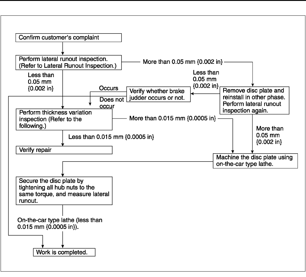
P18
CONVENTIONAL BRAKE SYSTEM
Inspection and repair procedure
Lateral runout inspection
1. To secure the disc plate and the hub, tighten the hub nuts upside down or insert a washer (thickness 10 mm
{0.39 in}, inner diameter more than 12 mm {0.47 in}) between the hub bolt and the hub nut.
Note
•The component parts of the SST (49 B017 001 or 49 G019 003) can be used as a suitable washer.
2. After tightening all the hub nuts to the same torque, put the dial gauge on the friction surface of disc plate 10
mm {0.39 in} from the disc plate edge.
3. Rotate the disc plate one time and measure the runout.
Runout limit
0.05 mm {0.002 in}
A6E6912W008
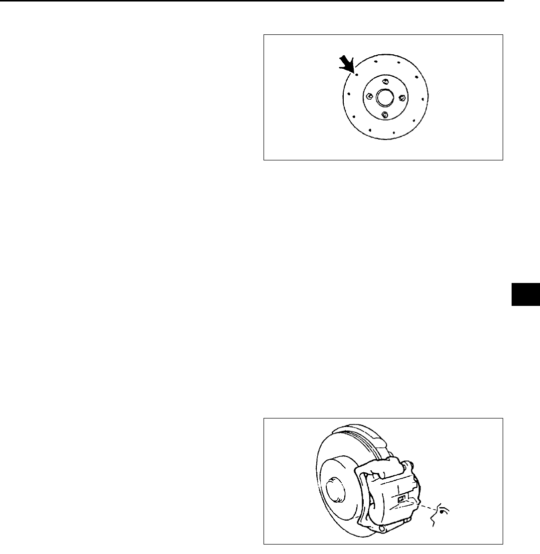
CONVENTIONAL BRAKE SYSTEM
P19
P
Thickness variation inspection
1. Clean the disc plate-to-pad friction surface using a brake cleaner.
2. Measure the points indicated in the illustration
using a caliper (micrometer).
3. Subtract the minimum value from the maximum,
and if the result is not within specification,
machine the disc plate using a lathe.
Thickness variation limit
0.015 mm {0.00059 in}
Warning
•
••
•Do not exceed minimum disc plate
thickness.
Disc Plate Thickness Inspection
Caution
•
••
•Excessive runout may result if the disc plate is removed from the vehicle then machined. Machine
the disc plate while installed on the vehicle.
1. Measure the thickness of the disc plate.
•If the thickness is not within the specification, replace the disc plate.
Minimum
22 mm {0.87 in}
Minimum thickness after machining using a brake lathe on-vehicle
22.8 mm {0.90 in}
Disc Pad Thickness Inspection
1. Jack up the front of the vehicle and support it with safety stands.
2. Remove the wheel and tires.
3. Verify the remaining thickness of the pads.
Minimum thickness
2.0 mm {0.079 in} min.
4. Replace the pads as a set: right and left wheels, if
either one is at or less than the minimum
thickness.
End Of Si e
X3U411WAR
X3U411WAS
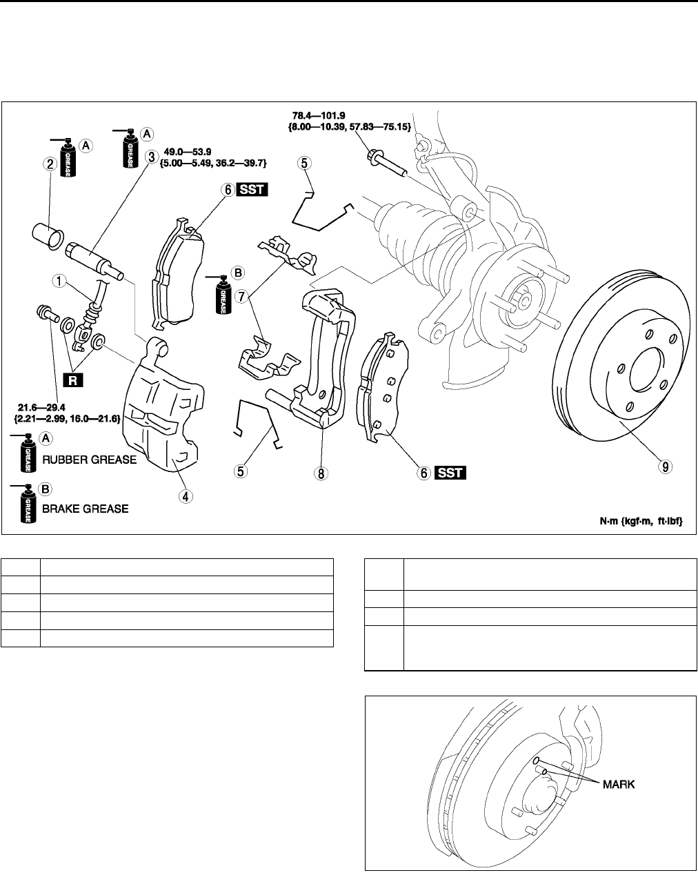
P20
CONVENTIONAL BRAKE SYSTEM
FRONT BRAKE (DISC) REMOVAL/INSTALLATION A6E691233980W02
1. Remove in the order indicated in the table.
2. Install in the reverse order of removal.
3. After installation, depress the pedal a few times, rotate the wheel by hand, and verify that the brake does not
drag.
.
Disc Plate Removal Note
1. Mark the wheel hub bolt and disc plate before
removal for reference during installation.
Disc Plate Installation Note
1. Remove any rust or grime on the contact face of the disc plate and wheel hub.
2. Install the disc plate and align the marks made before removal.
A6E6912W021
1 Flexible hose
2Cap
3Guide pin
4 Caliper
5 M-spring
6Disc pad
(See P21 Disc Pad Installation Note)
7Guide plate
8 Mounting support
9 Disc plate
(See P20 Disc Plate Removal Note)
(See P20 Disc Plate Installation Note)
A6E6912W037
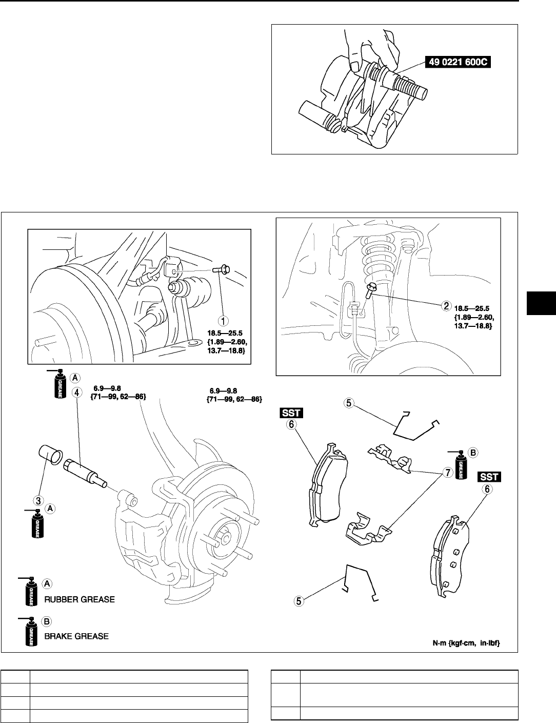
CONVENTIONAL BRAKE SYSTEM
P21
P
Disc Pad Installation Note
1. Push the piston fully inward using the SST.
2. Install the disc pad.
End Of Si e
DISC PAD (FRONT) REPLACEMENT A6E691233630W01
1. Remove in the order indicated in the table.
2. Install in the reverse order of removal.
.
End Of Si e
A6E6912W038
A6E6912W022
1Bolt
2Bolt
3Cap
4Guide pin
5M-spring
6 Disc pad
(See P21 Disc Pad Installation Note)
7 Guide plate
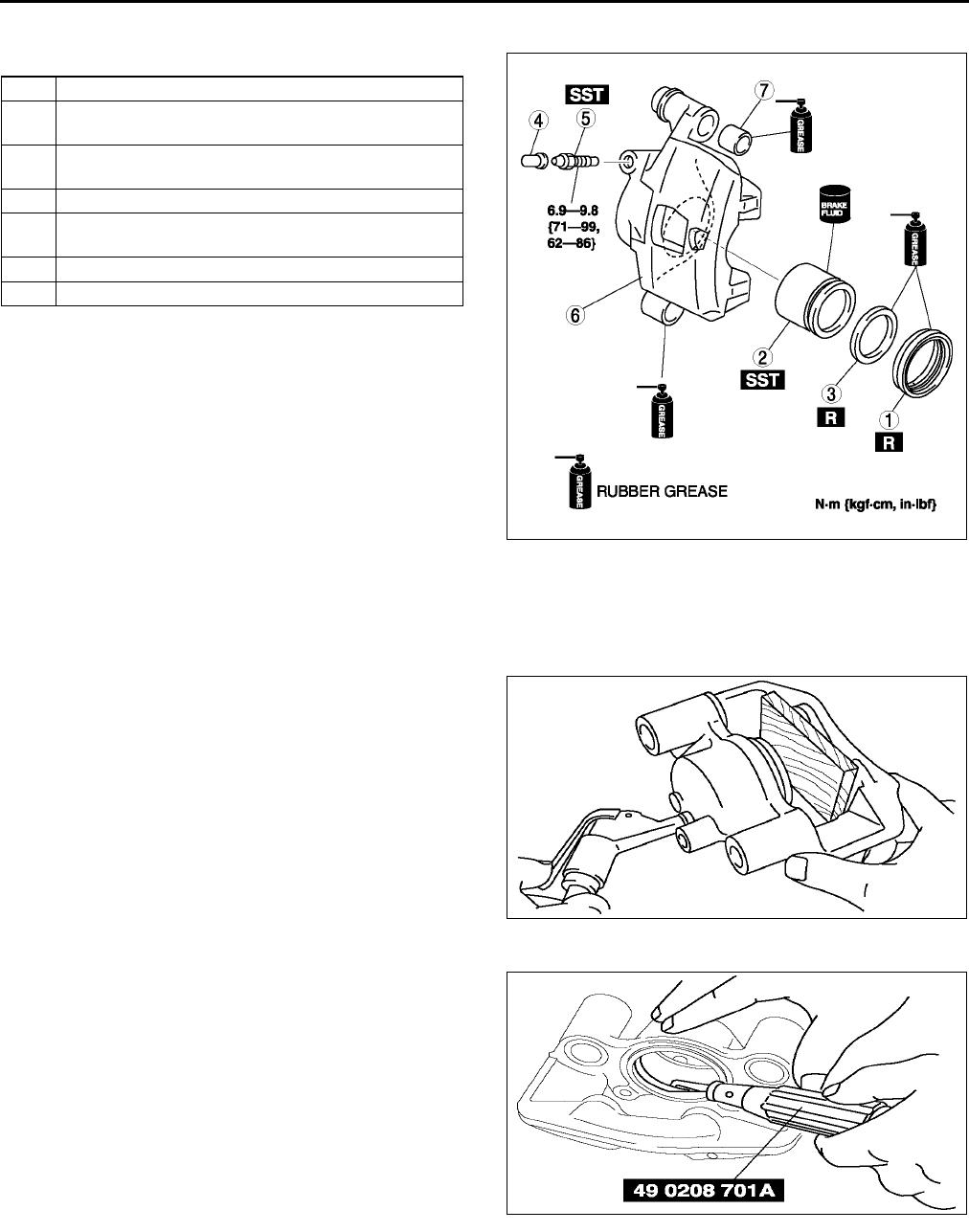
P22
CONVENTIONAL BRAKE SYSTEM
CALIPER (FRONT) DISASSEMBLY/ASSEMBLY A6E691233990W01
1. Disassemble in the order indicated in the table.
2. Assemble in the reverse order of removal.
Piston Disassembly Note
Caution
•
••
•Blow the compressed air slowly to prevent the piston from suddenly popping out.
1. Place a piece of wood in the caliper, then blow
compressed air through the hole to force the
piston out of the caliper.
Piston Seal Disassembly Note
1. Remove the piston seal from the brake caliper
using the SST.
1 Dust seal
2Piston
(See P22 Piston Disassembly Note)
3Piston seal
(See P22 Piston Seal Disassembly Note)
4 Bleeder cap
5 Bleeder screw
(See P23 Bleeder Screw Assembly Note)
6 Caliper body
7 Boot
A6E6912W046
A6E6912W047
A6E6912W048
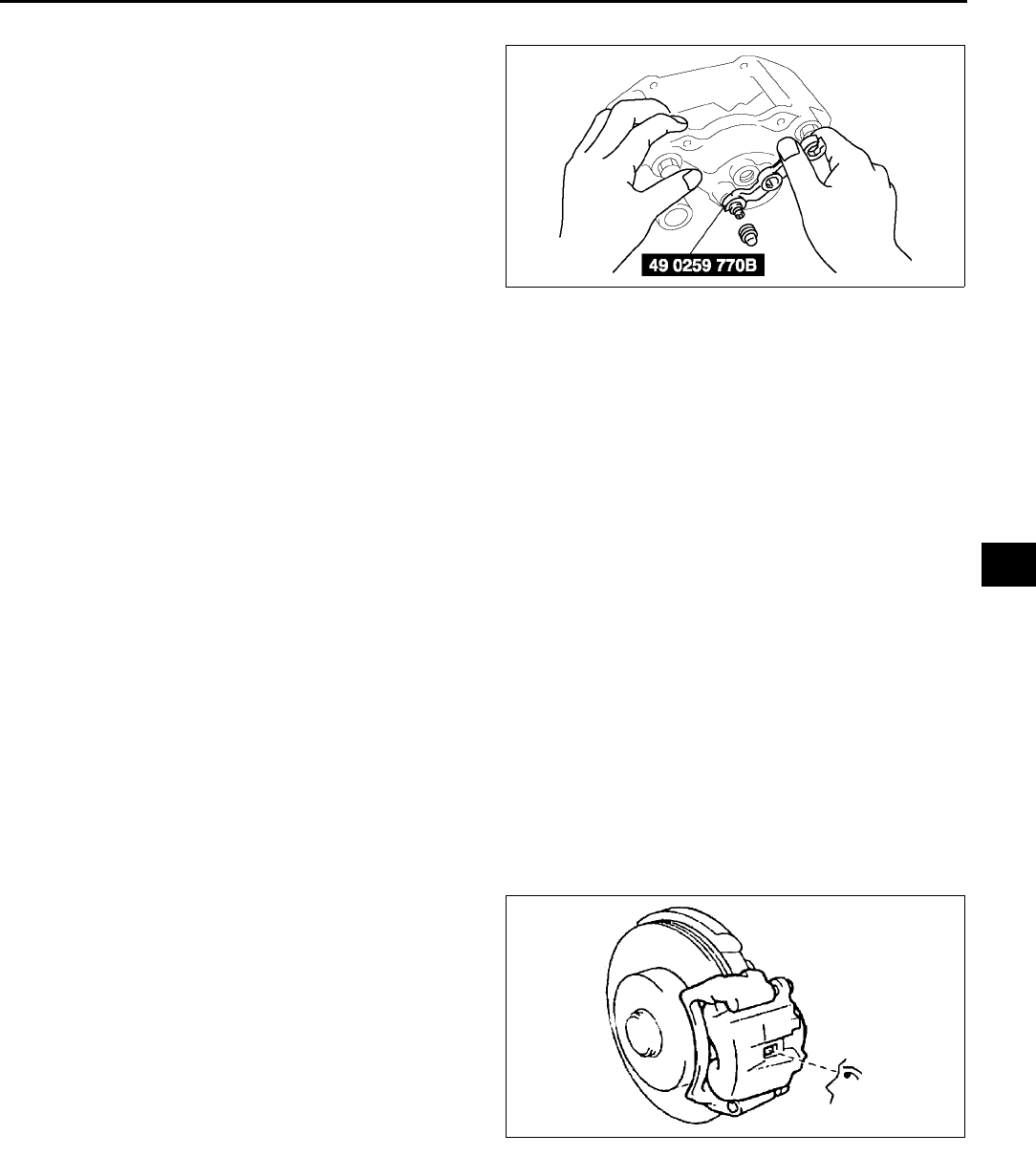
CONVENTIONAL BRAKE SYSTEM
P23
P
Bleeder Screw Assembly Note
1. Assemble the bleeder screw to the caliper using
the SST.
Tightening torque
6.99.8 N·m {7199 kgf·cm, 6286 in·lbf}
End Of Si e
REAR BRAKE (DISC) INSPECTION A6E691226980W01
Brake Judder Repair Hint
1. (See P17 FRONT BRAKE (DISC) INSPECTION.)
Disc Plate Thickness Inspection
Caution
•
••
•Excessive runout may result if the disc plate is removed from the vehicle then machined. Machine
the disc plate while installed on the vehicle.
1. Measure the thickness of the disc plate.
•If the thickness is not within the specification, replace the disc plate.
Minimum
8 mm {0.31 in}
Minimum thickness after machining using a brake lathe on-vehicle
8.8 mm {0.35 in}
Disc Pad Thickness Inspection
1. Jack up the front of the vehicle and support it with safety stands.
2. Remove the wheel and tires.
3. Verify the remaining thickness of the pads.
Minimum thickness
2.0 mm {0.079 in} min.
4. Replace the pads as a set: right and left wheels, if
either one is at or less than the minimum
thickness.
End Of Si e
A6E6912W049
X3U411WAS
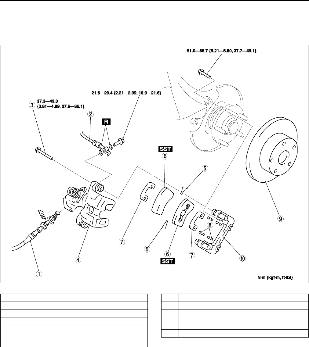
P24
CONVENTIONAL BRAKE SYSTEM
REAR BRAKE (DISC) REMOVAL/INSTALLATION A6E691226980W02
1. Remove in the order indicated in the table.
2. Install in the reverse order of removal.
3. After installation, depress the pedal several times, rotate the wheel by hand, and verify that the brake does not
drag.
.
A6E6912W026
1 Parking brake cable, clip
2 Flexible hose
3Bolt
4 Caliper
5Spring
6Disc pad
(See P25 Disc Pad Installation Note)
7Shim
8Guide plate
9 Disc plate
(See P20 Disc Plate Removal Note)
(See P20 Disc Plate Installation Note)
10 Mounting support
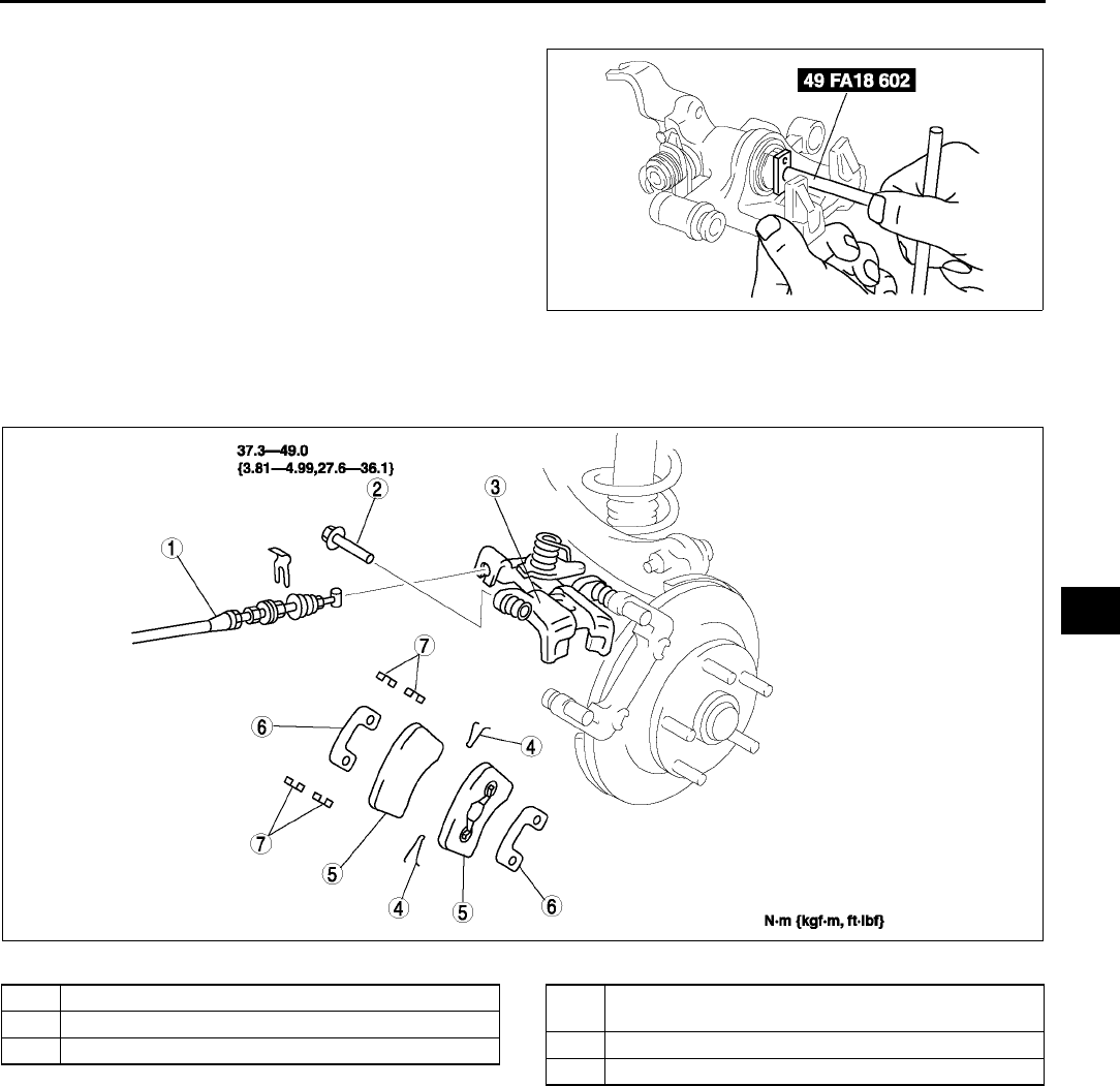
CONVENTIONAL BRAKE SYSTEM
P25
P
Disc Pad Installation Note
1. Turn the manual adjustment gear
counterclockwise with an Allen wrench to pull the
brake caliper piston inward. (Turn until it stops.)
2. Install the disc pads.
3. Turn the manual adjustment gear clockwise until
the brake pads just touch the disc plate. Turn the
manual adjustment gear back 1/3-turn.
End Of Si e
DISC PAD (REAR) REPLACEMENT A6E691226630W01
1. Remove in the order indicated in the table.
2. Install in the reverse order of removal.
.
End Of Si e
A6E6912W039
Z3U0411W009
1 Parking brake cable, clip
2Screw plug
3Lock bolt
4 Disc pad
(See P25 Disc Pad Installation Note)
5Shim
6 Guide plate
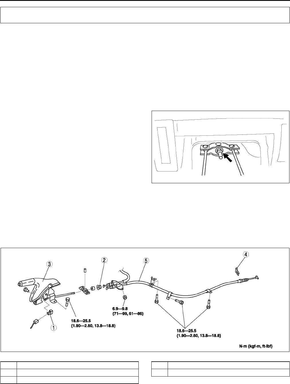
P26
PARKING BRAKE SYSTEM
PARKING BRAKE (LEVER TYPE) INSPECTION A6E691444000W01
1. Pull the parking brake lever a few times.
2. Depress the brake pedal a few times.
3. Inspect the parking brake stroke by pulling the parking brake lever with a force of 98 N {10 kgf, 22 lbf}.
Stroke
36 notches
End Of Sie
PARKING BRAKE (LEVER TYPE) ADJUSTMENT A6E691444000W02
1. Start the engine and depress the brake pedal several times.
2. Stop the engine.
3. Remove the ashtray behind the center console.
4. Turn the adjusting nut as shown in the figure.
5. After adjustment, inspect the following points:
(1) Turn the ignition switch to ON, pull the parking
brake lever one notch, and verify that the
parking brake warning light illuminates.
(2) Verify that the rear brakes do not drag.
End Of Sie
PARKING BRAKE (LEVER TYPE) REMOVAL/INSTALLATION A6E691444000W03
1. Remove the center console. (See S86 CONSOLE REMOVAL/INSTALLATION.)
2. Remove the rear seat cushion (4SD) or rear seat (5HB) . (See S110 REAR SEAT REMOVAL/
INSTALLATION.)
3. Remove the exhaust pipe bracket.
4. Remove in the order indicated in the table.
5. Install in the reverse order of removal.
6. Adjust the parking brake stroke. (See P26 PARKING BRAKE (LEVER TYPE) ADJUSTMENT.)
.
End Of Sie
PARKING BRAKE SYSTEM
A6E6914W002
A6E6914W001
1 Parking brake switch
2 Adjusting nut
3 Parking brake lever
4Clip
5 Parking brake cable
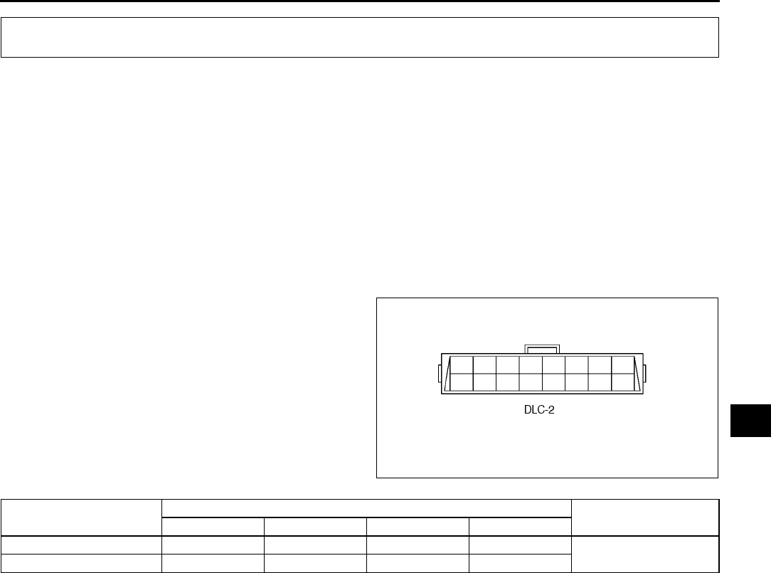
ABS/TCS
P27
P
ABS (ABS/TCS) HU/CM SYSTEM INSPECTION A6E692143780W01
System Inspection
Preparation
1. Verify that the battery is fully charged. With the ignition switch on, verify that the ABS and BRAKE system
warning lights goes out after 2.4 seconds.
2. If the lights stays on after 2.4 seconds, the ABS (ABS/TCS) HU/CM detects a failure. Follow the
troubleshooting procedures.
3. Turn the ignition switch off.
4. On level ground, jack up the vehicle and support it evenly on safety stands. Shift the transaxle to N position.
5. Release the parking brake.
6. Rotate the wheels by hand, and inspect for brake drag.
Operation of ABS inspection
1. Perform the Preparation.
2. Connect the SSTs (WDS or equivalent) to the
data link connector-2 (DLC-2).
3. Set up an active command mode inspection
according to the combination of commands
below.
The chart above shows an example of a right wheel inspection.
Note
•When working with two people, one should press on the brake pedal, the other should attempt to rotate
the wheel being inspected.
4. Send the command while pressing on the brake pedal and attempting to rotate the wheel being inspected.
5. When pressure is being maintained, and click sound indicating the solenoid is operating comes from the ABS
(ABS/TCS) HU/CM, confirm that the wheel does not rotate. When pressure is being reduced, and click sound
indicating the solenoid is operating comes from the ABS (ABS/TCS) HU/CM, confirm that the wheel rotates,
even though the brake pedal is being depressed.
Note
•To protect the ABS (ABS/TCS) HU/CM, the solenoid valve used for simulations and the ABS motor stay
on for 10 seconds each time they are switched on.
•Performing the inspections above determines the following.
The ABS (ABS/TCS) HU/CM brake lines are normal.
The ABS (ABS/TCS) HU/CM hydraulic system is not significantly abnormal.
The ABS (ABS/TCS) HU/CM wiring is normal.
•However, the following items cannot be checked.
ABS (ABS/TCS) HU/CM input system harness and parts
Extremely small leaks in the ABS (ABS/TCS) HU/CM internal hydraulic system
Unusual intermittent occurrences in the above items
End Of Si e
ABS/TCS
A6E6921W007
OPERATION COMMAND NAME COMMAND TYPE
PMP_MOTOR RF_OUTLET RF_INLET ABS_POWER
Pressure retention OFF OFF ON ON Manual
Pressure reduction ON ON ON ON
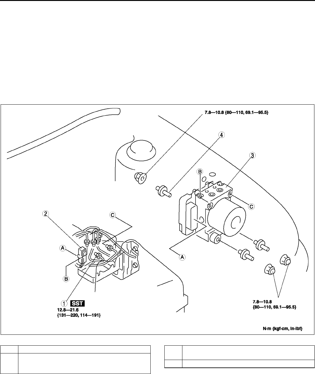
P28
ABS/TCS
ABS (ABS/TCS) HU/CM REMOVAL/INSTALLATION A6E692143700W01
Caution
•
••
•When replacing the ABS (ABS/TCS) HU/CM, configuration procedure must be done before
removing the ABS (ABS/TCS) HU/CM. If configuration is not completed before removing the ABS
(ABS/TCS) HU/CM, TCS will not work properly (with TCS model).
•
••
•Do not drop the ABS (ABS/TCS) HU/CM. Replace it if it is subjected to an impact.
1. Configurate the ABS (ABS/TCS) HU/CM (when only replacing it). (See P29 ABS (ABS/TCS) or DSC HU/CM
CONFIGURATION.)
2. Remove the battery, battery tray and battery tray bracket. (See G3 BATTERY REMOVAL/INSTALLATION.)
3. Remove the under cover.
4. Remove in the order indicated in the table.
5. Install in the reverse order of removal..
A6E6921W002
1Brake pipe
2 Connector
(See P29 Connector Removal Note)
(See P29 Connector Installation Note
3 ABS HU/CM
(See P29 ABS HU/CM Removal/Installation Note)
4Stud
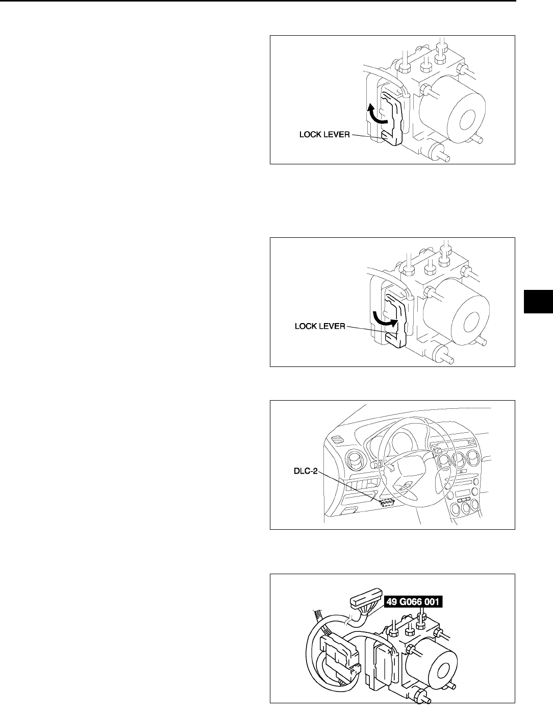
ABS/TCS
P29
P
Connector Removal Note
1. Pull the lock lever up and make it unlock.
2. Remove the connector.
ABS HU/CM Removal/Installation Note
1. When removing/installing the ABS HU/CM from/to the vehicle, attach a strip of protective tape on the ABS HU/
CM connector to prevent brake fluid from entering.
Connector Installation Note
1. Verify that the lock lever of the harness connector
is completely pulled up.
End Of Si e
ABS (ABS/TCS) OR DSC HU/CM CONFIGURATION A6E692143700W02
1. Connect the WDS or equivalent to the DLC-2.
2. Input vehicle information following the direction
on the WDS or equivalent screen.
3. Select Module programming.
4. Select Programmable module installation.
5. Select ABS/TCS.
6. Retrieve DTCs by the WDS or equivalent, then
verify that there is no DTC present.
•If DTC is present, perform applicable DTC
inspection.
End Of Si e
ABS (ABS/TCS) HU/CM INSPECTION A6E692167650W01
1. Disconnect the negative battery cable.
2. Connect the SST between the ABS (ABS/TCS)
HU/CM and harness connector with the ignition
switch off.
3. Attach the tester leads to the SST and inspect
voltage referring the table below.
A6E6916W006
A6E6916W007
A6E3970W002
A6E6921W005
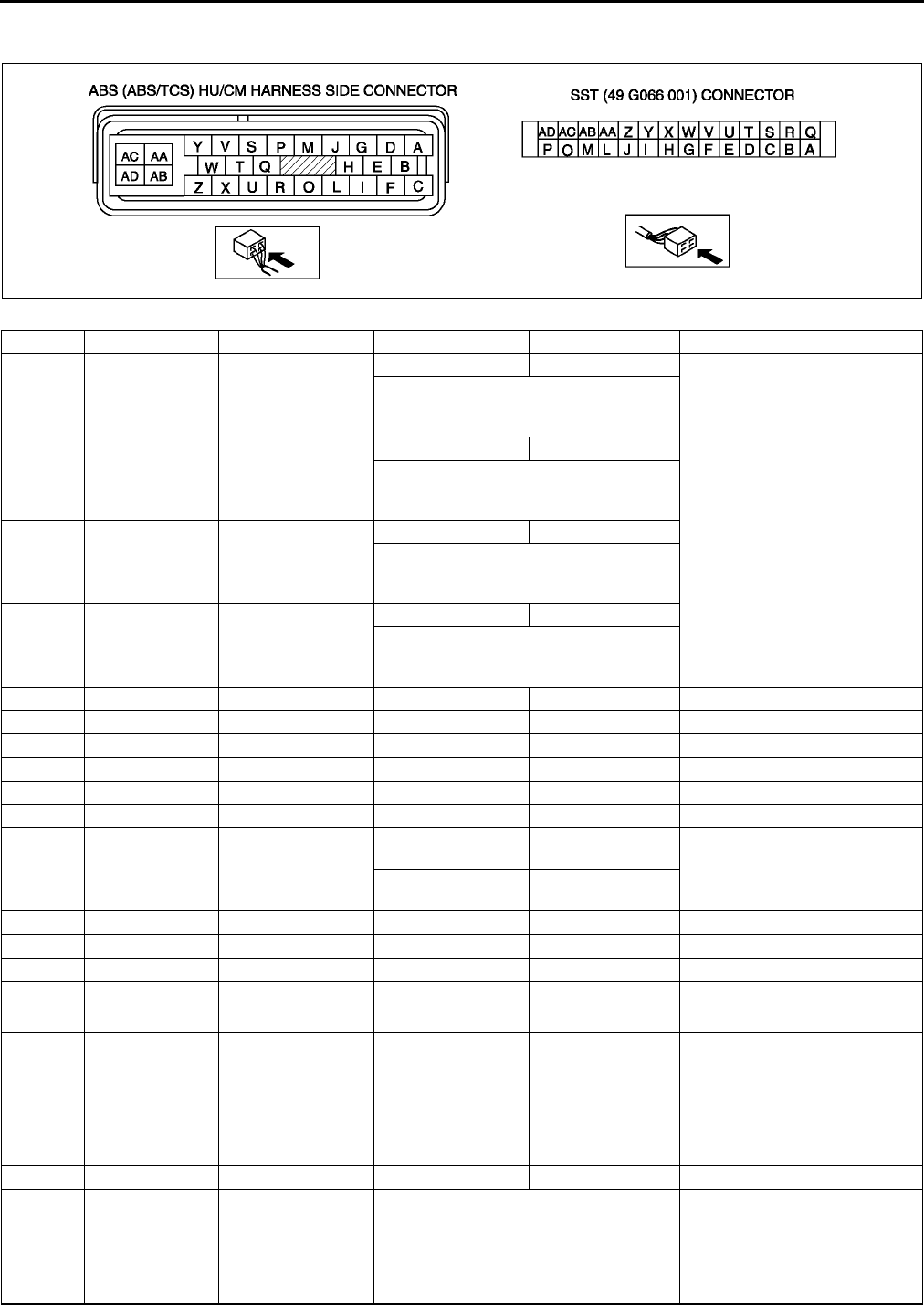
P30
ABS/TCS
Terminal Voltage Table (Reference)
(Engine is idling, and connector is connected unless otherwise indicated.)
Terminal Signal Connected to Test condition Voltage (V) Action
A
BRR wheel-speed RR wheel-speed
sensor
Vehicle is stopped 0 (AC)
•Inspect related harness
•Inspect ABS wheel-speed
sensor
•Inspect by using the wave profile.
(See P31 Inspection Using An
Oscilloscope (Reference))
C
FLR wheel-speed LR wheel-speed
sensor
Vehicle is stopped 0 (AC)
•Inspect by using the wave profile.
(See P31 Inspection Using An
Oscilloscope (Reference))
G
DRF wheel-speed RF wheel-speed
sensor
Vehicle is stopped 0 (AC)
•Inspect by using the wave profile.
(See P31 Inspection Using An
Oscilloscope (Reference))
I
ELF wheel-speed LF wheel-speed
sensor
Vehicle is stopped 0 (AC)
•Inspect by using the wave profile.
(See P31 Inspection Using An
Oscilloscope (Reference))
H
K
L
M
N
O CAN-H No need to check
P*1TCS OFF switch TCS OFF switch
When switch is
pressed Below 1.0 •Inspect related harness
•Inspect TCS OFF switch
When switch is not
pressed B+
Q
R CAN-L No need to check
S
T
U*2 DLC No need to check
VVehicle speed
output
Cruise actuator,
Wiper and washer
switch,
Audio unit,
Car-navigation unit,
Headlight leveling
actuator
Vehicle is stopped 0
•Inspect related harness
•Inspect ABS wheel-speed
sensor
W
XOBD KLN terminal of
DLC-2
It cannot be determined with terminal
voltage whether the condition is good or
bad because advanced function
diagnostic output is performed with
serial communication. Inspect with
service codes.
•Inspect related harness
•Inspect ABS/TCS HU/CM
A6E6921W001
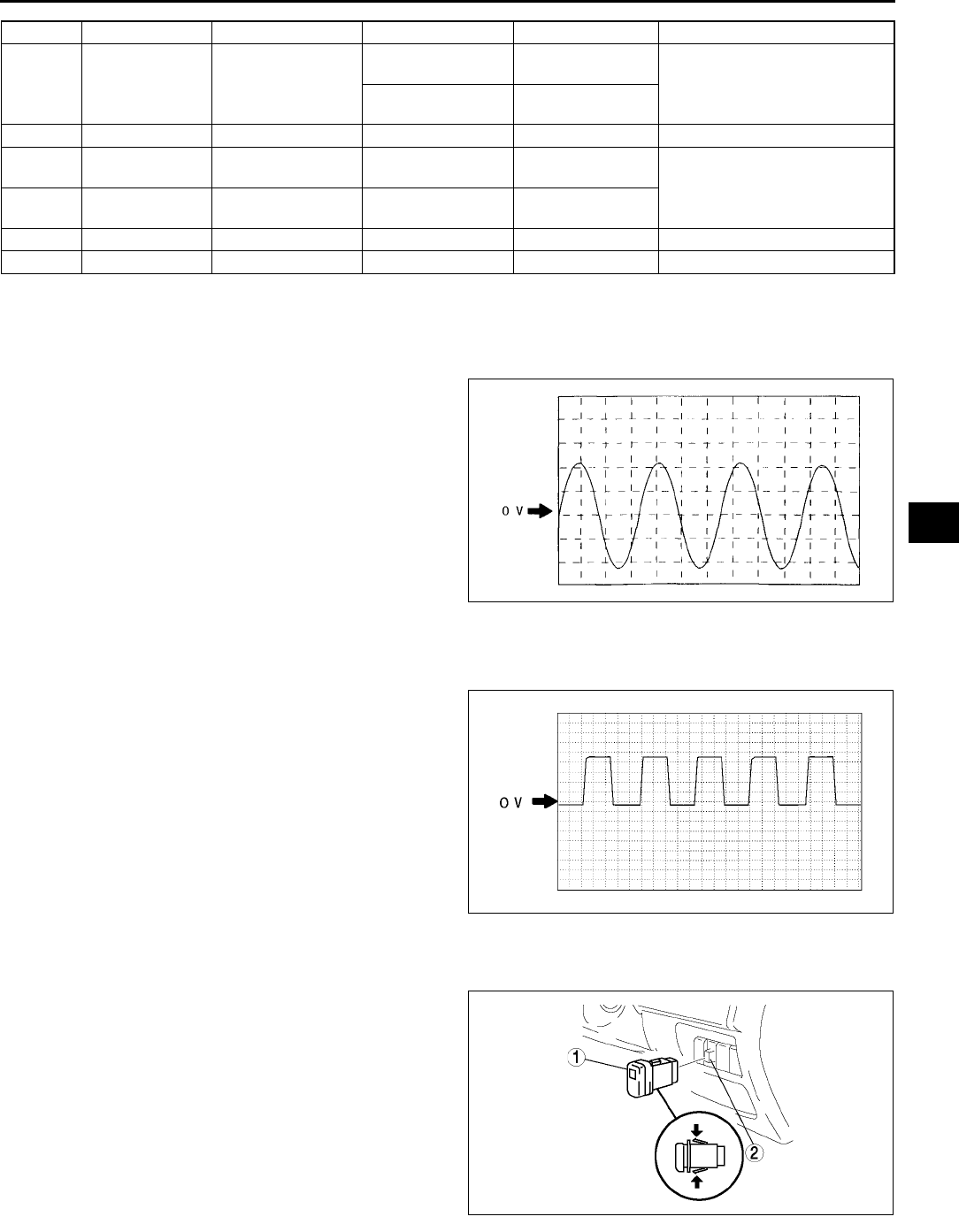
ABS/TCS
P31
P
*1:With TCS
*2: Use this terminal at factory only, not used for inspection and repair at field
Inspection Using An Oscilloscope (Reference)
Wheel speed
•
•ABS/TCS HU/CM terminal:
RR : A ( + ) B ( - )
LR : C ( + ) F ( - )
RF : D ( + ) G ( - )
LF : E ( + ) I ( - )
•Oscilloscope setting:
1 V/DIV (Y), 2 ms/DIV (X), AC range
•Vehicle condition: Driving 30 km/h (18.6 mph)
Note
•As vehicle speed increases, period of wave
shortens.
•If there is malfunctioning in the sensor rotor,
wave profile warps.
Vehicle speed output
•
•ABS/TCS HU/CM terminal: V( + ) AC ( - )
•Oscilloscope setting:
1 V/DIV (Y), 5 ms/DIV (X), DC range
•Vehicle condition: Driving 30 km/h (18.6 mph)
Note
•As vehicle speed increases, period of wave
shortens.
End Of Si e
TCS (DSC) OFF SWITCH REMOVAL/INSTALLATION A6E692167650W02
1. Press the hooks of the TCS OFF switch and pull the switch out.
2. Disconnect the connector.
3. Install in the reverse order of removal.
End Of Si e
Y Brake switch Brake switch
Brake pedal is
depressed 1014
•Inspect related harness
Brake pedal is
released Below 0.5
Z Power supply Ignition switch B+ •Inspect related harness
AA Power supply
(Solenoid valve) Battery B+
•Inspect related harness
AB Power supply
(ABS motor) Battery B+
AC Ground Ground 0 •Inspect related harness
AD Ground Ground 0 •Inspect related harness
Terminal Signal Connected to Test condition Voltage (V) Action
Z3U0413W201
Z3U0413W202
A6E6921W008
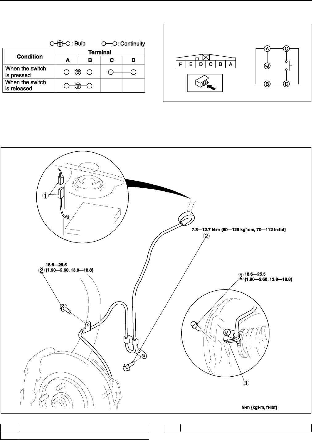
P32
ABS/TCS
TCS (DSC) OFF SWITCH INSPECTION A6E692167650W03
1. Remove the TCS OFF switch.
2. Inspect for continuity between the TCS OFF switch
terminals using an ohmmeter.
•If not within the specification, replace the TCS OFF switch.
End Of Si e
FRONT ABS WHEEL-SPEED SENSOR REMOVAL/INSTALLATION A6E692143720W01
1. Remove the mud guard.
2. Remove in the order indicated in the table.
3. Install in the reverse order of removal..
A6E6921W010
A6E6921W009
A6E6916W001
1 Connector
2Bolt
3 Front ABS wheel-speed sensor
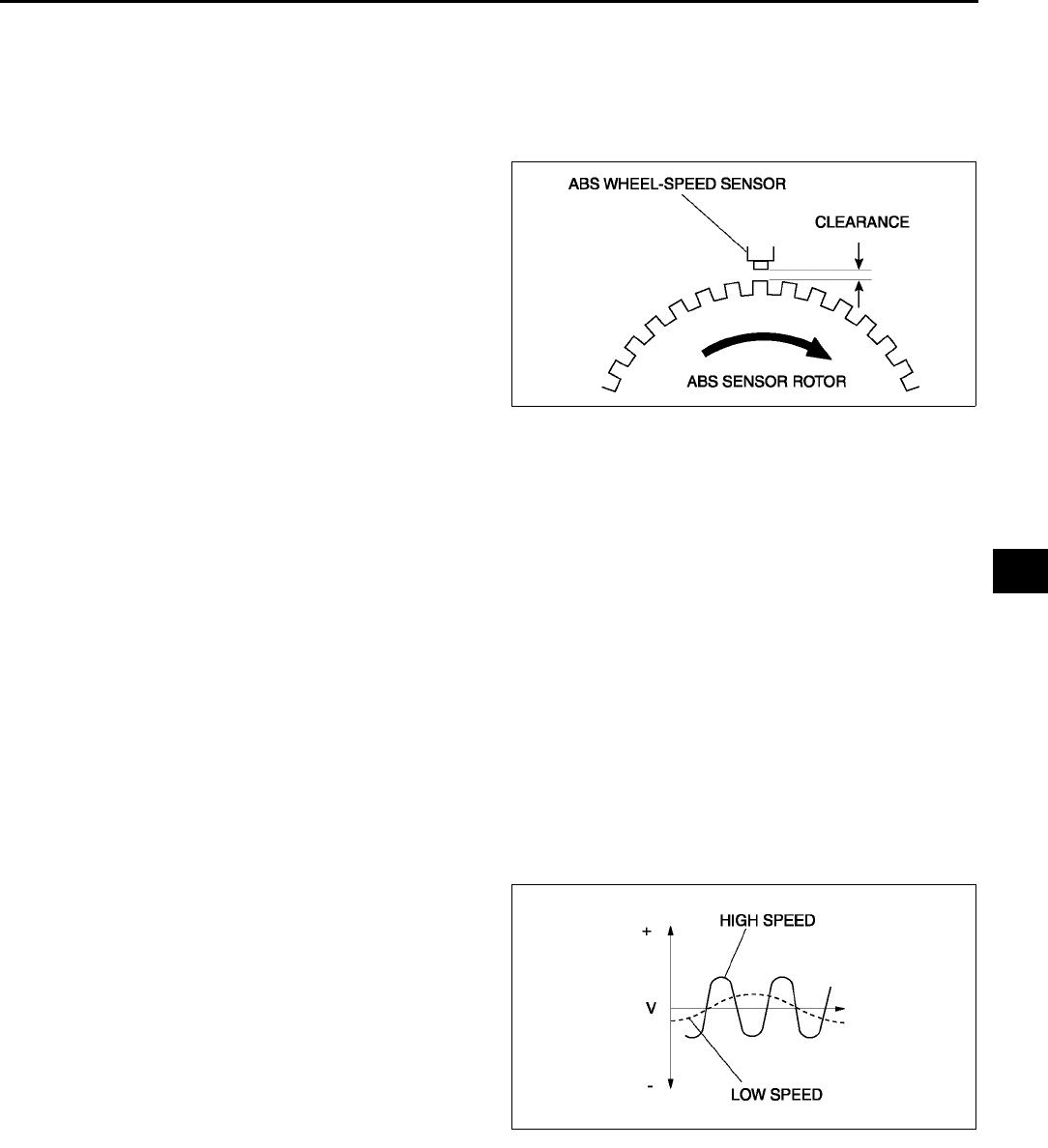
ABS/TCS
P33
P
End Of Si e
FRONT/REAR ABS WHEEL-SPEED SENSOR INSPECTION A6E692143720W02
Visual Inspection
1. Remove the wheel and tire, and inspect the sensor for looseness and damage. Replace the sensor if
necessary.
Clearance Inspection
1. Inspect the clearance between the wheel-speed
sensor and the sensor rotor.
Clearance
0.31.1 mm {0.0120.043 in}
Resistance Inspection
1. Disconnect the ABS wheel-speed sensor connector.
2. Inspect the resistance at the ABS wheel-speed sensor.
•If not as specified, replace the ABS wheel-speed sensor.
Resistance
1.31.7 kilohm
Voltage Inspection
1. On level ground, jack up the vehicle and support it evenly on safety stands.
2. Disconnect the ABS wheel-speed sensor connector.
3. Inspect each sensor by rotating each wheel one revolution per second.
•If not as specified, replace the ABS wheel-speed sensor.
Voltage
0.251.2 V (AC)
Voltage Pattern Inspection
1. On level ground, jack up the vehicle and support it evenly on safety stands.
2. Disconnect the ABS wheel-speed sensor connector.
3. Using an oscilloscope, inspect voltage pattern for
distortion and noise by rotating each wheel.
•If there is distortion or noise, inspect the ABS
sensor rotor.
End Of Si e
A6E6921W003
A6E6921W004
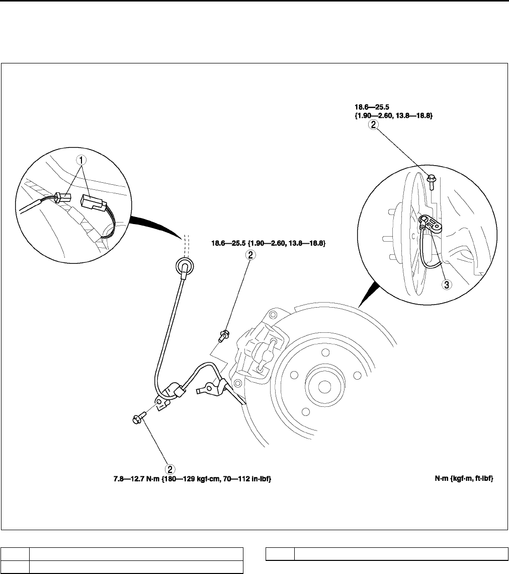
P34
ABS/TCS
REAR ABS WHEEL-SPEED SENSOR REMOVAL/INSTALLATION A6E692143710W01
1. Remove the tire house trim.S91 TIRE HOUSE TRIM REMOVAL/INSTALLATION.)
2. Remove in the order indicated in the table.
3. Install in the reverse order of removal.
.
End Of Si e
A6E6916W002
1 Connector
2Bolt
3 Rear ABS wheel-speed sensor
DYNAMIC STABILITY CONTROL
P35
P
DSC SYSTEM INSPECTION A6E692067650W01
Preparation
1. Verify that the battery is fully charged.
2. With ignition switch on, verify that the ABS warning light goes out after 2.4 seconds.
3. Turn the ignition switch off.
4. On level ground, jack up the vehicle and support it evenly on safety stands.
5. Shift the transaxle to N position.
6. Release the parking brake.
7. Rotate the wheels by hand, and inspect for brake drag.
Operation of DSC Inspection
1. Perform the Preparation.
2. Connect WDS or equivalent to the DLC-2.
3. Set up an active command modes inspection
according to the combination of commands
below.
Note
•When working with two people, one should
press on the brake pedal, the other should
attempt to rotate the wheel being inspected.
Pressure retention
DYNAMIC STABILITY CONTROL
A6E3970W002
Command name Wheels
LF RF LR RR
LF_TC_VLV
OFF
RF_TC_VLV
LF_DSC_V
RF_DSC_V
ABS_POWER ON
LF_INLET ON
OFF
OFF
OFF
LF_OUTLET
OFF
LR_INLET ON
LR_OUTLET
OFF
RF_INLET ON
RF_OUTLET
OFF
RR_INLET ON
RR_OUTLET OFF
PMP_MOTOR
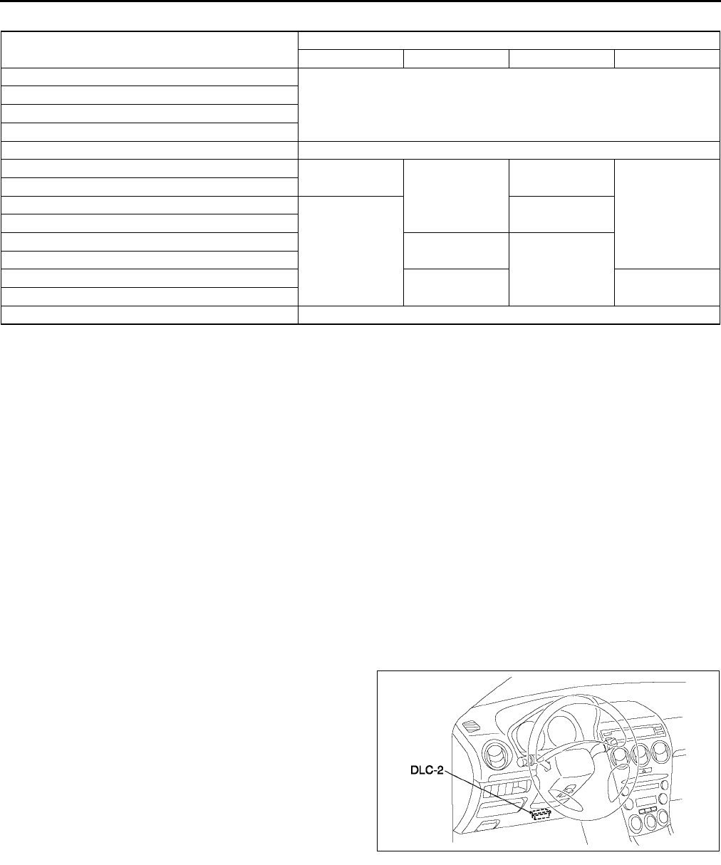
P36
DYNAMIC STABILITY CONTROL
Pressure reduction
Note
•To protect the DSC HU/CM, the solenoid valve used for simulations and the ABS motor stay on for 10
seconds each time they are switched on.
4. Send the command while pressing on the brake pedal and attempting to rotate the wheel being inspected.
5. When pressure is being maintained, and a click sound indicating the solenoid is operating comes from the DSC
HU/CM, confirm that the wheel does not rotate. When pressure is being reduced, and a click sound indicating
the solenoid is operating comes from DSC HU/CM, confirm that the wheel rotates, even though the brake pedal
is being depressed.
•Performing the inspections above determines the following.
The DSC HU/CM brake lines are normal
The DSC HU/CM hydraulic system is not significantly abnormal
The DSC HU/CM wiring is normal
Output system harness in DSC HU/CM (solenoid, relay) are normal
•However, the following items cannot be checked.
The DSC HU/CM input system harness and parts
Extremely small leaks in the DSC HU/CM internal hydraulic system
Unusual intermittent occurrences in the above items
DSC Control Inspection
1. Perform the Preparation.
2. Connect WDS or equivalent to the DLC-2.
3. Set up an active command modes inspection
according to the combination of commands
below.
Command name Wheels
LF RF LR RR
LF_TC_VLV
OFF
RF_TC_VLV
LF_DSC_V
RF_DSC_V
ABS_POWER ON
LF_INLET ON
OFF
OFF
OFF
LF_OUTLET
LR_INLET
OFF
ON
LR_OUTLET
RF_INLET ON
OFF
RF_OUTLET
RR_INLET OFF ON
RR_OUTLET
PMP_MOTOR ON
A6E3970W002
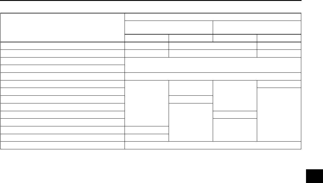
DYNAMIC STABILITY CONTROL
P37
P
Pressure retention
Note
•To protect the DSC HU/CM, the solenoid valve used for simulations and the ABS motor stay on for 10
seconds each time they are switched on.
4. Send the command while attempting to rotate the wheel being inspected.
5. When pressure is being maintained, and a click sound indicating the solenoid is operating comes from the DSC
HU/CM, confirm that the wheel does not rotate.
•Performing the inspections above determines the following.
The DSC HU/CM brake lines are normal
The DSC HU/CM hydraulic system is not significantly abnormal
The DSC HU/CM wiring is normal
Output system harness in DSC HU/CM (solenoid, relay) are normal
•However, the following items cannot be checked.
The DSC HU/CM input system harness and parts
Extremely small leaks in the DSC HU/CM internal hydraulic system
Unusual intermittent occurrences in the above items
End Of Si e
Command name
Wheels
Inhibition of understeer tendency
control
Inhibition of oversteer tendency
control
LF RF LR RR
LF_TC_VLV ON OFF ON
RF_TC_VLV OFF ON OFF
LF_DSC_V OFF
RF_DSC_V
ABS_POWER ON
LF_INLET
OFF
OFF
OFF
ON
LF_OUTLET
OFF
LR_INLET ON
LR_OUTLET
OFF
RF_INLET ON
RF_OUTLET
OFFRR_INLET ON
RR_OUTLET OFF
PMP_MOTOR ON
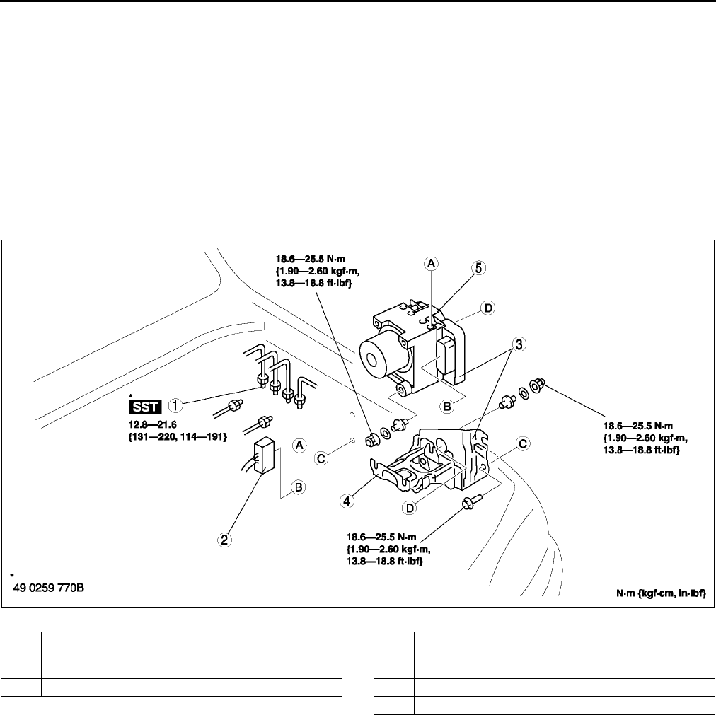
P38
DYNAMIC STABILITY CONTROL
DSC HU/CM REMOVAL/INSTALLATION A6E692067650W03
Caution
•
••
•When replacing the DSC HU/CM, configuration procedure must be done before removing the DSC
HU/CM. If configuration is not completed before removing the DSC HU/CM, DTC B2477 will be
detected.
•
••
•Do not drop the DSC HU/CM. Replace it if it is subjected to an impact.
1. Configurate the DSC HU/CM (when only replacing it).(See P29 ABS (ABS/TCS) or DSC HU/CM
CONFIGURATION.)
2. Remove the battery, battery tray and battery tray bracket.(See G3 BATTERY REMOVAL/INSTALLATION.)
3. Remove the under cover.
4. Remove in the order indicated in the table.
5. Install in the reverse order of removal.
.
A6E6920W001
1 Connector
(See P39 Connector Removal Note)
(See P39 Connector Installation Note)
2Brake pipe
3 DSC HU/CM and Bracket
(See P39 DSC HU/CM and Bracket Removal/
Installation Note)
4Bracket
5 DSC HU/CM
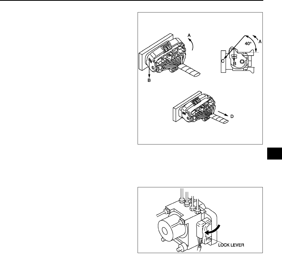
DYNAMIC STABILITY CONTROL
P39
P
Connector Removal Note
1. Rotate the lock lever 40° to the direction A, then
push the lock lever to the direction B.
Caution
•
••
•After rotated the lever 40°
°°
° , do not push
the lock lever to the direction C. The lock
lever will be damaged.
2. Verify that the lock lever is completely returned.
3. Remove the harness side connector to the
direction D.
DSC HU/CM and Bracket Removal/Installation Note
1. When removing/installing the DSC HU/CM from/to the vehicle, attach a strip of tape on the DSC HU/CM
connector to prevent brake fluid from entering.
Connector Installation Note
1. Verify that the connection part and waterproof packing are free of foreign material, then connect the connector.
2. Verify that the lock lever is completely pushed in.
End Of Si e
A6E6920W011
A6E6916W005
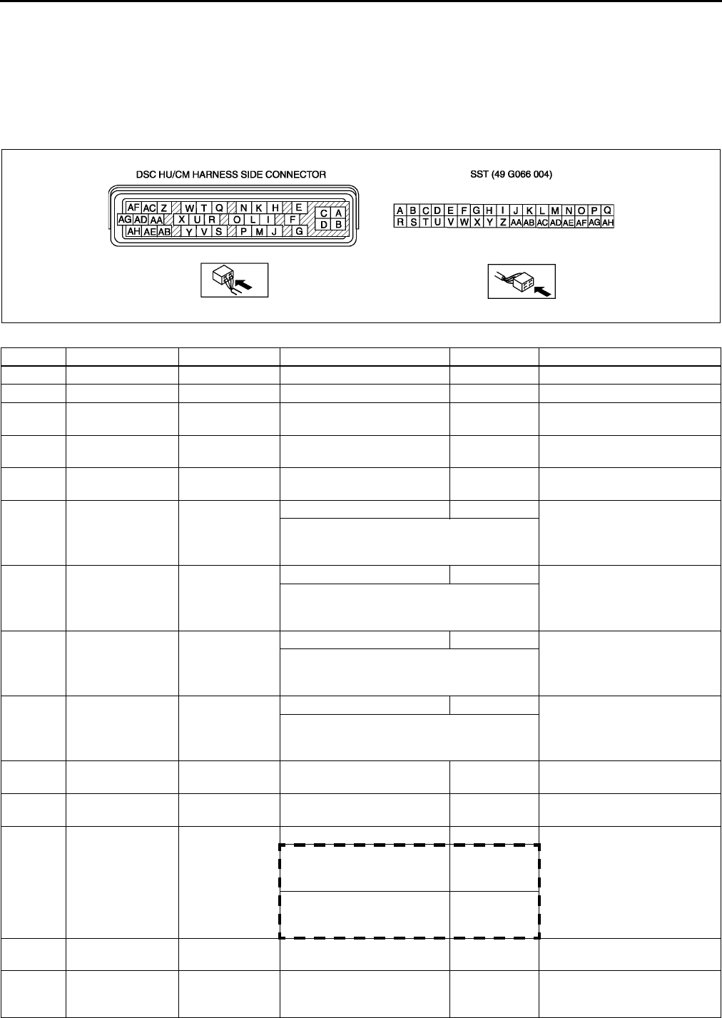
P40
DYNAMIC STABILITY CONTROL
DSC HU/CM INSPECTION A6E692067650W04
1. Remove the battery and battery bracket.
2. Disconnect the DSC HU/CM connector.
3. Connect the SST (49 G066 004) to the DSC HU/CM connector and harness side connector.
4. Inspect voltage referring the table below.
Terminal Voltage Table (reference value)
(Ignition switch is at ON, and connector is connected unless indicated otherwise.)
Terminal Signal Connected to Test condition Voltage (V) Action
A Ground (1) Ground part 1 Below 1.0 •Inspect related harness
B Ground (2) Ground part 2 Below 1.0 •Inspect related harness
CSolenoid valve
(power supply) Battery B+ •Inspect DSC HU/CM
•Inspect related harness
DPump motor
(power supply) Battery B+ •Inspect DSC HU/CM
•Inspect related harness
E*Check
connector No need to
check •Inspect related harness
F
JLF wheel-speed LF wheel-speed
sensor
Vehicle is stopped 0 (AC) •Inspect related harness
•Inspect wheel-speed
sensor
•Inspect using the wave profile.
(See P41 Inspection Using An
Oscilloscope (Reference))
K
HRR wheel-speed RR wheel-
speed sensor
Vehicle is stopped 0 (AC) •Inspect related harness
•Inspect wheel-speed
sensor
•Inspect using the wave profile.
(See P41 Inspection Using An
Oscilloscope (Reference))
M
IRF wheel-speed RF wheel-
speed sensor
Vehicle is stopped 0 (AC) •Inspect related harness
•Inspect wheel-speed
sensor
•Inspect using the wave profile.
(See P41 Inspection Using An
Oscilloscope (Reference))
Q
NLR wheel-speed LR wheel-speed
sensor
Vehicle is stopped 0 (AC) •Inspect related harness
•Inspect wheel-speed
sensor
•Inspect using the wave profile.
(See P41 Inspection Using An
Oscilloscope (Reference))
G Battery (IG) Ignition switch Ignition switch ON B+ •Inspect related harness
•Inspect ignition switch
L Brake switch Brake switch When brake pedal is
depressed 1014 •Inspect related harness
•Inspect brake switch
OLateral-G
(lateral-G signal)
Combine
sensor
Vehicle is stopped 2.12.9
•Inspect related harness
•Inspect combine sensor
Right cornering
Fluctuation
between
2.54.0
Left cornering
Fluctuation
between
2.51.0
PCombine sensor
power output
Combine
sensor Ignition switch ON 4.755.25 •Inspect related harness
•Inspect combine sensor
RSteering angle
(ground)
Steering angle
sensor Below 1.0
•Inspect related harness
•Inspect steering angle
sensor
A6E6920W009
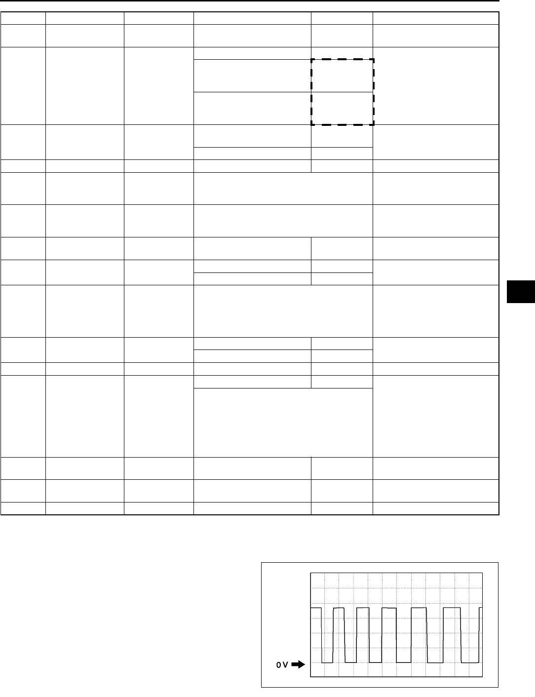
DYNAMIC STABILITY CONTROL
P41
P
*: Used for vehicle manufacturing, not used for DSC.
Inspection Using An Oscilloscope (Reference)
Steering angle (steering angle signal 1 and 2)
•DSC HU/CM terminal:
Steering angle signal 2 : W ( + ) R ( - )
Steering angle signal 1 : X ( + ) R ( - )
•Oscilloscope setting:
1 V/DIV (Y), 25 ms/DIV (X), DC range
•Vehicle condition: Rotating steering wheel at one
revolution per second
Note
•As steering wheel rotation speed increases,
period of wave shortens.
•As for shape of steering angle signals 1 and
2, the phase is different.
S Combine sensor Combine
sensor 3.55.0 •Inspect related harness
•Inspect combine sensor
TYaw rate
(yaw rate signal)
Combine
sensor
Vehicle is stopped 2.32.7
•Inspect related harness
•Inspect yaw rate sensor
Right cornering
Fluctuation
between
2.54.62
Left cornering
Fluctuation
between
2.50.33
USteering angle
(neutral signal)
Steering angle
sensor
Steering position:
center position 25°29°Below 1.0 •Inspect related harness
•Inspect steering angle
sensor
Except above condition Approx. 4
V
W
Steering angle
(steering angle
signal 2)
Steering angle
sensor
•Inspect using the wave profile.
(See P41 Inspection Using An
Oscilloscope (Reference))
•Inspect related harness
•Inspect steering angle
sensor
X
Steering angle
(steering angle
signal 1)
Steering angle
sensor
•Inspect using the wave profile.
(See P41 Inspection Using An
Oscilloscope (Reference))
•Inspect related harness
•Inspect steering angle
sensor
YCombine sensor
(ground)
Combine
sensor Below 1.0 •Inspect related harness
•Inspect combine sensor
AA DSC OFF switch DSC OFF
switch
When switch is pressed Below 1.0 •Inspect related harness
•Inspect DSC OFF switch
When switch is not pressed B+
AB OBD KLN terminal of
DLC-2
It cannot be determined with terminal
voltage whether the condition is good or bad
because advanced function diagnostic
output is performed with serial
communication. Inspect with service codes.
•Inspect related harness
•Inspect DSC HU/CM
AC Auto cruise set
signal output Auto cruise unit When auto cruise is ON Below 1.0 •Inspect related harness
•Inspect DSC HU/CM
When auto cruise is OFF B+
AD
AE Vehicle speed
output
Audio unit,
Wiper and
washer switch,
Car-navegation
unit, Auto
leveling control
unit, Cruise
actuator
Vehicle is stopped 0
•Inspect related harness
•Inspect front wheel-speed
sensor
•Inspect using the wave profile.
(See P41 Inspection Using An
Oscilloscope (Reference))
AF CAN-L No need to
check
AG CAN-H No need to
check
AH
Terminal Signal Connected to Test condition Voltage (V) Action
A6E6921W014
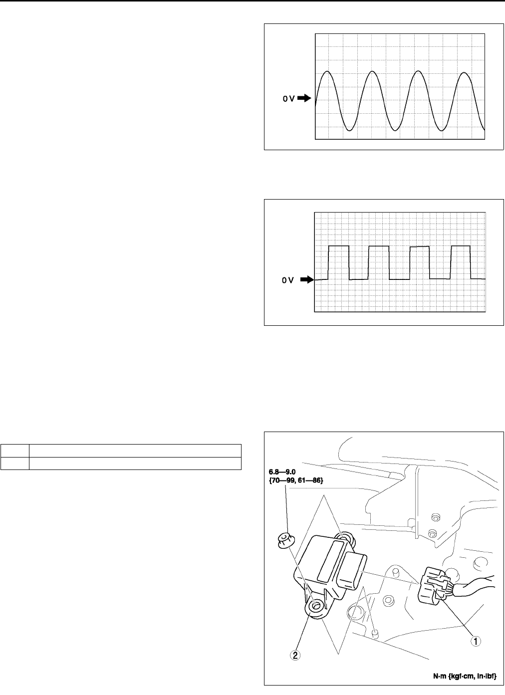
P42
DYNAMIC STABILITY CONTROL
Wheel speed
•DSC HU/CM terminal:
RF : M ( + ) I ( - )
RR : K ( + ) H ( - )
LF : F ( + ) J ( - )
LR : Q ( + ) N ( - )
•Oscilloscope setting:
1 V/DIV (Y), 2 ms/DIV (X), AC range
•Vehicle condition: Driving 30 km/h (18.6 mph)
Note
•As vehicle speed increases, period of wave
shortens.
•If there is malfunctioning in the sensor rotor,
wave profile warps.
Vehicle speed output
•DSC HU/CM terminal: AE ( + ) A( - )
•Oscilloscope setting:
1 V/DIV (Y), 5 ms/DIV (X), DC range
•Vehicle condition: Driving 30 km/h (18.6 mph)
Note
•As vehicle speed increases, period of wave
shortens.
End Of Si e
COMBINE SENSOR REMOVAL/INSTALLATION A6E692067650W05
Caution
•
••
•Be careful and do not allow the combine sensor to fall. If by chance it is subjected to strong
impact, replace it.
1. Remove the center console.
2. Remove in the order indicated in the table.
3. Install in the reverse order of removal.
4. After installation, perform the combine sensor
initialization procedure. (See P44 COMBINE
SENSOR INITIALIZATION PROCEDURE.)
End Of Si e
A6E6921W013
A6E6921W012
1 Combine sensor connector
2 Combine sensor
A6E6920W004
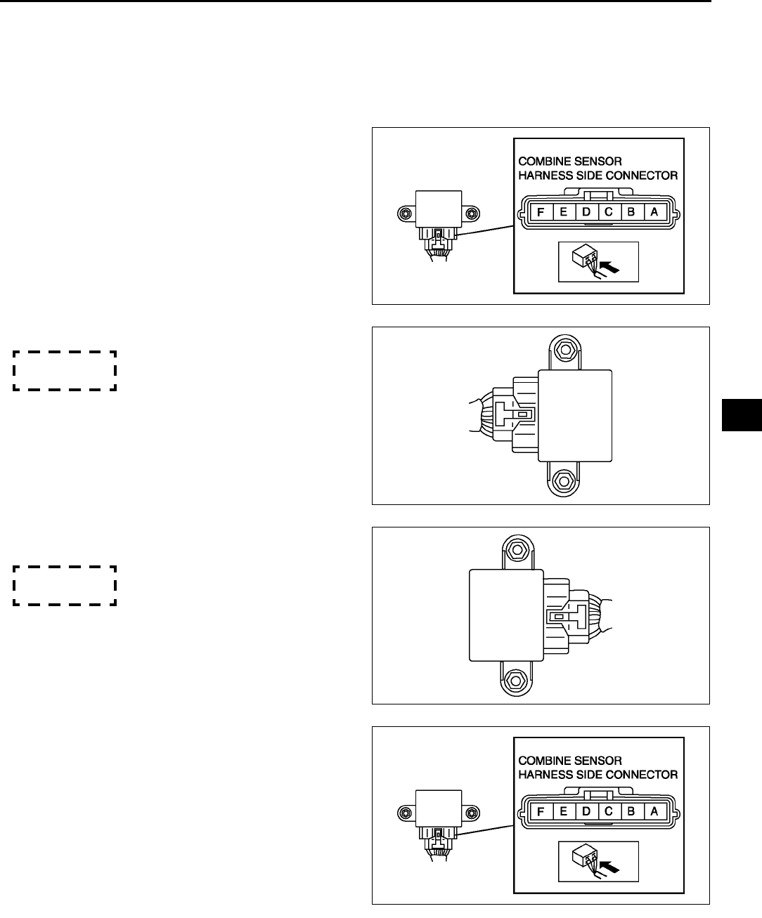
DYNAMIC STABILITY CONTROL
P43
P
COMBINE SENSOR INSPECTION A6E692067650W06
Caution
•
••
•Be careful and do not allow the lateral-G sensor to fall. If by chance it is subjected to strong
impact, replace it.
1. Connect the connector.
2. Turn ignition switch on, verify the voltage between
terminals B and E under the following conditions.
•If not within the specification, replace the
lateral-G sensor.
(1) Lateral-G
1) Horizontal
Voltage
2.42.6 V
2) Facing up (inclined 90° from horizontal)
Voltage
3.33.7 V
3) Facing down (declined 90° from
horizontal)
Voltage
1.31.7 V
(2) Yaw rate
1) Measure yaw rate sensor voltage under
static condition.
A6E6920W008
A6E6920W002
A6E6920W003
A6E6920W008
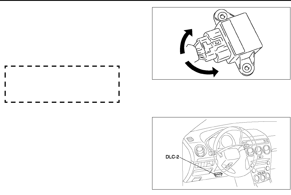
P44
DYNAMIC STABILITY CONTROL
2) Measure voltage at output terminal D and
ground terminal E when the yaw rate
sensor is rotated left and right.
Caution
•
••
•Be careful when turning the yaw rate
sensor rotation position while it is in a
reversed state because the rotation
direction and voltage will be reversed.
Voltage
Right rotation:
fluctuation between 2.54.62 V
Left rotation:
fluctuation between 2.50.33 V
End Of Si e
COMBINE SENSOR INITIALIZATION PROCEDURE A6E692067650W07
1. Set the SST (WDS or equivalent) to the DLC-2
2. Access the active command mode and select the
YAWRATE, then follow the indication on the
monitor.
3. Select the LATACCEL and follow the indication
on the monitor.
End Of Si e
STEERING ANGLE SENSOR REMOVAL/INSTALLATION A6E692067650W08
1. (See T38 COMBINATION SWITCH DISASSEMBLY/ASSEMBLY.)
End Of Si e
STEERING ANGLE SENSOR INSPECTION A6E692067650W09
1. (See T39 STEERING ANGLE SENSOR INSPECTION.)
End Of Si e
DSC OFF SWITCH REMOVAL/INSTALLATION A6E692067650W10
1. (See P31 TCS (DSC) OFF SWITCH REMOVAL/INSTALLATION.)
End Of Si e
DSC OFF SWITCH INSPECTION A6E692067650W11
1. (See P32 TCS (DSC) OFF SWITCH INSPECTION.)
End Of Si e
A6E6920W005
A6E3970W002
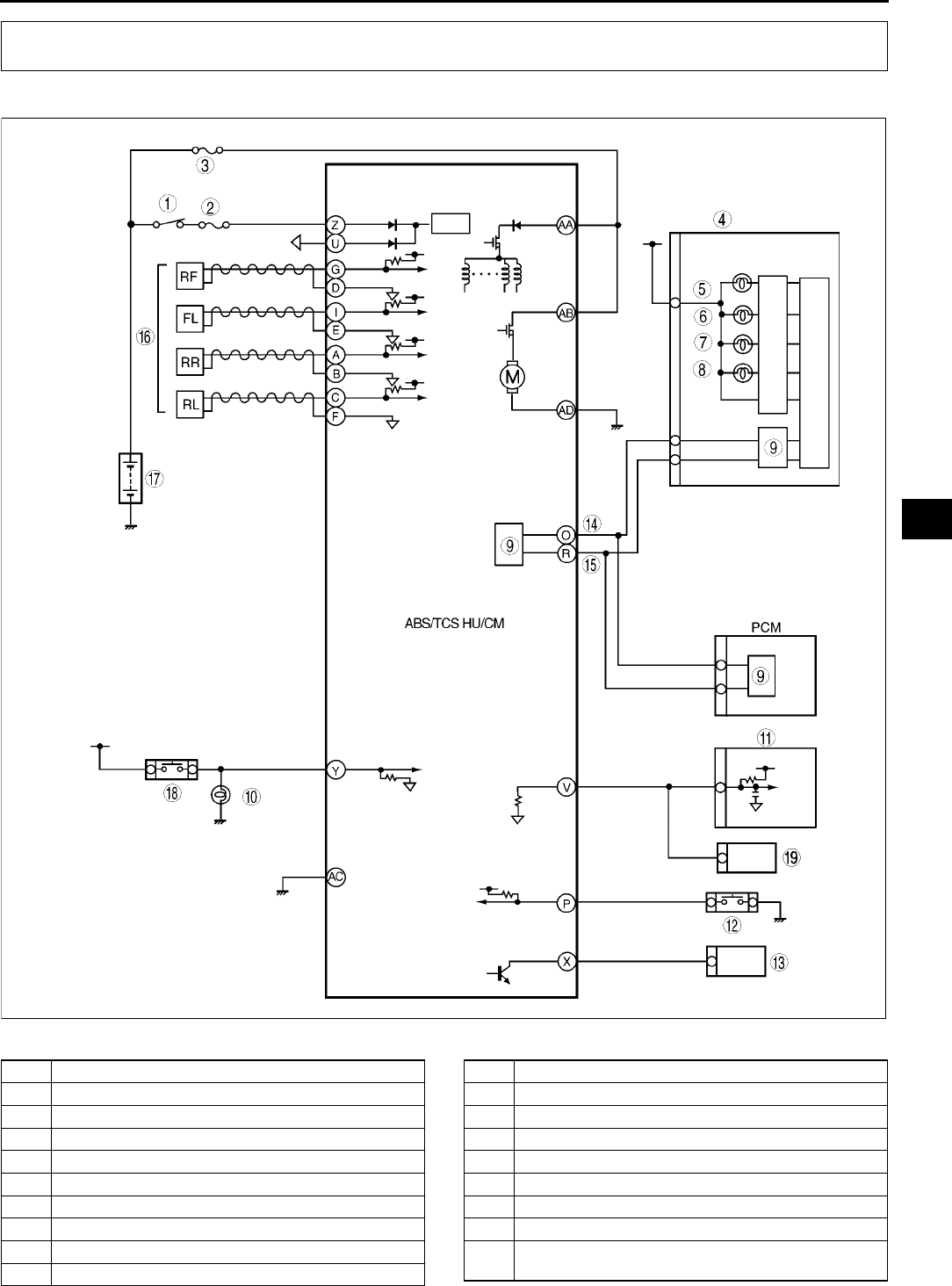
ON-BOARD DIAGNOSTIC (ABS/TCS)
P45
P
ABS (ABS/TCS) SYSTEM WIRING DIAGRAM A6E697567650W01
.
ON-BOARD DIAGNOSTIC (ABS/TCS)
A6E6921T001
1 IG switch
2 SUS 15 A fuse
3 ABS 60 A fuse
4 Meter
5 ABS warning light
6 Brake system warning light
7 TCS OFF light
8 TCS indicator light
9CAN driver
10 Brake light
11 Cruise actuator
12 TCS OFF switch
13 DLC-2
14 CAN-H
15 CAN-L
16 ABS Wheel-speed sensor
17 Battery
18 Brake switch
19 Audio unit, Wiper and washer switch, Car-navigation
unit, Auto leveling control unit
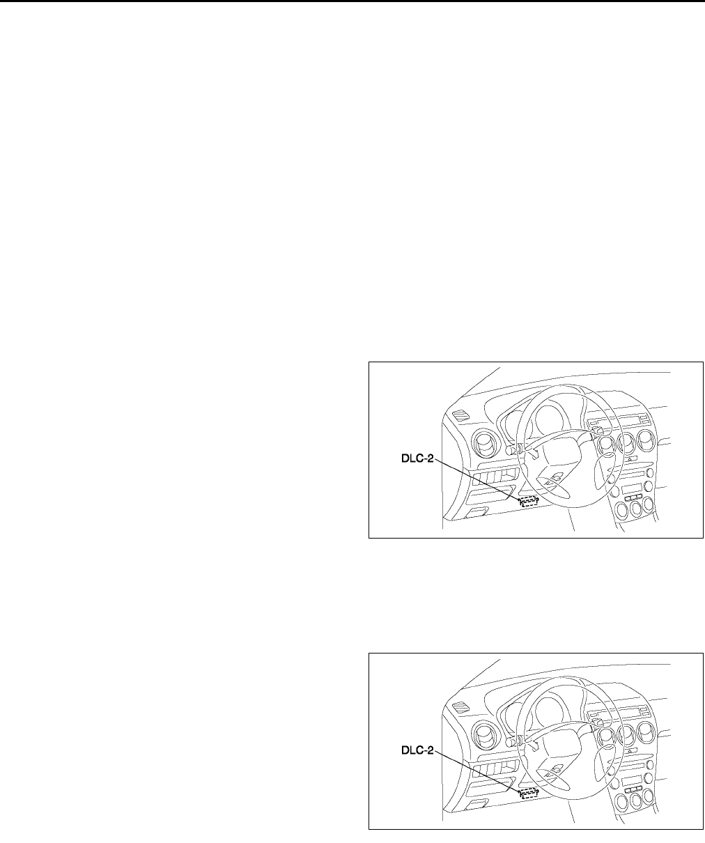
P46
ON-BOARD DIAGNOSTIC (ABS/TCS)
End Of Si e
ABS (ABS/TCS) ON-BOARD DIAGNOSIS A6E697567650W02
On-Board Diagnostic (OBD) Test Description
•The OBD test inspects the integrity and function of the ABS (ABS/TCS) and outputs the results when
requested by the specific tests.
•On-board diagnostic test also:
Provides a quick inspection of the ABS (ABS/TCS) usually performed at the start of each diagnostic
procedure.
Provides verification after repairs to ensure that no other faults occurred during service.
•The OBD test is divided into 3 tests:
Read/clear diagnostic results, PID monitor and record and active command modes.
Read/clear diagnostic results
•This function allows you to read or clear DTCs in the ABS (ABS/TCS) HU/CM memory.
PID/data monitor and record
•This function allows you to access certain data values, input signals, calculated values, and system status
information.
Active command modes
•This function allows you to control devices through the WDS or equivalent.
Reading DTCs Procedure
1. Connect WDS or equivalent to the vehicle DLC-2
16-pin connector.
2. Retrieve DTC by WDS or equivalent.
Clearing DTCs Procedures
1. After repairs have been made, perform the DTCs reading procedure.
2. Erase DTC by WDS or equivalent.
3. Ensure that the customers concern has been resolved.
PID/Data Monitor and Record Procedure
1. Connect WDS or equivalent to the vehicle DLC-2
16-pin connector.
2. Access and monitor PIDs by WDS or equivalent.
A6E3970W002
A6E3970W002
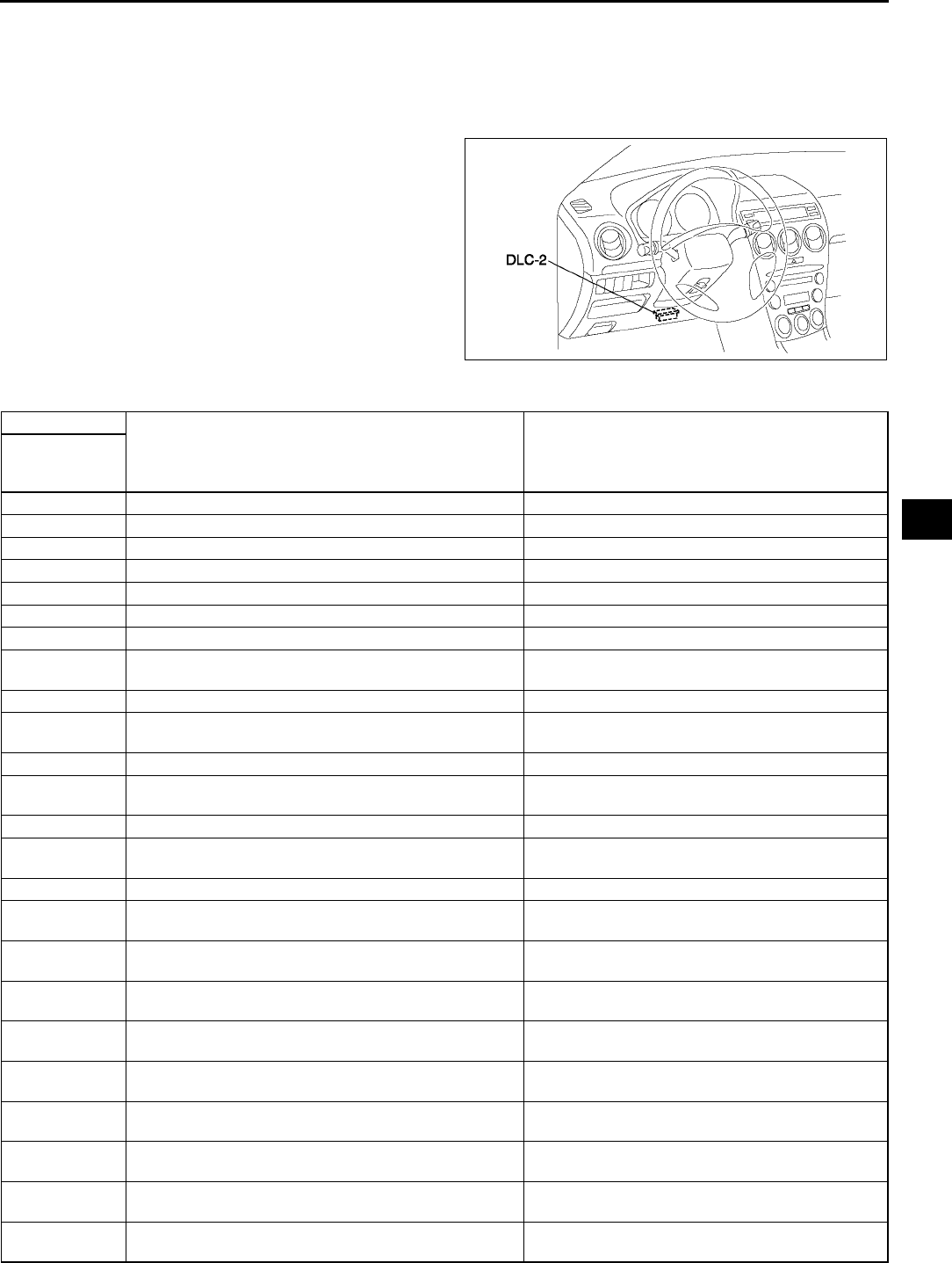
ON-BOARD DIAGNOSTIC (ABS/TCS)
P47
P
Active Command Modes Procedure
Note
•When driving, the ABS motor and each valve forcibly turn ABS_VOLT on, and then each command on.
ABS_VOLT regulates the power supply for the ABS motor and 8 valves.
1. Connect WDS or equivalent to the vehicle DLC-2
16-pin connector.
2. Turn the ignition switch to ON (Engine OFF) or
start engine.
3. Activate active command modes using WDS or
equivalent.
DTC Table
A6E3970W002
DTC
Diagnosis system component Page
WDS or
equiva-
lent
B1318 ABS (ABS/TCS) power supply (See P50 DTC B1318)
B1342 ABS (ABS/TCS) HU/CM (See P52 DTC B1342)
C1095 Motor relay, pump motor (See P52 DTC C1095, C1096)
C1096 Motor relay, pump motor (See P52 DTC C1095, C1096)
C1119 Engine control system (See P54 DTC C1119)
C1140 ABS (ABS/TCS) HU/CM (pump) (See P55 DTC C1140)
C1145 Right front wheel-speed sensor (See P56 DTC C1145, C1155, C1165, C1175)
C1148 Right front wheel-speed sensor/sensor rotor (See P59 DTC C1148, C1158, C1168, C1178,
C1233, C1234, C1235, C1236)
C1155 Left front wheel-speed sensor (See P56 DTC C1145, C1155, C1165, C1175)
C1158 Left front wheel-speed sensor/sensor rotor (See P59 DTC C1148, C1158, C1168, C1178,
C1233, C1234, C1235, C1236)
C1165 Right rear wheel-speed sensor (See P56 DTC C1145, C1155, C1165, C1175)
C1168 Right rear wheel-speed sensor/sensor rotor (See P59 DTC C1148, C1158, C1168, C1178,
C1233, C1234, C1235, C1236)
C1175 Left rear wheel-speed sensor (See P56 DTC C1145, C1155, C1165, C1175)
C1178 Left rear wheel-speed sensor/sensor rotor (See P59 DTC C1148, C1158, C1168, C1178,
C1233, C1234, C1235, C1236)
C1186 Fail-safe relay (See P62 DTC C1186, C1266)
C1194 Left front pressure reduction solenoid valve (See P63 DTC C1194, C1198, C1210, C1214,
C1242, C1246, C1250, C1254)
C1198 Left front pressure retention solenoid valve (See P63 DTC C1194, C1198, C1210, C1214,
C1242, C1246, C1250, C1254)
C1210 Right front pressure reduction solenoid valve (See P63 DTC C1194, C1198, C1210, C1214,
C1242, C1246, C1250, C1254)
C1214 Right front pressure retention solenoid valve (See P63 DTC C1194, C1198, C1210, C1214,
C1242, C1246, C1250, C1254)
C1233 Left front wheel-speed sensor/sensor rotor (See P59 DTC C1148, C1158, C1168, C1178,
C1233, C1234, C1235, C1236)
C1234 Right front wheel-speed sensor/sensor rotor (See P59 DTC C1148, C1158, C1168, C1178,
C1233, C1234, C1235, C1236)
C1235 Right rear wheel-speed sensor/sensor rotor (See P59 DTC C1148, C1158, C1168, C1178,
C1233, C1234, C1235, C1236)
C1236 Left rear wheel-speed sensor/sensor rotor (See P59 DTC C1148, C1158, C1168, C1178,
C1233, C1234, C1235, C1236)
C1242 Left rear pressure reduction solenoid valve (See P63 DTC C1194, C1198, C1210, C1214,
C1242, C1246, C1250, C1254)

P48
ON-BOARD DIAGNOSTIC (ABS/TCS)
PID/DATA Monitor Table
C1246 Right rear pressure reduction solenoid valve (See P63 DTC C1194, C1198, C1210, C1214,
C1242, C1246, C1250, C1254)
C1250 Left rear pressure retention solenoid valve (See P63 DTC C1194, C1198, C1210, C1214,
C1242, C1246, C1250, C1254)
C1254 Right rear ABS pressure retention solenoid valve (See P63 DTC C1194, C1198, C1210, C1214,
C1242, C1246, C1250, C1254)
C1266 Fail-safe relay (See P63 DTC C1194, C1198, C1210, C1214,
C1242, C1246, C1250, C1254 )
C1414 ABS (ABS/TCS) HU/CM (See P64 DTC C1414 )
C1508 ABS/TCS HU/CM (See P64 DTC C1508 )
C1510 Right front solenoid valve, motor or wheel-speed
sensor/sensor rotor
(See P64 DTC C1510, C1511, C1512, C1513 )
C1511 Left front solenoid valve, motor or wheel-speed sensor/
sensor rotor
(See P64 DTC C1510, C1511, C1512, C1513 )
C1512 Right rear solenoid valve, motor or wheel-speed
sensor/sensor rotor
(See P64 DTC C1510, C1511, C1512, C1513 )
C1513 Left rear solenoid valve, motor or wheel-speed sensor/
sensor rotor
(See P64 DTC C1510, C1511, C1512, C1513 )
U1900 Can communication (See T144 DTC U0073, U1900, U2516 )
U2021 Invalid/fault data received (See P65 DTC U2021 )
U2516 Can communication (See T144 DTC U0073, U1900, U2516 )
PID Name
(Definition) Unit/Condition Condition/Specification Action
ABS (ABS/
TCS) HU/CM/
CM terminal
RPM
(Engine speed signal
input)
RPM
•Engine is stopped: 0 RPM
•Engine is running:
Indicates engine speed
Inspect PCM.
CCNTABS
(Number of continuous
codes)
DTC is detected: 1255
DTC is not detected: 0
Perform inspection using
appropriate DTC.
PMPSTAT
(Pump motor output state) ON/OFF
•Pump motor is activated:
ON
•Pump motor is
deactivated: OFF
Inspect ABS (ABS/TCS)
HU/CM.
(See P27 ABS (ABS/TCS)
HU/CM SYSTEM
INSPECTION )
BOO_ABS
(Brake pedal switch input) ON/OFF
•Brake pedal is depressed:
ON
•Brake pedal is released:
OFF
Inspect brake switch.
Y
ABS_LAMP
(ABS warning light driver
output state)
ON/OFF
•ABS warning light is
illuminated: ON
•ABS warning light is not
illuminated: OFF
Inspect ABS warning light.
BRAKE_LMP
(BRAKE system warning
light output state)
ON/OFF
•BRAKE system warning
light is illuminated: ON
•BRAKE system warning
light is not illuminated:
OFF
Inspect BRAKE system
warning light.
ABSRR_O
(Right rear ABS pressure
reduction solenoid valve
output state)
ON/OFF
•During ABS control: ON/
OFF
(solenoid valve is
activated/deactivated)
•Not ABS control: OFF
(solenoid valve is
deactivated)
Internal fault of ABS (ABS/
TCS) HU/CM. Replace ABS
(ABS/TCS) HU/CM.
(See P28 ABS (ABS/TCS)
HU/CM REMOVAL/
INSTALLATION)
DTC
Diagnosis system component Page
WDS or
equiva-
lent

ON-BOARD DIAGNOSTIC (ABS/TCS)
P49
P
ABSLR_O
(Left rear ABS pressure
reduction solenoid valve
output state)
ON/OFF
•During ABS or EBD
control: ON/OFF
(solenoid valve is
activated/deactivated)
•Not ABS and EBD control:
OFF
(solenoid valve is
deactivated)
Internal fault of ABS (ABS/
TCS) HU/CM. Replace ABS
(ABS/TCS) HU/CM.
(See P28 ABS (ABS/TCS)
HU/CM REMOVAL/
INSTALLATION)
ABSRF_O
(Right front ABS pressure
reduction solenoid valve
output state)
ON/OFF
•During ABS control: ON/
OFF
(solenoid valve is
activated/deactivated)
•Not ABS control: OFF
(solenoid valve is
deactivated)
Internal fault of ABS (ABS/
TCS) HU/CM. Replace ABS
(ABS/TCS) HU/CM.
(See P28 ABS (ABS/TCS)
HU/CM REMOVAL/
INSTALLATION)
ABSLF_O
(Left front ABS pressure
reduction solenoid valve
output state)
ON/OFF
•During ABS control: ON/
OFF
(solenoid valve is
activated/deactivated)
•Not ABS control: OFF
(solenoid valve is
deactivated)
Internal fault of ABS (ABS/
TCS) HU/CM. Replace ABS
(ABS/TCS) HU/CM.
(See P28 ABS (ABS/TCS)
HU/CM REMOVAL/
INSTALLATION)
ABSRR_I
(Right rear ABS pressure
reduction solenoid valve
output state)
ON/OFF
•During ABS control: ON/
OFF
(solenoid valve is
activated/deactivated)
•Not ABS control: OFF
(solenoid valve is
deactivated)
Internal fault of ABS (ABS/
TCS) HU/CM. Replace ABS
(ABS/TCS) HU/CM.
(See P28 ABS (ABS/TCS)
HU/CM REMOVAL/
INSTALLATION)
ABSLR_I
(Left rear ABS pressure
retention solenoid valve
output state)
ON/OFF
•During ABS or EBD
control: ON/OFF
(solenoid valve is
activated/deactivated)
•Not ABS and EBD control:
OFF
(solenoid valve is
deactivated)
Internal fault of ABS (ABS/
TCS) HU/CM. Replace ABS
(ABS/TCS) HU/CM.
(See P28 ABS (ABS/TCS)
HU/CM REMOVAL/
INSTALLATION)
ABSRF_I
(Right front ABS pressure
retention solenoid valve
output state)
ON/OFF
•During ABS control: ON/
OFF
(solenoid valve is
activated/deactivated)
•Not ABS control: OFF
(solenoid valve is
deactivated)
Internal fault of ABS (ABS/
TCS) HU/CM. Replace ABS
(ABS/TCS) HU/CM.
(See P28 ABS (ABS/TCS)
HU/CM REMOVAL/
INSTALLATION)
ABSLF_I
(Left front ABS pressure
retention solenoid valve
output state)
ON/OFF
•During ABS control: ON/
OFF
(solenoid valve is
activated/deactivated)
•Not ABS control: OFF
(solenoid valve is
deactivated)
Internal fault of ABS (ABS/
TCS) HU/CM. Replace ABS
(ABS/TCS) HU/CM.
(See P28 ABS (ABS/TCS)
HU/CM REMOVAL/
INSTALLATION)
ABSVLVRLY
(Fail-safe relay output
state)
ON/OFF
•Fail-safe relay is
activated: ON
•Fail-safe relay is
deactivated: OFF
Inspect ABS (ABS/TCS)
HU/CM.
(See P29 ABS (ABS/TCS)
HU/CM INSPECTION )
ABSPMPRLY
(Motor relay output state) ON/OFF
•Motor relay is activated:
ON
•Motor relay is deactivated:
OFF
Inspect ABS (ABS/TCS)
HU/CM.
(See P29 ABS (ABS/TCS)
HU/CM INSPECTION )
LF_WSPD
(Left front wheel-speed
sensor input)
KPH or MPH
•Vehicle is stopped: 0 KPH
{0 MPH}
•Vehicle is driving:
Indicates vehicle speed
Inspect wheel-speed
sensor/sensor rotor. E, I
PID Name
(Definition) Unit/Condition Condition/Specification Action
ABS (ABS/
TCS) HU/CM/
CM terminal

P50
ON-BOARD DIAGNOSTIC (ABS/TCS)
Acrive Command Mode
End Of Si e
DTC B1318 A6E697567650W03
Caution
•
••
•When attaching the tester lead to the ABS (ABS/TCS) HU/CM harness connector, the SST (49 G066
001) must be used. (See P29 ABS (ABS/TCS) HU/CM INSPECTION.)
RF_WSPD
(Right front wheel-speed
sensor input)
KPH or MPH
•Vehicle is stopped: 0 KPH
{0 MPH}
•Vehicle is driving:
Indicates vehicle speed
Inspect wheel-speed
sensor/sensor rotor. D, G
LR_WSPD
(Left rear wheel-speed
sensor input)
KPH or MPH
•Vehicle is stopped: 0 KPH
{0 MPH}
•Vehicle is driving:
Indicates vehicle speed
Inspect wheel-speed
sensor/sensor rotor. C, F
RR_WSPD
(Right rear wheel-speed
sensor input)
KPH or MPH
•Vehicle is stopped: 0 KPH
{0 MPH}
•Vehicle is driving:
Indicates vehicle speed
Inspect wheel-speed
sensor/sensor rotor. A, B
ABS_VOLT
(System battery voltage
value)
V•Ignition key at ON: B+
•Idle: Approx. 1416 V
Inspect power supply circuit.
(See P29 ABS (ABS/TCS)
HU/CM INSPECTION )
Z
Command Name Definition Operation Note
ABS_POWER Fail-safe relay ON/OFF
Ignition key at ON
(Engine OFF), and
driving
LR_OUTLET Left rear ABS pressure reduction solenoid valve ON/OFF
LR_INLET Left rear ABS pressure retention solenoid valve ON/OFF
RR_INLET Right rear ABS pressure retention solenoid valve ON/OFF
RR_OUTLET Right rear ABS pressure reduction solenoid valve ON/OFF
LF_INLET Left front ABS pressure retention solenoid valve ON/OFF
LF_OUTLET Left front ABS pressure reduction solenoid valve ON/OFF
RF_INLET Right front ABS pressure retention solenoid valve ON/OFF
RF_OUTLET Right front ABS pressure reduction solenoid valve ON/OFF
PMP_MOTOR ABS motor ON/OFF
VS_OUTPUT Vehicle speed signal output SPEED
PID Name
(Definition) Unit/Condition Condition/Specification Action
ABS (ABS/
TCS) HU/CM/
CM terminal
DTC B1318 ABS (ABS/TCS) power supply
DETECTION
CONDITION •Low voltage is detected at the voltage monitor of solenoid valve monitor, or the motor monitor.
POSSIBLE
CAUSE
•Malfunction of fuse (SUS 15 A)
•Open or short to power circuit in harness between DSC HU/CM terminal G and battery positive terminal
•Open circuit in harness between body ground and ABS (ABS/TCS) HU/CM terminal A
•Battery and/or generator malfunction
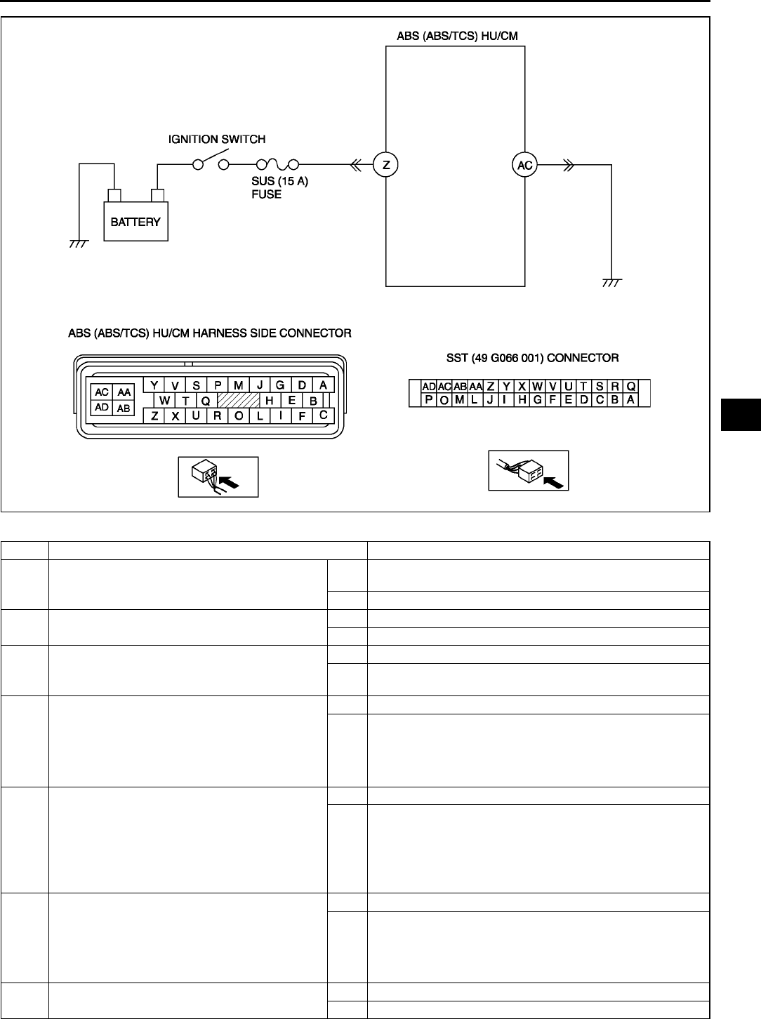
ON-BOARD DIAGNOSTIC (ABS/TCS)
P51
P
Diagnostic procedure
STEP INSPECTION ACTION
1INSPECT BATTERY VOLTAGE
•Is battery terminal voltage okay?
Yes Make sure that battery terminal connection is okay.
Go to next step.
No Charge or replace battery, then go to Step 6.
2INSPECT BATTERY GRAVITY
•Is battery specific gravity as specified?
Yes Go to next step.
No Replace battery, then go to Step 6.
3INSPECT CHARGING SYSTEM
•Are generator and drive belt tension okay?
Yes Go to next step.
No Adjust drive belt tension as necessary.
Replace generator and/or drive belt as necessary.
4INSPECT ABS (ABS/TCS) HU/CM POWER
SUPPLY CIRCUIT FOR OPEN CIRCUIT
•Start engine.
•Measure voltage between ABS (ABS/TCS)
HU/CM terminal Z and ground.
•Is voltage above 10 V?
Yes Go to next step.
No Go to Step 6.
5INSPECT ABS (ABS/TCS) HU/CM GROUND
CIRCUIT FOR POOR GROUND OR OPEN
CIRCUIT
•Turn ignition key to OFF.
•Measure resistance between ground and
DSC HU/CM terminal AC.
•Is resistance within 01 ohm?
Yes Go to next step.
No If there is no continuity:
•Repair or replace harness for open circuit between ABS
(ABS/TCS) HU/CM and ground, then go to next step.
If resistance is not within 01 ohm:
•Repair or replace harness for poor ground then go to
next step.
6VERIFY TROUBLESHOOTING COMPLETED
•Make sure to reconnect all disconnected
connectors.
•Clear DTC from memory.
(See P46 Clearing DTCs Procedures)
•Is same DTC present?
Yes Replace ABS (ABS/TCS) HU/CM, then go to next step.
No Go to next step.
7VERIFY AFTER REPAIR PROCEDURE
•Is there any other DTC present?
Yes Go to applicable DTC inspection.
No Troubleshooting completed.
P52
ON-BOARD DIAGNOSTIC (ABS/TCS)
End Of Si e
DTC B1342 A6E697567650W04
Caution
•
••
•When attaching the tester lead to the ABS (ABS/TCS) HU/CM harness connector, the SST (49 G066
001) must be used. (See P29 ABS (ABS/TCS) HU/CM INSPECTION.)
Diagnostic procedure
End Of Si e
DTC C1095, C1096 A6E697567650W06
Caution
•
••
•When attaching the tester lead to the ABS (ABS/TCS) HU/CM harnesses connector the SST (49
G066 001) must be used. (See P29 ABS (ABS/TCS) HU/CM INSPECTION.)
DTC B1342 ABS (ABS/TCS) HU/CM
DETECTION
CONDITION The on-board diagnostic function detects control module malfunction.
POSSIBLE
CAUSE •Malfunction of ABS (ABS/TCS) HU/CM
STEP INSPECTION ACTION
1VERIFY CURRENT STATUS OF
MALFUNCTION
•Clear DTC from memory.
(See P46 Clearing DTCs Procedures)
•Start engine and drive vehicle at 10 km/h
{6.2 mph} or above.
•Is same DTC present?
Yes Replace ABS (ABS/TCS) HU/CM, then go to next step.
No Inspect intermittent concern using the same procedure as
engine control system.
2VERIFY AFTER REPAIR PROCEDURE
•Is there any other DTC present?
Yes Go to applicable DTC inspection.
No Troubleshooting completed.
DTC C1095, C1096 Motor relay, pump motor
DETECTION
CONDITION
•C1095:
ABS motor stuck OFF when vehicle is started or during ABS operation, ABS motor ON is
commanded.
•C1096:
ABS motor stuck OFF when vehicle is started or during ABS operation, ABS motor ON is
commanded.
Motor monitor ON signal is not input after specified time when the motor signal is switched from ON
to OFF by ABS (ABS/TCS) HU/CM.
POSSIBLE
CAUSE
•Open, or short to power or short to ground of motor relay and/or ABS motor in ABS (ABS/TCS) HU/CM
•Stuck motor relay and/or ABS motor
•Open circuit of ABS motor power supply
•Open circuit of ABS motor ground
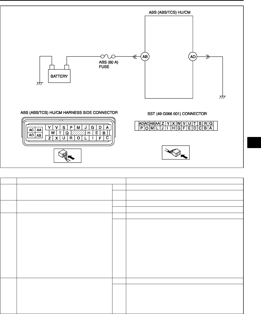
ON-BOARD DIAGNOSTIC (ABS/TCS)
P53
P
Diagnostic procedure
STEP INSPECTION ACTION
1VERIFY OTHER DTC HAS BEEN RECORDED
•If any of DTC C1186 and/or C1266 has also
been stored?
Yes Go to applicable DTC inspection.
No Go to next step.
2INSPECT ABS FUSE CONDITION
•Is ABS fuse (60 A) okay?
Yes Go to next step.
No Replace fuse, then go to Step 6.
3INSPECT MOTOR RELAY POWER SUPPLY
CIRCUIT FOR OPEN CIRCUIT
•Turn ignition key to OFF.
•Disconnect ABS (ABS/TCS) HU/CM
connector.
•Connect SST (adapter harness) to ABS
(ABS/TCS) HU/CM connector (harness side
only).
•Turn ignition key to ON (engine OFF).
•Measure voltage between ABS (ABS/TCS)
HU/CM terminal AB (harness side) of SST
and ground.
•Is voltage B+?
Yes Go to next step.
No Repair or replace harness for open circuit between battery
positive terminal and ABS (ABS/TCS) HU/CM terminal AC,
then go to Step 6.
4INSPECT PUMP MOTOR GROUND CIRCUIT
FOR OPEN CIRCUIT
•Turn ignition key to OFF.
•Inspect continuity between ABS (ABS/TCS)
HU/CM terminal AD (harness side) of SST
and ground.
•Is there continuity?
Yes Go to next step.
No Repair or replace harness for open circuit between ABS
(ABS/TCS) HU/CM terminal AB and ground, then go to Step
6.
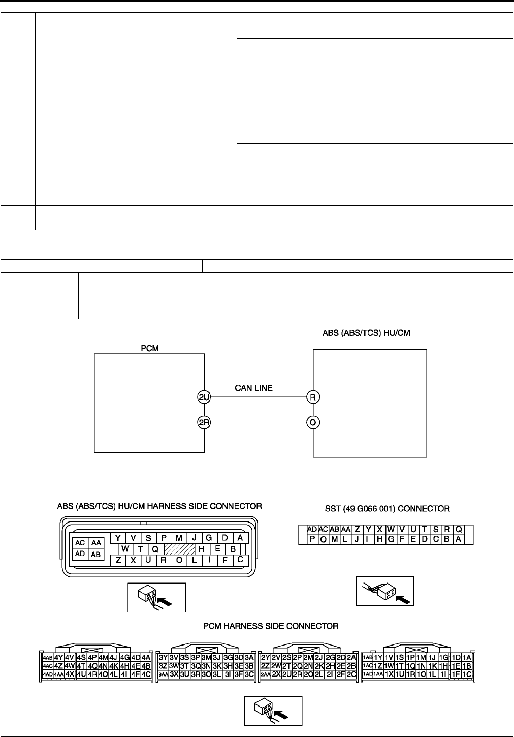
P54
ON-BOARD DIAGNOSTIC (ABS/TCS)
End Of Si e
DTC C1119 A6E697567650W07
5VERIFY PUMP MOTOR OPERATION
•Turn ignition key to OFF.
•Remove SST (adapter harness) and connect
all disconnected connectors.
•Connect WDS or equivalent to DLC-2.
•Turn ignition key to ON (engine OFF).
•Access ABS_POWER and PMP_MOTOR
active command modes using WDS or
equivalent.
•Does pump motor operate?
Yes Go to next step.
No Repair ABS (ABS/TCS) HU/CM, then go to next step.
6VERIFY TROUBLESHOOTING COMPLETED
•Clear DTC from memory.
(See P46 Clearing DTCs Procedures)
•Start engine and drive vehicle at 10 km/h
{6.2 mph} or above.
•Gradually slow down and stop vehicle.
•Is same DTC present?
Yes Replace ABS (ABS/TCS) HU/CM, then go to next step.
No Go to next step.
7VERIFY AFTER REPAIR PROCEDURE
•Is there any other DTC present?
Yes Go to applicable DTC inspection.
STEP INSPECTION ACTION
DTC C1119 Engine control system, torque reduction inhibit signal line
DETECTION
CONDITION
•Engine RPM information through CAN is out of specification or invalid value
•Throttle information through CAN is out of specification or invalid value
POSSIBLE
CAUSE •Malfunction of PCM
ON-BOARD DIAGNOSTIC (ABS/TCS)
P55
P
Diagnostic procedure
End Of Si e
DTC C1140 A6E697567650W09
Caution
•
••
•When attaching the tester lead to the ABS (ABS/TCS) HU/CM harness connector, the SST (49 G066
001) must be used. (See P29 ABS (ABS/TCS) HU/CM INSPECTION.)
Diagnostic procedure
STEP INSPECTION ACTION
1CHECK FOR CAN FOR DTCs
•If any of DTC U1900 and/or U2516 has also
been stored?
Yes Follow inspection procedures for CAN system.
See T144 DTC U0073, U1900, U2516
No Go to next step.
2CHECK FOR PCM FOR DTCs
•Turn ignition key to OFF.
•Connect WDS or equivalent to DLC-2
•Turn ignition key to ON (engine OFF).
•Is DTC for engine control system obtained?
Yes Follow inspection procedures for engine control system.
No Go to next step.
3VERIFY TROUBLESHOOTING COMPLETED
•Make sure to reconnect all disconnected
connectors.
•Clear DTC from memory.
(See P46 Clearing DTCs Procedures
•Start engine.)
•Is same DTC present?
Yes Replace DSC HU/CM, then go to next step.
No Go to next step.
4VERIFY AFTER REPAIR PROCEDURE
•Is there any other DTC present?
Yes Go to applicable DTC inspection.
No Troubleshooting completed.
DTC C1140 ABS (ABS/TCS) HU/CM (pump)
DETECTION
CONDITION
Right front and left rear wheels, or left front and right rear wheel-lock is detected during ABS (ABS/TCS)
operation.
POSSIBLE
CAUSE Stuck pump motor in ABS (ABS/TCS) HU/CM
STEP INSPECTION ACTION
1INSPECT ABS (ABS/TCS) HU/CM
OPERATION
•Perform ABS (ABS/TCS) HU/CM system
inspection.
(See P27 ABS (ABS/TCS) HU/CM
SYSTEM INSPECTION)
•Is it okay?
Yes Go to next step.
No Replace ABS (ABS/TCS) HU/CM, then go to Step 4.
2INSPECT CONVENTIONAL BRAKE
OPERATION
•Inspect brake fluid level.
•Start engine.
•Perform a road test to verify conventional
vehicle braking performance.
•Is there any concern.
Yes Inspect conventional brake line, then go to Step 4.
No Go to next step.
3INSPECT REAR BRAKE DRAGGING
•Turn ignition key to OFF.
•Jack-up vehicle and support it with safety
stand.
•Release parking brake.
•Turn rear wheel by hand and inspect for rear
brake drag.
•Is rear brake dragging?
Yes Repair parking brake system, then go to next step.
No Go to next step.
4VERIFY TROUBLESHOOTING COMPLETED
•Clear DTC from memory.
(See P46 Clearing DTCs Procedures)
•Start engine and drive vehicle at 10 km/h
{6.2 mph} or above at least one minute.
•Gradually slow down vehicle and stop.
•Is same DTC present?
Yes Replace ABS (ABS/TCS) HU/CM, then go to next step.
No Go to next step.
5VERIFY AFTER REPAIR PROCEDURE
•Is there any other DTC present?
Yes Go to applicable DTC inspection.
No Troubleshooting completed.
P56
ON-BOARD DIAGNOSTIC (ABS/TCS)
End Of Si e
DTC C1145, C1155, C1165, C1175 A6E697567650W10
Caution
•
••
•When attaching the tester lead to the ABS (ABS/TCS) HU/CM harness connector, the SST (49 G066
001) must be used. (See P29 ABS (ABS/TCS) HU/CM INSPECTION.)
DTC
C1145
C1155
C1165
C1175
RF wheel-speed sensor
LF wheel-speed sensor
RR wheel-speed sensor
LR wheel-speed sensor
DETECTION
CONDITION •Abnormal input is detected.
POSSIBLE
CAUSE
•Open or short to ground circuit in harness between ABS (ABS/TCS) HU/CM terminal and wheel-speed
sensor(s) terminal below
ABS (ABS/TCS) HU/CM terminal GRF ABS wheel-speed sensor terminal A
ABS (ABS/TCS) HU/CM terminal DRF ABS wheel-speed sensor terminal B
ABS (ABS/TCS) HU/CM terminal ILF ABS wheel-speed sensor terminal A
ABS (ABS/TCS) HU/CM terminal ELF ABS wheel-speed sensor terminal B
ABS (ABS/TCS) HU/CM terminal ARR ABS wheel-speed sensor terminal A
ABS (ABS/TCS) HU/CM terminal BRR ABS wheel-speed sensor terminal B
ABS (ABS/TCS) HU/CM terminal CLR ABS wheel-speed sensor terminal A
ABS (ABS/TCS) HU/CM terminal FLR ABS wheel-speed sensor terminal B
•ABS wheel-speed sensor(s) malfunction
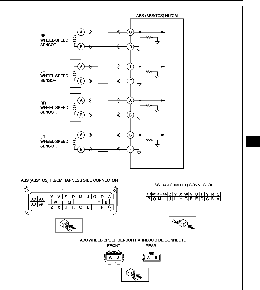
ON-BOARD DIAGNOSTIC (ABS/TCS)
P57
P

P58
ON-BOARD DIAGNOSTIC (ABS/TCS)
Diagnostic procedure
End Of Si e
STEP INSPECTION ACTION
1INSPECT WHEEL-SPEED SENSOR CIRCUIT
FOR OPEN CIRCUIT
•Turn ignition key to OFF.
•Disconnect ABS (ABS/TCS) HU/CM
connector.
•Measure resistance between suspected
sensor terminals of ABS (ABS/TCS) HU/CM
connector (harness side).
RF wheel-speed sensor: GD
LF wheel-speed sensor: IE
RR wheel-speed sensor: AB
LR wheel-speed sensor: CF
•Is resistance within 1.31.7 kilohm?
Yes Go to next step.
No Go to Step 3.
2INSPECT WHEEL-SPEED SENSOR CIRCUIT
FOR SHORT TO GROUND
•Turn ignition key to OFF.
•Inspect continuity between suspected sensor
terminal(s) of ABS (ABS/TCS) HU/CM
connector (harness side) and ground(s).
RF wheel-speed sensor: GD
LF wheel-speed sensor: IE
RR wheel-speed sensor: AB
LR wheel-speed sensor: CF
•Is there continuity?
Yes Repair or replace harness for short to ground circuit
between ABS (ABS/TCS) HU/CM and wheel-speed
sensor(s), then go to Step 5.
No Go to Step 5.
3INSPECT WHEEL-SPEED SENSOR
•Turn ignition key to OFF.
•Disconnect suspected sensor connector(s)
and inspect resistance between sensor
terminals (part side).
•Is resistance within 1.31.7 kilohm?
Yes Go to next step.
No Replace wheel-speed sensor, then go to Step 5.
4INSPECT ABS (ABS/TCS) HU/CM TO
WHEEL-SPEED SENSOR CIRCUIT FOR
OPEN CIRCUIT
•Inspect continuity between suspected sensor
terminal(s) of ABS (ABS/TCS) HU/CM
connector (harness side) and wheel-speed
sensor connector. (vehicle harness side)
RF wheel-speed sensor (+): GA
RF wheel-speed sensor (): DB
LF wheel-speed sensor (+): IA
LF wheel-speed sensor (): EB
RR wheel-speed sensor (+): AA
RR wheel-speed sensor (): BB
LR wheel-speed sensor (+): CA
LR wheel-speed sensor (): FB
•Is there continuity?
Yes Repair or replace poor connections of ABS (ABS/TCS) HU/
CM connector and/or wheel-speed sensor connector(s),
then go to next step.
No Repair or replace harness for open circuits between ABS
(ABS/TCS) HU/CM and wheel-speed sensor(s), then go to
next step.
5VERIFY TROUBLESHOOTING COMPLETED
•Make sure to reconnect all disconnected
connectors.
•Clear DTC from memory
(See P46 Clearing DTCs Procedures)
•Is same DTC present?
Yes Replace ABS (ABS/TCS) HU/CM, then go to next step.
No Go to next step.
6VERIFY AFTER REPAIR PROCEDURE
•Is there any other DTC present?
Yes Go to applicable DTC inspection.
No Troubleshooting completed.

ON-BOARD DIAGNOSTIC (ABS/TCS)
P59
P
DTC C1148, C1158, C1168, C1178, C1233, C1234, C1235, C1236 A6E697567650W11
Caution
•
••
•When attaching the tester lead to the ABS (ABS/TCS) HU/CM harness connector, the SST (49 G066
001) must be used. (See P29 ABS (ABS/TCS) HU/CM INSPECTION.)
DTC
C1148, C1234
C1158, C1233
C1168, C1235
C1178, C1236
RF wheel-speed sensor/sensor rotor
LF wheel-speed sensor/sensor rotor
RR wheel-speed sensor/sensor rotor
LR wheel-speed sensor/sensor rotor
DETECTION
CONDITION
•C1148, C1158, C1168, C1178:
Abnormal sensor output is detected on any of four vehicle wheels when the vehicle goes from start
to a speed of 10 km/h {6.2 mph}.
Greater than specified amount of ABS demand occurs from front wheel sensors when vehicle is
started.
•C1234, C1233, C1235, C1236:
Abnormal sensor output due to chipping of sensor rotor teeth, etc. is detected
ABS control operates for 60 seconds or more
POSSIBLE
CAUSE
•Short to ground circuit of wheel-speed sensor(s) circuit
•Malfunction of ABC wheel-speed sensor(s)
•Damaged sensor rotor(s)
•Incorrect clearance between ABC wheel-speed sensor and sensor rotor
•Poor installation of ABC wheel speed sensor and/or sensor rotor (If the sensor rotor is installed twisted,
it may cause output of abnormal wave form at high speeds.)
•ABS (ABS/TCS) HU/CM internal damage (Solenoid valve malfunction, pump motor malfunction, or pipe
clogging)
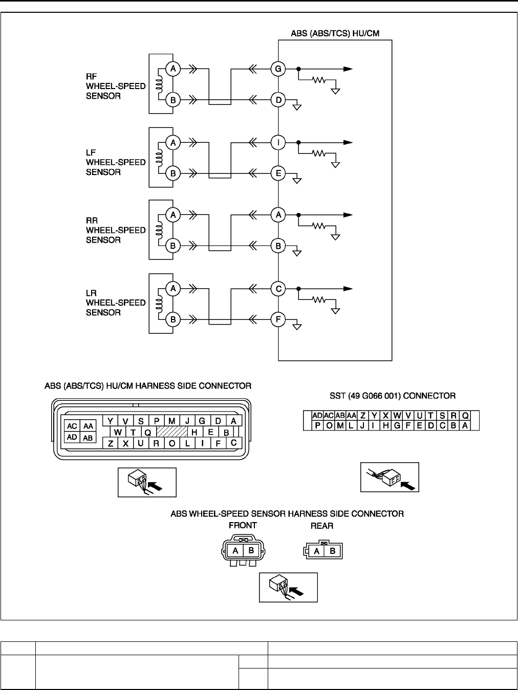
P60
ON-BOARD DIAGNOSTIC (ABS/TCS)
Diagnostic procedure
STEP INSPECTION ACTION
1VERIFY OTHER DTC HAS BEEN RECORDED
•Have DTCs related to solenoid valve, pump
motor, or pump motor relay been stored?
Yes Go to applicable DTC inspection.
No Go to next step.
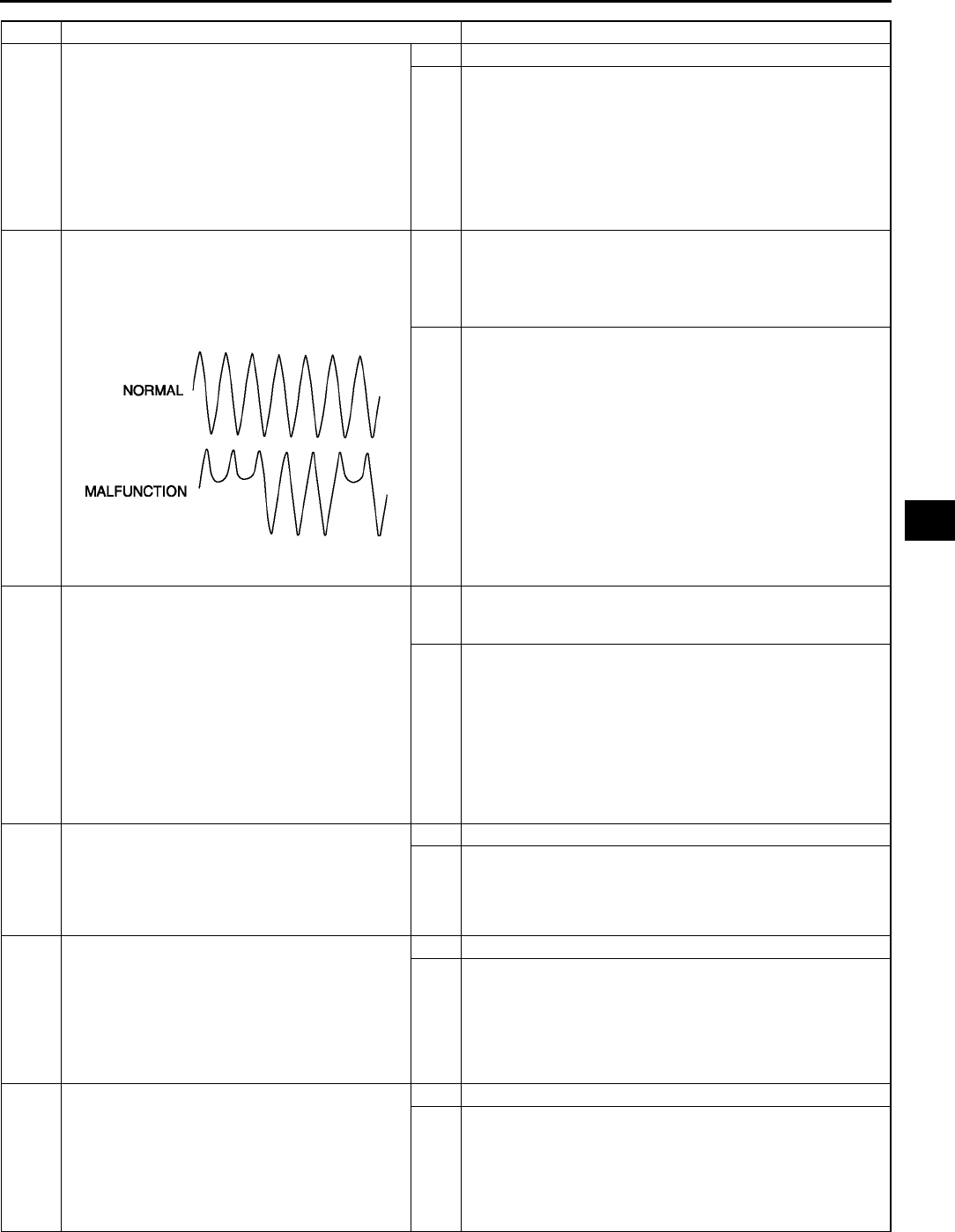
ON-BOARD DIAGNOSTIC (ABS/TCS)
P61
P
2VERIFY IF CURRENT CONCERNED INPUT
SIGNAL STATUS IS INTERMITTENT OR
CONSTANT
•Turn ignition key to OFF.
•Connect WDS or equivalent to DLC-2.
•Start engine and drive vehicle.
•Access LF_WSPD, LR_WSPD, RF_WSPD
and RR_WSPD using WDS or equivalent
•Do vehicle speeds correspond approximately
to the four PIDs above?
Yes Go to Step 8.
No If there is a difference in speed of four wheels: Go to next
step.
If any wheel speed is 0 km/h {0 mph}: Go to Step 4.
3INSPECT WHEEL-SPEED SENSOR OUTPUT
PULSE
•Start engine and drive vehicle.
•Inspect output voltage pattern using an
oscilloscope.
Yes Go to Step 9.
No Go to Step 6.
•Is output voltage pattern okay?
4INSPECT ABS WHEEL-SPEED SENSOR
CIRCUIT FOR SHORT TO GROUND
•Turn ignition key to OFF.
•Disconnect ABS (ABS/TCS) HU/CM and
wheel-speed sensor connectors.
•Inspect continuity between suspected sensor
terminal(s) of ABS (ABS/TCS) HU/CM
connector (harness side) and ground(s).
RF wheel-speed sensor: Gground
LF wheel-speed sensor: Iground
RR wheel-speed sensor: Aground
LR wheel-speed sensor: Cground
•Is there continuity?
Yes Repair or replace harness for short to ground circuit
between ABS (ABS/TCS) HU/CM and ABC wheel-sped
sensor, then go to Step 9.
No Go to next step.
5INSPECT WHEEL-SPEED SENSOR
•Turn ignition key to OFF.
•Disconnect suspected wheel-speed sensor
connector(s) and inspect resistance between
wheel-speed sensor terminal(s) (part side).
•Is resistance within 1.31.7 kilohm?
Yes Go to next step.
No Replace wheel-speed sensor(s), then go to Step 9.
6INSPECT SENSOR ROTOR CLEARANCE
•Jack-up vehicle and support it with safety
stands.
•Remove suspected wheel(s).
•Inspect clearance between wheel-speed
sensor and sensor rotor.
•Is clearance within 0.31.1 mm {0.012
0.043 in}?
Yes Go to next step.
No Replace wheel-speed sensor(s), then go to Step 9.
7INSPECT SENSOR ROTOR FOR DAMAGE
•Jack-up vehicle and support it with safety
stands.
•Remove suspected wheel(s).
•Visually inspect sensor rotor for missing,
deformed and obstructed teeth.
Number of teeth: 44
•Is sensor rotor okay?
Yes Go to next step.
No Replace sensor rotor, then go to Step 9.
STEP INSPECTION ACTION
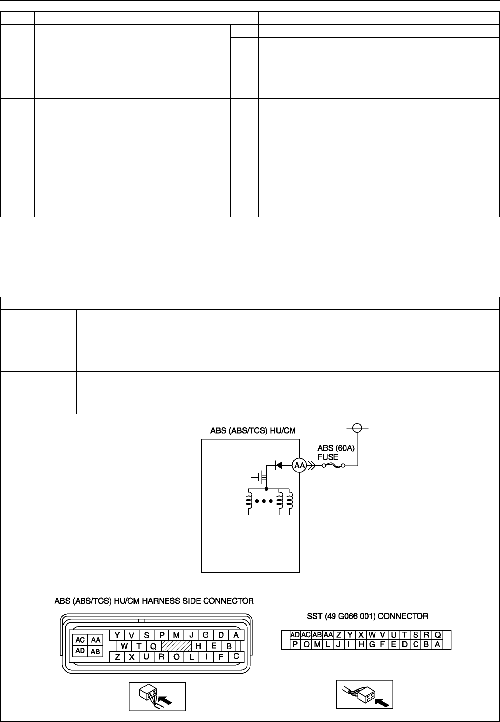
P62
ON-BOARD DIAGNOSTIC (ABS/TCS)
End Of Si e
DTC C1186, C1266 A6E697567650W12
Caution
•
••
•When attaching the tester lead to the ABS (ABS/TCS) HU/CM harnesses connector the SST (49
G066 001) must be used. (See P29 ABS (ABS/TCS) HU/CM INSPECTION.)
8INSPECT ABS (ABS/TCS) HU/CM
OPERATION
•Perform ABS (ABS/TCS) HU/CM system
inspection.
(See P27 ABS (ABS/TCS) HU/CM
SYSTEM INSPECTION)
•Is it okay?
Yes Go to next step.
No Replace ABS (ABS/TCS) HU/CM, then go to next step.
9VERIFY TROUBLESHOOTING COMPLETED
•Make sure to reconnect all disconnected
connectors.
•Clear DTC from memory.
See P46 Clearing DTCs Procedures
•Start engine and drive vehicle at 10 km/h
{6.2 mph} or above.
•Gradually slow down vehicle and stop.
•Is same DTC present?
Yes Replace ABS (ABS/TCS) HU/CM, then go to next step.
No Go to next step.
10 VERIFY AFTER REPAIR PROCEDURE
•Is there any other DTC present?
Yes Go to applicable DTC inspection.
No Troubleshooting completed.
STEP INSPECTION ACTION
DTC C1186, C1266 Fail-safe relay
DETECTION
CONDITION
•C1186:
Fail-safe relay in ABS (ABS/TCS) HU/CM stuck OFF when ignition switch is turned ON, fail-safe
relay ON is commanded.
•C1266:
Fail-safe relay in ABS (ABS/TCS) HU/CM stuck ON when ignition switch is turned ON, fail-safe relay
OFF is commanded.
POSSIBLE
CAUSE
•Malfunction of fuse (ABS 60 A)
•Open circuit in harness between ABS (ABS/TCS) HU/CM terminal AA and battery positive terminal
•Open or short of fail-safe relay in ABS (ABS/TCS) HU/CM
•Stuck fail-safe relay in ABS (ABS/TCS) HU/CM
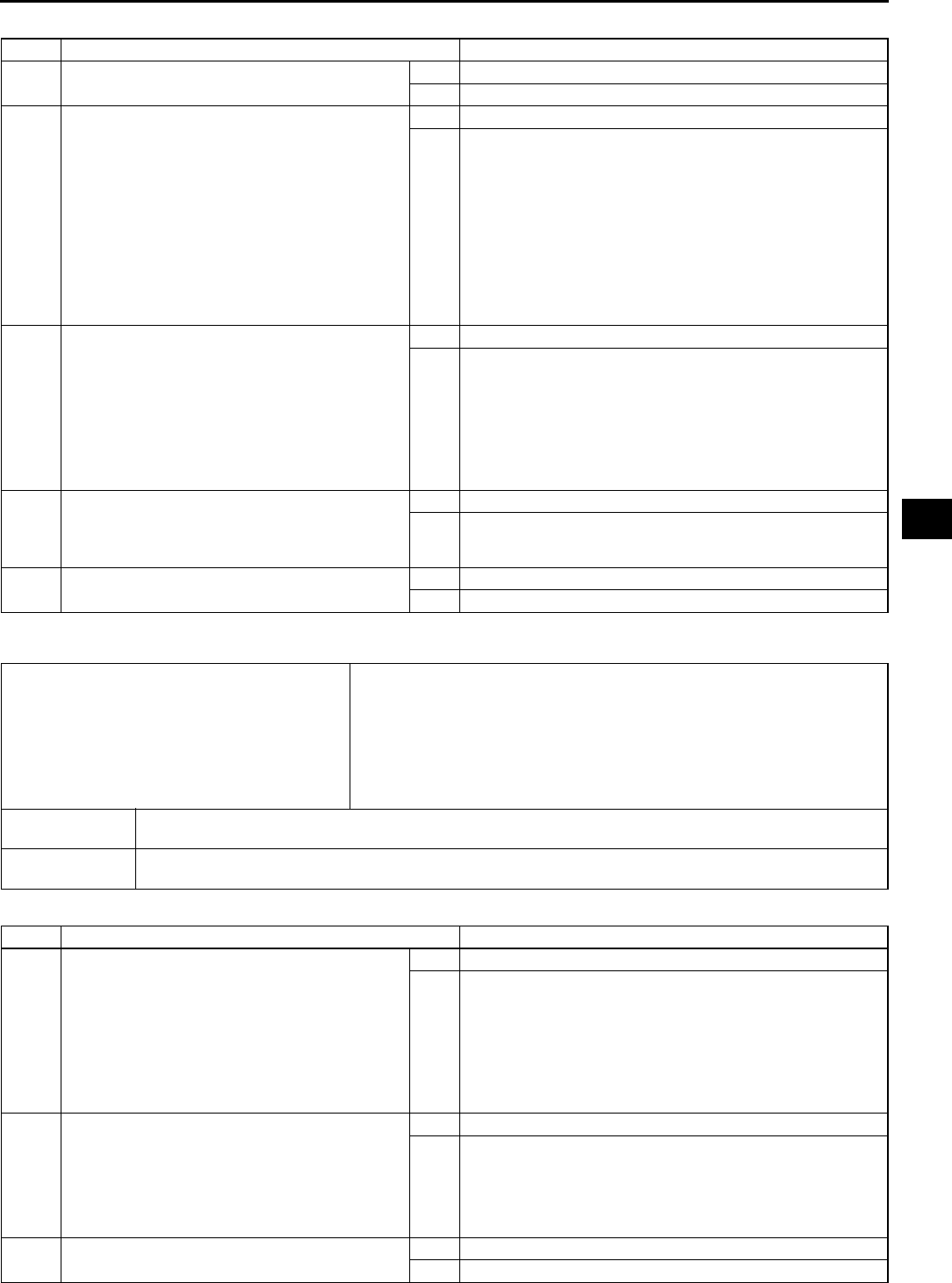
ON-BOARD DIAGNOSTIC (ABS/TCS)
P63
P
Diagnostic procedure
End Of Si e
DTC C1194, C1198, C1210, C1214, C1242, C1246, C1250, C1254 A6E697567650W13
Diagnostic procedure
STEP INSPECTION ACTION
1INSPECT ABS FUSE CONDITION
•Is ABS fuse (60 A) okay?
Yes Go to next step.
No Replace fuse, then go to Step 4.
2INSPECT FAIL-SAFE RELAY POWER
SUPPLY CIRCUIT FOR OPEN CIRCUIT
•Turn ignition key to OFF.
•Disconnect ABS (ABS/TCS) HU/CM
connector.
•Connect SST (adapter harness) to ABS (ABS/
TCS) HU/CM connector (harness side only).
•Turn ignition key to ON (engine OFF).
•Measure voltage between ABS (ABS/TCS)
HU/CM terminal AA (harness side) of SST
and ground.
•Is voltage B+?
Yes Go to next step.
No Repair or replace harness for open circuit between battery
positive terminal and ABS (ABS/TCS) HU/CM terminal AA,
then go to Step 4.
3VERIFY FAIL-SAFE OPERATION
•Turn ignition key to OFF.
•Remove SST (adapter harness) and connect
all disconnected connectors.
•Connect WDS or equivalent to DLC-2.
•Turn ignition key to ON (engine OFF).
•Access ABS_VOLT using WDS or
equivalent.
•Does fail-safe relay operate?
Yes Go to next step.
No Replace ABS (ABS/TCS) HU/CM, then go to next step.
4VERIFY TROUBLESHOOTING COMPLETED
•Clear DTC from memory.
(See P46 Clearing DTCs Procedures)
•Is same DTC present?
Yes Replace DSC HU/CM, then go to next step.
No Go to next step.
5VERIFY AFTER REPAIR PROCEDURE
•Is there any other DTC present?
Yes Go to applicable DTC inspection.
No Troubleshooting completed.
DTC
C 1210
C 1214
C 1194
C 1198
C 1246
C 1254
C 1242
C 1250
RF pressure reduction solenoid valve
RF pressure retention solenoid valve
LF pressure reduction solenoid valve
LF pressure retention solenoid valve
RR pressure reduction solenoid valve
RR pressure retention solenoid valve
LR pressure reduction solenoid valve
LR pressure reduction solenoid valve
DETECTION
CONDITION •Solenoid monitor signal does not track in response to solenoid ON/OFF command.
POSSIBLE
CAUSE
•Open, short to power, or short to ground circuit in ABS (ABS/TCS) HU/CM
•Stuck solenoid valve in ABS (ABS/TCS) HU/CM
STEP INSPECTION ACTION
1VERIFY SOLENOID VALVE OPERATION
•Turn ignition key to OFF.
•Remove SST (adapter harness) and connect
all disconnected connectors.
•Connect WDS or equivalent to DLC-2.
•Turn ignition key to ON (engine OFF).
•Access solenoid valve(s) PIDs using WDS or
equivalent.
•Does solenoid valve operate?
Yes Go to next step.
No Repair ABS (ABS/TCS) HU/CM, then go to next step.
2VERIFY TROUBLESHOOTING COMPLETED
•Clear DTC from memory.
(See P46 Clearing DTCs Procedures)
•Start engine and drive vehicle at 10 km/h
{6.2 mph} or above.
•Gradually slow down and stop vehicle.
•Is same DTC present?
Yes Replace ABS (ABS/TCS) HU/CM, then go to next step.
No Go to next step.
3VERIFY AFTER REPAIR PROCEDURE
•Is there any other DTC present?
Yes Go to applicable DTC inspection.
No Troubleshooting completed.
P64
ON-BOARD DIAGNOSTIC (ABS/TCS)
End Of Si e
DTC C1414 A6E697567650W14
Diagnostic procedure
End Of Si e
DTC C1508 A6E697567650W17
Diagnostic procedure
End Of Si e
DTC C1510, C1511, C1512, C1513 A6E697567650W15
DTC C1414 ABS (ABS/TCS) HU/CM mismatched installation
DETECTION
CONDITION
•Detection of situation where vehicle-type or drive system input signal and ABS (ABS/TCS) HU/CM
information remains incongruent through CAN information.
POSSIBLE
CAUSE •Mismatched installation of ABS (ABS/TCS) HU/CM
STEP INSPECTION ACTION
1INSPECT ABS (ABS/TCS) UNIT FOR
MISMATCHED INSTALLATION
•Verify ABS (ABS/TCS) HU/CM part number.
•Has a ABS (ABS/TCS) HU/CM with the
correct part number been installed?
Yes Go to next step.
No Replace with correct ABS (ABS/TCS) unit part number, then
go to Step 3.
2Configulate ABS (ABS/TCS) HU/CM
•Does ABS (ABS/TCS) HU/CM configulate
properly?
Yes Go to next step.
No Replace ABS (ABS/TCS) HU/CM
3VERIFY TROUBLESHOOTING COMPLETED
•Make sure to reconnected all disconnect
connectors.
•Clear DTC from memory.
(See P46 Clearing DTCs Procedures)
•Is same DTC present?
Yes Replace ABS (ABS/TCS) HU/CM, then go to next step.
No Go to next step.
4VERIFY AFTER REPAIR PROCEDURE
•Is there any other DTC present?
Yes Go to applicable DTC inspection.
No Troubleshooting completed.
DTC C1508 TCS control
DETECTION
CONDITION •TCS control continues operation for 60 seconds or more
POSSIBLE
CAUSE
•System is normal
For protection of solenoid valves in the ABS/TCS HU/CM, or protection of the engine, sustained and
continual control of TCS is inhibited
STEP INSPECTION ACTION
1VERIFY CURRENT STATUS OF
MALFUNCTION
•Clear DTC from memory
(See P46 Clearing DTCs Procedures)
•Start engine and drive vehicle at 10 km/h
{6.2 mph} or above.
•Is same DTC present?
Yes Replace ABS/TCS HU/CM, then go to next step.
No Inspect intermittent concern using the same procedure as
engine control system.
2VERIFY AFTER REPAIR PROCEDURE
•Is there any other DTC present?
Yes Go to applicable DTC inspection.
No Troubleshooting completed.
DTC
C1510
C1511
C1512
C1513
RF solenoid valve, motor or RF wheel-speed sensor/sensor rotor
LF solenoid valve, motor or LF wheel-speed sensor/sensor rotor
RR solenoid valve, motor or RR wheel-speed sensor/sensor rotor
LR solenoid valve, motor or LR wheel-speed sensor/sensor rotor
DETECTION
CONDITION
•Wheel lock is detected during ABS operation (pressure reduction inoperative).
•Pressure reduction on a single wheel continues for more than 20 seconds.
POSSIBLE
CAUSE
•Malfunction of solenoid valve in ABS (ABS/TCS) HU/CM
•Malfunction of wheel-speed sensor
•Damaged sensor rotor
•Stuck pump motor in ABS (ABS/TCS) HU/CM
ON-BOARD DIAGNOSTIC (ABS/TCS)
P65
P
Diagnostic procedure
End Of Si e
DTC U2021 A6E697567650W16
Note
•To warm up the engine completely, idle the engine and wait for more than 5 minutes.
Diagnostic procedure
End Of Si e
STEP INSPECTION ACTION
1VERIFY OTHER DTC HAS BEEN RECORDED
•Has any ABS wheel-speed sensor, sensor
rotor, solenoid valve, pump motor, or motor
relay related DTC been output?
Yes Go to applicable DTC inspection.
No Go to next step.
2INSPECT ABS (ABS/TCS) HU/CM
OPERATION
•Perform ABS (ABS/TCS) HU/CM system
inspection.
(See P27 ABS (ABS/TCS) HU/CM
SYSTEM INSPECTION
• Is it okay?
Yes Go to next step.
No Replace ABS (ABS/TCS) HU/CM, then go to next step.
3VERIFY CURRENT STATUS OF
MALFUNCTION
•Clear DTC from memory.
(See P46 Clearing DTCs Procedures)
•Start engine and drive vehicle at 10 km/h
{6.2 mph} or above at least one minute.
•Gradually slow down and stop vehicle.
•Is same DTC present?
Yes Replace ABS (ABS/TCS) HU/CM, then go to next step.
No Go to next step.
4VERIFY AFTER REPAIR PROCEDURE
•Is there any other DTC present?
Yes Go to applicable DTC inspection.
No Troubleshooting completed.
DTC U2021 Engine coolant temperature
DETECTION
CONDITION
•After engine is warmed up, engine coolant temperature is 0 °
°°
°C {32 °
°°
°F} or less, and TCS operation is
inhibited by PCM.
POSSIBLE
CAUSE •System is normal. When engine coolant temperature rises, TCS operation is executed by PCM.
STEP INSPECTION ACTION
1CHECK WHETHER ENGINE HAS WARMED
UP
•Has engine warmed up?
Yes Go to next step.
No Warm up the engine.
If TCS OFF light goes out, system is normal.
2VERIFY THAT MALFUNCTION SYMPTOM
OCCURS AFTER ENGINE IS WARMED UP
•Warm up the engine.
•Is TCS indicator light also illuminated and
DTC C1119 obtained?
Yes Go to DTC C1119 chart.
No If TCS OFF light goes out, system is normal.
If TCS OFF light does not goes out, go to next step.
3VERIFY TROUBLESHOOTING COMPLETED
•Clear DTC from memory.
(See P46 Clearing DTCs Procedures)
•Is same DTC present?
Yes Replace ABS (ABS/TCS) HU/CM, then go to next step.
No Go to next step.
4VERIFY AFTER REPAIR PROCEDURE
•Is there any other DTC present?
Yes Go to applicable DTC inspection.
No Troubleshooting completed.
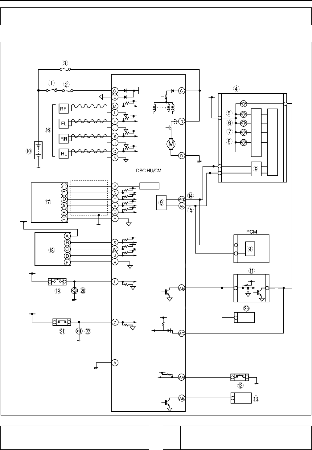
P66
ON-BOARD DIAGNOSTIC (DYNAMIC STABILITY CONTROL)
DSC SYSTEM WIRING DIAGRAM A6E697367650W01
.
ON-BOARD DIAGNOSTIC (DYNAMIC STABILITY CONTROL)
A6E6920T005
1 IG switch
2 SUS 15A fuse
3 ABS 60 A fuse
4 Meter
5 ABS warning light
6 Brake system warning light

ON-BOARD DIAGNOSTIC (DYNAMIC STABILITY CONTROL)
P67
P
End Of Si e
DSC ON-BOARD DIAGNOSIS A6E697367650W02
On-Board Diagnostic (OBD) Test Description
1. (See P46 ABS (ABS/TCS) ON-BOARD DIAGNOSIS)
DTC Table
7 DSC OFF light
8 DSC indicator light
9CAN driver
10 Battery
11 Cruise actuator
12 DSC OFF switch
13 DLC-2
14 CAN-H
15 CAN-L
16 Wheel-speed sensor
17 Combine sensor
18 Steering angle sensor
19 Brake switch
20 Brake light
21 Back-up light switch (MTX only)
22 Back-up light
23 Audio unit, Wiper and washer switch,
Car-navegation unit, Auto leveling control unit
DTC
Diagnosis system component Page
WDS or
equiva-
lent
B1318 DSC power supply (See P72 DTC B1318)
B1342 DSC HU/CM (See P74 DTC B1342)
B1483 Stop switch signal (See P74 DTC B1483, B1484, B1486)
B1484 Stop switch signal (See P74 DTC B1483, B1484, B1486)
B1486 Stop switch signal (See P74 DTC B1483, B1484, B1486)
B1627 Reverse signal (See P76 DTC B1627)
B2477 Module configuration (See P77 DTC B2477)
C1095 Motor relay, pump motor (See P77 DTC C1095, C1096)
C1096 Motor relay, pump motor (See P77 DTC C1095, C1096)
C1119 Engine control system (See P79 DTC C1119)
C1125 Brake fluid level sensor (See P80 DTC C1125)
C1140 DSC HU (pump) (See P81 DTC C1140)
C1145 Right front wheel-speed sensor (See P81 DTC C1145, C1155, C1165, C1175)
C1148 Right front wheel-speed sensor/sensor rotor (See P83 DTC C1148, C1158, C1168, C1178,
C1233, C1234, C1235, C1236)
C1155 Left front wheel-speed sensor (See P81 DTC C1145, C1155, C1165, C1175)
C1158 Left front wheel-speed sensor/sensor rotor (See P83 DTC C1148, C1158, C1168, C1178,
C1233, C1234, C1235, C1236)
C1165 Right rear wheel-speed sensor (See P81 DTC C1145, C1155, C1165, C1175)
C1168 Right rear wheel-speed sensor/sensor rotor (See P83 DTC C1148, C1158, C1168, C1178,
C1233, C1234, C1235, C1236)
C1175 Left rear wheel-speed sensor (See P81 DTC C1145, C1155, C1165, C1175)
C1178 Left rear wheel-speed sensor/sensor rotor (See P83 DTC C1148, C1158, C1168, C1178,
C1233, C1234, C1235, C1236)
C1186 Fail-safe relay (See P86 DTC C1186, C1266)
C1194 Left front pressure reduction solenoid valve (See P87 DTC C1194, C1198, C1210, C1214,
C1242, C1246, C1250, C1254, C1400, C1410,
C1957, C1958)
C1198 Left front pressure retention solenoid valve (See P87 DTC C1194, C1198, C1210, C1214,
C1242, C1246, C1250, C1254, C1400, C1410,
C1957, C1958)
C1210 Right front pressure reduction solenoid valve (See P87 DTC C1194, C1198, C1210, C1214,
C1242, C1246, C1250, C1254, C1400, C1410,
C1957, C1958)
C1214 Right front pressure retention solenoid valve (See P87 DTC C1194, C1198, C1210, C1214,
C1242, C1246, C1250, C1254, C1400, C1410,
C1957, C1958)
C1233 Left front wheel-speed sensor/sensor rotor (See P83 DTC C1148, C1158, C1168, C1178,
C1233, C1234, C1235, C1236)

P68
ON-BOARD DIAGNOSTIC (DYNAMIC STABILITY CONTROL)
C1234 Right front wheel-speed sensor/sensor rotor (See P83 DTC C1148, C1158, C1168, C1178,
C1233, C1234, C1235, C1236)
C1235 Right rear wheel-speed sensor/sensor rotor (See P83 DTC C1148, C1158, C1168, C1178,
C1233, C1234, C1235, C1236)
C1236 Left rear wheel-speed sensor/sensor rotor (See P83 DTC C1148, C1158, C1168, C1178,
C1233, C1234, C1235, C1236)
C1242 Left rear pressure reduction solenoid valve (See P87 DTC C1194, C1198, C1210, C1214,
C1242, C1246, C1250, C1254, C1400, C1410,
C1957, C1958 )
C1246 Right rear pressure reduction solenoid valve (See P87 DTC C1194, C1198, C1210, C1214,
C1242, C1246, C1250, C1254, C1400, C1410,
C1957, C1958 )
C1250 Left rear pressure retention solenoid valve (See P87 DTC C1194, C1198, C1210, C1214,
C1242, C1246, C1250, C1254, C1400, C1410,
C1957, C1958 )
C1254 Right rear ABS pressure retention solenoid valve (See P87 DTC C1194, C1198, C1210, C1214,
C1242, C1246, C1250, C1254, C1400, C1410,
C1957, C1958 )
C1266 Fail-safe relay (See P86 DTC C1186, C1266 )
C1280 Combine sensor (See P88 DTC C1280, C1730, C1951, C1952,
C1959 )
C1400 Right front traction switch solenoid valve (See P87 DTC C1194, C1198, C1210, C1214,
C1242, C1246, C1250, C1254, C1400, C1410,
C1957, C1958 )
C1410 Left front traction switch solenoid valve (See P87 DTC C1194, C1198, C1210, C1214,
C1242, C1246, C1250, C1254, C1400, C1410,
C1957, C1958 )
C1414 DSC HU/CM (See P91 DTC C1414 )
C1507 DSC control (See P91 DTC C1507, C1508 )
C1508 DSC control (See P91 DTC C1507, C1508 )
C1510 Right front solenoid valve, motor or wheel-speed
sensor/sensor rotor
(See P92 DTC C1510, C1511, C1512, C1513 )
C1511 Left front solenoid valve, motor or wheel-speed sensor/
sensor rotor
(See P92 DTC C1510, C1511, C1512, C1513 )
C1512 Right rear solenoid valve, motor or wheel-speed
sensor/sensor rotor
(See P92 DTC C1510, C1511, C1512, C1513 )
C1513 Left rear solenoid valve, motor or wheel-speed sensor/
sensor rotor
(See P92 DTC C1510, C1511, C1512, C1513 )
C1730 Combine sensor (See P88 DTC C1280, C1730, C1951, C1952,
C1959 )
C1951 Combine sensor (See P88 DTC C1280, C1730, C1951, C1952,
C1959 )
C1952 Combine sensor (See P88 DTC C1280, C1730, C1951, C1952,
C1959 )
C1953 Brake fluid pressure sensor (See P92 DTC C1953, C1954 )
C1954 Brake fluid pressure sensor (See P92 DTC C1953, C1954 )
C1955 Steering angle sensor (See P93 DTC C1955, C1956 )
C1956 Steering angle sensor (See P93 DTC C1955, C1956 )
C1957 Right front DSC switch solenoid valve (See P87 DTC C1194, C1198, C1210, C1214,
C1242, C1246, C1250, C1254, C1400, C1410,
C1957, C1958 )
C1958 Left front DSC switch solenoid valve (See P87 DTC C1194, C1198, C1210, C1214,
C1242, C1246, C1250, C1254, C1400, C1410,
C1957, C1958 )
C1959 Combine sensor (See P88 DTC C1280, C1730, C1951, C1952,
C1959 )
U1900 Can communication (See T144 DTC U0073, U1900, U2516 )
U2021 Invalid/fault data received (See P96 DTC U2021 )
DTC
Diagnosis system component Page
WDS or
equiva-
lent

ON-BOARD DIAGNOSTIC (DYNAMIC STABILITY CONTROL)
P69
P
PID/DATA Monitor Table
U2516 Can communication (See T144 DTC U0073, U1900, U2516 )
PID Name
(Definition) Unit/Condition Condition/Specification Action
ABS/TCS HU/
CM or DSC HU/
CM terminal
RPM
(Engine speed signal
input)
RPM
•Engine is stopped: 0 RPM
•Engine is running:
Indicates engine speed
Inspect PCM.
TRANSGR
(Transaxle gear position) 1/2/3/4/P/R/N
•Selector lever position is
displayed
ATX
D range (1GR): 1
D range (2GR): 2
D range (3GR): 3
D range (4GR): 4
P position: P
N position: N
R position: R
MTX
1GR: 1
2GR: 2
3GR: 3
4GR: 4
5GR: 5
Neutral: N
Reverse: R
Inspect PCM, TR switch, or
DSC HU/CM.
TRAC_SW
(TCS OFF switch input) ON/OFF
•TCS (DSC) OFF switch is
depressed: ON
•TCS(DSC) OFF switch is
released: OFF
Inspect TCS(DSC) OFF
switch. AA
TC LVAL
(Traction switch solenoid
valve (LF-RR))
ON/OFF
•Solenoid valve is
activated: ON
•Solenoid valve is
deactivated: OFF
Internal fault of DSC HU/
CM. Replace DSC HU/CM.
(See P38 DSC HU/CM
REMOVAL/
INSTALLATION)
TC RVAL
(Traction switch solenoid
valve (RF-LR))
ON/OFF
•Solenoid valve is
activated: ON
•Solenoid valve is
deactivated: OFF
Internal fault of DSC HU/
CM. Replace DSC HU/CM.
(See P38 DSC HU/CM
REMOVAL/
INSTALLATION)
L_DSC O
(Stability control solenoid
valve (LF-RR))
ON/OFF
•Solenoid valve is
activated: ON
•Solenoid valve is
deactivated: OFF
Internal fault of DSC HU/
CM. Replace DSC HU/CM.
(See P38 DSC HU/CM
REMOVAL/
INSTALLATION)
R_DSC O
(Stability control solenoid
valve (RF-LR))
ON/OFF
•Solenoid valve is
activated: ON
•Solenoid valve is
deactivated: OFF
Internal fault of DSC HU/
CM. Replace DSC HU/CM.
(See P38 DSC HU/CM
REMOVAL/
INSTALLATION)
CCNTABS
(Number of continuous
codes)
DTC is detected: 1255
DTC is not detected: 0
Perform inspection using
appropriate DTC.
PMPSTAT
(Pump motor output state) ON/OFF
•Pump motor is activated:
ON
•Pump motor is
deactivated: OFF
Inspect DSC HU/CM.
(See P40 DSC HU/CM
INSPECTION)
BRK_FLUID
(Brake fluid level sensor
input)
YES/NO
•Brake fluid is above LOW:
YES
•Brake fluid is below LOW:
NO
Inspect brake fluid level.
Inspect brake fluid level
sensor.
DTC
Diagnosis system component Page
WDS or
equiva-
lent

P70
ON-BOARD DIAGNOSTIC (DYNAMIC STABILITY CONTROL)
BOO_ABS
(Brake pedal switch input) ON/OFF
•Brake pedal is depressed:
ON
•Brake pedal is released:
OFF
Inspect brake switch.
L
ABS_LAMP
(ABS warning light driver
output state)
ON/OFF
•ABS warning light is
illuminated: ON
•ABS warning light is not
illuminated: OFF
Inspect ABS warning light.
BRAKE_LMP
(BRAKE system warning
light output state)
ON/OFF
•BRAKE system warning
light is illuminated: ON
•BRAKE system warning
light is not illuminated:
OFF
Inspect BRAKE system
warning light.
ABSRR_O
(Right rear ABS pressure
reduction solenoid valve
output state)
ON/OFF
•During ABS control: ON/
OFF (solenoid valve is
activated/deactivated)
•Not ABS control: OFF
•(solenoid valve is
deactivated)
Internal fault of DSC HU/
CM. Replace DSC HU/CM.
(See P38 DSC HU/CM
REMOVAL/
INSTALLATION)
ABSLR_O
(Left rear ABS pressure
reduction solenoid valve
output state)
ON/OFF
•During ABS or EBD
control: ON/OFF
(solenoid valve is
activated/deactivated)
•Not ABS and EBD control:
OFF (solenoid valve is
deactivated)
Internal fault of DSC HU/
CM. Replace DSC HU/CM.
(See P38 DSC HU/CM
REMOVAL/
INSTALLATION)
ABSRF_O
(Right front ABS pressure
reduction solenoid valve
output state)
ON/OFF
•During ABS control: ON/
OFF (solenoid valve is
activated/deactivated)
•Not ABS control: OFF
(solenoid valve is
deactivated)
Internal fault of DSC HU/
CM. Replace DSC HU/CM.
(See P38 DSC HU/CM
REMOVAL/
INSTALLATION)
ABSLF_O
(Left front ABS pressure
reduction solenoid valve
output state)
ON/OFF
•During ABS control: ON/
OFF(solenoid valve is
activated/deactivated)
•Not ABS control: OFF
(solenoid valve is
deactivated)
Internal fault of DSC HU/
CM. Replace DSC HU/CM.
(See P38 DSC HU/CM
REMOVAL/
INSTALLATION)
ABSRR_I
(Right rear ABS pressure
reduction solenoid valve
output state)
ON/OFF
•During ABS control: ON/
OFF (solenoid valve is
activated/deactivated)
•Not ABS control: OFF
(solenoid valve is
deactivated)
Internal fault of DSC HU/
CM. Replace DSC HU/CM.
(See P38 DSC HU/CM
REMOVAL/
INSTALLATION)
ABSLR_I
(Left rear ABS pressure
retention solenoid valve
output state)
ON/OFF
•During ABS or EBD
control: ON/OFF
(solenoid valve is
activated/deactivated)
•Not ABS and EBD control:
OFF (solenoid valve is
deactivated)
Internal fault of DSC HU/
CM. Replace DSC HU/CM.
(See P38 DSC HU/CM
REMOVAL/
INSTALLATION)
ABSRF_I
(Right front ABS pressure
retention solenoid valve
output state)
ON/OFF
•During ABS control: ON/
OFF (solenoid valve is
activated/deactivated)
•Not ABS control: OFF
(solenoid valve is
deactivated)
Internal fault of DSC HU/
CM. Replace DSC HU/CM.
(See P38 DSC HU/CM
REMOVAL/
INSTALLATION)
ABSLF_I
(Left front ABS pressure
retention solenoid valve
output state)
ON/OFF
•During ABS control: ON/
OFF (solenoid valve is
activated/deactivated)
•Not ABS control: OFF
(solenoid valve is
deactivated)
Internal fault of DSC HU/
CM. Replace DSC HU/CM.
(See P38 DSC HU/CM
REMOVAL/
INSTALLATION)
PID Name
(Definition) Unit/Condition Condition/Specification Action
ABS/TCS HU/
CM or DSC HU/
CM terminal

ON-BOARD DIAGNOSTIC (DYNAMIC STABILITY CONTROL)
P71
P
ABSVLVRLY
(Fail-safe relay output
state)
ON/OFF
•Fail-safe relay is
activated: ON
•Fail-safe relay is
deactivated: OFF
Inspect DSC HU/CM.
(See P40 DSC HU/CM
INSPECTION )
ABSPMPRLY
(Motor relay output state) ON/OFF
•Motor relay is activated:
ON
•Motor relay is deactivated:
OFF
Inspect DSC HU/CM.
(See P40 DSC HU/CM
INSPECTION )
SWA POS
(Steering angle sensor
input)
DEG
•Steering wheel is in neutral
position: 0 DEG
•Steering wheel is turned to
left: Changes between 0
DEG and -1,638.40 DEG
•Steering wheel is turned to
right: Changes between 0
DEG and 1,638.35 DEG
Inspect steering angle
sensor.
R, U, W, X
LF_WSPD
(Left front wheel-speed
sensor input)
KPH or MPH
•Vehicle is stopped: 0 KPH
{0 MPH}
•Vehicle is driving:
Indicates vehicle speed
Inspect wheel-speed
sensor/sensor rotor. F, J
RF_WSPD
(Right front wheel-speed
sensor input)
KPH or MPH
•Vehicle is stopped: 0 KPH
{0 MPH}
•Vehicle is driving:
Indicates vehicle speed
Inspect wheel-speed
sensor/sensor rotor. I, M
LR_WSPD
(Left rear wheel-speed
sensor input)
KPH or MPH
•Vehicle is stopped: 0 KPH
{0 MPH}
•Vehicle is driving:
Indicates vehicle speed
Inspect wheel-speed
sensor/sensor rotor. N, Q
RR_WSPD
(Right rear wheel-speed
sensor input)
KPH or MPH
•Vehicle is stopped: 0 KPH
{0 MPH}
•Vehicle is driving:
Indicates vehicle speed
Inspect wheel-speed
sensor/sensor rotor. H, K
LAT ACC
(Lateral-G sensor input) G
•Vehicle is stopped or
driving straight: 0 G
•Cornering to left: Changes
between 0 G and 1.27 G
•Cornering to right:
Changes between 0 G and
-1.28 G
Inspect ABS wheel-speed
sensor/sensor rotor.
O
YAW_RATE
(Yaw rate sensor input) DG/S
•Vehicle is stopped or
driving straight: 0 DG/S
•Cornering to left: Changes
between 0 DG/S and 127
DG/S
•Cornering to right:
Changes between 0 DG/S
and -128 DG/S
Inspect combine sensor.
(See P43 COMBINE
SENSOR INSPECTION )
T
MCYLI P
(Brake fluid pressure
sensor input)
MPA
•Brake pedal is released: 0
MPA
•Brake pedal is depressed:
Changes between 0 MPA
and 25.5 MPA
Inspect DSC HU/CM.
(See P40 DSC HU/CM
INSPECTION )
TCSOUTD
(Torque reduction request
value)
%
•Torque reduction is not
requested: 0 %
•Torque reduction is
requested: Changes
between 0 % and 100 %
Inspect DSC HU/CM.
(See P40 DSC HU/CM
INSPECTION )
TPI
(Throttle position signal
input)
•Closed throttle position: 0
•Wide open throttle:
Changes between 1 and 7
Inspect PCM and throttle
position sensor.
ABS_VOLT
(System battery voltage
value)
V•Ignition key at ON: B+
•Idle: Approx. 1416 V
Inspect power supply circuit.
(See P40 DSC HU/CM
INSPECTION )
G
PID Name
(Definition) Unit/Condition Condition/Specification Action
ABS/TCS HU/
CM or DSC HU/
CM terminal
P72
ON-BOARD DIAGNOSTIC (DYNAMIC STABILITY CONTROL)
Active Command Modes Table
End Of Si e
DTC B1318 A6E697367650W03
Caution
•
••
•When attaching the tester lead to the DSC HU/CM connector the SST (49 G066 004) must be used.
Command Name Definition Operation Note
RF_DSC_V Stability control solenoid valve (RF-LR) ON/OFF
Ignition key at ON
(Engine OFF), and
driving
LF_DSC_V Stability control solenoid valve (LF-RR) ON/OFF
ABS_POWER Fail-safe relay ON/OFF
LR_OUTLET Left rear ABS pressure reduction solenoid valve ON/OFF
LR_INLET Left rear ABS pressure retention solenoid valve ON/OFF
RR_INLET Right rear ABS pressure retention solenoid valve ON/OFF
RR_OUTLET Right rear ABS pressure reduction solenoid valve ON/OFF
LF_INLET Left front ABS pressure retention solenoid valve ON/OFF
LF_OUTLET Left front ABS pressure reduction solenoid valve ON/OFF
RF_INLET Right front ABS pressure retention solenoid valve ON/OFF
RF_OUTLET Right front ABS pressure reduction solenoid valve ON/OFF
PMP_MOTOR ABS motor ON/OFF
RF_TC_VLV Traction switch solenoid valve (RF-LR) ON/OFF
LF_TC_VLV Traction switch solenoid valve (LF-RR) ON/OFF
TRAC OFF Traction control off indicator ON/OFF
STAB_IND DSC indicator light ON/OFF
YAWRATE Yaw rate sensor initialization start ON/OFF
LATACCEL Lateral accel sensor initialization start TRUE/FALSE
DTC B1318 DSC power supply
DETECTION
CONDITION •Low voltage is detected at the voltage monitor of solenoid valve monitor, or the motor monitor.
POSSIBLE
CAUSE
•Malfunction of fuse (SUS 15 A)
•Open or short to power circuit in harness between DSC HU/CM terminal G and battery positive terminal
•Open circuit in harness between body ground and DSC HU/CM terminal A
•Battery and/or generator malfunction
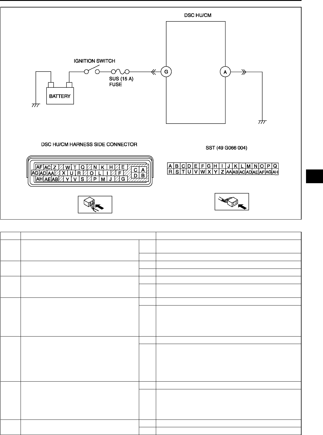
ON-BOARD DIAGNOSTIC (DYNAMIC STABILITY CONTROL)
P73
P
Diagnostic procedure
STEP INSPECTION ACTION
1INSPECT BATTERY VOLTAGE
•Is battery terminal voltage okay?
Yes Make sure that battery terminal connection is okay.
Go to next step.
No Charge or replace battery, then go to Step 6.
2INSPECT BATTERY GRAVITY
•Is battery specific gravity as specified?
Yes Go to next step.
No Replace battery, then go to Step 6.
3INSPECT CHARGING SYSTEM
•Are generator and drive belt tension okay?
Yes Go to next step.
No Adjust drive belt tension as necessary.
Replace generator and/or drive belt as necessary.
4INSPECT DSC HU/CM POWER SUPPLY
CIRCUIT FOR OPEN CIRCUIT
•Start engine.
•Measure voltage between DSC HU/CM
terminal G and ground.
•Is voltage above 10 V?
Yes Go to next step.
No Go to Step 6.
5INSPECT DSC HU/CM GROUND CIRCUIT
FOR POOR GROUND OR OPEN CIRCUIT
•Turn ignition key to OFF.
•Measure resistance between ground and
DSC HU/CM terminal A.
•Is resistance within 01 ohm?
Yes Go to next step.
No If there is no continuity:
•Repair or replace harness for open circuit between DSC
HU/CM and ground, then go to next step.
If resistance is not within 01 ohm:
•Repair or replace harness for poor ground, then go to
next step.
6VERIFY TROUBLESHOOTING COMPLETED
•Make sure to reconnect all disconnected
connectors.
•Clear DTC from memory.
(See P46 Clearing DTCs Procedures)
•Is same DTC present?
Yes Replace DSC HU/CM, then go to next step.
No Go to next step.
7VERIFY AFTER REPAIR PROCEDURE
•Is there any other DTC present?
Yes Go to applicable DTC inspection.
No Troubleshooting completed.
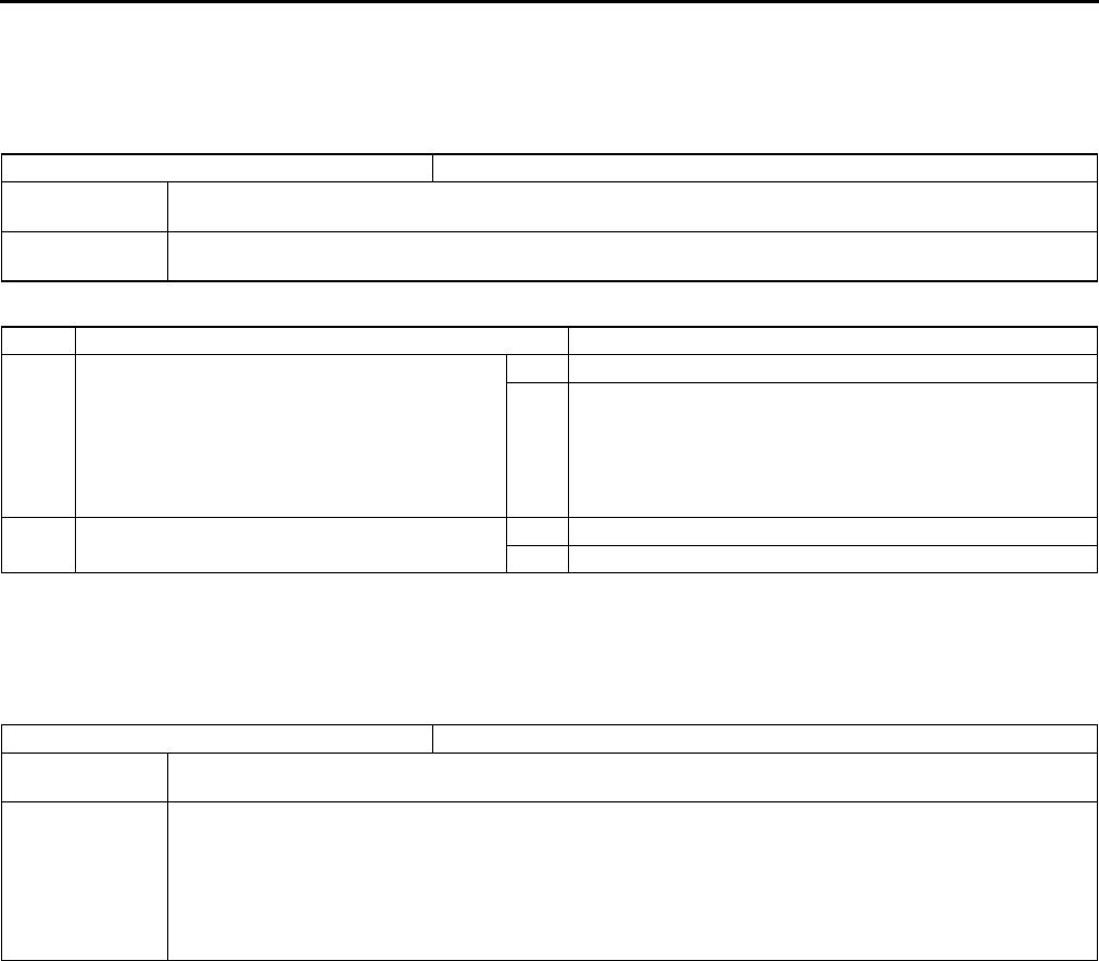
P74
ON-BOARD DIAGNOSTIC (DYNAMIC STABILITY CONTROL)
End Of Si e
DTC B1342 A6E697367650W04
Caution
•
••
•When attaching the tester lead to the DSC HU/CM connector the SST (49 G066 004) must be used.
Diagnostic procedure
End Of Si e
DTC B1483, B1484, B1486 A6E697367650W05
Caution
•
••
•When attaching the tester lead to the DSC HU/CM connector the SST (49 G066 004) must be used.
DTC B1342 DSC HU/CM
DETECTION
CONDITION The on-board diagnostic function detects control module malfunction.
POSSIBLE
CAUSE •Malfunction of DSC HU/CM
STEP INSPECTION ACTION
1VERIFY CURRENT STATUS OF
MALFUNCTION
•Clear DTC from memory.
(See P46 Clearing DTCs Procedures)
•Start engine and drive vehicle at 10 km/h
{6.2 mph} or above.
•Is same DTC present?
Yes Replace DSC HU/CM, then go to next step.
No Inspect intermittent concern using the same procedure as
engine control system.
2VERIFY AFTER REPAIR PROCEDURE
•Is there any other DTC present?
Yes Go to applicable DTC inspection.
No Troubleshooting completed.
DTC B1483, B1484, B1486 Brake switch signal
DETECTION
CONDITION •Low voltage is detected at the voltage monitor of solenoid valve monitor, or the motor monitor
POSSIBLE
CAUSE
•B1483
Malfunction of brake switch
•B1484
Open circuit in harness between DSC HU/CM terminal I and brake switch
•B1486
Short to ground circuit in harness between DSC HU/CM terminal I and brake switch
•Short to power circuit in harness between DSC HU/CM terminal I and brake switch
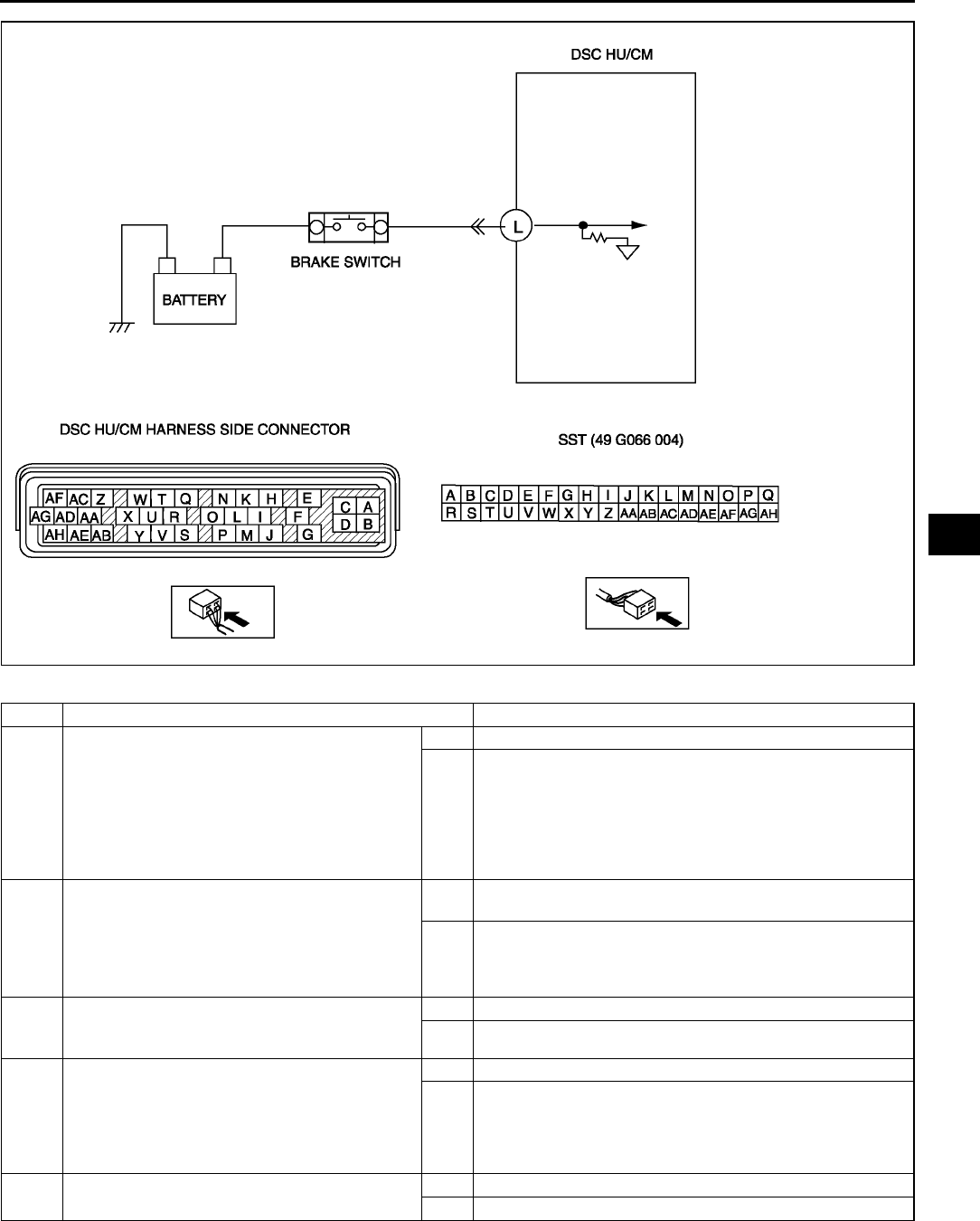
ON-BOARD DIAGNOSTIC (DYNAMIC STABILITY CONTROL)
P75
P
Diagnostic procedure
End Of Si e
STEP INSPECTION ACTION
1INSPECT DSC HU/CM TO BRAKE SWITCH
FOR OPEN CIRCUIT
•Turn ignition key to OFF.
•Disconnect DSC HU/CM and brake switch
connector
•Inspect continuity DSC HU/CM terminal L
and brake switch
•Is there continuity?
Yes Go to next step.
No Repair or replace harness for open circuit between DSC
HU/CM and brake switch, then go to next step.
2INSPECT DSC HU/CM TO BRAKE SWITCH
FOR SHORT TO GROUND
•Turn ignition key to OFF.
•Inspect continuity DSC HU/CM terminal L
and ground
•Is there continuity?
Yes Repair or replace harness for open circuit between DSC
HU/CM and brake switch, then go to next step.
No Go to next step.
3INSPECT BRAKE SWITCH
•Inspect bake switch.
•Is it okay?
Yes Go to next step.
No Replace bake switch, then go to next step.
4VERIFY TROUBLESHOOTING COMPLETED
•Make sure to reconnect all disconnected
connectors.
•Clear DTC from memory.
(See P46 Clearing DTCs Procedures)
•Is same DTC present?
Yes Replace bake switch, then go to next step.
No Go to next step.
5VERIFY AFTER REPAIR PROCEDURE
•Is there any other DTC present?
Yes Go to applicable DTC inspection.
No Troubleshooting completed.
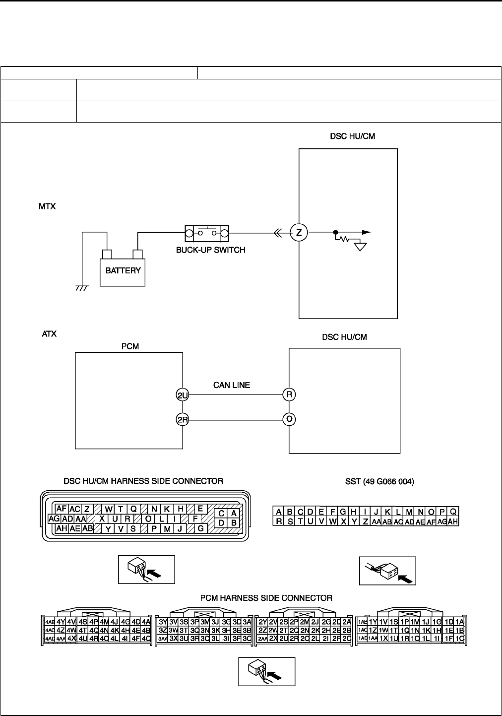
P76
ON-BOARD DIAGNOSTIC (DYNAMIC STABILITY CONTROL)
DTC B1627 A6E697367650W06
Caution
•
••
•When attaching the tester lead to the DSC HU/CM connector the SST (49 G066 004) must be used.
DTC B1627 Reverse signal
DETECTION
CONDITION
•Reverse signal is input for 10 seconds or more while driving at a vehicle speed of
65 km/h {40.3 mph}.
POSSIBLE
CAUSE
•Short to power circuit in harness between DSC HU/CM terminal Z and back-up light switch (MTX)
•Malfunction of TR switch (ATX) or back-up light switch (MTX)
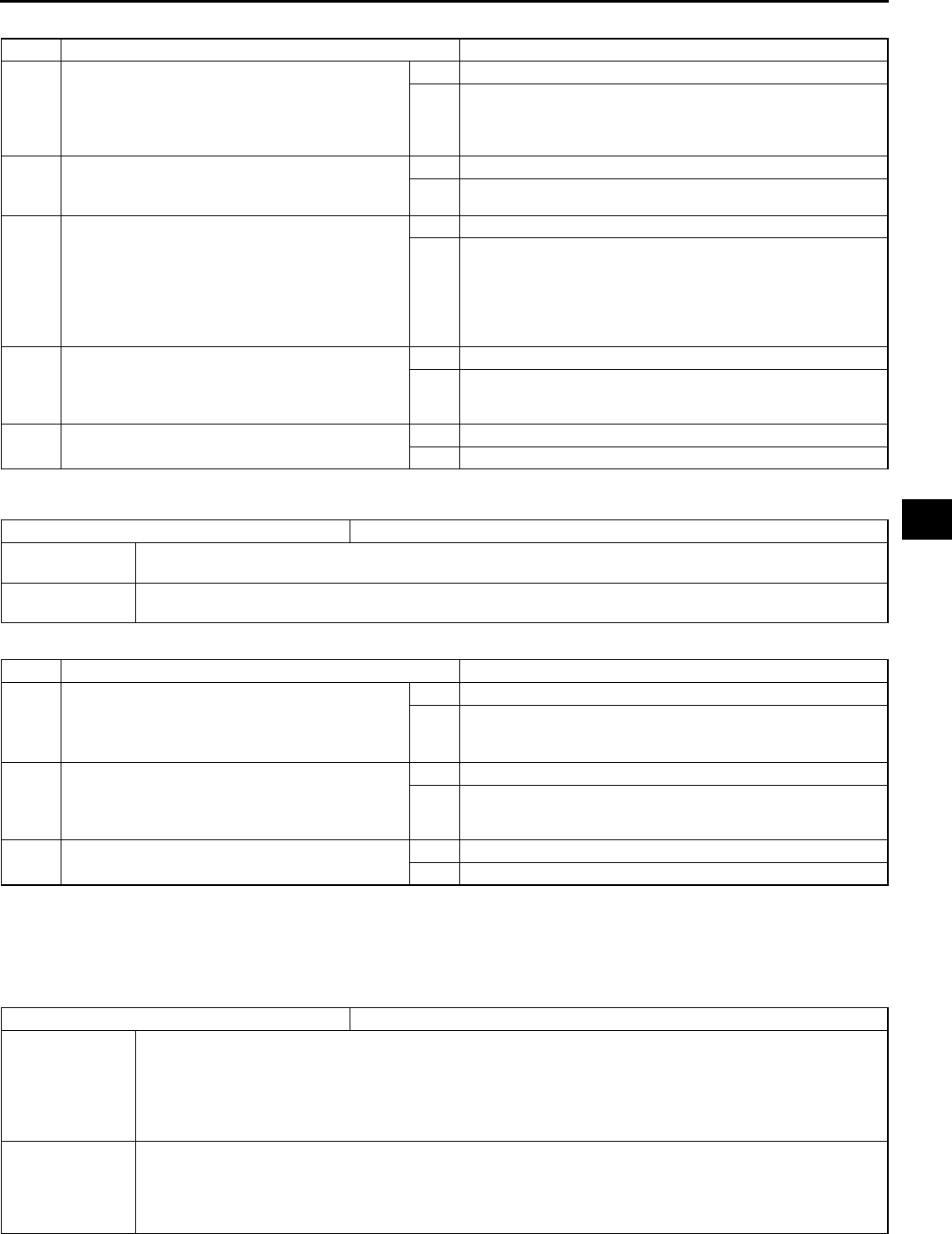
ON-BOARD DIAGNOSTIC (DYNAMIC STABILITY CONTROL)
P77
P
Diagnostic procedure
End Of Si e
DTC B2477 A6E697367650W07
Diagnostic procedure
End Of Si e
DTC C1095, C1096 A6E697367650W08
Caution
•
••
•When attaching the tester lead to the DSC HU/CM connector the SST (49 G066 004) must be used.
STEP INSPECTION ACTION
1CHECK TR SWITCH FOR DTCs (ATX)
•Turn ignition key to OFF.
•Connect WDS or equivalent to DLC-2.
•Turn ignition key to ON (engine OFF).
•Is DTC for TR switch obtained?
Yes Follow inspection procedures for TR switch.
No Go to step 4.
2 INSPECT BACK-UP LIGHT SWITCH (MTX)
•Inspect back-up light switch.
•Is it okay?
Yes Go to next step.
No Replace back-up light switch, then go to next step.
3INSPECT REVERSE SIGNAL CIRCUIT FOR
SHORT TO POWER (MTX)
•Shift select lever to neutral position.
•Turn ignition key to ON.
•Measure voltage between DSC HU/CM
terminal Z and ground.
•Is voltage above 10 V?
Yes Go to next step.
No Replace back-up light switch, then go to next step.
Replace reverse signal circuit, then go to next step.
4VERIFY TROUBLESHOOTING COMPLETED
•Clear DTC from memory.
(See P46 Clearing DTCs Procedures)
•Is same DTC present?
Yes Replace DSC HU/CM, then go to next step.
No Go to next step.
5VERIFY AFTER REPAIR PROCEDURE
•Is there any other DTC present?
Yes Go to applicable DTC inspection.
No Troubleshooting completed.
DTC B2477 Module configuration
DETECTION
CONDITION •Configuration write failure is detected.
POSSIBLE
CAUSE •Module configuration procedure is not done properly.
STEP INSPECTION ACTION
1CHECK WHETHER DSC HU/CM IS
CONFIGURED
•Is DSC HU/CM configured?
Yes Go to next step.
No Configurate DSC using WDS or equivalent.
(See P29 ABS (ABS/TCS) or DSC HU/CM
CONFIGURATION)
2VERIFY TROUBLESHOOTING COMPLETED
•Clear DTC from memory.
(See P46 Clearing DTCs Procedures)
•Is same DTC present?
Yes Replace DSC HU/CM, then go to next step.
No Go to next step.
3VERIFY AFTER REPAIR PROCEDURE
•Is there any other DTC present?
Yes Go to applicable DTC inspection.
No Troubleshooting completed.
DTC C1095, C1096 Motor relay, pump motor
DETECTION
CONDITION
•C1095 (54):
No motor monitor signal congruency is detected in relation to DSC HU/CM ON signal.
•C1096 (53):
No motor monitor signal congruency is detected in relation to DSC HU/CM OFF signal.
Motor monitor ON signal is not input after specified time when the motor signal is switched from ON
to OFF by DSC HU/CM.
POSSIBLE
CAUSE
•Malfunction of fuse (ABS 60 A)
•Open circuit in harness between DSC HU/CM terminal D and battery positive terminal
•Open circuit in harness between DSC HU/CM terminal B and body ground
•Open or short of motor relay and/or pump motor in DSC HU/CM
•Stuck motor relay and/or pump motor in DSC HU/CM
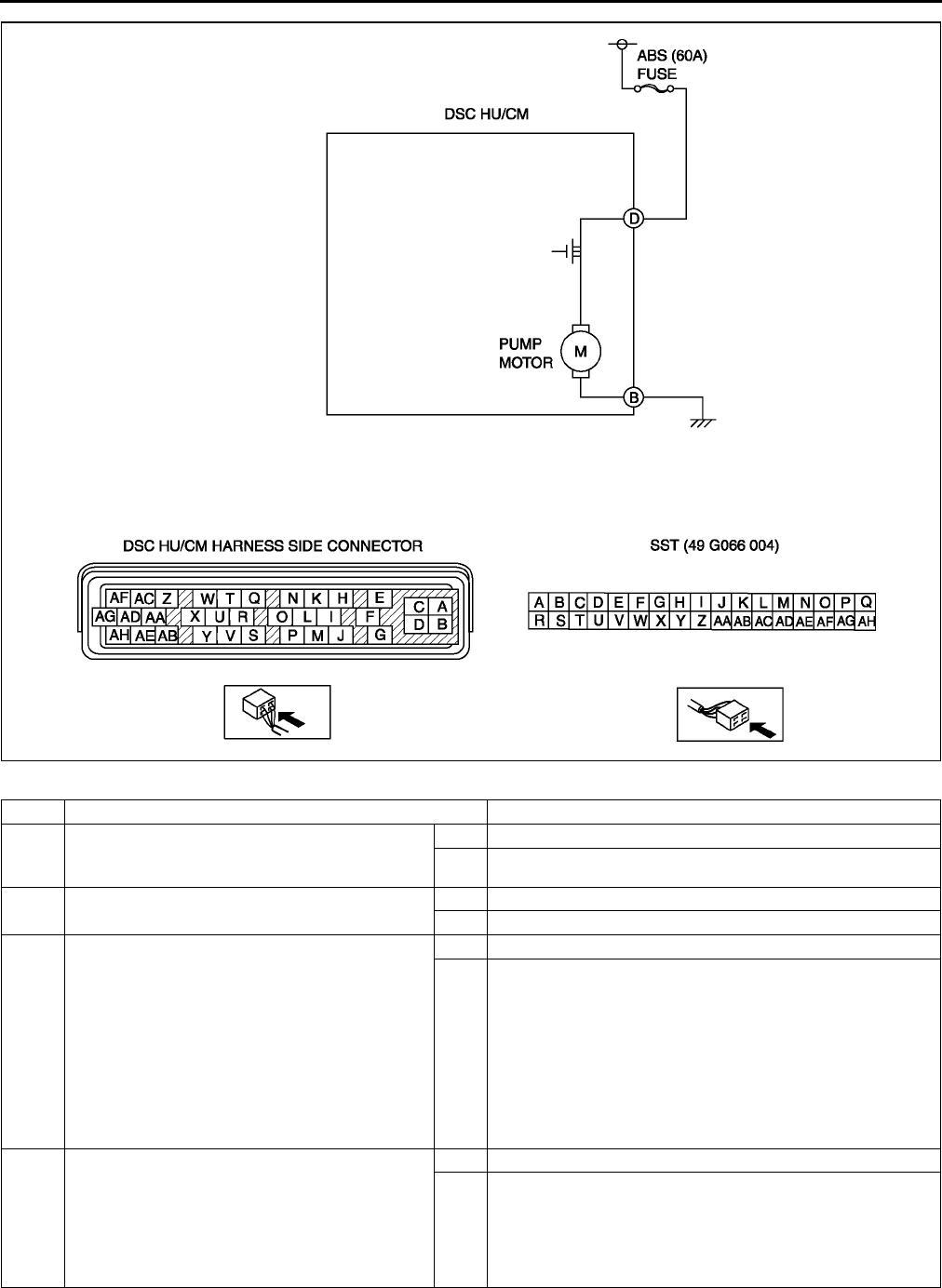
P78
ON-BOARD DIAGNOSTIC (DYNAMIC STABILITY CONTROL)
Diagnostic procedure
STEP INSPECTION ACTION
1VERIFY OTHER DTC HAS BEEN RECORDED
•If any of DTC C1186 and/or C1266 has also
been stored?
Yes Go to applicable DTC inspection.
No Go to next step.
2INSPECT ABS FUSE CONDITION
•Is ABS fuse (60 A) okay?
Yes Go to next step.
No Replace fuse, then go to Step 6.
3INSPECT MOTOR RELAY POWER SUPPLY
CIRCUIT FOR OPEN CIRCUIT
•Turn ignition key to OFF.
•Disconnect DSC HU/CM connector.
•Connect SST (adapter harness) to DSC HU/
CM connector (harness side only).
•Turn ignition key to ON (engine OFF).
•Measure voltage between DSC HU/CM
terminal D (harness side) of SST and
ground.
•Is voltage B+?
Yes Go to next step.
No Repair or replace harness for open circuit between battery
positive terminal and DSC HU/CM terminal D, then go to
Step 9.
4INSPECT PUMP MOTOR GROUND CIRCUIT
FOR OPEN CIRCUIT
•Turn ignition key to OFF.
•Inspect continuity between DSC HU/CM
terminal B (harness side) of SST and
ground.
•Is there continuity?
Yes Go to next step.
No Repair or replace harness for open circuit between DSC
HU/CM terminal B and ground, then go to Step 6.
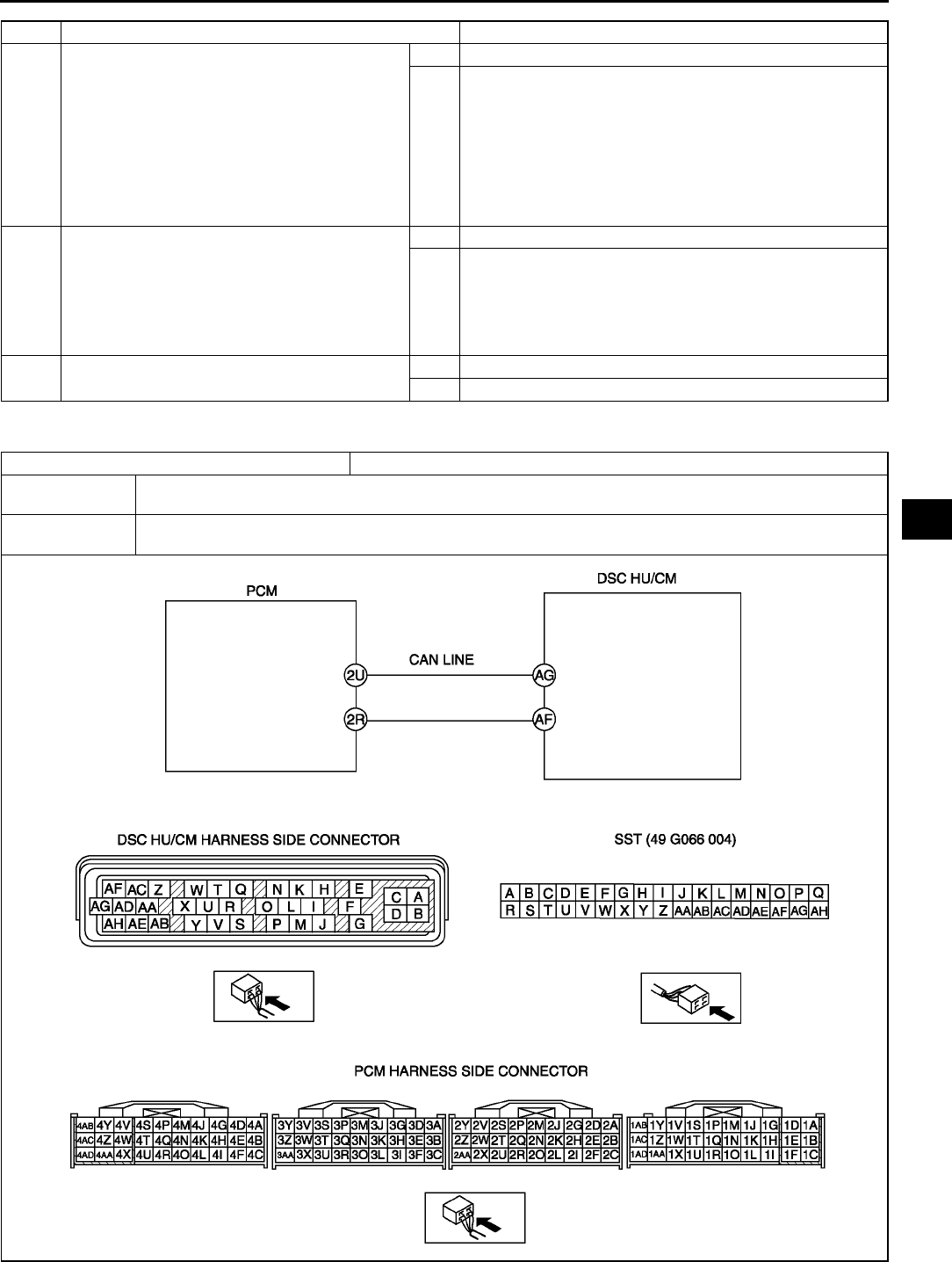
ON-BOARD DIAGNOSTIC (DYNAMIC STABILITY CONTROL)
P79
P
End Of Si e
DTC C1119 A6E697367650W09
5VERIFY PUMP MOTOR OPERATION
•Turn ignition key to OFF.
•Remove SST (adapter harness) and connect
all disconnected connectors.
•Connect WDS or equivalent to DLC-2.
•Turn ignition key to ON (engine OFF).
•Access ABS_POWER and PMP_MOTOR
active command modes using WDS or
equivalent.
•Does pump motor operate?
Yes Go to next step.
No Repair DSC HU/CM, then go to next step.
6VERIFY TROUBLESHOOTING COMPLETED
•Clear DTC from memory.
(See P46 Clearing DTCs Procedures)
•Start engine and drive vehicle at 10 km/h
{6.2 mph} or above.
•Gradually slow down and stop vehicle.
•Is same DTC present?
Yes Replace DSC HU/CM, then go to next step.
No Go to next step.
7VERIFY AFTER REPAIR PROCEDURE
•Is there any other DTC present?
Yes Go to applicable DTC inspection.
No Troubleshooting completed.
STEP INSPECTION ACTION
DTC C1119 Engine control system, torque reduction inhibit signal line
DETECTION
CONDITION
•Engine RPM information through CAN is out of specification.
•Throttle information through CAN is out of specification.
POSSIBLE
CAUSE
•Malfunction of PCM
•Malfunction of CAN

P80
ON-BOARD DIAGNOSTIC (DYNAMIC STABILITY CONTROL)
Diagnostic procedure
End Of Si e
DTC C1125 A6E697367650W10
Diagnostic procedure
End Of Si e
STEP INSPECTION ACTION
1CHECK FOR PCM FOR DTCs
•Turn ignition key to OFF.
•Connect WDS or equivalent to DLC-2
•Turn ignition key to ON (engine OFF).
•Is DTC for engine control system obtained?
Yes Follow inspection procedures for engine control system.
No Go to next step.
2MONITOR CAN SIGNAL
•Access PID RPM and TP using WDS or
equivalentI.
•Are engine speed and throttle position within
specification?
Yes Go to next step.
No Follow inspection procedures for engine control system.
3VERIFY TROUBLESHOOTING COMPLETED
•Make sure to reconnect all disconnected
connectors.
•Clear DTC from memory.
(See P46 Clearing DTCs Procedures)
•Start engine.
•Is same DTC present?
Yes Replace DSC HU/CM, then go to next step.
No Go to next step.
DTC C1125 Brake fluid level sensor
DETECTION
CONDITION •Brake fluid level remains low for 5 seconds or more.
POSSIBLE
CAUSE
•Decrease in amount of brake fluid
•Malfunction of brake fluid level sensor
STEP INSPECTION ACTION
1CHECK FOR CAN FOR DTCs
•Is any of DTC U1900 and/or U2516 has also
been stored?
Yes Follow inspection procedures for CAN system.
(See T144 DTC U0073, U1900, U2516)
No Go to next step.
2INSPECT BRAKE FLUID LEVEL
•Inspect brake fluid level.
•Is it okay?
Yes Go to next step.
No Add brake fluid to specified level, then go to Step 3.
3INSPECT BRAKE FLUID LEVEL SENSOR
•Turn ignition key to OFF.
•Disconnect brake fluid level sensor
connector.
•Measure resistance between brake fluid
level sensor terminals.
Brake fluid level above MIN: resistance
about 500 ohms
Brake fluid level below MIN: resistance
within 01 ohm
•Is it okay?
Yes Go to next step.
No Repair brake fluid level sensor, then go to Next step.
4VERIFY TROUBLESHOOTING COMPLETED
•Make sure to reconnected all disconnected
connectors.
•Clear DTC from memory.
(See P46 Clearing DTCs Procedures)
•Is same DTC present?
Yes Replace DSC HU/CM, then go to next step.
No Go to next step.
5VERIFY AFTER REPAIR PROCEDURE
•Is there any other DTC present?
Yes Go to applicable DTC inspection.
No Troubleshooting completed.
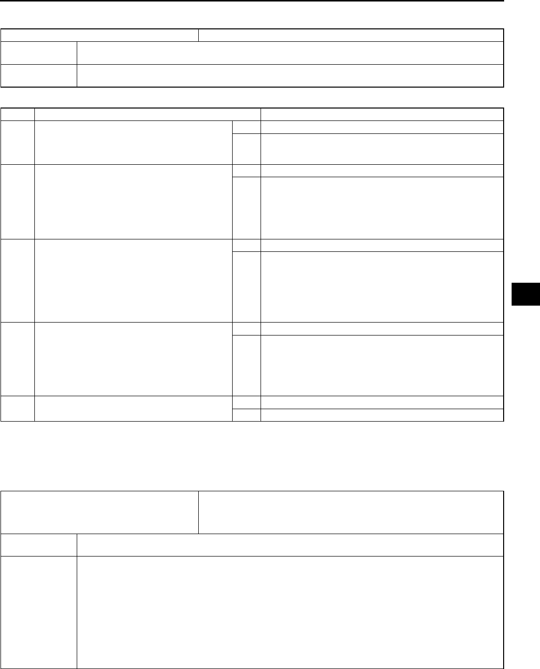
ON-BOARD DIAGNOSTIC (DYNAMIC STABILITY CONTROL)
P81
P
DTC C1140 A6E697367650W11
Diagnostic procedure
End Of Si e
DTC C1145, C1155, C1165, C1175 A6E697367650W12
Caution
•
••
•When attaching the tester lead to the DSC HU/CM connector the SST (49 G066 004) must be used.
DTC C1140 DSC HU/CM (pump)
DETECTION
CONDITION Right front and left rear wheels, or left front and right rear wheel-lock is detected during DSC operation.
POSSIBLE
CAUSE Stuck pump motor in DSC HU/CM
STEP INSPECTION ACTION
1INSPECT DSC HU/CM OPERATION
•Perform DSC HU/CM system inspection.
(See P35 DSC SYSTEM INSPECTION)
•Is it okay?
Yes Go to next step.
No Replace DSC HU/CM, then go to Step 4.
2INSPECT CONVENTIONAL BRAKE
OPERATION
•Inspect brake fluid level.
•Start engine.
•Perform a road test to verify conventional
vehicle braking performance.
•Is there any concern.
Yes Inspect conventional brake line, then go to Step 4.
No Go to next step.
3INSPECT REAR BRAKE DRAGGING
•Turn ignition key to OFF.
•Jack-up vehicle and support it with safety
stand.
•Release parking brake.
•Turn rear wheel by hand and inspect for rear
brake drag.
•Is rear brake dragging?
Yes Repair parking brake system, then go to next step.
No Go to next step.
4VERIFY TROUBLESHOOTING COMPLETED
•Clear DTC from memory.
(See P46 Clearing DTCs Procedures)
•Start engine and drive vehicle at 10 km/h
{6.2 mph} or above at least one minute.
•Gradually slow down vehicle and stop.
•Is same DTC present?
Yes Replace DSC HU/CM, then go to next step.
No Go to next step.
5VERIFY AFTER REPAIR PROCEDURE
•Is there any other DTC present?
Yes Go to applicable DTC inspection.
No Troubleshooting completed.
DTC
C1145
C1155
C1165
C1175
RF wheel-speed sensor
LF wheel-speed sensor
RR wheel-speed sensor
LR wheel-speed sensor
DETECTION
CONDITION •Abnormal input is detected.
POSSIBLE
CAUSE
•Open or short to ground circuit in harness between DSC HU/CM terminal and wheel-speed sensor(s)
terminal below
DSC HU/CM terminal MRF wheel-speed sensor terminal A
DSC HU/CM terminal IRF wheel-speed sensor terminal B
DSC HU/CM terminal FLF wheel-speed sensor terminal A
DSC HU/CM terminal JLF wheel-speed sensor terminal B
DSC HU/CM terminal KRR wheel-speed sensor terminal A
DSC HU/CM terminal HRR wheel-speed sensor terminal B
DSC HU/CM terminal QLR wheel-speed sensor terminal A
DSC HU/CM terminal NLR wheel-speed sensor terminal B
•Malfunction of wheel-speed sensor(s)
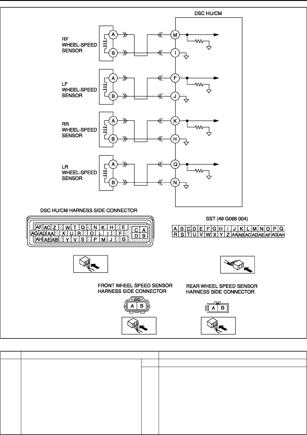
P82
ON-BOARD DIAGNOSTIC (DYNAMIC STABILITY CONTROL)
Diagnostic procedure
STEP INSPECTION ACTION
1INSPECT WHEEL-SPEED SENSOR CIRCUIT
FOR OPEN CIRCUIT
•Turn ignition key to OFF.
•Disconnect DSC HU/CM connector.
•Measure resistance between suspected
sensor terminals of DSC HU/CM connector
(harness side).
RF wheel-speed sensor: MI
LF wheel-speed sensor: FJ
RR wheel-speed sensor: KH
LR wheel-speed sensor: QN
•Is resistance within 1.31.7 kilohm?
Yes Go to next step.
No Go to Step 3.
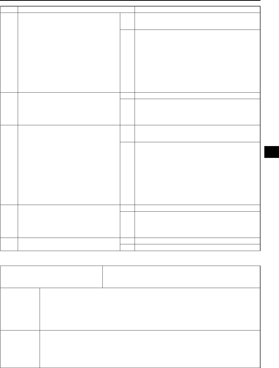
ON-BOARD DIAGNOSTIC (DYNAMIC STABILITY CONTROL)
P83
P
End Of Si e
DTC C1148, C1158, C1168, C1178, C1233, C1234, C1235, C1236 A6E697367650W13
2INSPECT WHEEL-SPEED SENSOR CIRCUIT
FOR SHORT TO GROUND
•Turn ignition key to OFF.
•Inspect continuity between suspected sensor
terminal(s) of DSC HU/CM connector
(harness side) and ground(s).
RF wheel-speed sensor (+): M
RF wheel-speed sensor (): I
LF wheel-speed sensor (+): F
LF wheel-speed sensor (): J
RR wheel-speed sensor (+): K
RR wheel-speed sensor (): H
LR wheel-speed sensor (+): Q
LR wheel-speed sensor (): N
•Is there continuity?
Yes Repair or replace harness for short to ground circuit
between DSC HU/CM and wheel-speed sensor(s), then go
to Step 5.
No Go to Step 5.
3INSPECT WHEEL-SPEED SENSOR
•Turn ignition key to OFF.
•Disconnect suspected sensor connector(s)
and inspect resistance between sensor
terminals (part side).
•Is resistance within 1.31.7 kilohm?
Yes Go to next step.
No Replace wheel-speed sensor, then go to Step 5.
4INSPECT DSC HU/CM TO WHEEL-SPEED
SENSOR CIRCUIT FOR OPEN CIRCUIT
•Inspect continuity between suspected sensor
terminal(s) of DSC HU/CM connector
(harness side) and wheel-speed sensor
connector. (vehicle harness side)
RF wheel-speed sensor (+): MA
RF wheel-speed sensor (): IB
LF wheel-speed sensor (+): FA
LF wheel-speed sensor (): JB
RR wheel-speed sensor (+): KA
RR wheel-speed sensor (): HB
LR wheel-speed sensor (+): QA
LR wheel-speed sensor (): NB
•Is there continuity?
Yes Repair or replace poor connections of DSC HU/CM
connector and/or wheel-speed sensor connector(s), then go
to next step.
No Repair or replace harness for open circuits between DSC
HU/CM and wheel-speed sensor(s), then go to next step.
5VERIFY TROUBLESHOOTING COMPLETED
•Make sure to reconnect all disconnected
connectors.
•Clear DTC from memory.
(See P46 Clearing DTCs Procedures)
•Is same DTC present?
Yes Replace DSC HU/CM, then go to next step.
No Go to next step.
6VERIFY AFTER REPAIR PROCEDURE
•Is there any other DTC present?
Yes Go to applicable DTC inspection.
No Troubleshooting completed.
STEP INSPECTION ACTION
DTC
C1148, C1234
C1158, C1233
C1168, C1235
C1178, C1236
RF wheel-speed sensor/sensor rotor
LF wheel-speed sensor/sensor rotor
RR wheel-speed sensor/sensor rotor
LR wheel-speed sensor/sensor rotor
DETECTION
CONDITION
•C1148, C1158, C1168, C1178:
Abnormal sensor output is detected on any of four vehicle wheels when the vehicle goes from start
to a speed of 10 km/h {6.2 mph}.
Greater than specified amount of ABS demand occurs from front wheel sensors when vehicle is
started.
•C1234, C1233, C1235, C1236:
Abnormal sensor output due to chipping of sensor rotor teeth, etc. is detected.
ABS control operates for 60 seconds or more.
POSSIBLE
CAUSE
•Short to ground circuit of wheel-speed sensor(s) circuit
•Malfunction of wheel-speed sensor(s)
•Damaged sensor rotor(s)
•Incorrect clearance between wheel-speed sensor and sensor rotor
•Poor installation of wheel speed sensor and/or sensor rotor (If the sensor rotor is installed twisted, it
may cause output of abnormal wave form at high speeds).
•DSC HU/CM internal damage (Solenoid valve malfunction, pump motor malfunction, or pipe clogging)
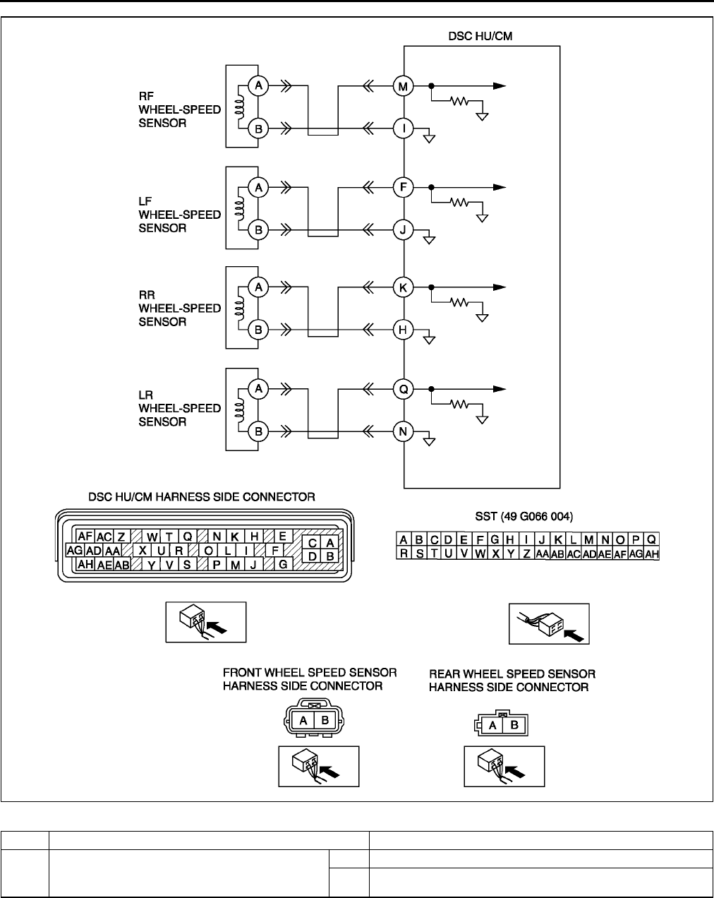
P84
ON-BOARD DIAGNOSTIC (DYNAMIC STABILITY CONTROL)
Diagnostic procedure
STEP INSPECTION ACTION
1VERIFY OTHER DTC HAS BEEN RECORDED
•Have DTCs related to solenoid valve, pump
motor, or pump motor relay been stored?
Yes Go to applicable DTC inspection.
No Go to next step.

ON-BOARD DIAGNOSTIC (DYNAMIC STABILITY CONTROL)
P85
P
2VERIFY IF CURRENT CONCERNED INPUT
SIGNAL STATUS IS INTERMITTENT OR
CONSTANT
•Turn ignition key to OFF.
•Connect WDS or equivalent to DLC-2.
•Start engine and drive vehicle.
•Access LF_WSPD, LR_WSPD, RF_WSPD
and RR_WSPD using WDS or equivalent.
•Do vehicle speeds correspond approximately
to the four PIDs above?
Yes Go to Step 8.
No If there is a difference in speed of four wheels, go to next
step.
If any wheel speed is 0 km/h {0 mph}, go to Step 4.
3INSPECT WHEEL-SPEED SENSOR OUTPUT
PULSE
•Start engine and drive vehicle.
•Inspect output voltage pattern using an
oscilloscope.
Yes Go to Step 9.
No Go to Step 6.
•Is output voltage pattern okay?
4INSPECT ABS WHEEL-SPEED SENSOR
CIRCUIT FOR SHORT TO GROUND
•Turn ignition key to OFF.
•Disconnect DSC HU/CM and wheel-speed
sensor connectors.
•Inspect continuity between suspected sensor
terminal(s) of DSC HU/CM connector
(harness side) and ground(s).
RF wheel-speed sensor: Mground
LF wheel-speed sensor: Fground
RR wheel-speed sensor: Kground
LR wheel-speed sensor: Qground
•Is there continuity?
Yes Repair or replace harness for short to ground circuit
between DSC HU/CM and wheel-sped sensor, then go to
Step 9.
No Go to next step.
5INSPECT WHEEL-SPEED SENSOR
•Turn ignition key to OFF.
•Disconnect suspected wheel-speed sensor
connector(s) and inspect resistance between
wheel-speed sensor terminal(s) (part side).
•Is resistance within 1.31.7 kilohm?
Yes Go to next step.
No Replace wheel-speed sensor, then go to Step 9.
6INSPECT SENSOR ROTOR CLEARANCE
•Jack-up vehicle and support it with safety
stands.
•Remove suspected wheel(s).
•Inspect clearance between wheel-speed
sensor and sensor rotor.
•Is clearance within 0.31.1 mm {0.012
0.043 in}?
Yes Go to next step.
No Replace wheel-speed sensor(s), then go to Step 9.
7INSPECT SENSOR ROTOR FOR DAMAGE
•Jack-up vehicle and support it with safety
stands.
•Remove suspected wheel(s).
•Visually inspect sensor rotor for missing,
deformed and obstructed teeth.
Number of teeth: 44
•Is sensor rotor okay?
Yes Go to next step.
No Replace sensor rotor, then go to Step 9.
STEP INSPECTION ACTION
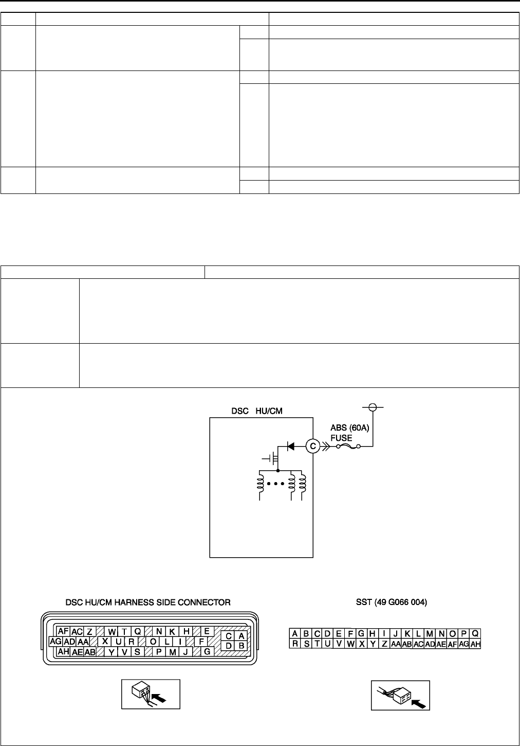
P86
ON-BOARD DIAGNOSTIC (DYNAMIC STABILITY CONTROL)
End Of Si e
DTC C1186, C1266 A6E697367650W14
Caution
•
••
•When attaching the tester lead to the DSC HU/CM connector the SST (49 G066 004) must be used.
8INSPECT DSC HU/CM OPERATION
•Perform DSC HU/CM system inspection.
•See P35 DSC SYSTEM INSPECTION
•Is it okay?
Yes Go to next step.
No Replace DSC HU/CM, then go to next step.
9VERIFY TROUBLESHOOTING COMPLETED
•Make sure to reconnect all disconnected
connectors.
•Clear DTC from memory.
(See P46 Clearing DTCs Procedures)
•Start engine and drive vehicle at 10 km/h
{6.2 mph} or above.
•Gradually slow down vehicle and stop.
•Is same DTC present?
Yes Replace DSC HU/CM, then go to next step.
No Go to next step.
10 VERIFY AFTER REPAIR PROCEDURE
•Is there any other DTC present?
Yes Go to applicable DTC inspection.
No Troubleshooting completed.
STEP INSPECTION ACTION
DTC C1186, C1266 Fail-safe relay
DETECTION
CONDITION
•C1186:
Fail-safe relay in DSC HU/CM stuck OFF when ignition switch is turned ON, fail-safe relay ON is
commanded.
•C1266:
Fail-safe relay in DSC HU/CM stuck ON when ignition switch is turned ON, fail-safe relay OFF is
commanded.
POSSIBLE
CAUSE
•Malfunction of fuse (ABS 60 A)
•Open circuit in harness between DSC HU/CM terminal C and battery positive terminal
•Open or short of fail-safe relay in DSC HU/CM
•Stuck fail-safe relay in DSC HU/CM
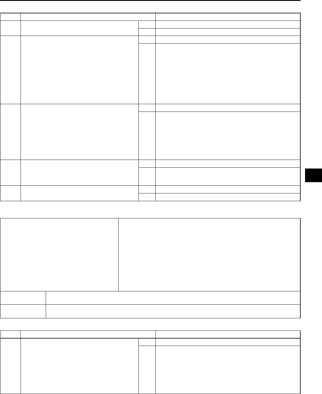
ON-BOARD DIAGNOSTIC (DYNAMIC STABILITY CONTROL)
P87
P
Diagnostic procedure
End Of Si e
DTC C1194, C1198, C1210, C1214, C1242, C1246, C1250, C1254, C1400, C1410, C1957, C1958 A6E697367650W15
Diagnostic procedure
STEP INSPECTION ACTION
1INSPECT ABS FUSE CONDITION
•Is ABS fuse (60 A) okay?
Yes Go to next step.
No Replace fuse, then go to Step 4.
2INSPECT FAIL-SAFE RELAY POWER
SUPPLY CIRCUIT FOR OPEN CIRCUIT
•Turn ignition key to OFF.
•Disconnect DSC HU/CM connector.
•Connect SST (adapter harness) to DSC HU/
CM connector (harness side only).
•Turn ignition key to ON (engine OFF).
•Measure voltage between DSC HU/CM
terminal C (harness side) of SST and
ground.
•Is voltage B+?
Yes Go to next step.
No Repair or replace harness for open circuit between battery
positive terminal and DSC HU/CM terminal C, then go to
Step 4.
4VERIFY FAIL-SAFE OPERATION
•Turn ignition key to OFF.
•Remove SST (adapter harness) and connect
all disconnected connectors.
•Connect WDS or equivalent to DLC-2.
•Turn ignition key to ON (engine OFF).
•Access ABS_POWER using WDS or
equivalent.
•Does fail-safe relay operate?
Yes Go to next step.
No Replace DSC HU/CM, then go to next step.
5VERIFY TROUBLESHOOTING COMPLETED
•Clear DTC from memory.
See P46 Clearing DTCs Procedures
•Is same DTC present?
Yes Replace DSC HU/CM, then go to next step.
No Go to next step.
6VERIFY AFTER REPAIR PROCEDURE
•Is there any other DTC present?
Yes Go to applicable DTC inspection.
No Troubleshooting completed.
DTC
C 1210
C 1214
C 1194
C 1198
C 1246
C 1254
C 1242
C 1250
C 1400
C 1410
C 1957
C 1958
RF pressure reduction solenoid valve
RF pressure retention solenoid valve
LF pressure reduction solenoid valve
LF pressure retention solenoid valve
RR pressure reduction solenoid valve
RR pressure retention solenoid valve
LR pressure reduction solenoid valve
LR pressure reduction solenoid valve
RF traction switch solenoid valve
LF traction switch solenoid valve
RF DSC switch solenoid valve
LF DSC switch solenoid valve
DETECTION
CONDITION •Solenoid monitor signal does not track in response to solenoid ON/OFF command.
POSSIBLE
CAUSE •Stuck solenoid valve in DSC HU/CM
STEP INSPECTION ACTION
1VERIFY SOLENOID VALVE OPERATION
•Turn ignition key to OFF.
•Remove SST (adapter harness) and connect
all disconnected connectors.
•Connect WDS or equivalent to DLC-2.
•Turn ignition key to ON (engine OFF).
•Access solenoid valve(s) PIDs using WDS or
equivalent.
•Does solenoid valve operate?
Yes Go to next step.
No Repair DSC HU/CM, then go to next step.

P88
ON-BOARD DIAGNOSTIC (DYNAMIC STABILITY CONTROL)
End Of Si e
DTC C1280, C1730, C1951, C1952, C1959 A6E697367650W17
Caution
•
••
•When attaching the tester lead to the DSC HU/CM connector the SST (49 G066 004) must be used.
2VERIFY TROUBLESHOOTING COMPLETED
•Clear DTC from memory.
(See P46 Clearing DTCs Procedures)
•Start engine and drive vehicle at 10 km/h
{6.2 mph} or above.
•Gradually slow down and stop vehicle.
•Is same DTC present?
Yes Replace DSC HU/CM, then go to next step.
No Go to next step.
3VERIFY AFTER REPAIR PROCEDURE
•Is there any other DTC present?
Yes Go to applicable DTC inspection.
No Troubleshooting completed.
STEP INSPECTION ACTION
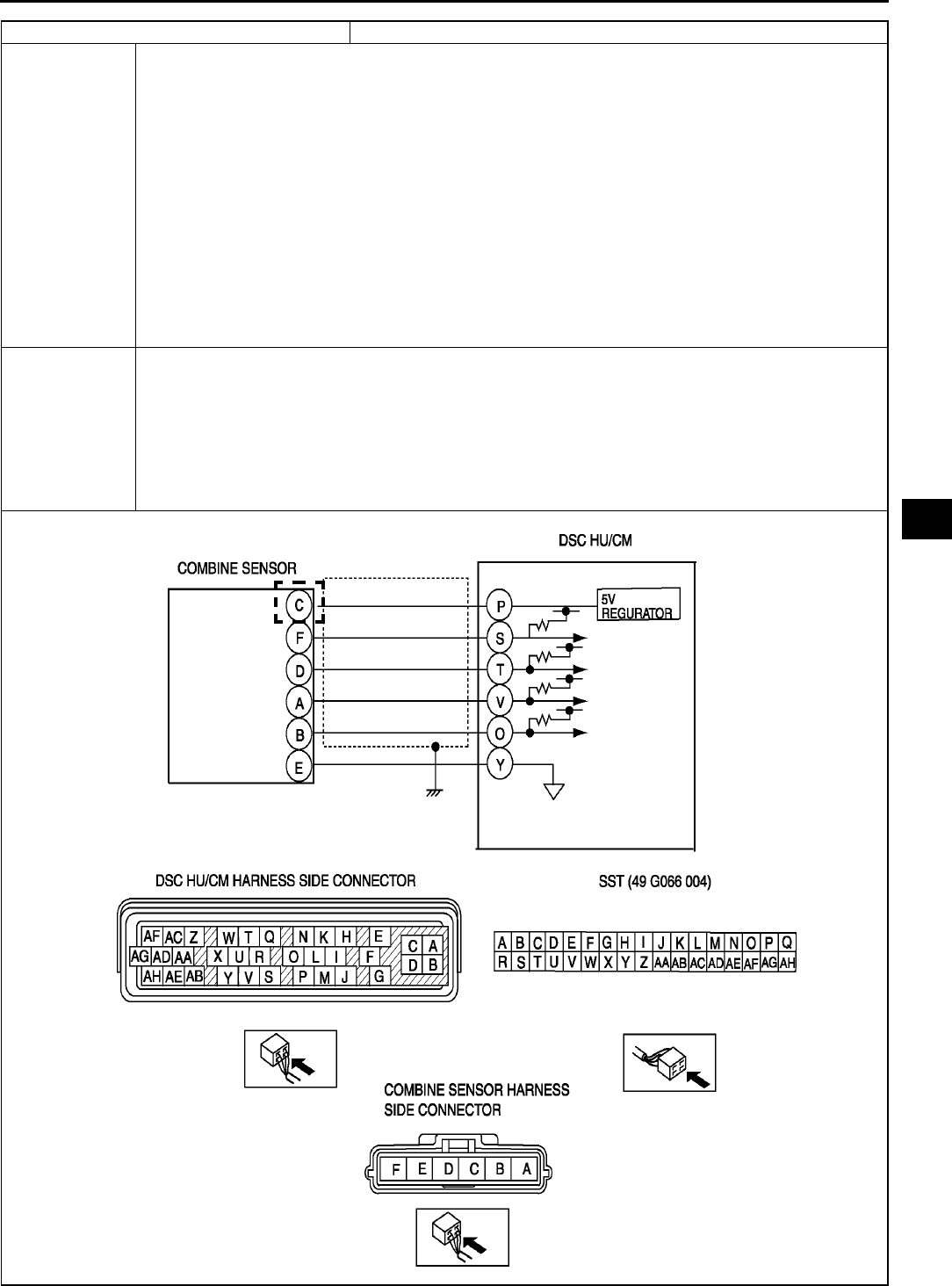
ON-BOARD DIAGNOSTIC (DYNAMIC STABILITY CONTROL)
P89
P
DTC C1280, C1730, C1951, C1952, C1959 Combine sensor
DETECTION
CONDITION
•C1280:
Yaw rate sensor part 0-point correction value is 3 or more, or 2 or less.
Output voltage value from yaw rate sensor part remains absolutely unchanged.
Difference between estimated yaw rate value, calculated from wheel speed-sensor, lateral-G
sensor, steering angle sensor, and the value output from yaw rate sensor exceeds specification.
•C1730
Voltage to combine sensor is detected out of range.
•C1952:
Voltage of yaw rate sensor monitor is detected at 3.5 V or less.
•C1951:
Monitor voltage of lateral-G sensor is detected at 4.5 V or more, or 0.5 V or less.
Monitor voltage difference of 1.25 V or more, within 1 cycle is detected 8 times in 1 second.
•C1959:
Lateral-G sensor part 0-point correction value is 3 or more, or 2 or less.
Output voltage value from lateral-G sensor part remains absolutely unchanged.
Difference between estimated lateral-G force calculated from steering angle sensor, and the value
output from lateral-G sensor exceeds specification.
POSSIBLE
CAUSE
•Open circuit in harness between combine sensor terminal C and DSC HU/CM terminal P
•Open, short to power, or short to ground circuit in harness between DSC HU/CM terminal T and
Combine sensor terminal D
•Open circuit, short to power, or short to ground in harness between DSC HU/CM terminal O and
combine sensor terminal B
•Open circuit in harness between combine sensor terminal E and DSC HU/CM terminal Y
•Open circuit, short to power, or short to ground in harness between DSC HU/CM terminal S and
combine sensor terminal F
•Malfunction of combine sensor

P90
ON-BOARD DIAGNOSTIC (DYNAMIC STABILITY CONTROL)
Diagnostic procedure
STEP INSPECTION ACTION
1INSPECT COMBINE SENSOR POWER
SUPPLY CIRCUIT FOR OPEN CIRCUIT
•Turn ignition key to ON (engine OFF).
•Measure voltage between combine sensor
terminal C (harness side) of and ground.
•Is voltage 4.55.5 V?
Yes Go to next step.
No Repair or replace harness for open circuit between yaw rate
sensor terminal C and ignition switch, then go to Step 8.
2INSPECT COMBINE SENSOR GROUND
CIRCUIT FOR OPEN CIRCUIT
•Turn ignition key to OFF.
•Disconnect DSC HU/CM and yaw rate
sensor connectors.
•Inspect continuity between DSC HU/CM
terminal Y (harness side) and combine
sensor terminal E (harness side).
•Is there continuity?
Yes Go to next step.
No Repair or replace harness for open circuit between DSC
HU/CM terminal Y and yaw rate sensor terminal E, then go
to Step 8.
3INSPECT YAW RATE SENSOR PART SIGNAL
CIRCUIT FOR OPEN CIRCUIT
•Inspect continuity between DSC HU/CM
terminal T (harness side) and combine
sensor terminal D (harness side).
•Is there continuity?
Yes Go to next step.
No Repair or replace harness for open circuit between DSC
HU/CM terminal T and yaw rate sensor terminal D, then go
to Step 8.
4INSPECT LATERAL-G SENSOR PART
SIGNAL CIRCUIT FOR OPEN CIRCUIT
•Inspect continuity between DSC HU/CM
terminal O (harness side) and combine
sensor terminal B (harness side).
•Is there continuity?
Yes Go to next step.
No Repair or replace harness for open circuit between DSC
HU/CM terminal O and combine sensor terminal B, then go
to Step 8.
5INSPECT YAW RATE SENSOR PART SIGNAL
CIRCUIT FOR SHORT TO GROUND
•Turn ignition key to OFF.
•Inspect continuity between DSC HU/CM
terminal T (harness side) and ground.
•Is there continuity?
Yes Repair or replace harness for short to ground circuit
between DSC HU/CM terminal T and combine sensor
terminal D, then go to Step 8.
No Go to next step.
6INSPECT LATERAL-G SENSOR PART
SIGNAL CIRCUIT FOR SHORT TO GROUND
•Turn ignition key to OFF.
•Inspect continuity between DSC HU/CM
terminal O (harness side) and ground.
•Is there continuity?
Yes Repair or replace harness for short to ground circuit
between DSC HU/CM terminal O and combine sensor
terminal B, then go to Step 8.
No Go to next step.
7INSPECT DIAGNOSIS SIGNAL CIRCUIT FOR
SHORT FOR OPEN
•Turn ignition key to OFF.
•Inspect continuity between DSC HU/CM
terminal S (harness side) and combine
sensor terminal F.
•Is there continuity?
Yes Repair or replace harness for open circuit between DSC
HU/CM terminal S and combine sensor terminal F, then go
to Step 8.
No Go to next step.
8INSPECT DIAGNOSIS SIGNAL CIRCUIT FOR
SHORT TO GROUND
•Turn ignition key to OFF.
•Inspect continuity between DSC HU/CM
terminal S (harness side) and combine
sensor terminal F.
•Is there continuity?
Yes Repair or replace harness for short to ground circuit
between DSC HU/CM terminal S and combine sensor
terminal F, then go to Step 8.
No Go to next step.
9INSPECT COMBINE SENSOR
•Inspect combine sensor.
(See P43 COMBINE SENSOR
INSPECTION)
•Is it okay?
Yes Go to next step.
No Replace yaw rate sensor, then go to next step.
10 VERIFY TROUBLESHOOTING COMPLETED
•Clear DTC from memory.
(See P46 Clearing DTCs Procedures)
•Is same DTC present?
Yes Replace DSC HU/CM, then go to next step.
No Go to next step.
11 VERIFY AFTER REPAIR PROCEDURE
•Is there any other DTC present?
Yes Go to applicable DTC inspection.
No Troubleshooting completed.
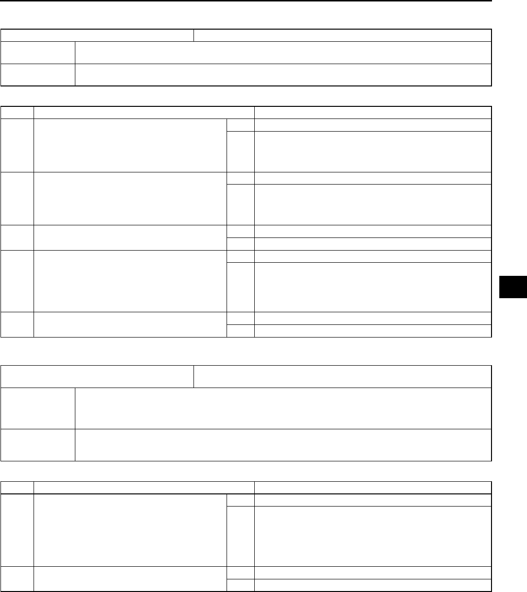
ON-BOARD DIAGNOSTIC (DYNAMIC STABILITY CONTROL)
P91
P
End Of Si e
DTC C1414 A6E697367650W16
Diagnostic procedure
End Of Si e
DTC C1507, C1508 A6E697367650W20
Diagnostic procedure
End Of Si e
DTC C1414 DSC HU/CM mismatched installation
DETECTION
CONDITION
•Detection of situation where vehicle-type or drive system input signal and DSC HU/CM information
remains incongruent through CAN information
POSSIBLE
CAUSE •Mismatched installation of DSC HU/CM
STEP INSPECTION ACTION
1INSPECT DSC HU/CM FOR MISMATCHED
INSTALLATION
•Verify DSC HU/CM part number
•Has a DSC HU/CM with the correct part
number been installed?
Yes Go to next step.
No Replace with correct DSC HU/CM part number, then go to
Step 7.
2INSPECT RELATED WIRING HARNESS FOR
MISMATCHED INSTALLATION
•Verify wiring harness part number
•Has a wiring harness with the correct part
number been installed?
Yes Go to next step.
No Replace with correct DSC HU/CM part number, then go to
next Step.
3Configulate ABS (ABS/TCS) HU/CM
•Can DSC HU/CM configulate properly?
Yes Go to next step.
No Replace DSC HU/CM
4VERIFY TROUBLESHOOTING COMPLETED
•Make sure to reconnected all disconnect
connectors.
•Clear DTC from memory.
See P46 Clearing DTCs Procedures
•Is same DTC present?
Yes Replace DSC HU/CM, then go to next step.
No Go to next step.
5VERIFY AFTER REPAIR PROCEDURE
•Is there any other DTC present?
Yes Go to applicable DTC inspection.
No Troubleshooting completed.
DTC C1507
C1508 DSC control
DETECTION
CONDITION
•C1507:
Brake TCS or DSC controls continue operation for 20 seconds or more.
•C1508:
Engine TCS control continues operation for 60 seconds or more.
POSSIBLE
CAUSE
•System is normal
For protection of solenoid valves in the DSC HU/CM, or protection of the engine, sustained and
continual control of DSC and TCS is inhibited.
STEP INSPECTION ACTION
1VERIFY CURRENT STATUS OF
MALFUNCTION
•Clear DTC from memory.
(See P46 Clearing DTCs Procedures)
•Start engine and drive vehicle at 10 km/h
{6.2 mph} or above.
•Is same DTC present?
Yes Replace DSC HU/CM, then go to next step.
No Inspect intermittent concern using the same procedure as
engine control system.
2VERIFY AFTER REPAIR PROCEDURE
•Is there any other DTC present?
Yes Go to applicable DTC inspection.
No Troubleshooting completed.

P92
ON-BOARD DIAGNOSTIC (DYNAMIC STABILITY CONTROL)
DTC C1510, C1511, C1512, C1513 A6E697367650W21
Diagnostic procedure
End Of Si e
DTC C1953, C1954 A6E697367650W18
Diagnostic procedure
End Of Si e
DTC
C1510
C1511
C1512
C1513
RF solenoid valve, motor or RF wheel-speed sensor/sensor rotor
LF solenoid valve, motor or LF wheel-speed sensor/sensor rotor
RR solenoid valve, motor or RR wheel-speed sensor/sensor rotor
LR solenoid valve, motor or LR wheel-speed sensor/sensor rotor
DETECTION
CONDITION
•Wheel lock is detected during ABS operation (pressure reduction inoperative).
•Pressure reduction on a single wheel continues for 20 seconds or more.
POSSIBLE
CAUSE
•Malfunction of solenoid valve in DSC HU/CM
•Malfunction of wheel-speed sensor
•Damaged sensor rotor
•Stuck pump motor in DSC HU/CM
STEP INSPECTION ACTION
1VERIFY OTHER DTC HAS BEEN RECORDED
•Has any wheel speed sensor, sensor rotor,
solenoid valve, pump motor, or motor relay
related DTC been output?
Yes Go to applicable DTC inspection.
No Go to next step.
2INSPECT DSC HU/CM OPERATION
•Perform DSC HU/CM system inspection.
See P35 DSC SYSTEM INSPECTION
• Is it okay?
Yes Go to next step.
No Replace DSC HU/CM, then go to next step.
3VERIFY CURRENT STATUS OF
MALFUNCTION
•Clear DTC from memory.
See P46 Clearing DTCs Procedures
•Start engine and drive vehicle at 10 km/h
{6.2 mph} or above at least one minute.
•Gradually slow down and stop vehicle.
•Is same DTC present?
Yes Replace DSC HU/CM, then go to next step.
No Go to next step.
4VERIFY AFTER REPAIR PROCEDURE
•Is there any other DTC present?
Yes Go to applicable DTC inspection.
No Troubleshooting completed.
DTC C1953, C1954 Brake fluid pressure sensor
DETECTION
CONDITION
•C1953:
Monitor voltage of the brake fluid pressure sensor is detected at 4.5 V or more, or 0.5 V or less.
Monitor voltage difference of 0.4 V or more within 1 cycle is detected 8 times in 1 second.
•C1954:
Brake fluid pressure sensor 0-point correction value is 0.3 V or less, or 0.9 V or more.
Output voltage value from brake fluid pressure sensor does not increase above 0.06 V.
Difference between estimated brake pressure value and output value of brake fluid pressure sensor
exceeds specification.
POSSIBLE
CAUSE •Malfunction of brake fluid pressure sensor
STEP INSPECTION ACTION
1INSPECT BRAKE FLUID PRESSURE
SENSOR
•Inspect PID/DATA in brake fluid pressure
sensor.
•Inspect MCYLIP item using WDS or
equivalent.
•Is pressure value change between 022.5
MPa when brake pedal is pressed?
Yes Go to next step.
No Repair DSC HU/CM.
2VERIFY TROUBLESHOOTING COMPLETED
•Clear DTC from memory.
(See P46 Clearing DTCs Procedures)
•Is same DTC present?
Yes Replace DSC HU/CM, then go to next step.
No Go to next step.
3VERIFY AFTER REPAIR PROCEDURE
•Is there any other DTC present?
Yes Go to applicable DTC inspection.
No Troubleshooting completed.

ON-BOARD DIAGNOSTIC (DYNAMIC STABILITY CONTROL)
P93
P
DTC C1955, C1956 A6E697367650W19
Caution
•
••
•When attaching the tester lead to the DSC HU/CM connector the SST (49 G066 004) must be used.
DTC C1955, C1956 Steering angle sensor
DETECTION
CONDITION
•C1955:
Output voltages from steering angle sensors 1 and 2 are not at 1 V or less, or not at 3.25 V or
more.
•C1956:
Sensor 1 voltage remains unchanged, sensor 2 voltage changes.
Sensor 2 voltage remains unchanged, sensor 1 voltage changes.
When steering wheel is turned in specified direction, neutral position is detected even when rotated
at 18 degrees or more.j
POSSIBLE
CAUSE
•Open circuit in harness between steering angle sensor terminal A and ignition switch
•Open, short to power, or short to ground circuit in harness between DSC HU/CM terminal X and
steering angle sensor terminal B
•Open, short to power, or short to ground circuit in harness between DSC HU/CM terminal W and
steering angle sensor terminal C
•Open, short to power, or short to ground circuit in harness between DSC HU/CM terminal U and
steering angle sensor terminal D
•Open circuit in harness between DSC HU/CM terminal Rand steering angle sensor terminal F
•Malfunction of steering angle sensor
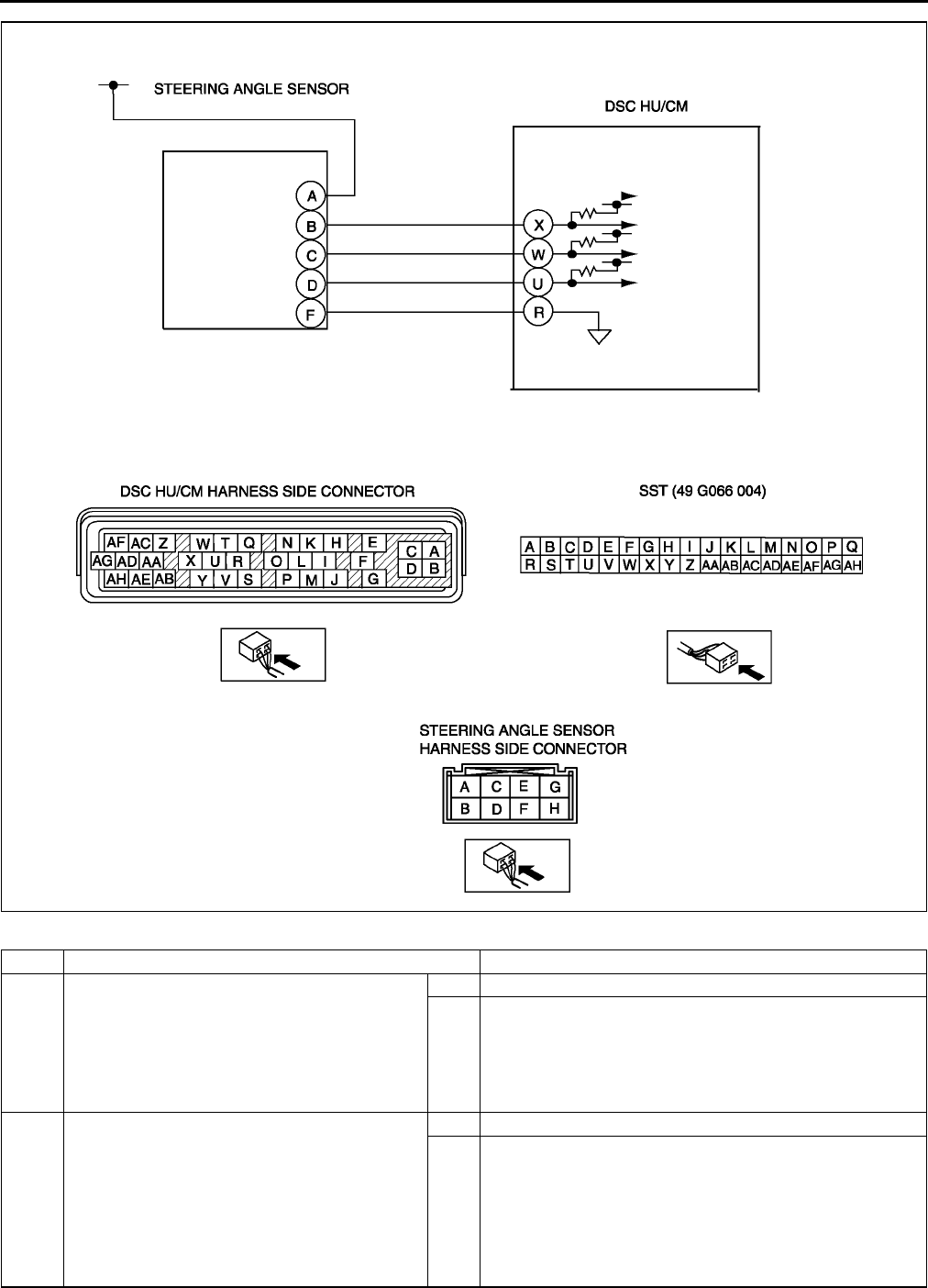
P94
ON-BOARD DIAGNOSTIC (DYNAMIC STABILITY CONTROL)
Diagnostic procedure
STEP INSPECTION ACTION
1INSPECT STEERING ANGLE SENSOR
POWER SUPPLY CIRCUIT FOR OPEN
CIRCUIT
•Turn ignition key to ON (engine OFF).
•Measure voltage between steering angle
sensor terminal A (harness side) and ground.
•Is voltage B+?
Yes Go to next step.
No Repair or replace harness for open circuit between steering
angle sensor terminal A and ignition switch, then go to Step
7.
2INSPECT STEERING ANGLE SENSOR
GROUND CIRCUIT FOR OPEN CIRCUIT
•Turn ignition key to OFF.
•Disconnect DSC HU/CM and steering angle
sensor connectors.
•Inspect continuity between DSC HU/CM
terminal R (harness side) and steering angle
sensor terminal F (harness side).
•Is there continuity?
Yes Go to next step.
No Repair or replace harness for open circuit between DSC
HU/CM terminal R and steering angle sensor terminal F,
then go to Step 7.

ON-BOARD DIAGNOSTIC (DYNAMIC STABILITY CONTROL)
P95
P
End Of Si e
3INSPECT STEERING ANGLE SENSOR
SIGNAL CIRCUIT FOR OPEN CIRCUIT
•Inspect continuity between DSC HU/CM
terminal (harness side) and steering angle
sensor terminal (harness side) below.
Sensor 1: DSC HU/CM X and steering
angle sensor B
Sensor 2: DSC HU/CM W and steering
sensor C
Neutral: DSC HU/CM U and steering
angle sensor D
•Is there continuity?
Yes Go to next step.
No Repair or replace harness for open circuit between DSC
HU/CM terminal and steering angle sensor terminal, then go
to Step 7.
4INSPECT STEERING ANGLE SENSOR
SIGNAL CIRCUIT FOR SHORT TO POWER
•Turn ignition key to ON (engine OFF).
•Measure voltage between DSC HU/CM
terminal (harness side) and ground below.
Sensor 1: DSC HU/CM X and ground
Sensor 2: DSC HU/CM W and ground
Neutral: DSC HU/CM U and ground
•Is voltage B+?
Yes Repair or replace harness for short to power circuit between
DSC HU/CM terminal and steering angle sensor terminal,
then go to Step 7.
No Go to next step.
5INSPECT STEERING ANGLE SENSOR
SIGNAL CIRCUIT FOR SHORT TO GROUND
•Turn ignition key to OFF.
•Inspect continuity between DSC HU/CM
terminal (harness side) and ground below.
Sensor 1: DSC HU/CM X and ground
Sensor 2: DSC HU/CM W and ground
Neutral: DSC HU/CM U and ground
•Is there continuity?
Yes Repair or replace harness for short to ground circuit
between DSC HU/CM terminal and steering angle sensor
terminal, then go to Step 7.
No Go to next step.
6INSPECT STEERING ANGLE SENSOR
•Inspect steering angle sensor.
(See P44 STEERING ANGLE SENSOR
INSPECTION)
•Is it okay?
Yes Go to next step.
No Replace steering angle sensor, then go to next step.
7VERIFY TROUBLESHOOTING COMPLETED
•Clear DTC from memory.
(See P46 Clearing DTCs Procedures)
•Is same DTC present?
Yes Replace DSC HU/CM, then go to next step.
No Go to next step.
8VERIFY AFTER REPAIR PROCEDURE
•Is there any other DTC present?
Yes Go to applicable DTC inspection.
No Troubleshooting completed.
STEP INSPECTION ACTION
P96
ON-BOARD DIAGNOSTIC (DYNAMIC STABILITY CONTROL)
DTC U2021 A6E697367650W22
Note
•To warm up the engine completely, idle the engine and wait for more than 5 minutes.
Diagnostic procedure
End Of Si e
DTC U2021 Engine coolant temperature
DETECTION
CONDITION
•After engine is warmed up, engine coolant temperature is 0 °
°°
°C {32 °
°°
°F} or less, and TCS operation is
inhibited by PCM.
POSSIBLE
CAUSE •System is normal. When engine coolant temperature rises, TCS operation is executed by PCM.
STEP INSPECTION ACTION
1CHECK WHETHER ENGINE HAS WARMED
UP
•Has engine warmed up?
Yes Go to next step.
No Warm up the engine.
If DSC OFF light goes out, system is normal.
2VERIFY THAT MALFUNCTION SYMPTOM
OCCURS AFTER ENGINE IS WARMED UP
•Warm up the engine.
•Is DSC indicator light also illuminated and
DTC C1119 obtained?
Yes Go to DTC C1119 chart.
No If DSC OFF light goes out, system is normal.
If DSC OFF light does not go out, go to next step.
3VERIFY TROUBLESHOOTING COMPLETED
•Clear DTC from memory.
(See P46 Clearing DTCs Procedures)
•Is same DTC present?
Yes Replace DSC HU/CM, then go to next step.
No Go to next step.
4VERIFY AFTER REPAIR PROCEDURE
•Is there any other DTC present?
Yes Go to applicable DTC inspection.
No Troubleshooting completed.
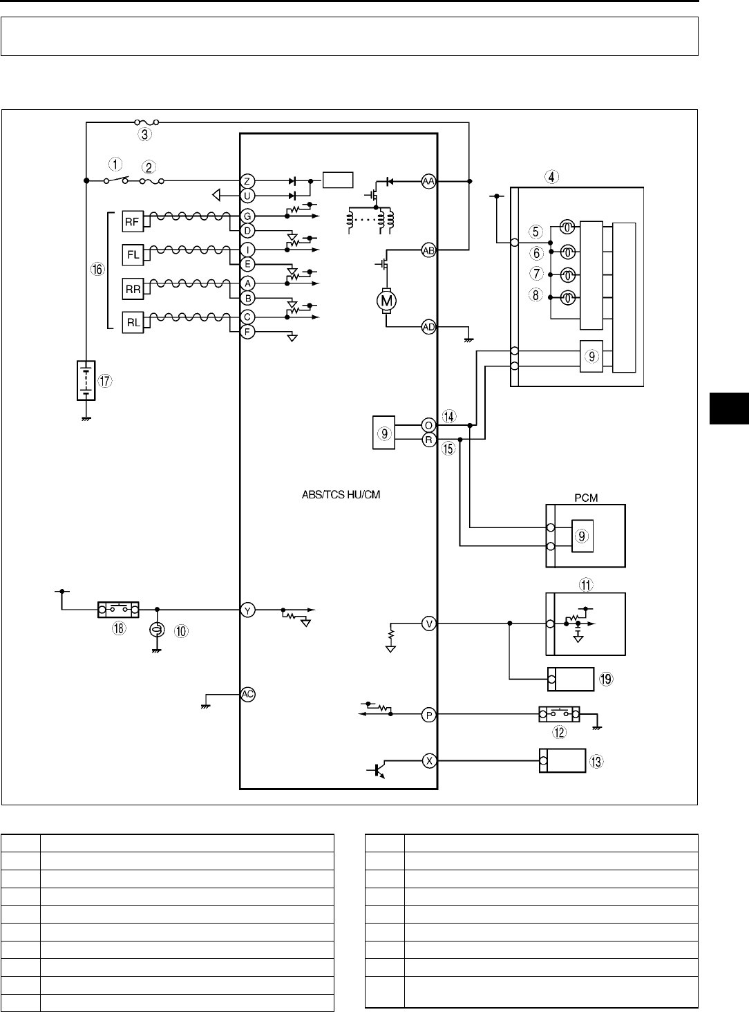
TROUBLESHOOTING (ABS/TCS/DYNAMIC STABILITY CONTROL)
P97
P
SYSTEM WIRING DIAGRAM A6E699067650W01
ABS (ABS/TCS)
.
TROUBLESHOOTING (ABS/TCS/DYNAMIC STABILITY CONTROL)
A6E6921T001
1 IG switch
2 SUS 15 A fuse
3 ABS 60 A fuse
4 Meter
5 ABS warning light
6 Brake system warning light
7 TCS OFF light
8 TCS indicator light
9CAN driver
10 Brake light
11 Cruise actuator
12 TCS OFF switch
13 DLC-2
14 CAN-H
15 CAN-L
16 ABS Wheel-speed sensor
17 Battery
18 Brake switch
19 Audio unit, Wiper and washer switch, Car-navigation
unit, Auto leveling control unit
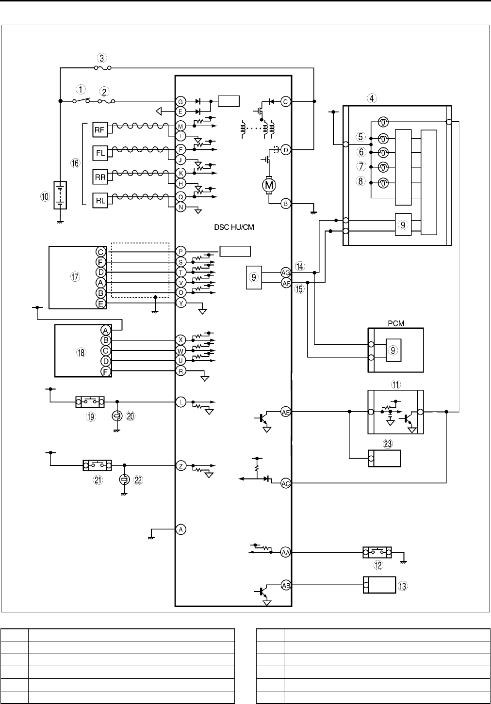
P98
TROUBLESHOOTING (ABS/TCS/DYNAMIC STABILITY CONTROL)
DSC
.
A6E6920T005
1 IG switch
2 SUS 15A fuse
3 ABS 60 A fuse
4Meter
5 ABS warning light
6 Brake system warning light
7 DSC OFF light
8 DSC indicator light
9CAN driver
10 Battery
11 Cruise actuator
12 DSC OFF switch
TROUBLESHOOTING (ABS/TCS/DYNAMIC STABILITY CONTROL)
P99
P
End Of Si e
FOREWORD A6E699067650W02
•Before performing the steps in Symptom Troubleshooting, perform the On-board Diagnostic Inspection. To
check the DTC, follow the DTC Inspection steps.
End Of Si e
PRECAUTION A6E699067650W03
Vehicles with ABS/TCS
1. The ABS warning light, BRAKE system warning light, TCS indicator light and/or TCS OFF light illuminate even
when the system is normal.
*1 : In cases where the light may illuminate, only when ABS/TCS HU/CM detects that speed sensor of rear wheel
is malfunctioning.
*2 : If battery voltage drops below 9 V while vehicle speed is greater than 6 km/h{3.7mph}, ABS HU/CM records
DTC B1318.
13 DLC-2
14 CAN-H
15 CAN-L
16 Wheel-speed sensor
17 Combine sensor
18 Steering angle sensor
19 Brake switch
20 Brake light
21 Back-up light switch (MTX only)
22 Back-up light
23 Audio unit, Wiper and washer switch,
Car-navegation unit, Auto leveling control unit
Warning lights that may
illuminate and/or flash
Cases in which the light may
illuminate
Conditions in which the
light will go out
ABS, EBD, TCS and DSC
control
Any or all the following light(s)
illuminate:
•ABS warning light
•BRAKE system warning
light(*1)
Under any of the following
conditions:
•When the front wheels are
jacked up, stuck, or placed
on a chassis roller, and
only the front wheel ABS
wheel speed sensors are
spun for more than 60
seconds.
After turning ignition switch
OFF, vehicle is driven at
speed greater than 10 km/h
{6.2 mph} and normal
operation is confirmed.
•ABS: Cuts control.
•EBD:
1. Cuts control, in cases
where the light may
illuminate, only when ABS
CM detects that a wheel
speed sensor determines
that more than the two rear
wheels are malfunctioning.
2. Operates control, if wheel
speed sensor determines
that more than 3 wheels
are functioning correctly.
Parking brake is not fully
released while driving.
Brake drag.
Sudden acceleration/
deceleration.
Left/right or front/rear tires are
different. (Size, radius, tire
pressure, or wear is other than
that listed on tire label.)
All the following lights
illuminate:
•ABS warning light
•BRAKE system warning
light
Battery voltage at ABS-TCS
HU/CM ignition terminal Z
drops below about 9 to 10
V.(*2)
Battery voltage rises abobe
about 10 V.
(Only BRAKE system warning
light goes out.)
ABS: Operates control.
EBD: Operates control.

P100
TROUBLESHOOTING (ABS/TCS/DYNAMIC STABILITY CONTROL)
*1 : DTC U2021 for past malfunction is not recorded in the ABS/TCS HU/CM. DTC U2021 for present malfunction
displayed, but goes out when engine coolant temperature rises above 0°
°°
°C {32F}.
*2 : When malfunctions happen that display DTCs, flashes the ABS warning light.
2. Precautions during servicing of ABS/TCS
The ABS/TCS is composed of electrical and mechanical parts.It is necessary to categorize malfunctions as
being either electrical or hydraulic when performing troubleshooting.
(1) Malfunction in electrical system
•The ABS/TCS hydraulic unit and control module (ABS/TCS HU/CM) has an on-board diagnostic
function. With this function, the ABS warning light and/or BRAKE system warning light will come on
when there is a problem in the electrical system. Also, past and present malfunctions are recorded in
the ABS/TCS HU/CM. This function can find malfunctions that do not occur during periodic inspections.
Connect the WDS or equivalent to the DLC-2. The stored malfunction will be displayed in the order of
occurrence. To find out the causes of ABS/TCS malfunction, use these on-board diagnostic results.
•If malfunction occurred in the past but is now normal, the cause is likely a temporary poor connection of
the harness. The ABS/TCS HU/CM usually operates normally. Be careful when searching for the cause
of malfunction.
•After repair, it is necessary to clear the
DTC from the ABS/TCS HU/CM memory. Also, if the ABS/TCS related parts have been replaced, verify
that the no DTC has been displayed after repairs.
•After repairing the ABS wheel-speed sensor or ABS sensor rotor, or after replacing the ABS CM (ABS
motor or ABS motor relay or solenoid valve), the ABS warning light may not go off (*) even when the
ignition switch is turned on. In this case, drive the vehicle at a speed of more than 10km/h{6.2mph},
make sure that ABS warning light goes off, and then clear the DTC.
* The BRAKE system warning light also illuminates when any rear wheel malformations.
•When repairing, if the ABS/TCS related connectors are disconnected and the ignition switch is turned
on, the ABS/TCS CM will mistakenly detect a fault and record it as a malfunction.
•To protect the ABS/TCS HU/CM, make sure the ignition is off before connecting or disconnecting the
ABS/TCS CM connector.
•To protect the terminal, use the SST (ABS/TCS: 49 G066 001, DSC: 49 G066 004) when connecting
the tester lead to the ABS/TCS HU/CM connector.
(2) Malfunction in hydraulic system
•Symptom in hydraulic system malfunction are similar to those in conventional brake malfunction.
However, it is necessary to determine if the malfunction is in an ABS component or the conventional
brake system.
•The ABS hydraulic unit contains delicate mechanical parts. If foreign materials get into the component,
the ABS may fail to operate. Also, it will likely become extremely difficult to find the location of the
malfunction in the event that the brakes operate but the ABS does not. Make sure foreign materials do
not get inside when servicing the ABS (e.g. brake fluid replacement, pipe removal).
Warning lights that may
illuminate and/or flash
Cases in which the light may
illuminate
Conditions in which the
light will go out
ABS, EBD, TCS and DSC
control
All the following lights
illuminate:
•TCS OFF light
When the engine coolant
temperature is below
0°
°°
°C {32 F}.(*2)
When engine is started and
engine coolant temperature
rises above 0°
°°
°C {32 F}.)
ABS: Cuts control.
EBD: Cuts control.
TCS:
1. If TCS is operating, cuts
control after gradually
released TCS control
value.
2. If TCS is not operating,
cuts control.
All the following lights flash:
•ABS warning light
•BRAKE system warning
light
Following light illuminates:
•TCS OFF light
When confirming DTC,PID/
DATA and ACTIVE COMAND
MODES item using WDS or
equivalent.
When ABS ON-BOARD
DIAGNOSTIC SYSTEM is
released.
ABS: Cuts control.
EBD: Cuts control.
TCS: Cuts control.

TROUBLESHOOTING (ABS/TCS/DYNAMIC STABILITY CONTROL)
P101
P
Vehicle with DSC
1. The ABS warning light and/or BRAKE system warning light and/or DSC indicator light and/or TSC OFF light
illuminate even when the system is normal.
2. Precautions during servicing of DSC The DSC is composed of electrical and mechanical parts. It is necessary
to categorize malfunctions as being either electrical or hydraulic when performing troubleshooting.
(1) Malfunction in electrical system
•The control module has an on-board diagnostic function. With this function, the ABS warning light and/
or BRAKE system warning light and/or DSC indicator light and/or TSC OFF light will come on when
there is a problem in the electrical system.
Also, past and present malfunction are recorded in the control module. This function can find
malfunction that do not occur during periodic inspections. Connect the WDS or equivalent to the DLC-2.
The stored malfunction will be displayed in the order of occurrence. To find out the causes of DSC
malfunction, use these on-board diagnostic results.
•If a malfunction occurred in the past but is now normal, the cause is likely a temporary poor connection
of the harness.
The control module usually operates normally. Be careful when searching for the cause of malfunction.
•After repair, it is necessary to clear the DTC from the control module memory.
Also, if the DSC related parts have been replaced, verify that the no DTC has been displayed after
repairs.
•After repairing the ABS wheel-speed sensor or ABS sensor rotor, or after replacing the control module,
the ABS warning light may not go off even when the ignition switch is turned on. In this case, drive the
vehicle at a speed of more than 10 km/h {6.2 mph}, make sure the ABS warning light goes off, and
then clear the DTC.
•When repairing, if the DSC related connectors are disconnected and the ignition switch is turned on,
the control module will mistakenly detect a fault and record it as malfunction.
Caution
•
••
•In DSC vehicles, when any DSC HU/CM, steering angle sensor, lateral-G sensor, yaw rate sensor
are replaced. Perform the sensor standard point installation of each sensor.
•To protect the control module, make sure the ignition is off before connecting or disconnecting the
control module connector.
•To protect the terminal, use the SST (ABS/TCS: 49 G066 001, DSC: 49 G066 004) when connecting
the tester lead to the DSC HU connector.
Warning lights that may
illuminate and/or flash
Cases in which the light may
illuminate
Conditions in which the
light will go out
ABS, EBD, TCS and DSC
control
•ABS warning light
•BRAKE system warning
light
•DSC indicator light
•DSC OFF light
Under any of the following
conditions:
•When the front wheels are
jacked up, struck, or
placed on a chassis roller,
and only the front wheel
ABS wheel speed sensors
are spun for more than 60
senconds.
After turning ignition switch
OFF, vehicle is driven at
speed greater than 10 km/h
{6.2MPH} and normal
operation is confirmed.
•ABS: Cuts control.
•EBD: Cuts control.
•TCS: Cuts control.
•DSC: Cuts control.
Parking brake is not fully
released while driving.
Brake drag.
Sudden
acceleration/deceleration.
Left/right or front/rear tires are
different. (Size, radius, tire
pressure, or wear is other than
that listed on tire label.)
Battery voltage at DSC HU/
CM ignition terminal drops
below about 9.5 V.
Battery voltage rises above
about 9.5 V.
ABS: Operates control.
EBD: Operates control.
TCS: Operates control.
DSC: Operates control.
•Brake system warning
light
•DSC indicator light
•TSC OFF light
Brake fluid amount is low. Brake fluid level lower than
recommended amount.
ABS: Operates control.
EBD: Operates control.
TCS: Cuts control.
DSC: Cuts control.
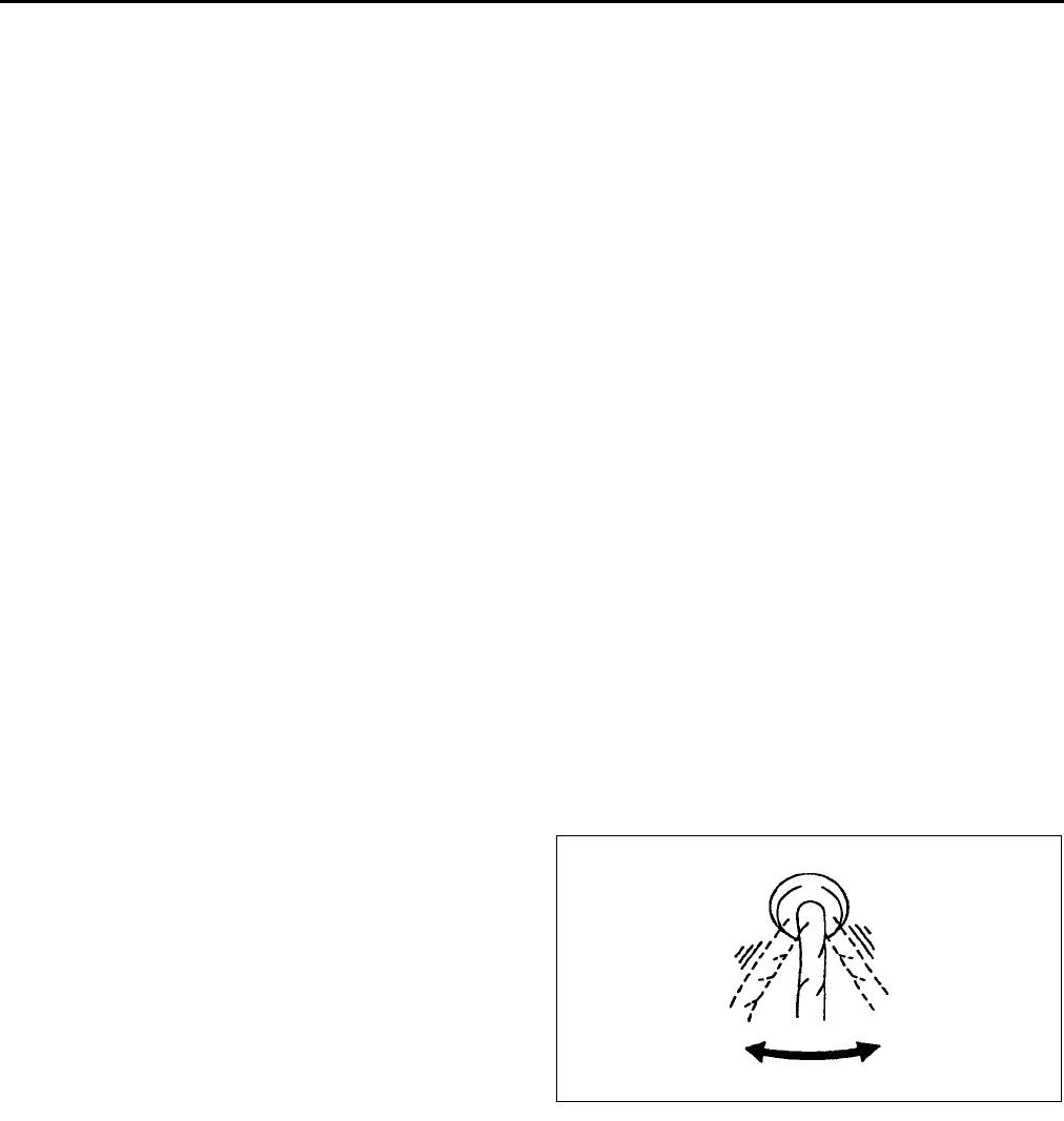
P102
TROUBLESHOOTING (ABS/TCS/DYNAMIC STABILITY CONTROL)
(2) Malfunction in hydraulic system
•Symptom in hydraulic system malfunction are similar to those in a conventional brake malfunction.
However, it is necessary to determine if the malfunction is in a DSC component or the conventional
brake system.
•The hydraulic unit contains delicate mechanical parts. If foreign materials get into the component, the
DSC may fail to operate. Also, it will likely become extremely difficult to find the location of the
malfunction in the event that the brakes operate but the DSC does not. Make sure foreign materials do
not get inside when servicing the DSC (e.g.brake fluid replacement, pipe removal).
Intermittent Concern Troubleshooting
Vibration method
•If malfunction occurs or becomes worse while driving on a rough road or when engine is vibrating, perform the
steps below.
Note
•There are several reasons why vehicle or engine vibration could cause an electrical malfunction. Check
the following:
Connectors not fully seated.
Wire harnesses not having full play.
Wires laying across brackets or moving parts.
Wires routed too close to hot parts.
•An improperly routed, improperly clamped, or loose harness can cause wiring to become pinched
between parts.
•The connector joints, points of vibration, and places where wire harnesses pass through the firewall, body
panels, etc. are the major areas to be checked.
Inspection method for switch connectors or wires
1. Connect WDS or equivalent to DLC-2.
2. Turn ignition key to ON (Engine OFF).
Note
•If engine starts and runs, perform the following steps at idle.
3. Access PIDs for the switch you are inspecting.
4. Turn switch on manually.
5. Shake each connector or wire harness a bit
vertically and horizontally while monitoring the
PID.
•If PID value is unstable, check for poor
connection.
Inspection method for sensor connectors or wires
1. Connect WDS or equivalent to DLC-2.
2. Turn ignition key to ON (Engine OFF).
Note
•If engine starts and runs, perform the following steps at idle.
3. Access PIDs for the switch you are inspecting.
YDE6980W003
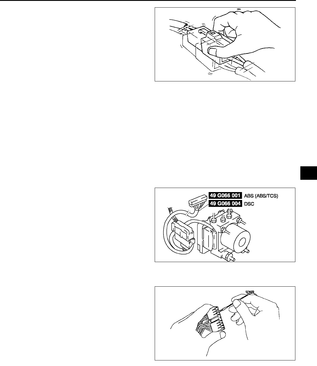
TROUBLESHOOTING (ABS/TCS/DYNAMIC STABILITY CONTROL)
P103
P
4. Shake each connector or wire harness a bit
vertically and horizontally while monitoring the
PID.
•If PID value is unstable, check for poor
connection.
Inspection method for sensors
1. Connect WDS or equivalent to DLC-2.
2. Turn ignition key to ON (Engine OFF).
Note
•If engine starts and runs, perform the following steps at idle.
3. Access PIDs for the switch you are inspecting.
4. Vibrate the sensor slightly with your finger.
•If PID value is unstable or malfunction occurs, check for poor connection and/or poorly mounted sensor.
Malfunction data monitor method
1. Perform malfunction reappearance test according to malfunction reappearance mode and malfunction data
monitor. The malfunction cause is found in the malfunction data.
Malfunction data monitor using SST (ABS/TCS: 49 G066 001, DSC: 49 G066 004)
Connector terminal check method
1. Check the connection condition of each female terminal.
2. Insert male terminal; fit female terminal size to
female terminal and check to see whether
malfunction is in female terminal or not.
End Of Si e
YDE6980W002
A6E6921W016
Y3E6980W001

P104
TROUBLESHOOTING (ABS/TCS/DYNAMIC STABILITY CONTROL)
SYMPTOM TROUBLESHOOTING A6E699067650W04
•Verify the symptoms, and perform troubleshooting according to the appropriate number.
Vehicles with ABS/TCS
Vehicles with DSC
*1 : DSC system contains traction control function, DSC indicator light goes on and off while DSC operates.
*2 : DSC indicator light goes on and off while DSC operates.
No. Symptom
1 ABS warning light, BRAKE system warning light, TCS OFF light do not illuminate with ignition switch on.
2 Neither ABS warning light nor BRAKE system warning light illuminate with ignition switch on.
3 ABS warning light does not illuminate with ignition switch on.
4 BRAKE system warning light does not illuminate with ginning switch on.
5 TCS OFF light and TCS indicator light do not illuminate with ignition switch on.
6 Both ABS warning light and BRAKE system warning light stay on more than 4 seconds with ignition with on.
7 ABS warning light stays on more than 4 seconds with ingestion switch on.
8 BRAKE system warning light stays on more than 4 seconds with ignition switch on. (Parking brake is released.)
9 TCS OFF light stays on more than 4 seconds with ignition switch on.
10 TCS does not work correctly.
11 There is a malfunction in the system even through ABS warning light, BRAKE system warning light, TCS OFF
light,TCS indicator light do not illuminate.
No. Symptom
1 Any of the following lights do not illuminate with ignition switch on.
•ABS warning light
•BRAKE system warning light
•DSC indicator light
•DSC OFF light
2 Any of the following lights stay on:
•ABS warning light.
•BRAKE system warning light
•DSC indicator light
•DSC OFF light
3 There is a malfunction in the system even though ABS warning light, BRAKE system warning light, DSC indicator
light and DSC OFF light do not illuminate.
4ABS or TCS*1 operates frequently.
TCS does not work correctly.
5DSC*2 operates frequently.
DSC does not work correctly.
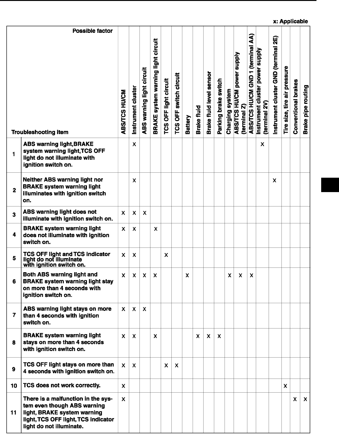
TROUBLESHOOTING (ABS/TCS/DYNAMIC STABILITY CONTROL)
P105
P
Vehicle with ABS/TCS
A6E6980W002
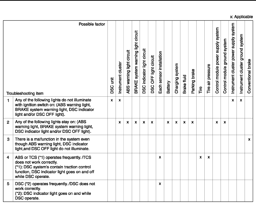
P106
TROUBLESHOOTING (ABS/TCS/DYNAMIC STABILITY CONTROL)
Vehicle with DSC
End Of Si e
A6E6980W001
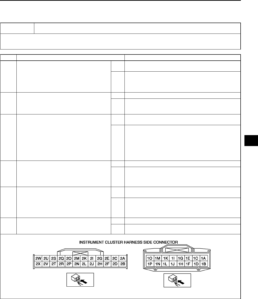
TROUBLESHOOTING (ABS/TCS/DYNAMIC STABILITY CONTROL)
P107
P
NO.1 ABS WARNING LIGHT, BRAKE SYSTEM WARNING LIGHT, TCS OFF LIGHT DO NOT ILLUMINATE
WITH IGNITION SWITCH ON A6E699067650W05
Vehicle with ABS/TCS
•When performing an asterisked (*) troubleshooting inspection, shake the wiring harness and connectors while
doing the inspection to discover whether poor contact points are the cause of any intermittent malfunction. If
there is a problem, check to make sure connectors, terminals and wiring harnesses are connected correctly
and undamaged.
End Of Si e
1ABS warning light, BRAKE system warning light, TCS OFF light do not illuminate with ignition switch
on.
[TROUBLESHOOTING HINTS]
•Malfunction of instrument cluster or ABS/TCS HU/CM
•Improper configuration (instrument cluster)
STEP INSPECTION ACTION
1VERIFY WHETHER MALFUNCTION IS IN
WARNING LIGHTS AND INDICATOR LIGHTS
COMMON POWER SUPPLY, OR IN OTHER
WARNING LIGHTS AND INDICATOR LIGHTS
•Do other warning and indicator lights
illuminate when IG switch is turned ON?
Yes Replace instrument cluster (open circuit in instrument
cluster).
No Go to next step.
2INSPECT INSTRUMENT CLUSTER POWER
SUPPLY FUSE
•Is instrument cluster ignition power supply
fuse okay?
Yes Go to next step.
No Check for a short to ground on blown fuses circuit.
Repair or replace as necessary.
Install appropriate amperage fuse.
*3VERIFY WHETHER MALFUNCTION IS IN
WIRING HARNESS (BETWEEN INSTRUMENT
CLUSTER POWER SUPPLY AND
INSTRUMENT CLUSTER FOR CONTINUITY)
OR INSTRUMENT CLUSTER
•Turn ignition switch ON.
•Measure voltage at instrument cluster
connector (24-pin ) terminal 2V.
•Is voltage approximately 12V?
Yes Replace instrument cluster (open circuit in instrument
cluster).
No Check for open circuit between instrment cluster and
ground.
Repair or replace as neccessary.
4COMFIRM DTC U1900 USING WDS OR
EQUIVALENT
•Retrieve DTC from PCM, ABS/TCS and
instrument cluster.
•Is DTC U1900 retrieved?
Yes Go to next step.
No Inspect instrment cluster. If OK, then go to step6.
5COMFIRM THE FOLLOWING PIDs USING
WDS OR EQUIVALENT:
•ABS_MSG
•PCM_MSG
•Is not present massage displayed on WDS
or equivalent?
Yes Replace instrument cluster (open circuit in instrument
cluster).
No Network communication, for related system is malfunction.
Repair or replace as neccessary.
6COMFIRM DTC B2477 FOR INSTRUMENT
CLUSTER USING WDS OR EQUIVALENT
•Is DTC B2477 retrieved?
Yes Re-configure the instrument cluster.
No Replace ABS/TCS HU/CM.
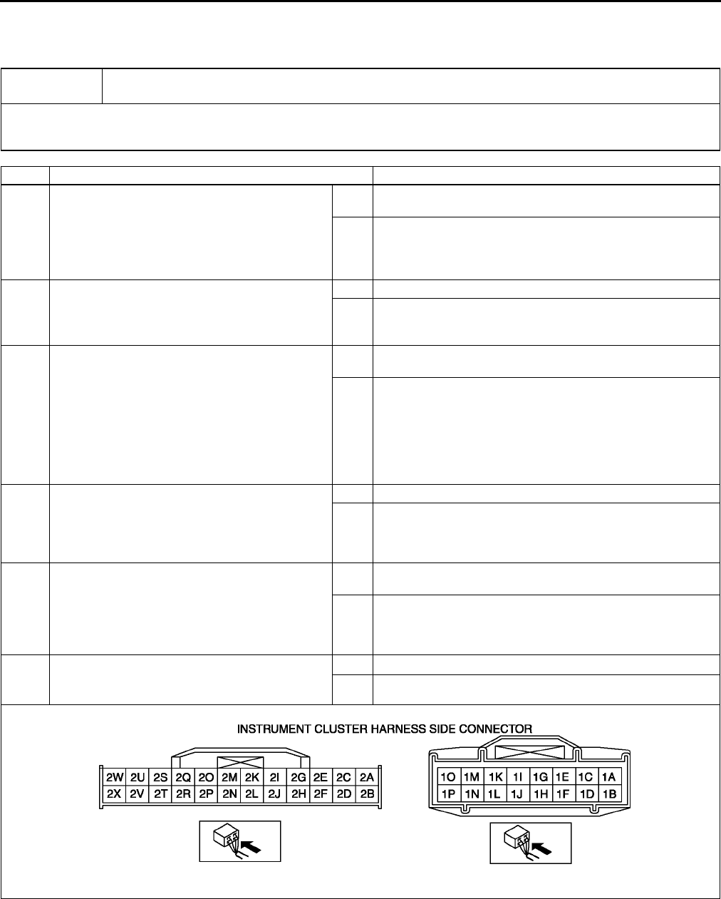
P108
TROUBLESHOOTING (ABS/TCS/DYNAMIC STABILITY CONTROL)
NO.2 NEITHER ABS WARNING LIGHT NOR BRAKE SYSTEM WARNING LIGHT ILLUMINATE WITH
IGNITION SWITCH ON A6E699067650W06
•When performing an asterisked (*) troubleshooting inspection, shake the wiring harness and connectors while
doing the inspection to discover whether poor contact points are the cause of any intermittent malfunction. If
there is a problem, check to make sure connectors, terminals and wiring harnesses are connected correctly
and undamaged.
End Of Sie
2Neither ABS warning light nor BRAKE system warning light illuminate with ignition switch
on.
[TROUBLESHOOTING HINTS]
•Malfunction of instrument cluster or ABS/TCS HU/CM
•Improper configuration (instrument cluster)
STEP INSPECTION ACTION
1VERIFY WHETHER MALFUNCTION IS IN
WARNING LIGHTS AND INDICATOR LIGHTS
COMMON POWER SUPPLY, OR IN OTHER
WARNING LIGHTS AND INDICATOR LIGHTS
•Do other warning and indicator lights
illuminate when IG switch is turned ON?
Yes Replace instrument cluster (open circuit in instrument
cluster).
No Go to next step.
2INSPECT INSTRUMENT CLUSTER POWER
SUPPLY FUSE
•Is instrument cluster ignition power supply
fuse okay?
Yes Go to next step.
No Check for a short to ground on blown fuses circuit.
Repair or replace as necessary.
Install appropriate amperage fuse.
*3VERIFY WHETHER MALFUNCTION IS IN
WIRING HARNESS (BETWEEN INSTRUMENT
CLUSTER POWER SUPPLY AND
INSTRUMENT CLUSTER FOR CONTINUITY)
OR INSTRUMENT CLUSTER
•Turn ignition switch ON.
•Measure voltage at instrument cluster
connector (24-pin ) terminal 2V.
•Is voltage approximately 12V?
Yes Replace instrument cluster (open circuit in instrument
cluster).
No Check for open circuit between instrment cluster and
ground.
Repair or replace as neccessary.
4COMFIRM DTC U1900 USING WDS OR
EQUIVALENT
•Retrieve DTC from PCM, ABS/TCS and
instrument cluster.
•Is DTC U1900 retrieved?
Yes Go to next step.
No Inspect instrment cluster. If OK, then go to step6.
5COMFIRM THE FOLLOWING PIDs USING
WDS OR EQUIVALENT:
•ABS_MSG
•PCM_MSG
•Is not present massage displayed on WDS
or equivalent?
Yes Replace instrument cluster (open circuit in instrument
cluster).
No Network communication, for related system is malfunction.
Repair or replace as neccessary.
6COMFIRM DTC B2477 FOR INSTRUMENT
CLUSTER USING WDS OR EQUIVALENT
•Is DTC B2477 retrieved?
Yes Re-configure the instrument cluster.
No Replace ABS/TCS HU/CM.
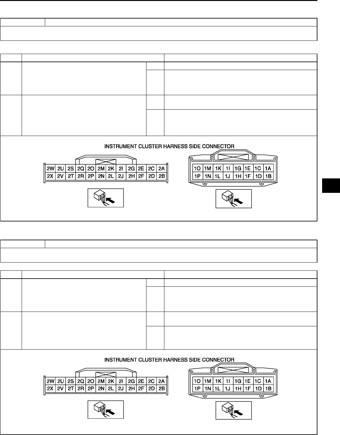
TROUBLESHOOTING (ABS/TCS/DYNAMIC STABILITY CONTROL)
P109
P
NO.3 ABS WARNING LIGHT DOES NOT ILLUMINATE WITH IGNITION SWITCH ON A6E699067650W07
Diagnostic procedure
End Of Si e
NO.4 BRAKE SYSTEM WARNING LIGHT DOES NOT ILLUMINATE WITH IGNITION SWITCH ON A6E699067650W08
End Of Si e
3 ABS warning light does not illuminate with ignition switch on.
[TROUBLESHOOTING HINTS]
•Malfunction of instrument cluster or ABS/TCS HU/CM
STEP INSPECTION ACTION
1COMFIRM DTC U1900 USING WDS OR
EQUIVALENT
•Retrieve DTC from PCM, ABS/TCS and
instrument cluster.
•Is DTC U1900 retrieved?
Yes Go to next step.
No Inspect instrment cluster. If OK, then go to step6.
2COMFIRM THE FOLLOWING PIDs USING
WDS OR EQUIVALENT:
•ABS_MSG
•PCM_MSG
•Is not present massage displayed on WDS
or equivalent?
Yes Replace instrument cluster (open circuit in instrument
cluster).
No Network communication, for related system is malfunction.
Repair or replace as neccessary.
4 BRAKE system warning light does not illuminate with ignition switch on.
[TROUBLESHOOTING HINTS]
•Malfunction of instrument cluster or ABS/TCS HU/CM
STEP INSPECTION ACTION
1COMFIRM DTC U1900 USING WDS OR
EQUIVALENT
•Retrieve DTC from PCM, ABS/TCS and
instrument cluster.
•Is DTC U1900 retrieved?
Yes Go to next step.
No Inspect instrment cluster. If OK, then go to step6.
2COMFIRM THE FOLLOWING PIDs USING
WDS OR EQUIVALENT:
•ABS_MSG
•PCM_MSG
•Is not present massage displayed on WDS
or equivalent?
Yes Replace instrument cluster (open circuit in instrument
cluster).
No Network communication, for related system is malfunction.
Repair or replace as neccessary.

P110
TROUBLESHOOTING (ABS/TCS/DYNAMIC STABILITY CONTROL)
NO.5 TCS OFF LIGHT, TCS INDICATOR LIGHT DO NOT ILLUMINATE WITH IGNITION SWITCH ON
A6E699067650W09
Diagnostic procedure
5 TCS OFF light , TCS indicator light do not illuminate with ignition switch on.
[TROUBLESHOOTING HINTS]
•Malfunction of instrument cluster or ABS/TCS HU/CM
•Improper configuration (ABS/TCS HU/CM)
STEP INSPECTION ACTION
1INSPECT WIRING HARNESS BETWEEN ABS/
TCS HU/CM AND DLC-2 (DATA LINK
CONNECTOR-2 ) FOR CONTINUITY AND
SHORTS
Activate TRAC_OFF (TCS OFF light) using
WDS or equivalent.
Is error message displayed regarding
communication between ABS/TCS CM and
WDS or equivalent?
Yes If a communication error message is displayed even after
inspecting according to procedures displayed on the WDS
or equivalent, go to Step 6.
No Go to next step.
2CHECK TCS OFF LIGHT BULB FOR
MALFUNCTIONS BY USING INSPECTION
FUNCTION IN ABS/TCS HU/CM
Activate TRAC_OFF (TCS OFF light) using
WDS or equivalent
Does TCS OFF light illuminate?
Yes Go to next step.
No Go to next step3.
3COMFIRM DTC U1900 USING WDS OR
EQUIVALENT
•Retrieve DTC from PCM, ABS/TCS and
instrument cluster.
•Is DTC U1900 retrieved?
Yes Go to next step.
No Inspect instrment cluster. If OK, then go to step6.
4COMFIRM THE FOLLOWING PIDs USING
WDS OR EQUIVALENT:
•ABS_MSG
•PCM_MSG
•Is not present massage displayed on WDS
or equivalent?
Yes Replace instrument cluster (open circuit in instrument
cluster).
No Network communication, for related system is malfunction.
Repair or replace as neccessary.
5COMFIRM DTC B2477 FOR INSTRUMENT
CLUSTER USING WDS OR EQUIVALENT
•Is DTC B2477 retrieved?
Yes Re-configure the instrument cluster.
No Replace ABS/TCS HU/CM.
*6INSPECT WIRING HARNESS BETWEEN ABS/
TCS CM AND DLC-2 (DATA LINK
CONNECTOR-2) FOR CONTINUITY
Is there continuity between SST connector
terminal X and data link connector?
Yes Go to next step.
No Repair wiring harness between ABS/TCS HU/CM and data
link connector.
*7INSPECT WIRING HARNESS BETWEEN ABS/
TCS HU/CM AND DLC-2 (DATA LINK
CONNECTOR-2) FOR SHORT TO B+
Is voltage approximately 12 V at SST
connector terminal X?
Yes Repair wiring harness between ABS/TCS HU/CM and data
link connector.
No Go to next step.
8INSPECT WIRING HARNESS BETWEEN ABS/
TCS HU/CM AND DLC-2 (DATA LINK
CONNECTOR-2) FOR SHORT TO GROUND
If there continuity between SST connector
terminal X and ground?
Yes Repair wiring harness between ABS/TCS HU/CM and data
link connector.
No Replace ABS/TCS HU/CM (communication circuit
malfunction in ABS/TCS HU/CM).
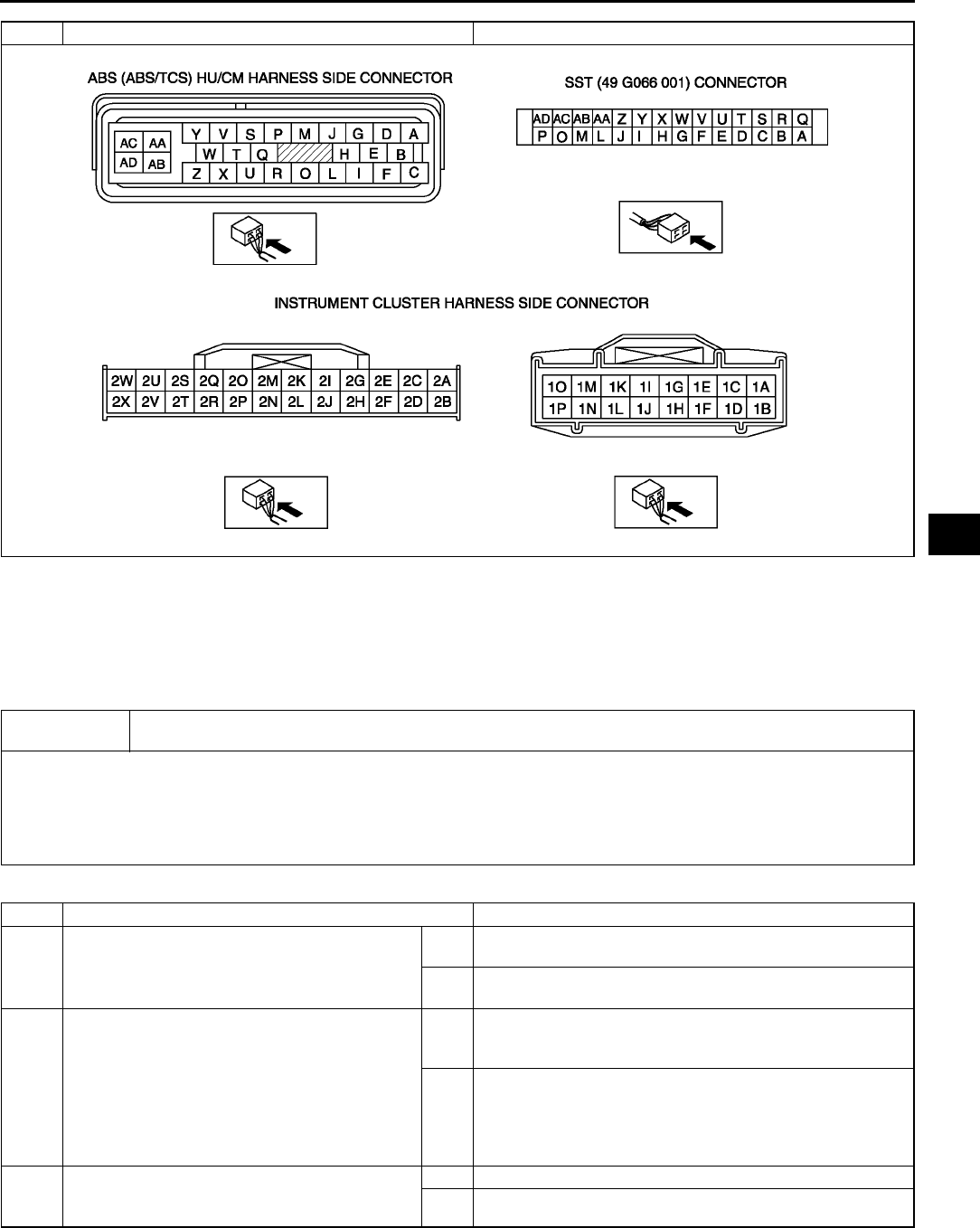
TROUBLESHOOTING (ABS/TCS/DYNAMIC STABILITY CONTROL)
P111
P
•When performing an asterisked (*) troubleshooting inspection, shake the wiring harness and connectors while
doing the inspection to discover whether poor contact points are the cause of any intermittent malfunction. If
there is a problem, check to make sure connectors, terminals and wiring harnesses are connected correctly
and undamaged.
End Of Si e
NO.6 BOTH ABS WARNING LIGHT AND BRAKE SYSTEM WARNING LIGHT STAY ON MORE THAN 4
SECONDS WITH IGNITION SWITCH ON A6E699067650W10
Diagnostic procedure
STEP INSPECTION ACTION
6Both ABS warning light and BRAKE system warning light stay on more than 4 seconds with ignition
switch on.
[TROUBLESHOOTING HINTS]
•ABS/TCS HU/CM detects ABS proportioning system malfunction.
•ABS/TCS HU/CM detects low voltage in power supply (ABS/TCS CM ingestion terminal Z voltage is below about 9
to 10 V).
•ABS/TCS HU/CM does not operate.
•Malfunction of communication network.
STEP INSPECTION ACTION
1INSPECT ABS/TCS HU/CM POWER SUPPLY
FUSE
Is ABS/TCS HU/CM ignition power supply fuse
okay?
Yes Go to next step.
Check for a short to ground on blown fuses circuit.
No Repair or replace as necessary.
Install appropriate amperage fuse.
2INSPECT WIRING HARNESS BETWEEN ABS/
TCS HU/CM AND DLC-2 (DATA LINK
CONNECTOR-2) FOR CONTINUITY AND
SHORTS
Perform DTC inspection.
Is error message displayed regarding
communication between ABS/TCS HU/CM and
WDS or equivalent?
Yes If a communication error message is displayed even after
inspecting according to procedure displayed on WDS or
equivalent, go to step 8.
No Go to next step.
3CHECK FOR DTCS IN ABS/TCS HU/CM
Have DTCs been recorded in memory?
Yes Perform inspection using appropriate DTC.
No Go to next step.

P112
TROUBLESHOOTING (ABS/TCS/DYNAMIC STABILITY CONTROL)
4INSPECT PID/DATA IN ABS/TCS HU/CM
Inspect the following items using WDS or
equivalent PID/DATA monitor function.
•ABS_LAMP (ABS warning light)
•BRAKE_ LAMP (BRAKE system warning
light)
•ABS_VOLT (power supply voltage)
Is ABS_LAMP and BRAKE_LAMP ON after
more than 4 seconds with ignition switch on?
Yes Go to Step 7.
No Go to next step.
5INSPECT ABS/TCS HU/CM IGNITION POWER
SUPPLY SYSTEM (TERMINAL Z)
Check the voltage for PID/DATA monitor
ABS_VOLT item.
Specification: about 10 V
Is voltage within specification?
Yes Replace ABS/TCS HU/CM (open or short in ground circuit in
ABS/TCS HU/CM)
No Go to next step.
6INSPECT BATTERY
Is battery voltage normal?
Yes Go to next step.
No Inspect battery and charging system.
7INSPECT CHARGING SYSTEM
Is battery voltage normal with electrical load (A/
C, headlight, etc.) on and engine idling?
Yes Go to Step 7.
No Inspect charging system (drive belt tension, generator, etc.).
*8INSPECT WIRING HARNESS BETWEEN ABS/
TCS HU/CM POWER SUPPLY AND ABS/TCS
HU/CM FOR CONTINUITY
Disconnect ABS/TCS HU/CM connector.
Connect the SST (49 G066 001) (vehicle
harness side only).
Is voltage approximately 12 V at SST
connector terminal Z?
Yes Go to next step.
No Check for connection of ABS/TCS HU/CM connector
securely.
*9INSPECT WIRING HARNESS BETWEEN ABS/
TCS HU/CM GROUND FOR CONTINUITY
Turn ignition switch to LOCK.
Is there continuity between SST connector
terminal AC and ground?
Yes If a malfunction error message is displayed on WDS or
equivalent in Step 1 inspection, go to next step.
If a malfunction error message is not displayed on WDS or
equivalent in Step 1 inspection, troubleshooting is
completed.
No Repair wiring harness between ABS/TCS HU/CM and
ground.
*10 INSPECT WIRING HARNESS BETWEEN ABS/
TCS HU/CM AND DLC-2 (DATA LINK
CONNECTOR-2) FOR CONTINUITY
Is there continuity between SST connector
terminal X and DLC-2?
Yes Go to next step.
No Repair wiring harness between ABS/TCS HU/CM and
DLC-2.
11 *INSPECT WIRING HARNESS BETWEEN
ABS/TCS HU/CM AND DLC-2 (DATA LINK
CONNECTOR-2) FOR SHORT TO BATTERY
Is voltage approximately 12 V at SST
connector terminal X?
Yes Repair wiring harness between ABS/TCS HU/CM and
DLC-2.
No Go to next step.
12 *INSPECT WIRING HARNESS BETWEEN
ABS/TCS HU/CM AND DLC-2 (DATA LINK
CONNECTOR-2) FOR SHORT TO GROUND
Is there continuity between SST connector
Terminal X and DLC-2?
Yes Repair wiring harness between ABS/TCS HU/CM and
DLC-2.
No Replace ABS/TCS HU/CM (communication circuit
malfunction in ABS/TCS HU/CM)
STEP INSPECTION ACTION
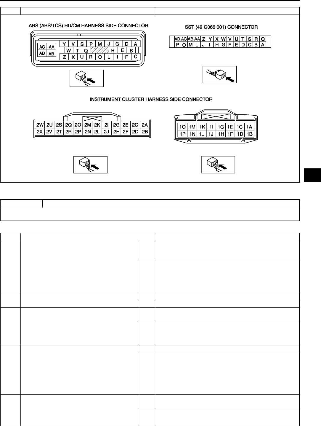
TROUBLESHOOTING (ABS/TCS/DYNAMIC STABILITY CONTROL)
P113
P
End Of Si e
NO.7 ABS WARNING LIGHT STAYS ON MORE THAN 4 SECONDS WITH IGNITION SWITCH ON A6E699067650W11
Diagnostic procedure
STEP INSPECTION ACTION
7ABS warning light stays on more than 4 seconds with ignition switch on.
[TROUBLESHOOTING HINTS]
•ABS/TCS CM detects ABS system malfunction.
STEP INSPECTION ACTION
1INSPECT WIRING HARNESS BETWEEN ABS/
TCS HU/CM AND DLC-2 (DATA LINK
CONNECTOR-2) FOR CONTINUITY AND
SHORTS
Perform DTC inspection.
Is error message displayed regarding
communication between ABS/TCS HU/CM and
WDS or equivalent?
Yes If the communication error message is displayed even after
inspecting according to procedures displayed in the WDS or
equivalent, go to Step 4.
No Go to next step.
2CHECK FOR DTCs IN ABS/TCS HU/CM
Have DTCs been recorded in memory?
Yes Perform inspection using appropriate DTC.
No Go to next step.
3INSPECT PID/DATA IN ABS/TCS HU/CM
Inspect the following items using WDS or
equivalent PID/DATA monitor function.
•ABS_LAMP (ABS warning light)
Is ABS_LAMP ON after more than 4
seconds with ignition switch on?
Yes Replace ABS/TCS HU/CM (open circuit or short to ground in
ABS/TCS HU/CM).
No Inspect instrment cluster.
*4INSPECT WIRING HARNESS BETWEEN ABS/
TCS HU/CM AND DLC-2 (DATA LINK
CONNECTOR-2) FOR CONTINUITY
Disconnect ABS/TCS HU/CM connector.
Connect the SST ( 49 G066 001) (vehicle
harness side only).
Is there continuity between SST connector
terminal X and data link connector?
Yes Go to next step.
No Repair wiring harness between ABS/TCS HU/CM and data
link connector.
*5INSPECT WIRING HARNESS BETWEEN ABS/
TCS HU/CM AND DLC-2 (DATA LINK
CONNECTOR-2) FOR SHORT TO B+
Is voltage approximately 12V at SST connector
terminal X?
Yes Repair wiring harness between ABS/TCS HU/CM and data
link connector.
No Go to next step.
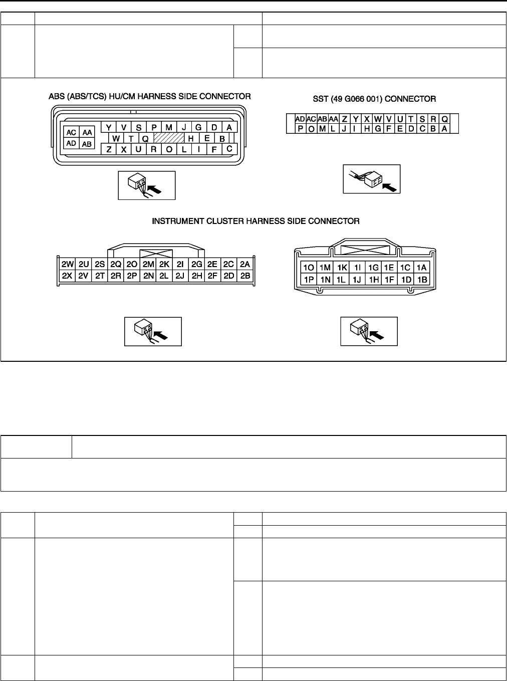
P114
TROUBLESHOOTING (ABS/TCS/DYNAMIC STABILITY CONTROL)
•When performing an asterisked (*) troubleshooting inspection, shake the wiring harness and connectors while
doing the inspection to discover whether poor contact points are the cause of any intermittent malfunction. If
there is a problem, check to make sure connectors, terminals and wiring harnesses are connected correctly
and undamaged.
End Of Si e
NO.8 BRAKE SYSTEM WARNING LIGHT STAYS ON MORE THAN 4 SECONDS WITH IGNITION SWITCH ON
A6E699067650W12
Diagnostic procedure
*6INSPECT WIRING HARNESS BETWEEN ABS/
TCS HU/CM AND DLC-2 (DATA LINK
CONNECTOR-2) FOR SHORT TO GROUND
Is there continuity between SST connector
terminal X and ground?
Yes Repair wiring harness between ABS/TCS HU/CM and data
link connector.
No Replace ABS/TCS HU/CM (communication circuit
malfunction is ABS/TCS HU/CM).
STEP INSPECTION ACTION
8BRAKE system warning light stays on more than 4 seconds with ignition switch on. (Parking brake
is released.)
[TROUBLESHOOTING HINTS]
•Malfunction of instrment cluster or ABS/TCS HU/CM
•Short to ground in circuit in parking brake switch and/or brake fluid level sensor
1INSPECT BRAKE FLUID LEVEL
Is brake fluid level okay?
Yes Go to next step.
No Add brake fluid.
*2INSPECT WIRING HARNESS BETWEEN ABS/
TCS HU/CM AND DLC-2 (DATA LINK
CONNECTOR-2 ) FOR CONTINUITY AND
SHORTS
Inspect the following items using WDS or
equivalent PID/DATA monitor function.
•BRAKE_LAMP(BRAKE system warning
light)
Is error message displayed regarding
communication between ABS/TCS HU/CM and
WDS or equivalent?
Yes If a communication error message is displayed even after
inspecting according to procedures displayed on WDS or
equivalent.
Go to next step6.
No Go to next step.
3CHECK FOR DTCs IN ABS/TCS HU/CM
Have DTCs been recorded in memory?
Yes Perform inspection using appropriate DTC.
No Go to next step.
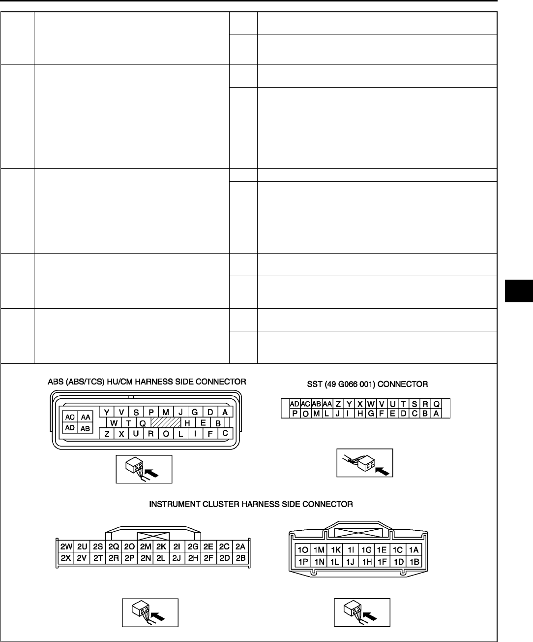
TROUBLESHOOTING (ABS/TCS/DYNAMIC STABILITY CONTROL)
P115
P
•When performing an asterisked (*) troubleshooting inspection, shake the wiring harness and connectors while
doing the inspection to discover whether poor contact points are the cause of any intermittent malfunction. If
there is a problem, check to make sure connectors, terminals and wiring harnesses are connected correctly
and undamaged.
End Of Si e
4INSPECT PID/DATA IN ABS/TCS HU/CM
Inspect (BRAKE system warning light) using
WDS or equivalent PID/DATA monitor function.
Is BRAKE_LAMP on after more than 4
seconds with ignition switch on?
Yes Connect ABS/TCS HU/CM connector terminal X securely,
then go to next step.
No Go to step 6.
5VERIFY WHETHER MALFUNCTION IS IN
PARKING BRAKE SWITCH OR BRAKE FLUID
LEVEL SENSOR, OR IN SOME OTHER PART
Disconnect the following in order:
1. Parking brake switch connector
2. Brake fluid level sensor connector
Does BRAKE system warning light go out with
ignition switch on?
Yes Replace parking brake switch and/or brake fluid level sensor
(shorted on some internal part).
No Perform the following inspections. Repair if necessary.
•Short to ground in wiring harness between instrument
cluster ( BRAKE system warning light) and parking
brake switch.
•Short to ground in wiring harness between instrument
cluster (BRAKE system warning light) and brake fluid
level sensor.
Inspect instrument cluster.
*6INSPECT WIRING HARNESS BETWEEN ABS/
TCS HU/CM AND DLC-2 (DATA LINK
CONNECTOR-2) FOR CONTINUITY
Disconnect ABS/TCS HU/CM connector.
Connect the SST ( 49 G066 001) (vehicle
harness side only).
Is there continuity between SST connector
terminal X and data link connector?
Yes Go to next step.
No Repair wiring harness between ABS/TCS HU/CM and data
link connector.
*7INSPECT WIRING HARNESS BETWEEN ABS/
TCS HU/CM AND DLC-2 (DATA LINK
CONNECTOR-2) FOR SHORT TO B+
Is voltage approximately 12 V at SST
connector terminal X?
Yes Repair wiring harness between ABS/TCS HU/CM and data
link connector.
No Go to next step.
*8INSPECT WIRING HARNESS BETWEEN ABS/
TCS HU/CM AND DLC-2 (DATA LINK
CONNECTOR-2) FOR SHORT TO GROUND
Is there continuity between SST connector
terminal X and ground?
Yes Repair wiring harness between ABS/TCS HU/CM and data
link connector.
No Replace ABS/TCS HU/CM (communication circuit
malfunction in ABS/TCS HU/CM).
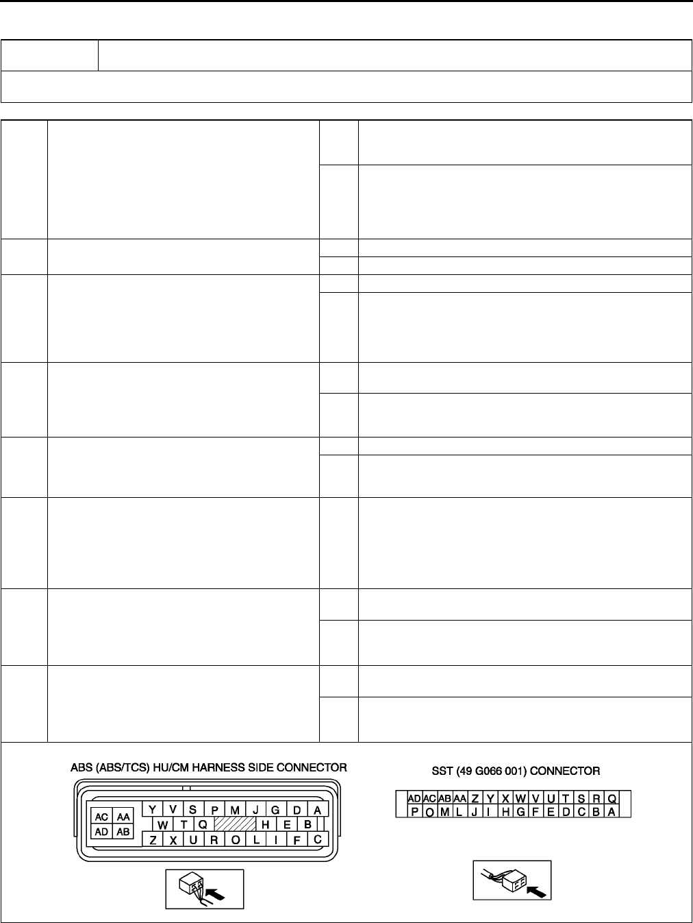
P116
TROUBLESHOOTING (ABS/TCS/DYNAMIC STABILITY CONTROL)
NO.9 TCS OFF LIGHT STAYS ON MORE THAN 4 SECONDS WITH IGNITION SWITCH ON A6E699067650W13
•When performing an asterisked (*) troubleshooting inspection, shake the wiring harness and connectors while
doing the inspection to discover whether poor contact points are the cause of any intermittent malfunction. If
there is a problem, check to make sure connectors, terminals and wiring harnesses are connected correctly
and undamaged.
End Of Si e
9BRAKE system warning light stays on more than 4 seconds with ignition switch on. (Parking brake
is released.)
[TROUBLESHOOTING HINTS]
•Warning light circuit open or shorted to ground in ABS/TCS HU/CM
1INSPECT WIRING HARNESS BETWEEN ABS/
TCS HU/CM AND DLC-2 (DATA LINK
CONNECTOR-2) FOR CONTINUITY AND
SHORTS
Perform DTC inspection.
Is error message displayed regarding
communication between ABS/TCS HU/CM and
WDS or equivalent?
Yes If a communication error message is displayed even after
inspecting according to procedures displayed on WDS or
equivalent, go to Step 7.
No Go to next step.
2CHECK FOR DTCS IN ABS/TCS HU/CM
Have DTCs been recorded in memory?
Yes Perform inspection using appropriate DTC.
No Go to next step.
3INSPECT PID/DATA IN ABS/TCS HU/CM
Inspect the following items using WDS or
equivalent PID/DATA monitor function.
•TRAC_SW (TCS OFF switch)
Is TRAC_SW ON displayed on WDS or
equivalent?
Yes Go to Step 5 (TCS OFF switch system malfunction).
No Go to next step.
*4CHECK FOR SHORT TO GROUND IN ABS/
TCS HU/CM
Disconnect ABS/TCS HU/CM connector.
Does TCS OFF light go out with ignition switch
on?
Yes Replace ABS/TCS HU/CM (short to ground in ABS/TCS
HU/CM).
No Inspect instrument cluster.
*5INSPECT TCS OFF SWITCH
Disconnect TCS OFF switch connector.
Is TRAC_SW ON displayed on WDS or
equivalent?
Yes Go to next step.
No Replace TCS OFF switch (TCS will not turn off, even though
switch is OFF).
*6VERIFY WHETHER MALFUNCTION IS IN
WIRING HARNESS (BETWEEN ABS/TCS HU/
CM AND TCS OFF SWITCH FOR SHORT TO
GROUND) OR ABS/TCS HU/CM
Is there continuity between SST connector
terminal P and ground?
Yes Repair wiring harness between ABS/TCS HU/CM (terminal
P) and TCS OFF switch.
*7INSPECT WIRING HARNESS BETWEEN ABS/
TCS HU/CM AND DLC-2 (DATA LINK
CONNECTOR-2) FOR SHORT TO B+
Is voltage approximately 12 V at SST
connector terminal T?
Yes Repair wiring harness between ABS/TCS HU/CM (terminal
P) and data link connector.
No Go to next step.
*8INSPECT WIRING HARNESS BETWEEN ABS/
TCS HU/CM AND DLC-2 (DATA LINK
CONNECTOR-2) FOR SHORT TO GROUND
Is there continuity between SST connector
terminal T and ground?
Yes Repair wiring harness between ABS/TCS HU/CM and data
link connector.
No Replace ABS/TCS HU/CM (communication circuit
malfunction in ABS/TCS HU/CM).
TROUBLESHOOTING (ABS/TCS/DYNAMIC STABILITY CONTROL)
P117
P
NO.10 TCS DOES NOT WORK CORRECTLY A6E699067650W14
Diagnostic procedure
End Of Si e
NO.11 THERE IS MALFUNCTION IN THE SYSTEM EVEN THOUGH ABS WARNING LIGHT, BRAKE SYSTEM
WARNING LIGHT, TCS OFF LIGHT, TCS INDICATOR LIGHT DO NOT ILLUMINTE A6E699067650W15
Diagnostic procedure
End Of Si e
NO.1 ANY OF THE FOLLOWING LIGHTS DO NOT ILLUMINATE WITH IGNITION SWITCH ON: (ABS
WARNING LIGHT, BRAKE SYSTEM WARNING LIGHT, DSC INDICATOR LIGHT AND/OR DSC OFF LIGHT)
A6E699067650W16
10 TCS does not work correctly.
[TROUBLESHOOTING HINTS]
•There is difference in size or air pressure between the front and rear tires.
•There is malfunction in the engine control system.
•ABS/TCS HU/CM detects TCS system malfunction.
STEP INSPECTION ACTION
1CHECK TIRE SIZE AND AIR PRESSURE
Inspect tire size and air pressure.
Are size and air pressure as specified?
Yes Go to next step.
No Replace with specified tires or adjust tire air pressure.
2CHECK FOR DTCS IN ABS/TCS HU/CM
Have DTCs been recorded in memory?
Yes Perform inspection using appropriate DTC.
No Go to next step.
3CHECK FOR DTCS IN PCM
Check the DTC for the PCM ON-BOARD
DIAGNOSTIC SYSTEM.
Have DTCs been recorded in memory?
Yes Perform inspection using appropriate DTC.
No Go to next step.
4CHECK TO MAKE SURE TORQUE
REDUCTION SIGNAL GOING FROM ABS/TCS
HU/CM TO PCM IS BEING RECEIVED
CORRECTLY
Select ENG - TRQ (engine torque reduction
signal) using WDS or equivalent.
Increase the engine speed to 3,000 rpm.
Input 280 N·m ENG _ TRQ to PCM using WDS
or equivalent.
Does engine speed decrease?
Yes System is normal.
Recheck customer's complaint.
No Replace ABS/TCS HU/CM.
11 There is a malfunction in system even though ABS warning light, BRAKE system warning light, TCS
OFF light, TCS indicator light do not illuminate.
[TROUBLESHOOTING HINTS]
•There is a difference in size or air pressure between the front and rear tires
STEP INSPECTION ACTION
1CHECK FOR DTCs IN ABS/TCS HU/CM
Have DTCs been recorded in memory?
Yes Perform inspection using appropriate DTC.
No Go to next step.
2INSPECT ABS HYDRAULIC UNIT
Perform "ABS hydraulic unit system inspection".
Is system okay?
Yes Inspect conventional brake system.
No If wheels do not rotate:
Replace ABS/TCS HU/CM.
If wheels rotate but order in which wheels rotate is
incorrect:
Inspect brake pipe passage to ABS/TCS HU/CM.
1Any of the following lights do not illuminate with ignition switch on: (ABS warning light, BRAKE
system warning light, DSC indicator light and/or DSC OFF light).
[TROUBLESHOOTING HINTS]
•Check each light in the instrument cluster for malfunction.
•Poor connection at DSC HU/CM connector
•ABS warning light circuit or BRAKE system warning light circuit shorted out
(when harness is shorted out between DSC HU/CM and ABS warning light or BRAKE system warning light, each
warning lights go off.)
•DSC indicator light circuit and/or DSC OFF light circuit may be open.
(when DSC indicator light circuit and/or DSC OFF light circuit is open, each circuits warning lights go off.)

P118
TROUBLESHOOTING (ABS/TCS/DYNAMIC STABILITY CONTROL)
Diagnostic procedure
End Of Si e
STEP INSPECTION ACTION
1CHECK FOR DTCS IN DSC HU/CM
•Check the DTC for the DSC ON-BOARD
DIAGNOSTIC SYSTEM.
•Have DTCs been recorded in memory?
Yes Perform inspection using appropriate DTC.
No Go to next step.
2CHECK TO SEE WHETHER MALFUNCTION
IS IN INSTRUMENT CLUSTER SYSTEM OR
OTHER SYSTEM
•Do other warning and indicator lights
illuminate when IG switch is turned ON?
Yes Go to next step.
No Inspect or repair instrument cluster (power supply system,
ground system).
3VERIFY THAT DSC HU/CM CONNECTOR IS
CONNECTED
•Is DSC HU/CM securely connected?
Yes Go to next step.
No Connect DSC HU/CM connector securely, then go to next
step.
4VERIFY THAT DSC HU/CM CONNECTOR
TERMINAL OR RELATED CONNECTOR
TERMINALS ARE CONNECTED
•Are DSC HU/CM connector terminal, or
instrument cluster connector terminal, or
related connector terminals securely
connected?
Yes Go to next step.
No Connect DSC HU/CM connector terminal etc. related
connector terminal securely.
5CHECK TO SEE WHETHER MALUNCTION IS
IN DSC INDICATOR LIGHT AND TCS OFF
LIGHT OR ABS WARNING LIGHT AND
BRAKE SYSTEM WARNING LIGHT
•If DSC indicator light and TCS OFF light do
not illuminate, go to Step 6.
•If ABS warning light and BRAKE system
warning light do not illuminate, go to Step 8.
--
6CHECK TO SEE WHETHER MALFUNCTION
IS IN DSC HU/CM OR OTHER
•Disconnect DSC HU/CM.
•Connect the DSC indicator light terminal and
DSC OFF light terminal to body ground.
•Do both indicator lights illuminate with
ignition switch on?
Yes Replace DSC HU/CM (open in DSC HU/CM).
No Go to next step.
7INSPECT WIRING HARNESS BETWEEN
INSTRUMENT CLUSTER AND DSC HU/CM
FOR CONTINUITY
•Is there continuity between each indicator
light terminals of instrument cluster and DSC
HU/CM connector terminal?
Yes Inspect or repair indicator light circuit in instrument cluster.
No Repair malfunctioning part.
8CHECK TO SEE WHETHER MALFUNCTION
IS IN DSC HU/CM OR OTHER
•Disconnect DSC HU/CM and turn ignition
switch on.
•Do ABS warning light and BRAKE system
warning lights illuminate with ignition switch
on?
(If above lights illuminate, both lights circuits
are normal.)
Yes Replace DSC HU/CM (short in DSC HU/CM).
No Go to next step.
9INSPECT WIRING HARNESS BETWEEN
INSTRUMENT CLUSTER AND DSC HU/CM
FOR SHORT
•Is there continuity between each warning
light terminal of DSC HU/CM and ground?
Yes Repair malfunctioning part.
No Inspect or repair warning light circuit in instrument cluster.
TROUBLESHOOTING (ABS/TCS/DYNAMIC STABILITY CONTROL)
P119
P
NO.2 ANY OF THE FOLLOWING LIGHTS STAY ON: (ABS WARNING LIGHT, BRAKE SYSTEM WARNING
LIGHT, DSC INDICATOR LIGHT AND/OR DSC OFF LIGHT) A6E699067650W17
Diagnostic procedure
End Of Si e
2Any of the following lights stay on: (ABS warning light, BRAKE system warning light, DSC indicator
light and/or DSC OFF light)
[TROUBLESHOOTING HINTS]
•Brake fluid amount is low.
•Parking brake does not release.
•No connection at DSC HU/CM connector
(when DSC HU/CM connector comes off, ABS warning light and BRAKE system warning light illuminate.)
•DSC HU/CM detected malfunction (input and output device malfunction)
•DSC HU/CM detects low voltage in power supply.
•DSC HU/CM ground malfunction
(when DSC HU/CM ground is not securely connected, ABS warning light and BRAKE system warning light
illuminate but diagnostic trouble code does not display)
•DSC HU/CM does not operate (DSC HU/CM malfunction.)
•DSC OFF light circuit shorted in ground (when DSC OFF circuit is shorted in ground, DSC OFF light illuminated.)
•ABS warning light circuit or BRAKE system warning light circuit open
(when the harness is open between DSC HU/CM and each warning light, each warning light illuminates)
STEP INSPECTION ACTION
1INSPECT BRAKE FLUID AMOUNT AND
VERIFY THAT PARKING BRAKE RELEASES
•Is brake fluid amount normal?
•Is parking brake lever released?
Yes Go to next step.
No Add brake fluid or release parking brake lever.
2CHECK FOR DTCS IN DSC HU/CM
•Check the DTC for the DSC ON-BOARD
DIAGNOSTIC SYSTEM.
•Have DTCs been recorded in memory?
Yes Perform inspection using appropriate DTC.
No Go to next step.
3CHECK TO SEE WHETHER MALFUNCTION
IS IN CONTROL MODULE CONNECTOR,
TERMINAL OR OTHER
•Do ABS warning light and BRAKE system
warning light go off after 4 seconds with
ignition switch on?
Yes Temporary poor connection in control module connector.
Inspect DSC HU/CM connector, then go to Step 6.
Inspect DSC HU/CM connector terminal, then go to Step 7.
No Go to next step.
4INSPECT BATTERY
•Is battery voltage normal?
Yes Go to next step.
No Inspect battery and charging system.
5INSPECT CHARGING SYSTEM
•Is battery voltage normal with electrical load
(A/C, headlight, etc.) on and engine idling?
Yes Go to next step.
No Inspect charging system (drive belt tension, generator, etc.).
6VERIFY THAT DSC HU/CM CONNECTOR IS
CONNECTED
•Is DSC HU/CM securely connected?
Yes Go to next step.
No Connect DSC HU/CM connector securely, then go to next
step.
7VERIFY THAT DSC HU/CM CONNECTOR
TERMINAL OR RELATED CONNECTOR
TERMINALS ARE CONNECTED
•Are DSC HU/CM connector terminal or
instrument cluster connector terminal etc.
related connector terminals securely
connected?
Yes Go to next step.
No Connect DSC HU/CM connector terminal etc. related
connector terminals securely.
8INSPECT WIRING HARNESS BETWEEN
INSTRUMENT CLUSTER AND DSC HU/CM
FOR CONTINUITY
•Is there continuity between each warning
light terminal of instrument cluster and DSC
HU/CM connector terminal?
Yes Go to next step.
No Repair malfunctioning part.
9INSPECT WIRING HARNESS BETWEEN
INSTRUMENT CLUSTER AND DSC HU/CM
FOR SHORT IN GROUND
•Is there continuity between each indicator
light terminal of DSC HU/CM and ground?
Yes Repair malfunctioning part.
No Inspect power supply harness and ground harness of DSC
HU/CM.
If above wiring harness are okay, replace DSC HU/CM.
If above wiring harness are malfunctioning, repair
malfunctioning wiring harness.
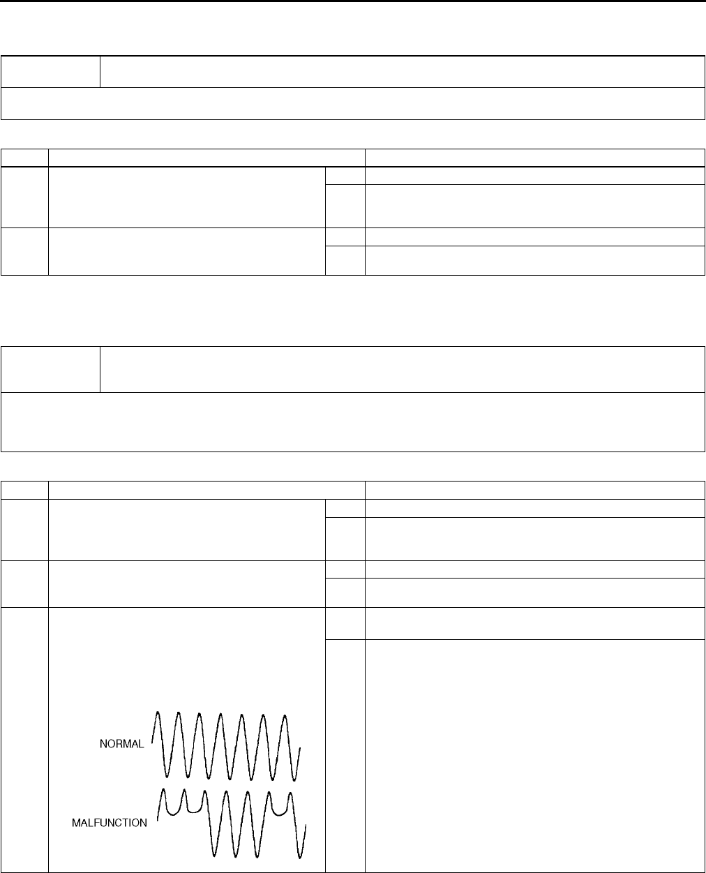
P120
TROUBLESHOOTING (ABS/TCS/DYNAMIC STABILITY CONTROL)
NO.3 THERE IS A MALFUNCTION IN THE SYSTEM EVEN THOUGH ABS WARNING LIGHT, BRAKE SYSTEM
WARNING LIGHT, DSC INDICATOR LIGHT AND DSC OFF LIGHT DO NOT ILLUMINATE A6E699067650W18
Diagnostic procedure
End Of Si e
NO.4 ABS OR TCS*1 OPERATES FREQUENTLY/TCS DOES NOT WORK CORRECTLY*1: DSC SYSTEM
FUNCTION CONTAINS TRACTION CONTROL FUNCTION, DSC INDICATOR LIGHT GOES ON AND OFF
WHILE DSC OPERATES A6E699067650W19
Diagnostic procedure
End Of Si e
3There is a malfunction in the system even though ABS warning light, BRAKE system warning light,
DSC indicator light and DSC OFF light do not illuminate.
[TROUBLESHOOTING HINTS]
•There is mechanical malfunction in system.
STEP INSPECTION ACTION
1CHECK DSC HU/CM FOR DTCs
•Check the DTC for the DSC ON-BOARD
DIAGNOSTIC SYSTEM.
•Have DTCs been recorded in memory?
Yes Perform inspection using appropriate DTC.
No Go to next step.
2INSPECT DSC SYSTEM
•Perform DSC system inspection.
•Is the system okay?
Yes Inspect conventional brake system.
No Repair or replace malfunctioning part.
4
ABS or TCS (*1) operates frequently./TCS does not work correctly.
(*1): DSC system function contains traction control function, DSC indicator light goes on and off
while DSC operates.
[TROUBLESHOOTING HINTS]
•There is difference in size or air pressure between the front and rear tires.
•Incorrect ABS wheel-speed signal is inputted to DSC HU/CM.
•There is malfunction in the engine control system (TCS malfunction.)
STEP INSPECTION ACTION
1CHECK FOR DTCS IN DSC HU/CM
•Check the DTC for the DSC ON-BOARD
DIAGNOSTIC SYSTEM.
•Have DTCs been recorded in memory?
Yes Perform inspection using appropriate DTC.
No Go to next step.
2CHECK TIRE SIZE AND AIR PRESSURE
•Inspect tire size and air pressure.
•Are size and air pressure as specified?
Yes Go to next step.
No Replace with specified tires and adjust tire air pressure.
3INSPECT ABS WHEEL-SPEED SENSOR
OUTPUT PULSE
•Start engine and drive vehicle.
•Inspect output voltage pattern using WDS or
equivalent (oscilloscope).
•Is output voltage pattern okay?
Yes Found malfunctioning part according to INTERMITTENT
CONCERN TROUBLESHOOTING.
No •ABS wheel-speed sensor installation inspection:
Inspect the sensor for looseness and confirm it is
securely adhered.
•Sensor rotor installation inspection:
Inspect the sensor rotor for poor installation and
chipping of sensor rotor teeth. (If sensor rotor is installed
poorly, it may cause output of abnormal wave form at
high speed.)

TROUBLESHOOTING (ABS/TCS/DYNAMIC STABILITY CONTROL)
P121
P
NO.5 DSC*2 OPERATES FREQUENTLY/DSC DOES NOT WORK CORRECTLY*2: DSC INDICATOR LIGHT
GOES ON AND OFF WHILE DSC OPERATES A6E699067650W20
Diagnostic procedure
End Of Si e
5DSC (*2) operates frequently. /DSC does not work correctly.
(*2): DSC indicator light goes on and off while DSC operates.
[TROUBLESHOOTING HINTS]
•DSC HU/CM detected malfunction (input and output device malfunction)
•Poor installation with combine sensor and/or steering angle sensor
(If any of the above sensors are poorly installed, DSC may operate intermittently.)
•When replacing DSC HU/CM, combine sensor or steering angle sensor, initialization is not performed.
(If initialization is not performed correctly, DSC may not work correctly.)
STEP INSPECTION ACTION
1CHECK DSC HU/CM FOR DTCs
•Check the DTC for the DSC ON-BOARD
DIAGNOSTIC SYSTEM.
•Have DTCs been recorded in memory?
Yes Perform inspection using appropriate DTC.
No Go to next step.
2VERIFY THAT EACH SENSOR IS INSTALLED
•Are yaw rate sensor, lateral-G sensor and
steering angle sensor securely installed?
Yes Go to next step.
No Install malfunctioning sensor securely.
*3 VERIFY THAT EACH SENSOR IS INITIALIZED
•Did each sensor initialize after replacement
of DTC unit, yaw rate sensor, lateral-G
sensor or steering angle sensor?
Yes Find malfunctioning part according to INTERMITTENT
CONCERN TROUBLESHOOTING.
No Perform initialization.

R1
R
RSUSPENSION
LOCATION INDEX .................................................R-2
FRONT SUSPENSION LOCATION INDEX.........R-2
REAR SUSPENSION LOCATION INDEX ...........R-3
GENERAL PROCEDURES ....................................R-4
PRECAUTION (SUSPENSION) ..........................R-4
WHEEL ALIGNMENT.............................................R-4
WHEEL ALIGNMENT PRE-INSPECTION...........R-4
FRONT WHEEL ALIGNMENT.............................R-5
REAR WHEEL ALIGNMENT ...............................R-6
WHEEL AND TIRE .................................................R-7
WHEEL BALANCE ADJUSTMENT
(16 INCH AND 17 INCH
ALUMINUM ALL WHEEL) ................................R-7
FRONT SUSPENSION ...........................................R-9
FRONT SHOCK ABSORBER AND
SPRING REMOVAL/INSTALLATION ...............R-9
FRONT SHOCK ABSORBER
INSPECTION ..................................................R-12
FRONT SHOCK ABSORBER
DISPOSAL ......................................................R-12
FRONT UPPER ARM
REMOVAL/INSTALLATION............................R-13
FRONT UPPER ARM INSPECTION .................R-14
FRONT LOWER ARM (FRONT)
REMOVAL/INSTALLATION............................R-15
FRONT LOWER ARM (FRONT)
INSPECTION ..................................................R-18
FRONT LOWER ARM (REAR)
REMOVAL/INSTALLATION............................R-19
FRONT LOWER ARM (REAR)
INSPECTION ..................................................R-21
FRONT STABILIZER
REMOVAL/INSTALLATION............................R-22
STABILIZER CONTROL LINK
INSPECTION ..................................................R-23
FRONT CROSSMEMBER
REMOVAL/INSTALLATION............................R-23
TRANSVERSE MEMBER
REMOVAL/INSTALLATION............................R-27
REAR SUSPENSION ...........................................R-28
REAR SHOCK ABSORBER
REMOVAL/INSTALLATION............................R-28
REAR SHOCK ABSORBER
INSPECTION ..................................................R-28
REAR SHOCK ABSORBER
DISPOSAL ......................................................R-28
REAR COIL SPRING
REMOVAL/INSTALLATION............................R-29
REAR LOWER ARM
REMOVAL/INSTALLATION............................R-30
REAR UPPER ARM
REMOVAL/INSTALLATION............................R-31
REAR LATERAL LINK
REMOVAL/INSTALLATION............................R-33
REAR STABILIZER
REMOVAL/INSTALLATION............................R-34
STABILIZER CONTROL
LINK INSPECTION .........................................R-35
TRAILING LINK
REMOVAL/INSTALLATION ............................R-35
REAR CROSSMEMBER
REMOVAL/INSTALLATION ............................R-37
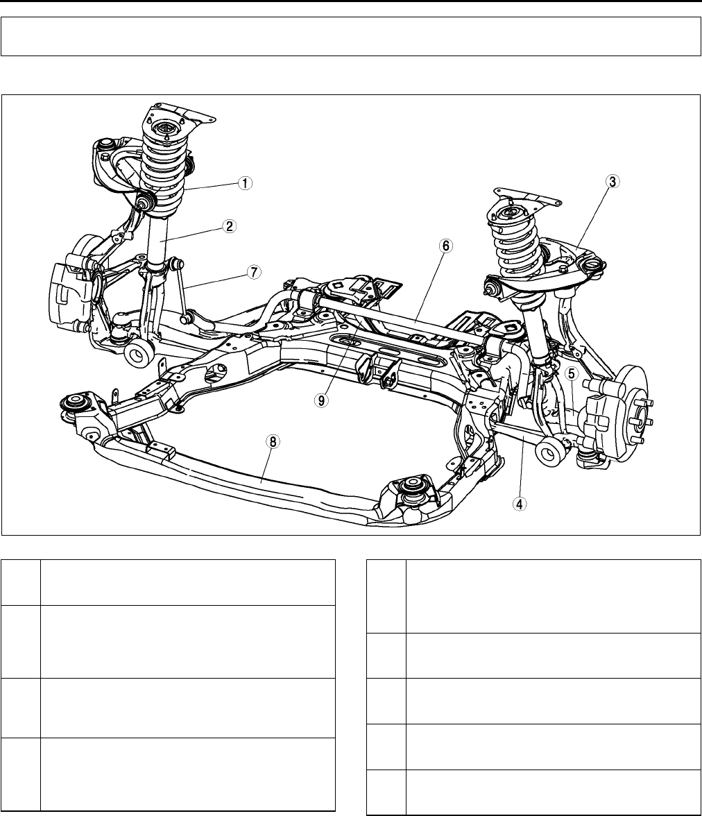
R2
LOCATION INDEX
FRONT SUSPENSION LOCATION INDEX A6E740001015W01
.
End Of Sie
LOCATION INDEX
A6E7414W033
1 Front shock absorber and coil spring
(See R9 FRONT SHOCK ABSORBER AND
SPRING REMOVAL/INSTALLATION)
2 Front shock absorber
(See R12 FRONT SHOCK ABSORBER
INSPECTION)
(SeeR12 FRONT SHOCK ABSORBER
DISPOSAL)
3 Front upper arm
(See R13 FRONT UPPER ARM REMOVAL/
INSTALLATION)
(See R14 FRONT UPPER ARM INSPECTION)
4 Front lower arm (front)
(See R15 FRONT LOWER ARM (FRONT)
REMOVAL/INSTALLATION)
(See R18 FRONT LOWER ARM (FRONT)
INSPECTION)
5 Front lower arm (rear)
(See R19 FRONT LOWER ARM (REAR)
REMOVAL/INSTALLATION)
(See R21 FRONT LOWER ARM (REAR)
INSPECTION)
6 Front stabilizer
(See R22 FRONT STABILIZER REMOVAL/
INSTALLATION)
7 Stabilizer control link
(See R23 STABILIZER CONTROL LINK
INSPECTION)
8 Front crossmember
(See R23 FRONT CROSSMEMBER REMOVAL/
INSTALLATION)
9 Transverse member
(See R27 TRANSVERSE MEMBER REMOVAL/
INSTALLATION)
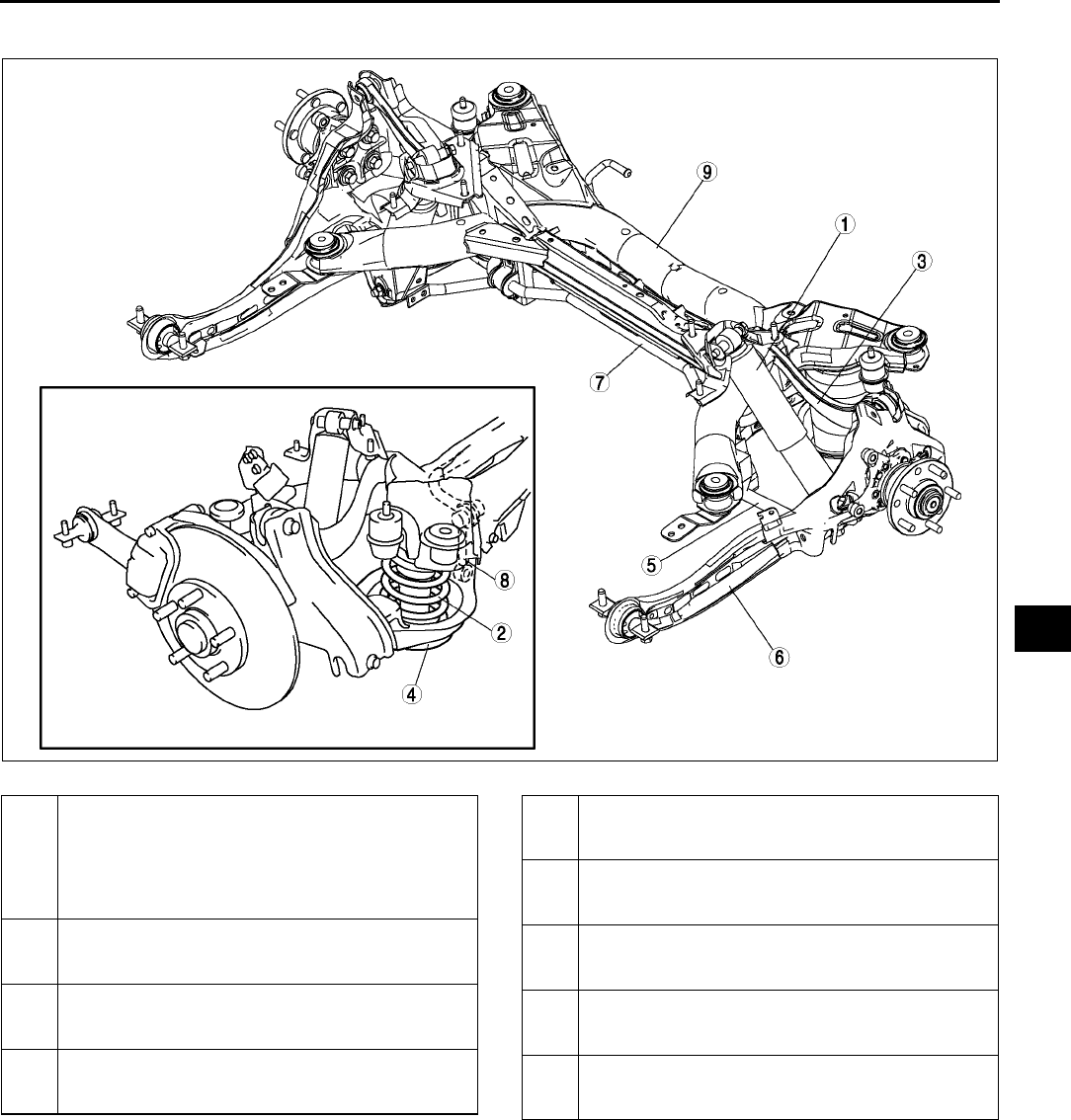
LOCATION INDEX
R3
R
REAR SUSPENSION LOCATION INDEX A6E740001016W01
.
End Of Sie
A6E7416W016
1 Rear shock absorber
(SeeR28 REAR SHOCK ABSORBER REMOVAL/
INSTALLATION)
(See R28 REAR SHOCK ABSORBER
INSPECTION)
(See R28 REAR SHOCK ABSORBER DISPOSAL)
2 Rear coil spring
(SeeR29 REAR COIL SPRING REMOVAL/
INSTALLATION)
3 Rear upper arm
(SeeR31 REAR UPPER ARM REMOVAL/
INSTALLATION)
4 Rear lower arm
(SeeR30 REAR LOWER ARM REMOVAL/
INSTALLATION)
5 Rear lateral link
(SeeR33 REAR LATERAL LINK REMOVAL/
INSTALLATION)
6 Trailing link
(SeeR35 TRAILING LINK REMOVAL/
INSTALLATION)
7 Rear stabilizer
(SeeR34 REAR STABILIZER REMOVAL/
INSTALLATION)
8 Stabilizer control link
(SeeR35 STABILIZER CONTROL LINK
INSPECTION)
9 Rear crossmember
(SeeR37 REAR CROSSMEMBER REMOVAL/
INSTALLATION)
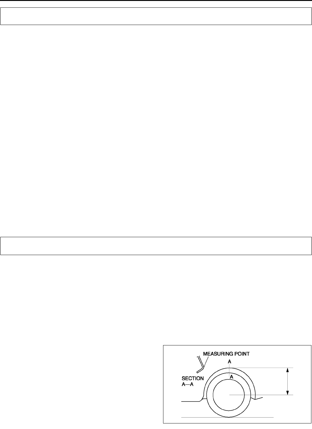
R4
GENERAL PROCEDURES , WHEEL ALIGNMENT
PRECAUTION (SUSPENSION) A6E741001013W01
Wheels and Tires Removal/Installation
1. When a wheel is installed, tighten it to
88118 N·m {9.012.0 kgf·m, 65.087.0 ft·lbf}.
Suspension Links Removal/Installation
1. Tighten any part of the suspension that uses rubber bushings only after the vehicle has been lowered and
unloaded.
Note
•Unloaded: Fuel tank is full. Engine coolant and engine oil are at specified levels. Spare tire, jack and tools
are in designated position.
Brake Lines Disconnection/Connection
Caution
•
••
•Brake fluid will damage painted surfaces. If brake fluid does get on a painted surface, wipe it off
immediately.
1. Tighten the brake pipe flare nut using the SST (49 0259 770B). Be sure to modify the brake pipe flare nut
tightening torque to allow for use of a torque wrench-SST combination.
(See GI16 TORQUE FORMULAS.)
2. If any brake line has been disconnected anytime during the procedure, add brake fluid, bleed the brakes, and
inspect for leakage after the procedure has been completed.
Power Steering Components Removal/Installation
1. If any power steering fluid line has been disconnected anytime during the procedure, add ATF M-III or
equivalent (e.g. Dexron®II), bleed the fluid line, and inspect for leakage after the procedure has been
completed.
End Of Sie
WHEEL ALIGNMENT PRE-INSPECTION A6E741201013W01
1. Inspect the tire inflation, and adjust to the recommended pressure as necessary.
2. Inspect the front wheel bearing play and correct it if necessary. (See M4 Wheel Bearing Play Inspection.)
3. Inspect the wheel and tire runouts. (See TD8 SUSPENSION.)
4. Inspect the ball joints and steering linkage for excessive looseness.
5. Shake the vehicle to inspect the operation of the shock absorbers.
Note
•The vehicle must be on level ground and unloaded.
•Unloaded: Fuel tank is full. Engine coolant and engine oil are at specified level. Spare tire, jack and tools
are in designated position.
6. Measure the height from the center of the wheel
to the fender brim. The difference between the left
and right measurement must not exceed 10 mm
{0.39 in}.
End Of Sie
GENERAL PROCEDURES
WHEEL ALIGNMENT
A6E7412W001
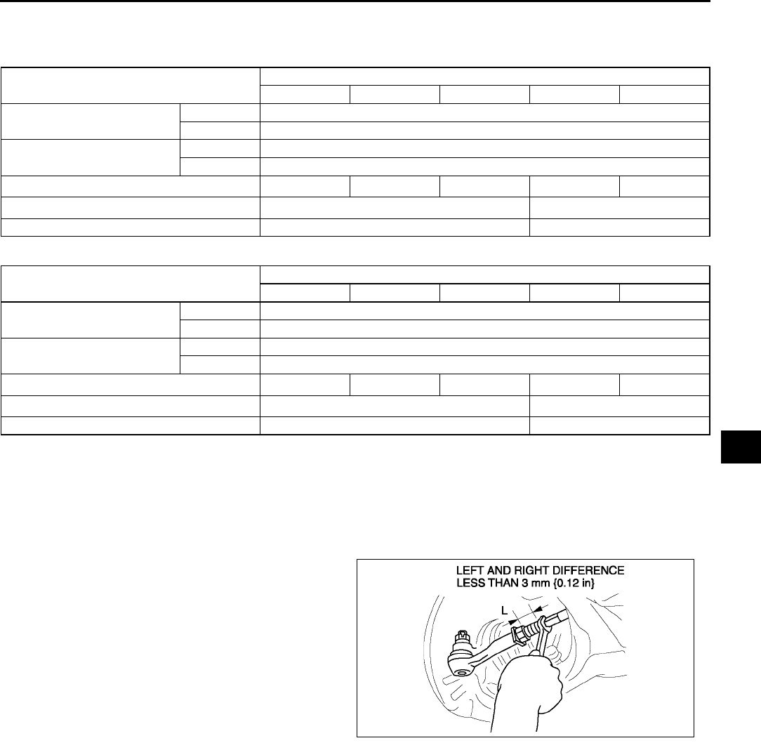
WHEEL ALIGNMENT
R5
R
FRONT WHEEL ALIGNMENT A6E741201015W01
Specification (Unloaded)*1
Normal
Elevated*3
*1: Engine coolant and engine oil are at specified level. Spare tire, jack and tools are in designated position.
*2: Difference between left and right must not exceed 1°30'.
*3 : Distance between wheel center and fender brim is 402 mm {15.8 in} (reference value).
Maximum Steering Angle Adjustment
1. Loosen the tie-rod end locknuts.
2. Remove the steering gear boot clamp.
3. Turn the tie rods to equalize the length L.
Maximum left/right difference
3 mm {0.12 in}
4. Turn the tie rods equally to provide the correct
maximum steering angle.
5. Tighten the tie-rod end locknuts.
Tightening torque
68.698.0 N·m
{7.009.99 kgf·m, 50.672.2 ft·lbf}
6. Verify that the boot is not twisted, and install the boot clamp.
7. Adjust the toe-in after adjusting the steering angle.
Total Toe-in Adjustment
1. Center the steering wheel and confirm that the vehicle wheels/tires are pointing straight.
2. Loosen the left and right tie-rod end locknuts and turn the tie-rods equally. Both tie rods are right threaded, so
turning the right tie-rod toward the front of the vehicle and the left toward the rear increases toe-in.
Note
•Turning both tie-rods one complete turn changes toe-in by about 6 mm {0.24 in} (0°
°°
°36').
3. Tighten the tie-rod end locknuts to the specified torque.
Tightening torque
68.698.0 N·m {7.009.99 kgf·m, 50.672.2 ft·lbf}
4. Verify that the boot is not twisted, and install the boot clamp.
End Of Si e
Item Fuel gauge indication
Empty 1/4 1/2 3/4 Full
Total toe-in (mm {in}) Tire: 2±4 {0.08±0.16}, Rim inner: 1±3 {0.04±0.12}
(degree) 0°11′±0°22′
Maximum steering angle Inner 39°±3°
Outer 31°±3°
Caster angle*2 (reference value) 3°37'±1°3°39'±1°3°41'±1°3°44'±1°3°47'±1°
Camber angle*2(reference value) -0°16'±1°-0°17'±1°
Steering axis inclination (reference value) 5°26' 5°28'
Item Fuel gauge indication
Empty 1/4 1/2 3/4 Full
Total toe-in (mm {in}) Tire: 2±4 {0.08±0.16}, Rim inner: 1±3 {0.04±0.12}
(degree) 0°11′±0°22′
Maximum steering angle Inner 39°±3°
Outer 31°±3°
Caster angle*2 (reference value) 3°32'±1°3°34'±1°3°36'±1°3°39'±1°3°42'±1°
Camber angle*2(reference value) -0°09'±1°-0°10'±1°
Steering axis inclination (reference value) 5°17' 5°18'
A6E7412W002
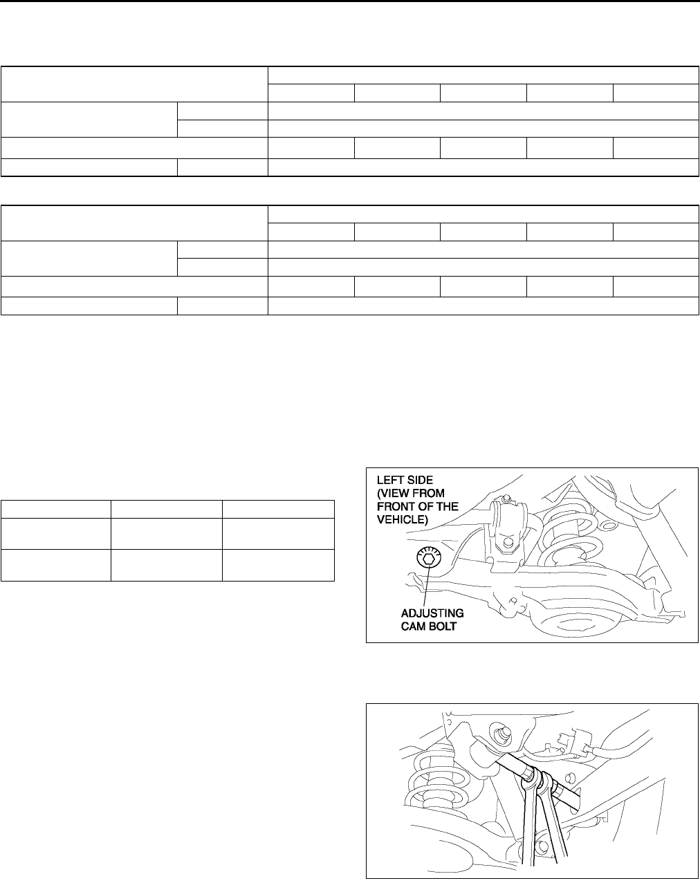
R6
WHEEL ALIGNMENT
REAR WHEEL ALIGNMENT A6E741201016W01
Specification (Unloaded)*1
Normal
Elevated*3
*1: Engine coolant and engine oil are at specified level. Spare tire, jack and tools are in designated position.
*2: Difference between left and right must not exceed 1°30'.
*3 : Distance between wheel center and fender brim is 392 mm {15.4 in} (reference value).
Note
•Adjust the toe-in after adjusting the camber.
Camber Adjustment
1. Loosen the cam nut on the lower arm.
2. Turn the adjusting cam bolt to provide the correct
camber angles as indicated.
3. Tighten the cam nut.
Tightening torque
86.2116.6 N·m
{8.7911.88 kgf·m, 63.5885.99 ft·lbf}
Total Toe-in Adjustment
1. Loosen the locknut of the lateral link.
Item Fuel gauge indication
Empty 1/4 1/2 3/4 Full
Total toe-in (mm {in}) Tire: 2±4 {0.08±0.16}, Rim inner: 1±3 {0.04±0.12}
(degree) 0°11′±0°22′
Camber angle*2 1°05′±1°1°07′±1°1°09′±1°1°11′±1°1°13′±1°
Thrust angle (degree) 0°±0°48′
Item Fuel gauge indication
Empty 1/4 1/2 3/4 Full
Total toe-in (mm {in}) Tire: 2±4 {0.08±0.16}, Rim inner: 1±3 {0.04±0.12}
(degree) 0°11′±0°22′
Camber angle*2 0°56′±1°0°58′±1°1°00′±1°1°02′±1°1°05′±1°
Thrust angle (degree) 0°±0°48′
Left wheel Right wheel
Positive direction Clockwise Counter-
clockwise
Negative direction Counter-
clockwise Clockwise
A6E7412W003
A6E7412W004
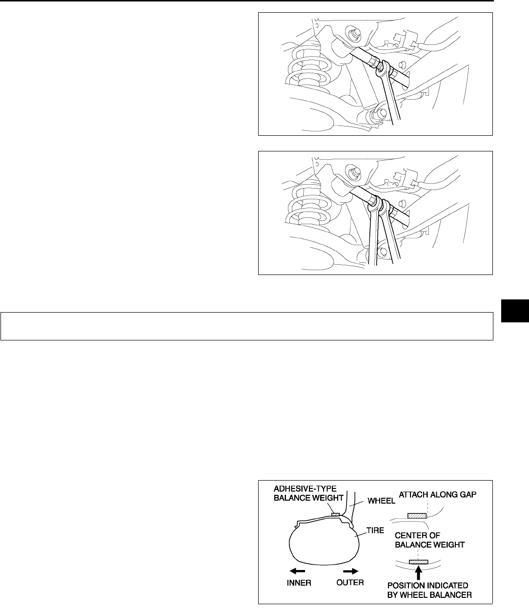
WHEEL ALIGNMENT, WHEEL AND TIRE
R7
R
2. Adjust the toe-in turning the adjusting link.
Specification
Total Toe-in: 2±
±±
±4 mm {0.08±
±±
±0.16 in}
Note
•Toe change amount: 0°43′ / one rotation
3. Tighten the locknut.
Tightening torque
68.698.1 N·m
{7.010.0 kgf·m, 50.672.3 ft·lbf}
End Of Sie
WHEEL BALANCE ADJUSTMENT (16 INCH AND 17 INCH ALUMINUM ALLOY WHEEL) A6E741701014W01
Caution
•
••
•Adjust the outer wheel balance first, then the inner wheel balance.
•
••
•Be careful not to scratch the wheels.
Adhesive-type Balance Weight (Outer)
1. Remove the old balance weight from the wheel.
2. Remove the double-sided adhesive tape remaining on the wheel, then clean and degrease the bonding area.
3. Set the wheel on a wheel balancer, measure the amount of unbalance and the position with the mode set for
knock-type balance weight.
4. Multiply the amount of unbalance by 1.6 to get the balance weight value.
5. Select a balance weight closest to the weight
value and attach the balance weight on the
position (outer) indicated by the wheel balancer.
Example calculation of balance weight value
Indicated amount of unbalance: 23 g
{0.81 oz}
23 g {0.81 oz}×
××
×1.6 = 36.8 g {1.30 oz}
Selected balance weight value: 35 g
{1.24 oz}
Note
•When selecting a balance weight, select one
closest to the calculated value.
Example: 32.4 g {1.14 oz}= 30 g {1.06 oz}, 32.5 g {1.15 oz}= 35 g {1.24 oz}
Caution
•
••
•Use a genuine balance weight or equivalent (steel).
•
••
•When attaching the weight balance, press the balance weight with a force of 25 N {2.5 kgf, 5.5 lbf}
per 5 g for 2 seconds or more.
A6E7412W005
A6E7412W004
WHEEL AND TIRE
Z5U0212W101
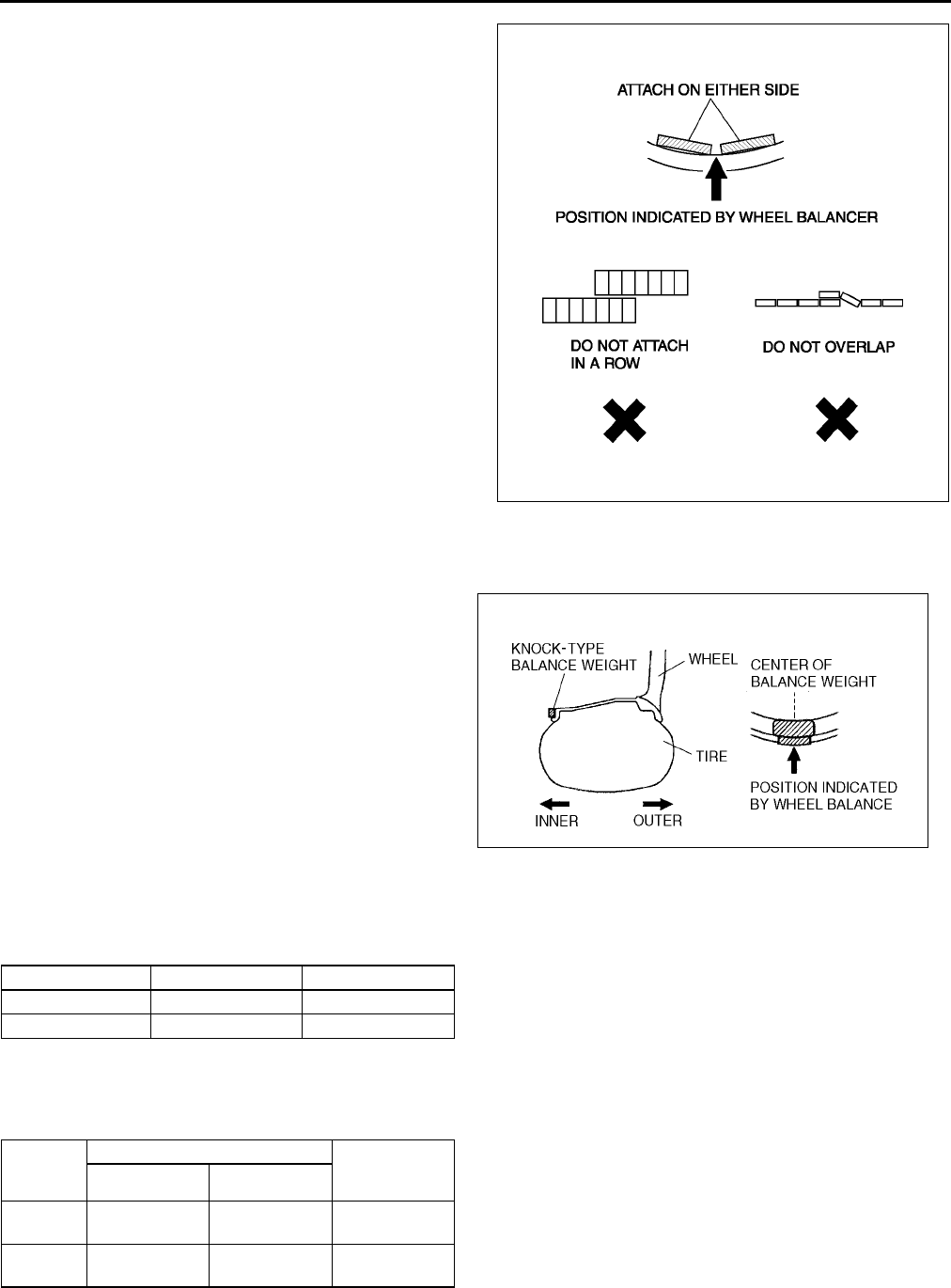
R8
WHEEL AND TIRE
6. If attaching 2 balance weights, position them so
that each is on either side of the position indicated
by the wheel balancer.
Caution
•
••
•Do not attach weight balances in a row.
•
••
•Do not overlap the balance weights.
•
••
•Total weight must not exceed 160g
{5.65 oz}.
Knock-type Balance Weight (Inner)
1. Measure the amount of unbalance with a wheel balancer.
2. Attach a balance weight corresponding to the
measured weight value on the position (inner)
indicated by the wheel balancer.
Caution
•
••
•Do not attach 3 or more balance weights.
•
••
•One balance weight must not exceed 60g
{2.12 oz}, and a total of 2 balance weights
must not exceed 100g {3.53 oz}.
Remaining Amount of Unbalance Confirmation
1. After installing the outer and inner balance weights, operate the wheel balancer again.
2. Confirm that the remaining unbalance does not exceed followings on either side.
•If the remaining unbalance exceeds 10 g {0.35 oz} (16 inch wheel) or 9g {0.32 oz} (17 inch wheel), perform
wheel balance adjustment again.
Allowable remaining unbalance value (g)
End Of Sie
Z5U0212W102
Z5U0212W103
Outer Inner
16 inch wheel 10 g {0.35 oz} 8 g {0.28 oz}
17 inch wheel 9 g {0.32 oz} 7 g {0.25 oz}
Dynamic unbalance (at rim) Static
unbalance
(at rim)
Outer Inner
16 inch
wheel
10 g {0.35 oz}
max.
8 g {0.28 oz}
max.
13 g {0.46 oz}
max.
17 inch
wheel
9 g {0.32 oz}
max.
7 g {0.25 oz}
max.
11 g {0.39 oz}
max.
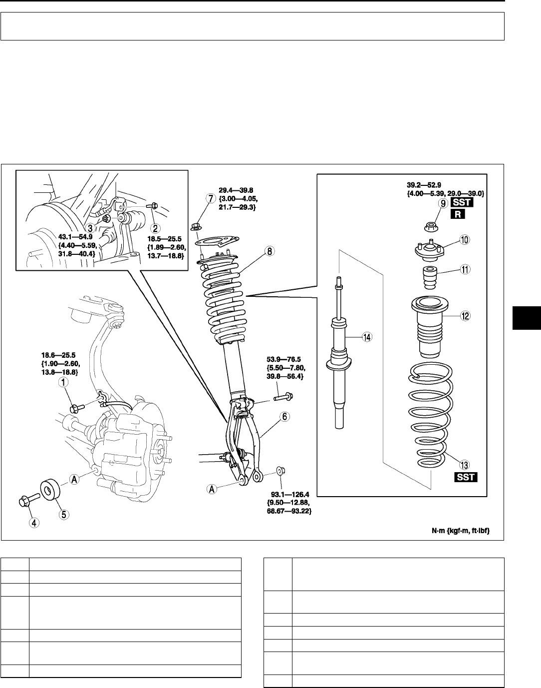
FRONT SUSPENSION
R9
R
FRONT SHOCK ABSORBER AND SPRING REMOVAL/INSTALLATION A6E741404910W01
Caution
•
••
•Performing the following procedures without first removing the ABS wheel-speed sensor may
possibly cause an open circuit in the harness if it is pulled by mistake. Before performing the
following procedures, remove the ABS wheel-sensor (axle side) and fix it to an appropriate place
where the sensor will not be pulled by mistake while servicing the vehicle.
1. Remove in the order indicated in the table.
2. Install in the reverse order of removal.
.
FRONT SUSPENSION
A6E7414W017
1 Bolt (ABS wheel-speed sensor)
2 Bolt (brake hose bracket)
3 Nut (front stabilizer control link)
4 Bolt (front shock absorber lower side)
(See R10 Bolt (Front Shock Absorber Lower Side)
Removal Note)
5 Dynamic damper
6 Damper fork
(See R12 Damper Fork Installation Note)
7 Nut (front shock absorber upper side)
8 Front shock absorber and coil spring
(See R11 Front Shock Absorber and Coil Spring
Installation Note)
9 Piston rod nut
(See R10 Piston Rod Nut Removal Note)
10 Mounting rubber
11 Bound stopper
12 Dust boot
13 Coil spring
(See R10 Coil Spring Installation Note)
14 Front shock absorber
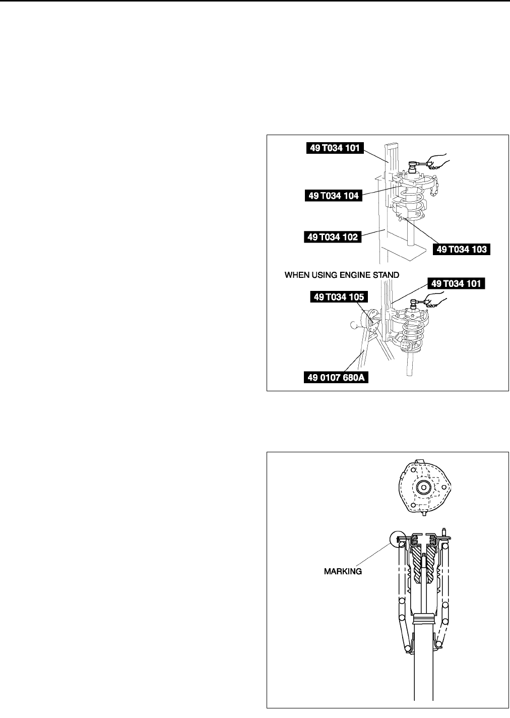
R10
FRONT SUSPENSION
Bolt (Front Shock Absorber Lower Side) Removal Note
1. Support the knuckle with a jack to prevent from falling.
Piston Rod Nut Removal Note
Warning
•
••
•Removing the piston rod nut is dangerous. The shock absorber and spring could fly off under
tremendous pressure and cause serious injury or death. Secure the shock absorber in the SSTs
before removing the piston rod nut.
1. Protect the coil spring using a piece of cloth, then set the SSTs.
2. Compress the coil spring using the SSTs, and
remove the piston rod nut.
Coil Spring Installation Note
1. Temporarily install the coil spring, dust boot and mounting rubber on the shock absorber so that the lower end
of the coil spring is seated on the step of the lower spring seat.
2. Mark the coil spring, dust boot and mounting
rubber for proper installation as shown in the
figure.
3. Align the marks of the coil spring and dust boot.
Protect the coil spring and dust boot using a piece
of cloth, then set the SSTs.
A6E7414W008
A6E7414W039
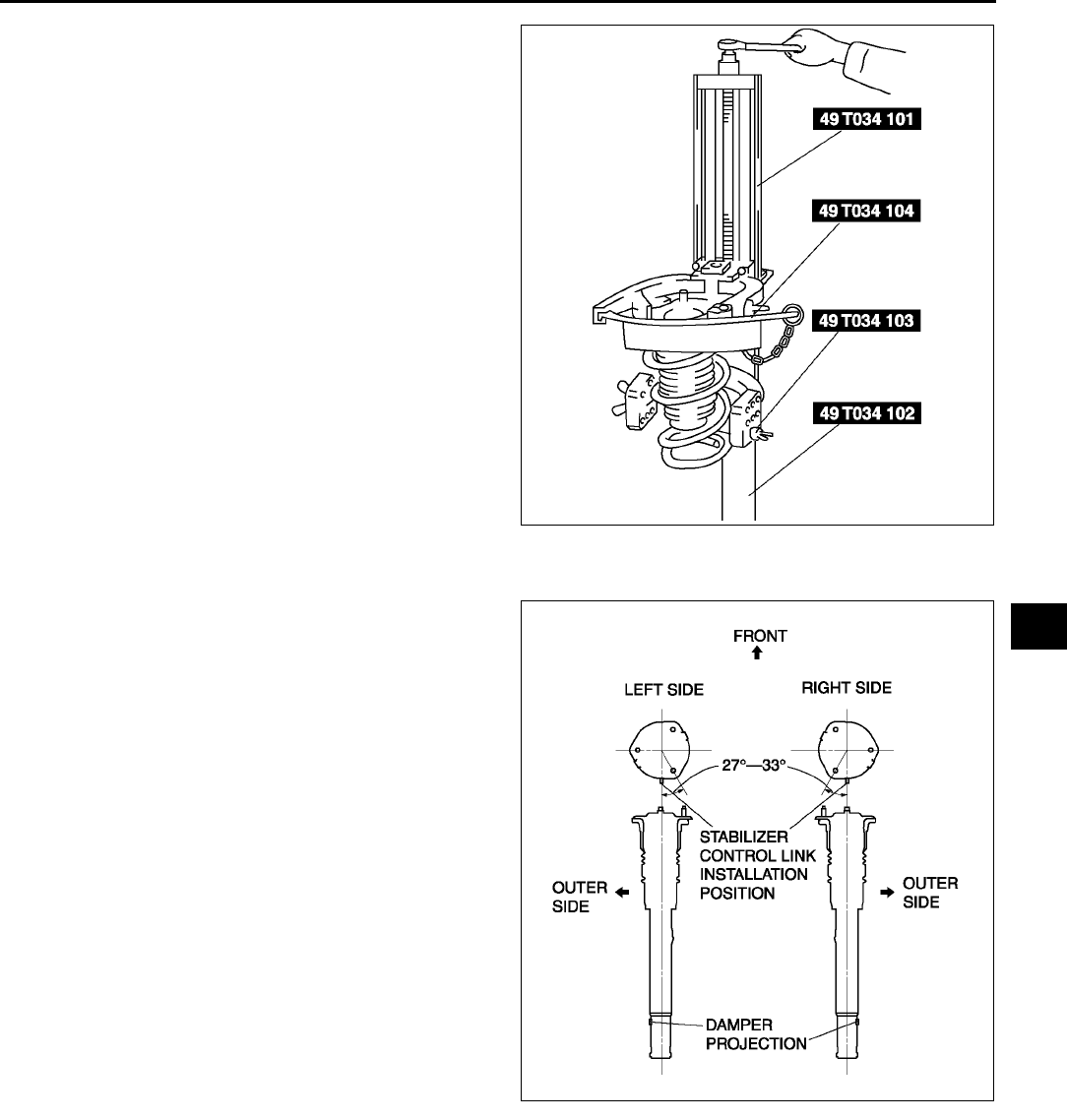
FRONT SUSPENSION
R11
R
4. Compress the coil spring using the SSTs.
5. Install the shock absorber so that the lower end of
the coil spring is seated on the step of the lower
spring seat.
6. Make sure that the marks on the shock absorber
and dust boot are aligned.
7. Install the mounting rubber and piston rod nut,
then remove the SSTs.
Piston rod nut tightening torque
39.252.9 N·m
{4.005.39 kgf·m, 29.039.0 ft·lbf}
Front Shock Absorber and Coil Spring Installation Note
1. Install the stud bolts at a 27°33° angle from
where the stabilizer control link is installed (center
line), towards the inner side of the vehicle.
A6E7414W029
A6E7414W004
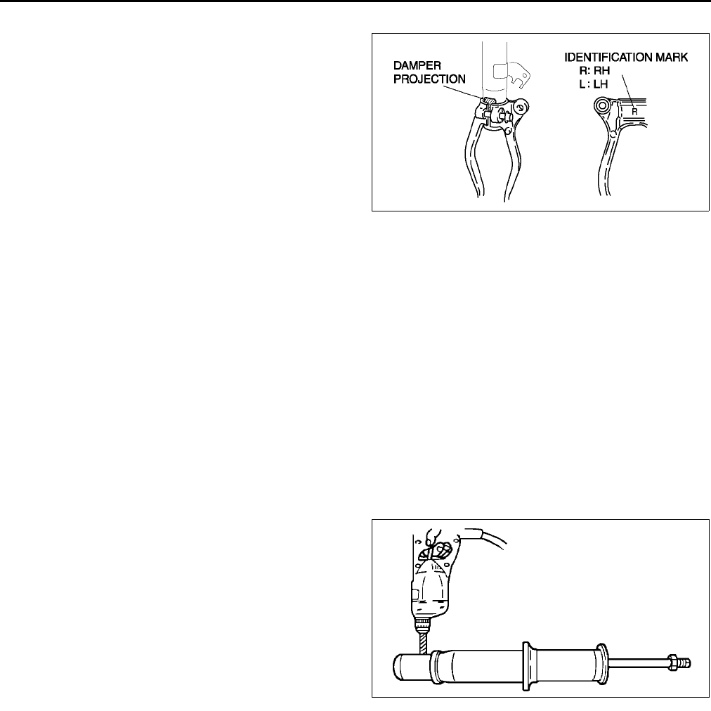
R12
FRONT SUSPENSION
Damper Fork Installation Note
1. Align the gap of the damper fork with the
projections of the damper.
2. Tighten the bolt.
End Of Sie
FRONT SHOCK ABSORBER INSPECTION A6E741434700W01
1. Remove the front shock absorber from the vehicle.
2. Inspect for damage and oil leakage.
3. Inspect the rubber bushing for deterioration and wear.
4. Compress and extend the shock piston at least three times. Verify that the operational force does not change
and that there is no unusual noise.
•If not as specified, replace the shock absorber.
(1) Compress the shock absorber piston and release it.
(2) Verify that the piston extends fully at a normal speed.
End Of Sie
FRONT SHOCK ABSORBER DISPOSAL A6E741434700W02
Warning
•
••
•Whenever drilling into a shock absorber, wear protective eye wear. The gas in the shock absorber
is pressurized, and could spray metal chips into the eyes and face when drilling.
1. Clamp a shock absorber on a flat surface or with the piston pointing downwards.
2. Drill a 23 mm {0.080.12 in} hole at a point
2030 mm {0.81.2 in} from the bottom of the
tube, so that the gas can escape.
3. Turn the hole downwards.
4. The oil can be collected by moving the piston rod
several times up and down and cutting the tube at
the end.
5. Dispose of waste oil according to the waste
disposal law.
Note
•Shock absorber gas is nitrogen gas.
•Shock absorber oil is mineral oil.
End Of Sie
A6E7414W005
A6E7414W022
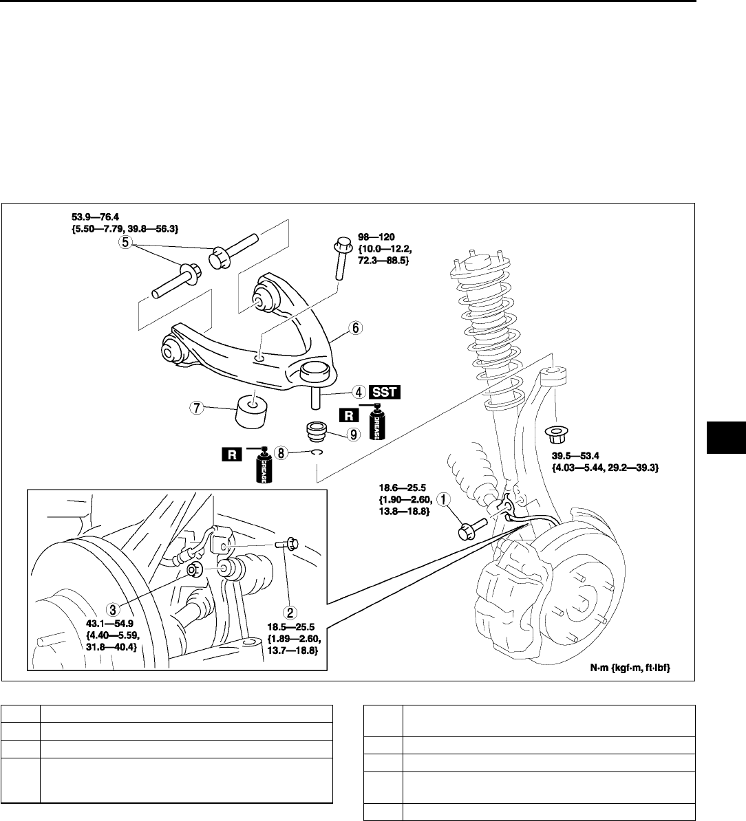
FRONT SUSPENSION
R13
R
FRONT UPPER ARM REMOVAL/INSTALLATION A6E741434200W01
Caution
•
••
•Performing the following procedures without first removing the ABS wheel-speed sensor may
possibly cause an open circuit in the harness if it is pulled by mistake. Before performing the
following procedures, remove the ABS wheel-sensor (axle side) and fix it to an appropriate place
where the sensor will not be pulled by mistake while servicing the vehicle.
1. Remove in the order indicated in the table.
2. Install in the reverse order of removal.
3. Inspect the front wheel alignment.
(See R5 FRONT WHEEL ALIGNMENT.)
.
Front Upper Arm Ball Joint Removal Note
1. Support the knuckle using the jack.
A6E7414W035
1 Bolt (ABS wheel-speed sensor)
2 Bolt (brake hose bracket)
3 Nut (stabilizer control link)
4 Front upper arm ball joint
(SeeR13 Front Upper Arm Ball Joint Removal
Note)
5 Bolt (front upper arm)
(See R14 Bolt (Front Upper Arm) Removal Note)
6 Front upper arm
7 Dynamic Damper
8Clip
(See R14 Clip Installation Note)
9 Dust boot
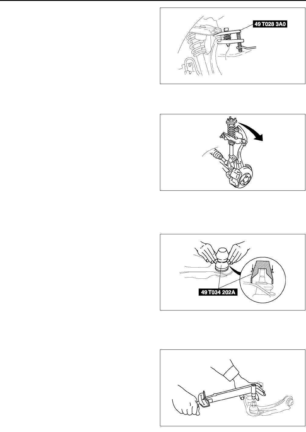
R14
FRONT SUSPENSION
2. Separate the ball joint from the knuckle using the
SST.
Bolt (Front Upper Arm) Removal Note
1. Remove the nuts (3 locations) from the upper part of the front shock absorber.
2. Pull the front shock absorber and coil spring out
of the way, towards the outer side of the vehicle.
3. Remove the bolts.
Clip Installation Note
1. Wipe the grease off the ball stud.
2. Fill the inside of the new dust boot with grease.
3. Install the boot on the ball joint.
4. Install the new clip using the SST.
5. Verify that the clip is installed securely to the
groove.
6. Wipe away the excess grease.
End Of Sie
FRONT UPPER ARM INSPECTION A6E741434200W02
1. Remove the upper arm from the vehicle.
2. Inspect for damage, cracks, and bending.
3. Inspect the ball joint rotation torque.
(1) Rotate the ball joint five times.
(2) Measure the rotation torque using a suitable
allen socket and a torque wrench.
•If not within the specification, replace the
lower arm component.
Rotation torque
1.5 N·m {15.0 kgf·cm, 13.2 in·lbf} max.
A6E7414W006
A6E7414W023
A6E7414W024
A6E7414W043
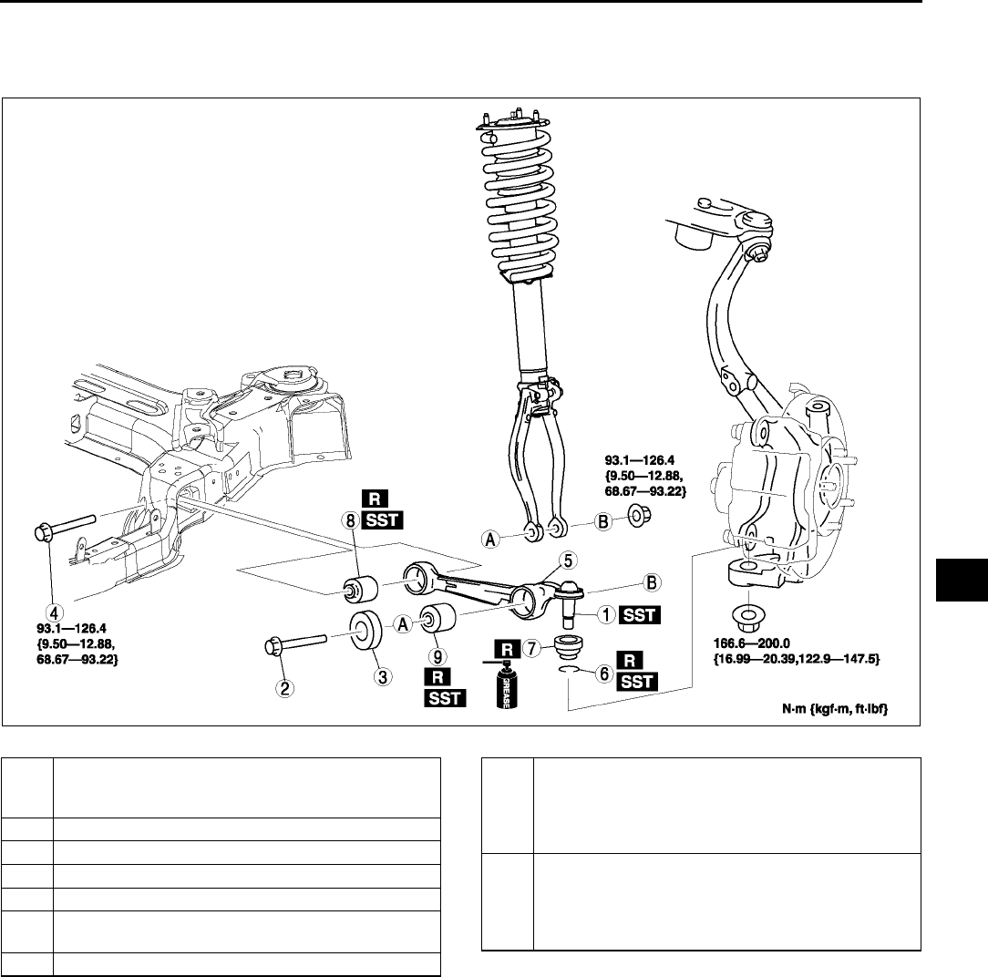
FRONT SUSPENSION
R15
R
End Of Si e
FRONT LOWER ARM (FRONT) REMOVAL/INSTALLATION A6E741434300W01
1. Remove in the order indicated in the table.
2. Install in the reverse order of removal.
.
A6E7414W018
1 Front lower arm (front) ball joint
(See R16 Front Lower Arm (Front) Ball Joint
Removal Note)
2 Bolt (front shock absorber lower side)
3 Dynamic damper
4 Bolt (front lower arm inner side)
5 Front lower arm (front) component
6Clip
(See R18 Clip Installation Note)
7 Dust boot
8 Front lower arm (front) bushing (inner side)
(See R16 Front Lower Arm (Front) Bushing (Inner
Side) Removal Note)
(See R17 Front Lower Arm (Front) Bushing (Inner
Side) Installation Note)
9 Front lower arm (front) bushing (outer side)
(See R16 Front Lower Arm (Front) Bushing (Outer
Side) Removal Note)
(See R16 Front Lower Arm (Front) Bushing (Outer
Side) Installation Note)
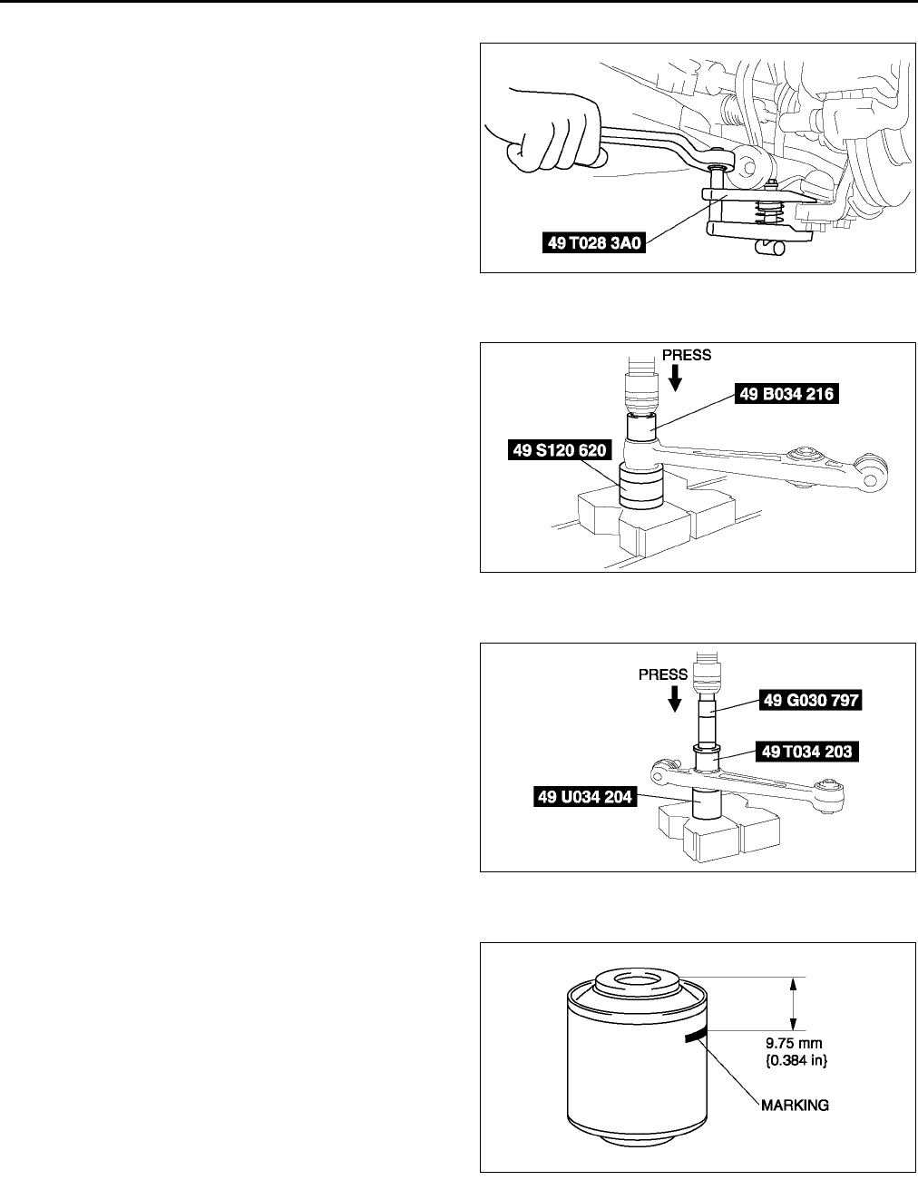
R16
FRONT SUSPENSION
Front Lower Arm (Front) Ball Joint Removal Note
1. Separate the ball joint from the knuckle using the
SSTs.
Front Lower Arm (Front) Bushing (Inner Side) Removal Note
1. Press the bushing (inner side) out using the
SSTs.
Front Lower Arm (Front) Bushing (Outer Side) Removal Note
1. Press the bushing (outer side) out using the
SSTs.
Front Lower Arm (Front) Bushing (Outer Side) Installation Note
1. Mark the new bushing as shown in the figure.
A6E7414W030
A6E7414W001
A6E7414W010
A6E7414W011
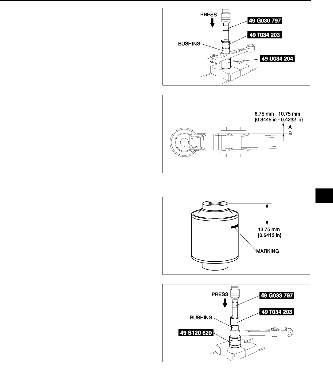
FRONT SUSPENSION
R17
R
2. Press the bushing in to the marking using the
SSTs.
3. Verify that clearance distance AB is 8.75 mm
10.75 mm {0.3445 in0.4232 in}.
Front Lower Arm (Front) Bushing (Inner Side) Installation Note
1. Mark the new bushing as shown in the figure.
2. Press the bushing in to the marking using the
SSTs.
A6E7414W012
A6E7414W003
A6E7414W013
A6E7414W002
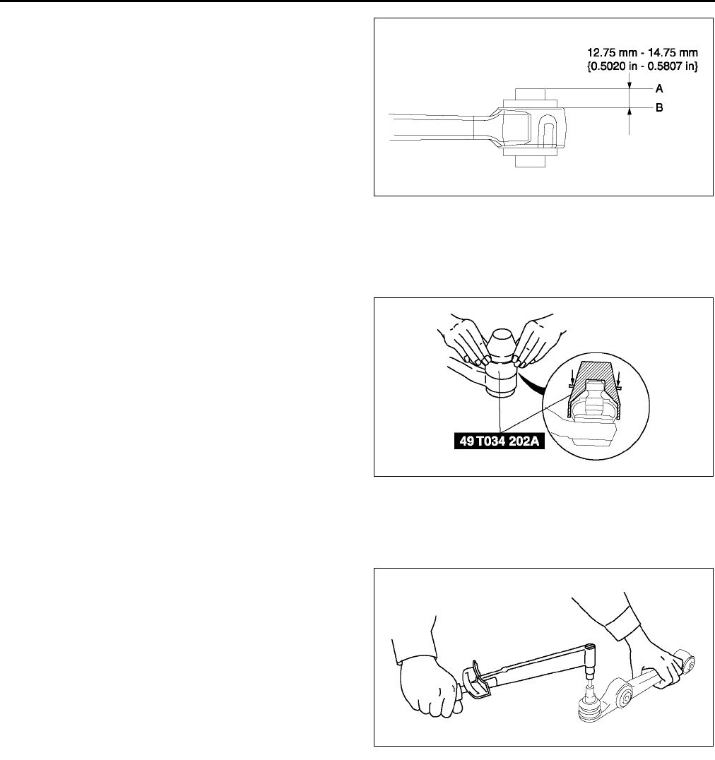
R18
FRONT SUSPENSION
3. Verify that clearance distance AB is 12.75
mm14.75 mm {0.5020 in0.5807 in}.
Clip Installation Note
1. Wipe the grease off the ball stud.
2. Fill the inside of the new dust boot with grease.
3. Install the boot on the ball joint.
4. Install the new clip using the SST.
5. Verify that the clip is installed securely to the
groove.
6. Wipe away the excess grease.
End Of Sie
FRONT LOWER ARM (FRONT) INSPECTION A6E741434300W03
1. Remove the lower arm (front) from the vehicle.
2. Inspect for damage, cracks, and bending.
3. Inspect the ball joint rotation torque.
(1) Rotate the ball joint five times.
(2) Measure the rotation torque using a suitable
allen socket and a torque wrench.
•If not within the specification, replace the
lower arm component.
Rotation torque
1.182.23 N·m
{12.122.7 kgf·cm, 10.519.7 in·lbf}
End Of Sie
A6E7414W007
A6E7414W025
A6E7414W044
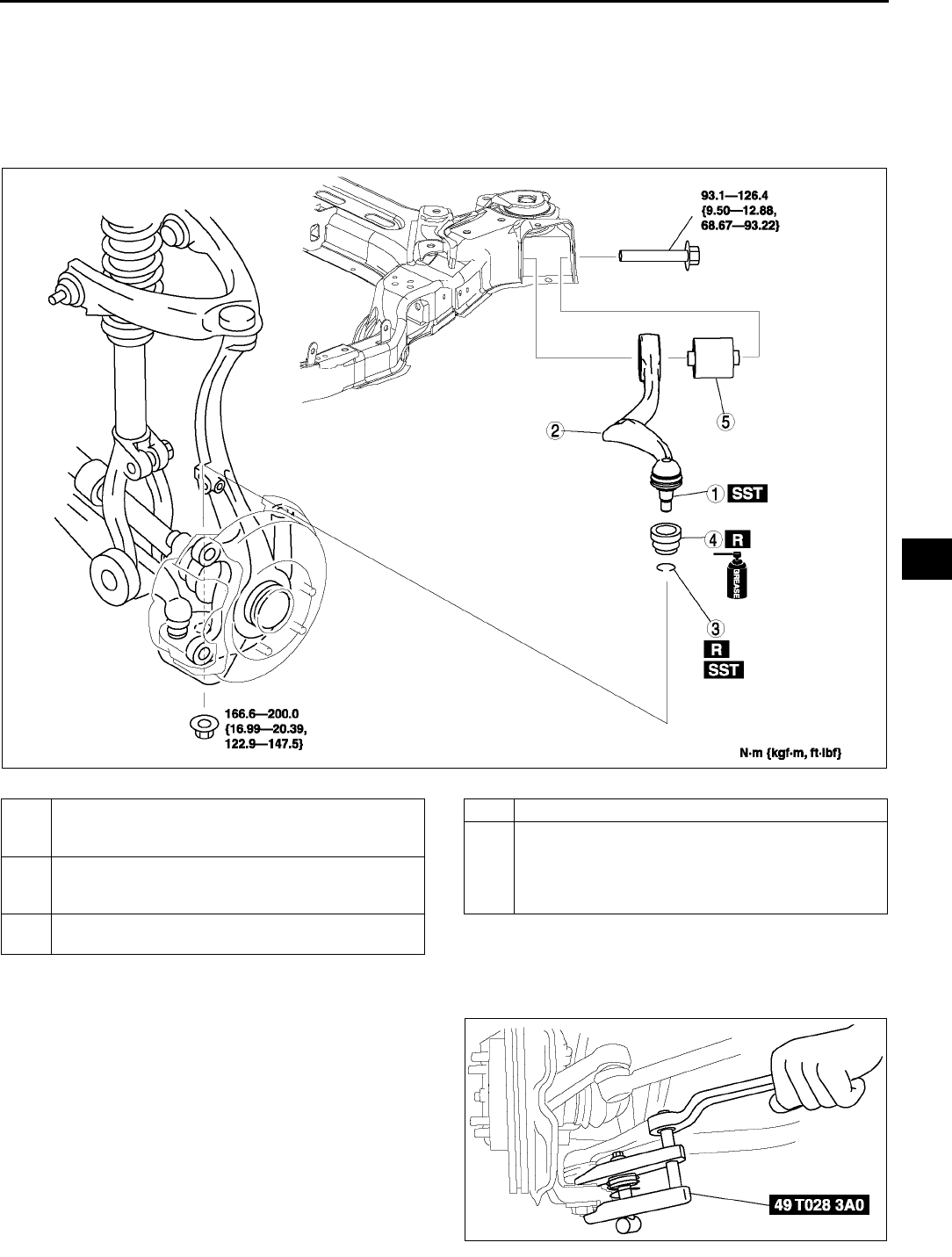
FRONT SUSPENSION
R19
R
FRONT LOWER ARM (REAR) REMOVAL/INSTALLATION A6E741434300W02
1. Remove the front crossmember component.
(See R23 FRONT CROSSMEMBER REMOVAL/INSTALLATION.)
2. Remove in the order indicated in the table.
3. Install in the reverse order of removal.
4. Inspect the front wheel alignment.
(See R5 FRONT WHEEL ALIGNMENT.)
.
Front Lower Arm (Rear) Ball Joint Removal Note
1. Separate the ball joint from the knuckle using the
SSTs.
A6E7414W019
1 Front lower arm (rear) ball joint
(See R19 Front Lower Arm (Rear) Ball Joint
Removal Note)
2 Front lower arm (rear)
(See R21 Front Lower Arm (Rear) Installation
Note)
3Clip
R21 Clip Installation Note
4 Dust boot
5 Front lower arm (rear) bushing
(See R20 Front Lower Arm (Rear) Bushing
Removal Note)
(See R20 Front Lower Arm (Rear) Bushing
Installation Note)
A6E7414W031
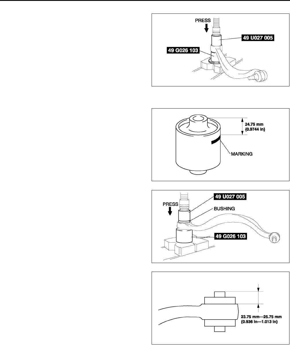
R20
FRONT SUSPENSION
Front Lower Arm (Rear) Bushing Removal Note
1. Press the bushing out using the SSTs.
2. Remove the front lower arm (rear) from the press
and tap the bushing out with a hammer.
Front Lower Arm (Rear) Bushing Installation Note
1. Mark the new bushing as shown in the figure.
2. Press the bushing in to the marking using the
SSTs.
3. Verify that clearance distance AB is 23.75
mm25.75 mm {0.936 in1.013 in}.
A6E7414W014
A6E7414W026
A6E7414W027
A6E7414W028
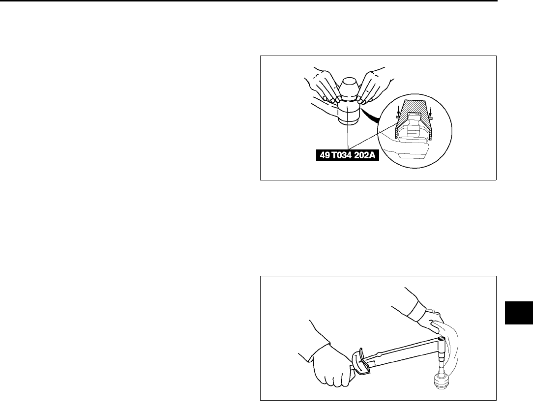
FRONT SUSPENSION
R21
R
Clip Installation Note
1. Wipe the grease off the ball stud.
2. Fill the inside of the new dust boot with grease.
3. Install the boot on the ball joint.
4. Install the new clip using the SST.
5. Verify that the clip is installed securely to the
groove.
6. Wipe away the excess grease.
Front Lower Arm (Rear) Installation Note
1. Install the lower arm (rear) so that identification mark (L or R) faces toward the front of the vehicle.
End Of Sie
FRONT LOWER ARM (REAR) INSPECTION A6E741434300W04
1. Remove the lower arm (rear) from the vehicle.
2. Inspect for damage, cracks, and bending.
3. Inspect the ball joint rotation torque.
(1) Rotate the ball joint five times.
(2) Measure the rotation torque using a suitable
allen socket and a torque wrench.
•If not within the specification, replace the
lower arm component.
Rotation torque
1.002.22 N·m
{10.222.6 kgf·cm, 8.8619.6 in·lbf}
End Of Sie
A6E7414W025
A6E7414W045
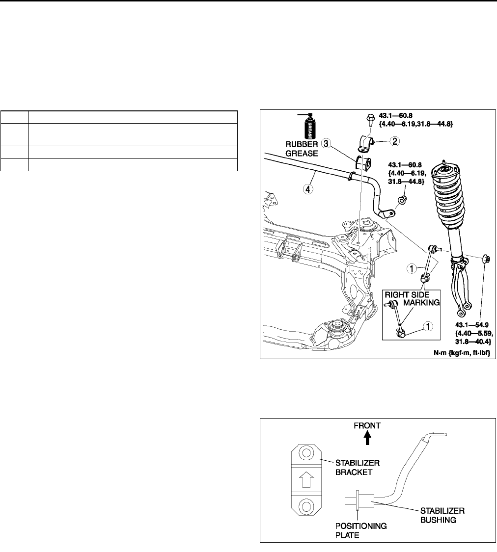
R22
FRONT SUSPENSION
FRONT STABILIZER REMOVAL/INSTALLATION
1. Remove the front crossmember component. (See R23 FRONT CROSSMEMBER REMOVAL/
INSTALLATION.)
2. Remove in the order indicated in the table.
3. Install in the reverse order of removal.
4. Adjust the headlight zeroset.
(See T31 HEADLIGHT ZEROSET.)
5. Inspect the front wheel alignment.
(See R5 FRONT WHEEL ALIGNMENT.)
.
Stabilizer Bracket Installation Note
1. Apply rubber grease to the inside surface of the stabilizer bushing.
2. Align the bushing with the inside of positioning plate on the stabilizer bar.
3. Install the stabilizer bracket.
End Of Sie
1 Stabilizer control link
2 Stabilizer bracket
(See R22 Stabilizer Bracket Installation Note)
3 Stabilizer bushing
4 Front stabilizer
A6E7414W020
A6E7414W015
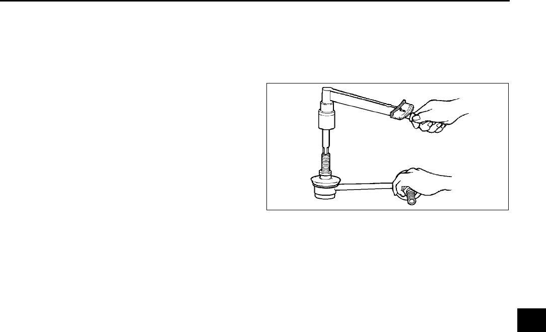
FRONT SUSPENSION
R23
R
STABILIZER CONTROL LINK INSPECTION A6E741434150W01
1. Remove the stabilizer control link from the vehicle.
2. Inspect for bending and damage.
3. Measure the ball joint starting torque.
(1) Rock the ball joint stud side to side 10 times.
(2) Rotate the ball joint stud 10 times.
(3) Measure the starting torque using a suitable
allen socket and a torque wrench.
Starting torque
0.230.47 N·m
{2.44.7 kgf·cm, 2.14.1 in·lbf}
End Of Sie
FRONT CROSSMEMBER REMOVAL/INSTALLATION A6E741434800W01
1. Remove the under cover.
2. Remove the splash shield.
3. Remove the front auto leveling sensor.
(See T32 FRONT AUTO LEVELING SENSOR REMOVAL/INSTALLATION.)
4. Remove the transverse member.
(See R27 TRANSVERSE MEMBER REMOVAL/INSTALLATION.)
5. Remove the steering gear and linkage, and pipe assembly installation bolts from the front crossmember, then
suspend the steering gear and linkage with a cable.
Tightening torque
•
••
•Steering gear and linkage: 74.4104.8 N·m {7.85710.68 kgf·m, 54.8877.29 ft·lbf}
•
••
•Pipe assembly: 7.810.8 N·m {79.6110.0 kgf·cm, 69.195.5 in·lbf}
6. Remove in the order indicated in the table.
7. Install in the reverse order of removal.
8. Adjust the headlight zeroset.
(See T31 HEADLIGHT ZEROSET.)
9. Inspect the front wheel alignment.
(See R5 FRONT WHEEL ALIGNMENT.)
A6E7414W021
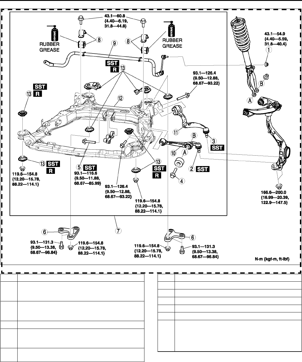
R24
FRONT SUSPENSION
.
A6E7414W100
1 Nut (stabilizer control link)
2 Front lower arm (front) ball joint
(See R16 Front Lower Arm (Front) Ball Joint
Removal Note)
3 Front lower arm (rear) ball joint
(See R19 Front Lower Arm (Rear) Ball Joint
Removal Note)
4 Bolt (front shock absorber lower side)
5 No.1 engine mount center bolt
(See R25 No.1 Engine Mount Center Bolt Removal
Note)
6 Crossmember bracket
(See R25 Crossmember Bracket Removal Note)
7 Crossmember component
8 Stabilizer bracket and bushing
9 Front Stabilizer
10 Front lower arm (front)
11 Front lower arm (rear)
12 Front crossmember
13 Front crossmember bushing
(See R25 Front Crossmember Bushing Removal
Note)
(See R26 Front Crossmember Bushing Installation
Note)
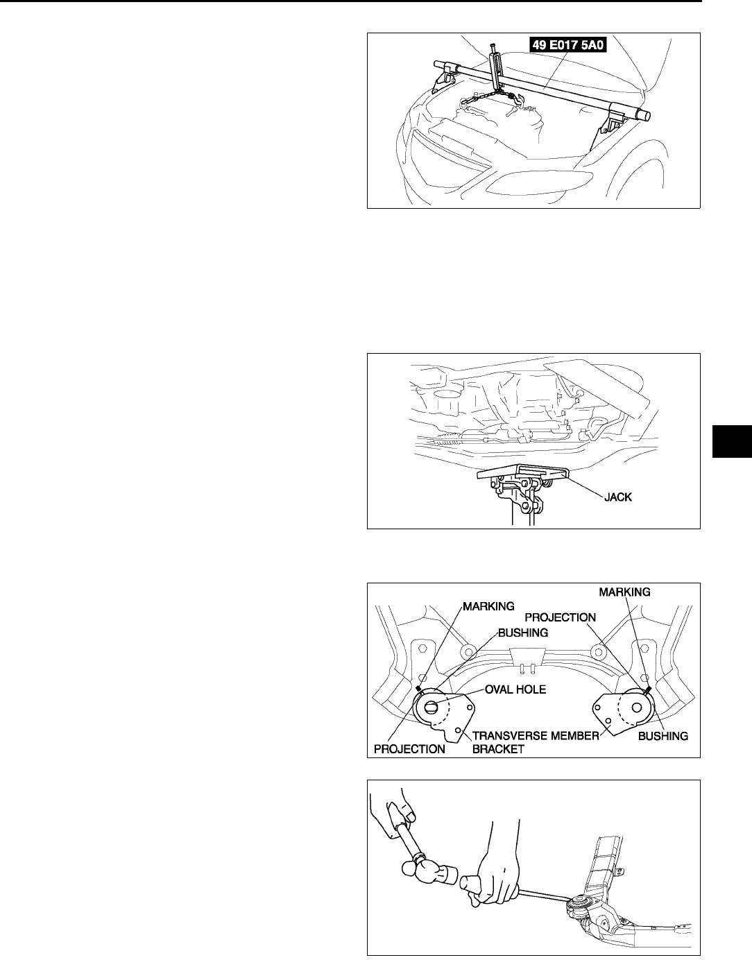
FRONT SUSPENSION
R25
R
No.1 Engine Mount Center Bolt Removal Note
1. Suspend the engine using the SST.
2. Remove the No.1 engine mount center bolt.
Crossmember Bracket Removal Note
Warning
•
••
•Removing the crossmember is dangerous. The crossmember component could fall and cause
serious injury or death. Verify that the jack securely supports the crossmember component before
removing the crossmember bracket.
1. Support the crossmember component with a jack
and remove the nuts.
2. Remove the crossmember bracket.
Front Crossmember Bushing Removal Note
1. Mark the crossmember as shown in the figure
(rear upper side only).
2. Remove the bushings using screw driver (-),
being care not to damage the front crossmember.
A6E7414W016
A6E7414W036
A6E7414W040
A6E7414W032
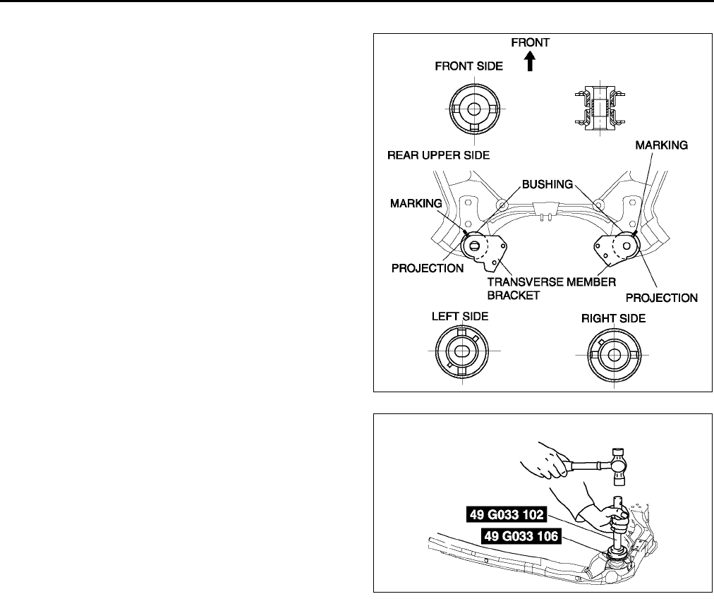
R26
FRONT SUSPENSION
Front Crossmember Bushing Installation Note
1. Set the bushings as shown in the figure.
2. Install the bushing onto the crossmember using
the SSTs.
End Of Sie
A6E7414W041
A6E7414W042
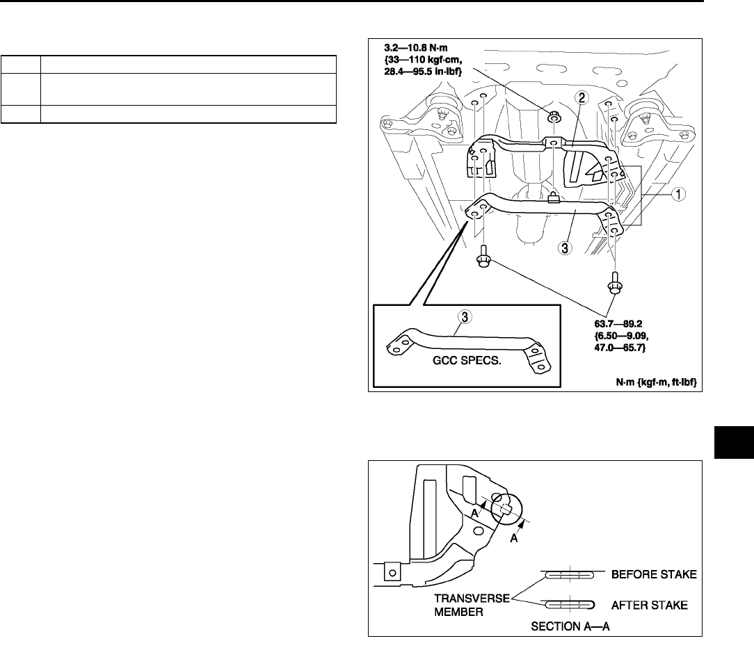
FRONT SUSPENSION
R27
R
TRANSVERSE MEMBER REMOVAL/INSTALLATION A6E741434890W01
1. Remove in the order indicated in the table.
2. Install in the reverse order of removal.
Transverse Cover Installation Note
1. Install the transverse cover.
2. Stake area A as shown in the figure.
End Of Sie
1 Transverse member and transverse cover
2 Transverse cover (European (L.H.D. U.K.) specs.)
(See R27 Transverse Cover Installation Note)
3 Transverse member
A6E7414W037
A6E7414W038
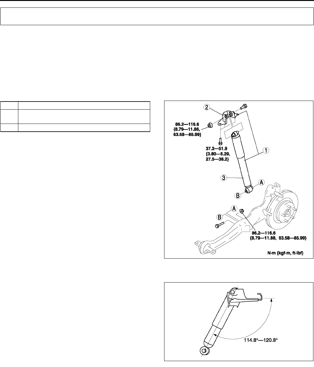
R28
REAR SUSPENSION
REAR SHOCK ABSORBER REMOVAL/INSTALLATION A6E741628700W01
Caution
•
••
•Performing the following procedures without first removing the ABS wheel-speed sensor may
possibly cause an open circuit in the harness if it is pulled by mistake. Before performing the
following procedures, remove the ABS wheel-speed sensor (axle side) and fix it to an appropriate
place where the sensor will not be pulled by mistake while servicing the vehicle.
1. Remove in the order indicated in the table.
2. Install in the reverse order of removal.
.
Bracket Installation Note
1. Install the bracket as shown in the figure.
End Of Sie
REAR SHOCK ABSORBER INSPECTION A6E741628700W02
1. Inspect the rear shock absorber in the same way as the front shock absorber. (See R12 FRONT SHOCK
ABSORBER INSPECTION.)
End Of Sie
REAR SHOCK ABSORBER DISPOSAL A6E741628700W03
1. Dispose the rear shock absorber in the same way as the front shock absorber. (See R12 FRONT SHOCK
ABSORBER DISPOSAL.)
End Of Sie
REAR SUSPENSION
1 Rear shock absorber and bracket
2Bracket
(See R28 Bracket Installation Note)
3 Rear shock absorber
A6E7416W003
A6E7416W024
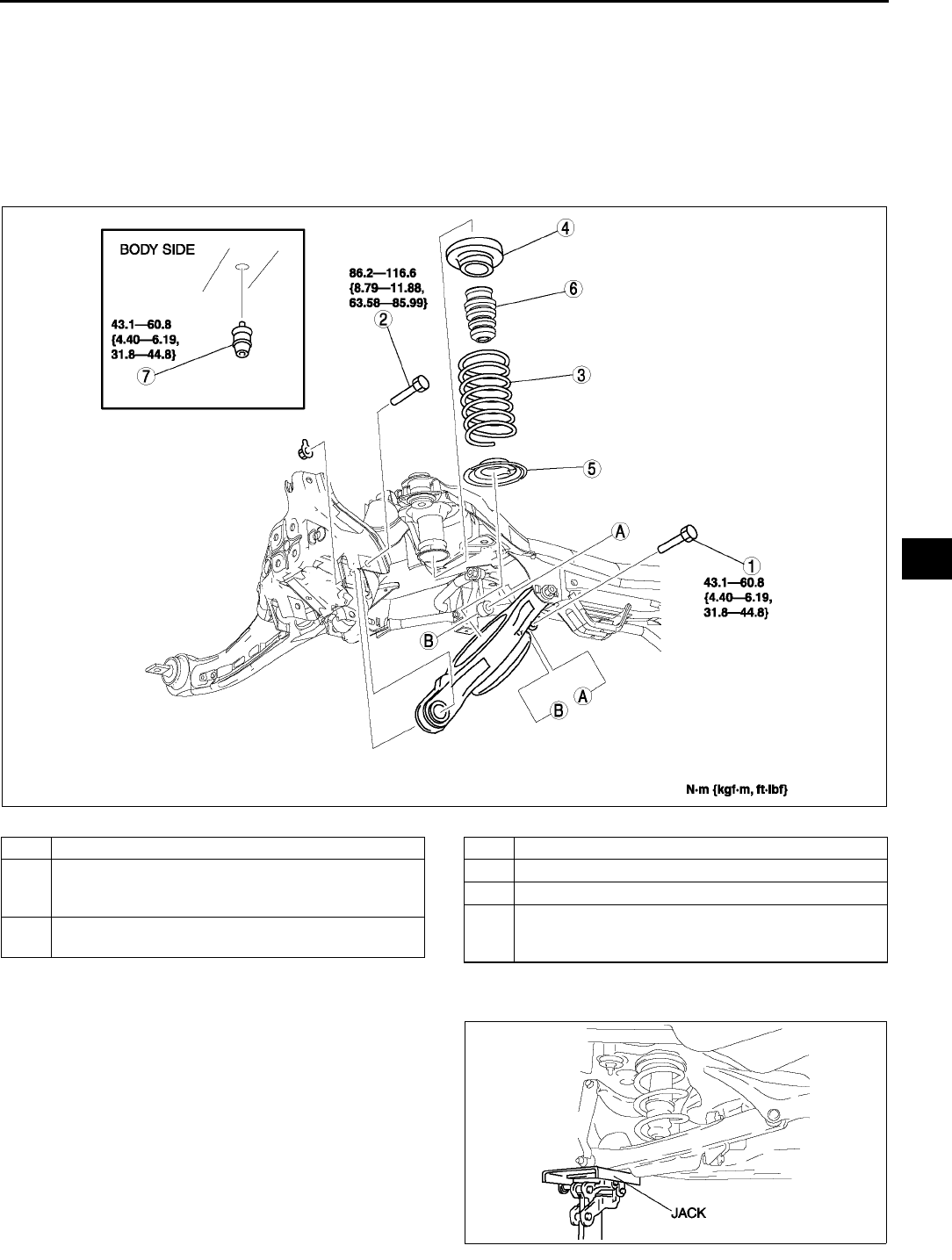
REAR SUSPENSION
R29
R
REAR COIL SPRING REMOVAL/INSTALLATION A6E741628011W01
1. Remove the rear auto leveling sensor.
(See T32 REAR AUTO LEVELING SENSOR REMOVAL/INSTALLATION.)
2. Remove in the order indicated in the table.
3. Install in the reverse order of removal.
4. Adjust the headlight zeroset.
(See T31 HEADLIGHT ZEROSET.)
5. Inspect the rear wheel alignment.
(See R6 REAR WHEEL ALIGNMENT.)
.
Bolt (Rear Lower Arm Outer Side) Removal Note
1. Support the lower arm with a jack.
2. Loosen the inner bolt of the lower arm.
3. Remove the outer bolt of the lower arm.
A6E7416W022
1 Bolt (stabilizer control link lower side)
2 Bolt (rear lower arm outer side)
(See R29 Bolt (Rear Lower Arm Outer Side)
Removal Note)
3 Rear coil spring
(See R30 Rear Coil Spring Installation Note)
4 Upper spring seat rubber
5 Lower spring seat
6 Bound stopper (spring side)
7 Bound stopper (body side)
(See R30 Bound Stopper (Body Side) Removal/
Installation Note)
A6E7416W019
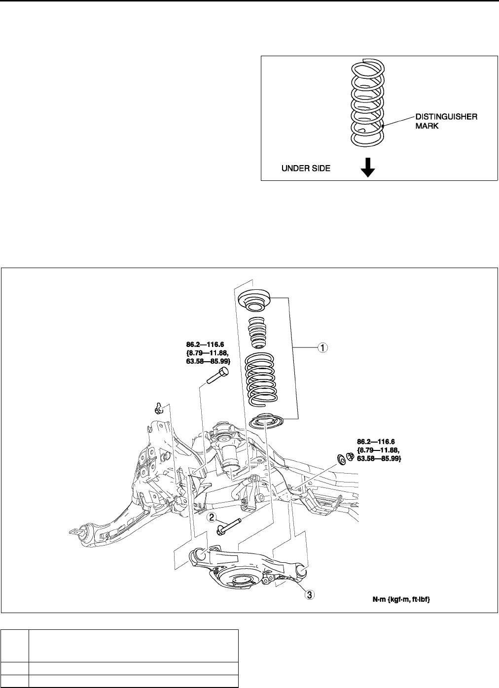
R30
REAR SUSPENSION
Bound Stopper (Body Side) Removal/Installation Note
1. Remove or/and install the bound stopper (body side) using the extension bar.
Rear Coil Spring Installation Note
1. Install the coil spring so that the distinguisher
mark is located on under side.
2. Position the jack under the lower arm and jack up
slowly.
Warning
•
••
•Installing the coil spring is dangerous.
The coil spring could fly off, and cause
serious injure of death.
3. Install the lower arm (outer side) bolt.
End Of Sie
REAR LOWER ARM REMOVAL/INSTALLATION A6E741628310W01
1. Remove in the order indicated in the table.
2. Install in the reverse order of removal.
3. Inspect the rear wheel alignment.
(See R6 REAR WHEEL ALIGNMENT.)
End Of Sie
A6E7416W015
A6E7416W008
1 Rear coil spring component
(See R29 REAR COIL SPRING REMOVAL/
INSTALLATION)
2 Bolt (rear lower arm inner side)
3 Rear lower arm
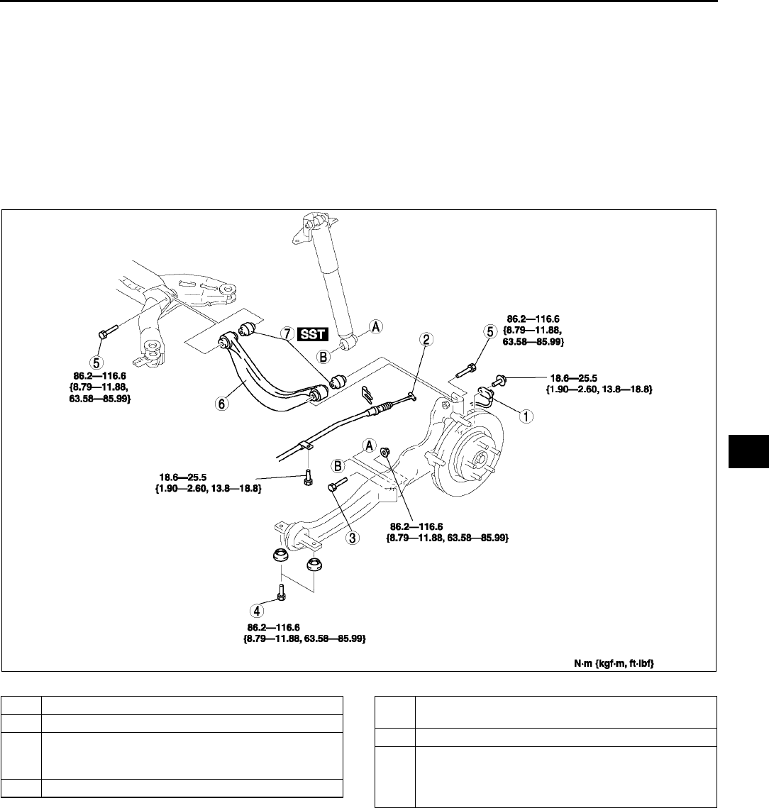
REAR SUSPENSION
R31
R
REAR UPPER ARM REMOVAL/INSTALLATION A6E741628210W01
Caution
•
••
•Performing the following procedures without first removing the ABS wheel-speed sensor may
possibly cause an open circuit in the harness if it is pulled by mistake. Before performing the
following procedures, remove the ABS wheel-speed sensor (axle side) and fix it to an appropriate
place where the sensor will not be pulled by mistake while servicing the vehicle.
1. Remove in the order indicated in the table.
2. Install in the reverse order of removal.
3. Inspect the rear wheel alignment.
(See R6 REAR WHEEL ALIGNMENT.)
.
A6E7416W009
1 ABS wheel-speed sensor
2 Parking brake cable
3 Bolt (rear shock absorber lower side)
(See R32 Bolt (Rear Shock Absorber Lower Side)
Removal Note)
4 Bolt (trailing link front side)
5 Bolt (rear upper arm)
(See R32 Bolt (Rear Upper Arm) Removal Note)
6 Rear upper arm
7 Rear upper arm bushing
(See R32 Rear Upper Arm Bushing Removal Note)
(See R32 Rear Upper Arm Bushing Installation
Note)
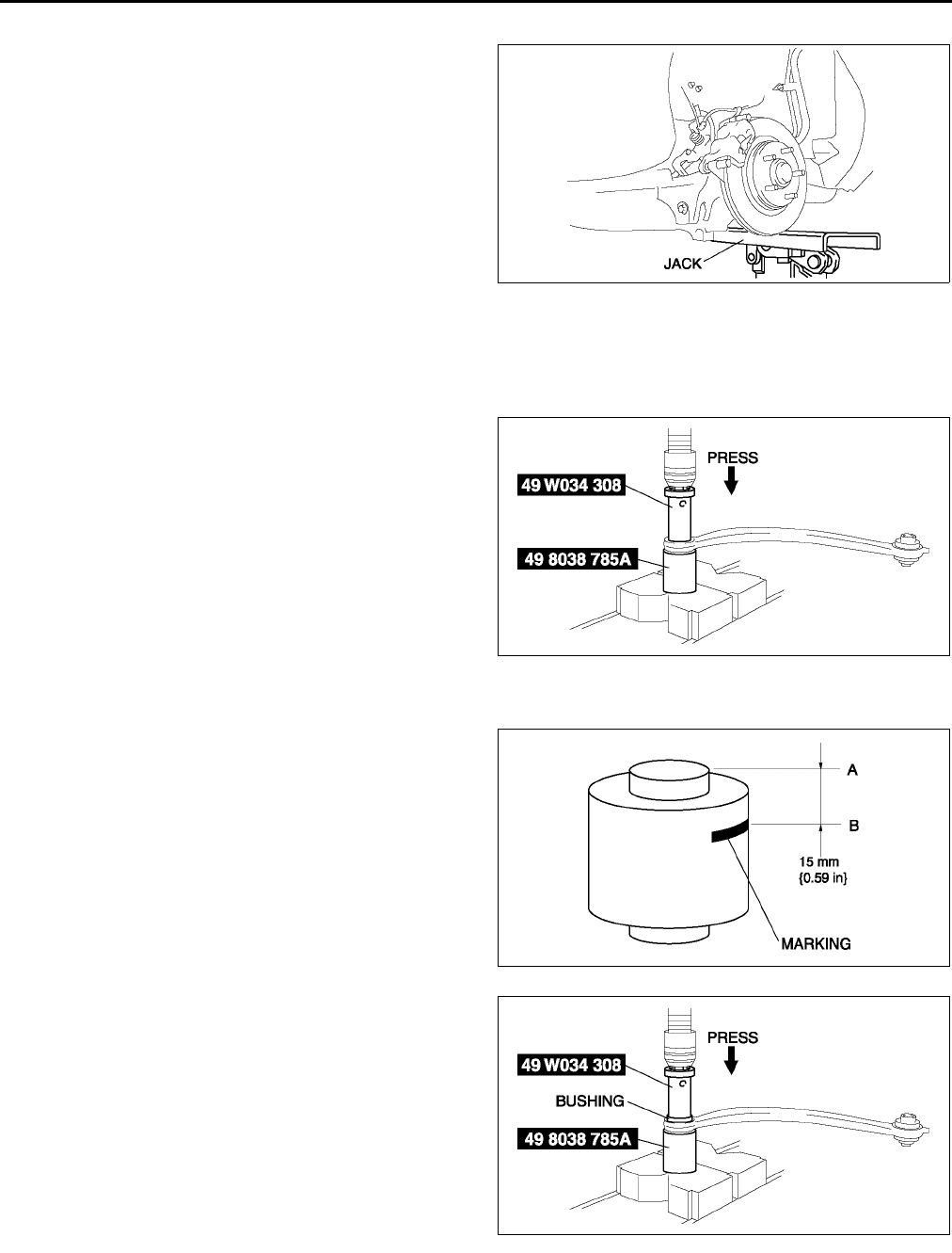
R32
REAR SUSPENSION
Bolt (Rear Shock Absorber Lower Side) Removal Note
1. Support the trailing link with a jack.
Bolt (Rear Upper Arm) Removal Note
1. Loosen the bolts on the inner and outer side of the lateral link.
Rear Upper Arm Bushing Removal Note
1. Press the upper arm bushing out using the SSTs.
Rear Upper Arm Bushing Installation Note
1. Mark the new bushing as shown in the figure.
2. Press the bushing in to the marking using the
SSTs.
A6E7416W005
A6E7416W010
A6E7416W011
A6E7416W012
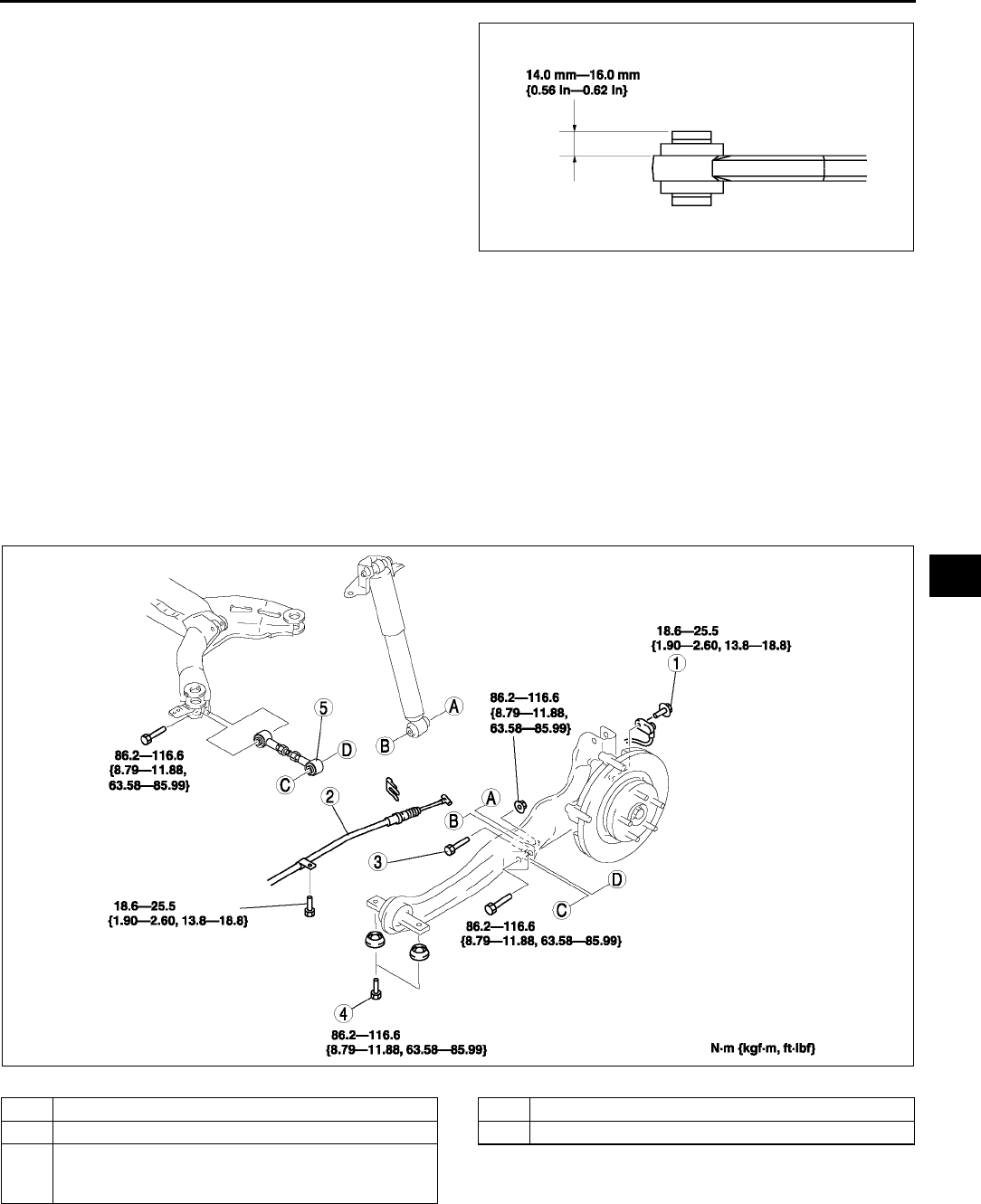
REAR SUSPENSION
R33
R
3. Verify that clearance distance AB is 14.0 mm
16.0 mm {0.56 in-0.62 in}.
End Of Sie
REAR LATERAL LINK REMOVAL/INSTALLATION A6E741628600W01
Caution
•
••
•Performing the following procedures without first removing the ABS wheel-speed sensor may
possibly cause an open circuit in the harness if it is pulled by mistake. Before performing the
following procedures, remove the ABS wheel-speed sensor (axle side) and fix it to an appropriate
place where the sensor will not be pulled by mistake while servicing the vehicle.
1. Remove in the order indicated in the table.
2. Install in the reverse order of removal.
3. Inspect the rear wheel alignment.
(See R6 REAR WHEEL ALIGNMENT.)
.
A6E7416W013
A6E7416W017
1 ABS wheel-speed sensor
2 Parking brake cable
3 Bolt (rear shock absorber lower side)
(SeeR34 Bolt (Rear Shock Absorber Lower Side)
Removal Note)
4 Bolt (trailing link front side)
5 Rear lateral link
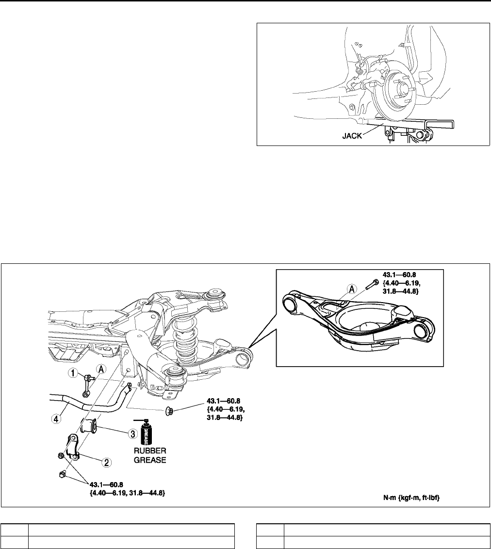
R34
REAR SUSPENSION
Bolt (Rear Shock Absorber Lower Side) Removal Note
1. Support the trailing link with a jack.
Caution
•
••
•Removing the trailing link is dangerous.
The trailing link could fall and cause
serious injury or death. Verify that the
jack securely supports the trailing link.
End Of Sie
REAR STABILIZER REMOVAL/INSTALLATION A6E741628100W01
1. Remove the rear auto leveling sensor.
(See T32 REAR AUTO LEVELING SENSOR REMOVAL/INSTALLATION.)
2. Remove in the order indicated in the table.
3. Install in the reverse order of removal.
4. Adjust the headlight zeroset.
(See T31 HEADLIGHT ZEROSET.)
.
End Of Sie
A6E7416W005
A6E7416W004
1 Stabilizer control link
2 Stabilizer bracket
3 Bushing
4 Rear stabilizer

REAR SUSPENSION
R35
R
STABILIZER CONTROL LINK INSPECTION A6E741634150W01
1. Remove the stabilizer control link from the vehicle.
2. Inspect for bending and damage.
3. Measure the ball joint starting torque.
(1) Rock the ball joint stud side to side 10 times.
(2) Rotate the ball joint stud 10 times.
(3) Measure the starting torque using a suitable
Allen socket and a torque wrench.
Starting torque
0.230.47 N·m
{2.44.7 kgf·cm, 2.14.1 in·lbf}
End Of Sie
TRAILING LINK REMOVAL/INSTALLATION A6E741628200W01
Caution
•
••
•Performing the following procedures without first removing the ABS wheel-speed sensor may
possibly cause an open circuit in the harness if it is pulled by mistake. Before performing the
following procedures, remove the ABS wheel-speed sensor (axle side) and fix it to an appropriate
place where the sensor will not be pulled by mistake while servicing the vehicle.
1. Remove the rear auto leveling sensor.
(See T32 REAR AUTO LEVELING SENSOR REMOVAL/INSTALLATION.)
2. Remove in the order indicated in the table.
3. Install in the reverse order of removal.
4. Adjust the headlight zeroset.
(See T31 HEADLIGHT ZEROSET.)
5. Inspect the rear wheel alignment.
(See R6 REAR WHEEL ALIGNMENT.)
A6E7414W021
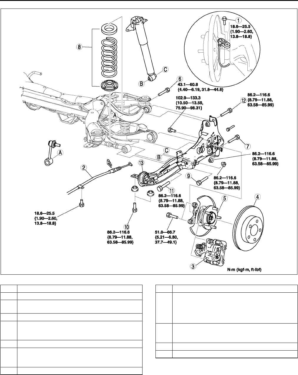
R36
REAR SUSPENSION
.
A6E7416W018
1 ABS wheel-speed sensor
2 Parking brake cable
3 Calliper component
(See R37 Caliper Component Removal Note)
4Disc plate
5 Spindle and hub component
(See M10 WHEEL HUB, HUB SPINDLE
REMOVAL/INSTALLATION)
6 Bolt (stabilizer control link lower side)
7 Bolt (rear lower arm outer side)
(See R29 Bolt (Rear Lower Arm Outer Side)
Removal Note)
8 Spring component
9 Bolt (rear shock absorber lower side)
10 Bolt (trailing link front side)
(See R37 Bolt (Trailing Link Front Side) Removal
Note)
(See R37 Bolt (Trailing Link Front Side) Installation
Note)
11 Bolt (rear lateral link outer side)
(See R37 Bolt (Rear Lateral Link Outer Side)
Removal Note)
12 Bolt (rear upper arm outer side)
13 Trailing link
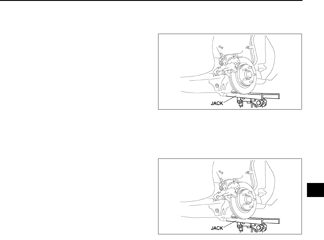
REAR SUSPENSION
R37
R
Caliper Component Removal Note
1. Suspend the caliper aside with cable.
Bolt (Trailing Link Front Side) Removal Note
1. Support the trailing link with a jack.
Caution
•
••
•Removing the trailing link is dangerous.
The trailing link could fall and cause
serious injury or death. Verify that the
jack securely supports the trailing link.
2. Remove the bolts (trailing link front side).
Bolt (Rear Lateral Link Outer Side) Removal Note
1. Loosen the bolt (lateral link inner side).
2. Remove the bolt (lateral link outer side).
Bolt (Trailing Link Front Side) Installation Note
1. Support the trailing link with a jack.
2. Tighten the bolts (trailing link front side).
End Of Sie
REAR CROSSMEMBER REMOVAL/INSTALLATION A6E741628400W01
Caution
•
••
•Performing the following procedures without first removing the ABS wheel-speed sensor may
possibly cause an open circuit in the harness if it is pulled by mistake. Before performing the
following procedures, remove the ABS wheel-speed sensor (axle side) and fix it to an appropriate
place where the sensor will not be pulled by mistake while servicing the vehicle.
1. Remove the rear auto leveling sensor and harness.
(See T32 REAR AUTO LEVELING SENSOR REMOVAL/INSTALLATION.)
2. Remove the middle pipe.
(See F35 EXHAUST SYSTEM REMOVAL/INSTALLATION.)
3. Remove in the order indicated in the table.
4. Install in the reverse order of removal.
5. Adjust the headlight zeroset.
(See T31 HEADLIGHT ZEROSET.)
6. Inspect the rear wheel alignment.
(See R6 REAR WHEEL ALIGNMENT.)
A6E7416W005
A6E7416W005
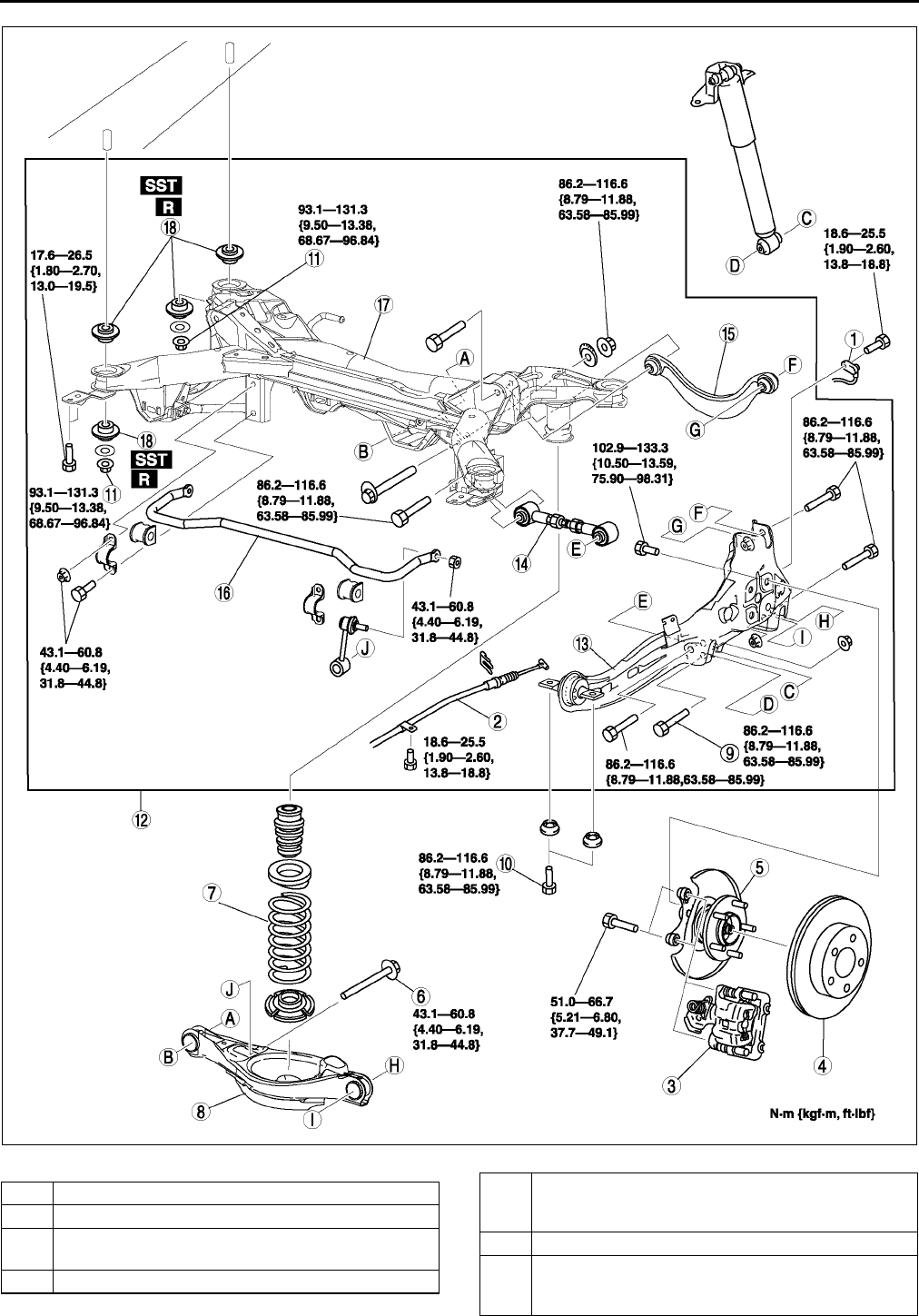
R38
REAR SUSPENSION
.
A6E7416W020
1 ABS wheel-speed sensor
2 Parking brake cable
3 Caliper component
(See R39 Caliper Component Removal Note)
4Disc plate
5 Spindle and hub component
(See M10 WHEEL HUB, HUB SPINDLE
REMOVAL/INSTALLATION)
6 Bolt (stabilizer control link)
7 Rear coil spring
(See R29 REAR COIL SPRING REMOVAL/
INSTALLATION)
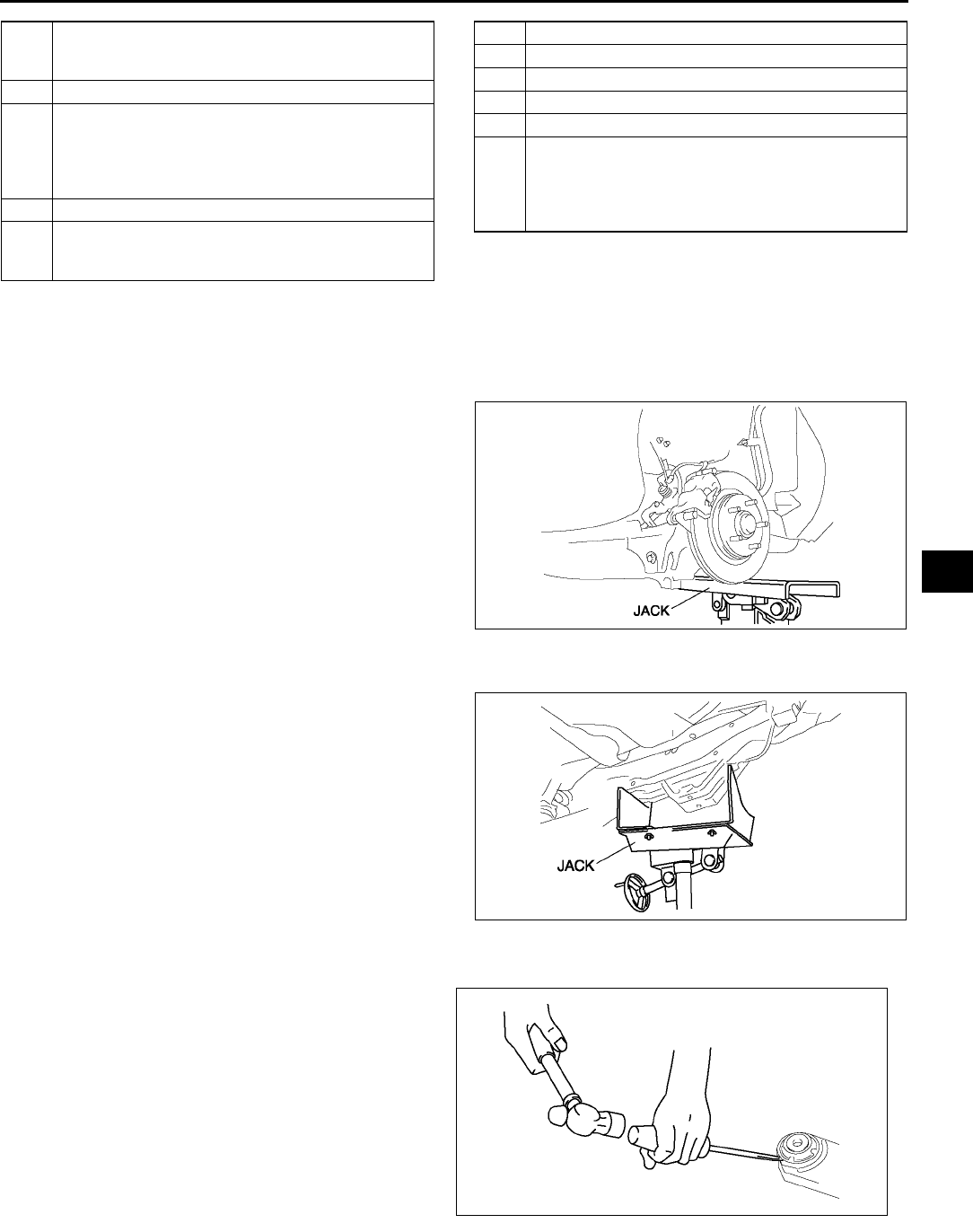
REAR SUSPENSION
R39
R
Caliper Component Removal Note
1. Remove the caliper, and suspend it aside with cable.
Bolt (Trailing Link Front Side) Removal Note
1. Support the trailing link with a jack.
2. Loosen the bolt (lateral link inner side).
Crossmember Component Removal Note
1. Support the crossmember component using a
jack and remove the nuts.
Warning
•
••
•Removing the crossmember is
dangerous. The crossmember
component could fall and cause serious
injury or death. Verify that the jack
securely supports the crossmember
component.
2. Remove the crossmember component.
Rear Crossmember Bushing Removal Note
1. Remove the bushing using screw driver (-), being
care not to damage the rear crossmember.
8 Rear lower arm
(See R30 REAR LOWER ARM REMOVAL/
INSTALLATION)
9 Bolt (rear shock absorber lower side)
10 Bolt (trailing link front side)
(See R39 Bolt (Trailing Link Front Side) Removal
Note)
(See R40 Bolt (Trailing Link Front Side) Installation
Note)
11 Nut (crossmember)
12 Crossmember component
(See R39 Crossmember Component Removal
Note)
13 Trailing link
14 Rear lateral link
15 Rear upper arm
16 Rear stabilizer
17 Rear crossmember
18 Rear crossmember Bushing
(See R39 Rear Crossmember Bushing Removal
Note)
(See R40 Rear Crossmember Bushing Installation
Note)
A6E7416W005
A6E7416W014
A6E7416W001
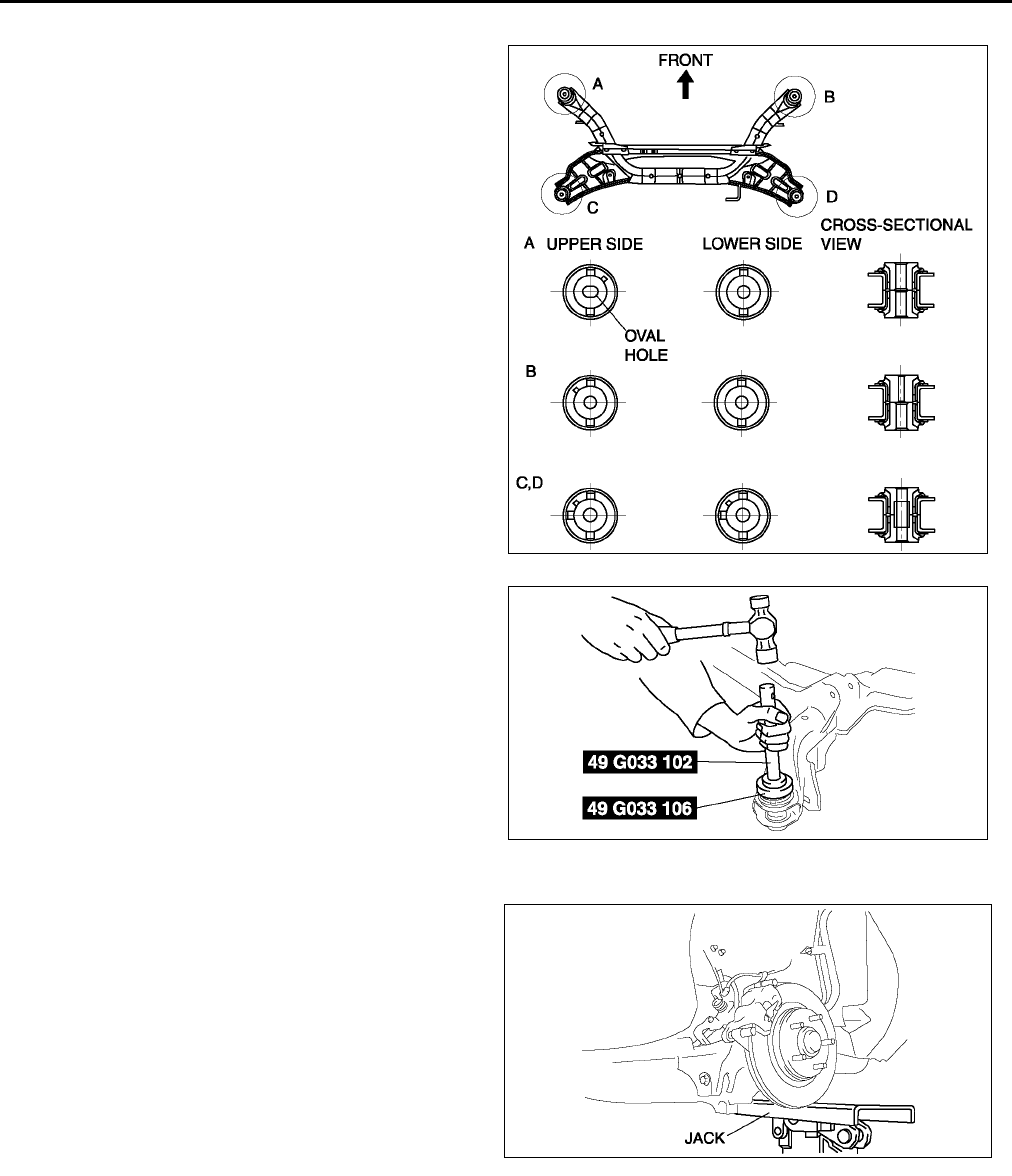
R40
REAR SUSPENSION
Rear Crossmember Bushing Installation Note
1. Set the bushings as shown in the figure.
2. Tap the bushing onto the rear crossmember using
the SSTs.
Bolt (Trailing Link Front Side) Installation Note
1. Support the trailing link with a jack.
2. Tighten the bolts (trailing link front side).
End Of Sie
A6E7416W021
A6E7416W002
A6E7416W005

S1
S
SBODY
LOCATION INDEX ................................................. S-4
EXTERIOR........................................................... S-4
INTERIOR............................................................ S-6
DOOR .................................................................. S-9
BONNET ............................................................... S-10
BONNET REMOVAL/INSTALLATION............... S-10
BONNET ADJUSTMENT................................... S-10
FRONT FENDER PANEL..................................... S-12
FRONT FENDER PANEL
REMOVAL/INSTALLATION............................ S-12
DOOR ................................................................... S-13
FRONT DOOR STRUCTURAL VIEW................ S-13
REAR DOOR STRUCTURAL VIEW .................. S-14
FRONT DOOR REMOVAL/INSTALLATION...... S-15
REAR DOOR REMOVAL/INSTALLATION ........ S-15
DOOR ADJUSTMENT ....................................... S-16
FRONT DOOR GLASS
REMOVAL/INSTALLATION............................ S-16
REAR DOOR GLASS
REMOVAL/INSTALLATION............................ S-17
FRONT DOOR UNIT
REMOVAL/INSTALLATION............................ S-18
REAR DOOR UNIT
REMOVAL/INSTALLATION............................ S-18
FRONT DOOR LATCH AND LOCK
ACTUATOR REMOVAL/INSTALLATION ....... S-19
REAR DOOR LATCH AND LOCK
ACTUATOR REMOVAL/INSTALLATION ....... S-19
FRONT DOOR KEY CYLINDER
REMOVAL/INSTALLATION............................ S-20
FRONT OUTER HANDLE
REMOVAL/INSTALLATION............................ S-21
REAR OUTER HANDLE
REMOVAL/INSTALLATION............................ S-21
INNER HANDLE
REMOVAL/INSTALLATION............................ S-22
REGULATOR HANDLE REMOVAL .................. S-22
REGULATOR HANDLE INSTALLATION .......... S-22
POWER WINDOW SYSTEM ................................ S-23
INITIAL SETTING .............................................. S-23
TWO-STEP DOWN FUNCTION
OPERATIVE/NON-OPERATIVE
SWITCHING PROCEDURE ........................... S-23
DOOR GLASS POSITION CHANGE
PROCEDURE ................................................. S-24
POWER WINDOW SWITCH
REMOVAL/INSTALLATION............................ S-25
POWER WINDOW MAIN SWITCH
INSPECTION .................................................. S-26
POWER WINDOW SUBSWITCH
INSPECTION .................................................. S-28
POWER WINDOW REGULATOR
REMOVAL/INSTALLATION............................ S-28
POWER WINDOW MOTOR
REMOVAL/INSTALLATION............................ S-29
POWER WINDOW MOTOR
INSPECTION .................................................. S-29
POWER DOOR LOCK SYSTEM.......................... S-30
FRONT DOOR LOCK ACTUATOR
INSPECTION .................................................. S-30
REAR DOOR LOCK ACTUATOR
INSPECTION .................................................. S-32
TRUNK LID LOCK ACTUATOR
INSPECTION .................................................. S-32
LIFTGATE LOCK ACTUATOR
INSPECTION .................................................. S-33
DOOR LOCK TIMER UNIT
REMOVAL/INSTALLATION ............................ S-33
DOOR LOCK TIMER UNIT
INSPECTION .................................................. S-34
DOOR LOCK TIMER UNIT ID CODE
CHANGE......................................................... S-36
TRANSMITTER BATTERY
REPLACEMENT ............................................. S-37
TRANSMITTER BATTERY INSPECTION .........S-38
TRUNK LID........................................................... S-39
TRUNK LID REMOVAL/INSTALLATION ........... S-39
TRUNK LID DISASSEMBLY/ASSEMBLY .........S-40
TRUNK LID ADJUSTMENT ............................... S-41
STAY DAMPER DISPOSAL .............................. S-41
LIFTGATE............................................................. S-42
LIFTGATE REMOVAL/INSTALLATION............. S-42
LIFTGATE DISASSEMBLY/ASSEMBLY ........... S-44
STAY DAMPER DISPOSAL .............................. S-44
LIFTGATE ADJUSTMENT................................. S-45
FUEL-FILLER LID AND OPENER ....................... S-46
FUEL-FILLER LID AND OPENER
REMOVAL/INSTALLATION ............................ S-46
FUEL-FILLER LID ADJUSTMENT..................... S-46
BUMPER............................................................... S-47
FRONT BUMPER
REMOVAL/INSTALLATION ............................ S-47
FRONT BUMPER
DISASSEMBLY/ASSEMBLY .......................... S-48
BUMPER REINFORCEMENT
REMOVAL/INSTALLATION ............................ S-48
REAR BUMPER REMOVAL/INSTALLATION.... S-49
EXTERIOR ATTACHMENT ..................................S-50
RADIATOR GRILLE
REMOVAL/INSTALLATION ............................ S-50
COWL GRILLE REMOVAL/INSTALLATION .....S-50
FRONT FLAP REMOVAL/INSTALLATION........ S-51
REAR FLAP REMOVAL/INSTALLATION .......... S-51
REAR DOOR GARNISH REMOVAL ................. S-51
REAR DOOR GARNISH INSTALLATION .........S-52
SIDE PROTECTOR REMOVAL......................... S-52
SIDE PROTECTOR INSTALLATION................. S-53
EXTRACTOR CHAMBER
REMOVAL/INSTALLATION ............................ S-53
REAR FINISHER
REMOVAL/INSTALLATION ............................ S-54
REAR SPOILER
REMOVAL/INSTALLATION ............................ S-54
ROOF CARRIER BRACKET
REMOVAL/INSTALLATION ............................ S-54

S2
MOLDING ............................................................. S-55
FRONT BELTLINE MOLDING REMOVAL ........ S-55
FRONT BELTLINE MOLDING
INSTALLATION............................................... S-55
REAR BELTLINE MOLDING REMOVAL...........S-56
REAR BELTLINE MOLDING
INSTALLATION............................................... S-56
ROOF MOLDING REMOVAL ............................ S-57
ROOF MOLDING INSTALLATION .................... S-57
OUTSIDE MIRROR...............................................S-58
POWER OUTSIDE MIRROR
REMOVAL/INSTALLATION ............................ S-58
POWER OUTSIDE MIRROR
DISASSEMBLY/ASSEMBLY ..........................S-58
POWER OUTSIDE MIRROR
INSPECTION ..................................................S-59
POWER OUTSIDE MIRROR SWITCH
REMOVAL/INSTALLATION ............................ S-60
POWER OUTSIDE MIRROR SWITCH
INSPECTION ..................................................S-60
REARVIEW MIRROR ...........................................S-61
REARVIEW MIRROR REMOVAL......................S-61
REARVIEW MIRROR INSTALLATION..............S-61
BASE REMOVAL ............................................... S-61
BASE INSTALLATION ....................................... S-62
REAR WINDOW DEFROSTER ............................ S-63
FILAMENT REPAIR ...........................................S-63
FILAMENT INSPECTION .................................. S-63
WINDOW GLASS .................................................S-64
WINDSHIELD REMOVAL .................................. S-64
WINDSHIELD INSTALLATION ..........................S-65
QUARTER WINDOW GLASS
REMOVAL/INSTALLATION ............................ S-67
REAR WINDOW GLASS REMOVAL.................S-68
REAR WINDOW GLASS INSTALLATION......... S-70
SLIDING SUNROOF.............................................S-74
DEFLECTOR REMOVAL/INSTALLATION ........ S-74
GLASS PANEL REMOVAL/INSTALLATION .....S-74
GLASS PANEL ADJUSTMENT .........................S-75
FRONT DRAIN HOSE REMOVAL..................... S-75
FRONT DRAIN HOSE INSTALLATION............. S-75
REAR DRAIN HOSE REMOVAL .......................S-76
REAR DRAIN HOSE INSTALLATION ............... S-76
SUNROOF UNIT
REMOVAL/INSTALLATION ............................ S-76
SUNROOF UNIT
DISASSEMBLY/ASSEMBLY ..........................S-77
SUNROOF MOTOR REMOVAL ........................S-79
SUNROOF MOTOR INSTALLATION ................ S-79
SUNROOF MOTOR INSPECTION....................S-79
SUNROOF RELAY INSPECTION .....................S-80
SUNROOF SWITCH
REMOVAL/INSTALLATION ............................ S-81
SUNROOF SWITCH INSPECTION ...................S-81
DASHBOARD AND CONSOLE ...........................S-82
DASHBOARD REMOVAL/INSTALLATION ....... S-82
DASHBOARD DISASSEMBLY/ASSEMBLY......S-83
SIDE PANEL REMOVAL/INSTALLATION......... S-83
COLUMN COVER
REMOVAL/INSTALLATION ............................ S-84
METER HOOD REMOVAL/INSTALLATION......S-84
LOWER PANEL REMOVAL/INSTALLATION ....S-84
CENTER BOX REMOVAL/INSTALLATION.......S-85
GLOVE COMPARTMENT
REMOVAL/INSTALLATION ............................ S-85
CONSOLE REMOVAL/INSTALLATION.............S-86
CONSOLE DISASSEmBLY/ASSEMBLY ...........S-86
TRIM......................................................................S-87
A-PILLAR TRIM REMOVAL ...............................S-87
A-PILLAR TRIM INSTALLATION .......................S-87
B-PILLAR LOWER TRIM
REMOVAL/INSTALLATION ............................S-88
B-PILLAR UPPER TRIM
REMOVAL/INSTALLATION ............................S-88
FRONT SIDE TRIM
REMOVAL/INSTALLATION ............................S-88
FRONT SCUFF PLATE
REMOVAL/INSTALLATION ............................S-89
REAR SCUFF PLATE
REMOVAL/INSTALLATION ............................S-89
C-PILLAR TRIM
REMOVAL/INSTALLATION ............................S-89
FRONT DOOR TRIM
REMOVAL/INSTALLATION ............................S-90
REAR DOOR TRIM
REMOVAL/INSTALLATION ............................S-90
TIRE HOUSE TRIM
REMOVAL/INSTALLATION ............................S-91
REAR PACKAGE TRIM
REMOVAL/INSTALLATION ............................S-92
TRUNK SIDE TRIM
REMOVAL/INSTALLATION ............................S-92
TRUNK SIDE UPPER TRIM
REMOVAL/INSTALLATION ............................S-93
TRUNK LID TRIM
REMOVAL/INSTALLATION ............................S-93
TRUNK END TRIM
REMOVAL/INSTALLATION ............................S-93
LIFTGATE UPPER TRIM
REMOVAL/INSTALLATION ............................S-94
LIFTGATE SIDE TRIM
REMOVAL/INSTALLATION ............................S-94
LIFTGATE LOWER TRIM
REMOVAL/INSTALLATION ............................S-95
HEADLINER .........................................................S-96
HEADLINER REMOVAL/INSTALLATION..........S-96
SHOCK ABSORBING PAD
REMOVAL/INSTALLATION ............................S-97
ASSIST HANDLE
REMOVAL/INSTALLATION ............................S-97
SUNVISOR REMOVAL/INSTALLATION ...........S-98
FLOOR COVERING..............................................S-99
FRONT FLOOR COVERING
REMOVAL/INSTALLATION ............................S-99
SEAT BELT ........................................................S-100
FRONT SEAT BELT
REMOVAL/INSTALLATION ..........................S-100
REAR SIDE SEAT BELT
REMOVAL/INSTALLATION ..........................S-101
REAR CENTER SEAT BELT
REMOVAL/INSTALLATION ..........................S-101
FRONT BUCKLE
REMOVAL/INSTALLATION ..........................S-102
REAR BUCKLE
REMOVAL/INSTALLATION ..........................S-102
SEAT BELT INSPECTION ...............................S-103
BUCKLE SWITCH INSPECTION.....................S-104
CHILD RESTRAINT SEAT ANCHOR
REMOVAL/INSTALLATION ..........................S-104

S3
S
SEAT................................................................... S-105
FRONT SEAT REMOVAL/INSTALLATION ..... S-105
FRONT SEAT DISASSEMBLY/ASSEMBLY ... S-106
REAR SEAT REMOVAL/INSTALLATION ....... S-110
REAR SEAT DISASSEMBLY/ASSEMBLY...... S-112
REMOTE HANDLE LEVER
REMOVAL/INSTALLATION.......................... S-114
SEAT BACK STRIKER
REMOVAL/INSTALLATION.......................... S-115
POWER SEAT SWITCH INSPECTION........... S-115
FRONT TILT MOTOR INSPECTION ............... S-116
REAR TILT MOTOR INSPECTION ................. S-116
SLIDE MOTOR INSPECTION ......................... S-116
RECLINER MOTOR INSPECTION ................. S-116
SEAT WARMER SWITCH
REMOVAL/INSTALLATION.......................... S-117
SEAT WARMER SWITCH INSPECTION ........ S-117
SEAT WARMER UNIT INSPECTION.............. S-118
BODY SHELL ..................................................... S-119
SHROUD PANEL REMOVAL/INSTALLATION S-119
COWL PANEL REMOVAL/INSTALLATION .... S-119
TROUBLESHOOTING
[POWER WINDOW SYSTEM]............................ S-120
INTERMITTENT CONCERN
TROUBLESHOOTING.................................. S-120
FOREWORD.................................................... S-120
BASIC POWER WINDOW SYSTEM
INSPECTION ................................................ S-121
TROUBLESHOOTING INDEX......................... S-123
NO. 1 DRIVER-SIDE FRONT WINDOW
DOES NOT GO UP AND DOWN IN
AUTOMATIC MODE ..................................... S-123
NO. 2 DRIVER-SIDE FRONT WINDOW
DOES NOT REVERSE, EVEN WHEN
ENCOUNTERING A FOREIGN OBJECT
IN ITS PATH ................................................. S-126
NO. 3 DRIVER-SIDE FRONT WINDOW
REVERSES EVEN THOUGH THE GLASS
DOES NOT ENCOUNTER A FOREIGN
OBJECT WHILE IT IS GOING UP IN
AUTOMATIC MODE ..................................... S-127
TROUBLESHOOTING
[KEYLESS ENTRY SYSTEM]............................ S-128
FOREWORD.................................................... S-128
KEYLESS ENTRY SYSTEM
CHECK SHEET ............................................ S-129
KEYLESS ENTRY SYSTEM
PRELIMINARY INSPECTION....................... S-129
ON-BOARD DIAGNOSTIC FUNCTION........... S-130
TROUBLESHOOTING INDEX......................... S-131
NO. 1 ONE OR MORE ON-BOARD
DIAGNOSTIC FUNCTIONS
INOPERATIVE.............................................. S-131
NO. 2 ALL ON-BOARD DIAGNOSTIC
FUNCTIONS INOPERATIVE........................ S-132
NO. 3 TRANSMITTER ID CODE CANNOT
BE REPROGRAMMED................................. S-133
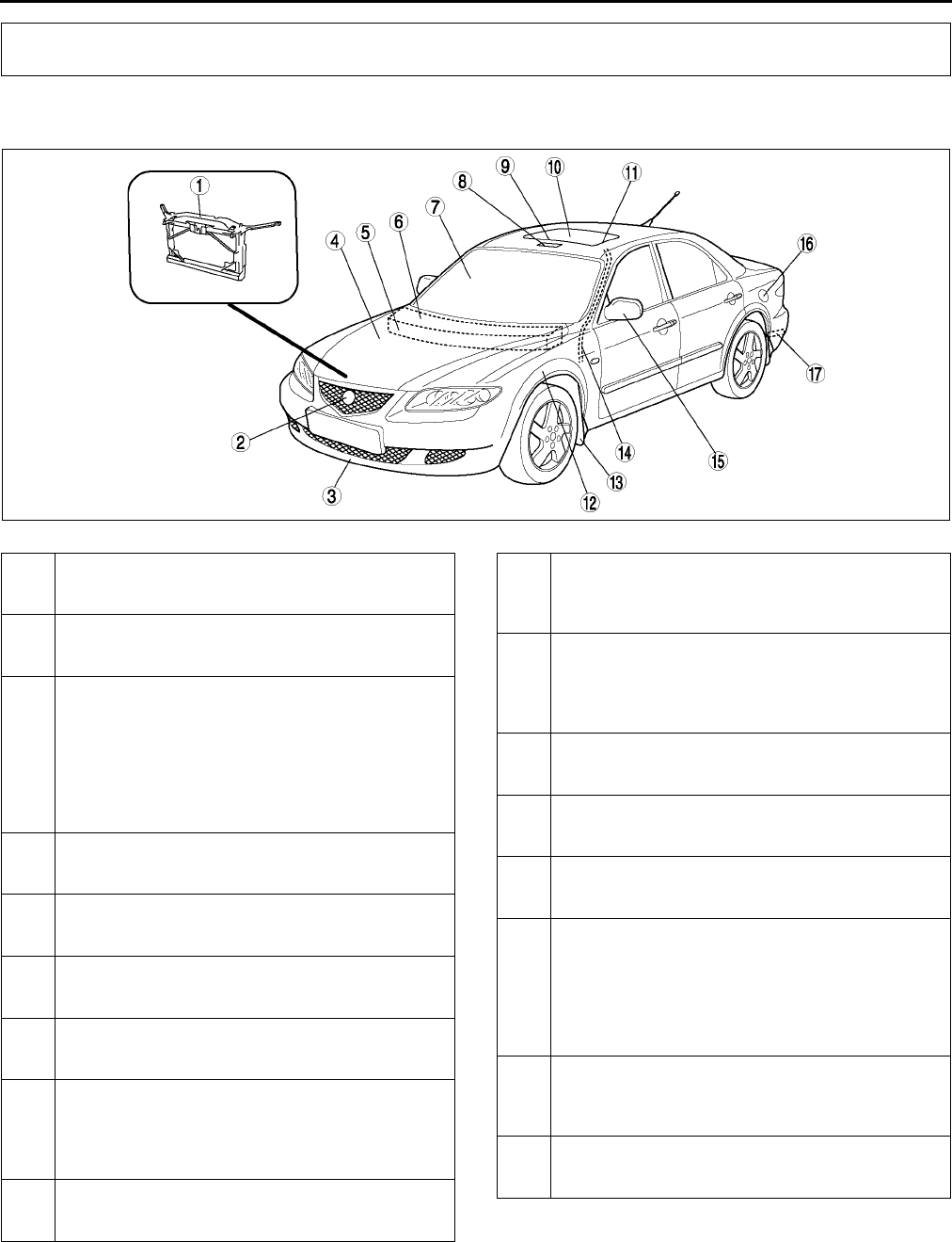
S4
LOCATION INDEX
EXTERIOR A6E770001086W01
Front
.
LOCATION INDEX
A6E7700W001
1 Shroud panel
(See S119 SHROUD PANEL REMOVAL/
INSTALLATION)
2 Radiator grille
(See S50 RADIATOR GRILLE REMOVAL/
INSTALLATION)
3 Front bumper
(See S47 FRONT BUMPER REMOVAL/
INSTALLATION)
(See S48 FRONT BUMPER DISASSEMBLY/
ASSEMBLY)
Bumper reinforcement
(See S48 BUMPER REINFORCEMENT
REMOVAL/INSTALLATION)
4 Bonnet
(See S10 BONNET REMOVAL/INSTALLATION)
(See S10 BONNET ADJUSTMENT)
5 Cowl panel
(See S119 COWL PANEL REMOVAL/
INSTALLATION)
6 Cowl grille
(See S50 COWL GRILLE REMOVAL/
INSTALLATION)
7 Windshield
(See S64 WINDSHIELD REMOVAL)
(See S65 WINDSHIELD INSTALLATION)
8 Sunroof motor and relay
(See S79 SUNROOF MOTOR REMOVAL)
(See S79 SUNROOF MOTOR INSTALLATION)
(See S79 SUNROOF MOTOR INSPECTION)
(See S80 SUNROOF RELAY INSPECTION)
9 Deflector
(See S74 DEFLECTOR REMOVAL/
INSTALLATION)
10 Glass panel
(See S74 GLASS PANEL REMOVAL/
INSTALLATION)
(See S75 GLASS PANEL ADJUSTMENT)
11 Sunroof unit
(See S76 SUNROOF UNIT REMOVAL/
INSTALLATION)
(See S77 SUNROOF UNIT DISASSEMBLY/
ASSEMBLY)
12 Front fender panel
(See S12 FRONT FENDER PANEL REMOVAL/
INSTALLATION)
13 Front flap
(See S51 FRONT FLAP REMOVAL/
INSTALLATION)
14 Front drain hose
(See S75 FRONT DRAIN HOSE REMOVAL)
(See S75 FRONT DRAIN HOSE INSTALLATION)
15 Power outside mirror
(See S58 POWER OUTSIDE MIRROR
REMOVAL/INSTALLATION)
(See S58 POWER OUTSIDE MIRROR
DISASSEMBLY/ASSEMBLY)
(See S59 POWER OUTSIDE MIRROR
INSPECTION)
16 Fuel-filler lid and opener
(See S46 FUEL-FILLER LID AND OPENER
REMOVAL/INSTALLATION)
(See S46 FUEL-FILLER LID ADJUSTMENT)
17 Extractor chamber
(See S53 EXTRACTOR CHAMBER REMOVAL/
INSTALLATION)
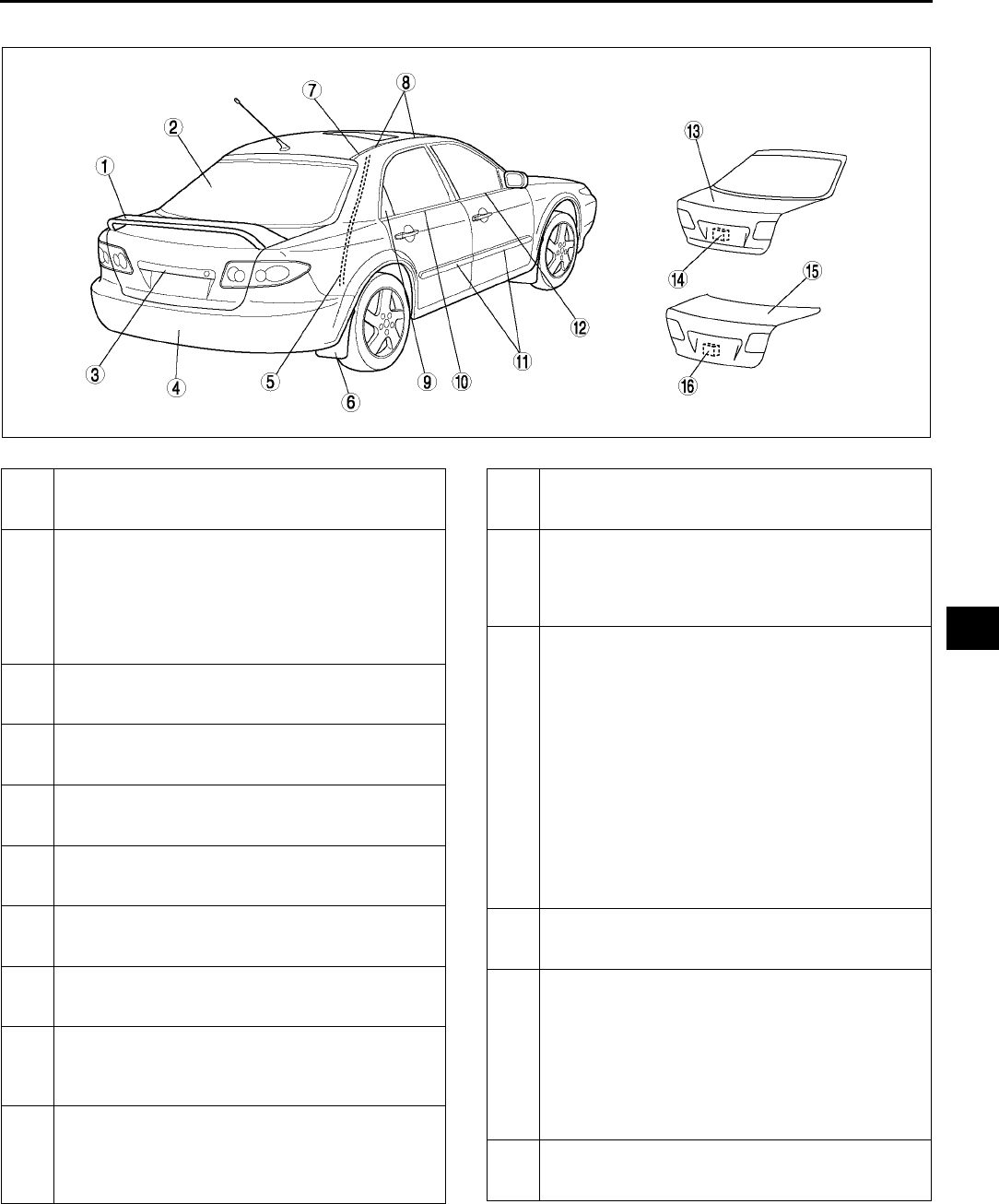
LOCATION INDEX
S5
S
Rear
.
End Of Sie
A6E7700W002
1 Rear spoiler
(See S54 REAR SPOILER REMOVAL/
INSTALLATION)
2 Rear window glass
(See S68 REAR WINDOW GLASS REMOVAL)
(See S70 REAR WINDOW GLASS
INSTALLATION)
Filament
(See S63 FILAMENT REPAIR)
(See S63 FILAMENT INSPECTION)
3 Rear finisher
(See S54 REAR FINISHER REMOVAL/
INSTALLATION)
4 Rear bumper
(See S49 REAR BUMPER REMOVAL/
INSTALLATION)
5 Rear drain hose
(See S76 REAR DRAIN HOSE REMOVAL)
(See S76 REAR DRAIN HOSE INSTALLATION)
6 Rear flap
(See S51 REAR FLAP REMOVAL/
INSTALLATION)
7 Roof molding
(See S57 ROOF MOLDING REMOVAL)
(See S57 ROOF MOLDING INSTALLATION)
8 Roof carrier bracket
(See S54 ROOF CARRIER BRACKET REMOVAL/
INSTALLATION)
9 Rear door garnish (5HB)
(See S51 REAR DOOR GARNISH REMOVAL)
(See S52 REAR DOOR GARNISH
INSTALLATION)
10 Rear beltline molding
(See S56 REAR BELTLINE MOLDING
REMOVAL)
(See S56 REAR BELTLINE MOLDING
INSTALLATION)
11 Side protector
(See S52 SIDE PROTECTOR REMOVAL)
(See S53 SIDE PROTECTOR INSTALLATION)
12 Front beltline molding
(See S55 FRONT BELTLINE MOLDING
REMOVAL)
(See S55 FRONT BELTLINE MOLDING
INSTALLATION)
13 Liftgate
(See S42 LIFTGATE REMOVAL/
INSTALLATION)
(See S44 LIFTGATE DISASSEMBLY/
ASSEMBLY)
(See S45 LIFTGATE ADJUSTMENT)
Liftgate upper trim
(See S94 LIFTGATE UPPER TRIM
REMOVAL/INSTALLATION)
Liftgate side trim
(See S94 LIFTGATE SIDE TRIM REMOVAL/
INSTALLATION)
Liftgate lower trim
(See S95 LIFTGATE LOWER TRIM
REMOVAL/INSTALLATION)
14 Liftgate lock actuator
(See S33 LIFTGATE LOCK ACTUATOR
INSPECTION)
15 Trunk lid
(See S39 TRUNK LID REMOVAL/
INSTALLATION)
(See S40 TRUNK LID DISASSEMBLY/
ASSEMBLY)
(See S41 TRUNK LID ADJUSTMENT)
Trunk lid trim
(See S93 TRUNK LID TRIM REMOVAL/
INSTALLATION)
16 Trunk lid lock actuator
(See S32 TRUNK LID LOCK ACTUATOR
INSPECTION)
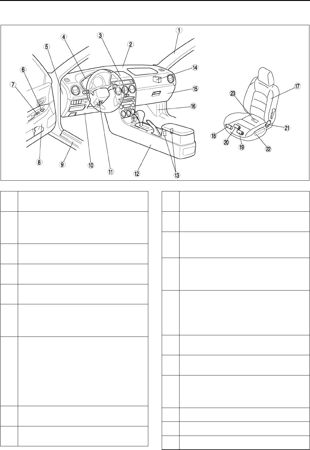
S6
LOCATION INDEX
INTERIOR A6E770001086W02
Front
.
A6E7700W003
1 A-pillar trim
(See S87 A-PILLAR TRIM REMOVAL)
(See S87 A-PILLAR TRIM INSTALLATION)
2 Dashboard
(See S82 DASHBOARD REMOVAL/
INSTALLATION)
(See S83 DASHBOARD DISASSEMBLY/
ASSEMBLY)
3 Center box
(See S85 CENTER BOX REMOVAL/
INSTALLATION)
4 Meter hood
(See S84 METER HOOD REMOVAL/
INSTALLATION)
5 Side panel
(See S83 SIDE PANEL REMOVAL/
INSTALLATION)
6 Power outside mirror switch
(See S60 POWER OUTSIDE MIRROR SWITCH
REMOVAL/INSTALLATION)
(See S60 POWER OUTSIDE MIRROR SWITCH
INSPECTION)
7 Power window main switch
(See S25 POWER WINDOW SWITCH REMOVAL/
INSTALLATION)
(See S26 POWER WINDOW MAIN SWITCH
INSPECTION)
(See S23 INITIAL SETTING)
(See S23 TWO-STEP DOWN FUNCTION
OPERATIVE/NON-OPERATIVE SWITCHING
PROCEDURE)
(See S24 DOOR GLASS POSITION CHANGE
PROCEDURE)
8 Front door trim
(See S90 FRONT DOOR TRIM REMOVAL/
INSTALLATION)
9 Front scuff plate
(See S89 FRONT SCUFF PLATE REMOVAL/
INSTALLATION)
10 Lower panel
(See S84 LOWER PANEL REMOVAL/
INSTALLATION)
11 Column cover
(See S84 COLUMN COVER REMOVAL/
INSTALLATION)
12 Console
(See S86 CONSOLE REMOVAL/INSTALLATION)
(See S86 CONSOLE DISASSEmBLY/
ASSEMBLY)
13 Seat warmer switch
(See S117 SEAT WARMER SWITCH REMOVAL/
INSTALLATION)
(See S117 SEAT WARMER SWITCH
INSPECTION)
14 Door lock timer unit
(See S33 DOOR LOCK TIMER UNIT REMOVAL/
INSTALLATION)
(See S34 DOOR LOCK TIMER UNIT
INSPECTION)
(See S36 DOOR LOCK TIMER UNIT ID CODE
CHANGE)
15 Glove compartment
(See S85 GLOVE COMPARTMENT REMOVAL/
INSTALLATION)
16 Front side trim
(See S88 FRONT SIDE TRIM REMOVAL/
INSTALLATION)
17 Front seat
(See S105 FRONT SEAT REMOVAL/
INSTALLATION)
(See S106 FRONT SEAT DISASSEMBLY/
ASSEMBLY)
18 Rear tilt motor
(See S116 REAR TILT MOTOR INSPECTION)
19 Front tilt motor
(See S116 FRONT TILT MOTOR INSPECTION)
20 Slide motor
(See S116 SLIDE MOTOR INSPECTION)
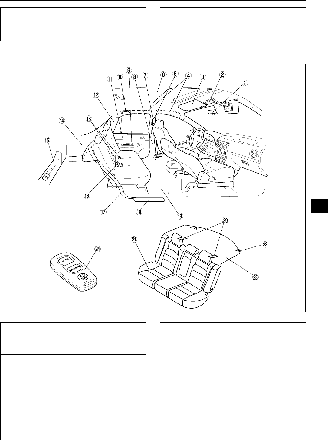
LOCATION INDEX
S7
S
Rear
.
21 Recliner motor
(See S116 RECLINER MOTOR INSPECTION)
22 Power seat switch
(See S115 POWER SEAT SWITCH
INSPECTION)
23 Seat warmer unit
(See S118 SEAT WARMER UNIT INSPECTION)
A6E7700W004
1 Rearview mirror
(See S61 REARVIEW MIRROR REMOVAL)
(See S61 REARVIEW MIRROR INSTALLATION)
(See S61 BASE REMOVAL)
(See S62 BASE INSTALLATION)
2 Sunroof switch
(See S81 SUNROOF SWITCH REMOVAL/
INSTALLATION)
(See S81 SUNROOF SWITCH INSPECTION)
3 Sunvisor
(See S98 SUNVISOR REMOVAL/
INSTALLATION)
4 Shock absorbing pad
(See S97 SHOCK ABSORBING PAD REMOVAL/
INSTALLATION)
5 B-pillar upper trim
(See S88 B-PILLAR UPPER TRIM REMOVAL/
INSTALLATION)
6 Headliner
(See S96 HEADLINER REMOVAL/
INSTALLATION)
7 Front seat belt
(See S100 FRONT SEAT BELT REMOVAL/
INSTALLATION )
(See S103 SEAT BELT INSPECTION )
8 B-pillar lower trim
(See S88 B-PILLAR LOWER TRIM REMOVAL/
INSTALLATION)
9 Power window subswitch
(See S25 POWER WINDOW SWITCH REMOVAL/
INSTALLATION)
(See S28 POWER WINDOW SUBSWITCH
INSPECTION )
10 Assist handle
(See S97 ASSIST HANDLE REMOVAL/
INSTALLATION)

S8
LOCATION INDEX
End Of Sie
11 Rear door trim
(See S90 REAR DOOR TRIM REMOVAL/
INSTALLATION)
12 C-pillar trim
(See S89 C-PILLAR TRIM REMOVAL/
INSTALLATION)
13 Rear buckle
(See S102 REAR BUCKLE REMOVAL/
INSTALLATION)
14 Trunk side trim
(See S92 TRUNK SIDE TRIM REMOVAL/
INSTALLATION)
Trunk side upper trim
(See S93 TRUNK SIDE UPPER TRIM
REMOVAL/INSTALLATION)
15 Trunk end trim
(See S93 TRUNK END TRIM REMOVAL/
INSTALLATION)
16 Rear center seat belt
(See S101 REAR CENTER SEAT BELT
REMOVAL/INSTALLATION )
(See S103 SEAT BELT INSPECTION )
17 Tire house trim
(See S91 TIRE HOUSE TRIM REMOVAL/
INSTALLATION)
18 Rear scuff plate
(See S89 REAR SCUFF PLATE REMOVAL/
INSTALLATION)
19 Front floor covering
(See S99 FRONT FLOOR COVERING
REMOVAL/INSTALLATION)
20 Child restraint seat anchor
(See S104 CHILD RESTRAINT SEAT ANCHOR
REMOVAL/INSTALLATION)
21 Rear seat
(See S110 REAR SEAT REMOVAL/
INSTALLATION)
(See S112 REAR SEAT DISASSEMBLY/
ASSEMBLY)
22 Remote handle lever
(See S114 REMOTE HANDLE LEVER
REMOVAL/INSTALLATION)
23 Rear package trim
(See S92 REAR PACKAGE TRIM REMOVAL/
INSTALLATION)
24 Transmitter
(See S37 TRANSMITTER BATTERY
REPLACEMENT)
(See S38 TRANSMITTER BATTERY
INSPECTION)
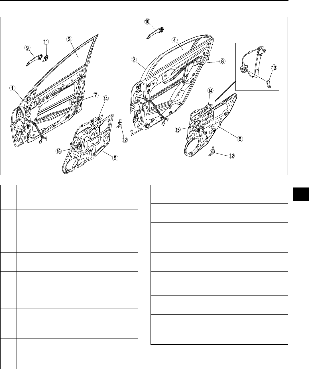
LOCATION INDEX
S9
S
DOOR A6E770001086W03
.
End Of Sie
A6E7700WH01
1 Front door
(See S15 FRONT DOOR REMOVAL/
INSTALLATION)
(See S16 DOOR ADJUSTMENT)
2 Rear door
(See S15 REAR DOOR REMOVAL/
INSTALLATION)
(See S16 DOOR ADJUSTMENT)
3 Front door glass
(See S16 FRONT DOOR GLASS REMOVAL/
INSTALLATION)
4 Rear door glass
(See S17 REAR DOOR GLASS REMOVAL/
INSTALLATION)
5 Front door unit
(See S18 FRONT DOOR UNIT REMOVAL/
INSTALLATION)
6 Rear door unit
(See S18 REAR DOOR UNIT REMOVAL/
INSTALLATION)
7 Front door latch and lock actuator
(See S19 FRONT DOOR LATCH AND LOCK
ACTUATOR REMOVAL/INSTALLATION)
(See S30 FRONT DOOR LOCK ACTUATOR
INSPECTION)
8 Rear door latch and lock actuator
(See S19 REAR DOOR LATCH AND LOCK
ACTUATOR REMOVAL/INSTALLATION)
(See S32 REAR DOOR LOCK ACTUATOR
INSPECTION)
9 Front outer handle
(See S21 FRONT OUTER HANDLE REMOVAL/
INSTALLATION)
10 Rear outer handle
(See S21 FRONT OUTER HANDLE REMOVAL/
INSTALLATION)
11 Front door key cylinder
(See S20 FRONT DOOR KEY CYLINDER
REMOVAL/INSTALLATION)
(See S30 FRONT DOOR LOCK ACTUATOR
INSPECTION)
12 Inner handle
(See S22 INNER HANDLE REMOVAL/
INSTALLATION)
13 Regulator handle
(See S22 REGULATOR HANDLE REMOVAL)
(See S22 REGULATOR HANDLE
INSTALLATION)
14 Power window regulator
(See S28 POWER WINDOW REGULATOR
REMOVAL/installation)
15 Power window motor
(See S29 POWER WINDOW MOTOR REMOVAL/
INSTALLATION)
(See S29 POWER WINDOW MOTOR
INSPECTION)
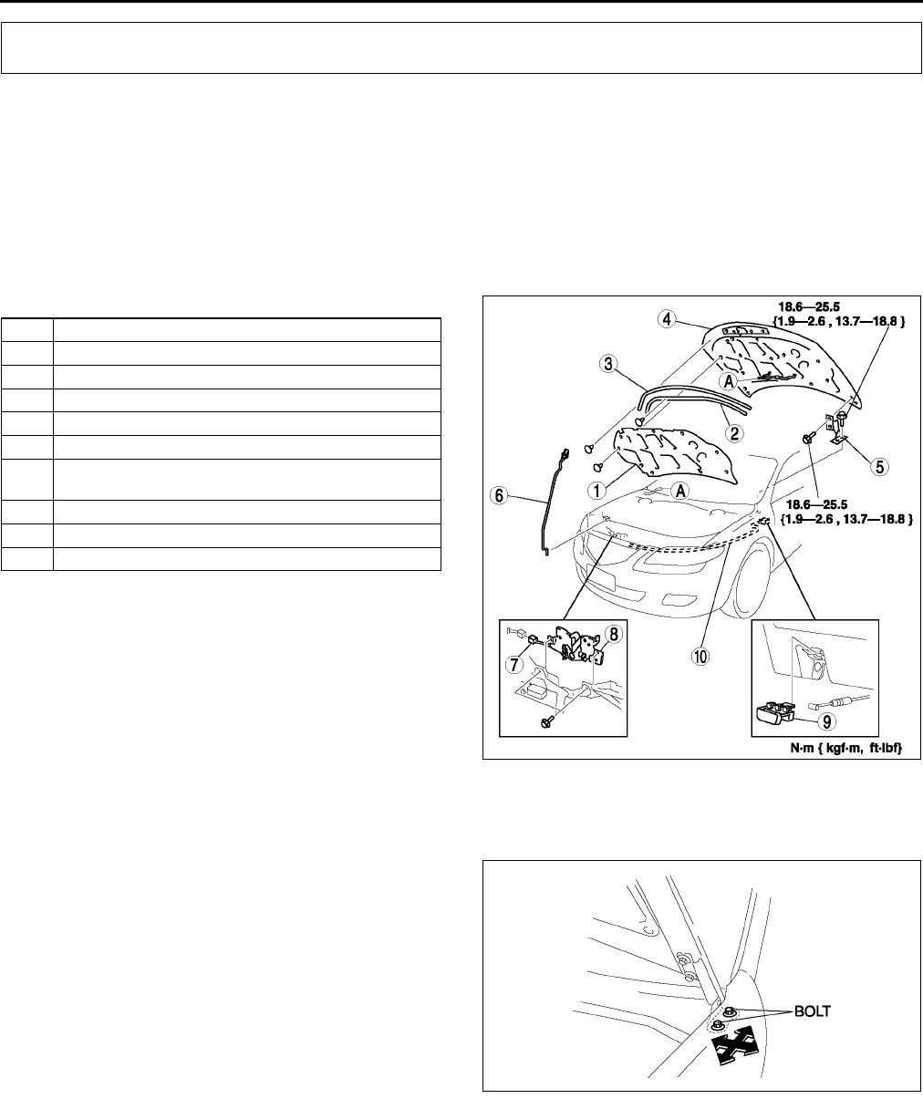
S10
BONNET
BONNET REMOVAL/INSTALLATION A6E771001084W01
Warning
•
••
•Removing the bonnet without supporting can be dangerous. The bonnet may fall and injure you.
Always perform the following procedure with at least another person.
1. Disconnect the windshield washer hose.
2. To remove the bonnet hinge, remove the front fender panel.
3. To remove the bonnet lock, remove the radiator grille.
4. To remove the bonnet release cable, remove the driver-side mud guard.
5. Remove in the order indicated in the table.
6. Install in the reverse order of removal.
7. Adjust the bonnet. (See S10 BONNET
ADJUSTMENT.)
End Of Sie
BONNET ADJUSTMENT A6E771001084W02
Gap Adjustment
1. Remove the front fender.
2. Loosen the bonnet hinge installation bolts and
reposition the bonnet.
3. Tighten the bolts.
BONNET
1 Bonnet insulator
2 Shroud seal weatherstrip
3 Parting seal weatherstrip
4 Bonnet
5 Bonnet hinge
6 Bonnet stay
7 Bonnet switch connector (With theft-deterrent
system)
8 Bonnet lock
9 Bonnet release lever
10 Bonnet release cable
A6E7710W001
A6E7710W002
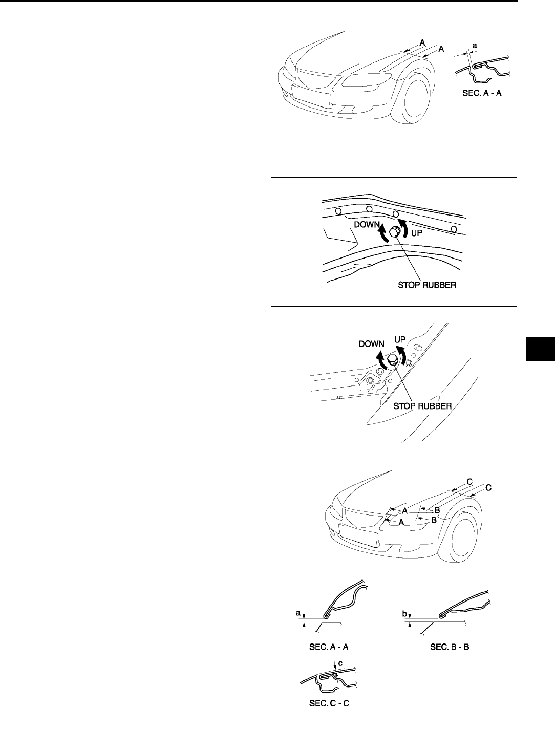
BONNET
S11
S
4. Verify that the gap between the bonnet and the
body is within the specification.
Clearance
a: 2.54.5 mm {0.080.17 in}
Height Adjustment
1. Turn the stop rubber to adjust the height of the
bonnet.
2. Verify that the height between the bonnet and the
body is within the specification.
Clearance
a: 3.06.0 mm {0.120.23 in}
b: 3.06.0 mm {0.120.23 in}
c: -1.01.0 mm {-0.040.04 in}
End Of Sie
A6E7710W004
A6E7710W006
A6E7710W003
A6E7710W005
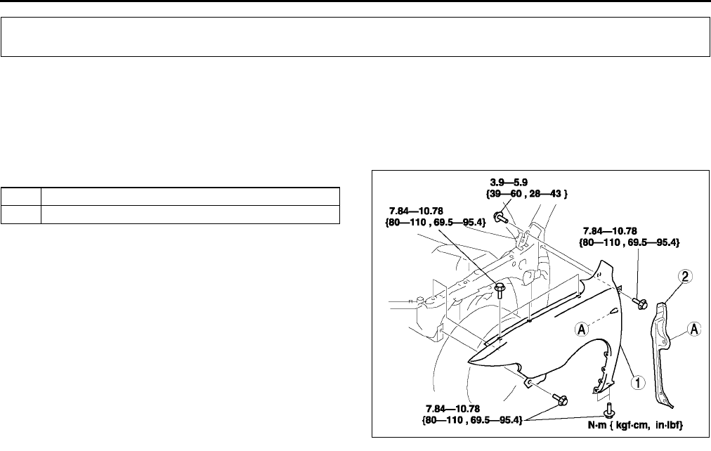
S12
FRONT FENDER PANEL
FRONT FENDER PANEL REMOVAL/INSTALLATION A6E771252110W01
1. Disconnect the negative battery cable.
2. Remove the front side turn light.
3. Remove the fender molding. (See S50 COWL GRILLE REMOVAL/INSTALLATION.)
4. Remove the front bumper. (See S47 FRONT BUMPER REMOVAL/INSTALLATION.)
5. Remove the front combination light. (See T26 FRONT COMBINATION LIGHT REMOVAL/INSTALLATION.)
6. Remove in the order indicated in the table.
7. Install in the reverse order of removal.
End Of Sie
FRONT FENDER PANEL
1 Front fender panel
2 Seal plate
A6E7712W001
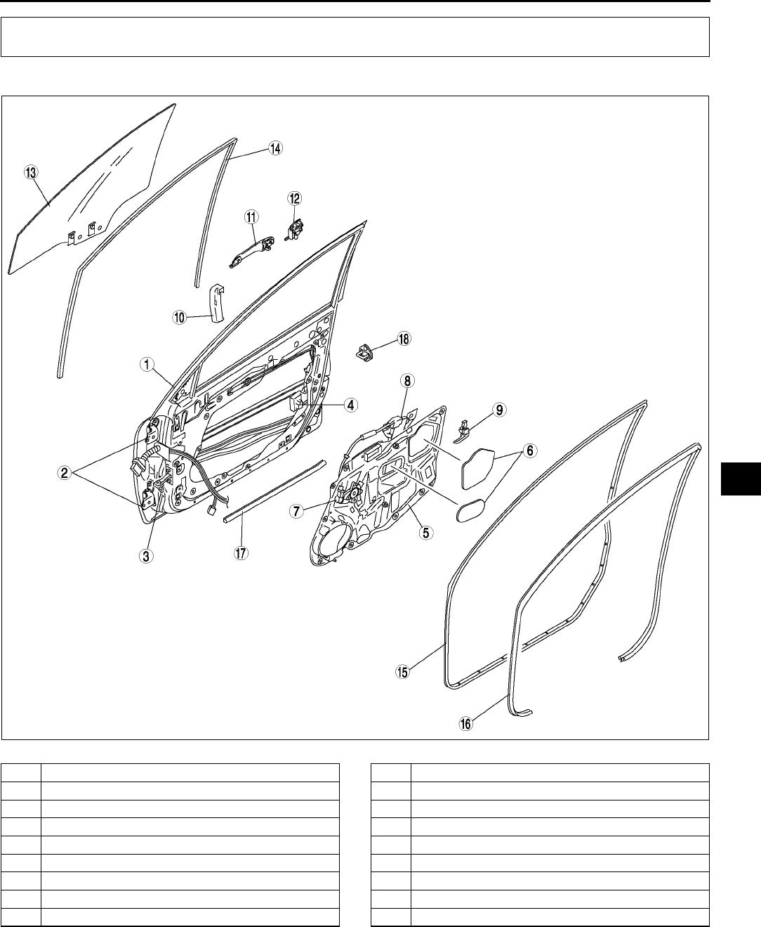
DOOR
S13
S
FRONT DOOR STRUCTURAL VIEW A6E771458010W01
.
End Of Sie
DOOR
A6E7714W001
1 Front door
2 Front door hinge
3 Checker
4 Front door latch and lock actuator
5 Front door unit
6 Hole cover
7 Power window motor
8 Power window regulator
9 Inner handle
10 Protector
11 Outer handle
12 Front door key cylinder
13 Front door glass
14 Glass run channel
15 Front door weatherstrip A
16 Front door lower weatherstrip
17 Front door weatherstrip B
18 Striker
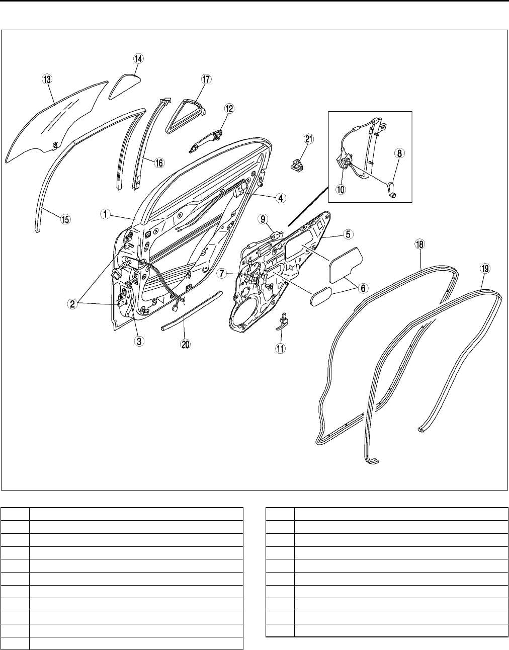
S14
DOOR
REAR DOOR STRUCTURAL VIEW A6E771472010W01
.
End Of Sie
A6E7714W002
1 Rear door
2 Rear door hinge
3 Checker
4 Rear door latch and lock actuator
5 Rear door unit
6 Hole cover
7 Power window motor
8 Regulator handle
9 Power window regulator
10 Manual window regulator
11 Inner handle
12 Outer handle
13 Rear door glass
14 Quarter window glass
15 Glass run channel
16 Glass guide
17 Quarter window molding
18 Rear door weatherstrip A
19 Rear door lower weatherstrip
20 Rear door weatherstrip B
21 Striker
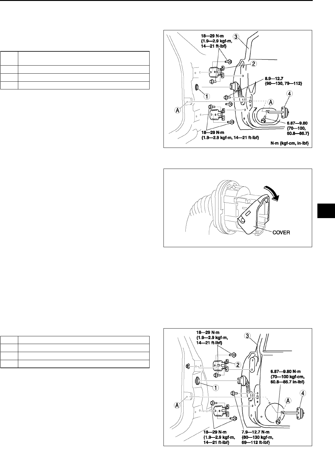
DOOR
S15
S
FRONT DOOR REMOVAL/INSTALLATION A6E771458010W02
1. Disconnect the negative battery cable.
2. To remove the front door hinge, remove the front fender panel.
3. To remove the checker, remove the door
speaker.
4. Remove in the order indicated in the table.
5. Install in the reverse order of removal.
6. Adjust the front door. (See S16 DOOR
ADJUSTMENT.)
Connector Removal Note
1. Push the rubber boot backward.
2. Pull down the cover in the direction indicated by
the arrow and disconnect the connector.
End Of Sie
REAR DOOR REMOVAL/INSTALLATION A6E771472010W02
Warning
•
••
•Handling the side air bag sensor improperly can accidentally deploy the side air bag module,
which may seriously injure you. Read AIR BAG SYSTEM SERVICE WARNINGS before working
around the B-pillar areas. (See T117 SERVICE WARNINGS.)
Note
•The side air bag sensor is located in the B-pillar.
1. Disconnect the negative battery cable.
2. To remove the checker, turn the rear door speaker.
3. Remove in the order indicated in the table.
4. Install in the reverse order of removal.
5. Adjust the rear door. (See S16 DOOR
ADJUSTMENT.)
1 Connector
(See S15 Connector Removal Note)
2 Front door hinge
3 Front door
4 Checker
A6E7714W006
A6E7714W007
1 Connector
2 Rear door hinge
3 Rear door
4 Checker
A6E7714W023
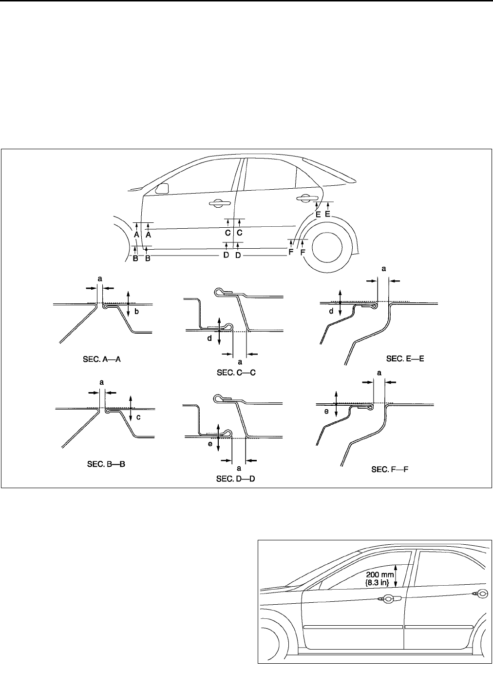
S16
DOOR
End Of Sie
DOOR ADJUSTMENT A6E771458010W03
1. Measure the gap and height between the front or rear door and the body.
2. If not as specified, loosen the front or rear door hinge installation bolts or the door lock striker installation
screws, and reposition the door.
Clearance
a: 2.54.5 mm {0.100.18 in}
b: -0.81.2 mm {-0.030.05 in}
c: -0.31.7 mm {-0.010.07 in}
d: -1.01.0 mm {-0.040.04 in}
e: -0.51.5 mm {-0.020.06 in}
3. Tighten the bolts or screws.
End Of Sie
FRONT DOOR GLASS REMOVAL/INSTALLATION A6E771458510W01
1. Operate the front door glass so that the distance
from the top of the front door glass to the upper
part of the rear beltline molding is 210 mm
{8.3 in}.
2. Disconnect the negative battery cable.
3. Remove the front door trim.
4. Remove the hole cover.
A6E7714W025
A6E7714W022
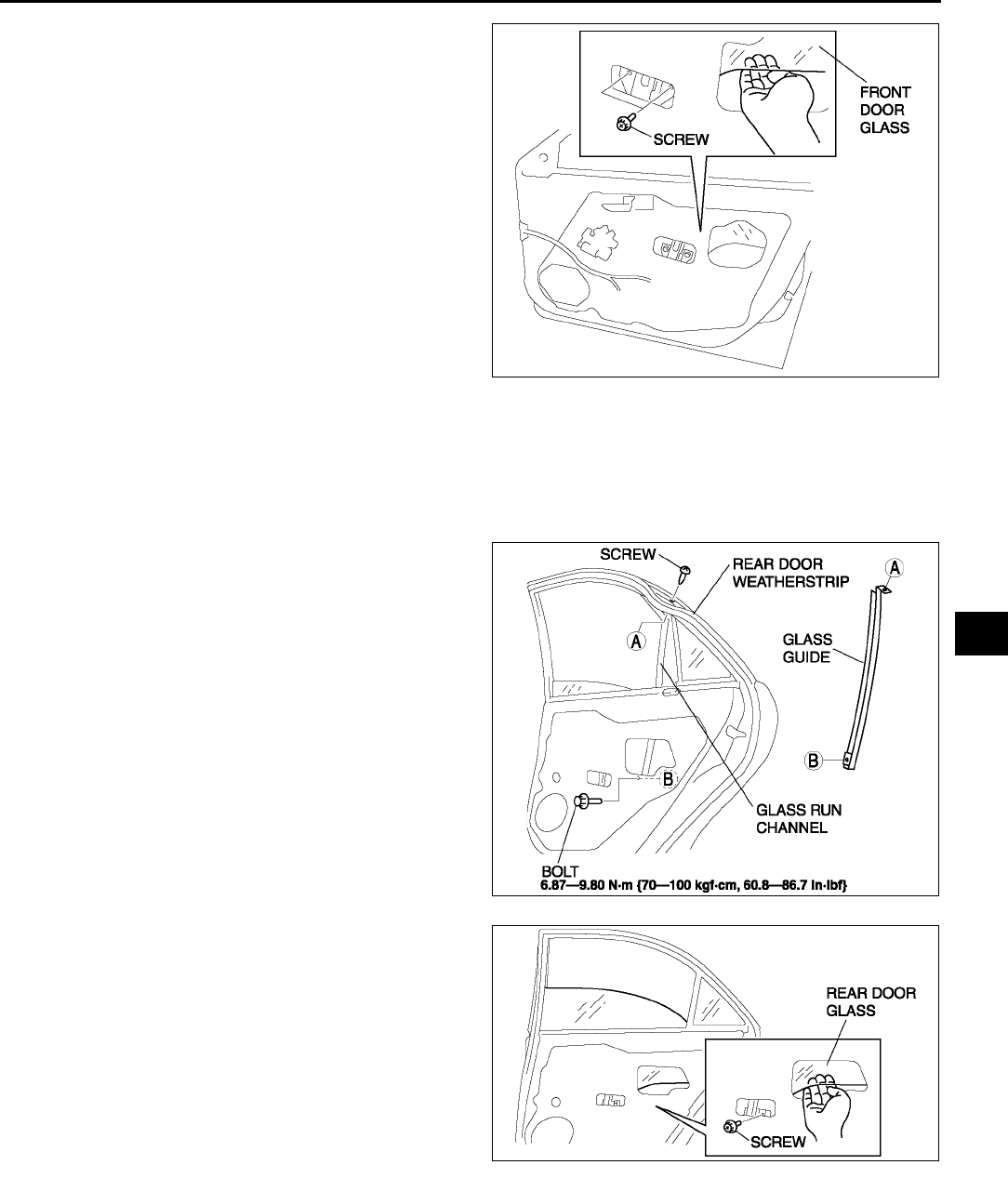
DOOR
S17
S
5. Remove the screws.
6. Insert your hand in hole of the front door unit, and
lift out the front door glass.
7. Install in the reverse order of removal.
End Of Sie
REAR DOOR GLASS REMOVAL/INSTALLATION A6E771472510W01
1. Fully down the rear door glass.
2. Remove the rear door trim.
3. Remove the hole cover.
4. Pull up the rear door weatherstrip and remove the screw.
5. Remove the bolt.
6. Remove the glass run channel from the rear door
glass guide.
7. Lift the rear door glass to the position where the
rear door glass installation screw is visible.
8. Remove the screw.
9. Insert your hand through the rear door unit hole
and lift out the rear door glass.
10. Install in the reverse order of removal.
End Of Sie
A6E7714W003
A6E7714W014
A6E7714W015
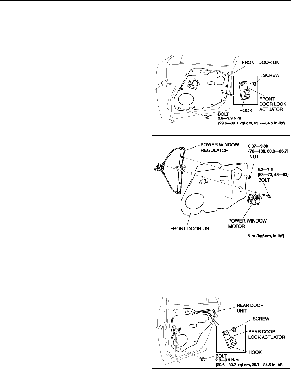
S18
DOOR
FRONT DOOR UNIT REMOVAL/INSTALLATION A6E771458971W01
1. Remove the front door glass.
2. Remove the inner handle.
3. Remove the front door speaker.
4. Disconnect the power window motor connector, front door lock actuator connector, power outside mirror
connector.
5. Remove the door harness from the front door unit.
6. Remove the bolts.
7. Remove the screw.
8. Remove the front door actuator hook from the
front door unit.
9. Pull the front door unit slightly towards you, and
while keeping the power window regulator from
catching on the door, remove the door unit from
the door.
10. Pull out the inner handle cable and door lock knob
cable from the hole.
11. Remove the power window motor and power
window regulator from the door unit.
12. Install in the reverse order of removal.
End Of Sie
REAR DOOR UNIT REMOVAL/INSTALLATION A6E771458971W02
1. Remove the rear door glass.
2. Remove the inner handle.
3. Remove the rear door speaker.
4. Disconnect the power window motor connector, and power door lock actuator connector.
5. Remove the rear door harness from the rear door unit.
6. Remove the bolts.
7. Remove the rear door lock actuator hook from the
rear door unit.
8. Pull the rear door unit slightly towards you, and
while keeping the power window regulator or
manual window regulator from catching on the
door, remove the door unit from the door.
9. Pull out the inner handle cable and door lock knob
cable from the hole.
A6E7714W011
A6E7714W012
A6E7714W016
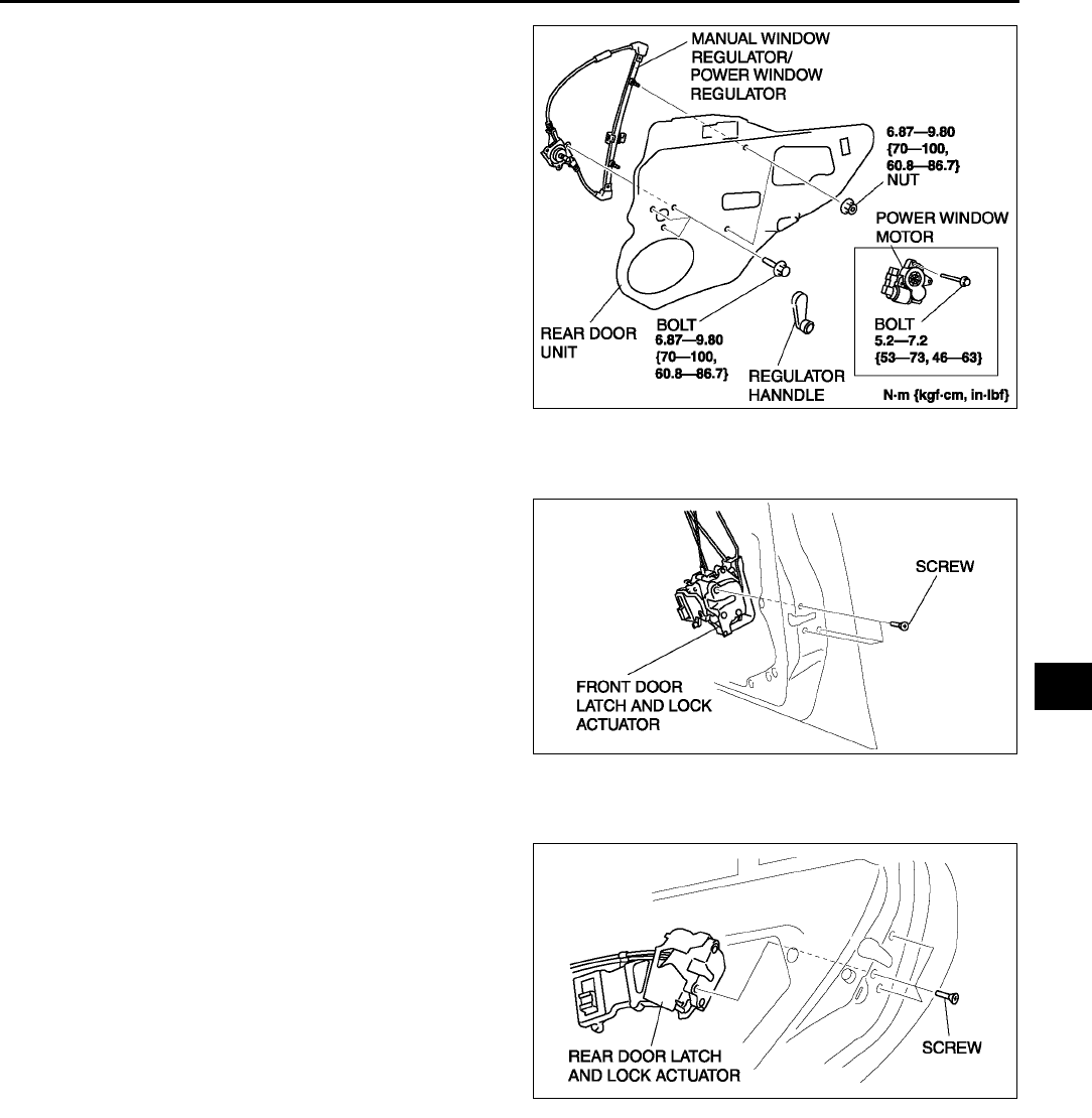
DOOR
S19
S
10. For power window system-equipped vehicles,
remove the power window motor and power
window regulator from the door unit. For manual
window system-equipped vehicles, remove the
regulator handle and manual window regulator.
11. Install in the reverse order of removal.
End Of Sie
FRONT DOOR LATCH AND LOCK ACTUATOR REMOVAL/INSTALLATION A6E771458310W01
1. Remove the front door unit.
2. Remove the screws, then remove the front door
latch and door lock actuator.
3. Install in the reverse order of removal.
End Of Sie
REAR DOOR LATCH AND LOCK ACTUATOR REMOVAL/INSTALLATION A6E771472310W01
1. Remove the rear door unit.
2. Remove the screws, then remove the rear door
latch and lock actuator.
3. Install in the reverse order of removal.
End Of Sie
A6E7714W017
A6E7714W013
A6E7714W020
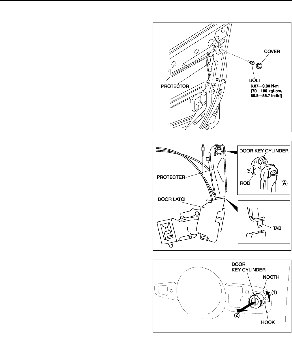
S20
DOOR
FRONT DOOR KEY CYLINDER REMOVAL/INSTALLATION A6E771458310W03
1. Remove the front door unit.
2. Remove the cover, then remove the bolt.
3. For protector-equipped vehicles, pull out the
protector tab from the latch and remove the
protector.
4. Disconnect the rod.
5. Remove the front outer handle.
6. Turn the key cylinder in the direction indicated by
the arrow (1) and move the hook to the notch.
7. Pull the key cylinder towards you (2) to remove it.
8. Install in the reverse order of removal.
End Of Sie
A6E7714W027
A6E7714W028
A6E7714W029
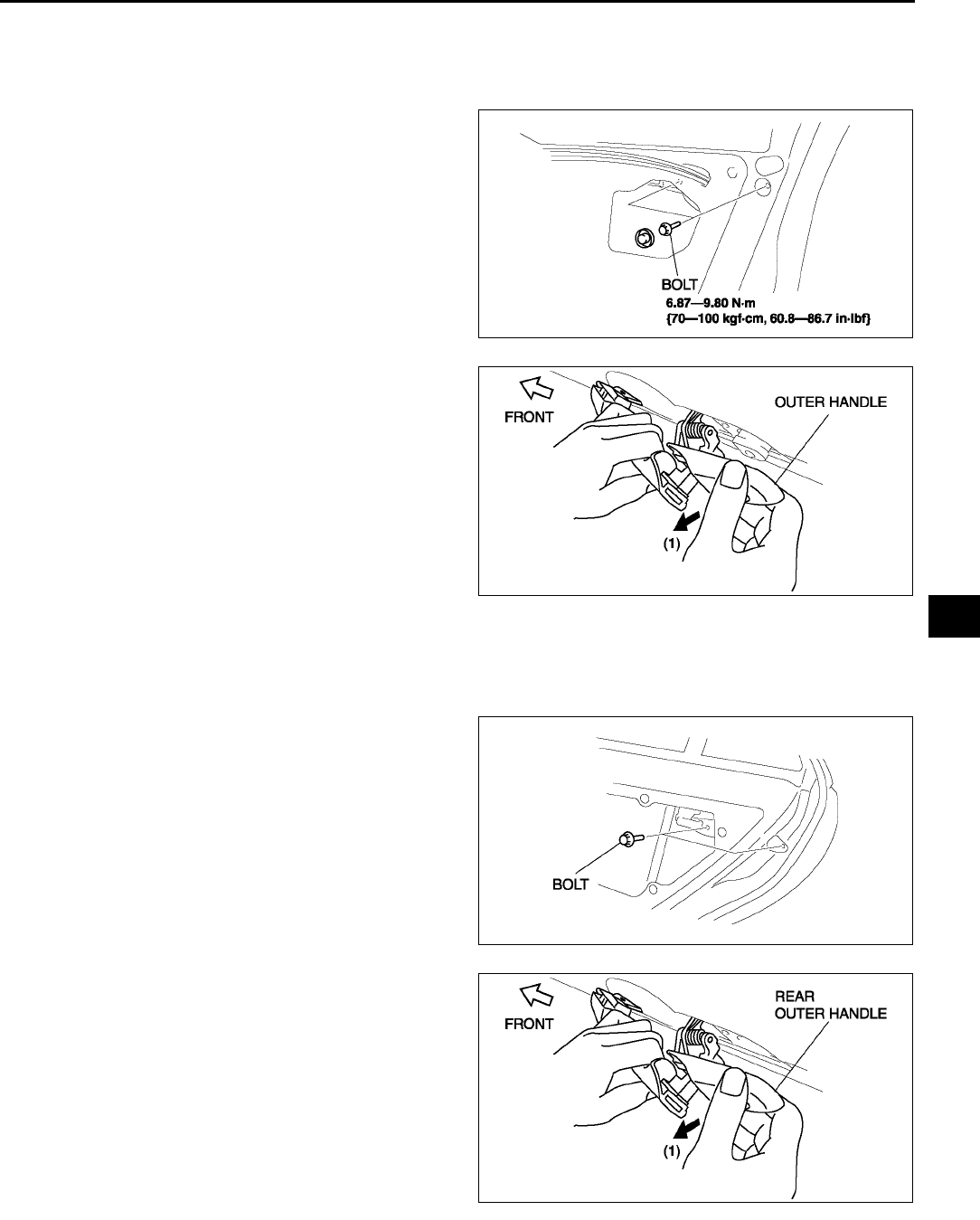
DOOR
S21
S
FRONT OUTER HANDLE REMOVAL/INSTALLATION A6E771458410W01
1. Remove the front door glass.
2. Detach the outer handle and front door latch rod.
3. For protector-equipped vehicles, refer to key cylinder removal/installation to remove the protector.
4. Remove the bolts.
5. With the rear side of the outer handle fixed and
the outer handle lever pulled out (1), remove the
rear side of the outer handle from the front door.
6. Pull out the front side of the outer handle from the
front door.
7. Install in the reverse order of removal.
End Of Sie
REAR OUTER HANDLE REMOVAL/INSTALLATION A6E771458410W02
1. Remove the rear door glass.
2. Remove the rear door unit.
3. Remove the rear door latch.
4. Remove the bolts.
5. Detach the rear outer handle and rear door latch
rod.
6. With the rear side of the rear outer handle fixed
and the outer handle lever pulled out (1), remove
the rear side of the rear outer handle from the
rear door.
7. Pull out the front side of the rear outer handle
from the rear door.
8. Install in the reverse order of removal.
End Of Sie
A6E7714W004
A6E7714W005
A6E7714W018
A6E7714W019
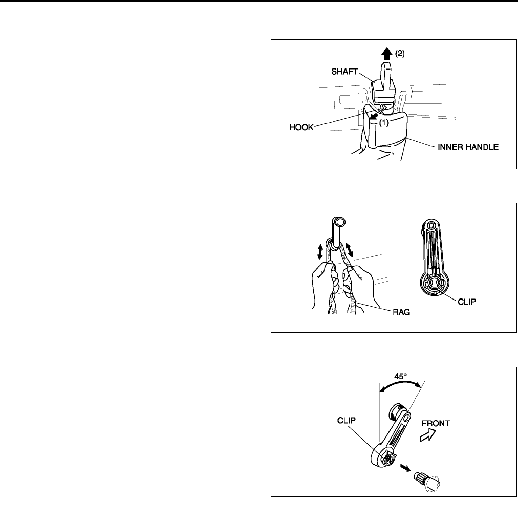
S22
DOOR
INNER HANDLE REMOVAL/INSTALLATION A6E771458330W01
1. Remove the front door trim.
2. Using a flathead screwdriver, press and hold the
hook in the direction indicated by arrow (1), and
pull the shaft in the direction indicated by arrow
(2), remove the shaft.
3. Pull off the inner handle, and remove the door
lock knob cable and inner handle cable.
4. Install in the reverse order of removal.
End Of Sie
REGULATOR HANDLE REMOVAL A6E771458580W01
1. Remove the regulator handle clip using a rag as
shown.
End Of Sie
REGULATOR HANDLE INSTALLATION A6E771458580W02
1. Install the clip in the regulator handle.
2. Close the door glass fully and push the regulator
handle on as shown.
End Of Sie
A6E7714W010
A6E7714W008
A6E7714W009
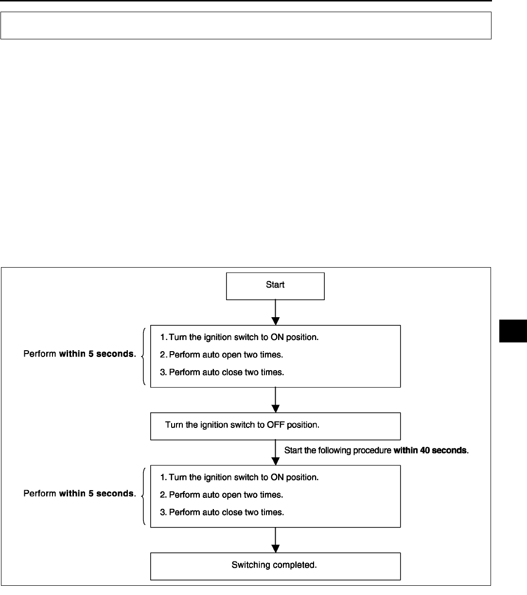
POWER WINDOW SYSTEM
S23
S
INITIAL SETTING A6E771666350W01
Note
•A driver side window will not fully close automatically under following the conditions:
The battery has been disconnected during vehicle maintenance or for other reasons.
The power window main switch connector, or driver-side power window motor connector has been
disconnected.
• Carry out the following procedure to resume operation:
1. Turn the ignition switch to the ON position.
2. Press the driver side power window main switch and fully open the driver side window.
3. Pull up the driver side power window main switch to manual-up position to fully close the driver side window,
and keep holding the switch up at the position for about 2 seconds to complete initial setting.
End Of Sie
TWO-STEP DOWN FUNCTION OPERATIVE/NON-OPERATIVE SWITCHING PROCEDURE A6E771666350W02
Note
•By following the procedure below, the two-step down function is switched to non-operative when it is
operative, and to operative when it is non-operative.
End Of Sie
POWER WINDOW SYSTEM
A6E7716W014
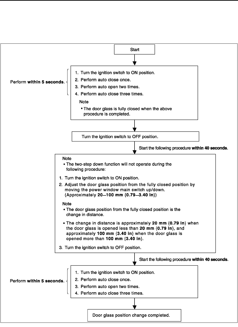
S24
POWER WINDOW SYSTEM
DOOR GLASS POSITION CHANGE PROCEDURE A6E771666350W03
Note
•After performing the following procedure, verify that the two-step down function operates normally and the
door glass position has changed. If the two-step down function does not operate or the door glass position
has not changed, the procedure was not performed properly. Repeat the procedure from the beginning.
End Of Sie
A6E7716W015
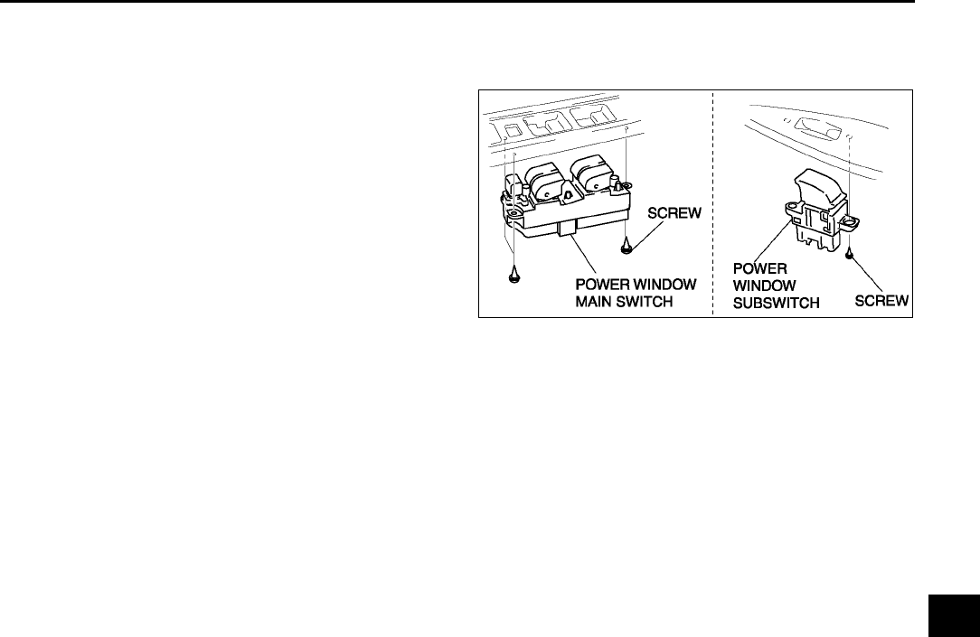
POWER WINDOW SYSTEM
S25
S
POWER WINDOW SWITCH REMOVAL/INSTALLATION A6E771666350W04
1. Disconnect the negative battery cable.
2. Remove the front door trim or rear door trim.
3. Remove the screws, then the power window
switch.
4. Install in the reverse order of removal.
End Of Sie
A6E7716W003
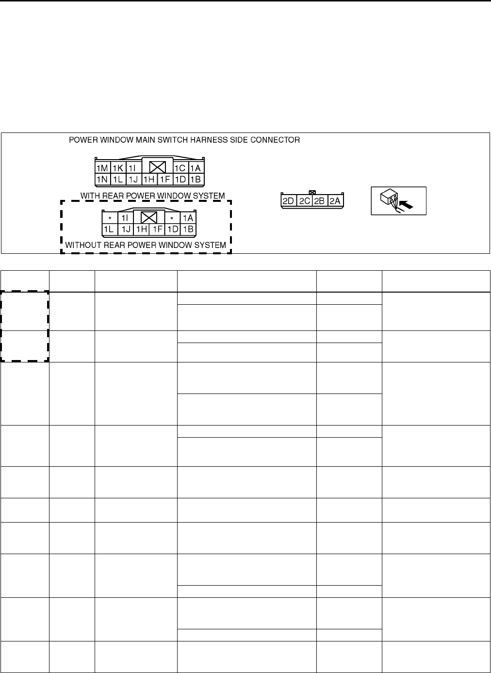
S26
POWER WINDOW SYSTEM
POWER WINDOW MAIN SWITCH INSPECTION A6E771666350W05
Drivers side
1. Remove the driver-side front door trim.
2. Connect the power window main switch connector.
3. Measure the voltage at the power window main switch terminals as indicated below.
4. Disconnect the power window main switch connector before inspecting for continuity at terminals 1M (1J*2) and
1F (1L*2).
•If not as specified, inspect the parts listed under Action.
•If the parts and wiring harnesses are okay but the system still does not work properly, replace the power
window main switch.
Terminal voltage list (Reference)
*1 : With rear power window system (L.H.D.)
*2 : Without rear power window system (L.H.D.)
*3 :R.H.D.
Terminal Signal Connected to Test condition Voltage (V)/
Continuity Action
1N*1
1F*2
1B*3
Open
output
Power window
motor
While door glass is opening B+ •Power window motor
•Inspect related
harness
While door glass is closing Below 1.0
1L*1
1D
Close
output
Power window
motor
While door glass is opening Below 1.0 •Power window motor
•Inspect related
harness
While door glass is closing B+
1F
1L*2 Door
switch Door switch
Any door is open (door switch is
on): inspect for continuity to
ground
Yes •Inspect door switch
•Inspect related
harness
All doors are closed (door switch is
off): inspect for continuity to
ground
No
1H
1B*2 IG1 P. WIND 30 A fuse
Ignition switch is at ON position B+ •Inspect P. WIND 30 A
fuse
•Inspect related
harness
Ignition switch is at LOCK position Below 1.0
1J
1H*2 Power
supply P. WIND 20 A fuse Under any condition B+
•P. WIND 20 A fuse
•Inspect related
harness
1M
1J*2 Ground GND Under any condition: inspect for
continuity to ground Yes •Inspect GND
2A Ground Power window
motor
Under any condition: inspect for
continuity to ground Yes
•Power window motor
•Inspect related
harness
2B Pulse 2 Power window
motor
Door glass is in motion
Alternates
between 0 and
5
•Power window motor
•Inspect related
harness
Door glass is not in motion 0 or 5
2C Pulse 1 Power window
motor
Door glass is in motion
Alternates
between 0 and
5
•Power window motor
•Inspect related
harness
Door glass is not in motion 0 or 5
2D Power
supply
Power window
motor Under any condition 9
•Power window motor
•Inspect related
harness
A6E7716W001
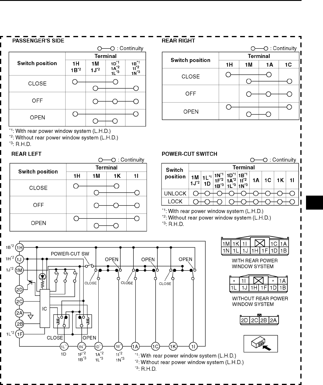
POWER WINDOW SYSTEM
S27
S
Except drivers side
1. Turn the power-cut switch to UNLOCK.
2. Inspect for continuity between the power window main switch terminals using an ohmmeter.
•If not as specified, replace the power window main switch.
End Of Sie
A6E7716W009
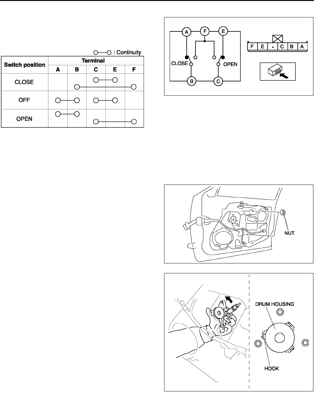
S28
POWER WINDOW SYSTEM
POWER WINDOW SUBSWITCH INSPECTION A6E771666370W01
1. Inspect for continuity between the power window
subswitch terminals.
•If not as specified, replace the power window
subswitch.
End Of Sie
POWER WINDOW REGULATOR REMOVAL/INSTALLATION A6E771658560W01
1. Disconnect the negative battery cable.
2. Remove the front door glass/rear door glass.
3. Remove the front door speaker/rear door speaker.
4. Remove the power window motor.
5. Remove the nuts.
6. Insert hand through the speaker installation hole,
rotate the regulator drum housing in the direction
shown in the figure and disengage the regulator
drum housing from the door unit connection
hooks.
A6E7716W011
A6E7716W013
A6E7716W005
A6E7716W006
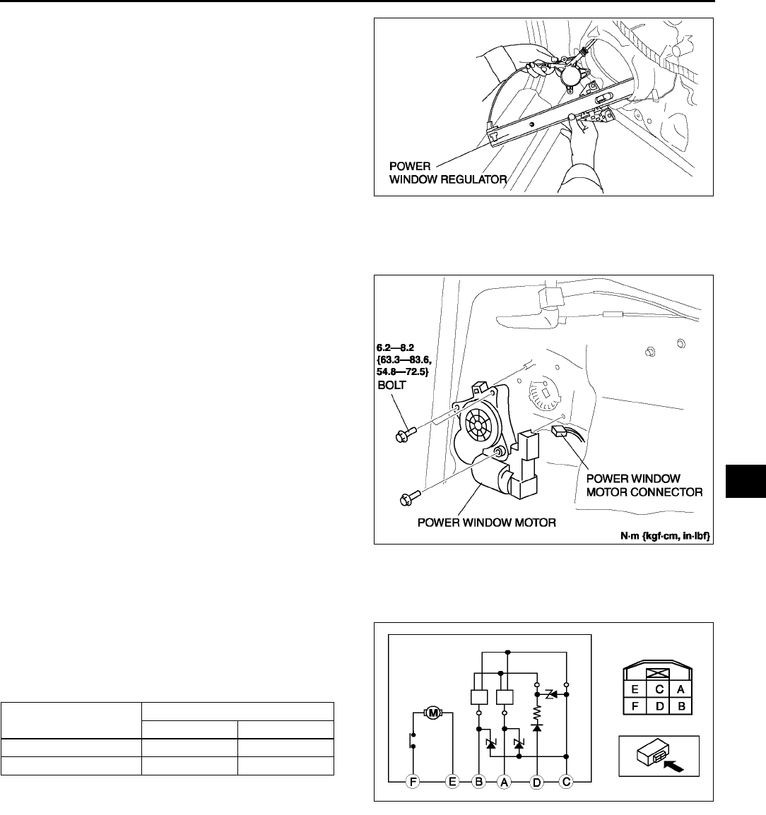
POWER WINDOW SYSTEM
S29
S
7. Remove the power window regulator from the
speaker installation hole.
8. Install in the reverse order of removal.
End Of Sie
POWER WINDOW MOTOR REMOVAL/INSTALLATION A6E771659560W01
1. Disconnect the negative battery cable.
2. Remove the front door trim or rear door trim.
3. Disconnect the power window motor connector.
4. Remove the bolts.
5. Remove the power window motor from the power
window regulator drum.
6. Install in the reverse order of removal.
Note
•When installing the power window motor to
the power window regulator drum, the drum
housing hook may come off the door unit. If
this happens, remove the door speaker,
insert your hand in the speaker installation
hole, connect the drum housing hooks, and
while supporting the drum housing, install
the power window motor to the drum.
End Of Sie
POWER WINDOW MOTOR INSPECTION A6E771659560W02
Drivers Side
1. Disconnect the power window motor connector.
2. Apply battery positive voltage to the power
window motor terminals E and F and inspect the
operation the power window motor operation.
•If not as specified, replace the power window
motor.
3. Apply battery positive voltage to the power
window motor terminal D and connect terminal C
to ground.
4. Measure the voltage at terminal B and A while performing Step 3.
•If not as specified, replace the power window motor.
Voltage
Pulse wave: MAX. 5 V, MIN. 0 V
A6E7716W007
A6E7716W004
Motor operation Terminal
FE
UP GND B+
DOWN B+ GND
A6E7716W008
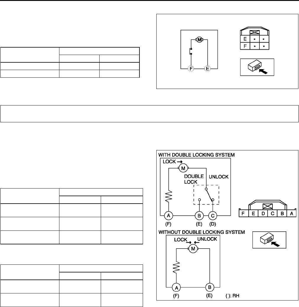
S30
POWER WINDOW SYSTEM, POWER DOOR LOCK SYSTEM
Except Driver's Side
1. Apply battery positive voltage to the power
window motor terminals and inspect the operation
of the power window motor.
•If not as specified, replace the power window
motor.
End Of Sie
FRONT DOOR LOCK ACTUATOR INSPECTION A6E771858310W01
Door Lock Actuator
1. Disconnect the front door lock actuator connector.
2. Apply battery positive voltage to the front door
lock actuator terminals and inspect the operation
of the front door lock actuator.
•If not as specified, replace the front door lock
actuator.
With double locking system
( ) : RH
Without double locking system
( ) : RH
Motor operation Terminal
FE
UP GND B+
DOWN B+ GND
A6E7716W010
POWER DOOR LOCK SYSTEM
Actuator operation Connection
B+ GND
Lock A
(F)
C
(D)
Double lock A
(F)
B
(E)
Unlock C and B
(D and E)
A
(F)
Actuator operation Connection
B+ GND
Lock A
(F)
B
(E)
Unlock A
(F)
B
(E) A6E7718W011
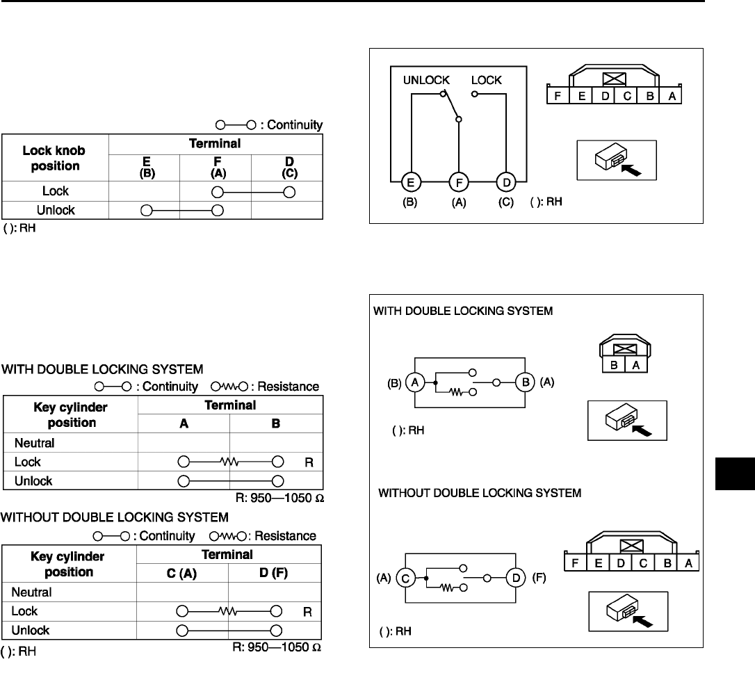
POWER DOOR LOCK SYSTEM
S31
S
Door Lock-link Switch
1. Disconnect the front door lock actuator connector.
2. Inspect for continuity between the door lock-link
switch terminals using an ohmmeter.
•If not as specified, replace the front door lock
actuator.
Door Key Cylinder Switch
1. Disconnect the front door lock actuator connector.
2. Inspect for continuity between the door lock-link
switch terminals using an ohmmeter.
•If not as specified, replace the front door lock
actuator.
End Of Sie
A6E7718W008
A6E7718W012
A6E7718W015
A6E7718W022
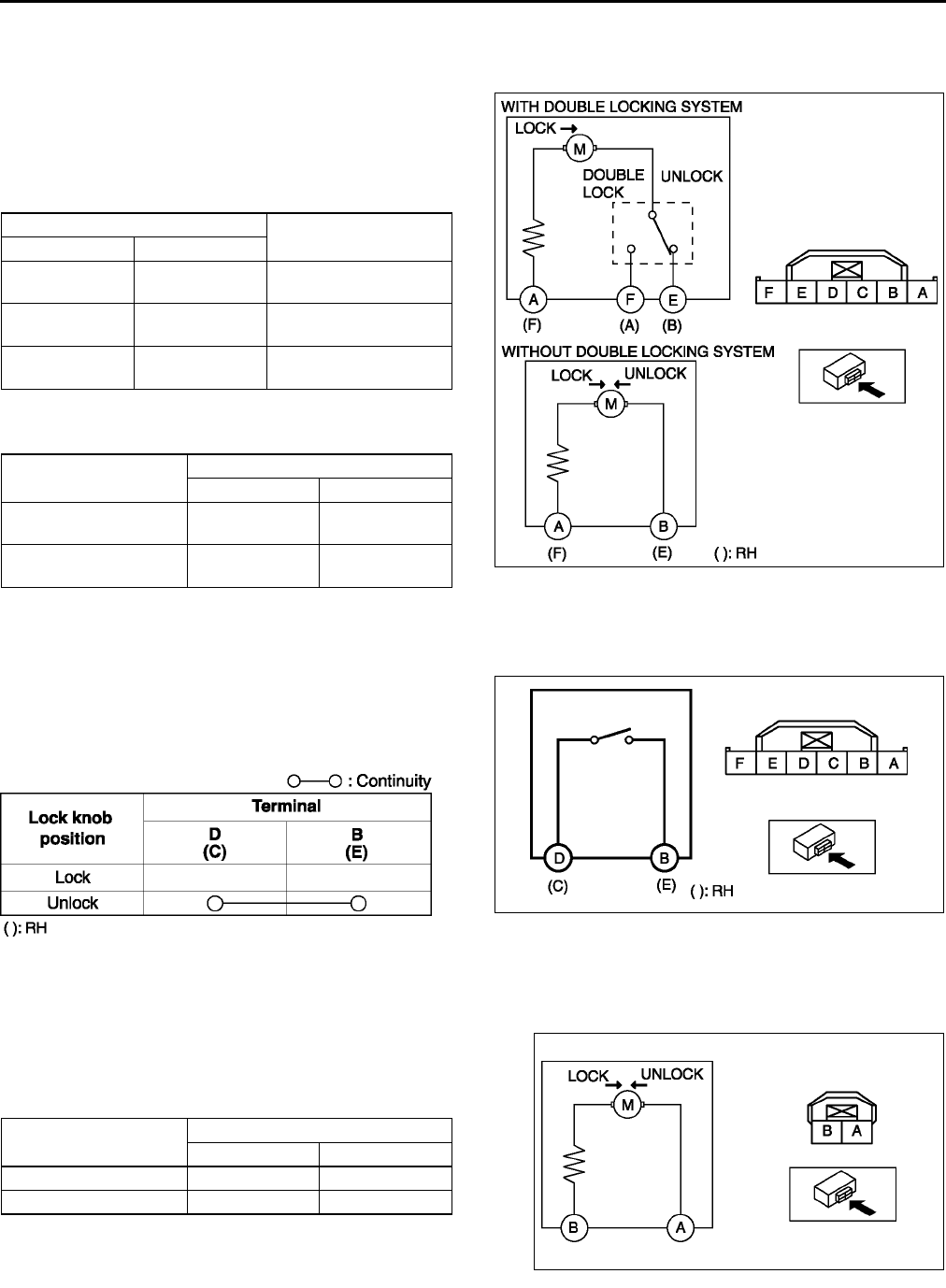
S32
POWER DOOR LOCK SYSTEM
REAR DOOR LOCK ACTUATOR INSPECTION A6E771872310W01
Door Lock Actuator
1. Disconnect the front door lock actuator connector.
2. Apply battery positive voltage to the front door
lock actuator terminals and inspect the operation
of the front door lock actuator.
•If not as specified, replace the front door lock
actuator.
With double locking system
( ) : RH
Without double locking system
( ) : RH
Door Lock-link Switch (With Theft-deterrent System
1. Disconnect the front door lock actuator connector.
2. Inspect for continuity between the door lock-link
switch terminals using an ohmmeter.
•If not as specified, replace the front door lock
actuator.
End Of Sie
TRUNK LID LOCK ACTUATOR INSPECTION A6E771856840W02
1. Disconnect the trunk lid lock actuator connector.
2. Apply battery positive voltage to the trunk lid lock
actuator terminals and inspect the operation of the
trunk lid lock actuator.
•If not as specified, replace the trunk lid lock.
End Of Sie
Connection Actuator operation
B+ GND
A
(F)
F
(A) Lock
F
(A)
A
(F) Double lock
F and E
(A and B)
E
(A) Unlock
Actuator operation Connection
B+ GND
Lock A
(F)
B
(E)
Unlock B
(E)
A
(F) A6E7718W018
A6E7718W010
A6E7718W019
Actuator operation Connection
B+ GND
Lock A B
Unlock B A
A6E7718W016
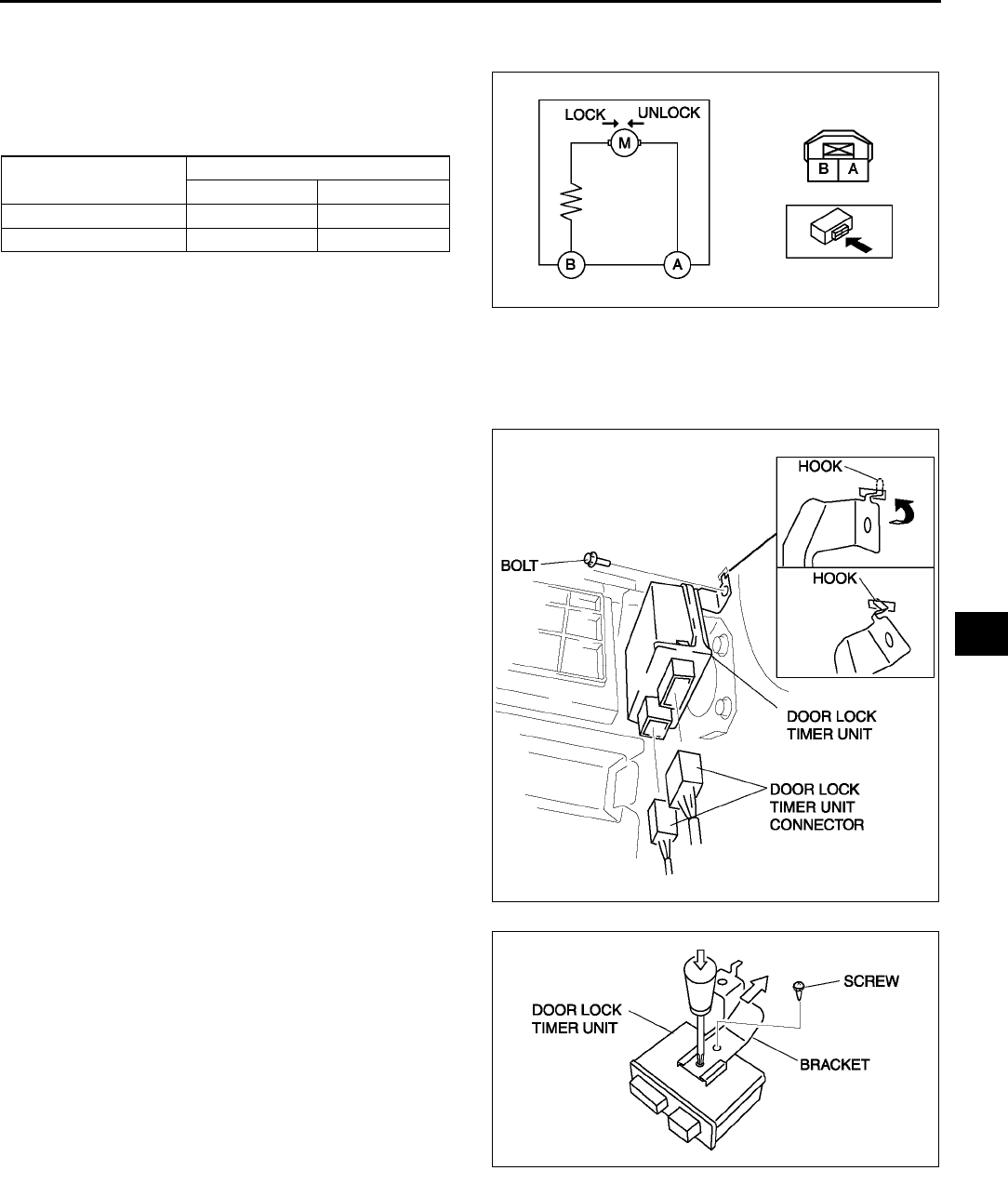
POWER DOOR LOCK SYSTEM
S33
S
LIFTGATE LOCK ACTUATOR INSPECTION A6E771862310W01
1. Disconnect the liftgate lock actuator connector.
2. Apply battery positive voltage to the liftgate lock
actuator terminals and inspect the operation of
the liftgate lock actuator.
•If not as specified, replace the liftgate lock.
End Of Sie
DOOR LOCK TIMER UNIT REMOVAL/INSTALLATION A6E771867830W01
1. Disconnect the negative battery cable.
2. Remove the glove compartment. (L.H.D.)
3. Remove the bolt.
4. While inclining the door lock timer unit along the
body panel in the direction indicated by the arrow,
disengage the bracket hook from the hole in the
body panel.
5. Disconnect the door lock timer unit connector.
6. Remove the door lock timer unit.
7. Remove the screw, then remove the bracket.
Note
•The screw which fixes the door lock timer
unit and bracket is for a body ground
connection. Be sure to secure the screw
when installing.
8. Install in the reverse order of removal.
End Of Sie
Actuator operation Connection
B+ GND
Lock A B
Unlock B A
A6E7718W016
A6E7718W004
A6E7718W020
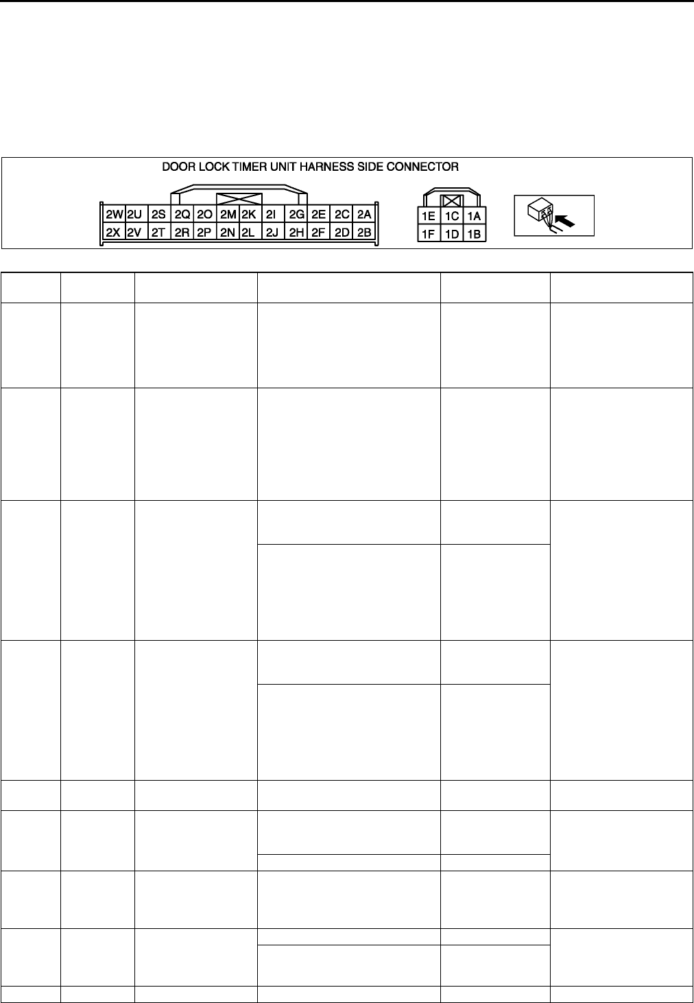
S34
POWER DOOR LOCK SYSTEM
DOOR LOCK TIMER UNIT INSPECTION A6E771867830W02
1. Measure the voltage at the door lock timer unit terminals (other than terminal 1E and 2W) as indicated below.
•If not as specified, inspect the parts listed under Action.
2. Disconnect the negative battery cable.
3. Disconnect the door lock timer unit connector and inspect for continuity between terminal 1E or 2W and the
bracket.
4. Inspect for continuity at terminal 1E and 2W as indicated below.
5. If the parts and wiring harnesses are okay but the system still does not work properly, perform the troubleshooting.
Terminal voltage list (Reference)
Terminal Signal Connected to Test condition Voltage (V)/
Continuity Action
1A Power
supply D. LOCK 30 A fuse Under any condition B+
•Inspect D. LOCK
30 A fuse
•Inspect the vehicle
battery
•Inspect related
harness
1B Room light
control
•Front map light
•Rear map light
•Courtesy light
Any door is open Below 1.0
•Inspect ROOM 15 A
fuse
•Inspect door switch
•
Inspect front map light
•Inspect rear map light
•Inspect courtesy light
•Inspect related
harness
1C Unlock
output
•Door lock
actuator
•Trunk lid lock
actuator (4SD)
•Liftgate lock
actuator (5HB)
While lock actuator is unlocking
Below
1.0→B+→Below
1.0
•Inspect door lock
actuator
•Inspect trunk lid lock
actuator (4SD)
•Inspect liftgate lock
actuator (5HB)
•Inspect D. LOCK
30 A fuse
•Inspect related
harness
Other Below 1.0
1D Lock output
•Door lock
actuator
•Trunk lid lock
actuator (4SD)
•Liftgate lock
actuator (5HB)
While lock actuator is locking
Below
1.0→B+→Below
1.0
•Inspect door lock
actuator
•Inspect trunk lid lock
actuator (4SD)
•Inspect liftgate lock
actuator (5HB)
•Inspect D. LOCK
30 A fuse
•Inspect related
harness
Other Below 1.0
1E Power
ground GND Under any condition: inspect for
continuity to ground Yes •Inspect GND
1F*1 Double lock
output Door lock actuator
Door lock actuators are double
locked
Below
1.0→B+→Below
1.0
•Inspect door lock
actuator
•Inspect related
harness
Other Below 1.0
2A Power
supply METER IG 15 A fuse Under any condition B+
•Inspect METER IG
15 A fuse
•Inspect related
harness
2B IG1 ROOM 15 A fuse
Ignition switch is at ON position B+ •Inspect ROOM 15 A
fuse
•Inspect related
harness
Ignition switch is at LOCK or
ACC position Below 1.0
2C - - - - -
A6E7718W017

POWER DOOR LOCK SYSTEM
S35
S
*1 : Vehicles with double locking system
*2 : Vehicles with theft-deterrent system
2D - - - - -
2E - - - - -
2F
Key
reminder
switch
Key reminder switch
Key reminder switch at on B+ •Inspect key reminder
switch
•Inspect related
harness
Other Below 1.0
2G Liftgate
open/closed Door switch
Lliftgate is open (cargo
compartment light switch is on) Below 1.0 •Inspect cargo
compartment light
switch
•Inspect related
harness
Liftgate are closed (cargo
compartment light switch are off) B+
2H - - - - -
2I Hazard Flasher unit
Except
vehicles
with theft-
deterrent
system
Transmitter LOCK
button is pressed
B+→Below
1.0→B+
•Inspect flasher unit
•Inspect related
harness
Transmitter
UNLOCK button is
pressed
B+→Below
1.0→B+→Below
1.0→B+
No transmitter
buttons are pressed B+
Vehicles
with theft-
deterrent
system
Under any condition B+
•Inspect theft-
deterrent control
module
•Inspect related
harness
2J*1 Security
light output Instrument cluster
Double locking system operated 1.4 •Inspect instrument
cluster
•Inspect related
harness
Other B+
2K Door open/
closed Door switch
Any door is open (any door
switch is on) Below 1.0 •Inspect door
switches
•Inspect related
harness
All door are closed (door
switches are off) B+
2L - - - - -
2N - - - - -
2M - - - - -
2O - - - - -
2P*2
Theft-
deterrent
alarm
control
Theft-deterrent
control module
Ignition switch is at ON position B+→Below
1.0→B+
•Inspect theft-
deterrent control
module
•Inspect related
harness
Other B+
2Q Lock input Door lock-link switch
Drivers side door is locked:
inspect for continuity to ground Yes •Inspect door lock-link
switch
•Inspect related
harness
Drivers side door is unlocked:
inspect for continuity to ground No
2R Unlock input Door lock-link switch
Drivers side door is locked:
inspect for continuity to ground No •Inspect door lock-link
switch
•Inspect related
harness
Drivers side door is unlocked:
inspect for continuity to ground Yes
2S Lock/Unlock
input
•Door key cylinder
switch (drivers
side)*1
•
Door key cylinder
switch
(passengers side)
At the moment of key cylinder is
locked Approx. 2.5 •Inspect key cylinder
switch
•Inspect related
harness
At the moment of key cylinder is
unlocked Below 1.0
Key cylinder at neutral position Approx. 5
2T - - - - -
2U - - - - -
2V - - - - -
2W Signal
ground GND Under any condition: inspect for
continuity to ground Yes •Inspect GND
2X - - - - -
Terminal Signal Connected to Test condition Voltage (V)/
Continuity Action
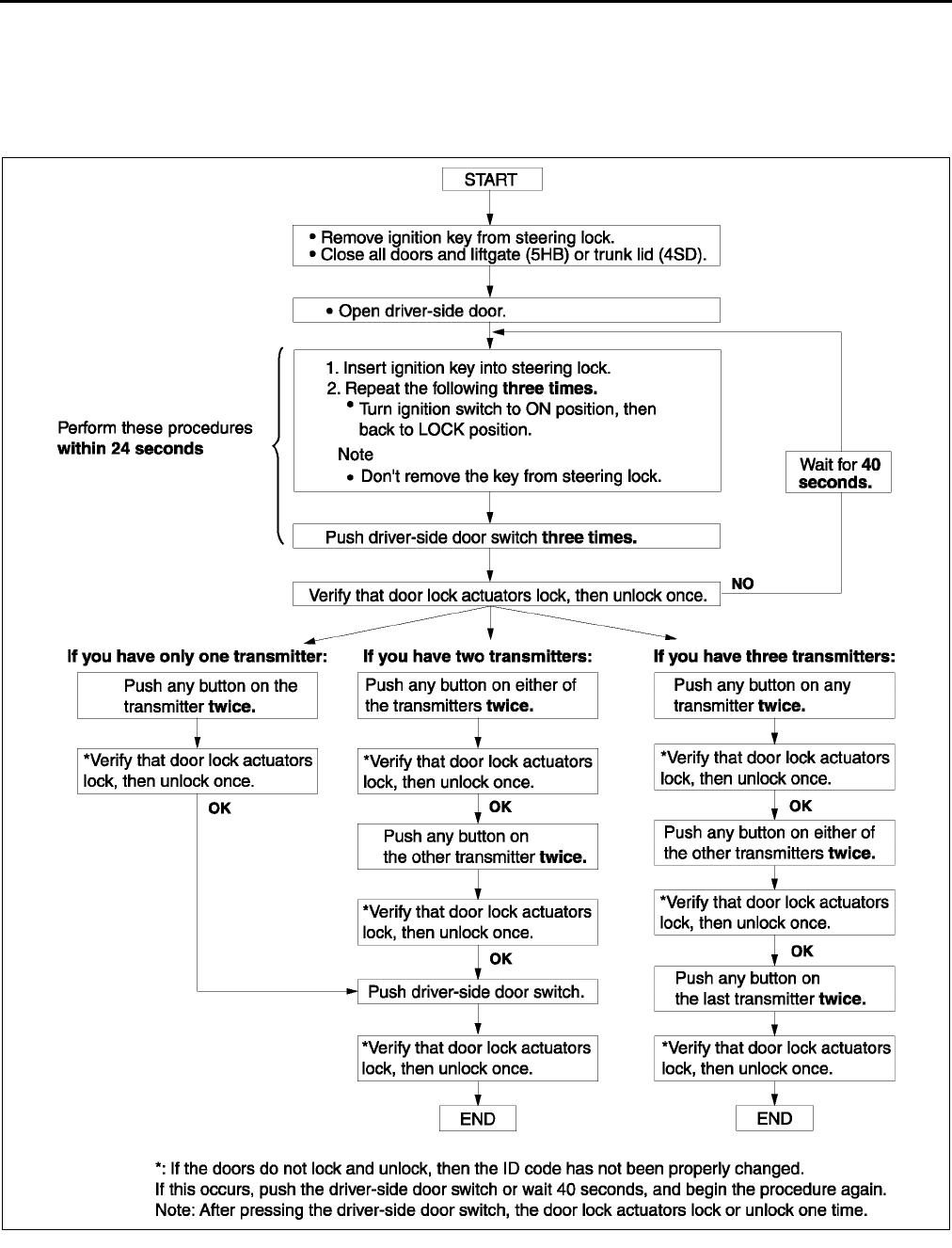
S36
POWER DOOR LOCK SYSTEM
End Of Sie
DOOR LOCK TIMER UNIT ID CODE CHANGE A6E771801097W01
Note
•When programming the ID code into a door lock timer unit, verify that other transmitters are not being
operated in the vicinity.
End Of Sie
A6E7718W021
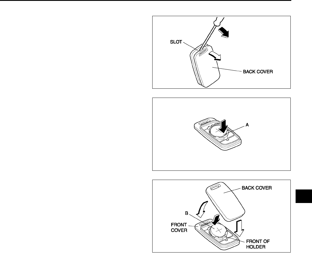
POWER DOOR LOCK SYSTEM
S37
S
TRANSMITTER BATTERY REPLACEMENT A6E771800110W01
1. Insert a small screwdriver into the slot and gently
pry open the transmitter.
2. Press the portion of the battery indicated by A and
remove the battery.
3. Install a new battery (CR2025) into the front
portion of the holder with the positive pole (+)
facing up. Press on the B portion of the battery to
set the battery.
4. Align the front and back covers and snap the
transmitter shut.
Battery specification
Lithium CR2025 ×
××
× 1
Note
•The batteries will last about 2 years when
used 10 times a day.
End Of Sie
A6E7718W001
A6E7718W002
A6E7718W003
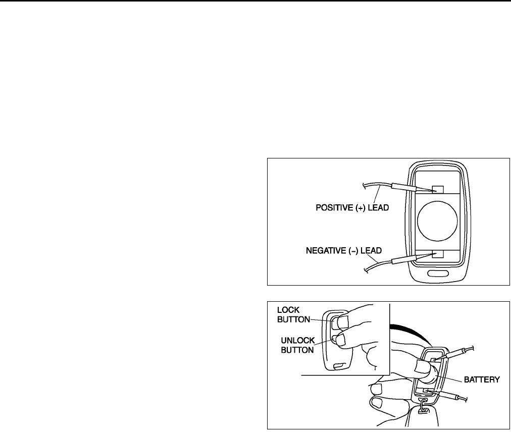
S38
POWER DOOR LOCK SYSTEM
TRANSMITTER BATTERY INSPECTION A6E771800110W02
Caution
•
••
•Since the battery voltage does not drop fully if the button is pushed for only 4 seconds or less, it
can not be properly examined to see whether it is good or bad. Always push the button for 5
seconds.
Note
•A correct measurement can not be obtained if the battery temperature is low. Make sure the battery is at
18 °
°°
°C {64 °
°°
°F} or more for at least 30 minutes before reinspecting if a measurement value is under the
standard voltage.
1. Remove the transmitter cover.
2. Apply the circuit tester leads to the positions as
indicated in the figure.
3. While pressing the battery as shown in the figure,
press the LOCK and UNLOCK buttons on the
transmitter at the same time to start measurement
of the voltage.
4. Release the buttons after 5 seconds.
5. Verify that the minimum voltage is the standard
voltage or more for 10 seconds after starting
measurement.
•If the voltage is under the standard voltage,
replace the battery.
Standard voltage
2.7 V
End Of Sie
A6E7718W005
A6E7718W006
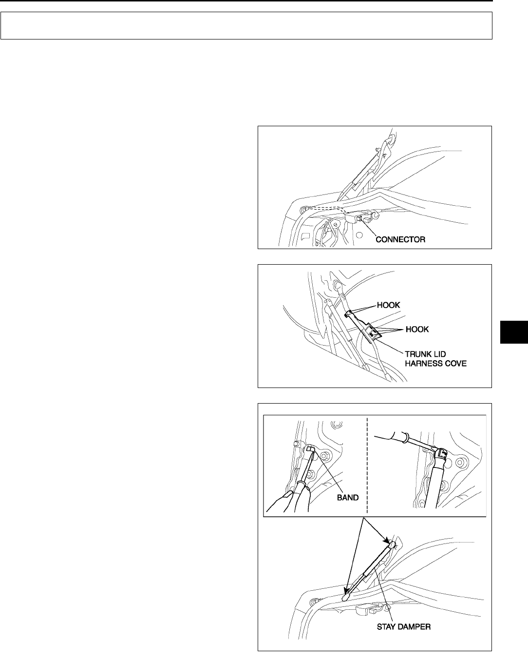
TRUNK LID
S39
S
TRUNK LID REMOVAL/INSTALLATION A6E772052610W01
Warning
•
••
•Removing the stay damper without supporting the trunk lid can be dangerous. The trunk lid may
fall and injure you. Open the trunk lid fully and support it before removing the stay damper.
1. Disconnect the negative battery cable.
2. Disconnect the trunk lid harness connector, pull
the trunk lid harness out from the cabin.
3. Disconnect the hooks, which secure the trunk lid
harness to the trunk lid hinge.
4. Pry away the stay damper's band with a
screwdriver.
5. Pry out the connecting part of the stay damper
and the hinge with a screwdriver to disconnect
them. Then remove the stay damper.
TRUNK LID
A6E7720W001
A6E7720W004
A6E7720W002
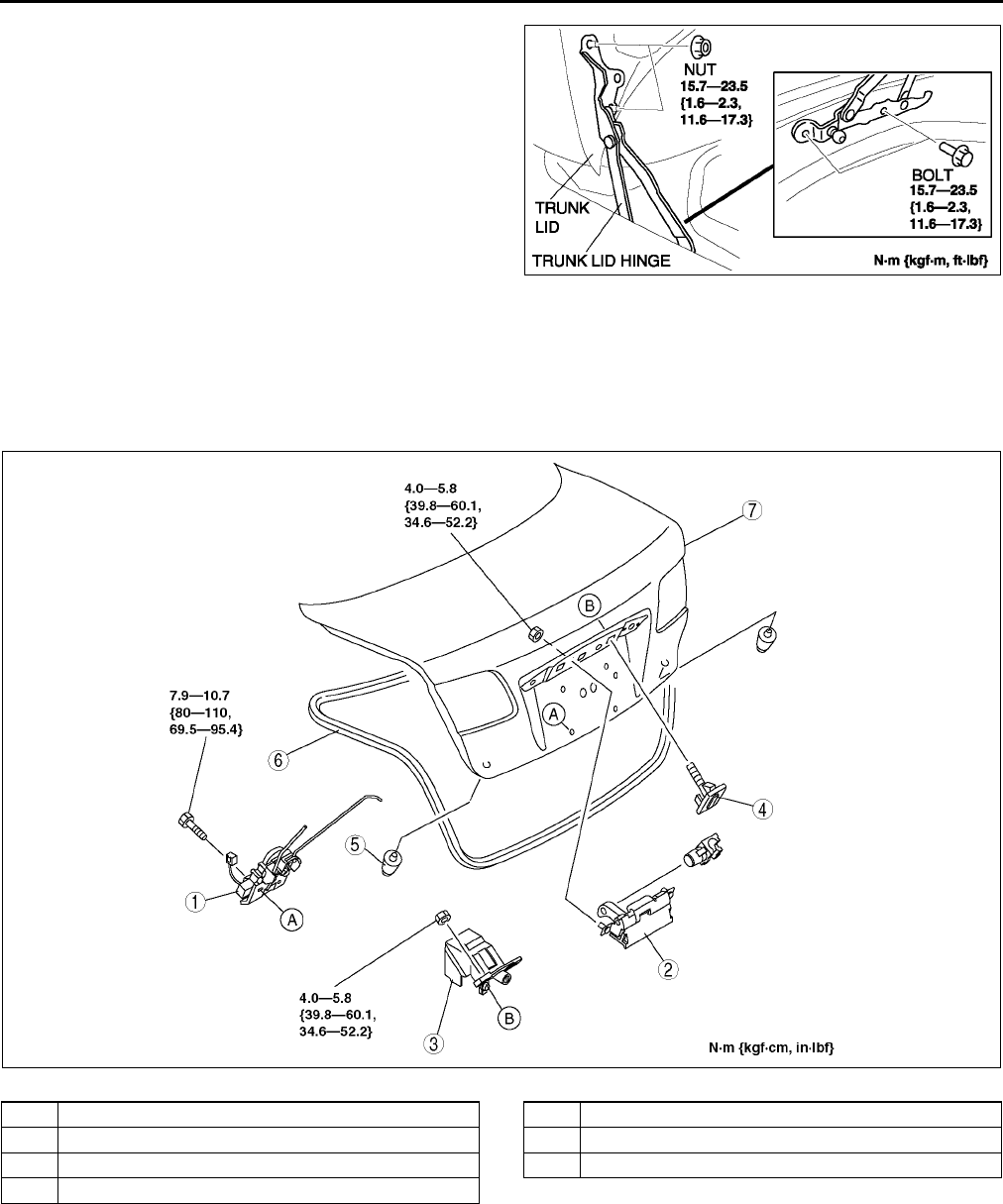
S40
TRUNK LID
6. Remove the nuts, then remove the trunk lid.
7. Remove the bolts, then remove the trunk lid
hinge.
8. Install in the reverse order of removal.
9. Adjust the trunk lid. (See S41 TRUNK LID
ADJUSTMENT.)
End Of Sie
TRUNK LID DISASSEMBLY/ASSEMBLY A6E772052610W02
1. Disconnect the negative battery cable.
2. Remove the trunk lid trim.
3. To remove the trunk lid outer handle and trunk lid key cylinder, remove the rear finisher.
4. Disassemble in the order indicated in the table.
5. Assemble in the reverse order of disassembly..
End Of Sie
A6E7720W007
A6E7720W006
1 Trunk Lid latch and lock actuator
2 Trunk Lid outer handle
3 Trunk Lid key cylinder
4 Clip
5 Stopper
6 Trunk Lid weatherstrip
7Trunk Lid
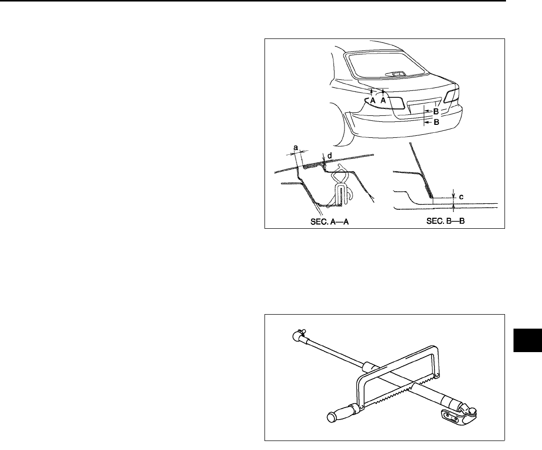
TRUNK LID
S41
S
TRUNK LID ADJUSTMENT A6E772052610W03
1. Measure the gap and height between the front door and the body.
2. If not as specified, loosen the door hinge
installation bolts or the door lock striker
installation screws, and reposition the door.
Clearance
a: 2.54.5 mm {0.100.18 in}
b: -1.01.0 mm {-0.040.04 in}
c: 4.08.0 mm {0.160.31 in}
3. Tighten the bolts or screws.
End Of Sie
STAY DAMPER DISPOSAL A6E772052610W04
Note
•The gas in the stay damper is colorless, odorless, and non-toxic.
1. Wear protective eye wear.
2. Lay the stay damper flat.
3. Saw through the stay damper body using a
hacksaw.
4. Allow the gas to escape from the stay damper.
5. Discard the stay damper.
End Of Sie
A6E7720W005
A6E7722W006
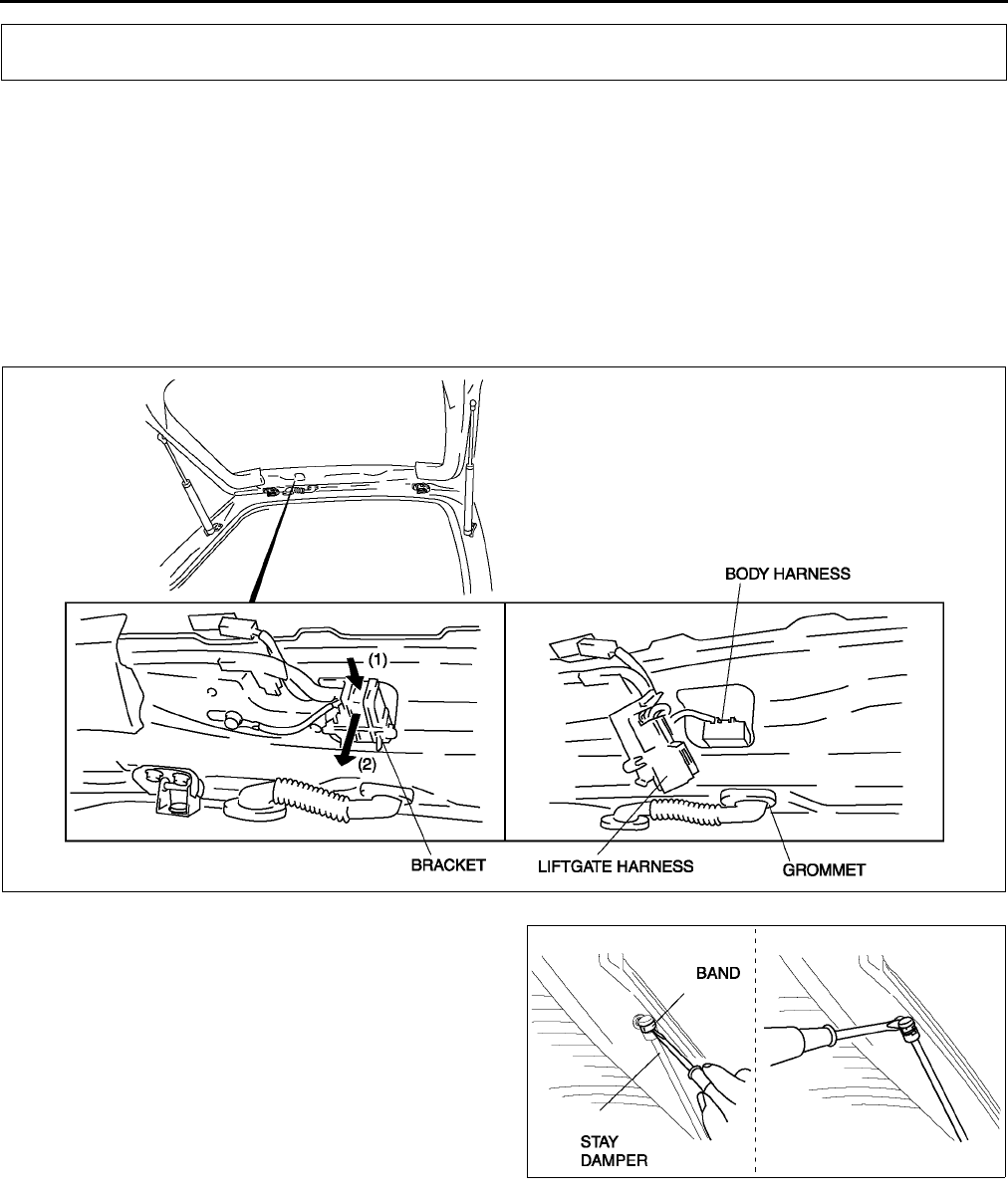
S42
LIFTGATE
LIFTGATE REMOVAL/INSTALLATION A6E772262010W01
Warning
•
••
•Removing the stay damper without supporting the liftgate can be dangerous. The liftgate may fall
and injure you. Open the liftgate fully and support it before removing the stay damper.
1. Disconnect the negative battery cable.
2. Remove the liftgate lower upper trim.
3. Press the liftgate harness connector's bracket, which is attached to the liftgate, to the (1) direction shown in the
figure, and then detach the fit. Then remove the connector toward the (2) direction shown in the figure.
4. Disconnect the vehicle harness connector and the liftgate connector. Then remove the grommet from the
liftgate.
5. Pry away the stay damper's band with a
screwdriver.
6. Pry out the connecting part of the stay damper
and the hinge with a screwdriver to disconnect
them. Then remove the stay damper.
7. Remove the bolts A, then remove the liftgate.
8. To remove the hinge, remove the headliner and
the nut.
LIFTGATE
A6E7722W003
A6E7722W005
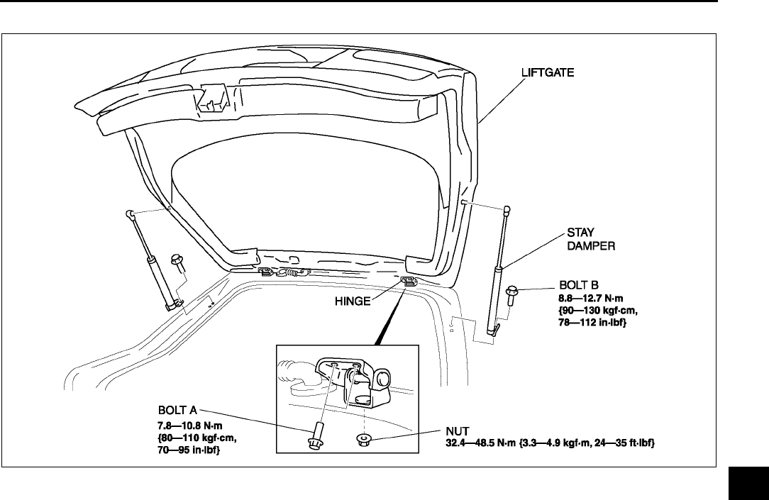
LIFTGATE
S43
S
9. To remove the stay damper, remove the bolt B.
10. Install in the reverse order of removal.
End Of Sie
A6E7722W001
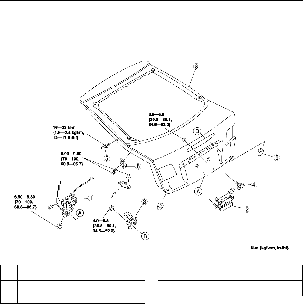
S44
LIFTGATE
LIFTGATE DISASSEMBLY/ASSEMBLY A6E772262010W02
1. Disconnect the negative battery cable.
2. Remove the liftgate lower trim.
3. To remove the liftgate outer handle and liftgate key cylinder, remove the rear finisher.
4. To remove the stud ball, separate the stud ball and the stay damper.
5. Disassemble in the order indicated in the table.
6. Assemble in the reverse order of disassembly..
End Of Sie
STAY DAMPER DISPOSAL A6E772262620W01
1. Referring to procedures for trunk lid stay damper disposal, dispose of the liftgate stay damper.
End Of Sie
A6E7722W007
1 Liftgate latch and lock actuator
2 Liftgate outer handle
3 Liftgate key cylinder
4 Clip
5 Stud ball
6 Liftgate wedge
7 Liftgate dovetail
8 Liftgate
9Stpper
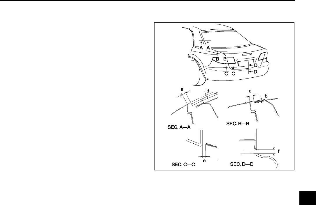
LIFTGATE
S45
S
LIFTGATE ADJUSTMENT A6E772262010W03
1. Measure the gap and height between the liftgate and the body.
2. If not as specified, loosen the liftgate hinge
installation bolts or the liftgate striker installation
screws, and reposition the liftgate.
Clearance
a: 3.07.0 mm {0.120.28 in}
b: -1.03.4 mm {-0.04013 in}
c: 2.85.2 mm {0.110.24 in}
d: -1.21.2 mm {0.050.05 in}
e: 2.85.8 mm {0.110.22 in}
f:4.08.0 mm {0.160.31 in}
3. Tighten the bolts or screws.
End Of Sie
A6E7722W004
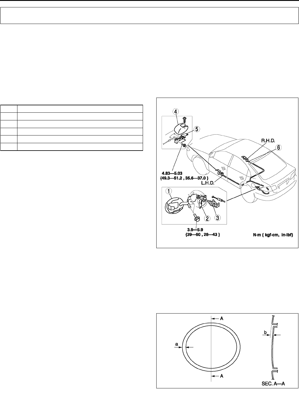
S46
FUEL-FILLER LID AND OPENER
FUEL-FILLER LID AND OPENER REMOVAL/INSTALLATION A6E772456890W01
1. To remove the fuel-filler lid opener, remove the left side trunk side trim (4SD) or trunk side lower trim (5HB).
2. To remove the fuel-filler lid opener cable, perform the following and turn over the floor covering.
(1) Remove the driver-side front seat.
(2) Remove the driver-side front scuff plate.
(3) Remove the driver-side rear scuff plate.
(4) Remove the driver-side B-pillar lower trim.
(5) Remove the driver-side tire house trim.
(6) Remove the rear seat cushion. (R.H.D., 4SD)
(7) Remove the rear seat installation bolts (front side), then lift the rear seat cushion. (R.H.D., 5HB)
3. Remove in the order indicated in the table.
4. Install in the reverse order of removal.
5. Adjust the fuel-filler lid. (See S46 FUEL-FILLER
LID ADJUSTMENT.)
End Of Sie
FUEL-FILLER LID ADJUSTMENT A6E772442410W01
1. If not as specified, loosen the fuel-filler lid installation bolts, and reposition the fuel-filler lid.
2. Measure the gap and height between the fuel-filler lid and the body.
Clearance
a: 1.73.7 mm {0.0670.145 in}
b: -0.51.5 mm {-0.0190.059 in}
3. Tighten the bolts.
End Of Sie
FUEL-FILLER LID AND OPENER
1 Fuel-filler lid
2 Lift spring
3 Fuel-filler lid opener
4Cover
5 Fuel-filler lid opener lever
6 Fuel-filler lid opener cable
A6E7724W001
A6E7724W002
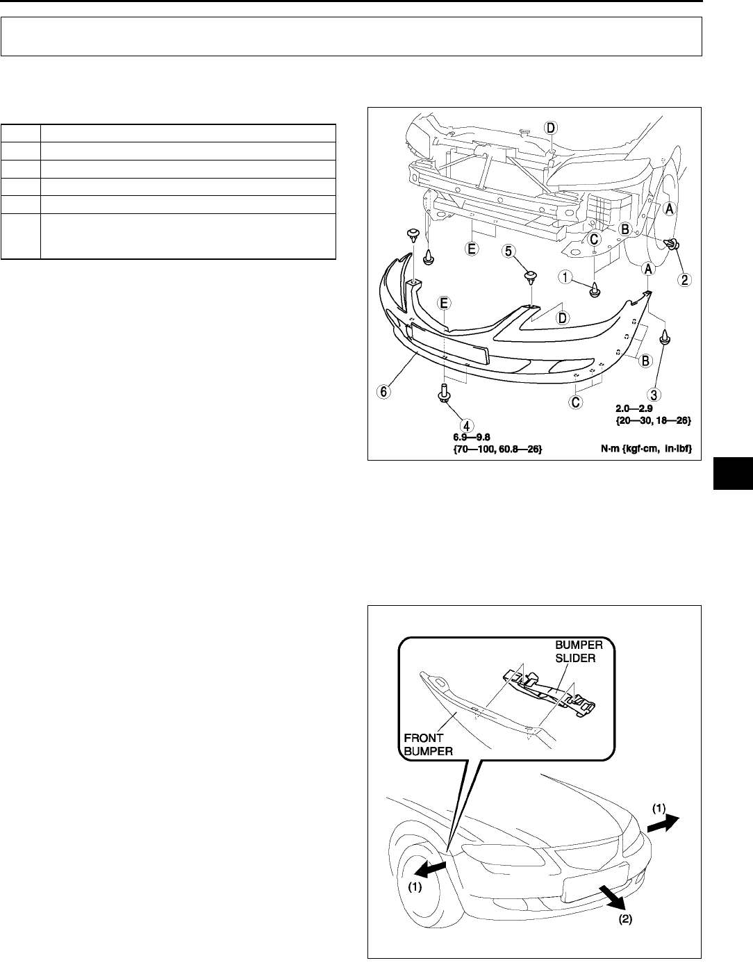
BUMPER
S47
S
FRONT BUMPER REMOVAL/INSTALLATION A6E772650031W01
1. Disconnect the negative battery cable.
2. Remove in the order indicated in the table.
3. Install in the reverse order of removal.
Front Bumper Removal Note
1. Pull the front bumper ends (wheel arch) outward to disengage from the bumper slider.
Caution
•
••
•If only one side of the front bumper is disengaged from the bumper slider and the bumper falls, it
could be damaged. When disengaging the front bumper from the slider, secure the bumper so that
it does not fall.
2. Remove the front bumper from the body.
BUMPER
1Screw A
2 Fastener A
3Screw B
4Bolt
5 Fastener B
6 Front bumper
(See S47 Front Bumper Removal Note)
(See S48 Front Bumper Installation Note)
A6E7726W003
A6E7726W006
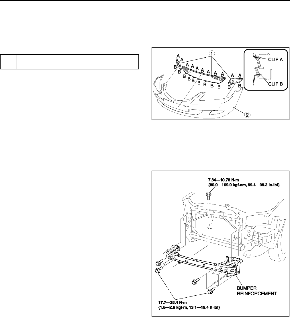
S48
BUMPER
Front Bumper Installation Note
1. Spread the front bumper ends (wheel arches) apart.
2. Attach the front bumper to the body.
3. Press the front bumper connection portion into the body to engage with the bumper slider.
End Of Sie
FRONT BUMPER DISASSEMBLY/ASSEMBLY A6E772650031W02
1. Disassemble in the order indicated in the table.
2. Assemble in the reverse order of disassembly.
End Of Sie
BUMPER REINFORCEMENT REMOVAL/INSTALLATION A6E772650031W03
1. Disconnect the negative battery cable.
2. Remove the front bumper. (See S47 FRONT BUMPER REMOVAL/INSTALLATION.)
3. Remove the headlight. (See T26 FRONT COMBINATION LIGHT REMOVAL/INSTALLATION.)
4. Suport the radiator and the condenser using the wire.
5. Remove the bolt.
6. Remove the bumper reinforcement.
7. Install in the reverse order of removal.
End Of Sie
1 Front bumper mesh
2 Front bumper fascia
A6E7726W004
A6E7726W005
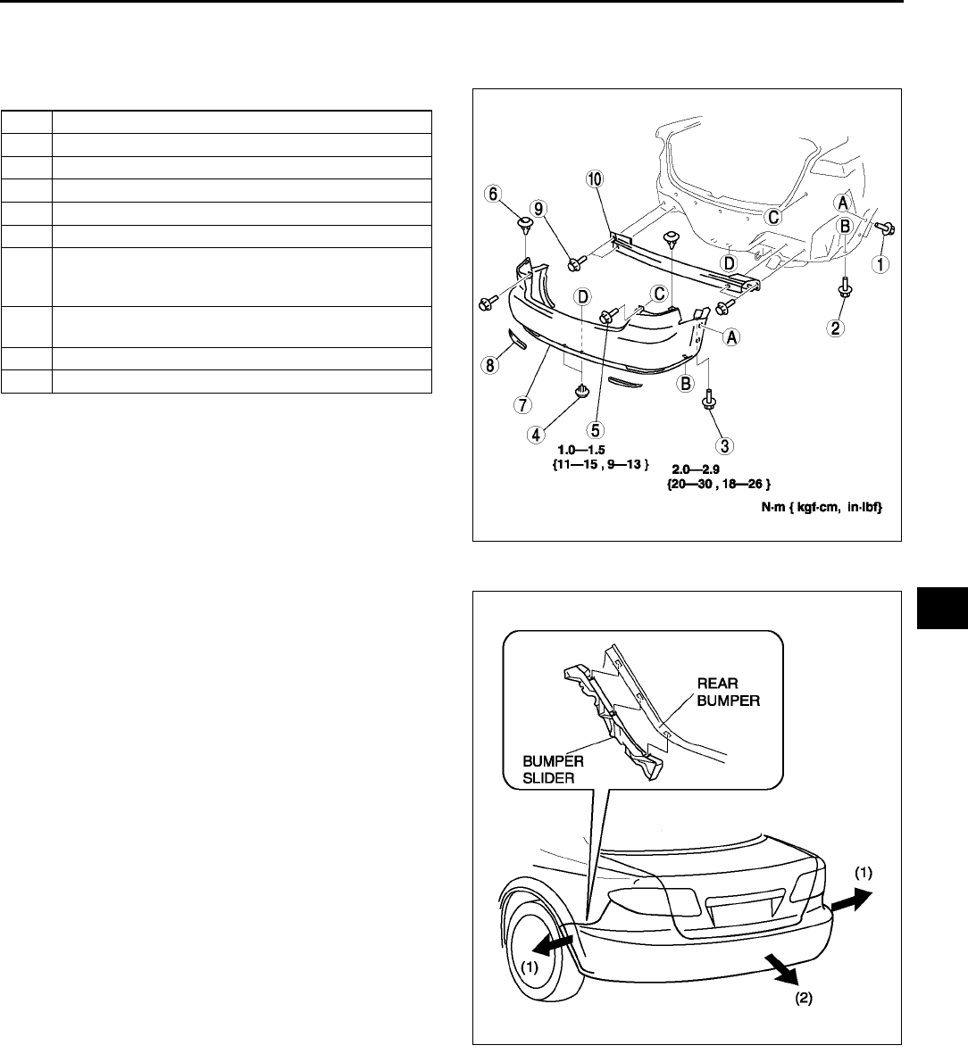
BUMPER
S49
S
REAR BUMPER REMOVAL/INSTALLATION A6E772650221W01
1. Disconnect the negative battery cable.
2. Remove the rear combination light.
3. Remove in the order indicated in the table.
4. Install in the reverse order of removal.
Rear Bumper Removal Note
1. Pull the rear bumper ends (wheel arch) outward
to disengage with the bumper slider.
Caution
•
••
•If only one side of the rear bumper is
disengaged from the bumper slider and
the bumper falls, it could be damaged.
When disengaging the rear bumper from
the slider, secure the bumper so that it
does not fall.
Rear Bumper Installation Note
1. Spread the rear bumper ends (wheel arches) apart.
2. Attach the rear bumper to the body.
3. Press the rear bumper connection portion into the body to engage with the bumper slider.
1Screw A
2Screw B
3Screw C
4 Fastener A
5 Bolt A
6 Fastener B
7 Rear bumper
(See S49 Rear Bumper Removal Note)
(See S49 Rear Bumper Installation Note)
8 Refractor
(See S50 Refractor Removal Note)
9 Bolt B
10 Rear bumper reinforcement
A6E7726W001
A6E7726W007
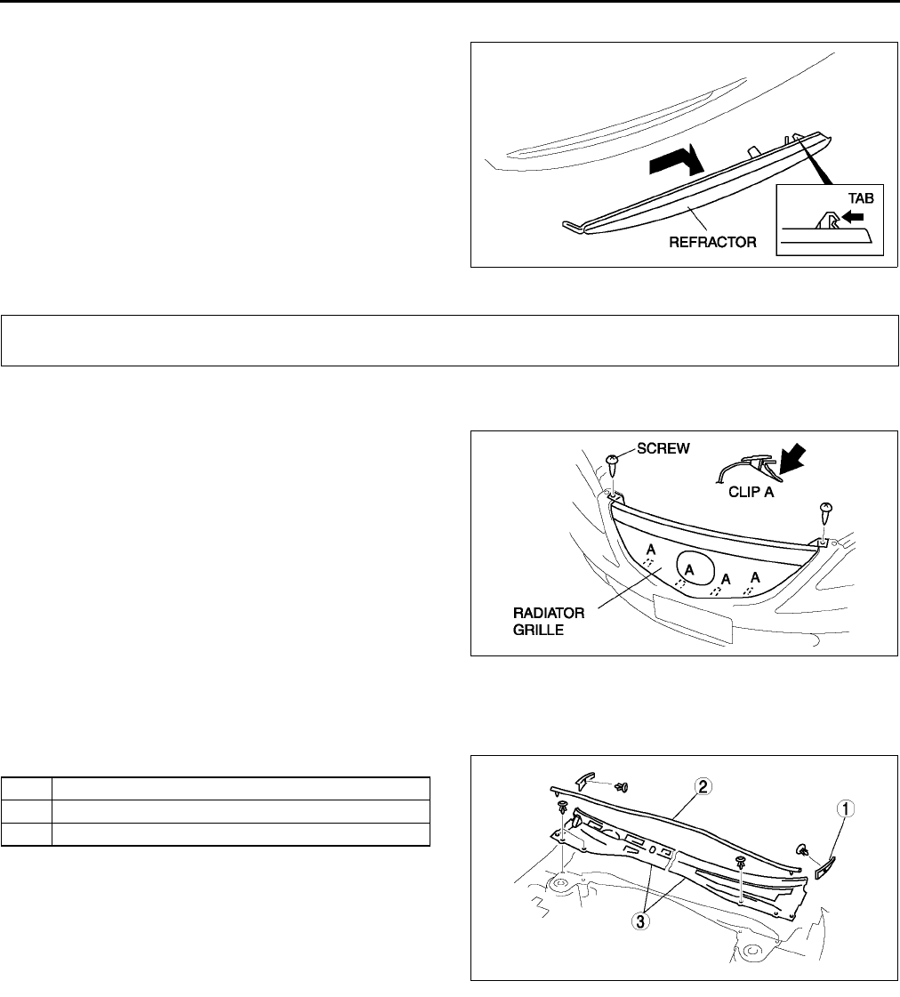
S50
BUMPER, EXTERIOR ATTACHMENT
Refractor Removal Note
1. Lift the refractor up in the direction of the arrow,
then unhook it from the rear bumper.
End Of Sie
RADIATOR GRILLE REMOVAL/INSTALLATION A6E772850710W01
1. Remove the screws.
2. Press clip A in the direction of the arrow, pll the
radiator grille outward and remove from the front
bumper.
3. Install in the reverse order of removal.
End Of Sie
COWL GRILLE REMOVAL/INSTALLATION A6E772850790W01
1. Remove the windshield wiper arm and blade. (See T57 WINDSHIELD WIPER ARM AND BLADE REMOVAL/
INSTALLATION.)
2. Remove in the order indicated in the table.
3. Install in the reverse order of removal.
End Of Sie
A6E7726W002
EXTERIOR ATTACHMENT
A6E7728W005
1 Front fender molding
2Weatherstrip
3 Cowl grille
A6E7728W004
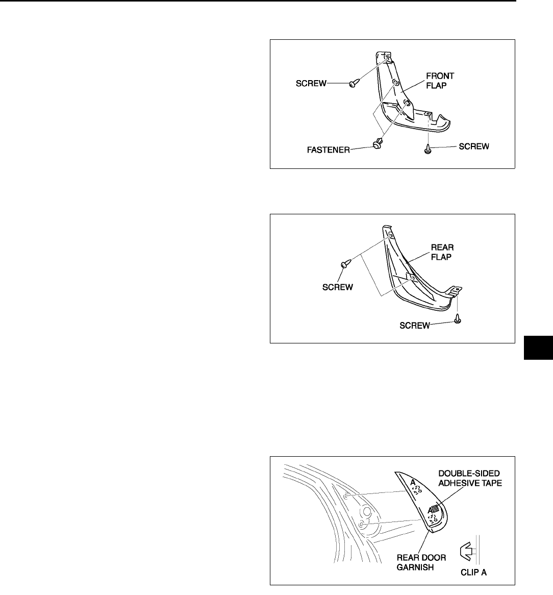
EXTERIOR ATTACHMENT
S51
S
FRONT FLAP REMOVAL/INSTALLATION A6E772851840W01
1. Remove the screws and fastner.
2. Remove the front flap.
3. Install in the reverse order of removal.
End Of Sie
REAR FLAP REMOVAL/INSTALLATION A6E772851940W01
1. Remove the screws.
2. Remove the rear flap.
3. Install in the reverse order of removal.
End Of Sie
REAR DOOR GARNISH REMOVAL A6E772850030W01
1. Disengage the door garnish clips using a fastener remover.
2. While cutting the double-sided adhesive tape using a screwdriver or a razor, separate the rear door garnish
from the body.
Warning
•
••
•Using a razor with bare hands can cause injury. Always wear gloves when using a razor.
3. Remove the rear door garnish.
End Of Sie
A6E7728W011
A6E7728W012
A6E7728W009
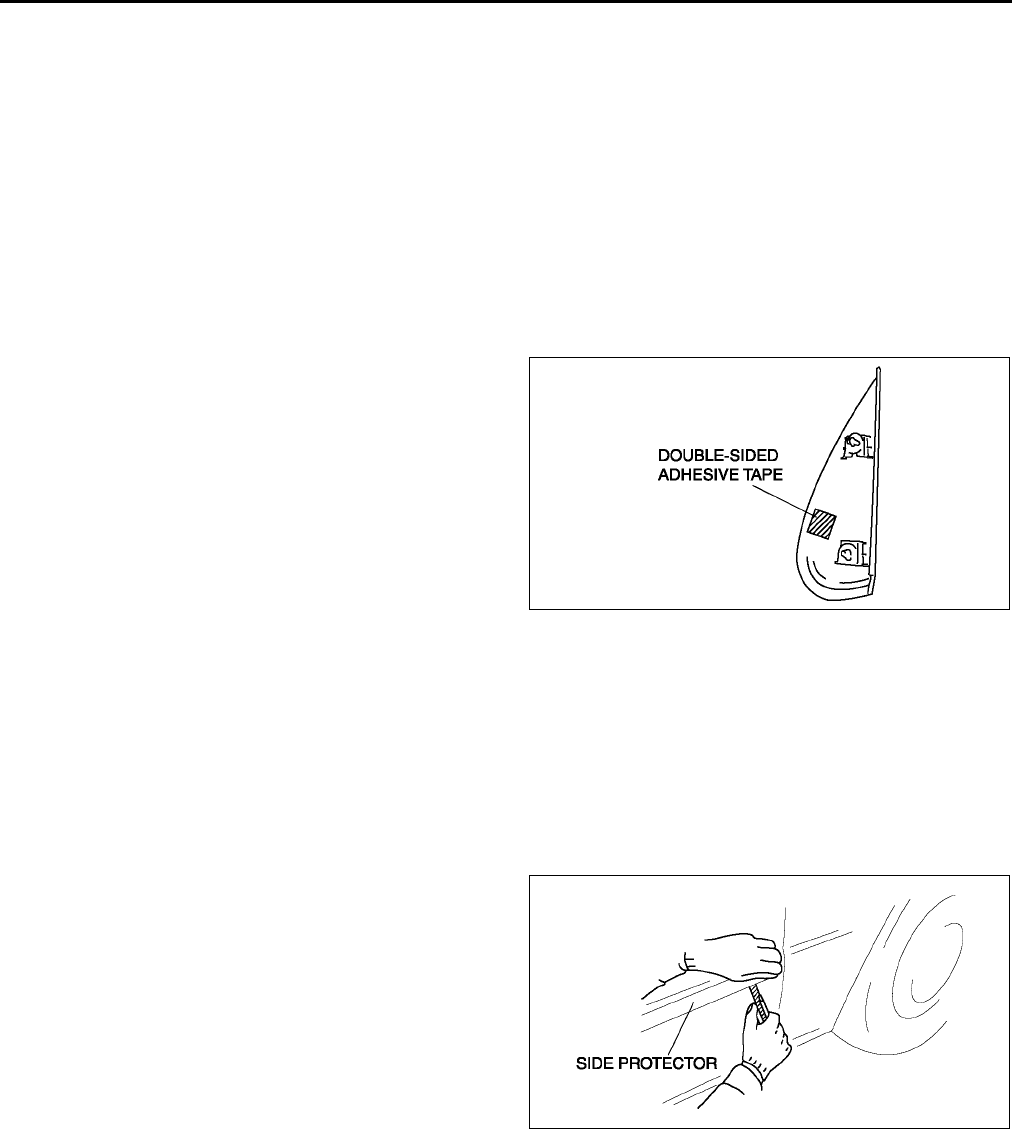
S52
EXTERIOR ATTACHMENT
REAR DOOR GARNISH INSTALLATION A6E772850030W02
Note
•Double-sided adhesive tape has already been attached to the new rear door garnish.
Warning
•
••
•Using a razor with bare hands can cause injury. Always wear gloves when using a razor.
1. When installing a new rear door garnish, follow the procedure below:
(1) Remove the adhesive remaining on the body using razor.
(2) Remove any grease or dirt from the adhesion surface of the body.
2. When reusing the rear door garnish, follow the procedure below:
(1) Remove the adhesive remaining on the rear door garnish and the body using a razor.
(2) Remove any grease or dirt from the adhesion surface of the rear door garnish and the body.
(3) Apply primer to the bonding area of the rear door garnish.
(4) Attach double-sided adhesive tape to the rear
door garnish as shown.
3. Peel off the backing of the double-sided adhesive
tape, then install the rear door garnish to the
body.
End Of Sie
SIDE PROTECTOR REMOVAL A6E772850680W01
1. Pry the side protector end 2030 mm {0.81.1 in} using a flathead screwdriver or a razor.
Warning
•
••
•Using a razor with bare hands can cause injury. Always wear gloves when using a razor.
Note
•The side protector is installed with double-sided adhesive tape. If the side protector is difficult to remove,
soften the double-sided adhesive tape using a hot air blower.
2. Pull the side protector toward you, then remove it.
End Of Sie
A6E7728W010
A6E7728W006
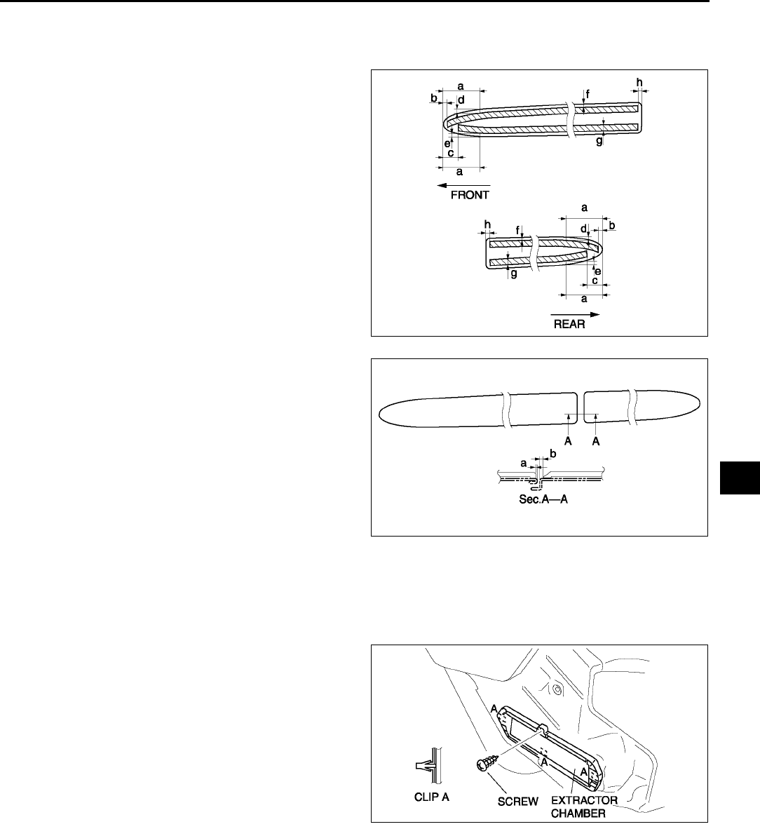
EXTERIOR ATTACHMENT
S53
S
SIDE PROTECTOR INSTALLATION A6E772850680W02
1. Remove the adhesive remaining on the side protector (if it will be reused) and the body using a razor.
2. Remove any grease or dirt from the adhesion surface of the side protector (if it will be reused) and the body.
3. Attach double-sided adhesive tape to the side
protector as shown (if it will be reused).
Clearance
a: 30.0 mm {1.18 in}
b: 3.0 mm {0.11 in}
c: 12.0 mm {0.47 in}
d: 3.0 mm {0.11 in}
e: 3.0 mm {0.11 in}
f: 1.03.0 mm {0.040.11 in}
g: 5.0 mm {0.19 in}
h: 2.0 mm {0.07 in}
4. Peel off the backing paper from the double-sided
adhesive tape and attach the side protector onto
the body as shown.
Clearance
a: 1.24.2 mm {0.050.16 in}
b: 3.26.2 mm {0.130.24 in}
End Of Sie
EXTRACTOR CHAMBER REMOVAL/INSTALLATION A6E772851920W01
1. Remove the rear bumper. (See S49 REAR BUMPER REMOVAL/INSTALLATION.)
2. Remove the left side trunk side trim.
3. Remove the screw.
4. Squeeze the clips with your fingers and remove
the extractor chamber from the vehicle side.
5. Install in the reverse order of removal.
End Of Sie
A6E7728W007
A6E7728W008
A6E7728W001
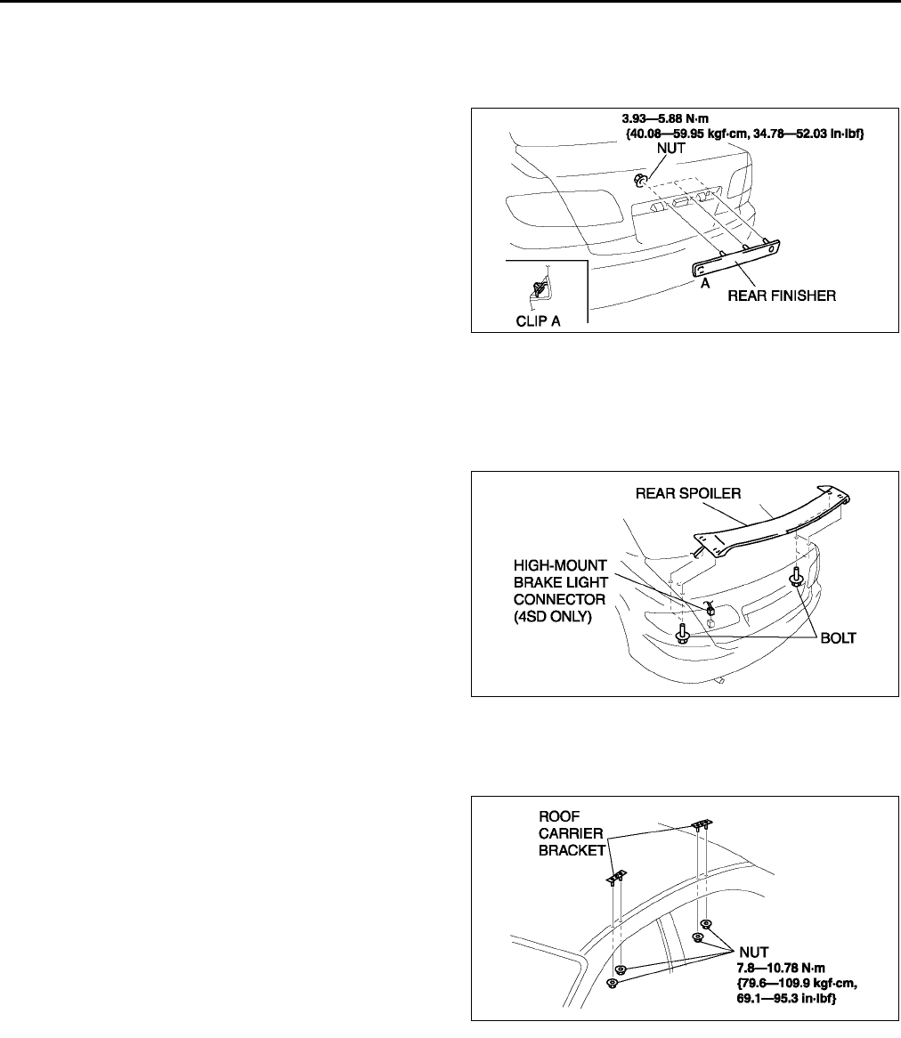
S54
EXTERIOR ATTACHMENT
REAR FINISHER REMOVAL/INSTALLATION A6E772850850W01
1. Remove the trunk lid trim (4SD).
2. Remove the liftgate lower trim (5HB).
3. Remove the nuts.
4. Pull the rear finisher toward you, then disengage
clip A from the body.
5. Install in the reverse order of removal.
End Of Sie
REAR SPOILER REMOVAL/INSTALLATION A6E772851920W02
1. Remove the trunk lid trim. (4SD)
2. Remove the liftgate lower trim. (5HB)
3. Remove the bolts.
4. Disconnect the high-mount brake light connector. (4SD)
5. Remove the rear spoiler.
6. Install in the reverse order of removal.
End Of Sie
ROOF CARRIER BRACKET REMOVAL/INSTALLATION A6E772870600W01
1. Remove the headliner.
2. Remove the nuts.
3. Remove the roof carrier bracket.
4. Install in the reverse order of removal.
End Of Sie
A6E7728W002
A6E7728W003
A6E7728W013
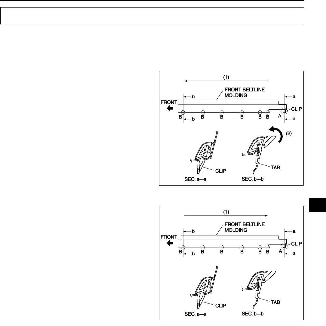
MOLDING
S55
S
FRONT BELTLINE MOLDING REMOVAL A6E773050640W01
Note
•When removing the front beltline molding, the clip may be damaged. If the clip is damaged, replace it with
a new one.
1. Pull the A section upward and remove the clip.
2. Rotate the B section of the front beltline molding
in direction (2), along the direction (1) shown in
the figure and remove it from the body.
End Of Sie
FRONT BELTLINE MOLDING INSTALLATION A6E773050640W02
1. Press the clip into the body.
2. Press in the B section of the front beltline molding
along the direction (1) shown in the figure to
attach it to the body.
Note
•If the front beltline molding is difficult to
attach, apply soapy water.
End Of Sie
MOLDING
A6E7730W001
A6E7730W003
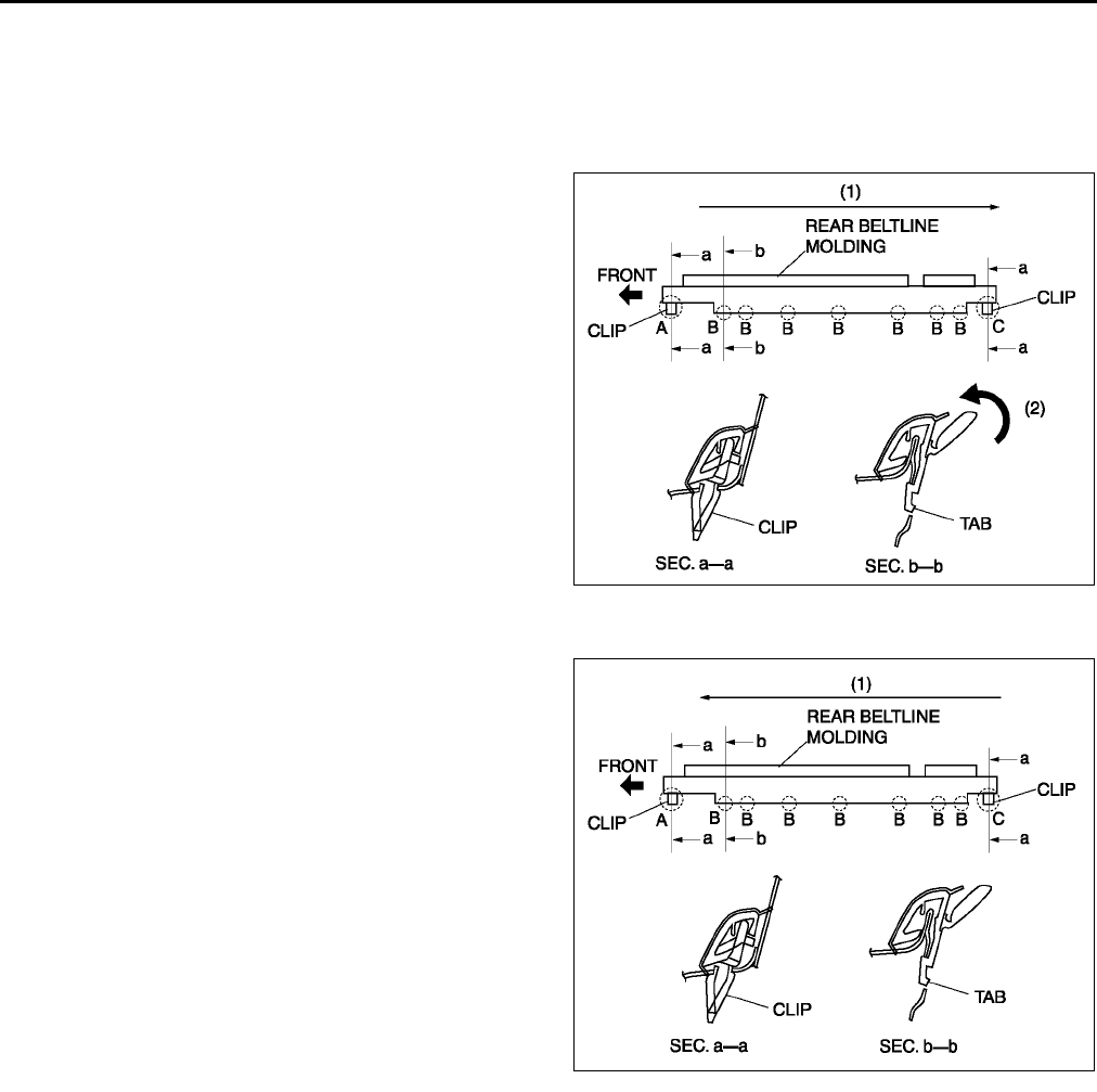
S56
MOLDING
REAR BELTLINE MOLDING REMOVAL A6E773050660W01
Note
•When removing the rear beltline molding, the clip may be damaged. If the clip is damaged, replace it with
a new one.
1. Pull the A section upward and remove the clip.
2. Rotate the B section of the front beltline molding
in direction (2), along the direction (1) shown in
the figure and remove it from the body.
3. Pull the C section upward and remove the clip.
Then remove the front beltline molding.
End Of Sie
REAR BELTLINE MOLDING INSTALLATION A6E773050660W02
1. Press the clip at the C section into the body.
2. Press in the B section of the rear beltline molding
along the direction (1) to attach it to the body.
3. Press the clip at the A section in and attach the
rear beltline molding.
Note
•If the rear beltline molding is difficult to
attach, apply soapy water.
End Of Sie
A6E7730W004
A6E7730W005
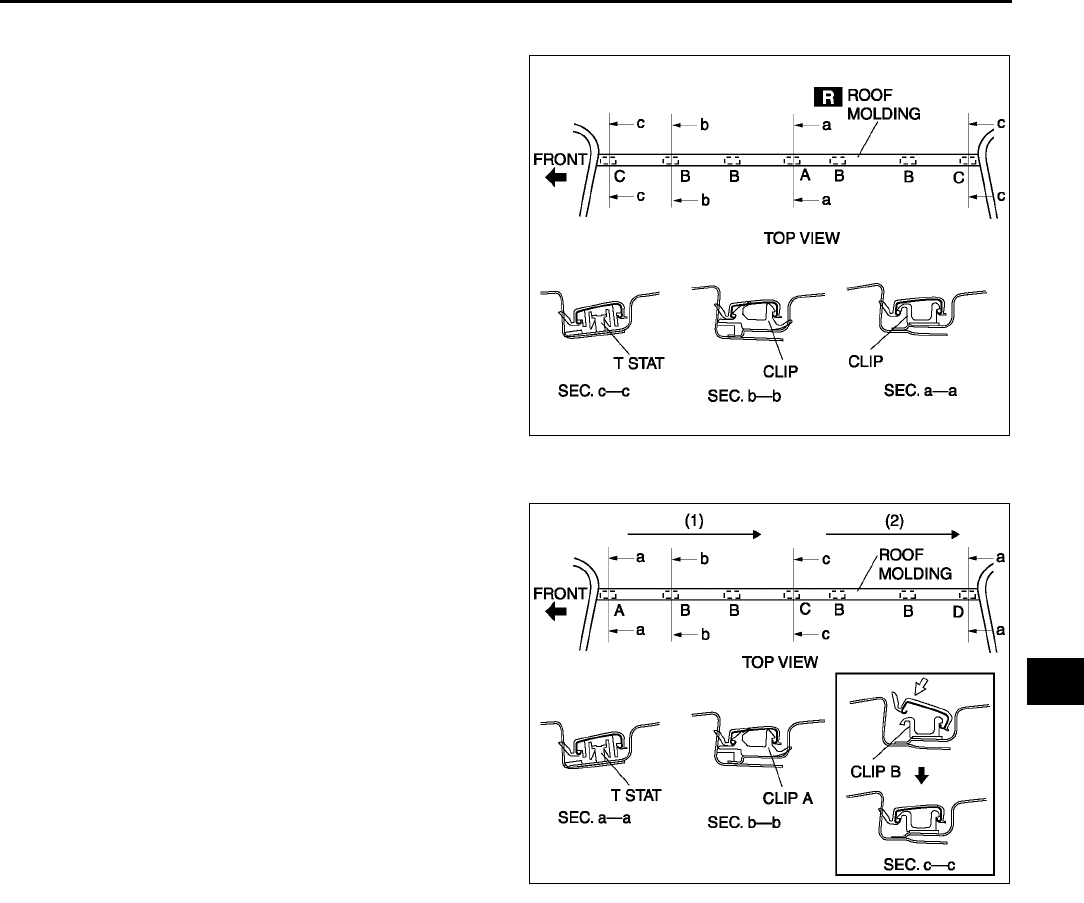
MOLDING
S57
S
ROOF MOLDING REMOVAL A6E773050620W01
1. Detach the clips which secure A and B sections of
roof molding, using a screwdriver or equivalent
tool.
2. While pulling the roof molding up, detach the fit
for the T stat of the A section and the roof molding
and then remove the roof molding.
End Of Sie
ROOF MOLDING INSTALLATION A6E773050620W02
1. Attach the roof molding to the T stud at the A
section.
2. Press in the roof molding along the direction (1)
shown in the figure and attach it to the clip A at
the B section.
3. Hook the roof molding to the clip B at the C
section, press it in, and attach the roof molding to
the clip B.
4. Press the roof molding along the direction (2)
shown in the figure and attach it to the clip A at
the B section.
5. Attach the roof molding to the T stud at the D
section.
End Of Sie
A6E7730W007
A6E7730W006
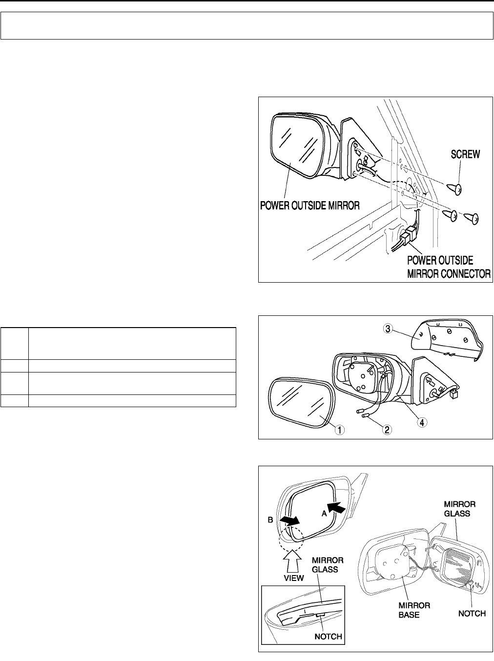
S58
OUTSIDE MIRROR
POWER OUTSIDE MIRROR REMOVAL/INSTALLATION A6E773269110W01
1. Disconnect the negative battery cable.
2. Remove the inner garnish.
3. Remove the front door trim.
4. Disconnect the power outside mirror connector.
5. Remove the screws and the mirror retention clips.
6. Remove the power outside mirror.
7. Install in the reverse order of removal.
End Of Sie
POWER OUTSIDE MIRROR DISASSEMBLY/ASSEMBLY A6E773269110W02
1. Disassemble in the order indicated in the table.
2. Assemble in the reverse order of disassembly.
Outside Mirror Glass Disassembly Note
1. Press area A of the glass so that area B moves
toward you.
2. Insert a screwdriver into the notch and remove
the glass from the mirror base.
OUTSIDE MIRROR
A6E7732W006
1 Outside mirror glass
(See S58 Outside Mirror Glass Disassembly Note)
(See S59 Outside Mirror Glass Assembly Note)
2 Connector (with heated outside mirror)
3Cover
(See S59 Cover Disassembly Note)
4 Outside mirror holder
A6E7732W002
A6E7732W003
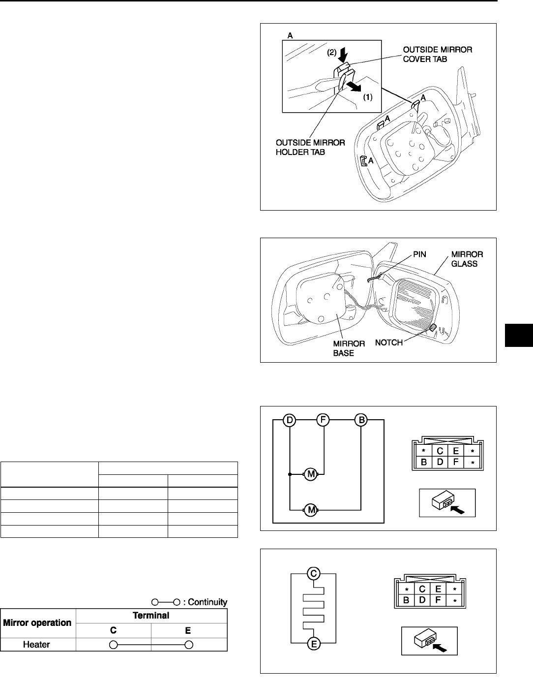
OUTSIDE MIRROR
S59
S
Cover Disassembly Note
1. Pull off the mirror holder tab with a screwdriver
and press the mirror cover tab downward.
Outside Mirror Glass Assembly Note
1. Press the mirror into the base so that the pin does
not dislodge.
End Of Sie
POWER OUTSIDE MIRROR INSPECTION A6E773269110W03
1. Disconnect the power outside mirror connector.
2. Apply battery positive voltage to the power
outside mirror terminals and inspect the operation
of the power outside mirror.
•If not as specified, replace the power outside
mirror.
3. Inspect for continuity between the power outside
mirror heater terminals.
•If not as specified, replace the power outside
mirror.
End Of Sie
A6E7732W004
A6E7732W005
Mirror operation Terminal
B+ GND
Up B D
Down D B
Left F D
Right D F A6E7732W007
A6E7732W009
A6E7732W010
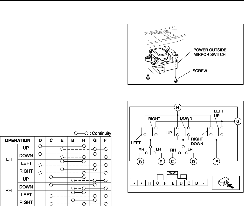
S60
OUTSIDE MIRROR
POWER OUTSIDE MIRROR SWITCH REMOVAL/INSTALLATION A6E773266600W01
1. Disconnect the negative battery cable.
2. Remove the front door trim.
3. Remove the screws and the power outside mirror
switch.
4. Install in the reverse order of removal.
End Of Sie
POWER OUTSIDE MIRROR SWITCH INSPECTION A6E773266600W02
1. Inspect for continuity between the power outside
mirror switch terminals using an ohmmeter.
•If not as specified, replace the power outside
mirror switch.
End Of Sie
A6E7732W008
A6E7732W001
A6E7734W003
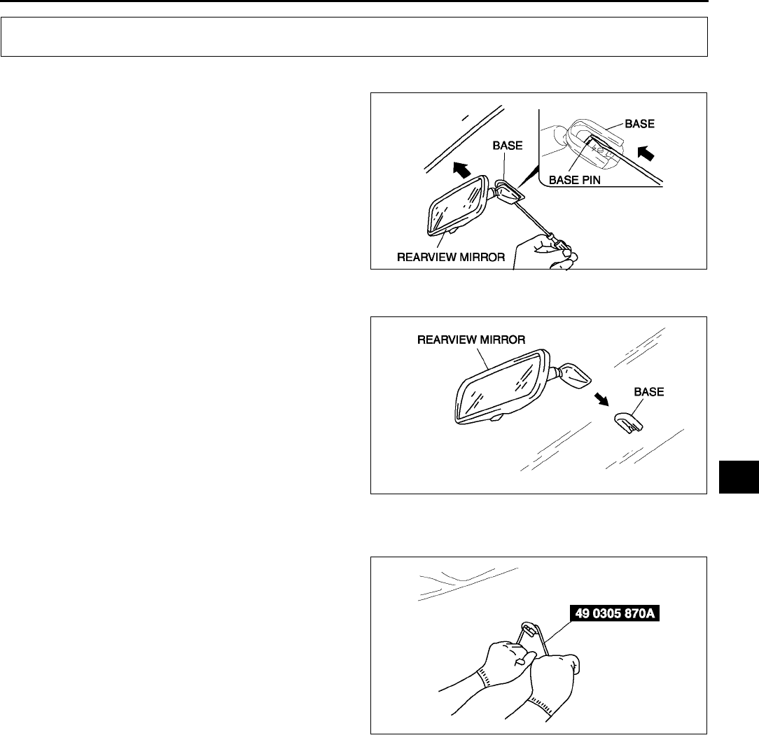
REARVIEW MIRROR
S61
S
REARVIEW MIRROR REMOVAL A6E773469220W01
1. Insert a screwdriver between the mirror and the
base.
2. Push the base pin down to remove the rearview
mirror.
End Of Sie
REARVIEW MIRROR INSTALLATION A6E773469220W02
1. Install the rearview mirror onto the base.
End Of Sie
BASE REMOVAL A6E773469240W01
1. Remove the rearview mirror.
2. Wind each end of a wire around a bar.
Warning
•
••
•Using a SST (piano wire) with bare hands
can cause injury. Always wear gloves
when using a SST (piano wire).
Note
•Use a long sawing action to spread the work
over the whole length of the SST (piano
wire) to prevent it from breaking.
3. Saw through the sealant to remove the base.
End Of Sie
REARVIEW MIRROR
A6E7734W001
A6E7734W002
A6E7734W006
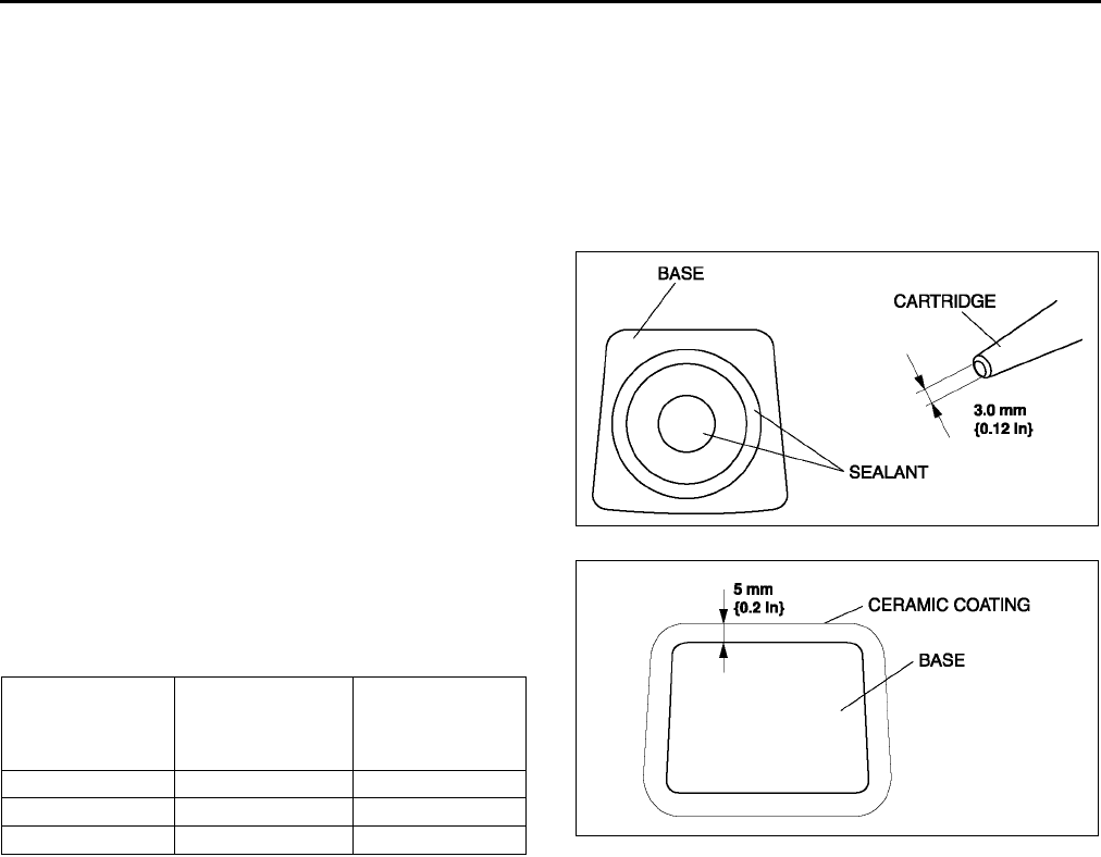
S62
REARVIEW MIRROR
BASE INSTALLATION A6E773469240W02
1. Cut away all of the original sealant using a razor.
2. Clean and degrease the ceramic coating on the glass and the base.
3. Apply primer to the bonding area of the glass and the base.
Caution
•
••
•Keep the area free of dirt and grease, and do not touch the surface or the primer may not properly
bond to the surface of the glass.
4. Apply a height of 3.0 mm {0.12 in} sealant to the
base.
Note
•Use only glass primer on the glass, and
body primer on the base. Allow the primer to
dry for approximately 30 minutes.
5. Center the base in the ceramic coating and press
it onto the glass.
6. Use isopropyl alcohol to remove any excess
repair sealant.
Hardening time of sealant
7. Install the rearview mirror.
End Of Sie
Temperature Surface
hardening time
Time required
until vehicle can
be put into
service
5 °C {41 °F} Approx. 1.5 h Approx. 12 h
20 °C {68 °F} Approx. 1 h Approx. 4 h
35 °C {95 °F} Approx. 10 min. Approx. 2 h
A6E7734W004
A6E7734W005
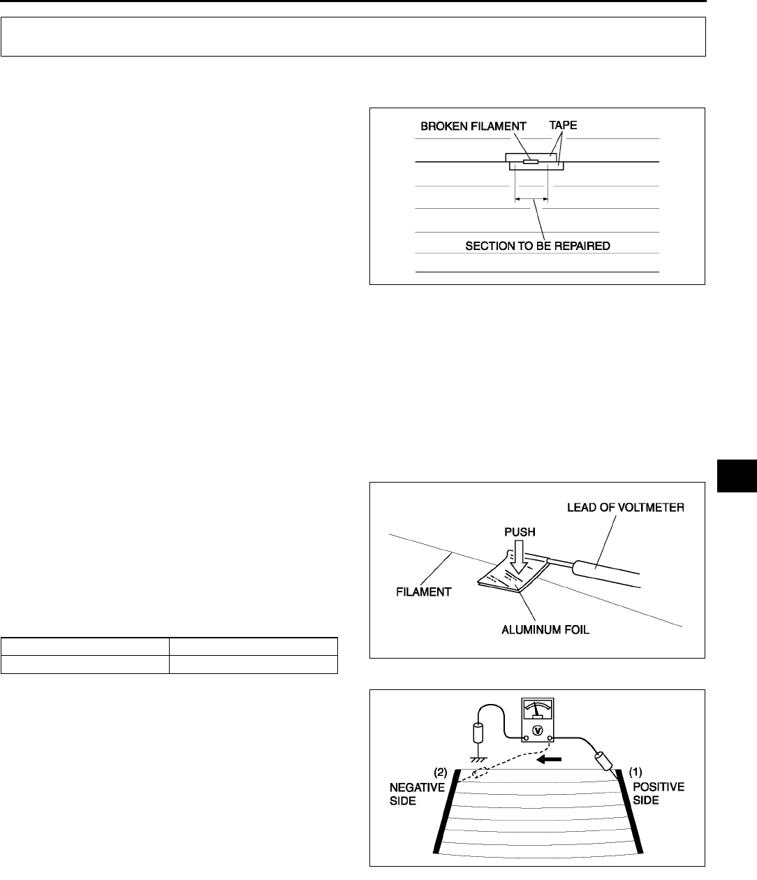
REAR WINDOW DEFROSTER
S63
S
FILAMENT REPAIR A6E773663930W01
1. Use isopropyl alcohol to clean around the damaged section of the filament.
2. Attach tape above and below the damaged
section of the filament.
3. Using a small brush or marking pen, repair the
filament with silver paint or equivalent.
4. After 23 minutes, carefully remove the tape
without disturbing the repaired area.
Caution
•
••
•Do not use the rear window defroster
until the paint is completely dry. It may
cause other malfunctions if it is used
before the paint is dry.
5. Use a hot air blower heated to 150 °
°°
°C {302 °
°°
°F} for
30 minutes or let the paint set for 24 hours at 25 °
°°
°C {77 °
°°
°F} to allow it to dry completely.
End Of Sie
FILAMENT INSPECTION A6E773663930W02
1. Turn the ignition switch to ON position.
2. Turn the rear window defroster switch on.
Caution
•
••
•Directly touching the rear window defroster filament with the lead of the voltmeter will damage it.
Wrap aluminum foil around the end of the lead and test the filament by touching it with the foil.
3. Connect the positive (+) lead of the voltmeter to
the positive side of each filament and the
negative (−) lead to ground.
4. Gradually, slide the positive (+) lead from the
positive side to the negative side and measure
the voltage. Verify that the voltage decreases
accordingly.
•If the voltage is not as specified or it changes
rapidly, the filament is faulty. Repair the
filament.
End Of Sie
REAR WINDOW DEFROSTER
A6E7736W003
Measurement place Voltage (Reference value)
(1)→(2) Approx. 12 V→ Approx. 0 V A6E7736W001
A6E7736W002
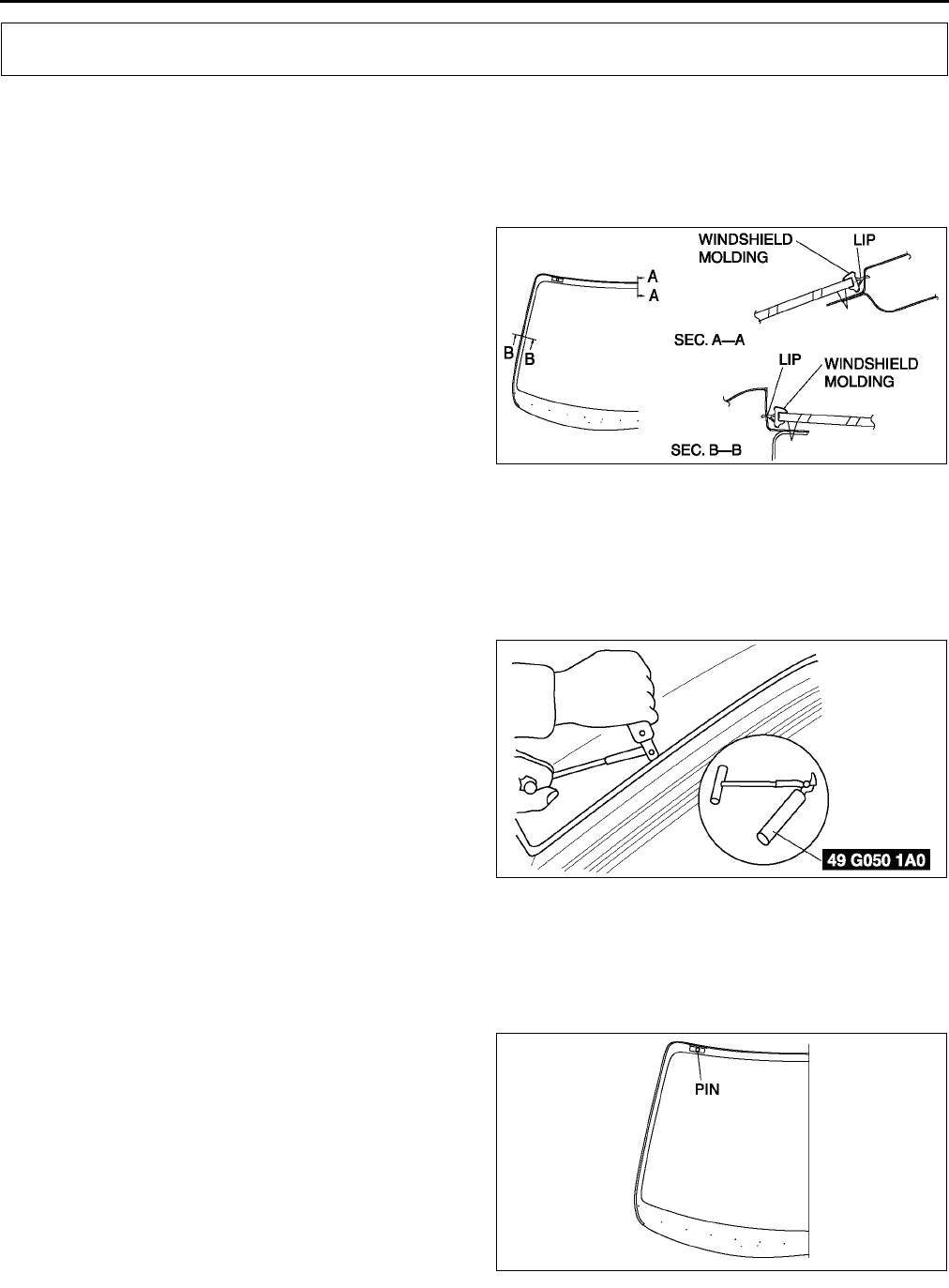
S64
WINDOW GLASS
WINDSHIELD REMOVAL A6E773863900W01
1. Remove the rearview mirror.
2. Remove the cowl grille.
3. Remove the headliner.
4. Apply protective tape along the edge of the body to protect it from damage.
5. Apply protective tape to the dashboard to protect it from damage.
6. Cut the lip of the windshield molding using a
razor.
Warning
•
••
•Using a razor with bare hands can cause
injury. Always wear gloves when using a
razor.
Note
•The windshield molding is a replacement
part.
Not Reusing Windshield
1. Remove the base.
Note
•For the areas of the sealant that are difficult to cut, use a SST (piano wire) and follow the procedure under
Reusing Windshield.
2. Use a SST, and insert the blade into the sealant.
3. Pull through the sealant around the edge of the
glass.
4. Remove the winshield.
Reusing Windshield
Note
•Before removing the windshield from the body, mark the position of the windshield by affixing tape to the
windshield and body panel.
1. Make a hole through the sealant, avoiding pins,
from the inside of the vehicle using an awl.
WINDOW GLASS
A6E7738W006
A6E7738W022
A6E7738W007
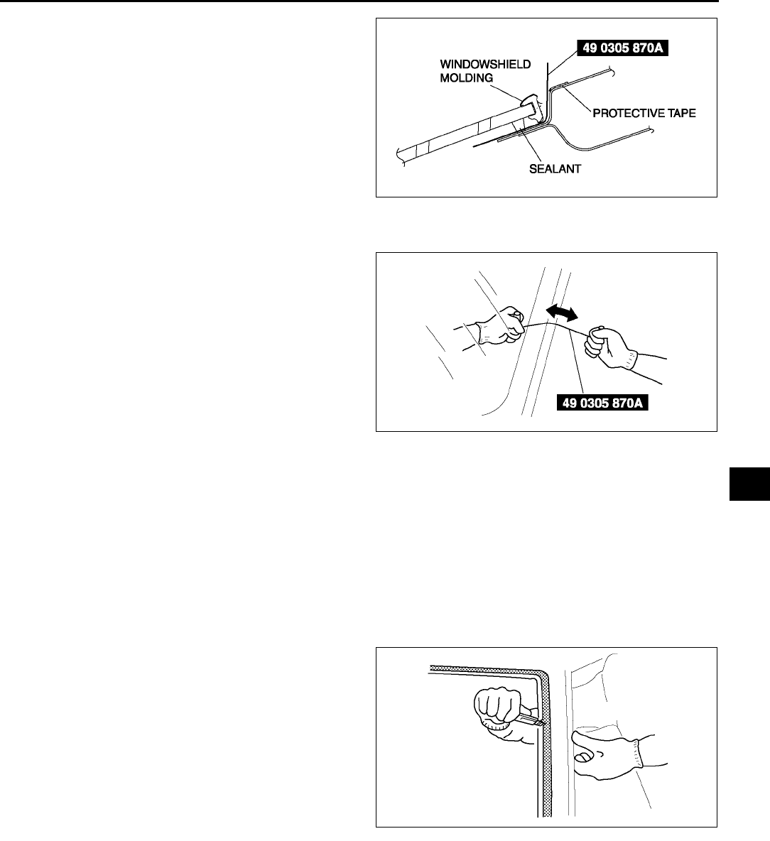
WINDOW GLASS
S65
S
2. Pass the SST (piano wire) through the hole.
Warning
•
••
•Using a SST (piano wire) with bare hands
can cause injury. Always wear gloves
when using a SST (piano wire).
3. Wind each end of the SST (piano wire) around a
bar.
Note
•Use a long sawing action to spread the work
over the whole length of the SST (piano
wire) to prevent it from breaking.
4. Working with another person, saw through the
sealant around the edge of the glass.
5. Remove the windshield.
6. Remove the pins from the windshield.
7. Remove the winshield molding from the
windshield glass.
End Of Sie
WINDSHIELD INSTALLATION A6E773863900W02
Caution
•
••
•To prevent the sealant from cracking or the glass from being pushed out by air pressure if a door
is closed, open all of the windows and leave them open until the sealant has hardened.
1. Cut away the old sealant using a razor so that 12 mm {0.040.07 in} thickness of sealant remains around
the circumference of the frame.
Warning
•
••
•Using a razor with bare hands can cause injury. Always wear gloves when using a razor.
2. If the sealant has come off completely in any one
place, apply some primer after degreasing, and
allow it approximately 30 minutes to dry. Then
put on new sealant to create a 2 mm {0.08 in}
layer.
3. Clean and degrease an approximately 50.0 mm
{1.97 in} wide strip around the circumference of
the glass and the bonding area on the body.
A6E7738W008
A6E7738W021
A6E7738W023
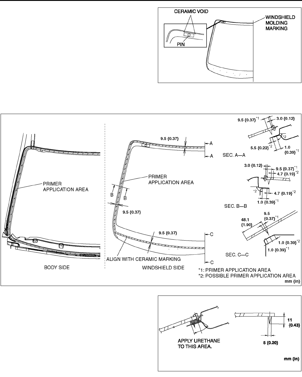
S66
WINDOW GLASS
4. If installing reused glass, install pins at the
ceramic void on the upper part of the windshield.
5. If installing reused glass, align the front
windshield molding marking and the center of the
upper section of the windshield, then install the
molding to the winshield.
6. Use only glass primer on the glass, and body
primer on the body and the molding. Allow it to
dry for approximately 30 minutes.
Caution
•
••
•Keep the area free of dirt and grease, and
do not touch the surface or the primer
may not properly bond to the surface of
the glass and body, which may cause leaks to occur.
7. Apply urethane to the area of the glass surface as
shown in the figure.
8. Set the the windshield in place and insert the pins
into the body. Install the windshield.
A6E7738W005
A6E7738W001
A6E7738W002
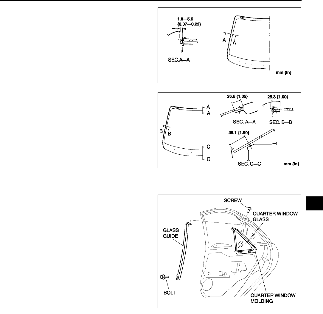
WINDOW GLASS
S67
S
9. Verify that the gap of the A pillar part as shown
the figure.
10. Keeping the measurement of the molding lip gap
within specification, press completely along the
perimeter of the glass.
11. Install the seaming welt.
12. Install the cowl grille.
13. Install the headliner
14. Install the interior light. (See T48 FRONT MAP
LIGHT REMOVAL/INSTALLATION.)
15. Allow the sealant to harden completely.
Sealant hardening time: 24 hours
End Of Sie
QUARTER WINDOW GLASS REMOVAL/INSTALLATION A6E773862580W01
1. Remove the rear door trim.
2. Remove the screw and bolt, then remove the
glass guide.
3. Remove the quarter window and the molding
together in one piece.
4. Remove the molding from the glass.
5. Install in the reverse order of removal.
End Of Sie
A6E7738W003
A6E7738W004
A6E7738W024
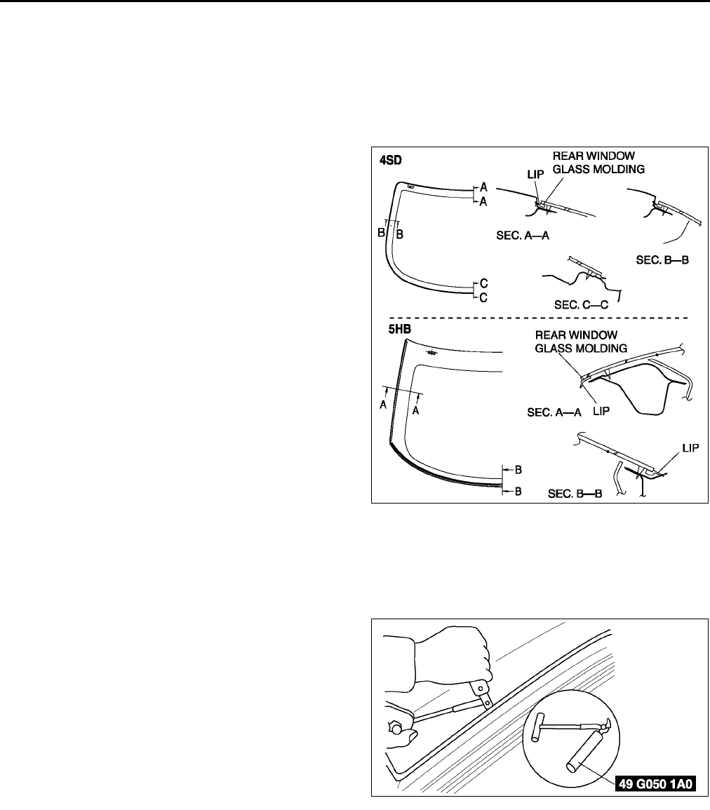
S68
WINDOW GLASS
REAR WINDOW GLASS REMOVAL A6E773863931W01
1. For the 4SD, remove the following parts:
(1) Remove the headliner.
(2) Remove the rear package trim.
2. For the 5HB, remove the following parts.
(1) Remove the rear wiper arm and blade.
(2) Remove the liftgate lower trim.
3. Apply protective tape along the edge of the body to protect it from damage.
4. Cut the lip of the rear window molding using a
razor.
Warning
•
••
•Using a razor with bare hands can cause
injury. Always wear gloves when using a
razor.
Note
•The rear window molding is a replacement
part.
Not Reusing Glass
Note
•For the areas of the sealant that are difficult to cut, use a SST (piano wire) and follow the procedure under
Reusing Glass.
1. Use a SST, and insert the blade into the sealant.
2. Pull through the sealant around the edge of the
glass.
3. Remove the glass.
A6E7738W009
A6E7738W022
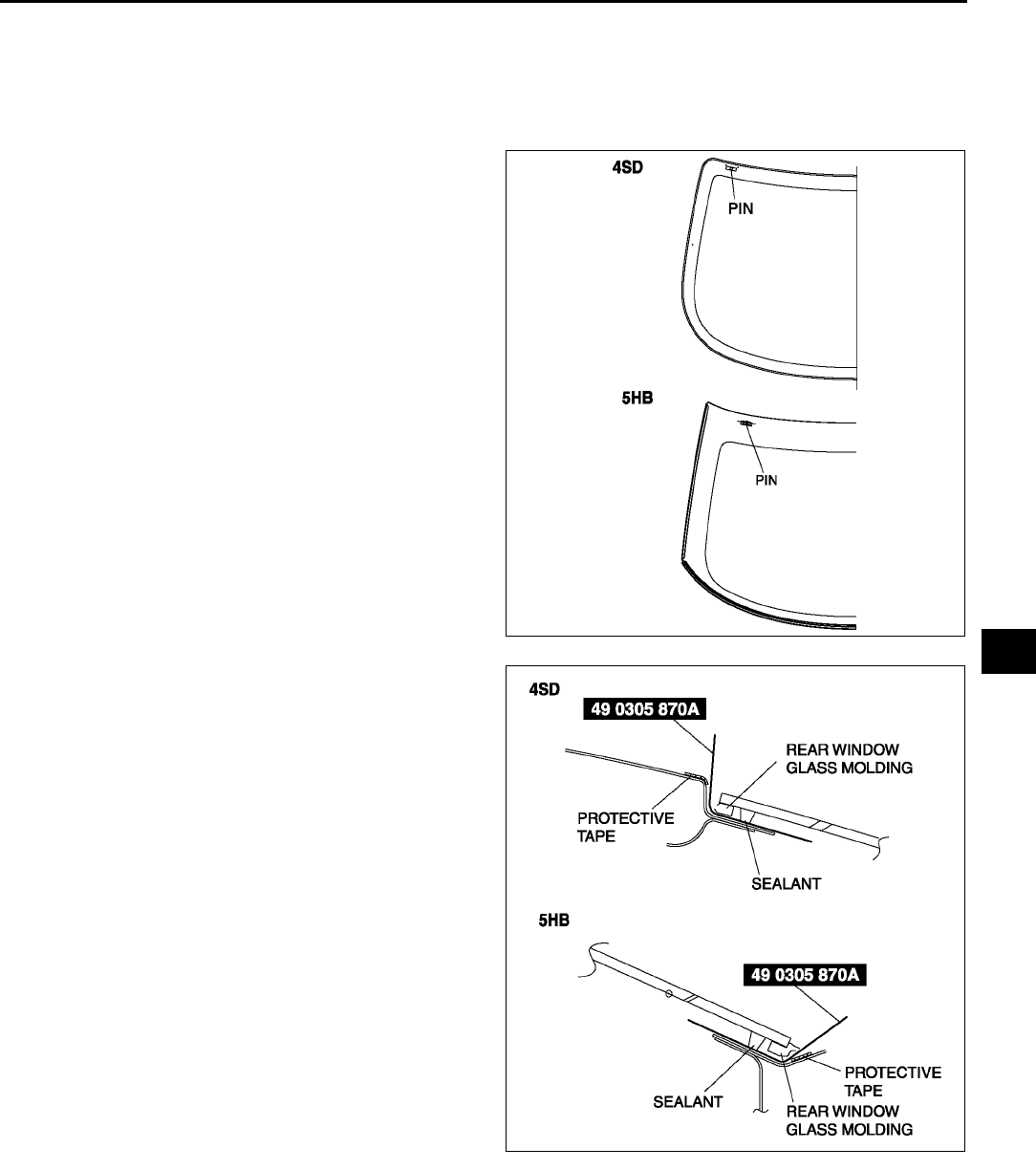
WINDOW GLASS
S69
S
Reusing Glass
Note
•Before removing the rear window glass from the body, mark the position of the glass by affixing tape to
the glass and body panel.
1. Make a hole through the sealant, avoiding pins,
from the inside of the vehicle using an awl.
2. Pass the SST (piano wire) through the hole.
Warning
•
••
•Using a SST (piano wire) with bare hands
can cause injury. Always wear gloves
when using a SST (piano wire).
3. Wind each end of the SST (piano wire) around a
bar.
Note
•Use a long sawing action to spread the work
over the whole length of the SST (piano
wire) to prevent it from breaking.
A6E7738W010
A6E7738W011
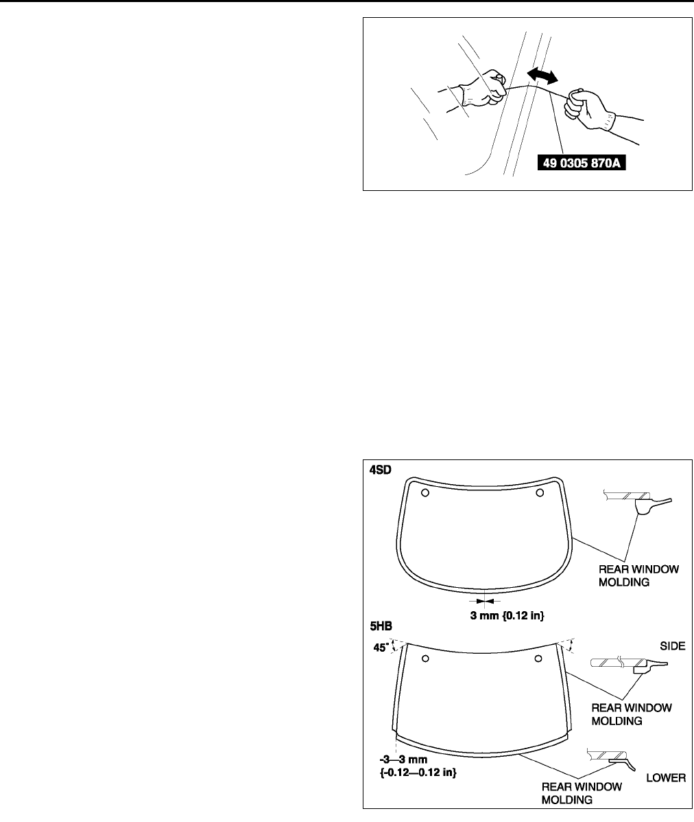
S70
WINDOW GLASS
4. Working with another person, saw through the
sealant around the edge of the glass.
5. Remove the rear window glass.
6. Remove the pins from the glass.
7. Remove the rear window molding from the glass.
End Of Sie
REAR WINDOW GLASS INSTALLATION A6E773863931W02
Caution
•
••
•To prevent the sealant from cracking or the glass from being pushed out by air pressure if a door
is closed, open all of the windows and leave them open until the sealant has hardened.
1. Cut away the old sealant using a razor so that 12 mm {0.040.07 in} thickness of sealant remains around
the circumference of the frame.
Warning
•
••
•Using a razor with bare hands can cause injury. Always wear gloves when using a razor.
2. If the sealant has come off completely in any one place, apply some primer after degreasing, and allow it
approximately 30 minutes to dry. Then put on new sealant to create a 2 mm {0.08 in} layer.
3. Clean and degrease an approximately 50.0 mm {1.97 in} wide strip around the circumference of the glass
and the bonding area on the body.
4. Install the molding as shown in the figure.
A6E7738W021
A6E7738W025
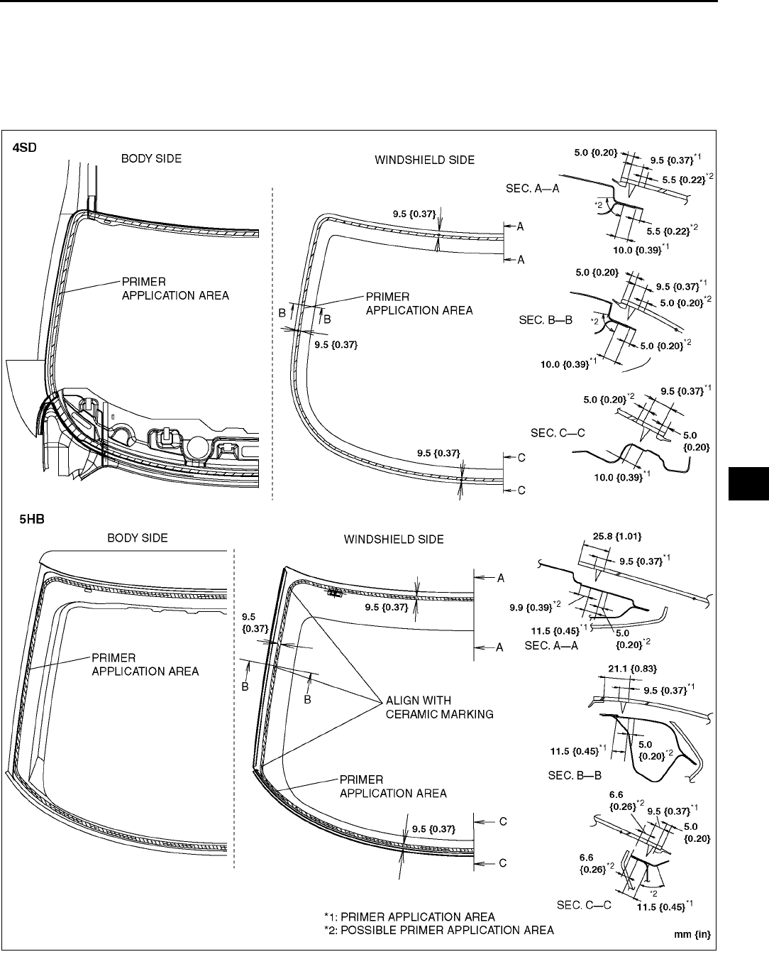
WINDOW GLASS
S71
S
5. Use only glass primer on the glass, and body primer on the body and the molding. Allow it to dry for
approximately 30 minutes.
Caution
•
••
•Keep the area free of dirt and grease, and do not touch the surface or the primer may not properly
bond to the surface of the glass and body, which may cause leaks to occur.
A6E7738W019
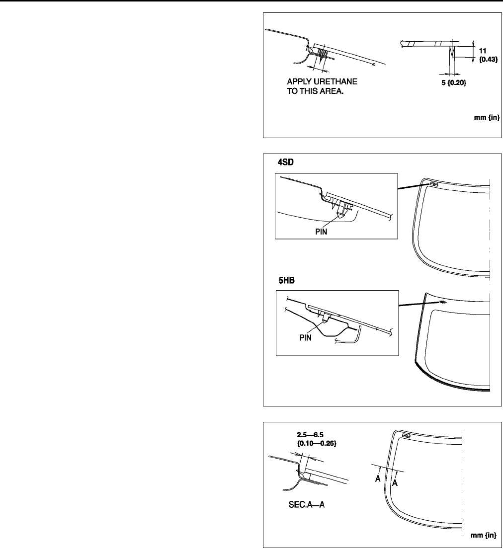
S72
WINDOW GLASS
6. Apply urethane to the area of the glass surface as
shown in the figure.
7. Set the position of the front windshield glass and
insert a pin into the body. Install the glass.
8. Verify that the gap of the upper part is 7.3 mm
{0.29 in} and the A pillar part is 6.8 mm {0.27 in}.
(Only for 4SD)
A6E7738W020
A6E7738W018
A6E7738W016
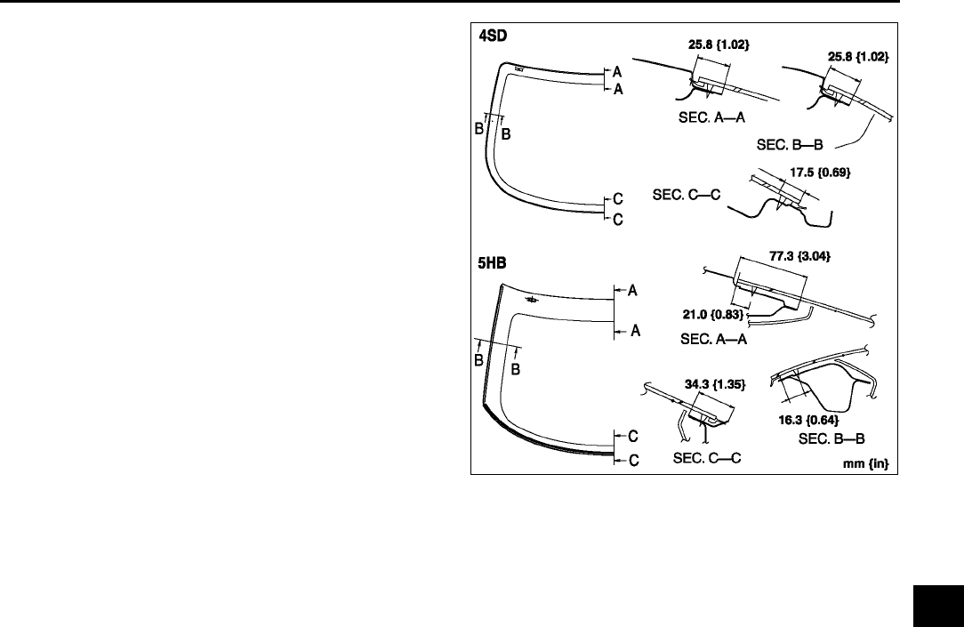
WINDOW GLASS
S73
S
9. Keeping the measurement of the molding lip gap
within specification, press completely along the
perimeter of the glass.
10. For the 4SD, install the following parts:
(1) Install the headliner.
(2) Install the rear package trim.
11. For the 5HB, install the following points.
(1) Install the rear wiper motor.
(2) Install the liftgate lower trim.
12. Allow the sealant to harden completely.
Sealant hardening time: 24 hours
End Of Sie
A6E7738W017
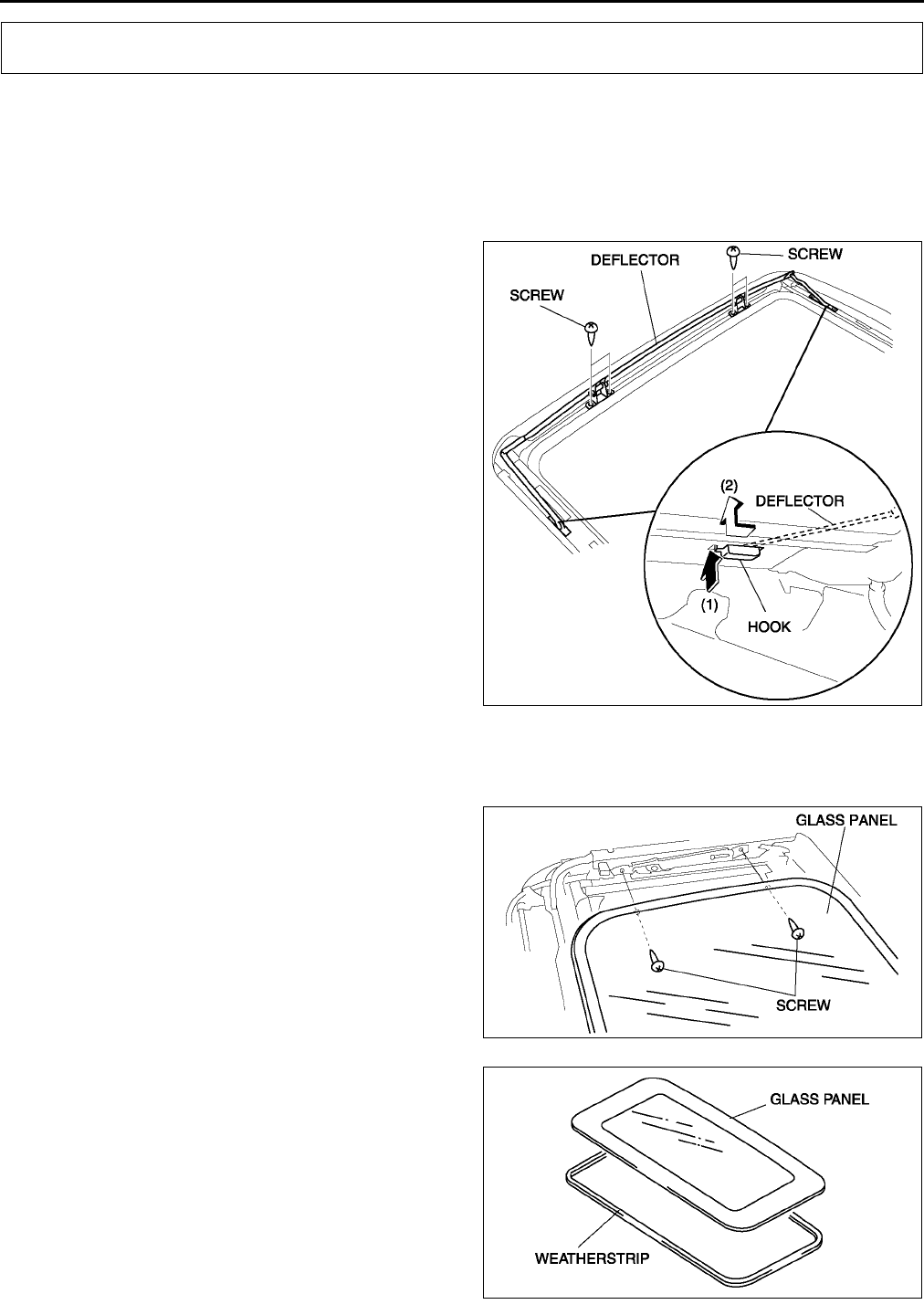
S74
SLIDING SUNROOF
DEFLECTOR REMOVAL/INSTALLATION A6E774069880W01
1. Fully open the glass panel.
2. Remove the headliner.
3. Remove the screws.
4. Disengage the hooks.
(1) Press the rear end of each hook.
(2) After sliding the hooks rearward, press them upward.
5. Remove the deflector.
6. Install in the reverse order of removal.
End Of Sie
GLASS PANEL REMOVAL/INSTALLATION A6E774069810W01
1. Fully close the glass panel.
2. Fully open the sunshade.
3. Remove the screws, and then remove the glass
panel.
4. Peel the weatherstrip off the glass panel.
5. Install in the reverse order of removal.
6. Adjust the glass panel. (See S75 GLASS
PANEL ADJUSTMENT.)
SLIDING SUNROOF
A6E7740W003
A6E7740W004
A6E7740W006
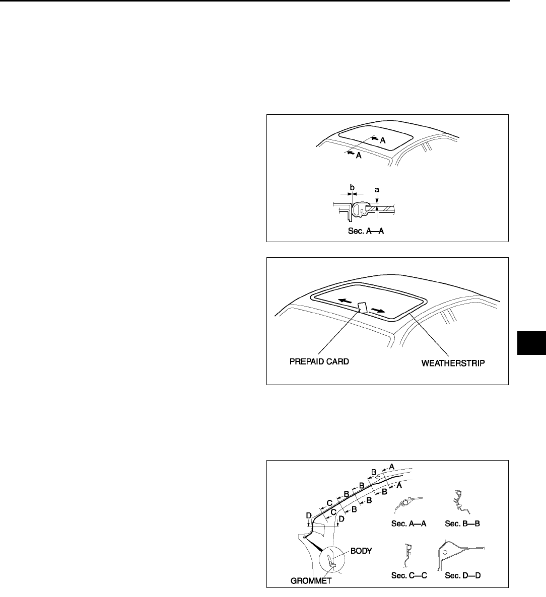
SLIDING SUNROOF
S75
S
End Of Sie
GLASS PANEL ADJUSTMENT A6E774069810W02
1. Fully close the glass panel.
2. Measure the gap and height between the glass panel and body.
3. If not as specified, loosen the glass panel installation screws and reposition the glass panel.
Clearance
a: -0.81.2 mm {-0.0320.047 in}
b: 0 mm {0 in}
4. Tighten the installation screws.
5. Insert a prepaid card between the weatherstrip
and the body of the vehicle. Verify that the
sunroof is shut tightly (there is resistance when
the prepaid card is moved).
•If the sunroof is not shut tightly, readjust by
performing Steps 3 and 4.
End Of Sie
FRONT DRAIN HOSE REMOVAL A6E774069920W01
1. Remove the headliner.
2. Disconnect the front drain hose from the sunroof frame.
3. Remove the front drain hose from the clips.
4. Pull the front drain hose into the room side.
5. Remove the front drain hose.
End Of Sie
FRONT DRAIN HOSE INSTALLATION A6E774069920W02
Caution
•
••
•If the front drain hose is pinched or bent anywhere, the water in the hose may not discharge and
enter the inside of the vehicle. During and after installation of the trims and the headliner, always
make sure there is no interference with the front drain hose. Fix any problem if found.
1. Apply soapy water to the front drain hose inserting area.
2. Insert one end (the wider end) of the front drain hose into the sunroof frame.
3. Install the front drain hose to the clips, parallel to the pillar and free of slack.
4. Insert the front drain hose joint into the hinge pillar inner hole.
5. Install the headliner.
A6E7740W007
A6E7740W008
A6E7740W009
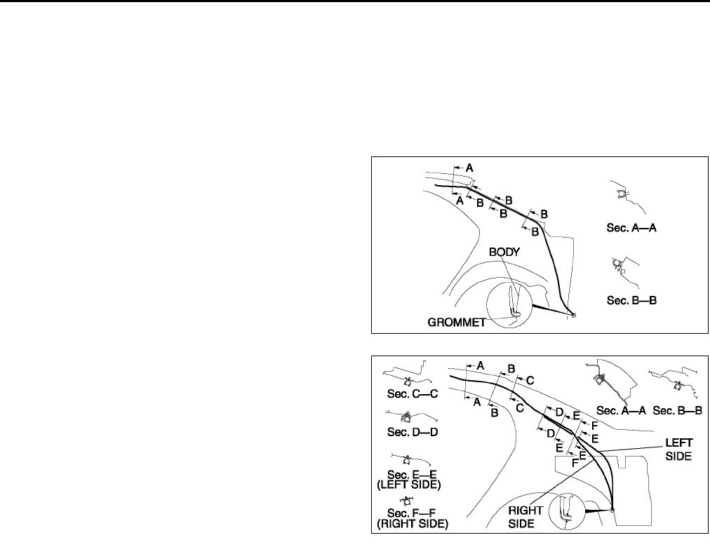
S76
SLIDING SUNROOF
End Of Sie
REAR DRAIN HOSE REMOVAL A6E774069922W01
1. Remove the headliner.
2. Remove the trunk side trim. (4SD)
3. Remove the trunk side upper trim and trunk side trim. (5HB)
4. Disconnect the rear drain hose from the sunroof frame.
5. Remove the rear drain hose from the clips.
6. Pull the rear drain hose into the room side.
7. Remove the rear drain hose.
4SD
5HB
End Of Sie
REAR DRAIN HOSE INSTALLATION A6E774069922W02
Caution
•
••
•If the rear drain hose is pinched or bent anywhere, the water in the hose may not discharge and
enter the inside of the vehicle. During and after installation of the trims and the headliner, always
make sure there is no interference with the rear drain hose. Fix any problem if found.
1. Apply soapy water to the rear drain hose inserting area.
2. Insert one end (the wider side) of the rear drain hose into the sunroof frame.
3. Install the rear drain hose to the clips parallel to the pillar and free of slack.
4. Insert the rear drain hose joint into the rear pillar inner hole.
5. Install the trunk side trim. (4SD)
6. Install the trunk side upper trim and trunk side trim. (5HB)
7. Install the headliner.
End Of Sie
SUNROOF UNIT REMOVAL/INSTALLATION A6E774069850W01
1. Disconnect the negative battery cable.
2. Remove the headliner.
3. Remove the glass panel.
4. Disconnect the front and rear drain hose from the sunroof frame.
5. Remove the bolt A, and then remove the rear set bracket.
A6E7740W010
A6E7740W011
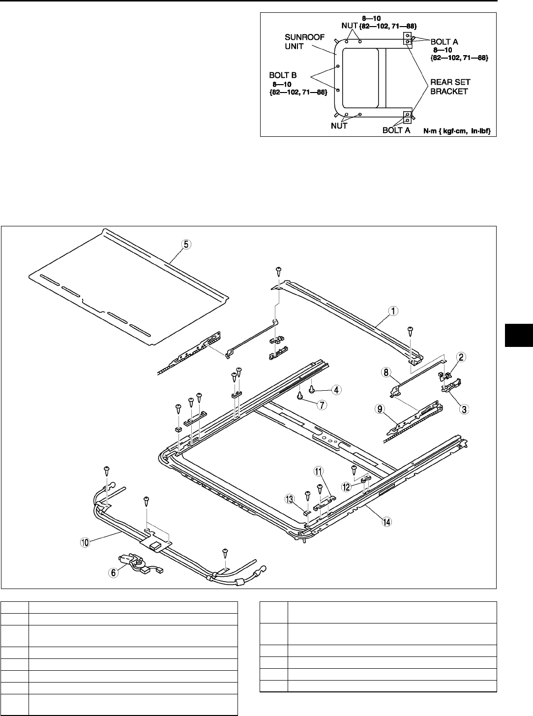
SLIDING SUNROOF
S77
S
6. Remove the bolt B and nuts, and then remove the
sunroof unit.
7. Install in the reverse order of removal.
8. Adjust the glass panel. (See S75 GLASS
PANEL ADJUSTMENT.)
End Of Sie
SUNROOF UNIT DISASSEMBLY/ASSEMBLY A6E774069850W02
1. Disconnect the negative battery cable.
2. Remove the deflector.
3. Remove the glass panel.
4. Disassemble in the order indicated in the table.
5. Assemble in the reverse order of disassembly.
.
A6E7740W005
A6E7740W001
1 Drip rail
2 Position plate
3 Slider
(See S78 Slider Disassembly Note)
4 Rear stopper A
5 Sunshade
6 Sunroof motor
7 Rear stopper B
8 Decoration link
(See S78 Decoration Link Assembly Note)
9 Guide
(See S78 Guide Disassembly Note)
10 Drive unit
(See S78 Guide Assembly Note)
11 Set plate A
12 Set plate B
13 Front stopper
14 Frame
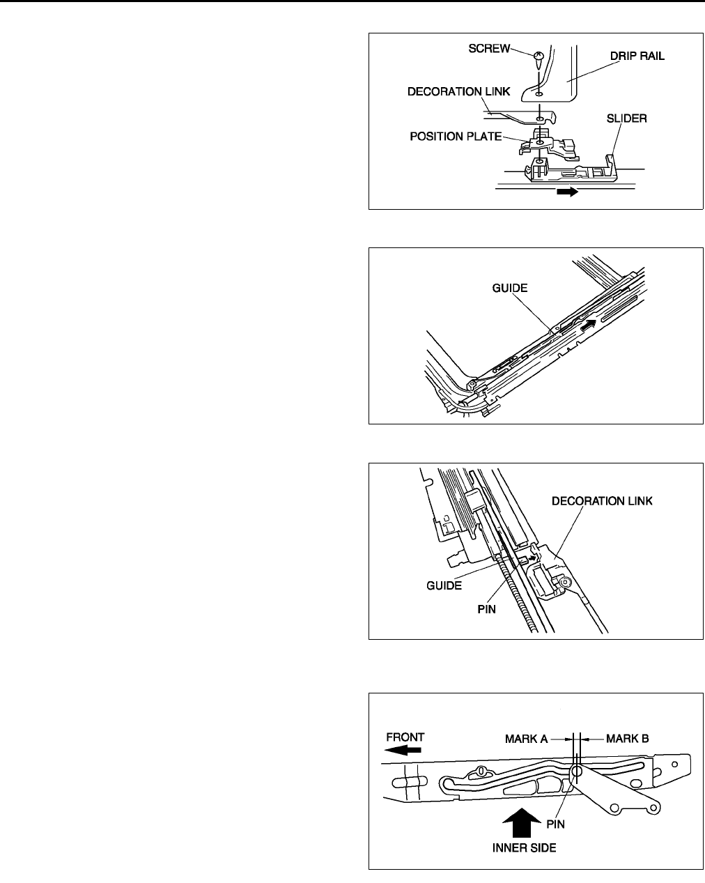
S78
SLIDING SUNROOF
Slider Disassembly Note
1. Remove the screw.
2. Slide the slider rearward, and remove it from the
sunroof frame.
Guide Disassembly Note
1. Slide the guide rearward, and remove it from the
sunroof frame.
Decoration Link Assembly Note
1. Set the pin in the decoration link.
Guide Assembly Note
1. Move the guide by hand until it comes to the front stopper.
2. Move the guide by hand until center of pin comes
between mark A and B.
End Of Sie
A6E7740W012
A6E7740W013
A6E7740W014
A6E7740W015
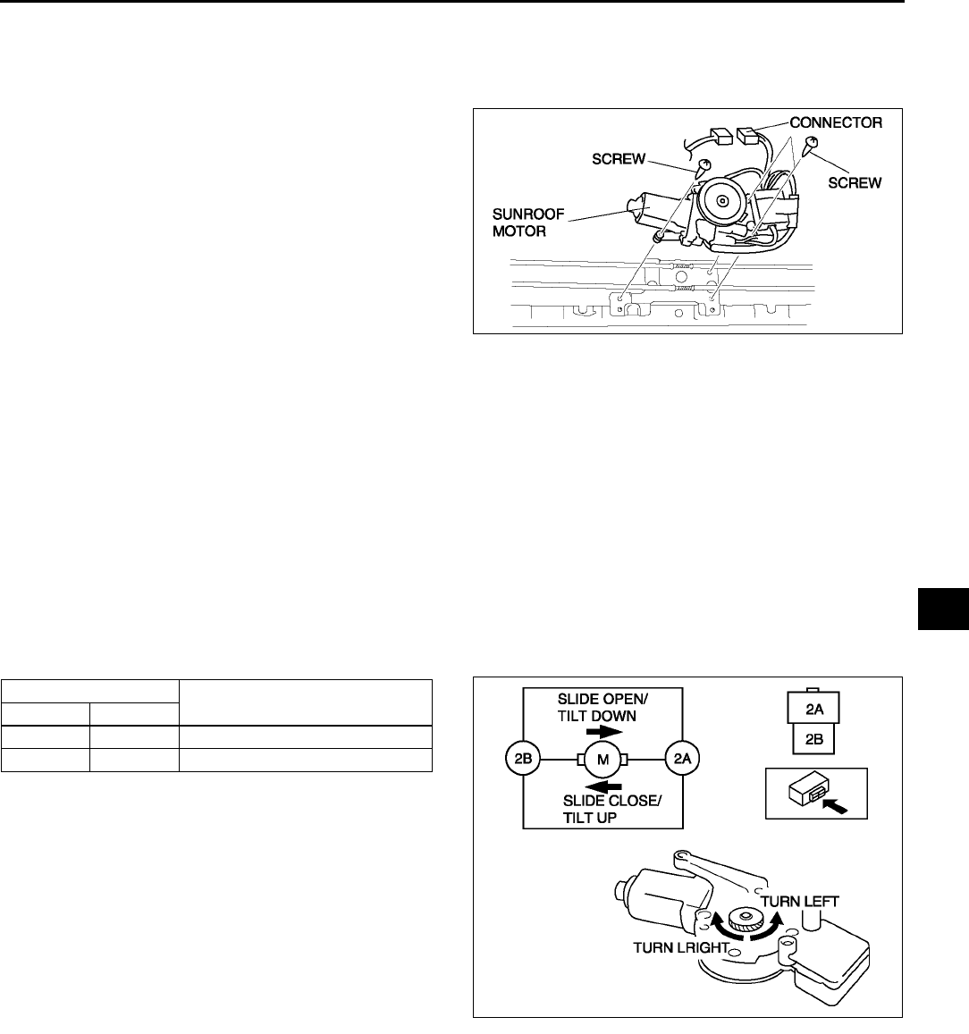
SLIDING SUNROOF
S79
S
SUNROOF MOTOR REMOVAL A6E774069870W01
1. Disconnect the negative battery cable.
2. Remove the headliner.
3. Disconnect the connector.
4. Remove the screws, and then remove the sunroof
motor.
End Of Sie
SUNROOF MOTOR INSTALLATION A6E774069870W02
1. Connect the sunroof motor connector.
2. Connect the sunroof switch connector.
3. Connect the negative battery cable.
4. Turn the ignition switch to ON position.
5. Press the CLOSE side of the slide switch until the sunroof motor stops.
6. Disconnect the sunroof switch connector.
7. Install the screws, and then install the sunroof motor.
8. Install the headliner.
End Of Sie
SUNROOF MOTOR INSPECTION A6E774069870W03
Motor
1. Remove the sunroof motor.
2. Apply battery positive voltage to the sunroof motor terminals and inspect the operation of the sunroof motor.
•If not as specified, replace the sunroof motor.
A6E7740W002
Connection Motor operation
2A 2B
B+ GND Turn left (Slide close/Tilt up)
GND B+ Turn right (Slide open/Tilt down)
A6E7740W016
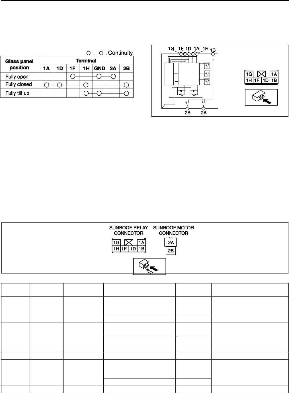
S80
SLIDING SUNROOF
Limit Switch
1. Remove the headliner. (See S96 HEADLINER REMOVAL/INSTALLATION.)
2. Verify the glass panel position.
3. Disconnect the connector.
4. Inspect for continuity between the sunroof motor terminals using an ohmmeter.
•If not as specified, replace the sunroof motor.
End Of Sie
SUNROOF RELAY INSPECTION A6E774069873W01
Note
•Sunroof relay is built in the sunroof motor.
1. Remove the headliner. (See S96 HEADLINER REMOVAL/INSTALLATION.)
2. Connect the sunroof switch connector.
3. Measure the voltage at the sunroof relay terminals as indicated below.
4. Disconnect the sunroof relay connector before inspecting for continuity at terminal 1G.
•If not as specified, inspect the parts listed under Action and the related wiring harnesses.
•If the parts and wiring harnesses are okay but the system still does not work properly, replace the sunroof
relay.
5. Connect the negative battery cable.
Terminal voltage list (Reference)
A6E7740W020
A6E7740W021
Terminal Signal Connected to Test condition Voltage (V)/
Continuity Action
1A Tilt down Sunroof switch
Sunroof is tilting down. (Not
including position when fully
closed)
0•Inspect sunroof switch
(See S81 SUNROOF
SWITCH INSPECTION)
•Inspect related harness
Other B+
1B IG2 Sunroof motor
Ignition switch is at ON
position. B+ •Inspect A/C 15 A fuse
•Inspect sunroof switch
(See S81 SUNROOF
SWITCH INSPECTION)
•Inspect related harness
Other 0
1C
1D Slide close Sunroof switch
Sunroof is closing. (Including
position when fully closed and
open)
0•Inspect sunroof switch
(See S81 SUNROOF
SWITCH INSPECTION)
•Inspect related harness
Other B+
1E
A6E7740W019
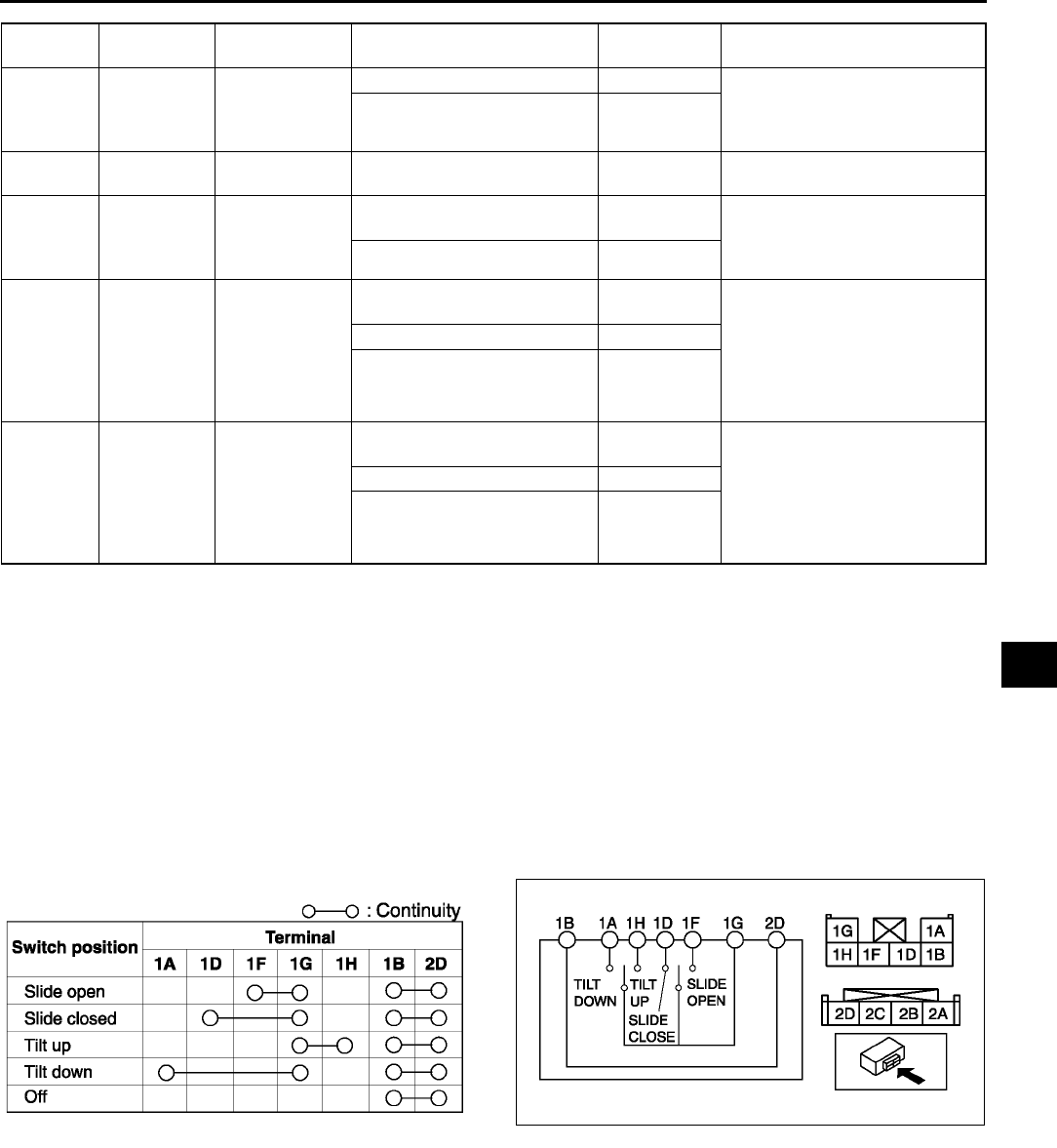
SLIDING SUNROOF
S81
S
End Of Sie
SUNROOF SWITCH REMOVAL/INSTALLATION A6E774066560W01
Note
•The sunroof switch is together with the map light.
1. Disconnect the negative battery cable.
2. Remove the map light from the headliner.
3. Install in the reverse order of removal.
End Of Sie
SUNROOF SWITCH INSPECTION A6E774066560W02
1. Remove the sunroof switch.
2. Inspect for continuity between the sunroof switch terminals using an ohmmeter.
•If not as specified, replace the sunroof switch.
End Of Sie
1F Slide open Sunroof switch
Sunroof is fully opening. 0 •Inspect sunroof switch
(See S81 SUNROOF
SWITCH INSPECTION)
•Inspect related harness
Other B+
1G Sunroof relay
ground GND Under any condition: inspect
for continuity to ground. Yes •Inspect related harness
1H Tilt up Sunroof switch
Sunroof is tilting up. (Including
position when fully closed) 0•Inspect sunroof switch
(See S81 SUNROOF
SWITCH INSPECTION)
•Inspect related harness
Other B+
2A Slide close/
tilt up Sunroof motor
Sunroof is opening/tilting
down. 0•Inspect sunroof switch
(See S81 SUNROOF
SWITCH INSPECTION)
•Inspect sunroof motor
(See S79 SUNROOF
MOTOR INSPECTION)
•Inspect related harness
Sunroof is closing/tilting up. B+
Other 0
2B Slide open/tilt
down Sunroof motor
Sunroof is opening/tilting
down. B+ •Inspect sunroof switch
(See S81 SUNROOF
SWITCH INSPECTION)
•Inspect sunroof motor
(See S79 SUNROOF
MOTOR INSPECTION)
•Inspect related harness
Sunroof is closing/tilting up. 0
Other 0
Terminal Signal Connected to Test condition Voltage (V)/
Continuity Action
A6E7740W022 A6E7740W023
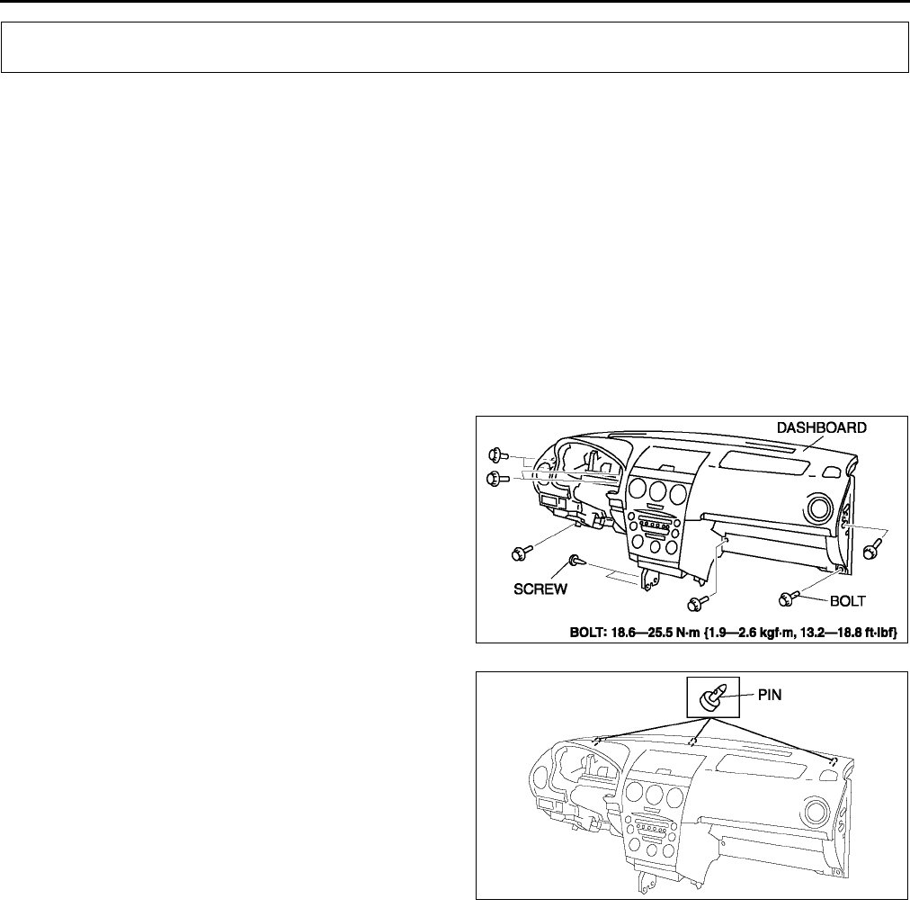
S82
DASHBOARD AND CONSOLE
DASHBOARD REMOVAL/INSTALLATION A6E774255100W01
1. Disconnect the negative battery cable.
2. Remove the glove compartment.
3. Remove the console.
4. Remove the meter hood.
5. Remove the instrument cluster.
6. Remove the column cover.
7. Remove the lower panel.
8. Remove the steering shaft.
9. Remove the A-pillar trims.
10. Remove the front scuff plates.
11. Remove the front side trims.
12. Remove the side panels.
13. For vehicles equipped with the wire-type climate control unit, disconnect the wires for the front A/C unit. (See to
U44 CLIMATE CONTROL UNIT REMOVAL.) (See to U45 CLIMATE CONTROL UNIT INSTALLATION.)
14. Disconnect the dashboard harness connectors.
15. Remove the bolts.
Warning
•
••
•Removing the dashboard without
supporting it can be dangerous. The
dashboard may fall and injure you.
Always perform these procedures
together with at least another person.
16. Pull out the support pins from the body to remove
the dashboard.
17. Take the dashboard off from the driver-side door
opening.
18. Install in the reverse order of removal.
End Of Sie
DASHBOARD AND CONSOLE
A6E7742W004
A6E7742W005
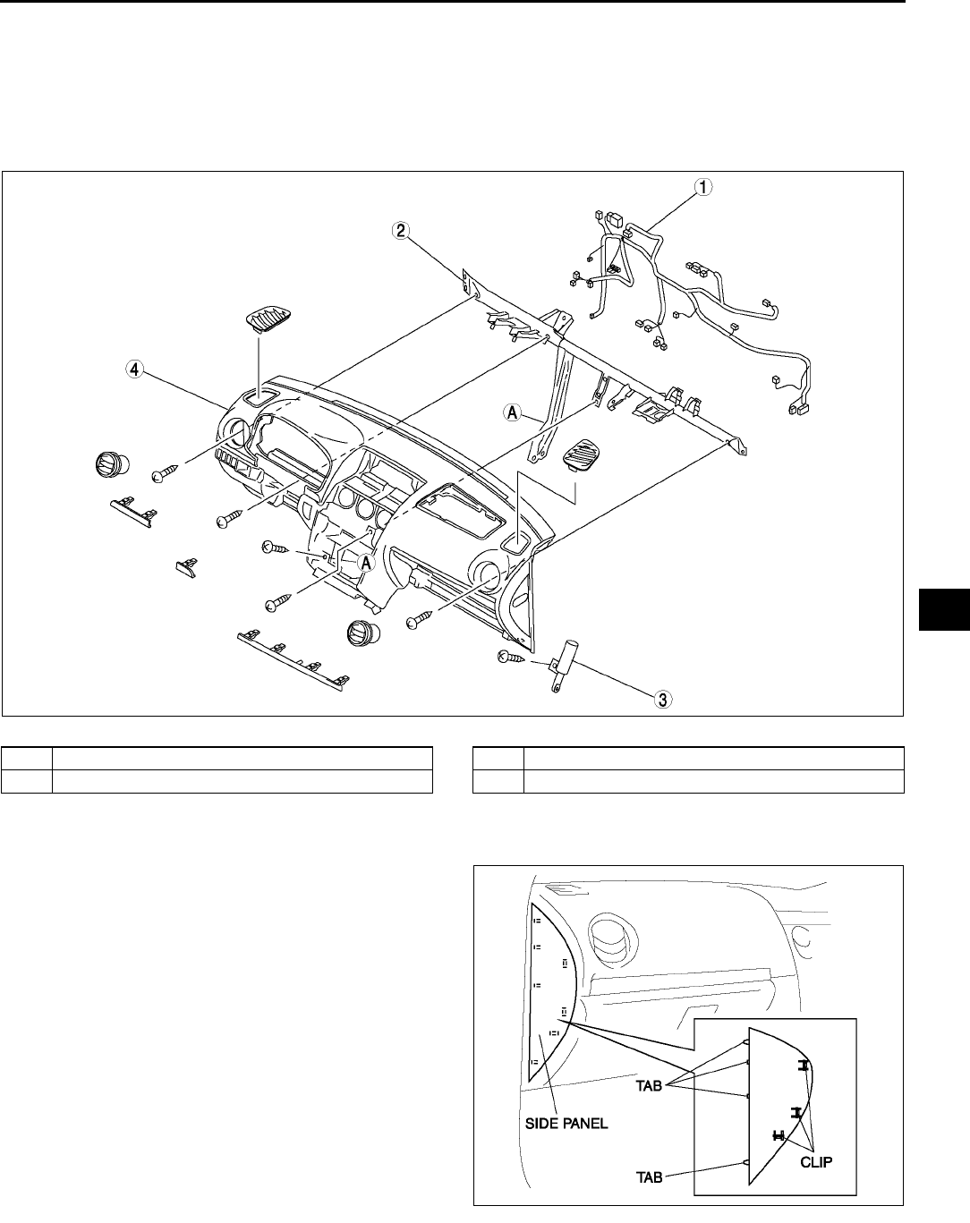
DASHBOARD AND CONSOLE
S83
S
DASHBOARD DISASSEMBLY/ASSEMBLY A6E774255100W02
1. Remove the passenger-side air bag module.
2. Remove the ventilator grilles.
3. Remove the audio unit.
4. Remove the climate control unit.
5. Disassemble in the order indicated in the table.
6. Assemble in the reverse order of disassembly.
.
End Of Sie
SIDE PANEL REMOVAL/INSTALLATION A6E774264960W01
1. Disengage clips using a tape-wrapped flathead
screwdriver.
2. Pull the side panel toward you, then disengage
tabs from dashboard, and remove the side panel.
3. Install in the reverse order of removal.
End Of Sie
A6E7742W003
1 Dashboard harness
2 Dashboard member
3 Damper
4 Dashboard
A6E7742W010
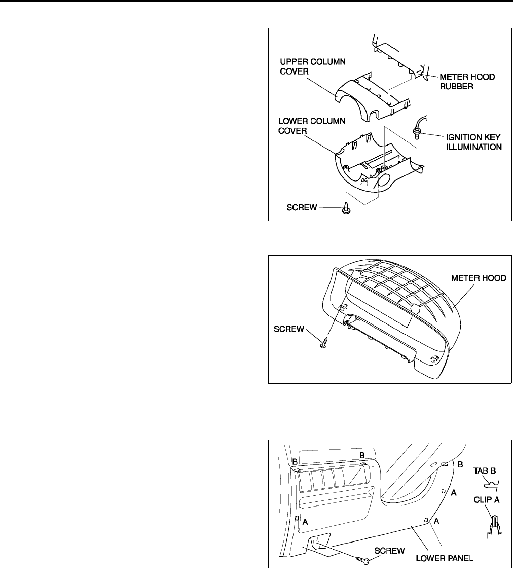
S84
DASHBOARD AND CONSOLE
COLUMN COVER REMOVAL/INSTALLATION A6E774260200W01
1. Detach the fit of the upper column cover from the
meter hood rubber.
2. Remove the upper column cover.
3. Remove the ignition key illumination.
4. Remove the screws.
5. Remove the lower column cover.
6. Install in the reverse order of removal.
End Of Sie
METER HOOD REMOVAL/INSTALLATION A6E774255420W01
1. Remove the screws.
2. Pull the meter hood toward you, then detach the
column cover.
3. Install in the reverse order of removal.
End Of Sie
LOWER PANEL REMOVAL/INSTALLATION A6E774264280W01
1. Remove the bonnet release lever.
2. Remove the screws.
3. Pull the lower panel toward you, then disengage
clips A and tabs B from the dashboard, and
remove the lower panel.
4. Install in the reverse order of removal.
End Of Sie
A6E7742W008
A6E7742W002
A6E7742W009
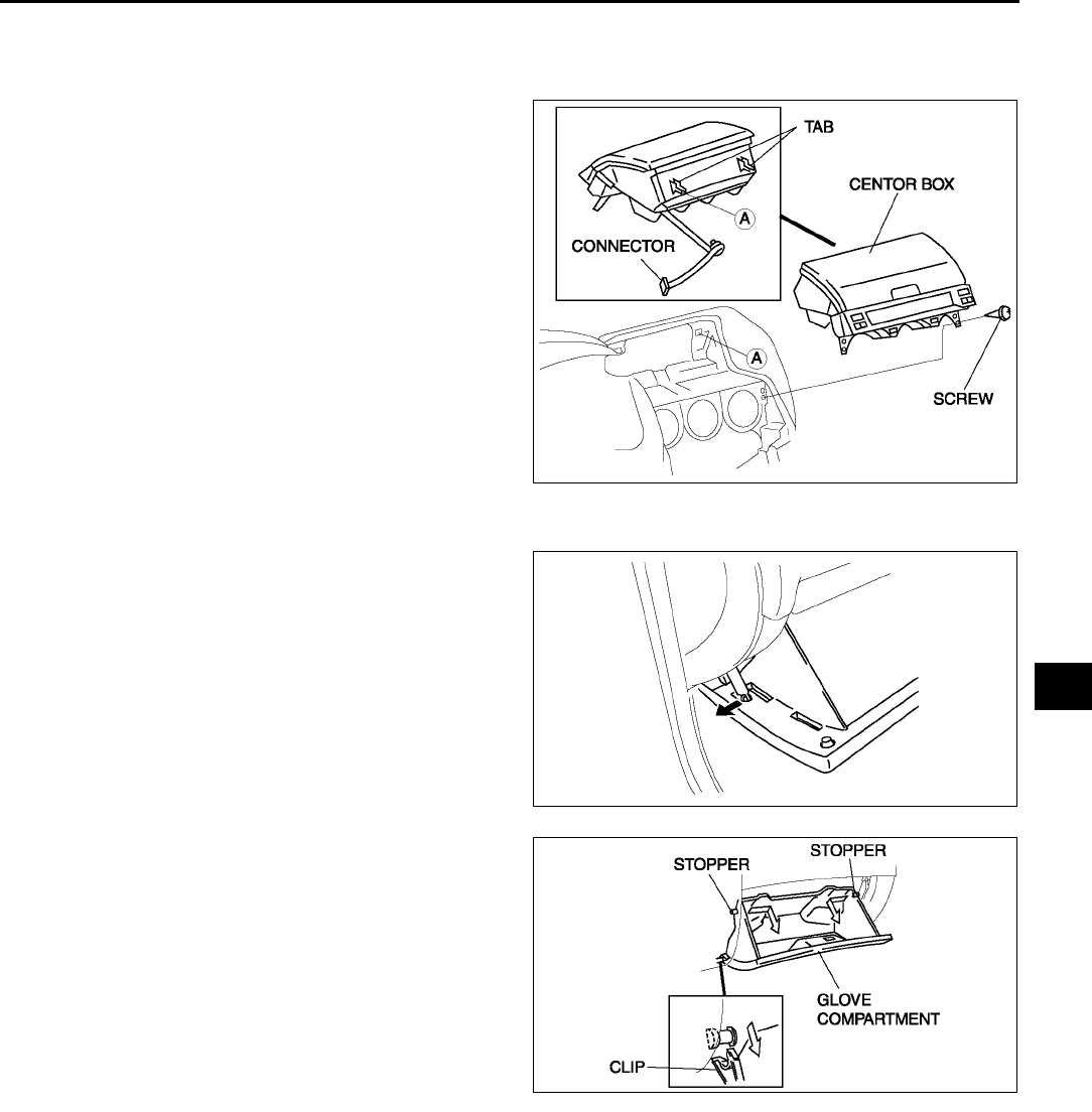
DASHBOARD AND CONSOLE
S85
S
CENTER BOX REMOVAL/INSTALLATION A6E774264030W01
1. Disconnect the negative battery cable.
2. Remove the center panel module.
3. Remove the screws.
4. Pull the center box forward, then disengage the
tabs
5. Disconnect the LDC unit connector.
6. Install in the reverse order of removal.
End Of Sie
GLOVE COMPARTMENT REMOVAL/INSTALLATION A6E774264030W02
1. Pull the stay damper to the direction shown in the
figure. Then detach the fit for the glove
compartment from the stay damper.
2. Bend the stoppers inward to remove.
3. Turn the glove compartment downward and pull
the clips to remove it.
4. Install in the reverse order of removal.
End Of Sie
A6E7742W012
A6E7742W006
A6E7742W007
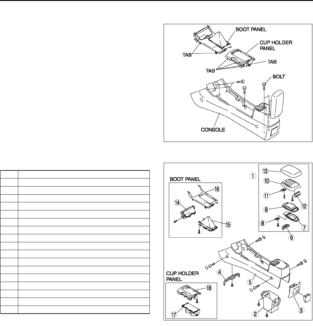
S86
DASHBOARD AND CONSOLE
CONSOLE REMOVAL/INSTALLATION A6E774264270W01
1. For MT vehicle, remove the shift lever knob.
2. Remove the cup holder panel using a tape-
wrapped screwdriver.
3. Remove the boot panel using a tape-wrapped
screwdriver, disconnect the cigarette lighter
connector, and remove the front ashtray
illumination.
4. Remove the bolts.
5. Install in the reverse order of removal.
End Of Sie
CONSOLE DISASSEMBLY/ASSEMBLY A6E774264270W02
1. Disassemble in the order indicated in the table.
2. Assemble in the reverse order of disassembly.
End Of Sie
A6E7742W011
1 Console lid (only large console box)
2Box
3 Rear ashtray case
4Bracket
5 Console
6 Console cover
7Box storage
8 Lock No.1
9 Inner console lid
10 Lid core
11 Lock No.2
12 Hinge
13 Outer console lid
14 Front ashtray
15 Boot
16 Boot panel
17 Cup holder
18 Cup holder panel
A6E7742W001
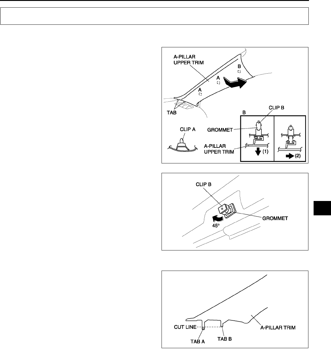
TRIM
S87
S
A-PILLAR TRIM REMOVAL A6E774468160W01
1. Turn the seaming welt over.
2. Disengage clips A using a fastener remover.
3. Pull the A-pillar trim, then disengage clip B (1).
4. Pull the A-pillar trim upward, then disengage clip
B from the A-pillar trim (2).
5. Pull clip B out, then rotate 45° .
6. Remove clip B from the grommet by pulling it
toward you.
End Of Sie
A-PILLAR TRIM INSTALLATION A6E774468160W02
1. Cut A-pillar trim tab A to the same length as tab B.
2. Install clip B to the A-pillar trim.
3. Install the A-pillar trim by tapping the clip into the
body.
End Of Sie
TRIM
A6E7744W023
A6E7744W024
A6E7744W022
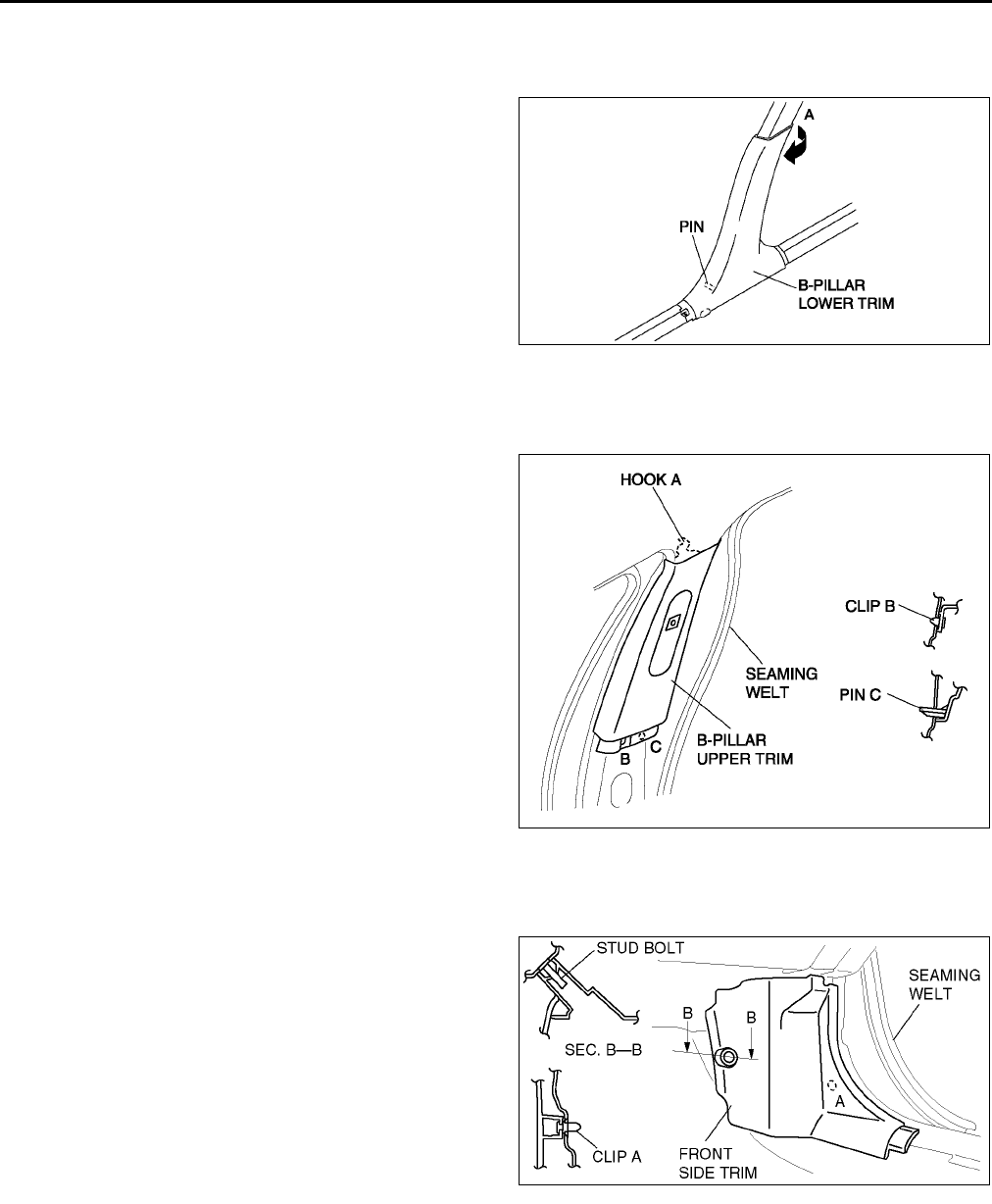
S88
TRIM
B-PILLAR LOWER TRIM REMOVAL/INSTALLATION A6E774468220W01
1. Remove the front scuff plate.
2. Remove the rear scuff plate.
3. Pull the area marked A, then remove one side of
the B-pillar lower trim.
4. Pull the B-pillar lower trim, then remove the pin
from the body.
5. Remove the B-pillar lower trim.
6. Install in the reverse order of removal.
End Of Sie
B-PILLAR UPPER TRIM REMOVAL/INSTALLATION A6E774468210W01
1. Remove the upper anchor of the front seat belt.
2. Remove the B-pillar lower trim.
3. Turn the seaming welt over.
4. Pull the B-pillar upper trim toward you, then
disengage, clip B, and pin C from the body.
5. Disengage hook A from the body, then remove B-
pillar upper trim.
6. Install in the reverse order of removal.
End Of Sie
FRONT SIDE TRIM REMOVAL/INSTALLATION A6E774468370W01
1. Remove the front scuff plate.
2. Turn the seaming welt over.
3. Pull the front side trim toward you, then
disengage clip A and the stud bolt, then remove
the front side trim.
4. Install in the reverse order of removal.
End Of Sie
A6E7744W021
A6E7744W025
A6E7744W014
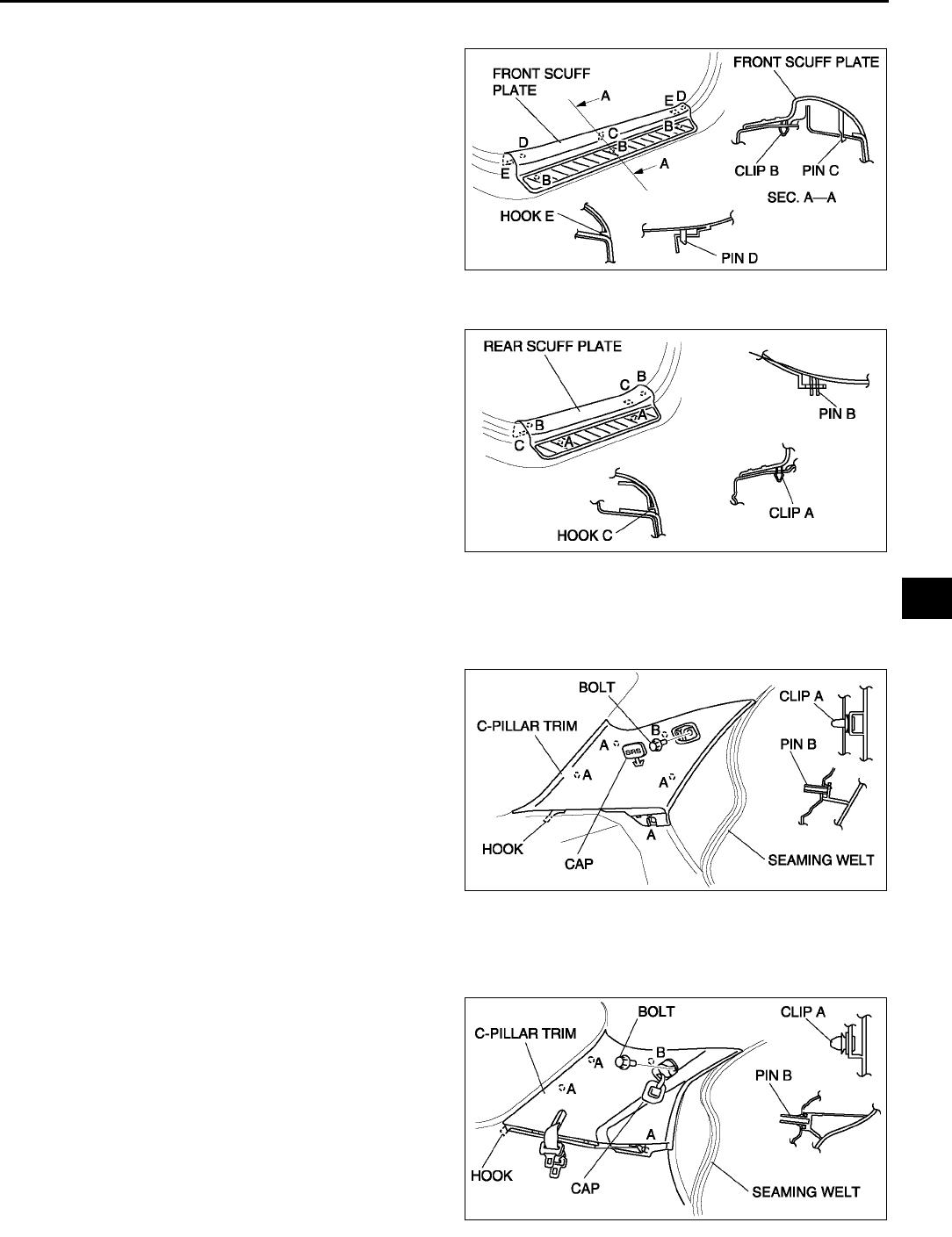
TRIM
S89
S
FRONT SCUFF PLATE REMOVAL/INSTALLATION A6E774468710W01
1. Pull the front scuff plate upward, then disengage
clips B, pins C, D and hooks E from the body, and
remove the front scuff plate.
2. Install in the reverse order of removal.
End Of Sie
REAR SCUFF PLATE REMOVAL/INSTALLATION A6E774468730W01
1. Pull the rear scuff plate upward, then disengage
clips A, pin B, and hooks C from the body, and
remove the rear scuff plate.
2. Install in the reverse order of removal.
End Of Sie
C-PILLAR TRIM REMOVAL/INSTALLATION A6E774468240W01
4SD
1. Remove the tire house trim.
2. Turn the seaming welt over.
3. Remove the cap using a fastener remover, and
remove the bolt (with curtain air bag system).
4. Disengage clips A and clip B using a fastener
remover.
5. Pull the C-pillar trim forward, then disengage
hook C from the body, and remove the C-pillar
trim.
6. Install in the reverse order of removal.
5HB
1. Remove the tire house trim.
2. Remove the trunk side upper trim
3. Turn the seaming welt over.
4. Remove the cap using a fastener remover the
bolt. (with curtain air bag system)
5. Disengage clips A and pin B using a fastener
remover.
6. Pull the C-pillar trim forward, then disengage the
hook from the body.
7. Remove the rear center seat belt tongue from the
C-pillar trim. (LH only)
8. Remove the C-pillar trim.
9. Install in the reverse order of removal.
End Of Sie
A6E7744W017
A6E7744W018
A6E7744W019
A6E7744W020
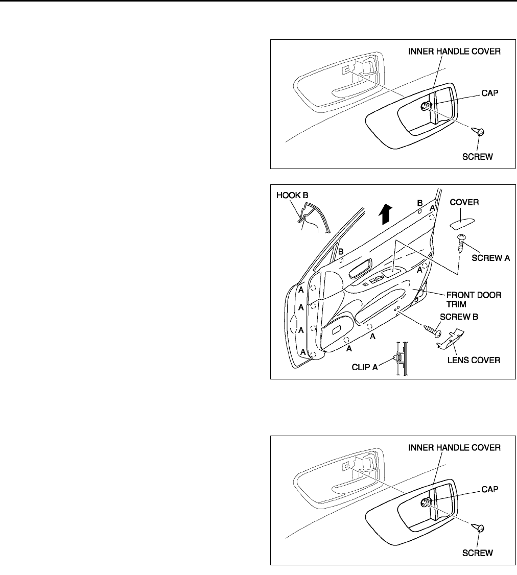
S90
TRIM
FRONT DOOR TRIM REMOVAL/INSTALLATION A6E774468420W01
1. Disconnect the negative battery cable.
2. Open the cap using a small screwdriver, then
remove the screw.
3. Remove the inner handle cover.
4. Remove the inner garnish.
5. Remove the cover, then remove screw A.
6. Remove the lens cover, then remove screw B.
7. Disengage clips A from the front door using a
fastener remover.
8. Pull the front door trim upward, then disengage
hooks B from the front door.
9. Disconnect the power door mirror switch
connector and the power window main switch
connector (drivers side) or power window
subswitch connector (passengers side).
10. Remove the courtesy light.
11. Remove the front door trim.
12. Remove the switch panel from the front door trim.
13. Install in the reverse order of removal.
End Of Sie
REAR DOOR TRIM REMOVAL/INSTALLATION A6E774468520W01
1. Disconnect the negative battery cable if equipped with power window system.
2. Remove the regulator handle if equipped.
3. Open the cap using a small screwdriver, then
remove the screw.
4. Remove the inner handle cover.
5. Remove the cover, then remove screw.
6. Disengage clips A from the rear door using a
fastener remover.
A6E7744W009
A6E7744W010
A6E7744W009
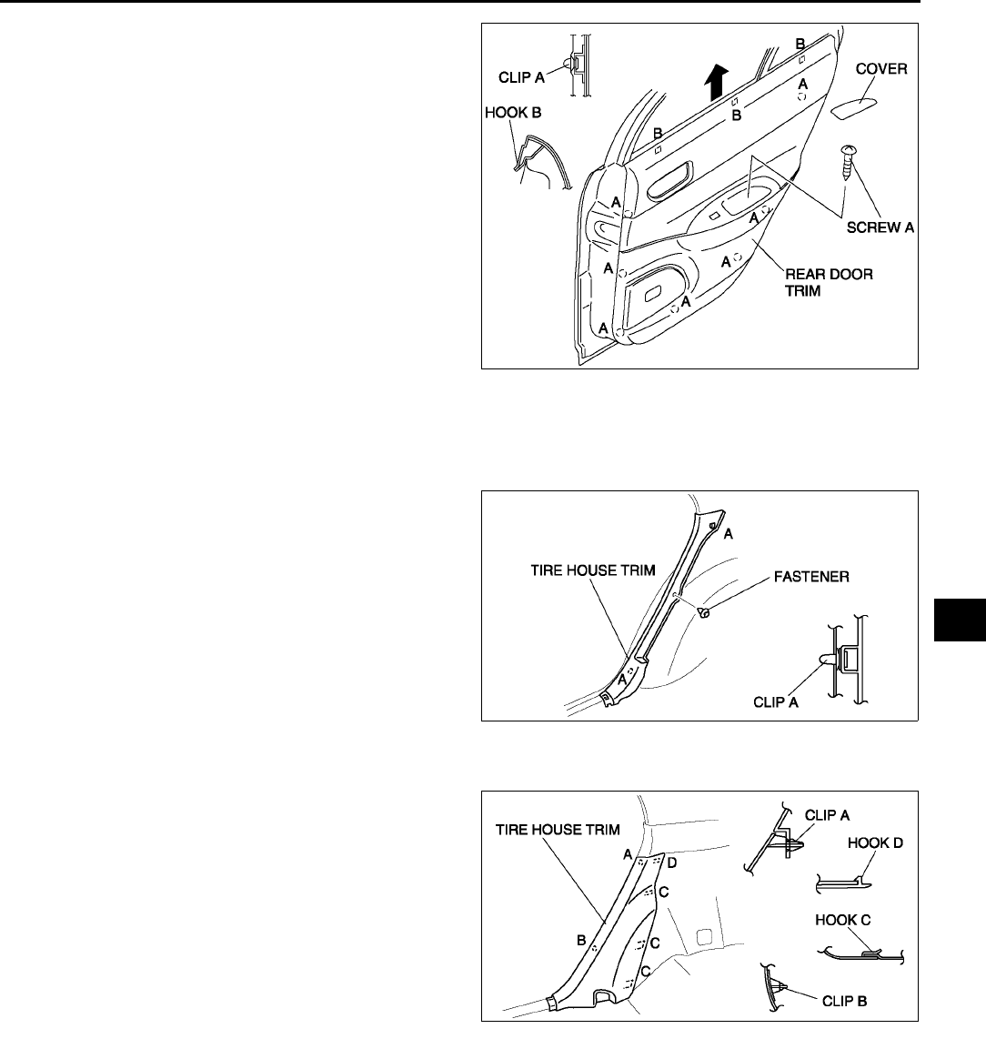
TRIM
S91
S
7. Pull the rear door trim upward, then disengage
hooks B from the rear door.
8. Disconnect the power window subswitch
connector if equipped.
9. Remove the rear door trim.
10. Remove the switch panel from the rear door trim.
11. Install in the reverse order of removal.
End Of Sie
TIRE HOUSE TRIM REMOVAL/INSTALLATION A6E774468760W01
4SD
1. Remove the rear scuff plate.
2. Remove the rear seat side.
3. Remove the fastener.
4. Pull the tire house trim upward, then disengage
clips A from the body, and remove the tire house
trim.
5. Install in the reverse order of removal.
5HB
1. Remove the rear scuff plate.
2. Pull the tire house trim toward you, then
disengage clip B from the body and clip A, hooks
C, D from the trunk side trim.
3. Remove the tire house trim.
4. Install in the reverse order of removal.
End Of Sie
A6E7744W011
A6E7744W015
A6E7744W016
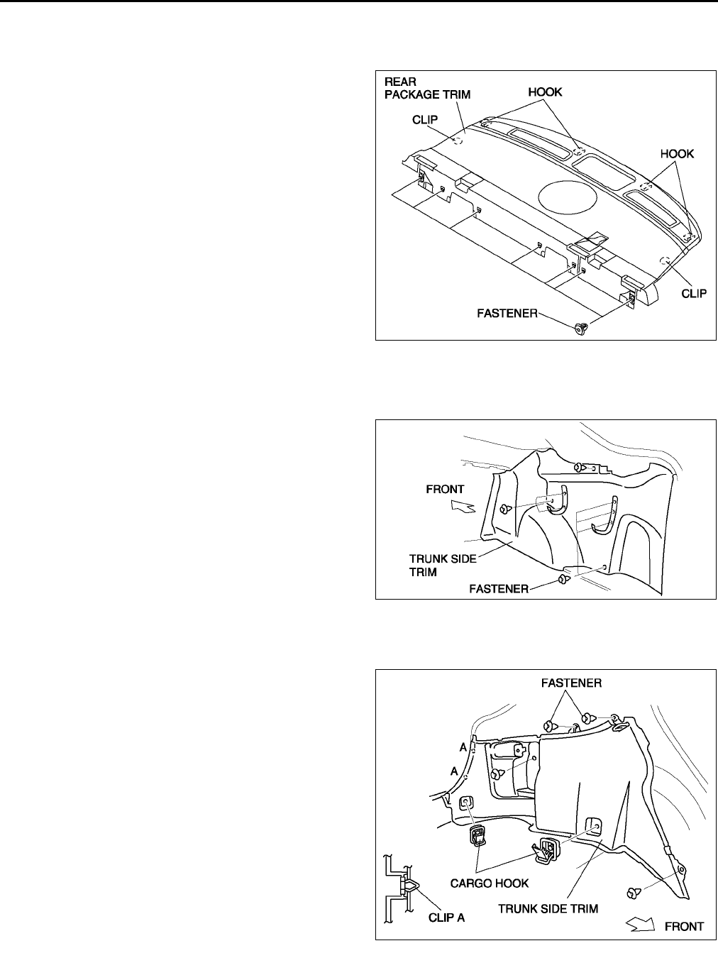
S92
TRIM
REAR PACKAGE TRIM REMOVAL/INSTALLATION A6E774468320W01
1. Remove the high-mount brake light.
2. Fold the rear seat back.
3. Remove the fasteners.
4. Pull the rear package trim upward, then
disengage the clips from the body.
5. Disengage the hooks, then remove the rear
package trim.
6. Install in the reverse order of removal.
End Of Sie
TRUNK SIDE TRIM REMOVAL/INSTALLATION A6E774468860W01
4SD
1. Remove the trunk end trim.
2. Remove the fasteners, then remove the trunk
side trim.
3. Install in the reverse order of removal.
5HB
1. Remove the trunk end trim.
2. Remove the trunk side upper trim.
3. Remove the cargo hooks.
4. Remove the fasteners.
5. Pull the trunk side trim toward you, then
disengage clips A from the body.
6. Install in the reverse order of removal.
End Of Sie
A6E7744W026
A6E7744W007
A6E7744W008
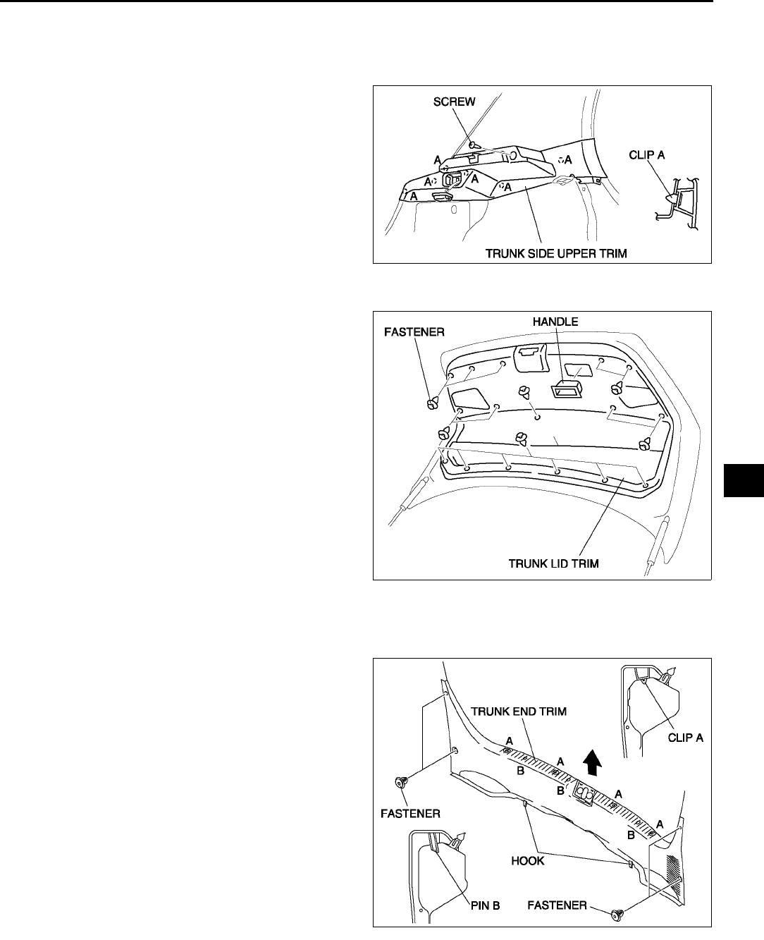
TRIM
S93
S
TRUNK SIDE UPPER TRIM REMOVAL/INSTALLATION A6E774468860W02
1. Disconnect the negative battery cable. (LH only)
2. Remove the tire house trim.
3. Remove the rear seat remote lever.
4. Remove the screw.
5. Pull the trunk side upper trim toward you, then
disengage clips A from the body.
6. Disconnect the cargo compartment light
connector. (LH only)
7. Install in the reverse order of removal.
End Of Sie
TRUNK LID TRIM REMOVAL/INSTALLATION A6E774458800W01
1. Pull the handle toward you, then remove the
handle.
2. Remove the fasteners, then remove the trunk lid
trim.
3. Install in the reverse order of removal.
End Of Sie
TRUNK END TRIM REMOVAL/INSTALLATION A6E774468890W01
4SD
1. Remove the fasteners.
2. Pull the trunk end trim upward, then disengage
clips A, pins B, and hooks.
3. Remove the trunk end trim.
4. Install in the reverse order of removal.
A6E7744W006
A6E7744W005
A6E7744W012
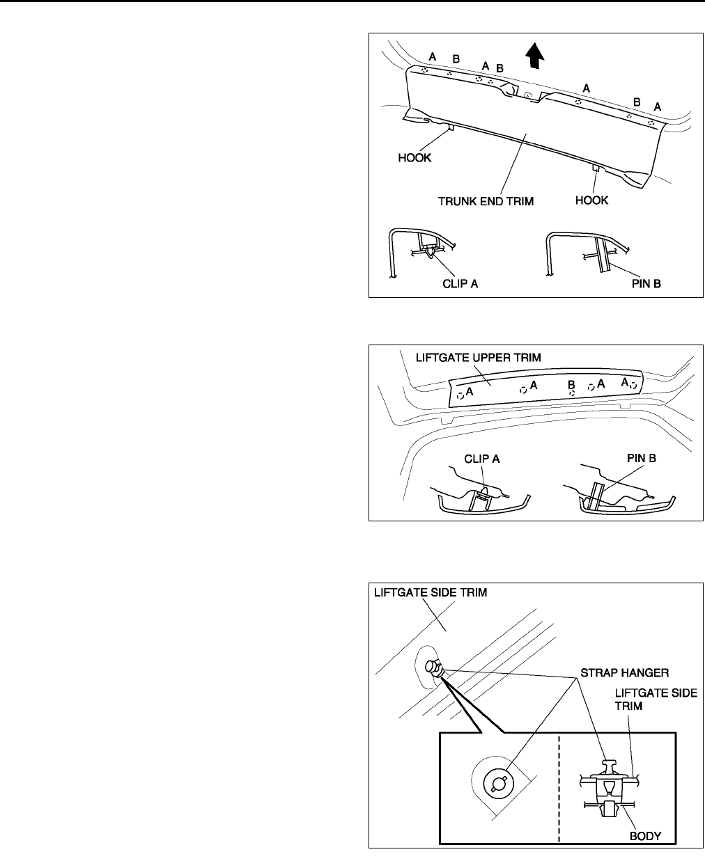
S94
TRIM
5HB
1. Pull the trunk end trim upward, then disengage
clips A, pins B, and hooks.
2. Remove the trunk end trim.
3. Install in the reverse order of removal.
End Of Sie
LIFTGATE UPPER TRIM REMOVAL/INSTALLATION A6E774468930W01
1. Pull the liftgate upper trim toward you, then
disengage clips A, and pin B from the body.
2. Remove the liftgate upper trim.
3. Install in the reverse order of removal.
End Of Sie
LIFTGATE SIDE TRIM REMOVAL/INSTALLATION A6E774468940W01
1. Remove the liftgate upper trim.
2. Position the strap hanger as shown in the figure.
A6E7744W013
A6E7744W002
A6E7744W003
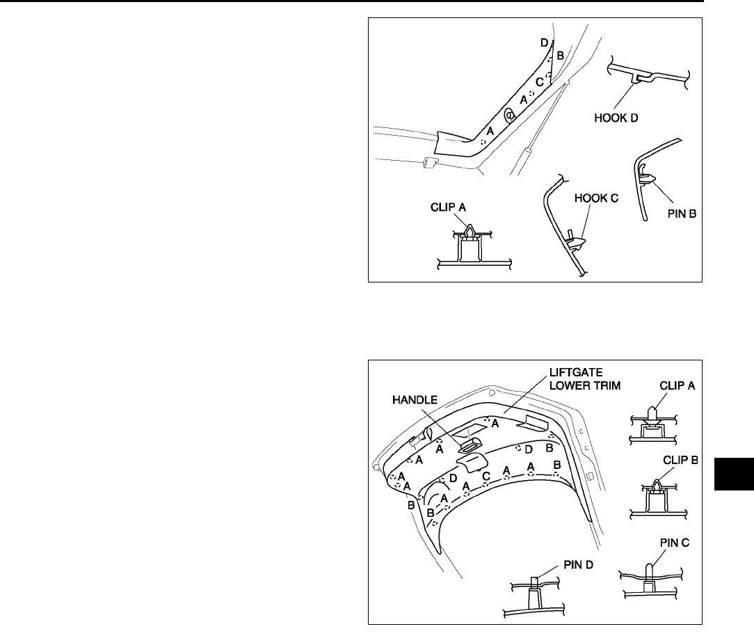
TRIM
S95
S
3. Pull the liftgate side trim toward you, then
disengage clips A, pin B and the strap hanger
from the body and pin B, hook C, D from the
liftgate lower trim.
4. Remove the liftgate side trim.
5. Remove the hanger strap from the liftgate side
trim.
6. Install in the reverse order of removal.
End Of Sie
LIFTGATE LOWER TRIM REMOVAL/INSTALLATION A6E774468960W01
1. Remove the liftgate upper trim.
2. Remove the liftgate side trim.
3. Pull the handle toward you, then remove the
handle.
4. Pull the liftgate lower trim toward you, then
disengage clips A, B and pins C, D from the body.
5. Remove the liftgate lower trim.
6. Install in the reverse order of removal.
End Of Sie
A6E7744W004
A6E7744W001
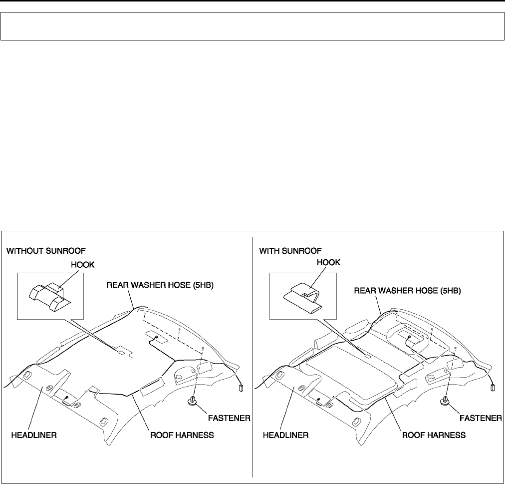
S96
HEADLINER
HEADLINER REMOVAL/INSTALLATION A6E774668030W01
1. Disconnect the negative battery cable.
2. Turn the seaming welt and weatherstrip over.
3. Remove the sunroof seaming welt. (vehicles with sunroof only)
4. Remove the A-pillar trims.
5. Remove the B-pillar upper trims.
6. Remove the C-pillar trims.
7. Remove the front and rear map light. (See T48 FRONT MAP LIGHT REMOVAL/INSTALLATION.)
(See T49 REAR MAP LIGHT REMOVAL/INSTALLATION.)
8. Remove the sunvisors.
9. Remove the assist handle.
10. Disconnect the roof harness connector, remove the clip, and remove the connector.
11. Remove the fasteners.
12. Disconnect the front and rear drain hose.
13. Disconnect the rear washer hose (5HB).
14. Remove the hook holding the roof panel and remove the headliner.
15. Take the headliner off from the passenger-side door opening.
16. Install in the reverse order of removal.
End Of Sie
HEADLINER
A6E7746W004
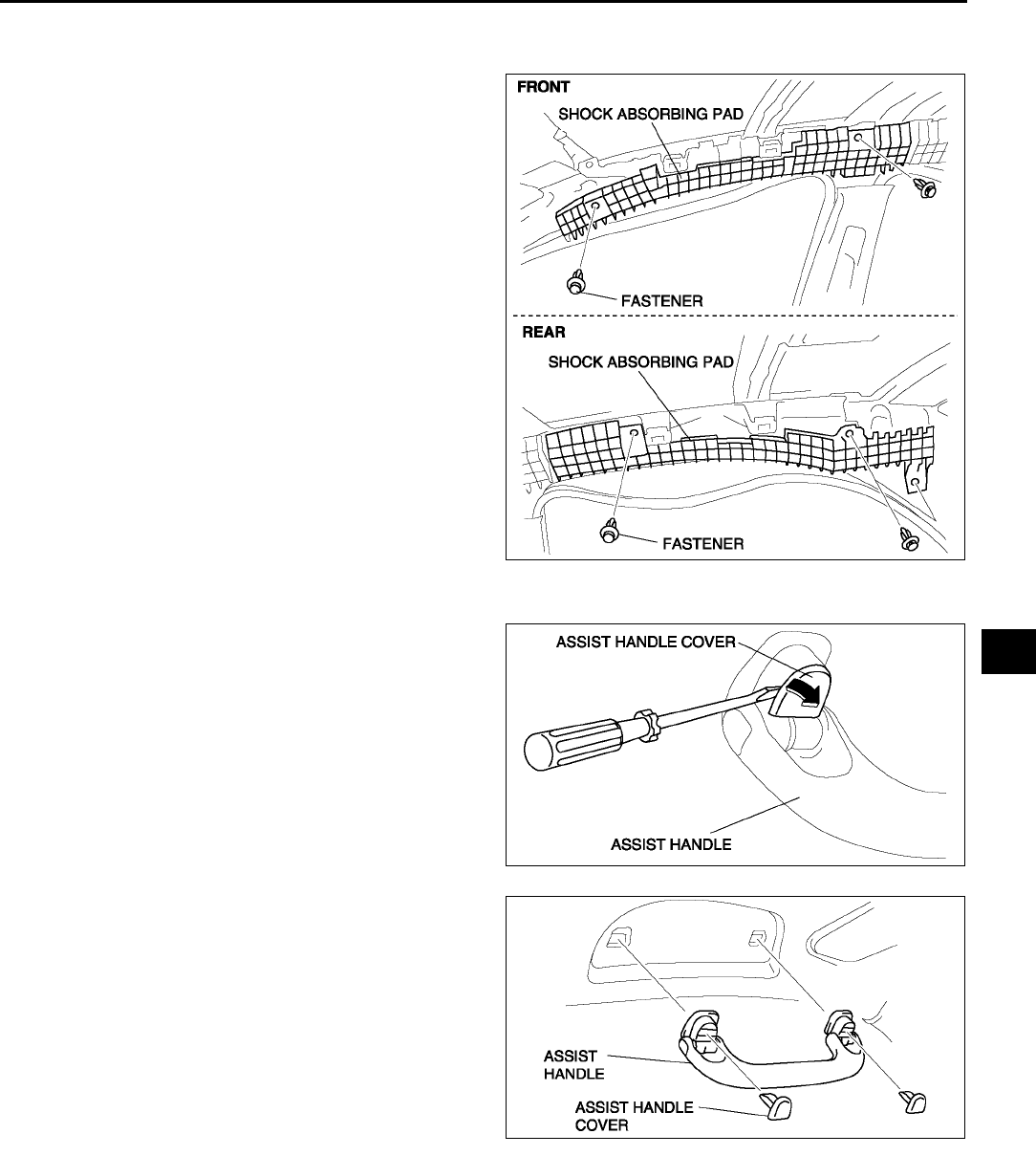
HEADLINER
S97
S
SHOCK ABSORBING PAD REMOVAL/INSTALLATION A6E774668H10W01
1. Remove the headliner.
2. Remove the fastener, then remove the shock
absorbing pad.
3. Install in the reverse order of removal.
End Of Sie
ASSIST HANDLE REMOVAL/INSTALLATION A6E774669440W01
1. Insert a screwdriver into the assist handle notch
and remove the assist handle cover.
2. Pull the assist handle forward you, then remove
the assist handle.
3. Install in the reverse order of removal.
End Of Sie
A6E7746W003
A6E7746W001
A6E7746W002
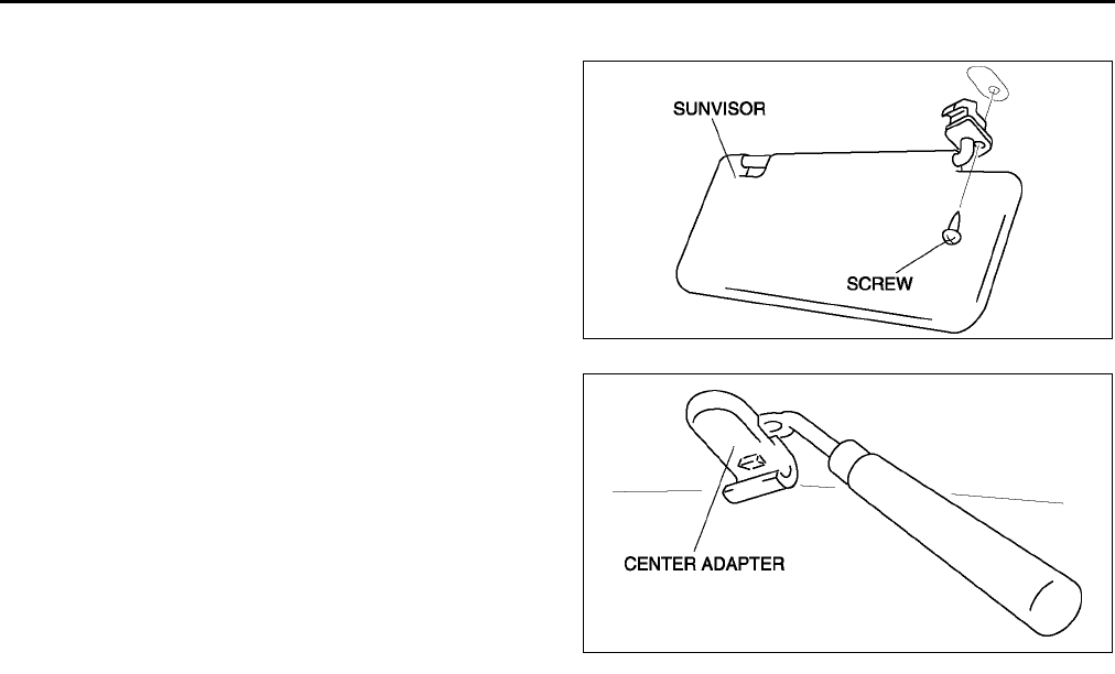
S98
HEADLINER
SUNVISOR REMOVAL/INSTALLATION A6E774669270W01
1. Remove the screws, then the sunvisor.
2. Disengage the center adapter (sunvisor stopper)
from the body using a fastener remover.
3. Install in the reverse order of removal.
End Of Sie
A6E7746W005
YTA7746W103
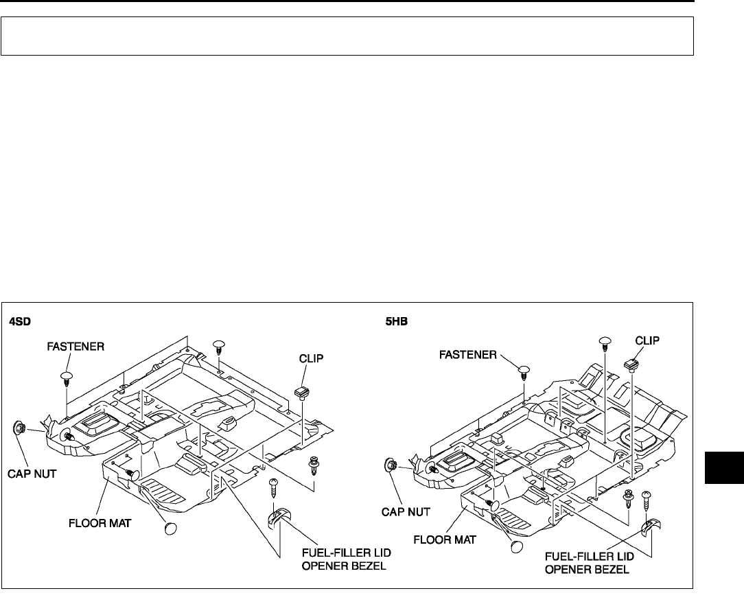
FLOOR COVERING
S99
S
FRONT FLOOR COVERING REMOVAL/INSTALLATION A6E774868670W01
1. Disconnect the negative battery cable.
2. Remove the front seats. (See S105 FRONT SEAT REMOVAL/INSTALLATION.)
3. Remove the rear seat.
4. Remove the front scuff plates.
5. Remove the rear scuff plates.
6. Remove the console.
7. Remove the front side trims.
8. Remove the B-pillar lower trims.
9. Remove the lower anchor of the front seat belt installation bolts.
10. Remove the tire house trim. (5HB)
11. Remove the fuel-filler lid opener bezel.
12. Remove the fasteners.
13. Remove the cap nuts.
14. Remove the clips.
15. Take the front floor covering off from the passenger-side door opening.
16. Install in the reverse order of removal.
End Of Sie
FLOOR COVERING
A6E7748W001
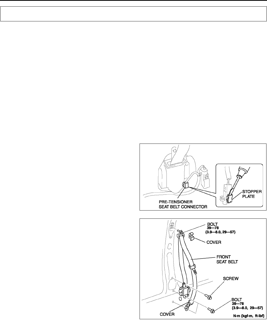
S100
SEAT BELT
FRONT SEAT BELT REMOVAL/INSTALLATION A6E775057630W01
Warning
•
••
•Handling the front seat belt (pre-tensioner seat belt) improperly can accidentally deploy the pre-
tensioner, which may seriously injure you. Read SERVICE WARNINGS before handling the front
seat belt. (See T117 SERVICE WARNINGS.)
Warning
•
••
•The side air bag sensor is attached to the lower part of the B-pillar. When working around the B-
pillar, disconnect the negative battery cable or work carefully, avoiding excessive impact to the
lower part of the B-pillar.
Caution
•
••
•The ELR has a spring that will unwind if the retractor's cover is removed. The spring cannot be
rewound by hand. If this occurs, the ELR will not work properly. Therefore, do not disassemble the
retractor.
1. Turn the ignition switch to LOCK position.
2. Disconnect the negative battery cable and wait for more than 1 minute.
3. Remove the B-pillar lower trim.
4. Using a screwdriver, pry out the pre-tensioner
seat belt connector's stopper plate.
5. Disconnect the pre-tensioner seat belt connector.
6. Remove the covers.
7. Remove the bolts and screw, then remove the
front seat belt.
8. Install in the reverse order of removal.
9. Verify that the air bag system warning light
illuminates for approximately 6 seconds and
then goes off.
•If the air bag system warning light does not
operate in the manner described above, there
are malfunction in the system. Inspect the
system using the on-board diagnostic
function.
End Of Sie
SEAT BELT
A6E7750W008
A6E7750W007
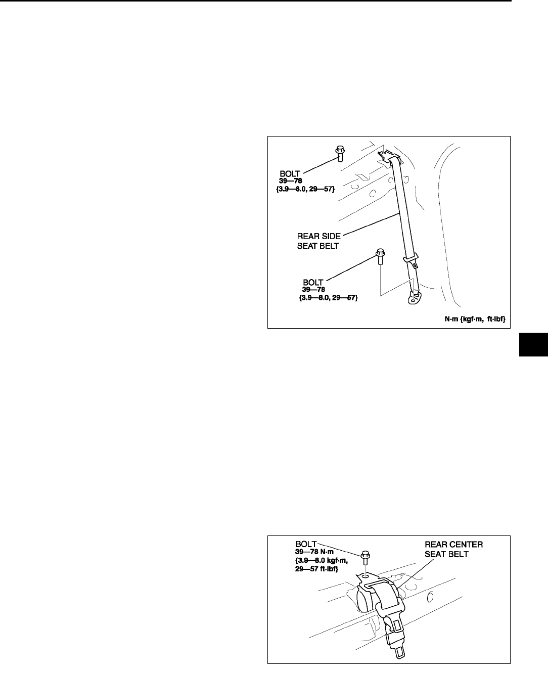
SEAT BELT
S101
S
REAR SIDE SEAT BELT REMOVAL/INSTALLATION A6E775057730W01
Caution
•
••
•The ELR has a spring that will unwind if the retractor's cover is removed. The spring cannot be
rewound by hand. If this occurs, the ELR will not work properly. Therefore, do not disassemble the
retractor.
4SD
1. Fold the rear seat back.
2. Remove the rear side seats.
3. Remove the rear package trim.
4. Remove the bolts.
5. Remove the rear seat belt.
6. Install in the reverse order of removal.
5HB
Note
•Rear side seat belts are embedded in the rear seat back. See rear seat disassembly/assembly, remove/
install the rear center seat belt.
End Of Sie
REAR CENTER SEAT BELT REMOVAL/INSTALLATION A6E775057730W02
Caution
•
••
•The ELR has a spring that will unwind if the retractor's cover is removed. The spring cannot be
rewound by hand. If this occurs, the ELR will not work properly. Therefore, do not disassemble the
retractor.
4SD
1. Fold the rear seat back.
2. Remove the rear package trim.
3. Remove the bolt.
4. Remove the rear center seat belt.
5. Install in the reverse order of removal.
A6E7750W005
A6E7750W003
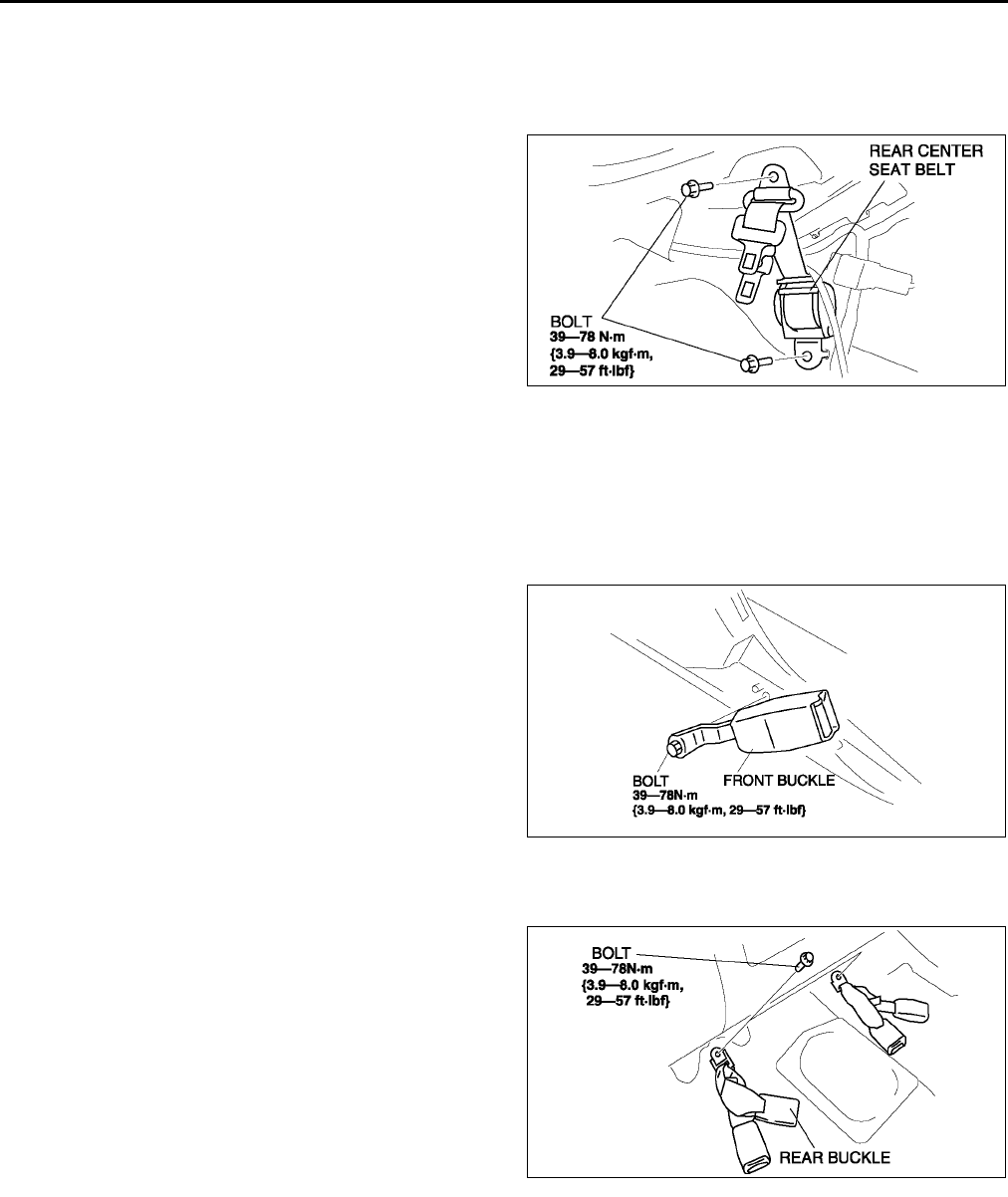
S102
SEAT BELT
5HB
1. Remove the rear scuff plate.
2. Remove the tire house trim.
3. Remove the trunk side upper trim.
4. Remove the C-pillar trims.
5. Remove the bolts.
6. Remove the rear center seat belt.
7. Install in the reverse order of removal.
End Of Sie
FRONT BUCKLE REMOVAL/INSTALLATION A6E775057620W01
1. Perform the following procedure for vehicles with seat belt warning.
(1) Disconnect the negative battery cable.
(2) Remove the front seat.
(3) Disconnect the buckle switch connector.
2. Perform the following procedure for vehicles without seat belt warning.
(1) Remove the console.
3. Remove bolt.
4. Install in the reverse order of removal.
End Of Sie
REAR BUCKLE REMOVAL/INSTALLATION A6E775057720W01
1. Remove the rear seat cushion.
2. Remove the bolts.
3. Remove the rear buckles.
4. Install in the reverse order of removal.
End Of Sie
A6E7750W004
A6E7750W002.
A6E7750W006
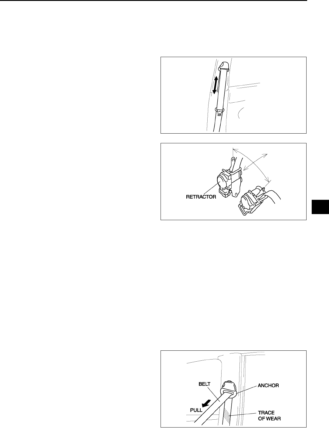
SEAT BELT
S103
S
SEAT BELT INSPECTION A6E775057000W01
Belt
1. Confirm that the seat belt is installed correctly.
2. Inspect the seat belt for damage and deformation of metal parts.
•If any damage is found, replace as necessary.
ELR
1. Verify that the belt can be pulled out smoothly,
and that it moves smoothly when wound.
•If not as specified, replace the seat belt.
2. Verify that the retractor locks when the belt is
quickly pulled.
•If not as specified, replace the seat belt.
3. Remove the retractor.
4. Make sure that the seat belt does not lock when
the retractor is tilted slowly up to 15°
°°
° from the
mounted position and locks when the retractor is
tilted 40°
°°
° or more.
•If not as specified, replace the seat belt.
ALR
1. Pull the belt out fully and the lock mode changes from ELR to ALR.
2. Verify that retractor makes a clicking sound as the belt slowly retracts. If no sound is heard, the lock mode has
not changed to ALR. If necessary, repeat the above Step 1.
•If not as specified, replace the seat belt.
3. Verify that the belt locks when pulled.
•If not as specified, replace the seat belt.
4. Verify that the lock mode changes to ELR when the belt fully retracts.
•If not as specified, replace the seat belt.
Load Limiter Retractor
Warning
•
••
•When the load limiter operates, the belt and anchor rub against each other strongly leaving a trace
of wear. If the seat belt is used in this state, the seat belt will not function to its designed effect and
there is the possibility of serious injury to passengers. Be sure to replace the seat belt once the
load limiter operates.
1. If the vehicle has been subjected to a shock in an
accident, pull the belt from the retractor and
confirm that there is no trace of wear (the load
limiter has not operated) by visually inspecting
and feeling the belt.
•If not as specified, replace the seat belt.
End Of Sie
YMU811WB0
YMU811WA4
YMU811WA6
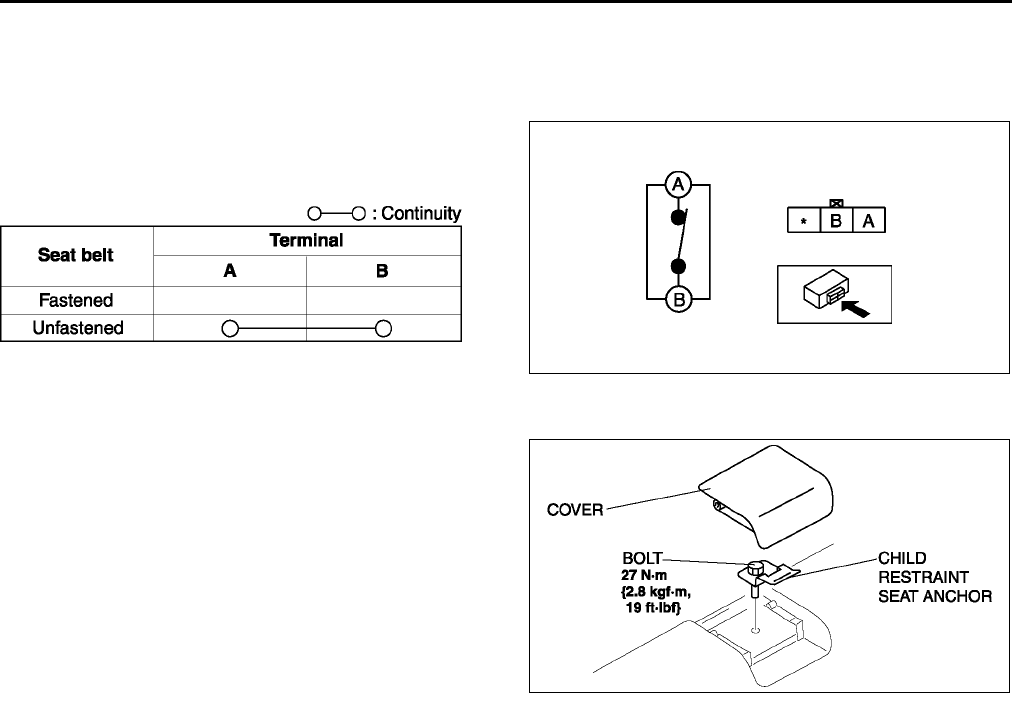
S104
SEAT BELT
BUCKLE SWITCH INSPECTION A6E775057620W02
Driver's Seat
1. Disconnect the negative battery cable.
2. Disconnect the buckle switch connector.
3. Inspect for continuity between the buckle switch
terminals using an ohmmeter.
•If not as specified, replace the front buckle.
End Of Sie
CHILD RESTRAINT SEAT ANCHOR REMOVAL/INSTALLATION A6E77505777ZW01
1. Remove the cover.
2. Remove the bolt and child restraint seat anchor.
3. Install in the reverse order of removal.
End Of Sie
A6E7750W010
A6E7750W009
A6E7750W001
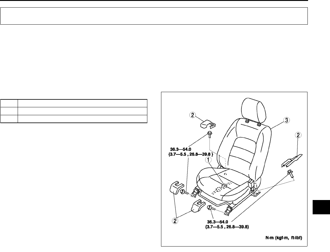
SEAT
S105
S
FRONT SEAT REMOVAL/INSTALLATION A6E775257100W01
Warning
•
••
•Handling the front seat (side air bag) improperly can accidentally deploy the side air bag, which
may seriously injure you. Read AIR BAG SYSTEM SERVICE WARNINGS before handling the front
seat. (See T117 SERVICE WARNINGS.)
1. Turn the ignition switch to the LOCK position.
2. Disconnect the negative battery cable and wait for more than 1 minute.
3. Remove in the order indicated in the table.
4. Install in the reverse order of removal.
End Of Sie
SEAT
1 Connector
2 Cover
3 Front seat
A6E7752W002
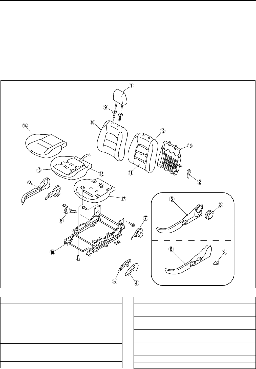
S106
SEAT
FRONT SEAT DISASSEMBLY/ASSEMBLY A6E775257100W02
Warning
•
••
•Handling the front seat (side air bag) improperly can accidentally deploy the side air bag, which
may seriously injure you. Read AIR BAG SYSTEM SERVICE WARNINGS before handling the front
seat. (See T117 SERVICE WARNINGS.)
1. Disconnect the negative battery cable and wait for more than 1 minute.
2. Remove the side air bag module. (See T121 SIDE AIR BAG MODULE REMOVAL/INSTALLATION.)
3. Disassemble in the order indicated in the table.
4. Assemble in the reverse order of disassembly.
Driver's Seat (Normal Seat)
.
A6E7752W017
1 Headrest
2 Lumber support lever
(See S109 Lumber support lever disassembly
note.)
3 Recliner dial (dial type)
(See S109 Recliner dial disassembly note.)
Recliner lever (lever type)
4 Lift lever outer
5 Lift lever inner
6Side cover
(See S109 Side cover disassembly note.)
7 Reverce cover
8 Front buckle
9 Pole guide
10 Seat back trim
11 Seat warmer unit (European (L.H.D.) specs. only)
12 Seat back pad
13 Seat back frame
14 Seat cushion trim
15 Seat warmer unit (European (L.H.D.) specs. only)
16 Seat cushion pad
17 Seat cushion frame
18 Slide adjuster
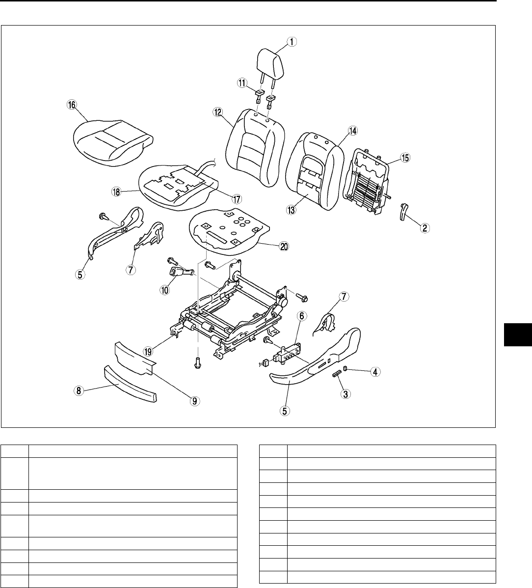
SEAT
S107
S
Driver's Seat (Power Seat)
.
A6E7752W027
1 Headrest
2 Lumber support lever
(See S109 Lumber support lever disassembly
note.)
3 Slider and lifter switch knob
4 Recliner switch knob
5 Side cover
(See S109 Side cover disassembly note.)
6 Power seat switch
7 Reverce cover
8 Front cover No. 1
9 Front cover No. 2
10 Front buckle
11 Pole guide
12 Seat back trim
13 Seat warmer unit (European (L.H.D.) specs. only)
14 Seat back pad
15 Seat back frame
16 Seat cushion trim
17 Seat warmer unit (European (L.H.D.) specs. only)
18 Seat cushion pad
19 Seat cushion frame
20 Slide adjuster
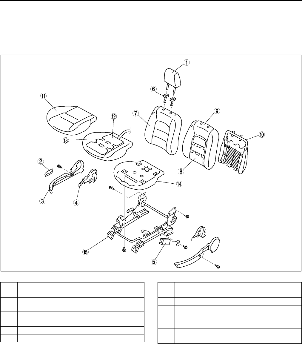
S108
SEAT
Passenger's Seat
Warning
•
••
•Do not disassemble the seat cushion. Doing so will necessitate reassembly which may damage or
press the occupancy sensor. This will cause the misoperation of the air bag system, which may
seriously injure you.
.
A6E7752W003
1 Headrest
2 Recliner lever
3Side cover
(See S109 Side cover disassembly note.)
4 Reverse cover
5 Front buckle
6 Pole guide
7 Seat back trim
8 Seat warmer unit (European (L.H.D.) specs. only)
9 Seat back pad
10 Seat back frame
11 Seat cushion trim
12 Seat warmer unit (European (L.H.D.) specs. only)
13 Seat cushion pad
14 Seat cushion frame
15 Slide adjuster
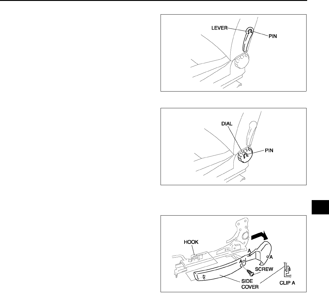
SEAT
S109
S
Lumber support lever disassembly note
1. Remove the pin from the lumber support lever
installation part with rag.
Recliner dial disassembly note
1. Remove the pin from the recliner dial installation
part with rag.
Side cover disassembly note
1. Remove the screws.
2. Disengage the clips.
3. Lift the side cover up in the direction of the arrow,
then unhook it from slide adjuster.
A6E7752W018
A6E7752W019
A6E7752W004
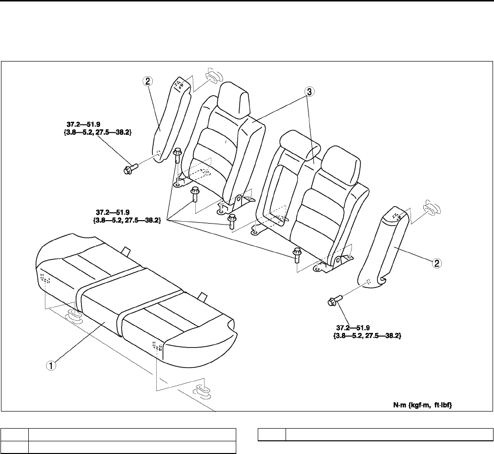
S110
SEAT
End Of Sie
REAR SEAT REMOVAL/INSTALLATION A6E775257200W01
4SD
1. Remove in the order indicated in the table.
2. Install in the reverse order of removal..
A6E7752W006
1 Rear seat cushion
2 Rear side seat
3 Rear seat back
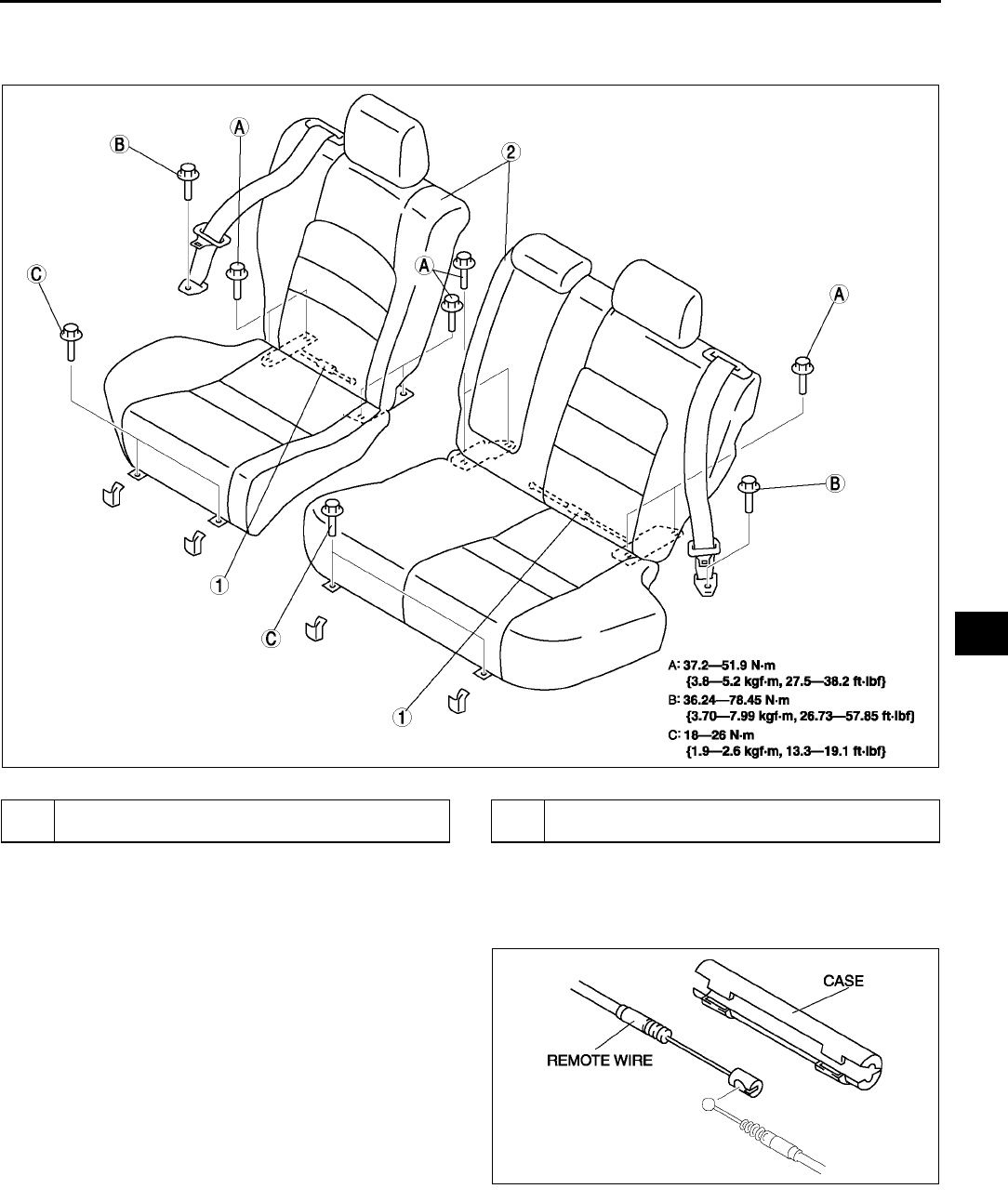
SEAT
S111
S
5HB
1. Remove in the order indicated in the table.
2. Install in the reverse order of removal..
Remote wire removal note
1. Turn over the trunk floor mat.
2. Remove the case.
3. Remove the remote wire.
A6E7752W012
1 Remote wire
(See S111 Remote wire removal note.)
2 Rear seat
(See S112 Rear seat removal note.)
A6E7752W014
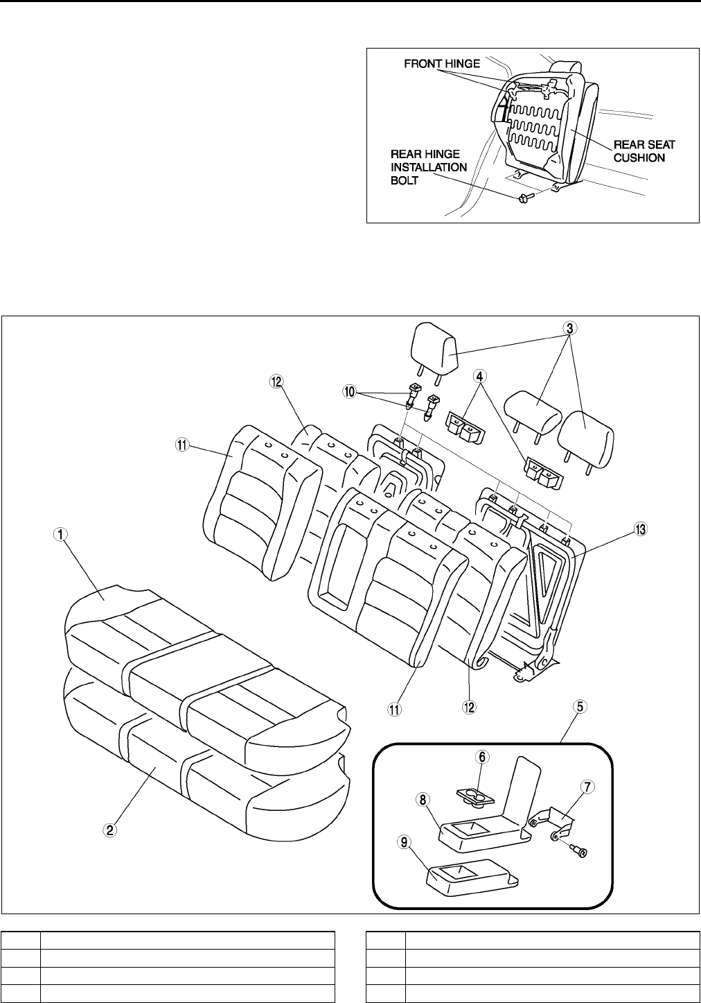
S112
SEAT
Rear seat removal note
1. Remove the front hinge installation bolts.
2. Lift the rear seat cushion, then remove the rear
hinge installation bolts.
End Of Sie
REAR SEAT DISASSEMBLY/ASSEMBLY A6E775257200W02
4SD
1. Disassemble in the order indicated in the table.
2. Assemble in the reverse order of disassembly..
A6E7752W013
A6E7752W007
1 Seat cushion trim
2 Seat cushion pad
3 Headrest
4 Striker cover
5 Armrest assembly
6 Cup holder
7 Armrest hinge
8 Armrest trim
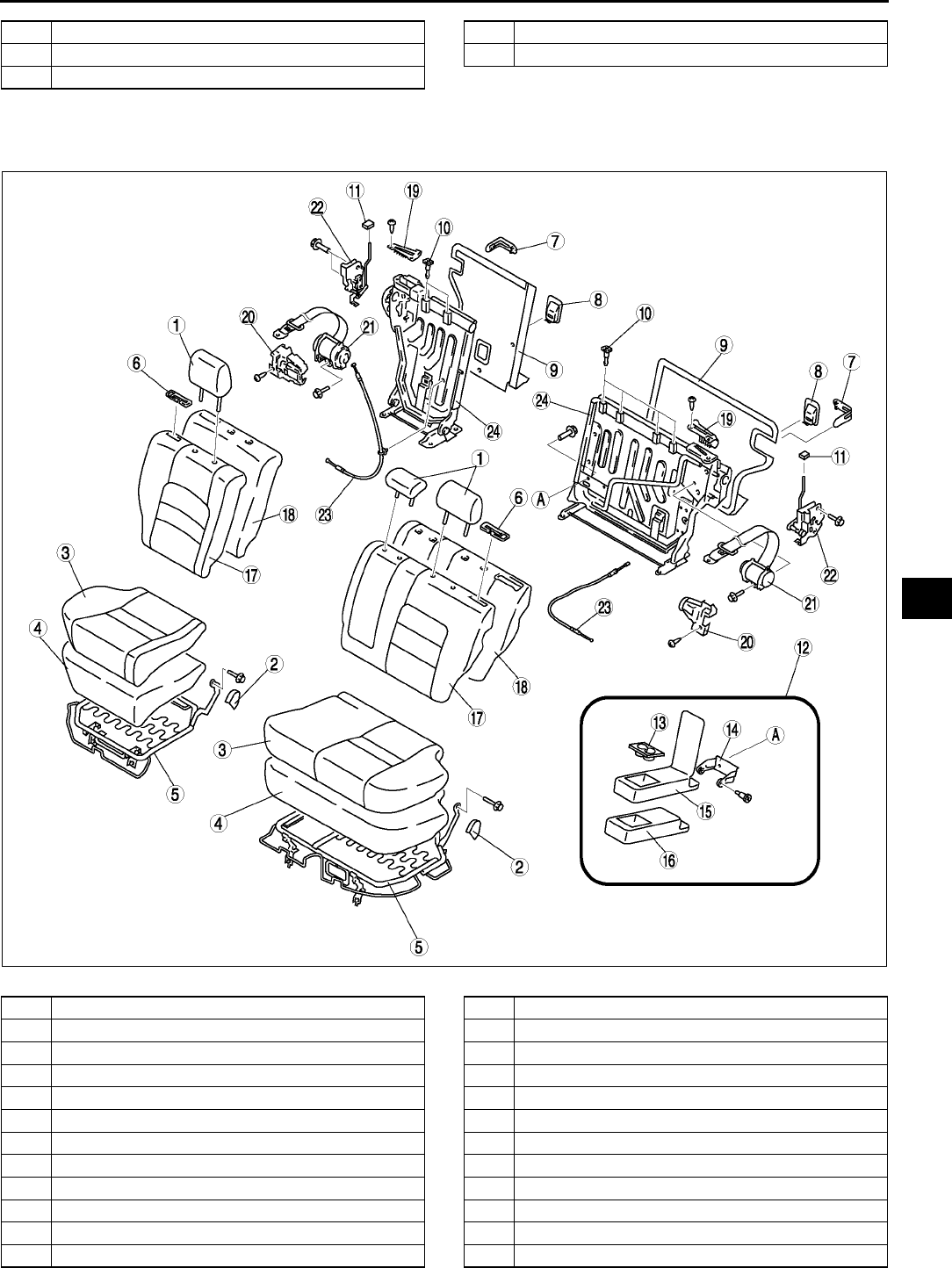
SEAT
S113
S
5HB
1. Disassemble in the order indicated in the table.
2. Assemble in the reverse order of disassembly..
9 Armrest pad
10 Pole guide
11 Seat back trim
12 Seat back pad
13 Seat back frame
A6E7752W015
1 Headrest
2 Hinge cover
3 Seat cushion trim
4 Seat cushion pad
5 Seat cushion frame
6 Remote button cover
7 Seat back catch cover
8 Child seat anchor cover
9 Seat back board
10 Pole guide
11 Remote button
12 Armrest assembly
13 Cup holder
14 Armrest hinge
15 Armrest trim
16 Armrest pad
17 Seat back trim
18 Seat back pad
19 Seat belt guide
20 Retractor cover
21 Rear seat belt
22 Seat back catch
23 Remote wire
24 Seat back frame
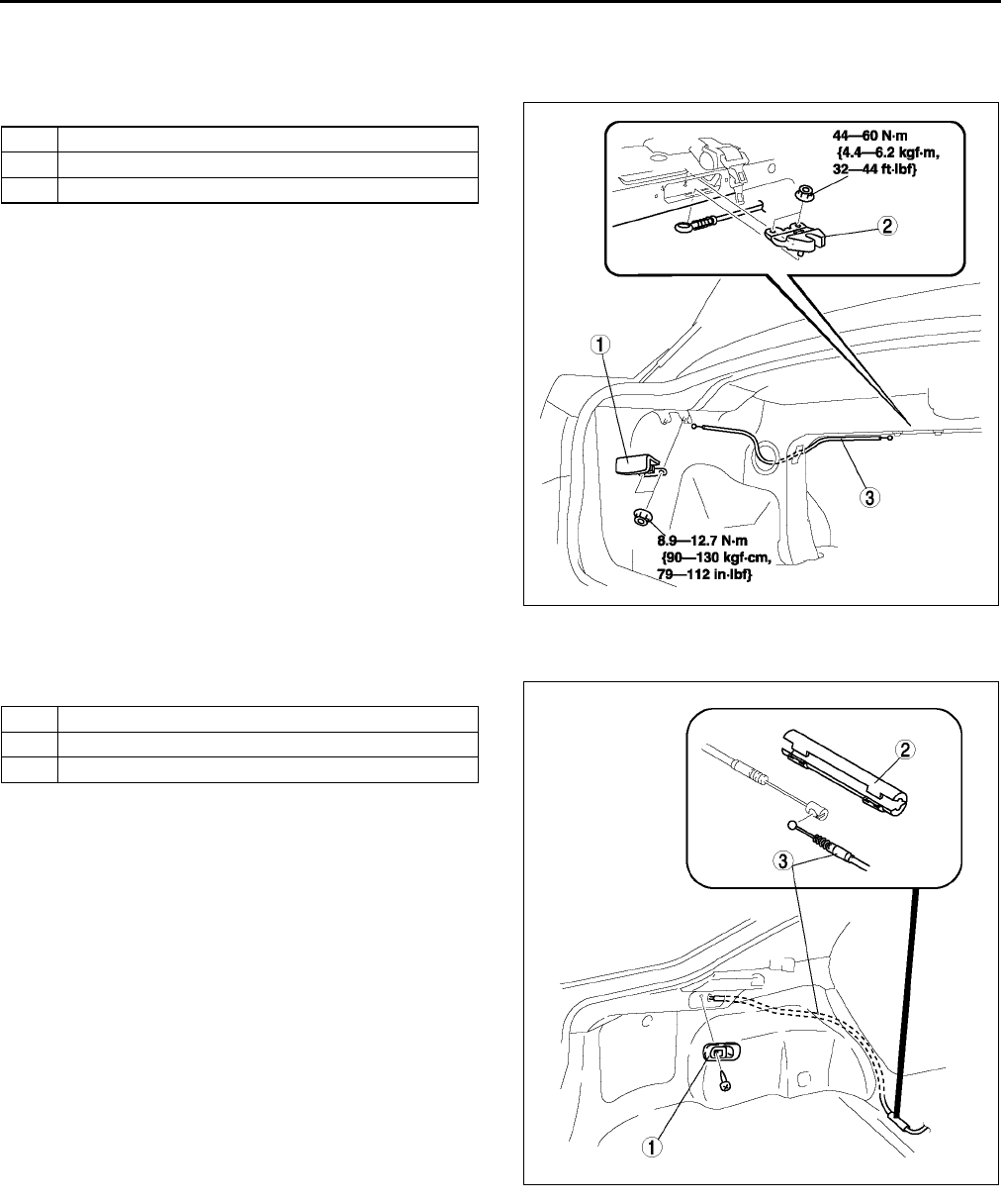
S114
SEAT
End Of Sie
REMOTE HANDLE LEVER REMOVAL/INSTALLATION A6E775200166W01
4SD
1. To remove the remote wire, remove the trunk side trim.
2. Remove in the order indicated in the table.
3. Install in the reverse order of removal.
5HB
1. To remove the remote wire, remove the trunk side upper trim and trunk side trim.
2. Remove in the order indicated in the table.
3. Install in the reverse order of removal.
End Of Sie
1 Remote handle lever
2 Remote wire
3 Remote catch
A6E7752W005
1 Remote handle lever
2Cover
3 Remote wire
A6E7752W011
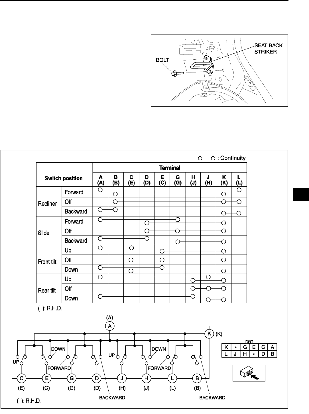
SEAT
S115
S
SEAT BACK STRIKER REMOVAL/INSTALLATION A6E775262361W01
1. Remove the tire house trim.
2. Remove the trunk side upper trim and trunk side lower trim.
3. Remove the bolts.
4. Remove the seat back striker.
5. Install in the reverse order of removal.
End Of Sie
POWER SEAT SWITCH INSPECTION A6E775257155W01
1. Disconnect the power seat switch connector.
2. Disconnect the rear tilt motor connector.
3. Inspect for continuity between the power seat switch connector terminals using an ohmmeter.
•If not as specified, replace the power seat switch.
A6E7752W016
A6E7752W029
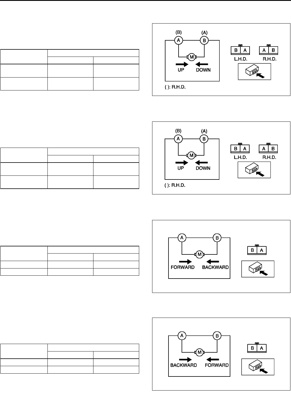
S116
SEAT
End Of Sie
FRONT TILT MOTOR INSPECTION A6E775288650W01
1. Disconnect the front tilt motor connector.
2. Inspect the front tilt motor operation when B+ is
applied to the terminals as shown.
•If not as specified, replace the seat cushion
frame.
( ) : R.H.D.
End Of Sie
REAR TILT MOTOR INSPECTION A6E775288651W01
1. Disconnect the rear tilt motor connector.
2. Inspect the rear tilt motor operation when B+ is
applied to the terminals as shown.
•If not as specified, replace the seat cushion
frame.
( ) : R.H.D.
End Of Sie
SLIDE MOTOR INSPECTION A6E775288662W01
1. Disconnect the slide motor connector.
2. Inspect the slide motor operation when B+ is
applied to the terminals as shown.
•If not as specified, replace the seat cushion
frame.
End Of Sie
RECLINER MOTOR INSPECTION A6E775288663W01
1. Disconnect the recliner motor connector.
2. Inspect the recliner motor operation when B+ is
applied to the terminal as shown.
•If not as specified, replace the seat cushion
frame.
End Of Sie
Motor operation Connection
B+ GND
Up A
(B)
B
(A)
Down B
(A)
A
(B)
A6E7752W008
Motor operation Connection
B+ GND
Up A
(B)
B
(A)
Down B
(A)
A
(B)
A6E7752W009
Motor operation Connection
B+ GND
Forward A B
Backward B A
A6E7752W010
Motor operation Connection
B+ GND
Forward B A
Backward A B
A6E7752W028
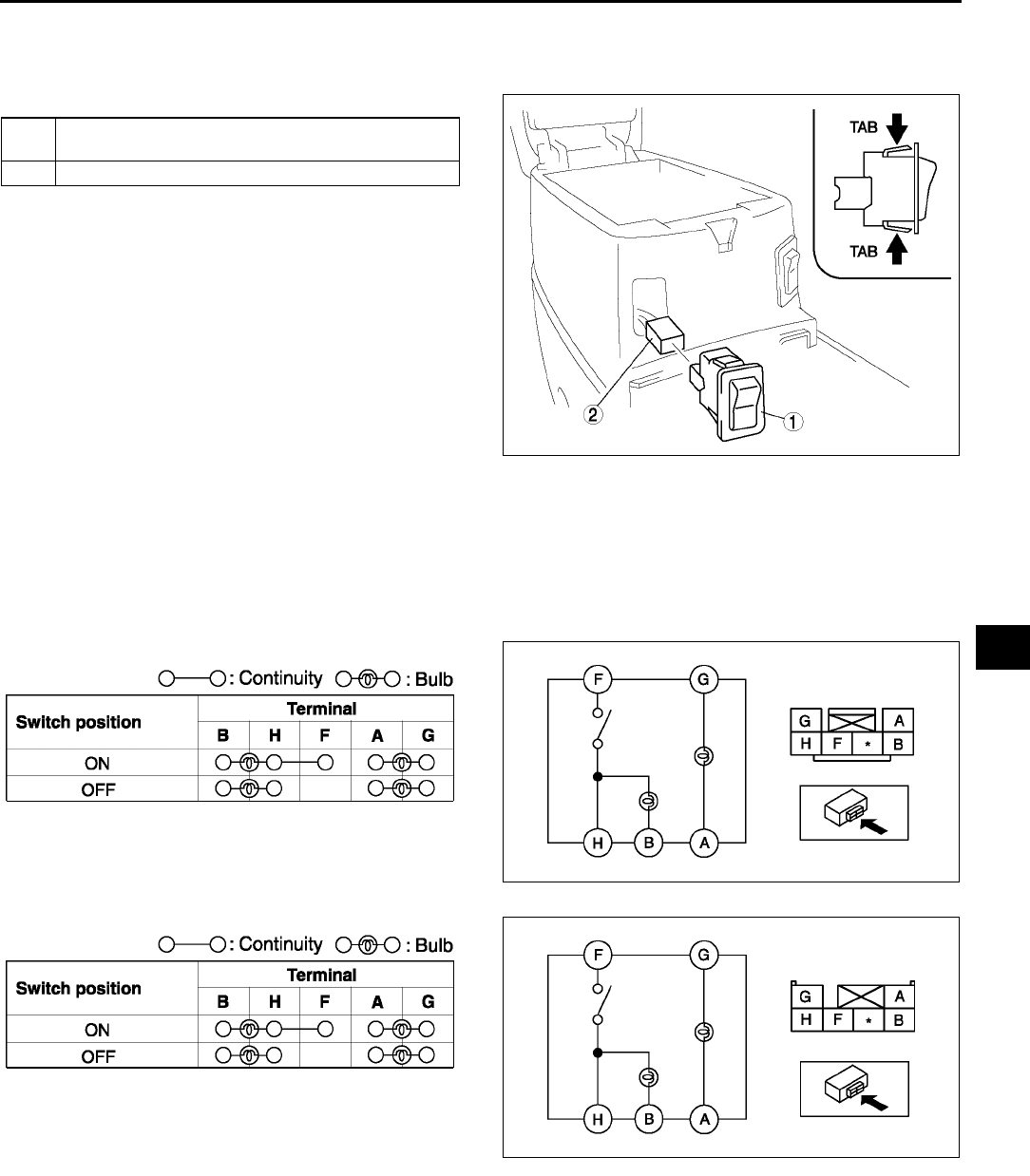
SEAT
S117
S
SEAT WARMER SWITCH REMOVAL/INSTALLATION A6E775259000W01
1. Disconnect the negative battery cable.
2. Remove the brake boots panel. (See S86 CONSOLE REMOVAL/INSTALLATION.)
3. Remove in the order indicated in the table.
4. Install in the reverse order of removal.
Seat Warmer Switch Removal Note
1. Squeeze the tabs of seat warmer switch and pull it forward to remove it.
End Of Sie
SEAT WARMER SWITCH INSPECTION A6E775259000W02
1. Remove the seat warmer switch.
2. Inspect for continuity between the seat warmer switch terminals using an ohmmeter.
•If not as specified, replace the seat warmer switch.
Drivers side
Passengers side
End Of Sie
1 Seat warmer switch
(See S117 Seat Warmer Switch Removal Note.)
2 Connector
A6E7752W001
A6E7752W024
A6E7752W025
A6E7752W024
A6E7752W026
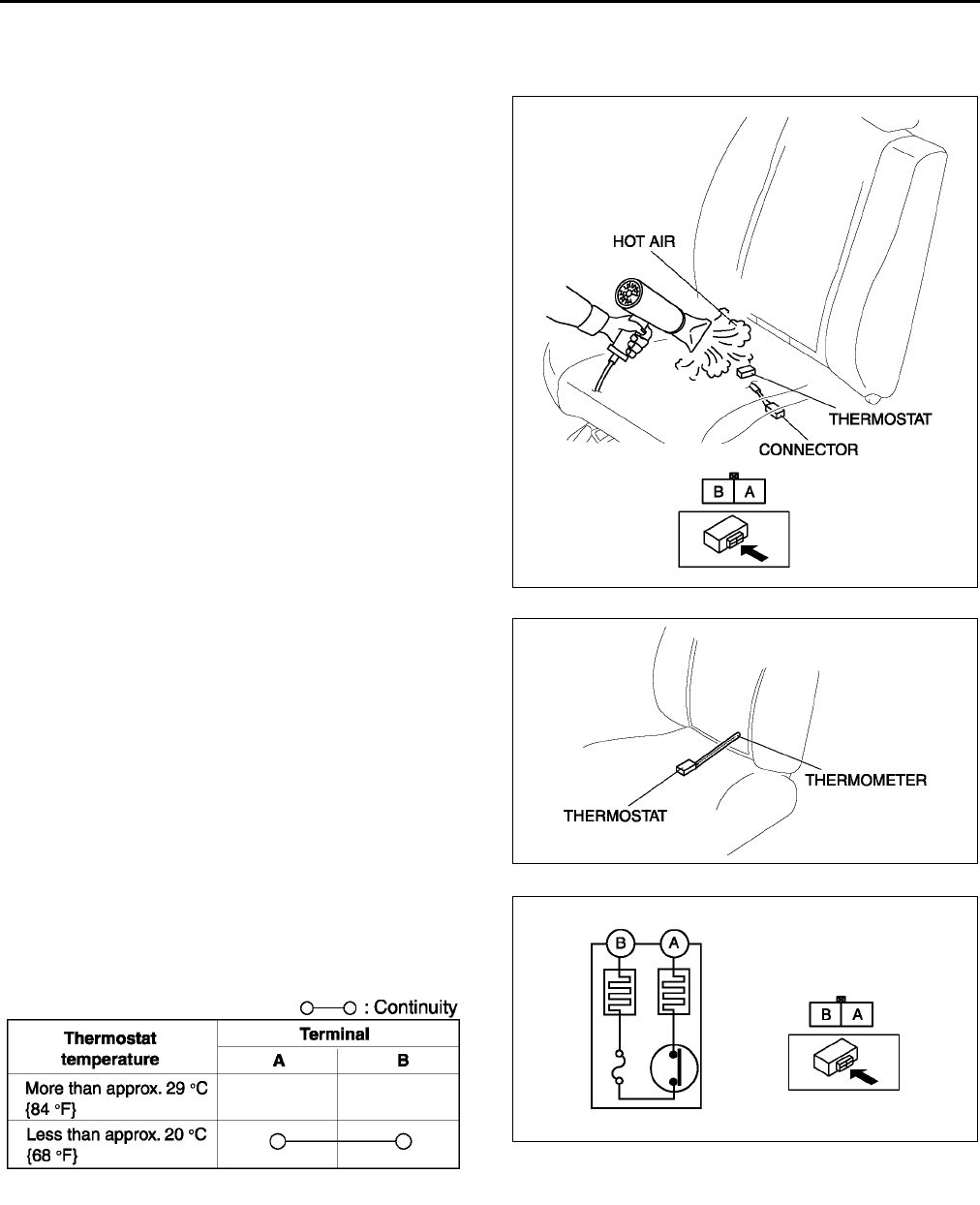
S118
SEAT
SEAT WARMER UNIT INSPECTION A6E775259000W03
1. Remove the front seat. (See S105 FRONT SEAT REMOVAL/INSTALLATION.)
2. Remove the seat cushion trim.
3. While inspecting for continuity between the
terminals A and B of the connector, use a dryer to
warm the thermostat of the seat warmer unit on
seat cushion.
4. When the indication on the ohmmeter is no
continuity, turn off the dryer, then use a
thermometer to measure the temperature of the
thermostat.
5. Verify that the temperature is approximately
29 °
°°
°C {84 °
°°
°F}.
6. Verify that there is continuity between the
terminals of seat warmer units connector using an
ohmmeter when temperature drops to
approximately 20 °
°°
°C {68 °
°°
°F}.
End Of Sie
A6E7752W020
A6E7752W021
A6E7752W022
A6E7752W023
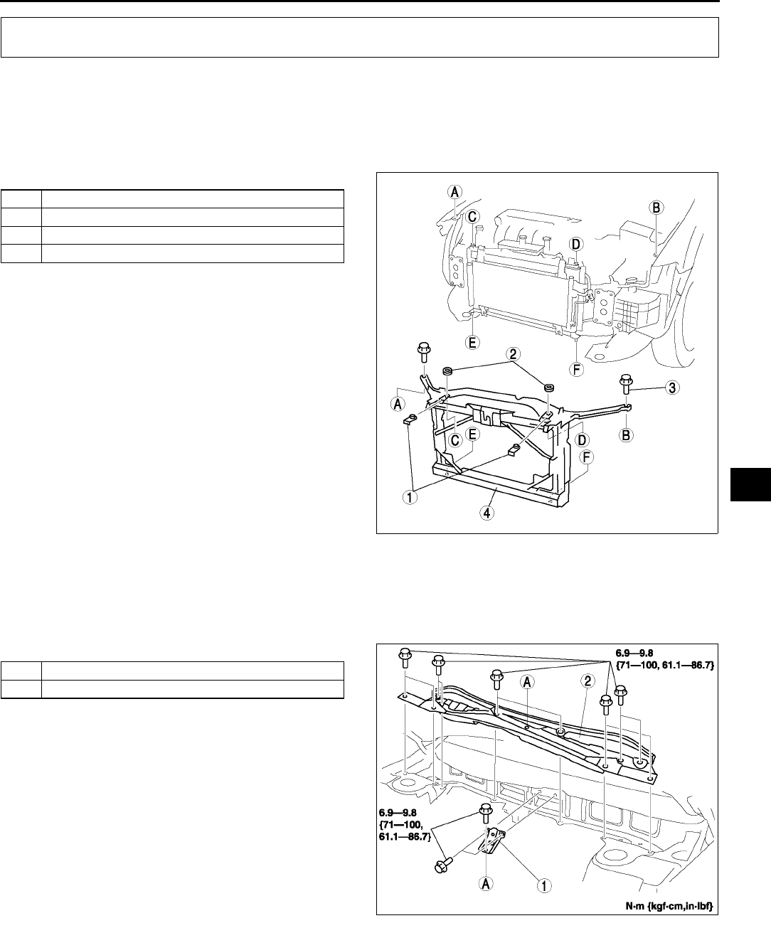
BODY SHELL
S119
S
SHROUD PANEL REMOVAL/INSTALLATION A6E775453140W01
1. Remove the bonnet. (See S10 BONNET REMOVAL/INSTALLATION.)
2. Remove the front bumper. (See S47 FRONT BUMPER REMOVAL/INSTALLATION.)
3. Remove the front combination light. (See T26 FRONT COMBINATION LIGHT REMOVAL/INSTALLATION.)
4. Remove the front bumper reinforcement. (See S48 BUMPER REINFORCEMENT REMOVAL/
INSTALLATION.)
5. Remove in the order indicated in the table.
6. Install in the reverse order of removal.
End Of Sie
COWL PANEL REMOVAL/INSTALLATION A6E775453580W01
1. Remove the windshield wiper arm and blade. (See T57 WINDSHIELD WIPER ARM AND BLADE REMOVAL/
INSTALLATION.)
2. Remove the cowl grille.
3. Remove the windshield wiper motor. (See T56 WINDSHIELD WIPER MOTOR REMOVAL/INSTALLATION.)
4. Remove in the order indicated in the table.
5. Install in the reverse order of removal.
End Of Sie
BODY SHELL
1 Radiator mount cover
2 Radiator mount rubber
3Bolt
4 Shroud panel
A6E7754W001
1Gusset
2 Cowl panel
A6E7754W002
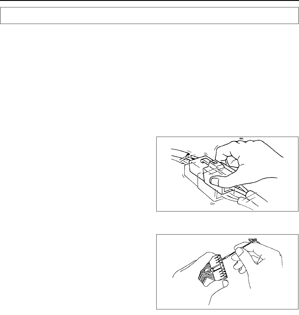
S120
TROUBLESHOOTING [POWER WINDOW SYSTEM]
INTERMITTENT CONCERN TROUBLESHOOTING A6E778058000W01
Vibration Method
•If malfunction occurs or becomes worse while driving on a rough road or when engine is vibrating, perform the
steps below.
Note
•There are several reasons why vehicle or engine vibration could cause an electrical malfunction. Some of
the things to check for:
Connectors not fully seated.
Wire harnesses not having full play.
Wires laying across brackets or moving parts.
Wires routed too close to hot parts.
•An improperly routed, improperly clamped, or loose harness can cause wiring to become pinched
between parts.
•The connector joints, points of vibration, and places where wire harnesses pass through the firewall, body
panels, etc. are the major areas to be checked.
•Check for DTCs or malfunctions by shaking
harnesses and connectors that are
suspected to be causing malfunction.
Connector Terminal Check Method
1. Check the connection condition of each female terminal.
2. Insert male terminal into the female terminals to
check for looseness.
End Of Sie
FOREWORD A6E778058000W02
•Always perform basic power window system inspection before troubleshooting.
•Troubleshooting gives content unique to trouble caused by problems in the automatic window return function.
End Of Sie
TROUBLESHOOTING [POWER WINDOW SYSTEM]
YDE7780W001
YDA8180W000

TROUBLESHOOTING [POWER WINDOW SYSTEM]
S121
S
BASIC POWER WINDOW SYSTEM INSPECTION A6E778058000W03
Manual Mode Function Inspection
Automatic Mode Function Inspection
STEP INSPECTION ACTION
1•Turn ignition switch to ON position.
•Do all windows go up and down in manual
mode using power window main switch?
Yes Go to next step.
No •Inspect the following items:
Power window main switch power supply fuses
Power window main switch ground wiring harness
Power window main switch power supply wiring
harnesses
Wiring harness between power window main switch
and power window motor
Power window main switch
Power window motor
Each power window motor wire installation point
Each window installation point on its carrier plate
Each power window regulator installation point on
each door
•Repair or replace the problem area, then go to Step 4.
2•Does each window go up and down in
manual mode using power window
subswitch?
Yes Go to next step.
No •Inspect the following items:
Power window main switch (power-cut switch system
malfunction)
Power window subswitch
Subswitch power supply wiring harnesses
•Repair or replace the problem area, then go to automatic
mode function inspection.
3•Turn power-cut switch UNLOCK.
•Push/pull power window main switch
(switches for all doors in manual mode).
•Does only driver-side front window go up and
down?
Yes •Manual mode function is normal.
•Go to automatic mode function inspection.
No Replace power window main switch, then go to automatic
mode function inspection (power-cut switch system
malfunction).
STEP INSPECTION ACTION
1•Turn ignition switch to ON position.
•Operate power window main switch for
driver-side front door in automatic mode.
•Does driver-side front window go up and
down?
Yes Go to next step.
No Driver-side front window does not go up and
down in automatic mode:
•Go to Step 1 of NO. 1 DRIVER-SIDE FRONT WINDOW
DOES NOT GO UP AND DOWN IN AUTOMATIC
MODE.
Driver-side front window go up and down in
automatic mode, but driver-side front window
reverses:
•Go to Step 1 of NO. 3 DRIVER-SIDE FRONT WINDOW
REVERSES EVEN THOUGH THE GLASS DOES NOT
ENCOUNTER A FOREIGN OBJECT WHILE IT IS
GOING UP IN AUTOMATIC MODE.
2•Gently pull the driver-side front power
window switch while driver-side front window
is going down in automatic mode.
•Does the glass stop?
Yes Go to next step.
No Replace power window main switch, then go to automatic
window return function inspection.
3•Gently press the driver-side front power
window switch while driver-side front window
is going up in automatic mode.
•Does the glass stop?
Yes •Automatic mode function is normal.
•Go to automatic window return function inspection.
No Replace power window main switch, then go to automatic
window return function inspection.

S122
TROUBLESHOOTING [POWER WINDOW SYSTEM]
Automatic Window Return Function Inspection
IG OFF Timer Function Inspection
STEP INSPECTION ACTION
1•Turn ignition switch to ON position.
•Lower driver-side front window completely.
•Use power window main switch to close
driver's window in automatic mode.
•Does window automatically reverse even
though the glass does not encounter a
foreign object while it is going up in
automatic mode?
Yes Go to Step 1 of NO. 3 DRIVER-SIDE FRONT WINDOW
REVERSES EVEN THOUGH THE GLASS DOES NOT
ENCOUNTER A FOREIGN OBJECT WHILE IT IS GOING
UP IN AUTOMATIC MODE.
No Go to next step.
2•Lower driver-side front window completely.
•Take a hammer and hold it against the inside
of the top of the window frame so that the
window will hit its handle when it is closed.
•Raise the window using automatic mode.
•When the window hits the hammer handle,
does it immediately reverse and go down to
approximately 200 mm {7.87 in} from the
completely closed position?
Yes •Automatic window return function inspection is normal.
•Go to IG OFF timer function inspection.
No Go to Step 1 of NO. 2 DRIVER-SIDE FRONT WINDOW
DOES NOT REVERSE, EVEN WHEN ENCOUNTERING A
FOREIGN OBJECT IN ITS PATH.
STEP INSPECTION ACTION
1•Turn ignition switch to ON position.
•In automatic mode, push down power
window main switch for driver-side front
window. Window should go down within
approximately 42 seconds from ignition
switch OFF position.
•In manual mode (finger continuously
depressing power window main switch),
window should go down within
approximately 42 seconds from ignition
switch OFF position.
•Does driver-side front window go down?
Yes Go to next step.
No Replace power window main switch, then go to next step.
2•Turn ignition switch to ON position.
•In automatic mode, pull up power window
main switch for driver-side front window.
Window cannot go up within approximately
4 seconds from ignition switch OFF position.
•Verify that driver-side front window does not
operate.
•Does driver-side front window go up?
Yes Replace power window main switch, then go to next step.
No Go to next step.
3•Turn ignition switch to ON position.
•Lower driver-side front window completely.
•Take a hammer and hold it against the inside
of the top of the window frame so that the
window will hit its handle when it is closing.
•Raise the window using manual mode.
•When the window hits the hammer handle,
does it immediately reverse and go down to
approximately 200 mm {7.87 in} from the
completely raised position?
Yes Go to next step.
No Replace power window main switch, then go to next step.
4•Open any door.
•Turn ignition switch to ON position.
•Push/pull power window main switch for
driver-side front window within
approximately 42 seconds from ignition
switch OFF position.
•Verify that driver-side front window does not
go up or down.
•Does driver-side front window go up or
down?
Yes •Inspect door switch and related warning harness.
•If above parts are okay, replace power window main
switch, then go to next step.
•If above parts are incorrect, repair or replace malfunction
part(s), then go to next step.
No Go to next step.
TROUBLESHOOTING [POWER WINDOW SYSTEM]
S123
S
Two-step Down Function Inspection
•The distance the door glass opens can be changed using the two-step down function. (Approximately 20-100
mm {0.79-3.93 in})
•The two-step down function can be made non-operative. (The function is operative at the initial setting.)
•The two-step down function does not function during IG OFF timer.
End Of Sie
TROUBLESHOOTING INDEX A6E778058000W04
End Of Sie
NO. 1 DRIVER-SIDE FRONT WINDOW DOES NOT GO UP AND DOWN IN AUTOMATIC MODE A6E778058000W05
5•Close all doors.
•Turn ignition switch to ON position.
•Push/pull power window main switch for
driver-side front window after approximately
60 seconds from ignition switch OFF
position.
•Verify that driver-side front window does not
go up or down.
•Does driver-side front window go up or
down?
Yes Replace power window main switch, then go to two-step
down function inspection.
No •IG OFF timer function is normal.
•Go to two-step down function inspection..
STEP INSPECTION ACTION
STEP INSPECTION ACTION
1•Turn ignition switch to ON position.
•Raise driver-side front window completely.
•When the driver-side front window is lowered
using manual mode, does it go down to
approximately 30 mm {1.18 in} from the
completely closed position and stop for 1
second? (This inspection cannot be carried
out during IG OFF timer function operation.)
Yes •two-step down function is normal.
•Recheck malfunction symptoms.
No Replace power window main switch.
No. TROUBLESHOOTING ITEM PAGE
1 Driver-side front window does not go up and down in
automatic mode.
(See S123 NO. 1 DRIVER-SIDE FRONT WINDOW DOES
NOT GO UP AND DOWN IN AUTOMATIC MODE.)
2 Driver-side front window does not reverse, even when
encountering a foreign object in its path.
(See S126 NO. 2 DRIVER-SIDE FRONT WINDOW DOES
NOT REVERSE, EVEN WHEN ENCOUNTERING A
FOREIGN OBJECT IN ITS PATH.)
3 Driver-side front window reverses even though the
glass does not encounter a foreign object while it is
going up in automatic mode.
(See S127 NO. 3 DRIVER-SIDE FRONT WINDOW
REVERSES EVEN THOUGH THE GLASS DOES NOT
ENCOUNTER A FOREIGN OBJECT WHILE IT IS GOING
UP IN AUTOMATIC MODE.)
1Driver-side front window does not go up and down in automatic mode
POSSIBLE
CAUSE
•Open or short to B+ circuit in position sensor 1 signal, ground signal from wiring harness (between
power window main switch and driver-side front power window motor), inner power window main
switch, or inner motor: Steps 36
•Open or short to B+/ground circuit in position sensor 2 signal from wiring harness (between power
window main switch and driver-side front power window motor), inner power window main switch, or
inner motor: Steps 711
Note
•The automatic function and the ignition off timer function do not operate while power window main
switch is in fail-safe mode. The fail-safe operates when position sensor 1, and/or position sensor 2,
and/or position sensor 2 power supply malfunctions.
•Position sensor 1 and/or 2 malfunction
When driver-side front window is kept up down, main switch can not sense a pulse signal from
position sensor 1 during that can sense 5 pulses (2.5 cycles) from position 2.
When driver-side front window is kept up down, main switch can not sense a pulse signal from
position sensor 2 during that can sense 5 pulses (2.5 cycles) from position 1.
There are 3 abnormal pulse from a pulse signal during driver-side front window is kept up or
down.
There are 20 cycle pulses from a close position during driver-side front window is kept up.
There is no pulse signal during 1 sec. after down is operated.

S124
TROUBLESHOOTING [POWER WINDOW SYSTEM]
Diagnostic procedure
STEP INSPECTION ACTION
1INSPECT WHETHER POWER WINDOW MAIN
SWITCH ENTERS FAIL-SAFE MODE OR NOT
•Did driver-side front window go up or down in
automatic mode?
Yes Recheck malfunction symptoms.
No Go to next step. (Power window main switch may enter fail-
safe mode.)
2VERIFY WHETHER MALFUNCTION IS IN
WIRING HARNESS (BETWEEN POWER
WINDOW MAIN SWITCH AND DRIVER-SIDE
FRONT POWER WINDOW MOTOR) OR
ELSEWHERE
•Turn ignition switch ON position.
•Test voltage at power window main switch
connector terminal 2C (position sensor 1
signal).
•Is voltage alternate between 0 V and
approximately 5 V when driver-side front
window is being gone up and down?
Yes Go to Step 7.
No Go to next step.
3VERIFY POSITION SENSOR 1 OUTPUT
SIGNAL
•Turn ignition switch to ON position.
•Test voltage at driver-side front power
window motor connector terminal H (position
sensor 1 signal).
•Is voltage alternate between 0 V and
approximately 12 V when driver-side front
window is being gone up and down at
manual mode?
Yes Go to next step.
No Replace driver-side front power window motor, then go to
Step 12.
4INSPECT WIRING HARNESS BETWEEN
POWER WINDOW MAIN SWITCH AND
DRIVER-SIDE FRONT POWER WINDOW
MOTOR FOR CONTINUITY
•Turn ignition switch to LOCK position.
•Disconnect power window main switch
connector.
•Is there continuity between the following
power window main switch connector
terminals and driver-side front power window
motor connector terminals?
2CH (position sensor 1 signal)
2DE (position sensor power supply)
2AF (ground signal)
Yes Go to next step.
No Repair wiring harness between power window main switch
and driver-side front power window motor, then go to Step
12.
5VERIFY WHETHER MALFUNCTION IS IN
WIRING HARNESS (BETWEEN POWER
WINDOW MAIN SWITCH AND DRIVER-SIDE
FRONT POWER WINDOW MOTOR) OR
POWER WINDOW MAIN SWITCH
•Turn ignition switch to ON position.
•Measure voltage at the following power
window main switch connector terminals:
2C (position sensor 1 signal)
2A (ground signal)
•Is voltage approximately 12 V?
Yes Repair wiring harness between power window main switch
and driver-side front power window motor, then go to Step
12.
No Replace power window main switch (open or short to B+ in
power window main switch).
6VERIFY WHETHER MALFUNCTION IS IN
WIRING HARNESS (BETWEEN POWER
WINDOW MAIN SWITCH AND DRIVER-SIDE
FRONT POWER WINDOW MOTOR) OR
ELSEWHERE
•Is continuity between following power
window main switch connector terminals and
ground?
2C (position sensor 1 signal)
2D (position sensor power supply)
Yes Replace wiring harness between power window main switch
and driver-side front power window motor, then go to Step
12.
No Go to next step.

TROUBLESHOOTING [POWER WINDOW SYSTEM]
S125
S
End Of Sie
7VERIFY WHETHER MALFUNCTION IS IN
POWER WINDOW MAIN SWITCH OR
ELSEWHERE
•Turn ignition switch to ON position.
•Test voltage at power window main switch
connector terminal 2B (position sensor 2
signal).
•Does voltage alternate between 0 V and
approximately 12 V when driver-side front
window is being gone up down?
Yes Replace power window main switch. (malfunction in power
window main switch automatic mode control), then go to
Step 11.
No Go to next step.
8VERIFY POSITION SENSOR 2 OUTPUT
SIGNAL
•Turn ignition switch to ON position.
•Test voltage at driver-side front power
window motor connector terminal G (position
sensor 2 signal).
•Is voltage alternate between 0 V and
approximately 12 V when driver-side front
window is being gone up down?
Yes Go to next step.
No Replace driver-side front power window motor, then go to
Step 12.
9VERIFY WHETHER MALFUNCTION IS IN
WIRING HARNESS (BETWEEN POWER
WINDOW MAIN SWITCH AND DRIVER-SIDE
FRONT POWER WINDOW MOTOR) OR
ELSEWHERE
•Turn ignition switch to LOCK position.
•Disconnect power window main switch
connector and driver-side front power
window motor connector.
•Is there continuity between power window
main switch connector terminal 2B (position
sensor 2 signal) and driver-side front power
window motor connector terminal G (position
sensor 2 signal)?
Yes Go to next step.
No Repair wiring harness between power window main switch
and driver-side front power window motor, then go to Step
12.
10 VERIFY WHETHER MALFUNCTION IS IN
WIRING HARNESS (BETWEEN POWER
WINDOW MAIN SWITCH AND DRIVER-SIDE
FRONT POWER WINDOW MOTOR) OR
ELSEWHERE
•Is there continuity between power window
main switch connector terminal 2B (position
sensor 2 signal) and ground?
Yes Repair wiring harness between power window main switch
and driver-side front power window motor, then go to Step
12.
No Go to next step.
11 VERIFY WHETHER MALFUNCTION IS IN
WIRING HARNESS (BETWEEN POWER
WINDOW MAIN SWITCH AND DRIVER-SIDE
FRONT POWER WINDOW MOTOR) OR
POWER WINDOW MAIN SWITCH
•Turn ignition switch to ON position.
•Measure voltage at power window main
switch connector terminal 2B (position
sensor 2 signal).
•Is voltage approximately 12 V?
Yes Repair wiring harness between power window main switch
and front driver-side power window motor, then go to next
step.
No Replace power window main switch (open or short to B+/
ground in power window main switch), then go to next step.
12 RECHECK MALFUNCTION SYMPTOM AFTER
REPAIR
•Did malfunction disappear?
Yes •Troubleshooting completed.
•Explain repairs to customer.
No Recheck malfunction symptoms, then repeat from Step 1 if
malfunction recurs.
STEP INSPECTION ACTION
S126
TROUBLESHOOTING [POWER WINDOW SYSTEM]
NO. 2 DRIVER-SIDE FRONT WINDOW DOES NOT REVERSE, EVEN WHEN ENCOUNTERING A FOREIGN
OBJECT IN ITS PATH A6E778058000W06
Diagnostic procedure
End Of Sie
2 Driver-side front window does not reverse, even when encountering a foreign object in its path.
POSSIBLE
CAUSE
•Automatic window return range did not reset after battery disconnect: Step 2
STEP INSPECTION ACTION
1CHECK FOR CUSTOMER COMPLAINT
•Did customer complain that driver-side front
window did not reverse when nearing
complete close?
Yes •System normal.
•Explain to customer that automatic window return power
window system does not operate when nearing of
complete close.
No Go to next step.
2RESET REVERSE AREA STORED IN
DRIVER-SIDE FRONT WINDOW MOTOR
•Reset the main switch to recognize driver-
side front window fully closed position.
•Did malfunction disappear?
Yes •Troubleshooting completed.
•Explain to customer that misadjustment of automatic
window return range was the problem.
No Replace power window main switch.

TROUBLESHOOTING [POWER WINDOW SYSTEM]
S127
S
NO. 3 DRIVER-SIDE FRONT WINDOW REVERSES EVEN THOUGH THE GLASS DOES NOT ENCOUNTER A
FOREIGN OBJECT WHILE IT IS GOING UP IN AUTOMATIC MODE A6E778058000W07
Diagnostic procedure
End Of Sie
3Driver-side front window reverses even though the glass does not encounter a foreign object while
it is going up in automatic mode.
POSSIBLE
CAUSE
•Too much driver-side front window friction resistance: Steps 15
•Short to ground in position sensor 1 signal from wiring harness (between power window main switch
and driver-side front power window motor), inner driver-side front power window motor, or inner power
window main switch: Steps 6, 7
STEP INSPECTION ACTION
1INSPECT FOR FOREIGN OBJECT IN DRIVER-
SIDE FRONT WINDOW
•Is there a foreign object in driver-side front
window?
Yes Remove the object.
No Go to next step.
2INSPECT ACRYLIC VISOR BRACKET
INSTALLATION
•Is acrylic visor bracket properly installed?
Yes Go to next step.
No Reinstall acrylic visor bracket properly.
3INSPECT TO SEE IF GLASS RUN CHANNEL
INTERFERES WITH DRIVER-SIDE FRONT
WINDOW
•Remove driver-side front door trim.
•Does glass run channel interfere with driver-
side front window?
Yes Repair or replace glass run channel, then go to Step 9.
No Go to next step.
4INSPECT LUBRICANT ON DRIVER-SIDE
CARRIER PLATE
•Is there lubricant on driver-side carrier plate?
Yes Go to next step.
No Apply lubricant (mineral oil).
5INSPECT INSTALLATION OF DRIVER-SIDE
FRONT POWER WINDOW SYSTEM
COMPONENTS
•Are the following parts properly installed?
Driver-side front door glass
Driver-side power window motor wire
Driver-side power window motor
Driver-side power window regulator frame
Driver-side carrier plate
Driver-side glass run channel
Yes Go to next step.
No Reinstall part(s) properly, then go to Step 9.
6VERIFY POSITION SENSOR 1 OUTPUT
SIGNAL
•Turn ignition switch to ON position.
•Test voltage at driver-side front power
window motor connector terminal H (position
sensor 1 signal).
•Is voltage alternate between 0 V and
approximately 12 V when driver-side front
window is being gone up and down at
manual mode?
Yes Go to next step.
No Replace driver-side front power window motor, then go to
Step 8.
7VERIFY WHETHER MALFUNCTION IS IN
WIRING HARNESS (BETWEEN POWER
WINDOW MAIN SWITCH AND DRIVER-SIDE
FRONT POWER WINDOW MOTOR) OR
POWER WINDOW MAIN SWITCH
•Turn ignition switch to LOCK position.
•Disconnect power window main switch.
•Is there continuity between power window
main switch connector terminal 2C (position
sensor 1 signal) and ground?
Yes Repair wiring harness between power window main switch
and driver-side front power window motor, then go to next
step.
No Replace power window main switch (short to ground in
power window main switch), then go to next step.
8RECHECK MALFUNCTION SYMPTOM AFTER
REPAIR
•Did malfunction disappear?
Yes •Troubleshooting completed.
•Explain repairs to customer.
No Recheck malfunction symptoms, then repeat from Step 1 if
malfunction recurs.
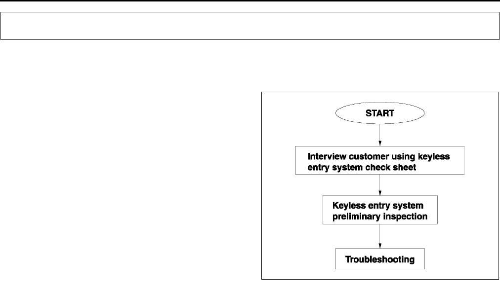
S128
TROUBLESHOOTING [KEYLESS ENTRY SYSTEM]
FOREWORD A6E778269000W01
•Go to troubleshooting after identifying the specific malfunction by doing a keyless entry system preliminary
inspection.
Flowchart
End Of Sie
TROUBLESHOOTING [KEYLESS ENTRY SYSTEM]
A6E7782W002
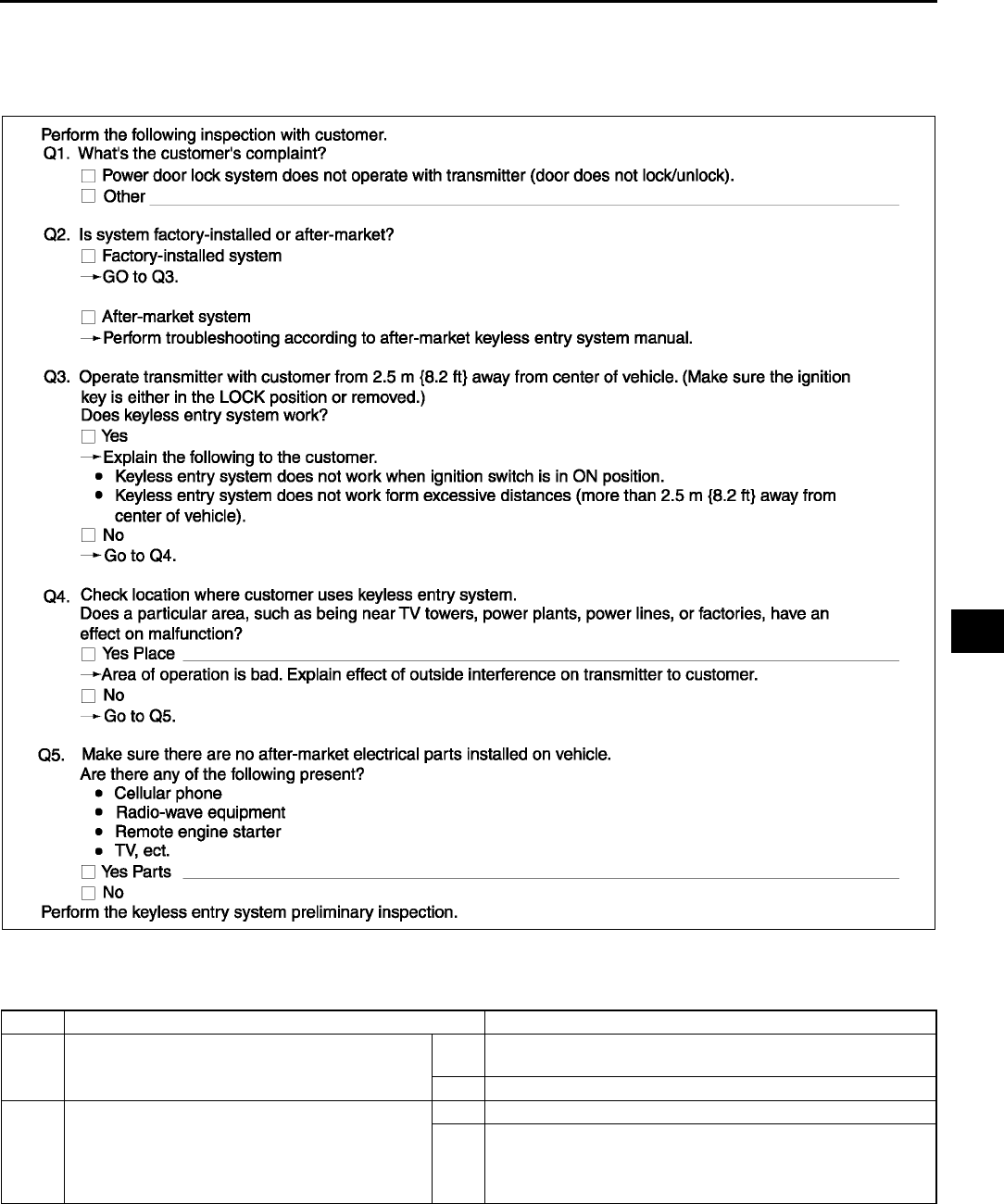
TROUBLESHOOTING [KEYLESS ENTRY SYSTEM]
S129
S
KEYLESS ENTRY SYSTEM CHECK SHEET A6E778269000W02
•Use the sheet below as a customer interview sheet when accepting a vehicle for service.
•If the symptom is Power door lock system does not operate with transmitter at all, find out how the customer
uses the keyless entry system by following the check sheet below.
End Of Sie
KEYLESS ENTRY SYSTEM PRELIMINARY INSPECTION A6E778269000W03
•Perform the following preliminary inspection before troubleshooting.
A6E7782W001
STEP INSPECTION ACTION
1•Is system an after-market one? Yes Perform troubleshooting according to after-market keyless
entry system manual.
No Go to next step.
2•Did customer activate keyless entry system
when ignition switch was in LOCK position?
Yes Go to next step.
No •Explain to customer that system does not work when
ignition is in ON position.
•Turn ignition switch to LOCK position, then go to next
step.
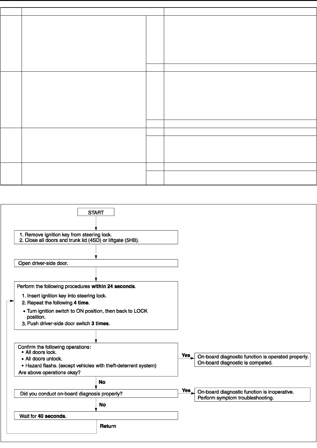
S130
TROUBLESHOOTING [KEYLESS ENTRY SYSTEM]
End Of Sie
ON-BOARD DIAGNOSTIC FUNCTION A6E778269000W04
End Of Sie
3•Did customer use keyless entry system in
particular area, such as being near TV
towers, power plants, power lines, or
factories?
Yes Attempt to lock/unlock doors with transmitter in
non-interference area.
If system operates:
•Area of operation is bad. Explain effect of outside
interference on transmitter to customer.
If system does not operate:
•Go to next step.
No Go to next step.
4•Are any of the following after-market
electrical parts on the vehicle?
Cellular phone
Radio-wave equipment
Remote engine starter
TV, etc.
Yes Disconnect after-market electrical part connectors and
attempt to lock/unlock doors with transmitter.
If system operates:
•After-market electrical parts are interfering with keyless
entry system.
If system does not operate:
•Go to next step.
No Go to next step.
5•Perform on-board diagnostic function.
(See S130 ON-BOARD DIAGNOSTIC
FUNCTION.)
•Does on-board diagnostic function work?
Yes Go to next step.
No •Go to Step 1 of NO. 1 ONE OR MORE ON-BOARD
DIAGNOSTIC FUNCTIONS INOPERATIVE.
•Go to Step 1 of NO. 2 ALL ON-BOARD DIAGNOSTIC
FUNCTIONS INOPERATIVE.
6•Attempt to reprogram transmitter ID code.
•Can transmitter ID code be reprogrammed?
Yes System is normal now.
No Go to Step 1 of troubleshooting NO. 3 TRANSMITTER ID
CODE CANNOT BE REPROGRAMMED.
STEP INSPECTION ACTION
A6E7782W003

TROUBLESHOOTING [KEYLESS ENTRY SYSTEM]
S131
S
TROUBLESHOOTING INDEX A6E778269000W05
End Of Sie
NO. 1 ONE OR MORE ON-BOARD DIAGNOSTIC FUNCTIONS INOPERATIVE A6E778269000W06
•When performing an asterisked (*) troubleshooting inspection, shake the wiring harness and connectors while
doing the inspection to discover whether poor contact points are the cause of any intermittent malfunctions. If
there is a problem, check to make sure connectors, terminals and wiring harnesses are connected correctly
and undamaged.
Diagnostic procedure
Note
•For with theft-deterrent system, follow the procedure from Step 4.
No. TROUBLESHOOTING ITEM DESCRIPTION PAGE
1 One or more on-board
diagnostic functions inoperative.
•Malfunction in hazard warning light system
(except vehicle with theft-deterrent system), or
door lock linkage system, drivers door key
cylinder switch system.
(See S131 NO. 1 ONE OR
MORE ON-BOARD DIAGNOSTIC
FUNCTIONS INOPERATIVE)
2 All on-board diagnostic
functions inoperative.
•Malfunction in door lock timer unit power
supply circuit, door switch circuit, cargo
compartment light circuit or door lock timer
unit ground circuit.
(See S132 NO. 2 ALL
ON-BOARD DIAGNOSTIC
FUNCTIONS INOPERATIVE)
3 Transmitter ID code cannot be
reprogrammed.
•Malfunction in transmitter battery, transmitter,
door lock timer unit bracket, door lock timer
unit bracket ground screw or door lock timer
unit circuit.
(See S133 NO. 3
TRANSMITTER ID CODE
CANNOT BE REPROGRAMMED)
1 One or more on-board diagnostic functions inoperative
DESCRIPTION •Malfunction in hazard warning light system, or door lock linkage system, drivers door key cylinder
switch system.
POSSIBLE
CAUSE
•Malfunction in hazard warning light system
Hazard warning light circuit
Door lock timer unit malfunction
Malfunction in wiring harness between door lock timer unit and flasher unit
•Malfunction in door lock linkage
•Malfunction in door lock timer unit door lock/unlock signal circuit
Door lock timer unit malfunction
STEP INSPECTION ACTION
1INSPECT HAZARD WARNING LIGHT
OPERATION DURING ON-BOARD
DIAGNOSIS
•Did hazard warning lights flash during on-
board diagnostic function operation?
Yes Go to Step 4.
No Go to next step.
2INSPECT HAZARD WARNING LIGHT
CIRCUIT
•Do hazard warning lights flash when hazard
warning switch is on?
Yes Go to next step.
No Inspect hazard warning light circuit.
*3 CHECK TO SEE WHETHER MALFUNCTION
IS IN WIRING HARNESS (BETWEEN DOOR
LOCK TIMER UNIT AND FLASHER UNIT) OR
DOOR LOCK TIMER UNIT
•Measure voltage at door lock timer unit
connector terminal I (24 pin) during on-board
diagnostic function operation.
When hazard warning light flashed:
B+⇔below 1.0 V
•Is voltage as above?
Yes Recheck malfunction symptoms, then repeat from Step 1 if
malfunction reoccurs.
No •Inspect wiring harness between door lock timer unit and
flasher unit.
If wiring harness is OK, replace door lock timer unit
and reprogram transmitter ID code, then go to Step 7.
If wiring harness malfunction, repair wiring harness,
then go to Step 7.
4MAKE SURE THAT ALL DOORS LOCK AND
UNLOCK DURING ON-BOARD DIAGNOSIS
•Did all doors unlock and lock during on-
board diagnostic function operation?
Yes Recheck malfunction symptoms, then repeat from Step 1 if
malfunction reoccurs.
No Go to next step.
5INSPECT DOOR LOCK LINKAGE
•Operate door lock knob and make sure door
locks and unlocks manually.
•Does every door lock system work?
Yes Go to next step.
No Inspect door lock linkage.

S132
TROUBLESHOOTING [KEYLESS ENTRY SYSTEM]
End Of Sie
NO. 2 ALL ON-BOARD DIAGNOSTIC FUNCTIONS INOPERATIVE A6E778269000W07
•When performing an asterisked (*) troubleshooting inspection, shake the wiring harness and connectors while
doing the inspection to discover whether poor contact points are the cause of any intermittent malfunctions. If
there is a problem, check to make sure connectors, terminals and wiring harnesses are connected correctly
and undamaged.
Diagnostic procedure
*6 CHECK TO SEE WHETHER MALFUNCTION
IS IN DOOR LOCK ACTUATOR, DOOR LOCK
TIMER UNIT GROUND CIRCUIT OR
ELSEWHERE
•Measure voltage at door lock timer unit
connector terminal C, D (6 pin) during on-
board diagnostic function operation.
All door locked: below 1.0 V→B+→below
1.0 V (terminal D, 6 pin)
All door unlocked: B+→below 1.0 V→B+
(terminal C, 6 pin)
•Is voltage as above?
Yes Recheck malfunction symptoms, then repeat from Step 1 if
malfunction reoccurs.
No •Inspect door lock timer unit connector.
•Inspect wiring harness between door lock timer unit and
door lock actuator.
If above parts are OK, go to next step.
If above parts malfunction, repair malfunction part.
7RECHECK MALFUNCTION SYMPTOM AFTER
REPAIR
•Does keyless entry system operate
properly?
Yes Troubleshooting completed.
Explain repairs to customer.
No Recheck malfunction symptoms, then repeat from Step 1 if
malfunction reoccurs.
STEP INSPECTION ACTION
2 All on-board diagnostic functions inoperative
DESCRIPTION •Malfunction in door lock timer unit power supply circuit, door switch circuit, cargo compartment light
circuit or door lock timer unit ground circuit.
POSSIBLE
CAUSE
•Malfunction in IG1, B+ signal circuit of door lock timer unit
Door lock timer unit power supply fuse malfunction
Malfunction in wiring harness between door lock timer unit power supply fuse(s) and door lock timer
unit itself
•Malfunction in door lock timer unit's door open/closed signal circuit
Door switch system malfunction
Door lock timer unit malfunction
Malfunction in wiring harness between door lock timer unit and door switch
•Malfunction in door lock timer unit's liftgate or trunk lid open/closed signal circuit
Cargo compartment light switch system malfunction
Door lock timer unit malfunction
Malfunction in wiring harness between door lock timer unit and cargo compartment light switch
•Malfunction in door lock timer unit GND signal circuit
Malfunction in wiring harness between door lock timer unit and ground
STEP INSPECTION ACTION
1INSPECT DOOR LOCK TIMER UNIT POWER
SUPPLY FUSES
•Are door lock timer unit power supply fuses
okay?
Yes Go to next step.
No Check for a short to ground on blown fuse's circuit. Repair
or replace as necessary.
Install appropriate amperage fuse.
2INSPECT DOOR SWITCH INSTALLATION
•Are door switches installed securely?
Yes Go to next step.
No Install door switch(es) securely, then go back to Step 5 of
keyless entry system preliminary inspection.
*3 CHECK TO SEE WHETHER MALFUNCTION
IS IN WIRING HARNESS (LACK OF
CONTINUITY BETWEEN FUSE BLOCK AND
DOOR LOCK TIMER UNIT) OR ELSEWHERE
•Turn ignition switch to ON position.
•Measure voltage at following door lock timer
unit terminals:
IG1 signal (Terminal B (24 pin))
B+ signal (Terminal A (24 pin))
•Is voltage B+?
Yes Go to next step.
No Repair wiring harness between fuse block and door lock
timer unit, then go to Step 8.

TROUBLESHOOTING [KEYLESS ENTRY SYSTEM]
S133
S
End Of Sie
NO. 3 TRANSMITTER ID CODE CANNOT BE REPROGRAMMED A6E778269000W08
Diagnostic procedure
*4 CHECK TO SEE WHETHER MALFUNCTION
IS IN WIRING HARNESS (SHORT TO B+
BETWEEN FUSE BLOCK AND DOOR LOCK
TIMER UNIT, OR BETWEEN DOOR LOCK
TIMER UNIT AND GROUND) OR
ELSEWHERE
•Turn ignition switch to LOCK position.
•Disconnect door lock timer unit connector.
•Measure voltage at following door lock timer
unit connector terminals:
IG1 signal (Terminal B (24 pin))
•Is voltage B+?
Yes Repair malfunctioning wiring harness, then go to Step 8.
No Go to next step.
*5 CHECK TO SEE WHETHER MALFUNCTION
IS IN WIRING HARNESS (LACK OF
CONTINUITY BETWEEN DOOR LOCK TIMER
UNIT AND GROUND) OR ELSEWHERE
•Is there continuity between door lock timer
unit connector terminal W (24 pin) and
ground?
Yes Go to next step.
No Repair wiring harness between door lock timer unit and
ground, then go to Step 8.
6INSPECT FOR CHECK CODE 04 IN
INSTRUMENT CLUSTER
•Inspect door switch using instrument cluster
input/output check mode.
(See Section T)
•Does DTC 04 function properly?
Yes Go to next step.
No Repair door switch system using DTC 04 inspection
procedure, then go to Step 8.
7INSPECT DOOR LOCK TIMER UNIT OR
WIRING HARNESS (BETWEEN DOOR LOCK
TIMER UNIT AND DOOR SWITCHES, CARGO
COMPARTMENT LIGHT SWITCH FOR
CONTINUITY)
•Open the driver-side door.
•Is there continuity between door lock timer
unit connector terminal K, G (24 pin) and
ground?
Yes Replace door lock timer unit and reprogram door lock timer
unit ID code, then go to next step.
No Repair wiring harness between door lock timer unit and door
switch(es), cargo compartment light switch then go to next
step.
8RECHECK MALFUNCTION SYMPTOM AFTER
REPAIR
•Does keyless entry system operate
properly?
Yes Troubleshooting completed.
Explain repairs to customer.
No Recheck malfunction symptoms, then repeat from Step 1 if
malfunction reoccurs.
STEP INSPECTION ACTION
3 Transmitter ID code cannot be reprogrammed
DESCRIPTION •Malfunction in transmitter battery, transmitter door lock timer unit bracket, door lock timer unit bracket
ground screw or door lock timer unit circuit.
POSSIBLE
CAUSE
•Malfunction in transmitter battery, transmitter, door lock timer unit bracket, door lock timer unit bracket
ground screw or door lock timer unit circuit
Transmitter battery, transmitter, door lock timer unit bracket, door lock timer unit bracket ground
screw or door lock timer unit malfunction
STEP INSPECTION ACTION
1INSPECT TRANSMITTER BATTERY
INSTALLATION AND TYPE
•Visually inspect transmitter battery.
•Are below items okay?
Transmitter battery installation (correct
polarity)
Battery type (CR2025)
Yes Go to next step.
No Set transmitter battery properly or replace with specified
transmitter battery (CR2025), then go to Step 8.
2INSPECT TRANSMITTER BATTERY
TERMINALS FOR RUST AND POOR
CONNECTION
•Visually inspect transmitter.
Is there rust on transmitter battery
terminals (positive or negative pole)?
Is there poor connection between
terminals and battery?
Yes Replace transmitter battery or repair transmitter battery
terminal, then go to Step 8.
No Go to next step.

S134
TROUBLESHOOTING [KEYLESS ENTRY SYSTEM]
End Of Sie
3INSPECT TRANSMITTER BATTERY
•Inspect transmitter battery.
•Is battery voltage normal?
Yes Go to next step.
No Replace transmitter battery, then go to Step 8.
4INSPECT DOOR LOCK TIMER UNIT
BRACKET INSTALLATION
•Is door lock timer unit bracket installed
securely?
Yes Go to next step.
No Install bracket securely, then go back to Step 6 of keyless
entry system preliminary inspection.
5INSPECT GROUND SCREW INSTALLATION
BETWEEN DOOR LOCK TIMER UNIT AND
DOOR LOCK TIMER UNIT BRACKET
•Are door lock timer unit and door lock timer
unit bracket connected securely to ground
screw?
Yes Go to next step.
No Install screw securely, then go back to Step 6 of keyless
entry system preliminary inspection.
6CHECK TO SEE WHETHER MALFUNCTION
IS IN TRANSMITTER BATTERY OR
ELSEWHERE
•Replace with a known good transmitter
battery.
•Does keyless entry system operate
properly?
Yes Replace transmitter battery, then go to Step 8.
No Go to next step.
7CHECK TO SEE WHETHER MALFUNCTION
IS IN TRANSMITTER OR DOOR LOCK TIMER
UNIT
•Reprogram door lock timer unit ID code by
using another known good transmitter.
•Does keyless entry system operate okay?
Yes Replace transmitter and reprogram transmitter ID code,
then go to next step.
No Replace door lock timer unit and reprogram door lock timer
unit ID code, then go to next step.
8RECHECK MALFUNCTION SYMPTOM AFTER
REPAIR
•Does keyless entry system operate
properly?
Yes Troubleshooting completed.
Explain repairs to customer.
No Recheck malfunction symptoms, then repeat from Step 1 if
malfunction reoccurs.
STEP INSPECTION ACTION

T1
T
TBODY ELECTRICAL SYSTEM
LOCATION INDEX ................................................. T-5
POWER SYSTEM................................................ T-5
EXTERIOR LIGHTING SYSTEM ......................... T-6
INTERIOR LIGHTING SYSTEM .......................... T-9
WIPER AND WASHER SYSTEM ...................... T-10
WARNING AND INDICATOR SYSTEM............. T-12
THEFT-DETERRENT SYSTEM ........................ T-13
IMMOBILIZER SYSTEM.................................... T-14
AUDIO AND NAVIGATION SYSTEM ................ T-15
CRUISE CONTROL SYSTEM ........................... T-17
AIR BAG SYSTEM............................................. T-18
POWER SYSTEM................................................. T-19
FUSE SERVICE CAUTION ............................... T-19
MAIN FUSE REMOVAL/INSTALLATION .......... T-19
FUSE BLOCK REMOVAL/INSTALLATION ....... T-20
IGNITION SWITCH
REMOVAL/INSTALLATION............................ T-20
IGNITION SWITCH INSPECTION ..................... T-20
KEY REMINDER SWITCH
REMOVAL/INSTALLATION............................ T-21
KEY REMINDER SWITCH INSPECTION.......... T-21
CIGARETTE LIGHTER
REMOVAL/INSTALLATION............................ T-21
CIGARETTE LIGHTER INSPECTION ............... T-22
RELAY LOCATION............................................ T-23
RELAY INSPECTION ........................................ T-24
EXTERIOR LIGHTING SYSTEM.......................... T-25
DISCHARGE HEADLIGHT
SERVICE WARNINGS ................................... T-25
FRONT COMBINATION LIGHT
REMOVAL/INSTALLATION............................ T-26
HEADLIGHT AIMING......................................... T-26
HEADLIGHT BULB
REMOVAL/INSTALLATION............................ T-28
DISCHARGE HEADLIGHT CONTROL UNIT
REMOVAL/INSTALLATION............................ T-30
AUTO LEVELING CONTROL UNIT
CONFIGURATION.......................................... T-30
HEADLIGHT ZEROSET .................................... T-31
FRONT AUTO LEVELING SENSOR
REMOVAL/INSTALLATION............................ T-32
REAR AUTO LEVELING SENSOR
REMOVAL/INSTALLATION............................ T-32
PARKING LIGHT BULB
REMOVAL/INSTALLATION............................ T-33
FRONT TURN LIGHT
REMOVAL/INSTALLATION............................ T-33
FRONT SIDE TURN LIGHT
REMOVAL/INSTALLATION............................ T-33
FRONT FOG LIGHT AIMING ............................ T-34
FRONT FOG LIGHT BULB
REMOVAL/INSTALLATION............................ T-34
REAR COMBINATION LIGHT
REMOVAL/INSTALLATION............................ T-35
INBOARD COMBINATION LIGHT
REMOVAL/INSTALLATION............................ T-35
HIGH-MOUNT BRAKE LIGHT
REMOVAL/INSTALLATION............................ T-36
LICENSE PLATE LIGHT
REMOVAL/INSTALLATION ............................ T-37
COMBINATION SWITCH
REMOVAL/INSTALLATION ............................ T-37
COMBINATION SWITCH
DISASSEMBLY/ASSEMBLY .......................... T-38
STEERING ANGLE SENSOR
INSPECTION .................................................. T-39
LIGHT SWITCH
REMOVAL/INSTALLATION ............................ T-39
LIGHT SWITCH INSPECTION .......................... T-40
HAZARD WARNING SWITCH
INSPECTION .................................................. T-41
FRONT AND REAR FOG LIGHT SWITCH
INSPECTION .................................................. T-42
HEADLIGHT LEVELING SWITCH
REMOVAL/INSTALLATION ............................ T-43
HEADLIGHT LEVELING SWITCH
INSPECTION .................................................. T-43
BACK-UP LIGHT SWITCH
REMOVAL/INSTALLATION ............................ T-43
BACK-UP LIGHT SWITCH INSPECTION ......... T-44
FLASHER UNIT
REMOVAL/INSTALLATION ............................ T-44
FLASHER UNIT INSPECTION .......................... T-44
RUNNING LIGHT UNIT
REMOVAL/INSTALLATION ............................ T-45
RUNNING LIGHT UNIT INSPECTION .............. T-46
INTERIOR LIGHTING SYSTEM ........................... T-48
FRONT MAP LIGHT
REMOVAL/INSTALLATION ............................ T-48
FRONT MAP LIGHT INSPECTION ................... T-48
REAR MAP LIGHT
REMOVAL/INSTALLATION ............................ T-49
REAR MAP LIGHT INSPECTION...................... T-49
CARGO COMPARTMENT LIGHT
REMOVAL/INSTALLATION ............................ T-50
CARGO COMPARTMENT LIGHT
INSPECTION .................................................. T-50
CARGO COMPARTMENT LIGHT SWITCH
INSPECTION .................................................. T-50
TRUNK COMPARTMENT LIGHT BULB
REMOVAL/INSTALLATION ............................ T-51
TRUNK COMPARTMENT LIGHT SWITCH
INSPECTION .................................................. T-51
COURTESY LIGHT BULB
REMOVAL/INSTALLATION ............................ T-51
DOOR SWITCH
REMOVAL/INSTALLATION ............................ T-52
DOOR SWITCH INSPECTION .......................... T-52
ASHTRAY ILLUMINATION BULB
REMOVAL/INSTALLATION ............................ T-52
IGNITION KEY ILLUMINATION BULB
REMOVAL/INSTALLATION ............................ T-53
GLOVE COMPARTMENT LIGHT BULB
REMOVAL/INSTALLATION ............................ T-53
PANEL LIGHT CONTROL SWITCH
REMOVAL/INSTALLATION ............................ T-53

T2
PANEL LIGHT CONTROL SWITCH
INSPECTION .................................................. T-54
WIPER AND WASHER......................................... T-56
WINDSHIELD WIPER MOTOR
REMOVAL/INSTALLATION ............................ T-56
WINDSHIELD WIPER MOTOR
DISASSEMBLY/ASSEMBLY .......................... T-56
WINDSHIELD WIPER MOTOR
INSPECTION .................................................. T-56
WINDSHIELD WIPER ARM AND BLADE
REMOVAL/INSTALLATION ............................ T-57
WINDSHIELD WIPER ARM AND BLADE
ADJUSTMENT ................................................ T-58
WASHER TANK
REMOVAL/INSTALLATION ............................ T-58
WINDSHIELD WASHER MOTOR
REMOVAL/INSTALLATION ............................ T-59
WINDSHIELD WASHER MOTOR
INSPECTION .................................................. T-59
WASHER FLUID-LEVEL SENSOR
REMOVAL/INSTALLATION ............................ T-59
WASHER FLUID-LEVEL SENSOR
INSPECTION .................................................. T-60
WINDSHIELD WASHER NOZZLE
REMOVAL/INSTALLATION ............................ T-60
WINDSHIELD WASHER NOZZLE
CLEANING...................................................... T-60
WINDSHIELD WASHER HOSE
REMOVAL/INSTALLATION ............................ T-61
REAR WASHER MOTOR
REMOVAL/INSTALLATION ............................ T-61
REAR WASHER MOTOR INSPECTION ........... T-61
REAR WIPER MOTOR
REMOVAL/INSTALLATION ............................ T-62
REAR WIPER MOTOR INSPECTION ............... T-62
REAR WIPER ARM AND BLADE
REMOVAL/INSTALLATION ............................ T-63
REAR WIPER ARM AND BLADE
ADJUSTMENT ................................................ T-64
REAR WASHER NOZZLE
REMOVAL/INSTALLATION ............................ T-64
REAR WASHER NOZZLE ADJUSTMENT ........ T-64
REAR WASHER NOZZLE CLEANING.............. T-64
REAR WASHER HOSE
REMOVAL/INSTALLATION ............................ T-65
INTERMITTENT REAR WIPER RELAY
REMOVAL/INSTALLATION ............................ T-66
INTERMITTENT REAR WIPER RELAY
INSPECTION .................................................. T-66
WIPER AND WASHER SWITCH
REMOVAL/INSTALLATION ............................ T-67
WIPER AND WASHER SWITCH
INSPECTION .................................................. T-68
HEADLIGHT CLEANER MOTOR
REMOVAL/INSTALLATION ............................ T-69
HEADLIGHT CLEANER MOTOR
INSPECTION .................................................. T-70
HEADLIGHT CLEANER NOZZLE
REMOVAL/INSTALLATION ............................ T-70
HEADLIGHT CLEANER NOZZLE
ADJUSTMENT ................................................ T-70
HEADLIGHT CLEANER NOZZLE
CLEANING...................................................... T-70
HEADLIGHT CLEANER HOSE
REMOVAL/INSTALLATION ............................ T-71
HEADLIGHT CLEANER SWITCH
REMOVAL/INSTALLATION ............................ T-71
HEADLIGHT CLEANER SWITCH
INSPECTION .................................................. T-71
WARNING AND INDICATOR SYSTEM ............... T-72
INSTRUMENT CLUSTER
REMOVAL/INSTALLATION ............................ T-72
INSTRUMENT CLUSTER
CONFIGURATION .......................................... T-72
INSTRUMENT CLUSTER
DISASSEMBLY/ASSEMBLY .......................... T-73
INSTRUMENT CLUSTER INSPECTION ........... T-73
INSTRUMENT CLUSTER REPAIR.................... T-74
INSTRUMENT CLUSTER
INPUT/OUTPUT CHECK MODE .................... T-75
PID/DATA MONITOR AND
RECORD PROCEDURE................................. T-83
FUEL GAUGE SENDER UNIT
INSPECTION .................................................. T-83
OIL PRESSURE SWITCH INSPECTION........... T-84
HORN REMOVAL/INSTALLATION.................... T-84
INFORMATION DISPLAY
REMOVAL/INSTALLATION ............................ T-84
THEFT-DETERRENT SYSTEM............................ T-85
BONNET SWITCH INSPECTION ...................... T-85
THEFT-DETERRENT CONTROL MODULE
REMOVAL/INSTALLATION ............................ T-86
THEFT-DETERRENT CONTROL MODULE
INSPECTION .................................................. T-86
INTRUDER SENSOR
REMOVAL/INSTALLATION ............................ T-89
THEFT-DETERRENT SIREN
REMOVAL/INSTALLATION ............................ T-89
IMMOBILIZER SYSTEM....................................... T-90
COIL REMOVAL/INSTALLATION...................... T-90
IMMOBILIZER SYSTEM REPROGRAM
PROCEDURE ................................................. T-90
AUDIO AND NAVIGATION SYSTEM................... T-93
ANTI-THEFT SYSTEM....................................... T-93
CENTER PANEL MODULE
REMOVAL/INSTALLATION ............................ T-96
CENTER PANEL MODULE
DISASSEMBLY/ASSEMBLY .......................... T-97
AUDIO UNIT
DISASSEMBLY/ASSEMBLY .......................... T-97
CAR-NAVIGATION UNIT
REMOVAL/INSTALLATION ............................ T-98
LCD UNIT REMOVAL/INSTALLATION.............. T-98
AUDIO CONTROL SWITCH
REMOVAL/INSTALLATION ............................ T-99
AUDIO CONTROL SWITCH
INSPECTION ................................................ T-100
AUDIO AMPLIFIER
REMOVAL/INSTALLATION .......................... T-100
FRONT DOOR SPEAKER
REMOVAL/INSTALLATION .......................... T-101
FRONT DOOR SPEAKER
INSPECTION ................................................ T-101
REAR DOOR SPEAKER
REMOVAL/INSTALLATION .......................... T-102
REAR DOOR SPEAKER INSPECTION........... T-102
TWEETER REMOVAL/INSTALLATION........... T-103
TWEETER INSPECTION................................. T-103
WOOFER REMOVAL/INSTALLATION ............ T-103
WOOFER INSPECTION .................................. T-104

T3
T
T
NOISE FILTER
REMOVAL/INSTALLATION.......................... T-104
NOISE FILTER INSPECTION ......................... T-105
CONDENSER
REMOVAL/INSTALLATION.......................... T-106
CENTER ROOF ANTENNA
REMOVAL/INSTALLATION.......................... T-107
CENTER ROOF ANTENNA
INSPECTION ................................................ T-107
GLASS ANTENNA INSPECTION.................... T-107
GPS ANTENNA
REMOVAL/INSTALLATION.......................... T-108
ANTENNA FEEDER LOCATION ..................... T-108
FRONT ANTENNA FEEDER INSPECTION.... T-109
REAR ANTENNA FEEDER INSPECTION ...... T-109
CRUISE CONTROL SYSTEM ............................ T-110
CRUISE ACTUATOR
REMOVAL/INSTALLATION.......................... T-110
CRUISE ACTUATOR INSPECTION................ T-110
ACTUATOR CABLE REMOVAL ...................... T-112
ACTUATOR CABLE INSTALLATION.............. T-114
CRUISE CONTROL SWITCH
REMOVAL/INSTALLATION.......................... T-115
CRUISE CONTROL SWITCH
INSPECTION ................................................ T-116
AIR BAG SYSTEM ............................................. T-117
SERVICE WARNINGS .................................... T-117
DRIVER-SIDE AIR BAG MODULE
REMOVAL/INSTALLATION.......................... T-120
PASSENGER-SIDE AIR BAG MODULE
REMOVAL/INSTALLATION.......................... T-121
SIDE AIR BAG MODULE
REMOVAL/INSTALLATION.......................... T-121
CURTAIN AIR BAG MODULE
REMOVAL/INSTALLATION.......................... T-122
CRASH ZONE SENSOR
REMOVAL/INSTALLATION.......................... T-123
SIDE AIR BAG SENSOR
REMOVAL/INSTALLATION.......................... T-123
SAS UNIT REMOVAL/INSTALLATION ........... T-124
SAS UNIT CONFIGURATION ......................... T-124
CLOCK SPRING
REMOVAL/INSTALLATION.......................... T-125
CLOCK SPRING ADJUSTMENT..................... T-125
CLOCK SPRING INSPECTION....................... T-126
PASSENGER-SIDE AIR BAG CUT-OFF
INDICATOR LIGHT
REMOVAL/INSTALLATION.......................... T-127
AIR BAG MODULE AND
PRE-TENSIONER SEAT BELT
DEPLOYMENT PROCEDURES................... T-127
AIR BAG MODULE AND
PRE-TENSIONER SEAT BELT
DISPOSAL PROCEDURES.......................... T-139
INSPECTION OF SST
(DEPLOYMENT TOOL) ................................ T-140
ON-BOARD DIAGNOSTIC
[MULTIPLEX COMMUNICATION
SYSTEM] ............................................................ T-141
MULTIPLEX COMMUNICATION
SYSTEM ....................................................... T-141
DTC TABLE ..................................................... T-142
PID/DATA MONITOR TABLE .......................... T-142
PROCEDURES FOR DETERMINING
THE LOCATION OF A MALFUNCTION ....... T-142
DTC U0073, U1900, U2516 ............................. T-144
ON-BOARD DIAGNOSTIC
[HEADLIGHT AUTO LEVELING
SYSTEM] ............................................................ T-147
FOREWORD.................................................... T-147
DTC TABLE ..................................................... T-148
DTC B1342 ...................................................... T-148
DTC B2141, B2477 .......................................... T-148
DTC B2390 ...................................................... T-149
DTC B2607 ...................................................... T-151
DTC B2615 ...................................................... T-153
DTC B2616 ...................................................... T-155
DTC B2619 ...................................................... T-157
DTC B2626, B2477 .......................................... T-158
DTC B2735 ...................................................... T-159
ON-BOARD DIAGNOSTIC
[IMMOBILIZER SYSTEM] .................................. T-160
FOREWORD.................................................... T-160
DTC TABLE ..................................................... T-160
DTC B1681 ...................................................... T-161
DTC B2103 ...................................................... T-162
DTC B1600 ...................................................... T-163
DTC B2431 ...................................................... T-163
DTC B1602 ...................................................... T-163
DTC B1601 ...................................................... T-164
DTC B1213 ...................................................... T-164
DTC B1342 ...................................................... T-164
ON-BOARD DIAGNOSTIC [AUDIO].................. T-165
STARTING PROCEDURE FOR
ON-BOARD DIAGNOSTIC
TEST MODE ................................................. T-165
SUPPLIER IDENTIFICATION
PROCEDURE ............................................... T-165
DTC CLEARING PROCEDURE ...................... T-166
DTC TABLE ..................................................... T-166
DTC 09:ER22................................................... T-166
DTC 09:ER20................................................... T-167
DTC 00:ER10................................................... T-168
DTC 03:ER10................................................... T-168
DTC 05:ER10................................................... T-169
DTC 06:ER10................................................... T-169
DTC 07:ER10................................................... T-170
DTC 03:ER01................................................... T-170
DTC 03:ER02................................................... T-170
DTC 03:ER07................................................... T-171
DTC 00:ER01................................................... T-171
DTC 00:ER03................................................... T-172
DTC 00:ER04................................................... T-172
DTC 05:ER01................................................... T-172
DTC 05:ER07................................................... T-173
DTC 06:ER01................................................... T-173
DTC 06:ER02................................................... T-174
DTC 06:ER07................................................... T-174
DTC 07:ER01................................................... T-175
DTC 07:ER02................................................... T-175
DTC 07:ER07................................................... T-176
DIAGNOSTIC ASSIST FUNCTION ................. T-176
ON-BOARD DIAGNOSTIC
[CRUISE CONTROL SYSTEM].......................... T-179
FOREWORD.................................................... T-179
INSPECTION OF DTCS
FOR OPERATION MODE............................. T-179
DTC 21............................................................. T-181
DTC 22............................................................. T-181
DTC 31............................................................. T-182

T4
DTC 35............................................................. T-183
DTC 37............................................................. T-184
INSPECTION OF DTCS
FOR CONDITION DETECTION MODE........ T-185
DTC 01............................................................. T-186
DTC 05............................................................. T-186
DTC 07............................................................. T-186
DTC 11............................................................. T-187
DTC 12............................................................. T-187
DTC 13............................................................. T-188
DTC 15............................................................. T-188
ON-BOARD DIAGNOSTIC
[AIR BAG SYSTEM]........................................... T-189
FOREWORD.................................................... T-189
DTC TABLE ..................................................... T-192
PID/DATA MONITOR TABLE .......................... T-195
ACTIVE COMMAND MODE TABLE ................ T-197
DTC B1231 ...................................................... T-198
DTC B1342 ...................................................... T-198
DTC B1869, B1870 .......................................... T-198
DTC B1871 ...................................................... T-200
DTC B1877, B1878, B1879, B1885 ................. T-202
DTC B1881, B1882, B1883, B1886 ................. T-203
DTC B1884, B1890 .......................................... T-205
DTC B1913, B1916, B1932, B1934 ................. T-208
DTC B1913, B1925, B1933, B1935 ................. T-210
DTC B1921 ...................................................... T-211
DTC B1992, B1993, B1994, B1995 ................. T-212
DTC B1996, B1997, B1998, B1999 ................. T-213
DTC B2228, B2230, B2232, B2234 ................. T-215
DTC B2229, B2231, B2233, B2235 ................. T-217
DTC B2296 ...................................................... T-218
DTC B2444, U2017.......................................... T-220
DTC B2445, U2018.......................................... T-222
DTC B2477 ...................................................... T-224
DTC B2773, B2774, B2775, B2776 ................. T-224
DTC B2777, B2778, B2779, B2780 ................. T-226
DTC B2867 ...................................................... T-227
TROUBLESHOOTING........................................ T-229
CAR-NAVIGATION SYSTEM .......................... T-229
NO.1 WHILE VEHICLE IS IN REVERSE,
VEHICLE LOCATOR MARK
GOES FORWARD. ....................................... T-229
NO.2 IN NAVIGATION MODE,
VEHICLE LOCATOR MARK SKIPS. ............ T-229
NO.3 EVEN WHEN HEADLIGHT SWITCH IS
TURNED ON, DAYTIME SCREEN DOES NOT
CHANGE TO NIGHT TIME SCREEN.
(FRONT AND REAR COMBINATION LIGHTS
OPERATE NORMALLY.) .............................. T-230
AIR BAG SYSTEM........................................... T-230
NO.1 AIR BAG SYSTEM WARNING LIGHT
DOES NOT ILLUMINATE ............................. T-231
NO.2 AIR BAG SYSTEM WARNING LIGHT IS
ILLUMINATED ALL THE TIME ..................... T-232
NO.3 PASSENGER-SIDE
AIR BAG CUT-OFF INDICATOR LIGHT
DOES NOT ILLUMINATE ............................. T-235
NO.4 PASSENGER-SIDE AIR BAG CUT-OFF
INDICATOR LIGHT IS ILLUMINATED
ALL THE TIME .............................................. T-237
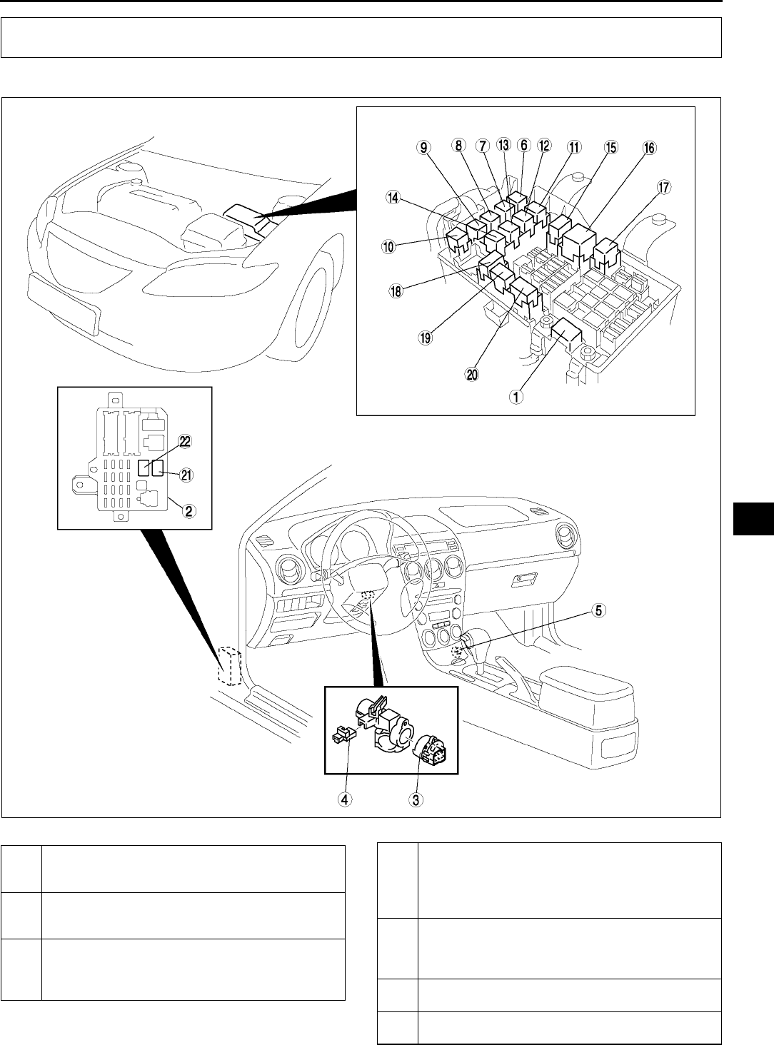
LOCATION INDEX
T5
T
POWER SYSTEM A6E810001072W01
.
LOCATION INDEX
A6E8110W124
1 Main fuse
(See T19 MAIN FUSE REMOVAL/
INSTALLATION)
2 Fuse block
(See T20 FUSE BLOCK REMOVAL/
INSTALLATION)
3 Ignition switch
(See T20 IGNITION SWITCH REMOVAL/
INSTALLATION)
(See T20 IGNITION SWITCH INSPECTION)
4 Key reminder switch
(See T21 KEY REMINDER SWITCH REMOVAL/
INSTALLATION)
(See T21 KEY REMINDER SWITCH
INSPECTION)
5 Cigarette lighter
(See T21 CIGARETTE LIGHTER REMOVAL/
INSTALLATION)
(See T22 CIGARETTE LIGHTER INSPECTION)
6 Cooling fan relay No.2
(See T24 RELAY INSPECTION)
7Horn relay
(See T24 RELAY INSPECTION)
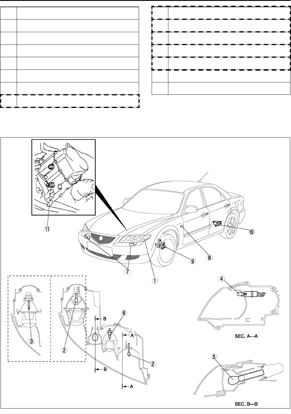
T6
LOCATION INDEX
End Of Si e
EXTERIOR LIGHTING SYSTEM A6E810001052W01
.
8 Cooling fan relay No.3
(See T24 RELAY INSPECTION)
9 Stater relay
(See T24 RELAY INSPECTION)
10 Cooling fan relay No.4
(See T24 RELAY INSPECTION)
11 Woofer relay
(See T24 RELAY INSPECTION)
12 Rear window defroster relay
(See T24 RELAY INSPECTION)
13 Rear fog light relay
(See T24 RELAY INSPECTION)
14 A/C relay
(See T24 RELAY INSPECTION)
15 Main relay
(See T24 RELAY INSPECTION)
16 Headlight relay
(See T24 RELAY INSPECTION)
17 TNS relay
(See T24 RELAY INSPECTION)
18 Cooling fan relay No.1
(See T24 RELAY INSPECTION)
19 Headlight cleaner relay
(See T24 RELAY INSPECTION)
20 Front fog light relay
(See T24 RELAY INSPECTION)
21 Blower motor relay
(See T24 RELAY INSPECTION)
22 Fuel pump relay
(See T24 RELAY INSPECTION)
A6E8112W160
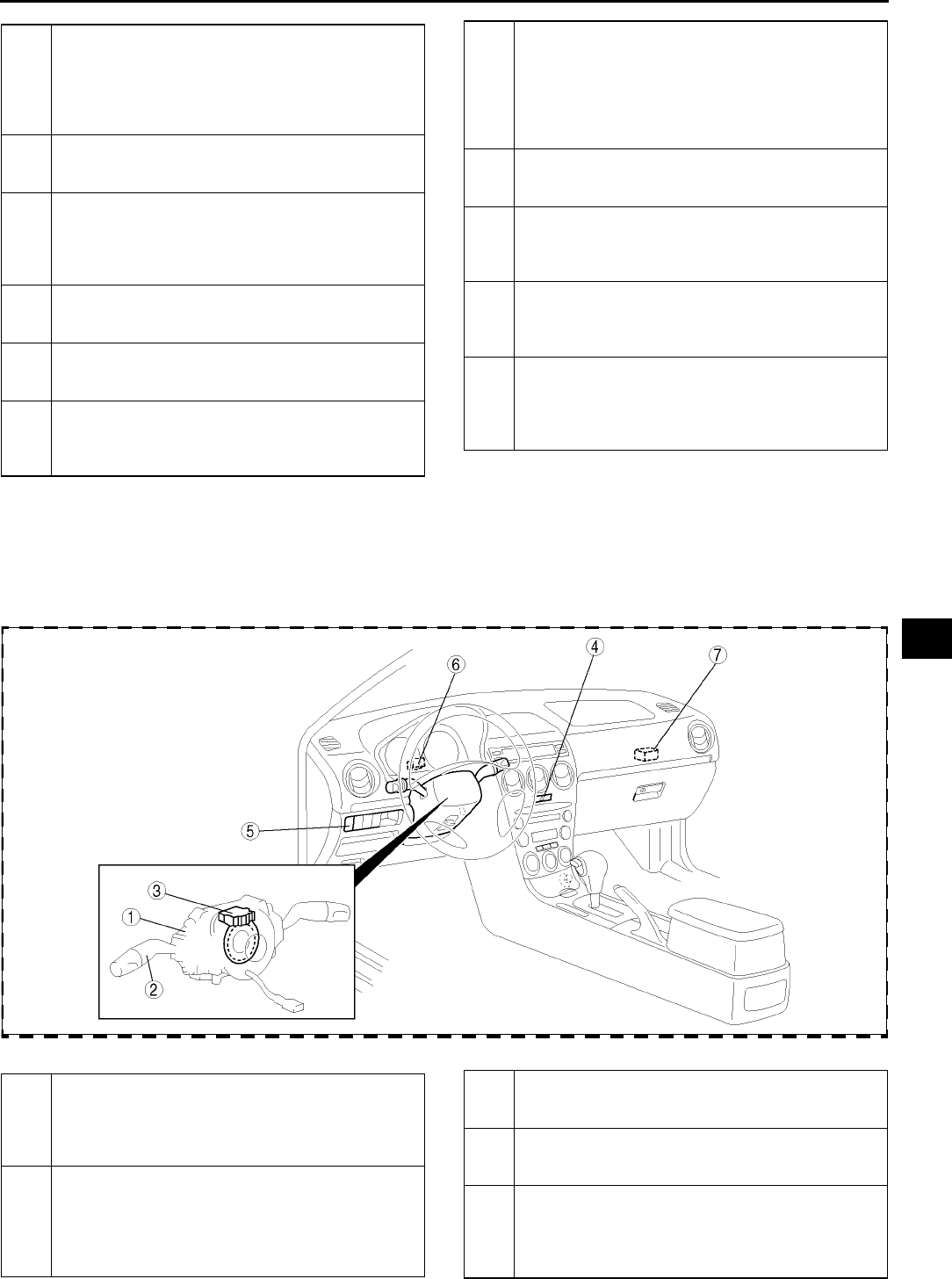
LOCATION INDEX
T7
T
.
1 Front combination light
(See T25 DISCHARGE HEADLIGHT SERVICE
WARNINGS)
(See T26 FRONT COMBINATION LIGHT
REMOVAL/INSTALLATION)
(See T26 HEADLIGHT AIMING)
2 Headlight bulb
(See T28 HEADLIGHT BULB REMOVAL/
INSTALLATION)
3 Discharge headlight bulb
(See T25 DISCHARGE HEADLIGHT SERVICE
WARNINGS)
(See T28 HEADLIGHT BULB REMOVAL/
INSTALLATION)
4 Parking light bulb
(See T33 PARKING LIGHT BULB REMOVAL/
INSTALLATION)
5 Front turn light
(See T33 FRONT TURN LIGHT REMOVAL/
INSTALLATION)
6 Front fog light bulb
(See T34 FRONT FOG LIGHT BULB REMOVAL/
INSTALLATION)
(See T34 FRONT FOG LIGHT AIMING)
7 Discharge headlight control unit
(See T25 DISCHARGE HEADLIGHT SERVICE
WARNINGS)
(See T30 DISCHARGE HEADLIGHT CONTROL
UNIT REMOVAL/INSTALLATION)
(See T30 AUTO LEVELING CONTROL UNIT
CONFIGURATION)
8 Front side turn light
(See T33 FRONT SIDE TURN LIGHT REMOVAL/
INSTALLATION)
9 Front auto leveling sensor
(See T32 FRONT AUTO LEVELING SENSOR
REMOVAL/INSTALLATION)
(See T31 HEADLIGHT ZEROSET)
10 Rear auto leveling sensor
(See T32 REAR AUTO LEVELING SENSOR
REMOVAL/INSTALLATION)
(See T31 HEADLIGHT ZEROSET)
11 Back-up light switch
(See T43 BACK-UP LIGHT SWITCH REMOVAL/
INSTALLATION)
(See T44 BACK-UP LIGHT SWITCH
INSPECTION)
A6E8112W161
1 Combination switch
(See T37 COMBINATION SWITCH REMOVAL/
INSTALLATION)
(See T38 COMBINATION SWITCH
DISASSEMBLY/ASSEMBLY)
2 Light switch
(See T39 LIGHT SWITCH REMOVAL/
INSTALLATION
(See T40 LIGHT SWITCH INSPECTION
(See T42 FRONT AND REAR FOG LIGHT
SWITCH INSPECTION
3 Steering angle sensor (with DSC)
(See T39 STEERING ANGLE SENSOR
INSPECTION)
4 Hazard warining switch
(See T41 HAZARD WARNING SWITCH
INSPECTION)
5 Headlight leveling switch
(See T43 HEADLIGHT LEVELING SWITCH
REMOVAL/INSTALLATION)
(See T43 HEADLIGHT LEVELING SWITCH
INSPECTION)
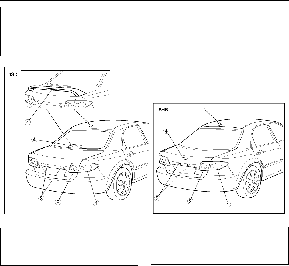
T8
LOCATION INDEX
.
End Of Sie
6Flasher unit
(See T44 FLASHER UNIT REMOVAL/
INSTALLATION)
(See T44 FLASHER UNIT INSPECTION)
7 Running light unit
(See T45 RUNNING LIGHT UNIT REMOVAL/
INSTALLATION)
(See T46 RUNNING LIGHT UNIT INSPECTION)
A6E8112W162
1 Rear combination light
(See T35 REAR COMBINATION LIGHT
REMOVAL/INSTALLATION)
2 Inboard combination light
(See T35 INBOARD COMBINATION LIGHT
REMOVAL/INSTALLATION
3 License plate light
(See T37 LICENSE PLATE LIGHT REMOVAL/
INSTALLATION)
4 High-mount brake light
(See T36 HIGH-MOUNT BRAKE LIGHT
REMOVAL/INSTALLATION)
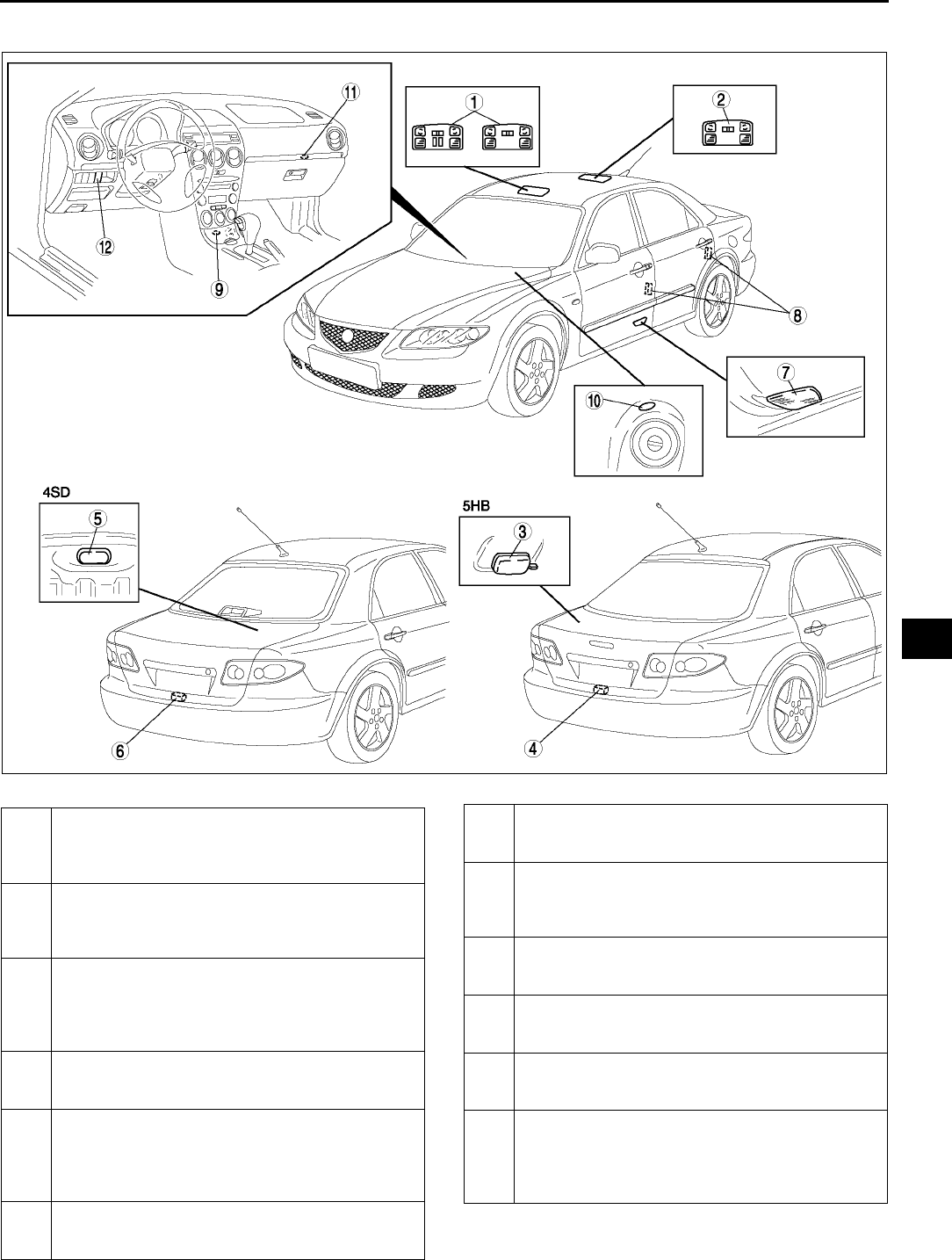
LOCATION INDEX
T9
T
INTERIOR LIGHTING SYSTEM A6E810001052W02
.
A6E8114W130
1 Front map light
(See T48 FRONT MAP LIGHT REMOVAL/
INSTALLATION)
(See T48 FRONT MAP LIGHT INSPECTION)
2 Rear map light
(See T49 REAR MAP LIGHT REMOVAL/
INSTALLATION)
(See T49 REAR MAP LIGHT INSPECTION)
3 Cargo compartment light
(See T50 CARGO COMPARTMENT LIGHT
REMOVAL/INSTALLATION)
(See T50 CARGO COMPARTMENT LIGHT
INSPECTION)
4 Cargo compartment light switch
(See T50 CARGO COMPARTMENT LIGHT
SWITCH INSPECTION)
5 Trunk compartment light
(See T51 TRUNK COMPARTMENT LIGHT BULB
REMOVAL/INSTALLATION)
(See T51 TRUNK COMPARTMENT LIGHT
SWITCH INSPECTION)
6 Trunk compartment light switch
(See T51 TRUNK COMPARTMENT LIGHT
SWITCH INSPECTION)
7 Courtesy light
(See T51 COURTESY LIGHT BULB REMOVAL/
INSTALLATION)
8 Door switch
(See T52 DOOR SWITCH REMOVAL/
INSTALLATION)
(See T52 DOOR SWITCH INSPECTION)
9 Ashtray illumination
(See T52 ASHTRAY ILLUMINATION BULB
REMOVAL/INSTALLATION)
10 Ignition key illumination
(See T53 IGNITION KEY ILLUMINATION BULB
REMOVAL/INSTALLATION)
11 Grove compartment light
(See T53 GLOVE COMPARTMENT LIGHT BULB
REMOVAL/INSTALLATION)
12 Panel light control switch
(See T53 PANEL LIGHT CONTROL SWITCH
REMOVAL/INSTALLATION)
(See T54 PANEL LIGHT CONTROL SWITCH
INSPECTION)
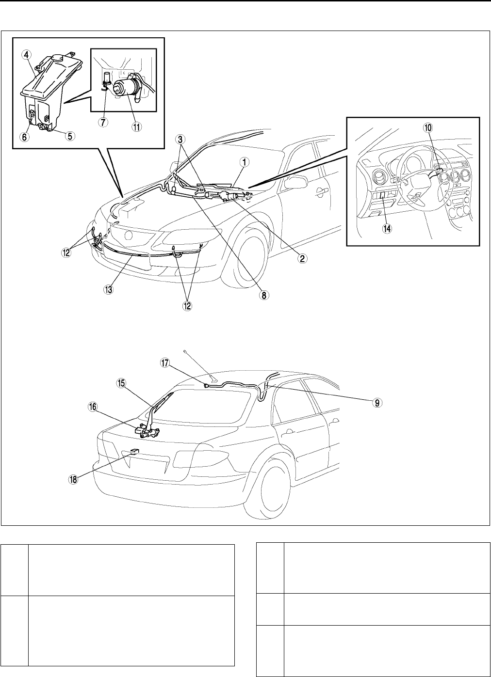
T10
LOCATION INDEX
End Of Si e
WIPER AND WASHER SYSTEM A6E810001052W03
.
A6E8116T101
1 Windshield wiper arm and blade
(See T57 WINDSHIELD WIPER ARM AND
BLADE REMOVAL/INSTALLATION)
(See T58 WINDSHIELD WIPER ARM AND
BLADE ADJUSTMENT)
2 Windshield wiper motor
(See T56 WINDSHIELD WIPER MOTOR
REMOVAL/INSTALLATION)
(See T56 WINDSHIELD WIPER MOTOR
DISASSEMBLY/ASSEMBLY)
(See T56 WINDSHIELD WIPER MOTOR
INSPECTION)
3 Windshield washer nozzle
(See T60 WINDSHIELD WASHER NOZZLE
REMOVAL/INSTALLATION)
(See T60 WINDSHIELD WASHER NOZZLE
CLEANING)
4 Washer tank
(See T58 WASHER TANK REMOVAL/
INSTALLATION)
5 Windshield washer motor
(See T59 WINDSHIELD WASHER MOTOR
REMOVAL/INSTALLATION)
(See T59 WINDSHIELD WASHER MOTOR
INSPECTION)

LOCATION INDEX
T11
T
End Of Sie
6 Rear washer motor (5HB)
(See T61 REAR WASHER MOTOR REMOVAL/
INSTALLATION)
(See T61 REAR WASHER MOTOR INSPECTION)
7 Washer fluid-level sensor (5HB)
(See T59 WASHER FLUID-LEVEL SENSOR
REMOVAL/INSTALLATION)
(See T60 WASHER FLUID-LEVEL SENSOR
INSPECTION)
8 Windshield washer hose
(See T61 WINDSHIELD WASHER HOSE
REMOVAL/INSTALLATION)
9 Rear washer hose (5HB)
(See T65 REAR WASHER HOSE REMOVAL/
INSTALLATION)
10 Wiper and washer switch
(See T67 WIPER AND WASHER SWITCH
REMOVAL/INSTALLATION)
(See T68 WIPER AND WASHER SWITCH
INSPECTION)
11 Headlight cleaner motor
(See T69 HEADLIGHT CLEANER MOTOR
REMOVAL/INSTALLATION)
T70 HEADLIGHT CLEANER MOTOR
INSPECTION)
12 Headlight cleaner nozzle
(See T70 HEADLIGHT CLEANER NOZZLE
REMOVAL/INSTALLATION)
(See T70 HEADLIGHT CLEANER NOZZLE
ADJUSTMENT)
(See T70 HEADLIGHT CLEANER NOZZLE
CLEANING)
13 Headlight cleaner hose
(See T71 HEADLIGHT CLEANER HOSE
REMOVAL/INSTALLATION)
14 Headlight cleaner switch
(See T71 HEADLIGHT CLEANER SWITCH
REMOVAL/INSTALLATION)
(See T71 HEADLIGHT CLEANER SWITCH
INSPECTION)
15 Rear wiper arm and blade (5HB)
T63 REAR WIPER ARM AND BLADE REMOVAL/
INSTALLATION)
(See T64 REAR WIPER ARM AND BLADE
ADJUSTMENT)
16 Rear wiper motor (5HB)
(See T62 REAR WIPER MOTOR REMOVAL/
INSTALLATION)
(See T62 REAR WIPER MOTOR INSPECTION)
17 Rear washer nozzle (5HB)
(See T64 REAR WASHER NOZZLE REMOVAL/
INSTALLATION)
(See T64 REAR WASHER NOZZLE
ADJUSTMENT)
(See T64 REAR WASHER NOZZLE CLEANING)
18 Intermittent rear wiper relay (5HB)
(See T66 INTERMITTENT REAR WIPER RELAY
REMOVAL/INSTALLATION)
(See T66 INTERMITTENT REAR WIPER RELAY
INSPECTION)
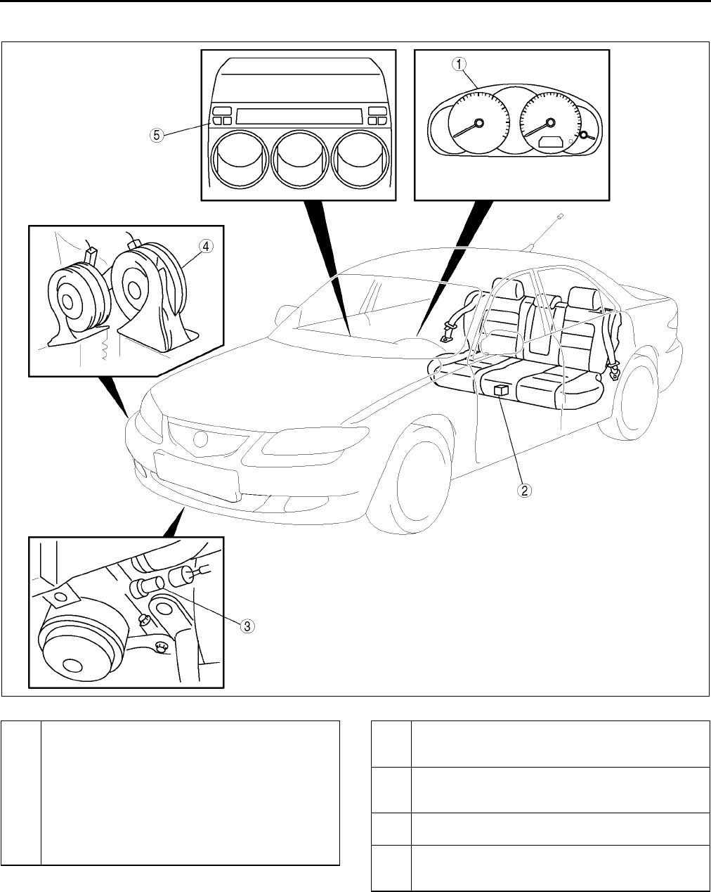
T12
LOCATION INDEX
WARNING AND INDICATOR SYSTEM A6E810001067W01
.
End Of Sie
A6E8118W012
1 Instrument cluster
(See T72 INSTRUMENT CLUSTER REMOVAL/
INSTALLATION)
(See T73 INSTRUMENT CLUSTER
DISASSEMBLY/ASSEMBLY)
(See T73 INSTRUMENT CLUSTER
INSPECTION)
(See T74 INSTRUMENT CLUSTER REPAIR)
(See T75 INSTRUMENT CLUSTER INPUT/
OUTPUT CHECK MODE)
2 Fuel gauge sender unit
(See T83 FUEL GAUGE SENDER UNIT
INSPECTION)
3 Oil pressure switch
(See T84 OIL PRESSURE SWITCH
INSPECTION)
4Horn
(See T84 HORN REMOVAL/INSTALLATION)
5 Information display
(See T84 INFORMATION DISPLAY REMOVAL/
INSTALLATION)
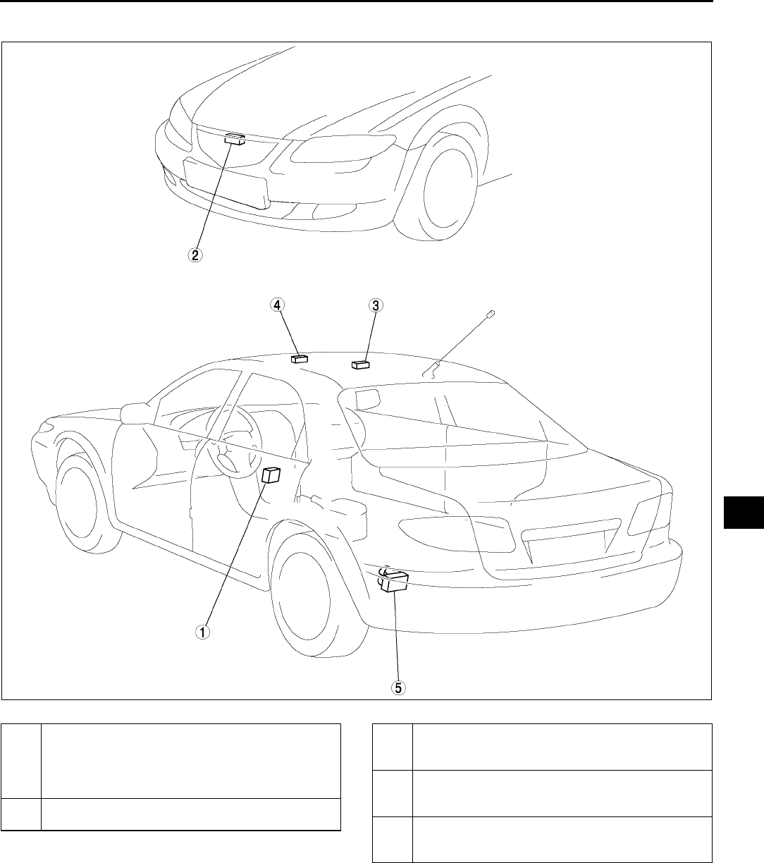
LOCATION INDEX
T13
T
THEFT-DETERRENT SYSTEM A6E810050000W01
.
End Of Sie
A6E8120W007
1 Theft-deterrent control module
(See T86 THEFT-DETERRENT CONTROL
MODULE REMOVAL/INSTALLATION)
(See T86 THEFT-DETERRENT CONTROL
MODULE INSPECTION)
2 Bonnet switch
(See T85 BONNET SWITCH INSPECTION)
3 Intruder sensor (Vehicle with sliding sunroof)
(See T89 INTRUDER SENSOR REMOVAL/
INSTALLATION)
4 Intruder sensor (Vehicle without sliding sunroof)
(See T89 INTRUDER SENSOR REMOVAL/
INSTALLATION)
5 Theft-deterrent siren
(See T89 THEFT-DETERRENT SIREN
REMOVAL/INSTALLATION)
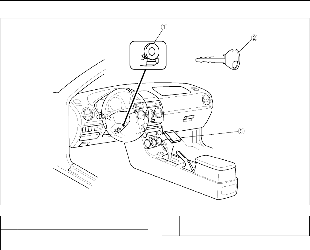
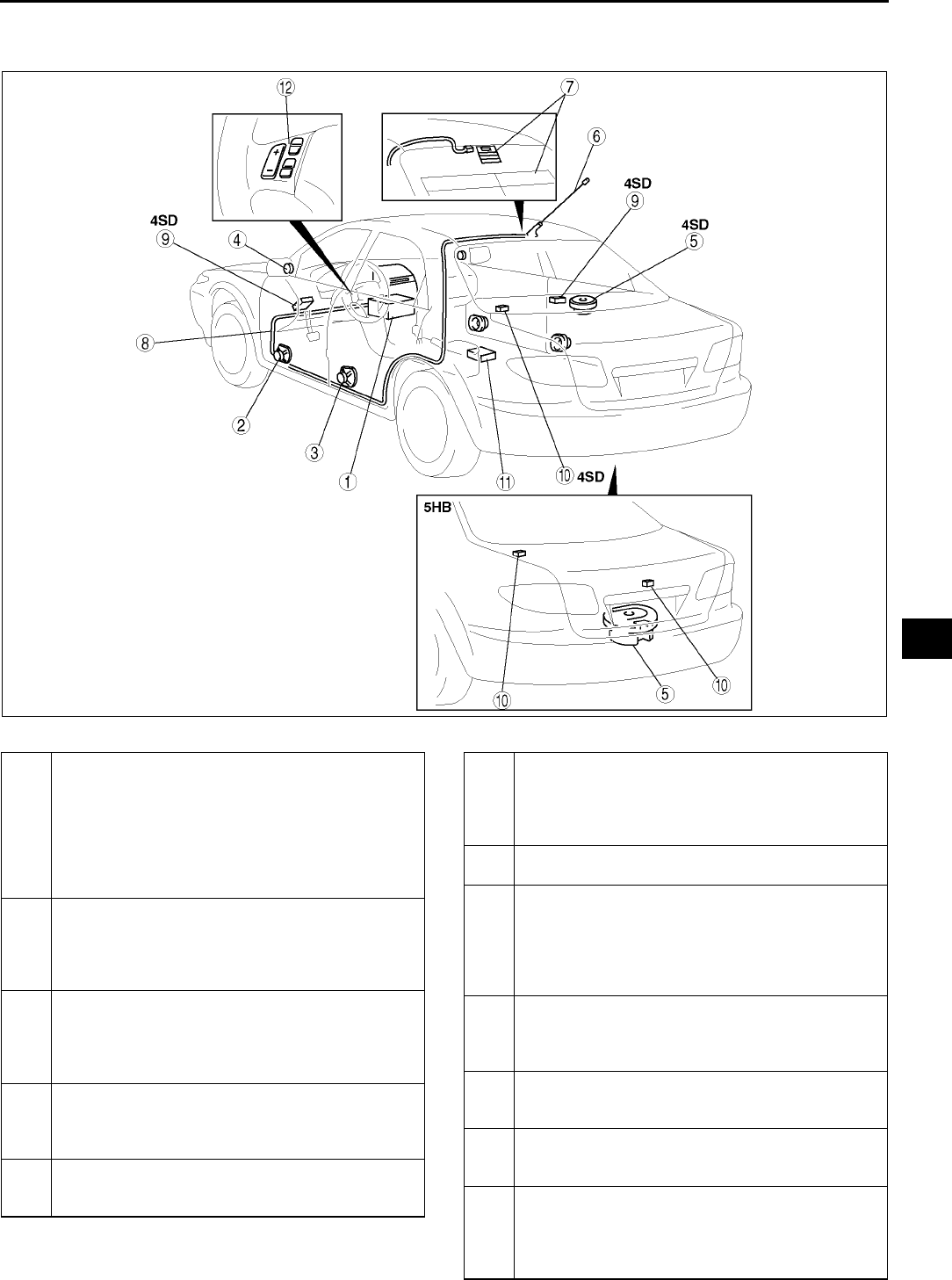
LOCATION INDEX
T15
T
AUDIO AND NAVIGATION SYSTEM A6E810001066W01
Audio System
.
A6E8124W044
1 Audio unit
(See T93 ANTI-THEFT SYSTEM)
(See T96 CENTER PANEL MODULE REMOVAL/
INSTALLATION)
(See T97 CENTER PANEL MODULE
DISASSEMBLY/ASSEMBLY)
(See T97 AUDIO UNIT DISASSEMBLY/
ASSEMBLY)
2 Front door speaker
(See T101 FRONT DOOR SPEAKER REMOVAL/
INSTALLATION)
(See T101 FRONT DOOR SPEAKER
INSPECTION)
3 Rear door speaker
(See T102 REAR DOOR SPEAKER REMOVAL/
INSTALLATION)
(See T102 REAR DOOR SPEAKER
INSPECTION)
4Tweeter
(See T103 TWEETER REMOVAL/
INSTALLATION)
(See T103 TWEETER INSPECTION)
5Woofer
(See T103 WOOFER REMOVAL/INSTALLATION)
(See T104 WOOFER INSPECTION)
6 Center roof antenna
(See T107 CENTER ROOF ANTENNA
REMOVAL/INSTALLATION)
(See T107 CENTER ROOF ANTENNA
INSPECTION)
7 Glass antenna
(See T107 GLASS ANTENNA INSPECTION)
8 Antenna feeder
(See T108 ANTENNA FEEDER LOCATION)
(See T109 FRONT ANTENNA FEEDER
INSPECTION)
(See T109 REAR ANTENNA FEEDER
INSPECTION)
9 Noise filter
(See T104 NOISE FILTER REMOVAL/
INSTALLATION)
(See T105 NOISE FILTER INSPECTION)
10 Condenser
(See T106 CONDENSER REMOVAL/
INSTALLATION)
11 Audio amplifier
(See T100 AUDIO AMPLIFIER REMOVAL/
INSTALLATION)
12 Audio control switch
(See T99 AUDIO CONTROL SWITCH REMOVAL/
INSTALLATION)
(See T100 AUDIO CONTROL SWITCH
INSPECTION)
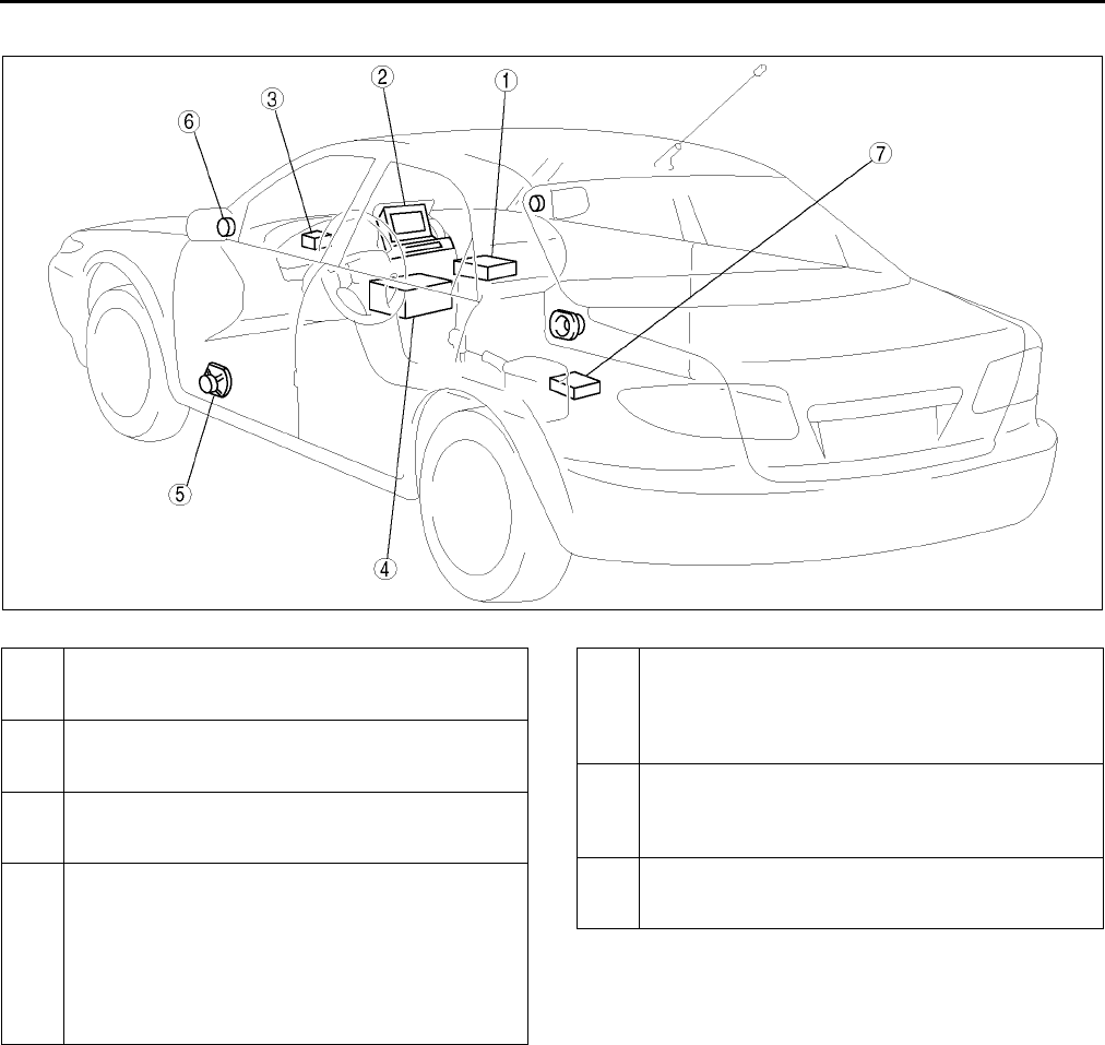
T16
LOCATION INDEX
Car-navigation System
.
End Of Sie
A6E8124W045
1 Car-navigation unit
(See T98 CAR-NAVIGATION UNIT REMOVAL/
INSTALLATION)
2 Car-navigation unit
(See T98 CAR-NAVIGATION UNIT REMOVAL/
INSTALLATION)
3 GPS antenna
(See T108 GPS ANTENNA REMOVAL/
INSTALLATION)
4 Audio unit
(See T93 ANTI-THEFT SYSTEM)
(See T96 CENTER PANEL MODULE REMOVAL/
INSTALLATION)
(See T97 CENTER PANEL MODULE
DISASSEMBLY/ASSEMBLY)
(See T97 AUDIO UNIT DISASSEMBLY/
ASSEMBLY)
5 Front door speaker
(See T101 FRONT DOOR SPEAKER REMOVAL/
INSTALLATION)
(See T101 FRONT DOOR SPEAKER
INSPECTION)
6Tweeter
(See T103 TWEETER REMOVAL/
INSTALLATION)
(See T103 TWEETER INSPECTION)
7 Audio amplifier
(See T100 AUDIO AMPLIFIER REMOVAL/
INSTALLATION)
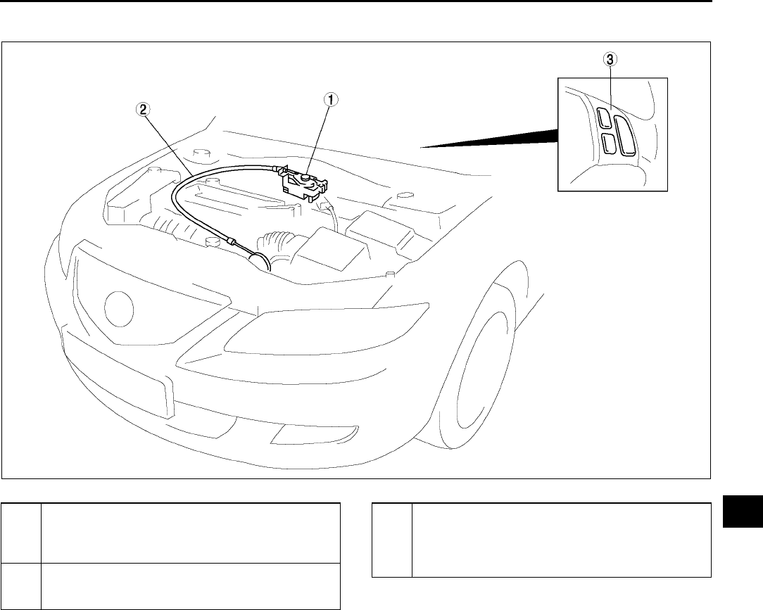
LOCATION INDEX
T17
T
CRUISE CONTROL SYSTEM A6E810001011W01
.
End Of Sie
A6E8128W017
1 Cruise actuator
(See T110 CRUISE ACTUATOR REMOVAL/
INSTALLATION)
(See T110 CRUISE ACTUATOR INSPECTION)
2 Actuator cable
(See T112 ACTUATOR CABLE REMOVAL)
(See T114 ACTUATOR CABLE INSTALLATION)
3 Cruise control switch
(See T115 CRUISE CONTROL SWITCH
REMOVAL/INSTALLATION)
(See T116 CRUISE CONTROL SWITCH
INSPECTION)
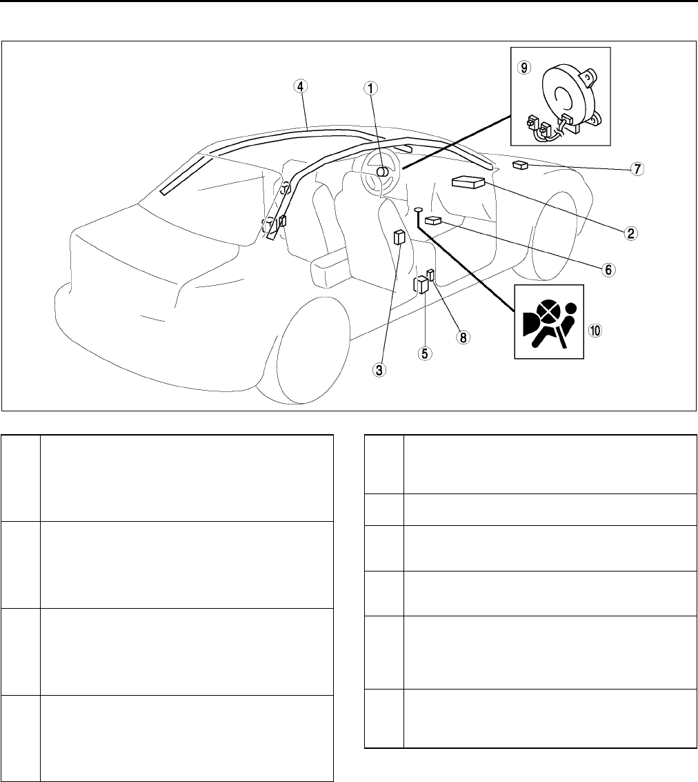
T18
LOCATION INDEX
AIR BAG SYSTEM A6E810001046W01
.
End Of Sie
A6E8130W049
1 Driver-side air bag module
(See T120 DRIVER-SIDE AIR BAG MODULE
REMOVAL/INSTALLATION)
(See T127 AIR BAG MODULE AND PRE-
TENSIONER SEAT BELT DEPLOYMENT
PROCEDURES)
2 Passenger-side air bag module
(See T121 PASSENGER-SIDE AIR BAG
MODULE REMOVAL/INSTALLATION)
(See T127 AIR BAG MODULE AND PRE-
TENSIONER SEAT BELT DEPLOYMENT
PROCEDURES)
3 Side air bag module
(See T121 SIDE AIR BAG MODULE REMOVAL/
INSTALLATION)
(See T127 AIR BAG MODULE AND PRE-
TENSIONER SEAT BELT DEPLOYMENT
PROCEDURES)
4 Curtain air bag module
(See T122 CURTAIN AIR BAG MODULE
REMOVAL/INSTALLATION)
(See T127 AIR BAG MODULE AND PRE-
TENSIONER SEAT BELT DEPLOYMENT
PROCEDURES)
5 Pre-tensioner seat belt
(See T127 AIR BAG MODULE AND PRE-
TENSIONER SEAT BELT DEPLOYMENT
PROCEDURES)
6 SAS unit
(See T124 SAS UNIT REMOVAL/INSTALLATION)
7 Crash zone sensor
(See T123 CRASH ZONE SENSOR REMOVAL/
INSTALLATION)
8 Side air bag sensor
(See T123 SIDE AIR BAG SENSOR REMOVAL/
INSTALLATION)
9 Clock spring
(See T125 CLOCK SPRING REMOVAL/
INSTALLATION)
(See T126 CLOCK SPRING INSPECTION)
(See T125 CLOCK SPRING ADJUSTMENT)
10 Passenger-side air bag cut-off indicator light
(See T127 PASSENGER-SIDE AIR BAG
CUT-OFF INDICATOR LIGHT REMOVAL/
INSTALLATION)
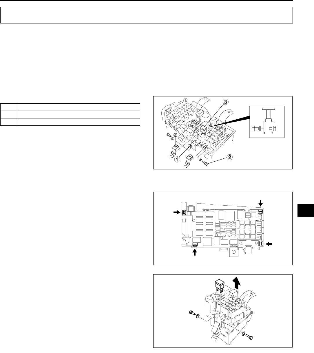
POWER SYSTEM
T19
T
FUSE SERVICE CAUTION A6E811066000W01
Caution
•
••
•Determine and correct the cause of the burnt fuse before replacing it with the specified type. If the
fuse is replaced before doing this, it may burn again.
End Of Sie
MAIN FUSE REMOVAL/INSTALLATION A6E811066761W01
1. Disconnect the negative battery cable.
2. Remove the main fuse block cover.
3. Remove in the order indicated in the table.
4. Install in the reverse order of removal.
Bolt Removal Note
1. Press and remove the tabs on the main fuse
block at the positions indicated by the arrows.
2. Lift up the main fuse block and remove the bolts.
End Of Sie
POWER SYSTEM
1Nut
2 Bolt (See T19 Bolt Removal Note)
3 Main fuse
A6E8110W108
A6E8110W119
A6E8110W120
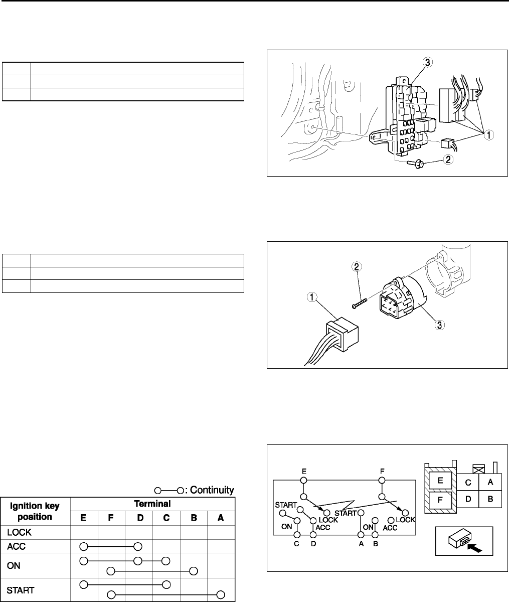
T20
POWER SYSTEM
FUSE BLOCK REMOVAL/INSTALLATION A6E811066730W01
1. Disconnect the negative battery cable.
2. Remove the left-side front side trim. (See S88 FRONT SIDE TRIM REMOVAL/INSTALLATION)
3. Remove in the order indicated in the table.
4. Install in the reverse order of removal.
End Of Sie
IGNITION SWITCH REMOVAL/INSTALLATION A6E811066151W01
1. Disconnect the negative battery cable.
2. Remove the column cover. (See S84 COLUMN COVER REMOVAL/INSTALLATION)
3. Remove in the order indicated in the table.
4. Install in the reverse order of removal.
End Of Sie
IGNITION SWITCH INSPECTION A6E811066151W02
1. Disconnect the negative battery cable.
2. Remove the column cover. (See S84 COLUMN COVER REMOVAL/INSTALLATION)
3. Disconnect the ignition switch connectors.
4. Inspect for continuity between the ignition switch
terminals using an ohmmeter.
•If not as specified, replace the ignition switch.
End Of Sie
1 Connector
2Bolt
3 Fuse block
A6E8110W107
1 Connector
2Screw
3 Ignition switch
A6E8110W101
A6E8110W116
A6E8110W114
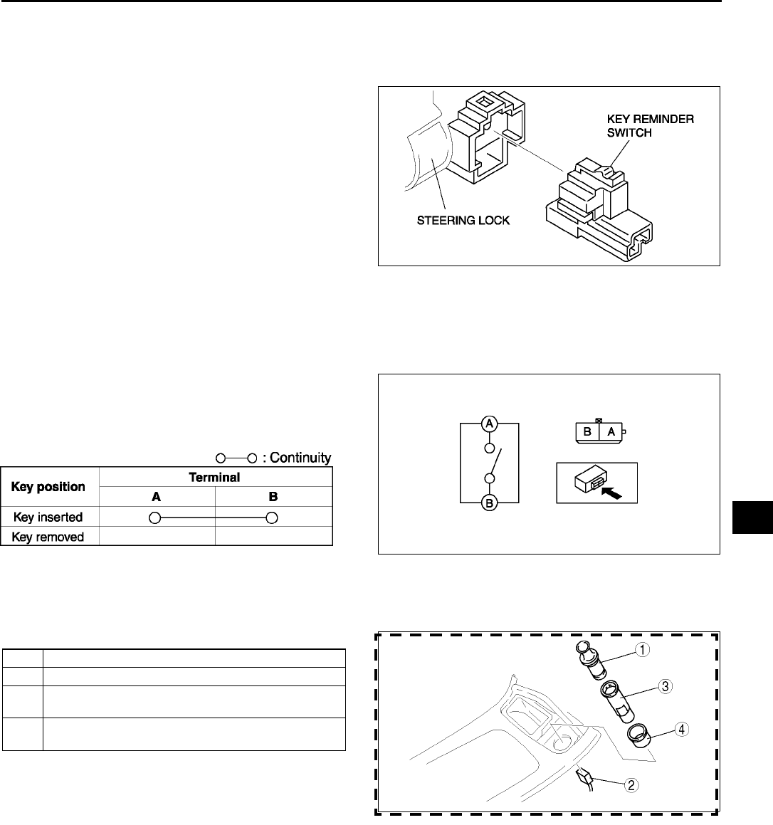
POWER SYSTEM
T21
T
KEY REMINDER SWITCH REMOVAL/INSTALLATION A6E811066152W01
1. Disconnect the negative battery cable.
2. Remove the column cover.
3. Disconnect the key reminder switch connector.
4. Remove the key reminder switch.
5. Install in the reverse order of removal.
End Of Sie
KEY REMINDER SWITCH INSPECTION A6E811066152W02
1. Disconnect the negative battery cable.
2. Remove the column cover. (See S84 COLUMN COVER REMOVAL/INSTALLATION)
3. Disconnect the key reminder switch connector.
4. Inspect for continuity between the key reminder
switch terminals using an ohmmeter.
•If not as specified, replace the key reminder
switch.
End Of Sie
CIGARETTE LIGHTER REMOVAL/INSTALLATION A6E811067000W01
1. Disconnect the negative battery cable.
2. Remove in the order indicated in the table.
3. Install in the reverse order of removal.
A6E8110W102
A6E8110W117
A6E8110W115
1 Cigarette lighter plug
2 Connector
3Socket
(See T22 Socket Removal Note)
4Ring
(See T22 Ring Removal Note)
A6E8110W103
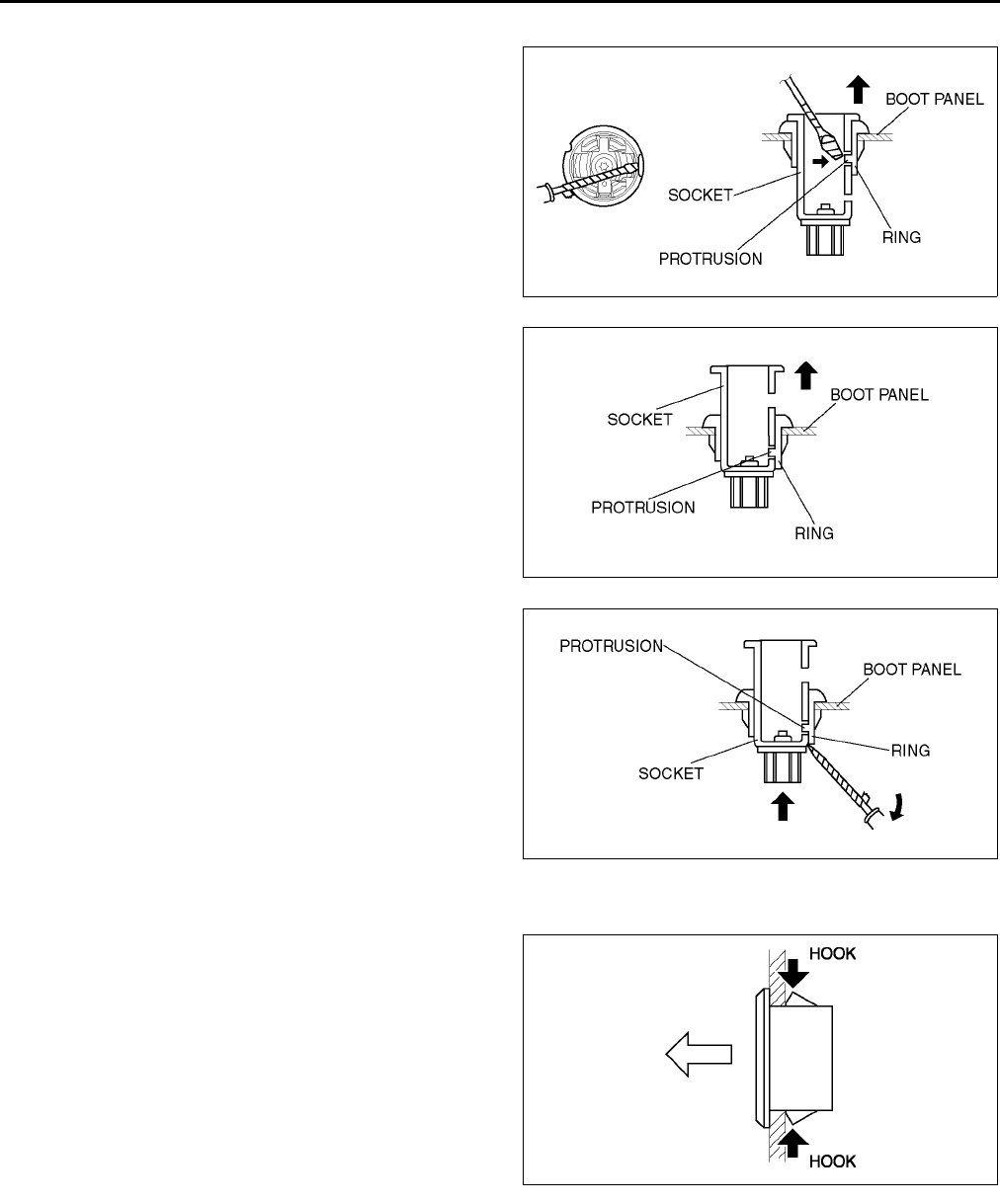
T22
POWER SYSTEM
Socket Removal Note
1. Insert a tape-wrapped screwdriver into the socket
hole, then press against the ring protrusion to lift
the socket toward you.
2. As shown in the figure, lift out the socket until the
ring protrusion locks into the lower socket hole.
3. Remove the boot panel.
4. From behind the boot panel, slide a tape-wrapped
screwdriver in between the socket and the ring
protrusion..
5. While twisting the ring protrusion with the
screwdriver, push out and remove the socket.
Ring Removal Note
1. Pull the ring forward while compressing the
hooks.
End Of Sie
CIGARETTE LIGHTER INSPECTION A6E811067000W02
1. Turn the ignition switch to ACC position.
2. Verify that the cigarette lighter comes out within 1020 seconds, after pressing the plug into the socket.
•If the cigarette lighter does not operate normally, replace the cigarette lighter plug and socket.
End Of Sie
A6E8110W104
A6E8110W106
A6E8110W201
A6E8110W105
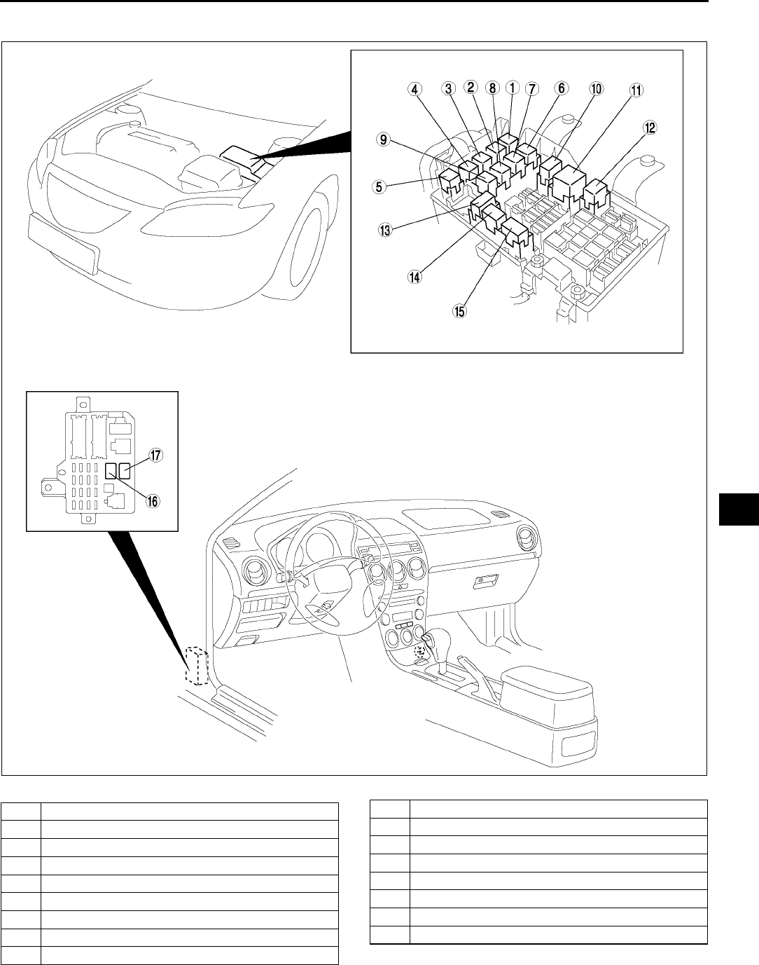
POWER SYSTEM
T23
T
RELAY LOCATION A6E811067730W01
.
End Of Sie
A6E8110T102
1 Cooling fan relay No.2
2Horn relay
3 Cooling fan relay No.3
4 Stater relay
5 Cooling fan relay No.4
6Woofer relay
7 Rear window defroster relay
8 Rear fog light relay
9 A/C relay
10 Main relay
11 Headlight relay
12 TNS relay
13 Cooling fan relay No.1
14 Headlight cleaner relay
15 Front fog light relay
16 Fuel pump relay
17 Blower relay
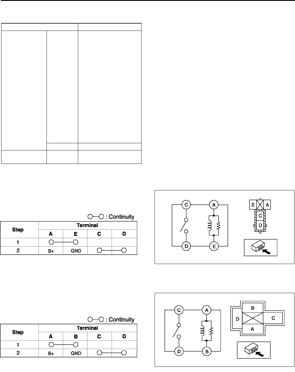
T24
POWER SYSTEM
RELAY INSPECTION A6E811067730W02
Relay Type
Four-terminal
Type A
1. Remove the relay.
2. Inspect for continuity between the relay terminals
using an ohmmeter.
•If not as specified, replace the relay.
Type B
1. Remove the relay.
2. Inspect for continuity between the relay terminals
using an ohmmeter.
•If not as specified, replace the relay.
Terminal type Parts name
Four-terminal Type A
•Main relay
•Fuel pump relay
•Stater relay
•TNS relay
•Front fog light relay
•Rear fog light relay
•Horn relay
•Headlight cleaner
relay
•Rear window
defroster relay
•Woofer relay
•A/C relay
•Blower relay
•Cooling fan relay No.1
(except L3 engine)
•Cooling fan relay No.2
•Cooling fan relay No.3
•Cooling fan relay No.4
Type B •Headlight relay
Five-terminal Type C •Cooling fan relay No.1
(L3 engine only)
A6E8110W118
A6E8110W121
A6E8110W125
A6E8110W123
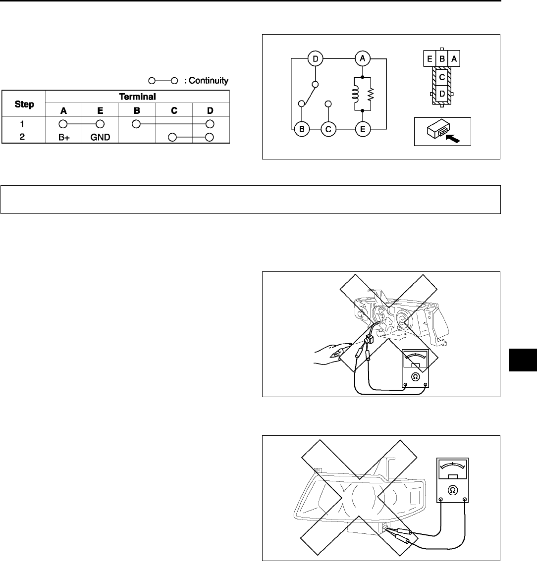
POWER SYSTEM, EXTERIOR LIGHTING SYSTEM
T25
T
Type C
1. Remove the relay.
2. Inspect for continuity between the relay terminals
using an ohmmeter.
•If not as specified, replace the relay.
End Of Sie
DISCHARGE HEADLIGHT SERVICE WARNINGS A6E811251060W01
Discharge headlight bulb service warnings
•To prevent electrical shock when replacing the discharge headlight bulb, dry hands thoroughly, and
carry out work in an area out of rain.
•When the light switch is on, approx. 25,000 V
of high voltage passes through the discharge
headlight bulb socket. Because of the danger
of electrical shock, do not insert fingers or a
circuit tester.
•When the headlights are on, high voltage
flows around the socket and bulb. When
turning on the discharge headlights while
working, always leave the headlights in the
vehicle-installed condition to prevent
electrical shock.
Discharge headlight control unit service warnings
•Because of the danger of electrical shock,
when inspecting with a circuit tester or similar
device, do not inspect the discharge headlight
control unit as a single unit or disassemble it.
•If there are scratches or damage to the
discharge headlight control unit, or it has
been impacted, there may be damage despite
apparent normal operation. Therefore, to
prevent electrical shock or operation error,
replace with new parts.
End Of Sie
A6E8110W122
A6E8110W126
EXTERIOR LIGHTING SYSTEM
A6E8112W163
A6E8112W164
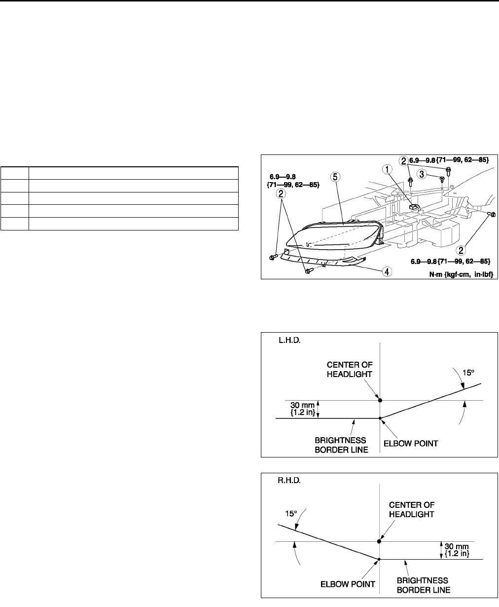
T26
EXTERIOR LIGHTING SYSTEM
FRONT COMBINATION LIGHT REMOVAL/INSTALLATION A6E811251060W02
Caution
•
••
•Incorrect servicing of the discharge headlights could result in electrical shock. Before servicing
the discharge headlights, always refer to the Discharge headlight service warnings. (See T25
DISCHARGE HEADLIGHT SERVICE WARNINGS)
Note
•When the ignition switch is turned to ON, it is normal to hear the headlight leveling actuator operating for a
few second, as it verifies headlight auto leveling system operating condition.
1. Disconnect the negative battery cable.
2. Remove the front bumper. (See S47 FRONT BUMPER REMOVAL/INSTALLATION)
3. Remove in the order indicated in the table.
4. Install in the reverse order of removal.
5. Adjust the headlight aiming. (See T26
HEADLIGHT AIMING.)
End Of Sie
HEADLIGHT AIMING A6E811251030W01
Low-beam
1. Set up a screen as shown in the figure below for
aiming the headlights.
2. Adjust the tire air pressure to the specification.
3. Position the unloaded vehicle on a flat, level
surface.
4. Seat one person in the driver's seat.
5. Position the vehicle straight ahead and
perpendicular to a wall.
1 Connector
2Bolt
3 Clip
4Cover
5 Front combination light
A6E8112W101
A6E8112W132
A6E8112W133
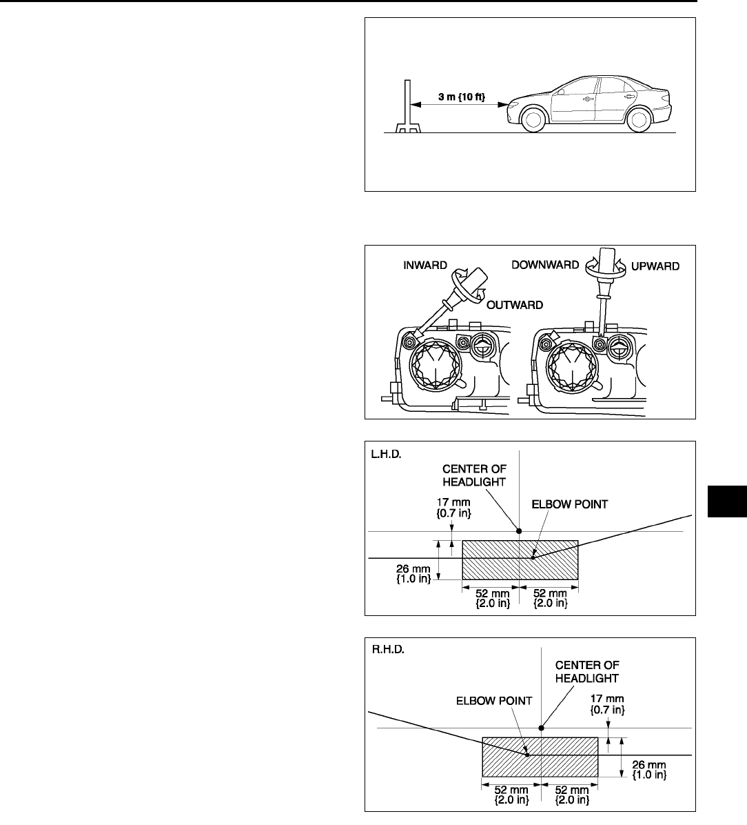
EXTERIOR LIGHTING SYSTEM
T27
T
6. Set the headlights 3 m {10 ft} from the wall.
7. While adjusting one headlight, mask the other.
8. Start the engine to charge the battery.
9. Turn on the lower-beam headlight.
10. Set the headlight leveling switch to 0 position.
11. Adjust the headlights by turning the adjusting
screws as shown in the figure. Loosen the screws
first, then tighten them.
Note
•If the adjusting screws are tightened first,
then loosened, they will continue to loosen
when the vehicle is in motion and may cause
the headlights to become misaligned.
12. Turn the adjusting screws and adjust the
headlight so that the elbow point in the shaded
area in the figure.
High-beam
1. Adjust the tire air pressure to the specification.
2. Position the unloaded vehicle on a flat, level surface.
3. Seat one person in the driver's seat.
4. Position the vehicle straight ahead and perpendicular to a wall.
A6E8112W157
A6E8112W125
A6E8112W134
A6E8112W135
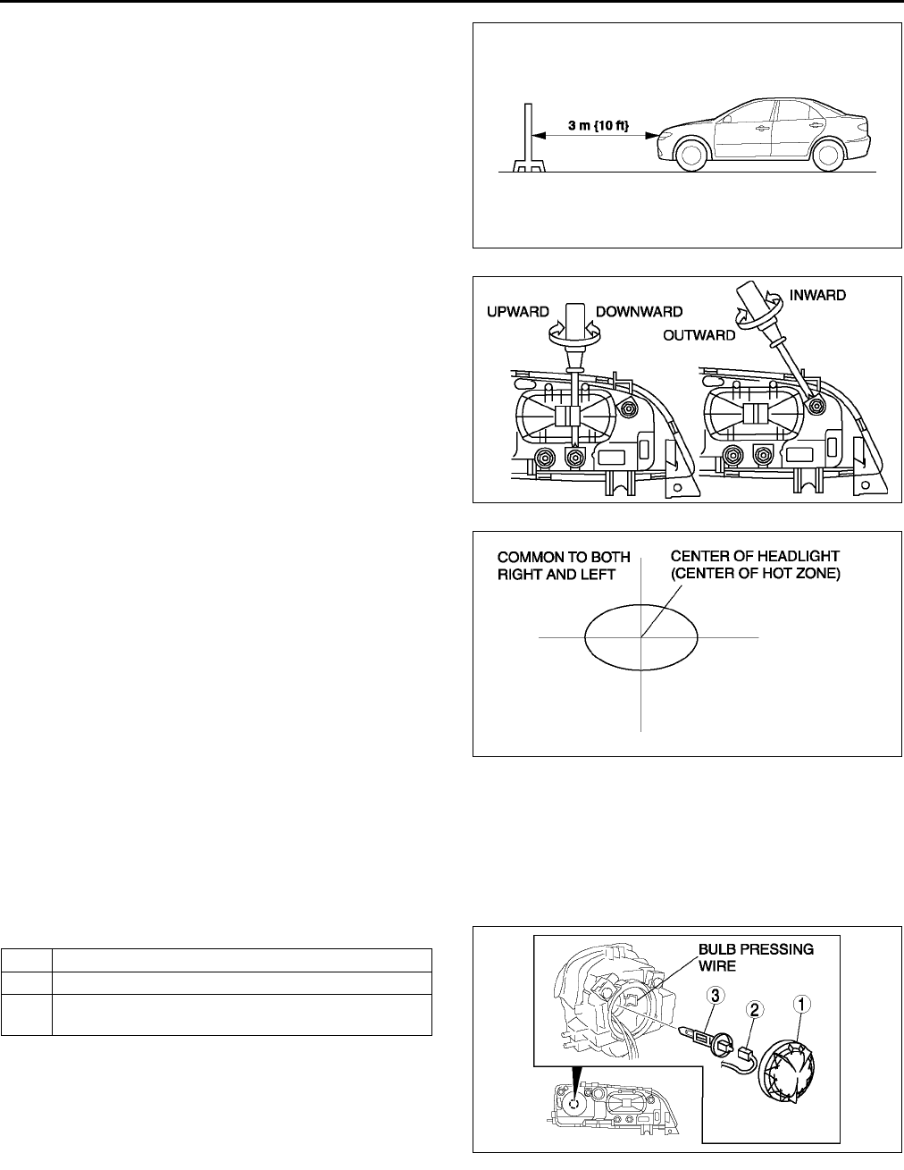
T28
EXTERIOR LIGHTING SYSTEM
5. Set the headlights 3 m {10 ft} from the wall.
6. While adjusting one headlight, mask the other.
7. Start the engine to charge the battery.
8. Turn on the high-beam headlights.
9. Set the headlight leveling switch to 0 position.
10. Adjust the headlights by turning the adjusting
screws as shown in the figure. Loosen the screws
first, then tighten them.
Note
•If the adjusting screws are tightened first,
then loosened, they will continue to loosen
when the vehicle is in motion and may cause
the headlights to become misaligned.
End Of Sie
HEADLIGHT BULB REMOVAL/INSTALLATION A6E811251030W02
Low-beam
Halogen type
1. Disconnect the negative battery cable.
2. Disconnect the front combination light. (See T26 FRONT COMBINATION LIGHT REMOVAL/
INSTALLATION)
3. Remove in the order indicated in the table.
Caution
•
••
•A halogen bulb generates extremely high
heat when it is used. If the surface of the
bulb is soiled, excessive heat will build
up and the light's life will be shortened.
When replacing the bulb, hold the metal
flange, not the glass.
4. Install in the reverse order of removal.
Headlight bulb removal note
1. Release the bulb pressing wire to remove the headlight bulb.
A6E8112W157
A6E8112W124
A6E8112W136
1Cover
2 Connector
3 Headlight bulb (See T28 Headlight bulb removal
note)
A6E8112W105
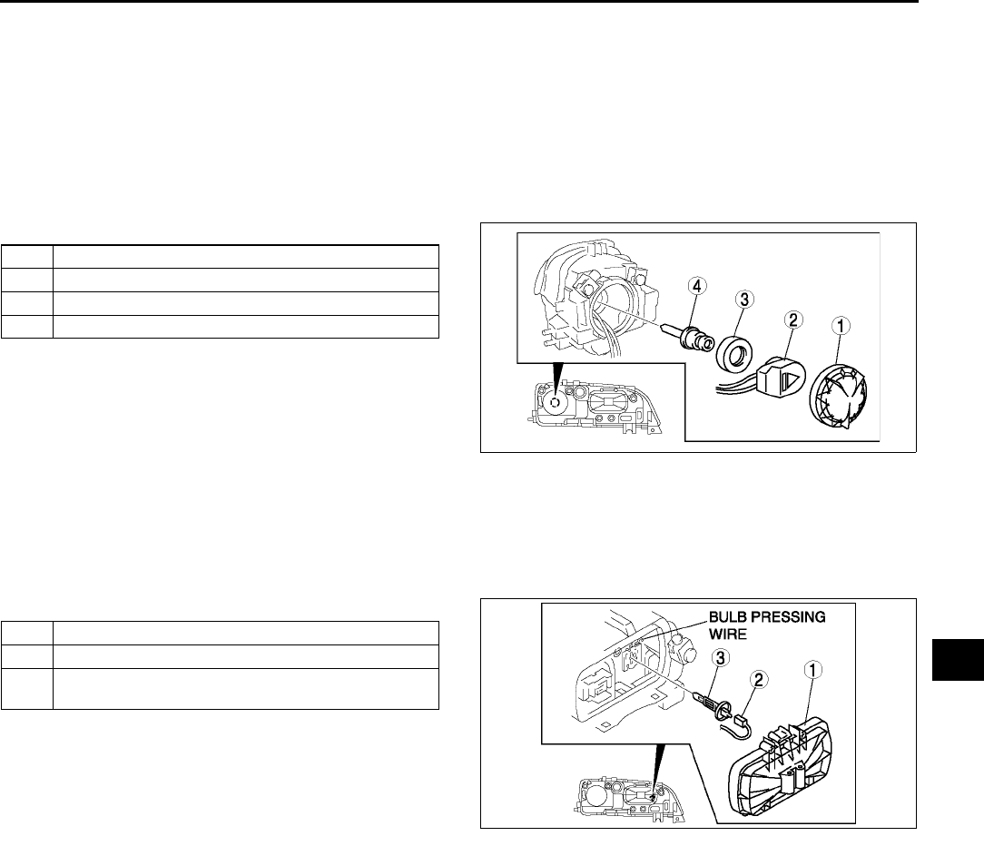
EXTERIOR LIGHTING SYSTEM
T29
T
Discharge type
Caution
•
••
•Incorrect servicing of the discharge headlights could result in electrical shock. Before servicing
the discharge headlights, always refer to the Discharge headlight service warnings. (See T25
DISCHARGE HEADLIGHT SERVICE WARNINGS)
1. Disconnect the negative battery cable.
2. Disconnect the front combination light. (See T26 FRONT COMBINATION LIGHT REMOVAL/
INSTALLATION)
3. Remove in the order indicated in the table.
Caution
•
••
•A bulb generates extremely high heat
when it is used. If the surface of the bulb
is soiled, excessive heat will build up and
the light's life will be shortened. When
replacing the bulb, hold the metal flange,
not the glass.
4. Install in the reverse order of removal.
High-beam
1. Disconnect the negative battery cable.
2. Remove in the order indicated in the table.
Caution
•
••
•A halogen bulb generates extremely high
heat when it is used. If the surface of the
bulb is soiled, excessive heat will build
up and the light's life will be shortened.
When replacing the bulb, hold the metal
flange, not the glass.
3. Install in the reverse order of removal.
Headlight bulb removal note
1. Release the bulb pressing wire to remove the headlight bulb.
End Of Sie
1 Cover
2 Connector
3 Bulb cover
4 Discharge headlight bulb
A6E8112W106
1 Cover
2 Connector
3 Headlight bulb (See T28 Headlight bulb removal
note)
A6E8112W107
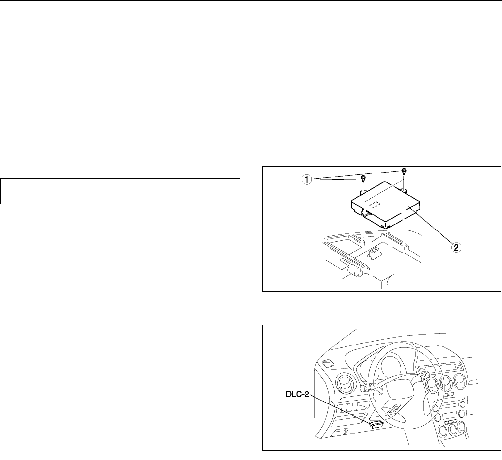
T30
EXTERIOR LIGHTING SYSTEM
DISCHARGE HEADLIGHT CONTROL UNIT REMOVAL/INSTALLATION A6E811251030W03
Caution
•
••
•Incorrect servicing of the discharge headlight control unit could result in electrical shock. Before
servicing the discharge headlight control unit, always refer to the Discharge headlight service
warnings. (See T25 DISCHARGE HEADLIGHT SERVICE WARNINGS)
•
••
•When replacing the discharge headlight control unit, configuration procedure must be done
before removing the auto leveling control unit. After replacing the discharge headlight control
unit, perform the headlight zeroset for auto leveling control unit.
1. Configurate the discharge headlight control unit (when only replacing it). (See T30 AUTO LEVELING
CONTROL UNIT CONFIGURATION)
2. Disconnect the negative battery cable.
3. Remove the front combination light. (See T26 FRONT COMBINATION LIGHT REMOVAL/INSTALLATION)
4. Remove in the order indicated in the table.
5. Install in the reverse order of removal.
6. Perform the headlight zeroset for the discharge
headlight control unit (when only replacing it).
(See T31 HEADLIGHT ZEROSET)
End Of Si e
AUTO LEVELING CONTROL UNIT CONFIGURATION A6E811251030W04
1. Connect the SST (WDS or equivalent) to the
DLC-2.
2. Input vehicle information following the directions
on the screen.
3. Select Module programming.
4. Select Programmable module installation.
5. When performing configuration corresponding to
each auto leveling control unit, select the
following items and perform procedures
according to directions on the screen.
Items
•
••
•Main: LHID
•
••
•Sub: RHID
6. Retrieve DTCs by the WDS or equivalent, then verify that there is no DTC present.
•If DTC is present, perform applicable DTC inspection.
End Of Sie
1Bolt
2 Discharge headlight control unit
A6E8112W141
A6E3970W002
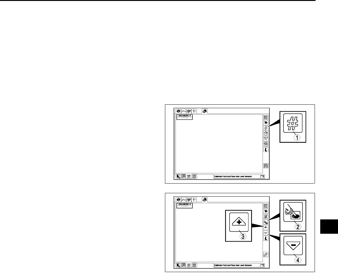
EXTERIOR LIGHTING SYSTEM
T31
T
HEADLIGHT ZEROSET A6E811251030W05
Note
•When the configuration is not set for the auto leveling control unit, headlight zeroset cannot be executed.
1. Adjust the tire air pressure to the specification.
2. Position the unloaded vehicle on a flat, level surface.
3. Connect the SST (WDS or equivalent) to the DLC-2.
4. Turn the ignition switch to ON position.
5. Turn on the headlights (low-beam).
6. Input the vehicle information following the directions on the screen.
7. Confirm that the WDS or equivalent identifies the vehicle, and select Datelogger.
8. After the screen appears, select LHID under Modules from the cascading menu.
9. After the next screen appears, select CALAXLSN#.
10. On the graphic display that appears, press the
icon near the top right of the screen indicated by a
1 in the figure.
11. After the next screen appears, press the icon
indicated by a 2 in the figure.
12. After pressing the icon indicated by the 2, press
the icon indicated by a 3 or 4 in the figure to
execute the zeroset setting.
Note
•Pressing an icon indicated by 3 or 4 once
will execute the headlight zeroset setting.
13. After executing the headlight zeroset setting,
perform an on-board diagnostic test and verify
that no DTCs are displayed.
14. Perform the headlight aiming adjustment. (See T
26 HEADLIGHT AIMING)
End Of Sie
A6E8112W158
A6E8112W159
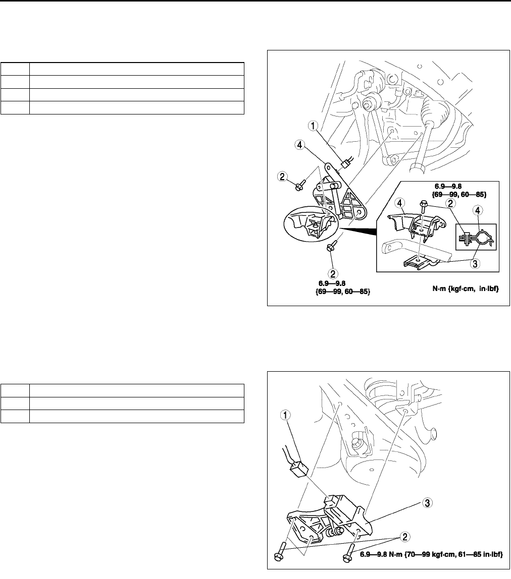
T32
EXTERIOR LIGHTING SYSTEM
FRONT AUTO LEVELING SENSOR REMOVAL/INSTALLATION A6E811251030W06
1. Disconnect the negative battery cable.
2. Jack up the vehicle and remove the wheel and tire.
3. Remove in the order indicated in the table.
4. Install in the reverse order of removal.
5. Adjust the headlight zeroset. (See T31
HEADLIGHT ZEROSET)
End Of Sie
REAR AUTO LEVELING SENSOR REMOVAL/INSTALLATION A6E811251030W07
1. Disconnect the negative battery cable.
2. Jack up the vehicle.
3. Remove in the order indicated in the table.
4. Install in the reverse order of removal.
5. Adjust the headlight zeroset. (See T31
HEADLIGHT ZEROSET)
End Of Sie
1 Connector
2Bolt
3Bracket
4 Front auto leveling sensor
A6E8112W165
1 Connector
2Bolt
3 Rear auto leveling sensor
A6E8112W156
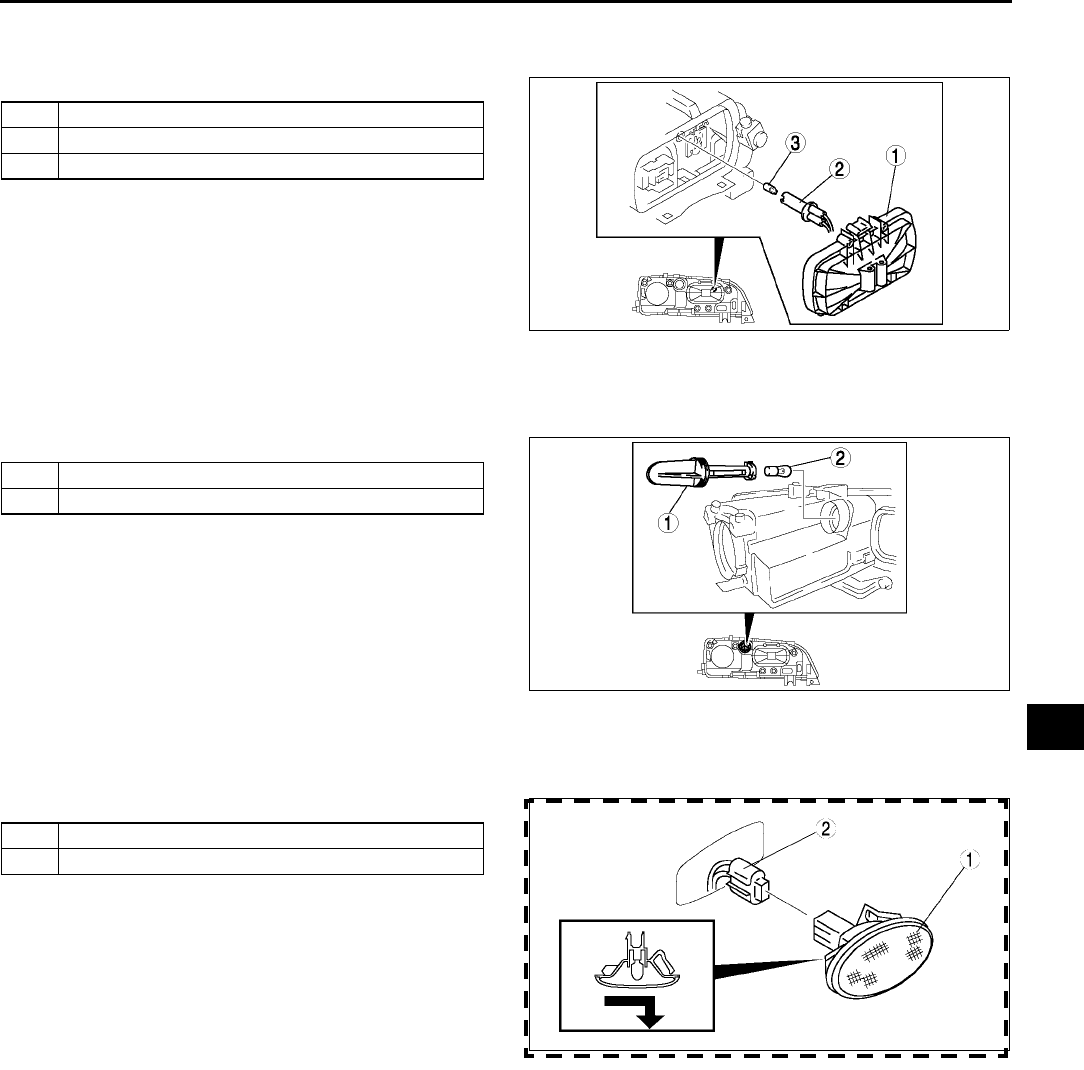
EXTERIOR LIGHTING SYSTEM
T33
T
PARKING LIGHT BULB REMOVAL/INSTALLATION A6E811251040W01
1. Disconnect the negative battery cable.
2. Remove in the order indicated in the table.
3. Install in the reverse order of removal.
End Of Sie
FRONT TURN LIGHT REMOVAL/INSTALLATION A6E811251050W01
1. Disconnect the negative battery cable.
2. Remove in the order indicated in the table..
3. Install in the reverse order of removal.
End Of Sie
FRONT SIDE TURN LIGHT REMOVAL/INSTALLATION A6E811268370W01
1. Disconnect the negative battery cable.
2. Remove in the order indicated in the table.
3. Install in the reverse order of removal.
End Of Sie
1 Cover
2Socket
3 Parking light bulb
A6E8112W109
1Socket
2 Front turn light bulb
A6E8112W110
1 Front side turn light
2 Connector
A6E8112W127
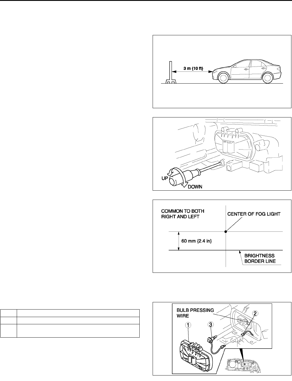
T34
EXTERIOR LIGHTING SYSTEM
FRONT FOG LIGHT AIMING A6E811251680W01
1. Adjust the tire air pressure to the specification.
2. Position the unloaded vehicle on a flat, level surface.
3. Seat one person in the drivers seat.
4. Position the vehicle 3 m {10 ft} in front of a white
screen.
5. While adjusting one fog light, mask the other.
6. Start the engine to charge the battery.
7. Turn the front fog light on.
8. Adjust the front fog light by turning the adjusting
screws as shown in the figure. Loosen the screws
first, then tighten them.
Note
•If the adjusting screws are tightened first,
then loosened, they will continue to loosen
when the vehicle is in motion and may cause
the front fog lights to become misaligned.
End Of Sie
FRONT FOG LIGHT BULB REMOVAL/INSTALLATION A6E811251680W02
1. Disconnect the negative battery cable.
2. Remove in the order indicated in the table.
Caution
•
••
•A halogen bulb generates extremely high
heat when it is used. If the surface of the
bulb is soiled, excessive heat will build
up and the lights life will be shortened.
When replacing the bulb, hold the metal
flange, not the glass.
3. Install in the reverse order of removal.
Front Fog Light Bulb Removal Note
1. Release the bulb pressing wire to remove the front fog light bulb.
End Of Si e
A6E8112W157
A6E8112W117
A6E8112W137
1Cover
2 Connector
3 Front fog light bulb (See T34 Front Fog Light Bulb
Removal Note)
A6E8112W111
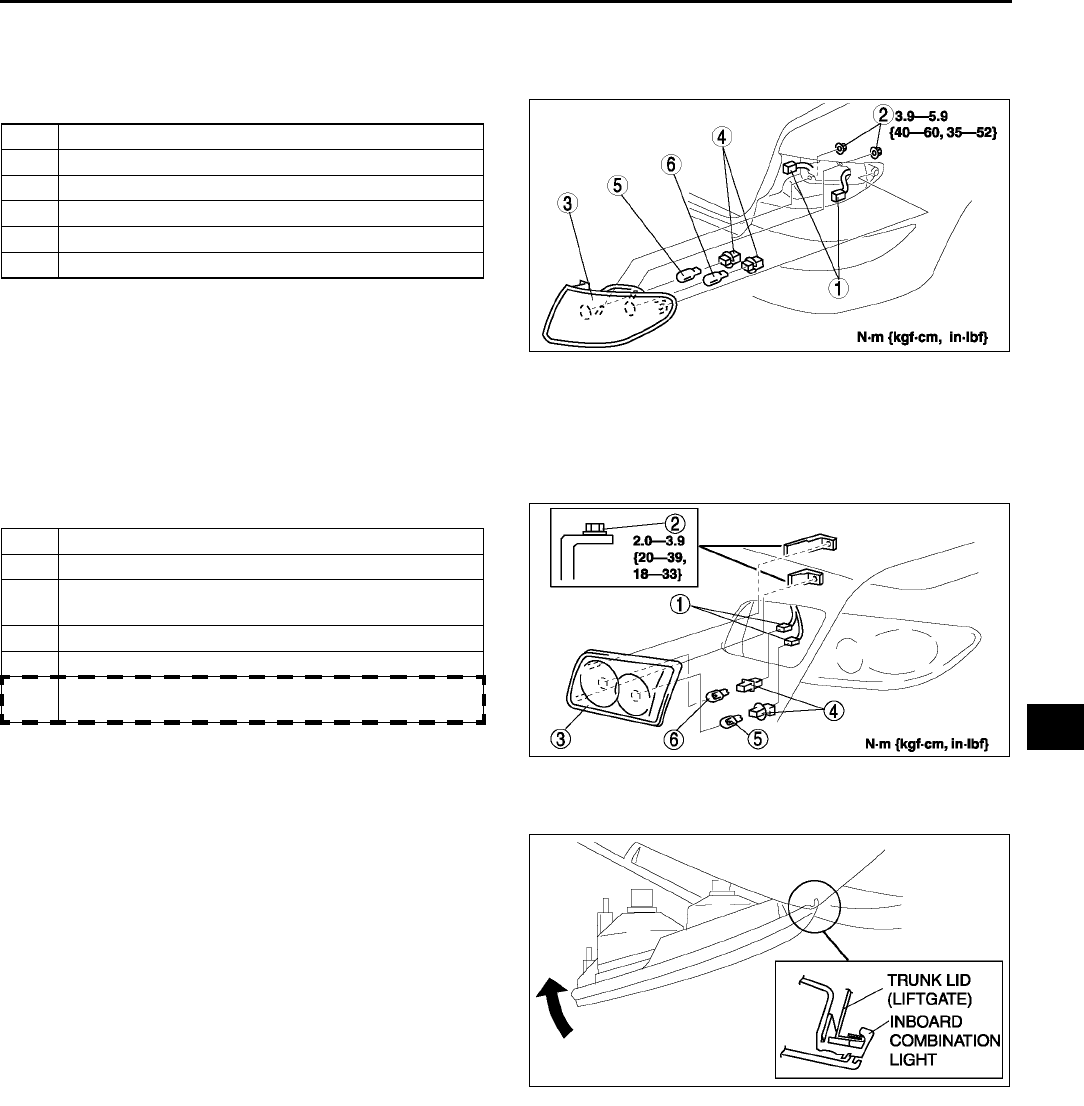
EXTERIOR LIGHTING SYSTEM
T35
T
REAR COMBINATION LIGHT REMOVAL/INSTALLATION A6E811251150W01
1. Disconnect the negative battery cable.
2. Remove the trunk side trim. (See S92 TRUNK SIDE TRIM REMOVAL/INSTALLATION)
3. Remove in the order indicated in the table.
4. Install in the reverse order of removal.
End Of Sie
INBOARD COMBINATION LIGHT REMOVAL/INSTALLATION A6E811251380W01
1. Disconnect the negative battery cable.
2. Remove the trunk lid trim (liftgate lower trim). (See S93 TRUNK LID TRIM REMOVAL/INSTALLATION) (See
S95 LIFTGATE LOWER TRIM REMOVAL/INSTALLATION)
3. Remove in the order indicated in the table.
4. Install in the reverse order of removal.
Inboard Combination Light Installation Note
1. Insert the inboard combination light into the trunk
lid (liftgate) as shown in the figure, then pivot it
inward and fix in place.
1 Connector
2Bolt
3 Rear combination light
4Socket
5 Rear turn light bulb
6 Brake light/taillight bulb
A6E8112W118
1 Connector
2Nut
3 Inboard combination light (See T35 Inboard
Combination Light Installation Note)
4Socket
5 Back-up light bulb
6 Rear fog light bulb (L.H.D.: left side only, R.H.D.:
right side only)
A6E8112W119
A6E8112W120
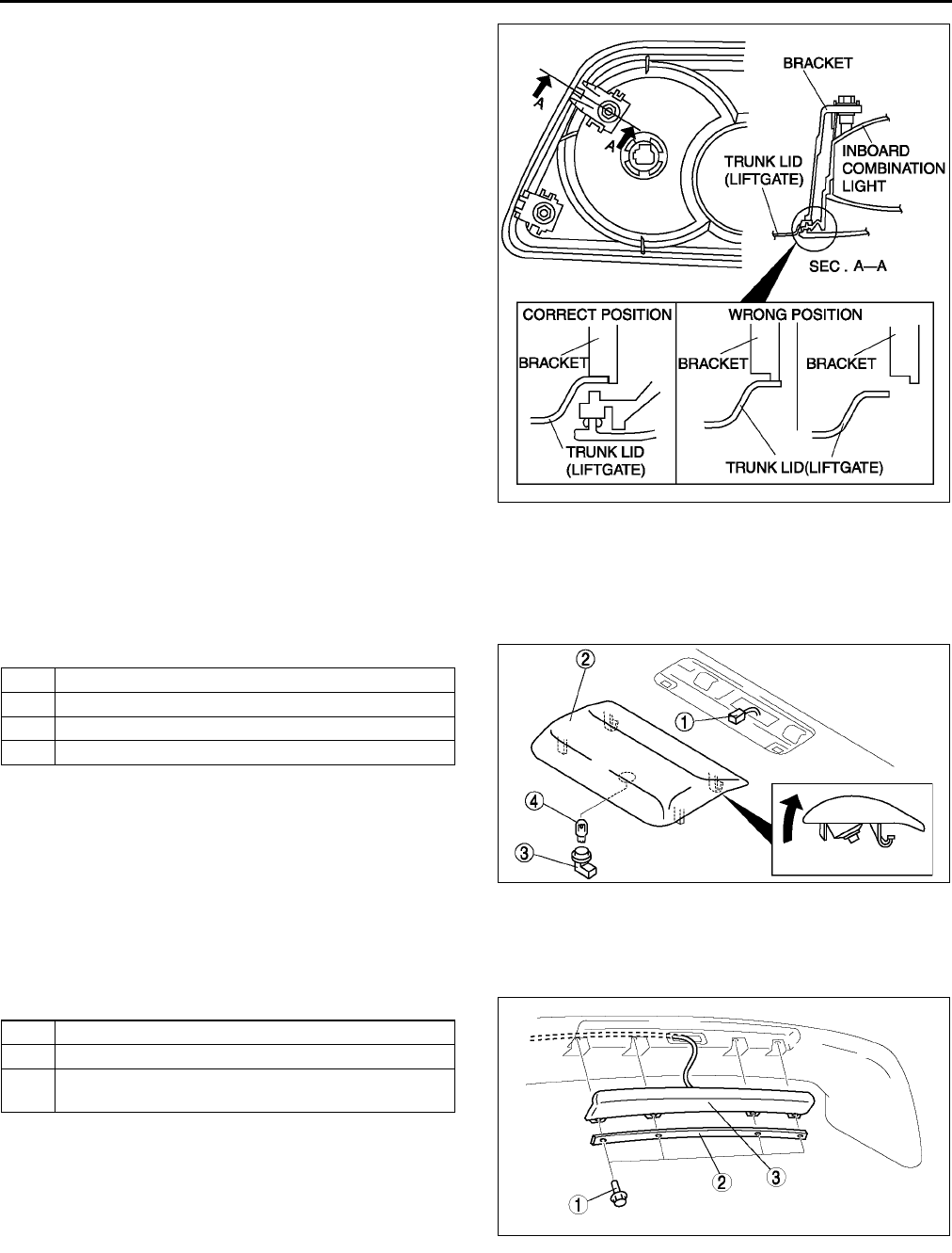
T36
EXTERIOR LIGHTING SYSTEM
2. Pleace the bracket in the proper position as
shown in the figure and press it to the trunk lid
(liftgate) to attach.
End Of Sie
HIGH-MOUNT BRAKE LIGHT REMOVAL/INSTALLATION A6E811251580W01
4SD
In-vehicle-type
1. Disconnect the negative battery cable.
2. Remove in the order indicated in the table.
3. Install in the reverse order of removal.
Rear spoiler type
1. Disconnect the negative battery cable.
2. Remove the rear spoiler. (See S54 REAR SPOILER REMOVAL/INSTALLATION)
3. Remove in the order indicated in the table.
4. Install in the reverse order of removal.
A6E8112W121
1 Connector
2 High-mount brake light
3Socket
4 High-mount brake light bulb
A6E8112W123
1Bolt
2Cover
2 High-mount brake light (See T37 High-mount
brake light removal note)
A6E8112W115
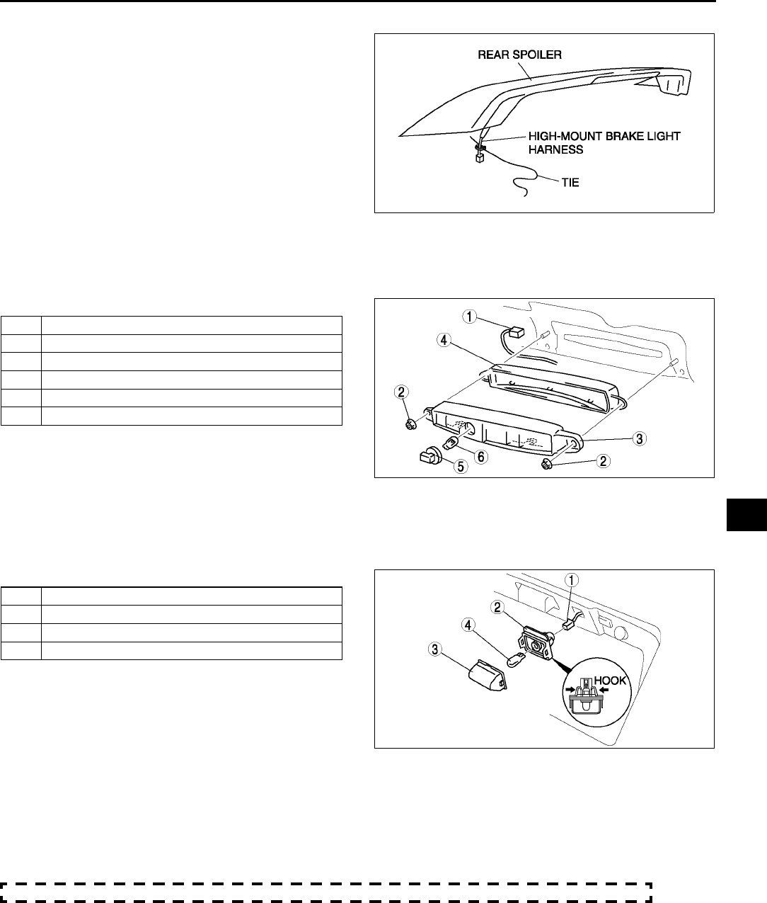
EXTERIOR LIGHTING SYSTEM
T37
T
High-mount brake light removal note
1. Tie a string to the end of the connector of the
high-mount brake light beforehand so that the
connector can be passed easily through the rear
spoiler during installation.
5HB
1. Disconnect the negative battery cable.
2. Remove the liftgate lower trim. (See S95 LIFTGATE LOWER TRIM REMOVAL/INSTALLATION)
3. Remove in the order indicated in the table.
4. Install in the reverse order of removal.
End Of Sie
LICENSE PLATE LIGHT REMOVAL/INSTALLATION A6E811251270W01
1. Disconnect the negative battery cable.
2. Remove the rear finisher. (See S54 REAR FINISHER REMOVAL/INSTALLATION)
3. Remove in the order indicated in the table.
4. Install in the reverse order of removal.
End Of Sie
COMBINATION SWITCH REMOVAL/INSTALLATION A6E811266120W01
1. Disconnect the negative battery cable.
2. Remove the driver-side air bag module. (See T120 DRIVER-SIDE AIR BAG MODULE REMOVAL/
INSTALLATION.)
3. Remove the steering wheel. (See N7 STEERING WHEEL AND COLUMN REMOVAL/INSTALLATION.)
4. Remove the column cover. (See S84 COLUMN COVER REMOVAL/INSTALLATION)
5. Remove the clock spring. (without DSC) (See T125 CLOCK SPRING REMOVAL/INSTALLATION.)
A6E8112W116
1 Connector
2Nut
3 High-mount brake light
4Lens
5Socket
6 High-mount brake light bulb
A6E8112W142
1 Connector
2 License plate light
3Lens
4 License plate light bulb
A6E8112W108
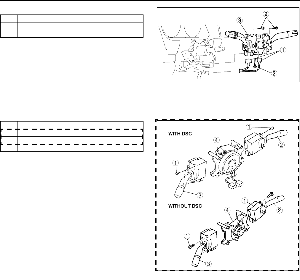
T38
EXTERIOR LIGHTING SYSTEM
6. Remove in the order indicated in the table.
7. Install in the reverse order of removal.
End Of Sie
COMBINATION SWITCH DISASSEMBLY/ASSEMBLY A6E811266120W02
1. Disassemble in the order indicated in the table.
2. Assemble in the reverse order of disassembly.
End Of Sie
1 Connector
2Screw
3 Combination switch
A6E8112W102
1Screw
2 Wiper and washer switch (Light switch)
3 Light switch (Wiper and washer switch)
4 Body
A6E8112W103
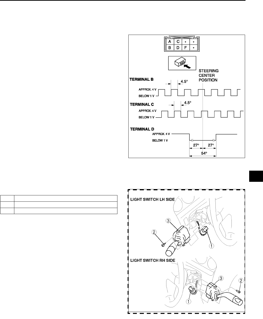
EXTERIOR LIGHTING SYSTEM
T39
T
STEERING ANGLE SENSOR INSPECTION A6E811266120W03
With DSC
1. Remove the column cover. (See S84 COLUMN COVER REMOVAL/INSTALLATION)
2. Disconnect the steering angle sensor connector.
3. Connect battery positive voltage to terminal A and ground to terminal F of the steering angle sensor.
4. Turn the steering wheel to the right and left, and
verify that the voltage and pulses at the terminals
are as shown in the figure.
•If not as specified, replace the body of the
combination switch.
End Of Sie
LIGHT SWITCH REMOVAL/INSTALLATION A6E811266121W01
1. Disconnect the negative battery cable.
2. Remove the column cover. (See S84 COLUMN COVER REMOVAL/INSTALLATION)
3. Remove in the order indicated in the table.
4. Install in the reverse order of removal.
End Of Sie
A6E8112W143
1 Connector
2Screw
3 Light switch
A6E8112W112
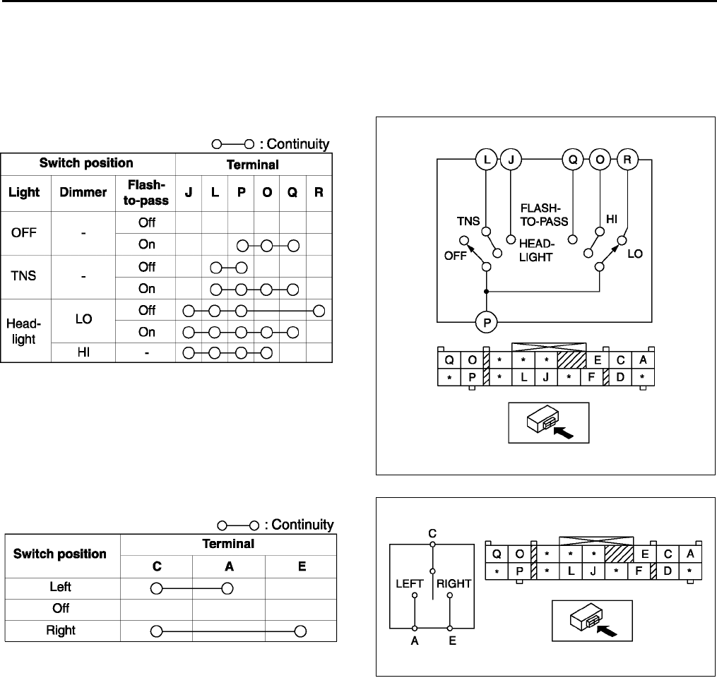
T40
EXTERIOR LIGHTING SYSTEM
LIGHT SWITCH INSPECTION A6E811266121W02
Light switch LH side
1. Remove the light switch. (See T39 LIGHT SWITCH REMOVAL/INSTALLATION)
2. Inspect for continuity between the light switch terminals using an ohmmeter.
•If not as specified, replace the light switch.
Headlight switch
Turn switch
A6E8112W144
A6E8112W129
A6E8112W145
A6E8112W130
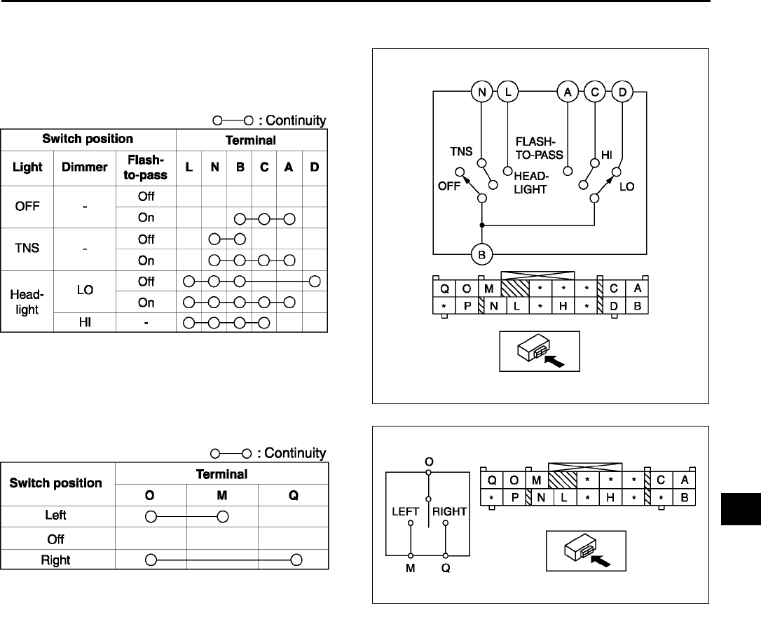
EXTERIOR LIGHTING SYSTEM
T41
T
Light switch RH side
1. Remove the light switch. (See T39 LIGHT SWITCH REMOVAL/INSTALLATION)
2. Inspect for continuity between the light switch
terminals using an ohmmeter.
•If not as specified, replace the light switch.
Headlight switch
Turn switch
End Of Sie
HAZARD WARNING SWITCH INSPECTION A6E811266401W01
1. Inspection the hazard warning switch. (See U47 CLIMATE CONTROL UNIT INSPECTION)
End Of Sie
A6E8112W146
A6E8112W131
A6E8112W147
A6E8112W139
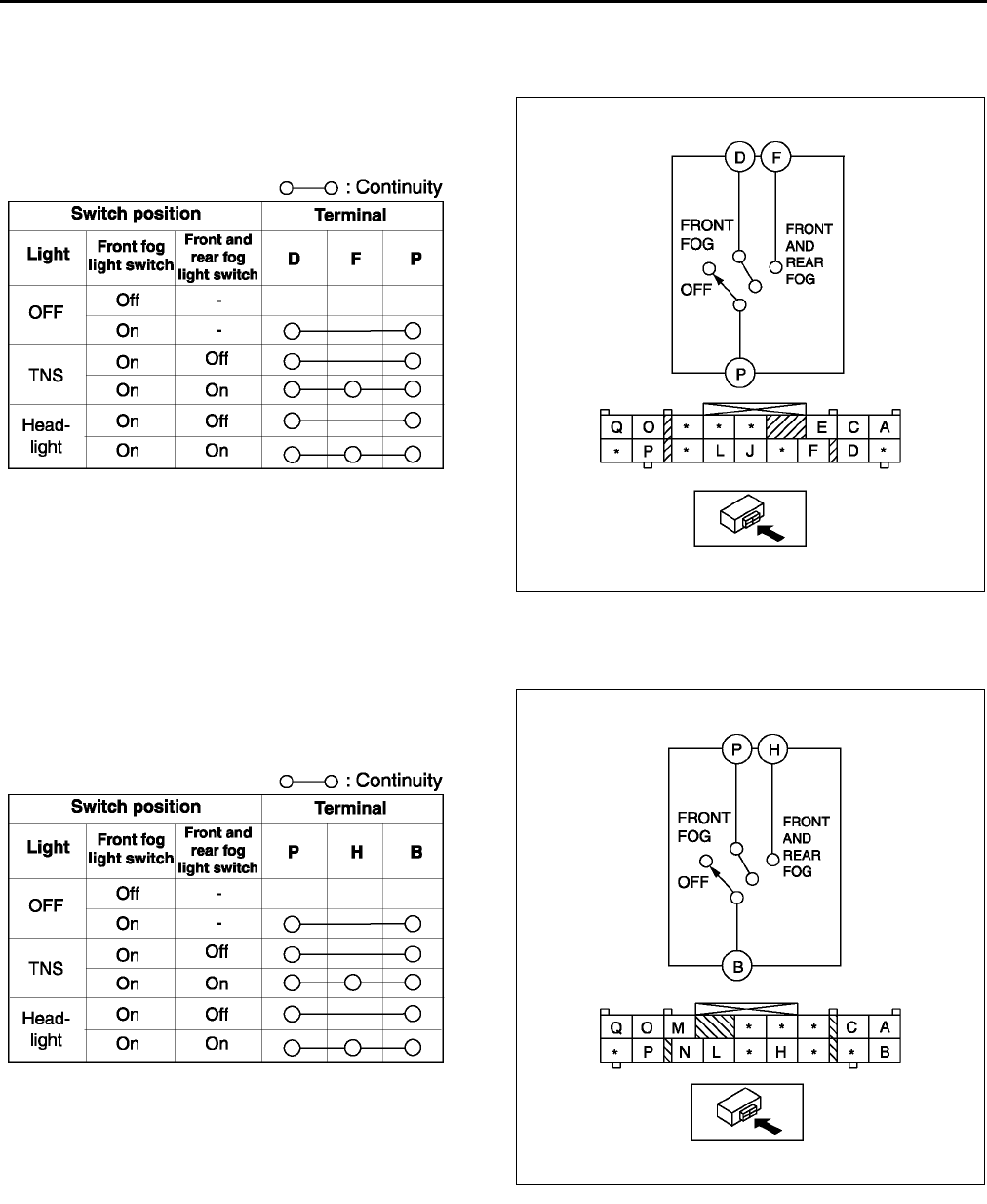
T42
EXTERIOR LIGHTING SYSTEM
FRONT AND REAR FOG LIGHT SWITCH INSPECTION A6E811266402W01
Light switch LH side
1. Remove the light switch. (See T39 LIGHT SWITCH REMOVAL/INSTALLATION.)
2. Inspect for continuity between the light switch
terminals using an ohmmeter.
•If not as specified, replace the light switch.
Light switch RH side
1. Remove the light switch. (See T39 LIGHT SWITCH REMOVAL/INSTALLATION.)
2. Inspect for continuity between the light switch
terminals using an ohmmeter.
•If not as specified, replace the light switch.
End Of Sie
A6E8112W148
A6E8112W140
A6E8112W167
A6E8112W166
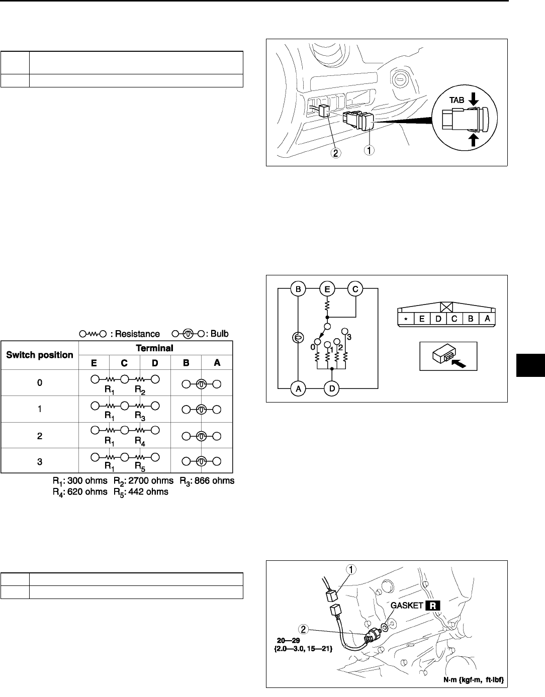
EXTERIOR LIGHTING SYSTEM
T43
T
HEADLIGHT LEVELING SWITCH REMOVAL/INSTALLATION A6E811251030W08
1. Disconnect the negative battery cable.
2. Remove in the order indicated in the table.
3. Install in the reverse order of removal.
Headlight Leveling Switch Removal Note
1. Insert your hand from the lower side of the dashboard and squeeze the tabs of the headlight leveling switch.
2. Pull the headlight leveling switch forward to remove it.
End Of Sie
HEADLIGHT LEVELING SWITCH INSPECTION A6E811251030W09
1. Remove the headlight leveling switch. (See T43 HEADLIGHT LEVELING SWITCH REMOVAL/
INSTALLATION.)
2. Inspect for continuity between the headlight
leveling switch terminals using an ohmmeter.
•If not as specified, replace the headlight
leveling switch.
End Of Sie
BACK-UP LIGHT SWITCH REMOVAL/INSTALLATION A6E811217640W01
1. Disconnect the negative battery cable.
2. Remove in the order indicated in the table.
3. Install in the reverse order of removal.
End Of Sie
1 Headlight leveling switch (See T43 Headlight
Leveling Switch Removal Note)
2 Connector
A6E8112W138
A6E8112W152
A6E8112W151
1 Connector
2 Back-up light switch
A6E8112W104
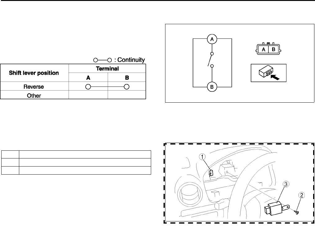
T44
EXTERIOR LIGHTING SYSTEM
BACK-UP LIGHT SWITCH INSPECTION A6E811217640W02
1. Disconnect the back-up light switch connector.
2. Inspect for continuity between the back-up light
switch terminals using an ohmmeter.
•If not as specified, replace the back-up light
switch.
End Of Sie
FLASHER UNIT REMOVAL/INSTALLATION A6E811266830W01
1. Disconnect the negative battery cable.
2. Remove the instrument cluster. (See T72 INSTRUMENT CLUSTER REMOVAL/INSTALLATION)
3. Remove in the order indicated in the table.
4. Install in the reverse order of removal.
End Of Sie
FLASHER UNIT INSPECTION A6E811266830W02
1. Connect the connector to the flasher unit.
2. Connect the negative battery cable.
3. Measure the voltage at the flasher unit using voltmeter.
•When inspecting terminal F for continuity, disconnect the flasher unit connector.
4. If the value are not as specified in the Terminal Voltage List (Reference), inspect the parts under Action and
related wiring harnesses.
5. If the system does not work properly even though the parts or related wiring harnesses do not have any
malfunction, replace the flasher unit.
A6E8112W153
A6E8112W128
1 Connector
2Screw
3Flasher unit
A6E8112W114
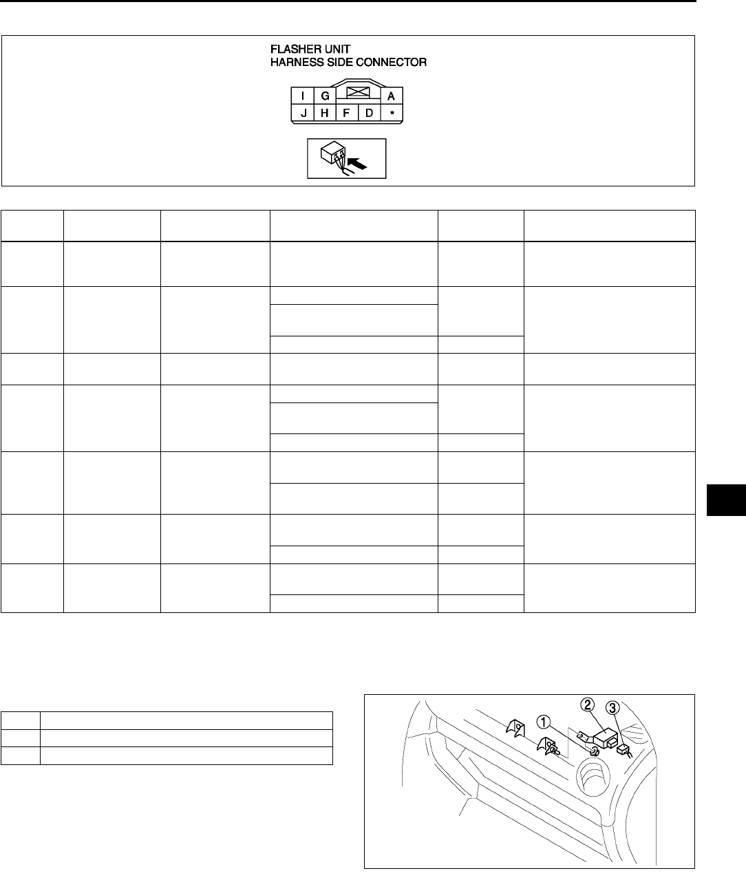
EXTERIOR LIGHTING SYSTEM
T45
T
Terminal Voltage List (Reference)
End Of Sie
RUNNING LIGHT UNIT REMOVAL/INSTALLATION A6E811266731W01
1. Disconnect the negative battery cable.
2. Remove the glove compartment. (See S85 GLOVE COMPARTMENT REMOVAL/INSTALLATION)
3. Remove in the order indicated in the table.
4. Install in the reverse order of removal.
End Of Sie
Terminal Signal Connected to Test condition Voltage (V)/
Continuity Action
A Power supply HAZARD 10 A
fuse Under any condition B+
•Inspect HAZARD 10 A
fuse
•Inspect related harness
DTurn signal
flasher (LH)
Turn signal light
(LH)
Turn signal light (LH) flashes Alternates
below 1.0 and
B+
•Inspect turn signal light
(LH)
•Inspect related harness
Hazard warning switch at on
position
Other Below 1.0
FFlasher unit
ground GND Constant: inspect for
continuity to ground Yes •Inspect GND
GTurn signal
flasher (RH)
Turn signal light
(RH)
Turn signal light (RH) flashes Alternates
below 1.0 and
B+
•Inspect turn signal light
(RH)
•Inspect related harness
Hazard warning switch at on
position
Other Below 1.0
HHazard warning
on
Hazard warning
switch
Hazard warning switch at on
position Below 1.0 •Inspect hazard warning
switch
•Inspect related harness
Hazard warning switch at off
position B+
ITurn switch on/
off (RH)
Combination
switch
Ignition switch is at ON and
turn switch (RH) on B+ •Inspect combination
switch
•Inspect related harness
Other Below 1.0
JTurn switch on/
off (LH)
Combination
switch
Ignition switch is at ON and
turn switch (LH) on B+ •Inspect combination
switch
•Inspect related harness
Other Below 1.0
A6E8112W154
1Nut
2 Running light unit
3 Connector
A6E8112W126
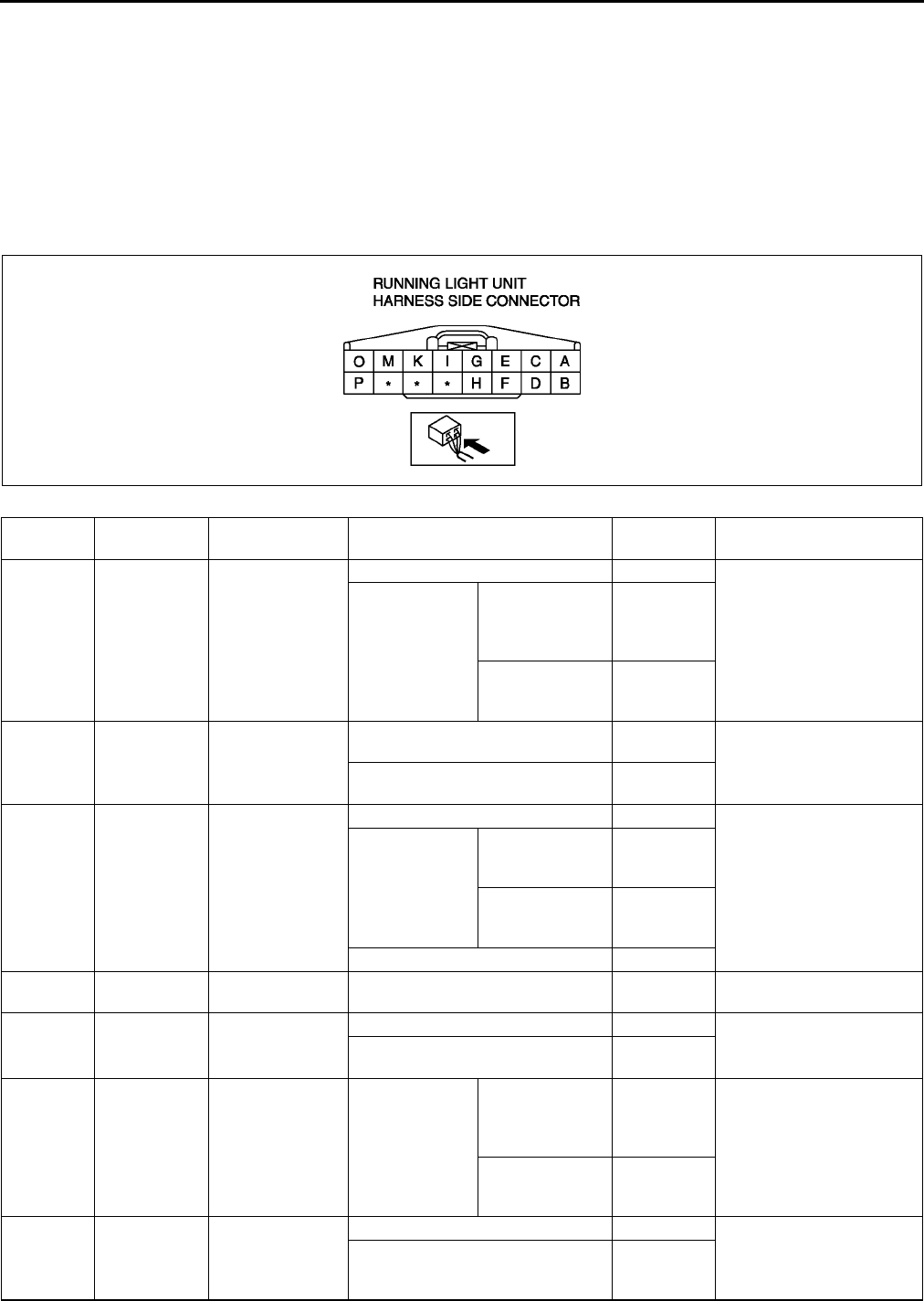
T46
EXTERIOR LIGHTING SYSTEM
RUNNING LIGHT UNIT INSPECTION A6E811266731W02
1. Connect the connector to the running light unit.
2. Connect the negative battery cable.
3. Measure the voltage at the running light unit using voltmeter.
•When inspecting terminal D, H or P for continuity, disconnect the running light unit connector.
4. If the value are not as specified in the Terminal Voltage List (Reference), inspect the parts under Action and
related wiring harnesses.
5. If the system does not work properly even though the parts or related wiring harnesses do not have any
malfunction, replace the running light unit.
Terminal Voltage List (Reference)
Terminal Signal Connected to Test condition Voltage (V)/
Continuity Action
AIllumination
light on/off TNS relay
Ignition switch at ON position B+
•Inspect ILLUMI 10 A
fuse
•Inspect TNS relay (See
T24 RELAY
INSPECTION)
•Inspect related harness
Ignition switch
at LOCK or
ACC position
Headlight switch
(light) at TNS or
headlight
position
Below 1.0
Headlight switch
(light) at OFF
position
B+
BIllumination
light operation
•Instrument
cluster
•Panel control
switch
Headlight switch (light) at TNS or
headlight position B+
Headlight switch (light) at OFF
position Below 1.0
C
Headlight
relay (high-
beam) on/off
Headlight relay
Ignition switch at ON position B+
•Inspect headlight relay
(See T24 RELAY
INSPECTION)
•Inspect related harness
Headliht switch
(light) at
headlight
position
Headlight switch
(dimmer) at LO
position
B+
Headlight switch
(dimmer) at HI
position
B+
Flash-to-pass on B+
DRunning light
unit ground GND Under any condition: inspect for
continuity to ground Yes •Inspect GND
EIG1 METER IG 15 A
fuse
Ignition switch at ON position B+ •Inspect METER IG
15 A fuse
•Inspect related harness
Ignition switch at LOCK or ACC
position Below 1.0
FFront fog light
relay on/off
Front fog light
relay
Front fog light
switch at ON
position
Headlight switch
(light) at TNS or
headlight
position
Below 1.0
•Inspect TNS relay (See
T24 RELAY
INSPECTION)
•Inspect front fog light
relay (See T24
RELAY INSPECTION)
•Inspect related harness
Headlight switch
(light) at OFF
position
B+
GTNS relay on/
off TNS relay
Ignition switch at ON position Below 1.0 •Inspect TNS relay (See
T24 RELAY
INSPECTION)
•Inspect related harness
Ignition switch at LOCK or ACC
position and headlight switch
(light) at OFF position
B+
A6E8112W155

EXTERIOR LIGHTING SYSTEM
T47
T
End Of Sie
HFront fog light
on/off
Front and rear
fog light switch
Front and rear fog light switch at
OFF position: inspect for continuity
to ground
No •Inspect front and rear
fog light switch (See T
42 FRONT AND REAR
FOG LIGHT SWITCH
INSPECTION)
•Inspect related harness
Front and rear fog light switch at
ON position: inspect for continuity
to ground
Yes
I TNS on/off Headlight switch
Headlight switch (light) at OFF
position No •Inspect headlight
switch (See T40
LIGHT SWITCH
INSPECTION)
•Inspect related harness
Headlight switch (light) at TNS or
headlight position Yes
KHeadlight
relay on/off Headlight relay
Ignition switch at ON position Below 1.0 •Inspect headlight relay
(See T24 RELAY
INSPECTION)
•Inspect related harness
Ignition switch at LOCK or ACC
and headlight switch (light) at OFF
position
B+
MFlash-to-pass
on/off
Headlight switch
(dimmer switch)
Headlight switch (light) at OFF or
TNS position No •Inspect headlight
switch (See T40
LIGHT SWITCH
INSPECTION)
•Inspect related harness
Headlight switch (light) at headlight
position Yes
Flash-to-pass on Yes
O
Headlight
high
operation
Headlight switch
(dimmer switch:
HI position)
Ignition switch at ON position B+
•Inspect headlight
switch (See T40
LIGHT SWITCH
INSPECTION)
•Inspect related harness
Headlight switch (light) at headlight
position and headlight switch
(dimmer) at LO position
B+
Headlight switch (light) at headlight
position and headlight switch
(dimmer) at HI position
Below 1.0
Flash-to-pass on Below 1.0
P
Headlight
(high-beam)
on/off
Headlight switch
Headlight switch (dimmer) at LO
position: inspect for continuity to
ground
No •Inspect headlight
switch (See T40
LIGHT SWITCH
INSPECTION)
•Inspect related harness
Headlight switch (dimmer) at HI
position: inspect for continuity to
ground
Yes
Terminal Signal Connected to Test condition Voltage (V)/
Continuity Action
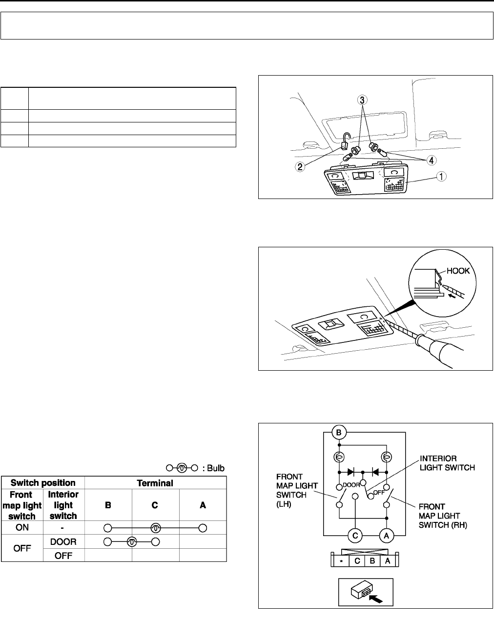
T48
INTERIOR LIGHTING SYSTEM
FRONT MAP LIGHT REMOVAL/INSTALLATION A6E811451310W01
1. Disconnect the negative battery cable.
2. Remove in the order indicated in the table.
3. Install in the reverse order of removal.
Front Map Light Removal Note
1. Insert a tape-wrapped flathead screwdriver into the gap between the headliner and the front map light.
2. Push the hooks to remove the front map light.
End Of Sie
FRONT MAP LIGHT INSPECTION A6E811451310W02
1. Remove the front map light. (See T48 FRONT MAP LIGHT REMOVAL/INSTALLATION.)
2. Inspect for continuity between the front map light
terminals using an ohmmeter.
•If not as specified, replace the front map light.
End Of Sie
INTERIOR LIGHTING SYSTEM
1 Front map light (See T48 Front Map Light Removal
Note)
2 Connector
3Socket
4 Map light bulb
A6E8114W102
A6E8114W103
A6E8114W118
A6E8114W117
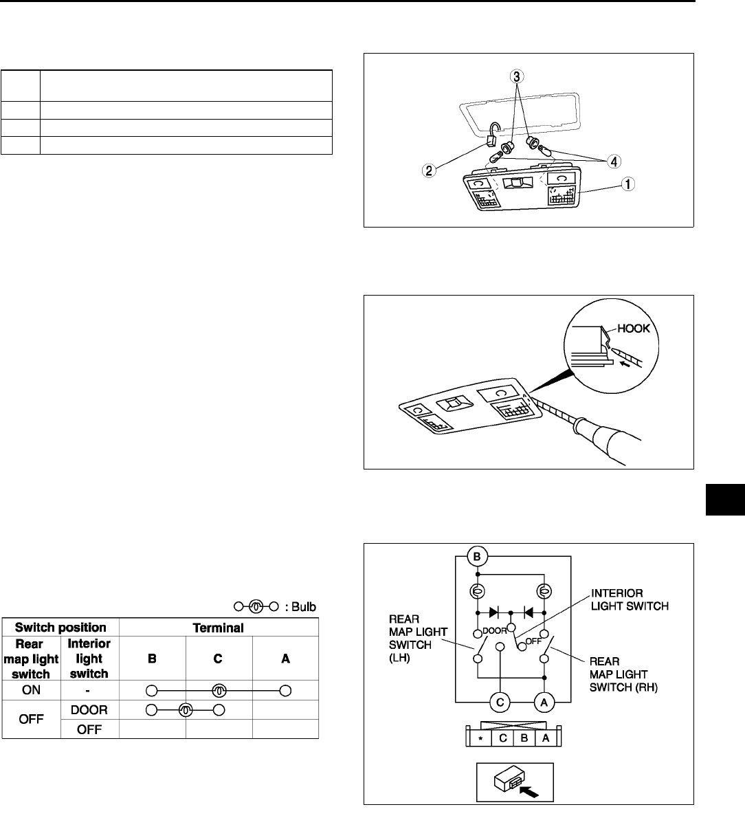
INTERIOR LIGHTING SYSTEM
T49
T
REAR MAP LIGHT REMOVAL/INSTALLATION A6E811451311W01
1. Disconnect the negative battery cable.
2. Remove in the order indicated in the table.
3. Install in the reverse order of removal.
Rear Map Light Removal Note
1. Insert a tape-wrapped flathead screwdriver into the gap between the headliner and the rear map light.
2. Push the hooks to remove the rear map light.
End Of Sie
REAR MAP LIGHT INSPECTION A6E811451311W02
1. Remove the rear map light. (See T49 REAR MAP LIGHT REMOVAL/INSTALLATION.)
2. Inspect for continuity between the rear map light
terminals using an ohmmeter.
•If not as specified, replace the rear map light.
End Of Sie
1 Rear map light (See T49 Rear Map Light Removal
Note)
2 Connector
3Socket
4 Rear map light bulb
A6E8114W104
A6E8114W105
A6E8114W128
A6E8114W127
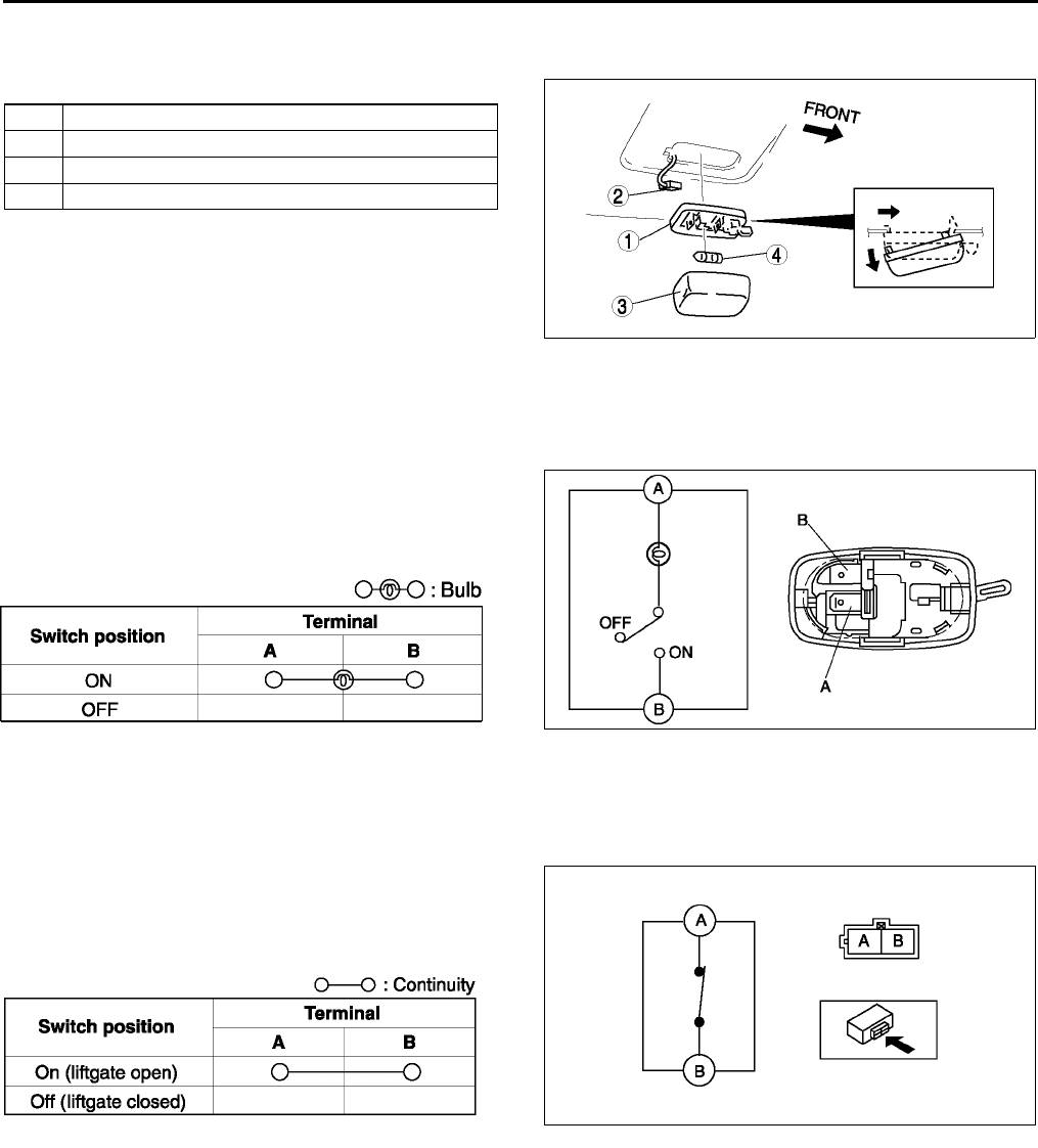
T50
INTERIOR LIGHTING SYSTEM
CARGO COMPARTMENT LIGHT REMOVAL/INSTALLATION A6E811451441W01
1. Disconnect the negative battery cable.
2. Remove in the order indicated in the table.
3. Install in the reverse order of removal.
End Of Sie
CARGO COMPARTMENT LIGHT INSPECTION A6E811451441W02
1. Remove the cargo compartment light. (See T50 CARGO COMPARTMENT LIGHT REMOVAL/
INSTALLATION)
2. Inspect for continuity between the cargo
compartment light terminals using an ohmmeter.
•If not as specified, replace the cargo
compartment light.
End Of Sie
CARGO COMPARTMENT LIGHT SWITCH INSPECTION A6E811451442W01
1. Remove the liftgate lower trim. (See S95 LIFTGATE LOWER TRIM REMOVAL/INSTALLATION)
2. Disconnect the cargo compartment light switch connector.
3. Inspect for continuity between the cargo
compartment light switch terminals using an
ohmmeter.
•If not as specified, replace the liftgate lock.
End Of Sie
1 Cargo compartment light
2 Connector
3 Lens
4 Cargo compartment light bulb
A6E8114W101
A6E8114W111
A6E8114W114
A6E8114W119
A6E8114W120
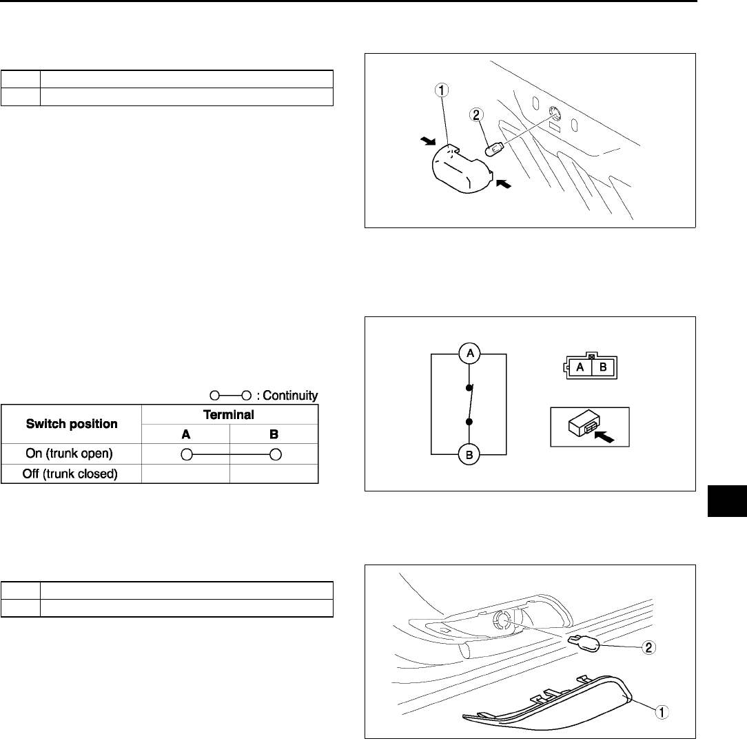
INTERIOR LIGHTING SYSTEM
T51
T
TRUNK COMPARTMENT LIGHT BULB REMOVAL/INSTALLATION A6E811451440W01
1. Disconnect the negative battery cable.
2. Remove in the order indicated in the table.
3. Install in the reverse order of removal.
End Of Sie
TRUNK COMPARTMENT LIGHT SWITCH INSPECTION A6E811451440W02
1. Remove the trunk lid trim. (See S93 TRUNK LID TRIM REMOVAL/INSTALLATION)
2. Disconnect the trunk compartment light switch connector.
3. Inspect for continuity between the trunk
compartment light switch terminals using an
ohmmeter.
•If not as specified, replace the trunk lock.
End Of Sie
COURTESY LIGHT BULB REMOVAL/INSTALLATION A6E811469971W01
1. Disconnect the negative battery cable.
2. Remove in the order indicated in the table.
3. Install in the reverse order of removal.
End Of Sie
1Lens
2 Trunk compartment light bulb
A6E8114W112
A6E8114W119
A6E8114W121
1Lens
2 Courtesy light bulb
A6E8114W110
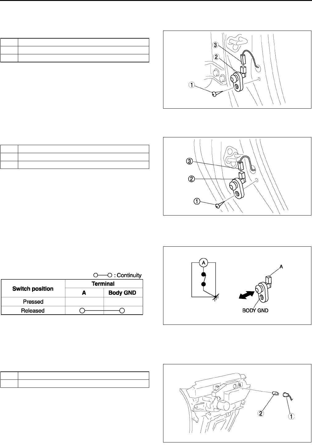
T52
INTERIOR LIGHTING SYSTEM
DOOR SWITCH REMOVAL/INSTALLATION A6E811466540W01
Front
1. Disconnect the negative battery cable.
2. Remove in the order indicated in the table.
3. Install in the reverse order of removal.
Rear
1. Disconnect the negative battery cable.
2. Remove in the order indicated in the table.
3. Install in the reverse order of removal.
End Of Sie
DOOR SWITCH INSPECTION A6E811466540W02
1. Remove the door switch. (See T52 DOOR SWITCH REMOVAL/INSTALLATION)
2. Inspect for continuity between the door switch
terminal and a body ground using an ohmmeter.
•If not as specified, replace the door switch.
End Of Sie
ASHTRAY ILLUMINATION BULB REMOVAL/INSTALLATION A6E811455431W01
1. Disconnect the negative battery cable.
2. Remove the boot panel.
3. Remove in the order indicated in the table.
4. Install in the reverse order of removal.
1Screw
2 Door switch
3 Connector
A6E8114W108
1Screw
2 Door switch
3 Connector
A6E8114W109
A6E8114W115
A6E8114W122
1Socket
2 Ashtray illumination bulb
A6E8114W106
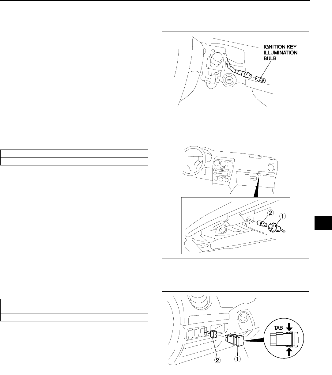
INTERIOR LIGHTING SYSTEM
T53
T
End Of Si e
IGNITION KEY ILLUMINATION BULB REMOVAL/INSTALLATION A6E811460231W01
1. Disconnect the negative battery cable.
2. Remove the column cover. (See S84 COLUMN COVER REMOVAL/INSTALLATION)
3. Remove the ignition key illumination bulb.
4. Install in the reverse order of removal.
End Of Sie
GLOVE COMPARTMENT LIGHT BULB REMOVAL/INSTALLATION A6E811451445W01
1. Disconnect the negative battery cable.
2. Remove in the order indicated in the table.
3. Install in the reverse order of removal.
End Of Sie
PANEL LIGHT CONTROL SWITCH REMOVAL/INSTALLATION A6E811466600W01
1. Disconnect the negative battery cable.
2. Remove in the order indicated in the table.
3. Install in the reverse order of removal.
Panel Light Control Switch Removal Note
1. Insert your hand from the lower side of the dashboard and squeeze the tabs of the panel light control switch.
2. Pull the panel light control switch forward to remove it.
End Of Sie
A6E8114W129
1Socket
2 Glove compartment light bulb
A6E8114W113
1 Panel light control switch (See T53 Panel Light
Control Switch Removal Note)
2 Connector
A6E8114W116
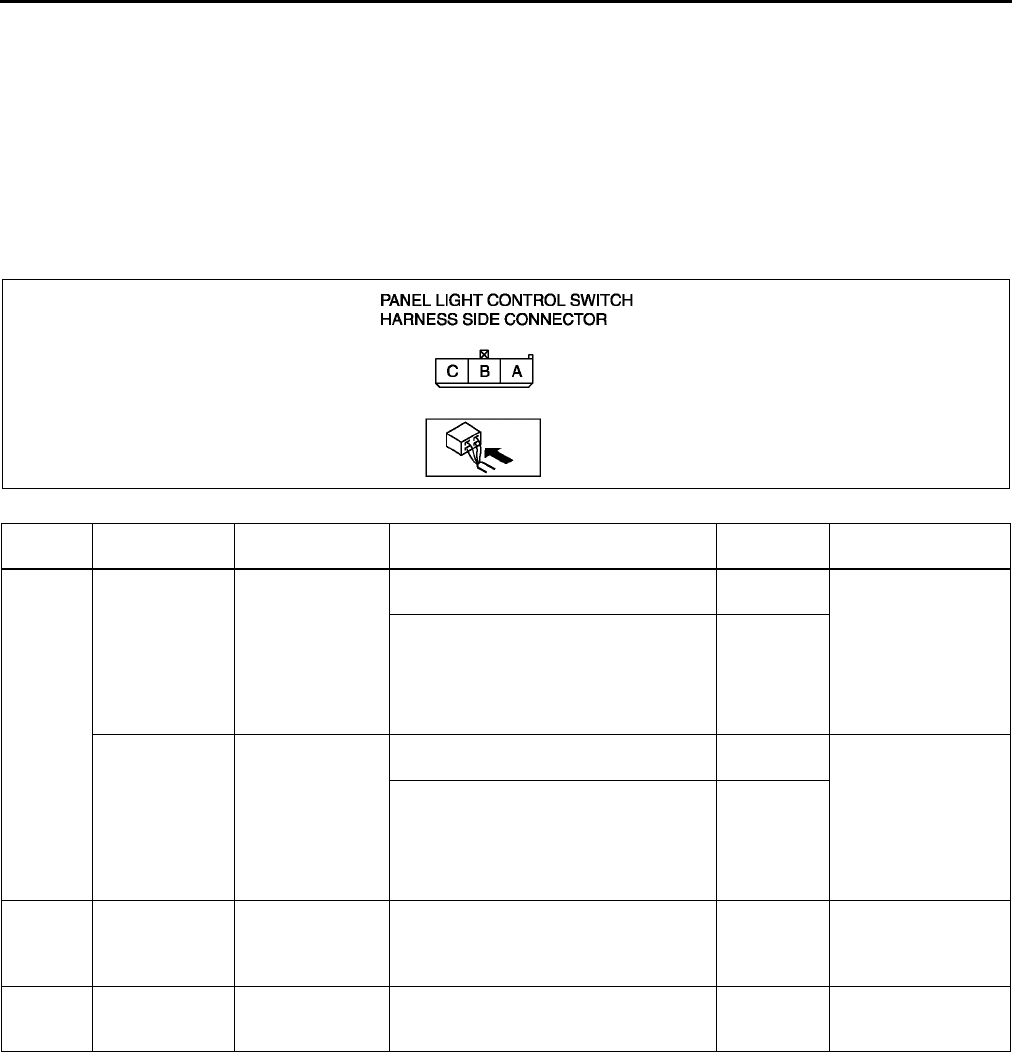
T54
INTERIOR LIGHTING SYSTEM
PANEL LIGHT CONTROL SWITCH INSPECTION A6E811466600W02
1. Connect the connector to the panel light control switch.
2. Connect the negative battery cable.
3. Measure the voltage at the panel light control switch using voltmeter.
•When inspecting terminal B for continuity, disconnect the panel light control switch connector.
4. If the value are not as specified in the Terminal Voltage List (Reference), inspect the parts under Action and
related wiring harnesses.
5. If the system does not work properly even though the parts or related wiring harnesses do not have any
malfunction, replace the panel light control switch.
Terminal Voltage Table (Reference)
Terminal Signal Connected to Test condition Voltage (V)/
Continuity Action
A
TNS (Without
running light
system)
TNS relay
Headlight switch at TNS or headlight
position B+ •Inspect TNS
relay (See T24
RELAY
INSPECTION)
•Inspect ILLUMI
10A fuse
•Inspect related
harness
Other 0
Running light
(With running
light system)
Running light unit
Headlight switch at TNS or headlight
position B+ •Inspect running
light unit
(See T46
RUNNING LIGHT
UNIT
INSPECTION)
•Inspect related
harness
Other 0
C Illumination Each illumination Inspect using an oscilloscope (See T
55 Terminal C inspection)
•Inspect each
illumination
•Inspect related
harness
BGround GND Under any condition: inspect for
continuity to ground Yes
•Inspect GND
•Inspect related
harness
A6E8114W123
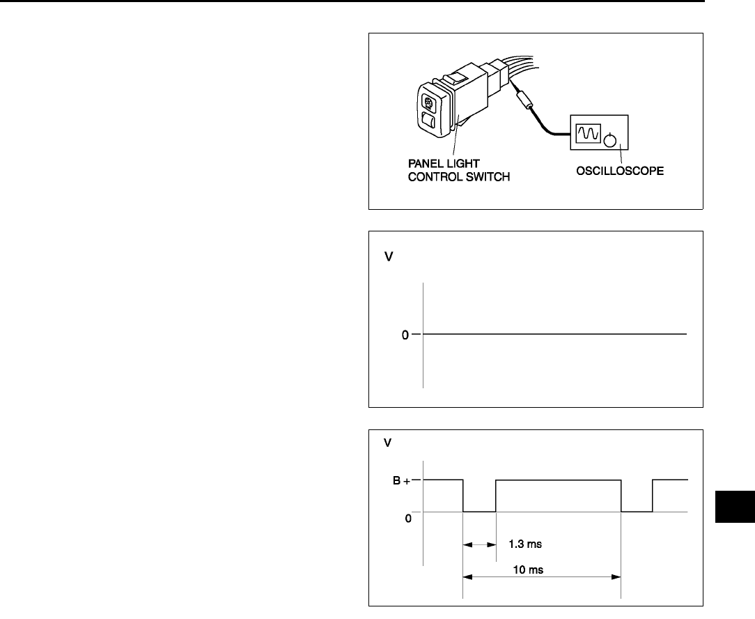
INTERIOR LIGHTING SYSTEM
T55
T
Terminal C inspection
1. Measure the wave pattern of the terminal C on
the panel light control switch using an
oscilloscope.
2. Set the headlight switch to either the TNS or
headlight position.
3. Set the panel light control switch to the brightest
position.
4. Verify that the pattern on the screen is as shown
in the figure.
5. Verify that the pattern on the screen matches the
pattern shown in the figure as the panel light
control switch is gradually turned to the darkest
position.
End Of Sie
A6E8114W124
A6E8114W125
A6E8114W126
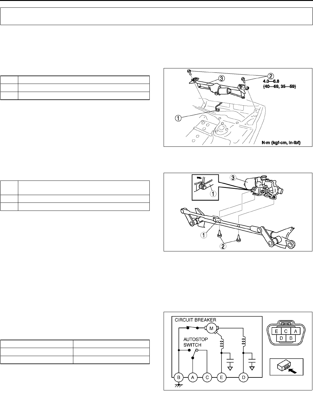
T56
WIPER AND WASHER
WINDSHIELD WIPER MOTOR REMOVAL/INSTALLATION A6E811667340W01
1. Disconnect the negative battery cable.
2. Remove the windshield wiper arm and blade. (See T57 WINDSHIELD WIPER ARM AND BLADE REMOVAL/
INSTALLATION.)
3. Remove the cowl grille. (See S50 COWL GRILLE REMOVAL/INSTALLATION.)
4. Remove in the order indicated in the table.
5. Install in the reverse order of removal.
6. Adjust the windshield wiper arm and blade. (See
T58 WINDSHIELD WIPER ARM AND BLADE
ADJUSTMENT.)
End Of Sie
WINDSHIELD WIPER MOTOR DISASSEMBLY/ASSEMBLY A6E811667340W02
1. Disassemble in the order indicated in the table.
2. Assemble in the reverse order of disassembly.
Windshield Wiper Link Removal Note
1. Pry off the connection between the windshield wiper motor and windshield wiper link.
End Of Sie
WINDSHIELD WIPER MOTOR INSPECTION A6E811667340W03
L.H.D.
1. Disconnect the windshield wiper motor connector.
2. Connect battery positive voltage to terminal E or
D and ground to terminal B, and inspect the
operation of the windshield wiper motor as
indicated below.
3. Disconnect battery positive voltage from terminal
E of the motor while the wipers are operating.
4. Verify that the wipers do not stop in the park
position.
5. Short between the motor terminals A and D and
connect battery positive voltage to the motor terminal C.
6. Verify that the wipers operate at low speed again, then stop in the park position.
•If not as specified, replace the windshield wiper motor.
WIPER AND WASHER
1 Connector
2Bolt
3 Windshield wiper motor
A6E8116W102
1 Windshield wiper link (See T56 Windshield Wiper
Link Removal Note)
2Bolt
3 Windshield wiper motor
A6E8116W140
Terminal Operation
EHigh
DLow
A6E8116W127
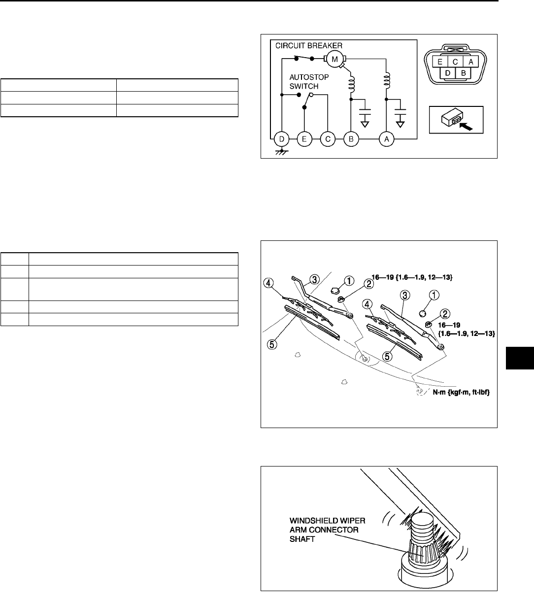
WIPER AND WASHER
T57
T
R.H.D.
1. Disconnect the windshield wiper motor connector.
2. Connect battery positive voltage to terminal B or
A and ground to terminal D, and inspect the
operation of the windshield wiper motor as
indicated below.
3. Disconnect battery positive voltage from terminal
B of the motor while the wipers are operating.
4. Verify that the wipers do not stop in the park
position.
5. Short between the motor terminals E and A and
connect battery positive voltage to the motor terminal C.
6. Verify that the wipers operate at low speed again, then stop in the park position.
•If not as specified, replace the windshield wiper motor.
End Of Sie
WINDSHIELD WIPER ARM AND BLADE REMOVAL/INSTALLATION A6E811667320W01
1. Remove in the order indicated in the table.
2. Install in the reverse order of removal.
3. Adjust the windshield wiper arm and blade. (See
T58 WINDSHIELD WIPER ARM AND BLADE
ADJUSTMENT.)
Windshield Wiper Arm Installation Note
1. Clean the windshield wiper arm connector shafts
using a wire brush before installing the windshield
wiper arms.
End Of Sie
Terminal Operation
BHigh
ALow
A6E8116W128
1Cap
2Nut
3 Windshield wiper arm (See T57 Windshield Wiper
Arm Installation Note)
4 Windshield wiper blade
5 Rubber brush
A6E8116W111
A6E8116W103
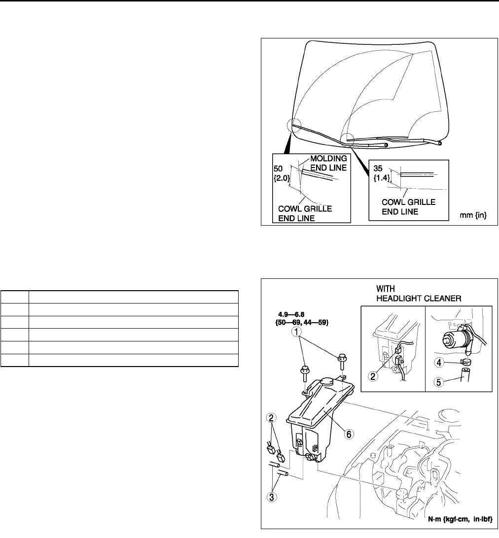
T58
WIPER AND WASHER
WINDSHIELD WIPER ARM AND BLADE ADJUSTMENT A6E811667320W02
1. Operate the windshield wiper motor to set the wipers in the park position.
2. Set the windshield wiper arms height as shown.
End Of Sie
WASHER TANK REMOVAL/INSTALLATION A6E811667481W01
1. Disconnect the negative battery cable.
2. Remove in the order indicated in the table.
3. Install in the reverse order of removal.
End Of Sie
A6E8116W107
1Bolt
2 Connector
3 Washer hose
4 Clip
5 Headlight cleaner hose
6 Washer tank
A6E8116W117
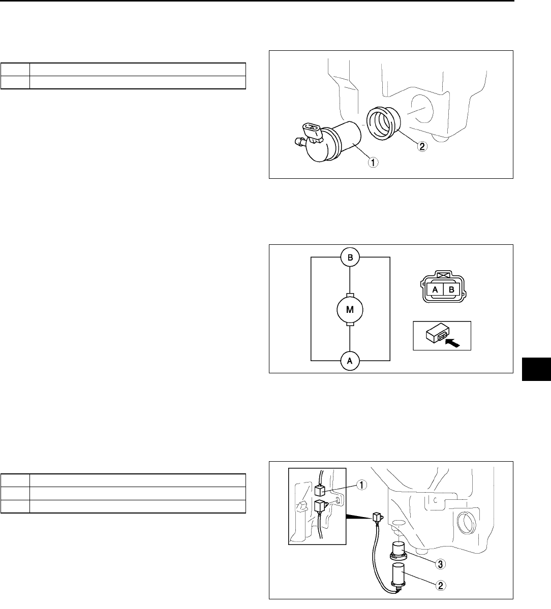
WIPER AND WASHER
T59
T
WINDSHIELD WASHER MOTOR REMOVAL/INSTALLATION A6E811676670W01
1. Disconnect the negative battery cable.
2. Remove the washer tank. (See T58 WASHER TANK REMOVAL/INSTALLATION)
3. Remove in the order indicated in the table.
4. Install in the reverse order of removal.
End Of Sie
WINDSHIELD WASHER MOTOR INSPECTION A6E811676670W02
1. Disconnect the negative battery cable.
2. Remove the washer tank. (See T58 WASHER TANK REMOVAL/INSTALLATION)
3. Connect battery positive voltage to the motor
terminal B and ground to the motor terminal A.
4. Verify that the windshield washer motor operates.
•If the motor does not operate, replace the
windshield washer motor.
End Of Sie
WASHER FLUID-LEVEL SENSOR REMOVAL/INSTALLATION A6E811676670W03
1. Disconnect the negative battery cable.
2. Remove the washer tank. (See T58 WASHER TANK REMOVAL/INSTALLATION)
3. Remove the headlight cleaner motor. (See T69 HEADLIGHT CLEANER MOTOR REMOVAL/
INSTALLATION)
4. Remove in the order indicated in the table.
5. Install in the reverse order of removal.
End Of Sie
1 Windshield washer motor
2Grommet
A6E8116W123
A6E8116W129
1 Connector
2 Washer fluid-level sensor
3Grommet
A6E8116W114
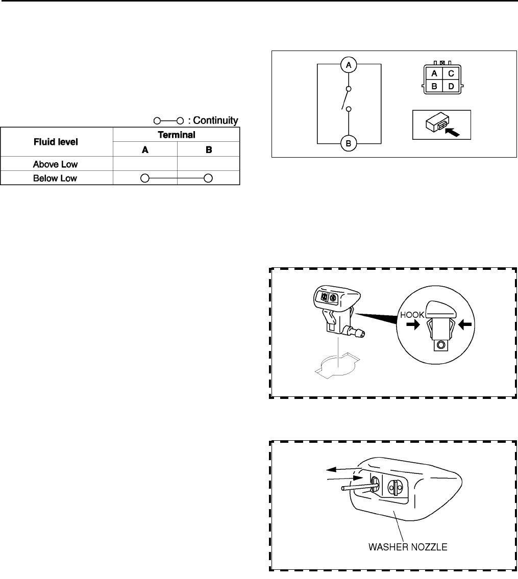
T60
WIPER AND WASHER
WASHER FLUID-LEVEL SENSOR INSPECTION A6E811676670W04
1. Disconnect the negative battery cable.
2. Remove the washer tank. (See T58 WASHER TANK REMOVAL/INSTALLATION)
3. Insoect for continuity between the washer fluid-
level sensor terminals using an ohmmeter.
4. Verify that the windshield washer motor operates.
•If not as specified, replace the washer fluid-
level sensor.
End Of Sie
WINDSHIELD WASHER NOZZLE REMOVAL/INSTALLATION A6E811667510W01
1. Remove the bonnet insulator.
2. Remove the windshield washer hose from the windshield washer nozzle.
3. Compress the hooks of the windshield washer nozzle.
4. Pull the windshield washer nozzle out to remove
it.
5. Install in the reverse order of removal.
End Of Sie
WINDSHIELD WASHER NOZZLE CLEANING A6E811667510W03
1. Clean the washer nozzle by inserting and moving
a needle or an equivalent tool back and forth.
•If the nozzle becomes clogged again after
cleaning, remove the hose from washer
nozzle. Make sure there is enough washer
fluid. Then turn the washer switch on and
flush the inside of the hose.
End Of Sie
A6E8116W130
A6E8116W144
A6E8116W143
A6E8116W124
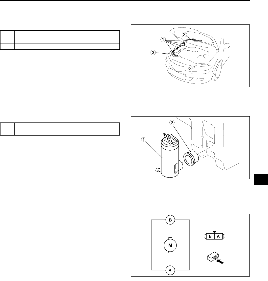
WIPER AND WASHER
T61
T
WINDSHIELD WASHER HOSE REMOVAL/INSTALLATION A6E811650601W01
1. Remove the bonnet insulator.
2. Partially peel off the right side mud guard.
3. Remove in the order indicated in the table.
4. Install in the reverse order of removal.
End Of Sie
REAR WASHER MOTOR REMOVAL/INSTALLATION A6E811676672W01
1. Disconnect the negative battery cable.
2. Remove the washer tank. (See T58 WASHER TANK REMOVAL/INSTALLATION)
3. Remove in the order indicated in the table.
4. Install in the reverse order of removal.
End Of Sie
REAR WASHER MOTOR INSPECTION A6E811676672W02
1. Disconnect the negative battery cable.
2. Remove the washer tank. (See T58 WASHER TANK REMOVAL/INSTALLATION)
3. Connect battery positive voltage to the terminal B and ground to the terminal A of the motor.
4. Verify that the rear washer motor operates.
•If the motor does not operate, replace the rear
washer motor.
End Of Sie
1Clip
2 Joint pipe
3 Windshield washer hose
A6E8116W126
1 Rear washer motor
2Grommet
A6E8116W104
A6E8116W131
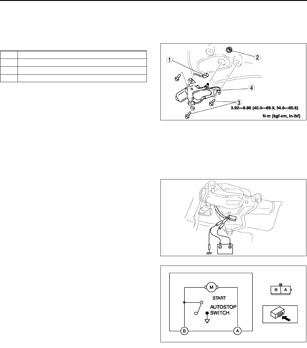
T62
WIPER AND WASHER
REAR WIPER MOTOR REMOVAL/INSTALLATION A6E811667450W01
1. Disconnect the negative battery cable.
2. Remove the rear wiper arm and blade. (See T63 REAR WIPER ARM AND BLADE REMOVAL/
INSTALLATION.)
3. Remove the liftgate lower trim. (See S95 LIFTGATE LOWER TRIM REMOVAL/INSTALLATION)
4. Remove in the order indicated in the table.
5. Install in the reverse order of removal.
6. Adjust the rear wiper arm and blade. (See T64
REAR WIPER ARM AND BLADE
ADJUSTMENT.)
End Of Sie
REAR WIPER MOTOR INSPECTION A6E811667450W02
1. Disconnect the negative battery cable.
2. Remove the liftgate lower trim. (See S95 LIFTGATE LOWER TRIM REMOVAL/INSTALLATION)
3. Disconnect the rear wiper motor connector.
4. Connect battery positive voltage to the rear wiper motor terminal A and the ground to a bare metal part of the
vehicle and the rear wiper motor terminal B.
5. Verify that the rear wiper motor operates.
6. Disconnect the ground to the terminal B while the
rear wiper is operating.
1 Connector
2 Outer bushing
3Bolt
4 Rear wiper motor
A6E8116W110
A6E8116W119
A6E8116W132
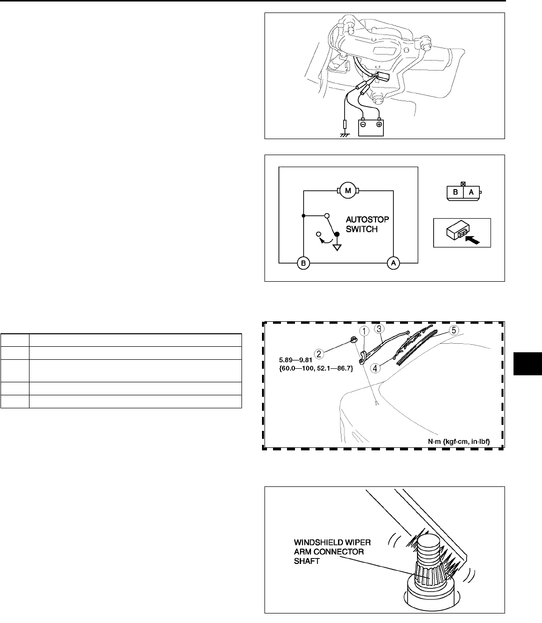
WIPER AND WASHER
T63
T
7. Verify that the rear wiper stops in the park
position.
•If not as specified, replace the rear wiper
motor.
End Of Sie
REAR WIPER ARM AND BLADE REMOVAL/INSTALLATION A6E811667420W01
1. Remove in the order indicated in the table.
2. Install in the reverse order of removal.
3. Adjust the rear wiper arm and blade. (See T64
REAR WIPER ARM AND BLADE
ADJUSTMENT)
Rear Wiper Arm Installation Note
1. Clean the rear wiper arm connector shaft using a
wire brush before installing the rear wiper arm.
End Of Sie
A6E8116W119
A6E8116W133
1Cap
2Nut
3 Rear wiper arm (See T63 Rear Wiper Arm
Installation Note)
4 Rear wiper blade
5 Rubber brush
A6E8116W112
A6E8116W103
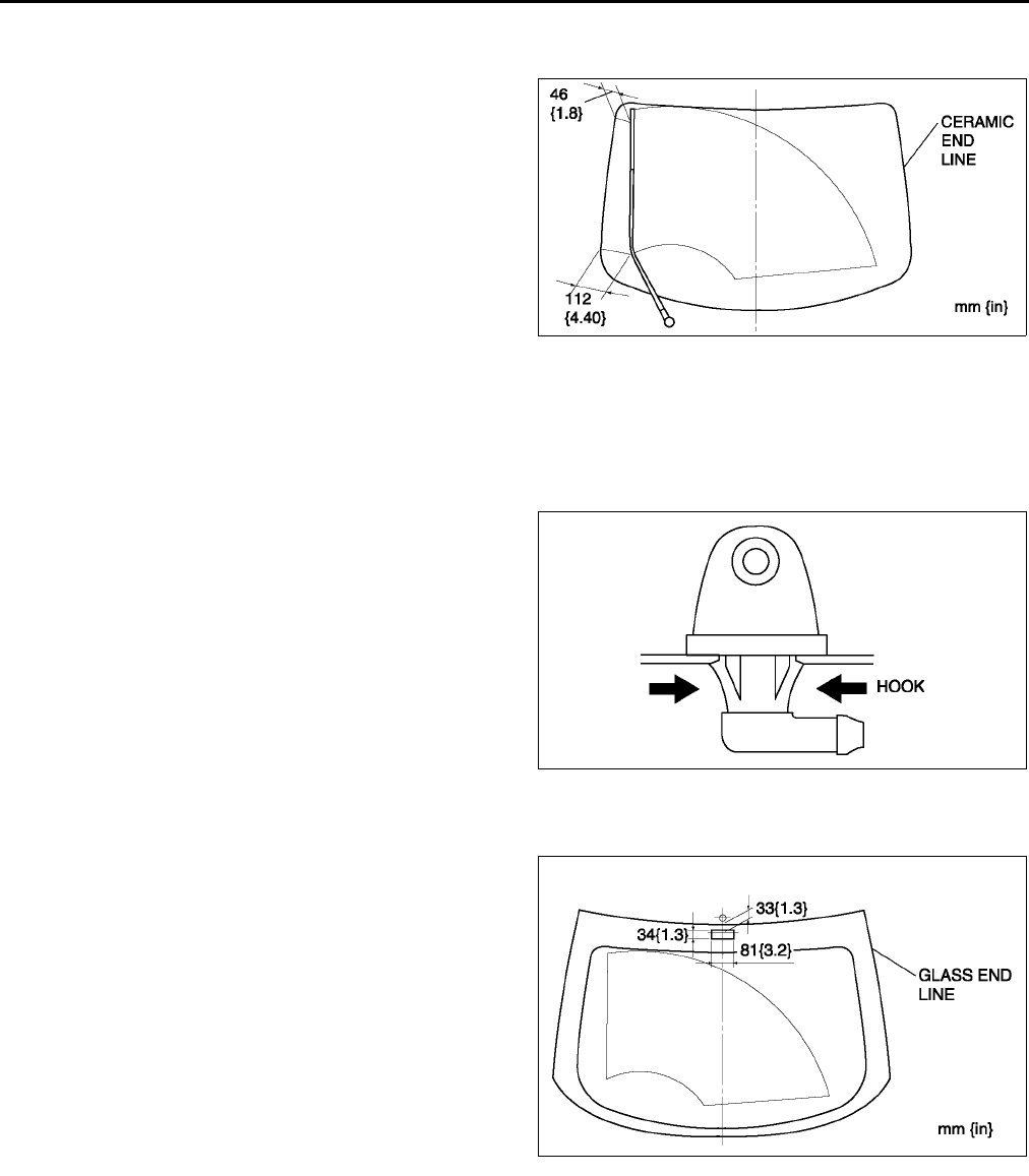
T64
WIPER AND WASHER
REAR WIPER ARM AND BLADE ADJUSTMENT A6E811667420W02
1. Operate the rear wiper motor to set the wiper in the park position.
2. Set the rear wiper arm onto the ceramics end line.
End Of Sie
REAR WASHER NOZZLE REMOVAL/INSTALLATION A6E811667511W01
1. Disconnect the negative battery cable.
2. Remove the liftgate upper trim. (See S94 LIFTGATE UPPER TRIM REMOVAL/INSTALLATION)
3. Remove the rear washer hose from the rear washer nozzle.
4. Compress the tabs of the rear washer nozzle.
5. Pull the rear washer nozzle out to remove it.
6. Install in the reverse order of removal.
7. Adjust the rear washer nozzle. (See T64 REAR
WASHER NOZZLE ADJUSTMENT.)
End Of Sie
REAR WASHER NOZZLE ADJUSTMENT A6E811667511W02
1. Insert a needle or an equivalent tool into the spray
hole of the rear washer nozzle and adjust the
nozzle direction as shown.
End Of Sie
REAR WASHER NOZZLE CLEANING A6E811667511W03
1. Clean the rear washer nozzle. (See T60 WINDSHIELD WASHER NOZZLE CLEANING.)
End Of Sie
A6E8116W109
A6E8116W105
A6E8116W108
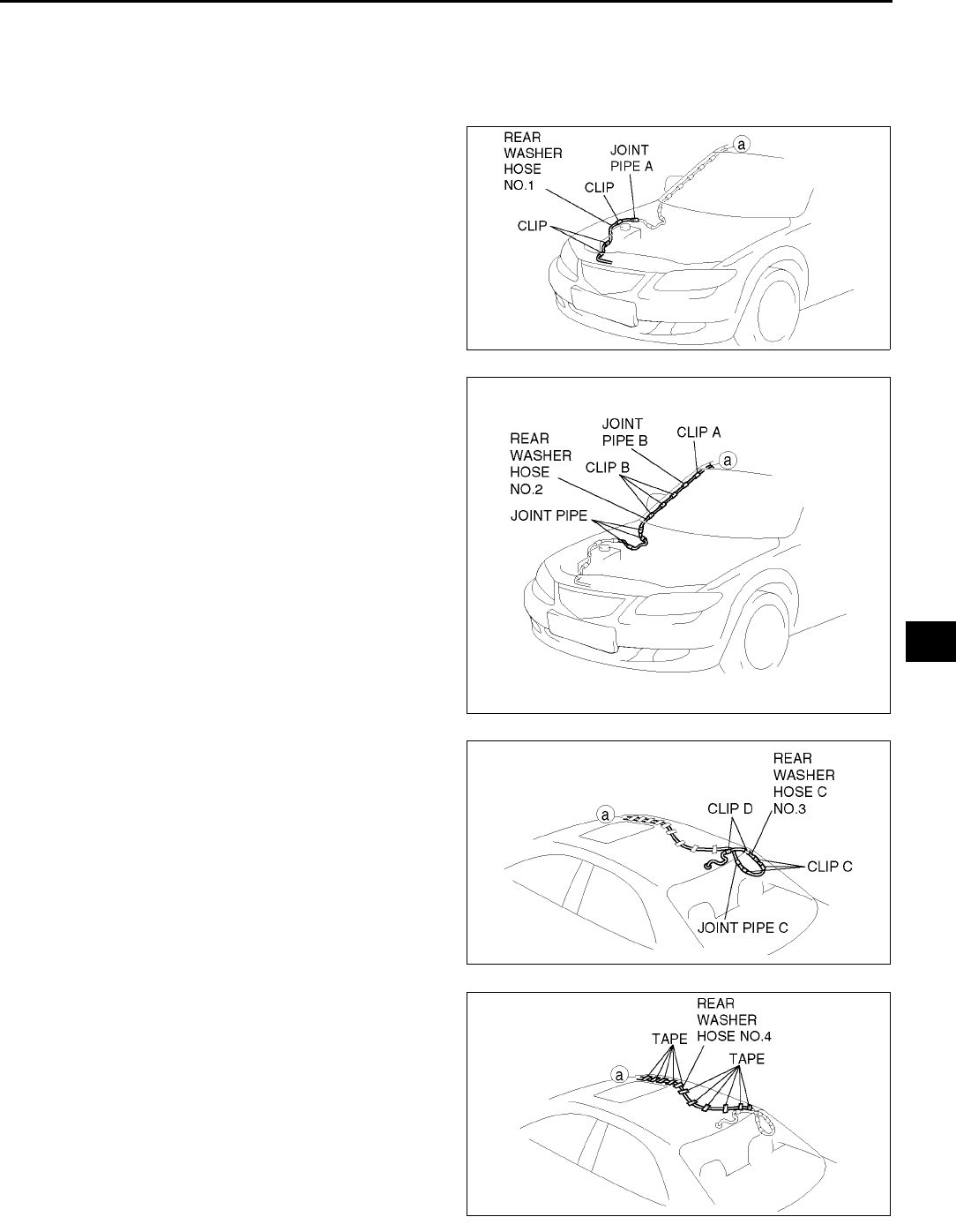
WIPER AND WASHER
T65
T
REAR WASHER HOSE REMOVAL/INSTALLATION A6E811667470W01
1. Disconnect the negative battery cable.
2. Remove the washer tank. (See T58 WASHER TANK REMOVAL/INSTALLATION)
3. Partially peel off the right side mud guard.
4. Remove rear washer hose No.1 from the clips.
5. Remove rear washer hose No.1 and joint pipe A.
6. Remove the A-pillar trim. (See S87 A-PILLAR
TRIM REMOVAL)
7. Remove rear washer hose No.2 from clip A.
8. Remove clips B from the body.
9. Remove rear washer hose No.2 and joint pipes B.
10. Remove the C-pillar trim. (See S89 C-PILLAR
TRIM REMOVAL/INSTALLATION)
11. Remove the liftgate upper trim. (See S94
LIFTGATE UPPER TRIM REMOVAL/
INSTALLATION)
12. Remove rear washer hose No.3 from clip C.
13. Remove clips D from the body.
14. Remove rear washer hose No.3 and joint pipe C.
15. Remove the headliner. (See S96 HEADLINER
REMOVAL/INSTALLATION)
16. Remove the tape from rear washer hose No.4.
17. Install in the reverse order of removal.
End Of Sie
A6E8116W148
A6E8116W149
A6E8116W201
A6E8116W202
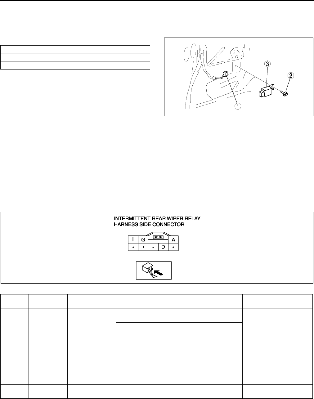
T66
WIPER AND WASHER
INTERMITTENT REAR WIPER RELAY REMOVAL/INSTALLATION A6E811666810W01
5HB
1. Disconnect the negative battery cable.
2. Remove the trunk side trim. (See S92 TRUNK SIDE TRIM REMOVAL/INSTALLATION)
3. Remove in the order indicated in the table.
4. Install in the reverse order of removal.
End Of Sie
INTERMITTENT REAR WIPER RELAY INSPECTION A6E811666810W02
1. Connect the connector to the intermittent rear wiper relay.
2. Connect the negative battery cable.
3. Measure the voltage at the intermittent rear wiper relay using voltmeter.
•When inspecting terminal D for continuity, disconnect the intermittent rear wiper relay connector.
4. If the value are not as specified in the Terminal Voltage List (Reference), inspect the parts under Action and
related wiring harnesses.
5. If the system does not work properly even though the parts or related wiring harnesses do not have any
malfunction, replace the intermittent rear wiper relay.
Terminal Voltage Table (Reference)
1 Connector
2Bolt
3 Interittent rear wiper relay
A6E8116W101
Terminal Signal Connected to Test condition Voltage (V)/
Continuity Action
A Autostop Rear wiper motor
Rear wiper is operating (INT
position or ON position)
Alternates 0
and B+
•Inspect R. WIP 10 A
fuse
•Inspect wiper and
washer switch (See T
68 WIPER AND
WASHER SWITCH
INSPECTION)
•Inspect rear wiper
motor (See T62
REAR WIPER MOTOR
INSPECTION)
•Inspect related harness
Other B+
DGND GND Under any condition: inspect for
continuity to ground Yes •Inspect GND
•Inspect related harness
A6E8116W134
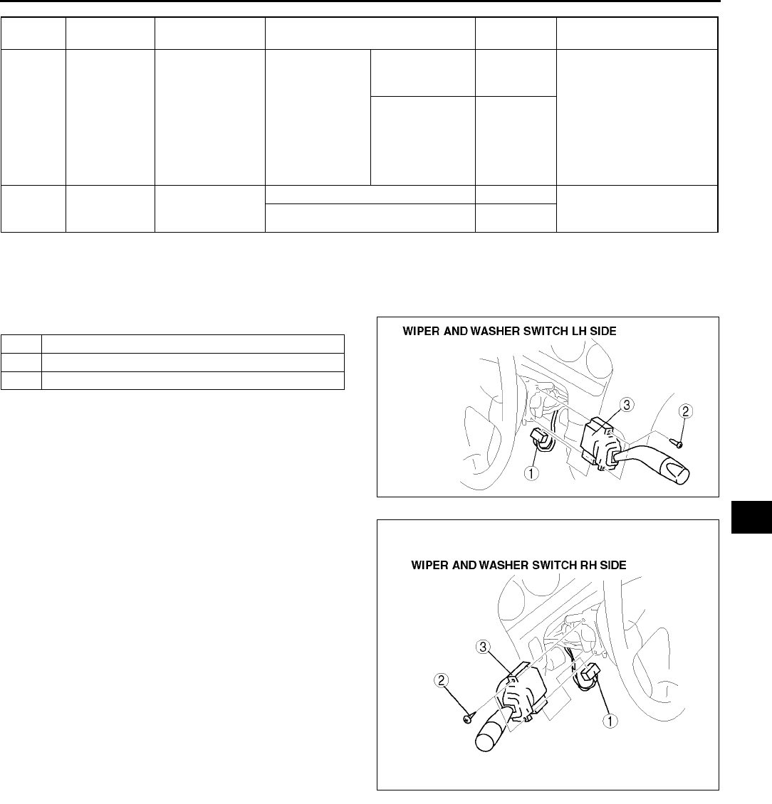
WIPER AND WASHER
T67
T
End Of Sie
WIPER AND WASHER SWITCH REMOVAL/INSTALLATION A6E811666122W01
1. Disconnect the negative battery cable.
2. Remove the column cover. (See S84 COLUMN COVER REMOVAL/INSTALLATION)
3. Remove in the order indicated in the table.
4. Install in the reverse order of removal.
End Of Sie
GRear wiper
switch INT Rear wiper switch Ignition switch at
ON position
Rear wiper
switch at INT
position
0•Inspect R. WIP 10 A
fuse
•Inspect wiper and
washer switch (See T
68 WIPER AND
WASHER SWITCH
INSPECTION)
•Inspect related harness
•Rear wiper
switch at
OFF position
•Rear wiper
switch at ON
position
B+
I IG 2 R. WIP 10 A fuse
Ignition switch at ON position B+ •Inspect R. WIP 10 A
fuse
•Inspect related harness
Other 0
Terminal Signal Connected to Test condition Voltage (V)/
Continuity Action
1 Connector
2Screw
3 Wiper and washer switch
A6E8116W203
A6E8116W204
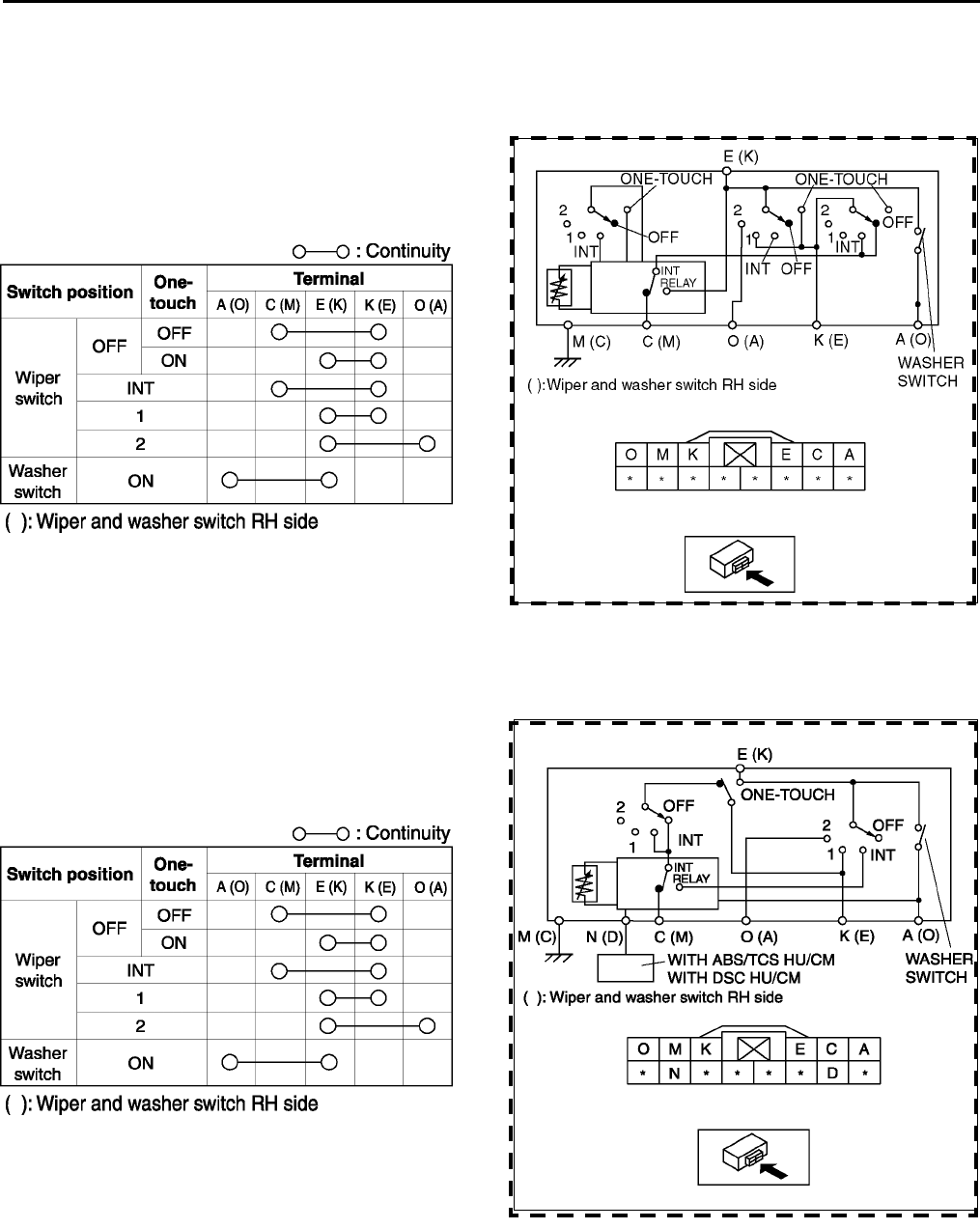
T68
WIPER AND WASHER
WIPER AND WASHER SWITCH INSPECTION A6E811666122W02
Windshield Wiper And Washer Switch
Without vehicle-speed sensing type wipers
1. Remove the wiper and washer switch. (See T67 WIPER AND WASHER SWITCH REMOVAL/
INSTALLATION)
2. Inspect for continuity between the wiper and
washer switch terminals using an ohmmeter.
•If not as specified, replace the wiper and
washer switch.
With vehicle-speed sensing type wipers
1. Remove the wiper and washer switch. (See T67 WIPER AND WASHER SWITCH REMOVAL/
INSTALLATION)
2. Inspect for continuity between the wiper and
washer switch terminals using an ohmmeter.
•If not as specified, replace the wiper and
washer switch.
3. Connect the negative battery cable.
A6E8116W135
A6E8116W146
A6E8116W145
A6E8116W146
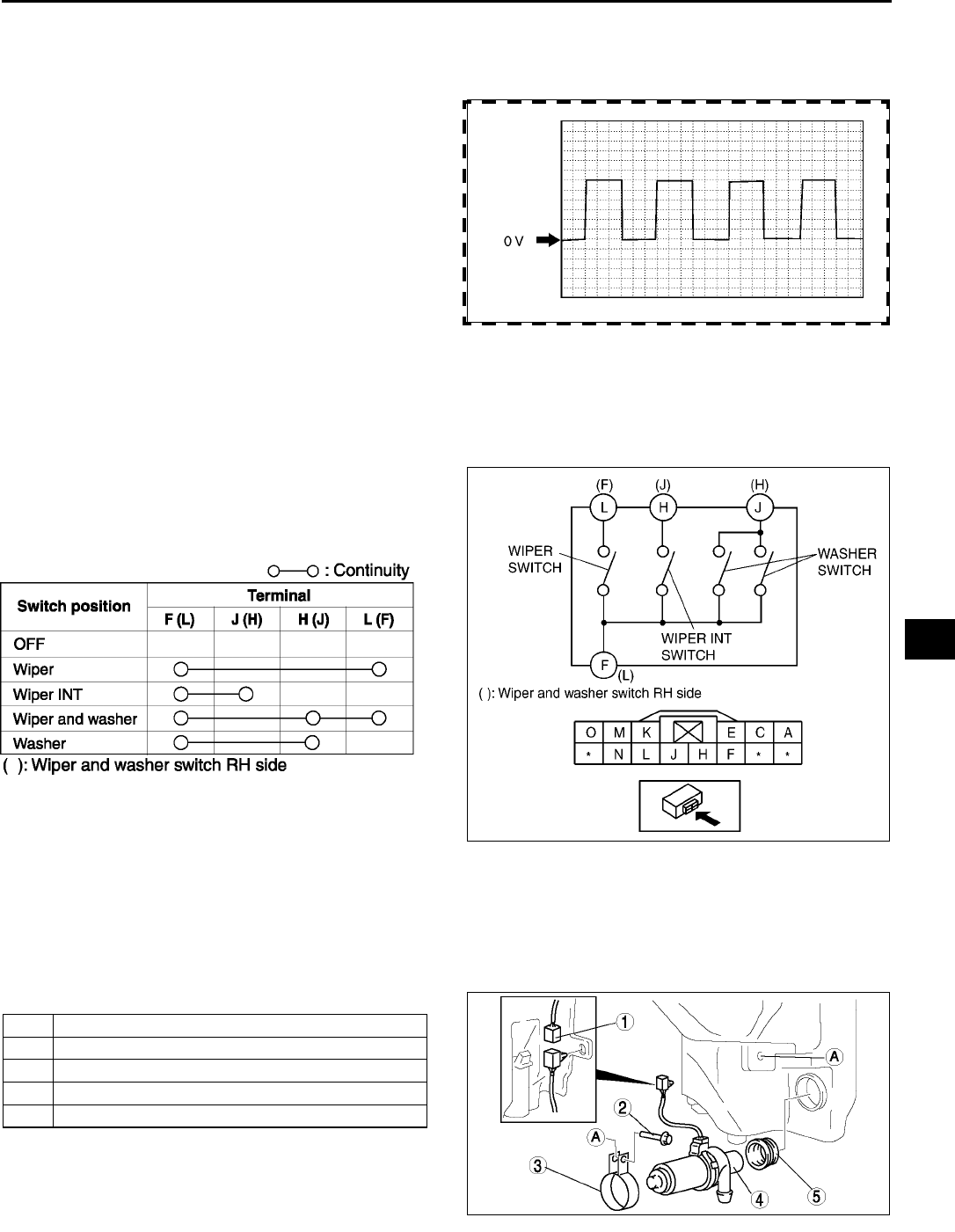
WIPER AND WASHER
T69
T
4. Inspect whether the vehicle speed signal to the wiper and washer switch terminal N (D) is input correctly using
an oscilloscope.
•Connect the oscilloscope probes to the wiper and washer switch terminal N (D) (+) and terminal M (C) (-).
•Set oscilloscope to 1V/DIV (Y), 5ms/DIV (X).
•Verify that the wave pattern below is
displayed while the vehicle is moving at 30
km/h {19 mph}.
Note
•As the vehicle speed increases, the
frequency shortens.
5. If the vehicle speed input signal and continuity for
the wiper and washer switch is correct, inspect
the windshield wiper motor.iSee T56
WINDSHIELD WIPER MOTOR INSPECTION)
•Even if the windshield wiper motor is normal,
if the vehicle-speed-sensing wipers do not
operate correctly, replace the wiper and washer switch.
Rear Wiper and Washer Switch
1. Remove the wiper and washer switch. (See T67 WIPER AND WASHER SWITCH REMOVAL/
INSTALLATION)
2. Inspect for continuity between the wiper and
washer switch terminals using an ohmmeter.
•If not as specified, replace the wiper and
washer switch.
End Of Sie
HEADLIGHT CLEANER MOTOR REMOVAL/INSTALLATION A6E811651030W01
1. Disconnect the negative battery cable.
2. Remove the washer tank. (See T58 WASHER TANK REMOVAL/INSTALLATION)
3. Remove the washer fluid-level sensor. (See T59 WASHER FLUID-LEVEL SENSOR REMOVAL/
INSTALLATION)
4. Remove in the order indicated in the table.
5. Install in the reverse order of removal.
End Of Sie
A6E8116W147
A6E8116W136
A6E8116W121
1 Connector
2Bolt
3Bracket
4 Headlight cleaner motor
5Grommet
A6E8116W113
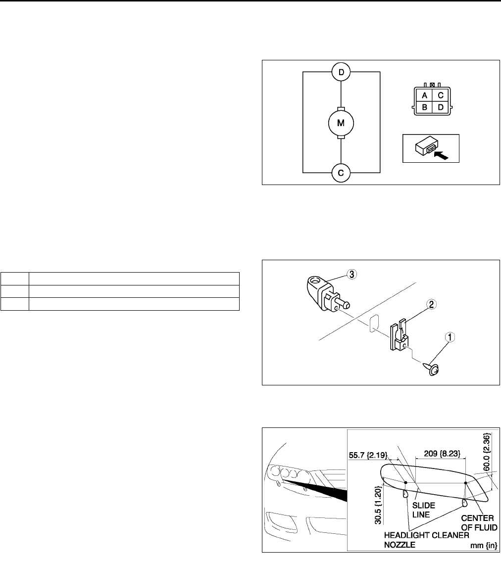
T70
WIPER AND WASHER
HEADLIGHT CLEANER MOTOR INSPECTION A6E811651030W02
1. Disconnect the negative battery cable.
2. Remove the washer tank. (See T58 WASHER TANK REMOVAL/INSTALLATION)
3. Connect battery positive voltage to terminal D and ground to terminal C of the motor.
4. Verify that the headlight cleaner motor operates.
•If the motor does not operate, replace the
headlight cleaner motor.
End Of Sie
HEADLIGHT CLEANER NOZZLE REMOVAL/INSTALLATION A6E811651030W03
1. Remove the front bumper. (See S47 FRONT BUMPER REMOVAL/INSTALLATION)
2. Disconnect the headlight cleaner hose. (See T71 HEADLIGHT CLEANER HOSE REMOVAL/
INSTALLATION)
3. Remove in the order indicated in the table.
4. Install in the reverse order of removal.
5. Adjust the headlight cleaner nozzle. (See T70
HEADLIGHT CLEANER NOZZLE
ADJUSTMENT.)
End Of Sie
HEADLIGHT CLEANER NOZZLE ADJUSTMENT A6E811651030W04
1. Use a needle or equivalent to adjust the headlight
cleaner nozzle so that the center of fluid properly
sprays on the headlight as shown in the figure.
End Of Sie
HEADLIGHT CLEANER NOZZLE CLEANING A6E811651030W05
1. Clean the rear washer nozzle. (See T60 WINDSHIELD WASHER NOZZLE CLEANING.)
End Of Sie
A6E8116W137
1Screw
2 Spacer
3 Headlight cleaner nozzle
A6E8116W142
A6E8116W115
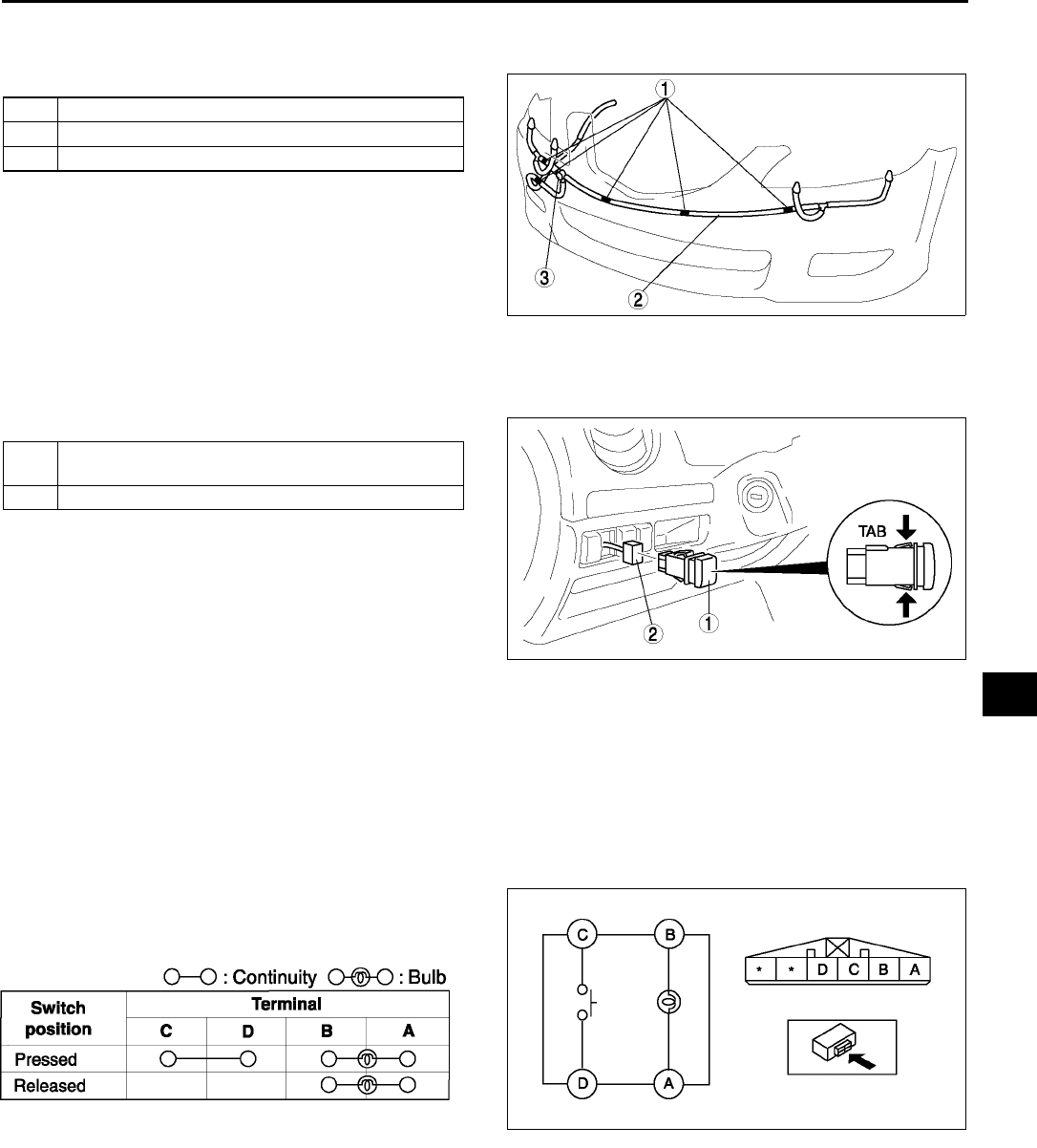
WIPER AND WASHER
T71
T
HEADLIGHT CLEANER HOSE REMOVAL/INSTALLATION A6E811651030W06
1. Remove the front bumper. (See S47 FRONT BUMPER REMOVAL/INSTALLATION)
2. Remove in the order indicated in the table.
3. Install in the reverse order of removal.
End Of Sie
HEADLIGHT CLEANER SWITCH REMOVAL/INSTALLATION A6E811651030W07
1. Disconnect the negative battery cable.
2. Remove in the order indicated in the table.
3. Install in the reverse order of removal.
Headlight Cleaner Switch Removal Note
1. Insert your hand from the lower side of the dashboard and squeeze the tabs of the headlight cleaner switch.
2. Pull the headlight cleaner switch forward to remove it.
End Of Sie
HEADLIGHT CLEANER SWITCH INSPECTION A6E811651030W08
1. Disconnect the negative battery cable.
2. Remove the headlight cleaner switch. (See T71 HEADLIGHT CLEANER SWITCH REMOVAL/
INSTALLATION)
3. Inspect for continuity between the headlight
cleaner switch terminals using an ohmmeter.
•If not as specified, replace the light switch.
End Of Sie
1Clip
2 Headlight cleaner hose
3Check valve
A6E8116W118
1 Headlight cleaner switch (See T71 Headlight
Cleaner Switch Removal Note)
2 Connector
A6E8116W125
A6E8116W138
A6E8116W139
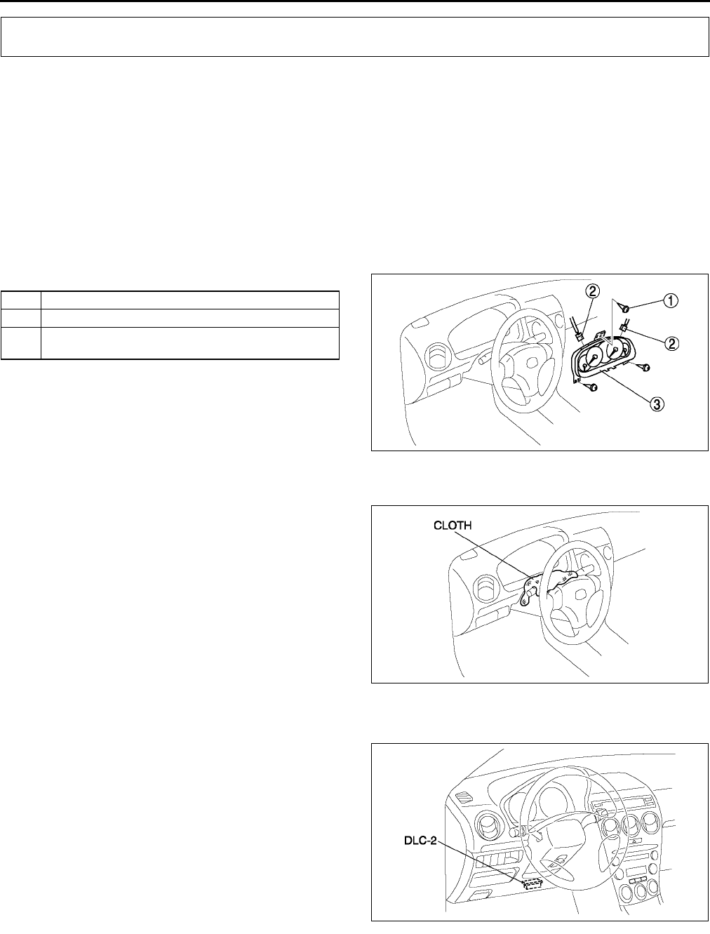
T72
WARNING AND INDICATOR SYSTEM
INSTRUMENT CLUSTER REMOVAL/INSTALLATION A6E811855430W01
Caution
•
••
•When replacing the instrument cluster, the configuration procedure must be performed before
removing the instrument cluster. If the configuration procedure is not performed before removing
the instrument cluster, it is possible that the instrument cluster will not operate normally.
1. Configurate the instrument cluter (when only replacing it). (See T72 INSTRUMENT CLUSTER
CONFIGURATION.)
2. Disconnect the negative battery cable.
3. Pull down the adjusting lever of the tilt steering wheel and push the steering wheel down.
4. Pull the steering wheel toward you.
5. Remove the meter hood.
6. Remove in the order indicated in the table.
7. Install in the reverse order of removal.
Instrument Cluster Removal Note
1. When removing the instrument cluster, in order to
prevent damage to the lens, cover the steering
shaft with a cloth.
End Of Sie
INSTRUMENT CLUSTER CONFIGURATION A6E811855430W02
1. Connect the SST (WDS or equivalent) to the
DLC-2.
2. Input vehicle information following the directions
on the screen.
3. Select Module programming.
4. Select Programmable module installation.
5. Select the following items and perform
procedures according to directions on the screen.
Items
•
••
•IC
6. Retrieve DTCs by the SST (WDS or equivalent),
then verify that there is no DTC present.
•If DTC is present, perform applicable DTC inspection.
End Of Sie
WARNING AND INDICATOR SYSTEM
1Screw
2 Connector
3 Instrument cluster
(See T72 Instrument Cluster Removal Note)
A6E8118W003
A6E8118W005
A6E3970W002
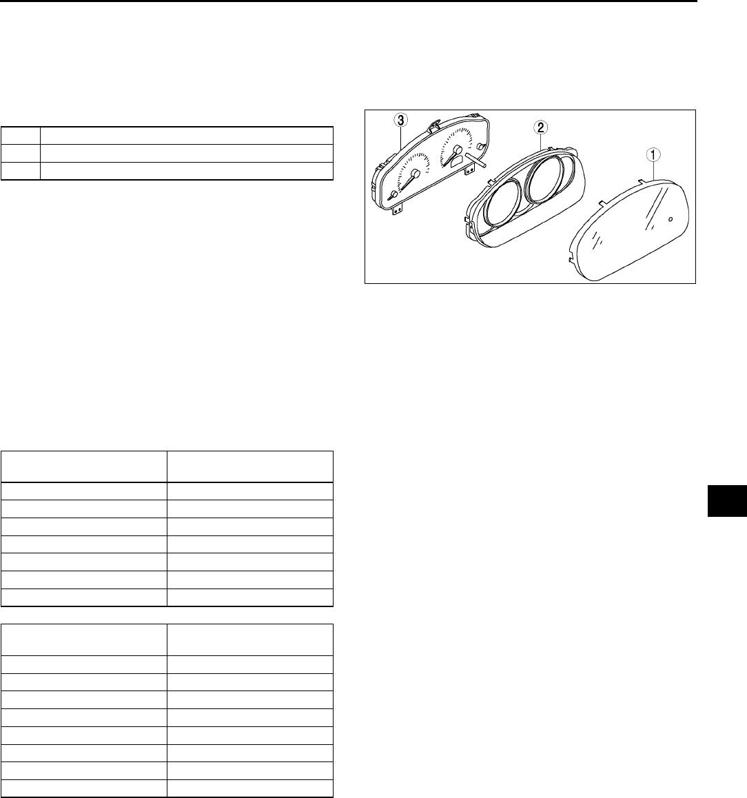
WARNING AND INDICATOR SYSTEM
T73
T
INSTRUMENT CLUSTER DISASSEMBLY/ASSEMBLY A6E811855430W03
Caution
•
••
•If the instrument cluster is dropped or the print plate is damaged, the system will not work
properly and it may be the cause of trouble or malfunctions.
1. Disassemble in the order indicated in the table.
2. Assemble in the reverse order of disassembly.
End Of Sie
INSTRUMENT CLUSTER INSPECTION A6E811855430W04
Speedometer
Using the input/output check mode
1. Inspect the speedometer by setting it in the input/output check mode DTC 12.
Using a speedometer tester
1. Adjust the tire air pressure to the specification.
2. Using a speedometer tester, verify that the speedometer indication is within the allowable ranges shown below.
3. Verify that fluctuation of the speedometer needle is within the allowable range.
•If the speedometer needle does not move or the indication is outside of the allowable range, inspect the
ABS (ABS/TCS) HU/CM (vehicles with ABS (ABS/TCS), DSC HU/CM (vehicles with DSC), PCM (vehicles
without ABS) and related wiring harness.
If the ABS (ABS/TCS) HU/CM (vehicles with ABS (ABS/TCS), DSC HU/CM (vehicles with DSC), PCM
(vehicles without ABS) and related wiring harness are normal, replace the instrument cluster.
Needle fluctuation allowable range
Within 3.0 km/h
1Lens
2Case
3 Meter unit
A6E8118W004
Speedometer tester
indication (km/h) Allowable range (km/h)
20 2024
40 4044
60 6064
80 8085
100 100105
120 120126
140 140146
Speedometer tester
indication (mph) Allowable range (mph)
10 1012
20 2022
30 3032
40 4043
50 5053
60 6063
70 7073
80 8084
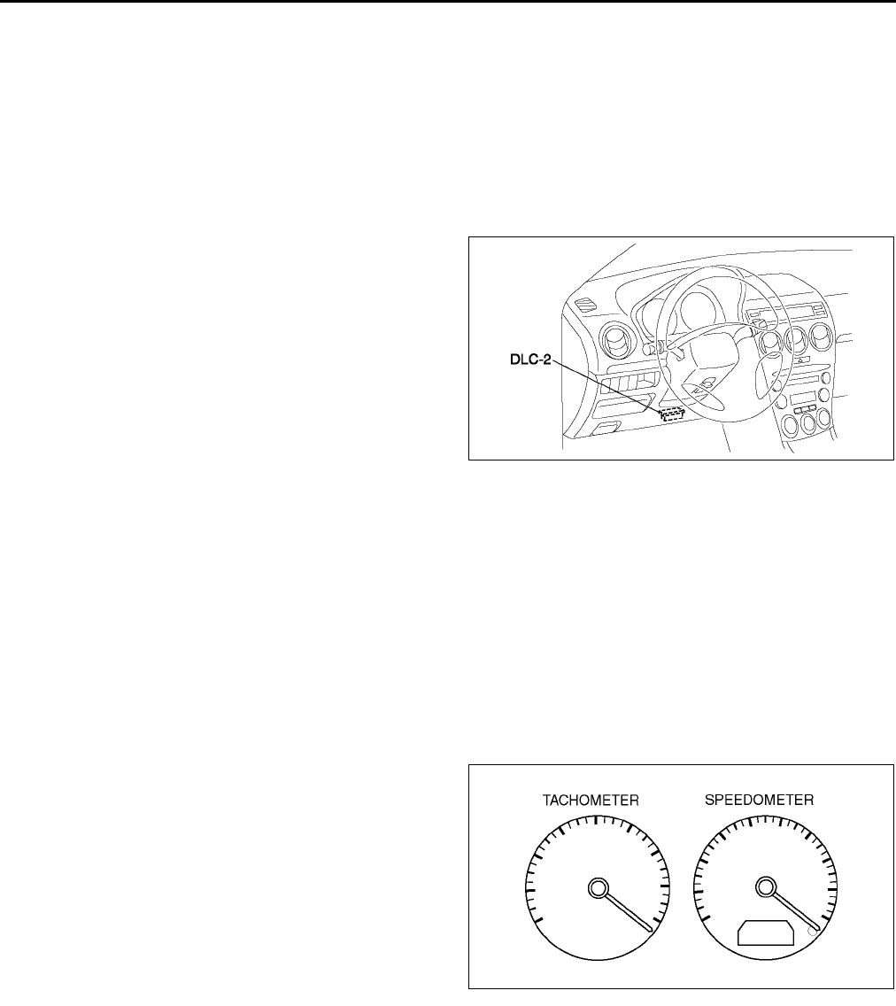
T74
WARNING AND INDICATOR SYSTEM
Tachometer
Using the input/output check mode
1. Inspect the tachometer by setting it in the input/output check mode DTC 13.
Using the SSTs (WDS or equivalent)
Caution
•
••
•If the engine speed exceeds the allowable range, the engine could be damaged. Therefore, when
inspecting the tachometer, do not allow the engine speed to exceed the allowable range indication
on the tachometer.
1. Connect the SSTs (WDS or equivalent) to the
vehicle DLC-2 16-pin connector.
2. Access and monitor PIDs by SSTs (WDS or
equivalent).
Fuel Gauge
1. Inspect the fuel gauge by setting it in the input/output check mode DTC 23.
Water Temperature Gauge
1. Inspect the water temperature gauge by setting it in the input/output check mode DTC 25.
End Of Sie
INSTRUMENT CLUSTER REPAIR A6E811855430W05
Note
•The needle of speedometer or tachometer may continue to rotate clockwise until it indicates over
maximum graduation. If a customer complains of this concern, repair the needle position according to the
following steps.
1. Verify the concern.
2. Turn the ignition switch to LOCK position.
3. Disconnect the negative battery cable.
4. Connect the negative battery cable.
5. Turn the ignition switch to ON position.
6. Verify that the needle returns to zero.
•If the needle does not return to zero, replace
the instrument cluster
End Of Sie
A6E3970W002
A6E8118W011
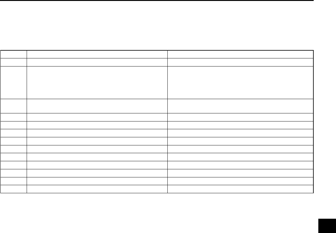
WARNING AND INDICATOR SYSTEM
T75
T
INSTRUMENT CLUSTER INPUT/OUTPUT CHECK MODE A6E811855430W06
Note
•In this mode, it is possible to check the items in the following chart.
Diagnostic Trouble Code Chart
Note
•Diagnostic trouble codes which are not listed may be indicated, but they cannot be inspected.
•The diagnostic trouble codes are displayed in numerical order. (While performing the inspection, if you
want to inspect a diagnostic trouble code of which the number is smaller than the code number you are
currently inspecting, terminate the check mode then repeat the inspection from the beginning.)
•If the speed signal is put into the instrument cluster (the front wheels are rotated) while a code other than
DTC 00 is display, the input/output check mode will be cancelled.
•The diagnostic trouble codes can be fast-forwarded by pushing and holding the odometer/tripmeter switch
for 1 second or more.
DTC Checked item Related item
01 Buckle switch Buckle switch
04 Door switch
•Ignition key illumination
•Key reminder warning buzzer
•Interior light control
•Power door lock system
•Lights-on reminder warning buzzer
08 TNS relay •Lights-on reminder warning buzzer
•Each illumination
12 Speedometer Speedometer
13 Tachometer Tachometer
14 Buzzer Buzzer
16 Fuel-level warning light Fuel-level warning light
18 Ignition key cylinder illumination Ignition key cylinder illumination
22 Fuel gauge sender unit Fuel gauge
23 Fuel gauge Fuel gauge
25 Water temperature gauge Water temperature gauge
26 LCD LCD
31 Key reminder switch Key reminder warning buzzer
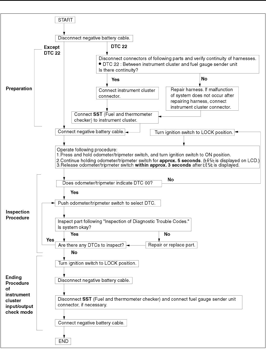
T76
WARNING AND INDICATOR SYSTEM
Operating Order
A6E8118W009
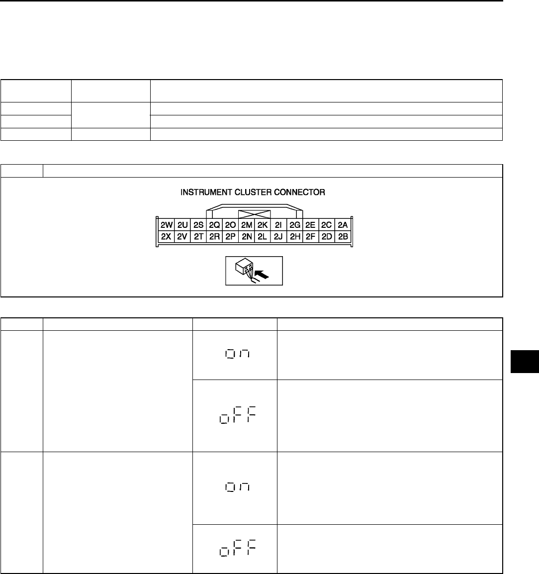
WARNING AND INDICATOR SYSTEM
T77
T
Checking Order
Note
•When inspecting more than two DTCs, perform the inspection by following the priority order of inspection
indicated in the chart below.
Inspection of Diagnostic Trouble Codes
Diagnostic procedure
Priority order
of inspection
IG switch
position Check code
1ON 22
2 01, 04, 08, 12, 13, 14, 16, 18, 23, 25, 26
3LOCK31
DTC 01 Buckle switch on/off signal
STEP INSPECTION INDICATION ACTION
1 Unfasten driver-side seat belt.
(Buckle switch on.)
Go to next step.
Measure voltage at instrument cluster terminal 2G.
Is voltage 0 V?
•If as specified, replace instrument cluster.
•If not as specified, inspect following parts.
Buckle switch
Wiring harness (Buckle switchinstrument
cluster)
2 Fasten driver-side seat belt. (Buckle
switch off.)
Measure voltage at instrument cluster terminal 2G.
Is voltage B+?
•If as specified, replace instrument cluster.
•If not as specified, inspect following parts.
Buckle switch
Wiring harness (Buckle switchinstrument
cluster)
Input signal to instrument cluster is okay.
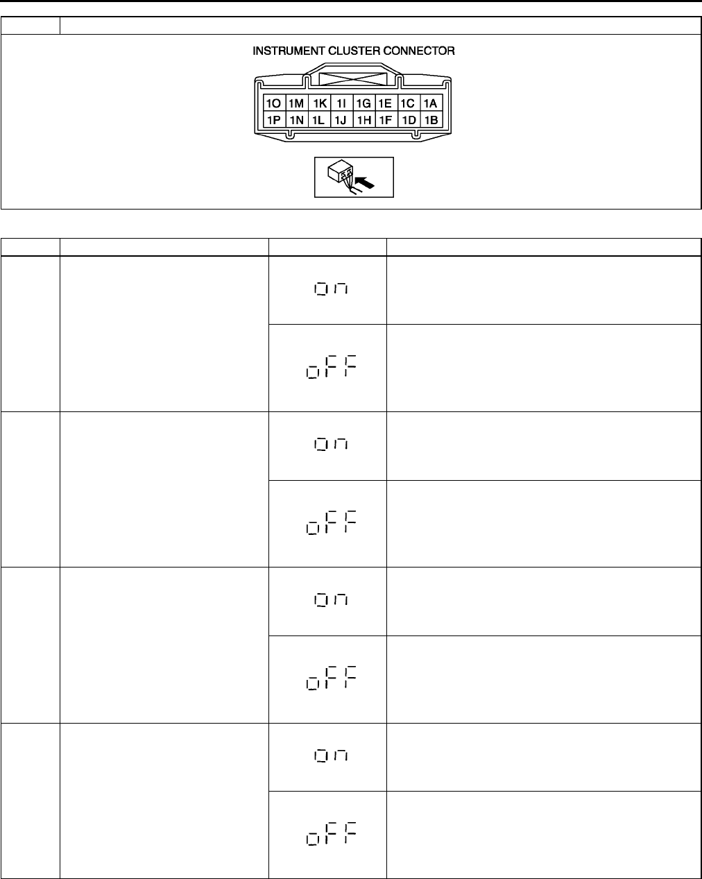
T78
WARNING AND INDICATOR SYSTEM
Diagnostic procedure
DTC 04 Door switch on/off signal
STEP INSPECTION INDICATION ACTION
1 Open driver-side door. (Door switch
on.)
Close driver-side door, then go to next step.
Measure voltage at instrument cluster terminal 1J.
Is voltage 0 V?
•If as specified, replace instrument cluster.
•If not as specified, inspect following parts.
Door switch
Wiring harness (Instrument clusterdoor switch)
2 Open passenger-side door. (Door
switch on.)
Close passenger-side door, then go to next step.
Measure voltage at instrument cluster terminal 1I.
Is voltage 0 V?
•If as specified, replace instrument cluster.
•If not as specified, inspect following parts.
Door switch
Wiring harness (Instrument clusterdoor switch)
3 Open rear door on drivers side.
(Door switch on.)
Close rear door on drivers side, then go to next step.
Measure voltage at instrument cluster terminal 1I.
Is voltage 0 V?
•If as specified, replace instrument cluster.
•If not as specified, inspect following parts.
Door switch
Wiring harness (Instrument clusterdoor switch)
4 Open rear door on passengers
side. (Door switch on.)
Close rear door on passengers side, then go to next
step.
Measure voltage at instrument cluster terminal 1I.
Is voltage 0 V?
•If as specified, replace instrument cluster.
•If not as specified, inspect following parts.
Door switch
Wiring harness (Instrument clusterdoor switch)
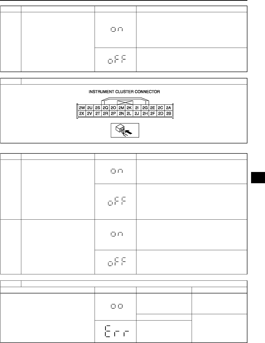
WARNING AND INDICATOR SYSTEM
T79
T
Diagnostic procedure
5 Close all doors. (Door switch off.) Measure voltage at instrument cluster terminals 1I and
1J.
Is voltage B+?
•If as specified, replace instrument cluster.
•If not as specified, inspect following parts.
Door switch
Wiring harness (Instrument clusterdoor switch)
Input signals to instrument cluster are okay.
DTC 08 TNS relay on/off signal
STEP INSPECTION INDICATION ACTION
1 Turn headlight switch to TNS
position. (TNS relay on.)
Go to next step.
Measure voltage at instrument cluster terminal 2K.
Is voltage B+?
•If as specified, replace instrument cluster.
•If not as specified, inspect following parts.
TNS relay
Wiring harness (BatteryTNS relayinstrument
cluster)
2 Turn headlight switch off. (TNS relay
off.)
Measure voltage at instrument cluster terminal 2K.
Is voltage 0 V?
•If as specified, replace instrument cluster.
•If not as specified, inspect following parts.
TNS relay
Wiring harness (TNS relayinstrument cluster)
Input signal to instrument cluster is okay.
DTC 12 Operation signal to speedometer
INSPECTION INDICATION SITUATION ACTION
Wait for 2 seconds after selecting DTC 12. Speedometer needle
moves full scale then
returns to 60 km/h or 60
MPH.
Speedometer is okay.
Other than stated above. Replace instrument
cluster.
STEP INSPECTION INDICATION ACTION
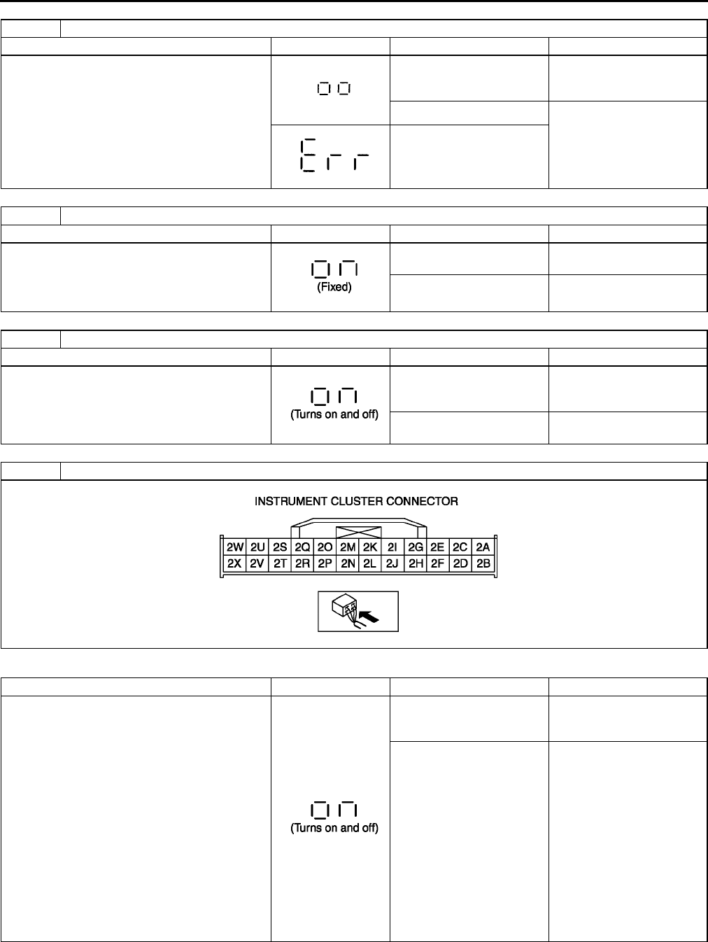
T80
WARNING AND INDICATOR SYSTEM
Diagnostic procedure
DTC 13 Operation signal to tachometer
INSPECTION INDICATION SITUATION ACTION
Wait for 2 seconds after selecting DTC 13. Tachometer needle moves
full scale then returns to
3000 rpm.
Tachometer is okay.
Other than stated above. Replace instrument
cluster.
DTC 14 Operation signal to buzzer
INSPECTION INDICATION SITUATION ACTION
Wait for 2 seconds after selecting DTC 14. Buzzer continuously
sounds.
Buzzer is okay.
Buzzer does not
continuously sound.
Replace instrument
cluster.
DTC 16 Operation signal to fuel-level warning light
INSPECTION INDICATION SITUATION ACTION
Wait for 2 seconds after selecting DTC 16. Fuel-level warning light
turns on and off three
times.
Fuel-level warning light is
okay.
Other than stated above. Replace instrument
cluster.
DTC 18 Ignition key illumination on/off signal
INSPECTION INDICATION SITUATION ACTION
Wait for 2 seconds after selecting DTC 18. Ignition key illumination
turns on and off three
times.
Ignition key illumination is
okay.
Other than stated above. Measure voltage at
instrument cluster terminal
2C.
Is voltage B+?
•If as specified, replace
instrument cluster.
•If not as specified,
inspect following parts.
Ignition key
illumination
Wiring harness
(Batteryignition
key illumination
instrument cluster)
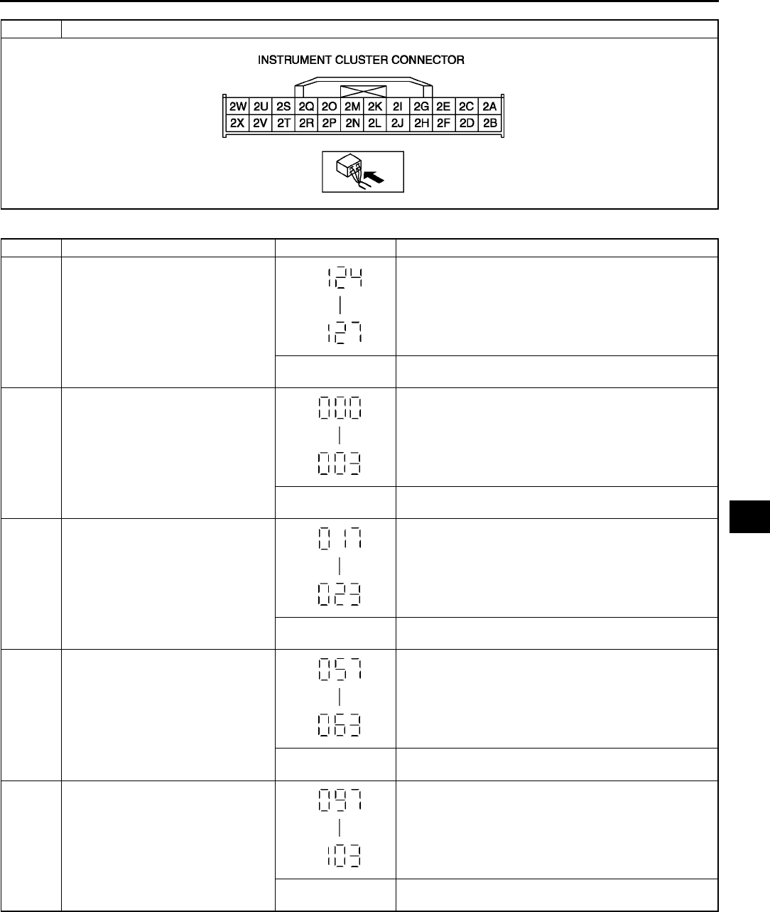
WARNING AND INDICATOR SYSTEM
T81
T
Diagnostic procedure
DTC 22 Fuel level signal
STEP INSPECTION INDICATION ACTION
1 Select DTC 22 with fuel gauge
sender unit connector disconnected.
Go to next step.
Other than stated
above.
Replace instrument cluster.
2 Connect between instrument cluster
terminals 2D and 2M.
Go to next step.
Other than stated
above.
Replace instrument cluster.
3 Using SST (Fuel and thermometer
checker) or resistor, input 20 ohms
to between instrument cluster
terminals 2D and 2M.
Go to next step.
Other than stated
above.
Replace instrument cluster.
4 Using SST (Fuel and thermometer
checker) or resistor, input 60 ohms
to between instrument cluster
terminals 2D and 2M.
Go to next step.
Other than stated
above.
Replace instrument cluster.
5 Using SST (Fuel and thermometer
checker) or resistor, input 100 ohms
to between instrument cluster
terminals 2D and 2M.
Inspect fuel gauge sender unit.
Other than stated
above.
Replace instrument cluster.
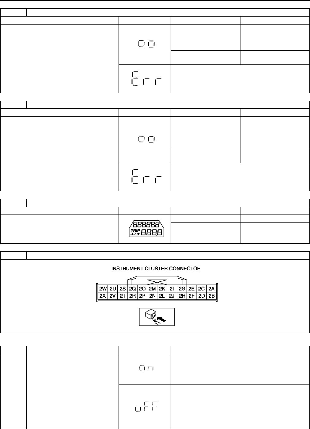
T82
WARNING AND INDICATOR SYSTEM
Diagnostic procedure
DTC 23 Operation signal to fuel gauge
INSPECTION INDICATION SITUATION ACTION
Wait for 2 seconds after selecting DTC 23. Fuel gauge indicates in
following order for every 2
seconds.
•F→1/2→E→F (fixed)
Fuel gauge is okay.
Other than stated above. Replace instrument
cluster.
Replace instrument cluster.
DTC 25 Operation signal to water temperature gauge
INSPECTION INDICATION SITUATION ACTION
Wait for 2 seconds after selecting DTC 25. Water temperature gauge
indicates in following order
for every 2 seconds.
•H→Center→C→H
(fixed)
Water temperature gauge
is okay.
Other than stated above. Replace instrument
cluster.
Replace instrument cluster.
DTC 26 LCD indication
INSPECTION INDICATION SITUATION ACTION
Select DTC 26. Indication is normal. LCD is okay.
Other than stated above. Replace instrument
cluster.
DTC 31 Key reminder on/off signal
STEP INSPECTION INDICATION ACTION
1 Remove key from steering lock and
then insert key into steering lock
after selecting DTC 31. (Key
reminder switch on.)
Go to next step.
Measure voltage at instrument cluster terminal 2B.
Is voltage B+?
•If as specified, replace instrument cluster.
•If not as specified, replace following parts.
Key reminder switch
Wiring harness (Batterykey reminder switch
instrument cluster)
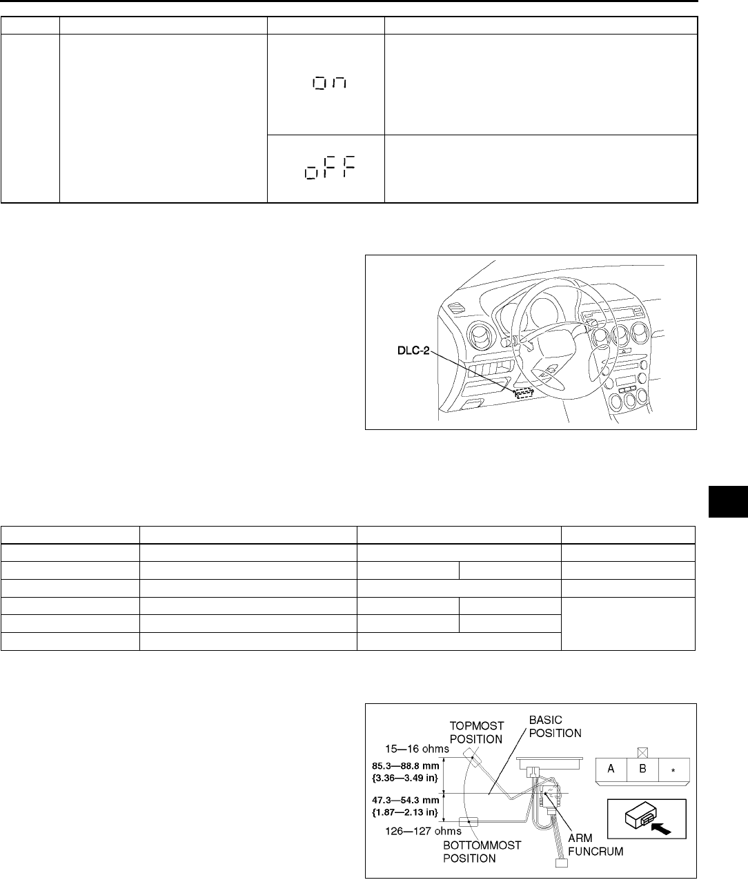
WARNING AND INDICATOR SYSTEM
T83
T
End Of Sie
PID/DATA MONITOR AND RECORD PROCEDURE A6E811855430W07
1. Connect SST (WDS or equivalent) to the vehicle
DLC-2 16-pin connector.
2. Access and monitor PIDs using SST (WDS or
equivalent).
Monitor Item Table
•The PID/DATA monitoring items for the instrument cluster is as shown in the table below.
: Not applicable
End Of Sie
FUEL GAUGE SENDER UNIT INSPECTION A6E811860960W01
1. Move the float to the topmost and bottommost
positions, and verify that the resistance between
terminals A and B of the unit and the position of
the float are as indicated in the figure.
•If they are not as indicated, replace the fuel
gauge sender unit.
End Of Sie
2 Remove key from steering lock (Key
reminder switch off.)
Measure voltage at instrument cluster terminal 2B.
Is voltage 0 V?
•If as specified, replace instrument cluster.
•If not as specified, inspect following parts.
Key reminder switch
Wiring harness (Key reminder switch
instrument cluster)
Input signal to instrument cluster is okay.
STEP INSPECTION INDICATION ACTION
A6E3970W002
PID item Definition Unit/Condition Terminal
CCNT_HE Continuous codes Number of continuous codes
ECT_GAUGE Temperature gauge °C°F 2W, 2X
FUEL Fuel flow l/min 2M
ODOMETR Total distance km mile
2W, 2XSPEEDSG Speedometer km/h mile/h
RPM Tachometer rpm
A6E8118W002
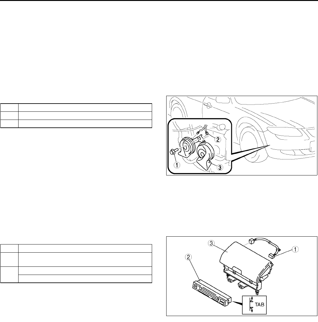
T84
WARNING AND INDICATOR SYSTEM
OIL PRESSURE SWITCH INSPECTION A6E811818500W01
1. Verify that the oil pressure warning light illuminates when the ignition switch is at ON position.
2. Verify that the oil pressure warning light goes off when the engine is started.
•If the oil pressure warning light does not illuminate or remains illuminated, inspect the related wiring
harness.
If the related wiring harness are normal, inspect the oil pressure. (See D3 OIL PRESSURE
INSPECTION.)
•If the oil pressure is normal, replace the oil pressure switch.
End Of Sie
HORN REMOVAL/INSTALLATION A6E811866790W01
1. Disconnect the negative battery cable.
2. Bend the mud guard.
3. Remove in the order indicated in the table.
4. Install in the reverse order of removal.
End Of Sie
INFORMATION DISPLAY REMOVAL/INSTALLATION A6E811855000W01
1. Disconnect the negative battery cable.
2. Remove the center panel module. (See T96 CENTER PANEL MODULE REMOVAL/INSTALLATION.)
3. Remove the LCD unit. (with car-navigation system) (See T98 LCD UNIT REMOVAL/INSTALLATION.)
4. Remove the center box. (without car-navigation system)
5. Remove in the order indicated in the table.
6. Install in the reverse order of removal.
Information Display Removal Note
1. Squeeze the tabs of information display and pull it forward to it.
End Of Sie
1Bolt
2 Connector
3Horn
A6E8118W001
1 Short harness
2 Information display
(See T84 Information Display Removal Note)
3 LCD unit (with car-navigation system)
Center box (without car-navigation system)
A6E8118W008
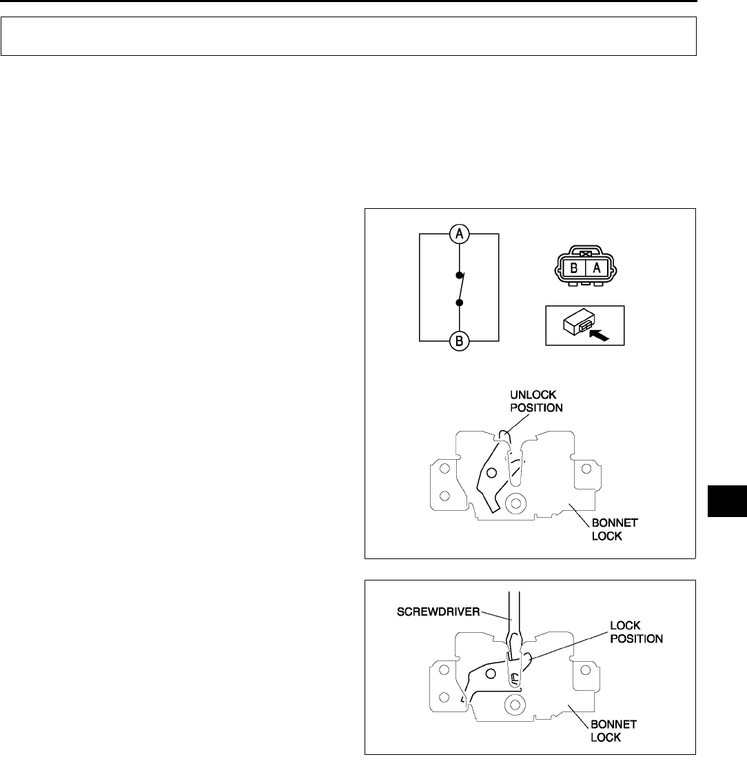
THEFT-DETERRENT SYSTEM
T85
T
BONNET SWITCH INSPECTION A6E812001084W01
Note
•Bonnet switch has a built-in bonnet lock.
1. Open the bonnet.
2. Disconnect the negative battery cable.
3. Remove the radiator grille.
4. Disconnect the bonnet switch connector.
5. Check the continuity between the bonnet switch
terminals A and B using an ohmmeter.
•If there is continuity, replace the bonnet
switch.
6. Lock the bonnet lock using a flat-head
screwdriver or equivalent as shown.
7. Check the no continuity between the bonnet
switch terminals A and B using an ohmmeter.
•If there is no continuity, replace the bonnet
switch.
Caution
•
••
•After the inspection, unlock the bonnet
lock. If closing the bonnet with the
bonnet lock locked, the bonnet lock and/
or bonnet striker may be broken.
End Of Sie
THEFT-DETERRENT SYSTEM
A6E8120W002
A6E8120W003
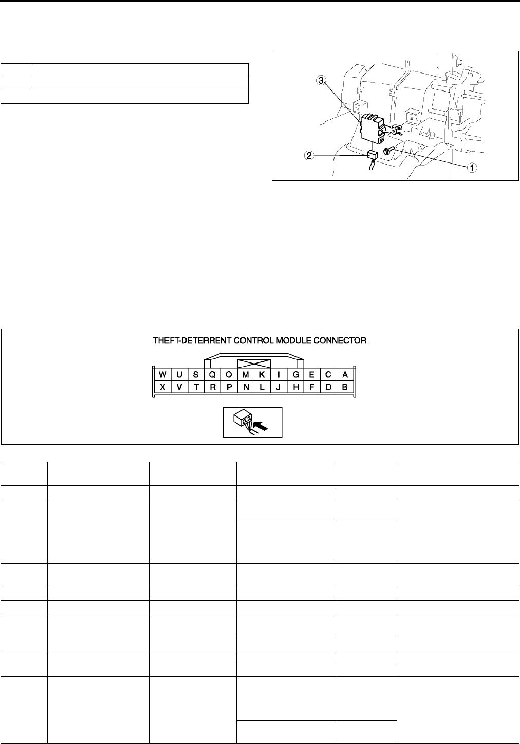
T86
THEFT-DETERRENT SYSTEM
THEFT-DETERRENT CONTROL MODULE REMOVAL/INSTALLATION A6E812067790W01
1. Disconnect the negative battery cable.
2. Remove the center panel module. (See T96 CENTER PANEL MODULE REMOVAL/INSTALLATION.)
3. Remove in the order indicated in the table.
4. Install in the reverse order of removal.
End Of Sie
THEFT-DETERRENT CONTROL MODULE INSPECTION A6E812067790W02
1. Remove the theft-deterrent control module without disconnecting the connectors.
2. Measure the voltage at the theft-deterrent control module terminals as indicated below.
3. Disconnect the theft-deterrent control module connector before inspecting for continuity at terminals L, Q, S, T,
and V.
4. If not as specified, inspect the parts listed under Action.
•If the parts and wiring harnesses are okay but the system still does not work properly, replace the
theft-deterrent control module.
Terminal Voltage Table (Reference)
1Screw
2 Connector
3 Theft-deterrent control module
A6E8120W001
Terminal Signal Connected to Test condition Voltage (V)/
continuity Action
A
BIG1 METER IG 15 A
fuse
Ignition switch at ON
position B+ •Inspect ignition switch
(See T20 IGNITION
SWITCH INSPECTION)
•Inspect METER IG 15 A
fuse
•Inspect related harness
Ignition switch at
LOCK or ACC position Below 1.0
C Power supply ROOM 15 A fuse Under any condition B+ •Inspect ROOM 15 A fuse
•Inspect related harness
D
E
FIntruder sensor power
supply Intruder sensor
Theft-deterrent system
pre-arming or arming B+ •Inspect related harness
Other Below 1.0
G Security light on/off Security light Security light on Below 2.0 •Inspect security light
•Inspect related harness
Security light off B+
HHazard warning signal
output Flasher unit
Theft-deterrent system
alarm: Active
Alternates
between
below 1.0
and B+
•Inspect flasher unit
(See T44 FLASHER
UNIT INSPECTION)
•Inspect related harness
Theft-deterrent system
alarm: Other B+
A6E8120W004

THEFT-DETERRENT SYSTEM
T87
T
ITheft-deterrent siren
on/off
Theft-deterrent
siren
Theft-deterrent system
alarm: Active
Alternates
between
below 1.0
and B+ •Inspect related harness
Theft-deterrent system
alarm: Other B+
J
•Theft-deterrent
system recognition
signal output
•Keyless entry
system operation
signal input
Door lock timer unit Under any condition B+
•Inspect door lock timer
unit
(See S34 DOOR LOCK
TIMER UNIT
INSPECTION)
•Inspect related harness
K Horn on/off Horn relay
Theft-deterrent system
alarm: Other B+ •Inspect horn relay
(See T24 RELAY
INSPECTION)
•Inspection related
harness
Theft-deterrent system
alarm: Active
Alternates
between
below 1.0
and B+
LTheft-deterrent control
module ground GND
Under any condition:
inspect for continuity
to ground
Yes •Inspect GND
MKey reminder switch
on/off
Key reminder
switch
Key reminder switch
on (key inserted) B+ •Inspect key reminder
switch
(See T21 KEY
REMINDER SWITCH
INSPECTION)
•Inspect related harness
Key reminder switch
off (key removed) Below 1.0
N
O Intruder sensor on/off Intruder sensor Theft-deterrent system
pre-arming or arming
Alternates
between
below 1.0
and B+
•Inspect related harness
P
Q Bonnet open/closed Bonnet switch
Bonnet switch on:
inspect for continuity
to ground
Yes •Inspect bonnet switch
(See T85 BONNET
SWITCH INSPECTION)
•Inspect related harness
Bonnet switch off:
inspect for continuity
to ground
No
R
Trunk compartment
light switch/cargo
compartment light
switch on/off
•Trunk
compartment
light switch
•Cargo
compartment
light switch
Trunk compartment
light switch/cargo
compartment light
switch on
Below 1.0
•Inspect trunk
compartment light switch
(See T51 TRUNK
COMPARTMENT LIGHT
SWITCH INSPECTION)
•Inspect cargo
compartment light switch
(See T50 CARGO
COMPARTMENT LIGHT
SWITCH INSPECTION)
•Inspect related harness
Trunk compartment
light switch/cargo
compartment light
switch off
B+
S Door open/closed Door switch
Any door open:
inspect for continuity
to ground
Yes •Inspect door switch
(See T52 DOOR
SWITCH INSPECTION)
•Inspect related harness
All doors closed:
inspect for continuity
to ground
No
Terminal Signal Connected to Test condition Voltage (V)/
continuity Action
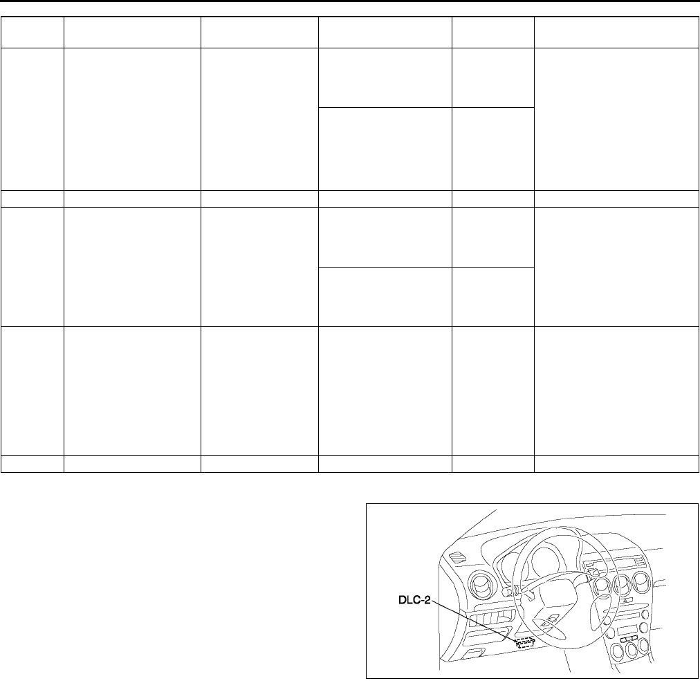
T88
THEFT-DETERRENT SYSTEM
W Terminal Inspection
1. Connect SST (WDS or equivalent) to the vehicle
DLC-2 16-pin connector.
2. Access and monitor RPM of PID using SST
(WDS or equivalent).
•If engine speed signal normal, go to next step.
•If engine speed signal abnormal, inspect the
ABS (ABS/TCS) HU/CM, DSC HU/CM and
related wiring harness.
3. Inspect for continuity between the ABS (ABS/
TCS) HU/CM terminal X and the theft-deterrent
control module terminal W, or DSC HU/CM
terminal AB and the theft-deterrent control
module terminal W using an ohmmeter.
•If not continuity, replace the related wiring
harness.
•If wiring harness is normal, replace the theft-deterrent control.
End Of Sie
T Lock/unlock
•Passengers
door lock-link
switch
•Rear door
lock-link switch
Passengers and rear
door lock-link switch
locked: inspect for
continuity to ground
No
•Inspect passengers or
rear door lock-link switch
(See S30 FRONT
DOOR LOCK
ACTUATOR
INSPECTION)
(See S32 REAR DOOR
LOCK ACTUATOR
INSPECTION)
•Inspect related harness
Passengers or any
rear door lock-link
switch unlocked:
inspect for continuity
to ground
Yes
U
V Lock/unlock •Drivers door
lock-link switch
Drivers door lock-link
switch locked: inspect
for continuity to
ground
No •Inspect drivers door
lock-link switch
(See S30 FRONT
DOOR LOCK
ACTUATOR
INSPECTION)
•Inspect related harness
Drivers door lock-link
switch unlocked:
inspect for continuity
to ground
Yes
W Engine speed
•ABS (ABS/TCS)
HU/CM (with
ABS (ABS/
TCS))
•DSC HU/CM
(with DSC)
(See T88 W Terminal
Inspection)
•Inspect ABS (ABS/TCS)
HU/CM
(See P29 ABS (ABS/
TCS) HU/CM
INSPECTION)
•Inspect DSC HU/CM
(See P40 DSC HU/CM
INSPECTION)
•Inspect related harness
X
Terminal Signal Connected to Test condition Voltage (V)/
continuity Action
A6E3970W002
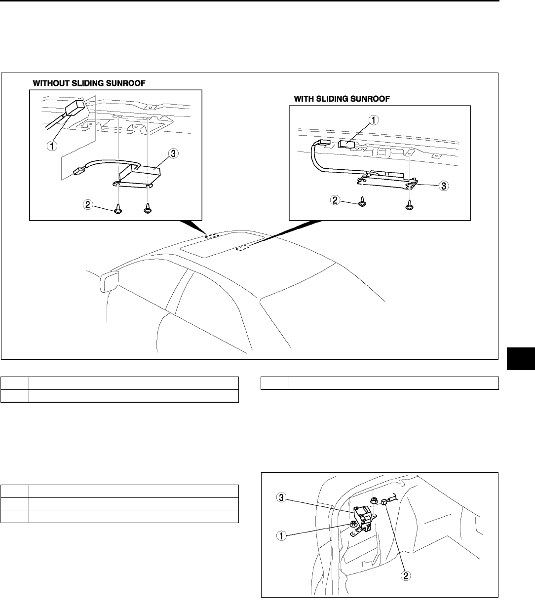
THEFT-DETERRENT SYSTEM
T89
T
INTRUDER SENSOR REMOVAL/INSTALLATION A6E812000172W01
1. Disconnect the negative battery cable.
2. Remove the headliner.
3. Remove in the order indicated in the table.
4. Install in the reverse order of removal.
.
End Of Sie
THEFT-DETERRENT SIREN REMOVAL/INSTALLATION A6E812000173W01
1. Disconnect the negative battery cable.
2. Remove the left side trunk side trim.
3. Remove in the order indicated in the table.
4. Install in the reverse order of removal.
End Of Sie
A6E8120W005
1 Connector
2Screw
3 Intruder sensor
1Nut
2 Connector
3 theft-deterrent siren
A6E8120W006
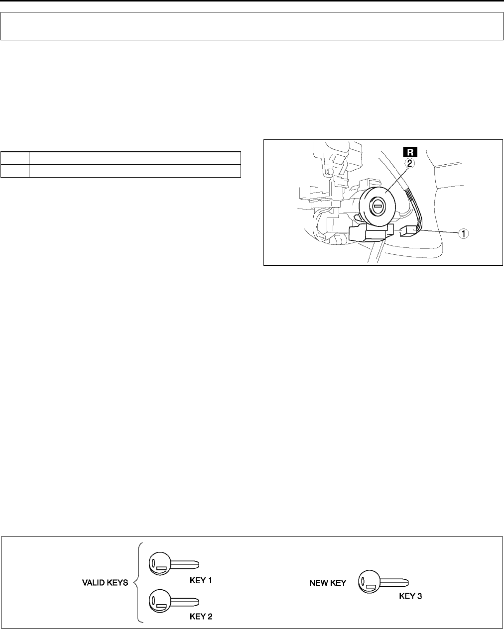
T90
IMMOBILIZER SYSTEM
COIL REMOVAL/INSTALLATION A6E812267004W01
Note
•Do not remove the coil unless you are replacing it.
•When only the coil is replaced, the immobilizer system reprogram procedure is not necessary.
1. Disconnect the negative battery cable.
2. Remove the column cover.
3. Remove in the order indicated in the table.
4. Install in the reverse order of removal.
End Of Sie
IMMOBILIZER SYSTEM REPROGRAM PROCEDURE A6E812267000W01
Note
•When an error occurs during the reprogram procedures, except when the PCM is replaced, repeat the
procedure from Step 1. If you still cannot reprogram, confirm how many keys can start the engine. Then,
perform the key replacement or addition reprogram procedure according to the valid key number.
•To make a copy of the key or replace the immobilizer system component parts (the key(s), and/or PCM),
the customer should bring all keys to the dealer. This is because the previously programmed key IDs are
erased when reprogramming the key IDs into the PCM.
•The PCM cannot be changed from one car to another. If an PCM is replaced with one from another car,
the engine will not start.
•The PCM should not be newly replaced as a trial during troubleshooting. If this is done, the ID and code
word will be programmed into the new unit and it cannot be used for other cars even if you find that the old
unit was normal.
•The immobilizer system cannot be deactivated.
•Confirm that all keys registered can start the engine after the reprogram procedure. When confirming, wait
for more than 5 seconds before inserting the next key.
•When the customer does not need to register more than two keys, the following procedures can be
stopped after registering two keys.
Key Replacement or Addition
When the customer has two or more valid keys
Note
•If no specific time interval is given, each step should be performed within 30 seconds of the previous
step.
IMMOBILIZER SYSTEM
1 Connector
2Coil
A6E8122W001
A6E8122W003
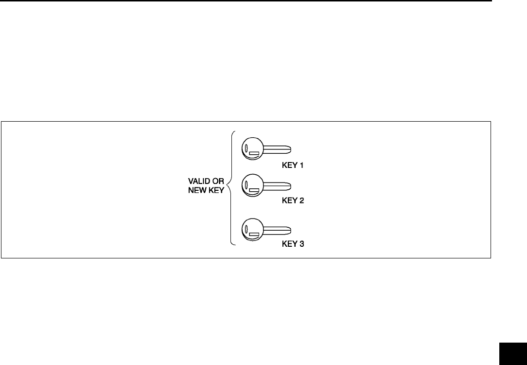
IMMOBILIZER SYSTEM
T91
T
1. Cut new transponder-equipped key(s).
2. Using key 1, turn ignition switch to ON position.
(1) Observe illumination of security light in instrument cluster.
(2) After the security light turns off, turn key 1 to LOCK position within 2 seconds and remove it from the
steering lock.
3. Repeat Step 2 with key 2.
4. Repeat Step 2 with key 3.
5. If there are 48 keys (valid and/or new keys), repeat Step 2.
When the customer has only one or no valid key
1. Cut new transponder equipped key(s) if necessary.
2. Connect the SST (WDS or equivalent).
3. Using key 1, turn ignition switch to ON position.
•Valid key: The security light illuminates, then turns off after approx. 3 seconds.
•New key: The security light illuminates. After approx. 1 minute DTC B1601 (DTC 15) is output
(1) Perform security access approval. (See T92 Security Access Procedure.)
(2) Select "Ignition Key Code Erase".
Note
•Do not select any other command from this menu.
(3) Turn key 1 to LOCK position for more than 1 second.
(4) Turn key 1 to ON position for more than 1 second. (After approx. 1 minute DTC B1213 (DTC 21) is
output.)
(5) Verify the security light is illuminated, then turn key 1 to LOCK position.
(6) Remove key 1 from steering lock.
4. Using key 2, turn ignition switch to ON position for more than 1 second. Observe that security light illuminates
(for approx. 3 seconds).
(1) Verify the security light is illuminated, then turn key 2 to LOCK position and remove from steering lock.
5. Repeat Step 4 with key 3.
6. If there are 48 keys (valid and/or new keys), repeat Step 5.
7. After reprogramming, clear DTCs of PCM with SST (WDS or equivalent).
PCM Replacement
•After PCM replacement, refer to the procedure for "When the customer has only one or no valid key", and
perform registration. (See T91 When the customer has only one or no valid key.)
A6E8122W002

T92
IMMOBILIZER SYSTEM
Enabling/Disabling Key Reprograming Without Using SST (WDS or Equivalent)
Note
•With this function, the need for use of the SST (WDS or equivalent) to perform key registration when
following the "When the customer has two or more valid keys" procedure can be optionally inhibited or
prohibited. This function is provided to prohibit drivers from performing the reprogram procedure on
vehicles owned by rental car companies or other large vehicle fleet owners.
1. Connect the SST (WDS or equivalent).
2. Using valid or new key, turn ignition switch to ON position.
3. Perform security access approval. (See T92 Security Access Procedure.)
4. Select "Customer Spare Key Programming Enable/Disable".
•Enable: Key registration can be performed without using the SST (WDS or equivalent).
•Disable: Key registration can only be performed using the SST (WDS or equivalent).
Note
•At the time of new vehicle delivery, the function is set on "Enable".
Security Access Procedure
Note
•When using a SST (WDS or equivalent) or equivalent to perform "Ignition Key Code Erase" or "Customer
Spare Key Programming Enable/Disable", it is necessary to obtain security access approval.
1. Connect the SST (WDS or equivalent).
2. Select "Tool box", "Body", "Security", and then "PATS Functions" (in this order).
3. The SST (WDS or equivalent). will read out an outcode depending on the designated procedure.
4. Access the Mazda official website to obtain the incode that corresponds to the outcode. Refer to Service
Information Ref. No. A001/02 for details of this procedure.
5. Input the incode to the SST (WDS or equivalent).
End Of Sie
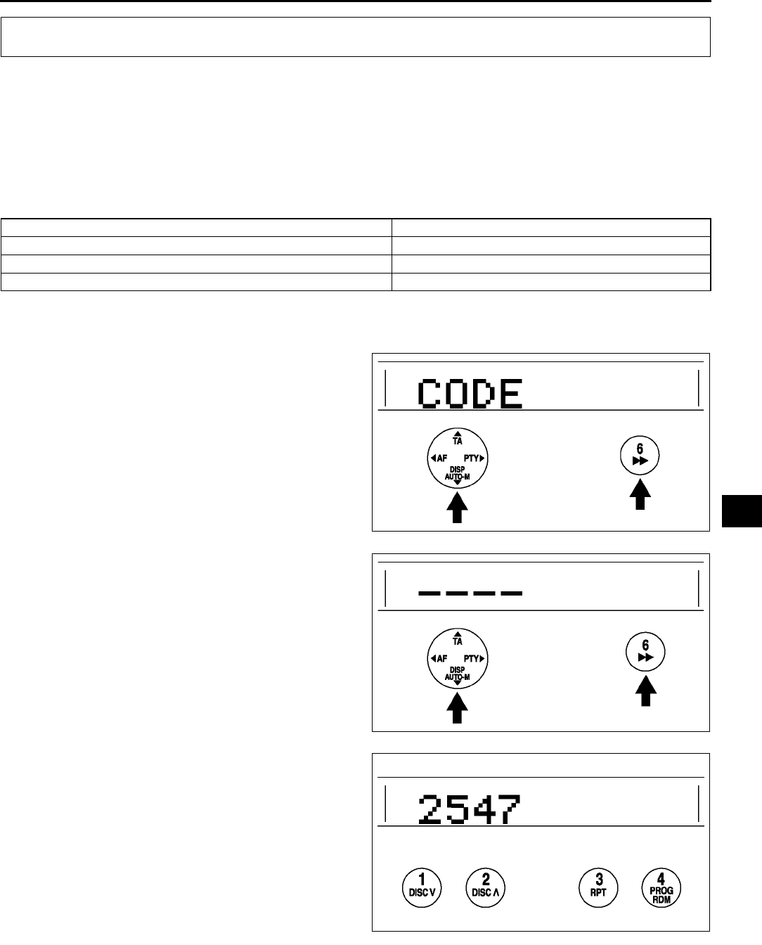
AUDIO AND NAVIGATION SYSTEM
T93
T
ANTI-THEFT SYSTEM A6E812466900W01
Alarm Conditions
•If the anti-theft system protection has been activated, any one of the following conditions will trigger the system:
Disconnected battery cable
Discharged battery
Disconnected audio unit connectors
•If the system is triggered, the audio unit will then be inoperative when it is reconnected to a power source, and
code will flash on the display until the preselected code number is input. If the anti-theft system is triggered,
follow the procedures in Canceling Anti-theft Operation to reset the unit.
Setting the Code Number
Complete each step (Steps 13) within 10 seconds or the setting procedure will be canceled.
1. Turn the ignition switch to ACC position and then turn off the audio unit.
2. First press the AUTO-M button, then
simultaneously press channel button 6 for
approximately 2 seconds until CODE appears
on the display.
3. Press the AUTO-M button again, then
simultaneously press channel button 6 until bars
appear on the display.
4. Select a personal code number and record it
before inputting it. If the number is input and then
forgotten, it cannot be canceled, and if the unit is
disconnected again, the audio unit will be
inoperative.
5. Use channel buttons 14 to input the selected
code number. Press button 1 for the first digit, 2
for the second, 3 for the third, and 4 for the last
digit. Input the number within 10 seconds. If the
display is deleted, repeat the procedure from Step
1.
Note
•Perform Step 6 within 10 seconds after
Step 5.
AUDIO AND NAVIGATION SYSTEM
Operation Reference
Input code number to activate anti-theft system Setting the Code Number
Delete previous code number and set new number Canceling the Code Number
Resume audio unit operation after anti-theft system is triggered Canceling Anti-theft Operation
A6E8124W025
A6E8124W026
A6E8124W027
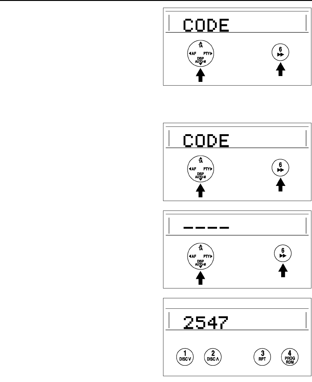
T94
AUDIO AND NAVIGATION SYSTEM
6. With the code number displayed, press the
AUTO-M button, then simultaneously press
channel button 6 for approximately 2 seconds.
CODE will be displayed for approximately 5
seconds. After it disappears, the code number is
set.
7. If Err (error) appears on the display, repeat the
procedure from Step 1. If input error is repeated
three times, turn the ignition switch to LOCK
position and repeat the procedure from Step 1.
Canceling the Code Number
Complete each step (Steps 13) within 10 seconds or the canceling procedure will be canceled.
1. Turn the ignition switch to ACC position and then turn off the audio unit.
2. First press the AUTO-M button, then
simultaneously press channel button 6 for
approximately 2 seconds until CODE appears
on the display.
3. Press the AUTO-M button again, then
simultaneously press channel button 6 until bars
appear on the display.
4. Use channel buttons 14 to input the current code
number. Press button 1 for the first digit, 2 for the
second, 3 for the third, and 4 for the last digit.
Input the number within 10 seconds. If the
display is deleted, repeat the procedure from Step
1.
Note
•Perform Step 5 within 10 seconds after
Step 4.
A6E8124W025
A6E8124W025
A6E8124W026
A6E8124W027
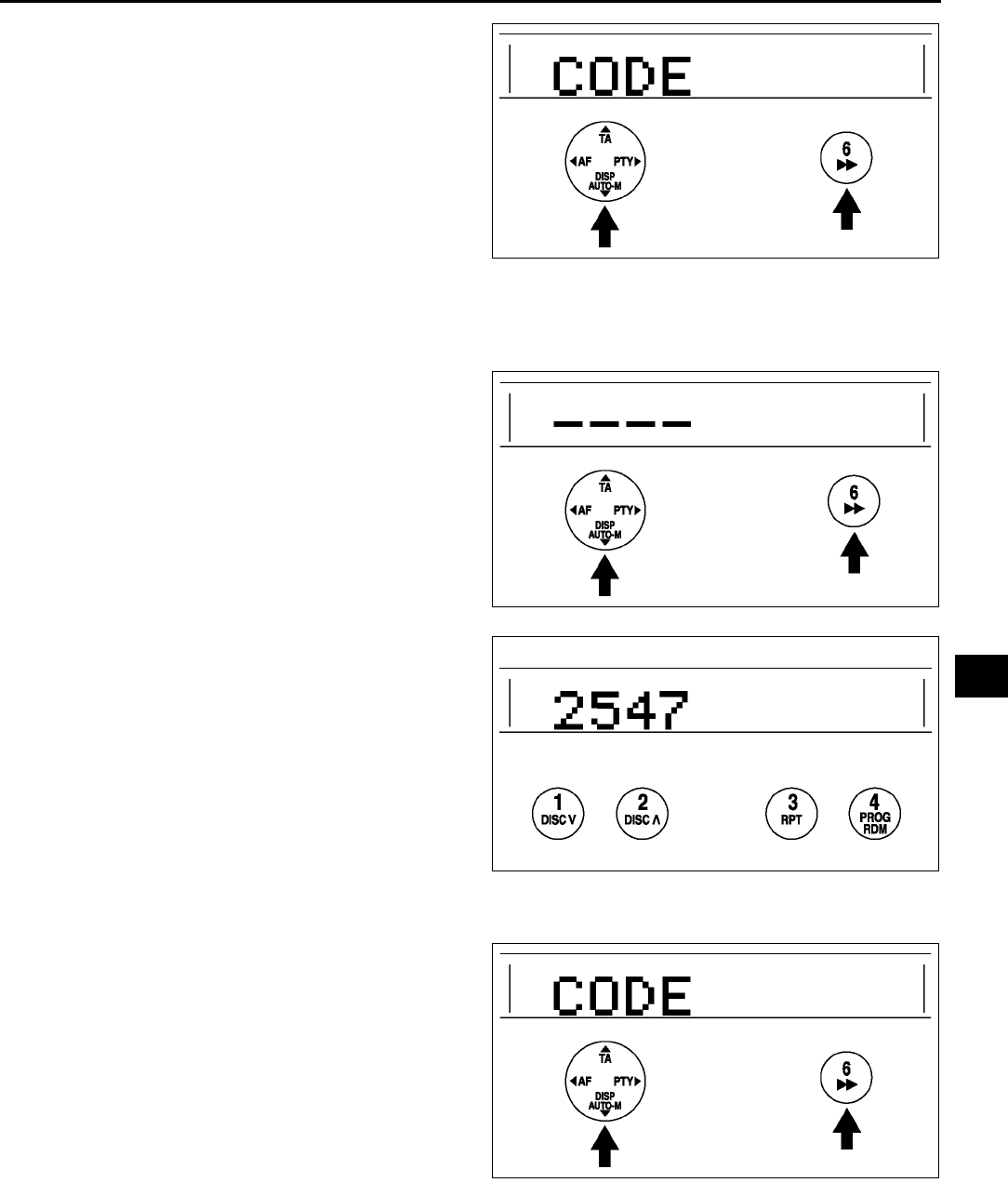
AUDIO AND NAVIGATION SYSTEM
T95
T
5. With the code number displayed, press the
AUTO-M button, then simultaneously press
channel button 6 for approximately 2 seconds.
CODE will be displayed for approximately 5
seconds. After it disappears, the code number is
canceled.
6. If Err (error) appears on the display, repeat the
procedure from Step 4.
Canceling Anti-theft Operation
Properly input the selected code number to deactivate the anti-theft system and resume normal audio operation.
1. Turn the ignition switch to ACC position. (CODE will flash on the display.)
2. First press the AUTO-M button, then
simultaneously press channel button 6 for
approximately 2 seconds until bars appears on
the display.
Note
•Perform Step 3 within 10 seconds after
Step 2.
3. Use channel buttons 14 to input the selected
code number. Press button 1 for the first digit, 2
for the second, 3 for the third, and 4 for the last
digit. Input the number within 10 seconds. If the
display is deleted, repeat the procedure from Step
1.
Caution
•
••
•Three consecutive errors, including
turning the ignition switch to LOCK
position and disconnecting the audio
unit, will activate the anti-theft system
and render the audio unit completely
inoperative.
4. With the code number displayed, press the
AUTO-M button, then simultaneously press
channel button 6 for approximately 2 seconds.
CODE will flash for approximately 5 seconds..
5. If Err (error) appears on the display, repeat the
procedure from Step 1.
End Of Sie
A6E8124W025
A6E8124W026
A6E8124W027
A6E8124W025
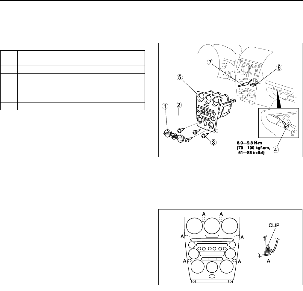
T96
AUDIO AND NAVIGATION SYSTEM
CENTER PANEL MODULE REMOVAL/INSTALLATION A6E812466900W02
1. Cancel the anti-theft operation. (with anti-theft system) (See T93 ANTI-THEFT SYSTEM.)
2. Disconnect the negative battery cable.
3. Remove the glove compartment.
4. Remove the rear console.
5. Remove in the order indicated in the table.
6. Install in the reverse order of removal.
Caution
•
••
•Make certain that the wiring harness and
antenna feeder are not caught between
the unit and dashboard. If the harness or
the antenna feeder is caught between the
unit and dashboard, it may cause trouble
or malfunctions.
7. Operate the anti-theft system by setting the code number. (with anti-theft system) (See T93 ANTI-THEFT
SYSTEM.)
Center Panel Module Removal Note
1. Pull the center panel module toward you, then
disengage clip A from the dashboard, and remove
the center panel module.
End Of Sie
1 Dial (manual A/C only)
2 Screw (manual A/C only)
3Screw
4Bolt
5 Center panel module
(See T96 Center Panel Module Removal Note)
6 Connector
7 Antenna feeder
A6E8124W020
A6E8124W029
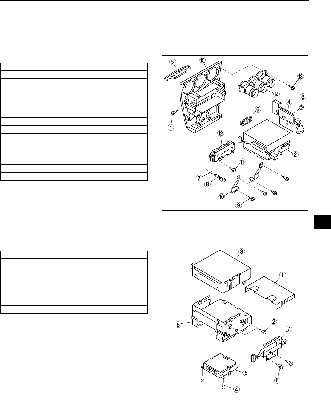
AUDIO AND NAVIGATION SYSTEM
T97
T
CENTER PANEL MODULE DISASSEMBLY/ASSEMBLY A6E812466900W03
Caution
•
••
•Before disassembling the center panel module, spread a cloth on the floor to put the
disassembled parts on. This protects the surface of the panel from scratches or dirt.
1. Remove the center panel module. (See T96 CENTER PANEL MODULE REMOVAL/INSTALLATION.)
2. Remove in the order indicated in the table.
3. Install in the reverse order of removal.
End Of Sie
AUDIO UNIT DISASSEMBLY/ASSEMBLY A6E812466900W04
1. Remove the audio unit. (See T97 CENTER PANEL MODULE DISASSEMBLY/ASSEMBLY.)
2. Disassemble in the order indicated in the table.
3. Assemble in the reverse order of disassembly.
End Of Sie
1Screw
2 Audio unit
3Screw
4 Circuit board (manual A/C only)
5 Cover (upper module)
6 Cover (lower module)
7 Passenger-side air bag cut indicator light bulb
8Socket
9Screw
10 Bracket
11 Screw
12 Climate control unit (auto A/C only)
13 Screw
14 Ventilator grille
15 Center panel
A6E8124W012
1 Cover (without upper module)
2Screw
3 Upper module
4Screw
5 Lower module
6Screw
7 Wiring harness
8 Base unit
A6E8124W013
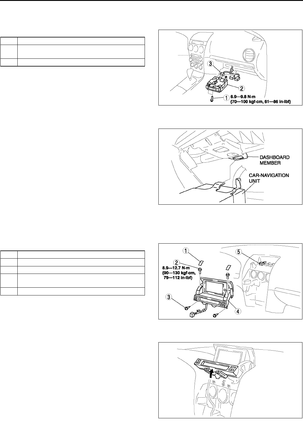
T98
AUDIO AND NAVIGATION SYSTEM
CAR-NAVIGATION UNIT REMOVAL/INSTALLATION A6E812466902W01
1. Disconnect the negative battery cable.
2. Remove the glove compartment.
3. Remove in the order indicated in the table.
4. Install in the reverse order of removal.
Car-navigation Unit Installation Note
1. Insert the car-navigation unit bracket into the
dashboard member hole, and with the car-
navigation unit fixed in place install the bolt.
End Of Sie
LCD UNIT REMOVAL/INSTALLATION A6E812466902W02
1. Disconnect the negative battery cable.
2. Remove the center panel module. (See T96 CENTER PANEL MODULE REMOVAL/INSTALLATION.)
3. Remove in the order indicated in the table.
4. Install in the reverse order of removal.
LCD Unit Removal Note
1. Pull up the front part of the LCD unit.
1Bolt
2 Car-navigation unit
(See T98 Car-navigation Unit Installation Note)
3 Connector
A6E8124W015
A6E8124W016
1Cover
2Bolt
3Screw
4 LCD unit
(See T98 LCD Unit Removal Note)
5 Connector
A6E8124W014
A6E8124W017
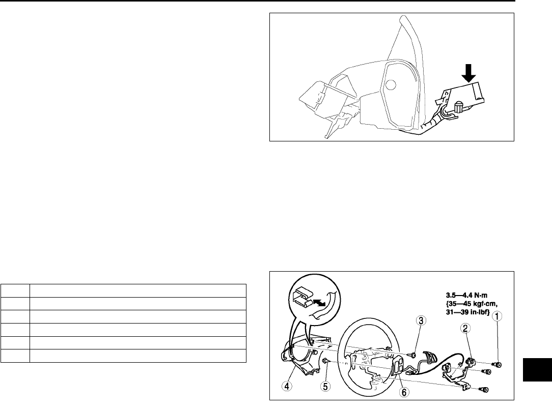
AUDIO AND NAVIGATION SYSTEM
T99
T
2. While pressing down the unit behind the LCD
unit, pull the LCD unit out from the dashboard.
End Of Sie
AUDIO CONTROL SWITCH REMOVAL/INSTALLATION A6E812400148W01
Note
•The audio control switch and the cruise control switch use a common connector.
1. Disconnect the negative battery cable.
2. Remove the driver-side air bag module. (See T120 DRIVER-SIDE AIR BAG MODULE REMOVAL/
INSTALLATION.)
3. Remove the steering wheel.
4. Remove in the order indicated in the table.
5. Install in the reverse order of removal.
End Of Sie
A6E8124W018
1Bolt
2Bracket
3Screw
4 Cover
5Screw
6 Audio control switch/cruise control switch
A6E8124W019
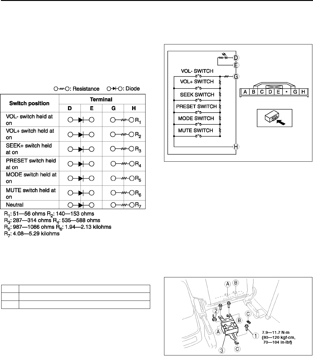
T100
AUDIO AND NAVIGATION SYSTEM
AUDIO CONTROL SWITCH INSPECTION A6E812400148W02
1. Disconnect the negative battery cable.
2. Remove the driver-side air bag module. (See T120 DRIVER-SIDE AIR BAG MODULE REMOVAL/
INSTALLATION.)
3. Disconnect the audio control switch connector.
4. Measure the resistance and inspect for continuity
between the cruise control switch terminals using
an ohmmeter.
•If not as specified, replace the cruise control
switch.
End Of Sie
AUDIO AMPLIFIER REMOVAL/INSTALLATION A6E812466910W01
1. Disconnect the negative battery cable.
2. Remove in the order indicated in the table.
3. Install in the reverse order of removal.
End Of Sie
A6E8124W043
A6E8124W028
1Bolt
2 Connector
3 Audio amplifier
A6E8124W010
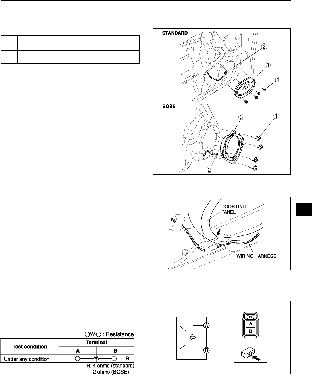
AUDIO AND NAVIGATION SYSTEM
T101
T
FRONT DOOR SPEAKER REMOVAL/INSTALLATION A6E812466960W01
1. Disconnect the negative battery cable.
2. Remove the front door trim.
3. Remove in the order indicated in the table.
4. Install in the reverse order of removal.
Front Door Speaker Installation Note
1. Attach the speaker with the wiring harness placed
in the groove of the door unit panel.
Caution
•
••
•If the speaker is attached with the
harness placed outside of the groove, the
wiring harness might be broken.
End Of Sie
FRONT DOOR SPEAKER INSPECTION A6E812466960W02
1. Inspect for resistance between the front door
speaker terminals using an ohmmeter.
•If not as specified, replace the front door
speaker.
2. To verify that the front door speaker outputs sound, apply voltage to the front door speaker and release using a
1.5-V battery.
•If not outputs sound, replace the front door speaker.
End Of Sie
1Screw
2 Connector
3 Front door speaker
(See T101 Front Door Speaker Installation Note)
A6E8124W001
A6E8124W002
A6E8124W040
A6E8124W032
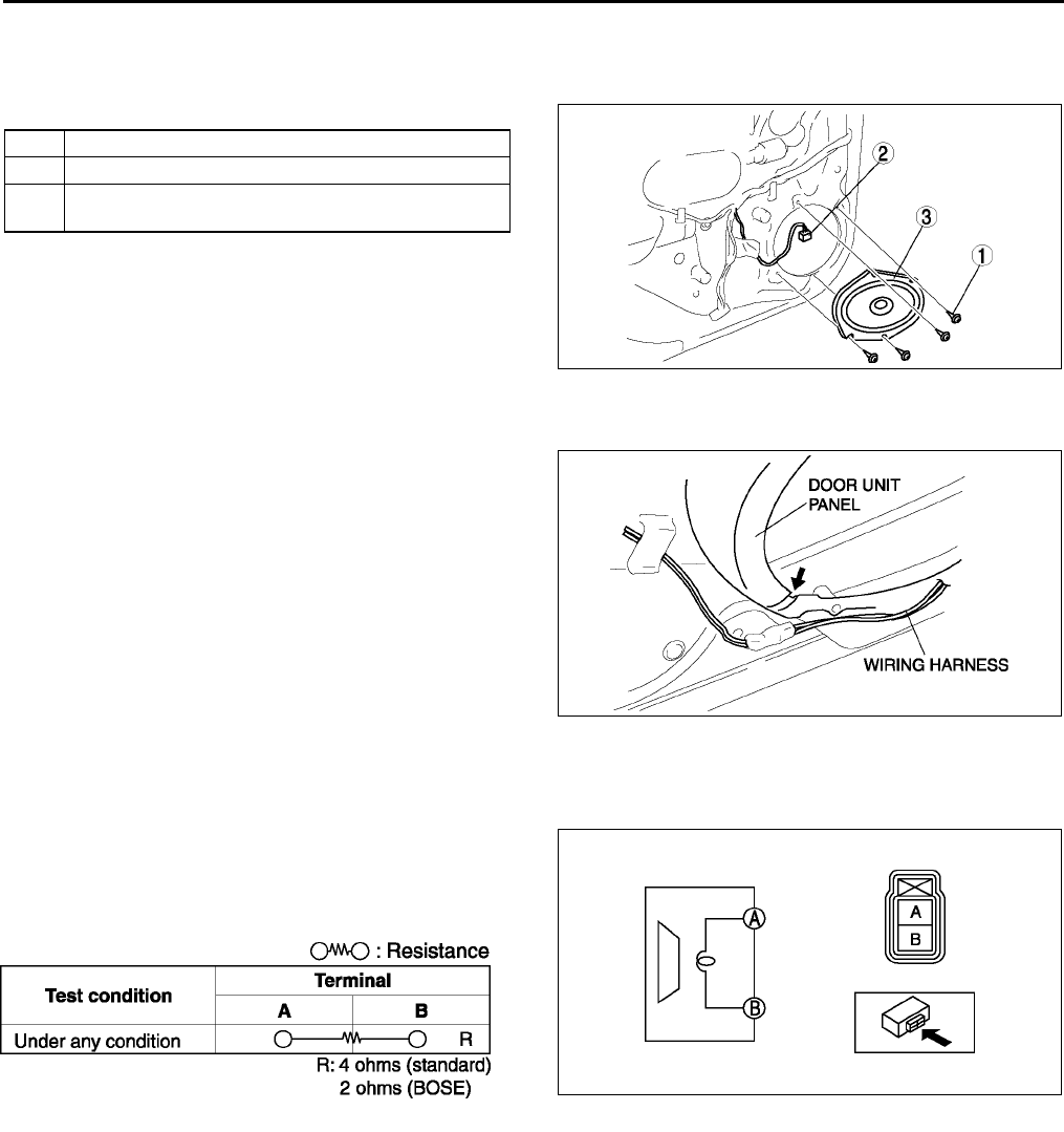
T102
AUDIO AND NAVIGATION SYSTEM
REAR DOOR SPEAKER REMOVAL/INSTALLATION A6E812466964W01
1. Disconnect the negative battery cable.
2. Remove the rear door trim.
3. Remove in the order indicated in the table.
4. Install in the reverse order of removal.
Rear Door Speaker Installation Note
1. Attach the speaker with the wiring harness placed
in the groove of the door unit panel.
Caution
•
••
•If the speaker is attached with the
harness placed outside of the groove, the
wiring harness might be broken.
End Of Sie
REAR DOOR SPEAKER INSPECTION A6E812466964W02
1. Inspect for resistance between the rear door
speaker terminals using an ohmmeter.
•If not as specified, replace the rear door
speaker.
2. To verify that the rear door speaker outputs sound, apply voltage to the rear door speaker and release using a
1.5-V battery.
•If not outputs sound, replace the rear door speaker.
End Of Sie
1Screw
2 Connector
3 Rear door speaker
(See T102 Rear Door Speaker Installation Note)
A6E8124W003
A6E8124W002
A6E8124W040
A6E8124W032
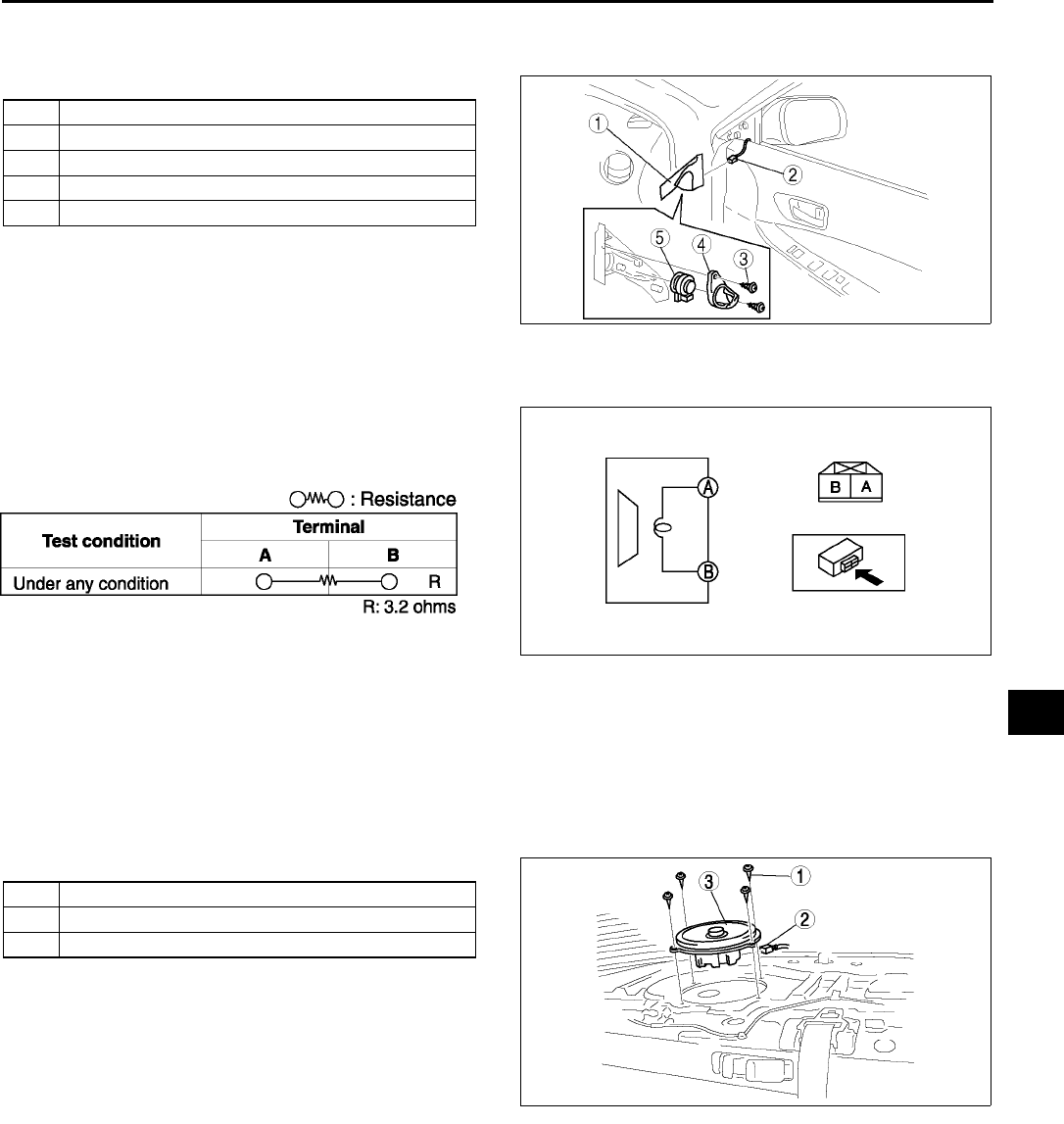
AUDIO AND NAVIGATION SYSTEM
T103
T
TWEETER REMOVAL/INSTALLATION A6E812468966W01
1. Disconnect the negative battery cable.
2. Remove in the order indicated in the table.
3. Install in the reverse order of removal.
End Of Sie
TWEETER INSPECTION A6E812468966W02
1. Inspect for resistance between the tweeter
terminals using an ohmmeter.
•If not as specified, replace the tweeter.
2. To verify that the tweeter outputs sound, apply
voltage to the tweeter and release using a 1.5-V
battery.
•If not outputs sound, replace the tweeter.
End Of Sie
WOOFER REMOVAL/INSTALLATION A6E812466967W01
4SD
1. Disconnect the negative battery cable.
2. Remove the rear package trim.
3. Remove in the order indicated in the table.
4. Install in the reverse order of removal.
1 Inner garnish
2 Connector
3Screw
4 Cover
5Tweeter
A6E8124W004
A6E8124W041
A6E8124W033
1Screw
2 Connector
3Woofer
A6E8124W005
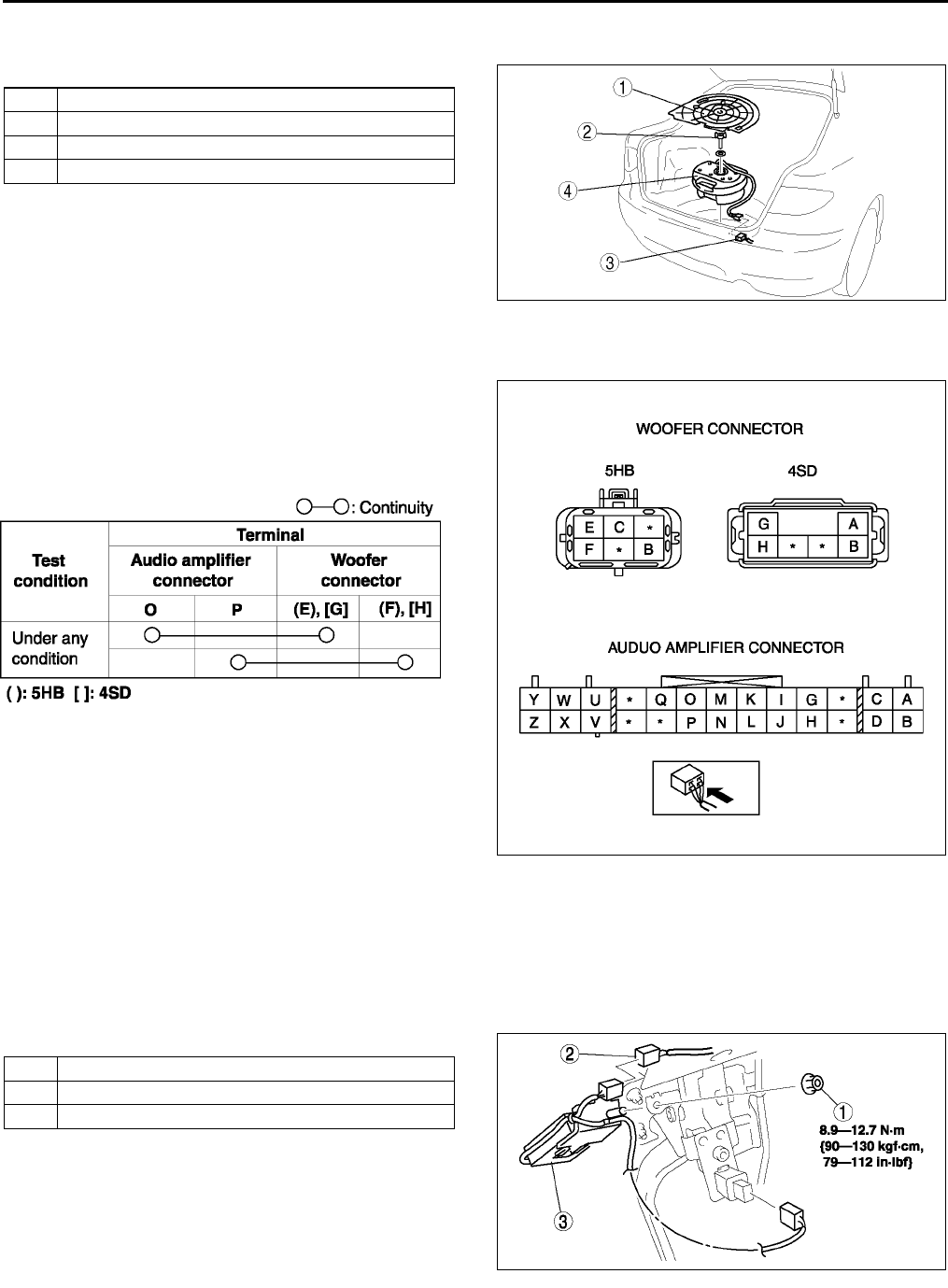
T104
AUDIO AND NAVIGATION SYSTEM
5HB
1. Disconnect the negative battery cable.
2. Remove in the order indicated in the table.
3. Install in the reverse order of removal.
End Of Sie
WOOFER INSPECTION A6E812466967W02
1. Inspect for continuity between the audio amplifier
connector terminals and woofer connector
terminals using an ohmmeter.
•If not as specified, replace the related wiring
harnesses.
2. Verify that there is battery positive voltage at the
woofer connector terminal A (4SD) or C (5HB)
using a voltmeter.
•If not as specified, replace the related wiring
haness.
3. Inspect continuity between the woofer connector
terminal B and body ground using an ohmmeter.
•If not as specified, replace the related wiring
harness.
•If as specified, replace the woofer.
End Of Sie
NOISE FILTER REMOVAL/INSTALLATION A6E812466869W01
Brake Light Noise Filter
1. Disconnect the negative battery cable.
2. Remove in the order indicated in the table.
3. Install in the reverse order of removal.
1 Temporary spare tire cover
2 Wing bolt
3 Connector
4Woofer
A6E8124W006
A6E8124W046
A6E8124W024
1Nut
2 Connector
3 Noise filter
A6E8124W008
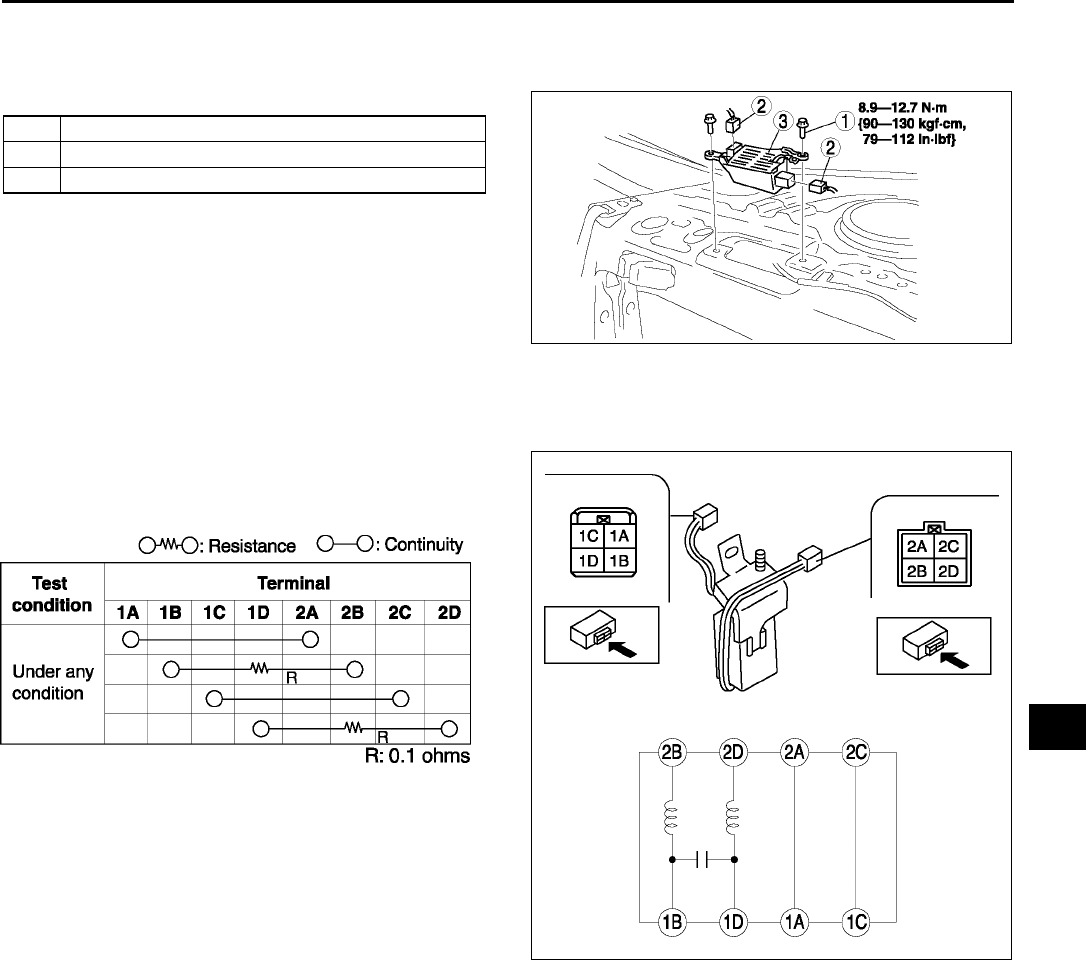
AUDIO AND NAVIGATION SYSTEM
T105
T
Rear Window Defroster Noise Filter
1. Disconnect the negative battery cable.
2. Remove the rear package trim.
3. Remove in the order indicated in the table.
4. Install in the reverse order of removal.
End Of Sie
NOISE FILTER INSPECTION A6E812466869W02
Brake Light Noise Filter
1. Inspect for resistance and continuity between the
noise filter terminals using an ohmmeter.
•If not as specified, replace the noise filter.
1Bolt
2 Connector
3Noise filter
A6E8124W009
A6E8124W034
A6E8124W035
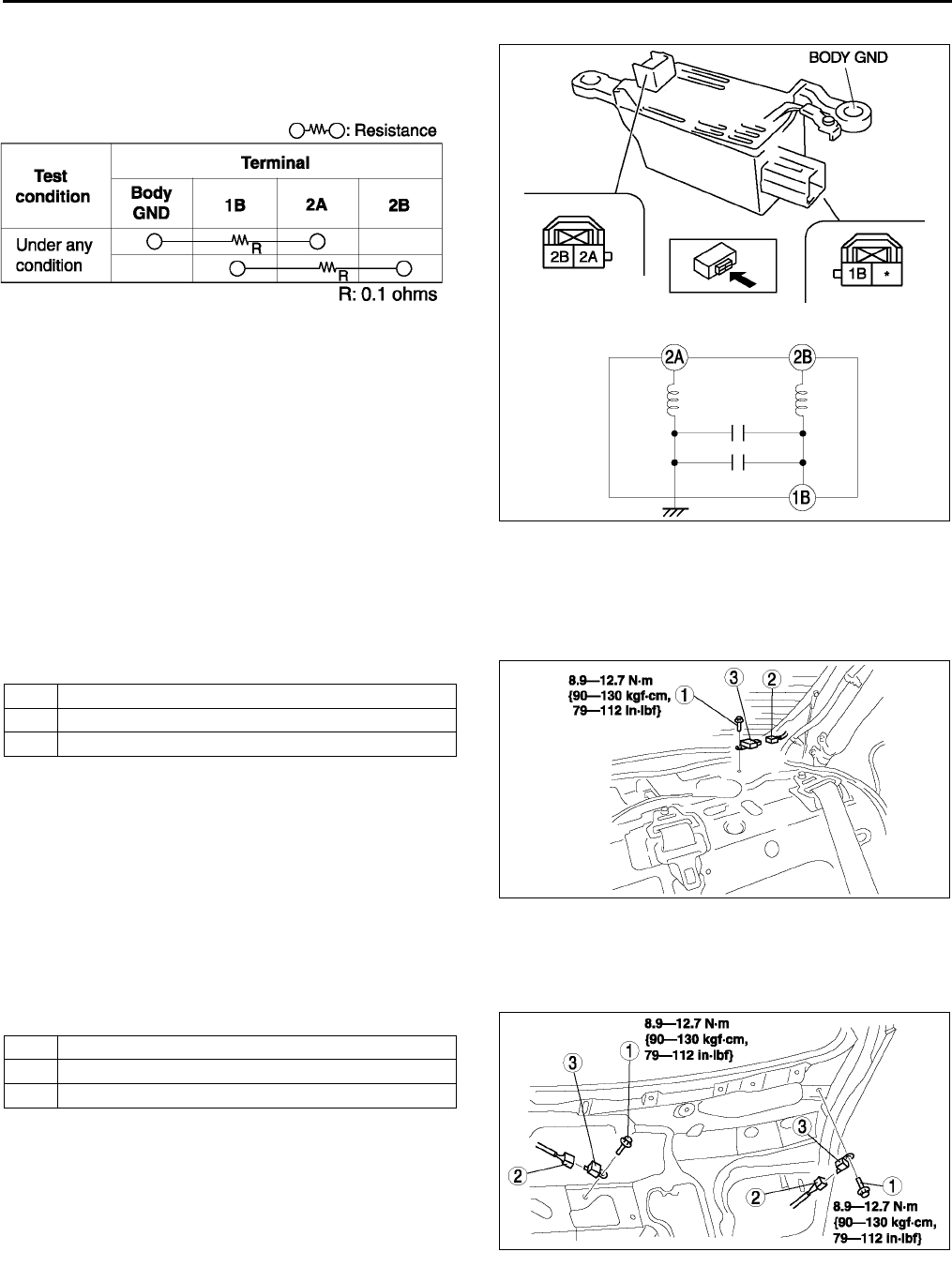
T106
AUDIO AND NAVIGATION SYSTEM
Rear Window Defroster Noise Filter
1. Inspect for resistance and continuity between the
noise filter terminals using an ohmmeter.
•If not as specified, replace the noise filter.
End Of Sie
CONDENSER REMOVAL/INSTALLATION A6E812466869W03
4SD
1. Disconnect the negative battery cable.
2. Remove the rear package trim.
3. Remove in the order indicated in the table.
4. Install in the reverse order of removal.
5HB
1. Disconnect the negative battery cable.
2. Remove the liftgate lower trim.
3. Remove in the order indicated in the table.
4. Install in the reverse order of removal.
End Of Sie
A6E8124W036
A6E8124W037
1Bolt
2 Connector
3 Condenser
A6E8124W007
1Bolt
2 Connector
3 Condenser
A6E8124W021
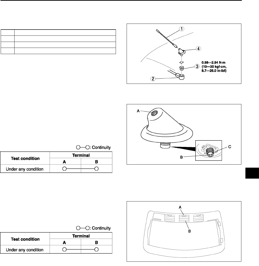
AUDIO AND NAVIGATION SYSTEM
T107
T
CENTER ROOF ANTENNA REMOVAL/INSTALLATION A6E812466939W01
1. Disconnect the negative battery cable.
2. Remove the headliner. (See S96 HEADLINER REMOVAL/INSTALLATION.)
3. Remove in the order indicated in the table.
4. Install in the reverse order of removal.
5. After installation, verify that the rubber of the
center roof antenna is installed to the roof panel
with no space between them.
End Of Sie
CENTER ROOF ANTENNA INSPECTION A6E812466939W02
1. Verify that there is no continuity between the
center roof antenna terminals A and C using an
ohmmeter.
2. Inspect for continuity between the center roof
antenna terminals using an ohmmeter.
•If not as specified, replace the center roof
antenna.
End Of Sie
GLASS ANTENNA INSPECTION A6E812466931W01
1. Inspect the glass antenna for damage visually.
2. Inspect for continuity between the glass antenna
terminals using an ohmmeter.
•If not as specified, repair the glass antenna.
(See S63 FILAMENT REPAIR.)
End Of Sie
1 Antenna rod
2 Antenna feeder
3Nut
4 Center roof antenna
A6E8124W023
A6E8124W048
A6E8124W031
A6E8124W030
A6E8124W031
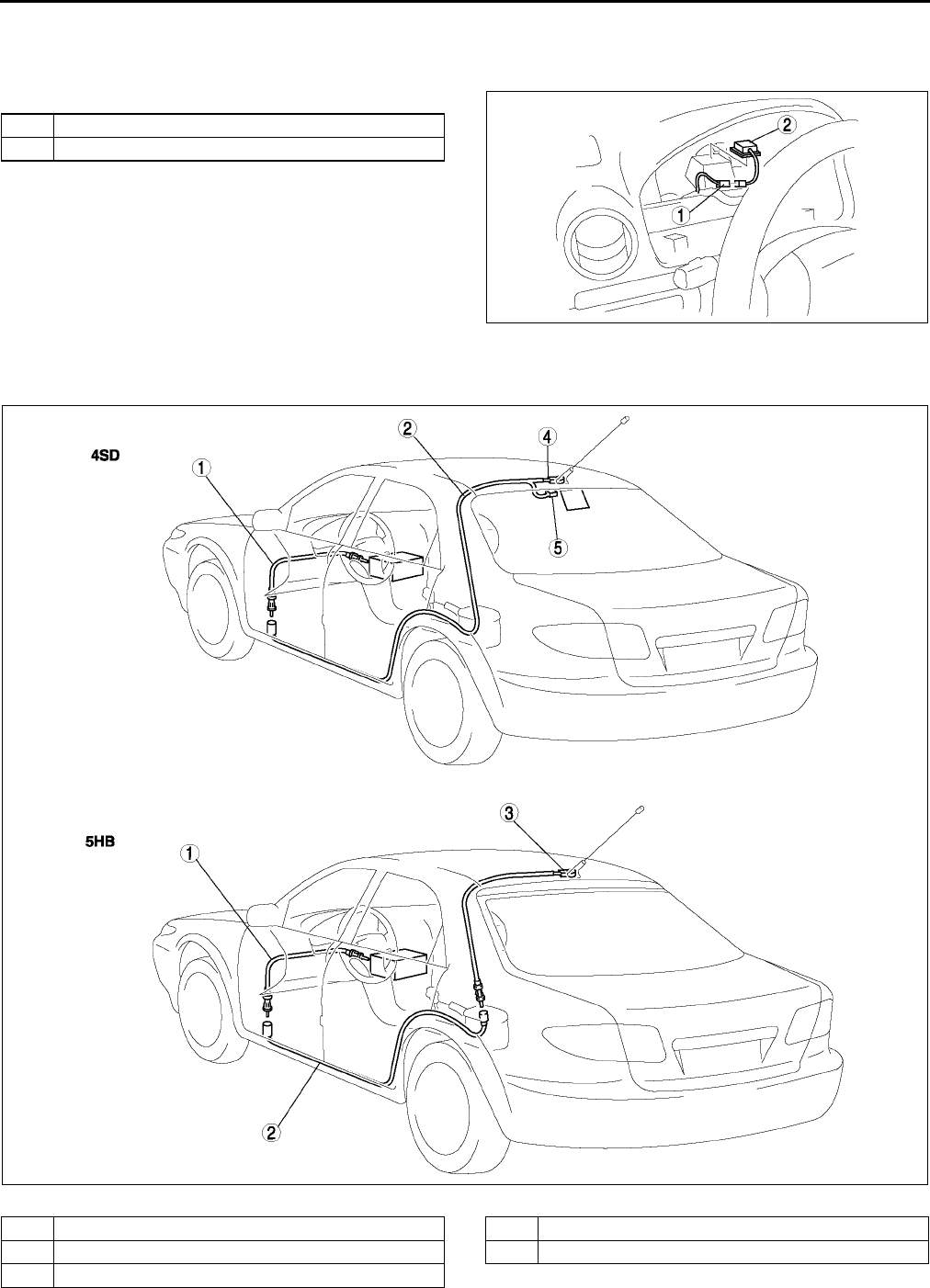
T108
AUDIO AND NAVIGATION SYSTEM
GPS ANTENNA REMOVAL/INSTALLATION A6E812466936W01
1. Disconnect the negative battery cable.
2. Remove the instrument cluster.
3. Remove in the order indicated in the table.
4. Install in the reverse order of removal.
End Of Sie
ANTENNA FEEDER LOCATION A6E812466941W01
.
End Of Si e
1 Connector
2 GPS antenna
A6E8124W022
A6E8124W038
1 Front antenna feeder
2 Rear antenna feeder No.1
3 Rear antenna feeder No.2
4 With center roof antenna
5 With glass antenna
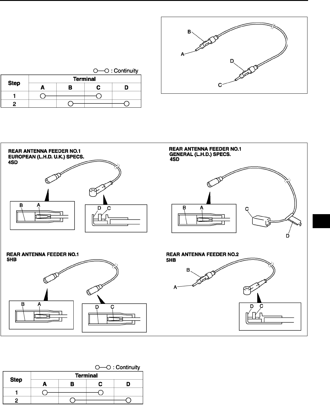
AUDIO AND NAVIGATION SYSTEM
T109
T
FRONT ANTENNA FEEDER INSPECTION A6E812466941W02
1. Verify that there is no continuity between the front
antenna feeder terminals A and B using an
ohmmeter.
2. Inspect for continuity between the front antenna
feeder terminals using an ohmmeter.
•If not as specified, replace the instrument
panel harness.
End Of Sie
REAR ANTENNA FEEDER INSPECTION A6E812466942W01
1. Verify that there is no continuity between antenna feeder terminals A and B using an ohmmeter.
2. Inspect for continuity between the antenna feeder terminals using an ohmmeter.
•If not as specified, replace the rear harness.
End Of Sie
A6E8124W039
A6E8124W047
A6E8124W042
A6E8124W047
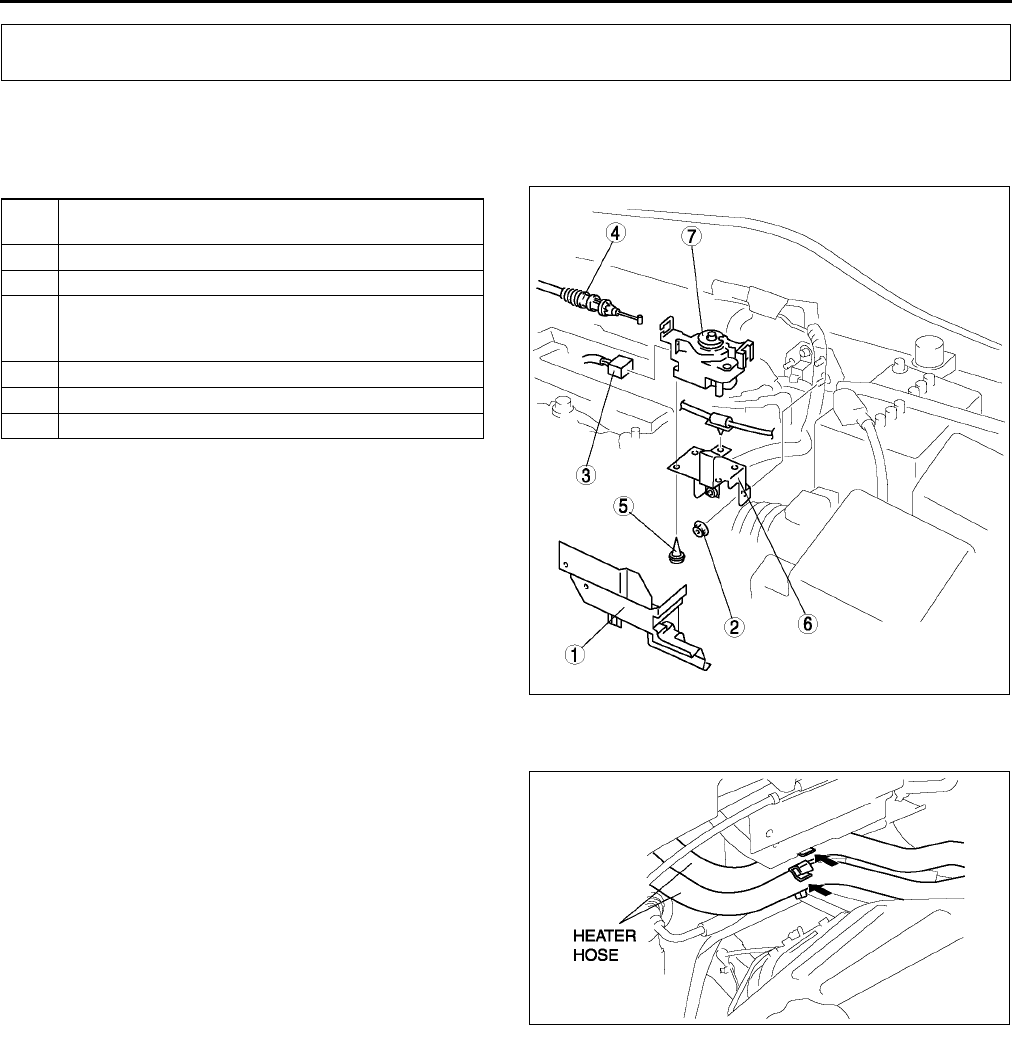
T110
CRUISE CONTROL SYSTEM
CRUISE ACTUATOR REMOVAL/INSTALLATION A6E812866310W01
1. Disconnect the negative battery cable.
2. Remove in the order indicated in the table.
3. Install in the reverse order of removal.
Cover Removal Note
1. Unclamp the clips of the heater hoses at the front
of the cover.
End Of Sie
CRUISE ACTUATOR INSPECTION A6E812866310W02
1. Disconnect the cruise actuator connector.
2. Measure the voltage, continuity and resistance at the cruise actuator terminals as indicated below.
•If not as specified, inspect the parts listed under Action.
•If the parts and wiring harnesses are okay but the system still does not work properly, replace the cruise
actuator.
CRUISE CONTROL SYSTEM
1Cover
(See T110 Cover Removal Note)
2Nut
3 Connector
4 Actuator cable
(See T112 ACTUATOR CABLE REMOVAL)
(See T114 ACTUATOR CABLE INSTALLATION)
5Screw
6Bracket
7 Cruise actuator
A6E8128W001
A6E8128W002
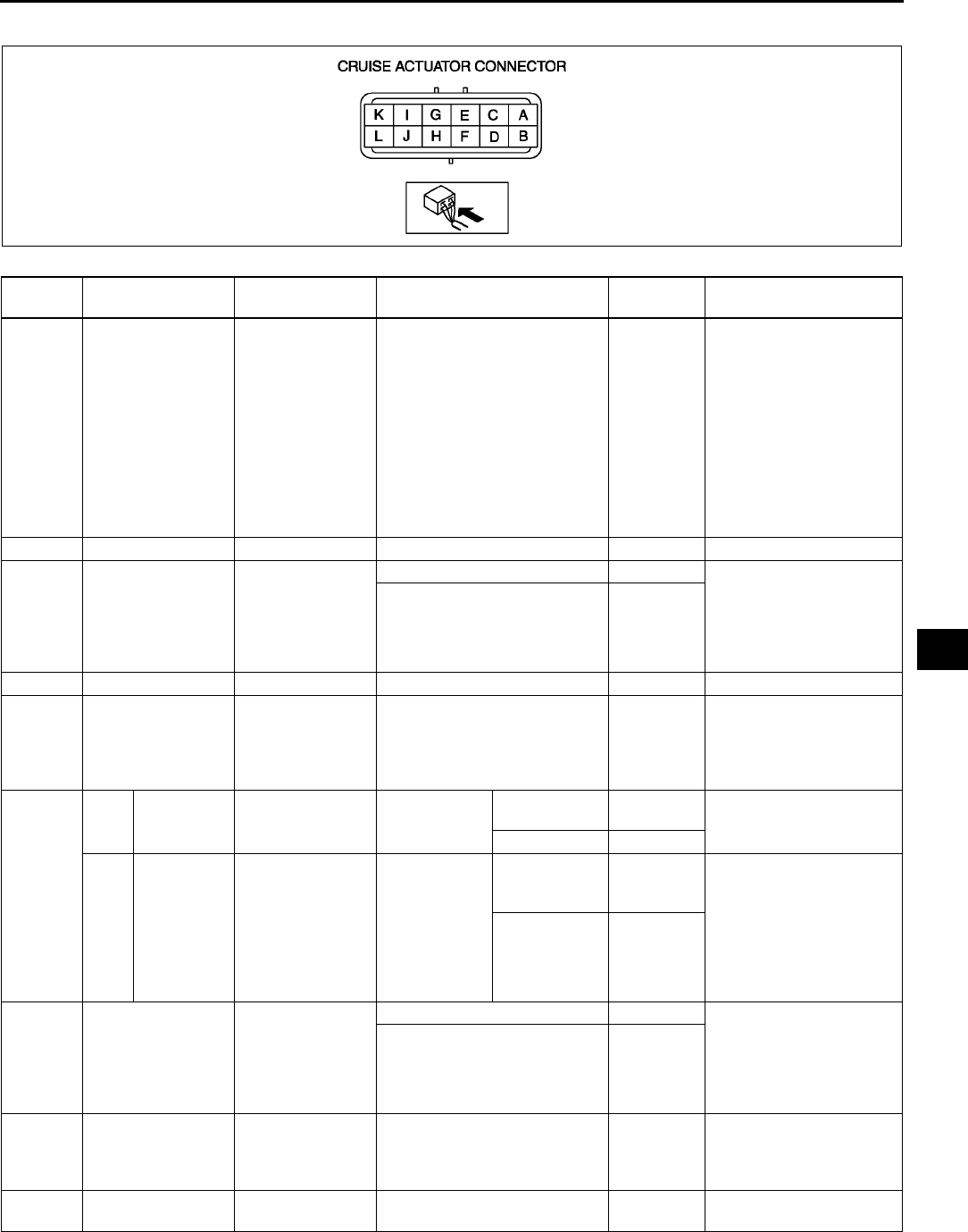
CRUISE CONTROL SYSTEM
T111
T
Terminal Voltage Table (Reference)
Terminal Signal Connected to Test condition Voltage (V)
/Continuity Action
A Vehicle speed
•DSC HU/CM
(with DSC)
•ABS (ABS/
TCS) HU/CM
(with ABS
(ABS/TCS))
1. Ignition switch at ON
position and cruise control
main switch held at on.
2. Front tire rotating
Alternates
below 1.0
and 5
•Inspect METER IG 15
A fuse
•Inspect DSC HU/CM
(See P40 DSC HU/
CM INSPECTION)
•Inspect ABS (ABS /
TCS) HU/CM
(See P29 ABS (ABS/
TCS) HU/CM
INSPECTION)
•Inspect related
harness
B
C Brake switch on/off Brake switch
Depress brake pedal B+ •Inspect brake switch
(See P8 BRAKE
SWITCH
INSPECTION)
•Inspect related
harness
Replace brake pedal Below 1.0
D
EO/D control
(ATX only) PCM Ignition switch at ON position B+
•Inspect PCM
(See F45 PCM
INSPECTION)
•Inspect related
harness
F
MTX
Clutch
switch on/off Clutch switch
Inspect for
continuity to
ground
Depress
crutch switch Yes •Inspect clutch switch
•Inspect related
harness
Other No
ATX
Selector
lever
position
TR switch
Inspect for
continuity to
ground
Selector lever
at N or P
position
Yes
•Inspect TR switch
(See K14
TRANSAXLE RANGE
(TR) SWITCH
INSPECTION)
•Inspect starter
•Inspect related
harness
Other No
GCruise set indicator
light output
Cruise set
indicator light
Ignition switch at ON position B+ •Inspect METER IG 15
A fuse
•Inspect instrument
cluster
•Inspect related
harness
Ignition switch at LOCK
position or ACC position Below 1.0
H
Cruise main
indicator light
output
Cruise main
indicator light
Under any condition: inspect
for continuity to ground Yes
•Inspect instrument
cluster
•Inspect related
harness
ICruise actuator
ground GND Under any condition: inspect
for continuity to ground Yes •Inspect GND
A6E8128W013
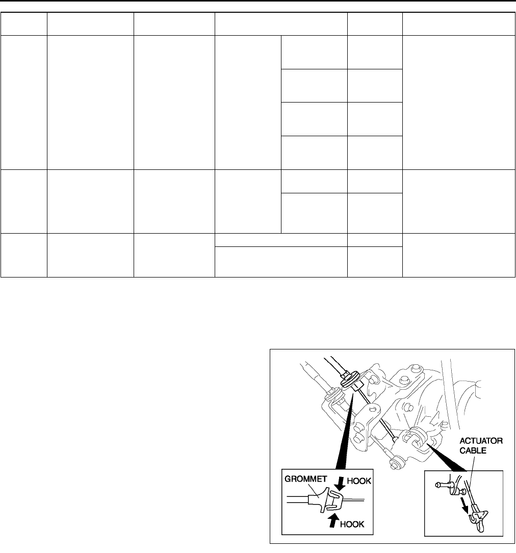
T112
CRUISE CONTROL SYSTEM
End Of Sie
ACTUATOR CABLE REMOVAL A6E812866311W01
1. Remove the plug hole plate.
2. Remove the cover from the cruise actuator. (See T110 CRUISE ACTUATOR REMOVAL/INSTALLATION.)
3. Remove the installation nut and pull the cruise actuator toward you.
4. Move the throttle, and remove the end fitting of
the actuator cable from the throttle.
5. Squeeze the hooks of the grommet, and remove
the actuator cable.
JCruise control
switch position
Cruise control
switch
Inspect for
resistance
Cruise control
main switch
held at on
0 ohm
•Inspect cruise control
switch
(See T116 CRUISE
CONTROL SWITCH
INSPECTION)
•Inspect related
harness
SET/COAST
switch held at
on
Approx.
680 ohms
RESUME/
ACCEL switch
held at on
Approx.
2200 ohms
CANCEL
switch held at
on
Approx.
120 ohms
K Brake switch on/off Brake switch 2 Ignition switch
at ON position
Depress brake
pedal Below 1.0 •Inspect brake switch 2
(See P8 BRAKE
SWITCH
INSPECTION)
•Inspect related
harness
Other B+
LIG1 METER IG 15 A
fuse
Ignition switch at ON position B+ •Inspect METER IG 15
A fuse
•Inspect related
harness
Ignition switch at LOCK
position or ACC position Below 1.0
Terminal Signal Connected to Test condition Voltage (V)
/Continuity Action
A6E8128W007
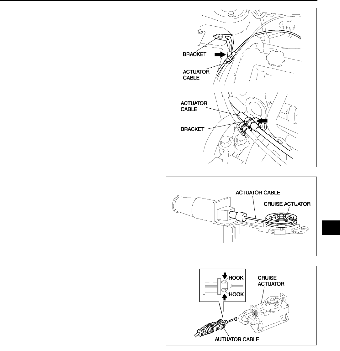
CRUISE CONTROL SYSTEM
T113
T
6. Remove the actuator cable from the bracket
7. Remove the end fitting of the actuator cable from
the cruise actuator.
8. Squeeze the hooks of the grommet, and remove
it from the cruise actuator.
9. Remove the actuator cable.
End Of Sie
A6E8128W004
A6E8128W005
A6E8128W008
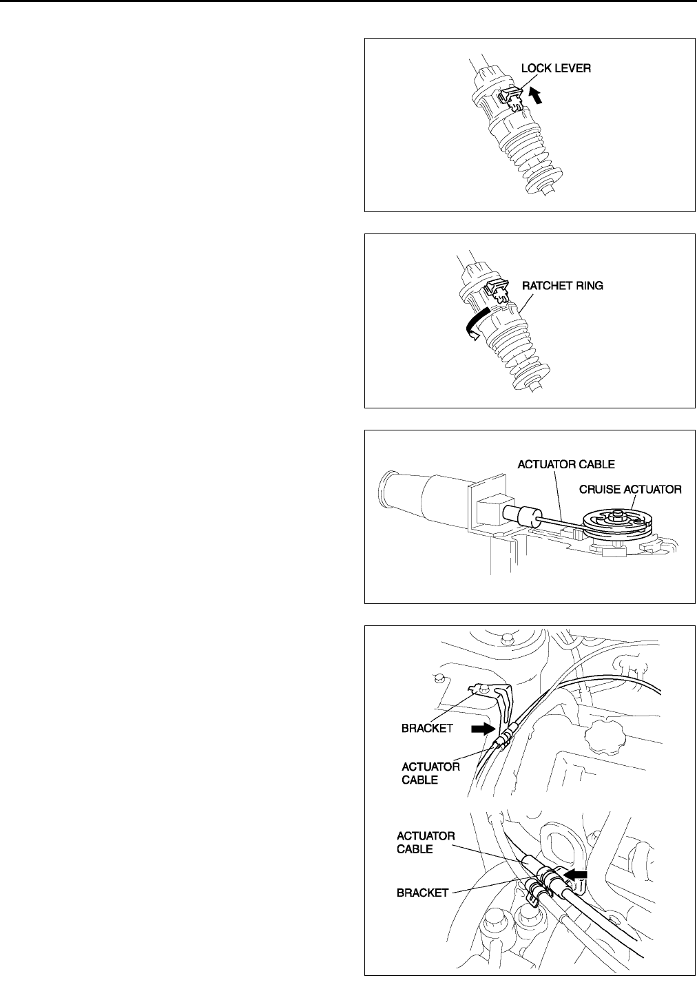
T114
CRUISE CONTROL SYSTEM
ACTUATOR CABLE INSTALLATION A6E812866311W02
1. Slide the lock lever in the direction shown by the
arrow to unlock the adjuster.
2. Turn the ratchet ring to release lock in the
direction shown by the arrow.
3. Install the actuator cable to the cruise actuator.
Caution
•
••
•Due to the possibility of actuator cable
damage, make sure there is no twisting in
the cable when installing.
4. Install the cruise actuator. (See T110 CRUISE
ACTUATOR REMOVAL/INSTALLATION.)
5. Pass the actuator cable under the accelerator
cable.
6. Install the actuator cable to the bracket.
A6E8128W009
A6E8128W010
A6E8128W005
A6E8128W004
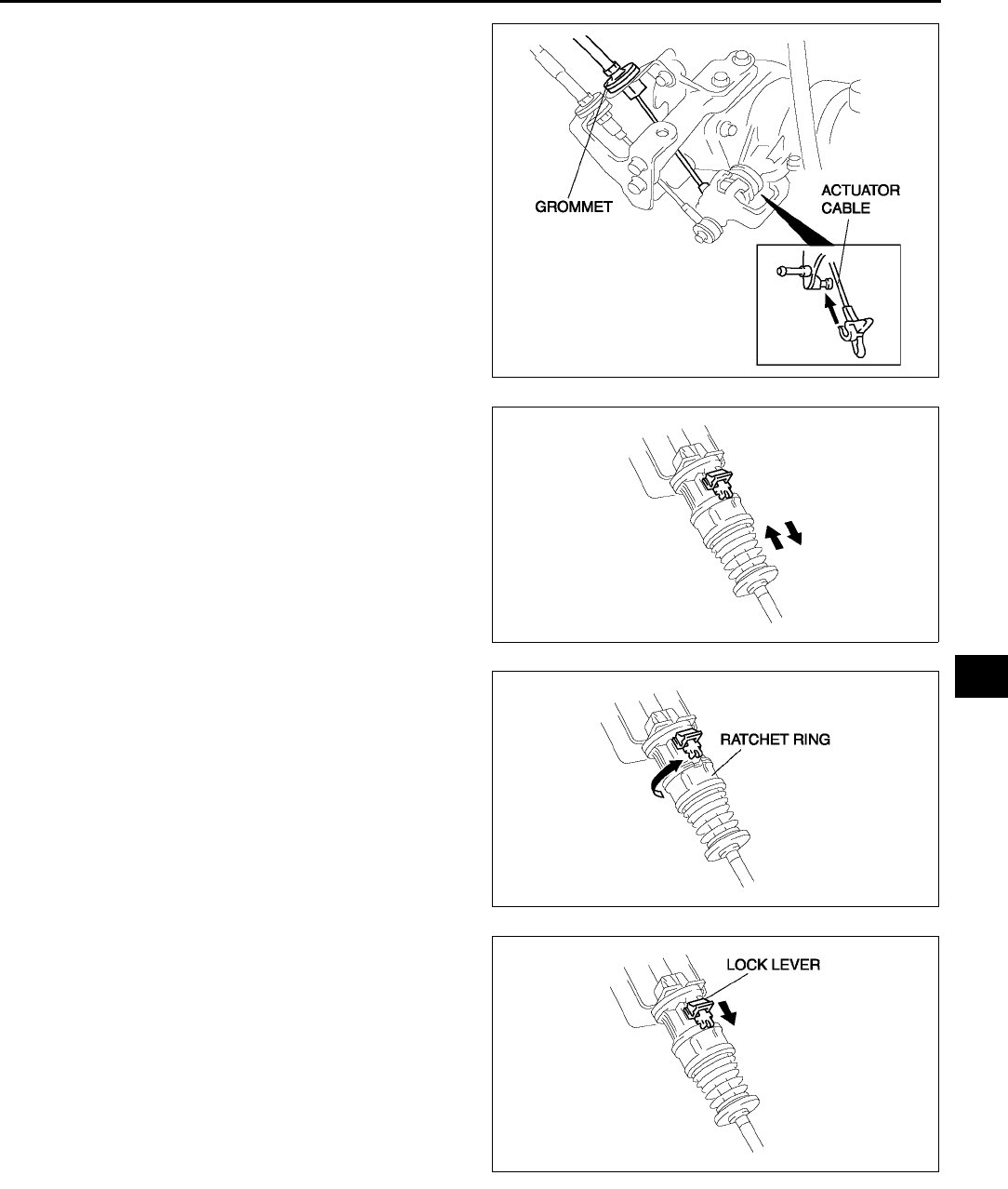
CRUISE CONTROL SYSTEM
T115
T
7. Install the grommet to the cable bracket.
8. Move the throttle, and install the end fitting of the
actuator cable to the throttle.
Caution
•
••
•Due to the possibility of actuator cable
damage, make sure there is no twisting in
the cable when installing.
9. To adjust the free play, push or pull the actuator
cable directly behind the spring two times.
10. Turn the ratchet ring in the direction shown by the
arrow to lock it.
11. Slide the lock lever in the direction shown by the
arrow to lock the adjuster.
12. Install the cover to the cruise actuator.
13. Install the plug hole plate.
End Of Sie
CRUISE CONTROL SWITCH REMOVAL/INSTALLATION A6E812866341W01
Note
•The audio control switch and the cruise control switch use a common connector.
•(See T99 AUDIO CONTROL SWITCH REMOVAL/INSTALLATION.)
A6E8128W011
A6E8128W014
A6E8128W015
A6E8128W016
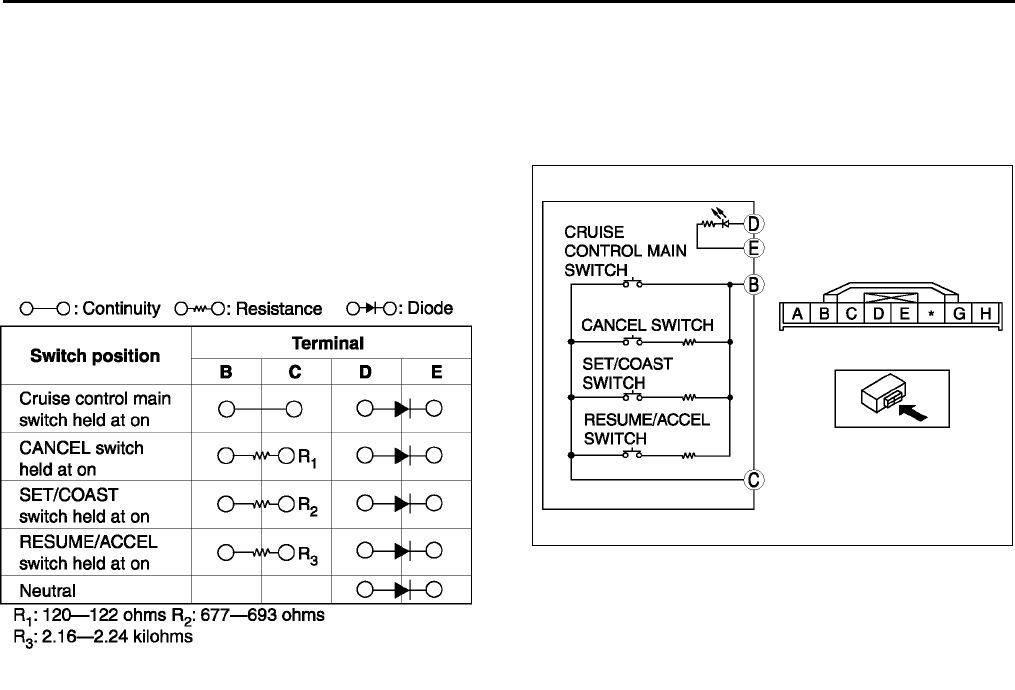
T116
CRUISE CONTROL SYSTEM
End Of Sie
CRUISE CONTROL SWITCH INSPECTION A6E812866341W02
1. Disconnect the negative battery cable.
2. Remove the driver-side air bag module. (See T120 DRIVER-SIDE AIR BAG MODULE REMOVAL/
INSTALLATION.)
3. Disconnect the cruise control switch connector.
4. Inspect for resistance and continuity between the
cruise control switch terminals using an
ohmmeter.
•If not as specified, replace the cruise control
switch.
End Of Sie
A6E8128W012
A6E8128W006
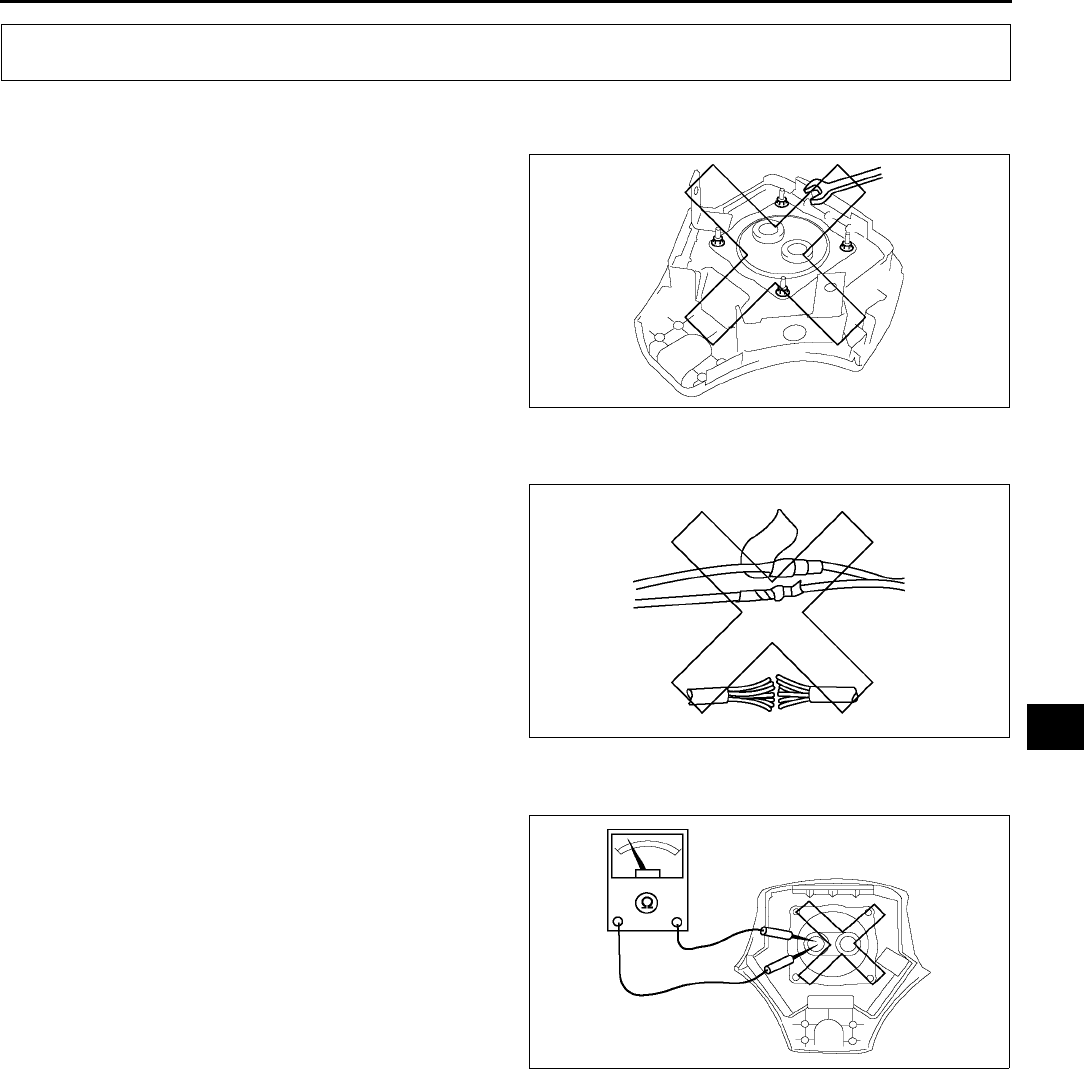
AIR BAG SYSTEM
T117
T
SERVICE WARNINGS A6E813001046W01
Component Disassembly
•Disassembling and reassembling the
components of the air bag system can render
the system inoperative, which may result in
serious injury or death in the event of an
accident. Do not disassemble any air bag
system components.
Wiring Harness Repair
•Incorrectly repairing an air bag system wiring
harness can accidentally deploy the air bag
module or pre-tensioner seat belt, which can
cause serious injury. If a problem is found in
the system wiring, replace the wiring harness.
Do not try to repair it.
Air Bag Module Inspection
•Inspecting an air bag module using an
ohmmeter can deploy the air bag module,
which may cause serious injury. Do not use
an ohmmeter to inspect an air bag module.
Always use the on-board diagnostic to
diagnose the air bag module for malfunctions.
AIR BAG SYSTEM
A6E8130W044
A6E8130W045
A6E8130W024
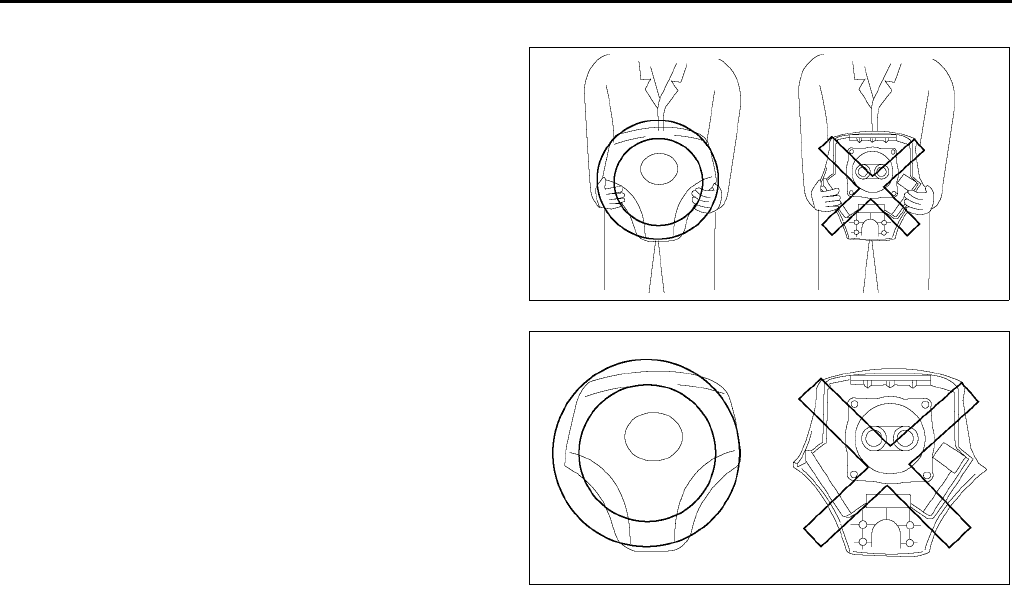
T118
AIR BAG SYSTEM
Air Bag Module Handling
•A live (undeployed) air bag module may
accidentally deploy when it is handled and
cause serious injury. When carrying a live
(undeployed) air bag module, point the front
surface away from your body to lessen the
chance of injury in case it deploys.
•A live (undeployed) air bag module placed
face down on a surface is dangerous. If the air
bag module deploys, the motion of the
module can cause serious injury. Always face
the front surface up to reduce the motion of
the module in case it accidentally deploys.
Side Air Bag Module Handling
•When the side air bag module deploys due to a collision, the interior of the seat back (pad, frame, etc.)
may become damaged. If the seat back is reused and the side air bag module does not deploy properly,
a serious accident may result. When the side air bag module deploys, always replace both the side air
bag module and the seat back (pad, frame, trim) with new parts. After service, confirm that the seat
operates normally and that the harness is positioned properly.
SAS Unit Handling
•Disconnecting the SAS unit connector or removing the SAS unit with the ignition switch at ON position
can cause the air bag modules to deploy, which may seriously injure you. Before disconnecting the
SAS unit connector or removing the SAS unit, turn the ignition switch to LOCK position, then
disconnect the negative battery cable and wait for more than 1 minute to allow the backup power
supply of the SAS unit to deplete its stored power.
•Connecting the SAS unit connector without firmly installing the SAS unit to the vehicle is dangerous.
The crash sensor inside the control module may send an electrical signal to the air bag modules. This
will deploy the air bag modules, which may result in serious injury. Therefore, before connecting the
connector, firmly mount the control module to the vehicle.
•For vehicles with a single point sensor, once an air bag module is deployed due to an accident or other
causes, the SAS unit must be replaced with a new one even if the used one does not have any external
signs of damage. The used SAS unit may have been damaged internally which may cause improper
operation, resulting in major injuries or even death. The used single point SAS unit cannot be
bench-checked or self-checked.
Crash Zone Sensor Handling
•Disconnecting the crash zone sensor connector or removing the crash zone sensor with the ignition
switch at ON position can cause the crash zone sensor to operate and the air bag modules and pre-
tensioner seat belts to deploy, which may seriously injure you. Before disconnecting the crash zone
sensor connector or removing the crash zone sensor, always turn the ignition switch to LOCK
position, then disconnect the negative battery cable and wait for more than 1 minute to allow the
backup power supply of the SAS control module to deplete its stored power.
•If the crash zone sensor is subjected to shock or the sensor is disassembled, the air bag modules and
pre-tensioner seat belts may operate (deploy) suddenly and cause injury, or it may fail to operate
normally and cause a serious accident. Do not subject the crash zone sensor to shock or disassemble
the sensor.
•Because a sensor is built into the crash zone sensor, when the air bag modules and pre-tensioner seat
belts operates (deploys), there may be a problem, such as an internal malfunction, even if there is not
any external damage or deformation. If the crash zone sensor is reused, the air bag modules and pre-
tensioner seat belts may fail to operate normally and cause a serious injury. Always replace the crash
zone sensor with a new part. The crash zone sensor cannot be bench-checked or self-checked.
A6E8130W022
A6E8130W021
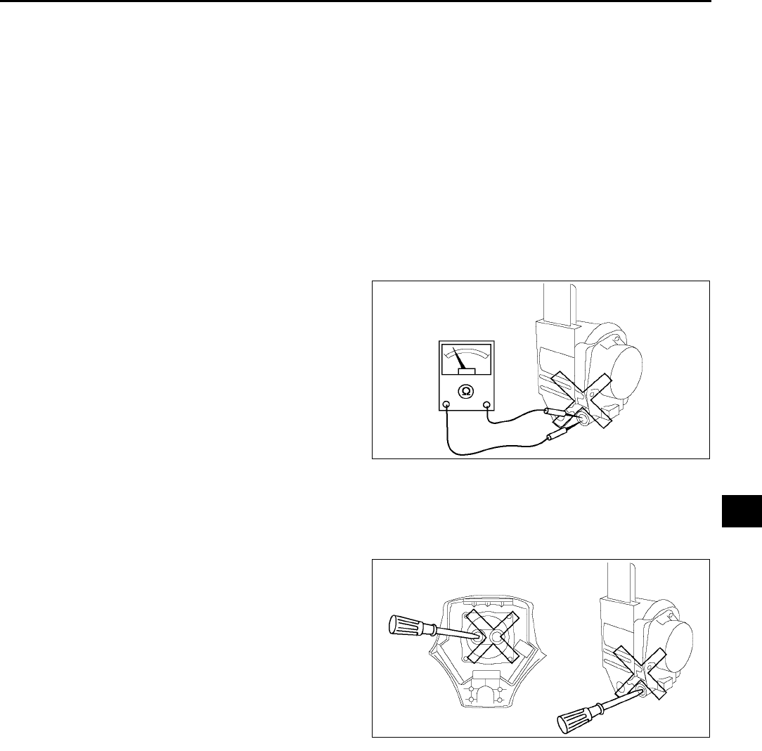
AIR BAG SYSTEM
T119
T
Side Air Bag Sensor Handling
•Disconnecting the side air bag sensor connector or removing the side air bag sensor with the ignition
switch at ON position can cause the side air bag sensor to operate and the side air bag module to
deploy, which may seriously injure you. Before disconnecting the side air bag sensor connector or
removing the side air bag sensor, always turn the ignition switch to LOCK position, then disconnect
the negative battery cable and wait for more than 1 minute to allow the backup power supply of the
SAS control module to deplete its stored power.
•If the side air bag sensor is subjected to shock or the sensor is disassembled, the side air bag module
may operate (deploy) suddenly and cause injury, or it may fail to operate normally and cause a serious
accident. Do not subject the side air bag sensor to shock or disassemble the sensor.
•Because a sensor is built into the side air bag sensor, when the side air bag module operates
(deploys), there may be a problem, such as an internal malfunction, even if there is not any external
damage or deformation. If the side air bag sensor is reused, the side air bag module may fail to operate
normally and cause a serious injury. Always replace the side air bag sensor with a new part. The side
air bag sensor cannot be bench-checked or self-checked.
Pre-tensioner Seat Belt Inspection
•Inspecting a pre-tensioner seat belt using an
ohmmeter can deploy the pre-tensioner seat
belt, which can cause serious injury. Do not
use an ohmmeter to inspect the pre-tensioner
seat belt. Always use the on-board diagnostic
to diagnose the pre-tensioner seat belt for
malfunctions.
Component Handling
•Oil, grease, water, etc on components may cause the air bag modules and pre-tensioner seat belts to
fall to deploy in an accident, which may cause serious injury. Do not allow oil, grease, water, etc., on
components.
•Inserting a screwdriver, etc., into the
connector of an air bag module or a pre-
tensioner seat belt may damage the connector
and cause the air bag module or the pre-
tensioner seat belt to deploy improperly,
which may cause serious injury. Do not insert
any foreign objects into the connector.
Component Reuse
•Even if an air bag module or a pre-tensioner seat belt does not deploy in a collision and does not have
any external signs of damage, it may have been damaged internally, which may cause improper
operation. Improper operation may cause serious injury. Always self-check the undamaged air bag
module or pre-tensioner seat belt to determine whether it can be reused.
End Of Si e
A6E8130W025
A6E8130W023
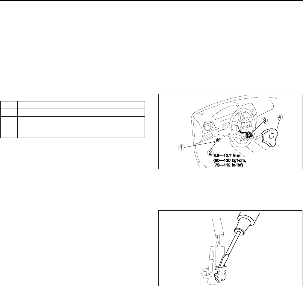
T120
AIR BAG SYSTEM
DRIVER-SIDE AIR BAG MODULE REMOVAL/INSTALLATION A6E813057010W01
Warning
•
••
•Handling the air bag module improperly can accidentally deploy the air bag module, which may
seriously injure you. Read AIR BAG SYSTEM SERVICE WARNINGS before handling the air bag
module. (See T117 SERVICE WARNINGS.)
•
••
•Due to the adoption of 2-step deployment control in both the driver-side air bag module,
depending on the impact force, it is possible that inflator No. 2 might not deploy. In such cases,
before disposing of the air bag module, make sure to follow the inflator deployment procedures
and verify complete deployment of inflator No. 1 and 2.
1. Turn the ignition switch to LOCK position.
2. Disconnect the negative battery cable and wait for more than 1 minute.
3. Remove in the order indicated in the table.
4. Install in the reverse order of removal.
5. Turn the ignition switch to ON position.
6. Verify that the air bag system warning light
illuminates for approximately 6 seconds and
then goes off.
•If the air bag system warning light does not
operate in the manner described above, there are malfunctions in the system. Inspect the system using the
on-board diagnostic.
Connector Removal Note
1. Using a flathead screwdriver, pry out the
connector's stopper plate.
2. Disconnect the connector.
End Of Sie
1Cover
2Bolt
3 Connector
(See T120 Connector Removal Note)
4 Driver-side air bag module
A6E8130W001
A6E8130W002
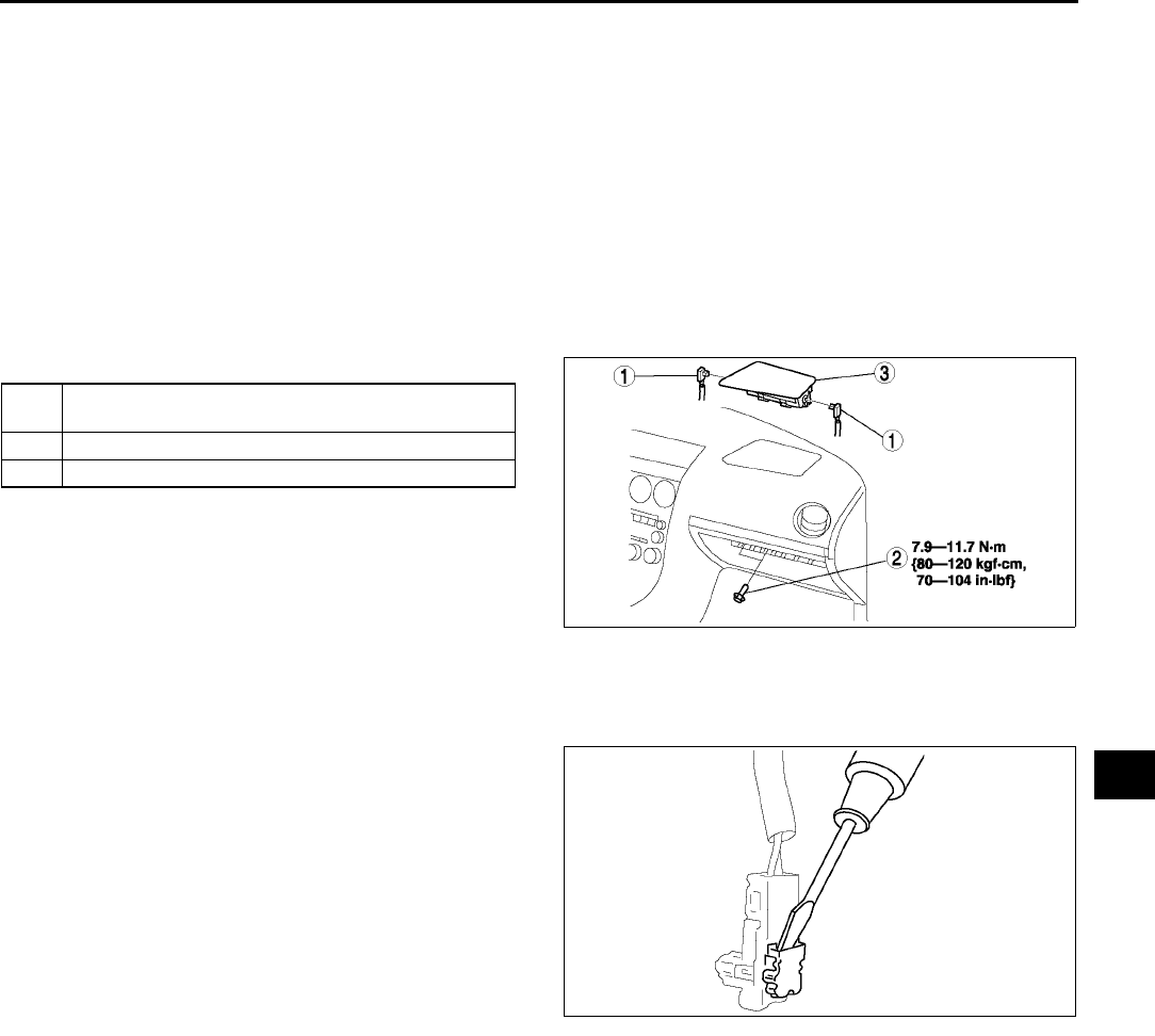
AIR BAG SYSTEM
T121
T
PASSENGER-SIDE AIR BAG MODULE REMOVAL/INSTALLATION A6E813057050W01
Warning
•
••
•Handling the air bag module improperly can accidentally deploy the air bag module, which may
seriously injure you. Read AIR BAG SYSTEM SERVICE WARNINGS before handling the air bag
module. (See T117 SERVICE WARNINGS.)
•
••
•Due to the adoption of 2-step deployment control in both the passenger-side air bag module,
depending on the impact force, it is possible that inflator No. 2 might not deploy. In such cases,
before disposing of the air bag module, make sure to follow the inflator deployment procedures
and verify complete deployment of inflator No. 1 and 2.
1. Turn the ignition switch to LOCK position.
2. Disconnect the negative battery cable and wait for more than 1 minute.
3. Remove the glove compartment.
4. Remove in the order indicated in the table.
5. Install in the reverse order of removal.
6. Turn the ignition switch to ON position.
7. Verify that the air bag system warning light
illuminates for approximately 6 seconds and
then goes off.
•If the air bag system warning light does not
operate in the manner described above, there
are malfunctions in the system. Inspect the system using the on-board diagnostic.
Connector Removal Note
1. Using a flathead screwdriver, pry out the
connector's stopper plate.
2. Disconnect the connector.
End Of Sie
SIDE AIR BAG MODULE REMOVAL/INSTALLATION A6E813000147W01
Warning
•
••
•Handling the air bag module improperly can accidentally deploy the air bag module, which may
seriously injure you. Read AIR BAG SYSTEM SERVICE WARNINGS before handling the air bag
module. (See T117 SERVICE WARNINGS.)
Warning
•
••
•If the side air bag module is installed with debris in the seat back, the foreign material may be
scattered when the side air bag module operates (deploys), causing injury. Verify that there is no
foreign material in the seat back before installing the side air bag module.
1 Connector
(See T121 Connector Removal Note)
2Bolt
3 Passenger-side air bag module
A6E8130W003
A6E8130W002
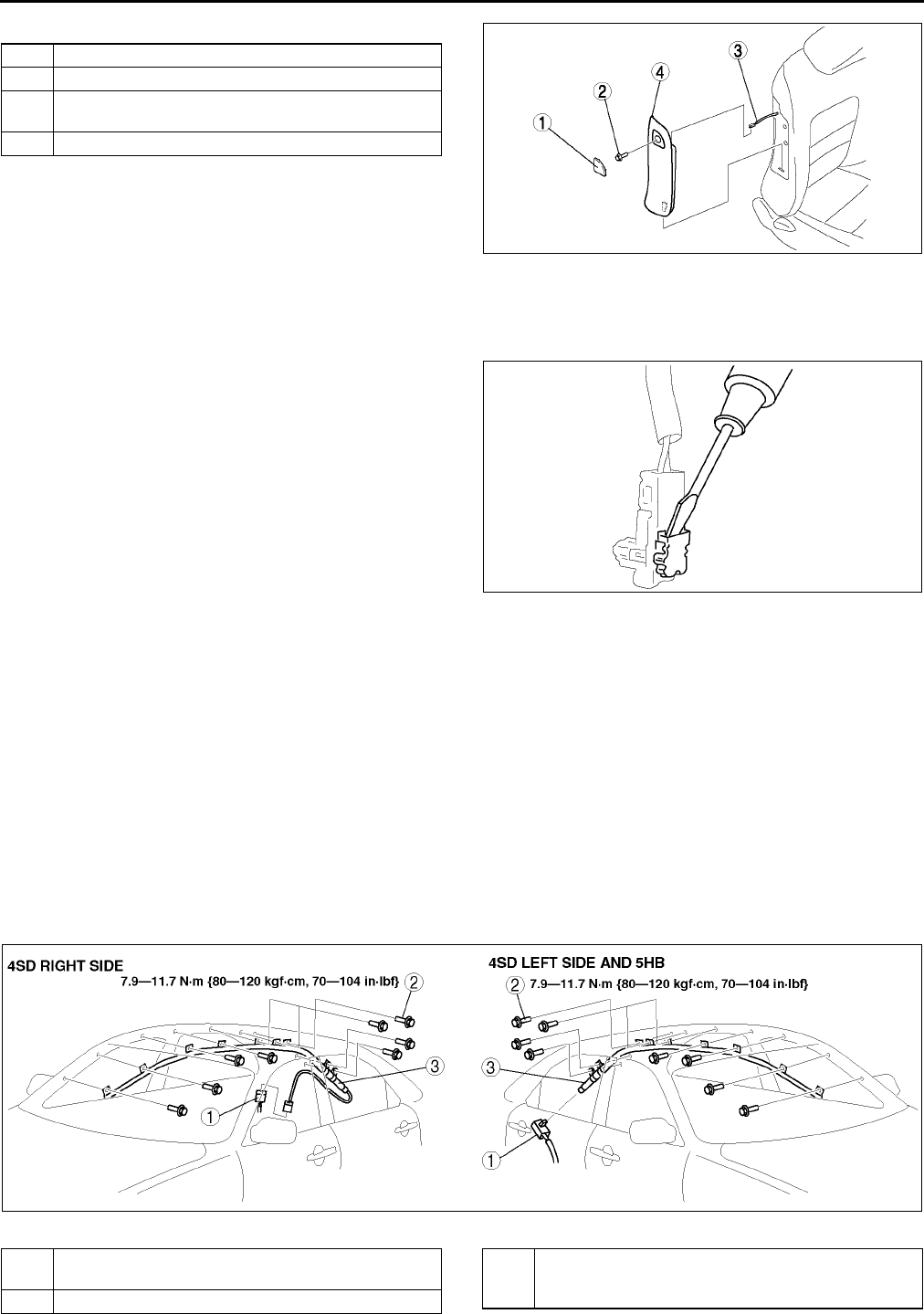
T122
AIR BAG SYSTEM
1. Remove in the order indicated in the table.
2. Install in the reverse order of removal.
3. Turn the ignition switch to ON position.
4. Verify that the air bag system warning light
illuminates for approximately 6 seconds and
then goes off.
•If the air bag system warning light does not
operate in the manner described above, there
are malfunctions in the system. Inspect the system using the on-board diagnostic.
Connector Removal Note
1. Using a flathead screwdriver, pry out the
connector's stopper plate.
2. Disconnect the connector.
End Of Sie
CURTAIN AIR BAG MODULE REMOVAL/INSTALLATION A6E813000171W01
Warning
•
••
•Handling the air bag module improperly can accidentally deploy the air bag module, which may
seriously injure you. Read AIR BAG SYSTEM SERVICE WARNINGS before handling the air bag
module. (See T117 SERVICE WARNINGS.)
1. Turn the ignition switch to LOCK position.
2. Disconnect the negative battery cable and wait for more than 1 minute.
3. Remove the headliner.
4. Remove in the order indicated in the table.
5. Install in the reverse order of removal.
6. Turn the ignition switch to ON position.
7. Verify that the air bag system warning light illuminates for approximately 6 seconds and then goes off.
•If the air bag system warning light does not operate in the manner described above, there are malfunctions
in the system. Inspect the system using the on-board diagnostic.
.
1Cover
2Bolt
3 Connector
(See T122 Connector Removal Note)
4 Side air bag module
A6E8130W004
A6E8130W002
A6E8130W026
1 Connector
(See T123 Connector Removal Note)
2Bolt
3 Curtain air bag module
(See T123 Curtain Air Bag Module Installation
Note (4SD Right Side))
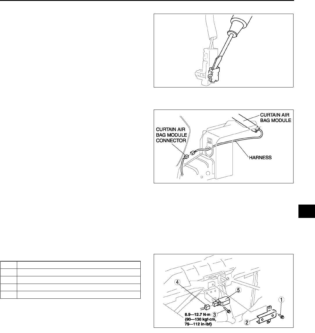
AIR BAG SYSTEM
T123
T
Connector Removal Note
1. Using a flathead screwdriver, pry out the
connector's stopper plate.
2. Disconnect the connector.
Curtain Air Bag Module Installation Note (4SD Right Side)
1. Pass the curtain air bag module harness through
the hole in the body.
End Of Sie
CRASH ZONE SENSOR REMOVAL/INSTALLATION A6E813000145W01
Warning
•
••
•Handling the crash zone sensor improperly can accidentally deploy the air bag module and pre-tensioner
seat belt, which may seriously injure you. Read AIR BAG SYSTEM SERVICE WARNINGS before handling the
crash zone sensor. (See T117 SERVICE WARNINGS.)
1. Turn the ignition switch to LOCK position.
2. Disconnect the negative battery cable and wait for more than 1 minute.
3. Remove the radiator grille.
4. Remove in the order indicated in the table.
5. Install in the reverse order of removal.
6. Turn the ignition switch to ON position.
7. Verify that the air bag system warning light
illuminates for approximately 6 seconds and
then goes off.
•If the air bag system warning light does not
operate in the manner described above, there are malfunctions in the system. Inspect the system using the
on-board diagnostic function.
End Of Sie
SIDE AIR BAG SENSOR REMOVAL/INSTALLATION A6E813000146W01
Warning
•
••
•Handling the side air bag sensor improperly can accidentally deploy the side air bag module,
which may seriously injure you. Read AIR BAG SYSTEM SERVICE WARNINGS before handling the
side air bag sensor. (See T117 SERVICE WARNINGS.)
1. Turn the ignition switch to LOCK position.
2. Disconnect the negative battery cable and wait for more than 1 minute.
3. Remove the B-pillar lower trim.
A6E8130W002
A6E8130W056
1Bolt
2 Cover
3Bolt
4 Connector
5 Crash zone sensor
A6E8130W007
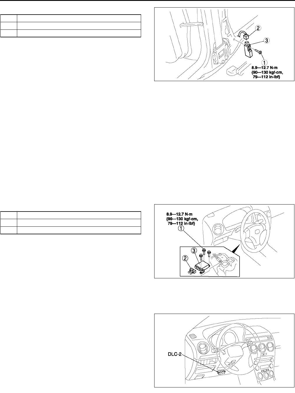
T124
AIR BAG SYSTEM
4. Remove in the order indicated in the table.
5. Install in the reverse order of removal.
6. Turn the ignition switch to ON position.
7. Verify that the air bag system warning light
illuminates for approximately 6 seconds and
then goes off.
•If the air bag system warning light does not
operate in the manner described above, there
are malfunctions in the system. Inspect the
system using the on-board diagnostic function.
End Of Si e
SAS UNIT REMOVAL/INSTALLATION A6E813057030W01
Warning
•
••
•Handling the SAS unit improperly can accidentally deploy the air bag modules and pre-tensioner
seat belt, which may seriously injure you. Read AIR BAG SYSTEM SERVICE WARNINGS before
handling the SAS unit. (See T117 SERVICE WARNINGS.)
Caution
•
••
•When replacing the SAS unit, configuration procedure must be done before removing the SAS
unit. If configuration is not completed before removing the SAS unit, DTC B1921 will detected.
1. Configurate the SAS unit (when only replacing it). (See T124 SAS UNIT CONFIGURATION.)
2. Turn the ignition switch to LOCK position.
3. Disconnect the negative battery cable and wait for more than 1 minute.
4. Partially peel off the floor covering.
5. Remove in the order indicated in the table.
6. Install in the reverse order of removal.
7. Turn the ignition switch to ON position.
8. Verify that the air bag system warning light
illuminates for approximately 6 seconds and
then goes off.
•If the air bag system warning light does not
operate in the manner described above, there
are malfunctions in the system. Inspect the
system using the on-board diagnostic.
End Of Sie
SAS UNIT CONFIGURATION A6E813057030W02
1. Connect the SST (WDS or equivalent) to the
DLC-2.
2. Input vehicle information following the directions
on the screen.
3. Select Module programming.
4. Select Programmable module installation.
5. Select the following items and perform
procedures according to directions on the screen.
Items
•
••
•RCM
6. Retrieve DTCs by the SST (WDS or equivalent),
then verify that there is no DTC present.
•If DTC is present, perform applicable DTC inspection.
End Of Sie
1Bolt
2 Connector
3 Side air bag sensor
A6E8130W005
1Bolt
2 Connector
3 SAS unit
A6E8130W006
A6E3970W002
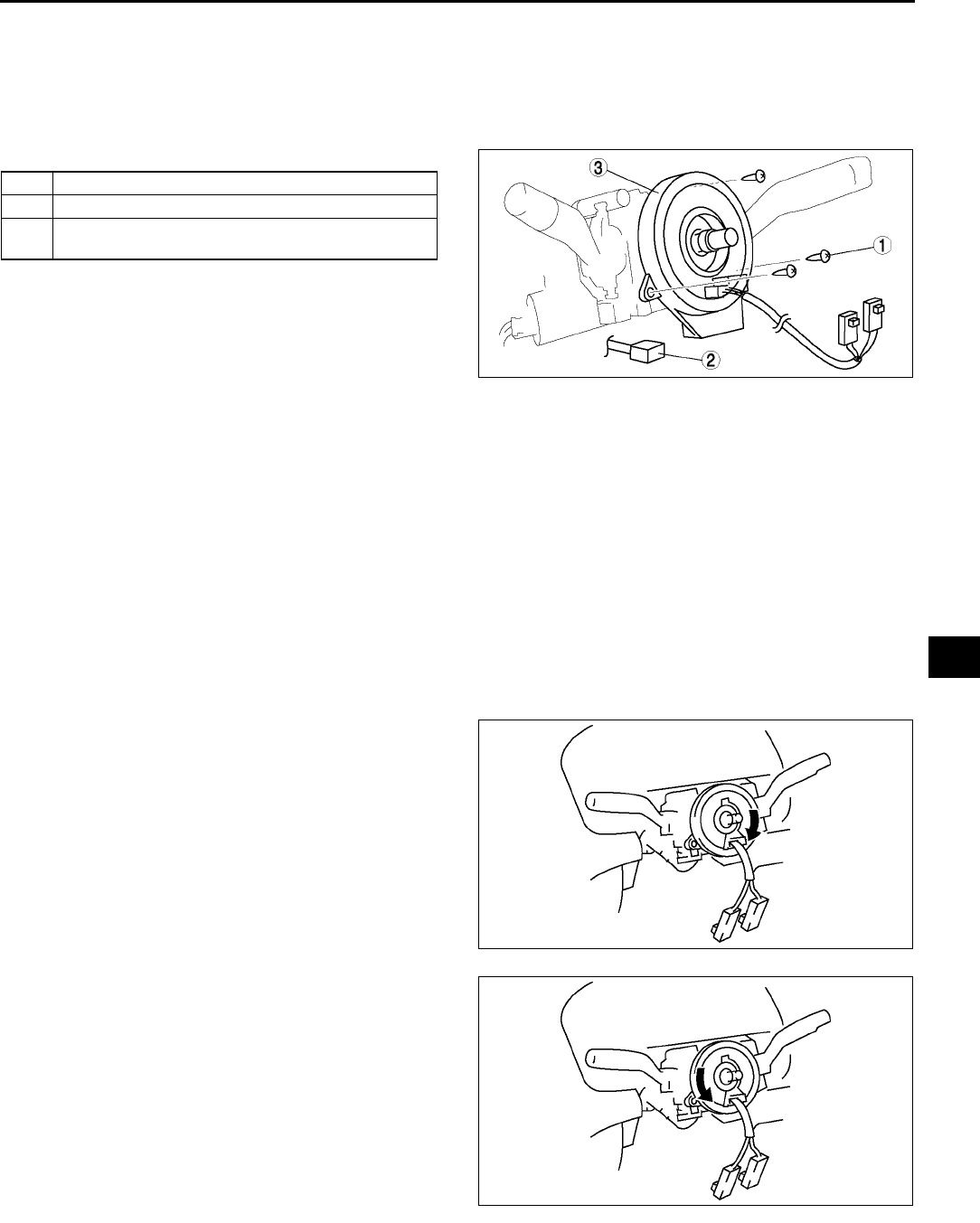
AIR BAG SYSTEM
T125
T
CLOCK SPRING REMOVAL/INSTALLATION A6E813066123W01
1. Disconnect the negative battery cable.
2. Remove the driver-side air bag module. (See T120 DRIVER-SIDE AIR BAG MODULE REMOVAL/
INSTALLATION.)
3. Remove the steering wheel. (See N7 STEERING WHEEL AND COLUMN REMOVAL/INSTALLATION.)
4. Remove the column cover.
5. Remove in the order indicated in the table.
6. Install in the reverse order of removal.
7. Verify that the air bag system warning light
illuminates for approximately 6 seconds and
then goes off.
•If the air bag system warning light does not
operate in the manner described above, there
are malfunctions in the system. Inspect the
system using the on-board diagnostic.
Clock Spring Installation Note
Caution
•
••
•If the clock spring is not adjusted, the spring wire in the clock spring will break due to overtension
when the steering wheel is turned. Always adjust the clock spring after installing it.
•Adjust the clock spring after installing it. (See T125 CLOCK SPRING ADJUSTMENT.)
End Of Sie
CLOCK SPRING ADJUSTMENT A6E813066123W02
Note
•The adjustment procedure is also specified on the caution label of the clock spring.
1. Set the front wheels straight ahead.
Caution
•
••
•The clock spring will break if
over-wound. Do not forcibly turn the
clock spring.
2. Turn the clock spring clockwise until it stops.
3. Turn the clock spring counterclockwise 2 3/4
turns.
1Screw
2 Connector
3 Clock spring
(See T125 Clock Spring Installation Note)
A6E8130W008
A6E8130W046
A6E8130W047
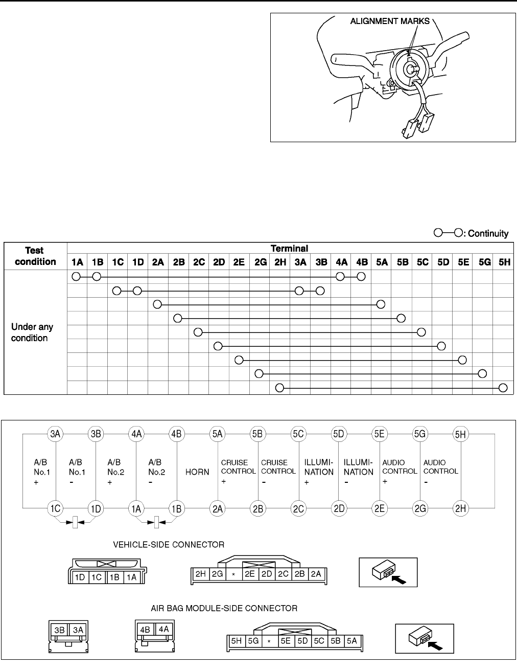
T126
AIR BAG SYSTEM
4. Align the mark on the clock spring with the mark
on the outer housing.
End Of Sie
CLOCK SPRING INSPECTION A6E813066123W03
1. Remove the clock spring.
2. Inspect for continuity between the clock spring terminals using an ohmmeter.
•If not as specified, replace the clock spring.
Note
•When the vehicle-side connector of clock spring is disconnected, the terminals 1A,1B, 1C and 1D are
shorted to prevent unexpected deployment of the air bag module. When it is connected, the terminals are
open.
A6E8130W048
A6E8130W009
A6E8130W010

AIR BAG SYSTEM
T127
T
End Of Sie
PASSENGER-SIDE AIR BAG CUT-OFF INDICATOR LIGHT REMOVAL/INSTALLATION A6E813001046W02
1. Remove the center panel module. (See T96 CENTER PANEL MODULE REMOVAL/INSTALLATION.)
2. Remove in the order indicated in the table.
3. Install in the reverse order of removal.
End Of Sie
AIR BAG MODULE AND PRE-TENSIONER SEAT BELT DEPLOYMENT PROCEDURES A6E813057000W01
Warning
•
••
•A live (undeployed) air bag module and pre-tensioner seat belt may accidentally deploy when it is
disposed of and cause serious injury. Do not dispose of a live (undeployed) air bag module and
pre-tensioner seat belt. If the SSTs (Deployment tool and Adapter harness) are not available,
consult the nearest Mazda representative for assistance.
Caution
•
••
•Deploying the air bag modules and pre-tensioner seat belts inside the vehicle may cause damage
to the vehicle interior. When the vehicle is not to be scrapped, always deploy the air bag modules
and pre-tensioner seat belts outside the vehicle.
•When the vehicle is to be scrapped, deploy the air bag modules and pre-tensioner seat belts inside the vehicle.
(See T127 Deployment Procedure for Inside of Vehicle (Only When Vehicle Is To Be Scrapped).)
•When the vehicle is not to be scrapped, deploy the air bag modules and pre-tensioner seat belts outside the
vehicle. (See T131 Deployment Procedure for Outside of Vehicle.)
Note
•When disposing of deployed air bag module and pre-tensioner seat belt, refer to the disposal procedure,
(See T139 AIR BAG MODULE AND PRE-TENSIONER SEAT BELT DISPOSAL PROCEDURES.)
Deployment Procedure for Inside of Vehicle (Only When Vehicle Is To Be Scrapped)
1. Inspect the SST (Deployment tool). (See T140 INSPECTION OF SST (DEPLOYMENT TOOL).)
2. Move the vehicle to an open space, away from strong winds, and close all of the vehicles doors and windows.
3. Turn the ignition switch to LOCK position.
4. Disconnect the negative battery cable and wait for more than 1 minute.
5. Follow the appropriate procedure for deploying the driver-side air bag module, passenger-side air bag module,
side air bag module, curtain air bag module, or pre-tensioner seat belt.
Driver-side air bag module
Warning
•
••
•Driver-side air bag module is the dual inflator type. When the inflators are forced to be deployed
simultaneously, one of them may fail to deploy. When disposing the air bag module, the inflators
may be deployed accidentally. Make sure to deploy the inflators sequentially, following the
procedures below.
1. Remove the driver-side air bag module. (See T120 DRIVER-SIDE AIR BAG MODULE REMOVAL/
INSTALLATION.)
1Socket
2 Passenger-side air bag cut-off indicator light bulb
A6E8130W057
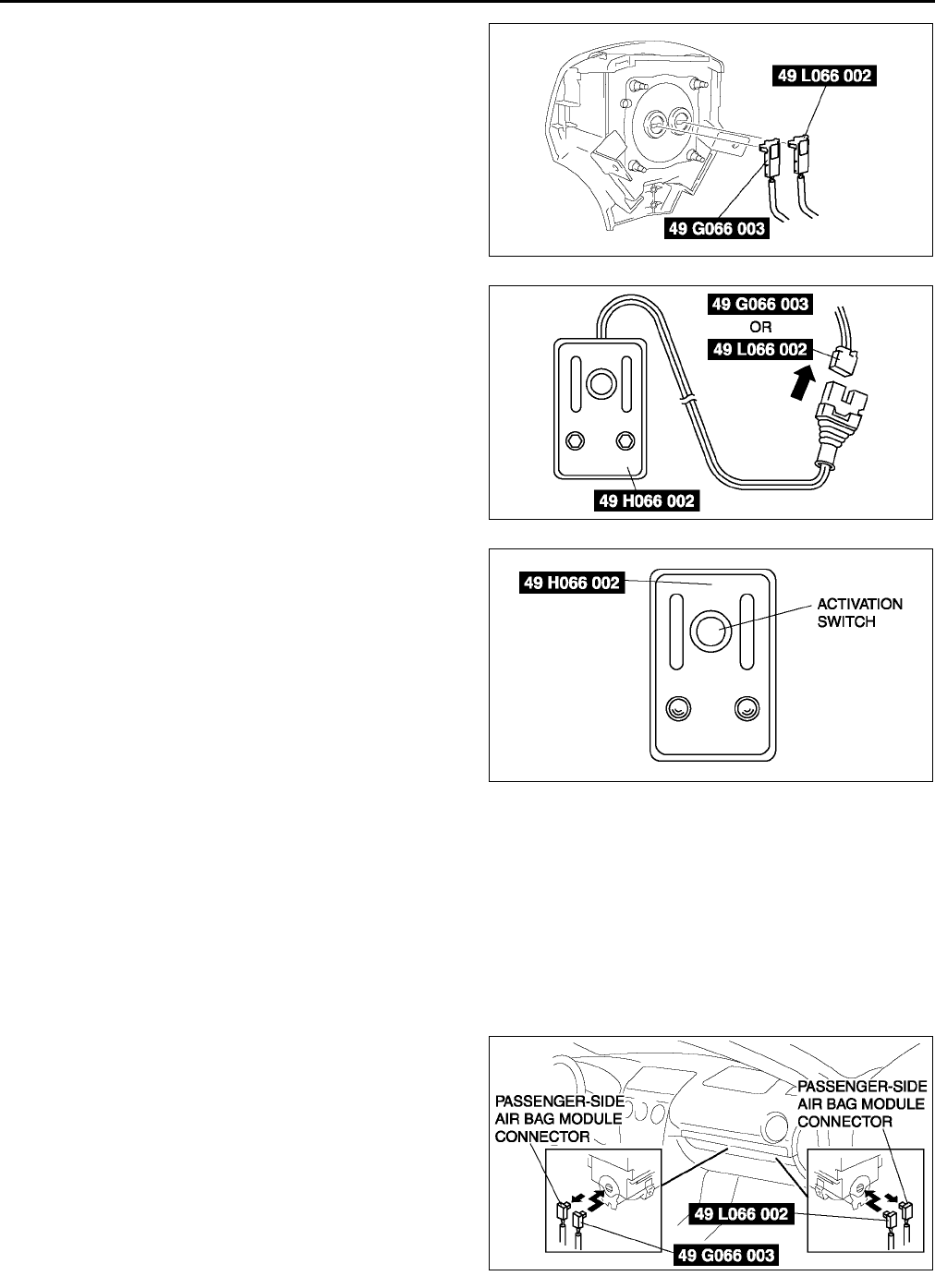
T128
AIR BAG SYSTEM
2. Connect the SST (Adapter harness) to the driver-
side air bag module as shown in the figure.
3. Install the driver-side air bag module. (See T120
DRIVER-SIDE AIR BAG MODULE REMOVAL/
INSTALLATION.)
4. Connect the SST (Deployment tool) to the SST
(Adapter harness).
5. Connect the red clip of the SST (Deployment tool)
to the positive battery terminal and the black clip
to the negative battery terminal.
6. Verify that the red light on the SST (Deployment
tool) is illuminated.
7. Make sure all persons are standing at least 6 m
{20 ft} away from the vehicle.
8. Press the activation switch on the SST
(Deployment tool) to deploy the driver-side air
bag module.
9. Disconnect the SST (Deployment tool) from the
SST (Adapter harness).
10. Connect the SST (Deployment tool) to the SST
(Adapter harness).
11. Perform steps 5 through 8, in order to deploy the
driver-side air bag module.
Passenger-side air bag module
Warning
•
••
•Passenger-side air bag module is the dual inflator type. When the inflators are forced to be
deployed simultaneously, one of them may fail to deploy. When disposing the air bag module, the
inflators may be deployed accidentally. Make sure to deploy the inflators sequentially, following
the procedures below.
1. Remove the glove compartment.
2. Disconnect the passenger-side sir bag module connector.
3. Connect the SST (Adapter harness) to the
passenger-side air bag module as shown it the
figure.
A6E8130W011
A6E8130W050
A6E8130W028
A6E8130W014
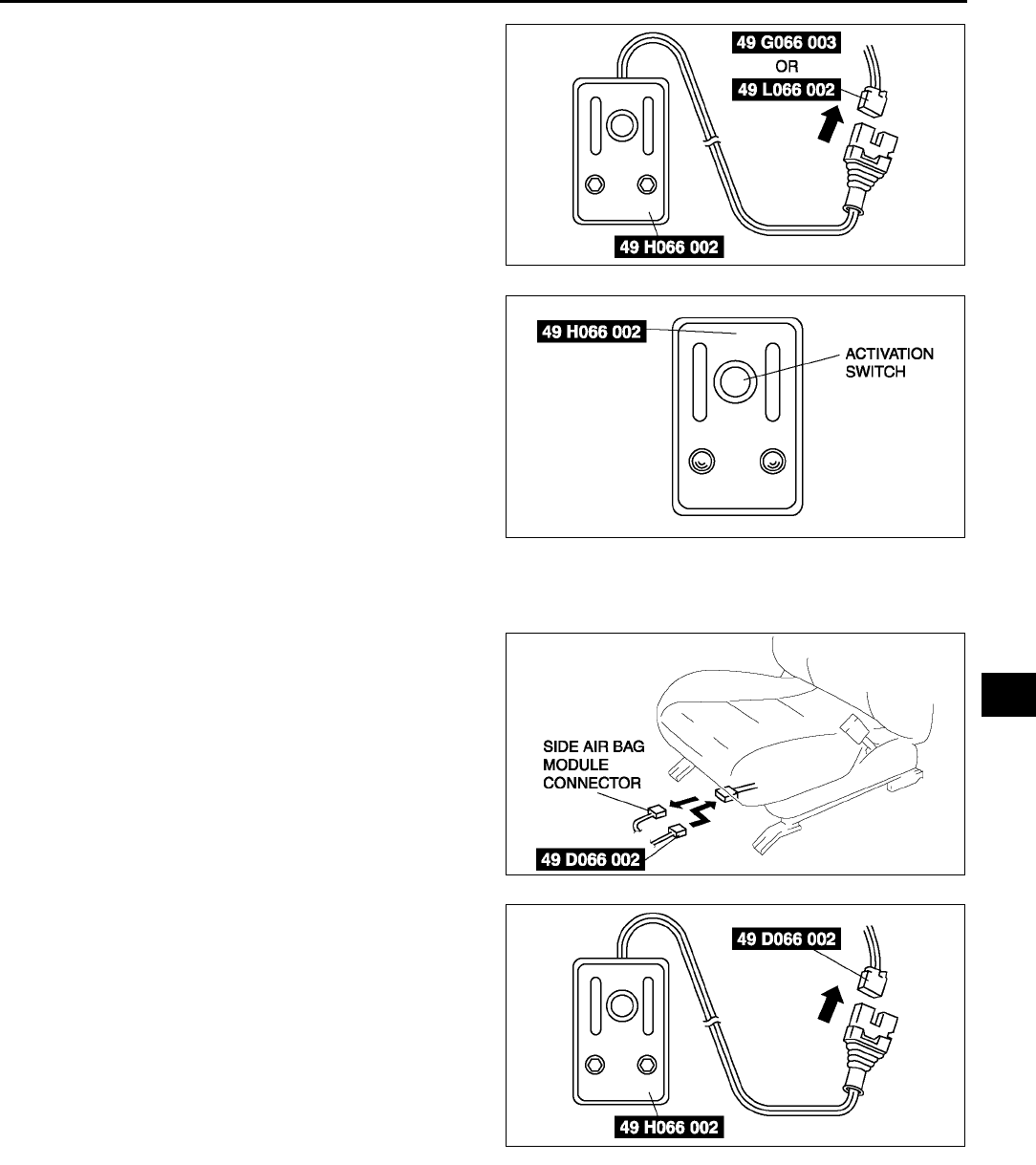
AIR BAG SYSTEM
T129
T
4. Connect the SST (Deployment tool) to the SST
(Adapter harness).
5. Connect the red clip of the SST (Deployment tool)
to the positive battery terminal and the black clip
to the negative battery terminal.
6. Verify that the red light on the SST (Deployment
tool) is illuminated.
7. Make sure all persons are standing at least 6 m
{20 ft} away from the vehicle.
8. Press the activation switch on the SST
(Deployment tool) to deploy the passenger-side
air bag module.
9. Disconnect the SST (Deployment tool) from the
SST (Adapter harness).
10. Connect the SST (Deployment tool) to the SST
(Adapter harness).
11. Perform steps 5 through 8, in order to deploy the
passenger-side air bag module.
Side air bag module
1. Disconnect the side air bag module connector.
2. Connect the SST (Adapter harness) to the side
air bag module.
3. Connect the SST (Deployment tool) to the SST
(Adapter harness).
4. Connect the red clip of the SST (Deployment tool)
to the positive battery terminal and the black clip
to the negative battery terminal.
5. Verify that the red light on the SST (Deployment
tool) is illuminated.
6. Make sure all persons are standing at least 6 m
{20 ft} from the vehicle.
A6E8130W050
A6E8130W028
A6E8130W029
A6E8130W027
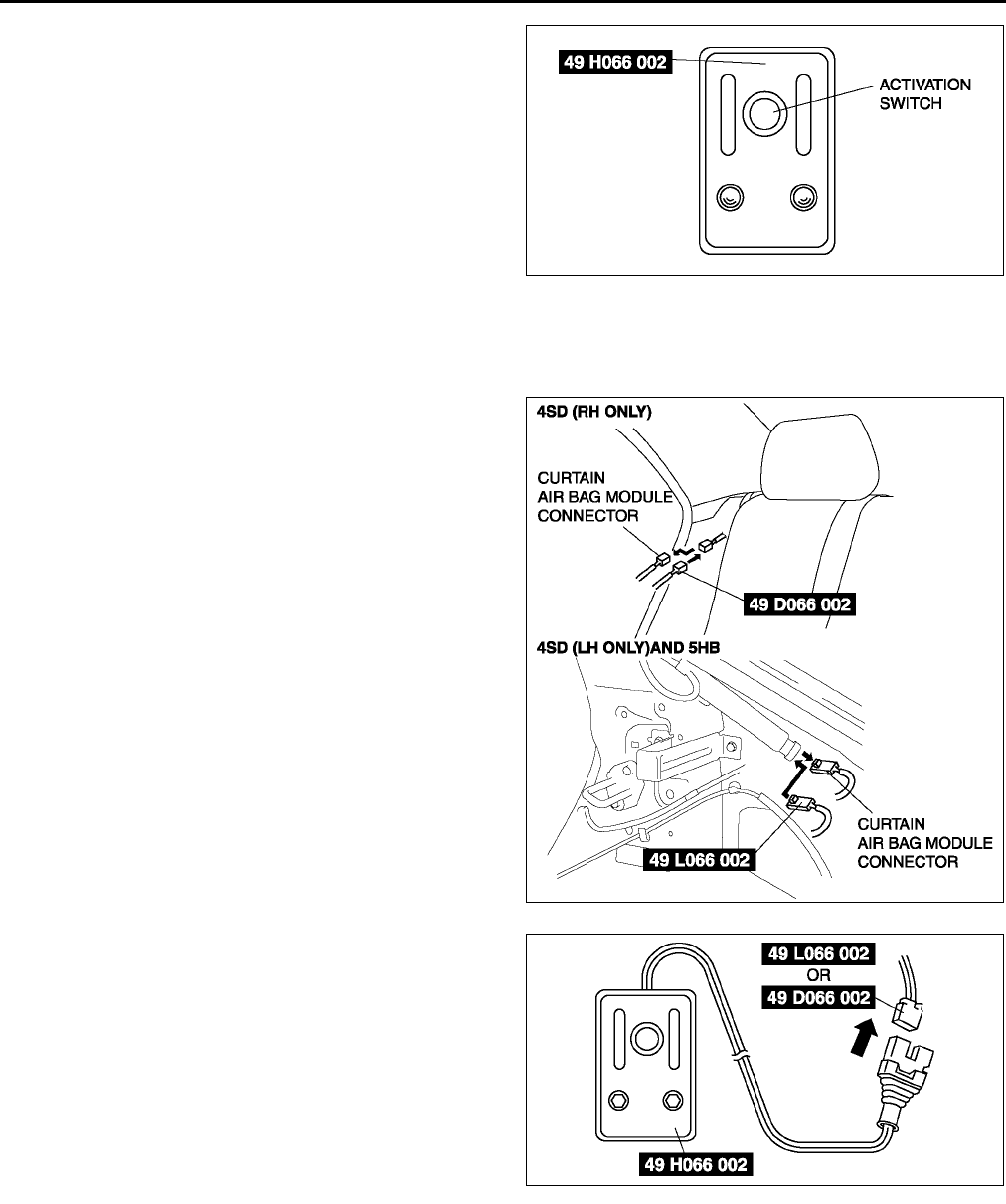
T130
AIR BAG SYSTEM
7. Press the activation switch on the SST
(Deployment tool) to deploy the side air bag
module.
Curtain air bag module
1. Remove the side tire house trim. (4SD)
2. Remove the side trunk side trim. (5HB)
3. Disconnect the curtain air bag module connector.
4. Connect the SST (Adapter harness) to the curtain
air bag module.
5. Connect the SST (Deployment tool) to the SST
(Adapter harness).
6. Connect the red clip of the SST (Deployment tool)
to the positive battery terminal and the black clip
to the negative battery terminal.
7. Verify that the red light on the SST (Deployment
tool) is illuminated.
8. Make sure all persons are standing at least 6 m
{20 ft} from the vehicle.
A6E8130W028
A6E8130W012
A6E8130W051
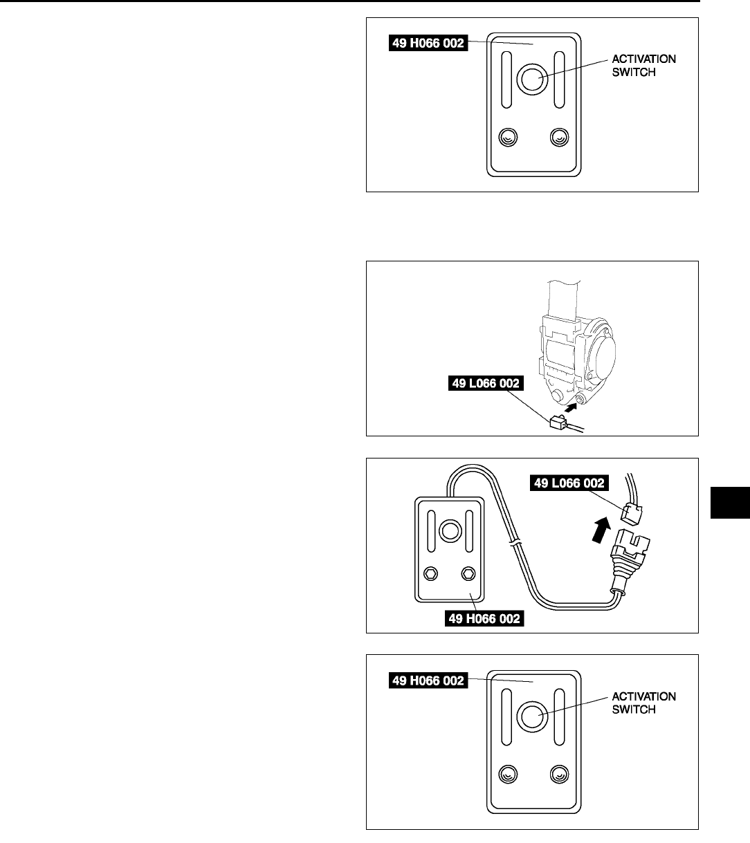
AIR BAG SYSTEM
T131
T
9. Press the activation switch on the SST
(Deployment tool) to deploy the curtain air bag
module.
Pre-tensioner seat belt
1. Remove the B-pillar lower trim.
2. Remove the pre-tensioner seat belt and connect
the SST (Adapter harness) to it as shown in the
figure. (See S100 FRONT SEAT BELT
REMOVAL/INSTALLATION.)
3. Install the pre-tensioner seat belt.
4. Connect the SST (Deployment tool) to the SST
(Adapter harness).
5. Connect the red clip of the SST (Deployment tool)
to the positive battery terminal and the black clip
to the negative battery terminal.
6. Verify that the red light on the SST (Deployment
tool) is illuminated.
7. Make sure all persons are standing at least 6 m
{20 ft} from the vehicle.
8. Press the activation switch on the SST
(Deployment tool) to deploy the pre-tensioner
seat belt.
Deployment Procedure for Outside of Vehicle
1. Inspect the SST (Deployment tool). (See T140 INSPECTION OF SST (DEPLOYMENT TOOL).)
2. Turn the ignition switch to LOCK position.
3. Disconnect the negative battery cable and wait for more than 1 minute.
4. Follow the appropriate procedure for deploying the driver-side air bag module, passenger-side air bag module,
side air bag module, curtain air bag module, or pre-tensioner seat belt.
A6E8130W028
A6E8130W030
A6E8130W052
A6E8130W028
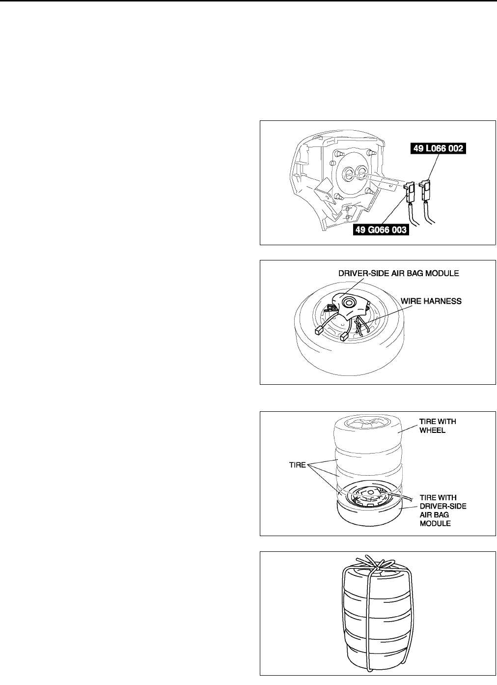
T132
AIR BAG SYSTEM
Driver-side air bag module
Warning
•
••
•Driver-side air bag module is the dual inflator type. When the inflators are forced to be deployed
simultaneously, one of them may fail to deploy. When disposing the air bag module, the inflators
may be deployed accidentally. Make sure to deploy the inflators sequentially, following the
procedures below.
1. Remove the driver-side air bag module. (See T120 DRIVER-SIDE AIR BAG MODULE REMOVAL/
INSTALLATION.)
2. Connect the SST (Adapter harness) to the driver-
side air bag module as shown in the figure,
3. Place the driver-side air bag module on the center
of the tire wheel with the module facing up. To
secure the air bag module to the tire wheel, wrap
the wire harness through the wheel and around
the bolt installation hole at least four times.
Warning
•
••
•If the air bag module is not properly
installed to the tire wheel, serious injury
may occur when the module is deployed.
When installing the air bag module to the
tire wheel, make sure the module is
facing up.
4. Stack three tires on top of the tire with the air bag
module. Stack another tire that has a wheel on
top of the four tires.
5. Tie all tires together with wire.
A6E8130W011
A6E8130W031
A6E8130W033
A6E8130W034
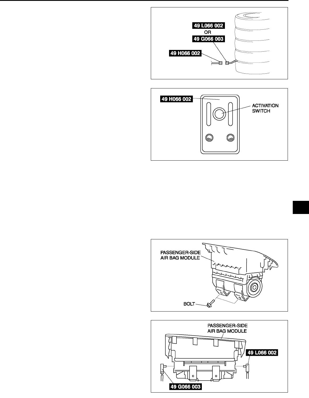
AIR BAG SYSTEM
T133
T
6. Connect the SST (Deployment tool) to the SST
(Adapter harness).
7. Connect the red clip of the SST (Deployment tool)
to the positive battery terminal and the black clip
to the negative battery terminal.
8. Verify that the red light on the SST (Deployment
tool) is illuminated.
9. Make sure all persons are standing at least 6 m
{20 ft} away from the vehicle.
10. Press the activation switch on the SST
(Deployment tool) to deploy the driver-side air
bag module.
11. Disconnect the SST (Deployment tool) from the
SST (Adapter harness).
12. Connect the SST (Deployment tool) to the SST
(Adapter harness).
13. Perform steps 7 through 10, in order to deploy the
driver-side air bag module.
Passenger-side air bag module
Warning
•
••
•Passenger-side air bag module is the dual inflator type. When the inflators are forced to be
deployed simultaneously, one of them may fail to deploy. When disposing the air bag module, the
inflators may be deployed accidentally. Make sure to deploy the inflators sequentially, following
the procedures below.
1. Remove the passenger-side air bag module. (See T121 PASSENGER-SIDE AIR BAG MODULE REMOVAL/
INSTALLATION.)
2. Install the bolts to the passenger-side air bag
module.
3. Connect the SST (Adapter harness) to the
passenger-side air bag module as shown in the
figure.
A6E8130W032
A6E8130W028
A6E8130W035
A6E8130W015
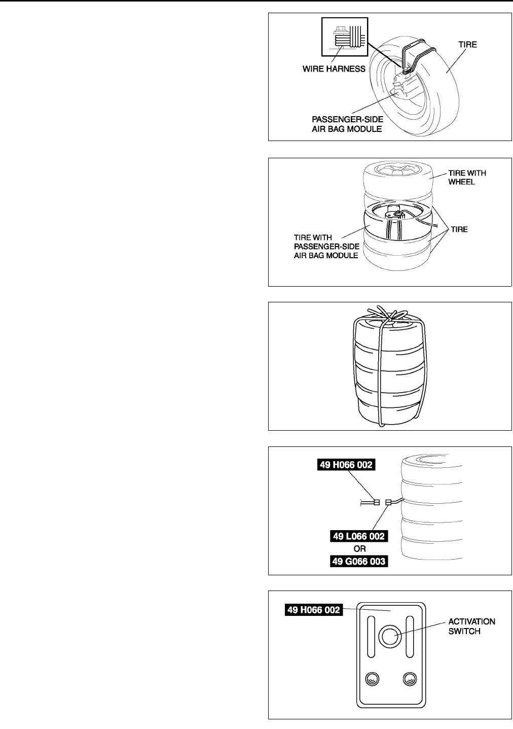
T134
AIR BAG SYSTEM
4. Tie the passenger-side air bag module to the tire
with the module facing the center of the tire. Wrap
the wire harness through the tire and around the
bolts at least four times.
Warning
•
••
•If the air bag module ia not properly
installed to the tire, serious injury may
occur when the module is deployed,
When installing the air bag module to the
tire, make sure the module is facing the
center of the tire.
5. Stack the tire with the passenger-side air bag
module on top of two tires. Stack another tire that
has a wheel on top of the four tires.
6. Tie all tires together with wire.
7. Connect the SST (Deployment tool) to the SST
(Adapter harness).
8. Connect the red clip of the SST (Deployment tool)
to the positive battery terminal and the black clip
to the negative battery terminal.
9. Verify that the red light on the SST (Deployment
tool) is illuminated.
10. Make sure all persons are standing at least 6 m
{20 ft} away from the vehicle.
11. Press the activation switch on the SST
(Deployment tool) to deploy the passenger-side
air bag module.
12. Disconnect the SST (Deployment tool) from the
SST (Adapter harness).
13. Connect the SST (Deployment tool) to the SST
(Adapter harness).
14. Perform steps 8 through 11, in order to deploy the
passenger-side air bag module.
A6E8130W036
A6E8130W037
A6E8130W034
A6E8130W038
A6E8130W028
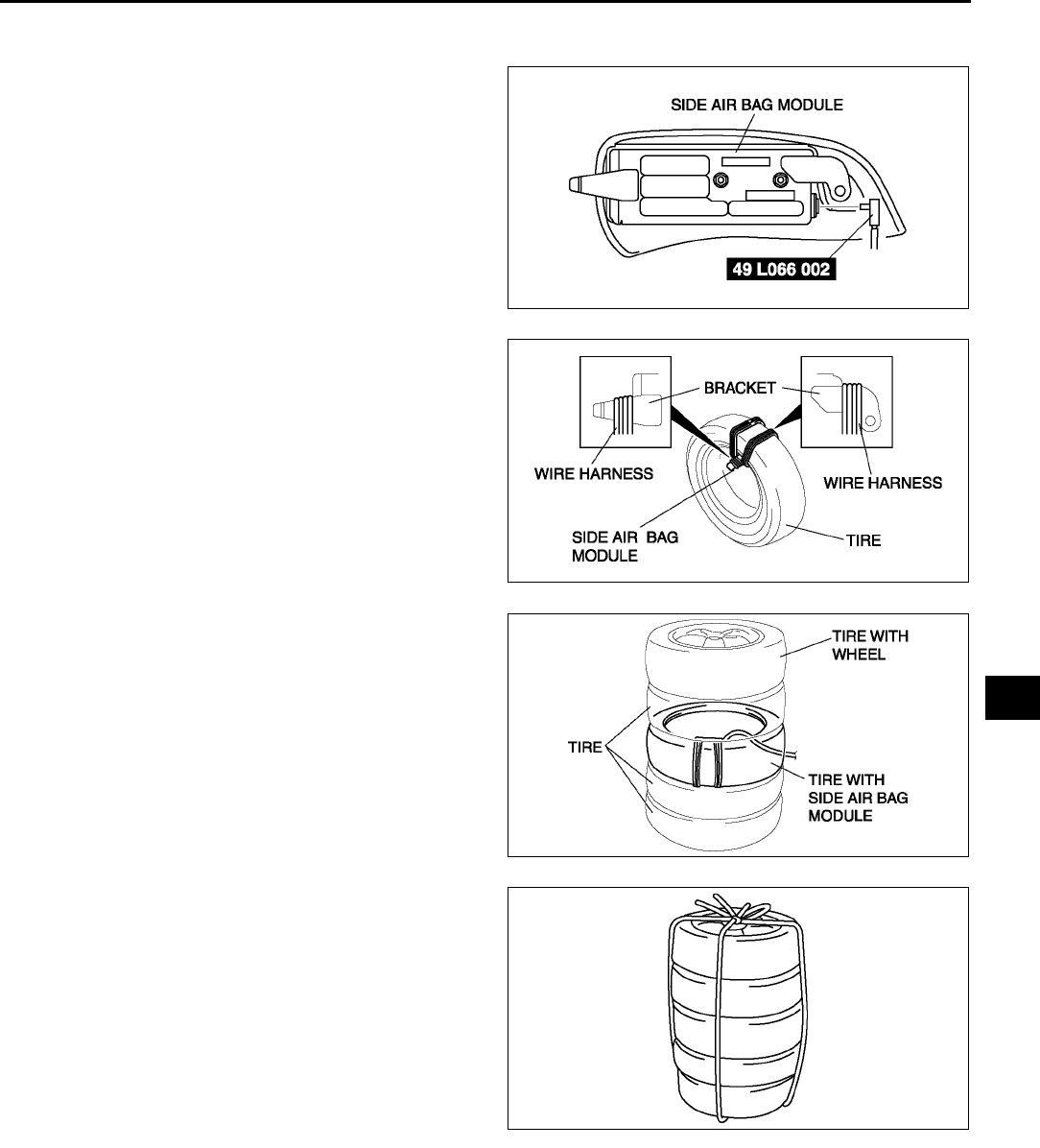
AIR BAG SYSTEM
T135
T
Side air bag module
1. Remove the side air bag module. (See T121 SIDE AIR BAG MODULE REMOVAL/INSTALLATION.)
2. Connect the SST (Adapter harness) to the side
air bag module as shown in the figure.
3. Tie the side air bag module to the tire with the
module facing the center of the tire. Wrap the wire
harness through the tire and around the bracket
at least four times.
Warning
•
••
•If the air bag module is not properly
installed to the tire, serious injury may
occur when the module is deployed.
When installing the air bag module to the
tire, make sure the module is facing the
center of the tire.
4. Stack the tire with the side air bag module on top
of two tires. Stack a tire on top of three tires.
Stack another tire that has a wheel on top of the
four tires.
5. Tie all tires together with wire.
A6E8130W016
A6E8130W017
A6E8130W053
A6E8130W034
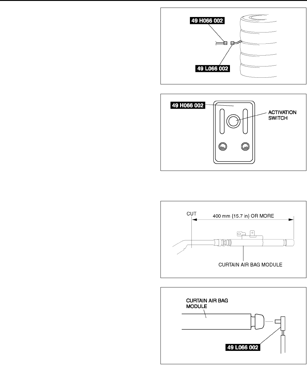
T136
AIR BAG SYSTEM
6. Control the SST (Deployment tool) to the SST
(Adapter harness).
7. Connect the red clip of the SST (Deployment tool)
to the positive battery terminal and the black clip
to the negative battery terminal.
8. Verify that the red light on the SST (Deployment
tool) is illuminated.
9. Make sure all persons are standing at least 6 m
{20 ft} from the vehicle.
10. Press the activation switch on the SST
(Deployment tool) to deploy the side air bag
module.
Curtain air bag module
1. Remove the curtain air bag module. (See T122 CURTAIN AIR BAG MODULE REMOVAL/INSTALLATION.)
2. Secure the curtain air bag module in a vise, and
cut off the deployment section, as shown in the
figure.
Warning
•
••
•Be sure not to collapse the pipe on the
side where it is cut. If it is collapsed, the
interior pressure of the pipe will build up
and can cause it to explode during air
bag module deployment.
3. Connect the SST (Adapter harness) to the curtain
air bag module as shown in the figure. (5HB)
A6E8130W054
A6E8130W028
A6E8130W013
A6E8130W040
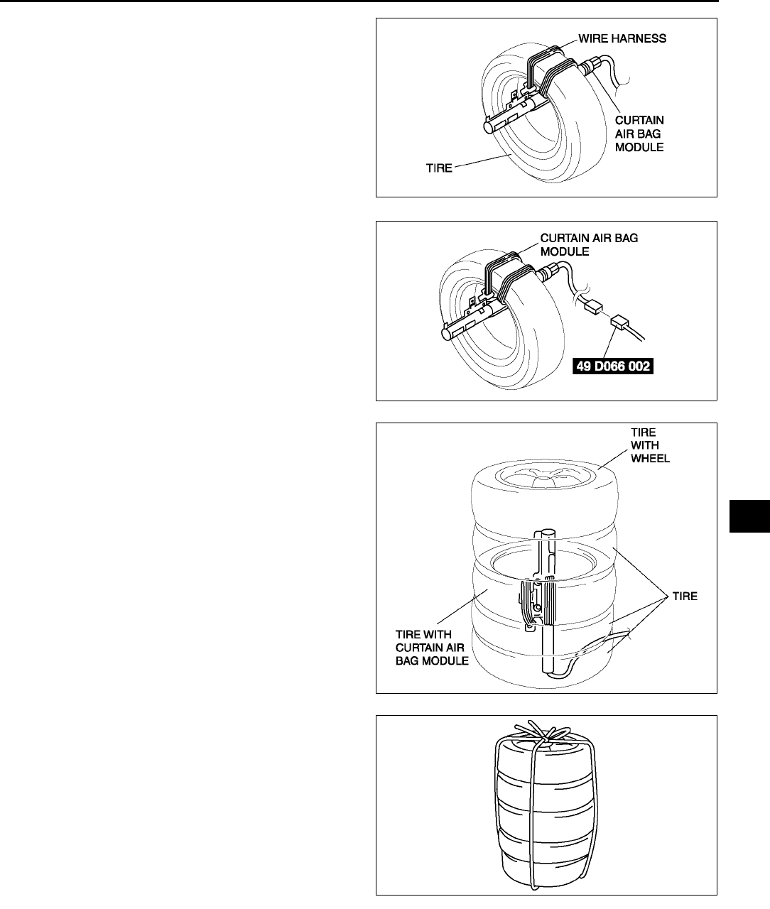
AIR BAG SYSTEM
T137
T
4. Tie the side air bag module to the tire with the
module facing the center of the tire. Wrap the wire
harness through the tire and around the bracket
at least four times.
Warning
•
••
•If the air bag module is not properly
installed to the tire, serious injury may
occur when the module is deployed.
When installing the air bag module to the
tire, make sure the module is facing the
downward.
5. Connect the SST (Adapter harness) to the curtain
air bag module as shown in the figure. (4SD, RH
only)
6. Stack the tire with the curtain air bag module on
top of two tires. Stack a tire on top of three tires.
Stack another tire that has a wheel on top of the
four tires.
7. Tie all tires together with wire.
A6E8130W018
A6E8130W019
A6E8130W020
A6E8130W034
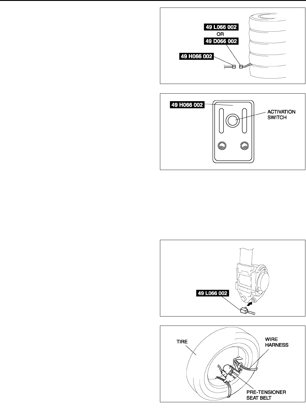
T138
AIR BAG SYSTEM
8. Control the SST (Deployment tool) to the SST
(Adapter harness).
9. Connect the red clip of the SST (Deployment tool)
to the positive battery terminal and the black clip
to the negative battery terminal.
10. Verify that the red light on the SST (Deployment
tool) is illuminated.
11. Make sure all persons are standing at least 6 m
{20 ft} from the vehicle.
12. Press the activation switch on the SST
(Deployment tool) to deploy the curtain air bag
module.
Pre-tensioner seat belt
1. Remove the pre-tensioner seat belt. (See S100 FRONT SEAT BELT REMOVAL/INSTALLATION.)
Warning
•
••
•If the pre-tensioner seat belt is not properly installed to the tire, serious injury may occur when the
pre-tensioner part is deployed. When installing the pre-tensioner seat belt to the tire, make sure
the pre-tensioner part is inside the tire.
2. Connect the SST (Adapter harness) to the pre-
tensioner seat belt as shown in the figure.
3. With the pre-tensioner part inside the tire, tie the
pre-tensioner seat belt to the tire. Wrap the wire
harness through the tire and around the pre-
tensioner seat belt at least four times.
A6E8130W055
A6E8130W028
A6E8130W030
A6E8130W041
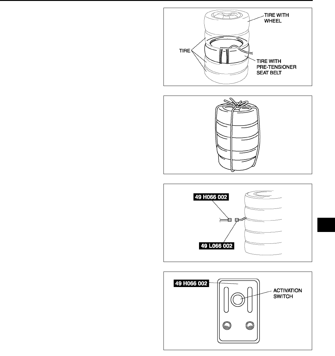
AIR BAG SYSTEM
T139
T
4. Stack the tire with the pre-tensioner seat belt on
top of two tires. Stack a tire on top of the three
tires. Stack another tire that has a wheel on top of
the four tires.
5. Tie all tires together with wire.
6. Connect the SST (Deployment tool) to the SST
(Adapter harness).
7. Connect the red clip of the SST (Deployment tool)
to the positive battery terminal and the black clip
to the negative battery terminal.
8. Verify that the red light on the SST (Deployment
tool) is illuminated.
9. Make sure all persons are standing at least 6 m
{20 ft} from the vehicle.
10. Press the activation switch on the SST
(Deployment tool) to deploy the pre-tensioner
seat belt.
End Of Sie
AIR BAG MODULE AND PRE-TENSIONER SEAT BELT DISPOSAL PROCEDURES A6E813057000W02
Warning
•
••
•Before scrapping a vehicle with a live (undeployed) air bag module and pre-tensioner seat belt,
deploy the air bag module and pre-tensioner seat belt. Never dispose of a live (undeployed) air
bag module and pre-tensioner seat belt.
•
••
•The air bag module and the pre-tensioner seat belt are very hot immediately after they are
deployed. You can get burned. Do not touch the air bag module and pre-tensioner seat belt for at
least 15 minutes after deployment.
•
••
•Pouring water on the deployed air bag module and pre-tensioner seat belt is dangerous. The water
will mix with the residual gases to form a gas that can make breathing difficult. Do not pour water
on the deployed air bag module and pre-tensioner seat belt.
A6E8130W039
A6E8130W034
A6E8130W054
A6E8130W028
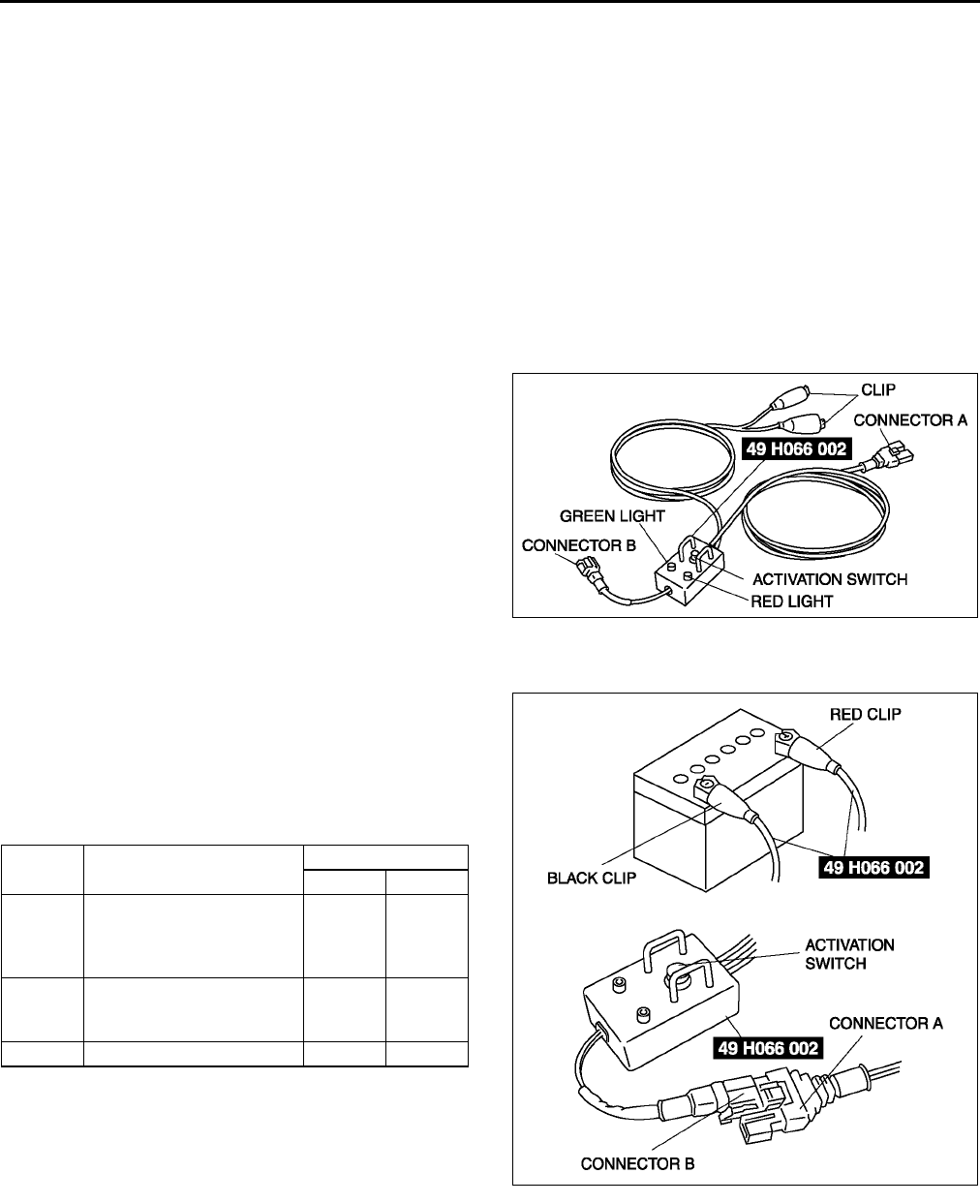
T140
AIR BAG SYSTEM
•
••
•The deployed air bag module and pre-tensioner seat belt may contain deposits of sodium
hydroxide, a caustic byproduct of the gas-generated combustion. If this substance gets into your
eyes or on your hands, it can cause irritation and itching. When handling the deployed air bag
module and pre-tensioner seat belt, wear gloves and safety glasses.
•
••
•Due to the adoption of 2-step deployment control in both the driver and passenger-side air bag
modules, depending on the impact force, it is possible that inflator No. 2 might not deploy. In such
cases, before disposing of the air bag module, make sure to follow the inflator deployment
procedures and verify complete deployment of inflator No. 1 and 2.
1. Put on gloves and safety glasses.
2. Put the deployed air bag module or pre-tensioner seat belt in a plastic bag, seal it, and then dispose of it.
3. Wash your hands after removing your gloves.
End Of Sie
INSPECTION OF SST (DEPLOYMENT TOOL) A6E813001046W03
•Use the SST (Deployment tool) to deploy a live (undeployed) air bag module or pre-tensioner seat belt before
disposing of it.
•Before using the SST (Deployment tool), inspect
its operation.
Inspection Procedure
1. Follow the steps below to verify that the SST
(Deployment tool) is operating correctly.
•If not as specified, do not use the SST
(Deployment tool) because it may cause the
air bag module or pre-tensioner seat belt to
unexpectedly deploy upon connection to the
air bag module or pre-tensioner seat belt.
End Of Sie
A6E8130W043
Step Inspection procedure Light condition
Green Red
1
Connect red clip to positive
battery terminal and black
clip to negative battery
terminal.
On Off
2
Connect connectors A and
B of SST (Deployment
tool).
Off On
3 Press activation switch. On Off
A6E8130W042
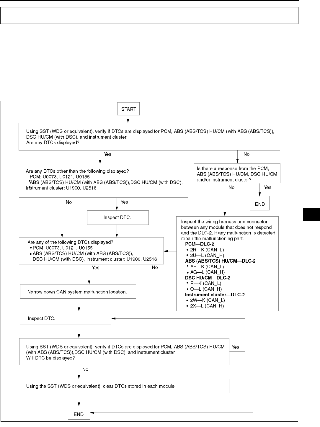
ON-BOARD DIAGNOSTIC [MULTIPLEX COMMUNICATION SYSTEM]
T141
T
MULTIPLEX COMMUNICATION SYSTEM A6E816255430W01
Outline
•In case the controller area network (CAN) system is malfunctioning, read the DTCs of the following modules,
using the SST (WDS or equivalent) to determine the malfunctioning system.
PCM
DSC HU/CM (with DSC)
ABS (ABS/TCS) HU/CM (with ABS (ABS/TCS)
Instrument cluster
Flowchart
•Use the following flowchart to verify the cause of the trouble.
End Of Si e
ON-BOARD DIAGNOSTIC [MULTIPLEX COMMUNICATION SYSTEM]
A6E8162W001
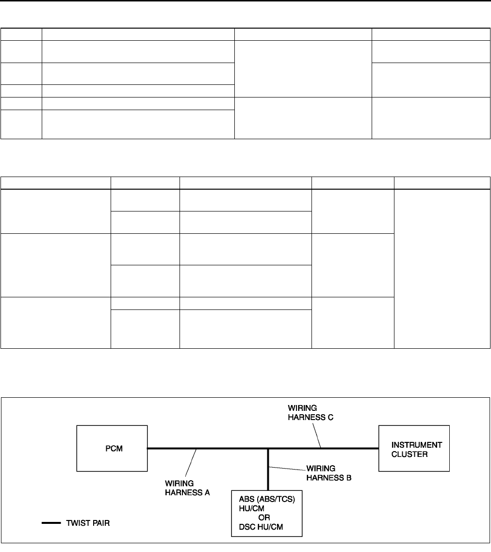
T142
ON-BOARD DIAGNOSTIC [MULTIPLEX COMMUNICATION SYSTEM]
DTC TABLE A6E816255430W02
End Of Sie
PID/DATA MONITOR TABLE A6E816255430W03
End Of Sie
PROCEDURES FOR DETERMINING THE LOCATION OF A MALFUNCTION A6E816255430W04
System Wiring Diadram
DTC Malfunction location Related module Page
U0073 CAN system communication error
PCM
(See T144 DTC U0073,
U1900, U2516)
U0121 Communication error to ABS (ABS/TCS) HU/CM
or DSC HU/CM
U0155 Communication error to instrument cluster
U1900 CAN system communication error •ABS (ABS/TCS) HU/CM (with
ABS (ABS/TCS)
•DSC HU/CM (with DSC)
•Instrument cluster
(See T144 DTC U0073,
U1900, U2516)
U2516 CAN system wiring harness open and short
circuit
PID name (definition) Condition Specification Related module Terminal
IC_MSG
(Missing message from the
instrument cluster)
Present Circuit in the instrument cluster
is normal. ABS (ABS/TCS)
HU/CM or DSC HU/
CM
•ABS (ABS/TCS)
HU/CM: O, R
•DSC HU/CM: AF,
AG
•Instrument cluster:
2W, 2X
Not Present Circuit in the instrument cluster
is abnormal.
ABS_MSG
(Missing message from the
ABS (ABS/TCS) HU/CM or
DSC HU/CM)
Present
Circuit in the ABS (ABS/TCS)
HU/CM or DSC HU/CM is
normal. Instrument cluster
Not Present
Circuit in the ABS (ABS/TCS)
HU/CM or DSC HU/CM is
abnormal.
PCM_MSG
(Missing message from the
PCM)
Present Circuit in the PCM is normal. •ABS (ABS/TCS)
HU/CM or DSC
HU/CM
•Instrument
cluster
Not Present Circuit in the PCM is abnormal.
A6E8162W002
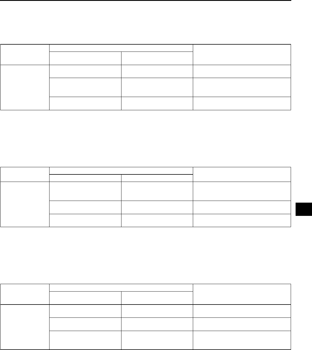
ON-BOARD DIAGNOSTIC [MULTIPLEX COMMUNICATION SYSTEM]
T143
T
PCM
1. Check the display of DTC U0121 and/or U0155, using the SST (WDS or equivalent). (See T142 DTC TABLE.)
2. Referring to the following table, determine the malfunctioning part of the CAN system.
X: Normal
: Communication error
ABS/TCS HU/CM or DSC HU/CM
1. Accec and monitor the PCM MSG and IC MSGof PID using the SST (WDS or equivalent).
2. Referring to the PID/DATA MONITOR, confirm the display status of the PID. (See T142 PID/DATA MONITOR
TABLE.)
3. Referring to the following table, determine the malfunctioning part of the CAN system.
X: Normal
: Communication error
Instrument Cluster
1. Accec and monitor the PCM MSG and ABS MSG of PID using the SST (WDS or equivalent).
2. Referring to the PID/DATA MONITOR, confirm the display status of the PID. (See T142 PID/DATA MONITOR
TABLE.)
3. Referring to the following table, determine the malfunctioning part of the CAN system.
X: Normal
: Communication error
End Of Sie
Module
Communication status
Malfunction location
•
••
•ABS (ABS/TCS) HU/CM
•
••
•DSC HU/CM Instrument cluster
PCM
•Wiring harness A
•PCM
X
•Wiring harness B
•ABS (ABS/TCS) HU/CM
•DSC HU/CM
X
•Wiring harness C
•Instrument cluster
Module Communication status Malfunction location
PCM Instrument cluster
•ABS (ABS/TCS)
HU/CM
•DSC HU/CM
•Wiring harness B
•ABS (ABS/TCS) HU/CM
•DSC HU/CM
X
•Wiring harness A
•PCM
X
•Wiring harness C
•Instrument cluster
Module
Communication status
Malfunction location
PCM •
••
•ABS (ABS/TCS) HU/CM
•
••
•DSC HU/CM
Instrument cluster
•Wiring harness C
•Instrument cluster
X
•Wiring harness A
•PCM
X
•Wiring harness B
•ABS (ABS/TCS) HU/CM
•DSC HU/CM
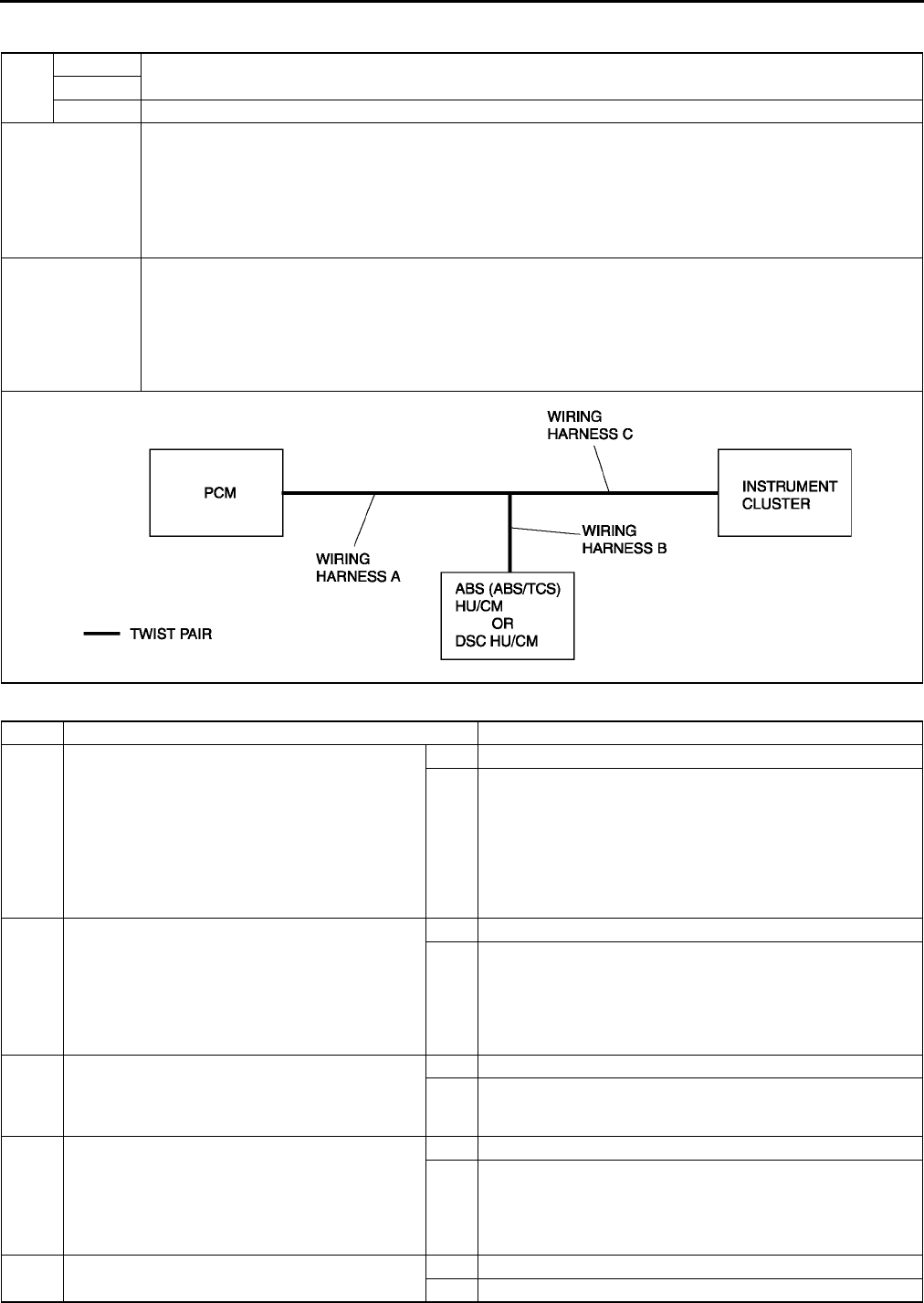
T144
ON-BOARD DIAGNOSTIC [MULTIPLEX COMMUNICATION SYSTEM]
DTC U0073, U1900, U2516 A6E816255430W05
Diagnostic procedure
DTC
U0073 CAN system communication error
U1900
U2516 CAN system wiring harness open and short circuit
DETECTION
CONDITION
Warning
•
••
•Detection conditions are for understanding DTC outline before performing inspection.
Performing inspection with only detection conditions may cause injury due to operating error
or damage the system. When performing inspection, always follow inspection procedure.
•CAN system related harness malfunction
•Related module communication error
POSSIBLE
CAUSE
•Open or short circuit in wiring harness
•Malfunction of connectors between PCM, ABS (ABS/TCS) HU/CM or DSC HU/CM and Instrument
cluster
•PCM malfunction
•ABS (ABS/TCS) HU/CM malfunction (with ABS (ABS/TCS))
•DSC HU/CM malfunction (with DSC)
•Instrument cluster malfunction
STEP INSPECTION ACTION
1DETERMINING THE LOCATION OF A
MALFUNCTION
•Determine the malfunctioning part of the
CAN system.
(See T142 PROCEDURES FOR
DETERMINING THE LOCATION OF A
MALFUNCTION)
•Is the malfunctioning part the wiring harness
C or the instrument cluster?
Yes Go to Step 4.
No Go to next step.
2DETERMINING THE LOCATION OF A
MALFUNCTION
•Is the malfunctioning part the wiring harness
B or the ABS (ABS/TCS) HU/CM? (with ABS
(ABS/TCS))
•Is the malfunctioning part the wiring harness
B or the DSC HU/CM? (with DSC)
Yes Go to Step 8.
No Go to next step.
3DETERMINING THE LOCATION OF A
MALFUNCTION
•Is the malfunctioning part the wiring harness
A or the PCM?
Yes Go to Step 12.
No Troubleshooting completed.
4INSPECT INSTRUMENT CLUSTER
CONNECTOR
•Disconnect negative battery cable.
•Disconnect instrument cluster connector.
•Is poor connection detection bars of
instrument cluster connector okay?
Yes Go to next step.
No Replace wiring harness.
5•Is vehicle equipped with DSC? Yes Go to next step.
No Go to Step 7.

ON-BOARD DIAGNOSTIC [MULTIPLEX COMMUNICATION SYSTEM]
T145
T
6INSPECT WIRING HARNESS BETWEEN DSC
HU/CM AND INSTRUMENT CLUSTER
•Disconnect DSC HU/CM connector.
•Inspect following wiring harness between
DSC HU/CM and instrument cluster
terminals for short to ground, short power
supply, and open circuit:
AF2W (CAN_L)
AG2X (CAN_H)
•Is wiring harness okay?
Yes Replace instrument cluster, then go to Step 16.
No Replace wiring harness.
7INSPECT WIRING HARNESS BETWEEN ABS
(ABS/TCS) HU/CM AND INSTRUMENT
CLUSTER
•Disconnect ABS (ABS/TCS) HU/CM
connector.
•Inspect following wiring harness between
ABS (ABS/TCS) HU/CM and instrument
cluster terminals for short to ground, short
power supply, and open circuit:
R2W (CAN_L)
O2X (CAN_H)
•Is wiring harness okay?
Yes Replace instrument cluster, then go to Step 16.
No Replace wiring harness.
8INSPECT ABS (ABS/TCS) HU/CM OR DSC
HU/CM CONNECTOR
•Disconnect negative battery cable.
•Disconnect ABS (ABS/TCS) HU/CM or DSC
HU/CM connector.
•Is poor connection detection bars of ABS
(ABS/TCS) HU/CM or DSC HU/CM
connector okay?
Yes Go to next step.
No Replace wiring harness.
9•Is vehicle equipped with DSC? Yes Go to next step.
No Go to Step 11.
10 INSPECT WIRING HARNESS BETWEEN DSC
HU/CM AND INSTRUMENT CLUSTER
•Disconnect instrument cluster connector.
•Inspect following wiring harness between
DSC HU/CM and instrument cluster
terminals for short to ground, short power
supply, and open circuit:
AF2W (CAN_L)
AG2X (CAN_H)
•Is wiring harness okay?
Yes Replace DSC HU/CM , then go to Step 16.
No Replace wiring harness.
11 INSPECT WIRING HARNESS BETWEEN ABS
(ABS/TCS) HU/CM AND INSTRUMENT
CLUSTER
•Disconnect instrument cluster connector.
•Inspect following wiring harness between
ABS (ABS/TCS) HU/CM and instrument
cluster terminals for short to ground, short
power supply, and open circuit:
R2W (CAN_L)
O2X (CAN_H)
•Is wiring harness okay?
Yes Replace ABS (ABS/TCS) HU/CM , then go to Step 16.
No Replace wiring harness.
12 INSPECT PCM CONNECTOR
•Disconnect negative battery cable.
•Disconnect PCM connector.
•Is poor connection detection bars of PCM
connector okay?
Yes Go to next step.
No Replace wiring harness.
13 •Is vehicle equipped with DSC? Yes Go to next step.
No Go to Step 15.
STEP INSPECTION ACTION

T146
ON-BOARD DIAGNOSTIC [MULTIPLEX COMMUNICATION SYSTEM]
End Of Sie
14 INSPECT WIRING HARNESS BETWEEN PCM
AND DSC HU/CM
•Disconnect negative battery cable.
•Disconnect DSC HU/CM connector.
•Inspect following wiring harness between
PCM and DSC HU/CM terminals for short to
ground, short power supply, and open circuit:
2RAF (CAN_L)
2UAG (CAN_H)
•Is wiring harness okay?
Yes Replace PCM, then go to Step 16.
No Replace wiring harness.
15 INSPECT WIRING HARNESS BETWEEN PCM
AND ABS (ABS/TCS) HU/CM
•Disconnect negative battery cable.
•Disconnect ABS (ABS/TCS) HU/CM
connector.
•Inspect following wiring harness between
PCM and ABS (ABS/TCS) HU/CM terminals
for short to ground, short power supply, and
open circuit:
2RR (CAN_L)
2UO (CAN_H)
•Is wiring harness okay?
Yes Replace PCM, then go to next step.
No Replace wiring harness.
16 CHECK DTC INDICATE
•Connect PCM connector.
•Connect ABS (ABS/TCS) HU/CM or DSC
HU/CM connector.
•Connect instrument cluster connector.
•Clear DTC from module memory using SST
(WDS or equivalent).
•Perform KOEO/KOER self-test.
•Are DTCs U0073, U1900 and/or U2516
indicated?
Yes Repeat from Step 1.
No Troubleshooting completed.
STEP INSPECTION ACTION
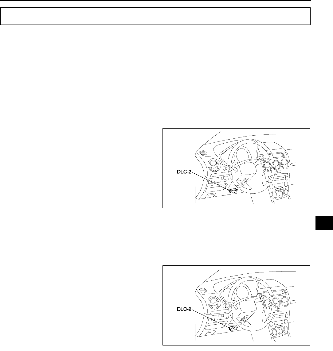
ON-BOARD DIAGNOSTIC [HEADLIGHT AUTO LEVELING SYSTEM]
T147
T
FOREWORD A6E816467000W01
Outline
•The OBD (on-board diagnostic) test inspects the integrity and function of the headlight auto leveling system
and output the results when reqested by the specitic tests.
•OBD test also:
Provides a quick inspection of the headlight auto leveling system.
Is usually performed at the start of each deagnostic procedure.
Provides verification after repairs to ensure that no other faults occurred during service.
•Diagnostic DTC can be read/cleared, using the SST (WDS or equivalent).
Read/clear diagnostic results
•This function allows you to read or clear DTCs in the auto leveling control unit (main) memory.
Reading DTCs Procedure Using WDS or equivalent
1. Connect WDS or equivalent to the vehicle DLC-2
16-pin connector.
2. Retrieve DTC by WDS or equivalent.
Clearing DTCs Procedures Using WDS or equivalent
1. After repairs have been made, perform the DTCs reading procedure.
2. Erase DTC by WDS or equivalent.
3. Ensure that the customer′s concern has been resolved.
Active Command Modes Procedure
1. Connect WDS or equivalent to the vehicle DLC-2
16-pin connector.
2. Turn the ignition switch to ON (Engine OFF) or
start engine.
3. Turn on the headlight (low-beam).
4. Activate active command modes using WDS or
equivalent.
End Of Sie
ON-BOARD DIAGNOSTIC [HEADLIGHT AUTO LEVELING SYSTEM]
A6E3970W002
A6E3970W002
T148
ON-BOARD DIAGNOSTIC [HEADLIGHT AUTO LEVELING SYSTEM]
DTC TABLE A6E816467000W02
•DTCs are common for present and past malfunction diagnosis.
End Of Sie
DTC B1342 A6E816467000W03
Diagnostic procedure
End Of Sie
DTC B2141, B2477 A6E816467000W04
Diagnostic procedure
End Of Sie
DTC Description Page
B1342 Auto leveling control unit system. (See T148 DTC B1342)
B2141 Configuration setting system for auto leveling control unit. (See T148 DTC B2141, B2477)
B2390 Communication system between auto leveling control unit (main) and
auto leveling contro unit (sub). (See T149 DTC B2390)
B2477 Auto leveling control unit setting system.
B2607 Auto leveling control unit controlling system. (See T151 DTC B2607)
B2615 Front auto leveling sensor or rear auto leveling sensors power supply
system. (See T153 DTC B2615)
B2616 Front auto leveling sensor signal system. (See T155 DTC B2616)
B2619 Rear auto leveling sensor signal system. (See T157 DTC B2619)
B2626 Headlight zerosetting system for auto leveling control unit. (See T158 DTC B2626, B2477)
B2735 Headlight leveling actuator signal system. (See T159 DTC B2735)
DTC B1342 Auto leveling control unit system.
DETECTION
CONDITION
Warning
•
••
•incorrect servicing of the auto leveling control unit could result in electrical shock because
the unit is integrated with the discharge headlight control unit. Before servicing the auto
leveling control unit, always refer to Discharge headlight service warnings. (See T25
DISCHARGE HEADLIGHT SERVICE WARNINGS)
Auto leveling control unit does not work properly.
POSSIBLE
CAUSE
•Auto leveling control unit malfunction
•Poor fit of auto leveling control unit
STEP INSPECTION ACTION
1
INSPECT AUTO LEVELING CONTROL
UNIT CONNECTION
•Check fit of auto leveling control unit.
•Is condition of the fit okay?
Yes Replace auto leveling control unit.
(See T30 DISCHARGE HEADLIGHT CONTROL UNIT
REMOVAL/INSTALLATION)
No After correcting fit, clear DTC and check DTC again.
•If DTC is displayed again, replace auto leveling control
unit. (See T30 DISCHARGE HEADLIGHT CONTROL
UNIT REMOVAL/INSTALLATION)
DTC B2141,
B2477 Configuration setting system for auto leveling control unit.
DETECTION
CONDITION
Warning
•
••
•incorrect servicing of the auto leveling control unit could result in electrical shock because
the unit is integrated with the discharge headlight control unit. Before servicing the auto
leveling control unit, always refer to Discharge headlight service warnings. (See T25
DISCHARGE HEADLIGHT SERVICE WARNINGS)
Configuration for auto leveling control unit is not set.
POSSIBLE
CAUSE •Configuration for auto leveling control unit is not set or the setting is invalid
ACTION
Check connections of each sensor and the unit. Then connect WDS or equivalent and perform configuration.
(See T30 AUTO LEVELING CONTROL UNIT CONFIGURATION)
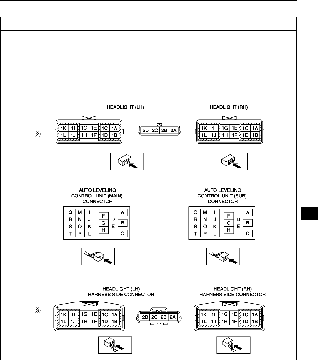
ON-BOARD DIAGNOSTIC [HEADLIGHT AUTO LEVELING SYSTEM]
T149
T
DTC B2390 A6E816467000W05
DTC B2390 Communication system between auto leveling control unit (main) and auto leveling control unit
(sub).
DETECTION
CONDITION
Warning
•
••
•incorrect servicing of the auto leveling control unit could result in electrical shock because
the unit is integrated with the discharge headlight control unit. Before servicing the auto
leveling control unit, always refer to Discharge headlight service warnings. (See T25
DISCHARGE HEADLIGHT SERVICE WARNINGS)
Communication between auto leveling control unit (main) and auto leveling control unit (sub) is not
performed.
POSSIBLE
CAUSE
•Auto leveling control unit (main) malfunction
•Open or shortcircuit in wiring harness between auto leveling control unit (main) and auto leveling
control unit (sub)

T150
ON-BOARD DIAGNOSTIC [HEADLIGHT AUTO LEVELING SYSTEM]
Diagnostic procedure
End Of Sie
STEP INSPECTION ACTION
1
INSPECT CONNECTOR CONNECTION
•Check fit of auto leveling control units and
headlight connectors on both sides (auto
leveling control unit (main) and (sub)).
•Are installation condition and fit okay?
Yes Go to next step.
No After correcting fit, clear DTC and check DTC again.
•If DTC is displayed again, go to next step.
2
INSPECT HEADLIGHT (LH) AND
HEADLIGHT (RH)
•Disconnect auto leveling control unit (main)
connector (20-pin) and headlight (LH)
connector (12-pin) and auto leveling control
unit (sub) connector (20-pin) and headlight
(RH) connector (12-pin).
•Is there continuity between the following
connectors?
Auto leveling control unit (main) connector
(terminal I) and headlight (LH) connector
(terminal 1F)
Auto leveling control unit (sub) connector
(terminal P) and headlight (RH) connector
(terminal 1F)
Yes Go to next step.
No Possible cause is an open circuit in headlight. Replace
headlight (LH) or headlight (RH). (See T26 FRONT
COMBINATION LIGHT REMOVAL/INSTALLATION)
3
INSPECT WIRING HARNESS BETWEEN
HEADLIGHT (LH) CONNECTOR AND
HEADLIGHT (RH) CONNECTOR
•Disconnect headlight (LH) connector (12-pin)
and headlight (RH) connector (12-pin).
•Is there continuity between the following
connectors?
Headlight (LH) connector (terminal 1F)
and headlight (RH) connector (terminal
1F)
Yes Repair auto leveling control unit (main).
(See T30 DISCHARGE HEADLIGHT CONTROL UNIT
REMOVAL/INSTALLATION)
No Repair or replace wiring harness between headlight (LH)
and headlight (RH).
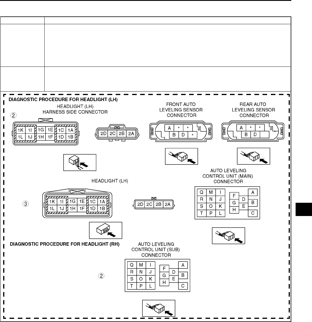
ON-BOARD DIAGNOSTIC [HEADLIGHT AUTO LEVELING SYSTEM]
T151
T
DTC B2607 A6E816467000W06
Remark: In this case other DTCs can be reported for wrong side.
DTC B2607 Auto leveling control unit controlling system.
DETECTION
CONDITION
Warning
•
••
•incorrect servicing of the auto leveling control unit could result in electrical shock because
the unit is integrated with the discharge headlight control unit. Before servicing the auto
leveling control unit, always refer to Discharge headlight service warnings. (See T25
DISCHARGE HEADLIGHT SERVICE WARNINGS)
Operation of auto leveling control unit (main) and auto leveling control unit (sub) are reversed.
POSSIBLE
CAUSE
•Mounting of auto leveling control unit (main) and auto leveling control unit (sub) changed
•Poor fit of auto leveling control unit
•Headlight malfunction
•Open or short circuit in wiring harness between auto leveling sensors and headlight (LH)

T152
ON-BOARD DIAGNOSTIC [HEADLIGHT AUTO LEVELING SYSTEM]
Diagnostic procedure for headlight (LH)
Diagnostic procedure for headlight (RH)
End Of Sie
STEP INSPECTION ACTION
1
INSPECT CONNECTION
•Check fit of auto leveling control unit and fit
of connectors.
•Is fit okay?.
Yes Go to next step.
No After correcting fit, clear DTC and check DTC again.
•If DTC is displayed again, go to next step.
2
INSPECT WIRING HARNESS BETWEEN
AUTO LEVELING SENSOR
CONNECTORS AND HEADLIGHT
(LH) CONNECTOR
•Disconnect front and rear auto leveling
sensor connector (6-pin) and headlight (LH)
connector (4-pin).
•Is there no continuity between the following
connectors?
Headlight (LH) connector (terminal 2C)
and front auto leveling sensor connector
(terminal A)
Headlight (LH) connector (terminal 2D)
and front auto leveling sensor connector
(terminal D)
Yes Go to next step.
No Repair or replace wiring harness between front auto leveling
sensor and headlight (LH).
3
INSPECT HEADLIGHT (LH)
•Disconnect auto leveling control unit (main)
connector (20-pin) and headlight (LH)
connector (4-pin).
•Is there no continuity between the following
connectors?
Headlight (LH) connector (terminal 2B)
and auto leveling control unit (main)
connector (terminal H)
Headlight (LH) connector (terminal 2A)
and auto leveling control unit (main)
connector (terminal F)
Yes Clear DTC and check DTC again.
•If DTC is displayed again, replace auto leveling control
unit.
(See T30 DISCHARGE HEADLIGHT CONTROL UNIT
REMOVAL/INSTALLATION)
No Replace headlight (LH). (See T26 FRONT COMBINATION
LIGHT REMOVAL/INSTALLATION)
STEP INSPECTION ACTION
1
INSPECT CONNECTION
•Check fit of auto leveling control unit.
•Is fit okay?.
Yes Go to next step.
No After correcting fit, clear DTC and check DTC again.
•If DTC is displayed again, go to next step.
2
INSPECT HEADLIGHT (RH)
•Disconnect auto leveling control unit (sub)
connector (20-pin).
•Is there no continuity between the following
connectors?
Terminals F and K
Yes Clear DTC and check DTC again.
•If DTC is displayed again, replace auto leveling control
unit.
(See T30 DISCHARGE HEADLIGHT CONTROL UNIT
REMOVAL/INSTALLATION)
No Replace headlight (LH). (See T26 FRONT COMBINATION
LIGHT REMOVAL/INSTALLATION)
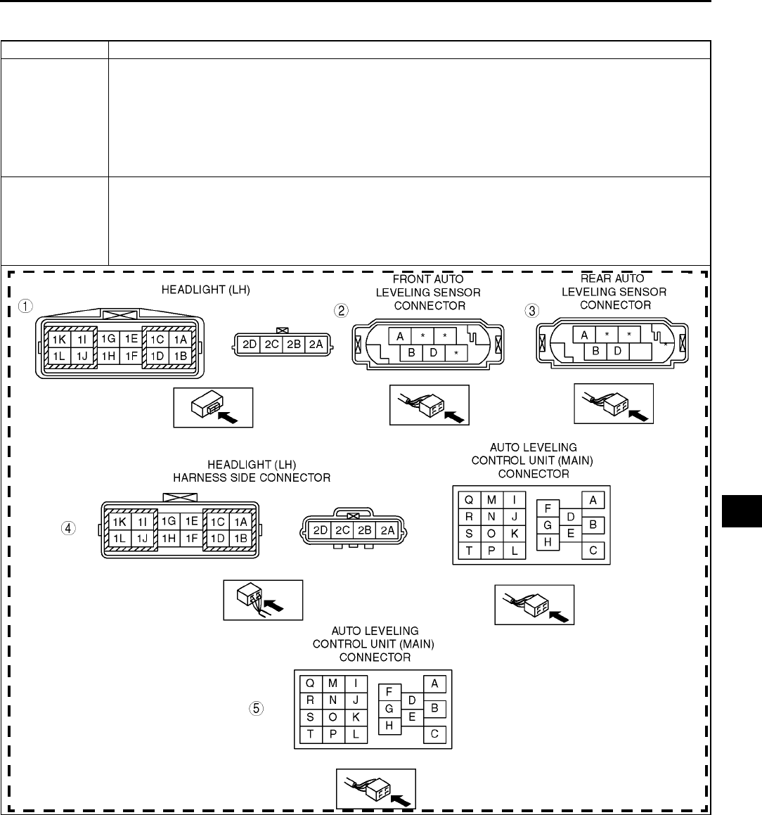
ON-BOARD DIAGNOSTIC [HEADLIGHT AUTO LEVELING SYSTEM]
T153
T
DTC B2615 A6E816467000W07
DTC B2615 Front or rear auto leveling sensors power supply system.
DETECTION
CONDITION
Warning
•
••
•incorrect servicing of the auto leveling control unit could result in electrical shock because
the unit is integrated with the discharge headlight control unit. Before servicing the auto
leveling control unit, always refer to Discharge headlight service warnings. (See T25
DISCHARGE HEADLIGHT SERVICE WARNINGS)
Front auto leveling sensor or rear auto leveling sensor supply voltage (5 V), which is generated by auto
leveling control unit (main), is incorrect.
POSSIBLE
CAUSE
•Front auto leveling sensor malfunction
•Rear auto leveling sensor malfunction
•Auto leveling control unit malfunction
•Short circuit in wiring harness between front auto leveling sensor and headlight (LH)
•Short circuit in wiring harness between rear auto leveling sensor and headlight (LH)
•Headlight (LH) malfunction

T154
ON-BOARD DIAGNOSTIC [HEADLIGHT AUTO LEVELING SYSTEM]
Diagnostic procedure
End Of Sie
STEP INSPECTION ACTION
1
INSPECT POWER SUPPLY CIRCUIT OF
HEADLIGHT (LH)
•Disconnect headlight (LH) connector (4-pin).
•Turn the ignition switch to ON.
•Measure voltage at headlight (LH) connector
terminal 2A.
•Is voltage approximately 5 V?
Yes Go to next step.
No Go to step 4.
2
INSPECT POWER SUPPLY CIRCUIT OF
FRONT AUTO LEVELING SENSOR
•Turn the ignition switch to OFF and connect
headlight (LH) connector (4-pin) again.
•Disconnect front auto leveling sensor
connector (6-pin).
•Measure voltage at front auto leveling sensor
connector terminal D.
•Is voltage approximately 5 V?
Yes Replace front auto leveling sensor.
(See T32 FRONT AUTO LEVELING SENSOR REMOVAL/
INSTALLATION)
After replacement, clear DTC and check DTC again.
•If DTC is displayed again, go to next step.
No Repair or replace wiring harness between front auto leveling
sensor and headlight (LH).
3
INSPECT POWER SUPPLY CIRCUIT OF
REAR AUTO LEVELING SENSOR
•Disconnect rear auto leveling sensor
connector.
•Measure voltage at rear auto leveling sensor
connector terminal D.
•Is voltage approximately 5 V?
Yes Replace front auto leveling sensor.
(See T32 REAR AUTO LEVELING SENSOR REMOVAL/
INSTALLATION)
After replacement, clear DTC and check DTC again.
•If DTC is displayed again, go to next step.
No Repair or replace wiring harness between rear auto leveling
sensor and headlight (LH).
4
INSPECT HEADLIGHT (LH)
•Disconnect auto leveling control unit (main)
connector (20-pin) and headlight (LH)
connector (4-pin).
•Is there continuity between the following
connectors?
Auto leveling control unit (main) connector
(terminal K) and headlight (LH) connector
(terminal 2A)
Yes Go to next step.
No Possible cause is an open circuit in headlight (LH). Replace
headlight (LH). (See T26 FRONT COMBINATION LIGHT
REMOVAL/INSTALLATION)
5
INSPECT HEADLIGHT (LH)
•Disconnect auto leveling control unit (main)
connector (20-pin).
•Is there no continuity between the following
connectors?
Terminals K and E
Terminals K and D
Terminals K and L
Yes Replace auto leveling control unit.
(See T30 DISCHARGE HEADLIGHT CONTROL UNIT
REMOVAL/INSTALLATION)
No Possible cause is an open circuit in headlight (LH). Replace
headlight (LH). (See T26 FRONT COMBINATION LIGHT
REMOVAL/INSTALLATION)
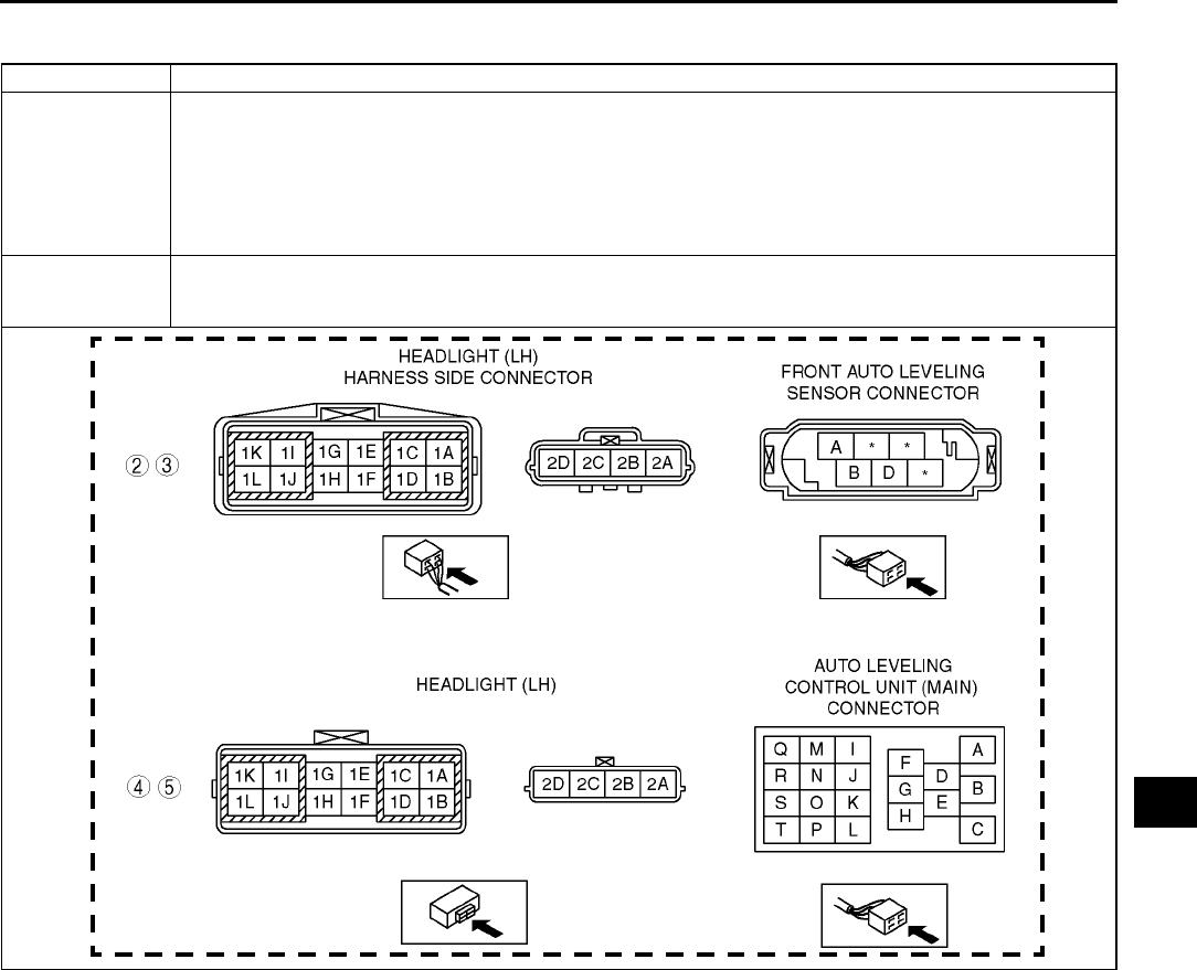
ON-BOARD DIAGNOSTIC [HEADLIGHT AUTO LEVELING SYSTEM]
T155
T
DTC B2616 A6E816467000W08
DTC B2616 Front auto leveling sensor signal system.
DETECTION
CONDITION
Warning
•
••
•incorrect servicing of the auto leveling control unit could result in electrical shock because
the unit is integrated with the discharge headlight control unit. Before servicing the auto
leveling control unit, always refer to Discharge headlight service warnings. (See T25
DISCHARGE HEADLIGHT SERVICE WARNINGS)
Output signal is not sent from the front auto leveling sensor.
POSSIBLE
CAUS
•Front auto leveling sensor malfunction
•Open or short circuit in wiring harness between front auto leveling sensor and headlight (LH)
•Headlight (LH) malfunction

T156
ON-BOARD DIAGNOSTIC [HEADLIGHT AUTO LEVELING SYSTEM]
Diagnostic procedure
End Of Sie
STEP INSPECTION ACTION
1
INSPECT FRONT LEVELING SENSOR
CONNECTION
•Check installation condition of front auto
leveling sensor and fit of connector.
•Are installation condition and fit okay?
Yes Go to next step.
No After correcting fit, clear DTC and check DTC again.
•If DTC is displayed again, go to next step.
2
INSPECT WIRING HARNESS BETWEEN
FRONT AUTO LEVELING SENSOR
CONNECTOR AND HEADLIGHT (LH)
CONNECTOR
•Disconnect front auto leveling sensor
connector (6-pin) and headlight (LH)
connector (4-pin).
•Is there continuity between the following
connectors?
Front auto leveling sensor connector
(terminal B) and headlight (LH) connector
(terminal 2C)
Yes Go to next step.
No Repair or replace wiring harness between front auto leveling
sensor and headlight (LH).
3
INSPECT WIRING HARNESS BETWEEN
FRONT AUTO LEVELING SENSOR
CONNECTOR AND HEADLIGHT (LH)
CONNECTOR
•Disconnect front auto leveling sensor
connector (6-pin) and headlight (LH)
connector (4-pin).
•Is there no continuity between the following
connectors?
Front auto leveling sensor connector
(terminal B) and headlight (LH) connector
(terminal 2B)
Front auto leveling sensor connector
(terminal B) and headlight (LH) connector
(terminal 2A)
Yes Go to next step.
No Repair or replace wiring harness between front auto leveling
sensor and headlight (LH).
4
INSPECT HEADLIGHT (LH)
•Disconnect auto leveling control unit (main)
connector (20-pin) and headlight (LH)
connector (4-pin).
•Is there continuity between the following
connectors?
Auto leveling control unit (main) connector
(terminal H) and headlight (LH) connector
(terminal 2C)
Yes Go to next step.
No Possible cause is an open circuit in headlight (LH). Replace
headlight (LH). (See T26 FRONT COMBINATION LIGHT
REMOVAL/INSTALLATION)
5
INSPECT HEADLIGHT (LH)
•Disconnect auto leveling control unit (main)
connector (20-pin) and headlight (LH)
connector (4-pin).
•Is there continuity between the following
connectors?
Auto leveling control unit (main) connector
(terminal G) and headlight (LH) connector
(terminal 2C)
Auto leveling control unit (main) connector
(terminal K) and headlight (LH) connector
(terminal 2C)
Auto leveling control unit (main) connector
(terminal E) and headlight (LH) connector
(terminal 2C)
Yes Replace front auto leveling sensor.
(See T32 FRONT AUTO LEVELING SENSOR REMOVAL/
INSTALLATION)
No Possible cause is an open circuit in headlight (LH). Replace
headlight (LH). (See T26 FRONT COMBINATION LIGHT
REMOVAL/INSTALLATION)
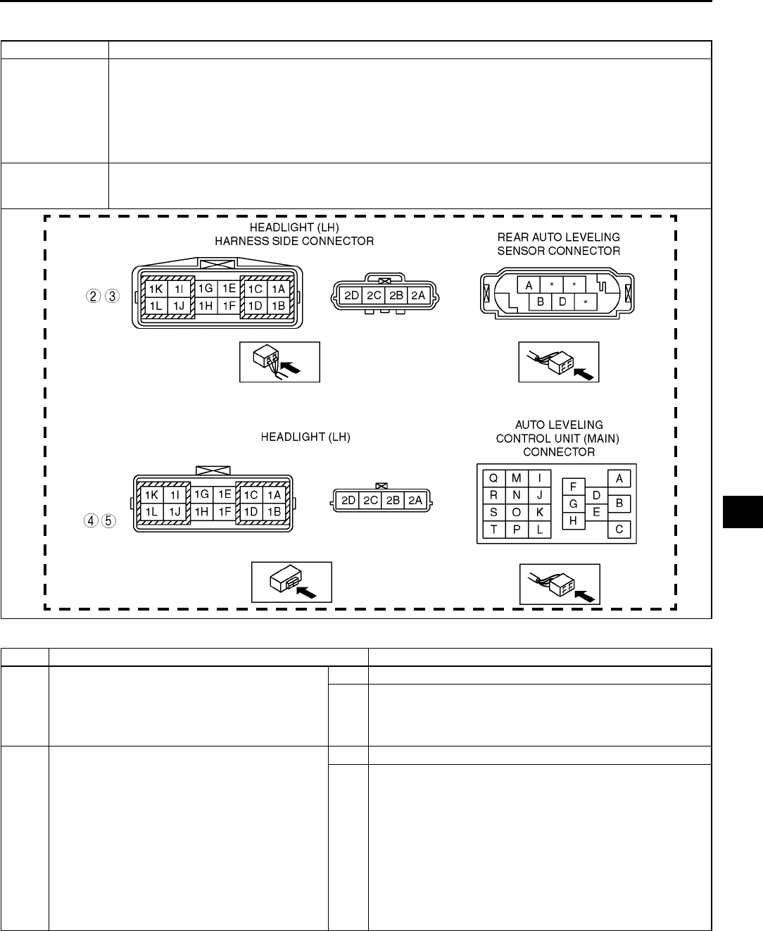
ON-BOARD DIAGNOSTIC [HEADLIGHT AUTO LEVELING SYSTEM]
T157
T
DTC B2619 A6E816467000W09
Diagnostic procedure
DTC B2619 Rear auto leveling sensor signal system.
DETECTION
CONDITION
Warning
•
••
•incorrect servicing of the auto leveling control unit could result in electrical shock because
the unit is integrated with the discharge headlight control unit. Before servicing the auto
leveling control unit, always refer to Discharge headlight service warnings. (See T25
DISCHARGE HEADLIGHT SERVICE WARNINGS)
Output signal is not sent from the rear auto leveling sensor.
POSSIBLE
CAUSE
•Rear auto leveling sensor malfunction
•Open or short circuit in wiring harness between rear auto leveling sensor and headlight (LH)
•Headlight (LH) malfunction
STEP INSPECTION ACTION
1
INSPECT REAR LEVELING SENSOR
CONNECTION
•Check installation condition of rear auto
leveling sensor and fit of connector.
•Are installation condition and fit okay?
Yes Go to next step.
No After correcting fit, clear DTC and check DTC again.
•If DTC is displayed again, go to next step.
2
INSPECT WIRING HARNESS BETWEEN
REAR AUTO LEVELING SENSOR
CONNECTOR AND HEADLIGHT (LH)
CONNECTOR
•Disconnect rear auto leveling sensor
connector (6-pin) and headlight (LH)
connector (4-pin).
•Is there continuity between the following
connectors?
Rear auto leveling sensor connector
(terminal B) and headlight (LH) connector
(terminal 2D)
Yes Go to next step.
No Repair or replace wiring harness between rear auto leveling
sensor and headlight (LH).

T158
ON-BOARD DIAGNOSTIC [HEADLIGHT AUTO LEVELING SYSTEM]
End Of Sie
DTC B2626, B2477 A6E816467000W10
Diagnostic procedure
End Of Sie
3
INSPECT WIRING HARNESS BETWEEN
REAR AUTO LEVELING SENSOR
CONNECTOR AND HEADLIGHT (LH)
CONNECTOR
•Disconnect rear auto leveling sensor
connector (6-pin) and headlight (LH)
connector (4-pin).
•Is there no continuity between the following
connectors?
Rear auto leveling sensor connector
(terminal B) and headlight (LH) connector
(terminal 2B)
Rear auto leveling sensor connector
(terminal B) and headlight (LH) connector
(terminal 2A)
Yes Go to next step.
No Repair or replace wiring harness between rear auto leveling
sensor and headlight (LH).
4
INSPECT HEADLIGHT (LH)
•Disconnect auto leveling control unit (main)
connector (20-pin) and headlight (LH)
connector (4-pin).
•Is there continuity between the following
connectors?
Auto leveling control unit (main) connector
(terminal F) and headlight (LH) connector
(terminal 2D)
Yes Go to next step.
No Possible cause is an open circuit in headlight (LH). Replace
headlight (LH). (See T26 FRONT COMBINATION LIGHT
REMOVAL/INSTALLATION)
5
INSPECT HEADLIGHT (LH)
•Disconnect auto leveling control unit (main)
connector (20-pin) and headlight (LH)
connector (4-pin).
•Is there continuity between the following
connectors?
Auto leveling control unit (main) connector
(terminal G) and headlight (LH) connector
(terminal 2D)
Auto leveling control unit (main) connector
(terminal K) and headlight (LH) connector
(terminal 2D)
Auto leveling control unit (main) connector
(terminal E) and headlight (LH) connector
(terminal 2D)
Yes Replace rear auto leveling sensor.
(See T32 REAR AUTO LEVELING SENSOR REMOVAL/
INSTALLATION)
No Possible cause is an open circuit in headlight (LH). Replace
headlight (LH). (See T26 FRONT COMBINATION LIGHT
REMOVAL/INSTALLATION)
STEP INSPECTION ACTION
DTC B2626,
B2477 Headlight zeroset system for auto leveling control unit.
DETECTION
CONDITION
Warning
•
••
•incorrect servicing of the auto leveling control unit could result in electrical shock because
the unit is integrated with the discharge headlight control unit. Before servicing the auto
leveling control unit, always refer to Discharge headlight service warnings. (See T25
DISCHARGE HEADLIGHT SERVICE WARNINGS)
Headlight zeroset for auto leveling control unit is not set.
POSSIBLE
CAUSE •Headlight zeroset for auto leveling control unit is not set or the setting is invalid
ACTION
Check connections of each sensor and the unit. Then connect WDS or equivalent and perform headlight zeroset.
(See T31 HEADLIGHT ZEROSET)
ON-BOARD DIAGNOSTIC [HEADLIGHT AUTO LEVELING SYSTEM]
T159
T
DTC B2735 A6E816467000W11
Diagnostic procedure
End Of Sie
DTC B2735 Headlight leveling actuator signal system.
DETECTION
CONDITION
Warning
•
••
•incorrect servicing of the auto leveling control unit could result in electrical shock because
the unit is integrated with the discharge headlight control unit. Before servicing the auto
leveling control unit, always refer to Discharge headlight service warnings. (See T25
DISCHARGE HEADLIGHT SERVICE WARNINGS)
Output signal to headlight leveling actuator is abnormal.
POSSIBLE
CAUSE
•Headlight leveling actuator malfunction
•Auto leveling control unit malfunction
•Headlight malfunction
STEP INSPECTION ACTION
1
INSPECT CONNECTOR CONNECTION
•Check fit of auto leveling control unit.
•Is condition of the fit okay?
Yes Possible cause is headlight wiring harness malfunction or
malfunctioning headlight leveling acutuator.
Replace headlight and go to next step. (See T26 FRONT
COMBINATION LIGHT REMOVAL/INSTALLATION)
No After correcting fit, clear DTC and check DTC again.
•If DTC is displayed again, go to next step.
2
•Does headlight leveling actuator work
properly?
Yes Troubleshooting completed.
No Replace auto leveling control unit.
(See T30 DISCHARGE HEADLIGHT CONTROL UNIT
REMOVAL/INSTALLATION)
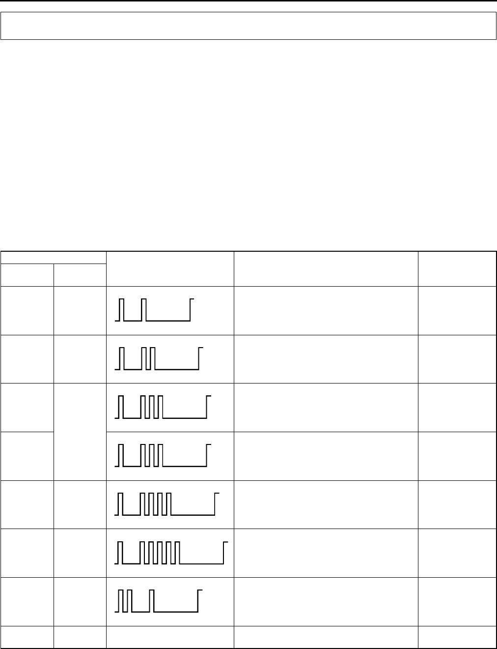
T160
ON-BOARD DIAGNOSTIC [IMMOBILIZER SYSTEM]
FOREWORD A6E817067000W01
Caution
•
••
•When the engine does not start or stalls and the following DTCs are not indicated, go to engine
symptom troubleshooting.
Note
•When the immobilizer system is defective, the engine cannot be started.
•If engine condition is normal but light stays on, inspect for short circuit between security light. Repair or
replace the wiring harness if necessary.
1. Turn the ignition switch to START position for 2 seconds, then back to ON position.
2. Wait for 1 minute.
3. Verify the security light condition and read the DTC if indicated.
4. Verify the DTC with WDS or equivalent.
5. If the DTC is indicated, go to troubleshooting referring to the DTC table.
End Of Sie
DTC TABLE A6E817067000W02
ON-BOARD DIAGNOSTIC [IMMOBILIZER SYSTEM]
DTC Security light flashing
pattern Description Page
WDS or
equivalent
Security
light
B1681 11 Coil signal is not received. (See T161 DTC
B1681)
B2103 12 Coil not connected. (See T162 DTC
B2103)
B1600
13
ID number signal is not input into PCM. (See T163 DTC
B1600)
B2431 Transponder programming failure. (See T163 DTC
B2431)
B1602 14 PCM received invalid format of ID number
from transponder.
(See T163 DTC
B1602)
B1601 15 PCM received incorrect ID number from
transponder.
(See T164 DTC
B1601)
B1213 21 Number of valid keys is below minimum. (See T164 DTC
B1213)
B1342 PCM is defective. (See T164 DTC
B1342)
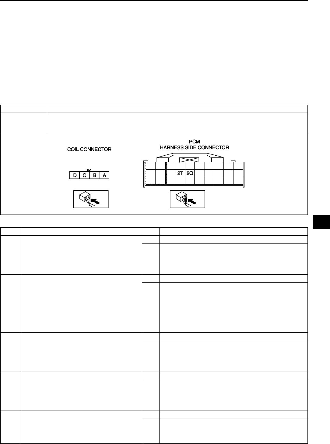
ON-BOARD DIAGNOSTIC [IMMOBILIZER SYSTEM]
T161
T
Note
•Perform the following if the security light stays on:
If gasoline engine stalls, go to symptom troubleshooting NO.11 ENGINE STALLS/QUITS, ENGINE
RUNS ROUGH, MISSES, BUCK/JERK, HESITATION/STUMBLE, SURGES in. (See F204 NO.11
ENGINE STALLS/QUITS, ENGINE RUNS ROUGH, MISSES, BUCK/JERK, HESITATION/
STUMBLE, SURGES.)
If gasoline engine wont start, go to symptom troubleshooting NO.6 CRANKS NORMALLY BUT WILL
NOT START in. (See F195 NO.6 CRANKS NORMALLY BUT WILL NOT START.)
If engine condition is normal but light stays on, inspect for continuity between the following wiring
harness and body ground: security light and PCM connector terminal 2W. Repair or replace the wiring
harness.
End Of Sie
DTC B1681 A6E817067000W03
Diagnostic procedure
DTC B1681 Coil signal is not received.
POSSIBLE
CAUSE
•Defective coil
•Defective PCM
•Defective wiring harness
STEP INSPECTION ACTION
1INSPECT POWER SUPPLY CIRCUIT OF COIL
•Disconnect coil connector.
•Turn ignition switch to ON position.
•Measure voltage at terminal D of coil
connector.
•Is voltage more than 10 V?
Yes Go to next step.
No Repair wiring harness.
2INSPECT WIRING HARNESS BETWEEN COIL
AND GROUND
•Turn ignition switch to OFF position.
•Inspect wiring harness between coil
connector terminal C and ground for
following.
Short to power supply
Open circuit
•Is wiring harness okay?
Yes Go to next step.
No Repair wiring harness.
3INSPECT COIL INPUT SIGNAL CIRCUIT
•Connect coil connector.
•Turn ignition switch to ON position.
•Measure voltage at terminal B of coil
connector.
•Is voltage more than 9 V?
Yes Go to Step 5.
No Go to next step.
4INSPECT COIL INPUT SIGNAL CIRCUIT
•Turn ignition switch to OFF position.
•Disconnect coil connector.
•Measure resistance between coil connector
terminal B and ground.
•Is resistance more than 10 kilohms?
Yes Go to Step 12.
No Repair wiring harness.
5INSPECT COMMUNICATION CIRCUIT
(INPUT) FOR CONTINUITY
•Disconnect coil and PCM connectors.
•Is there continuity between coil connector
terminal B and PCM terminal 2T?
Yes Go to next step.
No Repair wirimg harness.

T162
ON-BOARD DIAGNOSTIC [IMMOBILIZER SYSTEM]
End Of Sie
DTC B2103 A6E817067000W04
Diagnostic procedure
End Of Sie
6INSPECT COIL OUTPUT SIGNAL CIRCUIT
•Connect coil and PCM connectors.
•Turn ignition switch to ON position.
•Measure voltage at terminal A of coil
connector.
•Is voltage more than 9 V?
Yes Go to Step 10.
No Go to next step.
7INSPECT COIL OUTPUT SIGNAL CIRCUIT
•Turn ignition switch to OFF position.
•Disconnect PCM connector.
•Measure resistance between PCM connector
terminal 2Q and ground.
•Is resistance more than 10 kilohms?
Yes Go to Step 9.
No Go to next step.
8INSPECT COIL OUTPUT SIGNAL CIRCUIT
FOR SHORT TO GND
•Disconnect coil connector.
•Measure resistance between coil connector
terminal A and ground.
•Is resistance more than 10 kilohms?
Yes Replace coil.
(See T90 COIL REMOVAL/INSTALLATION)
No Repair wiring harness.
9INSPECT COMMUNICATION CIRCUIT
(OUTPUT) FOR CONTINUITY
•Disconnect coil and PCM connectors.
•Is there continuity between coil connector
terminal A and PCM terminal 2Q?
Yes Replace PCM and reprogram immobilizer system.
(See T90 IMMOBILIZER SYSTEM REPROGRAM
PROCEDURE)
No Repair wirimg harness.
10 INSPECT COMMUNICATION CIRCUIT
(OUTPUT) FOR CONTINUITY
•Disconnect coil and PCM connectors.
•Is there continuity between coil connector
terminal A and PCM terminal 2Q?
Yes Replace coil.
(See T90 COIL REMOVAL/INSTALLATION)
No Go to next step.
11 INSPECT COIL OUTPUT CIRCUIT FOR
SHORT TO POWER SUPPLY
•Disconnect coil connector.
•Measure voltage at terminal A of coil
connector.
•Is there voltage?
Yes Repair wirimg harness.
No Replace PCM and reprogram immobilizer system.
(See T90 IMMOBILIZER SYSTEM REPROGRAM
PROCEDURE)
12 INSPECT PCM
•Turn ignition switch from LOCK position to
START position for 2 seconds.
•Does security light indicate DTC B1681
again?
Yes Replace PCM and reprogram immobilizer system.
(See T90 IMMOBILIZER SYSTEM REPROGRAM
PROCEDURE)
No Troubleshooting is completed.
STEP INSPECTION ACTION
DTC B2103 Coil not connected.
POSSIBLE
CAUSE
•Defective Coil
•Poor connection of coil connector
STEP INSPECTION ACTION
INSPECT CONNECTOR CONNECTION
•Is connector of coil and PCM connected
securely?
Yes Replace coil.
(See T90 COIL REMOVAL/INSTALLATION)
No Connect connector securely.
ON-BOARD DIAGNOSTIC [IMMOBILIZER SYSTEM]
T163
T
DTC B1600 A6E817067000W05
Diagnostic procedure
End Of Sie
DTC B2431 A6E817067000W06
Diagnostic procedure
End Of Sie
DTC B1602 A6E817067000W07
Diagnostic procedure
DTC B1600 ID number is not input into PCM.
POSSIBLE
CAUSE
•No transponder in the key
•Defective transponder in the key (ID number is not output.)
STEP INSPECTION ACTION
1REPROGRAM NEW KEY
•Register new key.
(See T90 IMMOBILIZER SYSTEM
REPROGRAM PROCEDURE)
•Clear DTCs with WDS or equivalent.
•Turn ignition switch to ON position with new
key.
Note
•Two or more valid keys are held in a
manner of not interfering each other.
•Does security light indicate DTC B1600
again?
Yes Go to next step.
No Immobilizer system is okay.
2INSPECT FOR OTHER PROPER KEYS
•Does engine start with other proper keys?
Yes Dispose of defective key.
Duplicate key if necessary.
(See T90 IMMOBILIZER SYSTEM REPROGRAM
PROCEDURE)
No Go to next step.
3INSPECT PCM
•Turn ignition switch from LOCK position to
START position For 2 seconds.
•Does security light indicate DTC B1600
again?
Yes Replace PCM and reprogram immobilizer system.
(See T90 IMMOBILIZER SYSTEM REPROGRAM
PROCEDURE)
No Troubleshooting is completed.
DTC B2431 ID number programing failure.
POSSIBLE
CAUSE •The procedure fails to program the transponder into PCM
STEP INSPECTION ACTION
Go to ID number input procedure.
(See T90 IMMOBILIZER SYSTEM REPROGRAM
PROCEDURE)
DTC B1602 PCM received invalid format of ID number from key (transponder)
POSSIBLE
CAUSE
•Defective transponder in the key
•Defective coil
•Defective PCM
STEP INSPECTION ACTION
1INSPECT FOR OTHER PROPER KEYS
•Does engine start with other proper keys?
Yes Dispose of defective key.
Duplicate key if necessary.
(See T90 IMMOBILIZER SYSTEM REPROGRAM
PROCEDURE)
No Go to next step.
2INSPECT COIL
•Replace coil.
(See T90 COIL REMOVAL/
INSTALLATION)
•Does engine start?
Yes Coil was defective.
No Replace PCM and reprogram immobilizer system.
(See T90 IMMOBILIZER SYSTEM REPROGRAM
PROCEDURE)
T164
ON-BOARD DIAGNOSTIC [IMMOBILIZER SYSTEM]
End Of Sie
DTC B1601 A6E817067000W08
Diagnostic procedure
End Of Sie
DTC B1213 A6E817067000W09
Diagnostic procedure
End Of Sie
DTC B1342 A6E817067000W10
Diagnostic procedure
End Of Sie
DTC B1601 PCM received incorrect ID number from key (transponder).
POSSIBLE
CAUSE
•Defective transponder in the key
STEP INSPECTION ACTION
INSPECT KEYS
•Turn ignition switch to ON position with first
encoded key for 3 seconds.
•Turn ignition switch to ON position with
second encoded key for 3 seconds.
•Turn ignition switch to START position with
second encoded key.
•Does engine start?
Yes Immobilizer system is okay.
No Replace PCM and reprogram immobilizer system.
(See T90 IMMOBILIZER SYSTEM REPROGRAM
PROCEDURE)
DTC B1213 Number of valid keys is below minimum.
POSSIBLE
CAUSE
•Less than two valid keys
STEP INSPECTION ACTION
REPROGRAM NEW KEY
•Register new key.
(See T90 IMMOBILIZER SYSTEM
REPROGRAM PROCEDURE)
Note
•Two or more valid keys are necessary
to start engine.
•After reprogramming, does the security light
illuminate for approximately 3 seconds and
then go out?
Yes Troubleshooting is completed.
No Reprogram immobilizer system again.
DTC B1342 PCM is defective
POSSIBLE
CAUSE
•Defective PCM
STEP INSPECTION ACTION
INSPECT PCM
•Clear DTCs with WDS or equivalent.
•Does security light indicate DTC B1342
again.
Yes Replace PCM and reprogram immobilizer system.
(See T90 IMMOBILIZER SYSTEM REPROGRAM
PROCEDURE)
No Connect connectors properly.
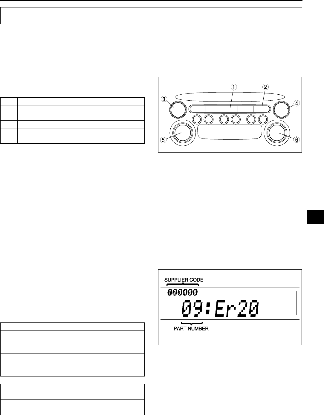
ON-BOARD DIAGNOSTIC [AUDIO]
T165
T
STARTING PROCEDURE FOR ON-BOARD DIAGNOSTIC TEST MODE A6E817566900W01
Note
•All DTCs displayed in the on-board diagnostic test mode should be entered in the Audio Repair Order
Form.
1. Turn the ignition switch to the ACC or ON position.
2. First press the POWER button, then
simultaneously press the AM button and TAPE/
MD button for 2 seconds or more.
Note
•If several DTCs are in the memory, they can
be displayed by the SEEK button.
3. To stop the on-board diagnostic test mode, turn the ignition switch to the LOCK position.
End Of Sie
SUPPLIER IDENTIFICATION PROCEDURE A6E817566900W02
Note
•When asking the supplier (service center) for repair or replacement, verify which supplier the module
belongs to and enter in the Audio Repair Order Form.
Identification With Printed Numbers/Label
1. Remove the audio unit.
2. Verify the supplier name written on the label attached on each module.
Identification With On-board Diagnostic Test Mode
1. Start the on-board diagnostic test mode.
2. Verify the part number and supplier code
displayed in the LCD.
Note
•When no DTCs are in the memory, part
numbers and supplier codes will not be
displayed.
End Of Sie
ON-BOARD DIAGNOSTIC [AUDIO]
1 AM button
2 TAPE/MD button
3 SEEK button (type A)
4 SEEK button (type B)
5 POWER button (type A)
6 POWER button (type B)
A6E8175W010
Part number Part name
00 Cassette deck (lower module)
03 CD player (upper module)
05 CD changer (external type)
06 CD changer (upper module)
07 MD player (lower module)
09 Base unit
Supplier code Supplier name
1FMS Audio
2 Panasonic
3Clarion
A6E8175W008
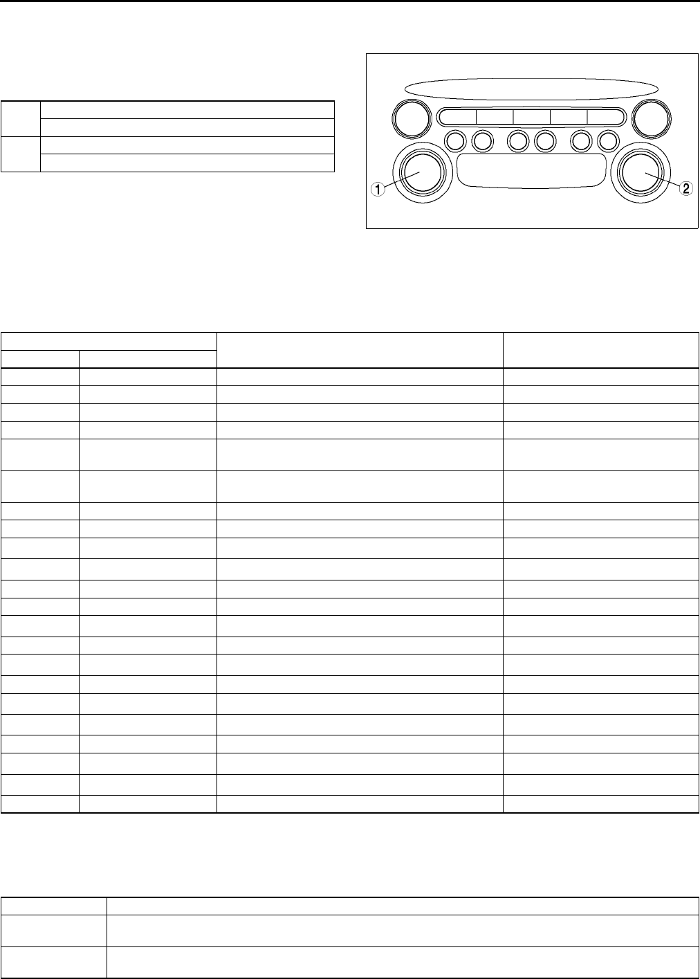
T166
ON-BOARD DIAGNOSTIC [AUDIO]
DTC CLEARING PROCEDURE A6E817566900W03
1. Start the on-board diagnostic test mode.
2. First press the POWER button, then
simultaneously press AUDIO CONT button for 2
seconds or more.
Caution
•
••
•Before clearing the DTCs, be sure to
enter all of them displayed in the on-
board diagnostic test mode in the Audio
Repair Order Form.
3. To stop the on-board diagnostic test mode, turn the ignition switch to the LOCK position.
End Of Sie
DTC TABLE A6E817566900W04
*1,*2: When an error occurs, the error messages are displayed three times in the order of *1 and *2, respectively.
End Of Sie
DTC 09:ER22 A6E817566900W05
1 POWER button (type A)
AUDIO CONT button (type B)
2 AUDIO CONT button (type A)
POWER button (type B)
A6E8175W009
Screen display Malfunction location Page
DTC Output signal
09:Er22 Base unit (peripheral circuit) (See T166 DTC 09:ER22)
09:Er20 Power supply circuit of base unit (See T167 DTC 09:ER20)
00:Er10 Cassette deckbase unit communication line (See T168 DTC 00:ER10)
03:Er10 CD playerbase unit communication line (See T168 DTC 03:ER10)
05:Er10 CD changer (external type)base unit
communication line (See T169 DTC 05:ER10)
06:Er10 CD changer (upper module)base unit
communication line (See T169 DTC 06:ER10)
07:Er10 MD playerbase unit communication line (See T170 DTC 07:ER10)
03:Er01 CD player (See T170 DTC 03:ER01)
03:Er02 CHECK*1 CD*2 CD player (See T170 DTC 03:ER02)
03:Er07 CHECK*1 CD*2 CD player (See T171 DTC 03:ER07)
00:Er01 Cassette deck (See T171 DTC 00:ER01)
00:Er03 Cassette deck (See T172 DTC 00:ER03)
00:Er04 CHECK*1 TAPE*2 Cassette tape (See T172 DTC 00:ER04)
05:Er01 CD changer (external type) (See T172 DTC 05:ER01)
05:Er07 CHECK*1 CD*2 CD changer (external type) (See T173 DTC 05:ER07)
06:Er01 CD changer (upper module) (See T173 DTC 06:ER01)
06:Er02 CHECK*1 CD*2 CD changer (upper module) (See T174 DTC 06:ER02)
06:Er07 CHECK*1 CD*2 CD changer (upper module) (See T174 DTC 06:ER07)
07:Er01 MD player (See T175 DTC 07:ER01)
07:Er02 CHECK*1 MD*2 MD player (See T175 DTC 07:ER02)
07:Er07 CHECK*1 MD*2 MD player (See T176 DTC 07:ER07)
NO Err No stored DTCs
DTC 09:Er22 Base unit (peripheral circuit)
DETECTION
CONDITION •Base unit detects malfunction in its inner circuit (related to tuner).
POSSIBLE
CAUSE •Base unit malfunction
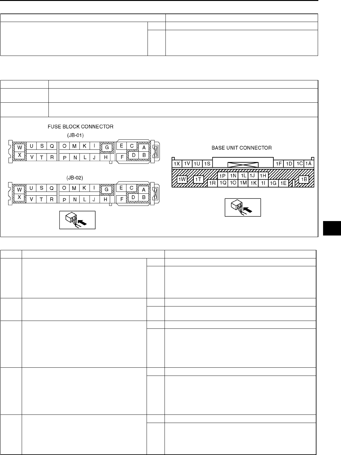
ON-BOARD DIAGNOSTIC [AUDIO]
T167
T
Diagnostic procedure
End Of Sie
DTC 09:ER20 A6E817566900W06
Diagnostic procedure
INSPECTION ACTION
INSPECT BASE UNIT
•Clear DTC.
•Turn on radio and operate it for 3 seconds or more.
•Start on-board diagnostic test mode.
•Is DTC 09:Er22 displayed?
Yes Replace base unit.
No Troubleshooting completed.
DTC 09:Er20 Power supply circuit of base unit
DETECTION
CONDITION
•Voltage detected at base unit terminals 1B and 1R is less than 8.5 V, or more than 16 V (must not be
16V).
POSSIBLE
CAUSE
•Weak battery
•Malfunction in wiring harness between battery and base unit
STEP INSPECTION ACTION
1INSPECT FUSE
•Remove MIRROR 5 A fuse and ROOM 15 A
fuse.
•Inspect MIRROR 5 A fuse and ROOM 15 A
fuse.
•Are fuses okay?
Yes Go to next step.
No Replace fuse.
2INSPECT BATTERY
•Measure battery voltage.
•Is voltage 8.5 V 16 V?
Yes Go to next step.
No Battery is weak.
•Inspect charge/discharge system.
3INSPECT WIRING HARNESS BETWEEN
BATTERY AND FUSE BLOCK
•Turn ignition switch to ACC position.
•Measure voltage at fuse block connector
(JB-01) terminals B and fuse block connector
(JB-02) terminals D.
•voltage 8.5 V 16 V?
Yes Go to next step.
No Repair wiring harness between battery and fuse block.
4INSPECT WIRING HARNESS BETWEEN
FUSE BLOCK AND BASE UNIT
•Install MIRROR 5 A fuse and ROOM 15 A
fuse.
•Measure voltage at base unit connector
terminals 1B and 1R.
•Is voltage 8.5 V 16 V?
Yes Go to next step.
No Repair wiring harness between fuse block and base unit.
5INSPECT BASE UNIT
•Clear DTC.
•Turn ignition switch to ACC or ON position
and hold for 30 seconds or more.
•Start on-board diagnostic test mode.
•Is DTC 09:Er20 displayed?
Yes Replace base unit.
No Troubleshooting completed.

T168
ON-BOARD DIAGNOSTIC [AUDIO]
End Of Si e
DTC 00:ER10 A6E817566900W07
Diagnostic procedure
End Of Sie
DTC 03:ER10 A6E817566900W08
Diagnostic procedure
End Of Sie
DTC 00:Er10 Cassette deckbase unit communication line
DETECTION
CONDITION •Base unit detects communication error with cassette deck.
POSSIBLE
CAUSE
•Malfunction of connectors between base unit and cassette deck
•Cassette deck malfunction
•Base unit malfunction
STEP INSPECTION ACTION
1INSPECT CONNECTOR
•Remove cassette deck and inspect
connector for the following.
Deformation of pin
Poor connection of female terminal
Pinching of foreign material
•Is connector okay?
Yes Go to next step.
No Repair connector, then go to next step.
2VERIFY THAT CASSETTE DECK IS
INSTALLED WITH BASE UNIT
•Install cassette deck and verify its installation
condition.
•Is cassette deck securely installed?
Yes Go to next step.
No Securely install cassette deck, then go to next step.
3INSPECT CASSETTE DECK
•Clear DTC.
•Turn ignition switch to ACC or ON position
and hold for 3 seconds or more.
•Start on-board diagnostic test mode.
•Is DTC 00:Er10 displayed?
Yes Replace base unit and cassette deck.
No Troubleshooting completed.
DTC 03:Er10 CD playerbase unit communication line
DETECTION
CONDITION •Base unit detects communication error with CD player.
POSSIBLE
CAUSE
•Malfunction of connectors between base unit and CD player
•CD player malfunction
•Base unit malfunction
STEP INSPECTION ACTION
1INSPECT CONNECTOR
•Remove CD player and inspect connector for
the following.
Deformation of pin
Poor connection of female terminal
Pinching of foreign material
•Is connector okay?
Yes Go to next step.
No Repair connector, then go to next step.
2VERIFY THAT CD PLAYER IS INSTALLED
WITH BASE UNIT
•Install CD player and verify its installation
condition.
•Is CD player securely installed?
Yes Go to next step.
No Securely install CD player, then go to next step.
3INSPECT CD PLAYER
•Clear DTC.
•Turn ignition switch to ACC or ON position
and hold for 3 seconds or more.
•Start on-board diagnostic test mode.
•Is DTC 03:Er10 displayed?
Yes Replace base unit and CD player.
No Troubleshooting completed.
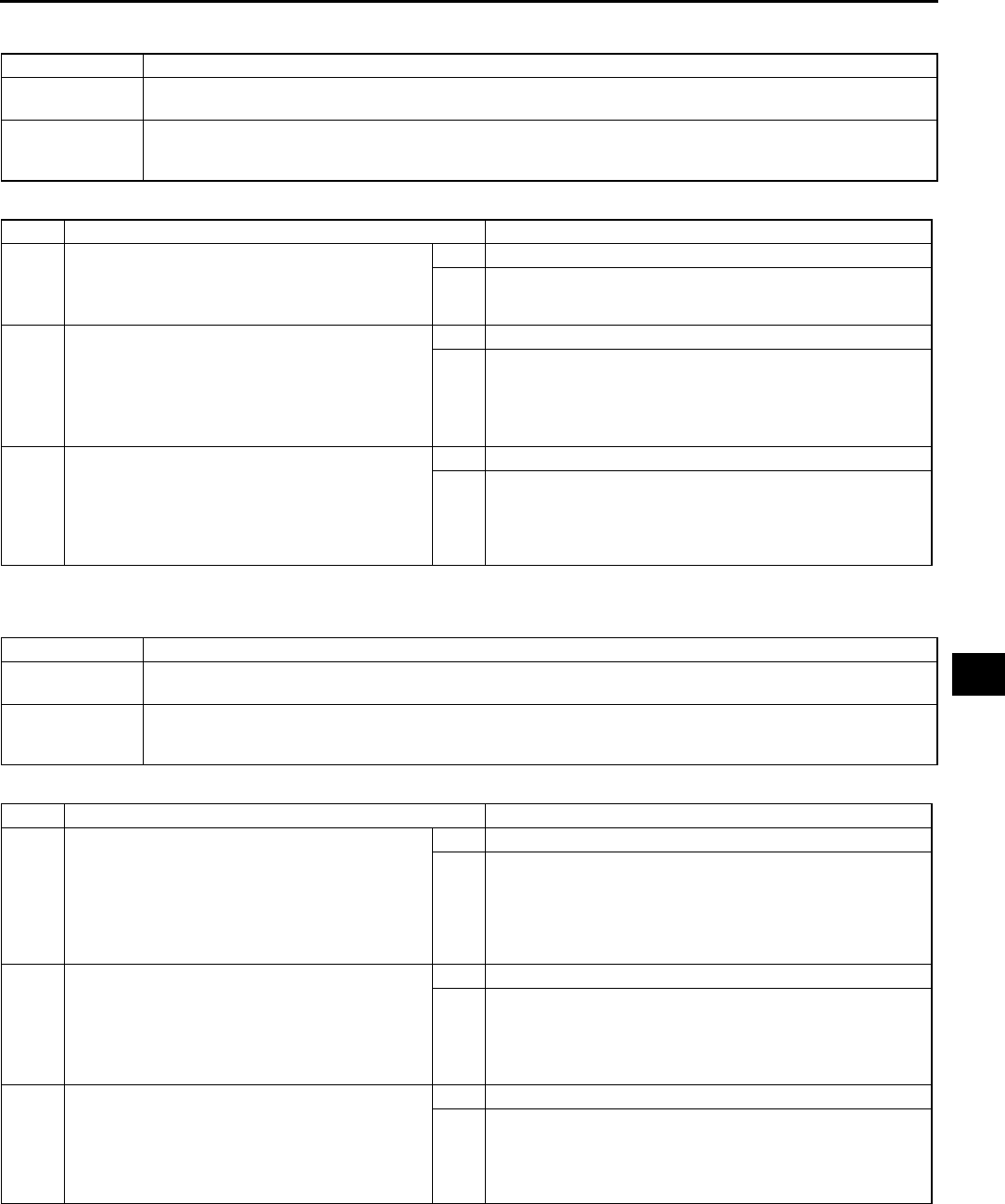
ON-BOARD DIAGNOSTIC [AUDIO]
T169
T
DTC 05:ER10 A6E817566900W09
Diagnostic procedure
End Of Sie
DTC 06:ER10 A6E817566900W10
Diagnostic procedure
End Of Sie
DTC 05:Er10 CD changer (external type)base unit communication line
DETECTION
CONDITION •Base unit detects communication error with CD changer (external type).
POSSIBLE
CAUSE
•Malfunction of connectors between base unit and CD changer (external type)
•CD changer (external type) malfunction
•Base unit malfunction
STEP INSPECTION ACTION
1INSPECT CONNECTOR
•Inspect base unit and CD changer (external
type) connectors for connection.
•Are connectors securely connected?
Yes Go to next step.
No Reconnect connector, then go to next step.
2INSPECT WIRING HARNESS BETWEEN CD
CHANGER (EXTERNAL TYPE) AND BASE
UNIT
•Inspect wiring harness between base unit
and CD changer (external type).
•Is wiring harness okay?
Yes Go to next step.
No Securely install CD changer (external type), then go to next
step.
3INSPECT CD CHANGER (EXTERNAL TYPE)
•Clear DTC.
•Turn ignition switch to ACC or ON position
and hold for 3 seconds or more.
•Start on-board diagnostic test mode.
•Is DTC 05:Er10 displayed?
Yes Replace base unit and CD changer (external type).
No Troubleshooting completed.
DTC 06:Er10 CD changer (upper module)base unit communication line
DETECTION
CONDITION •Base unit detects communication error with CD changer (upper module).
POSSIBLE
CAUSE
•Malfunction of connectors between base unit and CD changer (upper module)
•CD changer (upper module) malfunction
•Base unit malfunction
STEP INSPECTION ACTION
1INSPECT CONNECTOR
•Remove CD changer (upper module) and
inspect connector for the following.
Deformation of pin
Poor connection of female terminal
Pinching of foreign material
•Is connector okay?
Yes Go to next step.
No Repair connector, then go to next step.
2VERIFY THAT CD CHANGER (UPPER
MODULE) IS INSTALLED WITH BASE UNIT
•Install CD changer (upper module) and verify
its installation condition.
•Is CD changer (upper module) securely
installed?
Yes Go to next step.
No Securely install CD changer (upper module), then go to
next step.
3INSPECT CD CHANGER (UPPER MODULE)
•Clear DTC.
•Turn ignition switch to ACC or ON position
and hold for 3 seconds or more.
•Start on-board diagnostic test mode.
•Is DTC 06:Er10 displayed?
Yes Replace base unit and CD changer (upper module).
No Troubleshooting completed.

T170
ON-BOARD DIAGNOSTIC [AUDIO]
DTC 07:ER10 A6E817566900W11
Diagnostic procedure
End Of Sie
DTC 03:ER01 A6E817566900W12
Diagnostic procedure
End Of Sie
DTC 03:ER02 A6E817566900W13
DTC 07:Er10 MD playerbase unit communication line
DETECTION
CONDITION •Base unit detects communication error with MD player.
POSSIBLE
CAUSE
•Malfunction of connectors between base unit and MD player
•MD player malfunction
•Base unit malfunction
STEP INSPECTION ACTION
1INSPECT CONNECTOR
•Remove MD player and inspect connector
for the following.
Deformation of pin
Poor connection of female terminal
Pinching of foreign material
•Is connector okay?
Yes Go to next step.
No Repair connector, then go to next step.
2VERIFY THAT MD PLAYER IS INSTALLED
WITH BASE UNIT
•Install MD player and verify its installation
condition.
•Is MD player securely installed?
Yes Go to next step.
No Securely install MD player, then go to next step.
3INSPECT MD PLAYER
•Clear DTC.
•Turn ignition switch to ACC or ON position
and hold for 3 seconds or more.
•Start on-board diagnostic test mode.
•Is DTC 07:Er10 displayed?
Yes Replace base unit and MD player.
No Troubleshooting completed.
DTC 03:Er01 CD player
DETECTION
CONDITION •CD player cannot implement insert and eject commands.
POSSIBLE
CAUSE
•Defective CD (broken or foreign material stuck/attached)
•CD player malfunction
STEP INSPECTION ACTION
1•Is CD able to be ejected? Yes Go to next step.
No Replace CD player.
2INSPECT CD
•Inspect condition of CD where error has
occurred.
•Is CD okay?
Yes Go to next step.
No Repair (remove foreign material) or replace CD, then go to
next step.
3INSPECT CD PLAYER
•Clear DTC.
•Insert and eject CD with no defect.
•Start on-board diagnostic test mode.
•Is DTC 03:Er01 displayed?
Yes Replace CD player.
No Troubleshooting completed.
DTC 03:Er02 CD player
DETECTION
CONDITION
Note
•When error occurs, error message CHECK CD is displayed in the LCD.
•Cannot play CD normally or change tracks.
POSSIBLE
CAUSE
•Defective CD (scratches or dirt)
•CD player malfunction
ON-BOARD DIAGNOSTIC [AUDIO]
T171
T
Diagnostic procedure
End Of Sie
DTC 03:ER07 A6E817566900W14
Diagnostic procedure
End Of Sie
DTC 00:ER01 A6E817566900W15
Diagnostic procedure
STEP INSPECTION ACTION
1VERIFY WHETHER MALFUNCTION IS IN CD
PLAYER OR CD
•Play CD and select other song (change
tracks).
•Does CD player change tracks?
Yes Go to Step 3.
No Not able to change particular
tracks.
Go to next step.
Not able to change any
tracks.
Change CD and perform
track-change again.
•If CD player changes
tracks, then go to Step 3.
•If not, replace CD player.
2INSPECT CD
•Inspect condition of CD where error has
occurred.
•Is CD okay?
Yes Go to next step.
No Repair (remove foreign material) or replace CD, then go to
next step.
3INSPECT CD PLAYER
•Clear DTC.
•Play CD and select other song (change
tracks).
•Start on-board diagnostic test mode.
•Is DTC 03:Er02 displayed?
Yes Replace CD player.
No Troubleshooting completed.
DTC 03:Er07 CD player
DETECTION
CONDITION
Note
•When error occurs, error message CHECK CD is displayed in the LCD.
•Base unit detects CD reading error.
POSSIBLE
CAUSE
•Defective CD (scratches or dirt)
•CD player malfunction
STEP INSPECTION ACTION
1INSPECT CD
•Inspect condition of CD where error has
occurred.
•Is CD okay?
Yes Go to next step.
No Repair (remove foreign material) or replace CD, then go to
next step.
2INSPECT CD PLAYER
•Clear DTC.
•Insert and play CD with no defect.
•Start on-board diagnostic test mode.
•Is DTC 03:Er07 displayed?
Yes Replace CD player.
No Troubleshooting completed.
DTC 00:Er01 Cassette deck
DETECTION
CONDITION •Cassette deck cannot implement insert and eject commands.
POSSIBLE
CAUSE
•Defective cassette tape (deformation, broken, or foreign material stuck/attached)
•Cassette deck malfunction
STEP INSPECTION ACTION
1•Is cassette tape able to be ejected? Yes Go to next step.
No Replace cassette deck.
2INSPECT CASSETTE TAPE
•Inspect condition of cassette tape where
error has occurred.
•Is cassette tape okay?
Yes Go to next step.
No Repair (remove foreign material) or replace cassette tape,
then go to next step.

T172
ON-BOARD DIAGNOSTIC [AUDIO]
End Of Sie
DTC 00:ER03 A6E817566900W16
Diagnostic procedure
End Of Sie
DTC 00:ER04 A6E817566900W17
Diagnostic procedure
End Of Sie
DTC 05:ER01 A6E817566900W18
3INSPECT CASSETTE DECK
•Clear DTC.
•Insert and eject cassette tape with no defect.
•Start on-board diagnostic test mode.
•Is DTC 00:Er01 displayed?
Yes Replace cassette deck.
No Troubleshooting completed.
STEP INSPECTION ACTION
DTC 00:Er03 Cassette deck
DETECTION
CONDITION •Base unit detects that reel built into cassette deck does not operate.
POSSIBLE
CAUSE
•Defective cassette tape (tape slack, pinched tape in internal cassette deck)
•Cassette deck malfunction
STEP INSPECTION ACTION
1INSPECT CASSETTE TAPE
•Inspect condition of cassette tape where
error has occurred.
•Is cassette tape okay?
Yes Go to next step.
No Repair (remove tape slack or repair pinched tape) or
replace cassette tape, then go to next step.
2INSPECT CASSETTE DECK
•Clear DTC.
•Insert cassette tape with no defect.
•Play cassette tape for 20 seconds or more.
•Start on-board diagnostic test mode.
•Is DTC 00:Er03 displayed?
Yes Replace cassette deck.
No Troubleshooting completed.
DTC 00:Er04 Cassette tape
DETECTION
CONDITION
Note
•When error occurs, error message CHECK TAPE is displayed in the LCD.
•Cassette tape is worn out.
POSSIBLE
CAUSE
•Tape wear
•Cassette deck malfunction
STEP INSPECTION ACTION
1INSPECT CASSETTE TAPE
•Inspect condition of cassette tape where
error has occurred.
•Is cassette tape okay?
Yes Go to next step.
No Replace cassette tape, then go to next step.
2INSPECT CASSETTE DECK
•Clear DTC.
•Insert cassette tape with no defect.
•Play cassette tape for 20 seconds or more.
•Start on-board diagnostic test mode.
•Is DTC 00:Er04 displayed?
Yes Replace cassette deck.
No Troubleshooting completed.
DTC 05:Er01 CD changer (external type)
DETECTION
CONDITION •Changer function does not operate.
POSSIBLE
CAUSE
•Defective CD (broken or foreign material)
•Magazine malfunction
•CD changer (external type) malfunction
ON-BOARD DIAGNOSTIC [AUDIO]
T173
T
Diagnostic procedure
End Of Sie
DTC 05:ER07 A6E817566900W19
Diagnostic procedure
End Of Sie
DTC 06:ER01 A6E817566900W20
Diagnostic procedure
STEP INSPECTION ACTION
1VERIFY WHETHER MALFUNCTION IS IN CD
CHANGER OR OTHER PARTS
•Operate changer function.
•Is function okay?
Yes Go to Step 4.
No Not able to change particular
CD.
Go to next step.
Not able to change any CD. Go to Step 3.
2INSPECT CD
•Inspect condition of CD where error has
occurred.
•Is CD okay?
Yes Go to next step.
No Repair (remove foreign material) or replace CD, then go to
next step.
3INSPECT MAGAZINE
•Inspect magazine.
•Is magazine okay?
Yes Go to next step.
No Repair or replace magazine, then go to next step.
4INSPECT CD CHANGER (EXTERNAL TYPE)
•Clear DTC.
•Operate changer.
•Start on-board diagnostic test mode.
•Is DTC 05:Er01 displayed?
Yes Replace CD changer (external type).
No Troubleshooting completed.
DTC 05:Er07 CD changer (external type)
DETECTION
CONDITION
Note
•When error occurs, error message CHECK CD is displayed in the LCD.
•Base unit detects CD reading error.
POSSIBLE
CAUSE
•Defective CD (scratches or dirt)
•CD changer (external type) malfunction
STEP INSPECTION ACTION
1VERIFY WHETHER MALFUNCTION IS IN CD
CHANGER OR OTHER PARTS
•Play all CD in magazine.
•Is CD changer able to read them properly?
Yes Go to Step 3.
No Not able to change particular
CD.
Go to next step.
Not able to change any CD. Go to Step 3.
2INSPECT CD
•Inspect condition of CD where error has
occurred.
•Is CD okay?
Yes Go to next step.
No Repair (remove foreign material) or replace CD, then go to
next step.
3INSPECT CD CHANGER (EXTERNAL TYPE)
•Clear DTC.
•Insert and play CD with no defect.
•Start on-board diagnostic test mode.
•Is DTC 05:Er07 displayed?
Yes Replace CD changer (external type).
No Troubleshooting completed.
DTC 06:Er01 CD changer (upper module)
DETECTION
CONDITION •CD changer (upper module) cannot implement insert, eject, and disc change commands.
POSSIBLE
CAUSE
•Defective CD (broken or foreign material stuck/attached)
•CD changer (upper module) malfunction
STEP INSPECTION ACTION
1•Is CD able to be ejected? Yes Go to next step.
No Replace CD changer (upper module).
2INSPECT CD
•Inspect condition of CD where error has
occurred.
•Is CD okay?
Yes Go to next step.
No Repair (remove foreign material) or replace CD, then go to
next step.

T174
ON-BOARD DIAGNOSTIC [AUDIO]
End Of Sie
DTC 06:ER02 A6E817566900W21
Diagnostic procedure
End Of Sie
DTC 06:ER07 A6E817566900W22
Diagnostic procedure
3INSPECT CD CHANGER (UPPER MODULE)
•Clear DTC.
•Insert and eject CD with no defect.
•Start on-board diagnostic test mode.
•Is DTC 06:Er01 displayed?
Yes Replace CD changer (upper module).
No Troubleshooting completed.
STEP INSPECTION ACTION
DTC 06:Er02 CD changer (upper module)
DETECTION
CONDITION
Note
•When error occurs, error message CHECK CD is displayed in the LCD.
•Cannot play CD normally or change tracks.
POSSIBLE
CAUSE
•Defective CD (scratches or dirt)
•CD changer (upper module) malfunction
STEP INSPECTION ACTION
1VERIFY WHETHER MALFUNCTION IS IN CD
CHANGER (UPPER MODULE) OR CD
•Play all CDs in changer and select other
song (change tracks).
•Is CD changer able to change tracks?
Yes Go to Step 3.
No Not able to change particular
tracks.
Go to next step.
Not able to change any
tracks.
Change CD and perform
track-change again.
•If CD changer changes
tracks, go to Step 3.
•If not, replace CD
changer (upper module).
2INSPECT CD
•Inspect condition of CD where error has
occurred.
•Is CD okay?
Yes Go to next step.
No Repair (remove foreign material) or replace CD, then go to
next step.
3INSPECT CD CHANGER (UPPER MODULE)
•Clear DTC.
•Play CD and select other song (change
tracks).
•Start on-board diagnostic test mode.
•Is DTC 06:Er02 displayed?
Yes Replace CD changer (upper module).
No Troubleshooting completed.
DTC 06:Er07 CD changer (upper module)
DETECTION
CONDITION
Note
•When error occurs, error message CHECK CD is displayed in the LCD.
•Base unit detects CD reading error.
POSSIBLE
CAUSE
•Defective CD (scratches or dirt)
•CD changer (upper module) malfunction
STEP INSPECTION ACTION
1VERIFY WHETHER MALFUNCTION IS IN CD
CHANGER (UPPER MODULE) OR CD
•Play all CDs in changer.
•Is CD changer able to read them properly?
Yes Go to Step 3.
No Not able to read particular
CD.
Go to next step.
Not able to read any CD. Go to Step 3.
2INSPECT CD
•Inspect condition of CD where error has
occurred.
•Is CD okay?
Yes Go to next step.
No Repair (remove foreign material) or replace CD, then go to
next step.
ON-BOARD DIAGNOSTIC [AUDIO]
T175
T
End Of Sie
DTC 07:ER01 A6E817566900W23
Diagnostic procedure
End Of Sie
DTC 07:ER02 A6E817566900W24
Diagnostic procedure
End Of Sie
3INSPECT CD CHANGER (UPPER MODULE)
•Clear DTC.
•Insert and play CD for 12 seconds or more.
•Start on-board diagnostic test mode.
•Is DTC 06:Er07 displayed?
Yes Replace CD changer (upper module).
No Troubleshooting completed.
STEP INSPECTION ACTION
DTC 07:Er01 MD player
DETECTION
CONDITION •MD player cannot implement insert and eject commands.
POSSIBLE
CAUSE
•Defective MD (broken or foreign material stuck/attached)
•MD player malfunction
STEP INSPECTION ACTION
1•Is MD able to be ejected? Yes Go to next step.
No Replace MD player.
2INSPECT MD
•Inspect condition of MD where error has
occurred.
•Is MD okay?
Yes Go to next step.
No Repair (remove foreign material) or replace MD, then go to
next step.
3INSPECT MD PLAYER
•Clear DTC.
•Insert and eject MD with no defect.
•Start on-board diagnostic test mode.
•Is DTC 07:Er01 displayed?
Yes Replace MD player.
No Troubleshooting completed.
DTC 07:Er02 MD player
DETECTION
CONDITION
Note
•When error occurs, error message CHECK MD is displayed in the LCD.
•Cannot play MD normally or change tracks.
POSSIBLE
CAUSE
•Defective MD (scratches or dirt)
•MD player malfunction
STEP INSPECTION ACTION
1VERIFY WHETHER MALFUNCTION IS IN MD
PLAYER OR MD
•Play MD and select other song (change
tracks).
•Is MD player able to change tracks?
Yes Go to Step 3.
No Not able to change particular
tracks.
Go to next step.
Not able to change any
tracks.
Change MD and perform
track-change again.
•If MD player changes
tracks, then go to Step 3.
•If not, replace MD player.
2INSPECT MD
•Inspect condition of MD where error has
occurred.
•Is MD okay?
Yes Go to next step.
No Repair (remove foreign material) or replace MD, then go to
next step.
3INSPECT MD PLAYER
•Clear DTC.
•Play MD and select other song (change
tracks).
•Start on-board diagnostic test mode.
•Is DTC 07:Er02 displayed?
Yes Replace MD player.
No Troubleshooting completed.
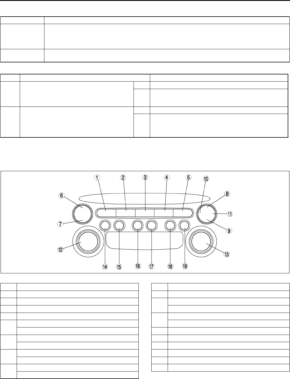
T176
ON-BOARD DIAGNOSTIC [AUDIO]
DTC 07:ER07 A6E817566900W25
Diagnostic procedure
End Of Sie
DIAGNOSTIC ASSIST FUNCTION A6E817566900W26
Structural View
Switch location
.
DTC 07:Er07 MD player
DETECTION
CONDITION
Note
•When error occurs, error message CHECK MD is displayed in the LCD.
•Base unit detects MD reading error.
POSSIBLE
CAUSE
•Defective MD (scratches or dirt)
•MD player malfunction
STEP INSPECTION ACTION
1INSPECT MD
•Inspect condition of MD where error has
occurred.
•Is MD okay?
Yes Go to next step.
No Repair (remove foreign material) or replace MD, then go to
next step.
2INSPECT MD PLAYER
•Clear DTC.
•Insert and play MD for 12 seconds or more.
•Start on-board diagnostic test mode.
•Is DTC 07:Er07 displayed?
Yes Replace MD player.
No Troubleshooting completed.
A6E8175W001
1 FM1 button
2 FM2 button
3AM button
4 CD button
5 TAPE/MD button
6 SEEK button (upper) (type A)
SCAN button (type B)
7 SEEK button (lower) (type A)
AUTO-M button (type B)
8 TA button (type A)
SEEK button (upper) (type B)
9 AUTO-M button (type A)
SEEK button (lower) (type B)
10 AF button (type A)
11 PYT button (type A)
12 POWER button (type A)
AUDIO CONT button (type B)
13 AUDIO CONT button (type A)
POWER button (type B)
14 Preset button 1
15 Preset button 2
16 Preset button 3
17 Preset button 4
18 Preset button 5
19 Preset button 6
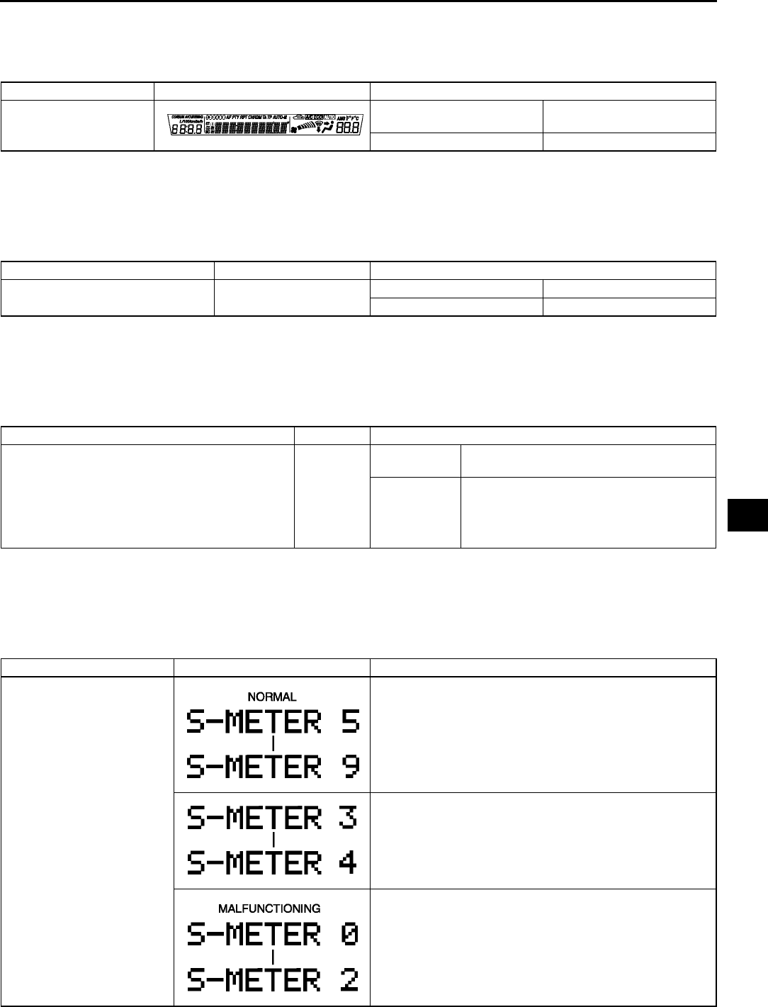
ON-BOARD DIAGNOSTIC [AUDIO]
T177
T
LCD Inspection
1. With audio on, first press the POWER button, then simultaneously press the SEEK button (upper) for
approximately 1 second.
2. Inspect the LCD according to the following table:
3. Turn the audio off or the ignition switch to the LOCK position to stop the diagnostic assist function.
Button Inspection
1. With audio on, first press the POWER button, then simultaneously press the TAPE/MD button for
approximately 1 second.
2. Inspect the button according to the following table:
3. Turn the audio off or the ignition switch to the LOCK position to stop the diagnostic assist function.
Speaker Inspection
1. With audio on, first press the POWER button, then simultaneously press the AUTO-M button for
approximately 1 second.
2. Inspect the speaker according to the following table:
3. Turn the audio off or the ignition switch to the LOCK position to stop the diagnostic assist function.
Radio Reception Condition Inspection
1. With audio on and at radio mode, first press the POWER button, then simultaneously press the preset button
2 for approximately 1 second.
2. Inspect the radio reception condition according to the following table:
3. Turn the audio off or the ignition switch to the LOCK position to stop the diagnostic assist function.
Inspection Display Action
Start LCD inspection
mode.
Characters displayed in LCD
are not truncated or faint.
LCD is okay.
Other than above. Replace base unit.
Inspection Display Action
•Start button inspection mode.
•Press the all buttons. Buzzer sounds. Button is okay.
Buzzer does not sound. Replace base unit.
Inspection Display Action
•Start speaker inspection mode.
•Does each speaker output sound in the
following order?
1. Left front door speaker and tweeter
2. Right front door speaker and tweeter
3. Right rear door speaker and woofer
4. Left rear rear door speaker and woofer
Yes Speakers and wiring harness between base
unit and speakers are okay.
No
Inspect the following parts.
•Malfunctioning speaker
•Wiring harness between base unit and
malfunctioning speaker
Inspection Display Action
Start radio reception
condition inspection mode.
Antenna, antenna feeder, and base unit are okay.
Change frequency (channel) and inspect again.
Inspect antenna and antenna feeder.
•If either one of them is not okay, replace malfunctioning
part.
•If both are okay, replace base unit.
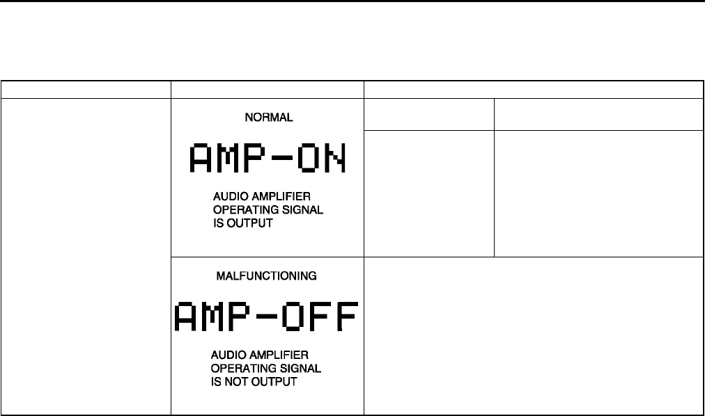
T178
ON-BOARD DIAGNOSTIC [AUDIO]
Audio Amplifier (External) Inspection
1. With audio on, first press the POWER button, then simultaneously press the SCAN button for approximately 1
second.
2. Inspect the audio amplifier (external) according to the following table:
3. Turn the audio off or the ignition switch to the LOCK position to stop the diagnostic assist function.
End Of Sie
Inspection Display Action
Start audio amplifier
(external) inspection mode.
Speakers output
sound.
System is okay.
Speakers do not
output sound.
Inspect following parts.
•Audio amplifier (external)
•Speakers
•Woofer relay
•Wiring harness
(base unitaudio amplifier
(external)Woofer relay)
Replace base unit.
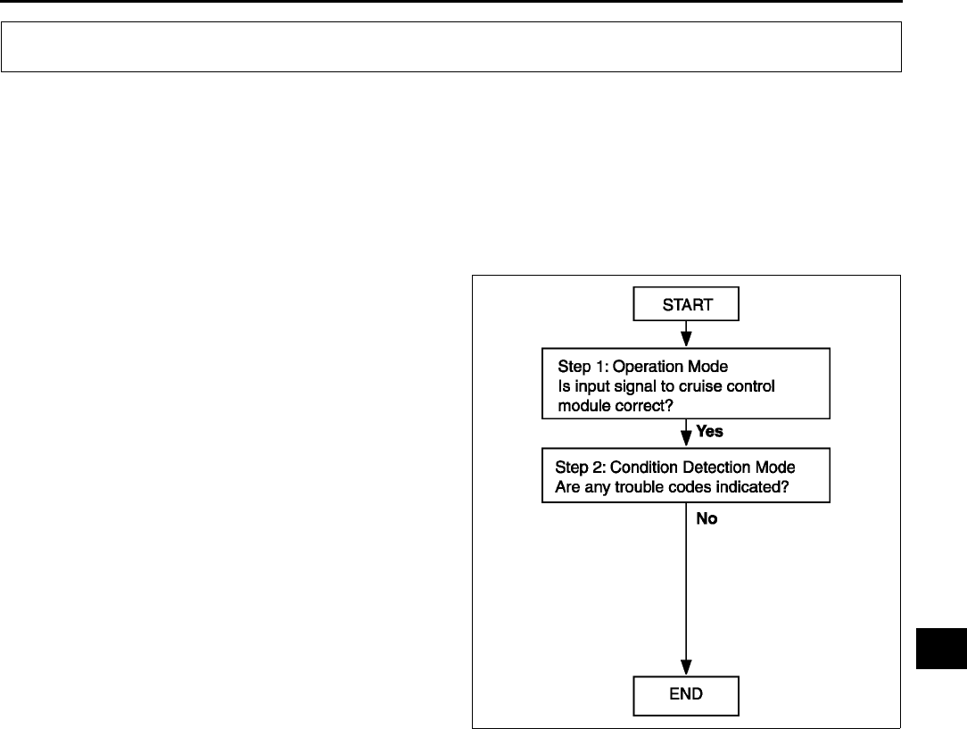
ON-BOARD DIAGNOSTIC [CRUISE CONTROL SYSTEM]
T179
T
FOREWORD A6E817266350W01
Outline
•There are two on-board diagnostic functions: Operation mode, which inspects for and indicates correct
operation of the input signals to the control module, and condition detection mode, which indicates troubles in
the system.
•The two functions can be done using either of the following methods:
Verifying the flashing pattern of the cruise set indicator light in the instrument cluster.
Inspection Order
End Of Sie
INSPECTION OF DTCS FOR OPERATION MODE A6E817266350W02
Note
•The cruise set indicator light will illuminate for 3 seconds when operation mode is on.
•If the cruise set indicator light does not illuminate for 3 seconds (Operation mode is not on) the following
may be the cause of the malfunction:
Cruise actuator ignition power supply fuse
Cruise set indicator light power supply fuse
Cruise control switch
Cruise control main switch
Clock spring for air bag system
Print plate in instrument cluster
Cruise set indicator light bulb
Cruise actuator
Open or short circuit in following wiring harnesses:
•Between cruise set indicator light and cruise actuator terminal G
•Between fuse block and cruise actuator terminal L
•Between fuse block and instrument cluster
•Between cruise actuator and clock spring
•Between clock spring and cruise control switch
Open circuit in following wiring harnesses:
•Between cruise actuator terminal I and ground
•Between clock spring and ground
1. Turn the ignition switch to the ON position.
2. Verify that the cruise control main switch is off.
ON-BOARD DIAGNOSTIC [CRUISE CONTROL SYSTEM]
A6E8172W001
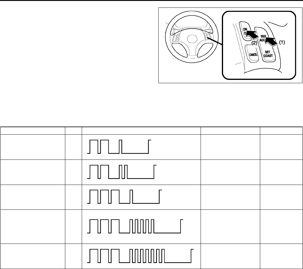
T180
ON-BOARD DIAGNOSTIC [CRUISE CONTROL SYSTEM]
3. Press and hold the RESUME/ACCEL switch on
(1), and turn on the cruise control main switch (2).
Keep the RESUME/ACCEL switch on for 3
seconds or more after the cruise control main
switch released. (The cruise set indicator light will
illuminate for 3 seconds, showing that the system
inspection has started.)
4. Operate each switch as described in the
operation code list and note the operation code
list pattern.
•If the cruise set indicator light does not flash,
inspect the corresponding system area.
•If it flashes, the corresponding DTC(s) will be
indicated and mode can be judged normal.
5. The operation mode is canceled by turning the ignition switch to LOCK position or turning off the cruise control
main switch.
Operation Code List
Inspection of Diagnostic Trouble Codes
Foreword
•When performing an asterisked (*) troubleshooting inspection shake the wiring harness and connectors while
doing the inspection to discover whether poor contact points are the cause of any intermittent malfunction. If
there is a problem check to make sure connectors terminals and wiring harness are connected correctly and
undamaged.
End Of Sie
A6E8172W002
Operation DTC Output pattern Diagnosed circuit Page
Turn SET/COAST switch
on 21 Cruise control switch
(SET/COAST switch)
(See T181
DTC 21)
Turn RESUME/ACCEL
switch on 22
Cruise control switch
(RESUME/ACCEL
switch)
(See T181
DTC 22)
Depress brake pedal 31 Brake switch (See T182
DTC 31)
MTX:
Depress clutch pedal
ATX:
Shift selector lever to P
or N position
35
MTX:
Clutch switch
ATX:
TR switch
(See T183
DTC 35)
Drive vehicle above 40
km/h {25 mph} 37 Vehicle speed sensor (See T184
DTC 37)
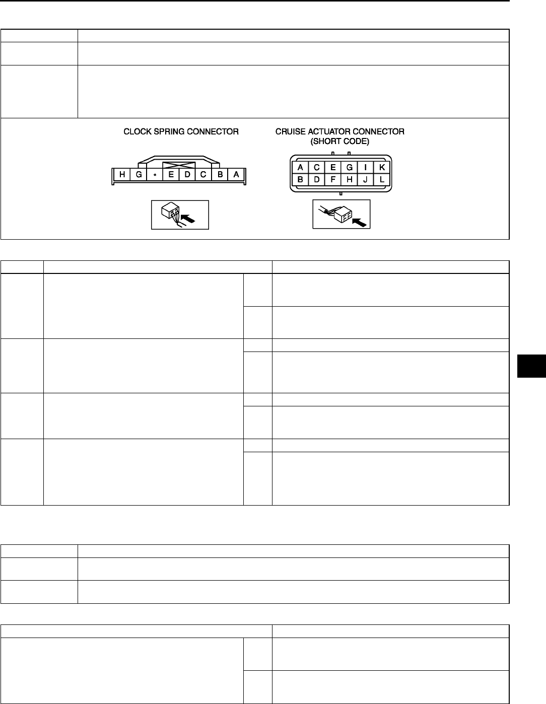
ON-BOARD DIAGNOSTIC [CRUISE CONTROL SYSTEM]
T181
T
DTC 21 A6E817266350W03
Diagnostic procedure
End Of Sie
DTC 22 A6E817266350W04
Diagnostic procedure
End Of Sie
DTC 21 Cruise control switch (SET/COAST switch)
DETECTION
CONDITION
•Resistance detected between cruise actuator connector terminal J and ground is other than
approximately 680 ohms.
POSSIBLE
CAUSE
•Cruise actuator malfunction
•Cruise control switch malfunction
•Clock spring malfunction
•Open circuit in wiring harness between clock spring and ground
•Open or short circuit in wiring harness between cruise actuator and clock spring
STEP INSPECTION ACTION
1INSPECT SIGNAL LINE OF CRUISE
CONTROL SWITCH POSITION
•Disconnect cruise actuator connector.
•Turn SET/COAST switch on.
•Is resistance at cruise actuator connector
terminal J approximately 680 ohms?
Yes Replace cruise actuator.
(See T110 CRUISE ACTUATOR REMOVAL/
INSTALLATION)
No Go to next step.
2INSPECT CRUISE CONTROL SWITCH
•Inspect cruise control switch.
(See T116 CRUISE CONTROL SWITCH
INSPECTION)
•Is cruise control switch okay?
Yes Go to next step.
No Replace cruise control switch.
(See T115 CRUISE CONTROL SWITCH REMOVAL/
INSTALLATION)
3INSPECT CLOCK SPRING
•Inspect clock spring.
(See T126 CLOCK SPRING INSPECTION)
•Is clock spring okay?
Yes Go to next step.
No Replace clock spring.
(See T125 CLOCK SPRING REMOVAL/
INSTALLATION)
4INSPECT WIRING HARNESS BETWEEN
CLOCK SPRING AND GROUND FOR
CONTINUITY
•Disconnect cruise control switch connector.
•Is there continuity between clock spring
connector terminal C and ground?
Yes Repair wiring harness. (cruise actuatorclock spring)
No Repair wiring harness. (clock springground)
DTC 22 Cruise control switch (RESUME/ACCEL switch)
DETECTION
CONDITION
•Resistance detected between cruise actuator connector terminal J and ground is other than
approximately 2.2 kilohms.
POSSIBLE
CAUSE
•Cruise actuator malfunction
•Cruise control switch malfunction
INSPECTION ACTION
INSPECT CRUISE CONTROL SWITCH
•Inspect cruise control switch.
(See T116 CRUISE CONTROL SWITCH
INSPECTION)
•Is cruise control switch okay?
Yes •Replace cruise actuator.
(See T110 CRUISE ACTUATOR REMOVAL/
INSTALLATION)
No •Replace cruise control switch.
(See T115 CRUISE CONTROL SWITCH
REMOVAL/INSTALLATION)
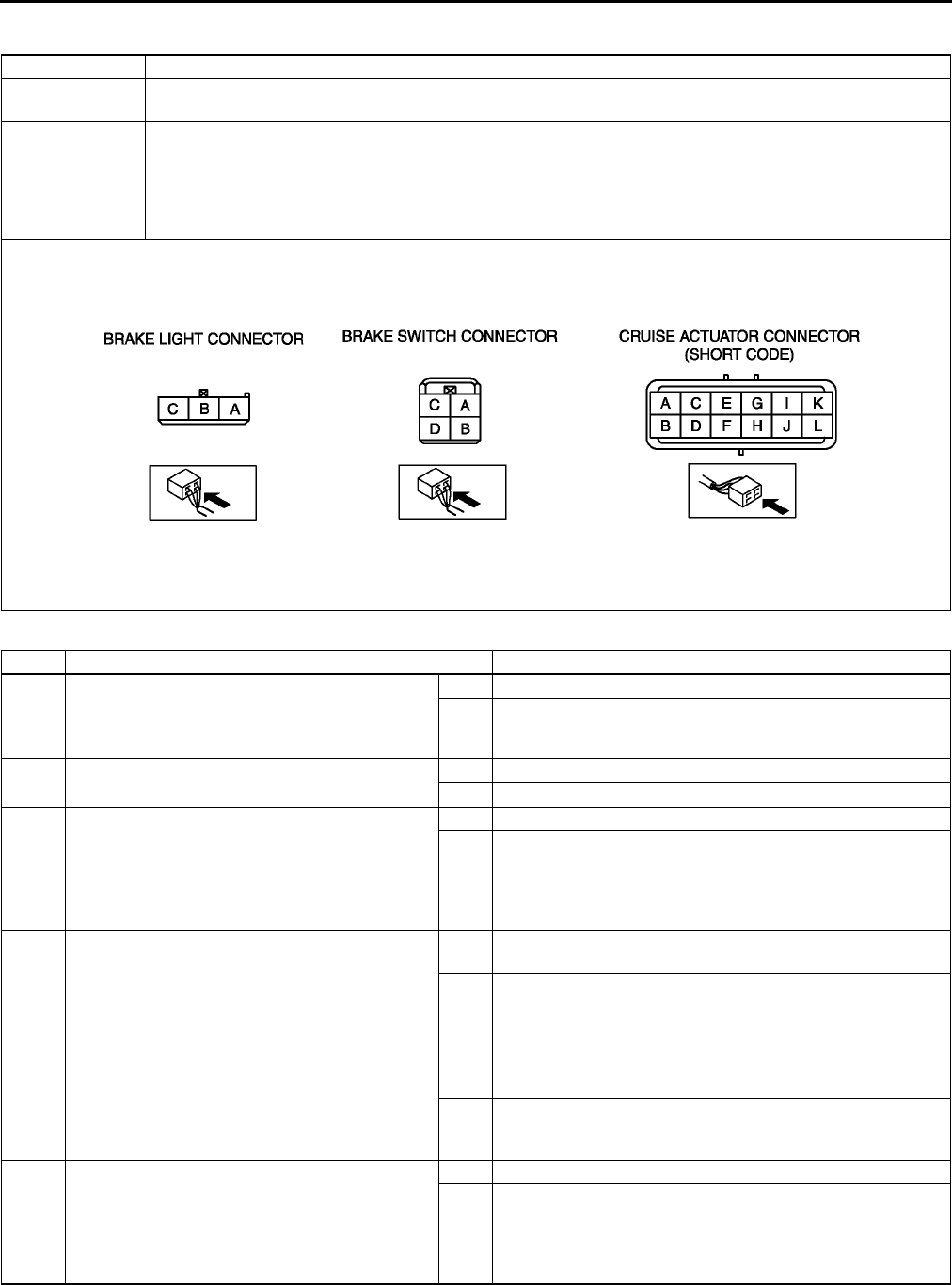
T182
ON-BOARD DIAGNOSTIC [CRUISE CONTROL SYSTEM]
DTC 31 A6E817266350W05
Diagnostic procedure
DTC 31 Brake switch
DETECTION
CONDITION
•Voltage detected at cruise actuator connector terminal C is not approximately 12 V or voltage detected
at cruise actuator connector terminal K is not approximately 0 V.
POSSIBLE
CAUSE
•Burnt STOP 15 A fuse
•Cruise actuator malfunction
•Brake switch and/or brake switch 2 malfunction
•Open circuit in wiring harness between STOP 15 A fuse and brake switch
•Open circuit in wiring harness between brake switch and cruise actuator terminal C
•Short circuit in wiring harness between brake switch 2 and cruise actuator terminal K
STEP INSPECTION ACTION
1VERIFY WHICH BRAKE SWITCH CIRCUIT IS
MALFUNCTIONING
•Does brake light illuminate when brake pedal
depressed?
Yes Go to Step 6.
No Go to next step.
2INSPECT STOP 15 A FUSE FOR FUSION
•Is STOP 15 A fuse okay?
Yes Go to next step.
No Replace fuse after inspecting and repairing wiring harness.
* 3 INSPECT WIRING HARNESS BETWEEN
STOP 15 A FUSE AND BRAKE SWITCH FOR
CONTINUITY
•Depress brake pedal.
•Is voltage at brake switch connector terminal
D approximately 12 V?
Yes Go to Step 5.
No Go to next step.
* 4 INSPECT WIRING HARNESS BETWEEN
STOP 15 A FUSE AND BRAKE SWITCH FOR
CONTINUITY
•Is voltage at brake switch connector terminal
B approximately 12 V?
Yes Inspect brake switch.
(See P8 BRAKE SWITCH INSPECTION)
No Repair wiring harness. (STOP 15 A fuseBrake switch)
* 5 INSPECT WIRING HARNESS BETWEEN
BRAKE SWITCH AND BRAKE LIGHT FOR
CONTINUITY
•Depress brake pedal.
•Is voltage at brake light connector terminal
(power supply side) approximately 12 V?
Yes Inspect following electrical parts.
•Brake light bulb
•Wiring harness between brake light and ground
No Repair wiring harness. (Brake switchBrake light)
* 6 INSPECT WIRING HARNESS BETWEEN
BRAKE SWITCH AND CRUISE ACTUATOR
FOR CONTINUITY
•Depress brake pedal.
•Is voltage at cruise actuator connector
terminal C approximately 12 V?
Yes Go to next step.
No Repair wiring harness. (Cruise actuatorBrake switch)
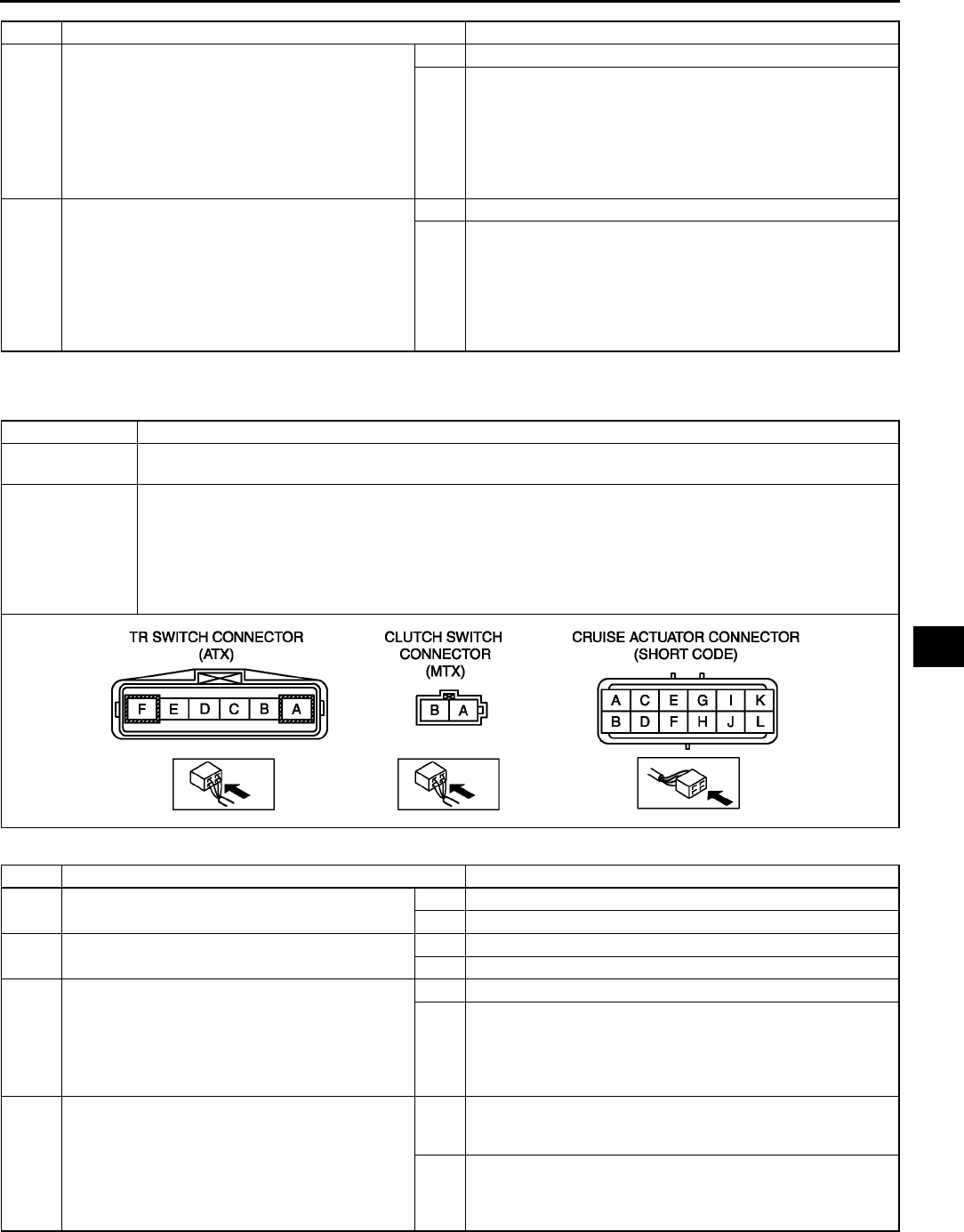
ON-BOARD DIAGNOSTIC [CRUISE CONTROL SYSTEM]
T183
T
End Of Sie
DTC 35 A6E817266350W06
Diagnostic procedure
* 7 VERIFY WHICH IS MALFUNCTIONING
CRUISE ACTUATOR AND WIRING HARNESS
(BRAKE SWITCH 2 AND CRUISE
ACTUATOR) OR BRAKE SWITCH 2
•Disconnect brake switch connector.
•Turn ignition switch ON position.
•Is voltage at brake switch connector terminal
B approximately 12 V?
Yes Go to next step.
No Inspect brake switch 2.
(See P8 BRAKE SWITCH INSPECTION)
* 8 INSPECT WIRING HARNESS BETWEEN
BRAKE SWITCH 2 AND CRUISE ACTUATOR
FOR SHORT TO POWER SUPPLY
•Turn ignition switch to LOCK position.
•Disconnect cruise actuator connector.
•Turn ignition switch ON position.
•Is voltage at cruise actuator connector
terminal K approximately 12 V?
Yes Repair wiring harness. (Cruise actuatorBrake switch 2)
No Repalce cruise actuator.
(See T110 CRUISE ACTUATOR REMOVAL/
INSTALLATION)
STEP INSPECTION ACTION
DTC 35 Clutch switch (MTX), TR switch (ATX)
DETECTION
CONDITION •Voltage detected at cruise actuator connector terminal F is not approximately 0 V.
POSSIBLE
CAUSE
•Cruise actuator malfunction
•Starter relay malfunction (ATX)
•Clutch switch malfunction (MTX)
•TR switch malfunction (ATX)
•Open circuit in wiring harness between PCM and clutch switch (MTX)
•Open circuit in wiring harness between starter relay and TR switch (ATX)
•Open circuit in wiring harness between cruise actuator and clutch switch (MTX) or TR switch (ATX)
STEP INSPECTION ACTION
1•Does vehicle has MTX? Yes Go to next step.
No Go to step 5.
2 INSPECT CLUTCH SWITCH
Is clutch switch okay?
Yes Go to next step.
No Replace clutch switch.
* 3 INSPECT WIRING HARNESS BETWEEN
CLUTCH SWITCH AND GROUND FOR
CONTINUITY
•Disconnect clutch switch connector.
•Is there continuity between clutch switch
connector terminal B and ground?
Yes Go to next step.
No Repair wiring harness.
(Clutch switchground)
* 4 INSPECT WIRING HARNESS BETWEEN
CRUISE ACTUATOR AND CLUTCH SWITCH
FOR CONTINUITY
•Disconnect cruise actuator connector.
•Is there continuity between cruise actuator
connector terminal F and clutch switch
connector terminal A?
Yes Replace cluise actuator.
(SeeT110 CRUISE ACTUATOR REMOVAL/
INSTALLATION)
No Repair wiring harness.
(Cruise actuatorclutch switch)
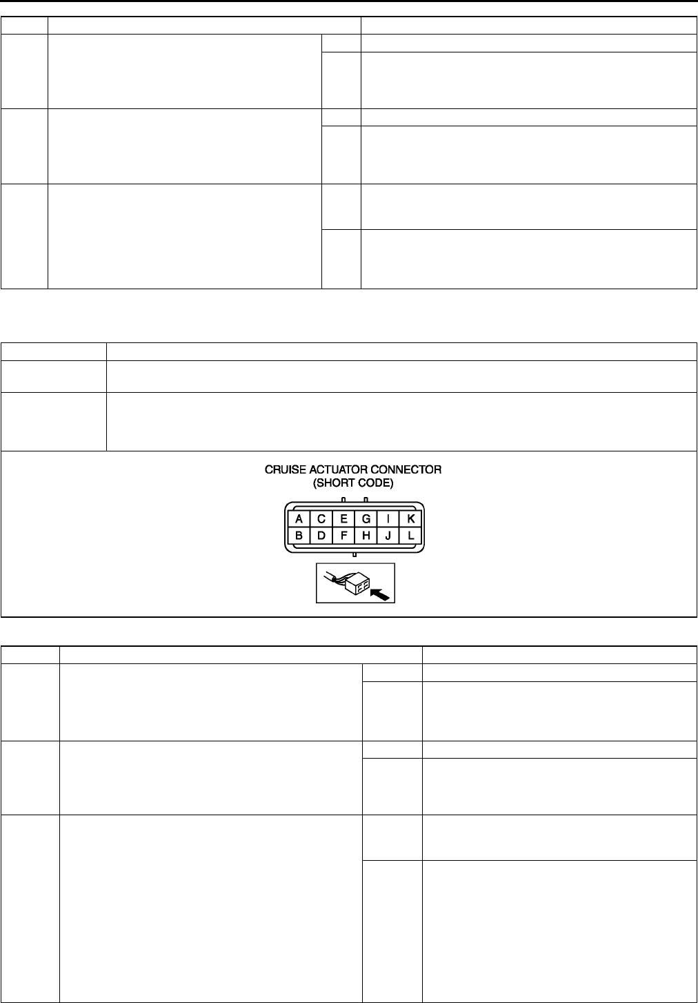
T184
ON-BOARD DIAGNOSTIC [CRUISE CONTROL SYSTEM]
End Of Sie
DTC 37 A6E817266350W07
Diagnostic procedure
5INSPECT TR SWITCH
•Inspect TR switch.
(See K14 TRANSAXLE RANGE (TR) SWITCH
INSPECTION)
•Is TR switch okay?
Yes Go to next step.
No Repair TR switch.
(See K15 TRANSAXLE RANGE (TR) SWITCH
REMOVAL/INSTALLATION)
* 6 INSPECT WIRING HARNESS BETWEEN TR
SWITCH AND GROUND FOR CONTINUITY
•Disconnect TR switch connector.
•Is there continuity between TR switch
connector terminal A and ground?
Yes Go to next step.
No Repair wiring harness (TR switchground ) or inspect
starter.
* 7 INSPECT WIRING HARNESS BETWEEN
CRUISE ACTUATOR AND TR SWITCH FOR
CONTINUITY
•Disconnect cruise actuator connector.
•Is there continuity between cruise actuator
connector terminal F and TR switch
connector terminal F?
Yes Replace cruise actuator.
(SeeT110 CRUISE ACTUATOR REMOVAL/
INSTALLATION)
No Repair wiring harness. (cruise actuatorTR switch)
STEP INSPECTION ACTION
DTC 37 Vehicle speed sensor
DETECTION
CONDITION •Vehicle speed signal is not detected at cruise actuator connector terminal A.
POSSIBLE
CAUSE
•Cruise actuator malfunction
•DSC HU/CM (with ABS/TCS HU/CM)
•Open or short circuit in wiring harness between ABS/TCS cruise actuator and DSC HU/CM (without
DSC: ABS/TCS HU/CM)
STEP INSPECTION ACTION
1INSPECT SPEEDOMETER OPERATION
•Does speedometer operate correctly?
Yes Go to next step.
No Perform instrument cluster input/output check
mode.
(See T75 INSTRUMENT CLUSTER INPUT/
OUTPUT CHECK MODE)
2INSPECT PCM ON-BOARD DIAGNOSTIC
•Drive the vehicle at more than 40 km/h {25 mph}.
•Check the DTC for PCM ON-BOARD
DIAGNOSTIC.
•Is DTC P0500 displayed?
Yes Go to applicable DTC inspection.
No Go to next step.
* 3 VERIFY WHICH IS MALFUNCTIONING WIRING
HARNESS WITH DSC OR CRUISE ACTUATOR
•Disconnect cruise actuator connector and DSC
HU/CM connector.
•Is there continuity between cruise actuator
connector terminal A and DSC HU/CM connector
terminal AE?
With ABS/TCS
•Disconnect cruise actuator connector and ABS/
TCS HU/CM connector.
•Is there continuity between cruise actuator
connector terminal A and ABS/TCS connector
terminal V?
Yes Replace cruise actuator.
(See T110 CRUISE ACTUATOR REMOVAL/
INSTALLATION)
No Repair wiring harness.
With DSC
(DSC HU/CMCruise actuator)
With ABS/TCS
(ABS/TCS HU/CMCruise actuator)
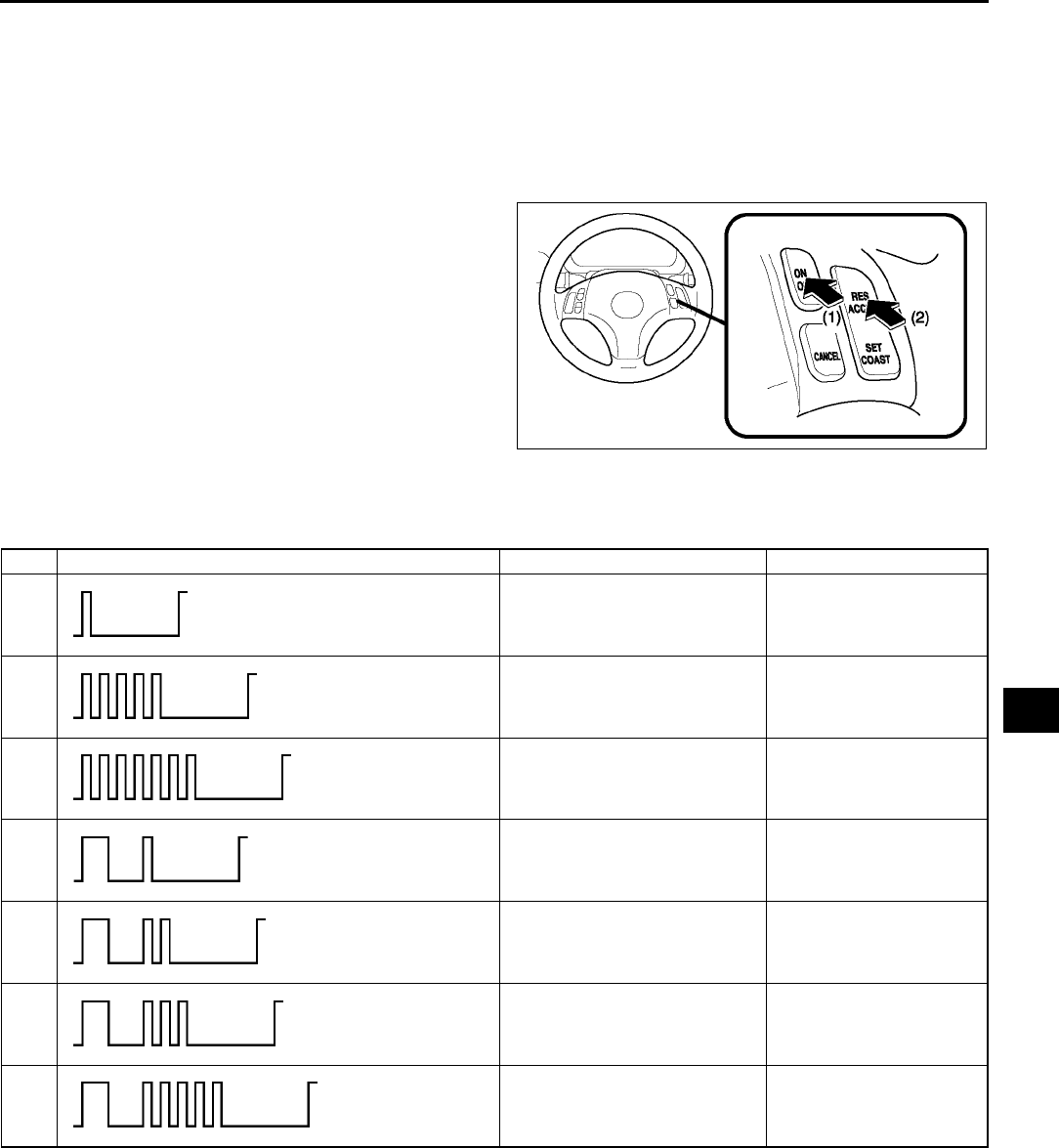
ON-BOARD DIAGNOSTIC [CRUISE CONTROL SYSTEM]
T185
T
End Of Si e
INSPECTION OF DTCS FOR CONDITION DETECTION MODE A6E817266350W08
Note
•The cruise set indicator light will illuminate for 3 seconds, when condition detection mode is on.
•If the RESUME/ACCEL switch on the cruise control switch is malfunctioning, the cruise set indicator light
will not give a correct indication when you inspect the system.
1. Drive the vehicle at 30 km/h {19 mph} or more.
2. Press on the cruise control main switch (1).
3. Operate each of the cruise control switches.
4. Stop the vehicle and let it idle.
5. Turn and hold the RESUME/ACCEL switch on for
at least 3 seconds (2). The cruise set indicator
light will illuminate for 3 seconds, and then go off
for at least 2 seconds. Thus, the condition
detection mode begins.
•If a DTC is indicated, inspect the
corresponding system area.
•If normal, DTC(s) will not be indicated.
6. The condition detection mode is canceled by
turning the ignition switch to LOCK position or
turning off the cruise control main switch.
Condition Code List
Note
•When two or more DTCs are indicated, inspect the malfunction with the smallest number first.
Inspection of Diagnostic Trouble Codes
Foreword
•When performing an asterisked (*) troubleshooting inspection shake the wiring harness and connectors while
doing the inspection to discover whether poor contact points are the cause of any intermittent malfunction. If
there is a problem check to make sure connectors terminals and wiring harness are connected correctly and
undamaged.
End Of Sie
A6E8172W013
DTC Output pattern Diagnosed circuit Page
01 Cruise actuator (Drive circuit) (See T186 DTC 01)
05 Brake switch (See T186 DTC 05)
07 Brake switch
Brake switch 2 (See T186 DTC 07)
11 Cruise control switch (SET/
COAST switch) (See T187 DTC 11)
12 Cruise control switch (RESUME/
ACCEL switch) (See T187 DTC 12)
13 Cruise control switch (Ground
circuit) (See T188 DTC 13)
15 Cruise actuator (Control circuit) (See T188 DTC 15)
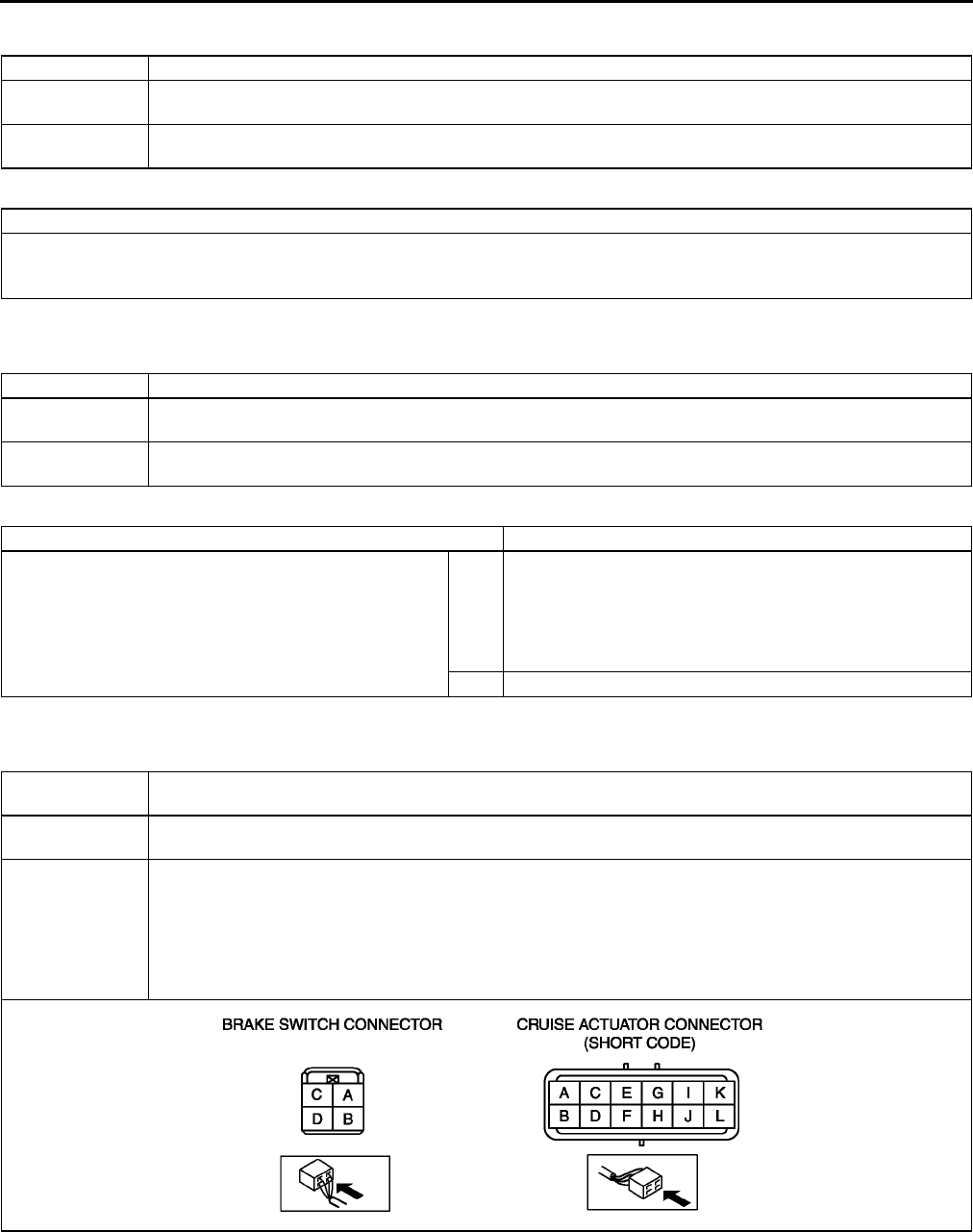
T186
ON-BOARD DIAGNOSTIC [CRUISE CONTROL SYSTEM]
DTC 01 A6E817266350W09
Diagnostic procedure
End Of Sie
DTC 05 A6E817266350W10
Diagnostic procedure
End Of Sie
DTC 07 A6E817266350W11
DTC 01 Cruise actuator (Drive circuit)
DETECTION
CONDITION •Malfunction in cruise actuator circuit (drive circuit)
POSSIBLE
CAUSE •Cruise actuator malfunction
ACTION
REPLACE CRUISE ACTUATOR IF IT IS MALFUNCTIONING
•Replace cruise actuator.
(See T110 CRUISE ACTUATOR REMOVAL/INSTALLATION)
DTC 05 Brake switch
DETECTION
CONDITION •Voltage detected at cruise actuator connector terminal C is always approximately 0 V.
POSSIBLE
CAUSE •Cruise actuator malfunction
INSPECTION ACTION
INSPECT DTC FOR OPERATION MODE
•Was operation mode for DTC 31 performed?
Yes Perform operation mode for DTC 31 on-board diagnostic
again. Even if no malfunction is detected in operation mode,
if DTC 05 is indicated in condition detection mode on-board
diagnostic, replace cruise actuator.
(See T110 CRUISE ACTUATOR REMOVAL/
INSTALLATION)
No Perform operation mode for DTC 31.
DTC 07 Brake switch
Brake switch 2
DETECTION
CONDITION
•Voltage detected at cruise actuator connector terminal C or K is always approximately 12 V.
•Voltage detected at cruise actuator connector terminal K is always approximately 0 V.
POSSIBLE
CAUSE
•METER IG15 A fuse burnt out
•Brake switch and/or brake switch 2 malfunction
•Cruise actuator malfunction
•Open circuit in wiring harness between STOP 15 A fuse and brake switch
•Open or short circuit in wiring harness between brake switch and cruise actuator terminal C
•Open circuit in wiring harness between brake switch 2 and METER IG15 A fuse
•Open or short circuit in wiring harness between cruise actuator terminal K and brake switch 2
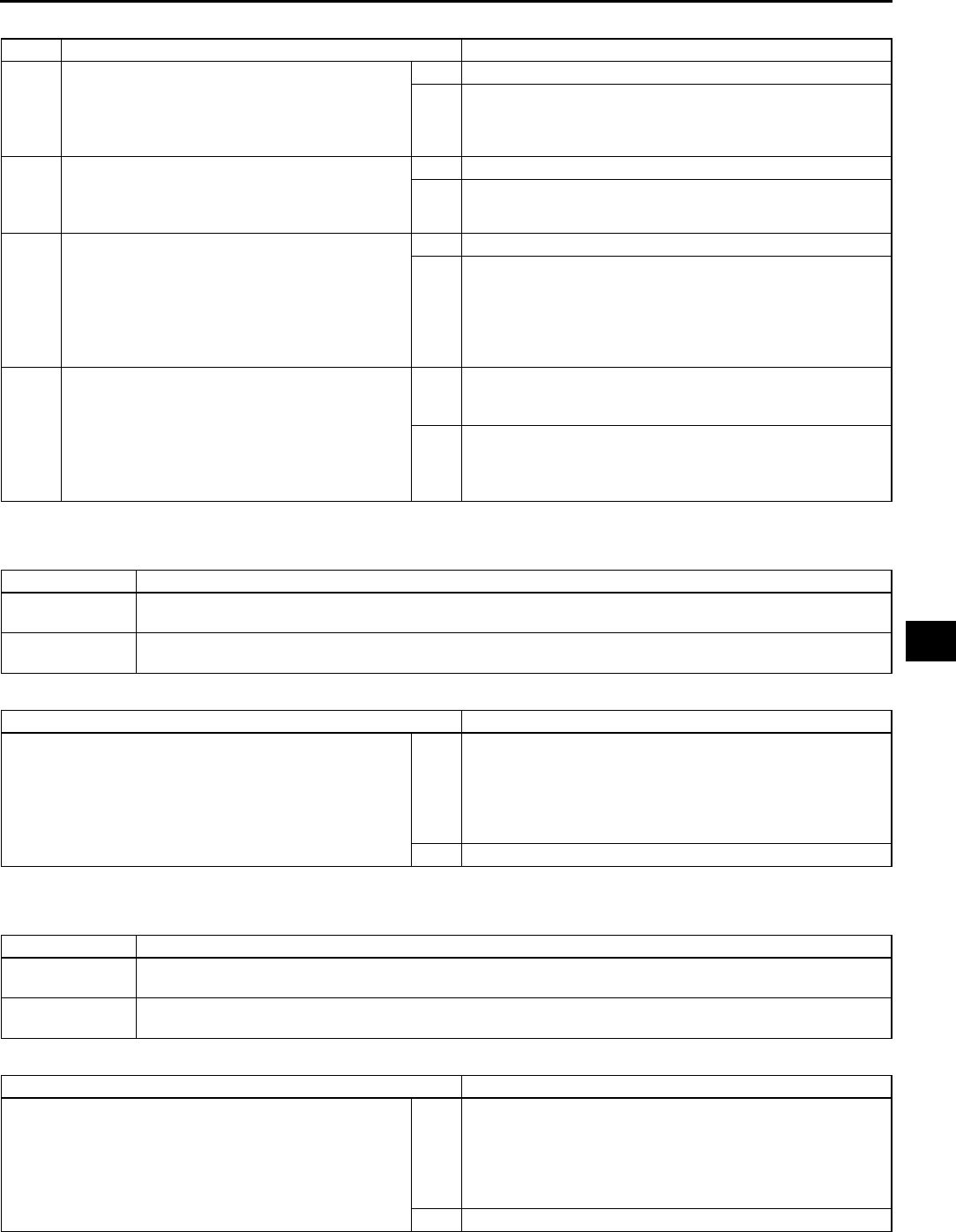
ON-BOARD DIAGNOSTIC [CRUISE CONTROL SYSTEM]
T187
T
Diagnostic procedure
End Of Sie
DTC 11 A6E817266350W12
Diagnostic procedure
End Of Sie
DTC 12 A6E817266350W13
Diagnostic procedure
End Of Sie
STEP INSPECTION ACTION
1INSPECT BRAKE SWITCH
•Disconnect brake switch connector.
•Inspect brake switch.
(See P8 BRAKE SWITCH INSPECTION)
•Is brake switch okay?
Yes Go to next step.
No Replace brake switch.
2INSPECT BRAKE SWITCH 2
•Inspect brake switch 2.
(See P8 BRAKE SWITCH INSPECTION)
•Is brake switch okay?
Yes Go to next step.
No Replace brake switch.
3INSPECT WIRING HARNESS BETWEEN
BRAKE SWITCH AND CRUISE ACTUATOR
FOR CONTINUITY
•Disconnect cruise actuator connector.
•Is there continuity between brake switch
connector D and cruise actuator connector
C.
Yes Go to next step.
No Repair wiring harness. (Cruise actuatorBrake switch)
4INSPECT WIRING HARNESS BETWEEN
BRAKE SWITCH 2 AND CRUISE ACTUATOR
FOR SHORT TO POWER SUPPLY
•Connect brake switch connector.
•Turn ignition switch ON position.
•Is voltage at cruise actuator connector
terminal K approximately 12 V?
Yes Replace cruise actuator.
(See T110 CRUISE ACTUATOR REMOVAL/
INSTALLATION)
No Repair wiring harness. (Cruise actuatorBrake switch 2)
DTC 11 Cruise control switch (SET/COAST switch)
DETECTION
CONDITION
•Resistance detected between cruise actuator connector terminal J and ground is always
approximately 680 ohms.
POSSIBLE
CAUSE
•Cruise actuator malfunction
•Cruise control switch malfunction
INSPECTION ACTION
INSPECT DTC FOR OPERATION MODE
•Was operation mode for DTC 21 performed?
Yes Perform operation mode for DTC 21 on-board diagnostic
again. Even if no malfunction is detected in operation mode,
if DTC 11 is indicated in condition detection mode on-board
diagnostic, replace cruise actuator.
(See T110 CRUISE ACTUATOR REMOVAL/
INSTALLATION)
No Perform operation mode for DTC 21.
DTC 12 Cruise control switch (RESUME/ACCEL switch)
DETECTION
CONDITION
•Resistance detected between cruise actuator connector terminal J and ground is always
approximately 2.2 kilohms.
POSSIBLE
CAUSE •Cruise actuator malfunction
INSPECTION ACTION
INSPECT DTC FOR OPERATION MODE
•Was operation mode for DTC 22 performed?
Yes Perform operation mode for DTC 22 on-board diagnostic
again. Even if no malfunction is detected in operation mode,
if DTC 12 is indicated in condition detection mode on-board
diagnostic, replace cruise actuator.
(See T110 CRUISE ACTUATOR REMOVAL/
INSTALLATION)
No Perform operation mode for DTC 22.
T188
ON-BOARD DIAGNOSTIC [CRUISE CONTROL SYSTEM]
DTC 13 A6E817266350W14
Diagnostic procedure
End Of Sie
DTC 15 A6E817266350W15
Diagnostic procedure
End Of Sie
DTC 13 Cruise control switch (ground circuit)
DETECTION
CONDITION
•Resistance detected between cruise actuator connector terminal J and ground is always
approximately 0 ohm.
POSSIBLE
CAUSE •Cruise actuator malfunction
INSPECTION ACTION
INSPECT DTC FOR OPERATION MODE
•Was operation mode for DTCs 21 and 22 performed?
Yes Perform operation mode for DTCs 21 and 22 on-board
diagnostic again. Even if no malfunction is detected in
operation mode, if DTC 13 is indicated in condition detection
mode on-board diagnostic, replace cruise actuator.
(See T110 CRUISE ACTUATOR REMOVAL/
INSTALLATION)
No Perform operation mode for DTCs 21 and 22.
DTC 15 Cruise actuator (control circuit)
DETECTION
CONDITION •Malfunction in cruise actuator circuit (control circuit)
POSSIBLE
CAUSE •Cruise actuator malfunction
ACTION
REPLACE CRUISE ACTUATOR IF IT IS MALFUNCTIONING
•Replace cruise actuator.
(See T110 CRUISE ACTUATOR REMOVAL/INSTALLATION)

ON-BOARD DIAGNOSTIC [AIR BAG SYSTEM]
T189
T
FOREWORD A6E817401046W01
Outline
•The OBD (on-board diagnostic) test inspects the integrity and function of the air bag system and outputs the
results when requested by the specific tests.
•OBD test also:
Provides a quick inspection of the air bag system.
Is usually performed at the start of each diagnostic procedure.
Provides verification after repairs to ensure that no other faults occurred during service.
•The OBD test is divided into three tests:
Read/clear diagnostic results
PID/data monitor and record
Active command mode
•Diagnostic DTC can be read/cleared, using the SST (WDS or equivalent).
Note
•When the air bag system is malfunctioning, turn the ignition switch to the ON position to display the
current DTC, using the air bag system warning light on the instrument cluster. However this light is strictly
for reference. Make sure to inspect the system, using the SST (WDS or equivalent).
Read/clear diagnostic results
•This function allows you to read or clear DTCs in the SAS unit memory.
PID/data monitor and record
•This function allows you access certain data values, input signals, calculated values, and system status
information.
Active command modes
•This function allows you to control devices through WDS or equivalent.
ON-BOARD DIAGNOSTIC [AIR BAG SYSTEM]
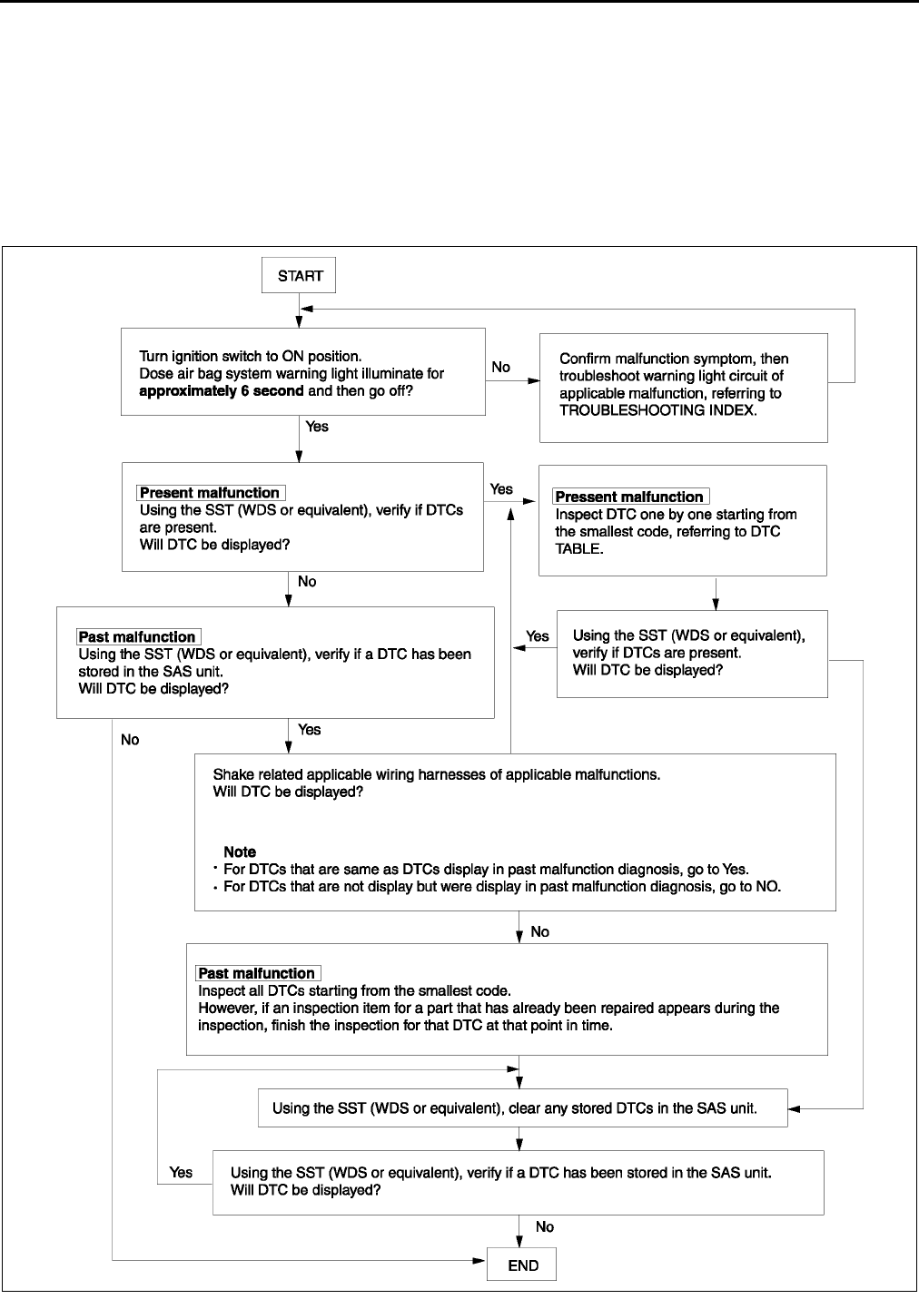
T190
ON-BOARD DIAGNOSTIC [AIR BAG SYSTEM]
Flowchart
•Use the following flowchart to verify the cause of the trouble.
Note
•While performing the inspection of the past malfunction code, the applicable DTCs may be added to
memory by removing or disconnecting the related parts. Inspect only the DTCs that were indicated before
inspecting.
•When DTCs of present malfunction are no longer output after present and/or past malfunctions have been
repaired, be sure to perform past malfunction display cancellation to prevent repair of malfunctions that
have already been repaired.
A6E8174W013
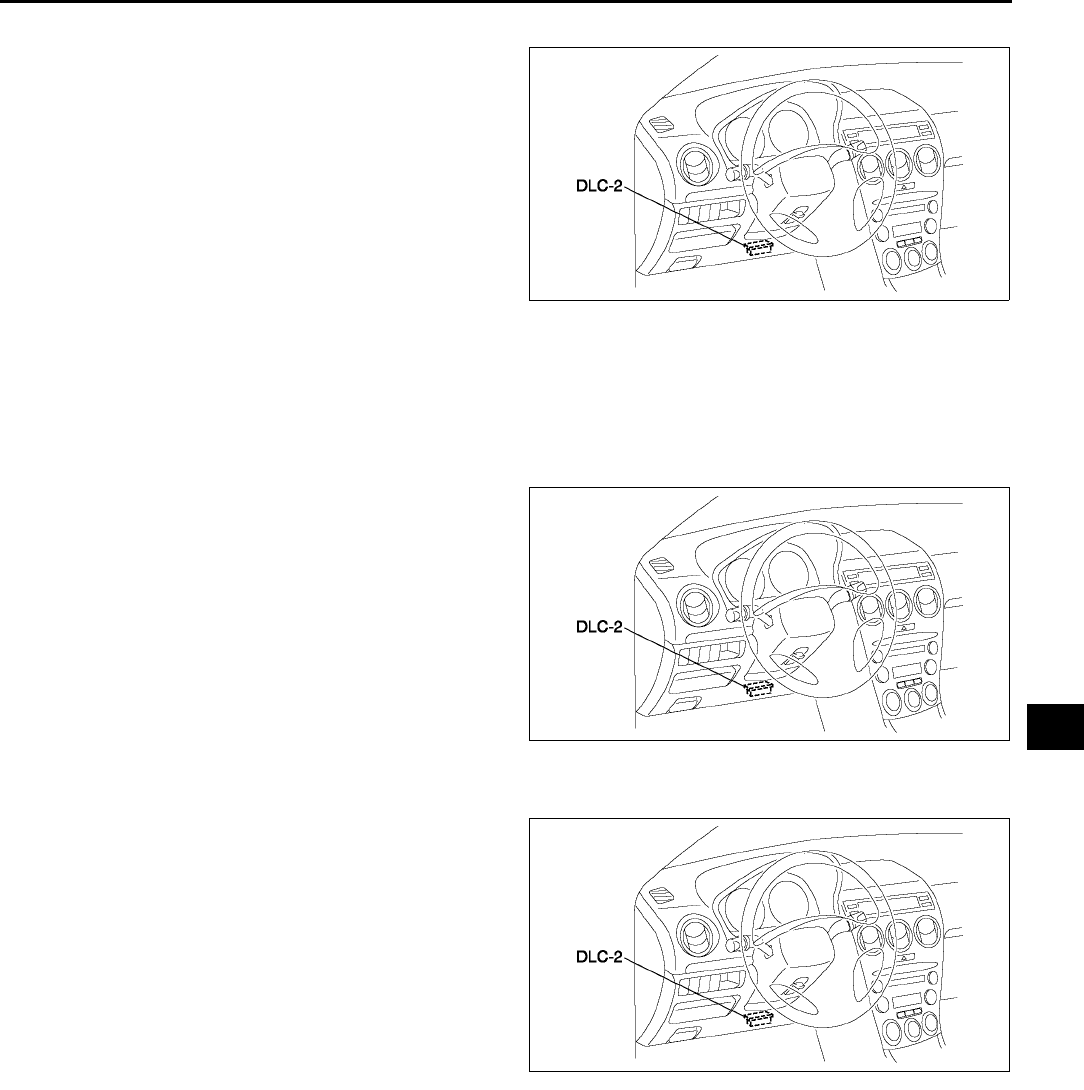
ON-BOARD DIAGNOSTIC [AIR BAG SYSTEM]
T191
T
DTCs Reading Procedure
1. Connect SST (WDS or equivalent) to the vehicle
DLC-2 16-pin connector.
2. Retrieve DTC using SST (WDS or equivalent).
Clearing DTCs Procedure
1. After repairs have been made, perform the DTCs reading procedure.
2. Erase DTCs using SST (WDS or equivalent).
3. Ensure that the customer's concern has been resolved.
PID/Data Monitor and Record Procedure
1. Connect SST (WDS or equivalent) to the vehicle
DLC-2 16-pin connector.
2. Access and monitor PIDs using SST (WDS or
equivalent).
Active Command Mode Procedure
1. Connect SST (WDS or equivalent) to the vehicle
DLC-2 16-pin connector.
2. Turn the ignition switch to ON position.
3. Activate active command mode using SST (WDS
or equivalent).
End Of Sie
A6E3970W002
A6E3970W002
A6E3970W002
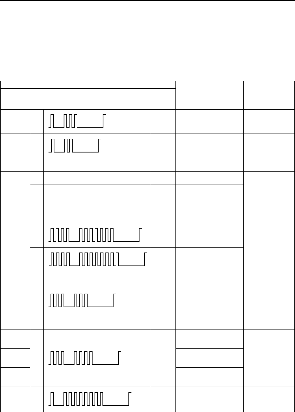
T192
ON-BOARD DIAGNOSTIC [AIR BAG SYSTEM]
DTC TABLE A6E817401046W02
•DTCs are common for present and past malfunction diagnosis.
Note
•When DTCs not shown in the DTC table are displayed, replace the SAS unit.
•If the air bag system warning light does not illuminate or remains illuminated when the ignition switch is
turned to ON position, inspect and repair the air bag system warning light circuitry and then confirm that
the air bag system warning light is operational.
•The air bag system warning light will flash the DTC pattern for five cycles, and then will remain illuminated
until the ignition switch is turned to the LOCK position.
DTC
Malfunction location Page
WDS or
equivalent
Air bag system warning light
Flashing pattern Priority
ranking
B1231 13 3 SAS unit activation
(deployment) control freeze
(See T198 DTC
B1231)
B1342
12 2 SAS unit (See T198 DTC
B1342)
Air bag system warning light is illuminated all
the time. 1SAS unit (DTC 12 detection
circuit malfunction)
B1869
Air bag system warning light is illuminated all
the time. 1Air bag system warning
light system circuit open
(See T198 DTC
B1869, B1870)
Air bag system warning light is illuminated
does not illuminate.
Air bag system warning
light system circuit short to
ground
B1870 Air bag system warning light is illuminated all
the time. 1
Air bag system warning
light system circuit short to
power supply
B1871
47 19 Occupancy sensor system
(communication error)
(See T200 DTC
B1871)
48 20
Occupancy sensor system
(sensor internal circuit
abnormal)
B1877
33 13
Driver-side pre-tensioner
seat belt system resistance
high
(See T202 DTC
B1877, B1878,
B1879, B1885)
B1878
Driver-side pre-tensioner
seat belt system circuit
short to power supply
B1879
Driver-side pre-tensioner
seat belt system circuit
short to ground
B1881
34 12
Passenger-side pre-
tensioner seat belt system
resistance high
(See T203 DTC
B1881, B1882,
B1883, B1886)
B1882
Passenger-side pre-
tensioner seat belt system
circuit short to power supply
B1883
Passenger-side pre-
tensioner seat belt system
short to ground
B1884 18 18
Passenger-side air bag cut-
off indicator light system
circuit open or short to
ground
(See T205 DTC
B1884, B1890)
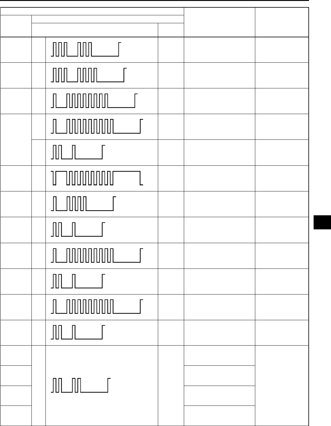
ON-BOARD DIAGNOSTIC [AIR BAG SYSTEM]
T193
T
B1885 33 13
Driver-side pre-tensioner
seat belt system resistance
low
(See T202 DTC
B1877, B1878,
B1879, B1885)
B1886 34 12
Passenger-side pre-
tensioner seat belt system
resistance low
(See T203 DTC
B1881, B1882,
B1883, B1886)
B1890 18 18
Passenger-side air bag cut-
off indicator light system
circuit short to power supply
(See T205 DTC
B1884, B1890)
B1913
19 11
Driver-side air bag module
(inflator No.1) system
circuit short to ground
(See T208 DTC
B1913, B1916,
B1932, B1934)
21 10
Passenger-side air bag
module (inflator No.1)
system circuit short to
ground
(See T210 DTC
B1913, B1925,
B1933, B1935)
B1916 19 11
Driver-side air bag module
(inflator No.1) system
circuit short to power supply
(See T208 DTC
B1913, B1916,
B1932, B1934)
B1921 14 4
Deployment prohibited
because configuration is
not set
(See T211 DTC
B1921)
B1925 21 10
Passenger-side air bag
module (inflator No.1)
system circuit short to
power supply
(See T210 DTC
B1913, B1925,
B1933, B1935)
B1932 19 11
Driver-side air bag module
(inflator No.1) system
resistance high
(See T208 DTC
B1913, B1916,
B1932, B1934)
B1933 21 10
Passenger-side air bag
module (inflator No.1)
system resistance high
(See T210 DTC
B1913, B1925,
B1933, B1935)
B1934 19 11
Driver-side air bag module
(inflator No.1) system
resistance low
(See T208 DTC
B1913, B1916,
B1932, B1934)
B1935 21 10
Passenger-side air bag
module (inflator No.1)
system resistance low
(See T210 DTC
B1913, B1925,
B1933, B1935)
B1992
22 15
Driver-side side air bag
module system circuit short
to power supply
(See T212 DTC
B1992, B1993,
B1994, B1995)
B1993
Driver-side side air bag
module system circuit short
to ground
B1994
Driver-side side air bag
module system resistance
high
B1995
Driver-side side air bag
module system resistance
low
DTC
Malfunction location Page
WDS or
equivalent
Air bag system warning light
Flashing pattern Priority
ranking
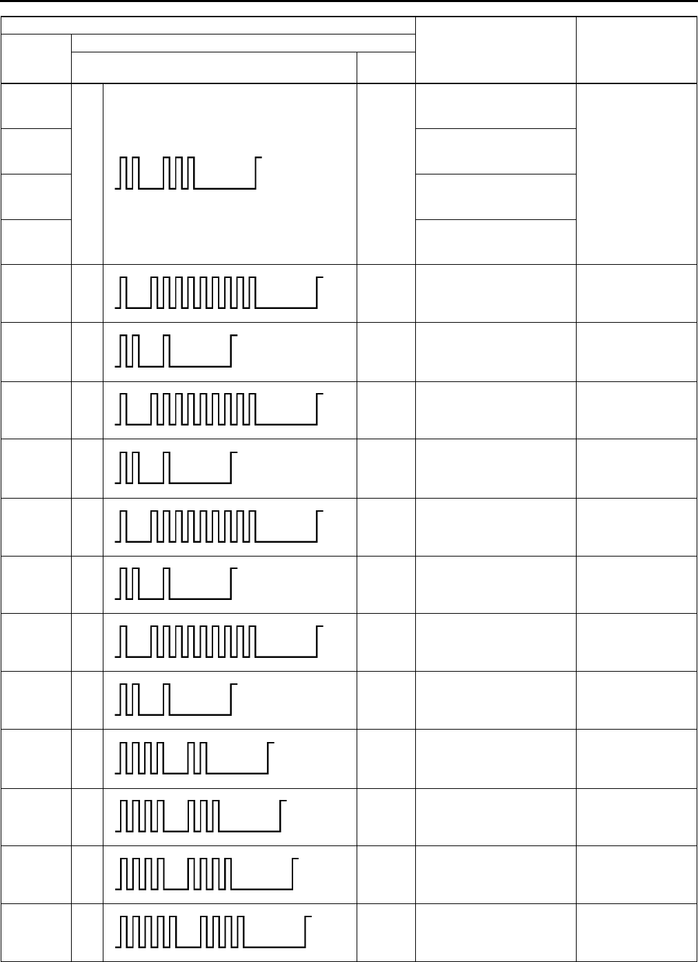
T194
ON-BOARD DIAGNOSTIC [AIR BAG SYSTEM]
B1996
23 14
Passenger-side side air
bag module system circuit
short to power supply
(See T213 DTC
B1996, B1997,
B1998, B1999)
B1997
Passenger-side side air
bag module system circuit
short to ground
B1998
Passenger-side side air
bag module system
resistance high
B1999
Passenger-side side air
bag module system
resistance low
B2228 19 11
Driver-side air bag module
(inflator No.2) system
circuit short to ground
(See T215 DTC
B2228, B2230,
B2232, B2234)
B2229 21 10
Passenger-side air bag
module (inflator No.2)
system circuit short to
ground
(See T217 DTC
B2229, B2231,
B2233, B2235)
B2230 19 11
Driver-side air bag module
(inflator No.2) system
circuit short to power supply
(See T215 DTC
B2228, B2230,
B2232, B2234)
B2231 21 10
Passenger-side air bag
module (inflator No.2)
system circuit short to
power supply
(See T217 DTC
B2229, B2231,
B2233, B2235)
B2232 19 11
Driver-side air bag module
(inflator No.2) system
resistance high
(See T215 DTC
B2228, B2230,
B2232, B2234)
B2233 21 10
Passenger-side air bag
module (inflator No.2)
system resistance high
(See T217 DTC
B2229, B2231,
B2233, B2235)
B2234 19 11
Driver-side air bag module
(inflator No.2) system
resistance low
(See T215 DTC
B2228, B2230,
B2232, B2234)
B2235 21 10
Passenger-side air bag
module (inflator No.2)
system resistance low
(See T217 DTC
B2229, B2231,
B2233, B2235)
B2296 42 9
Crash zone sensor system
(communication error,
sensor internal circuit
abnormal)
(See T218 DTC
B2296)
B2444 43 8
Driver-side side air bag
sensor system (sensor
internal circuit abnormal)
(See T220 DTC
B2444, U2017)
B2445 44 7
Passenger-side side air
bag sensor system (sensor
internal circuit abnormal)
(See T222 DTC
B2445, U2018)
B2477 54 5 Configuration error (See T224 DTC
B2477)
DTC
Malfunction location Page
WDS or
equivalent
Air bag system warning light
Flashing pattern Priority
ranking
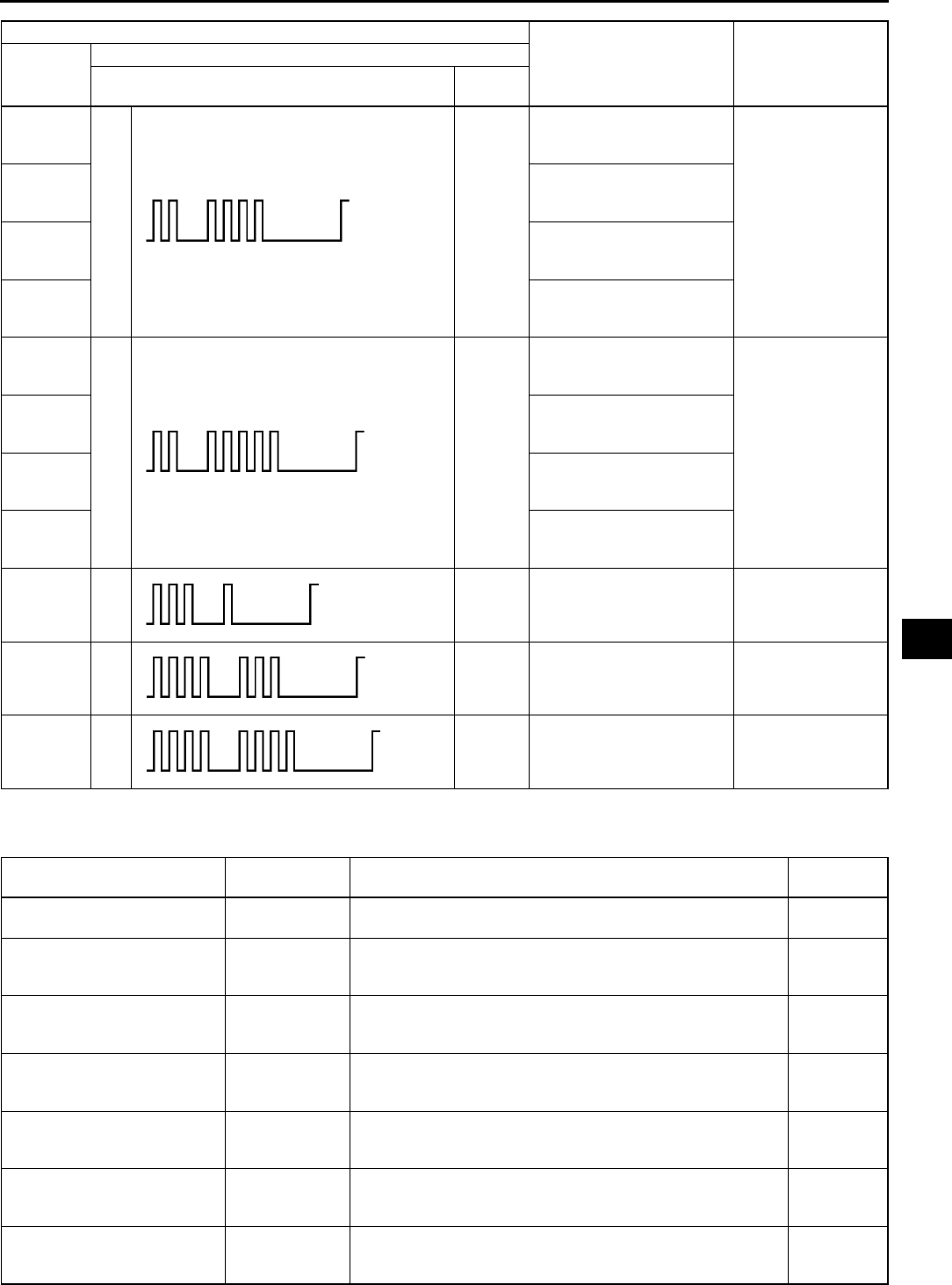
ON-BOARD DIAGNOSTIC [AIR BAG SYSTEM]
T195
T
End Of Sie
PID/DATA MONITOR TABLE A6E817401046W03
B2773
24 17
Driver-side curtain air bag
module system resistance
low
(See T224 DTC
B2773, B2774,
B2775, B2776)
B2774
Driver-side curtain air bag
module system resistance
high
B2775
Driver-side curtain air bag
module system circuit short
to ground
B2776
Driver-side curtain air bag
module system circuit short
to power supply
B2777
25 16
Passenger-side curtain air
bag module system
resistance low
(See T226 DTC
B2777, B2778,
B2779, B2780)
B2778
Passenger-side curtain air
bag module system
resistance high
B2779
Passenger-side curtain air
bag module system circuit
short to ground
B2780
Passenger-side curtain air
bag module system circuit
short to power supply
B2867 31 6 SAS unit connector poor
connection
(See T227 DTC
B2867)
U2017 43 8
Driver-side side air bag
sensor system
(communication error)
(See T220 DTC
B2444, U2017)
U2018 44 7
Passenger-side side air
bag sensor system
(communication error)
(See T222 DTC
B2445, U2018)
DTC
Malfunction location Page
WDS or
equivalent
Air bag system warning light
Flashing pattern Priority
ranking
PID name (definition) Unit/condition Condition/specification SAS unit
terminal
CONT_RCM
(Number of continuous DTC) •DTC is detected: 1255
•DTC is not detected: 0
D_ABAGR2
(Driver-side air bag module
(inflator No.2) resistance)
ohm Under any condition: 1.53.7 ohm 1G, 1J
D_CRSH_S
(Driver-side side air bag
sensor state)
OK/
COMM FAIL/
INT FAIL
•Sensor normal: OK
•Sensor communication error: COMM FAIL
•Sensor internal circuit abnormal: INT FAIL
2Z, 2AA
DABAGR
(Driver-side air bag module
(inflator No.1) resistance)
ohm Under any condition: 1.53.7 ohm 1S, 1V
DR_CURTN
(Driver-side curtain air bag
module resistance)
ohm Under any condition: 1.43.2 ohm 2V, 2Y
DR_PTENS
(Driver-side pre-tensioner seat
belt resistance)
ohm Under any condition: 1.53.1 ohm 2P, 2S
DS_AB
(Driver-side side air bag
module resistance)
ohm Under any condition: 1.43.2 ohm 2M, 2O

T196
ON-BOARD DIAGNOSTIC [AIR BAG SYSTEM]
DS_AB_ST
(Driver-side side air bag
module circuit state)
NORMAL/
OPEN/
SHRT GND/
SHRT B+
•Related wiring harness normal: NORMAL
•Related wiring harness circuit open: OPEN
•Related wiring harness short to ground: SHRT GND
•Related wiring harness short to power supply: SHRT B+
2M, 2O
DS_CURT_ST
(Driver-side curtain air bag
module circuit state)
NORMAL/
OPEN/
SHRT GND/
SHRT B+
•Related wiring harness normal: NORMAL
•Related wiring harness circuit open: OPEN
•Related wiring harness short to ground: SHRT GND
•Related wiring harness short to power supply: SHRT B+
2V, 2Y
DS1_STAT
(Driver-side air bag module
(inflator No.1) circuit state)
NORMAL/
OPEN/
SHRT GND/
SHRT B+
•Related wiring harness normal: NORMAL
•Related wiring harness circuit open: OPEN
•Related wiring harness short to ground: SHRT GND
•Related wiring harness short to power supply: SHRT B+
1S, 1V
DS2_STAT
(Driver-side air bag module
(inflator No.2) circuit state)
NORMAL/
OPEN/
SHRT GND/
SHRT B+
•Related wiring harness normal: NORMAL
•Related wiring harness circuit open: OPEN
•Related wiring harness short to ground: SHRT GND
•Related wiring harness short to power supply: SHRT B+
1G, 1J
DSB_P_ST
(On demand driver-side pre-
tensioner seat belt circuit
state)
NORMAL/
OPEN/
SHRT GND/
SHRT B+
•Related wiring harness normal: NORMAL
•Related wiring harness circuit open: OPEN
•Related wiring harness short to ground: SHRT GND
•Related wiring harness short to power supply: SHRT B+
2P, 2S
DSSBLT_PF
(Driver-side pre-tensioner seat
belt circuit state)
NORMAL/
OPEN/
SHRT GND/
SHRT B+
•Related wiring harness normal: NORMAL
•Related wiring harness circuit open: OPEN
•Related wiring harness short to ground: SHRT GND
•Related wiring harness short to power supply: SHRT B+
2P, 2S
FRNT_CRSH_SNSR
(Crash zone sensor state)
OK/
COMM FAIL/
INT FAIL
•Sensor normal: OK
•Sensor communication error: COMM FAIL
•Sensor internal circuit abnormal: INT FAIL
1B, 1C
OD_D_CRSH
(On demand driver-side side
air bag sensor state)
OK/
COMM FAIL/
INT FAIL
•Sensor normal: OK
•Sensor communication error: COMM FAIL
•Sensor internal circuit abnormal: INT FAIL
2Z, 2AA
OD_D_CURT
(On demand driver-side
curtain air bag module circuit
state)
NORMAL/
OPEN/
SHRT GND/
SHRT B+
•Related wiring harness normal: NORMAL
•Related wiring harness circuit open: OPEN
•Related wiring harness short to ground: SHRT GND
•Related wiring harness short to power supply: SHRT B+
2V, 2Y
OD_DAB1_ST
(On demand driver-side air
bag module (inflator No.1)
circuit state)
NORMAL/
OPEN/
SHRT GND/
SHRT B+
•Related wiring harness normal: NORMAL
•Related wiring harness circuit open: OPEN
•Related wiring harness short to ground: SHRT GND
•Related wiring harness short to power supply: SHRT B+
1S, 1V
OD_DAB2_ST
(On demand driver-side air
bag module (inflator No.2)
circuit state)
NORMAL/
OPEN/
SHRT GND/
SHRT B+
•Related wiring harness normal: NORMAL
•Related wiring harness circuit open: OPEN
•Related wiring harness short to ground: SHRT GND
•Related wiring harness short to power supply: SHRT B+
1G, 1J
OD_DSAB_ST
(On demand driver-side side
air bag circuit state)
NORMAL/
OPEN/
SHRT GND/
SHRT B+
•Related wiring harness normal: NORMAL
•Related wiring harness circuit open: OPEN
•Related wiring harness short to ground: SHRT GND
•Related wiring harness short to power supply: SHRT B+
2M, 2O
OD_F_CRSH
(On demand crash zone
sensor state)
OK/
COMM FAIL/
INT FAIL
•Sensor normal: OK
•Sensor communication error: COMM FAIL
•Sensor internal circuit abnormal: INT FAIL
1B, 1C
OD_P_CRSH
(On demand passenger-side
side air bag sensor state)
OK/
COMM FAIL/
INT FAIL
•Sensor normal: OK
•Sensor communication error: COMM FAIL
•Sensor internal circuit abnormal: INT FAIL
2B, 2C
OD_P_CURT
(On demand passenger-side
curtain air bag module circuit
state)
NORMAL/
OPEN/
SHRT GND/
SHRT B+
•Related wiring harness normal: NORMAL
•Related wiring harness circuit open: OPEN
•Related wiring harness short to ground: SHRT GND
•Related wiring harness short to power supply: SHRT B+
2A, 2D
OD_PAB1ST
(On demand passenger-side
air bag module (inflator No.1)
circuit state)
NORMAL/
OPEN/
SHRT GND/
SHRT B+
•Related wiring harness normal: NORMAL
•Related wiring harness circuit open: OPEN
•Related wiring harness short to ground: SHRT GND
•Related wiring harness short to power supply: SHRT B+
1M, 1P
OD_PAB2_ST
(On demand passenger-side
air bag module (inflator No.2)
circuit state)
NORMAL/
OPEN/
SHRT GND/
SHRT B+
•Related wiring harness normal: NORMAL
•Related wiring harness circuit open: OPEN
•Related wiring harness short to ground: SHRT GND
•Related wiring harness short to power supply: SHRT B+
1A,1D
PID name (definition) Unit/condition Condition/specification SAS unit
terminal

ON-BOARD DIAGNOSTIC [AIR BAG SYSTEM]
T197
T
End Of Sie
ACTIVE COMMAND MODE TABLE A6E817401046W04
End Of Sie
OD_P_PSAB_ST
(On demand passenger-side
side air bag sensor circuit
state)
NORMAL/
OPEN/
SHRT GND/
SHRT B+
•Related wiring harness normal: NORMAL
•Related wiring harness circuit open: OPEN
•Related wiring harness short to ground: SHRT GND
•Related wiring harness short to power supply: SHRT B+
2I, 2L
P_ABAGR2
(Passenger-side air bag
module (inflator No.2)
resistance)
ohm Under any condition: 1.42.9 ohm 1A, 1D
P_PTENSFLT
(Passenger-side pre-tensioner
seat belt circuit state)
NORMAL/
OPEN/
SHRT GND/
SHRT B+
•Related wiring harness normal: NORMAL
•Related wiring harness circuit open: OPEN
•Related wiring harness short to ground: SHRT GND
•Related wiring harness short to power supply: SHRT B+
2G, 2J
PABAGR
(Passenger-side air bag
module (inflator No.1)
resistance)
ohm Under any condition: 1.42.9 ohm 1M, 1P
PCRSH_SNSR
(Passenger-side side air bag
sensor state)
OK/
COMM FAIL/
INT FAIL
•Sensor normal: OK
•Sensor communication error: COMM FAIL
•Sensor internal circuit abnormal: INT FAIL
2B, 2C
PS_AB
(Passenger-side side air bag
module resistance)
ohm Under any condition: 1.43.2 ohm 2I, 2L
PS_AB_ST
(Passenger-side side air bag
sensor circuit state)
NORMAL/
OPEN/
SHRT GND/
SHRT B+
•Related wiring harness normal: NORMAL
•Related wiring harness circuit open: OPEN
•Related wiring harness short to ground: SHRT GND
•Related wiring harness short to power supply: SHRT B+
2I, 2L
PS_CURTN
(Passenger-side curtain air
bag module resistance)
ohm Under any condition: 1.43.2 ohm 2A, 2B
PS_CURT_ST
(Passenger-side curtain air
bag module circuit state)
NORMAL/
OPEN/
SHRT GND/
SHRT B+
•Related wiring harness normal: NORMAL
•Related wiring harness circuit open: OPEN
•Related wiring harness short to ground: SHRT GND
•Related wiring harness short to power supply: SHRT B+
2A, 2D
PS_PTENS
(Passenger-side pre-tensioner
seat belt resistance)
ohm Under any condition: 1.53.1 ohm 2G, 2J
PS1_STAT
(Passenger-side air bag
module (inflator No.1) circuit
state)
NORMAL/
OPEN/
SHRT GND/
SHRT B+
•Related wiring harness normal: NORMAL
•Related wiring harness circuit open: OPEN
•Related wiring harness short to ground: SHRT GND
•Related wiring harness short to power supply: SHRT B+
1M, 1P
PS2_STAT
(Passenger-side air bag
module (inflator No.2) circuit
state)
NORMAL/
OPEN/
SHRT GND/
SHRT B+
•Related wiring harness normal: NORMAL
•Related wiring harness circuit open: OPEN
•Related wiring harness short to ground: SHRT GND
•Related wiring harness short to power supply: SHRT B+
1A, 1D
PSB_P_ST
(On demand passenger-side
pre-tensioner seat belt circuit
state)
NORMAL/
OPEN/
SHRT GND/
SHRT B+
•Related wiring harness normal: NORMAL
•Related wiring harness circuit open: OPEN
•Related wiring harness short to ground: SHRT GND
•Related wiring harness short to power supply: SHRT B+
2G, 2J
RCM_VOLT
(System IG1 voltage value) V•Ignition switch to ON position: B+
•Other: 0 V 1W
PID name (definition) Unit/condition Condition/specification SAS unit
terminal
Command name Definition Operation
WRNLAMPCHM Air bag system warning light ON/OFF
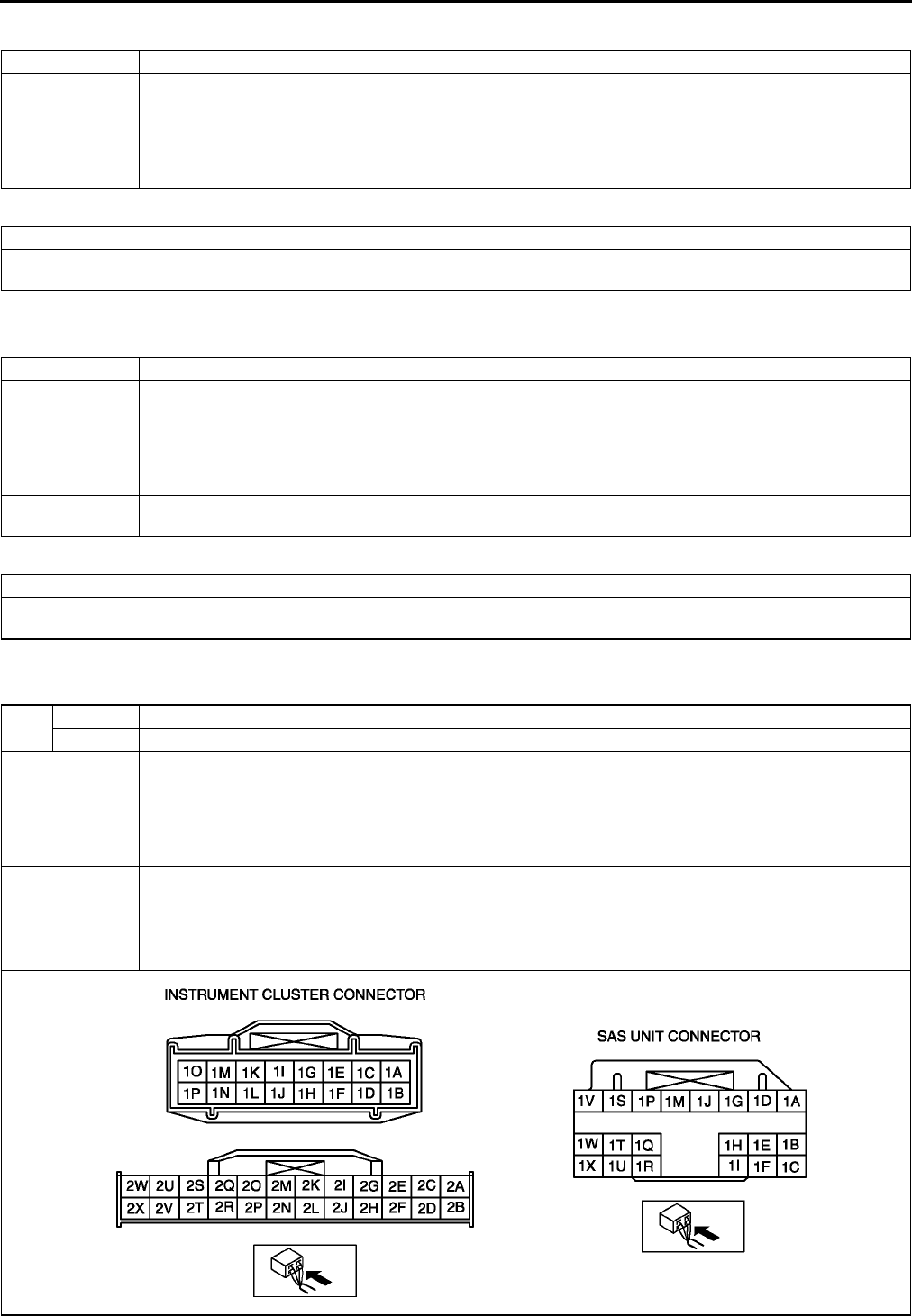
T198
ON-BOARD DIAGNOSTIC [AIR BAG SYSTEM]
DTC B1231 A6E817401046W05
Diagnostic procedure
End Of Sie
DTC B1342 A6E817401046W06
Diagnostic procedure
End Of Sie
DTC B1869, B1870 A6E817401046W07
DTC B1231 SAS unit activation (deployment) control freeze
DETECTION
CONDITION
Warning
•
••
•Detection conditions are for understanding DTC outline before performing inspection.
Performing inspection with only detection conditions may cause injury due to operating error
or damage the system. When performing inspection, always follow inspection procedure.
•SAS unit determined collision
ACTION
Replace SAS unit.
(See T124 SAS UNIT REMOVAL/INSTALLATION)
DTC B1342 SAS unit
DETECTION
CONDITION
Warning
•
••
•Detection conditions are for understanding DTC outline before performing inspection.
Performing inspection with only detection conditions may cause injury due to operating error
or damage the system. When performing inspection, always follow inspection procedure.
•Malfunction in SAS unit inner circuit
POSSIBLE
CAUSE •SAS unit malfunction
ACTION
•Replace SAS unit.
(See T124 SAS UNIT REMOVAL/INSTALLATION)
DTC B1869 Air bag system warning light system circuit open or short to ground
B1870 Air bag system warning light system circuit short to power supply
DETECTION
CONDITION
Warning
•
••
•Detection conditions are for understanding DTC outline before performing inspection.
Performing inspection with only detection conditions may cause injury due to operating error
or damage the system. When performing inspection, always follow inspection procedure.
•Malfunction in air bag system warning light circuit
POSSIBLE
CAUSE
•METER IG 15 A fuse malfunction
•Instrument cluster malfunction
•Malfunction of connectors between instrument cluster and SAS unit
•Open or short circuit in wiring harness between METER IG 15 A fuse and instrument cluster
•Open or short circuit in wiring harness between instrument cluster and SAS unit
•SAS unit malfunction

ON-BOARD DIAGNOSTIC [AIR BAG SYSTEM]
T199
T
Diagnostic procedure
STEP INSPECTION ACTION
1INSPECT METER IG 15 A FUSE
•Turn ignition switch to LOCK position.
•Disconnect negative battery cable.
•Remove METER IG 15 A fuse.
•Is fuse okay?
Yes Reinstall METER IG 15 A fuse, then go to next step.
No Replace METER IG 15 A fuse.
2INSPECT FOR CONTINUITY BETWEEN
METER IG 15 A FUSE AND INSTRUMENT
CLUSTER
•Connect negative battery cable.
•Turn ignition switch to ON position.
•Measure voltage at instrument cluster
connector terminal 2V.
•Is voltage more than 9 V?
Yes Go to next step.
No Repair wiring harness.
3INSPECT WIRING HARNESS BETWEEN
INSTRUMENT CLUSTER AND SAS UNIT
Warning
•
••
•Handling air bag system components
improperly can accidentally deploy air
bag modules and pre-tensioner seat
belts, which may seriously injure you.
Read AIR BAG SYSTEM SERVICE
WARNINGS before handling air bag
system components.
(See T117 SERVICE WARNINGS)
•Turn ignition switch to LOCK position.
•Disconnect negative battery cable and wait
for more than 1 minute.
•Remove column cover.
•Disconnect clock spring connector.
•Remove glove compartment.
•Disconnect passenger-side air bag module
connector.
•Disconnect driver and passenger-side
curtain air bag module connectors. (Vehicles
with curtain air bag)
•Disconnect driver and passenger-side side
air bag module connectors. (Vehicles with
side air bag)
•Remove B-pillar lower trims. (Vehicle with
pre-tensioner seat belt)
•Disconnect driver and passenger-side pre-
tensioner seat belt connectors. (Vehicle with
pre-tensioner seat belt)
•Turn up floor covering.
•Disconnect all SAS unit connectors.
•Disconnect instrument cluster.
•Inspect following wiring harness between
SAS unit and instrument cluster terminals for
short to ground, short to power supply, and
open circuit:
1T1O
•Is wiring harness okay?
Yes Go to next step.
No Replace wiring harness.
4INSPECT AIR BAG SYSTEM WARNING
LIGHT
•Connect instrument cluster.
•Turn ignition switch to ON position.
•Is air bag system warning light illuminated?
Yes Go to next step.
No Replace instrument cluster.
(See T72 INSTRUMENT CLUSTER REMOVAL/
INSTALLATION)
5INSPECT AIR BAG SYSTEM WARNING
LIGHT
•Using a jumper wire, cause a short circuit
between instrument cluster terminal 1O and
ground.
•Does air bag system warning light go out?
Yes [Present malfunction diagnosis]
Replace SAS unit.
(See T124 SAS UNIT REMOVAL/INSTALLATION)
[Past malfunction diagnosis]
Troubleshooting completed.
No Replace instrument cluster.
(See T72 INSTRUMENT CLUSTER REMOVAL/
INSTALLATION)
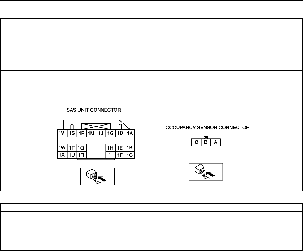
T200
ON-BOARD DIAGNOSTIC [AIR BAG SYSTEM]
End Of Si e
DTC B1871 A6E817401046W08
Diagnostic procedure
DTC B1871 Occupancy sensor system (communication error, sensor internal circuit abnomal)
DETECTION
CONDITION
Warning
•
••
•Detection conditions are for understanding DTC outline before performing inspection.
Performing inspection with only detection conditions may cause injury due to operating error
or damage the system. When performing inspection, always follow inspection procedure.
•Malfunction in wiring harness between SAS unit and occupancy sensor
•Malfunction in occupancy sensor circuit
POSSIBLE
CAUSE
•Open or short circuit in wiring harness between METER IG 15 A fuse and occupancy sensor
•Open or short circuit in wiring harness between SAS unit and occupancy sensor
•Open circuit in wiring harness between occupancy sensor and ground
•Occupancy sensor malfunction
•SAS unit malfunction
STEP INSPECTION ACTION
1•Is vehicle equipped with passenger-side air bag
cut-off function?
Yes Go to next step.
No [Present malfunction diagnosis]
Replace SAS unit.
(See T124 SAS UNIT REMOVAL/INSTALLATION)
[Past malfunction diagnosis]
Troubleshooting completed.

ON-BOARD DIAGNOSTIC [AIR BAG SYSTEM]
T201
T
End Of Sie
2INSPECT WIRING HARNESS BETWEEN
OCCUPANCY SENSOR AND SAS UNIT
Warning
•
••
•Handling air bag system components
improperly can accidentally deploy air bag
modules, and pre-tensioner seat belts
which may seriously injure you. Read AIR
BAG SYSTEM SERVICE WARNINGS
before handling air bag system
components.
(See T117 SERVICE WARNINGS)
•Turn ignition switch to LOCK position.
•Disconnect negative battery cable and wait for
more than 1 minute.
•Remove column cover.
•Disconnect clock spring connector.
•Remove glove compartment.
•Disconnect passenger-side air bag module
connector.
•Disconnect driver and passenger-side side air
bag module connectors. (Vehicle with side air
bag)
•Disconnect driver and passenger-side curtain air
bag module connectors. (Vehicles with curtain
air bag)
•Remove B-pillar lower trim. (Vehicle with pre-
tensioner seat belt)
•Disconnect drive- and passenger-side pre-
tensioner seat belt connectors. (Vehicle with
pre-tensioner seat belt)
•Turn up floor covering.
•Disconnect all SAS unit connectors.
•Disconnect occupancy sensor connector.
•Connect negative battery cable.
•Inspect following wiring harness between SAS
unit and occupancy sensor terminals for short to
ground, short to power supply, and open circuit:
1IB
•Is wiring harness okay?
Yes Go to next step.
No Replace wiring harness.
3INSPECT WIRING HARNESS BETWEEN METER
IG 15 A FUSE AND OCCUPANCY SENSOR
•Connect negative battery cable.
•Turn ignition switch to ON position.
•Measure voltage at occupancy connector
terminal A.
•Is voltage more than 9V?
Yes [Present malfunction diagnosis]Go to next step.
[Past malfunction diagnosis]
Troubleshooting completed.
No Replace wiring harness.
4VERIFY WHETHER MALFUNCTION IS IN
OCCUPANCY SENSOR OR SAS UNIT
•Turn ignition switch to LOCK position.
•Disconnect negative battery cable and wait for
more than 1 minute.
•Connect all SAS unit connectors.
•Connect drive- and passenger-side pre-
tensioner seat belt connectors. (Vehicle with
pre-tensioner seat belt)
•Connect driver and passenger-side curtain air
bag module connectors. (Vehicles with curtain
air bag)
•Connect driver and passenger-side side air bag
module connectors. (Vehicle with side air bag)
•Connect passenger-side air bag module
connector.
•Connect clock spring connector.
•Connect occupancy sensor connector.
•Short occupancy sensor connector terminal B to
ground.
•Connect negative battery cable.
•Turn ignition switch to ON position.
•Is DTC B1871 indicated?
Yes Replace SAS unit.
(See T124 SAS UNIT REMOVAL/INSTALLATION)
No Replace seat cushion.
(See S106 FRONT SEAT DISASSEMBLY/
ASSEMBLY)
STEP INSPECTION ACTION
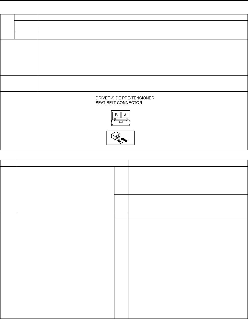
T202
ON-BOARD DIAGNOSTIC [AIR BAG SYSTEM]
DTC B1877, B1878, B1879, B1885 A6E817401046W09
Diagnostic procedure
DTC
B1877 Driver-side pre-tensioner seat belt system resistance high
B1878 Driver-side pre-tensioner seat belt system circuit short to power supply
B1879 Driver-side pre-tensioner seat belt system circuit short to ground
B1885 Driver-side pre-tensioner seat belt system resistance low
DETECTION
CONDITION
Warning
•
••
•Detection conditions are for understanding DTC outline before performing inspection.
Performing inspection with only detection conditions may cause injury due to operating error
or damage the system. When performing inspection, always follow inspection procedure.
•Abnormal resistance (other than 1.53.1 ohm) detected in driver-side pre-tensioner seat belt circuit
•Malfunction in wiring harness between driver-side pre-tensioner seat belt and SAS unit
POSSIBLE
CAUSE
•Open or short circuit in wiring harness between driver-side pre-tensioner seat belt and SAS unit
•Driver-side pre-tensioner seat belt malfunction
•SAS unit malfunction
STEP INSPECTION ACTION
1INSPECT DRIVER-SIDE PRE-TENSIONER
SEAT BELT
•Check following PID/DATA monitor, using
SST (WDS or equivalent).
(See T195 PID/DATA MONITOR TABLE)
DR_PTENS
•Is resistant value of driver-side pre-tensioner
seat belt normal?
Resistance: 1.53.1 ohm
Yes Present malfunction diagnosis:
•Replace SAS unit.
(See T124 SAS UNIT REMOVAL/INSTALLATION)
Past malfunction diagnosis:
•Troubleshooting completed.
No Go to next step.
2INSPECT DRIVER-SIDE PRE-TENSIONER
SEAT BELT CONNECTOR
Warning
•
••
•Handling air bag system components
improperly can accidentally deploy air
bag modules and pre-tensioner seat
belts, which may seriously injure you.
Read AIR BAG SYSTEM SERVICE
WARNINGS before handling air bag
system components.
(See T117 SERVICE WARNINGS)
•Turn ignition switch to LOCK position.
•Disconnect negative battery cable and wait
for more than 1 minute.
•Remove drivers side B-pillar lower trim.
•Disconnect driver-side pre-tensioner seat
belt connector.
•Is there cracking or chipping in driver-side
pre-tensioner seat belt connector?
Yes Replace wiring harness.
No Go to next step.
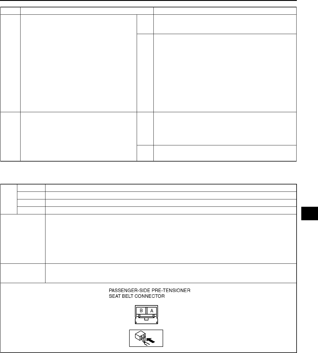
ON-BOARD DIAGNOSTIC [AIR BAG SYSTEM]
T203
T
End Of Sie
DTC B1881, B1882, B1883, B1886 A6E817401046W10
3VERIFY WHETHER MALFUNCTION IS IN
DRIVER-SIDE PRE-TENSIONER SEAT BELT
OR RELATED WIRING HARNESS
•Connect leads of SST (Fuel and
thermometer checker) or apply 2 ohm
resistor to driver-side pre-tensioner seat belt
connector terminal A and B.
•Set resistance of SST (Fuel and
thermometer checker) to 2 ohm.
•Connect negative battery cable.
•Turn ignition switch to ON position.
•Check following PID/DATA monitor, using
SST (WDS or equivalent).
(See T195 PID/DATA MONITOR TABLE)
DSB_P_ST
•Is related wiring harness normal?
Yes Replace driver-side pre-tensioner seat belt.
(See S100 FRONT SEAT BELT REMOVAL/
INSTALLATION)
No Replace wiring harness, then go to next step.
4INSPECT SAS UNIT
•Turn ignition switch to LOCK position.
•Disconnect negative battery cable and wait
for more than 1 minute.
•Connect driver-side pre-tensioner seat belt
connector.
•Are DTCs B1877, B1878, B1879 and/or
B1885 indicated?
Yes Present malfunction diagnosis:
•Replace SAS unit.
(See T124 SAS UNIT REMOVAL/INSTALLATION)
Past malfunction diagnosis:
•Troubleshooting completed.
No Troubleshooting completed.
STEP INSPECTION ACTION
DTC
B1881 Passenger-side pre-tensioner seat belt system resistance high
B1882 Passenger-side pre-tensioner seat belt system circuit short to power supply
B1883 Passenger-side pre-tensioner seat belt system circuit short to ground
B1886 Passenger-side pre-tensioner seat belt system resistance low
DETECTION
CONDITION
Warning
•
••
•Detection conditions are for understanding DTC outline before performing inspection.
Performing inspection with only detection conditions may cause injury due to operating error
or damage the system. When performing inspection, always follow inspection procedure.
•Abnormal resistance (other than 1.53.1 ohm) detected in passenger-side pre-tensioner seat belt
circuit
•Malfunction in wiring harness between passenger-side pre-tensioner seat belt and SAS unit
POSSIBLE
CAUSE
•Open or short circuit in wiring harness between passenger-side pre-tensioner seat belt and SAS unit
•Passenger-side pre-tensioner seat belt malfunction
•SAS unit malfunction

T204
ON-BOARD DIAGNOSTIC [AIR BAG SYSTEM]
Diagnostic procedure
End Of Sie
STEP INSPECTION ACTION
1INSPECT PASSENGER-SIDE PRE-
TENSIONER SEAT BELT
•Check following PID/DATA monitor, using
SST (WDS or equivalent).
(See T195 PID/DATA MONITOR TABLE)
PS_PTENS
•Is resistant value of passenger-side pre-
tensioner seat belt normal?
Resistance: 1.53.1 ohm
Yes Present malfunction diagnosis:
•Replace SAS unit.
(See T124 SAS UNIT REMOVAL/INSTALLATION)
Past malfunction diagnosis:
•Troubleshooting completed.
No Go to next step.
2INSPECT PASSENGER-SIDE PRE-
TENSIONER SEAT BELT CONNECTOR
Warning
•
••
•Handling air bag system components
improperly can accidentally deploy air
bag modules and pre-tensioner seat
belts, which may seriously injure you.
Read AIR BAG SYSTEM SERVICE
WARNINGS before handling air bag
system components.
(See T117 SERVICE WARNINGS)
•Turn ignition switch to LOCK position.
•Disconnect negative battery cable and wait
for more than 1 minute.
•Remove passengers side B-pillar lower trim.
•Disconnect passenger-side pre-tensioner
seat belt connector.
•Is there cracking or chipping in passenger-
side pre-tensioner seat belt connector?
Yes Replace wiring harness.
No Go to next step.
3VERIFY WHETHER MALFUNCTION IS IN
PASSENGER-SIDE PRE-TENSIONER SEAT
BELT OR RELATED WIRING HARNESS
•Connect leads of SST (Fuel and
thermometer checker) or apply 2 ohm
resistor to passenger-side pre-tensioner seat
belt connector terminal A and B.
•Set resistance of SST (Fuel and
thermometer checker) to 2 ohm.
•Connect negative battery cable.
•Turn ignition switch to ON position.
•Check following PID/DATA monitor, using
SST (WDS or equivalent).
(See T195 PID/DATA MONITOR TABLE)
PSB_P_ST
•Is related wiring harness normal?
Yes Replace passenger-side pre-tensioner seat belt.
(See S100 FRONT SEAT BELT REMOVAL/
INSTALLATION)
No Replace wiring harness, then go to next step.
4INSPECT SAS UNIT
•Turn ignition switch to LOCK position.
•Disconnect negative battery cable and wait
for more than 1 minute.
•Connect passenger-side pre-tensioner seat
belt connector.
•Are DTCs B1881, B1882, B1883 and/or
B1886 indicated?
Yes Present malfunction diagnosis:
•Replace SAS unit.
(See T124 SAS UNIT REMOVAL/INSTALLATION)
Past malfunction diagnosis:
•Troubleshooting completed.
No Troubleshooting completed.
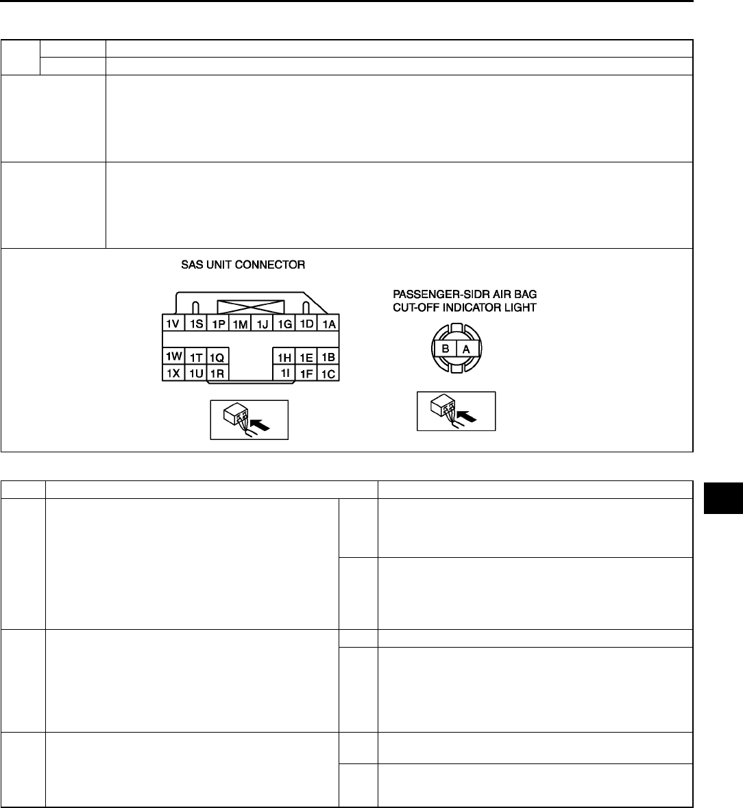
ON-BOARD DIAGNOSTIC [AIR BAG SYSTEM]
T205
T
DTC B1884, B1890 A6E817401046W11
Diagnostic procedure
DTC B1884 Passenger-side air bag cut-off indicator light system circuit open or short to ground
B1890 Passenger-side air bag cut-off indicator light system circuit short to power supply
DETECTION
CONDITION
Warning
•
••
•Detection conditions are for understanding DTC outline before performing inspection.
Performing inspection with only detection conditions may cause injury due to operating error
or damage the system. When performing inspection, always follow inspection procedure.
•Malfunction in passenger-side air bag cut-off indicator light circuit
POSSIBLE
CAUSE
•Open or short circuit in wiring harness between SAS unit and passenger-side air bag cut-off indicator
light
•Open circuit in wiring harness between METER IG 15 A fuse and passenger-side air bag cut-off
indicator light
•Passenger-side air bag cut-off indicator light malfunction
•SAS unit malfunction
STEP INSPECTION ACTION
1•Is vehicle equipped with passenger-side air bag
cut-off function?
Yes [Present malfunction diagnosis]
Go to next step.
[Past malfunction diagnosis]
Go to Step 4.
No [Present malfunction diagnosis]
Replace SAS unit.
(See T124 SAS UNIT REMOVAL/INSTALLATION)
[Past malfunction diagnosis]
Troubleshooting completed.
2INSPECT OPERATION OF PASSENGER-SIDE
AIR BAG CUT-OFF INDICATOR LIGHT
•Turn ignition switch to LOCK position and wait
for more than 1 minute.
•Turn ignition switch to ON position.
•Does passenger-side air bag cut-off indicator
light illuminate?
Yes Go to next step.
No Go to Step 6.
3INSPECT OPERATION OF PASSENGER-SIDE
AIR BAG CUT-OFF INDICATOR LIGHT
•Without child restraint seat on passengers seat,
does passenger-side air bag cut-off indicator
light go off after approximately 6 seconds?
Yes Replace SAS unit.
(See T124 SAS UNIT REMOVAL/INSTALLATION)
No Go to next step.

T206
ON-BOARD DIAGNOSTIC [AIR BAG SYSTEM]
4INSPECT WIRING HARNESS BETWEEN
PASSENGER-SIDE AIR BAG CUT-OFF
INDICATOR LIGHT AND SAS UNIT
Warning
•
••
•Handling air bag system components
improperly can accidentally deploy air bag
modules, and pre-tensioner seat belts
which may seriously injure you. Read AIR
BAG SYSTEM SERVICE WARNINGS
before handling air bag system
components.
(See T117 SERVICE WARNINGS)
•Turn ignition switch to LOCK position.
•Disconnect negative battery cable and wait for
more than 1 minute.
•Remove column cover.
•Disconnect clock spring connector.
•Remove glove compartment.
•Disconnect passenger-side air bag module
connector.
•Disconnect driver and passenger-side side air
bag module connectors. (Vehicle with side air
bag)
•Disconnect driver and passenger-side curtain air
bag module connectors. (Vehicles with curtain
air bag)
•Remove B-pillar lower trim. (Vehicle with pre-
tensioner seat belt)
•Disconnect drive- and passenger-side pre-
tensioner seat belt connectors. (Vehicle with pre-
tensioner seat belt)
•Turn up floor covering.
•Disconnect all SAS unit connectors.
•Connect negative battery cable.
•Turn ignition switch to ON position.
•Measure voltage at 1U of SAS unit connector
terminal.
•Is voltage more than 9V?
Yes [Present malfunction diagnosis]
Replace SAS unit.
(See T124 SAS UNIT REMOVAL/INSTALLATION)
[Past malfunction diagnosis]
Go to next step.
No Go to next step.
5INSPECT WIRING HARNESS BETWEEN
PASSENGER-SIDE AIR BAG CUT-OFF
INDICATOR LIGHT AND SAS UNIT
•Turn ignition switch to LOCK position.
•Disconnect negative battery cable.
•Remove center panel module.
(See T96 CENTER PANEL MODULE
REMOVAL/INSTALLATION)
•Inspect following wiring harness between
passenger-side air bag cut-off indicator light and
SAS unit terminals for short to ground:
A1U
•Is wiring harness okay?
Yes [Present malfunction diagnosis]
Replace passenger-side air bag cut-off indicator light.
[Past malfunction diagnosis]
Go to next step.
No Replace wiring harness.
6INSPECT PASSENGER-SIDE AIR BAG CUT-OFF
INDICATOR LIGHT BULB
•Turn ignition switch to LOCK position.
•Disconnect negative battery cable and wait for
more than 1 minutes.
•Remove center panel module.
(See T96 CENTER PANEL MODULE
REMOVAL/INSTALLATION)
•Remove passenger-side air bag cut-off indicator
light bulb.
•Is passenger-side air bag cut-off indicator light
bulb okay?
Yes Reinstall passenger-side air bag cut-off indicator light
bulb, then go to next step.
No Replace passenger-side air bag cut-off indicator light
bulb.
STEP INSPECTION ACTION

ON-BOARD DIAGNOSTIC [AIR BAG SYSTEM]
T207
T
End Of Sie
7INSPECT PASSENGER-SIDE AIR BAG CUT-OFF
INDICATOR LIGHT
•Turn ignition switch to LOCK position.
•Disconnect negative battery cable and wait for
more than 1 minutes.
•Remove center panel module.
(See T96 CENTER PANEL MODULE
REMOVAL/INSTALLATION)
•Inspect continuity wiring harness between
passenger-side air bag cut-off indicator light
terminals A and B.
•Is passenger-side air bag cut-off indicator light
normal?
Yes Go to next step.
No Replace passenger-side air bag cut-off indicator light .
8INSPECT FOR CONTINUITY BETWEEN METER
IG 15 A FUSE AND PASSENGER-SIDE AIR BAG
CUT-OFF INDICATOR LIGHT
•Connect negative battery cable.
•Turn ignition switch to ON position.
•Measure voltage at terminal B of passenger-side
air bag cut-off indicator light connector.
•Is voltage more than 9V?
Yes Go to next step.
No Replace wiring harness.
9INSPECT WIRING HARNESS BETWEEN
PASSENGER-SIDE AIR BAG CUT-OFF
INDICATOR LIGHT AND SAS UNIT
Warning
•
••
•Handling air bag system components
improperly can accidentally deploy air bag
modules, and pre-tensioner seat belts
which may seriously injure you. Read AIR
BAG SYSTEM SERVICE WARNINGS
before handling air bag system
components.
(See T117 SERVICE WARNINGS)
•Turn ignition switch to LOCK position.
•Disconnect negative battery cable and wait for
more than 1 minute.
•Remove column cover.
•Disconnect clock spring connector.
•Remove glove compartment.
•Disconnect passenger-side air bag module
connector.
•Disconnect driver and passenger-side side air
bag module connectors. (Vehicle with side air
bag)
•Disconnect driver and passenger-side curtain air
bag module connectors. (Vehicles with curtain
air bag)
•Remove B-pillar lower trims. (Vehicle with pre-
tensioner seat belt)
•Disconnect driver and passenger-side pre-
tensioner seat belt connectors. (Vehicle with pre-
tensioner seat belt)
•Turn up floor covering.
•Disconnect all SAS unit connectors.
•Inspect following wiring harness between
passenger-side air bag cut-off indicator light and
SAS unit terminals for short to ground or open
circuit:
A1U
•Is wiring harness okay?
Yes [Present malfunction diagnosis]
Replace SAS unit.
(See T124 SAS UNIT REMOVAL/INSTALLATION)
[Part malfunction diagnosis]
Troubleshooting completed.
No Replace wiring harness.
STEP INSPECTION ACTION
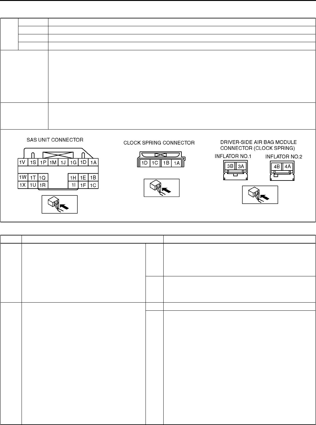
T208
ON-BOARD DIAGNOSTIC [AIR BAG SYSTEM]
DTC B1913, B1916, B1932, B1934 A6E817401046W12
Diagnostic procedure
DTC
B1913 Driver-side air bag module (inflator No.1) system circuit short to ground
B1916 Driver-side air bag module (inflator No.1) system circuit short to power supply
B1932 Driver-side air bag module (inflator No.1) system resistance high
B1934 Driver-side air bag module (inflator No.1) system resistance low
DETECTION
CONDITION
Warning
•
••
•Detection conditions are for understanding DTC outline before performing inspection.
Performing inspection with only detection conditions may cause injury due to operating error
or damage the system. When performing inspection, always follow inspection procedure.
•Abnormal resistance (other than 1.53.7 ohm) detected in driver-side air bag module (inflator No.1)
circuit
•Malfunction in wiring harness between driver-side air bag module (inflator No.1) and SAS unit
POSSIBLE
CAUSE
•Open or short circuit in wiring harness between clock spring and SAS unit
•Clock spring malfunction
•Driver-side air bag module (inflator No.1) malfunction
•SAS unit malfunction
STEP INSPECTION ACTION
1INSPECT DRIVER-SIDE AIR BAG MODULE
(INFLATOR NO.1)
•Check following PID/DATA monitor, using
SST (WDS or equivalent).
(See T195 PID/DATA MONITOR TABLE)
DABAGR
•Is resistant value of driver-side air bag
module normal?
Resistance: 1.53.7 ohm
Yes [Present malfunction diagnosis]
Replace SAS unit.
(See T124 SAS UNIT REMOVAL/INSTALLATION)
[Part malfunction diagnosis]
Troubleshooting completed.
No Go to next step.
2INSPECT DRIVER-SIDE AIR BAG MODULE
CONNECTOR (CLOCK SPRING)
Warning
•
••
•Handling air bag system components
improperly can accidentally deploy air
bag modules and pre-tensioner seat
belts, which may seriously injure you.
Read AIR BAG SYSTEM SERVICE
WARNINGS before handling air bag
system components.
(See T117 SERVICE WARNINGS)
•Turn ignition switch to LOCK position.
•Disconnect negative battery cable and wait
for more than 1 minute.
•Remove driver-side air bag module.
•Is there cracking or chipping in driver-side air
bag module connector?
Yes Replace wiring harness.
No Go to next step.

ON-BOARD DIAGNOSTIC [AIR BAG SYSTEM]
T209
T
End Of Sie
3VERIFY WHETHER MALFUNCTION IS IN
DRIVER-SIDE AIR BAG MODULE (INFLATOR
NO.1) OR RELATED WIRING HARNESS
•Connect leads of SST (Fuel and
thermometer checker) or apply 2 ohm
resistor to driver-side air bag module (inflator
No.1) connector terminal 3A and 3B, and
driver-side air bag module (inflator No.2)
connector terminal 4A and 4B.
•Set resistance of SST (Fuel and
thermometer checker) to 2 ohm.
•Connect negative battery cable.
•Turn ignition switch to ON position.
•Check following PID/DATA monitor, using
SST (WDS or equivalent).
(See T195 PID/DATA MONITOR TABLE)
OD_DAB1_ST
•Is related wiring harness normal?
Yes Replace driver-side air bag module.
(See T120 DRIVER-SIDE AIR BAG MODULE REMOVAL/
INSTALLATION)
No Go to next step.
4INSPECT CLOCK SPRING
•Inspect clock spring.
(See T126 CLOCK SPRING INSPECTION)
•Is clock spring normal?
Yes Go to next step.
No Replace clock spring.
(See T125 CLOCK SPRING REMOVAL/INSTALLATION)
5INSPECT WIRING HARNESS BETWEEN
CLOCK SPRING AND SAS UNIT
•Turn ignition switch to LOCK position.
•Disconnect negative battery cable and wait
for more than 1 minute.
•Remove column cover.
•Disconnect clock spring connector.
•Remove glove compartment.
•Disconnect passenger-side air bag module
connector.
•Disconnect driver and passenger-side side
air bag module connectors. (Vehicle with
side air bag)
•Disconnect driver and passenger-side
curtain air bag module connectors. (Vehicle
with curtain air bag)
•Remove B-pillar lower trim. (Vehicle with pre-
tensioner seat belt)
•Disconnect driver and passenger-side pre-
tensioner seat belt connectors. (Vehicle with
pre-tensioner seat belt)
•Turn up floor covering.
•Disconnect all SAS unit connectors.
•Inspect following wiring harnesses between
SAS unit and clock spring terminals for short
to ground, short to power supply, and open
circuit:
1S1D
1V1C
•Is wiring harness okay?
Yes Present malfunction diagnosis:
•Replace SAS unit.
(See T124 SAS UNIT REMOVAL/INSTALLATION)
Past malfunction diagnosis:
•Troubleshooting completed.
No Replace wiring harnesses.
STEP INSPECTION ACTION
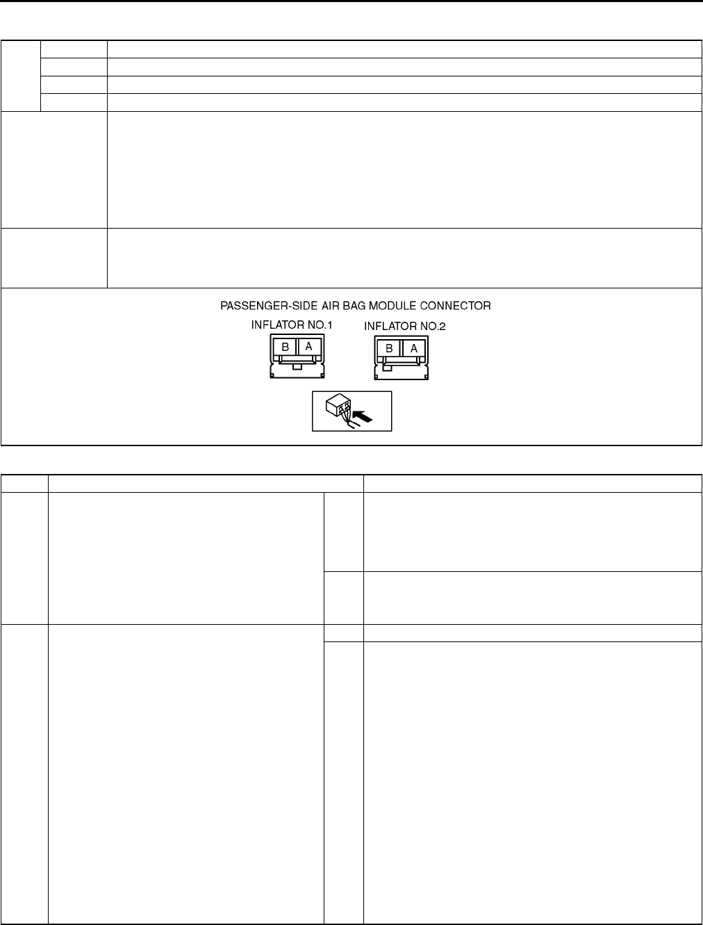
T210
ON-BOARD DIAGNOSTIC [AIR BAG SYSTEM]
DTC B1913, B1925, B1933, B1935 A6E817401046W13
Diagnostic procedure
DTC
B1913 Passenger-side air bag module (inflator No.1) system circuit short to ground
B1925 Passenger-side air bag module (inflator No.1) system circuit short to power supply
B1933 Passenger-side air bag module (inflator No.1) system resistance high
B1935 Passenger-side air bag module (inflator No.1) system resistance low
DETECTION
CONDITION
Warning
•
••
•Detection conditions are for understanding DTC outline before performing inspection.
Performing inspection with only detection conditions may cause injury due to operating error
or damage the system. When performing inspection, always follow inspection procedure.
•Abnormal resistance (other than 1.42.9 ohm) detected in passenger-side air bag module (inflator
No.1) circuit
•Malfunction in wiring harness between passenger-side air bag module (inflator No.1) and SAS unit
POSSIBLE
CAUSE
•Open or short circuit in wiring harness between passenger-side air bag module (inflator No.1) and SAS
unit
•Passenger-side air bag module (inflator No.1) malfunction
•SAS unit malfunction
STEP INSPECTION ACTION
1INSPECT PASSENGER-SIDE AIR BAG
MODULE (INFLATOR NO.1)
•Check following PID/DATA monitor, using
SST (WDS or equivalent).
(See T195 PID/DATA MONITOR TABLE)
PABAGR
•Is resistant value of passenger-side air bag
module normal?
Resistance: 1.42.9 ohm
Yes Present malfunction diagnosis:
•Replace SAS unit.
(See T124 SAS UNIT REMOVAL/INSTALLATION)
Past malfunction diagnosis:
•Troubleshooting completed.
No Go to next step.
2INSPECT PASSENGER-SIDE AIR BAG
MODULE (INFLATOR NO.1) CONNECTOR
Warning
•
••
•Handling air bag system components
improperly can accidentally deploy air
bag modules and pre-tensioner seat
belts, which may seriously injure you.
Read AIR BAG SYSTEM SERVICE
WARNINGS before handling air bag
system components.
(See T117 SERVICE WARNINGS)
•Turn ignition switch to LOCK position.
•Disconnect negative battery cable and wait
for more than 1 minute.
•Remove glove compartment.
•Disconnect passenger-side air bag module
connector.
•Is there cracking or chipping in passenger-
side air bag module connector?
Yes Replace wiring harness.
No Go to next step.
ON-BOARD DIAGNOSTIC [AIR BAG SYSTEM]
T211
T
End Of Sie
DTC B1921 A6E817401046W14
Diagnostic procedure
End Of Sie
3VERIFY WHETHER MALFUNCTION IS IN
PASSENGER-SIDE AIR BAG MODULE
(INFLATOR NO.1) OR RELATED WIRING
HARNESS
•Connect leads of SST (Fuel and
thermometer checker) or apply 2 ohm
resistor to passenger-side air bag module
(inflator No.1) connector terminal A and B,
and passenger-side air bag module (inflator
No.2) connector terminal A and B.
•Set resistance of SST (Fuel and
thermometer checker) to 2 ohm.
•Connect negative battery cable.
•Turn ignition switch to ON position.
•Check following PID/DATA monitor, using
SST (WDS or equivalent).
(See T195 PID/DATA MONITOR TABLE)
DO_PAB1ST
•Is related wiring harness normal?
Yes Replace passenger-side air bag module.
(See T121 PASSENGER-SIDE AIR BAG MODULE
REMOVAL/INSTALLATION)
No Replace wiring harness, then go to next step.
4INSPECT SAS UNIT
•Turn ignition switch to LOCK position.
•Disconnect negative battery cable and wait
for more than 1 minute.
•Connect passenger-side air bag module
connector.
•Are DTCs B1913, B1925, B1933 and/or
B1935 indicated?
Yes Present malfunction diagnosis:
•Replace SAS unit.
(See T124 SAS UNIT REMOVAL/INSTALLATION)
Past malfunction diagnosis:
•Troubleshooting completed.
No Troubleshooting completed.
STEP INSPECTION ACTION
DTC B1921 Deployment prohibited because configuration is not set
DETECTION
CONDITION
Warning
•
••
•Detection conditions are for understanding DTC outline before performing inspection.
Performing inspection with only detection conditions may cause injury due to operating error
or damage the system. When performing inspection, always follow inspection procedure.
•SAS unit configuration has not been set
POSSIBLE
CAUSE
•SAS unit configuration has not been set
•SAS unit malfunction
INSPECTION ACTION
CONFIGRATION
•Configurate SAS unit, using SST (WDS or equivalent).
•Is DTC B1921 indicated?
Yes [Present malfunction diagnosis]
Replace SAS unit.
(See T124 SAS UNIT REMOVAL/INSTALLATION)
[Past malfunction diagnosis]
Troubleshooting completed.
No Troubleshooting completed.
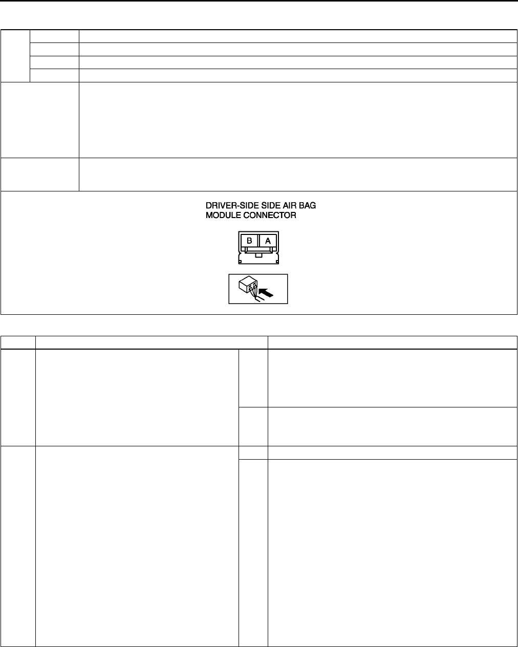
T212
ON-BOARD DIAGNOSTIC [AIR BAG SYSTEM]
DTC B1992, B1993, B1994, B1995 A6E817401046W15
Diagnostic procedure
DTC
B1992 Driver-side side air bag module system circuit short to power supply
B1993 Driver-side side air bag module system circuit short to ground
B1994 Driver-side side air bag module system resistance high
B1995 Driver-side side air bag module system resistance low
DETECTION
CONDITION
Warning
•
••
•Detection conditions are for understanding DTC outline before performing inspection.
Performing inspection with only detection conditions may cause injury due to operating error
or damage the system. When performing inspection, always follow inspection procedure.
•Abnormal resistance (other than 1.43.2 ohm) detected in driver-side side air bag module circuit
•Malfunction in wiring harness between driver-side side air bag module and SAS unit
POSSIBLE
CAUSE
•Open or short circuit in wiring harness between driver-side side air bag module and SAS unit
•Driver-side side air bag module malfunction
•SAS unit malfunction
STEP INSPECTION ACTION
1INSPECT DRIVER-SIDE SIDE AIR BAG
MODULE
•Check following PID/DATA monitor, using
SST (WDS or equivalent).
(See T195 PID/DATA MONITOR TABLE)
DS_AB
•Is resistant value of driver-side side air bag
module normal?
Resistance: 1.43.2 ohm
Yes Present malfunction diagnosis:
•Replace SAS unit.
(See T124 SAS UNIT REMOVAL/INSTALLATION)
Past malfunction diagnosis:
•Troubleshooting completed.
No Go to next step.
2INSPECT DRIVER-SIDE SIDE AIR BAG
MODULE CONNECTOR
Warning
•
••
•Handling air bag system components
improperly can accidentally deploy air
bag modules and pre-tensioner seat
belts, which may seriously injure you.
Read AIR BAG SYSTEM SERVICE
WARNINGS before handling air bag
system components.
(See T117 SERVICE WARNINGS)
•Turn ignition switch to LOCK position.
•Disconnect negative battery cable and wait
for more than 1 minute.
•Remove driver-side side air bag module.
•Is there cracking or chipping in driver-side
side air bag module connector?
Yes Replace wiring harness.
No Go to next step.
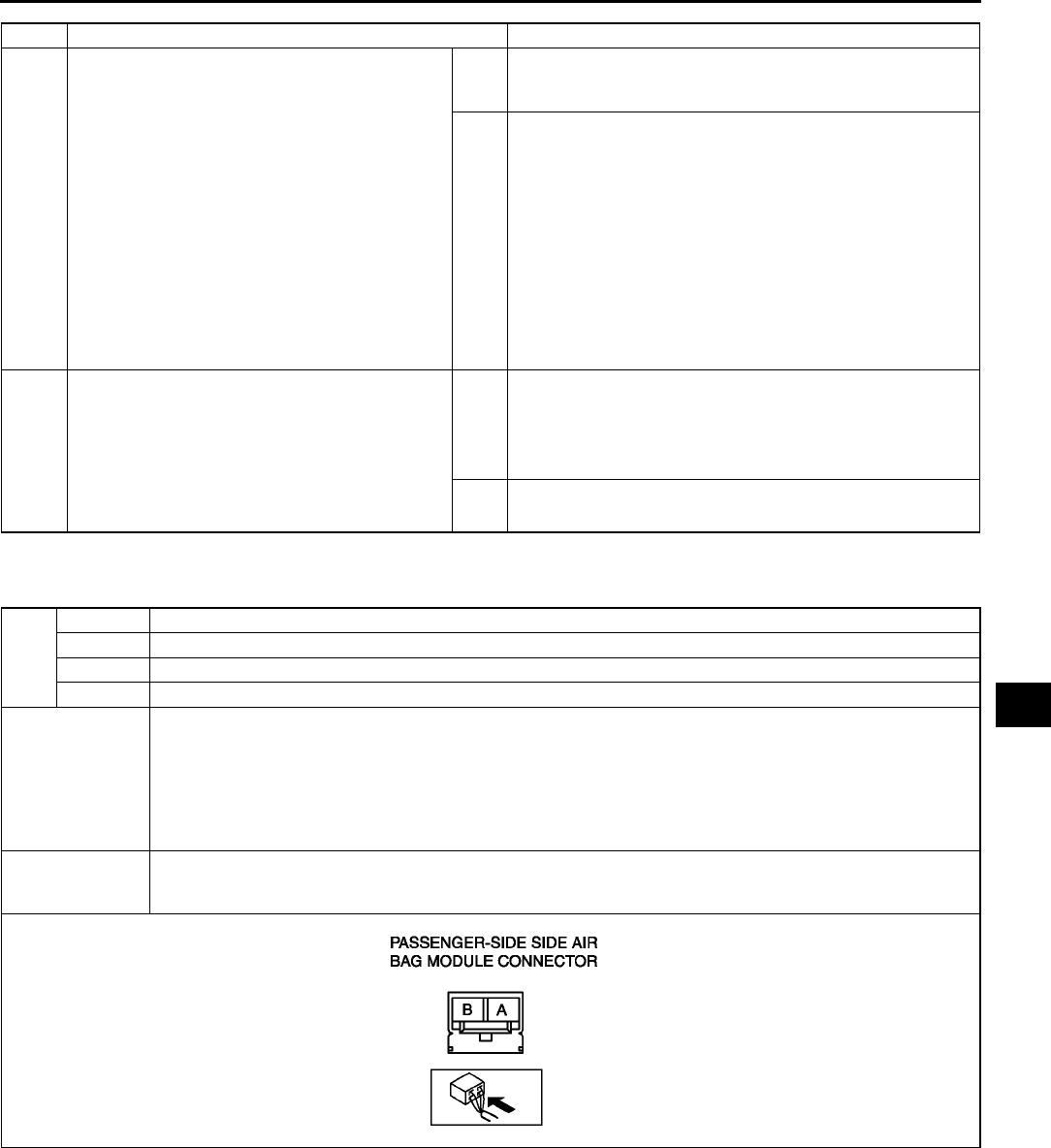
ON-BOARD DIAGNOSTIC [AIR BAG SYSTEM]
T213
T
End Of Sie
DTC B1996, B1997, B1998, B1999 A6E817401046W16
3VERIFY WHETHER MALFUNCTION IS IN
DRIVER-SIDE SIDE AIR BAG MODULE OR
RELATED WIRING HARNESS
•Connect leads of SST (Fuel and
thermometer checker) or apply 2 ohm
resistor to driver-side side air bag module
connector terminal A and B.
•Set resistance of SST (Fuel and
thermometer checker) to 2 ohm.
•Connect negative battery cable.
•Turn ignition switch to ON position.
•Check following PID/DATA monitor, using
SST (WDS or equivalent).
(See T195 PID/DATA MONITOR TABLE)
OD_DSAB_ST
•Is related wiring harness normal?
Yes Replace driver-side side air bag module.
(See T121 SIDE AIR BAG MODULE REMOVAL/
INSTALLATION)
No Replace wiring harness, then go to next step.
4INSPECT SAS UNIT
•Turn ignition switch to LOCK position.
•Disconnect negative battery cable and wait
for more than 1 minute.
•Connect driver-side side air bag module
connector.
•Are DTCs B1992, B1993, B1994 and/or
B1995 indicated?
Yes Present malfunction diagnosis:
•Replace SAS unit.
(See T124 SAS UNIT REMOVAL/INSTALLATION)
Past malfunction diagnosis:
•Troubleshooting completed.
No Troubleshooting completed.
STEP INSPECTION ACTION
DTC
B1996 Passenger-side side air bag module system circuit short to power supply
B1997 Passenger-side side air bag module system circuit short to ground
B1998 Passenger-side side air bag module system resistance high
B1999 Passenger-side side air bag module system resistance low
DETECTION
CONDITION
Warning
•
••
•Detection conditions are for understanding DTC outline before performing inspection.
Performing inspection with only detection conditions may cause injury due to operating error
or damage the system. When performing inspection, always follow inspection procedure.
•Abnormal resistance (other than 1.43.2 ohm) detected in passenger-side side air bag module circuit
•Malfunction in wiring harness between passenger-side side air bag module and SAS unit
POSSIBLE
CAUSE
•Open or short circuit in wiring harness between passenger-side side air bag module and SAS unit
•Passenger-side side air bag module malfunction
•SAS unit malfunction

T214
ON-BOARD DIAGNOSTIC [AIR BAG SYSTEM]
Diagnostic procedure
End Of Sie
STEP INSPECTION ACTION
1INSPECT PASSENGER-SIDE SIDE AIR BAG
MODULE
•Check following PID/DATA monitor, using
SST (WDS or equivalent).
(See T195 PID/DATA MONITOR TABLE)
PS_AB
•Is resistant value of passenger-side side air
bag module normal?
Resistance: 1.43.2 ohm
Yes Present malfunction diagnosis:
•Replace SAS unit.
(See T124 SAS UNIT REMOVAL/INSTALLATION)
Past malfunction diagnosis:
•Troubleshooting completed.
No Go to next step.
2INSPECT PASSENGER-SIDE SIDE AIR BAG
MODULE CONNECTOR
Warning
•
••
•Handling air bag system components
improperly can accidentally deploy air
bag modules and pre-tensioner seat
belts, which may seriously injure you.
Read AIR BAG SYSTEM SERVICE
WARNINGS before handling air bag
system components.
(See T117 SERVICE WARNINGS)
•Turn ignition switch to LOCK position.
•Disconnect negative battery cable and wait
for more than 1 minute.
•Remove passenger-side side air bag
module.
•Is there cracking or chipping in passenger-
side side air bag module connector?
Yes Replace wiring harness.
No Go to next step.
3VERIFY WHETHER MALFUNCTION IS IN
PASSENGER-SIDE SIDE AIR BAG MODULE
OR RELATED WIRING HARNESS
•Connect leads of SST (Fuel and
thermometer checker) or apply 2 ohm
resistor to passenger-side side air bag
module connector terminal A and B.
•Set resistance of SST (Fuel and
thermometer checker) to 2 ohm.
•Connect negative battery cable.
•Turn ignition switch to ON position.
•Check following PID/DATA monitor, using
SST (WDS or equivalent).
(See T195 PID/DATA MONITOR TABLE)
DSB_P_ST
•Is related wiring harness normal?
Yes Replace passenger-side side air bag module.
(See T121 SIDE AIR BAG MODULE REMOVAL/
INSTALLATION)
No Replace wiring harness, then go to next step.
4INSPECT SAS UNIT
•Turn ignition switch to LOCK position.
•Disconnect negative battery cable and wait
for more than 1 minute.
•Connect passenger-side side air bag module
connector.
•Are DTCs B1996, B1997, B1998 and/or
B1999 indicated?
Yes Present malfunction diagnosis:
•Replace SAS unit.
(See T124 SAS UNIT REMOVAL/INSTALLATION)
Past malfunction diagnosis:
•Troubleshooting completed.
No Troubleshooting completed.
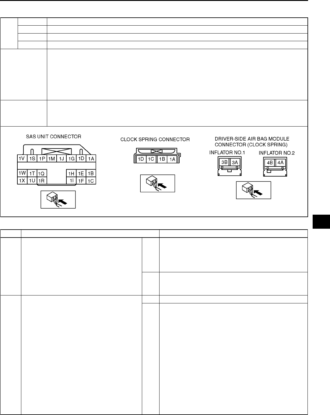
ON-BOARD DIAGNOSTIC [AIR BAG SYSTEM]
T215
T
DTC B2228, B2230, B2232, B2234 A6E817401046W17
Diagnostic procedure
DTC
B2228 Driver-side air bag module (inflator No.2) system circuit short to ground
B2230 Driver-side air bag module (inflator No.2) system circuit short to power supply
B2232 Driver-side air bag module (inflator No.2) system resistance high
B2234 Driver-side air bag module (inflator No.2) system resistance low
DETECTION
CONDITION
Warning
•
••
•Detection conditions are for understanding DTC outline before performing inspection.
Performing inspection with only detection conditions may cause injury due to operating error
or damage the system. When performing inspection, always follow inspection procedure.
•Abnormal resistance (other than 1.53.7 ohm) detected in driver-side air bag module (inflator No.2)
circuit
•Malfunction in wiring harness between driver-side air bag module (inflator No.2) and SAS unit
POSSIBLE
CAUSE
•Open or short circuit in wiring harness between clock spring and SAS unit
•Clock spring malfunction
•Driver-side air bag module (inflator No.2) malfunction
•SAS unit malfunction
STEP INSPECTION ACTION
1INSPECT DRIVER-SIDE AIR BAG MODULE
(INFLATOR NO.2)
•Check following PID/DATA monitor, using
SST (WDS or equivalent).
(See T195 PID/DATA MONITOR TABLE)
D_ABAGR2
•Is resistant value of driver-side air bag
module normal?
Resistance: 1.53.7 ohm
Yes Present malfunction diagnosis:
•Replace SAS unit.
(See T124 SAS UNIT REMOVAL/INSTALLATION)
Past malfunction diagnosis:
•Troubleshooting completed.
No Go to next step.
2INSPECT DRIVER-SIDE AIR BAG MODULE
CONNECTOR (CLOCK SPRING)
Warning
•
••
•Handling air bag system components
improperly can accidentally deploy air
bag modules and pre-tensioner seat
belts, which may seriously injure you.
Read AIR BAG SYSTEM SERVICE
WARNINGS before handling air bag
system components.
(See T117 SERVICE WARNINGS)
•Turn ignition switch to LOCK position.
•Disconnect negative battery cable and wait
for more than 1 minute.
•Remove driver-side air bag module.
•Is there cracking or chipping in driver-side air
bag module connector?
Yes Replace wiring harness.
No Go to next step.

T216
ON-BOARD DIAGNOSTIC [AIR BAG SYSTEM]
End Of Sie
3VERIFY WHETHER MALFUNCTION IS IN
DRIVER-SIDE AIR BAG MODULE (INFLATOR
NO.2) OR RELATED WIRING HARNESS
•Connect leads of SST (Fuel and
thermometer checker) or apply 2 ohm
resistor to driver-side air bag module (inflator
No.1) connector terminal 3A and 3B, and
driver-side air bag module (inflator No.2)
connector terminal 4A and 4B.
•Set resistance of SST (Fuel and
thermometer checker) to 2 ohm.
•Connect negative battery cable.
•Turn ignition switch to ON position.
•Check following PID/DATA monitor, using
SST (WDS or equivalent).
(See T195 PID/DATA MONITOR TABLE)
OD_DAB2_ST
•Is related wiring harness normal?
Yes Replace driver-side air bag module.
(See T120 DRIVER-SIDE AIR BAG MODULE REMOVAL/
INSTALLATION)
No Go to next step.
4INSPECT CLOCK SPRING
•Inspect clock spring.
(See T126 CLOCK SPRING INSPECTION)
•Is clock spring normal?
Yes Go to next step.
No Replace clock spring.
(See T125 CLOCK SPRING REMOVAL/INSTALLATION)
5INSPECT WIRING HARNESS BETWEEN
CLOCK SPRING AND SAS UNIT
•Turn ignition switch to LOCK position.
•Disconnect negative battery cable and wait
for more than 1 minute.
•Remove column cover.
•Disconnect clock spring connector.
•Remove glove compartment.
•Disconnect passenger-side air bag module
connector.
•Disconnect driver and passenger-side side
air bag module connectors. (Vehicle with
side air bag)
•Disconnect driver and passenger-side
curtain air bag module connectors. (Vehicle
with curtain air bag)
•Remove B-pillar lower trim. (Vehicle with pre-
tensioner seat belt)
•Disconnect driver and passenger-side pre-
tensioner seat belt connectors. (Vehicle with
pre-tensioner seat belt)
•Turn up floor covering.
•Disconnect all SAS unit connectors.
•Inspect following wiring harnesses between
SAS unit and clock spring terminals for short
to ground, short to power supply, and open
circuit:
1G1B
1J1A
•Is wiring harness okay?
Yes Present malfunction diagnosis:
•Replace SAS unit.
(See T124 SAS UNIT REMOVAL/INSTALLATION)
Past malfunction diagnosis:
•Troubleshooting completed.
No Replace wiring harnesses.
STEP INSPECTION ACTION
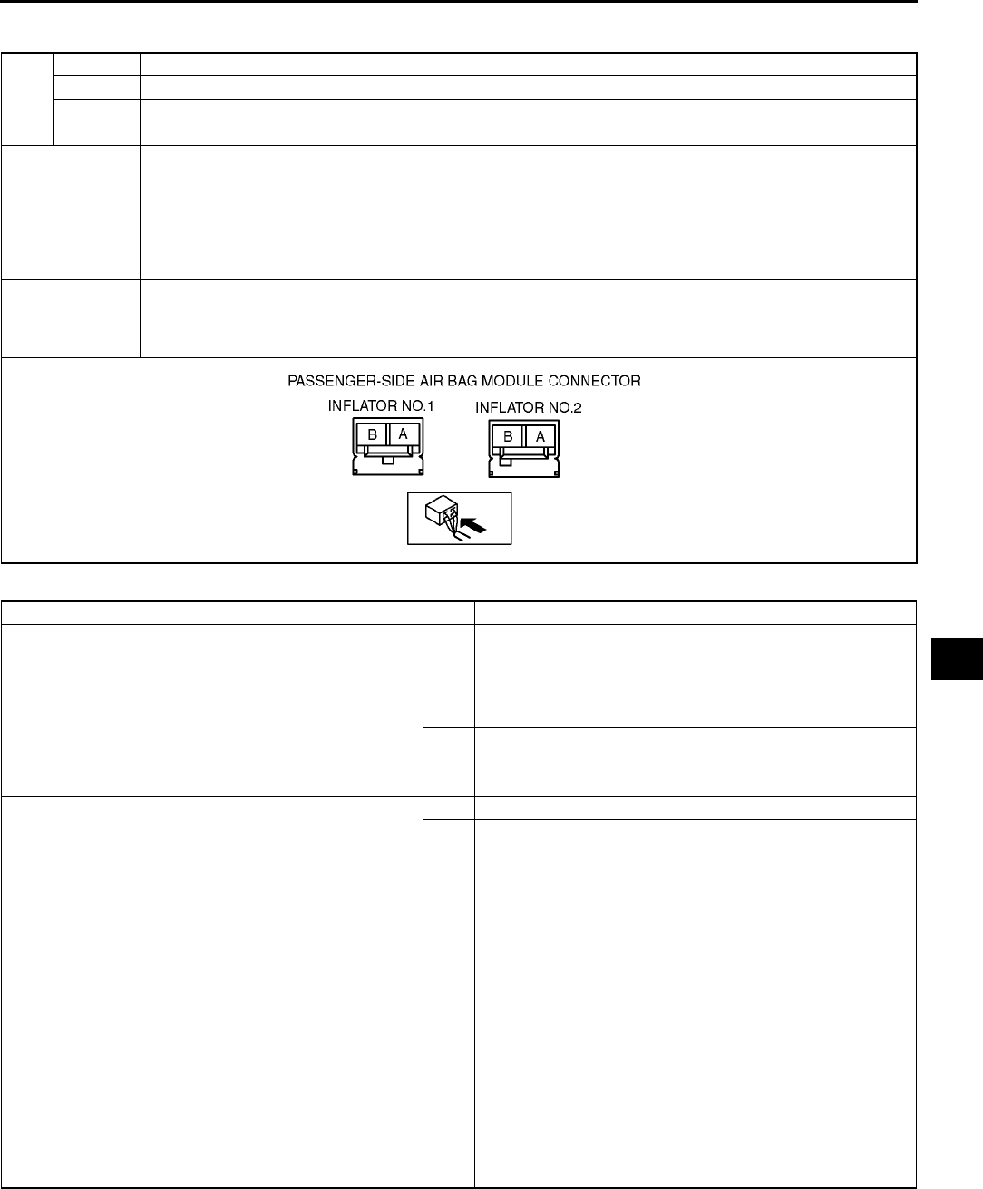
ON-BOARD DIAGNOSTIC [AIR BAG SYSTEM]
T217
T
DTC B2229, B2231, B2233, B2235 A6E817401046W18
Diagnostic procedure
DTC
B2229 Passenger-side air bag module (inflator No.2) system circuit short to ground
B2231 Passenger-side air bag module (inflator No.2) system circuit short to power supply
B2233 Passenger-side air bag module (inflator No.2) system resistance high
B2235 Passenger-side air bag module (inflator No.2) system resistance low
DETECTION
CONDITION
Warning
•
••
•Detection conditions are for understanding DTC outline before performing inspection.
Performing inspection with only detection conditions may cause injury due to operating error
or damage the system. When performing inspection, always follow inspection procedure.
•Abnormal resistance (other than 1.42.9 ohm) detected in passenger-side air bag module circuit
•Malfunction in wiring harness between passenger-side air bag module (inflator No.2) and SAS unit
POSSIBLE
CAUSE
•Open or short circuit in wiring harness between passenger-side air bag module (inflator No.2) and SAS
unit
•Passenger-side air bag module (inflator No.2) malfunction
•SAS unit malfunction
STEP INSPECTION ACTION
1INSPECT PASSENGER-SIDE AIR BAG
MODULE (INFLATOR NO.2)
•Check following PID/DATA monitor, using
SST (WDS or equivalent).
(See T195 PID/DATA MONITOR TABLE)
P_ABAGR2
•Is resistant value of passenger-side air bag
module normal?
Resistance: 1.42.9 ohm
Yes Present malfunction diagnosis:
•Replace SAS unit.
(See T124 SAS UNIT REMOVAL/INSTALLATION)
Past malfunction diagnosis:
•Troubleshooting completed.
No Go to next step.
2INSPECT PASSENGER-SIDE AIR BAG
MODULE (INFLATOR NO.2) CONNECTOR
Warning
•
••
•Handling air bag system components
improperly can accidentally deploy air
bag modules and pre-tensioner seat
belts, which may seriously injure you.
Read AIR BAG SYSTEM SERVICE
WARNINGS before handling air bag
system components.
(See T117 SERVICE WARNINGS)
•Turn ignition switch to LOCK position.
•Disconnect negative battery cable and wait
for more than 1 minute.
•Remove glove compartment.
•Disconnect passenger-side air bag module
connector.
•Is there cracking or chipping in passenger-
side air bag module connector?
Yes Replace wiring harness.
No Go to next step.
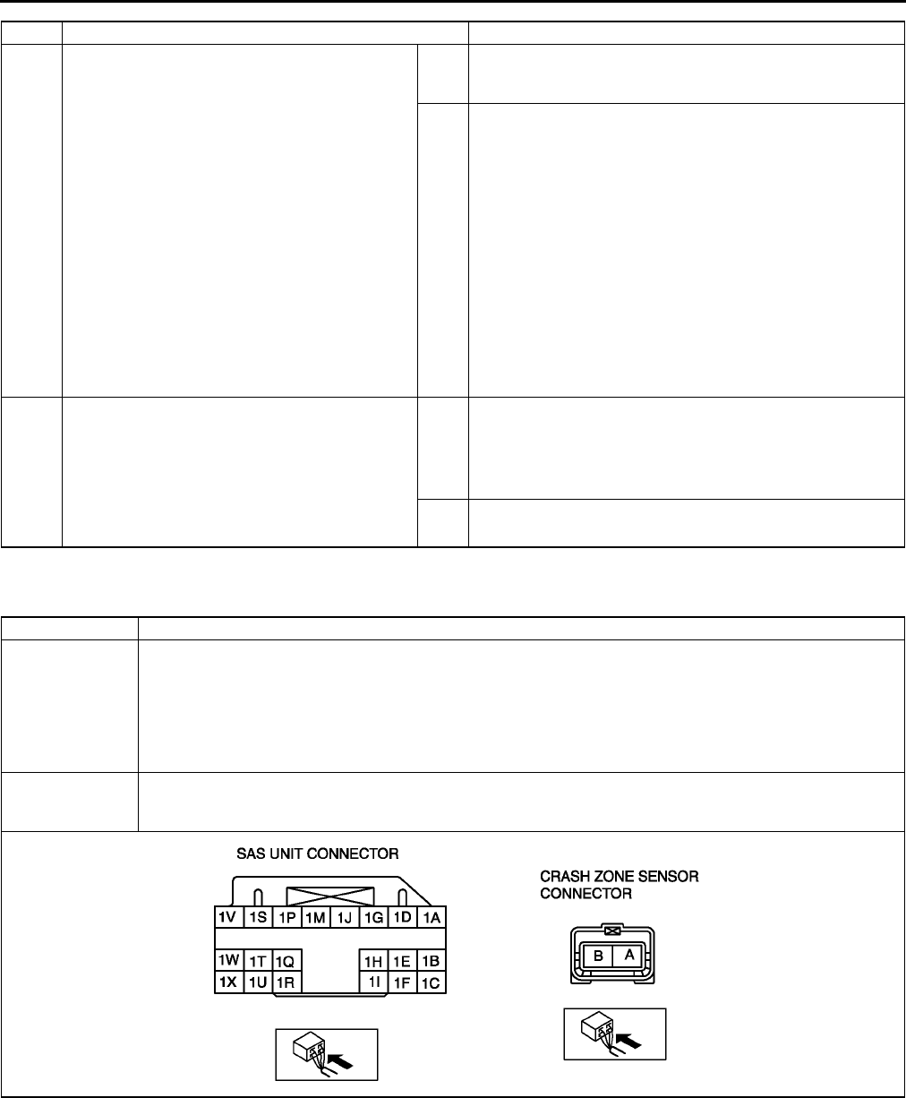
T218
ON-BOARD DIAGNOSTIC [AIR BAG SYSTEM]
End Of Sie
DTC B2296 A6E817401046W19
3VERIFY WHETHER MALFUNCTION IS IN
PASSENGER-SIDE AIR BAG MODULE
(INFLATOR NO.2) OR RELATED WIRING
HARNESS
•Connect leads of SST (Fuel and
thermometer checker) or apply 2 ohm
resistor to passenger-side air bag module
(inflator No.1) connector terminal A and B,
and passenger-side air bag module (inflator
No.2) connector terminal A and B.
•Set resistance of SST (Fuel and
thermometer checker) to 2 ohm.
•Connect negative battery cable.
•Turn ignition switch to ON position.
•Check following PID/DATA monitor, using
SST (WDS or equivalent).
(See T195 PID/DATA MONITOR TABLE)
DO_PAB2ST
•Is related wiring harness normal?
Yes Replace passenger-side air bag module.
(See T121 PASSENGER-SIDE AIR BAG MODULE
REMOVAL/INSTALLATION)
No Replace wiring harness, then go to next step.
4INSPECT SAS UNIT
•Turn ignition switch to LOCK position.
•Disconnect negative battery cable and wait
for more than 1 minute.
•Connect passenger-side air bag module
connector.
•Are DTCs B2229, B2231, B2233 and/or
B2235 indicated?
Yes Present malfunction diagnosis:
•Replace SAS unit.
(See T124 SAS UNIT REMOVAL/INSTALLATION)
Past malfunction diagnosis:
•Troubleshooting completed.
No Troubleshooting completed.
STEP INSPECTION ACTION
DTC B2296 Crash zone sensor system (communication error, sensor internal circuit abnormal)
DETECTION
CONDITION
Warning
•
••
•Detection conditions are for understanding DTC outline before performing inspection.
Performing inspection with only detection conditions may cause injury due to operating error
or damage the system. When performing inspection, always follow inspection procedure.
•Malfunction in wiring harness between crash zone sensor and SAS unit
•Malfunction in crash zone sensor circuit
POSSIBLE
CAUSE
•Open or short circuit in wiring harness between crash zone sensor and SAS unit
•SAS unit malfunction
•Crash zone sensor malfunction

ON-BOARD DIAGNOSTIC [AIR BAG SYSTEM]
T219
T
Diagnostic procedure
End Of Sie
STEP INSPECTION ACTION
1INSPECT CRASH ZONE SENSOR
•Check following PID/DATA monitor, using
SST (WDS or equivalent).
(See T195 PID/DATA MONITOR TABLE)
OD_F_CRSH
•Is crash zone sensor normal?
Yes Present malfunction diagnosis:
•Replace SAS unit.
(See T124 SAS UNIT REMOVAL/INSTALLATION)
Past malfunction diagnosis:
•Troubleshooting completed.
No Go to next step.
2INSPECT WIRING HARNESS BETWEEN
CRASH ZONE SENSOR AND SAS UNIT
Warning
•
••
•Handling air bag system components
improperly can accidentally deploy air
bag modules and pre-tensioner seat
belts, which may seriously injure you.
Read AIR BAG SYSTEM SERVICE
WARNINGS before handling air bag
system components.
(See T117 SERVICE WARNINGS)
•Turn ignition switch to LOCK position.
•Disconnect negative battery cable and wait
for more than 1 minute.
•Remove column cover.
•Disconnect clock spring connector.
•Remove glove compartment.
•Disconnect passenger-side air bag module
connector.
•Disconnect driver and passenger-side side
air bag module connectors. (Vehicle with
side air bag)
•Disconnect driver and passenger-side
curtain air bag module connectors. (Vehicle
with curtain air bag)
•Remove B-pillar lower trim. (Vehicle with pre-
tensioner seat belt)
•Disconnect driver and passenger-side pre-
tensioner seat belt connectors. (Vehicle with
pre-tensioner seat belt)
•Turn up floor covering.
•Disconnect all SAS unit connectors.
•Disconnect crash zone sensor connector.
•Connect negative battery cable.
•Inspect following wiring harnesses between
SAS unit and crash zone sensor terminals
for short to ground, short to power supply,
and open circuit:
1BA
1CB
•Is wiring harness okay?
Yes Replace crash zone sensor, then go to next step.
(See T123 CRASH ZONE SENSOR REMOVAL/
INSTALLATION)
No Replace wiring harnesses.
3INSPECT SAS UNIT
•Turn ignition switch to LOCK position.
•Disconnect negative battery cable and wait
for more than 1 minute.
•Connect all SAS unit connectors.
•Connect crash zone sensor connector.
•Is DTC B2296 indicated?
Yes Present malfunction diagnosis:
•Replace SAS unit.
(See T124 SAS UNIT REMOVAL/INSTALLATION)
Past malfunction diagnosis:
•Troubleshooting completed.
No Troubleshooting completed.
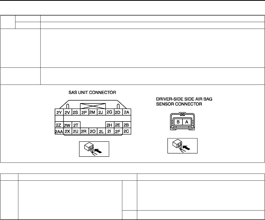
T220
ON-BOARD DIAGNOSTIC [AIR BAG SYSTEM]
DTC B2444, U2017 A6E817401046W20
Diagnostic procedure
DTC B2444 Driver-side side air bag sensor system (sensor internal circuit abnormal)
U2017 Driver-side side air bag sensor system (communication error)
DETECTION
CONDITION
Warning
•
••
•Detection conditions are for understanding DTC outline before performing inspection.
Performing inspection with only detection conditions may cause injury due to operating error
or damage the system. When performing inspection, always follow inspection procedure.
•Malfunction in wiring harness between driver-side side air bag sensor and SAS unit
•Malfunction in driver-side side air bag sensor circuit
POSSIBLE
CAUSE
•Open or short circuit in wiring harness between driver-side side air bag sensor and SAS unit
•Driver-side side air bag sensor malfunction
•SAS unit malfunction
STEP INSPECTION ACTION
1INSPECT DRIVER-SIDE SIDE AIR BAG
SENSOR
•Check following PID/DATA monitor, using
SST (WDS or equivalent).
(See T195 PID/DATA MONITOR TABLE)
OD_D_CRSH
•Is driver-side side air bag sensor normal?
Yes Present malfunction diagnosis:
•Replace SAS unit.
(See T124 SAS UNIT REMOVAL/INSTALLATION)
Past malfunction diagnosis:
•Troubleshooting completed.
No Go to next step.

ON-BOARD DIAGNOSTIC [AIR BAG SYSTEM]
T221
T
End Of Sie
2INSPECT WIRING HARNESS BETWEEN
DRIVER-SIDE SIDE AIR BAG SENSOR AND
SAS UNIT
Warning
•
••
•Handling air bag system components
improperly can accidentally deploy air
bag modules and pre-tensioner seat
belts, which may seriously injure you.
Read AIR BAG SYSTEM SERVICE
WARNINGS before handling air bag
system components.
(See T117 SERVICE WARNINGS)
•Turn ignition switch to LOCK position.
•Disconnect negative battery cable and wait
for more than 1 minute.
•Remove column cover.
•Disconnect clock spring connector.
•Remove glove compartment.
•Disconnect passenger-side air bag module
connector.
•Disconnect driver and passenger-side side
air bag module connectors. (Vehicle with
side air bag)
•Disconnect driver and passenger-side
curtain air bag module connectors. (Vehicle
with curtain air bag)
•Remove B-pillar lower trim.
•Disconnect driver and passenger-side pre-
tensioner seat belt connectors. (Vehicle with
pre-tensioner seat belt)
•Turn up floor covering.
•Disconnect all SAS unit connectors.
•Disconnect driver-side side air bag sensor
connector.
•Connect negative battery cable.
•Inspect following wiring harnesses between
SAS unit and driver-side side air bag sensor
terminals for short to ground, short to power
supply, and open circuit:
2ZA
2AAB
•Is wiring harness okay?
Yes Replace driver-side side air bag sensor, then go to next
step.
(See T123 SIDE AIR BAG SENSOR REMOVAL/
INSTALLATION)
No Replace wiring harnesses.
3INSPECT SAS UNIT
•Turn ignition switch to LOCK position.
•Disconnect negative battery cable and wait
for more than 1 minute.
•Connect all SAS unit connectors.
•Connect driver-side side air bag sensor
connector.
•Are DTCs B2444 and/or U2017 indicated?
Yes Present malfunction diagnosis:
•Replace SAS unit.
(See T124 SAS UNIT REMOVAL/INSTALLATION)
Past malfunction diagnosis:
•Troubleshooting completed.
No Troubleshooting completed.
STEP INSPECTION ACTION
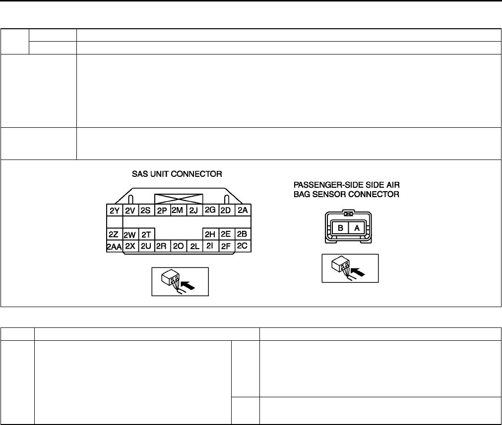
T222
ON-BOARD DIAGNOSTIC [AIR BAG SYSTEM]
DTC B2445, U2018 A6E817401046W21
Diagnostic procedure
DTC B2445 Passenger-side side air bag sensor system (sensor internal circuit abnormal)
U2018 Passenger-side side air bag sensor system (communication error)
DETECTION
CONDITION
Warning
•
••
•Detection conditions are for understanding DTC outline before performing inspection.
Performing inspection with only detection conditions may cause injury due to operating error
or damage the system. When performing inspection, always follow inspection procedure.
•Malfunction in wiring harness between passenger-side side air bag sensor and SAS unit
•Malfunction in passenger-side side air bag sensor circuit
POSSIBLE
CAUSE
•Open or short circuit in wiring harness between passenger-side side air bag sensor and SAS unit
•Passenger-side side air bag sensor malfunction
•SAS unit malfunction
STEP INSPECTION ACTION
1INSPECT PASSENGER-SIDE SIDE AIR BAG
SENSOR
•Check following PID/DATA monitor, using
SST (WDS or equivalent).
(See T195 PID/DATA MONITOR TABLE)
OD_P_CRSH
•Is passenger-side side air bag sensor
normal?
Yes Present malfunction diagnosis:
•Replace SAS unit.
(See T124 SAS UNIT REMOVAL/INSTALLATION)
Past malfunction diagnosis:
•Troubleshooting completed.
No Go to next step.
ON-BOARD DIAGNOSTIC [AIR BAG SYSTEM]
T223
T
End Of Sie
2INSPECT WIRING HARNESS BETWEEN
PASSENGER-SIDE AIR BAG SENSOR AND
SAS UNIT
Warning
•
••
•Handling air bag system components
improperly can accidentally deploy air
bag modules and pre-tensioner seat
belts, which may seriously injure you.
Read AIR BAG SYSTEM SERVICE
WARNINGS before handling air bag
system components.
(See T117 SERVICE WARNINGS)
•Turn ignition switch to LOCK position.
•Disconnect negative battery cable and wait
for more than 1 minute.
•Remove column cover.
•Disconnect clock spring connector.
•Remove glove compartment.
•Disconnect passenger-side air bag module
connector.
•Disconnect driver and passenger-side side
air bag module connectors. (Vehicle with
side air bag)
•Disconnect driver and passenger-side
curtain air bag module connectors. (Vehicle
with curtain air bag)
•Remove B-pillar lower trim.
•Disconnect driver and passenger-side pre-
tensioner seat belt connectors. (Vehicle with
pre-tensioner seat belt)
•Turn up floor covering.
•Disconnect all SAS unit connectors.
•Disconnect passenger-side side air bag
sensor connector.
•Connect negative battery cable.
•Inspect following wiring harnesses between
SAS unit and passenger-side side air bag
sensor terminals for short to ground, short to
power supply, and open circuit:
2BA
2CB
•Is wiring harness okay?
Yes Replace passenger-side side air bag sensor, then go to next
step.
(See T123 SIDE AIR BAG SENSOR REMOVAL/
INSTALLATION)
No Replace wiring harnesses.
3INSPECT SAS UNIT
•Turn ignition switch to LOCK position.
•Disconnect negative battery cable and wait
for more than 1 minute.
•Connect all SAS unit connectors.
•Connect passenger-side side air bag sensor
connector.
•Are DTCs B2445 and/or U2018 indicated?
Yes Present malfunction diagnosis:
•Replace SAS unit.
(See T124 SAS UNIT REMOVAL/INSTALLATION)
Past malfunction diagnosis:
•Troubleshooting completed.
No Troubleshooting completed.
STEP INSPECTION ACTION
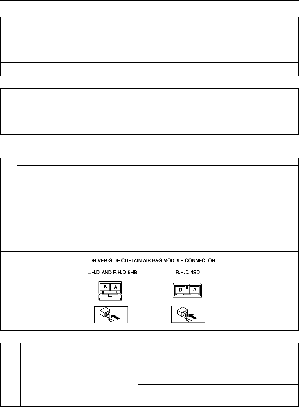
T224
ON-BOARD DIAGNOSTIC [AIR BAG SYSTEM]
DTC B2477 A6E817401046W22
Diagnostic procedure
End Of Sie
DTC B2773, B2774, B2775, B2776 A6E817401046W23
Diagnostic procedure
DTC B2477 SAS unit configuration error
DETECTION
CONDITION
Warning
•
••
•Detection conditions are for understanding DTC outline before performing inspection.
Performing inspection with only detection conditions may cause injury due to operating error
or damage the system. When performing inspection, always follow inspection procedure.
•SAS unit configuration not set correctly
POSSIBLE
CAUSE
•SAS unit configuration error
•SAS unit malfunction
INSPECTION ACTION
CONFIGRATION
•Configurate SAS unit, using SST (WDS or equivalent).
•Is DTC B2477 indicated?
Yes [Present malfunction diagnosis]
Replace SAS unit.
(See T124 SAS UNIT REMOVAL/INSTALLATION)
[Past malfunction diagnosis]
Troubleshooting completed.
No Troubleshooting completed.
DTC
B2773 Driver-side curtain air bag module system resistance low
B2774 Driver-side curtain air bag module system resistance high
B2775 Driver-side curtain air bag module system circuit short to ground
B2776 Driver-side curtain air bag module system circuit short to power supply
DETECTION
CONDITION
Warning
•
••
•Detection conditions are for understanding DTC outline before performing inspection.
Performing inspection with only detection conditions may cause injury due to operating error
or damage the system. When performing inspection, always follow inspection procedure.
•Abnormal resistance (other than 1.43.2 ohm) detected in driver-side curtain air bag module circuit
•Malfunction in wiring harness between driver-side curtain air bag module and SAS unit
POSSIBLE
CAUSE
•Open or short circuit in wiring harness between driver-side curtain air bag module and SAS unit
•Driver-side curtain air bag module malfunction
•SAS unit malfunction
STEP INSPECTION ACTION
1INSPECT DRIVER-SIDE CURTAIN AIR BAG
MODULE
•Check following PID/DATA monitor, using
SST (WDS or equivalent).
(See T195 PID/DATA MONITOR TABLE)
DR_CURTN
•Is resistant value of driver-side curtain air
bag module normal?
Resistance: 1.43.2 ohm
Yes Present malfunction diagnosis:
•Replace SAS unit.
(See T124 SAS UNIT REMOVAL/INSTALLATION)
Past malfunction diagnosis:
•Troubleshooting completed.
No Go to next step.

ON-BOARD DIAGNOSTIC [AIR BAG SYSTEM]
T225
T
End Of Sie
2INSPECT DRIVER-SIDE CURTAIN AIR BAG
MODULE CONNECTOR
Warning
•
••
•Handling air bag system components
improperly can accidentally deploy air
bag modules and pre-tensioner seat
belts, which may seriously injure you.
Read AIR BAG SYSTEM SERVICE
WARNINGS before handling air bag
system components.
(See T117 SERVICE WARNINGS)
•Turn ignition switch to LOCK position.
•Disconnect negative battery cable and wait
for more than 1 minute.
•Disconnect driver-side curtain air bag
module connector.
•Is there cracking or chipping in driver-side
curtain air bag module connector?
Yes Replace wiring harness.
No Go to next step.
3VERIFY WHETHER MALFUNCTION IS IN
DRIVER-SIDE CURTAIN AIR BAG MODULE
OR RELATED WIRING HARNESS
•Connect leads of SST (Fuel and
thermometer checker) or apply 2 ohm
resistor to driver-side curtain air bag module
connector terminal A and B.
•Set resistance of SST (Fuel and
thermometer checker) to 2 ohm.
•Connect negative battery cable.
•Turn ignition switch to ON position.
•Check following PID/DATA monitor, using
SST (WDS or equivalent).
(See T195 PID/DATA MONITOR TABLE)
DO_D_CURT
•Is related wiring harness normal?
Yes Replace driver-side curtain air bag module.
(See T122 CURTAIN AIR BAG MODULE REMOVAL/
INSTALLATION)
No Replace wiring harness, then go to next step.
4INSPECT SAS UNIT
•Turn ignition switch to LOCK position.
•Disconnect negative battery cable and wait
for more than 1 minute.
•Connect driver-side curtain air bag module
connector.
•Are DTCs B2773, B2774, B2775 and/or
B2776 indicated?
Yes Present malfunction diagnosis:
•Replace SAS unit.
(See T124 SAS UNIT REMOVAL/INSTALLATION)
Past malfunction diagnosis:
•Troubleshooting completed.
No Troubleshooting completed.
STEP INSPECTION ACTION
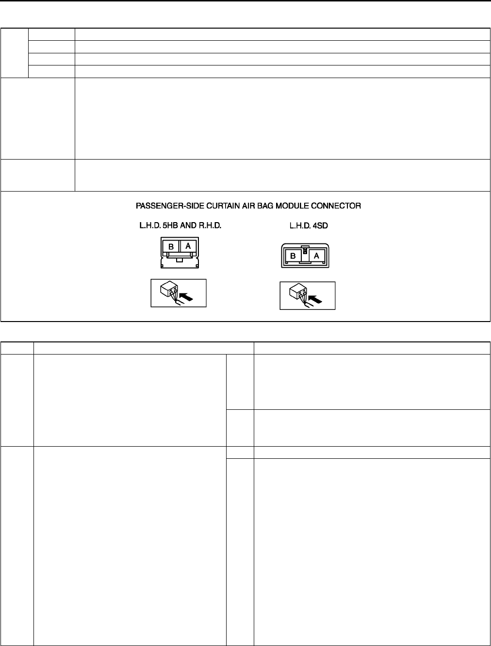
T226
ON-BOARD DIAGNOSTIC [AIR BAG SYSTEM]
DTC B2777, B2778, B2779, B2780 A6E817401046W24
Diagnostic procedure
DTC
B2777 Passenger-side curtain air bag module system resistance low
B2778 Passenger-side curtain air bag module system resistance high
B2779 Passenger-side curtain air bag module system circuit short to ground
B2780 Passenger-side curtain air bag module system circuit short to power supply
DETECTION
CONDITION
Warning
•
••
•Detection conditions are for understanding DTC outline before performing inspection.
Performing inspection with only detection conditions may cause injury due to operating error
or damage the system. When performing inspection, always follow inspection procedure.
•Abnormal resistance (other than 1.43.2 ohm) detected in passenger-side curtain air bag module
circuit
•Malfunction in wiring harness between passenger-side curtain air bag module and SAS unit
POSSIBLE
CAUSE
•Open or short circuit in wiring harness between passenger-side curtain air bag module and SAS unit
•Passenger-side curtain air bag module malfunction
•SAS unit malfunction
STEP INSPECTION ACTION
1INSPECT PASSENGER-SIDE CURTAIN AIR
BAG MODULE
•Check following PID/DATA monitor, using
SST (WDS or equivalent).
(See T195 PID/DATA MONITOR TABLE)
PC_CURTN
•Is resistant value of passenger-side curtain
air bag module normal?
Resistance: 1.43.2 ohm
Yes Present malfunction diagnosis:
•Replace SAS unit.
(See T124 SAS UNIT REMOVAL/INSTALLATION)
Past malfunction diagnosis:
•Troubleshooting completed.
No Go to next step.
2INSPECT PASSENGER-SIDE CURTAIN AIR
BAG MODULE CONNECTOR
Warning
•
••
•Handling air bag system components
improperly can accidentally deploy air
bag modules and pre-tensioner seat
belts, which may seriously injure you.
Read AIR BAG SYSTEM SERVICE
WARNINGS before handling air bag
system components.
(See T117 SERVICE WARNINGS)
•Turn ignition switch to LOCK position.
•Disconnect negative battery cable and wait
for more than 1 minute.
•Disconnect passenger-side curtain air bag
module connector.
•Is there cracking or chipping in passenger-
side curtain air bag module connector?
Yes Replace wiring harness.
No Go to next step.
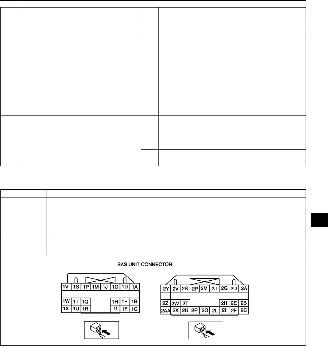
ON-BOARD DIAGNOSTIC [AIR BAG SYSTEM]
T227
T
End Of Sie
DTC B2867 A6E817401046W25
3VERIFY WHETHER MALFUNCTION IS IN
PASSENGER-SIDE CURTAIN AIR BAG
MODULE OR RELATED WIRING HARNESS
•Connect leads of SST (Fuel and
thermometer checker) or apply 2 ohm
resistor to passenger-side curtain air bag
module connector terminal A and B.
•Set resistance of SST (Fuel and
thermometer checker) to 2 ohm.
•Connect negative battery cable.
•Turn ignition switch to ON position.
•Check following PID/DATA monitor, using
SST (WDS or equivalent).
(See T195 PID/DATA MONITOR TABLE)
DO_P_CURT
•Is related wiring harness normal?
Yes Replace passenger-side curtain air bag module.
(See T122 CURTAIN AIR BAG MODULE REMOVAL/
INSTALLATION)
No Replace wiring harness, then go to next step.
4INSPECT SAS UNIT
•Turn ignition switch to LOCK position.
•Disconnect negative battery cable and wait
for more than 1 minute.
•Connect passenger-side curtain air bag
module connector.
•Are DTCs B2777, B2778, B2779 and/or
B2780 indicated?
Yes Present malfunction diagnosis:
•Replace SAS unit.
(See T124 SAS UNIT REMOVAL/INSTALLATION)
Past malfunction diagnosis:
•Troubleshooting completed.
No Troubleshooting completed.
STEP INSPECTION ACTION
DTC B2867 SAS unit connector poor connection
DETECTION
CONDITION
Warning
•
••
•Detection conditions are for understanding DTC outline before performing inspection.
Performing inspection with only detection conditions may cause injury due to operating error
or damage the system. When performing inspection, always follow inspection procedure.
•There is no continuity between poor connection detector bar terminals of SAS unit.
POSSIBLE
CAUSE
•Poor connection of any SAS unit connectors
•Malfunction of any SAS unit connectors
•SAS unit malfunction

T228
ON-BOARD DIAGNOSTIC [AIR BAG SYSTEM]
Diagnostic procedure
End Of Si e
STEP INSPECTION ACTION
1VERIFY THAT ALL SAS UNIT CONNECTORS
ARE CONNECTED WITH SAS UNIT
Warning
•
••
•Handling air bag system components
improperly can accidentally deploy air
bag modules and pre-tensioner seat
belts, which may seriously injure you.
Read AIR BAG SYSTEM SERVICE
WARNINGS before handling air bag
system components.
(See T117 SERVICE WARNINGS)
•Turn ignition switch to LOCK position.
•Disconnect negative battery cable and wait
for more than 1 minute.
•Turn up floor covering.
•Are all SAS unit connectors securely
connected?
Yes Go to next step.
No Reconnect connector properly.
2INSPECT ALL SAS UNIT CONNECTORS
•Remove column cover.
•Disconnect clock spring connector.
•Remove glove compartment.
•Disconnect passenger-side air bag module
connector.
•Disconnect driver and passenger-side side
air bag module connectors. (Vehicles with
side air bag)
•Disconnect driver and passenger-side
curtain air bag module connectors. (Vehicles
with curtain air bag)
•Remove B-pillar lower trims. (Vehicle with
pre-tensioner seat belt)
•Disconnect driver and passenger-side pre-
tensioner seat belt connectors. (Vehicle with
pre-tensioner seat belt)
•Disconnect all SAS unit connectors.
•Are poor connection detector bars of all SAS
unit connectors okay?
Yes Present malfunction diagnosis:
•Replace SAS unit.
(See T124 SAS UNIT REMOVAL/INSTALLATION)
Past malfunction diagnosis:
•Troubleshooting completed.
No Replace wiring harnesses.
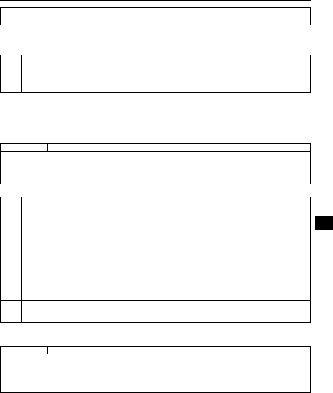
TROUBLESHOOTING
T229
T
CAR-NAVIGATION SYSTEM A6E818066000W01
Troubleshooting Index
•Use the chart below verify the trouble in order to diagnose the appropriate area.
End Of Sie
NO.1 WHILE VEHICLE IS IN REVERSE, VEHICLE LOCATOR MARK GOES FORWARD. A6E818066000W02
•When performing an asterisked (*) troubleshooting inspection, shake the wiring harness and connectors while
doing the inspection to discover whether poor contact points are the cause of any intermittent malfunction. If
there is a problem, check to make sure connectors, terminals and wiring harness are connected correctly and
undamaged.
Diagnostic procedure
End Of Sie
NO.2 IN NAVIGATION MODE, VEHICLE LOCATOR MARK SKIPS. A6E818066000W03
TROUBLESHOOTING
No. Malfunction symptom
1 While vehicle is in reverse, vehicle locator mark goes forward.
2 In navigation mode, vehicle locator mark skips.
3Even when headlight switch is turned on, daytime screen does not change to night time screen.
(Front and rear combination lights operate normally.)
1 While vehicle is in reverse, vehicle locator mark goes forward.
TROUBLESHOOTING HINTS
•Malfunction in shift position (R range (ATX) or revese position (MTX)) signal line of car-navigation unit.
Car-navigation unit malfunction
Malfunction in wiring harness between car-navigation unit and transaxle range switch
Transaxle range switch malfunction
STEP INSPECTION ACTION
1•While the vehicle is in reverse, are back-up
lights illuminated?
Yes Go to next step.
No Repair back-up light circuit, then go to next step.
2* •Disconnect car-navigation unit connector
(16-pin).
•Turn ignition switch to ON position.
•Shift selector lever to R range (ATX) or
revese position (MTX).
•Measure voltage at the following terminal of
car-navigation unit connector (16-pin,
harness side):
Terminal 2L (Shift position (R range (ATX)
or revese position (MTX)) signal)
•Is voltage 9 V or more?
Yes Replace car-navigation unit (available at Clarion service
center) or get it repaired at Panasonic Service center, then
go to next step.
No ATX
•Inspect wiring harness between car-navigation unit (16-
pin, terminal 2L) and transaxle range switch, then go to
next step.
MTX
•Inspect wiring harness between car-navigation unit (16-
pin, terminal 2L) and back-up light switch, then go to
next step.
3•Does vehicle locator mark indicate actual
position of vehicle?
Yes Complete troubleshooting, then explain repairs to customer.
No Recheck malfunction symptoms, then repeat from Step 1 if
malfunction recurs.
2 In navigation mode, vehicle locator mark skips.
TROUBLESHOOTING HINTS
•Malfunction in vehicle speed signal line of car-navigation unit.
Car-navigation unit malfunction
ABS (ABS/TCS) HU/CM malfunction (with ABS (ABS/TCS))
DSC HU/CM malfunction (with DSC)
Malfunction in wiring harness between car-navigation unit and instrument cluster

T230
TROUBLESHOOTING
Diagnostic procedure
End Of Sie
NO.3 EVEN WHEN HEADLIGHT SWITCH IS TURNED ON, DAYTIME SCREEN DOES NOT CHANGE TO
NIGHT TIME SCREEN. (FRONT AND REAR COMBINATION LIGHTS OPERATE NORMALLY.) A6E818066000W04
Diagnostic procedure
End Of Sie
AIR BAG SYSTEM A6E818001046W01
Troubleshooting Index
•Use the chart below verify the symptoms of the trouble in order to diagnose the appropriate area.
STEP INSPECTION ACTION
1•Disconnect car-navigation unit connector
(16-pin).
•Jack up vehicle and run engine at low speed.
•Measure voltage at the following terminal of
car-navigation unit connector (16-pin):
Terminal 2H (Vehicle speed signal)
•Is voltage approx. 2.5 V (reference)?
Note
•Vehicle speed signal is in electrical pulses
of approx. 0 V to 5 V.
Yes Replace car-navigation unit (available at Clarion service
center) or get it repaired at Panasonic service center, then
go to Step 4.
No Go to next step.
2* •Disconnect ABS (ABS/TCS) HU/CM
connector (28-pin) or DSC HU/CM connector
(34-pin).
•Is there continuity between car-navigation
unit connector (16-pin) terminal 2H and ABS
(ABS/TCS) HU/CM connector (28-pin)
terminal V, or car-navigation unit connector
(16-pin) terminal 2H and DSC HU/CM
connector (34-pin) terminal AE?
Yes Go to next step.
No Repair wiring harness between car-navigation unit and ABS
(ABS/TCS) HU/CM, or car-navigation unit and DSC HU/CM,
then go to Step 4.
3•Inspect wiring harness between car-
navigation unit connector (16-pin) terminal
2H and and ABS (ABS/TCS) HU/CM
connector (28-pin) terminal V, or car-
navigation unit connector (16-pin) terminal
2H and DSC HU/CM connector (34-pin)
terminal AE for short to ground.
•Is there short to ground?
Yes Repair wiring harness between car-navigation unit and ABS
(ABS/TCS) HU/CM, or car-navigation unit and DSC HU/CM,
then go to next step.
No Replace instrument cluster, then go to next step.
4•Does vehicle locator mark operate normally? Yes Complete troubleshooting, then explain repairs to customer.
No Recheck malfunction symptoms, then repeat from Step 1 if
malfunction recurs.
3Even when headlight switch is turned on, daytime screen does not change to night time screen.
(Front and rear combination lights operate normally.)
TROUBLESHOOTING HINTS
•Malfunction in TNS (+) signal line of LCD unit
LCD unit malfunction
Malfunction in wiring harness between LCD unit and TNS relay
STEP INSPECTION ACTION
1* •Turn headlight switch on.
•Measure voltage at the following terminal of
LCD unit connector (24-pin):
Terminal 1V (TNS (+) signal)
•Is voltage 10 V or more?
Yes Replace LCD unit (available at Panasonic service center) or
get it repaired at Panasonic service center, then go to next
step.
No Repair wiring harness between LCD unit and TNS relay,
then go to next step.
2•When headlight switch is turned on, does
daytime screen change to night time screen?
Yes Complete troubleshooting, then explain repairs to customer.
No Recheck malfunction symptoms, then repeat from Step 1 if
malfunction recurs.
No. Troubleshooting item Description Page
1
Air bag system warning light does not
illuminate.
Malfunction in air bag system warning
circuit (short to ground).
(See T231 NO.1 AIR BAG SYSTEM
WARNING LIGHT DOES NOT
ILLUMINATE)
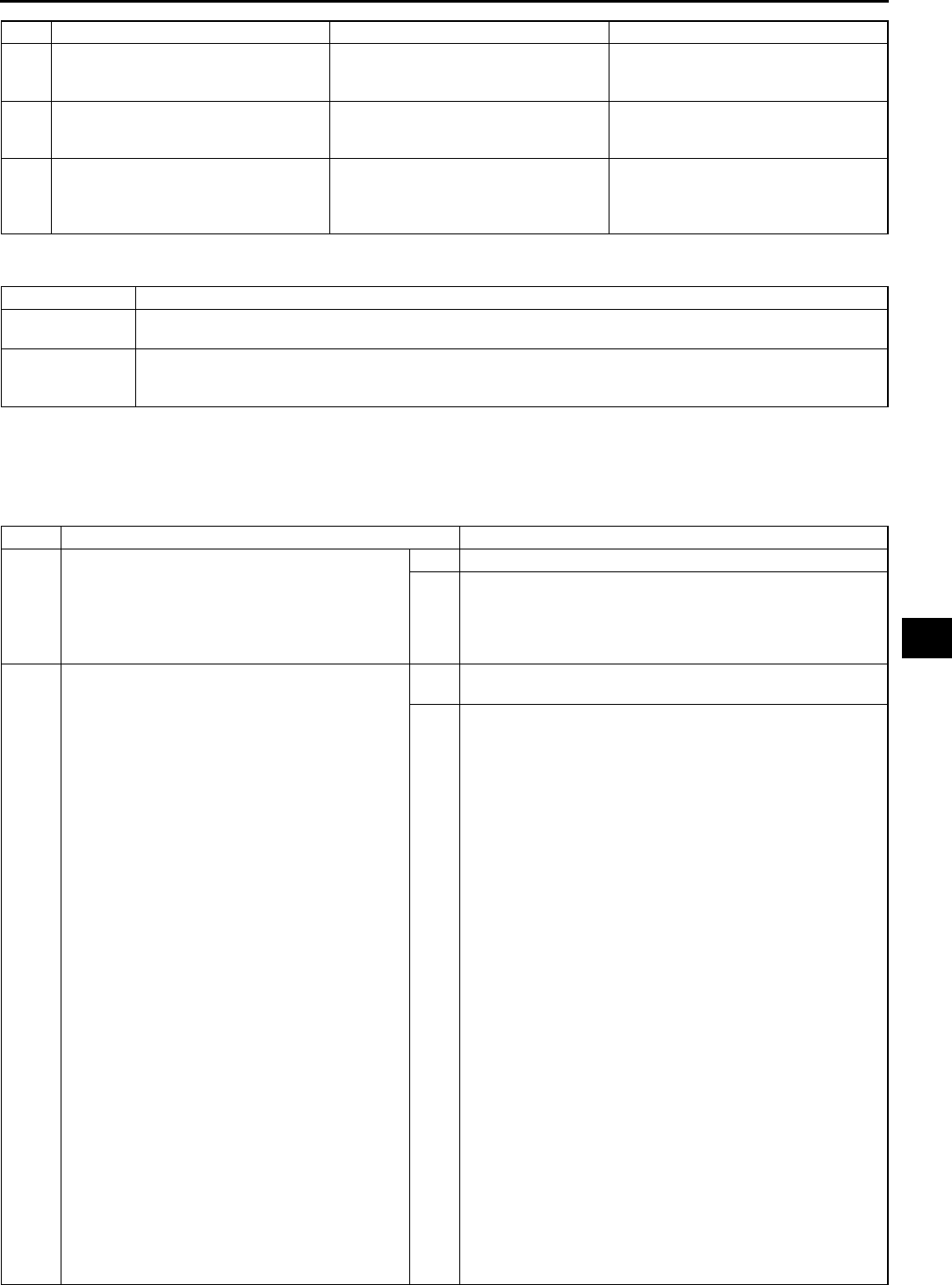
TROUBLESHOOTING
T231
T
End Of Sie
NO.1 AIR BAG SYSTEM WARNING LIGHT DOES NOT ILLUMINATE A6E818001046W02
Diagnostic Procedure
•When performing an asterisked (*) troubleshooting inspection, shake the wiring harness and connectors while
doing the inspection to discover whether poor contact points are the cause of any intermittent malfunction. If
there is a problem, check to make sure connectors, terminals and wiring harness are connected correctly and
undamaged.
2
Air bag system warning light is
illuminated all the time.
Malfunction in air bag system warning
circuit (open circuit or short to power
supply).
(See T232 NO.2 AIR BAG SYSTEM
WARNING LIGHT IS ILLUMINATED
ALL THE TIME)
3
Passenger-side air bag cut-off
indicator light does not illuminate.
Malfunction in passenger-side air bag
cut-off indicator light circuit (open
circuit or short to power supply).
(See T235 NO.3 PASSENGER-SIDE
AIR BAG CUT-OFF INDICATOR
LIGHT DOES NOT ILLUMINATE)
4
Passenger-side air bag cut-off
indicator light is illuminated all the
time.
Malfunction in passenger-side air bag
cut-off indicator light circuit (short to
ground).
(See T237 NO.4 PASSENGER-SIDE
AIR BAG CUT-OFF INDICATOR
LIGHT IS ILLUMINATED ALL THE
TIME)
No. Troubleshooting item Description Page
1 Air bag system warning light does not illuminate.
DETECTION
CONDITION
Malfunction in air bag system warning light circuit (short to ground)
POSSIBLE
CAUSE
•SAS unit malfunction
•Instrument cluster (print plate) malfunction
•Short to ground circuit in wiring harness between instrument cluster and SAS unit
STEP INSPECTION ACTION
1INSPECT OTHER WARNING AND
INDICATOR LIGHTS CIRCUIT IN
INSTRUMENT CLUSTER
•Turn ignition switch to ON position.
•Do other warning and indicator lights
illuminate?
Yes Turn ignition switch to LOCK position, then go to next step.
No Inspect instrument cluster power supply system and ground
system, then go to Step 5.
2INSPECT SAS UNIT
Warning
•
••
•Handling air bag system components
improperly can accidentally deploy air
bag modules and pre-tensioner seat
belts, which may seriously injure you.
Read AIR BAG SYSTEM SERVICE
WARNINGS before handling air bag
system components.
(See T117 SERVICE WARNINGS)
•Turn ignition switch to LOCK position.
•Disconnect negative battery cable and wait
for more than 1 minute.
•Remove column cover.
•Disconnect clock spring connector.
•Remove glove compartment.
•Disconnect passenger-side air bag module
connector.
•Disconnect driver and passenger-side side
air bag module connectors. (Vehicles with
side air bag)
•Disconnect driver and passenger-side
curtain air bag module connectors. (Vehicles
with curtain air bag)
•Remove B-pillar lower trims. (Vehicle with
pre-tensioner seat belt)
•Disconnect driver- and passenger-side
pre-tensioner seat belt connectors. (Vehicle
with pre-tensioner seat belt)
•Turn up floor covering.
•Disconnect all SAS unit connectors.
•Connect negative battery cable.
•Turn ignition switch to ON position.
•Do air bag system warning light illuminate?
Yes Replace SAS unit, then go to Step 5.
(See T124 SAS UNIT REMOVAL/INSTALLATION)
No Go to next step.

T232
TROUBLESHOOTING
End Of Sie
NO.2 AIR BAG SYSTEM WARNING LIGHT IS ILLUMINATED ALL THE TIME A6E818001046W03
Diagnostic Procedure
•When performing an asterisked (*) troubleshooting inspection, shake the wiring harness and connectors while
doing the inspection to discover whether poor contact points are the cause of any intermittent malfunction. If
there is a problem, check to make sure connectors, terminals and wiring harness are connected correctly and
undamaged.
*3 INSPECT WIRING HARNESS BETWEEN SAS
UNIT AND INSTRUMENT CLUSTER FOR
SHORT TO GROUND
•Turn ignition switch to LOCK position.
•Disconnect negative battery cable.
•Disconnect instrument cluster connector.
•Is there continuity between terminal 1O of
instrument cluster connector and ground?
Yes Replace wiring harness, then go to Step 5.
No Go to next step.
4INSPECT INSTRUMENT CLUSTER
•Connect instrument cluster connector.
•Connect instrument cluster connector
terminal 1O to ground, then reconnect
connector.
•Connect negative battery cable.
•Does air bag system warning light illuminate
with ignition switch ON?
Yes Replace instrument cluster, then go to next step.
(See T72 INSTRUMENT CLUSTER REMOVAL/
INSTALLATION)
No Go to next step.
5CONFIRM THAT MALFUNCTION SYMPTOMS
DO NOT RECUR AFTER REPAIR
•Turn ignition switch to LOCK position.
•Disconnect negative battery cable and wait
for more than 1 minute.
•Connect all SAS unit connectors.
•Connect driver and passenger-side
pre-tensioner seat belt connectors. (Vehicles
with pre-tensioner seat belt)
•Connect driver and passenger-side curtain
air bag module connectors. (Vehicles with
curtain air bag)
•Connect driver and passenger-side side air
bag module connectors. (Vehicles with side
air bag)
•Connect passenger-side air bag module
connector.
•Connect clock spring connector.
•Connect negative battery cable.
•Turn ignition switch to ON position.
•Does air bag system warning light operate
properly?
Yes Complete troubleshooting, then explain repairs to customer.
No Recheck malfunction symptoms, then repeat from Step 1 if
malfunction recurs.
STEP INSPECTION ACTION
2 Air bag system warning light is illuminated all the time.
DETECTION
CONDITION
Malfunction in air bag system warning light circuit (open circuit or short to power supply).
POSSIBLE
CAUSE
•Weak battery
•SAS unit malfunction
•Instrument cluster (print plate) malfunction
•No connection in SAS unit connector
•Poor contact in instrument cluster connector (16-pin)
•Open or short to power supply circuit in wiring harness between instrument cluster and SAS unit
•Poor contact at terminals 1T, 1X and/or 1W of SAS unit connector
•Poor contact in wiring harness between terminal 1X of SAS unit connector and ground
•Poor contact in wiring harness between AIR BAG 15 A fuse and terminal 1W of SAS unit
STEP INSPECTION ACTION
1INSPECT BATTERY
•Measure voltage of battery.
•Is voltage more than 9 V?
Yes Go to next step.
No Battery is weak.
Inspect charge/discharge system, then go to Step 10.
(See G4 BATTERY INSPECTION)

TROUBLESHOOTING
T233
T
2VERIFY THAT SAS unit CONNECTOR IS
CONNECTED
Warning
•
••
•Handling air bag system components
improperly can accidentally deploy air
bag modules and pre-tensioner seat
belts, which may seriously injure you.
Read AIR BAG SYSTEM SERVICE
WARNINGS before handling air bag
system components.
(See T117 SERVICE WARNINGS)
•Turn ignition switch to LOCK position.
•Disconnect negative battery cable and wait
for more than 1 minute.
•Turn up floor covering.
•Are all SAS unit connectors securely
connected?
Yes Go to next step.
No Reconnect connector properly, then go to Step 10.
* 3 INSPECT WIRING HARNESS BETWEEN SAS
UNIT AND INSTRUMENT CLUSTER FOR
CONTINUITY
•Remove column cover.
•Disconnect clock spring connector.
•Remove glove compartment.
•Disconnect passenger-side air bag module
connector.
•Disconnect driver and passenger-side side
air bag module connectors. (Vehicles with
side air bag)
•Disconnect driver and passenger-side
curtain air bag module connectors. (Vehicles
with curtain air bag)
•Remove B-pillar lower trims. (Vehicle with
pre-tensioner seat belt)
•Disconnect driver- and passenger-side
pre-tensioner seat belt connectors. (Vehicle
with pre-tensioner seat belt)
•Turn up floor covering.
•Disconnect all SAS unit connectors.
•Disconnect instrument cluster connector.
•Is there continuity between SAS unit
connector terminal 1T and instrument cluster
connector terminal 1O?
Yes Go to next step.
No Replace wiring harness, then go to Step 10.
* 4 INSPECT WIRING HARNESS BETWEEN SAS
UNIT AND INSTRUMENT CLUSTER FOR
SHORT TO POWER SUPPLY
•Connect negative battery cable.
•Turn ignition switch to ON position.
•Measure voltage at instrument cluster
connector terminal 1O.
•Is voltage more than approximately 9 V?
Yes Replace wiring harness, then go to Step 10.
No Go to next step.
5CHECK TO SEE WHETHER MALFUNCTION
IS IN AIR BAG SYSTEM WARNING LIGHT IN
INSTRUMENT CLUSTER
•Connect instrument cluster connector
terminal 1O to ground, then reconnect
connector.
•Does air bag system warning light illuminate
with ignition switch ON?
Yes Replace instrument cluster, then go to Step 9.
(See T72 INSTRUMENT CLUSTER REMOVAL/
INSTALLATION)
No Go to next step.
STEP INSPECTION ACTION

T234
TROUBLESHOOTING
6INSPECT POWER SUPPLY CIRCUIT OF SAS
UNIT (TERMINAL 1W)
•Turn ignition switch to LOCK position.
•Disconnect negative battery cable and wait
for more than 1 minute.
•Connect all SAS unit connectors.
•Connect driver and passenger-side
pre-tensioner seat belt connectors. (Vehicles
with pre-tensioner seat belt)
•Connect driver and passenger-side curtain
air bag module connectors. (Vehicles with
curtain air bag)
•Connect driver and passenger-side side air
bag module connectors. (Vehicles with side
air bag)
•Connect passenger-side air bag module
connector.
•Connect clock spring connector.
•Inspect voltage for PID/DATA monitor RCM
VOLT item using SST (WDS or equivalent ).
•Is voltage of at least either terminal more
than 9 V?
Yes Go to Step 9.
No Go to next step.
7INSPECT WIRING HARNESS BETWEEN
BATTERY AND FUSE BLOCK
•Remove driver-side front side trim.
•Remove fuse block without disconnecting
connectors.
•Turn ignition switch to ON position.
•Measure voltage at terminals D (JB01) of
fuse block connector.
•Is voltage of at least either terminal more
than 9 V?
Yes Go to next step.
No Repair wiring harnesses, then go to Step 10.
8INSPECT WIRING HARNESS BETWEEN
FUSE BLOCK AND SAS UNIT
•Measure voltage at terminals G (JB03) of
fuse block connector.
•Is voltage of at least either terminal more
than 9 V?
Yes Repair wiring harnesses, then go to Step 10.
No Inspect fuse block, then go to Step 10.
9VERIFY THAT SAS UNIT CONNECTOR
TERMINAL 1X IS GROUND
•Turn ignition switch to LOCK position.
•Disconnect negative battery cable and wait
for more than 1 minute.
•Remove column cover.
•Disconnect clock spring connector.
•Remove glove compartment.
•Disconnect passenger-side air bag module
connector.
•Disconnect driver and passenger-side side
air bag module connectors. (Vehicles with
side air bag)
•Disconnect driver and passenger-side
curtain air bag module connectors. (Vehicles
with curtain air bag)
•Remove B-pillar lower trim. (Vehicle with pre-
tensioner seat belt)
•Disconnect driver and passenger-side pre-
tensioner seat belt connectors. (Vehicle with
pre-tensioner seat belt)
•Turn up floor covering.
•Disconnect all SAS unit connectors.
•Inspect wiring harness between SAS unit
connector terminal 1X and ground for
following:
Short to power supply
Open circuit
•Is wiring harness okay?
Yes Replace SAS unit, then go to next step.
(See T124 SAS UNIT REMOVAL/INSTALLATION)
No Replace wiring harnesses, then go to next step.
STEP INSPECTION ACTION
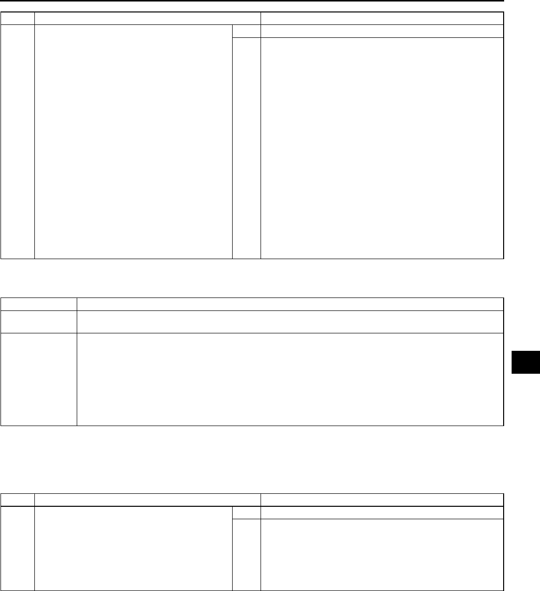
TROUBLESHOOTING
T235
T
End Of Sie
NO.3 PASSENGER-SIDE AIR BAG CUT-OFF INDICATOR LIGHT DOES NOT ILLUMINATE A6E818001046W04
Diagnostic Procedure
•When performing an asterisked (*) troubleshooting inspection, shake the wiring harness and connectors while
doing the inspection to discover whether poor contact points are the cause of any intermittent malfunction. If
there is a problem, check to make sure connectors, terminals and wiring harness are connected correctly and
undamaged.
10 CONFIRM THAT MALFUNCTION SYMPTOMS
DO NOT RECUR AFTER REPAIR
•Turn ignition switch to LOCK position.
•Disconnect negative battery cable and wait
for more than 1 minute.
•Connect all SAS unit connectors.
•Connect driver and passenger-side
pre-tensioner seat belt connectors. (Vehicles
with pre-tensioner seat belt)
•Connect driver and passenger-side curtain
air bag module connectors. (Vehicles with
curtain air bag)
•Connect driver and passenger-side side air
bag module connectors. (Vehicles with side
air bag)
•Connect passenger-side air bag module
connector.
•Connect clock spring connector.
•Connect instrument cluster connector.
•Connect negative battery cable.
•Turn ignition switch to ON position.
•Does air bag system warning light operate
properly?
Yes Complete troubleshooting, then explain repairs to customer.
No Recheck malfunction symptoms, then repeat from Step 1 if
malfunction recurs.
STEP INSPECTION ACTION
3 Passenger-side air bag cut-off indicator light does not illuminate
DETECTION
CONDITION
Malfunction in passenger-side air bag cut-off indicator light circuit (open circuit or short to power supply)
POSSIBLE
CAUSE
•SAS unit malfunction
•Passenger-side air bag cut-off indicator light bulb malfunction
•Open or short to power supply circuit in wiring harness between passenger-side air bag cut-off indicator
light and SAS unit
•Poor contact at terminals 1U 1X and/or 1W of SAS unit connector
•Poor contact at terminals 1I of SAS unit connector
•Poor contact in wiring harness between terminal 1X of SAS unit connector and ground
•Poor contact or short circuits in wiring harness between METER IG 15 A fuse and SAS unit, between
AIR BAG 15 A fuse and SAS unit at the time
STEP INSPECTION ACTION
1INSPECT PASSENGER-SIDE AIR BAG CUT-
OFF INDICATOR LIGHT BULB
•Disconnect negative battery cable.
•Remove center panel module.
(See T96 CENTER PANEL MODULE
REMOVAL/INSTALLATION)
•Is passenger-side air bag cut-off indicator
light bulb functional?
Yes Reinstall it properly, then go to next step.
No Replace bulb, then go to Step 5.

T236
TROUBLESHOOTING
*2 INSPECT WIRING HARNESS BETWEEN
PASSENGER-SIDE AIR BAG CUT-OFF
INDICATOR LIGHT AND SAS UNIT FOR
CONTINUITY
Warning
•
••
•Handling air bag system components
improperly can accidentally deploy air
bag modules and pre-tensioner seat
belts, which may seriously injure you.
Read SERVICE WARNINGS before
handling air bag system components.
(See T117 SERVICE WARNINGS)
•Turn ignition switch to LOCK position.
•Disconnect negative battery cable and wait
for more than 1 minute.
•Remove column cover.
•Disconnect clock spring connector.
•Remove glove compartment.
•Disconnect passenger-side air bag module
connector.
•Disconnect driver and passenger-side side
air bag module connectors. (Vehicles with
side air bag)
•Disconnect driver and passenger-side
curtain air bag module connectors. (Vehicles
with curtain air bag)
•Remove B-pillar lower trims. (Vehicle with
pre-tensioner seat belt)
•Disconnect driver- and passenger-side
pre-tensioner seat belt connectors. (Vehicle
with pre-tensioner seat belt)
•Turn up floor covering.
•Disconnect all SAS unit connectors.
•Is there continuity between terminal 1U of
SAS unit connector and terminal A of
passenger-side air bag cut-off indicator light?
Yes Go to next step.
No Replace wiring harness, then go to Step 5.
*3 INSPECT WIRING HARNESS BETWEEN
PASSENGER-SIDE AIR BAG CUT-OFF
INDICATOR LIGHT AND SAS UNIT FOR
SHORT TO POWER SUPPLY
•Connect negative battery cable.
•Turn ignition switch to ON position.
•Measure voltage at terminal A of passenger-
side air bag cut-off indicator light connector.
•Is voltage more than approximately 9 V?
Yes Replace wiring harness, then go to Step 5.
No Go to next step.
4CHECK TO SEE WHETHER MALFUNCTION
IS IN PASSENGER-SIDE AIR BAG CUT-OFF
INDICATOR LIGHT OR SAS UNIT
•Connect SAS unit connector terminal 1U to
ground.
•Does passenger-side air bag cut-off indicator
light illuminate with ignition switch on?
Yes Replace SAS unit, then go to next step.
(See T124 SAS UNIT REMOVAL/INSTALLATION)
No Go to next step.
STEP INSPECTION ACTION
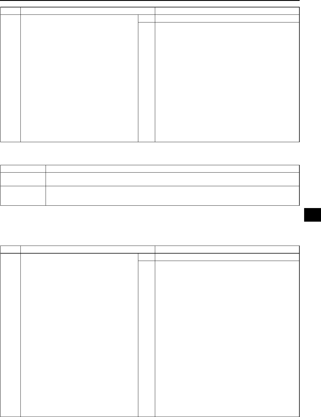
TROUBLESHOOTING
T237
T
End Of Sie
NO.4 PASSENGER-SIDE AIR BAG CUT-OFF INDICATOR LIGHT IS ILLUMINATED ALL THE TIME
A6E818001046W05
Diagnostic Procedure
•When performing an asterisked (*) troubleshooting inspection, shake the wiring harness and connectors while
doing the inspection to discover whether poor contact points are the cause of any intermittent malfunction. If
there is a problem, check to make sure connectors, terminals and wiring harness are connected correctly and
undamaged.
5CONFIRM THAT MALFUNCTION SYMPTOMS
DO NOT RECUR AFTER REPAIR
•Turn ignition switch to LOCK position.
•Disconnect negative battery cable and wait
for more than 1 minute.
•Connect all SAS unit connectors.
•Connect driver and passenger-side
pre-tensioner seat belt connectors. (Vehicles
with pre-tensioner seat belt)
•Connect driver and passenger-side curtain
air bag module connectors. (Vehicles with
curtain air bag)
•Connect driver and passenger-side side air
bag module connectors. (Vehicles with side
air bag)
•Connect passenger-side air bag module
connector.
•Connect clock spring connector.
•Connect negative battery cable.
•Turn ignition switch to ON position.
•Does passenger-side air bag cut-off indicator
light operate properly?
Yes Complete troubleshooting, then explain repairs to customer.
No Recheck malfunction symptoms, then repeat from Step 1 if
malfunction recurs.
STEP INSPECTION ACTION
4 Passenger-side air bag cut-off indicator light is illuminated all the time.
DETECTION
CONDITION
Malfunction in passenger-side air bag cut-off indicator light circuit (short to ground).
POSSIBLE
CAUSE
•SAS unit malfunction
•Short to ground circuit in wiring harness between passenger-side air bag cut-off indicator light and SAS
unit
STEP INSPECTION ACTION
*1 INSPECT WIRING HARNESS BETWEEN
PASSENGER-SIDE AIR BAG CUT-OFF
INDICATOR LIGHT AND SAS UNIT FOR
SHORT TO GROUND
•Remove center panel module.
(See T96 CENTER PANEL MODULE
REMOVAL/INSTALLATION)
•Remove column cover.
•Disconnect clock spring connector.
•Remove glove compartment.
•Disconnect passenger-side air bag module
connector.
•Disconnect driver and passenger-side side
air bag module connectors. (Vehicles with
side air bag)
•Disconnect driver and passenger-side
curtain air bag module connectors. (Vehicles
with curtain air bag)
•Remove B-pillar lower trims. (Vehicle with
pre-tensioner seat belt)
•Disconnect driver- and passenger-side
pre-tensioner seat belt connectors. (Vehicle
with pre-tensioner seat belt)
•Turn up floor covering.
•Disconnect all SAS unit connectors.
•Is there continuity between terminal 1U of
SAS unit connector and ground?
Yes Replace wiring harness, then go to next step.
No Replace SAS unit, then go to next step.
( See T124 SAS UNIT REMOVAL/INSTALLATION)
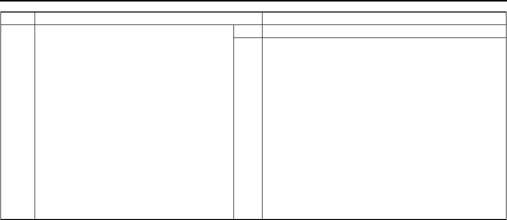
T238
TROUBLESHOOTING
End Of Sie
2CONFIRM THAT MALFUNCTION SYMPTOMS
DO NOT RECUR AFTER REPAIR
•Connect all SAS unit connectors.
•Connect driver and passenger-side
pre-tensioner seat belt connectors. (Vehicles
with pre-tensioner seat belt)
•Connect driver and passenger-side curtain
air bag module connectors. (Vehicles with
curtain air bag)
•Connect driver and passenger-side side air
bag module connectors. (Vehicles with side
air bag)
•Connect passenger-side air bag module
connector.
•Connect clock spring connector.
•Connect negative battery cable.
•Turn ignition switch to ON position.
•Does passenger-side air bag cut-off indicator
light operate properly?
Yes Complete troubleshooting, then explain repairs to customer.
No Recheck malfunction symptoms, then repeat from Step 1 if
malfunction recurs.
STEP INSPECTION ACTION

U1
U
UHEATER AND AIR CONDITIONER SYSTEMS
LOCATION INDEX .................................................U-3
BASIC SYSTEM ..................................................U-3
CONTROL SYSTEM............................................U-4
SERVICE WARNINGS ...........................................U-8
HANDLING REFRIGERANT................................U-8
STORING REFRIGERANT ..................................U-8
SERVICE CAUTIONS.............................................U-8
HANDLING INSUFFICIENT REFRIGERANT
LEVEL...............................................................U-8
HANDLING COMPRESSOR OIL.........................U-8
REFRIGERANT SYSTEM SERVICE
PROCEDURES.......................................................U-9
GAS CHARGING SET INSTALLATION ..............U-9
RECOVERY .........................................................U-9
CHARGING..........................................................U-9
REFRIGERANT PRESSURE CHECK ...............U-12
REFRIGERANT SYSTEM PERFORMANCE
TEST...............................................................U-13
BASIC SYSTEM ...................................................U-14
BLOWER UNIT REMOVAL/INSTALLATION.....U-14
BLOWER UNIT DISASSEMBLY/ASSEMBLY ...U-14
AIR FILTER REMOVAL/INSTALLATION ..........U-15
AIR FILTER INSPECTION.................................U-15
A/C UNIT REMOVAL/INSTALLATION ..............U-15
A/C UNIT DISASSEMBLY/ASSEMBLY.............U-18
EXPANSION VALVE
REMOVAL/INSTALLATION............................U-21
EVAPORATOR INSPECTION ...........................U-22
HEATER CORE INSPECTION ..........................U-23
REAR HEAT DUCT
REMOVAL/INSTALLATION............................U-23
A/C COMPRESSOR
REMOVAL/INSTALLATION............................U-23
CONDENSER REMOVAL/INSTALLATION.......U-24
CONDENSER INSPECTION .............................U-24
REFRIGERANT LINES
REMOVAL/INSTALLATION............................U-25
CONTROL SYSTEM.............................................U-30
AIR INTAKE ACTUATOR
REMOVAL/INSTALLATION............................U-30
AIR INTAKE ACTUATOR INSPECTION ...........U-30
AIR MIX ACTUATOR
REMOVAL/INSTALLATION............................U-31
AIR MIX ACTUATOR INSPECTION..................U-32
AIRFLOW MODE ACTUATOR
REMOVAL/INSTALLATION............................U-33
AIRFLOW MODE ACTUATOR INSPECTION ...U-34
BLOWER MOTOR
REMOVAL/INSTALLATION............................U-35
BLOWER MOTOR INSPECTION ......................U-35
RESISTOR REMOVAL/INSTALLATION ...........U-35
RESISTOR INSPECTION..................................U-36
POWER MOS FET
REMOVAL/INSTALLATION............................U-36
POWER MOS FET INSPECTION .....................U-36
MAGNETIC CLUTCH
DISASSEMBLY/ASSEMBLY ..........................U-36
MAGNETIC CLUTCH ADJUSTMENT ...............U-38
MAGNETIC CLUTCH INSPECTION..................U-38
SOLAR RADIATION SENSOR
REMOVAL/INSTALLATION ............................U-39
SOLAR RADIATION SENSOR INSPECTION ...U-39
AMBIENT TEMPERATURE SENSOR
REMOVAL/INSTALLATION ............................U-39
AMBIENT TEMPERATURE SENSOR
INSPECTION ..................................................U-40
CABIN TEMPERATURE SENSOR
REMOVAL/INSTALLATION ............................U-40
CABIN TEMPERATURE SENSOR
INSPECTION ..................................................U-41
EVAPORATOR TEMPERATURE SENSOR
REMOVAL/INSTALLATION ............................U-41
EVAPORATOR TEMPERATURE SENSOR
INSPECTION ..................................................U-41
WATER TEMPERATURE SENSOR
REMOVAL/INSTALLATION ............................U-42
WATER TEMPERATURE SENSOR
INSPECTION ..................................................U-42
REFRIGERANT PRESSURE SWITCH
REMOVAL/INSTALLATION ............................U-42
REFRIGERANT PRESSURE SWITCH
INSPECTION ..................................................U-43
CLIMATE CONTROL UNIT REMOVAL .............U-44
CLIMATE CONTROL UNIT INSTALLATION .....U-45
CLIMATE CONTROL UNIT
DISASSEMBLY/ASSEMBLY ..........................U-45
CLIMATE CONTROL UNIT WIRE
ADJUSTMENT ................................................U-46
CLIMATE CONTROL UNIT INSPECTION.........U-47
FAN SWITCH INSPECTION..............................U-52
DEFROSTER SWITCH INSPECTION...............U-52
ON-BOARD DIAGNOSTIC ...................................U-53
DIAGNOSTIC TROUBLE CODE NUMBER
INSPECTION ..................................................U-53
DTC 02...............................................................U-56
DTC 06...............................................................U-56
DTC 07...............................................................U-57
DTC 10...............................................................U-57
DTC 11...............................................................U-57
DTC 12...............................................................U-58
DTC 13...............................................................U-58
DTC 14...............................................................U-59
DTC 15...............................................................U-59
DTC 18...............................................................U-59
DTC 19...............................................................U-60
DTC 21...............................................................U-60
DTC 22...............................................................U-61
DTC 58...............................................................U-61
DTC 59...............................................................U-61
DTC 02, 18, 21 (WHEN TWO OR MORE
DTCS ARE INDICATED AT THE
SAME TIME) ...................................................U-62
DTC 06, 10, 12, 14, 18, 21 (WHEN TWO OR
MORE DTCS ARE INDICATED AT THE
SAME TIME) ...................................................U-62

U2
DTC 07, 11, 13, 15, 19, 22 (WHEN TWO OR
MORE DTCS ARE INDICATED AT THE
SAME TIME) ...................................................U-63
DTC 19, 22 (WHEN TWO OR MORE DTCS
ARE INDICATED AT THE SAME TIME).........U-63
TROUBLESHOOTING..........................................U-64
FOREWORD......................................................U-64
TROUBLESHOOTING INDEX ...........................U-64
NO.1 INSUFFICIENT AIR (OR NO AIR)
BLOWN FROM VENTS ..................................U-65
NO.2 AMOUNT OF AIR BLOWN FROM
VENTS DOES NOT CHANGE ........................U-65
NO.3 AMOUNT OF AIR BLOWN FROM
VENTS DOES NOT CHANGE ........................U-67
NO.4 AIR INTAKE MODE DOES NOT
CHANGE.........................................................U-68
NO.5 NO TEMPERATURE CONTROL WITH
CLIMATE CONTROL UNIT.............................U-70
NO.6 WINDSHIELD FOGGED...........................U-70
NO.7 AIR FROM VENTS COLD ENOUGH .......U-72
NO.8 NO COOL AIR ..........................................U-75
NO.9 NOISE WHILE OPERATING A/C
SYSTEM .........................................................U-76
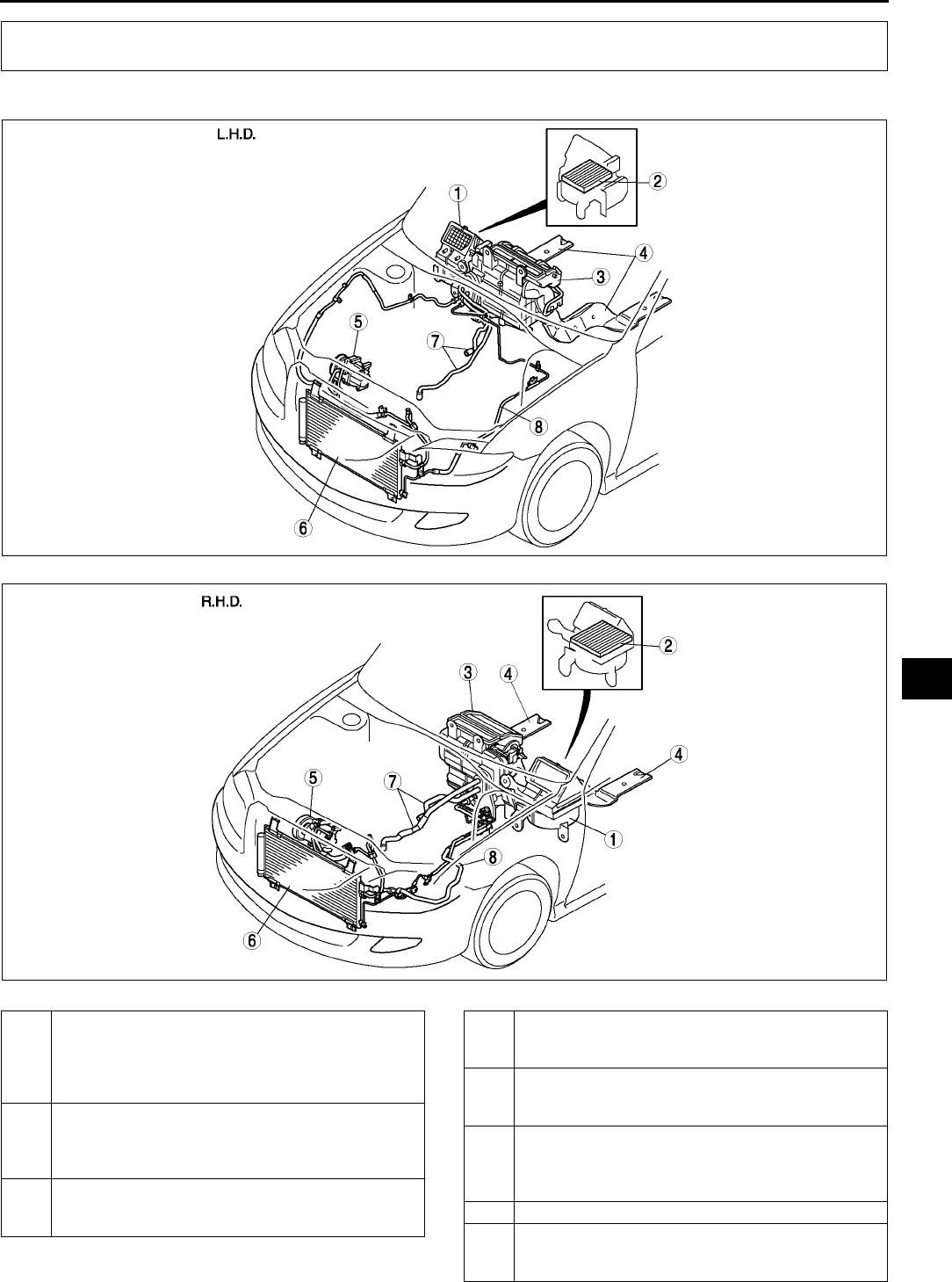
LOCATION INDEX
U3
U
BASIC SYSTEM A6E850001040W01
.
LOCATION INDEX
A6E8500W001
A6E8500W002
1 Blower unit
(See U14 BLOWER UNIT REMOVAL/
INSTALLATION)
(SeeU14 BLOWER UNIT DISASSEMBLY/
ASSEMBLY)
2 Air filter
(See U15 AIR FILTER REMOVAL/
INSTALLATION)
(See U15 AIR FILTER INSPECTION)
3 A/C unit
(See U15 A/C UNIT REMOVAL/INSTALLATION)
(See U18 A/C UNIT DISASSEMBLY/ASSEMBLY)
4 Rear heat duct
(See U23 REAR HEAT DUCT REMOVAL/
INSTALLATION)
5 A/C compressor
(See U23 A/C COMPRESSOR REMOVAL/
INSTALLATION)
6 Condenser
(See U24 CONDENSER REMOVAL/
INSTALLATION)
(See U24 CONDENSER INSPECTION)
7 Heater hose
8 Refrigerant lines
(See U25 REFRIGERANT LINES REMOVAL/
INSTALLATION)
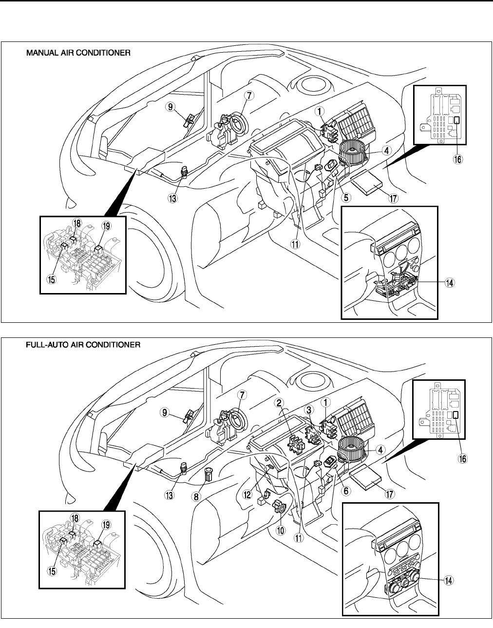
U4
LOCATION INDEX
End Of Si e
CONTROL SYSTEM A6E850001042W01
L.H.D.
.
A6E8500W003
A6E8500W004

LOCATION INDEX
U5
U
1 Air intake actuator
(See U30 AIR INTAKE ACTUATOR REMOVAL/
INSTALLATION)
(See U30 AIR INTAKE ACTUATOR INSPECTION)
2 Air mix actuator
(See U31 AIR MIX ACTUATOR REMOVAL/
INSTALLATION)
(See U32 AIR MIX ACTUATOR INSPECTION)
3 Airflow mode actuator
(See U33 AIRFLOW MODE ACTUATOR
REMOVAL/INSTALLATION)
(See U34 AIRFLOW MODE ACTUATOR
INSPECTION)
4Blower motor
(See U35 BLOWER MOTOR REMOVAL/
INSTALLATION)
(See U35 BLOWER MOTOR INSPECTION)
5Resistor
(See U35 RESISTOR REMOVAL/INSTALLATION)
(See U36 RESISTOR INSPECTION)
6 Power MOS FET
(See U36 POWER MOS FET REMOVAL/
INSTALLATION)
(See U36 POWER MOS FET INSPECTION)
7 Magnetic clutch
(See U36 MAGNETIC CLUTCH DISASSEMBLY/
ASSEMBLY)
(See U38 MAGNETIC CLUTCH ADJUSTMENT)
(See U38 MAGNETIC CLUTCH INSPECTION)
8 Solar radiation sensor
(See U39 SOLAR RADIATION SENSOR
REMOVAL/INSTALLATION)
(See U39 SOLAR RADIATION SENSOR
INSPECTION)
9 Ambient temperature sensor
(See U39 AMBIENT TEMPERATURE SENSOR
REMOVAL/INSTALLATION)
(See U40 AMBIENT TEMPERATURE SENSOR
INSPECTION)
10 Cabin temperature sensor
(See U40 CABIN TEMPERATURE SENSOR
REMOVAL/INSTALLATION)
(See U41 CABIN TEMPERATURE SENSOR
INSPECTION)
11 Evaporator temperature sensor
(See U41 EVAPORATOR TEMPERATURE
SENSOR REMOVAL/INSTALLATION)
(See U41 EVAPORATOR TEMPERATURE
SENSOR INSPECTION)
12 Water temperature sensor
(See U42 WATER TEMPERATURE SENSOR
REMOVAL/INSTALLATION)
(See U42 WATER TEMPERATURE SENSOR
INSPECTION)
13 Refrigerant pressure switch
(See U42 REFRIGERANT PRESSURE SWITCH
REMOVAL/INSTALLATION)
(See U43 REFRIGERANT PRESSURE SWITCH
INSPECTION)
14 Climate control unit
(See U44 CLIMATE CONTROL UNIT REMOVAL)
(See U45 CLIMATE CONTROL UNIT
INSTALLATION)
(See U45 CLIMATE CONTROL UNIT
DISASSEMBLY/ASSEMBLY)
(See U46 CLIMATE CONTROL UNIT WIRE
ADJUSTMENT)
(See U47 CLIMATE CONTROL UNIT
INSPECTION)
15 A/C relay
(See T24 RELAY INSPECTION)
16 Blower relay
(See T24 RELAY INSPECTION)
17 PCM
(See F45 PCM INSPECTION)
18 Rear window defroster relay
(See T24 RELAY INSPECTION)
19 TNS relay
(See T24 RELAY INSPECTION)
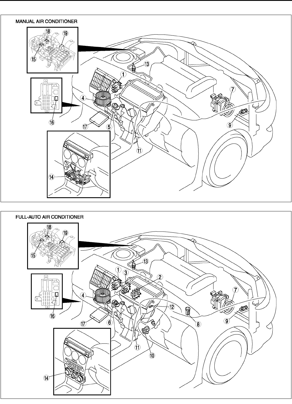
U6
LOCATION INDEX
R.H.D.
.
A6E8500W005
A6E8500W006

LOCATION INDEX
U7
U
End Of Sie
1 Air intake actuator
(See U30 AIR INTAKE ACTUATOR REMOVAL/
INSTALLATION)
(See U30 AIR INTAKE ACTUATOR INSPECTION)
2 Air mix actuator
(See U31 AIR MIX ACTUATOR REMOVAL/
INSTALLATION)
(See U32 AIR MIX ACTUATOR INSPECTION)
3 Airflow mode actuator
(See U33 AIRFLOW MODE ACTUATOR
REMOVAL/INSTALLATION)
(See U34 AIRFLOW MODE ACTUATOR
INSPECTION)
4Blower motor
(See U35 BLOWER MOTOR REMOVAL/
INSTALLATION)
(See U35 BLOWER MOTOR INSPECTION)
5Resistor
(See U35 RESISTOR REMOVAL/INSTALLATION)
(See U36 RESISTOR INSPECTION)
6 Power MOS FET
(See U36 POWER MOS FET REMOVAL/
INSTALLATION)
(See U36 POWER MOS FET INSPECTION)
7 Magnetic clutch
(See U36 MAGNETIC CLUTCH DISASSEMBLY/
ASSEMBLY)
(See U38 MAGNETIC CLUTCH ADJUSTMENT)
(See U38 MAGNETIC CLUTCH INSPECTION)
8 Solar radiation sensor
(See U39 SOLAR RADIATION SENSOR
REMOVAL/INSTALLATION)
(See U39 SOLAR RADIATION SENSOR
INSPECTION)
9 Ambient temperature sensor
(See U39 AMBIENT TEMPERATURE SENSOR
REMOVAL/INSTALLATION)
(See U40 AMBIENT TEMPERATURE SENSOR
INSPECTION)
10 Cabin temperature sensor
(See U40 CABIN TEMPERATURE SENSOR
REMOVAL/INSTALLATION)
(See U41 CABIN TEMPERATURE SENSOR
INSPECTION)
11 Evaporator temperature sensor
(See U41 EVAPORATOR TEMPERATURE
SENSOR REMOVAL/INSTALLATION)
(See U41 EVAPORATOR TEMPERATURE
SENSOR INSPECTION)
12 Water temperature sensor
(See U42 WATER TEMPERATURE SENSOR
REMOVAL/INSTALLATION)
(See U42 WATER TEMPERATURE SENSOR
INSPECTION)
13 Refrigerant pressure switch
(See U42 REFRIGERANT PRESSURE SWITCH
REMOVAL/INSTALLATION)
(See U43 REFRIGERANT PRESSURE SWITCH
INSPECTION)
14 Climate control unit
(See U44 CLIMATE CONTROL UNIT REMOVAL)
(See U45 CLIMATE CONTROL UNIT
INSTALLATION)
(See U45 CLIMATE CONTROL UNIT
DISASSEMBLY/ASSEMBLY)
(See U46 CLIMATE CONTROL UNIT WIRE
ADJUSTMENT)
(See U47 CLIMATE CONTROL UNIT
INSPECTION)
15 A/C relay
(See T24 RELAY INSPECTION)
16 Blower relay
(See T24 RELAY INSPECTION)
17 PCM
(See F45 PCM INSPECTION)
18 Rear window defroster relay
(See T24 RELAY INSPECTION)
19 TNS relay
(See T24 RELAY INSPECTION)
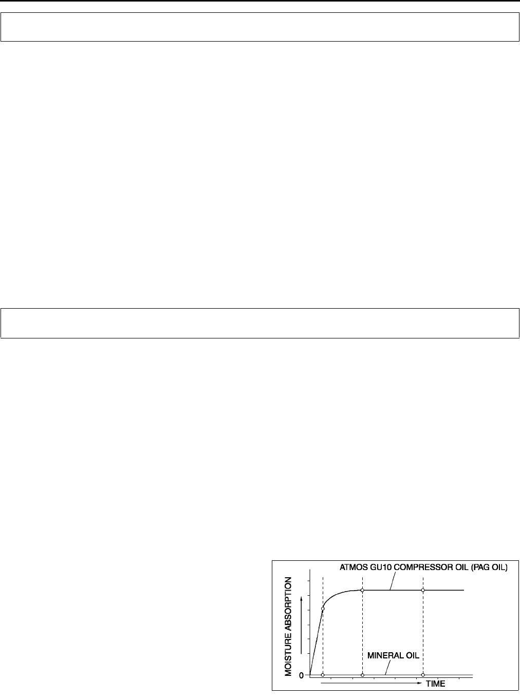
U8
SERVICE WARNINGS , SERVICE CAUTION
HANDLING REFRIGERANT A6E851001039W01
•Avoid breathing air conditioning refrigerant or lubricant vapor. Exposure may irritate eyes, nose and
throat. Also, due to environmental concerns, we urge use of recovery/recycling/recharging equipment
when draining R-134a from the air conditioning system. If accidental system discharge occurs,
ventilate work area before resuming service.
•Do not perform pressure test or leak test for R-134a service equipment and/or vehicle air conditioning
system using compressed air. Some mixtures of air and R-134a have been shown to be combustible at
elevated pressures. These mixtures, if ignited, may cause injury or property damage. Additional health
and safety information may be obtained from refrigerant manufacturers.
•Do not allow the refrigerant to leak near fire or any kind of heat. A poisonous gas may be generated if
the refrigerant gas contacts fire or heat such as from cigarettes and heaters. When carrying out any
operation that can cause refrigerant leakage, extinguish or remove the above-mentioned heat sources
and maintain adequate ventilation.
•Handling liquid refrigerant is dangerous. A drop of it on the skin can result in localized frostbite. When
handling the refrigerant, wear gloves and safety goggles. If refrigerant splashes into the eyes,
immediately wash them with clean water and consult a doctor.
End Of Sie
STORING REFRIGERANT A6E851001039W02
•The refrigerant container is highly pressurized. If it is subjected to high heat, it could explode,
scattering metal fragments and liquid refrigerant that can seriously injure you. Store the refrigerant at
temperatures below 40 °
°°
°C {104 °
°°
°F}.
End Of Sie
HANDLING INSUFFICIENT REFRIGERANT LEVEL A6E851201039W02
•If an insufficient refrigerant level is detected at troubleshooting, do not charge (add) the refrigerant.
Because an accurate amount of refrigerant cannot be determined from the pressure indicated on the
manifold gauge, never charge the refrigerant. If there is too much or too little refrigerant from the
refilling, there may be secondary problems such as damage to the refrigerant cycle parts, or a
decrease of cooling performance. Therefore, if it is determined that the refrigerant level is insufficient,
completely remove refrigerant from the refrigerant cycle and refill with refrigerant to the specified
amount.
End Of Sie
HANDLING COMPRESSOR OIL A6E851201039W01
•Use only ATMOS GU10 compressor oil for this vehicle. Using a PAG oil other than ATMOS GU10
compressor oil can damage the A/C compressor.
•Do not spill ATMOS GU10 compressor oil on the vehicle. A drop of compressor oil on the vehicle
surface can eat away at the paint. If oil gets on the vehicle, wipe it off immediately.
•ATMOS GU10 compressor oil (PAG oil) has a higher moisture absorption efficiency than the previously
used mineral oil. If moisture mixes with the compressor oil, the refrigerant system could be damaged.
Therefore, install caps immediately after using the compressor oil or removing refrigerant system parts
to prevent moisture absorption.
End Of Sie
SERVICE WARNINGS
SERVICE CAUTIONS
A6E8512W001
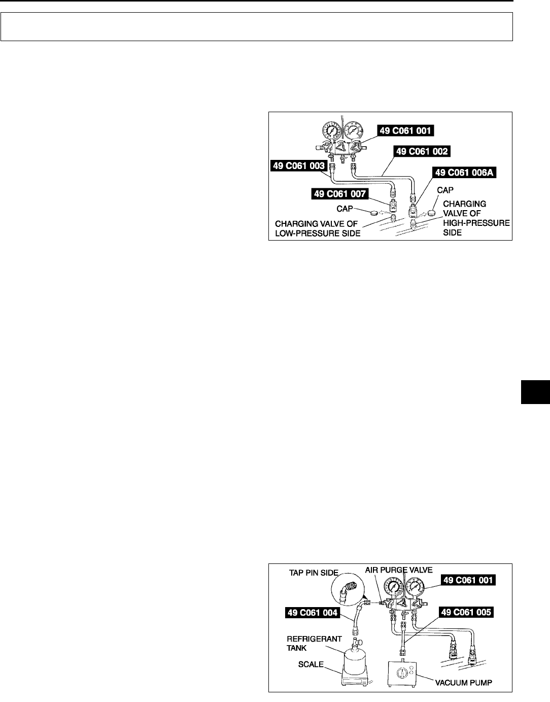
REFRIGERANT SYSTEM SERVICE PROCEDURES
U9
U
GAS CHARGING SET INSTALLATION A6E851401039W01
1. Fully close the valves of the SST (49 C061 001).
2. Connect the SSTs (49 C061 002, 49 C061 003) to the high- and low-pressure side joints of the SST (49 C061
001).
3. Connect the SSTs (49 C061 006A, 49 C061 007) to the ends of the SSTs (49 C061 002, 49 C061 003).
4. Connect the SSTs (49 C061 006A, 49 C061 007)
to the charging valves.
End Of Sie
RECOVERY A6E851478834W01
1. Connect an R-134a recovery/recycling/recharging device to the vehicle and follow the device manufacturer's
instructions.
End Of Sie
CHARGING A6E851478834W02
Caution
•
••
•Do not exceed the specification when charging the system with refrigerant. Doing so will decrease
the efficiency of the air conditioner or damage the refrigeration cycle parts.
Charging Recycled R-134a Refrigerant
1. Connect an R-134a recovery/recycling/recharging device to the vehicle and follow the device manufacturer's
instructions.
Charging Preparation
1. Install the SSTs (gas charging set).
2. Connect the tap pin side of the SST (49 C061 004) to the air purge valve of the SST (49C061 001).
3. Connect the SST (49 C061 005) to the center joint of the SST (49 C061 001).
4. Connect the SST (49 C061 005) to the vacuum pump.
5. Connect the SST (49 C061 004) to the refrigerant tank.
6. Place the refrigerant tank on the scale.
Regular amount of refrigerant (approximate quantity)
470 g {16.6 oz}: L.H.D.
430 g {15.2 oz}: R.H.D.
REFRIGERANT SYSTEM SERVICE PROCEDURES
A6E8514W003
A6E8514W004
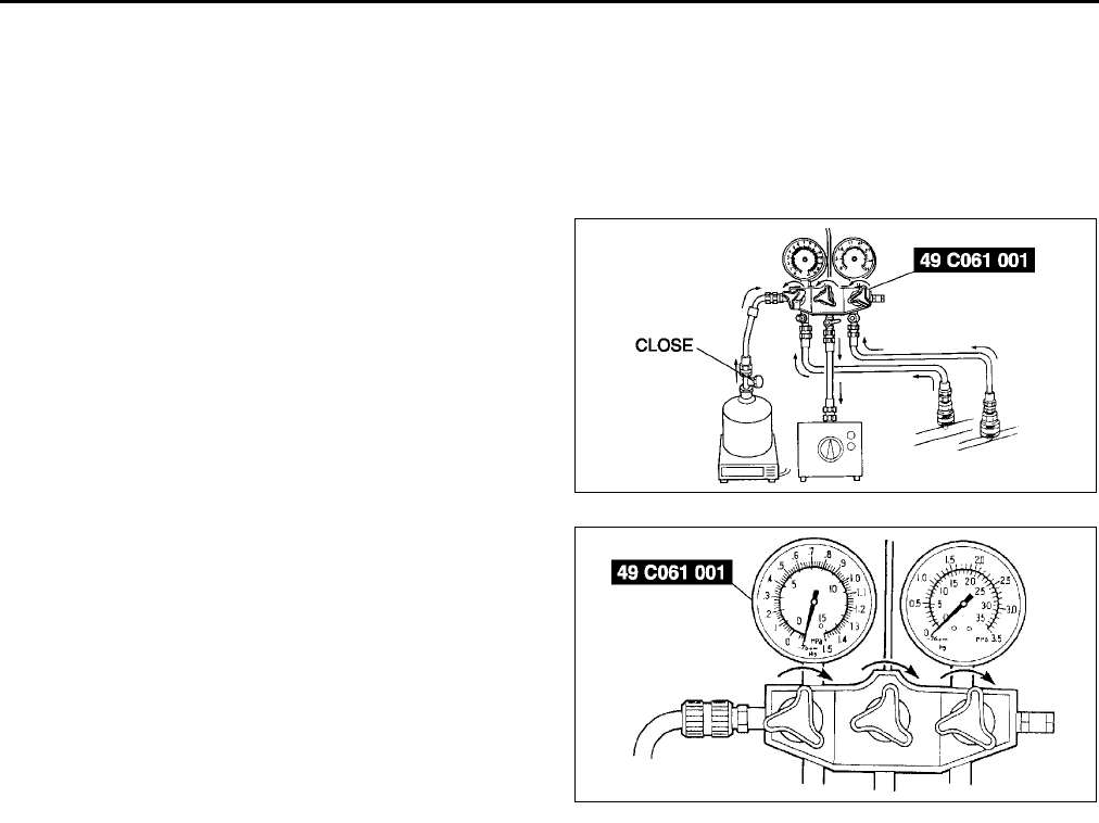
U10
REFRIGERANT SYSTEM SERVICE PROCEDURES
Evacuation
1. Open all the valves of the SST (49 C061 001).
Caution
•
••
•Close the SST (49 C061 001) valve immediately after stopping the vacuum pump. If the valve is left
open, the vacuum pump oil will flow back into the refrigeration cycle and cause a decrease in the
efficiency of the air conditioner.
2. Start the vacuum pump and let it operate for 15
minutes.
3. Verify that high- and low-pressure side readings
of the SST (49 C061 001) are at 101 kPa {760
mmHg, 29.9 inHg}. Close each valve of the
SST (49 C061 001).
Airtightness Check
1. Stop the vacuum pump and wait for 5 minutes.
2. Check the high- and low-pressure side readings of the SST (49 C061 001).
•If the reading has changed, inspect for leakage and go to Evacuation. (See U10 Evacuation.)
•If the reading has not changed, go to Charging New R-134a Refrigerant. (See U10 Charging New R-134a
Refrigerant.)
Charging New R-134a Refrigerant
1. Open the valve of the refrigerant tank.
2. Weigh the refrigerant tank to charge the suitable amount of refrigerant.
Warning
•
••
•If the refrigerant system is charged with a large amount of refrigerant when inspecting for gas
leakage, and if any leakage should occur, the refrigerant will be released into the atmosphere. In
order to prevent the accidental release of refrigerant which can destroy the ozone layer in the
stratosphere, follow the proper procedures and charge with only a small amount of refrigerant
when inspecting for gas leakage.
•
••
•If charging the system with refrigerant using service cans, running the engine with the high-
pressure side valve open is dangerous. Pressure within the service cans will increase and the
cans could explode, scattering metal fragments and liquid refrigerant that can seriously injure
you. Therefore, do not open the high-pressure side valve while the engine is running.
Caution
•
••
•Always being charging of refrigerant from the high-pressure side. If changing is begun from the
low-pressure side, the vanes of the A/C compressor will not be released and abnormal noise may
result.
A6E8514W005
A6E8514W006
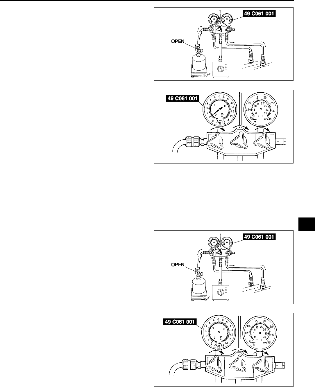
REFRIGERANT SYSTEM SERVICE PROCEDURES
U11
U
3. Open the high-pressure side valve of the SST (49
C061 001).
4. When the low-pressure side reading increases to
0.098 MPa {1.0 kgf/cm2, 14 psi}, close the
high-pressure side valve of the SST (49 C061
001).
5. Inspect for leakage from the cooler pipe/hose
connections using the SST (gas leak tester).
•If there is no leakage, go to Step 7.
•If leakage is found at a loose joint, tighten the
joint, then go to next step.
6. Inspect for leakage again.
•If there is no leakage after tightening the joint,
go to next step.
•If there is still a leakage at the same joint,
discharge the refrigerant and then repair the
joint. Repeat the charging procedure from evacuation.
Warning
•
••
•If charging the system with refrigerant using service cans, running the engine with the
high-pressure side valve open is dangerous. Pressure within the service cans will increase and
the cans could explode, scattering metal fragments and liquid refrigerant that can seriously injure
you. Therefore, do not open the high-pressure side valve while the engine is running.
7. Open the high-pressure side valve of the SST (49
C061 001) and charge with refrigerant until the
weight of refrigerant tank has decreased 250 g
{8.83 oz} from the amount in Step 2.
8. Close the high-pressure side valve of the SST (49
C061 001).
Warning
•
••
•If charging the system with refrigerant
using service cans, running the engine
with the high-pressure side valve open is
dangerous. Pressure within the service
cans will increase and the cans could
explode, scattering metal fragments and
liquid refrigerant that can seriously injure
you. Therefore, do not open the
high-pressure side valve while the engine
is running.
9. Start the engine and actuate the A/C compressor.
A6E8514W007
A6E8514W008
A6E8514W007
A6E8514W009
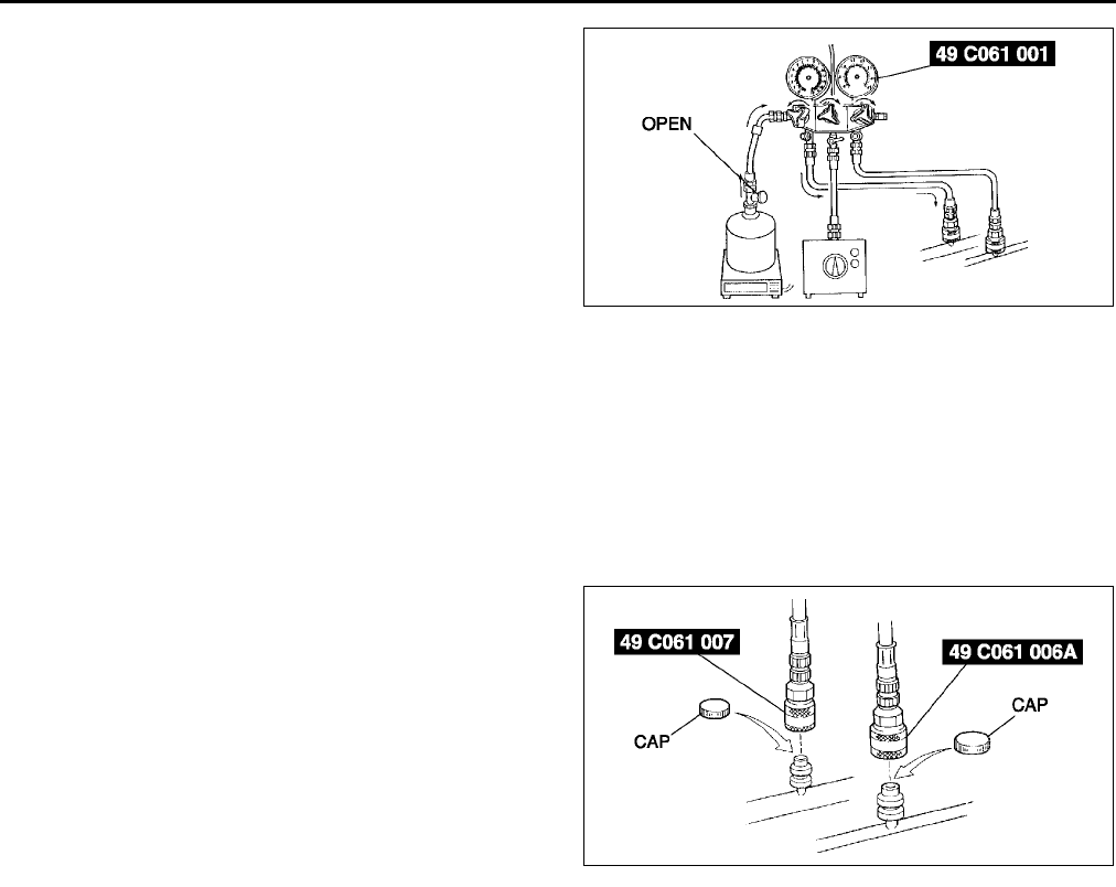
U12
REFRIGERANT SYSTEM SERVICE PROCEDURES
10. Open the low-pressure side valve of the SST (49
C061 001) and charge with refrigerant until the
weight of the refrigerant tank has decreased
regular amount from the amount in Step 2.
11. Close the low-pressure side valve of the SST (49
C061 001) and the valve of the refrigerant tank.
12. Stop the engine and A/C compressor.
Leak Test
1. Inspect for leakage using the SST (gas leak tester).
•If there is no leakage, go to Step 3.
•If leakage is found at a loose joint, tighten the joint, then go to next step.
2. Inspect for leakage again.
•If there is no leakage after tightening the joint, go to next step.
•If there is still leakage at the same joint, discharge the refrigerant and then repair the joint. Repeat the
charging procedure from evacuation.
3. Disconnect the SSTs (49 C061 006A, 49 C061 007) from the charging valves.
4. Install the caps to the charging valves.
End Of Sie
REFRIGERANT PRESSURE CHECK A6E851478834W03
1. Install the SSTs (gas charging set).
2. Warm up the engine and run it at a constant 1,500 rpm.
3. Set the fan speed to MAX HI.
4. Turn the A/C switch on.
5. Set the RECIRCULATE mode.
6. Set the temperature control to MAX COLD.
7. Set the VENT mode.
8. Close all the doors and all the windows.
9. Measure the ambient temperature and the high- and low-pressure side reading of the SST (49 C061 001).
A6E8514W010
A6E8514W011
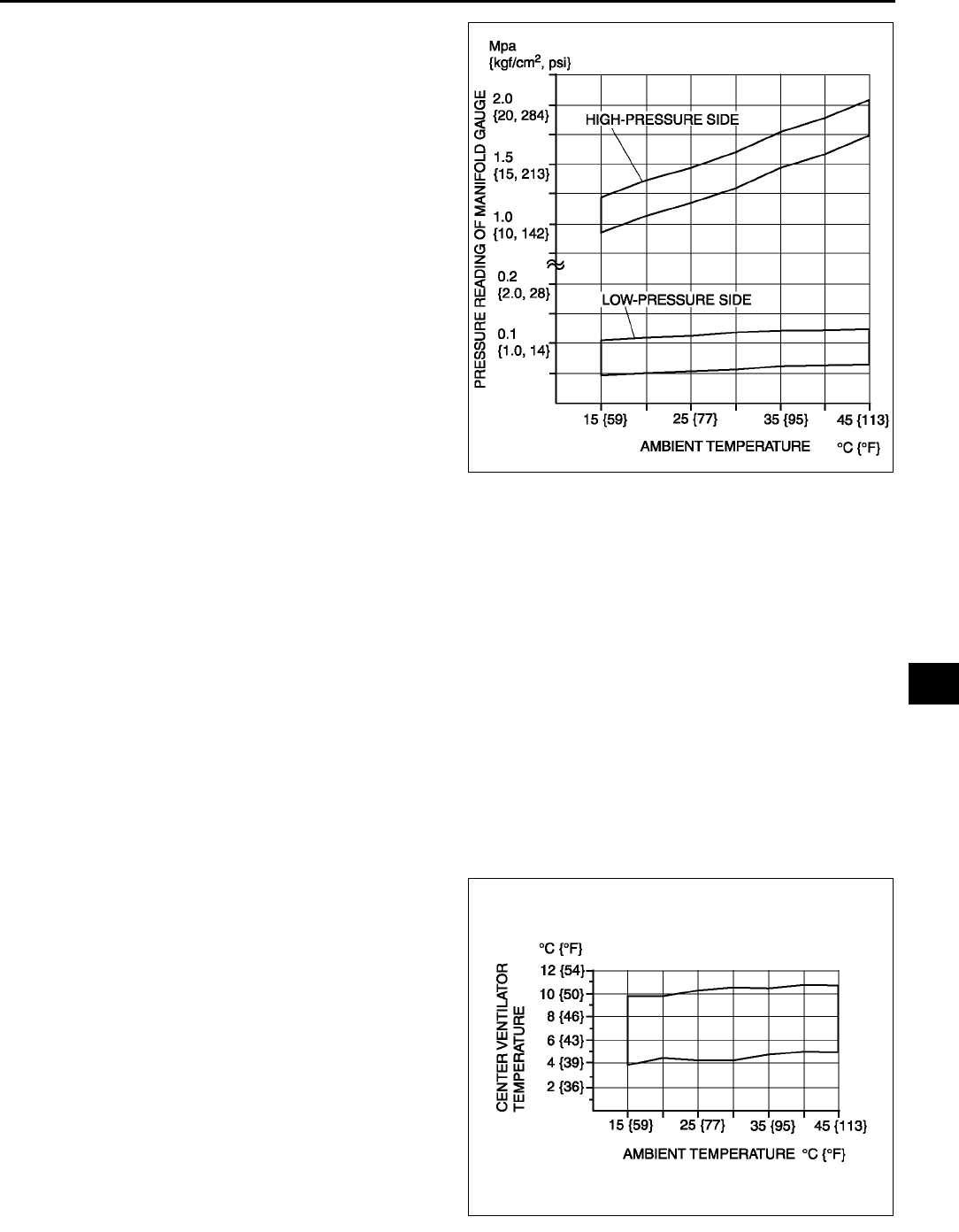
REFRIGERANT SYSTEM SERVICE PROCEDURES
U13
U
10. Verify that the intersection of the pressure reading
of the SST (49 C061 001) and ambient
temperature is in the shaded zone.
•If not as specified, troubleshoot the refrigerant
system. (See U64 TROUBLESHOOTING
INDEX.)
End Of Sie
REFRIGERANT SYSTEM PERFORMANCE TEST A6E851401039W02
1. Perform refrigerant pressure check. (See U12 REFRIGERANT PRESSURE CHECK.)
•If they are correct, go to next step.
•If not as specified, troubleshoot the refrigerant system. (See U64 TROUBLESHOOTING INDEX.)
2. Place a dry-bulb thermometer in the driver-side center ventilator outlet.
3. Warm up the engine and run it at a constant 1,500 rpm.
4. Set the fan speed to MAX HI.
5. Turn the A/C switch on.
6. Set the RECIRCULATE mode.
7. Set the temperature control to MAX COLD.
8. Set the VENT mode.
9. Close all the doors and all the windows.
10. Wait until the air conditioner output temperature stabilizes.
Stabilized condition
•The A/C compressor is repeatedly turned on and off based on the A/C compressor control of center panel
(manual air conditioner) or climate control unit (full-auto air condtioner).
11. Record driver-side center ventilator outlet temperature.
12. Determine and record ambient temperature.
13. Verify that the temperature reading is in the
shaded zone.
•If the performance is not within the shaded
zone, troubleshoot the refrigerant system.
(See U64 TROUBLESHOOTING INDEX.)
End Of Sie
A6E8514W001
A6E8514W002
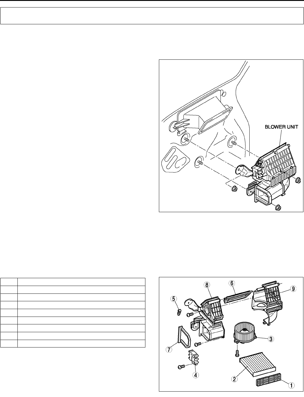
U14
BASIC SYSTEM
BLOWER UNIT REMOVAL/INSTALLATION A6E851661140W01
1. Disconnect the negative battery cable.
2. Remove the dashboard. (See S82 DASHBOARD REMOVAL/INSTALLATION.)
3. Remove the A/C unit. (See U15 A/C UNIT REMOVAL/INSTALLATION.)
4. Remove the blower unit.
5. Install in the reverse order of removal.
End Of Sie
BLOWER UNIT DISASSEMBLY/ASSEMBLY A6E851661140W02
1. Disassemble in the order indicated in the table.
Caution
•
••
•Apply only the specified grease to the link. Otherwise abnormal noise or improper operation may
result.
.
2. Assemble in the reverse order of disassembly.
End Of Sie
BASIC SYSTEM
A6E8516W001
1 Air filter cover
2 Air filter
3Blower motor
4 Air intake actuator
5 Air intake crank
6 Air intake door
7 Polyurethane protector
8 Blower case (1)
9 Blower case (2)
A6E8516W002
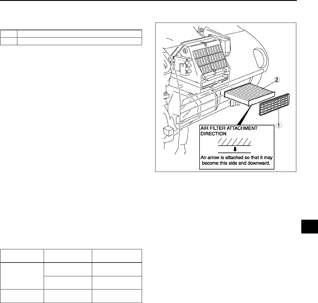
BASIC SYSTEM
U15
U
AIR FILTER REMOVAL/INSTALLATION A6E851661140W03
1. Remove the glove compartment.
2. Remove in the order indicated in the table.
3. Install in the reverse order of removal.
End Of Sie
AIR FILTER INSPECTION A6E851661140W04
1. Remove the air filter.
2. Inspect the air filter.
•If the air filter is damaged, excessively dirty, or foul smelling, replace the air filter.
Note
•The air filter cannot be reused by cleaning it with water or compressed air.
•Replace the air filter at the following interval, depending on operating conditions.
End Of Sie
A/C UNIT REMOVAL/INSTALLATION A6E851661130W01
1. Disconnect the negative battery cable.
2. Discharge the refrigerant from the system. (See U9 RECOVERY.) (See U9 CHARGING.)
3. Drain the engine coolant. (See E3 ENGINE COOLANT REPLACEMENT.)
4. Remove the dashboard. (See S82 DASHBOARD REMOVAL/INSTALLATION.)
5. Remove the theft-deterrent control module. (See T86 THEFT-DETERRENT CONTROL MODULE
REMOVAL/INSTALLATION.)
Caution
•
••
•If moisture or foreign material enters the refrigeration cycle, cooling ability will be lowered and
abnormal noise will occur. Always immediately plug open fittings after removing any refrigeration
cycle parts to keep moisture or foreign material out of the cycle.
1 Air filter cover
2 Air filter
A6E8516W018
Destinations Type Interval (year or
km {miles})
Europe (L.H.D.
U.K.) specs.
Aldehyde, pollen,
and a dust removal
1 or 20,000
{12,500}
Pollen, and a dust
removal
2 or 40,000
{25,000}
GCC specs. 1 or 20,000
{12,500}
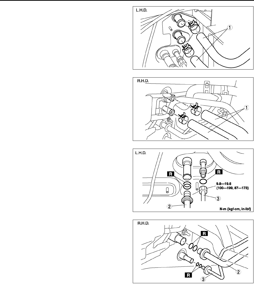
U16
BASIC SYSTEM
6. Remove in the order indicated in the table. Do not
allow compressor oil to spill.
A6E8516W003
A6E8516W025
A6E8516W004
A6E8516W026
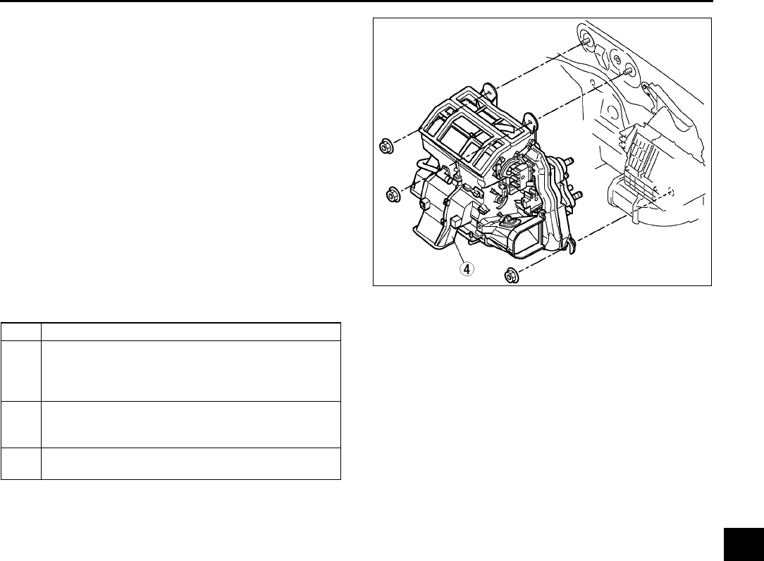
BASIC SYSTEM
U17
U
.
7. Install in the reverse order of removal.
8. Perform the refrigerant system performance test. (See U13 REFRIGERANT SYSTEM PERFORMANCE
TEST.)
A/C Unit Installation Note
1. When installing a new A/C unit or evaporator, add a supplemental amount of ATMOS GU10 compressor oil into
the refrigerant cycle.
Supplemental amount (approximate quantity)
25 ml {25 cc, 0.8 fl oz}
End Of Sie
A6E8516W019
1Heater hose
2 Cooler hose (Lo) (L.H.D.) or cooler pipe No.4
(R.H.D.)
(See U28 Refrigerant Lines Removal Note)
(See U29 Refrigerant Lines Installation Note)
3 Cooler pipe No.3
(See U28 Refrigerant Lines Removal Note)
(See U29 Refrigerant Lines Installation Note)
4 A/C unit
(See U17 A/C Unit Installation Note)
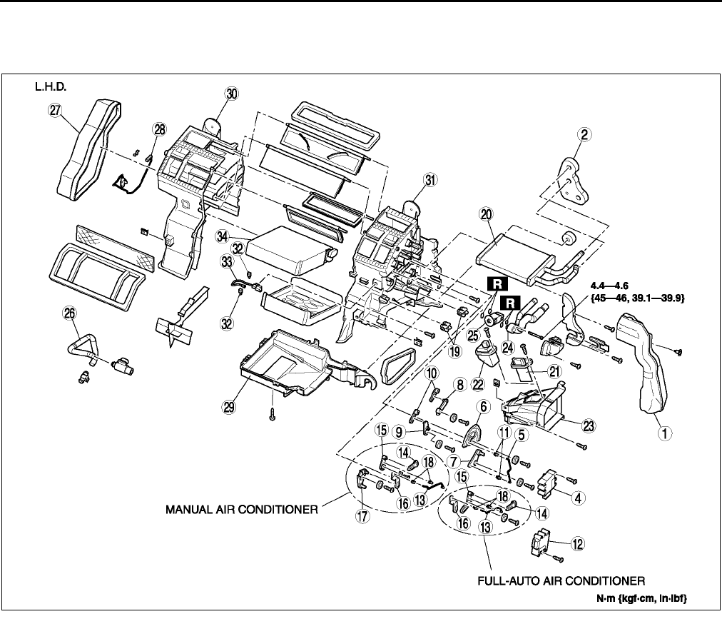
U18
BASIC SYSTEM
A/C UNIT DISASSEMBLY/ASSEMBLY A6E851661130W02
1. Disassemble in the order indicated in the table.
2. Assemble in the reverse order of disassembly.
A6E8516W005
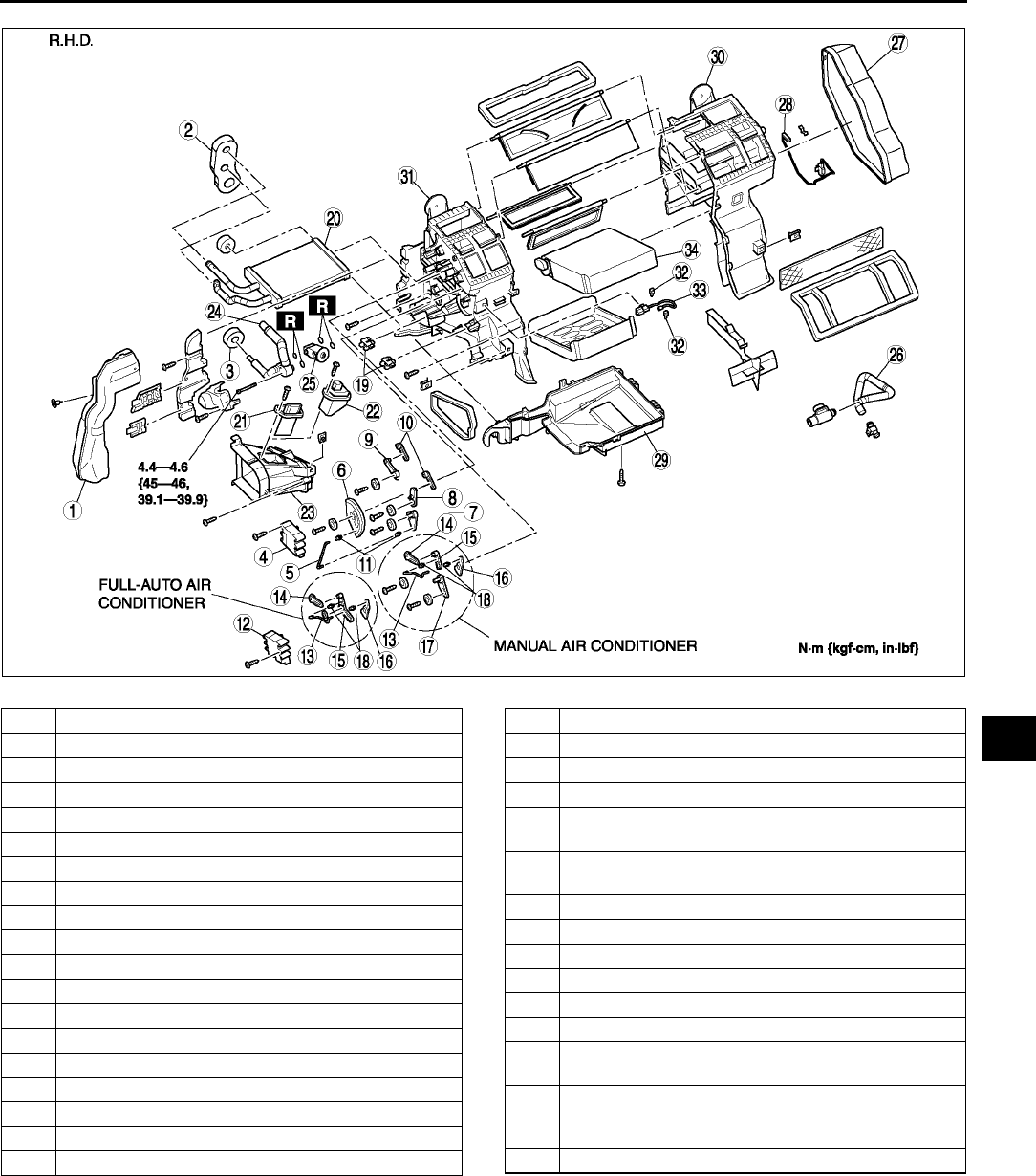
BASIC SYSTEM
U19
U
.
A6E8516W006
1 Duct (1)
2 Polyurethane protector (1)
3 Polyurethane protector (2) (R.H.D.)
4 Airflow mode actuator (full-auto air conditioner)
5 Airflow mode rod (manual air conditioner)
6 Airflow mode main link
7 Airflow mode sub link (1) (manual air conditioner)
8 Airflow mode sub link (2)
9 Airflow mode sub link (3)
10 Airflow mode crank
11 Airflow mode rod holder (manual air conditioner)
12 Air mix actuator (full-auto air conditioner)
13 Air mix rod
14 Air mix crank (1)
15 Air mix link (1)
16 Air mix crank (2)
17 Air mix link (2) (manual air conditioner)
18 Air mix rod holder
19 Wire clamp (manual air conditioner)
20 Heater core
21 Resistor (manual air conditioner)
22 Power MOS FET (full-auto air conditioner)
23 Duct (2)
24 Outlet pipe
(SeeU21 Outlet Pipe Assembly Note)
25 Expansion valve
(See U20 Expansion Valve Assembly Note)
26 Air hose
27 Duct (3)
28 Water temperature sensor (full-auto air conditioner)
29 A/C case (3)
30 A/C case (1)
31 A/C case (2)
32 Sensor clamp
(SeeU20 Sensor Clamp Assembly Note)
33 Evaporator temperature sensor
(See U20 Evaporator Temperature Sensor
Assembly Note)
34 Evaporator
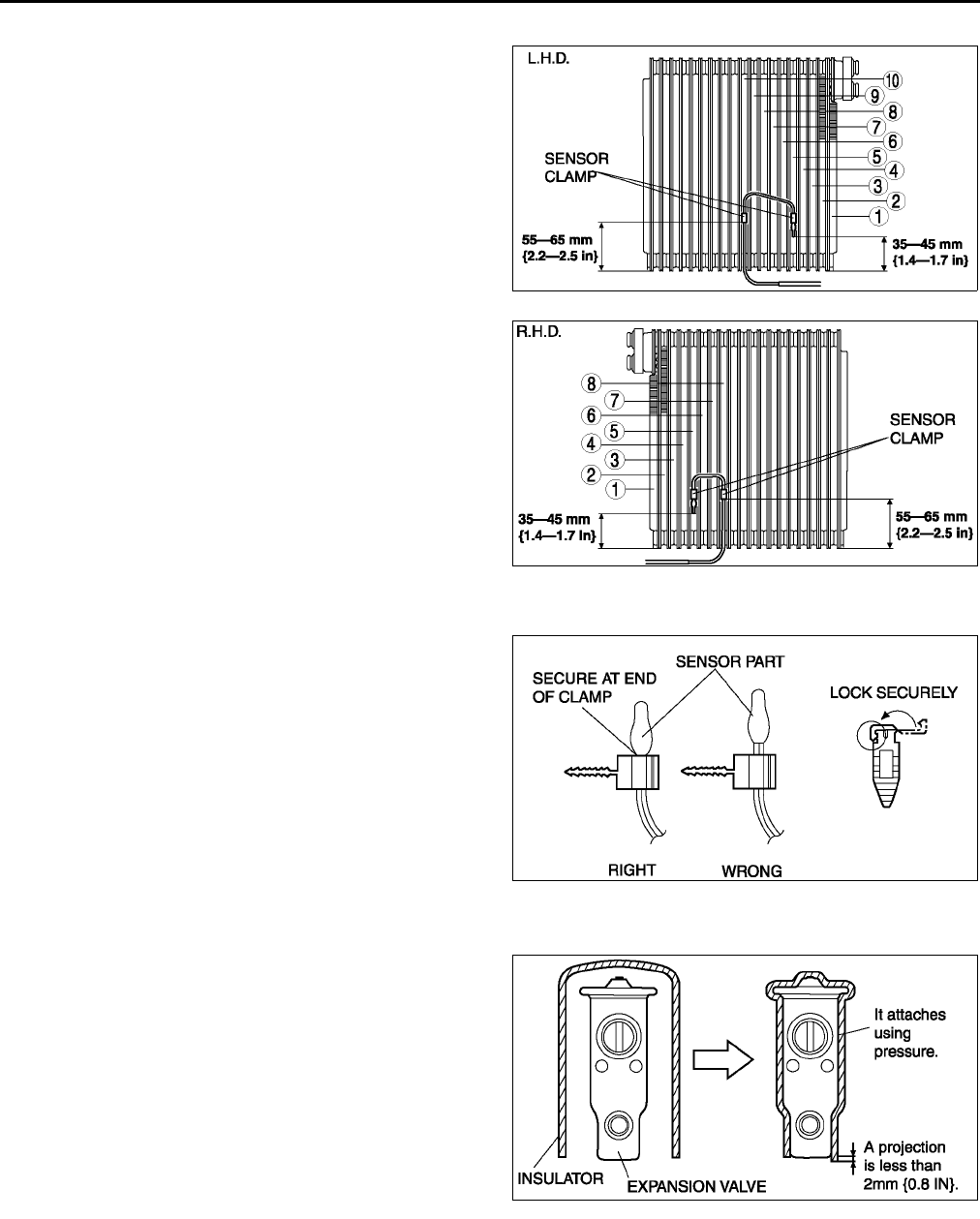
U20
BASIC SYSTEM
Evaporator Temperature Sensor Assembly Note
1. Assemble the evaporator temperature sensor as
shown in the figure.
Sensor Clamp Assembly Note
1. Attach the sensor clamp as shown in the figure.
Expansion Valve Assembly Note
1. Attach the insulator as shown in the figure.
A6E8516W020
A6E8516W021
A6E8516W007
A6E8516W027
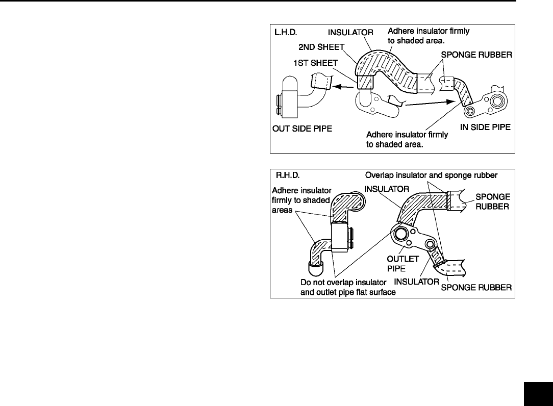
BASIC SYSTEM
U21
U
Outlet Pipe Assembly Note
1. Wrap the insulator around the outlet pipe as
shown in the figure.
End Of Sie
EXPANSION VALVE REMOVAL/INSTALLATION A6E851661130W03
1. Disconnect the negative battery cable.
2. Discharge the refrigerant from the system. (See U9 RECOVERY.) (See U9 CHARGING.)
Caution
•
••
•If moisture or foreign material enters the refrigeration cycle, cooling ability will be lowered and
abnormal noise will occur. Always immediately plug open fittings after removing any refrigeration
cycle parts to keep moisture or foreign material out of the cycle.
3. Disconnect the cooler hose (Lo) (L.H.D) or cooler pipe No.4 (R.H.D.) and cooler pipe No.3. (See U25
REFRIGERANT LINES REMOVAL/INSTALLATION.)
4. Remove the dashboard. (See S82 DASHBOARD REMOVAL/INSTALLATION.)
5. Remove the duct (1).
6. Remove the air mix actuator. (Full-auto air conditioner)
7. Remove the screws and cover.
8. Remove the one plate (L.H.D.) or two plates (R.H.D.).
9. Remove the bolts and shift the outlet pipe. Do not allow compressor oil to spill.
A6E8516W028
A6E8516W031
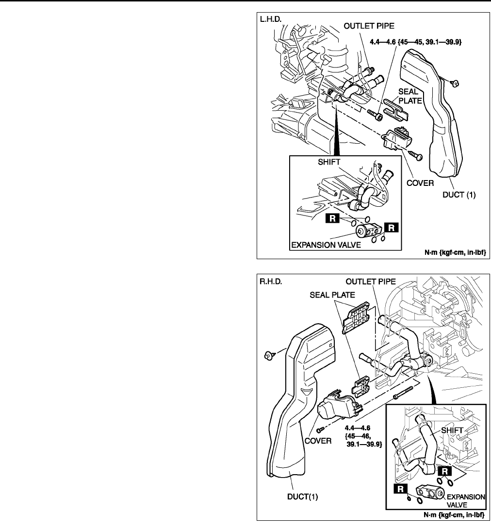
U22
BASIC SYSTEM
10. Remove the expansion valve. Do not allow
compressor oil to spill.
11. Install in the reverse order of removal.
12. Perform the refrigerant system performance test.
(See U13 REFRIGERANT SYSTEM
PERFORMANCE TEST.)
End Of Sie
EVAPORATOR INSPECTION A6E851661810W01
1. Remove the A/C unit. (See U15 A/C UNIT REMOVAL/INSTALLATION.)
2. Remove the evaporator from the A/C unit.
3. Inspect for cracks, damage, and oil leakage.
•If any problems are found, replace the evaporator.
4. Inspect for bent fins.
•If any are bent, use a flathead screwdriver to straighten them.
End Of Sie
A6E8516W010
A6E8516W022
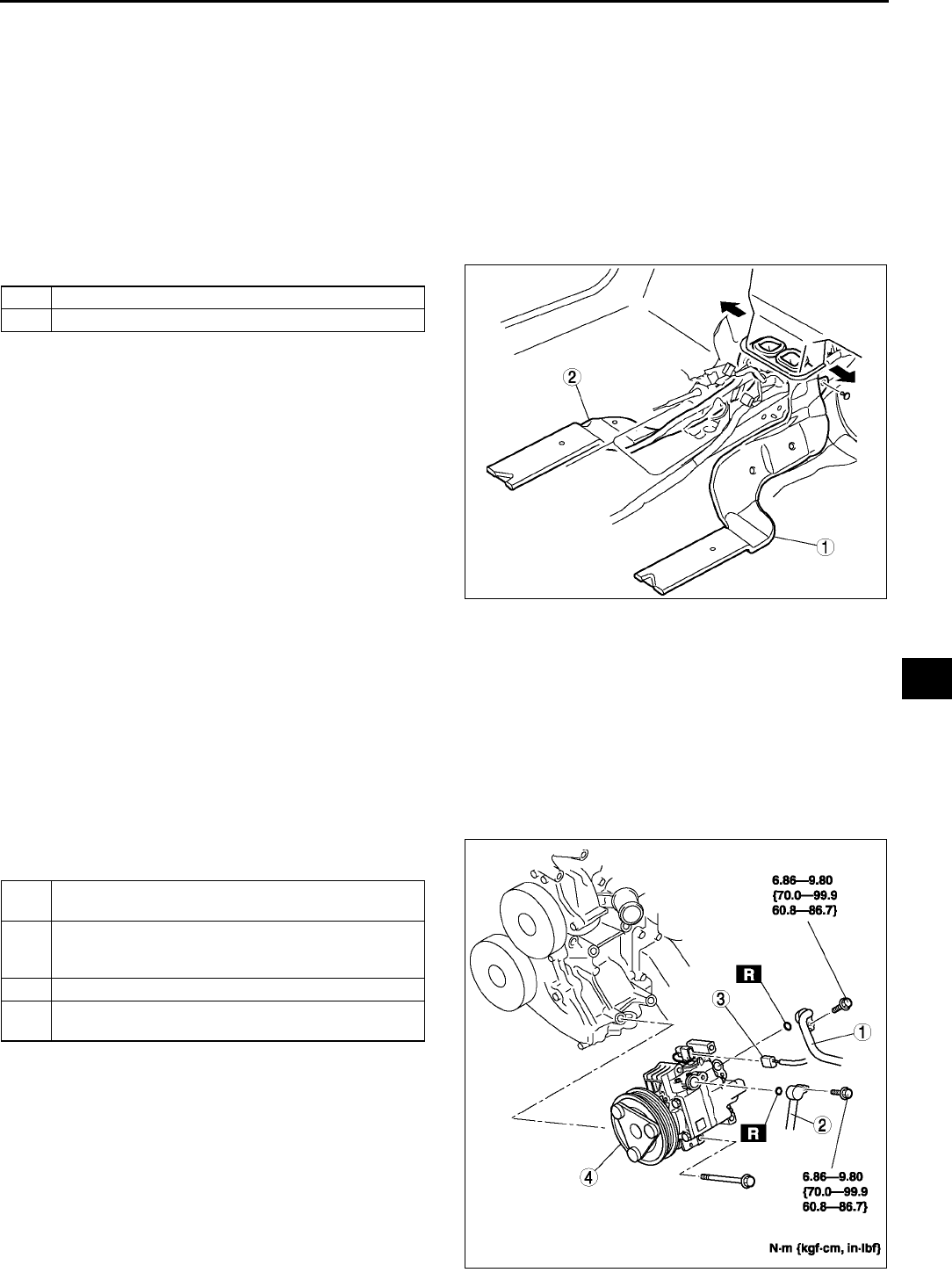
BASIC SYSTEM
U23
U
HEATER CORE INSPECTION A6E851661910W01
1. Remove the A/C unit. (See U15 A/C UNIT REMOVAL/INSTALLATION.)
2. Remove the heater core from the A/C unit.
3. Inspect for cracks, damage, and coolant leakage.
•If any problems are found, replace the heater core.
4. Inspect for bent fins.
•If any are bent, use a flathead screwdriver to straighten them.
5. Verify that the heater core inlet and outlet pipe are not distorted or damaged.
•Repair with pliers if necessary.
End Of Sie
REAR HEAT DUCT REMOVAL/INSTALLATION A6E851661273W01
1. Turn over the front floor covering. (See S99 FRONT FLOOR COVERING REMOVAL/INSTALLATION.)
2. Remove in the order indicated in the table..
3. Install in the reverse order of removal.
End Of Sie
A/C COMPRESSOR REMOVAL/INSTALLATION A6E851661450W01
1. Disconnect the negative battery cable.
2. Discharge the refrigerant from the system. (See U9 RECOVERY.) (See U9 CHARGING.)
3. Remove the right side splash shield and mudguard (L.H.D. only).
4. Loosen the drive belt and remove it.
Caution
•
••
•If moisture or foreign material enters the refrigeration cycle, cooling ability will be lowered and
abnormal noise will occur. Always immediately plug open fittings after removing any refrigeration
cycle parts to keep moisture or foreign material out of the cycle.
5. Remove in the order indicated in the table. Do not
allow compressor oil to spill..
6. Install in the reverse order of removal.
7. Adjust the drive belt.
8. Perform the refrigerant system performance test.
(See U13 REFRIGERANT SYSTEM
PERFORMANCE TEST.)
1 Rear heat duct (Right)
2 Rear heat duct (Left)
A6E8516W011
1 Cooler hose (HI)
(See U29 Refrigerant Lines Installation Note)
2 Cooler pipe No.4 (L.H.D.) or cooler hose (LO)
(R.H.D.)
(See U29 Refrigerant Lines Installation Note)
3 Magnetic clutch connector
4 A/C compressor
(See U24 A/C Compressor Installation Note)
A6E8516W012
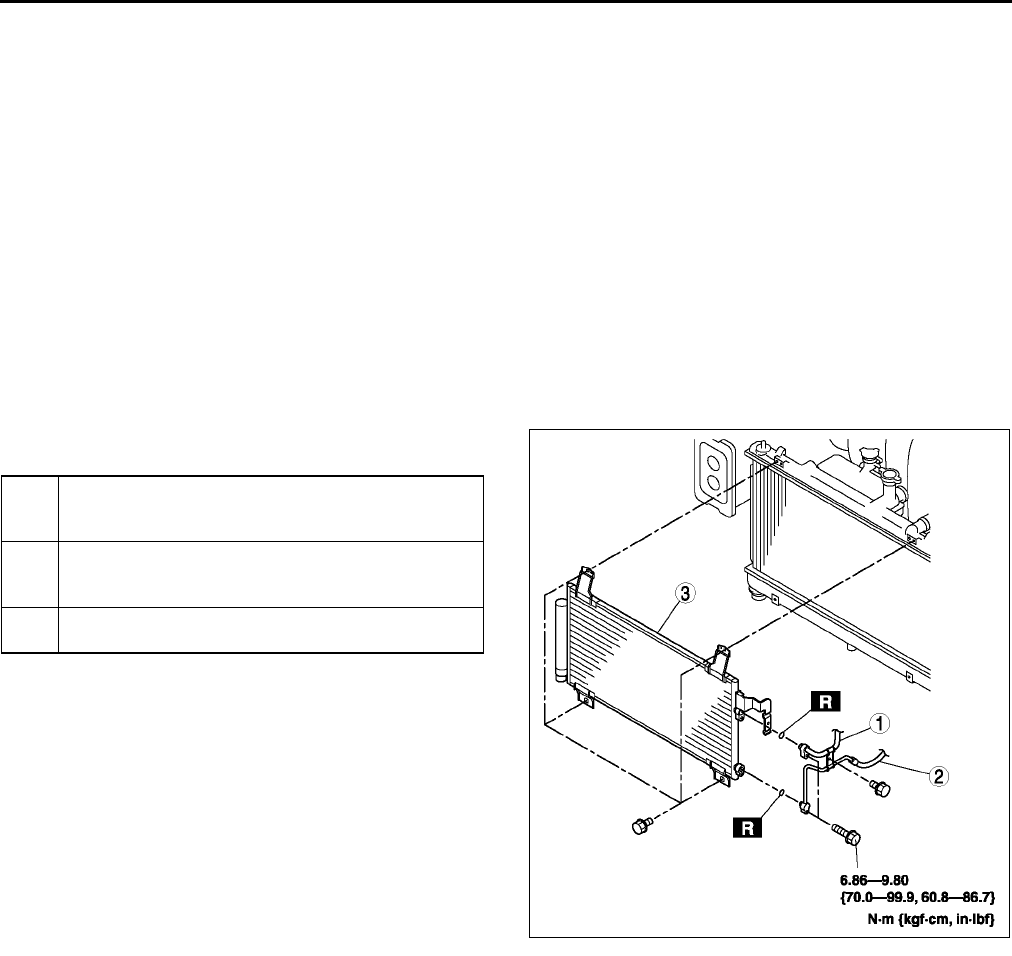
U24
BASIC SYSTEM
A/C Compressor Installation Note
1. Remove the following amount of compressor oil from the new A/C compressor when replacing the A/C
compressor.
Compressor oil to be removed (approximate quantity)
120 ml {120 cc, 4.06 fl oz} [compressor oil from old A/C compressor + 15 ml {15 cc, 0.5 fl oz}]
End Of Sie
CONDENSER REMOVAL/INSTALLATION A6E851661480W01
1. Disconnect the negative battery cable.
2. Discharge the refrigerant from the system. (See U9 RECOVERY.) (See U9 CHARGING.)
3. Remove the shroud panel. (See S119 SHROUD PANEL REMOVAL/INSTALLATION.)
Caution
•
••
•If moisture or foreign material enters the refrigeration cycle, cooling ability will be lowered and
abnormal noise will occur. Always immediately plug all open fittings after removing any
refrigeration cycle parts to keep moisture or foreign material out of the cycle.
4. Remove in the order indicated in the table. Do not
allow compressor oil to spill..
5. Install in the reverse order of removal.
6. Perform the refrigerant system performance test.
(See U13 REFRIGERANT SYSTEM
PERFORMANCE TEST.)
Condenser Installation Note
1. When installing a new condenser, add a supplemental amount of ATMOS GU10 compressor oil inlet the
refrigerant cycle.
Supplemental amount (approximate quantity)
20 ml {20 cc, 0.7 fl oz}
End Of Sie
CONDENSER INSPECTION A6E851661480W02
1. Inspect for cracks, damage, and oil leakage.
•If any are found, replace the condenser.
2. Inspect for fins clogged by dust.
•If any are clogged, remove the dust from the fins.
3. Inspect for bent fins.
•If any are bent, use a flathead screwdriver to straighten them.
End Of Sie
1 Cooler pipe No.1
(See U28 Refrigerant Lines Removal Note)
(See U29 Refrigerant Lines Installation Note)
2 Cooler pipe No.2
(See U28 Refrigerant Lines Removal Note)
(See U29 Refrigerant Lines Installation Note)
3 Condenser
(See U24 Condenser Installation Note)
A6E8516W013

BASIC SYSTEM
U25
U
REFRIGERANT LINES REMOVAL/INSTALLATION A6E851661460W01
1. Remove the battery.
2. Discharge the refrigerant from the system. (See U9 RECOVERY.) (See U9 CHARGING.)
3. Remove the washer tank. (L.H.D. only) (See T58 WASHER TANK REMOVAL/INSTALLATION.)
4. Remove the air cleaner cover, air cleaner element and air cleaner case. (See F10 INTAKE-AIR SYSTEM
REMOVAL/INSTALLATION.)
5. Remove the charcoal canister.
6. Remove the No.3 engine mount. (L.H.D. only)
7. Remove the shroud panel. (See S119 SHROUD PANEL REMOVAL/INSTALLATION.)
8. Remove the right splash shield.
9. Remove the right mud guard. (L.H.D. only)
Caution
•
••
•If moisture or foreign material enters the refrigeration cycle, cooling ability will be lowered and
abnormal noise will occur. Always immediately plug all open fittings after removing any
refrigeration cycle parts to keep moisture or foreign material out of the cycle.
10. Remove in the order indicated in the table. Do not allow compressor oil to spill.
11. Install in the reverse order of removal.
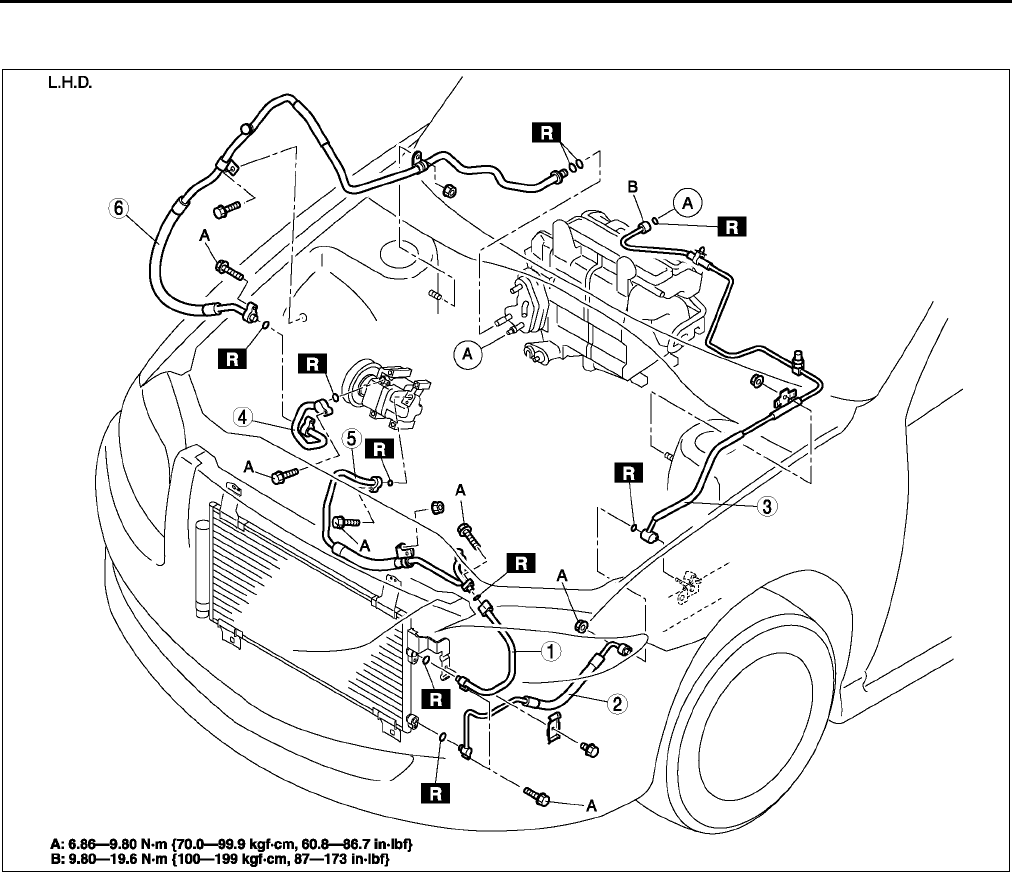
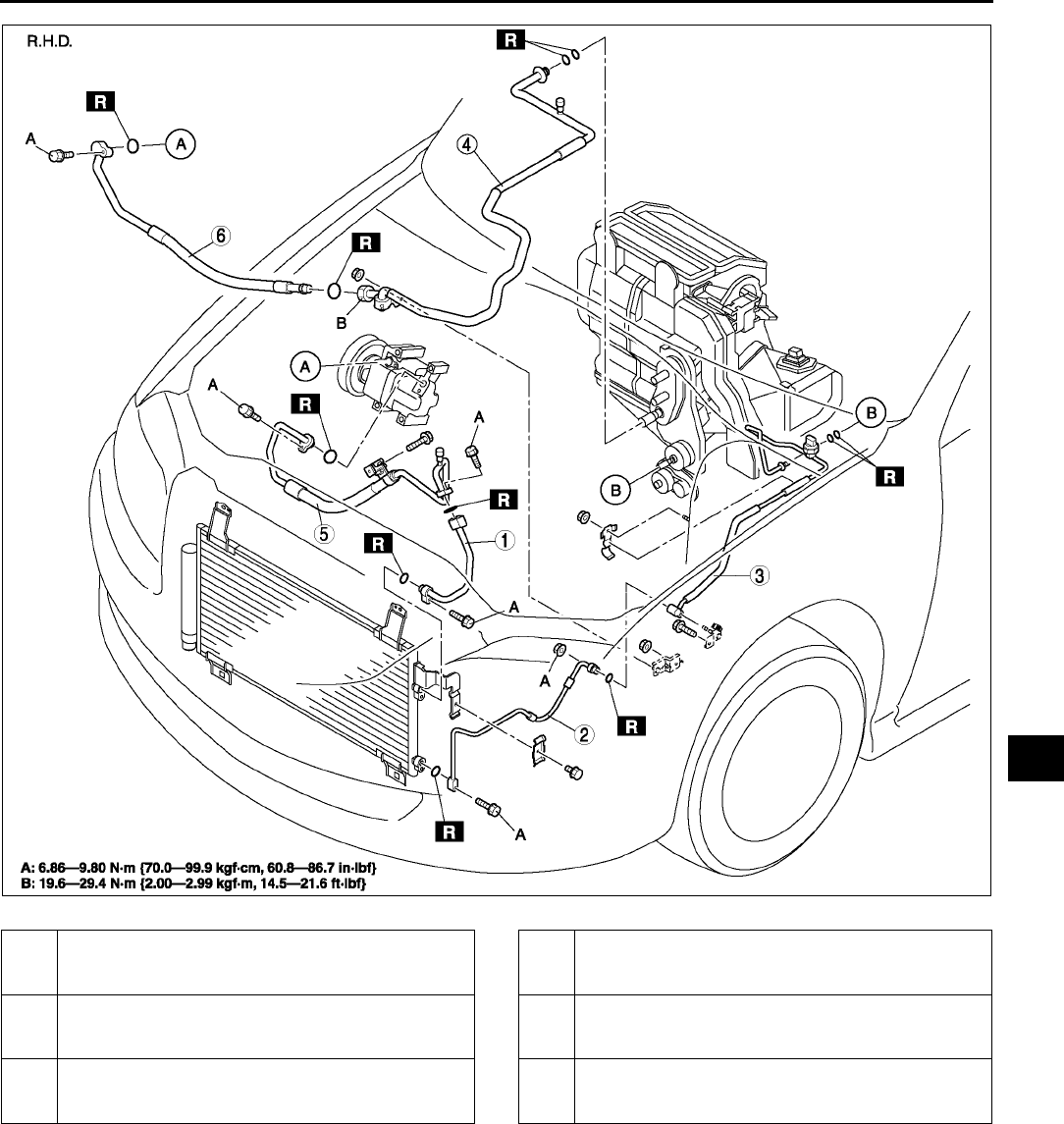
BASIC SYSTEM
U27
U
A6E8516W030
1 Cooler pipe No.1
(See U28 Refrigerant Lines Removal Note)
(See U29 Refrigerant Lines Installation Note)
2 Cooler pipe No.2
(See U28 Refrigerant Lines Removal Note)
(See U29 Refrigerant Lines Installation Note)
3 Cooler pipe No.3
(See U28 Refrigerant Lines Removal Note)
(See U29 Refrigerant Lines Installation Note)
4 Cooler pipe No.4
(See U28 Refrigerant Lines Removal Note)
(See U29 Refrigerant Lines Installation Note)
5 Cooler hose (HI)
(See U28 Refrigerant Lines Removal Note)
(See U29 Refrigerant Lines Installation Note)
6 Cooler hose (LO)
(See U28 Refrigerant Lines Removal Note)
(See U29 Refrigerant Lines Installation Note)
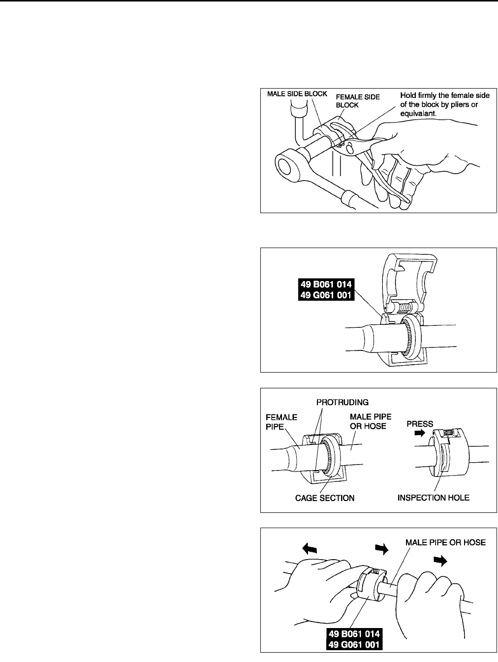
U28
BASIC SYSTEM
Refrigerant Lines Removal Note
Nut joint type
1. Loosen the nut using two spanners, then remove the cooler pipe or hose.
Block joint type
1. Disconnect the block joint type pipes by grasping female side of the block with pliers or similar tool and holding
firmly, then remove the connection bolt or nut.
Spring-lock coupling type
1. Set the SST.
2. While looking through the inspection hole of the
SST, insert the protruding part of the SST until it
makes contact with the cage section.
3. Use the SST to disconnect the male pipe or hose
from the female by pulling the male pipe or hose.
Note
•The male pipe or hose can be disconnected
easily from the female pipe by pulling from
the male pipe or hose while maintaining the
pressure of the protruding part of the SST.
A6E8516W023
A6E8516W014
A6E8516W015
A6E8516W016
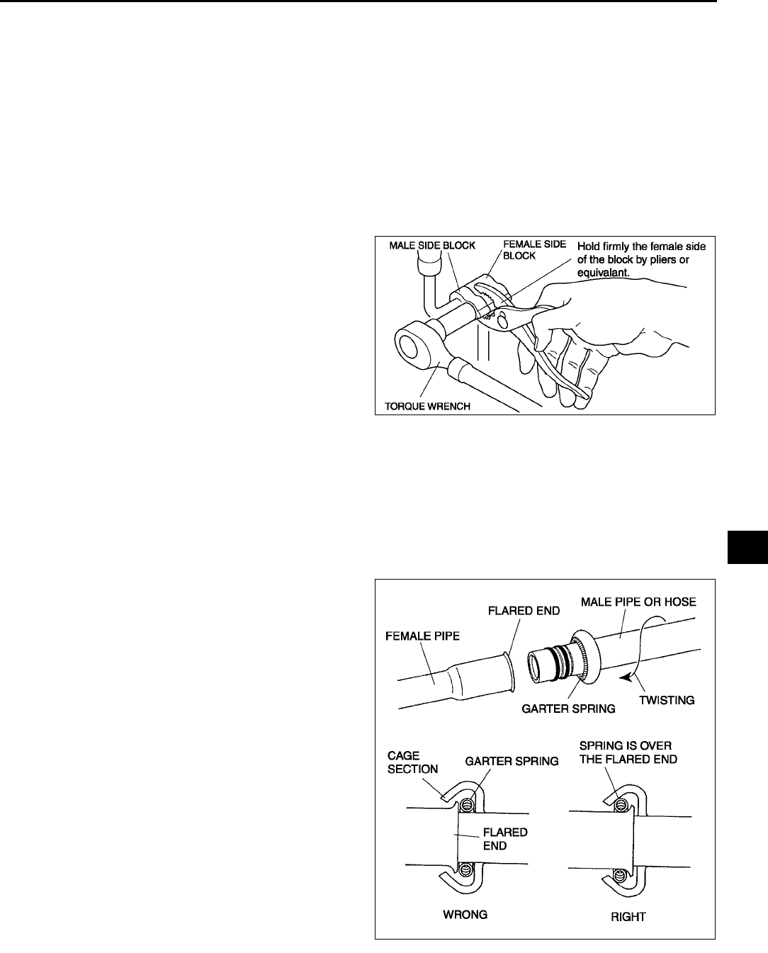
BASIC SYSTEM
U29
U
Refrigerant Lines Installation Note
1. When installing a new cooler pipe No.4 or cooler hose (LO), add a supplemental amount of ATMOS GU10
compressor oil into the refrigeration cycle.
Supplemental amount (approximate quantity)
5 ml {5 cc, 0.2 fl oz}: Cooler pipe No.4
10 ml {10 cc, 0.3 fl oz}: Cooler hose (LO)
2. Apply compressor oil to the O-rings and connect the joints.
3. Tighten the joints.
Nut or block joint type
1. Tighten the nut or bolt of joint by hand.
2. Tighten the joint to the specified torque. If it is a nut joint, tighten the nut with a spanner and torque wrench.
3. Connect the block joint type pipes by grasping the
female side of the block with pliers or similar tool
and holding firmly, then tighten the connection
bolt or nut with a torque wrench.
Spring-lock coupling type
1. Connect the male pipe or hose by twisting it onto female pipe until the garter spring at the male pipe or hose is
over the flared end of female pipe.
Note
•When the male pipe or hose is replaced, the indicator ring comes out after connecting to indicate that it is
locked.
End Of Sie
A6E8516W024
A6E8516W017
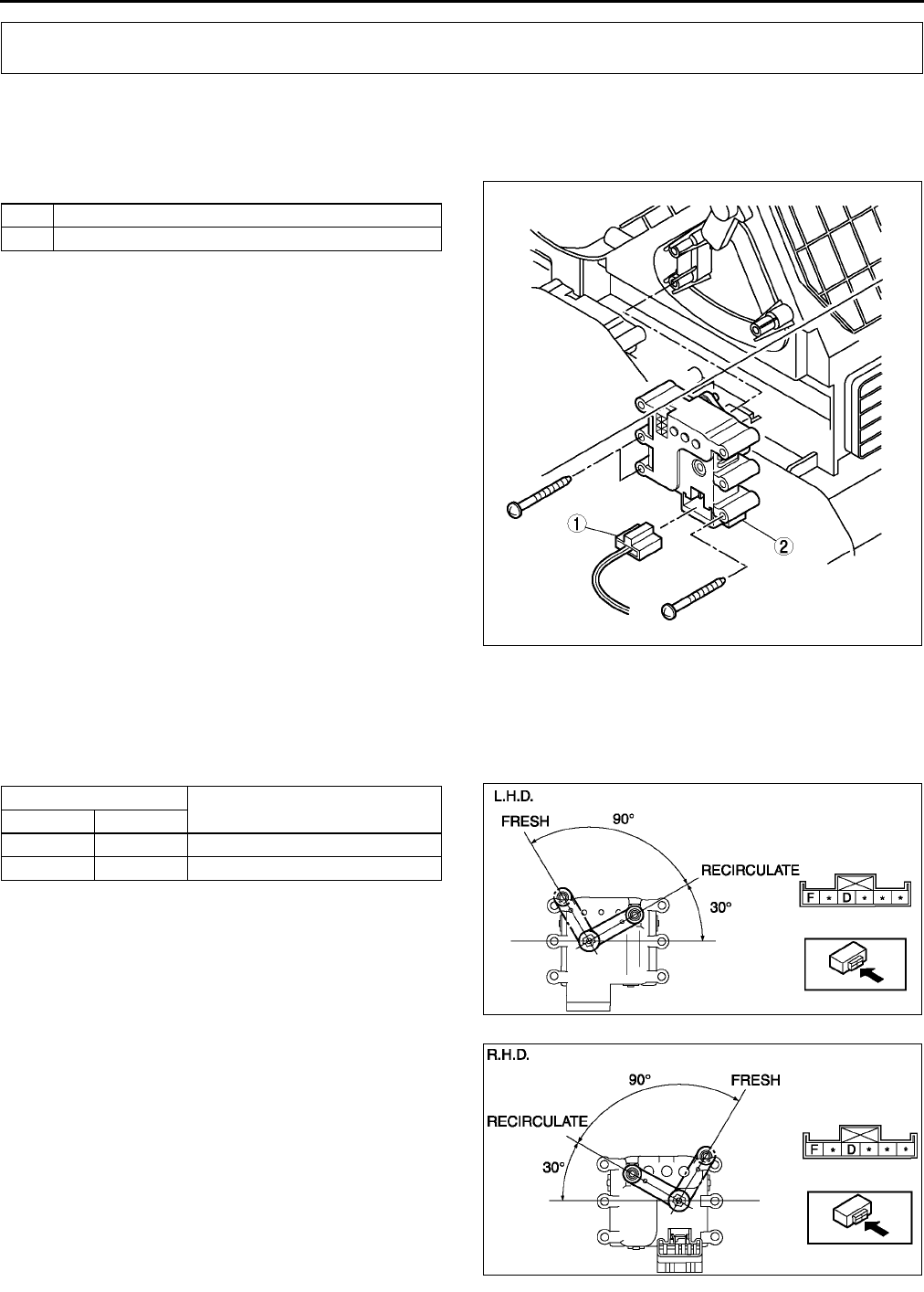
U30
CONTROL SYSTEM
AIR INTAKE ACTUATOR REMOVAL/INSTALLATION A6E854061060W01
1. Disconnect the negative battery cable.
2. Remove the glove compartment.
3. Remove the car navigation unit. (See T98 CAR-NAVIGATION UNIT REMOVAL/INSTALLATION.)
4. Remove in the order indicated in the table.
5. Install in the reverse order of removal.
End Of Sie
AIR INTAKE ACTUATOR INSPECTION A6E854061060W02
1. Connect battery positive voltage to terminal D or F and ground to terminal F or D of the air intake actuator.
2. Verify that the air intake actuator operates as shown below.
•If not as specified, replace the air intake actuator.
CONTROL SYSTEM
1 Air intake actuator connector
2 Air intake actuator
A6E8540W001
Connection Movement
B+ GND
D F RECIRCULATE→FRESH
F D FRESH→RECIRCULATE
A6E8540W002
A6E8540W003
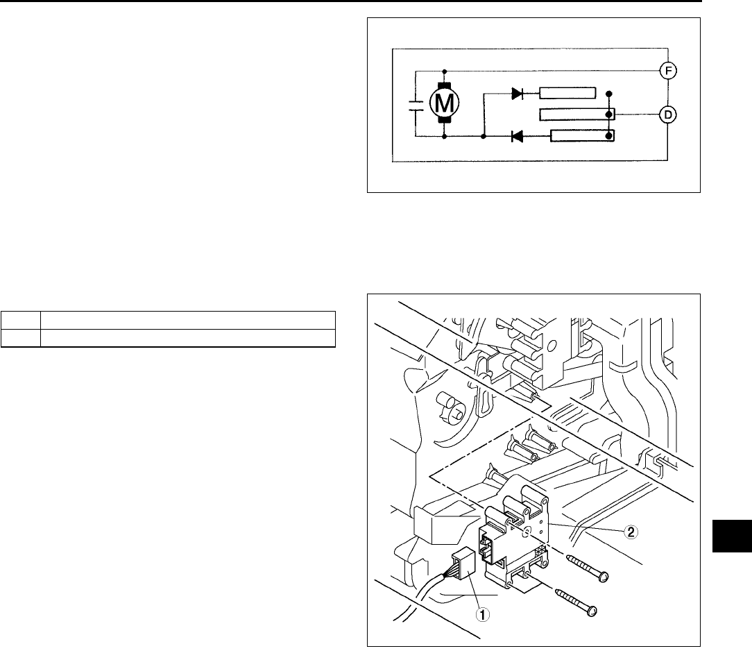
CONTROL SYSTEM
U31
U
End Of Sie
AIR MIX ACTUATOR REMOVAL/INSTALLATION A6E854061415W01
1. Disconnect the negative battery cable.
2. Remove the glove compartment.
3. Remove the car navigation unit. (See T98 CAR-NAVIGATION UNIT REMOVAL/INSTALLATION.)
4. Remove in the order indicated in the table.
5. Install in the reverse order of removal.
End Of Sie
A6E8540W043
1 Air mix actuator connector
2 Air mix actuator
A6E8540W004
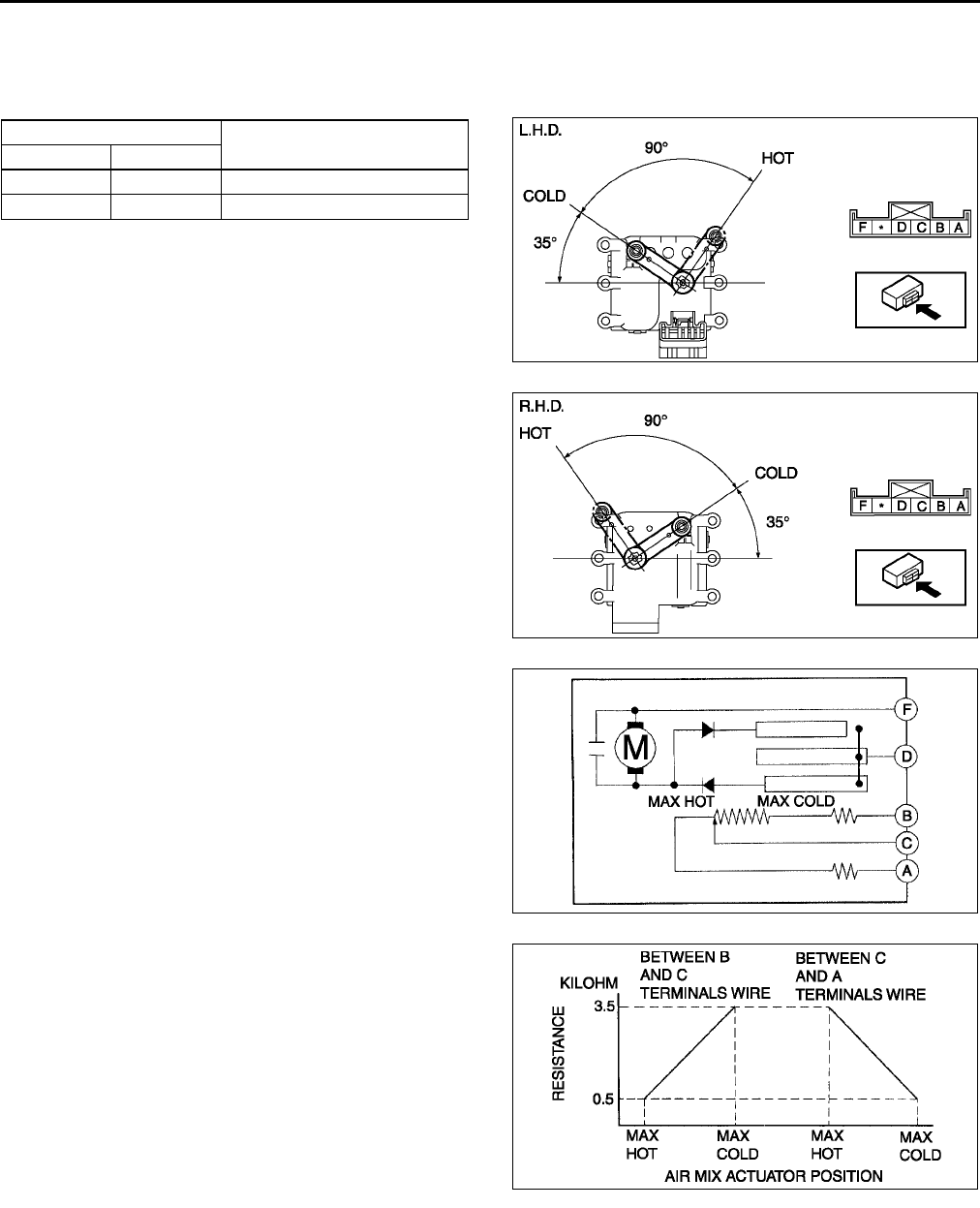
U32
CONTROL SYSTEM
AIR MIX ACTUATOR INSPECTION A6E854061415W02
1. Connect battery positive voltage to terminal D or F and ground to terminal F or D of the air mix actuator.
2. Verify that the air mix actuator operates as shown below.
•If not as specified, replace the air mix actuator.
3. Verify that the resistance between the terminals
of the air mix actuator are as shown in the graph.
•If not as specified, replace the air mix
actuator.
End Of Sie
Connection Movement
B+ GND
DF COLD→HOT
FD HOT→COLD
A6E8540W005
A6E8540W006
A6E8540W044
A6E8540W045
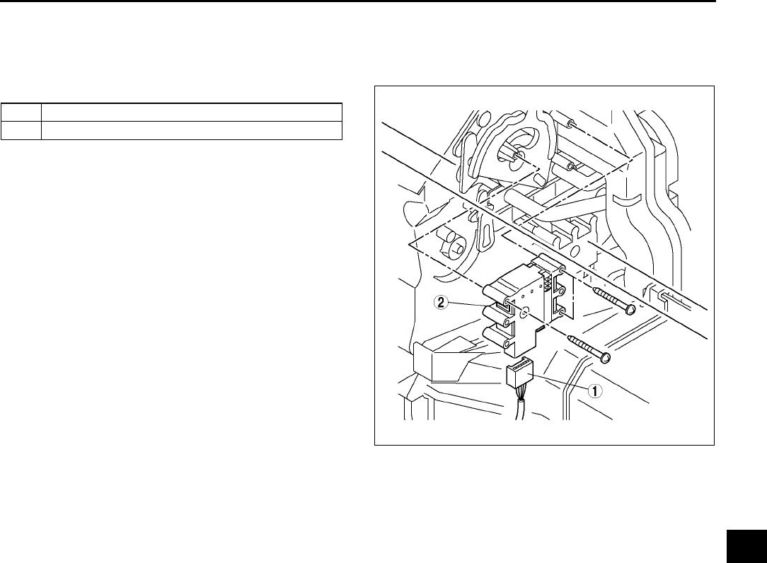
CONTROL SYSTEM
U33
U
AIRFLOW MODE ACTUATOR REMOVAL/INSTALLATION A6E854061070W01
1. Disconnect the negative battery cable.
2. Remove the glove compartment.
3. Remove the car navigation unit. (See T98 CAR-NAVIGATION UNIT REMOVAL/INSTALLATION.)
4. Remove in the order indicated in the table.
5. Install in the reverse order of removal.
End Of Sie
1 Airflow mode actuator connector
2 Airflow mode actuator
A6E8540W007
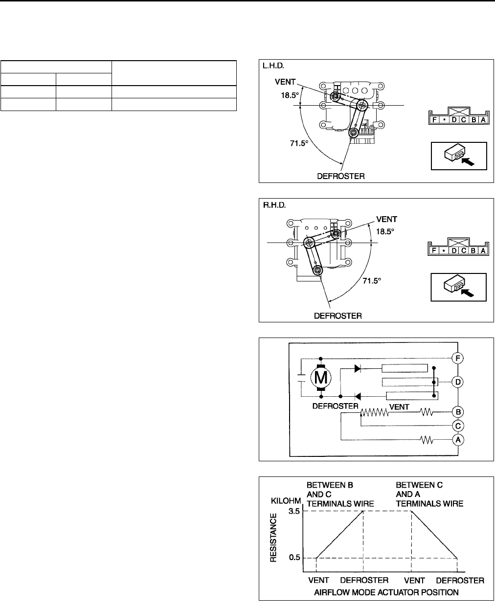
U34
CONTROL SYSTEM
AIRFLOW MODE ACTUATOR INSPECTION A6E854061070W02
1. Connect battery positive voltage to terminal D or F and ground to terminal F or D of the airflow mode actuator.
2. Verify that the airflow mode actuator operates as shown below.
•If not as specified, replace the airflow mode actuator.
3. Verify that the resistance between the terminals
of the airflow mode actuator is as shown in the
graph.
•If not as specified, replace the airflow mode
actuator.
End Of Sie
Connection Movement
B+ GND
D F DEFROSTER → VENT
F D VENT → DEFROSTER
A6E8540W008
A6E8540W009
A6E8540W046
A6E8540W047
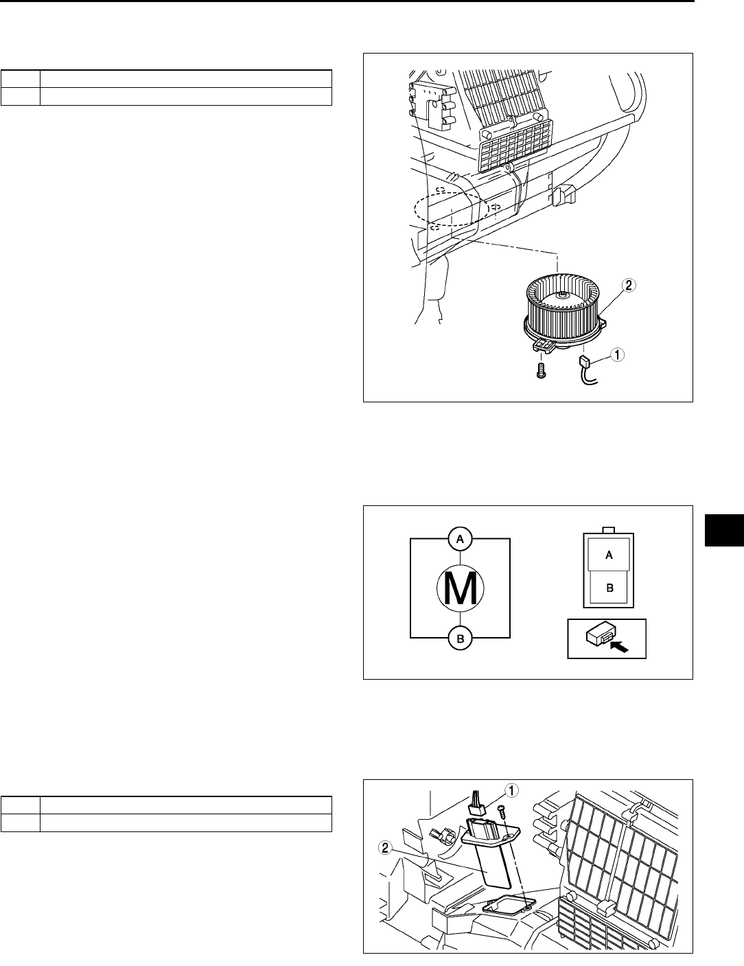
CONTROL SYSTEM
U35
U
BLOWER MOTOR REMOVAL/INSTALLATION A6E854061140W01
1. Disconnect the negative battery cable.
2. Remove in the order indicated in the table.
3. Install in the reverse order of removal.
End Of Sie
BLOWER MOTOR INSPECTION A6E854061140W02
1. Connect battery positive voltage to terminal A and ground to terminal B of the blower motor and verify its
operation.
•If not as specified, replace the blower motor.
End Of Sie
RESISTOR REMOVAL/INSTALLATION A6E854061215W01
1. Disconnect the negative battery cable.
2. Remove the glove compartment.
3. Remove the car navigation unit. (See T98 CAR-NAVIGATION UNIT REMOVAL/INSTALLATION.)
4. Remove in the order indicated in the table.
5. Install in the reverse order of removal.
End Of Sie
1 Blower motor connector
2Blower motor
A6E8540W060
A6E8540W010
1 Resistor connector
2Resistor
A6E8540W011
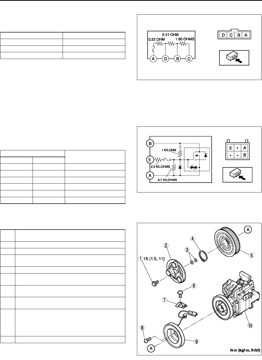
U36
CONTROL SYSTEM
RESISTOR INSPECTION A6E854061215W02
1. Verify that the resistance between the terminals
of the resistor is as shown in the table.
•If not as specified, replace the resistor.
End Of Sie
POWER MOS FET REMOVAL/INSTALLATION A6E854061B15W01
(See U35 RESISTOR REMOVAL/INSTALLATION.)
End Of Sie
POWER MOS FET INSPECTION A6E854061B15W02
1. Verify that the resistance between the terminals
of the power MOS FET is as shown in the table.
•If not as specified, replace the power MOS
FET.
End Of Sie
MAGNETIC CLUTCH DISASSEMBLY/ASSEMBLY A6E854061010W01
1. Disassemble in the order indicated in the table.
2. Assemble in the reverse order of disassembly.
3. Adjust the magnetic clutch clearance. (See U38
MAGNETIC CLUTCH ADJUSTMENT.)
Terminal Resistance (ohm)
AD 0.210.23
AB 0.600.68
AC 2.292.62
A6E8540W012
Ohmmeter lead Resistance (kilohm)
+−
−−
−
AB ∞
AE 6.9
BA Continuity
BE Continuity
EA 6.9
EB ∞
A6E8540W013
1Bolt
(See U37 Bolt Removal/Installation Note)
2 Pressure plate
3Shim
4 Snap ring
(See U37 Snap Ring Installation Note)
5 A/C compressor pulley
6Screw
(See U37 Screw Installation Note)
7Clamp
(See U37 Clamp Installation Note)
8Screw
(See U37 Screw Installation Note)
9 Stator and thermal protector
(See U37 Stator and Thermal Protector Removal
Note)
(See U37 Stator and Thermal Protector Installation
Note)
10 A/C compressor body
A6E8540W014
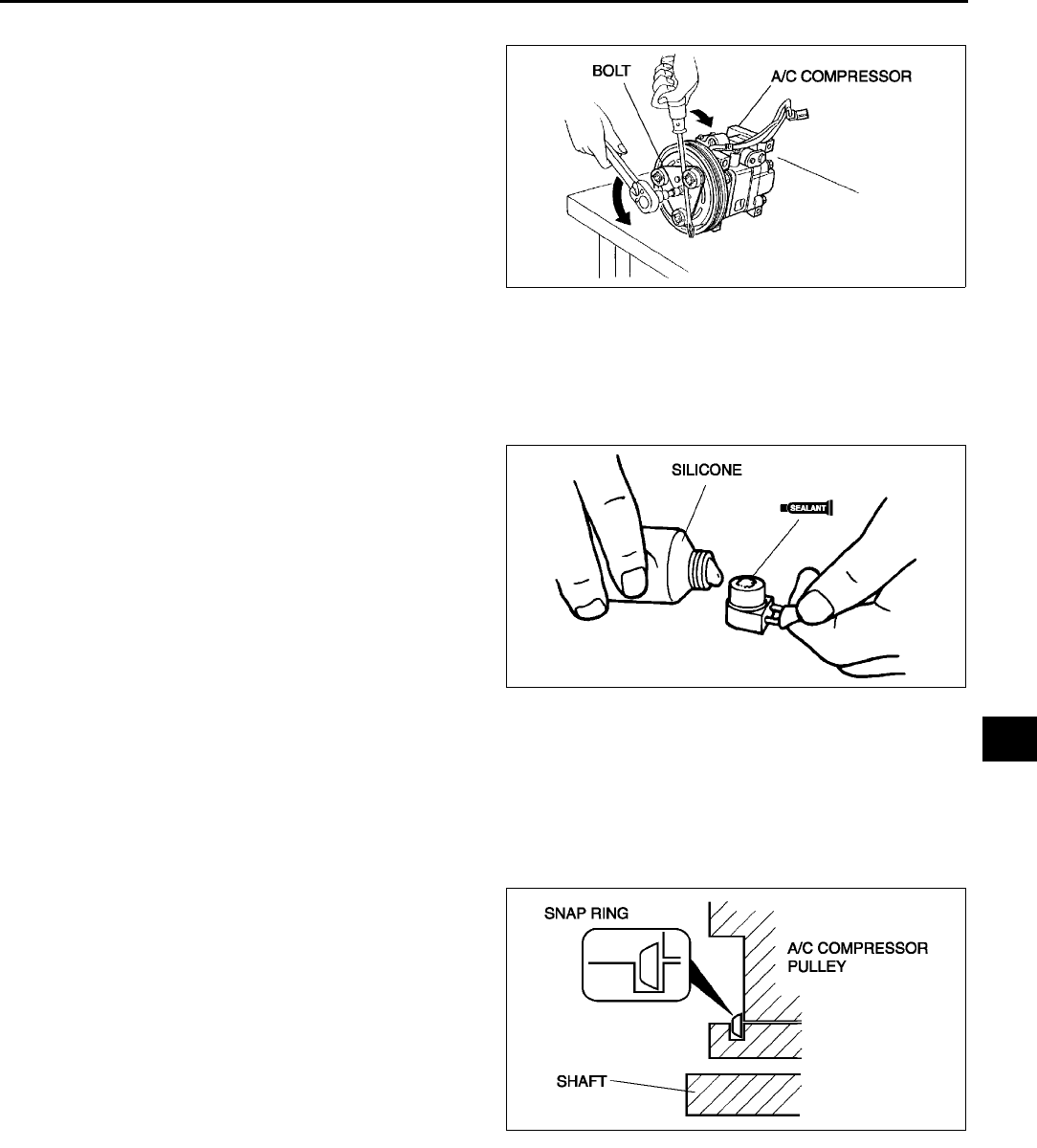
CONTROL SYSTEM
U37
U
Bolt Removal/Installation Note
1. When removing or installing the bolt, hold the
pressure plate in place as shown in the figure.
2. When installing a new A/C compressor body,
replace the bolt.
Stator and Thermal Protector Removal Note
1. After removing the stator and thermal protector, completely remove the silicone adhering to the A/C
compressor side.
Stator and Thermal Protector Installation Note
1. Apply approximately 1 g {0.04 oz} of silicone
(Shin-Etsu Silicone KE-347W or similar) to the
contact surface of the thermal protector, then
thoroughly install it onto the A/C compressor,
leaving no gaps.
Screw Installation Note
1. When installing a new stator and thermal protector, replace the screw.
Clamp Installation Note
1. When installing a new stator and thermal protector, replace the clamp.
Snap Ring Installation Note
1. When installing a new pressure plate, A/C
compressor pulley, stator, or A/C compressor
body, replace the snap ring.
End Of Sie
A6E8540W048
A6E8540W049
A6E8540W050
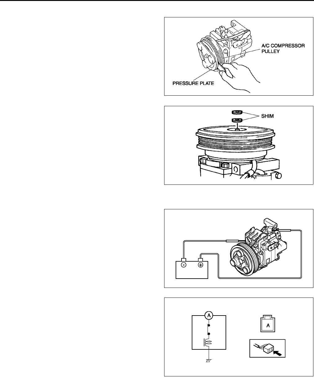
U38
CONTROL SYSTEM
MAGNETIC CLUTCH ADJUSTMENT A6E854061010W02
1. Measure the clearance around the entire
circumference between the pressure plate and A/
C compressor pulley using a thickness gauge.
2. Verify that the clearance is within the
specification.
•If not within the specification, remove the
pressure plate and adjust the clearance by
changing the shim (0.2 mm {0.008 in}, 0.5
mm {0.02 in}) or the number of shims.
Clearance
0.30.5 mm {0.0120.019 in}
End Of Sie
MAGNETIC CLUTCH INSPECTION A6E854061010W03
1. Connect battery positive voltage to terminal A of
magnetic clutch and ground to A/C compressor
body.
2. Verify that the magnetic clutch operates.
•If not as specified, replace the stator and
thermal protector.
End Of Sie
A6E8540W051
A6E8540W052
A6E8540W015
A6E8540W016
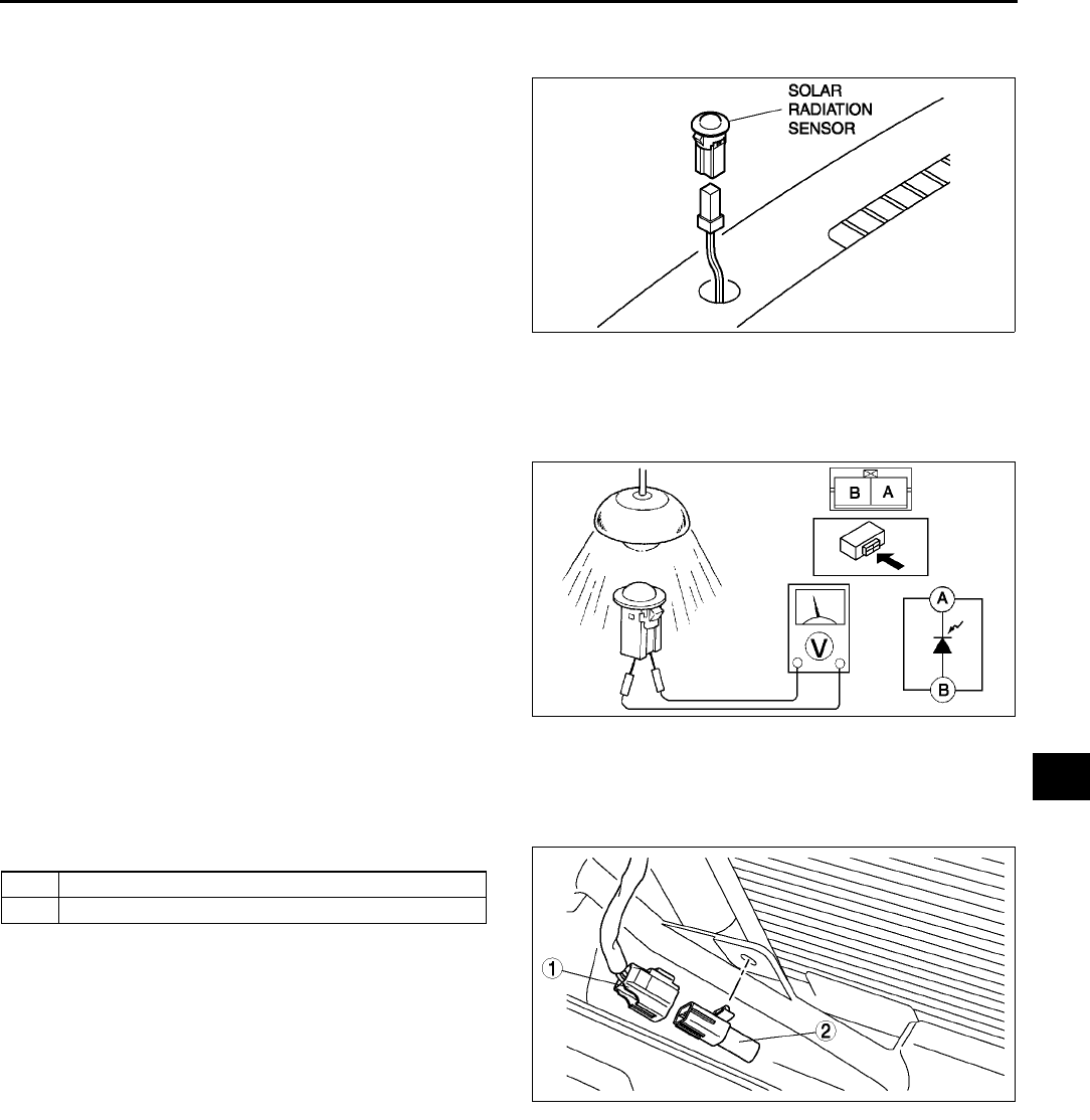
CONTROL SYSTEM
U39
U
SOLAR RADIATION SENSOR REMOVAL/INSTALLATION A6E854061751W01
1. Disconnect the negative battery cable.
2. Remove the solar radiation sensor from the
dashboard using a tape-wrapped flathead
screwdriver.
3. Install in the reverse order of removal.
End Of Sie
SOLAR RADIATION SENSOR INSPECTION A6E854061751W02
1. Shine an incandescent light (60 W) on the solar radiation sensor from a distance of approximately 100 mm
{3.94 in}.
2. Connect positive (+) lead to terminal A and
negative (−) lead to terminal B of the solar
radiation sensor.
•If the output voltage is not above 0.45 V,
replace the solar radiation sensor.
End Of Sie
AMBIENT TEMPERATURE SENSOR REMOVAL/INSTALLATION A6E854061764W01
1. Disconnect the negative battery cable.
2. Remove the radiator grille. (See S50 RADIATOR GRILLE REMOVAL/INSTALLATION.)
3. Remove in the order indicated in the table.
4. Install in the reverse order of removal.
A6E8540W017
A6E8540W058
1 Ambient tenperature sensor connector
2 Ambient temperature sensor
A6E8540W018
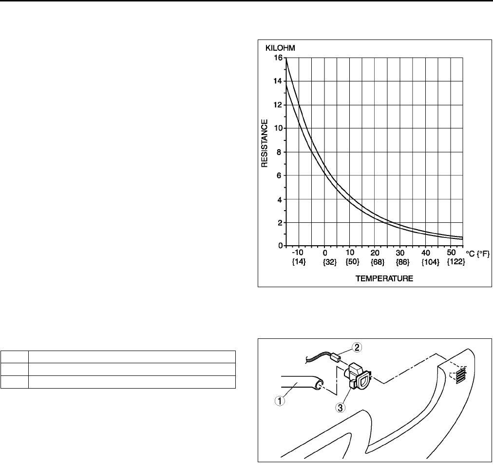
U40
CONTROL SYSTEM
End Of Si e
AMBIENT TEMPERATURE SENSOR INSPECTION A6E854061764W02
1. Measure the temperature around the ambient temperature sensor.
2. Measure the resistance between terminals of the
ambient temperature sensor.
•If the resistance is not as shown in the graph,
replace the ambient temperature sensor.
End Of Sie
CABIN TEMPERATURE SENSOR REMOVAL/INSTALLATION A6E854061757W01
1. Disconnect the negative battery cable.
2. Remove the lower panel. (See S84 LOWER PANEL REMOVAL/INSTALLATION.)
3. Remove in the order indicated in the table.
4. Install in the reverse order of removal.
End Of Sie
A6E8540W019
1Air hose
2 Cabin temperature sensor connector
3 Cabin temperature sensor
A6E8540W020
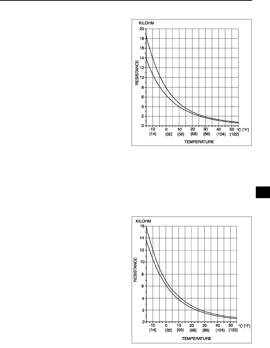
CONTROL SYSTEM
U41
U
CABIN TEMPERATURE SENSOR INSPECTION A6E854061757W02
1. Measure the temperature around the cabin temperature sensor.
2. Measure the resistance between terminals of the
cabin temperature sensor.
•If the resistance is not as shown in the graph,
replace the cabin temperature sensor.
End Of Sie
EVAPORATOR TEMPERATURE SENSOR REMOVAL/INSTALLATION A6E854061022W01
1. Remove the evaporator temperature sensor from the A/C unit. (See U18 A/C UNIT DISASSEMBLY/
ASSEMBLY.)
End Of Sie
EVAPORATOR TEMPERATURE SENSOR INSPECTION A6E854061022W02
1. Turn the AUTO switch on.
2. Set the temperature control at MAX COLD (Turn the left).
3. Turn the A/C switch.
4. Set the RECIRCULATE mode.
5. Close all doors and windows.
6. Wait for 5 minutes.
7. Remove the glove compartment.
8. Disconnect the evaporator temperature sensor.
9. Measure the temperature at the blower inlet.
10. Measure the resistance between terminals of the
evaporator temperature sensor.
•If the resistance is not as shown in the graph,
replace the evaporator temperature sensor.
End Of Si e
A6E8540W021
A6E8540W019
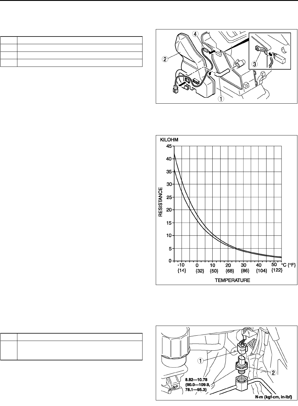
U42
CONTROL SYSTEM
WATER TEMPERATURE SENSOR REMOVAL/INSTALLATION A6E854061752W01
1. Disconnect the negative battery cable.
2. Remove the dashboard. (See S82 DASHBOARD REMOVAL/INSTALLATION.)
3. Remove in the order indicated in the table.
4. Install in the reverse order of removal.
End Of Sie
WATER TEMPERATURE SENSOR INSPECTION A6E854061752W02
1. Measure the temperature around the water temperature sensor.
2. Measure the resistance between terminals of the
water temperature sensor.
•If the resistance is not as shown in the graph,
replace the water temperature sensor.
End Of Sie
REFRIGERANT PRESSURE SWITCH REMOVAL/INSTALLATION A6E854061503W01
1. Remove the battery.
2. Discharge the refrigerant from the system. (See U9 RECOVERY.) (See U9 CHARGING.)
3. Loosen the refrigerant pressure switch using two spanners.
4. Remove in the order indicated in the table.
5. Install in the reverse order of removal.
Refrigerant Pressure Switch Installation Note
1. Apply compressor oil to O-ring and connect the joint.
End Of Si e
1Air hose
2Duct (3)
3 Plate spring
4 Water temperature sensor
A6E8540W023
A6E8540W024
1 Refrigerant pressure switch connector
2 Refrigerant pressure switch
(See U42 Refrigerant Pressure Switch Installation
Note)
A6E8540W025
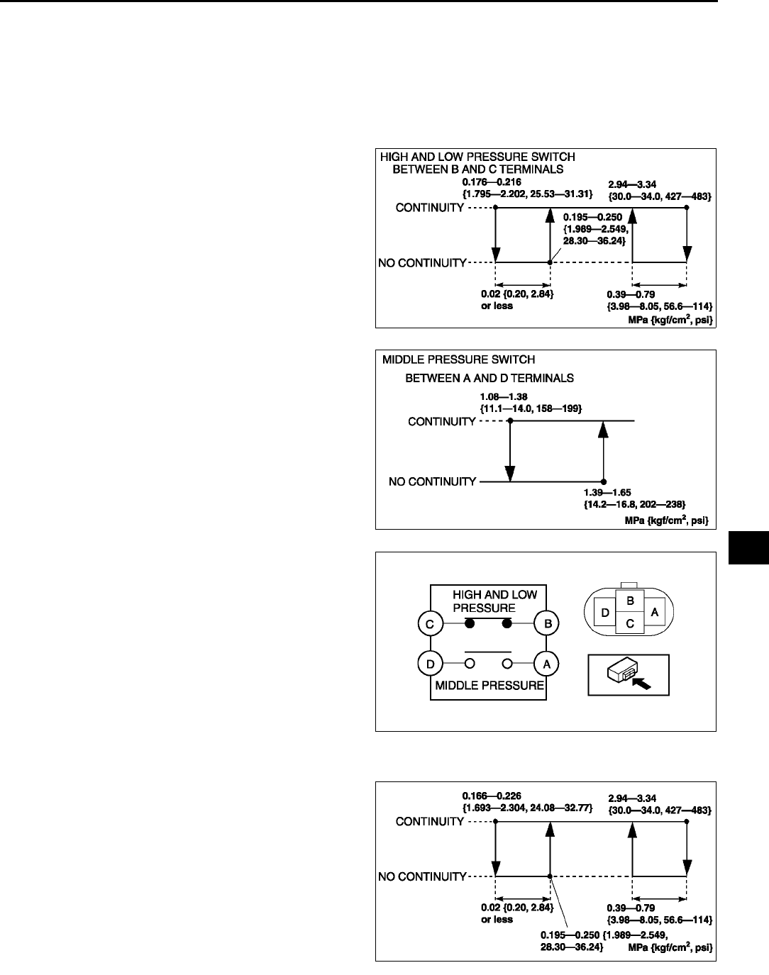
CONTROL SYSTEM
U43
U
REFRIGERANT PRESSURE SWITCH INSPECTION A6E854061503W02
1. Install the SST (gas charging set).
2. Disconnect the refrigerant pressure switch connector.
3. Verify the high-pressure side reading of the SST (manifold gauge) and continuity between the terminals of the
refrigerant pressure switch.
•If not as specified, replace the refrigerant pressure switch.
Triple-pressure Type
Dual-pressure Type
A6E8540W053
A6E8540W054
A6E8540W026
A6E8540W055
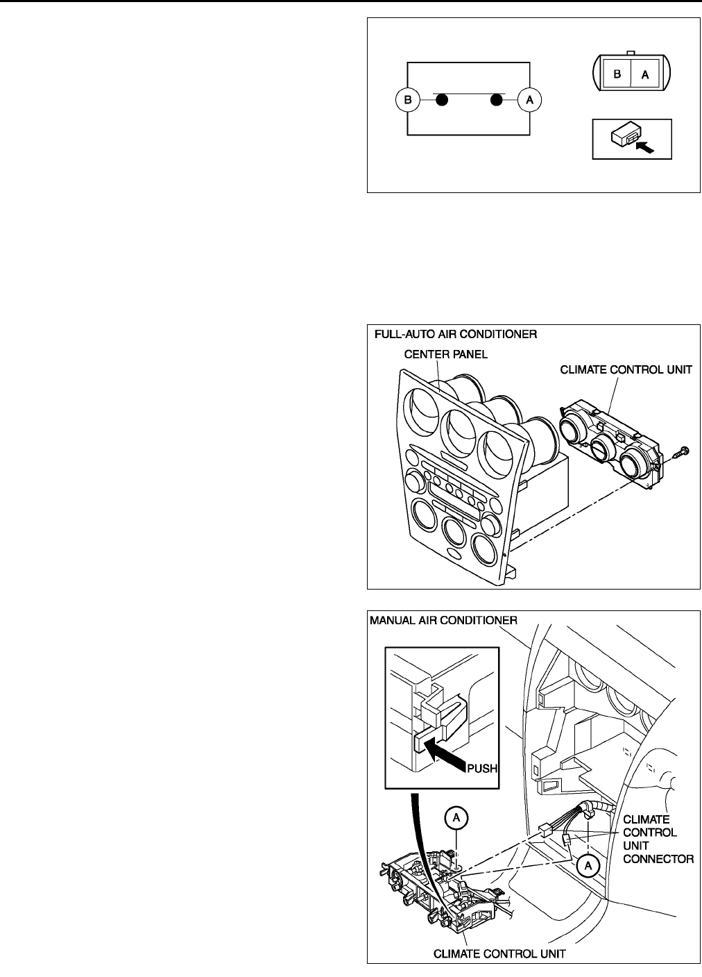
U44
CONTROL SYSTEM
End Of Sie
CLIMATE CONTROL UNIT REMOVAL A6E854061190W03
1. Disconnect the negative battery cable.
2. Disconnect the air mix and airflow mode wires from each wire clamp and link. (Manual air conditioner)
3. Remove the center panel. (See T96 CENTER PANEL MODULE REMOVAL/INSTALLATION.)
4. Remove the screws and climate control unit. (Full-auto air conditioner)
5. Release the hook and pull the climate control unit toward you. (Manual air conditioner)
6. Disconnect the climate control unit connectors
and remove the climate control unit. (Manual air
conditioner)
End Of Sie
A6E8540W027
A6E8540W028
A6E8540W059
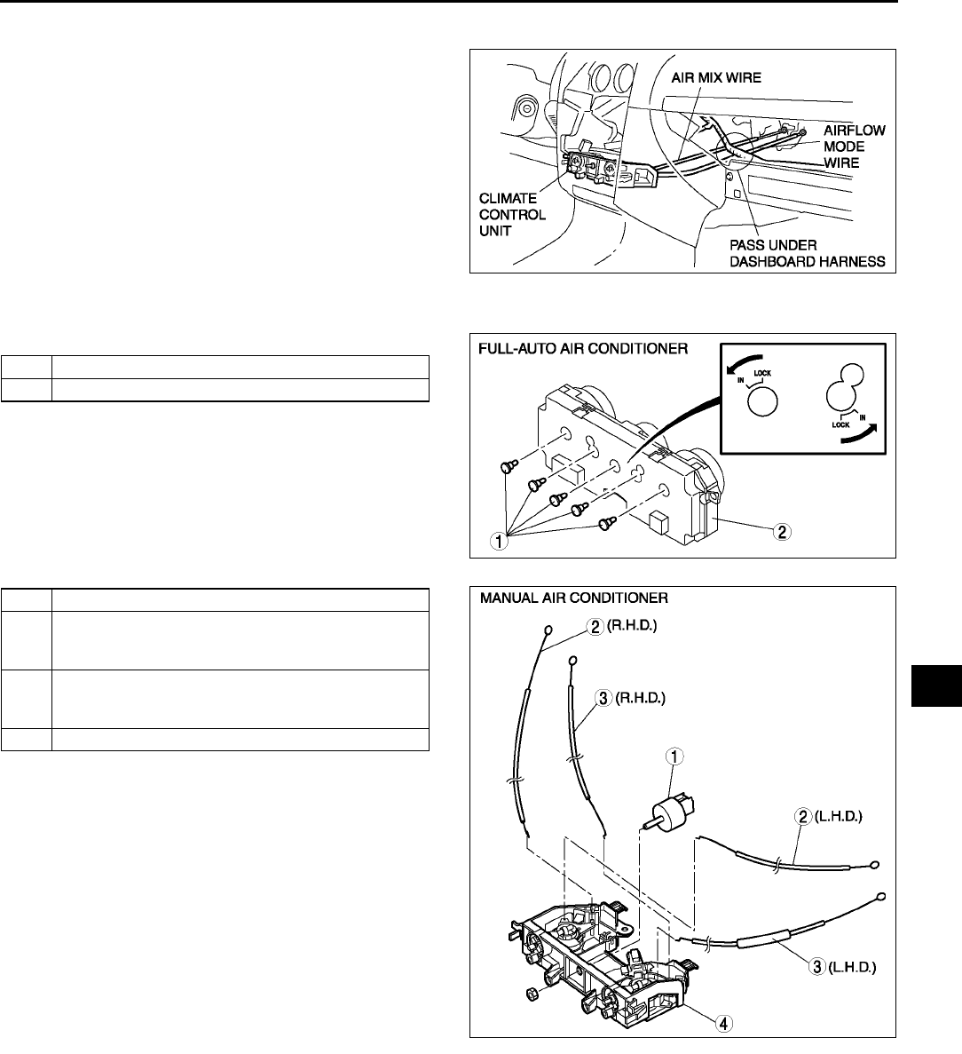
CONTROL SYSTEM
U45
U
CLIMATE CONTROL UNIT INSTALLATION A6E854061190W04
1. Pass each wire through the following routes then
connect to A/C unit. (Manual air conditioner)
2. Connect the climate control unit connectors.
(Manual air conditioner)
3. Install the climate control unit to the center panel.
(Full-auto air conditioner)
4. Install the center panel.
5. Adjust the climate control unit wires. (Manual air
conditioner) (See U46 CLIMATE CONTROL
UNIT WIRE ADJUSTMENT.)
6. Connect the negative battery cable.
End Of Si e
CLIMATE CONTROL UNIT DISASSEMBLY/ASSEMBLY A6E854061190W01
1. Disassemble in the order indicated in the table.
2. Assemble in the reverse order of disassembly.
A6E8540W029
1 Illumination bulb
2Body
1 Fan switch
2 Air mix wire
(See U46 Wire Disassembly Note)
(See U46 Wire Assembly Note)
3 Airflow mode wire
(See U46 Wire Disassembly Note)
(See U46 Wire Assembly Note)
4Body
A6E8540W061
A6E8540W030
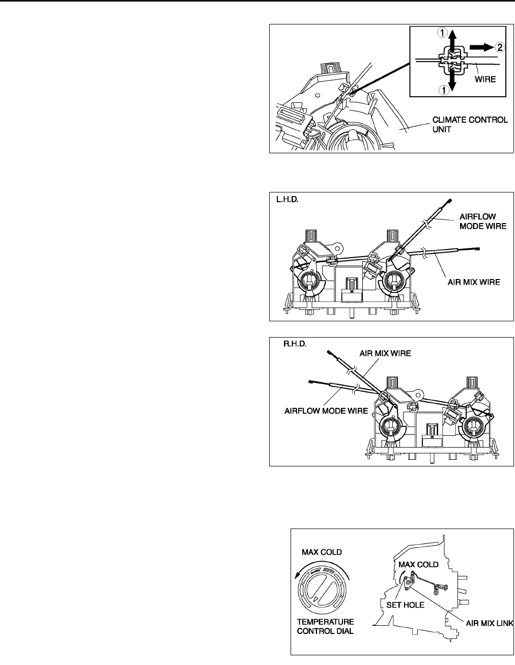
U46
CONTROL SYSTEM
Wire Disassembly Note
1. Disassemble the wires in the shown in the figure.
Wire Assembly Note
1. Assemble the wires to the position as shown in
the figure.
End Of Sie
CLIMATE CONTROL UNIT WIRE ADJUSTMENT A6E854061190W05
Air Mix Wire
1. Set the temperature control dial at max cold.
2. Set the air mix link to max cold in the direction shown
by the arrow and insert a screwdriver at the set hole.
3. Connect the air mix wire to air mix link.
4. Clamp the air mix wire to wire clamp.
5. Verify that the temperature control dial moves its full
stroke.
Airflow Mode Wire
1. Set the airflow mode control dial at defroster.
A6E8540W031
A6E8540W032
A6E8540W033
A6E8540W034
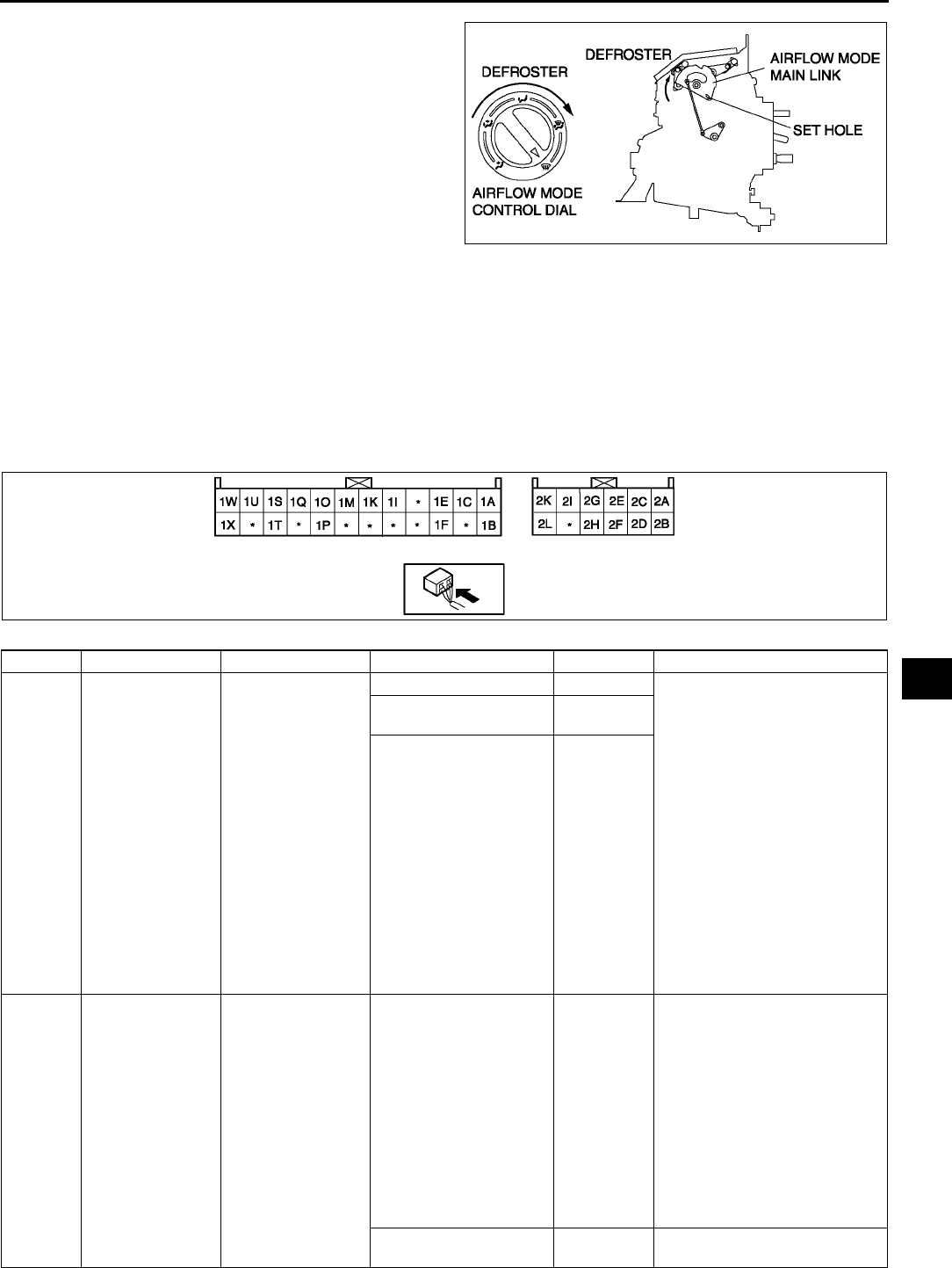
CONTROL SYSTEM
U47
U
2. Set the airflow mode main link to defroster in the
direction shown by the arrow and insert a
screwdriver at the set hole.
3. Connect the airflow mode wire to airflow mode
main link.
4. Clamp the airflow mode wire to wire clamp.
5. Verify that the airflow mode control dial moves its
full stroke.
End Of Sie
CLIMATE CONTROL UNIT INSPECTION A6E854061190W02
Full-auto Air Conditioner
1. Connect the all center panel connectors.
2. Turn the ignition switch to ON position.
3. Measure the voltage at each climate control unit terminal and refer to the terminal voltage list.
•If not as specified, inspect the parts listed under Action and the related wiring harness.
If there is any malfunction, replace the climate control unit.
Terminal Voltage List (Reference)
A6E8540W035
Terminal Signal Connected to Test condition Voltage (V) Action
1A Blower motor
feedback signal
•Blower motor
•Power MOS
FET
Fan switch is OFF 12 1. Inspect for continuity or
short circuit (Climate control
unitblower motor: 1AB)
(Climate control unitpower
MOS FET: 1AB, 1CE)
(Blower motorblower
relay: AC) (Blower relay
fuse: DBLOWER 40 A
fuse)
2. Inspect for continuity (Power
MOS FETground: A
GND) (Blower relay
ground: AGND)
3. Inspect power MOS FET
4. Inspect blower motor
5. Inspect blower relay
6. Inspect BLOWER 40 A fuse
7. Replace power MOS FET
Fan switch is at manual
LO 7.8
Fan switch is at manual
HI
0.2
1B +5 V •Air mix actuator
•Airflow mode
actuator
•Solar radiation
sensor
Ignition switch at ON
position
5.0
•Inspect for short circuit
(Climate control unit air
mix actuator, airflow mode
actuator, solar radiation
sensor: 1BB, B, A)
•Inspect air mix actuator
•Inspect airflow mode
actuator
•Inspect solar radiation
sensor
•Inspect terminal voltage of
climate control unit
connector (2H, 2L)
Ignition switch at LOCK
position Below 1.0 •Replace climate control unit
A6E8540W038

U48
CONTROL SYSTEM
1C Blower motor
control signal
Power MOS FET Fan switch is OFF Below 1.0 •Inspect terminal voltage of
climate control unit (1A)
Fan switch is at manual
LO 4.1
Fan switch is at manual
HI 7.9
1D
1E Rear window
defroster SW
signal
Rear window
defroster relay
Rear window defroster
switch is off
12
•Inspect for continuity or
short circuit (Climate control
unitrear window defroster
relay: 1EE)
•Inspect rear window
defroster relay
Rear window defroster
switch is on Below 1.0
•Inspect terminal voltage of
climate control unit (1H, 1L)
•Inspect audio switch panel
1F On-board
diagnostic signal
A/C check
connector
Terminal A of A/C check
connector is shorted. Below 1.0
•Inspect for continuity
(Climate control unitA/C
check connector: 1FA)
Other
5.4
•Inspect short circuit (Climate
control unitA/C check
connector: 1FA)
•Inspect terminal voltage of
climate control unit (2H, 2L)
1G
1H
1I GND •Cabin
temperature
sensor
•Evaporator
temperature
sensor
•Ambient
temperature
sensor
•Water
temperature
sensor
•Air mix actuator
•Airflow mode
actuator
Under any condition
Below 1.0
•Inspect terminal voltage of
climate control unit (2L)
1J
1K Ambient
temperature
sensor input
Ambient
temperature sensor
Depends on temperature
surrounding sensor
See Figure
2
•Inspect for continuity
(Climate control unit
ambient temperature
sensor: 1KB, 1IA)
•Inspect for short circuit
(Climate control unit
ambient temperature
sensor: 1KB)
•Inspect ambient
temperature sensor
•Inspect terminal voltage of
climate control unit (2H, 2L)
1L
1M Cabin
temperature
sensor input
Cabin temperature
sensor
Depends on temperature
surrounding sensor
See Figure
3
•Inspect for continuity
(Climate control unit cabin
temperature sensor: 1MB,
1IA)
•Inspect for short circuit
(Climate control unit cabin
temperature sensor: 1MB)
•Inspect cabin temperature
sensor
•Inspect terminal voltage of
climate control unit (2H, 2L)
1N
Terminal Signal Connected to Test condition Voltage (V) Action

CONTROL SYSTEM
U49
U
1O Water
temperature
sensor input
Water temperature
sensor
Depends on temperature
surrounding sensor
See Figure
4
•Inspect for continuity
(Climate control unitwater
temperature sensor: 1OA,
1IB)
•Inspect for short circuit
(Climate control unitwater
temperature sensor: 1OA)
•Inspect water temperature
sensor
•Inspect terminal voltage of
climate control unit (2H, 2L)
1P A/C Refrigerant
pressure switch
Fan switch at OFF
12
•Inspect for continuity or
short circuit (Climate control
unitrefrigerant pressure
switch: 1PA (Dual-
pressure type), 1PC
(Triple-pressure type))
(Refrigerant pressure
switchPCM: B1AC)
•Inspect refrigerant pressure
switch
•Inspect PCM terminal
voltage (1AC)
(See F45 PCM
INSPECTION )
Fan switch at 1st
position, A/C switch ON Below 1.0 •Inspect terminal voltage of
climate control unit (2H, 2L)
1Q Evaporator
temperature
sensor input
signal
Evaporator
temperature sensor
Depends on temperature
surrounding sensor
See Figure
1
•Inspect for continuity
(Climate control unit
evaporator temperature
sensor: 1QA, 1IB)
•Inspect for short circuit
(Climate control unit
evaporator temperature
sensor: 1QA)
•Inspect evaporator
temperature sensor
•Inspect terminal voltage of
climate control unit (2H, 2L)
1R
1S Solar radiation
sensor input
Solar radiation
sensor
Incandescent light (60W)
shining on solar
radiation sensor from
distance of approx.
100mm {3.9 in}
4.0
•Inspect for continuity or
short circuit (Climate control
unitsolar radiation sensor:
1SB, 1BA)
•Inspect terminal voltage of
climate control unit (1B)
•Inspect solar radiation
sensor
Light to solar radiation
sensor block Below 1.0
1T GND Ground Under any condition
Below 1.0
•Inspect for continuity
(Climate control unit
ground: 1TGND)
•Inspect center panel
1U Potentiometer
signal
Air mix actuator Set temperature at MAX
COLD 0.6 •Inspect for continuity or
short circuit (Climate control
unitair mix actuator: 1U
C)
•Inspect air mix actuator
•Inspect terminal voltage of
climate control unit (1B)
Set temperature at MAX
HOT 4.3
1V
Terminal Signal Connected to Test condition Voltage (V) Action

U50
CONTROL SYSTEM
1W Potentiometer
signal
Airflow mode
actuator
VENT mode 4.3 •Inspect for continuity or
short circuit (Climate control
unitairflow mode actuator:
1WC)
•Inspect airflow mode
actuator
•Inspect terminal voltage of
climate control unit (1B)
BI-LEVEL mode 3.3
HEAT mode 2.3
HEAT/DEF mode 1.5
DEFROSTER mode
0.6
1X Hazard warning
SW signal
Hazard warning
switch
Hazard warning switch is
off 12
•Inspect for continuity or
short circuit (Climate control
unitflasher unit: 1XH)
•Inspect flasher unit
Hazard warning switch is
on Below 1.0
•Inspect terminal voltage of
climate control unit (1T)
•Inspect center panel
2A Panel light control
signal
Panel light control
switch
Headlight switch ON and
panel light control switch
at max. illumination
0.2
•Inspect for continuity
(Climate control unit panel
light control switch: 2AC)
(Panel light control switch
ground: CGND)
•Inspect panel light control
switch
Headlight switch ON and
panel light control switch
at min. illumination
10.2
•Inspect for short circuit
(Climate control unit panel
light control switch: 2AC)
2B TNS signal TNS relay Headlight switch OFF
Below 1.0
•Inspect for short circuit
(Climate control unitTNS
relay: 2BD)
•Inspect TNS relay
•Inspect headlight switch
Headlight switch ON
12
•Inspect for continuity or
short circuit (Climate control
unitTNS relay: 2BD)
•Inspect TNS relay
•Inspect headlight switch
2C Motor drive signal Air mix actuator Moving to COLD 12 •Inspect for continuity or
short circuit (Climate control
unitair mix actuator: 2D
D, 2CF)
•Inspect air mix actuator
Moving to HOT
Below 1.0
2D Motor drive signal Air mix actuator Moving to HOT 12 •Inspect for continuity or
short circuit (Climate control
unitair mix actuator: 2C
F, 2DD)
•Inspect air mix actuator
Moving to COLD
Below 1.0
2E Motor drive signal Airflow mode
actuator
Moving to DEFROSTER 12 •Inspect for continuity or
short circuit (Climate control
unitairflow mode actuator:
2EF, 2GD)
•Inspect airflow mode
actuator
Moving to VENT
Below 1.0
2F Backup power
supply
ROOM 15 A fuse Under any condition
B+
•Inspect for continuity or
short circuit (Climate control
unitfuse: 2F ROOM 15
A fuse)
•Inspect ROOM 15 A fuse
2G Motor drive signal Airflow mode
actuator
Moving to VENT 12 •Inspect for continuity or
short circuit (Climate control
unitairflow mode actuator:
2GD, 2EF)
•Inspect airflow mode
actuator
Moving to DEFROSTER
Below 1.0
Terminal Signal Connected to Test condition Voltage (V) Action
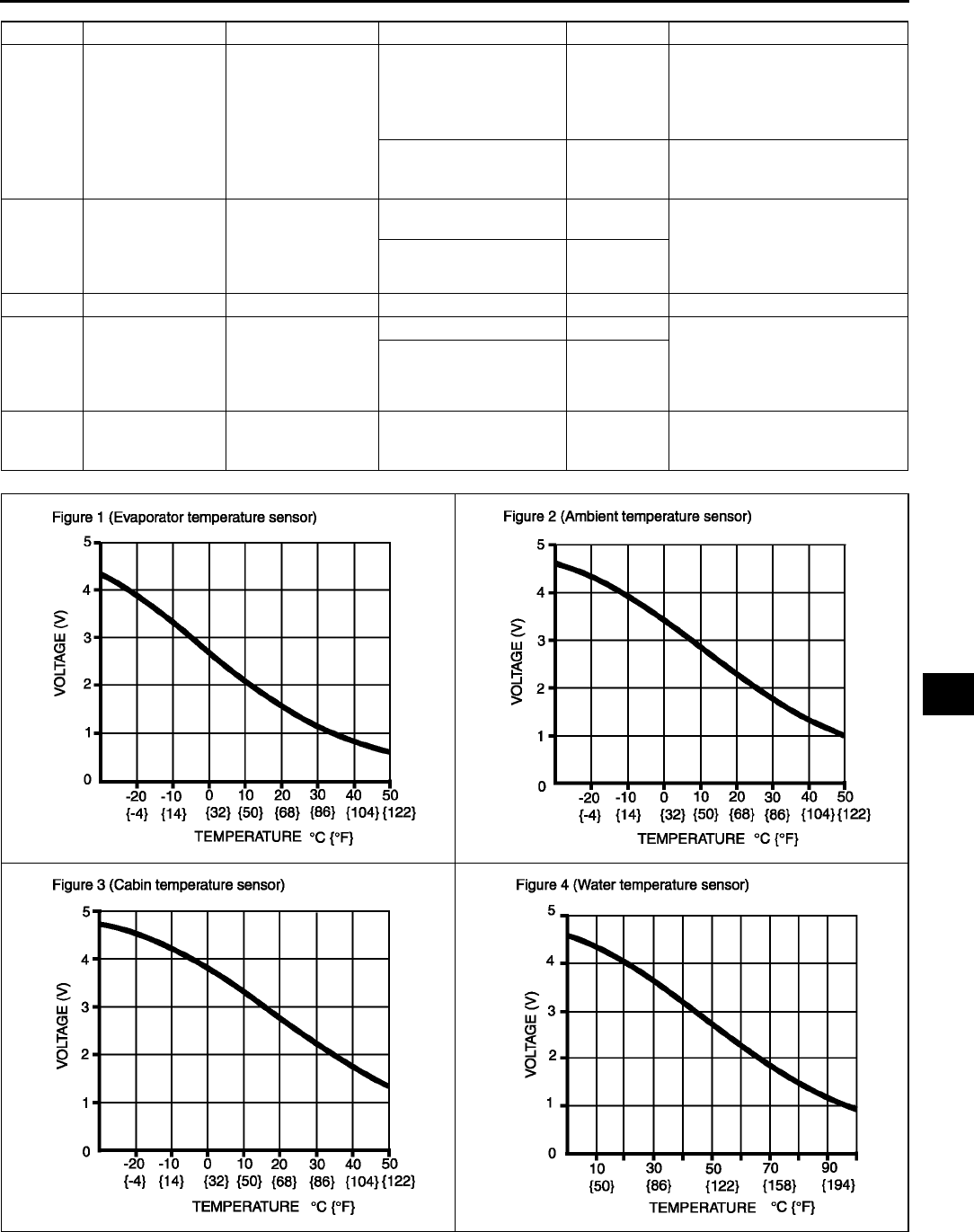
CONTROL SYSTEM
U51
U
End Of Sie
2H IG2 A/C 15 A fuse Ignition switch at ON
position
B+
•Inspect for continuity or
short circuit (Climate control
unitfuse: 2HA/C 15 A
fuse)
•Inspect A/C 15 A fuse
Ignition switch at LOCK
position Below 1.0
•Inspect for short circuit
(Climate control unitfuse:
2HA/C 15 A fuse)
2I Motor drive signal Air intake actuator Moving to
RECIRCULATE 12 •Inspect for continuity or
short circuit (Climate control
unitair intake actuator:
2IF, 2KD)
•Inspect air intake actuator
Moving to FRESH Below 1.0
2J
2K Motor drive signal Air intake actuator Moving to FRESH 12 •Inspect for continuity or
short circuit (Climate control
unitair intake actuator:
2KD, 2IF)
•Inspect air intake actuator
Moving to
RECIRCULATE Below 1.0
2L GND Ground Under any condition
Below 1.0
•Inspect for continuity
(Climate control unit
ground: 2LGND)
Terminal Signal Connected to Test condition Voltage (V) Action
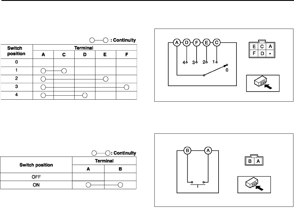
U52
CONTROL SYSTEM
FAN SWITCH INSPECTION A6E854061050W01
1. Remove the climate control unit.
2. Inspect for continuity between the fan switch terminals using an ohmmeter.
•If not as specified, replace the fan switch.
End Of Sie
DEFROSTER SWITCH INSPECTION A6E854061050W02
1. Remove the climate control unit.
2. Inspect for continuity between the defroster switch terminals using an ohmmeter.
•If not as specified, replace the climate control
unit.
End Of Si e
A6E8540W036
A6E8540W056
A6E8540W037
A6E8540W057
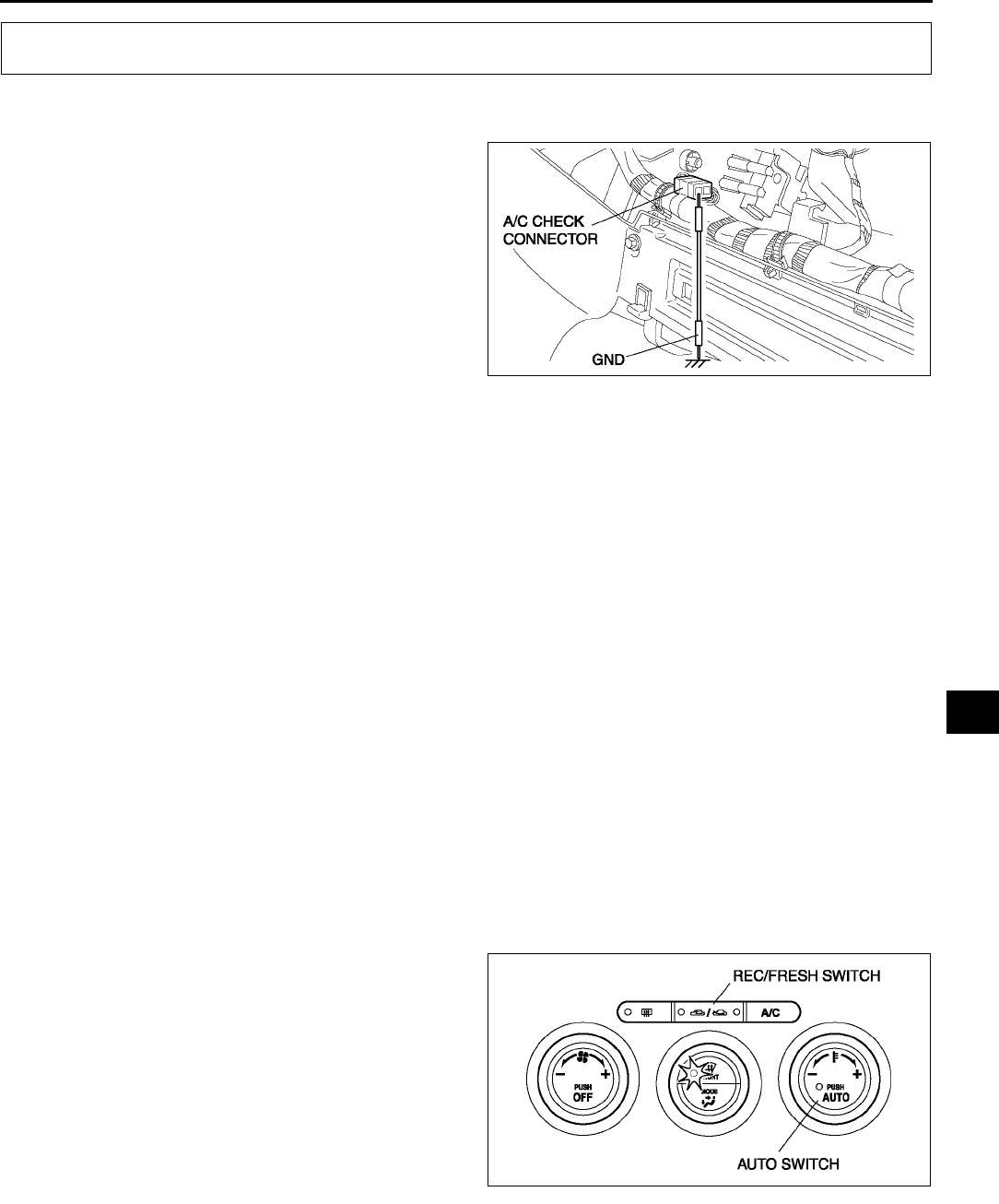
ON-BOARD DIAGNOSTIC
U53
U
DIAGNOSTIC TROUBLE CODE NUMBER INSPECTION A6E857001038W01
1. Remove the glove compartment.
2. Short the A/C check connector to the GND
terminal using a jumper wire.
3. Shine a 60 W incandescent light from a height of
approximately 100 mm {3.9 in} onto the solar
radiation sensor.
Note
•When incandescent light does not shine on
the solar radiation sensor, the climate
control unit determines a malfunction and
indicates a diagnostic trouble code 02.
4. Turn the ignition switch to ON position.
5. Read DTCs from the flashing of the rear defroster
indicator light on the climate control unit. Carry out DTC inspection. (present and past failure indication modes)
•When the system is normal, the rear defroster indicator light does not flash.
•If any of the diagnostic trouble codes are indicated, carry out troubleshooting according to the code.
6. After completion of repairs, erase all diagnostic trouble code(s) from memory. (See U53 Erasing Past Failure
Memory.)
7. Remove the jumper wire.
Present Failure Indication Mode
•The on-board diagnostic function display the present failure indication mode directly after start up. In present
failure indication mode, present failures in the control system circuits (open, short circuits) are detected, and
the flashing of the rear defroster indicator light on the climate control unit indicates the DTCs.
If a diagnostic trouble code is indicated, refer to the following diagnostic trouble code table and inspect the
appropriate system.
Past Failure Indication Mode
•While in present failure indication mode, press the A/C switch to change to the past failure indication mode. In
past failure indication mode, past failures (intermittent problems) in the input sensor circuits (open, short
circuits) are shorted, and the flashing of the rear defroster indicator light on the climate control unit indicates the
DTCs.
If a diagnostic trouble code is indicated, refer to the following diagnostic trouble code table and inspect the
appropriate system. (Disconnections and short circuits are memorized in the same system even if either
occurs only once.)
If the A/C switch is pressed again while in past failure indication mode, the on-board diagnostic function will
return to present failure indication mode.
Erasing Past Failure Memory
•When DTCs are displayed in the past failure
indication mode, they remain in the memory after
the failed systems are corrected. Consequently,
the next time the past failure indication mode is
used, the same past failure DTCs will be
indicated by the flashing of the rear defroster
indicator light on the climate control unit.
Therefore, erase the past failure memory after
correcting all failed systems. To erase the past
failure memory, press the AUTO switch and REC/
FRESH switch on the climate control unit at the
same time while in past failure indication mode. If
erased, the rear defroster indicator light flashes
once.
ON-BOARD DIAGNOSTIC
A6E8570W004
A6E8570W001
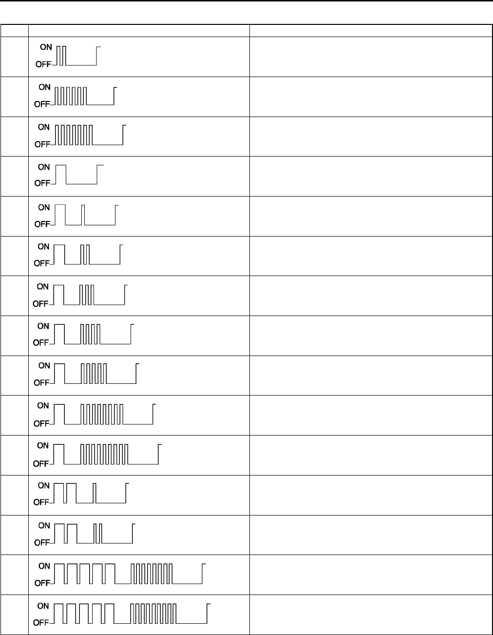
U54
ON-BOARD DIAGNOSTIC
DTC Table
No. Indicator pattern Diagnosed circuit
02 Solar radiation sensor (present)
06 Cabin temperature sensor (present)
07 Cabin temperature sensor (past)
10 Evaporator temperature sensor (present)
11 Evaporator temperature sensor (past)
12 Ambient temperature sensor (present)
13 Ambient temperature sensor (past)
14 Water temperature sensor (present)
15 Water temperature sensor (past)
18 Air mix actuator [potentiometer] (present)
19 Air mix actuator [potentiometer] (past)
21 Airflow mode actuator [potentiometer] (present)
22 Airflow mode actuator [potentiometer] (past)
58 Air mix actuator [motor lock] (past)
59 Airflow mode actuator [motor lock] (past)
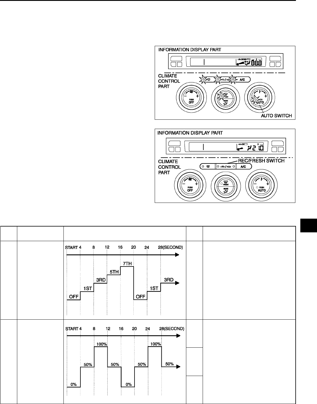
ON-BOARD DIAGNOSTIC
U55
U
Output Device Operation Check Mode
Inspection
1. Warm up the engine.
2. Turn the ignition switch to LOCK position.
3. Start up the on-board diagnostic function (present failure indication mode).
4. Press the AUTO switch.
5. Verify that all the indicator lights of the climate
control unit and center panel (climate control part)
illuminate for 4 seconds.
6. Verify the operation of the each output device
when changing steps by pressing the REC/
FRESH switch, and referring to the output device
operation check chart.
•If not as specified, inspect the malfunctioning
system.
Note
•If the AUTO switch is pressed again, the on-
board diagnostic function will return to
present failure indication mode.
7. Turn the ignition switch to LOCK position to end
the on-board diagnostic function.
Output device operation check table
A6E8570W002
A6E8570W003
Step Operating device Operating conditions Moni
tor*Other device conditions
1 Blower motor
speed
1
•Air mix actuator operation
50%
•Airflow mode actuator operation
VENT
•Air intake actuator operation
FRESH
•A/C compressor operation
ON
2 Air mix actuator
operation 21.0
•Blower motor speed
3rd
•Airflow mode actuator operation
VENT
•Air intake actuator operation
FRESH
•A/C compressor operation
ON
20.5
20.0
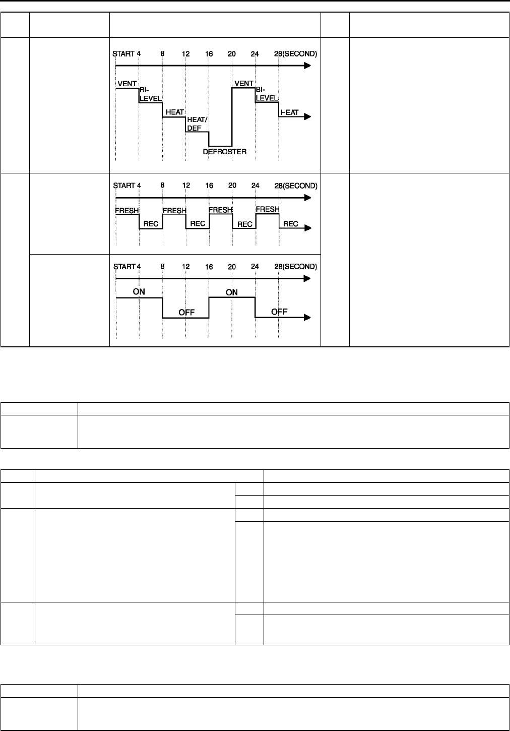
U56
ON-BOARD DIAGNOSTIC
*: Shown on the information display according to step.
End Of Sie
DTC 02 A6E857001038W02
Diagnostic Procedure
End Of Sie
DTC 06 A6E857001038W03
3 Airflow mode
actuator operation
3
•Blower motor speed
3rd
•Air mix actuator operation
50%
•Air intake actuator operation
FRESH
•A/C compressor operation
ON
4 Air intake actuator
operation
4
•Blower motor speed
3rd
•Air mix actuator operation
0%
•Airflow mode actuator operation
VENT
A/C compressor
operation
Step Operating device Operating conditions Moni
tor*Other device conditions
DTC 02 Solar radiation sensor system inspection
POSSIBLE
CAUSE
•Solar radiation sensor malfunction
•Climate control unit malfunction
•Open or short circuit between solar radiation sensor and climate control unit
STEP INSPECTION ACTION
1•Inspect solar radiation sensor.
•Is it okay?
Yes Go to next step.
No Replace solar radiation sensor.
2•Disconnect climate control unit connector
(24-pin) and solar radiation sensor
connector.
•Is there continuity between following
terminals of climate control unit connector
(24-pin) and terminal solar radiation sensor
connector?
1SB
1BA
Yes Go to next step.
No Repair wiring harness.
3•Is there short circuit to ground between
terminal 1S of climate control unit connector
(24-pin) and terminal B of solar radiation
sensor connector?
Yes Repair wiring harness.
No Replace climate control unit.
DTC 06 Cabin temperature sensor system inspection
POSSIBLE
CAUSE
•Cabin temperature sensor malfunction
•Climate control unit malfunction
•Open or short circuit between cabin temperature sensor and climate control unit
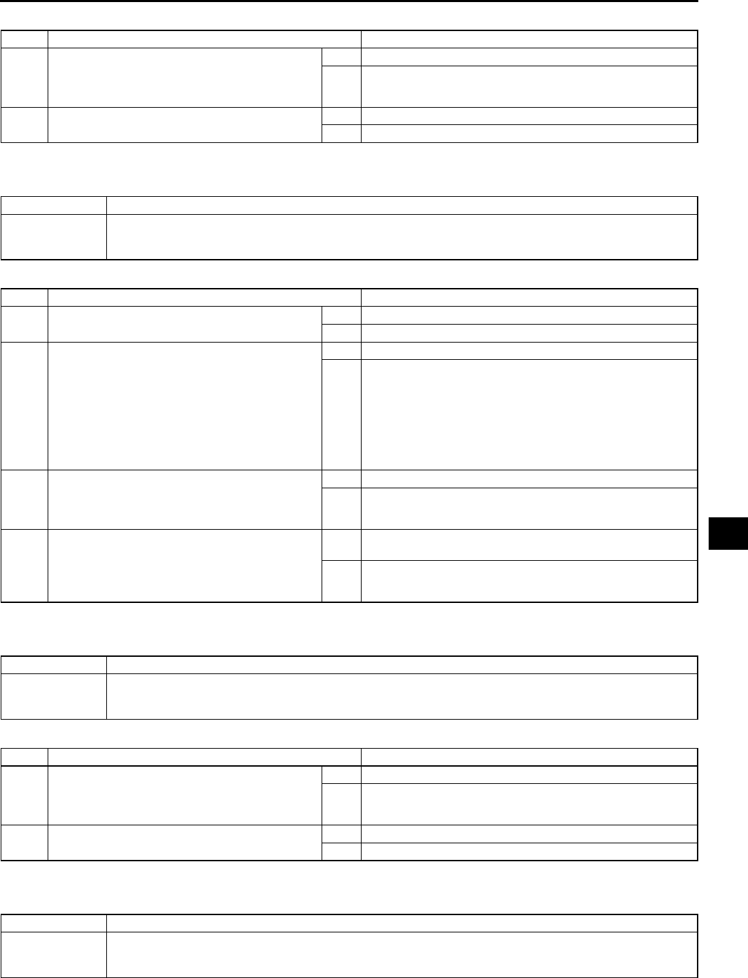
ON-BOARD DIAGNOSTIC
U57
U
Diagnostic Procedure
End Of Sie
DTC 07 A6E857001038W04
Diagnostic Procedure
End Of Sie
DTC 10 A6E857001038W05
Diagnostic Procedure
End Of Sie
DTC 11 A6E857001038W06
STEP INSPECTION ACTION
1•Is resistance between terminals 1I and 1M of
climate control unit connector (24-pin) as
indicated below?
137 ohms220 kilohms
Yes Replace climate control unit.
No Go to next step.
2•Inspect cabin temperature sensor.
•Is it okay?
Yes Repair wiring harness.
No Replace cabin temperature sensor.
DTC 07 Cabin temperature sensor system inspection
POSSIBLE
CAUSE
•Cabin temperature sensor malfunction
•Climate control unit malfunction
•Open or short circuit between cabin temperature sensor and climate control unit
STEP INSPECTION ACTION
1•Inspect cabin temperature sensor.
•Is it okay?
Yes Go to next step.
No Replace cabin temperature sensor.
2•Disconnect climate control unit connector
(24-pin) and cabin temperature sensor
connector.
•Is there open circuit between the following
terminals of climate control unit connector
(24-pin) and cabin temperature sensor
connector?
1IA
1MB
Yes Repair wiring harness.
No Go to next step.
3•Is there short circuit to ground between
terminal 1M of climate control unit connector
(24-pin) and B of cabin temperature sensor
connector?
Yes Repair wiring harness.
No Connect climate control unit connector, then go to next step.
4•Turn the ignition switch to ON position.
•Measure voltage at terminal the following
terminal 1M of climate control unit connector
(24-pin).
•Is voltage approximately 5V?
Yes This system is normal at present. (Erase the past failure
from memory.)
No Replace climate control unit.
DTC 10 Evaporator temperature sensor system inspection
POSSIBLE
CAUSE
•Evaporator temperature sensor malfunction
•Climate control unit malfunction
•Open or short circuit between evaporator temperature sensor and climate control unit
STEP INSPECTION ACTION
1•Is resistance between terminals 1I and 1Q of
climate control unit connector (24-pin) as
indicated below?
128 ohms179 kilohms
Yes Replace climate control unit.
No Go to next step.
2•Inspect evaporator temperature sensor.
•Is it okay?
Yes Repair wiring harness.
No Replace evaporator temperature sensor.
DTC 11 Evaporator temperature sensor system inspection
POSSIBLE
CAUSE
•Evaporator temperature sensor malfunction
•Climate control unit malfunction
•Open or short circuit between evaporator temperature sensor and climate control unit

U58
ON-BOARD DIAGNOSTIC
Diagnostic Procedure
End Of Sie
DTC 12 A6E857001038W07
Diagnostic Procedure
End Of Sie
DTC 13 A6E857001038W08
Diagnostic Procedure
STEP INSPECTION ACTION
1•Inspect evaporator temperature sensor.
•Is it okay?
Yes Go to next step.
No Replace evaporator temperature sensor.
2•Disconnect climate control unit connector
(24-pin) and evaporator temperature sensor
connector.
•Is there open circuit between following
terminals of climate control unit connector
(24-pin) and evaporator temperature sensor
connector?
1QB
1IA
Yes Repair wiring harness.
No Go to next step.
3•Is there short circuit to ground between
terminal 1Q of climate control unit connector
(24-pin) and terminal B of evaporator
temperature sensor connector?
Yes Repair wiring harness.
No Connect climate control unit connector, then go to next step.
4•Turn ignition switch to ON position.
•Measure voltage at terminal 1Q of climate
control unit connector (24-pin).
•Is voltage approximately 5 V?
Yes This system is normal at present. (Erase the past failure
from memory.)
No Replace climate control unit.
DTC 12 Ambient temperature sensor system inspection
POSSIBLE
CAUSE
•Ambient temperature sensor malfunction
•Climate control unit malfunction
•Open or short circuit between ambient temperature sensor and climate control unit
STEP INSPECTION ACTION
1•Is resistance between terminals 1I and 1K of
climate control unit connector (24-pin) as
indicated below?
122 ohms182 kilohms
Yes Replace climate control unit.
No Go to next step.
2•Inspect ambient temperature sensor.
•Is it okay?
Yes Repair wiring harness.
No Replace ambient temperature sensor.
DTC 13 Ambient temperature sensor system inspection
POSSIBLE
CAUSE
•Ambient temperature sensor malfunction
•Climate control unit malfunction
•Open or short circuit between ambient temperature sensor and climate control unit
STEP INSPECTION ACTION
1•Inspect ambient temperature sensor.
•Is it okay?
Yes Go to next step.
No Replace ambient temperature sensor.
2•Disconnect climate control unit connector
(24-pin) and ambient temperature sensor
connector.
•Is there open circuit between following
terminals of climate control unit connector
(24-pin) and ambient temperature sensor
connector?
1KB
1IA
Yes Repair wiring harness.
No Go to next step.
3•Is there short circuit to ground between
terminal 1K of climate control unit connector
(24-pin) and terminal B of ambient
temperature sensor connector?
Yes Repair wiring harness.
No Connect climate control unit connector, then go to next step.
ON-BOARD DIAGNOSTIC
U59
U
End Of Sie
DTC 14 A6E857001038W09
Diagnostic Procedure
End Of Sie
DTC 15 A6E857001038W10
Diagnostic Procedure
End Of Sie
DTC 18 A6E857001038W11
Diagnostic Procedure
4•Turn ignition switch to ON position.
•Measure voltage at terminal 1K of climate
control unit connector (24-pin).
•Is voltage approximately 5 V?
Yes This system is normal at present. (Erase the past failure
from memory.)
No Replace climate control unit.
STEP INSPECTION ACTION
DTC 14 Water temperature sensor system inspection
POSSIBLE
CAUSE
•Water temperature sensor malfunction
•Climate control unit malfunction
•Open or short circuit between water temperature sensor and climate control unit
STEP INSPECTION ACTION
1•Is resistance between terminals 1I and 1O of
climate control unit connector (24-pin) as
indicated below?
•112 ohms110 kilohms
Yes Replace climate control unit.
No Go to next step.
2•Inspect water temperature sensor.
•Is it okay?
Yes Repair wiring harness.
No Replace water temperature sensor.
DTC 15 Water temperature sensor system inspection
POSSIBLE
CAUSE
•Water temperature sensor malfunction
•Climate control unit malfunction
•Open or short circuit between water temperature sensor and climate control unit
STEP INSPECTION ACTION
1•Is water temperature sensor normal? Yes Go to next step.
No Replace water temperature sensor.
2•Disconnect climate control unit connector
(24-pin) and water temperature sensor
connector.
•Is there open circuit between following
terminals of climate control unit connector
(24-pin) and water temperature sensor
connector?
1OA
1IB
Yes Repair wiring harness.
No Go to next step.
3•Is there short circuit to ground between
terminal 1O of climate control unit connector
(24-pin) and terminal A of water temperature
sensor connector?
Yes Repair wiring harness.
No Connect climate control unit connector and go to next step.
4•Turn the ignition switch to ON position.
•Is voltage at terminal 1O of climate control
unit connector (24-pin) above 5 V?
Yes This system is normal at present. (Erase the past failure
from memory.)
No Replace climate control unit.
DTC 18 Air mix actuator (potentiometer) system inspection
POSSIBLE
CAUSE
•Air mix actuator malfunction
•Climate control unit malfunction
•Open circuit between air mix actuator and climate control unit
•Short circuit between air mix actuator (terminal C) and climate control unit (terminal 1U: 24-pin)
STEP INSPECTION ACTION
1•Inspect air mix actuator.
•Is it okay?
Yes Go to next step.
No Replace air mix actuator.

U60
ON-BOARD DIAGNOSTIC
End Of Sie
DTC 19 A6E857001038W12
Diagnostic Procedure
End Of Sie
DTC 21 A6E857001038W13
Diagnostic Procedure
End Of Si e
2•Disconnect airflow mode actuator connector.
•Is resistance between terminals 1U and 1I of
climate control unit connector (24-pin) more
than 387 ohms?
Yes Go to next step.
No Repair wiring harness. (Short circuit)
3•Disconnect climate control unit connector
(24-pin).
•Is resistance between terminals 1B and 1I of
climate control unit connector (24-pin) less
than 4.8 kilohms?
Yes Go to next step.
No Repair wiring harness. (Open circuit)
4•Is resistance between terminals 1B and 1U
of climate control unit connector (24-pin) less
than 4.2 kilohms?
Yes Replace climate control unit.
No Repair wiring harness. (Open circuit)
STEP INSPECTION ACTION
DTC 19 Air mix actuator (potentiometer) system inspection
POSSIBLE
CAUSE
•Air mix actuator malfunction
•Climate control unit malfunction
•Open circuit between air mix actuator and climate control unit
•Short circuit between air mix actuator (terminal C) and climate control unit (terminal 1U: 24-pin)
STEP INSPECTION ACTION
1•Inspect air mix actuator.
•Is it okay?
Yes Go to next step.
No Replace air mix actuator.
2•Disconnect climate control unit connector
(24-pin) and air mix actuator connector.
•Is there open circuit between following
terminals of climate control unit connector
(24-pin) and air mix actuator connector?
1BB
1UC
1IA
Yes Repair wiring harness.
No Go to next step.
3•Is there short circuit to ground between
terminal 1U of climate control unit connector
(24-pin) and terminal C of air mix actuator
connector?
Yes Repair wiring harness.
No This system is normal at present. (Erase the past failure
from memory.)
DTC 21 Airflow mode actuator (potentiometer) system inspection
POSSIBLE
CAUSE
•Airflow mode actuator malfunction
•Climate control unit malfunction
•Open circuit between airflow mode actuator and climate control unit
•Short circuit between airflow mode actuator (terminal C) and climate control unit (terminal 1W: 24-pin)
STEP INSPECTION ACTION
1•Inspect airflow mode actuator.
•Is it okay?
Yes Go to next step.
No Replace airflow mode actuator.
2•Disconnect air mix actuator connector.
•Is resistance between terminals 1W and 1I of
climate control unit connector (24-pin) more
than 387 ohms?
Yes Go to next step.
No Repair wiring harness. (Short circuit)
3•Disconnect climate control unit connector
(24-pin).
•Is resistance between terminals 1B and 1I of
climate control unit connector (24-pin) less
than 4.8 kilohms?
Yes Go to next step.
No Repair wiring harness. (Open circuit)
4•Is resistance between terminals 1B and 1W
of climate control unit connector (24-pin) less
than 4.2 kilohms?
Yes Replace climate control unit.
No Repair wiring harness. (Open circuit)
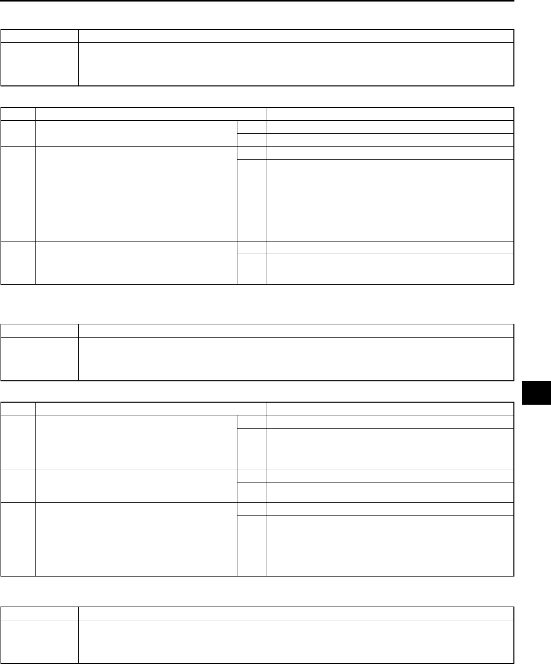
ON-BOARD DIAGNOSTIC
U61
U
DTC 22 A6E857001038W14
Diagnostic Procedure
End Of Sie
DTC 58 A6E857001038W15
Diagnostic Procedure
End Of Si e
DTC 59 A6E857001038W16
DTC 22 Airflow mode actuator (potentiometer) system inspection
POSSIBLE
CAUSE
•Airflow mode actuator malfunction
•Climate control unit malfunction
•Open circuit between airflow mode actuator and climate control unit
•Short circuit between airflow mode actuator (terminal C) and climate control unit (terminal 1W: 24-pin)
STEP INSPECTION ACTION
1•Inspect airflow mode actuator.
•Is it okay?
Yes Go to next step.
No Replace airflow mode actuator.
2•Disconnect climate control unit connector
(24-pin) and air mix actuator connector.
•Is there open circuit between following
terminals of climate control unit connector
(24-pin) and airflow mode actuator
connector?
1BB
1WC
1IA
Yes Repair wiring harness.
No Go to next step.
3•Is there short circuit to ground between
terminal 1W of climate control unit connector
(24-pin) and terminal C of airflow mode
actuator connector?
Yes Repair wiring harness.
No This system is normal at present. (Erase the past failure
from memory.)
DTC 58 Air mix actuator (motor lock) system inspection
POSSIBLE
CAUSE
•Air mix actuator malfunction
•A/C unit (air mix link and/or air mix crank) malfunction
•Climate control unit malfunction
•Open or short circuit between air mix actuator and climate control unit
STEP INSPECTION ACTION
1•Disconnect air mix actuator connector.
•Connect battery positive voltage to terminal
D (or terminal F) and ground to terminal F (or
terminal D) of air mix actuator connector.
•Does air mix actuator operate?
Yes Connect air mix actuator connector, then go to Step 3.
No Go to next step.
2•Remove air mix actuator.
•Operate air mix link by hand.
•Does air mix link operate smoothly?
Yes Replace air mix actuator.
No Replace air mix link and/or air mix crank.
3•Disconnect climate control unit connect (12-
pin).
•Connect battery positive voltage to terminal
2D (or terminal 2C) and ground to terminal
2C (or terminal 2D) of climate control unit
connector (24-pin).
•Does air mix actuator operate?
Yes Replace climate control unit.
No Repair wiring harness.
DTC 59 Airflow mode actuator (motor lock) system inspection
POSSIBLE
CAUSE
•Airflow mode actuator malfunction
•A/C unit (airflow mode links and/or airflow mode cranks) malfunction
•Climate control unit malfunction
•Open or short circuit between airflow mode actuator and climate control unit

U62
ON-BOARD DIAGNOSTIC
Diagnostic Procedure
End Of Sie
DTC 02, 18, 21 (WHEN TWO OR MORE DTCS ARE INDICATED AT THE SAME TIME) A6E857001038W17
Diagnostic Procedure
End Of Sie
DTC 06, 10, 12, 14, 18, 21 (WHEN TWO OR MORE DTCS ARE INDICATED AT THE SAME TIME) A6E857001038W18
STEP INSPECTION ACTION
1•Disconnect airflow mode actuator connector.
•Connect battery positive voltage to terminal
D (or terminal F) and ground to terminal F (or
terminal D) of airflow mode actuator
connector.
•Does airflow mode actuator operate?
Yes Connect airflow mode actuator connector, then go to Step 3.
No Go to next step.
2•Remove airflow mode actuator.
•Operate airflow mode main link by hand.
•Does airflow mode main link operate
smoothly?
Yes Replace airflow mode actuator.
No Replace airflow mode links and/or airflow mode cranks.
3•Disconnect climate control unit connect (12-
pin).
•Connect battery positive voltage to terminal
2G (or terminal 2E) and ground to terminal
2E (or terminal 2G) of climate control unit
connector (24-pin).
•Does airflow mode actuator operate?
Yes Replace climate control unit.
No Repair wiring harness.
DTC 02, 18, 21 Climate control unit (+5 V power supply) inspection
POSSIBLE
CAUSE
•Climate control unit malfunction
•Short circuit between climate control unit and solar radiation sensor
•Short circuit between climate control unit and air mix actuator
•Short circuit between climate control unit and airflow mode actuator
•Open circuit between climate control unit and solar radiation sensor
•Open circuit between climate control unit and air mix actuator
•Open circuit between climate control unit and airflow mode actuator
STEP INSPECTION ACTION
1•Disconnect climate control unit cooonnector
(24-pin) and airflow mode actuator
connector.
•Is there continuity between terminal 1B of
climate control unit connector (24-pin) and
terminal B of airflow mode actuator
connector?
Yes Go to next step.
No Repair wiring harness.
2•Is there short circuit to ground between
terminal 1B of climate control unit connector
(24-pin) and terminal B of airflow mode
actuator connector?
Yes Repair wiring harness.
No Go to next step.
3•Is there short circuit to ground between
terminal 1B of climate control unit connector
(24-pin) and terminal B of air mix actuator
connector?
Yes Repair wiring harness.
No Go to next step.
4•Is there short circuit to ground between
terminal 1B of climate control unit connector
(24-pin) and terminal A of solar radiation
sensor connector?
Yes Repair wiring harness.
No Replace climate control unit.
DTC 06, 10, 12,
18, 21
Climate control unit (+5V power supply or sensor ground system) or sensor ground system
inspection
POSSIBLE
CAUSE
•Climate control unit malfunction
•Open circuit between climate control unit and each temperature sensor
•Open circuit between climate control unit and air mix actuator
•Open circuit between climate control unit and airflow mode actuator
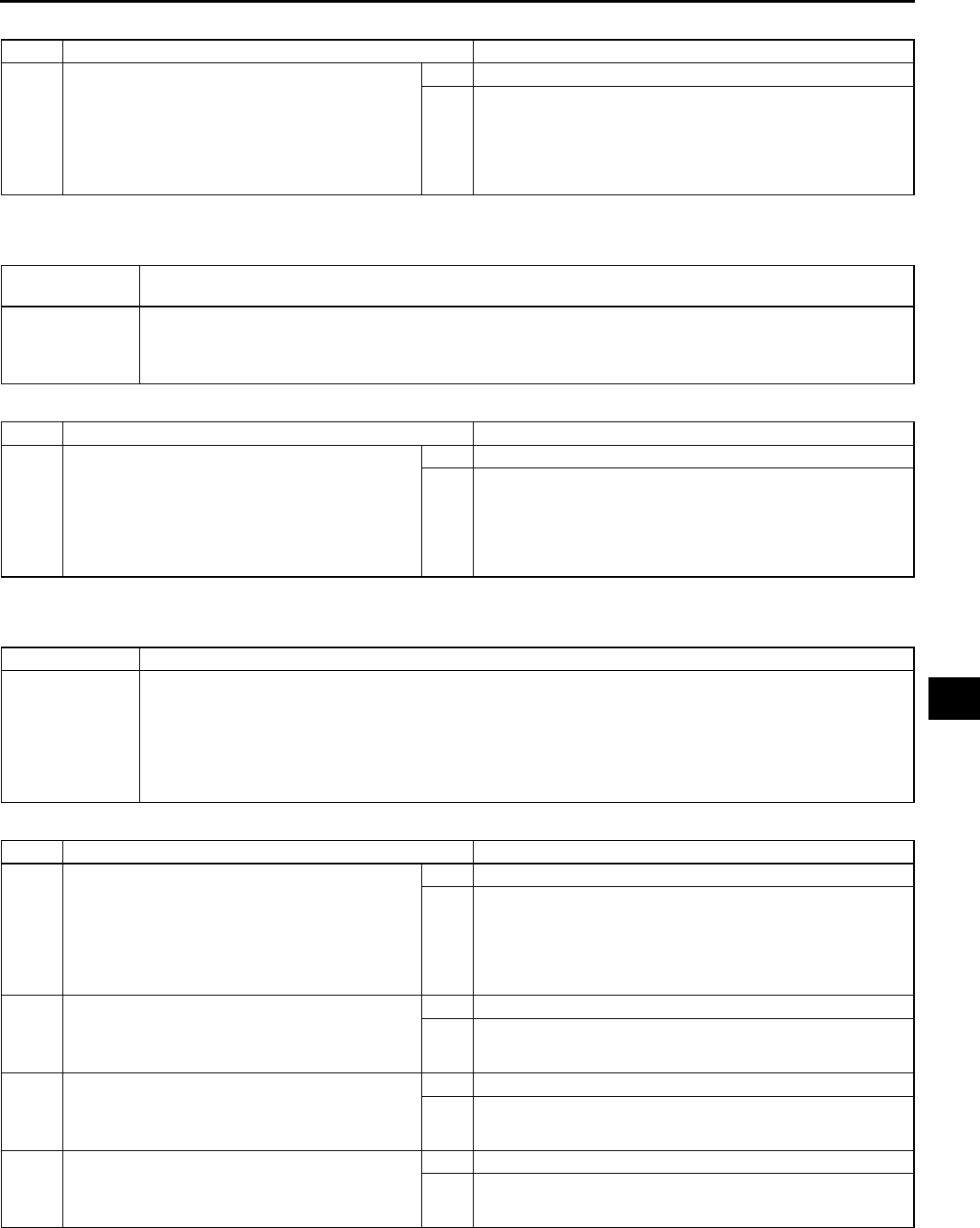
ON-BOARD DIAGNOSTIC
U63
U
Diagnostic Procedure
End Of Sie
DTC 07, 11, 13, 15, 19, 22 (WHEN TWO OR MORE DTCS ARE INDICATED AT THE SAME TIME) A6E857001038W19
Diagnostic Procedure
End Of Sie
DTC 19, 22 (WHEN TWO OR MORE DTCS ARE INDICATED AT THE SAME TIME) A6E857001038W20
Diagnostic Procedure
End Of Sie
STEP INSPECTION ACTION
1•Disconnect climate control unit connector
(24-pin) and evaporator temperature sensor
connector.
•Is there continuity between terminal 1I of
climate control unit connector (24-pin) and
terminal A of evaporator temperature sensor
connector?
Yes Replace climate control unit.
No Repair wiring harness.
DTC 07, 11, 13,
15, 19, 22
Climate control unit (+5V power supply or sensor ground system) or sensor ground system
inspection
POSSIBLE
CAUSE
•Climate control unit malfunction
•Open circuit between climate control unit each temperature sensor
•Open circuit between climate control unit and air mix actuator
•Open circuit between climate control unit and airflow mode actuator
STEP INSPECTION ACTION
1•Disconnect climate control unit connector
(24-pin) and evaporator temperature sensor
connector.
•Is there open circuit between terminal 1I of
climate control unit connector (24-pin) and
terminal A of evaporator temperature sensor
connector?
Yes Repair wiring harness.
No This system is normal at present. (Erase the past failure
from memory.)
DTC 19, 22 Climate control unit (+5V power supply) inspection
POSSIBLE
CAUSE
•Climate control unit malfunction
•Short circuit between climate control unit and solar radiation sensor
•Short circuit between climate control unit and air mix actuator
•Short circuit between climate control unit and airflow mode actuator
•Open circuit between climate control unit and solar radiation sensor
•Open circuit between climate control unit and air mix actuator
•Open circuit between climate control unit and airflow mode actuator
STEP INSPECTION ACTION
1•Disconnect climate control unit connector
(24-pin) and airflow mode actuator
connector.
•Is there open circuit between terminal 1B of
climate control unit connector (24-pin) or
terminal B of airflow mode actuator
connector?
Yes Repair wiring harness.
No Go to next step.
2•Is there short circuit to ground between
terminal 1B of climate control unit connector
(24-pin) and terminal B of airflow mode
actuator connector?
Yes Repair wiring harness.
No Go to next step.
3•Is there short circuit to ground between
terminal 1B of climate control unit connector
(24-pin) and terminal B of air mix actuator
connector?
Yes Repair wiring harness.
No Go to next step.
4•Is there short circuit to ground between
terminal 1B of climate control unit connector
(24-pin) and terminal A of solar radiation
sensor connector?
Yes Repair wiring harness.
No This system is normal at present. (Erase the past failure
from memory.)
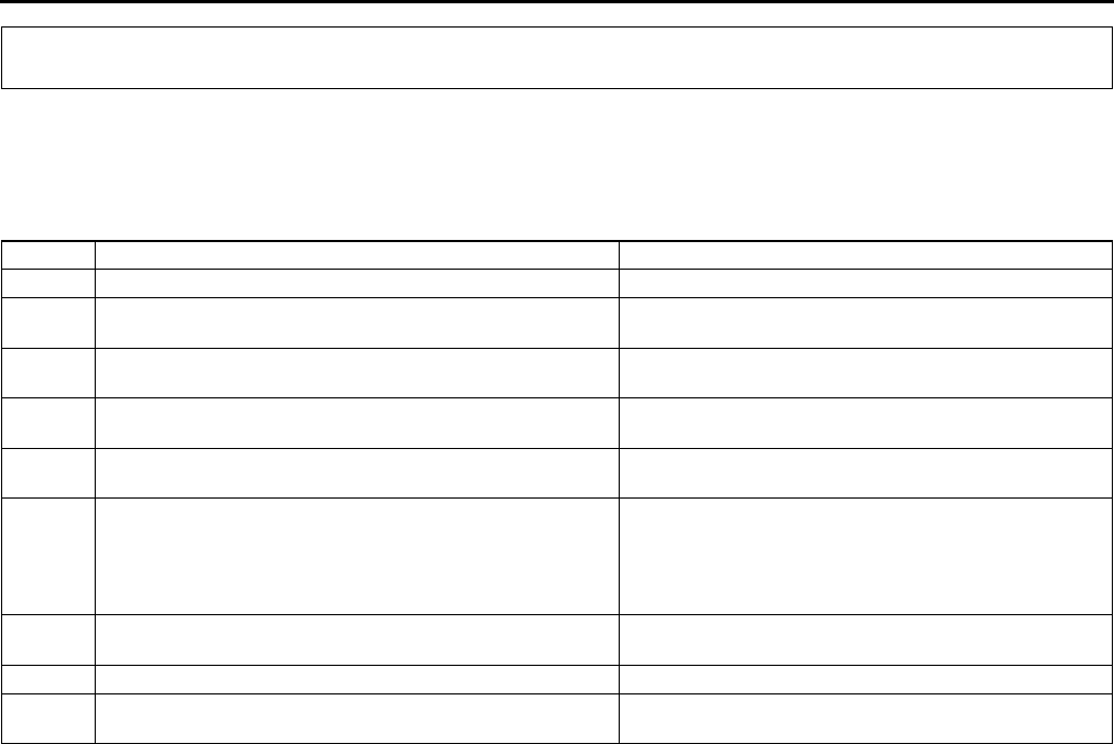
U64
TROUBLESHOOTING
FOREWORD A6E858001038W01
•The areas for inspection (steps) are given according to various circuit malfunctions. Use the following chart to
verify the symptoms of the trouble in order to diagnose the appropriate area.
End Of Sie
TROUBLESHOOTING INDEX A6E858001038W02
End Of Sie
TROUBLESHOOTING
No. TROUBLESHOOTING ITEM DESCRIPTION
1 Insufficient air (or no air) blown from vents. •Problem with each vent and/or duct.
2 Amount of air blown from vents does not change. (Full-
auto air conditioner)
•Malfunction in blower system.
3 Amount of air blown from vents does not change. (Manual
air conditioner)
•Malfunction in blower system.
4 Air intake mode does not change. •Air intake mode does not change when switching
REC/FRESH mode.
5 No temperature control with climate control unit. •Malfunction in A/C unit and/or climate control unit
air mix system.
6 Windshield fogged. •A/C compressor does not operate while airflow
mode is in DEFROSTER or HEAT/DEF modes.
•Air intake mode does not change to FRESH while
airflow mode is in DEFROSTER or HEAT/DEF
modes.
7 Air from vents not cold enough. •Magnetic clutch operates but A/C system
malfunctions.
8No cool air. •Magnetic clutch does not operate.
9 Noise while operating A/C system. •Noise from magnetic clutch, A/C compressor, hose
or refrigerant line.
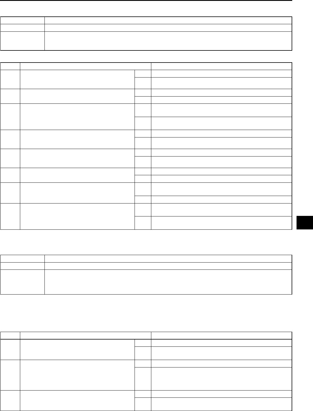
TROUBLESHOOTING
U65
U
NO.1 INSUFFICIENT AIR (OR NO AIR) BLOWN FROM VENTS A6E858001038W03
Diagnostic procedure
End Of Sie
NO.2 AMOUNT OF AIR BLOWN FROM VENTS DOES NOT CHANGE A6E858001038W04
Full-auto Air Conditioner
•When performing an asterisked (*) troubleshooting inspection, shake the wiring harness and connectors while
performing the inspection to discover whether poor contact points are the cause of any intermittent
malfunctions. If there is a problem, check to make sure connectors, terminals and wiring harnesses are
connected correctly and undamaged.
Diagnostic procedure
1 Insufficient air (or no air) blown from vents.
DESCRIPTION •Problem with each vent and/or duct.
POSSIBLE
CAUSE
•Malfunction in VENT mode system (Steps 14)
•Malfunction in HEAT mode system (Step 5)
•Malfunction in DEFROSTER mode system (Steps 68)
STEP INSPECTION ACTION
1INSPECT TO SEE WHETHER MALFUNCTION
IS IN VENT MODE OR OTHER MODES
•Does air blow out when in VENT mode?
Yes Go to Step 4.
No Go to next step.
2INSPECT VENT
•Is vent clogged?
Yes Remove obstruction, then go to Step 8.
No Go to next step.
3VERIFY THAT DUCT IN DASHBOARD IS
INSTALLED
•Is duct in dashboard properly installed?
Yes Inspect duct for clogging, deformity and air leakage, then go
to Step 8.
No Install duct securely in the proper position, then go to Step
8.
4INSPECT TO SEE WHETHER MALFUNCTION
IS IN HEAT MODE OR DEFROSTER MODE
•Does air blow out when in HEAT mode?
Yes Go to next step.
No Inspect vent for clogging, then go to Step 8.
5INSPECT DEFROSTER MODE
•Does air blow out when in DEFROSTER
mode?
Yes Operation is okay. Recheck malfunction symptoms.
No Go to next step.
6INSPECT VENT
•Is vent clogged?
Yes Remove obstruction, then go to Step 8.
No Go to next step.
7VERIFY THAT DEFROSTER DUCT IS
INSTALLED
•Is defroster duct properly installed?
Yes Inspect duct for clogging, deformity, and air leakage, then
go to next step.
No Install duct securely in proper position, then go to next step.
8CONFIRM THAT MALFUNCTION SYMPTOMS
DO NOT RECUR AFTER REPAIR
•Does air blow out?
Yes Troubleshooting completed.
Explain repairs to customer.
No Recheck malfunction symptoms, then repeat from Step 1 if
malfunction recurs.
2 Amount of air blown from vents does not change.
DESCRIPTION •Malfunction in blower system.
POSSIBLE
CAUSE
•Malfunction in blower unit (Steps 3, 4, 12)
•Malfunction in blower motor (Steps 59)
•Malfunction in power MOS FET system (Steps 10, 11, 13, 14)
•Malfunction in climate control unit (Step 15)
STEP INSPECTION ACTION
1INSPECT BLOWER 40 A FUSE
•Inspect BLOWER 40 A fuse.
•Is it okay?
Yes Go to next step.
No Replace fuse, then go to Step 15. If fuse burns out
immediately, go to next step.
2INSPECT TO SEE WHETHER MALFUNCTION
IS IN BLOWER UNIT OR ELSEWHERE
•Turn ignition switch to ON position.
•Recirculate air inside vehicle.
•Does blower unit fan rotate smoothly?
Yes Go to Step 4.
No Go to next step.
3INSPECT BLOWER UNIT INTAKE VENT
•Is intake vent of blower unit clogged?
Yes Remove obstruction, then go to Step 15.
No Inspect if there are any obstruction in passage between
blower unit to A/C unit, then go to Step 15.

U66
TROUBLESHOOTING
4* INSPECT TO SEE WHETHER MALFUNCTION
IS IN BLOWER RELAY SYSTEM OR POWER
MOS FET SYSTEM
•Turn ignition switch to ON position.
•Test voltage at the following terminal of
blower motor.
Terminal B (blower motor operation
signal)
•Is voltage approximately 12 V?
Yes Go to Step 8.
No Go to next step.
5* INSPECT TO SEE WHETHER MALFUNCTION
IS IN WIRING HARNESS (LACK OF
CONTINUITY BETWEEN FUSE BLOCK AND
BLOWER RELAY) OR ELSEWHERE
•Test voltage at the following terminal of
blower relay.
Terminal A (IG2 signal)
Terminal C (B+ signal)
•Is voltage approximately 12 V?
Yes Go to next step.
No Repair wiring harness between blower relay and BLOWER
40 A fuse, then go to Step 15.
6* INSPECT TO SEE WHETHER MALFUNCTION
IS IN WIRING HARNESS (LACK OF
CONTINUITY BETWEEN BLOWER RELAY
AND GROUND) OR ELSEWHERE
•Test voltage at the following terminal of
blower relay.
Terminal E (GND signal)
•Is voltage approximately 0 V?
Yes Go to next step.
No Repair wiring harness between blower relay and ground,
then go to Step 15.
7* INSPECT TO SEE WHETHER MALFUNCTION
IS IN WIRING HARNESS (LACK OF
CONTINUITY BETWEEN BLOWER RELAY
AND BLOWER MOTOR) OR BLOWER RELAY
•Test voltage at the following terminal of
blower relay.
Terminal D (blower motor operation
signal)
•Is voltage approximately 12 V?
Yes Repair wiring harness between blower relay and blower
motor, then go to Step 15.
No Replace blower relay, then go to Step 15.
8* INSPECT TO SEE WHETHER MALFUNCTION
IS IN BLOWER MOTOR OR ELSEWHERE
•Test voltage at the following terminal of
blower motor.
Terminal B (blower motor operation
signal)
•Is voltage approximately 12 V?
Yes Go to next step.
No Inspect blower motor, then go to Step 15.
9* INSPECT TO SEE WHETHER MALFUNCTION
IS IN WIRING HARNESS (LACK OF
CONTINUITY BETWEEN BLOWER MOTOR
AND POWER MOS FET) OR ELSEWHERE
•Test voltage at the following terminal of
power MOS FET.
Terminal C (blower motor operation
signal)
•Is voltage approximately 12 V?
Yes Go to next step.
No Repair wiring harness between blower motor and power
MOS FET, then go to Step 15.
10* INSPECT TO SEE WHETHER MALFUNCTION
IS IN WIRING HARNESS (LACK OF
CONTINUITY BETWEEN POWER MOS FET
AND GROUND) OR ELSEWHERE
•Test voltage at the following terminal of
power MOS FET.
Terminal A (blower motor operation
signal)
•Is voltage approximately 0 V?
Yes Go to next step.
No Repair wiring harness between power MOS FET and
ground, then go to Step 15.
11 INSPECT BLOWER UNIT
•Inspect fan in blower unit.
Is fan free of interference with blower unit
case?
Is fan free of foreign material and
obstruction?
•Is fan okay?
Yes Go to next step.
No Remove obstruction, repair or replace fan and blower unit
case, then go to Step 15.
STEP INSPECTION ACTION
ON-BOARD DIAGNOSTIC, TROUBLESHOOTING
U67
U
End Of Sie
NO.3 AMOUNT OF AIR BLOWN FROM VENTS DOES NOT CHANGE A6E858001038W05
Manual Air Conditioner
Diagnostic procedure
12* INSPECT TO SEE WHETHER MALFUNCTION
IS IN POWER MOS FET OR ELSEWHERE
•Disconnect power MOS FET connector.
•Test voltage at the following terminal of
power MOS FET.
Terminal B (blower motor control signal)
•Is voltage approximately 10 V?
Yes Replace power MOS FET, then go to Step 15.
No Go to next step.
13* INSPECT TO SEE WHETHER MALFUNCTION
IS IN WIRING HARNESS (LACK OF
CONTINUITY BETWEEN POWER MOS FET
AND CLIMATE CONTROL UNIT) OR
ELSEWHERE
•Turn ignition switch to LOCK position.
•Disconnect climate control unit connector.
•Inspect for continuity at the following
terminals between power MOS FET and
climate control unit.
Terminal B1C (24-pin, blower motor
control signal)
Terminal C1A (24-pin, blower motor
feedback signal)
•Is there continuity?
Yes Go to next step.
No Repair wiring harness between power MOS FET and
climate control unit, then go to Step 15.
14* INSPECT TO SEE WHETHER MALFUNCTION
IS IN CLIMATE CONTROL UNIT OR WIRING
HARNESS (SHORT TO GROUND BETWEEN
POWER MOS FET AND CLIMATE CONTROL
UNIT)
•Inspect for continuity at the following terminal
between power MOS FET and ground.
Terminal B (blower motor control signal)
ground
•Is there continuity?
Yes Repair wiring harness between power MOS FET and
ground, then go to next step.
No Replace climate control unit, then go to next step.
15 CONFIRM THAT MALFUNCTION SYMPTOMS
DO NOT RECUR AFTER REPAIR
•Is air discharged from vent?
Yes Troubleshooting completed.
Explain repairs to customer.
No Recheck malfunction symptoms, then repeat from Step 1 if
malfunction recurs.
STEP INSPECTION ACTION
3 Amount of air blown from vents does not change.
DESCRIPTION •Malfunction in blower system.
POSSIBLE
CAUSE
•Blower relay, blower motor, resistor, fan switch malfunction (Step 1)
•Blower unit malfunction (Steps 24)
STEP INSPECTION ACTION
1INSPECT BLOWER SYSTEM
•Inspect the following systems and electrical
parts.
Blower relay
Blower motor
Resistor
Fan switch
Related wiring harnesses
•Are they okay?
Yes Go to next step.
No Repair or replace malfunctioning part, then go to Step 5.
2CHECK TO SEE WHETHER MALFUNCTION
IS IN BLOWER UNIT OR ELSEWHERE
•Turn ignition switch to ON position.
•Turn fan switch on.
•Recirculate air inside vehicle.
•Does fan in blower unit rotate smoothly?
Yes Go to Step 4.
No Go to next step.

U68
TROUBLESHOOTING
End Of Sie
NO.4 AIR INTAKE MODE DOES NOT CHANGE A6E858001038W06
•When performing an asterisked (*) troubleshooting inspection, shake the wiring harness and connectors while
performing the inspection to discover whether poor contact points are the cause of any intermittent
malfunctions. If there is a problem, check to make sure connectors, terminals and wiring harnesses are
connected correctly and undamaged.
Diagnostic procedure
3INSPECT BLOWER UNIT
•Inspect fan in blower unit.
Is fan free of interference from blower unit
case?
Is fan free of foreign material and
obstructions?
•Is fan okay?
Yes Go to next step.
No Remove obstruction, repair or replace fan and blower unit
case, then go to Step 5.
4INSPECT BLOWER UNIT INTAKE VENT
•Is blower unit intake vent clogged?
Yes Remove obstruction, then go to next step.
No Inspect if there are any obstructions in passage between
blower unit and A/C unit, then go to next step.
5VERIFY THAT MALFUNCTION SYMPTOM
OCCURS AFTER REPAIR
•Does air blow out?
Yes Troubleshooting completed.
Explain repairs to customer.
No Recheck malfunction symptoms, then repeat from Step 1 if
malfunction recurs.
STEP INSPECTION ACTION
4 Air intake mode does not change.
DESCRIPTION •Air intake mode does not change when switching REC/FRESH mode.
POSSIBLE
CAUSE
•Malfunction in air intake actuator (Steps 16)
•Malfunction in air intake door (Step 7)
STEP INSPECTION ACTION
1* INSPECT TO SEE WHETHER MALFUNCTION
(LACK OF CONTINUITY) IS IN AIR INTAKE
ACTUATOR, WIRING HARNESS (BETWEEN
CLIMATE CONTROL UNIT AND AIR INTAKE
ACTUATOR) OR ELSEWHERE
•Turn ignition switch to ON position.
•Test voltages at the following terminals of
climate control unit.
Terminal 2K (12-pin, FRESH motor drive
signal)
Terminal 2I (12-pin, RECIRCULATE
motor drive signal)
(See U47 Full-auto Air Conditioner)
•Are voltages okay?
Yes Go to next step.
No Go to Step 3.
2* INSPECT TO SEE WHETHER MALFUNCTION
(LACK OF CONTINUITY) IS IN AIR INTAKE
ACTUATOR OR WIRING HARNESS
(BETWEEN CLIMATE CONTROL UNIT AND
AIR INTAKE ACTUATOR)
•Test voltages at the following terminals of air
intake actuator.
Terminal D (FRESH motor drive signal)
Terminal F (RECIRCULATE motor drive
signal)
•Are voltages as shown below?
Terminal D: approximately 0.5 V during
RECIRCULATE and approximately 10 V
during FRESH
Terminal F: approximately 10 V during
RECIRCULATE and approximately 0.5 V
during FRESH
Yes Replace air intake actuator, then go to Step 8.
No Repair wiring harness between climate control unit and air
intake actuator, then go to Step 8.

TROUBLESHOOTING
U69
U
End Of Sie
3INSPECT TO SEE WHETHER MALFUNCTION
IS IN AIR INTAKE ACTUATOR OR
ELSEWHERE
•Disconnect air intake actuator connector.
•Test voltages at the following terminals of
climate control unit.
Terminal 2K (12-pin, FRESH motor drive
signal)
Terminal 2I (12-pin, RECIRCULATE
motor drive signal)
(See U47 Full-auto Air Conditioner)
•Are voltages okay?
Yes Inspect air intake actuator, then go to Step 8.
No Go to next step.
4INSPECT TO SEE WHETHER MALFUNCTION
IS IN WIRING HARNESS (SHORT TO B+
BETWEEN CLIMATE CONTROL UNIT AND
AIR INTAKE ACTUATOR) OR ELSEWHERE
•Disconnect climate control unit connector.
•Test voltages at the following terminals of
climate control unit.
Terminal 2K (12-pin, FRESH motor drive
signal)
Terminal 2I (12-pin, RECIRCULATE
motor drive signal)
•Are voltages approximately 0 V?
Yes Go to next step.
No Repair wiring harness between climate control unit and air
intake actuator, then go to Step 8.
5INSPECT TO SEE WHETHER MALFUNCTION
IS IN WIRING HARNESS (SHORT TO
GROUND BETWEEN CLIMATE CONTROL
UNIT AND AIR INTAKE ACTUATOR) OR
ELSEWHERE
•Turn ignition switch to LOCK position.
•Inspect for continuity at the following
terminals between climate control unit and
ground.
Terminal 2K (12-pin, FRESH motor drive
signal)
Terminal 2I (12-pin, RECIRCULATE
motor drive signal)
•Is there continuity?
Yes Repair wiring harness between climate control unit and air
intake actuator, then go to Step 8.
No Go to next step.
6INSPECT AIR INTAKE LINK
•Inspect air intake links.
Is there grease on link?
Are links securely and properly installed?
Are links free of obstructions and
hindrances?
•Are above items okay?
Yes Go to next step.
No Apply grease to links. If any links are damaged, replace air
intake actuator, then go to Step 8.
7INSPECT TO SEE WHETHER MALFUNCTION
IS IN CLIMATE CONTROL UNIT OR AIR
INTAKE DOOR
•Inspect blower unit air intake door.
Is door free of obstructions, cracks, and
damage?
Are doors securely and properly installed?
•Are above items okay?
Yes Replace climate control unit, then go to next step.
No Remove obstruction, or install doors in proper position. If
any doors are cracked or damaged, replace them, then go
to next step.
8CONFIRM THAT MALFUNCTION SYMPTOMS
DO NOT RECUR AFTER REPAIR
•Does air intake mode change smoothly?
Yes Troubleshooting completed. Explain repairs to customer.
No Recheck malfunction symptoms, then repeat from Step 1 if
malfunction recurs.
STEP INSPECTION ACTION

U70
TROUBLESHOOTING
NO.5 NO TEMPERATURE CONTROL WITH CLIMATE CONTROL UNIT A6E858001038W07
Diagnostic procedure
End Of Sie
NO.6 WINDSHIELD FOGGED A6E858001038W08
•When performing an asterisked (*) troubleshooting inspection, shake the wiring harness and connectors while
doing the inspection to discover whether poor contact points are the cause of any intermittent malfunctions. If
there is a problem, check to make sure connectors, terminals and wiring harness are connected correctly and
undamaged.
5 No temperature control with climate control unit.
DESCRIPTION •Malfunction in A/C unit and/or climate control unit air mix system.
POSSIBLE
CAUSE
•A/C unit air mix link, air mix crank, air mix rod, air mix wire, wire clamp malfunction (Steps 2, 3)
•Climate control unit rack-and-pinion, air mix wire malfunction (Step 4)
•A/C unit air mix door malfunction (Steps 5, 6)
•Heater piping malfunction (Step 7)
STEP INSPECTION ACTION
1INSPECT COOLANT TEMPERATURE
•Is coolant sufficiently warmed up?
Yes Go to next step.
No Warm engine up, then go to Step 8.
2INSPECT A/C UNIT AIR MIX SYSTEM
•Inspect A/C unit air mix links, air mix cranks,
air mix rods, air mix actuator or wire clamp.
Is there grease on links and cranks?
Are links, cranks, and rods securely
installed in their proper positions?
Is wire clamp free of deformation?
•Are above items okay?
Yes Go to next step.
No Apply grease or install links, cranks, and rods securely in
their proper positions, repair or replace air mix actuator or
wire clamp, then go to Step 8.
3VERIFY THAT AIR MIX WIRE FROM A/C UNIT
IS POSITIONED SECURELY AND
CORRECTLY (IF AVAILABLE)
•Is air mix wire securely installed in the
correct position in relation to A/C unit air mix
links?
Yes Go to next step.
No Adjust air mix wire or install securely in correct position, then
go to Step 8.
4INSPECT CLIMATE CONTROL UNIT
•Inspect climate control unit. (See U47
CLIMATE CONTROL UNIT INSPECTION)
•Is climate control unit okay?
Yes Go to next step.
No Repair or replace climate control unit, then go to Step 8.
5INSPECT A/C UNIT
•Is there any foreign material or obstruction in
A/C unit air mix doors?
Yes Remove obstruction, then go to Step 8.
No Go to next step.
6INSPECT A/C UNIT AIR MIX DOORS
•Is A/C unit air mix door securely and properly
installed?
Yes Inspect air mix door for cracks or damage, then go to next
step.
No Install air mix door securely in proper position, then go to
next step.
7INSPECT HEATER LINES
•Inspect heater lines.
Is heater piping free of damage and
cracks?
Are heater piping connections free of
engine coolant leakage?
Are heater piping connections securely
tightened?
Are heater piping installation points on A/
C unit free of engine coolant leakage?
•Are above items okay?
Yes Operation is okay. Recheck malfunction symptoms.
No If heater piping connections is loosed, tighten connections
with specified torque.
Repair or replace heater piping, then go to next step.
8VERIFY THAT MALFUNCTION SYMPTOM
OCCURS AFTER REPAIR
•Does unit operate in every temperature
setting?
Yes Troubleshooting completed.
Explain repairs to customer.
No Recheck malfunction symptoms, then repeat from Step 1 if
malfunction recurs.
6 Windshield fogged.
DESCRIPTION
•A/C compressor does not operate while airflow mode is in DEFROSTER or HEAT/DEF modes.
•Air intake mode does not change to FRESH while airflow mode is in DEFROSTER or HEAT/DEF
modes.

TROUBLESHOOTING
U71
U
Diagnostic procedure
POSSIBLE
CAUSE
•Climate control unit (B+ signal) system malfunction (Steps 2, 4, 5)
•Air intake actuator malfunction (Steps 3, 7)
•Climate control unit (RECIRCULATE, FRESH signal) system malfunction (Steps 911)
•Malfunction in blower unit air intake doors (Steps 12, 13)
STEP INSPECTION ACTION
1COOL AIR BLOW OUT INSPECTION
•When both A/C and fan switch in climate
control unit are on, does cool air blow out
from front vent?
Yes Go to next step.
No Go to Step 1 of troubleshooting index No.8.
2INSPECT CLIMATE CONTROL UNIT POWER
SUPPLY FUSE FOR B+ SIGNAL
•Is climate control unit power supply fuse for
B+ signal okay?
Yes Go to next step.
No Inspect for a short to ground on blown fuse circuit.
•Repair or replace as necessary. Install appropriate
amperage fuse.
3INSPECT AIR INTAKE ACTUATOR
•Inspect air intake actuator.
Is there grease on link?
Is link securely and properly positioned?
Is link free of obstructions?
•Are above items okay?
Yes Go to next step.
No Apply grease or install link properly and securely, remove
obstruction, then go to Step 14.
*4 INSPECT WIRING HARNESS BETWEEN
FUSE BLOCK AND CLIMATE CONTROL UNIT
FOR CONTINUITY
•Disconnect climate control unit connector
(12-pin).
•Turn ignition switch to ON position.
•Test voltage at climate control unit connector
terminal F (B+ signal).
•Is voltage approximately 12 V?
Yes Go to next step.
No Repair wiring harness between fuse block and climate
control unit, then go to Step 14.
*5 INSPECT WIRING HARNESS BETWEEN
CLIMATE CONTROL UNIT AND GROUND
FOR VOLTAGE
•Test voltage at climate control unit connector
terminal 2L (Ground).
•Is voltage approximately 0V?
Yes Go to next step.
No Repair wiring harness between climate control unit and
ground, then go to Step 14.
6VERIFY WHETHER MALFUNCTION IS IN
BLOWER UNIT AIR INTAKE DOOR OR
ELSEWHERE
•Turn ignition switch to LOCK position.
•Connect climate control unit connector (12-
pin).
•Remove air intake actuator.
•Turn ignition switch to ON position.
•Set fan switch to 4th position.
•Does air intake mode (RECIRCULATE,
FRESH) change smoothly when air intake
link is operated by hand?
Yes Go to next step.
No Go to Step 12.
7INSPECT AIR INTAKE ACTUATOR
•Inspect air intake actuator.
(See U30 AIR INTAKE ACTUATOR
INSPECTION)
•Is it okay?
Yes Go to next step.
No Replace air intake actuator, go to Step 14.
8INSPECT AIR INTAKE SELECTOR SWITCH
AND DEFROSTER SWITCH IN CLIMATE
CONTROL UNIT
•Test voltage at climate control unit connector
(12-pin) terminals 2K and 2I.
•Is it okay?
Yes Go to next step.
No Replace climate control unit, then go to Step 14.

U72
TROUBLESHOOTING
End Of Sie
NO.7 AIR FROM VENTS COLD ENOUGH A6E858001038W09
Diagnostic procedure
*9 INSPECT WIRING HARNESS BETWEEN
CLIMATE CONTROL UNIT AND AIR INTAKE
ACTUATOR FOR CONTINUITY
•Turn ignition switch to LOCK position.
•Is there continuity between following climate
control unit connector (12-pin) terminal and
air intake actuator connector terminal?
Terminal D Terminal 2K (FRESH
signal)
Terminal F Terminal 2I
(RECIRCULATE signal)
Yes Go to next step.
No Repair wiring harness between climate control unit and air
intake actuator, then go to Step 14.
*10 INSPECT WIRING HARNESS BETWEEN
CLIMATE CONTROL UNIT AND AIR INTAKE
ACTUATOR FOR SHORT TO GROUND
•Is there continuity between following climate
control unit connector (12-pin) terminal and
ground?
Terminal 2K (FRESH signal)
Terminal 2I (RECIRCULATE signal)
Yes Repair wiring harness between climate control unit and air
intake actuator, then go to Step 14.
No Go to next step.
*11 INSPECT WIRING HARNESS BETWEEN
CLIMATE CONTROL UNIT AND AIR INTAKE
ACTUATOR FOR SHORT TO B+
•Turn ignition switch to ON position
•Test voltage at following climate control unit
connector (12-pin) terminal.
Terminal 2K (FRESH signal)
Terminal 2I (RECIRCULATE signal)
•Is voltage approximately 12 V?
Yes Repair wiring harness between climate control unit and air
intake actuator, then go to Step 14.
No Replace climate control unit, then go to Step 14.
12 INSPECT BLOWER UNIT AIR INTAKE DOOR
•Is there any foreign material or obstruction in
blower unit air intake door?
Yes Remove obstruction, then go to Step 14.
No Go to next step.
13 VERIFY THAT BLOWER UNIT AIR INTAKE
DOOR IS POSITIONED SECURELY AND
PROPERLY
•Is blower unit air intake door securely and
properly positioned?
Yes Inspect air intake door for cracks or damage, then go to next
step.
No Install air intake door securely in proper position, then go to
next step.
14 VERIFY THAT MALFUNCTION SYMPTOM
OCCURS AFTER REPAIR
•Does malfunction disappear?
Yes Troubleshooting completed.
Explain repairs to customer.
No Recheck malfunction symptoms, then repeat from Step 1 if
malfunction recurs.
STEP INSPECTION ACTION
7 Air from vents not cold enough.
DESCRIPTION •Magnetic clutch operates but A/C system malfunctions.
POSSIBLE
CAUSE
•Drive belt malfunction (Step 2)
•Malfunction in blower unit or condenser (Steps 4, 5)
•Malfunction in receiver/drier or expansion valve (valve closes too much) (Steps 8, 9)
•Malfunction in refrigerant lines (Steps 10, 11)
•A/C compressor system malfunction, insufficient compressor oil (Steps 15, 16)
•Over filling of compressor oil, malfunction in expansion valve or A/C unit air mix link system (Steps 17
19)
STEP INSPECTION ACTION
1INSPECT DRIVE BELT
•Inspect drive belt.
(See B3 DRIVE BELT INSPECTION)
•Is it okay?
Yes Go to next step.
No Adjust or replace drive belt, then go to Step 20.
2INSPECT REFRIGERANT SYSTEM
PERFORMANCE
•Perform refrigerant system performance test.
(See U13 REFRIGERANT SYSTEM
PERFORMANCE TEST)
•Is operation normal?
Yes Operation is normal. (Recheck malfunction symptoms.)
No Go to next step.

TROUBLESHOOTING
U73
U
3CHECK TO SEE WHETHER MALFUNCTION
IS IN BLOWER UNIT INTAKE AND
CONDENSER OR ELSEWHERE
•Are refrigerant high-pressure and low-
pressure values both high?
Yes Go to next step.
No Go to Step 6.
4INSPECT BLOWER UNIT INTAKE
•Is blower unit intake clogged?
Yes Remove obstruction, then go to Step 20. (If air does not
reach evaporator within A/C unit, heat exchange does not
occur and refrigerant pressure becomes high.
Therefore, removal of obstruction is necessary.)
No Go to next step.
5INSPECT CONDENSER
•Inspect condenser.
(See U24 CONDENSER INSPECTION)
•Is it okay?
Yes Adjust refrigerant to specified amount, then go to Step 20.
(Excessive amount of refrigerant.)
No Replace condenser, or repair and clean condenser fins,
then go to Step 20.
6CHECK TO SEE WHETHER MALFUNCTION
IS IN EXPANSION VALVE, RECEIVER/DRIER
AND REFRIGERANT LINES OR ELSEWHERE
•Are refrigerant high-pressure and low-
pressure values low?
Yes Go to next step.
No Go to Step 14.
7CHECK TO SEE WHETHER MALFUNCTION
IS IN EXPANSION VALVE AND RECEIVER/
DRIER OR ELSEWHERE
•Immediately after A/C compressor operates,
does refrigerant high-pressure value
momentarily rise to correct value, then fall
and stay below it? (Is there negative
pressure on low-pressure side?)
Yes Go to next step.
No Go to Step 10.
8CHECK TO SEE WHETHER MALFUNCTION
IS IN EXPANSION VALVE OR RECEIVER/
DRIER
•Turn A/C switch off and let air conditioner
stop for 10 minutes.
•Start engine.
•Turn both A/C switch and fan switch on.
•Does malfunction occur after A/C
compressor turns on?
Yes Go to next step.
No Replace condenser and vacuum refrigerant line more than
30 minutes by vacuum pump, add refrigerant to specified
level, then go to Step 20. (Since water has intermixed in
receiver/drier and it is saturated, replacement is necessary.)
9VERIFY THAT EXPANSION VALVE HEAT-
SENSING TUBE WITHIN A/C UNIT IS
POSITIONED SECURELY AND CORRECTLY
•Is expansion valve heat-sensing tube within
A/C unit securely installed in proper position?
Yes Replace expansion valve, then go to Step 20. (Since valve
closes too much, replacement is necessary.)
No Install heat-sensing tube securely in proper position, then go
to Step 20.
10 INSPECT REFRIGERANT LINES
•Inspect refrigerant lines.
Is piping free of damage and cracks?
Are piping connections free of oil grime?
(Visual inspection)
Are piping connections free of gas
leakage?
Are piping installation points on
condenser free of gas leakage?
Are piping installation points on receiver/
drier free of gas leakage?
Are piping installation points on A/C
compressor free of gas leakage?
Are piping installation points on A/C unit
free of gas leakage?
Perform gas leak inspection using gas
leak tester.
•Are above items okay?
Yes Go to next step.
No If piping or A/C component(s) are damaged or cracked,
replace them.
Then go to Step 20.
If there is no damage, go to Step 13.
11 INSPECT EVAPORATOR PIPING
CONNECTIONS IN A/C UNIT FOR GAS
LEAKAGE
•Are piping connections for evaporator in A/C
unit free of gas leakage?
Yes If the vane makes a noise, add 10 ml {10 cc, 0.34 fl oz} of
compressor oil to the A/C compressor. Verify that the noise
is no longer heard.
Adjust refrigerant to specified amount, then go to Step 20.
No If piping is damaged or cracked, replace it.
Then go to Step 20.
If there is no damage, go to next step.
STEP INSPECTION ACTION

U74
TROUBLESHOOTING
12 INSPECT EVAPORATOR PIPING
CONNECTIONS IN A/C UNIT FOR LOOSE
•Are piping connections for evaporator in A/C
unit loose?
Yes Tighten connections with specified torque, adjust both
compressor oil and refrigerant to specified amount, then go
to Step 20.
No If the vane makes a noise, add 10 ml {10 cc, 0.34 fl oz} of
compressor oil to the A/C compressor. Verify that the noise
is no longer heard.
Replace O-ring on piping, adjust refrigerant to specified
amount, then go to Step 20.
13 INSPECT PIPING CONNECTIONS FOR
LOOSE
•Are piping connections loose?
Yes Tighten connections with specified torque, adjust both
compressor oil and refrigerant to specified amount, then go
to Step 20.
No If the vane makes a noise, add 10 ml {10 cc, 0.34 fl oz} of
compressor oil to the A/C compressor. Verify that the noise
is no longer heard.
Replace O-ring on piping, adjust refrigerant to specified
amount, then go to Step 20.
14 CHECK TO SEE WHETHER MALFUNCTION
IS IN EXPANSION VALVE, AIR MIX
ACTUATOR AND COMPRESSOR OIL OR
ELSEWHERE
•Does refrigerant high-pressure value hardly
increase?
Yes Go to next step. (Pressure hardly increases.)
No Go to Step 17.
15 CHECK TO SEE WHETHER MALFUNCTION
IS IN COMPRESSOR OIL AMOUNT AND A/C
COMPRESSOR OR ELSEWHERE
•When engine is racing, does high-pressure
value increase?
Yes Return to Step 3.
No Go to next step.
16 CHECK TO SEE WHETHER MALFUNCTION
IS IN COMPRESSOR OIL AMOUNT OR A/C
COMPRESSOR
•After compressor oil is replenished each 10
ml {10 cc, 0.34 fl oz}, does high-pressure
value increase?
Yes Troubleshooting completed. (Explain to customer that cause
was insufficient compressor oil.)
No Replace A/C compressor, then go to Step 20. (Cause is
defective A/C compressor.)
17 CHECK TO SEE WHETHER MALFUNCTION
IS IN EXPANSION VALVE OR ELSEWHERE
•Is only refrigerant low-pressure value high?
Yes Go to Step 19.
No Go to next step.
18 VERIFY THAT AIR MIX IS INSTALLED
SECURELY AND PROPERLY
•Are A/C unit air mix links, air mix cranks, and
air mix rods securely and properly installed?
Yes Set fan switch to 4th position.
Turn A/C switch on.
Set FRESH mode.
Set temperature control to MAX COLD.
Set VENT mode.
(1)Start and run the engine at 1,500 rpm for 10 minutes.
(2)Run the engine at idle for 1 minute.
(3)Within 12 seconds, idle → 4,000 rpm → idle. Perform
cycle 5 times.
(4) Run the engine at idle for 30 seconds.
(5)Drain the compressor oil completely from the A/C
compressor and verify the amount.
•If there is approximately 90 ml {90 cc, 3.0 fl oz} of
compressor oil, go to Step 20.
•If there is more than 90 ml {90 cc, 3.0 fl oz} of
compressor oil, remove surplus oil and fill A/C
compressor with 90 ml {90 cc, 3.0 fl oz} of
compressor oil. Repeat Steps (1) to (5).
(Cause is excessive amount of compressor oil.)
No Repair or install links, cranks and rods securely in proper
position, then go to Step 20.
19 VERIFY THAT EXPANSION VALVE HEAT-
SENSING TUBE WITHIN A/C UNIT IS
POSITIONED SECURELY AND CORRECTLY
•Is expansion valve heat-sensing tube within
A/C unit securely installed in proper position?
Yes Replace expansion valve, then go to next step. (Since valve
opens too much, replacement is necessary.)
No Install heat-sensing tube securely in proper position, then go
to next step.
20 VERIFY THAT MALFUNCTION SYMPTOM
OCCURS AFTER REPAIR
•Does cool air blow out? (Are results of
refrigerant system performance test okay?)
Yes Troubleshooting completed.
Explain repairs to customer.
No Recheck malfunction symptoms, then repeat from Step 1 if
malfunction recurs.
STEP INSPECTION ACTION

TROUBLESHOOTING
U75
U
End Of Si e
NO.8 NO COOL AIR A6E858001038W10
•When performing an asterisked (*) troubleshooting inspection, shake the wiring harness and connectors while
performing the inspection to discover whether poor contact points are the cause of any intermittent
malfunctions. If there is a problem, check to make sure connectors, terminals and wiring harnesses are
connected correctly and undamaged.
Diagnostic procedure
8No cool air
DESCRIPTION •Magnetic clutch does not operate.
POSSIBLE
CAUSE
•Malfunction in PCM A/C cut control system (Step 3)
•Malfunction in climate control unit (Step 4)
•Malfunction in refrigerant pressure switch (Steps 5, 79)
•Malfunction in PCM (A/C signal) (Step 6)
•Malfunction in PCM (IG1 signal) (Steps 10, 11)
•Malfunction in A/C compressor (Step 12)
•Malfunction in A/C relay (Steps 1315)
•Malfunction in evaporator temperature sensor (Step 16)
STEP INSPECTION ACTION
1INSPECT AIR BLOW OUT
•Does air blow out?
Yes Go to next step.
No Go to Step 1 of troubleshooting indexes No.1 and 2.
2INSPECT A/C COMPRESSOR OPERATION
•Start engine.
•Turn A/C switch and fan switch on.
•Does A/C compressor operate?
Yes Go to Step 1 of troubleshooting index No.7.
No Go to next step.
3INSPECT FOR DTC IN PCM
•Inspect for DTCs related to the PCM on-
board diagnostic system.
•Are any DTCs displayed?
Yes Go to appropriate inspection procedure.
No Go to next step.
4INSPECT TO SEE WHETHER MALFUNCTION
IS IN CLIMATE CONTROL UNIT OR
ELSEWHERE
•Does cool air blow out when terminal 1P of
climate control unit connector (24-pin, A/C
signal) is grounded?
Yes Replace climate control unit, then go to Step 17.
No Release short, then go to next step.
5* INSPECT TO SEE WHETHER MALFUNCTION
IS IN A/C SIGNAL CIRCUIT (BETWEEN
REFRIGERANT PRESSURE SWITCH AND
PCM) OR ELSEWHERE
•Test voltage at following terminal of
refrigerant pressure switch.
Terminal B (A/C signal)
•Is voltage approximately 12 V?
Yes Go to Step 7.
No Go to next step.
6* INSPECT TO SEE WHETHER MALFUNCTION
(LACK OF CONTINUITY) IS IN WIRING
HARNESS (BETWEEN REFRIGERANT
PRESSURE SWITCH AND PCM) OR PCM
•Test voltage at A/C signal terminal of PCM.
•Is voltage approximately 12 V?
Yes Repair wiring harness between PCM and refrigerant
pressure switch, then go to Step 17.
No Inspect PCM, then go to Step 17.
7INSPECT TO SEE WHETHER MALFUNCTION
IS IN REFRIGERANT PRESSURE SWITCH,
REFRIGERANT AMOUNT, OR ELSEWHERE
•Does cool air blow out when terminals A and
B of refrigerant pressure switch connector
are shorted?
Yes Go to Step 9.
No Go to next step.
8* INSPECT TO SEE WHETHER MALFUNCTION
IS IN WIRING HARNESS (BETWEEN
REFRIGERANT PRESSURE SWITCH AND
CLIMATE CONTROL UNIT) OR ELSEWHERE
•Test voltage at following terminal of climate
control unit.
Terminal 1P (24-pin, A/C signal)
•Is voltage approximately 12 V?
Yes Go to Step 10.
No Repair wiring harness between refrigerant pressure switch
and climate control unit, then go to Step 17.

U76
TROUBLESHOOTING
End Of Sie
NO.9 NOISE WHILE OPERATING A/C SYSTEM A6E858001038W11
9INSPECT TO SEE WHETHER MALFUNCTION
IS IN REFRIGERANT PRESSURE SWITCH OR
REFRIGERANT AMOUNT
•Inspect refrigerant pressure switch.
•Is it okay?
Yes If refrigerant amount is empty, replace condenser, vaccum
refrigerant line more than 30 minutes by vacuum pump,
and add refrigerant to specified level, then go to Step 17.
No Replace refrigerant pressure switch, then go to Step 17.
10 INSPECT TO SEE WHETHER MALFUNCTION
(LACK OF CONTINUITY) IS IN A/C CONTROL
SIGNAL CIRCUIT (BETWEEN A/C RELAY
AND PCM) OR ELSEWHERE
•Does cool air blow out when terminal E of A/
C relay connector (A/C control signal) is
grounded?
Yes Release short, then go to next step.
No Go to Step 12.
11* INSPECT TO SEE WHETHER MALFUNCTION
(LACK OF CONTINUITY) IS IN PCM OR
WIRING HARNESS (BETWEEN A/C RELAY
AND PCM)
•Test voltage at the A/C relay control signal
terminal of PCM.
•Is voltage approximately 12 V?
Yes Inspect PCM, then go to Step 17.
No Repair wiring harness between A/C relay and PCM, then go
to Step 17.
12* INSPECT TO SEE WHETHER MALFUNCTION
IS IN MAGNETIC CLUTCH OR ELSEWHERE
•Test voltage at the following terminal of
magnetic clutch thermal protector.
Terminal A (magnetic clutch operation
signal)
•Is voltage approximately 12 V?
Yes Inspect magnetic clutch, then go to Step 17.
No Go to next step.
13 INSPECT FUSE
•Are A/C relay power supply fuses okay?
Yes Go to next step.
No Replace fuse, then go to Step 17. If fuse burns out
immediately, go to next step.
14 INSPECT WIRING HARNESS BETWEEN
FUSE BLOCK AND A/C RELAY FOR LACK
OF CONTINUITY
•Test voltages at following terminals of A/C
relay.
Terminal A (A/C relay control signal)
Terminal C (A/C control signal)
•Are voltages approximately 12 V?
Yes Go to next step.
No Repair wiring harness between fuse block and A/C relay,
then go to Step 17.
15 INSPECT TO SEE WHETHER MALFUNCTION
IS IN A/C RELAY OR WIRING HARNESS
(BETWEEN A/C RELAY AND MAGNETIC
CLUTCH) AND EVAPORATOR
TEMPERATURE SENSOR
•Test voltage at the following terminal of A/C
relay.
Terminal D (magnetic clutch operation
signal)
•Is voltage approximately 12 V?
Yes Inspect wiring harness between A/C relay and magnetic
clutch.
•If above wiring harness is OK, go to next step.
•If above wiring harness malfunctions, repair wiring
harness, then go to Step 17.
No Replace A/C relay, then go to Step 17.
16 INSPECT EVAPORATOR TEMPERATURE
SENSOR
•Inspect evaporator temperature sensor.
•Is it okay?
Yes Go to next step.
No Replace evaporator temperature sensor, then go to next
step.
17 CONFIRM THAT MALFUNCTION SYMPTOMS
DO NOT RECUR AFTER REPAIR
•Does cool air blow out? (Are the results of
refrigerant system performance test okay?)
Yes Troubleshooting completed. Explain repairs to customer.
No Recheck malfunction symptoms, then repeat from Step 1 if
malfunction recurs.
STEP INSPECTION ACTION
9 Noise while operating A/C system.
DESCRIPTION •Noise from magnetic clutch, A/C compressor, hose or refrigerant line.
POSSIBLE
CAUSE
•Magnetic clutch operation noise (Step 4)
•A/C compressor vane noise (Steps 513)
•A/C compressor slippage noise (Steps 1417)
•Hose or refrigerant line interference noise (Step 18)

TROUBLESHOOTING
U77
U
Diagnostic procedure
STEP INSPECTION ACTION
1CHECK A/C COMPRESSOR VANE NOISE
•Is there a jingling, popping, beeping, or
buzzing sound (A/C compressor vane
noise)?
Yes Go to Step 5.
No Go to next step.
2INSPECT A/C COMPRESSOR SLIPPAGE
NOISE
•Is there a squeaking or whirling sound (A/C
compressor slippage noise)?
Yes Go to Step 14.
No Go to next step.
3INSPECT A/C COMPRESSOR
INTERFERENCE NOISE
•Is there a rattling or vibrating sound
(interference noise)?
Yes Go to Step 18.
No Go to next step.
4INSPECT MAGNETIC CLUTCH OPERATION
NOISE
•Is there a clicking sound (magnetic clutch
operation noise)?
Yes Adjust clearance between pressure plate of magnetic clutch
and A/C compressor pulley, then go to Step 19.
(See U38 MAGNETIC CLUTCH ADJUSTMENT)
No Condition is normal. (Recheck malfunction symptoms.)
5INSPECT A/C COMPRESSOR NOISE TIME
•Is noise heard continuously for more than 3
seconds after A/C compressor comes on?
Yes Go to next step.
No Condition is normal. (Noise occurs for 23 seconds
immediately after A/C compressor turns on.)
6INSPECT IDLE SPEED
•Inspect idle speed.
(See F8 IDLE SPEED INSPECTION)
•Is it okay?
Yes Go to next step.
No Follow the repair instruction described in section F, then go
to Step 19.
7INSPECT REFRIGERANT AMOUNT
•Inspect refrigerant amount.
•Is it okay?
Yes Go to Step 10.
No Go to next step.
8INSPECT REFRIGERANT LINES
•Inspect refrigerant lines.
Is piping free of damage and cracks?
Are piping connections free of oil grime?
(Visual inspection)
Are piping connections free of gas
leakage?
Are piping installation points on
condenser free of gas leakage?
Are piping installation points on receiver/
drier free of gas leakage?
Are piping installation points on A/C
compressor free of gas leakage?
Are piping installation points on A/C unit
free of gas leakage
Perform gas leak inspection using gas
leak tester.
•Are above items okay?
Yes Go to next step.
No If piping or A/C component(s) is damaged or cracked,
replace then go to Step 19.
If there is gas leakage, repair or replace connection and
replace condenser*, then go to Step 19.
9INSPECT EVAPORATOR PIPING
CONNECTIONS IN A/C UNIT FOR GAS
LEAKAGE
•Are piping connections for evaporator in A/C
unit free of gas leakage?
Yes Adjust refrigerant amount to specified level, then go to Step
19.
No If piping is damaged or cracked, replace then go to Step 19.
If there is gas leakage, repair or replace connection and
replace condenser*, then go to Step 19.
10 CHECK TO SEE WHETHER MALFUNCTION
IS IN COMPRESSOR OIL OR ELSEWHERE
•Add 20 ml {20 cc, 0.8 fl oz} of compressor
oil.
•Is noise heard when racing engine?
Yes Go to next step.
No Troubleshooting completed.
Explain repair to customer.
11 CHECK TO SEE WHETHER MALFUNCTION
IS IN A/C COMPRESSOR OR ELSEWHERE
•Drain compressor oil.
•Is it contaminated with metal particles?
Yes Go to next step.
No Replace A/C compressor, then go to Step 19.
12 CHECK TO SEE WHETHER MALFUNCTION
IS SOMEWHERE IN A/C SYSTEM OR
ELSEWHERE
•Is compressor oil whitish and mixed with
water?
Yes Replace entire A/C system (excluding heater), then go to
Step 19.
No Go to next step.

U78
TROUBLESHOOTING
* : If there is gas leakage, air enters into the A/C system. The desiccant within the receiver/drier absorbs the
moisture from the air and becomes saturated. If the A/C system is used in this condition, the inside of the A/C
compressor will begin to rust due to this moisture, which may cause lock up or noise to occur. Therefore,
replacement of the receiver/drier is necessary.
End Of Sie
13 INSPECT A/C COMPRESSOR OIL
•Is compressor oil darker than normal and
contaminated with aluminum chips?
Yes Replace A/C compressor and condenser, then go to Step
19. (Since A/C compressor may be worn and receiver/drier
may be clogged, replacement of receiver/drier is
necessary.)
No Condition is normal. Recheck malfunction symptoms.
14 CHECK TO SEE WHETHER MALFUNCTION
IS IN A/C COMPRESSOR OR ELSEWHERE
•Is noise heard immediately after A/C
compressor is stopped?
Yes Replace A/C compressor, then go to Step 19. (A/C
compressor discharge valve left open)
No Go to next step.
15 INSPECT DRIVE BELT
•Inspect drive belt.
(See B3 DRIVE BELT INSPECTION)
•Is it okay?
Yes Go to next step.
No Adjust or replace drive belt, then go to Step 19.
16 INSPECT DRIVE BELT CONDITION
•Is drive belt worn?
•Does it have foreign material imbedded in it,
or have oil on it?
Yes Remove obstruction, remove oil, or replace drive belt, then
go to Step 19.
No Go to next step.
17 INSPECT MAGNETIC CLUTCH
•Inspect magnetic clutch.
(See U38 MAGNETIC CLUTCH
INSPECTION)
•Is it okay?
Yes Replace A/C compressor (excluding pressure plate, A/C
compressor pulley, and stator), then go to Step 19.
No Replace magnetic clutch, then go to Step 19.
18 CHECK TO SEE WHETHER MALFUNCTION
IS IN A/C COMPRESSOR OR REFRIGERANT
LINES
•Is noise emitted from A/C compressor?
Yes Visually inspect A/C compressor, replace appropriate parts
if necessary, then go to next step.
No If noise is due to refrigerant lines, repair detached or
missing clips, tighten loose bolts, then go to next step.
19 VERIFY THAT MALFUNCTION SYMPTOM
OCCURS AFTER REPAIR
•Has A/C compressor noise stopped?
Yes Troubleshooting completed.
Explain repairs to customer.
No Recheck malfunction symptoms, then repeat from Step 1 if
malfunction recurs.
STEP INSPECTION ACTION

TD1
TD
TDTECHNICAL DATA
TECHNICAL DATA ............................................. TD-2
ENGINE ............................................................ TD-2
LUBRICATION SYSTEM .................................. TD-2
COOLING SYSTEM.......................................... TD-3
FUEL AND EMISSION CONTROL SYSTEMS . TD-3
ENGINE ELECTRICAL SYSTEM ..................... TD-4
CLUTCH............................................................ TD-5
MANUAL TRANSAXLE..................................... TD-5
AUTOMATIC TRANSAXLE............................... TD-5
FRONT AND REAR AXLE ................................ TD-6
STEERING SYSTEM ........................................ TD-6
BRAKING SYSTEM .......................................... TD-7
SUSPENSION................................................... TD-8
BODY ELECTRICAL SYSTEM ....................... TD-10
HEATER AND
AIR CONDITIONER SYSTEMS................... TD-10
TD2
TECHNICAL DATA
ENGINE A6E931001001W01
End Of Sie
LUBRICATION SYSTEM A6E931001001W02
Note
•The maintenance intervals on scheduled maintenance table (See GI33 SCHEDULED MAINTENANCE
TABLE) can only be supported by the use of following oils.
Recommended engine oil
End Of Sie
TECHNICAL DATA
Item Engine
L8 LF L3
MECHANICAL
valve clearance (mm {in}
[Engine cold])
IN 0.220.28 {0.00870.0110}
EX 0.270.33 {0.01060.0130}
Compression pressure
(kPa {kgf/cm2,
psi})
Standard 1,750 {17.8, 253}
[300 rpm]
1,720 {17.5, 249}
[300 rpm]
1,430 {14.6, 208}
[290 rpm]
Minimum
1,225
{12.492, 177.64}
[300 rpm]
1,204
{12.277, 174.58}
[300 rpm]
1,000
{10.197, 145.00}
[290 rpm]
Maximum
difference
between cylinders
196.1{2.0, 28}
Cylinder head bolt length (mm {in}) Standard 149.0150.0 {5.865.90}
Minimum 150.5 {5.92}
Pushing distance of the front oil seal (mm {in}) 00.5 {00.02}
(from the edge of the engine front cover)
Item Engine
L8 LF L3
Oil pressure kPa {kgf/cm2, psi} [rpm]
234521
{2.395.31, 33.971}
[3,000]
395649
{4.036.61,
57.394.1}
[3,000]
Oil capacity
Oil replacement 3.9 {4.0, 3.4} 3.1 {3.3, 2.7}
(L {US qt, Imp qt})
Oil and oil filter replacement 4.3 {4.5, 3.8} 3.5 {3.7, 3.1}
(L {US qt, Imp qt})
Total (dry engine) 4.6 {4.8, 4.0} 4.2 {4.4, 3.6}
(L {US qt, Imp qt})
Item
Market
European countries Except European
countries
Engine oil
Grade API SJ
ACEA A1 or A3
API SL
ILSAC GF-3
API SG, SH, SJ, SL
ILSAC GF-2, GF-3
Viscosity (SAE) 5W-30 5W-20
40, 30, 20,
20W-20, 10W-30,
10W-40, 10W-50,
20W-40, 15W-40,
20W-50, 15W-50,
5W-20, 5W-30
Remarks Mazda genuine
DEXELIA oil
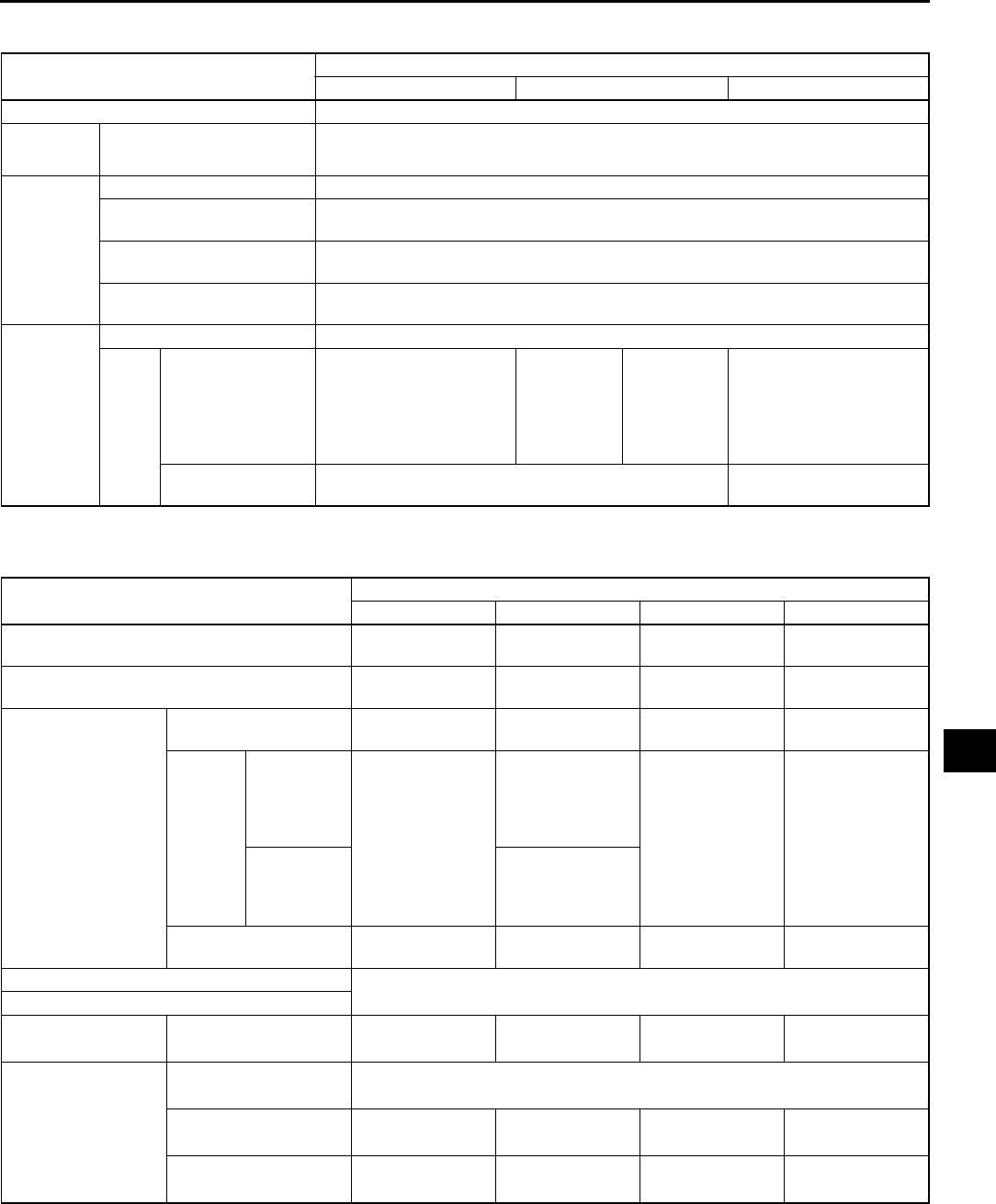
TECHNICAL DATA
TD3
TD
COOLING SYSTEM A6E931001001W03
End Of Sie
FUEL AND EMISSION CONTROL SYSTEMS A6E931001001W04
End Of Sie
Item Engine
L8 LF L3
Coolant capacity (L {US qt, Imp qt}) 7.5 {7.9, 6.6}
Radiator
cap
Cap valve opening pressure 113142 {1.151.44, 16.420.6}
(kPa {kgf/cm2, psi})
Thermostat
Type Wax, bottom-bypass
Initial-opening
temperature
(°C
{°F}) 8084 {176183}
Full-opening
temperature
(°C
{°F}) 90{194}
Full-open lift
(mm {in}) 8.0{0.32} min.
Cooling fan
Type Electrical
Blade
Number Cooling fan No.1: 5,
Cooling fan No.2: 7
(Except for
Israel)
Cooling fan
No.1:5
Cooling fan
No.2: 7
(For Israel)
Cooling fan
No.1:7
Cooling fan
No.2: 5
Cooling fan No.1: 7,
Cooling fan No.2: 5
Outer
diameter
(mm
{in}) 300 {11.8} 320 {12.6}
Item Engine
L8 LF (ATX) LF (MTX) L3
Idle speed (rpm) 650750
(700±50)
650750
(700±50)
600700
(650±50)
600700
(650±50)
Ignition timing (BTDC°/
rpm) Approx. 10/700 Approx. 10/700 Approx. 10/650 Approx. 10/650
Idle-up speed
E/L ON 650750
(700±50)
650750
(700±50)
650750
(700±50)
650750
(700±50)
A/C ON
refrigerant
pressure
switch
(middle)
OFF 700800
(750±50)
650750
(700±50)
700800
(750±50)
700800
(750±50)
refrigerant
pressure
switch
(middle) ON
700800
(750±50)
P/S ON 700800
(750±50)
650750
(700±50)
650750
(700±50)
650750
(700±50)
CO concentration Within the regulation
HC concentration
Fuel pressure
(kPa {kgf/cm2, psi} Hold pressure More than 408
{4.2, 59}
More than 408
{4.2, 59}
More than 408
{4.2, 59}
More than 408
{4.2, 59}
Fuel injector Fuel leakage Less than 1
(drop/2 minutes)
Injection volume 5177 {5177,
1.82.7}
6484 {6484,
2.33.0}
6484 {6484,
2.33.0}
7396 {7396,
2.63.3}
(ml {cc, fl oz}/15 sec.)
Resistance 11.412.6 11.412.6 11.412.6 11.412.6
(ohm) [20°C {68°F}]

TD4
TECHNICAL DATA
ENGINE ELECTRICAL SYSTEM A6E931001001W05
*1: Back-up current is the constant flow of current present (for the audio unit, clock, PCM, etc.) when the ignition
switch is off and with the ignition key removed.
*2: Must not be 0 A.
*3: Turn the following electrical loads on and verify that the voltage reading increases.
Headlights, blower motor, and rear window defroster
*4: Intensely hot area
End Of Sie
Item Engine
L8 LF L3
Battery
Electrolyte gravity 1.271.29
Back-up current*1(mA) Max. 20
Market European spec. 50D20L, 75D26L 50D20L,
80D26L
GCC spec. 46B24LS 46B24LS,
75D26L*4 46B24LS
Test load
chart
(A)
Battery type
46B24LS (36) 135
50D20L (48) 150
75D26L (52) 195
80D26L (55) 195
Slow charge
(A)
Battery type
(5-hour rate)
46B24LS (36) 3.54.5
50D20L (48) 4.05.0
75D26L (52) 5.06.0
80D26L (55) 5.56.5
Quick charge Battery type
(5-hour rate)
46B24LS (36) 25
50D20L (48) 25
75D26L (52) 35
(A/30 min) 80D26L (55) 35
Generator
Standard
voltage (V)
Ignition switch
ON Terminal
BB+
P Below approx. 1
D Approx. 0
Idle
[20 °C
{68 °F}]
Terminal
B1315
P Approx. 38
D* 3
Generated
current* 2
(Reference)
Engine speed 1000 080
(A)
(rpm) 2000 090
Ignition coil Resistance
[20 °C {68 °F}]
Primary coil (ohm) 0.490.57
Secondary coil 9.511.1
(kilohm)
Insulation resistance of case Above 10
(megohm)
High-tension
lead
Resistance
No.1 lead
9.8422.96 9.8422.96
No.2 lead
No.3 lead
(kilohm) No.4 lead
Spark plug Type NGK ITR6F13
Starter No load test Voltage (V) 11
Current (A) Below 90
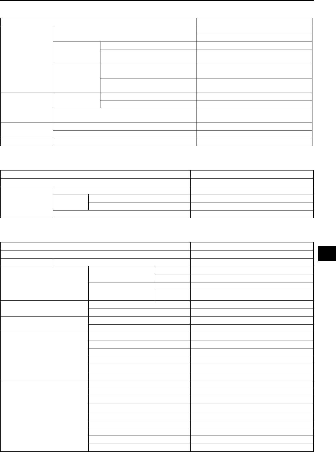
TECHNICAL DATA
TD5
TD
CLUTCH A6E931001024W01
End Of Sie
MANUAL TRANSAXLE A6E931001024W02
End Of Sie
AUTOMATIC TRANSAXLE A6E931001024W03
Item Specification
Clutch pedal
Height (with carpet) mm {in} L.H.D.: 226222 {8.508.74}
R.H.D.: 229235 {9.029.25}
Free play
Pedal free play mm {in} 1.03.0 {0.040.11}
Push rod free play at
clutch pedal mm {in} 0.10.5 {0.0040.02}
(Reference value)
Disengagement
point
Disengagement stroke mm {in} 20 {0.79}
(Reference value)
Pedal stroke mm {in} 130.7 {5.15}
(Reference value)
Clutch cover
Diaphragm
spring fingers
Depth mm {in} 0.6 {0.024}
Misalignment mm {in} 0.6 {0.024}
Maximum clearance of flatness of the
pressure plate mm {in} 0.5 {0.020}
Clutch disc Minimum thickness mm {in} 0.3 {0.012}
Run out limit mm {in} 0.7 {0.028}
Flywheel Run out limit mm {in} 0.1 {0.004}
Item Specification
Manual transaxle type G35M-R
Transaxle oil
Grade API service GL-4 or GL-5
Viscosity All-season SAE 75W-90
Above 10 °C {50 °F} SAE 80W-90
Capacity (L {US qt, lmp qt}) 2.87 {3.03, 2.53}
Item Specification
Transaxle type FN4A-EL
ATF Type ATF M-V
Line pressure
(kPa {kgf/cm2, psi})
D, S, L range Idle 330470 {3.44.8, 4868}
Stall 1,1601,320 {11.812.5, 168191}
R position Idle 490710 {5.07.2, 71102}
Stall 1,6001,820 {16.318.6, 232264}
Engine stall speed (rpm) D, S, L range 2,0002,600
R position 2,0002,600
Time lag (s) N → D 0.40.7
N → R 0.40.7
Transaxle range
(TR) switch (ohm)
P position 4,0854,515
R position 1,4251,575
N position 713788
D range 371410
S range 190210
L range 8796
Transaxle Fluid temperature
(TFT) sensor
(kilohm)
ATF temperature: 20 °C {4 °F} 236324
ATF temperature: 0 °C {32 °F} 84.3110
ATF temperature: 20 °C {68 °F} 33.542.0
ATF temperature: 40 °C {104 °F} 14.717.9
ATF temperature: 60 °C {140 °F} 7.088.17
ATF temperature: 80 °C {176 °F} 3.614.15
ATF temperature: 100 °C {212 °F} 1.962.24
ATF temperature: 120 °C {248 °F} 1.131.28
ATF temperature: 130 °C {266 °F} 0.870.98
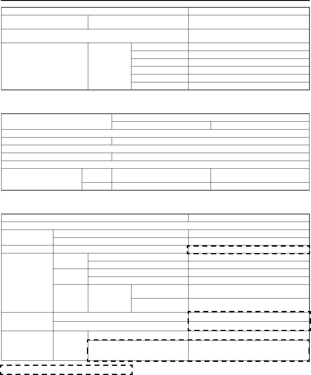
TD6
TECHNICAL DATA
End Of Sie
FRONT AND REAR AXLE A6E931001018W01
End Of Sie
STEERING SYSTEM A6E931001034W01
* : When reservoir tank is at maximum volume
End Of Sie
Input/turbine speed sensor
(ohm)
ATF temperature: 40160 °C {40
320 °F}
250600
Vehicle speedometer sensor (VSS)
(V) 4.55.5
Solenoid valve (ohm)
ATF
temperature:
40150 °C
{40302 °F}
Shift solenoid A 1.04.2
Shift solenoid B 1.04.2
Shift solenoid C 1.04.2
Shift solenoid D 10.926.2
Shift solenoid E 10.926.2
Pressure control 2.47.3
Item Specification
Item Specification
ATX MTX
FRONT AXLE
Maximum wheel bearing play (mm {in}) 0.05 {0.002}
REAR AXLE
Maximum wheel bearing play (mm {in}) 0.05 {0.002}
DRIVE SHAFT
Shaft length (Air in
boot at atmospheric
pressure)
(mm {in}) Left side 674.5684.5 {26.5626.94} 677.7687.7 {26.6727.07} (L8, LF),
676.6686.6 {26.6427.03} (L3)
Right side 631.2641.2 {24.8625.24} 628.6638.6 {24.7525.14}
Item Specification
ENGINE SPEED SENSING POWER STEERING
Steering wheel Play (mm {in}) 030 {01.18}
Effort (N·m {kgf·cm, in·lbf}) 7.8 {80, 58} max.
Steering shaft Length (mm {in}) 211.6 {8.3}
Steering gear
Tie-rod end Rotation torque (N·m {kgf·cm, in·lbf}) 0.42.7 {3.527.5, 3.123.8}
[Pull scale reading] (N {kgf, lbf}) 3.425.5 {0.352.60, 0.85.7}
Tie rod Swinging torque (N·m {kgf·cm, in·lbf}) 0.14.0 {140.7, 0.935.3}
[Pull scale reading] (N {kgf, lbf}) 0.624.5 {0.062.49 0.25.5}
Steering
rack
Runout
Large diameter
portion 0.15 mm {0.006 in} max.
(mm {in}) Small diameter
portion 0.20 mm {0.008 in} max.
Power steering oil
pump
Oil pump fluid pressure (MPa {kgf·cm2, psi}) 10.8011.29 {110.2115.2, 15671637}
Gear housing fluid pressure (MPa {kgf·cm2, psi}) 10.8011.29 {110.2115.2, 15671637}
Power steering
system Fluid
Type ATF M-III or equivalent (e.g. Dexron®II)
Capacity*
(Approximate
quantity)
(L {US qt, Imp qt}) 0.80 {0.85, 0.70} (MTX)
0.87 {0.92, 0.77} (ATX)
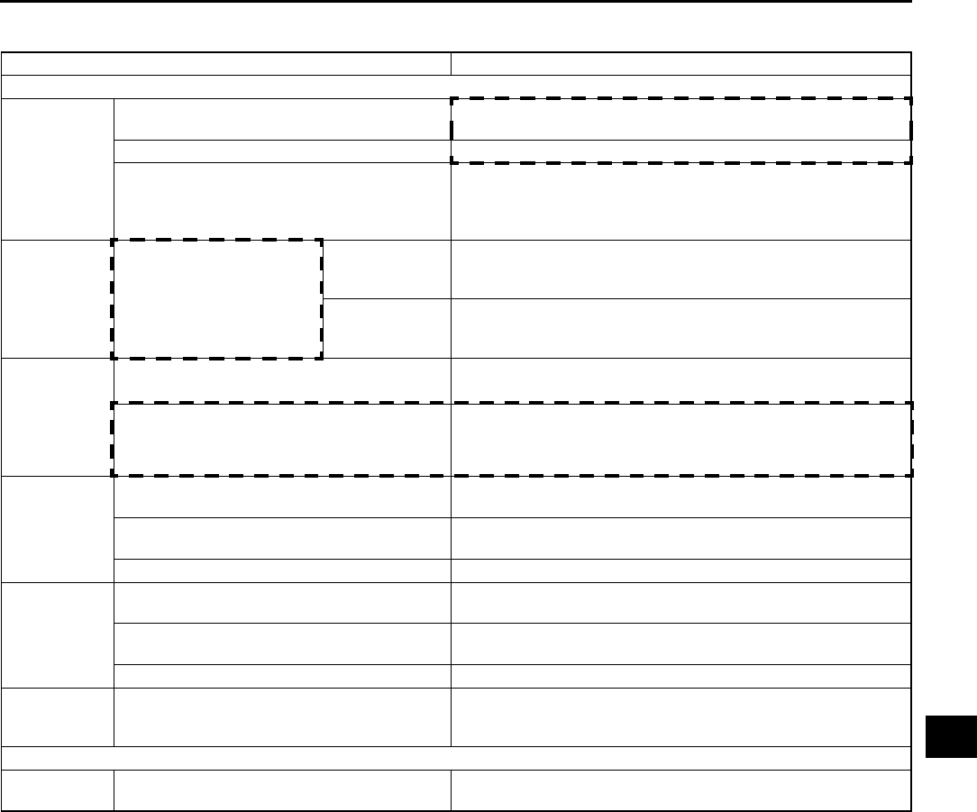
TECHNICAL DATA
TD7
TD
BRAKING SYSTEM A6E931001020W01
End Of Sie
Item Specification
CONVENTIONAL BRAKE SYSTEM
Brake pedal
Brake pedal height (mm {in}) R.H.D.: 172 {6.77}
L.H.D.: 187 {7.36}
Brake pedal play (mm {in}) 0 3 {00.1}
Pedal-to-floor clearance
(Brake pedal when
depressed at 588 N {60 kgf,
132 lbf})
(mm {in}) 68 {2.7} min.
Power brake
unit
Fluid pressure when pedal
depressed at
200 N {20 kgf, 44 lbf}
At 0 kPa {0
mmHg, 0 inHg} 590 {6.02, 85.6} min.
(kPa {kgf/cm2, psi}) At 66.7 kPa
{500 mmHg,
19.7 inHg}
8,780 {89.53, 1,273} min.
Dual
proportioning
valve (without
ABS)
Switching point (kPa {kgf/cm2,
psi}) 2,450 {25, 355} ±200 {2, 29}
Rear wheel pressure when master cylinder
pressure is 5,880 kPa {60 kgf/cm2, 853 psi} 3,480 {35.5, 505} ±300 {3, 44}
(kPa {kgf/cm2, psi})
Front disc
brake
Minimum disc pad
thickness (mm {in}) 2.0 {0.079}
Minimum disc plate
thickness (mm {in}) 22 {0.87}
Disc plate runout limit (mm {in}) 0.05 {0.002}
Rear disc
brake
Minimum disc pad
thickness (mm {in}) 2.0 {0.079}
Minimum disc plate
thickness (mm {in}) 8 {0.31}
Disc plate runout limit (mm {in}) 0.05 {0.002}
Brake fluid Type
European (L.H.D. U.K.) specs.: SAE J1703, FMVSS 116 DOT3
OR DOT4
GCC specs.: SAE J1703, FMVSS 116 DOT3
PARKING BRAKE SYSTEM
Parking brake
lever
Lever stroke when pulled at
98 N {10 kgf, 22 lbf} (notches) 36
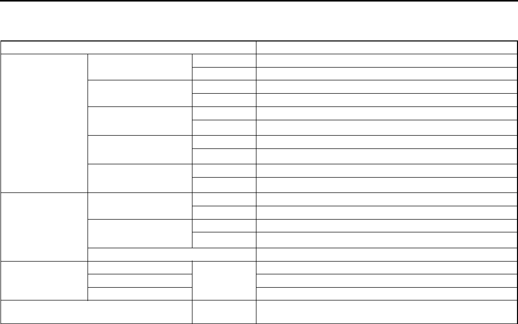
TD8
TECHNICAL DATA
SUSPENSION A6E931001013W01
Suspension
*1 : Fuel tank full. Engine coolant and engine oil are at specified level. Spare tire, jack, and tools are in designated
position. Adjust to the median when carrying out wheel alignment.
*2 : Difference between left and right must not exceed 1° 30′.
*3 : Distance between wheel center and fender brim is following. Front: 402 mm {15.8 in} (reference value) Rear:
392 mm {15.4 in} (reference value)
Item Specification
Front wheel
alignment
(Unloaded)*1
Maximum steering
angle
Inner 39°±3°
Outer 31°±3°
Total toe-in (mm {in}) Tire: 2±4 {0.08±0.16}, Rim inner: 1±3 {0.04±0.12}
(degree) 0°11′±0°22′
Caster angle*2
(Reference value)
normal 3°47′±1°
height up*3 3°42′±1°
Camber angle*2
(Reference value)
normal −0°17′±1°
height up*3 −0°10′±1°
Steering axis inclination
(Reference value)
normal 5°28′
height up*3 5°18′
Rear wheel
alignment
(Unloaded)*1
Total toe-in (mm {in}) Tire: 2±4 {0.08±0.16}, Rim inner: 1±3 {0.04±0.12}
(degree) 0°11′±0°22′
Camber angle*2 normal −1°13′±1°
height up*3 −1°05′±1°
Thrust angle 0°±0°48′
Ball joint rotation
torque
Front upper arm (N·m {kgf·cm,
in·lbf})
1.5 (15.0, 13.2) max.
Front lower arm (front) 1.182.23 (12.122.7, 10.519.7)
Front lower arm (rear) 1.002.22 (10.222.6, 8.8619.6)
Front and rear stabilizer control link rotation
torque
(N·m {kgf·cm,
in·lbf}) 0.230.47 (2.44.7, 2.14.1)
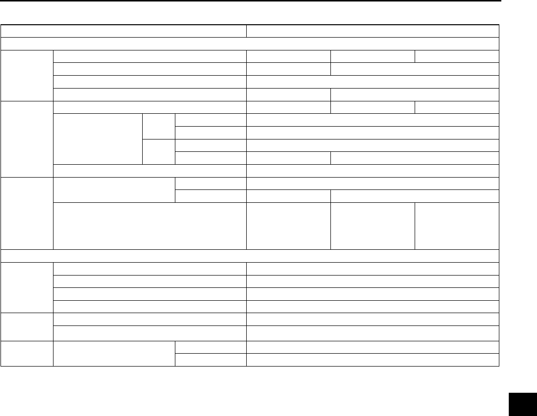
TECHNICAL DATA
TD9
TD
Wheel and Tires
*1: Total weight exceeds 160 g {5.65 oz}.
*2: One balance weight: 60 g {2.12 oz} max. If the total weight exceeds 100 g {3.53 oz} on one side, rebalance
after moving the tire around on the rim. Do not use 3 or more balance weights.
End Of Sie
Item Specification
Standard tire and wheel
Wheel
Size 15 × 6JJ 16 × 7JJ 17 × 7JJ
Offset (mm {in}) 50 {1.97} 55 {2.17}
Pitch circle diameter (mm {in}) 114.3 {4.50}
Material Steel Aluminum alloy
Tire
Size 195/65R15 91V 205/55R16 91V 215/45R17 87W
Air pressure
(kPa {kgf/cm2, psi})
Front Up to 4 persons 220 {2.2, 32}
Full load 240 {2.4, 35}
Rear Up to 4 persons 220 {2.2, 32}
Full load 300 {3.1, 44} 270 {2.8, 39}
Remaining tread (mm {in}) 1.6 {0.06}
Wheel and
tire
Wheel and tire runout Radial direction 1.5 {0.06} max.
(mm {in}) Lateral direction 2.5 {0.10} max. 2.0 {0.08} max.
Wheel imbalance (g {oz}) Knock-type*2:
9 {0.32} max.
Adhesive-type*1:
13 {0.46} max.
Knock-type*2:
8 {0.28} max.
Adhesive-type*1:
11 {0.39} max.
Knock-type*2:
7 {0.25} max.
Temporary spare tire
Wheel
Size 15×4T
Offset (mm {in}) 40 {1.57}
Pitch circle diameter (mm {in}) 114.3 {4.50}
Material Steel
Tire Size T115/70 D15
Air pressure (kPa {kgf/cm2, psi}) 420 {4.2, 60}
Wheel and
tire
Wheel and tire runout Radial direction 2.0 {0.08} max.
(mm {in}) Lateral direction 2.5 {0.10} max.
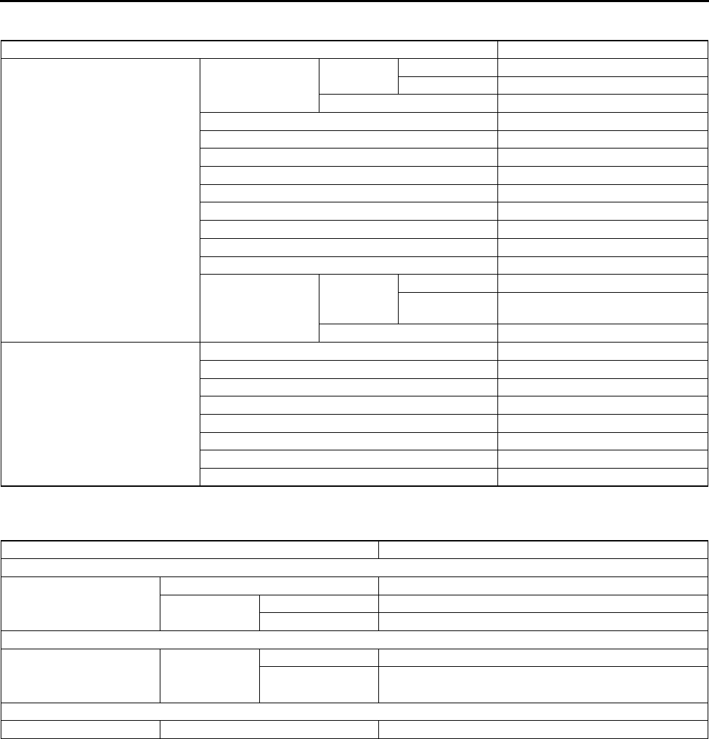
TD10
TECHNICAL DATA
BODY ELECTRICAL SYSTEM A6E931001047W01
End Of Sie
HEATER AND AIR CONDITIONER SYSTEMS A6E931001038W01
End Of Sie
Item Specifications
Exterior light bulb capacity (W)
Headlight Low beam Halogen type 55 × 2
Discharge type 35 × 2
High beam 55 × 2
Parking light 5 × 2
Front fog light 55 × 2
Front turn light 21 × 2
Front side turn light 5 × 2
Brake light/taillight 21/5 × 2
Rear turn light 21 × 2
Back-up light 18.4 × 2
Rear fog light 21 × 1
License plate light 5 × 2
High-mount brake
light
4SD
In-vehicle-type 18.4 × 1
Rear spoiler
type 4 × 1
5HB 21 × 1
Interior light bulb capacity (W)
Front map light 5 × 2
Rear map light 5 × 2
Trunk compartment light 5 × 1
Cargo compartment light 5 × 1
Courtesy light 5 × 2
Ignition key illumination 1.4 × 1
Ashtray illumination 1.4 × 1
Glove compartment light 1.7 × 1
Item Specification
REFRIGERANT SYSTEM
Refrigerant
Type R134a
Regular amount L.H.D. 470 {16.6}
(g {oz}) R.H.D. 430 {15.2}
BASIC SYSTEM
A/C compressor Lubricating oil
Type ATMOS GU10
Sealed volume 120 {120, 4.06}
(ml {cc, fl oz})
CONTROL SYSTEM
Magnetic clutch Clearance (mm {in}) 0.30.5 {0.0120.019}

ST1
ST
STSPECIAL TOOLS
SPECIAL TOOLS .................................................ST-2
ENGINE .............................................................ST-2
LUBRICATION SYSTEM ...................................ST-2
COOLING SYSTEM...........................................ST-2
FUEL AND EMISSION CONTROL SYSTEMS ..ST-3
CLUTCH.............................................................ST-3
MANUAL TRANSAXLE......................................ST-3
AUTOMATIC TRANSAXLE................................ST-4
FRONT AND REAR AXLE .................................ST-4
STEERING SYSTEM .........................................ST-6
BRAKING SYSTEM ...........................................ST-7
SUSPENSION....................................................ST-8
BODY .................................................................ST-8
BODY ELECTRICAL SYSTEM ..........................ST-9
HEATER AND AIR CONDITIONER SYSTEMS.ST-9
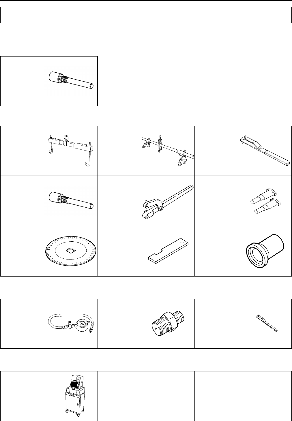
ST2
SPECIAL TOOLS
ENGINE A6E941001001W01
Ford SST numbers are collated with Mazda SST numbers in the example below.
Ford SSTs are marked with Ford SST number.
Example
1: Mazda SST number
2: Ford SST number
End Of Sie
LUBRICATION SYSTEM A6E941001001W02
End Of Sie
COOLING SYSTEM A6E941001001W03
SPECIAL TOOLS
1:49 JE01 061
2:303-507
Peg
49 L017 5A0
Support hanger
set
49 G017 5A0
Engine support
set
1:49 G032 354
2:
Adjusting
wrench
1:49 JE01 061
2:303507
Peg
1:49 UN20 5072
2:205072
Holder
1:49 UN20
507202
2:20507202
Adapter
1:49 D032 316
2:
Protractor
1:49 JE01 054
(Europe)
49 UN30 3376
(Except Europe)
2: 303376
Plate
1:49 H010 401
2:
Oil seal installer
49 0187 280A
Oil pressure
gauge
49 E019 001
Adapter
49 G032 354
Adjusting
wrench
WDS
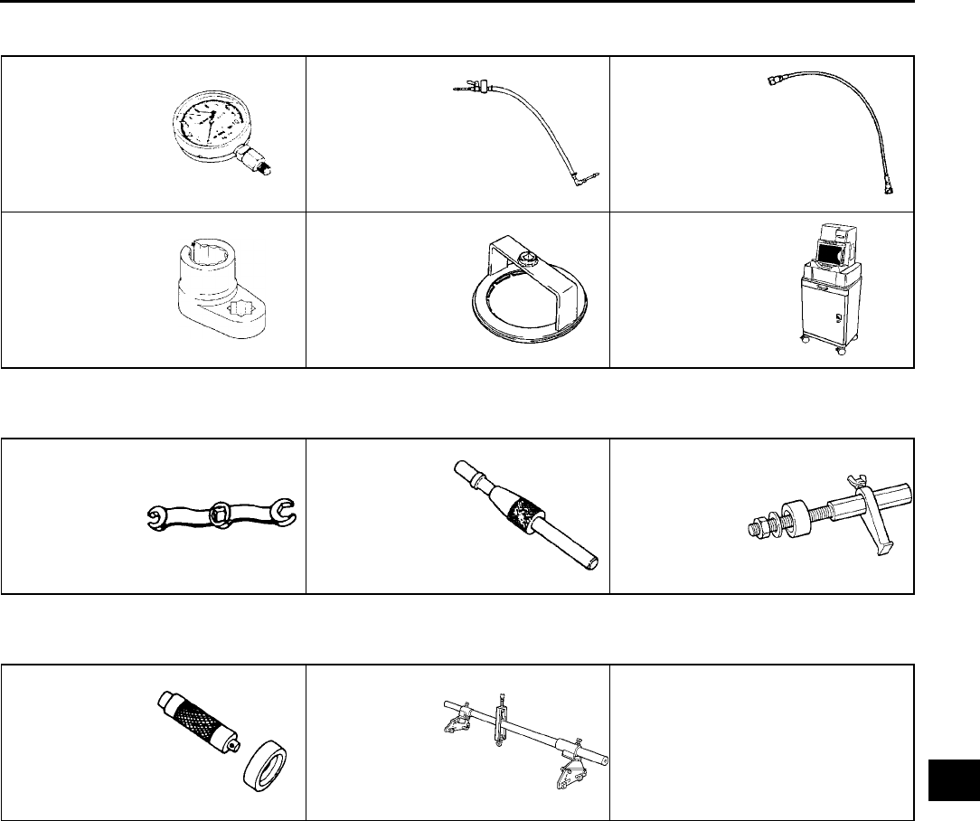
SPECIAL TOOLS
ST3
ST
End Of Sie
FUEL AND EMISSION CONTROL SYSTEMS A6E941001001W04
End Of Sie
CLUTCH A6E941001024W01
End Of Sie
MANUAL TRANSAXLE A6E941001024W02
End Of Sie
49 B019 901B
Oil Pressure
Gauge
49 N013 101A
Body
49 N013 102A
Adapter Hose
49 L018 001
O2 sensor
wrench
49 T042 001
Union wrench
WDS
49 0259 770B
Flare Nut
Wrench
49 SE01 310A
Clutch Disc
Centering Tool
49 E011 1A0
Ring Gear
Brake Set
49 G030 795
Oil Seal Installer
49 E017 5A0
Engine Support
Set
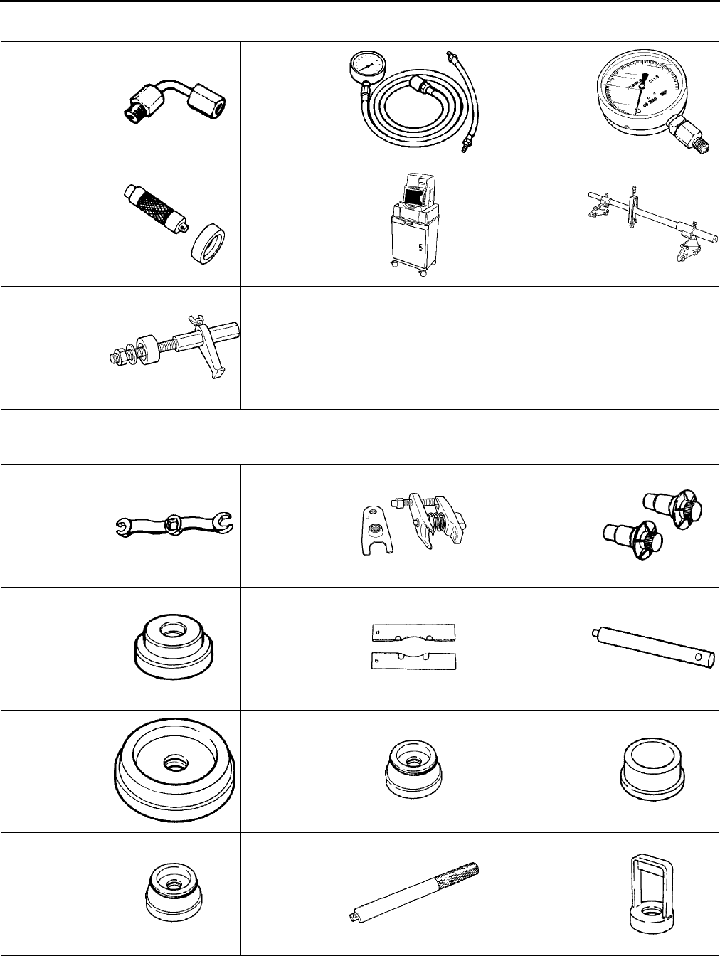
ST4
SPECIAL TOOLS
AUTOMATIC TRANSAXLE A6E941001024W03
End Of Sie
FRONT AND REAR AXLE A6E941001018W01
49 H019 002
Adapter
49 0378 400C
Oil Pressure
Gauge Set
49 B019 901B
Oil Pressure
Gauge
49 G030 795
Oil Seal Installer WDS
49 E017 5A0
Engine Support
Set
49 E011 1A0
Ring Gear
Brake Set
49 0259 770B
Flare Nut
Wrench
49 T028 3A0
Ball joint puller
set
49 G030 455
Diff. side gear
holder
49 G033 105
Attachment
49 F026 103
Wheel hub
puller
49 G033 102
Handle
49 G033 106
Attachment
φ
80
49 S033 101
Dust cover
installer
49 F027 009
Attachment
φ
68 & 77
49 F027 004
Attachment
ø 80
49 F027 003
Handle
49 B025 006A
Sensor rotor
installer
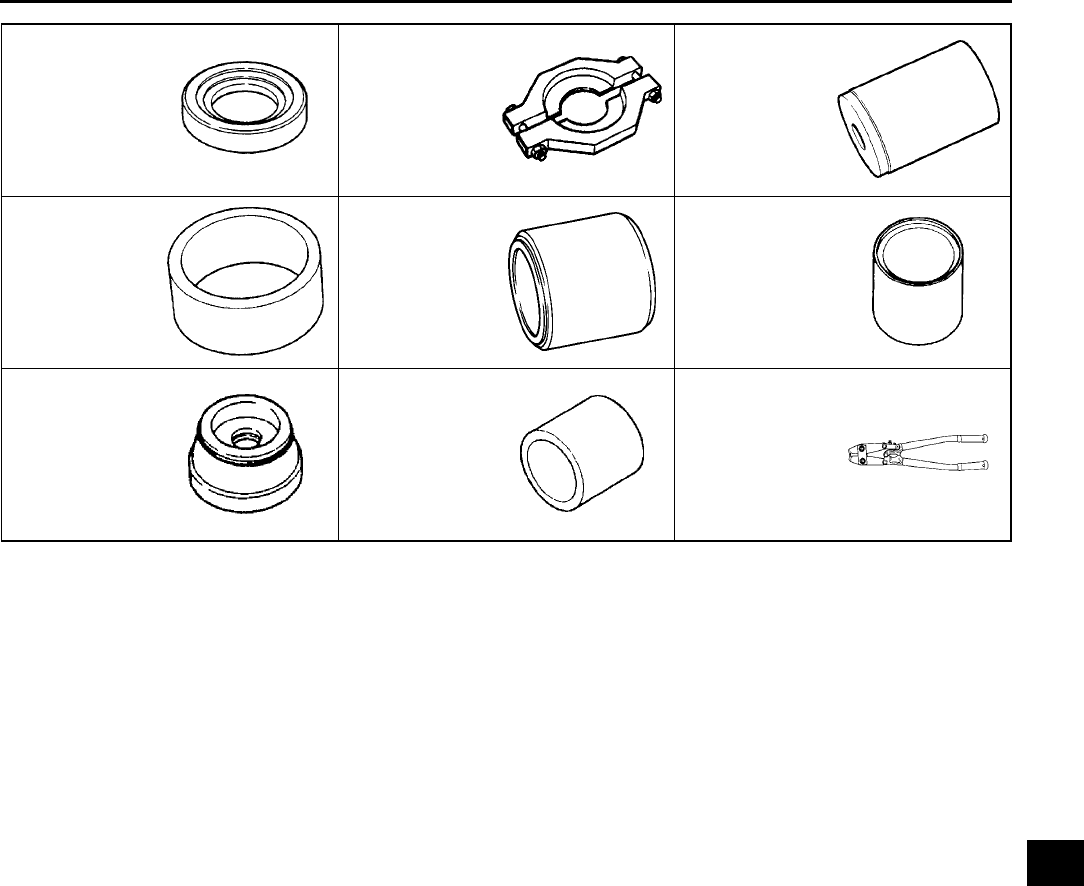
SPECIAL TOOLS
ST5
ST
End Of Sie
49 G026 105
Sensor rotor
installer
49 H027 002
Bearing
remover
49 W034 301
Support block
49 S231 626
Support block
49 B014 001
Oil seal installer
49 B025 004
Dust seal
installer
49 F027 005
Attachment ø62
49 W027 003
Bearing installer
49 T025 001
Boot clamp
crimper
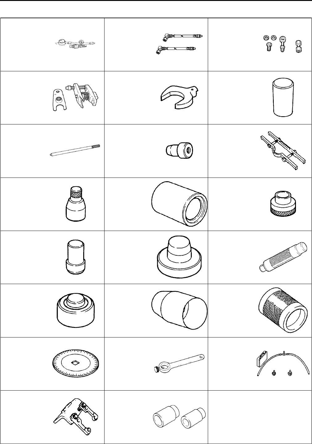
ST6
SPECIAL TOOLS
STEERING SYSTEM A6E941001034W01
49 1232 670B
Power steering
gauge set
49 H002 671
Adapter
49 G032 3A4
Power steering
gauge adapter
set
49 T028 3A0
Ball joint puller
set
49 B032 320
Wrench
49 B032 317
Bearing and oil
seal remover
49 F032 303
Handle
49 B032 323
Rod seal
remover body
49 N032 319A
Support plate
49 B032 326
Outer box
protector
49 T028 301
Support plate
49 B032 324
Rod seal
protector body
49 B032 325
Rod seal guide
49 B032 331
Oil seal installer
49 B001 797
Handle
49 N032 320
Bearing installer
49 E032 305
Slipper seal
protector
49 E032 306
Slipper seal
former
49 D032 316
Protractor
49 0180 510B
Preload
measuring
attachment
49 G032 3A1
Joint host set
49 F032 301
Power steering
pump hanger
49 F032 3A2
Installer set
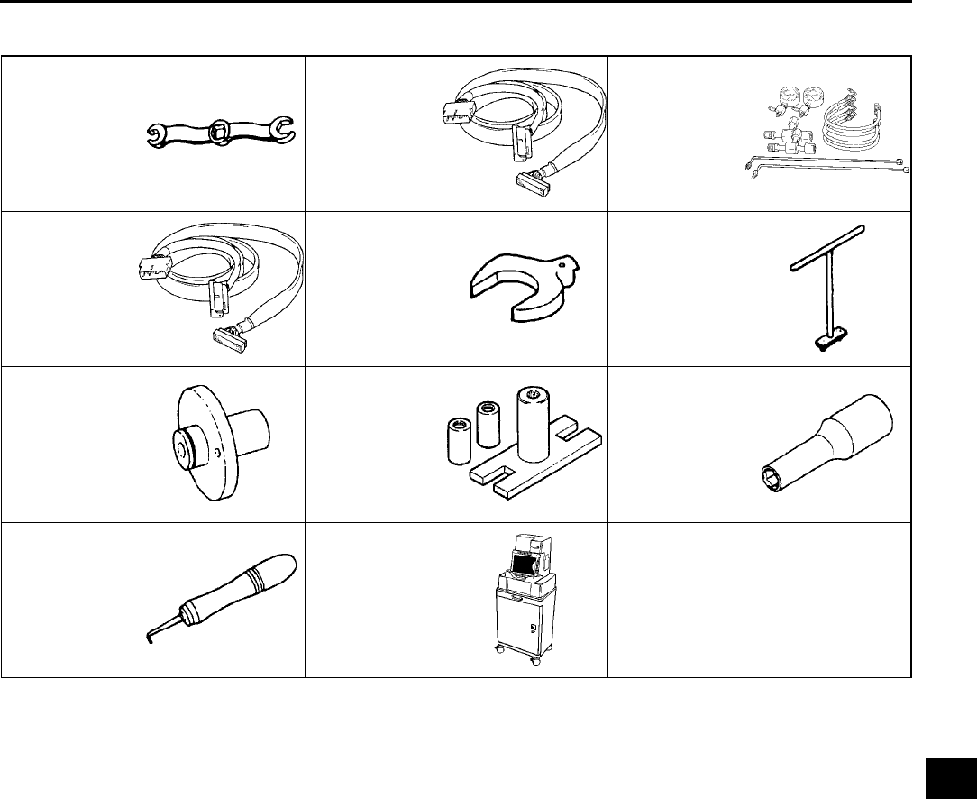
SPECIAL TOOLS
ST7
ST
End Of Sie
BRAKING SYSTEM A6E941001020W01
End Of Sie
49 0259 770B
Flare nut
wrench
49 G066 001
Adapter
harness
49 U043 0A0A
Oil pressure
gauge set
49 C066 001
Adapter
harness
49 0221 600C
Disc brake
expand tool
49 FA18 602
Disc brake
piston wrench
49 G043 001
Adjust gauge
49 E043 003A
Turning lock
tool
49 B043 004
Socket wrench
49 0208 701A
Boot air out tool
WDS
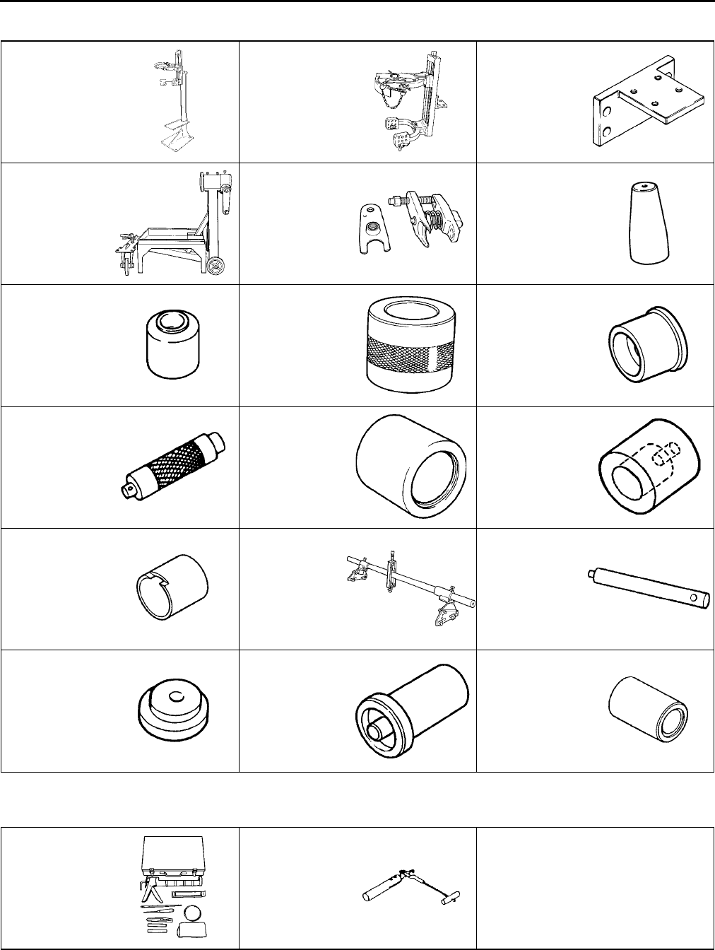
ST8
SPECIAL TOOLS
SUSPENSION A6E941001013W01
End Of Sie
BODY A6E941001047W01
End Of Sie
49 T034 1A0
Coil spring
compressor set
49 T034 101
Coil spring
compressor
49 T034 105
Attachment
49 0107 680A
Engine stand
49 T028 3A0
Ball joint puller
set
49 T034 202A
Guide
49 B034 216
Installer
49 S120 620
Bearing installer
49 T034 203
Attachment
49 G030 797
Handle
49 U034 204
Dust boot
installer
49 U027 005
Bearing installer
49 G026 103
Support block
49 E017 5A0
Engine support
set
49 G033 102
Handle
49 G033 106
Attachment
49 W034 308
Puller and
installer
49 8038 785A
Dust boot
installer
49 0305 870A
Window tool set
49 G050 1A0
Sealant
remover
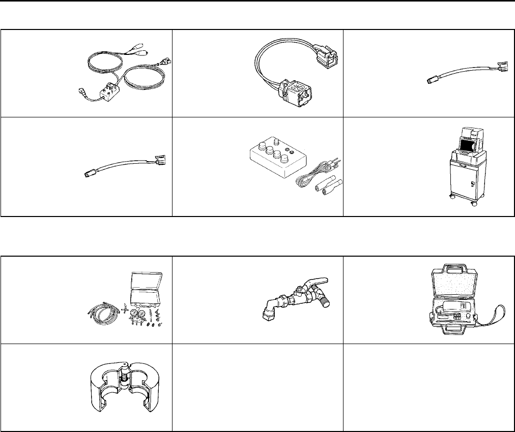
SPECIAL TOOLS
ST9
BODY ELECTRICAL SYSTEM A6E941001047W02
End Of Sie
HEATER AND AIR CONDITIONER SYSTEMS A6E941001038W01
End Of Sie
49 H066 002
Deployment tool
49 D066 002
Adapter
harness
49 G066 003
Adapter
harness
49 L066 002
Adapter
harness
49 N088 0A0
Fuel and
Thermometer
checker
WDS
49 C061 0A0B
Gas Charge Set
49 C061 012
Anti-Back Flow
Valve
49 C061 013
Gas Leak
Tester
49 G061 001
Spring lock
coupling
disconnect tool
