18 BC86D1 4 01/01/2012 Trane Installer's Guide Heat Pumps 4TWX6 XL16i Installation
User Manual: 4TWX6
Open the PDF directly: View PDF ![]() .
.
Page Count: 28
18-BC86D1-4
ALL phases of this installation must comply with NATIONAL, STATE AND LOCAL CODES
IMPORTANT — This Document is customer property and is to remain with this unit. Please return to service informa-
tion pack upon completion of work.
Heat Pumps
These instructions do not cover all variations in systems or provide for every possible contingency to be met in connection with
the installation. Should further information be desired or should particular problems arise which are not covered sufficiently for the
purchaser’s purposes, the matter should be referred to your installing dealer or local distributor.
Note: The manufacturer recommends installing only approved matched indoor and outdoor systems. All of the manufacture’s split
systems are A.H.R.I. rated only with TXV/EEV indoor systems. Some of the benefits of installing approved matched indoor and
outdoor split systems are maximum efficiency, optimum performance and the best overall system reliability.
4TWX6
Installer’s Guide
Table of Contents
Section 1. Safety ..................................................................................... 2
Section 2. Unit Location Considerations.............................................. 3
Section 3. Unit Preparation .................................................................... 5
Section 4. Setting the Unit ..................................................................... 5
Section 5. Refrigerant Line Considerations ......................................... 6
Section 6. Refrigerant Line Routing ..................................................... 7
Section 7. Refrigerant Line Brazing ...................................................... 8
Section 8. Refrigerant Line Leak Check ............................................. 10
Section 9. Evacuation ........................................................................... 11
Section 10. Service Valves ................................................................... 11
Section 11. Electrical - Low Voltage .................................................... 13
Section 12. Electrical - High Voltage ................................................... 16
Section 13. Start Up .............................................................................. 17
Section 14. System Charge Adjustment ............................................. 18
Section 15. Checkout Procedures and Troubleshooting ................... 26
2 18-BC86D1-4
Section 1. Safety
▲
WARNING
!
This information is intended for use by individuals
possessing adequate backgrounds of electrical and
mechanical experience. Any attempt to repair a central
air conditioning product may result in personal injury
and/or property damage. The manufacture or seller
cannot be responsible for the interpretation of this
information, nor can it assume any liability in connec-
tion with its use.
These units use R-410A refrigerant which operates
at 50 to 70% higher pressures than R-22. Use only
R-410A approved service equipment. Refrigerant cyl-
inders are painted a “Rose” color to indicate the type
of refrigerant and may contain a “dip” tube to allow
for charging of liquid refrigerant into the system. All
R-410A systems use a POE oil that readily absorbs
moisture from the atmosphere. To limit this “hygro-
scopic” action, the system should remain sealed
whenever possible. If a system has been open to the
atmosphere for more than 4 hours, the compressor oil
must be replaced. Never break a vacuum with air and
always change the driers when opening the system
for component replacement. For specific handling
concerns with R-410A and POE oil reference Retrofit
Bulletins SS-APG006-EN and APP-APG011-EN.
Extreme caution should be exercised when opening
the Liquid Line Service Valve. Turn counterclockwise
until the valve stem just touches the rolled edge. No
torque is required. Failure to follow this warning will
result in abrupt release of system charge and may
result in personal injury and /or property damage.
UNIT CONTAINS R-410A REFRIGERANT!
R-410A operating pressures exceed the limit of R-22.
Proper service equipment is required. Failure to use
proper service tools may result in equipment damage
or personal injury.
SERVICE
USE ONLY R-410A REFRIGERANT AND AP-
PROVED POE COMPRESSOR OIL.
▲
WARNING
!
▲
WARNING
!
LIVE ELECTRICAL COMPONENTS!
During installation, testing, servicing, and trouble-
shooting of this product, it may be necessary to work
with live electrical components. Failure to follow all
electrical safety precautions when exposed to live
electrical components could result in death or serious
injury.
▲
WARNING
!
If using existing refrigerant lines make certain that all
joints are brazed, not soldered.
▲CAUTION
!
Scroll compressor dome temperatures may be hot. Do
not touch the top of compressor; it may cause minor to
severe burning.
▲CAUTION
!
▲
WARNING
!
18-BC86D1-4 3
When mounting the outdoor unit on a roof, be
sure the roof will support the unit’s weight.
Properly selected isolation is recommended to
alleviate sound or vibration transmission to the
building structure.
Please refer to application bulletin APP-
APG013-EN for detailed mounting information.
Section 2. Unit Location Considerations
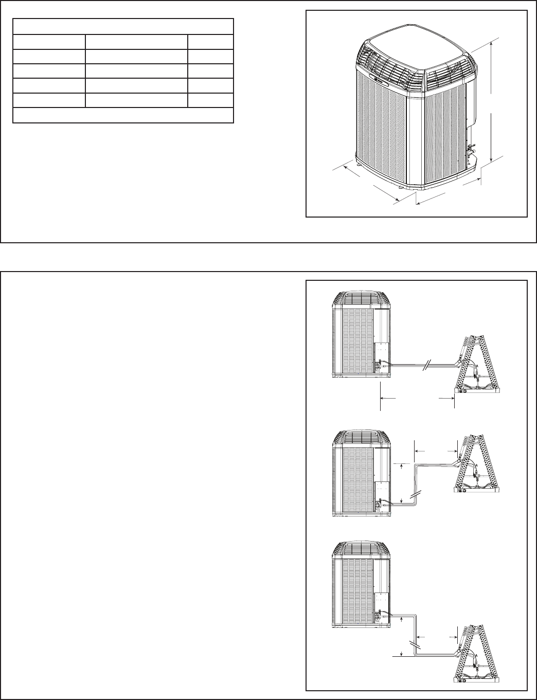
2.1 Unit Dimensions and Weight
2.2 Refrigerant Piping Limits
D
H
W
Unit Dimensions and Weight
Models H x D x W (in)
Weight* (lb)
4TWX6024G
50 x 34 x 37 257
4TWX6036G
54 x 34 x 37 257
4TWX6048G
54 x 34 x 37 310
4TWX6060E/G
54 x 34 x 37 311
* Weight values are estimated.
25’
Max
Line
Lift
Standard
Line Set
60’ Max
Line Length
25’
Max
Line
Lift
35’ Max
Line
Length
35’ Max
Line
Length
1. The maximum length of refrigerant lines
from outdoor to indoor unit should NOT
exceed sixty (60) feet.
2. The maximum vertical change should not
exceed twenty five (25) feet*.
3. Service valve connection diameters are
shown in Table 5.1.
Note: For line lengths greater than sixty (60)
feet, Refer to Refrigerant Piping Application
Guide, SS-APG006-EN or Refrigerant Piping
Software Program, 32-3312-03 (or latest revi-
sion).
Table 2.1
*
*
*
Restricted to maximum vertical change of 25 ft.
4 18-BC86D1-4
Min. 12” to
Shrubbery
Avoid Install
Near Bedrooms
Min 5’ Unrestricted
Access Panel
Min 3’
Unrestricted
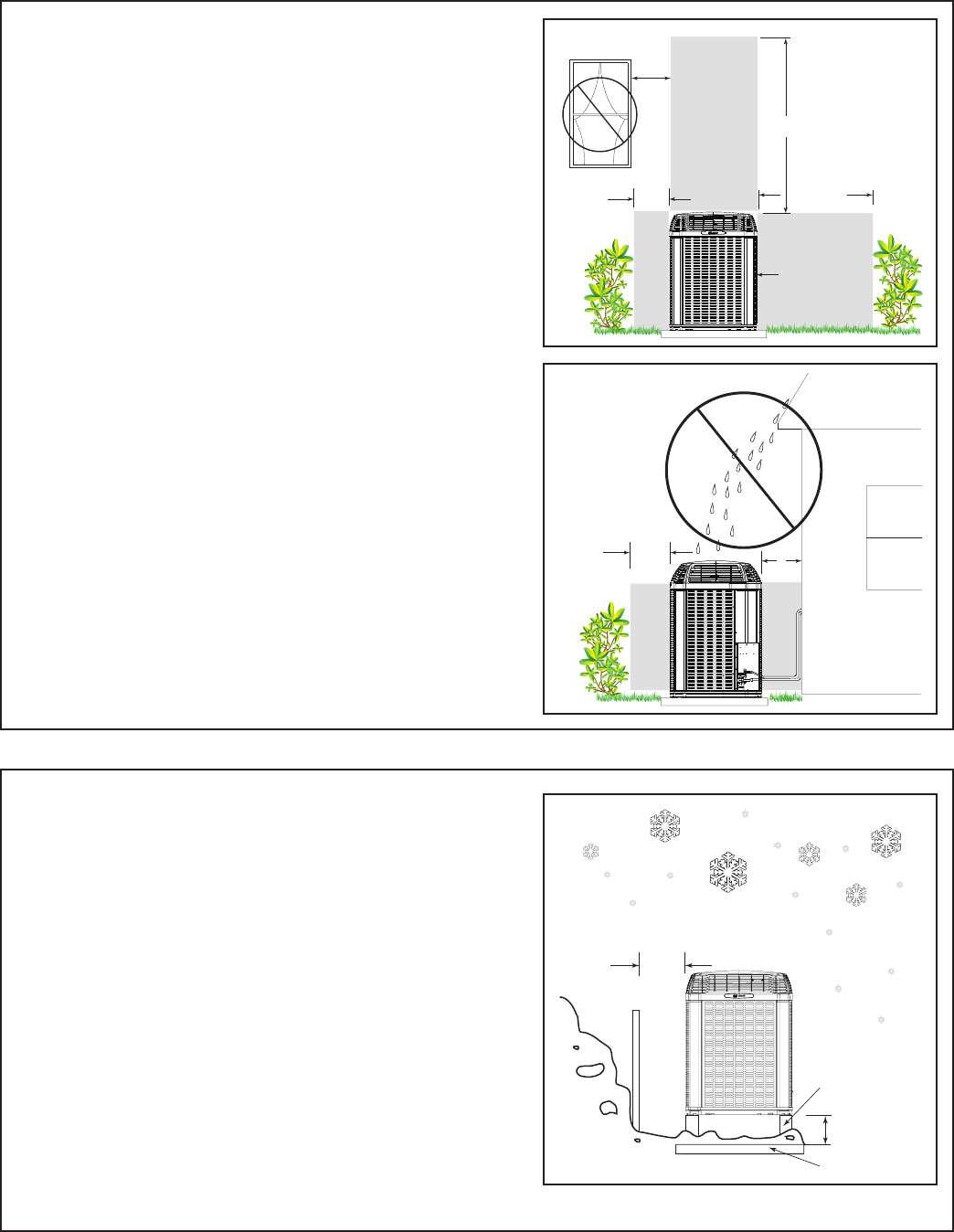
2.3 Suggested Locations for Best Reliability
2.4 Cold Climate Considerations
Ensure the top discharge area is unrestricted for
at least five (5) feet above the unit.
Three (3) feet clearance must be provided in
front of the control box (access panels) and any
other side requiring service.
Do not locate close to bedrooms as operational
sounds may be objectionable.
Avoid locations such as near windows where
condensation and freezing defrost vapor can
annoy a customer.
Min. 12” to
Shrubbery Min. 12”
to Wall
Position the outdoor unit a minimum of 12” from
any wall or surrounding shrubbery to ensure
adequate airflow.
Outdoor unit location must be far enough away
from any structure to prevent excess roof runoff
water or icicles from falling directly on the unit.
NOTE: It is recommended that these precau-
tions be taken for units being installed in areas
where snow accumulation and prolonged below
freezing temperatures occur.
• Units should be elevated 3-12 inches above
the pad or roof top, depending on local
weather. This additional height will allow
drainage of snow and ice melted during
defrost cycle prior to its refreezing. Ensure
that drain holes in unit base pan are not
obstructed preventing draining of defrost
water.
• If possible, avoid locations that are likely to
accumulate snow drifts. If not possible, a
snow drift barrier should be installed around
the unit to prevent a build-up of snow on the
sides of the unit.
Min. 12”
Snow
Barrier
3-12” Elevation
Snow Legs
Pad
18-BC86D1-4 5
2.5 Coastal Considerations
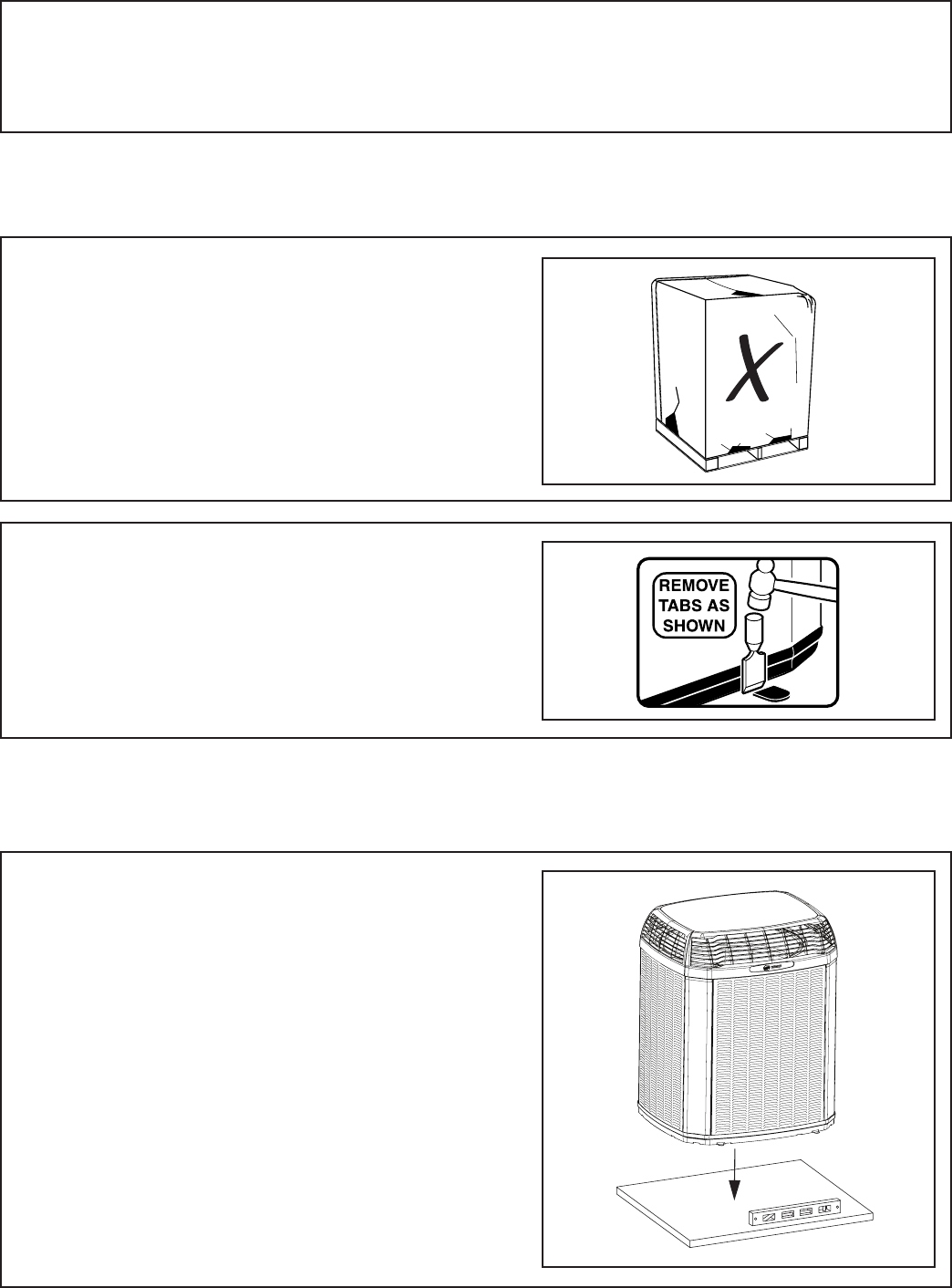
STEP 2 - To remove the unit from the pallet,
remove tabs by cutting with a sharp tool.
Section 3. Unit Preparation
3.1 Prepare The Unit For Installation
STEP 1 - Check for damage and report prompt-
ly to the carrier any damage found to the unit.
Section 4. Setting the Unit
4.1 Pad Installation
When installing the unit on a support pad, such
as a concrete slab, consider the following:
• The pad should be at least 1” larger than the
unit on all sides.
• The pad must be separate from any structure.
• The pad must be level.
• The pad should be high enough above grade
to allow for drainage.
• The pad location must comply with National,
State, and Local codes.
For other applications refer to Application Guide
APP-APG013-EN.
If installed within one mile of salt water, including seacoasts and inland waterways, models without factory
supplied Seacoast Salt Shields require the addition of BAYSEAC001 (Seacoast Kit) at installation time. Please
refer to Application Guide SS-APB006-EN: Trane - Sea Coast Applications and Seascoast Corrosion Protection
Bulletin UN-SVB11A-EN.
6 18-BC86D1-4
Section 5. Refrigerant Line Considerations
5.1 Refrigerant Line and Service Valve Connection Sizes
5.3 Required Refrigerant Line Length
5.2 Factory Charge
Line Sizes Service Valve Connection Sizes
Model Vapor
Line
Liquid
Line
Vapor Line
Connection
Liquid Line
Connection
4TWX6024G 5/8 3/8 5/8 3/8
4TWX6036G 3/4 3/8 3/4 3/8
4TWX6048G 7/8 3/8 7/8 3/8
4TWX6060E/G 1-1/8 3/8 1-1/8 3/8
Table 5.1
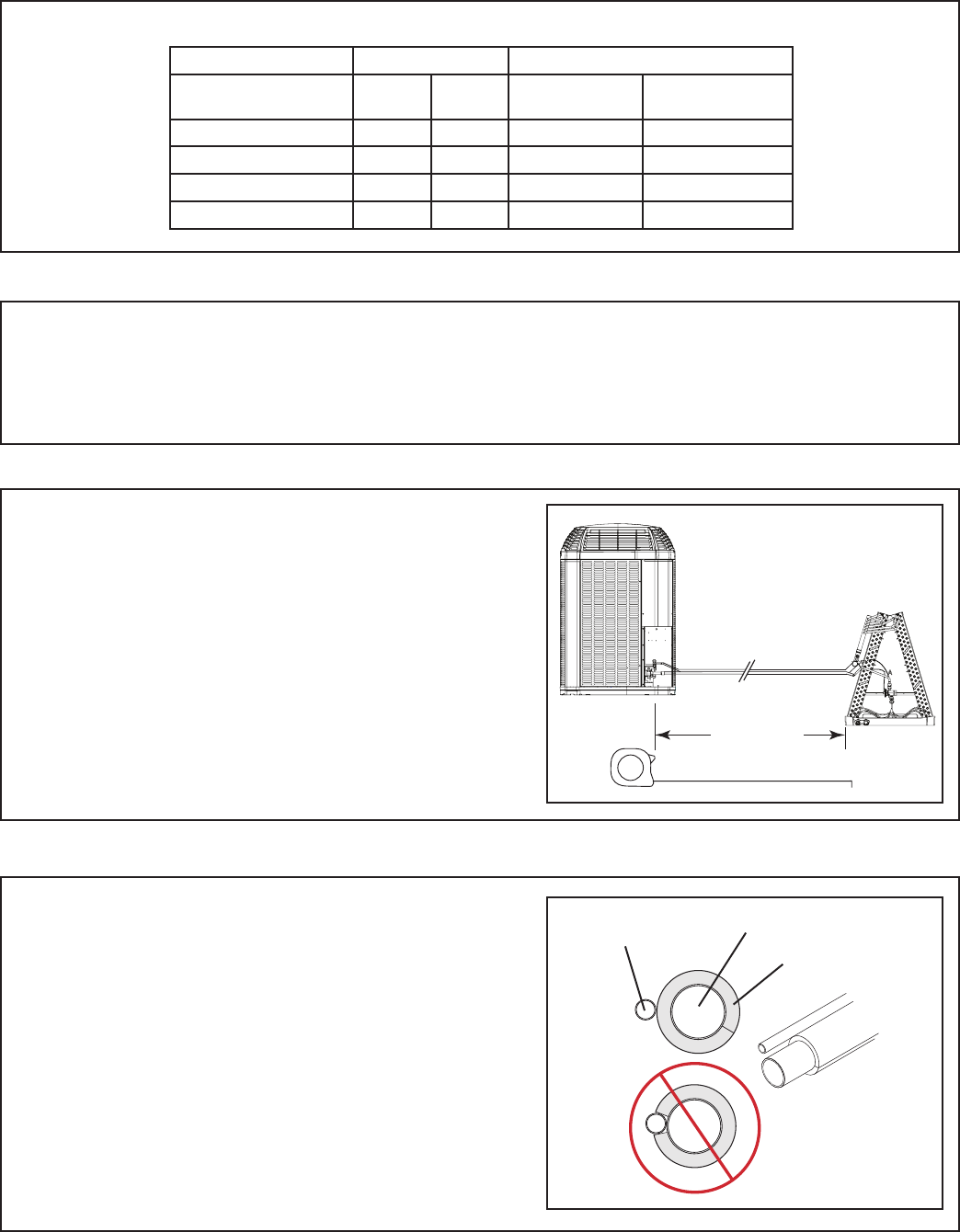
Line Length
5.4 Refrigerant Line Insulation
Important: The Vapor Line must always be
insulated. DO NOT allow the Liquid Line and
Vapor Line to come in direct (metal to metal)
contact.
Vapor Line
Liquid Line
Insulation
Determine required line length and lift. You will
need this later in STEP 2 of Section 14.
Total Line Length = __________ Ft.
Total Vertical Change (lift) = __________ Ft.
Trane outdoor condensing units are factory charged with the system charge required for the outdoor condensing
unit, fifteen (15) feet of tested connecting line, and the smallest indoor evaporative coil match. If connecting line
length exceeds fifteen (15) feet and/or a larger indoor evaporative coil is installed, then final refrigerant
charge adjustment is necessary.
18-BC86D1-4 7
5.5 Reuse Existing Refrigerant Lines
For retrofit applications, where the existing
indoor evaporator coil and/or refrigerant lines
will be used, the following precautions should
be taken:
• Ensure that the indoor evaporator coil and
refrigerant lines are the correct size.
• Ensure that the refrigerant lines are free of
leaks, acid, and oil.
Important: For more information see publi-
cation numbers SS-APG006-EN and APP-
APG011-EN.
▲CAUTION
!
If using existing refrigerant lines make certain
that all joints are brazed, not soldered.
Section 6. Refrigerant Line Routing
6.1 Precautions
Important: Take precautions to prevent noise
within the building structure due to vibration
transmission from the refrigerant lines.
For Example:
• When the refrigerant lines have to be fastened to floor joists or other framing in a structure, use isolation type
hangers.
• Isolation hangers should also be used when refrigerant lines are run in stud spaces or enclosed ceilings.
• Where the refrigerant lines run through a wall or sill, they should be insulated and isolated.
• Isolate the lines from all ductwork.
• Minimize the number of 90º turns.
Comply with National, State, and Local Codes when
isolating line sets from joists, rafters, walls, or other
structural elements.
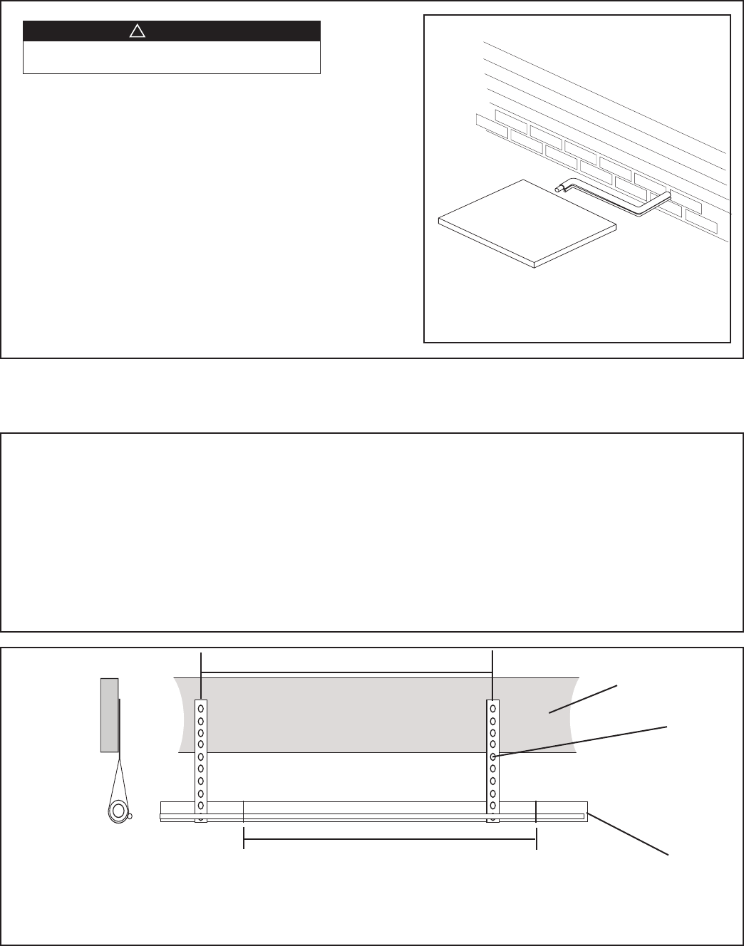
Isolation From Joist/Rafter
Side View
8 Feet Maximum
Secure Vapor line from joists using isolators every 8 ft. Secure
Liquid Line directly to Vapor line using tape, wire, or other appro-
priate method every 8 ft.
Joist/Rafter
Isolator
Line Set
8 Feet Maximum
8 18-BC86D1-4
Isolation In Wall Spaces
Side View
Wall
Isolator
Line Set
8 Feet Maximum
Secure Vapor Line using isolators every 8 ft. Secure Liquid Line
directly to Vapor Line using tape, wire, or other appropriate
method every 8 ft.
8 Feet Maximum
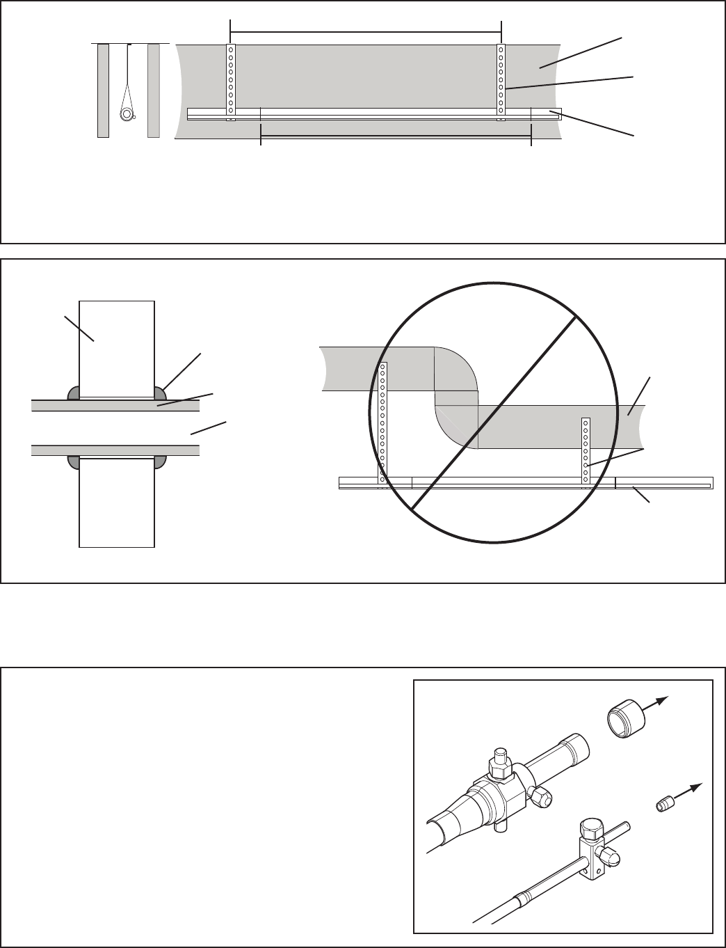
Isolation Through Wall DO NOT hang line sets from ductwork
Sealant
Insulation
Vapor Line
Wall
Ductwork
Isolator
Line Set
Section 7. Refrigerant Line Brazing
7.1 Braze The Refrigerant Lines
STEP 1 - Remove caps or plugs. Use a debur-
ing tool to debur the pipe ends. Clean both
internal and external surfaces of the tubing
using an emery cloth.
18-BC86D1-4 9
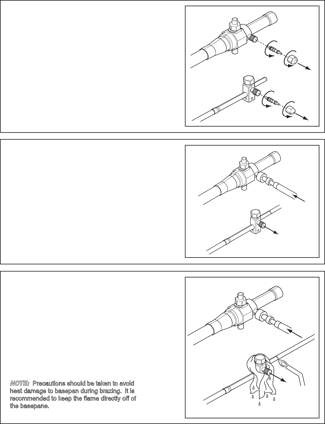
STEP 2 - Remove the pressure tap cap and
valve cores from both service valves.
STEP 3 - Purge the refrigerant lines and indoor
coil with dry nitrogen.
STEP 4 - Wrap a wet rag around the valve
body to avoid heat damage and continue the
dry nitrogen purge.
Braze the refrigerant lines to the service
valves.
Continue the dry nitrogen purge. Do not re-
move the wet rag until all brazing is completed.
Important: Remove the wet rag before stopping
the dry nitrogen purge.
NOTE: Precautions should be taken to avoid
heat damage to basepan during brazing. It is
recommended to keep the flame directly off of
the basepane.
10 18-BC86D1-4
STEP 5 - Replace the pressure tap valve cores
after the service valves have cooled.
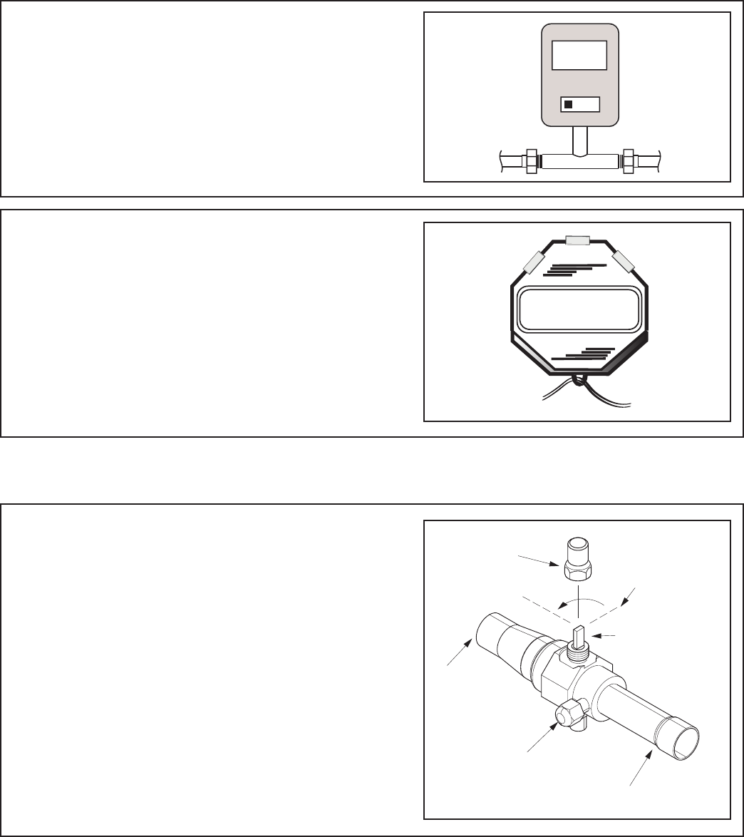
STEP 2 - Check for leaks by using a soapy solu-
tion or bubbles at each brazed location.
Remove nitrogren pressure and repair any leaks
before continuing.
Section 8. Refrigerant Line Leak Check
8.1 Check For Leaks
STEP 1 - Pressurize the refrigerant lines and
evaporator coil to 150 PSIG using dry nitrogen.
150 PSIG
18-BC86D1-4 11
Section 9. Evacuation
9.1 Evacuate the Refrigerant Lines and Indoor Coil
Important: Do not open the service valves until
the refrigerant lines and indoor coil leak check
and evacuation are complete.
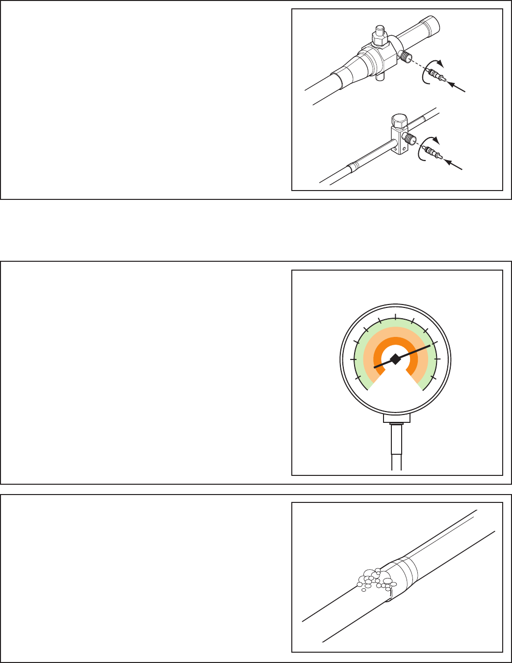
STEP 1 - Evacuate until the micron gauge reads
no higher than 350 microns, then close off the
valve to the vacuum pump.
STEP 2 - Observe the micron gauge. Evacuation
is complete if the micron gauge does not rise
above 500 microns in one (1) minute.
Once evacuation is complete blank off the
vacuum pump and micron gauge, and close the
valves on the manifold gauge set.
1 MIN.
Section 10. Service Valves
10.1 Open the Gas Service Valve
Important: Leak check and evacuation must be
completed before opening the service valves.
NOTE: Do not vent refrigerant gases into the
atmosphere
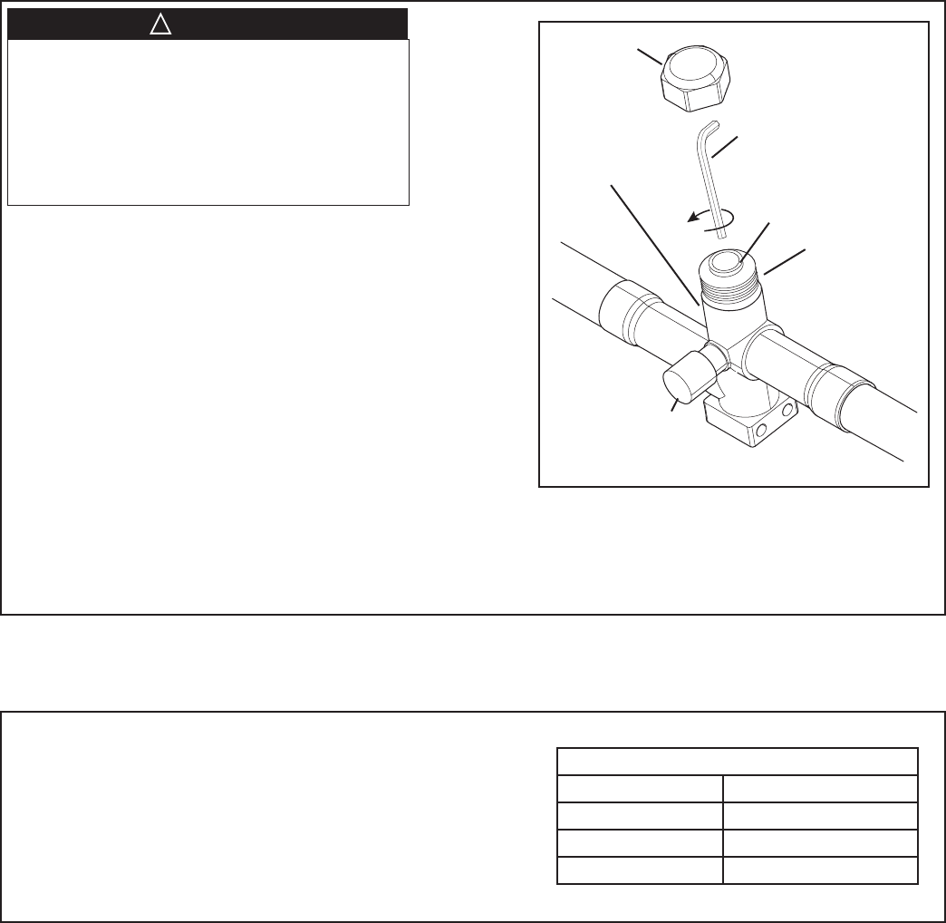
STEP 1 - Remove valve stem cap.
STEP 2 - Using an adjustable wrench, turn valve
stem 1/4 turn counterclockwise to the fully open
position.
STEP 3 - Replace the valve stem cap to prevent
leaks. Tighten finger tight plus an additional 1/6
turn.
0350
Microns
ON OFF
CAP
1/4 TURN ONLY
COUNTERCLOCKWISE
FOR FULL OPEN
POSITION
VALVE STEM
GAS LINE CONNECTION
UNIT SIDE
OF VALVE
PRESSURE TAP PORT
12 18-BC86D1-4
10.1 Open the Liquid Service Valve
Important: Leak check and evacuation must be
completed before opening the service valves.
STEP 1 - Remove service valve cap.
STEP 2 - Fully insert 3/16” hex wrench into the
stem and back out counterclockwise until valve
stem just touches the rolled edge (approximately
five (5) turns.)
STEP 3 - Replace the valve cap to prevent leaks.
Tighten finger tight plus an additional 1/6 turn.
Cap
Rolled Edge to
Captivate Stem
Hex Headed
Valve System
Service Port
3/16” Hex Wrench
Unit Side
of Service
Valve
Extreme caution should be exercised when
opening the Liquid Line Service Valve. Turn
counterclockwise until the valve stem just
touches the rolled edge. No torque is required.
Failure to follow this warning will result in abrupt
release of system charge and may result in
personal injury and /or property damage.
▲WARNING
!
Section 11. Electrical - Low Voltage
11.1 Low Voltage Maximum Wire Length
Table 11.1 defines the maximum total length of
low voltage wiring from the outdoor unit, to the
indoor unit, and to the thermostat.
Table 11.1
24 VOLTS
WIRE SIZE MAX. WIRE LENGTH
18 AWG 150 Ft.
16 AWG 225 Ft.
14 AWG 300 Ft.
18-BC86D1-4 13
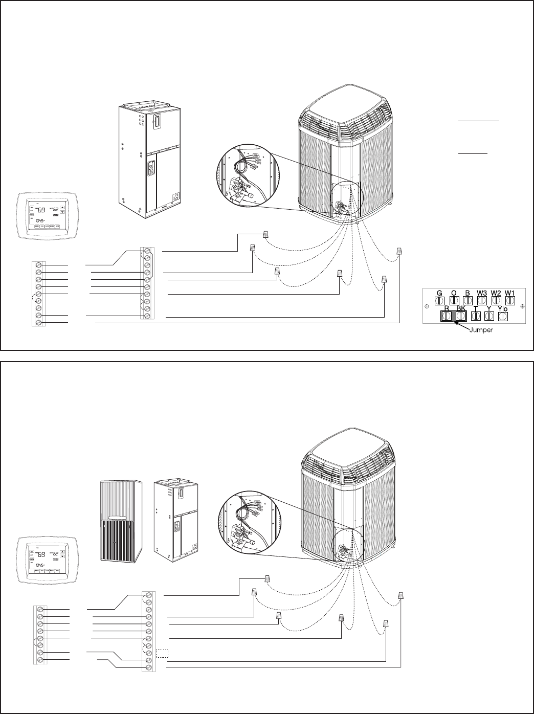
11.2 Low Voltage Hook-up Diagrams
Red
Yellow
Brown
Green
White
Blue
Orange
W1
O
B
X2
G
Y2
Y1 Yellow
Yellow
Brown Yellow/Red
Blue
Orange
Blue
Black
(X2)
Red Red Orange
R
Comfort Control
Variable Speed
Air Handler
Heat Pump
Black
W1
W2
W3
G
Y
B
O
BK
YLO
R
Neatly bundle all low voltage
wires behind the service
valve cover as shown.
Notes:
1. If electric heat does not
have 3rd contactor (CH),
connect a jumper wire from
W3 to W2. If electric heat
does not have 2nd contactor
(BH), connect a jumper wire
from W2 to W1.
2. Installer must remove the
factory installed jumper
between R and BK on the
air handler terminal strip.
3. Installer must add a field
installed jumper between
R and O on the air handler
terminal strip.
4. 4TWX6 units require 80%
airflow with Y1 (low stage)
and 100% airflow with Y2
(high stage).
A) Connect Y1 from comfort
control to Y at the VS air
handler and to Y1 (yel-
low) at the HP.
B) Connect Y2 from comfort
control to BK at the VS
air handler and to Y2
(yellow/red) at the HP.
Red
Yellow
Brown
Green
White
Blue
Orange
W1
O
B
X2
G
Y2
Y1 Yellow
Yellow
Brown Yellow/Red
Blue
Orange
Blue
Black
(X2)
Red Red Orange
R
Comfort Control
Comm. Variable Speed
Furnace or Air Handler - Note 1
Air Conditioner or
Heat Pump - Note 6
Black
Note 7
W1
W2
W3
G
Y2
B
O
BK
D
Y1
R
Neatly bundle all low voltage
wires behind the service
valve cover as shown.
Notes:
1. See User Interface setup
menu for 24 VAC control
mode and cooling CFM
options.
2. First stage CFM options
for 4TWX6 are 65–80%.
3. For furnace+heat pump
applications, comfort
control must be dual fuel
capable or use accessory
TAYPLUS103A.
4. W3 terminal may not be
present on indoor unit.
4TEE3F31-66
Variable Speed Air Handler Hook-up
Diagram
Communicating Indoor Unit
with 24 V Control Hook-up
Diagram
14 18-BC86D1-4
Notes:
1. Comfort control must be dual
fuel capable or use acces-
sory TAYPLUS103A.
2. Installer must cut the factory
R to BK jumper on furnace
circuit board. OR, on new
15-digit models, set the S5-2
DIP switch to OFF.
3. Installer must add a field
installed jumper between R
and O on the furnace termi-
nal strip
4. 4TWX6 units require 80%
airflow with Y1 (low stage)
and 100% airflow with Y2
(high stage).
A) Connect Y1 from comfort
control to Y at the VS fur-
nace and to Y1 (yellow) at
the HP.
B) Connect Y2 from comfort
control to BK at the VS
furnace and to Y2 (yellow/
red) at the HP.
5. Comfort control may not
have W2 or W3 terminals.
6. If single stage heating com-
fort control is used, jumper
W1 to W2 on the furnace
terminal strip.
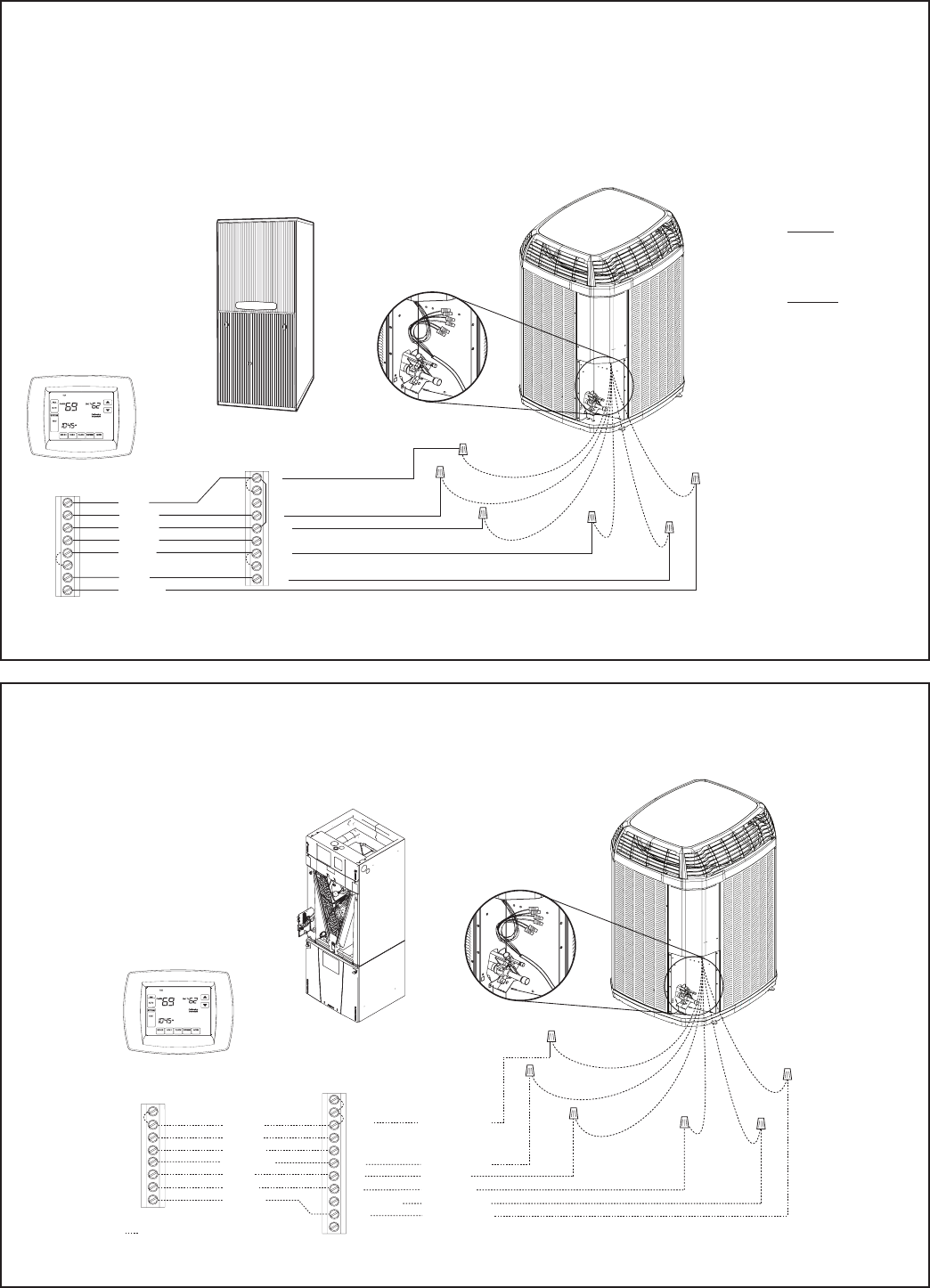
Red
Yellow
Brown
Green
White
Blue
Yellow
Yellow
Brown Yellow/Red
Blue
Orange
Blue
Black
(X2)
Red Red Orange
Black
Orange
Heat Pump
O
W1
B
X2
G
Y2
Y1
R
Comfort Control
Variable Speed
Furnace
W1
W2
G
Y
B
O
BK
YLO
R
Neatly bundle all low voltage
wires behind the service
valve cover as shown.
Comfort Control
Air Handler
Heat Pump
Neatly bundle all low voltage
wires behind the service
valve cover as shown.
Y
ellow/Red
Field wiring
Yellow
Blue
Black
(X2)
Red
Orange
Red
Yellow
Orange
Green
White
Blue
BB - Blue
W
X2
G
Y1
Brown
Y2 Y1 - Yellow
Y2 - Brown
R
OO
R
B
YI
W1
YO
Y2
DH/BK
G
W2
W3
R - Red
O - Orange
(In)
(Out)
W1 - White
Variable Speed Furnace
Hook-up Diagram
*AM7 Air Handler
Hook-up Diagram
18-BC86D1-4 15
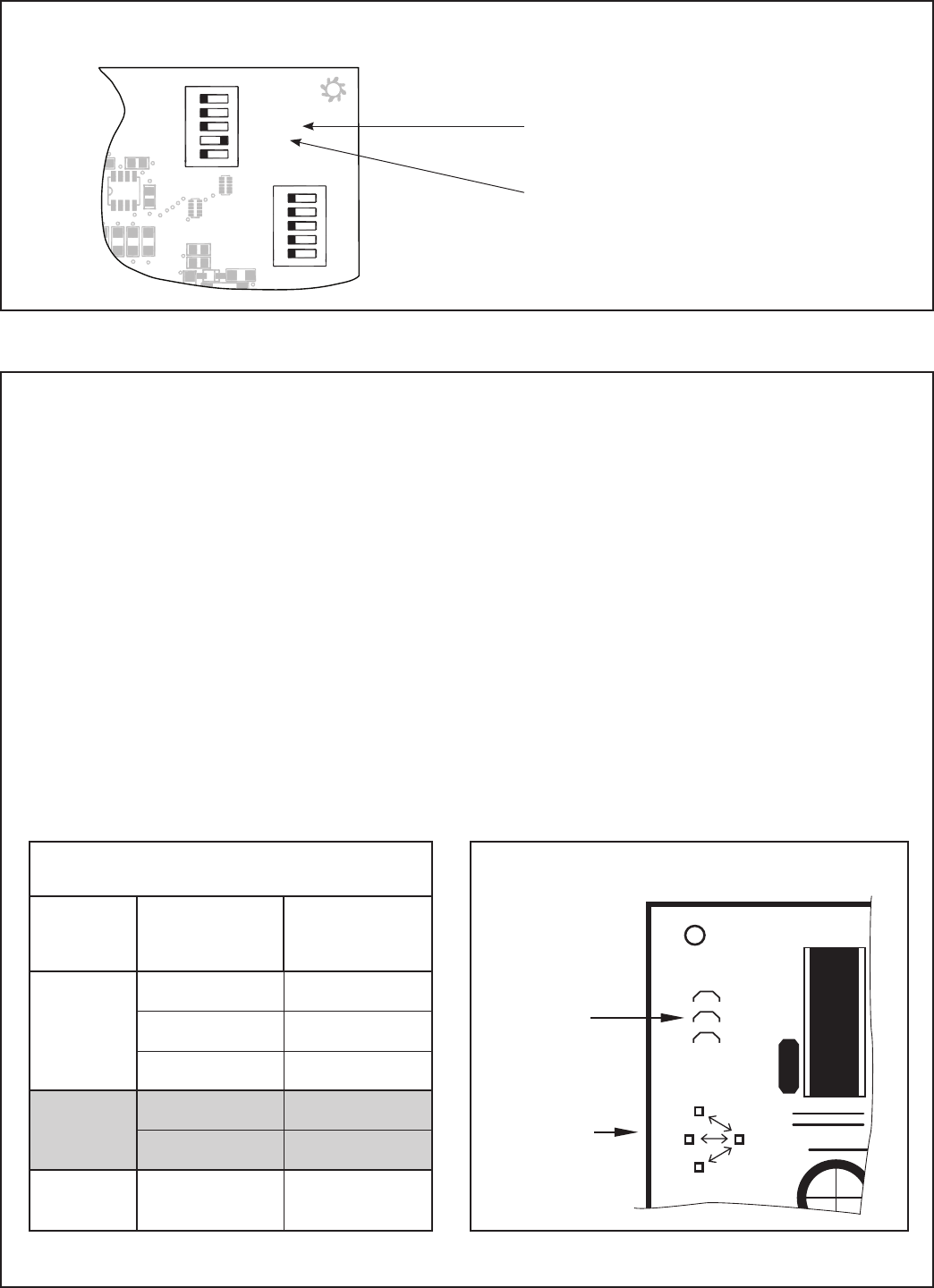
11.3 Defrost Control
Defrost controls have a selectable termination temperature. As shipped, defrost will terminate at 47°F. For a
higher termination temperature, cut Jumper J2 to achieve 70°F when at or below 30°F ambient. See Service
Facts shipped in the outdoor unit for more information.
Pin Identification (See Illustration at right)
1. TEST_COMMON (Shorting any of the other pins to this pin causes the function of the other pin to be
executed. Leaving this pin open results in the normal mode of operation.)
2. TST = Test (Shorting TEST_COMMON to this pin speeds up all defrost board timings.)
3. FRC_DFT = Forced Defrost (Short TEST_COMMON to this pin for two (2) seconds to initiate a forced
defrost. Remove the short after defrost initiates.)
Defrost Control Checkout
Normal operation requires:
• LED on board flashing 1 time/second.
• 24V AC between R & B.
• 24V AC between Y & B with unit operating.
• Defrost initiation when FRC_DFT pin is shorted to TEST_COMMON pin.
If a defrost control problem is suspected, refer to the service information in control box.
Defrost Termination Temperatures
Outdoor
Temperature
Termination
Temperature
As
Shipped
>22°F 47°F
10°F–22°F ODT + 25°F
6°F–10°F 35°F
Cut
Jumper 2
>30°F 47°F
6°F–30°F 70°F
All < 6°F 12 min. or 35°F
every 3 hrs.
J1
U1
J2
J3
FRC_DFT
TST
TEST_COMMON
LOW_FAN
JUMPER 2
TEST PINS
Defrost Board
Detail
1
1
12345
12345
HP
2(Compressor)
2(Stages)
AC (System)
}
OUTDOOR
Capacity (Tons)
OUTDOOR
}
Torque
CFM/Ton
Cool OffDelay
}
INDOOR
CFM
+12V
R13
R14
R1
R4
1
U1
RNET 1
S1
on
on
S2
RNET 2
R6
C22
C19
C15
C12
C18
C21
C10
D9
L1
R22
Must configure to “OFF” for heat pump.
Must configure to “ON” for 16 SEER
two-stage compressors.
*AM7 Air Handler Hook-up (Continued)
Control
Board
16 18-BC86D1-4
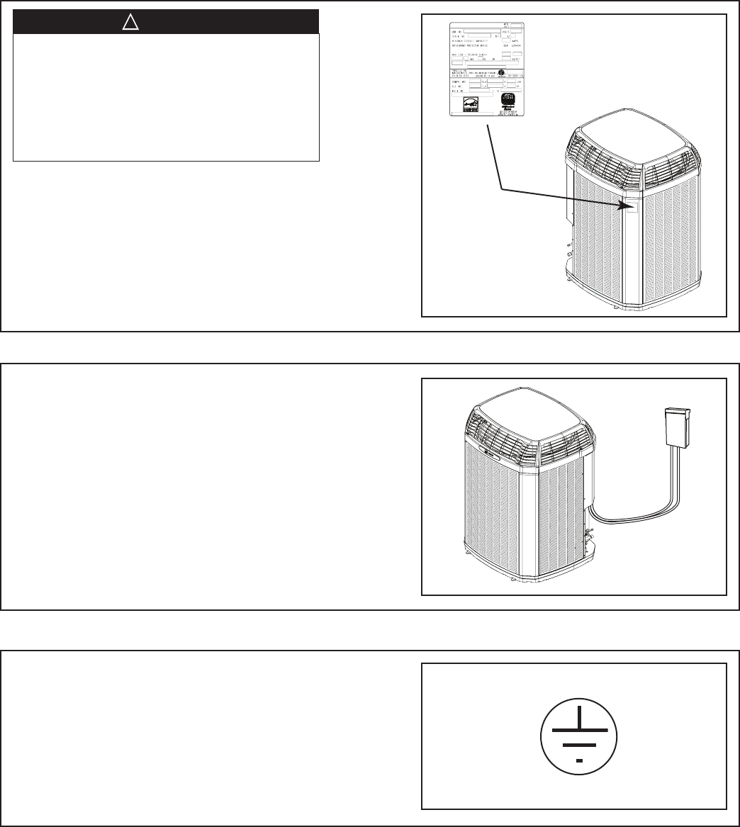
Section 12. Electrical - High Voltage
12.1 High Voltage Power Supply
The high voltage power supply must agree with
the equipment nameplate.
Power wiring must comply with national, state,
and local codes.
Follow instructions on unit wiring diagram located
on the inside of the control box cover and in the
Service Facts document included with the unit.
12.2 High Voltage Disconnect Switch
12.3 High Voltage Ground
Ground the outdoor unit per national, state, and
local code requirements.
Install a separate disconnect switch at the
outdoor unit.
For high voltage connections, flexible electri-
cal conduit is recommended whenever vibra-
tion transmission may create a noise problem
within the structure.
LIVE ELECTRICAL COMPONENTS!
During installation, testing, servicing, and
troubleshooting of this product, it may be nec-
essary to work with live electrical components.
Failure to follow all electrical safety precau-
tions when exposed to live electrical compo-
nents could result in death or serious injury.
▲
WARNING
!
18-BC86D1-4 17
Section 13. Start Up
13.1 System Start Up
STEP 2 - Set System Thermostat to OFF.
STEP 3 - Turn on disconnect(s) to apply power
to the indoor and outdoor units.
STEP 5 - Set system thermostat to ON.
OFF
D
O
N
E
CANCEL
ON
OFF
STEP 4 - Wait one (1) hour before starting the
unit if compressor crankcase heater acces-
sory is used and the Outdoor Ambient is below
70ºF.
60 MIN.
STEP 1 - Ensure Sections 7 through 12 have
been completed.
ON
D
O
N
E
CANCEL
18 18-BC86D1-4
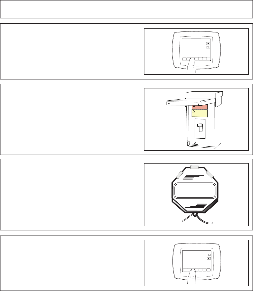
STEP 1 - Check the outdoor temperatures.
Subcooling (in cooling mode) is the only recom-
mended method of charging above 55º F ambi-
ent outdoor temperature. See Section 14.2.
For outdoor temperatures below 55º F, follow
the Superheat charging instructions (in heating
mode). See Section 14.3.
Note: It is important to return in the spring or
summer to accurately charge the system in the
cooling mode with outdoor ambient temperature
above 55ºF.
For best results the indoor temperature should
be kept between 70º F to 80º F.
STEP 1 - Use the refrigerant line total length
and lift measurements from Section 5.3.
Total Line Length = __________ Ft.
Vertical Change (Lift) = __________ Ft.
Section 14. System Charge Adjustment
14.1 Temperature Measurements
14.2 Subcooling Charging in Cooling (Above 55º F Outdoor Temp.)
LIFT
Indoor Temp
80º F
70º F
Outdoor Temp 1
55º F
120º F
Outdoor Temp 2
See Section 14.3 for
Outdoor
Temperatures
Below 55º F
See Section 14.2 for
Outdoor
Temperatures
Above 55º F
55º F
18-BC86D1-4 19
Design Subcooling Value = __________º F
(from nameplate or Service Facts)
Subcooling Correction = __________º F
Final Subcooling Value = __________º F
STEP 2 -
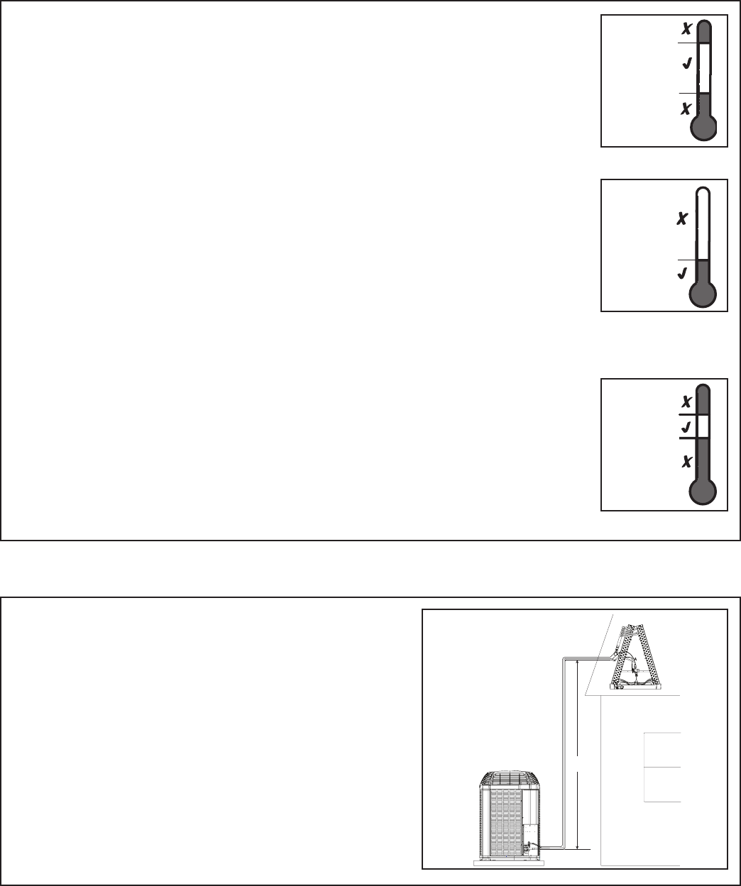
Determine the final subcooling value using total Line Length and Lift measured in STEP 1 and the charts below.
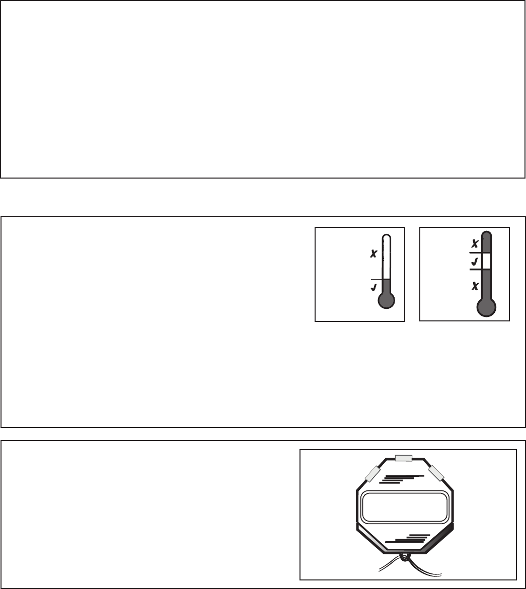
STEP 3 - Stabilize the system by operating for a
minimum of 20 minutes.
At startup, or whenever charge is removed or
added, the system must be operated for a mini-
mum of 20 minutes to stabilize before accurate
measurements can be made.
20 MIN.
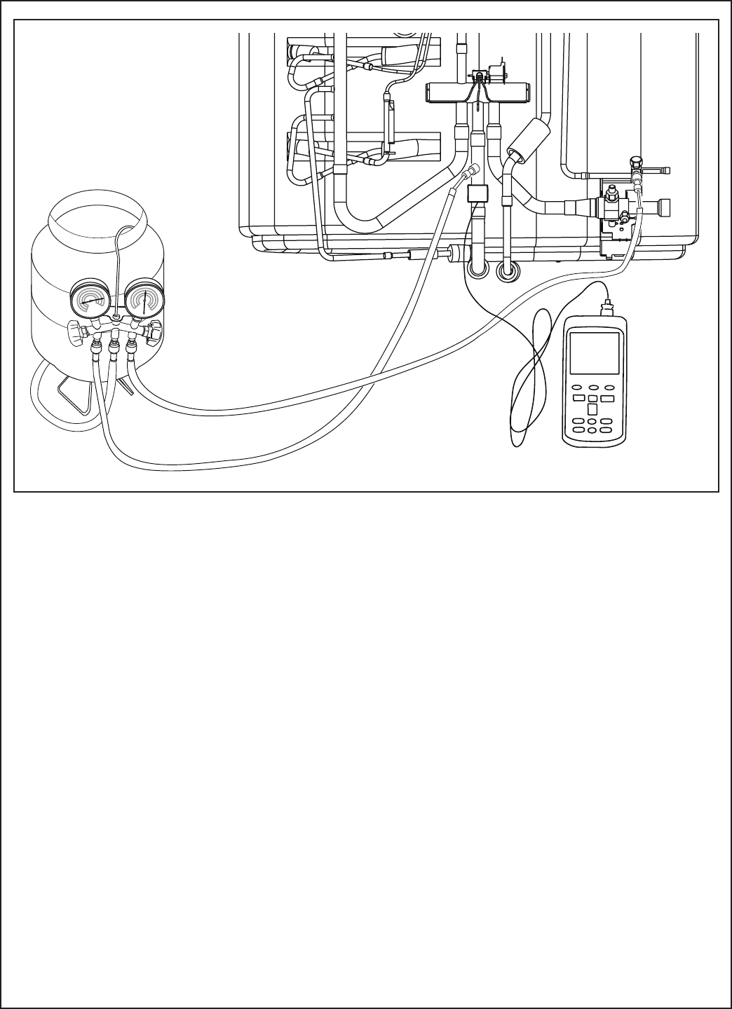
2 Ton Unit
4 Ton Unit
3 Ton Unit
5 Ton Unit
60
50
40
30
25
20
15
10
0
10 20 25 30 40 60
25 ft. Maximum Lift
Add 3o
Add 2o
Add 1o
TOTAL REFRIGERANT LINE LENGTH (FT)
Use design subcooling
SUBCOOL CHARGING CHART CORRECTIONS TABLE
REFRIGERANT LINE LIFT (FT)
60
50
40
30
25
20
15
10 Add 1o
0Add 1o
10 20 25 30 40 60
REFRIGERANT LINE LIFT (FT)
Add 3o
Add 2o
Use design subcooling
TOTAL REFRIGERANT LINE LENGTH (FT)
SUBCOOL CHARGING CHART CORRECTIONS TABLE
25 ft. Maximum Lift
60
50
40
30
25
20
15
10 Add 1º
0
10 20 25 30 40 60
Add 3º Add 4º
REFRIGERANT LINE LIFT (FT)
SUBCOOL CHARGING CHART CORRECTIONS TABLE
25 ft. Maximum Lift
Use Design Subcooling
TOTAL REFRIGERANT LINE LENGTH (FT)
Add 2º
60
50
40
30
25
20
15
10 Add 1º
0
10 20 25 30 40 60
Add 4º
REFRIGERANT LINE LIFT (FT)
SUBCOOL CHARGING CHART CORRECTIONS TABLE
25 ft. Maximum Lift
Use Design Subcooling
TOTAL REFRIGERANT LINE LENGTH (FT)
Add 3º
Add 2º
20 18-BC86D1-4
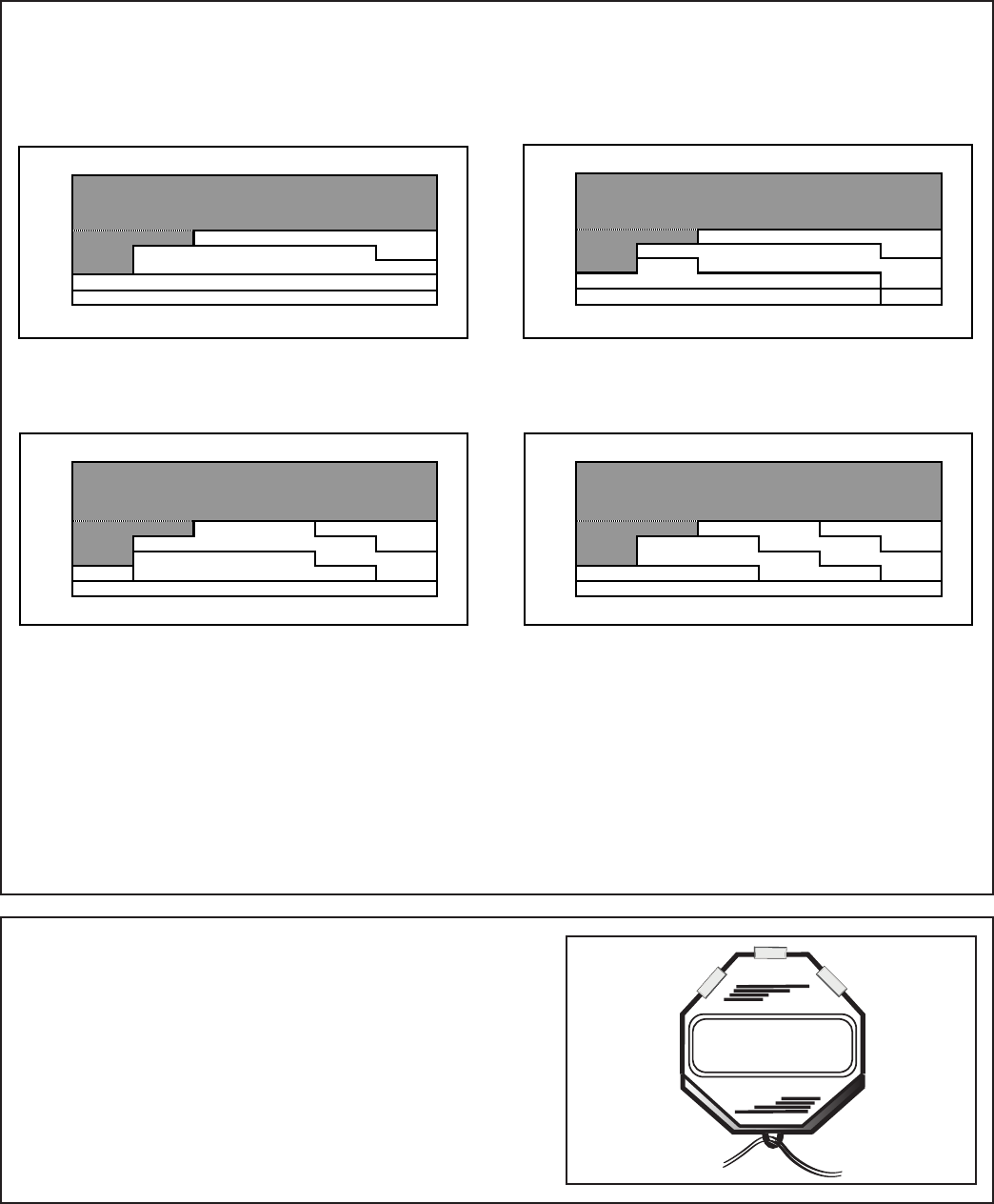
STEP 4 - Measure the liquid line temperature
and pressure at the outdoor unit’s service valve.
Measured Liquid Line Temp = __________ º F
Liquid Gage Pressure = __________ PSI
Final Subcooling Value = __________ º F
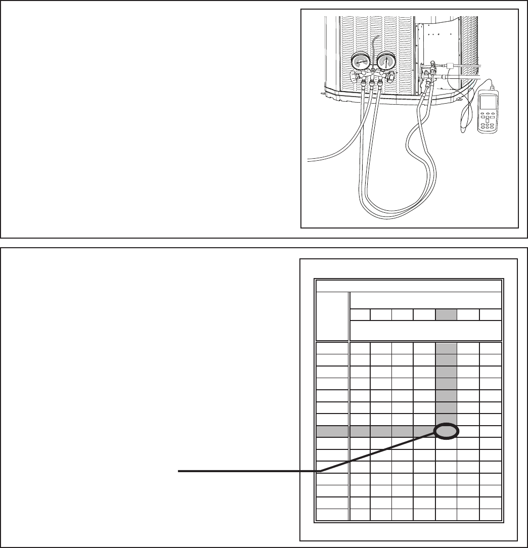
STEP 5 - Use the final subcooling value, refriger-
ant temperature and pressure from STEP 4, to
determine the proper liquid gage pressure using
Table 14.2.
Example: Assume a 12º F Final Subcooling
value and liquid temp of 90º F.
1. Locate 12º F Final Subcooling in Table 14.2.
2. Locate the Liquid Temperarature (90º F) in
the left column.
3. The Liquid Gage Pressure should be ap-
proximately 327 PSI. (This is the shown as
the intersection of the Final Subcooling column
and the Liquid Temperature row.
Table 14.2
8910 11 12 13 14
179 182 185 188 191 195 198
195 198 201 204 208 211 215
211 215 218 222 225 229 232
229 232 236 240 243 247 251
247 251 255 259 263 267 271
267 271 275 279 283 287 291
287 291 296 300 304 309 313
309 313 318 322 327 331 336
331 336 341 346 351 355 360
355 360 365 370 376 381 386
381 386 391 396 402 407 413
407 413 418 424 429 435 441
435 441 446 452 458 464 470
464 470 476 482 488 495 501
495 501 507 514 520 527 533
R-410A REFRIGERANT CHARGING CHART
55
60
65
70
75
80
85
90
95
100
105
110
115
120
125
LIQUID
TEMP
(°F)
FINAL SUBCOOLING (°F)
LIQUID GAGE PRESSURE (PSI)
From Dwg. D154557P01 Rev.
3
107 °F
18-BC86D1-4 21
STEP 8 - Verify typical performance.
Refer to System Pressure Curves in the Service
Facts to verify typical performance.
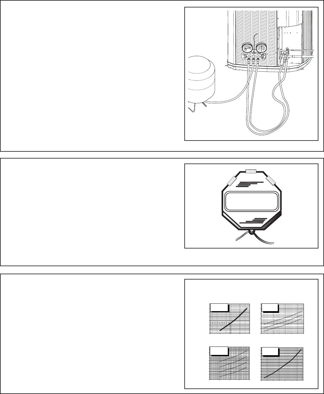
STEP 6 - Adjust refrigerant level to attain
proper gage pressure.
Add refrigerant if the Liquid Gage Pressure
is lower than the chart value.
1. Connect gages to refrigerant bottle
and unit as illustrated.
2. Purge all hoses.
3. Open bottle.
4. Stop adding refrigerant when liquid
line temperature and Liquid Gage
Pressure matches the charging chart
Final Subcooling value.
Recover refrigerant if the Liquid Gage Pres-
sure is higher than the chart value.
(Example only - see Service Facts)
20 MIN.
STEP 7 - Stabilize the system.
1. Wait 20 minutes for the system condi-
tion to stabilize between adjustments.
Note: When the Liquid Line Temperature and
Gage Pressure approximately match the chart,
the system is properly charged.
2. Remove gages.
3. Replace service port caps to prevent
leaks. Tighten finger tight plus an ad-
ditional 1/6 turn.
PRESSURE CURVES FOR 4TWX5049E1000B
4TEE3F49C1 4TEE3F49C1
Cooling @ 1450 SCFM Heating @ 1350 SCFM
DISCHARGE PRESSURE (PSIG)
OUTDOOR TEMPERATURE (Degree F)
SUCTION PRESSURE (PSIG)
OUTDOOR TEMPERATURE (Degree F)
COOLING PERFORMANCE CAN BE CHECKED WHEN THE OUTDOOR TEMP IS ABOVE 65 DEG F.
TO CHECK COOLING PERFORMANCE, SELECT THE PROPER INDOOR CFM, ALLOW PRESSURES TO STABILIZE. MEASURE INDOOR WET BULB
TEMPERATURE, OUTDOOR TEMPERATURE, DISCHARGE AND SUCTION PRESSURES. ON THE PLOTS LOCATE OUTDOOR TEMPERATURE (1);
LOCATE INDOOR WET BULB (2); FIND INTERSECTION OF OD TEMP. & ID W.B. (3); READ DISCHARGE OR SUCTION PRESSURE IN LEFT
COLUMN (4).
EXAMPLE: (1) OUTDOOR TEMP. 82 F.
(2) IND
OO
R WET BULB 67 F.
(3) AT INTER
S
E
C
TI
ON
A
C
TUAL:
(4) DISCHARGE PRESSURE @ 1450 CFM IS 323 PSIG DISCHARGE PRESSURE SHOULD BE +/- 10 PSI OF CHAR
T
(5) SUCTION PRESSURE @ 1450 CFM IS 140 PSIG SUCTION PRESSURE SHOULD BE +/- 3 PSIG OF CHAR
T
INTERCONNECTING LINES
GAS - 7/8" O.D.
LIQUID - 3/8" O.D.
DWG.NO. 4TWX5049E1
110
115
120
125
130
135
140
145
150
155
160
165
170
40 60 80 100 120
200
250
300
350
400
450
500
550
40 60 80 100 120
(1)
(1)
(3)
(3)
(5)
(4)
(2)
(2)
INDOOR ENTERING
WET BULB CURVES
TOP TO BOTTOM
71, 67, 63 AND 59 DEG F.
INDOOR ENTERING
WET BULB CURVES
TOP TO BOTTOM
71, 67, 63 AND 59 DEG F.
30
40
50
60
70
80
90
100
110
120
130
140
-5 5 15 25 35 45 55 65
200
250
300
350
400
450
500
-5 5 15 25 35 45 55 65
INDOOR ENTERING
DRY BULB CURVES
TOP TO BOTTOM
80, 70, AND 60 DEG F.
INDOOR ENTERING
DRY BULB CURVES
TOP TO BOTTOM
80, 70, AND 60 DEG F.
22 18-BC86D1-4
STEP 9 - Record System Information for refer-
ence.
Record system pressures and temperatures
after charging is complete.
Outdoor model number = _________________
Measured Outdoor Ambient = __________ º F
Measured Indoor Ambient = __________ º F
Measured Liquid Line Temp = __________ º F
Measured Suction Line Temp = __________ º F
Liquid Gage Pressure = __________ PSI
Suction Gage Pressure = __________ PSI
STEP 1 - Check the outdoor temperature. If
the ODT is less than 55º F, follow these charg-
ing instructions for the heating mode of opera-
tion. For temperatures above 55º F, see Sec-
tion 14.1.
Note: It is important to return in the spring or
summer to accurately charge the system in
the cooling mode with outdoor ambient above
55ºF.
For best results the indoor temperature should
be kept between 70º F and 80º F. See the
Indoor Temp illustration. Add system heat if
needed.
STEP 2 - Stabilize the system by operating in
the heating mode for a minimum of 20 minutes.
Important: Whenever charge is added or re-
moved, the system must run for a minimum of
20 minutes before accurate measurements can
be made.
14.3 Subcooling Charging Below 55º F Outdoor Temp. (In Heating Only)
20 MIN.
80º F
70º F
Indoor Temp
55º F
Outdoor Temp
18-BC86D1-4 23
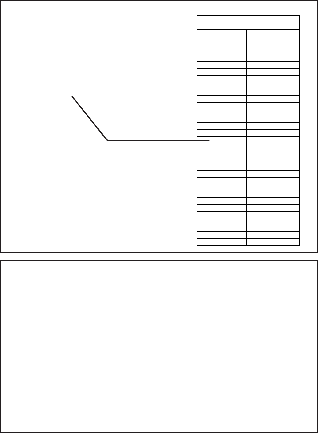
STEP 3 - Measure the suction line pressure and
temperature at the “true” suction line and record
the values below.
Note: the side service panel will need to be
removed to gain access to this area.
Attach temperature probe and the gage as
shown. Ensure the probe is securely attached
and well insulated.
Measured
Suction Line Temperature = __________º F
Measured
Suction Line Pressure = __________º F
Compare these values to the 15 degree super-
heat chart in Table 13.2.
36 °F
24 18-BC86D1-4
STEP 4 - Use the measured values from Step 3
to determine a target superheat of 15 degrees.
Example: Assume a suction pressure of 81 PSI
and a suction temperature of 36º F.
When the suction temperature is in line with
the suction gage pressure, the target superheat
value will be 15 degrees. (Example values high-
lighted in Table 13.2)
Table 13.2
STEP 5 - Adjust refrigerant level to attain 15
degrees of superheat.
Add refrigerant if the suction line temperature
is above the value that is in line with the mea-
sured suction gage pressure.
1. Connect gages as shown in Step 3.
2. Purge all hoses.
3. Open bottle.
4. Stop adding refrigerant when the suc-
tion line temperature is in line with the
measured suction line pressure in Table
13.2.
Recover refrigerant if the suction line tempera-
ture is lower than the temperature that is in line
with the system’s suction pressure.
Suction Line
Temp
Suction Gage
Pressure
10 42
12 44
14 47
16 50
18 52
20 55
22 58
24 61
26 64
28 67
30 70
32 74
34 77
36 81
38 84
40 88
42 92
44 96
46 100
48 104
50 108
52 112
54 117
56 121
58 126
60 131
62 136
64 141
70 157
15 degree Superheat Chart
18-BC86D1-4 25
STEP 7 - Target 10–15 degrees of subcooling
using Section 14.1 as a guide.
Note: It is important to return in the spring or
summer to accurately charge the system in the
cooling mode with outdoor ambient above 55ºF.
STEP 8 - Verify typical performance.
Refer to System Pressure Curves in the Service
Facts to verify typical performance.
PRESSURE CURVES FOR 4TWX6048G
4TEE3F49C1 4TEE3F49C1
COOLING PERFORMANCE CAN BE CHECKED WHEN THE OUTDOOR TEMP IS ABOVE 65 DEG F.
TO CHECK COOLING PERFORMANCE, SELECT THE PROPER INDOOR CFM, ALLOW PRESSURES TO STABILIZE. MEASURE INDOOR WET BULB
TEMPERATURE, OUTDOOR TEMPERATURE, DISCHARGE AND SUCTION PRESSURES. ON THE PLOTS LOCATE OUTDOOR TEMPERATURE (1);
LOCATE INDOOR WET BULB (2); FIND INTERSECTION OF OD TEMP. & ID W.B. (3); READ DISCHARGE OR SUCTION PRESSURE IN LEFT
COLUMN (4).
EXAMPLE: (1) OUTDOOR TEMP. 82 F.
(2) IND
OO
R WET BULB 67 F.
(3) AT INTER
S
E
C
TI
ON
A
C
TUAL:
(4) DISCHARGE PRESSURE @ 1130 CFM IS 297 PSIG DISCHARGE PRESSURE SHOULD BE +/- 10 PSI OF CHAR
T
(5) SUCTION PRESSURE @ 1460 CFM IS 148 PSIG SUCTION PRESSURE SHOULD BE +/- 3 PSIG OF CHAR
T
INTERCONNECTING LINES
GAS - 7/8" O.D.
LIQUID - 3/8" O.D.
DWG.NO. 4TWX6048G1
200
250
300
350
400
450
500
550
40 60 80 100 120
110
120
130
140
150
160
170
180
40 60 80 100 120
110
120
130
140
150
160
170
180
40 60 80 100 120
30
40
50
60
70
80
90
100
110
120
130
140
-5 5 15 25 35 45 55 65
200
250
300
350
400
-5 5 15 25 35 45 55 65
30
40
50
60
70
80
90
100
110
120
130
140
-5 5 15 25 35 45 55 65
200
250
300
350
400
-5 5 15 25 35 45 55 65
Heating with Expansion Valve
INDOOR ENTERING DRY BULB CURVES TOP TO BOTTOM
80, 70, AND 60 DEG F.
200
250
300
350
400
450
500
550
40 60 80 100 120
Cooling with Expansion Valve
INDOOR ENTERING WET BULB CURVES TOP TO BOTTOM
71, 67, 63 AND 59 DEG F.
INDOOR ENTERING WET BULB CURVES TOP TO BOTTOM
71, 67, 63 AND 59 DEG F.
INDOOR ENTERING DRY BULB CURVES TOP TO BOTTOM
80, 70, AND 60 DEG F.
OUTDOOR TEMPERATURE (Degree F)
OUTDOOR TEMPERATURE (Degree F)
2ND STAGE
2ND STAGE
1ST STAGE
1ST STAGE
2ND STAGE
2ND STAGE
1ST STAGE
1ST STAGE
DISCHARGE PRESSURE (PSIG)
SUCTION PRESSURE (PSIG)
(1)
(1)
(3)
(3)
(5)
(4)
(2)
(2)
(Example only - see Service Facts)
20 MIN.
STEP 6 - Stabilization and completion.
1. Wait 20 minutes for the system condi-
tion to stabilize between adjustments.
Note: When the suction temperature is in line
with the suction gage pressure, the target super-
heat value will be 15 degrees.
2. Remove gages.
3. Replace service port caps to prevent
leaks. Tighten finger tight plus an ad-
ditional 1/6 turn.

26 18-BC86D1-4
1. Leak check refrigerant lines. ........................................ [ ]
2. Properly insulate suction lines and fittings. ................... [ ]
3. Properly secure and isolate all refrigerant lines. ........... [ ]
4. Seal passages through masonry.
If mortar is used, prevent mortar from coming
into direct contact with copper tubing. .......................... [ ]
5. Verify that all electrical connections are tight. ............... [ ]
6. Observe outdoor fan during on cycle for clearance
and smooth operation. .................................................. [ ]
Section 15. Checkout Procedures and Troubleshooting
15.1 Operational And Checkout Procedures
CHECKOUT PROCEDURE
After installation has been completed, it is recommended that the entire system be checked against the following list:
Final phases of this installation are the unit Operational and Checkout Procedures. To obtain proper performance, all units
must be operated and charge adjustments made.
Important: Perform a final unit inspection to be sure that factory tubing has not shifted during shipment. Adjust tubing if nec-
essary so tubes do not rub against each other when the unit runs. Also be sure that wiring connections are tight and properly
secured.
7. Be sure that indoor coil drain line drains freely. Pour water
into drain pan. ............................................................... [ ]
8. Be sure that supply registers and return grilles are open
and unobstructed. ......................................................... [ ]
9. Be sure that a return air filter is installed. ..................... [ ]
10. Be sure that the correct airflow setting is used.
(Indoor blower motor) ................................................... [ ]
11. Operate complete system in each mode to
ensure safe operation. .................................................. [ ]
18-BC86D1-4 27
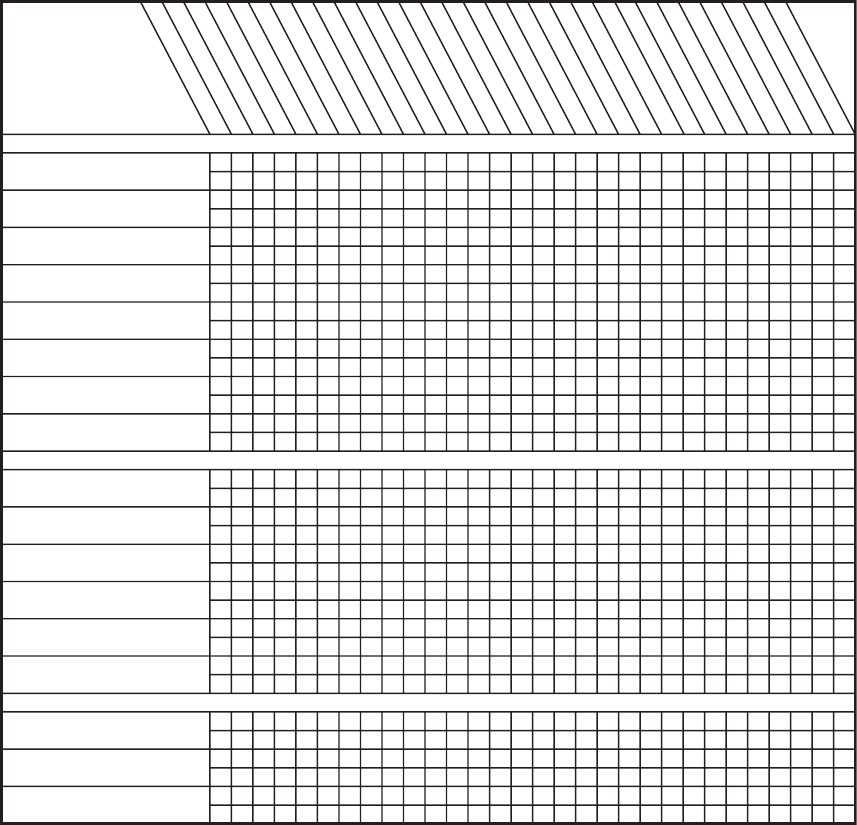
SYSTEM FAULTS
REFRIGERANT CIRCUIT
Head Pressure To o High
Head Pressure To o Low
Suction Pressure To o High
Suction Pressure To o Low
Liquid Refrig. Floodback (TXV/EEV)
Liquid Refrig. Floodback
(Cap. Tube)
I.D. Coil Frosting
Compressor Runs
Inadequate or No Cooling/Htg
ELECTRICAL
Compressor & O.D. Fan
Won’t Start
Compressor Will Not Start
But O.D. Fan Runs
O.D. Fan Won’t Start
Compressor Hums But Won’t Start
Compressor Cycles on IOL
I.D. Blower Won’t Start
DEFROST
Unit Won’t Initiate Defrost
Defrost Te rminates on Time
Unit Icing Up
WHAT TO CHECK MODE
POWER SUPPLY
HIGH VOLTAGE WIRING
COMPRESSOR IOL
RUN CAPACITOR
START CAPACITOR
START RELAY
CONTACTOR CONTACTS
LOW VOLTAGE WIRING
CONTROL TRANSFORMER
THERMOSTAT
CONTACTOR COIL
LOW VOLTAGE FUSE
STUCK COMPRESSOR
INEFFICIENT COMP.
REF. UNDERCHARGE
REF. OVERCHARGE
EXCESSIVE EVAP. LOAD
NONCONDENSABLES
RES. O.D. AIRFLOW
O.D. AIR RECIRCULATION
TXV/EEV STUCK OPEN
SUPERHEAT
RES. I.D. AIRFLOW
REF. CIR. RESTRICTIONS
SOV LEAKING
SOV COIL DEFECTIVE
CHECK VALVE LEAKING
*
DEFROST RELAY DEF.
DEFROST CONTROL DEF.
C
H
C
H
C
H
C
H
C
H
C
H
C
H
C
H
C
H
C
H
C
H
C
H
C
H
C
H
C
H
C
H
C
H
P
P
P
P
P
P
P
P
P
P
P
P
P
P
S
S
S
S
S
S
S
S
S
S
S
S
S
S
S
S
S
S
S
S
S
S
S
S
S
S
S
S
P
P
P
P
S
S
S
S
P
P
P
P
S
S
P
P
P
P
P
P
P
P
P
P
P
P
P
P
S
S
S
S
S
S
S
S
P
P
P
P
P
P
P
P
P
P
P
P
P
P
P
P
P
P
P
P
P
S
S
S
S
S
S
S
P
S
S
S
S
S
S
S
S
S
S
S
S
S
S
S
S
P
P
S
S
S
S
S
S
S
S
S
S
S
S
P
P
P
P
P
P
S
S
S
S
S
S
S
S
S
S
S
P
P
S
S
S
S
S
S
S
S
P
P
P
P
P
P
P
S
S
PP
P
P
C - Cooling H - Heating P - Primary Causes S - Secondary Causes
*
- 3 Phase Only
15.2 Troubleshooting
28 18-BC86D1-4
The manufacturer has a policy of continuous product and product data improvement
and it reserves the right to change design and specifications without notice.
Representative-only illustrations included in this document.
6200 Troup Highway
Tyler, TX 75707
www.trane.com © 2011 Trane 01/12
