XL AK400 01 90547733 XLAK40001
User Manual: 90547733
Open the PDF directly: View PDF  .
.
Page Count: 20
XL-AK400-01 1
ADL SERIES
G
O THE DISTANCE.
ADL-120-7
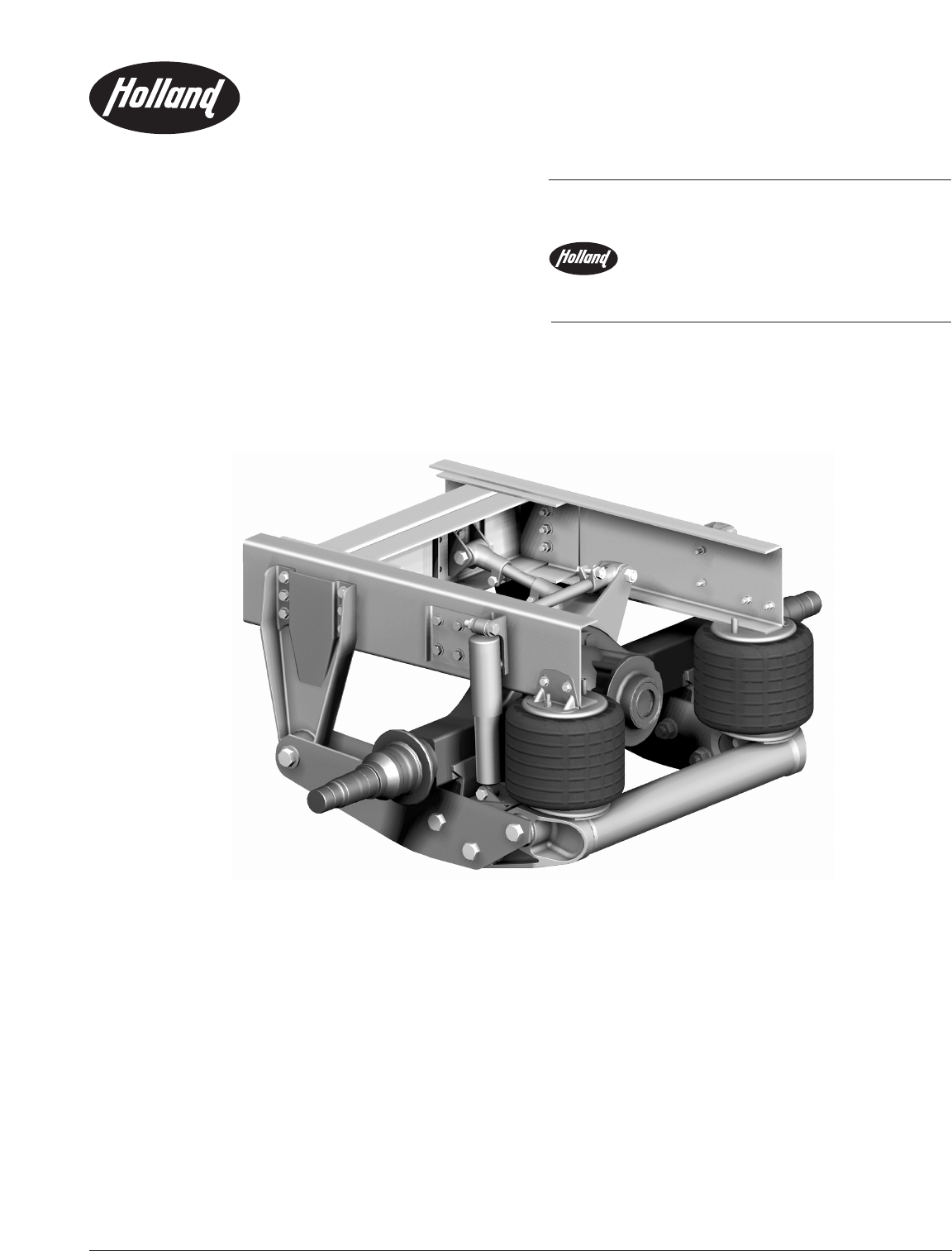
Drive-Axle Air-Ride Suspension
Maintenance and Parts List Manual
MAINTENANCE
AND PARTS LIST

2XL-AK400-01
Introduction ...................................................................................3
Warranty .........................................................................................3
Notes, Cautions, and Warnings ....................................................3
Model Identification ......................................................................4
Model Nomenclature ....................................................................4
Operating and Maintenance Instructions .....................................5
ADL Suspension Operation .....................................................5
Routine Maintenance and Daily Inspection.............................5
Initial 5,000 Mile (8,000 km) or 100 Hours
of Service Inspection ........................................................5
Routine Maintenance – 50,000 Miles (80,000 km) or
1,000 Hours of Service or as Needed .............................5
General Information .................................................................5
Pre-Operational Checklist .............................................................6
ADL-120 Parts List .........................................................................7
Suspension Adjustment Instructions ............................................8
Ride Height ................................................................................8
Axle Alignment .........................................................................8
Pinion Angle Adjustment .........................................................9
CONTENTS
Page Page
Service Repair Kits ......................................................................10
Pivot Connection ....................................................................10
Pivot Connection Alignment Block .......................................10
Front Transverse Beam Connection ....................................10
Rear Transverse Beam Connection .......................................10
Axle Connection ....................................................................11
Torque Rod and Track Bar Bushing ....................................11
Part Replacement Instructions ...................................................12
Suspension Air Springs ...........................................................12
Axle Adapter Bushing ............................................................13
Frame Bracket Pivot Bushing ................................................14
Transverse Beam Bushing ......................................................15
Shock Absorbers .....................................................................16
Torque Rod ..............................................................................17
Track Bar .................................................................................18
Troubleshooting ..........................................................................19
XL-AK400-01 3
INTRODUCTION
This manual provides you information necessary for the
care, maintenance, inspection, and safe operation of
Holland’s ADL Series drive-axle suspension models.
The Holland Suspension is designed and engineered
to provide trouble-free service. In the event of minor
breakdown, such as a loss of air in the air springs, there
are safety features designed into the suspension that will
allow the vehicle to be driven CAUTIOUSLY at slow speed,
to the nearest service facility. Be sure tire clearance remains
adequate with the underside of the body and equipment.
This suspension uses air drawn from the vehicle’s air
system to pressurize the air springs. The height control
valve regulates the air pressure required for varying loads
and maintains the design ride height.
NOTE: Contact the vehicle OEM or Dealer Service Center
with all service/maintenance questions.
WARRANTY
Refer to the complete warranty for the country in which
the product will be used. A copy of the written warranty
is included with the product as well as in the
suspension catalogs and the Holland Group Web
Site (www.thehollandgroupinc.com).
It may also be ordered by calling 1-888-396-6501.
NOTES, CAUTIONS,
AND WARNINGS
You must read and understand all of the safety procedures
presented in this manual before starting any work on
the suspension.
Proper tools must be used to perform the maintenance and
repair procedures described in this manual. Many of these
procedures require special tools.
Failure to use the proper equipment could result in personal
injury and/or damage to the suspension.
Safety glasses must be worn at all times when
performing the procedures covered in this manual.
Throughout this manual, you will notice the terms “NOTE,”
“IMPORTANT,” “CAUTION” and “WARNING” followed by
important product information. So that you may better
understand the manual, those terms are as follows:
NOTE: Includes additional information to
enable accurate and easy performance
of procedures.
IMPORTANT: Includes additional information that
if not followed could lead to hindered
product performance.
Used without the safety alert symbol,
indicates a potentially hazardous situa-
tion which, if not avoided, may result in
property damage.
Indicates a potentially hazardous
situation which, if not avoided, may
result in minor or moderate injury.
Indicates a potentially hazardous
situation which, if not avoided, could
result in death or serious injury.
4XL-AK400-01
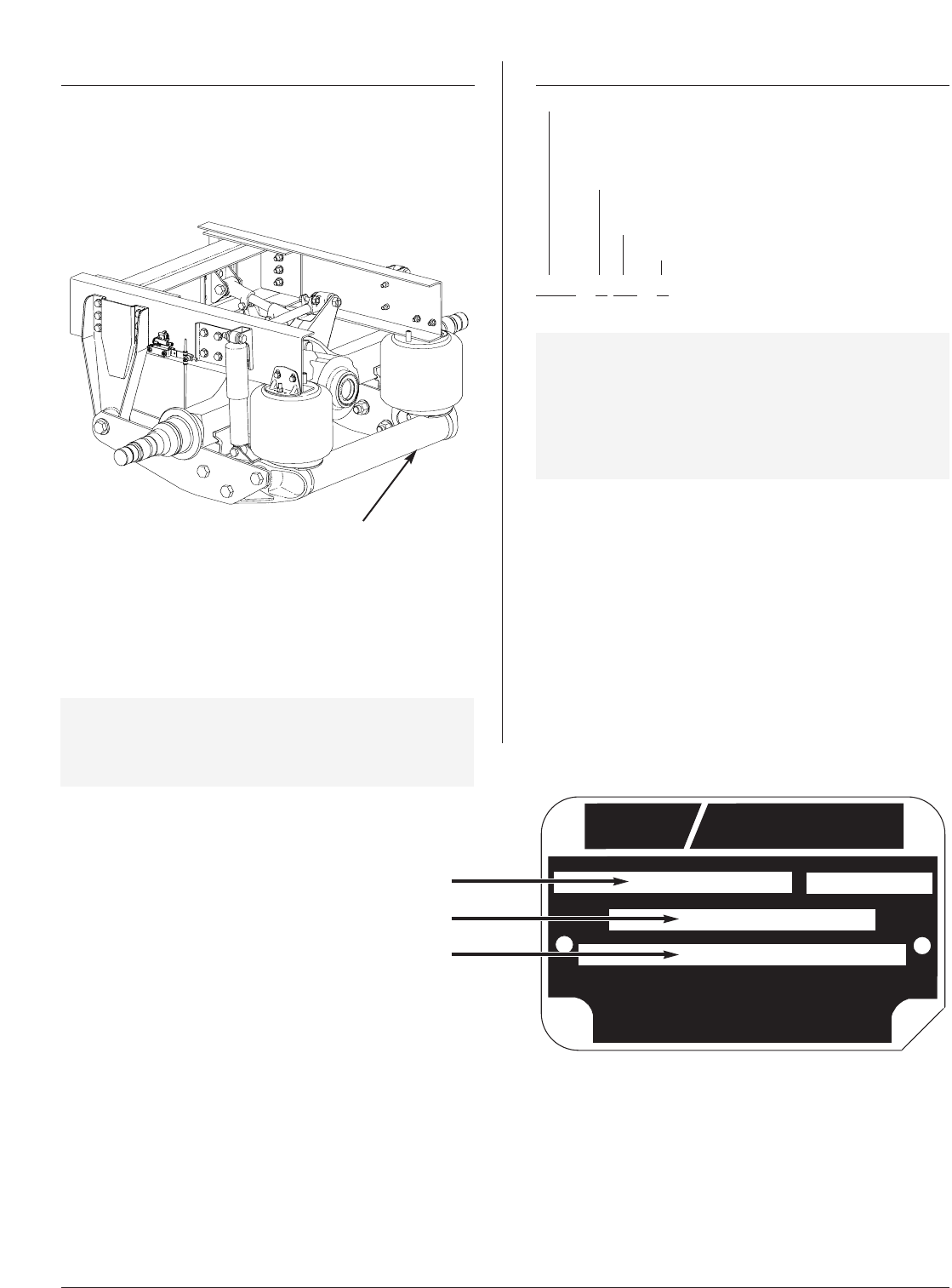
SERIAL NUMBER TAG
(underside of the transverse
beam)
Serial Number Tag Location
FIGURE 1
MODEL IDENTIFICATION
A serial number tag is attached to the underside of the
transverse beam for identification purposes (FIGURE 1).
This tag supplies valuable information regarding the exact
components used to manufacture the suspension.
Depending upon OEM configuration, the serial number tag
may not call out the exact kit or parts list number. If so, the
vehicle OEM should be able to identify the suspension model
and its components using the vehicle's VIN number.
IMPORTANT: Due to some OEMs using several variations
of parts, having the exact parts used by the
OEM is critical in determining proper
replacement components.
It is recommended that you determine your specific model
number, write that information below, and refer to it when
obtaining information or replacement parts.
Model Number _______________________________
Serial Number ________________________________
Parts List Number_____________________________
MODEL NOMENCLATURE
AIR DRIVE
NO. OF AXLES
1 - SINGLE
2 - TANDEM
3 - TRIDEM
RATED CAPACITY
(X 1,000 LBS.)
RIDE HEIGHT (INCHES)
ADL - 1 20 - 7
IMPORTANT: This manual applies to the ADL suspension
series and for special orders of the same.
It is very important to determine your
specific model number, serial number, and
parts list number. Record those numbers
on this page, and refer to them when
obtaining information or replacement parts.
MODEL NO. CAPACITY (LBS.)
PARTS LIST NO
.
COVERED BY ONE OR MORE OF THE FOLLOWING PATENTS (OTHER PATENTS PENDING)
4,193,612 4,322,061 4,595,216 4,634,141 4,700,968 4,729,579
4,262,929 4,405,154 4,615,539 4,693,486 4,726,571 4,736,958
4,854,409 5,083,812 5,201,898 5,335,695 5,393,096
4,858,949 5,088,763 5,203,585 5,335,932 5,413,374
4,991,872 5,112,078 5,288,100 5,375,819 5,192,101
5,058,916 5,116,075 5,315,918 5,058,917 5,333,645
JAPAN PATENT 2038539
PART #93800269
HOLLAND USA, INC.
MUSKEGON, MICH., U.S.A.
ADL-120-7 XX,XXX LBS.
SERIAL NO.
8-digit number
8-digit number
Serial Number Tag
FIGURE 2
XL-AK400-01 5
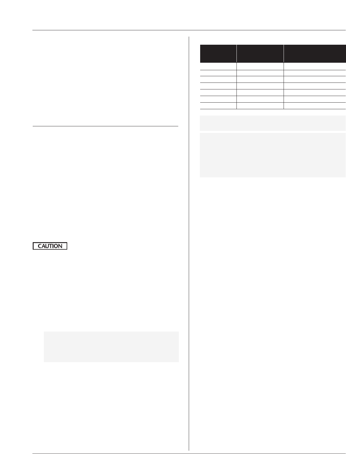
TORQUE SPECIFICATIONS
ADL TORQUE
SPECIFICATIONS*
SIZE ITEM FT. LBS NM
1/2˝ and 3/4˝ Air Spring Nuts 30-35 41-48
5/8˝ Control Rod Adj. Nut 85-95 115-129
3/4˝ Shock Absorber 250-280 340-380
7/8˝ Track Bar Nut 400-450 542-610
11/8˝Pivot Conn. Nut 800-850 1085-1153
11/8˝Axle Conn. Nut 800-850 1085-1153
11/8˝Transv. Beam Nuts 800-850 1085-1153
*NOTE: Torque specifications listed above are with clean
lubricated threads.
IMPORTANT: Use of special lubricants with friction
modifiers, such as Anti-Seize or
Never-Seize, without written approval
from Holland Engineering, will void
warranty and could lead to over torquing
of fasteners or other component issues.
General Information
1. The torque specifications listed throughout the manual
are applied to the nut, not the bolt.
2. Torque specifications: ± 5% tolerance.
3. Lubricated Vs. Non-Lubricated Threads:
The torque specifications stated are for lubricated
fasteners. Holland defines lubricated vs. non-lubricated
as follows:
Lubricated...............a bolted connection, such as
the pivot bolt/nut arrangement,
that has a lubricant—like motor
oil—pre-applied or applied to
the thread surfaces, providing
a lower torque requirement for a
predetermined clampload.
Non-Lubricated......a bolted connection, either new or
in service, that has little or no
lubricant on the thread surfaces.
Typically, this applies to bolted
connections that have been in
service for a certain length of time
where the original protective coating
has evaporated or deteriorated due
to environmental exposure. Thus,
a “non-lube” torque specification
is commonly required for in-service
torque check or retorquing
procedures. A “non-lube” specifica-
tion could be required for new
installations if the pivot bolt has
seen sufficient shelf life to allow
for evaporation and deterioration of
the protective coating.
OPERATING AND MAINTENANCE INSTRUCTIONS
ADL Suspension Operation
The ADL Series Suspension is controlled by either one or
two height control valves. When properly adjusted, they
automatically maintain the specified ride height throughout
the unloaded to loaded range. The height control valve
automatically adds air to, or exhausts air from, the
suspension to maintain a constant ride height.
Before putting the vehicle in operation, build air pressure in
excess of 70 psig (4.8 bars). This will open the pressure pro-
tection valve and allow air flow to the height control valves.
IMPORTANT
Routine Maintenance and Daily Inspection
Daily Inspection
Daily or before each trip, check the suspension to be sure it
is fully operational. Visually inspect air springs for equal
firmness and to see that suspension is set at proper ride
height. See page 8 for ride height measurement and
re-setting instructions. Service as necessary.
Initial 5,000 Mile (8,000 km) or 100 Hours
of Service Inspection
1. Suspension ride height (underside of frame to center line
of axle) MUST BE WITHIN ± 0.25˝ OF RECOMMENDED
DESIGN HEIGHT. See page 8 for instructions on
measuring ride height.
An improperly set ride height could result
in suspension component damage and/or
poor vehicle ride performance.
2. After initial 5,000 miles (8,000 km) or 100 hours of
service, inspect bolts and nuts at the pivot connections,
transverse beam connections, and axle connections to
assure they are properly torqued. Check all other nuts
and bolts for proper torque. Retorque as necessary
thereafter.
3. With vehicle on level surface and air pressure in
excess of 70 psig (4.8 bars), all air springs should be
of sufficient and equal firmness.
NOTE: Height control valves control all air springs.
Check all fittings for air leaks, by applying a
soapy water solution and checking for bub-
bles at all air connections and fittings.
Routine Maintenance – 50,000 Miles (80,000
km) or 1,000 Hours of Service or as Needed
At 50,000 miles or 1,000 hours of service, or when
servicing vehicle brake system, inspect suspension
components per 5,000 mile inspection. Also check all
other suspension components for any sign of damage,
looseness, wear or cracks. Replace any damaged parts
to prevent equipment breakdown.

6XL-AK400-01
PRE-OPERATIONAL CHECKLIST
1
NOTE: Prior to placing unit in service, check the
following items:
1. On page 4, write down the Serial Number and Parts List
Number shown on the Serial Number Tag.
2. With the vehicle on a level surface, build the vehicle’s
air pressure above 100 psig (6.9 bars). With the vehicle
shut off, check the system for air leaks and check all of
the air springs for equal firmness.
3. Minimum clearance around air springs must be 13/4˝
(44.5mm).
4. Check the shock absorbers for proper installation (shock
must be installed so shock dust cover is on top).
5. 3/4˝ shock absorber nuts must be torqued to the specifi-
cation found in the Torque Specifications on page 5.
Re-torque Procedure – to retorque a connection,
Holland recommends that the nut be loosened
a couple of turns and then torqued to the
recommended specification.
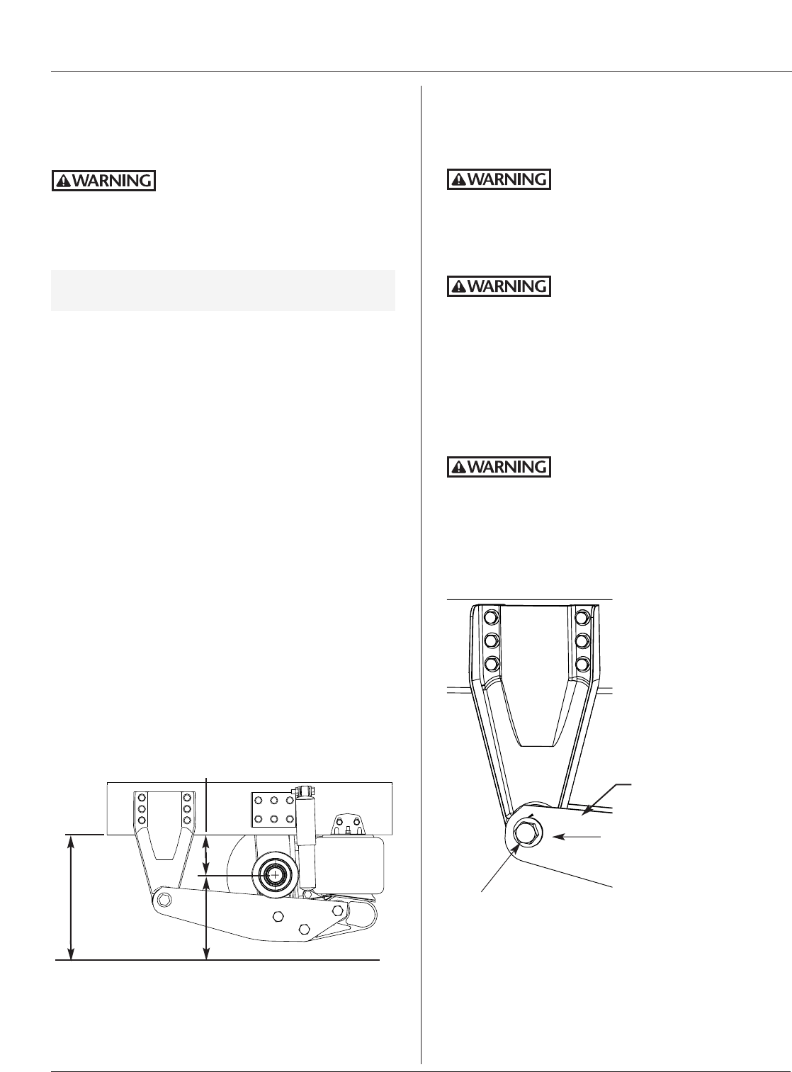
8
7”± 0.25˝
(177.8±6.4mm)
11
10
ADL-120 Components - Pre-Operational Checklist
FIGURE 3
7
54
5
7
6. 1/2˝ air spring piston nuts must be torqued to the spec-
ification found in the Torque Specifications on page 5.
7. All 1 1/8˝ equalizing beam plate fasteners must be
torqued to the specification found in the Torque
Specifications on page 5; apply torque to nuts.
8. Check for proper installation of C-shape spacer washers
at transverse beam and equalizing beam inner plate.
9. Check all frame fasteners per OEM recommended torque
specification(s).
10. Check to ensure the shock absorber debris shields are
installed.
11. Suspension ride height should be within ±0.25˝ of
recommended OEM design height. Reference the OEM’s
Height Control Valve adjustment procedure for proper
ride height adjustment.
12. The pinion angle should be within OEM specifications
(FIGURE 9, page 9).
3
XL-AK400-01 7
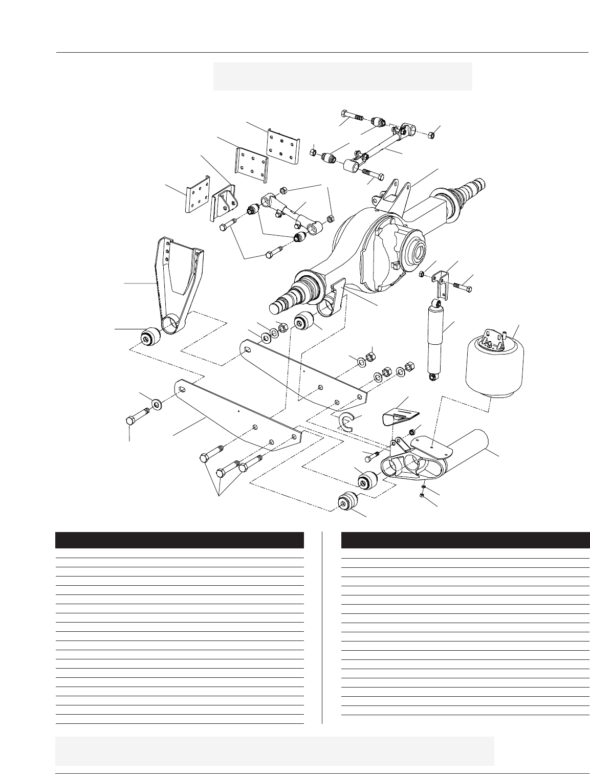
ADL-120 PARTS LIST
Item Part
No. Description No. Qty
1a Frame Bracket Assembly - standard 90521654 2
1b Frame Bracket Assembly - stacked rail (not shown) 90521653 2
2Bushing - pivot, axle, front transverse beam 90008211 6
3Equalizing Beam, adjustable 90015113 2
4Equalizing Beam, fixed (not shown) 90015115 2
5a Transverse Beam, for 34.0-34.12-inch frame rail width 90547733 1
5b Transverse Beam, for 34.25-inch frame rail width 90547813 1
5c Transverse Beam, for 34.62-inch frame rail width 90557736 1
6Bushing, rear transverse beam 90008241 2
7Axle Adapter 90501427 2
8Air Spring 90557290 2
9Control Arm Axle Bracket 90018670 1
10a Shock Upper Bracket, for short frame rail M0018031 2
10b Shock Upper Bracket, for standard frame rail 90018542 2
11a Shock Absorber, standard bus 90045443 2
11b Shock Absorber for RV applications Contact OEM 2
12 Track Bar, adjustable 90547801 1
13 Torque Rod, adjustable 90547800 1
14 Bushing - track bar and torque rod 90008243 4
1
2
31
Item Part
No. Description No. Qty
15 Bracket, track bar frame 90501439 1
16 Plate Reinforcement 90026068 1
17a Bracket, torque rod crossmember for bus 90501439 1
17b Bracket, torque rod crossmember for RV 90018658 1
18 Plate Reinforcement for crossmember 90026068 1
19 Shim Adapter 90036251 2
20 Hex Lock Nut 0.875-9 GR C 93400498 4
21 Hex Bolt 0.875-9x4.5 GR 8 93003833 4
22 Hex Bolt 1.125-7x6.5 GR 8 93004517 8
23 Hex Nut 1.125-7 GRC 93400506 8
24 Flat Washer, narrow 1.12 93600174 8
25 Hex Nut 0.5-13 GR B 93400136 2
26 Lock Washer 0.53 93600072 2
27 Hex Bolt 0.75-10x3.5 GR 8 93003599 4
28 Hex Lock Nut 0.75-10 GR C 93400494 4
29 C-Shape Spacer Washer 90036249 2
30 Debris Shield 90045456 2
31 Alignment Block 90008242 2
3
22
6
2
30
5
8
25
26
6
11
29
24 23
2
27
28 10
7
31
14
13
14
21 20
12
20
21
9
20
21
15
16
17
18
27
28
22
ADL-120 Parts List
FIGURE 4
24 23
NOTE: Service parts should be ordered through the vehicle
OEM or dealer Service Centers.
IMPORTANT: The part numbers listed may or may not correspond with your vehicle’s ADL installation.
Contact your vehicle OEM for part specification and ordering information.
8XL-AK400-01
Ride Height
1. Before beginning to check the ride height, park the
vehicle on a level floor. Block the front tires to prevent
the vehicle from rolling forward or backward.
Always block tires to prevent
rollaway—serious injury or death
may occur.
2. Pressurize the air system with a constant supply of air in
excess of 100 psig (6.9 bars). All air springs should
inflate and locate suspension at proper ride height.
IMPORTANT: The specified ride height for the ADL-120-7
Model is 7.0˝ (178mm, FIGURE 5).
3. If ride height is not within ±0.25˝ (6mm) of the specified
ride height, adjust the height control valve in accordance
with the instructions in Height Control Valve Manual or
the OEM’s manual. To accurately measure ride height,
perform steps 4 - 6 (FIGURE 5).
4. Measure the distance from the bottom of the frame rail
to the ground (FIGURE 5).
5. Measure the distance from the center of the wheel to the
ground (FIGURE 5).
6. To determine ride height, subtract the value measured in
step 5 from the value measured in step 4.
EXAMPLE: The bottom of the frame rail to the
ground measures 27.5˝ (699mm) (A);
the center of the wheel to the ground
measures 20.5˝ (521mm) (B).
A - B = RIDE HEIGHT, therefore:
27.5˝ minus 20.5˝ = 7.0˝ (178mm)
RIDE HEIGHT is 7.0˝ (178mm)
7. If ride height is out of specification, see the Height
Control Valve manual for instructions on how to adjust.
SUSPENSION ADJUSTMENT INSTRUCTIONS
x
x
x
x
x
x
x
x
x
x
x
x
x
x
x
x
x
x
x
x
x
x
x
x
x
x
x
x
x
x
x
x
x
x
x
x
x
x
x
x
x
x
x
x
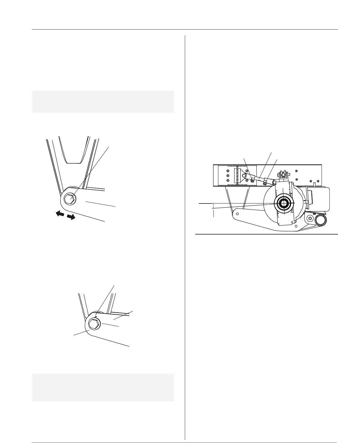
EQUALIZING BEAM PLATE
ALIGNMENT BLOCK WELDING
PATTERN ON EQUALIZING
BEAM PLATE
ALIGNMENT BLOCK
7”±0.25˝
(178±6mm)
Ride Height
FIGURE 5
Alignment Block Welded to Equalizing Beam
FIGURE 6
GROUND
A B
Axle Alignment
1. The vehicle must be on a level floor and unloaded.
Block the front tires to prevent the vehicle from rolling
forward or backward.
Always block tires to prevent
rollaway—serious injury or death
may occur.
2. Support the frame with jack stands and then completely
exhaust air from the air springs by disconnecting air
supply line from air spring.
Always use jack stands of sufficient
strength and position them according
to OEM recommendations. Failure to do so may cause
vehicle to fall causing vehicle damage and/or serious
personal injury.
3. Remove the pivot bolt from the side that has alignment
blocks welded to the equalizing beam plates (FIGURE 6).
4. Grind off the welds attaching the alignment blocks to
the equalizing beam plates being especially careful not
to grind off equalizing beam plate material (FIGURE 6).
Never remove parent material from
an equalizing beam plate when
grinding to remove the alignment block. If parent
material is removed—weakening the plate—always
replace the equalizing beam plate with a new plate.
XL-AK400-01 9
Axle Alignment continued
5. Replace pivot bolt, alignment blocks, hardened washer,
and nut with new hardware. Tighten all hardware so
that all components are secure, but DO NOT tighten to
torque specifications.
6. Align the axle per the OEM’s recommendation
(FIGURE 7).
IMPORTANT: Holland recommends that the chassis be
set at the specified ride height of 7.0˝ ±
0.25˝ (178 ± 6mm) prior to axle alignment.
SUSPENSION ADJUSTMENT INSTRUCTIONS continued
Pinion Angle Adjustment
IMPORTANT: Pinion angle must be checked with the
vehicle at ride height (FIGURE 5).
1. If pinion angle is not within the OEM specification, it
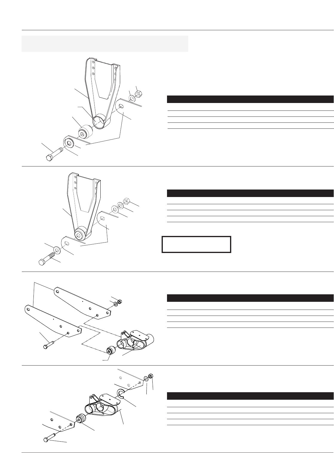
can be adjusted by changing the length of the torque
rod (FIGURE 9).
IMPORTANT: Adjusting the pinion angle will change
the ride height. Ride height should be
rechecked after pinion angle is adjusted.
2. Loosen both adjustment nuts on the torque rod
(FIGURE 9).
xx
xx
xx
xx
xxxxxxxxxxxxxx
xx
xx
xx
xx
xx
xx
xx
xx
xx
xxxx
Move equalizing-beam
plate/axle assembly forward
or backward to align the
axle, then torque pivot nut.
(To move the axle, use a pry
bar, a come-a-long, or
adjustable chain.)
END FORWARD OF
BOLT CENTER LINE
WELD BOTH SIDES
AS SHOWN (ONE
CONTINUOUS WELD)
Adjusting Alignment Block Prior to Welding
FIGURE 7
Alignment Block Welded in Place
FIGURE 8
EQUALIZING
BEAM PLATE
EQUALIZING BEAM
PLATE
7. Torque the pivot connection nut (see Torque
Specifications on page 5).
8. Recheck the alignment, and weld the alignment blocks
to the equalizing beam plates (FIGURE 8).
START FORWARD OF
BOLT CENTER LINE
9. After the alignment blocks have cooled, retorque the
pivot connection (see Torque Specifications on page 5).
IMPORTANT: A minimum 3-minute cool down
period is required after welding
connection before reapplying torque
to the pivot nut.
3. If torque rod center link has wrench flats, turn the
center link using a 1 9/16˝ (39.9mm) wrench—or
using a pipe wrench.
4. After the pinion angle is within OEM specifications,
tighten the two adjustment nuts (see Torque
Specifications on page 5).
5. After pinion angle adjustment angle is completed,
the ride height must be checked for proper setting.
A ride height of 7˝ ± 0.25˝ (178mm ± 6mm) is the only
acceptable specification. If specification is exceeded, see
“Ride Height” procedure on page 8.
Torque rod center link
Adjustment nut
Adjustment nut
Pinion
Angle
Pinion Angle Adjustment
FIGURE 9
GROUND
LINE PARALLEL
TO GROUND
10 XL-AK400-01
SERVICE REPAIR KITS
Equalizing Beam Plates
1
2
3
4
4
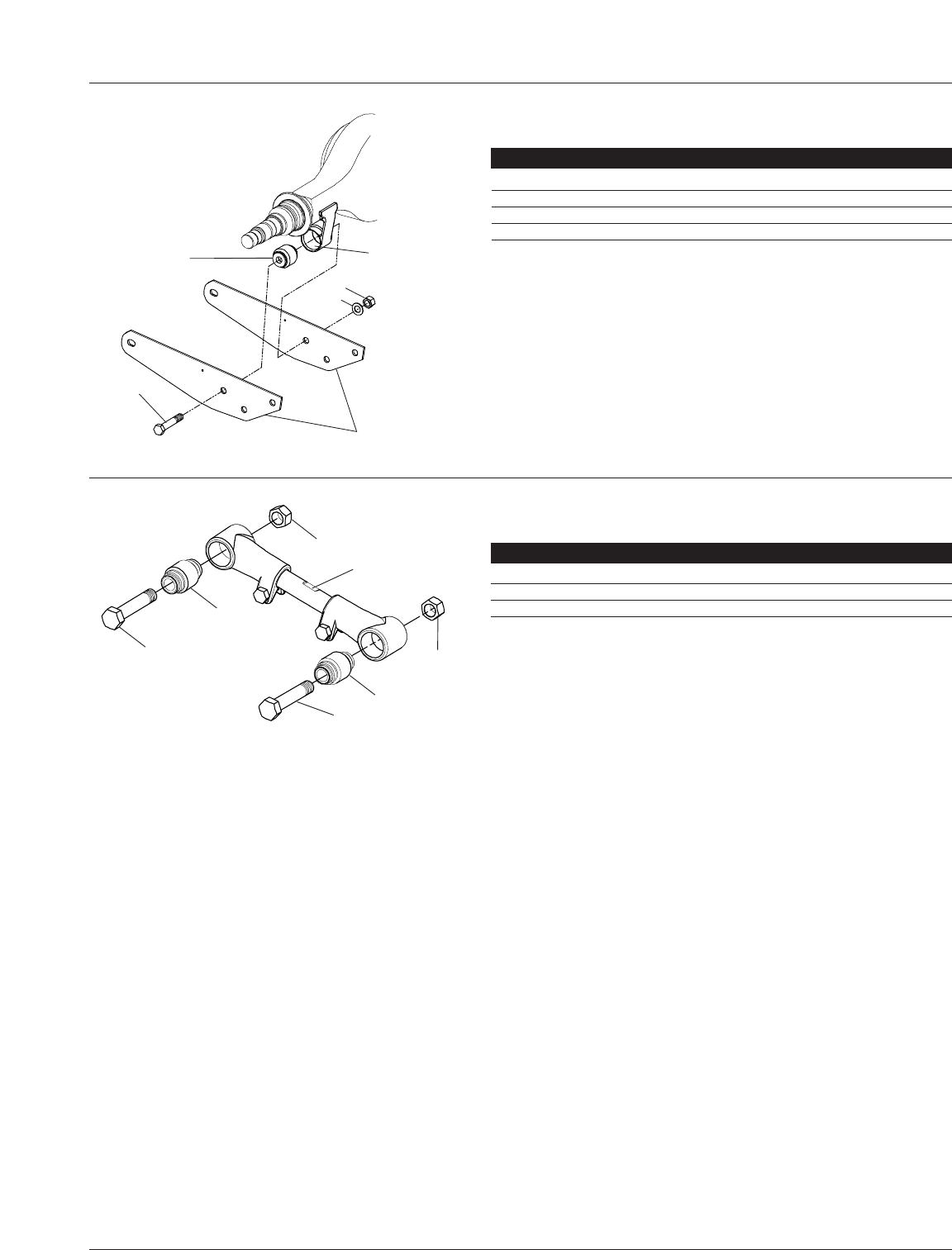
Pivot Connection
SRK-514 – Holland part number: 481 00 378
ITEM PART NO. DESCRIPTION QTY.
1930 04 517 Hex Bolt 1.13˝-7x6.5 GR 8 2
2900 08 211 Bushing 2
3936 00 174 Washer Flat Narrow 1.12˝ 2
4934 00 506 Hex Nut 1.125˝-7 GR C 2
1
2
34
1
2
34
1
2
3
4
2
Frame Bracket
(Welded to plate)
Transverse
Beam
Equalizing Beam
Plates
Frame Bracket
ONLY USED IN THE REAR RECEPTACLE
Bushing
Receptacle
NOTE: Each Service Repair Kit contains enough parts to repair
both sides of the suspension.
Equalizing
Beam Plates
Spacer
Washer
Transverse Beam
Pivot Connection Alignment Block
SRK-518 – Holland part number: 481 00 482
ITEM PART NO. DESCRIPTION QTY.
1930 04 517 Hex Bolt 1.13˝-7x6.5 GR 8 2
2900 08 242 Alignment Block 2
3936 00 174 Washer Flat Narrow 1.12˝ 2
4934 00 506 Hex Nut 1.125˝-7 GR C 2
Front Transverse Beam Connection
SRK-514 – Holland part number: 481 00 378
ITEM PART NO. DESCRIPTION QTY.
1930 04 517 Hex Bolt 1.13˝-7x6.5 GR 8 2
2900 08 211 Bushing 2
3936 00 174 Washer Flat Narrow 1.12˝ 2
4934 00 506 Hex Nut 1.125˝-7 GR C 2
Rear Transverse Beam Connection
SRK-515 – Holland part number: 481 00 379
ITEM PART NO. DESCRIPTION QTY.
1930 04 517 Hex Bolt 1.13˝-7x6.5 GR 8 2
2900 08 241 Bushing 2
3936 00 174 Washer Flat Narrow 1.12˝ 2
4934 00 506 Hex Nut 1.125˝-7 GR C 2
One side is adjustable
and one side is fixed.
XL-AK400-01 11
SERVICE REPAIR KITS continued
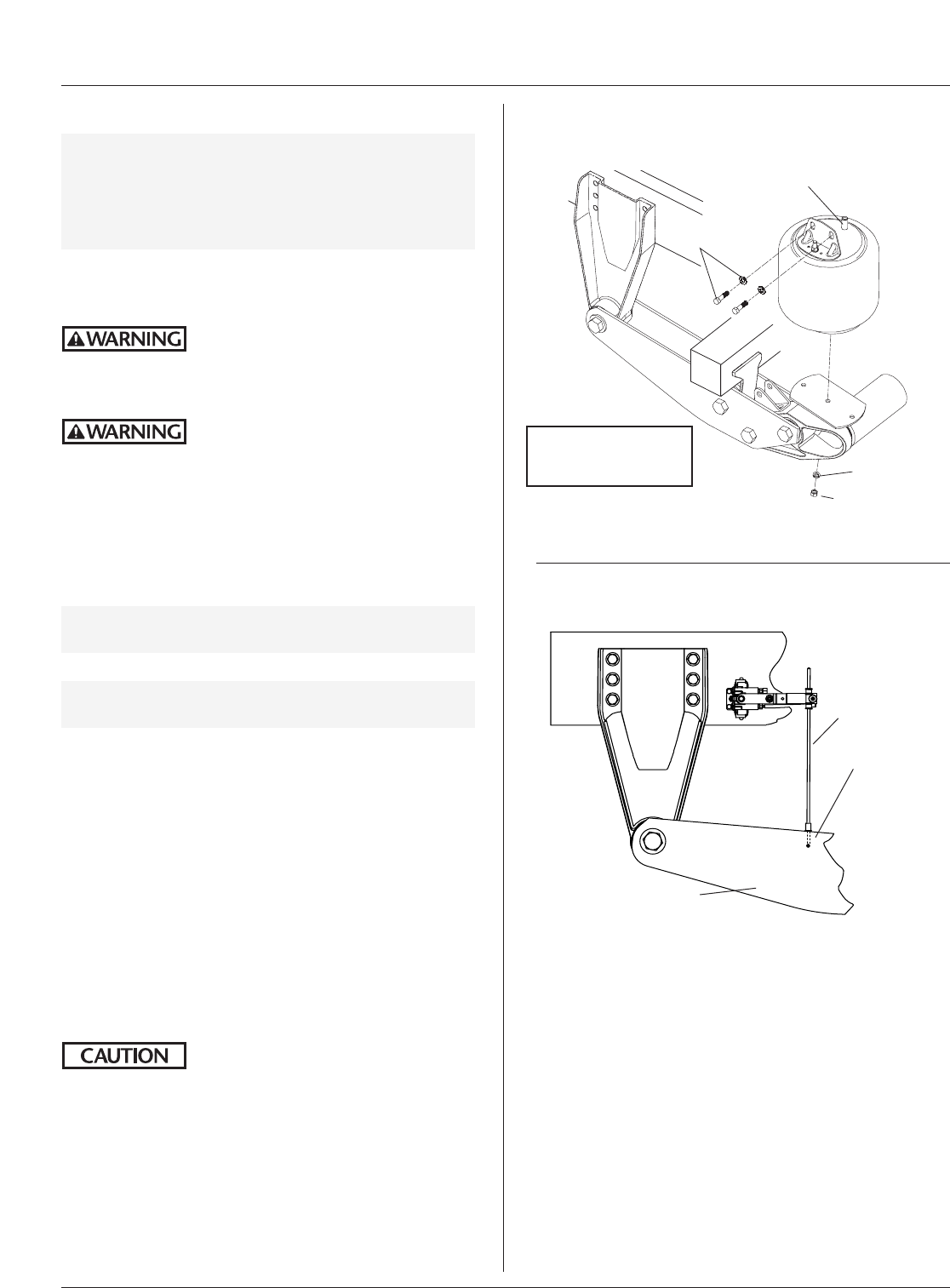
Axle Connection
SRK-514 – Holland part number: 481 00 378
ITEM PART NO. DESCRIPTION QTY.
1930 04 517 Hex Bolt 1.13˝-7x6.5 GR 8 2
2900 08 211 Bushing 2
3936 00 174 Washer Flat Narrow 1.12˝ 2
4934 00 506 Hex Nut 1.125˝-7 GR C 2
1
2Axle Bushing
Receptacle
Equalizing
Beam Plates
3
4
1
2
3
1
2
3
Torque Rod
Torque Rod and Track Bar Bushing
SRK-517 – Holland part number: 481 00 481
ITEM PART NO. DESCRIPTION QTY.
1930 03 833 Hex Bolt 0.875˝-9x4.5 GR 8 2
2900 08 243 Bushing 2
3934 00 498 Hex Nut 0.875˝-9 GR C 2
12 XL-AK400-01
PART REPLACEMENT INSTRUCTIONS
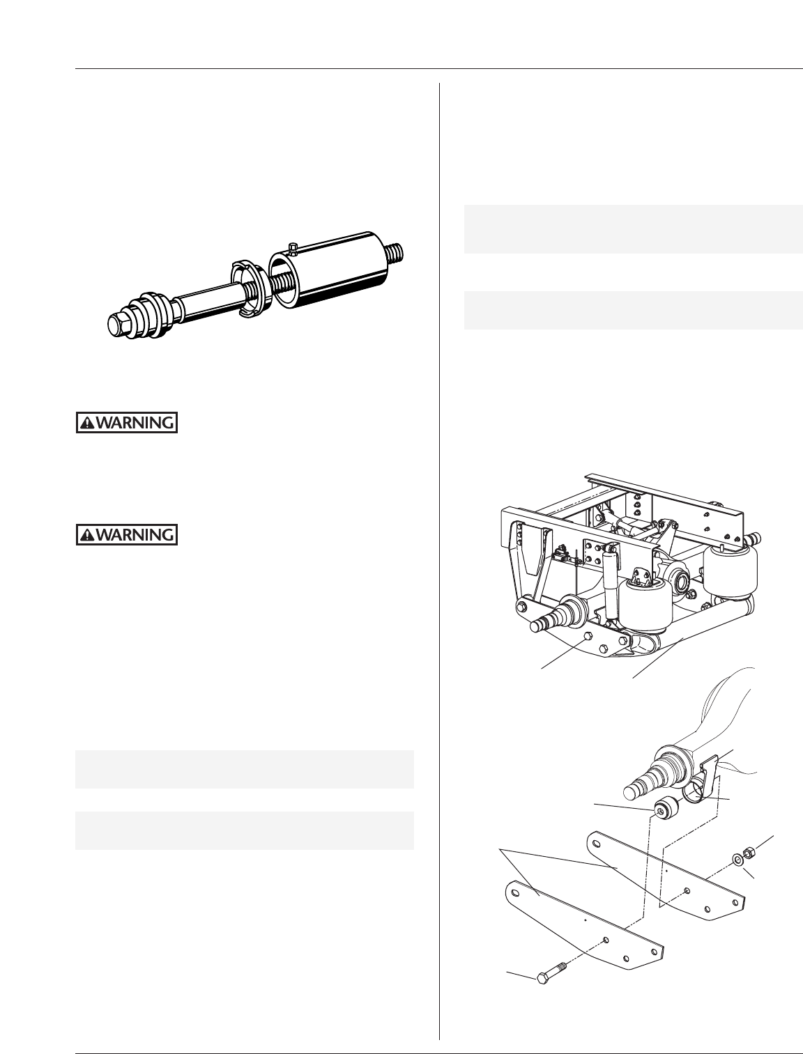
AIR SPRING
NUT TO AIR
SPRING PISTON
MOUNTING STUD
FRAME
FASTENERS
AIR SUPPLY FITTING
WASHER
FOR HCV LINK
LOWER CONNECTION,
SEE FIGURE 10B
EQUALIZING BEAM
PLATE
LOWER-LINK
CONNECTION
HCV LINK
FIGURE 10B
FIGURE 10A
Air Spring Replacement
HCV Linkage
Suspension Air Springs
IMPORTANT: Air springs must be replaced with the
proper air spring for your vehicle instal-
lation. Check the flexible member and
piston for the part number. If the part
number is unidentifiable, contact your
vehicle OEM for assistance.
1. The vehicle must be on a level floor and unloaded.
Block the front tires to prevent the vehicle from rolling
forward or backward.
Always block tires to prevent
rollaway—serious injury or death
may occur.
2. Support the frame with jack stands.
Always use jack stands of sufficient
strength and position them according
to OEM recommendations. Failure to do so may cause
vehicle to fall causing vehicle damage and/or serious
personal injury.
3. Exhaust air from the suspension system by:
•Height Control Valve - disconnect the link from
lower connection (FIGURE 10B) and pull down on
the link, or
NOTE: Holland recommends referring to the Height
Control Valve Manual for the correct procedure.
•Disconnect air supply line from the air spring.
NOTE: If air spring has a leak and is deflated, Step 3 still
must be performed.
4. Disconnect and remove the old air spring assembly
(FIGURE 10).
5. Install the new air spring assembly, and properly torque
the piston fastener (see Torque Specifications on page 5).
6. Torque the frame fasteners per the OEM recommended
torque specification.
7. Reconnect the air supply line and height control valve
lower-link connection (FIGURE 10B).
8. Remove the jack stands.
9. Increase suspension air system reservoir pressure in
excess of 100 psig (6.9 bars). Check for leaks. All air
springs should inflate and locate suspension at proper
ride height.
While vehicle air system pressure
capabilities may be in excess of 120
psig (8.3 bars), the air spring pressure must not be set
above 100 psig (6.9 bars) or the rubber air spring can
tear or fracture.
10. Check ride height to make sure it is within ±0.25˝ of
specification.
11. If ride height adjustment is necessary, refer to page 8 for
adjustment procedure.
XL-AK400-01 13
PART REPLACEMENT INSTRUCTIONS continued
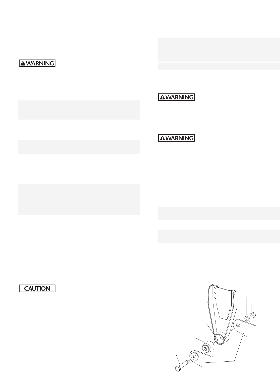
Axle Adapter Bushing
NOTE: Because the axle adapter is welded to the axle, a
Holland Bushing Service Tool, Part No. 505 44 012
(FIGURE 11), is available to ease removal and
replacement of bushings. Contact your OEM
Service Center for details.
9. Remove the axle adapter connection hardware on
both sides of the equalizing beam (FIGURE 12) —
transverse beam must be supported by floor jack before
disconnection.
10. Using the floor jack, support and slowly lower the
equalizing beam/transverse beam assembly, providing
access to the axle adapter bushings.
NOTE: If equalizing beam plates are too snug on axle
adapter, it may be necessary to loosen the trans-
verse beam connection hardware on both sides.
11. Using a Bushing Service Tool, Part No. 505 44 012, press
out old axle adapter bushings.
IMPORTANT: DO NOT use an open flame or other
heat source to remove the bushings.
12. Clean out all foreign material from axle adapter bushing
receptacles.
Part No. 505 44 012
The bushing service tool can be used
on all ADL bushings, including pivot
connections and transverse
beam connections.
Equalizing Beam
Plates
Bolt
Washer
Nut
Axle Adapter
Receptacle
Bushing Service Tool
FIGURE 11
Axle Adapter Bushing Replacement
FIGURE 12
Bolt for Roadside
Axle Connection Transverse beam
must be supported
with floor jack
1. The vehicle must be on a level floor and unloaded.
Block the front tires to prevent the vehicle from rolling
forward or backward.
Always block tires to prevent
rollaway—serious injury or death
may occur.
2. Jack up the rear of the vehicle using jack points and
procedure provided in vehicle maintenance manual.
3. Support the frame with jack stands.
Always use jack stands of sufficient
strength and position them according
to OEM recommendations. Failure to do so may cause
vehicle to fall causing vehicle damage and/or serious
personal injury.
4. Remove the tires.
5. Using a floor jack, support the axle at the axle bowl.
6. Using another floor jack, support the transverse beam.
7. Exhaust air from the suspension system by:
•Height Control Valve - disconnect the link from
lower connection (FIGURE 10B) and pull down on
the link, or
NOTE: Holland recommends referring to the Height
Control Valve Manual for the correct procedure.
•Disconnect air supply line from the air spring.
NOTE: If air spring has a leak and is deflated, Step 7 still
must be performed.
8. Disconnect the shock absorbers and air springs at their
lower connections.
Bushing
continued
14 XL-AK400-01
PART REPLACEMENT INSTRUCTIONS continued
Frame Bracket Pivot Bushing
NOTE: A Holland Bushing Service Tool, Part No. 505 44
012, is available to ease removal and replacement
of bushings (FIGURE 11). Contact your OEM
Service Center for details.
IMPORTANT: At time of service, replace both bushings.
1. The vehicle must be on a level floor and unloaded.
Block the front tires to prevent the vehicle from rolling
forward or backward.
Always block tires to prevent
rollaway—serious injury or death
may occur.
2. Jack up the rear of the vehicle using jack points and
procedure provided in vehicle maintenance manual.
3. Support the frame with jack stands.
Always use jack stands of sufficient
strength and position them according
to OEM recommendations. Failure to do so may cause
vehicle to fall causing vehicle damage and/or serious
personal injury.
4. Remove the tires.
5. Using a floor jack, support the axle at the axle bowl.
6. Exhaust air from the suspension system by:
•Height Control Valve - disconnect the link from
lower connection (FIGURE 10B) and pull down on
the link, or
NOTE: Holland recommends referring to the Height
Control Valve Manual for the correct procedure.
•Disconnect air supply line from the air spring.
NOTE: If air spring has a leak and is deflated, Step 6 still
must be performed.
7. Disconnect the shock absorbers and air springs at their
lower connections.
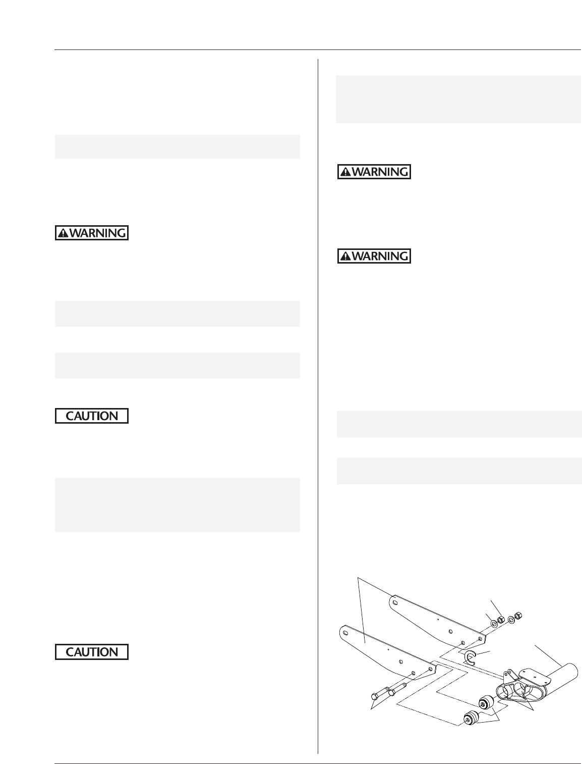
8. Remove the pivot connection hardware (FIGURE 13).
Axle Adapter Bushing continued
13. Inspect the axle adapters, their welds, and other parts
for cracks or failed welds. If cracks are detected any-
where on an axle adapter, replace the adapter.
Never repair a cracked axle adapter.
DO NOT weld cracks. Secondary weld
failures during use may cause loss of vehicle control and
could cause serious injury or death.
14. Lubricate the new replacement bushings and bushing
receptacles with an approved rubber lubricant or a soap
and water solution.
IMPORTANT: DO NOT use oil-based lubricant or
brake fluid, as it can cause damage to
the rubber.
15. Using the Bushing Service Tool, Part No. 505 44 012,
press the new bushings into the axle adapter receptacles
(FIGURE 12).
NOTE: Bushing must be centered in axle adapter
receptacle.
16. Using the floor jack, raise the transverse beam assembly
to its original position. Reassemble with new hardware,
and torque all the axle adapter and transverse beam nuts
(see Torque Specifications on page 5). Remove the
floor jack supporting transverse beam.
IMPORTANT: Suspension should be close to ride
height when torquing the axle adapter
connection to avoid bushing windup.
(Axle bowel can be supported by floor
jack: DO NOT raise rear of vehicle.)
17. Reconnect the air springs, shocks, and height control
valve link, and torque all hardware (see Torque
Specifications on page 5).
18. Remove the floor jack supporting the axle bowl.
19. Reinstall the tires. Remove jack stands, lower vehicle,
and remove floor jack.
20. Increase suspension air system reservoir pressure in
excess of 100 psig (6.9 bars). Check for leaks. All air
springs should inflate and locate suspension at proper
ride height.
While vehicle air system pressure
capabilities may be in excess of 120
psig (8.3 bars), the air spring pressure must not be set
above 100 psig (6.9 bars) or the rubber air spring can
tear or fracture.
21. Check ride height to make sure it is within ±0.25˝ (6mm)
of specification.
22. If ride height adjustment is necessary, refer to page 8 for
adjustment procedure.
continued
Bushing
Equalizing
Beam Plates
Bolt
Washer
Nut
Pivot Bushing
Receptacle
Frame Bracket Pivot Bushing Replacement
FIGURE 13
XL-AK400-01 15
PART REPLACEMENT INSTRUCTIONS continued
Frame Bracket Pivot Bushing continued
9. Using the floor jack supporting the axle bowel, lower
the axle and suspension to enable access to the frame
bracket pivot bushings.
10. Using a Bushing Service Tool, Part No. 505 44 012, press
out old frame bracket pivot bushings.
IMPORTANT: DO NOT use an open flame or other
heat source to remove the bushings.
11. Clean out all foreign material from frame bracket pivot
bushing receptacle(s).
12. Inspect the frame brackets for cracks. If cracks are
detected anywhere on a frame bracket, replace
the bracket.
Never repair a cracked frame bracket.
DO NOT weld cracks. Secondary weld
failures during use may cause loss of vehicle control and
could cause serious injury or death.
13. Lubricate the new replacement bushings and bushing
receptacles with an approved rubber lubricant or a soap
and water solution.
IMPORTANT: DO NOT use oil-based lubricant or brake
fluid, as it can cause damage to the rubber.
14. Using the Bushing Service Tool, Part No. 505 44 012,
press the new bushings into the proper receptacles.
NOTE: Bushings must be centered in frame bracket
receptacle.
15. Reassemble pivot connection, and raise the axle and sus-
pension to its original position.
DO NOT lift the vehicle off the
jack stands.
Align the holes from the equalizing beams with the holes
from the pivot bushings, and replace the pivot hardware.
16. Torque the pivot connection nuts (see Torque
Specifications on page 5).
IMPORTANT: Suspension should be close to ride
height when torquing the front pivot
connection to avoid bushing windup.
(Axle bowel can be supported by floor
jack: DO NOT raise rear of vehicle.)
17. Reconnect the air springs, shocks, and height control
valve link, and torque all hardware (see Torque
Specifications on page 5).
18. Reinstall the tires. Remove jack stands, lower vehicle,
and remove floor jack supporting the transverse beam.
19. Increase suspension air system reservoir pressure in
excess of 100 psig (6.9 bars). Check for leaks. All air
springs should inflate and locate suspension at proper
ride height.
While vehicle air system pressure
capabilities may be in excess of 120
psig (8.3 bars), the air spring pressure must not be set
above 100 psig (6.9 bars) or the rubber air spring can
tear or fracture.
20. Check ride height to make sure it is within ±0.25˝ (6mm)
of specification.
21. If ride height adjustment is necessary, refer to page 8 for
adjustment procedure.
Transverse Beam Bushing
NOTE: A Holland Bushing Service Tool, Part No.
505 44 012, is available to ease removal and
replacement of bushings (FIGURE 11).
Contact your OEM Service Center for details.
1. The vehicle must be on a level floor and unloaded.
Block the front tires to prevent the vehicle from rolling
forward or backward.
Always block tires to prevent
rollaway—serious injury or death
could occur.
2. Jack up the rear of the vehicle using jack points and
procedure provided in vehicle maintenance manual.
3. Support the frame with jack stands.
Always use jack stands of sufficient
strength and position them according
to OEM recommendations. Failure to do so may cause
vehicle to fall causing vehicle damage and/or serious
personal injury.
4. Remove the tires.
5. Using a floor jack, support the axle at the axle bowl.
6. Using another floor jack, support the transverse beam.
7. Exhaust air from the suspension system by:
•Height Control Valve - disconnect the link from
lower connection (FIGURE 10B) and pull down on
the link, or
NOTE: Holland recommends referring to the Height
Control Valve Manual for the correct procedure.
•Disconnect air supply line from the air spring.
NOTE: If air spring has a leak and is deflated, Step 7 still
must be performed.
8. Disconnect the shock absorbers and air springs at their
lower connections.
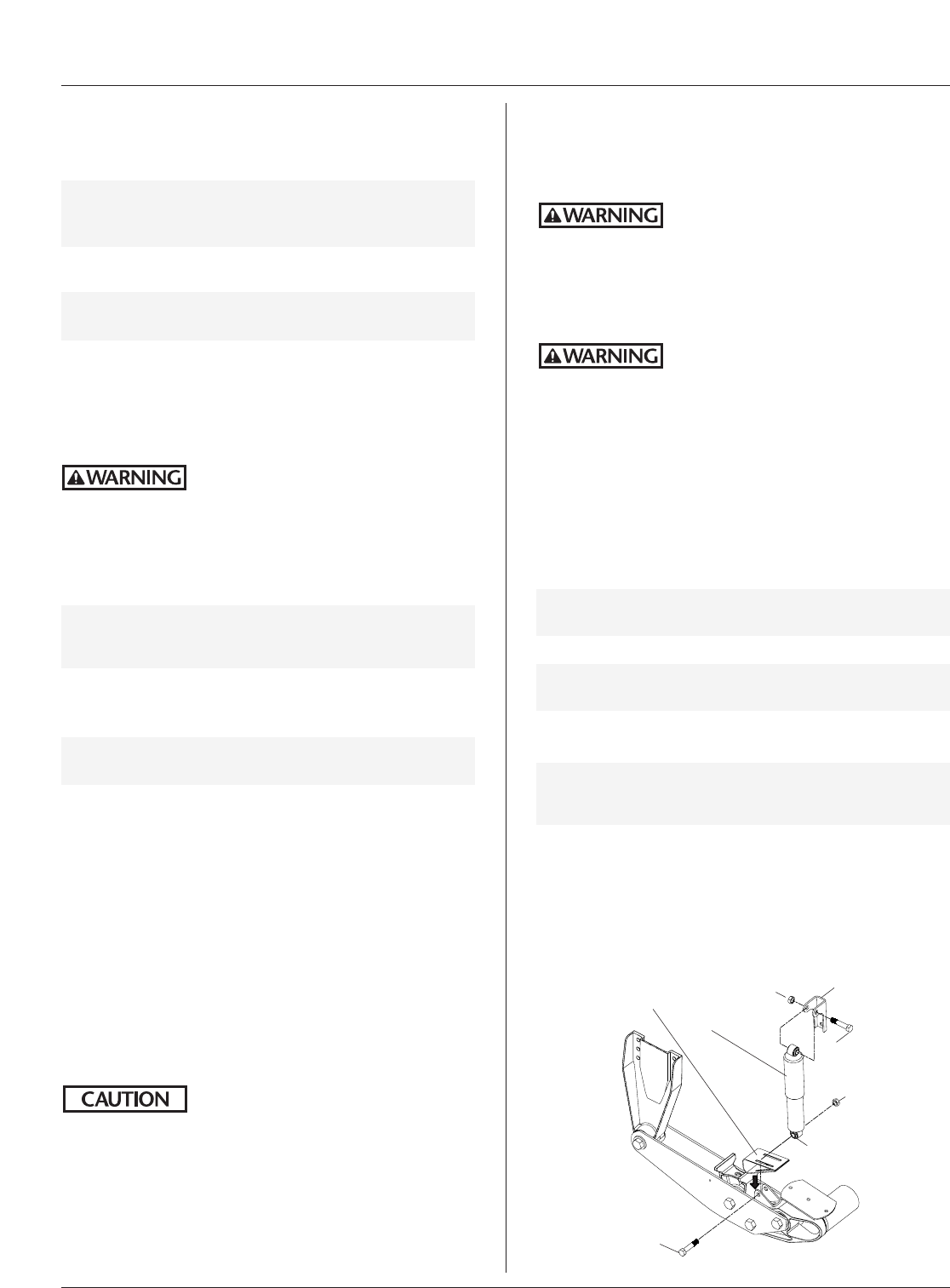
9. Remove the transverse beam connection hardware on
both sides (FIGURE 14).
continued
Bushings
(separate kits)
Equalizing Beam Plates
Bolts
Washer
Nut
Washer
Transverse
Beam
Receptacles
Transverse Beam Bushing Replacement
FIGURE 14
16 XL-AK400-01
PART REPLACEMENT INSTRUCTIONS continued
Transverse Beam Bushing continued
10. Using the floor jack, support and lower the transverse
beam, providing access to the transverse beam bushings.
NOTE:The axle adapter hardware connecting the
equalizing beam plates to the axle adapter may
need to be loosened on both sides.
11. Using a Bushing Service Tool, Part No. 505 44 012, press
out the old transverse beam bushings.
IMPORTANT: DO NOT use an open flame or other
heat source to remove the bushings.
12. Clean out all foreign material from transverse beam
bushing receptacles.
13. Inspect the transverse beam for any cracks or failed
welds. If cracks are detected anywhere on the beam,
replace the beam.
Never repair a cracked transverse
beam. DO NOT weld cracks.
Secondary weld failures during use may cause loss of
vehicle control and could cause serious injury or death.
14. Lubricate the new replacement bushings and bushing
receptacles with an approved rubber lubricant or a soap
and water solution.
IMPORTANT: DO NOT use oil-based lubricant or
brake fluid, as it can cause damage to
the rubber.
15. Using the Bushing Service Tool, Part No. 505 44 012,
press the new bushings into the transverse beam
receptacles.
NOTE: Bushings must be centered in the transverse beam
receptacle.
16. Raise the transverse beam assembly to its original position.
Reassemble with new hardware, and torque all the trans-
verse beam nuts (see Torque Specifications on page 5).
17. Reconnect the air springs, shocks, and height control
valve link, and torque all hardware (see Torque
Specifications on page 5).
18. Remove the floor jack supporting the axle bowl.
19. Reinstall the tires. Remove jack stands, lower vehicle,
and remove floor jack supporting the transverse beam.
20. Increase suspension air system reservoir pressure in
excess of 100 psig (6.9 bars). Check for leaks. All air
springs should inflate and locate suspension at proper
ride height.
While vehicle air system pressure
capabilities may be in excess of 120
psig (8.3 bars), the air spring pressure must not be set
above 100 psig (6.9 bars) or the rubber air spring can
tear or fracture.
21. Check ride height to make sure it is within ±0.25˝
(6mm) of specification.
22. If ride height adjustment is necessary, refer to page 8 for
adjustment procedure.
Shock Absorbers
1. The vehicle must be on a level floor and unloaded.
Block the front tires to prevent the vehicle from rolling
forward or backward.
Always block tires to prevent
rollaway—serious injury or death
could occur.
2. Jack up the rear of the vehicle using jack points and
procedure provided in vehicle maintenance manual.
3. Support the frame with jack stands.
Always use jack stands of sufficient
strength and position them according
to OEM recommendations. Failure to do so may cause
vehicle to fall causing vehicle damage and/or serious
personal injury.
4. Remove the tires.
5. Using a floor jack, support the axle at the axle bowl.
6. Exhaust air from the suspension system by:
•Height Control Valve - disconnect the link from
lower connection (FIGURE 10B) and pull down on
the link, or
NOTE: Holland recommends referring to the Height
Control Valve Manual for the correct procedure.
•Disconnect air supply line from the air spring.
NOTE: If air spring has a leak and is deflated, Step 6 still
must be performed.
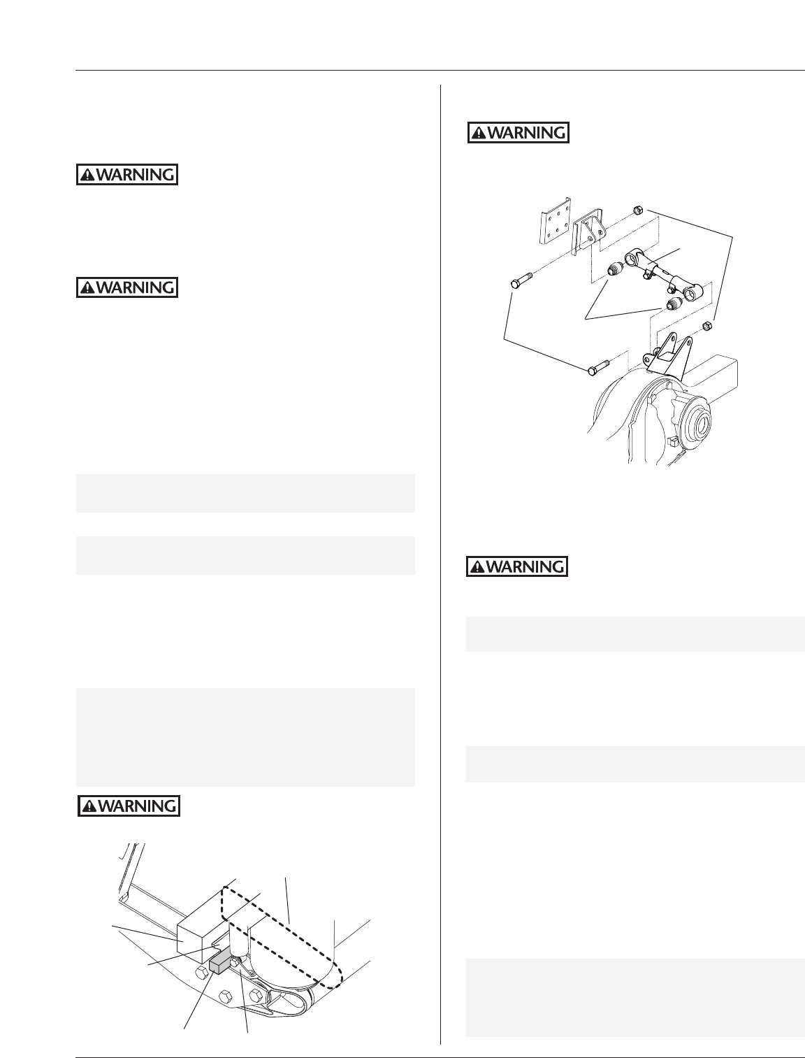
7. Remove upper and lower mounting hardware and shock
absorber (FIGURE 15).
NOTE: Inspect space within or above debris shield
(below lower loop of shock), and remove rocks
that may be lodged in this space.
8. Replace with correct shock absorber. Shock orientation
is with the dust cover near the top mounting bolt
(FIGURE 15).
9. Torque fasteners (see Torque Specifications on page 5).
Bolt
Nut
Debris Shield
(slides down over
shock mounting
bracket)
Shock
Absorber
(Dust Cover)
Bolt
Nut
Mounting
Bracket
Shock Lower Loop
Shock Replacement
FIGURE 15
XL-AK400-01 17
PART REPLACEMENT INSTRUCTIONS continued
Torque Rod
1. The vehicle must be on a level floor and unloaded.
Block the front tires to prevent the vehicle from rolling
forward or backward.
Always block tires to prevent
rollaway—serious injury or death
could occur.
2. Jack up the rear of the vehicle using jack points and pro-
cedure provided in OEM’s vehicle maintenance manual.
3. Support the frame with jack stands.
Always use jack stands of sufficient
strength and position them according
to OEM recommendations. Failure to do so may cause
vehicle to fall causing vehicle damage and/or serious
personal injury.
4. Remove the tires.
5. Using a floor jack, support the axle at the axle bowl.
6. Exhaust air from the suspension system by:
•Height Control Valve - disconnect the link from
lower connection (FIGURE 10B) and pull down on
the link, or
NOTE: Holland recommends referring to the Height
Control Valve Manual for the correct procedure.
•Disconnect air supply line from the air spring.
NOTE: If air spring has a leak and is deflated, Step 6 still
must be performed.
7. Disconnect the shock absorbers and air springs at their
lower connections.
8. With the floor jack supporting the axle bowl, lower the
suspension and axle to enable access to the torque rod.
9. Secure the axle so the axle will not move when the
torque rod is removed.
IMPORTANT: First, place a solid 13/4˝ square spacer block
between the axle adapter and the lower
shock bracket to prevent axle from moving
backwards. Second, loop and tie a chain
around the axle and transverse beam to
prevent axle from moving forwards.
Axle must not move—or personal
injury may occur.
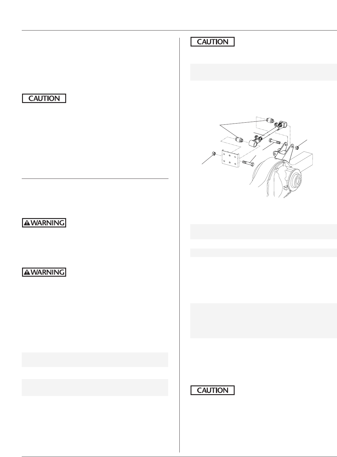
Bolts
Torque
Rod
Nuts
Bushings
Torque Rod Replacement
FIGURE 16
Always secure axle (see Step 9).
Failure to secure axle could cause
the axle to move in either direction, which may result
in serious personal injury.
Lower shock bracket
To prevent axle movement, loop the chain
around the axle and the transverse beam
(dashed line), ensuring the chain is secure.
Axle adapter
Axle
13/4˝x 13/4˝Spacer block
10. Remove the torque rod connection hardware
(FIGURE 16).
11. Using a hydraulic press capable of 10,000 lbs. of force,
press out the old bushings from the torque rod ends.
The torque rod support fixture must
be securely mounted to the hydraulic
press; otherwise, the torque rod may abruptly shift and
personal injury could occur.
IMPORTANT: DO NOT use an open flame or other
heat source to remove the bushings.
12. Clean out all foreign material from torque rod
bushing receptacles.
13. Lubricate the replacement bushings and bushing recepta-
cles with an approved rubber lubricant or a soap and
water solution.
IMPORTANT: DO NOT use oil-based lubricant or brake
fluid, as it can cause damage to the rubber.
14. Press in the new torque rod bushings.
NOTE: Bushings must be centered in the torque rod
end receptacles.
15. Reattach the torque rod using new hardware, and torque
fasteners (see Torque Specifications on page 5).
16. With the floor jack supporting the axle bowl, raise the
axle/suspension to its original position. Reconnect the air
springs, shocks, and height control valve link, and torque
all hardware (see Torque Specifications on page 5).
IMPORTANT: Suspension should be close to ride
height when torquing the torque rod
connections to avoid bushing windup.
(Axle bowl can be supported by floor
jack: DO NOT raise rear of vehicle.)
continued
18 XL-AK400-01
PART REPLACEMENT INSTRUCTIONS continued
Torque Rod continued
17. Reinstall the tires. Remove jack stands, lower vehicle,
and remove floor jack.
18. Increase suspension air system reservoir pressure in
excess of 100 psig (6.9 bars). Check for leaks. All air
springs should inflate and locate suspension at proper
ride height.
While vehicle air system pressure
capabilities may be in excess of 120
psig (8.3 bars), the air spring pressure must not be set
above 100 psig (6.9 bars) or the rubber air spring can
tear or fracture.
19. Check ride height to make sure it is within ±0.25˝ (6mm)
of specification.
20. If ride height adjustment is necessary, refer to page 8 for
adjustment procedure.
21. Compare the pinion angle to the OEM specification.
22. If it is necessary to adjust the pinion angle, refer to page 9.
Track Bar
1. The vehicle must be on a level floor and unloaded.
Block the front tires to prevent the vehicle from rolling
forward or backward.
Always block tires to prevent
rollaway—serious injury or death
could occur.
2. Jack up the rear of the vehicle using jack points and
procedure provided in vehicle maintenance manual.
3. Support the frame with jack stands.
Always use jack stands of sufficient
strength and position them according
to OEM recommendations. Failure to do so may cause
vehicle to fall causing vehicle damage and/or serious
personal injury.
4. Remove the tires.
5. Using a floor jack, support the axle at the axle bowl.
6. Exhaust air from the suspension system by:
•Height Control Valve - disconnect the link from
lower connection (FIGURE 10B) and pull down on
the link, or
NOTE: Holland recommends referring to the Height
Control Valve Manual for the correct procedure.
•Disconnect air supply line from the air spring.
NOTE: If air spring has a leak and is deflated, Step 6 still
must be performed.
7. Disconnect the shock absorbers and air springs at their
lower connections.
8. Using the floor jack, support and lower the axle and sus-
pension to enable access to the track bar.
9. Remove the track bar connection hardware (FIGURE 17).
10. Using a hydraulic press capable of 10,000 lbs. of force,
press out the old bushings from the track bar ends.
The track bar support fixture must be
securely mounted to the hydraulic
press; otherwise, the track bar may abruptly shift and
personal injury could occur.
IMPORTANT: DO NOT use an open flame or other
heat source to remove the bushings.
11. Clean out all foreign material from track bar bushing
receptacles.
Bolt
Track Bar
Nut
Bushings
Nut
Track Bar Replacement
FIGURE 17
12. Lubricate the replacement bushings and bushing
receptacles with an approved rubber lubricant or a
soap and water solution.
IMPORTANT: DO NOT use oil-based lubricant or brake
fluid, as it can cause damage to the rubber.
13. Press in the new bushings.
NOTE:
Bushings must be centered in the track bar receptacles.
14. Reattach the track bar using new hardware, and torque
fasteners (see Torque Specifications on page 5).
15. With the floor jack supporting the axle bowl, raise the
axle/suspension to its original position. Reconnect the air
springs, shocks, and height control valve link, and torque
all hardware (see Torque Specifications on page 5).
IMPORTANT: Suspension should be close to ride
height when torquing the track bar
connections to avoid bushing windup.
(Axle bowl can be supported by floor
jack: DO NOT raise rear of vehicle.)
16. Reinstall the tires. Remove jack stands, lower vehicle,
and remove floor jack.
17. Increase suspension air system reservoir pressure in
excess of 100 psig (6.9 bars). Check for leaks. All air
springs should inflate and locate suspension at proper
ride height.
While vehicle air system pressure
capabilities may be in excess of 120
psig (8.3 bars), the air spring pressure must not be set
above 100 psig (6.9 bars) or the rubber air spring can
tear or fracture.
18. Check ride height to make sure it is within ±0.25˝
(6mm) of specification.
19. If ride height adjustment is necessary, refer to page 8 for
adjustment procedure.

XL-AK400-01 19
TROUBLESHOOTING
Problem
All air springs flat (no air).
Air springs deflate rapidly when
vehicle is parked.
Chassis ride height too high or too low.
Air springs ruptured.
Air spring failed.
Air spring(s) fail to fully deflate when all
weight is removed from the suspension.
Shock absorber failures.
Excessive tire wear.
Vehicle unstable or handles poorly.
Constant noise from suspension.
Drive-Line vibration.
Possible Cause and Remedy
Insufficient air pressure in the vehicle air system. Check the air pressure
gauge on instrument panel. If air pressure is low, run the engine until a minimum
pressure of 100 psig (6.9 bars) is indicated on the gauge.
Air leakage from the suspension air system or the air brake system. Listen for
air leakage due to loose fittings or damaged air lines, air springs, brake actuators
or control valve. Tighten loose fittings to stop leakage and/or replace worn or
damaged parts.
Air leakage from the suspension air system. Listen for air leakage due to loose
fittings between air tank and air suspension or damaged air lines, air springs or
height control valve. Apply a soapy solution to connections and air springs if
necessary to check for bubbles (leaks). Tighten loose fittings to stop leakage
and/or replace worn or damaged parts with new ones.
Height control valve out of adjustment. Readjust the height control valve.
Air spring cut or punctured. Replace.
Continual or repeated over-extension of the air spring. Visually inspect for
broken or loose shock absorber or shock absorber mounting bracket. Reconnect
loose parts and replace any defective parts. Check the adjustment of the height
control valves.
Air spring(s) worn out. Replace.
Restricted air lines(s) between the height control valve and the air spring(s).
Disconnect the height control valve linkage and rotate the actuating lever to the
45° down position. If the air spring(s) remain inflated, check for pinched or
blocked line(s).
Over-extension. Mislocated shock brackets. Improper shocks installed. Check
for oil leaking from shock. If worn out from length of service, replace.
Axles mis-aligned. Realign axles per vehicle manufacturer’s recommendations.
See Axle Alignment procedure on page 8.
Loose frame bolts or attachments. Tighten frame bolts and attaching parts to
proper specifications.
Cracked or loose frame crossmembers. Repair or replace damaged frame
members, and torque all nuts and bolts to proper torque specifications.
Check the ride height. Readjust if necessary.
Loose transverse beam connection. Replace worn bushings, retorque to specifications.
Loose or worn pivot connection. Retorque to specification and/or rebush
if necessary.
Cracked or loose equalizing beam plates or transverse beam.
Replace failed part.
Contact your vehicle manufacturer for his recommendation if these possible causes
and effects do not solve the vehicle handling problem.
Loose shock, track bar, or torque rod. Retighten to torque specified in
Torque Specifications on page 5.
Loose equalizing beam plate connection at frame bracket, axle adapter
and/or transverse beam. Retighten approriate hardware to torque specified in
Torque Specifications on page 5.
Rocks wedged between axle adapter and transverse beam. Remove debris
shield and remove rocks, then reinstall debris shield.
Pinion angle out of adjustment. Readjust using instructions on page 9.
Incorrect ride height. Readjust using instructions on page 8.

20 XL-AK400-01
Copyright © April 2003 • The Holland Group, Inc.
Holland USA, Inc. Facilities:
Denmark, SC Muskegon, MI
Dumas, AR Warrenton, MO
Holland, MI Wylie, TX
Ph: 888-396-6501 Fax: 800-356-3929
Holland International, Inc.
Holland, MI
Phone: 616-396-6501
Fax: 616-396-1511
Holland Equipment, Ltd.
Norwich, Ontario • Canada
Phone: 519-863-3414
Fax: 519-863-2398
Holland Hitch Western, Ltd.
Surrey, British Columbia • Canada
Phone: 604-574-7491
Fax: 604-574-0244
Holland Hitch of Canada, Ltd.
Woodstock, Ontario • Canada
Phone: 519-537-3494
Fax: 800-565-7753
