XCTU User Guide XTCU
User Manual:
Open the PDF directly: View PDF ![]() .
.
Page Count: 206 [warning: Documents this large are best viewed by clicking the View PDF Link!]
- Download and install XCTU
- RF concepts and terminology
- XCTU overview
- Add radio modules to XCTU
- Configure your modules
- Configuration working mode
- Read radio module configuration
- Write module settings
- Load default firmware settings
- Update firmware
- Save a configuration profile
- Load a configuration profile
- Search for a firmware setting
- Configure remote modules securely
- Configure a Wi-Fi access point
- Enable and configure Bluetooth
- View firmware release notes
- Communicate with your modules
- View your radio network
- Configure XCTU
- Update software
- Use the XCTU command line
- XCTU tools
- How-to articles and videos
- Troubleshooting for XCTU
- Known issues

XCTU
Configuration and Test Utility Software
User Guide

Revision history—90001458-13
Revision Date Description
H November
2017
Added support for XBee Cellular modem update.
J April 2018 Added support for all XBee3 variants.
K June 2018 Added support for File System Manager. Updated with XCTU 6.4.0.X
information.
L September
2018
6.4.1.X release.
M November
2018
6.4.2.X release.
Trademarks and copyright
Digi, Digi International, and the Digi logo are trademarks or registered trademarks in the United
States and other countries worldwide. All other trademarks mentioned in this document are the
property of their respective owners.
© 2018 Digi International Inc. All rights reserved.
Disclaimers
Information in this document is subject to change without notice and does not represent a
commitment on the part of Digi International. Digi provides this document “as is,” without warranty of
any kind, expressed or implied, including, but not limited to, the implied warranties of fitness or
merchantability for a particular purpose. Digi may make improvements and/or changes in this manual
or in the product(s) and/or the program(s) described in this manual at any time.
Warranty
To view product warranty information, go to the following website:
www.digi.com/howtobuy/terms
Customer support
Gather support information: Before contacting Digi technical support for help, gather the following
information:
Product name and model
Product serial number (s)
Firmware version
Operating system/browser (if applicable)
Logs (from time of reported issue)
XCTU User Guide 2

Trace (if possible)
Description of issue
Steps to reproduce
Contact Digi technical support: Digi offers multiple technical support plans and service packages.
Contact us at +1 952.912.3444 or visit us at www.digi.com/support.
Feedback
To provide feedback on this document, email your comments to
techcomm@digi.com
Include the document title and part number (XCTU User Guide, 90001458-13 B) in the subject line of
your email.
XCTU User Guide 3

Contents
Download and install XCTU
XCTU requirements 10
Operating systems 10
System requirements 10
Supported RF modules 10
Install XCTU - Windows 11
XCTU updates 11
Install XCTU - Linux 11
XCTU updates 12
Install XCTU - OSX 12
XCTU updates 12
Optional: Manually install USB drivers 12
RF concepts and terminology
RF modules 15
XBee RF modules 15
XTend RF modules 15
XLR PRO radio solutions 15
Radio firmware 15
Radio communication protocols 16
Radio module operating modes 16
AT operating mode 17
API operating mode 17
API escaped operating mode 18
API frames 18
AT settings or commands 19
Configuring in AT mode 19
Configuring in API mode 20
Local radio modules 20
Remote radio modules 20
XCTU overview
Menu bar 21
Main toolbar 22
Devices list 22
Working area 23
Status bar 23
XCTU preferences 23
XCTU User Guide 4

XCTU User Guide 5
Appearance 23
Automatic updates 24
Consoles 24
Firmware updates 24
Network 24
Radio firmware library 26
XCTU working modes 26
Configuration working mode 26
Consoles working mode 26
Network working mode 27
Add radio modules to XCTU
Add a radio module manually 29
Add a programmable radio module 30
Discover local radio modules 32
Radio module information panel 34
Module Icon 35
New firmware indicator 37
Remove a radio module 38
Expand/Collapse radio modules list 38
Module information box 39
Organize your modules 39
Find radio modules 39
Sort radio modules 39
Clear radio modules 39
Discover remote radio modules 39
Find radio modules 41
Search expressions 41
Configure your modules
Configuration working mode 44
Configuration toolbar 44
Firmware information panel 45
Firmware settings 45
Setting status 47
Setting types 47
Special functions 48
Read radio module configuration 51
Write module settings 51
Load default firmware settings 51
Update firmware 52
Cellular modem firmware updates 53
Remote firmware updates 53
Bootloader updates 53
Save a configuration profile 54
Load a configuration profile 55
Search for a firmware setting 57
Configure remote modules securely 57
Configure a Wi-Fi access point 58
Enable and configure Bluetooth 60
View firmware release notes 61

XCTU User Guide 6
Communicate with your modules
Consoles working mode 64
Console status 64
Consoles toolbar 64
Line status indicator 65
Console overview 66
Connect and disconnect the console 66
Record a console session 66
Attach and detach the console 67
Communicate with modules running in API or API escaped mode 68
API console 68
Filter sent and received frames 72
Add an API frame 76
Manage API frames 79
Send a single API frame 81
Send a sequence of API frames 82
Save an API console session 83
Communicate with modules running in AT mode 83
AT console 84
Add a data packet 86
Manage data packets 88
Send a single packet 89
Send a sequence of packets 90
Save an AT console session 91
Console log files 91
Console session records 91
Data records 92
View your radio network
Network working mode 94
Network toolbar 94
Network scan status 95
Graph view 95
Table view 99
Scan the network for available modules 101
Search for network nodes 101
Change network perspective 101
Set network layout 102
Filter network connections by quality 102
Take a screenshot of the network 103
Set zoom level in Graph view 104
Export a network table 104
Configure XCTU
Set general preferences 106
Set appearance preferences 106
Set automatic software update preferences 107
Set console preferences 109
Set firmware update preferences 110
Set network discovery preferences 111
Set network appearance preferences 114

XCTU User Guide 7
Set radio firmware library preferences 116
Set MicroPython Terminal preferences 117
Update software
Update radio firmware library 120
Install legacy radio firmware 121
Install XCTU updates 122
Open change log 123
Use the XCTU command line
Understanding the XCTU command line interface 125
List all commands 125
Program arguments 125
List ports via command line 125
Options 126
Load profile via command line 126
Options 126
Examples 127
Update firmware via command line 127
Set options 128
Examples 128
XCTU tools
Frames generator tool 131
XBee APIFrame generator dialog 132
ASCII/HEX conversion 134
Generate an API frame 134
Frames interpreter tool 136
XBee API Frames interpreter dialog 137
Decode a frame 138
XBee recovery tool 140
Recover a radio module dialog 141
Recover a radio module 143
Load console session tool 144
Console session viewer dialog 145
Load a console session 148
Range test tool 149
Radio range test dialog 150
Device Selection 151
Range Test Configuration 153
Data representation 154
Supported products 155
Special considerations 156
Range test 157
Perform a range test 158
Firmware explorer tool 159
Firmware explorer dialog 159
Firmware toolbar 160
Firmware selection panel 161
Firmware settings panel 161

XCTU User Guide 8
Inspect a firmware version 162
Serial console tool 163
Serial console dialog 164
Open a serial console session 166
Configure the serial port settings 166
Open a serial console session 167
Spectrum analyzer tool 168
Spectrum analyzer dialog 169
Device selection 170
Analysis configuration 170
Channels Chart 171
Channel summary values 172
Number of samples 173
Analyze the spectrum of a radio band 173
Throughput tool 173
Throughput dialog 175
Device selection 175
Throughput session configuration 176
Data representation 181
Supported products 182
Special considerations 182
Measure the transfer ratio between two radio modules 183
MicroPython Terminal tool 185
Configure the serial port settings - MicroPython Terminal tool 187
Open a MicroPython Terminal session 188
File system manger tool 189
File system manager dialog 190
File System Manager sections 191
Interact with XBee file system 191
How-to articles and videos
How to update the firmware of your modules 195
Step 1: Add the module to XCTU 195
Step 2: Update the firmware 196
Over-the-air firmware update considerations 197
How to visualize your network 197
Step 1:Scan the network 198
Step 2:Explore the network 199
199
Troubleshooting for XCTU
Troubleshooting: General 201
Troubleshooting: Networking 202
Troubleshooting: Firmware update 202
Troubleshooting: Add radio module 203
Known issues

Download and install XCTU
This section contains download and install instructions based on operating system. XCTU is
compatible with Linux, OSX, and Windows. It may be necessary to configure your system prior to
installing XCTU for the first time.
XCTU requirements 10
Install XCTU - Windows 11
Install XCTU - Linux 11
Install XCTU - OSX 12
Optional: Manually install USB drivers 12
XCTU User Guide 9

Download and install XCTU XCTU requirements
XCTU User Guide 10
XCTU requirements
Operating systems
XCTU is compatible with the following operating systems:
nWindows Vista/7/8/10 (32-bit or 64-bit versions)
nMac OS X v10.6 and higher versions (64-bit only)
nLinux with KDE or GNOME window managers (32-bit or 64-bit versions)
System requirements
Property Minimum Recommended
HDD space 500 MB 1 GB
RAM memory 2 GB 4 GB
CPU Dual-core processor Quad-core processor
Supported RF modules
XCTU supports configuration and communication for most Digi RF modules. XCTU uses a serial link to
interact with these radio modules, providing an easy-to-use and intuitive graphical interface. The
following is a complete list of XCTU-compatible RF modules:
nXBee®/XBee-PRO® RF Module Family
lXBee SX
lXBee-PRO SX
lXBee 802.15.4
lXBee-PRO 802.15.4
lXBee ZB
lXBee-PRO ZB
lProgrammable XBee-PRO ZB
lXBee ZB SMT
lXBee-PRO ZB SMT
lProgrammable XBee-PRO ZB SMT
lXBee-PRO 900HP
lProgrammable XBee-PRO 900HP
lXBee-PRO XSC
lXBee-PRO 900
lXBee-PRO DigiMesh 900
lXBee DigiMesh 2.4
lXBee-PRO DigiMesh 2.4
lXBee-PRO 868

Download and install XCTU Install XCTU - Windows
XCTU User Guide 11
lXBee Wi-Fi
lXBee 865LP
lProgrammable XBee 865LP
lXBee Cellular
lXBee 868LP SX
lXBee Thread
lXBee3 (Zigbee, DigiMesh 2.4, 802.15.4 and Cellular)
nXTend® RF Module family
nXLR PRO radio solution
nXLR Module
Install XCTU - Windows
Follow the steps below to download and install XCTU on your computer.
1. Visit www.digi.com/xctu.
2. Click Download XCTU.
3. Under Utilities, click the Windows installer link.
4. When the file has finished downloading, run the executable file and follow the steps in the XCTU
Setup Wizard.
A “What’s new” dialog appears when XCTU opens the first time after the installation.
XCTU updates
You may be notified about XCTU software updates once XCTUhas loaded. You should always update
XCTU to the latest available version. See Install XCTU updates.
Install XCTU - Linux
By default, access to the serial and USB ports in Linux is restricted to root and dialout group users. To
access your XBee devices and use XCTU to communicate with them, your Linux user must belong to
this group.
To add your Linux user to the dialout group:
1. Open a terminal console.
2. Execute this command:
sudo usermod -a -G dialout <user>
where <user> is the user you want to add to the dialout group.
3. Log out and log in again with your user in the system.
Then download and install XCTU:

Download and install XCTU Install XCTU - OSX
XCTU User Guide 12
4. Visit www.digi.com/xctu.
5. Click Download XCTU.
6. Under Utilities, click the Linux installer link.
7. When the file has finished downloading, run the executable file and follow the steps in the XCTU
Setup Wizard.
A “What’s new” dialog appears when XCTU opens the first time after the installation.
XCTU updates
You may be notified about XCTU software updates once XCTUhas loaded. You should always update
XCTU to the latest available version. See Install XCTU updates.
Install XCTU - OSX
OSX version 10.8 (Mountain Lion) and greater only allows you to install applications downloaded from
the Apple Store. To install XCTU, you must temporarily disable this setting.
Follow these steps to enable installation of "unsigned" software:
1. Click the Apple icon in the top-left corner of your screen and choose System Preferences.
2. Click the Security & Privacy icon.
3. To edit security settings, click the padlock icon in the bottom left of the window.
4. Enter your Mac credentials and click Unlock. The Allow applications downloaded from dialog
appears.
5. Click the Anywhere radio button and, in the confirmation window, click Allow From
Anywhere.
Note We recommend you set this option back to Mac App Store or Mac App Store and identified
developers once you have finished installing XCTU.
Then download and install XCTU:
6. Visit www.digi.com/xctu.
7. Click Download XCTU.
8. Under Utilities, click the OSX installer link.
9. When the file has finished downloading, unzip and run the executable file and follow the steps
in the XCTU Setup Wizard.
A “What’s new” dialog appears when XCTU opens the first time after the installation.
XCTU updates
You may be notified about XCTU software updates once XCTUhas loaded. You should always update
XCTU to the latest available version. See Install XCTU updates.
Optional: Manually install USB drivers
When you connect the XBee board to your computer for the first time, USB drivers are installed
automatically. There are times when this does not occur, and you need to install device drivers


RF concepts and terminology
This section contains concepts regarding radio frequency modules and the XCTU application itself.
Understanding these concepts will help you work most effectively with XCTU.
RF modules 15
Radio firmware 15
Radio communication protocols 16
Radio module operating modes 16
API frames 18
AT settings or commands 19
Local radio modules 20
Remote radio modules 20
XCTU User Guide 14
RF concepts and terminology RF modules
XCTU User Guide 15
RF modules
A radio frequency (RF) module is a small electronic circuit used to transmit and receive radio signals
on different frequencies. Digi produces a wide variety of RF modules to meet the requirements of
almost any wireless solution, such as long-range, low-cost, and low-power modules. The most popular
wireless products are the XBee RF modules.
XCTU is compatible with Digi's XBee and XTend RF modules and XLR PRO. For a complete list of XCTU-
compatible modules, see XCTU requirements.
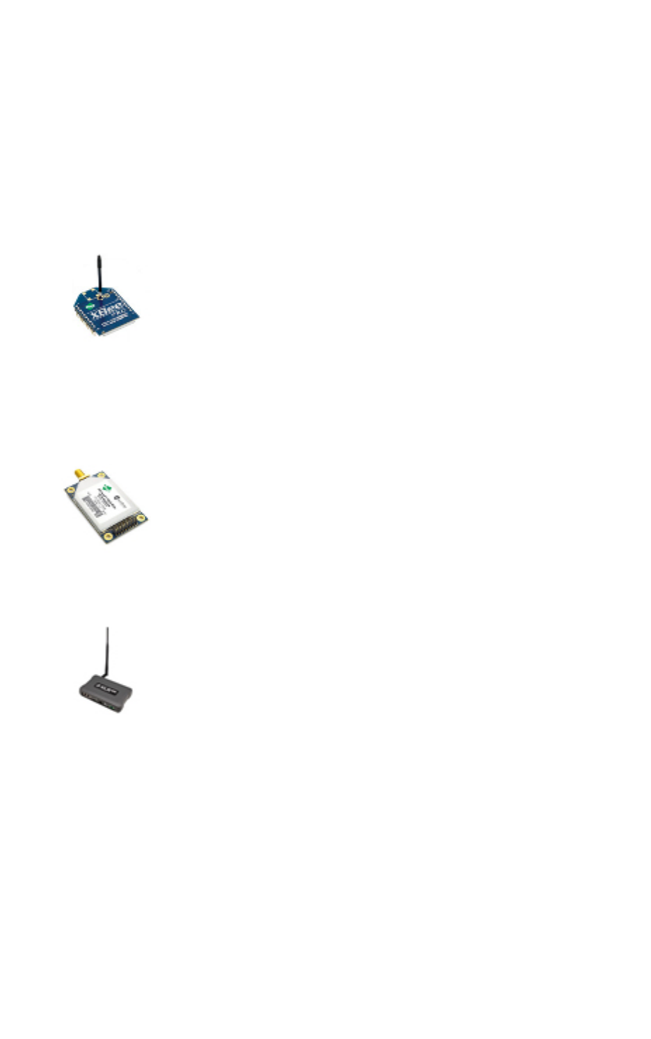
XBee RF modules
XBee is the brand name of a family of RF modules produced by Digi. They are
modular products that make deploying wireless technology easy and cost-
effective. Digi has made multiple protocols and RF features available in the
popular XBee footprint, giving customers enormous flexibility to choose the best
technology for their needs.
XBee RF modules are available in two form-factors, Through-Hole and Surface Mount, with different
antenna options. One of the most popular features of these modules is that almost all of them are
available in the Through-Hole form factor and share the same footprint.
XTend RF modules
XTend family devices are long-range RF modules produced by Digi that provide
unprecedented range in a low-cost wireless data solution. They were engineered
to provide customers with an easy-to-use RF solution that provides reliable
delivery of critical data between remote devices. These modules transfer
standard asynchronous serial data streams, operate within the ISM 900 MHz
frequency band, and sustain up to 115.2 Kbps data throughput.
XLR PRO radio solutions
The XLR PRO is an ultra long-range, rugged 900MHz radio solution designed for
optimal performance even in the most challenging RF environments. Leveraging
Digi's patent-pending Chirp Spread Spectrum technology, the XLR PRO provides
industry-leading receive sensitivity and interference immunity, making it ideal for
deployments in noisy RF environments like oil fields. The XLR PRO includes 2
Ethernet ports and 1 serial port, enabling wireless data communications
between Ethernet and/or serial devices up to distances of over 90 miles.
Radio firmware
Radio firmware is program code stored in a radio module's persistent memory that provides the
control program for the device. Digi periodically releases new radio firmware versions to fix bugs or
improve functionality. You may need to add these firmware files to XCTU's radio firmware library. You
can use XCTU to update or change the firmware of a module if, for example, you want to change the
role of a device or you want to use the latest firmware version.
RF concepts and terminology Radio communication protocols
XCTU User Guide 16
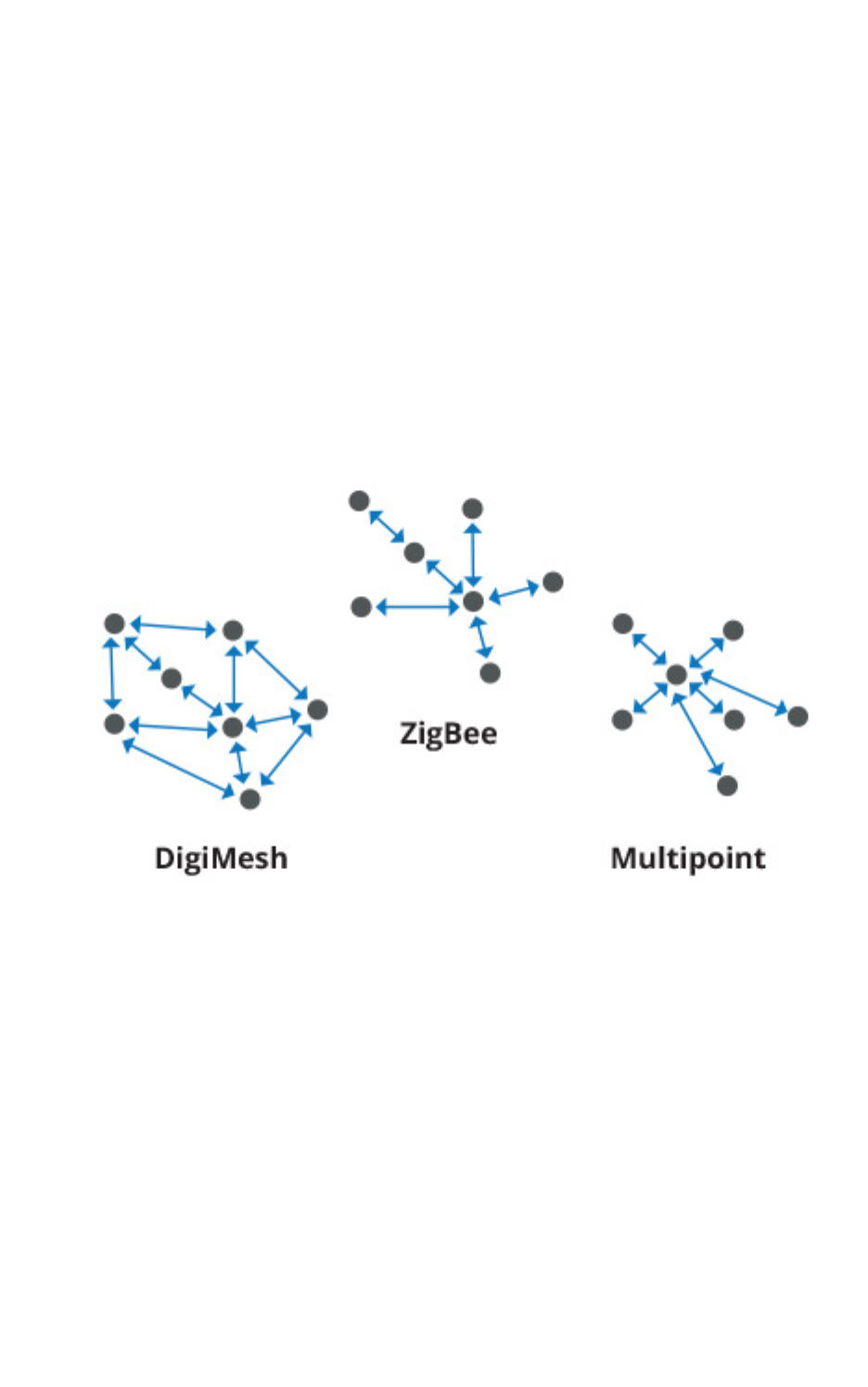
Radio communication protocols
A radio communication protocol is a set of rules for data exchange between radio devices. An RF
module supports a specific radio communication protocol depending on the module and its radio
firmware.
The following is the complete list of protocols supported by the XBee radio modules:
nIEEE 802.15.4
nZigBee
nZigBee Smart Energy
nDigiMesh (Digi proprietary)
nZNet
nIEEE 802.11 (Wi-Fi)
nPoint-to-multipoint (Digi proprietary)
nXSC (XStream-compatible)
Not all XBee devices can run all listed communication protocols. The combination of XBee hardware
and radio firmware determines the protocol that an XBee device can execute. For more information
about the available XBee RF modules and the protocols they support, see XBee RF Family Comparison
Matrix.
Radio module operating modes
The operating mode of an XBee radio module establishes the way a user or any microcontroller
attached to the XBee communicates with the module through the Universal Asynchronous
Receiver/Transmitter (UART) or serial interface.
Depending on the firmware and its configuration, radio modules can work in three different operating
modes:

RF concepts and terminology Radio module operating modes
XCTU User Guide 17
nApplication Transparent (AT) operating mode
nAPI operating mode
nAPI escaped operating mode
In some cases, the operating mode of a radio module is established by the firmware version, which
determines whether the operating mode is AT or API, and the AP setting of the firmware, which
determines if the API mode is escaped (2) or not (1). In other cases, the operating mode is only
determined by the AP setting, which allows you to configure the mode to be AT (AP=0), API (AP=1), or
API escaped (AP=2).
AT operating mode
In AT (Application Transparent) or transparent operating mode, all serial data received by the radio
module is queued up for RF transmission. When RF data is received by the module, the data is sent out
through the serial interface.
To configure an XBee module operating in AT, you must put it in command mode to send the
configuration commands.
AT Command mode
When the radio module is working in AT operating mode, you must use the command mode interface
to configure settings.
To enter AT command mode, send the three-character command sequence (usually "+++") within one
second. Once AT command mode has been instigated, the module sends an "OK\r", the command
mode timer is started, and the radio module is able to receive AT commands.
AT command structure
The structure of an AT command is:
AT[ASCII command][Space (optional)][Parameter (optional)][Carriage return]
For example:
ATNI MyDevice\r
If no valid AT commands are received within the command mode timeout, the radio module
automatically exits AT command mode. You can also exit command mode by issuing the CN command:
(ATCN\r)
API operating mode
API (Application Programming Interface) operating mode is an alternative to AT mode. API operating
mode requires that communication with the module be done through a structured interface. In other
words, data is communicated via API frames.
The API specifies how commands, command responses, and module status messages are sent and
received from the module using the serial interface. With API operating mode, you can:
nConfigure the XBee module itself.
nConfigure remote modules in the network.
nManage data transmission to multiple destinations.

RF concepts and terminology API frames
XCTU User Guide 18
nReceive success/failure status of each transmitted RF packet.
nIdentify the source address of each received packet.
Depending on the AP parameter value, the radio module can operate in one of two modes: API (AP=1)
or API escaped (AP=2) operating mode.
API escaped operating mode
API escaped operating mode (AP=2) is similar to API mode except that when working in API escaped
mode, some bytes of the API frame specific data must be escaped. Since XCTU is compatible with both
API and API escaped operating modes, you do not need to manually escape characters.
API escaped operating mode increases the reliability of RF transmission by preventing conflicts with
special characters such as the start-of-frame byte (0x7E). API non-escaped (API=1) operation relies
solely on the start delimiter and length bytes to differentiate API frames. In API escaped mode, on the
other hand, those special bytes are escaped. Since 0x7E can only appear at the start of an API packet,
a module can always "assume" that a new packet has started if 0x7E is received at any time while in
API escaped mode.
Escape characters
When sending or receiving an API frame in API escaped mode, specific data values must be escaped
(flagged) so they do not interfere with the data frame sequence.
To escape a data byte, insert 0x7D and follow it with the byte to be escaped XOR'd with 0x20. The
data bytes that need to be escaped are as follows:
n0x7E: Frame delimiter
n0x7D: Escape
n0x11: XON
n0x13: XOFF
Note XCTU automatically escapes the appropriate characters when interacting with API escaped
radio modules.
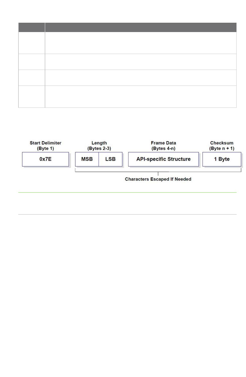
API frames
An API frame is the structured data sent and received through the serial interface of the radio module
when it is configured in API or API escaped operating modes. API frames are used to communicate
with the module or with other modules in the network. An API frame has the following structure:
RF concepts and terminology AT settings or commands
XCTU User Guide 19
Field Description
Start
delimeter
The first byte of a frame consisting of a special sequence of bits which indicate the
beginning of a data frame. Its value is always 0x7E. This allows for easy detection of a
new incoming frame.
Length Specifies the total number of bytes included in the frame data field. Its two-byte value
excludes the start delimiter, the length, and the checksum.
Frame
data
Composed by the API identifier and the API identifier-specific data. The content of the
specific data depends on the API identifier (also called API frame type).
Checksum The last byte of the frame. It helps test data integrity and is calculated by taking the
hash sum of all the API frame bytes that came before it, excluding the first three bytes
(start delimiter and length).
If your module is operating in API escaped operating mode, some bytes in the Length, Frame data, and
Checksum frame fields may need to be escaped. XCTU automatically performs this step and escapes
the appropriate characters. See API escaped operating mode.
Note There are many different types of API frames. You can use the Frames generator tool to learn
the specific data contained within a determined API frame as well as to build and fill any type of API
frame. See Frames generator tool.
AT settings or commands
The firmware running in RF modules contains a set of settings and commands that can be configured
to change the behavior of the module or to perform any action related to it. Depending on the
protocol, the number of settings and their meanings varies, but all XBee RF modules can be configured
with AT commands.
All firmware settings or commands are identified with two ASCII characters. Applications and
documents refer to them as either AT settings or AT commands.
The configuration process of these AT settings varies depending on the operating mode of the RF
module.
Configuring in AT mode
In AT operating mode, you must put the module in a special mode called command mode so it can
receive AT commands. For more information about configuring RF modules working in AT operating
mode, see AT operating mode.

RF concepts and terminology Local radio modules
XCTU User Guide 20
Configuring in API mode
To configure or execute AT commands when the RF module is in API operating mode, you must
generate an AT command API frame containing the AT setting identifier and the value of that setting,
and send it to the RF module. See API frames.
Local radio modules
A local radio module is any module added to the device list using the Add a radio module or Discover
radio modules buttons.
XCTU communicates directly with local modules, and they are physically attached to the PC through a
serial or USB port. A local radio module can discover remote modules in the same network if their
protocol is ZigBee or DigiMesh. A local module is configurable if Configuration working mode is active,
and you can communicate with a local module through its console when Consoles working mode is
active.
Remote radio modules
You can locate remote radio modules in the same network as a local module. A remote module is not
physically attached to your computer. Remote modules are displayed in a sub-list under the local
module, and that local module functions as an interpreter; without it, XCTUis unable to communicate
with the remote module. See Discover remote radio modules.
Communication between XCTU and a remote module takes place in two stages: serial communication
from XCTU to the local module, and wireless communication between the local module and the
remote module. XCTU uses the serial port to send a message intended for the remote module, along
with delivery specifics, to the local module. The local module then transmits the message wirelessly to
the remote module.
If the local device containing remote modules is configured in AT (transparent) operating mode, you
cannot configure its remote radio modules due to a protocol limitation. If the local radio module is
configured in API operating mode, you can configure its remote radio modules like any local module.
Since a remote radio module is not physically connected to the PC, it does not have a communication
console in Consoles working mode. For the same reason, you also cannot obtain a remote radio
module's network topology in Network working mode. See Consoles working mode and Network
working mode.
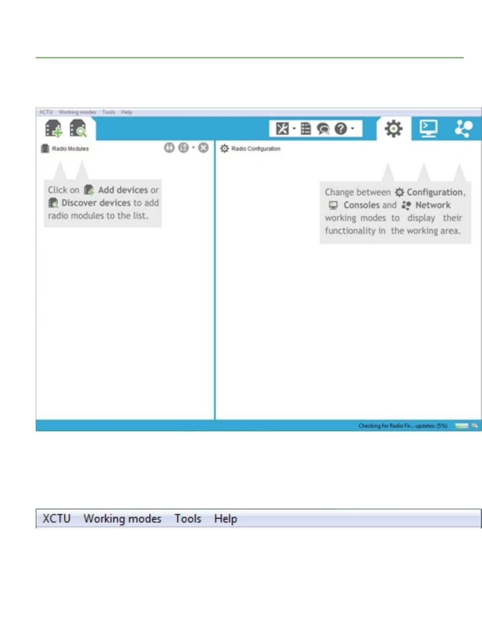
XCTU overview
XCTUis divided into five main sections: the menu bar, main toolbar, devices list, working area, and
status bar.
Menu bar
The menu bar is located at the top of the application. You can use the menu bar to access all
XCTUfeatures, tools, and working modes.
XCTU User Guide 21
XCTU overview Main toolbar
XCTU User Guide 22
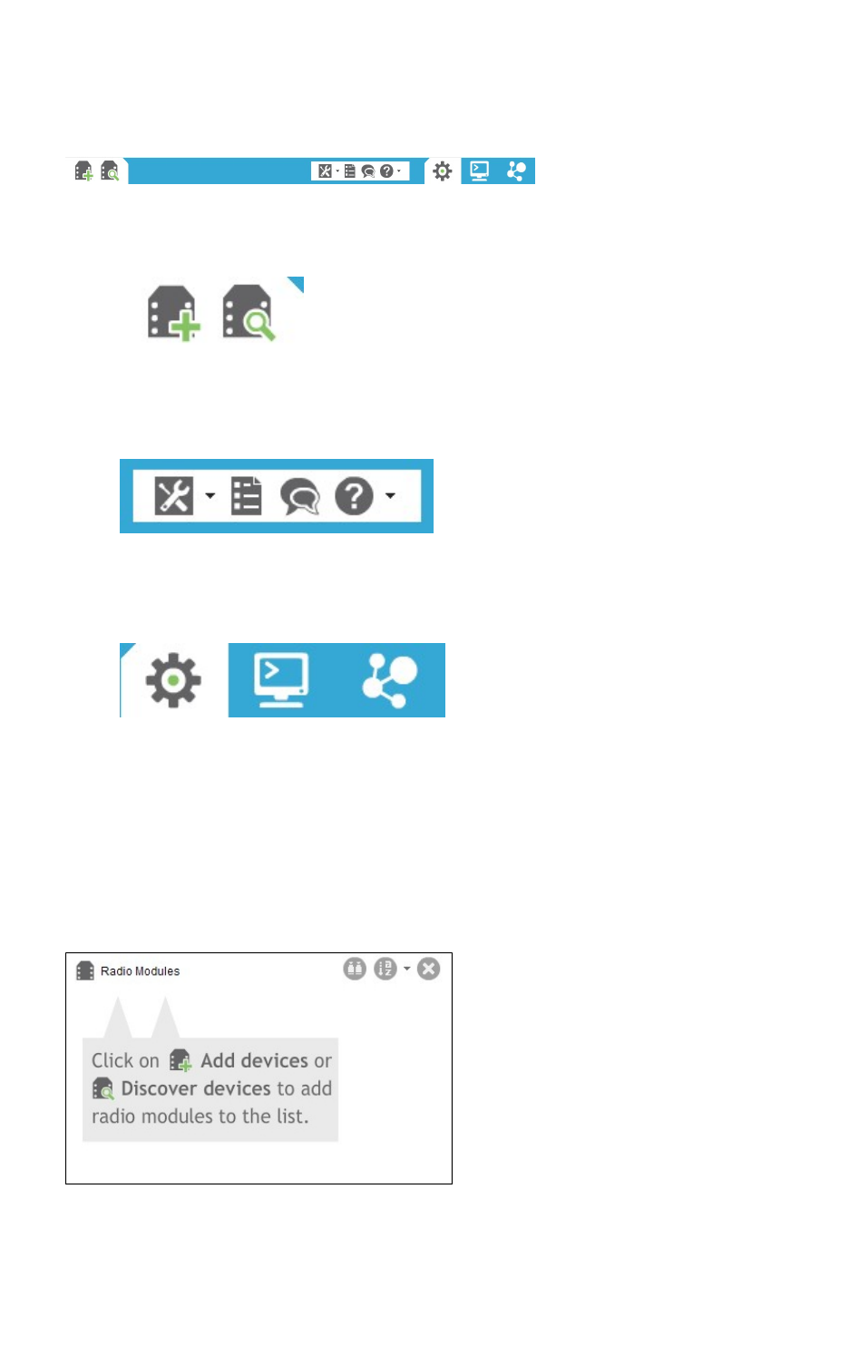
Main toolbar
The main toolbar is located at the top of the application and is divided into three sections.
nThe first section contains two icons used to add radio modules to the radio modules list. See
Add radio modules to XCTU.
nThe second section contains the static XCTU functionality that does not require a radio module.
This section includes the XCTU tools, the XCTU configuration, the feedback form, and the help
and updates functions. See XCTU tools and Configure XCTU.
nThe third section contains tabs corresponding to the three XCTU working modes. To use this
functionality, you must have added one or more radio modules to the list. See XCTU working
modes.
Devices list
The radio modules list, or devices list, is located on the left side of the tool and displays the radio
modules that are connected to your computer. If you know the serial port configuration of a radio
module, you can add it to the list directly. You can also use the discovery feature of XCTU to find radio
modules connected to your PC and add them to the list. See Add radio modules to XCTU.
Depending on the protocol of the local radio modules added, you can also add remote radio modules
to the list using the module's search feature.
XCTU overview Working area
XCTU User Guide 23
Working area
The working area is the largest section and is located at the right side of the application. The contents
of the working area depend on the working mode selected in the toolbar. To interact with the controls
displayed in the working area, you must have added one or more radio modules to the list and one of
the modules must be selected.
Status bar
The status bar is located at the bottom of the application and displays the status of specific tasks,
such as the firmware download process.
XCTU preferences
To configure XCTUsettings, click the Preferences button on the XCTU toolbar.
Configuration preferences are grouped into categories listed on the left-hand side of the preferences
dialog box. You can configure settings in the following XCTU categories:
Appearance
You can configure some graphic aspects of the tool and how some elements are displayed.
Field Description
Font size Change all the XCTU texts size in percentage, from 50 to 120%.
Show top bar
menu
Displays an application top bar menu with texts.
Show text on
toolbar actions
Displays the name of the action below each toolbar element for a better
understanding of the meaning of each action.
Use reduced
toolbars size
Changes the size of the application toolbars reducing them.

XCTU overview XCTU preferences
XCTU User Guide 24
Automatic updates
Field Description
Automatically find
new updates and
notify me
Enables or disables automatic XCTUupdates. Uncheck if you do not want
XCTUto update automatically.
Update schedule Sets a schedule to search for updates or to update when XCTU is started. If you
select Look for updates on the following schedule, you must also specify
the search interval and hour.
Download options Establishes when new updates should download and sets permissions for
whether updates are automatically downloaded.
When updates are
found
Sets the frequency of update notification.
Consoles
Field Description
API
console
Configures the maximum number of API frames that can be displayed in the frames log
during a session. When the maximum limit is reached, the session starts overwriting
frames.
AT
console
Configures the maximum number of bytes that can be displayed during a session. When
the maximum limit is reached, the session starts overwriting bytes.
MadCap:autonum="<span style="color: #84c361;" class="mcFormatColor"><b>Note
</b></span>">If you set high values for maximum API frames and/or ATbytes, you may notice
performance issues in the consoles.
Firmware updates
Field Description
Remote
firmware
update
timeout
Configures the remote firmware update timeout in milliseconds. This value is the
maximum time the application will wait for answers sent by the remote node during
remote firmware update before concluding that there was an error during the process.
Network
You can configure Network view in the Network preferences dialog. The first four options are
common to all networks:

XCTU overview XCTU preferences
XCTU User Guide 25
Field Description
Always clear the Network view
before starting
Clears Network view before each new network scan.
Remove nodes if they were not
discovered in the last performed
scan
Removes any nodes not discovered in the last scan.
Stop after scan Sets the number of scans to perform before stopping the
discovery process. A value of '0' means the process will not stop
automatically.
Time between scans Sets the duration of time XCTU waits before starting a new
network scan. The value must be between 0 and 300 seconds.
The remainder of the options are specific to 802.15.4, DigiMesh, and ZigBee network types:
Field Description
Discovery
mode
Sets the method used by the network discovery process.
nFlood: The neighbor discovery process is performed for every node at the
moment it is found. Several discovery processes may be running at the same
time. This method may be faster, but it may also generate a lot of traffic and
saturate the network.
nCascade: The neighbor discovery process is performed for every node as soon as
the discovery process finishes. Only one discovery process runs at a time. This
method may be slower, but it is likely to generate less traffic.
Neighbor
discovery
timeout
Sets the maximum duration, in seconds, the discovery process should spend finding
neighbors of a module. Value must be between 5 and 1800 seconds (30 minutes).
This timeout is highly dependent on the nature of the network. For DigiMesh, the value
should be greater than the highest NT (Node Discover Timeout) and include enough time
to let the message propagate, depending on the sleep cycle of your devices.
Time
between
requests
Sets the wait time between node neighbor requests. The value must be between 0 and
300 seconds (5 minutes).
For the Cascade method, this is the number of seconds to wait after completion of the
neighbor discovery process of the previous node.
For the Flood method, this is the minimum time to wait between each radio module's
neighbor requests.
Note The Cascade discovery method is recommended for large networks.
Network appearance
You can configure how node links are represented in Network graphic view.
XCTU overview XCTU working modes
XCTU User Guide 26
Field Description
Connection default
color
Defines the default color of the node's connection lines.
Show colored
connections based
on their quality
Enables or disables the coloring of node connection lines based on their link
quality.
DigiMesh / ZigBee
network
Enables you to modify the maximum and minimum values and RGB colors for
each quality range. Click in the cell, type the value, and click Enter to change a
value.
Ranges include minimum values but not maximum values. When you change
the minimum value of a quality range, the maximum value of the next range
adopts a corresponding value.
Radio firmware library
You can instruct XCTU to look for new radio firmware when it starts up by checking Automatically
update the XBee Firmware Library each time XCTU is started. If this option is disabled, you can
only check for firmware updates manually.
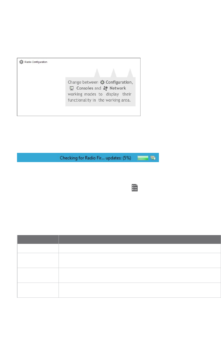
XCTU working modes
XCTU operations are grouped into three working modes—Configuration, Consoles, and Network. The
selected working mode determines which specific operations you can perform with a radio module or
modules in your device list. You can only select one working mode at a time. By default, XCTU launches
in Configuration mode.
Configuration working mode
Use configuration working mode to configure a radio module selected from your device list. See
Configure your modules.
Consoles working mode
Use consoles working mode to interact or communicate with the selected radio module. See
Communicate with your modules.


Add radio modules to XCTU
This section describes how to add, discover and organize your radio modules in XCTU.
Add a radio module manually 29
Add a programmable radio module 30
Discover local radio modules 32
Radio module information panel 34
Organize your modules 39
Discover remote radio modules 39
Find radio modules 41
XCTU User Guide 28
Add radio modules to XCTU Add a radio module manually
XCTU User Guide 29
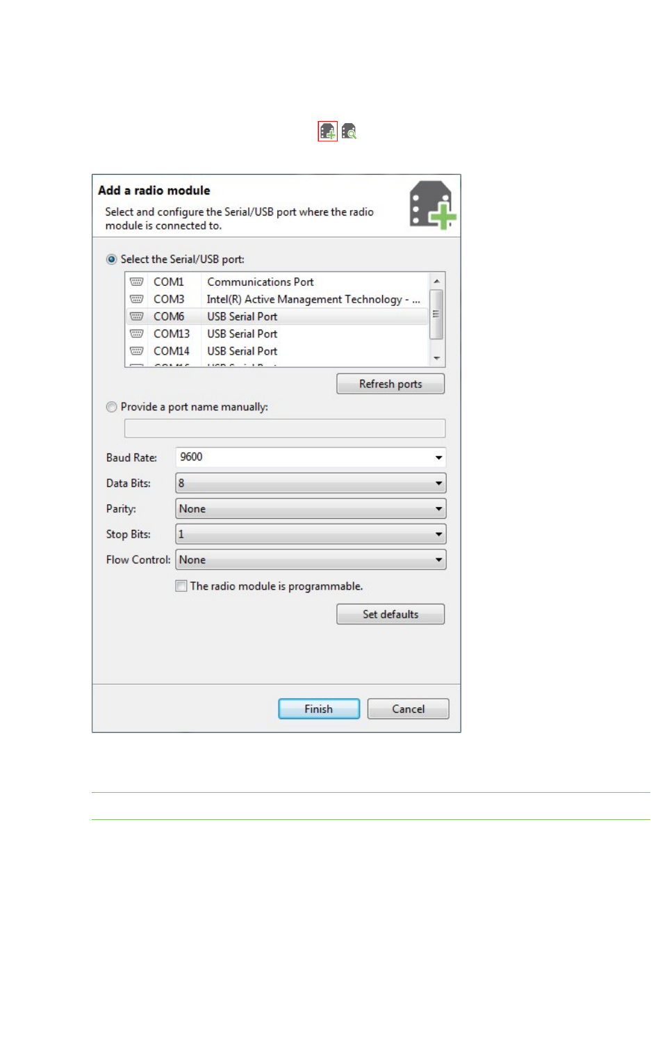
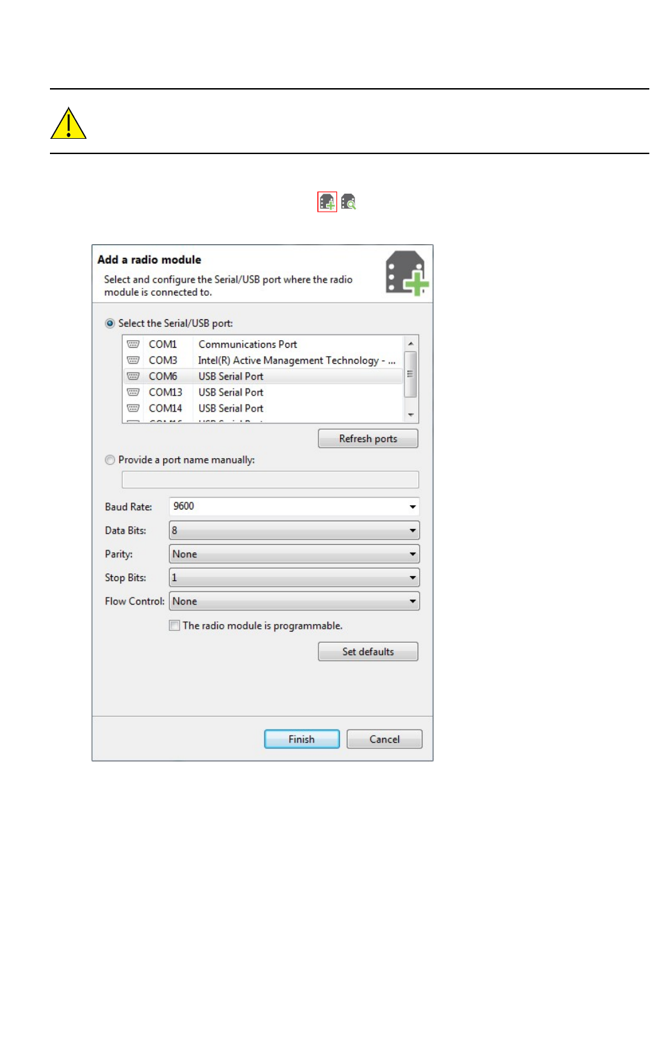
Add a radio module manually
If you know the serial configuration of your radio module, you can add it to the list manually.
1. Click the Add a radio module button from the toolbar. The Add a radio module
dialog opens.
2. Select the serial port where the radio module is connected (or enter its name manually) and
configure the serial settings of the port.
Note Custom baud rates can only be typed under Windows OS.
3. Click Finish to add the radio module to the list of radio modules.
Add radio modules to XCTU Add a programmable radio module
XCTU User Guide 30
4. If the settings were configured correctly and the radio module was connected to the selected
port, the module is displayed in the device list. For more information about the device list, see
Radio module information panel.
5. If the settings were configured incorrectly, an Action Required dialog asks you to reset the
module. Reset the module. The action required dialog should close and your module should be
added to the list.
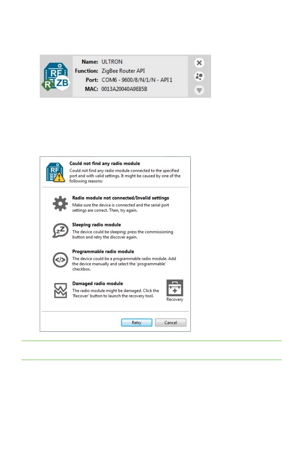
6. If your module could not be found, XCTU displays the Could not find any radio module dialog
providing possible reasons why the module could not be added. To resolve the issue, see
Troubleshooting for XCTU.
Note You can also use the Add a radio module dialog to add programmable radio modules. See Add a
programmable radio module.
For more information, see Local radio modules and Radio module information panel.
Add a programmable radio module
Some radio module variants are programmable, which means they are able to run applications
written in C. Normally, they are known as Programmable XBee modules and can be identified by a
Add radio modules to XCTU Add a programmable radio module
XCTU User Guide 31
part number ending in B on the back label.
XBee-PRO modules are often confused with Programmable XBee modules. The -PRO suffix
does not mean that the module is programmable.
To add a programmable radio module:
1. Click the Add a radio module button from the toolbar. The Add a radio module
dialog opens.
2. Select the serial port to which the radio module is connected (or enter its name manually) and
configure the serial settings of the port.
3. Check the My radio module is programmable setting.
4. Click Finish.
Add radio modules to XCTU Discover local radio modules
XCTU User Guide 32
5. Reset your radio module when prompted. The module appears in the device list.
For more information, see Local radio modules and Radio module information panel.
Discover local radio modules
XCTU can discover radio modules that are connected directly to your computer. You can use the
discovery tool if you don't know the serial configuration of your radio module, don't know the port it is
connected to, or want to add multiple modules at once.
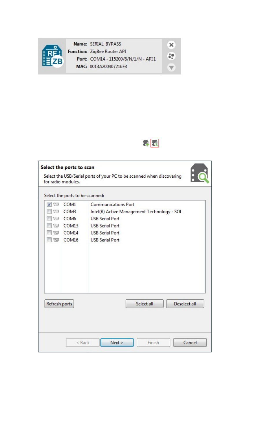
1. Click the Discover radio modules button on the XCTUtoolbar. The Discover radio
modules dialog box opens.
2. Select the serial ports you would like to scan for radio modules. Click Next.
Add radio modules to XCTU Discover local radio modules
XCTU User Guide 33
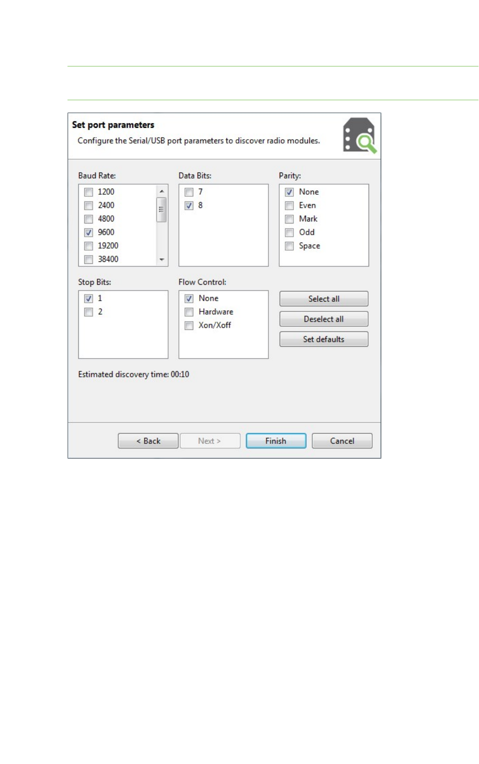
3. Select any port parameters you would like to include in the search process.
Note XCTU displays estimated discovery time in the Set port parameters dialog. Adding more
port parameters to the search increases discovery time.
Add radio modules to XCTU Radio module information panel
XCTU User Guide 34
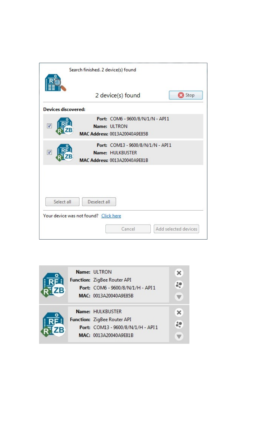
4. Click Finish to initiate the discovery scan.
A new dialog opens, displaying devices found and estimated time remaining. You can click Stop
to halt the discovery process at any time. For example, you can stop the process if the modules
you were looking for are already found.
5. Select the box next to the module(s) you want to add to your device list and click Add selected
devices. The modules appear in the device list.
For more information, see Local radio modules and Radio module information panel.
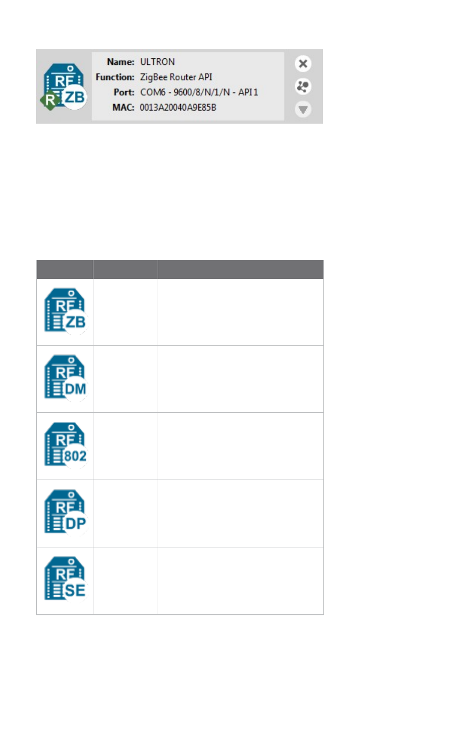
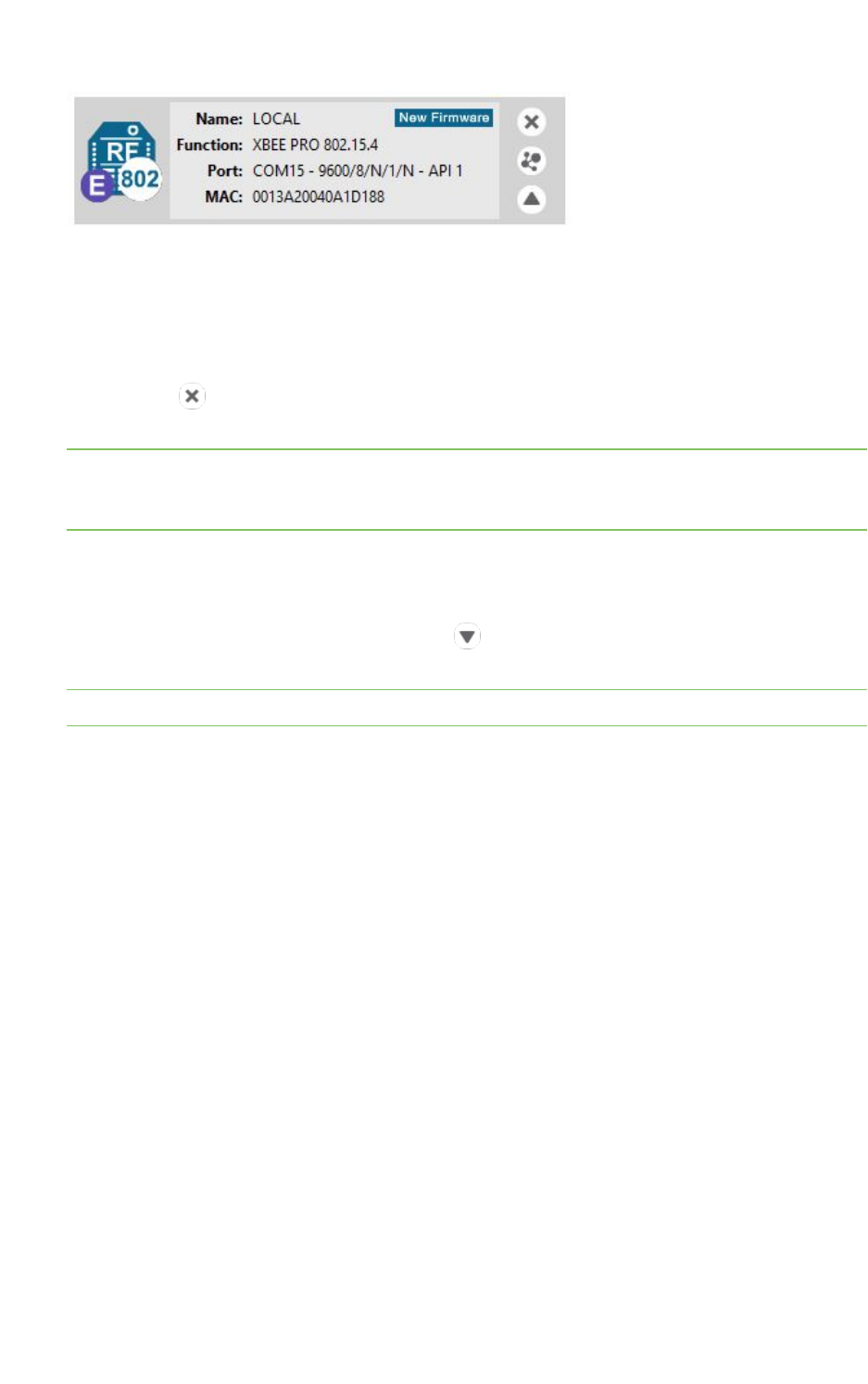
Radio module information panel
Local radio modules appear as big buttons in the modules list. Each module displays identifying
information about itself.
Add radio modules to XCTU Radio module information panel
XCTU User Guide 35
To work with a radio module, you must select it from the list of devices. When you hover over a
module, the background color changes to yellow.
Selecting a radio module refreshes the contents of the working area, displaying the information or
actions you can perform on the selected module. The contents of the working area depend on the
active working mode.
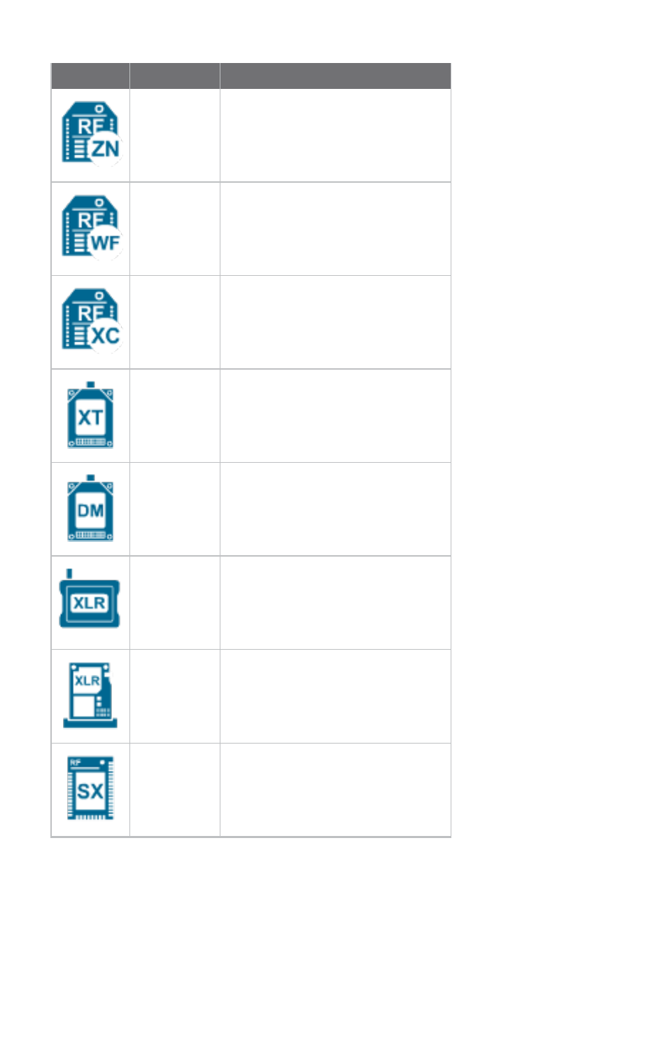
Module Icon
An icon on the left side of the information panel identifies the module type and protocol.
Icon Module type Protocol
XBee ZigBee
XBee DigiMesh (Digi's proprietary protocol)
XBee 802.15.4
XBee Point-to-multipoint
XBee Smart Energy
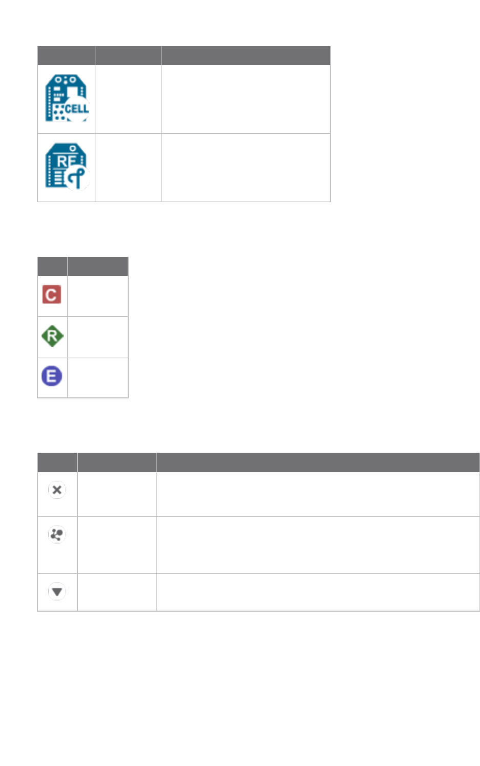
Add radio modules to XCTU Radio module information panel
XCTU User Guide 36
Icon Module type Protocol
XBee ZNet
XBee Wi-Fi
XBee XStream Compatibility
XTend XTend native
XTend DigiMesh (Digi's proprietary protocol)
XLR XLR-PRO native
XLR Module XLR Module
XBee SX
Add radio modules to XCTU Radio module information panel
XCTU User Guide 37
Icon Module type Protocol
XBee Cellular
XBee Thread
Each icon may contain a small image in the lower-right corner that identifies the role of that module
within its network:
Icon Description
Coordinator
Router
End device
Buttons along the right-hand side of the module information panel perform actions on the selected
module:
Button Name Description
Remove Removes the radio module from the list of devices. Also removes the
associated communication console and network view of that module.
Removes the local module and any associated remote modules.
Search Discovers remote radio modules in the same network. Dependent on
radio module protocol. Performs an SSID discovery for Wi-Fi modules,
and for any other protocol performs a discovery of remote radio
modules. See Discover remote radio modules and Active scan.
Expand/collapse Expands and collapses the remote radio modules list.
New firmware indicator
When a radio module is not running the latest firmware version it is able to run, the New Firmware
control displays next to the name label for the information panel.
Add radio modules to XCTU Radio module information panel
XCTU User Guide 38
This control indicates that there is a newer firmware version that can be flashed in the radio module.
If you click New Firmware, the Update firmware dialog is automatically opened for that radio
module. All of the available firmware versions for the radio module are listed in the dialog.
Remove a radio module
Click Remove to remove a selected radio module from the list of devices. Removing a module
from the list also disables the associated communication console and network view of the module.
Note Clicking the Remove button of a remote module removes only that radio module from the sub-
list of remote modules. Click the Remove button of a local module with a sub-list of remote modules
removes the local module as well as all of its remote modules.
Expand/Collapse radio modules list
If the protocol of the radio module is ZigBee or DigiMesh and you have found remote modules in the
same network, you can use the expand/collapse button to expand or collapse the list of remote
modules under the local device.
Note This button is only enabled for local radio modules.
Add radio modules to XCTU Organize your modules
XCTU User Guide 39
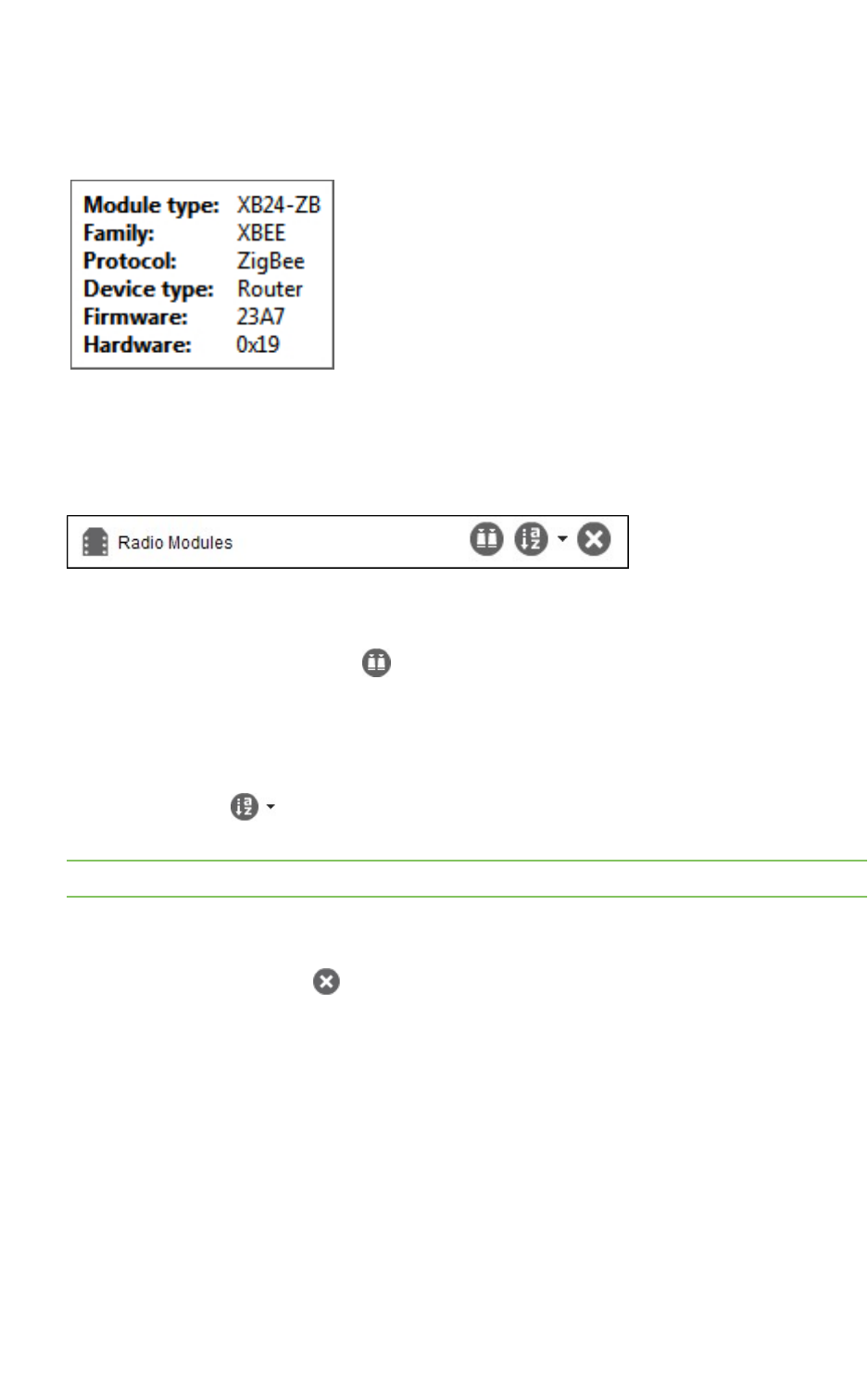
Module information box
When you hover over the icon, XCTU displays additional information about the selected module,
including module type, family, protocol, device type, firmware, and hardware.
Organize your modules
The Radio Modules view contains a toolbar with options to manage radio modules in the list. These
options are only enabled when the list contains at least one radio module.
Find radio modules
Click the Find radio modules button to find local and remote radio modules in your list. For
details, see Find radio modules.
Sort radio modules
Radio modules are displayed in the order in which you added them to XCTU. Click the Sort radio
modules list button to sort radio modules by name, function, serial port, or MAC address. Or
you can select a specific device and move it up/down in the list.
Note The sorting feature affects both local and remote radio modules.
Clear radio modules
Click Clear radio modules list to remove all discovered modules from the radio modules list.
For more information, see Local radio modules and Remote radio modules.
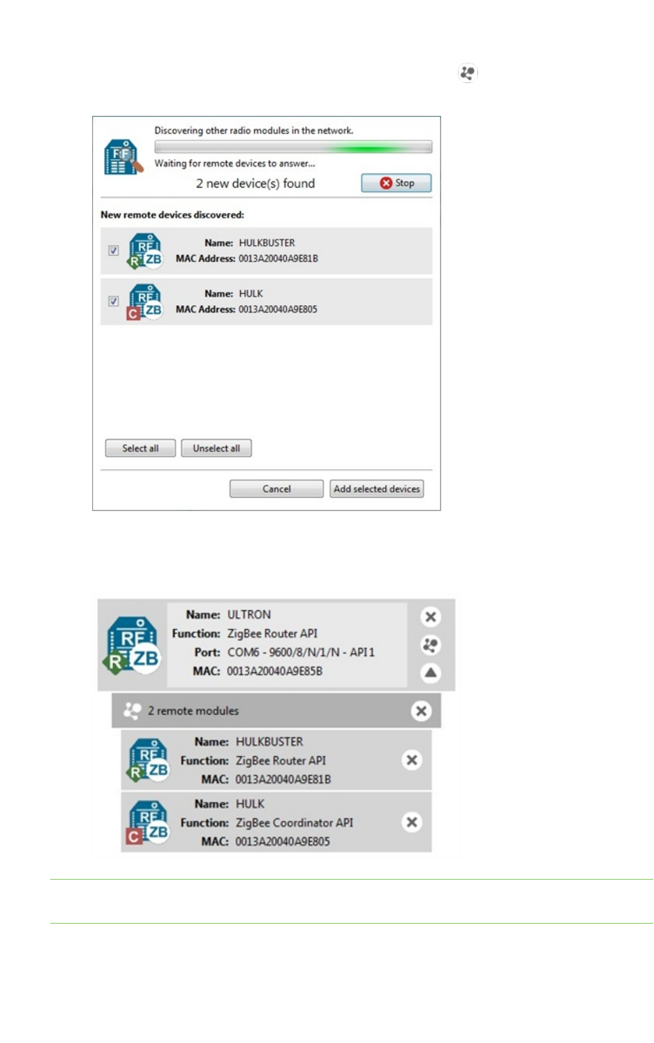
Discover remote radio modules
You can execute a discovery process to locate remote radio modules in the same network as the local
(selected) module. To discover remote modules:
1. Select a module from your device list. If you do not have any modules in the list, see Add a radio
module manually or Discover local radio modules.
Add radio modules to XCTU Discover remote radio modules
XCTU User Guide 40
2. Click the Discover radio nodes in the same network button . As XCTU discovers new
remote radio modules, they appear in the discovery process dialog box.
3. Click Stop to halt the discovery process at any time.
4. Check the box next to the module(s) you want to add to your device list and click Add selected
devices. The discovered remote modules appear in the list of remote modules.
Note XBee Wi-Fi modules do not support the remote radio modules discovery feature. Instead, they
can look for access points.
For more information, see Remote radio modules.
Add radio modules to XCTU Find radio modules
XCTU User Guide 41
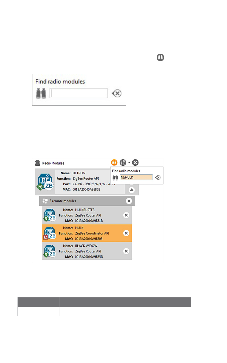
Find radio modules
To find local or remote radio modules, you must have already discovered the network they are on. You
can then use the Find radio modules search box to find radio modules by MAC address, name, network
address, and other search expressions.
1. On the Radio Modules toolbar, click the Find radio modules button.
The Find radio modules search box appears.
2. Enter your search expression to find one or more modules.
For a list of search prefixes and wildcards, as well as sample searches, see Search expressions.
3. Press Enter.
The background color of the search box and search icon indicates status. Yellow indicates
matches found by XCTU, and red indicates no matches. Modules found along the list are also
highlighted in yellow.
Search expressions
You can enter the following search prefixes in the Find radio modules dialog box.
Search prefix Search by
MAC: (or no prefix) MACaddress

Add radio modules to XCTU Find radio modules
XCTU User Guide 42
Search prefix Search by
SH: Serial Number High
SL: Serial Number Low
NI: Node Identifier (only available in 802.15.4 and DigiMesh)
MY: 16-bit Network Address (only available in 802.15.4 and ZigBee)
You can also use a wildcard if you do not want to specify the entire parameter or if you want to find
more than one node.
Wildcard Equals
* any string
? any character
\ escape for literals (i.e. *, ?, or \)
Sample searches:
nTo search for a module with node identifier (NI) "NODE1" and network address (MY) 0831,
enter
NI:NODE1, or MY:0831
nTo find all nodes whose MAC starts with 00 and ends with B, enter
MAC:00*B

Configure your modules
This section describes how to use Configuration working mode to configure your modules and change
application settings once you have added a radio module or modules to your list of devices.
Configuration working mode 44
Read radio module configuration 51
Write module settings 51
Load default firmware settings 51
Update firmware 52
Save a configuration profile 54
Load a configuration profile 55
Search for a firmware setting 57
Configure remote modules securely 57
Configure a Wi-Fi access point 58
Enable and configure Bluetooth 60
View firmware release notes 61
XCTU User Guide 43
Configure your modules Configuration working mode
XCTU User Guide 44
Configuration working mode
When you launch XCTU, Configuration working mode opens as the default operating mode.
The Configuration working mode allows you to configure any radio module that has been added to
your device list. When you select a module from the list, XCTU loads the firmware information of the
selected radio module and displays the firmware settings in the working area. It automatically reads
the values and fills in the fields.
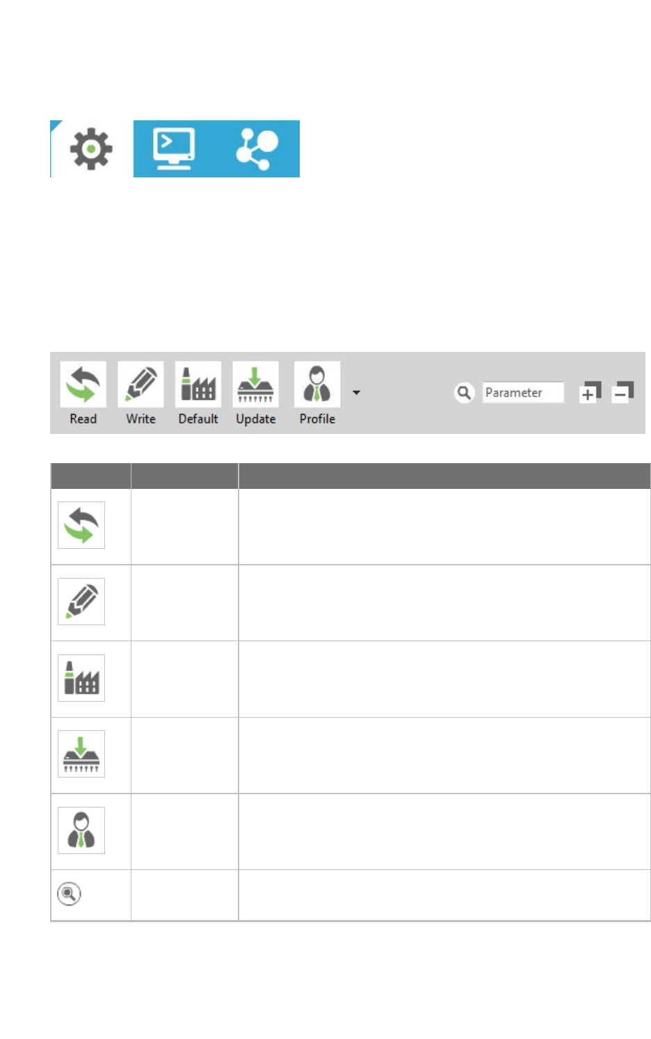
Configuration toolbar
The Configuration toolbar presents the configuration actions you can perform with the selected radio
module and firmware settings.
Button Name Description
Read module
settings
Reads the firmware settings for the selected radio module.
Write module
settings
Writes new firmware values to the selected radio module.
Load default
firmware
settings
Loads the default firmware values on to the selected radio module
but does not write them.
Update
firmware
Opens the Update the radio module firmware dialog, displaying
available compatible firmware for the selected radio module.
Load/save
configuration
profile
Opens the Load configuration profile or Save configuration
profile dialog.
Search Enables you to search firmware settings by AT parameter.
Configure your modules Configuration working mode
XCTU User Guide 45
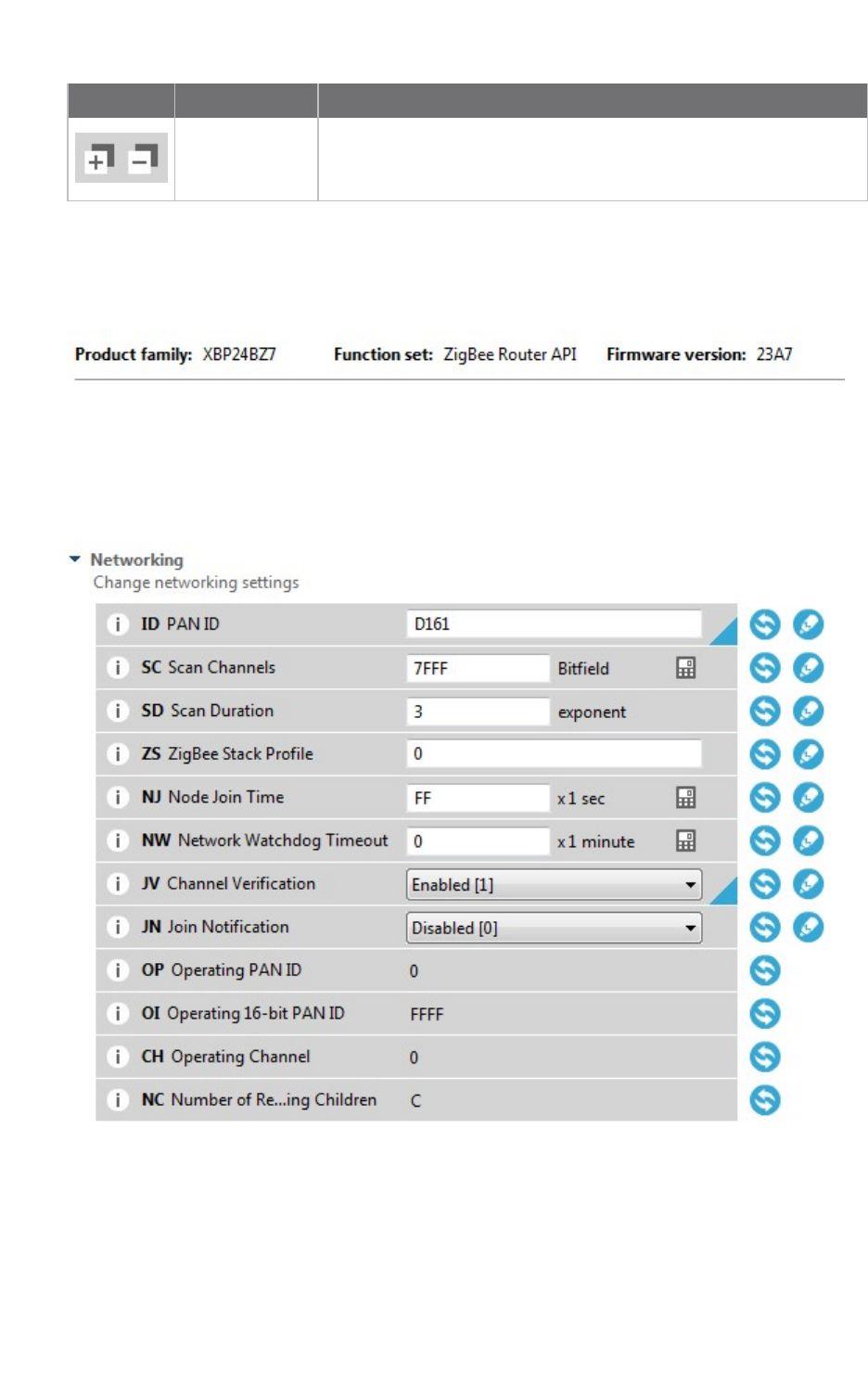
Button Name Description
Expand/collapse
settings
Expands or collapses all firmware settings sections.
Firmware information panel
The firmware information panel is located below the Configuration toolbar and displays information
about the firmware running in the selected radio module.
Firmware settings
XCTU displays firmware settings of the radio module below the firmware information panel. They are
divided into sections or categories with a short description in each. Read-only settings are displayed
with a gray label.
The following table provides descriptions for the setting controls.
Configure your modules Configuration working mode
XCTU User Guide 46
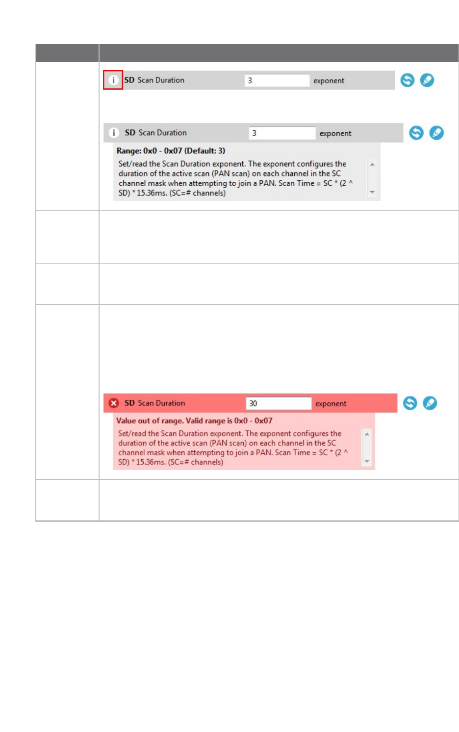
Field Description
Information
button
Clicking the information button displays a short description of the setting, including
the default value and the valid range, if the setting is numeric.
AT
parameter
Displays the associated AT parameter of the setting. Some settings, such as actions,
may not have an associated AT parameter.
In the example above, the ATparameter is SD.
Setting
name
Displays the name of the setting.
In the example above, the setting name is Scan Duration.
Setting
configuration
control
Contains the text box or combo box where the setting value must be entered or
configured. You can hover over the text box of a numeric setting to display the valid
range for that setting. Always enter numeric values in hexadecimal format (without
the '0x' prefix), unless the hover text indicates that an ASCII value is required.
If the setting is configured with an invalid value, an explanation for the error
appears.
Units label Displays the units of measure for that setting. Not all settings have a units label.
In the example above, the unit is exponent.
Configure your modules Configuration working mode
XCTU User Guide 47
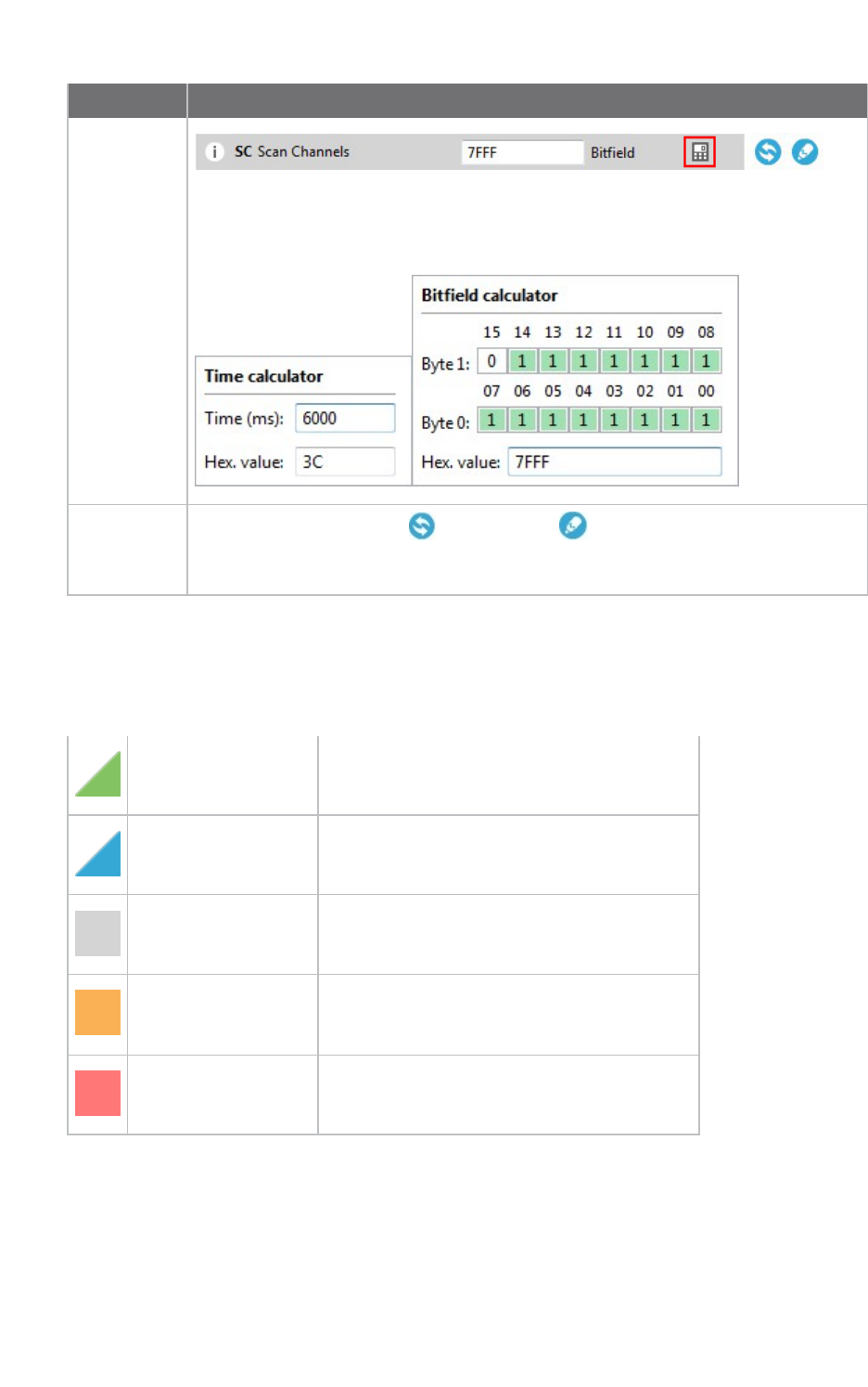
Field Description
Value
calculator
icon Clicking the value calculator icon launches a time or bitfield calculator for numeric
settings that are difficult to compute. The content of the calculator panel depends
on the setting.
Refresh and
write
buttons
Clicking the refresh button or write button allows you to read or write the
value of the setting. Some settings, such as the read-only settings, do not have a
write button.
Setting status
XCTU delineates the status of each setting with background color and/or the color of a triangle
located next to the setting value. These are the possible statuses of a setting:
Green triangle The value of the setting has changed but it has
not been written in the radio module yet.
Blue triangle The value of the setting is written in the radio
module but is different from the default value.
Gray background The value of the setting is written in the radio
module and matches the default value.
Yellow background Indicates that the setting is highlighted
because it has been found using the Search
parameter control.
Red background The value of the setting is not valid.
Setting types
There are different kind of settings that you can configure in a radio firmware. Depending on the
setting type they display different controls and options.
Configure your modules Configuration working mode
XCTU User Guide 48
nNumeric settings: These settings must always be configured with a numeric value in
hexadecimal format (without the '0x' prefix). Hovering over the text box of a numeric setting
displays the valid range for the setting. There are several types of settings:
nText settings: Text settings are very similar to the numeric settings, but they can be
configured with hexadecimal or ASCII characters. If you hover over the text box of a text
setting, a dialog displays the minimum and maximum characters and whether they must be an
ASCII or hexadecimal value.
nCombo settings: A combo box displays all the possible values of the setting with symbolic text,
to help you to choose the correct option.
nRead-only settings: These settings cannot be modified. They can only be read from the radio
module and their values are displayed in a label.
nAction settings: These settings can be neither read nor written. The main purpose of the
action settings is to execute a task or process in XCTU that implies some interaction with the
radio module. To learn more about the Action settings see the Special functions topic.
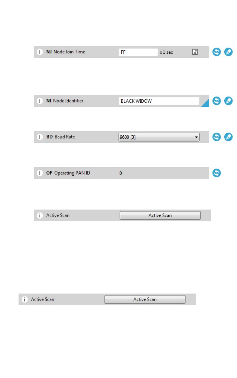
Special functions
Some settings within XCTU cannot be read or written. Instead, they execute tasks or processes in
XCTU related to interaction with the radio module. The processes that these settings execute are
called special functions. At this time, XCTU has two special functions: Active scan and Bluetooth
Authentication.
Active Scan
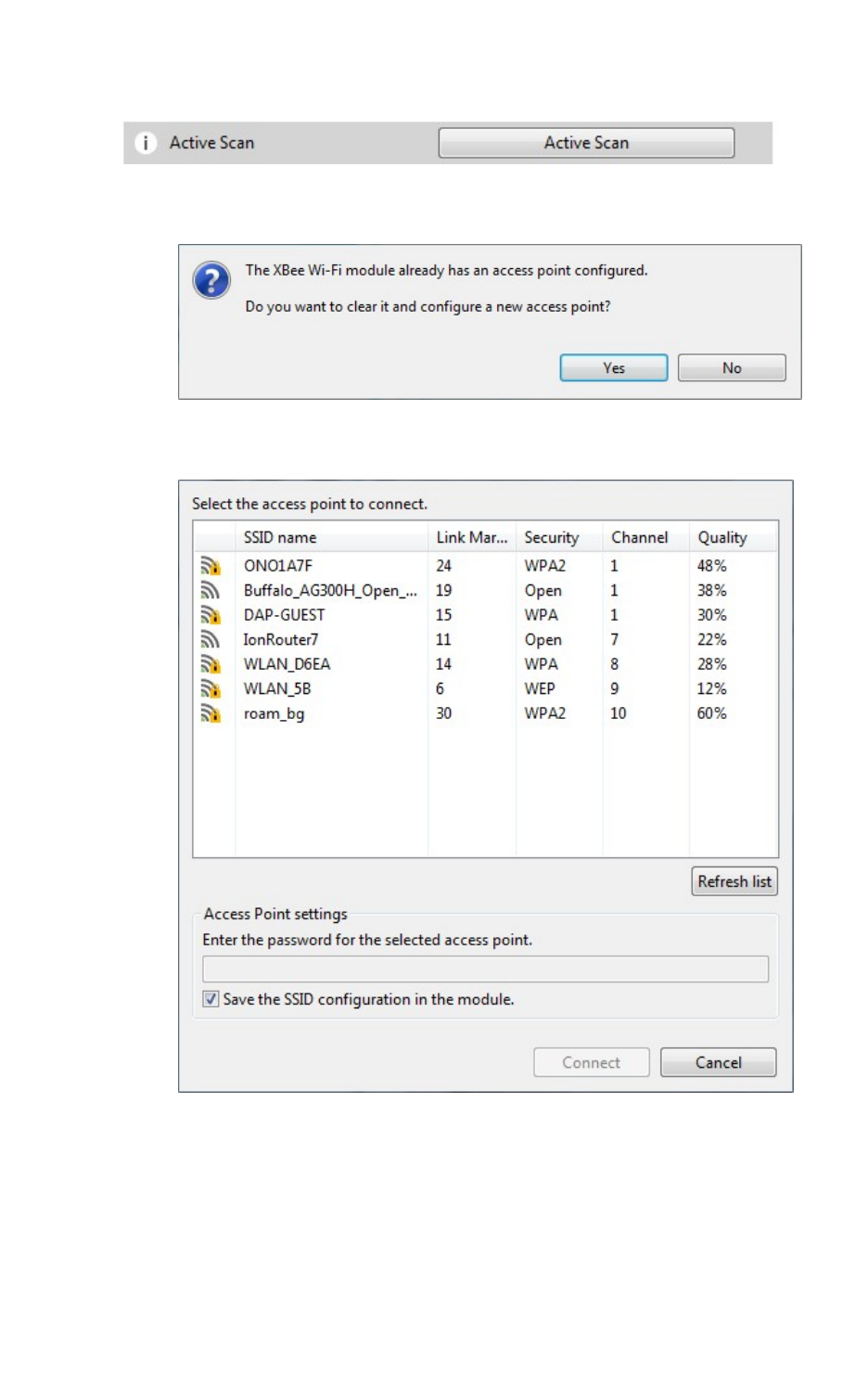
The Active Scan function discovers and configures the access point for an XBee Wi-Fi module.
When you click the Active Scan button, XCTU reads the SSID configuration of the Wi-Fi module. If the
module has an SSID already configured, you need to clear the configuration and perform a new SSID
discovery. If the SSID configuration is empty, the nearby SSIDs are displayed in a new dialog.
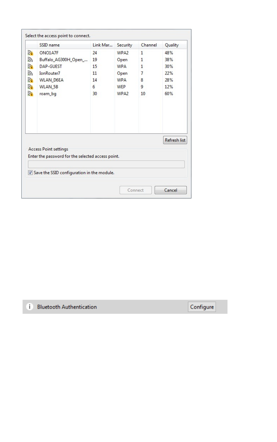
Configure your modules Configuration working mode
XCTU User Guide 49
The dialog displays all the nearby access points as well as their security protocols and signal quality.
Select the Access Point you want the Wi-Fi module to connect to and, if necessary, configure the
password of the Access Point. The Access Point settings also have a check box that allows you to
permanently save the SSID configuration in the Wi-Fi module. If you uncheck this option, the next time
you reset the module the SSID configuration is cleared.
Click Connect to connect the Wi-Fi module to that Access Point and refresh the settings of the radio
module.
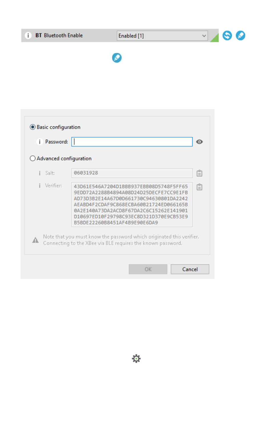
Enable BLEand configure the BLEpassword
The Bluetooth Authentication function allows you to configure the security parameters of your XBee
device with Bluetooth Low Energy (BLE)support. This step is mandatory if you want to enable
Bluetooth on the module.
XBee BLE security is based on the Secure Remote Password protocol. When you click the Configure
button, XCTU displays a dialog asking you to either:
1. Type a password, which you are asked for when you connect to the XBee via Bluetooth Low
Energy.
2. Enter a random salt and a password verifier generated from a password and that salt (as
specified in the SRP protocol).
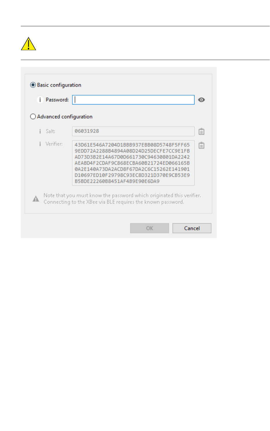
Configure your modules Configuration working mode
XCTU User Guide 50
CAUTION! Only use the advanced configuration if you are familiar with the SRP protocol. You
must know the password which originated the verifier since you will be asked for it when you
connect to the XBee via BLE.
When you enter the password or the salt/verifier combination, click OK to save the settings to the
module.
For more information about Bluetooth security, see the user guide for your XBee device.

Configure your modules Read radio module configuration
XCTU User Guide 51
Read radio module configuration
You can refresh a radio module's firmware settings once you have added the module to your device
list. To read a module's configuration settings:
1. Switch to Configuration working mode .
2. Select a radio module from the device list. XCTU displays the current firmware settings for that
module.
Note If the selected module is remote and the Remote AT Command password (KZ) is set, you
may be asked to enter that password in order to access the module configuration.
3. From the configuration toolbar, click the Read module settings button to refresh the
selected radio module's firmware settings.
Write module settings
You can configure a radio module's firmware settings once you have the module to your device list. To
configure a radio module:
1. Switch to Configuration working mode .
2. Select a radio module from the device list. XCTU displays the current firmware settings for that
module.
Tip To refresh the selected radio module's firmware settings, click the Read module settings
button on the configuration toolbar.
Note If the selected module is remote and the Remote AT Command password (KZ) is set, you
may be asked to enter that password in order to access the module configuration.
3. Change the value of the setting or settings to be configured.
4. Click the Write module settings button to write any newly configured firmware values to
the module.
Load default firmware settings
You can load default radio firmware settings in a module in your device list.
1. Switch to Configuration working mode .
2. Select a radio module from the device list. XCTU displays the current firmware settings for that
module.
3. On the Configuration toolbar, click the Load default firmware settings button to load the
default values established by the firmware.
4. Firmware settings are loaded but not written to the radio module. In order to write them in
the module, click the Write module settings button on the toolbar.
Configure your modules Update firmware
XCTU User Guide 52
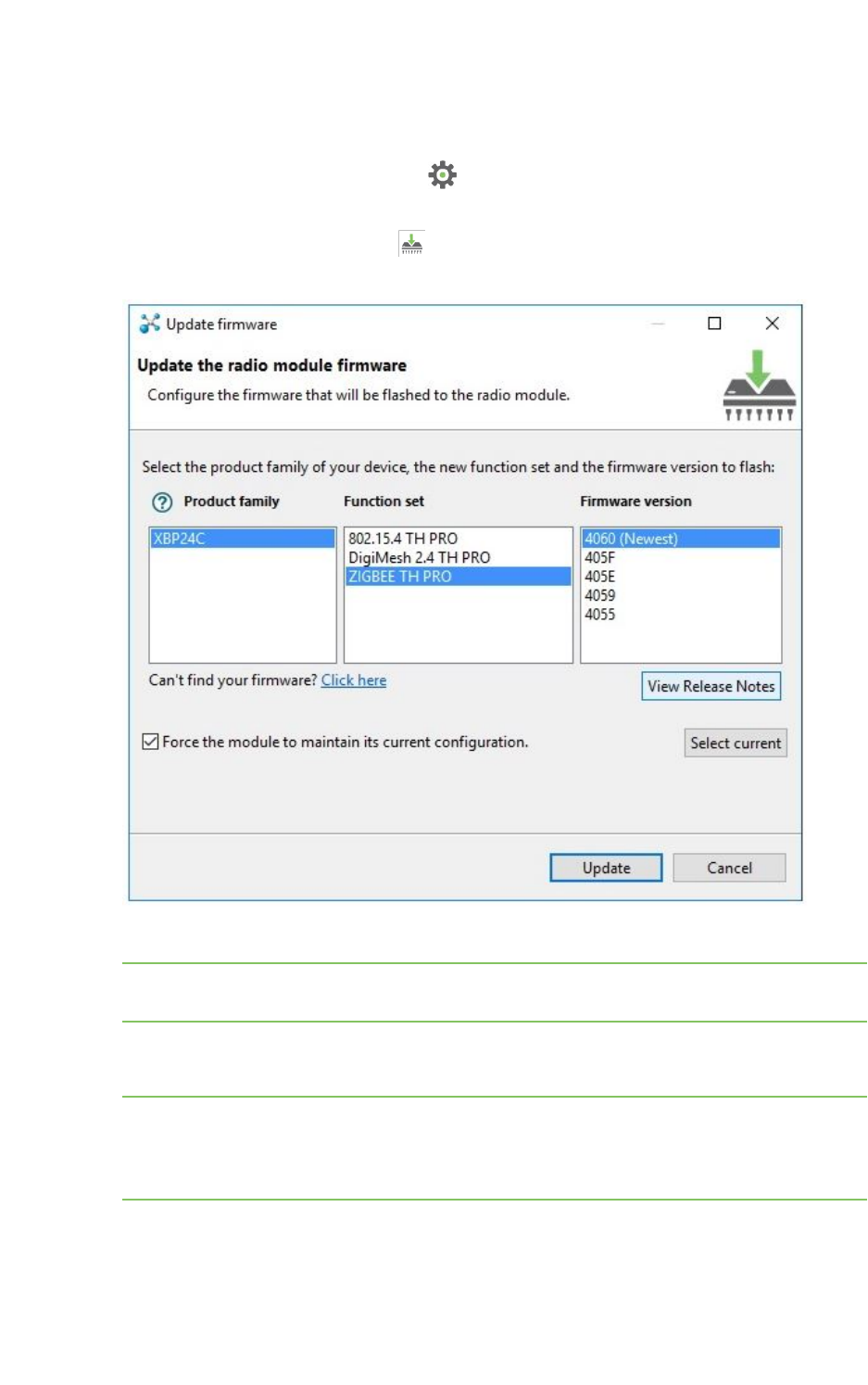
Update firmware
You can use XCTU to update a module's radio firmware.
1. Switch to Configuration working mode .
2. Select a radio module from the device list.
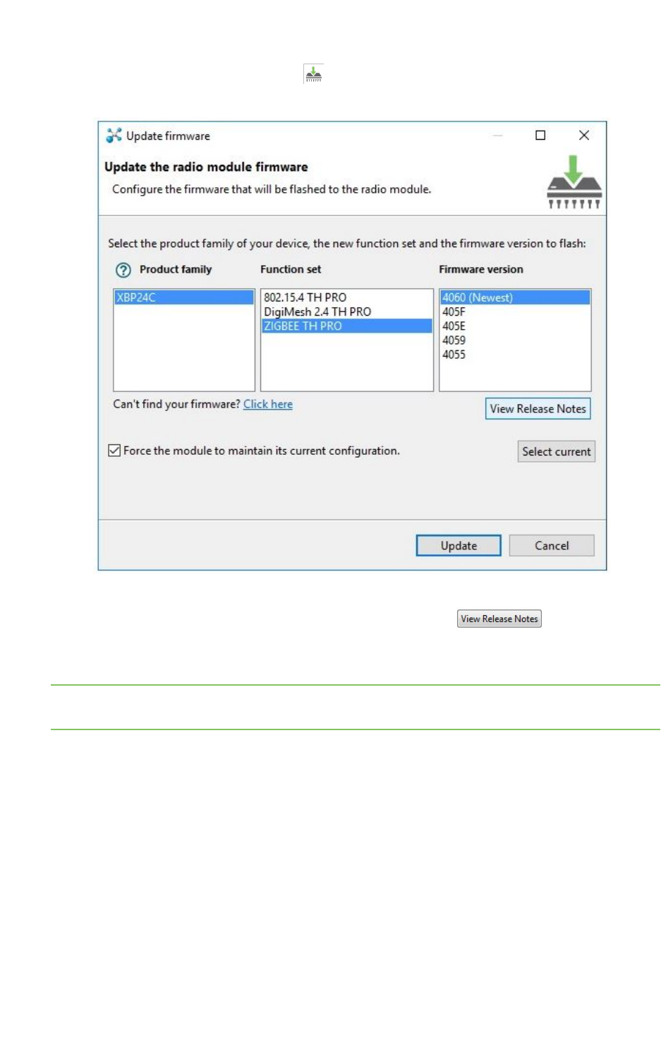
3. Click the Update firmware button . A dialog box appears displaying the available and
compatible firmware for the selected module.
4. Choose the firmware family, function, and version.
Note If you do not remember the firmware version that is currently installed in your radio
module, click Select current to automatically select it.
5. Click Update. A dialog box displays update progress. You can click the Show details button to
view a detailed progress log, and Hide details to hide it.
Note During the firmware update process, XCTU attempts to obtain the module information
again, as some critical settings such as the operating mode could have changed. If the
Maintain current module configuration setting is checked, XCTU writes the old configuration
to the module and then reads the setting's values.

Configure your modules Update firmware
XCTU User Guide 53
Cellular modem firmware updates
When you update the firmware of an XBee Cellular module, XCTU may need to update the modem
firmware. This process is completely transparent, but note that XCTU requires an Internet connection
to download the modem firmware.
Note The system prompts you for confirmation when the module requires a modem firmware update,
as this process may take up to 30 minutes.
Remote firmware updates
You can use XCTU to perform firmware updates on remote modules because once you add a remote
module to XCTU's device list, the update process is exactly the same whether you are updating a local
module or a remote module. To perform a remote firmware update, the local module must be working
in API or API escaped operating mode.
Remote firmware updates can be performed on the following radio modules:
nXBee/XBee PRO SX
nXLR Module
nXBee/XBee PRO 802.15.4 (S2C module versions only)
nXBee/XBee-PRO DigiMesh 2.4 (S2C module versions only)
nXTend RF Module Family (SX module versions only)
nXLR PRO Radio Solution
nXBee/XBee-PRO ZB and Programmable XBee-PRO ZB
nXBee/XBee-PRO ZB SMT and Programmable XBee-PRO ZB SMT
nXBee-PRO 900HP and Programmable XBee-PRO 900HP
nXBee 865LP and Programmable XBee 865LP
nXBee 868LP SX
nXBee3 (Zigbee, DigiMesh 2.4, and 802.15.4)
Note If something goes wrong during an over-the-air firmware update on a remote module—for
example, communication is lost because the remote device is disconnected—you must perform a
manual recovery. See Recover a radio module.
Bootloader updates
Some firmware versions require a specific bootloader version in order to work properly. The
bootloader is the software running in the module that, among other things, launches the firmware as
soon as the module boots.
The bootloader update takes place during the firmware update process. If the firmware to be flashed
requires a bootloader update, XCTU updates the bootloader first and then the module's firmware.
Note The system prompts you for confirmation when the firmware requires a bootloader update, as
this process erases the configuration of the module. You must accept it in order to continue with the
firmware update process. If you decline the bootloader update, the overall firmware update process is
canceled.
Configure your modules Save a configuration profile
XCTU User Guide 54
Save a configuration profile
A configuration profile is a snapshot of a specific radio firmware configuration, including settings
values and other configuration information. XCTU allows you to save and write configuration profiles
to the radio module. This feature is useful in a production environment when you need to set the same
parameters on multiple radios.
You must first create a representative model upon which to base the configuration profile and then
save the profile. Note that you only need to configure the values; it is not necessary to write the
settings to the module.
To save a configuration profile:
1. Switch to Configuration working mode .
2. Select a radio module from the device list.
3. Configure the radio module with your desired values.
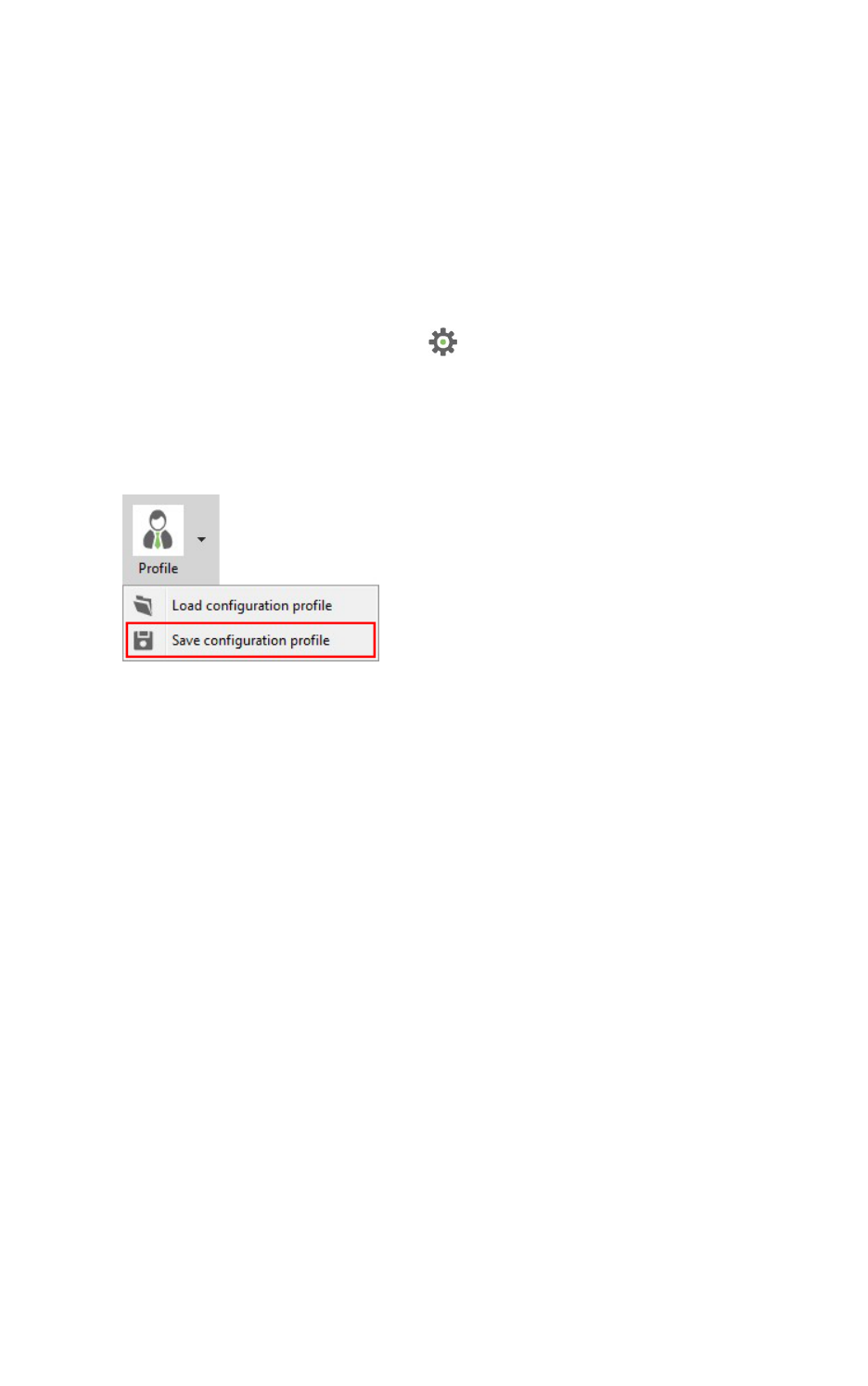
4. Click the Configuration profiles drop-down menu on the Configuration toolbar and select
Save configuration profile.
5. The Profile configuration dialog displays asking you to configure other profile settings:
nThe Description field is optional and you can use it to enter any information that helps
to identify the profile and its purpose.
nIn the Radio firmware group you can set the action to perform with the radio firmware
of the profile. This action is used later by XCTU and other applications when loading the
profile.
lFlash always. Radio firmware configured in the profile is always flashed in the radio
module, it does not matter if the module already has the same radio firmware
version flashed.
lFlash if firmware is different. Radio firmware configured in the profile is flashed in
the radio module only if the radio firmware version of the module is different than
the one configured in the profile.
lDo not flash firmware. Only settings configured in the profile are written in the
radio module.
nWhether you want to reset all XBee device settings to defaults before applying those
specified in the profile you are saving. Select this option if you want to ensure that the
XBee device where you apply this profile will only have the settings you have specified;
all other devices will have the default values. If you want to keep the state of the device
and only change some settings, clear this option.
Configure your modules Load a configuration profile
XCTU User Guide 55
nIf the selected firmware version corresponds to the Cellular protocol and it has a
specific modem firmware version associated, the profile configuration dialog displays a
new option. Check the Attach Cellular modem firmware option if you want to include
the modem firmware in the profile.
6. Enter your configuration preferences and click OK.
7. A Save file dialog box appears. Choose a name and path and click Save.
Note You can also use the Firmware explorer tool to save a configuration profile. See Firmware
explorer tool.
Load a configuration profile
A configuration profile is a snapshot of a specific radio firmware configuration, including settings
values and other configuration information. XCTU allows you to save and write configuration profiles
to the radio module. This feature is useful in a production environment when you need to set the same
parameters on multiple radios. To load a configuration profile:
1. Switch to the Configuration working mode .
2. Select a radio module.
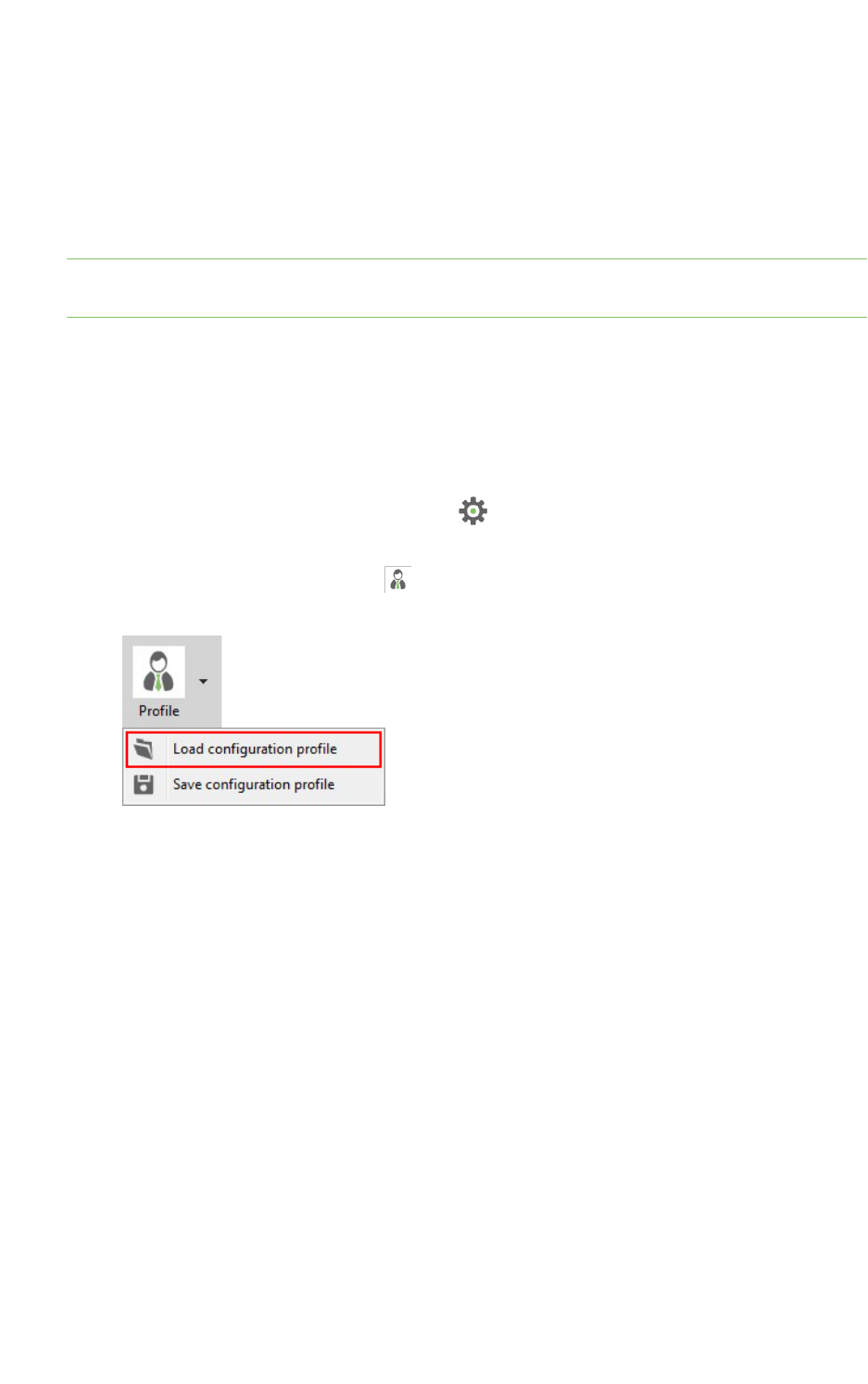
3. Click the Configuration profiles drop-down menu on the Configuration toolbar and select
Load configuration profile.
An Open file dialog appears, asking for the configuration profile file to load.
Configure your modules Load a configuration profile
XCTU User Guide 56
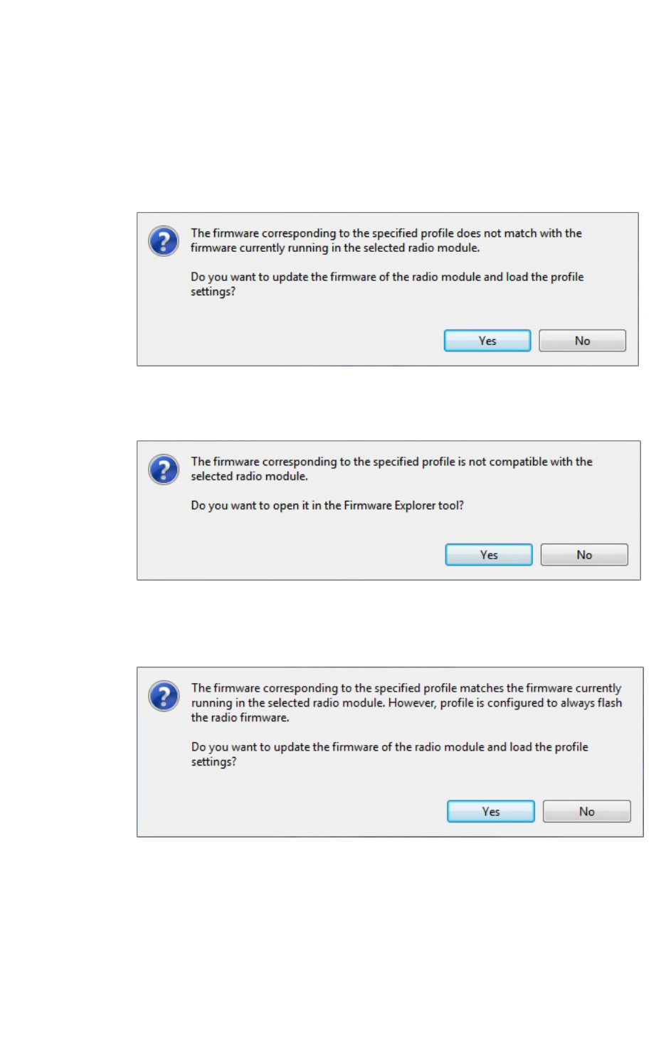
4. Locate the configuration profile (a ZIP file) and click Open. Depending on the firmware
compatibility with your radio module and the firmware flash action configured in the profile, a
dialog box may appear:
nIf the firmware of the configuration profile does not match the firmware running in the
radio module but is compatible with the module and the profile is configured to always
flash the firmware or flash when it is different, click Yes to update the module's
firmware so the profile will load correctly.
nIf the firmware of the configuration profile is not compatible with the radio module, click
Yes to open the firmware file in the Firmware explorer tool.
nIf the firmware of the configuration profile matches the firmware running in the radio
module but the profile is configured to always flash the firmware, click Yes to update
the module's firmware so the profile will load correctly.
nIf the firmware of the profile you are loading and the firmware running in the radio
module match or the profile is configured to don't flash the radio firmware, XCTU loads
the settings saved in the profile but does not write them to the radio module.
5. Locate the configuration profile (an XPRO document) and click Open. A dialog box may appear
based on firmware compatibility with the module.
Configure your modules Search for a firmware setting
XCTU User Guide 57
Search for a firmware setting
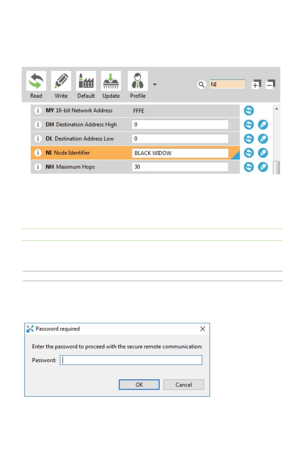
The configuration toolbar includes a search box. To search for a firmware setting in the list of settings,
search for the AT parameter associated with the setting. If the setting is found, it is highlighted in
yellow.
Configure remote modules securely
Some new firmware versions allow you to add an extra protection layer to encrypted networks in
order to prevent an intruder from hijacking a module and making changes in the network. This feature
requires you to enter a pre-configured password every time you want to configure a remote module.
Note To learn more about this feature and how it works, refer to the user guide for your XBee module.
To enable the secured remote configuration, set a password with the KZ parameter. To do so, enter
the old password ('0' by default), followed by a blank space and the new password. For example, if
your password is "1234" and you want to change it to "7a$b3l1", you should enter:
1234 7a$b3l1
After the password has been set, Password required dialog appears when you try to configure a
remote module and the password is set on your local one (KZ is not set to '0'). The same dialog
appears if you perform a range or throughput test with a remote module.
You must enter the password and click OK before you can configure the module.

Configure your modules Configure a Wi-Fi access point
XCTU User Guide 58
Configure a Wi-Fi access point
The Active scan special function discovers and configures the access point for the XBee Wi-Fi module.
The feature is only enabled for Wi-Fi modules.
1. Switch to Configuration working mode .
2. Select a Wi-Fi-enabled radio module from the device list.
Configure your modules Configure a Wi-Fi access point
XCTU User Guide 59
3. Click the Active scan button. XCTU reads the SSID configuration of the Wi-Fi module.
nIf the module already has an SSID configured, click Yes to clear the configuration and
perform a new SSID discovery.
nIf the SSID configuration is empty, XCTU displays all nearby access points as well as
their security protocols and signal quality.

Configure your modules Enable and configure Bluetooth
XCTU User Guide 60
4. Select the SSID you want the Wi-Fi module to connect to.
For S6 Wi-Fi modules, the table displays the following fields:
Field Description
SSID name Name of the access point
RSSI (dBm) RSSI of the access point (negated hex value)
Security Security type of the access point
Quality Link quality (based on the RSSI) with the access point
For S6B Wi-Fi modules, the table displays the following fields
Field Description
SSID name Name of the access point
Link margin (dBm) Signal strength in dBm above sensitivity
Security Security type of the access point
Channel Channel number in use by the access point
Quality Link quality (based on the link margin) of the access point
5. If necessary, enter the password of the access point.
6. If you would like to retain the SSID configuration for future use, check Save the SSID
configuration in the module.
7. Click Connect to connect the Wi-Fi module to that access point and refresh the settings of the
radio module.
Enable and configure Bluetooth
Some of the latest XBee3 modules support Bluetooth Low Energy (BLE) as an extra interface for
configuration. If you want to use this feature, you have to enable BLE. You must also enable security by
setting a password on the XBee device in order to connect, configure, or send data over BLE.
Before you begin, you should determine the password you want to use for BLEon the XBee device and
store it in a secure place. Digi recommends a secure password of at least 8 characters and a random
combination of letters, numbers, and special characters. Digi recommends using a security
management tool such as LastPass or Keepass for generating and storing passwords for many
devices.
The salt and verifier values are calculated when you set your password.
1. Switch to Configuration working mode .
2. Select a BLE compatible radio module from the device list.
3. Select Enabled[1] from the BT Bluetooth Enable command drop-down.
Configure your modules View firmware release notes
XCTU User Guide 61
4. Click the Write setting button . The Bluetooth authentication not set dialog appears.
5. Click Configure in the dialog. The Configure Bluetooth Authentication dialog appears.
6. Type a password or a salt/verifier combination (as specified by the Secure Remote Password
protocol—only for advanced users). When you connect the XBee device via BLE, it asks for this
password (or the one that generated the verifier).
7. In the Password field, type the password for the device. As you type, the Salt and Verifier fields
are automatically calculated and populated in the dialog as shown above. This password is
used when you connect to this XBee device via BLE using the XBee Configurator app.
For more information about Bluetooth, see the user guide for your XBee device.
View firmware release notes
XCTU allows you to review the release notes of some of the firmware it hosts.
1. Switch to Configuration working mode .
2. Select a radio module from the device list.
Configure your modules View firmware release notes
XCTU User Guide 62
3. Click the Update firmware button . The Update firmware dialog appears, displaying the
available compatible firmware for that module.
4. Select the firmware family, the firmware function, and the firmware version. If the selected
firmware has release notes, the View Release Notes button below the
firmware list is enabled.
5. Click View Release Notes. A new window displays the release notes for the selected firmware.
Note You can also access the release notes of firmware via the XBee recovery tool and the Firmware
explorer tool.

Communicate with your modules
This section describes how to use Consoles working mode to communicate with your modules once
you have added a radio module or modules to your list of devices.
Consoles working mode 64
Connect and disconnect the console 66
Record a console session 66
Attach and detach the console 67
Communicate with modules running in API or API escaped mode 68
Communicate with modules running in AT mode 83
Console log files 91
XCTU User Guide 63
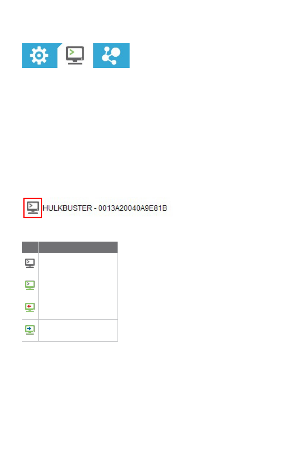
Communicate with your modules Consoles working mode
XCTU User Guide 64
Consoles working mode
The Consoles working mode allows you to communicate with radio modules in the device list. When
you click the Consoles working mode button on the toolbar, XCTU displays a tabbed list of consoles
with one entry for each module of the devices list. Each tab is labeled with the name of the radio
module and its physical address (MAC).
If you select a module from the device list, the associated console activates and moves to the front of
the display. Conversely, selecting a console from the working area highlights the associated module in
the device list.
The console type depends on the operating mode of the selected radio module.
nThe API Console is used for radio modules working in API or API escaped operating mode. See
API console.
nThe AT Console is used for radio modules working in AT (transparent) operating mode. See AT
console.
Console status
The icon in the left corner of the console tab displays the following states:
Icon Status
The console is disconnected.
The console is connected.
The console is receiving data.
The console is sending data.
The text of each tab contains the name of the radio module and its physical address (MAC). This
makes it easy to identify the console corresponding to each radio module.
Consoles toolbar
All consoles have a common toolbar that allows you to connect or disconnect the console and to
attach or detach it from the working area.
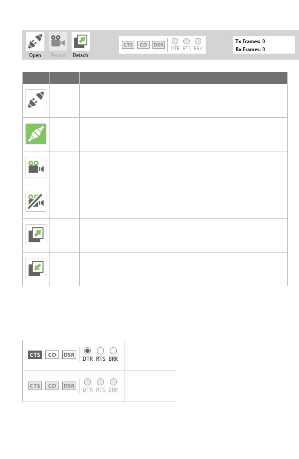
Communicate with your modules Consoles working mode
XCTU User Guide 65
Button Name Description
Open Establishes communication with the radio module corresponding to the
console. When the console is connected, the background color of the button
changes to green and the text changes to "Close" See Connect and
disconnect the console.
Close The console is connected. Clicking this button disconnects the module from
the console. See Connect and disconnect the console.
Start
recording
Records all incoming and outgoing console data as it is sent or received and
saves to a console log file. The console must be connected to start or stop
recording. See Record a console session.
Stop
recording
Stops the process of saving any sent or received data. The console must be
connected to start or stop recording. See Record a console session.
Detach Detaches the console from the tabbed working area and displays it in a new
floating dialog.
Attach Reattaches the console to the tabbed working area.
Line status indicator
The line status indicator displays the status of the RS-232 hardware flow control lines. Dark gray
indicates that the line is asserted, while white indicates that it is de-asserted. You must open the
console connection to display line status and enable line status control.
Connection open
Connection closed
You can view and manage the following lines from the line status indicator:
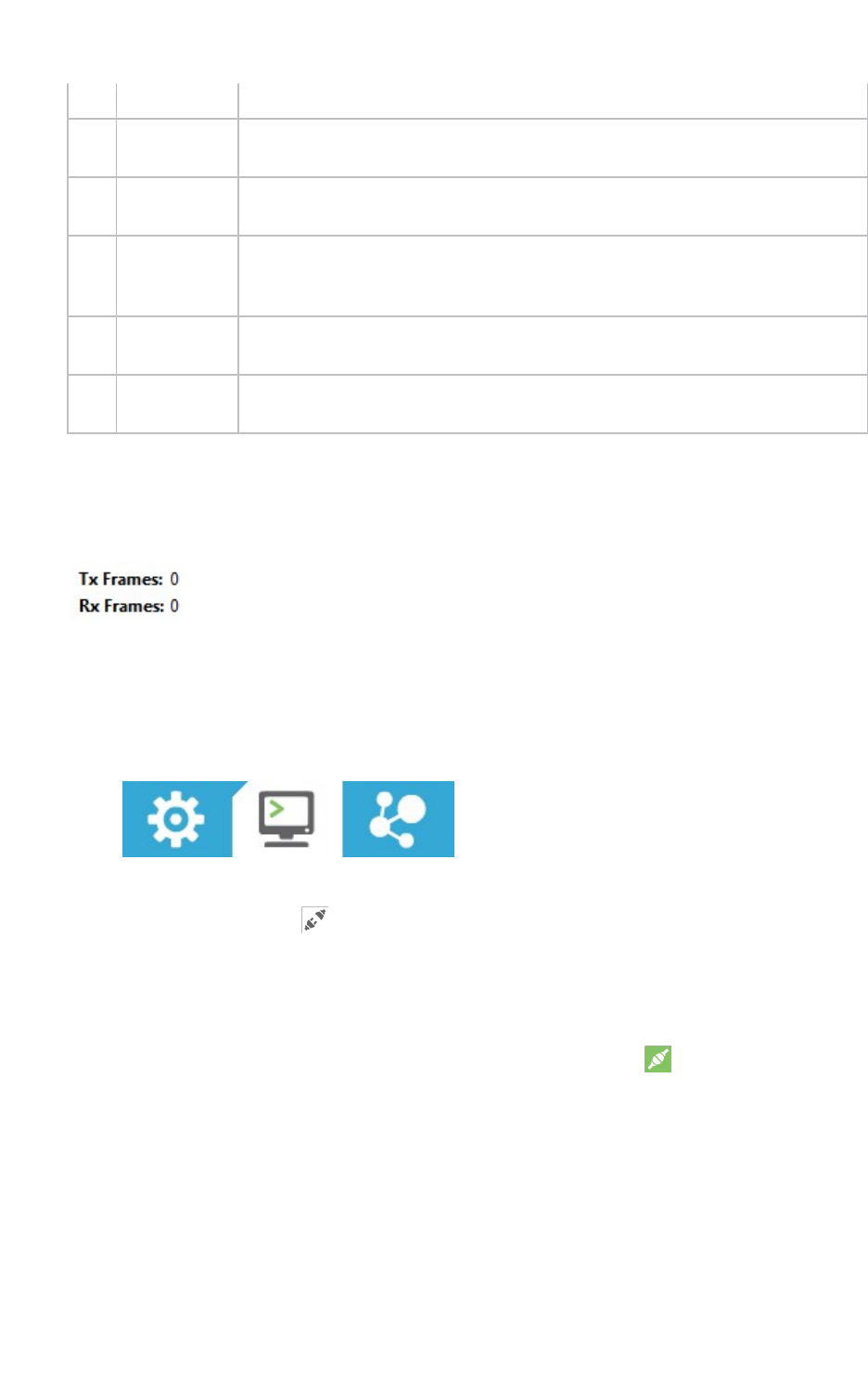
Communicate with your modules Connect and disconnect the console
XCTU User Guide 66
CTS Clear to send Indicates that the connected device is ready to accept data.
CD Carrier
Detect
Detects the presence of connection.
DSR Data Set
Ready
Indicates that the connected device is ready for communication.
DTR Data
Terminal
Ready
Indicates that the terminal is ready for communication.
RTS Ready to
send
Requests that the connected device prepare to receive data.
BRK Break Engages the serial line break. Asserting this line places the DI line high,
preventing data from being sent to the radio.
Console overview
The console overview panel, located on the right side of the toolbar, displays the number of sent and
received frames or bytes.
Connect and disconnect the console
The first time you open a console, it is disconnected by default.
1. Switch to Consoles working mode.
2. Select a radio module from the list.
3. Click the Open button to establish communication with the radio module corresponding to
the console. The background color of the Open button changes to green and its text changes
to Close.
When the console is connected, all the data traffic of the radio module is captured by the
console and displayed in the corresponding controls.
4. To disconnect the console from the module, click the Close button . The background color
of the button changes to white and its text changes to Open.
Record a console session
In the Consoles working mode, you can record all incoming and outgoing console data as it is sent or
received. XCTU saves this data in a Console log file. The console must be connected to start or stop
recording.

Communicate with your modules Attach and detach the console
XCTU User Guide 67
Note You can also use the Serial console tool to record console sessions. See Serial console tool.
1. Switch to Consoles working mode .
2. Select a radio module from the list.
3. Click the Open button to establish communication. The background color of the button
changes to green.
4. Click the Start Recording button . A Save file dialog appears.
5. Specify a destination for the console log file. Data is periodically written to this log file in
comma separated values (CSV) format. See Console log files.
6. Click the Stop Recording button to stop the process of saving sent or received data.
Note You can use the Load console session tool to load a saved console session at a later time. For
details, see Load console session tool.
Attach and detach the console
You can attach or detach the console from the working area by clicking the Attach and Detach buttons
on the Console toolbar. By default, all the consoles are attached and sorted in tabs.
1. To detach a console from the working area, click the Detach button . The console is
displayed in a floating dialog.
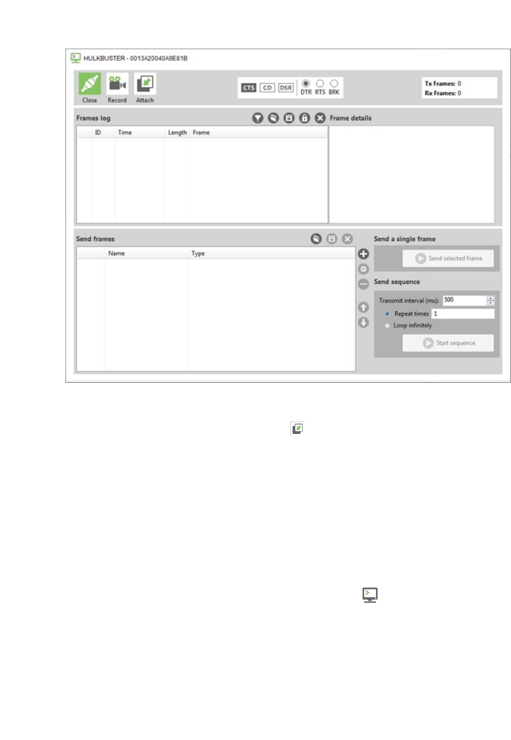
Communicate with your modules Communicate with modules running in API or API escaped mode
XCTU User Guide 68
You can detach all the consoles to display them in multiple dialogs. This is useful if you need to
see the traffic for different radio modules simultaneously.
2. To reattach the console view, click the Attach button or close the floating dialog
containing that console.
Communicate with modules running in API or API escaped mode
XCTU uses API frames to communicate with radio modules running in API or API escaped mode. You
can use XCTU's API console to communicate with radio modules running in API or API escaped
operating mode. XCTU automatically creates an API console for these modules when you switch to
Consoles working mode.
API console
The API console allows you to communicate with radio modules running in API or API escaped
operating mode. To display the API console, switch to Consoles working mode and select a radio
module configured with either API or API escaped operating mode. For more information, see API
operating mode and API escaped operating mode.
XCTU uses API frames to communicate with radio modules running in API mode. An API frame is an
array of bytes with a specific structure defined by the API Frame Specifications. For more information,
see API frames.
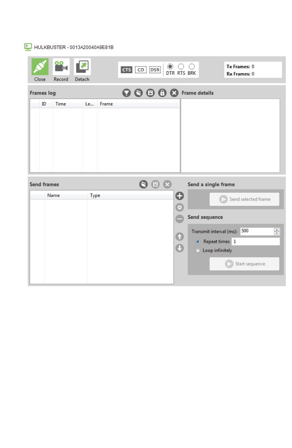
Communicate with your modules Communicate with modules running in API or API escaped mode
XCTU User Guide 69
API console view
Frames log
The Frames log is XCTU's API frames traffic monitor. When API frames are sent or received by the
module, they are added to the Frames log. Depending on whether the frame is sent or received, the
color of the frame fields is blue or red, respectively.
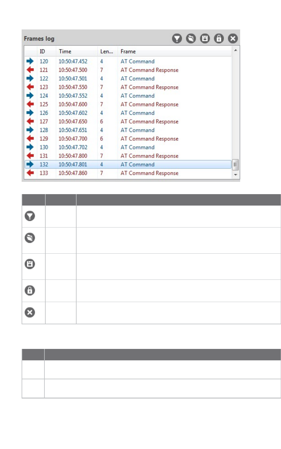
Communicate with your modules Communicate with modules running in API or API escaped mode
XCTU User Guide 70
Button Name Description
Configure
filters
Opens the Frames filtering configuration dialog.
Load
console
session
Opens the embedded Load console session tool. For details, see Load console
session tool.
Save
console
session
Saves the active console session in a Console log files.
Lock
scroll
Toggles the scroll behavior of the data box. If Lock scroll is enabled, the
Frames log will not automatically scroll when a new frame is sent or received.
Clear
data
Clears the list of sent and received API frames.
The Frames log displays the following properties of the transmitted and received API frames:
Field Description
Icon Displays as a right blue arrow if the API frame is sent, and as a left red arrow if it is
received.
ID Lists a numeric value given by XCTU to identify the API frame. When the list of frames is
cleared, this value is reset to 0.
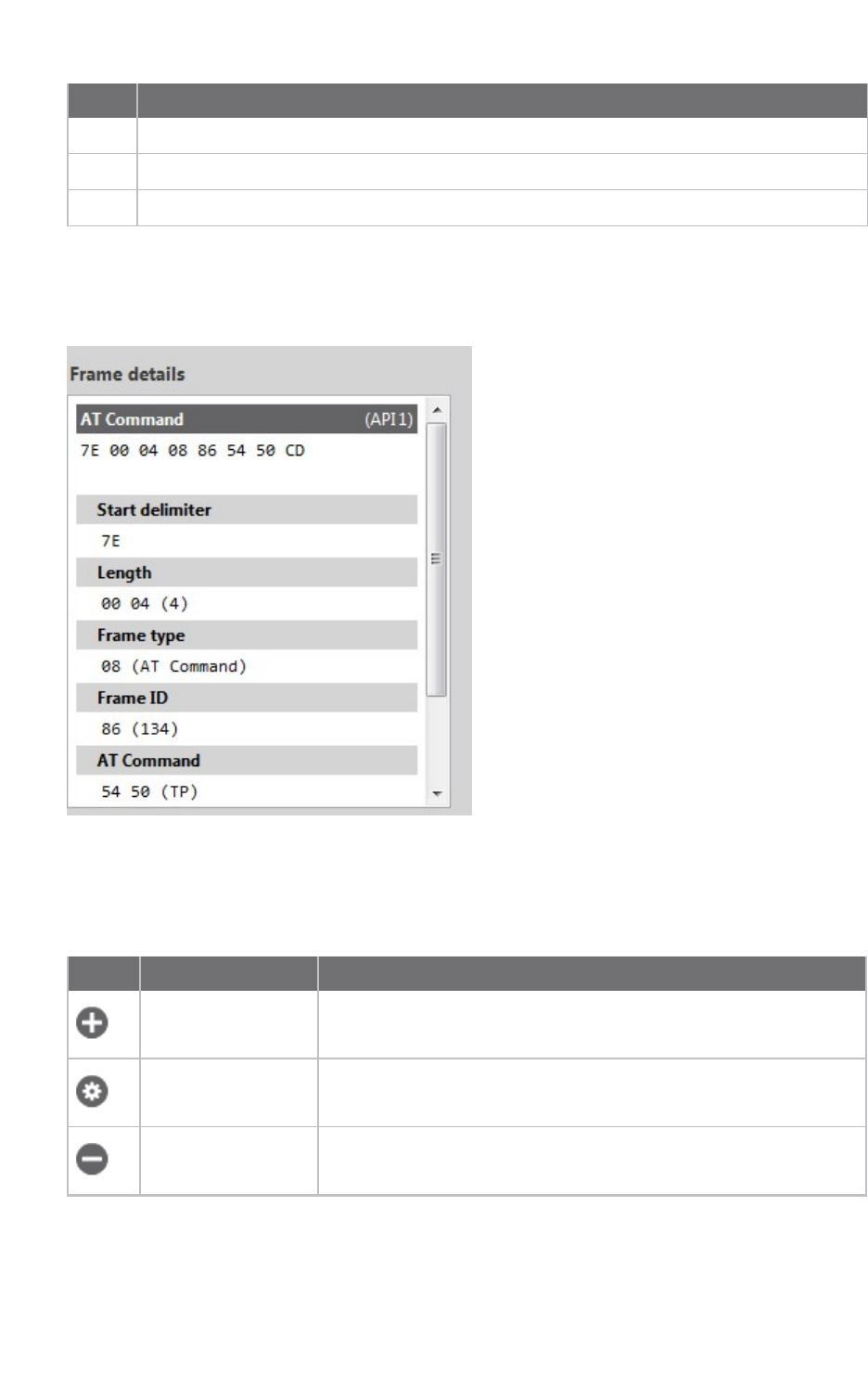
Communicate with your modules Communicate with modules running in API or API escaped mode
XCTU User Guide 71
Field Description
Time Displays the time at which the API frame was sent or received.
Length Contains the number of bytes of the API frame.
Frame Displays the API frame type.
Frame details
Frame details appear next to the API frames table and display the decoded contents of the selected
API frame.
Send frames
The Send frames section of the API Console allows you to add, manage, and send an API frame or
sequence of frames.
Button Name Description
Add new frame Adds a new API frame to the list of frames to send
Edit selected frame Changes the name or contents of a frame
Remove selected
frame
Removes a frame from the list
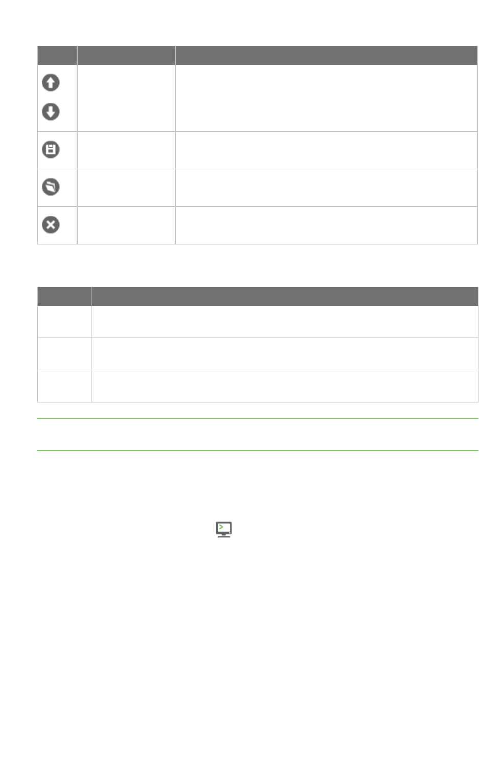
Communicate with your modules Communicate with modules running in API or API escaped mode
XCTU User Guide 72
Button Name Description
Move up / move
down
Changes the order of frames in the list
Save frames list Saves the list of frames to be used in future sessions or on another
computer
Load frames list Loads a saved list of frames
Clear the list of
frames
Clears the entire frames list
The Send sequence dialog contains the following fields:
Field Description
Transmit
interval
Amount of time, in milliseconds, to pause between frames. The minimum value is 0 ms
and the maximum value is 60000 ms (1 minute).
Repeat
times
Number of times the sequence should be repeated or sent. By default, this value is 1.
Loop
infinitely
Sends the sequence of frames in an infinite loop.
Note You can send a single frame (Send selected frame) or the configured sequence of frames (Start
sequence).
Filter sent and received frames
You can filter by sent and received frames in the API console to focus only on specific frames. For both
sent and received frames, you can show any, show all, filter by sender MAC, and filter by frame type.
1. Switch to Consoles working mode .
2. Select a radio module configured in API or API escaped operating mode.
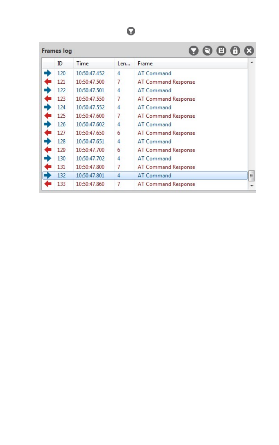
Communicate with your modules Communicate with modules running in API or API escaped mode
XCTU User Guide 73
3. Click the Configure filters button in the Frames log area.
The Frames filtering configuration dialog appears.
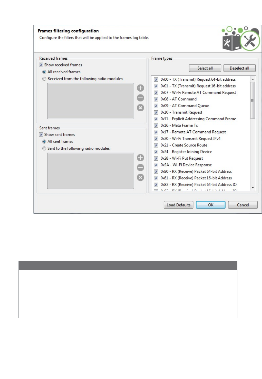
Communicate with your modules Communicate with modules running in API or API escaped mode
XCTU User Guide 74
4. Configure the filtering options for one or more of the following: received frames, sent frames,
and frame types.
Received frames
When filtering the received frames, you have the following options:
Option Description
Show received
frames
Shows/hides received frames
All received frames Shows all the received frames
Received from the
following radio
modules
Shows the received frames by source address and lists the source MAC
addresses that can be filtered. You can add and remove addresses from this
list at any time.
To add a new MAC address:
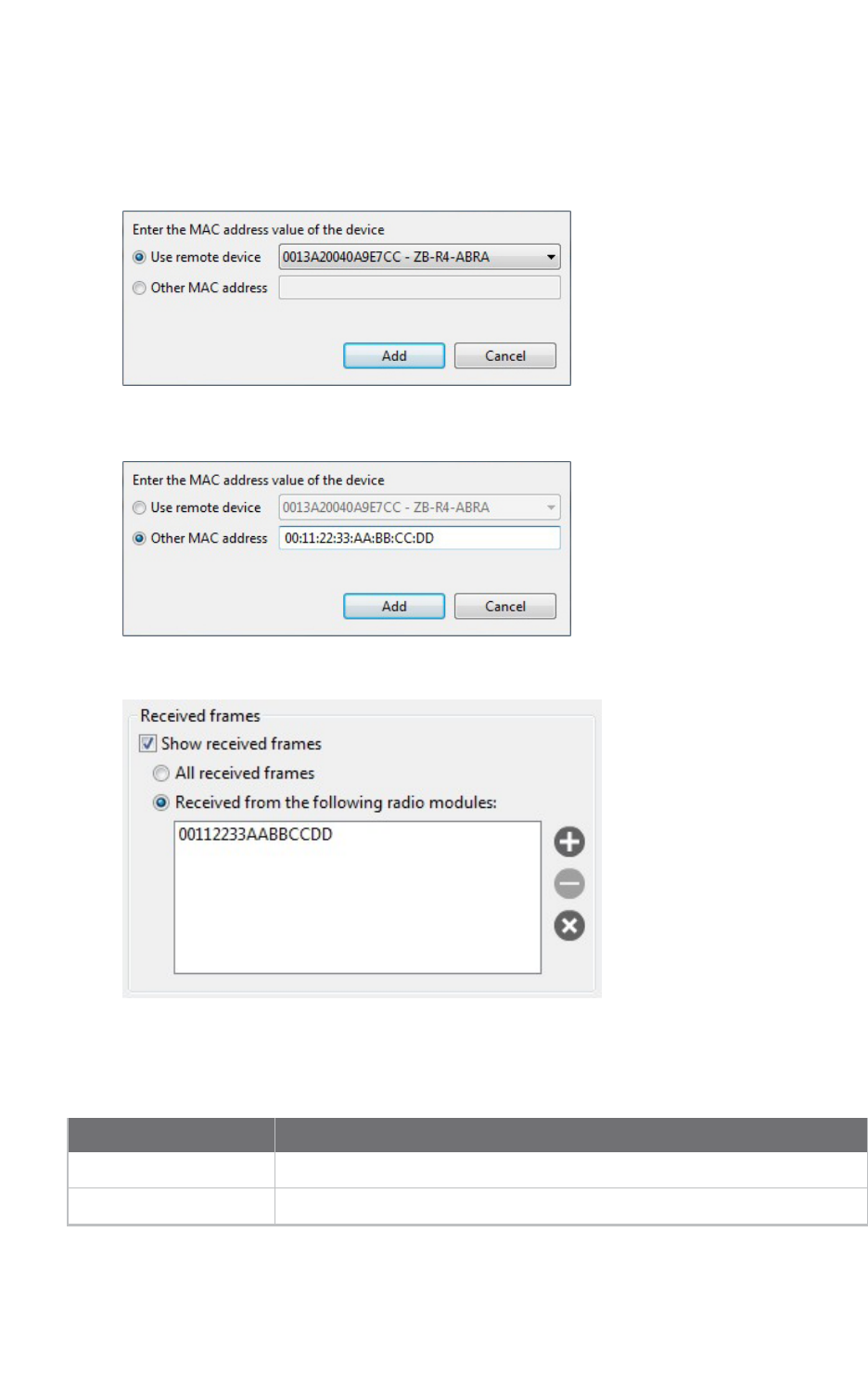
Communicate with your modules Communicate with modules running in API or API escaped mode
XCTU User Guide 75
1. Select the Received from the following radio modules option.
2. Click the Add new item button. A new dialog appears.
3. If any remote devices have been discovered for your local device, you can select the specific
device from the combo box:
If no remote devices are discovered for the local device, you can enter the MAC address
manually:
4. Click the Add button to add the MAC address to the list:
Sent frames
When filtering the sent frames, you have the following options:
Option Description
Show sent frames Shows/hides sent frames
All sent frames Shows all the sent frames

Communicate with your modules Communicate with modules running in API or API escaped mode
XCTU User Guide 76
Option Description
Sent to the following
radio modules
Shows the sent frames by destination addresses and lists the source MAC
addresses that can be filtered.
Note You can add a MAC address to the list by following the steps in Received frames.
Frame types
When filtering frames by type, you can select or deselect the desired frame types. By default all frame
types but the Invalid frame are selected. You can also use the following buttons:
Option Description
Select all Checks all the frame types
Deselect all Unchecks all the frame types
Add an API frame
An API frame is the structured data sent and received through the serial interface of the radio module
when it is configured in API or API escaped operating modes. API frames are used to communicate
with the module or with other modules in the network. For more information, see API frame.
If you want to send an API frame either individually or as part of a series, you first need to create the
API frame:
1. Switch to Consoles working mode .
2. Select a radio module from the list.
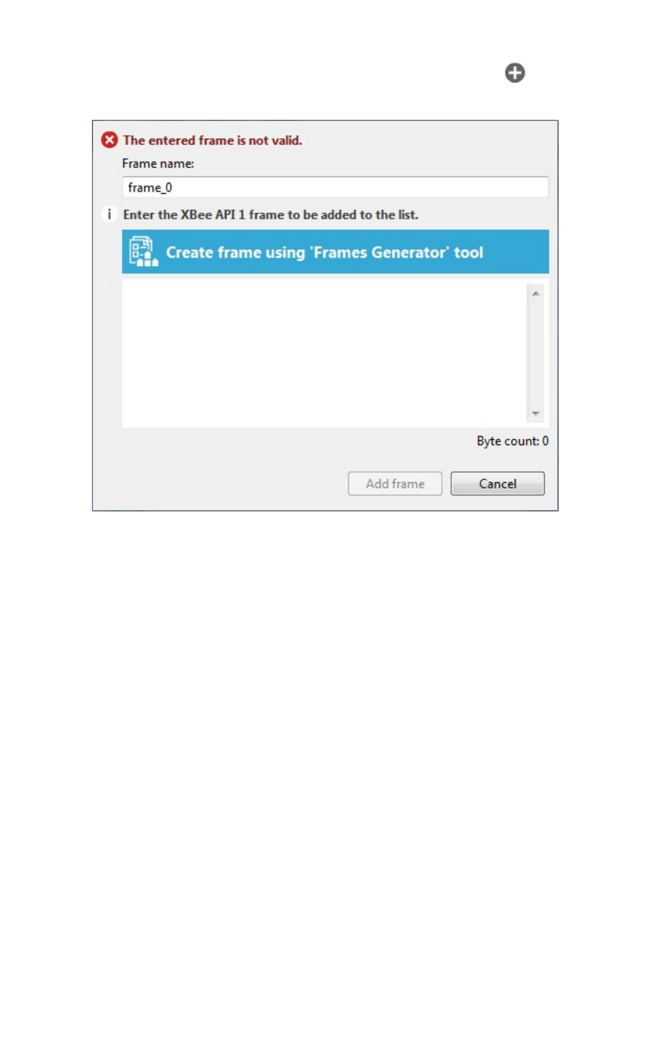
Communicate with your modules Communicate with modules running in API or API escaped mode
XCTU User Guide 77
3. In the Send frames area, click the Add new frame to the list button .
The Add API frame to the list dialog appears.
4. Enter a name for the frame.
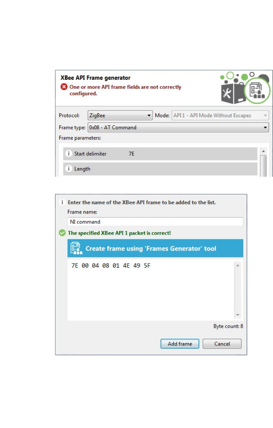
Communicate with your modules Communicate with modules running in API or API escaped mode
XCTU User Guide 78
5. Create the frame by doing one of the following:
nEnter the byte array of the API frame.
nClick the Create frame using ‘Frames Generator’ tool button to open the Frames
Generator tool. Then, configure the frame and click OK. For more information, see
Frames generator tool.
Your generated frame appears in the API frame.
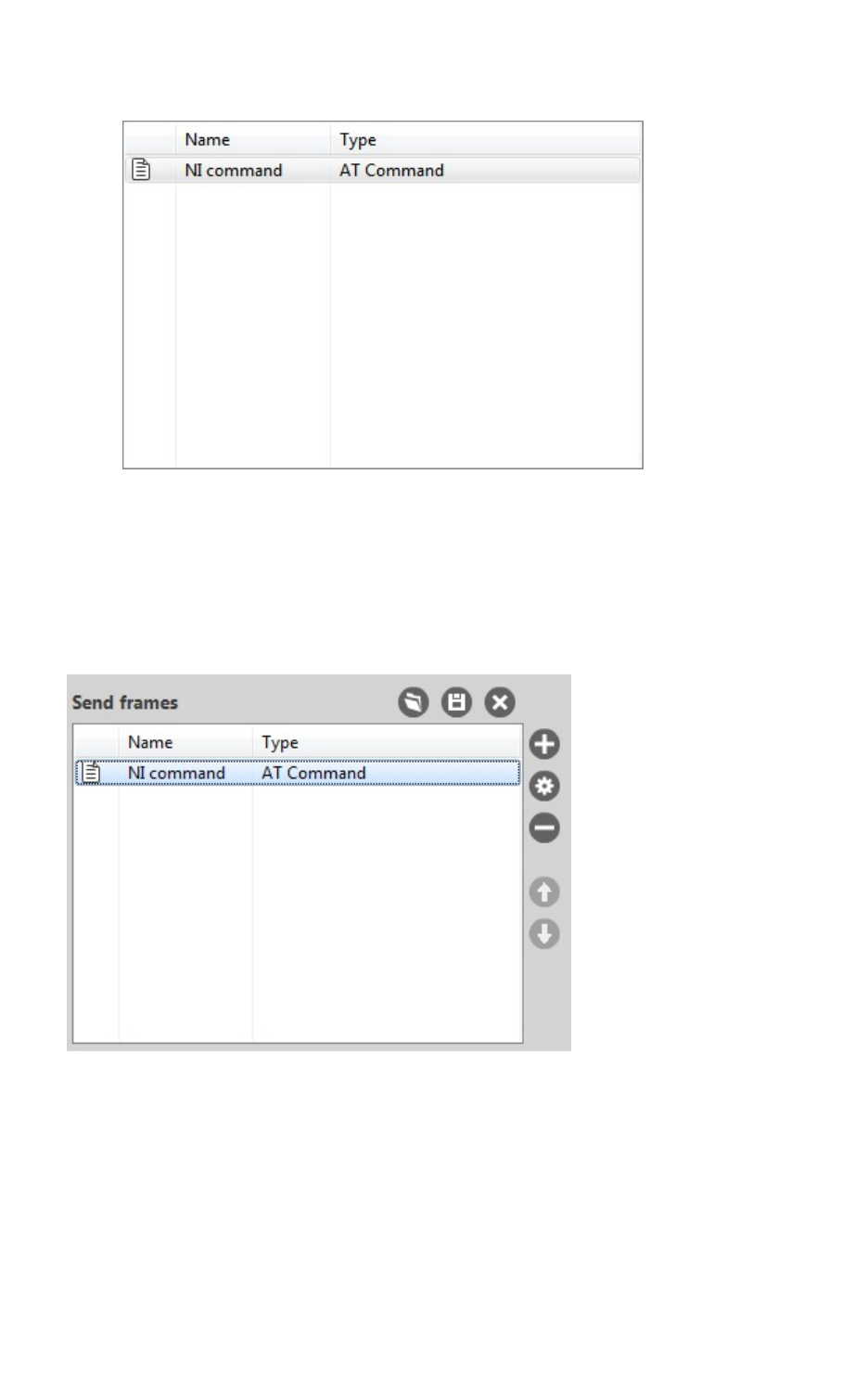
Communicate with your modules Communicate with modules running in API or API escaped mode
XCTU User Guide 79
6. Click the Add frame button to add the API frame to the list of frames to send.
7. Repeat the steps to add additional API frames.
When finished, you can Send a single API frame and Send a sequence of API frames.
Manage API frames
Once you add an API frame to the list, you can perform the following actions. For instructions on
adding a frame, see Add an API frame.
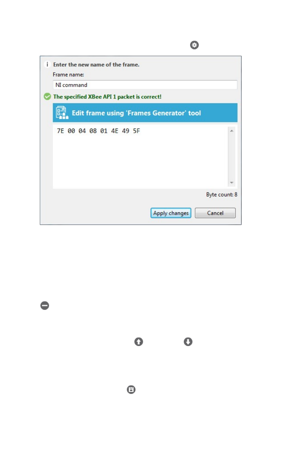
Communicate with your modules Communicate with modules running in API or API escaped mode
XCTU User Guide 80
Edit a frame
1. Select the frame and click the Edit selected frame button .
2. Do one of the following:
nManually edit the frame name and content.
nClick Edit frame using 'Frames Generator' tool to edit the content of the frame within
the tool.
3. Click Apply changes.
Remove a frame
To remove a frame from the frames list, select the frame and click the Remove selected frame
button .
Change the order of the frames list
If your list of API frames contains more than one frame, you can change the order of the frames.
Select an API frame and then click Move up or Move down to change the position of the
frame in the list.
Save a list of frames
You can save a list of frames for use in future XCTU sessions.
1. Click the Save frames list button . A Save file dialog box appears.
2. Specify a name and path for the API frames list XML file, and click Save.
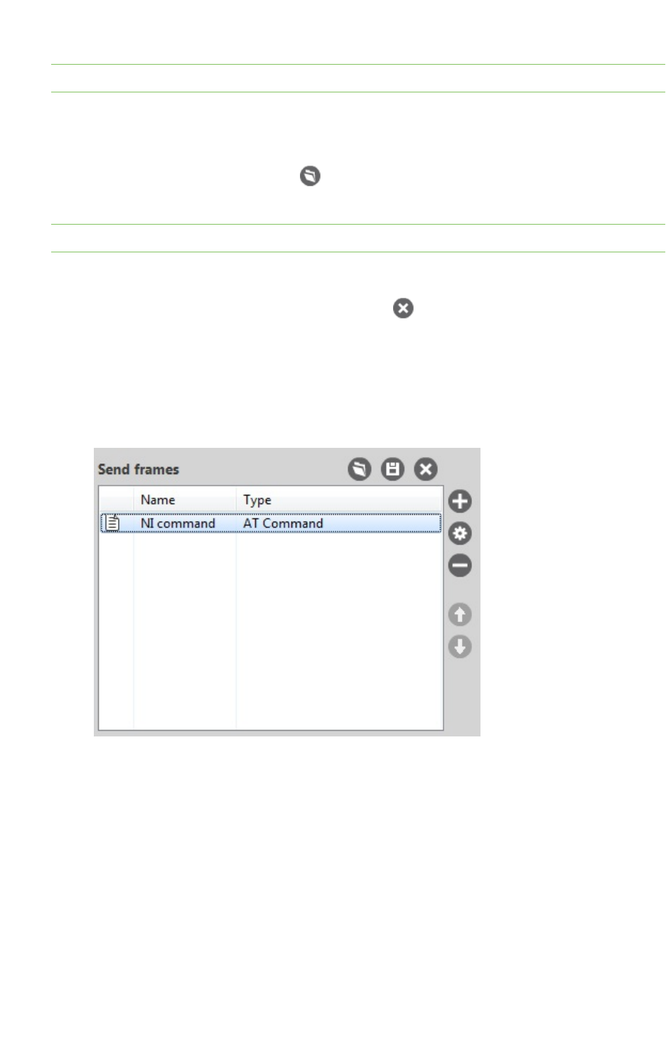
Communicate with your modules Communicate with modules running in API or API escaped mode
XCTU User Guide 81
Note XCTU also saves the sending configuration.
Load a saved list of frames
You can load a previously saved list of API frames.
1. Click the Load frames list button . A Load file dialog box appears.
2. Select the saved API frame list XML file and click Open.
Note XCTU also loads the sending configuration.
Clear the frames list
To clear the list of API frames, click the Clear list button .
Send a single API frame
After you have added at least one frame to the Send frames area, you can send a single API frame to
the console's corresponding radio module. For instructions on adding a frame, see Add an API frame.
1. In the API Console, select a frame in the Send frames area.
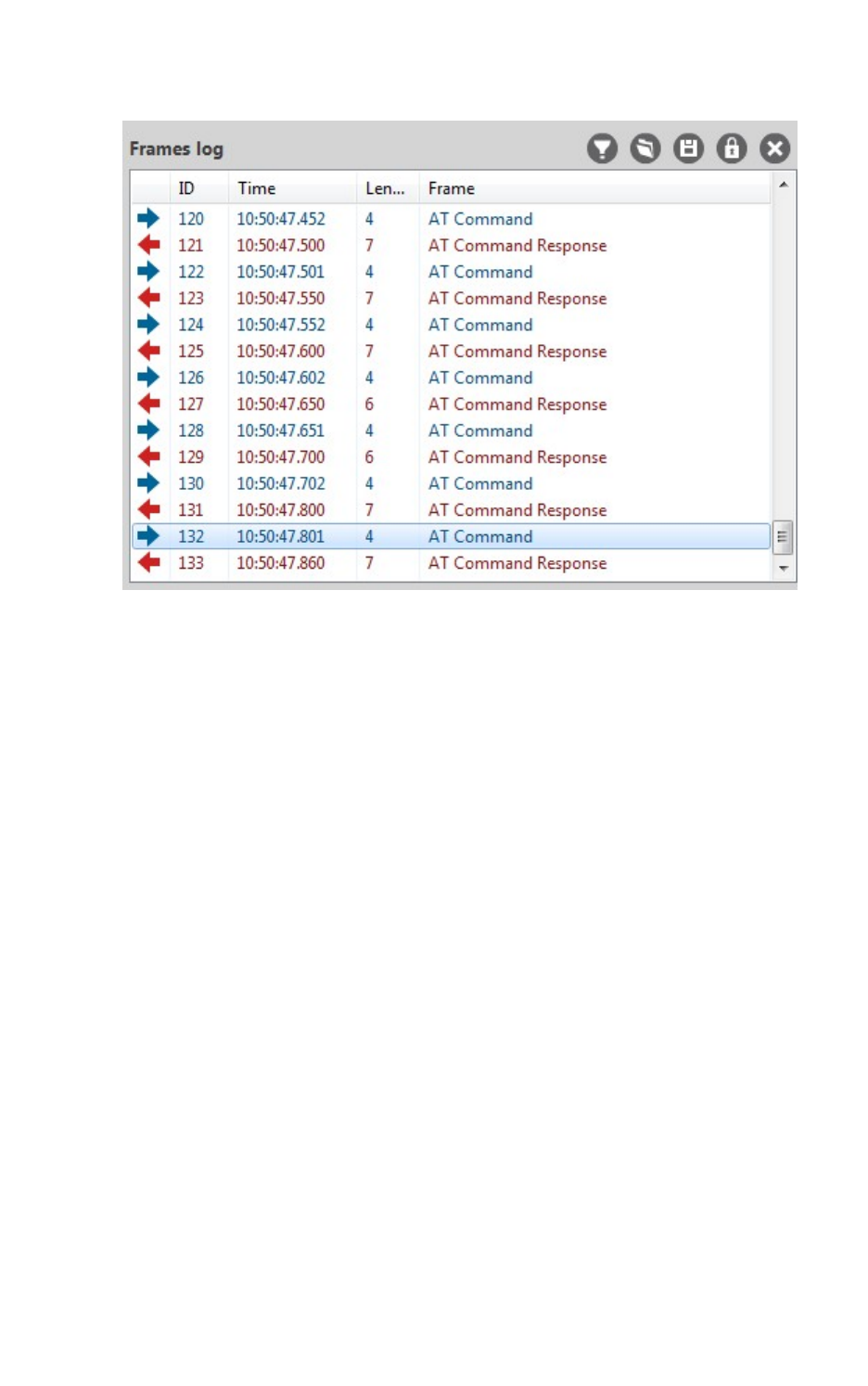
Communicate with your modules Communicate with modules running in API or API escaped mode
XCTU User Guide 82
2. Click Send selected frame. The sent frame appears in the Frames log area.
For more information, see Send a sequence of API frames.
Send a sequence of API frames
After you have added at least two APIframes to the Send frames area, you can send a sequence of
API frames to a radio module running in API mode. For instructions on adding a frame, see Add an API
frame.
An API frame sequence contains the list of frames to send as well as configured information about the
way the frames will be sent.
1. In the Send sequence area of the API console, configure the following options:
nTransmit interval: Specify the amount of time, in milliseconds, to pause between
frames. The minimum value is 0ms and the maximum value is 60000ms (1 minute).
nRepeat times: Select this option to specify the number of times the sequence should be
repeated or sent. By default, this value is 1.
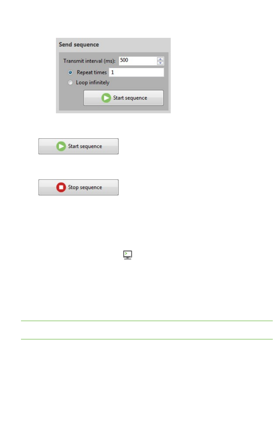
Communicate with your modules Communicate with modules running in AT mode
XCTU User Guide 83
nLoop infinitely: Select this option to send the sequence of frames in an infinite loop.
2. Click Start sequence. XCTU sends all frames in the Send frames list. Sent and received frames
appear in the Frame logs area.
3. The process could end by itself, but you can click Stop sequence at any time to halt
transmission.
For more information, see Send a single API frame.
Save an API console session
You can save the API console session, containing the list of sent and received API frames, by clicking
the Save console session button.
1. Switch to Consoles working mode .
2. Select a radio module running in API or API escaped operating mode from the list.
3. Connect the console.
4. Generate some traffic.
5. Click the Save console session button in the Frames log view. The Save file dialog appears.
6. Designate a filename and path for the console session file.
7. Click Save.
Note You can load an API console session using the Load console session tool. See Load console
session tool.
Communicate with modules running in AT mode
In AT (Application Transparent) or transparent operating mode, all serial data received by the radio
module is queued up for RF transmission. When RF data is received by the module, the data is sent out
through the serial interface.
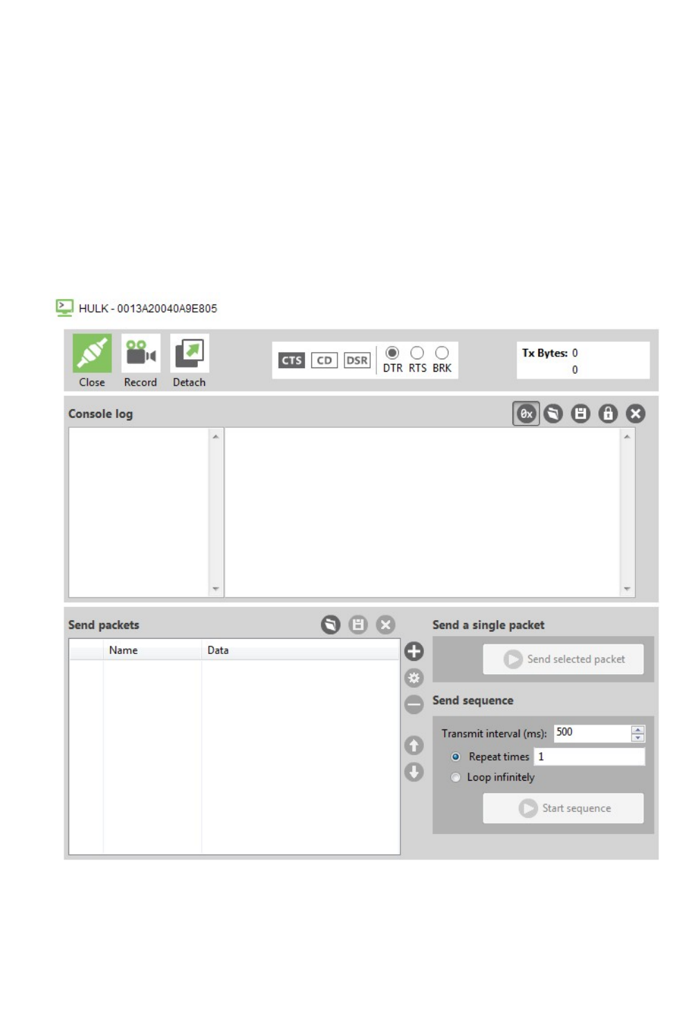
Communicate with your modules Communicate with modules running in AT mode
XCTU User Guide 84
You can use XCTU's ATconsole to communicate with radio modules running in AT operating mode.
XCTU automatically creates an AT console for these modules when you switch to Consoles working
mode.
AT console
The ATconsole allows you to communicate with radio modules running in AT (transparent) operating
mode. To display the ATconsole, switch to Consoles working mode and select a radio module
configured with AT operating mode.
In the ATconsole, communication with the device is direct. All the data you send through the serial
interface is queued for transmission by the module, and all data received by the module is sent
through the serial interface.
AT console view
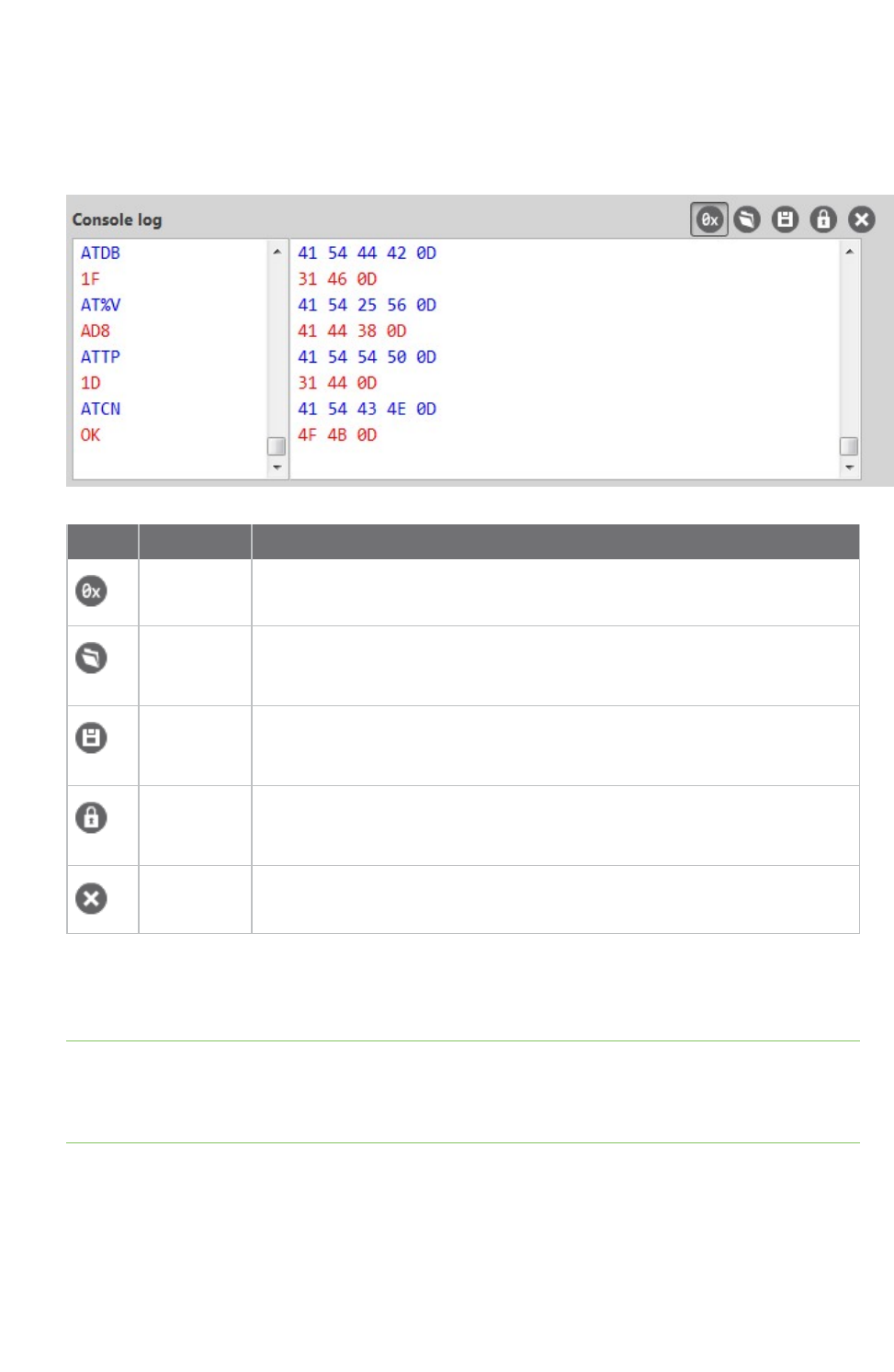
Communicate with your modules Communicate with modules running in AT mode
XCTU User Guide 85
Console log
The Console log operates as a data traffic monitor. It displays all sent (blue) and received (red) data
characters. Sent and received data is appended at the bottom of the data box. The right-hand side of
the Console log displays corresponding hexadecimal values for all sent and received data characters.
Button Name Description
Show/hide
hexadecimal
Toggles hexadecimal view.
Load
console
session
Opens the embedded Load console sessions tool. See Load console session
tool.
Save
console
session
Saves the active console session in a Console log files.
Lock scroll Toggles the scroll behavior of the data box. If Lock scroll is enabled, the data
box will not automatically scroll when a new data character is sent or
received.
Clear data Clears all data characters, as well as their hexadecimal representation,
from the data box.
When operating in AToperating mode, XCTU does not require that you use structured data to
communicate with a radio module. Communication with the device is direct. Type directly in the data
box and the characters you enter are automatically sent to the radio module.
Note To insert CR/LF, CR or LF characters, right click on the ASCII panel of the Console log and select
the appropriate option from the context menu. It is also possible to configure the default behavior
when you press the ENTER key. For more information about configuring default behavior, see Set
console preferences.
Send packets
The Send packets section of the AT Console allows you to add and manage data packets. You can
send a data packet—one or more groups of characters—to a radio module in your device list. When
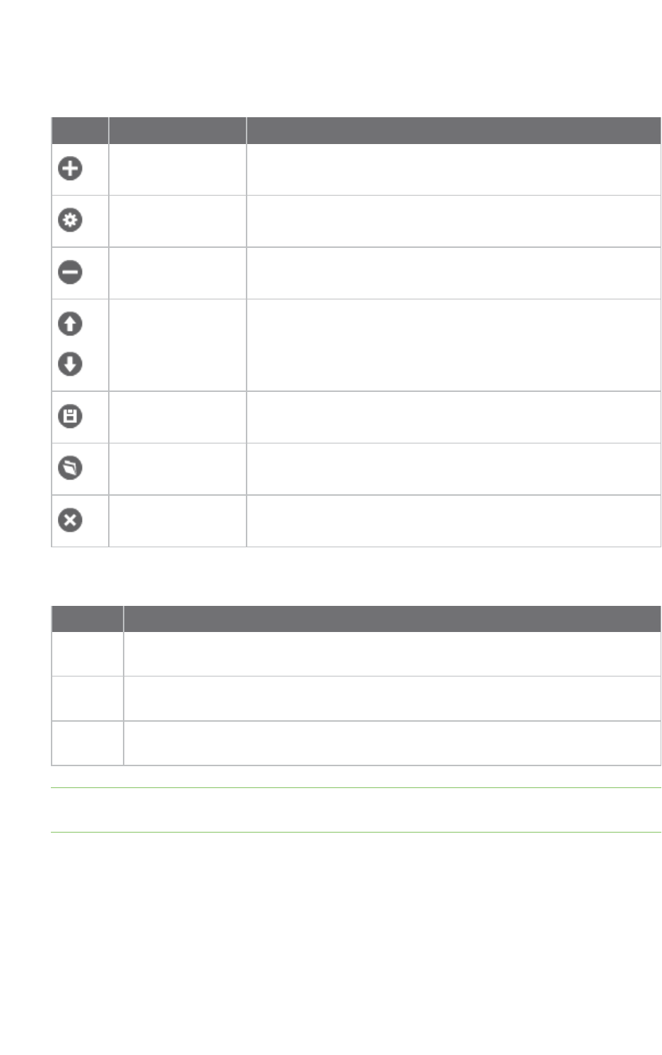
Communicate with your modules Communicate with modules running in AT mode
XCTU User Guide 86
you type in the data box, XCTU sends the data as individual characters. Sending a data packet sends
all of the characters in a single operation.
Button Name Description
Add new packet Adds a packet to the list of packets to send
Edit selected packet Changes the name or contents of a data packet
Remove selected
packet
Removes a data packet from the list
Move up / move
down
Changes the order of packets in the list
Save packets list Saves the list of packets to be used in future sessions or on
another computer
Load packets list Loads a saved list of data packets
Clear the list of
packets
Clears the entire packet list
The Send sequence dialog contains the following fields:
Field Description
Transmit
interval
Amount of time, in milliseconds, to pause between data packets. The minimum value is
0ms and the maximum value is 60000ms (1 minute).
Repeat
times
Number of times the sequence should be repeated or sent. By default, this value is 1.
Loop
infinitely
Sends the sequence of data packets in an infinite loop.
Note You can send a single packet (Send selected packet) or the configured sequence of packets
(Start sequence).
For more information, see Consoles working mode and AT operating mode.
Add a data packet
When a module is operating in AT mode, you can send data byte by byte, or you can send a set of
bytes—a data packet. To send a data packet, you must first create one. By default, the data packets
list is empty.
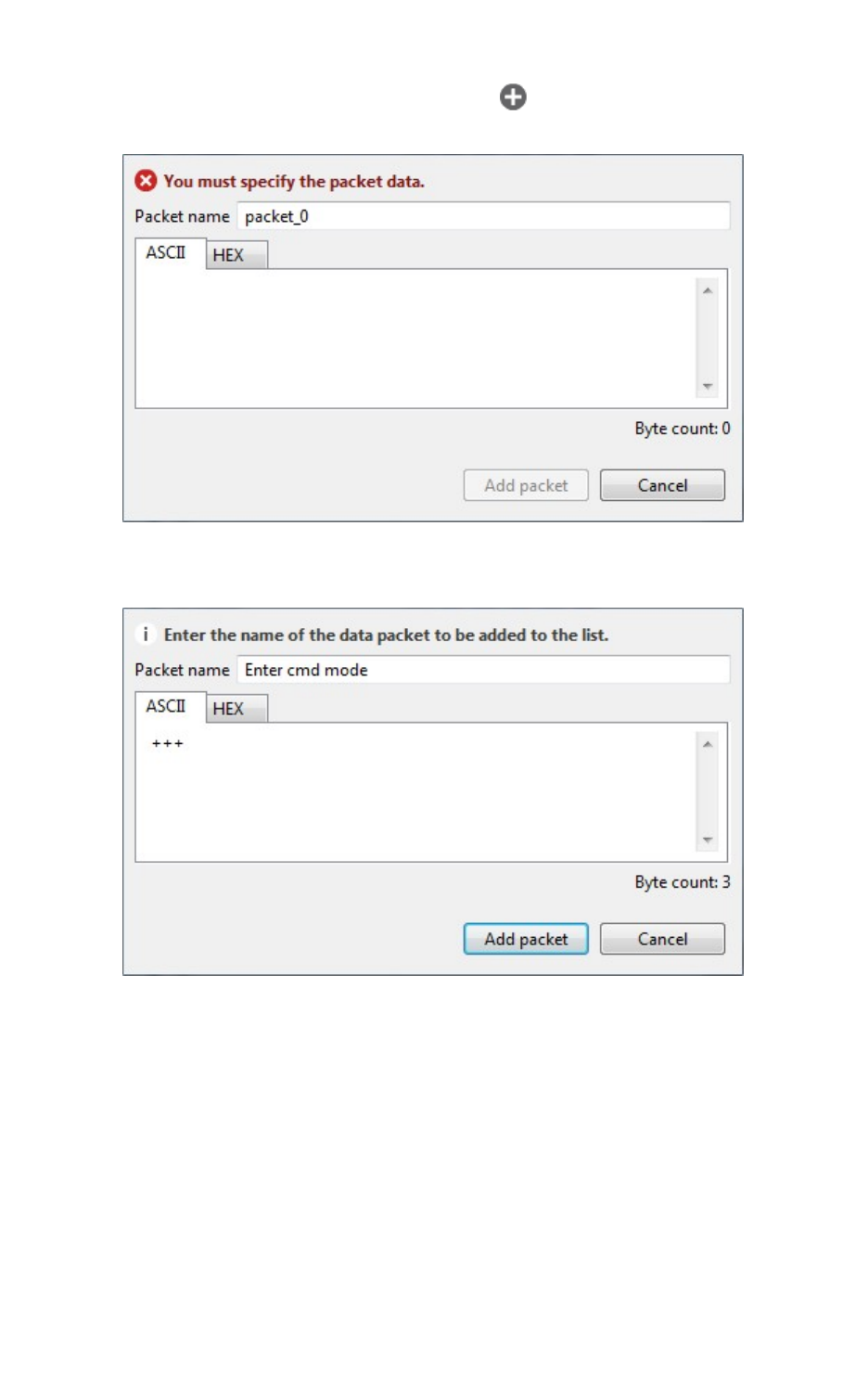
Communicate with your modules Communicate with modules running in AT mode
XCTU User Guide 87
1. From the AT console, click the Add new packet button in the Send packets dialog. The
Add new packet dialog appears.
2. Enter the name of the data packet to be added to the list.
3. Type in your data. You can use the tabs to toggle between ASCII and HEX input views.
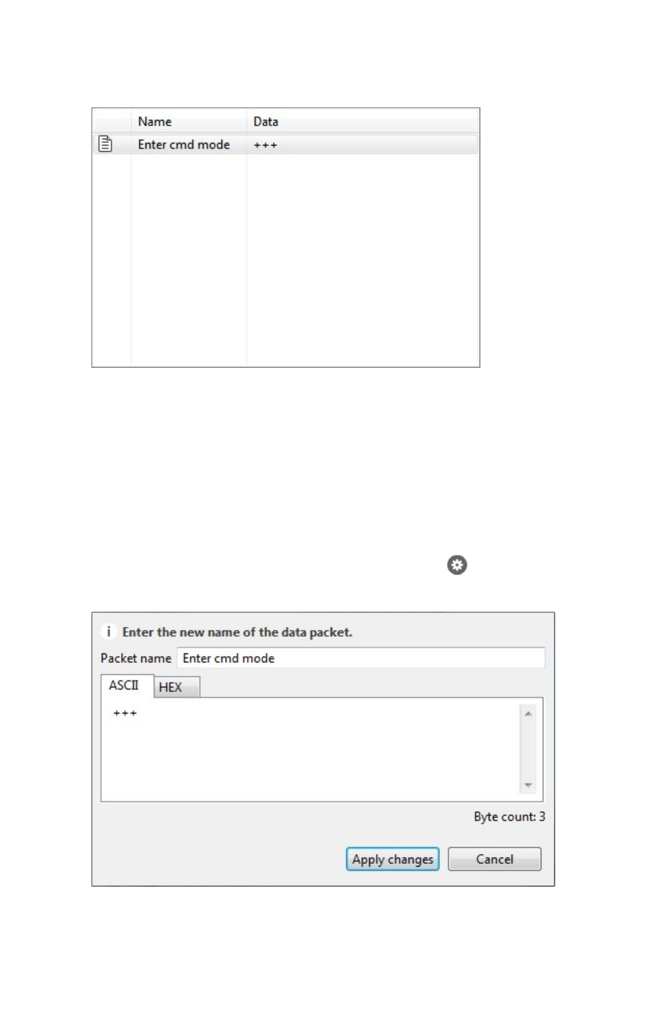
Communicate with your modules Communicate with modules running in AT mode
XCTU User Guide 88
4. Click Add packet. The data packet appears in the list of packets. Repeat the operation to add
additional packets to the list.
When finished, you can send a single packet or a sequence of packets. See Send a single packet and
Send a sequence of packets.
Manage data packets
Once you create a data packet, you can perform the following actions. For instructions on adding a
packet, see Add a data packet.
Edit a data packet
1. Select the packet and click the Edit selected packet button .
2. Manually edit the packet name and content.
3. Click Apply changes.

Communicate with your modules Communicate with modules running in AT mode
XCTU User Guide 89
Remove a data packet
To remove a data packet from the list, select the packet and click the Remove selected packet
button .
Change the order of the data packets list
If your list of data packets contains more than one packet, you can select a packet and then click
Move up or Move down to change the position of the packet in the list.
Save a list of packets
You can save a list of packets for use in future XCTU sessions.
1. Click the Save packets list button . A Save file dialog box appears.
2. Specify a name and path for the XML file and click Save.
Note XCTU also saves the sending configuration.
Load a saved list of packets
You can load a previously saved list of data packets.
1. Click the Load packets list button . The Load file dialog box appears.
2. Select the saved XML file and click Open.
Note XCTU also loads the sending configuration.
Clear the packet list
To clear the list of data packets, click the Clear list button .
Send a single packet
After you have added at least one data packet to the Send packets area, you can send a single packet
to the console's corresponding radio module. For instructions on adding a packet, see Add a data
packet.
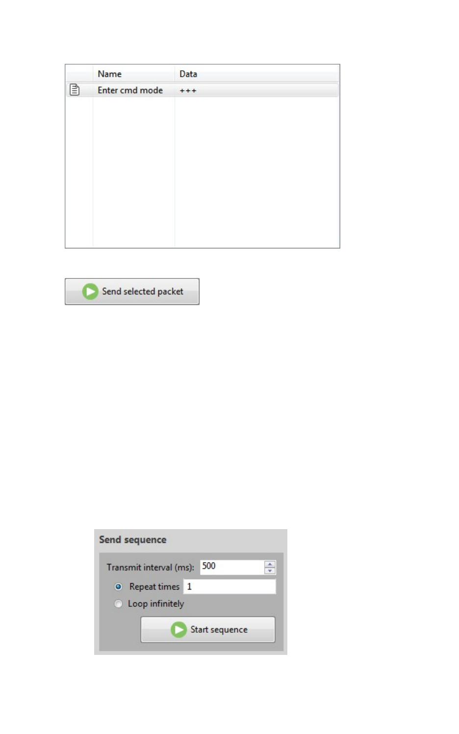
Communicate with your modules Communicate with modules running in AT mode
XCTU User Guide 90
1. In the Consoles working mode, select a packet in the Send packets area.
2. Click Send selected packet.
The sent data appears in the Data traffic section.
For more information, see Send a sequence of packets.
Send a sequence of packets
After you have added at least two data packets to the Send packets area, you can send a sequence of
data packets to a radio module running in AT mode. The sequence is defined by the list of packets to
send and the send sequence options located next to the list. For instructions on adding packets, see
Add a data packet.
1. In the Send sequence dialog of the AT Console, configure the following options:
nTransmit interval: Specify the amount of time, in milliseconds, to pause between
frames. The minimum value is 0ms and the maximum value is 60000ms (1 minute).
nRepeat times: Select this option to specify the number of times the sequence should be
repeated or sent. By default, this value is 1.
nLoop infinitely: Select this option to send the sequence of frames in an infinite loop.
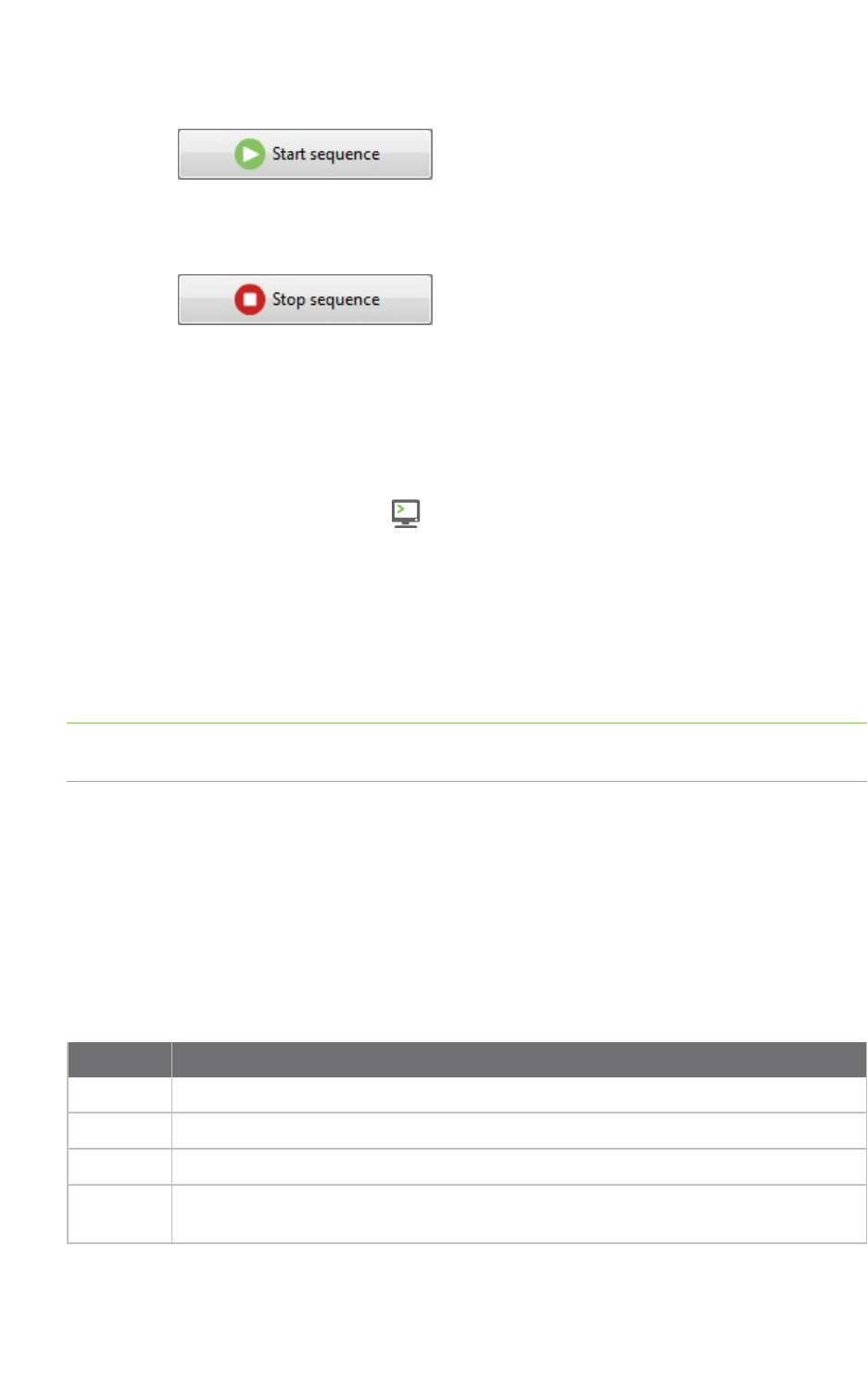
Communicate with your modules Console log files
XCTU User Guide 91
2. Click Start sequence. The sent and received data appear in the Data traffic monitor.
3. The process can end by itself. You can also click Stop sequence at any time to halt
transmission.
For more information, see Send a single packet.
Save an AT console session
A saved AT console session contains sent and received data. You can use the AT console and Serial
console tool to save a console session. XCTU saves this data in a Console log file.
1. Switch to Consoles working mode .
2. Select a radio module running in AT (transparent) operating mode.
3. Connect the console.
4. Generate some traffic. (The save feature doesn't work if there is no data to save.)
5. Click the Save console session button. The Save file dialog appears.
6. Designate a filename and path for the console session file.
7. Click Save.
Note You can load an AT console session using the Load console session tool. For more information,
see Load console session tool.
Console log files
A console log file is the file generated when saving or recording a console session. It consists of a
record containing console session information followed by multiple data records with sent and
received data. XCTU writes data in a console log file using Comma Separated Value (CSV) format.
Console session records
A console session record contains the following fields:
Field Description
Date Date and time when the session record started
ID Not used in this record; this field contains a "-" character
Type API, API2, AT, or Serial
Description Comma-separated console session information such as the module node identifier,
MAC address, function set, firmware version, and COM port

Communicate with your modules Console log files
XCTU User Guide 92
Console session records look like this:
02-05-2015 11:44:56.017,-,API,"A,0013A2004031A8D7,ZigBee Router
API,23A7,COM4 - 9600/8/N/1/N,0"
Data records
Data records contain the following fields:
Field Description
Date Date and time when the data was sent or received
ID ID number of the packet or API frame
Type SENT or RECV
Data Data sent or received in Hexadecimal string format
Data records look like this:
02-05-2015 11:44:58.857,0,SENT,7E000408764944F4

View your radio network
This section describes how to use Network working mode to view your radio network once you have
added a radio module or modules to your list of devices.
Modules in AT (transparent) operating mode do not support the network discovery process.
Network working mode 94
Scan the network for available modules 101
Search for network nodes 101
Change network perspective 101
Set network layout 102
Filter network connections by quality 102
Take a screenshot of the network 103
Set zoom level in Graph view 104
Export a network table 104
XCTU User Guide 93
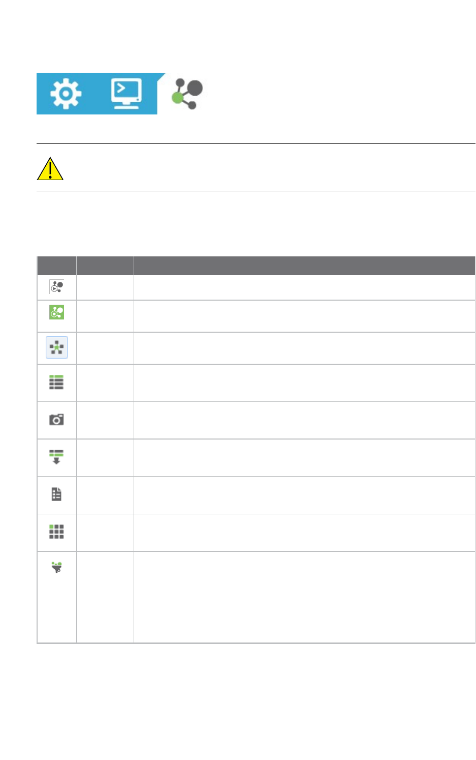
View your radio network Network working mode
XCTU User Guide 94
Network working mode
The Network working mode allows you to discover and see the topology of your network.
The Network perspective only works in API operating mode. Radio modules in AT
(transparent) mode do not support the network discovery process.
Network toolbar
The Network toolbar presents the network actions you can perform.
Button Name Description
Start scan Scans the radio module's network and displays a list of available modules.
Stop scan When scans specified in scan preferences are finished, the discovery process
stops automatically. You can also click the Stop scan button at any time.
Graph view Displays the modules as nodes in a graph.
Table view Displays the modules as rows in a table.
Screenshot Saves an image of the network to your computer.
Export
table
Exports network information in a tabular file format.
Settings Configures network-related parameters.
Layout Changes the network layout to one of six types: composite, spring, vertical
tree, horizontal tree, grid (default), and radial.
Filter links Hides or displays connections between RF modules based on their quality.
Enables/disables quality ranges via radio buttons. All filters are enabled by
default so all connections are visible.
You can establish connection quality colors and ranges in Preferences >
Network > Appearance or by clicking Configure quality ranges link in the
Filter links dialog.
See Set network discovery preferences.
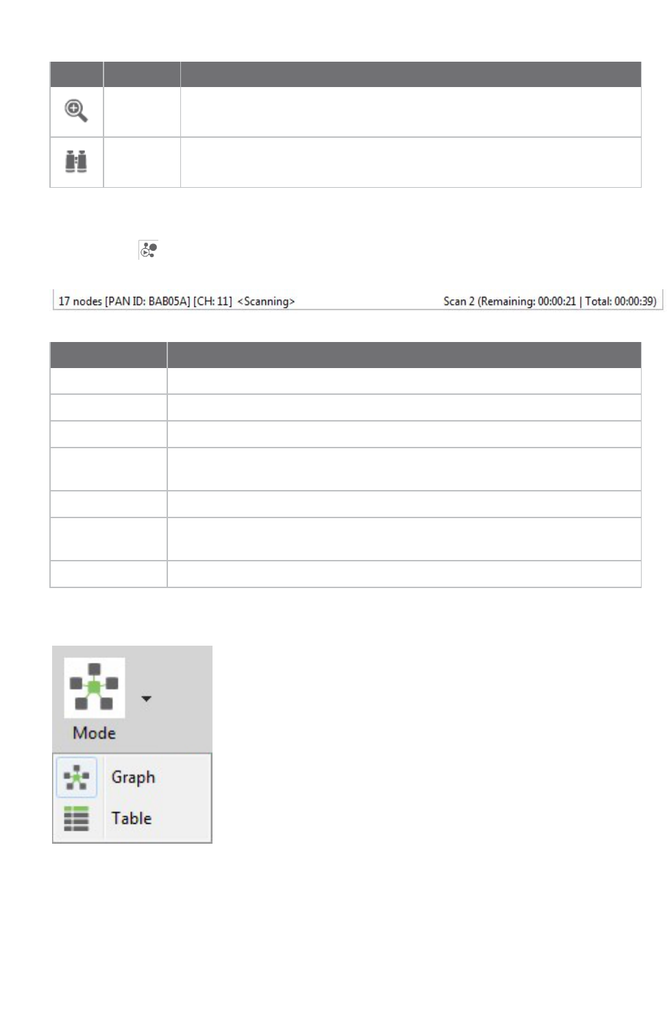
View your radio network Network working mode
XCTU User Guide 95
Button Name Description
Zoom Changes the zoom level of the network.
Find box Searches for a particular module in the network.
Network scan status
When you scan a radio module's network to find available modules, XCTU displays the status of
the scan along the bottom edge of the Network working mode display.
Field Description
17 nodes Number of nodes in the network
[PAN ID: BAB05A] PAN ID
[CH: 11] Channel
<Scanning> Status: Getting information, Initializing scan, Scanning, Waiting for next scan, or
Stopped
Scan 2 Current scan number
Remaining:
00:00:21
Estimated time remaining to finish current scan
Total: 00:00:39 Total elapsed time of scan
Graph view
In Graph view, XCTU displays the modules as nodes in a graph. A green background denotes the local
radio module and a blue background denotes the selected module. Each module is labeled with its role
(coordinator, router, or end device) and MAC address as well as the 16-bit network address for ZigBee
networks and node identifier for other protocols. You can click any node to inspect its connections.
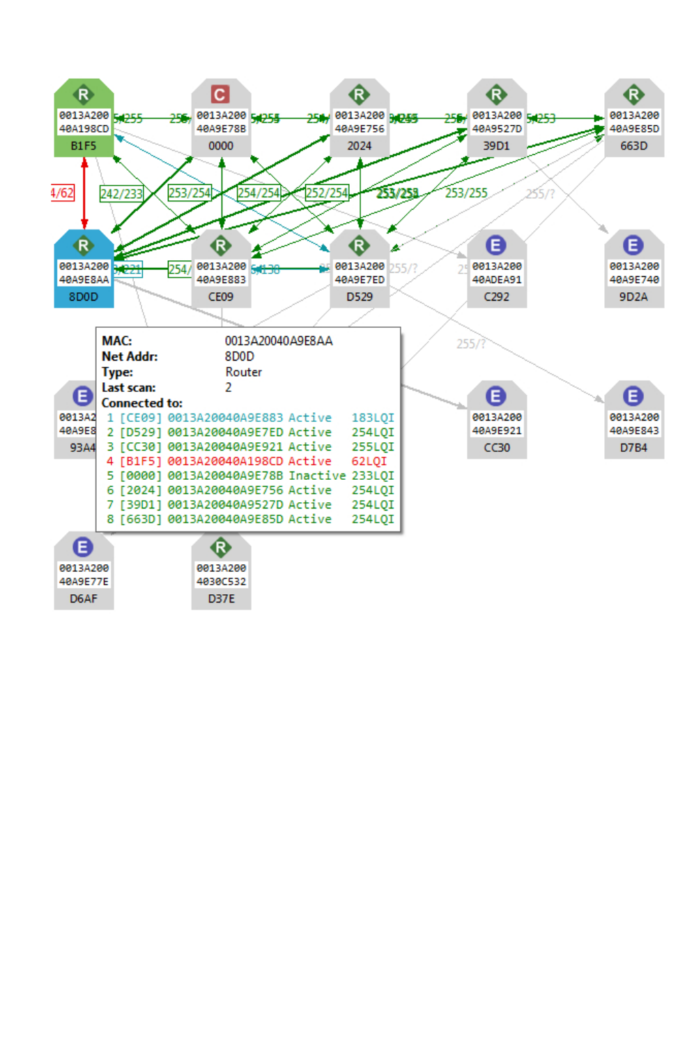
View your radio network Network working mode
XCTU User Guide 96
nEach node is connected to its neighbors with solid lines (active connections) or dotted lines
(undiscovered connections), with arrows indicating the direction of communication. Selected
nodes are blue, and connections are black. Nodes discovered in previous scans that have not
been found in the current scan are delineated via lighter-colored lines; they will "turn on" as
they are discovered.
nWhen a radio module leaves the network, some devices continue to store information about
their relationship. When you perform a new discovery, the module appears because of the
preserved information but the device is unreachable if you attempt to verify the connection.
These modules are shown in red.
nWhen you double click a node, XCTUswitches to Configuration mode and displays the node's
settings. If the node was not previously discovered, XCTU will add it to the device list as a
remote node before displaying its settings.
Connection quality filters
You can filter connections by quality in Graph view to show/hide connections between modules
according to configurable quality ranges.
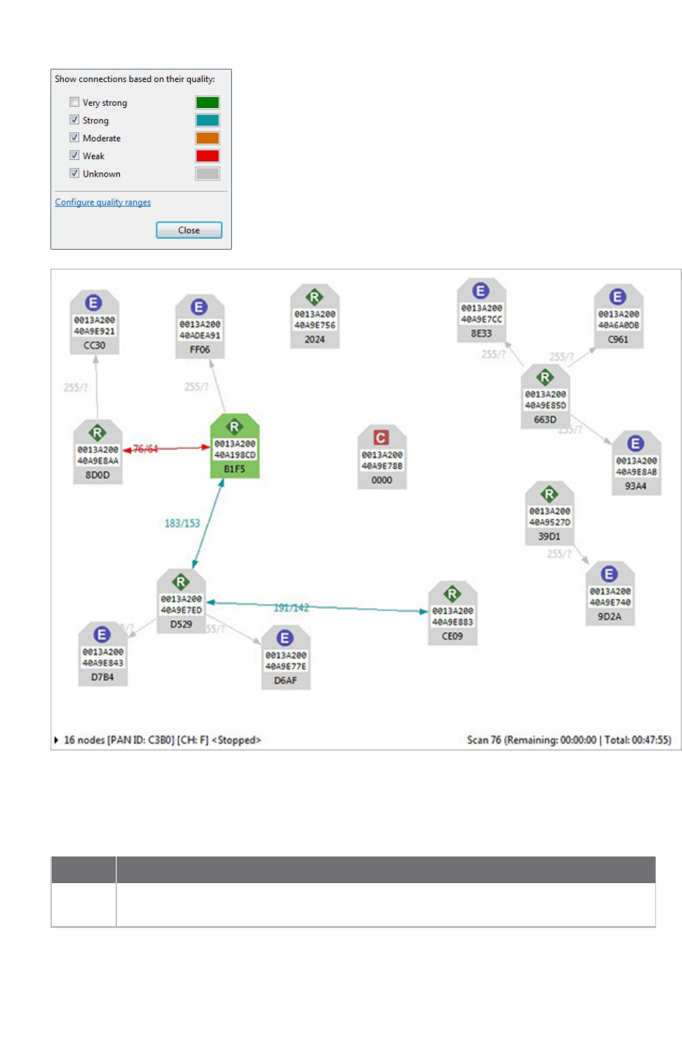
View your radio network Network working mode
XCTU User Guide 97
Connections in 802.15.4, DigiMesh, and ZigBee
When viewing 802.15.4, DigiMesh, and ZigBee modules in Graph view, consider the following
differences in node display:
Protocol Description and Node Display
802.15.4 XCTU does not display the quality of the connection between two nodes. The nodes
displayed are in the RF range of the local radio module.
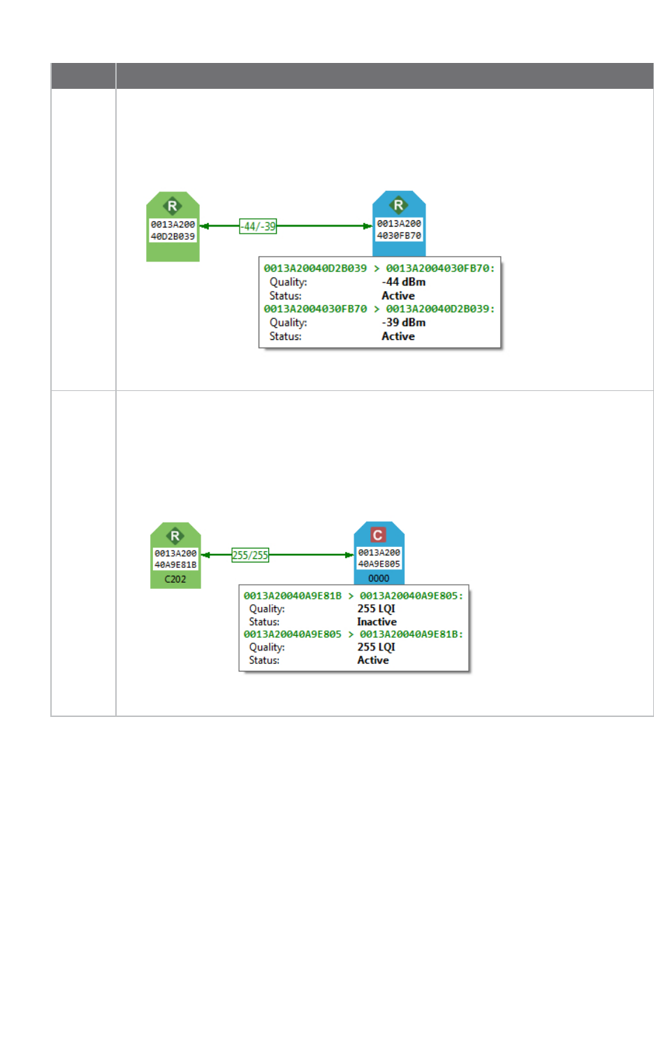
View your radio network Network working mode
XCTU User Guide 98
Protocol Description and Node Display
DigiMesh The quality of the connection between two nodes is displayed next to the line that
connects them. Hover over the line joining the nodes to see bidirectional quality (in dB)
and status of the connection, respectively.
ZigBee The quality of the connection between two nodes is displayed next to the line that
connects them. Hover over the line joining the nodes to see bidirectional quality and
status of the connection, respectively. Link quality is represented by Link Quality
Indication, or LQI, a number between 0 and 255 where 0 is the weakest and 255 is the
strongest.
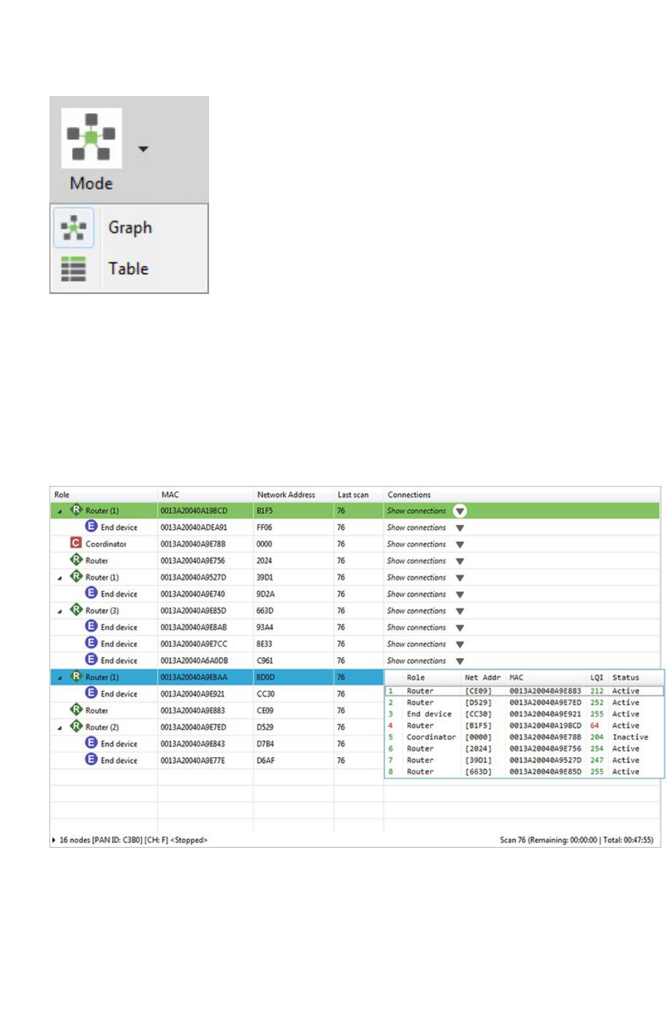
View your radio network Network working mode
XCTU User Guide 99
Table view
In Table view, network radio modules are displayed as rows in a table. ZigBee devices display end
devices as children of their coordinators or routers. Other protocols display all nodes at the same
level.
Nodes discovered in previous scans that have not been found in the current scan are delineated via
italicized grey text. Connections not yet discovered are also displayed with grey text. A green
background denotes the local radio module and a blue background denotes the selected module.
When a radio module leaves the network, some devices continue to store information about their
relationship. When you perform a new discovery, the module appears because of the preserved
information but the device is unreachable if you attempt to verify the connection. These modules are
shown in red.

View your radio network Network working mode
XCTU User Guide 100
Field Description
Role Coordinator, router, or end device
MAC 64-bit address of the module
Network
address
Network address (ZigBee) / Node identifier (other protocols)
Last scan Scan number when the device was last discovered
Connections Description of current module connections. Click Show connections to view a table
with additional information about the module's connections.
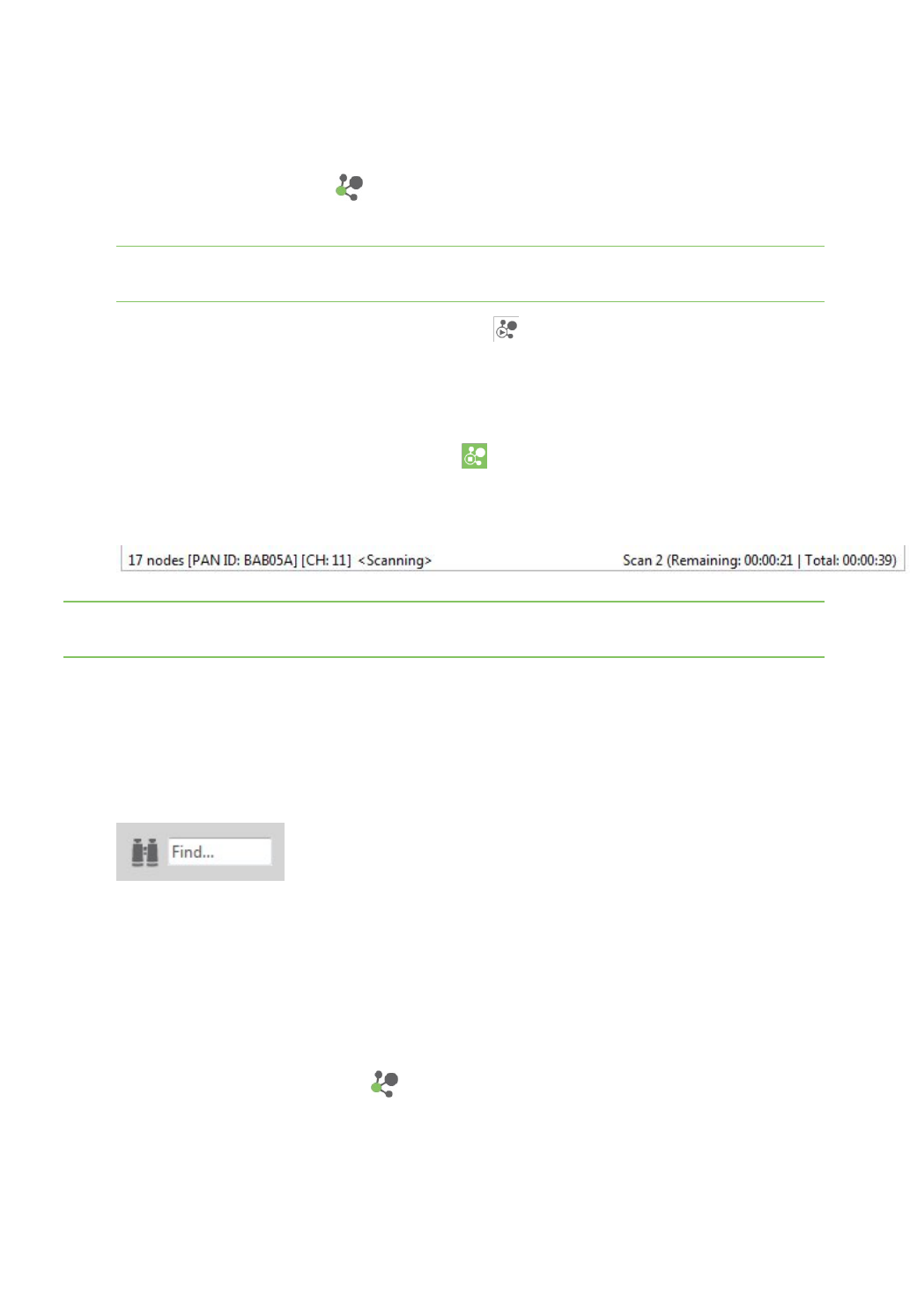
View your radio network Scan the network for available modules
XCTU User Guide 101
Scan the network for available modules
You can scan a radio module's network to find available modules. Note that the search may take some
time. To scan the network:
1. Switch to the Network mode .
2. Select a radio module running in API mode.
Note Modules in AT (transparent) operating mode do not support the network discovery
process.
3. Click the Scan the radio module network button to begin the network discovery process.
Radio modules are dynamically added to the working area as they are found, showing
connections and link quality.
4. The scan process automatically stops according to the network preferences configured in the
Network Preferences dialog. For details, see Set network discovery preferences. You can also
click the Stop scanning the network button at any time.
XCTU displays the network scan status along the bottom edge of the Network working mode
display. For a description of the status fields, see Network working mode.
Note You may need to perform multiple scans to discover the entire network if, for example, modules
are sleeping or the network is very large.
Search for network nodes
If a network scan is active, you can use search expressions to find particular nodes in the network:
1. In the search box, type in a search expression to search for particular nodes in the network.
For more information on available search prefixes and parameters, see Find radio modules.
2. The background color of the search box changes based on search status: yellow indicates
matches found, and red indicates no matches found.
Change network perspective
The Network working mode has two different view perspectives: graph view and table view. The
Network perspective button allows you to switch between them.
1. Switch to Network working mode .
2. Select a radio module running in APImode from the list.
3. Click the Network perspective button and select either Graph view or Table view.
For a description of each view, see Network working mode.
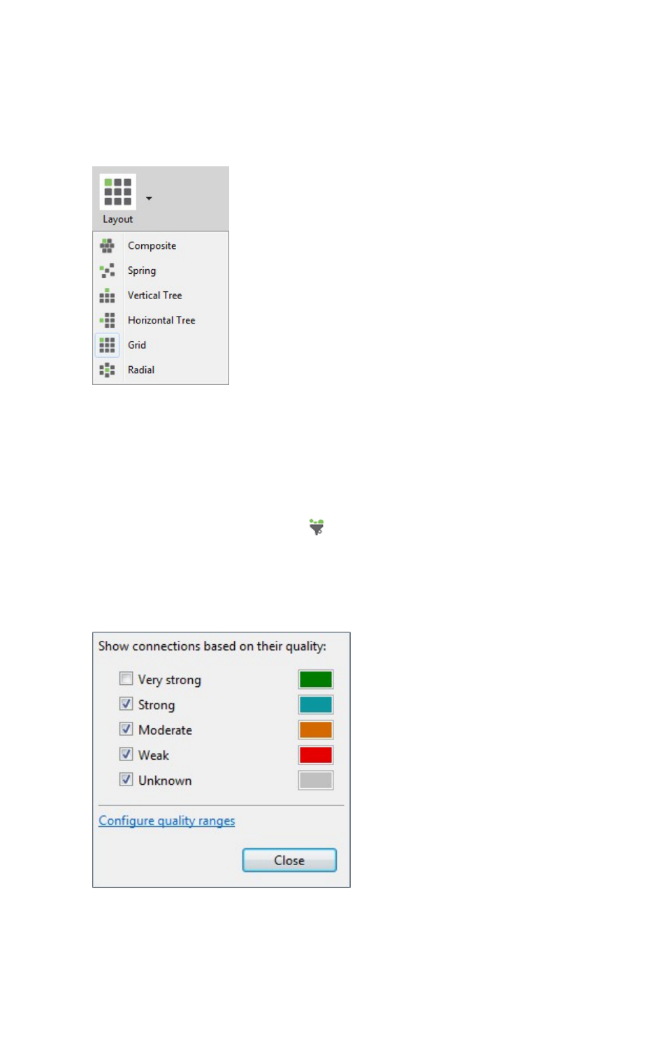
View your radio network Set network layout
XCTU User Guide 102
Set network layout
If a network scan is active, you can change the network layout:
1. Change the network perspective to Graph view. For details, see Change network perspective.
2. Click the Set layout drop-down menu.
3. Select one of the six layout options.
Filter network connections by quality
If a network scan is active, you can hide and show connections between RF modules depending on
their quality. All filters are enabled by default, so all connections are initially visible.
1. Click the Filter connections button . A dialog appears with all of the filters enabled.
2. Check or uncheck quality connection filters. Unchecking a box hides all connections associated
with that quality filter, and checking a box displays all connections associated with that quality
filter.
In this example, we unchecked the Very strong filter.
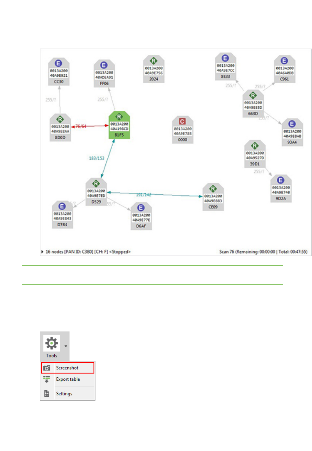
View your radio network Take a screenshot of the network
XCTU User Guide 103
3. Click Close. XCTU displays network connections based on the filters you selected.
In this example, we can see all of the connections except for those that are very strong.
Note Click Configure quality ranges to configure quality range values and display colors. You can
also access quality range configuration options from Tools > Settings on the Network view toolbar.
Take a screenshot of the network
If a network scan is active, you can save a Graph view or Table view screenshot.
1. Click the Options drop-down menu and select Screenshot. A Save file dialog appears.
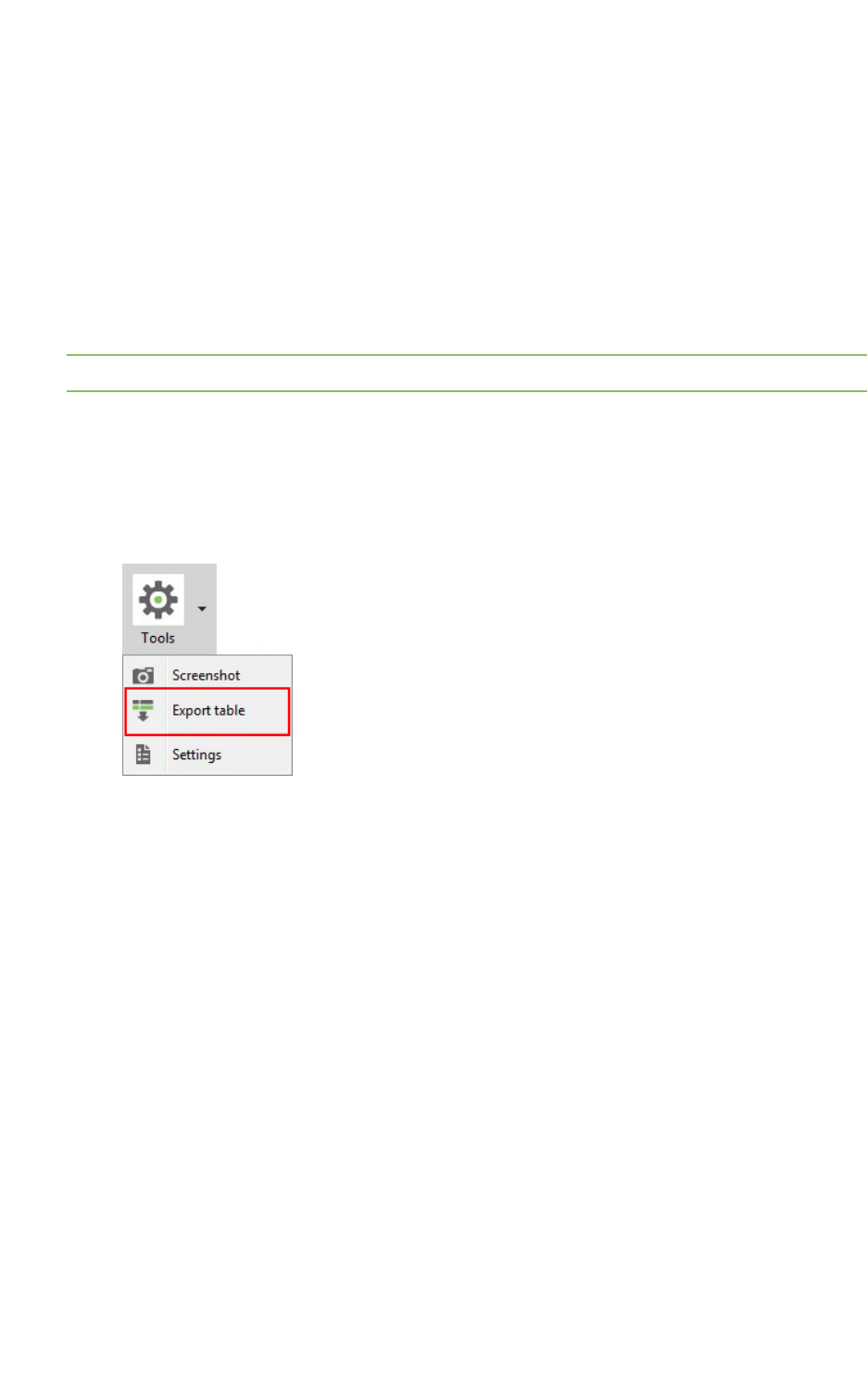
View your radio network Set zoom level in Graph view
XCTU User Guide 104
2. Specify the name and location of the image and click Save. A screenshot is saved to your
clipboard.
Set zoom level in Graph view
If a network scan is active, you can use the zoom control in Graph view to change the zoom level of
the view:
1. Change the network perspective to Graph view. For details, see Change network perspective.
2. In the Zoom level dialog, use the up/down arrows to change the zoom level or enter a
percentage between 10 and 400.
Note You can also zoom in and out by pressing the Control key while scrolling the mouse wheel.
Export a network table
If a network scan is active, you can save network information from either graph view in CSV (comma
separated value) file format. To export a network table when a network scan is active:
1. Click the Options drop-down menu and select Export table.
ASave file dialog appears.
2. Designate a filename and location and click Save.

Configure XCTU
This section describes how to configure several XCTU settings such as firmware updates, display
settings, and network connectivity. To open the Preferences dialog box, click the Preferences button
on the XCTU toolbar.
The preference categories are listed on the left side of the Preferences dialog box. You can configure
settings for the following categories:
Set general preferences 106
Set appearance preferences 106
Set automatic software update preferences 107
Set console preferences 109
Set firmware update preferences 110
Set network discovery preferences 111
Set network appearance preferences 114
Set radio firmware library preferences 116
Set MicroPython Terminal preferences 117
XCTU User Guide 105
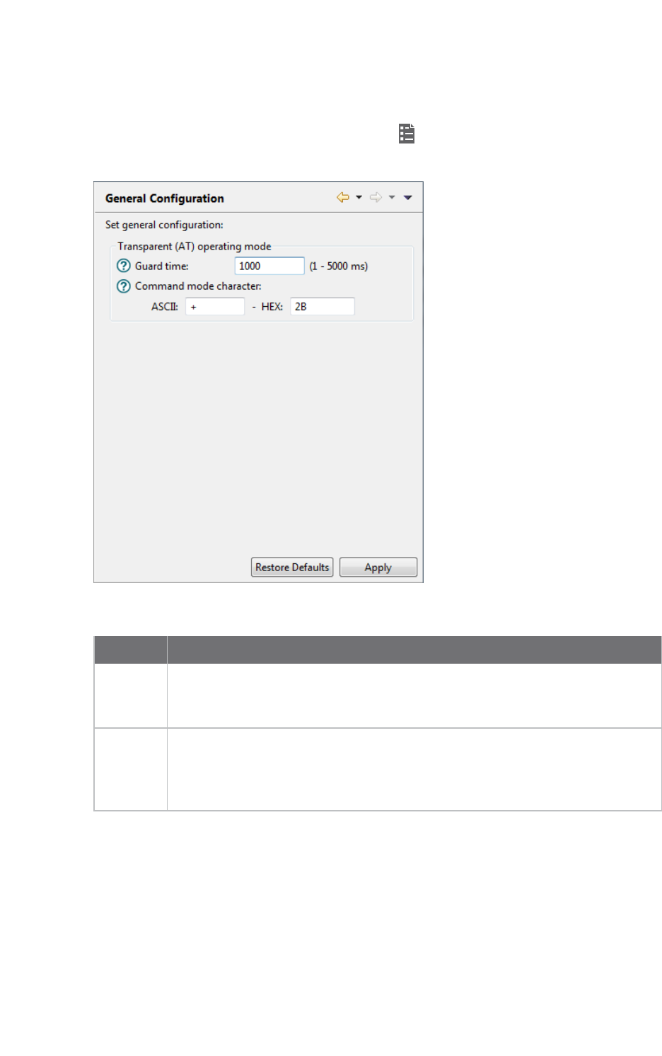
Configure XCTU Set general preferences
XCTU User Guide 106
Set general preferences
You can configure some general settings related with the transparent operating mode.
1. On the XCTU toolbar, click the Preferences button . The Preferences dialog appears.
2. On the left side of the Preferences dialog, select General Preferences.
3. Configure your preferred settings and click Apply.
Settings Description
Guard
time
Sets the period of silence XCTU waits before and after entering command mode
when the radio module operates in transparent (AT) mode. This value must
match the GT value of the radio modules.
Command
mode
character
Sets the character value to be used to enter command mode when the radio
module operates in transparent (AT) mode. The command mode character can
be specified either in ASCII or hexadecimal format. This value must match the CC
value of the radio modules.
Set appearance preferences
You can configure some graphic aspects of the tool and how some elements are displayed.
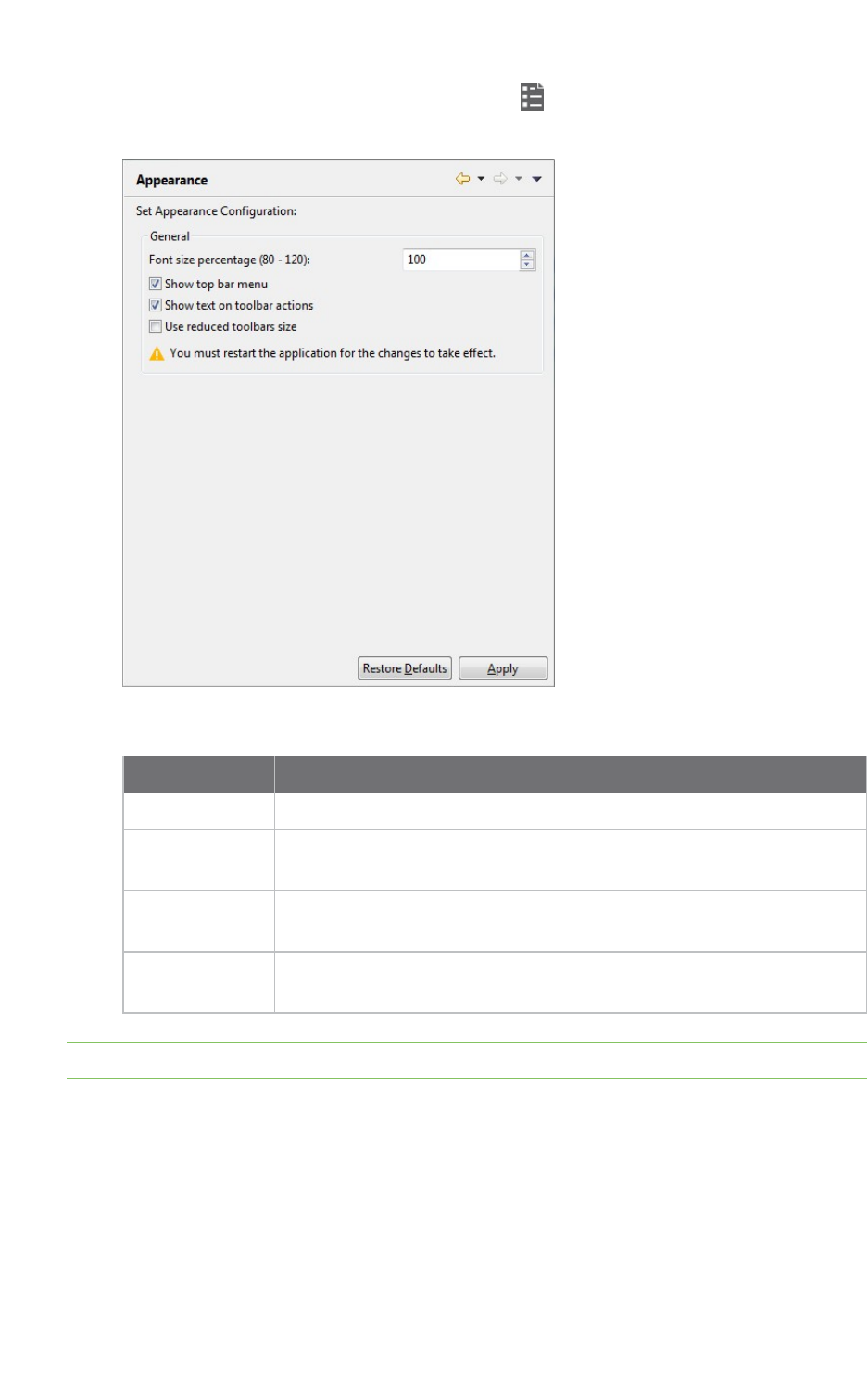
Configure XCTU Set automatic software update preferences
XCTU User Guide 107
1. On the XCTU toolbar, click the Preferences button . The Preferences dialog appears.
2. On the left side of the Preferences dialog, select Appearance.
3. Configure your preferred settings and click Apply.
Field Description
Font size Changes all the XCTU texts size in percentage, from 50 to 120%.
Show top bar
menu
Displays an application top bar menu with texts.
Show text on
toolbar actions
Displays the name of the action below each toolbar element for a better
understanding of the meaning of each action.
Use reduced
toolbars size
Changes the size of the application toolbars reducing them.
Note You must restart XCTUfor the changes to take effect.
Set automatic software update preferences
You can configure when and how new updates for XCTU are downloaded and installed.
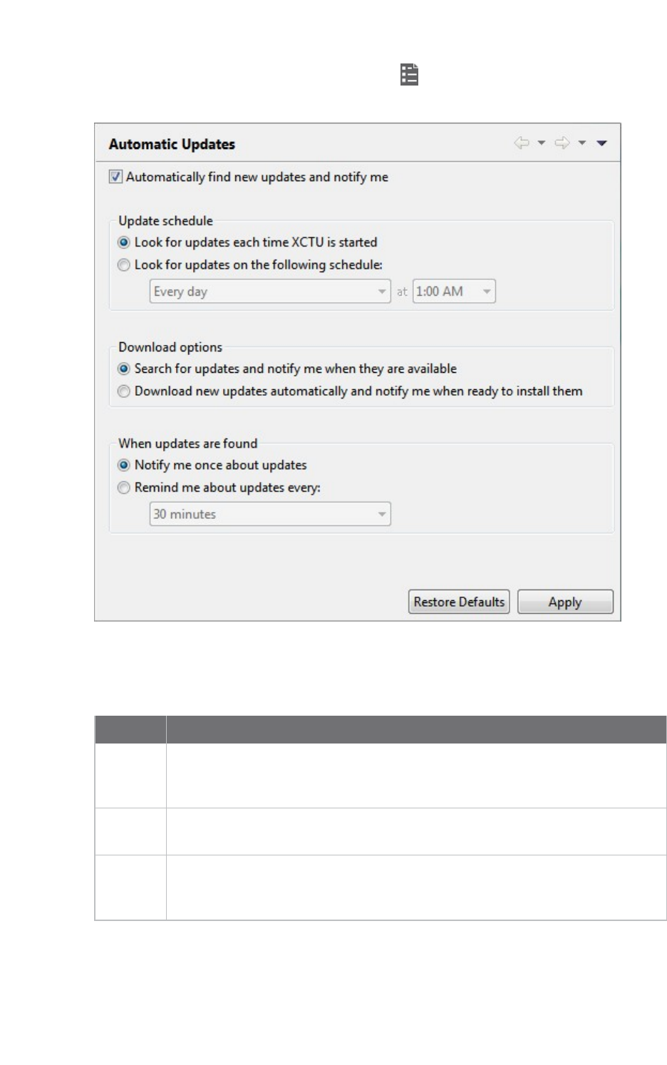
Configure XCTU Set automatic software update preferences
XCTU User Guide 108
1. On the XCTU toolbar, click the Preferences button . The configuration dialog appears.
2. On the left side of the configuration dialog, select Automatic Updates.
3. Check Automatically find new updates and notify me to enable the automatic updates
feature.
4. Configure your preferred settings and click Apply.
Field Description
Update
schedule
Sets a schedule to search for updates or to update when XCTU is started. If you
select Look for updates on the following schedule, you must also specify the
search interval and hour.
Download
options
Establishes when new updates should download and sets permissions for
whether updates are automatically downloaded.
When
updates
are found
Sets the frequency of update notification.
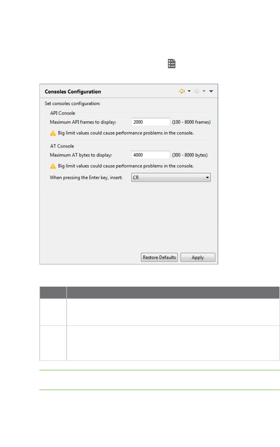
Configure XCTU Set console preferences
XCTU User Guide 109
Set console preferences
You can configure the number of frames to display in an APIconsole and/or the number of bytes to
display in an AT console.
1. On the XCTU toolbar, click the Preferences button to open the Preferences dialog.
2. On the left side of the Preferences dialog, select Consoles preferences.
3. Configure your preferred settings and click Apply.
Settings Description
API
console
Configures the maximum number of API frames that can be displayed in the
frames log during a session. When the maximum limit is reached, the session
starts overwriting frames.
AT
console
Configures the maximum number of bytes that can be displayed during a session.
When the maximum limit is reached, the session starts overwriting bytes. It also
establishes the default behavior when you press the ENTER key in the AT Console
to insert CR/LF, CR or LF characters.
Note If you set high values for maximum API frames and/or ATbytes, you may notice
performance issues in the consoles.
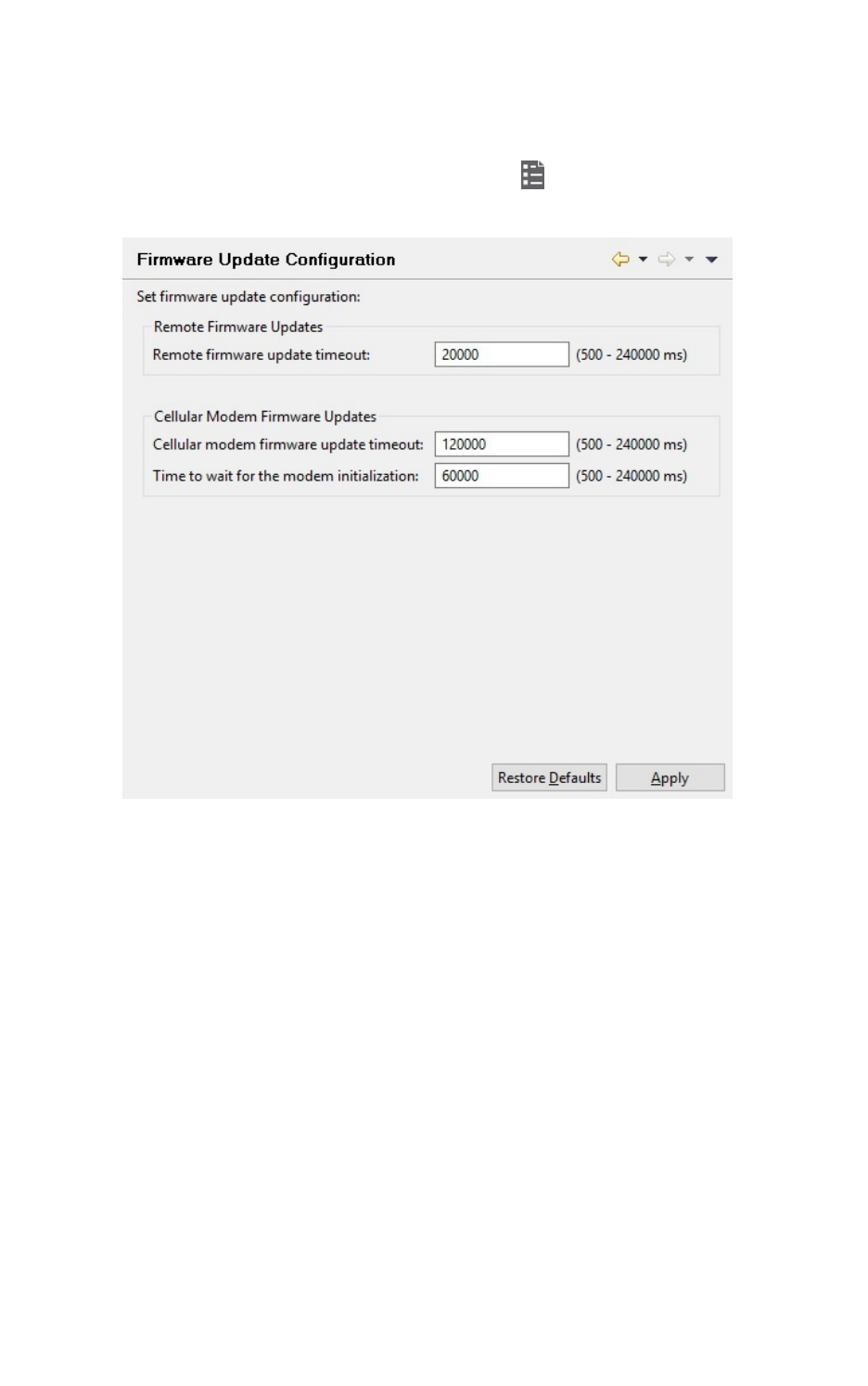
Configure XCTU Set firmware update preferences
XCTU User Guide 110
Set firmware update preferences
You can configure some preferences related to the firmware update process.
1. On the XCTU toolbar, click the Preferences button . to open the Preferences dialog.
2. On the left side of the Preferences dialog, select Firmware Update preferences.

Configure XCTU Set network discovery preferences
XCTU User Guide 111
3. Configure your preferred settings and click Apply.
Field Description
Remote
firmware
update
timeout
Configures the remote firmware update timeout in milliseconds. This is the
maximum time that XCTU waits for a response sent by the remote node during
the remote firmware update before determining if there was an error during
the process.
Cellular
modem
firmware
update
timeout
Configures the cellular modem firmware update timeout in milliseconds. This
is the maximum time that XCTU waits for a response sent by the modem of a
Cellular device during a local firmware update before determining if there was
an error during the process.
Time to
wait for the
modem
initialization
Configures the time to wait for the modem initialization in milliseconds. This is
the maximum time that XCTU waits for the Cellular modem initialization. If
this time expires and the modem version cannot be read, XCTU forces the
modem firmware update.
Set network discovery preferences
You can configure network discovery parameters in the Network preferences panel.
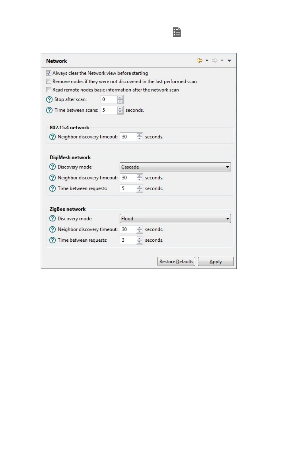
Configure XCTU Set network discovery preferences
XCTU User Guide 112
1. On the XCTU toolbar, click the Preferences button to open the Preferences dialog.
2. On the left side of the Preferences dialog, select Network.

Configure XCTU Set network discovery preferences
XCTU User Guide 113
3. Configure your preferred settings and click Apply.
The first set of options are common to all networks:
Settings Description
Always clear the Network
view before starting
Clears Network view before each new network scan.
Remove nodes if they
were not discovered in
the last performed scan
Removes any nodes not discovered in the last scan.
Read remote nodes basic
information after the
network scan
Reads the following information from the remote nodes after
each network scan: Node identifier, hardware version, firmware
version, network address and device type.
Stop after scan Sets the number of scans to perform before stopping the
discovery process. A value of '0' means the process will not stop
automatically.
Time between scans Sets the duration of time XCTU waits before starting a new
network scan. The value must be between 0 and 300 seconds.
The remainder of the options are specific to 802.15.4, DigiMesh, and ZigBee network types:
Settings Description
Discovery
mode
Sets the method used by the network discovery process.
nFlood: The neighbor discovery process is performed for every node at the
moment it is found. Several discovery processes may be running at the
same time. This method may be faster, but it may also generate a lot of
traffic and saturate the network.
nCascade: The neighbor discovery process is performed for every node as
soon as the discovery process finishes. Only one discovery process runs at
a time. This method may be slower, but it is likely to generate less traffic.
Neighbor
discovery
timeout
Sets the maximum duration, in seconds, the discovery process should spend
finding neighbors of a module. Value must be between 5 and 1800 seconds (30
minutes).
This timeout is highly dependent on the nature of the network. For DigiMesh, the
value should be greater than the highest NT (Node Discover Timeout) and include
enough time to let the message propagate, depending on the sleep cycle of your
devices.

Configure XCTU Set network appearance preferences
XCTU User Guide 114
Settings Description
Time
between
requests
Sets the wait time between node neighbor requests. The value must be between
0 and 300 seconds (5 minutes).
For the Cascade method, this is the number of seconds to wait after completion
of the neighbor discovery process of the previous node.
For the Flood method, this is the minimum time to wait between each radio
module's neighbor requests.
Note The Cascade discovery method is recommended for large networks.
Set network appearance preferences
The Network preferences has a sub-category named Appearance where you can customize the
appearance of node links in Network view.
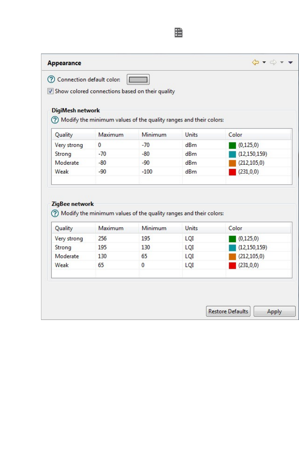
Configure XCTU Set network appearance preferences
XCTU User Guide 115
1. On the XCTU toolbar, click the Preferences button to open the Preferences dialog.
2. On the left side of the Preferences dialog, select Network and then select Appearance.

Configure XCTU Set radio firmware library preferences
XCTU User Guide 116
3. Configure your preferred settings and click Apply.
Settings Description
Connection
default color
Defines the default color of the node's connection lines.
Show colored
connections
based on their
quality
Enables or disables the coloring of node connection lines based on their
link quality.
DigiMesh / ZigBee
network
Enables you to modify the maximum and minimum values and RGB
colors for each quality range. Click in the cell, type the value, and click
Enter to change a value.
Ranges include minimum values but not maximum values. When you
change the minimum value of a quality range, the maximum value of the
next range adopts a corresponding value.
Set radio firmware library preferences
You can configure XCTU to look for new radio firmware at startup.
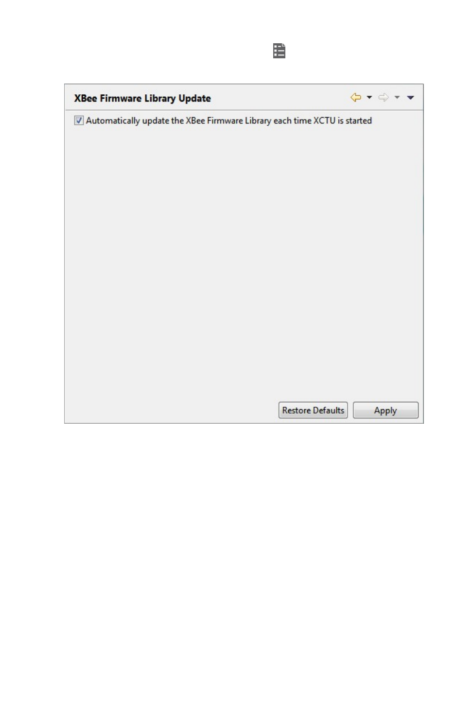
Configure XCTU Set MicroPython Terminal preferences
XCTU User Guide 117
1. On the XCTU toolbar, click the Preferences button . The Preferences dialog appears.
2. On the left side of the Preferences dialog, select Radio Firmware Library Update.
3. Check Automatically update the Radio Firmware Library each time XCTU is started. If you
do not select this option, you can only check for firmware updates manually.
4. Click Apply.
For more information, see Update radio firmware library.
Set MicroPython Terminal preferences
You can configure some terminal related preferences of the MicroPython terminal tool.
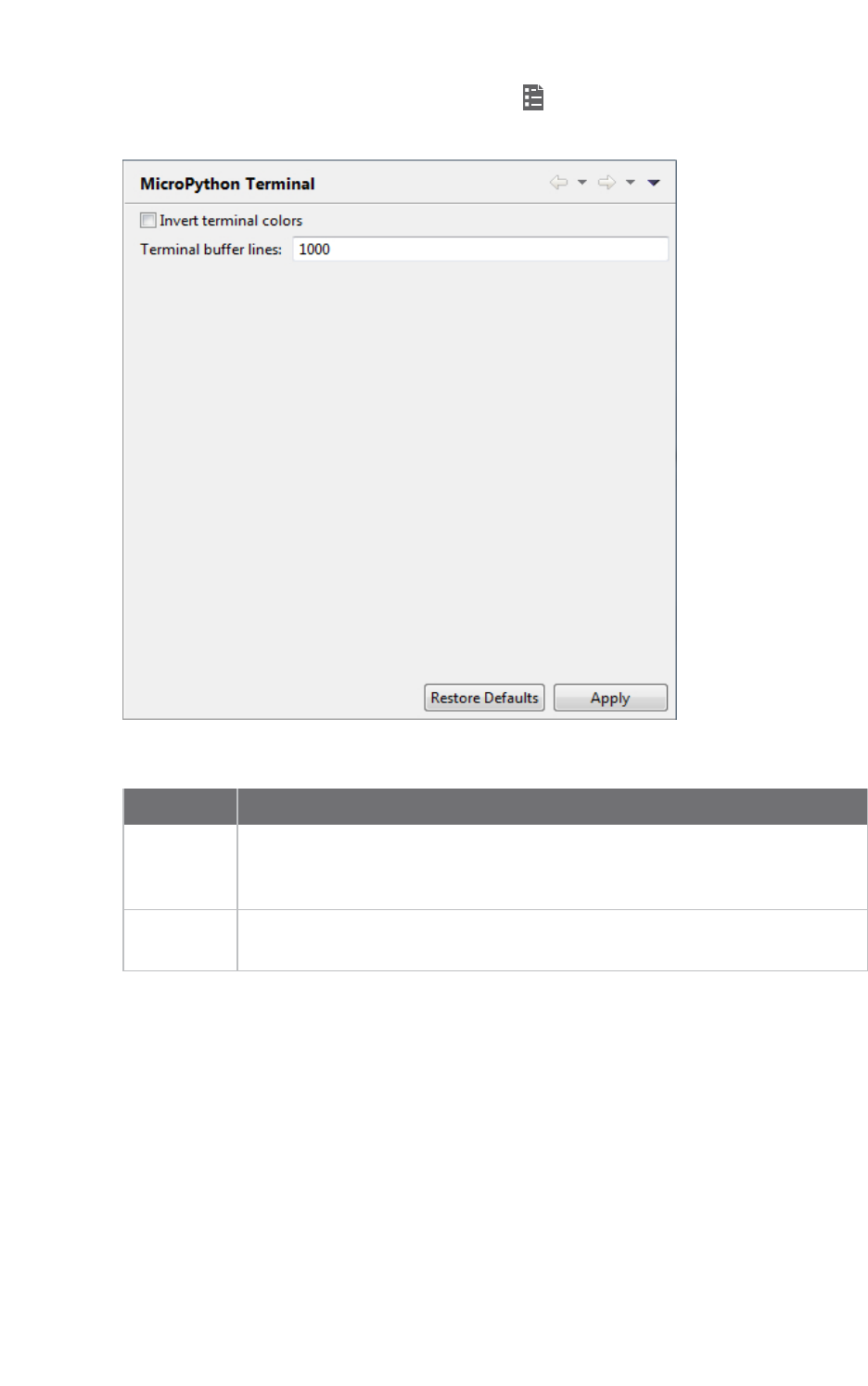
Configure XCTU Set MicroPython Terminal preferences
XCTU User Guide 118
1. On the XCTU toolbar, click the Preferences button . The Preferences dialog appears.
2. On the left side of the Preferences dialog, select MicroPython Terminal.
3. Configure your preferred settings and click Apply.
Field Description
Invert
terminal
colors
Inverts the colors of the terminal. By default, this sets the background from
white to black and the font color from black to white.
Terminal
buffer lines
Sets the maximum number of lines that are displayed in the terminal.

Update software
XCTU allows you to automatically update the radio firmware library and the XCTU application itself
without downloading any extra files. These processes can be configured to execute automatically, but
you can also execute them manually at any time. For more information about configuring automatic
XCTU and radio firmware library updates, see Configure XCTU.
Update radio firmware library 120
Install legacy radio firmware 121
Install XCTU updates 122
Open change log 123
XCTU User Guide 119
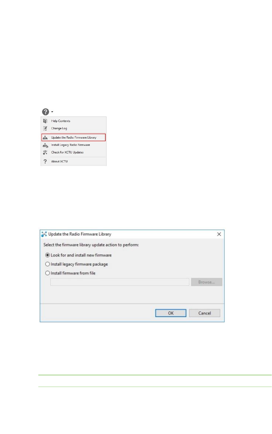
Update software Update radio firmware library
XCTU User Guide 120
Update radio firmware library
Digi periodically releases new versions of the radio firmware to fix issues, improve functionality, or add
new features. These firmware files might not be included with XCTU and need to be added to the
radio firmware library. Also, new RF products may be launched in the market that require new radio
firmware to be configured with XCTU. For this reason, XCTU can update the radio firmware library
from the application itself.
You can configure XCTU so the firmware is automatically updated. For more information, see XCTU
preferences. To manually update the radio firmware library:
1. Select Help >Update Radio Firmware Library option.
2. Do one of the following:
nTo look for new radio firmware inside Digi's update site, select Look for and install
new firmware.
nTo install legacy radio firmware, select Install legacy firmware package.
nTo install a local radio firmware file, select Install firmware from file and specify the
path where the file is located.
3. Click OK to start. A dialog displays the status of the download process.
4. You can click the Run in background button of the progress dialog to execute this process in
the background. This allows you to keep working with XCTU while the new firmware is
downloaded. The status bar displays the update process.
When the process finishes, a dialog displays the list of downloaded firmware.
Note Downloading the firmware does not automatically update attached modules.
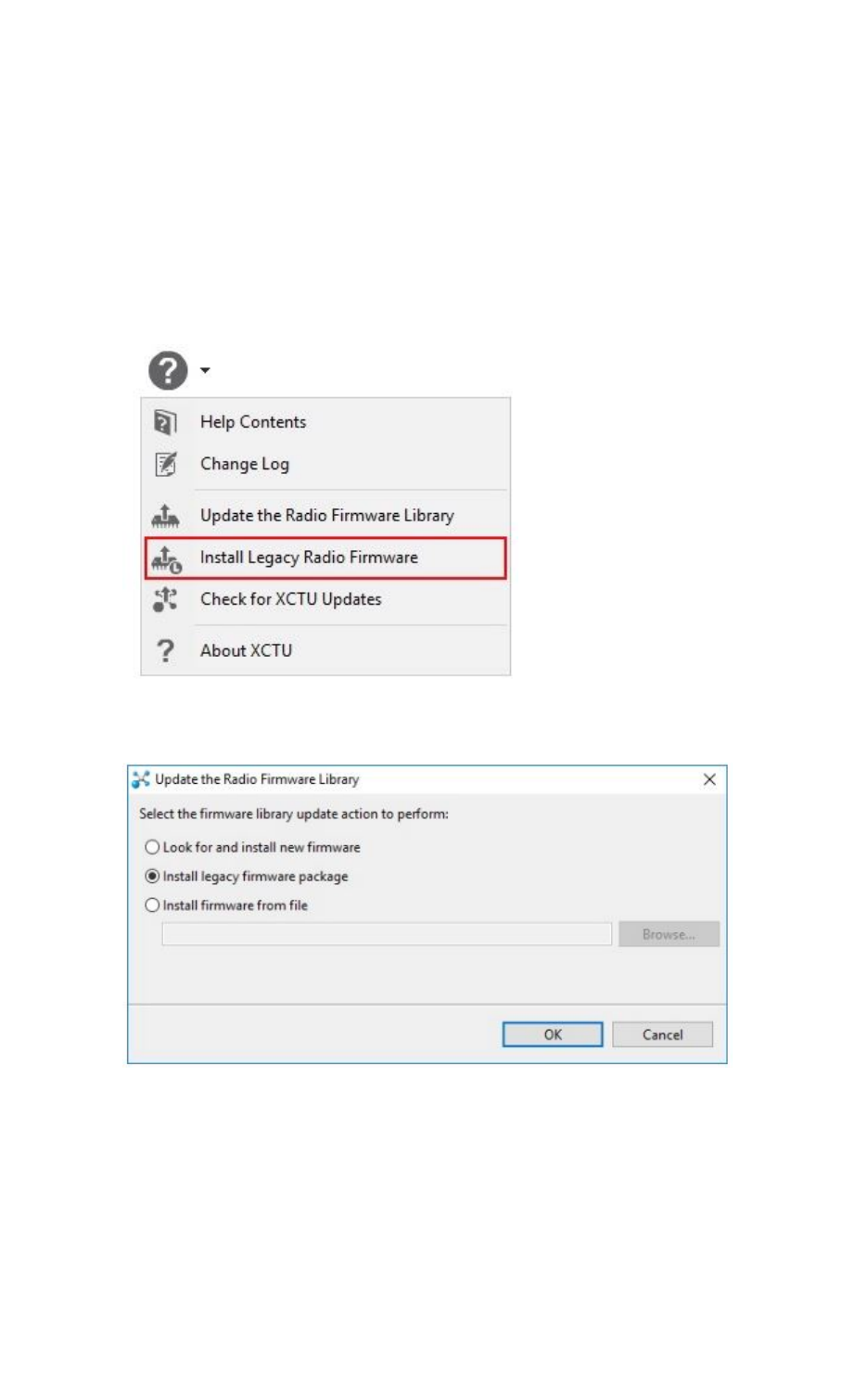
Update software Install legacy radio firmware
XCTU User Guide 121
Install legacy radio firmware
The latest versions of XCTU provide only the latest firmware versions of the currently supported
products and families. In the past, the current version of XCTU installed all of the existing radio
firmware versions.
However, if you have a legacy product or an old firmware version that cannot be found in XCTU, you
can install the legacy radio firmware package.
To install the legacy radio firmware package:
1. Select Help >Install Legacy Radio Firmware option. The Update the Radio Firmware
Library dialog appears.
2. In the Update the Radio Firmware Library dialog, select the Install legacy firmware
package option. This option should be selected by default.
3. Click OK to start. A dialog displays the status of the download process.
4. Click the Run in background button in the progress dialog to run the download process in the
background. This allows you to keep working with XCTU while the legacy firmware is
downloaded. The status bar displays the update process.
When the process finishes, a dialog displays the list of installed firmware.
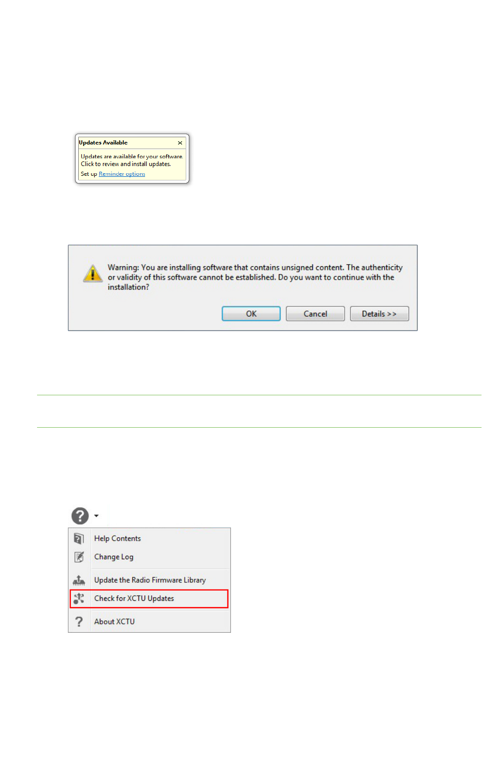
Update software Install XCTU updates
XCTU User Guide 122
Install XCTU updates
When you start XCTU, you may be notified about software updates. You should always run the latest
version of XCTU.
1. When a new version is available, a pop-up window appears in the bottom-right corner of XCTU.
2. Click anywhere in that window and follow the prompts to proceed with the update.
3. During installation, you may be asked if you want to proceed with installing unsigned software.
Click OK to continue.
4. When the installation process is finished, you must reset XCTU so new changes can be applied.
When prompted, click Yes to restart XCTU.
Note You can click the Run in background button of the progress dialog to execute this process in
the background. The status bar displays the update process.
5. Once restarted, XCTUdisplays a change log. You can manually open the change log at any time
by clicking Help >Change Log.
6. You can also check for updates and manually update the tool by clicking Help >Check for
XCTU Updates.
If an update for the application is found, a dialog box displays the update. Click Finish to
start the update process.
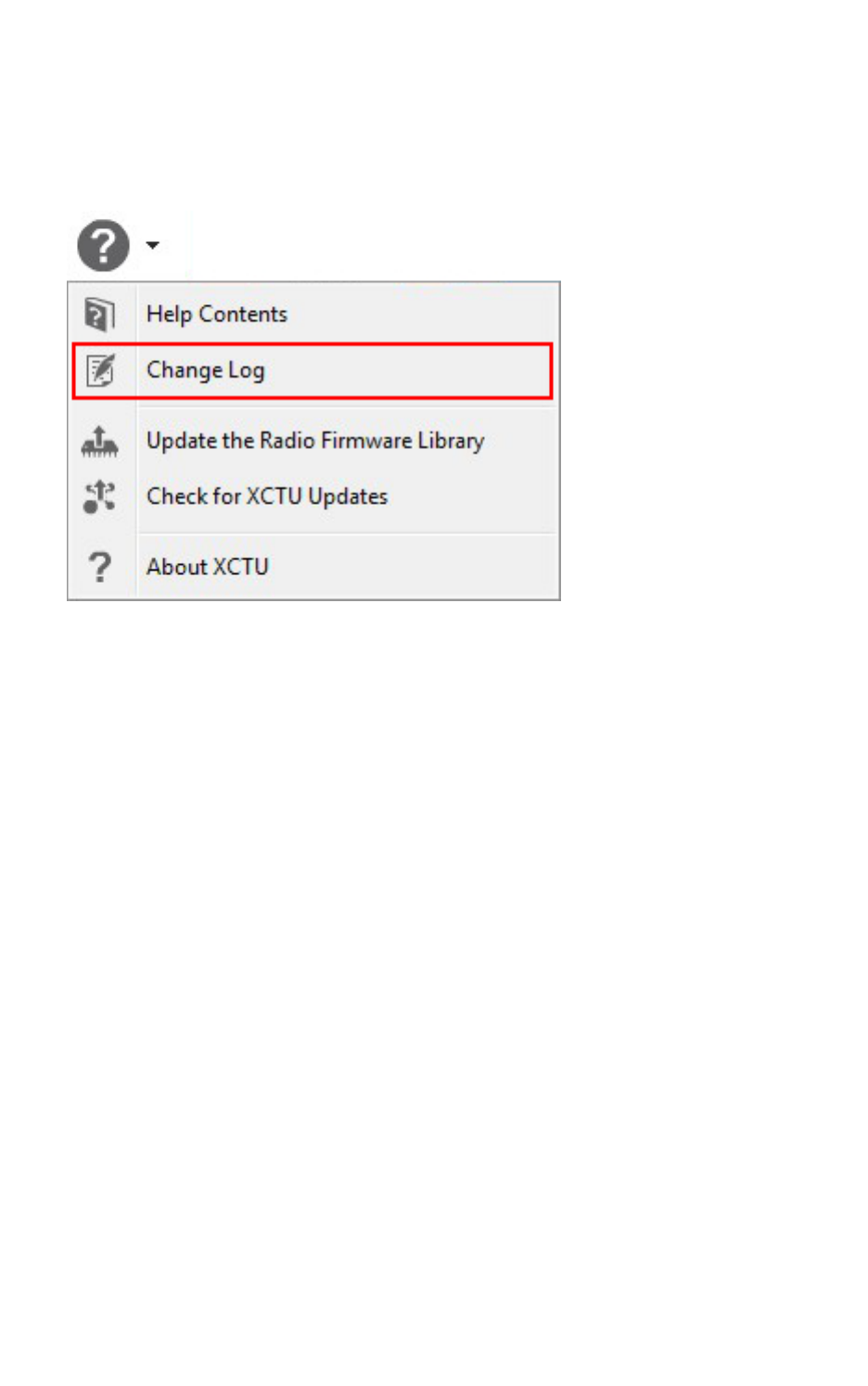
Update software Open change log
XCTU User Guide 123
Open change log
XCTU includes a change log with historical changes and additions between versions. You can view the
change log at any time. To open the change log:
Select Help >Change Log.
A new dialog opens listing all the XCTU versions with their corresponding dates and changes.


Use the XCTU command line Understanding the XCTU command line interface
XCTU User Guide 125
Understanding the XCTU command line interface
The XCTU Command-Line Interface (CLI) enables you to manage and automate certain tasks without
launching the graphic user interface.
The CLI uses a multipart structure on the command line:
XCTUcmd <command> <required parameters> [optional parameters]
The first portion of the syntax is the base call to XCTUcmd executable. The location of this file depends
on your operating system:
OS File location
Windows <installation_directory>/XCTUcmd.exe
MacOS X <installation_directory>/XCTU.app/Contents/MacOS/XCTUcmd
Linux <installation_directory>/XCTUcmd
The next part specifies a top-level command, which often represents an XCTU management action
supported in the CLI. You can specify additional parameters or options for each command in any order
on the command line. If an exclusive parameter is specified multiple times, then only the last value
applies.
List all commands
You can run XCTUcmd by itself to display a list of all available commands. This is the complete list:
nupdate_firmware updates the firmware of the specified device.
nload_profile loads a profile to the specified device.
nlist_ports lists all the available serial and USB ports on your computer.
Program arguments
You can also run XCTUcmd with specific program arguments to display information about the tool:
Display the tool usage information
XCTUcmd --help
Display the tool version
XCTUcmd --version
Print the tool error codes table
XCTUcmd --errorlist
List ports via command line
The list_ports command allows you to list all available serial and USB ports on your computer. To list
the ports on your computer using the XCTUCLI:

Use the XCTU command line Load profile via command line
XCTU User Guide 126
1. Enter the following command syntax.
XCTUcmd list_ports
The location of the base call to XCTUcmd executable depends on your operating system:
nWindows:<installation_directory>/XCTUcmd.exe
nMacOS X: <installation_directory>/XCTU.app/Contents/MacOS/XCTUcmd
nLinux: <installation_directory>/XCTUcmd
2. If the command is executed successfully, the command line prompt returns an error code 0. A
return code different than 0 is represented by the error ID. Enter the following command for a
list of possible errors:
XCTUcmd --errorlist
Options
Some commands have multiple options. There are no options for the list_ports command.
Load profile via command line
The load_profile command allows you to load a previously saved profile to the specified device. To
load a profile using the XCTUCLI:
1. Enter the following command syntax. Both -f <file> and -p <port> are required parameters. The
rest are optional. The file option must point to an existing XPRO profile. These files are
generated from the XCTU graphic application and can be stored anywhere in your computer.
XCTUcmd load_profile -f <file> -p <port> [-b <baud_rate>] [-e] [-o] [-h] [-
F] [-R] [-P] [-v]
The location of the base call to XCTUcmd executable depends on your operating system:
nWindows:<installation_directory>/XCTUcmd.exe
nMacOS X: <installation_directory>/XCTU.app/Contents/MacOS/XCTUcmd
nLinux: <installation_directory>/XCTUcmd
2. If the command is executed successfully, the command line prompt returns an error code 0. A
return code different than 0 is represented by the error ID. Enter the following command for a
list of possible errors:
XCTUcmd --errorlist
Note Legacy XCTU *.PRO profile files are not supported by this command. If you have a legacy *.pro
file, you must first load the profile in the XCTU graphic application and save it in the new XPRO format.
Options
Usethe following options with the load_profile command:

Use the XCTU command line Update firmware via command line
XCTU User Guide 127
-f <file> Required * Specify the profile file location path.
-p <port> Required Specify the serial port name to be used.
-b <baud_rate> Optional Specify serial connection baud rate to use. [Default 9600]
-e Optional Set parity to even for the serial connection. [Default NONE]
-o Optional Set parity to odd for the serial connection. [Default NONE]
-h Optional Set hardware flow control for the serial connection. [Default
NONE]
-F Optional Force firmware update if profile firmware does not match
with firmware of device.
-R Optional ** Force a device recovery if device cannot be discovered.
-P Optional ** Indicate that the device is a programmable radio. These
radios have a baud rate of 115200 by default.
-v Optional Show details about the process being executed.
* File paths containing blank spaces must be quoted.
** These options may trigger an action request event where users will be asked to reset the device.
Examples
For additional guidance, see the following usage examples for the load_profile command:
Load profile ZB1_profile to the device connected to COM7 at 115200 bps, updating the firmware if
required and displaying process details
XCTUcmd load_profile -f "C:\profiles\ZB1_profile.xpro" -p COM7 -b 115200 -F -v
Load profile ZB2_profile to the programmable device connected to COM1 using parity even and
displaying process details
XCTUcmd load_profile -f "C:\profiles\ZB2_profile.xpro" -p COM1 -e -P -v
Load profile ZB3_profile to the device connected to COM4 and perform a device recovery if required
XCTUcmd load_profile -f "C:\profiles\ZB3_profile.xpro" -p COM4 -R
Update firmware via command line
The update_firmware command allows you to update the firmware of the specified device. To update
firmware using the XCTUCLI:
1. Enter the following command syntax. Both -f <file> and -p <port> are required parameters. The
rest are optional. The file option must point to an existing firmware description XML file. These
files are stored within the XCTU installation path under a folder named radio_firmwares,
sorted by protocols or hardware models.
XCTUcmd update_firmware -f <file> -p <port> [-b <baud_rate>] [-e] [-o] [-h]
[-R] [-P] [-v]

Use the XCTU command line Update firmware via command line
XCTU User Guide 128
The location of the base call to XCTUcmd executable depends on your operating system:
nWindows:<installation_directory>/XCTUcmd.exe
nMacOS X: <installation_directory>/XCTU.app/Contents/MacOS/XCTUcmd
nLinux: <installation_directory>/XCTUcmd
2. If the command is executed successfully, the command line prompt returns an error code 0. A
return code different than 0 is represented by the error ID. Enter the following command for a
list of possible errors:
XCTUcmd --errorlist
Set options
Usethe following options with the update_firmware command:
Option Required/optional Action
-f <file> Required * Specify the firmware file location path.
-p <port> Required Specify the serial port name to be used.
-b <baud_rate> Optional Specify serial connection baud rate to use. [Default 9600]
-e Optional Set parity to even for the serial connection. [Default
NONE]
-o Optional Set parity to odd for the serial connection. [Default NONE]
-h Optional Set hardware flow control for the serial connection.
[Default NONE]
-R Optional ** Force a device recovery if device cannot be discovered.
-P Optional ** Indicate that the device is a programmable radio. These
radios have a baud rate of 115200 by default.
-v Optional Show details about the process being executed.
* File paths containing blank spaces must be quoted.
** These options may trigger an action request event where users will be asked to reset the device.
Examples
For additional guidance, see the following usage examples for the update_firmware command:
Flash XBP24-ZB_23A7_S2B firmware to the device connected to COM7 at 115200 bps and display
process details:
XCTUcmd update_firmware -f "C:\Program Files (x86)\Digi\XCTU-NG\radio_
firmwares\xbee_zb\XBP24-ZB_23A7_S2B.xml" -p COM7 -b 115200 -v
Flash XBP24-ZB_23A7_S2B firmware to the programmable device connected to COM1 using HW flow
control and display process details:

Use the XCTU command line Update firmware via command line
XCTU User Guide 129
XCTUcmd update_firmware -f "C:\Program Files (x86)\Digi\XCTU-NG\radio_
firmwares\xbee_zb\XBP24-ZB_23A7_S2B.xml" -p COM1 -h -P -v
Flash XBP24-ZB_23A7_S2B firmware to the device connected to COM4 and perform a recovery if
required:
XCTUcmd update_firmware -f "C:\Program Files (x86)\Digi\XCTU-NG\radio_
firmwares\xbee_zb\XBP24-ZB_23A7_S2B.xml" -p COM4 -R
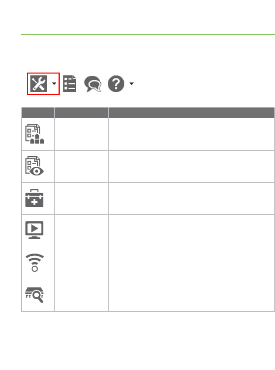
XCTU tools
XCTU includes a set of embedded tools that you can execute at any time, regardless of the active
working mode.
Access the following XCTU tools from the Tools drop-down menu of the main toolbar:
Icon Tool Description
Frames generator
tool
Generate an API frame.
Frames interpreter
tool
Decode any API frame and get the value of any field.
XBee recovery tool Recover a radio module that is out of communication.
Load console
session tool
Load and navigate previously saved console sessions.
Range test tool Perform a range test between two radio modules in your
network.
Firmware explorer
tool
Navigate and investigate any XCTU-hosted radio firmware.
XCTU User Guide 130
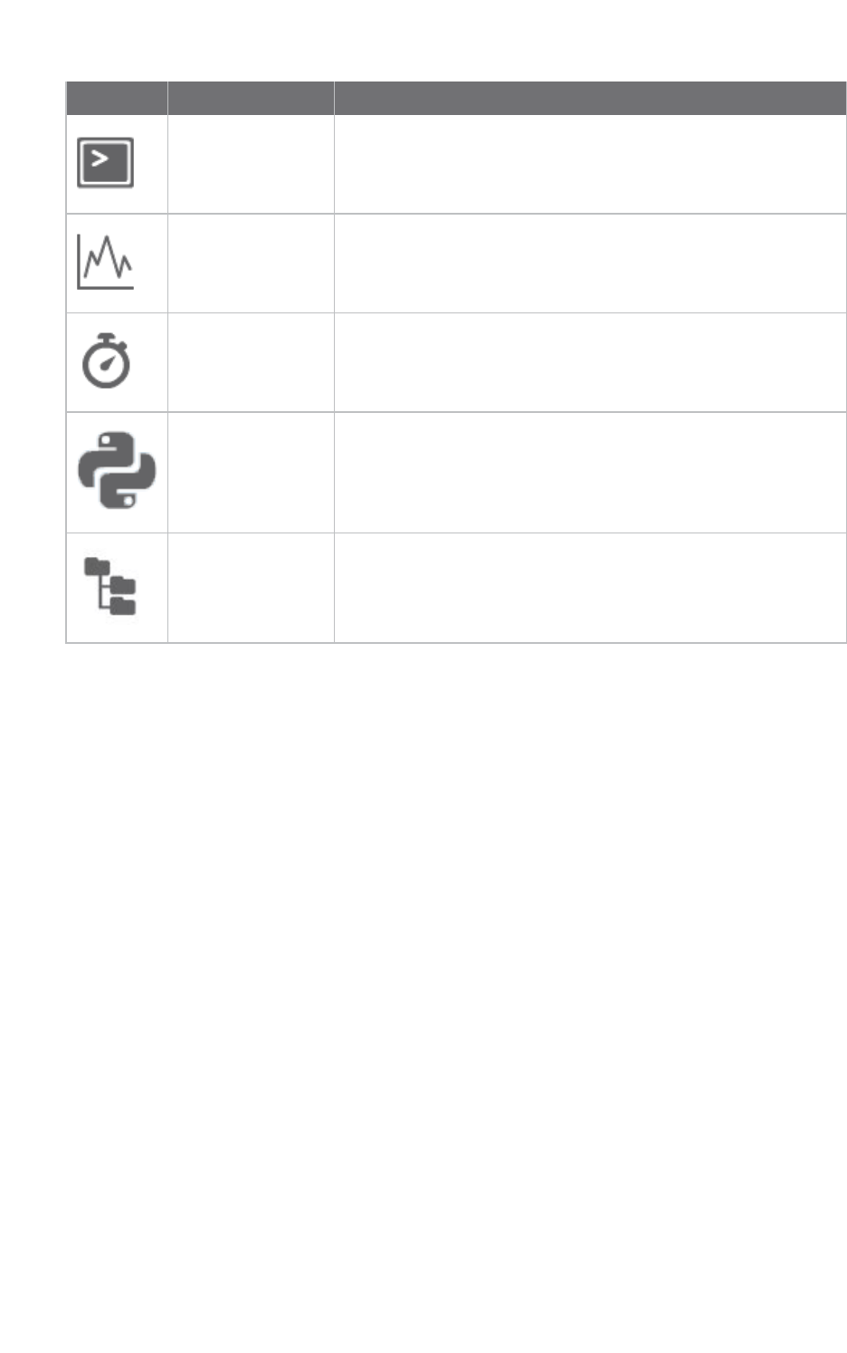
XCTU tools Frames generator tool
XCTU User Guide 131
Icon Tool Description
Serial console tool Open a serial communication with a radio module without
adding it to your device list.
Spectrum analyzer
tool
Test and measure the spectrum of a radio band.
Throughput tool Measure the transfer ratio between two radio modules in the
same network.
MicroPython
Terminal tool
Communicate with the XBee Cellular Modem when it is in
MicroPython mode.
File system manger
tool
Access and interact with the file system of your XBee module.
Frames generator tool
The Frames generator tool generates any type of API frame (output or input), automatically
generating the byte array from a series of inputs in the tool. You do not have to add a radio module to
your device list to use the Frames generator tool. Frame parameters are dependent on the protocol,
mode, and frame type you choose from the drop-down boxes. For more information, see API frames.
To open the Frames generator tool, select Frames generator from the Tools drop-down menu on the
main XCTU toolbar.
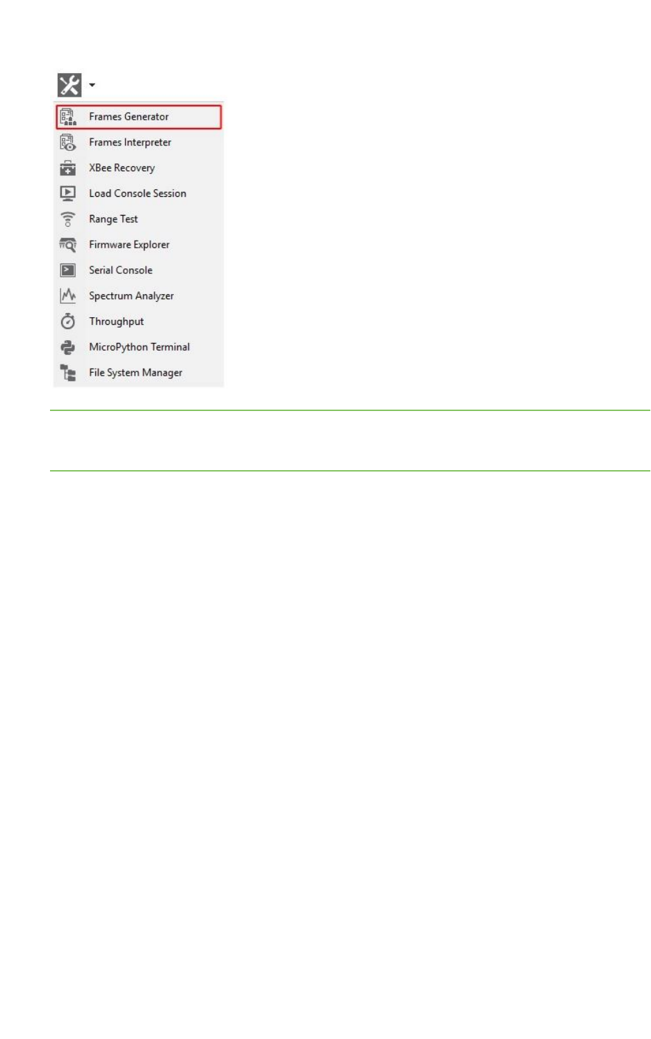
XCTU tools Frames generator tool
XCTU User Guide 132
Note You can also access the Frames generator tool from the API console when you add a new API
frame to the list of frames to send. Use the OK button to automatically copy the generated byte array
to the content of the frame to be added.
XBee APIFrame generator dialog
Use the Frame generator dialog to generate an APIframe. For instructions, see Generate an API
frame.
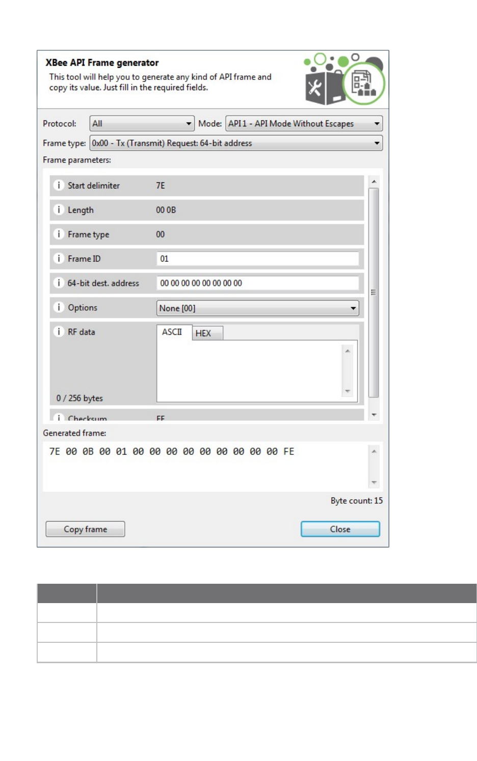
XCTU tools Frames generator tool
XCTU User Guide 133
The following table provides descriptions of the fields in the XBee APIFrame generator dialog.
Field Description
Protocol Radio protocol of the frame to be generated. Select All to display all frame types.
Mode API mode (API or API escaped) of the frame to be generated.
Frame type API frame type of the frame to be generated.
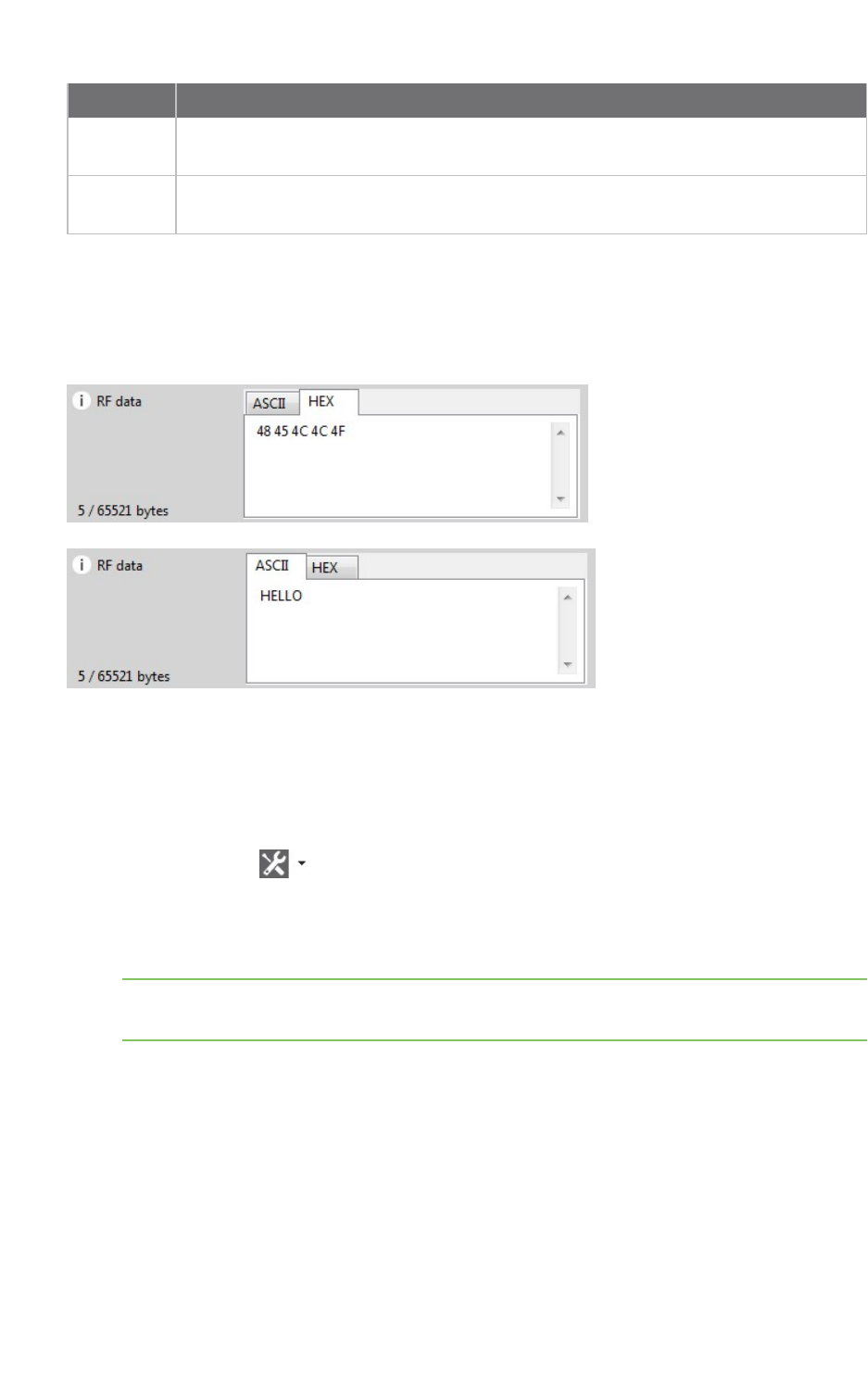
XCTU tools Frames generator tool
XCTU User Guide 134
Field Description
Frame
parameters
Options are dependent upon the selected API frame. Hover over the information icon
next to each setting to view a short description of the setting and its parameters.
Generated
frame
Byte array result of API frame generation. You can select and copy the text or use the
Copy frame button.
ASCII/HEX conversion
Settings with text boxes have a tab control with two tabs, HEX and ASCII, that allow you to fill the
setting with ASCII or HEX values. If you enter a value in HEX, the same value is represented in the
ASCII tab, and vice versa.
Generate an API frame
Follow these instructions to generate an API frame (output or input). For more information, see the
Frames generator tool.
1. Launch the XBee API Frame generator tool by selecting Frames generator from the Tools
drop-down menu on the main toolbar. The XBee APIFrame generator dialog appears.
2. For Protocol, select a radio protocol to display its corresponding API frames. If you select All,
all the frame types are displayed.
3. For Mode, select the API mode (API or API Escaped) of the frame to generate.
Tip To learn more about these modes, see API operating mode and API escaped operating
mode.
4. For Frame type, select the API frame type you want to generate.
The selected frame's settings appear in the Frame parameters area. In this example, we
selected the ZigBee protocol and the ZigBee Transmit Request API frame type.
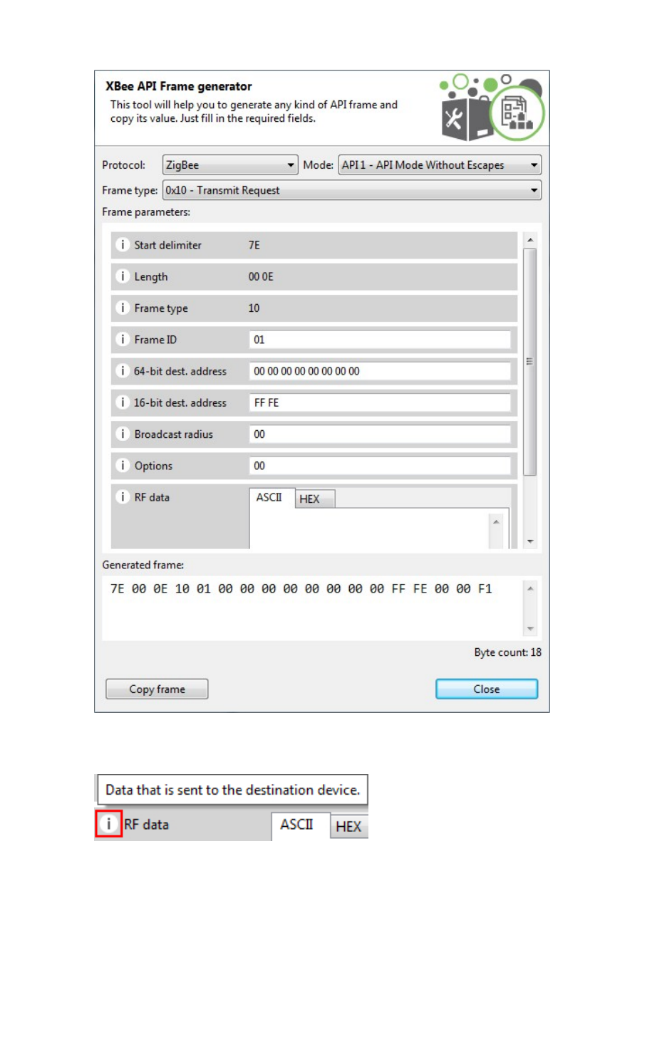
XCTU tools Frames generator tool
XCTU User Guide 135
5. Hover over a setting's information icon to see a short description of the setting and its
parameters.
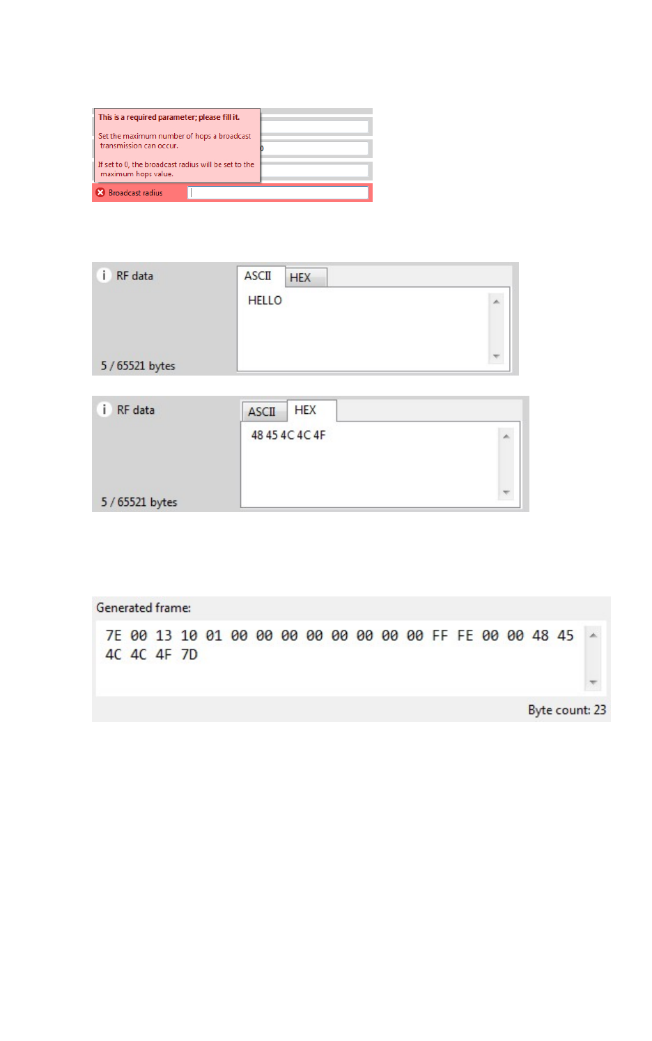
XCTU tools Frames interpreter tool
XCTU User Guide 136
6. If any setting is not configured correctly, its background color changes to red and the
information icon is replaced by a red cross. Hover over the icon to display the error message.
7. For RFdata, you can enter a value in ASCII or HEX. If you enter a value in HEX, the same value
is represented in the ASCII tab, and vice versa.
8. After you fill in all of the settings correctly, the frame is generated automatically and the byte
array of the frame is displayed in the Generated frame box. You can copy it from here or click
the Copy frame button.
Frames interpreter tool
The Frames interpreter tool decodes the byte array of an API frame and displays it in a set of fields
with corresponding values. The number of frame fields depends on the API frame type.
To open the Frames interpreter tool, select Frames interpreter from the Tools drop-down menu on
the main XCTU toolbar.
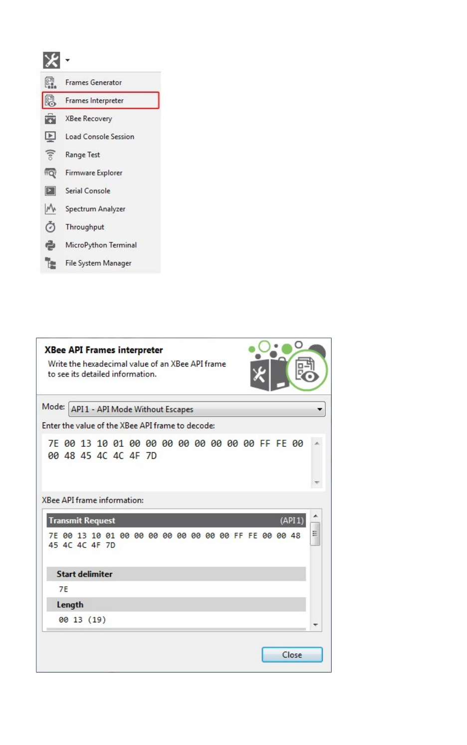
XCTU tools Frames interpreter tool
XCTU User Guide 137
XBee API Frames interpreter dialog
Use the Frames interpreter dialog to decode the byte array of an API frame.
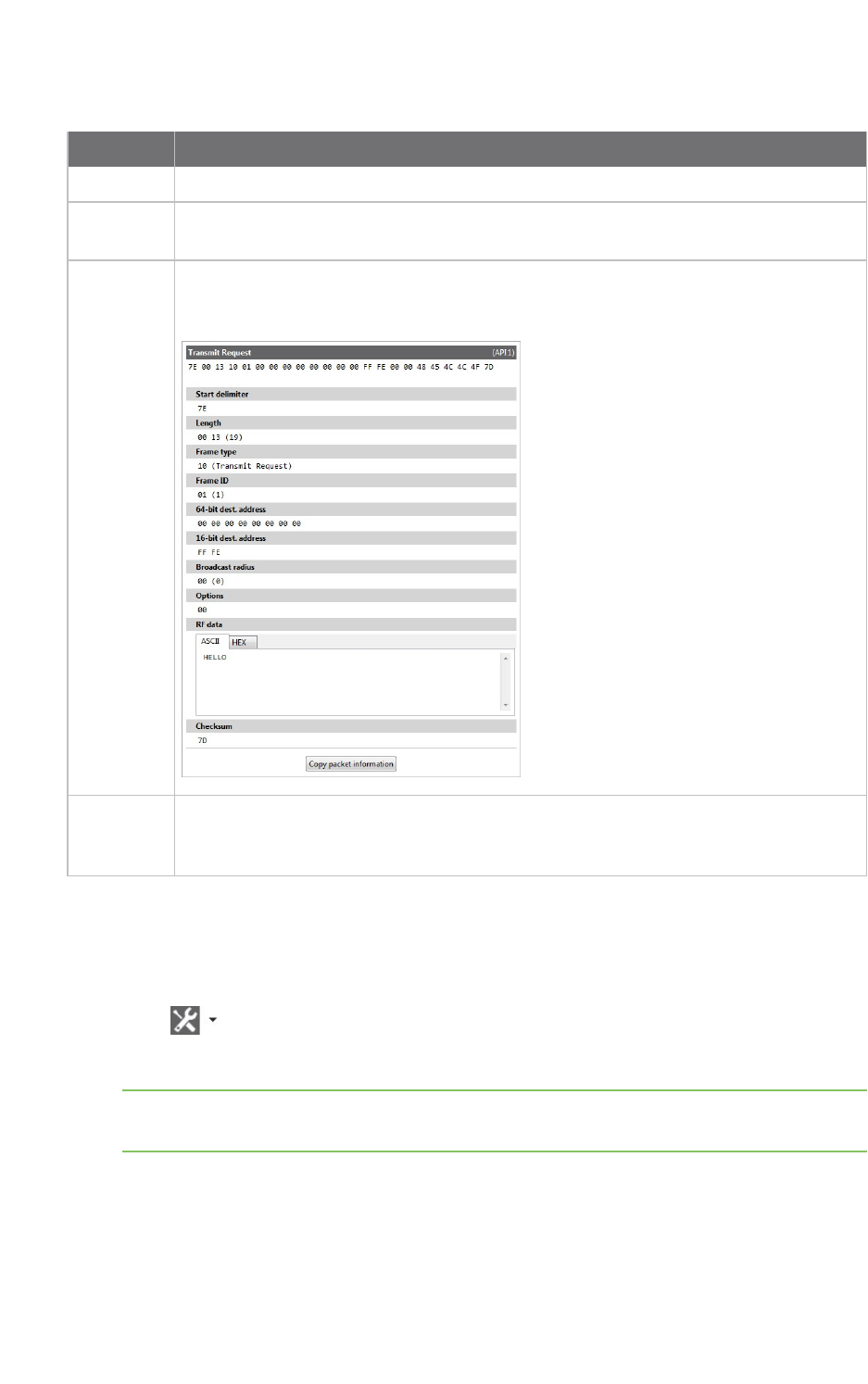
XCTU tools Frames interpreter tool
XCTU User Guide 138
The following table provides descriptions of the fields in the XBee APIFrames interpreter dialog.
Field Description
Mode API mode or API escaped mode
API frame
value
Byte array of the API frame to decode. The value of each byte must be hexadecimal
without the "0x" prefix.
API frame
information
Includes the type of API frame with all specific frame fields as well as the start
delimiter, length, and checksum of the frame. Frames with an RF data field display the
data in both Hexadecimal and ASCII formats.
Copy
packet
information
Copies the decoded API frame information to the clipboard in plain text.
Decode a frame
Follow these steps to decode a frame. For more information, see the Frames interpreter tool.
1. Launch the Frames interpreter tool by selecting Frames interpreter from the Tools drop-down
menu on the main toolbar. The XBee APIFrame interpreter dialog appears.
2. For Mode, select the API mode (API or API Escaped) of the frame to generate.
Tip To learn more about these modes, see API operating mode and API escaped operating
mode.
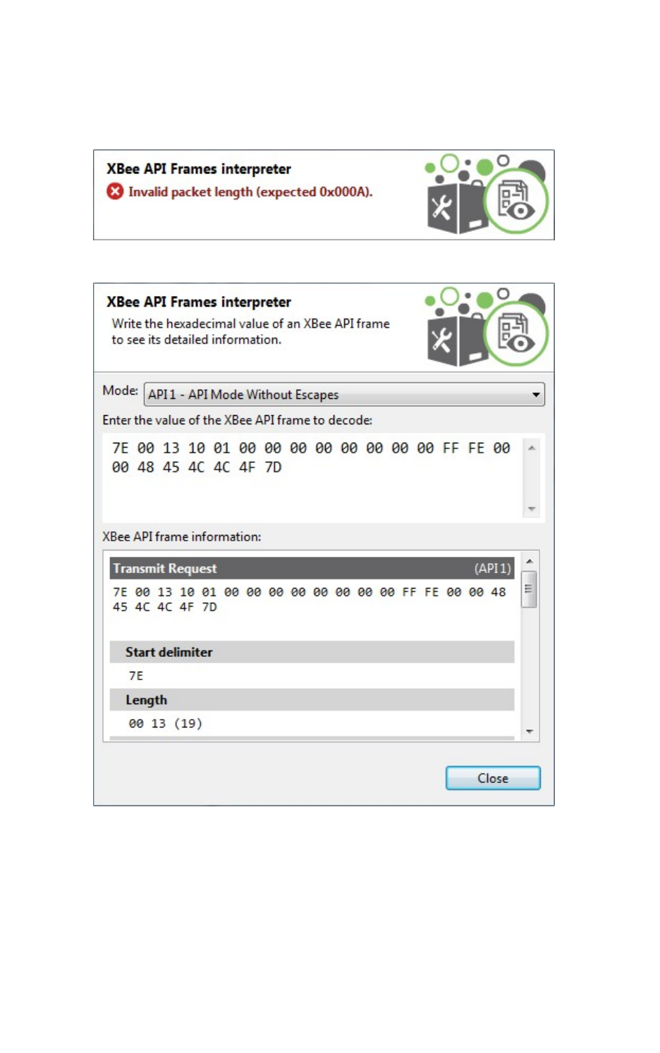
XCTU tools Frames interpreter tool
XCTU User Guide 139
3. Below the API mode selection there are two text boxes. Enter the byte array of the API frame
to decode in the top text box. The value of each byte must be hexadecimal and without the
"0x" prefix.
If the byte array is not valid, the tool displays the corresponding error at the top.
If the byte array is valid, the bottom text box displays information about the API frame.
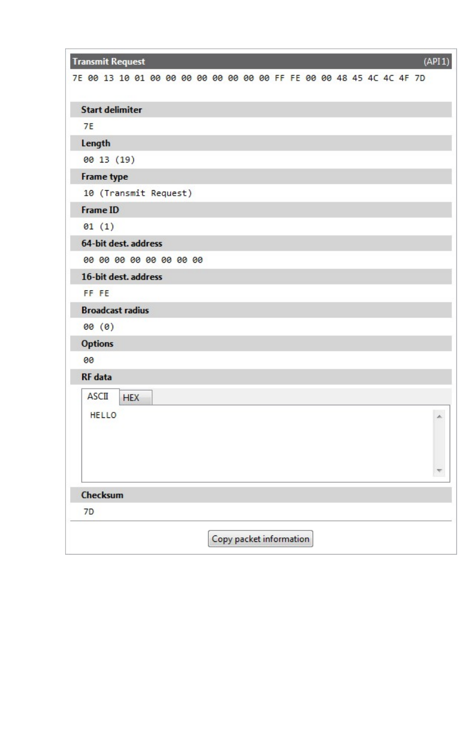
XCTU tools XBee recovery tool
XCTU User Guide 140
XBee recovery tool
The XBee recovery tool is an embedded tool that you can use to force a firmware update on radio
modules with damaged firmware. You can also use this tool to recover a radio module from
programming mode.
To open the XBee recovery tool, select XBee recovery from the Tools drop-down menu on the main
XCTU toolbar.

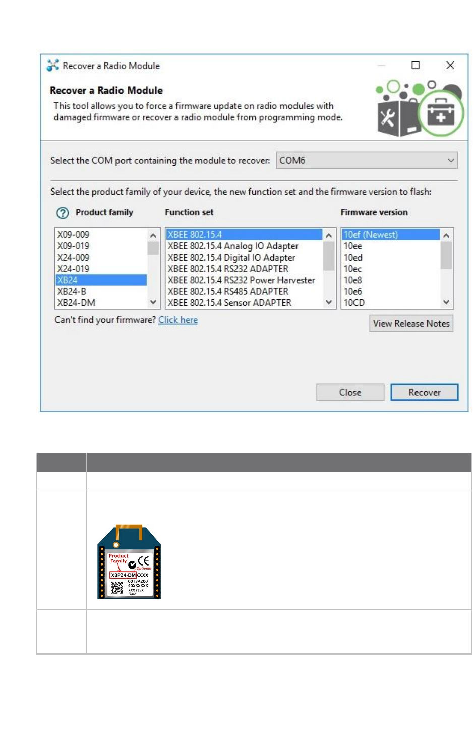
XCTU tools XBee recovery tool
XCTU User Guide 142
The following table provides descriptions of the fields in the Recover a radio module dialog.
Field Description
COM port Serial port where the module to be recovered is connected
Product
family
Product family of the module to be recovered. If you do not know the product family,
check the label on the back of the device.
Function
set
Determines the available functionality such as mode of operation; end device, router, or
coordinator designation; special sensor and adapter settings; etc. Available options
depend on the module selected.
XCTU tools XBee recovery tool
XCTU User Guide 143
Field Description
Firmware
version
Firmware version to flash to the module to be recovered. The most recent firmware
version appears at the top of the list.
View
release
notes
Enabled if the selected firmware has release notes available. Click to open a new dialog
containing release notes for the selected firmware.
Programmable XBee radio modules and the XLR PRO cannot be recovered using the XCTU
recovery tool.
Note The recovery process may require you to reset the radio module. Reset the module and wait for
the dialog to close; the recovery process will continue after the module is reset.
Recover a radio module
Follow these steps to recover radio modules that have damaged firmware or are in programming
mode. For more information, see the XBee recovery tool.
Note You cannot use the recovery tool to recover programmable radio modules or the XLR-PRO.
1. Launch the XBee recovery tool by selecting XBee recovery from the Tools drop-down menu
on the main toolbar. The Recover a radio module dialog appears.
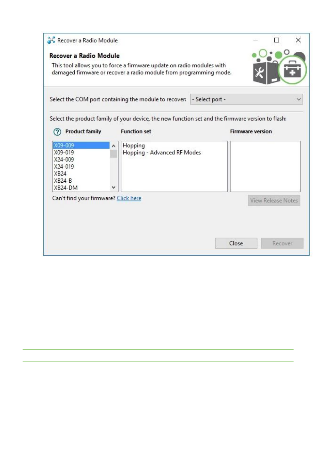
XCTU tools Load console session tool
XCTU User Guide 144
2. Select the serial port where the damaged radio module is attached.
3. Select the firmware you want to use for recovery. Specify the product family, function set, and
version.
4. Click Recover to program the new firmware in the radio module. Click Show Details from the
progress box to view a detailed progress log.
5. If XCTU displays a dialog asking you to reset your radio module, reset the module and wait for
the dialog to close.
6. If the recovery is successful, click OK to close the validation message. Errors are displayed as
separate error messages and are also logged in the progress log.
Note You can click View Release Notes if the selected firmware has available release notes.
Load console session tool
The Load console session tool allows you to load a saved API or AT console session to review the
recorded API frames or data. You can load a session saved directly from the frames/packets log of the
console or a session generated using the recording feature.
To open the Load console session tool, select Load console session from the Tools drop-down menu
on the main XCTU toolbar.

XCTU tools Load console session tool
XCTU User Guide 145
Console session viewer dialog
The Console session viewer dialog is where you can load a saved API or AT console session. For
instructions, see Load a console session.
If the console session file successfully loads, the tool displays three new controls inside the Console
session viewer:
nRadio module information box
nConsole session control
nSession data splitting
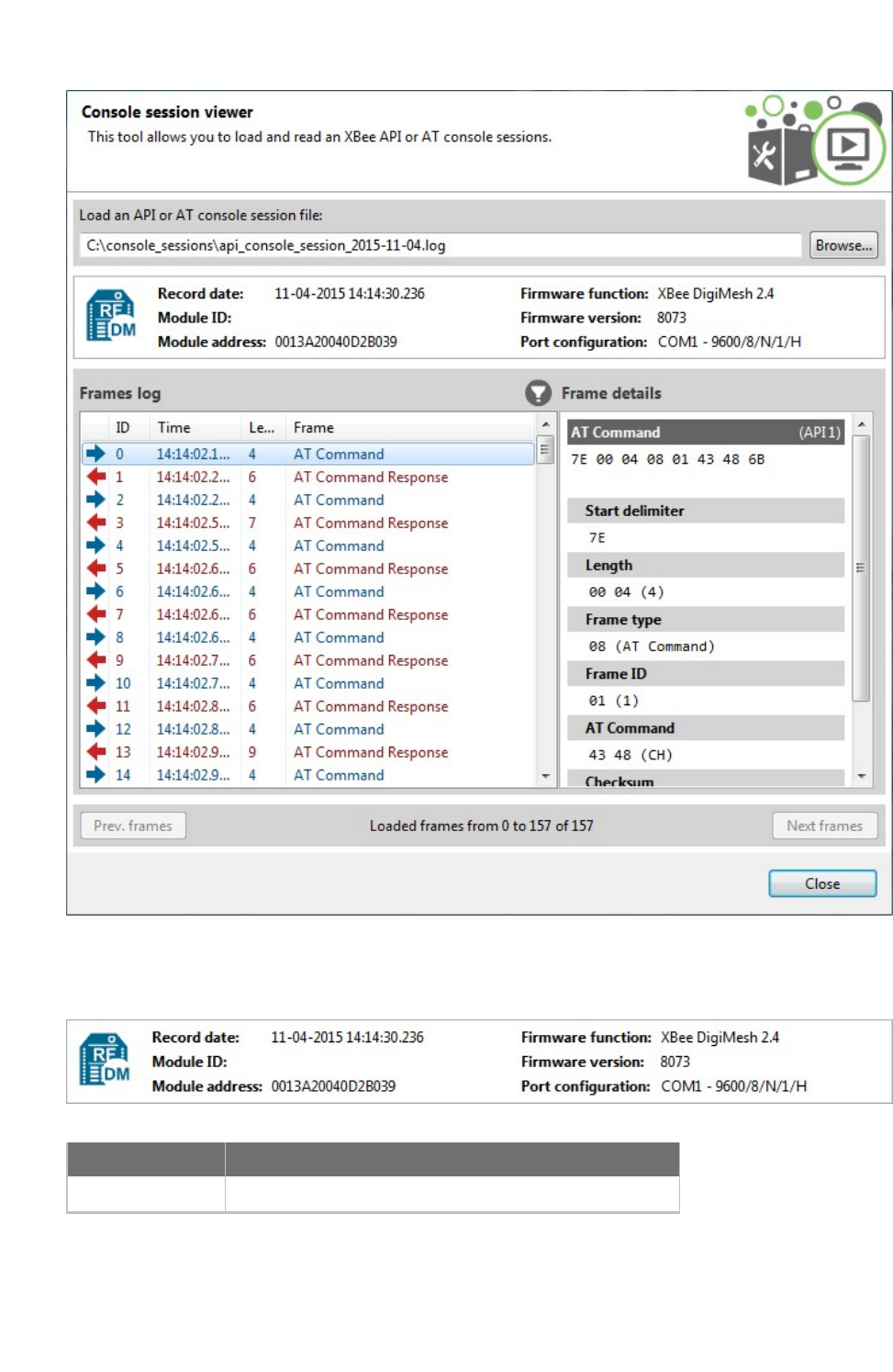
XCTU tools Load console session tool
XCTU User Guide 146
Radio module information box
The radio module information box displays information about the radio module used in the session.
Field Description
Icon Represents the protocol of the radio module
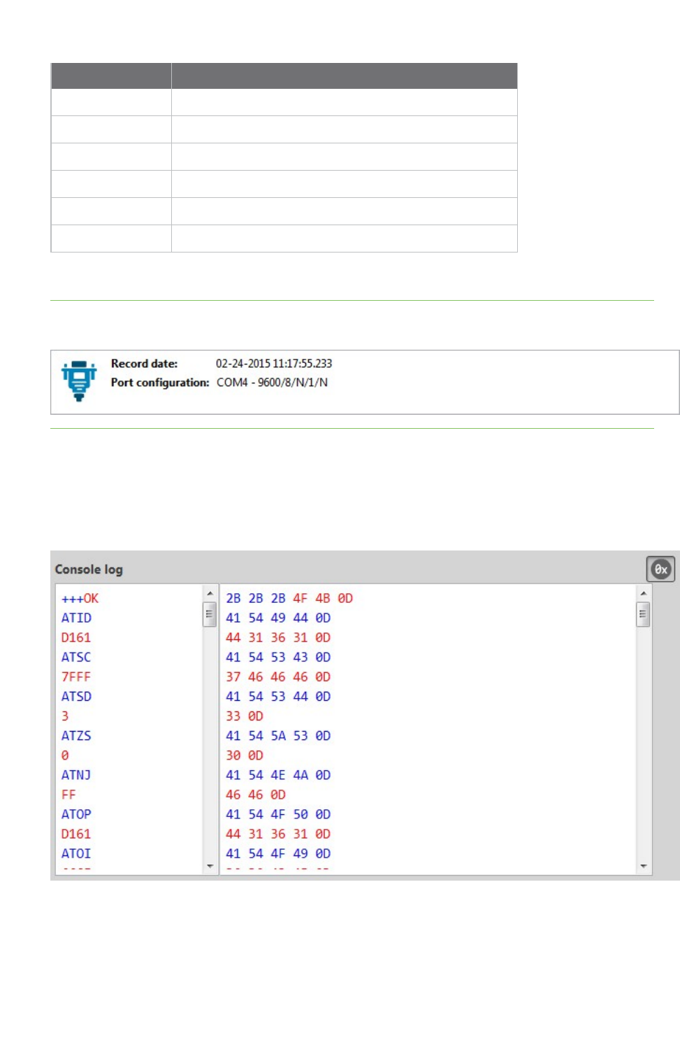
XCTU tools Load console session tool
XCTU User Guide 147
Field Description
Record date The date the console session was saved
Module ID The name or identifier of the radio module
Module address The physical (MAC) address of the device
Firmware function The function of the firmware running in the radio module
Firmware version The version of the firmware running in the radio module
Port configuration The radio module port statistics from the session
Note If the session you attempt to load corresponds to a Serial console session, the Radio module
information box displays only the Record date and Port configuration fields.
Console session control
The console session control varies depending on the type of console session. If the saved console
session is an AT (transparent) or Serial session, the control is the same as the one in the Data traffic
monitoring section of the AT or Serial consoles. In other words, it is a data text box with the
hexadecimal representation of the data.
If the saved console session is an API session, XCTU displays an API frames table with an API frame
details view attached on the right side. This is the same control as the one in the API frames traffic
monitoring section of the API Console.
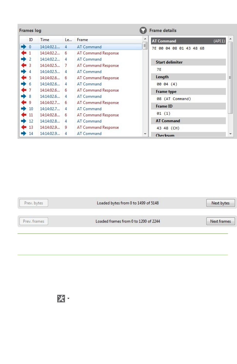
XCTU tools Load console session tool
XCTU User Guide 148
Regardless of the control displayed, you can only review the session data; any other functionality with
the controls is disabled in this tool.
Session data splitting
If the data to be loaded is too long for XCTU to display all at once, the data is split into blocks of bytes
(when the session is an AT or Serial session) or blocks of frames (when the session is an API session).
Depending on which console you used to save the session, XCTUdisplays a Frames log viewer (API) or
aConsole log viewer (AT and Serial Console).
Note You can also use the console session scroll bar to load the next and previous blocks of data. The
next block of data loads automatically when you scroll to the bottom of the control and scroll down
again.
Load a console session
Follow these steps to load a saved API or AT console session. For more information, see the Load
console session tool.
1. Launch the Load console session tool by selecting Load console session from the Tools drop-
down menu on the main toolbar. The Console session viewer dialog opens.
2. Click Browse. An Open file dialog box asks you for a saved XML console session file.
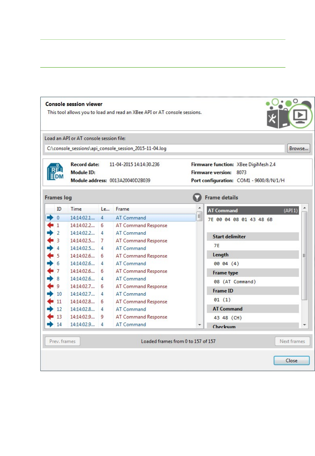
XCTU tools Range test tool
XCTU User Guide 149
3. Navigate to your saved console session file and click Open.
Note You can open log sessions in XML format that were generated with previous versions of
XCTU. Although saving sessions in XML is no longer supported, XCTU maintains backward
compatibility.
If the tool is not able to load the selected file, an error states the cause of the problem.
The Console session viewer displays a loaded console session.
Range test tool
The Range test tool is an embedded tool that tests the real RFrange and link quality between two
radio modules in the same network. To perform a range test, you must have at least one local radio
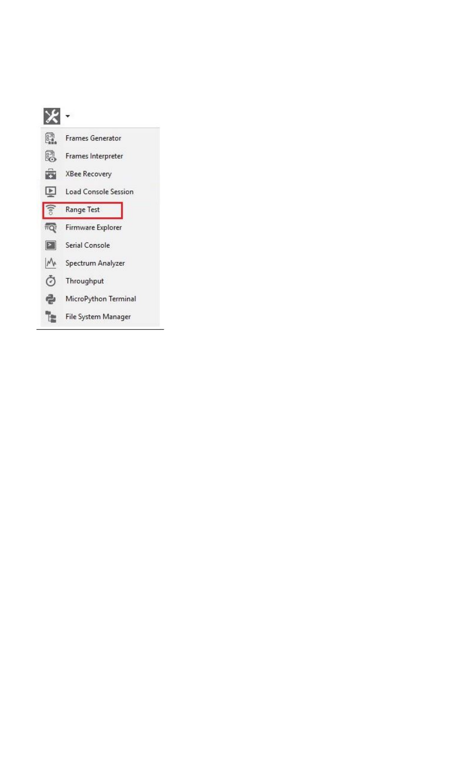
XCTU tools Range test tool
XCTU User Guide 150
module connected to your computer and added to XCTU, and a remote device in the same network
configured as the local device. See Range test.
To open the Range test tool, select Range test from the Tools drop-down menu on the main XCTU
toolbar.
Radio range test dialog
Use the Radio range test dialog to perform a range test. For instructions, see Perform a range test.
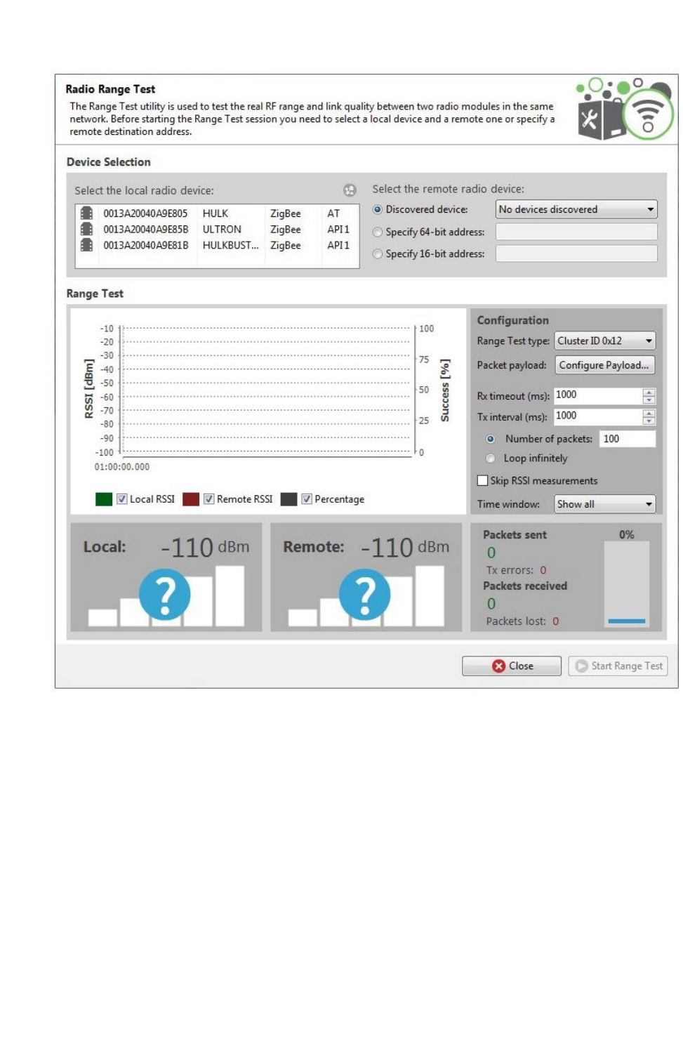
XCTU tools Range test tool
XCTU User Guide 151
The following sections provide descriptions of the controls and fields in the Radio Range Test dialog.
Device Selection
Use the Device Selection section to designate the local device that will perform the range test and
the remote device the range test will be performed upon.

XCTU tools Range test tool
XCTU User Guide 152
Select the local radio device:
Field/button Description
Local device
list
Populates with devices currently added to XCTU. The list provides the following
information about each local device:
nMAC address
nDevice name
nProtocol
nOperating mode
Discovers remote devices for the selected local device.
Select the remote radio device:
Field Description
Discovered
device
Displays a list of any remote devices discovered for the selected local device. Only
devices whose protocols support node discovery list remote devices.
Specify 64-
bit address
Allows a user to manually enter the 64-bit address of the destination device.
Specify 16-
bit address
Allows a user to manually enter the 16-bit address of the destination device.
Note Not all protocols support 64- and 16-bit addressing.
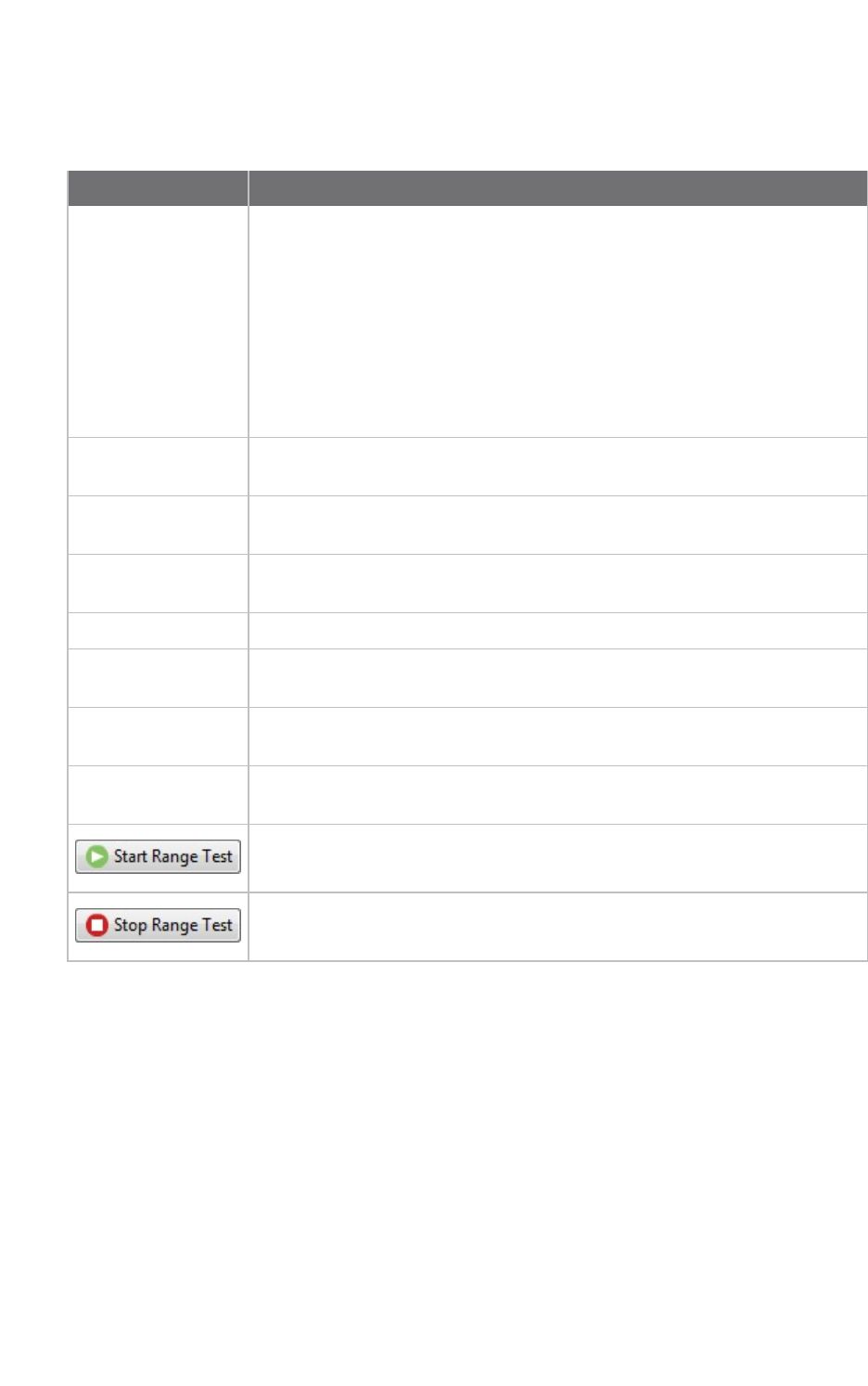
XCTU tools Range test tool
XCTU User Guide 153
Range Test Configuration
You can configure the following range test options from within the Range test tool:
Field Description
Range Test type nCluster ID 0x12: Performed using explicit addressing frames/packets
directed to the Cluster ID 0x12 on the data endpoint (0xE8), which
returns the received data to the sender. Not all protocols and
operating modes support the Cluster ID 0x12 range test. XCTU
displays an error message for unsupported devices.
nLoopback: Performed using the serial port/USB hardware loopback
capabilities. Before initiating this range test, you must configure the
remote module to work in transparent mode and close the loopback
jumper. Works only with remote devices in AT operating mode.
Packet payload Allows you to configure the packet payload that will be sent to the remote
device during range test. Opens a new window for ASCII/HEX input.
Rx Timeout (ms) Sets the maximum time in milliseconds to wait for response from the remote
device before considering a packet to be lost.
Tx interval (ms) Sets the minimum time in milliseconds to wait before sending a new packet
to the remote device.
Number of packets Configures the number of packets to send in a single range test session.
Loop infinitely When checked, configures the Range test tool to send packets infinitely until
the session is stopped manually.
Skip RSSI
measurements
When checked, the test skips the RSSI measurements. Note that you can
only skip them when your local module works in AT (transparent) mode.
Time window Configures the visible time window of the RSSI data measured by the range
test.
When you have configured all the options, click Start Range Test to start
sending packets and measure the signal strength.
You can stop the process any time by pressing the same button, now
showing the text Stop Range Test.
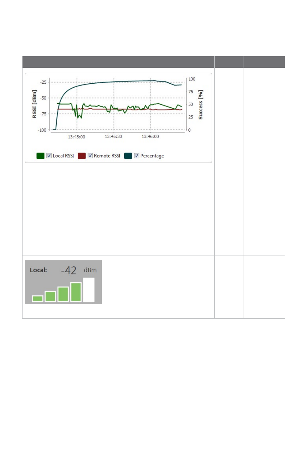
XCTU tools Range test tool
XCTU User Guide 154
Data representation
XCTU represents range test data in three ways:
Field Description
RSSI
chart
Represents
the RSSI
values of the
local and
remote
devices
during the
range test
session. The
line graph
also contains
the
percentage of
success for
the total
packets sent.
You can
hide/show
chart data by
checking or
unchecking
Local RSSI,
Remote RSSI,
and
Percentage.
Local
RSSI
value
Displays
instant RSSI
value of a
local device,
in dBm, for
the last
packet
transmitted.
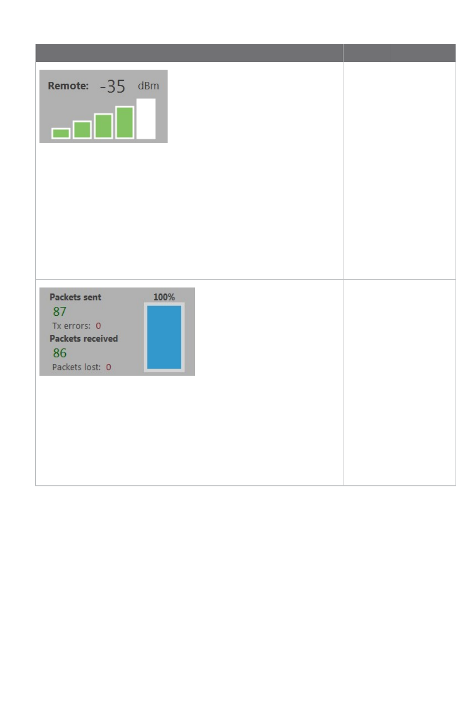
XCTU tools Range test tool
XCTU User Guide 155
Field Description
Remote
RSSI
value
Displays
instant RSSI
value of a
remote
device in
dBm, for the
last packet
transmitted.
When the
local module
is working in
AT
(transparent)
mode, XCTU
cannot read
the remote
device RSSI
value.
Packet
summary
Displays total
number of
packets sent
and received,
transmission
errors, and
packets lost.
It also
displays the
percentage of
success
sending and
receiving
packets
during the
range test
session.
Supported products
Range test is only supported in the following:
nSX
nXLRPro Module
nZigBee
nDigiMesh
nXTend
nXTend - DigiMesh
nXC/XSC

XCTU tools Range test tool
XCTU User Guide 156
n802.15.4
nDigiPoint
Special considerations
There are some special considerations to be aware of while working with the Range test tool:
nWhen the local module is working in AT (transparent) mode, the tool automatically performs
configuration steps in the module before starting the range test, and after finishing or stopping
it. A progress bar shows the level of completion for this process.
nWhen the local module is working in AT (transparent) mode, it is not possible to read the
remote device RSSI value.
nThe Loopback range test type only works with remote devices in AT (transparent) operating
mode.
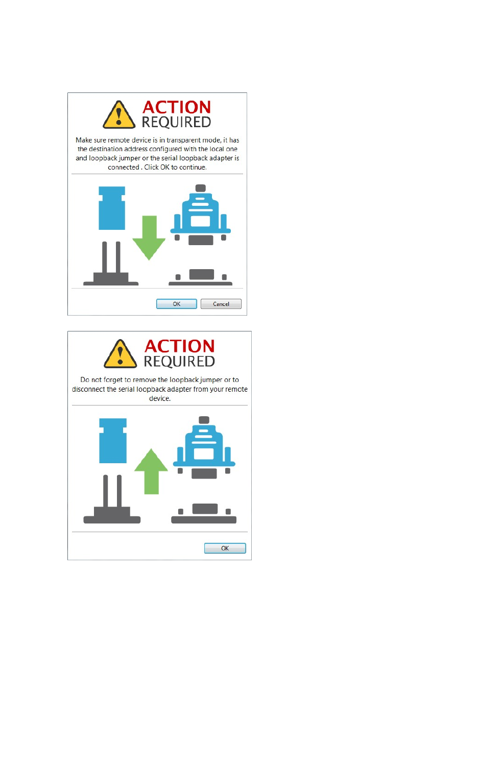
XCTU tools Range test tool
XCTU User Guide 157
nWhen performing a Loopback range test, you need to connect the loopback jumper or the
loopback adapter in the remote device before starting and disconnect it after finishing. A dialog
box notifies you of the action required:
Range test
Since communication between XBee RF modules takes place over the air, the quality of the wireless
signal can be affected by many factors: absorption, reflection of waves, line-of-sight issues, antenna
style and location, etc. A range test demonstrates the real-world RF range and link quality between
two XBee modules in the same network. During a range test, XCTU send data packets from the local
XBee module to the remote module and waits for the echo to be returned from the remote module to
the local module. XCTU counts the number of packets sent and received by the local module and
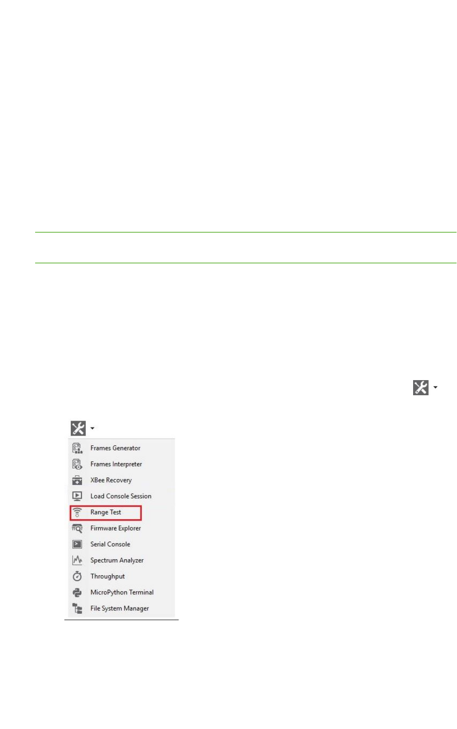
XCTU tools Range test tool
XCTU User Guide 158
measures the signal strength of both sides as an RSSI (Received Signal Strength Indicator) value.
Every sent packet from the local XBee should be received again as an echo by the same local XBee.
The following products support range testing:
nZigBee
nDigiMesh
nXTend
nXTend - DigiMesh
nXC/XSC
nXLR PRO
n802.15.4
nDigiPoint
nSX
Note When deploying an actual network, perform multiple range tests to analyze varying conditions in
your application.
Perform a range test
Follow these steps to perform a a range test. For more information, see the Range test tool. When the
local module is working in AT (transparent) mode, the Range test tool automatically pre-configures
the module before starting the range test, as well as after the range test is completed or manually
stopped. A progress bar displays the level of completion for this process.
To perform a range test, you must have at least one local radio module connected to your computer
and added to XCTU, and a remote device in the same network as the local device.
1. Launch the Range test tool by selecting Range test from the Tools drop-down menu on
the main toolbar.
2. Select the local device that will perform the range test and the remote device against which
the range test will be performed.

XCTU tools Firmware explorer tool
XCTU User Guide 159
3. Configure the following range test parameters:
nRange Test type
nPacket payload
nRx timeout
nTx interval
nNumber of packets
nLoop infinitely
nSkip RSSImeasurements
nTime window
4. Click Start range test to begin sending packets and measuring signal strength. You can stop
the range test at any time by clicking the Stop range test button.
Note If the Loopback range test type is configured, you must connect the loopback jumper in the
remote module before starting the range test and remove it when the range test has finished.
Firmware explorer tool
The Firmware explorer tool allows you to navigate through XCTU's firmware library to review
available firmware versions and their settings, without having a radio module attached to your
computer. It also lets you save and load firmware profiles.
To open the Firmware explorer tool, select Firmware explorer from the Tools drop-down menu on
the main XCTU toolbar.
Firmware explorer dialog
Use the Firmware explorer dialog to review available firmware versions and their settings. For
instructions, see Inspect a firmware version.
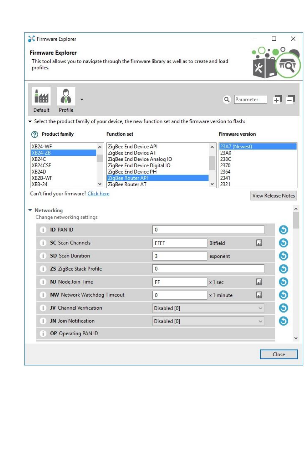
XCTU tools Firmware explorer tool
XCTU User Guide 160
Firmware toolbar
The toolbar displays all the actions you can perform on the selected firmware:
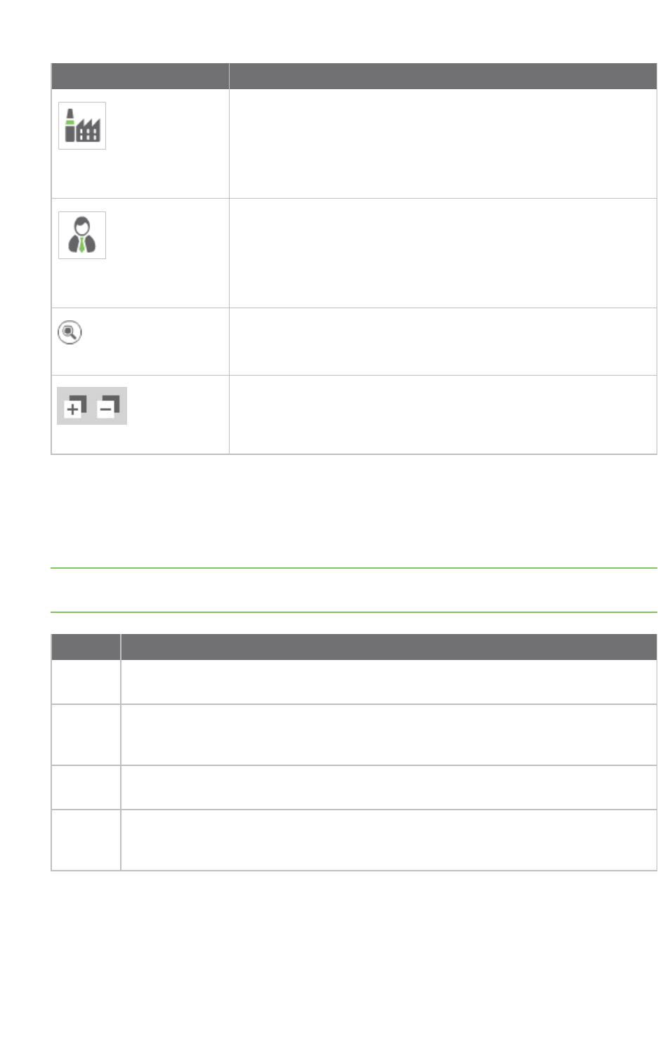
XCTU tools Firmware explorer tool
XCTU User Guide 161
Field Description
Load default firmware
settings
Loads the default firmware values.
Load/save configuration
profile
Opens the Load configuration profile or Save configuration profile
dialog.
Search
Enables you to search firmware settings by AT parameter.
Expand/collapse settings
Expands or collapses all firmware settings sections.
Firmware selection panel
The firmware selection panel allows you to specify the firmware to be loaded. To display the settings
of a specific radio firmware, specify the firmware family, function, and version from the corresponding
lists.
Note The firmware selection panel does not flash the firmware on a module. It loads the firmware in
the dialog so you can view its settings.
Field Description
Product
family
Product family of the firmware to load. If you do not know the product family, check the
label on the back.
Function
set
Determines the available functionality such as mode of operation; end device, router, or
coordinator designation; special sensor and adapter settings; etc. Available options
depend on the module selected.
Firmware
version
Firmware version to be loaded. The most recent firmware version appears at the top of
the list.
View
release
notes
Displays the release notes of the selected firmware, if available.
Firmware settings panel
The firmware settings panel is located below the firmware selection panel and contains all the
settings that make up the firmware, in categories.

XCTU tools Firmware explorer tool
XCTU User Guide 162
You can see the default value of each setting, and also change them to edit configuration profiles.
Click the blue arrow button next to a setting to load the default value of that setting.
The settings are displayed and managed the same way as they are in the Radio configuration section.
For more information, see Configure your modules.
Inspect a firmware version
Follow these steps to inspect a firmware version. For more information, see the Firmware explorer
tool.
1. Launch the Firmware explorer tool by selecting Firmware explorer from the Tools drop-down
menu on the main toolbar. The Firmware Explorer dialog displays all the available
firmware hosted in XCTU.
2. Select the product family of the firmware, the function set, and the desired firmware version.
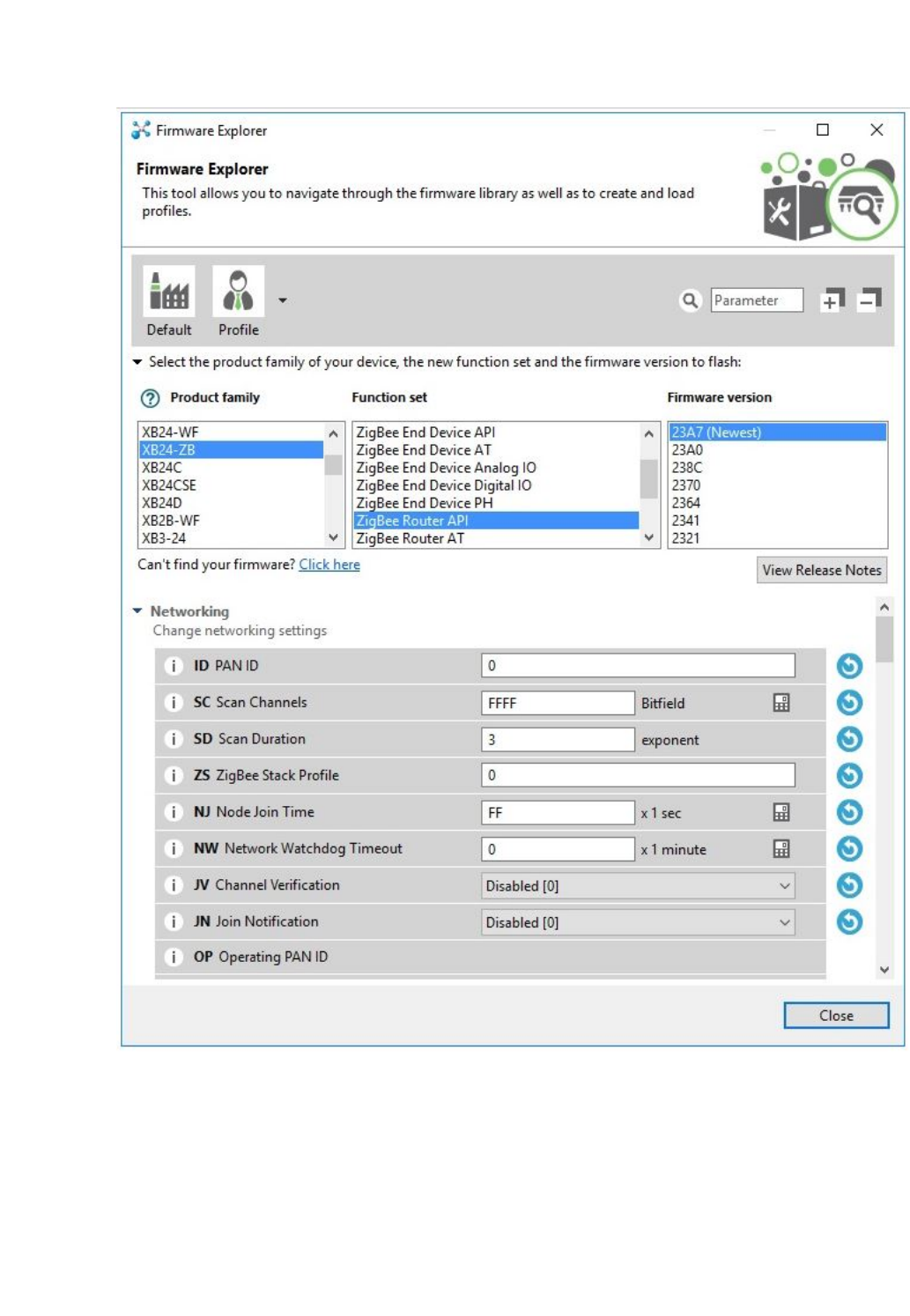
XCTU tools Serial console tool
XCTU User Guide 163
3. You can inspect available settings for the selected firmware version.
Serial console tool
The Serial console tool allows you to interact with your radio modules without having to first discover
them and add them to the list of radio modules. It is essentially an AT console, but instead of
XCTU tools Serial console tool
XCTU User Guide 164
associating directly with a module it communicates with the port attached to the module you want to
communicate with.
To open the Serial console tool, select Serial console from the Tools drop-down menu on the main
XCTU toolbar.
Serial console dialog
The workflow and components of the serial console are similar to those of the AT console. However,
since the serial console is not associated with a radio module, you must configure the serial port the
console will open a connection with. For instructions, see Configure the serial port settings.
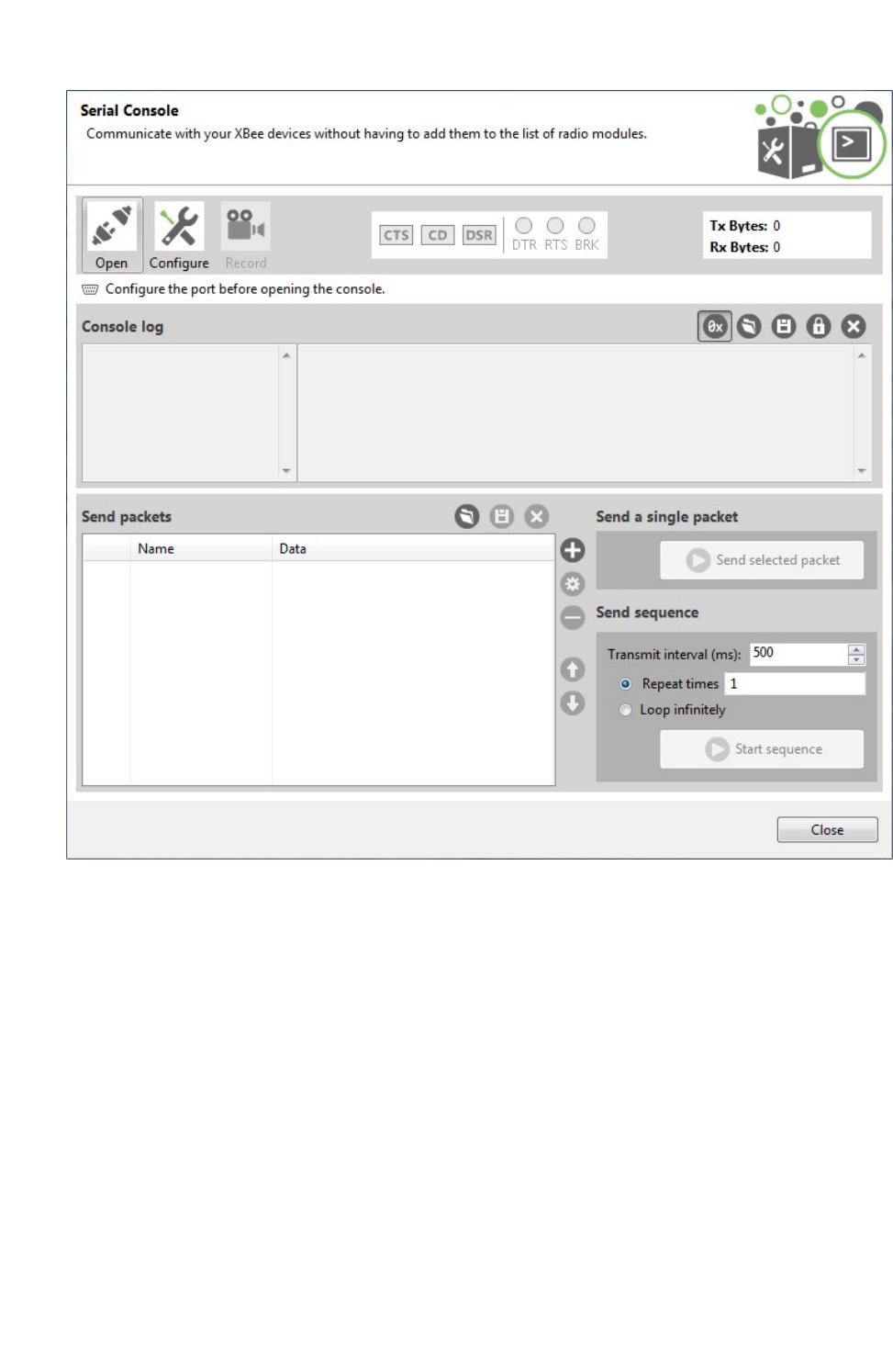
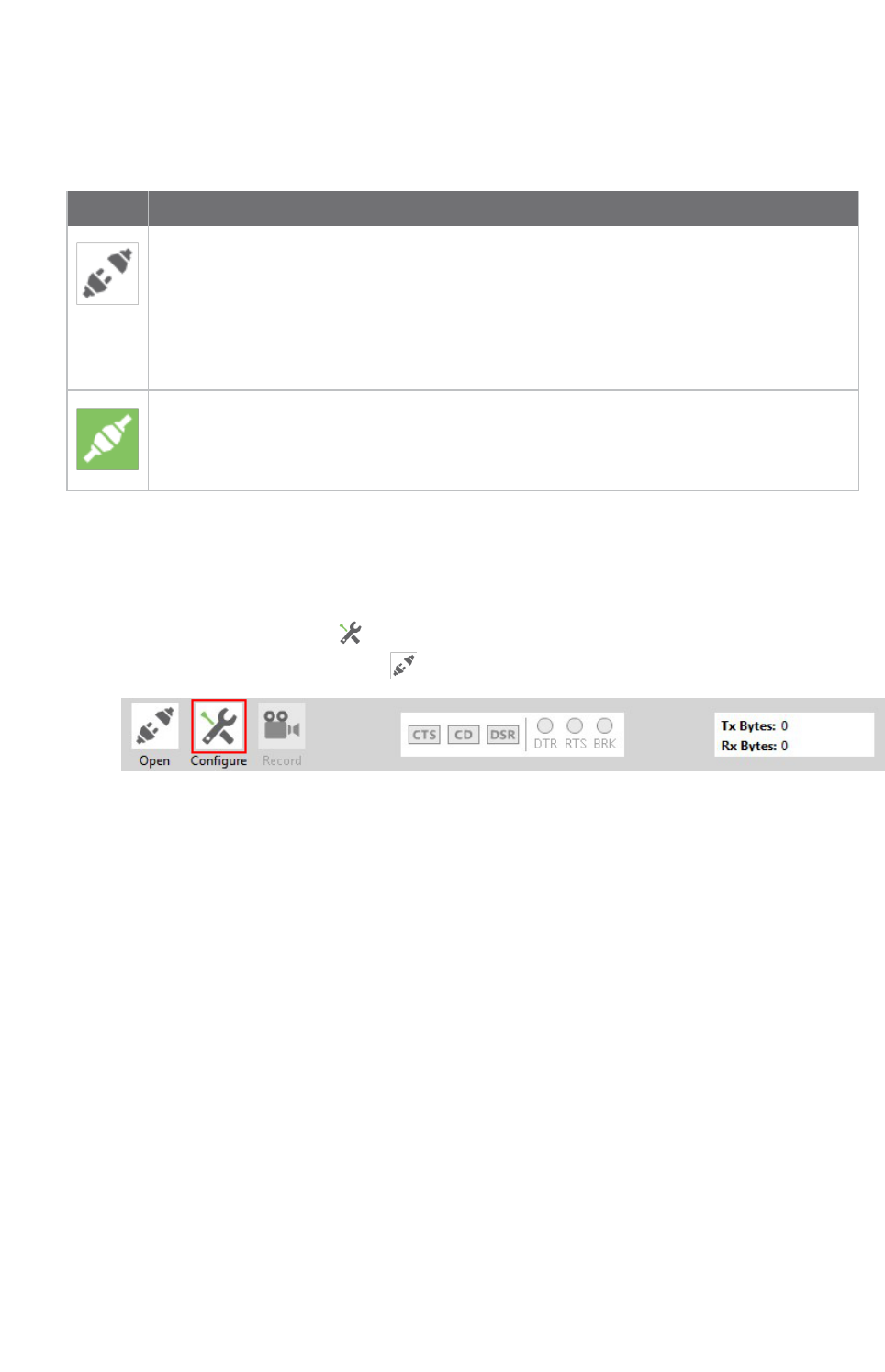
XCTU tools Serial console tool
XCTU User Guide 166
Open a serial console session
The first time you open a console, it is disconnected by default. This is indicated by the gray
background of the toolbar and the status text reading "Closed."
Buttons Description
Click the Open button to establish communication with the radio module corresponding
to the console. If it is the first time you connect the console, you are prompted to
configure the serial connection.
The background color of the Open button changes to green and its text changes to Close.
When the console is connected, all the data traffic of the radio module is captured by the
console and displayed in the corresponding controls.
Click the Closebutton if you want to disconnect the console from the module.
Configure the serial port settings
Follow these steps to configure the serial port settings of an instance of the Serial console tool. For
more information, see Serial console tool.
1. Click the Configure button on the Serial Console toolbar. If the console is not yet
connected, click the Open button .
The Serial Port Configuration dialog list all of the serial connection parameters to be
configured.

XCTU tools Serial console tool
XCTU User Guide 167
2. Select the device's serial port, or provide it manually. The rest of the parameters are loaded
with their default values.
3. Change the configuration if needed. The most common serial configuration is:
Baud rate: 9600 or 115200
Data bits: 8
Stop bits: 1
Parity: None
Flow control: None
Note Custom baud rates can only be typed under Windows OS.
Open a serial console session
The first time you open a console, it is disconnected by default. To open a serial console session:
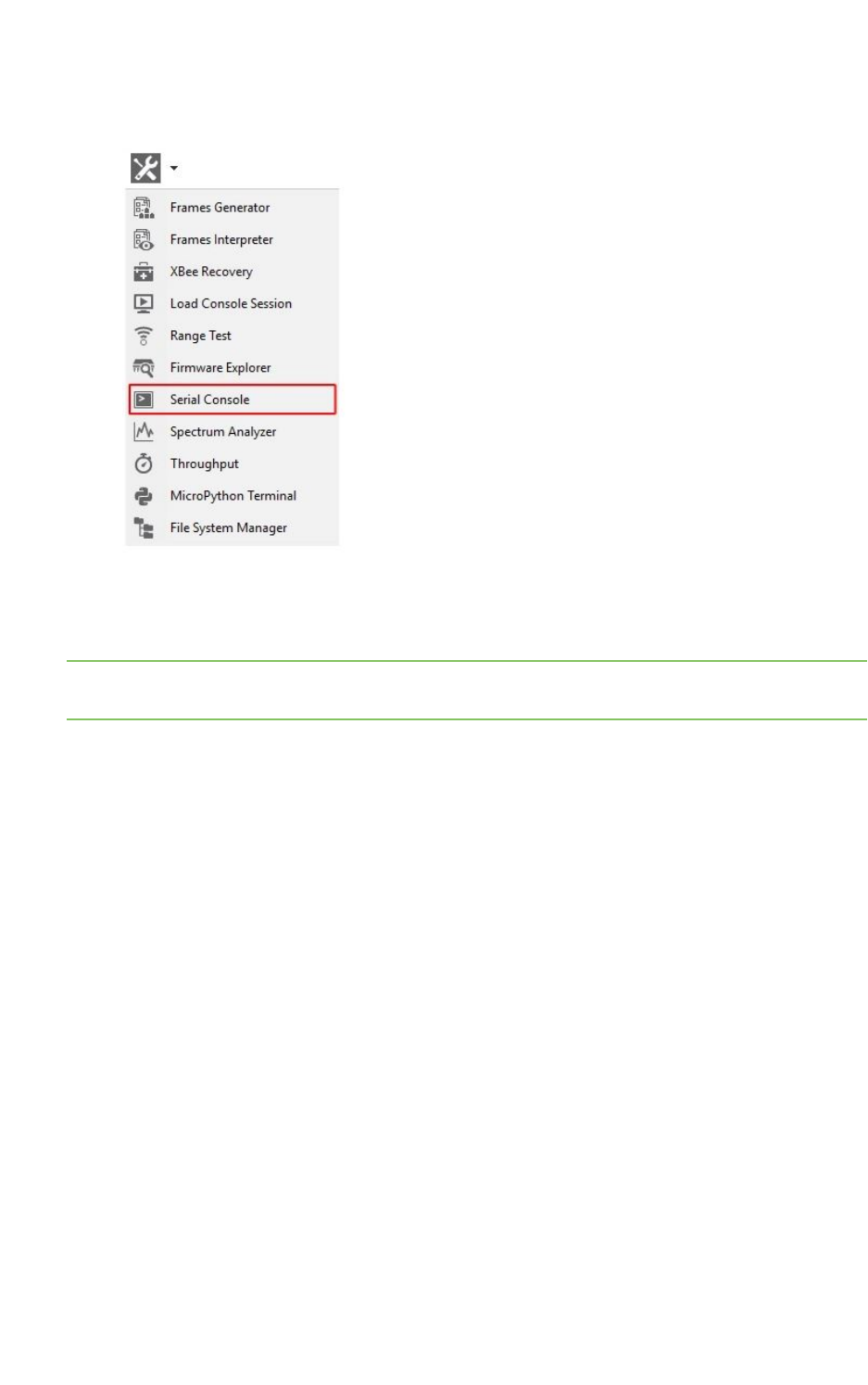
XCTU tools Spectrum analyzer tool
XCTU User Guide 168
1. Select Serial console from the Tools drop-down menu on the main XCTU toolbar. The Serial
console dialog appears.
2. Click the Configure button from the toolbar and configure the serial port where the radio
module is attached. See Configure the serial port settings for details.
3. Click the Open button to establish communication with the radio module.
Note The serial console tool operates just like an ATconsole. For more information, see Consoles
working mode,AT console, and Serial console tool.
Spectrum analyzer tool
The Spectrum analyzer tool allows you to test and measure the spectrum of the selected radio band.
The tool reports the noise level of each channel indicating its best, worst and average measures.
To open the Spectrum Analyzer tool, select Spectrum analyzer from the Tools drop-down menu on
the main XCTU toolbar.

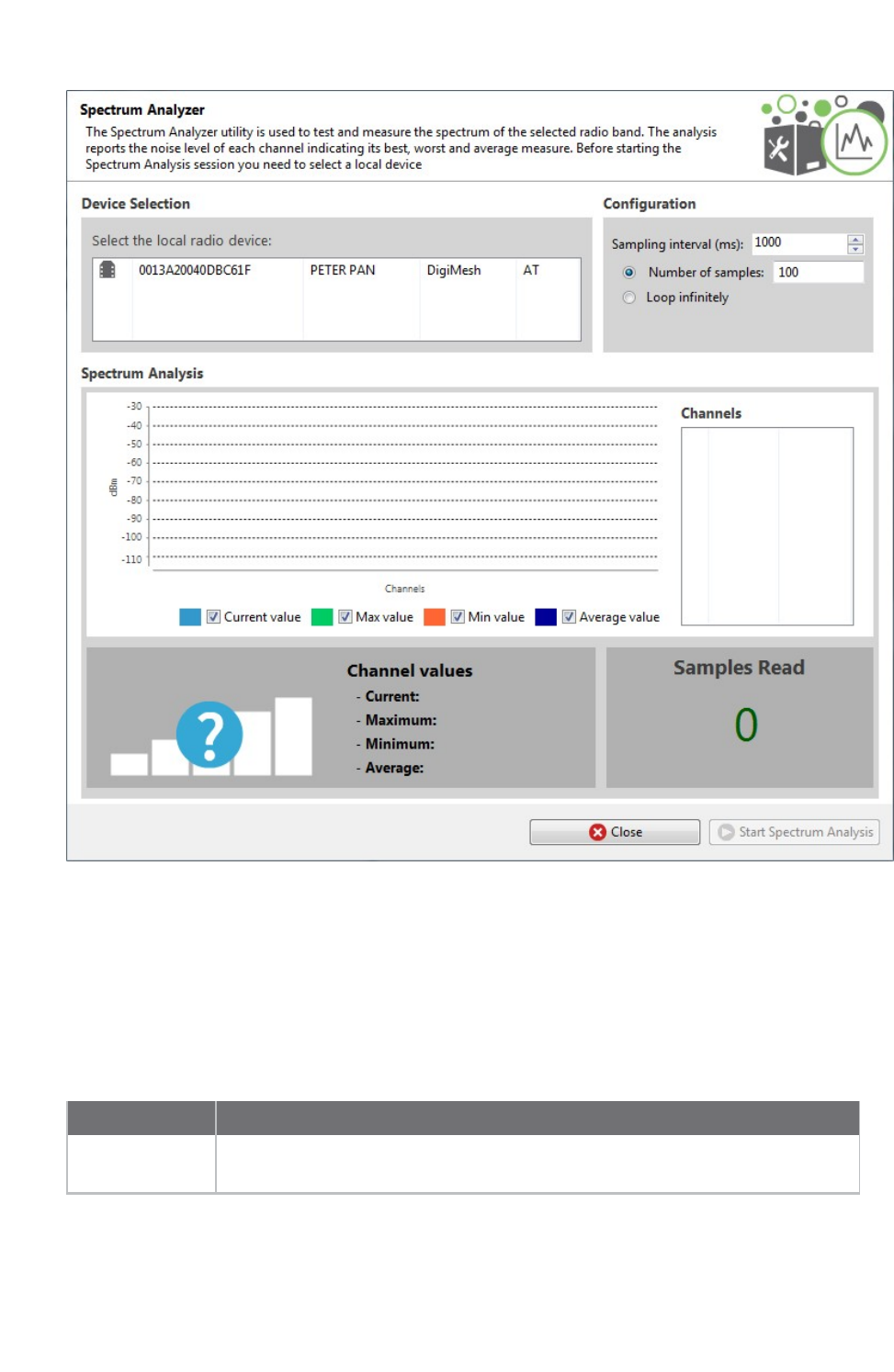
XCTU tools Spectrum analyzer tool
XCTU User Guide 170
Device selection
The Device selection area lists the devices that you have added to XCTU. Select the radio module you
want to use to perform the analysis.
Analysis configuration
The Configuration area allows you to configure the spectrum analysis process.
Field Description
Sampling
interval (ms)
Determines the time to wait in milliseconds before reading a new noise level
sample of the RF channels.
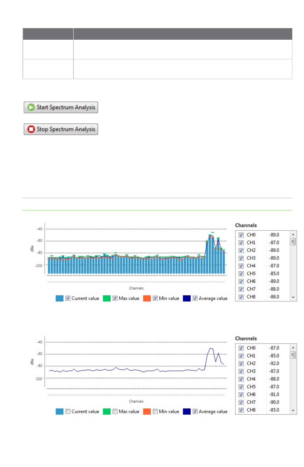
XCTU tools Spectrum analyzer tool
XCTU User Guide 171
Field Description
Number of
samples
Select this option to configure the number of samples to read in the spectrum
analysis session.
Loop infinitely Select this option to read samples infinitely until the spectrum analysis session is
stopped manually.
When you have configured all the options, click the Start Spectrum
Analysis button to start reading samples and measure the noise level
of each RF channel.
You can manually stop the analysis at any time by clicking the same
button, which changes to Stop Spectrum Analysis.
Channels Chart
The Channels chart represents the noise level of all the RF channels. Each channel displays one bar
with the current noise level and two little marks representing the highest noise level (green) and the
lowest noise level (red). A blue line indicates the average noise level of all the channels. The spectrum
analysis refreshes the noise levels of each channel continuously until the analysis ends or is stopped.
Note The list of supported channels may vary depending on the device type and device region.
You can use chart filters to hide or display the bars, the best and worst noise level values and the
average noise level line.
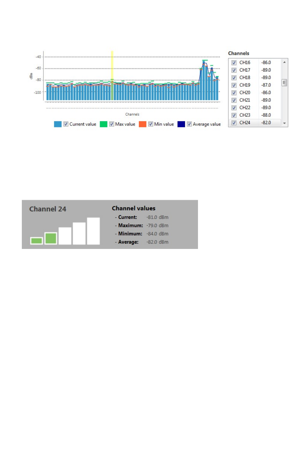
XCTU tools Spectrum analyzer tool
XCTU User Guide 172
If you click a channel from the list of channels, it is highlighted in the chart. Likewise, you can select a
channel in the chart to highlight it in the list of channels.
Selecting or clearing the check box of each channel within the list of channels shows and displays it in
the chart.
Channel summary values
The Channel area displays the instant noise level of a channel as well as its average, best and worst
noise level. To display channel values, select a channel in the chart or highlight a channel in the list of
channels on the right.
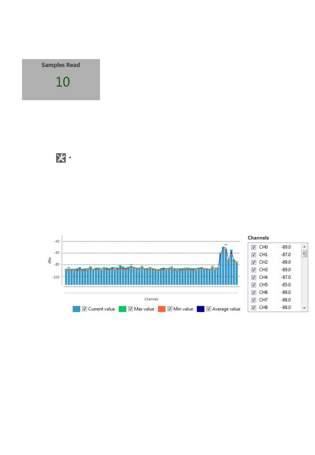
XCTU tools Throughput tool
XCTU User Guide 173
Number of samples
The Samples Read area displays the number of noise level samples read by the selected radio module.
Note that you can specify the number of samples to read in the Configuration area.
Analyze the spectrum of a radio band
Follow these steps to analyze the spectrum of a radio band. For more information, see Spectrum
analyzer tool.
1. Launch the Spectrum analyzer tool by selecting Spectrum analyzer from the Tools drop-down
menu on the main toolbar. The Spectrum Analyzer dialog appears.
2. Under Device Selection, select the local radio device you want to analyze.
3. Under Configuration, specify the sampling interval and a configuration method.
4. Click the Start Spectrum Analysis button to start reading samples and measure the noise
level of each RF channel. You can manually stop the analysis at any time by clicking the Stop
Spectrum Analysis button.
When an analysis begins, the chart and channels list display the RF channels supported by the
selected device.
5. Use chart filters to hide or display channels, the best and worst noise level values and the
average noise level line. You can also display channel values and samples read. For details, see
Spectrum analyzer tool.
Throughput tool
The Throughput tool allows you to measure the transfer ratio between two radio modules in the same
network. To perform a throughput measure, you need to have a local radio module added to XCTU and
a remote device in the same network as the local one.
To open the Throughput tool, select Throughput from the Tools drop-down menu on the main XCTU
toolbar.

XCTU tools Throughput tool
XCTU User Guide 174
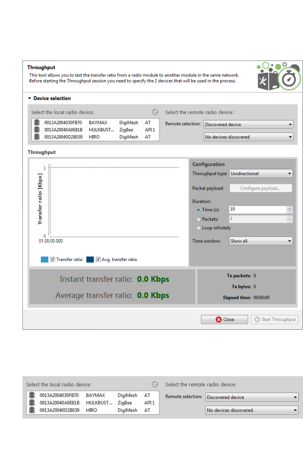
XCTU tools Throughput tool
XCTU User Guide 175
Throughput dialog
Use the Throughput dialog to measure the transfer ratio between two radio modules in the same
network. For instructions, see Measure the transfer ratio between two radio modules.
Device selection
Use the Device selection section to designate the local device that will perform the throughput and
the remote device that receives the data:

XCTU tools Throughput tool
XCTU User Guide 176
Select the local radio device
Field/button Description
Local device
list
Populates with devices currently added to XCTU. Select the device you want to use
in the throughput session. The list provides the following information about each
local device:
nMAC address
nDevice name
nProtocol
nOperating mode
Discovers remote devices for the selected local device.
Select the remote radio device
The remote device selection can be performed in four ways:
Field Description
Discovered
device
Displays a list of any remote devices discovered for the selected local device. Only
devices whose protocols support node discovery list remote devices.
Specify 64-
bit address
Allows a user to manually enter the 64-bit address of the destination device.
Specify 16-
bit address
Allows a user to manually enter the 16-bit address of the destination device.
Specify
IPv6
address
Allows a user to manually enter the IPv6 address of the destination device. Only
supported by Thread modules.
Note Not all protocols support node discovery. Only devices that support node discovery list remote
devices.
Note Not all protocols support IPv6, 64 and 16-bit addressing. Devices that do not support any of
these mechanisms display an error at the top of the page.
Throughput session configuration
You can configure the following throughput session options from within the Throughput tool:

XCTU tools Throughput tool
XCTU User Guide 177
Field Description
Throughput type Determines the type of throughput process to perform. Available
options include:
nUnidirectional: Sends data from the local device to the
remote device. Before sending the next packet of data, it
waits for the transmission status of the previous one.
nUnidirectional (UDP): Sends data from the local device to
the remote device using UDP protocol. Before sending the
next packet of data, it waits for the transmission status of
the previous one. Only supported by Thread modules.
nUnidirectional CoAP: Sends data from the local device to
the remote device using CoAP protocol. Before sending the
next packet of data, it waits for the CoAP transmission
status of the previous one. Only supported by Thread
modules.
nBidi - Cluster ID 0x12: Sends data from the local device to
the remote one and waits for the data receipt from the
remote device. The transmission is performed using explicit
addressing frames/packets directed to the Cluster ID 0x12
which returns the sent message.
Note Not all protocols and operating modes support
Bidi - Cluster ID 0x12 Throughput type. Devices
that do not support it display an error at the top of
the page.
nBidi - Loopback: Same as previous bidirectional mode, this
one also waits for the data back from the remote device
before sending the next block of data. The data back is
performed using the serial port/USB hardware loopback
capabilities. Specific user actions are required to use this
mechanism. See Special considerations. This method is valid
for local modules working in both AT and API operating
modes.
nBidi - Loopback (UDP): Bidirectional mode. Sends data
from the local device to the remote one using UDP protocol
and waits for the data receipt from the remote device
before sending the next block of data. The data back is
performed using the serial port/USB hardware loopback
capabilities. Specific user actions are required to use this
mechanism. See Special considerations. This method is valid
only for Thread modules working either in AT or API
operating modes.

XCTU tools Throughput tool
XCTU User Guide 178
Field Description
nBidi - Loopback (CoAP): Same as Bidi - Loopback (UDP) but
using CoAP protocol. Specific user actions are required to
use this mechanism. See Special considerations. See Special
considerations. This method is valid only for Thread modules
working either in AT or API operating modes
Note Loopback throughput sessions require the
remote device to be in AT (transparent) mode.
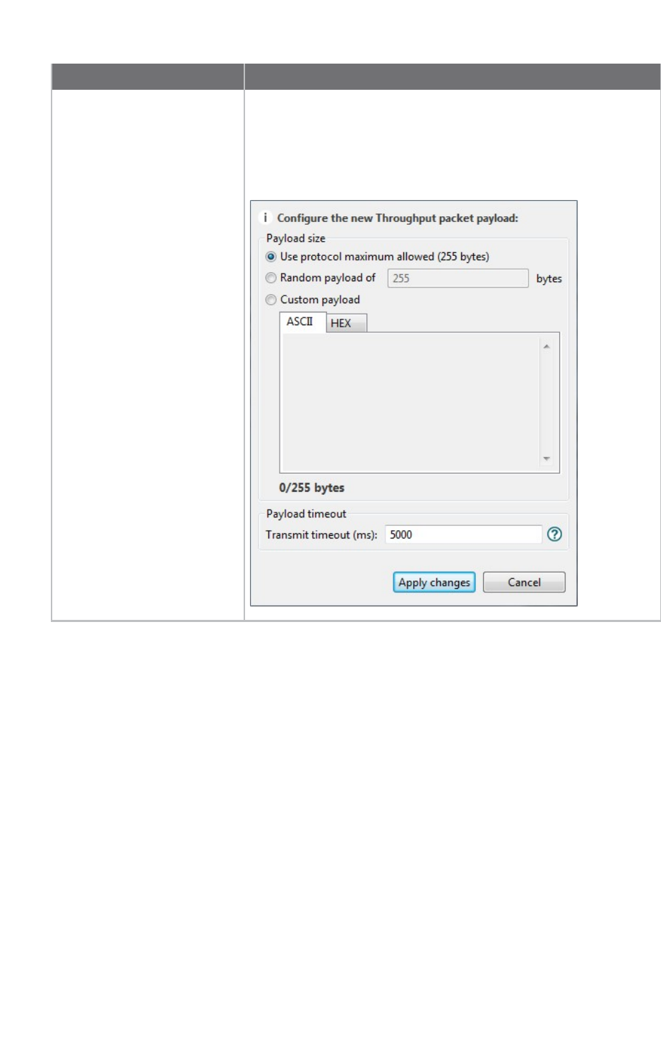
XCTU tools Throughput tool
XCTU User Guide 179
Field Description
Packet payload Allows you to configure the packet payload that will be sent to the
remote device. Opens a new window where you can configure
different payload values by operating mode of the local radio
module (AT or API):
Local module working in API mode:
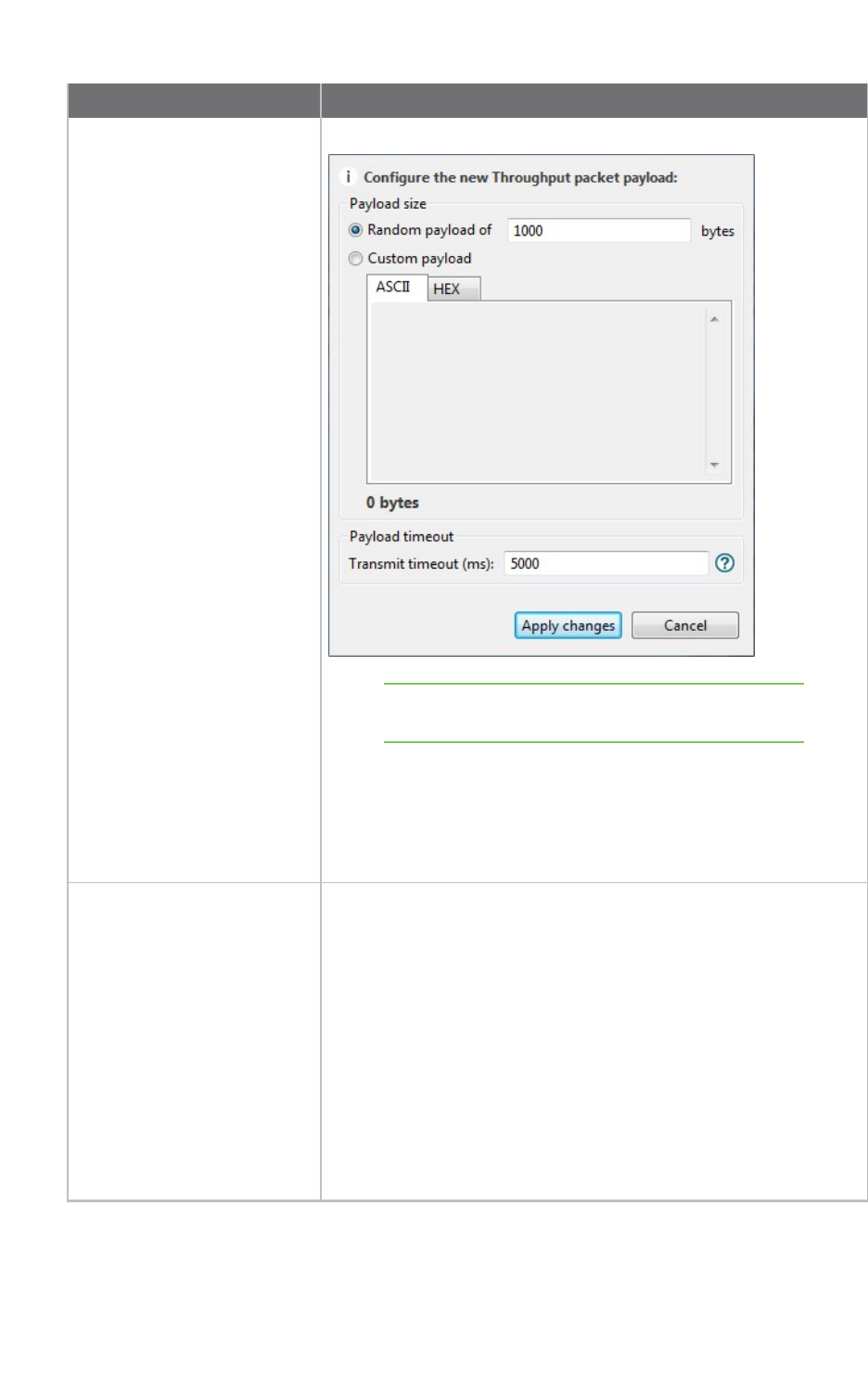
XCTU tools Throughput tool
XCTU User Guide 180
Field Description
Local module working in AT mode:
Note In API mode the payload length is limited by the
protocol. In AT mode the payload length is unlimited.
nPayload timeout: This is the time that the Throughput
session waits to receive the transmit status packet (when
the throughput type is unidirectional) or the data back from
the module (when the throughput type is bidirectional). The
bigger the payload is the greater this time should be.
Duration Determines the duration of the Throughput session. Available
options include:
nTime (s): Establishes the minimum duration of the session in
seconds. The process sends data packets to the remote
device until this time is reached.
nPackets: The duration of the session is established by the
number of packets configured in this field. Bear in mind that
depending on the packet payload, a packet can take several
seconds to be sent.
nLoop infinitely: The process sends packets infinitely until
the throughput session is stopped manually.
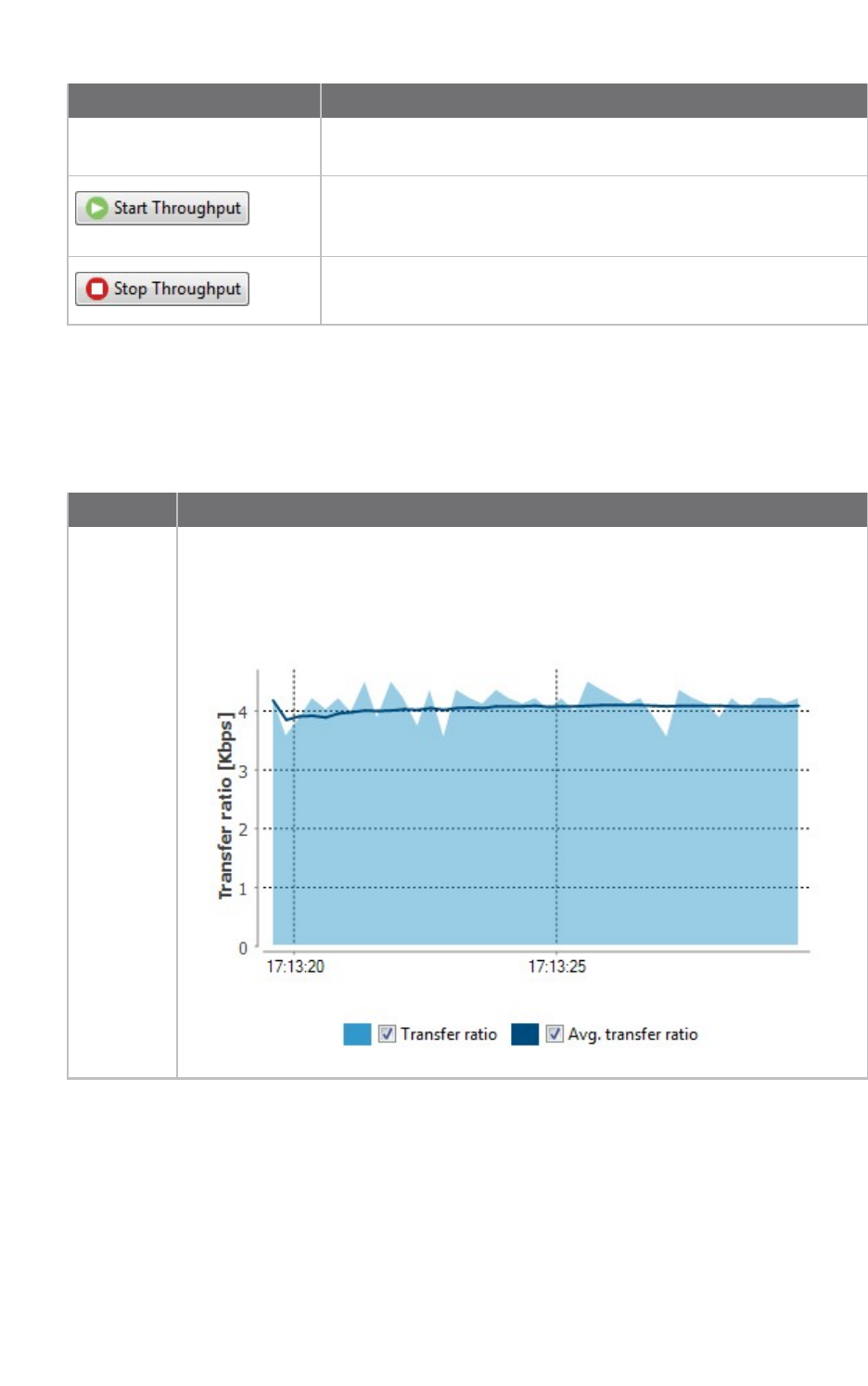
XCTU tools Throughput tool
XCTU User Guide 181
Field Description
Time window Configures the visible time window of the transfer ration measured
by the throughput session.
When you have configured all the options, click the Start
Throughput button to start measuring the transfer ratio of your
radio module.
You can stop the process at any time by pressing the same button,
now showing the text Stop Throughput.
Data representation
The chart in the tool represents the instant transfer ratio and the average transfer ratio.
Field Description
Transfer
ratio chart
Displays the instant transfer ratio with a light blue area and the average transfer
ratio as a dark blue line. The instant transfer ratio is calculated every 250ms or every
time a packet is sent if sending takes longer than 250ms. You can hide and show chart
data by checking or unchecking Transfer ratio and Avg. transfer ratio.
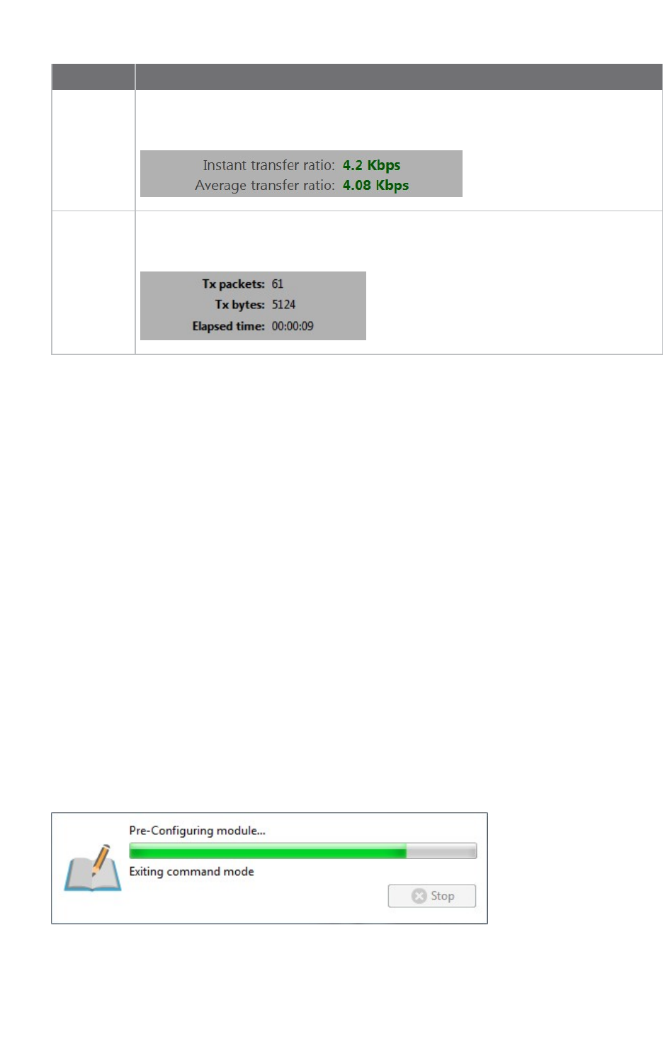
XCTU tools Throughput tool
XCTU User Guide 182
Field Description
Transfer
ratio values
Displays the instant and average transfer ratio as packets are sent to the remote
module during the session.
Session
statistics
Displays session statistics such as the number of packets sent to the remote device,
the number of transferred bytes, and the duration of the session.
Supported products
Throughput is only supported in these protocols:
nSX
nXLR Module
nZigBee
nDigiMesh
nXTend
nXTend - DigiMesh
nXC/XSC
nXLR PRO
n802.15.4
nDigi Point
nThread
Special considerations
There are some special considerations to be aware of while working with the Throughput tool.
When the local module is working in AT (transparent) mode, the tool automatically performs
configuration steps in the module before starting the throughput session, and after finishing or
stopping it. A progress bar shows the level of completion for this process:
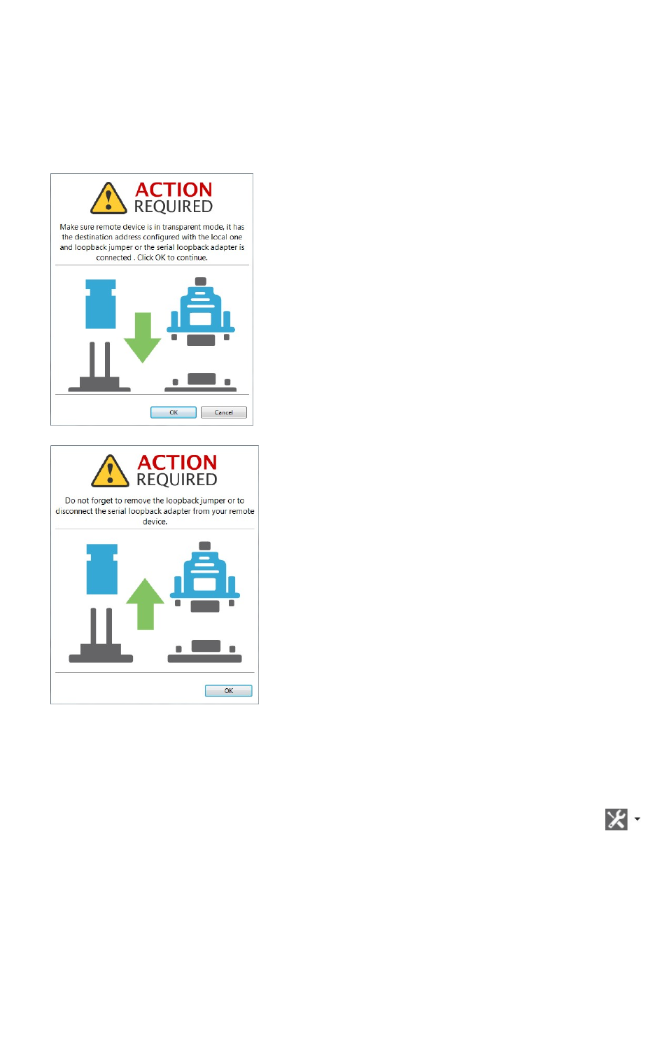
XCTU tools Throughput tool
XCTU User Guide 183
nThe bidirectional loopback throughput types only work with remote devices in AT
(transparent) operating mode.
nWhen performing any bidirectional loopback throughput, you need to connect the loopback
jumper or the loopback adapter in the remote device before starting and disconnect it after
finishing. A dialog box notifies you of the action required:
Measure the transfer ratio between two radio modules
Follow these steps to measure the transfer ratio between two radio modules in the same network.
For more information, see Throughput tool.
1. Launch the Throughput tool by selecting Throughput from the Tools drop-down menu
on the main toolbar. The Throughput dialog appears.
2. Under Device selection, select a local device to perform the throughput and a remote device
to receive the data.
3. Under Configuration, configure the throughput type, packet payload, duration, and time
window.
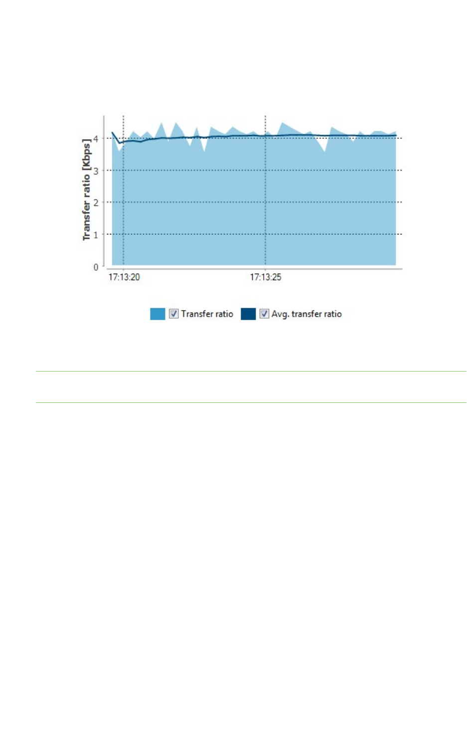
XCTU tools Throughput tool
XCTU User Guide 184
4. Once you have configured all the options, click the Start Throughput button to start
measuring the transfer ratio of your radio module. You can stop the process at any time by
pressing the same button, which has changed to Stop Throughput.
The Throughput chart represents the instant transfer ratio and the average transfer ratio.
5. You can hide and show any of the chart data by selecting or clearing the transfer ratio check
boxes.
Note There are special considerations to be aware of while working with the Throughput tool. For
details, see Throughput tool.
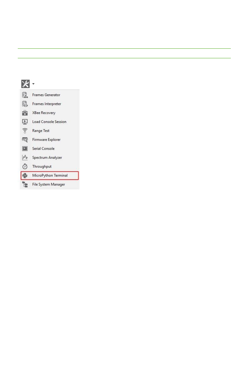
XCTU tools MicroPython Terminal tool
XCTU User Guide 185
MicroPython Terminal tool
The MicroPython Terminal tool allows you to communicate with the MicroPython stack of your radio
module through the serial interface.
Note Make sure your radio module supports MicroPython and is configured in that mode.
To open the MicroPython Terminal tool, select MicroPython Terminal from the Tools drop-down
menu on the main XCTU toolbar.
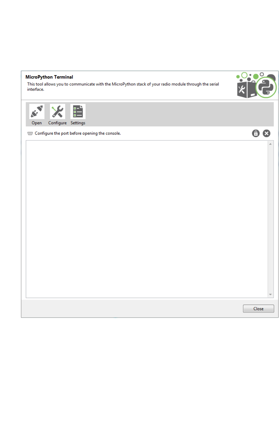
XCTU tools MicroPython Terminal tool
XCTU User Guide 186
MicroPython Terminal dialog
The workflow and components of the MicroPython Terminal tool are similar to those of the Serial
console one. Because the MicroPython Terminal is not associated with a radio module, you must
configure the serial port the console will open a connection with. For more information, see Configure
the serial port settings - MicroPython Terminal tool.
Open a terminal session
By default, the first time you open the terminal it is disconnected, as is indicated by the gray
background of the toolbar.
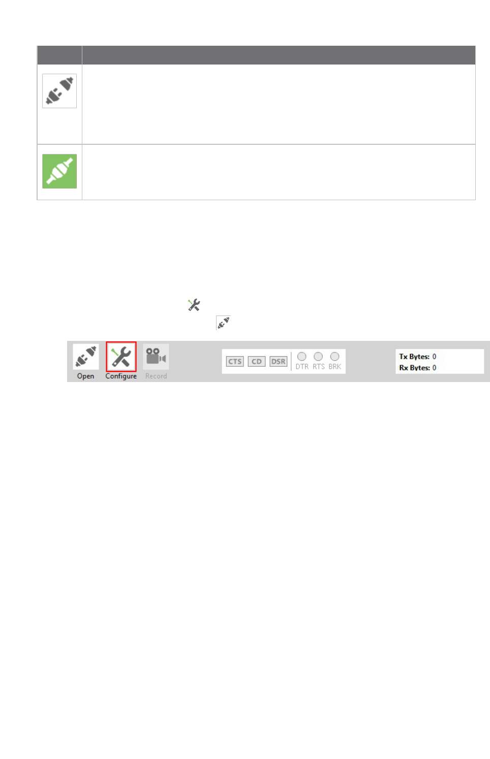
XCTU tools MicroPython Terminal tool
XCTU User Guide 187
Buttons Description
Click the Open button to establish communication with the radio module corresponding
to the terminal. If it is the first time you are connecting the console, you are prompted to
configure the serial connection.
The background color of the Open button changes to green and its text changes to Close.
When the terminal is connected, all data traffic of the radio module is captured by the
console and displayed in the corresponding controls.
Click the Close button to disconnect the terminal from the module.
Configure the serial port settings - MicroPython Terminal tool
Follow these steps to configure the serial port settings of an instance of the MicroPython Terminal
tool. For more information, see MicroPython Terminal tool.
1. Click the Configure button on the MicroPython Terminal. If the console is not yet
connected, click the Open button .
The Serial Port Configuration dialog lists all of the serial connection parameters to be
configured.
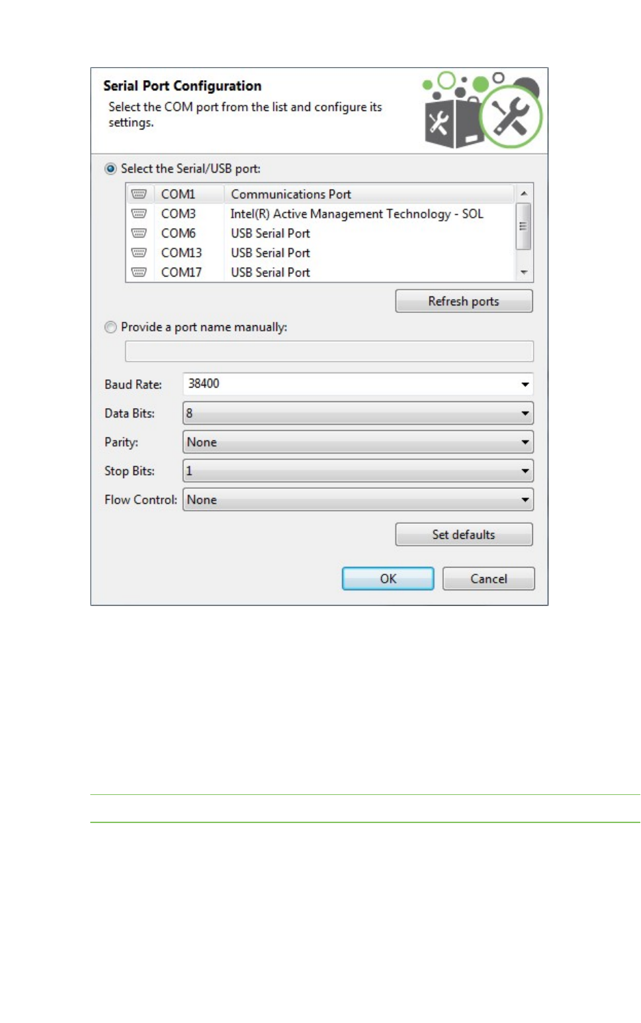
XCTU tools MicroPython Terminal tool
XCTU User Guide 188
2. Select the device's serial port, or provide it manually. The rest of the parameters are loaded
with their default values.
3. Change the configuration if needed. The most common serial configuration is:
Baud rate: 9600 or 115200
Data bits: 8
Stop bits: 1
Parity: None
Flow control: None
Note Custom baud rates can only be typed under Windows OS.
Open a MicroPython Terminal session
The first time you open a console, it is disconnected by default. To open a MicroPython Terminal
session:
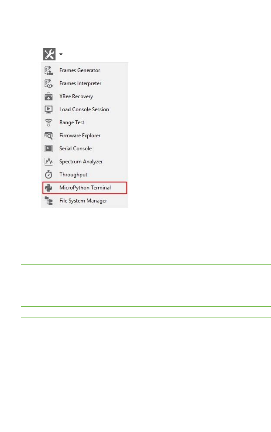
XCTU tools File system manger tool
XCTU User Guide 189
1. Select MicroPython Terminal from the Tools drop-down menu on the main XCTU toolbar. The
MicroPython Terminal dialog appears.
2. Click the Configure button from the toolbar and configure the serial port where the radio
module is attached. See Configure the serial port settings - MicroPython Terminal tool for
details.
3. Click the Open button to establish communication with the radio module.
Note The MicroPython Terminal tool operates the same as any other VT100 terminal emulator.
File system manger tool
The File system manger tool allows you to access and interact with the file system of your XBee
module.
Note Make sure your radio module supports the file system feature.
To open the File System Manager tool, select File System Manager from the Tools drop-down menu
on the main XCTU toolbar.
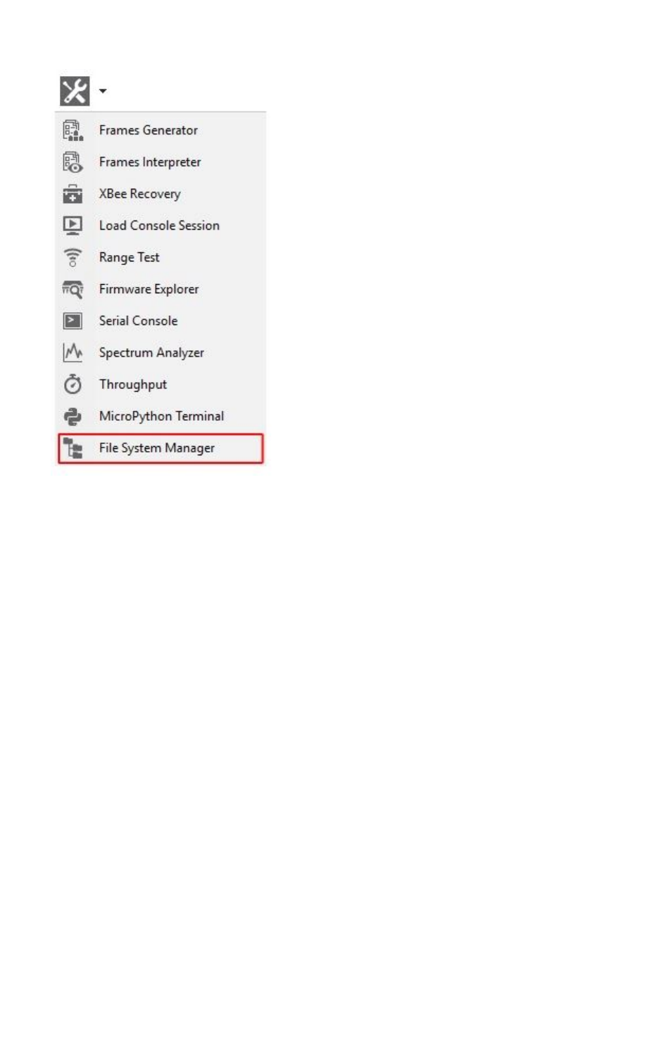
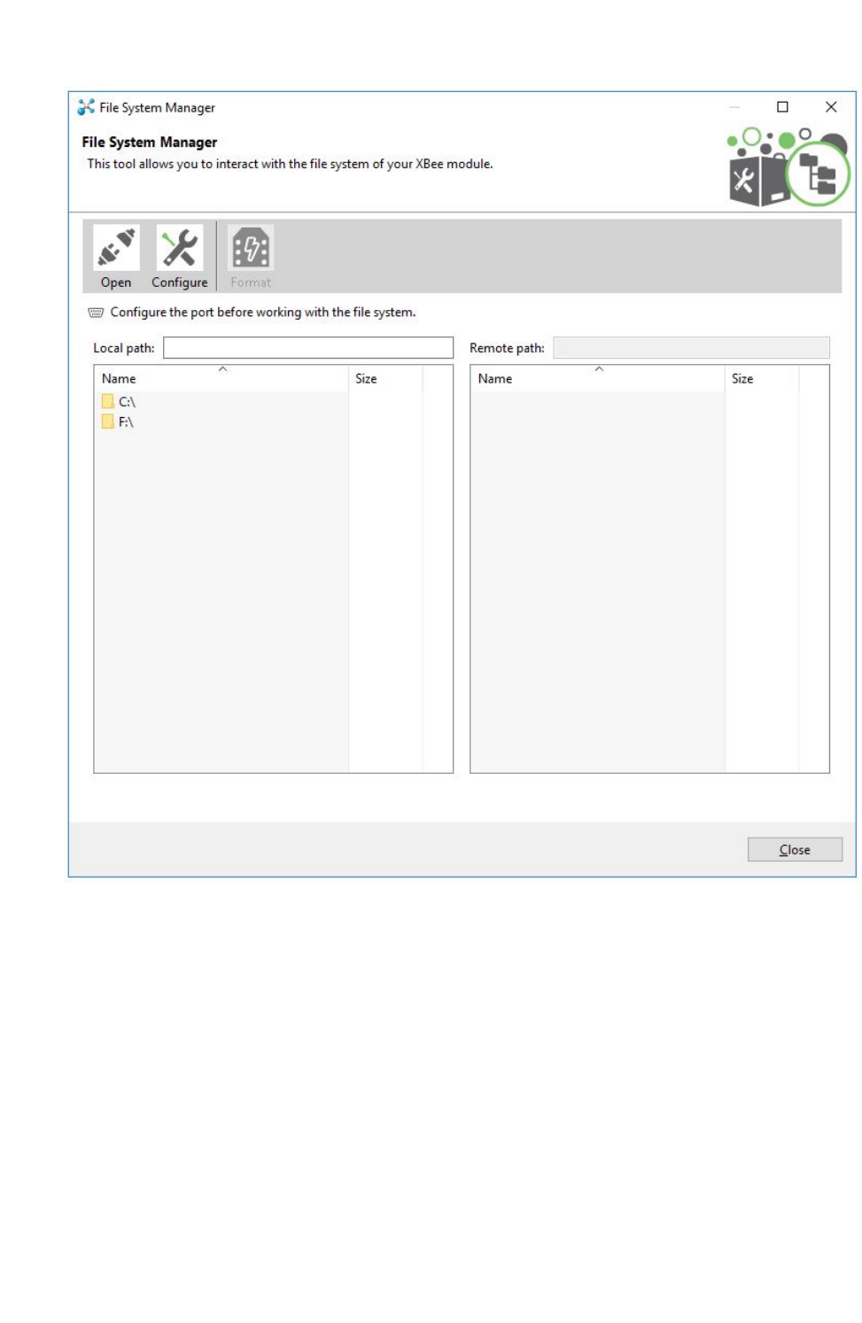
XCTU tools File system manger tool
XCTU User Guide 191
File System Manager sections
The File System Manager dialog is divided into three parts:
nToolbar: Allows opening/closing the connection with the XBee module, configuring the serial
port parameters, and formatting the XBee file system.
nLocal file system view: Shows the current path of your computer and its contents.
nRemote file system view: Shows the current path of the XBee module and its contents.
Interact with XBee file system
Follow these steps to interact with the file system of your XBee module. For more information, see
File system manger tool.
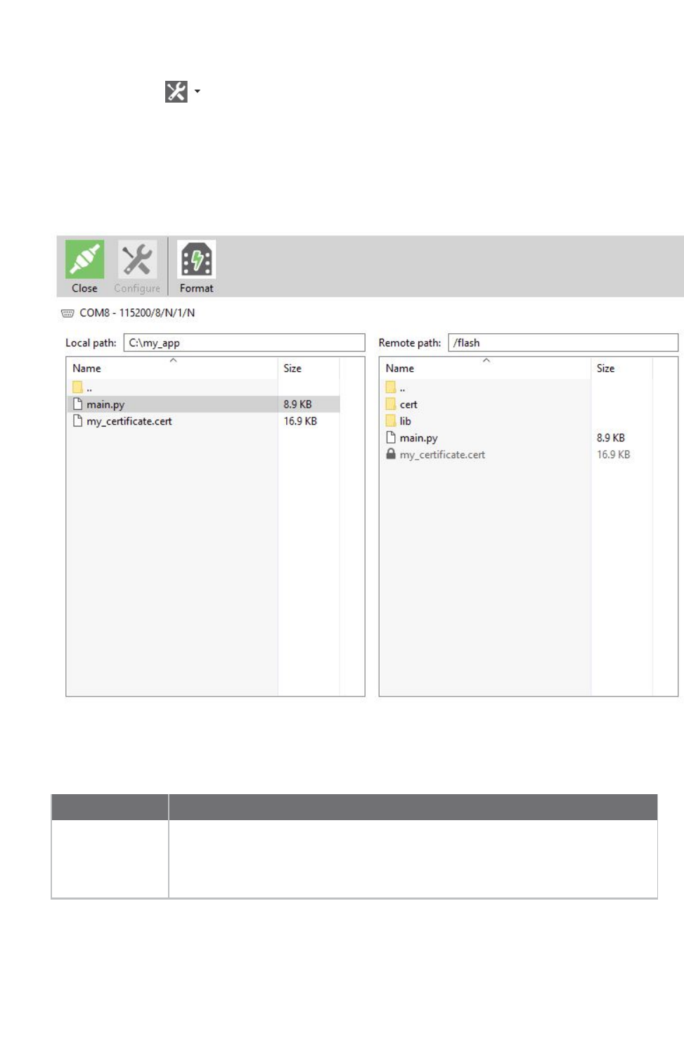
XCTU tools File system manger tool
XCTU User Guide 192
1. Launch the File System Mangager tool by selecting File System Manager from the Tools drop-
down menu on the main toolbar. The File System Manager dialog appears.
2. Click Open.
3. If you did not add your XBee module to XCTU before, select its serial port configuration. Click
OK to open the connection with the module.
4. If the serial configuration is correct and your XBee module supports file system, the contents of
the default path are listed in the remote file system view.
Operations with the file system
You can perform the following operations in the XBee file system:
Operation Description
Navigate Navigate through the different directories by double clicking on them. To go
back, double click on the parent directory (..) or press the backspace key. You
can also go directly to a specific path by typing it on the local/remote path text
box and pressing enter.

XCTU tools File system manger tool
XCTU User Guide 193
Operation Description
Upload Upload a file or directory to the XBee module. Drag-and-drop or right-click on a
file or directory and then click Upload. If you want to upload several files or
directories, select and drag them to the XBee file system view.
Upload a secure
file
Upload special files, such as certificates or keys, as write-only. Once the files are
uploaded to the XBee, they cannot be downloaded, renamed or moved; only
deleted. These secure files are displayed in the XBee file system with a lock
and are grayed out.
Download Download a file or directory from the XBee module. Drag-and-drop or right-click
a file or directory and then click Download. If you want to download several files
or directories, select and drag them to the local file system view.
Create directory Create a directory. Right-click on either the local or remote file system view and
click Create directory. You are asked to enter the name of the new directory.
Delete Delete any file or directory. Right-click a file or directory and click Delete. You
are asked to confirm the operation.
Rename Rename any file or directory. Right-click a file or directory and click Rename.
Get and
compare hash
Get the SHA256 hash of any secure file that is on the XBee file system and
compare it with the hash of a local file. Since secure files cannot be downloaded,
this operation allows you to verify that the secure file is actually equal to other
located on your computer. Right-click on a secure file and clickGet hash or
Compare hash.
Format Re-format the entire XBee file system by clicking the Format button located in
the toolbar.
Note This process erases all your files on the XBee module and cannot be
undone.

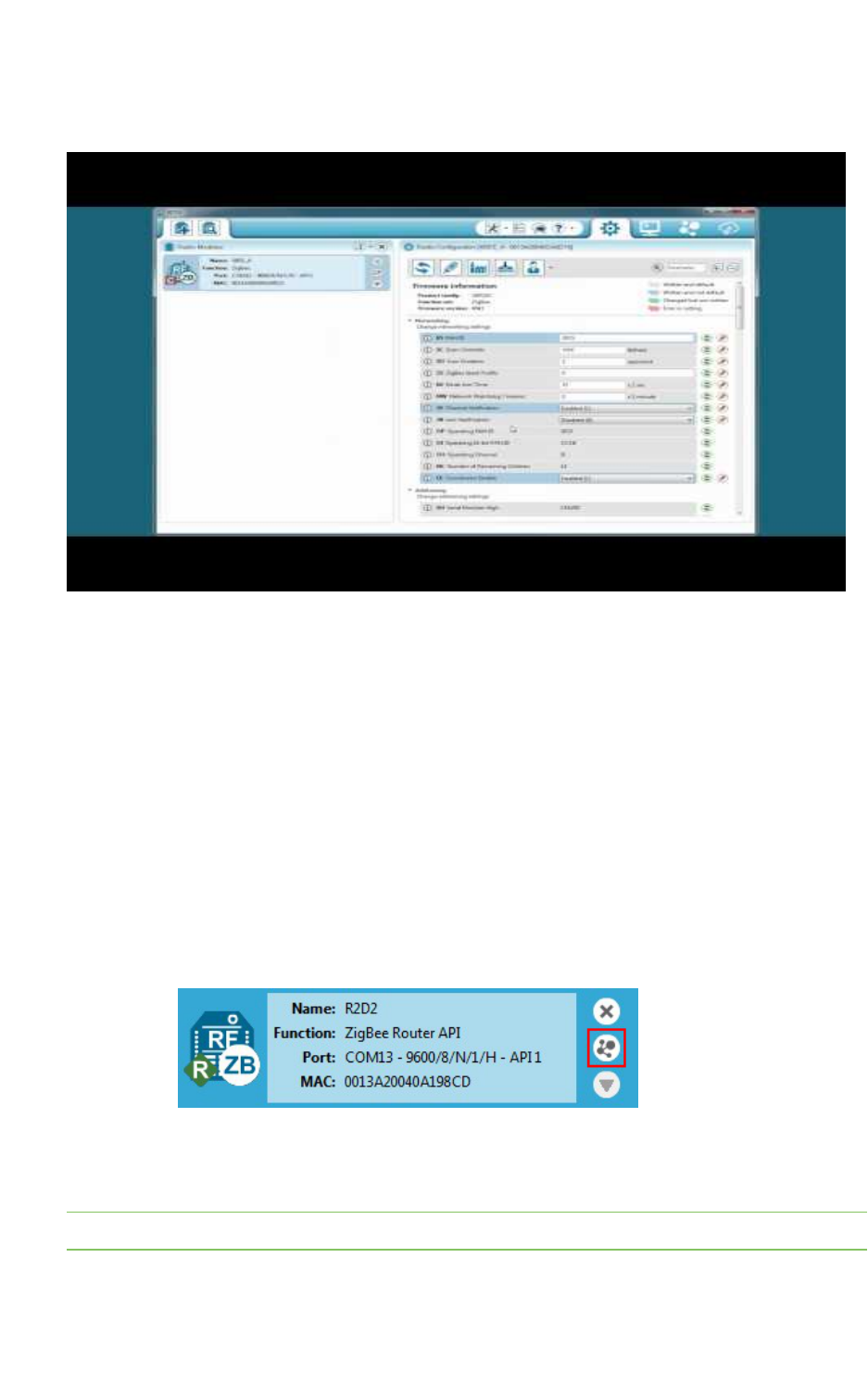
How-to articles and videos How to update the firmware of your modules
XCTU User Guide 195
How to update the firmware of your modules
Watch the video to learn how to perform local and remote firmware updates.
You can use XCTU to update firmware in both local and remote modules. For more information, see
Update firmware.
Step 1: Add the module to XCTU
You must have a local module connected to your computer in order to perform firmware updates,
either to update local firmware through the serial connection or to use the local device to remotely
upgrade another module in the same network. With a local module properly attached to your
computer, follow these steps:
1. Add the local module attached to your computer to XCTU so it is displayed in the radio modules
list.
2. Add your remote module in the network to XCTU:
a. Configure the local module you have just added to work in API mode.
b. Click Discover radio nodes in the same network to start a search of the remote
module.
c. When a remote module is found, it is listed in the Discovering remote devices
dialog. Select the device and click Add selected devices. The remote module is
added to the radio modules list as a subordinate to the local module.
Note Once you add your module to the radio modules list in XCTU, the update process is exactly the
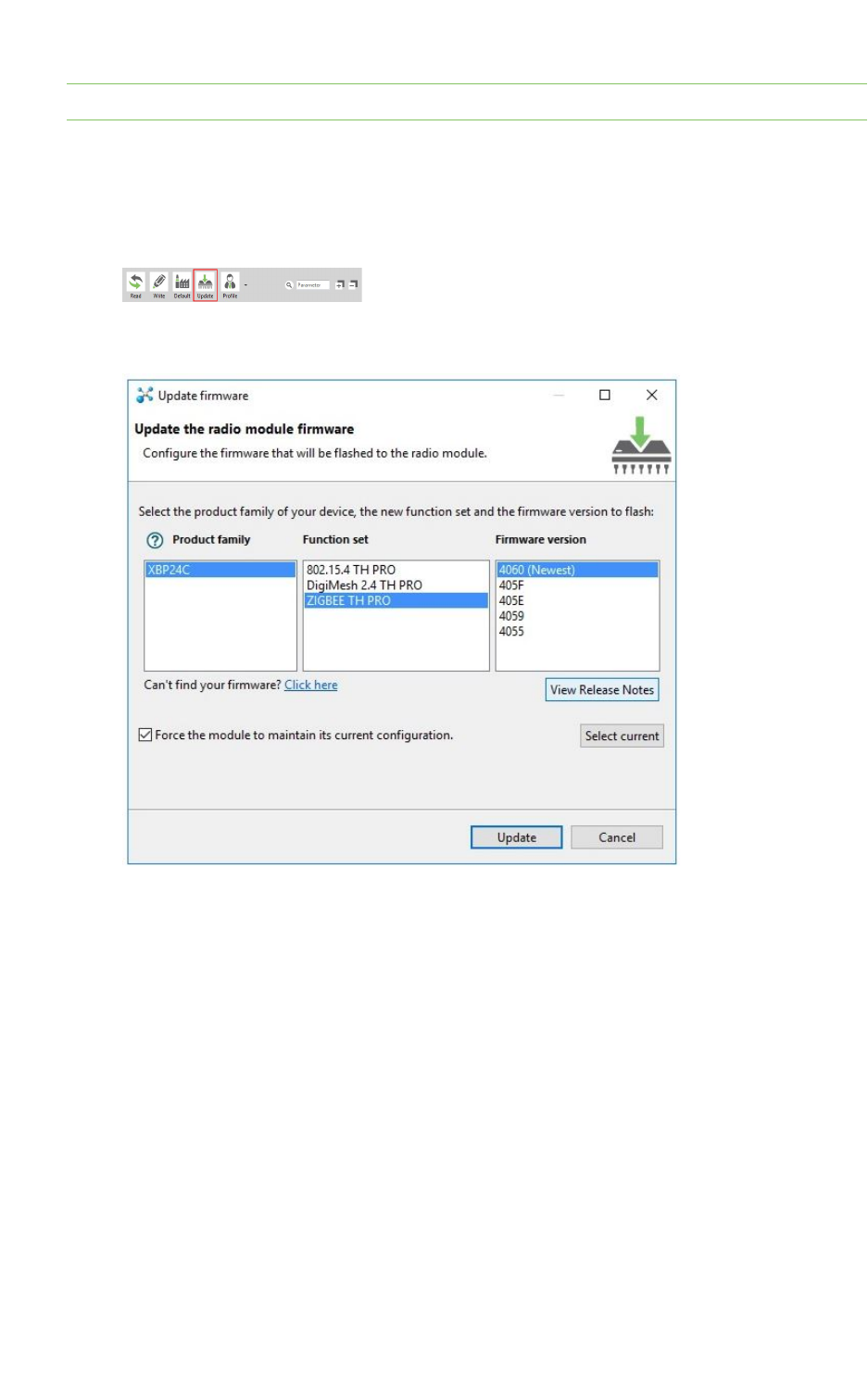
How-to articles and videos How to update the firmware of your modules
XCTU User Guide 196
same whether it is a local or remote module.
Step 2: Update the firmware
1. Select a local or remote module from the radio modules list. Click Update firmware. The
Update the radio module firmware dialog is displayed.
2. Select the product family, function set, and firmware version.
3. Click Update. A progress dialog displays the status of the update. Click Show details to review
the steps of the firmware update process.

How-to articles and videos How to visualize your network
XCTU User Guide 197
Over-the-air firmware update considerations
1. To perform a firmware update of a remote XBee in the same network, you must configure the
local module to work in API mode.
2. Remote firmware update functionality is limited to the following radio modules:
nXBee/XBee PRO SX
nXLR Pro Module
nXBee/XBee PRO 802.15.4 (S2C module versions only)
nXBee/XBee-PRO DigiMesh 2.4 (S2C module versions only)
nXTend RF Module Family (SX module versions only)
nXBee/XBee-PRO ZB and Programmable XBee-PRO ZB
nXBee/XBee-PRO ZB SMT and Programmable XBee-PRO ZB SMT
nXBee-PRO 900HP and Programmable XBee-PRO 900HP
nXBee 865LP and Programmable XBee 865LP
nXBee3 (Zigbee, DigiMesh 2.4, and 802.15.4)
3. If something goes wrong during the over-the-air firmware update of a remote node—for
example, the communication is lost because the remote device is disconnected—you must
perform a manual recovery. See XBee recovery tool.
How to visualize your network
Watch the video to learn how to explore your network with Network view.
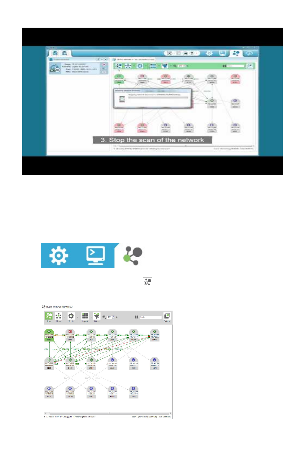
How-to articles and videos How to visualize your network
XCTU User Guide 198
Network working mode allows you to discover and visualize the topology and interconnections of your
network. For more information, see View your radio network.
Step 1:Scan the network
To discover the network, follow these steps:
1. Once you have added a module to XCTU, switch to Network working mode.
2. Click Scan the radio module network to start the network discovery process. Modules are
dynamically added as they are discovered, showing their connections and link quality.
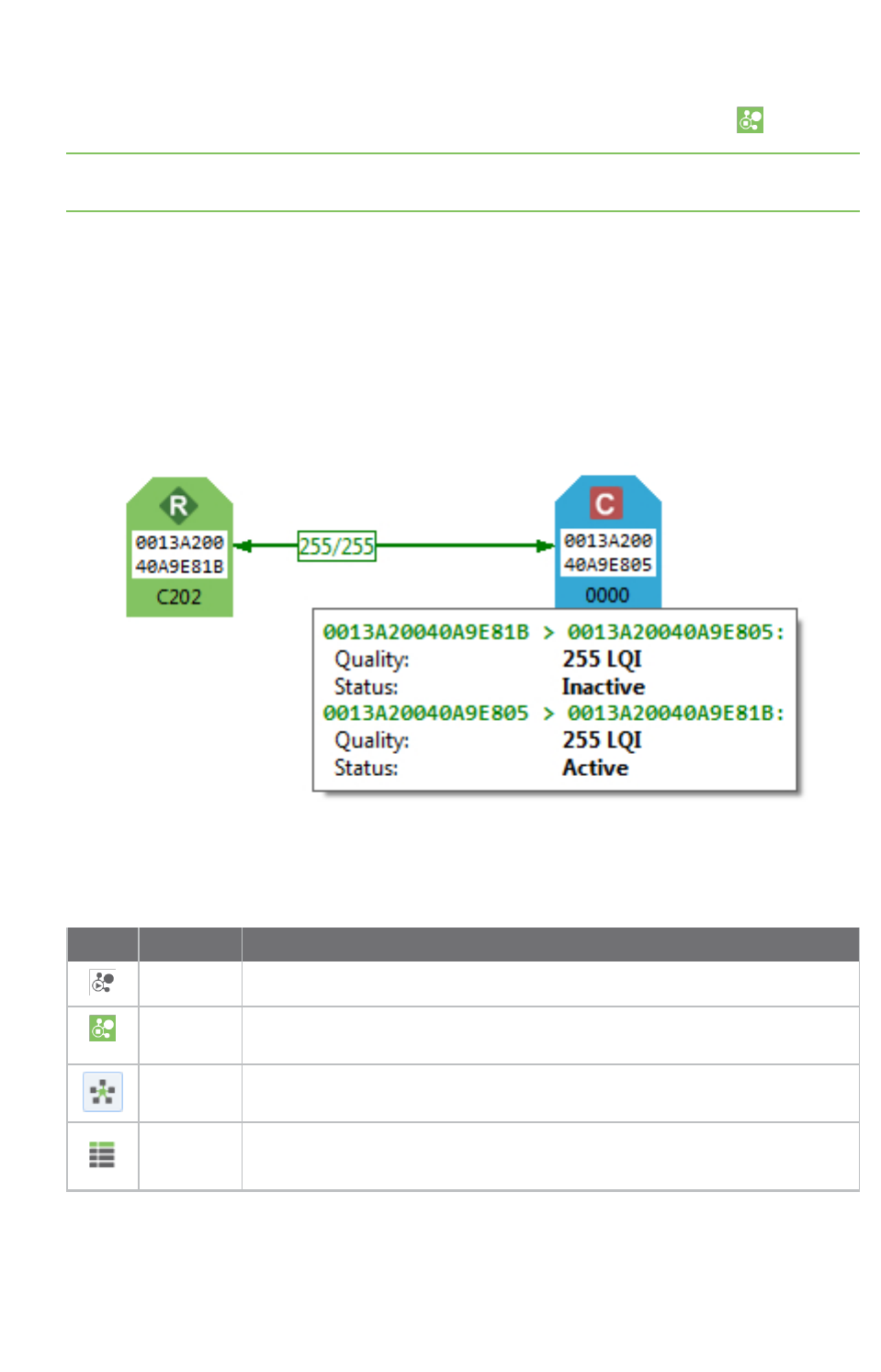
How-to articles and videos How to visualize your network
XCTU User Guide 199
3. The scan process automatically stops according to the network preferences configured in Set
network discovery preferences. You can also click Stop scanning the network at any time.
Note You may need to perform multiple scans to discover the entire network if, for example, modules
are sleeping or the network is very large.
Step 2:Explore the network
Each module displays information about itself such as its role or its address. Hover the cursor over a
module to view more detail.
The modules are connected by lines indicating connections with neighboring modules. The arrows
indicate the direction of communication. When you are using protocols such as ZigBee or DigiMesh,
click on a connection to view additional information about link quality and status.
Network working mode features can help you examine your network:
Button Name Description
Start scan Scans the radio module's network and displays a list of available modules.
Stop scan When scans specified in scan preferences are finished, the discovery process
stops automatically. You can also click the Stop scan button at any time.
Graph view Displays the modules as nodes in a graph.
Table view Displays the modules as rows in a table.
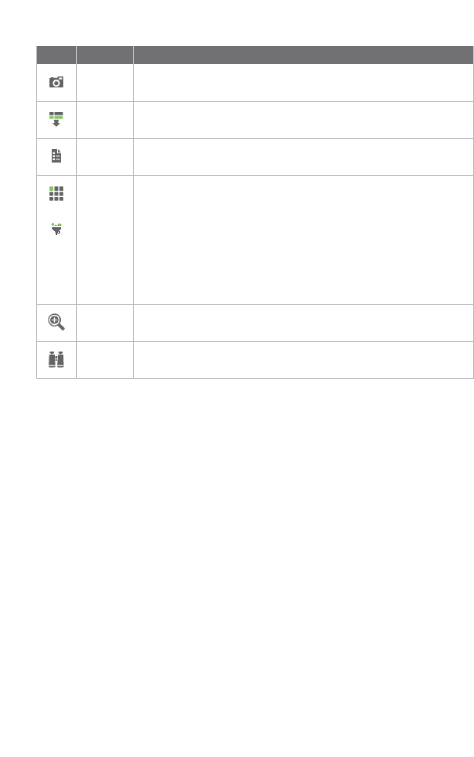
How-to articles and videos How to visualize your network
XCTU User Guide 200
Button Name Description
Screenshot Saves an image of the network to your computer.
Export
table
Exports network information in a tabular file format.
Settings Configures network-related parameters.
Layout Changes the network layout to one of six types: composite, spring, vertical
tree, horizontal tree, grid (default), and radial.
Filter links Hides or displays connections between RF modules based on their quality.
Enables/disables quality ranges via radio buttons. All filters are enabled by
default so all connections are visible.
You can establish connection quality colors and ranges in Preferences >
Network > Appearance or by clicking Configure quality ranges link in the
Filter links dialog.
See Set network discovery preferences.
Zoom Changes the zoom level of the network.
Find box Searches for a particular module in the network.
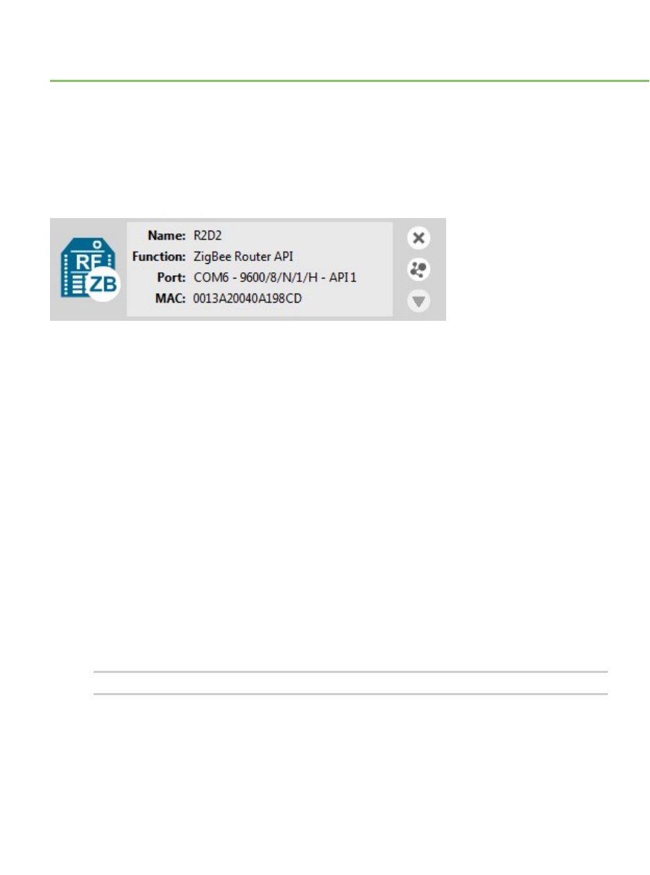
Troubleshooting for XCTU
Check here for answers to common questions about working with XCTU.
Troubleshooting: General
After adding a local device to the list of devices, the icon corresponding to the module does not display
the role of the module within its network.
The local radio module might not be joined to any network. In some cases (mostly in ZigBee
protocols), the device must be joined to a network in order to determine its configured role.
After a local DigiMesh radio module executes a remote node discovery process, the device becomes
unresponsive.
In the DigiMesh protocol, when you perform a Node Discovery (ND) or a Find Neighbors (FN) operation,
the module will not process any AT command until its configured NT time expires. If you want to talk
with the device immediately, you must restart it by pressing its reset button.
I have an end device radio module configured to sleep. It works in API operation mode with an ST
value less than one second, but XCTU is not able to find it or read its settings.
You may need to press the commissioning button of the device before performing any action with that
module in XCTU. Pressing the commissioning button will wake the module for 30 seconds so XCTU can
communicate with it.
I get a "Permission denied" error while trying to add or discover modules in Linux.
By default, access to the serial and USB ports in Linux is restricted to root and dialout group users. To
access your devices and communicate with them using XCTU, it is mandatory that your Linux user
belongs to this group. Follow these steps to add your Linux user to the dialout group:
1. Open a terminal console
2. Execute this command:
sudo usermod -a -G dialout <user>
Where <user> is the user you want to add to the dialout group.
3. Log out and log in again with that user in the system.
XCTU User Guide 201
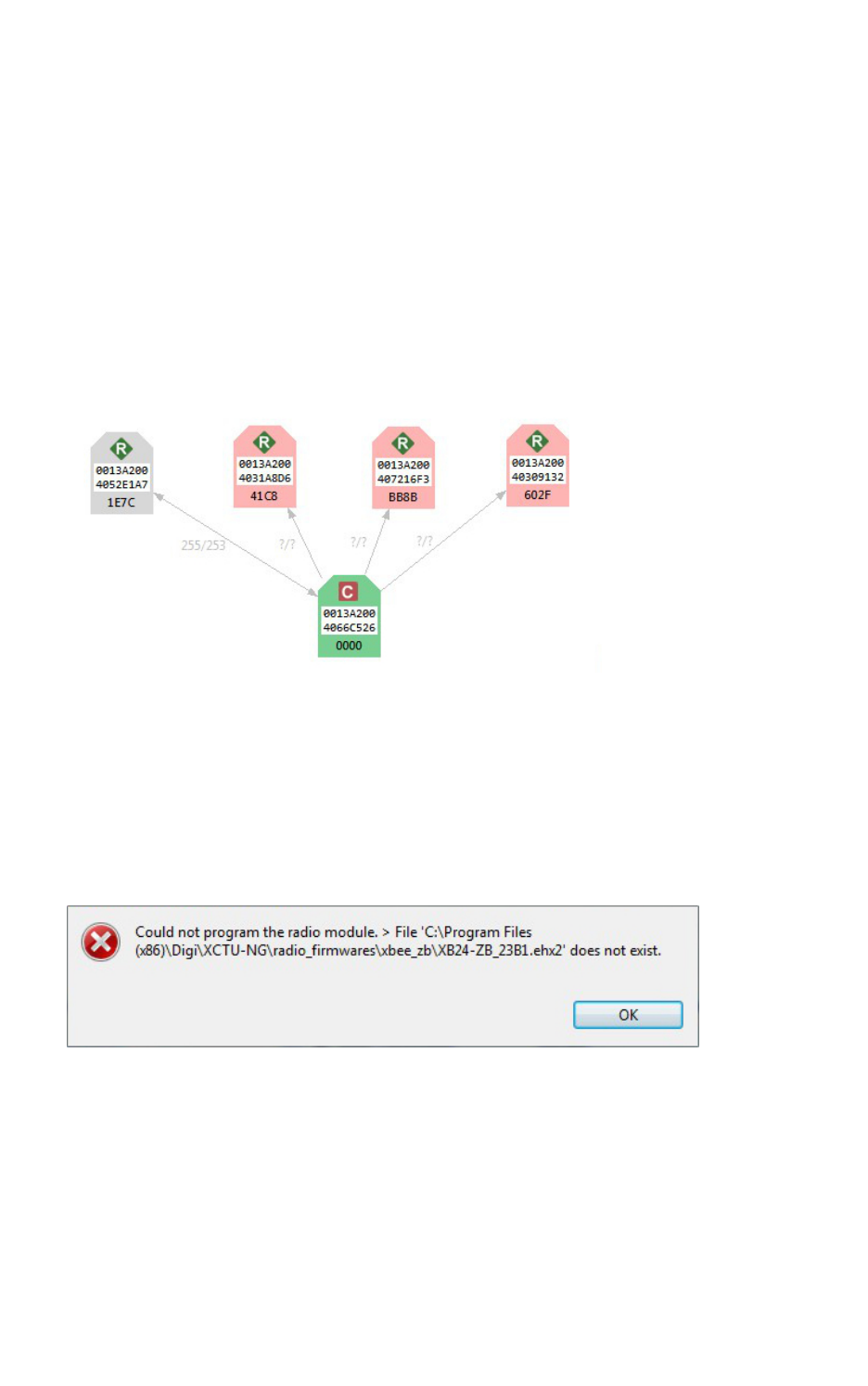
Troubleshooting for XCTU Troubleshooting: Networking
XCTU User Guide 202
Troubleshooting: Networking
Not all remote devices are found after clicking the search button of a local radio module in a relatively
big network.
In big networks, some devices may not answer the ND command in time. If not all devices are found
after executing the remote discovery process, do the following:
1. Add those that have been found.
2. Click the search button of the local device again.
3. When asked whether to clear the list of remote modules, click NO.
4. Wait for new modules to be discovered.
Repeat this process until all the modules on your network are found.
When discovering a network, some of the nodes are displayed in light red color. What does it mean?
Red radio modules represent devices that were in the network at any time in the past but are
unreachable now. When a radio module leaves the network, some devices may still contain
information about it. When a new discovery is performed, the module appears to be there but does
not answer or is unreachable when XCTU tries to verify the connection.
Troubleshooting: Firmware update
When XCTU is attempting to update the firmware of a local radio module, an error appears indicating
that the firmware binary does not exist.
You probably tried to install a firmware using an old firmware. Old firmware packets are not
compatible with this new version of XCTU. To obtain an updated firmware version, contact Digi
support.
When XCTU is attempting to update the firmware of a remote radio module, an error appears
indicating XCTU could not retrieve remote platform information.
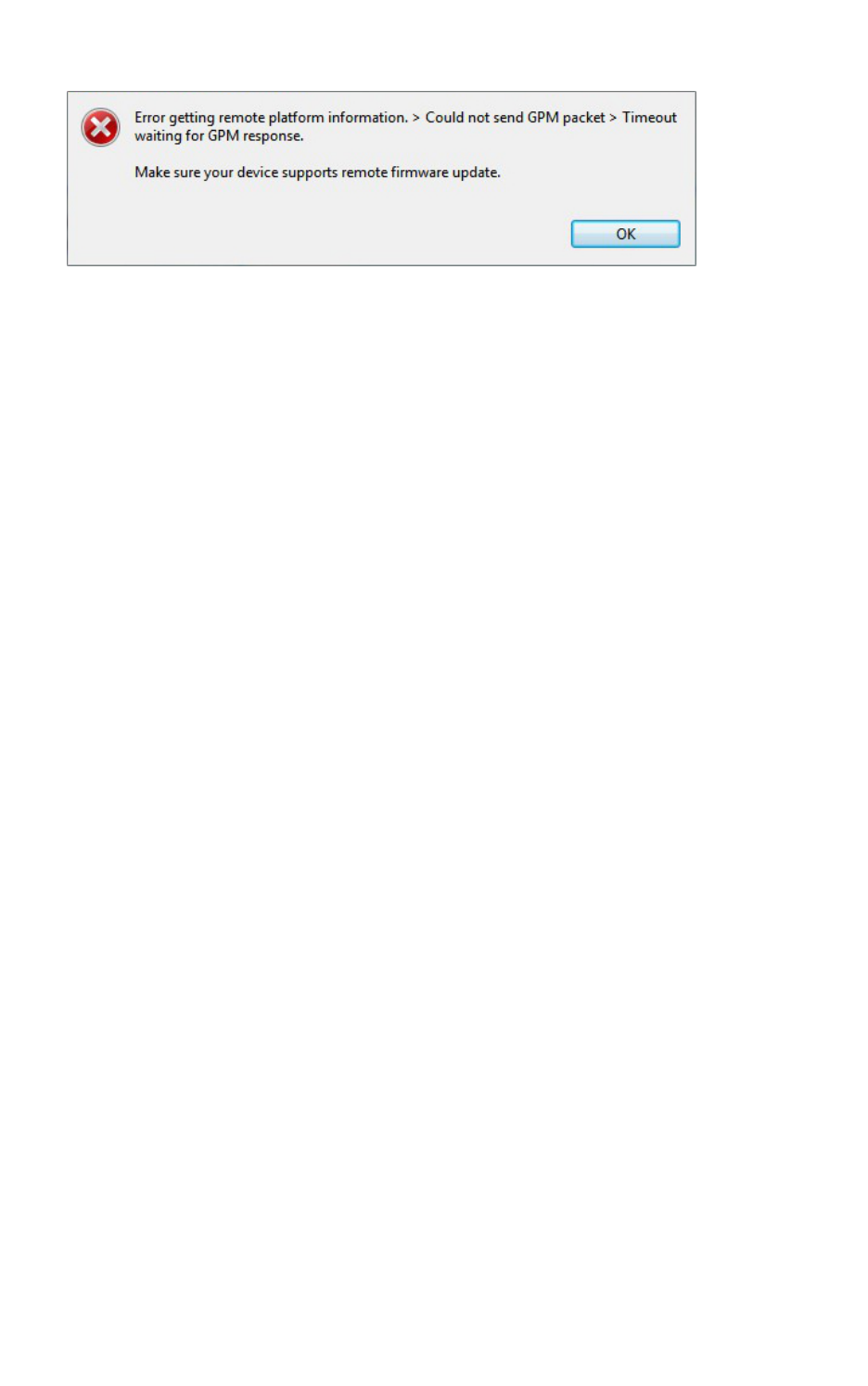
Troubleshooting for XCTU Troubleshooting: Add radio module
XCTU User Guide 203
Your remote radio module probably does not support remote firmware update. The following radio
modules support the remote firmware update feature:
nXBee/XBee-PRO SX
nXLR Pro Module
nXLRPRO Radio Solution
nXBee/XBee-PRO 802.15.4 (S2C module versions only)
nXBee/XBee-PRO DigiMesh 2.4 (S2C module versions only)
nXTend RF Module Family (SX module versions only)
nXBee/XBee-PRO ZB and Programmable XBee-PRO ZB
nXBee/XBee-PRO ZB SMTand Programmable XBee-PRO ZB SMT
nXBee-PRO 900HP and Programmable XBee-PRO 900HP
nXBee 868LP and Programmable XBee 868LP
nXBee3 (Zigbee, DigiMesh 2.4, and 802.15.4)
Troubleshooting: Add radio module
I can't find my module when trying to add it to the list of devices.
Investigate the following possible reasons that XCTU isn't finding your module:
nRadio module not connected/Invalid settings. The selected port or the serial port settings
where the radio module is connected are not valid. Make sure you have selected the correct
port and settings. The most common serial configuration is:
lBaud rate: 9600 or 115200
lData bits: 8
lStop bits: 1
lParity: None
lFlow control: None
nSleeping radio module. The radio module may be a sleeping node. If the module is sleeping at
the time XCTU tries to communicate with it, XCTU cannot add it to the device list. If you believe
your module could be sleeping, try to wake it up by pressing the Commissioning button of the
board the module is connected to. Immediately click Retry to attempt to add the radio module
again.
nProgrammable radio module. The radio module you are trying to add may be a
programmable variant. You must check the box next to The radio module is programmable in
the Add a radio module dialog. Then, try to add it again and reset your module when
prompted. For more information, see Add a programmable radio module.
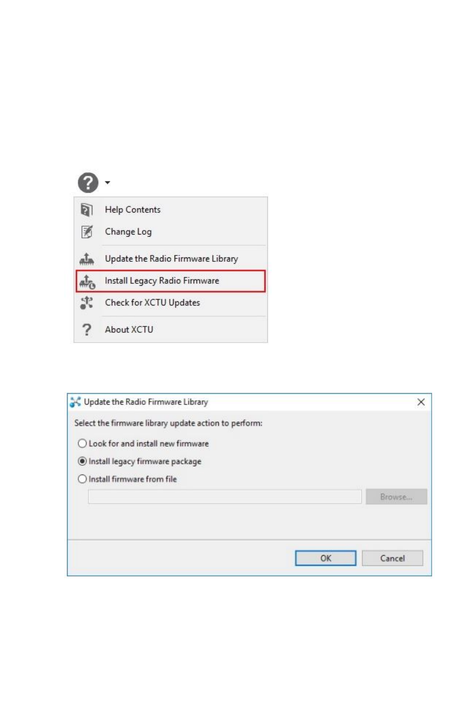
Troubleshooting for XCTU Troubleshooting: Add radio module
XCTU User Guide 204
nDamaged radio module. The firmware of the module may be damaged or the module may be
in programming mode. Click Recovery from the dialog to open XCTU’s XBee recovery tool. For
more information, see XBee recovery tool.
After adding a device to the list of devices, the Function field states "XXX - Not found in XCTU".
The firmware version of the radio module is not installed in XCTU. The radio module firmware may be
legacy firmware, and you need to install the legacy radio firmware package on XCTU. Follow these
steps to do so:
1. Select Help > Install Legacy Radio Firmware option.
2. The Install legacy firmware package option should be already selected in the Update the
Radio Firmware Library dialog. If not, select it.

Troubleshooting for XCTU Troubleshooting: Add radio module
XCTU User Guide 205
3. Click OK to start. A dialog displays the status of the download process.
nIf it does not fix the problem, try the same steps but choose the Look for and install
new firmware option in the Update the Radio Firmware Library dialog.
nIf the problem persists, contact with support so they can provide you the proper
firmware for your module. Then, follow previous steps but the Install firmware from
file option in the Update the Radio Firmware Library dialog and select the firmware
file you were provided with.

Known issues
XCTU currently has the following known issues and limitations:
nXCTU is not compatible with the following Digi RF devices:
oXTream OEM RF modules family
oXCite OEM RF modules family
nXCTU includes a mechanism to prevent the computer from going to sleep automatically in
Windows and MacOS systems when it is performing long-duration tasks such as network
discovery and range testing. Note that if you force the computer to sleep while XCTU is
performing such tasks, the USB ports that XCTU was communicating with may become
unresponsive after the system wakes from sleep. Furthermore, if you try to close the
communication with them they could hang and they won't recover even if you close XCTU. If
your experience this issue, you must unplug the USB cable and plug it in again to restore the
communication with the port. You can do this even while XCTU is running.
nZigBee local modules configured as end devices cannot perform network discovery in network
working mode.
nThe XLR PRO Radio Solution and programmable XBee radio modules do not support the XCTU
recovery feature.
nUNIX-based operating systems allow you to open multiple instances of the same port. This
scenario can produce unexpected behavior if you have the same port open simultaneously by
different Linux apps.
XCTU User Guide 206
