94C09_XTS2500_BSM XTS Series/XTS2500 Basic Service Manual 6881094C09 B XTS2500
User Manual: -XTS Series/XTS2500 Basic service manual 6881094C09-B
Open the PDF directly: View PDF ![]() .
.
Page Count: 88
- Table of Contents
- List of Figures
- List of Tables
- Related Manuals
- Commercial Warranty
- Specifications
- Introduction
- Basic Maintenance
- Basic Theory of Operation
- Recommended Test Equipment and Service Aids
- Performance Checks
- Radio Alignment Procedures
- XTS 2500/XTS 1500/MT 1500 Exploded View and Parts List
- Disassembly/Assembly
- Radio-Level Troubleshooting
- Accessories
- Glossary
- Index
- theory.pdf

XTS™2500
XTS™1500
MT 1500
700 - 800 MHz
Digital Portable Radios
Basic Service Manual

Foreword
This manual covers all models of the ASTRO™ Digital XTS 2500® Portable Radio, unless otherwise specified. It includes
all the information necessary to maintain peak product performance and maximum working time, using the pass/fail service
approach. This basic level of service is typical of some local service centers, self-maintained customers, and some
distributors.
Included in this manual are: radio specifications for the 700/800 MHz frequency bands; a general description of ASTRO
Digital XTS 2500 models; recommended test equipment, service aids, and tools; radio alignment procedures; fundamental
disassembly/reassembly procedures; and general maintenance recommendations.
For details on the operation of the radio, or board or component-level troubleshooting, refer to the applicable manuals,
available separately. To help you with your selection, a list is provided under “Related Publications” at the front of this
manual.
Safety
Before operating an ASTRO XTS 2500 Radio, please read the RF energy awareness information and operating instructions
in the Product Safety and RF Exposure booklet enclosed with your radio (Motorola Publication part number 68P81095C98)
to ensure compliance with RF energy exposure limits.
Manual Revisions
Changes which occur after this manual is printed are described in “FMRs.” These FMRs provide complete information on
changes, including pertinent parts list data.
Computer Software Copyrights
The Motorola products described in this manual may include copyrighted Motorola computer programs stored in
semiconductor memories or other media. Laws in the United States and other countries preserve for Motorola certain
exclusive rights for copyrighted computer programs, including, but not limited to, the exclusive right to copy or reproduce
in any form the copyrighted computer program. Accordingly, any copyrighted Motorola computer programs contained in
the Motorola products described in this manual may not be copied, reproduced, modified, reverse-engineered, or
distributed in any manner without the express written permission of Motorola. Furthermore, the purchase of Motorola
products shall not be deemed to grant either directly or by implication, estoppel, or otherwise, any license under the
copyrights, patents or patent applications of Motorola, except for the normal non-exclusive license to use that arises by
operation of law in the sale of a product.

i
Table of Contents ➠
List of Figures. . . . . . . . . . . . . . . . . . . . . . . . . . . . . . . . . . . . . . . . . . . . . . . . . . . . . . . . . . . . . . . . . . . . . . . . . . . . . . . . v
List of Tables . . . . . . . . . . . . . . . . . . . . . . . . . . . . . . . . . . . . . . . . . . . . . . . . . . . . . . . . . . . . . . . . . . . . . . . . . . . . . . . vii
Related Manuals. . . . . . . . . . . . . . . . . . . . . . . . . . . . . . . . . . . . . . . . . . . . . . . . . . . . . . . . . . . . . . . . . . . . . . . . . . . . viii
Commercial Warranty . . . . . . . . . . . . . . . . . . . . . . . . . . . . . . . . . . . . . . . . . . . . . . . . . . . . . . . . . . . . . . . . . . . . . . . .ix
Limited Warranty. . . . . . . . . . . . . . . . . . . . . . . . . . . . . . . . . . . . . . . . . . . . . . . . . . . . . . . . . . . . . . . . . . . . . . . . . . .ix
Specifications . . . . . . . . . . . . . . . . . . . . . . . . . . . . . . . . . . . . . . . . . . . . . . . . . . . . . . . . . . . . . . . . . . . . . . . . . . . . . . xiii
Portable Radio Model Numbering System. . . . . . . . . . . . . . . . . . . . . . . . . . . . . . . . . . . . . . . . . . . . . . . . . . . . . . xiii
Specifications for 700 MHz/800 MHz Radios. . . . . . . . . . . . . . . . . . . . . . . . . . . . . . . . . . . . . . . . . . . . . . . . . . . .xiv
ASTRO Digital XTS 2500 Model Chart . . . . . . . . . . . . . . . . . . . . . . . . . . . . . . . . . . . . . . . . . . . . . . . . . . . . . . . . xv
ASTRO XTS 1500/MT 1500 Model Chart . . . . . . . . . . . . . . . . . . . . . . . . . . . . . . . . . . . . . . . . . . . . . . . . . . . . . . xv
1 - Introduction. . . . . . . . . . . . . . . . . . . . . . . . . . . . . . . . . . . . . . . . . . . . . . . . . . . . . . . . . . . . . . . . . . . . . . . . . . . . . . . 1
General . . . . . . . . . . . . . . . . . . . . . . . . . . . . . . . . . . . . . . . . . . . . . . . . . . . . . . . . . . . . . . . . . . . . . . . . . . . . . . . . . . . 1
Notations Used in This Manual . . . . . . . . . . . . . . . . . . . . . . . . . . . . . . . . . . . . . . . . . . . . . . . . . . . . . . . . . . . . . . . . 1
Radio Description. . . . . . . . . . . . . . . . . . . . . . . . . . . . . . . . . . . . . . . . . . . . . . . . . . . . . . . . . . . . . . . . . . . . . . . . . . . 2
FLASHport. . . . . . . . . . . . . . . . . . . . . . . . . . . . . . . . . . . . . . . . . . . . . . . . . . . . . . . . . . . . . . . . . . . . . . . . . . . . . . . . 2
2 - Basic Maintenance . . . . . . . . . . . . . . . . . . . . . . . . . . . . . . . . . . . . . . . . . . . . . . . . . . . . . . . . . . . . . . . . . . . . . . . . . 3
Introduction to This Section. . . . . . . . . . . . . . . . . . . . . . . . . . . . . . . . . . . . . . . . . . . . . . . . . . . . . . . . . . . . . . . . . . . 3
Preventive Maintenance. . . . . . . . . . . . . . . . . . . . . . . . . . . . . . . . . . . . . . . . . . . . . . . . . . . . . . . . . . . . . . . . . . . . . . 3
Inspection . . . . . . . . . . . . . . . . . . . . . . . . . . . . . . . . . . . . . . . . . . . . . . . . . . . . . . . . . . . . . . . . . . . . . . . . . . . . . . 3
Cleaning . . . . . . . . . . . . . . . . . . . . . . . . . . . . . . . . . . . . . . . . . . . . . . . . . . . . . . . . . . . . . . . . . . . . . . . . . . . . . . . 3
Cleaning External Plastic Surfaces. . . . . . . . . . . . . . . . . . . . . . . . . . . . . . . . . . . . . . . . . . . . . . . . . . . . . . . . 3
Handling Precautions . . . . . . . . . . . . . . . . . . . . . . . . . . . . . . . . . . . . . . . . . . . . . . . . . . . . . . . . . . . . . . . . . . . . . . . . 4
3 - Basic Theory of Operation. . . . . . . . . . . . . . . . . . . . . . . . . . . . . . . . . . . . . . . . . . . . . . . . . . . . . . . . . . . . . . . . . . . 5
General Overview . . . . . . . . . . . . . . . . . . . . . . . . . . . . . . . . . . . . . . . . . . . . . . . . . . . . . . . . . . . . . . . . . . . . . . . . . . 5
Analog Mode of Operation . . . . . . . . . . . . . . . . . . . . . . . . . . . . . . . . . . . . . . . . . . . . . . . . . . . . . . . . . . . . . . . . . . . 6
Receiving . . . . . . . . . . . . . . . . . . . . . . . . . . . . . . . . . . . . . . . . . . . . . . . . . . . . . . . . . . . . . . . . . . . . . . . . . . . . . . 6
Transmitting . . . . . . . . . . . . . . . . . . . . . . . . . . . . . . . . . . . . . . . . . . . . . . . . . . . . . . . . . . . . . . . . . . . . . . . . . . . . 6
ASTRO Mode of Operation . . . . . . . . . . . . . . . . . . . . . . . . . . . . . . . . . . . . . . . . . . . . . . . . . . . . . . . . . . . . . . . . . . . 7
RF Basic Theory of Operation . . . . . . . . . . . . . . . . . . . . . . . . . . . . . . . . . . . . . . . . . . . . . . . . . . . . . . . . . . . . . . . . . 7
VOCON Basic Theory of Operation . . . . . . . . . . . . . . . . . . . . . . . . . . . . . . . . . . . . . . . . . . . . . . . . . . . . . . . . . . . . 8
4 - Recommended Test Equipment and Service Aids. . . . . . . . . . . . . . . . . . . . . . . . . . . . . . . . . . . . . . . . . . . . . . . . 9
Recommended
Test Equipment . . . . . . . . . . . . . . . . . . . . . . . . . . . . . . . . . . . . . . . . . . . . . . . . . . . . . . . . . . . . . . . . . . . . . . . . . . . . 9
Service Aids . . . . . . . . . . . . . . . . . . . . . . . . . . . . . . . . . . . . . . . . . . . . . . . . . . . . . . . . . . . . . . . . . . . . . . . . . . . . . . 10
Field Programming Equipment . . . . . . . . . . . . . . . . . . . . . . . . . . . . . . . . . . . . . . . . . . . . . . . . . . . . . . . . . . . . . . . 10
5 - Performance Checks. . . . . . . . . . . . . . . . . . . . . . . . . . . . . . . . . . . . . . . . . . . . . . . . . . . . . . . . . . . . . . . . . . . . . . . 11
Introduction to This Section. . . . . . . . . . . . . . . . . . . . . . . . . . . . . . . . . . . . . . . . . . . . . . . . . . . . . . . . . . . . . . . . . . 11
Setup. . . . . . . . . . . . . . . . . . . . . . . . . . . . . . . . . . . . . . . . . . . . . . . . . . . . . . . . . . . . . . . . . . . . . . . . . . . . . . . . . . . . 11
Display Radio Test Mode. . . . . . . . . . . . . . . . . . . . . . . . . . . . . . . . . . . . . . . . . . . . . . . . . . . . . . . . . . . . . . . . . . . . 12
Entering Display Radio Test Mode . . . . . . . . . . . . . . . . . . . . . . . . . . . . . . . . . . . . . . . . . . . . . . . . . . . . . . . . . 12
RF Test Mode (Display Radio) . . . . . . . . . . . . . . . . . . . . . . . . . . . . . . . . . . . . . . . . . . . . . . . . . . . . . . . . . . . . 13
Table of Contents
ii
Control Top and Keypad Test Mode (Display Radio). . . . . . . . . . . . . . . . . . . . . . . . . . . . . . . . . . . . . . . . . . . 14
Non-Display Radio Test Mode . . . . . . . . . . . . . . . . . . . . . . . . . . . . . . . . . . . . . . . . . . . . . . . . . . . . . . . . . . . . . . . 15
Entering Non-Display Radio Test Mode . . . . . . . . . . . . . . . . . . . . . . . . . . . . . . . . . . . . . . . . . . . . . . . . . . . . . 15
RF Test Mode (Non-Display Radio) . . . . . . . . . . . . . . . . . . . . . . . . . . . . . . . . . . . . . . . . . . . . . . . . . . . . . . . . 15
Control Top and Keypad Test Mode (Non-Display Radio) . . . . . . . . . . . . . . . . . . . . . . . . . . . . . . . . . . . . . . 16
6 - Radio Alignment Procedures . . . . . . . . . . . . . . . . . . . . . . . . . . . . . . . . . . . . . . . . . . . . . . . . . . . . . . . . . . . . . . . 19
Introduction to This Section . . . . . . . . . . . . . . . . . . . . . . . . . . . . . . . . . . . . . . . . . . . . . . . . . . . . . . . . . . . . . . . . . 19
General . . . . . . . . . . . . . . . . . . . . . . . . . . . . . . . . . . . . . . . . . . . . . . . . . . . . . . . . . . . . . . . . . . . . . . . . . . . . . . . . . 19
Radio Information . . . . . . . . . . . . . . . . . . . . . . . . . . . . . . . . . . . . . . . . . . . . . . . . . . . . . . . . . . . . . . . . . . . . . . . . . 21
Reference Oscillator Alignment . . . . . . . . . . . . . . . . . . . . . . . . . . . . . . . . . . . . . . . . . . . . . . . . . . . . . . . . . . . . . . 21
Transmit Power Alignment . . . . . . . . . . . . . . . . . . . . . . . . . . . . . . . . . . . . . . . . . . . . . . . . . . . . . . . . . . . . . . . . . . 23
Transmit Deviation Balance Alignment . . . . . . . . . . . . . . . . . . . . . . . . . . . . . . . . . . . . . . . . . . . . . . . . . . . . . . . . 25
Transmit Deviation Limit Alignment . . . . . . . . . . . . . . . . . . . . . . . . . . . . . . . . . . . . . . . . . . . . . . . . . . . . . . . . . . 27
Front End Filter Alignment . . . . . . . . . . . . . . . . . . . . . . . . . . . . . . . . . . . . . . . . . . . . . . . . . . . . . . . . . . . . . . . . . . 28
Definition. . . . . . . . . . . . . . . . . . . . . . . . . . . . . . . . . . . . . . . . . . . . . . . . . . . . . . . . . . . . . . . . . . . . . . . . . . . . . 28
Procedure for 700 MHz Frequencies. . . . . . . . . . . . . . . . . . . . . . . . . . . . . . . . . . . . . . . . . . . . . . . . . . . . . . . . 28
Procedure for 800 MHz Frequencies. . . . . . . . . . . . . . . . . . . . . . . . . . . . . . . . . . . . . . . . . . . . . . . . . . . . . . . . 28
Procedure for UHF/VHF . . . . . . . . . . . . . . . . . . . . . . . . . . . . . . . . . . . . . . . . . . . . . . . . . . . . . . . . . . . . . . . . . 28
Bit Error Rate . . . . . . . . . . . . . . . . . . . . . . . . . . . . . . . . . . . . . . . . . . . . . . . . . . . . . . . . . . . . . . . . . . . . . . . . . . . . 29
Definition. . . . . . . . . . . . . . . . . . . . . . . . . . . . . . . . . . . . . . . . . . . . . . . . . . . . . . . . . . . . . . . . . . . . . . . . . . . . . 29
Bit Error Rate Fields . . . . . . . . . . . . . . . . . . . . . . . . . . . . . . . . . . . . . . . . . . . . . . . . . . . . . . . . . . . . . . . . . . . . 29
Transmitter Test Pattern . . . . . . . . . . . . . . . . . . . . . . . . . . . . . . . . . . . . . . . . . . . . . . . . . . . . . . . . . . . . . . . . . . . . 31
Definition. . . . . . . . . . . . . . . . . . . . . . . . . . . . . . . . . . . . . . . . . . . . . . . . . . . . . . . . . . . . . . . . . . . . . . . . . . . . . 31
Transmitter Test Fields . . . . . . . . . . . . . . . . . . . . . . . . . . . . . . . . . . . . . . . . . . . . . . . . . . . . . . . . . . . . . . . . . . 31
7 - XTS 2500/XTS 1500/MT 1500 Exploded View and Parts List . . . . . . . . . . . . . . . . . . . . . . . . . . . . . . . . . . . . 33
XTS 2500/XTS 1500/MT 1500 Model I Exploded View. . . . . . . . . . . . . . . . . . . . . . . . . . . . . . . . . . . . . . . . . . . 33
XTS 2500 Model II Exploded View . . . . . . . . . . . . . . . . . . . . . . . . . . . . . . . . . . . . . . . . . . . . . . . . . . . . . . . . . . . 34
XTS 2500 Model III Exploded View . . . . . . . . . . . . . . . . . . . . . . . . . . . . . . . . . . . . . . . . . . . . . . . . . . . . . . . . . . 35
8 - Disassembly/Assembly. . . . . . . . . . . . . . . . . . . . . . . . . . . . . . . . . . . . . . . . . . . . . . . . . . . . . . . . . . . . . . . . . . . . . 37
Introduction to This Section . . . . . . . . . . . . . . . . . . . . . . . . . . . . . . . . . . . . . . . . . . . . . . . . . . . . . . . . . . . . . . . . . 37
Antenna . . . . . . . . . . . . . . . . . . . . . . . . . . . . . . . . . . . . . . . . . . . . . . . . . . . . . . . . . . . . . . . . . . . . . . . . . . . . . . . . . 37
Attach the Antenna . . . . . . . . . . . . . . . . . . . . . . . . . . . . . . . . . . . . . . . . . . . . . . . . . . . . . . . . . . . . . . . . . . . . . 37
Remove the Antenna . . . . . . . . . . . . . . . . . . . . . . . . . . . . . . . . . . . . . . . . . . . . . . . . . . . . . . . . . . . . . . . . . . . . 37
Battery . . . . . . . . . . . . . . . . . . . . . . . . . . . . . . . . . . . . . . . . . . . . . . . . . . . . . . . . . . . . . . . . . . . . . . . . . . . . . . . . . . 38
Attach the Battery . . . . . . . . . . . . . . . . . . . . . . . . . . . . . . . . . . . . . . . . . . . . . . . . . . . . . . . . . . . . . . . . . . . . . . 38
Remove the Battery . . . . . . . . . . . . . . . . . . . . . . . . . . . . . . . . . . . . . . . . . . . . . . . . . . . . . . . . . . . . . . . . . . . . . 38
Belt Clip. . . . . . . . . . . . . . . . . . . . . . . . . . . . . . . . . . . . . . . . . . . . . . . . . . . . . . . . . . . . . . . . . . . . . . . . . . . . . . . . . 39
Attach the Belt Clip . . . . . . . . . . . . . . . . . . . . . . . . . . . . . . . . . . . . . . . . . . . . . . . . . . . . . . . . . . . . . . . . . . . . . 39
Remove the Belt Clip. . . . . . . . . . . . . . . . . . . . . . . . . . . . . . . . . . . . . . . . . . . . . . . . . . . . . . . . . . . . . . . . . . . . 39
Universal Connector Cover. . . . . . . . . . . . . . . . . . . . . . . . . . . . . . . . . . . . . . . . . . . . . . . . . . . . . . . . . . . . . . . . . . 40
Remove the Universal Connector Cover . . . . . . . . . . . . . . . . . . . . . . . . . . . . . . . . . . . . . . . . . . . . . . . . . . . . . 40
Attach the Universal Connector Cover . . . . . . . . . . . . . . . . . . . . . . . . . . . . . . . . . . . . . . . . . . . . . . . . . . . . . . 40
Remote Speaker Microphone Adapter . . . . . . . . . . . . . . . . . . . . . . . . . . . . . . . . . . . . . . . . . . . . . . . . . . . . . . . . . 41
Remove the Adapter . . . . . . . . . . . . . . . . . . . . . . . . . . . . . . . . . . . . . . . . . . . . . . . . . . . . . . . . . . . . . . . . . . . . 41
Attach the Adapter. . . . . . . . . . . . . . . . . . . . . . . . . . . . . . . . . . . . . . . . . . . . . . . . . . . . . . . . . . . . . . . . . . . . . . 41
Radio Disassembly—Detailed. . . . . . . . . . . . . . . . . . . . . . . . . . . . . . . . . . . . . . . . . . . . . . . . . . . . . . . . . . . . . . . . 42
Required Tools. . . . . . . . . . . . . . . . . . . . . . . . . . . . . . . . . . . . . . . . . . . . . . . . . . . . . . . . . . . . . . . . . . . . . . . . . 42
Front Cover from Chassis Disassembly . . . . . . . . . . . . . . . . . . . . . . . . . . . . . . . . . . . . . . . . . . . . . . . . . . . . . 42
Chassis Disassembly . . . . . . . . . . . . . . . . . . . . . . . . . . . . . . . . . . . . . . . . . . . . . . . . . . . . . . . . . . . . . . . . . . . . 45
Backup Battery Disassembly. . . . . . . . . . . . . . . . . . . . . . . . . . . . . . . . . . . . . . . . . . . . . . . . . . . . . . . . . . . . . . 46
Keypad and Keypad/Option Board Disassembly . . . . . . . . . . . . . . . . . . . . . . . . . . . . . . . . . . . . . . . . . . . . . . 47
Display Disassembly . . . . . . . . . . . . . . . . . . . . . . . . . . . . . . . . . . . . . . . . . . . . . . . . . . . . . . . . . . . . . . . . . . . . 49
Speaker, Microphone, and Universal Connector Flex Disassembly . . . . . . . . . . . . . . . . . . . . . . . . . . . . . . . . 50
PTT Disassembly. . . . . . . . . . . . . . . . . . . . . . . . . . . . . . . . . . . . . . . . . . . . . . . . . . . . . . . . . . . . . . . . . . . . . . . 51
Radio Reassembly—Detailed . . . . . . . . . . . . . . . . . . . . . . . . . . . . . . . . . . . . . . . . . . . . . . . . . . . . . . . . . . . . . . . . 52
Table of Contents
iii
PTT Reassembly. . . . . . . . . . . . . . . . . . . . . . . . . . . . . . . . . . . . . . . . . . . . . . . . . . . . . . . . . . . . . . . . . . . . . . . . 52
Keypad and Keypad Option Board Reassembly . . . . . . . . . . . . . . . . . . . . . . . . . . . . . . . . . . . . . . . . . . . . . . . 53
Display Reassembly . . . . . . . . . . . . . . . . . . . . . . . . . . . . . . . . . . . . . . . . . . . . . . . . . . . . . . . . . . . . . . . . . . . . . 53
Speaker, Microphone, and Universal Connector Flex Reassembly . . . . . . . . . . . . . . . . . . . . . . . . . . . . . . . . . 53
Chassis Assembly Reassembly. . . . . . . . . . . . . . . . . . . . . . . . . . . . . . . . . . . . . . . . . . . . . . . . . . . . . . . . . . . . . 54
Backup Battery Reassembly. . . . . . . . . . . . . . . . . . . . . . . . . . . . . . . . . . . . . . . . . . . . . . . . . . . . . . . . . . . . . . . 54
Chassis and Front Cover Reassembly . . . . . . . . . . . . . . . . . . . . . . . . . . . . . . . . . . . . . . . . . . . . . . . . . . . . . . . 54
9 - Radio-Level Troubleshooting . . . . . . . . . . . . . . . . . . . . . . . . . . . . . . . . . . . . . . . . . . . . . . . . . . . . . . . . . . . . . . . 57
Introduction to This Section. . . . . . . . . . . . . . . . . . . . . . . . . . . . . . . . . . . . . . . . . . . . . . . . . . . . . . . . . . . . . . . . . . 57
Power-Up Error Codes. . . . . . . . . . . . . . . . . . . . . . . . . . . . . . . . . . . . . . . . . . . . . . . . . . . . . . . . . . . . . . . . . . . . . . 57
Operational Error Codes. . . . . . . . . . . . . . . . . . . . . . . . . . . . . . . . . . . . . . . . . . . . . . . . . . . . . . . . . . . . . . . . . . . . . 58
10 - Accessories. . . . . . . . . . . . . . . . . . . . . . . . . . . . . . . . . . . . . . . . . . . . . . . . . . . . . . . . . . . . . . . . . . . . . . . . . . . . . . 61
General . . . . . . . . . . . . . . . . . . . . . . . . . . . . . . . . . . . . . . . . . . . . . . . . . . . . . . . . . . . . . . . . . . . . . . . . . . . . . . . . . . 61
Antennas. . . . . . . . . . . . . . . . . . . . . . . . . . . . . . . . . . . . . . . . . . . . . . . . . . . . . . . . . . . . . . . . . . . . . . . . . . . . . . . . . 61
Audio . . . . . . . . . . . . . . . . . . . . . . . . . . . . . . . . . . . . . . . . . . . . . . . . . . . . . . . . . . . . . . . . . . . . . . . . . . . . . . . . . . . 61
Headsets . . . . . . . . . . . . . . . . . . . . . . . . . . . . . . . . . . . . . . . . . . . . . . . . . . . . . . . . . . . . . . . . . . . . . . . . . . . . . . 61
Earpieces. . . . . . . . . . . . . . . . . . . . . . . . . . . . . . . . . . . . . . . . . . . . . . . . . . . . . . . . . . . . . . . . . . . . . . . . . . . . . . 61
Remote Speaker Microphones . . . . . . . . . . . . . . . . . . . . . . . . . . . . . . . . . . . . . . . . . . . . . . . . . . . . . . . . . . . . . 61
Surveillance . . . . . . . . . . . . . . . . . . . . . . . . . . . . . . . . . . . . . . . . . . . . . . . . . . . . . . . . . . . . . . . . . . . . . . . . . . . . . . 62
Batteries . . . . . . . . . . . . . . . . . . . . . . . . . . . . . . . . . . . . . . . . . . . . . . . . . . . . . . . . . . . . . . . . . . . . . . . . . . . . . . . . . 62
Belt Clips . . . . . . . . . . . . . . . . . . . . . . . . . . . . . . . . . . . . . . . . . . . . . . . . . . . . . . . . . . . . . . . . . . . . . . . . . . . . . . . . 62
Carrying Cases . . . . . . . . . . . . . . . . . . . . . . . . . . . . . . . . . . . . . . . . . . . . . . . . . . . . . . . . . . . . . . . . . . . . . . . . . . . . 62
Chargers . . . . . . . . . . . . . . . . . . . . . . . . . . . . . . . . . . . . . . . . . . . . . . . . . . . . . . . . . . . . . . . . . . . . . . . . . . . . . . . . . 63
Charger Mounting Kits. . . . . . . . . . . . . . . . . . . . . . . . . . . . . . . . . . . . . . . . . . . . . . . . . . . . . . . . . . . . . . . . . . . 63
Enhanced and Multi-Unit Line Cords . . . . . . . . . . . . . . . . . . . . . . . . . . . . . . . . . . . . . . . . . . . . . . . . . . . . . . . . . . 63
Glossary. . . . . . . . . . . . . . . . . . . . . . . . . . . . . . . . . . . . . . . . . . . . . . . . . . . . . . . . . . . . . . . . . . . . . . . . . . . . . . . . . . . . 65
Index . . . . . . . . . . . . . . . . . . . . . . . . . . . . . . . . . . . . . . . . . . . . . . . . . . . . . . . . . . . . . . . . . . . . . . . . . . . . . . . . . . . . . . 67
Table of Contents
iv
List of Figures
v
List of Figures
Figure 1. XTS 2500 Overall Block Diagram. . . . . . . . . . . . . . . . . . . . . . . . . . . . . . . . . . . . . . . . . . . . . . . . . . . . . . . . . . . . 5
Figure 2. Receiver Block Diagram . . . . . . . . . . . . . . . . . . . . . . . . . . . . . . . . . . . . . . . . . . . . . . . . . . . . . . . . . . . . . . . . . . . 6
Figure 3. RF Block Diagram (Power and Control Omitted) . . . . . . . . . . . . . . . . . . . . . . . . . . . . . . . . . . . . . . . . . . . . . . . . 7
Figure 4. Radio Alignment Test Setup. . . . . . . . . . . . . . . . . . . . . . . . . . . . . . . . . . . . . . . . . . . . . . . . . . . . . . . . . . . . . . . . 11
Figure 5. Tuner Menu Layout . . . . . . . . . . . . . . . . . . . . . . . . . . . . . . . . . . . . . . . . . . . . . . . . . . . . . . . . . . . . . . . . . . . . . . 19
Figure 6. Typical Softpot Screen . . . . . . . . . . . . . . . . . . . . . . . . . . . . . . . . . . . . . . . . . . . . . . . . . . . . . . . . . . . . . . . . . . . . 20
Figure 7. Radio Information Screen. . . . . . . . . . . . . . . . . . . . . . . . . . . . . . . . . . . . . . . . . . . . . . . . . . . . . . . . . . . . . . . . . . 21
Figure 8. Reference Oscillator Alignment Screen . . . . . . . . . . . . . . . . . . . . . . . . . . . . . . . . . . . . . . . . . . . . . . . . . . . . . . . 22
Figure 9. Transmit Power Alignment Screen (Typical). . . . . . . . . . . . . . . . . . . . . . . . . . . . . . . . . . . . . . . . . . . . . . . . . . . 24
Figure 10. Transmit Deviation Balance Alignment Screen. . . . . . . . . . . . . . . . . . . . . . . . . . . . . . . . . . . . . . . . . . . . . . . . 26
Figure 11. Transmit Deviation Limit Alignment Screen. . . . . . . . . . . . . . . . . . . . . . . . . . . . . . . . . . . . . . . . . . . . . . . . . . 27
Figure 12. Front End Filter Alignment Screen . . . . . . . . . . . . . . . . . . . . . . . . . . . . . . . . . . . . . . . . . . . . . . . . . . . . . . . . . 29
Figure 13. Bit Error Rate Screen . . . . . . . . . . . . . . . . . . . . . . . . . . . . . . . . . . . . . . . . . . . . . . . . . . . . . . . . . . . . . . . . . . . . 30
Figure 14. Transmitter Test Pattern Screen . . . . . . . . . . . . . . . . . . . . . . . . . . . . . . . . . . . . . . . . . . . . . . . . . . . . . . . . . . . . 31
Figure 15. Attaching the Antenna . . . . . . . . . . . . . . . . . . . . . . . . . . . . . . . . . . . . . . . . . . . . . . . . . . . . . . . . . . . . . . . . . . . 37
Figure 16. Removing the Antenna. . . . . . . . . . . . . . . . . . . . . . . . . . . . . . . . . . . . . . . . . . . . . . . . . . . . . . . . . . . . . . . . . . . 37
Figure 17. Step 1, Attaching the Battery . . . . . . . . . . . . . . . . . . . . . . . . . . . . . . . . . . . . . . . . . . . . . . . . . . . . . . . . . . . . . . 38
Figure 18. Step 2, Attaching the Battery . . . . . . . . . . . . . . . . . . . . . . . . . . . . . . . . . . . . . . . . . . . . . . . . . . . . . . . . . . . . . . 38
Figure 19. Step 1, Removing the Battery. . . . . . . . . . . . . . . . . . . . . . . . . . . . . . . . . . . . . . . . . . . . . . . . . . . . . . . . . . . . . . 38
Figure 20. Step 2, Removing the Battery. . . . . . . . . . . . . . . . . . . . . . . . . . . . . . . . . . . . . . . . . . . . . . . . . . . . . . . . . . . . . . 38
Figure 21. Attaching the Belt Clip. . . . . . . . . . . . . . . . . . . . . . . . . . . . . . . . . . . . . . . . . . . . . . . . . . . . . . . . . . . . . . . . . . . 39
Figure 22. Removing the Belt Clip . . . . . . . . . . . . . . . . . . . . . . . . . . . . . . . . . . . . . . . . . . . . . . . . . . . . . . . . . . . . . . . . . . 39
Figure 23. Removing the Universal Connector Cover. . . . . . . . . . . . . . . . . . . . . . . . . . . . . . . . . . . . . . . . . . . . . . . . . . . . 40
Figure 24. Attaching the Universal Connector Cover . . . . . . . . . . . . . . . . . . . . . . . . . . . . . . . . . . . . . . . . . . . . . . . . . . . . 40
Figure 25. Removing the RSM Adapter . . . . . . . . . . . . . . . . . . . . . . . . . . . . . . . . . . . . . . . . . . . . . . . . . . . . . . . . . . . . . . 41
Figure 26. Step 1, Attaching the RSM Adapter. . . . . . . . . . . . . . . . . . . . . . . . . . . . . . . . . . . . . . . . . . . . . . . . . . . . . . . . . 41
List of Figures
vi
Figure 27. Step 2, Attaching the RSM Adapter . . . . . . . . . . . . . . . . . . . . . . . . . . . . . . . . . . . . . . . . . . . . . . . . . . . . . . . . . 41
Figure 28. Knob Removal . . . . . . . . . . . . . . . . . . . . . . . . . . . . . . . . . . . . . . . . . . . . . . . . . . . . . . . . . . . . . . . . . . . . . . . . . . 43
Figure 29. Chassis Removal. . . . . . . . . . . . . . . . . . . . . . . . . . . . . . . . . . . . . . . . . . . . . . . . . . . . . . . . . . . . . . . . . . . . . . . . 43
Figure 30. Chassis Separation. . . . . . . . . . . . . . . . . . . . . . . . . . . . . . . . . . . . . . . . . . . . . . . . . . . . . . . . . . . . . . . . . . . . . . . 44
Figure 31. Unlatching the Flex Connectors . . . . . . . . . . . . . . . . . . . . . . . . . . . . . . . . . . . . . . . . . . . . . . . . . . . . . . . . . . . . 44
Figure 32. Removing the Main Board from the Chassis. . . . . . . . . . . . . . . . . . . . . . . . . . . . . . . . . . . . . . . . . . . . . . . . . . . 46
Figure 33. Remove the Backup Battery . . . . . . . . . . . . . . . . . . . . . . . . . . . . . . . . . . . . . . . . . . . . . . . . . . . . . . . . . . . . . . . 47
Figure 34. Retainer Removal . . . . . . . . . . . . . . . . . . . . . . . . . . . . . . . . . . . . . . . . . . . . . . . . . . . . . . . . . . . . . . . . . . . . . . . 48
Figure 35. Keypad Retainer and Boards Removal . . . . . . . . . . . . . . . . . . . . . . . . . . . . . . . . . . . . . . . . . . . . . . . . . . . . . . . 48
Figure 36. Display Disassembly . . . . . . . . . . . . . . . . . . . . . . . . . . . . . . . . . . . . . . . . . . . . . . . . . . . . . . . . . . . . . . . . . . . . . 49
Figure 37. Speaker-Microphone Removal . . . . . . . . . . . . . . . . . . . . . . . . . . . . . . . . . . . . . . . . . . . . . . . . . . . . . . . . . . . . . 51
Figure 38. PTT Removal. . . . . . . . . . . . . . . . . . . . . . . . . . . . . . . . . . . . . . . . . . . . . . . . . . . . . . . . . . . . . . . . . . . . . . . . . . . 52
Figure 39. Lock Retainer Catches to Radio Body. . . . . . . . . . . . . . . . . . . . . . . . . . . . . . . . . . . . . . . . . . . . . . . . . . . . . . . . 53
Figure 40. Reassemble the Backup Battery . . . . . . . . . . . . . . . . . . . . . . . . . . . . . . . . . . . . . . . . . . . . . . . . . . . . . . . . . . . . 54
Figure 41. Fastening the Chassis. . . . . . . . . . . . . . . . . . . . . . . . . . . . . . . . . . . . . . . . . . . . . . . . . . . . . . . . . . . . . . . . . . . . . 55
List of Tables
vii
List of Tables
Table 1.ASTRO XTS 2500 Basic Features . . . . . . . . . . . . . . . . . . . . . . . . . . . . . . . . . . . . . . . . . . . . . . . . . . . . . . . . . . . . . 2
Table 2.Local Oscillator and First IF Frequencies. . . . . . . . . . . . . . . . . . . . . . . . . . . . . . . . . . . . . . . . . . . . . . . . . . . . . . . . 7
Table 3.Recommended Test Equipment . . . . . . . . . . . . . . . . . . . . . . . . . . . . . . . . . . . . . . . . . . . . . . . . . . . . . . . . . . . . . . . 9
Table 4.Service Aids . . . . . . . . . . . . . . . . . . . . . . . . . . . . . . . . . . . . . . . . . . . . . . . . . . . . . . . . . . . . . . . . . . . . . . . . . . . . . 10
Table 5.Initial Equipment Control Settings . . . . . . . . . . . . . . . . . . . . . . . . . . . . . . . . . . . . . . . . . . . . . . . . . . . . . . . . . . . . 12
Table 6.Front-Panel Access Test-Mode Displays . . . . . . . . . . . . . . . . . . . . . . . . . . . . . . . . . . . . . . . . . . . . . . . . . . . . . . . 12
Table 7.Test Frequencies . . . . . . . . . . . . . . . . . . . . . . . . . . . . . . . . . . . . . . . . . . . . . . . . . . . . . . . . . . . . . . . . . . . . . . . . . . 13
Table 8.Test Environments . . . . . . . . . . . . . . . . . . . . . . . . . . . . . . . . . . . . . . . . . . . . . . . . . . . . . . . . . . . . . . . . . . . . . . . . 14
Table 9.Receiver Performance Checks . . . . . . . . . . . . . . . . . . . . . . . . . . . . . . . . . . . . . . . . . . . . . . . . . . . . . . . . . . . . . . . 17
Table 10.Transmitter Performance Checks . . . . . . . . . . . . . . . . . . . . . . . . . . . . . . . . . . . . . . . . . . . . . . . . . . . . . . . . . . . . 18
Table 11.Reference Oscillator Alignment . . . . . . . . . . . . . . . . . . . . . . . . . . . . . . . . . . . . . . . . . . . . . . . . . . . . . . . . . . . . . 22
Table 12.Transmit Power Settings. . . . . . . . . . . . . . . . . . . . . . . . . . . . . . . . . . . . . . . . . . . . . . . . . . . . . . . . . . . . . . . . . . . 23
Table 13.Model I Exploded View Parts List . . . . . . . . . . . . . . . . . . . . . . . . . . . . . . . . . . . . . . . . . . . . . . . . . . . . . . . . . . . 33
Table 14.Model II Exploded View Parts List . . . . . . . . . . . . . . . . . . . . . . . . . . . . . . . . . . . . . . . . . . . . . . . . . . . . . . . . . . 34
Table 15.Model III Exploded View Parts List. . . . . . . . . . . . . . . . . . . . . . . . . . . . . . . . . . . . . . . . . . . . . . . . . . . . . . . . . . 35
Table 16.Front Cover from Chassis Disassembly . . . . . . . . . . . . . . . . . . . . . . . . . . . . . . . . . . . . . . . . . . . . . . . . . . . . . . . 42
Table 17.Chassis Disassembly. . . . . . . . . . . . . . . . . . . . . . . . . . . . . . . . . . . . . . . . . . . . . . . . . . . . . . . . . . . . . . . . . . . . . . 45
Table 18.Backup Battery Disassembly . . . . . . . . . . . . . . . . . . . . . . . . . . . . . . . . . . . . . . . . . . . . . . . . . . . . . . . . . . . . . . . 46
Table 19.Keypad and Keypad/Option Board. . . . . . . . . . . . . . . . . . . . . . . . . . . . . . . . . . . . . . . . . . . . . . . . . . . . . . . . . . . 47
Table 20.Display Disassembly. . . . . . . . . . . . . . . . . . . . . . . . . . . . . . . . . . . . . . . . . . . . . . . . . . . . . . . . . . . . . . . . . . . . . . 49
Table 21.Speaker, Microphone, and Universal connector Flex Disassembly . . . . . . . . . . . . . . . . . . . . . . . . . . . . . . . . . . 50
Table 22.PTT Disassembly . . . . . . . . . . . . . . . . . . . . . . . . . . . . . . . . . . . . . . . . . . . . . . . . . . . . . . . . . . . . . . . . . . . . . . . . 51
Table 23.Power-Up Error Code Displays . . . . . . . . . . . . . . . . . . . . . . . . . . . . . . . . . . . . . . . . . . . . . . . . . . . . . . . . . . . . . 58
Table 24.Operational Error Code Displays . . . . . . . . . . . . . . . . . . . . . . . . . . . . . . . . . . . . . . . . . . . . . . . . . . . . . . . . . . . . 58
Table 25.Receiver Troubleshooting Chart. . . . . . . . . . . . . . . . . . . . . . . . . . . . . . . . . . . . . . . . . . . . . . . . . . . . . . . . . . . . . 59
Table 26.Transmitter Troubleshooting Chart. . . . . . . . . . . . . . . . . . . . . . . . . . . . . . . . . . . . . . . . . . . . . . . . . . . . . . . . . . . 59
Related Manuals
viii
Related Manuals
ASTRO XTS 2500 Digital Portable Radio Model I User Guide . . . . . . . . . . . . . . . . . . . . . . . . . . . . 68P81094C04
ASTRO XTS 2500 Digital Portable Radio Model II User Guide . . . . . . . . . . . . . . . . . . . . . . . . . . . 68P81094C05
ASTRO XTS 2500 Digital Portable Radio Model III User Guide . . . . . . . . . . . . . . . . . . . . . . . . . . . 68P81094C06
ASTRO XTS 2500 Digital Portable Radio Detailed Service Manual. . . . . . . . . . . . . . . . . . . . . . . . . 68P81094C10
ASTRO XTS 1500 Digital Portable Radio Model 1 User Guide . . . . . . . . . . . . . . . . . . . . . . . . . . . . .68P04113J52
ASTRO MT 1500 Analog Portable Radio Model 1 User Guide. . . . . . . . . . . . . . . . . . . . . . . . . . . . . .68P04113J71

ix
Commercial Warranty ➠
Limited Warranty
MOTOROLA COMMUNICATION PRODUCTS
I. What This Warranty
Covers And For How
Long
MOTOROLA INC. (“MOTOROLA”) warrants the MOTOROLA manufactured
Communication Products listed below (“Product”) against defects in material and
workmanship under normal use and service for a period of time from the date of purchase
as scheduled below:
Motorola, at its option, will at no charge either repair the Product (with new or
reconditioned parts), replace it (with a new or reconditioned Product), or refund the
purchase price of the Product during the warranty period provided it is returned in
accordance with the terms of this warranty. Replaced parts or boards are warranted for the
balance of the original applicable warranty period. All replaced parts of Product shall
become the property of MOTOROLA.
This express limited warranty is extended by MOTOROLA to the original end user
purchaser only and is not assignable or transferable to any other party. This is the complete
warranty for the Product manufactured by MOTOROLA. MOTOROLA assumes no
obligations or liability for additions or modifications to this warranty unless made in
writing and signed by an officer of MOTOROLA. Unless made in a separate agreement
between MOTOROLA and the original end user purchaser, MOTOROLA does not warrant
the installation, maintenance or service of the Product.
MOTOROLA cannot be responsible in any way for any ancillary equipment not furnished
by MOTOROLA which is attached to or used in connection with the Product, or for
operation of the Product with any ancillary equipment, and all such equipment is expressly
excluded from this warranty. Because each system which may use the Product is unique,
MOTOROLA disclaims liability for range, coverage, or operation of the system as a whole
under this warranty.
ASTRO Digital XTS2500 Portable Units One (1) Year
Product Accessories One (1) Year
Commercial Warranty
x
II. General Provisions This warranty sets forth the full extent of MOTOROLA'S responsibilities regarding the
Product. Repair, replacement or refund of the purchase price, at MOTOROLA's option, is
the exclusive remedy. THIS WARRANTY IS GIVEN IN LIEU OF ALL OTHER
EXPRESS WARRANTIES. IMPLIED WARRANTIES, INCLUDING WITHOUT
LIMITATION, IMPLIED WARRANTIES OF MERCHANTABILITY AND FITNESS
FOR A PARTICULAR PURPOSE, ARE LIMITED TO THE DURATION OF THIS
LIMITED WARRANTY. IN NO EVENT SHALL MOTOROLA BE LIABLE FOR
DAMAGES IN EXCESS OF THE PURCHASE PRICE OF THE PRODUCT, FOR ANY
LOSS OF USE, LOSS OF TIME, INCONVENIENCE, COMMERCIAL LOSS, LOST
PROFITS OR SAVINGS OR OTHER INCIDENTAL, SPECIAL OR CONSEQUENTIAL
DAMAGES ARISING OUT OF THE USE OR INABILITY TO USE SUCH PRODUCT,
TO THE FULL EXTENT SUCH MAY BE DISCLAIMED BY LAW.
III. State Law Rights SOME STATES DO NOT ALLOW THE EXCLUSION OR LIMITATION OF
INCIDENTAL OR CONSEQUENTIAL DAMAGES OR LIMITATION ON HOW LONG
AN IMPLIED WARRANTY LASTS, SO THE ABOVE LIMITATION OR
EXCLUSIONS MAY NOT APPLY.
This warranty gives specific legal rights, and there may be other rights which may vary
from state to state.
IV. How To Get
Warranty Service
You must provide proof of purchase (bearing the date of purchase and Product item serial
number) in order to receive warranty service and, also, deliver or send the Product item,
transportation and insurance prepaid, to an authorized warranty service location. Warranty
service will be provided by Motorola through one of its authorized warranty service
locations. If you first contact the company which sold you the Product, it can facilitate your
obtaining warranty service. You can also call Motorola at 1-888-567-7347 US/Canada.
V. What This Warranty
Does Not Cover
A) Defects or damage resulting from use of the Product in other than its normal and
customary manner.
B) Defects or damage from misuse, accident, water, or neglect.
C) Defects or damage from improper testing, operation, maintenance, installation,
alteration, modification, or adjustment.
D) Breakage or damage to antennas unless caused directly by defects in material
workmanship.
E) A Product subjected to unauthorized Product modifications, disassemblies or repairs
(including, without limitation, the addition to the Product of non-Motorola supplied
equipment) which adversely affect performance of the Product or interfere with
Motorola's normal warranty inspection and testing of the Product to verify any
warranty claim.
F) Product which has had the serial number removed or made illegible.
G) Rechargeable batteries if:
•any of the seals on the battery enclosure of cells are broken or show evidence of
tampering.
•the damage or defect is caused by charging or using the battery in equipment or
service other than the Product for which it is specified.
H) Freight costs to the repair depot.
Commercial Warranty
xi
I) A Product which, due to illegal or unauthorized alteration of the software/firmware in
the Product, does not function in accordance with MOTOROLA's published
specifications or the FCC type acceptance labeling in effect for the Product at the time
the Product was initially distributed from MOTOROLA.
J) Scratches or other cosmetic damage to Product surfaces that does not affect the
operation of the Product.
K) Normal and customary wear and tear.
VI. Patent And Software
Provisions
MOTOROLA will defend, at its own expense, any suit brought against the end user
purchaser to the extent that it is based on a claim that the Product or parts infringe a United
States patent, and MOTOROLA will pay those costs and damages finally awarded against
the end user purchaser in any such suit which are attributable to any such claim, but such
defense and payments are conditioned on the following:
A) that MOTOROLA will be notified promptly in writing by such purchaser of any
notice of such claim;
B) that MOTOROLA will have sole control of the defense of such suit and all
negotiations for its settlement or compromise; and
C) should the Product or parts become, or in MOTOROLA's opinion be likely to
become, the subject of a claim of infringement of a United States patent, that such
purchaser will permit MOTOROLA, at its option and expense, either to procure for
such purchaser the right to continue using the Product or parts or to replace or modify
the same so that it becomes noninfringing or to grant such purchaser a credit for the
Product or parts as depreciated and accept its return. The depreciation will be an equal
amount per year over the lifetime of the Product or parts as established by
MOTOROLA.
MOTOROLA will have no liability with respect to any claim of patent infringement which
is based upon the combination of the Product or parts furnished hereunder with software,
apparatus or devices not furnished by MOTOROLA, nor will MOTOROLA have any
liability for the use of ancillary equipment or software not furnished by MOTOROLA
which is attached to or used in connection with the Product. The foregoing states the entire
liability of MOTOROLA with respect to infringement of patents by the Product or any parts
thereof.
Laws in the United States and other countries preserve for MOTOROLA certain exclusive
rights for copyrighted MOTOROLA software such as the exclusive rights to reproduce in
copies and distribute copies of such Motorola software. MOTOROLA software may be
used in only the Product in which the software was originally embodied and such software
in such Product may not be replaced, copied, distributed, modified in any way, or used to
produce any derivative thereof. No other use including, without limitation, alteration,
modification, reproduction, distribution, or reverse engineering of such MOTOROLA
software or exercise of rights in such MOTOROLA software is permitted. No license is
granted by implication, estoppel or otherwise under MOTOROLA patent rights or
copyrights.
VII. Governing Law This Warranty is governed by the laws of the State of Illinois, USA.

Commercial Warranty
xii
Notes
xiii
Specifications ➠
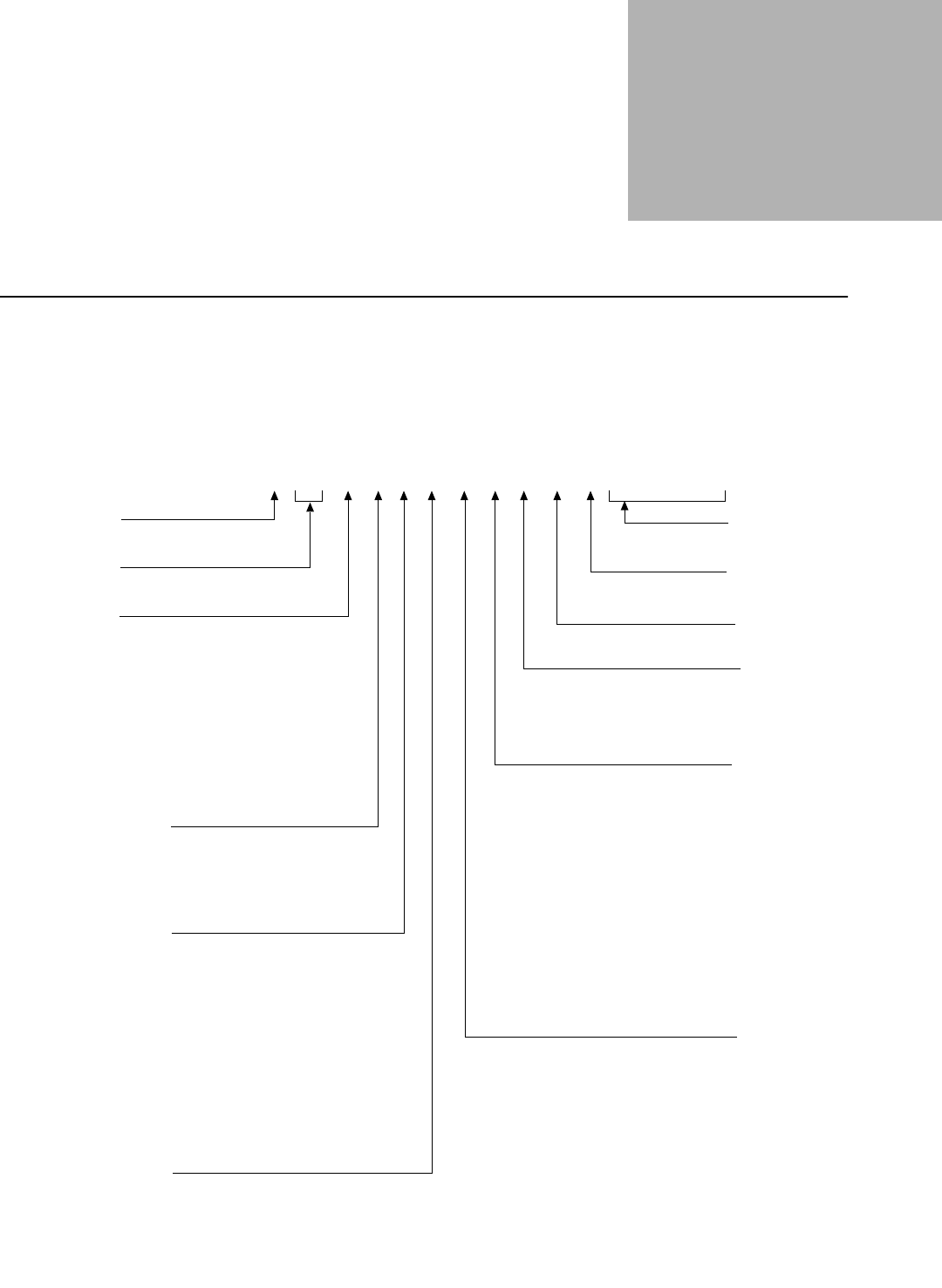
Portable Radio
Model
Numbering
System
Position 1 - Type of Unit
H = Hand-Held Portable
Positions 2 & 3 - Model Series
Position 4 - Frequency Band
Less than 29.7MHz
29.7 to 35.99MHz
36 to 41.99MHz
42 to 50MHz
66 to 80MHz
74 to 90MHz
Product Specific
136 to 162MHz
146 to 178MHz
174 to 210MHz
190 to 235MHz
336 to 410MHz
403 to 437MHz
438 to 482MHz
470 to 520MHz
Product Specific
764 to 870MHz
825 to 870MHz
896 to 941MHz
1.0 to 1.6GHz
1.5 to 2.0GHz
Values given represent range only; they are
not absolute.
Position 5 - Power Level
0 to 0.7 Watts
0.7 to 0.9 Watts
1.0 to 3.9 Watts
4.0 to 5.0 Watts
5.1 to 6.0 Watts
6.1 to 10 Watts
Position 6 - Physical Packages
RF Modem Operation
Receiver Only
Standard Control; No Display
Standard Control; With Display
Limited Keypad; No Display
Limited Keypad; With Display
Full Keypad; No Display
Full Keypad; With Display
Limited Controls; No Display
Limited Controls; Basic Display
Limited Controls; Limited Display
Rotary Controls; Standard Display
Enhanced Controls; Enhanced Display
Low Profile; No Display
Low Profile; Basic Display
Low Profile; Basic Display, Full Keypad
Position 7 - Channel Spacing
1 = 5kHz
2 = 6.25kHz
3 = 10kHz
4 = 12.5kHz
5 = 15kHz
6 = 20/25kHz
7 = 30kHz
9 = Variable/Programmable
Typical Model Number:
Position:
Position 8 - Primary Operation
Conventional/Simplex
Conventional/Duplex
Trunked Twin Type
Dual Mode Trunked
Dual Mode Trunked/Duplex
Trunked Type I
Trunked Type II
FDMA* Digital Dual Mode
TDMA** Digital Dual Mode
Single Sideband
Global Positioning Satellite Capable
Amplitude Companded Sideband (ACSB)
Programmable
* FDMA = Frequency Division Multiple Access
** TDMA = Time Division Multiple Access
Position 9 - Primary System Type
Conventional
Privacy Plus
Clear SMARTNET
Advanced Conventional Stat-Alert
Enhanced Privacy Plus
Nauganet 888 Series
Japan Specialized Mobile Radio (JSMR)
Multi-Channel Access (MCA)
CoveragePLUS
MPT1327* - Public
MPT1327* - Private
Radiocom
Tone Signalling
Binary Signalling
Phonenet
Programmable
Secure Conventional
Secure SMARTNET
* MPT = Ministry of Posts and Telecommunications
Position 10 - Feature Level
1 = Basic
2 = Limited Package
3 = Limited Plus
4 = Intermediate
5 = Standard Package
6 = Standard Plus
7 = Expanded Package
8 = Expanded Plus
9 = Full Feature/
Programmable
Position 11 - Version
Version Letter (Alpha) - Major Change
Position 12 -
Unique Model Variations
C = Cenelec
N = Standard Package
Positions 13 - 16
SP Model Suffix
123 4 5 6 7 8 9 10111213141516
H46 U CH 9 P W 7 A N S P 0 1
46 = XTS 2500
66 = XTS 1500
67 = MT 1500
A
B
C
D
F
G
H
J
K
L
M
=
=
=
=
=
=
=
=
=
=
=
P
Q
R
S
T
U
V
W
Y
Z
=
=
=
=
=
=
=
=
=
=
A
B
C
D
E
F
=
=
=
=
=
=
A
B
C
D
E
F
G
H
J
K
L
M
N
P
Q
R
=
=
=
=
=
=
=
=
=
=
=
=
=
=
=
=
A
B
C
D
E
F
G
H
J
K
L
M
P
=
=
=
=
=
=
=
=
=
=
=
=
=
A
B
C
D
E
F
G
H
J
K
L
M
N
P
Q
W
X
Y
=
=
=
=
=
=
=
=
=
=
=
=
=
=
=
=
=
=
MAEPF-27327-A

Specifications
xiv
Specifications for 700 MHz/800 MHz Radios
All specifications are per Telecommunications Industries Association TIA-603 unless otherwise noted
GENERAL RECEIVER TRANSMITTER
FCC ID:
700/800 MHz: AZ489FT5804
Temperature Range:
Operating: –30°C to +60°C
Storage: –40°C to +85°C
Power Supply: Nickel-Cadmium Battery (NiCd)
or Nickel-Metal-Hydride Battery (NiMH)
Battery Voltage
Nominal: 7.5 Volts
Range: 6 to 9 Volts
Transmit Current Drain (Typical): 1250mA
Receive Current Drain (Rated Audio): 220mA
Standby Current Drain: 70mA
Recommended Battery:
High-Capacity NiCd: NTN9815
or Ultra-High-Capacity NiMH: NTN9858
or High-Capacity NiCd FM: NTN9816*
or Ultra–High-Capacity NiMH FM: NTN9857*
Optional FM (Factory Mutual) Battery:
* FM Intrinsically Safe: Class I, II, III
Dimensions
Height x Width x Depth
Radio Less Battery: 6.0" x 2.3" x 1.5"
With NiCd Ultra-High Cap.: 6.0" x 2.3" x 2.0"
With NiMH Ultra-High Cap.: 6.0" x 2.3" x 2.0"
Weight
Radio Less Battery: 11.0 oz.
With NiCd Ultra-High Capacity: 20.0 oz.
With NiMH Ultra-High Capacity: 20.5 oz.
Frequency Range:
700 MHz: 764 to 767; 773 to 776 MHz
800 MHz: 851 to 870 MHz
Quieting Sensitivity (typical) (20dBQ): 0.23µV
Usable Sensitivity (typical)
(12dB SINAD): 0.25µV
Intermodulation (typical): –74dB
Selectivity (typical)
(25kHz Channel): –72dB
(12.5kHz Channel): –63dB
Spurious Rejection (typical): –75dB
Frequency Stability
(–30+60°C; 25°C reference): 1.5ppm
Rated Audio: 500mW
FM Hum and Noise (typical)
(25kHz channel): –47dB
(12.5kHz channel): –40dB
Distortion (At Rated Audio; typical): 2.5%
Channel Spacing: 12.5/20/25 kHz
RF Power
806 - 870 MHz: 3 Watts
764 - 806 MHz: 2.5 Watts
Frequency Range:
700 MHz: 764 to 767; 773 to 776; 794 to 797; 803
to 806 MHz
800 MHz: 806 to 824; 851 to 870 MHz
Frequency Stability (typical)
(–30 to +60°C; 25°C ref.): 1.5ppm
Emission (typical conducted): -75dBc<1GHz
FM Hum and Noise (typical)
(25 kHz channel): –43dB
(12.5 kHz channel): –40dB
Distortion (typical): 2%
Modulation Limiting: 25 kHz chnls ±5.0kHz
20 kHz chnls ±4.0kHz
12.5 kHz chnls ±2.5kHz
Emissions Designators: 16K0F3E,11K0F3E,
8K10F1D, and 8K10F1E
Specifications
xv
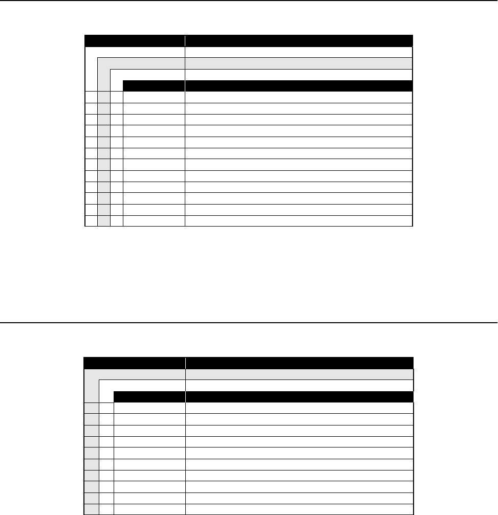
ASTRO Digital XTS 2500 Model Chart
Notes:X=Item Included
ASTRO XTS 1500/MT 1500 Model Chart
Notes:X=Item Included
MODEL NUMBER DESCRIPTION
H46UCC9PW5AN 700/800 MHz, 1-3 Watts, ASTRO Digital XTS 2500 Model I
H46UCF9PW6AN 700/800 MHz, 1-3 Watts, ASTRO Digital XTS 2500 Model II
H46UCH9PW7AN 700/800 MHz, 1-3, Watts ASTRO Digital XTS 2500 Model III
ITEM NUMBER DESCRIPTION
XXX 1505579Z01 Cover, Dust, Accessory Connector
XXX 4385665D01 Adapter, Remote Speaker Microphone
XXX NTN9815 Hi Capacity NiCd Battery
XXX NAF5037 1/2 Wave Whip Antenna, 800 MHz
XXX HLN6853 2.250 inch Belt Clip
XNTN9637 Front Cover Kit, Model I
XNTN9638 Front Cover Kit, Model II
XNTN9639 Front Cover Kit, Model III
XXX NUF6541 RF/VOCON Board Kit
X6881094C04 User’s Guide, Model I
X6881094C05 User’s Guide, Model II
X6881094C06 User’s Guide, Model III
MODEL NUMBER DESCRIPTION
H66UCC9PW5AN 700/800 MHz, 1-3 Watts, ASTRO Digital XTS 1500 Model l
H67UCC9PW5AN 700/800 MHz, 1-3, Watts ASTRO Analog MT 1500 Model I
ITEM NUMBER DESCRIPTION
X X 1585746D04 Cover, Dust, Accessory Connector
X X 4385665D01 Adapter, Remote Speaker Microphone
X X NTN9815_ Hi Capacity NiCd Battery
X X NAF5037_ 1/2 Wave Whip Antenna, 800 MHz
X X HLN6853_ 2.250 inch Belt Clip
X PMTN4080_ Front Cover Kit, XTS1500 Model I
X PMTN4079_ Front Cover Kit, MT1500 Model I
X X PMUF6541_ RF/VOCON Board Kit
X 6804113J52 User’s Guide, XTS1500 Model I
X 6804113J71 User’s Guide, MT1500 Model I

Specifications
xvi
Notes
1
Introduction 1
General This manual covers information needed for level one and two troubleshooting. Level one
troubleshooting consists of radio programming, tuning (via CPS/tuner), knobs
replacement, and installation and removal of antenna, belt clip, battery, and universal
connector cover. Level two troubleshooting consists of everything listed in level one, plus
the identification and replacement of Field Replaceable Units (FRUs). No soldering will be
allowed; only board swapping.
Included in this manual are radio specifications for the 700/800 MHz frequency bands, a
general description of ASTRO Digital XTS 2500 models, recommended test equipment,
service aids, radio alignment procedures, general maintenance recommendations, and
procedures for basic assembly and disassembly.
Notations Used in
This Manual Throughout the text in this publication, you will notice the use of warnings, cautions, and
notes. These notations are used to emphasize that safety hazards exist, and care must be
taken and observed.
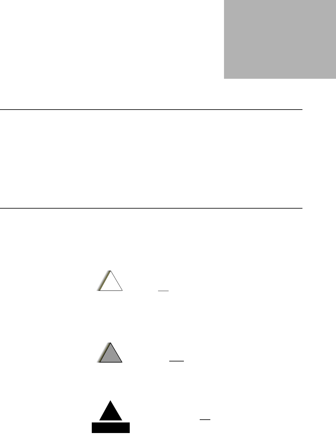
NOTE: An operational procedure, practice, or condition, etc., which is
essential to emphasize.
CAUTION indicates a potentially hazardous situation which, if not
avoided, may result in equipment damage.
!
C a u t i o n
WARNING indicates a potentially hazardous situation which, if
not avoided, could result in death or injury.
!
W A R N I N G
!
DANGER indicates an imminently hazardous situation
which, if not avoided, will result in death or injury.
D A N G E R
!
Introduction
2
Radio
Description The ASTRO Digital XTS 2500 radios are among the most sophisticated two-way radios
available.
One of the newest in a long line of quality Motorola products, the ASTRO Digital XTS
2500 radio provides improved voice quality across more coverage area. The digital process,
called “embedded signalling,” intermixes system signalling information with digital voice,
resulting in improved system reliability, and the capability of supporting a multitude of
advanced features. Such features add up to better, more cost-effective two-way radio
communications.
ASTRO Digital XTS 2500 radios are available in three basic models. Table 1 describes
their basic features.
FLASHport The ASTRO® Digital XTS 2500 radio utilizes Motorola’s revolutionary FLASHport™
technology. FLASHport makes it possible to add software that drives the radio’s
capabilities both at the time of purchase and later on. Previously, changing a radio’s features
and capabilities meant significant modifications, or buying a new radio. But now, just as a
computer can be loaded with different software, the radio’s features and capabilities can be
upgraded with FLASHport software.
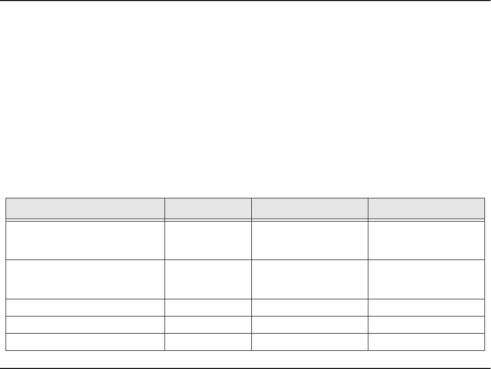
Table 1. ASTRO XTS 2500 Basic Features
Feature Model I Model II Model III
Display None LCD
6 lines/
12 characters per line
LCD
6 lines/
12 characters per line
Keypad None 3 x 2 button with
4-Position Navigation but-
ton
3 x 6 button with
4-Position Navigation but-
ton
Channel Capability 48 160 160
Dialing from Prestored List No Yes Yes
Programmable Softkeys No Yes Yes

3
Basic Maintenance 2
Introduction to
This Section This section of the manual describes preventive maintenance and handling precautions.
Each of these topics provides information vital to the successful operation and maintenance
of your radio.
Preventive
Maintenance ASTRO Digital XTS 2500 radios do not require a scheduled preventive maintenance
program; however, periodic visual inspection and cleaning is recommended.
Inspection Check that the external surfaces of the radio are clean, and that all external controls and
switches are functional. A detailed inspection of the interior electronic circuitry is not
needed.
Cleaning The following procedures describe the recommended cleaning agents and the methods to
be used when cleaning the external surfaces of the radio. External surfaces include the
housing assembly and battery case. These surfaces should be cleaned whenever a periodic
visual inspection reveals the presence of smudges, grease, and/or grime.
The only recommended agent for cleaning the external radio surfaces is a 0.5% solution of
a mild dishwashing detergent, such as JOY®, in water.
Cleaning External
Plastic Surfaces The detergent-water solution should be applied sparingly with a stiff, non-metallic, short-
bristled brush to work all loose dirt away from the radio. A soft, absorbent, lintless cloth or
tissue should be used to remove the solution and dry the radio. Make sure that no water
remains entrapped near the connectors, cracks, or crevices.
The effects of certain chemicals and their vapors can have harmful results
on certain plastics. Aerosol sprays, tuner cleaners, and other chemicals
should be avoided.
!
C a u t i o n

Basic Maintenance
4
Handling
Precautions Complementary metal-oxide semiconductor (CMOS) devices, and other high-technology
devices, are used in this family of radios. While these devices have many attributes, their
characteristics make them susceptible to damage by electrostatic discharge (ESD) or high-
voltage charges. Damage can be latent, resulting in failures occurring weeks or months
later. Therefore, special precautions must be taken to prevent device damage during
disassembly, troubleshooting, and repair. Handling precautions are mandatory for this
radio, and are especially important in low-humidity conditions.
Never heat the RF PA above 210°C while performing repair or rework procedures to
maintain its integrity. Utilizing a Chipmaster (R1319 or R1321) top-side set point of 215°C
and a Dragon (R1427) bottom-side pre-heat set point of 180°C has proven to satisfy this
condition during the rework of the RF PA (note: the RF PA temperature does not reach the
Chipmaster’s internal set point temperature). All other parts on the transceiver board can
be reworked with Chipmaster top-side heat alone.
5
Basic Theory of Operation 3
General
Overview The ASTRO Digital XTS 2500 radio is a wideband, synthesized, fixed-tuned radio
available in the 700/800 MHz bands. All XTS 2500 radios are capable of both analog
operation (12.5 kHz or 25 kHz bandwidths) and digital ASTRO mode operation (12.5 kHz
only).
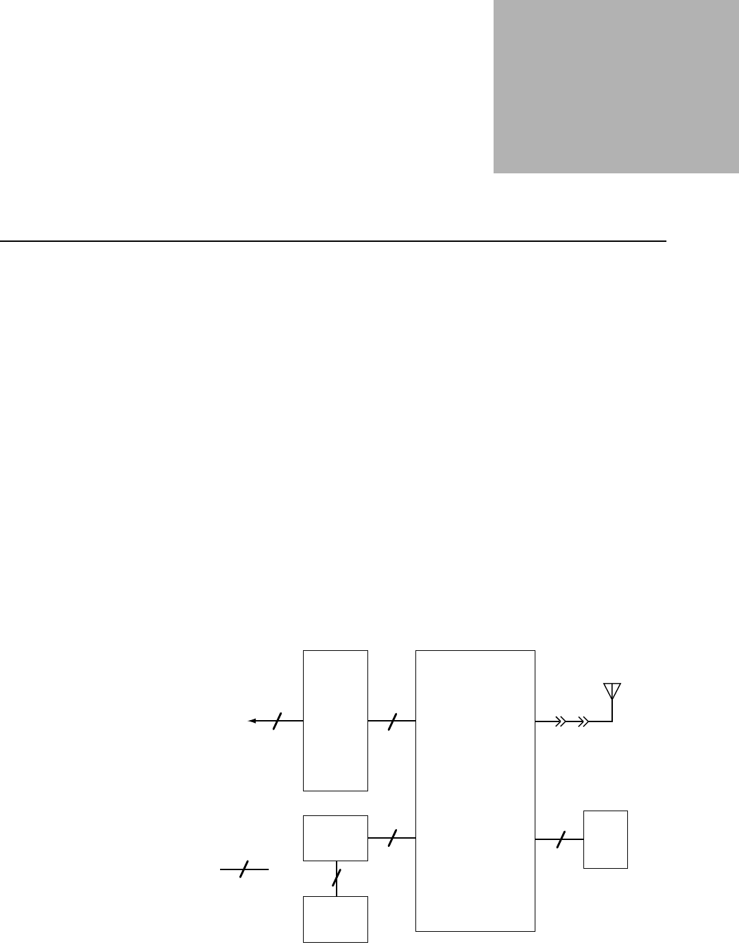
The ASTRO Digital XTS 2500 radio includes the following major assemblies (see Figure
1):
•Main Board: contains the microcontrol unit (MCU) and its associated memory and
memory management integrated circuit (IC), the audio power amplifier, and a
switching regulator. The board also contains the digital signal processor (DSP) and its
support IC and associated memories. It further contains all transmit, receive, and
frequency generation circuitry, including the digital receiver back-end IC and the
reference oscillator.
•Universal Flex: contains the universal connector, speaker, and microphone.
•Display (Models II and III only): a six-line, 12-character, liquid-crystal display
(LCD).
•Keypad (Models II and III only):
-Model II: a 3 x 2 keypad
-Model III: a 3 x 6 keypad.
Figure 1. XTS 2500 Overall Block Diagram
Universal
Flex
(Side Connector,
Controls, LEDs,
Speaker,
Microphone)
Note:
indicates 20
wires
Main
Board
7.5V
Battery
Keypad
Antenna
Display
3
20
45
22
20
13
J601
J650 J101
B500
Basic Theory of Operation
6
Analog Mode of
Operation
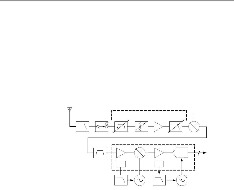
Receiving When the radio is receiving (see Figure 2), the signal comes from the antenna connector to
the radio board, passes through the RX/TX antenna switch and into the receiver front end.
A 15dB step attenuator is included in the front end to provide additional protection against
strong signals. The attenuator is controlled by a DSP based algorithm that continuously
monitors signal strength. When the ON threshold is exceeded (approximately -95dBm), the
attenuator is activated via a DAC in the PCIC by the host. The attenuator remains activated
until the signal drops below the OFF threshold (approximately -115dBm including the
15dB attenuation). Hysterisis and timer functions are included in the algorithm to enhance
performance. The algorithm controlling the attenuator is enabled via the CPS for each
personality. When the algorithm is disabled, the attenuator is essentially a short circuit from
input to output.The signal is then filtered, amplified, and mixed with the first local-
oscillator signal generated by the voltage-controlled oscillator (VCO).
The resulting intermediate frequency (IF) signal is fed to the IF circuitry, where it is again
filtered and amplified. This amplified signal passes to the digital back-end IC, where it is
mixed with the second local oscillator to create the second IF at 450 kHz. It is then
converted to a digital bit stream and mixed a third time to produce a baseband signal. This
signal is passed to the VOCON circuitry through a current-driven differential output.
In the VOCON circuitry, the digital-signal processor (DSP) support IC digitally filters and
discriminates the signal, and passes it to the DSP. The DSP decodes the information in the
signal and identifies the appropriate destination for it. For a voice signal, the DSP routes
the digital voice data to the CODEC for conversion to an analog signal. The CODEC then
presents the signal to the audio power amplifier, which drives the speaker. For signalling
information, the DSP decodes the message and pass it to the microcontrol unit.
Transmitting When the radio is transmitting (see Figure 3), microphone audio is passed through gain
stages to the CODEC where the signal is digitized. The CODEC passes digital data to the
DSP where pre-emphasis and low-pass (splatter) filtering are done. The DSP passes this
signal to a digital-to-analog (D/A) converter where it is reconverted into an analog signal
and scaled for application to the voltage-controlled oscillator as a modulation signal.
Figure 2. Receiver Block Diagram
RF Input RX Front End
Harmonic
Filter
ADC
LO CKO
RX_SSI_ DATA
to VOCON Board
XTAL
Filter
ABACUS III - RX Back End
Antenna
Switch Tuneable
Preslector RF
Amp
Attenuator
Tuneable
Preselector
Filter 1st
Mixer
1st LO
3
MAEPF-27278-O
Basic Theory of Operation
7
Transmitted signalling information is accepted by the DSP from the microcontrol unit,
coded appropriately, and passed to the D/A converter, which handles it the same as a voice
signal. Modulation information is passed to the synthesizer along the modulation line. A
modulated carrier is provided to the RF PA, which transmits the signal under dynamic
power control.
ASTRO Mode of
Operation In the ASTRO mode (digital mode) of operation, the transmitted or received signal is
limited to a discrete set of deviation levels, instead of continuously varying. The receiver
handles an ASTRO-mode signal identically to an analog-mode signal up to the point where
the DSP decodes the received data. In the ASTRO receive mode, the DSP uses a
specifically defined algorithm to recover information.
In the ASTRO transmit mode, microphone audio is processed identically to an analog mode
with the exception of the algorithm the DSP uses to encode the information. This algorithm
will result in deviation levels that are limited to discrete levels.
RF Basic Theory
of Operation The receiver front end consists of a preselector, an RF amplifier, a second preselector, and
a mixer. Both preselectors are varactor-tuned, two-pole filters, controlled by the
microcontroller unit through the D/A IC. The RF amplifier is a dual-gate, gallium-arsenide-
based IC. The mixer is a double-balanced, active mixer, coupled by transformers. Injection
is provided by the VCO through an injection filter. See Table 2 for local oscillator (LO) and
first IF information.
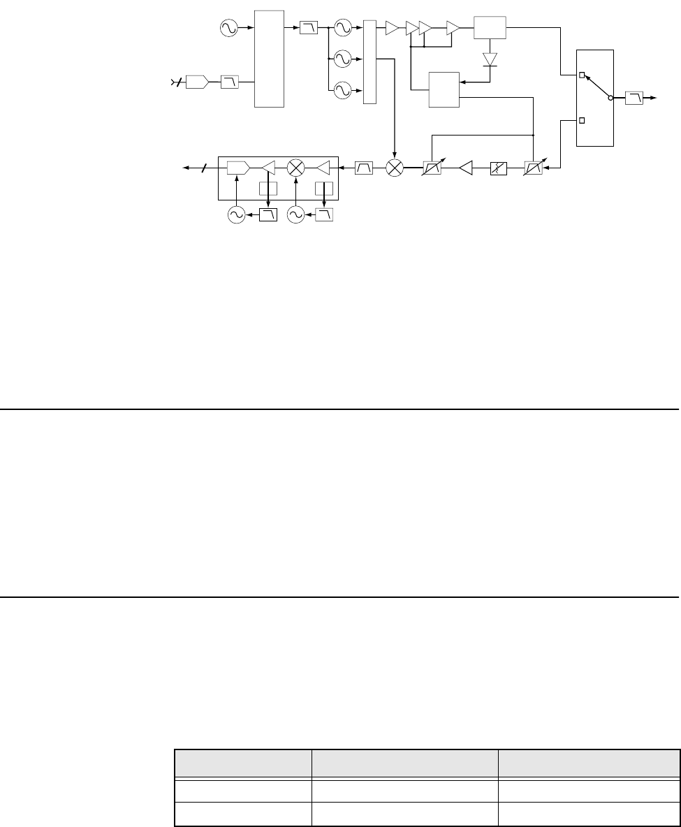
The frequency generation function is performed by three ICs and associated circuitry. The
reference oscillator provides a frequency standard to the synthesizer/prescaler IC, which
controls the VCOB IC. The VCOB IC actually generates the first LO and transmit-injection
Figure 3. RF Block Diagram (Power and Control Omitted)
Reference
Oscillator
FracN
U201
MOD
IN
Loop
Filter
LPF
FL200
EPIC
Y200
DAC
U203
VCO
VCOBIC
U250
VCO
Crystal
Filter
FL3
Mixer
U1
2ND
LO
Sample
Clk
To RX_SSI
From TX_SSI
Preselector
Filter
FL2
Attenuator
PCIC
U102
Power
Module
Q101
TX
Buffer
Q216
TX Driver
Amplifier
U101
RF Power
Detector
D103
Directional
Coupler
U106
Antenna
Switch
Preselector
Filter
FL1
RX LNA
Q1
To
Antenna
Harmonic
Filter
ABACUS III U401
MAEPF-27322-O
VCO
3
3
Table 2. Local Oscillator and First IF Frequencies
700 MHz 800 MHz
LO Frequency Range -- --
First IF Frequency 109.65 MHz 109.65 MHz

Basic Theory of Operation
8
signals and buffers them to the required power level. The synthesizer/prescaler circuit
module incorporates frequency-division and comparison circuitry to keep the VCO signals
stable. The synthesizer/prescaler IC is controlled by the microcontrol unit through a serial
bus.
The receiver back end consists of a two-pole crystal filter, an IF amplifier, a second two-
pole crystal filter, and the digital back-end IC. The two-pole filters are wide enough to
accommodate 4 kHz modulation. Final IF filtering is done digitally in the DSP.
The digital back-end IC consists of an amplifier, the second mixer, an IF analog-to-digital
converter, a baseband down-converter, and a 2.4 MHz synthesis circuit to provide a clock
to the DSP-support IC on the VOCON circuitry. The second LO is generated by discrete
components external to the IC. The output of the digital back-end IC is a digital bit stream
that is current driven on a differential pair for a reduction in noise generation.
The transmitter consists of an RF driver IC that gets an injection signal from the VCO and
a final-stage power amplifier. Transmit power is controlled by a power-control IC that
monitors the output of a directional coupler and adjusts PA control voltages
correspondingly. The signal passes through a RX/TX switch that uses PIN diodes to
automatically provide an appropriate interface to transmit or receive signals. Antenna
selection is done mechanically in the control top.
VOCON Basic
Theory of
Operation
The vocoder and controller (VOCON) circuitry contains the radio’s microcontrol unit with
its memory and support circuits, the DSP, its memory devices, and the DSP-support IC,
voltage regulators, audio, and power control circuits. Connected to the VOCON circuitry
are the display board, RF circuitry, keypad board, and controls/universal flex.
The microcontrol unit controls receive/transmit frequencies, power levels, display, and
other radio functions, using either direct logic control or serial communications paths to the
devices.The microcontrol unit executes a stored program located in the FLASH ROM. Data
is transferred to and from memory by the microcontrol unit data bus. The memory location
from which data is read, or to which data is written, is selected by the address lines.
The DSP-support IC is supplied with a 16.8 MHz clock from the RF circuitry. Both the DSP
and the microprocessor have their clocks generated by the DSP-support IC. They can both
be adjusted so that the harmonics do not cause interference with the radio’s receive channel.
The regulator and power-control circuits include 3.3-volt analog, 3.3-volt digital, and 5-
volt regulators. The audio PA is sourced from 7.5V. The regulator’s power-down mode is
controlled by the microcontrol unit, which senses the position of the on/off switch. The 5-
volt regulator has an error pin for low-voltage resets.
The DSP performs signalling and voice encoding and decoding, as well as audio filtering
and volume control. This IC performs Private-Line®/Digital Private Line™ (PL/DPL)
encode and alert-tone generation. The IC transmits pre-emphasis on analog signals and
applies a low-pass (splatter) filter to all transmitted signals. It requires a clock on the
EXTAL pin. An 8 kHz interrupt signal generated by the DSP-support IC is also required
for functionality. It is programmed using parallel programming from the microcontrol unit.
The audio CODEC performs analog-to-digital (A/D), and digital-to-analog conversions on
audio signals. The DSP controls squelch, deviation, and executes receiver and transmitter
filtering. The DSP-support IC receives a 2.4 MHz clock, and also receives data, which it
formats for the DSP.
9
Recommended Test
Equipment and Service Aids 4
Recommended
Test Equipment The list of equipment contained in Table 3 includes all of the standard test equipment
required for servicing two-way portable radios, as well as several unique items designed
specifically for servicing this family of radios. The “Characteristics” column is included so
that equivalent equipment may be substituted; however, when no information is provided
in this column, the specific Motorola model listed is either a unique item or no substitution
is recommended.
Table 3. Recommended Test Equipment
Motorola
Model Number Description Characteristics Application
R2600 Series Communications
System Analyzer
This monitor will substitute for
items with an asterisk (*).
Frequency/deviation meter and signal
generator for wide-range
troubleshooting and alignment.
Fluke 8012 Digital Multimeter Recommended for ac/dc voltage and
current measurements
R1150_* Code Synthesizer Injection of audio and digital
signalling codes
R1377_* AC Voltmeter 1mV to 300V, 10-Megohm input
impedance
Audio voltage measurements
R1094_ Dual-Trace
Oscilloscope
20 MHz bandwidth 5mV to 5V/
division
Waveform measurements
S1350_*
ST1213_ (VHF)*
ST1223_ (UHF)*
Wattmeter
Plug-In Element
RF Dummy Load
50-ohm, ±5% accuracy
10 watts, maximum
0-1000 MHz, 300W
Transmitter power output
measurements
R1065_ Load Resistor 10-watt Broadband For use with wattmeter
S1339_ RF Millivolt Meter 100µV to 3V RF RF-level measurements
R1013_* SINAD Meter Receiver sensitivity measurements
S1347_ or S1348_
(programmable)
DC Power Supply 0-20Vdc, 0-5 Amps
current limited
Bench supply for 7.5Vdc
*The R2600 Series monitor will substitute for these items.
Recommended Test Equipment and Service Aids
10
Service Aids Refer to Table 4., “Service Aids,” for a listing and description of the service aids designed
specifically for servicing this family of radios. These kits and/or parts are available from
the Motorola Parts Division offices listed in the “Replacement Parts Ordering” section
located on the inside back cover of this manual. While all of these items are available from
Motorola, most are standard shop equipment items, and any equivalent item capable of the
same performance may be substituted for the item listed.
NOTE: The Radio Interface Box (RIB), Smart Radio Interface
Box (SRIB), and any cables that connect with those
boxes are incompatible with the XTS 2500 radio and
should NOT be used.
Field
Programming
Equipment
This family of radios can be aligned and programmed in the field. This requires specific
equipment and special instructions. Refer to the applicable “CPS On-line Help” for
complete field programming information.
Table 4. Service Aids
Motorola Part Number Description Application
6685666D01 Chassis Opener Tool Used to remove radio knobs and to separate chassis from Front
Cover.
RKN-4106_ RS232/Radio/Test Set Cable Connects radio to RLN4460 Test Box and to RS232 computer
connector (DB9).
0180305G54 Battery Eliminator Interconnects radio to power supply.
RLN-4460 Portable Test Set Enables connection to the universal connector.
Allows switching for radio testing.
RVN-4181_ Customer Programming
Software
Customer Programming Software (CPS)/Tuner on one CD-ROM.
58-80348B33 SMA to BNC Adaptor Adapts radio’s antenna port to BNC cabling of test equipment.
RKN4105 USB/Radio/Test Set Cable Connects radio to RLN4460 test box and to USB computer
connector.
8180384M37 Test Fixture Provides for troubleshooting the radio board when the back
casting is removed.
11
Performance Checks 5
Introduction to
This Section This section covers performance checks used to verify that the radio meets published
specifications. The recommended test equipment listed in the previous section approaches
the accuracy of the manufacturing equipment, with a few exceptions. Accuracy of the
equipment must be maintained in compliance with the manufacturer’s recommended
calibration schedule. Checks should be performed if radio performance degradation is
suspected.
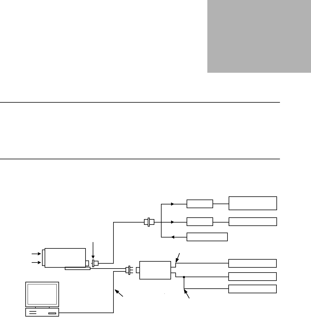
Setup Supply voltage can be connected from the battery eliminator. The equipment required for
alignment procedures is connected as shown in the “Radio Alignment Test Setup” diagram
(Figure 4).
Figure 4. Radio Alignment Test Setup
BNC
COMPUTER
AUDIO GENERATOR
SINAD METER
AC VOLTMETER
TX
RX
30 dB PAD
30 dB PAD
RF GENERATOR
SYSTEM ANALYZER
OR COUNTER
WATTMETER
BATTERY
ELIMINATOR
0180305G54
TRANSMIT
RECEIVE
RADIO
PROGRAM/TEST CABLE
RKN4106
AUDIO IN
SET TO APPROX. 450mV FOR Tx
MEASURE 80mV FOR Tx
SMA-BNC
58-80348B33
TEST SET
RLN-4460
Performance Checks
12
Initial equipment control settings should be as indicated in the Table 5, and should hold for
all alignment procedures except as noted.
Display Radio
Test Mode
Entering Display
Radio Test Mode
1. Turn the radio on.
2. Within 10 seconds after “Self Test” is complete, press Side button 3 five times in
succession.
3. The radio will show a series of displays that will give information regarding various
version numbers and subscriber specific information. The displays are described in
Table 6.
NOTE: All displays are temporary and will disappear without
any user intervention. If information is longer than the
physical length of the radio’s display, the information
will wrap around to the next display. After the last
display, “RF TEST” will be displayed. For non-display
radios, refer to the CPS Radio Information Screen.
Table 5. Initial Equipment Control Settings
System Analyzer Test Set Power Supply
Monitor Mode: Pwr Mon Spkr Set: A Voltage: 7.5Vdc
RF Attn: –70dB Spkr/Load: Speaker DC On/Standby: Standby
AM, CW, FM: FM PTT: OFF (center) Volt Range: 10Vdc
O'scope Source: Mod
O'scope Horiz: 10mSec/Div
O'scope Vert: 2.5 kHz/Div
O'scope Trig: Auto
Monitor Image: Hi
Monitor BW: Nar
Monitor Squelch: Mid CW
Monitor Vol: 1/4 CW
Current: 2.5Amps
Table 6. Front-Panel Access Test-Mode Displays
Name of Display Description Appears
“SERVICE” The literal string indicates the radio has entered test
mode.
Always.
Host Software Version The version of host firmware. Always.
DSP Software Version The version of DSP firmware. Always.
Model Number The radio’s model number as programmed in the
codeplug.
Always.
Serial Number The radio’s serial number as programmed in the
codeplug.
Always.
ROM Size The memory capacity of the host FLASH part. Always.
FLASHcode The FLASH codes as programmed in the codeplug. Always.

Performance Checks
13
4a. Press Side Button 1 to stop the displays and put the radio into the Control Top and
Keypad test mode (display radio). The test mode menu “CH TEST” will be
displayed. Go to the “Control Top and Keypad Test Mode (Display Radio)” section
on page 14.
NOTE: Each press of Side Button 1 will toggle between “CH TEST” and
“RF TEST.”
OR
4b. Press the Top Programmable Button to stop the displays and put the radio into the
RF test mode (display radio). The test mode menu “1 CSQ.” will be displayed,
indicating test frequency 1, Carrier SQuelch mode. Go to “RF Test Mode (Display
Radio)” in the next section.
RF Test Mode
(Display Radio)
When the ASTRO Digital XTS 2500 radio is operating in its normal environment, the radio's
microcomputer controls the RF channel selection, transmitter key-up, and receiver muting,
according to the customer codeplug configuration. However, when the unit is on the bench for
testing, alignment, or repair, it must be removed from its normal environment via a special
routine, called TEST MODE or “air test.”
1. Each additional press of Side Button 3 will advance to the next test channel. (Refer
to Figure 7.)
2. Pressing Side Button 2 will scroll through and access test environments as shown in
Figure 8.
NOTE: Transmit into a load when keying a radio under test.
Table 7. Test Frequencies
Frequency 700/800 MHz RX 700/800 MHz TX
F1 764.0625 764.0125
F2 769.0625 769.0125
F3 775.9375 775.9875
F4 851.0625 794.0125
F5 860.0625 809.0125
F6 869.9375 823.9875
F7 851.0625 851.0125
F8 860.0625 860.0125
F9 869.9375 869.8875

Performance Checks
14
Control Top and
Keypad Test
Mode (Display
Radio)
This test mode is used to verify proper operation of all radio buttons and switches if a failure
is suspected.
1. Press and hold the Top Programmable Button; all segments on the display will light,
and the LED on the control top will illuminate a red color.
2. Release the Top Programmable Button; “3/0” appears, indicating that the Top
Programmable Button is in the open condition.
3. Press the Top Programmable Button again; “3/1” appears, indicating that the Top
Programmable Button is in the closed condition.
4. Rotate the Mode/Zone Selector Switch; “4/0” through “4/15” appears, indicating
that the selector switch is in mode/zone position 1 through 16.
5. Rotate the Three-Position Concentric Switch; “65/0” through “65/2” appear.
6. Cycle through the 16-Position Programmable Switch; “67/0,”
“67/1,” and “67/2” appear.
7. Rotate the Volume Control; “2/0” through “2/255” appear.
8. Press Side Button 1; “96/1” appears; release, “96/0” appears.
9. Press Side Button 2; “97/1”appears; release, “97/0” appears.
10. Press Side Button 3; “98/1”appears; release, “98/0” appears.
11. Press the PTT Switch; “1/1” appears; release, “1/0” appears.
12. Keypad Checks:
Model III Only—
-Press 0, “48/1” appears; release, “48/0” appears.
-Press 1, “49/1” appears; release, “49/0” appears.
-Press 2, “50/1” appears; release, “50/0” appears.
-Press 3, “51/1” appears; release, “51/0” appears.
-Press 4, “52/1” appears; release, “52/0” appears.
-Press 5, “53/1” appears; release, “53/0” appears.
-Press 6, “54/1” appears; release, “54/0” appears.
Table 8. Test Environments
No. of
Beeps Display Description Function
1 CSQ Carrier Squelch RX: unsquelch if carrier detected
TX: mic audio
3TPLTone
Private-Line RX: unsquelch if carrier and
tone (192.8 Hz) detected
TX: mic audio + tone (192.8 Hz)
11 AST ASTRO RX: none
TX: 1200Hz tone **
12 USQ Carrier
Unsquelch RX: unsquelch always
TX: mic audio
** All deviation values are based on deviation tuning of this mode.

Performance Checks
15
-Press 7, “55/1” appears; release, “55/0” appears.
-Press 8, “56/1” appears; release, “56/0” appears.
-Press 9, “57/1” appears; release, “57/0” appears.
-Press *, “58/1” appears; release, “58/0” appears.
-Press #, “59/1” appears; release, “59/0” appears.
All Display Models—
-Press V, “128/1” appears; release, “128/0” appears.
-Press h, “129/1” appears; release, “129/0” appears.
-Press U, “130/1” appears; release, “130/0” appears.
-Press the left-hand D key on the top row of keys, “131/1” appears; release, “131/
0” appears.
-Press the center E key, “132/1” appears; release, “132/0” appears.
-Press the right-hand F key, “133/1” appears; release, “133/0” appears.
-Press @ button, “134/1” appears; release, “134/0” appears.
-Press X (up arrow), “135/1 appears; release, “135/0” appears.
-Press Y (down arrow), “136/1” appears; release, “136/0” appears.
Non-Display
Radio Test Mode
Entering Non-
Display Radio Test
Mode
1. Turn the radio on.
2. Within 10 seconds after the top green LED turns off, press Side button 3 five times in
succession.
3a. Press Side Button 1 to put the radio into the Control Top and Keypad test mode (non-
display radio). Go to the “Control Top and Keypad Test Mode (Non-Display Radio)”
section on page 16.
NOTE: Each press of Side Button 1 will toggle between Control Top and
Keypad test mode (non-display radio) and RF test mode (non-
display radio).
OR
3b. Press the Top Programmable Button to stop the displays and put the radio into the
RF test mode (non-display radio). Go to “RF Test Mode (Non-Display Radio)” in the
next section.
RF Test Mode (Non-
Display Radio)
When the ASTRO Digital XTS 2500 radio is operating in its normal environment, the radio's
microcomputer controls the RF channel selection, transmitter key-up, and receiver muting
according to the customer codeplug configuration. However, when the unit is on the bench for
testing, alignment or repair, it must be removed from its normal environment via a special
routine, called TEST MODE or “air test.”
1. Each additional press of Side Button 3 will advance to the next test channel. (Refer to
Table 7 on page 13.) The channel number is represented by the number of beeps
Performance Checks
16
emitted by the radio after the button press (for example, five beeps indicates channel
5).
2. Pressing Side Button 2 will scroll through and access test environments as shown in
Table 8 on page 14. The test environment is represented by the number of beeps
emitted by the radio after the button press (for example, 11 beeps indicate AST).
NOTE: Transmit into a load when keying a radio under test.
Control Top and
Keypad Test
Mode (Non-
Display Radio)
This test mode is used to verify proper operation of all radio buttons and switches if a failure
is suspected.
1. Press and hold the Top Programmable Button; the LED on the control top lights
red, and the radio beeps.
2. Release the Top Programmable Button; the radio beeps again.
3. Press the Top Programmable Button again; the radio beeps, indicating that the Top
Programmable Button is in the closed condition.
4. Rotate the Three-Position Concentric Switch; the radio beeps in each switch
position.
5. Rotate the Mode/Zone Selector Switch; the radio beeps in each switch position.
6. Cycle through the 16-Position Programmable Switch; the radio beeps in each switch
position.
7. Rotate the Volume Control; the radio beeps at each new volume setting.
8. Press Side Button 1; the radio beeps.
9. Press Side Button 2; the radio beeps.
10. Press Side Button 3; the radio beeps.

Performance Checks
17
Table 9. Receiver Performance Checks
Test Name System Analyzer Radio Test Set Comments
Reference
Frequency Mode: PWR MON 4th channel
test frequency*
Monitor: Frequency error. Input
at RF In/Out
TEST MODE, 4
CSQ output at
antenna
PTT to continuous (during
the performance check)
Frequency error to be
≤ ±1.3 kHz
Rated Audio Mode: GEN
Output level: 1.0mV RF 4th
channel test frequency*
Mod: 1 kHz tone at 3 kHz
deviation
Monitor: DVM: ac Volts
TEST MODE, 4
CSQ
PTT to OFF (center);
meter selector to Audio PA
Set volume control to
3.74Vrms
Distortion As above, except to distortion As above As above Distortion < 3.0%
Sensitivity
(SINAD)
As above, except SINAD; lower
the RF level for 12dB SINAD
As above PTT to OFF (center) RF input to be <
0.35µV
Noise Squelch
Threshold (only
radios with
conventional
system need to be
tested)
RF level set to 1mV RF As above PTT to OFF (center);
meter selection to Audio
PA; spkr/load to speaker
Set volume control to
3.74Vrms
As above, except change
frequency to a conventional
system. Raise RF level from
zero until radio unsquelches.
Out of TEST
MODE; select a
conventional
system
As above Unsquelch to occur at
< 0.25µV. Preferred
SINAD = 5-8dB
*See Table 7 on page 13.

Performance Checks
18
Table 10. Transmitter Performance Checks
Test Name System Analyzer Radio Test Set Comments
Reference
Frequency Mode: PWR MON 4th
channel test frequency*
Monitor: Frequency error.
Input at RF In/Out
TEST MODE, 4
CSQ
PTT to continuous
(during the performance
check).
Frequency error to be ≤ ±1.3
kHz.
Power RF As above As above,
4 CSQ
As above Refer to Maintenance
Specifications page in front of
manual.
Voice
Modulation Mode: PWR MON 4th
channel test frequency*
atten to –70, input to RF In/
Out.
Monitor: DVM, ac Volts. Set
1 kHz Mod Out level for
0.025Vrms at test set,
80mVrms at ac/dc test set
jack
As above,
4 CSQ
As above, meter
selector to mic Deviation: ≥ 4.1 kHz but ≤
5.0 kHz
Voice
Modulation
(internal)
Mode: PWR MON 4th
channel test frequency*
atten to –70, input to RF In/
Out
TEST MODE, 4
CSQ, output at
antenna
Remove modulation
input
Press PTT switch on radio.
Say “four” loudly into the
radio mic. Measure
deviation: ≥ 4.1 kHz but ≤ 5.0
kHz
PL Modu-lation
(radios with
conven-tional,
clear mode,
coded squelch
oper-ation only)
Change frequency to a
conventional transmit
frequency
Conventional
coded squelch
personality
(clear mode
operation) 4
TPL
As above Deviation: ≥ 500Hz but ≤
1000Hz
Talkaround
Modulation
(radios with
conventional,
clear mode,
talk-around
operation only)
Change frequency to
conventional talk-around
frequency.
Mode: PWR MON
deviation, attenuation to –70,
input to RF In/Out.
Monitor: DVM, ac volts Set
1 kHz Mod Out level for
25mVrms at test set.
Conventional
talkaround
personality
(clear mode
operation)
1 CSQ
As above Deviation: ≥ 4.1 kHz but ≤
5.0 kHz
*See Table 7 on page 13
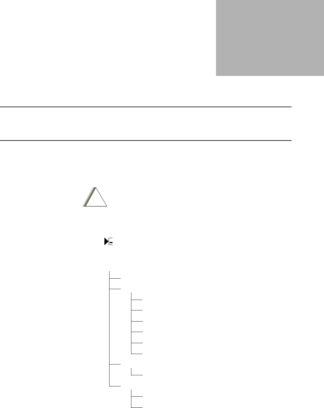
19
Radio Alignment
Procedures 6
Introduction to
This Section
This section describes both receiver and transmitter radio alignment procedures.
General A personal computer (PC) and tuner software are required to align the radio. Refer to the
applicable manual for installation and setup procedures for the software. To perform the
alignment procedures, the radio must be connected to the PC and to a universal test set as
shown in Figure 4. Radio Alignment Test Setup on page 11.
Select Tuner from the START menu. To read the radio, use the File ➝ Read Device menu
or click on . Figure 5 illustrates how the alignment screens are organized. To access a
screen, double-click on the desired screen name in the Tuner menu.
These procedures should only be attempted by qualified service
personnel. Failure to perform alignment procedures properly may result
in seriously degraded radio or system performance.
Figure 5. Tuner Menu Layout
!
C a u t i o n
123ABC1234
Radio Information
Transmitter Alignments
Reference Oscillator (page 21)
Tx Power High (page 23)
Tx Power Mid (page 23)
Tx Power Low (page 23)
Tx Deviation Balance (page 25)
Tx Deviation Limit (page 27)
Receiver Alignments
Front End Filter (page 28)
Performance Testing
Bit Error Rate (page 29)
Transmitter Test Pattern (page 31)
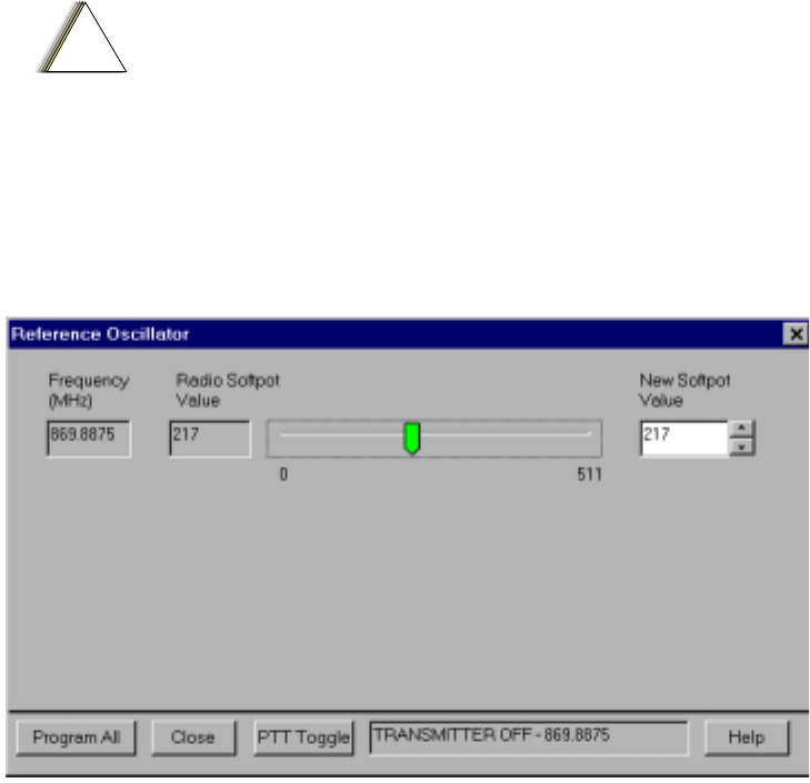
Radio Alignment Procedures
20
The alignment screens introduce the concept of the “softpot,” an analog SOFTware-
controlled POTentiometer used for adjusting all transceiver alignment controls.
Each alignment screen provides the ability to increase or decrease the softpot value by
using a slider or the screen’s UP/DOWN arrow keys (▲ ▼), or by entering the new value
from the keyboard. A graphical scale on the display indicates the minimum, maximum, and
proposed value of the softpot; see Figure 6.
Adjusting the softpot value sends information to the radio to increase (or decrease) a
voltage in the corresponding circuit. For example, left-clicking the UP arrow ▲ on the
Reference Oscillator screen instructs the radio’s microcomputer to increase the voltage
across a varactor in the reference oscillator, which increases the frequency.
In ALL cases, the softpot value is just a relative number corresponding to a digital-to-
analog (D/A) generated voltage in the radio.
Perform the following procedures in the sequence indicated.
NOTE: Some of the following screens may vary depending upon the radio under
test and the version of tuner software you are using. Refer to the
software’s on-line help.
Do NOT switch radios in the middle of any Alignment procedure.
Always left-click the Close button on the screen to return to the MAIN
menu screen before disconnecting the radio. Improper exits from the
Alignment screens may leave the radio in an improperly configured
state and result in seriously degraded radio or system performance.
Figure 6. Typical Softpot Screen
!
C a u t i o n
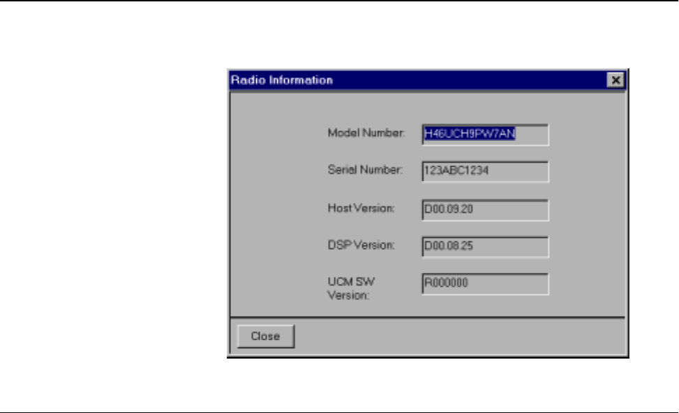
Radio Alignment Procedures
21
Radio Information Figure 7 shows a typical Radio Information screen.
Reference
Oscillator
Alignment
Adjustment of the reference oscillator is critical for proper radio operation. Improper
adjustment will result not only in poor operation, but also in a misaligned radio that will
interfere with other users operating on adjacent channels. For this reason, the reference
oscillator should be checked every time the radio is serviced, or once a year, whichever
comes first. The frequency counter used for this procedure must have a stability of 0.1 ppm
(or better).
NOTE: Reference oscillator alignment is required after replacing (or servicing)
the transceiver board.
This test can be done with either the R-2670 Communication Analyzer or the
8901_Modulation Analyzer.
• Initial setup using the R-2670 Communication Analyzer:
-RF Control: MONITOR
-B/W: WB
-Freq: CPS frequency under test
-Attenuation: 20dB
-Mon RF in: RF I/O
-Meter: RF Display
-Mode: STD
-Input Level: uV or W
-Display: Bar Graphs
-Squelch: Mid-range or adjust as necessary
•Initial setup using the 8901_ Series Modulation Analyzer:
Figure 7. Radio Information Screen
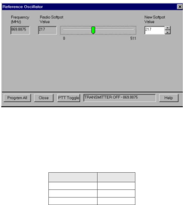
Radio Alignment Procedures
22
-Press the green Automatic Operation button on the analyzer.
-Press the FREQ key.
-Type 7.1 followed by SPCL button to set the 8901B_ modulation analyzer for
maximum accuracy.
To align the reference oscillator:
1. Select the Reference Oscillator alignment screen. See Figure 8.
2. Left-click the PTT Toggle button on the screen to make the radio transmit. The screen
indicates whether the radio is transmitting.
3. Measure the transmit RF frequency with your service monitor.
4. Adjust the reference oscillator’s softpot value until the measured value is as close as
possible to the frequency shown on the screen. See Table 11.
5. Left-click the Program All button on the screen to dekey the radio and save the tuned
values.
6. Left-click the Close button on the screen to return to the Transmitter Alignments
menu.
Figure 8. Reference Oscillator Alignment Screen
Table 11. Reference Oscillator Alignment
Band Target
VHF ±100 Hz
UHF R1 (380-470 MHz) ±100 Hz
700 MHz/800 MHz ±100 Hz

Radio Alignment Procedures
23
Transmit Power
Alignment
This alignment procedure adjusts the transmit power of the radio and must be performed
for three different power levels (Low, Mid, High), at multiple frequencies for each power
level, to allow for proper alignment across the entire RF band. The RF band is divided into
frequency zones with a calibration point (value) in each zone.
NOTES:
•The same softpot attenuation value will result in DIFFERENT radio output
power levels at different frequencies.
•All power measurements are to be made at the antenna port.
•Transmit Power alignment is required after replacing (or servicing) the
transceiver board.
1. Select the TX Power alignment screen. The screen will indicate the transmit frequencies
to be used. See Figure 9.
2. Left-click the desired frequency field (starting with the highest frequency shown).
3. Left-click the PTT Toggle button on the screen to make the radio transmit. The screen
indicates whether the radio is transmitting.
4. Measure the transmit power of the radio with a service monitor.
5. Adjust the softpot value until the required power, as shown in Table 12, is indicated
on the service monitor.
6. Repeat the above process for all frequencies and all power levels.
Table 12. Transmit Power Settings
Power Level Test Frequencies
700/800 MHz
Low (1 Watt) 1.2 - 1.4W
Mid (2 Watts) 2.5W - 2.7W
High (3 Watts) 3.2W - 3.4W
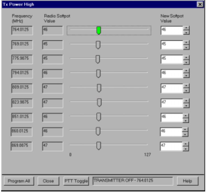
Radio Alignment Procedures
24
7. Left-click the Program All button on the screen to dekey the radio and save the tuned
values.
Left-click the Close button on the screen to return to the Transmitter Alignments menu.
Figure 9. Transmit Power Alignment Screen (Typical)

Radio Alignment Procedures
25
Transmit Deviation
Balance Alignment
This alignment procedure balances the modulation contributions of the low- and high-
frequency portions of a baseband signal. Proper alignment is critical to the operation of
signalling schemes that have very low frequency components (for example, DPL) and
could result in distorted waveforms if improperly adjusted.
This procedure needs to be performed at multiple frequencies to allow for proper alignment
across the entire RF band. The RF band is divided into frequency zones with a calibration
point (value) in each zone.
NOTE: This alignment is required after replacing (or servicing) the VOCON
board or the transceiver board.
Proper alignment requires a modulation analyzer or meter with a frequency response to less
than 10 Hz modulating frequency. The modulation analyzer settings during this test should
be set for average deviation, a 15 kHz low-pass filter, no de-emphasis, and no high-pass
filter, if these settings are supported.
This test can be done with either the R-2670 Communication Analyzer or the 8901_ Series
Modulation Analyzer. The method of choice is the R-2670 analyzer.
1. Initial setup using the R-2670 Communication Analyzer:
-Connect a BNC cable between the “DEMOD OUT” port and the “VERT/SINAD
DIST/DMM COUNTER IN” port on the R-2670.
-Press the SPF key on the R-2670 to display the “SPECIAL FUNCTIONS
MENU.” Move the cursor to “High Pass,” and select 5 Hz on the soft key menu.
Select 20 kHz for the “Low Pass” setting.
-In the “RF Control” section of the R-2670, enter the frequency displayed on the
RSS screen. Move the cursor to the “B/W” setting and select “WIDE +/- 100 kHz”
on the soft key menu.
-Place the R-2670 cursor in the “Display” zone. Select “AC VOLTS” on the soft
key menu. Move the cursor to the “Range” setting and select “AUTO.”
2. Initial setup using the 8901_ Series Modulation Analyzer:
-Press the FM MEASUREMENT button. (The “Error 03-input level too low”
indication is normal until an input signal is applied.)
-Simultaneously press the Peak – and Peak + buttons. Both LEDs on the buttons
should light.
-Press the 15 kHz LP filter key.
3. Select the TX Deviation Balance alignment screen. The screen indicates the transmit
frequencies to be used. See Figure 10.
4. Left-click the desired frequency field (starting with the highest frequency shown).
5. Left-click the PTT Toggle button on the screen to make the radio transmit. The screen
indicates whether the radio is transmitting.
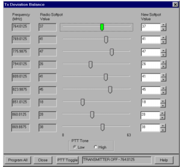
Radio Alignment Procedures
26
6. Left-click the PTT Tone: Low button.
7. Left-click the PTT Toggle button on the screen to enable transmission. The screen
indicates whether the radio is transmitting. Wait approximately 5 seconds until the
voltage shown on R-2670, or the deviation shown on the 8901_ analyzer, stabilizes.
8. Measure and record the ac voltage value from the R-2670 analyzer or the deviation
value from the 8901_ series analyzer.
9. Left-click the PTT Tone: High button.
10. Adjust the softpot value until the measured deviation/voltage, when using the high
tone, is within +/- 1.5% of the value observed when using the low tone.
11. Repeat the above process for all frequencies.
12. Left-click the Program All button on the screen to dekey the radio and save the tuned
values.
13. Left-click the Close button on the screen to return to the Transmitter Alignments
menu.
Figure 10. Transmit Deviation Balance Alignment Screen
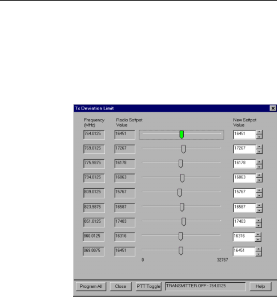
Radio Alignment Procedures
27
Transmit
Deviation Limit
Alignment
This alignment procedure limits the modulation of a baseband signal. It is used for primary
modulation limiting.
This procedure needs to be performed at multiple frequencies to allow for proper alignment
across the entire RF band. The RF band is divided into frequency zones with a calibration
point (value) in each zone.
NOTE: This alignment is required after replacing (or servicing) the VOCON
board or the transceiver board.
1. Select the TX Deviation Limit alignment screen. The screen will indicate the
transmit frequencies to be used. See Figure 11.
2. Left-click the desired frequency field (starting with the highest frequency shown).
3. Left-click the PTT Toggle button on the screen to make the radio transmit. The screen
indicates whether the radio is transmitting.
4. Measure the transmitted signal deviation of the radio with a service monitor.
5. Adjust softpot value until the measured deviation is as close as possible to 2.83 kHz.
6. Repeat the above process for all frequencies.
7. Left-click the Program All button on the screen to dekey the radio and save the tuned
values.
Figure 11. Transmit Deviation Limit Alignment Screen

Radio Alignment Procedures
28
8. Left-click the Close button on the screen to return to the Transmitter Alignments
menu.
Front End Filter
Alignment
Definition This alignment procedure adjusts the front end receiver bandpass filters for best receiver sensitivity
and selectivity. It should be performed for all test frequencies to allow for proper software
interpolation for frequencies in between the test frequencies in the band (see Figure 12).
NOTE: Rx Front End Filter Alignment is required after replacing (or servicing)
the transceiver board.
Procedure for 700
MHz Frequencies
1. Left-click the desired frequency field.
2. Apply an RF signal with no modulation at -90 dBm on the current operating
frequency.
3. Start with a softpot value (approximately 10 or 20), increase softpot in ascending
order, and note the RSSI values. The RSSI will reach a peak value and remain stable
and then decrease. Allow the limits of the peak range to be defined as RSSI PEAK - 3.
Choose the middle of the peak range and program the corresponding softpot value as
the tuned softpot value.
4. Repeat the above process for all 700MHz frequencies.
5. Click on the “Program All” button to save the tuned values in the radio.
Procedure for 800
MHz Frequencies
1. Left-click the desired frequency field.
2. Apply an RF signal with no modulation at -90 dBm on the current operating
frequency.
3. Start with a softpot value of 50, increase softpot in ascending order, and note the RSSI
values. The RSSI will reach a peak value and remain stable and then decrease. Allow
the limits of the peak range to be defined as RSSI PEAK - 3. Note the upper end of
the peak range and program the corresponding softpot value as the tuned softpot
value.
4. Repeat the above process for all 800MHz frequencies.
5. Click on the “Program All” button to save the tuned values in the radio.
Procedure for UHF/
VHF
1. Left-click the desired frequency field.
2. Apply an RF signal with no modulation at -90 dBm on the current operating
frequency.
3. Adjust the softpot value until the maximum RSSI value is found.
4. Repeat the above process for all frequencies.
Refer to your Radio Service Manual for alignment procedure details.
This procedure should only be attempted by qualified service personnel.
!
C a u t i o n
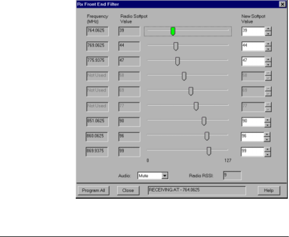
Radio Alignment Procedures
29
Click on the “Program All” button to save the tuned values in the radio.
Bit Error Rate
Definition This screen is used to test the Bit Error Rate (BER) of the radio’s receiver at a desired
frequency.
Bit Error Rate Fields This screen contains the following fields:
Rx Frequency:
This field selects the Receive Frequency directly in MHz.
Test Pattern:
This field selects the Digital test pattern — TIA. Choices are: Standard Tone Test Pattern
(framed 1011) and Standard Interface Test Pattern (CCITT V.52).
Modulation Type:
Figure 12. Front End Filter Alignment Screen
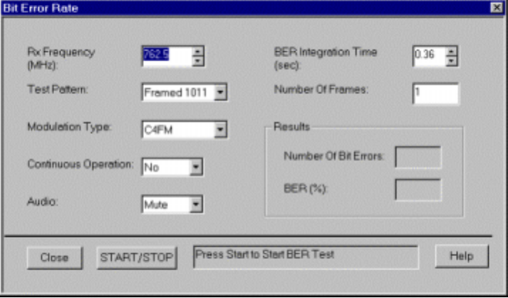
Radio Alignment Procedures
30
This field represents the digital modulation type of the incoming signal on which BER is to
be calculated.
Continuous Operation:
This field allows the user to make the BER test repeat indefinitely. A selection of Yes will
cause the radio to calculate BER on a continuous basis and update the results on this screen
after each integration time. A selection of No will cause the BER test to execute for only
one sample of the integration time and then update the display.
Audio:
This field allows the user to select the audio output during a test. Selecting Internal will
cause the radio's built-in speaker to unmute to any signals at the desired frequency which
are present during the test. Selecting External will route the same signal to the radio's
accessory connector audio output. Selecting Mute will disable the audio output.
Integration Time:
This field represents the amount of time over which the Bit Error Rate is to be calculated.
The range is from 0.360 to 91.8 seconds in increments of 0.360 seconds.
NOTE: When Continuous Operation = Yes, all fields will be grayed out while
test is in progress. They will be enabled when the STOP button is
pressed.
When Continuous Operation = No, a wait cursor will be displayed while
the test is in progress and return to normal when the test is done.
Figure 13. Bit Error Rate Screen
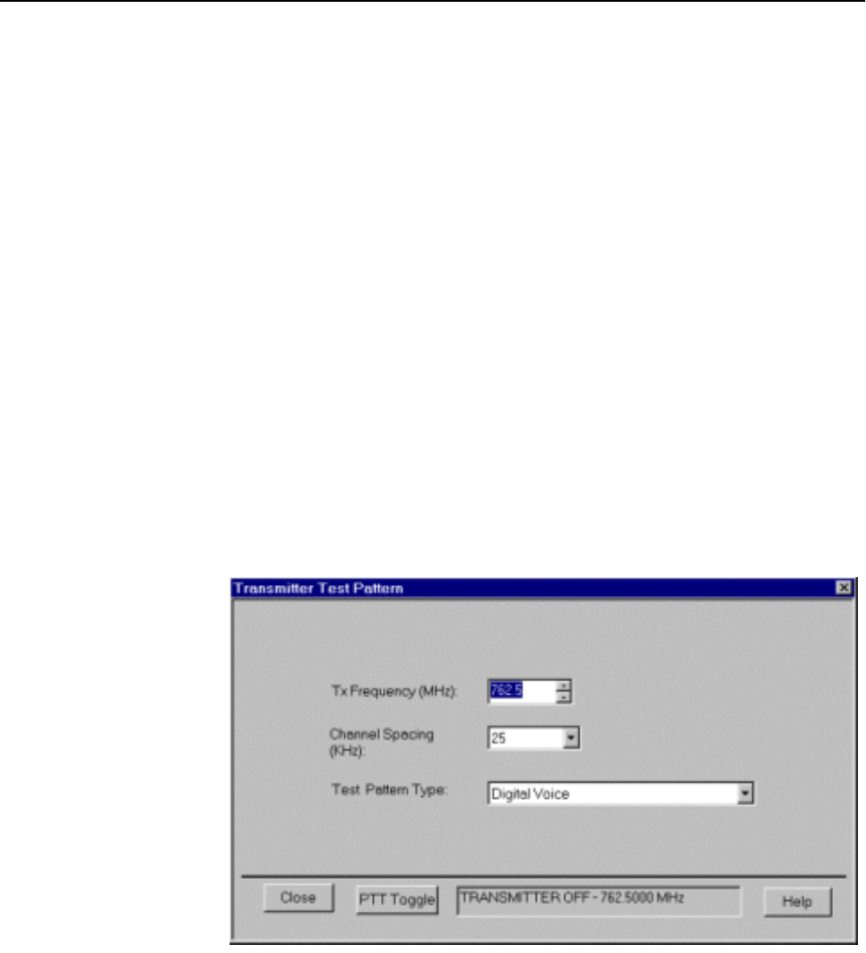
Radio Alignment Procedures
31
Transmitter Test
Pattern
Definition This screen is used to transmit specific test patterns at a desired frequency so that the user
can perform tests on the radio’s transmitter.
Transmitter Test
Fields
This screen contains the following fields:
Tx Frequency:
This field selects the Transmit Frequency directly in MHz.
Channel Spacing:
This field allows the user to select the desired transmit deviation.
Test Pattern Type:
This field represents the type of test pattern which will be transmitted by the radio when
“PTT TOGGLE” button is pressed.
NOTE: Channel Spacing and Test Pattern Type fields will be grayed out while
radio is transmitting.
Figure 14. Transmitter Test Pattern Screen

Radio Alignment Procedures
32
Notes
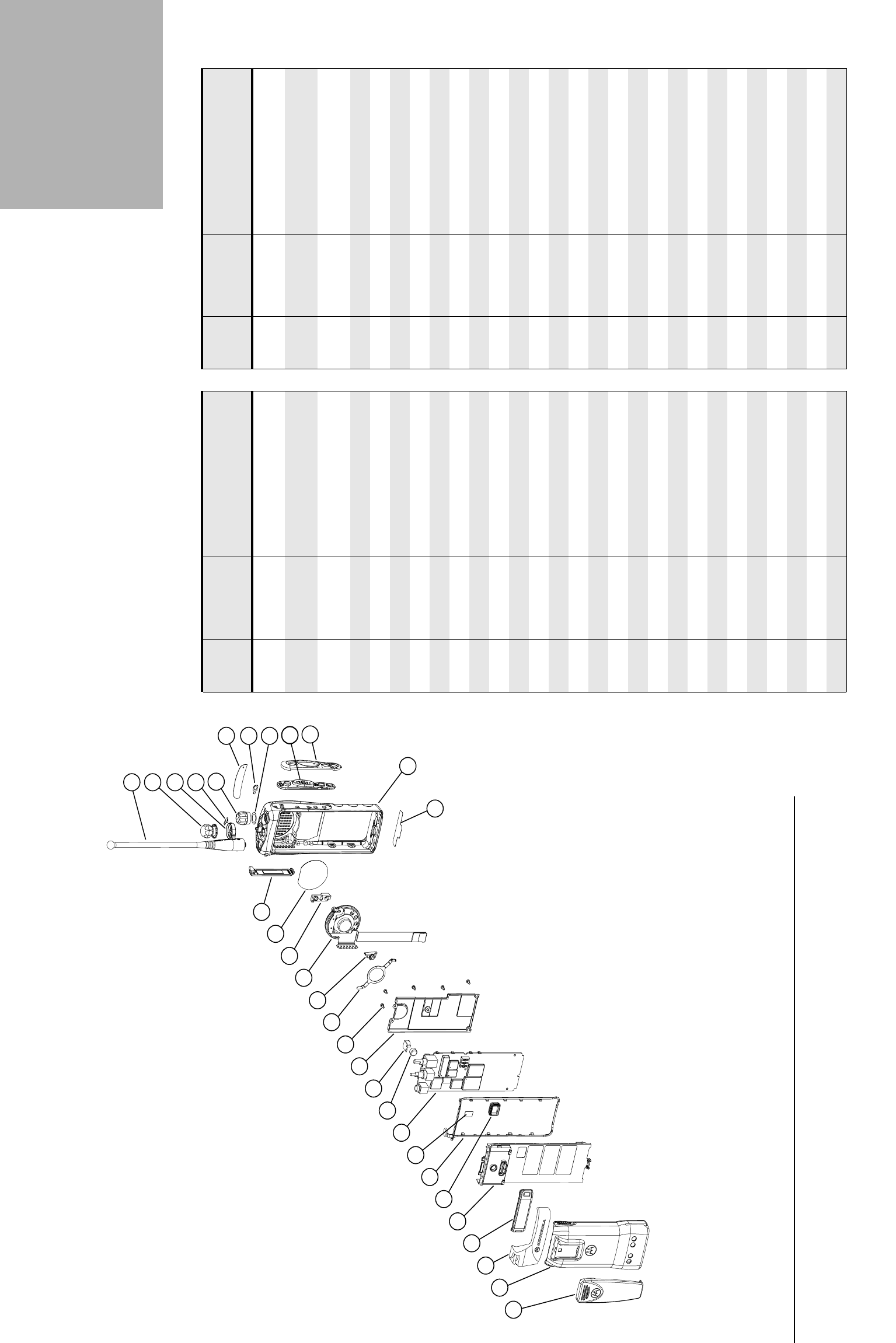
33
XTS 2500/XTS 1500/MT 1500
Exploded View and Parts List 7
XTS 2500/XTS 1500/MT 1500 Model I Exploded View
12 31
7
10
4
11
3
1
9
21
19
18
MAEPF-27251-O
24
25
2
8
5
6
26
17
20
13
22
27
23
16
14
15
29
28
30
Table 13. Model I Exploded View Parts List
Item
Number Motorola Part
Number Description Item
Number Motorola Part
Number Description
1 1585746D01 Cover, Front Assembly Kit
(XTS2500)
26 2685785C01 Main Shield
1585746D04 Cover, Front Assembly Kit
(XTS1500/MT1500)
27 Typical Main Board
2 8485939D01 Assembly, Speaker/Microphone/
Universal Connector Flex
28 4385665D01 Adaptor, Remote Speaker Mic.
31385149D01 Bezel, PTT 29 Typical Battery
4 7585959C01 Keypad, PTT/Side Controls 30 Typical Belt Clip
54285446D01 Retainer, Speaker 31 0485667D01 Washer, Teflon
6 4285632D01 Retainer, Microphone Boot
73585469D01 Microphone Felt
8 1485218D01 Boot, Microphone
91385855C01 Label, ABC
10 3385466D01 Nameplate, Front (XTS2500)
3386597Z01 Nameplate, Front (XTS1500)
3386597Z02 Nameplate, Front (MT1500)
11 3385511D01 Label, Bottom
12 3585339D01 Speaker Mesh
13 0385563D01 Screw
14 1585405D01 Shroud
15 2785787C01 Chassis Cover, Rear
16 3285270D01 Seal, Main O-ring
17 4285633D01 Retaining Clip
18 3680529Z01 Knob, Volume
19 3685779C01 Knob, Frequency (W/D-Clip)
20 6003710K08 Battery, Backup
21 4585782C01 Lever, Concentric Switch
22 7585382D01 Pad, Thermal
23 3280534Z01 Seal, Contact
24 Typical Antenna
25 1505579Z01 Dust Cover, Universal Conn.
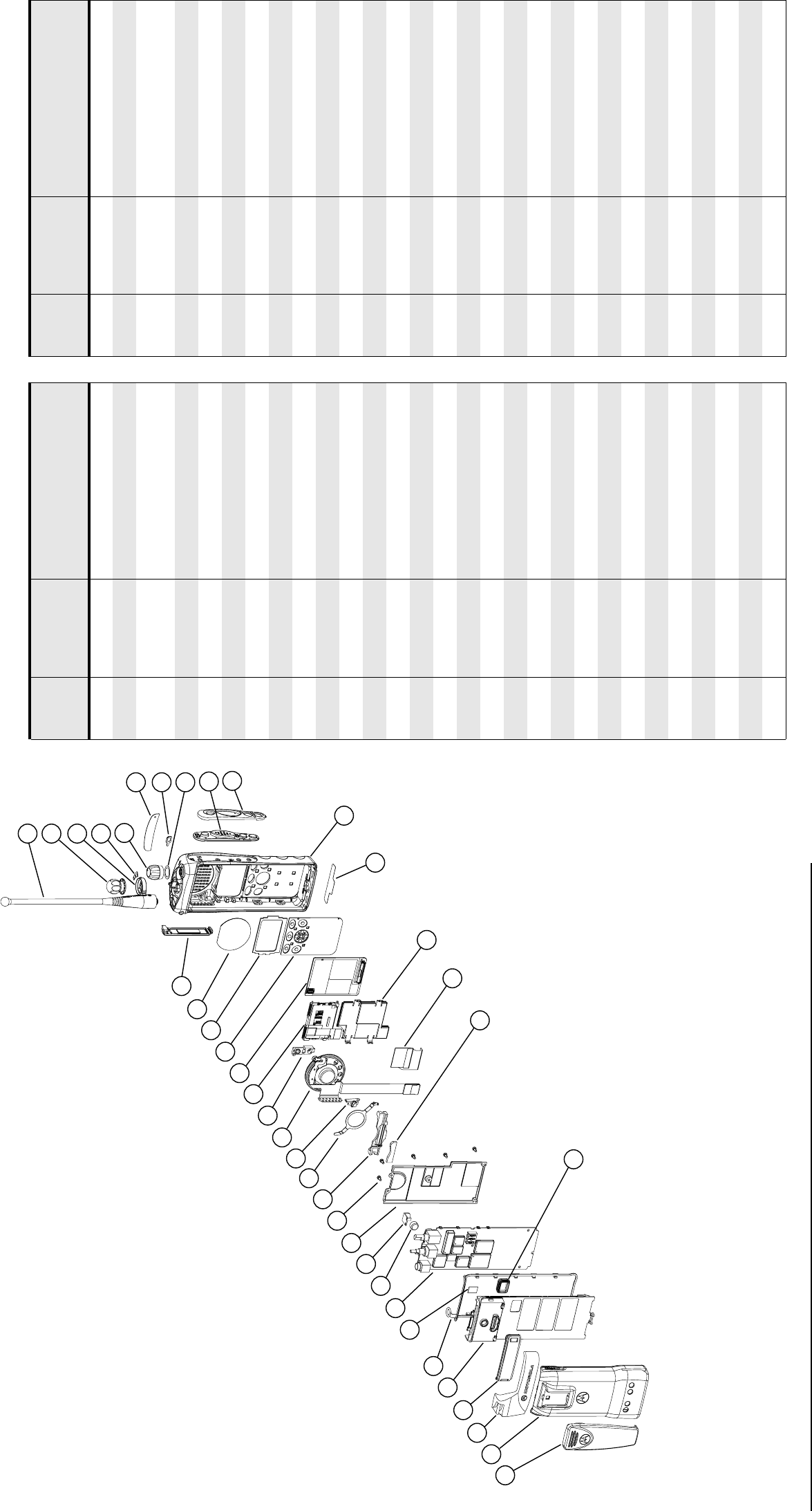
XTS 2500/XTS 1500/MT 1500 Exploded View and Parts List
34
XTS 2500 Model II Exploded View
18 5
13
39
16
4
17
9
8
7
2
6
14
3
11
10
12
19
28
22
21
20
36
1
29
15
27
25
24
MAEPF-27250-O
33
34
23
26
35
37
38
32
30
31
Table 14. Model II Exploded View Parts List
Item
Number Motorola Part
Number Description Item
Number Motorola Part
Number Description
1 1585746D02 Cover, Front Assembly Kit 30 Typical Antenna
20185947D01 Board, Model II 31 1505579Z01 Dust Cover, Universal Conn.
3 8485939D01 Assembly, Speaker/Microphone/
Universal Connector Flex
32 8485268D01 Board, Jumper Flex
41385149D01 Bezel, PTT 33 7585737D01 Spacer Pad
5 7585959C01 Keypad, PTT/Side Controls 34 2685785C01 Main Shield
67285726C01 Display Module 35 Typical Main Board
7 7585776C02 Keypad, Limited 36 4385665D01 Adaptor, Remote Speaker Mic.
87585915C01 Pad, Shock LCD 37 Typical Battery
9 4285214D01 Retainer, Keypad 38 Typical Belt Clip
10 4285446D01 Retainer, Speaker 39 0485667D01 Washer, Teflon
11 4285632D01 Retainer, Microphone Boot
12 4385717D01 Spacer, Plastic
13 3585469D01 Microphone Felt
14 1485218D01 Boot, Microphone
15 1385855C01 Label, ABC
16 3385466D01 Nameplate, Front
17 3385511D01 Label, Bottom
18 3585339D01 Speaker Mesh
19 0385563D01 Screw
20 1585405D01 Shroud
21 2785787C01 Chassis Cover, Rear
22 3285270D01 Seal, Main O-ring
23 4285633D01 Retaining Clip
24 3680529Z01 Knob, Volume
25 3685779C01 Knob, Frequency (W/D-Clip)
26 6003710K08 Battery, Backup
27 4585782C01 Lever, Concentric Switch
28 7585382D01 Pad, Thermal
29 3280534Z01 Seal, Contact
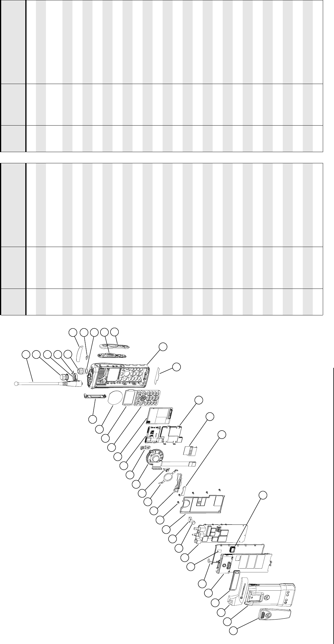
XTS 2500/XTS 1500/MT 1500 Exploded View and Parts List
35
XTS 2500 Model III Exploded View
18 5
13
16
4
17
9
8
7
2
6
14
3
11
10
12
19
28
22
21
20
36
1
29
15
27
25
24
MAEPF-27249-O
33
34
35
37
38
32
30
31 39
23
26
Table 15. Model III Exploded View Parts List
Item
Number Motorola Part
Number Description Item
Number Motorola Part
Number Description
1 1585746D03 Cover, Front Assembly Kit 30 Typical Antenna
20185948D01 Keypad Board, Model III 31 1505579Z01 Dust Cover, Universal Conn.
3 8485939D01 Assembly, Speaker/Microphone/
Universal Connector Flex
32 8485268D01 Board, Jumper Flex
41385149D01 Bezel, PTT 33 7585737D01 Spacer Pad
5 7585959C01 Keypad, PTT/Side Controls 34 2685785C01 Main Shield
67285726C01 Display Module 35 Typical Main Board
7 7585776C01 Keypad, Full 36 4385665D01 Adaptor, Remote Speaker Mic.
87585915C01 Pad, Shock LCD 37 Typical Battery
9 4285214D01 Retainer, Keypad 38 Typical Belt Clip
10 4285446D01 Retainer, Speaker 39 0485667D01 Washer, Teflon
11 4285632D01 Retainer, Microphone Boot
12 4385717D01 Spacer, Plastic
13 3585469D01 Microphone Felt
14 1485218D01 Boot, Microphone
15 1385855C01 Label, ABC
16 3385466D01 Nameplate, Front
17 3385511D01 Label, Bottom
18 3585339D01 Speaker Mesh
19 0385563D01 Screw
20 1585405D01 Shroud
21 2785787C01 Chassis Cover, Rear
22 3285270D01 Seal, Main O-ring
23 4285633D01 Retaining Clip
24 3680529Z01 Knob, Volume
25 3685779C01 Knob, Frequency (W/D-Clip)
26 6003710K08 Battery, Backup
27 4585782C01 Lever, Concentric Switch
28 7585382D01 Pad, Thermal
29 3280534Z01 Seal, Contact
XTS 2500/XTS 1500/MT 1500 Exploded View and Parts List
36
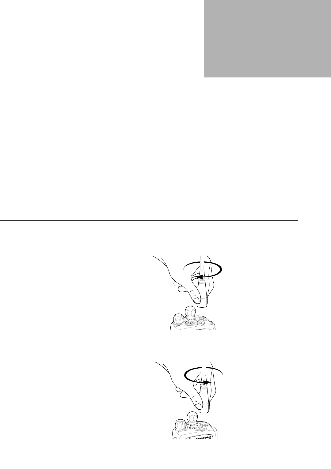
37
Disassembly/Assembly 8
Introduction to
This Section
This section contains basic procedures for removing and installing the following
components of the XTS 2500 radio:
•Antenna
•Battery
•Belt Clip
•Universal Connector Cover
•Remote Speaker Microphone Adapter
•Radio Disassembly—Detailed
•Radio Reassembly—Detailed
Antenna
Attach the Antenna With the radio off, turn the antenna clockwise to attach it.
Remove the
Antenna
With the radio off, turn the antenna counter-clockwise to remove it.
Figure 15. Attaching the Antenna
Figure 16. Removing the Antenna
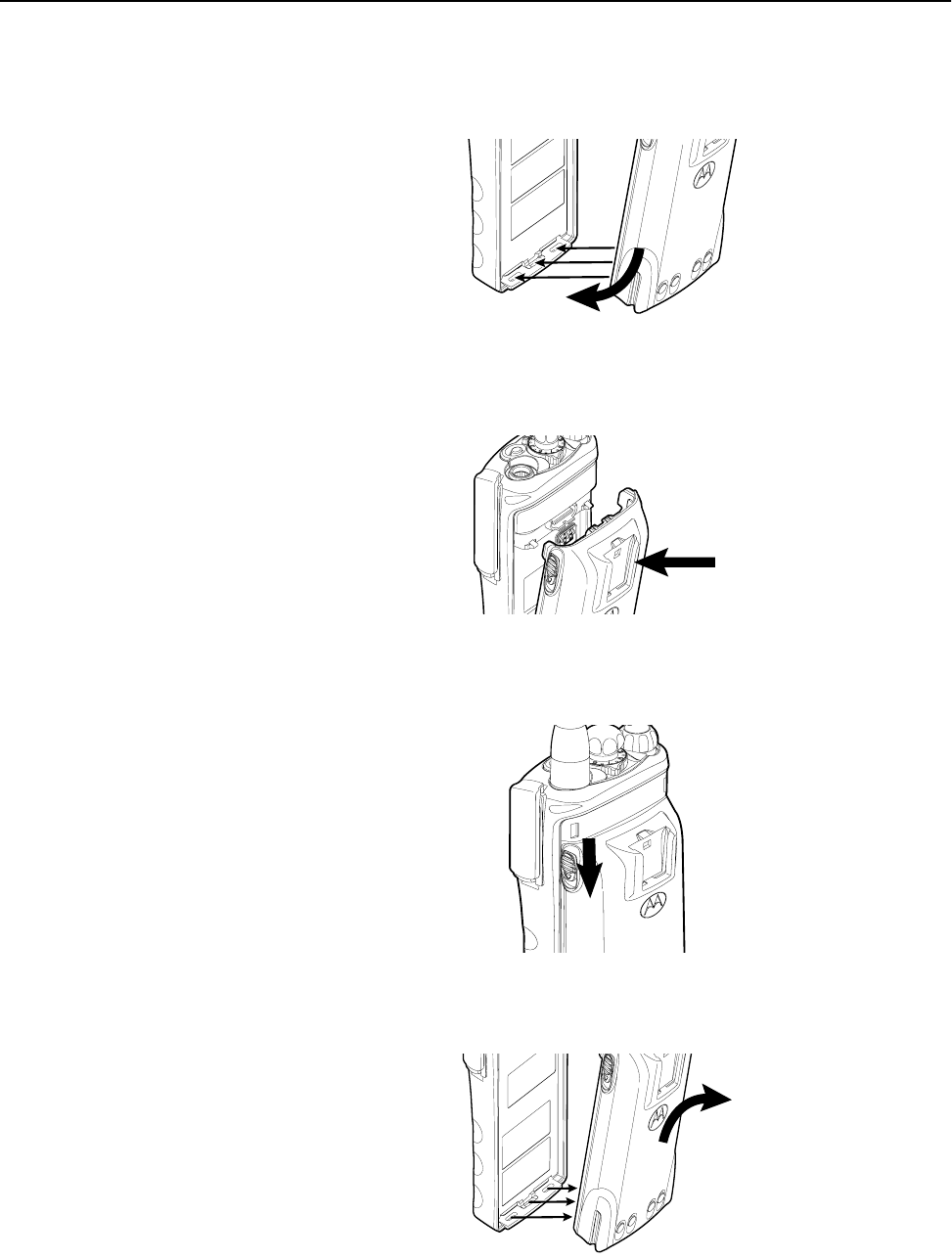
Disassembly/Assembly
38
Battery
Attach the Battery 1. With the radio off, fit the three extensions at the bottom of the battery into the bottom
slots on the radio.
2. Press the top of the battery against the radio until both latches click into place.
Remove the Battery 1. With the radio off, slide down the latches on the sides of the battery.
2. Pull the top of the battery away from the radio.
Figure 17. Step 1, Attaching the Battery
Figure 18. Step 2, Attaching the Battery
Figure 19. Step 1, Removing the Battery
Figure 20. Step 2, Removing the Battery
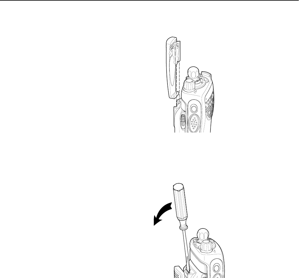
Disassembly/Assembly
39
Belt Clip
Attach the Belt Clip 1. Align the grooves of the belt clip with those of the battery.
2. Press the belt clip downward until you clear a “click.”
Remove the Belt
Clip
1. Use a flat-bladed object to press the belt clip tab away from the battery.
2. Slide the belt clip upward to remove it.
Figure 21. Attaching the Belt Clip
Figure 22. Removing the Belt Clip
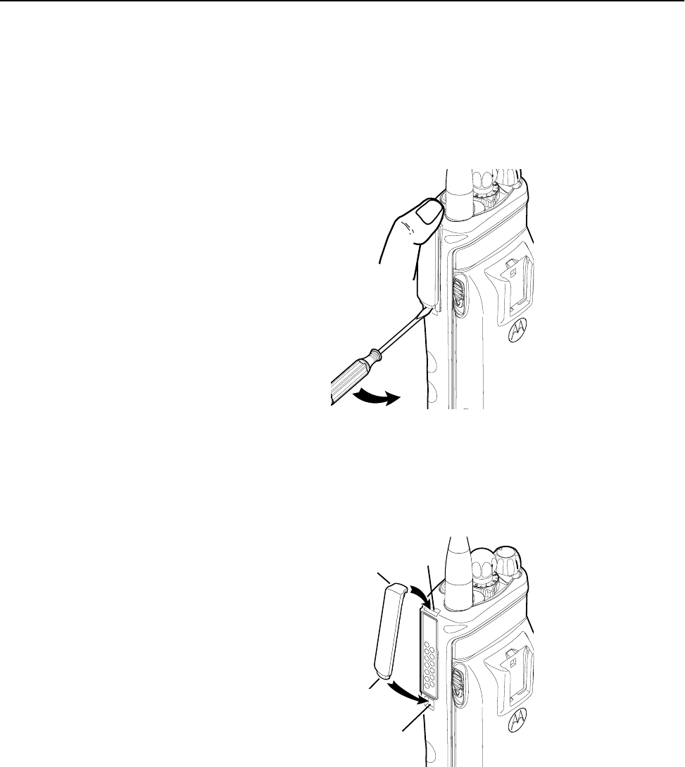
Disassembly/Assembly
40
Universal
Connector Cover
The universal connector cover is located on the antenna side of the radio. It is used to cover
the connector when not in use.
NOTE: To prevent damage to the connector, shield it with the
connector cover when not in use.
Remove the
Universal Connector
Cover
1. Insert a flat-blade screwdriver into the area between the bottom of the cover and the
slot below the connector.
2. Hold the top of the cover with your thumb while you pry the bottom of the cover
away from the radio with the screwdriver.
Attach the Universal
Connector Cover
1. Insert the, hooked end of the cover into the top of the connector.
2. Press downward on the top of the cover to seat it into the slot.
3. Press the lower tab of the cover below the connector until it snaps in place.
Figure 23. Removing the Universal Connector Cover
Figure 24. Attaching the Universal Connector Cover
Top
Slot
Bottom
Slot
Top
Hooked End
Bottom
Hooked End
Tab
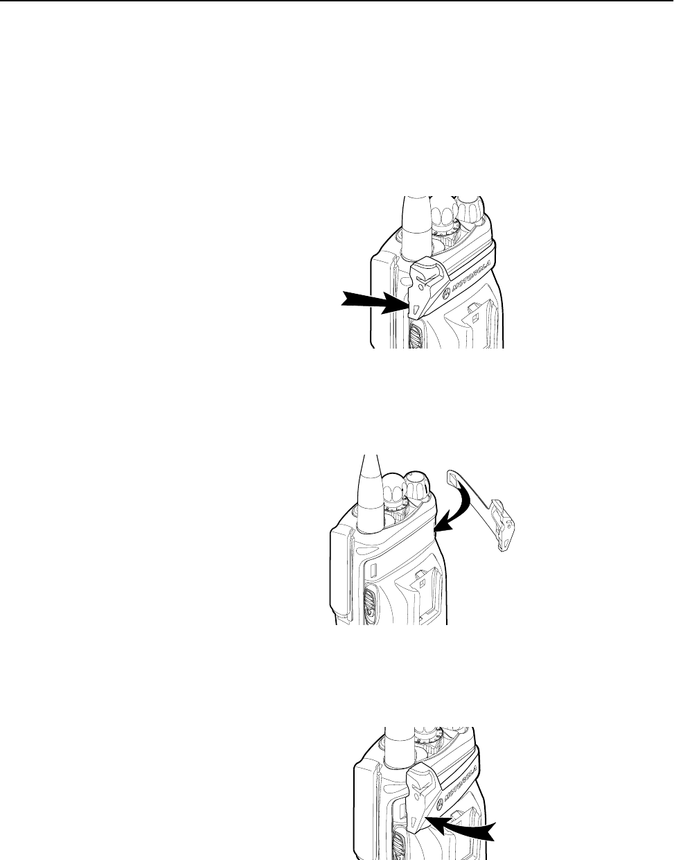
Disassembly/Assembly
41
Remote Speaker
Microphone
Adapter
The Remote Speaker Microphone (RSM) adapter is located on the back of the radio, just
above the battery. It must be used to connect the RSM to the radio. If the RSM is not
used, the adapter must be removed.
Remove the Adapter Lift the larger side (below the antenna port) of the adapter away from the radio using your
finger.
If you cannot easily remove the adapter with your finger, use a small, flat bladed
screwdriver to pry the larger end side of the adapter away from the radio.
Attach the Adapter 1. With the Motorola side of the adapter facing out, snap the smaller end of the adapter
into place in the shroud indent, below the On/Off Volume Control Knob.
2. Snap the larger end of the adapter into place in the shroud indent, below the antenna
port.
Figure 25. Removing the RSM Adapter
Figure 26. Step 1, Attaching the RSM Adapter
Figure 27. Step 2, Attaching the RSM Adapter

Disassembly/Assembly
42
Radio
Disassembly—
Detailed
When disassembling and reassembling the radio, pay particular attention to the snaps and
tabs and how parts align with each other.
The following steps describe how to disassemble the radio. This includes the following
major components:
•Front Cover
•Chassis
•Backup Battery
•Keypad
•Keypad/option board
•Display
•Speaker, microphone, universal flex connector
•PTT
Required Tools •Small, flat-bladed screwdriver
•TORX™ T7-IP screwdriver
•Chassis Opener/Knob removal tool (Motorola part number 6685666D01)
Front Cover from
Chassis
Disassembly
For this section, please refer to the Model III exploded view and parts list on page 35 for
part numbers and more information on the location of parts in the radio.
1. Turn off the radio.
2. Remove the battery completely from the radio (see Figure 19 and Figure 20 on page
38).
3. Remove the antenna (see Figure 16 on page 37).
Table 16. Front Cover from Chassis Disassembly
Exploded
View
Item
Number
Motorola Part Number Description
1 1585746D03 Cover, Front Assembly Kit
3 8485939D01 Assembly Speaker/Microphone/Universal
Connector Flex
21 2785787C01 Chassis Cover, Rear
24 3680529Z01 Knob, Volume
25 3685779C01 Knob, Frequency (16-Position Select)
27 4585782C01 Lever, Concentric Switch
30 Typical Antenna
32 8485268D01 Board, Jumper Flex
37 Typical Battery
39 0485667D01 Washer, Teflon
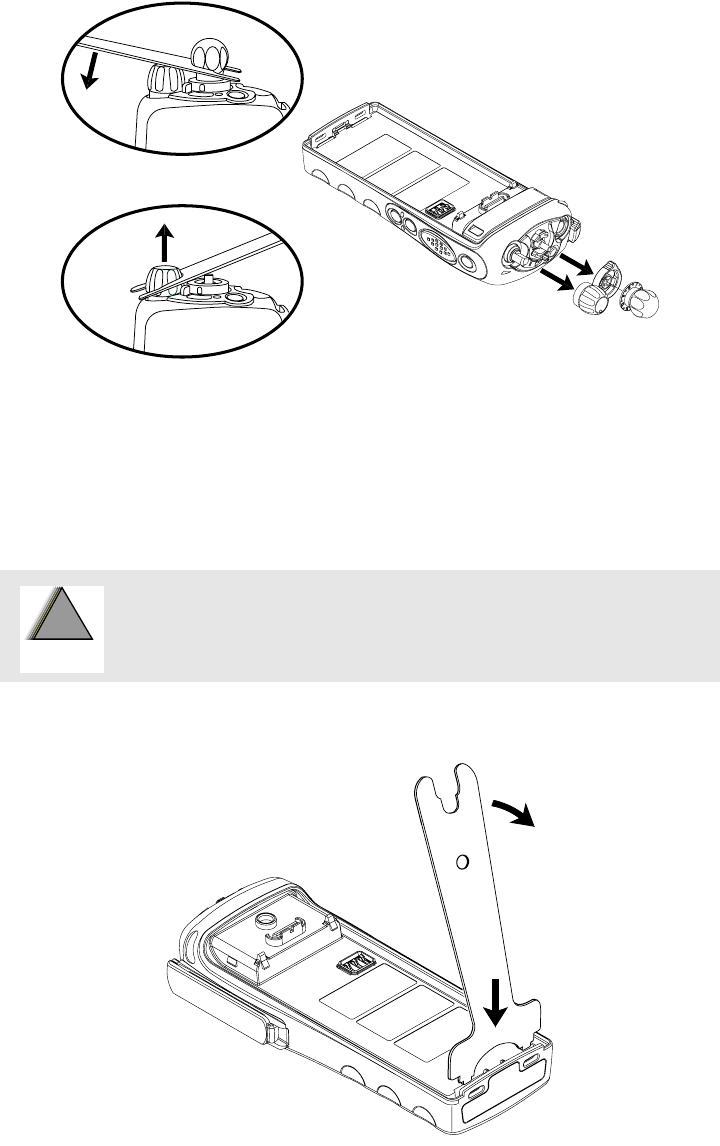
Disassembly/Assembly
43
4. Pull the 16-Position Select and the On/Off/Volume Control knobs off their shafts
using the Chassis Opener tool.
5. After you remove the On/Off/Volume Control knob, remove the Teflon® washer
and set it aside.
6. Separate the chassis from the front cover by inserting the chassis opener between the
thin, plastic retaining wall and the metal chassis at the bottom of the radio.
Figure 28. Knob Removal
Be careful not to mar the O-ring sealing area on the housing. Marring
the front cover O-ring sealing areas will prevent the radio from
sealing properly.
Figure 29. Chassis Removal
!
W A R N I N G
!
KNOBS OPENER
CHASSIS OPENER
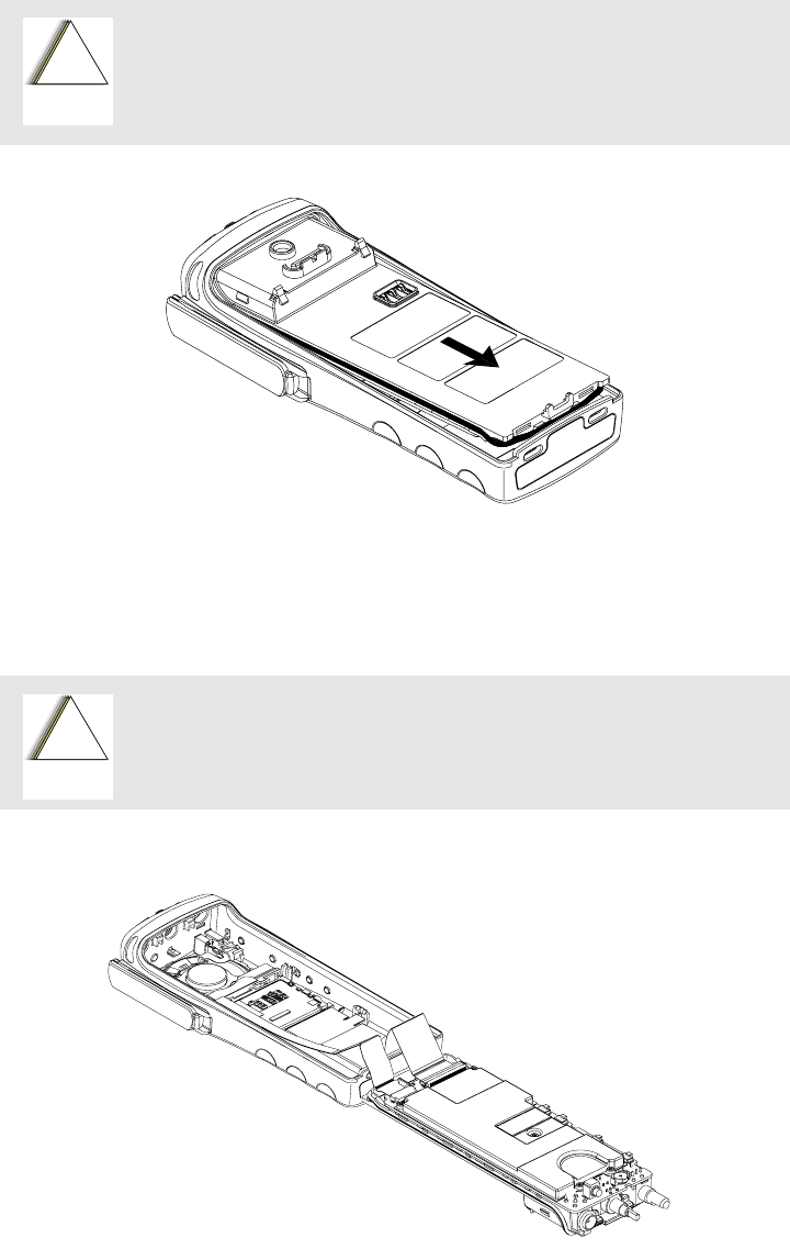
Disassembly/Assembly
44
7. Slowly pry the bottom of the chassis away from the front cover by pushing the chassis
opener tool down. Rotate the handle of the tool over and behind the base of the radio.
This prying action forces the thin inner plastic wall toward the base of the radio,
releasing the two chassis tabs.
8. Remove the chassis assembly by holding the chassis in one hand while slowly, with a
firm side-to-side motion, removing the chassis.
9. Lay the chassis down. Rotate the front cover backward and slightly away from the
chassis.
The chassis assembly has switches that can be damaged if the chassis
is removed too quickly. Be careful not to damage the switches at the
top of the board.
Figure 30. Chassis Separation
Flexible ribbon circuits (flexes) connecting the front cover assembly
and the chassis prevent you from completely separating the two units.
Display radios and radios with option boards have two flexes.
Figure 31. Unlatching the Flex Connectors
!
C a u t i o n
!
C a u t i o n
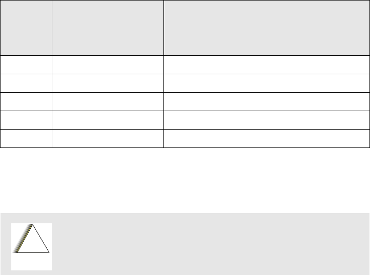
Disassembly/Assembly
45
10. Carefully lift the latches on the main circuit board to release the flexible circuits from
their connectors.
NOTE: For proper reassembly, note how the flex circuits are
folded.
11. Remove the concentric lever from the front cover assembly.
Chassis
Disassembly
For this section, please refer to the Model III exploded view and parts list on page 35 for
part numbers and more information on the location of parts in the radio.
1. If disassembly of the chassis or the main board is required, then use a TORX™
screwdriver with a T7-IP head to remove the five screws holding the main board and
shield to the chassis.
2. Remove the O-ring from around the bushing at the antenna connector
3. Lift the main board from the chassis as shown in Figure 32.
Table 17. Chassis Disassembly
Exploded
View
Item
Number
Motorola Part Number Description
19 0385563D01 Screw (5 required)
21 2785787C01 Chassis Cover, Rear
22 3285270D01 Seal, Main O-ring
34 2685785C01 Main Shield
35 Typical Main Board
Refer to the Handling Precautions on page 4 before removing the
main board. Be sure to use ESD protection when handing circuit
boards.
!
C a u t i o n
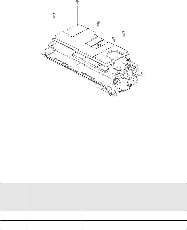
Disassembly/Assembly
46
4. Most repairs to the main board can be performed without further disassembly of the
chassis. If it is necessary to replace the O-ring, remove the small O-ring retainers
from their slots in the chassis. Note the alignment of the retainers for reassembly.
5. Remove the O-ring.
Backup Battery
Disassembly
For this section, please refer to the Model III exploded view and parts list on page 35 for
part numbers and more information on the location of parts in the radio.
1. The backup battery can be removed without disassembling the board or the chassis.
2. Remove the backup battery retaining clip by sliding it away from the main circuit
board, as shown in Figure 33.
3. Insert a small, flat head screwdriver between the battery and the battery holder.
Gently pry the battery out of the battery holder.
Figure 32. Removing the Main Board from the Chassis
Table 18. Backup Battery Disassembly
Exploded
View
Item
Number
Motorola Part Number Description
23 4285633D01 Retaining Clip
26 6003710K08 Battery, Backup
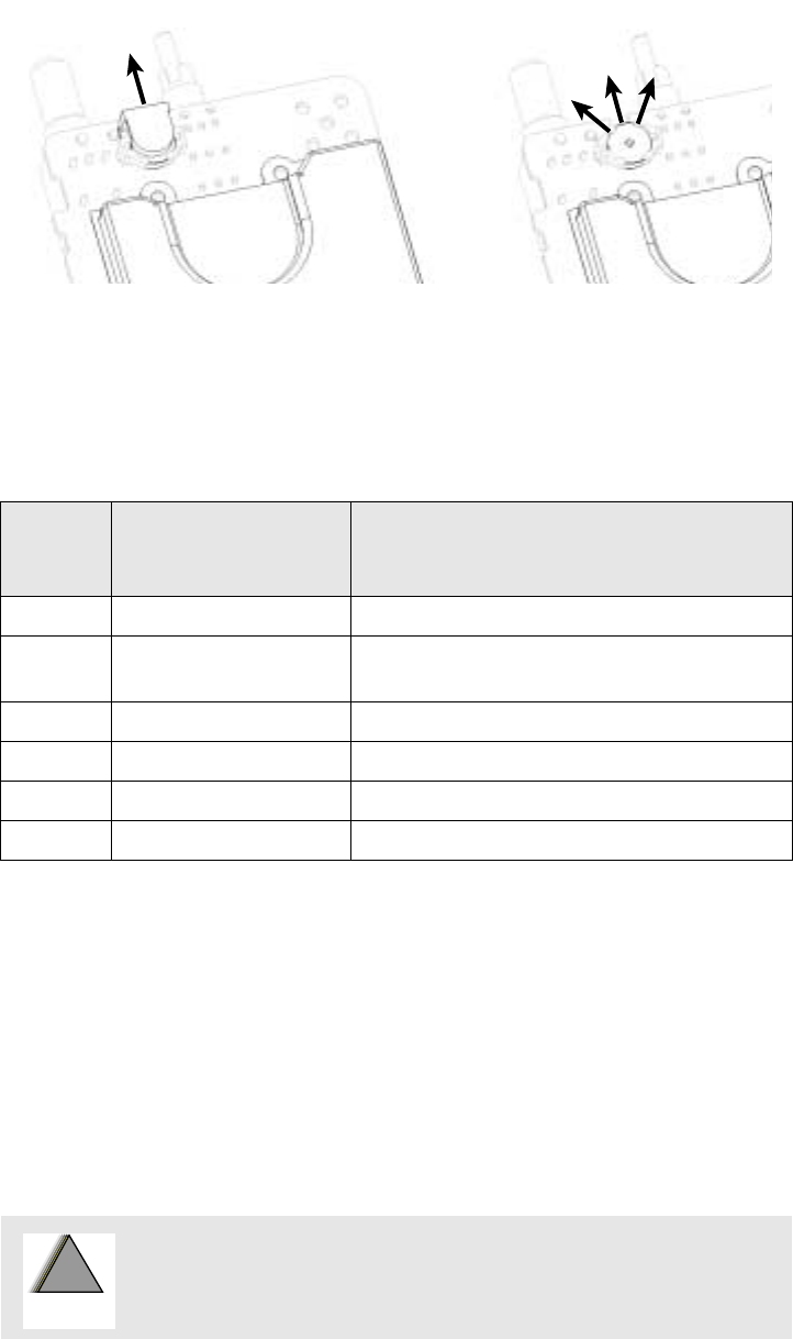
Disassembly/Assembly
47
Keypad and
Keypad/Option
Board Disassembly
For this section, please refer to the Model III exploded view and parts list on page 35 for
part numbers and more information on the location of parts in the radio. (For the Model II
keypad, please refer to the exploded view and parts list on page 34.)
1. The keypad and keypad board can be disassembled without the disassembly of the
display or speaker/microphone flex assembly.
2. If the disassembly of the keypad or the keypad printed circuit board is required, lift
the microphone flex circuit up to move it out of the way.
3. Disconnect the display connector, and move the tail of flex circuit out of the way.
4. To remove the keypad retainer shield, insert the tip of a “penknife size,” flat-bladed
screwdriver in the opening at the end of the keypad retainer arm tab. Pry the tab away
from the side of the front cover until it moves past the ledges on the side wall. Repeat
this procedure for the four remaining retainer arm tabs.
Figure 33. Remove the Backup Battery
Table 19. Keypad and Keypad/Option Board
Exploded
View Item
Number Motorola Part Number Description
2 0185948D01 Keypad Board, Model III
3 8485939D01 Assembly Speaker/Microphone/Universal
Connector Flex
6 7285726C01 Display Module
7 7585776C01 Keypad, Full (for Model III only)
9 4285214D01 Retainer, Keypad
22 3285270D01 Seal, Main O-ring
Be careful not to mar the O-ring sealing area on the housing. Marring
the front cover O-ring sealing areas will prevent the radio from
sealing properly.
!
W A R N I N G
!
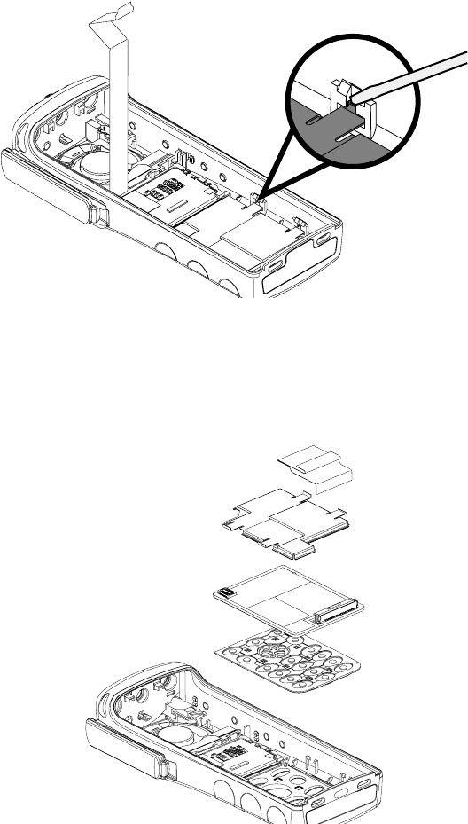
Disassembly/Assembly
48
5. Lift the keypad retainer out of the front cover.
6. The keypad/option board and the keypad can be removed without the use of tools.
Figure 34. Retainer Removal
Figure 35. Keypad Retainer and Boards Removal
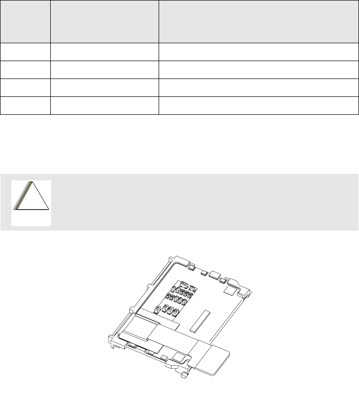
Disassembly/Assembly
49
Display
Disassembly
For this section, please refer to the Model III exploded view and parts list on page 35 for
part numbers and more information on the location of parts in the radio. (For the Model II
display, please refer to the exploded view and parts list on page 34.)
1. The display assembly can be removed without the disassembly of the keypad board or
the speaker-microphone flex assembly. If the disassembly involves the removal of the
display module, disconnect the display flex from the keypad option board connector.
2. The display module snaps into the front cover assembly. Insert two flat-bladed
screwdrivers between the flexible beam at the top of the display module (one on each
side). Deflect the beam down until it moves past the hooks on the front cover. The
display module is hooked to the front cover at the base of the display. Lift the top of
the display module past the hooks and remove it from the front cover.
Table 20. Display Disassembly
Exploded
View Item
Number Motorola Part Number Description
1 1585746D03 Cover, Front Assembly Kit (Model III)
2 0185948D01 Keypad Board, Model III
6 7285726C01 Display Module
9 4285214D01 Retainer, Keypad
Take care not to damage the display. Do not cut, bend, or pinch the heat
seal. Display modules contain CMOS devices. Be sure to use ESD
protection.
Figure 36. Display Disassembly
!
C a u t i o n

Disassembly/Assembly
50
Speaker,
Microphone, and
Universal Connector
Flex Disassembly
For this section, please refer to the Model III exploded view and parts list on page 35 for
part numbers and more information on the location of parts in the radio.
1. The speaker-microphone assembly can be removed without the disassembly of the
display or the keypad assemblies. If disassembly of the speaker-microphone assembly
is necessary, removal of the universal connector dust cover is optional (see Figure 23
on page 40).
2. Remove the plastic spacer at the bottom of the speaker. The spacer can be removed by
pulling upward with a slight, side-to-side motion until it clears the retaining ribs in the
front cover. Take special care to prevent damage to the tail of the speaker flex circuit
while the flex is still in place.
3. Using a screwdriver, push down on the portion of the speaker retainer bracket that is
pointing toward the bottom of the radio. Then, remove the retainer by slightly pushing
it toward the top of the radio until you slide it past the front cover slot.
4. Remove the microphone boot retainer by inserting a penknife-sized screwdriver in the
notch between the retainer and the housing. Pry the retainer away from the housing
and remove the clip.
5. Remove the microphone rubber boot by sliding it out of the pocket in the front cover.
Take care not to pull on the flex cable while pulling on the microphone boot. Unless
you are replacing the microphone, leave it in the boot. At this point, the speaker and
microphone are disconnected, but the assembly is still attached to the universal
connector by 13 pins in the printed circuit backer board.
6. To remove the speaker-microphone flex circuit from the universal connector,
carefully grasp the flex circuit at a point directly across from the universal connector
pins. Applying firm pressure, gradually pull the flex away from the pins.
Table 21. Speaker, Microphone, and Universal connector Flex Disassembly
Exploded
View Item
Number Motorola Part Number Description
1 1585746D03 Cover, Front Assembly Kit
3 8485939D01 Assembly Speaker/Microphone/Universal
Connector Flex
10 4285446D01 Retainer, Speaker
11 4285632D01 Retainer, Microphone Boot
12 4385717D01 Spacer, Plastic
14 1485218D01 Boot, Microphone
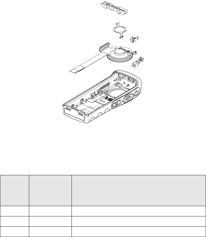
Disassembly/Assembly
51
NOTE: There are notches on the ends of the 13-pin printed
circuit backer board. If necessary, you can insert a small
screwdriver in one of the notches to pry the backer board
away from the front cover.
After the universal connector portion of the speaker-microphone flex circuit is
detached, the assembly can be completely removed. If it is necessary to replace the
speaker or the microphone, or both, do it while the flex circuit is removed from the
front cover.
PTT Disassembly For this section, please refer to the Model III exploded view and parts list on page 35 for
part numbers and more information on the location of parts in the radio.
1. If required, the PTT bezel and the PTT seal assembly can be disassembled using a
small screwdriver.
2. Remove the PTT bezel by pushing the snaps out at the top and pulling the bezel up
toward the top of the front cover so that the T-tab slides up and out.
3. The PTT seal can be easily lifted from the bezel without the use of tools.
Figure 37. Speaker-Microphone Removal
Table 22. PTT Disassembly
Exploded
View
Item
Number
Motorola
Part Number Description
1 1585746D03 Cover, Front Assembly Kit
4 1385149D01 Bezel, PTT
5 7585959C01 Keypad, PTT/Side Controls
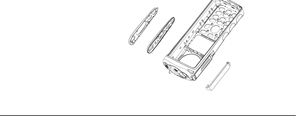
Disassembly/Assembly
52
Radio
Reassembly—
Detailed
The following steps describe how to reassemble the radio. This includes the following
major components:
•PTT
•Keypad/option board
•Display
•Speaker, microphone, universal connector flex
•Chassis
•Backup Battery
•Chassis and front cover
PTT Reassembly 1. Put the PTT seal in the PTT bezel.
2. Align the PTT bezel and seal to the front cover housing so that the bottom tabs will
engage with the opening in the front cover.
3. Slide the PTT bezel down so that the T-tab engages into the front cover opening.
4. Snap the top snaps.
NOTE: Look inside the front cover to be sure the T-tab and snaps
are fully engaged with the front cover.
Figure 38. PTT Removal
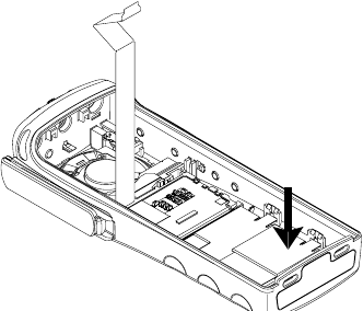
Disassembly/Assembly
53
Keypad and Keypad
Option Board
Reassembly
1. Insert the keypad into the front cover. Align the keypad to the pins in the front cover.
2. Replace the board on the locator pins.
3. Replace the keypad retainer legs on the PTT side first. Then, press the retainer down
and snap the other two legs into place on the universal connector side; make sure that
all four legs snap into place. If necessary, use a small, flat-bladed screwdriver to put
pressure on the corner bend of each retainer leg.
Display Reassembly 1. Slide the two bottom tabs of the display module, with the LCD facing the front
housing lens, into the grooves located above the keypad assembly area in the front
cover housing. Gently press on the upper portion of the display until it snaps into
place past the two small hooks in the housing.
2. Connect the display flex to the keypad option board connector.
Speaker,
Microphone, and
Universal Connector
Flex Reassembly
1. Insert the microphone boot into the pocket in the front cover housing.
2. Insert the microphone boot plastic retainer. Make sure the retainer is securely hooked
to the front cover.
3. Center the speaker in the speaker recess. Make certain the speaker is correctly nested
inside the front cover.
4. Before you replace the speaker retainer, be sure the retainer is placed between the
speaker-microphone flex circuit and the speaker. Insert the flat end of the speaker
retainer into the opening in the front cover. Press the other end of the retainer against
the speaker. Hold the retainer in place with your thumb while pushing down on the
retainer with a flat-bladed screwdriver. Use the screwdriver to push down on the
portion of the speaker retainer that is pointing toward the bottom of the radio. Move
the retainer by pushing it toward the bottom of the radio. Slide it into the front cover
slot above the display.
5. Connect the universal flex to the pins and press into place.
Figure 39. Lock Retainer Catches to Radio Body
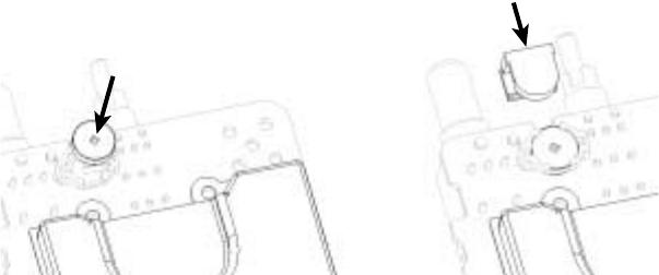
Disassembly/Assembly
54
Chassis Assembly
Reassembly
Before you assemble the main board to the chassis, make sure that the following steps are
done to the chassis.
1. Replace the O-ring. The tabs on the O-ring should reach into the chassis and point
down.
2. Stretch the O-ring to place it into the retaining pocket at the bottom end of the chassis.
NOTE: When properly assembled, the retainers on the O-ring
should align with the slots on the chassis. If this is not the
case, remove and replace the O-ring until it is aligned
with the chassis and completely seated in place around
the perimeter.
3. Replace the battery contact seal (if necessary) surrounding the battery contact.
NOTE: Be sure the battery contact seal protrudes through the
chassis and is not pinched under the chassis.
4. Make sure the thermal pad is placed on top of the RF Power Amplifier on the main
board.
5. Use the notch in the bottom of the main board and the protrusion at the bottom of the
casting to align the board to the casting. Place the board against the casting. Make
sure that the five screw holes are aligned.
6. Place the main shield assembly on the main board. Again, make sure that the five
screw holes are aligned.
7. Use the TORX T7-IP screwdriver to fasten the screws holding the main board and
shield to the chassis. Do not over torque. Torque limit is 4 inch-lbs.
8. Place the O-ring at the antenna connector over the antenna connector bushing.
Backup Battery
Reassembly
1. Insert the backup battery (positive side up) into the battery holder, as shown in Figure
40.
2. Replace the retaining clip by sliding it into its recess on the board.
Chassis and Front
Cover Reassembly
1. Align the chassis assembly end-to-end with the front cover assembly.
2. Insert the tails of the flex circuits into their respective connectors at the bottom of the
Figure 40. Reassemble the Backup Battery
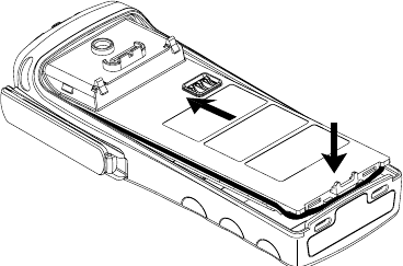
Disassembly/Assembly
55
chassis assembly.
3. Push down the latches on the connectors to hold the flex circuits to the main board.
NOTE: Be sure the concentric lever is not in place on the
frequency knob shaft when reassembling the chassis with
the front cover assembly.
4. Align the volume knob shaft and the frequency switch shaft with their respective
holes in the front cover. Slowly reassemble the chassis and front cover assemblies.
Slowly slide the volume knob and frequency switch shafts into their respective holes
in the front cover.
NOTE: Make sure the flex circuits are correctly folded in place.
Take special care to prevent pinching or excess binding
of these flexes.
5. Push the chassis assembly completely into the top of the front cover until it settles in
place.
NOTE: Be sure the O-ring is properly seated.
6. Press down at the bottom of the chassis until the chassis snaps into place in the front
cover.
7. Reassemble the concentric lever to the frequency knob shaft by aligning the
protrusions in the lever with the openings in the shaft. The triangular-shaped side of
the lever should point toward the back of the radio.
8. Reassemble the Teflon washer to the volume knob shaft. Reassemble the knobs, dust
cover, antenna, and battery.
Figure 41. Fastening the Chassis

Disassembly/Assembly
56
Notes

57
Radio-Level Troubleshooting 9
Introduction to
This Section
This section of the manual contains troubleshooting charts and error codes that will help
you to isolate problems. Level one troubleshooting will support only radio alignment,
programming, battery replacement, and knob replacement. If the radio needs further
troubleshooting, it must be sent to the depot.
Board-level, component-level, and service information can be found in the ASTRO Digital
XTS 2500 Portable Radios Detailed Service Manual, Motorola publication number
68P81094C10.
Power-Up Error
Codes
When the radio is turned on (power-up), the radio performs cursory tests to determine if its
basic electronics and software are in working order. Problems detected during these tests
are presented as error codes on the radio’s display. For non-display radios, the problem is
indicated at power-up by a single, low-frequency tone. If cycling power and code plug
reprogramming do not fix the error, the radio should be sent to the depot for repair. The
presence of an error should prompt the user that a problem exists and that a service
technician should be contacted.
Self-test errors are classified as either fatal or non-fatal. Fatal errors will inhibit user
operation; non-fatal errors will not. Table 23. lists their descriptions and suggested
corrective action.
Radio-Level Troubleshooting
58
Operational Error
Codes
During radio operation, the radio performs dynamic tests to determine if the radio is
working properly. Problems detected during these tests are presented as error codes on the
radio’s display. Ann error code indicates that a problem exists and that a service technician
should be contacted. Operational error codes are listed in Table 24..
Table 23. Power-Up Error Code Displays
Error
Code Description Corrective Action
01/02 FLASH ROM Codeplug Checksum Non-Fatal Error Reprogram the codeplug.
01/12 Security partition Checksum Non-Fatal Error Send Radio to Depot.
01/22 Tuning Codeplug Checksum Non-Fatal Error Send Radio to Depot.
01/81 Host ROM Checksum Fatal Error Send Radio to Depot.
01/82 FLASH ROM Codeplug Checksum Fatal Error Reprogram the codeplug.
01/88 External RAM FATAL Error -- Note: not a checksum failure Send radio to depot.
01/90 General Hardware Failure Fatal Error Turn the radio off, then on.
01/92 Security Partition Checksum Fatal Error Send radio to depot.
01/93 Flashport AUTHENTIFICATION CODE failure Send radio to depot.
01/98 Internal RAM Fail Fatal Error Send radio to depot.
01/A0 ABACUS Tune failure Fatal Error Turn the radio off, then on.
01/A2 Tuning Codeplug Checksum Fatal Error Send radio to depot.
02/10 DSP Support IC Checksum Non-Fatal Error Turn the radio off, then on.
02/81 DSP ROM Checksum Fatal Error Send radio to depot.
02/88 DSP RAM Fatal Error -- Note: not a checksum failure Turn the radio off, then on.
02/90 General DSP Hardware Failure (DSP startup message not received
correctly)
Turn the radio off, then on.
NOTE: If the corrective action does not fix the failure, send the radio to the depot.
Table 24. Operational Error Code Displays
Error Code Description Corrective Action
FAIL 001 Synthesizer Out-of-Lock a. Reprogram external codeplug
b. Send radio to depot
FAIL 002 Selected Mode/Zone Codeplug Checksum Error Reprogram external codeplug
Radio-Level Troubleshooting
59
Table 25. Receiver Troubleshooting Chart
Symptom Possible Cause Correction or Test (Measurements
Taken at Room Temperature)
Radio dead; Display does not
light up
1. Dead Battery Replace with charged battery.
2. Blown Fuse Send radio to depot.
3. On/Off Switch
4. Regulators
Radio dead; display
lights up
1. VOCON Send radio to depot.
2. RF
No receiver audio or receiver
does not unmeet
Programming a. Does the transmitted signal match the receiver
configuration (PL, DPL, etc.)?
b. With the monitor function enabled, can the radio
be unmuted?
Audio distorted or not loud
enough
Synthesizer Not On
Frequency
Check synthesizer frequency by measuring the transmitter
frequency; if off by more than ±1000Hz, realign.
RF sensitivity poor 1. Synthesizer Not
On Frequency
Check synthesizer frequency by measuring the transmitter
frequency; if off by more than ≤ ±1000Hz, realign.
2. Antenna Switch Send radio to depot.
3. Receiver Front-
End Tuning
Check RF front-end tuning for optimum sensitivity using the CPS.
Radio will not turn off VOCON Send radio to depot.
Table 26. Transmitter Troubleshooting Chart
Symptom Possible Cause Correction or Test (Measurements Taken
at Room Temperature)
No RF power out 1. TX Power Level or Frequency Check TX power level and frequency
programming (from CPS).
2. No PTT From Control Top Send radio to depot.
3. No Injection To Power Amplifier
No modulation;
Distorted modulation
1. Programming Check deviation and compensation settings
using the CPS.
2. VOCON Send radio to depot.
Bad microphone sensitivity 1. Check Deviation and Compensation Realign if necessary.
2. Microphone Send radio to depot.
No/Low signalling
(PL, DPL, MDC)
1. Programming Check programming.
2. VOCON Send radio to depot.
Cannot set deviation balance RF Send radio to depot.

Radio-Level Troubleshooting
60
Notes
61
Accessories 10
General Motorola provides the following approved accessories to improve the productivity of your
XTS 2500 portable two-way radio.
Antennas
Audio
Headsets
Earpieces
Remote Speaker
Microphones
NAF5037 806-870 MHz Whip, Half-wave, 7 inch
NAF5042 806-870 MHz Quarter Wave, 3 inch, Stubby
NAF5080 764-870 MHz Whip, Half-wave, 6.5 inch
BDN6635 Boom Mic Headset with VOX (Adapter BDN6673)
BDN6636 Throat Mic Headset with VOX (Adapter BDN6673)
BDN6645 Noise-Canceling Boom Mic Headset with PTT on earcup
BDN6673 Headset Adapter Cable for use with BDN6645, BDN6635, and
BDN6636
NMN6258 Over the Head Headset w/ In Line PTT
NMN6259 Medium Weight Dual Headset with NC Mic
RMN4049 Temple Transducer
BDN6677 Ear mic, standard, noise up to 95dB, black (must order
Interface module)
BDN6641 Ear mic, high noise level up to 105dB, grey (must order
interface module)
NMN6193 Remote Speaker Microphone
NMN6191 RSM Noise Cancelling Includes: 6.0' coiled cord assembly,
3.5mm earjack, swivel clip, quick disconnect
Accessories
62
Surveillance
Batteries
Belt Clips
Carrying Cases
BDN6671 PTT and VOX Interface Module for use with BDN6677,
BDN6678, and BDN6641
BDN6677 Ear Microphone, Standard 95 dB (Black)
BDN6678 Ear Microphone, Standard 95 dB (Beige)
BDN6708 PTT Interface Module for use with BDN6677, BDN6678, and
BDN6641
NTN9815 NiCd High Capacity
NTN9816 NiCd High Capacity, Factory Mutual Intrinsically Safe
NTN9857 NiMH Ultra-High Capacity, Factory Mutual
Intrinsically Safe
NTN9858 NiMH Ultra-High Capacity
HLN6853 Belt Clip, 2 1/4 inch
NNTN4115 Carrying case, Bonded leather with 3” Swivel Belt Loop and T-
strap
NNTN4116 Carrying case, Bonded leather with 2.5” Swivel Belt Loop and T-
strap
NNTN4117 Carrying case, Bonded leather with 3” Belt Loop and T-strap
Accessories
63
Chargers
NOTE: Charge only the battery, not the radio with the battery
attached, with NTN1177, NTN1178, and NTN1179.
Charger Mounting
Kits
Enhanced and
Multi-Unit Line
Cords
NTN1177 Multi-Unit, Dual Rate, Rapid: 110 V
NTN1178 Multi-Unit, Dual Rate, Rapid: 240 V (3-prong UK plug)
NTN1179 Multi-Unit, Rapid, 240V (UK 13 MAP Plug)
NTN1667 Tri-Chemistry, 110V
NTN1668 Tri-Chemistry, 220V Single Unit Charger (2 Prong Euro Plug)
NTN1669 Tri-Chemistry, 230V
NTN1873 IMPRES™ Rapid, 110V Single Unit Charger
NTN1874 IMPRES™ Rapid, 220V Single Unit Charger
NTN1875 IMPRES™ Rapid, 240V Single Unit Charger
NTN7209 Single-Unit Dual Rate, Rapid w/o Cord
WPLN4111_R IMPRES™ Single-Unit Smart Charger, 110V
NLN7967 Wall Mount Kit for Multi-unit (6-pocket) Charger
NLN7968 Charger, Rack Mount for 6 Unit
NTN7373 110 V Interchangeable Line
NTN7374 220 V Interchangeable Line (2 prong Euro plug)
NTN7375 240 V Interchangeable Line (3 prong Euro plug)

Accessories
64
Notes

65
Glossary ➠
A/D Analog-to-Digital converter; converts an instantaneous dc voltage level to a corresponding digital
value.
ABACUS IC Custom integrated circuit providing a digital receiver IF backend.
CPS Customer Programming Software
CODEC Coder/Decoder IC for analog-to-digital and digital-to-analog conversion.
D/A Digital-to-Analog converter; converts a digital value to a corresponding dc voltage value.
DTMF Dual-Tone Multi-Frequency
DPL Digital Private-Line™
DSP Digital Signal Processor; microcontroller specifically tailored for signal processing
computations. In this case refers specifically to Motorola DSP56603.
Firmware Software or a software/hardware combination of computer programs and data, with a fixed logic
configuration stored in a read-only memory; information can not be altered or reprogrammed.
FGU Frequency Generation Unit
FLASHport™ A Motorola term that describes the ability of a radio to change memory. Every FLASHport radio
contains a FLASHport EEPROM memory chip that can be software written and rewritten to,
again and again.
Host Motorola HC12A4 microcontrol unit U204 (see MCU).
Host Port Parallel memory mapped interface consisting of eight registers in the DSP56603.
IC Integrated Circuit
IMBE Improved Multi-Band Excitation: a sub-band, voice encoding algorithm used in ASTRO digital
voice.
MCU MicroControl Unit
MDC Motorola Digital Communications
MISO Master In Slave Out; used by the slave device to send data to the master device
MOSI Master Out Slave In; used by the master device to send data to the slave device.
Open Architecture A controller configuration that utilizes a microprocessor with extended ROM and RAM.
PC Board Printed Circuit board
PCIC Power Control IC
PL Private-Line® tone squelch; a continuous sub-audible tone that is transmitted along with the
carrier.
PLL Phase-Locked Loop; a circuit in which an oscillator is kept in phase with a reference, usually
after passing through a frequency divider.
Glossary
66
PTT Push-To-Talk; the switch located on the left side of the radio which, when pressed, causes the
radio to transmit.
Registers Short-term data-storage circuits within the microcontrol unit or programmable logic IC.
Repeater Remote transmit/receive facility that re-transmits received signals in order to improve
communications coverage.
RESET Reset line; an input to the microcontroller that restarts execution.
RF PA Radio Frequency Power Amplifier
RPT/TA RePeaTer/Talk-Around
RX DATA Recovered digital data line.
Signal Qualifier Mode An operating mode whereby the radio is muted but still continues to analyze receive data to
determine RX signal type.
SCI IN Serial Communication Interface INput line
Softpot Software potentiometer; a computer-adjustable electronic attenuator.
Software Computer programs, procedures, rules, documentation, and data pertaining to the operation of a
system.
SPI Serial Peripheral Interface; how the microcontroller communicates to modules and ICs through
the CLOCK and DATA lines.
Squelch Muting of audio circuits when received signal levels fall below a pre-determined value.
SRAM Static-RAM chip used for volatile, program/data memory.
Standby Mode An operating mode whereby the radio is muted but still continues to monitor data.
System Select The act of selecting the desired operating system with the system-select switch (also, the name
given to this switch).
TOT Time-Out Timer; a timer that limits the length of a transmission.
TSOP Thin Small-Outline Package
UART Universal Asynchronous Receiver Transmitter.
µC Microcontrol unit (see MCU).
VCO Voltage-Controlled Oscillator; an oscillator whereby the frequency of oscillation can be varied by
changing a control voltage.
Vocoder VOice enCODER; the DSP-based system for digitally processing the analog signals, includes the
capabilities of performing voice compression algorithms or voice encoding.
VSWR Voltage Standing Wave Ratio

67
A
accessories
antennas ......................................................................61
batteries .......................................................................62
belt clips ......................................................................62
carry cases ..................................................................62
chargers .......................................................................63
multi-unit line cords ...................................................63
remote speaker microphones ......................................61
analog mode of operation .................................................6
antenna
attach the antenna .......................................................37
remove the antenna .....................................................37
ASTRO mode of operation ..............................................7
B
battery
attach the battery .........................................................38
remove the battery ......................................................38
belt clip
attach the belt clip .......................................................39
remove the belt clip ....................................................39
bit error rate ....................................................................29
C
chassis disassembly ........................................................45
cleaning external plastic surfaces .....................................3
control top and keypad test mode (display radio) ..........14
control top and keypad test mode (non-display radio) ...16
D
display radio test mode ..................................................12
E
exploded view, Model I .................................................33
exploded view, Model II ................................................34
exploded view, Model III ...............................................35
F
field programming equipment ........................................10
FLASHport .......................................................................2
front end filter alignment ...............................................28
G
glossary ..........................................................................65
H
handling precautions ........................................................4
M
model
chart, radio .................................................................. xv
model chart
ASTRO digital XTS 5000 .......................................... xv
Model numbering system ...............................................xiii
N
non-display radio test mode ...........................................15
notations used in this manual ...........................................1
O
operational error codes ...................................................58
P
power-up codes ..............................................................57
preventive maintenance ....................................................3
R
radio
model chart ................................................................. xv
radio alignment
front end filter .............................................................28
general ........................................................................19
reference oscillator .....................................................21
transmit deviation balance (compensation) ................25
transmit deviation limit ...............................................27
transmit power ............................................................23
radio alignment test setup ...............................................11
radio description ...............................................................2
radio disassembly
backup battery .............................................................46
chassis disassembly ....................................................45
display disassembly ....................................................49
front cover from chassis .............................................42
kepad and keypad option board ..................................47
PTT disassembly .........................................................51
required tools ..............................................................42
speaker, microphone, and universal connector flex ...50
radio information screen ................................................21
radio reassembly
backup battery .............................................................54
chassis and front cover ...............................................54
chassis assembly .........................................................54
keypad and keypad option board ..........................53, 54
PTT reassembly ..........................................................52
speaker, microphone, and universal connector flex ...53
recommended test equipment ...........................................9
reference oscillator alignment ........................................21
Index ➠
Index
68
remote speaker microphone adapter
attach the adapter ........................................................41
remove the adpater ......................................................41
required tools ..................................................................42
RF basic theory of operation ............................................7
RF test mode (display model) ........................................13
RF test mode (non-display radio) ...................................15
S
service aids .....................................................................10
Specifications for 700/800 MHz radios ........................ xiv
T
transmit deviation balance alignment .............................25
transmit deviation limit alignment .................................27
transmit power alignment ...............................................23
transmitter test pattern ....................................................31
U
universal connector cover
attach the connector cover ..........................................40
remove the connector cover ........................................40
V
VOCON basic theory of operation ...................................8
W
warranty ........................................................................... ix
warranty service ...............................................................x
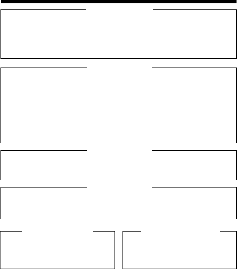
REPLACEMENT PARTS ORDERING
ORDERING INFORMATION
MAIL ORDERS
Send written orders to the following addresses:
TELEPHONE ORDERS
United States and Canada Accessories and Aftermarket Division: Servicers Training (VHS Video Tapes):
Call: 1-800-422-4210 Call: 847-783-2522
1-800-826-1913 (For Federal Government Orders) 847-783-2523 (FAX)
1-847-538-8023 (International Orders)
FAX ORDERS
United States and Canada Accessories and Aftermarket Division: Federal Government Orders:
FAX: 847-538-8198 (Domestic) FAX: 410-712-4991
847-576-3023 (International) International: 410-712-6200
Parts ID: 847-538-8194
PARTS CUSTOMER SERVICE PRODUCT CUSTOMER SERVICE
When ordering replacement parts or equipment
information, the complete identification number should
be included. This applies to all components, kits, and
chassis. If the component part number is not known, the
order should include the number of the chassis or kit of
which it is a part, and sufficient description of the desired
component to identify it.
Crystal and channel element orders should specify the
crystal or channel element type number, crystal and
carrier frequency, and the model number in which the
part is used.
Replacement Parts/
Test Equipment/Manuals/
Crystal Service Items:
Motorola Inc.
United States and Canada Accessories
and Aftermarket Division
Attention: Order Processing
1313 E. Algonquin Road
Schaumburg, IL 60196
Federal Government Orders:
Motorola Inc.
United States and Canada Accessories
and Aftermarket Division
Attention: Order Processing
7230 Parkway Drive
Landover, MD 21076
International Orders:
Motorola Inc.
United States and Canada
Accessories and Aftermarket Division
Attention: International Order
Processing
1313 E. Algonquin Road
Schaumburg, IL 60196
United States and Canada Accessories and Aftermarket
Division:
Call: 1-800-422-4210
Parts Identification:
Call: 847-538-0021
Customer Response Center
(Sales and Service Assistance):
Call: 1-800-247-2346
FAX: 1-800-232-9272

Motorola, Inc.
8000 West Sunrise Boulevard
Ft. Lauderdale, Florida 33322
MOTOROLA and the Stylized M Logo are registered in the U.S. Patent and
Trademark Office. All other product or service names are the
property of their respective owners.
© Motorola, Inc. 2002, 2003
All rights reserved. Printed in U.S.A.
6881094C09-B
