Yamaha XV1600 A RoadStar 98 03 Service Manual ENG XV16
User Manual: XV16
Open the PDF directly: View PDF ![]() .
.
Page Count: 449 [warning: Documents this large are best viewed by clicking the View PDF Link!]

SERVICE MANUAL
LIT-11616-12-56 4WM-28197-E0
XV16AL/XV16ALC
XV16ATL/XV16ATLC

EAS00001
XV16AL/XV16ALC
XV16ATL/XV16ATLC
SERVICE MANUAL
1998 by Yamaha Motor Corporation, U.S.A.
First Edition, October 1998
All rights reserved. Any reproduction or unautho-
rized use without the written permission of
Yamaha Motor Corporation, U.S.A. is expressly
prohibited.
Printed in U.S.A.
P/N LIT-11616-12-56
EAS00003
NOTICE
This manual was produced by the Yamaha Motor Company, Ltd. primarily for use by Yamaha
dealers and their qualified mechanics. It is not possible to include all the knowledge of a
mechanic in one manual. Therefore, anyone who uses this book to perform maintenance and
repairs on Yamaha vehicles should have a basic understanding of mechanics and the tech-
niques to repair these types of vehicles. Repair and maintenance work attempted by anyone
without this knowledge is likely to render the vehicle unsafe and unfit for use.
This model has been designed and manufactured to perform within certain specifications in
regard to performance and emissions. Proper service with the correct tools is necessary to
ensure that the vehicle will operate as designed. If there is any question about a service pro-
cedure, it is imperative that you contact a Yamaha dealer for any service information changes
that apply to this model. This policy is intended to provide the customer with the most satis-
faction from his vehicle and to conform with federal environmental quality objectives.
Yamaha Motor Company, Ltd. is continually striving to improve all of its models. Modifica-
tions and significant changes in specifications or procedures will be forwarded to all autho-
rized Yamaha dealers and will appear in future editions of this manual where applicable.
This Service Manual contains information regarding periodic maintenance to the emission
control system. Please read this material carefully.
NOTE:
Designs and specifications are subject to change without notice.
EAS00004
IMPORTANT MANUAL INFORMATION
Particularly important information is distinguished in this manual by the following.
The Safety Alert Symbol means ATTENTION! BECOME ALERT! YOUR
SAFETY IS INVOLVED!
Failure to follow WARNING instructions could result in severe injury or
death to the motorcycle operator, a bystander or a person checking or
repairing the motorcycle.
A CAUTION indicates special precautions that must be taken to avoid
damage to the motorcycle.
A NOTE provides key information to make procedures easier or clearer.
WARNING
CAUTION:
NOTE:
EAS00007
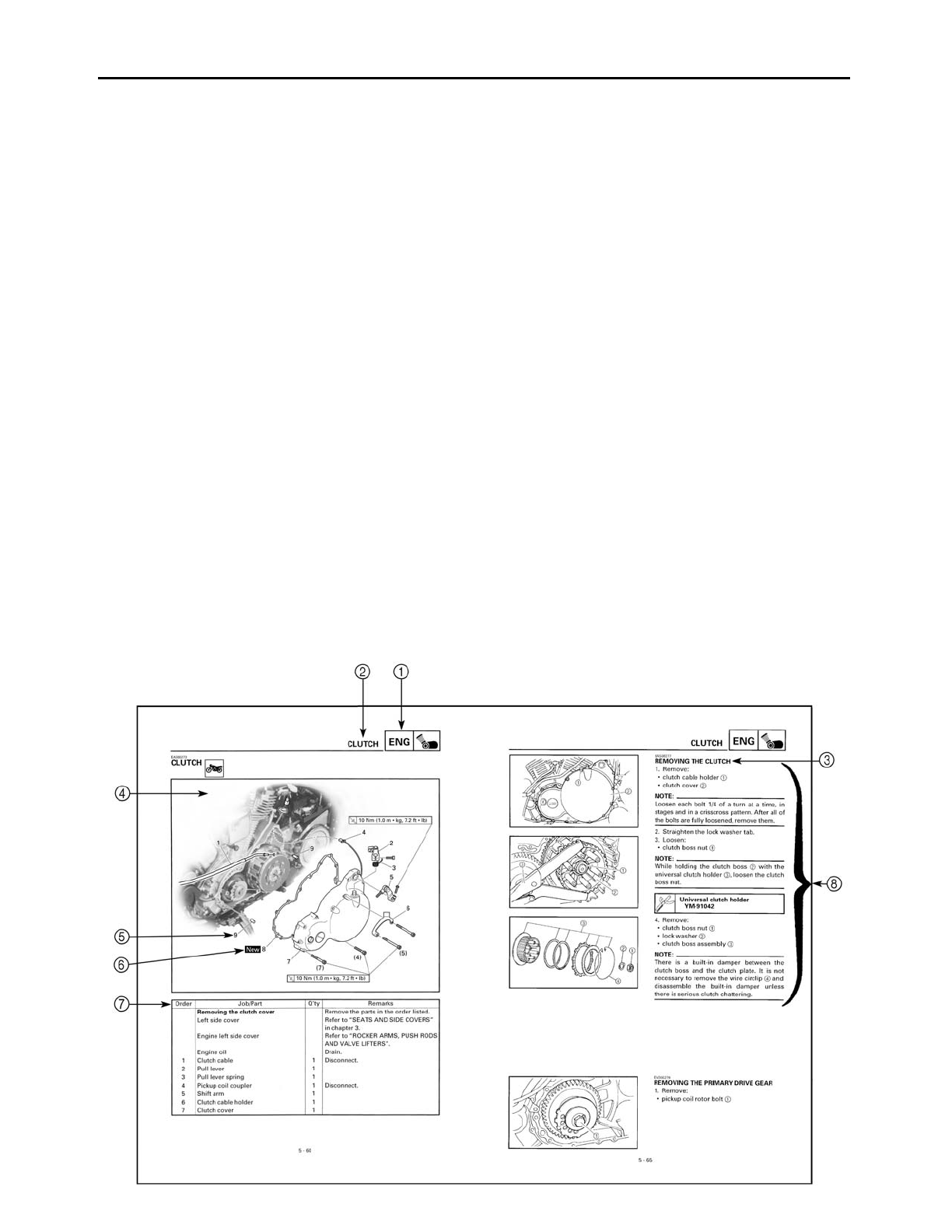
HOW TO USE THIS MANUAL
This manual is intended as a handy, easy-to-read reference book for the mechanic. Compre-
hensive explanations of all installation, removal, disassembly, assembly, repair and check
procedures are laid out with the individual steps in sequential order.
1 The manual is divided into chapters. An abbreviation and symbol in the upper right corner
of each page indicate the current chapter.
Refer to “SYMBOLS”.
2 Each chapter is divided into sections. The current section title is shown at the top of each
page, except in Chapter 3 (“PERIODIC CHECKS AND ADJUSTMENTS”), where the sub sec-
tion title(s) appears.
3 Sub section titles appear in smaller print than the section title.
4 To help identify parts and clarify procedure steps, there are exploded diagrams at the start
of each removal and disassembly section.
5 Numbers are given in the order of the jobs in the exploded diagram. A circled number indi-
cates a disassembly step.
6 Symbols indicate parts to be lubricated or replaced.
Refer to “SYMBOLS”.
7 A job instruction chart accompanies the exploded diagram, providing the order of jobs,
names of parts, notes in jobs, etc.
8 Jobs requiring more information (such as special tools and technical data) are described
sequentially.
********
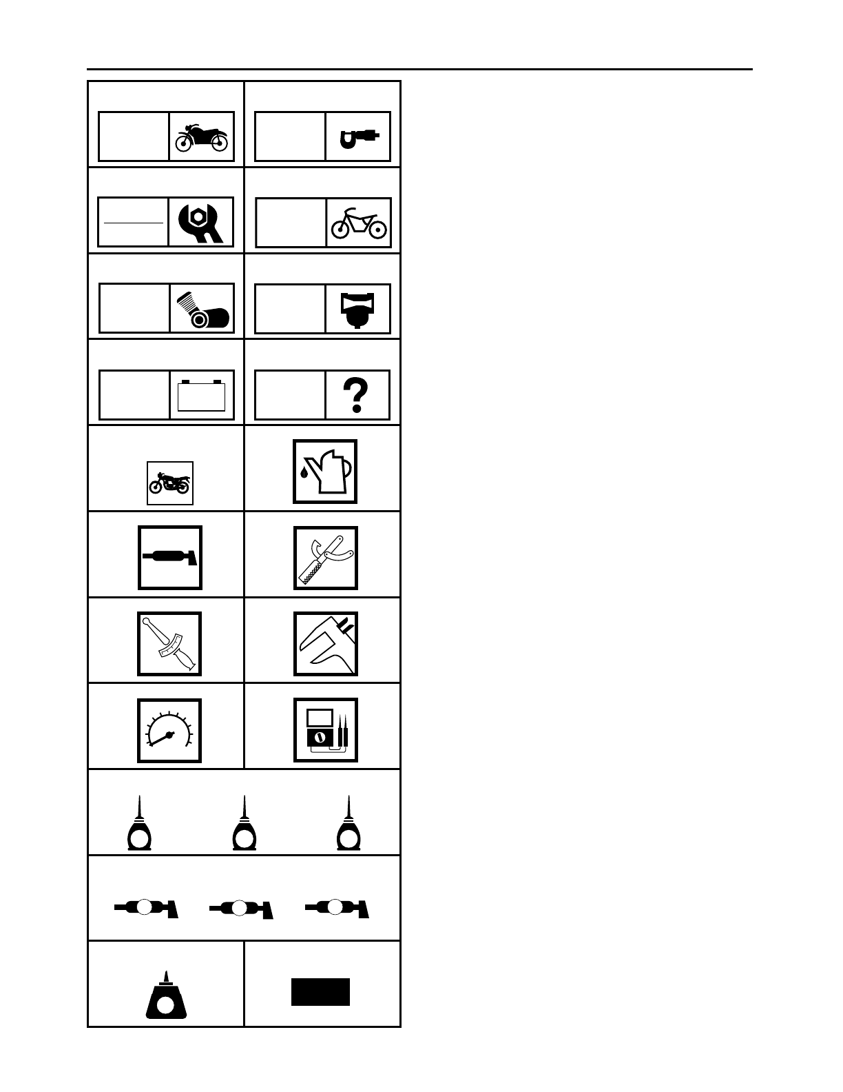
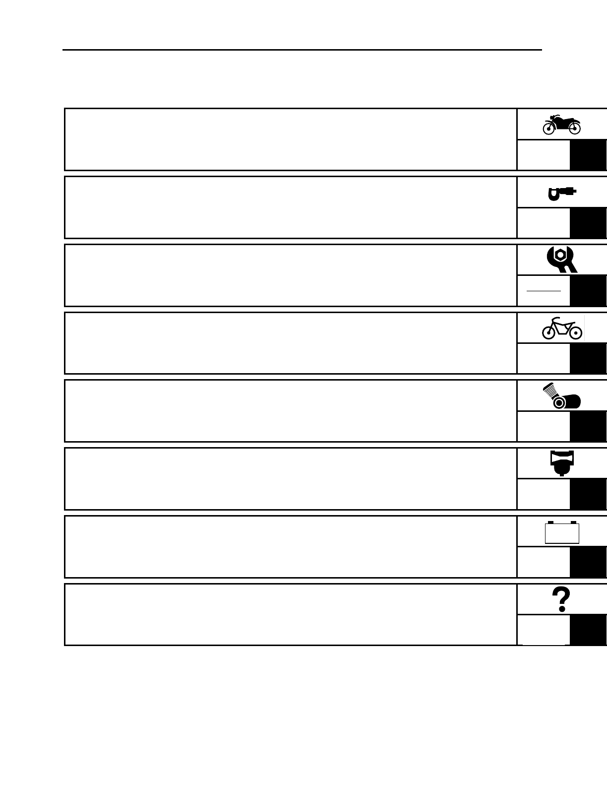
SYMBOLS
The following symbols are not relevant to
every vehicle.
Symbols
1 to
8 indicate the subject of
each chapter.
1General information
2Specifications
3Periodic checks and adjustments
4Chassis
5Engine
6Carburetor
7Electrical system
8Troubleshooting
Symbols
9 to
F indicate the following.
9Serviceable with engine mounted
0Filling fluid
ALubricant
BSpecial tool
CTightening torque
DWear limit, clearance
EEngine speed
FElectrical data
Symbols
G to
L in the exploded diagrams
indicate the types of lubricants and lubrica-
tion points.
GEngine oil
HGear oil
IMolybdenum disulfide oil
JWheel bearing grease
KLithium soap base grease
LMolybdenum disulfide grease
Symbols
M to
N in the exploded diagrams
indicate the following.
MApply locking agent (LOCTITE
).
NReplace the part.
12
34
56
78
90
AB
CD
EF
GHI
JKL
MN
GEN
INFO
SPEC
CHK
ADJ
CHAS
ENG
CARB
–+
ELEC TRBL
SHTG
T
R
.
.
GM
E
BLS M
LT New
******** TABLE OF CONTENTS
GENERAL INFORMATION
1
SPECIFICATIONS SPEC
2
PERIODIC CHECKS AND
ADJUSTMENTS
3
CHASSIS CHAS
4
ENGINE ENG
5
CARBURETION CARB
6
ELECTRICAL SYSTEM ELEC
7
TROUBLESHOOTING
8
GEN
INFO
CHK
ADJ
–+
TRBL
SHTG

GEN
INFO
CONTENTS
GENERAL INFORMATION
MOTORCYCLE IDENTIFICATION ................................................................ 1-1
VEHICLE IDENTIFICATION NUMBER .................................................. 1-1
MODEL CODE ....................................................................................... 1-1
FEATURES ....................................................................................................1-2
IMPORTANT INFORMATION ...................................................................... 1-6
PREPARATION FOR REMOVAL AND DISASSEMBLY ....................... 1-6
REPLACEMENT PARTS ........................................................................ 1-6
GASKETS, OIL SEALS AND O-RINGS ................................................ 1-6
LOCK WASHERS/PLATES AND COTTER PINS .................................. 1-7
BEARINGS AND OIL SEALS ................................................................ 1-7
CIRCLIPS ............................................................................................... 1-7
CHECKING THE CONNECTIONS ................................................................. 1-8
SPECIAL TOOLS ........................................................................................... 1-9
1
GEN
INFO
1 - 1
MOTORCYCLE IDENTIFICATION
EAS00014
GENERAL INFORMATION
MOTORCYCLE IDENTIFICATION
EAS00017
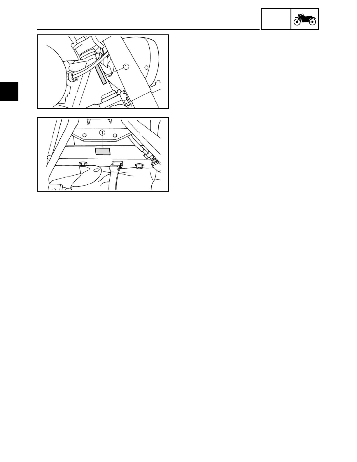
VEHICLE IDENTIFICATION NUMBER
The vehicle identification number
1 is
stamped into the right side of the steering
head pipe.
EAS00018
MODEL CODE
The model code label
1 is affixed to the
frame. This information will be needed to
order spare parts.
1
1 - 2
GEN
INFO
FEATURES
EAS00019
FEATURES
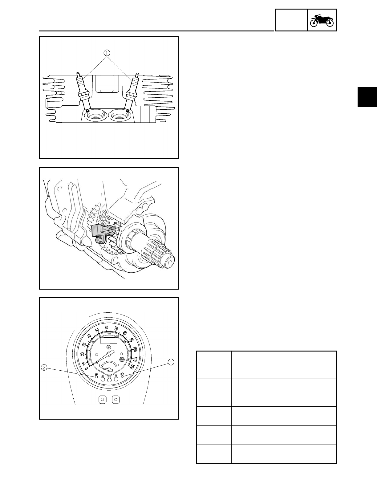
Twin spark plugs
For this model, two spark plugs are incor-
porated in each cylinder.
By using two spark plugs, the combustion
time in the combustion chamber is short-
ened in an attempt to improve torque.
Speed sensor
The speed sensor is installed to the crank-
case and it detects the number of passing
gears while the vehicle is running in 5th
gear and sends the information out as an
electrical signal to the ignitor unit.
Self-diagnosis device
This model is equipped with a self-diagno-
sis device that has four functions.
The engine trouble indicator light will come
on or flash if trouble occurs in an engine
monitoring circuit.
Refer to “SELF-DIAGNOSIS” in chapter 7.
Circuit Indicator lights
Num-
ber of
flashes
Throttle
position
sensor
Engine trouble indica-
tor light 1
3
Speed
sensor
Engine trouble indica-
tor light 1
4
Solenoid Engine trouble indica-
tor light 1
6
Fuel level
meter
Fuel level indicator light
2
8
1
1 - 3
GEN
INFO
FEATURES
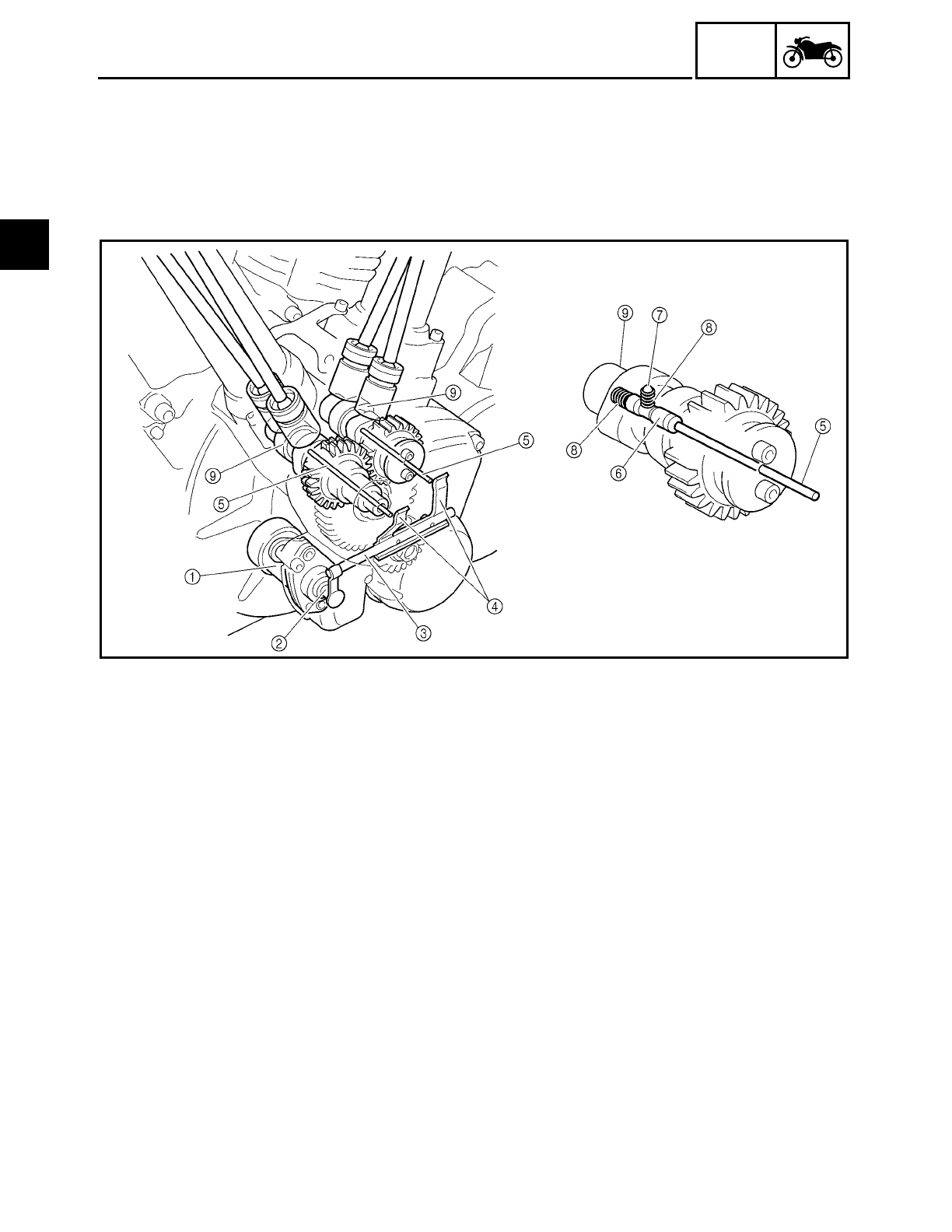
Auto decompression mechanism
The auto decompression mechanism occurs when the engine is started. When the engine is
started, the decompression cam and pin raise the exhaust valve lifters, push the push rods,
move the rocker arms, and lower the exhaust valves which compress the cylinder. When the
cylinder is compressed, pressure is released immediately, resulting in smoother engine start-
ing capabilities and smoother crankshaft revolutions.
1Decompression solenoid
2Decompression solenoid rod
3Decompression connector
4Decompression lever
5Decompression push rod
6Decompression cam
7Pin
8Spring
9Camshaft
1
1 - 4
GEN
INFO
FEATURES
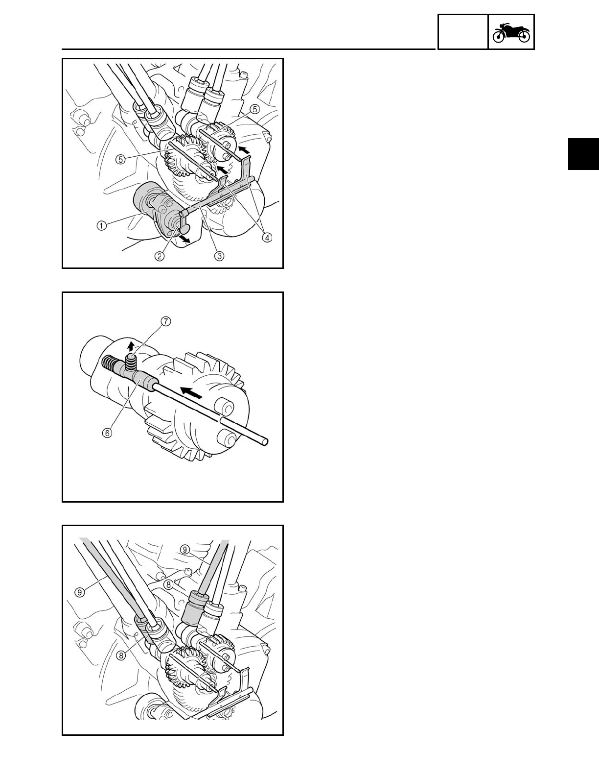
Operation
1. When the starter switch is pushed, elec-
tricity is run to the decompression sole-
noid
1 causing it to push out the
decompression solenoid rod 2.
2. When the decompression solenoid rod is
pushed out, the decompression connec-
tor
3 moves the decompression levers
4 in the direction indicated by the
arrows, and then the levers push the
decompression rods
5 toward the cam-
shaft side.
3. The decompression cam
6 is pushed in
the direction indicated by the arrow, and
then the pin
7 raises the projection of
the decompression cam.
4. When the camshaft is rotated by the self-
timing motor, the exhaust valve lifters 8
are lifted by the pin just before top dead
center (TDC) and the exhaust valve push
rod 9 and valve rocker arms are oper-
ated. Thus, opening the exhaust valve
becomes easy.
5. When the engine starts and reaches a
specific engine speed the decompres-
sion solenoid is turned off and the
decompression system stops operating.
1
1 - 5
GEN
INFO
FEATURES
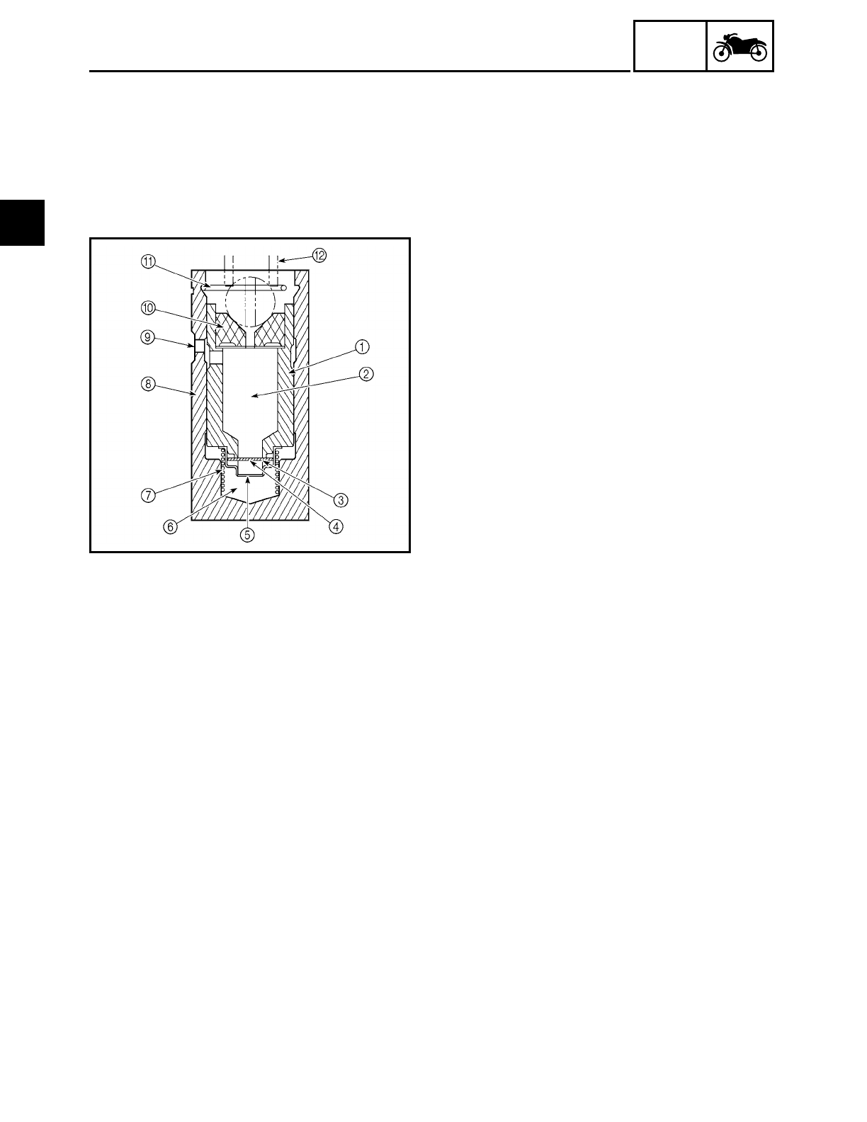
Hydraulic valve lifters
Since the hydraulic valve-lifting mechanism maintains a valve clearance of zero, periodic
valve clearance adjustments are unnecessary.
The advantages of this system as compared to conventional techniques include the follow-
ing: mechanical noise is reduced, the camshaft action on the valves remains unaffected by
engine speed or temperature, and the valve timing is kept stable.
1Plunger
2Oil reservoir
3Check valve spring
4Check valve
5Spring retainer
6High-pressure chamber
7Plunger spring
8Valve lifter body
9Oil supply inlet
0Push rod cup
APlunger retaining clip
BValve push rod
The hydraulic valve-lifting system functions as follows:
1. As the camshaft rotates, the valve lifter is pushed up by the passing cam lobe.
2. Since the check valve 4 prevents the engine oil contained inside the high-pressure cham-
ber from escaping, the plunger 1 moves up along with the valve lifter body 8 and pushes
up the push rod, causing the valve to be lifted.
3. As the camshaft continues to rotate, the valve lifter moves back down to its original posi-
tion, where it remains while the cam heel passes.
When a positive valve clearance is caused by either heat expansion of the cylinder head or
engine oil leaking from the valve lifter during stage 2, the plunger, which no longer receives
pressure from the push rod, is pushed up by the plunger spring 7. As a result, the valve
clearance is zeroed and engine oil is allowed to return to the high-pressure chamber from the
reservoir 2 through the check valve 4.
When, on the contrary, a negative valve clearance occurs (this is the case when the cam heel
is passing the valve lifter, but the rocker arm, pushed by the push rod, is lifting the valve), the
plunger 1 continues to receive pressure from the valve push rod. As engine oil contained
inside the high-pressure chamber leaks from the gaps between the valve lifter body 8 and
the plunger 1 as well as between the valve lifter body 8 and the check valve 4, the
plunger 1 moves down and the valve clearance is zeroed.
1
GEN
INFO
1 - 6
IMPORTANT INFORMATION
EAS00020
IMPORTANT INFORMATION
PREPARATION FOR REMOVAL AND
DISASSEMBLY
1. Before removal and disassembly,
remove all dirt, mud, dust, and foreign
material.
2. Use only the proper tools and cleaning
equipment.
Refer to “SPECIAL TOOLS”.
3. When disassembling, always keep
mated parts together. This includes
gears, cylinders, pistons, and other parts
that have been “mated” through normal
wear. Mated parts must always be
reused or replaced as an assembly.
4. During disassembly, clean all of the parts
and place them in trays in the order of
disassembly. This will speed up assem-
bly and allow for the correct installation
of all parts.
5. Keep all parts away from any source of
fire.
EAS00021
REPLACEMENT PARTS
Use only genuine Yamaha parts for all
replacements. Use oil and grease recom-
mended by Yamaha for all lubrication jobs.
Other brands may be similar in function
and appearance, but inferior in quality.
EAS00022
GASKETS, OIL SEALS AND O-RINGS
1. When overhauling the engine, replace all
gaskets, seals, and O-rings. All gasket
surfaces, oil seal lips, and O-rings must
be cleaned.
2. During reassembly, properly oil all mat-
ing parts and bearings and lubricate the
oil seal lips with grease.
1
GEN
INFO
1 - 7
IMPORTANT INFORMATION
EAS00023
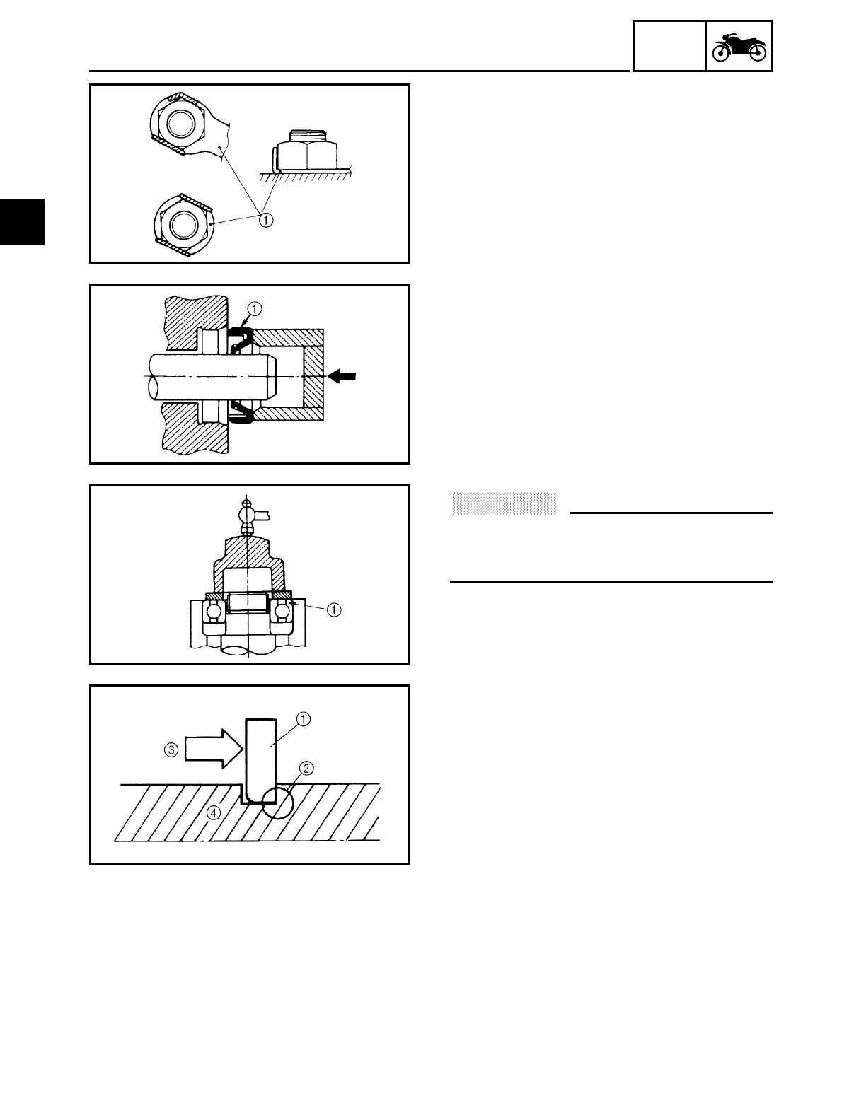
LOCK WASHERS/PLATES AND COTTER
PINS
After removal, replace all lock washers/
plates 1 and cotter pins. After the bolt or
nut has been tightened to specification,
bend the lock washer tabs and the cotter
pin ends along a flat of the bolt or nut.
EAS00024
BEARINGS AND OIL SEALS
1. Install bearings and oil seals so that the
manufacturer’s marks or numbers are
visible. When installing oil seals, lubri-
cate the oil seal lips with a light coat of
lithium soap base grease. Oil bearings
liberally when installing, if appropriate.
1Oil seal
ACHTUNG:
CAUTION:
Do not spin bearings with compressed air
because this will damage the bearing sur-
faces.
1Bearing
EAS00025
CIRCLIPS
Before reassembly, check all circlips care-
fully and replace damaged or distorted cir-
clips. Always replace piston pin clips after
one use. When installing a circlip 1, make
sure the sharp-edged corner 2 is posi-
tioned opposite the thrust 3 that the circlip
receives.
4Shaft
1
GEN
INFO
1 - 8
CHECKING THE CONNECTIONS
EAS00026
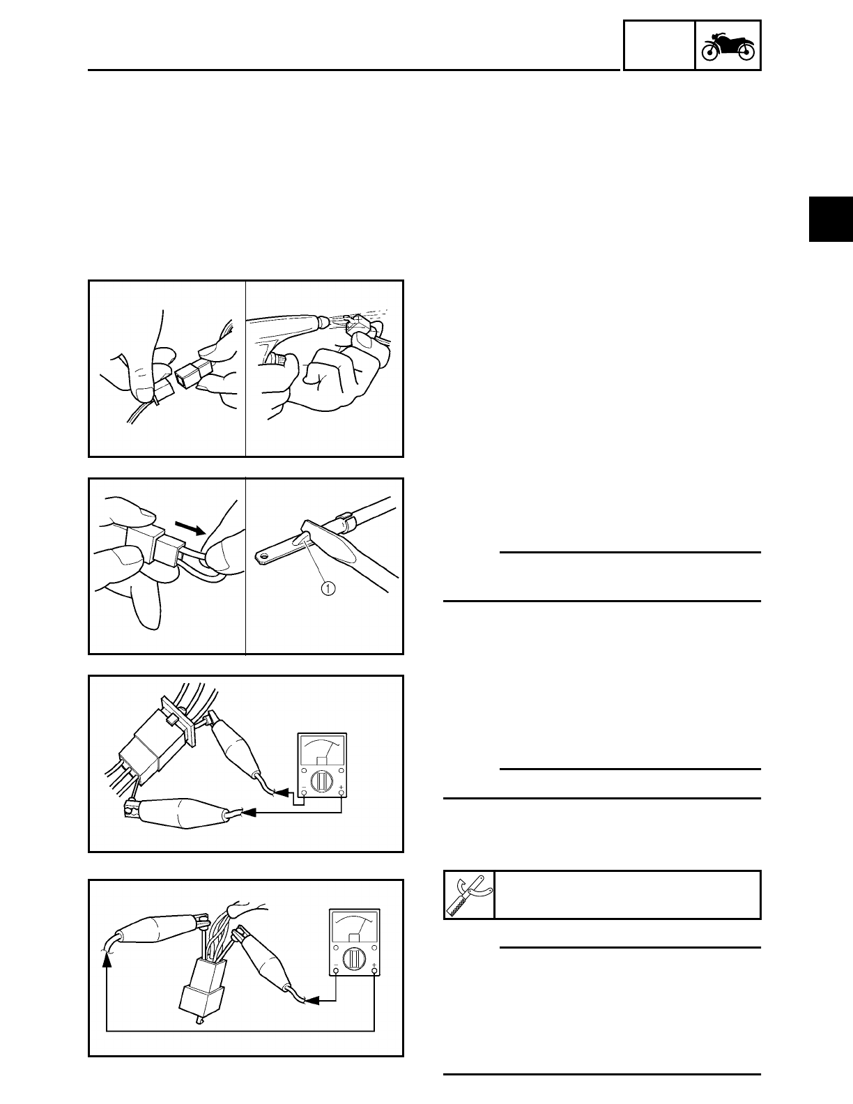
CHECKING THE CONNECTIONS
Check the leads, couplers, and connectors
for stains, rust, moisture, etc.
1. Disconnect:
• lead
• coupler
• connector
2. Check:
• lead
• coupler
• connector
Moisture → Dry with an air blower.
Rust/stains → Connect and disconnect
several times.
3. Check:
• all connections
Loose connection → Connect properly.
NOTE:
If the pin 1 on the terminal is flattened,
bend it up.
4. Connect:
• lead
• coupler
• connector
NOTE:
Make sure all connections are tight.
5. Check:
• continuity
(with the pocket tester)
NOTE:
• If there is no continuity, clean the termi-
nals.
• When checking the wire harness, perform
steps (1) to (3).
• As a quick remedy, use a contact revital-
izer available at most part stores.
Pocket tester
YU-03112
1
1 - 9
GEN
INFO
SPECIAL TOOLS
EAS00027
SPECIAL TOOLS
The following special tools are necessary for complete and accurate tune-up and assembly.
Use only the appropriate special tools as this will help prevent damage caused by the use of
inappropriate tools or improvised techniques. Special tools, part numbers, or both may differ
depending on the country.
When placing an order, refer to the list provided below to avoid any mistakes.
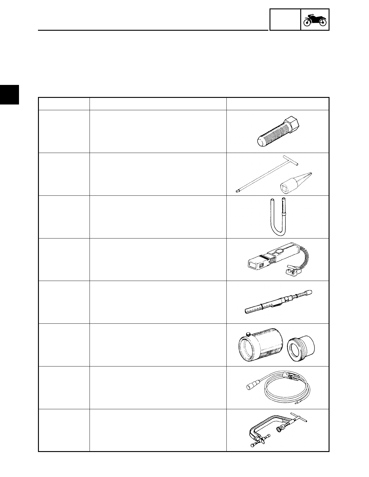
Tool No. Tool name/Function Illustration
YM-01080-A Flywheel puller
This tool is used to remove the generator
rotor.
T-handle
YM-01326
Damper rod
holder
YM-1300-1
T-handle
Damper rod holder
These tools are used to hold the cartridge
cylinder when loosening or tightening the
cartridge cylinder bolt.
YM-01312-A
Fuel level gauge
This tool is used to measure the fuel level
in the float chamber.
YM-33277-A
Timing light
This tool is used to check the ignition tim-
ing.
YM-03170
Belt tension gauge
This tool is used to measure the drive belt
slack.
Fork seal
driver weight
YM-33963
Adapter
YM-8020
Fork seal driver weight
Adapter
These tools are used to install the front
fork’s oil seal and dust seal.
YM-34487
Dynamic spark tester
This tool is used to check the ignition sys-
tem components.
YM-04019
Valve spring compressor
This tool is used to remove or install the
valve assemblies.
1
1 - 10
GEN
INFO
SPECIAL TOOLS
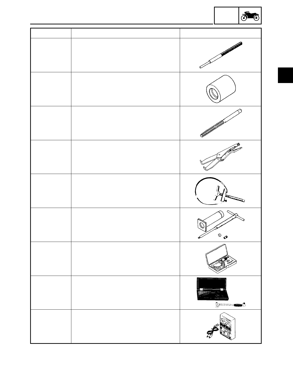
YM-4064-A
Valve guide remover (6 mm)
This tool is used to remove or install the
valve guides.
YM-4065-A
Valve guide installer
This tool is used to install the valve
guides.
YM-4066
Valve guide reamer
This tool is used to rebore the new valve
guides.
YM-91042
Universal clutch holder
This tool is used to hold the clutch boss
when removing or installing the clutch
boss nut.
YS-01880
Sheave holder
This tool is used to hold the generator
rotor when removing or installing the gen-
erator rotor bolt, generator shaft bolt or
pickup coil rotor bolt.
YU-01304
Piston pin puller
This tool is used to remove the piston
pins.
YU-03009
Micrometer (75 ~ 100 mm)
This tool is used to measure the piston
skirt diameter.
YU-03017
Cylinder bore gauge (50 ~ 100 mm)
This tool is used to measure the cylinder
bore.
YU-03112
Pocket tester
This tool is used to check the electrical
system.
Tool No. Tool name/Function Illustration
1
1 - 11
GEN
INFO
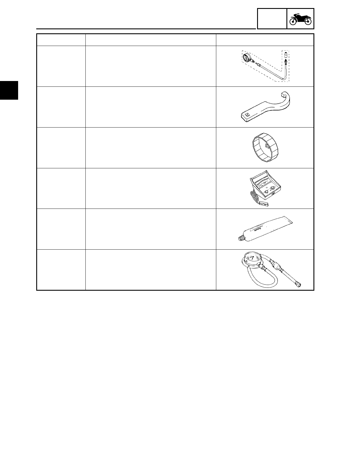
SPECIAL TOOLS
Compression
gauge
YU-33223
Compression
gauge adapter
YU-33223-3
Compression gauge
These tools are used to measure engine
compression.
YU-33975
Steering nut wrench
This tool is used to loosen or tighten the
steering stem ring nuts.
YU-38411
Oil filter wrench
This tool is needed to loosen or tighten
the oil filter cartridge.
YU-8036-A
Inductive tachometer
This tool is used to check engine speed.
ACC-11001-05-
01
Quick Gasket
This sealant is used to seal two mating
surfaces (e. g., crankcase mating sur-
faces).
90890-03153
Oil pressure gauge
This tool is used to measure the engine oil
pressure.
Tool No. Tool name/Function Illustration
1

SPEC
CONTENTS
SPECIFICATIONS
GENERAL SPECIFICATIONS ....................................................................... 2-1
ENGINE SPECIFICATIONS ........................................................................... 2-2
CHASSIS SPECIFICATIONS ....................................................................... 2-11
ELECTRICAL SPECIFICATIONS ................................................................. 2-15
TIGHTENING TORQUES ............................................................................ 2-18
GENERAL TIGHTENING TORQUES .................................................. 2-18
ENGINE TIGHTENING TORQUES ..................................................... 2-19
CHASSIS TIGHTENING TORQUES ................................................... 2-21
LUBRICATION POINTS AND LUBRICANT TYPES ................................... 2-23
ENGINE LUBRICATION POINTS AND LUBRICANT TYPES ............ 2-23
CHASSIS LUBRICATION POINTS AND LUBRICANT TYPES .......... 2-24
ENGINE OIL LUBRICATION CHART .......................................................... 2-25
ENGINE OIL FLOW DIAGRAMS ................................................................ 2-26
TRANSFER GEAR OIL FLOW DIAGRAMS ................................................2-30
CABLE ROUTING ....................................................................................... 2-32
2
GENERAL SPECIFICATIONS SPEC
2 - 1
SPECIFICATIONS
GENERAL SPECIFICATIONS
Item Standard Limit
Dimensions
Overall length 2,500 mm (98.4 in) ----
Overall width 980 mm (38.6 in) ----
Overall height 1,140 mm (44.9 in): XV16A ----
1,500 mm (59.1 in): XV16AT ----
Seat height 710 mm (28.0 in) ----
Wheelbase 1,685 mm (66.3 in) ----
Minimum ground clearance 145 mm (5.71 in) ----
Minimum turning radius 3,200 mm (126 in) ----
Weight
Wet (with oil and a full fuel tank) 332 kg (732 lb): XV16A ----
347 kg (765 lb): XV16AT ----
Dry (without oil and fuel) 307 kg (678 lb): XV16A ----
322 kg (710 lb): XV16AT ----
Maximum load (total of cargo, rider,
passenger, and accessories)
196 kg (432 lb): XV16A
181 kg (399 lb): XV16AT
----
----
2
ENGINE SPECIFICATIONS SPEC
2 - 2
ENGINE SPECIFICATIONS
Item Standard Limit
Engine
Engine type Air-cooled, 4-stroke, OHV ----
Displacement 1,602 cm3----
Cylinder arrangement V-type 2-cylinder ----
Bore × stroke 95 × 113 mm (3.74 × 4.45 in) ----
Compression ratio 8.3:1 ----
Engine idling speed 850 ~ 950 r/min ----
Vacuum pressure at engine idling
speed
52 kPa (390 mm Hg, 15.4 in Hg) ----
Standard compression pressure
(at sea level)
1,200 kPa
(12.0 kgf/cm2, 171 psi) at 200 r/min
----
Fuel
Recommended fuel Unleaded fuel (for USA) ----
Regular unleaded gasoline (for CDN) ----
Fuel tank capacity
Total (including reserve) 20 L (17.6 Imp qt, 21.1 US qt) ----
Reserve only 3.5 L (3.08 Imp qt, 3.70 US qt) ----
Engine oil
Lubrication system Dry sump ----
Recommended oil
Yamalube 4 (20W40) or SAE 20W40 type
SE motor oil (40˚F/5˚C or above)
(Non-Friction modified)
----
Quantity
Total amount 5.0 L (4.4 Imp qt, 5.3 US qt) ----
Without oil filter cartridge
replacement
3.7 L (3.3 Imp qt, 3.9 US qt) ----
With oil filter cartridge replace-
ment
4.1 L (3.6 Imp qt, 4.3 US qt) ----
Oil pressure (hot) 60 kPa (0.6 kgf/cm2, 8.5 psi) at 900 r/min ----
Relief valve opening pressure 0.60 MPa (6.0 kgf/cm2, 85 psi) ----
Transfer gear oil
Recommended oil SAE80API “GL-4” hypoid gear oil ----
Quantity 0.4 L (0.35 Imp qt, 0.42 US qt) ----
Oil filter
Oil filter type Cartridge (paper) ----
Bypass valve opening pressure 80 ~ 120 kPa
(0.8 ~ 1.2 kgf/cm2, 11.3 ~ 17.1 psi)
----
30 40 50 60˚F
05
10 15˚C
2
ENGINE SPECIFICATIONS SPEC
2 - 3
Engine oil pump
Oil pump type Trochoidal ----
Inner rotor to outer rotor tip clear-
ance
0.00 ~ 0.12 mm (0.000 ~ 0.005 in) 0.17 mm
(0.007 in)
Inner rotor outer rotor 2 to oil pump
housing clearance (feed pump)
0.03 ~ 0.08 mm (0.001 ~ 0.003 in) 0.13 mm
(0.005 in)
Inner rotor outer rotor 1 to oil
pump housing clearance
(scavenging pump)
0.06 ~ 0.11 mm (0.002 ~ 0.004 in) 0.16 mm
(0.006 in)
Transfer oil pump
Oil pump type Trochoidal
Inner rotor to outer rotor tip clear-
ance
0.07 ~ 0.12 mm (0.003 ~ 0.005 in) 0.17 mm
(0.007 in)
Inner rotor outer rotor to oil pump
housing clearance
0.03 ~ 0.08 mm (0.001 ~ 0.003 in) 0.16 mm
(0.006 in)
Starting system type Electric starter
Spark plugs
Model
Manufacturer
Quantity
DPR7EA-9/X22EPR-U9
NGK/DENSO
4
----
----
----
Spark plug gap 0.8 ~ 0.9 mm (0.031 ~ 0.035 in) ----
Cylinder heads
Max. warpage ---- 0.10 mm
(0.004 in)
Camshafts
Drive system Gear drive ----
Crankcase hole inside diameter 25.000 ~ 25.021 mm
(0.9843 ~ 0.9851 in) ----
Camshaft cover hole inside diam-
eter
28.000 ~ 28.021 mm
(1.1024 ~ 1.1032 in) ----
Camshaft journal diameter
(crankcase side)
24.937 ~ 24.950 mm
(0.9818 ~ 0.9823 in) ----
Camshaft journal diameter
(camshaft cover side)
27.967 ~ 27.980 mm
(1.1011 ~ 1.1016 in) ----
Camshaft to crankcase clearance 0.050 ~ 0.084 mm (0.0020 ~ 0.0033 in) ----
Camshaft to camshaft cover clear-
ance
0.020 ~ 0.054 mm (0.0008 ~ 0.0021 in) ----
Camshaft intake cam dimensions
Item Standard Limit
A
B
2
ENGINE SPECIFICATIONS SPEC
2 - 4
Measurement A 36.594 ~ 36.649 mm
(1.4407 ~ 1.4429 in)
36.494 mm
(1.4368 in)
Measurement B 31.950 ~ 32.050 mm
(1.2579 ~ 1.2618 in)
31.850 mm
(1.2539 in)
Camshaft exhaust cam dimen-
sions
Measurement A 36.554 ~ 36.654 mm
(1.4391~ 1.4431 in)
36.454 mm
(1.4352 in)
Measurement B 31.950 ~ 32.050 mm
(1.2579 ~ 1.2618 in)
31.850 mm
(1.2539 in)
Rocker arms, Rocker arm shafts
Rocker arm inside diameter 15.000 ~ 15.018 mm
(0.5906 ~ 0.5913 in)
15.036 mm
(0.5920 in)
Rocker arm shaft outside diameter 14.981 ~ 14.991 mm
(0.5898 ~ 0.5902 in)
14.97 mm
(0.5894 in)
Rocker arm to rocker arm shaft
clearance
0.009 ~ 0.037 mm (0.0004 ~ 0.0015 in) 0.08 mm
(0.003 in)
Valves, valve seats, valve guides
Valve clearance (cold)
Intake 0 ~ 0.04 mm (0 ~ 0.0016 in) ----
Exhaust 0 ~ 0.04 mm (0 ~ 0.0016 in) ----
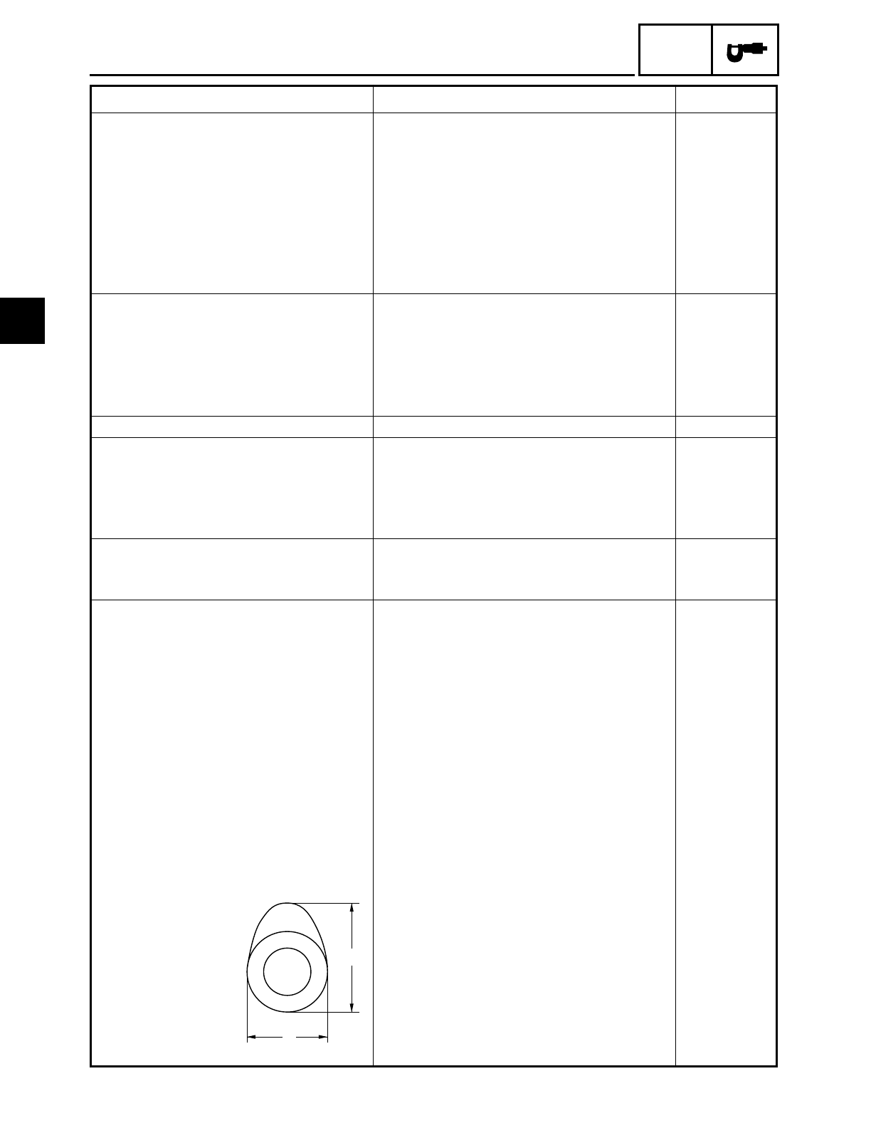
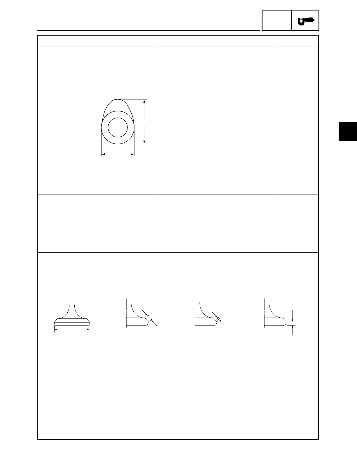
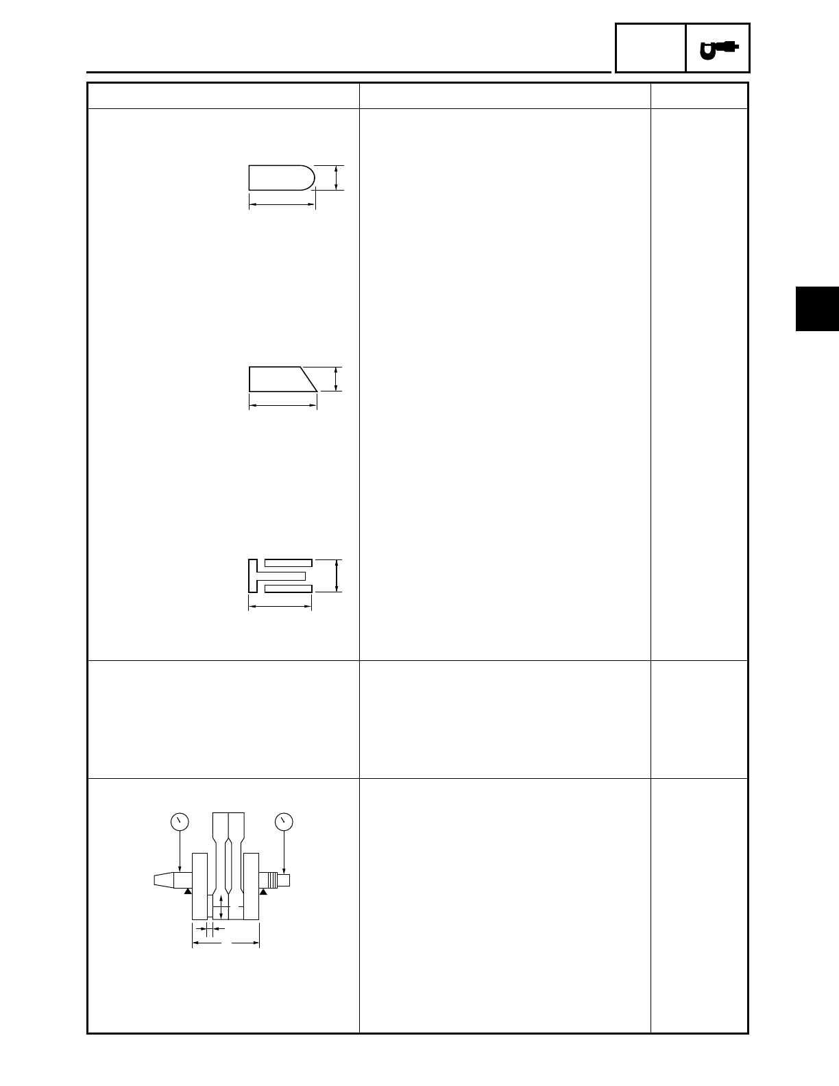
Valve dimensions
Valve head diameter A
Intake 33.9 ~ 34.1 mm (1.3346 ~ 1.3425 in) ----
Exhaust 27.9 ~ 28.1 mm (1.0984 ~ 1.1063 in) ----
Valve face width B
Intake 1.3 ~ 2.3 mm (0.0512 ~ 0.0906 in) ----
Exhaust 1.2 ~ 2.4 mm (0.0472 ~ 0.0945 in) ----
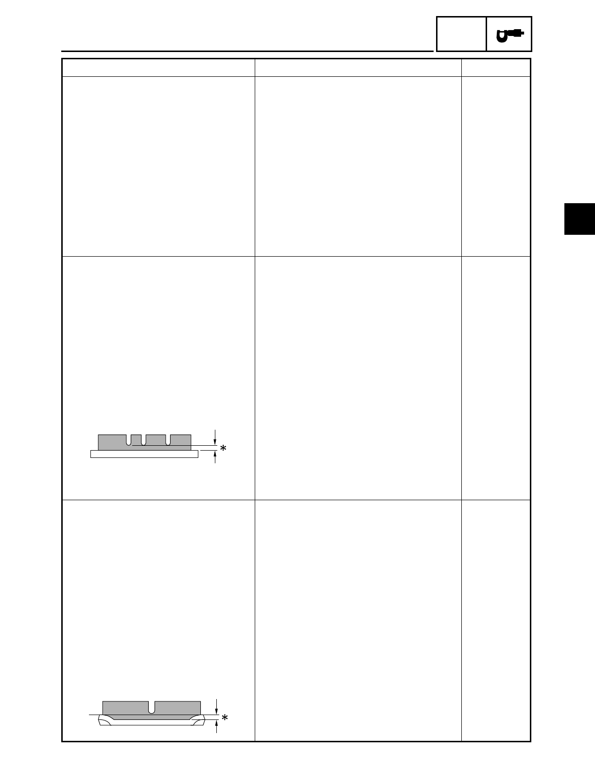
Valve seat width C
Intake 0.9 ~ 1.1 mm (0.035 ~ 0.043 in) 2.0 mm
(0.079 in)
Exhaust 0.9 ~ 1.1 mm (0.035 ~ 0.043 in) 2.0 mm
(0.079 in)
Item Standard Limit
A
B
Head Diameter
B
Face Width
C
Seat Width
D
Margin Thickness
A
2
ENGINE SPECIFICATIONS SPEC
2 - 5
Valve margin thickness D
Intake 0.7 ~ 1.3 mm (0.028 ~ 0.051 in) 0.4 mm
(0.016 in)
Exhaust 0.7 ~ 1.3 mm (0.028 ~ 0.051 in) 0.4 mm
(0.016 in)
Valve stem diameter
Intake 5.975 ~ 5.990 mm (0.2352 ~ 0.2358 in) 5.945 mm
(0.2341 in)
Exhaust 5.960 ~ 5.975 mm (0.2346 ~ 0.2352 in) 5.920 mm
(0.2331 in)
Valve guide inside diameter
Intake 6.000 ~ 6.012 mm (0.2362 ~ 0.2367 in) 6.05 mm
(0.2382 in)
Exhaust 6.000 ~ 6.012 mm (0.2362 ~ 0.2367 in) 6.05 mm
(0.2382 in)
Valve stem-to-valve guide clear-
ance
Intake 0.010 ~ 0.037 mm (0.0004 ~ 0.0015 in) 0.08 mm
(0.0031 in)
Exhaust 0.025 ~ 0.052 mm (0.0010 ~ 0.0020 in) 0.1 mm
(0.004 in)
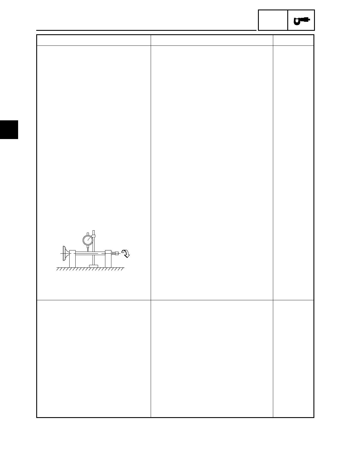
Valve stem runout ---- 0.01 mm
(0.0004 in)
Valve seat width
Intake 0.9 ~ 1.1 mm (0.035 ~ 0.043 in) ----
Exhaust 0.9 ~ 1.1 mm (0.035 ~ 0.043 in) ----
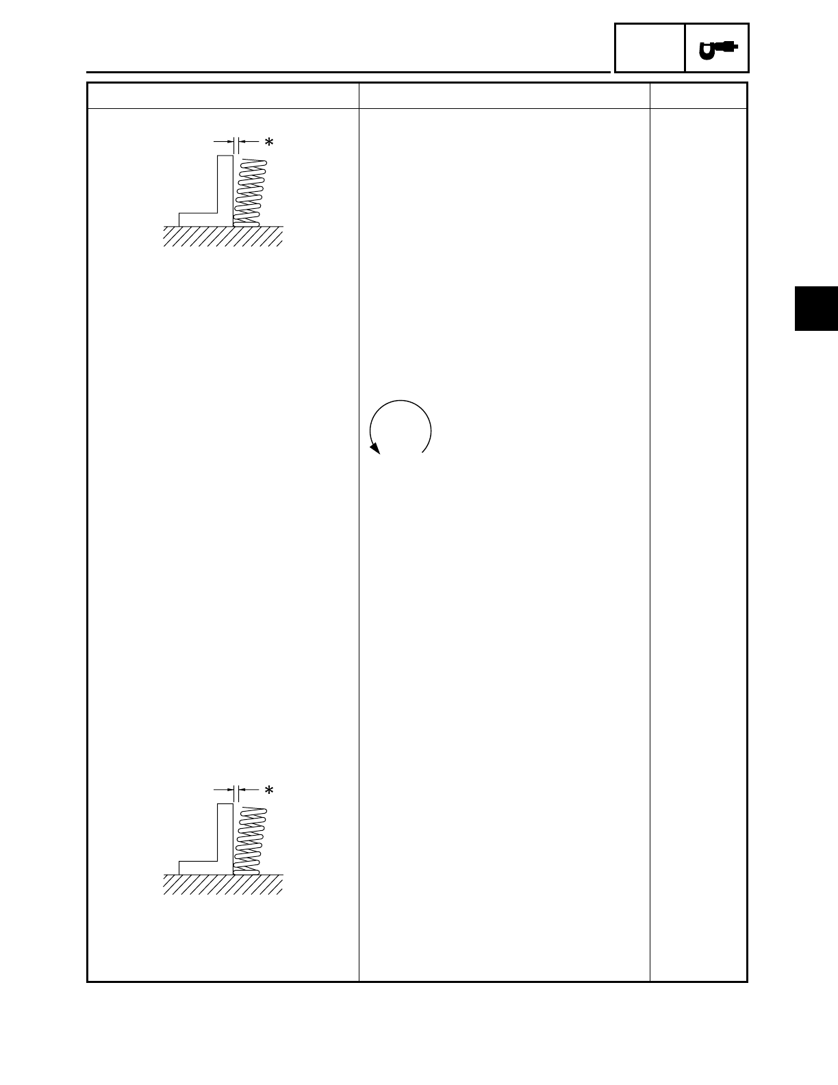
Valve springs
Inner springs
Free length
Intake 38.26 mm (1.51 in) 36.26 mm
(1.43 in)
Exhaust 38.26 mm (1.51 in) 36.26 mm
(1.43 in)
Installed length (valve closed)
Intake 29.0 mm (1.14 in) ----
Exhaust 29.0 mm (1.14 in) ----
Compressed spring force
(installed)
Intake 63 ~ 73 N (6.3 ~ 7.3 kgf, 13.9~ 16.1 lb) ----
Exhaust 63 ~ 73 N (6.3 ~ 7.3 kgf, 13.9~ 16.1 lb) ----
Item Standard Limit
2
ENGINE SPECIFICATIONS SPEC
2 - 6
Spring tilt
Intake ---- 2.5˚ /2.4 mm
(2.5˚/0.094 in)
Exhaust ---- 2.5˚ /2.4 mm
(2.5˚/0.094 in)
Winding direction (top view)
Intake Counterclockwise ----
Exhaust Counterclockwise ----
Outer springs
Free length
Intake 43.25 mm (1.70 in) 41.26 mm
(1.62 in)
Exhaust 43.25 mm (1.70 in) 41.26 mm
(1.62 in)
Installed length (valve closed)
Intake 31.0 mm (1.22 in) ----
Exhaust 31.0 mm (1.22 in) ----
Compressed spring force
(installed)
Intake 139 ~ 161 N
(13.9 ~ 16.1 kgf, 30.6 ~ 35.5 lb)
----
Exhaust 139 ~ 161 N
(13.9 ~ 16.1 kgf, 30.6 ~ 35.5 lb)
----
Spring tilt
Intake ---- 2.5˚ /2.4 mm
(2.5˚/0.094 in)
Exhaust ---- 2.5˚ /2.4 mm
(2.5˚/0.094 in)
Item Standard Limit
2
ENGINE SPECIFICATIONS SPEC
2 - 7
Winding direction (top view)
Intake Clockwise ----
Exhaust Clockwise ----
Valve lifters
Valve lifter outside diameter 22.9680 ~ 22.9744 mm
(0.9043 ~ 0.9045 in)
----
Valve lifter case inside diameter 22.990 ~ 23.010 mm
(0.9051 ~ 0.9059 in)
----
Valve lifter-to-valve lifter case
clearance
0.0156 ~ 0.0420 mm
(0.0006 ~ 0.0017 in)
----
Valve push rods
Valve push rod length 293.45 ~ 293.95 mm
(11.553 ~ 11.573 in)
----
Valve push rod runout 0.3 mm (0.012 in) ----
Cylinders
Bore 95.000 ~ 95.010 mm
(3.7402 ~ 3.7406 in)
----
Max. taper ---- 0.05 mm
(0.0016 in)
Max. out of round ---- 0.05 mm
(0.0016 in)
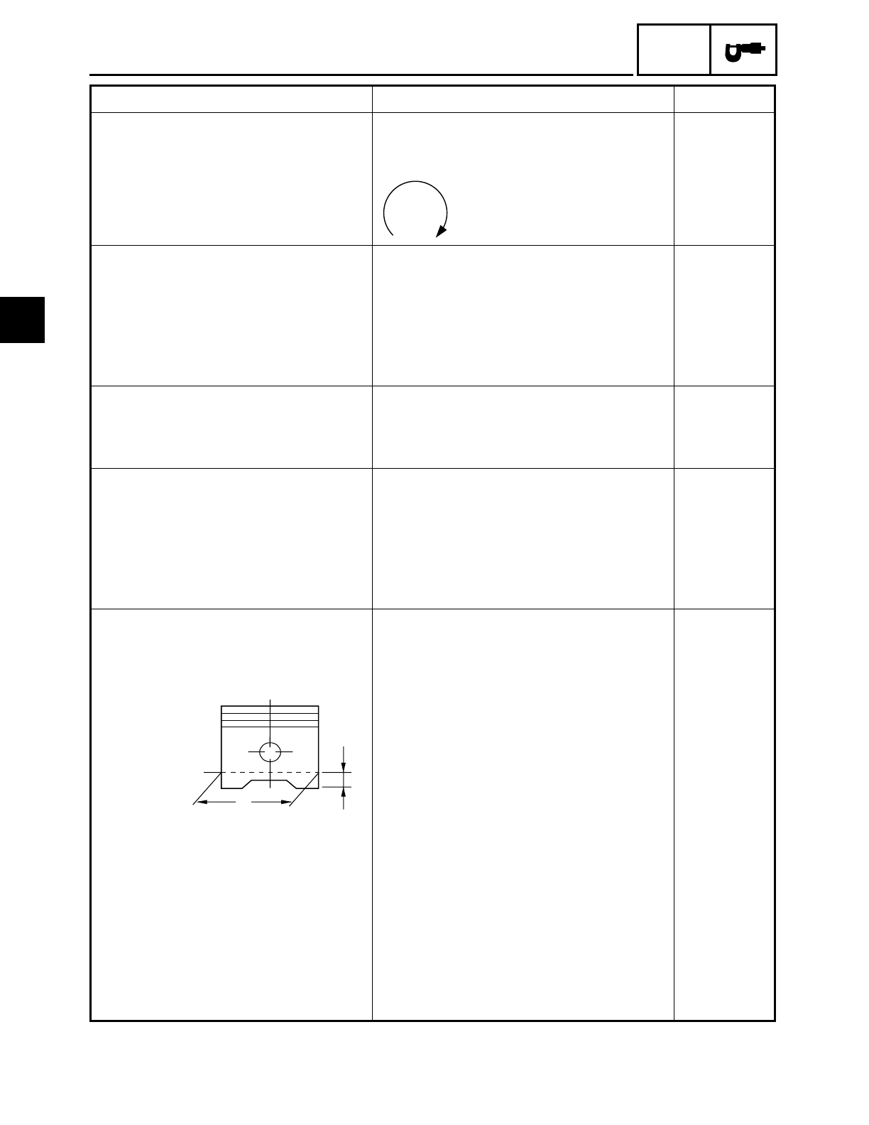
Pistons
Piston-to-cylinder clearance 0.025 ~ 0.050 mm (0.001 ~ 0.002 in) 0.15 mm
(0.006 in)
Diameter D 94.960 ~ 94.975 mm
(3.7386 ~ 3.7392 in)
----
Height H 5 mm (0.20 in) ----
Piston pin bore (in the piston)
Diameter 22.004 ~ 22.015 mm
(0.8663 ~ 0.8667 in)
22.045 mm
(0.8679 in)
Offset 1.0 mm (0.04 in) ----
Piston pins
Outside diameter 21.991 ~ 22.000 mm
(0.8658 ~ 0.8661 in)
21.971 mm
(0.8650 in)
Piston pin-to-piston pin bore
clearance
0.004 ~ 0.024 mm
(0.00016 ~ 0.00094 in)
0.074 mm
(0.0029 in)
Item Standard Limit
H
D
2
ENGINE SPECIFICATIONS SPEC
2 - 8
Piston rings
Top ring
Ring type Barrel ----
Dimensions (B ×T) 1.2 × 3.8 mm (0.047 × 0.150 in) ----
End gap (installed) 0.30 ~ 0.45 mm (0.012 ~ 0.018 in) 0.65 mm
(0.026 in)
Ring side clearance 0.03 ~ 0.08 mm (0.0012 ~ 0.0031 in) 0.12 mm
(0.0047 in)
2nd ring
Ring type Taper ----
Dimensions (B ×T) 1.2 × 3.8 mm (0.047 × 0.150 in) ----
End gap (installed) 0.30 ~ 0.45 mm (0.012 ~ 0.018 in) 0.8 mm
(0.031 in)
Ring side clearance 0.03 ~ 0.07 mm (0.0012 ~ 0.0028 in) 0.12 mm
(0.0047 in)
Oil ring
Dimensions (B ×T) 2.5 × 3.4 mm (0.098 × 0.134 in) ----
End gap (installed) 0.2 ~ 0.7 mm (0.008 ~ 0.028 in) ----
Connecting rods
Crankshaft pin-to-big end bearing
clearance
0.037 ~ 0.074 mm (0.0015 ~ 0.0029 in) ----
Bearing color code 1 = Blue, 2 = Black, 3 = Brown,
4 = Green, 5 = Yellow.
----
Connecting rod length 191.95 ~ 192.05 mm (7.557 ~ 7.561 in)
Crankshaft
Width A 132.8 ~ 133.2 mm (5.228 ~ 5.244 in) ----
Max. runout C 0.04 mm
(0.0016 in)
Big end side clearance D 0.320 ~ 0.474 mm (0.013 ~ 0.019 in) ----
Item Standard Limit
T
B
B
T
B
T
A
D
CC
E
2
ENGINE SPECIFICATIONS SPEC
2 - 9
Big end radial clearance E 0.037 ~ 0.074 mm (0.0015 ~ 0.0029 in) 0.09 mm
(0.0035 in)
Crankshaft journal-to-crankshaft-
journal bearing clearance
0.030 ~ 0.062 mm (0.0012 ~ 0.0024 in) 0.1 mm
(0.0040 in)
Clutch
Clutch type Wet, multiple disc ----
Clutch release method Rack and pinion (pull rod type) ----
Clutch release method operation Cable operation ----
Operation Left-hand operation ----
Clutch cable free play (at the end
of the clutch lever)
10 ~ 15 mm (0.39 ~ 0.59 in) ----
Friction plates
Thickness 2.9 ~ 3.1 mm (0.114 ~ 0.122 in) 2.8 mm
(0.110 in)
Plate quantity 9 ----
Clutch plates
Thickness 2.2 ~ 2.4 mm (0.087 ~ 0.094 in) ----
Plate quantity 8 ----
Max. warpage ---- 0.2 mm
(0.008 in)
Clutch springs
Free length 7 mm (0.276 in) ----
Spring quantity 1 ----
Min. length 6.5 mm
(0.256 in)
Transmission
Transmission type Constant mesh, 5-speed ----
Primary reduction system Spur gear ----
Primary reduction ratio 72/47 (1.532) ----
Secondary reduction system Belt drive ----
Secondary reduction ratio 35/32 × 70/33 (2.320) ----
Operation Left-foot operation ----
Gear ratios
1st gear 39/16 (2.437) ----
2nd gear 30/19 (1.578) ----
3rd gear 29/25 (1.160) ----
4th gear 29/32 (0.906) ----
5th gear 21/28 (0.750) ----
Max. main axle runout ---- 0.08 mm
(0.003 in)
Max. drive axle runout ---- 0.08 mm
(0.003 in)
Item Standard Limit
2
ENGINE SPECIFICATIONS SPEC
2 - 10
Shifting mechanism
Shift mechanism type Guide bar ----
Max. shift fork guide bar bending ---- 0.025 mm
(0.001 in)
Shift fork thickness 6.26 ~ 6.39 mm (0.246 ~ 0.252 in) ----
Air filter type Dry element ----
Fuel pump
Pump type Electrical ----
Model (manufacturer) 4WM (MITSUBISHI) ----
Output pressure 15 ~ 20 kPa
(0.15 ~0.20 kgf/cm2, 2.1 ~ 2.8 psi)
----
Carburetor
Model (manufacturer)
× quantity BSR40 (MIKUNI)
× 1 ----
Throttle cable free play (at the
flange of the throttle grip)
3 ~ 5 mm (0.12 ~ 0.20 in) ----
ID mark 4WM1 00 ----
4WM2 10 (for California) ----
Main jet #165 ----
Main air jet #60 ----
Jet needle 6HDC26 ----
Needle jet X-2 ----
Pilot air jet #100 ----
Pilot outlet 1.0 (XV16A), 1.1 (XV16AT) ----
Pilot jet #35 ----
Bypass 1 0.9 ----
Bypass 2 1.0 ----
Bypass 3 0.9 ----
Pilot screw turns out 2-1/2 ----
Valve seat size 2.0 ----
Starter jet 1 #57.5 ----
Starter jet 2 1.0 ----
Butterfly valve size #110 ----
Fuel level (below the float cham-
ber mating surface)
2.0 ~ 3.0 mm (0.079 ~ 0.12 in) ----
Item Standard Limit
2

CHASSIS SPECIFICATIONS SPEC
2 - 11
CHASSIS SPECIFICATIONS
Item Standard Limit
Frame
Frame type Double cradle ----
Caster angle 32˚ ----
Trail 142 mm (5.59 in) ----
Front wheel
Wheel type Spoke wheel ----
Rim
Size 16
× MT3.00 ----
Material Steel ----
Wheel travel 140 mm (5.51 in) ----
Wheel runout
Max. radial wheel runout ---- 1 mm
(0.04 in)
Max. lateral wheel runout ---- 0.5 mm
(0.02 in)
Rear wheel
Wheel type Spoke wheel ----
Rim
Size 16 × MT3.50 ----
Material Steel ----
Wheel travel 110 mm (4.33 in) ----
Wheel runout
Max. radial wheel runout ---- 1 mm
(0.04 in)
Max. lateral wheel runout ---- 0.5 mm
(0.02 in)
Front tire
Tire type With tube ----
Size 130/90 - 16 67H ----
Model (manufacturer) D404FL (DUNLOP)/
G703F (BRIDGESTONE)
----
Tire pressure (cold)
0 ~ 90 kg (0 ~ 198 lb) 250 kPa (2.5 kg/cm2, 36 psi) ----
90 kg (198 lb) ~ Maximum load* 250 kPa (2.5 kg/cm2, 36 psi) ----
High-speed riding 250 kPa (2.5 kg/cm2, 36 psi) ----
* Load is the total weight of the cargo,
rider, passenger and accessories.
Min. tire tread depth ---- 1.6 mm
(0.06 in)
2
CHASSIS SPECIFICATIONS SPEC
2 - 12
Rear tire
Tire type With tube ----
Size 150/80 B16 71H ----
Model (manufacturer) D404 (DUNLOP)/
G702 (BRIDGESTONE)
----
Tire pressure (cold)
0 ~ 90 kg (0 ~ 198 lb) 250 kPa (2.5 kg/cm2, 36 psi) ----
90 kg (198 lb) ~ Maximum load* 280 kPa (2.8 kg/cm2, 40 psi) ----
High-speed riding 280 kPa (2.8 kg/cm2, 40 psi) ----
* Load is the total weight of the cargo,
rider, passenger and accessories.
Min. tire tread depth ---- 1.6 mm
(0.06 in)
Front brakes
Brake type Dual-disc brake ----
Operation Right-hand operation ----
Brake lever free play (lever end) 2 ~ 5 mm (0.08 ~ 0.20 in) ----
Recommended fluid DOT 4 ----
Brake discs
Diameter ×thickness 298 × 5 mm (11.7 × 0.20 in) ----
Min. thickness ---- 4.5 mm
(0.18 in)
Max. deflection ---- 0.1 mm
(0.004 in)
Brake pad lining thickness 6.0 mm (0.24 in) 0.5 mm
(0.02 in)
Master cylinder inside diameter 15.8 mm (0.62 in) ----
Caliper cylinder inside diameter 30.1 mm (1.19 in) and 33.3 mm (1.31 in) ----
Rear brake
Brake type Single-disc brake ----
Operation Right-foot operation ----
Brake pedal position (from the top
of the brake pedal to the bottom of
the rider footrest board)
100 mm (3.9 in) ----
Recommended fluid DOT 4 ----
Brake discs
Diameter ×thickness 320 × 7 mm (12.6 × 0.28 in) ----
Min. thickness ---- 6.5 mm
(0.26 in)
Max. deflection ---- 0.1 mm
(0.004 in)
Brake pad lining thickness 7.5 mm (0.30 in) 0.5 mm
(0.02 in)
Item Standard Limit
2
CHASSIS SPECIFICATIONS SPEC
2 - 13
Master cylinder inside diameter 12.7 mm (0.5 in) ----
Caliper cylinder inside diameter 33.9 mm (1.33 in) and 30.2 mm (1.19 in) ----
Steering
Steering bearing type Taper roller bearings ----
Front suspension
Suspension type Telescopic fork ----
Front fork type Coil spring/oil damper ----
Front fork travel 140 mm (5.51 in) ----
Spring
Free length 571 mm (22.5 in) 566 mm
(22.3 in)
Spring rate (K1) 6.8 N/mm (0.7 kgf/mm, 39.2 lb/in)
Spring stroke (K1) 0 ~ 140 mm (0 ~ 5.51 in) ----
Optional spring available No ----
Fork oil
Recommended oil Yamaha fork oil 5WT ----
Quantity (each front fork leg) 554 cm3 (19.5 Imp oz, 18.7 US oz) ----
Level (from the top of the inner
tube, with the inner tube fully
compressed, and without the
fork spring)
110 mm (4.33 in) ----
Inner tube outer diameter 43 mm (1.69 in) ----
Rear suspension
Suspension type Swingarm (link suspension) ----
Rear shock absorber assembly
type
Coil spring/gas-oil damper ----
Rear shock absorber assembly
travel
50 mm (1.97 in) ----
Spring
Free length 187 mm (7.36 in) 182 mm
(7.17 in)
Installed length 172 mm (6.77 in): XV16A ----
169 mm (6.65 in): XV16AT
Spring rate (K1) 127 N/mm (13 kgf/mm, 728 lb/in) ----
Spring stroke (K1) 0 ~ 50 mm (0 ~ 1.97 in) ----
Optional spring available No ----
Standard spring preload gas/air
pressure
1,000 kPa (10 kgf/cm2, 142 psi) ----
Swingarm
Free play (at the end of the swin-
garm)
Radial ---- 1 mm
(0.04 in)
Axial ---- 1 mm
(0.04 in)
Item Standard Limit
2

CHASSIS SPECIFICATIONS SPEC
2 - 14
Drive belt
Model (manufacturer) UBD-0568 ----
Drive belt slack (on a sidestand) 7.5 ~ 13 mm (0.30 ~ 0.51 in) ----
Drive belt slack
(on a suitable stand)
14 ~ 21 mm (0.55 ~ 0.83 in) ----
Item Standard Limit
2
ELECTRICAL SPECIFICATIONS SPEC
2 - 15
ELECTRICAL SPECIFICATIONS
Item Standard Limit
System voltage 12 V ----
Ignition system
Ignition system type Transistorized coil ignition (TCI) ----
Ignition timing 10˚ BTDC at 1,000 r/min ----
Advanced timing 40˚ BTDC at 4,000 r/min ----
Advancer type Throttle position sensor and electrical ----
Pickup coil resistance/color 248 ~ 372 Ω / Gy–B ----
Transistorized coil ignition unit
model (manufacturer)
J4T098 (MITSUBISHI) ----
----
Ignition coils
Model (manufacturer) J0383 (DENSO) ----
Minimum ignition spark gap 6 mm (0.24 in) ----
Primary coil resistance 1.53 ~ 2.07 Ω ----
Secondary coil resistance 12 ~ 18 kΩ ----
Spark plug caps
Material Resin ----
Resistance 10 kΩ----
Throttle position sensor standard
resistance
4.0 ~ 6.0 kΩ----
Charging system
System type AC magneto ----
Model (manufacturer) F4T363 (MITSUBISHI) ----
Nominal output 14 V / 21 A at 5,000 r/min ----
Stator coil resistance 0.45 ~ 0.55 Ω at 20˚C (68˚F) ----
Voltage regulator
Regulator type Semiconductor, short circuit ----
Model SH650D-11 ----
No-load regulated voltage 14.1 ~ 14.9 V ----
Rectifier
Model SH650D-11 ----
Rectifier capacity 18 A ----
Withstand voltage 200 V ----
Battery
Battery type YTX20L-BS ----
Battery voltage/capacity 12V / 18AH ----
Headlight type Halogen bulb
Indicator light type × quantity Bulb × 3 and LED × 2
Bulbs (voltage/wattage × quantity)
Headlight 12 V 60 W / 55 W × 1 ----
Tail/brake light 12 V 8 W / 27 W × 1 ----
Front turn signal/position light 12 V 27 W / 8 W × 2 ----
Rear turn signal light 12 V 27 W × 2 ----
Meter light 14 V 1.7 W × 3 ----
2
ELECTRICAL SPECIFICATIONS SPEC
2 - 16
Neutral indicator light 12 V 1.7 W × 1
Turn signal indicator light 12 V 1.7 W × 1
High beam indicator light 12 V 1.7 W × 1
Fuel level indicator light LED
Engine trouble indicator light LED
Electric starting system
System type Constant mesh ----
Starter motor
Model (manufacturer) SM-13 (MITSUBA) ----
Power output 0.8 kW ----
Brushes
Overall length 10 mm (0.40 in) 5 mm
(0.20 in)
Spring force 7.65 ~ 10.01 N
(765 ~ 1,001 gf, 27.0 ~ 35.3 oz)
----
Commutator resistance 25 ~ 35 mΩ----
Commutator diameter 28 mm (1.10 in) 27 mm
(1.06 in)
Mica undercut 0.7 mm (0.03 in) ----
Starter relay
Model (manufacturer) MS5F-411 (JIDECO) ----
Amperage 100 A ----
Coil resistance 4.18 ~ 4.62 Ω ----
Horn
Horn type Eddy ----
Model (manufacturer) × quantity YP-12 (NIKKO) ×2 ----
Max. amperage 2 A ----
Turn signal relay
Relay type Semi-transistor ----
Model (manufacturer) FB257H (DENSO) ----
Self-cancelling device built-in Yes ----
Turn signal blinking frequency 75 ~ 95 cycles/min. ----
Wattage 27 W × 2 + 3.4 W, 21 (23) W × 2 + 3.4 W ----
Fuel sender
Model (manufacturer) 4WM (NIPPON SEIKI) ----
Resistance 13 ~ 140 Ω at 20 ˚C (68 ˚F) ----
Sidestand relay
Model (manufacturer) G8R-30Y-B (OMRON) ----
Coil resistance 202 ~ 248 Ω ----
Diode Yes ----
Fuel pump maximum amperage 1 A ----
Fuel pump relay model (manufac-
turer)
G8R-30Y-B (OMRON) ----
Thermo switch model (manufac-
turer)
4TR (NIPPON TEXISAS INSTALL-
MENTS)
----
Item Standard Limit
2
ELECTRICAL SPECIFICATIONS SPEC
2 - 17
Fuses (amperage × quantity)
Main fuse 30 A × 1 ----
Headlight fuse 15 A × 1 ----
Signaling system fuse 10 A × 1 ----
Ignition fuse 15 A × 1 ----
Carburetor heater fuse 10 A × 1 ----
Backup fuse (odometer) 5 A × 1
Reserve fuse 30 A, 15 A, 10 A, 5 A × 1 ----
Item Standard Limit
2
2 - 18
SPEC
TIGHTENING TORQUES
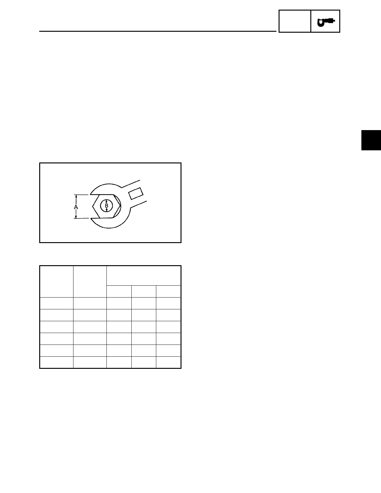
GENERAL TIGHTENING TORQUES
This chart specifies tightening torques for
standard fasteners with a standard ISO
thread pitch. Tightening torque specifica-
tions for special components or assemblies
are provided for each chapter of this man-
ual. To avoid warpage, tighten multi-fas-
tener assemblies in a crisscross pattern and
progressive stages until the specified tight-
ening torque is reached. Unless otherwise
specified, tightening torque specifications
require clean, dry threads. Components
should be at room temperature.
A: Width across flats
B: Thread diameter
A
(nut)
B
(bolt)
General tightening
torques
Nm m•kg ft•lb
10 mm 6 mm 6 0.6 4.3
12 mm 8 mm 15 1.5 11
14 mm 10 mm 30 3.0 22
17 mm 12 mm 55 5.5 40
19 mm 14 mm 85 8.5 61
22 mm 16 mm 130 13.0 94
TIGHTENING TORQUES
2
2 - 19
SPEC
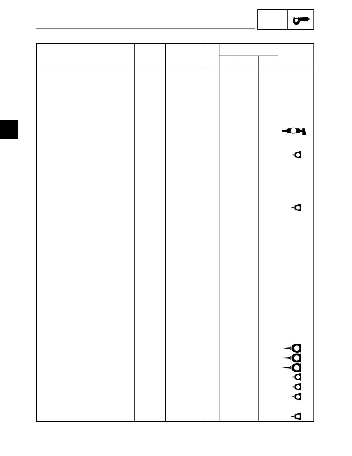
ENGINE TIGHTENING TORQUES
Item Fastener Thread size Q’ty Tightening torque Remarks
Nm m·kgf ft·lb
Spark plug – M12 4 18 1.8 13
Cylinder head Nut M12 8 50 5.0 36
Cylinder head Nut M10 4 39 3.9 28
Cylinder head (exhaust pipe) Stud bolt M8 4 15 1.5 11
Camshaft driven gear Nut M14 1 52 5.2 37
Camshaft drive gear Bolt M10 1 30 3.0 22
Connecting rod Bolt M8 4 38.5 3.85 28 M
Rocker arm adjusting screw Nut M7 4 20 2.0 14
Front cylinder camshaft end
cover Bolt M5 2 10 1.0 7.2 LT
Engine oil drain bolt (crankcase) – M14 1 43 4.3 31
Engine oil drain bolt (oil tank) – M14 1 43 4.3 31
Oil filter cartridge – M20 1 17 1.7 12
Oil filter bolt – M20 1 70 7.0 50
Oil filter bracket Bolt M6 4 10 1.0 7.2 LT
Oil delivery pipe (generator
cover-to-crankcase) Nut M20 1 40 4.0 29
Joint bolt – M16 1 40 4.0 29
Oil delivery pipe (cylinder head-
to-crankcase)
Union
bolt M10 2 21 2.1 15
Oil delivery pipe (cylinder head-
to-crankcase)
Union
bolt M8 1 18 1.8 13
Carburetor joint Bolt M6 4 12 1.2 8.7
Carburetor joint clamp Screw M4 1 3 0.3 2.2
Air filter case Bolt M6 3 7 0.7 5.1
Air filter case clamp Screw M4 1 3 0.3 2.2
Exhaust pipe Nut M6 4 20 2.0 14
Muffler Bolt M10 2 25 2.5 18
Muffler clamp Bolt M10 2 30 3.0 22
Crankcase (cylinder head) Stud bolt M12 8 – – – E*1
Crankcase (cylinder head) Stud bolt M10 4 – – – E*1
Crankcase (transfer gear case) Stud bolt M8 1 13 1.3 9.4 E*2
Pickup coil Screw M6 2 7 0.7 5.1 LT
Pickup coil lead holder Screw M6 7 7 0.7 5.1 LT
Stator coil assembly Screw M6 37 0.7 5.1 LT
Stator coil assembly lead holder Bolt M6 1 7 0.7 5.1
Starter clutch Bolt M8 6 24 2.4 17 LT
TIGHTENING TORQUES
2
2 - 20
SPEC
HINWEIS:
NOTE:
*1: When installing the crankcase stud bolts (cylinder head), make sure that their installed
length is 140.5 ~ 142.5 mm (5.53 ~ 5.61 in).
*2: When installing the crankcase stud bolts (transfer gear case), make sure that their
installed length is 68.3 ~ 70.3 mm (2.69 ~ 2.77 in).
Generator rotor Bolt M12 1 160 16.0 115
Generator shaft Bolt M8 1 28 2.8 20 LT
Pickup coil rotor Bolt M12 1 115 11.5 85 LT
Baffle plate Bolt M6 4 10 1.0 7.2 LT
Clutch boss Nut M20 1 70 7.0 50 Use a lock
washer.
Clutch spring plate Bolt M6 6 8 0.8 5.8
Pull lever Bolt M6 1 10 1.0 7.2
Transfer gear oil drain bolt – M8 1 18 1.8 13
Middle drive gear Nut M22 1 85 8.5 61 Use a lock
washer.
Transfer gear case Bolt M8 4 30 3.0 22
Transfer gear case Nut M8 1 30 3.0 22
Transfer gear oil checking bolt – M6 1 8 0.8 5.8
Transfer gear oil pump cover Screw M6 2 7 0.7 5.1 LT
Transfer gear oil pump Bolt M6 5 10 1.0 7.2 LT
Drive pulley case Bolt M8 7 30 3.0 22
Drive pulley Nut M22 1 85 8.5 61 Use a lock
washer.
Drive pulley cover bracket Bolt M8 2 30 3.0 22
Shift arm Bolt M6 1 10 1.0 7.2
Shift rod locknut – M8 2 12 1.2 8.7
Shift shaft spring stopper Bolt M8 1 22 2.2 16 LT
Stopper lever Bolt M6 1 10 1.0 7.2 LT
Neutral switch Screw M6 2 7 0.7 5.1
Item Fastener Thread size Q’ty Tightening torque Remarks
Nm m·kgf ft·lb
TIGHTENING TORQUES
2
2 - 21
SPEC
CHASSIS TIGHTENING TORQUES
Item Thread size Tightening torque Remarks
Nm m·kgf ft·lb
Upper bracket and inner tube M6 10 1.0 7.2
Upper bracket and steering shaft M22 130 13.0 94
Handlebar holder (lower) and handlebar
holder (upper) M8 23 2.3 17
Ring nut (steering shaft) M25 3 0.3 2.2 See NOTE.
Brake hose joint and lower bracket M6 7 0.7 5.1
Front brake master cylinder cap M4 2 0.2 1.4
Handlebar holder (lower) M12 40 4.0 29
Front brake master cylinder M6 10 1.0 7.2
Union bolt (brake hose) M10 30 3.0 22
Engine mounting:
Mounting bolt
(cylinder head and engine stay) M10 48 4.8 35
Mounting bolt
(crankcase and engine stay) M12 88 8.8 64
Mounting bolt (crankcase and frame) M12 88 8.8 64
Engine stay and frame M10 48 4.8 35
Transfer gear case stay and frame M8 30 3.0 22
Muffler stay and frame M8 26 2.6 19
Muffler stay and muffler M10 30 3.0 22
Ignition coil M6 7 0.7 5.1
Swingarm pivot shaft M18 125 12.5 90
Relay arm and swingarm M12 59 5.9 43
Relay arm and connecting rod M12 59 5.9 43
Relay arm and rear shock absorber M10 40 4.0 29
Rear shock absorber, connecting rod
and frame M12 59 5.9 43
Drive belt case (upper) and swingarm M6 10 1.0 7.2
Drive belt case (lower) and swingarm M6 7 0.7 5.1
Mud guard and swingarm M6 7 0.7 5.1
Fuel petcock and fuel tank M6 7 0.7 5.1
Fuel sender and fuel tank M6 7 0.7 5.1
Fuel tank (rear) and frame M6 7 0.7 5.1
Meter cover and fuel tank M6 7 0.7 5.1
Side cover and frame M6 7 0.7 5.1
Starter relay and battery positive lead M6 7 0.7 5.1
Starter relay and starter motor lead M6 7 0.7 5.1
Rear fender side mold and rear fender
stay M8 30 3.0 22
Sidestand bolt and nut M10 48 4.8 35
Footrest bracket and frame M10 48 4.8 35
Rear footrest and frame M8 23 2.3 17
TIGHTENING TORQUES
2
2 - 22
SPEC
HINWEIS:
NOTE:
1.First, tighten the ring nut to approximately 52 Nm (5.2 m • kg, 37 ft • lb) with a torque
wrench, then loosen the ring nut completely.
2.Retighten the ring nut to specification.
Rear master cylinder and rear brake
bracket M8 23 2.3 17
Rear brake reservoir tank M6 4 0.4 2.9
Union bolt (rear brake hose) M10 30 3.0 22
Footrest bracket and rear brake bracket M8 16 1.6 11
Footrest bracket and shift rod bracket M8 16 1.6 11
Front wheel axle M18 78 7.8 56
Front wheel axle pinch bolt M8 19 1.9 13
Rear wheel axle nut M18 150 15.0 110
Front brake caliper M10 40 4.0 29
Rear brake caliper M10 40 4.0 29
Brake disc and wheel M8 23 2.3 17 LT
Caliper bleed screw M8 6 0.6 4.3
Driven pulley and rear wheel clutch hub M12 95 9.5 68
Rear brake caliper bracket and swin-
garm M10 48 4.8 35
Item Thread size Tightening torque Remarks
Nm m·kgf ft·lb
TIGHTENING TORQUES
2
2 - 23
SPEC
LUBRICATION POINTS AND LUBRICANT TYPES
ENGINE LUBRICATION POINTS AND LUBRICANT TYPES
Lubrication point Lubricant
Oil seal lips LS
O-rings LS
Bearings E
Connecting rod bolts and nuts M
Connecting rod small end and big end E
Crankshaft pins E
Crankshaft journals E
Piston surfaces E
Piston pins E
Camshaft cam lobes and camshaft journals M
Valve push rods E
Valve push rod end balls E
Valve stems (intake and exhaust) M
Valve stem ends (intake and exhaust) E
Valve lifters E
Oil pump rotors (inner and outer) and oil pump housing E
Oil strainer E
Starter clutch idle gear inner surface E
Starter clutch idle gear shaft E
Starter clutch roller and starter clutch gear outer surface E
Clutch pull rod M
Pressure plate bearing E
Transmission gears (wheel and pinion) M
Shift drum E
Shift forks and shift fork guide bars E
Shift shaft LS
Shift pedal LS
Shift lever joint LS
Crankcase mating surface Sealant
(Quick Gasket
)
Stator coil lead grommet Sealant
(Quick Gasket
)
Pickup coil lead grommet Sealant
(Quick Gasket
)
LUBRICATION POINTS AND LUBRICANT TYPES
2
2 - 24
SPEC
CHASSIS LUBRICATION POINTS AND LUBRICANT TYPES
Lubrication point Lubricant
Steering bearings and bearing races (upper and lower) LS
Steering bearing cover LS
Steering head pipe lower oil seal LS
Front wheel oil seal (right and left) LS
Rear wheel oil seal LS
Rear wheel drive hub mating surface LS
Rear brake pedal shaft LS
Shift pedal LS
Front footrest pivot LS
Sidestand sliding surface LS
Tube guide (throttle grip) inner surface LS
Brake lever pivot bolt, contact surface LS
Clutch lever pivot bolt, contact surface LS
Swingarm pivot shaft M
Swingarm pivot bearing M
Swingarm pivot oil seal M
Relay arm bearing (inner) M
Rear shock absorber bearing (inner) M
Connecting rod bearing (inner) M
LUBRICATION POINTS AND LUBRICANT TYPES
2
SPEC
2 - 25
ENGINE OIL LUBRICATION CHART
ENGINE OIL LUBRICATION CHART
2
2 - 26
SPEC
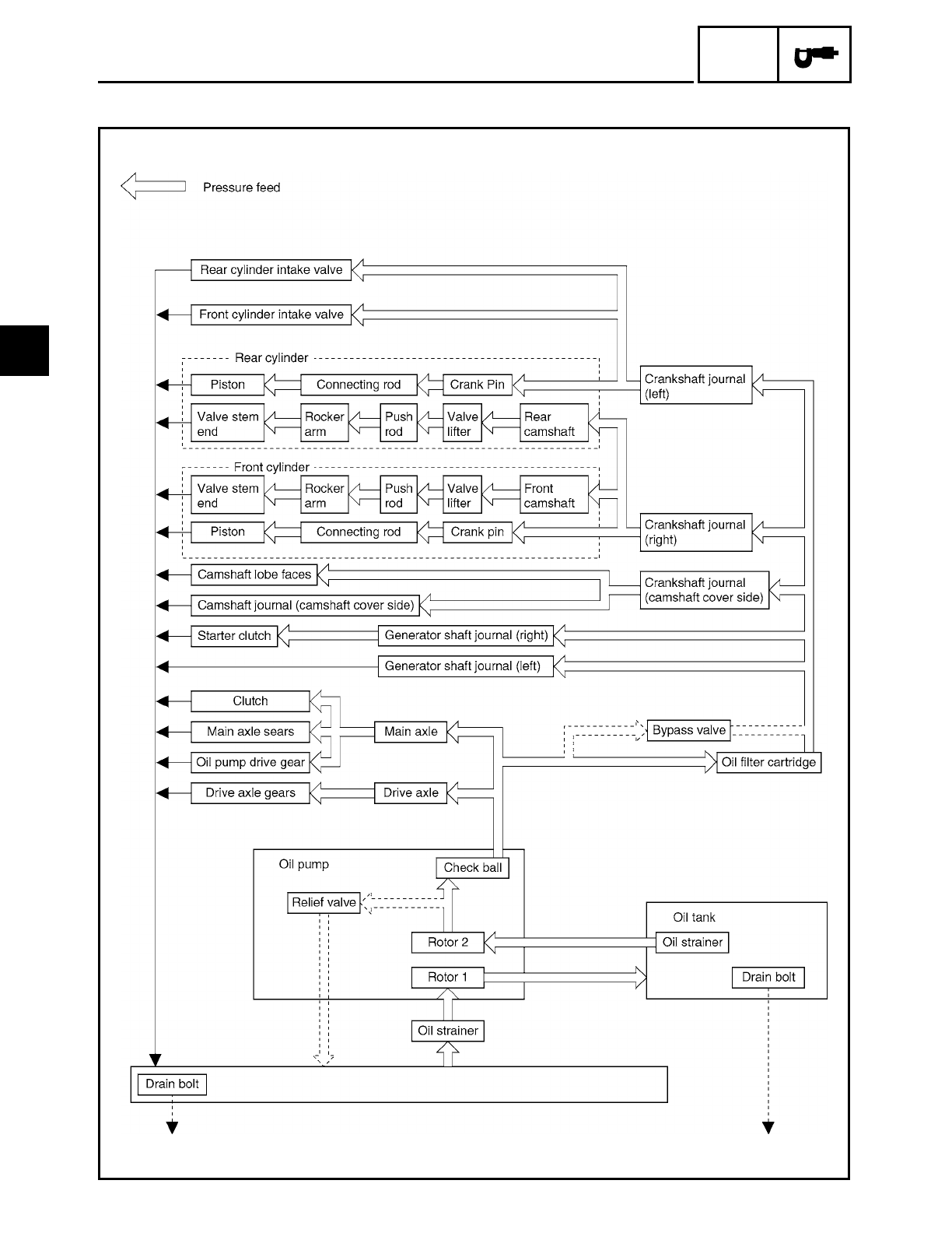
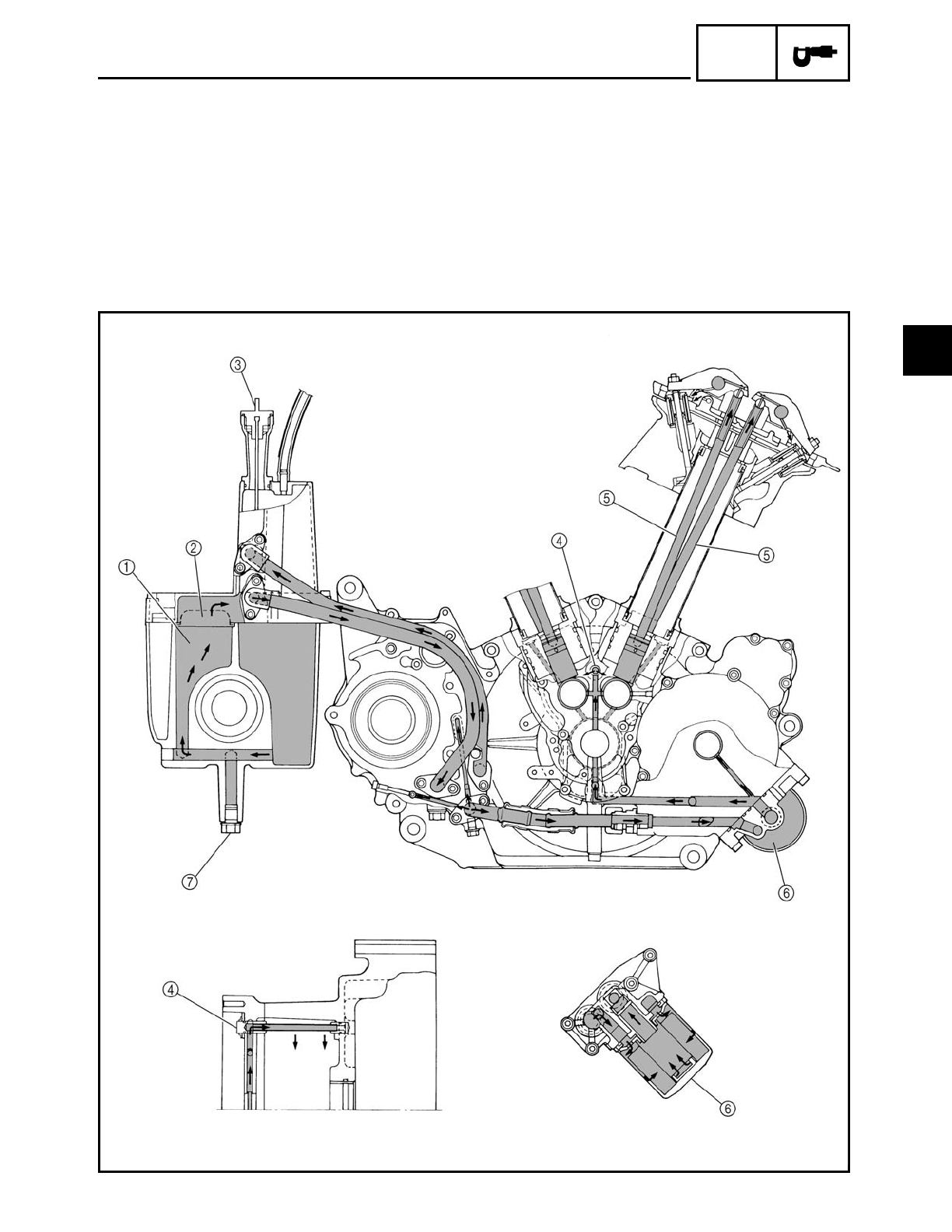
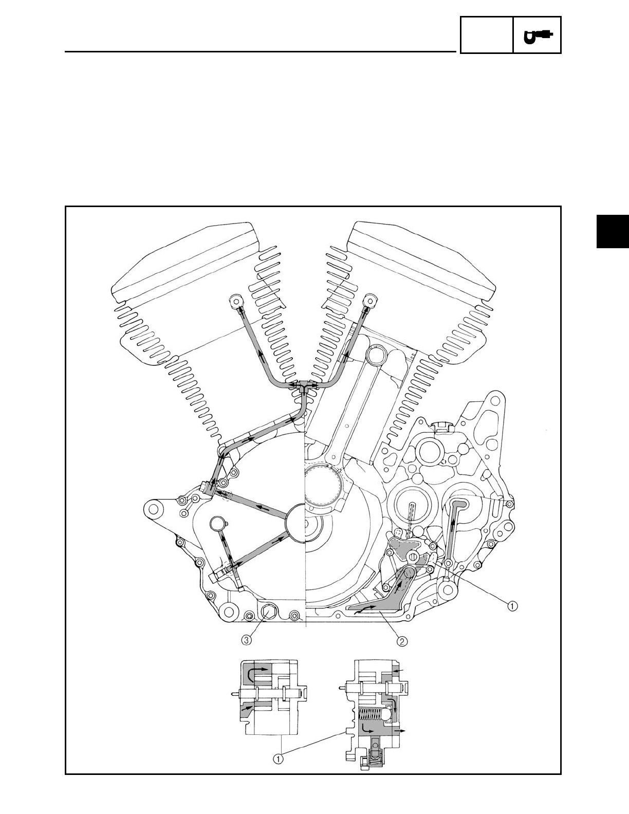
ENGINE OIL FLOW DIAGRAMS
1Oil tank
2Oil strainer
3Dipstick
4Oil delivery pipe
5Push rod
6Oil filter cartridge
7Engine oil drain bolt (oil tank)
ENGINE OIL FLOW DIAGRAMS
2
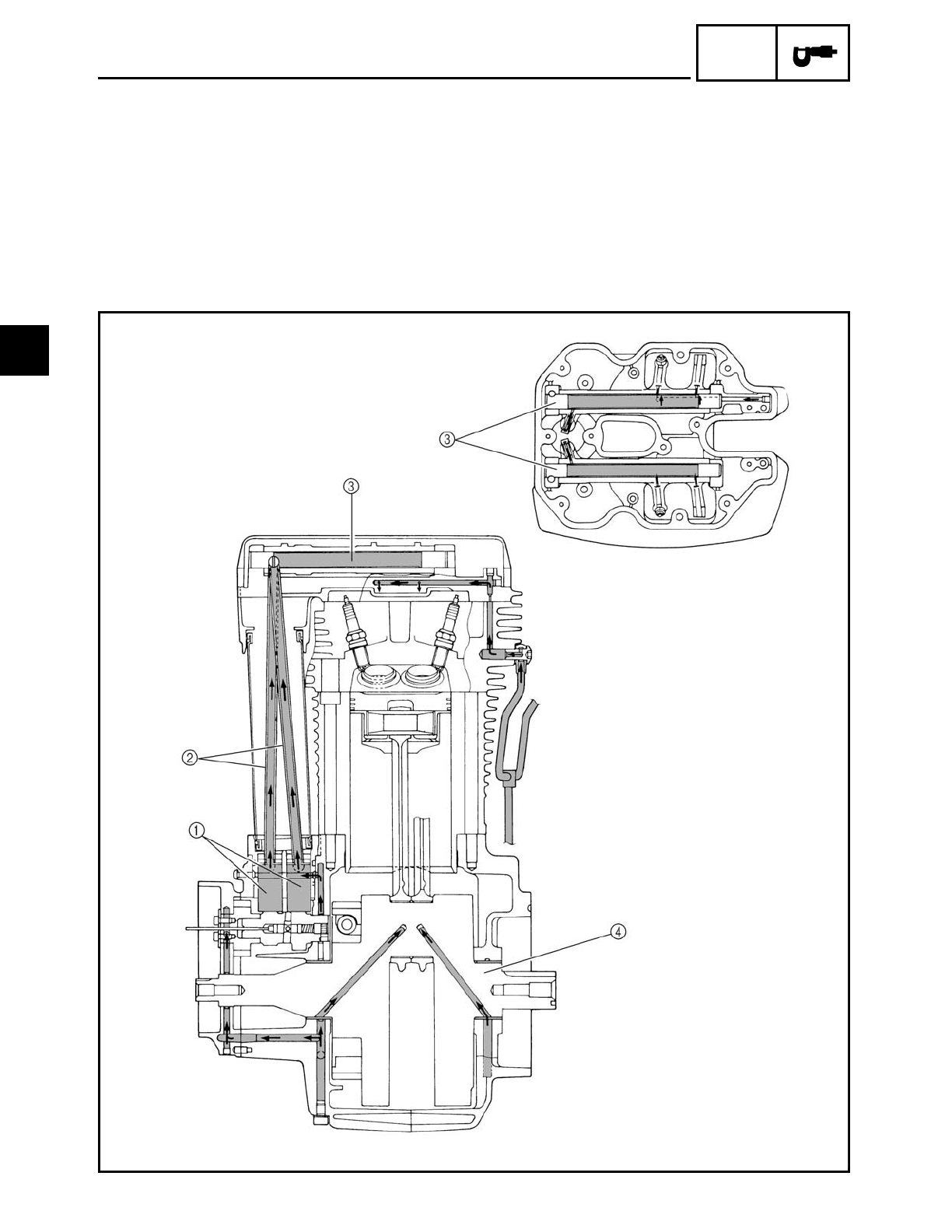
2 - 27
SPEC
1Valve lifter
2Push rod
3Rocker arm shaft
4Crankshaft
ENGINE OIL FLOW DIAGRAMS
2
2 - 28
SPEC
1Engine oil pump
2Oil strainer
3Engine oil drain bolt (engine)
ENGINE OIL FLOW DIAGRAMS
2
2 - 29
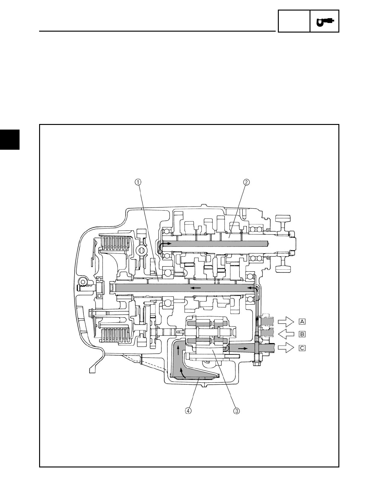
SPEC
1Main axle
2Drive axle
3Engine oil pump
4Oil strainer
ÅTo oil tank
ıFrom oil tank
ÇTo oil filter cartridge
ENGINE OIL FLOW DIAGRAMS
2
SPEC
2 - 30
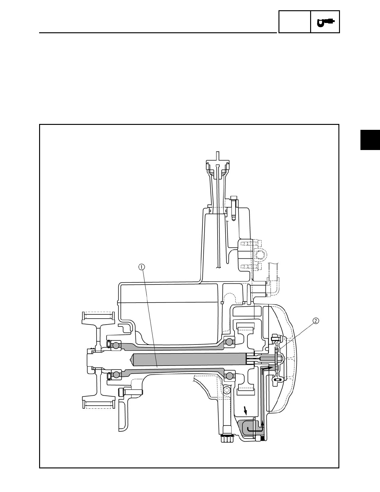
TRANSFER GEAR OIL FLOW DIAGRAMS
1Middle driven shaft
2Transfer gear oil pump
TRANSFER GEAR OIL FLOW DIAGRAMS
2
SPEC
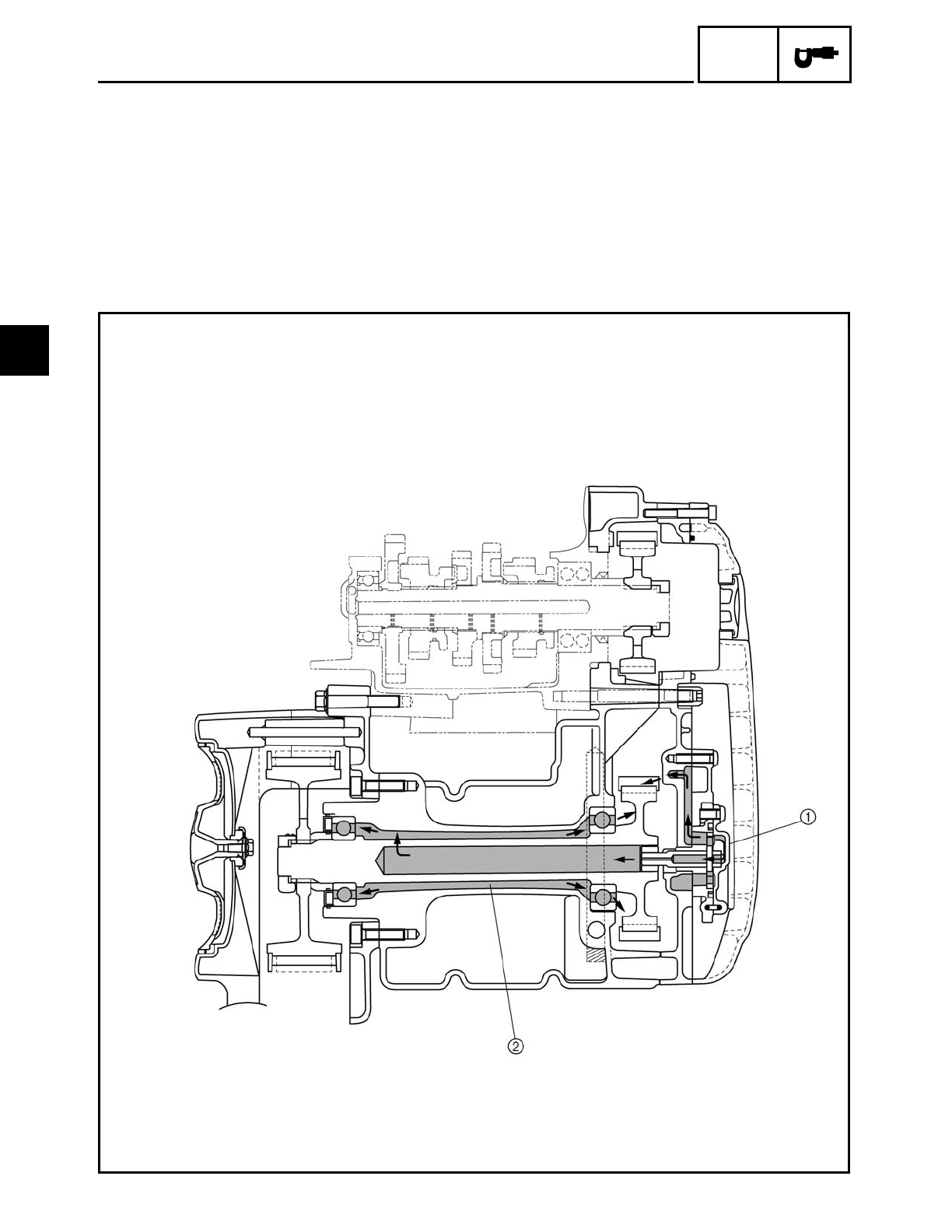
2 - 31
1Transfer gear oil pump
2Middle driven shaft
TRANSFER GEAR OIL FLOW DIAGRAMS
2
2 - 32
SPEC
EB206000
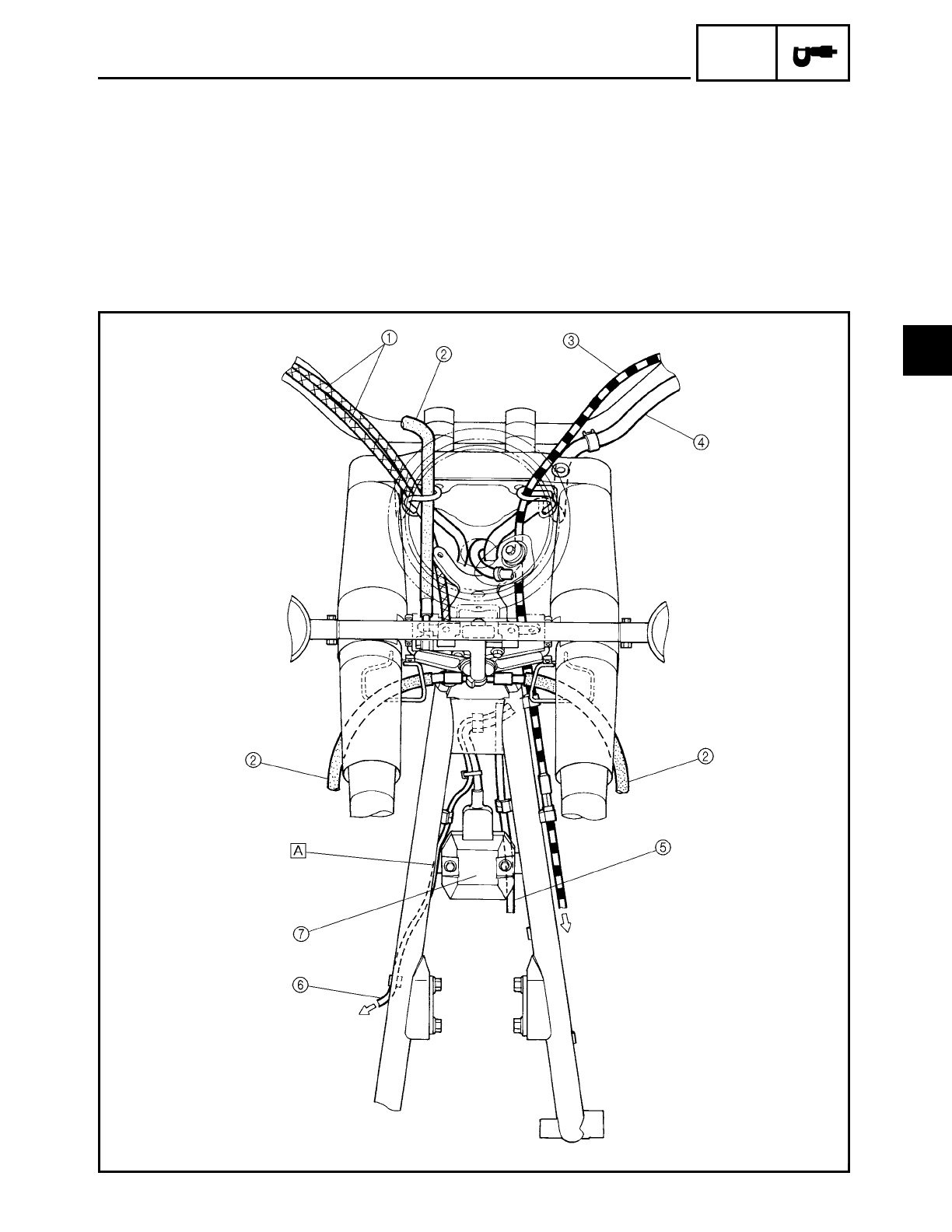
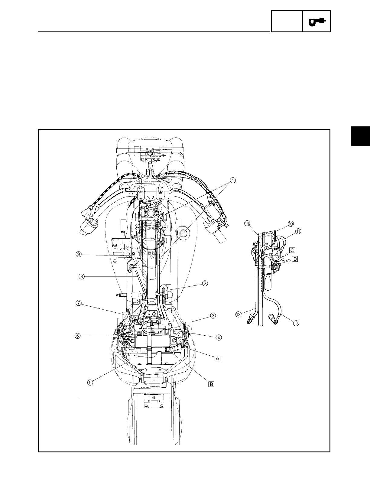
CABLE ROUTING
1Throttle cables
2Brake hose
3Clutch cable
4Left handlebar switch lead
5Vacuum hose (air induction system)
6Rear brake light switch lead
7Rectifier/regulator
ÅRoute the rear brake light switch lead in front of the
rectifier/regulator bracket on the frame.
CABLE ROUTING
2
SPEC
2 - 33
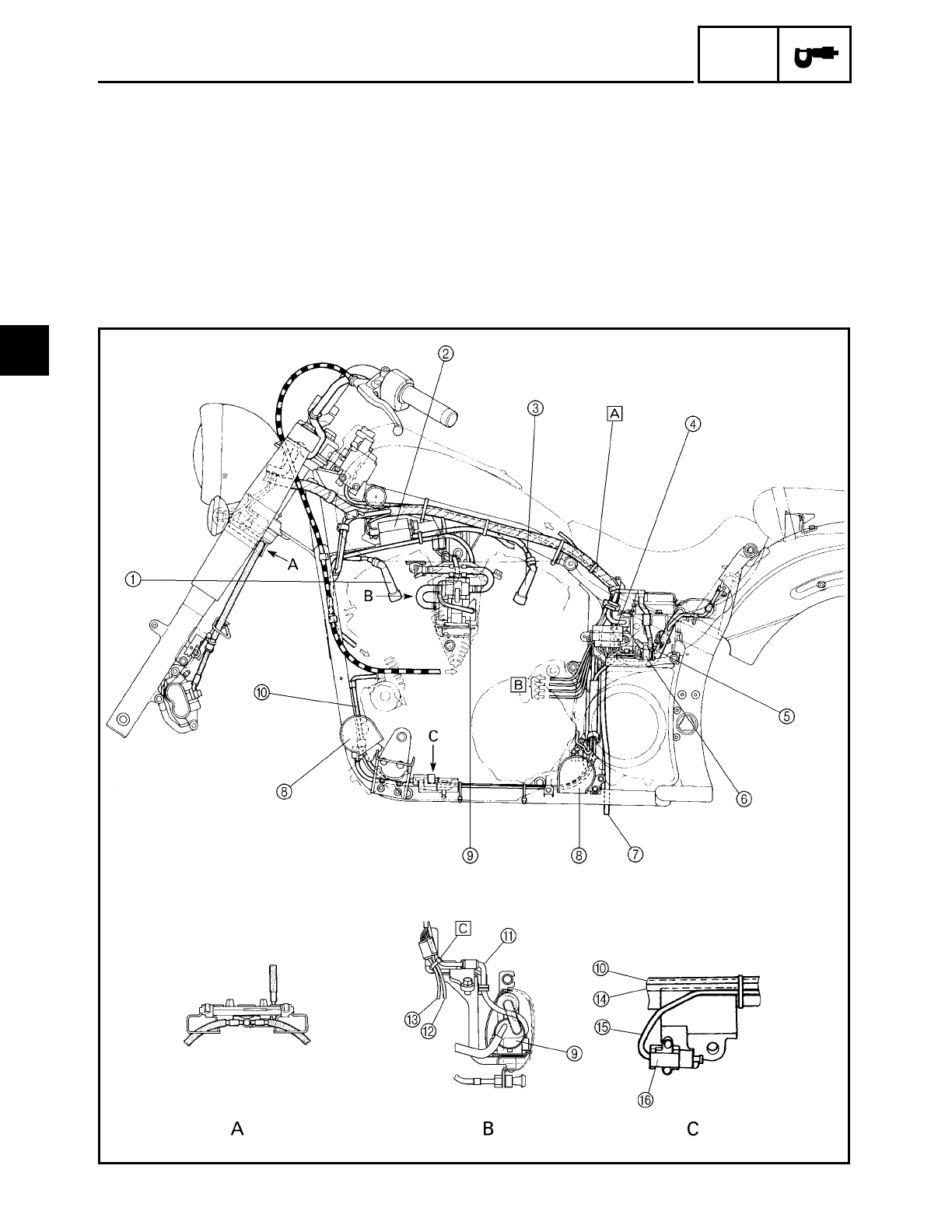
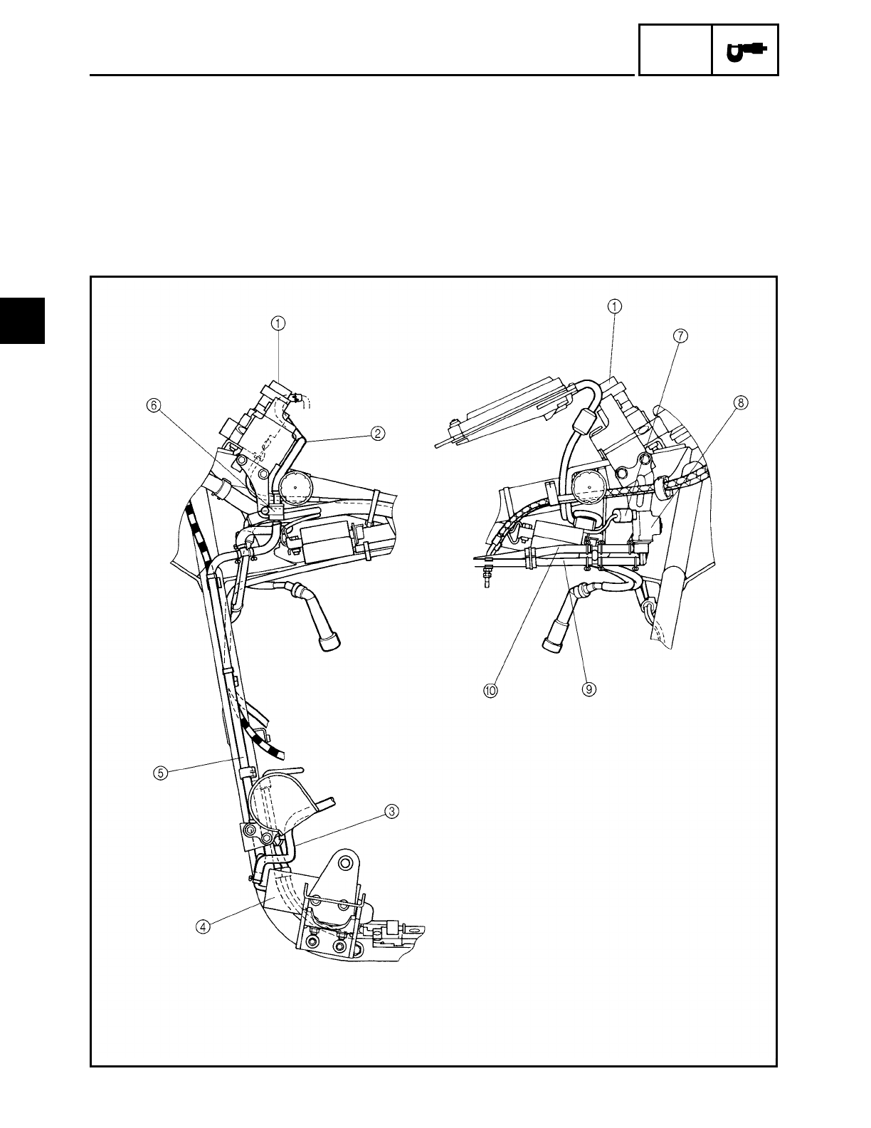
1Spark plug cap #3
2Ignition coil (rear cylinder)
3Spark plug cap #1
4Fuse box
5Starter relay
6Thermo switch
7Fuel tank breather hose
8Horns
9Fuel pump
0Starter motor lead
AFuel pump lead
BCarburetor heater lead
CThrottle position sensor lead
DHorn lead
ESidestand switch lead
FSidestand switch
ÅFasten the wire harness, fuel sender lead (wire harness side) and
seat lock cable with a plastic locking tie.
ıTo the speed sensor, neutral switch, stator coil and decompres-
sion solenoid.
ÇFasten the throttle position sensor lead, carburetor heater lead and
fuel pump lead with a plastic locking tie to the engine bracket.
CABLE ROUTING
2
SPEC
2 - 34
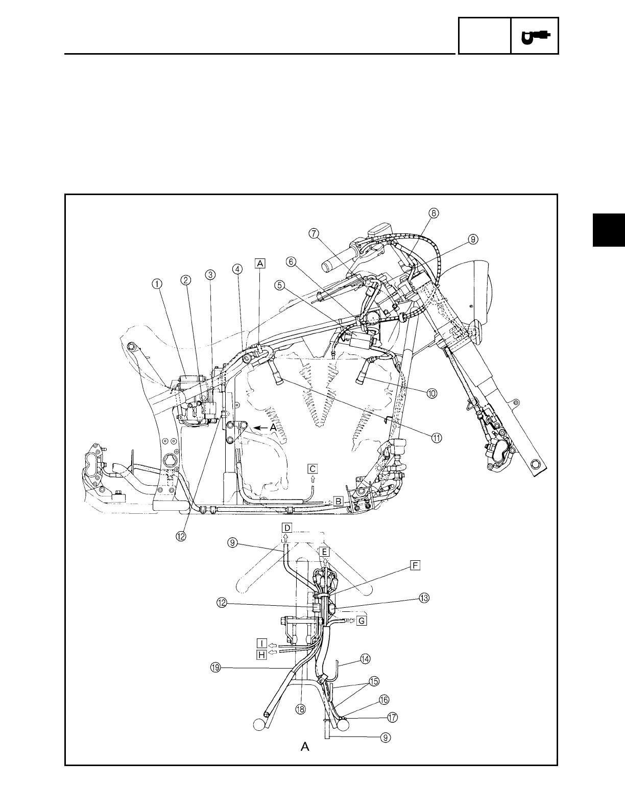
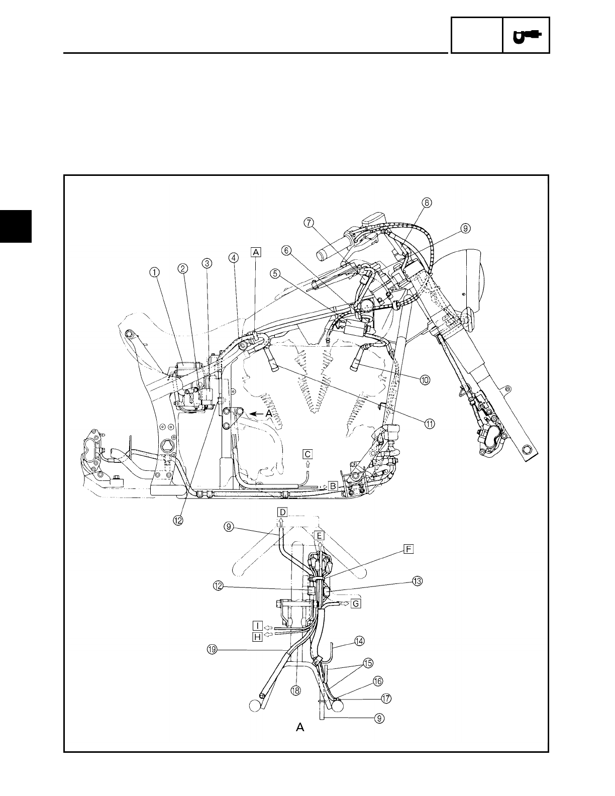
1Battery
2Turn signal relay
3Relay unit
4Oil tank breather hose
5Ignition coil (front cylinder)
6Main switch coupler
7Meter assembly couplers
8Right handlebar switch lead
9Fuel tank breather hose
0Spark plug cap #4
ASpark plug cap #2
BSidestand switch coupler
CPickup coil lead
DHorn leads
EStarter motor lead
FSidestand switch lead
GDecompression solenoid lead
HStator coil lead
IRollover valve
CABLE ROUTING
2
SPEC
2 - 35
ÅFasten the fuel tank breather and oil tank
breather hose with a plastic clamp and then
insert the clamp into the frame.
ıTo the stator coil.
ÇTo the decompression solenoid.
ÎTo the fuel tank.
‰To the wire harness.
ÏFasten the starter motor lead, stator coil lead,
decompression solenoid lead, pickup coil
lead speed sensor lead and neutral switch
lead with a plastic clamp and then insert the
clamp into the frame.
ÌTo the starter relay.
ÓTo the decompression solenoid.
ÈTo the speed sensor.
CABLE ROUTING
2
SPEC
2 - 36
1Fuel tank breather hose
2Oil tank breather hose
3Relay unit
4Turn signal relay
5Tail/brake light and rear turn signal light sub-
wire harness coupler
6Thermo switch
7Fuse box
8Fuel sender lead
9Vacuum hose (air induction system)
0Solenoid valve lead (California only)
ASpark plug lead #4
BSpark plug lead #2
CSpark plug lead #1
DSpark plug lead #3
ÅFasten the wire harness with a plastic clamp
and then insert the clamp into the relay
bracket.
ıPosition the white tape on the wire harness
with the hole on battery box, as shown.
ÇTo the main switch.
ÎTo the meter assembly.
CABLE ROUTING
2
SPEC
2 - 37
Evaporative emission control system (California only)
1Main switch
2Fuel tank breather hose
3Charcoal canister to carburetor hose
4Charcoal canister
5Charcoal canister to rollover valve hose
6Rollover valve
7Solenoid valve coupler
8Solenoid valve
9Solenoid valve to air filter case hose
0Solenoid valve to carburetor hose
CABLE ROUTING
2

CHK
ADJ
CONTENTS
PERIODIC CHECKS AND ADJUSTMENTS
INTRODUCTION ........................................................................................... 3-1
PERIODIC MAINTENANCE/LUBRICATION INTERVALS ........................... 3-1
GENERAL MAINTENANCE AND LUBRICATION CHART .......................... 3-1
SEATS AND SIDE COVERS ......................................................................... 3-3
XV16AT ACCESSORY PARTS ..................................................................... 3-4
FUEL TANK ...................................................................................................3-6
AIR FILTER CASE ......................................................................................... 3-7
ENGINE ......................................................................................................... 3-8
ADJUSTING THE VALVE CLEARANCE ............................................... 3-8
ADJUSTING THE ENGINE IDLING SPEED ....................................... 3-12
ADJUSTING THE THROTTLE CABLE FREE PLAY ............................ 3-13
CHECKING THE SPARK PLUGS ........................................................ 3-14
CHECKING THE IGNITION TIMING ................................................... 3-16
MEASURING THE COMPRESSION PRESSURE ............................... 3-18
CHECKING THE ENGINE OIL LEVEL ................................................. 3-20
CHANGING THE ENGINE OIL ............................................................ 3-22
MEASURING THE ENGINE OIL PRESSURE ..................................... 3-25
CHECKING THE TRANSFER GEAR OIL LEVEL ................................. 3-26
CHANGING THE TRANSFER GEAR OIL ........................................... 3-27
ADJUSTING THE CLUTCH CABLE FREE PLAY ................................ 3-28
CLEANING THE AIR FILTER ELEMENT ............................................. 3-29
CHECKING THE CARBURETOR JOINT ............................................. 3-30
CHECKING THE FUEL HOSES AND FUEL FILTER ........................... 3-30
CHECKING THE CYLINDER HEAD BREATHER HOSE AND
TRANSFER GEAR CASE BREATHER HOSE .................................3-31
CHECKING THE EXHAUST SYSTEM ................................................ 3-31
CHASSIS ..................................................................................................... 3-32
ADJUSTING THE FRONT BRAKE ...................................................... 3-32
ADJUSTING THE REAR BRAKE ........................................................ 3-33
CHECKING THE BRAKE FLUID LEVEL .............................................. 3-34
3

CHK
ADJ
CHECKING THE FRONT BRAKE PADS ............................................. 3-35
CHECKING THE REAR BRAKE PADS ................................................ 3-35
ADJUSTING THE REAR BRAKE LIGHT SWITCH ............................. 3-35
CHECKING THE BRAKE HOSE .......................................................... 3-36
BLEEDING THE HYDRAULIC BRAKE SYSTEM ................................ 3-37
ADJUSTING THE SHIFT PEDAL ........................................................ 3-39
ADJUSTING THE DRIVE BELT SLACK .............................................. 3-39
CHECKING AND ADJUSTING THE STEERING HEAD ..................... 3-41
CHECKING THE FRONT FORK ........................................................... 3-43
ADJUSTING THE REAR SHOCK ABSORBER ASSEMBLY .............. 3-44
CHECKING THE TIRES ....................................................................... 3-45
CHECKING AND TIGHTENING THE SPOKES ................................... 3-48
CHECKING AND LUBRICATING THE CABLES ................................. 3-49
LUBRICATING THE LEVERS AND PEDALS ...................................... 3-50
LUBRICATING THE SIDESTAND ....................................................... 3-50
LUBRICATING THE REAR SUSPENSION ......................................... 3-50
ELECTRICAL SYSTEM ............................................................................... 3-51
CHECKING AND CHARGING THE BATTERY .................................... 3-51
CHECKING THE FUSES ...................................................................... 3-56
REPLACING THE HEADLIGHT BULB ................................................ 3-58
ADJUSTING THE HEADLIGHT BEAM ............................................... 3-59
INSTRUMENT FUNCTIONS ...................................................................... 3-61
INDICATOR LIGHTS ........................................................................... 3-61
COMBINATION METER ..................................................................... 3-61
3
3 - 1
CHK
ADJ
INTRODUCTION/PERIODIC MAINTENANCE/LUBRICATION INTERVALS/
GENERAL MAINTENANCE AND LUBRICATION CHART
EAS00036
PERIODIC CHECKS AND ADJUSTMENTS
INTRODUCTION
This chapter includes all information necessary to perform recommended checks and adjust-
ments. If followed, these preventive maintenance procedures will ensure more reliable vehi-
cle operation, a longer service life and reduce the need for costly overhaul work. This
information applies to vehicles already in service as well as to new vehicles that are being
prepared for sale. All service technicians should be familiar with this entire chapter.
EAS00037
PERIODIC MAINTENANCE/LUBRICATION INTERVALS
* Since these items require special tools, data and technical skills, they should be serviced by a
Yamaha dealer.
GENERAL MAINTENANCE AND LUBRICATION CHART
No. ITEM ROUTINE
INITIAL ODOMETER READINGS
600 mi
(1,000 km)
or
1 month
4,000 mi
(7,000 km)
or
6 months
8,000 mi
(13,000 km)
or
12 months
12,000 mi
(19,000 km)
or
18 months
16,000 mi
(25,000 km)
or
24 months
20,000 mi
(31,000 km)
or
30 months
1*Valve clearance
(See page 3-8.)
• Check valve clearance when
engine is cold.
• Adjust if necessary.
Every 15,000 mi (24,000 km)
2Spark plug
(See page 3-14.)
• Check condition.
• Adjust gap and clean.
• Replace at 8,000 mi (13,000 km) or
12 months and thereafter every
8,000 mi (13,000 km) or 12 months.
√Replace
√Replace
√
3*
Crankcase ventilation
system
(See page 3-31.)
• Check breather hose for cracks or
damage.
• Replace if necessary.
√
√
√
√
√
4*Fuel line
(See page 3-30.)
• Check fuel hose for cracks or dam-
age.
• Replace if necessary.
√
√
√
√
√
5*Fuel filter
(See page 3-30.)
• Replace initial 20,000 mi (31,000
km) and thereafter every 20,000 mi
(31,000 km).
Replace
6*Exhaust system
(See page 3-31.)
• Check for leakage.
• Retighten if necessary.
• Replace gasket(s) if necessary.
√
√
√
√
√
7*Idle speed
(See page 3-12.)
• Check and adjust engine idle
speed.
• Adjust cable free play.
√
√
√
√
√
√
8*
Evaporative Emission
control system (For
California only)
• Check control system for damage.
• Replace if necessary.
√
√
No. ITEM ROUTINE TYPE
INITIAL ODOMETER READINGS
600 mi
(1,000 km)
or
1 month
4,000 mi
(7,000 km)
or
6 months
8,000 mi
(13,000 km)
or
12 months
12,000 mi
(19,000 km)
or
18 months
16,000 mi
(25,000 km)
or
24 months
20,000 mi
(31,000 km)
or
30 months
1
Engine oil
(See page 3-
22.)
• Replace See page 3-21.
√
√
√
√
√
√
2 * Oil filter • Replace —
√
√
√
3*
Air filter
(See page 3-
29.)
• Clean with compressed
air.
• Replace if necessary.
—
√
√
√
√
√
4*
Front brake
(See page 3-
32.)
• Check operation and
fluid leakage. (See page
3-34)
• Correct if necessary.
—
√
√
√
√Replace
brake fluid
√
5*
Rear brake
(See page 3-
33.)
• Check operation and
fluid leakage. (See page
3-34)
• Correct if necessary.
—
√
√
√
√Replace
brake fluid
√
3
3 - 2
CHK
ADJ
GENERAL MAINTENANCE AND LUBRICATION CHART
*Since these items require special tools, data and technical skills, they should be serviced by a
Yamaha dealer.
NOTE:
The air filter element needs more frequent service if you are riding in unusually wet or dry
areas.
1.Hydraulic brake system
• Replace the brake fluid after disassembling the master cylinder or caliper cylinder.
• Check the brake fluid level and add fluid as required.
• Replace the master cylinder and caliper cylinder oil seals every two years.
• Replace the brake hoses every four years or if cracked or damaged.
6*
Clutch
(See page 3-
28.)
• Check operation and
free play.
• Correct if necessary.
—
√
√
√
√
√
√
7*
Transfer
case oil
(See page 3-
26.)
• Check vehicle for leak-
age.
• Replace every 16,000
mi (25,000 km) or
24 months.
SAE 80 API “GL-4”
hypoid gear oil Replace Check Replace
8*
Control
cable
(See page 3-
49.)
• Apply chain lube thor-
oughly.
Yamaha chain and
cable lube or SAE
10W30 motor oil
√
√
√
√
√
√
9*
Rear arm
pivot bear-
ing
(See page 4-
84.)
• Check bearing assem-
bly for looseness.
• Moderately repack
every 16,000 mi (25,000
km).
Medium weight
wheel bearing
grease
√Repack
10
Brake/
Clutch lever
pivot shaft
(See page 3-
50.)
• Apply chain lube
lightly.
Yamaha chain and
cable lube or SAE
10W30 motor oil
√
√
√
√
√
11
Brake pedal
and shift
pedal shaft
(See page 3-
50.)
• Lubricate
• Apply chain lube
lightly.
Yamaha chain and
cable lube or SAE
10W30 motor oil
√
√
√
√
√
12 *
Sidestand
pivot
(See page 3-
50.)
• Check operation and
lubricate.
• Apply chain lube
lightly.
Yamaha chain and
cable lube or SAE
10W30 motor oil
√
√
√
√
√
13 *
Sidestand
switch
(See page 3-
50.)
• Check and clean or
replace if necessary. —
√
√
√
√
√
√
14 *
Front fork
(See page 3-
43.)
• Check operation and for
leakage. —
√
√
√
√
√
15 *
Steering
bearings
(See page 3-
41.)
• Check bearing assem-
bly for looseness.
• Moderately repack
every 16,000 mi (25,000
km).
Lithium soap base
grease
√
√
√Repack
√
16 *
Wheel bear-
ings
(See page 4-
5.)
• Check bearings for
smooth rotation. —
√
√
√
√
√
17 *
Rear sus-
pension link
pivots
(See page 4-
84.)
• Apply grease lightly. Molybdenum disul-
fide grease
√
18 *
Drive belt
(See page 3-
39.)
• Check the belt tension.
• Adjust if necessary. —
√Every 2,500 mi (4,000 km)
No. ITEM ROUTINE TYPE
INITIAL ODOMETER READINGS
600 mi
(1,000 km)
or
1 month
4,000 mi
(7,000 km)
or
6 months
8,000 mi
(13,000 km)
or
12 months
12,000 mi
(19,000 km)
or
18 months
16,000 mi
(25,000 km)
or
24 months
20,000 mi
(31,000 km)
or
30 months
3
3 - 3
CHK
ADJ
SEATS AND SIDE COVERS
SEATS AND SIDE COVERS
Order Job/Part Q’ty Remarks
Removing the seats and side covers Remove the parts in the order listed.
1 Rider seat 1
2 Passenger seat 1
3 Left side cover 1
4 Right side cover 1
For installation, reverse the removal
procedure.
3
3 - 4
CHK
ADJ
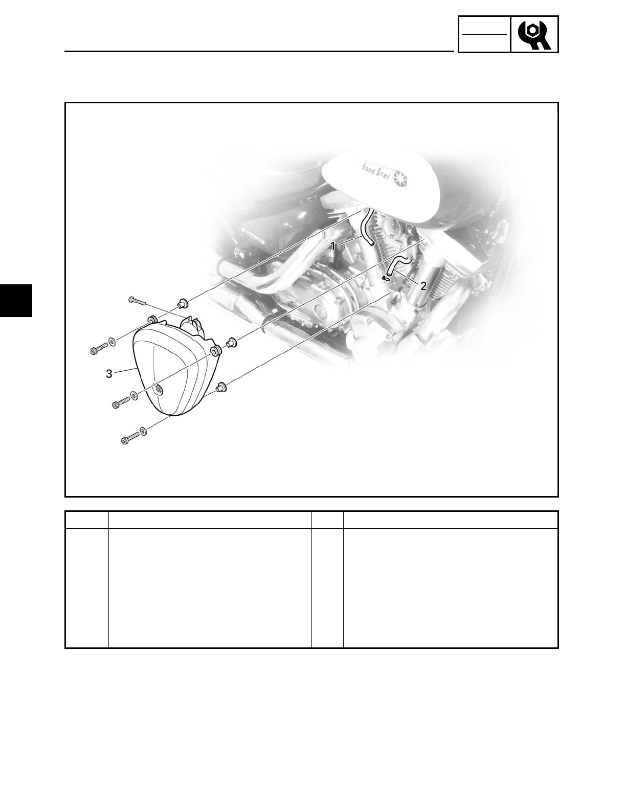
XV16AT ACCESSORY PARTS
XV16AT ACCESSORY PARTS
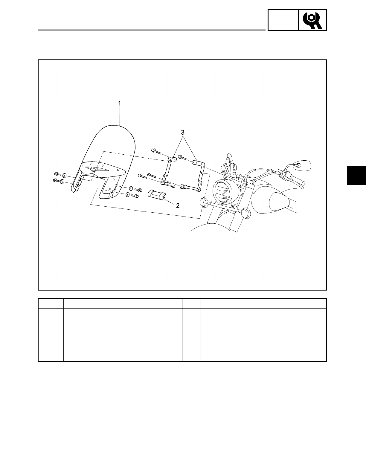
Order Job/Part Q’ty Remarks
Accessory parts removal (front) Remove the parts in the order listed.
1 Front windshield 1
2 Chrome flasher bracket cover 1
3 Windshield stay 2
For installation, reverse the removal
procedure.
3
3 - 5
CHK
ADJ
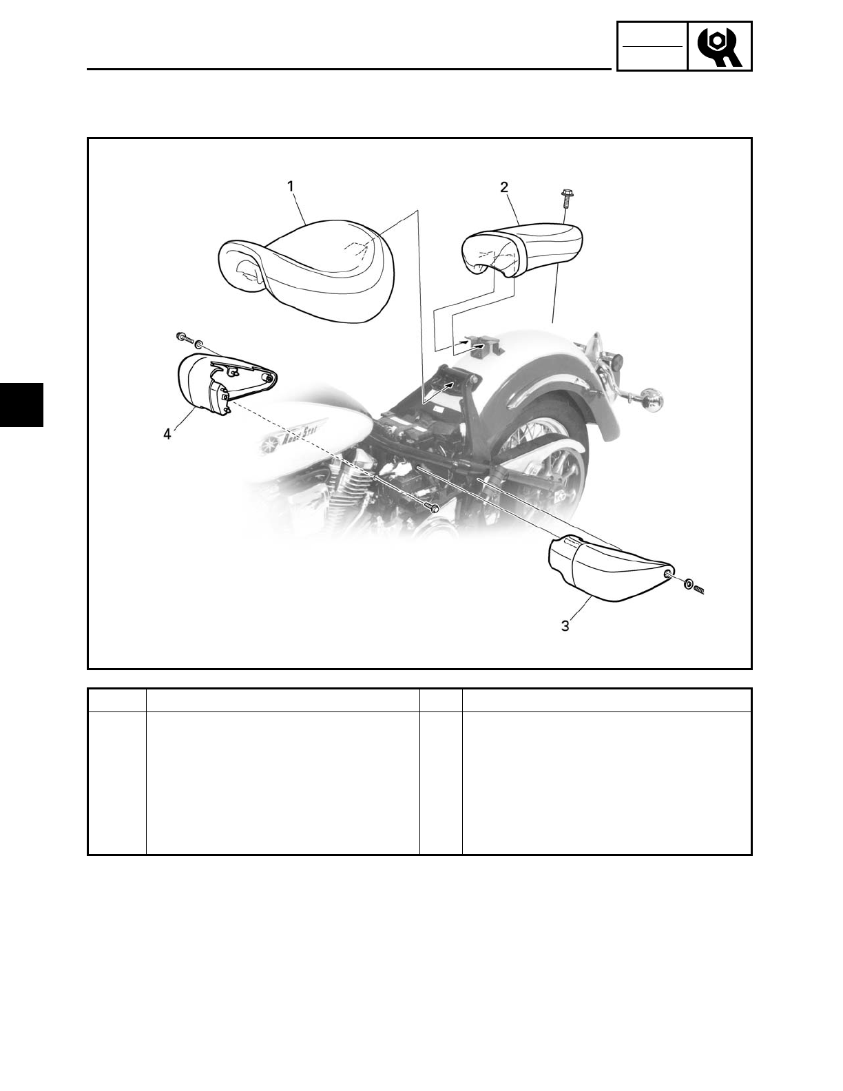
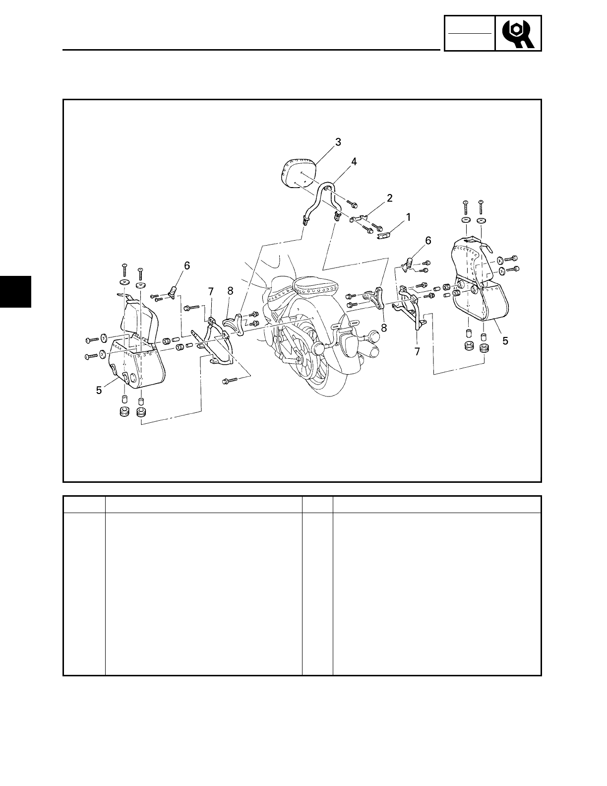
Order Job/Part Q’ty Remarks
Accessory parts removal (rear) Remove the parts in the order listed.
1 Emblem 1
2 Backrest holder 1
3 Backrest 1
4 Backrest stay 1
5 Saddlebag 2
6 Passenger footrest 2
7 Saddlebag stay 2
8 Grip 2
For installation, reverse the removal
procedure.
XV16AT ACCESSORY PARTS
3
3 - 6
CHK
ADJ
FUEL TANK
EAS00040
FUEL TANK
1
2
1
6
5
3
4
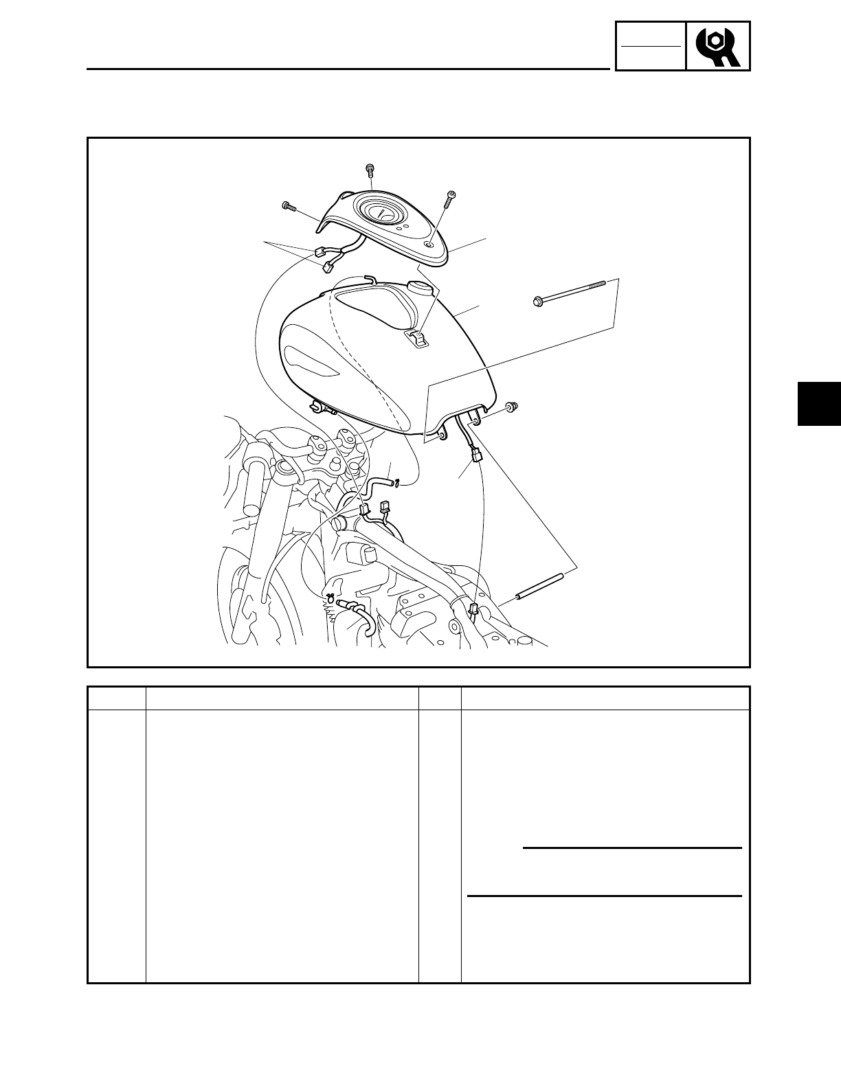
Order Job/Part Q’ty Remarks
Removing the fuel tank Remove the parts in the order listed.
Rider seat Refer to “SEATS AND SIDE COVERS”.
1 Meter assembly
2 Meter assembly coupler 2 Disconnect.
3 Fuel tank breather hose 1
4 Fuel hose Disconnect.
5 Fuel sender coupler 1 Disconnect.
6 Fuel tank 1
For installation, reverse the removal
procedure.
NOTE:
Before disconnecting the fuel hose,
set the fuel cock to “OFF”.
3
3 - 7
CHK
ADJ
AIR FILTER CASE
Order Job/Part Q’ty Remarks
Removing the air filter case Remove the parts in the order listed.
1 Vacuum chamber breather hose
(air filter case to solenoid valve
hose)
1 Disconnect.
2 Cylinder head breather hose 1 Disconnect.
3 Air filter case 1
For installation, reverse the removal
procedure.
AIR FILTER CASE
3
3 - 8
CHK
ADJ
EAS00047
ENGINE
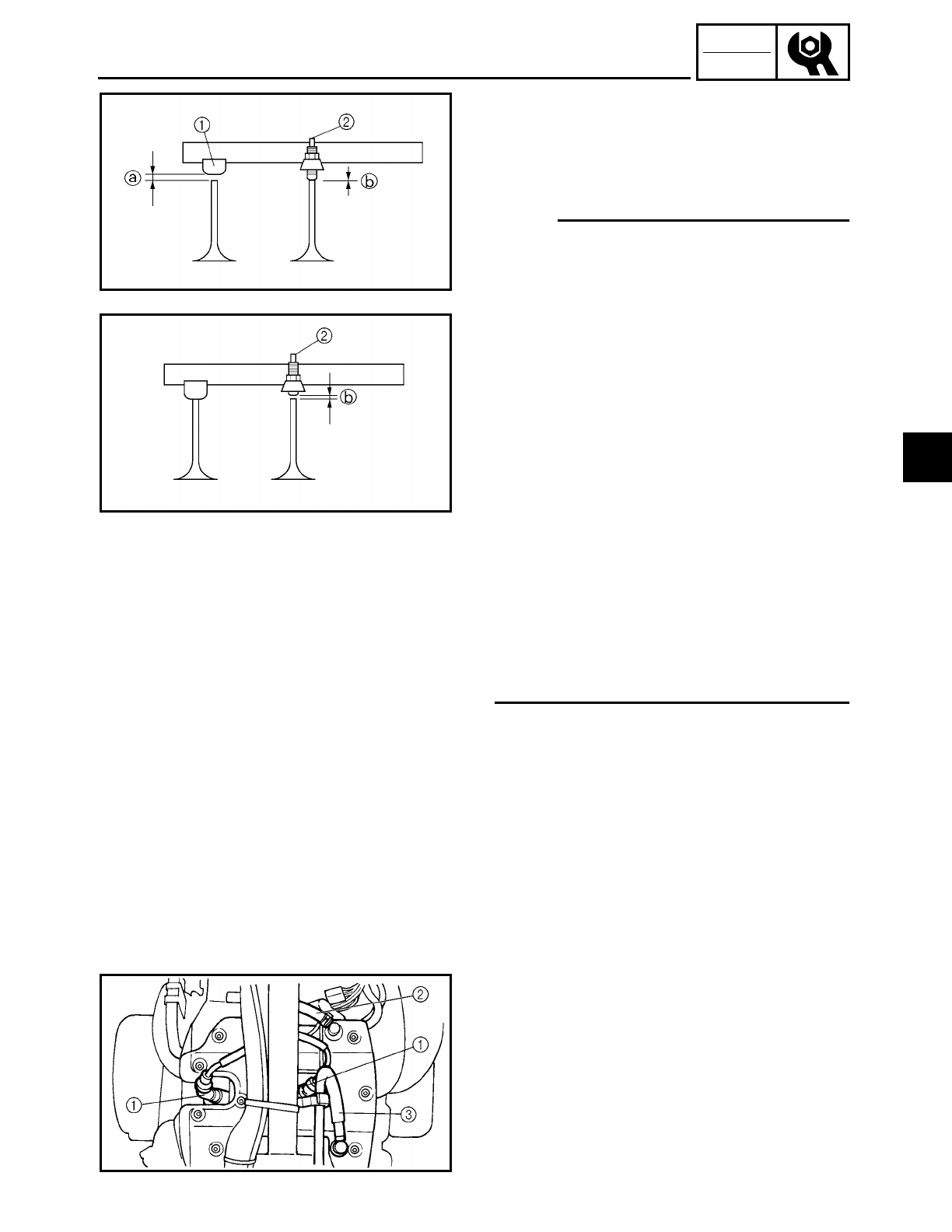
ADJUSTING THE VALVE CLEARANCE
The following procedure applies to all of
the valves.
NOTE:
• The valve clearance is automatically
adjusted by the hydraulic valve lifter.
However, there are times that the valve
clearance is needed to be adjusted manu-
ally. If this is the case, adjust the clearance
of the two maladjusted or worn valves, of
a rocker arm, with the adjusting screw.
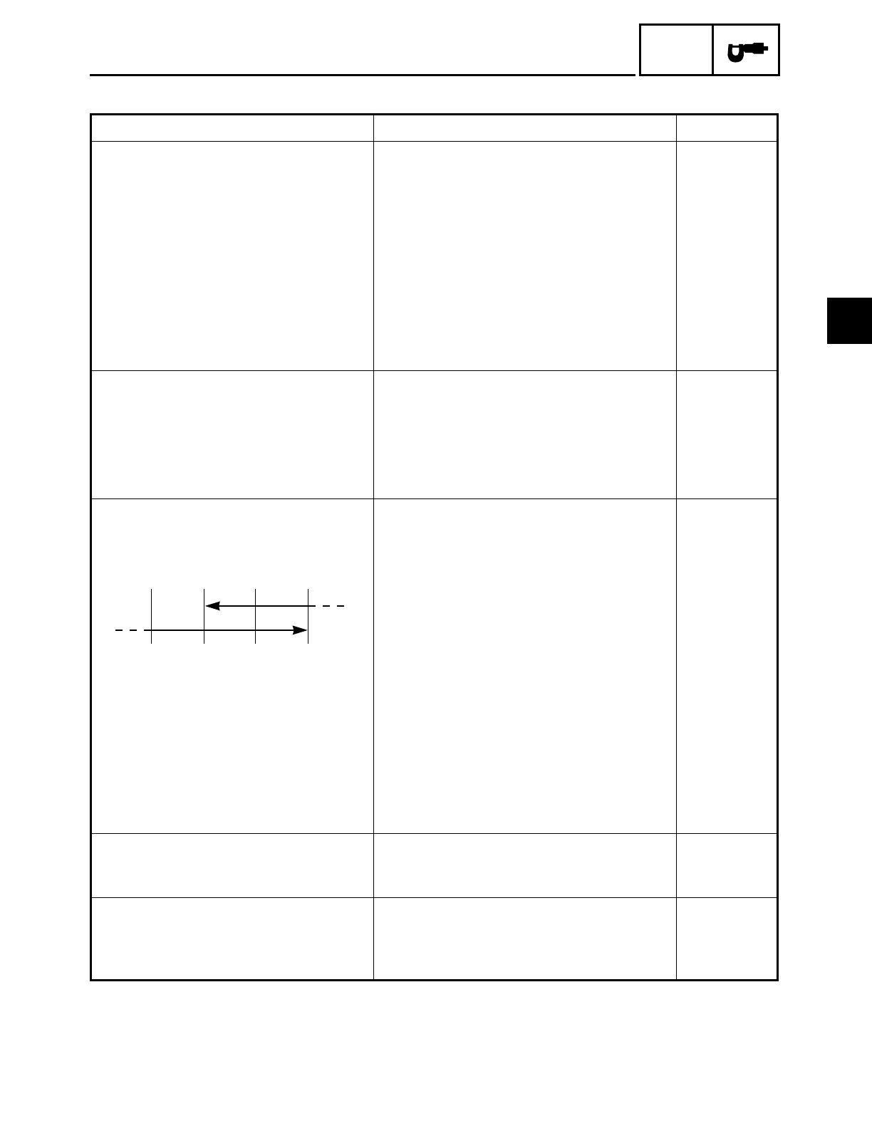
ÅIf clearance is on the slip side
1, loosen the
adjusting screw and bring the valve clearance
a within specification. Check if the valve
clearance
b on the adjusting screw
2 side is
within specification.
ıIf clearance is on the adjusting screw 2 side,
tighten the adjusting screw and bring the
valve clearance b within specification.
• Valve clearance adjustment should be
made on a cold engine, at room tempera-
ture.
• When the valve clearance is to be mea-
sured or adjusted, the piston must be at
top dead center (TDC) on the compression
stroke.
1. Remove:
• rider seat
Refer to “SEATS AND SIDE COVERS”.
• fuel tank
Refer to “FUEL TANK”.
Å
ı
2. Disconnect:
• spark plug caps 1
• cylinder head breather hose 2
• oil tank breather hose 3
3. Remove:
• spark plugs
• cylinder head covers (upper)
• gaskets
• dowel pins
ADJUSTING THE VALVE CLEARANCE
3
3 - 9
CHK
ADJ
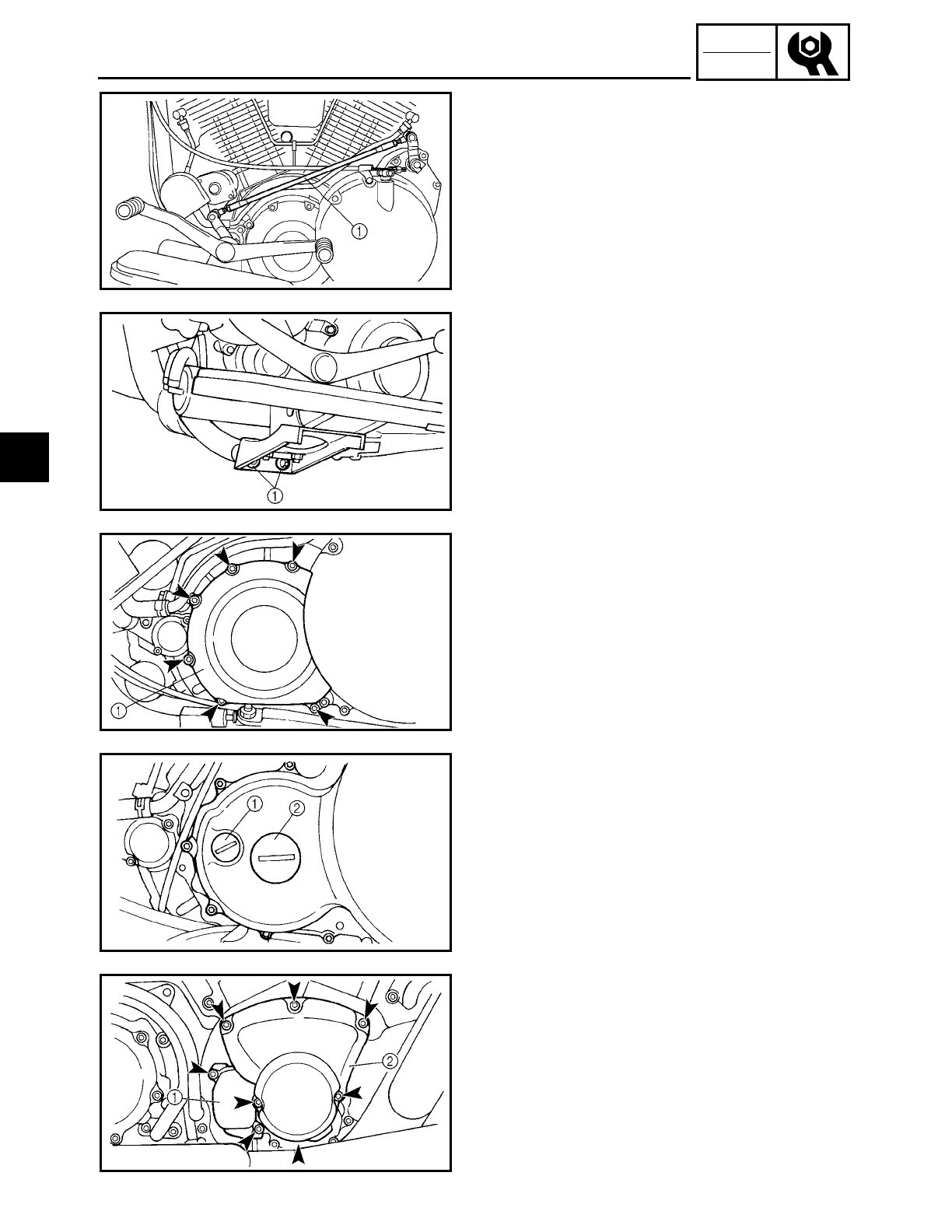
4. Remove:
• shift rod 1
5. Remove:
• rider footrest (left) bolts 1
6. Remove:
• engine left side cover 1
7. Remove:
• timing mark accessing screw 1
• crankshaft end cover 2
8. Remove:
• decompression solenoid cover 1
• camshaft sprocket cover 2
ADJUSTING THE VALVE CLEARANCE
3
3 - 10
CHK
ADJ
9. Measure:
• valve clearance
Out of specification → Adjust.
ACHTUNG:
CAUTION:
Be sure to check the intake and exhaust
valves.
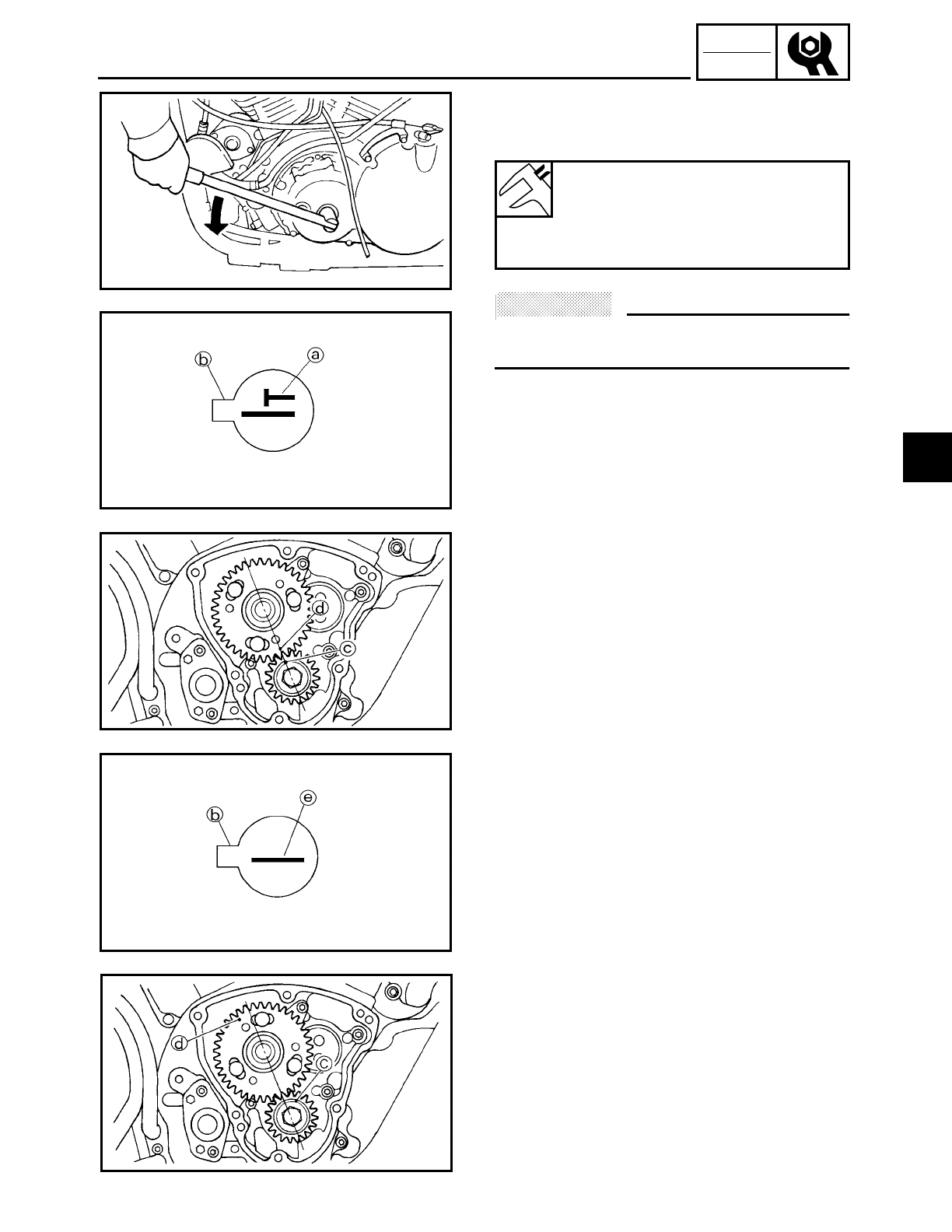
▼ ▼ ▼ ▼ ▼ ▼ ▼ ▼ ▼ ▼ ▼ ▼ ▼ ▼ ▼ ▼ ▼ ▼ ▼ ▼ ▼ ▼ ▼ ▼ ▼ ▼ ▼ ▼
Piston #1 TDC (rear cylinder)
a. Turn the crankshaft counterclockwise.
b. When piston #1 is at TDC on the com-
pression stroke, align the TDC mark a
on the pickup coil rotor with the pointer
b on the clutch/pickup coil rotor cover.
c. Check the camshaft drive gear mark c
position and camshaft driven gear mark
d position as shown.
If the marks are not aligned, turn the
crankshaft counterclockwise 360 degrees
and recheck step b.
d. Measure the valve clearance with a thick-
ness gauge.
Valve clearance (cold)
Intake valve
0 ~ 0.04 mm (0 ~ 0.0016 in)
Exhaust valve
0 ~ 0.04 mm (0 ~ 0.0016 in)
Piston #2 TDC (front cylinder)
a. Turn the crankshaft counterclockwise
from the piston #1 TDC by 405 degrees.
b. When piston #2 is at TDC on the com-
pression stoke, align the TDC mark e on
the pickup coil rotor with the pointer b
on the clutch/pickup coil rotor cover.
c. Check the camshaft drive gear mark c
position and camshaft driven gear mark
d position as shown.
d. Measure the valve clearance with a thick-
ness gauge.
▲ ▲ ▲ ▲ ▲ ▲ ▲ ▲ ▲ ▲ ▲ ▲ ▲ ▲ ▲ ▲ ▲ ▲ ▲ ▲ ▲ ▲ ▲ ▲ ▲ ▲ ▲ ▲
ADJUSTING THE VALVE CLEARANCE
3
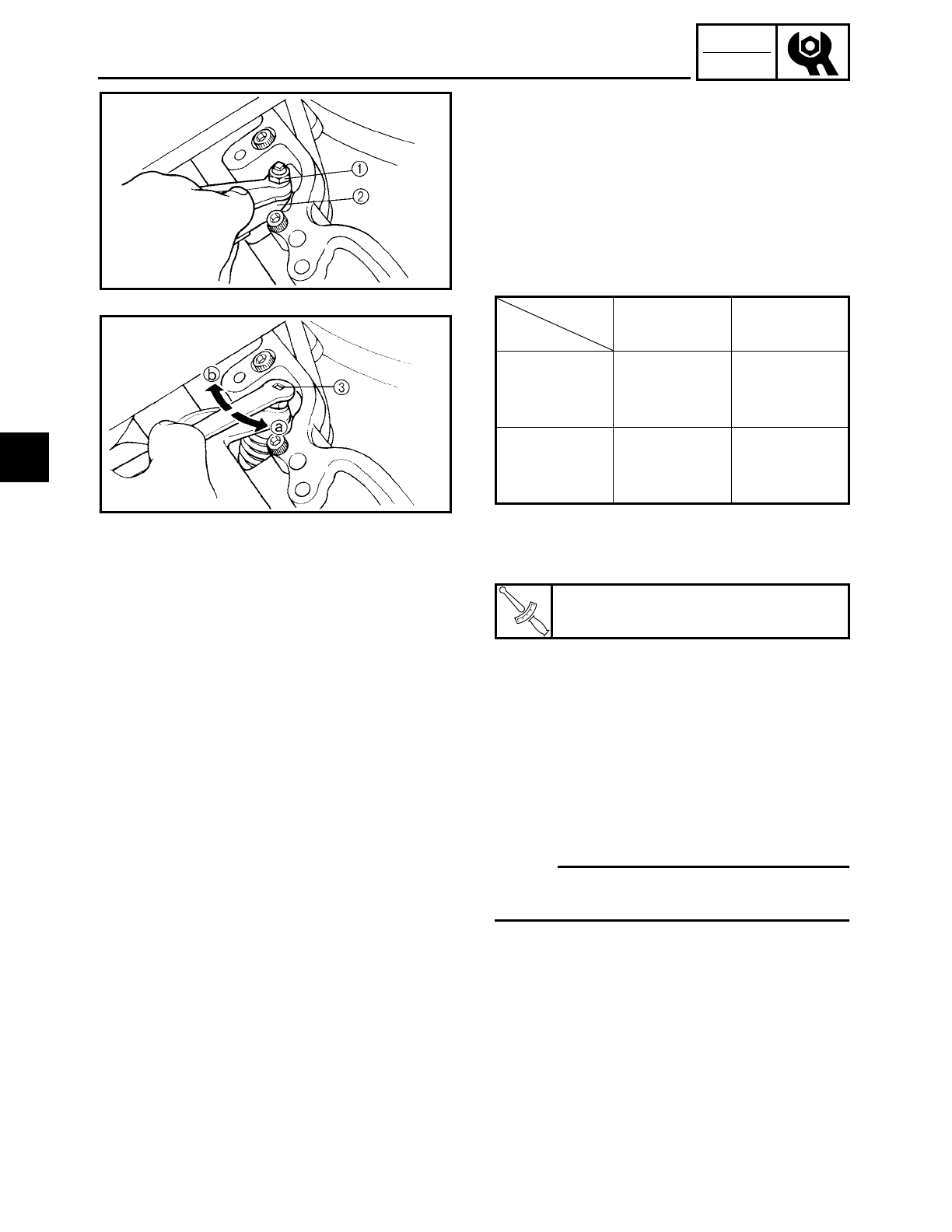
3 - 11
CHK
ADJ
10.Adjust:
• valve clearance
▼ ▼ ▼ ▼ ▼ ▼ ▼ ▼ ▼ ▼ ▼ ▼ ▼ ▼ ▼ ▼ ▼ ▼ ▼ ▼ ▼ ▼ ▼ ▼ ▼ ▼ ▼ ▼
a. Loosen the locknut 1.
b. Insert a thickness gauge 2 between the
end of the adjusting screw and the valve tip.
c. Turn the adjusting screw 3 in direction
a or b until the specified valve clear-
ance is obtained.
d. Hold the adjusting screw to prevent it
from moving and tighten the locknut to
specification.
e. Measure the valve clearance again.
f. If the valve clearance is still out of speci-
fication, repeat all of the valve clearance
adjustment steps until the specified
clearance is obtained.
▲ ▲ ▲ ▲ ▲ ▲ ▲ ▲ ▲ ▲ ▲ ▲ ▲ ▲ ▲ ▲ ▲ ▲ ▲ ▲ ▲ ▲ ▲ ▲ ▲ ▲ ▲ ▲
11.Install:
• all removed parts
NOTE:
For installation, reverse the removal proce-
dure. Note the following points.
Refer to “ROCKER ARMS, PUSH RODS
AND VALVE LIFTERS” in chapter 5.
12.Adjust:
• installed shift rod length
Refer to “ADJUSTING THE SHIFT
PEDAL”.
Adjusting
screw side Slip side
Direction a
Valve clear-
ance is
increased.
Valve clear-
ance is
decreased.
Direction b
Valve clear-
ance is
decreased.
Valve clear-
ance is
increased.
T
R
.
.
Locknut
20 Nm (2.0 m • kg, 14 ft • lb)
ADJUSTING THE VALVE CLEARANCE
3
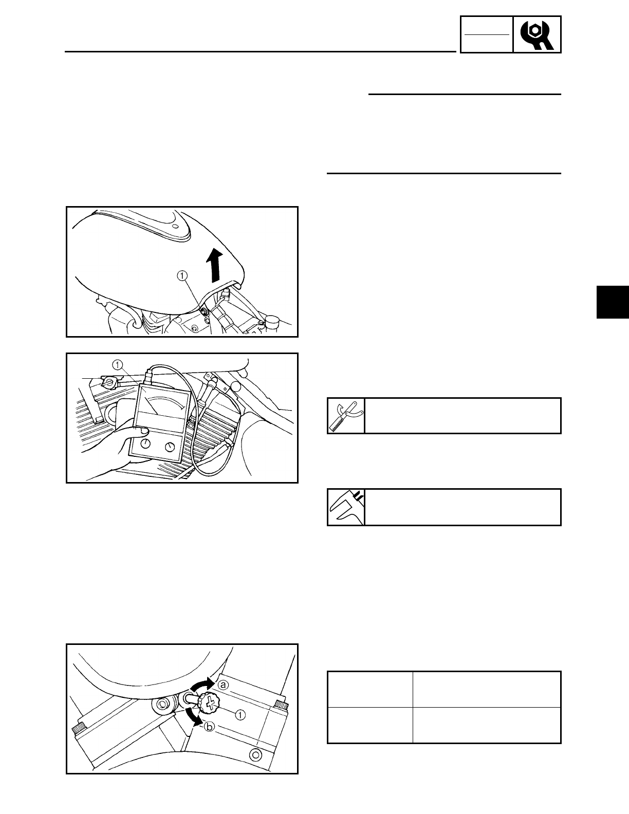
3 - 12
CHK
ADJ
ADJUSTING THE ENGINE IDLING SPEED
EAS00054
ADJUSTING THE ENGINE IDLING SPEED
NOTE:
Prior to adjusting the engine idling speed,
the carburetor synchronization should be
adjusted properly, the air filter element
should be clean, and the engine should
have adequate compression.
1. Start the engine and let it warm up for
several minutes.
2. Remove:
• rider seat
Refer to “SEATS AND SIDE COVERS”.
3. Remove:
• fuel tank bolt 1
4. Lift up the fuel tank end.
5. Install:
• inductive tachometer 1
(onto the spark plug lead of cylinder #1)
6. Measure:
• engine idling speed
Out of specification → Adjust.
7. Adjust:
• engine idling speed
▼ ▼ ▼ ▼ ▼ ▼ ▼ ▼ ▼ ▼ ▼ ▼ ▼ ▼ ▼ ▼ ▼ ▼ ▼ ▼ ▼ ▼ ▼ ▼ ▼ ▼ ▼ ▼
a. Turn the throttle stop screw 1 in direc-
tion a or b until the specified engine
idling speed is obtained.
▲ ▲ ▲ ▲ ▲ ▲ ▲ ▲ ▲ ▲ ▲ ▲ ▲ ▲ ▲ ▲ ▲ ▲ ▲ ▲ ▲ ▲ ▲ ▲ ▲ ▲ ▲ ▲
Inductive tachometer
YU8036-A
Engine idling speed
850 ~ 950 r/min
Direction aEngine idling speed is
increased.
Direction bEngine idling speed is
decreased.
3
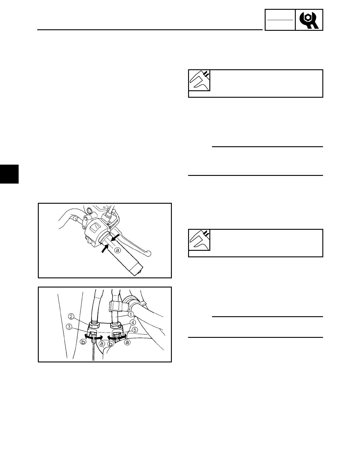
3 - 13
CHK
ADJ
ADJUSTING THE ENGINE IDLING SPEED/
ADJUSTING THE THROTTLE CABLE FREE PLAY
8. Adjust:
• throttle cable free play
Refer to “ADJUSTING THE THROTTLE
CABLE FREE PLAY”.
Throttle cable free play (at the
flange of the throttle grip)
4 ~ 8 mm (0.16 ~ 0.31 in)
EAS00058
ADJUSTING THE THROTTLE CABLE FREE
PLAY
NOTE:
Prior to adjusting the throttle cable free
play, the engine idling speed should be
adjusted.
1. Measure:
• throttle cable free play a
Out of specification → Adjust.
Throttle cable free play (at the
flange of the throttle grip)
4 ~ 8 mm (0.16 ~ 0.31 in)
2. Adjust:
• throttle cable free play
▼ ▼ ▼ ▼ ▼ ▼ ▼ ▼ ▼ ▼ ▼ ▼ ▼ ▼ ▼ ▼ ▼ ▼ ▼ ▼ ▼ ▼ ▼ ▼ ▼ ▼ ▼ ▼
NOTE:
When the throttle is opened, the accelerator
cable 1 is pulled.
Carburetor side
a. Remove the rider seat and fuel tank.
Refer to “SEATS AND SIDE COVERS”
and “FUEL TANK”.
b. Loosen the locknut 2 on the decelerator
cable.
c. Turn the adjusting nut 3 in direction a
or b to take up any slack on the deceler-
ator cable.
d. Loosen the locknut 4 on the accelerator
cable.
3
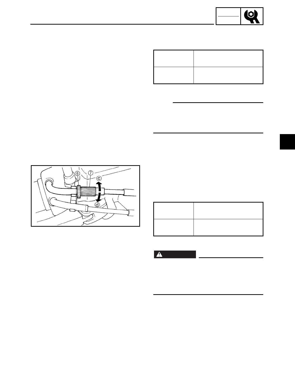
3 - 14
CHK
ADJ
ADJUSTING THE THROTTLE CABLE FREE PLAY/
CHECKING THE SPARK PLUGS
e. Turn the adjusting nut 5 in direction a
or b until the specified throttle cable free
play is obtained.
f. Tighten the locknuts.
NOTE:
If the specified throttle cable free play can-
not be obtained on the carburetor side of
the cable, use the adjusting nut on the han-
dlebar side.
g. Install the fuel tank and rider seat. Refer
to “FUEL TANK” and “SEATS AND SIDE
COVERS”.
Direction aThrottle cable free play is
increased.
Direction bThrottle cable free play is
decreased.
Handlebar side
a. Loosen the locknut 6.
b. Turn the adjusting nut 7 in direction c
or d until the specified throttle cable free
play is obtained.
c. Tighten the locknut.
WARNING
WARNING
After adjusting the throttle cable free play,
start the engine and turn the handlebar to
the right and to the left to ensure that this
does not cause the engine idling speed to
change.
▲ ▲ ▲ ▲ ▲ ▲ ▲ ▲ ▲ ▲ ▲ ▲ ▲ ▲ ▲ ▲ ▲ ▲ ▲ ▲ ▲ ▲ ▲ ▲ ▲ ▲ ▲ ▲
EAS00059
CHECKING THE SPARK PLUGS
The following procedure applies to all of
the spark plugs.
1. Remove:
• rider seat
• fuel tank
Refer to “SEATS AND SIDE COVERS”
and “FUEL TANK”.
Direction cThrottle cable free play is
increased.
Direction dThrottle cable free play is
decreased.
3
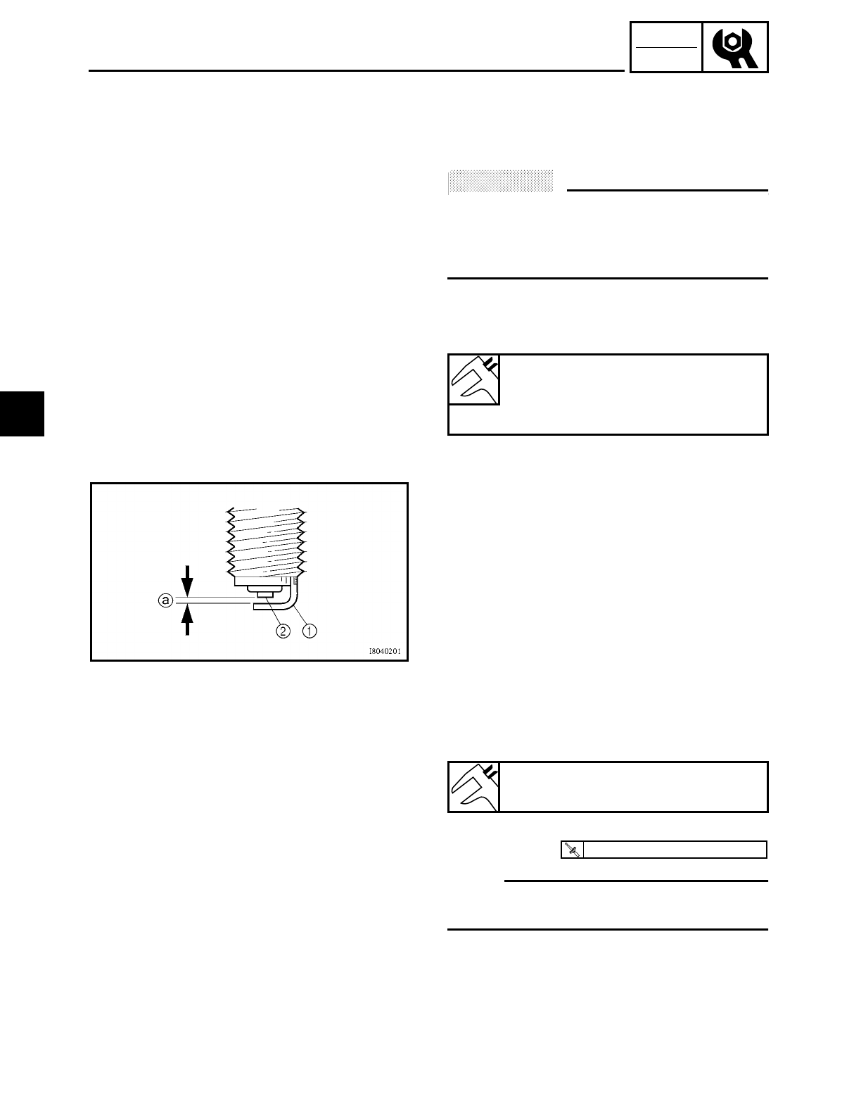
3 - 15
CHK
ADJ
CHECKING THE SPARK PLUGS
2. Disconnect:
• spark plug cap
3. Remove:
• spark plug
ACHTUNG:
CAUTION:
Before removing the spark plugs, blow
away any dirt accumulated in the spark
plug wells with compressed air to prevent
it from falling into the cylinders.
4. Check:
• spark plug type
Incorrect → Change.
Spark plugs
Model (manufacturer)
DPR7EA-9 (NGK)
X22EPR-U9 (DENSO)
5. Check:
• electrodes 1
Damage/wear → Replace the spark plug.
• insulator 2
Abnormal color → Replace the spark
plug.
Normal color is medium-to-light tan.
6. Clean:
• spark plug
(with a spark plug cleaner or wire brush)
7. Measure:
• spark plug gap a
(with a wire gauge)
Out of specification → Regap.
8. Install:
• spark plug
NOTE:
Before installing the spark plug, clean the
spark plug and gasket surface.
9. Connect:
• spark plug cap
10.Install:
• fuel tank
• rider seat
Refer to “FUEL TANK” and “SEATS AND
SIDE COVERS”.
Spark plug gap
0.8 ~ 0.9 mm (0.031 ~ 0.35 in)
T
R
.
.
18 Nm (1.8 m · kg, 13 ft · lb)
3
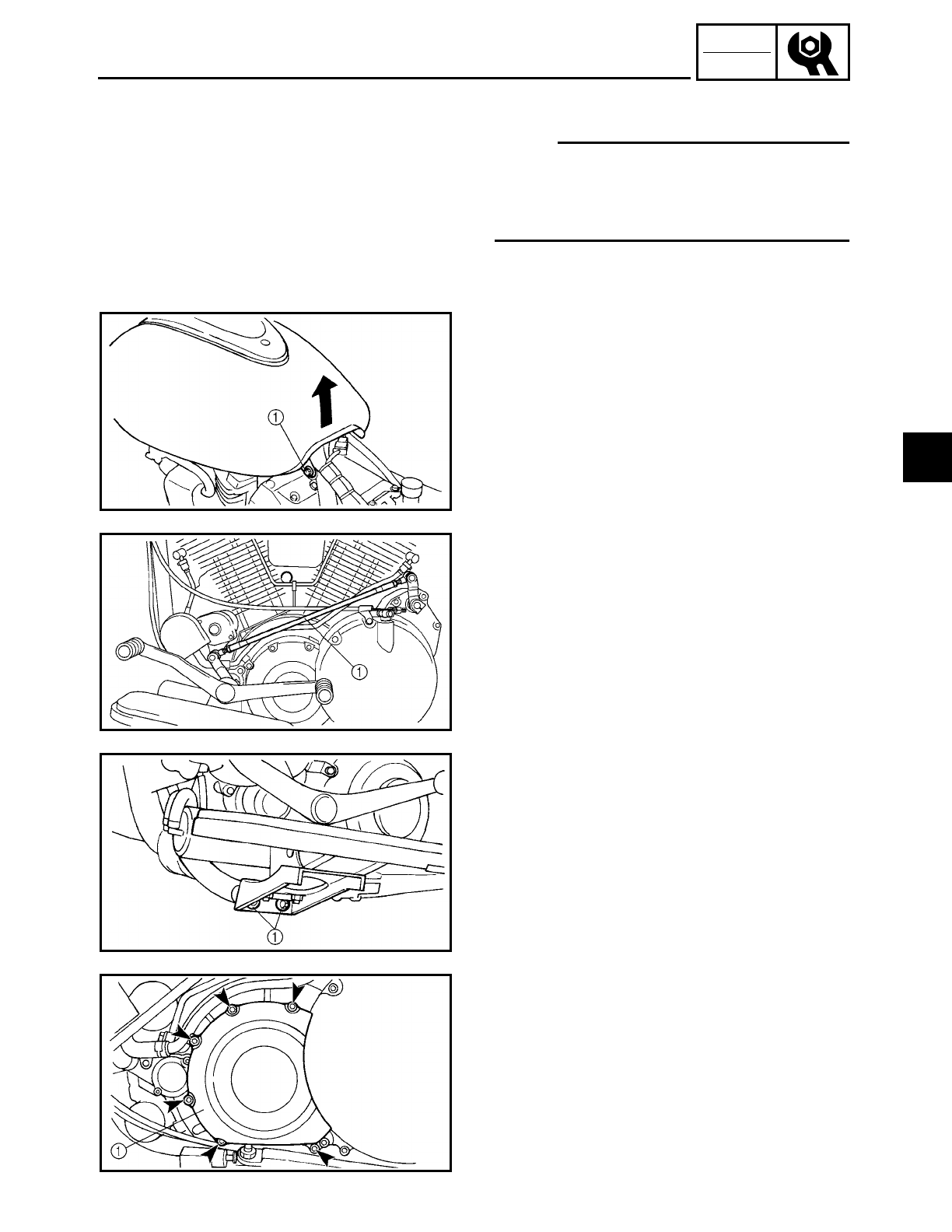
3 - 16
CHK
ADJ
CHECKING THE IGNITION TIMING
EAS00061
CHECKING THE IGNITION TIMING
NOTE:
Prior to checking the ignition timing, check
the wiring connections of the entire ignition
system. Make sure all connections are tight
and free of corrosion.
1. Remove:
• rider seat
Refer to “SEATS AND SIDE COVERS”.
2. Remove:
• fuel tank bolt 1
3. Lift up the fuel tank end.
4. Remove:
• shift rod 1
5. Remove:
• rider footrest (left) bolts 1
6. Remove:
• engine left side cover 1
3
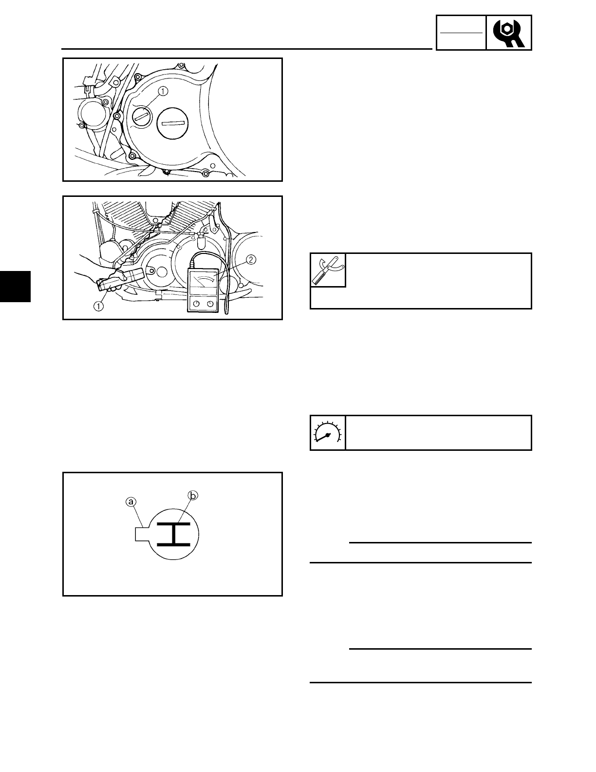
3 - 17
CHK
ADJ
CHECKING THE IGNITION TIMING
7. Remove:
• timing mark accessing screw 1
8. Install:
• timing light 1
• inductive tachometer 2
(onto the spark plug lead of cylinder #1)
Timing light
YU-33277-A
Inductive tachometer
YU-8036-A
9. Check:
• ignition timing
▼ ▼ ▼ ▼ ▼ ▼ ▼ ▼ ▼ ▼ ▼ ▼ ▼ ▼ ▼ ▼ ▼ ▼ ▼ ▼ ▼ ▼ ▼ ▼ ▼ ▼ ▼ ▼
a. Start the engine, warm it up for several
minutes, and then let it run at the speci-
fied engine idling speed.
b. Check that the pointer a is within the
required firing range b on the pickup
coil rotor.
Incorrect firing range → Check the igni-
tion system.
NOTE:
The ignition timing is not adjustable.
▲ ▲ ▲ ▲ ▲ ▲ ▲ ▲ ▲ ▲ ▲ ▲ ▲ ▲ ▲ ▲ ▲ ▲ ▲ ▲ ▲ ▲ ▲ ▲ ▲ ▲ ▲ ▲
Engine idling speed
850 ~ 950 r/min
10.Install:
• all removed parts
NOTE:
For installation, reverse the removal proce-
dure. Note the following point.
Refer to “ROCKER ARMS, PUSH RODS
AND VALVE LIFTERS” in chapter 5.
3
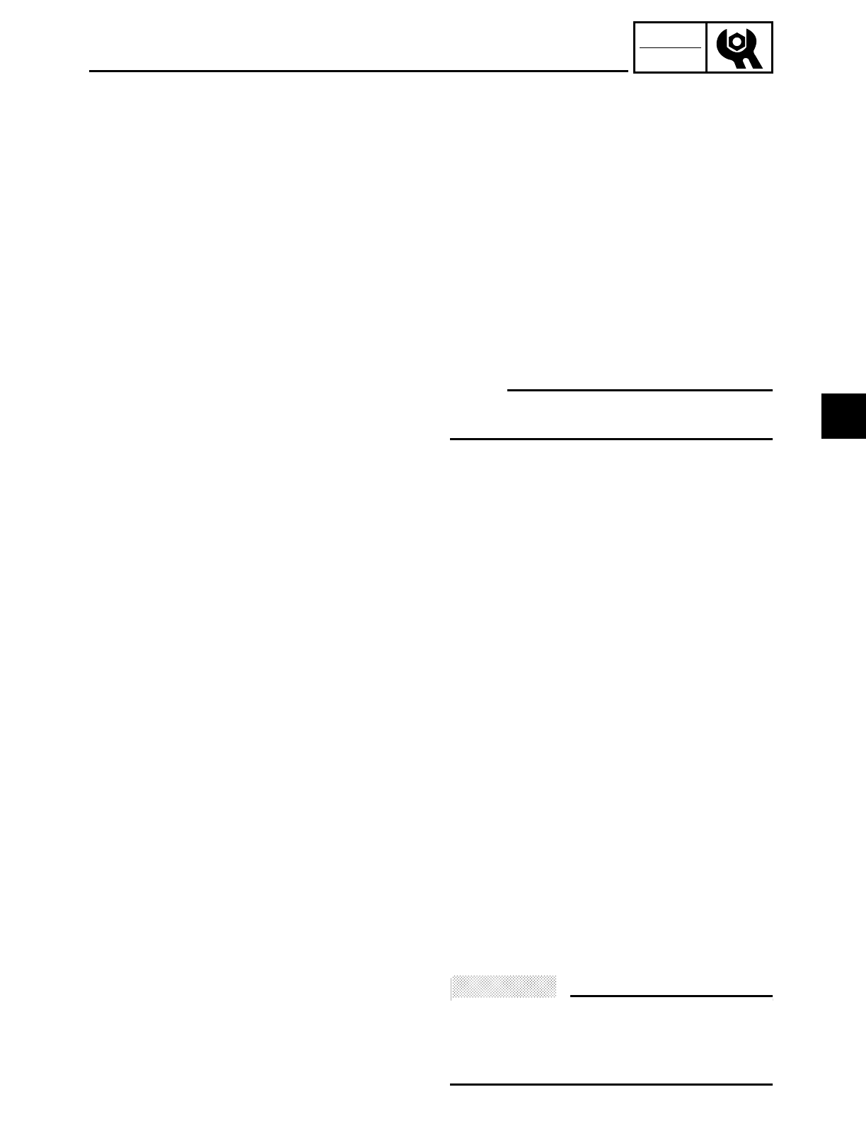
3 - 18
CHK
ADJ
CHECKING THE IGNITION TIMING/
MEASURING THE COMPRESSION PRESSURE
11.Adjust:
• installed shift rod length
Refer to “ADJUSTING THE SHIFT
PEDAL”.
EAS00065
MEASURING THE COMPRESSION
PRESSURE
The following procedure applies to all of
the cylinders.
NOTE:
Insufficient compression pressure will
result in a loss of performance.
1. Measure:
• valve clearance
Out of specification → Adjust.
Refer to “ADJUSTING THE VALVE
CLEARANCE”.
2. Start the engine, warm it up for several
minutes, and then turn it off.
3. Remove:
• rider seat
• fuel tank
Refer to “SEATS AND SIDE COVERS”
and “FUEL TANK”.
4. Remove:
• camshaft sprocket cover
Refer to “ROCKER ARMS, PUSH RODS
AND VALVE LIFTERS”.
• decompression solenoid
Refer to “CAMSHAFTS”.
5. Install:
• camshaft sprocket cover
Refer to “ROCKER ARMS, PUSH RODS
AND VALVE LIFTERS”.
6. Disconnect:
• spark plug cap
7. Remove:
• spark plug
ACHTUNG:
CAUTION:
Before removing the spark plugs, use com-
pressed air to blow away any dirt accumu-
lated in the spark plug wells to prevent it
from falling into the cylinders.
3
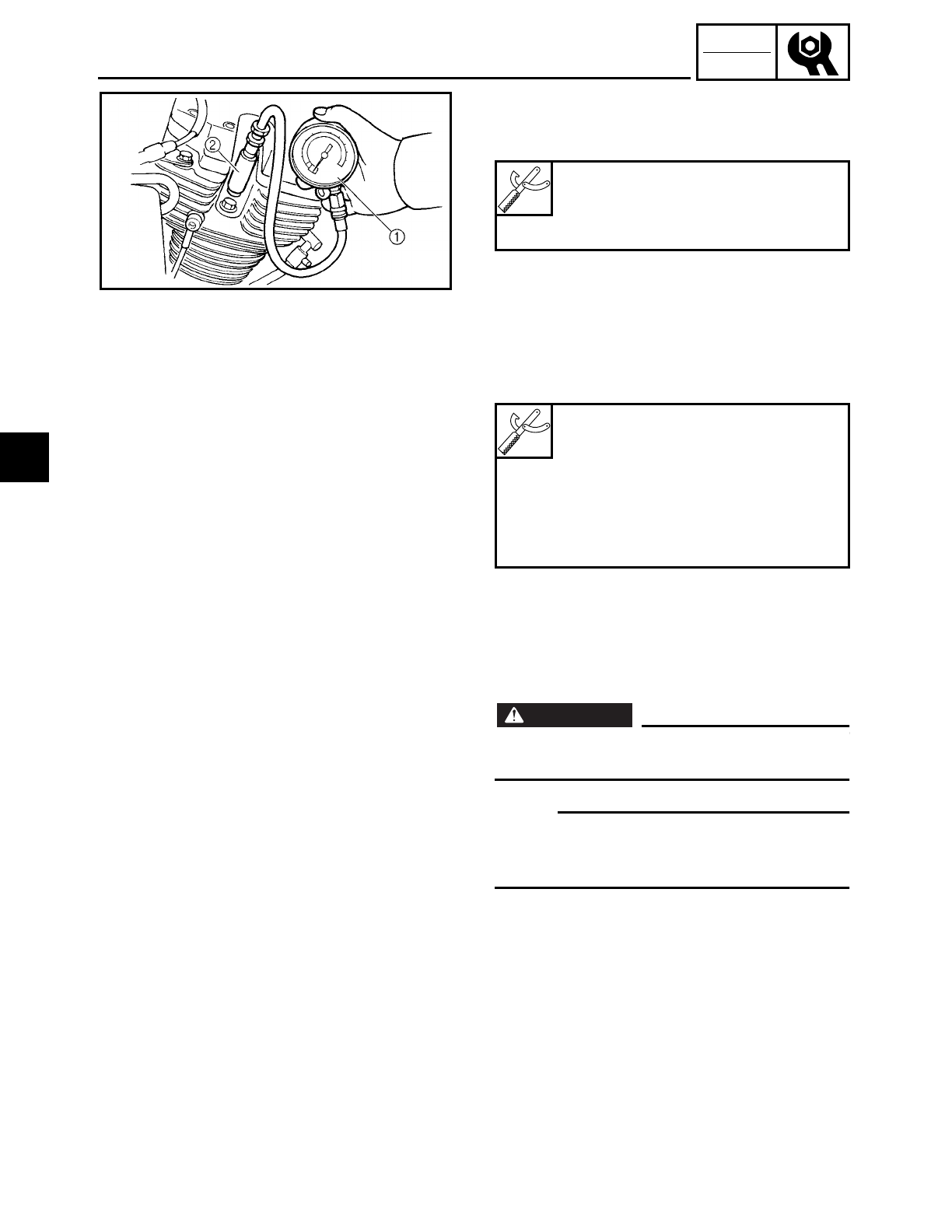
3 - 19
CHK
ADJ
MEASURING THE COMPRESSION PRESSURE
8. Install:
• compression gauge 1
• compression gauge adapter 2
Compression gauge
YU-33223
Compression gauge adapter
YU-33223-3
9. Measure:
• compression pressure
Out of specification → Refer to steps (c)
and (d).
▼ ▼ ▼ ▼ ▼ ▼ ▼ ▼ ▼ ▼ ▼ ▼ ▼ ▼ ▼ ▼ ▼ ▼ ▼ ▼ ▼ ▼ ▼ ▼ ▼ ▼ ▼ ▼
a. Set the main switch to “ON”.
b. With the throttle wide open, crank the
engine until the reading on the compres-
sion gauge stabilizes.
WARNING
WARNING
To prevent sparking, ground all spark plug
leads before cranking the engine.
NOTE:
The difference in compression pressure
between cylinders should not exceed
100 kPa (1 kg/cm2, 14 psi).
c. If the compression pressure is above the
maximum specification, check the cylin-
der head, valve surfaces, and piston
crown for carbon deposits.
d. Carbon deposits → Eliminate.
e. If the compression pressure is below the
minimum specification, squirt a few
drops of oil into the cylinder and mea-
sure again.
Compression pressure (at sea
level)
Minimum
1,000 kPa (10 kg/cm2, 142 psi)
Standard
1,200 kPa (12 kg/cm2, 171 psi)
Maximum
1,400 kPa (14 kg/cm2, 199 psi)
3
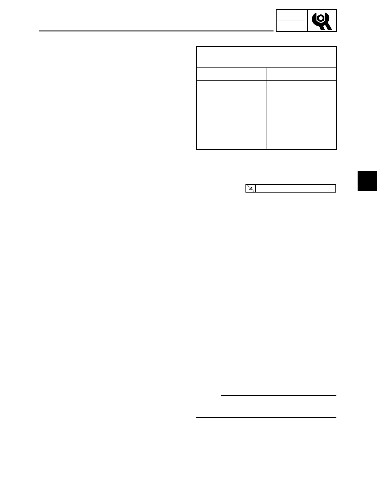
3 - 20
CHK
ADJ
MEASURING THE COMPRESSION PRESSURE/
CHECKING THE ENGINE OIL LEVEL
Refer to the following table.
▲ ▲ ▲ ▲ ▲ ▲ ▲ ▲ ▲ ▲ ▲ ▲ ▲ ▲ ▲ ▲ ▲ ▲ ▲ ▲ ▲ ▲ ▲ ▲ ▲ ▲ ▲ ▲
10.Install:
• spark plug
11.Connect:
• spark plug cap
12.Remove:
• camshaft sprocket cover
Refer to “ROCKER ARMS, PUSH RODS
AND VALVE LIFTERS”.
13.Install:
• decompression solenoid
Refer to “CAMSHAFTS”.
• camshaft sprocket cover
Refer to “ROCKER ARMS, PUSH RODS
AND VALVE LIFTERS”.
14.Install:
• fuel tank
• rider seat
Refer to “FUEL TANK” and “SEATS AND
SIDE COVERS”.
EAS00071
CHECKING THE ENGINE OIL LEVEL
1. Stand the motorcycle on a level surface.
NOTE:
• Place the motorcycle on a suitable stand.
• Make sure the motorcycle is upright.
2. Start the engine and warm it up by run-
ning the engine or letting the engine run
at idle for 15 minutes until the engine oil
inside of the oil tank has reached a tem-
perature of 60 ˚C (140 ˚F) and then turn it
off.
Compression pressure
(with oil applied into the cylinder)
Reading Diagnosis
Higher than with-
out oil
Piston wear or dam-
age → Repair.
Same as without oil
Piston rings,
valves, cylinder
head gasket, or pis-
ton possibly defec-
tive → Repair.
T
R
.
.
18 Nm (1.8 m · kg, 13 ft · lb)
3
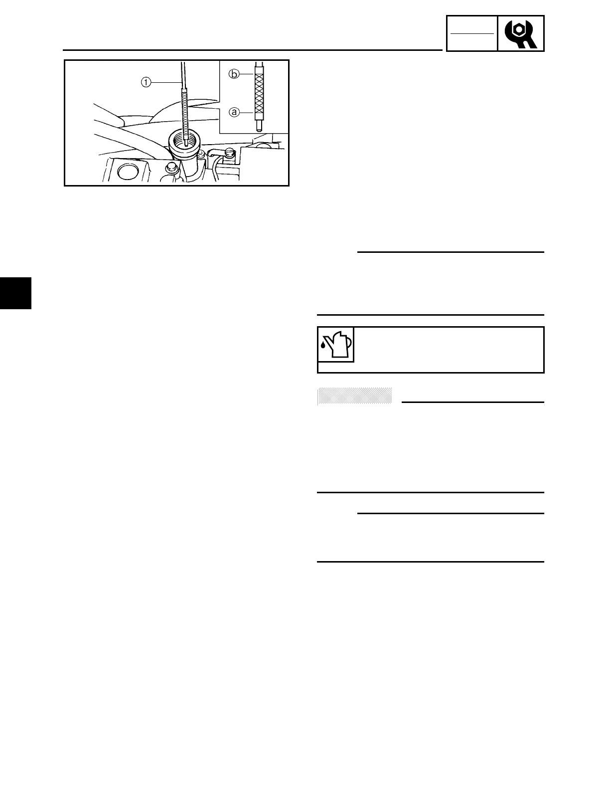
3 - 21
CHK
ADJ
CHECKING THE ENGINE OIL LEVEL
3. Remove:
• rider seat
Refer to “SEATS AND SIDE COVERS”.
4. Remove:
• dipstick 1
5. Check:
• engine oil level
The engine oil level should be between
the minimum level mark a and maxi-
mum level mark b.
Below the minimum level mark → Add
the recommended engine oil to the
proper level.
NOTE:
• Before checking the engine oil level, wait
a few minutes until the oil has settled.
• Do not screw the dipstick in when insect-
ing the oil level.
ACHTUNG:
CAUTION:
• Engine oil also lubricates the clutch and
the wrong oil types or additives could
cause clutch slippage. Therefore, do not
add any chemical additives.
• Do not allow foreign materials to enter
the crankcase.
NOTE:
API Service “SE”, “SF” and “SG” type or
equivalent (e.g., “SF-SE”, “SF-SE-CC”, “SF-
SE-SD”).
6. Install:
• dipstick
Recommended oil
Yamalube 4 (20W 40) or
SAE 20W40 type SE motor oil
3
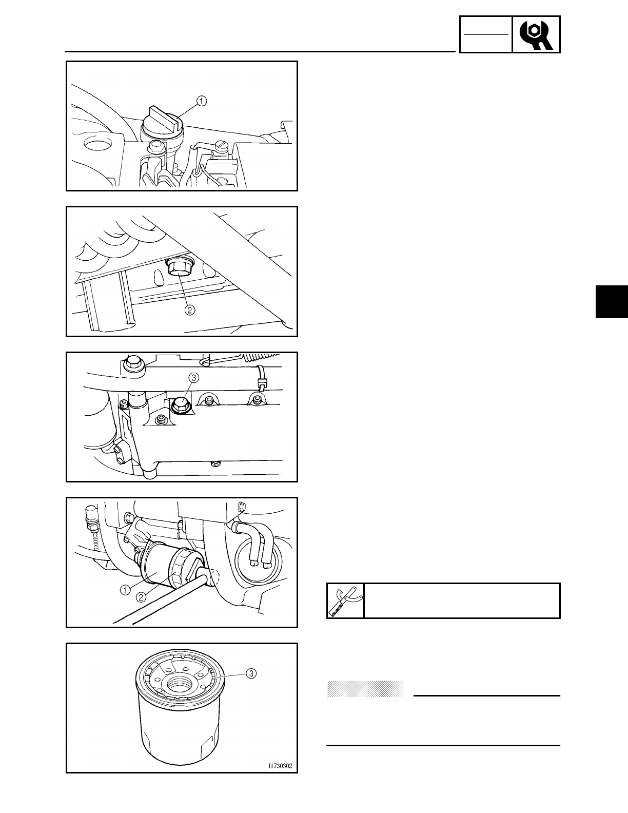
3 - 22
CHK
ADJ
CHANGING THE ENGINE OIL
EAS00073
CHANGING THE ENGINE OIL
1. Start the engine, warm it up for several
minutes, and then turn it off.
2. Place a container under the engine oil
drain bolt.
3. Remove:
• dipstick 1
• engine oil drain bolt (oil tank) 2
• engine oil drain bolt (engine) 3
4. Drain:
• engine oil
(completely from the oil tank and crank-
case)
5. If the oil filter cartridge is also to be
replaced, perform the following proce-
dure.
▼ ▼ ▼ ▼ ▼ ▼ ▼ ▼ ▼ ▼ ▼ ▼ ▼ ▼ ▼ ▼ ▼ ▼ ▼ ▼ ▼ ▼ ▼ ▼ ▼ ▼ ▼ ▼
a. Remove the oil filter cartridge 1 with an
oil filter wrench 2.
b. Lubricate the O-ring 3 of the new oil fil-
ter cartridge with a thin coat of engine
oil.
ACHTUNG:
CAUTION:
Make sure the O-ring 3 is positioned cor-
rectly in the groove of the oil filter car-
tridge.
Oil filter wrench
YU-38411
3
3 - 23
CHK
ADJ
c. Tighten the new oil filter cartridge to
specification with an oil filter wrench.
▲ ▲ ▲ ▲ ▲ ▲ ▲ ▲ ▲ ▲ ▲ ▲ ▲ ▲ ▲ ▲ ▲ ▲ ▲ ▲ ▲ ▲ ▲ ▲ ▲ ▲ ▲ ▲
6. Check:
• engine oil drain bolt gasket
Damage → Replace.
7. Install:
• engine oil drain bolt
8. Fill:
• oil tank
(with the specified amount of the recom-
mended engine oil)
NOTE:
• Pour the engine oil in several stages.
• First, pour in 2.5 L (2.2 Imp qt, 2.6 US qt)
of oil, and then start the engine and rev it
3 to 5 times. Stop the engine, and then
pour in the remainder of the specified
amount.
ACHTUNG:
CAUTION:
When starting the engine make sure the
dipstick is securely fitted into the oil tank.
9. Fill: (when the engine is disassembled)
• crankcase and oil tank
T
R
.
.
Oil filter cartridge
17 Nm (1.7 m • kg, 12 ft • lb)
Quantity
Total amount
5.0 L (4.4 lmp qt, 5.3 US qt)
Periodic oil replacement
3.7 L (3.3 lmp qt, 3.9 US qt)
With oil filter cartridge replace-
ment
4.1 L (3.6 lmp qt, 4.3 US qt)
Quantity
Total amount
5.0 L (4.4 lmp qt, 5.3 US qt)
Oil tank
2.0 L (1.8 lmp qt, 2.1 US qt)
Crankcase
3.0 L (2.6 lmp qt, 3.2 US qt)
T
R
.
.
43 Nm (4.3 m · kg, 31 ft · lb)
CHANGING THE ENGINE OIL
3
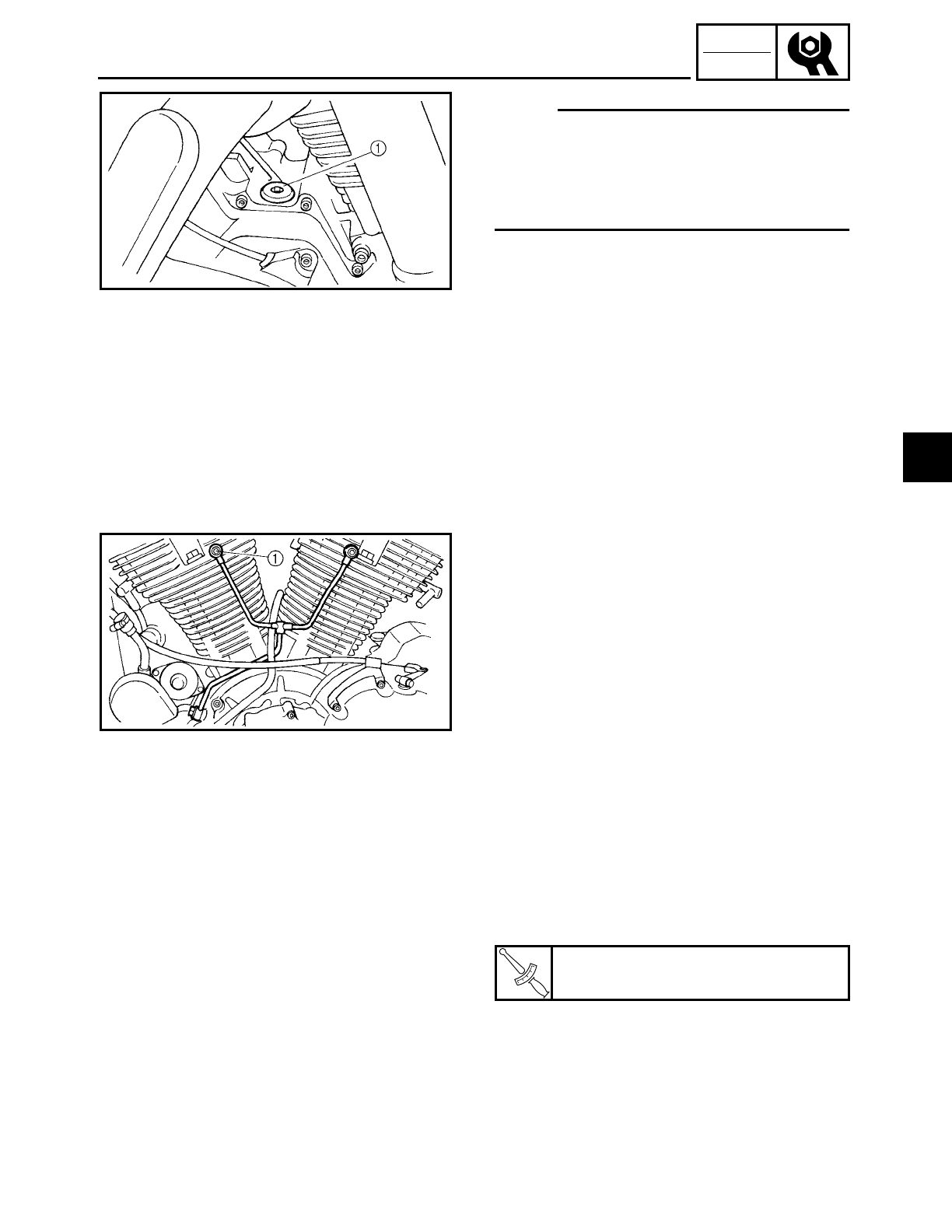
3 - 24
CHK
ADJ
CHANGING THE ENGINE OIL
NOTE:
After the engine has been disassembled,
pour the specified amount of engine oil into
the crankcase and the oil tank. When pour-
ing engine oil into the crankcase, pour it
into the hole of the removed bolt 1.
10.Install:
• dipstick
11.Start the engine, warm it up for several
minutes, and then turn it off.
12.Check:
• engine
(for engine oil leaks)
13.Check:
• engine oil level
Refer to “CHECKING THE ENGINE OIL
LEVEL”.
14.Check:
• engine oil pressure
▼ ▼ ▼ ▼ ▼ ▼ ▼ ▼ ▼ ▼ ▼ ▼ ▼ ▼ ▼ ▼ ▼ ▼ ▼ ▼ ▼ ▼ ▼ ▼ ▼ ▼ ▼ ▼
a. Slightly loosen the oil gallery bolt 1.
b. Start the engine and keep it idling until
engine oil starts to seep from the oil gal-
lery bolt. If no engine oil comes out after
one minute, turn the engine off so that it
will not seize.
c. Check the engine oil passages, the oil fil-
ter cartridge and the oil pump for dam-
age or leakage. Refer to “ENGINE OIL
PUMP” in chapter 5.
d. Start the engine after solving the prob-
lem(s) and check the engine oil pressure
again.
e. Tighten the oil gallery bolt to specifica-
tion.
▲ ▲ ▲ ▲ ▲ ▲ ▲ ▲ ▲ ▲ ▲ ▲ ▲ ▲ ▲ ▲ ▲ ▲ ▲ ▲ ▲ ▲ ▲ ▲ ▲ ▲ ▲ ▲
T
R
.
.
Oil gallery bolt
21 Nm (2.1 m • kg, 15 ft • lb)
3
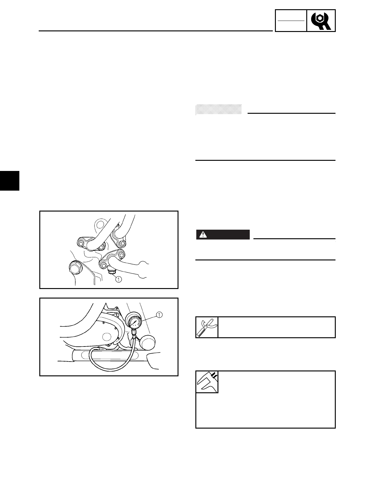
3 - 25
CHK
ADJ
MEASURING THE ENGINE OIL PRESSURE
EAS00077
MEASURING THE ENGINE OIL PRESSURE
1. Check:
• engine oil level
Refer to “CHECKING THE ENGINE OIL
LEVEL”.
2. Start the engine, warm it up for several
minutes, and then turn it off.
ACHTUNG:
CAUTION:
When the engine is cold, the engine oil will
have a higher viscosity, causing the engine
oil pressure to increase. Therefore, be sure
to measure the engine oil pressure after
warming up the engine.
3. Remove:
• oil gallery bolt 1
WARNING
WARNING
The engine, muffler and engine oil are
extremely hot.
4. Install:
• oil pressure gauge 1
5. Measure:
• engine oil pressure
(at the following conditions)
Oil pressure gauge
90890-03153
Engine oil pressure
0.4 ~ 0.8 kPa (0.004 ~
0.008 kg/cm2, 0.057 ~ 0.114 psi)
Engine speed
Approx. 900 r/min
Engine oil temperature
60 ˚C (140 ˚F)
3
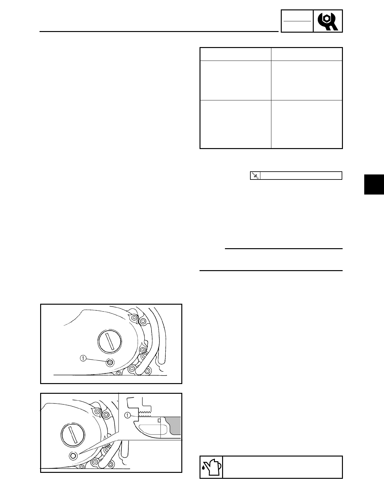
3 - 26
CHK
ADJ
MEASURING THE ENGINE OIL PRESSURE/
CHECKING THE TRANSFER GEAR OIL LEVEL
Out of specification → Adjust.
6. Install:
• oil gallery bolt
Engine oil pressure Possible causes
Below specification
• Faulty oil pump
• Clogged oil filter
• Leaking oil pas-
sage
Broken or damaged
oil seal
Above specification
• Leaking oil pas-
sage
• Faulty oil filter
• Oil viscosity too
high
T
R
.
.
20 Nm (2.0 m · kg, 14 ft · lb)
CHECKING THE TRANSFER GEAR OIL
LEVEL
1. Stand the motorcycle on a level surface.
NOTE:
• Place the motorcycle on a suitable stand.
• Make sure the motorcycle is upright.
2. Remove:
• checking bolt 1
3. Check:
• transfer gear oil level
The transfer gear oil level should be up
to the brim 1 of the hole.
Below the brim → Add the recom-
mended transfer gear oil to the proper
level.
Recommended oil
SAE80API “GL-4” Hypoid gear oil
3
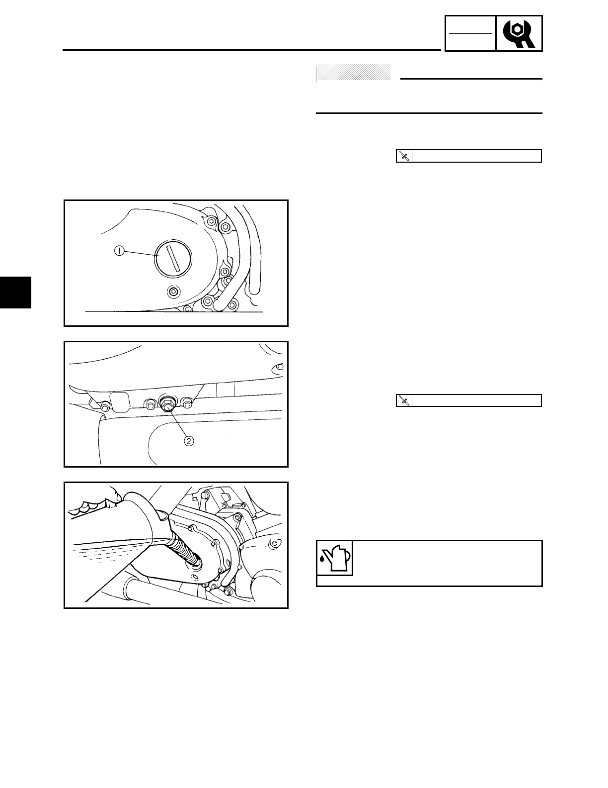
3 - 27
CHK
ADJ
CHECKING THE TRANSFER GEAR OIL LEVEL/
CHANGING THE TRANSFER GEAR OIL
ACHTUNG:
CAUTION:
Do not allow foreign materials to enter the
transfer case.
4. Install:
• checking bolt
T
R
.
.
8 Nm (0.8 m · kg, 5.8 ft · lb)
CHANGING THE TRANSFER GEAR OIL
1. Place a container under the transfer gear
oil drain bolt.
2. Remove:
• straight plug 1
• transfer gear oil drain bolt 2
3. Drain:
• transfer gear oil
(completely from the transfer gear case)
4. Check:
• transfer gear oil drain bolt gasket
Damage → Replace.
5. Install:
• transfer gear oil drain bolt
T
R
.
.
18 Nm (1.8 m · kg, 13 ft · lb)
6. Fill:
• transfer gear case
(with the specified amount of the recom-
mended transfer gear oil)
Quantity
Total amount
0.4 L (0.35 Imp qt, 0.42 US qt)
7. Install:
• straight plug
8. Check:
• transfer gear oil level
Refer to “CHECKING THE TRANSFER
GEAR OIL LEVEL”.
3
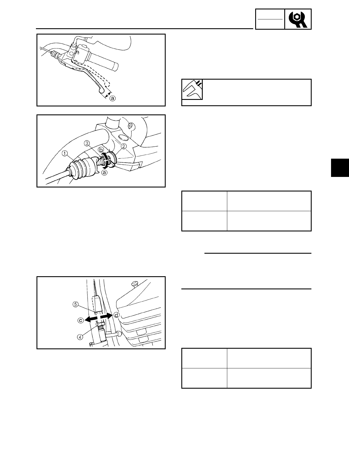
3 - 28
CHK
ADJ
ADJUSTING THE CLUTCH CABLE FREE PLAY
EAS00078
ADJUSTING THE CLUTCH CABLE FREE
PLAY
1. Measure:
• clutch cable free play a
Out of specification → Adjust.
Clutch cable free play (at the end
of the clutch lever)
10 ~ 15 mm (0.39 ~ 0.59 in)
2. Adjust:
• clutch cable free play
▼ ▼ ▼ ▼ ▼ ▼ ▼ ▼ ▼ ▼ ▼ ▼ ▼ ▼ ▼ ▼ ▼ ▼ ▼ ▼ ▼ ▼ ▼ ▼ ▼ ▼ ▼ ▼
Handlebar side
a. Pull the boot 1 off.
b. Loosen the locknut 2.
c. Turn the adjusting bolt 3 in direction a
or b until the specified clutch cable free
play is obtained.
d. Tighten the locknut.
NOTE:
If the specified clutch cable free play cannot
be obtained on the handlebar side of the
cable, use the adjusting nut on the engine
side.
e. Pull the boot 1 in.
Engine side
a. Loosen the locknut 4.
b. Turn the adjusting bolt 5 in direction c
or d until the specified clutch cable free
play is obtained.
c. Tighten the locknut.
▲ ▲ ▲ ▲ ▲ ▲ ▲ ▲ ▲ ▲ ▲ ▲ ▲ ▲ ▲ ▲ ▲ ▲ ▲ ▲ ▲ ▲ ▲ ▲ ▲ ▲ ▲ ▲
Direction aClutch cable free play is
increased.
Direction bClutch cable free play is
decreased.
Direction cClutch cable free play is
increased.
Direction dClutch cable free play is
decreased.
3
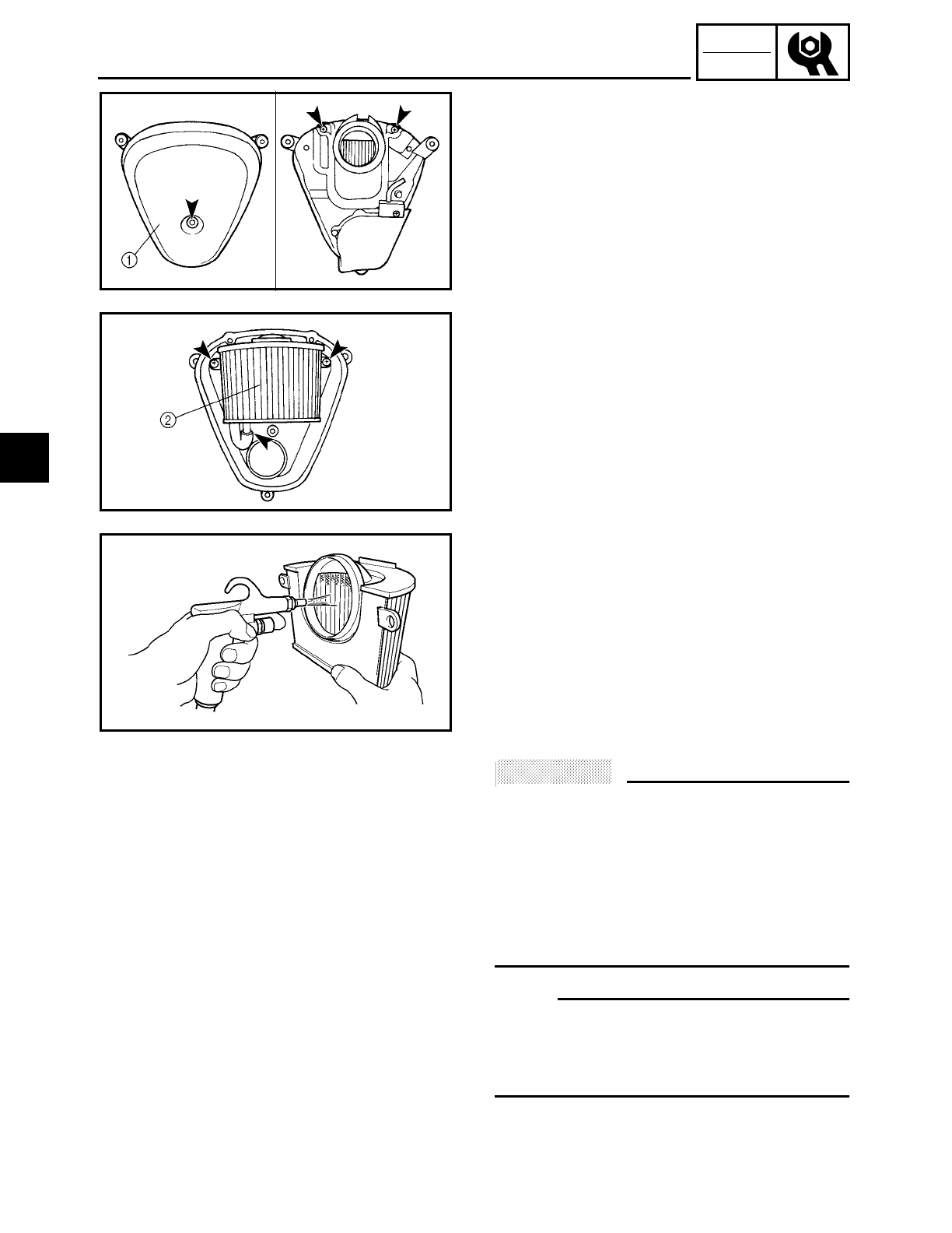
3 - 29
CHK
ADJ
CLEANING THE AIR FILTER ELEMENT
EAS00086
CLEANING THE AIR FILTER ELEMENT
1. Remove:
• air filter case
Refer to “AIR FILTER CASE”.
2. Remove:
• air filter case cover 1
• air filter element 2
3. Clean:
• air filter element
Apply compressed air to the outer sur-
face of the air filter element.
4. Check:
• air filter element
Damage → Replace.
• O-ring
Damage → Replace.
5. Install:
• air filter element
• air filter case cover
ACHTUNG:
CAUTION:
Never operate the engine without the air
filter element installed. Unfiltered air will
cause rapid wear of engine parts and may
damage the engine. Operating the engine
without the air filter element will also
affect the carburetor tuning, leading to
poor engine performance and possible
overheating.
NOTE:
When installing the air filter element into
the air filter case cover, make sure their
sealing surfaces are aligned to prevent any
air leaks.
6. Install:
• air filter case
Refer to “AIR FILTER CASE”.
3
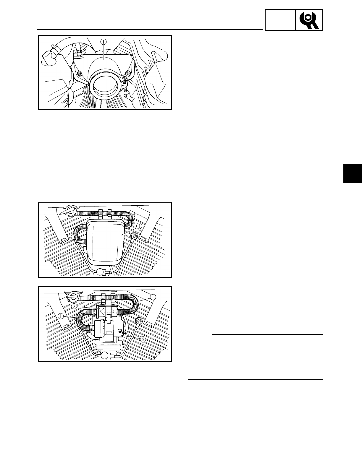
3 - 30
CHK
ADJ
CHECKING THE CARBURETOR JOINT/
CHECKING THE FUEL HOSES AND FUEL FILTER
EAS00094
CHECKING THE CARBURETOR JOINT
1. Remove:
• carburetor assembly
Refer to “CARBURETOR” in chapter 6.
2. Check:
• carburetor joint 1
Cracks/damage → Replace.
Refer to “CARBURETOR” in chapter 6.
3. Install:
• carburetor assembly
Refer to “CARBURETOR” in chapter 6.
EAS00097
CHECKING THE FUEL HOSES AND FUEL
FILTER
The following procedure applies to all of
the fuel hoses.
1. Remove:
• fuel pump cover 1
2. Check:
• fuel hose 1
Cracks/damage → Replace.
• fuel filter 2
Contaminants/damage → Replace.
NOTE:
• Drain and flush the fuel tank if abrasive
damage to any components of the fuel
line is evident.
• The arrow mark on the fuel filter must
point towards the fuel pump 3 as shown.
3. Install:
• fuel pump cover
3
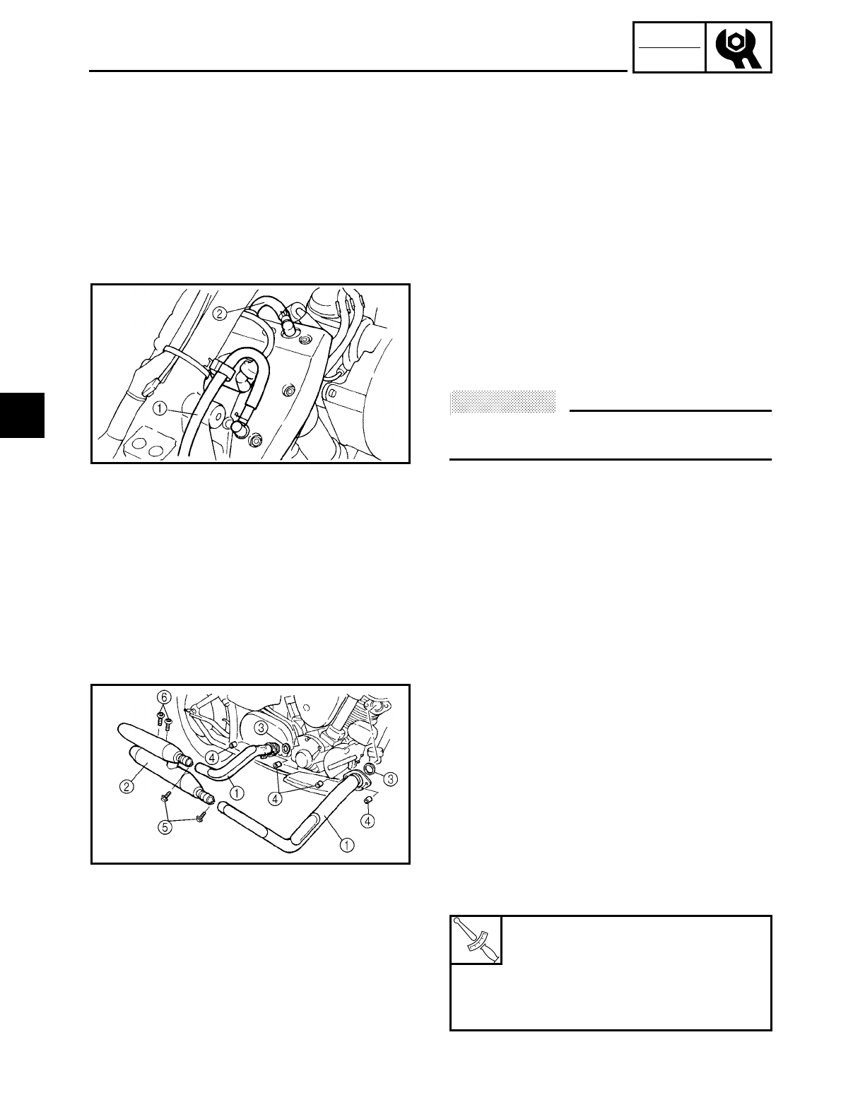
3 - 31
CHK
ADJ
CHECKING THE CYLINDER HEAD BREATHER HOSE AND TRANSFER
GEAR CASE BREATHER HOSE/CHECKING THE EXHAUST SYSTEM
EAS00098
CHECKING THE CYLINDER HEAD
BREATHER HOSE AND TRANSFER GEAR
CASE BREATHER HOSE
1. Remove:
• rider seat
• fuel tank
Refer to “SEATS AND SIDE COVERS”
and “FUEL TANK”.
2. Check:
• oil pump breather hose 1
• cylinder head breather hose 2
Cracks/damage → Replace.
Loose connection → Connect properly.
ACHTUNG:
CAUTION:
Make sure the crankcase breather hose is
routed correctly.
3. Install:
• fuel tank
• rider seat
Refer to “FUEL TANK” and “SEATS AND
SIDE COVERS”.
EAS00100
CHECKING THE EXHAUST SYSTEM
The following procedure applies to all of
the exhaust pipes, mufflers and gaskets.
1. Check:
• exhaust pipe 1
• muffler 2
Cracks/damage → Replace.
• gasket 3
Exhaust gas leaks → Replace.
2. Measure:
• tightening torque
T
R
.
.
Exhaust pipe nut
4
20 Nm (2.0 m • kg, 14 ft • lb)
Exhaust pipe and muffler bolt
5
25 Nm (2.5 m • kg, 18 ft • lb)
Muffler and muffler bracket bolt
6
30 Nm (3.0 m • kg, 22 ft • lb)
3
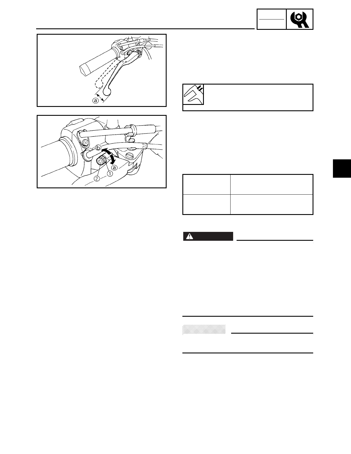
3 - 32
CHK
ADJ
ADJUSTING THE FRONT BRAKE
EAS00108
CHASSIS
ADJUSTING THE FRONT BRAKE
1. Measure:
• brake lever free play a
Out of specification → Adjust.
2. Adjust:
• brake lever free play
▼ ▼ ▼ ▼ ▼ ▼ ▼ ▼ ▼ ▼ ▼ ▼ ▼ ▼ ▼ ▼ ▼ ▼ ▼ ▼ ▼ ▼ ▼ ▼ ▼ ▼ ▼ ▼
a. Loosen the locknut
1.
b. Turn the adjusting screw
2 in direction
a or
b until the specified brake lever
free play is obtained.
c. Tighten the locknut.
WARNING
WARNING
A soft or spongy feeling in the brake lever
can indicate the presence of air in the brake
system. Before the vehicle is operated, the
air must be removed by bleeding the brake
system. Air in the brake system will consid-
erably reduce braking performance and
could result in loss of control and possibly
an accident. Therefore, check and, if neces-
sary, bleed the brake system.
ACHTUNG:
CAUTION:
After adjusting the brake lever free play,
make sure there is no brake drag.
▲ ▲ ▲ ▲ ▲ ▲ ▲ ▲ ▲ ▲ ▲ ▲ ▲ ▲ ▲ ▲ ▲ ▲ ▲ ▲ ▲ ▲ ▲ ▲ ▲ ▲ ▲ ▲
Brake lever free play (at the end
of the brake lever)
2 ~ 5 mm (0.08 ~ 0.20 in)
Direction aBrake lever free play is
increased.
Direction bBrake lever free play is
decreased.
3
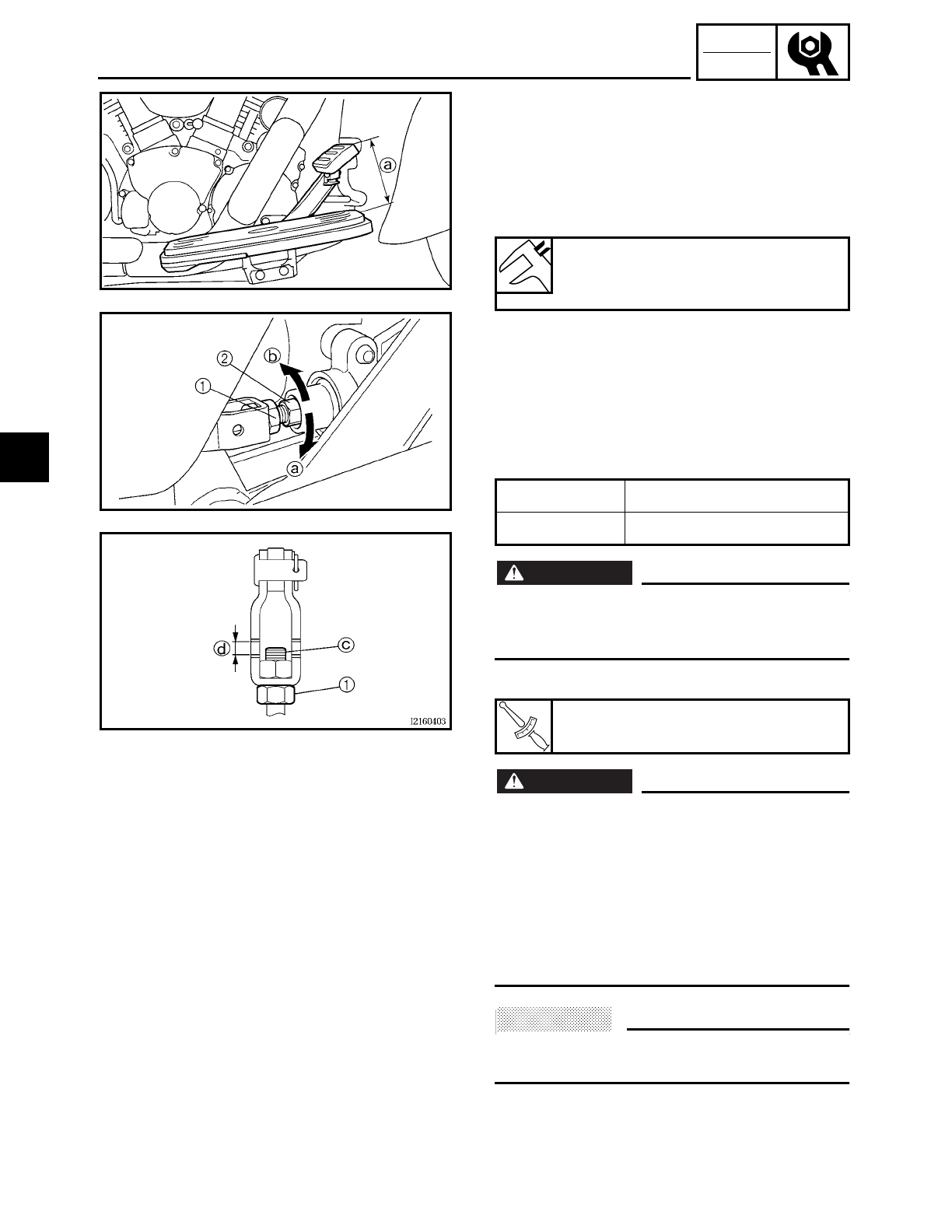
3 - 33
CHK
ADJ
ADJUSTING THE REAR BRAKE
EAS00110
ADJUSTING THE REAR BRAKE
1. Measure:
• brake pedal position
(distance a from the top of the rider
footrest to the top of the brake pedal)
Out of specification → Adjust.
2. Adjust:
• brake pedal position
▼ ▼ ▼ ▼ ▼ ▼ ▼ ▼ ▼ ▼ ▼ ▼ ▼ ▼ ▼ ▼ ▼ ▼ ▼ ▼ ▼ ▼ ▼ ▼ ▼ ▼ ▼ ▼
a. Loosen the locknut
1.
b. Turn the adjusting bolt
2 in direction
a
or
b until the specified brake pedal posi-
tion is obtained.
WARNING
WARNING
After adjusting the brake pedal position,
check that the end c of the adjusting bolt
is visible through the hole
d.
c. Tighten the locknut
1 to specification.
WARNING
WARNING
A soft or spongy feeling in the brake pedal
can indicate the presence of air in the brake
system. Before the vehicle is operated, the
air must be removed by bleeding the brake
system. Air in the brake system will consid-
erably reduce braking performance and
could result in loss of control and possibly
an accident. Therefore, check and, if neces-
sary, bleed the brake system.
ACHTUNG:
CAUTION:
After adjusting the brake pedal position,
make sure there is no brake drag.
▲ ▲ ▲ ▲ ▲ ▲ ▲ ▲ ▲ ▲ ▲ ▲ ▲ ▲ ▲ ▲ ▲ ▲ ▲ ▲ ▲ ▲ ▲ ▲ ▲ ▲ ▲ ▲
3. Adjust:
• rear brake light switch
Refer to “ADJUSTING THE REAR BRAKE
LIGHT SWITCH”.
Brake pedal position (below the
top of the rider footrest)
100 mm (3.9 in)
Direction
aBrake pedal is raised.
Direction
bBrake pedal is lowered.
T
R
.
.
Locknut
18 Nm (1.8 m • kg, 13 ft • lb)
3
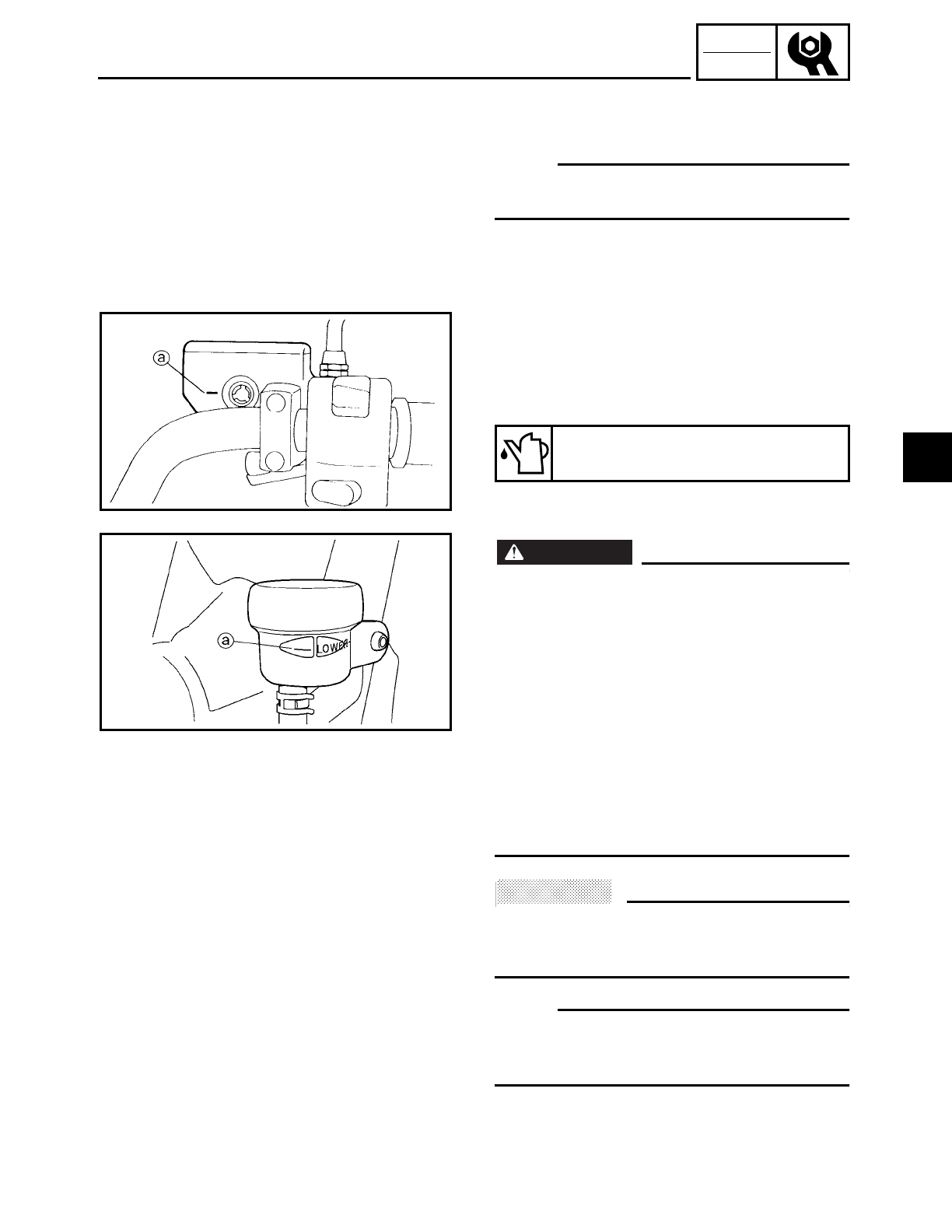
3 - 34
CHK
ADJ
EAS00115
CHECKING THE BRAKE FLUID LEVEL
1. Stand the motorcycle on a level surface.
NOTE:
• Place the motorcycle on a suitable stand.
• Make sure the motorcycle is upright.
2. Check:
• brake fluid level
Below the minimum level mark
a
→ Add
the recommended brake fluid to the
proper level.
ÅFront brake
ıRear brake
WARNING
WARNING
• Use only the designated brake fluid.
Other brake fluids may cause the rubber
seals to deteriorate, causing leakage and
poor brake performance.
• Refill with the same type of brake fluid
that is already in the system. Mixing
brake fluids may result in a harmful
chemical reaction, leading to poor brake
performance.
• When refilling, be careful that water does
not enter the brake fluid reservoir. Water
will significantly lower the boiling point of
the brake fluid and could cause vapor lock.
ACHTUNG:
CAUTION:
Brake fluid may damage painted surfaces
and plastic parts. Therefore, always clean
up any spilt brake fluid immediately.
NOTE:
In order to ensure a correct reading of the
brake fluid level, make sure the top of the
brake fluid reservoir is horizontal.
Recommended brake fluid
DOT 4
Å
ı
CHECKING THE BRAKE FLUID LEVEL
3
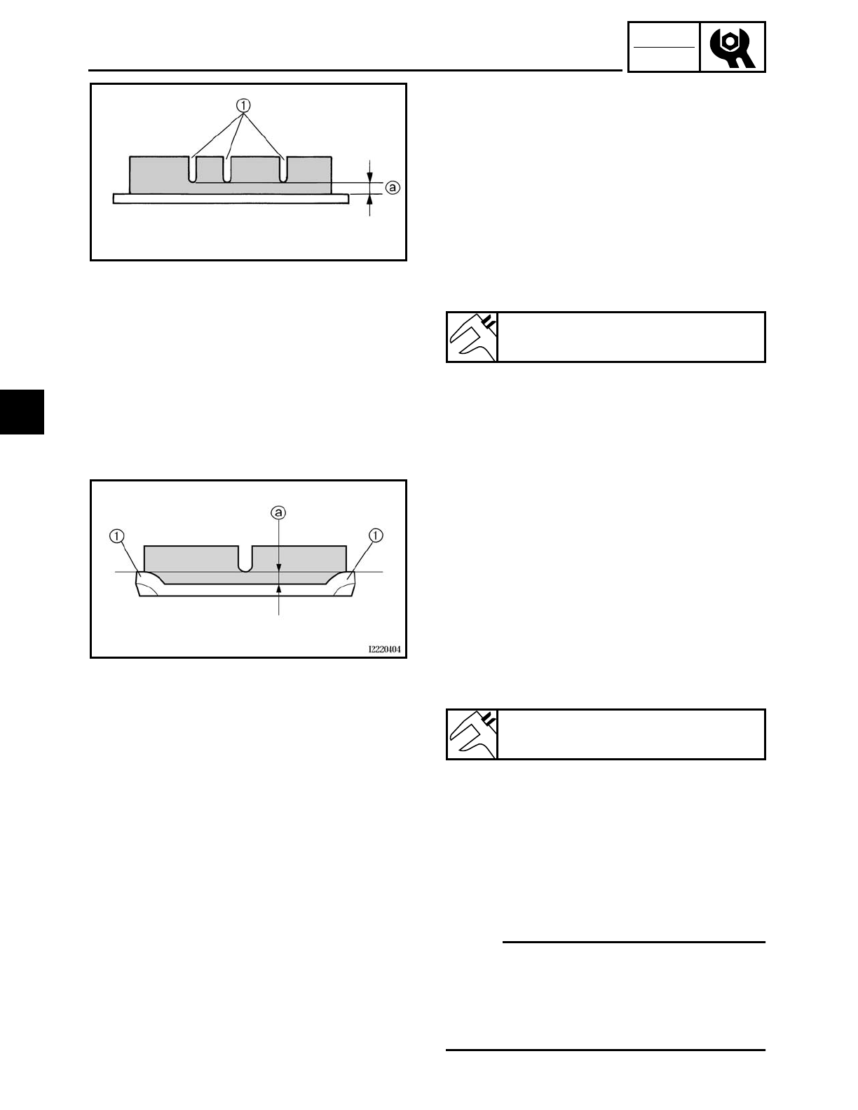
3 - 35
CHK
ADJ
CHECKING THE FRONT BRAKE PADS/CHECKING THE REAR BRAKE
PADS/ADJUSTING THE REAR BRAKE LIGHT SWITCH
EAS00120
CHECKING THE FRONT BRAKE PADS
The following procedure applies to all of
the brake pads.
1. Operate the brake.
2. Check:
• brake pad
Wear indicator groove 1 almost disap-
peared → Replace the brake pads as a
set.
Refer to “REPLACING THE FRONT
BRAKE PADS” in chapter 4.
Brake pad wear limit a
0.5 mm (0.02 in)
EAS00118
CHECKING THE REAR BRAKE PADS
The following procedure applies to all of
the brake pads.
1. Operate the brake.
2. Check:
• brake pad
Wear indicators 1 almost touch the
brake disc → Replace the brake pads as a
set.
Refer to “REPLACING THE REAR BRAKE
PADS” in chapter 4.
Brake pad wear limit a
0.5 mm (0.02 in)
EAS00128
ADJUSTING THE REAR BRAKE LIGHT
SWITCH
NOTE:
The rear brake light switch is operated by
movement of the brake pedal.
The rear brake light switch is properly
adjusted when the brake light comes on
just before the braking effect starts.
3
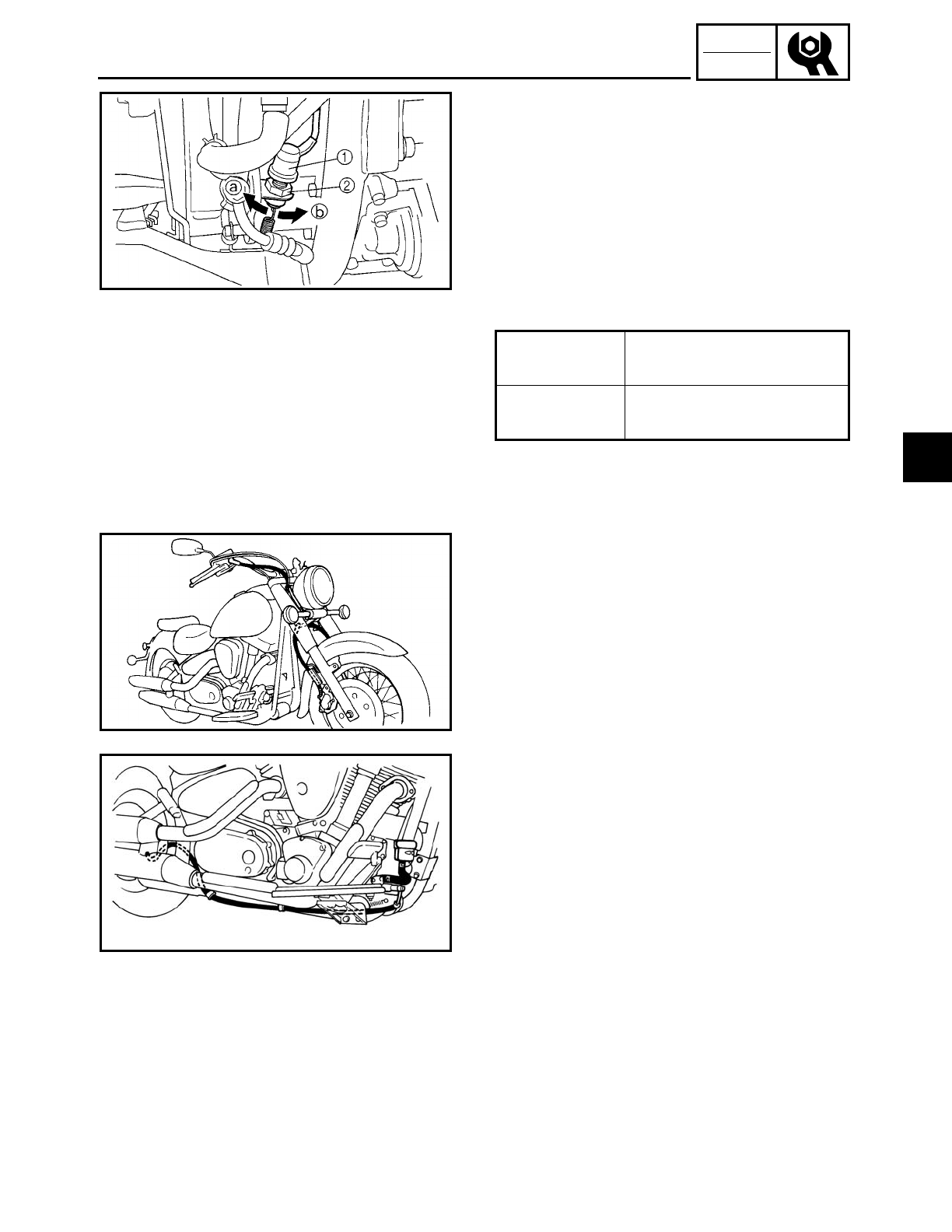
3 - 36
CHK
ADJ
ADJUSTING THE REAR BRAKE LIGHT SWITCH/
CHECKING THE BRAKE HOSE
1. Check:
• rear brake light operation timing
Incorrect → Adjust.
2. Adjust:
• rear brake light operation timing
▼ ▼ ▼ ▼ ▼ ▼ ▼ ▼ ▼ ▼ ▼ ▼ ▼ ▼ ▼ ▼ ▼ ▼ ▼ ▼ ▼ ▼ ▼ ▼ ▼ ▼ ▼ ▼
a. Hold the main body 1 of the rear brake
light switch so that it does not rotate and
turn the adjusting nut 2 in direction a
or b until the rear brake light comes on
at the proper time.
▲ ▲ ▲ ▲ ▲ ▲ ▲ ▲ ▲ ▲ ▲ ▲ ▲ ▲ ▲ ▲ ▲ ▲ ▲ ▲ ▲ ▲ ▲ ▲ ▲ ▲ ▲ ▲
Direction aBrake light comes on
sooner.
Direction bBrake light comes on
later.
EAS00129
CHECKING THE BRAKE HOSE
1. Check:
• brake hose
Cracks/damage/wear → Replace.
2. Check:
• brake hose clamp
Loose → Tighten the clamp bolt.
3. Hold the motorcycle upright and apply
the front or rear brake several times.
4. Check:
• brake hose
Brake fluid leakage → Replace the dam-
aged hose.
Refer to “FRONT AND REAR BRAKES” in
chapter 4.
3
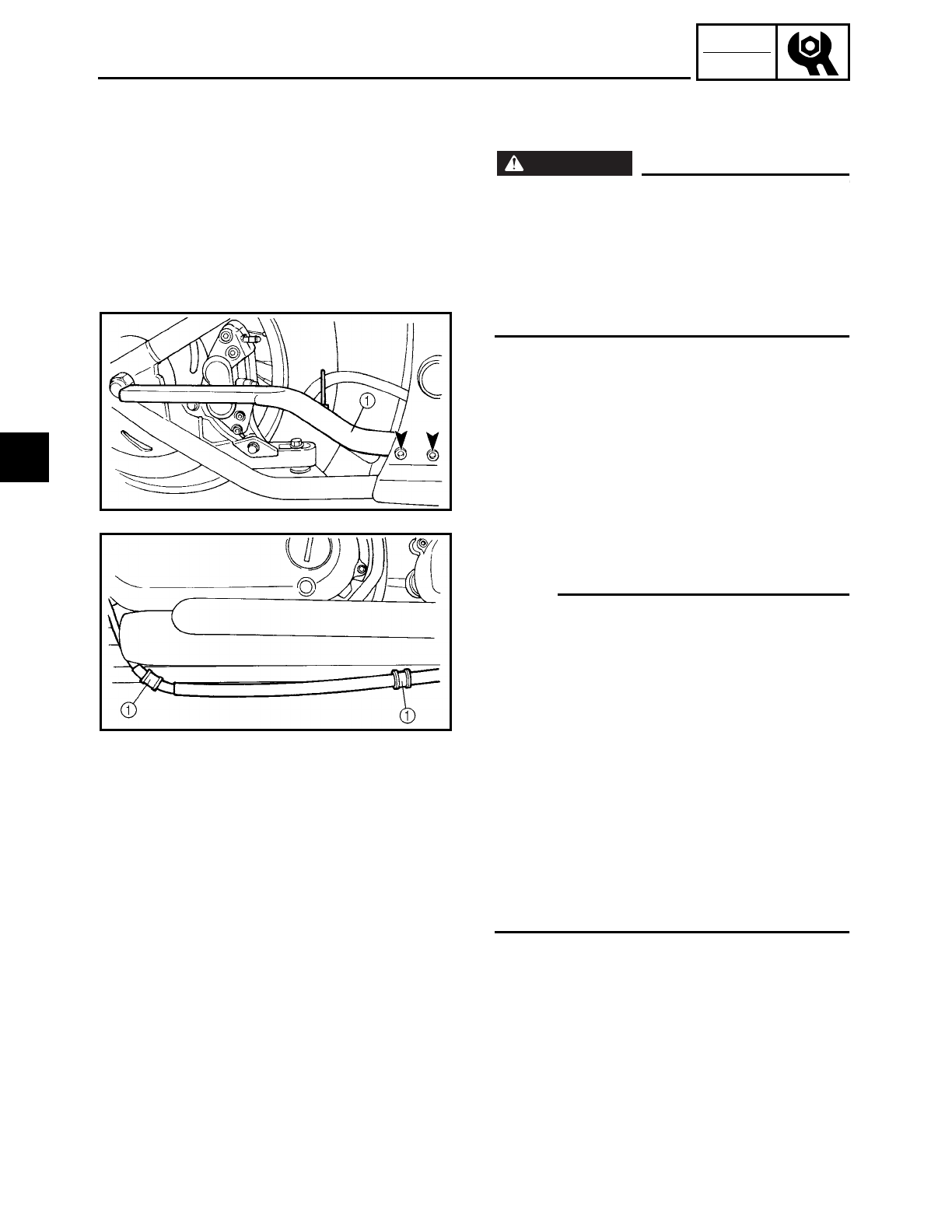
3 - 37
CHK
ADJ
BLEEDING THE HYDRAULIC BRAKE SYSTEM
EAS00134
BLEEDING THE HYDRAULIC BRAKE
SYSTEM
WARNING
WARNING
Bleed the hydraulic brake system when-
ever:
• the brake system was disassembled,
• a brake hose was loosened, discon-
nected, or replaced,
• the brake fluid level is very low,
• brake operation is faulty.
1. Remove:
• muffler
• muffler bracket 1
2. Remove:
• plastic clamps 1
NOTE:
• Be careful not to spill any brake fluid or
allow the brake master cylinder reservoir
or brake fluid reservoir to overflow.
• When bleeding the hydraulic brake sys-
tem, make sure there is always enough
brake fluid before applying the brake.
Ignoring this precaution could allow air to
enter the hydraulic brake system, consid-
erably lengthening the bleeding proce-
dure.
• If bleeding is difficult, it may be necessary
to let the brake fluid settle for a few hours.
Repeat the bleeding procedure when the
tiny bubbles in the hose have disap-
peared.
3. Bleed:
• hydraulic brake system
▼ ▼ ▼ ▼ ▼ ▼ ▼ ▼ ▼ ▼ ▼ ▼ ▼ ▼ ▼ ▼ ▼ ▼ ▼ ▼ ▼ ▼ ▼ ▼ ▼ ▼ ▼ ▼
a. Fill the brake fluid reservoir to the proper
level with the recommended brake fluid.
b. Install the diaphragm (brake master cyl-
inder reservoir or brake fluid reservoir).
3
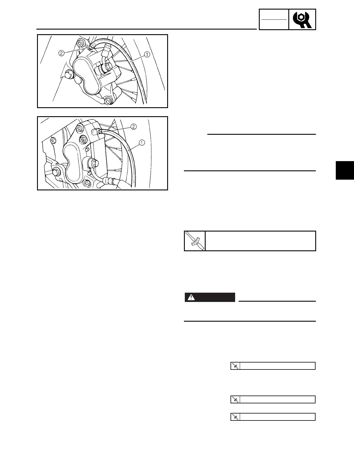
3 - 38
CHK
ADJ
c. Connect a clear plastic hose 1 tightly to
the bleed screw 2.
ÅFront ıRear
d. Place the other end of the hose into a
container.
e. Slowly apply the brake several times.
f. Fully squeeze the brake lever or fully
depress the brake pedal and hold it in
position.
g. Loosen the bleed screw.
NOTE:
Loosening the bleed screw will release the
pressure and cause the brake lever to con-
tact the throttle grip or the brake pedal to
fully extend.
h. Tighten the bleed screw and then release
the brake lever or brake pedal.
i. Repeat steps (e) to (h) until all of the air
bubbles have disappeared from the
brake fluid in the plastic hose.
j. Tighten the bleed screw to specification.
k. Fill the brake fluid reservoir to the proper
level with the recommended brake fluid.
Refer to “CHECKING THE BRAKE FLUID
LEVEL”.
WARNING
WARNING
After bleeding the hydraulic brake system,
check the brake operation.
▲ ▲ ▲ ▲ ▲ ▲ ▲ ▲ ▲ ▲ ▲ ▲ ▲ ▲ ▲ ▲ ▲ ▲ ▲ ▲ ▲ ▲ ▲ ▲ ▲ ▲ ▲ ▲
4. Install:
• plastic clamps
• muffler bracket
• muffler
5. Tighten:
• muffler bolts
• muffler clamp bolts
T
R
.
.
Bleed screw
6 Nm (0.6 m • kg, 4.3 ft • lb)
T
R
.
.
26 Nm (2.6 m · kg, 19 ft · lb)
T
R
.
.
30 Nm (3.0 m · kg, 22 ft · lb)
T
R
.
.
25 Nm (2.5 m · kg, 18 ft · lb)
BLEEDING THE HYDRAULIC BRAKE SYSTEM
3
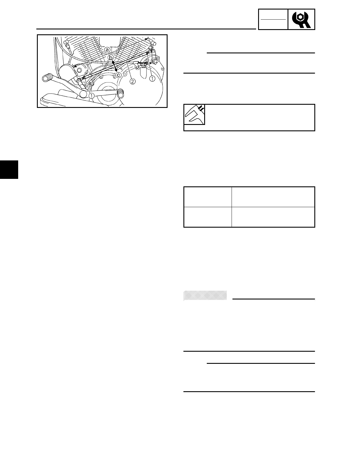
3 - 39
CHK
ADJ
ADJUSTING THE SHIFT PEDAL/
ADJUSTING THE DRIVE BELT SLACK
EAS00137
ADJUSTING THE SHIFT PEDAL
NOTE:
The shift pedal position is determined by
the installed shift rod length a.
1. Measure:
• installed shift rod length a
Incorrect → Adjust.
2. Adjust:
• installed shift rod length a
▼ ▼ ▼ ▼ ▼ ▼ ▼ ▼ ▼ ▼ ▼ ▼ ▼ ▼ ▼ ▼ ▼ ▼ ▼ ▼ ▼ ▼ ▼ ▼ ▼ ▼ ▼ ▼
a. Loosen both locknuts 1.
b. Turn the shift rod 2 in direction b or c
to obtain the correct shift pedal position.
c. Tighten both locknuts.
d. Make sure the installed shift rod length is
within specification.
▲ ▲ ▲ ▲ ▲ ▲ ▲ ▲ ▲ ▲ ▲ ▲ ▲ ▲ ▲ ▲ ▲ ▲ ▲ ▲ ▲ ▲ ▲ ▲ ▲ ▲ ▲ ▲
Installed shift rod length
374.4 ~ 378.4 mm
(14.74 ~ 14.90 in)
Direction bInstalled shift rod length
increases.
Direction cInstalled shift rod length
decreases.
ADJUSTING THE DRIVE BELT SLACK
ACHTUNG:
CAUTION:
A drive belt that is too tight will overload
the engine and other vital parts, and one
that is too loose can skip and damage the
swingarm or cause an accident. Therefore,
keep the drive belt slack within the speci-
fied limits.
NOTE:
Measure the drive belt slack when the
engine is cold, and when the drive belt is
dry.
3
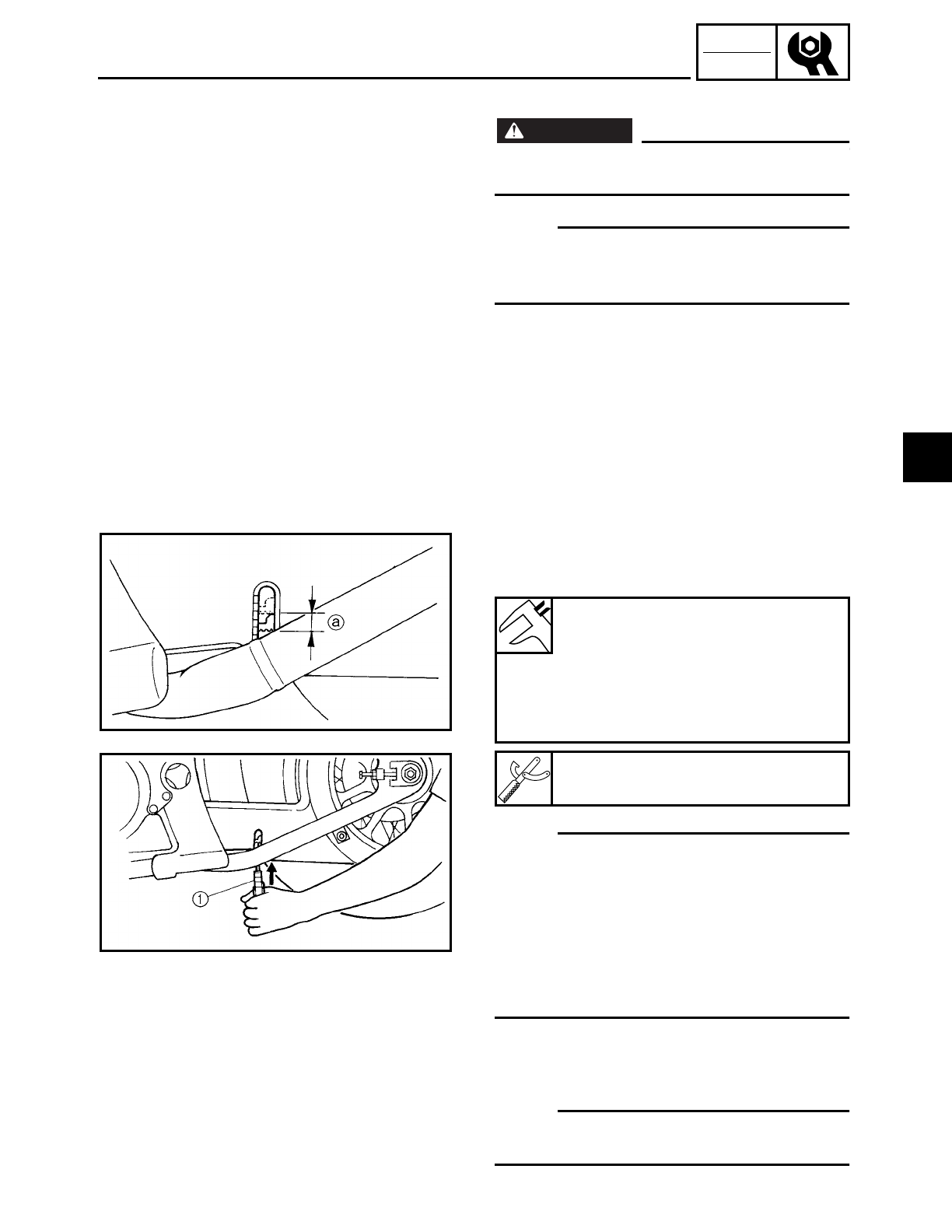
3 - 40
CHK
ADJ
ADJUSTING THE DRIVE BELT SLACK
1. Stand the motorcycle on a level surface.
WARNING
WARNING
Securely support the motorcycle so that
there is no danger of it falling over.
NOTE:
Place the motorcycle on the sidestand and
or on a suitable stand so that the rear wheel
is elevated.
2. Rotate the rear wheel several times and
check the drive belt to locate its tightest
point.
3. Measure:
• drive belt slack a
Out of specification → Adjust.
NOTE:
• The level marks of the level window on
the lower drive belt cover are in units of 5
mm (0.20 in). Use them as a standard for
measuring the drive belt slack.
• Measure the drive belt slack when the
drive belt has been pushed with 4.5 kg (10
lbs) of pressure using a belt tension
gauge 1.
4. Adjust:
• drive belt slack
▼ ▼ ▼ ▼ ▼ ▼ ▼ ▼ ▼ ▼ ▼ ▼ ▼ ▼ ▼ ▼ ▼ ▼ ▼ ▼ ▼ ▼ ▼ ▼ ▼ ▼ ▼ ▼
NOTE:
Place the motorcycle on the suitable stand
so that the rear wheel is elevated.
Drive belt slack
On the sidestand
7.5 ~ 13 mm at 4.5 kg
(0.30 ~ 0.51 in at 10 lbs)
On a suitable stand
14 ~ 21 mm at 4.5 kg
(0.55 ~ 0.83 in at 10 lbs)
Belt tension gauge
YM-03170
3

3 - 41
CHK
ADJ
ADJUSTING THE DRIVE BELT SLACK/
CHECKING AND ADJUSTING THE STEERING HEAD
a. Loosen the brake caliper bracket bolt 1.
b. Loosen the wheel axle nut 2.
c. Loosen both locknuts 3.
ÅRight ıLeft
d. Turn both adjusting bolts 4 in direction
a or b until the specified drive chain
slack is obtained.
NOTE:
To maintain the proper wheel alignment,
adjust both sides evenly.
e. Tighten both locknuts to specification.
f. Tighten the wheel axle nut to
specification.
g. Tighten the brake caliper bracket bolt to
specification.
▲ ▲ ▲ ▲ ▲ ▲ ▲ ▲ ▲ ▲ ▲ ▲ ▲ ▲ ▲ ▲ ▲ ▲ ▲ ▲ ▲ ▲ ▲ ▲ ▲ ▲ ▲ ▲
EAS00146
CHECKING AND ADJUSTING THE
STEERING HEAD
1. Stand the motorcycle on a level surface.
WARNING
WARNING
Securely support the motorcycle so that
there is no danger of it falling over.
NOTE:
Place the motorcycle on a suitable stand so
that the front wheel is elevated.
Direction aDrive belt slack is
reduced.
Direction bDrive belt slack is
increased.
T
R
.
.
Locknut
32 Nm (3.2 m • kg, 23 ft • lb)
T
R
.
.
Wheel axle nut
150 Nm (15.0 m • kg, 110 ft • lb)
T
R
.
.
Brake caliper bracket bolt
40 Nm (4.0 m • kg, 29 ft • lb)
Å
ı
3
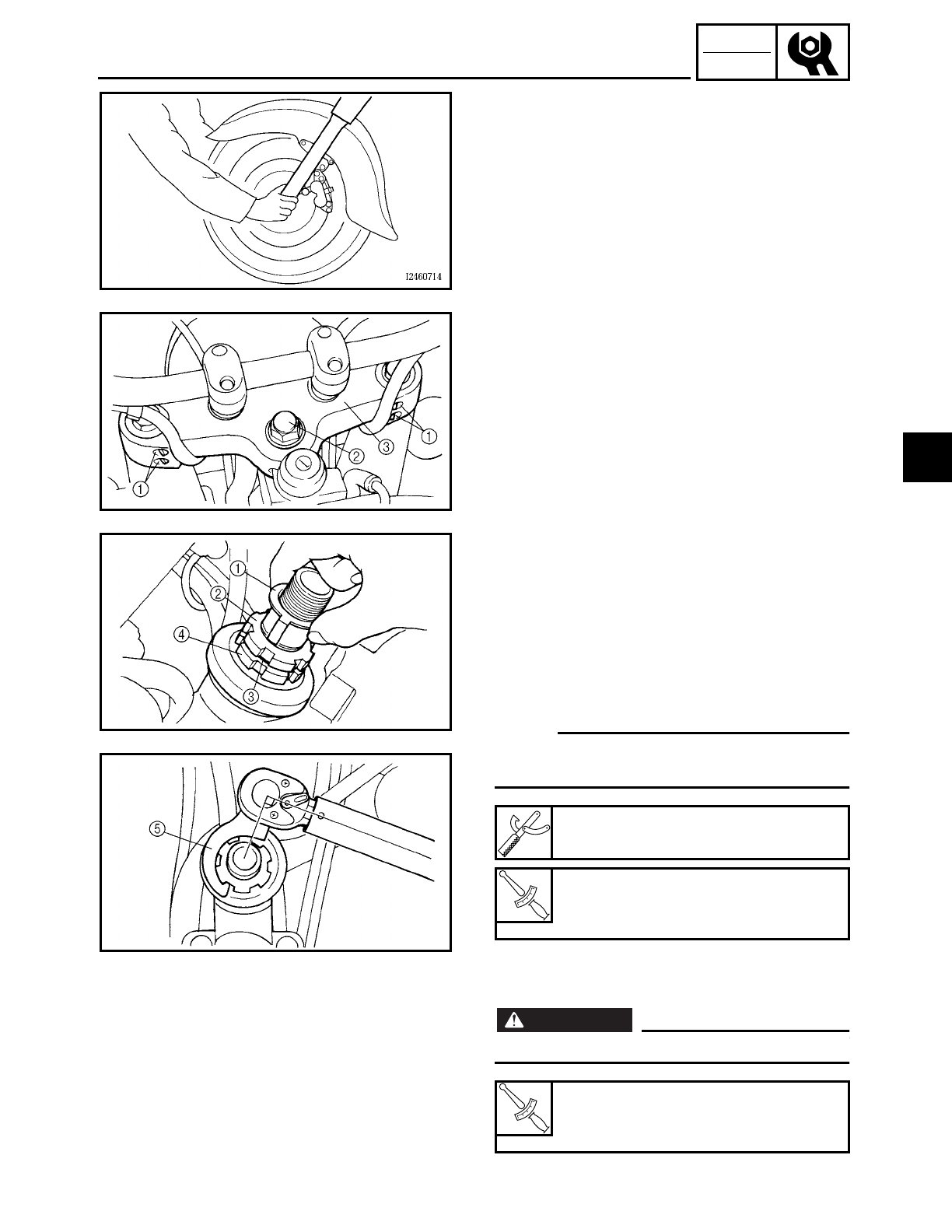
3 - 42
CHK
ADJ
2. Check:
• steering head
Grasp the bottom of the front fork legs
and gently rock the front fork.
Binding/looseness → Adjust the steering
head.
3. Remove:
• meter assembly
Refer to “FUEL TANK”.
4. Loosen:
• upper bracket pinch bolts 1
5. Remove:
• steering stem nut 2
• washer
• upper bracket 3
6. Adjust:
• steering head
▼ ▼ ▼ ▼ ▼ ▼ ▼ ▼ ▼ ▼ ▼ ▼ ▼ ▼ ▼ ▼ ▼ ▼ ▼ ▼ ▼ ▼ ▼ ▼ ▼ ▼ ▼ ▼
a. Remove the lock washer 1, the upper
ring nut 2, and the rubber washer 3.
b. Loosen the lower ring nut 4 and then
tighten it to specification with a ring nut
wrench 5.
NOTE:
Set the torque wrench at a right angle to the
ring nut wrench.
c. Loosen the lower ring nut completely,
then tighten it to specification.
WARNING
WARNING
Do not overtighten the lower ring nut.
Ring nut wrench
YU-33975
T
R
.
.
Lower ring nut (initial tightening
torque)
52 Nm (5.2 m • kg, 37 ft • lb)
T
R
.
.
Lower ring nut (final tightening
torque)
3 Nm (0.3 m • kg, 2.2 ft • lb)
CHECKING AND ADJUSTING THE STEERING HEAD
3
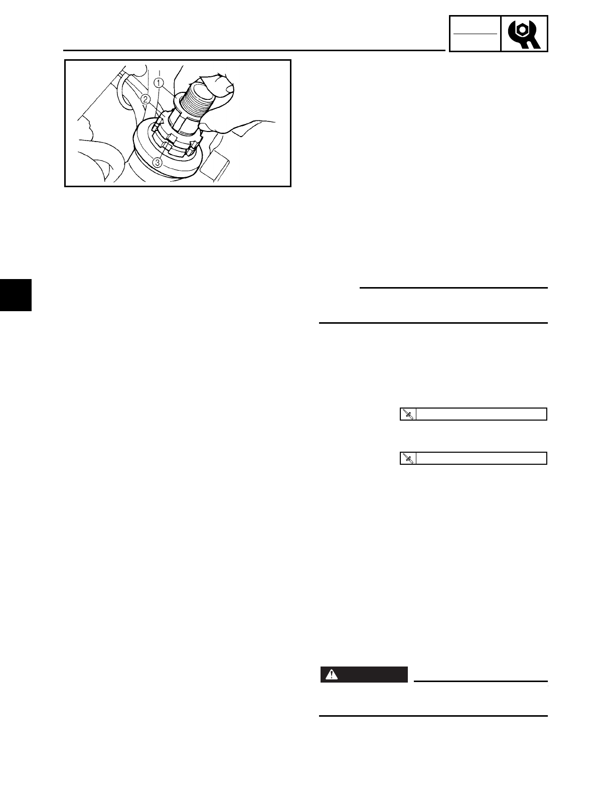
3 - 43
CHK
ADJ
CHECKING AND ADJUSTING THE STEERING HEAD/
CHECKING THE FRONT FORK
d. Check the steering head for looseness or
binding by turning the front fork all the
way in both directions. If any binding is
felt, remove the lower bracket and check
the upper and lower bearings.
Refer to “STEERING HEAD” in chapter 4.
e. Install the rubber washer 3.
f. Install the upper ring nut 2.
g. Finger tighten the upper ring nut 2, then
align the slots of both ring nuts. If neces-
sary, hold the lower ring nut and tighten
the upper ring nut until their slots are
aligned.
h. Install the lock washer 1.
NOTE:
Make sure the lock washer tabs sit correctly
in the ring nut slots.
▲ ▲ ▲ ▲ ▲ ▲ ▲ ▲ ▲ ▲ ▲ ▲ ▲ ▲ ▲ ▲ ▲ ▲ ▲ ▲ ▲ ▲ ▲ ▲ ▲ ▲ ▲ ▲
7. Install:
• upper bracket
• washer
• steering stem nut
8. Tighten:
• upper bracket pinch bolt
9. Install:
• meter assembly
Refer to “FUEL TANK”.
T
R
.
.
130 Nm (13.0 m · kg, 94 ft · lb)
T
R
.
.
10 Nm (1.0 m · kg, 7.2 ft · lb)
EAS00149
CHECKING THE FRONT FORK
1. Stand the motorcycle on a level surface.
WARNING
WARNING
Securely support the motorcycle so that
there is no danger of it falling over.
3
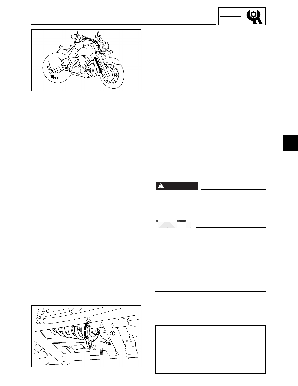
3 - 44
CHK
ADJ
CHECKING THE FRONT FORK/
ADJUSTING THE REAR SHOCK ABSORBER ASSEMBLY
2. Check:
• inner tube
Damage/scratches → Replace.
• oil seal
Oil leakage → Replace.
3. Hold the motorcycle upright and apply
the front brake.
4. Check:
• front fork operation
Push down hard on the handlebar sev-
eral times and check if the front fork
rebounds smoothly.
Rough movement → Repair.
Refer to “FRONT FORK” in chapter 4.
ADJUSTING THE REAR SHOCK
ABSORBER ASSEMBLY
WARNING
WARNING
Securely support the motorcycle so that
there is no danger of it falling over.
Spring preload
ACHTUNG:
CAUTION:
Never go beyond the maximum or mini-
mum adjustment positions.
1. Adjust:
• spring preload
NOTE:
Adjust the spring preload with the special
wrench and extension bar included in the
owner’s tool kit.
▼ ▼ ▼ ▼ ▼ ▼ ▼ ▼ ▼ ▼ ▼ ▼ ▼ ▼ ▼ ▼ ▼ ▼ ▼ ▼ ▼ ▼ ▼ ▼ ▼ ▼ ▼ ▼
a. Loosen the locknut 1
b. Turn the adjusting ring 2 in direction a
or b.
Direction a
Spring preload is
increased (suspension is
harder).
Direction b
Spring preload is
decreased (suspension is
softer).
3
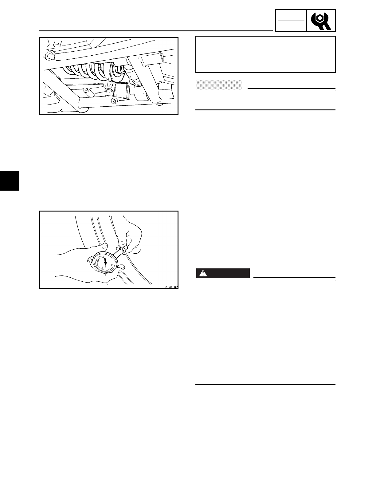
3 - 45
CHK
ADJ
ADJUSTING THE REAR SHOCK ABSORBER ASSEMBLY/
CHECKING THE TIRES
ACHTUNG:
CAUTION:
Never turn the adjusting ring beyond the
maximum or minimum setting.
▲ ▲ ▲ ▲ ▲ ▲ ▲ ▲ ▲ ▲ ▲ ▲ ▲ ▲ ▲ ▲ ▲ ▲ ▲ ▲ ▲ ▲ ▲ ▲ ▲ ▲ ▲ ▲
Adjusting length a
Minimum 42.5 mm (1.67 in)
Standard 42.5 mm (1.67 in)
Maximum 51.5 mm (2.03 in)
EAS00166
CHECKING THE TIRES
The following procedure applies to both of
the tires.
1. Measure:
• tire pressure
Out of specification → Regulate.
WARNING
WARNING
• The tire pressure should only be checked
and regulated when the tire temperature
equals the ambient air temperature.
• The tire pressure and the suspension
must be adjusted according to the total
weight (including cargo, rider, passenger
and accessories) and the anticipated
riding speed.
• Operation of an overloaded motorcycle
could cause tire damage, an accident, or
an injury.
NEVER OVERLOAD THE MOTORCYCLE.
3
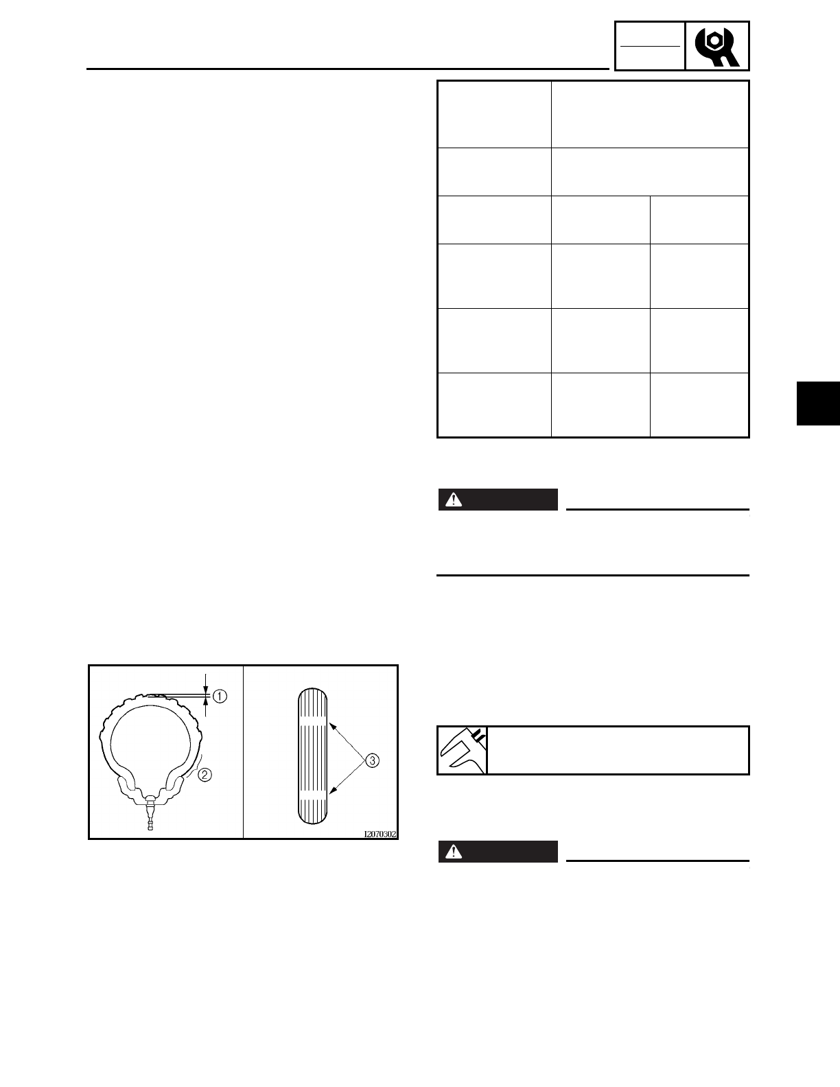
3 - 46
CHK
ADJ
CHECKING THE TIRES
* total of cargo, rider, passenger and acces-
sories
WARNING
WARNING
It is dangerous to ride with a worn-out tire.
When the tire tread reaches the wear limit,
replace the tire immediately.
Basic weight
(with oil and a
full fuel tank)
332 kg (732 lb): XV16A
347 kg (765 lb): XV16AT
Maximum
load*
196 kg (432 lb): XV16A
181 kg (399 lb): XV16AT
Cold tire pres-
sure Front tire Rear tire
Up to 90 kg
load*
250 kPa
(2.5 kgf/cm2,
36 psi)
250 kPa
(2.5 kgf/cm2,
36 psi)
90 kg ~ maxi-
mum load*
250 kPa
(2.5 kgf/cm2,
36 psi)
280 kPa
(2.8 kgf/cm2,
40 psi)
High-speed
riding
250 kPa
(2.5 kgf/cm2,
36 psi)
280 kPa
(2.8 kgf/cm2,
40 psi)
2. Check:
• tire surfaces
Damage/wear → Replace the tire.
1Tire tread depth
2Side wall
3Wear indicator
WARNING
WARNING
• Do not use a tubeless tire on a wheel
designed only for tube tires to avoid tire
failure and personal injury from sudden
deflation.
• When using a tube tire, be sure to install
the correct tube.
• Always replace a new tube tire and a new
tube as a set.
Minimum tire tread depth
1.6 mm (0.06 in)
3
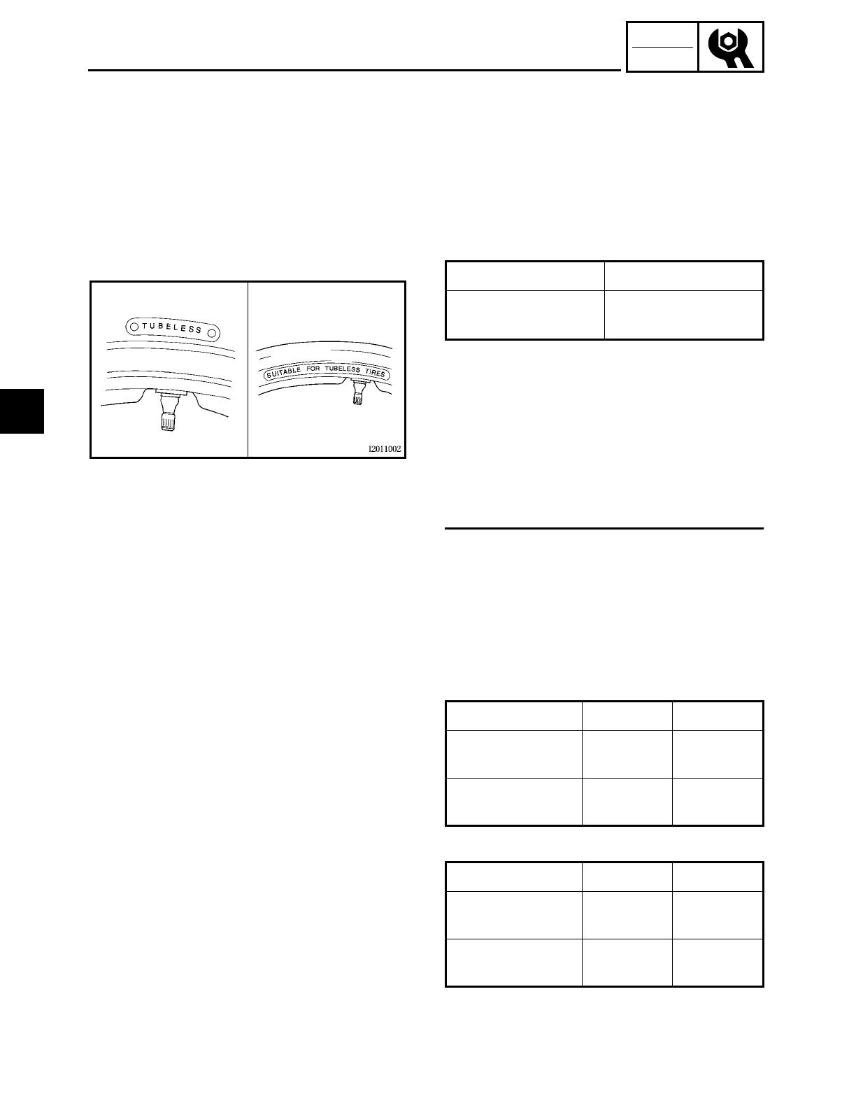
3 - 47
CHK
ADJ
CHECKING THE TIRES
• To avoid pinching the tube, make sure
the wheel rim band and tube are centered
in the wheel groove.
• Patching a punctured tube is not recom-
mended. If it is absolutely necessary to do
so, use great care and replace the tube as
soon as possible with a good quality
replacement.
ÅTire ıWheel
• After extensive tests, the tires listed
below have been approved by Yamaha
Motor Co., Ltd. for this model. The front
and rear tires should always be by the
same manufacturer and of the same
design. No guarantee concerning han-
dling characteristics can be given if a tire
combination other than one approved by
Yamaha is used on this motorcycle.
Tube wheel Tube tire only
Tubeless wheel Tube or tubeless
tire
Åı
Front tire
Rear tire
Manufacturer Size Model
BRIDGESTONE 130/90-16
67H G703F
DUNLOP 130/90-16
67H D404FL
Manufacturer Size Model
BRIDGESTONE 150/80 B16
71H G702
DUNLOP 150/80 B16
71H D404
3
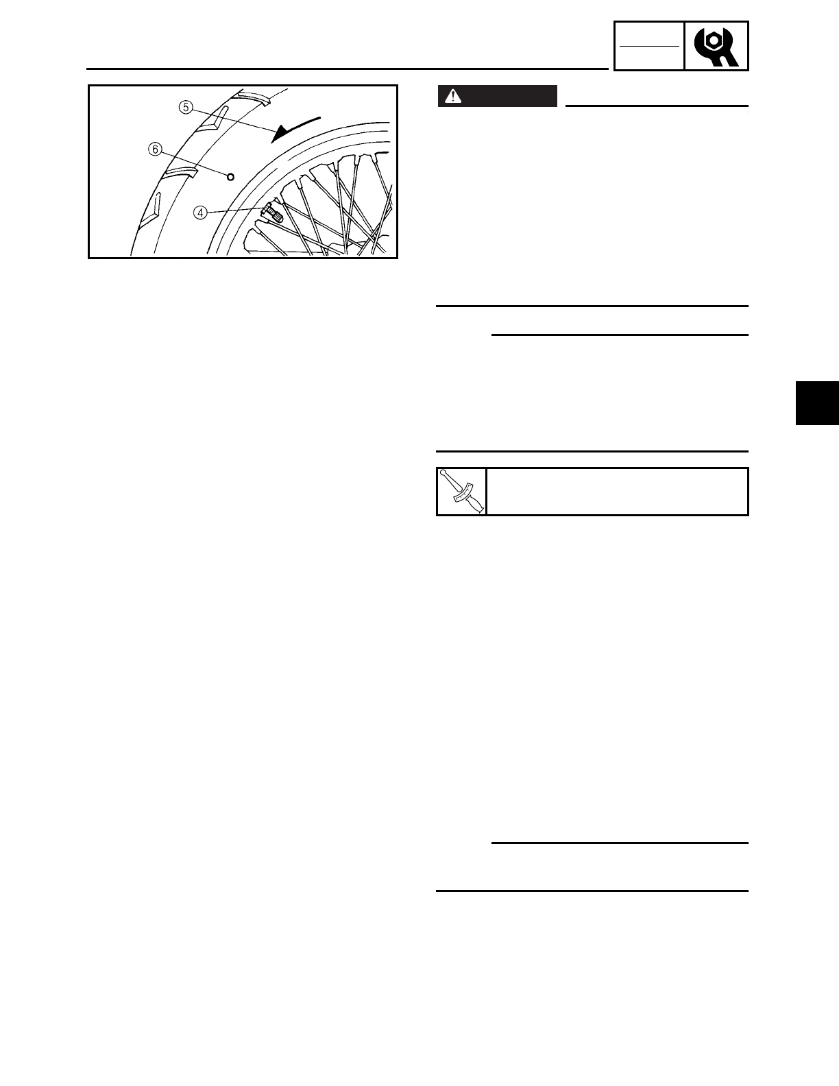
3 - 48
CHK
ADJ
CHECKING THE TIRES/
CHECKING AND TIGHTENING THE SPOKES
WARNING
WARNING
• After mounting a new tire, ride conserva-
tively for a while to become accustomed
to the “feel” of the new tire and to allow
the tire to seat itself properly in the rim.
Failure to do so could lead to an accident
with possible injury to the rider or dam-
age to the motorcycle.
• After a tire has been repaired or replaced,
be sure to tighten the tire air valve stem
locknut 4 to specification.
NOTE:
For tires with a direction of rotation mark
5:
• Install the tire with the mark pointing in
the direction of wheel rotation.
• Align the mark 6 with the valve installa-
tion point.
T
R
.
.
Tire air valve stem locknut
1.5 Nm (0.5 m • kg, 1.1 ft • Ib)
EAS00169
CHECKING AND TIGHTENING THE SPOKES
The following procedure applies to all of
the spokes.
1. Check:
• spoke
Bends/damage → Replace.
Loose → Tighten.
Tap the spokes with a screwdriver.
NOTE:
A tight spoke will emit a clear, ringing tone;
a loose spoke will sound flat.
3
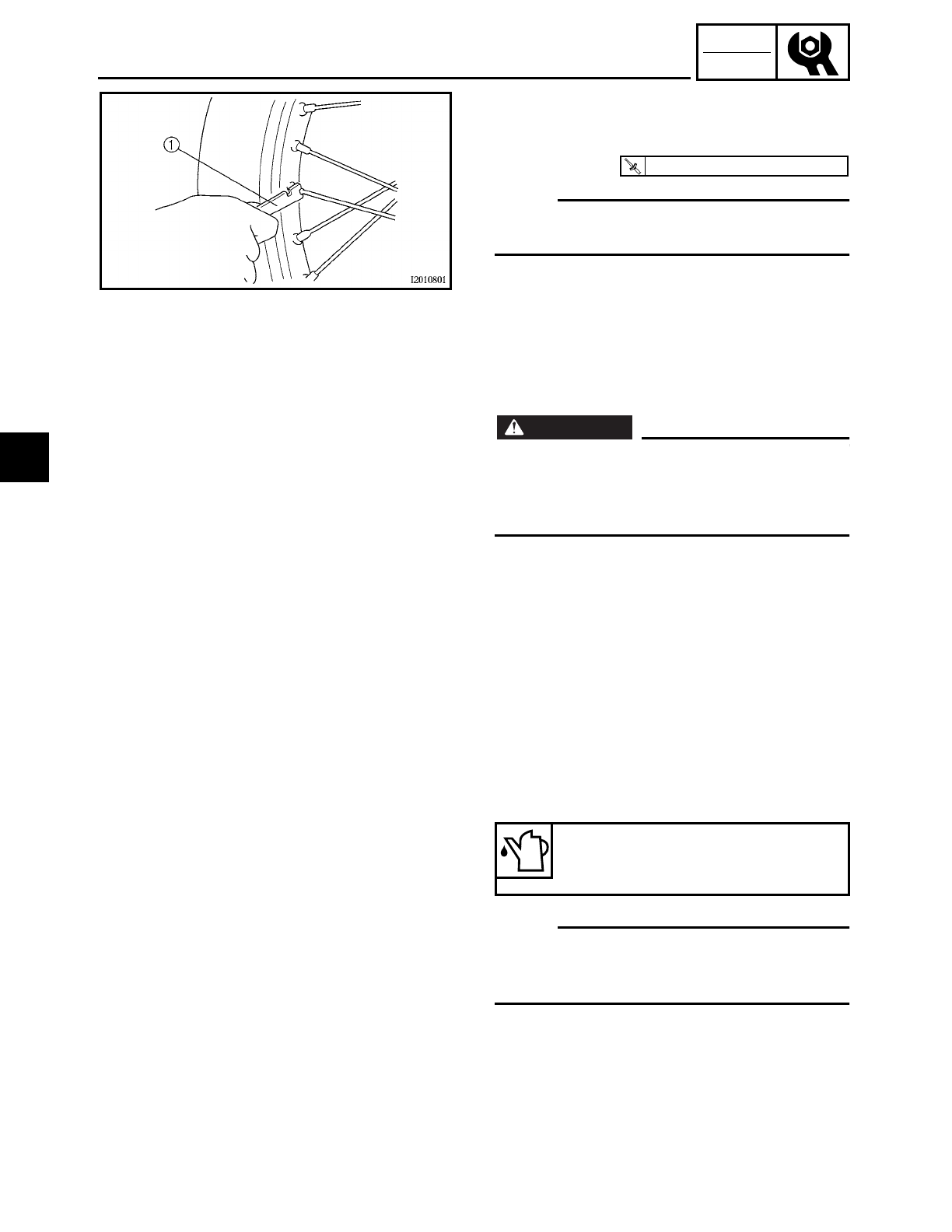
3 - 49
CHK
ADJ
CHECKING AND TIGHTENING THE SPOKES/
CHECKING AND LUBRICATING THE CABLES
2. Tighten:
• spokes
(with a spoke wrench 1)
NOTE:
Be sure to tighten the spokes before and
after break-in.
T
R
.
.
3 Nm (0.3 m · kg, 2.2 ft · lb)
EAS00170
CHECKING AND LUBRICATING THE
CABLES
The following procedure applies to all of
the cable sheaths and cables.
WARNING
WARNING
Damaged cable sheaths may cause the
cable to corrode and interfere with its
movement. Replace damaged cable
sheaths and cables as soon as possible.
1. Check:
• cable sheath
Damage → Replace.
2. Check:
• cable operation
Rough movement → Lubricate.
NOTE:
Hold the cable end upright and pour a few
drops of lubricant into the cable sheath or
use a suitable lubing device.
Recommended lubricant
Engine oil or a suitable cable
lubricant
3
3 - 50
CHK
ADJ
LUBRICATING THE LEVERS AND PEDALS/LUBRICATING
THE SIDESTAND/LUBRICATING THE REAR SUSPENSION
EAS00171
LUBRICATING THE LEVERS AND PEDALS
Lubricate the pivoting point and metal-to-
metal moving parts of the levers and ped-
als.
Recommended lubricant
Lithium soap base grease
EAS00172
LUBRICATING THE SIDESTAND
Lubricate the pivoting point and metal-to-
metal moving parts of the sidestand.
Recommended lubricant
Lithium soap base grease
EAS00174
LUBRICATING THE REAR SUSPENSION
Lubricate the pivoting point and metal-to-
metal moving parts of the rear suspension.
Recommended lubricant
Molybdenum disulfide grease
3
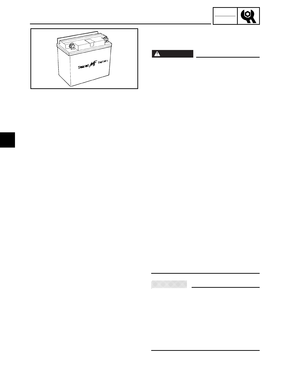
3 - 51
CHK
ADJ
CHECKING AND CHARGING THE BATTERY
EAS00178
ELECTRICAL SYSTEM
CHECKING AND CHARGING THE BATTERY
WARNING
WARNING
Batteries generate explosive hydrogen gas
and contain electrolyte which is made of
poisonous and highly caustic sulfuric acid.
Therefore, always follow these preventive
measures:
• Wear protective eye gear when handling
or working near batteries.
• Charge batteries in a well-ventilated area.
• Keep batteries away from fire, sparks, or
open flames (e.g., welding equipment,
lighted cigarettes).
• DO NOT SMOKE when charging or han-
dling batteries.
• KEEP BATTERIES AND ELECTROLYTE
OUT OF REACH OF CHILDREN.
• Avoid bodily contact with electrolyte as it
can cause severe burns or permanent eye
injury.
FIRST AID IN CASE OF BODILY CONTACT:
EXTERNAL
• Skin – Wash with water.
• Eyes – Flush with water for 15 minutes
and get immediate medical attention.
INTERNAL
• Drink large quantities of water or milk fol-
lowed with milk of magnesia, beaten egg,
or vegetable oil. Get immediate medical
attention.
• This is a sealed battery. Never remove the
sealing caps because the balance
between cells will not be maintained and
battery performance will deteriorate.
ACHTUNG:
CAUTION:
Charging time, charging amperage and
charging voltage for an MF battery are dif-
ferent from those of conventional batteries.
The MF battery should be charged as
explained in the charging method illustra-
tions. If the battery is overcharged, the
electrolyte level will drop considerably.
Therefore, take special care when charging
the battery.
3
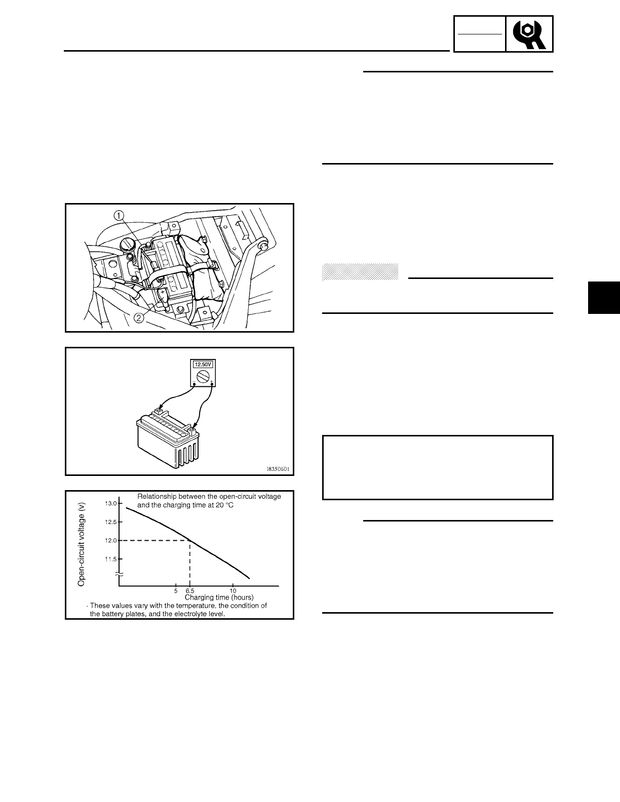
3 - 52
CHK
ADJ
CHECKING AND CHARGING THE BATTERY
NOTE:
Since MF batteries are sealed, it is not pos-
sible to check the charge state of the battery
by measuring the specific gravity of the
electrolyte. Therefore, the charge of the bat-
tery has to be checked by measuring the
voltage at the battery terminals.
1. Remove:
• rider seat
Refer to “SEATS AND SIDE COVERS”.
2. Disconnect:
• battery leads
(from the battery terminals)
ACHTUNG:
CAUTION:
First, disconnect the negative battery lead
1, then the positive battery lead 2.
3. Remove:
• battery band
• battery
4. Measure:
• battery charge
▼ ▼ ▼ ▼ ▼ ▼ ▼ ▼ ▼ ▼ ▼ ▼ ▼ ▼ ▼ ▼ ▼ ▼ ▼ ▼ ▼ ▼ ▼ ▼ ▼ ▼ ▼ ▼
a. Connect a pocket tester to the battery ter-
minals.
NOTE:
• The charge state of an MF battery can be
checked by measuring its open-circuit
voltage (i.e., the voltage when the positive
battery terminal is disconnected).
• No charging is necessary when the open-
circuit voltage equals or exceeds 12.8 V.
b. Check the charge of the battery, as
shown in the charts and the following
example.
Example
c. Open-circuit voltage = 12.0 V
d. Charging time = 6.5 hours
e. Charge of the battery = 20 ~ 30 %
▲ ▲ ▲ ▲ ▲ ▲ ▲ ▲ ▲ ▲ ▲ ▲ ▲ ▲ ▲ ▲ ▲ ▲ ▲ ▲ ▲ ▲ ▲ ▲ ▲ ▲ ▲ ▲
Positive tester probe →
positive battery terminal
Negative tester probe →
negative battery terminal
3
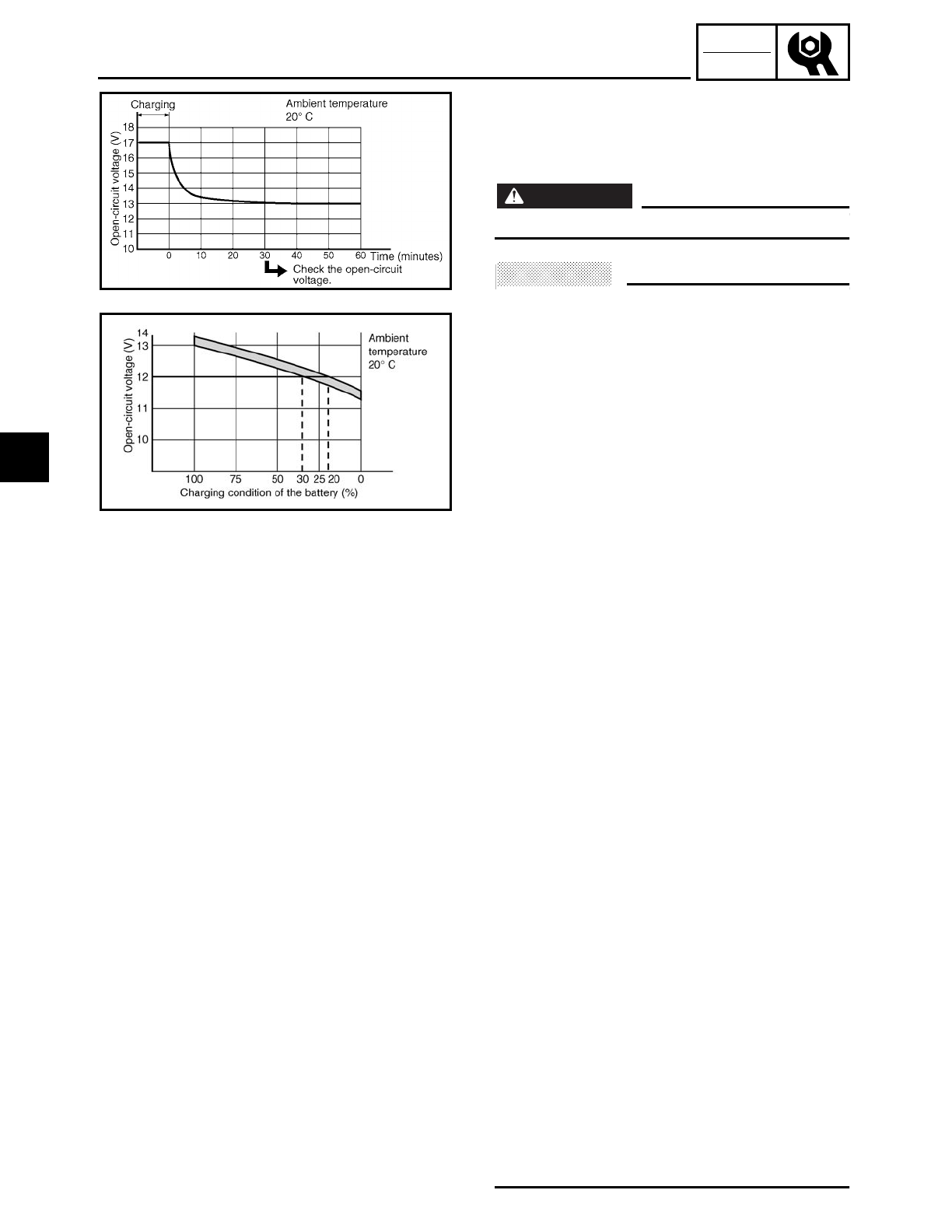
3 - 53
CHK
ADJ
CHECKING AND CHARGING THE BATTERY
5. Charge:
• battery
(refer to the appropriate charging
method illustration)
WARNING
WARNING
Do not quick charge a battery.
ACHTUNG:
CAUTION:
• Never remove the MF battery sealing
caps.
• Do not use a high-rate battery charger
since it forces a high-amperage current
into the battery quickly and can cause
battery overheating and battery plate
damage.
• If it is impossible to regulate the charging
current on the battery charger, be careful
not to overcharge the battery.
• When charging a battery, be sure to
remove it from the motorcycle. (If charg-
ing has to be done with the battery
mounted on the motorcycle, disconnect
the negative battery lead from the battery
terminal.)
• To reduce the chance of sparks, do not
plug in the battery charger until the bat-
tery charger leads are connected to the
battery.
• Before removing the battery charger lead
clips from the battery terminals, be sure
to turn off the battery charger.
• Make sure the battery charger lead clips
are in full contact with the battery termi-
nals and that they are not shorted. A cor-
roded battery charger lead clip may
generate heat in the contact area and a
weak clip spring may cause sparks.
• If the battery becomes hot to the touch at
any time during the charging process, dis-
connect the battery charger and let the
battery cool before reconnecting it. Hot
batteries can explode!
• As shown in the following illustration, the
open-circuit voltage of an MF battery sta-
bilizes about 30 minutes after charging
has been completed. Therefore, wait 30
minutes after charging is completed
before measuring the open-circuit volt-
age.
3
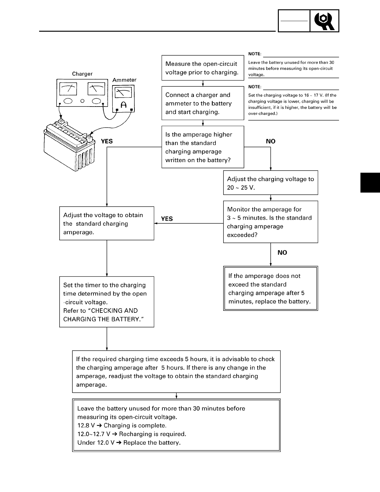
3 - 54
CHK
ADJ
CHECKING AND CHARGING THE BATTERY
Charging method using a variable voltage charger
3
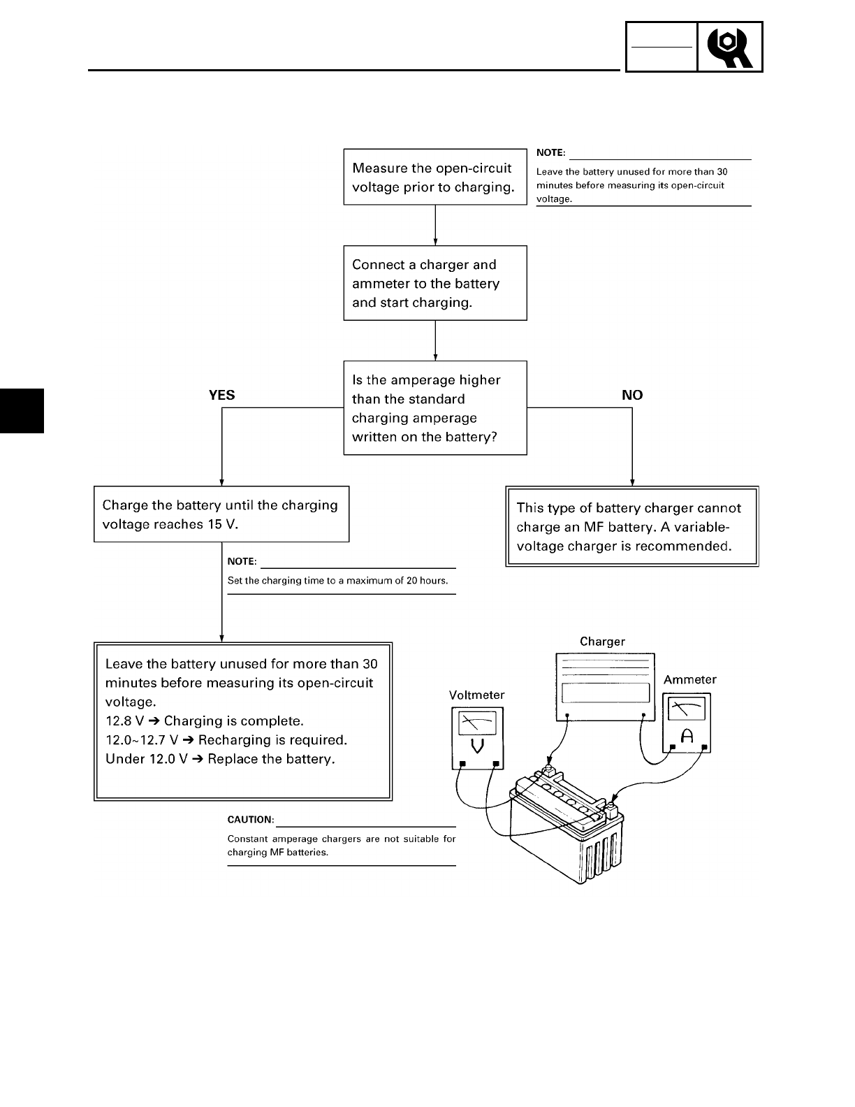
3 - 55
CHK
ADJ
CHECKING AND CHARGING THE BATTERY
Charging method using a constant voltage charger
3
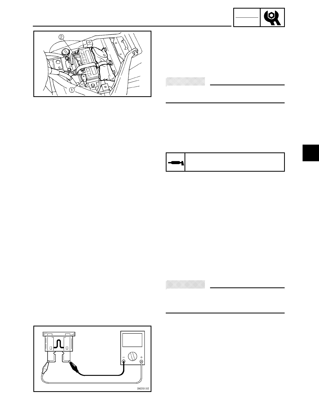
3 - 56
CHK
ADJ
CHECKING AND CHARGING THE BATTERY/
CHECKING THE FUSES
6. Install:
• battery
• battery band
7. Connect:
• battery leads
(to the battery terminals)
ACHTUNG:
CAUTION:
First, connect the positive battery lead 1,
then the negative battery lead 2.
8. Check:
• battery terminals
Dirt → Clean with a wire brush.
Loose connection → Connect properly.
9. Lubricate:
• battery terminals
10.Install:
• rider seat
Refer to “SEATS AND SIDE COVERS”.
Recommended lubricant
Dielectric grease
EAS00181
CHECKING THE FUSES
The following procedure applies to all of
the fuses.
ACHTUNG:
CAUTION:
To avoid a short circuit, always set the
main switch to “OFF” when checking or
replacing a fuse.
1. Remove:
• left side cover
Refer to “SEATS AND SIDE COVERS”.
2. Check:
• continuity
▼ ▼ ▼ ▼ ▼ ▼ ▼ ▼ ▼ ▼ ▼ ▼ ▼ ▼ ▼ ▼ ▼ ▼ ▼ ▼ ▼ ▼ ▼ ▼ ▼ ▼ ▼ ▼
a. Connect the pocket tester to the fuse and
check the continuity.
3
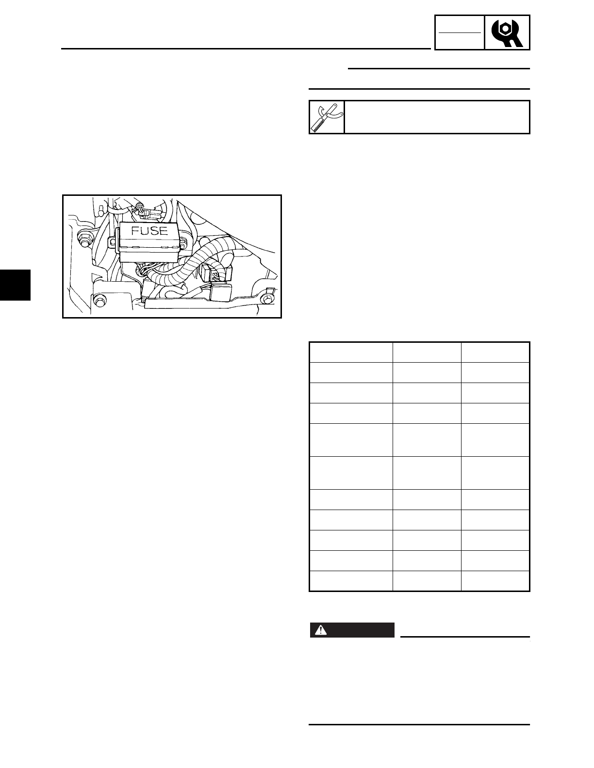
3 - 57
CHK
ADJ
CHECKING THE FUSES
NOTE:
Set the pocket tester selector to “Ω × 1”.
b. If the pocket tester indicates “∞”, replace
the fuse.
▲ ▲ ▲ ▲ ▲ ▲ ▲ ▲ ▲ ▲ ▲ ▲ ▲ ▲ ▲ ▲ ▲ ▲ ▲ ▲ ▲ ▲ ▲ ▲ ▲ ▲ ▲ ▲
Pocket tester
YU-03112
3. Replace:
• blown fuse
▼ ▼ ▼ ▼ ▼ ▼ ▼ ▼ ▼ ▼ ▼ ▼ ▼ ▼ ▼ ▼ ▼ ▼ ▼ ▼ ▼ ▼ ▼ ▼ ▼ ▼ ▼ ▼
a. Set the main switch to “OFF”.
b. Install a new fuse of the correct amper-
age.
c. Set the main switch to “ON” and verify if
the electrical circuit is operational.
d. If the fuse immediately blows again,
check the electrical circuit.
▲ ▲ ▲ ▲ ▲ ▲ ▲ ▲ ▲ ▲ ▲ ▲ ▲ ▲ ▲ ▲ ▲ ▲ ▲ ▲ ▲ ▲ ▲ ▲ ▲ ▲ ▲ ▲
WARNING
WARNING
Never use a fuse with an amperage other
than that specified. Improvising or using a
fuse with the wrong amperage may cause
extensive damage to the electrical system,
cause the lighting and ignition systems to
malfunction and could possibly cause a fire.
Item Amperage Q’ty
Main fuse 30A 1
Headlight fuse 15A 1
Ignition fuse 15A 1
Signaling sys-
tem fuse 10A 1
Carburetor
heater fuse 10A 1
Backup fuse 5A 1
Reserve fuse 30A 1
Reserve fuse 15A 1
Reserve fuse 10A 1
Reserve fuse 5A 1
3
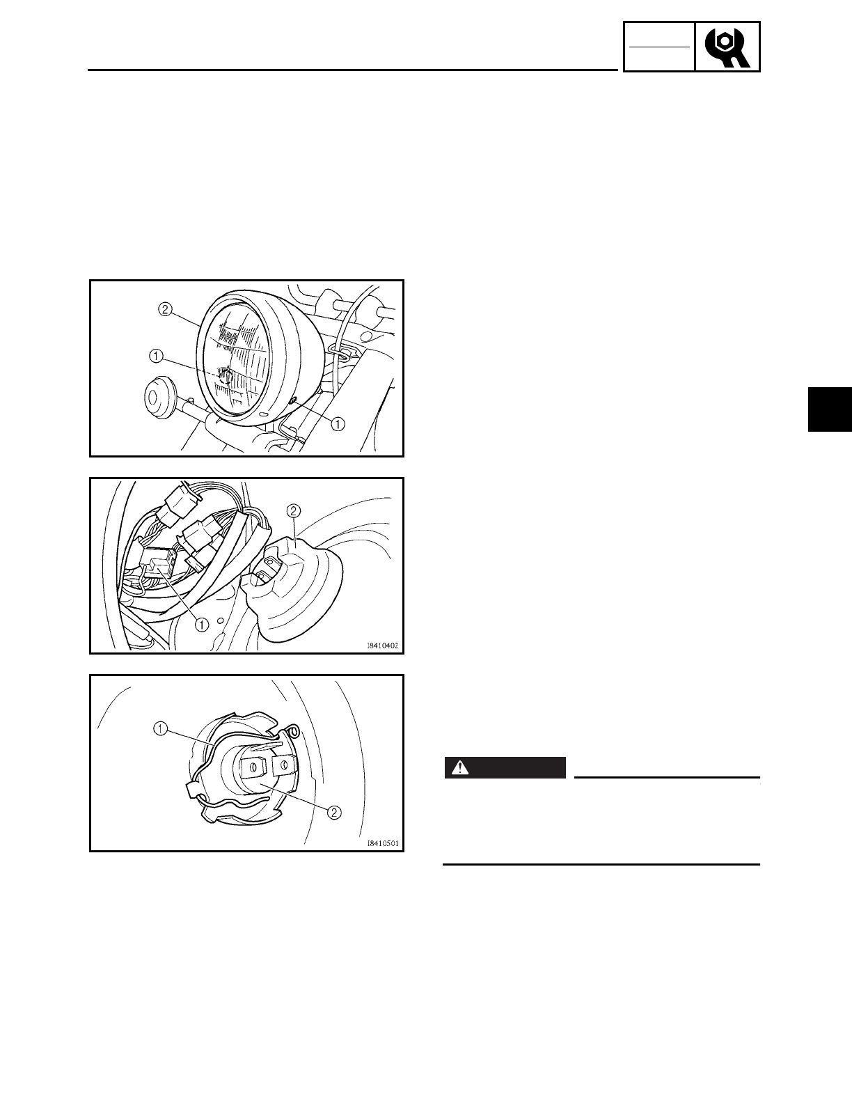
3 - 58
CHK
ADJ
CHECKING THE FUSES/
REPLACING THE HEADLIGHT BULB
4. Install:
• left side cover
Refer to “SEATS AND SIDE COVERS”.
EAS00182
REPLACING THE HEADLIGHT BULB
1. Remove:
• screws 1
• headlight lens unit 2
2. Disconnect:
• headlight coupler 1
3. Remove:
• headlight bulb holder cover 2
4. Detach:
• headlight bulb holder 1
5. Remove:
• headlight bulb 2
WARNING
WARNING
Since the headlight bulb gets extremely
hot, keep flammable products and your
hands away from the bulb until it has
cooled down.
3
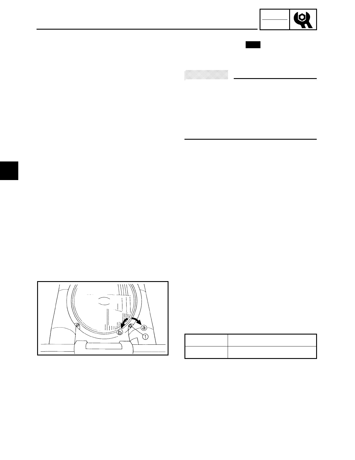
3 - 59
CHK
ADJ
REPLACING THE HEADLIGHT BULB/
ADJUSTING THE HEADLIGHT BEAM
6. Install:
• headlight bulb
Secure the new headlight bulb with the
headlight bulb holder.
ACHTUNG:
CAUTION:
Avoid touching the glass part of the head-
light bulb to keep it free from oil, otherwise
the transparency of the glass, the life of the
bulb, and the luminous flux will be
adversely affected. If the headlight bulb
gets soiled, thoroughly clean it with a cloth
moistened with alcohol or lacquer thinner.
7. Attach:
• headlight bulb holder
8. Install:
• headlight bulb holder cover
9. Connect:
• headlight coupler
10.Install:
• headlight lens unit
• screws
New
EAS00184
ADJUSTING THE HEADLIGHT BEAM
1. Adjust:
• headlight beam (vertically)
▼ ▼ ▼ ▼ ▼ ▼ ▼ ▼ ▼ ▼ ▼ ▼ ▼ ▼ ▼ ▼ ▼ ▼ ▼ ▼ ▼ ▼ ▼ ▼ ▼ ▼ ▼ ▼
a. Turn the adjusting screw 1 in direction
a or b.
▲ ▲ ▲ ▲ ▲ ▲ ▲ ▲ ▲ ▲ ▲ ▲ ▲ ▲ ▲ ▲ ▲ ▲ ▲ ▲ ▲ ▲ ▲ ▲ ▲ ▲ ▲ ▲
Direction aHeadlight beam is raised.
Direction bHeadlight beam is lowered.
3
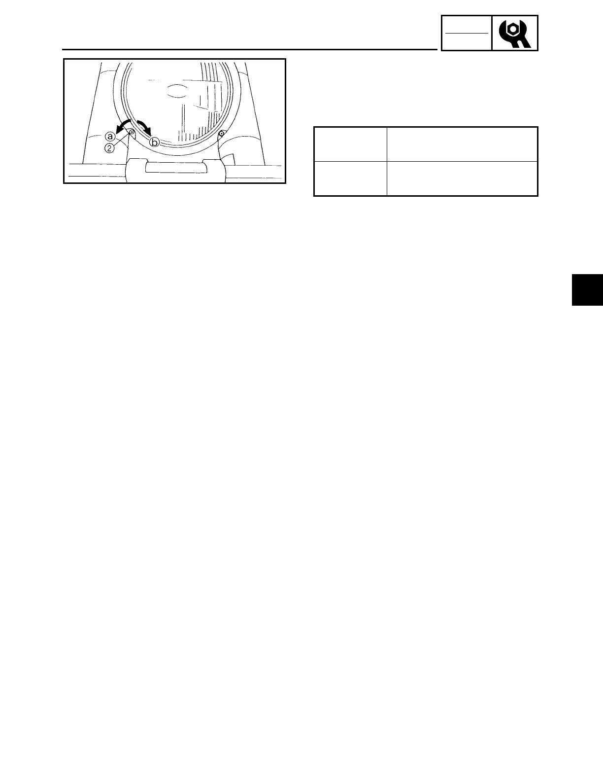
3 - 60
CHK
ADJ
ADJUSTING THE HEADLIGHT BEAM
2. Adjust:
• headlight beam (horizontally)
▼ ▼ ▼ ▼ ▼ ▼ ▼ ▼ ▼ ▼ ▼ ▼ ▼ ▼ ▼ ▼ ▼ ▼ ▼ ▼ ▼ ▼ ▼ ▼ ▼ ▼ ▼ ▼
a. Turn the adjusting knob 2 in direction a
or b.
▲ ▲ ▲ ▲ ▲ ▲ ▲ ▲ ▲ ▲ ▲ ▲ ▲ ▲ ▲ ▲ ▲ ▲ ▲ ▲ ▲ ▲ ▲ ▲ ▲ ▲ ▲ ▲
Direction aHeadlight beam moves to
the right.
Direction bHeadlight beam moves to
the left.
3
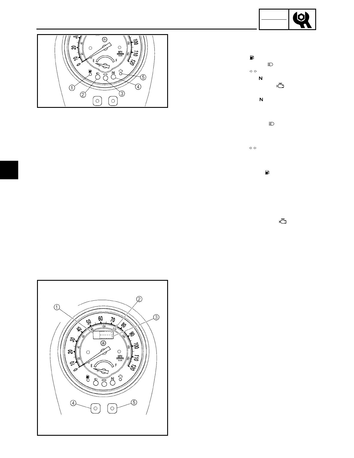
3 - 61
CHK
ADJ
INSTRUMENT FUNCTIONS
INSTRUMENT FUNCTIONS
INDICATOR LIGHTS
1Fuel indicator light “ ”
2High beam indicator light “ ”
3Turn indicator light “ ”
4Neutral indicator light “ ”
5Engine trouble indicator light “ ”
Neutral indicator light “ ”
This indicator comes on when the trans-
mission is in neutral.
High beam indicator light “ ”
This indicator comes on when the head-
light high beam is used.
Turn indicator light “ ”
This indicator flashes when the turn
switch is moved to the left or right.
Fuel level indicator light “ ”
When the fuel level drops below approxi-
mately 3.5 L (0.8 Imp gal, 0.9 US gal), this
light will come on. When this light comes
on, turn the fuel cock to “RES”. Then, fill
the tank at the first opportunity.
Engine trouble indicator light “ ”
This indicator light will come on or flash
if trouble occurs in a monitoring circuit.
In such a case, take the motorcycle to a
Yamaha dealer to have the self-diagnos-
tic systems checked.
COMBINATION METER
1Combination meter
2Clock
3Odometer/trip meter
4Mode button
5Set button
This combination meter is equipped with an
odometer and a twin trip meter. Pushing
the mode button will change the display
from one to the other as follows.
“ODO” → “TRIP A” → “TRIP B” → “ODO”
When set to “ODO”, it indicates the motor-
cycle’s total mileage. When set to “TRIP A”
or “TRIP B”, it indicates the motorcycle’s
mileage since the trip meter was last reset.
Use the trip meter to estimate how far you
can ride on a tank of fuel. This information
will enable you to plan fuel stops in the
future.
3
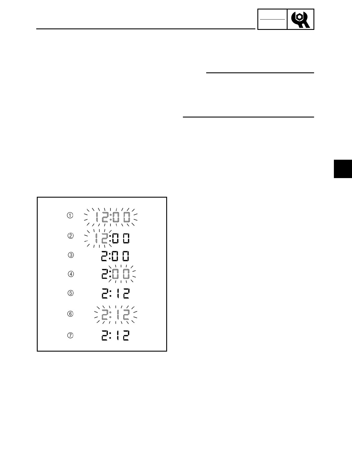
3 - 62
CHK
ADJ
INSTRUMENT FUNCTIONS
To reset the trip meter to “0”, push the set
button until it displays “TRIP A” or “TRIP
B”, then push mode button and hold it
down for at least one second.
NOTE:
This motorcycle does not have a tachome-
ter. However, it is equipped with an engine
revolution limiter, which prevents the
engine revolution from exceeding approxi-
mately 4,400 r/min.
Setting the clock
This clock always shows the time regard-
less of the main switch position.
1. Turn the main switch to “ON”.
2. Press both left and right buttons simulta-
neously until both hours and minutes
flash. 1
3. Push the left button and the hour display
will flash. 2
4. Push the right button to change the
hours. 3
5. Push the left button and the minute dis-
play will flash. 4
6. Push the right button to change the min-
utes. 5
7. Push the left button and both hours and
minutes will flash. 6
8. Push the right button for two seconds to
set the clock. 7
3
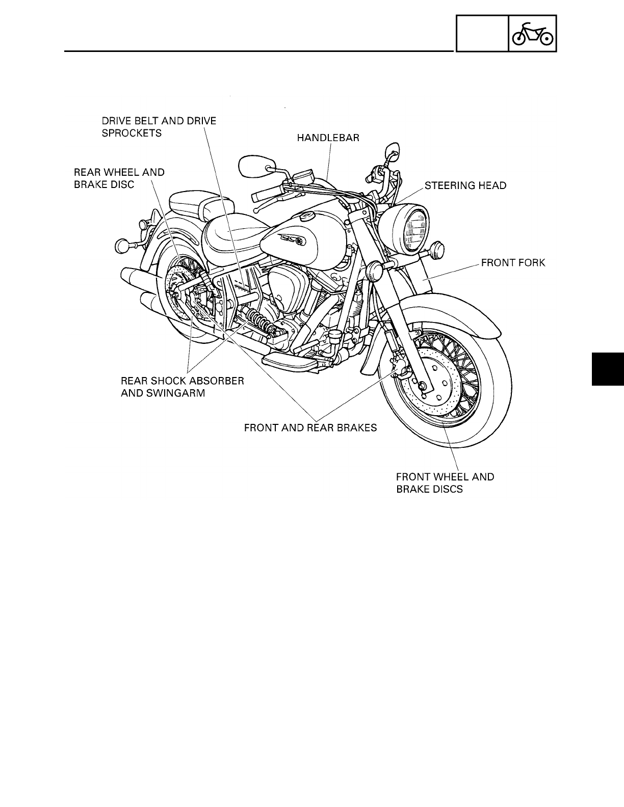
CHAS
CONTENTS
CHASSIS
FRONT WHEEL AND BRAKE DISCS ........................................................... 4-1
REMOVING THE FRONT WHEEL ........................................................ 4-3
DISASSEMBLING THE FRONT WHEEL .............................................. 4-3
CHECKING THE FRONT WHEEL .......................................................... 4-4
CHECKING THE BRAKE DISCS ............................................................ 4-6
ASSEMBLING THE FRONT WHEEL .................................................... 4-7
INSTALLING THE FRONT WHEEL ....................................................... 4-7
ADJUSTING THE FRONT WHEEL STATIC BALANCE ....................... 4-9
REAR WHEEL, BRAKE DISC AND REAR WHEEL PULLEY ...................... 4-11
REMOVING THE REAR WHEEL ......................................................... 4-16
CHECKING THE REAR WHEEL .......................................................... 4-16
CHECKING THE REAR WHEEL DRIVE HUB ...................................... 4-17
CHECKING AND REPLACING THE REAR WHEEL PULLEY ............. 4-17
ASSEMBLING THE REAR WHEEL ..................................................... 4-18
INSTALLING THE REAR WHEEL ....................................................... 4-18
ADJUSTING THE REAR WHEEL STATIC BALANCE ........................ 4-21
4

CHAS
FRONT AND REAR BRAKES ...................................................................... 4-22
REPLACING THE FRONT BRAKE PADS ............................................ 4-24
REPLACING THE REAR BRAKE PADS .............................................. 4-27
DISASSEMBLING THE FRONT BRAKE MASTER CYLINDER .......... 4-35
DISASSEMBLING THE REAR BRAKE MASTER CYLINDER ............ 4-35
CHECKING THE FRONT AND REAR BRAKE MASTER
CYLINDERS ..................................................................................... 4-36
ASSEMBLING AND INSTALLING THE FRONT BRAKE
MASTER CYLINDER ....................................................................... 4-37
ASSEMBLING AND INSTALLING THE REAR BRAKE
MASTER CYLINDER ....................................................................... 4-40
DISASSEMBLING THE FRONT BRAKE CALIPERS ........................... 4-47
DISASSEMBLING THE REAR BRAKE CALIPER ................................ 4-47
CHECKING THE FRONT AND REAR BRAKE CALIPERS .................. 4-48
ASSEMBLING AND INSTALLING THE FRONT
BRAKE CALIPERS ........................................................................... 4-49
ASSEMBLING AND INSTALLING THE REAR
BRAKE CALIPER ............................................................................. 4-52
FRONT FORK ..............................................................................................4-55
REMOVING THE FRONT FORK LEGS ............................................... 4-59
DISASSEMBLING THE FRONT FORK LEGS ..................................... 4-59
CHECKING THE FRONT FORK LEGS ................................................ 4-60
ASSEMBLING THE FRONT FORK LEGS ........................................... 4-61
INSTALLING THE FRONT FORK LEGS ............................................. 4-64
HANDLEBAR ...............................................................................................4-67
REMOVING THE HANDLEBAR .......................................................... 4-69
CHECKING THE HANDLEBAR ........................................................... 4-69
INSTALLING THE HANDLEBAR ........................................................ 4-69
STEERING HEAD ........................................................................................ 4-73
REMOVING THE LOWER BRACKET .................................................. 4-75
CHECKING THE STEERING HEAD .................................................... 4-75
INSTALLING THE STEERING HEAD ................................................. 4-76
REAR SHOCK ABSORBER AND SWINGARM .......................................... 4-79
HANDLING THE REAR SHOCK ABSORBER ..................................... 4-83
DISPOSING OF A REAR SHOCK ABSORBER AND
GAS CYLINDER .............................................................................. 4-83
REMOVING THE REAR SHOCK ABSORBER AND
SWINGARM .................................................................................... 4-83
CHECKING THE REAR SHOCK ABSORBER ...................................... 4-84
CHECKING THE REPLAY ARM AND CONNECTING ARM ............... 4-85
CHECKING THE SWINGARM ............................................................ 4-85
INSTALLING THE REAR SHOCK ABSORBER AND
SWINGARM .................................................................................... 4-86
4

CHAS
DRIVE BELT AND DRIVE PULLEY ............................................................. 4-90
REMOVING THE DRIVE BELT AND DRIVE PULLEY ......................... 4-91
CHECKING THE DRIVE BELT ............................................................. 4-91
INSTALLING THE DRIVE BELT AND DRIVE PULLEY ....................... 4-92
4
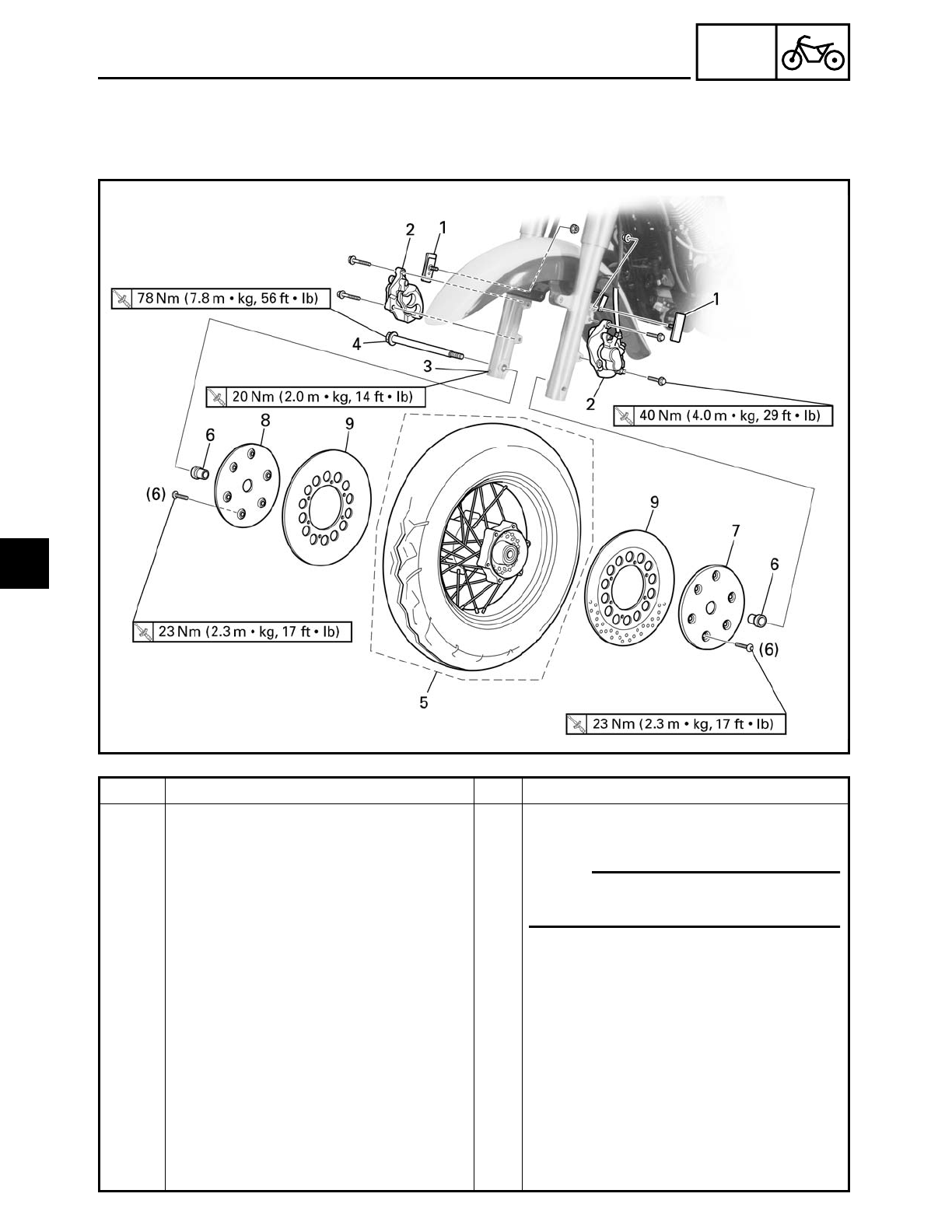
4 - 1
CHAS
FRONT WHEEL AND BRAKE DISCS
EAS00514
CHASSIS
FRONT WHEEL AND BRAKE DISCS
Order Job/Part Q’ty Remarks
Removing the front wheel and brake
discs
Remove the parts in the order listed.
1 Reflector (left and right) 2
2 Brake caliper (left and right) 2
3 Wheel axle pinch bolt 1 Loosen.
4 Front wheel axle 1
5 Front wheel 1
6 Collar (left and right) 2
7 Brake disc cover (left) 1
8 Brake disc cover (right-with weight) 1
9 Brake disc (left and right) 2
For installation, reverse the removal
procedure.
NOTE:
Place the motorcycle on a suitable stand
so that the front wheel is elevated.
4
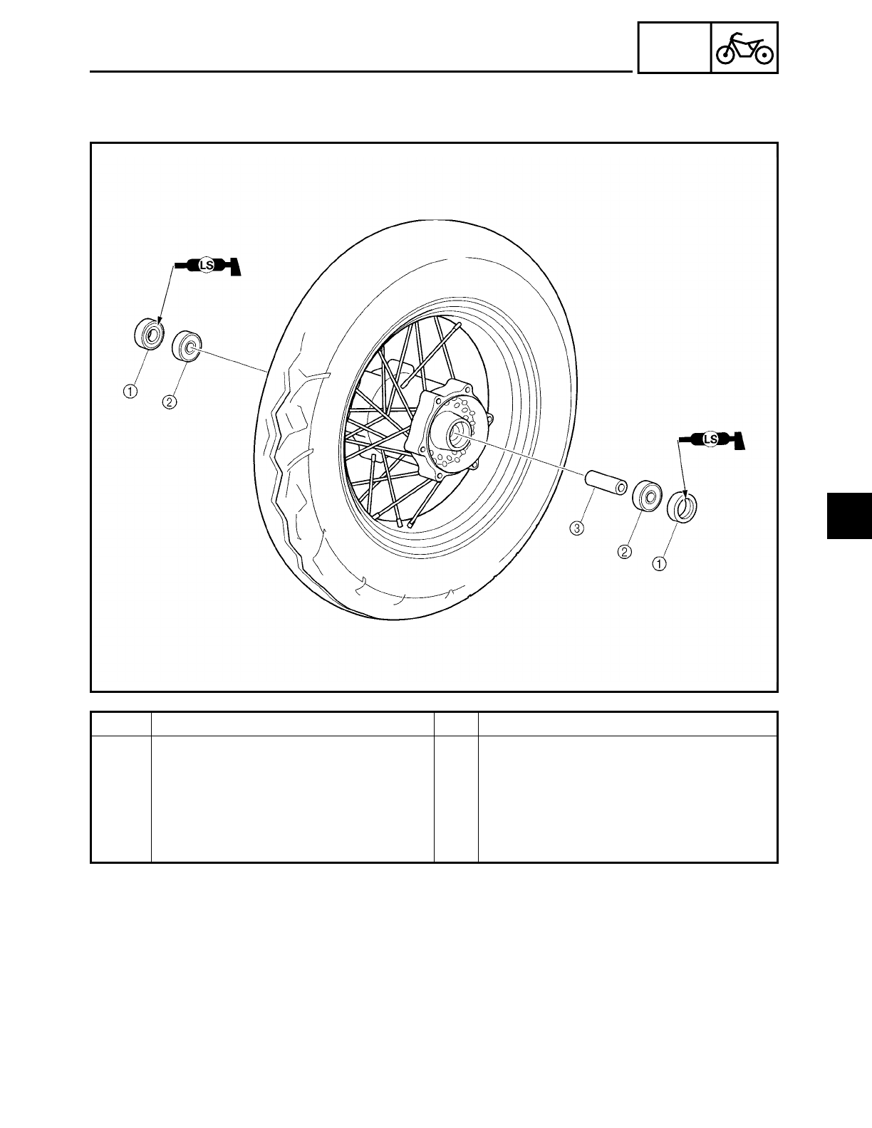
4 - 2
CHAS
FRONT WHEEL AND BRAKE DISCS
Order Job/Part Q’ty Remarks
Disassembling the front wheel Remove the parts in the order listed.
1Oil seal (left and right) 2
2Wheel bearing (left and right) 2
3Spacer 1
For assembly, reverse the disassembly
procedure.
4

4 - 3
CHAS
FRONT WHEEL AND BRAKE DISCS
EAS00521
REMOVING THE FRONT WHEEL
1. Stand the motorcycle on a level surface.
WARNING
WARNING
Securely support the motorcycle so that
there is no danger of it falling over.
NOTE:
Place the motorcycle on a suitable stand so
that the front wheel is elevated.
2. Remove:
• left brake caliper
• right brake caliper
NOTE:
Do not squeeze the brake lever when
removing the brake calipers.
3. Elevate:
• front wheel
NOTE:
Place the motorcycle on a suitable stand so
that the front wheel is elevated.
EAS00523
DISASSEMBLING THE FRONT WHEEL
1. Remove:
• oil seals
• wheel bearings
▼ ▼ ▼ ▼ ▼ ▼ ▼ ▼ ▼ ▼ ▼ ▼ ▼ ▼ ▼ ▼ ▼ ▼ ▼ ▼ ▼ ▼ ▼ ▼ ▼ ▼ ▼ ▼
a. Clean the outside of the front wheel hub.
b. Remove the oil seals
1 with a flat-head
screwdriver.
NOTE:
To prevent damaging the wheel, place a rag
2 between the screwdriver and the wheel
surface.
c. Remove the wheel bearings with a gen-
eral bearing puller.
▲ ▲ ▲ ▲ ▲ ▲ ▲ ▲ ▲ ▲ ▲ ▲ ▲ ▲ ▲ ▲ ▲ ▲ ▲ ▲ ▲ ▲ ▲ ▲ ▲ ▲ ▲ ▲
4
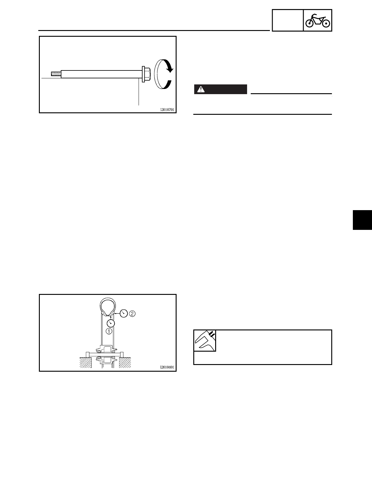
4 - 4
CHAS
FRONT WHEEL AND BRAKE DISCS
EAS00526
CHECKING THE FRONT WHEEL
1. Check:
• wheel axle
Roll the wheel axle on a flat surface.
Bends → Replace.
WARNING
WARNING
Do not attempt to straighten a bent wheel
axle.
2. Check:
• tire
• front wheel
Damage/wear → Replace.
Refer to “CHECKING THE TIRES” and
“CHECKING THE WHEELS” in chapter 3.
3. Check:
• spokes
Bends/damage → Replace.
Loose → Tighten.
Refer to “CHECKING AND TIGHTENING
THE SPOKES” in chapter 3.
4. Measure:
• radial wheel runout 1
• lateral wheel runout 2
Over the specified limits → Replace.
Maximum radial wheel runout
1.0 mm (0.04 in)
Maximum lateral wheel runout
0.5 mm (0.02 in)
5. Check:
• collars
Damage/wear → Replace.
4
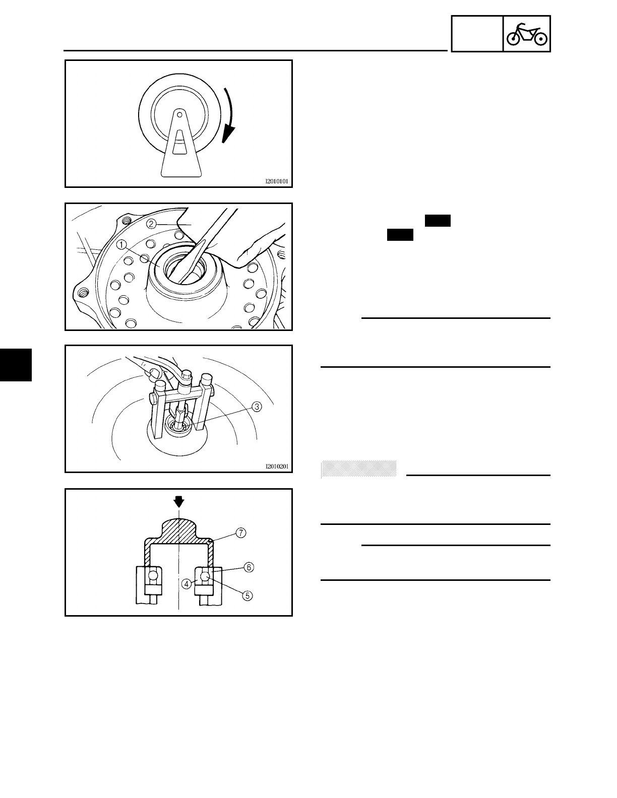
4 - 5
CHAS
FRONT WHEEL AND BRAKE DISCS
6. Check:
• wheel bearings
Front wheel turns roughly or is loose
→
Replace the wheel bearings.
• oil seals
Damage/wear → Replace.
7. Replace:
• wheel bearings
• oil seals
▼ ▼ ▼ ▼ ▼ ▼ ▼ ▼ ▼ ▼ ▼ ▼ ▼ ▼ ▼ ▼ ▼ ▼ ▼ ▼ ▼ ▼ ▼ ▼ ▼ ▼ ▼ ▼
a. Clean the outside of the front wheel hub.
b. Remove the oil seals
1 with a flat-head
screwdriver.
NOTE:
To prevent damaging the wheel, place a rag
2 between the screwdriver and the wheel
surface.
c. Remove the wheel bearings 3 with a
general bearing puller.
d. Install the new wheel bearings and oil
seals in the reverse order of disassem-
bly.
ACHTUNG:
CAUTION:
Do not contact the wheel bearing inner
race
4 or balls
5. Contact should be made
only with the outer race
6.
NOTE:
Use a socket
7 that matches the diameter
of the wheel bearing outer race and oil seal.
▲ ▲ ▲ ▲ ▲ ▲ ▲ ▲ ▲ ▲ ▲ ▲ ▲ ▲ ▲ ▲ ▲ ▲ ▲ ▲ ▲ ▲ ▲ ▲ ▲ ▲ ▲ ▲
New
New
4
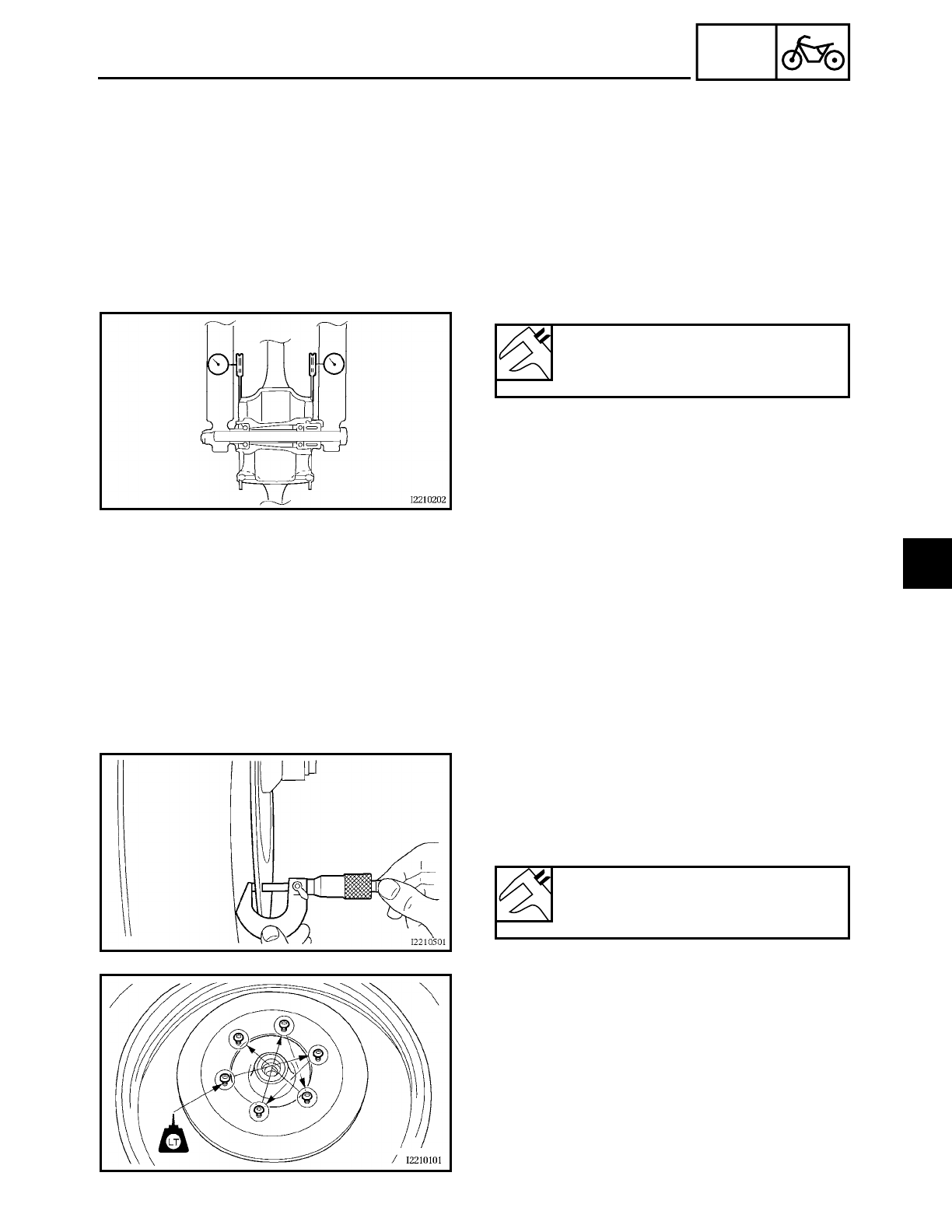
4 - 6
CHAS
FRONT WHEEL AND BRAKE DISCS
EAS00531
CHECKING THE BRAKE DISCS
The following procedure applies to all of
the brake discs.
1. Check:
• brake disc
Damage/galling → Replace.
2. Measure:
• brake disc deflection
Out of specification → Correct the brake
disc deflection or replace the brake disc.
▼ ▼ ▼ ▼ ▼ ▼ ▼ ▼ ▼ ▼ ▼ ▼ ▼ ▼ ▼ ▼ ▼ ▼ ▼ ▼ ▼ ▼ ▼ ▼ ▼ ▼ ▼ ▼
a. Place the motorcycle on a suitable stand
so that the wheel is elevated.
b. Before measuring the front brake disc
deflection, turn the handlebar to the left
or right to ensure that the front wheel is
stationary.
c. Remove the brake caliper.
d. Hold the dial gauge at a right angle
against the brake disc surface.
e. Measure the deflection 1.5 mm (0.05 in)
below the edge of the brake disc.
▲ ▲ ▲ ▲ ▲ ▲ ▲ ▲ ▲ ▲ ▲ ▲ ▲ ▲ ▲ ▲ ▲ ▲ ▲ ▲ ▲ ▲ ▲ ▲ ▲ ▲ ▲ ▲
Maximum brake disc deflection
Front: 0.15 mm (0.006 in)
Rear: 0.15 mm (0.006 in)
3. Measure:
• brake disc thickness
Measure the brake disc thickness at a
few different locations.
Out of specification → Replace.
Minimum brake disc thickness
Front: 4.5 mm (0.18 in)
Rear: 6.5 mm (0.26 in)
4. Adjust:
• brake disc deflection
▼ ▼ ▼ ▼ ▼ ▼ ▼ ▼ ▼ ▼ ▼ ▼ ▼ ▼ ▼ ▼ ▼ ▼ ▼ ▼ ▼ ▼ ▼ ▼ ▼ ▼ ▼ ▼
a. Remove the brake disc cover and brake
disc.
b. Rotate the brake disc cover and brake
disc by one bolt hole.
c. Install the brake disc cover and brake
disc.
4
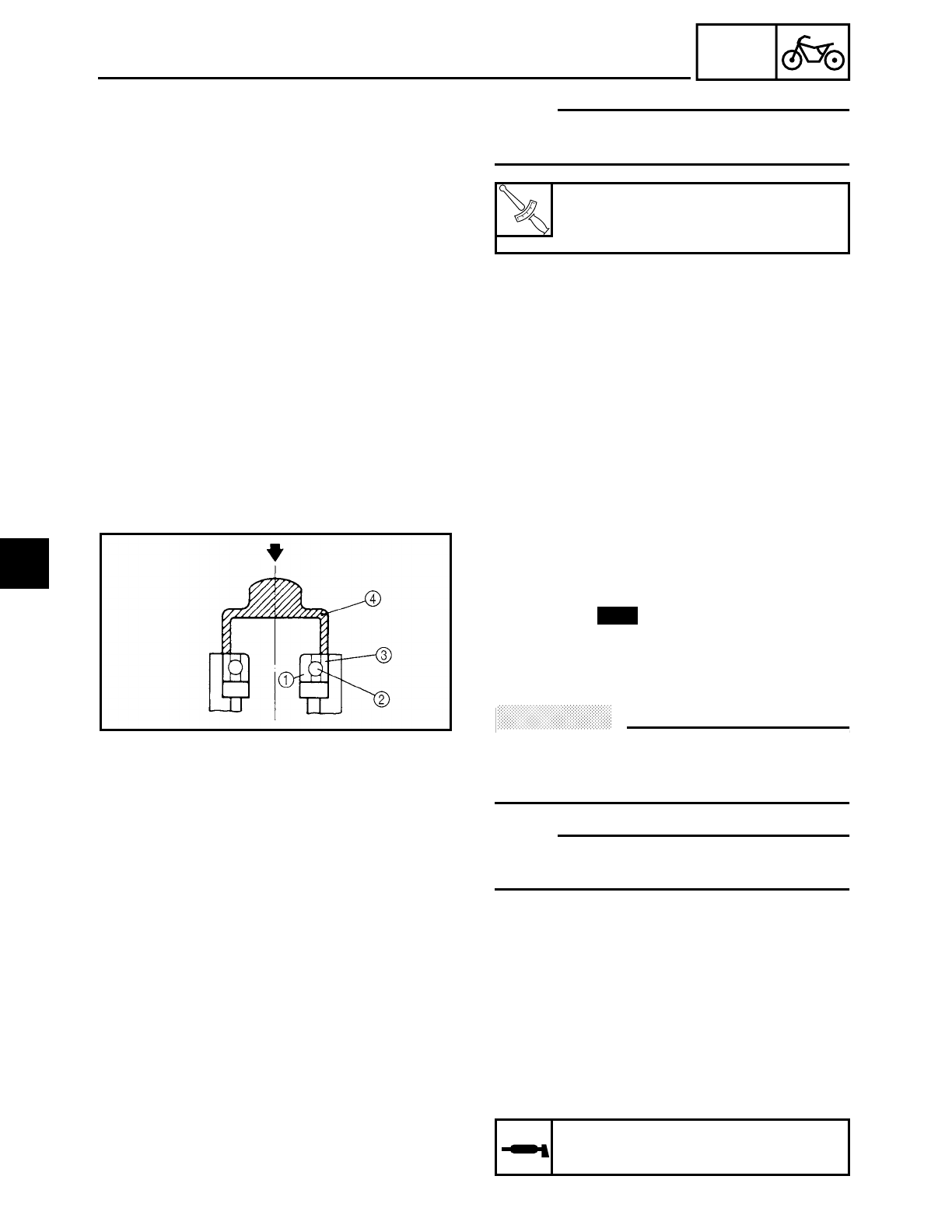
4 - 7
CHAS
FRONT WHEEL AND BRAKE DISCS
NOTE:
Tighten the brake disc bolts in stages and in
a crisscross pattern.
d. Measure the brake disc deflection.
e. If out of specification, repeat the adjust-
ment steps until the brake disc deflection
is within specification.
f. If the brake disc deflection cannot be
brought within specification, replace the
brake disc.
▲ ▲ ▲ ▲ ▲ ▲ ▲ ▲ ▲ ▲ ▲ ▲ ▲ ▲ ▲ ▲ ▲ ▲ ▲ ▲ ▲ ▲ ▲ ▲ ▲ ▲ ▲ ▲
T
R
.
.
Brake disc bolt
23 Nm (2.3 m • kg, 17 ft • lb)
LOCTITE
EAS00539
ASSEMBLING THE FRONT WHEEL
1. Install:
• wheel bearings
• oil seals
Install the new wheel bearings and oil
seals in the reverse order of disassem-
bly.
ACHTUNG:
CAUTION:
Do not contact the wheel bearing inner
race 1 or balls 2. Contact should be made
only with the outer race 3.
NOTE:
Use a socket 4 that matches the diameter
of the wheel bearing outer race and oil seal.
New
EAS00544
INSTALLING THE FRONT WHEEL
The following procedure applies to both
brake discs.
1. Lubricate:
• wheel axle
• oil seal lips
Recommended lubricant
Lithium soap base grease
4
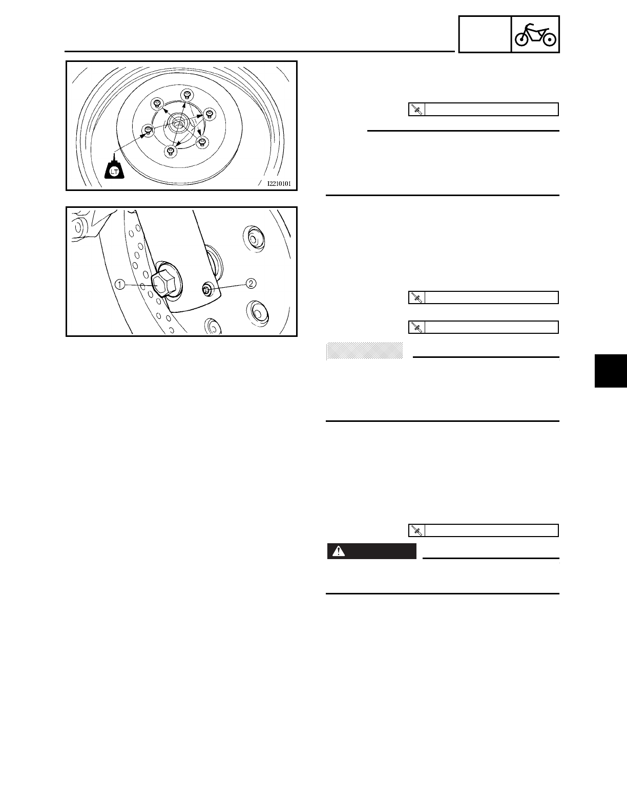
4 - 8
CHAS
FRONT WHEEL AND BRAKE DISCS
2. Install:
• brake discs
• brake disc covers
NOTE:
• Apply locking agent (LOCTITE 648) to the
threads of the brake disc bolts.
• Tighten the brake disc bolts in stages and
in a crisscross pattern.
T
R
.
.
23 Nm (2.3 m · kg, 17 ft · lb)
3. Install:
• collars
• front wheel
• front wheel axle
4. Tighten:
• front wheel axle 1
• wheel axle pinch bolt 2
ACHTUNG:
CAUTION:
Before tightening the wheel axle nut, push
down hard on the handlebar several times
and check if the front fork rebounds
smoothly.
T
R
.
.
78 Nm (7.8 m · kg, 56 ft · lb)
T
R
.
.
20 Nm (2.0 m · kg, 14 ft · lb)
5. Install:
• brake calipers
WARNING
WARNING
Make sure the brake hose is routed prop-
erly.
6. Install:
• reflectors
T
R
.
.
40 Nm (4.0 m · kg, 29 ft · lb)
4
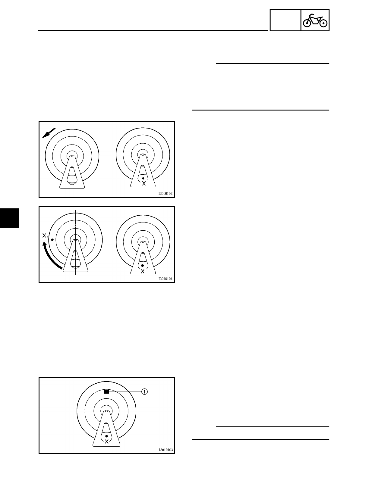
4 - 9
CHAS
FRONT WHEEL AND BRAKE DISCS
EAS00549
ADJUSTING THE FRONT WHEEL STATIC
BALANCE
NOTE:
• After replacing the tire, wheel, or both, the
front wheel static balance should be
adjusted.
• Adjust the front wheel static balance with
the brake discs installed.
1. Remove:
• balancing weight(s)
2. Find:
• front wheel’s heavy spot
▼ ▼ ▼ ▼ ▼ ▼ ▼ ▼ ▼ ▼ ▼ ▼ ▼ ▼ ▼ ▼ ▼ ▼ ▼ ▼ ▼ ▼ ▼ ▼ ▼ ▼ ▼ ▼
a. Place the front wheel on a suitable bal-
ancing stand.
b. Spin the front wheel.
c. When the front wheel stops, put an “X1”
mark at the bottom of the wheel.
d. Turn the front wheel 90˚ so that the “X1”
mark is positioned as shown.
e. Release the front wheel.
f. When the wheel stops, put an “X2” mark
at the bottom of the wheel.
g. Repeat steps (b) through (f) several times
until all the marks come to rest at the
same spot.
h. The spot where all the marks come to
rest is the front wheel’s heavy spot “X”.
▲ ▲ ▲ ▲ ▲ ▲ ▲ ▲ ▲ ▲ ▲ ▲ ▲ ▲ ▲ ▲ ▲ ▲ ▲ ▲ ▲ ▲ ▲ ▲ ▲ ▲ ▲ ▲
3. Adjust:
• front wheel static balance
▼ ▼ ▼ ▼ ▼ ▼ ▼ ▼ ▼ ▼ ▼ ▼ ▼ ▼ ▼ ▼ ▼ ▼ ▼ ▼ ▼ ▼ ▼ ▼ ▼ ▼ ▼ ▼
a. Install a balancing weight 1 onto the rim
exactly opposite the heavy spot “X”.
NOTE:
Start with the lightest weight.
b. Turn the front wheel 90˚ so that the
heavy spot is positioned as shown.
4
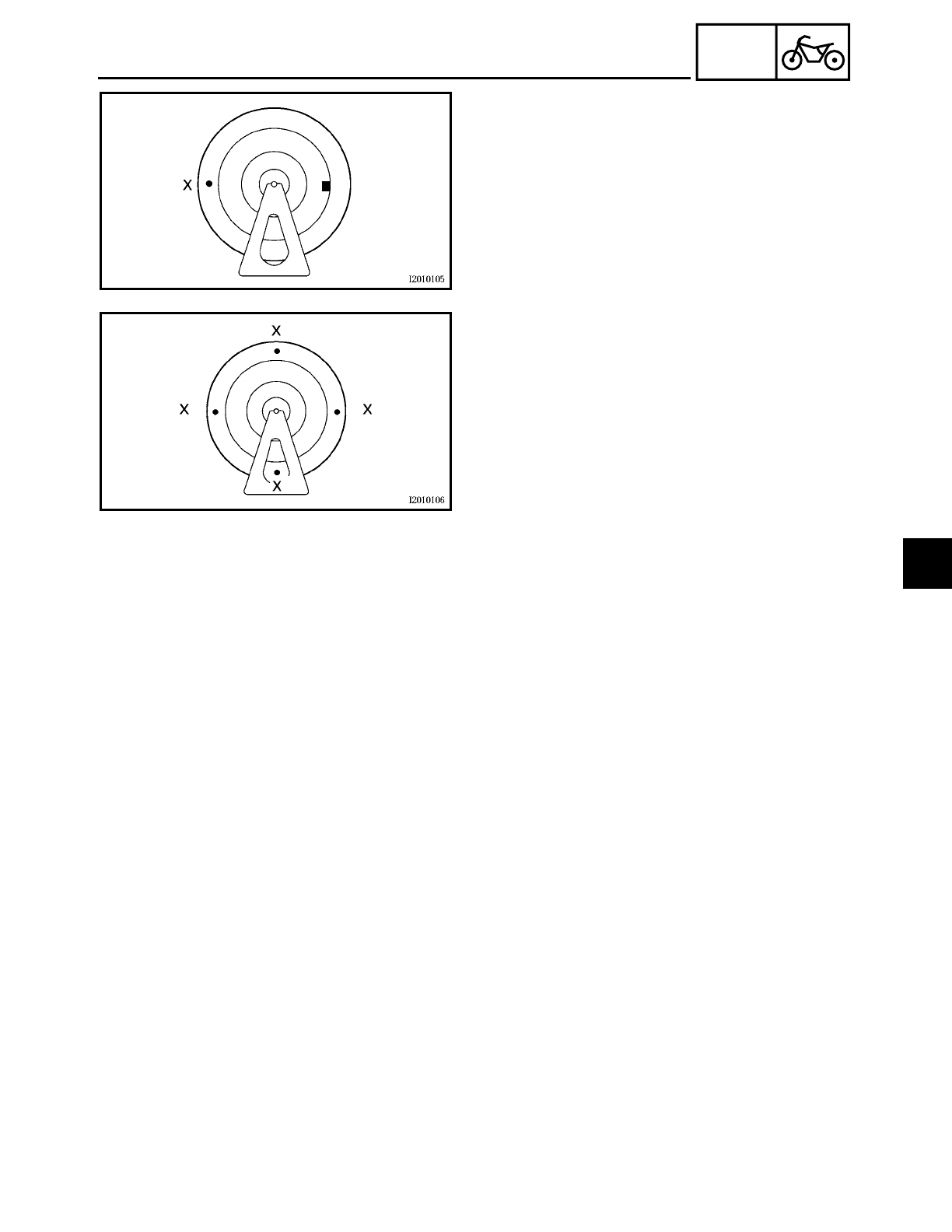
4 - 10
CHAS
FRONT WHEEL AND BRAKE DISCS
c. If the heavy spot does not stay in that
position, install a heavier weight.
d. Repeat steps (b) and (c) until the front
wheel is balanced.
▲ ▲ ▲ ▲ ▲ ▲ ▲ ▲ ▲ ▲ ▲ ▲ ▲ ▲ ▲ ▲ ▲ ▲ ▲ ▲ ▲ ▲ ▲ ▲ ▲ ▲ ▲ ▲
4. Check:
• front wheel static balance
▼ ▼ ▼ ▼ ▼ ▼ ▼ ▼ ▼ ▼ ▼ ▼ ▼ ▼ ▼ ▼ ▼ ▼ ▼ ▼ ▼ ▼ ▼ ▼ ▼ ▼ ▼ ▼
a. Turn the front wheel and make sure it
stays at each position shown.
b. If the front wheel does not remain sta-
tionary at all of the positions, rebalance
it.
▲ ▲ ▲ ▲ ▲ ▲ ▲ ▲ ▲ ▲ ▲ ▲ ▲ ▲ ▲ ▲ ▲ ▲ ▲ ▲ ▲ ▲ ▲ ▲ ▲ ▲ ▲ ▲
4
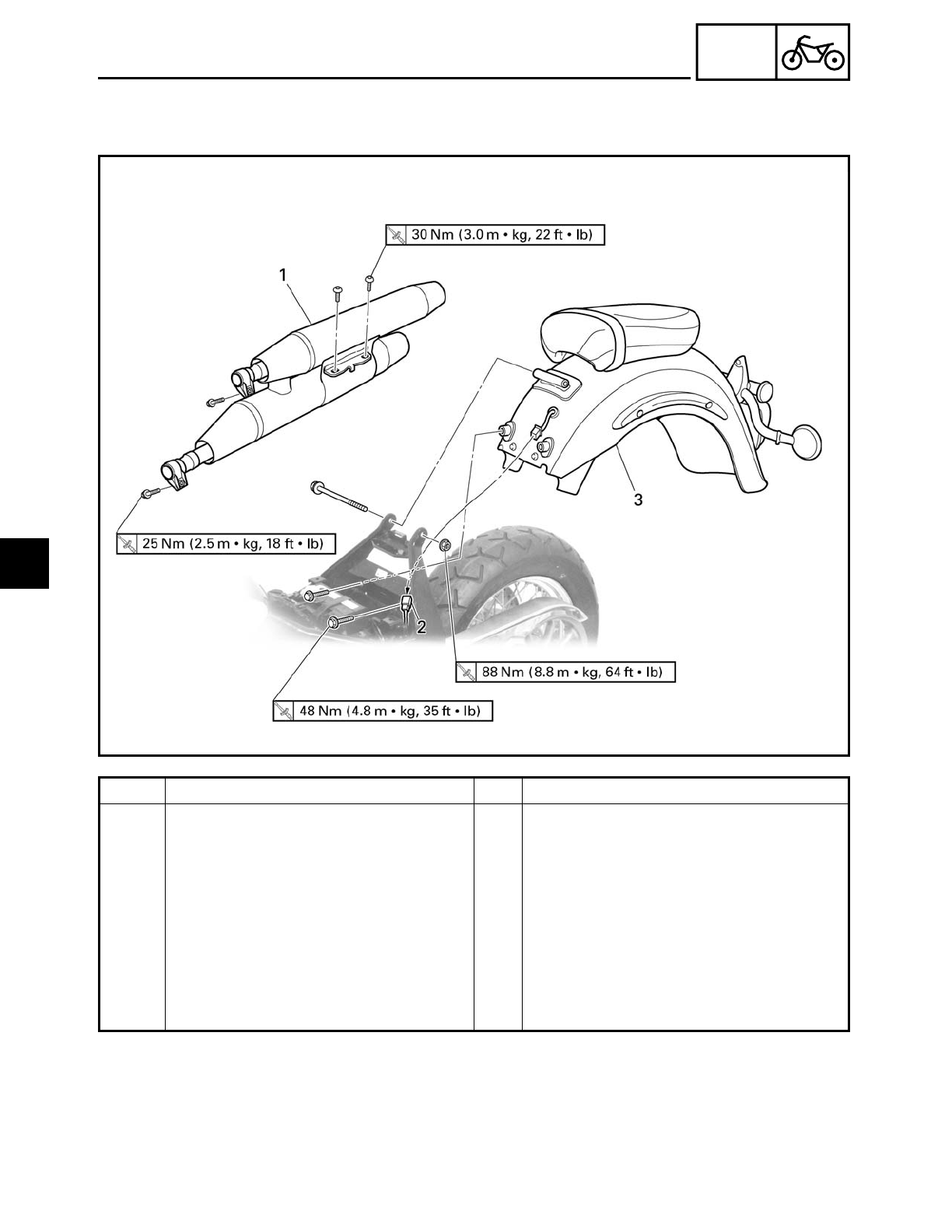
4 - 11
CHAS
REAR WHEEL, BRAKE DISC AND REAR WHEEL PULLEY
EAS00550
REAR WHEEL, BRAKE DISC AND REAR WHEEL PULLEY
Order Job/Part Q’ty Remarks
Removing the rear fender and muf-
fler
Remove the parts in the order listed.
Rider seat Refer to “SEATS AND SIDE COVERS”
in chapter 3.
1 Muffler 1
2 Tail/brake light and turn signal light
sub-wire harness
1 Disconnect.
3 Rear fender assembly 1
For installation, reverse the removal
procedure.
4
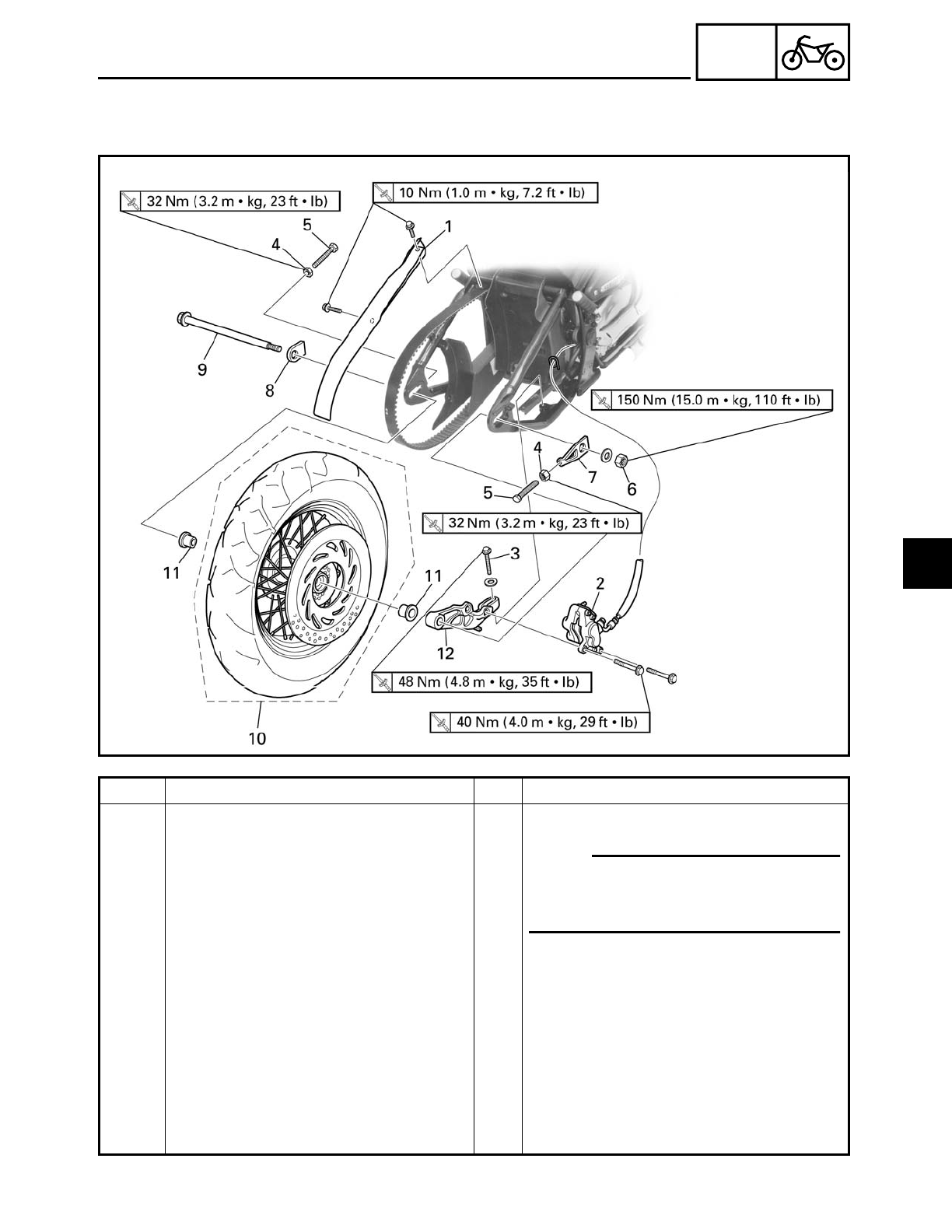
4 - 12
CHAS
REAR WHEEL, BRAKE DISC AND REAR WHEEL PULLEY
EAS00550
Order Job/Part Q’ty Remarks
Removing the rear wheel Remove the parts in the order listed.
1 Upper drive belt cover 1
2 Brake caliper 1
3 Brake caliper bracket bolt 1
4 Locknut (left and right) 2 Loosen.
5 Adjusting bolt (left and right) 2 Loosen.
6 Wheel axle nut 1
7 Right adjusting plate 1
8 Left adjusting plate 1
9 Rear wheel axle 1
NOTE:
Place the motorcycle on a suitable
stand so that the rear wheel is ele-
vated.
4
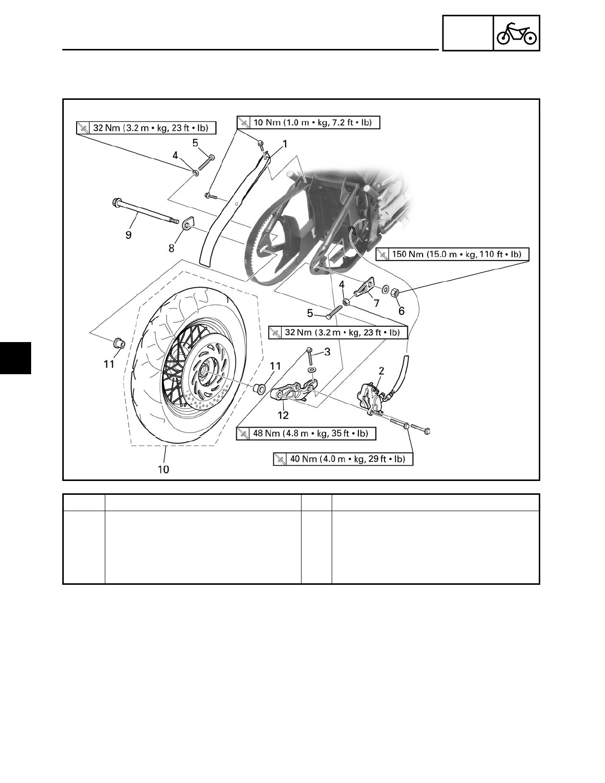
4 - 13
CHAS
Order Job/Part Q’ty Remarks
10 Rear wheel 1
11 Collar (left and right) 2
12 Brake caliper bracket 1
For installation, reverse the removal
procedure.
REAR WHEEL, BRAKE DISC AND REAR WHEEL PULLEY
4
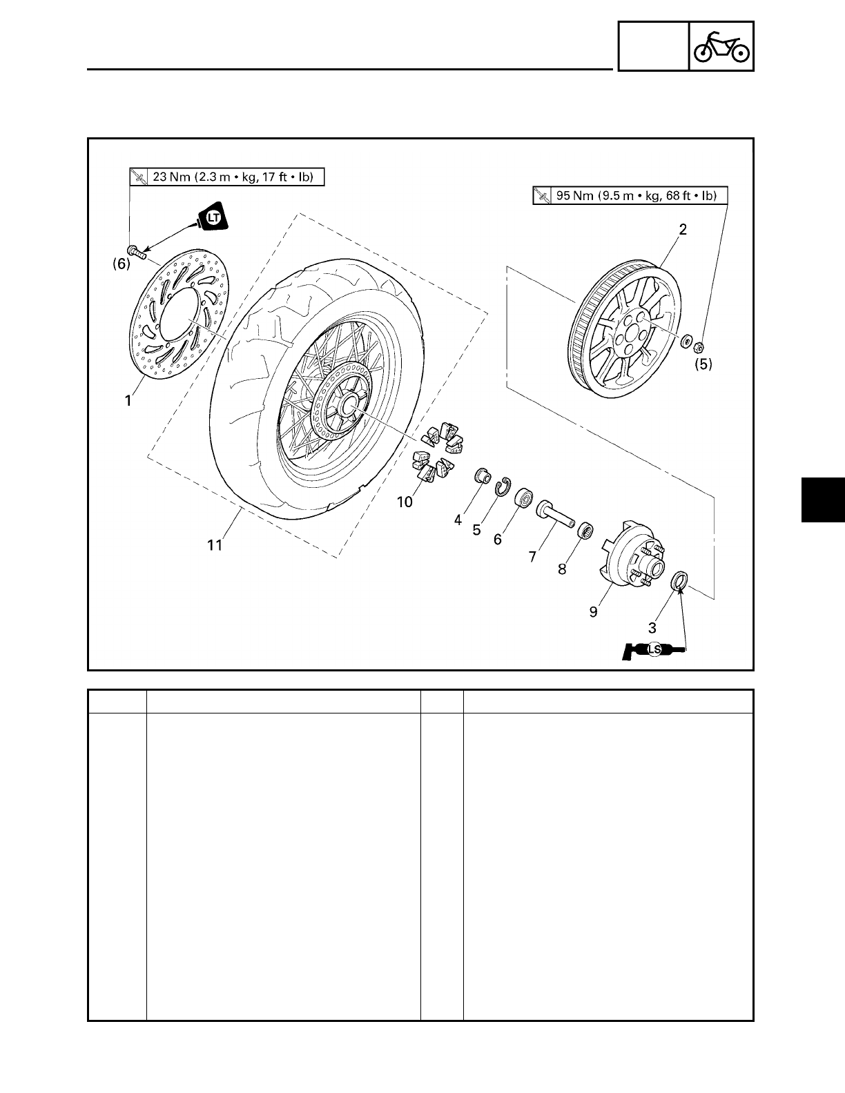
4 - 14
CHAS
REAR WHEEL, BRAKE DISC AND REAR WHEEL PULLEY
EAS00556
Order Job/Part Q’ty Remarks
Removing the brake disc and rear
wheel pulley
Remove the parts in the order listed.
1 Brake disc 1
2 Rear wheel pulley 1
3 Oil seal 1
4 Collar 1
5 Circlip 1
6 Bearing 1
7 Collar 1
8 Bearing 1
9 Rear wheel drive hub 1
10 Rear wheel drive hub damper 6
11 Rear wheel 1
For installation, reverse the removal
procedure.
4
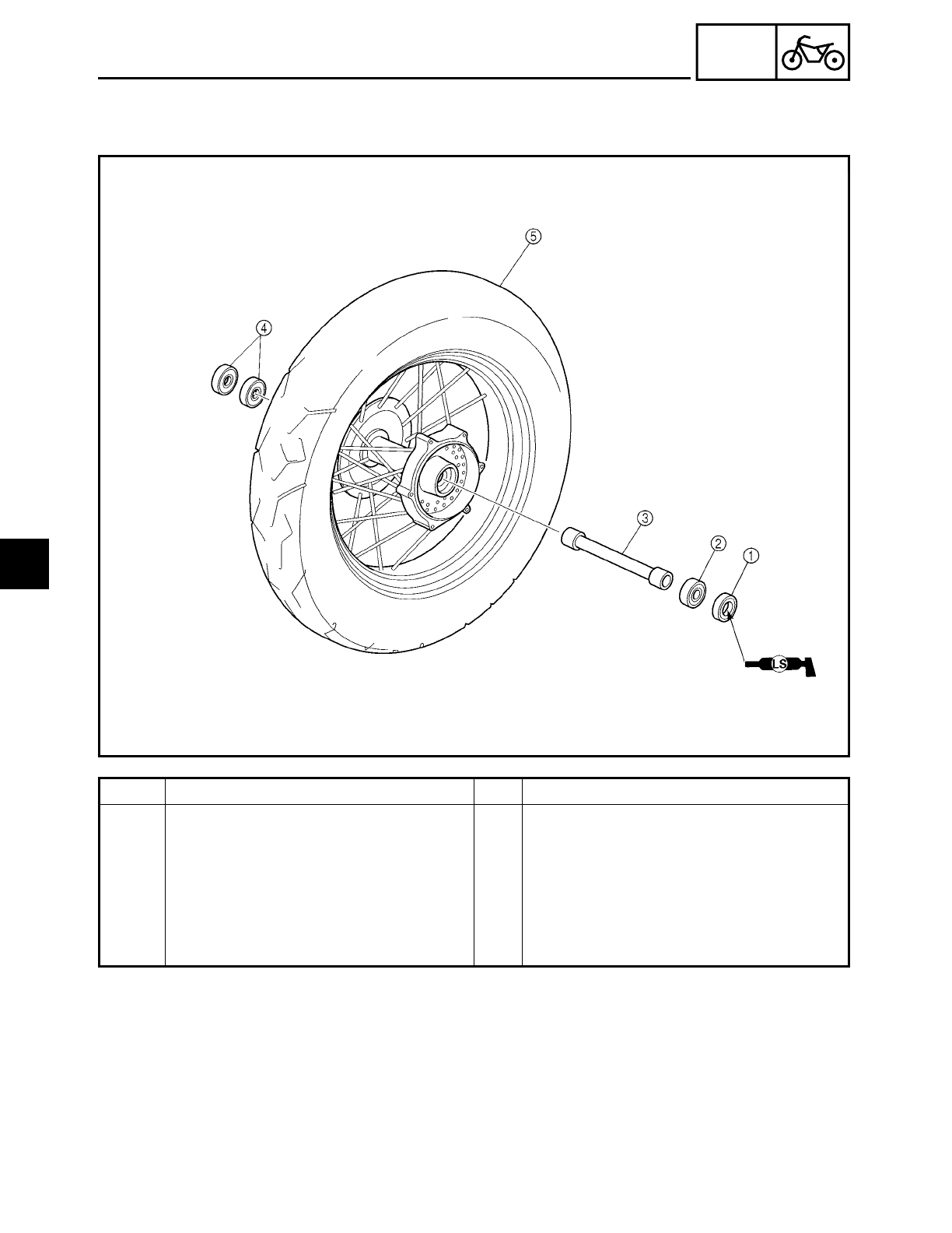
4 - 15
CHAS
REAR WHEEL, BRAKE DISC AND REAR WHEEL PULLEY
EAS00560
Order Job/Part Q’ty Remarks
Disassembling the rear wheel Remove the parts in the order listed.
1Oil seal 1
2Bearing 1
3Spacer 1
4Bearing 4
For assembly, reverse the disassembly
procedure.
4
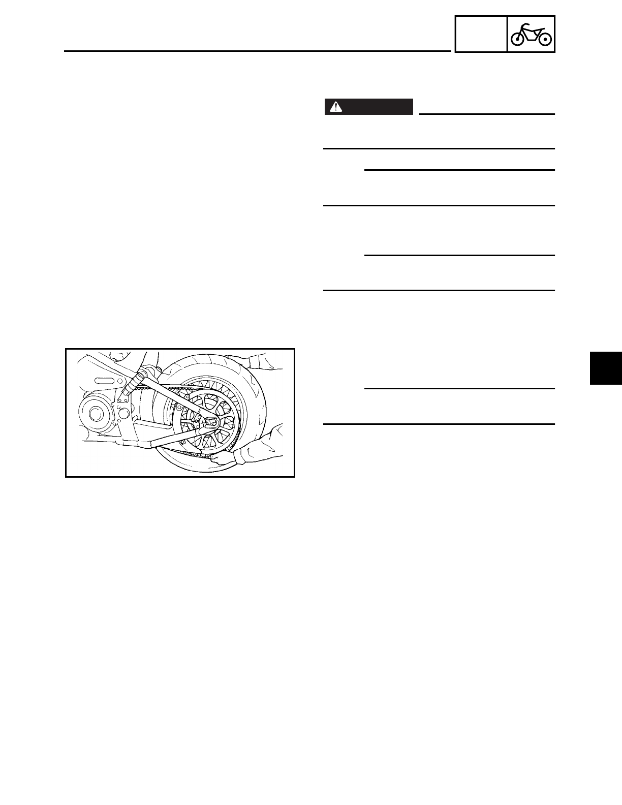
4 - 16
CHAS
REAR WHEEL, BRAKE DISC AND REAR WHEEL PULLEY
EAS00561
REMOVING THE REAR WHEEL
1. Stand the motorcycle on a level surface.
WARNING
WARNING
Securely support the motorcycle so that
there is no danger of it falling over.
NOTE:
Place the motorcycle on a suitable stand so
that the rear wheel is elevated.
2. Remove:
• brake caliper
NOTE:
Do not depress the brake pedal when
removing the brake caliper.
3. Remove:
• rear wheel
NOTE:
Push the rear wheel forward and remove
the drive belt from the rear wheel pulley.
EAS00566
CHECKING THE REAR WHEEL
1. Check:
• wheel axle
• rear wheel
• wheel bearings
• oil seals
Refer to “FRONT WHEEL AND BRAKE
DISCS”.
2. Check:
• tire
• rear wheel
Damage/wear → Replace.
Refer to “CHECKING THE TIRES” and
“CHECKING THE WHEELS” in chapter 3.
4
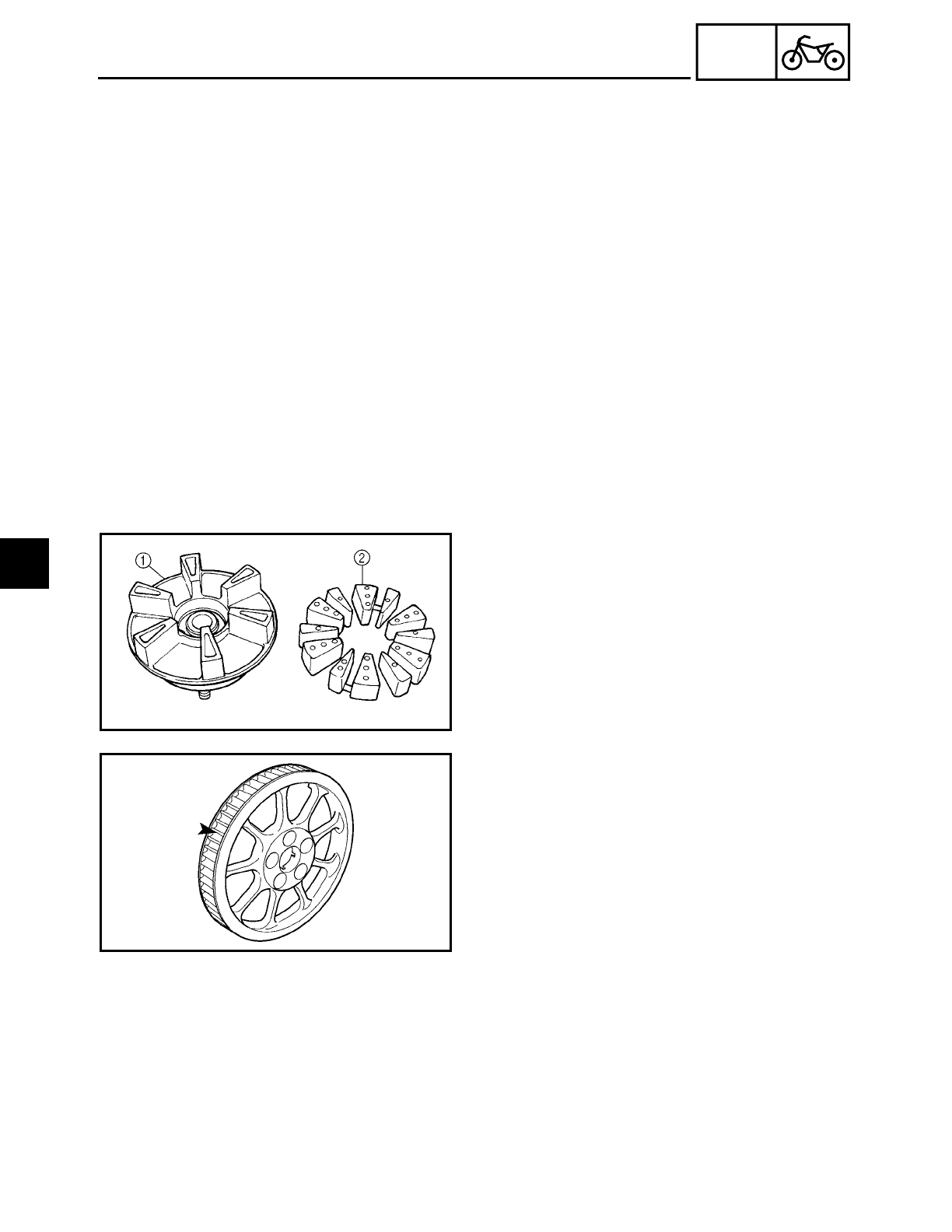
4 - 17
CHAS
REAR WHEEL, BRAKE DISC AND REAR WHEEL PULLEY
3. Check:
• spokes
Refer to “FRONT WHEEL AND BRAKE
DISCS”.
4. Measure:
• radial wheel runout
• lateral wheel runout
Refer to “FRONT WHEEL AND BRAKE
DISCS”.
EAS00567
CHECKING THE REAR WHEEL DRIVE HUB
1. Check:
• rear wheel drive hub 1
Cracks/damage → Replace.
• rear wheel drive hub dampers 2
Damage/wear → Replace.
EAS00568
CHECKING AND REPLACING THE REAR
WHEEL PULLEY
1. Check:
• rear wheel pulley
Surface plating has come off → Replace
the rear wheel pulley.
Bent teeth → Replace the rear wheel pul-
ley.
2. Replace:
• rear wheel pulley
▼ ▼ ▼ ▼ ▼ ▼ ▼ ▼ ▼ ▼ ▼ ▼ ▼ ▼ ▼ ▼ ▼ ▼ ▼ ▼ ▼ ▼ ▼ ▼ ▼ ▼ ▼ ▼
a. Remove the self-locking nuts and the
rear wheel pulley.
b. Clean the rear wheel drive hub with a
clean cloth, especially the surfaces that
contact the pulley.
c. Install the new rear wheel pulley.
4
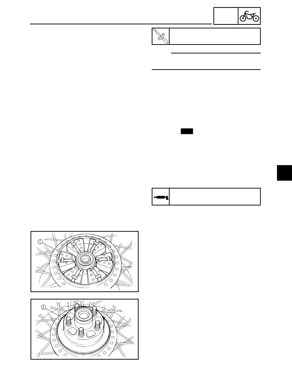
4 - 18
CHAS
REAR WHEEL, BRAKE DISC AND REAR WHEEL PULLEY
NOTE:
Tighten the self-locking nuts in stages and
in a crisscross pattern.
▲ ▲ ▲ ▲ ▲ ▲ ▲ ▲ ▲ ▲ ▲ ▲ ▲ ▲ ▲ ▲ ▲ ▲ ▲ ▲ ▲ ▲ ▲ ▲ ▲ ▲ ▲ ▲
T
R
.
.
Rear wheel pulley self-locking nut
95 Nm (9.5 m • kg, 68 ft • lb)
ASSEMBLING THE REAR WHEEL
1. Install:
• bearings
• spacer
• bearing
• oil seal
Refer to “FRONT WHEEL AND BRAKE
DISCS”.
New
EAS00572
INSTALLING THE REAR WHEEL
1. Lubricate:
• oil seal lips
Recommended lubricant
Lithium soap base grease
2. Install:
• rear wheel drive hub dampers 1
3. Install:
• rear wheel drive hub assembly 1
4
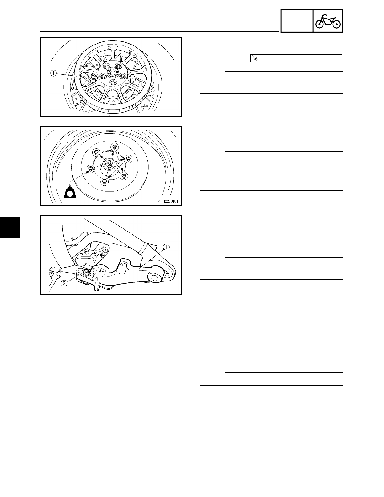
4 - 19
CHAS
REAR WHEEL, BRAKE DISC AND REAR WHEEL PULLEY
4. Install:
• rear wheel pulley 1
NOTE:
Tighten the self-locking nuts in stages and
in a crisscross pattern.
T
R
.
.
95 Nm (9.5 m · kg, 68 ft · lb)
5. Install:
• brake disc
NOTE:
• Apply locking agent (LOCTITE 648) to the
threads of the brake disc bolts.
• Tighten the brake disc bolts in stages and
in a crisscross pattern.
6. Install:
• brake caliper bracket 1
• washer
• brake caliper bracket bolt 2
NOTE:
Temporarily tighten the brake caliper
bracket bolt.
7. Install:
• collars
• rear wheel
• adjusting plates
• rear wheel axle
• washer
• wheel axle nut
NOTE:
Temporarily tighten the wheel axle nut.
8. Adjust:
• drive belt slack
Refer to “ADJUSTING THE DRIVE BELT
SLACK” in chapter 3.
4
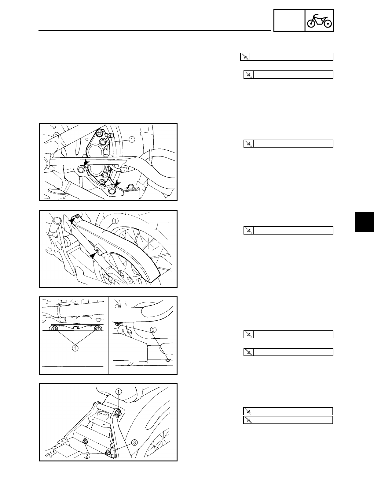
4 - 20
CHAS
9. Tighten:
• wheel axle nut
• brake caliper bracket bolt
T
R
.
.
150 Nm (15.0 m · kg, 110 ft · lb)
T
R
.
.
48 Nm (4.8 m · kg, 35 ft · lb)
10.Install:
• brake caliper 1
T
R
.
.
40 Nm (4.0 m · kg, 29 ft · lb)
11.Install:
• upper drive belt cover 1
T
R
.
.
10 Nm (1.0 m · kg, 7.2 ft · lb)
12.Install:
• muffler
13.Tighten:
• muffler mounting bolt 1
• Clamp bolt 2
T
R
.
.
30 Nm (3.0 m · kg, 22 ft · lb)
T
R
.
.
25 Nm (2.5 m · kg, 18 ft · lb)
14.Install:
• rear fender assembly
15.Tighten:
• nut 1
• bolts 2
16.Connect:
• tail/brake light and turn signal light sub-
wire harness coupler 3
T
R
.
.
88 Nm (8.8 m · kg, 64 ft · lb)
T
R
.
.
48 Nm (4.8 m · kg, 35 ft · lb)
REAR WHEEL, BRAKE DISC AND REAR WHEEL PULLEY
4

4 - 21
CHAS
REAR WHEEL, BRAKE DISC AND REAR WHEEL PULLEY
17.Install:
• rider seat
Refer to “SEATS AND SIDE COVERS” in
chapter 3.
EAS00575
ADJUSTING THE REAR WHEEL STATIC
BALANCE
NOTE:
• After replacing the tire, wheel, or both, the
rear wheel static balance should be
adjusted.
• Adjust the rear wheel static balance with
the brake disc and rear wheel drive hub
installed.
1. Adjust:
• rear wheel static balance
Refer to “FRONT WHEEL AND BRAKE
DISCS”.
4
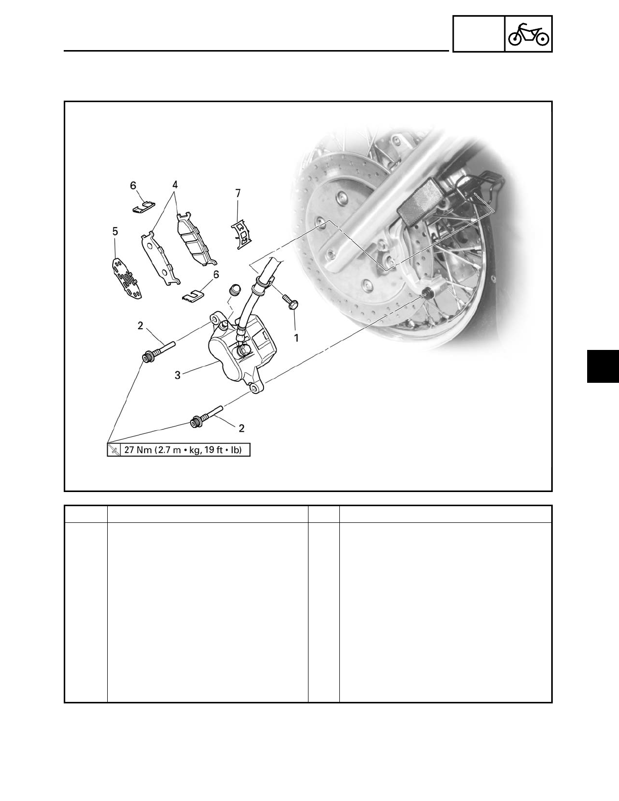
4 - 22
CHAS
FRONT AND REAR BRAKES
EAS00577
FRONT AND REAR BRAKES
FRONT BRAKE PADS
Order Job/Part Q’ty Remarks
Removing the front brake pads Remove the parts in the order listed.
The following procedure applies to
both of the front brake calipers.
1 Brake hose holder bolt 1
2 Retaining bolt 2
3 Brake caliper 1
4 Brake pad 2
5 Brake pad shim 1
6 Brake pad spring 2
7 Brake pad spring 1
For installation, reverse the removal
procedure.
4
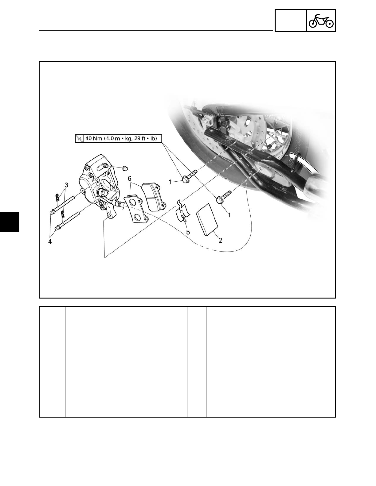
4 - 23
CHAS
FRONT AND REAR BRAKES
EAS00578
REAR BRAKE PADS
Order Job/Part Q’ty Remarks
Removing the rear brake pads Remove the parts in the order listed.
Muffler Refer to “REAR WHEEL, BRAKE DISC
AND REAR WHEEL PULLEY”.
1 Brake caliper bolt 2
2 Brake pad cover 1
3 Brake pad clip 2
4 Brake pad pin 2
5 Brake pad spring 1
6 Brake pad 2
For installation, reverse the removal
procedure.
4
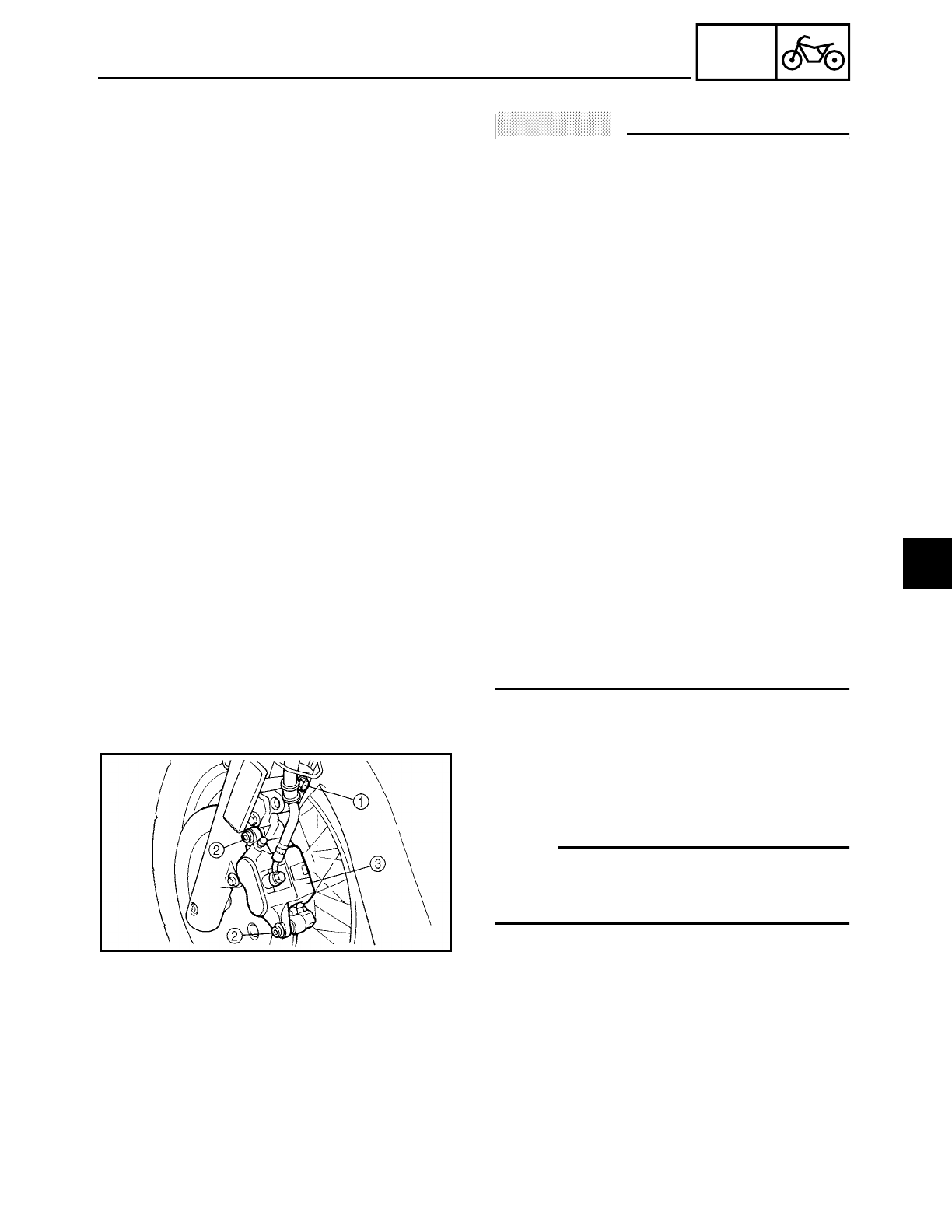
4 - 24
CHAS
FRONT AND REAR BRAKES
EAS00579
ACHTUNG:
CAUTION:
Disc brake components rarely require dis-
assembly.
Therefore, always follow these preventive
measures:
• Never disassemble brake components
unless absolutely necessary.
• If any connection on the hydraulic brake
system is disconnected, the entire brake
system must be disassembled, drained,
cleaned, properly filled, and bled after
reassembly.
• Never use solvents on internal brake
components.
• Use only clean or new brake fluid for
cleaning brake components.
• Brake fluid may damage painted surfaces
and plastic parts. Therefore, always clean
up any spilt brake fluid immediately.
• Avoid brake fluid coming into contact
with the eyes as it can cause serious
injury.
FIRST AID FOR BRAKE FLUID ENTERING
THE EYES:
• Flush with water for 15 minutes and get
immediate medical attention.
EAS00580
REPLACING THE FRONT BRAKE PADS
The following procedure applies to both
brake calipers.
NOTE:
When replacing the brake pads, it is not
necessary to disconnect the brake hose or
disassemble the brake caliper.
1. Remove:
• brake hose holder bolt 1
• brake caliper retaining bolts 2
• brake caliper 3
4
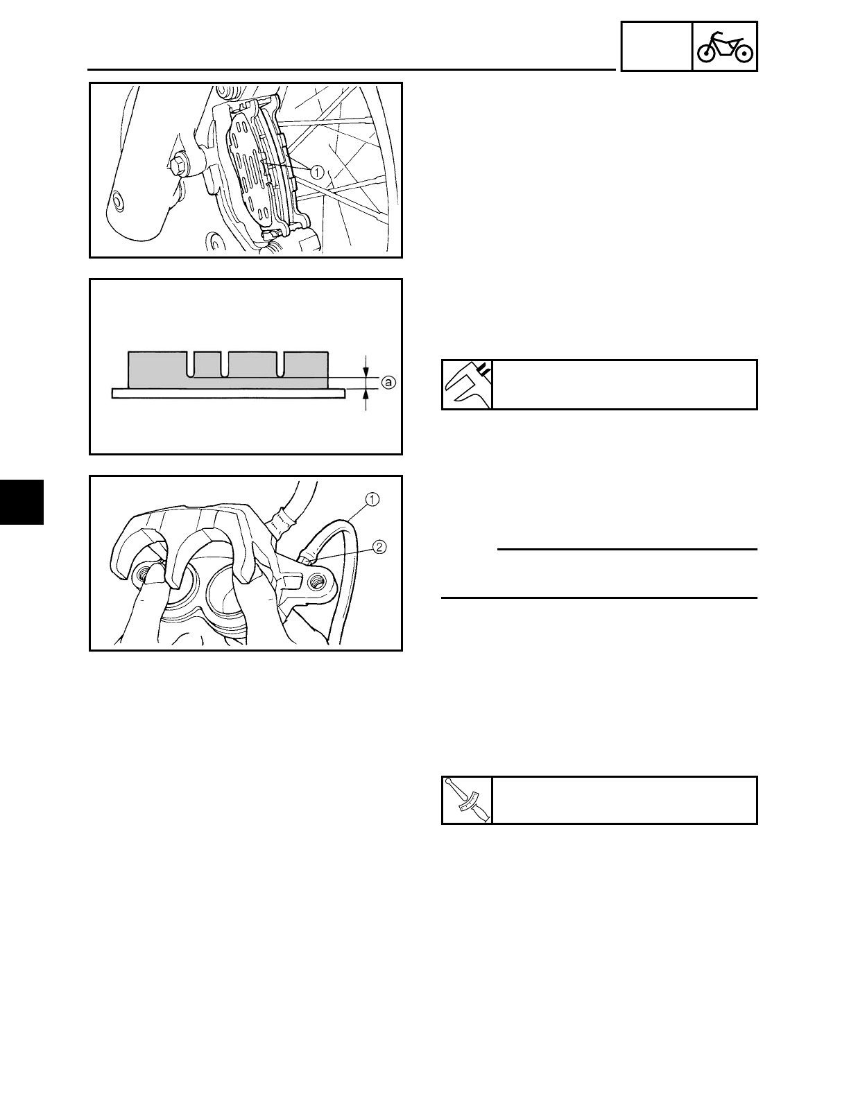
4 - 25
CHAS
FRONT AND REAR BRAKES
2. Remove:
• brake pads 1
(along with the brake pad shim)
• brake pad springs
3. Measure:
• brake pad thickness a
Out of specification → Replace the brake
pads as a set.
Minimum brake pad thickness
0.5 mm (0.02 in)
4. Install:
• brake pads
• brake pad springs
NOTE:
Always install new brake pads, brake pad
shim and a new brake pad springs as a set.
▼ ▼ ▼ ▼ ▼ ▼ ▼ ▼ ▼ ▼ ▼ ▼ ▼ ▼ ▼ ▼ ▼ ▼ ▼ ▼ ▼ ▼ ▼ ▼ ▼ ▼ ▼ ▼
a. Connect a clear plastic hose 1 tightly to
the bleed screw 2. Put the other end of
the hose into an open container.
b. Loosen the bleed screw and push the
brake caliper pistons into the brake cali-
per with your finger.
c. Tighten the bleed screw.
d. Install a new brake pad shim onto the
new brake pad that is on the caliper pis-
ton side.
▲ ▲ ▲ ▲ ▲ ▲ ▲ ▲ ▲ ▲ ▲ ▲ ▲ ▲ ▲ ▲ ▲ ▲ ▲ ▲ ▲ ▲ ▲ ▲ ▲ ▲ ▲ ▲
T
R
.
.
Bleed screw
6 Nm (0.6 m • kg, 4.3 ft • lb)
4
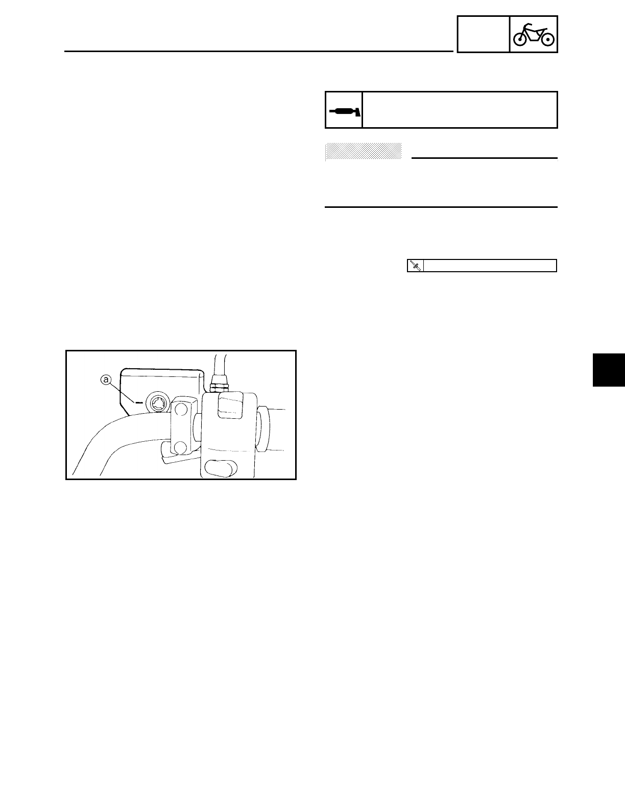
4 - 26
CHAS
FRONT AND REAR BRAKES
5. Lubricate:
• brake caliper retaining bolt
ACHTUNG:
CAUTION:
• Do not allow grease to contact the brake
pads.
• Remove any excess grease.
6. Install:
• brake caliper
• brake caliper retaining bolts
• brake hose holder bolt
Recommended lubricant
Lithium soap base grease
T
R
.
.
27 Nm (2.7 m · kg, 19 ft · lb)
7. Check:
• brake fluid level
Below the minimum level mark a→ Add
the recommended brake fluid to the
proper level.
Refer to “CHECKING THE BRAKE FLUID
LEVEL” in chapter 3.
8. Check:
• brake lever operation
Soft or spongy feeling → Bleed the brake
system.
Refer to “BLEEDING THE HYDRAULIC
BRAKE SYSTEM” in chapter 3.
4
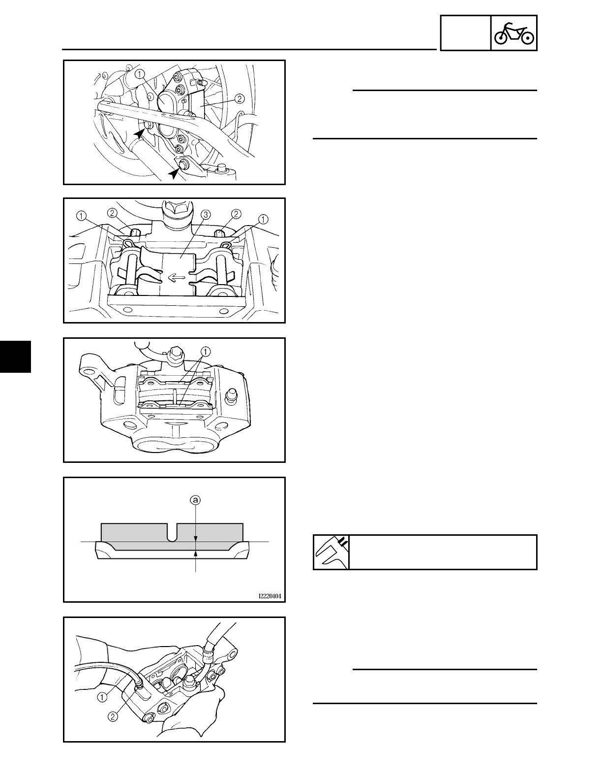
4 - 27
CHAS
FRONT AND REAR BRAKES
EAS00583
REPLACING THE REAR BRAKE PADS
NOTE:
When replacing the brake pads, it is not
necessary to disconnect the brake hose or
disassemble the brake caliper.
1. Remove:
• brake caliper
1
• brake pad cover
2
2. Remove:
• brake pad clips
1
• brake pad pins
2
• brake pad spring
3
3. Remove:
• brake pads
1
4. Measure:
• brake pad thickness a
Out of specification → Replace the brake
pads as a set.
Minimum brake pad thickness
0.5 mm (0.02 in)
5. Install:
• brake pads
• brake pad spring
NOTE:
Always install new brake pads and a brake
pad spring as a set.
▼ ▼ ▼ ▼ ▼ ▼ ▼ ▼ ▼ ▼ ▼ ▼ ▼ ▼ ▼ ▼ ▼ ▼ ▼ ▼ ▼ ▼ ▼ ▼ ▼ ▼ ▼ ▼
a. Connect a clear plastic hose
1 tightly to
the bleed screw
2. Put the other end of
the hose into an open container.
4
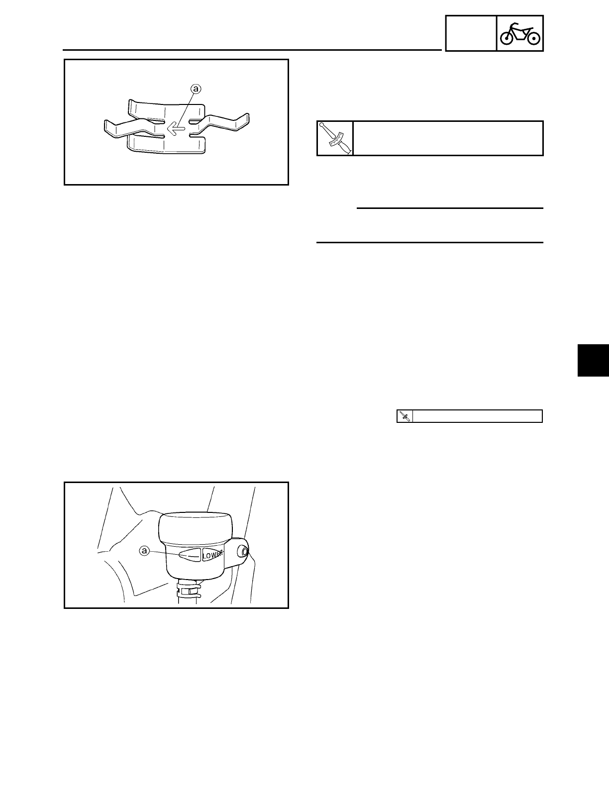
4 - 28
CHAS
FRONT AND REAR BRAKES
b. Loosen the bleed screw and push the
brake caliper pistons into the brake cali-
per with your finger.
c. Tighten the bleed screw.
d. Install new brake pads and a new brake
pad spring.
NOTE:
The arrow
a on the brake pad spring must
point in the direction of disc rotation.
▲ ▲ ▲ ▲ ▲ ▲ ▲ ▲ ▲ ▲ ▲ ▲ ▲ ▲ ▲ ▲ ▲ ▲ ▲ ▲ ▲ ▲ ▲ ▲ ▲ ▲ ▲ ▲
T
R
.
.
Bleed screw
6 Nm (0.6 m • kg, 4.3 ft • lb)
6. Install:
• brake pad pins
• brake pad clips
• brake pad cover
• brake caliper
T
R
.
.
40 Nm (4.0 m · kg, 29 ft · lb)
7. Check:
• brake fluid level
Below the minimum level mark a→ Add
the recommended brake fluid to the
proper level.
Refer to “CHECKING THE BRAKE FLUID
LEVEL” in chapter 3.
8. Check:
• brake pedal operation
Soft or spongy feeling → Bleed the brake
system.
Refer to “BLEEDING THE HYDRAULIC
BRAKE SYSTEM” in chapter 3.
4
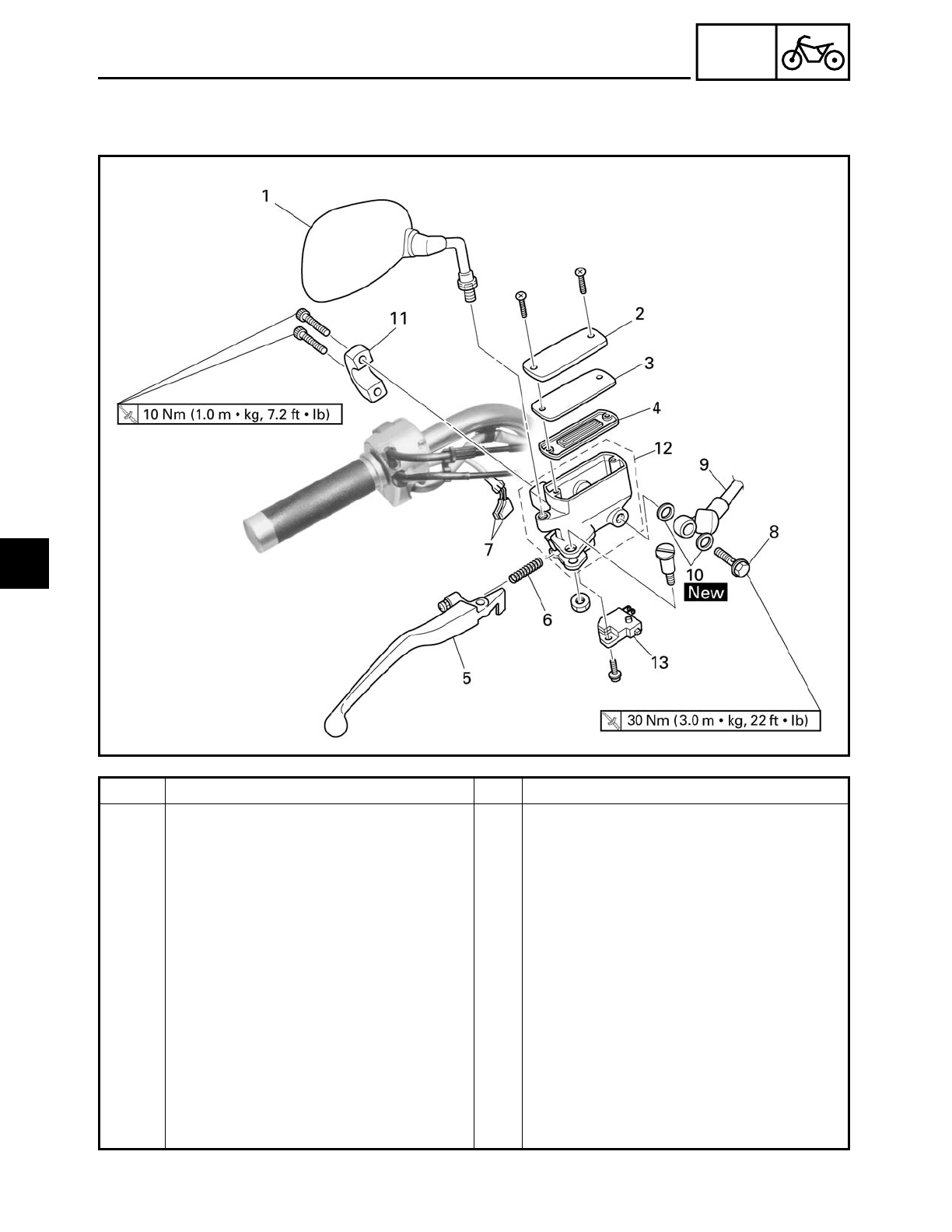
4 - 29
CHAS
FRONT AND REAR BRAKES
EAS00584
FRONT BRAKE MASTER CYLINDER
Order Job/Part Q’ty Remarks
Removing the front brake master
cylinder
Remove the parts in the order listed.
Brake fluid Drain.
1 Rear view mirror 1
2 Brake master cylinder reservoir cap 1
3 Brake master cylinder reservoir dia-
phragm holder
1
4 Brake master cylinder reservoir dia-
phragm
1
5 Brake lever 2
6 Brake lever spring 1
7 Front brake light switch connector 2 Disconnect.
8 Union bolt 1
9 Brake hose 1 Disconnect.
10 Copper washer 2
4
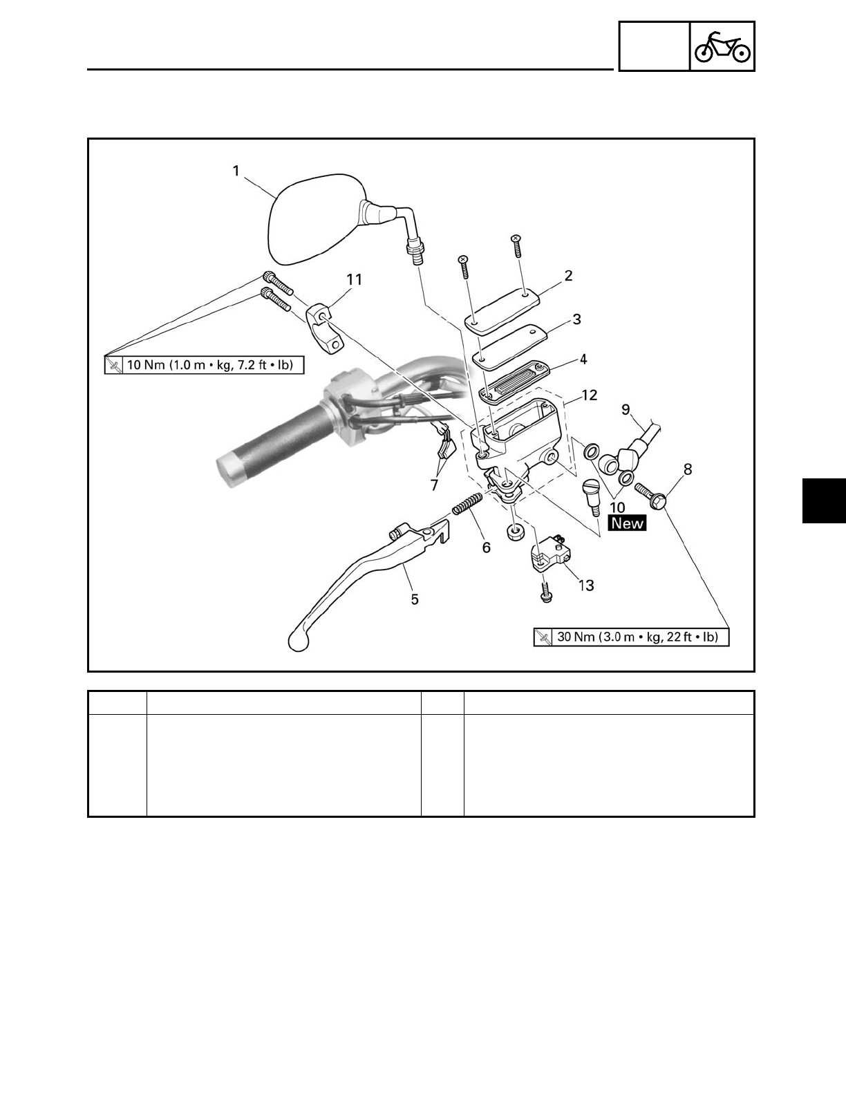
4 - 30
CHAS
FRONT AND REAR BRAKES
Order Job/Part Q’ty Remarks
11 Brake master cylinder holder 1
12 Brake master cylinder 1
13 Front brake light switch 1
For installation, reverse the removal
procedure.
4
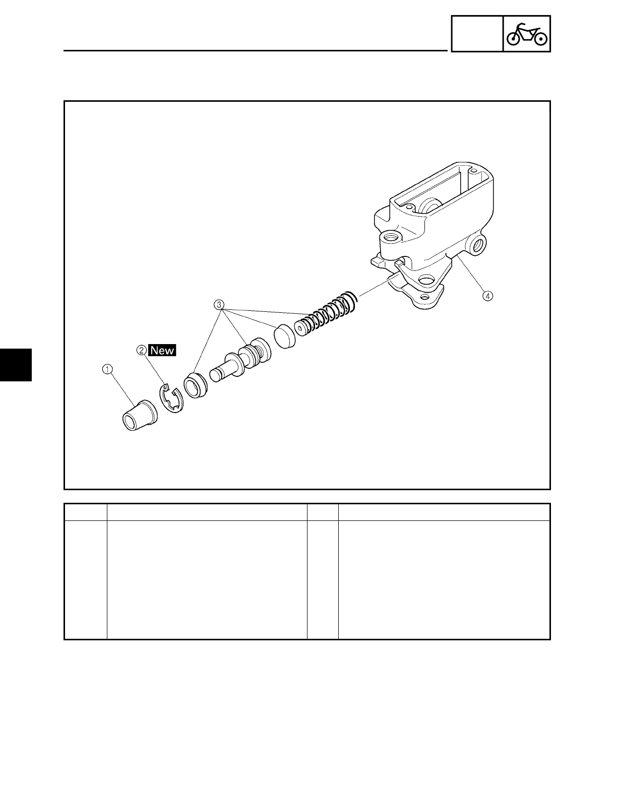
4 - 31
CHAS
FRONT AND REAR BRAKES
EAS00585
Order Job/Part Q’ty Remarks
Disassembling the front brake mas-
ter cylinder
Remove the parts in the order listed.
1Dust boot 1
2Circlip 1
3Brake master cylinder kit 1
4Brake master cylinder 1
For assembly, reverse the disassembly
procedure.
4
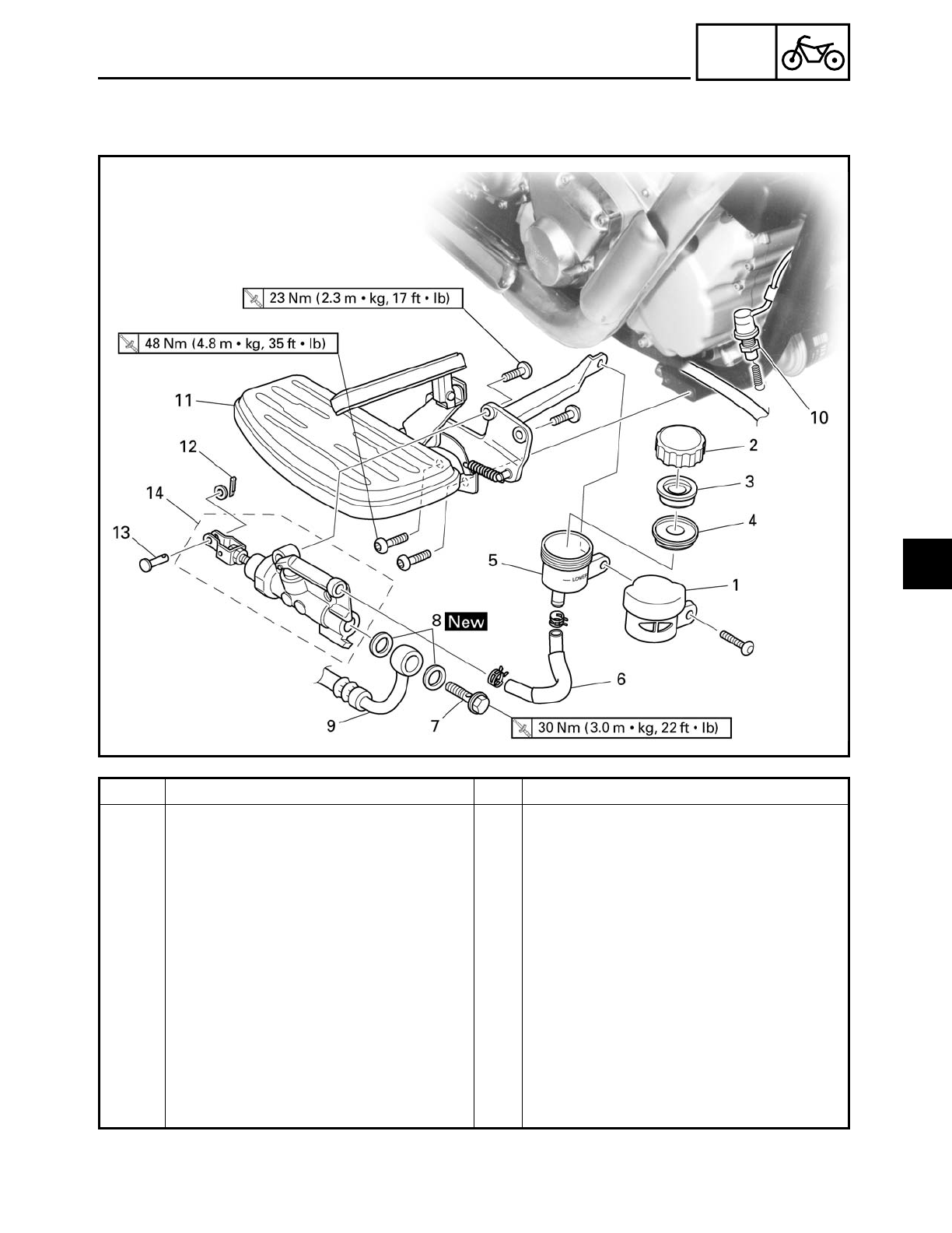
4 - 32
CHAS
FRONT AND REAR BRAKES
EAS00586
REAR BRAKE MASTER CYLINDER
Order Job/Part Q’ty Remarks
Removing the rear brake master cyl-
inder
Remove the parts in the order listed.
Brake fluid Drain.
1 Brake fluid reservoir cover 1
2 Brake fluid reservoir cap 1
3 Brake fluid reservoir diaphragm
holder
1
4 Brake fluid reservoir diaphragm 1
5 Brake fluid reservoir 1
6 Brake fluid reservoir hose 1
7 Union bolt 1
8 Copper washer 2
9 Brake hose 1 Disconnect.
10 Rear brake light switch 1 Disconnect.
4
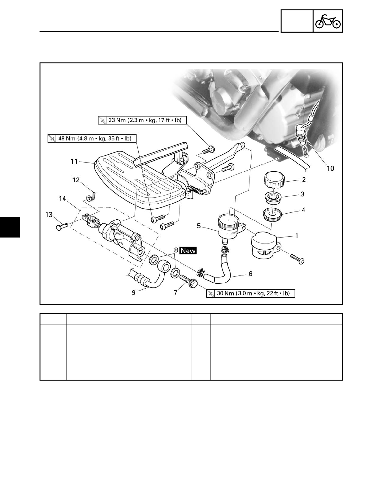
4 - 33
CHAS
FRONT AND REAR BRAKES
Order Job/Part Q’ty Remarks
11 Left footrest assembly 1
12 Cotter pin 1
13 Pin 1
14 Brake master cylinder 1
For installation, reverse the removal
procedure.
4
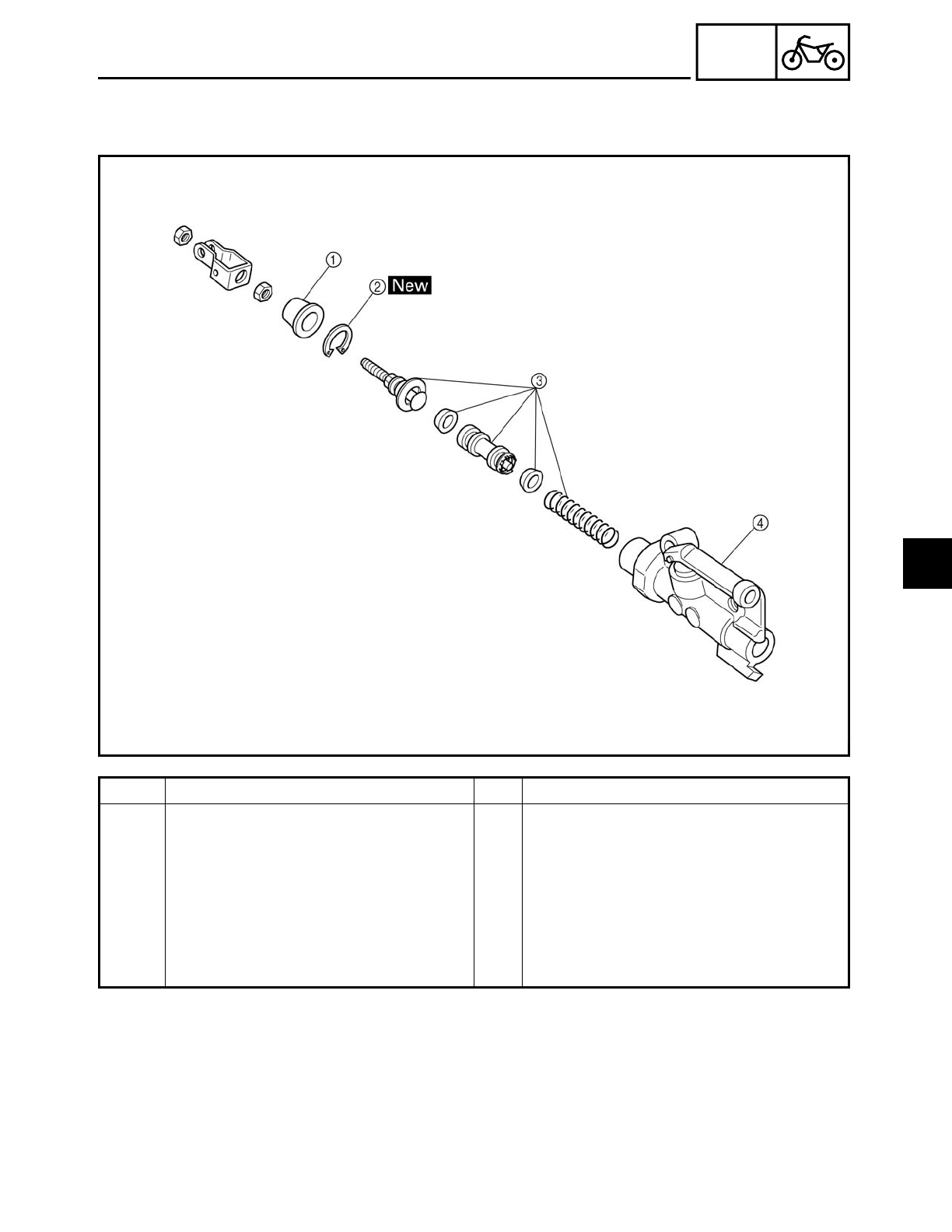
4 - 34
CHAS
FRONT AND REAR BRAKES
EAS00587
Order Job/Part Q’ty Remarks
Disassembling the rear brake mas-
ter cylinder
Remove the parts in the order listed.
1Dust boot 1
2Circlip 1
3Brake master cylinder kit 1
4Brake master cylinder 1
For assembly, reverse the disassembly
procedure.
4
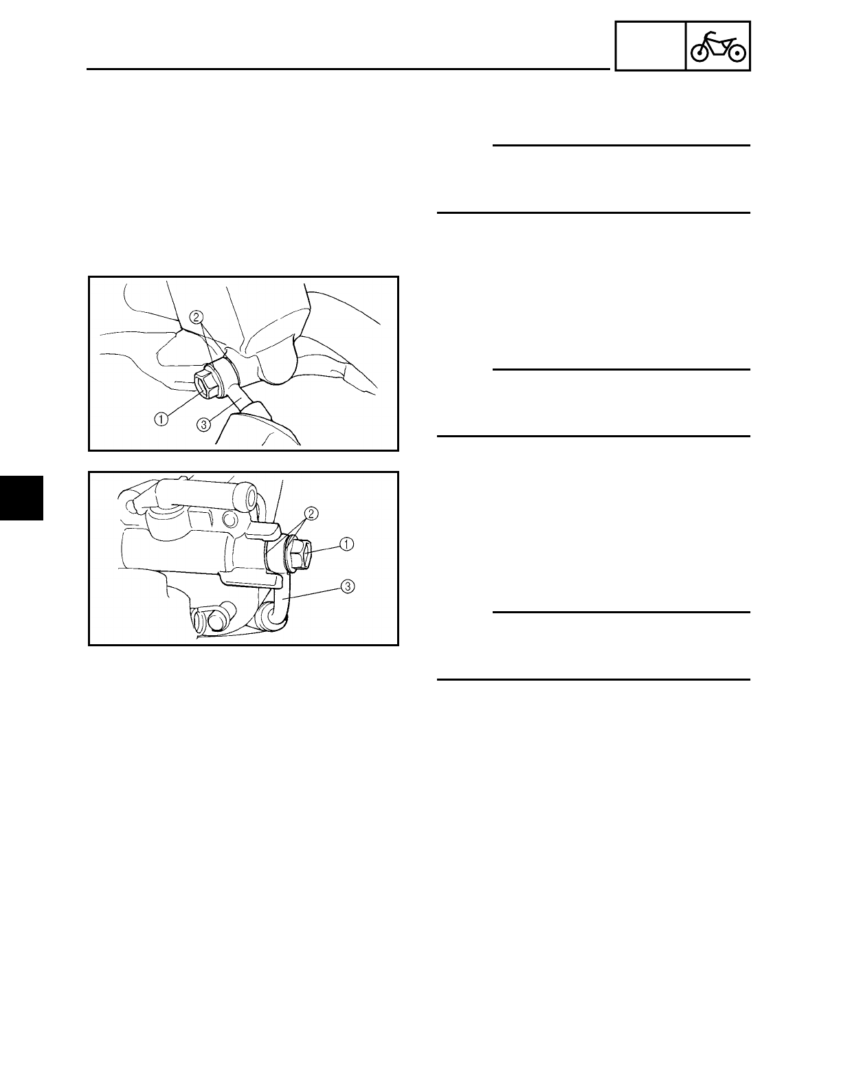
4 - 35
CHAS
FRONT AND REAR BRAKES
EAS00588
DISASSEMBLING THE FRONT BRAKE
MASTER CYLINDER
NOTE:
Before disassembling the front brake mas-
ter cylinder, drain the brake fluid from the
entire brake system.
1. Remove:
• union bolt 1
• copper washers 2
• brake hose 3
NOTE:
To collect any remaining brake fluid, place a
container under the master cylinder and the
end of the brake hose.
EAS00589
DISASSEMBLING THE REAR BRAKE
MASTER CYLINDER
1. Remove:
• union bolt 1
• copper washers 2
• brake hose 3
NOTE:
To collect any remaining brake fluid, place a
container under the master cylinder and the
end of the brake hose.
4
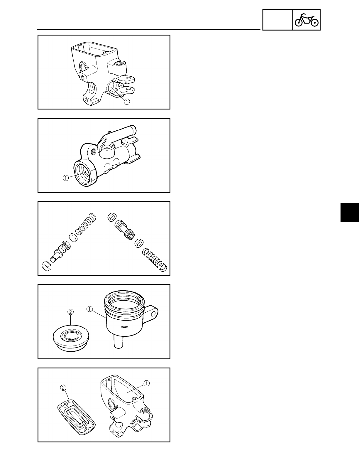
4 - 36
CHAS
FRONT AND REAR BRAKES
EAS00592
CHECKING THE FRONT AND REAR BRAKE
MASTER CYLINDERS
The following procedure applies to both
brake master cylinders.
1. Check:
• brake master cylinder 1
Damage/scratches/wear → Replace.
• brake fluid delivery passages
(brake master cylinder body)
Obstruction → Blow out with com-
pressed air.
ÅFront
ıRear
Å
ı
2. Check:
• brake master cylinder kit 1
Damage/scratches/wear → Replace.
ÅFront
ıRear
Åı
3. Check:
• rear brake fluid reservoir 1
Cracks/damage → Replace.
• rear brake fluid reservoir diaphragm 2
Cracks/damage → Replace.
4. Check:
• front brake master cylinder reservoir 1
Cracks/damage → Replace.
• front brake master cylinder reservoir dia-
phragm 2
Damage/wear → Replace.
4
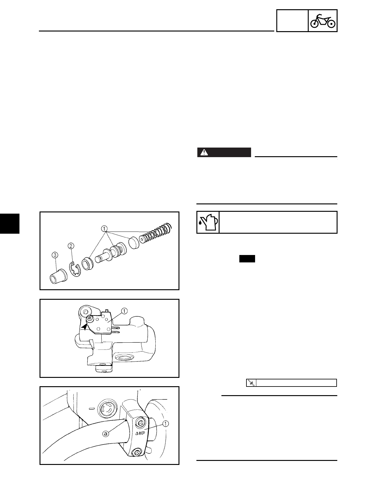
4 - 37
CHAS
FRONT AND REAR BRAKES
5. Check:
• brake hoses
• brake fluid reservoir hose
Cracks/damage/wear → Replace.
EAS00598
ASSEMBLING AND INSTALLING THE
FRONT BRAKE MASTER CYLINDER
WARNING
WARNING
• Before installation, all internal brake com-
ponents should be cleaned and lubricated
with clean or new brake fluid.
• Never use solvents on internal brake
components.
1. Install:
• brake master cylinder kit 1
• circlip 2
• dust boot 3
Recommended brake fluid
DOT 4
New
2. Install:
• front brake light switch 1
3. Install:
• brake master cylinder
• brake master cylinder holder 1
NOTE:
• Install the brake master cylinder holder
with the “UP” mark facing up.
• Align the end of the brake master cylinder
holder with the punch mark a in the han-
dlebar.
• First, tighten the upper bolt, then the
lower bolt.
T
R
.
.
10 Nm (1.0 m · kg, 7.2 ft · lb)
4
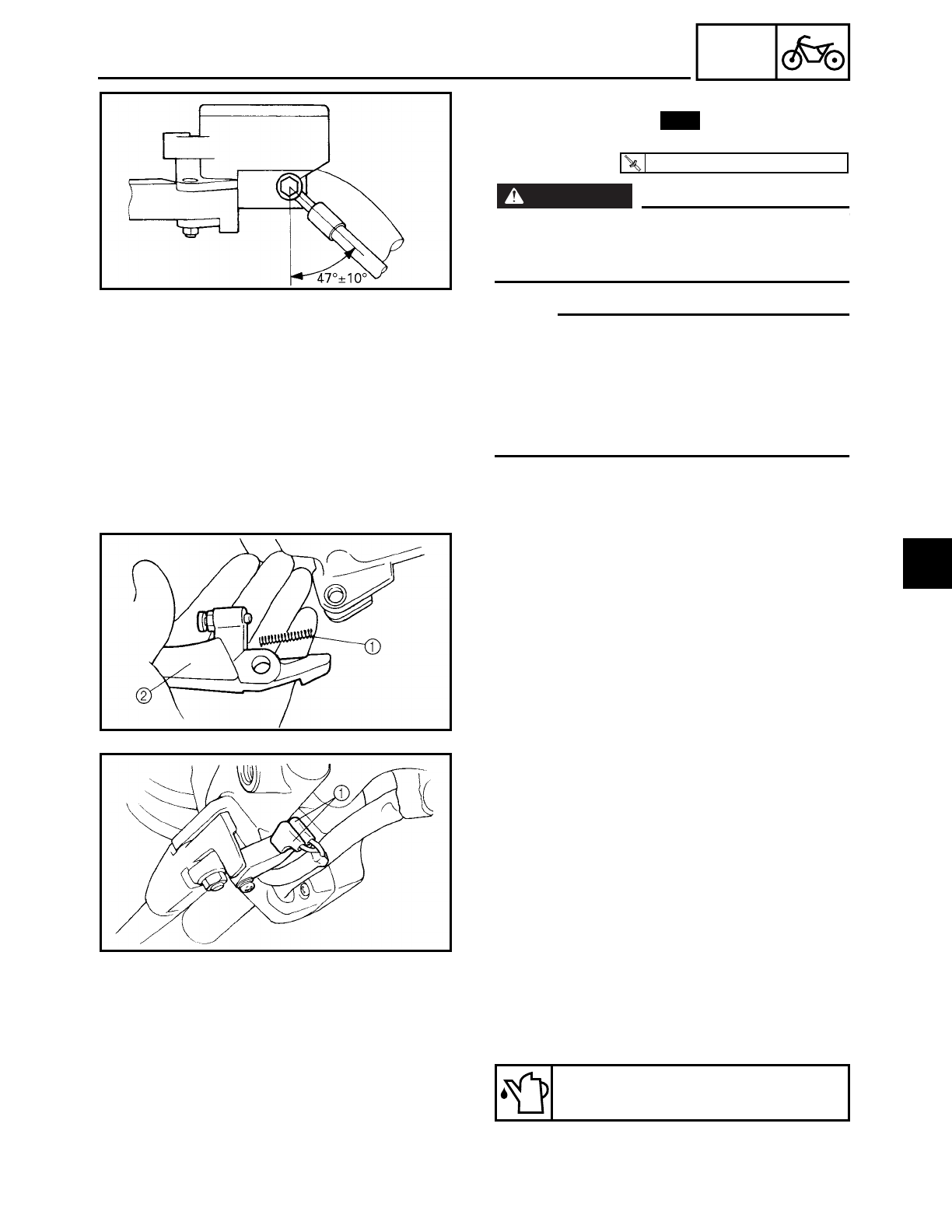
4 - 38
CHAS
FRONT AND REAR BRAKES
4. Install:
• copper washers
• brake hose
• union bolt
WARNING
WARNING
Proper brake hose routing is essential to
insure safe motorcycle operation. Refer to
“CABLE ROUTING”.
NOTE:
• While holding the brake hose, tighten the
union bolt as shown.
• Turn the handlebar to the left and to the
right to make sure the brake hose does
not touch other parts (e.g., wire harness,
cables, leads). Correct if necessary.
New
T
R
.
.
30 Nm (3.0 m · kg, 22 ft · lb)
5. Install:
• brake lever spring 1
• brake lever 2
6. Connect:
• front brake light switch connectors 1
7. Fill:
• brake master cylinder reservoir
(with the specified amount of the recom-
mended brake fluid)
Recommended brake fluid
DOT 4
4
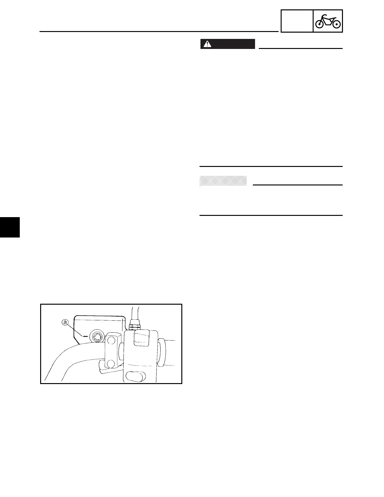
4 - 39
CHAS
FRONT AND REAR BRAKES
WARNING
WARNING
• Use only the designated brake fluid.
Other brake fluids may cause the rubber
seals to deteriorate, causing leakage and
poor brake performance.
• Refill with the same type of brake fluid that
is already in the system. Mixing brake fluids
may result in a harmful chemical reaction,
leading to poor brake performance.
• When refilling, be careful that water does
not enter the brake master cylinder reser-
voir. Water will significantly lower the
boiling point of the brake fluid and could
cause vapor lock.
ACHTUNG:
CAUTION:
Brake fluid may damage painted surfaces
and plastic parts. Therefore, always clean
up any spilt brake fluid immediately.
8. Bleed:
• brake system
Refer to “BLEEDING THE HYDRAULIC
BRAKE SYSTEM” in chapter 3.
9. Install:
• brake master cylinder diaphragm
• brake master cylinder diaphragm holder
• brake master cylinder cap
• rear view mirror
10.Check:
• brake fluid level
Below the minimum level mark a→ Add
the recommended brake fluid to the
proper level.
Refer to “CHECKING THE BRAKE FLUID
LEVEL” in chapter 3.
11.Check:
• brake lever operation
Soft or spongy feeling → Bleed the brake
system.
Refer to “BLEEDING THE HYDRAULIC
BRAKE SYSTEM” in chapter 3.
4
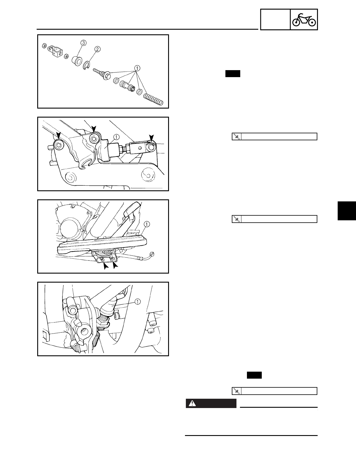
4 - 40
CHAS
FRONT AND REAR BRAKES
EAS00608
ASSEMBLING AND INSTALLING THE REAR
BRAKE MASTER CYLINDER
1. Install:
• brake master cylinder kit 1
• circlip 2
• dust boot 3
New
2. Install:
• brake master cylinder 1
T
R
.
.
23 Nm (2.3 m · kg, 17 ft · lb)
3. Install:
• left footrest assembly 1
T
R
.
.
48 Nm (4.8 m · kg, 35 ft · lb)
4. Install:
• rear brake light switch 1
5. Install:
• copper washers
• brake hose
• union bolt
WARNING
WARNING
Proper brake hose routing is essential to
insure safe motorcycle operation. Refer to
“CABLE ROUTING”.
New
T
R
.
.
30 Nm (3.0 m · kg, 22 ft · lb)
4
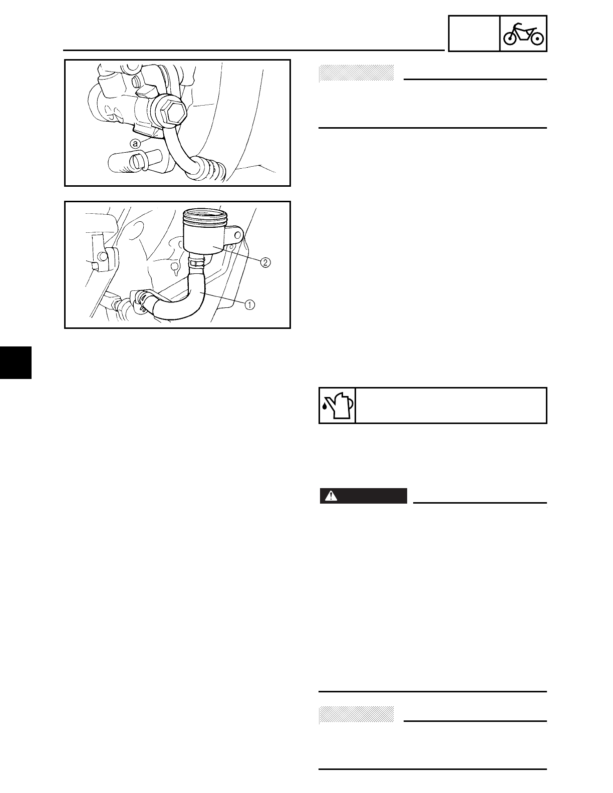
4 - 41
CHAS
FRONT AND REAR BRAKES
ACHTUNG:
CAUTION:
When installing the brake hose onto the
brake master cylinder, make sure the brake
pipe touches the projection a as shown.
6. Install:
• brake fluid reservoir hose 1
• brake fluid reservoir 2
7. Fill:
• brake fluid reservoir
(to the maximum level mark)
Recommended brake fluid
DOT 4
WARNING
WARNING
• Use only the designated brake fluid.
Other brake fluids may cause the rubber
seals to deteriorate, causing leakage and
poor brake performance.
• Refill with the same type of brake fluid
that is already in the system. Mixing
brake fluids may result in a harmful
chemical reaction, leading to poor brake
performance.
• When refilling, be careful that water does
not enter the brake fluid reservoir. Water
will significantly lower the boiling point of
the brake fluid and could cause vapor lock.
ACHTUNG:
CAUTION:
Brake fluid may damage painted surfaces
and plastic parts. Therefore, always clean
up any spilt brake fluid immediately.
4
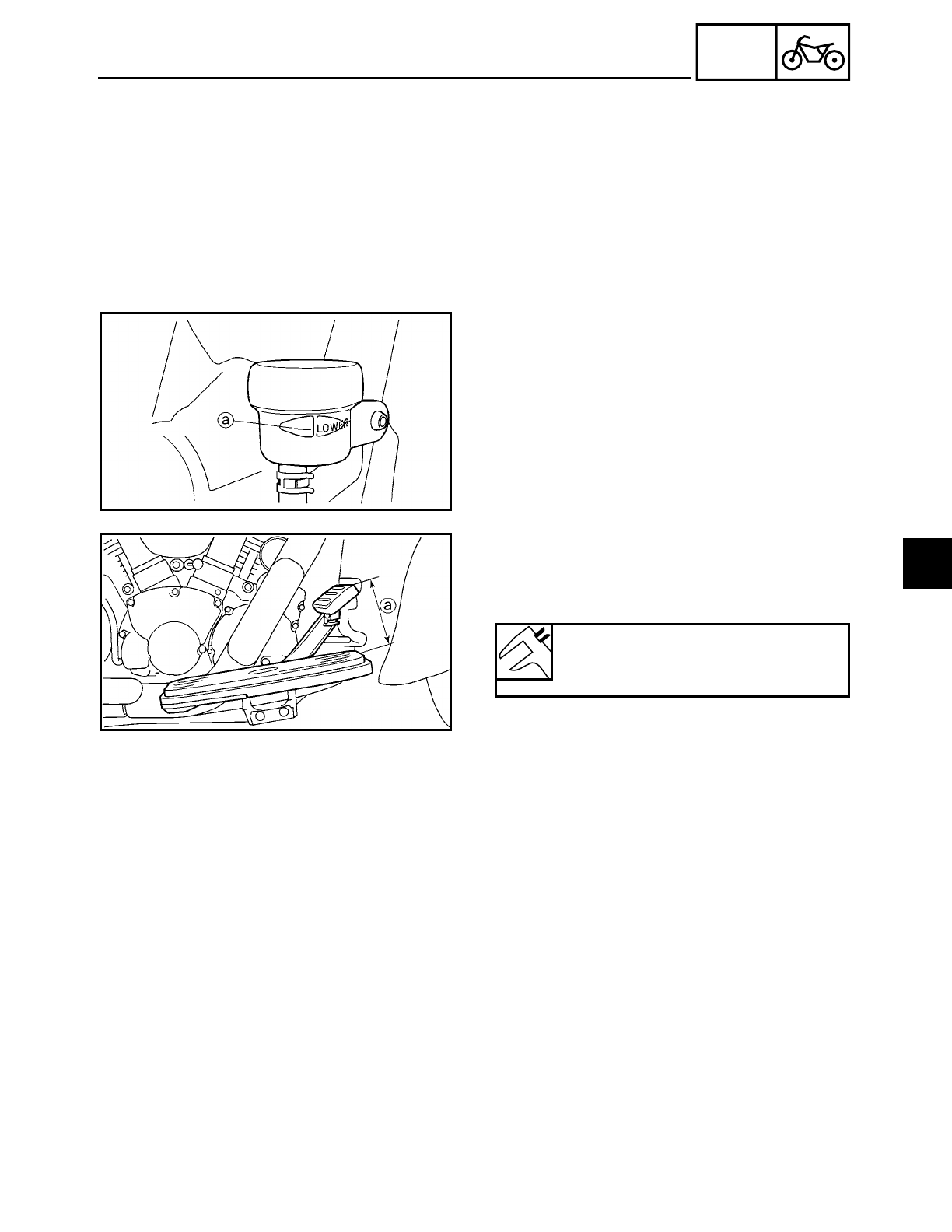
4 - 42
CHAS
FRONT AND REAR BRAKES
8. Bleed:
• brake system
Refer to “BLEEDING THE HYDRAULIC
BRAKE SYSTEM” in chapter 3.
9. Install:
• brake fluid reservoir diaphragm
• brake fluid reservoir diaphragm holder
• brake fluid reservoir cap
• brake fluid reservoir cover
10.Check:
• brake fluid level
Below the minimum level mark a→ Add
the recommended brake fluid to the
proper level.
Refer to “CHECKING THE BRAKE FLUID
LEVEL” in chapter 3.
11.Adjust:
• brake pedal position a
Refer to “ADJUSTING THE REAR
BRAKE” in chapter 3.
Brake pedal position (below the
top of the rider footrest)
100 mm (3.9 in)
12.Adjust:
• rear brake light operation timing
Refer to “ADJUSTING THE REAR BRAKE
LIGHT SWITCH” in chapter 3.
4
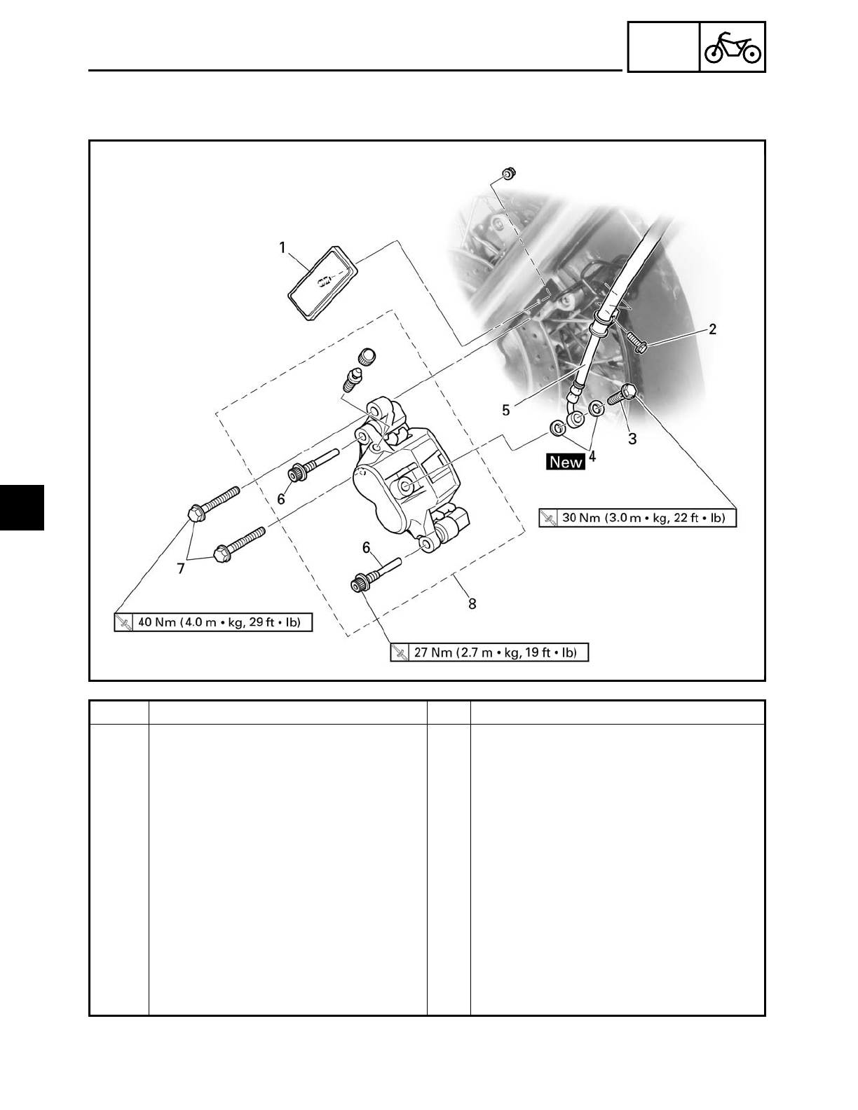
4 - 43
CHAS
FRONT AND REAR BRAKES
EAS00613
FRONT BRAKE CALIPERS
Order Job/Part Q’ty Remarks
Removing the front brake calipers Remove the parts in the order listed.
The following procedure applies to
both of the front brake calipers.
Brake fluid Drain.
1 Reflector 1
2 Brake hose holder bolt 1
3 Union bolt 1
4 Copper washer 2
5 Brake hose 1
6 Retaining bolt 2 Loosen.
7 Brake caliper bolt 2
8 Brake caliper 1
For installation, reverse the removal
procedure.
4
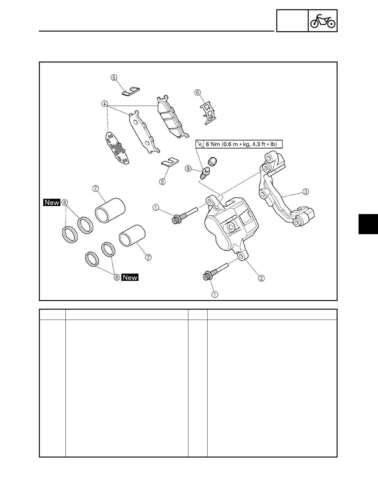
4 - 44
CHAS
FRONT AND REAR BRAKES
EAS00615
Order Job/Part Q’ty Remarks
Disassembling the front brake cali-
pers
Remove the parts in the order listed.
The following procedure applies to
both of the front brake calipers.
1Retaining bolt 2
2Brake caliper 1
3Brake caliper bracket 2
4Brake pad 2
5Brake pad spring 2
6Brake pad spring 1
7Brake caliper piston 2
8Brake caliper piston seal 4
9Bleed screw 1
For assembly, reverse the disassembly
procedure.
4
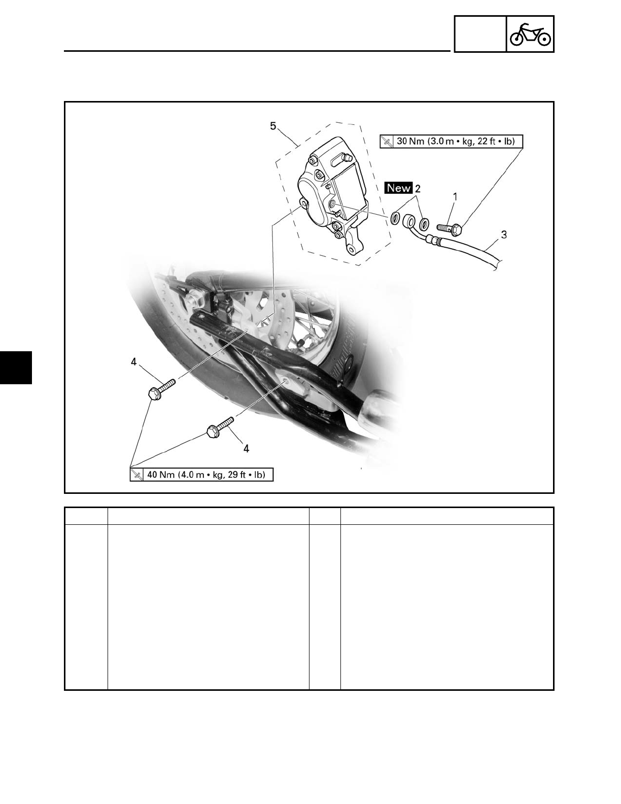
4 - 45
CHAS
FRONT AND REAR BRAKES
EAS00616
REAR BRAKE CALIPER
Order Job/Part Q’ty Remarks
Removing the rear brake caliper Remove the parts in the order listed.
Muffler Refer to “REAR WHEEL, BRAKE DISC
AND REAR WHEEL PULLEY”.
Brake fluid Drain.
1 Union bolt 1
2 Copper washer 2
3 Brake hose 1
4 Brake caliper bolt 2
5 Brake caliper 1
For installation, reverse the removal
procedure.
4
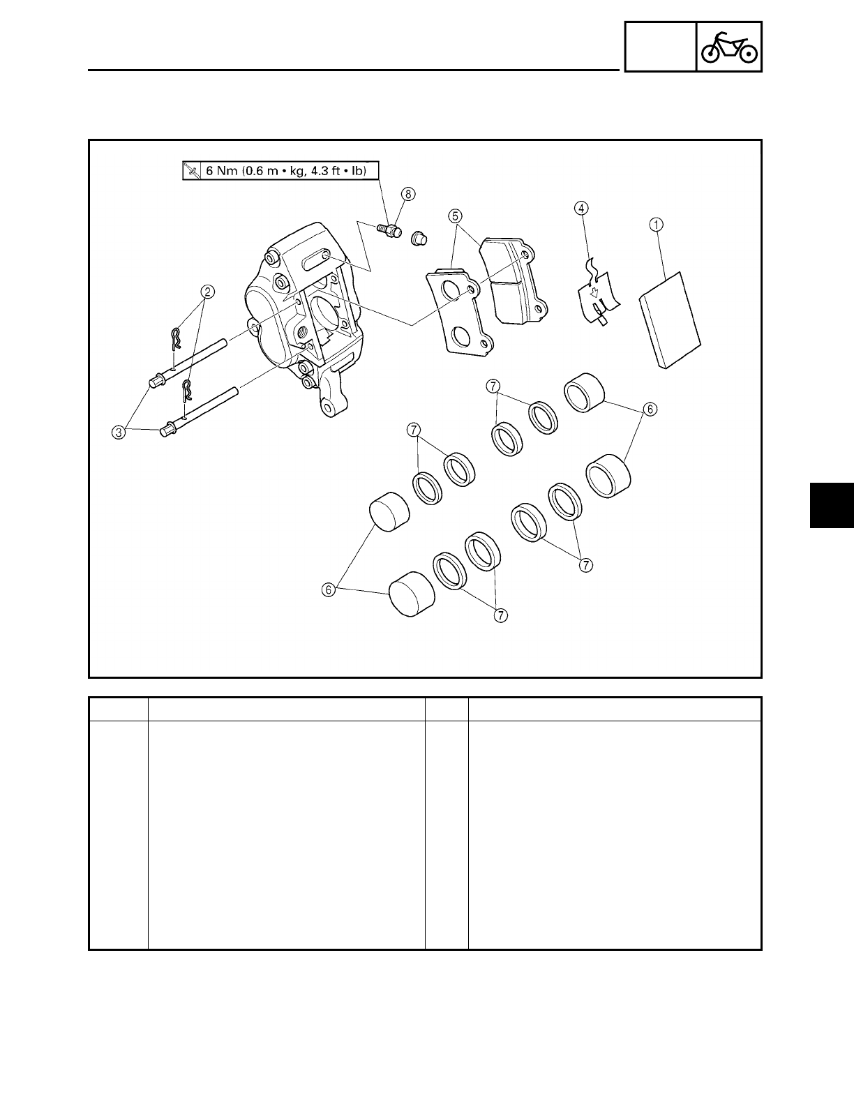
4 - 46
CHAS
FRONT AND REAR BRAKES
EAS00617
Order Job/Part Q’ty Remarks
Disassembling the rear brake caliper Remove the parts in the order listed.
1Brake pad cover 1
2Brake pad clip 2
3Brake pad pin 2
4Brake pad spring 1
5Brake pad 2
6Brake caliper piston 4
7Brake caliper piston seal 8
8Bleed screw 1
For assembly, reverse the disassembly
procedure.
4
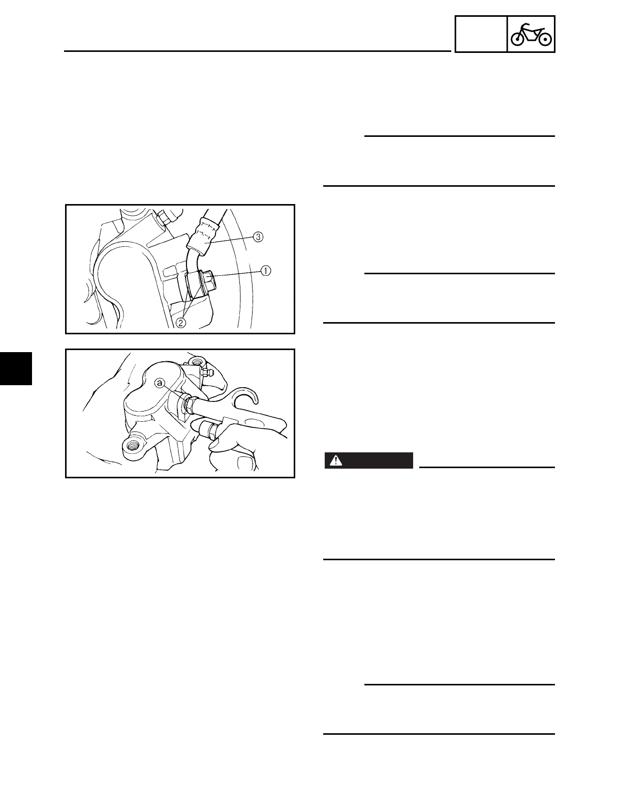
4 - 47
CHAS
FRONT AND REAR BRAKES
EAS00624
DISASSEMBLING THE FRONT BRAKE
CALIPERS
The following procedure applies to both of
the brake calipers.
NOTE:
Before disassembling either brake caliper,
drain the brake fluid from the entire brake
system.
1. Remove:
• union bolt 1
• copper washers 2
• brake hose 3
NOTE:
Put the end of the brake hose into a con-
tainer and pump out the brake fluid care-
fully.
2. Remove:
• brake caliper pistons
• brake caliper piston seals
▼ ▼ ▼ ▼ ▼ ▼ ▼ ▼ ▼ ▼ ▼ ▼ ▼ ▼ ▼ ▼ ▼ ▼ ▼ ▼ ▼ ▼ ▼ ▼ ▼ ▼ ▼ ▼
a. Blow compressed air into the brake hose
joint opening a to force out the pistons
from the brake caliper.
WARNING
WARNING
• Cover the brake caliper pistons with a
rag. Be careful not to get injured when
the pistons are expelled from the brake
caliper.
• Never try to pry out the brake caliper pis-
tons.
b. Remove the brake caliper piston seals.
▲ ▲ ▲ ▲ ▲ ▲ ▲ ▲ ▲ ▲ ▲ ▲ ▲ ▲ ▲ ▲ ▲ ▲ ▲ ▲ ▲ ▲ ▲ ▲ ▲ ▲ ▲ ▲
EAS00627
DISASSEMBLING THE REAR BRAKE
CALIPER
NOTE:
Before disassembling the brake caliper,
drain the brake fluid from the entire brake
system.
4
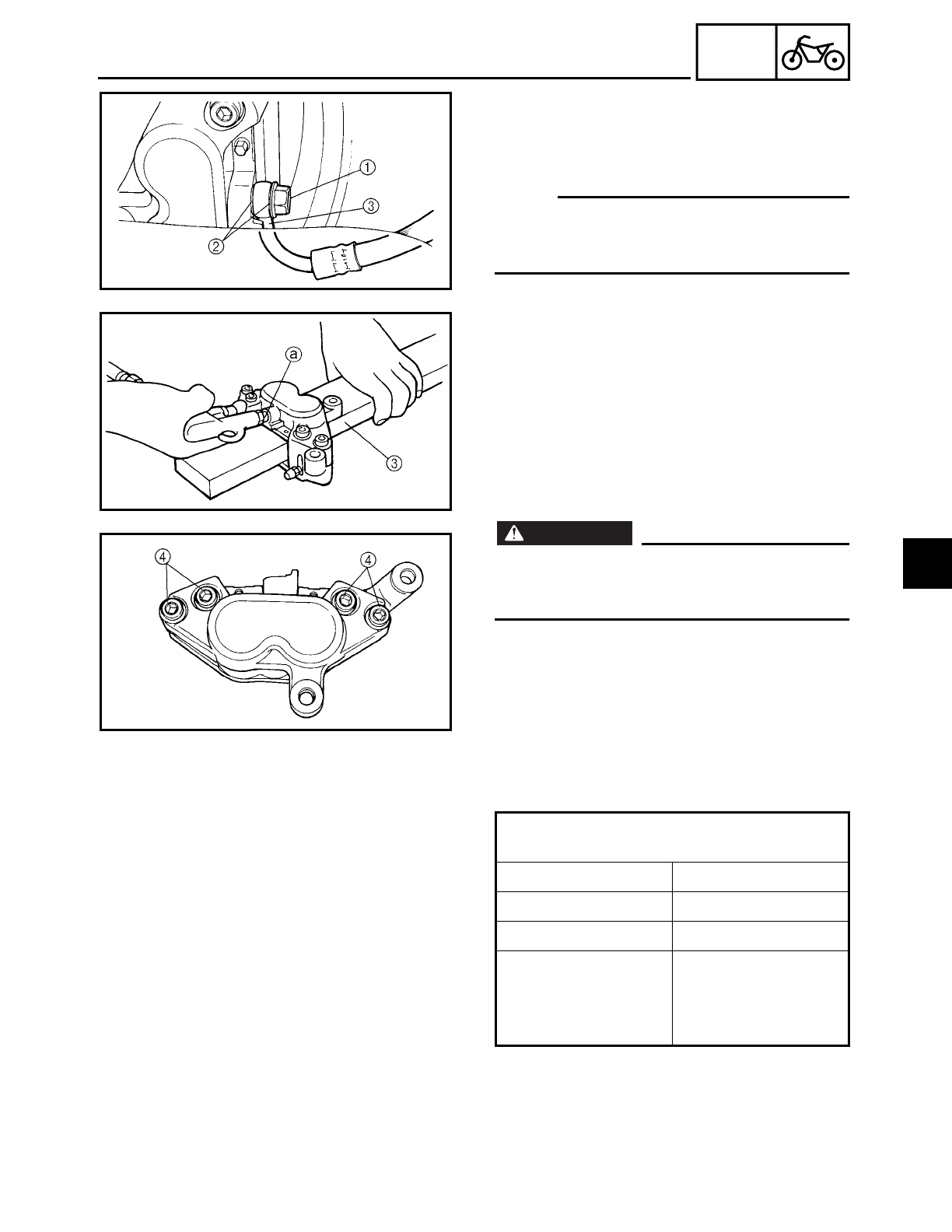
4 - 48
CHAS
FRONT AND REAR BRAKES
1. Remove:
• union bolt 1
• copper washers 2
• brake hose 3
NOTE:
Put the end of the brake hose into a con-
tainer and pump out the brake fluid care-
fully.
2. Remove:
• brake caliper pistons 1
• brake caliper piston seals 2
▼ ▼ ▼ ▼ ▼ ▼ ▼ ▼ ▼ ▼ ▼ ▼ ▼ ▼ ▼ ▼ ▼ ▼ ▼ ▼ ▼ ▼ ▼ ▼ ▼ ▼ ▼ ▼
a. Secure the right side brake caliper piston
with a peace of wood 3.
b. Blow compressed air into the brake hose
joint opening a to force out the left side
pistons from the brake caliper.
WARNING
WARNING
• Never try to pry out the brake caliper pis-
tons.
• Do not loosen the bolts 4.
c. Remove the brake caliper piston seals.
d. Repeat the previous steps to force out the
right side piston from the brake caliper.
▲ ▲ ▲ ▲ ▲ ▲ ▲ ▲ ▲ ▲ ▲ ▲ ▲ ▲ ▲ ▲ ▲ ▲ ▲ ▲ ▲ ▲ ▲ ▲ ▲ ▲ ▲ ▲
EAS00633
CHECKING THE FRONT AND REAR BRAKE
CALIPERS
Recommended brake component replace-
ment schedule
Brake pads If necessary
Piston seals Every two years
Brake hoses Every two years
Brake fluid
Every two years
and whenever the
brake is disassem-
bled
4
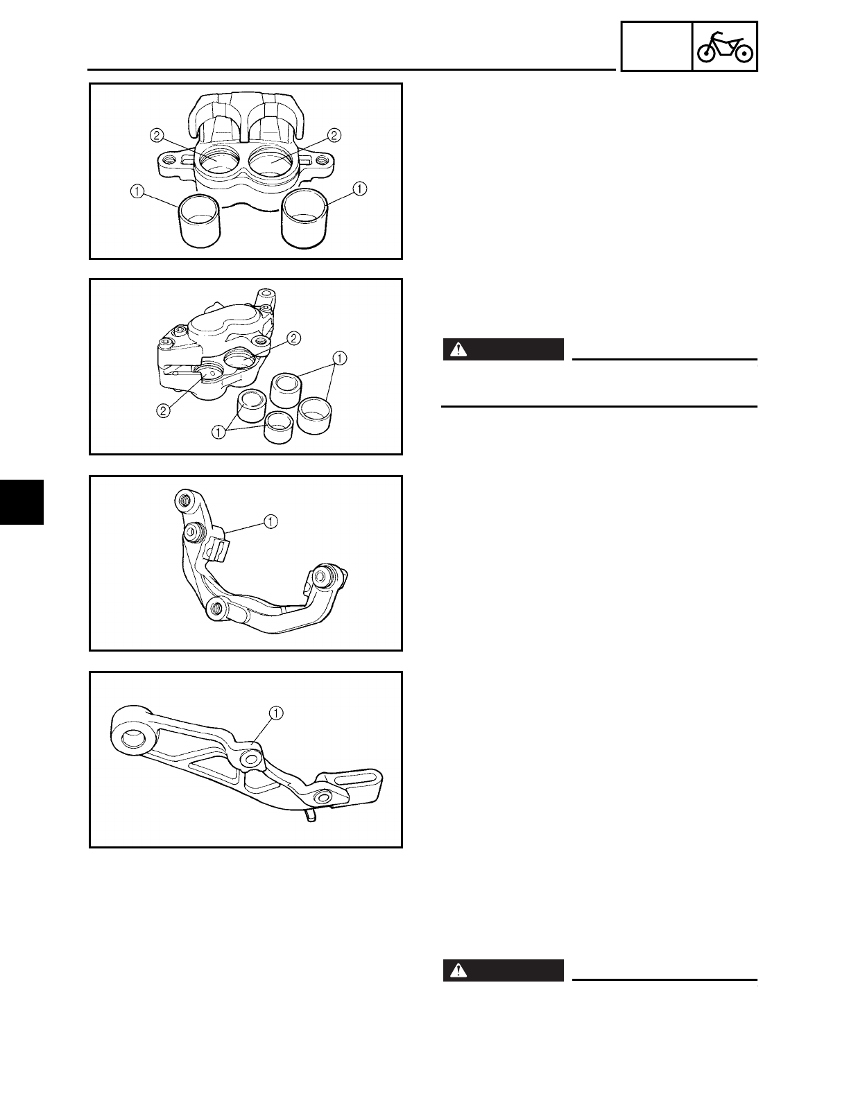
4 - 49
CHAS
FRONT AND REAR BRAKES
1. Check:
• brake caliper pistons 1
Rust/scratches/wear → Replace the brake
caliper.
• brake caliper cylinders 2
Scratches/wear → Replace the brake cali-
per.
• brake calipers
Cracks/damage → Replace.
• brake fluid delivery passages
(brake caliper body)
Obstruction → Blow out with com-
pressed air.
WARNING
WARNING
Whenever a brake caliper is disassembled,
replace the brake caliper piston seals.
ÅFront
ıRear
Å
ı
2. Check:
• brake caliper brackets 1
Cracks/damage → Replace.
ÅFront
ıRear
Å
ı
EAS00638
ASSEMBLING AND INSTALLING THE
FRONT BRAKE CALIPERS
The following procedure applies to both of
the brake calipers.
WARNING
WARNING
• Before installation, all internal brake com-
ponents should be cleaned and lubricated
with clean or new brake fluid.
4
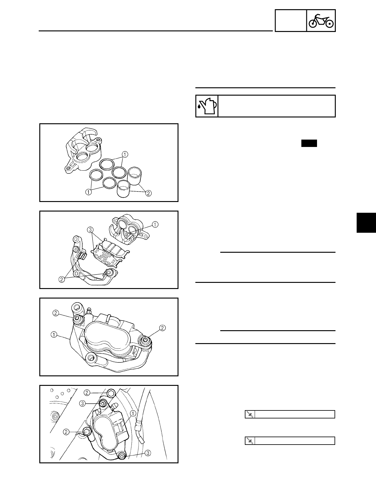
4 - 50
CHAS
FRONT AND REAR BRAKES
• Never use solvents on internal brake
components as they will cause the piston
seals to swell and distort.
• Whenever a brake caliper is disassem-
bled, replace the brake caliper piston
seals.
Recommended brake fluid
DOT 4
1. Install:
• bleed screw
• brake caliper piston seals 1
• brake caliper pistons 2
New
2. Install:
• brake pad spring 1
• brake pad springs 2
• brake pads 3
NOTE:
Install the brake pad with the attached
brake pad shim on the brake caliper piston
side.
3. Install:
• brake caliper bracket 1
• retaining bolts 2
NOTE:
Temporarily tighten the retaining bolts.
4. Install:
• brake caliper 1
• brake caliper bolts 2
5. Tighten:
• retaining bolts 3
T
R
.
.
40 Nm (4.0 m · kg, 29 ft · lb)
T
R
.
.
27 Nm (2.7 m · kg, 19 ft · lb)
4
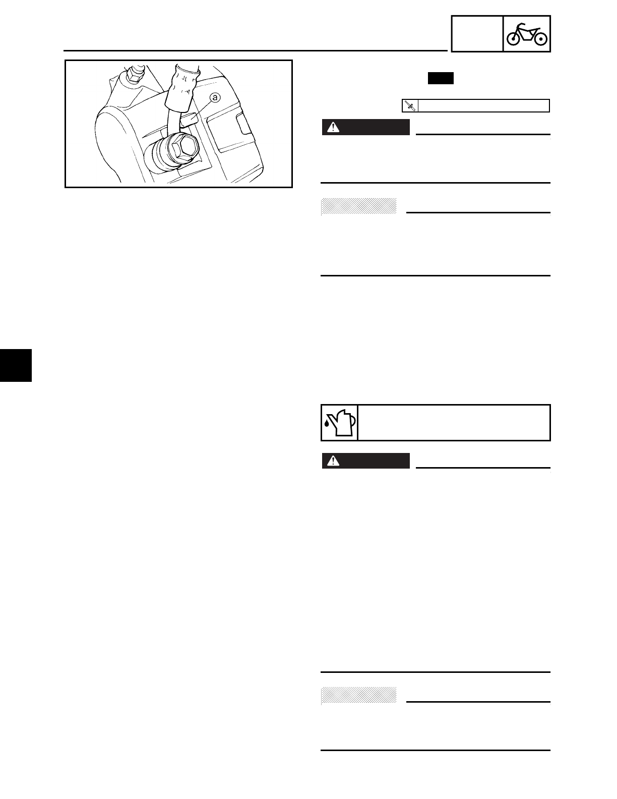
4 - 51
CHAS
FRONT AND REAR BRAKES
6. Install:
• copper washers
• brake hose
• union bolt
WARNING
WARNING
Proper brake hose routing is essential to
insure safe motorcycle operation. Refer to
“CABLE ROUTING”.
ACHTUNG:
CAUTION:
When installing the brake hose onto the
brake caliper, make sure the brake pipe
touches the projection
a on the brake cali-
per.
New
T
R
.
.
30 Nm (3.0 m · kg, 22 ft · lb)
7. Fill:
• brake master cylinder reservoir
(with the specified amount of the recom-
mended brake fluid)
WARNING
WARNING
• Use only the designated brake fluid.
Other brake fluids may cause the rubber
seals to deteriorate, causing leakage and
poor brake performance.
• Refill with the same type of brake fluid
that is already in the system. Mixing
brake fluids may result in a harmful
chemical reaction, leading to poor brake
performance.
• When refilling, be careful that water does
not enter the brake master cylinder reser-
voir. Water will significantly lower the
boiling point of the brake fluid and could
cause vapor lock.
ACHTUNG:
CAUTION:
Brake fluid may damage painted surfaces
and plastic parts. Therefore, always clean
up any spilt brake fluid immediately.
Recommended brake fluid
DOT 4
4
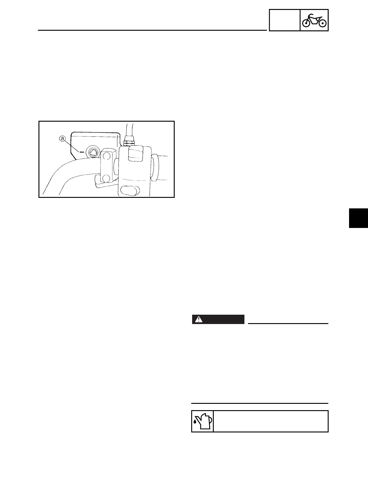
4 - 52
CHAS
FRONT AND REAR BRAKES
8. Bleed:
• brake system
Refer to “BLEEDING THE HYDRAULIC
BRAKE SYSTEM” in chapter 3.
9. Check:
• brake fluid level
Below the minimum level mark a→ Add
the recommended brake fluid to the
proper level.
Refer to “CHECKING THE BRAKE FLUID
LEVEL” in chapter 3.
10.Check:
• brake lever operation
Soft or spongy feeling → Bleed the brake
system.
Refer to “BLEEDING THE HYDRAULIC
BRAKE SYSTEM” in chapter 3.
EAS00642
ASSEMBLING AND INSTALLING THE REAR
BRAKE CALIPER
WARNING
WARNING
• Before installation, all internal brake com-
ponents should be cleaned and lubricated
with clean or new brake fluid.
• Never use solvents on internal brake
components as they will cause the piston
seals to swell and distort.
• Whenever a brake caliper is disassem-
bled, replace the brake caliper piston
seals.
Recommended brake fluid
DOT 4
4
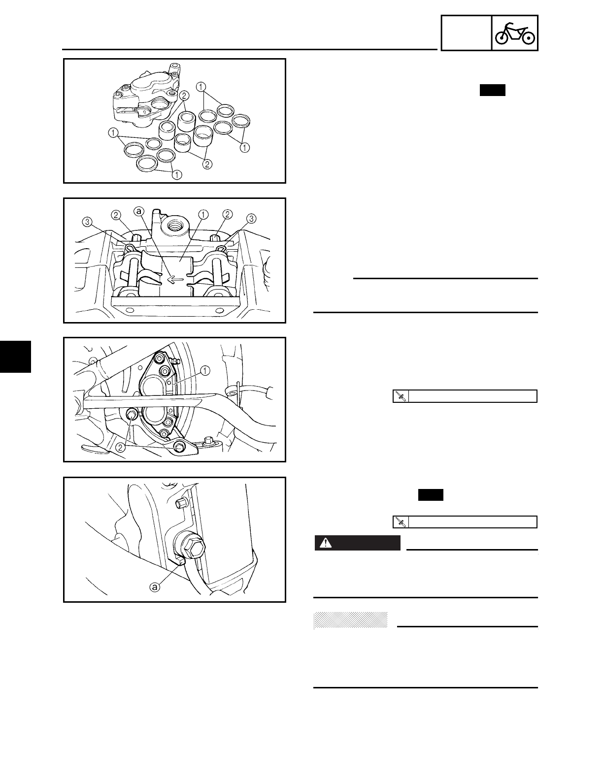
4 - 53
CHAS
FRONT AND REAR BRAKES
1. Install:
• bleed screw
• brake caliper piston seals
1
• brake caliper pistons
2
New
2. Install:
• brake pads
• brake pad spring
1
• brake pad pins
2
• brake pad clips
3
NOTE:
The arrow
a on the brake pad spring must
point in the direction of disc rotation.
3. Install:
• brake pad cover
4. Install:
• brake caliper 1
• brake caliper bolts 2
T
R
.
.
40 Nm (4.0 m · kg, 29 ft · lb)
5. Install:
• copper washers
• brake hose
• union bolt
WARNING
WARNING
Proper brake hose routing is essential to
insure safe motorcycle operation. Refer to
“CABLE ROUTING”.
ACHTUNG:
CAUTION:
When installing the brake hose onto the
brake caliper, make sure the brake pipe
touches the projection
a on the brake cali-
per.
New
T
R
.
.
30 Nm (3.0 m · kg, 22 ft · lb)
4
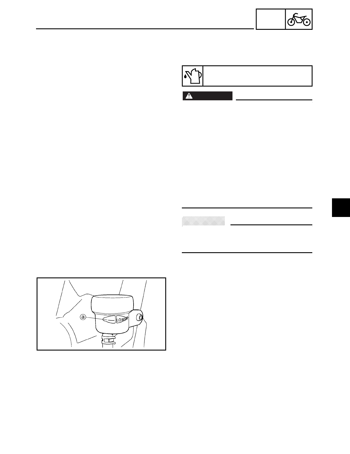
4 - 54
CHAS
FRONT AND REAR BRAKES
6. Fill:
• brake fluid reservoir
(with the specified amount of the recom-
mended brake fluid)
WARNING
WARNING
• Use only the designated brake fluid.
Other brake fluids may cause the rubber
seals to deteriorate, causing leakage and
poor brake performance.
• Refill with the same type of brake fluid
that is already in the system. Mixing
brake fluids may result in a harmful
chemical reaction, leading to poor brake
performance.
• When refilling, be careful that water does
not enter the brake fluid reservoir. Water
will significantly lower the boiling point of
the brake fluid and could cause vapor lock.
ACHTUNG:
CAUTION:
Brake fluid may damage painted surfaces
and plastic parts. Therefore, always clean
up any spilt brake fluid immediately.
7. Bleed:
• brake system
Refer to “BLEEDING THE HYDRAULIC
BRAKE SYSTEM” in chapter 3.
8. Check:
• brake fluid level
Below the minimum level mark a→ Add
the recommended brake fluid to the
proper level.
Refer to “CHECKING THE BRAKE FLUID
LEVEL” in chapter 3.
Recommended brake fluid
DOT 4
9. Check:
• brake pedal operation
Soft or spongy feeling → Bleed the brake
system.
Refer to “BLEEDING THE HYDRAULIC
BRAKE SYSTEM” in chapter 3.
4
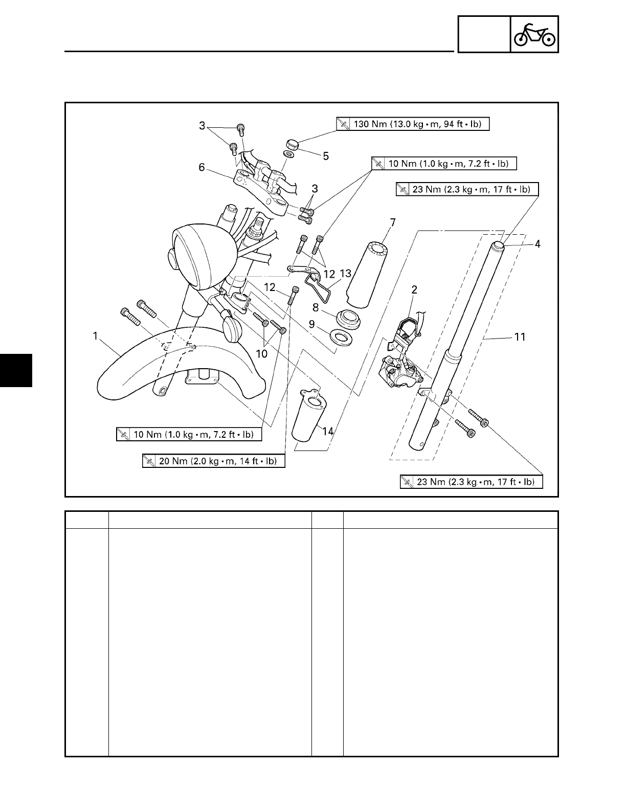
4 - 55
CHAS
FRONT FORK
EAS00647
FRONT FORK
Order Job/Part Q’ty Remarks
Removing the front fork legs Remove the parts in the order listed.
The following procedure applies to
both of the front fork legs.
Front wheel Refer to “FRONT WHEEL AND BRAKE
DISCS”.
Meter assembly Refer to “FUEL TANK” in chapter 3.
1 Front fender 1
2 Brake hose holder 1
3 Upper bracket pinch bolt 4 Loosen.
4 Cap bolt 1
5 Steering stem nut 1
6 Upper bracket 1
7 Upper fork cover 1
8 Upper fork cover spacer 1
9 Upper fork cover washer 1
4
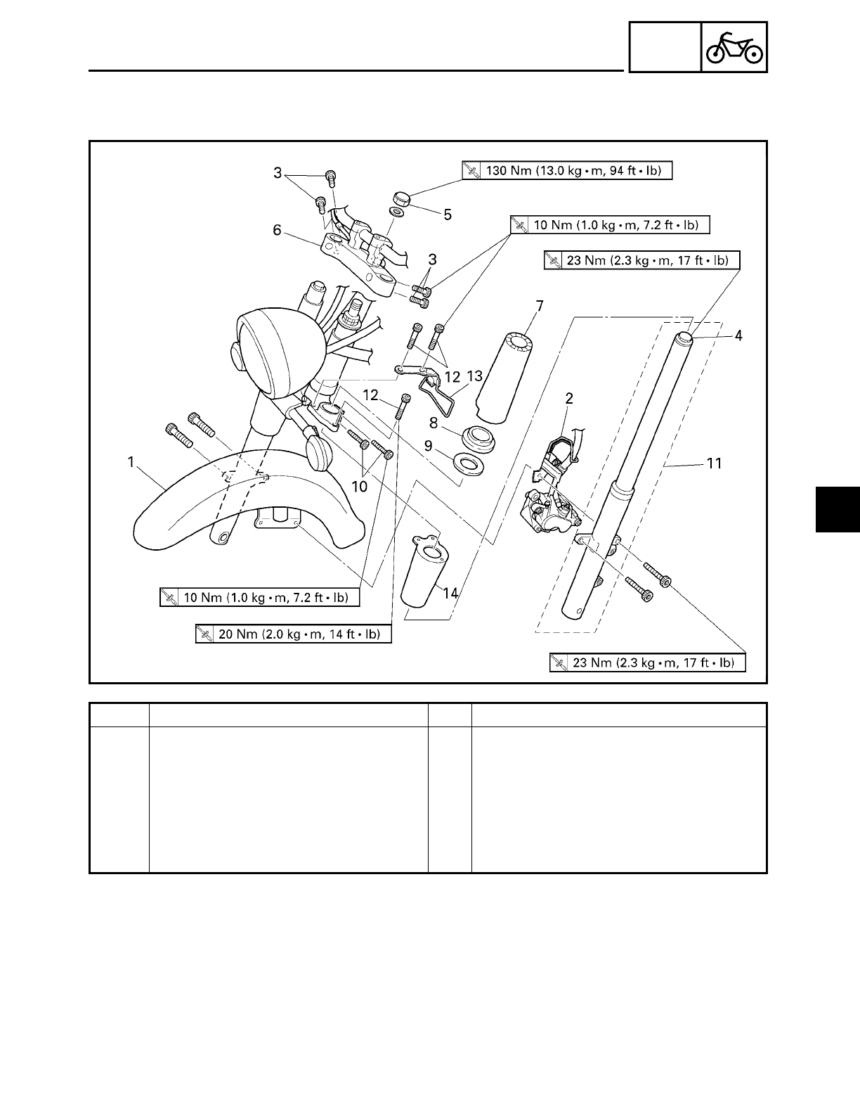
4 - 56
CHAS
Order Job/Part Q’ty Remarks
10 Lower bracket pinch bolt 2 Loosen.
11 Front fork leg 1
12 Bolt 3
13 Brake hose guide 1
14 Lower fork cover 1
For installation, reverse the removal
procedure.
FRONT FORK
4
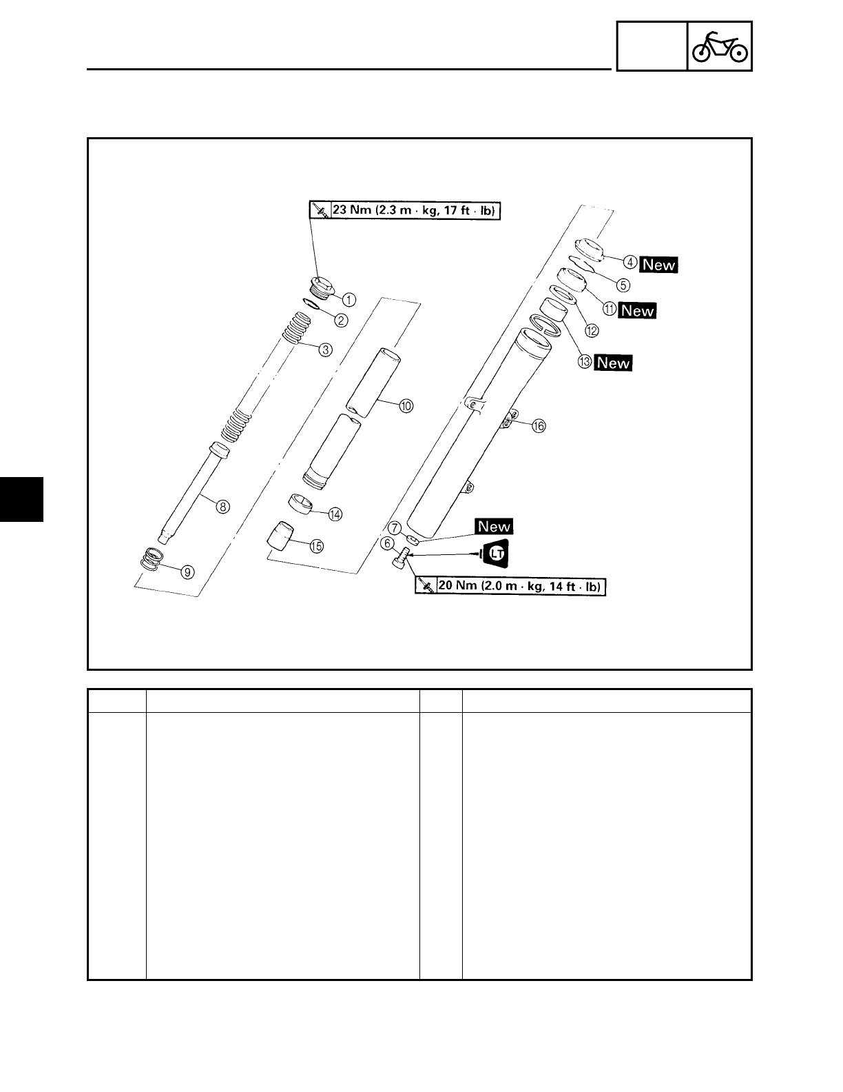
4 - 57
CHAS
FRONT FORK
EAS00648
Order Job/Part Q’ty Remarks
Disassembling the front fork leg Remove the parts in the order listed.
The following procedure applies to
both of the front fork legs.
1Cap bolt 1
2O-ring 1
3Fork spring 1
4Dust seal 1
5Oil seal clip 1
6Cartridge cylinder bolt 1
7Copper washer 1
8Cartridge cylinder 1
9Rebound spring 1
0Inner tube 1
4
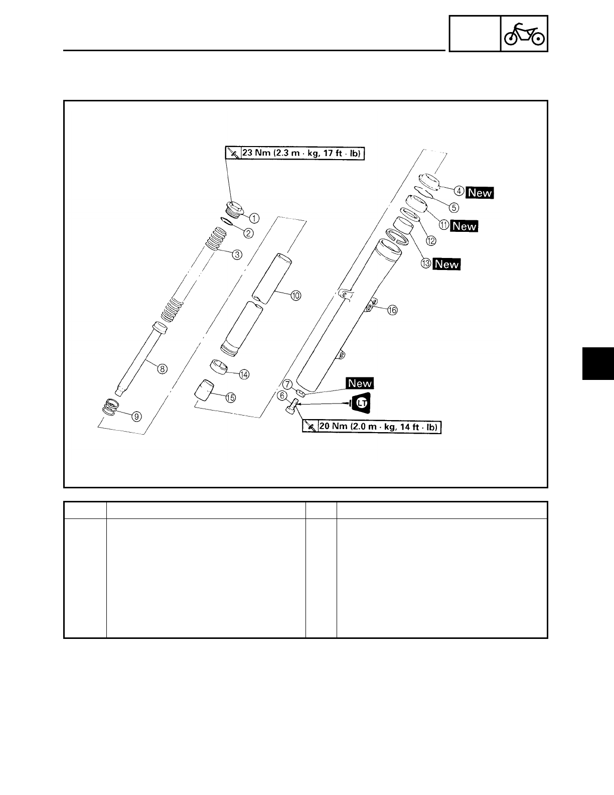
4 - 58
CHAS
Order Job/Part Q’ty Remarks
AOil seal 1
BSeal spacer 1
COuter tube bushing 1
DInner tube bushing 1
EOil flow stopper 1
FOuter tube 1
For assembly, reverse the disassembly
procedure.
FRONT FORK
4
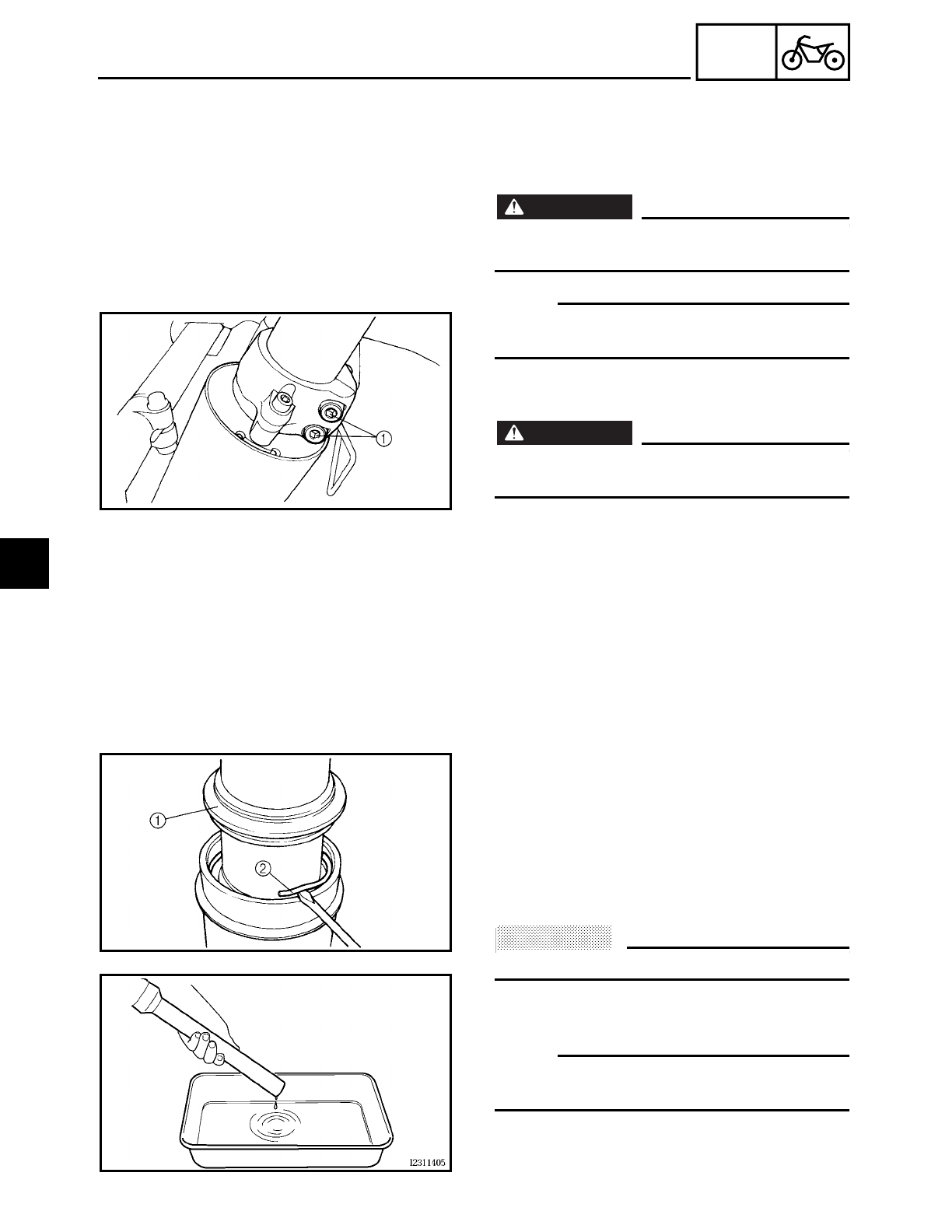
4 - 59
CHAS
FRONT FORK
EAS00649
REMOVING THE FRONT FORK LEGS
The following procedure applies to both of
the front fork legs.
1. Stand the motorcycle on a level surface.
WARNING
WARNING
Securely support the motorcycle so that
there is no danger of it falling over.
NOTE:
Place the motorcycle on a suitable stand so
that the front wheel is elevated.
2. Loosen:
• lower bracket pinch bolts 1
WARNING
WARNING
Before loosening the lower bracket pinch
bolts, support the front fork leg.
3. Remove:
• front fork leg
EAS00652
DISASSEMBLING THE FRONT FORK LEGS
The following procedure applies to both of
the front fork legs.
1. Remove:
• dust seal 1
• oil seal clip 2
(with a flat-head screwdriver)
ACHTUNG:
CAUTION:
Do not scratch the inner tube.
2. Drain:
• fork oil
NOTE:
Stroke the outer tube several times while
draining the fork oil.
4
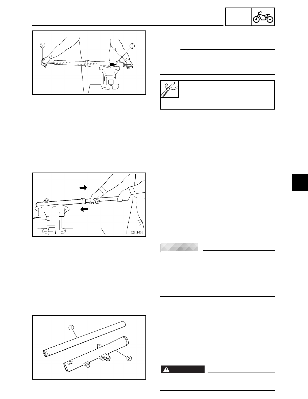
4 - 60
CHAS
FRONT FORK
3. Remove:
• cartridge cylinder bolt
NOTE:
While holding the cartridge cylinder with
the damper rod holder 1 and T-handle 2,
loosen the cartridge cylinder bolt.
Damper rod holder
YM-1300-1
T-Handle
YM-01326
4. Remove:
• inner tube
▼ ▼ ▼ ▼ ▼ ▼ ▼ ▼ ▼ ▼ ▼ ▼ ▼ ▼ ▼ ▼ ▼ ▼ ▼ ▼ ▼ ▼ ▼ ▼ ▼ ▼ ▼ ▼
a. Hold the front fork leg horizontally.
b. Securely clamp the brake caliper bracket
in a vise with soft jaws.
c. Separate the inner tube from the outer
tube by pulling the inner tube forcefully
but carefully.
ACHTUNG:
CAUTION:
• Excessive force will damage the oil seal
and bushing. A damaged oil seal or bush-
ing must be replaced.
• Avoid bottoming the inner tube into the
outer tube during the above procedure,
as the oil flow stopper will be damaged.
▲ ▲ ▲ ▲ ▲ ▲ ▲ ▲ ▲ ▲ ▲ ▲ ▲ ▲ ▲ ▲ ▲ ▲ ▲ ▲ ▲ ▲ ▲ ▲ ▲ ▲ ▲ ▲
EAS00656
CHECKING THE FRONT FORK LEGS
The following procedure applies to both of
the front fork legs.
1. Check:
• inner tube 1
• outer tube 2
Bends/damage/scratches → Replace.
WARNING
WARNING
Do not attempt to straighten a bent inner
tube as this may dangerously weaken it.
4
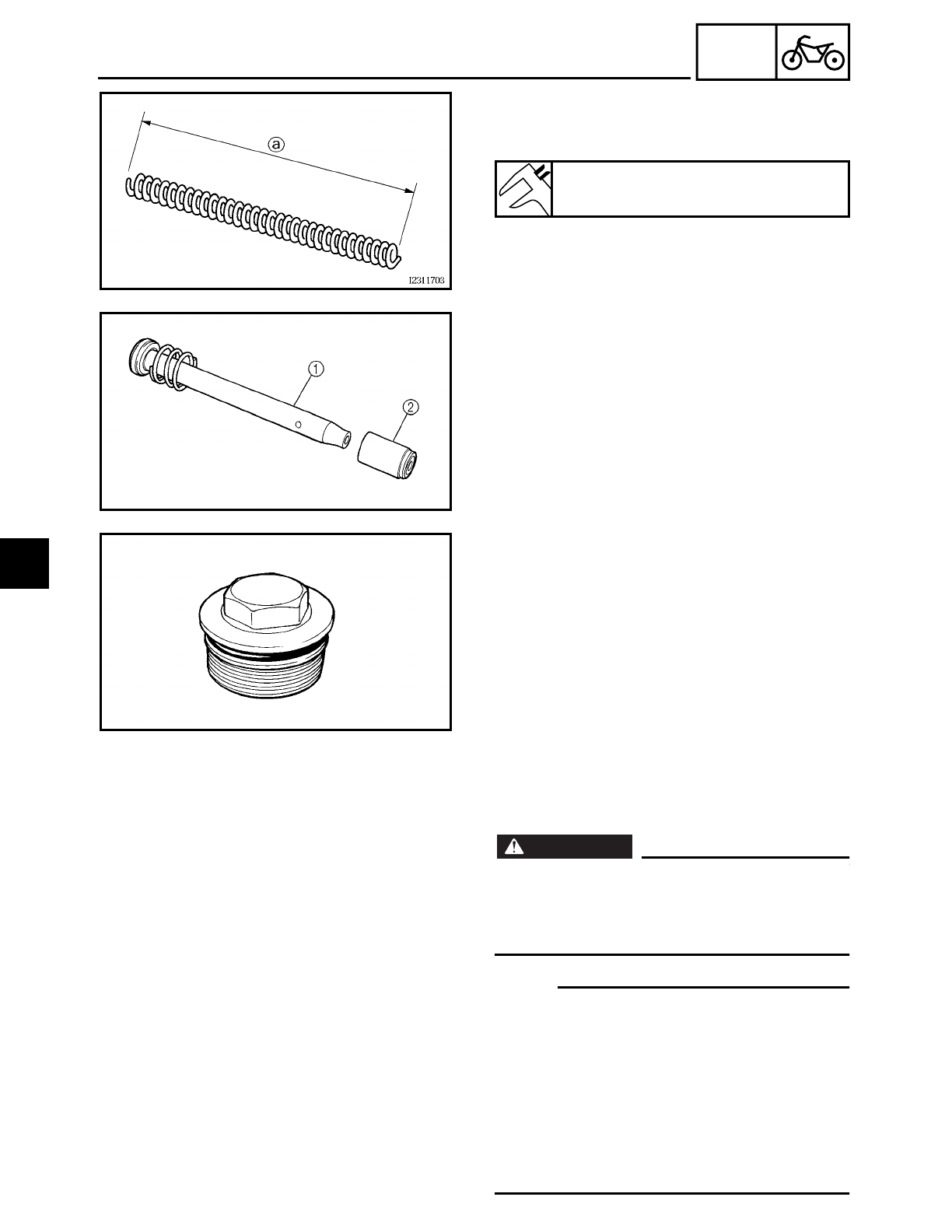
4 - 61
CHAS
FRONT FORK
2. Measure:
• spring free length a
Out of specification → Replace.
Spring free length limit
566 mm (22.3 in)
3. Check:
• cartridge cylinder 1
Damage/wear → Replace.
Obstruction → Blow out all of the oil pas-
sages with compressed air.
• oil flow stopper 2
Damage → Replace.
4. Check:
• cap bolt O-ring
Damage/wear → Replace.
EAS00658
ASSEMBLING THE FRONT FORK LEGS
The following procedure applies to both of
the front fork legs.
WARNING
WARNING
• Make sure the oil levels in both front fork
legs are equal.
• Uneven oil levels can result in poor han-
dling and a loss of stability.
NOTE:
• When assembling the front fork leg, be
sure to replace the following parts:
- inner tube bushing
- outer tube bushing
- oil seal
- dust seal
• Before assembling the front fork leg,
make sure all of the components are
clean.
4
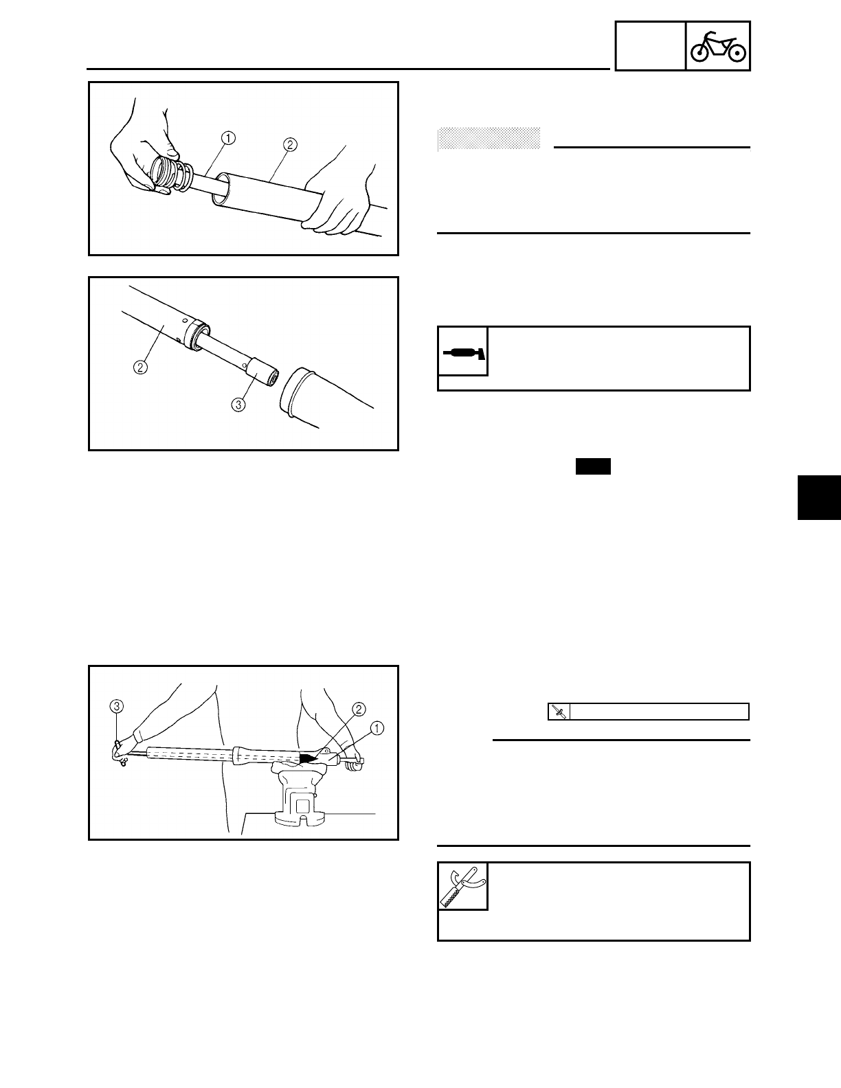
4 - 62
CHAS
FRONT FORK
1. Install:
• cartridge cylinder 1
ACHTUNG:
CAUTION:
Allow the cartridge cylinder to slide slowly
down the inner tube 2 until it protrudes
from the bottom of the inner tube. Be care-
ful not to damage the inner tube.
2. Install:
• oil flow stopper 3
3. Lubricate:
• inner tube’s outer surface
4. Install:
• outer tube
(onto the inner tube)
• copper washer
• cartridge cylinder bolt
Recommended lubricant
Yamaha fork and shock oil 5WT
or equivalent
New
5. Tighten:
• cartridge cylinder bolt 1
NOTE:
• Apply the locking agent (LOCTITE 204) to
the threads of the cartridge cylinder bolt.
• While holding the cartridge cylinder with
the damper rod holder 2 and T-handle 3,
tighten the cartridge cylinder bolt.
Damper rod holder
YM-1300-1
T-handle
YM-01326
T
R
.
.
20 Nm (2.0 m · kg, 14 ft · lb)
4
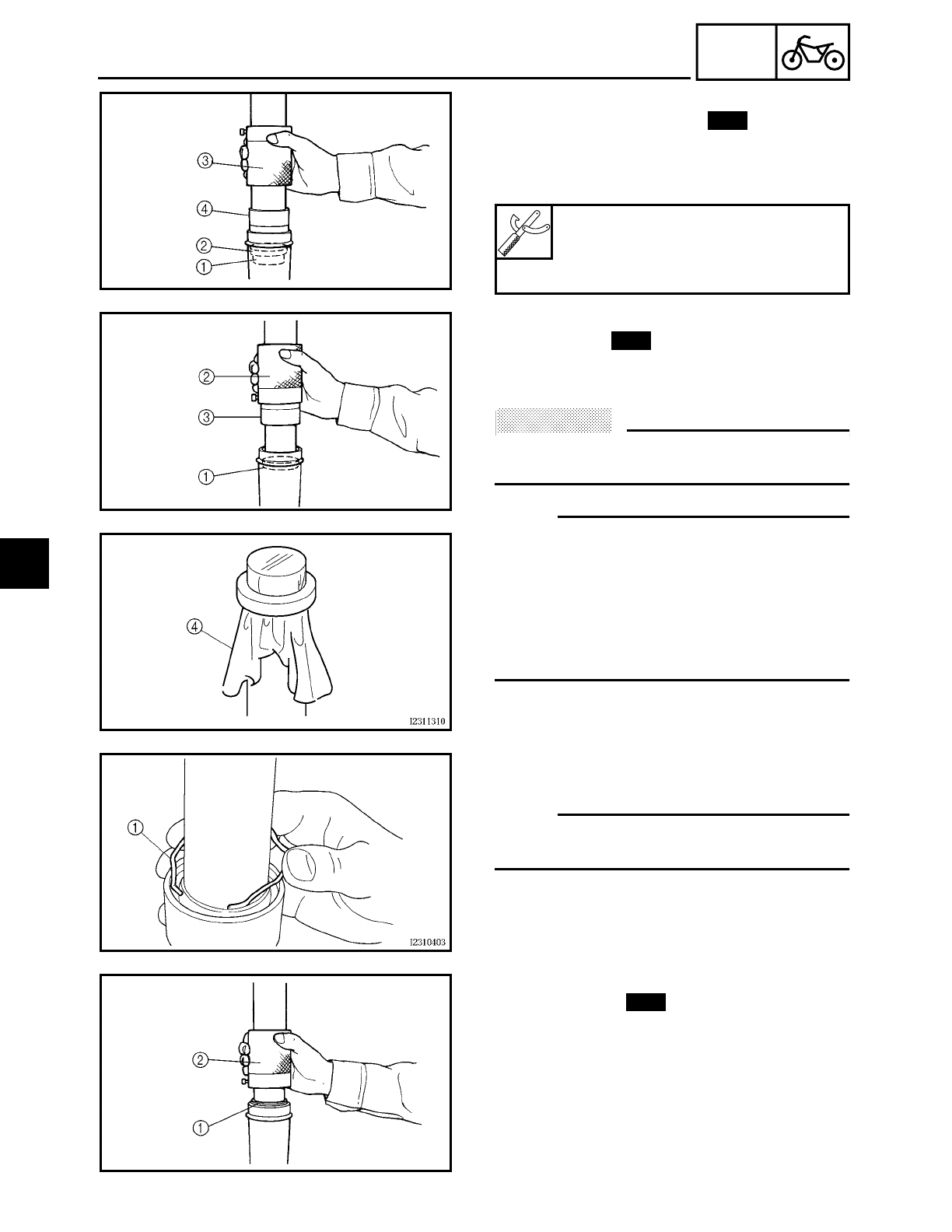
4 - 63
CHAS
FRONT FORK
6. Install:
• outer tube bushing 1
• seal spacer 2
(with the fork seal driver weight 3 and
adapter 4)
Fork seal driver weight
YM-33963
Adapter
YM-8020
New
7. Install:
• oil seal 1
(with the fork seal driver weight 2 and
adapter 3)
ACHTUNG:
CAUTION:
Make sure the numbered side of the oil seal
faces up.
NOTE:
• Before installing the oil seal, lubricate its
lips with lithium soap base grease.
• Lubricate the outer surface of the inner
tube with fork oil.
• Before installing the oil seal, cover the top
of the front fork leg with a plastic bag 4 to
protect the oil seal during installation.
New
8. Install:
• oil seal clip 1
NOTE:
Adjust the oil seal clip so that it fits into the
outer tube’s groove.
9. Install:
• dust seal 1
(with the fork seal driver weight 2)
New
4
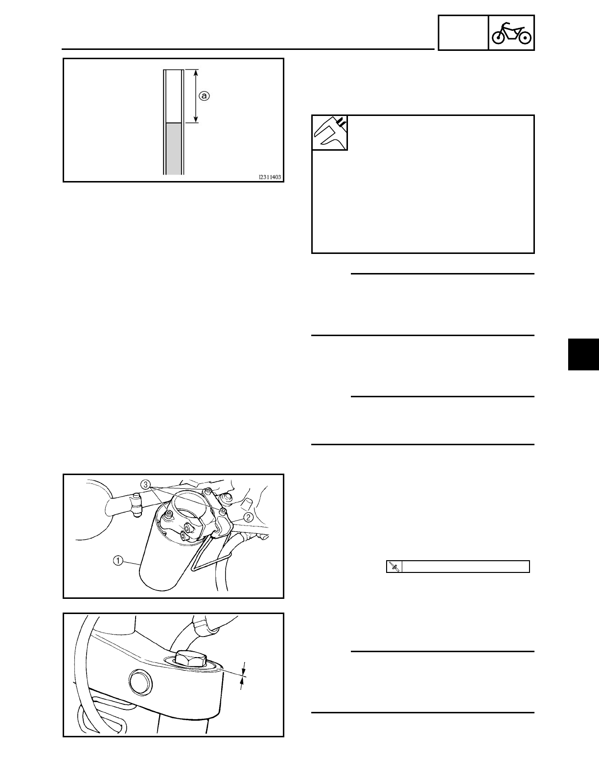
4 - 64
CHAS
FRONT FORK
10.Fill:
• front fork leg
(with the specified amount of the recom-
mended fork oil)
NOTE:
• While filling the front fork leg, keep it
upright.
• After filling, slowly pump the front fork
leg up and down to distribute the fork oil.
11.Install:
• fork spring
• cap bolt
NOTE:
• Before installing the cap bolt, lubricate its
O-ring with grease.
• Temporarily tighten the cap bolt.
Quantity (each front fork leg)
554 L (488 lmp qt, 589 US qt)
Front fork leg oil level a
(from the top of the inner tube,
with the inner tube fully com-
pressed, and without the fork
spring)
110 mm (4.33 in)
Recommended oil
Yamaha fork and shock oil 5WT
or equivalent
EAS00662
INSTALLING THE FRONT FORK LEGS
The following procedure applies to both of
the front fork legs.
1. Install:
• lower fork cover 1
• brake hose guide 2
• bolts 3
T
R
.
.
10 Nm (1.0 m · kg, 7.2 ft · lb)
2. Install:
• front fork leg
NOTE:
• When aligning the fork tube do not install
the upper fork cover.
• Temporarily tighten the lower bracket
pinch bolts.
4
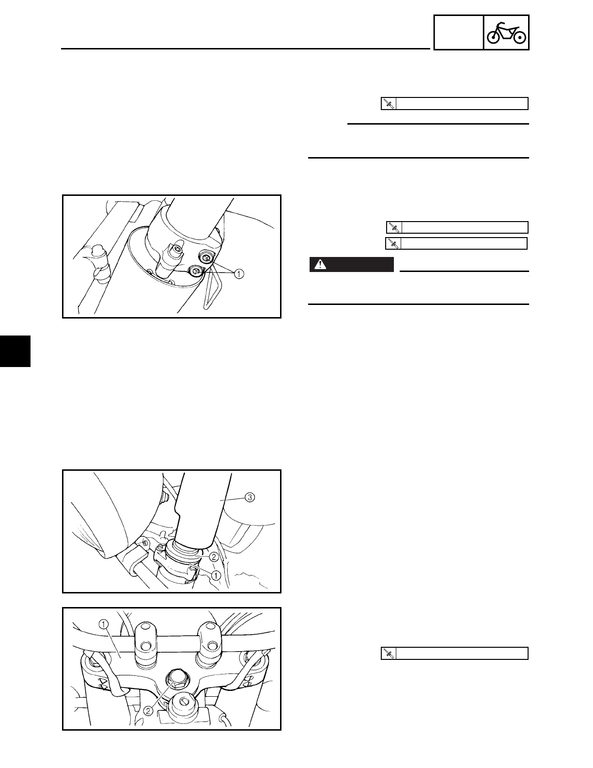
4 - 65
CHAS
FRONT FORK
3. Install:
• Upper bracket
• Steering stem nut
NOTE:
Make sure the inner fork tube is flush with
the top of the upper bracket.
T
R
.
.
130 Nm (13.0 m · kg, 94 ft · lb)
4. Tighten:
• lower bracket pinch bolt 1
• cap bolt
WARNING
WARNING
Make sure the brake hoses are routed prop-
erly.
5. Remove:
• steering stem nut
• upper bracket
T
R
.
.
20 Nm (2.0 m · kg, 14 ft · lb)
T
R
.
.
23 Nm (2.3 m · kg, 17 ft · lb)
6. Install:
• upper fork washer 1
• upper fork spacer 2
• upper fork cover 3
7. Install:
• upper bracket 1
• steering stem nut 2
T
R
.
.
130 Nm (13.0 m · kg, 94 ft · lb)
4
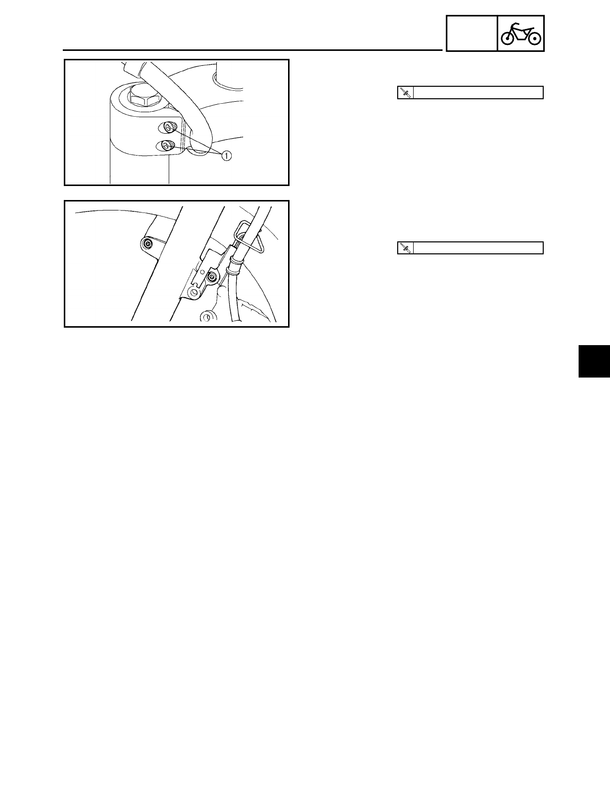
4 - 66
CHAS
FRONT FORK
8. Tighten:
• upper bracket pinch bolts 1
T
R
.
.
10 Nm (1.0 m · kg, 7.2 ft · lb)
9. Install:
• brake hose holder
• front fender
T
R
.
.
23 Nm (2.3 m · kg, 17 ft · lb)
10.Install:
• front wheel
Refer to “FRONT WHEEL AND BRAKE
DISCS”.
4
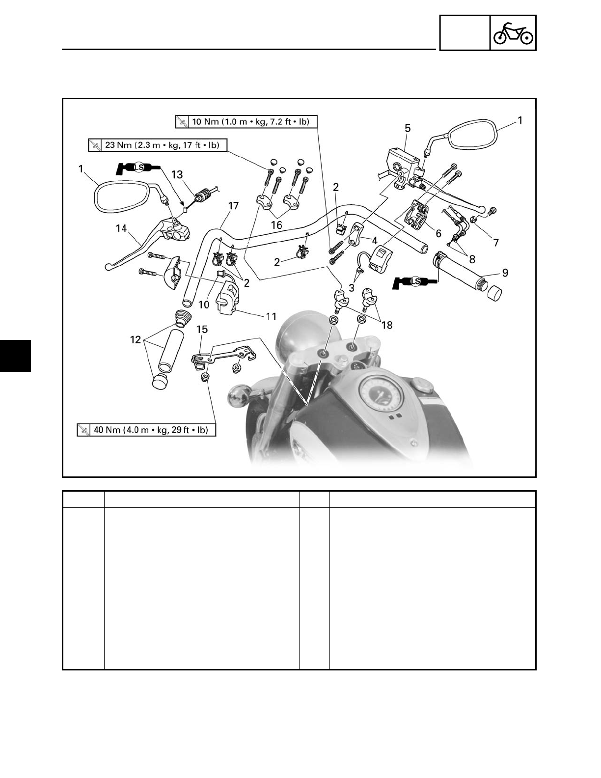
4 - 67
CHAS
HANDLEBAR
EAS00664
HANDLEBAR
Order Job/Part Q’ty Remarks
Removing the handlebar Remove the parts in the order listed.
1 Rear view mirror (left and right) 2
2 Plastic clamp 4
3 Front brake light switch connector 2 Disconnect.
4 Brake master cylinder holder 1
5 Brake master cylinder 1
6 Right handlebar switch 1
7 Throttle cable holder 1
8 Throttle cable 2 Disconnect.
9 Throttle grip 1
10 Clutch switch connector 1 Disconnect.
4
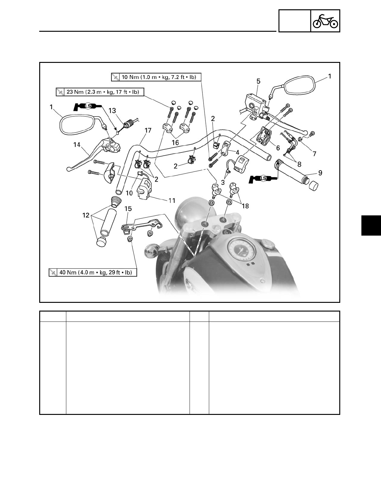
4 - 68
CHAS
HANDLEBAR
Order Job/Part Q’ty Remarks
11 Left handlebar switch 1
12 Handlebar grip 1
13 Clutch cable 1 Disconnect.
14 Clutch lever holder 1
15 Cable guide 1
16 Upper handlebar holder 2
17 Handlebar 1
18 Lower handlebar holder 2
For installation, reverse the removal
procedure.
4
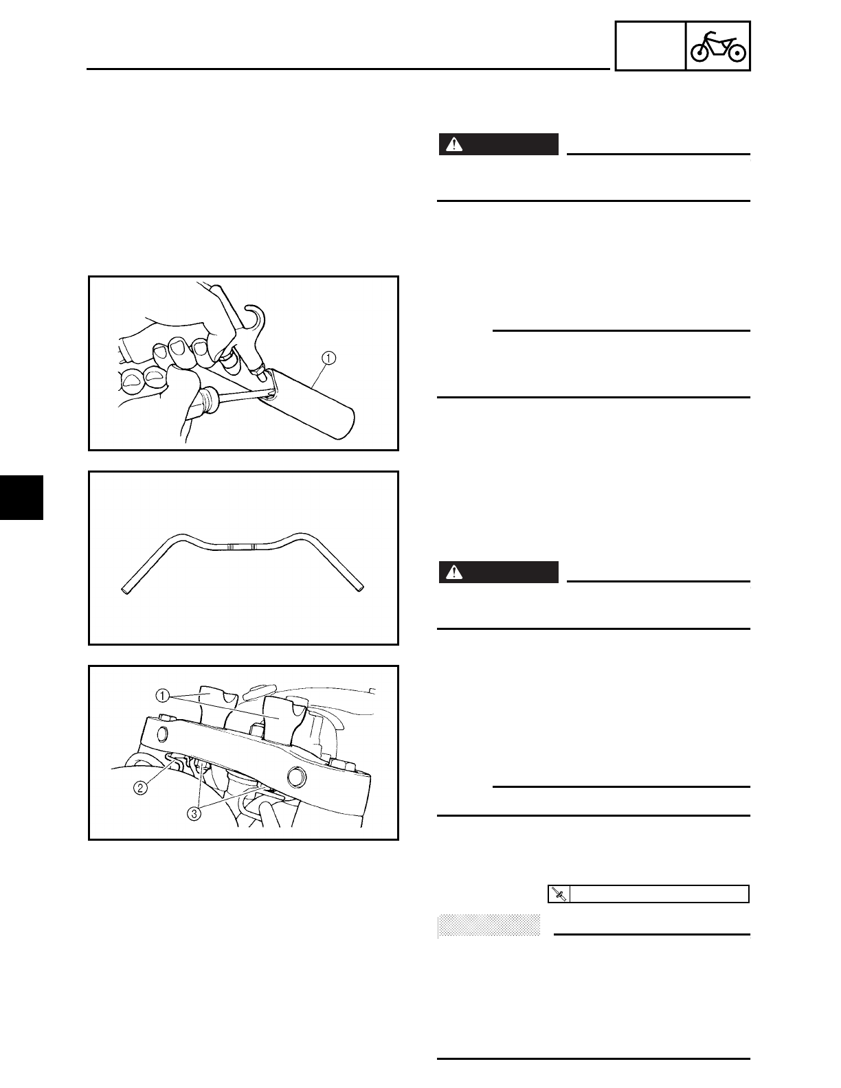
4 - 69
CHAS
HANDLEBAR
EAS00666
REMOVING THE HANDLEBAR
1. Stand the motorcycle on a level surface.
WARNING
WARNING
Securely support the motorcycle so that
there is no danger of it falling over.
2. Remove:
• handlebar grip 1
NOTE:
Blow compressed air between the handle-
bar and the handlebar grip, and gradually
push the grip off the handlebar.
EAS00668
CHECKING THE HANDLEBAR
1. Check:
• handlebar
Bends/cracks/damage → Replace.
WARNING
WARNING
Do not attempt to straighten a bent han-
dlebar as this may dangerously weaken it.
EAS00670
INSTALLING THE HANDLEBAR
1. Install:
• washers
• lower handlebar holders 1
• cable guide 2
NOTE:
Temporarily tighten the nuts 3.
2. Install:
• handlebar
• upper handlebar holders
ACHTUNG:
CAUTION:
• First, tighten the bolts on the front side of
the handlebar holder, then on the rear
side.
• Turn the handlebar all the way to the left
and right. If there is any contact with the
fuel tank, adjust the handlebar position.
T
R
.
.
23 Nm (2.3 m · kg, 17 ft · lb)
4
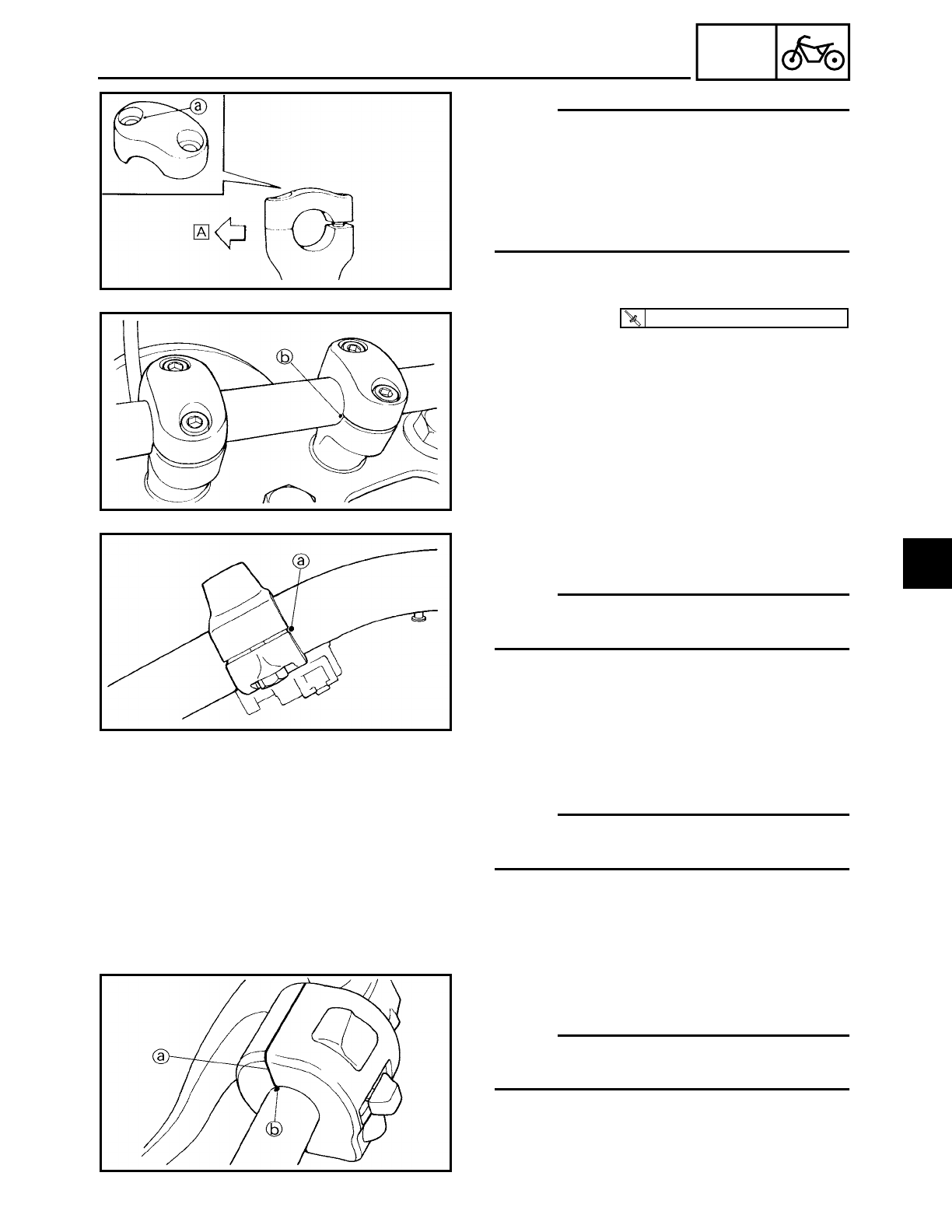
4 - 70
CHAS
HANDLEBAR
NOTE:
• The upper handlebar holders should be
installed with the arrows a facing for-
ward Å.
• Align the match marks b on the handle-
bar with the upper surface of the lower
handlebar holders.
3. Tighten:
• lower handlebar holder nuts
T
R
.
.
40 Nm (4.0 m · kg, 29 ft · lb)
4. Install:
• clutch lever
NOTE:
Align the slit of clutch lever holder with the
punch mark a on the handlebar.
5. Install:
• clutch cable
NOTE:
Lubricate the end of the clutch cable with a
thin coat of lithium soap base grease.
6. Install:
• left handlebar switch
NOTE:
Align the end a of the left handlebar switch
with the punch mark b on the handlebar.
7. Connect:
• clutch switch connector
4
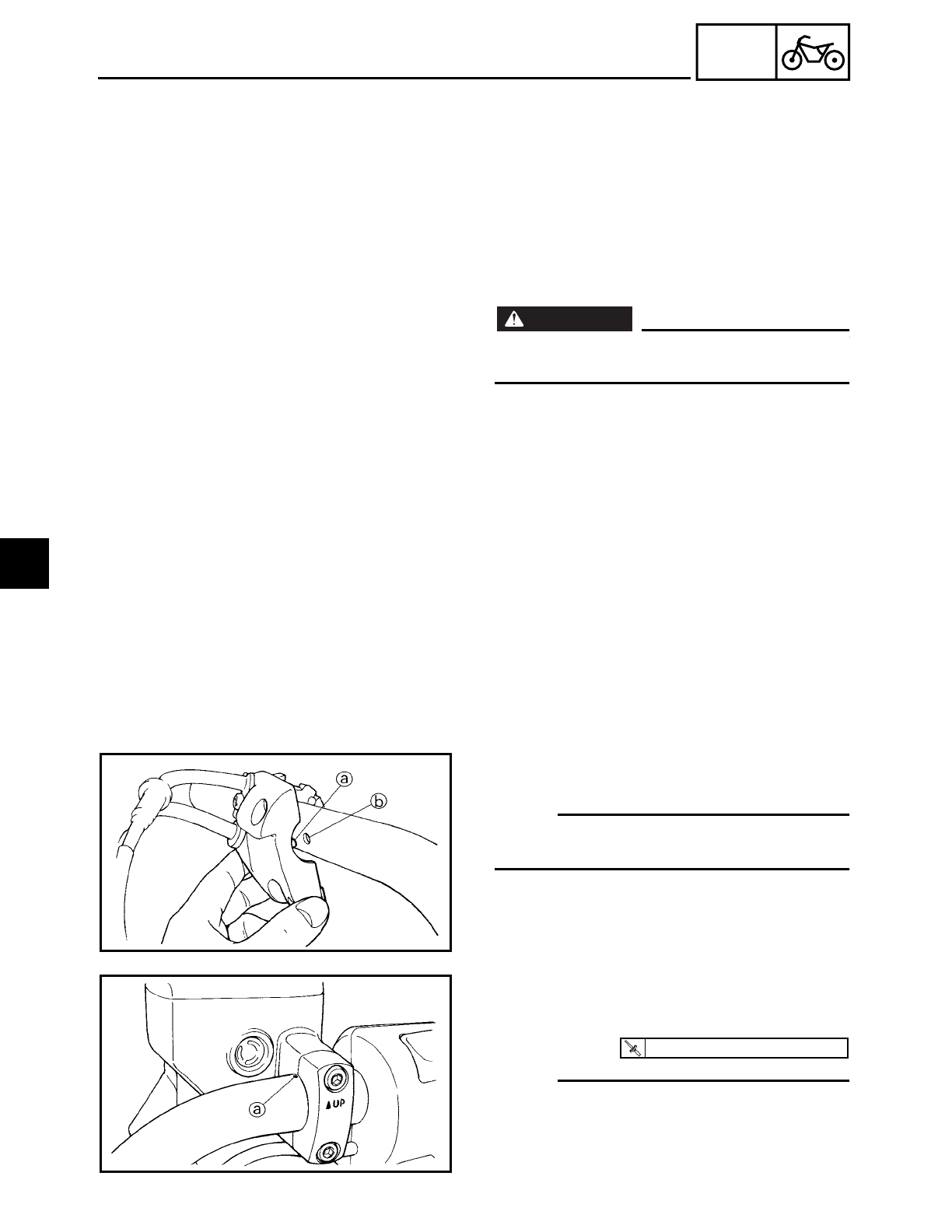
4 - 71
CHAS
HANDLEBAR
8. Install:
• handlebar grip
▼ ▼ ▼ ▼ ▼ ▼ ▼ ▼ ▼ ▼ ▼ ▼ ▼ ▼ ▼ ▼ ▼ ▼ ▼ ▼ ▼ ▼ ▼ ▼ ▼ ▼ ▼ ▼
a. Apply a thin coat of rubber adhesive
onto the left end of the handlebar.
b. Slide the handlebar grip over the left end
of the handlebar.
c. Wipe off any excess rubber adhesive
with a clean rag.
WARNING
WARNING
Do not touch the handlebar grip until the
rubber adhesive has fully dried.
▲ ▲ ▲ ▲ ▲ ▲ ▲ ▲ ▲ ▲ ▲ ▲ ▲ ▲ ▲ ▲ ▲ ▲ ▲ ▲ ▲ ▲ ▲ ▲ ▲ ▲ ▲ ▲
9. Install:
• throttle grip
10.Connect:
• throttle cable
11.Install:
• right handlebar switch
NOTE:
Align the projection a on the right handle-
bar switch with the hole b in the handlebar.
12.Install:
• brake master cylinder
• brake master cylinder holder
NOTE:
• Install the brake master cylinder holder
with the “UP” mark facing up.
• Align the end of the brake master cylinder
holder with the punch mark a in the han-
dlebar.
T
R
.
.
10 Nm (1.0 m · kg, 7.2 ft · lb)
4
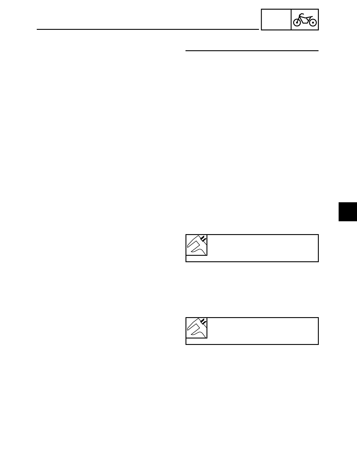
4 - 72
CHAS
HANDLEBAR
• First, tighten the upper bolt, then the
lower bolt.
13.Connect:
• front brake light switch connector
14.Install:
• plastic clamp
• rear view mirrors
15.Adjust:
• clutch cable free play
Refer to “ADJUSTING THE CLUTCH
CABLE FREE PLAY” in chapter 3.
Clutch cable free play (at the end
of the clutch lever)
10 ~ 15 mm (0.39 ~ 0.59 in)
16.Adjust:
• throttle cable free play
Refer to “ADJUSTING THE THROTTLE
CABLE FREE PLAY” in chapter 3.
Throttle cable free play (at the
flange of the throttle grip)
4 ~ 8 mm (0.16 ~ 0.31 in)
4
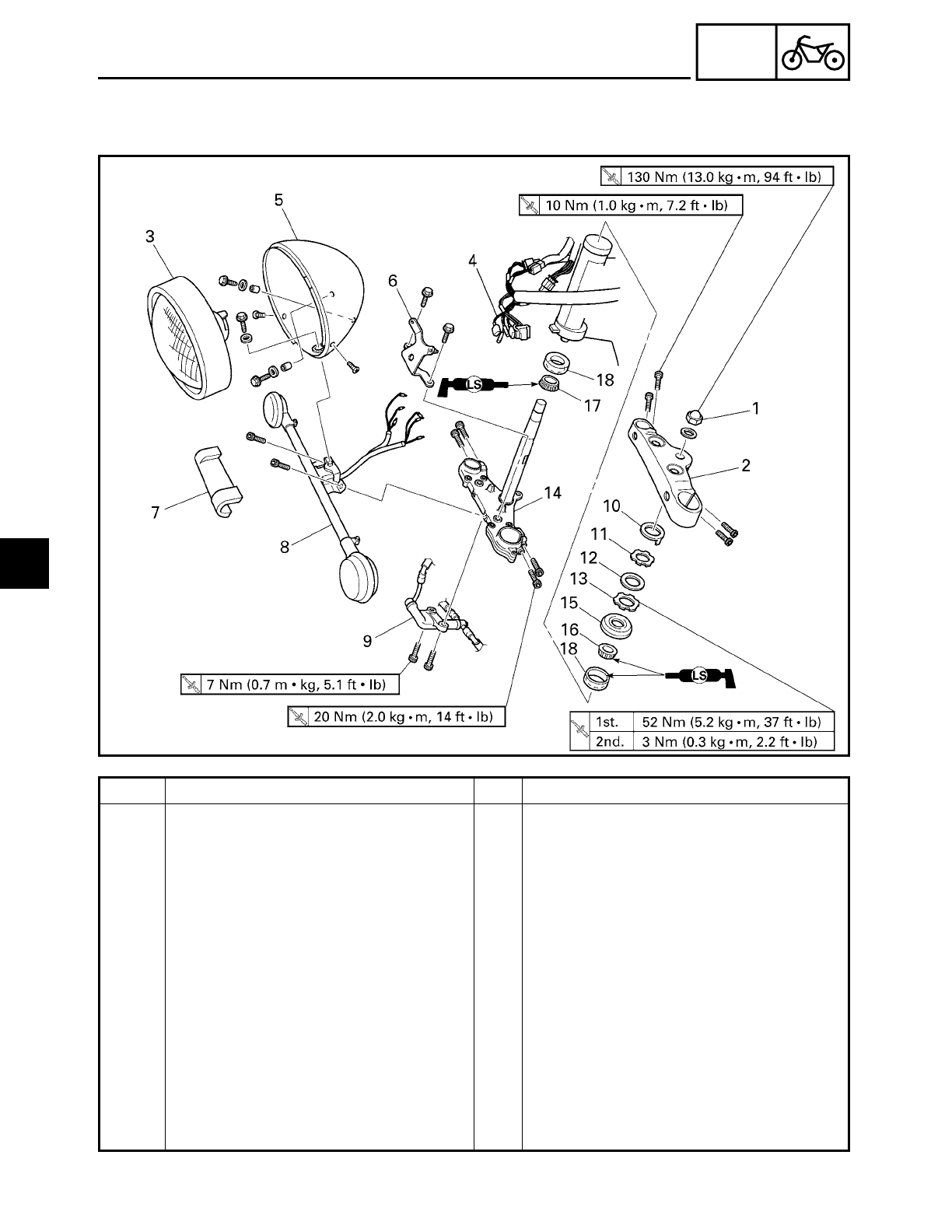
4 - 73
CHAS
STEERING HEAD
EAS00676
STEERING HEAD
Order Job/Part Q’ty Remarks
Removing the lower bracket Remove the parts in the order listed.
Meter assembly Refer to “FUEL TANK” in chapter 3.
Front fork legs/fork covers Refer to “FRONT FORK”.
Front wheel Refer to “FRONT WHEEL AND BRAKE
DISCS”.
Handlebar/handlebar holders Refer to “HANDLEBAR”.
1 Steering stem nut 1
2 Upper bracket 1
3 Headlight lens unit 1
4 Lead (in the headlight body) 1
5 Headlight body 1
6 Headlight bracket 1
7 Chrome turn signal light bracket
cover
1
8 Turn signal light bracket assembly 1
4
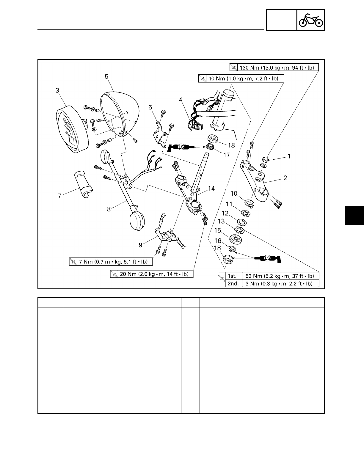
4 - 74
CHAS
STEERING HEAD
Order Job/Part Q’ty Remarks
9 Brake hose joint 1
10 Lock washer 1
11 Upper ring nut 1
12 Rubber washer 1
13 Lower ring nut 1
14 Lower bracket 1
15 Bearing cover 1
16 Upper bearing 1
17 Lower bearing 1
18 Bearing outer race 2
For installation, reverse the removal
procedure.
4
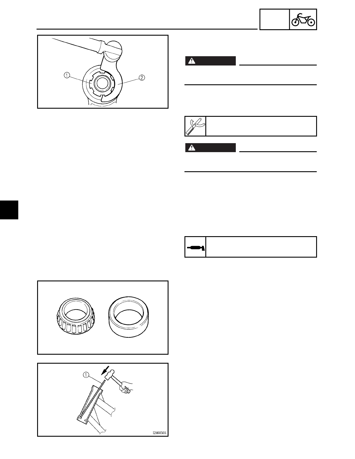
4 - 75
CHAS
STEERING HEAD
EAS00677
REMOVING THE LOWER BRACKET
1. Stand the motorcycle on a level surface.
WARNING
WARNING
Securely support the motorcycle so that
there is no danger of it falling over.
2. Remove:
• lower ring nut 1
(with the special tool 2)
WARNING
WARNING
Securely support the lower bracket so that
there is no danger of it falling.
Ring nut wrench
YU-33975
EAS00681
CHECKING THE STEERING HEAD
1. Wash:
• bearings
• bearing races
Recommended cleaning solvent
Kerosene
2. Check:
• bearings
• bearing races
Damage/pitting→ Replace.
3. Replace:
• bearings
• bearing races
▼ ▼ ▼ ▼ ▼ ▼ ▼ ▼ ▼ ▼ ▼ ▼ ▼ ▼ ▼ ▼ ▼ ▼ ▼ ▼ ▼ ▼ ▼ ▼ ▼ ▼ ▼ ▼
a. Remove the bearing races from the
steering head pipe with a long rod 1 and
hammer.
b. Remove the bearing race from the lower
bracket with a floor chisel 2 and hammer.
4
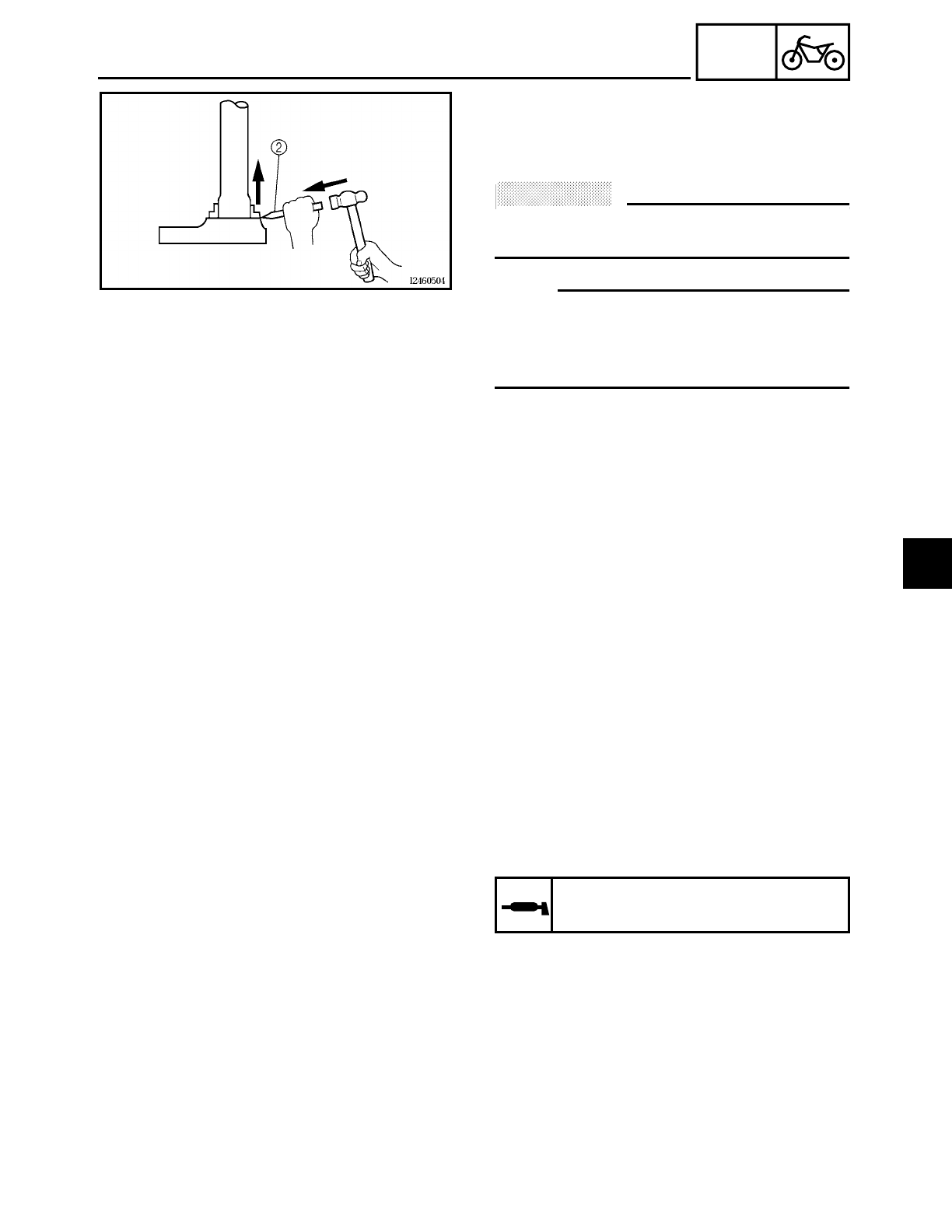
4 - 76
CHAS
STEERING HEAD
c. Install a new rubber seal and new bear-
ing races.
▲ ▲ ▲ ▲ ▲ ▲ ▲ ▲ ▲ ▲ ▲ ▲ ▲ ▲ ▲ ▲ ▲ ▲ ▲ ▲ ▲ ▲ ▲ ▲ ▲ ▲ ▲ ▲
ACHTUNG:
CAUTION:
If the bearing race is not installed properly,
the steering head pipe could be damaged.
NOTE:
• Always replace the bearings and bearing
races as a set.
• Whenever the steering head is disassem-
bled, replace the rubber seal.
4. Check:
• upper bracket
• lower bracket
(along with the steering stem)
Bends/cracks/damage → Replace.
EAS00683
INSTALLING THE STEERING HEAD
1. Lubricate:
• upper bearing
• lower bearing
• bearing races
Recommended lubricant
Lithium soap base grease
2. Install:
• upper bearing
• lower bearing
• bearing races
• bearing cover
• lower bracket
4
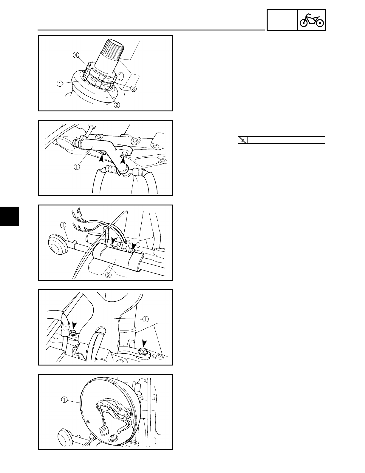
4 - 77
CHAS
STEERING HEAD
3. Install:
• lower ring nut
1
• rubber washer
2
• upper ring nut
3
• lock washer
4
Refer to “CHECKING AND ADJUSTING
THE STEERING HEAD” in chapter 3.
4. Install:
• brake hose joint
1
T
R
.
.
7 Nm (0.7 m · kg, 5.1 ft · lb)
5. Install:
• turn signal light bracket assembly
1
• chrome turn signal light bracket cover
2
6. Install:
• headlight bracket 1
7. Install:
• headlight body 1
8. Connect:
• leads
(in the headlight body)
9. Install:
• headlight lens unit
4

4 - 78
CHAS
STEERING HEAD
10.Install:
• upper bracket
• steering stem nut
• front fork legs
Refer to “FRONT FORK”.
11.Install:
• handlebar
Refer to “HANDLEBAR”.
• front fork legs
Refer to “FRONT FORK”.
• meter assembly
Refer to “FUEL TANK” in chapter 3.
4
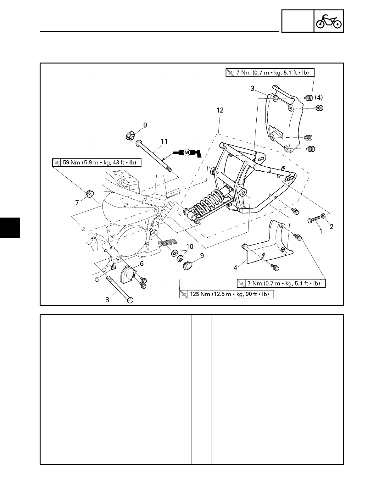
4 - 79
CHAS
REAR SHOCK ABSORBER AND SWINGARM
********
REAR SHOCK ABSORBER AND SWINGARM
Order Job/Part Q’ty Remarks
Removing the rear shock absorber
and swingarm
Remove the parts in the order listed.
Rear wheel Refer to “REAR WHEEL, BRAKE DISC
AND REAR WHEEL PULLEY”.
1 Adjusting bolt 1
2 Locknut 1
3 Mud guard 1
4 Lower drive belt cover 1
5 Horn coupler 1 Disconnect.
6 Horn 1
7 Self-locking nut 1
8 Bolt (shock absorber-connecting
arm-frame)
1R= 158 mm (6.22 in)
9 Cover (left and right) 2
10 Pivot shaft nut/washer 1/1
4
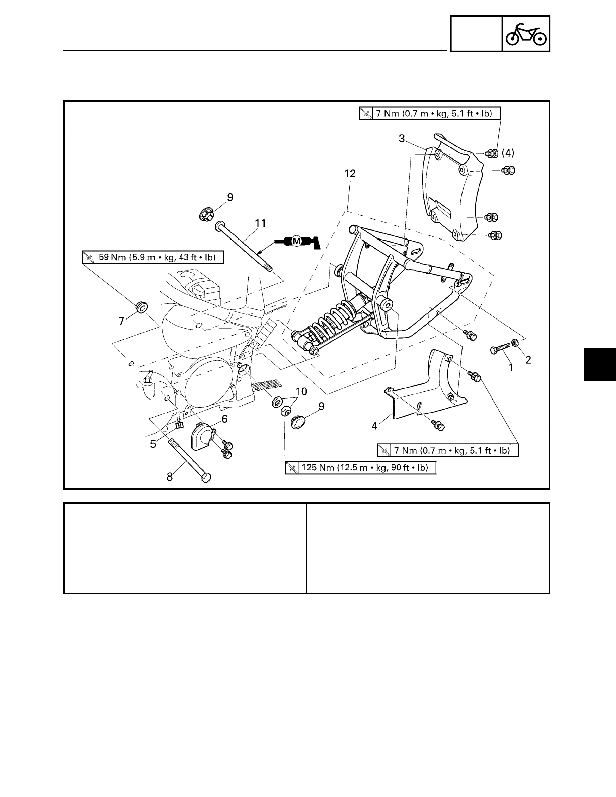
4 - 80
CHAS
REAR SHOCK ABSORBER AND SWINGARM
Order Job/Part Q’ty Remarks
11 Pivot shaft 1
12 Rear shock absorber and swingarm
assembly
1
For installation, reverse the removal
procedure.
4
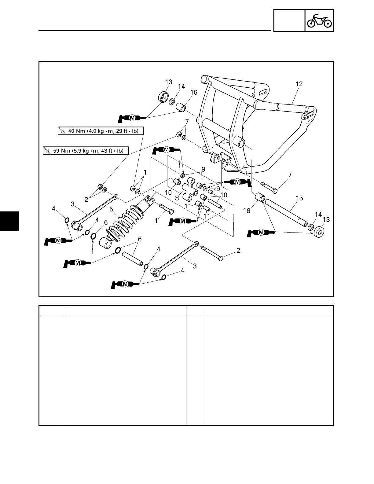
4 - 81
CHAS
REAR SHOCK ABSORBER AND SWINGARM
Order Job/Part Q’ty Remarks
Removing the rear shock absorber
and swingarm
Remove the parts in the order listed.
1 Self-locking nut/washer/bolt 1/1/1 Bolt
R= 53 mm (2.19 in)
2 Self-locking nut/washer/bolt 1/1/1 Bolt
R= 124 mm (4.88 in)
3 Connecting arm 2
4 O-ring 4
5 Rear shock absorber 1
6 Spacer/O-ring 1/2
7 Self-locking nut/washer/bolt 1/1/1 Bolt R= 77 mm (3.03 in)
8 Relay arm 1
9 Spacer/oil seal/bearing 1/2/1
10 Spacer/bearing 1/2
4
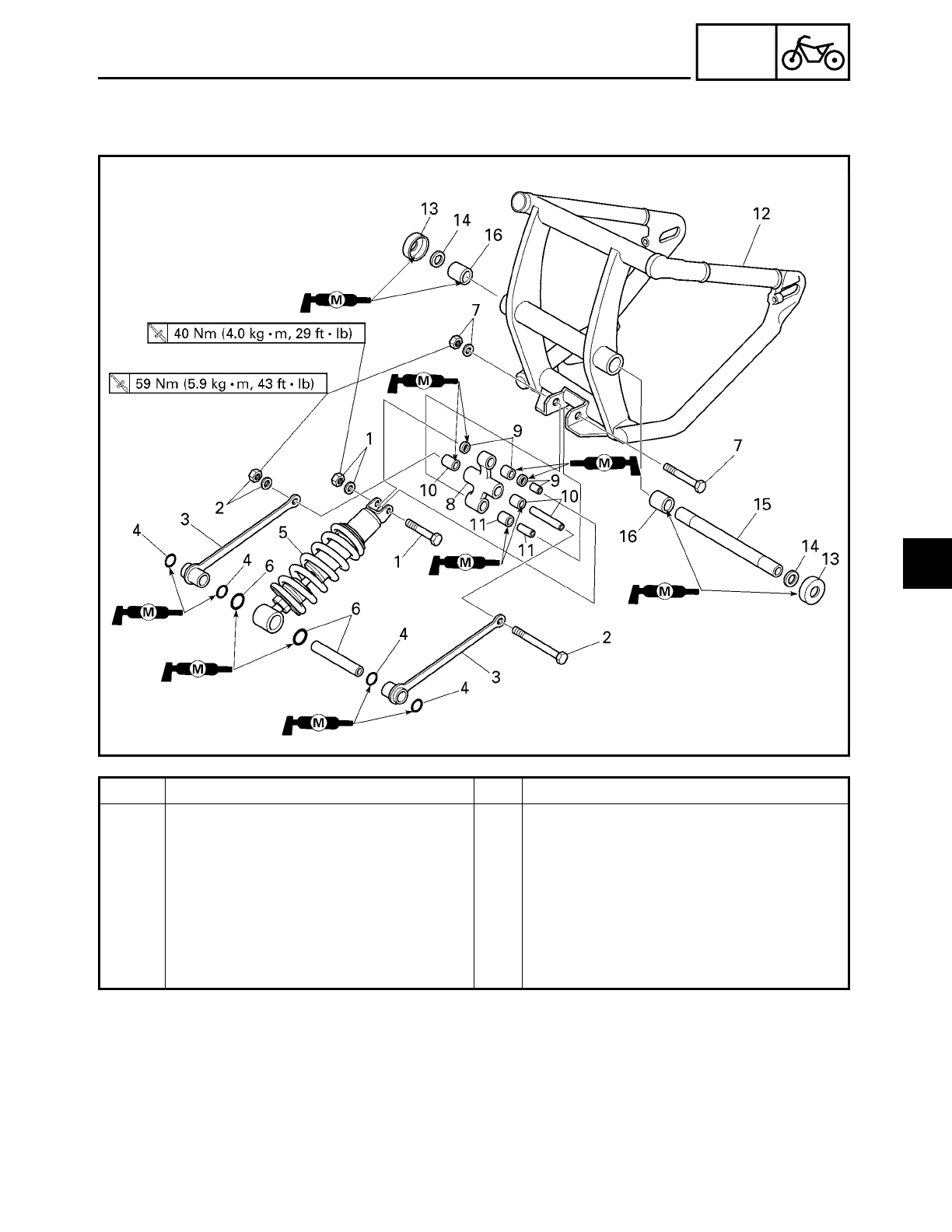
4 - 82
CHAS
REAR SHOCK ABSORBER AND SWINGARM
Order Job/Part Q’ty Remarks
11 Spacer/bearing 1/1
12 Swingarm 1
13 Dust cover 2
14 Washer 2
15 Spacer 1
16 Bearing 2
For installation, reverse the removal
procedure.
4
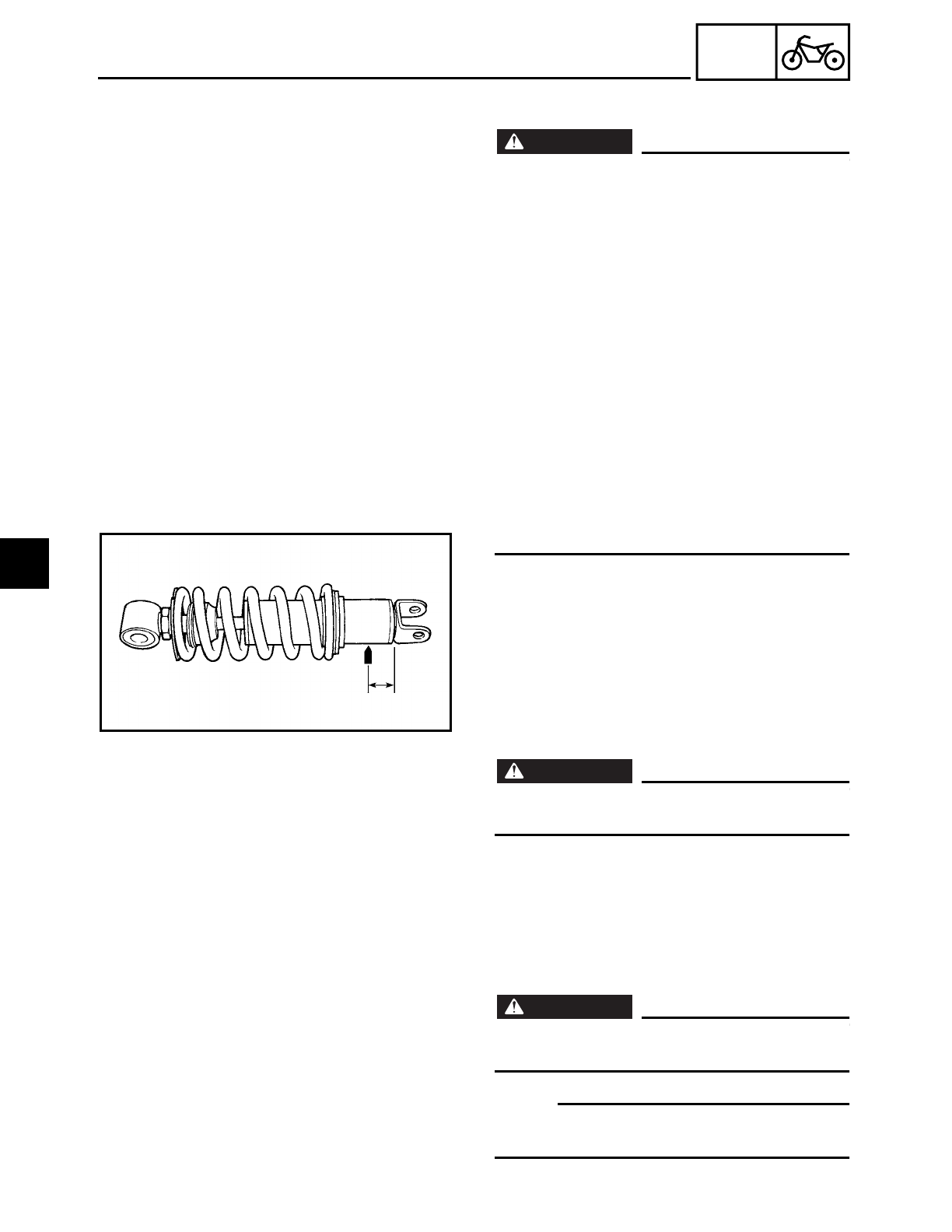
4 - 83
CHAS
REAR SHOCK ABSORBER AND SWINGARM
EAS00686
HANDLING THE REAR SHOCK ABSORBER
WARNING
WARNING
This rear shock absorber contains highly
compressed nitrogen gas. Before handling
the rear shock absorber, read and make
sure you understand the following informa-
tion. The manufacturer cannot be held
responsible for property damage or per-
sonal injury that may result from improper
handling of the rear shock absorber.
• Do not tamper or attempt to open the
rear shock absorber.
• Do not subject the rear shock absorber to
an open flame or any other source of high
heat. High heat can cause an explosion
due to excessive gas pressure.
• Do not deform or damage the rear shock
absorber in any way. Rear shock absorber
damage will result in poor damping per-
formance.
EAS00689
DISPOSING OF A REAR SHOCK ABSORBER
AND GAS CYLINDER
Gas pressure must be released before dis-
posing of a rear shock absorber and gas cyl-
inder. To release the gas pressure, drill a 2 ~
3-mm (0.08 ~ 0.12 in) hole through the gas
cylinder at a point 15 mm (0.6 in) from its
end as shown.
WARNING
WARNING
Wear eye protection to prevent eye dam-
age from released gas or metal chips.
EAS00703
REMOVING THE REAR SHOCK ABSORBER
AND SWINGARM
1. Stand the motorcycle on a level surface.
WARNING
WARNING
Securely support the motorcycle so that
there is no danger of it falling over.
NOTE:
Place the motorcycle on a suitable stand so
that the rear wheel is elevated.
4
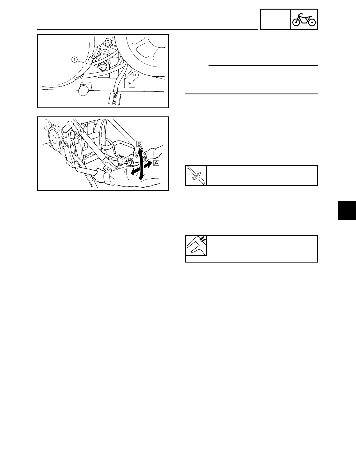
4 - 84
CHAS
REAR SHOCK ABSORBER AND SWINGARM
2. Remove:
• bolt (shock absorber - connecting arm -
frame)
1
NOTE:
When removing the bolt (shock absorber -
connecting arm - frame)
1, hold the swin-
garm so that it does not drop down.
3. Measure:
• swingarm free play
• swingarm vertical movement
▼ ▼ ▼ ▼ ▼ ▼ ▼ ▼ ▼ ▼ ▼ ▼ ▼ ▼ ▼ ▼ ▼ ▼ ▼ ▼ ▼ ▼ ▼ ▼ ▼ ▼ ▼ ▼
a. Measure the tightening torque of the
pivot shaft nut.
b. Measure the swingarm free play
Å by
moving the swingarm from side to side.
c. If the swingarm free play is out of specifi-
cation, check the spacers, bearings,
washers, and dust covers.
d. Check the swingarm vertical movement
ı by moving the swingarm up and
down.
If swingarm vertical movement is not
smooth or if there is binding, check the
spacers, bearings, washers, and dust
covers.
▲ ▲ ▲ ▲ ▲ ▲ ▲ ▲ ▲ ▲ ▲ ▲ ▲ ▲ ▲ ▲ ▲ ▲ ▲ ▲ ▲ ▲ ▲ ▲ ▲ ▲ ▲ ▲
T
R
.
.
Pivot shaft nut
125 Nm (12.5 m • kg, 90 ft • lb)
Swingarm free play (at the end of
the swingarm)
Zero mm (Zero in)
EAS00696
CHECKING THE REAR SHOCK ABSORBER
1. Check:
• rear shock absorber rod
Bends/damage → Replace the rear shock
absorber assembly.
• rear shock absorber
Gas leaks/oil leaks → Replace the rear
shock absorber assembly.
4
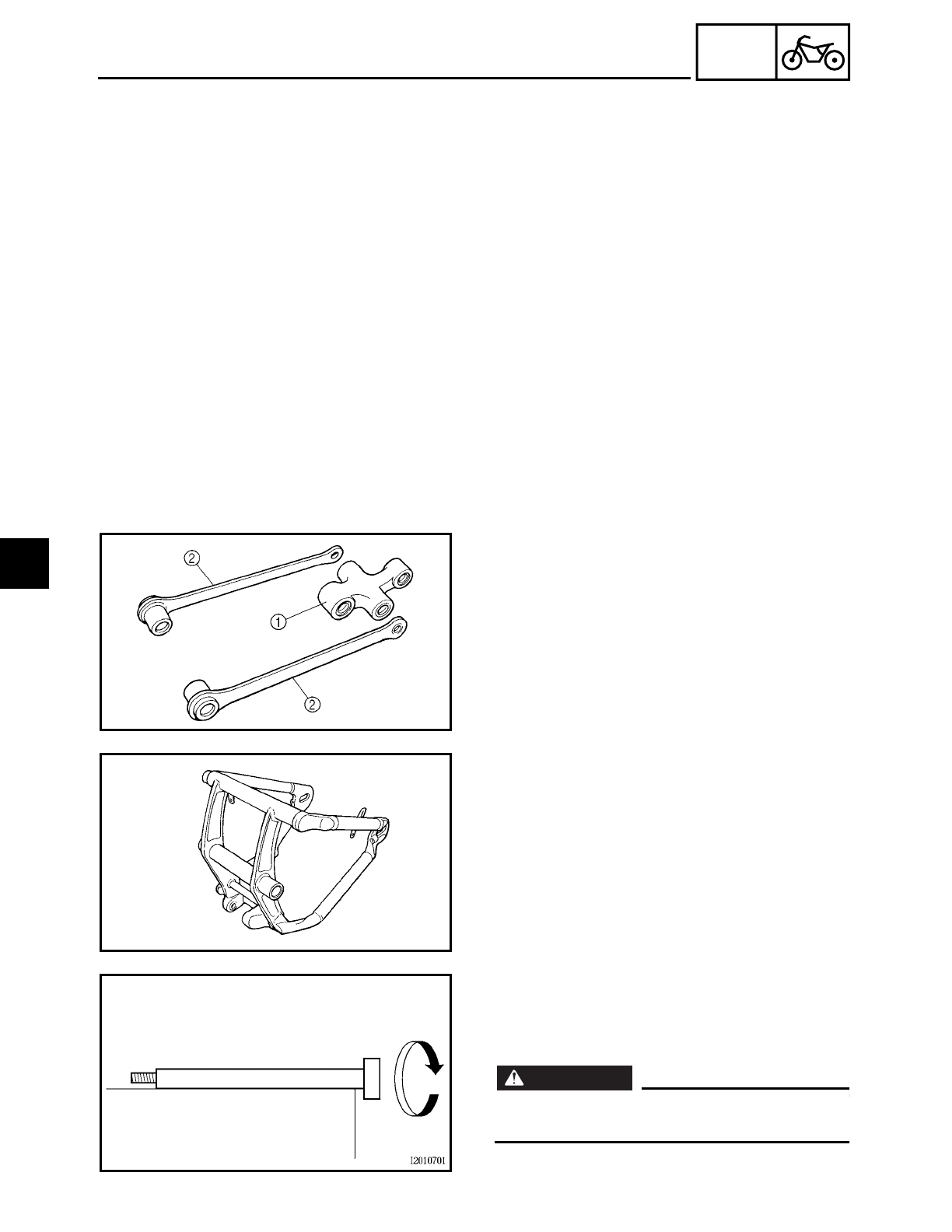
4 - 85
CHAS
REAR SHOCK ABSORBER AND SWINGARM
• spring
Damage/wear → Replace the rear shock
absorber assembly.
• gas cylinder
Damage/gas leaks → Replace.
• bushings
Damage/wear → Replace.
• O-ring
Damage/wear → Replace.
• bolts
Bends/damage/wear → Replace.
CHECKING THE RELAY ARM AND
CONNECTING ARM
1. Check:
• relay arm 1
• connecting arms 2
Damage/wear → Replace.
• bearings
• oil seals
Damage/pitting → Replace.
• spacers
• Damage/scratches → Replace.
CHECKING THE SWINGARM
1. Check:
• swingarm
Bends/cracks/damage → Replace.
2. Check:
• pivot shaft
Roll the pivot shaft on a flat surface.
Bends → Replace.
WARNING
WARNING
Do not attempt to straighten a bent pivot
shaft.
4
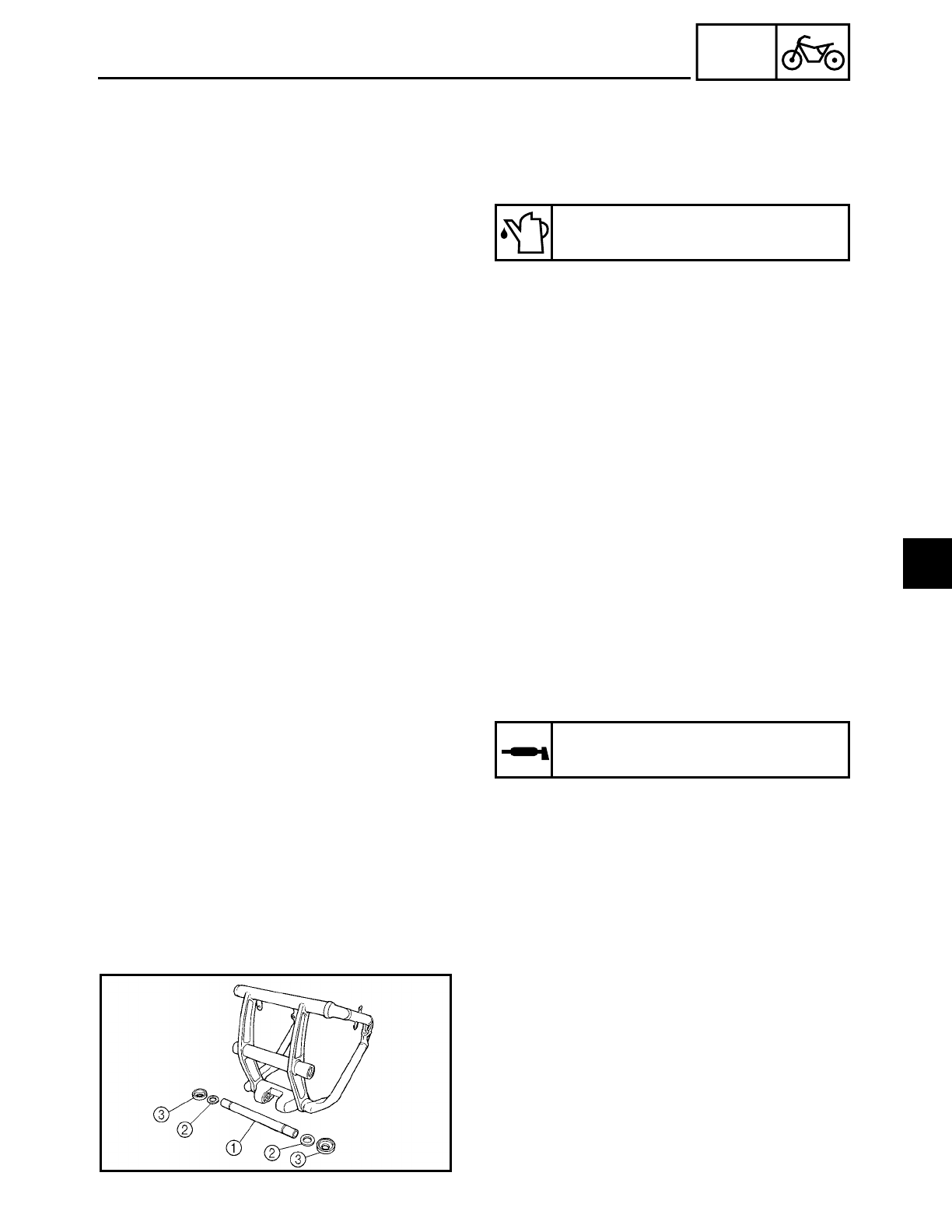
4 - 86
CHAS
REAR SHOCK ABSORBER AND SWINGARM
3. Wash:
• pivot shaft
• dust covers
• spacer
• bearings
Recommended cleaning solvent
Kerosine
4. Check:
• dust covers
• spacer
• oil seals
Damage/wear → Replace.
• bearings
Damage/pitting → Replace.
EAS00711
INSTALLING THE REAR SHOCK ABSORBER
AND SWINGARM
1. Lubricate:
• bearings
• spacers
• dust covers
• O-rings
• pivot shaft
Recommended lubricant
Molybdenum disulfide grease
2. Install:
• bearings
• spacer 1
• washers 2
• dust covers 3
4
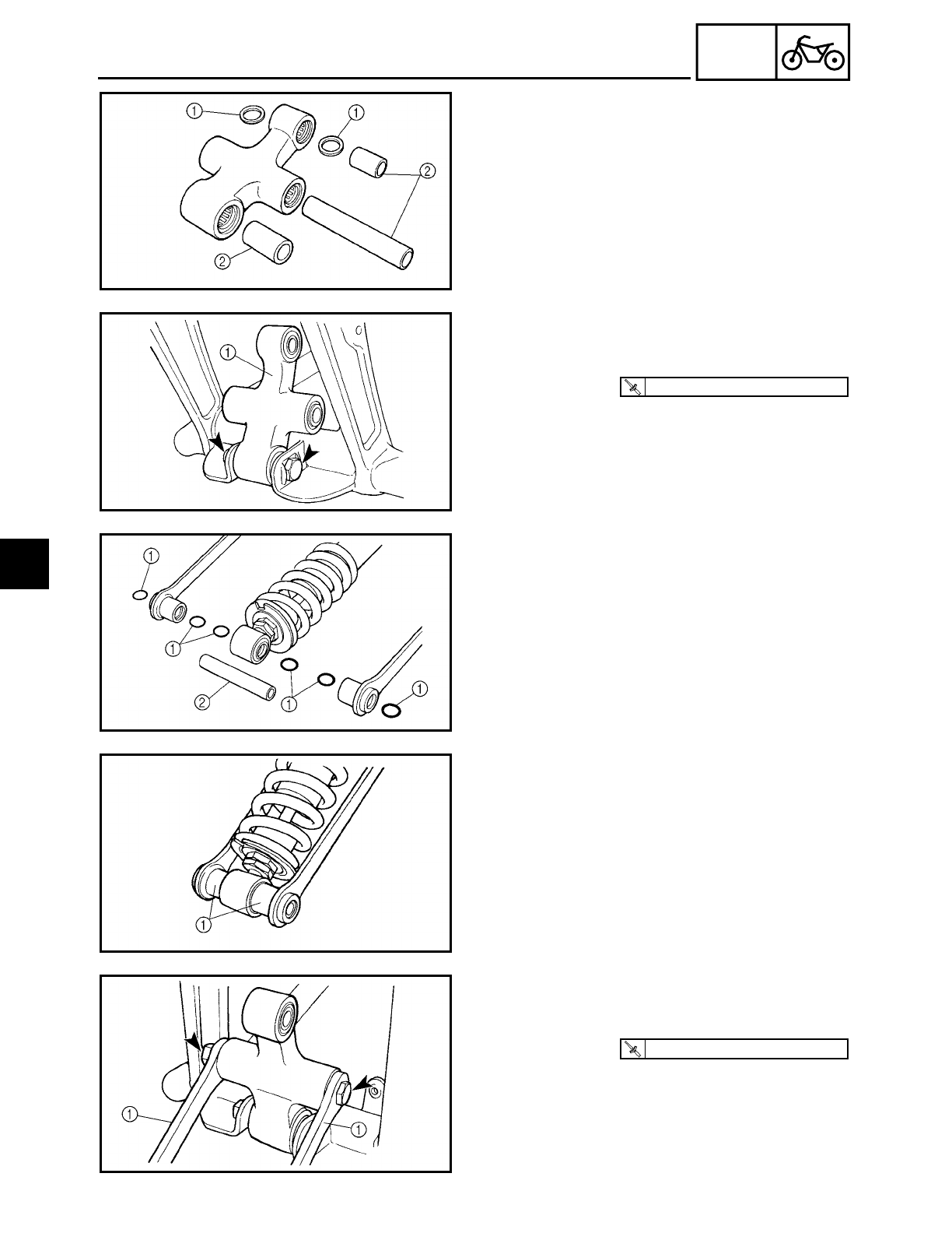
4 - 87
CHAS
REAR SHOCK ABSORBER AND SWINGARM
3. Install:
• bearings
• oil seals 1
• spacers 2
4. Install:
• relay arm 1
(onto the swingarm)
T
R
.
.
59 Nm (5.9 m · kg, 43 ft · lb)
5. Install:
• o-rings 1
• spacer 2
6. Install:
• connecting arms 1
(onto the rear shock absorber)
7. Install:
• connecting arms 1
(onto the relay arm)
T
R
.
.
59 Nm (5.9 m · kg, 43 ft · lb)
4
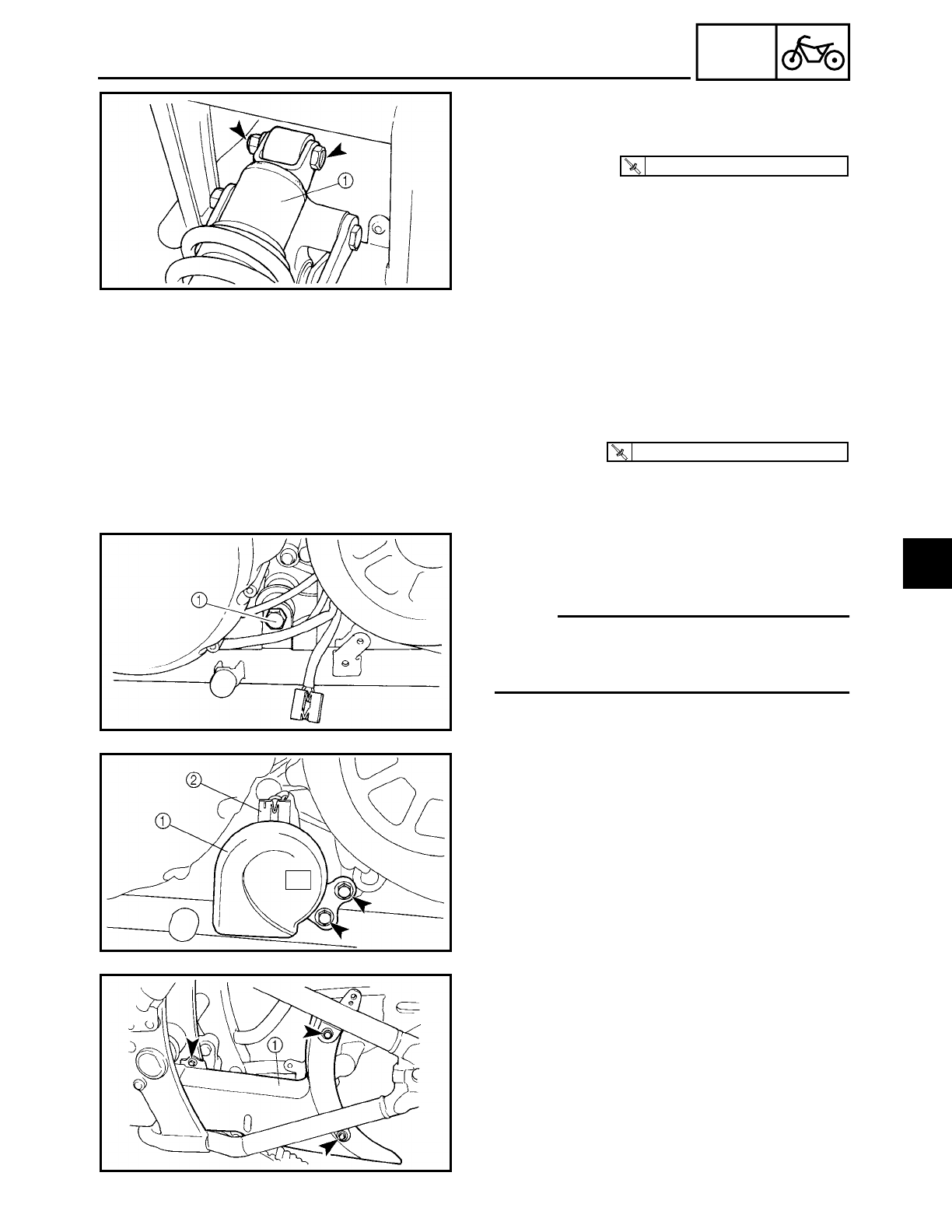
4 - 88
CHAS
REAR SHOCK ABSORBER AND SWINGARM
8. Install:
• rear shock absorber 1
(onto the relay arm)
T
R
.
.
40 Nm (4.0 m · kg, 29 ft · lb)
9. Install:
• rear shock absorber and swingarm
assembly
• pivot shaft
• washer
• pivot shaft nut
• covers
T
R
.
.
125 Nm (12.5 m · kg, 90 ft · lb)
10.Install:
• bolt (shock absorber - connecting arm -
frame) 1
NOTE:
When installing the bolt (shock absorber -
connecting arm - frame), hold the swingarm
so that it does not drop down.
11.Install:
• horn 1
12.Connect:
• horn coupler 2
13.Install:
• lower drive belt cover 1
4
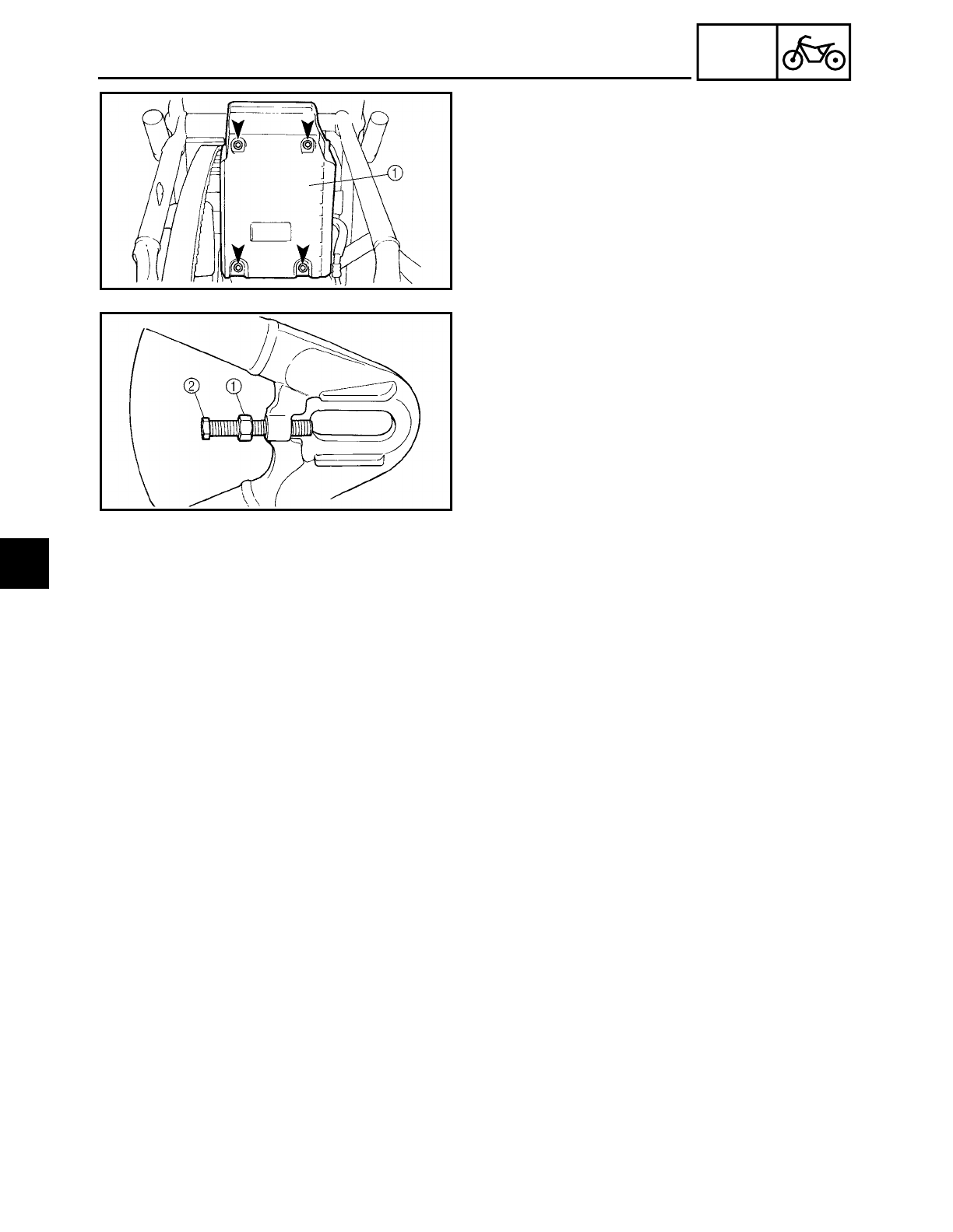
4 - 89
CHAS
REAR SHOCK ABSORBER AND SWINGARM
14.Install:
• mud guard 1
15.Install:
• locknut 1
• adjusting bolt 2
16.Install:
• rear wheel
Refer to “REAR WHEEL, BRAKE DISC
AND REAR WHEEL PULLEY”.
17.Adjust:
• drive belt slack
Refer to “ADJUSTING THE DRIVE BELT
SLACK” in chapter 3.
4
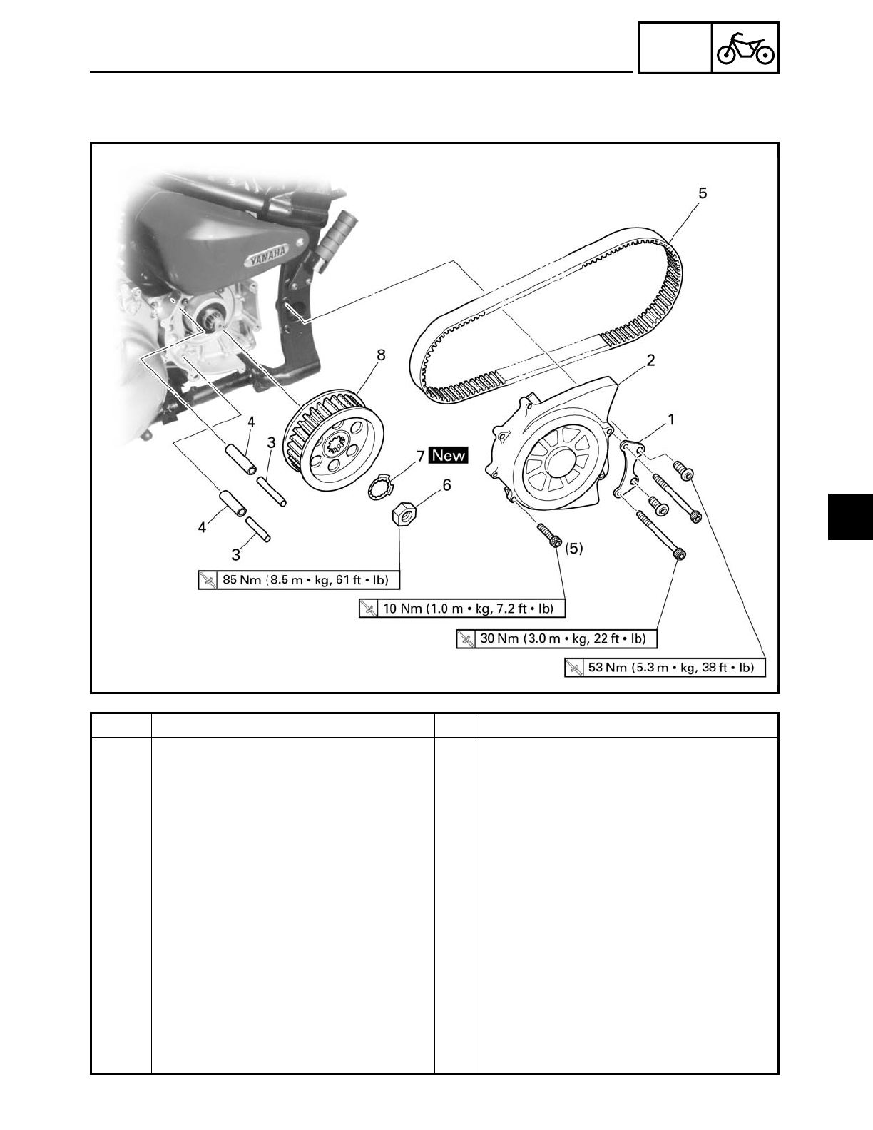
4 - 90
CHAS
DRIVE BELT AND DRIVE PULLEY
DRIVE BELT AND DRIVE PULLEY
Order Job/Part Q’ty Remarks
Removing the drive belt and drive
pulley
Remove the parts in the order listed.
Rear wheel Refer to “REAR WHEEL, BRAKE DISC
AND REAR WHEEL PULLEY”.
Rear shock absorber and swingarm
assembly
Refer to “REAR SHOCK ABSORBER
AND SWINGARM”.
1 Drive pulley cover bracket 1
2 Drive pulley cover 1
3 Slider 2
4 Dowel pin 2
5 Drive belt 1
6 Drive pulley nut 1
7 Lock washer 1
8 Drive pulley 1
For installation, reverse the removal
procedure.
4
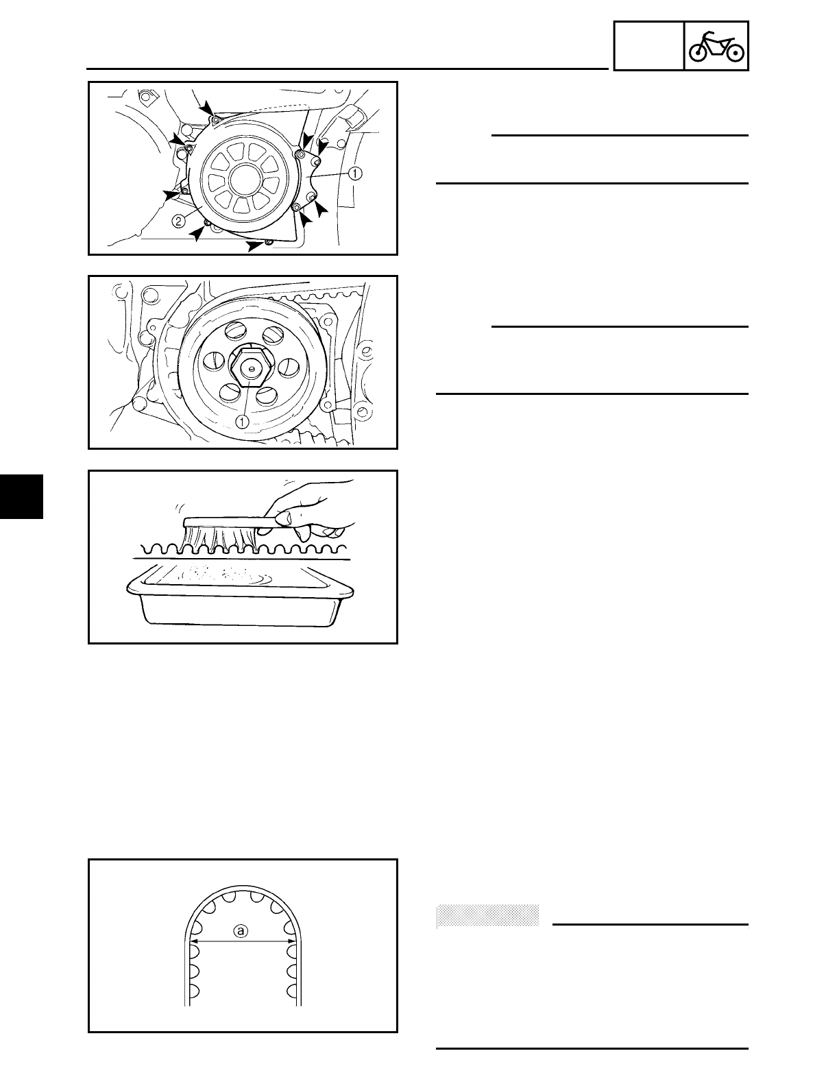
4 - 91
CHAS
DRIVE BELT AND DRIVE PULLEY
REMOVING THE DRIVE BELT AND DRIVE
PULLEY
NOTE:
Loosen the drive pulley nut before remove
the rear wheel.
1. Remove:
• drive pulley cover bracket 1
• drive pulley cover 2
2. Straighten the lock washer tab.
3. Loosen:
• drive pulley nut 1
NOTE:
When loosening the drive pulley nut, press
down on the brake pedal so the drive pulley
does not move.
CHECKING THE DRIVE BELT
1. Clean:
• drive belt
▼ ▼ ▼ ▼ ▼ ▼ ▼ ▼ ▼ ▼ ▼ ▼ ▼ ▼ ▼ ▼ ▼ ▼ ▼ ▼ ▼ ▼ ▼ ▼ ▼ ▼ ▼ ▼
a. Wipe the drive belt with a clean cloth.
b. Put the drive belt in a mixture of mild
detergent and water. Then, remove any
dirt from the drive belt.
c. Remove the drive belt from the mixture
and rinse it off with clean water. Then, let
the drive belt thoroughly dry.
▲ ▲ ▲ ▲ ▲ ▲ ▲ ▲ ▲ ▲ ▲ ▲ ▲ ▲ ▲ ▲ ▲ ▲ ▲ ▲ ▲ ▲ ▲ ▲ ▲ ▲ ▲ ▲
2. Check:
• drive belt
ACHTUNG:
CAUTION:
• To protect the drive belt from damage,
handle it with care.
• The drive belt can not be bent smaller
than 127 mm (5 in) a.
• The removed drive belt can not be
twisted inside out.
4
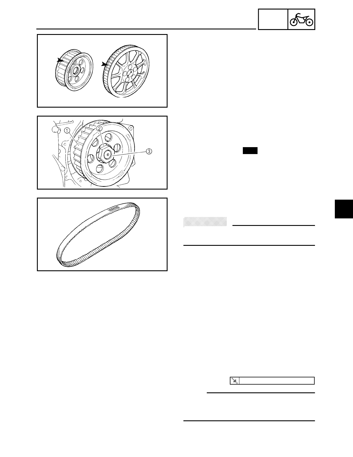
4 - 92
CHAS
DRIVE BELT AND DRIVE PULLEY
3. Check:
• drive pulley
• rear wheel pulley
Bent teeth → Replace the drive belt and
pulleys as a set.
INSTALLING THE DRIVE BELT AND DRIVE
PULLEY
1. Install:
• drive pulley 1
• lock washer 2
• drive pulley nut 3
New
2. Install:
• drive belt
ACHTUNG:
CAUTION:
Install the drive belt facing the same way it
was removed.
3. Install:
• rear shock absorber and swingarm
assembly
Refer to “REAR SHOCK ABSORBER AND
SWINGARM”.
• rear wheel
Refer to “REAR WHEEL, BRAKE DISC
AND SWINGARM”.
4. Tighten:
• drive pulley nut
NOTE:
When tightening the drive pulley nut, press
down on the brake pedal so the drive pulley
does not move.
5. Bend the lock washer tab along a flat
side of the nut.
T
R
.
.
85 Nm (8.5 m · kg, 61 ft · lb)
4
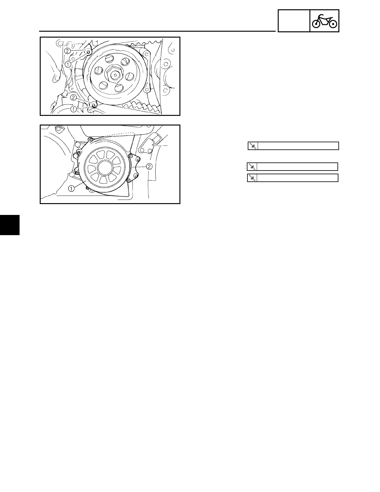
4 - 93
CHAS
DRIVE BELT AND DRIVE PULLEY
6. Install:
• dowel pins 1
• sliders 2
7. Install:
• drive pulley cover 1
• drive pulley cover bracket 2
• bolts (M10)
• bolts (M8)
T
R
.
.
10 Nm (1.0 m · kg, 7.2 ft · lb)
T
R
.
.
53 Nm (5.3 m · kg, 38 ft · lb)
T
R
.
.
30 Nm (3.0 m · kg, 22 ft · lb)
4
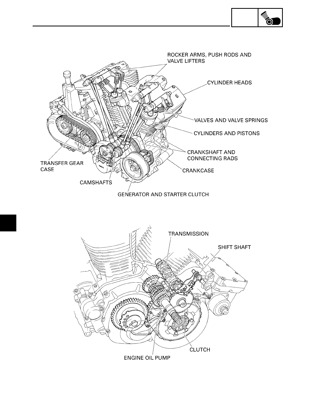
ENG
CONTENTS
ENGINE
ENGINE ......................................................................................................... 5-1
INSTALLING THE ENGINE ................................................................... 5-8
5

ENG
ROCKER ARMS, PUSH RODS AND VALVE LIFTERS .............................. 5-12
REMOVING THE ROCKER ARMS, PUSH RODS AND
VALVE LIFTERS .............................................................................. 5-18
CHECKING THE ROCKER ARMS AND ROCKER
ARM SHAFTS ................................................................................. 5-18
CHECKING THE ROCKER ARM BASES ............................................ 5-20
CHECKING THE PUSH RODS ............................................................ 5-20
CHECKING THE VALVE LIFTERS AND VALVE
LIFTER CASES ................................................................................ 5-20
BLEEDING THE VALVE LIFTER .......................................................... 5-21
CHECKING THE PUSH ROD COVERS ............................................... 5-23
INSTALLING THE VALVE LIFTERS AND PUSH ROD COVERS ....... 5-23
INSTALLING THE ROCKER ARMS AND PUSH RODS ..................... 5-24
INSTALLING THE CYLINDER HEAD COVERS .................................. 5-26
INSTALLING THE CAMSHAFT SPROCKET COVER AND
ENGINE LEFT SIDE COVER ........................................................... 5-27
CAMSHAFTS ..............................................................................................5-29
REMOVING THE CAMSHAFTS .......................................................... 5-31
CHECKING THE CAMSHAFTS ........................................................... 5-32
CHECKING THE DECOMPRESSION SYSTEM .................................. 5-34
CHECKING THE OIL DELIVERY PIPE ................................................. 5-35
INSTALLING THE CAMSHAFTS ........................................................ 5-35
CYLINDER HEADS ...................................................................................... 5-39
REMOVING THE CYLINDER HEADS ................................................. 5-41
CHECKING THE CYLINDER HEADS .................................................. 5-41
CHECKING THE OIL DELIVERY PIPE ................................................. 5-42
INSTALLING THE CYLINDER HEADS ............................................... 5-42
VALVES AND VALVE SPRINGS ............................................................... 5-44
REMOVING THE VALVES .................................................................. 5-45
CHECKING THE VALVES AND VALVE GUIDES ............................... 5-46
CHECKING THE VALVE SEATS ......................................................... 5-48
CHECKING THE VALVE SPRINGS ..................................................... 5-50
INSTALLING THE VALVES ................................................................ 5-51
CYLINDERS AND PISTONS ....................................................................... 5-53
REMOVING THE CYLINDERS AND PISTONS .................................. 5-54
CHECKING THE CYLINDERS AND PISTONS ................................... 5-54
CHECKING THE PISTON RINGS ........................................................ 5-56
CHECKING THE PISTON PINS ........................................................... 5-57
INSTALLING THE PISTONS AND CYLINDERS ................................ 5-58
5

ENG
CLUTCH ...................................................................................................... 5-60
REMOVING THE CLUTCH .................................................................. 5-65
REMOVING THE PRIMARY DRIVE GEAR ......................................... 5-65
CHECKING THE FRICTION PLATES .................................................. 5-66
CHECKING THE CLUTCH PLATES .................................................... 5-66
CHECKING THE CLUTCH SPRING PLATE ........................................ 5-67
CHECKING THE CLUTCH HOUSING ................................................. 5-67
CHECKING THE CLUTCH BOSS ........................................................ 5-67
CHECKING THE PRESSURE PLATE .................................................. 5-67
CHECKING THE PULL LEVER SHAFT AND PULL ROD .................... 5-68
CHECKING THE PRIMARY DRIVE ..................................................... 5-68
INSTALLING THE PICKUP COIL AND PULL LEVER SHAFT ............ 5-68
INSTALLING THE PRIMARY DRIVE GEAR ....................................... 5-69
INSTALLING THE CLUTCH ................................................................ 5-70
SHIFT SHAFT ..............................................................................................5-74
CHECKING THE SHIFT SHAFT .......................................................... 5-75
CHECKING THE STOPPER LEVER ..................................................... 5-75
INSTALLING THE STOPPER LEVER AND SHIFT SHAFT ................. 5-75
GENERATOR AND STARTER CLUTCH ..................................................... 5-77
REMOVING THE GENERATOR .......................................................... 5-80
CHECKING THE STARTER CLUTCH .................................................. 5-80
INSTALLING THE GENERATOR ........................................................ 5-81
TRANSFER GEAR CASE ............................................................................ 5-85
REMOVING THE BATTERY ................................................................ 5-91
REMOVING THE MIDDLE DRIVEN SHAFT ....................................... 5-91
CHECKING THE MIDDLE DRIVE ........................................................ 5-91
CHECKING THE OIL STRAINER ......................................................... 5-92
CHECKING THE OIL PUMP ................................................................ 5-92
CHECKING THE OIL PIPE ................................................................... 5-93
ASSEMBLING THE OIL PUMP ........................................................... 5-93
INSTALLING THE TRANSFER GEAR CASE ...................................... 5-94
INSTALLING THE OIL TANK COVER ................................................ 5-97
INSTALLING THE BATTERY .............................................................. 5-98
CRANKCASE .............................................................................................5-100
DISASSEMBLING THE CRANKCASE .............................................. 5-103
CHECKING THE CRANKCASE ......................................................... 5-104
CHECKING THE BEARINGS AND OIL SEAL ................................... 5-104
CHECKING THE OIL DELIVERY PIPE ............................................... 5-105
CHECKING THE ENGINE OIL PUMP DRIVE .................................... 5-105
ASSEMBLING THE CRANKCASE .................................................... 5-105
5

ENG
ENGINE OIL PUMP ................................................................................... 5-108
CHECKING THE OIL PUMP .............................................................. 5-111
CHECKING THE RELIEF VALVE ....................................................... 5-111
CHECKING THE OIL STRAINER ....................................................... 5-112
ASSEMBLING THE OIL PUMP ......................................................... 5-112
INSTALLING THE OIL PUMP ........................................................... 5-113
INSTALLING THE OIL STRAINER .................................................... 5-113
CRANKSHAFT AND CONNECTING RODS .............................................5-114
REMOVING THE CRANKSHAFT ...................................................... 5-115
REMOVING THE CONNECTING RODS ........................................... 5-115
CHECKING THE CRANKSHAFT AND CONNECTING RODS .......... 5-115
INSTALLING THE CONNECTING RODS ......................................... 5-119
INSTALLING THE CRANKSHAFT .................................................... 5-121
TRANSMISSION ....................................................................................... 5-122
CHECKING THE SHIFT FORKS ........................................................ 5-125
CHECKING THE SHIFT DRUM ASSEMBLY .................................... 5-125
CHECKING THE TRANSMISSION ................................................... 5-126
INSTALLING THE TRANSMISSION, SHIFT DRUM
ASSEMBLY AND SHIFT FORKS .................................................. 5-126
5
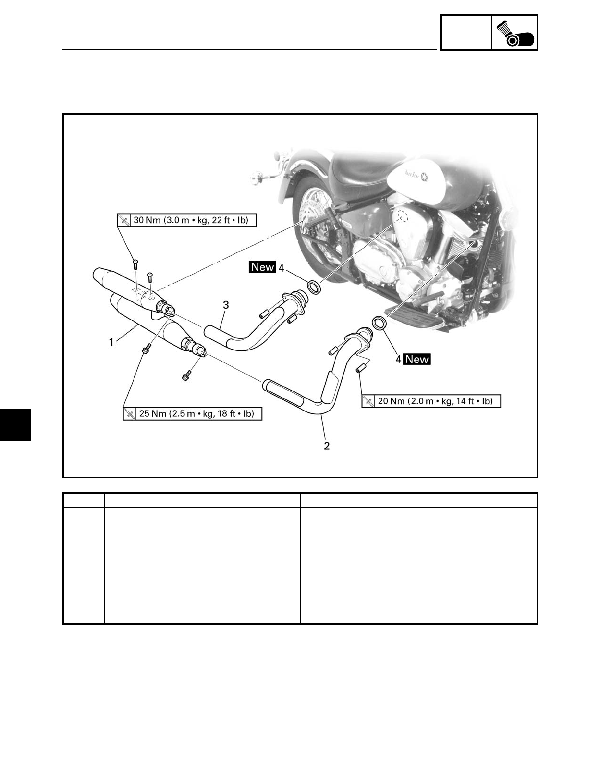
5 - 1
ENG
ENGINE
EAS00188
ENGINE
ENGINE
Order Job/Part Q’ty Remarks
Removing the muffler and exhaust
pipes
Remove the parts in the order listed.
1 Muffler 1
2 Front exhaust pipe 1
3 Rear exhaust pipe 1
4 Gasket 2
For installation, reverse the removal
procedure.
5
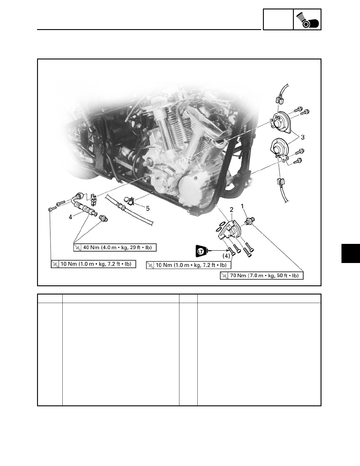
5 - 2
ENG
ENGINE
Order Job/Part Q’ty Remarks
Removing the oil filter bracket and
horns
Rider seat/side covers Refer to “SEATS AND SIDE COVERS”
in chapter 3.
Fuel tank Refer to “FUEL TANK” in chapter 3.
Air filter case Refer to “AIR FILTER CASE” in chapter
3.
Carburetor/carburetor joint Refer to “CARBURETOR” in chapter 6.
Air induction system parts Refer to “AIR INDUCTION SYSTEM” in
chapter 6.
Starter motor Refer to “STARTER MOTOR” in chap-
ter 7.
5
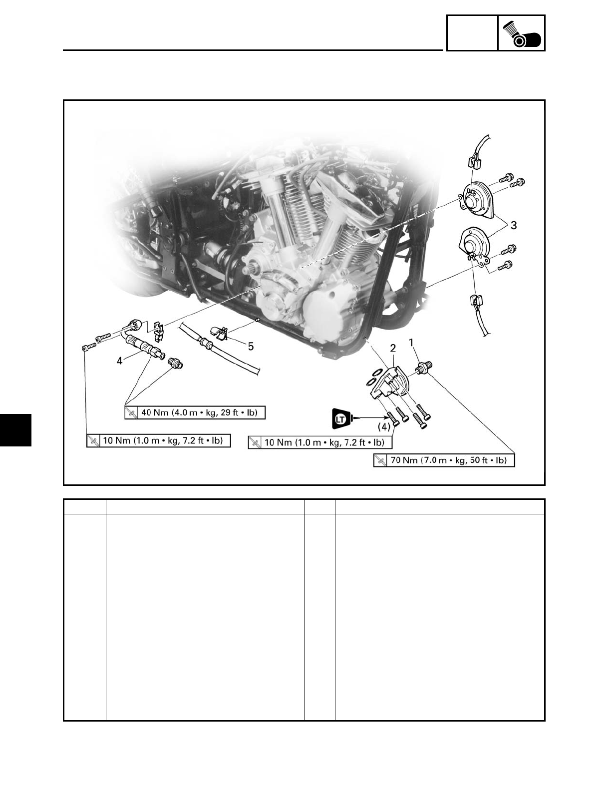
5 - 3
ENG
Order Job/Part Q’ty Remarks
Engine oil/oil filter cartridge Drain.
Transfer gear oil Drain.
Transfer gear case Refer to “TRANSFER GEAR CASE”.
Rider footrest (left) Refer to “ROCKER ARMS, PUSH RODS
AND VALVE LIFTERS”.
Rider footrest (right) Refer to “GENERATOR AND STARTER
CLUTCH”.
1 Oil filter bolt 1
2 Oil filter bracket 1
3 Horn 2
4 Oil delivery pipe 1
5 Brake hose holder 1
For installation, reverse the removal
procedure.
ENGINE
5
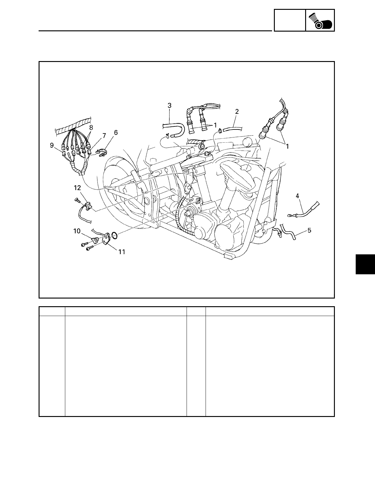
5 - 4
ENG
Order Job/Part Q’ty Remarks
Disconnecting the leads and hoses Disconnect the parts in the order listed.
1 Spark plug caps 4
2 Cylinder head breather hose 1
3 Oil tank breather hose 1
4 Clutch cable 1
5Charcoal canister hose (carburetor
to charcoal canister) 1
6 Plastic clamp 1
7 Stator coil coupler 1
8 Decompression solenoid coupler 2
9 Pickup coil coupler 1
ENGINE
5
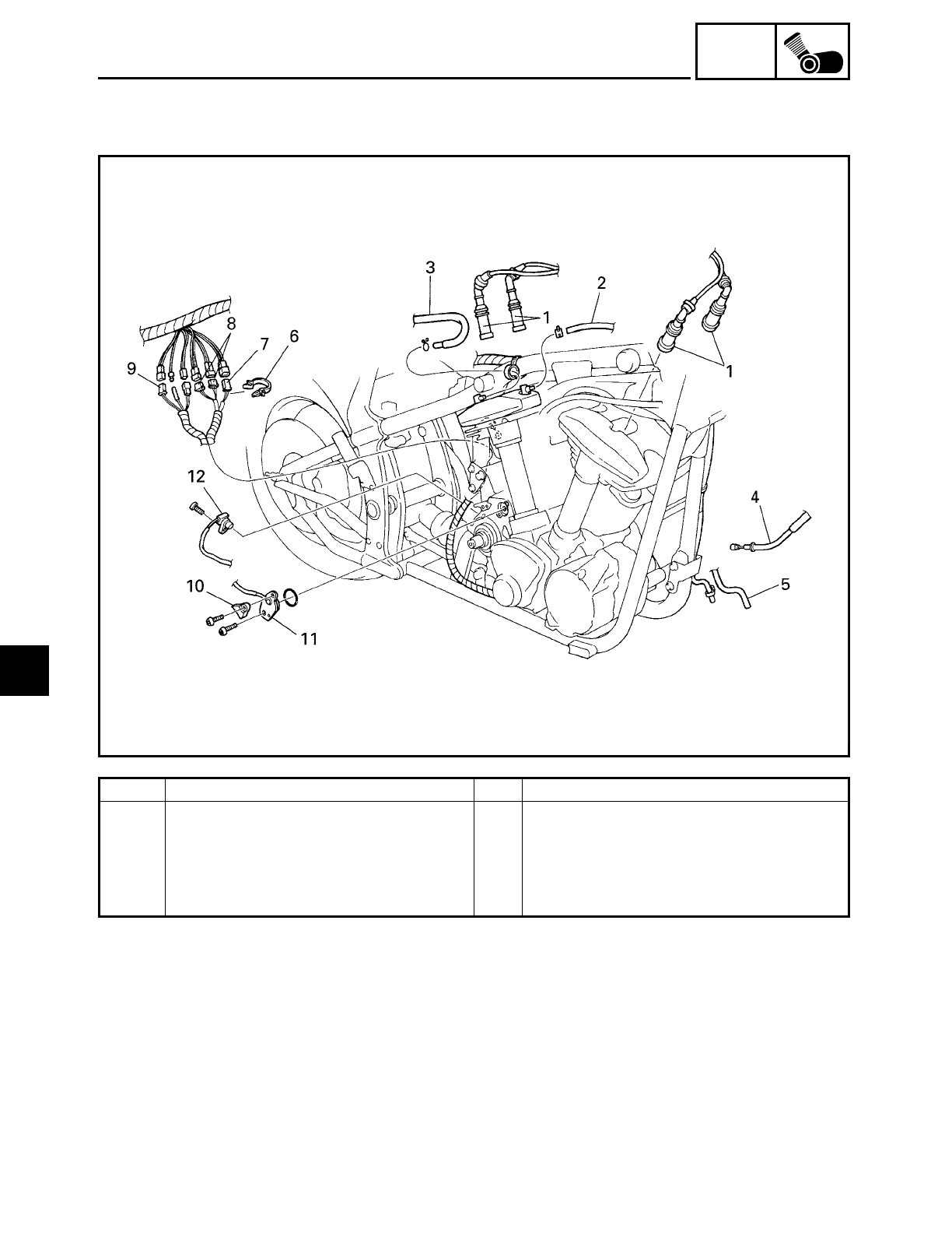
5 - 5
ENG
Order Job/Part Q’ty Remarks
10 Neutral switch cover 1
11 Neutral switch 1
12 Speed sensor 1
For connecting, reverse the disconnec-
tion procedure.
ENGINE
5
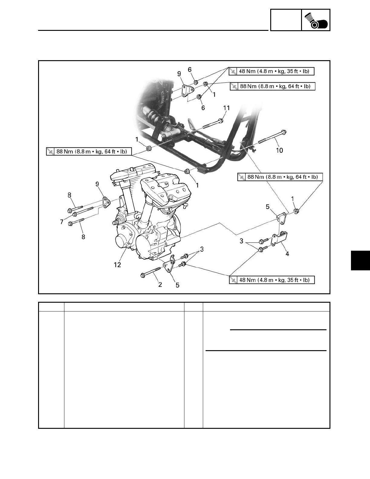
5 - 6
ENG
ENGINE
EAS00191
ENGINE
Order Job/Part Q’ty Remarks
Removing the engine Remove the parts in the order listed.
1 Self-locking nut 4
2 Upper front mounting bolt 1
3 Front engine bracket bolt 4
4 Horn bracket 1
5 Front engine bracket 2
6 Self-locking nut 2
7 Upper rear mounting bolt 1
8 Rear engine bracket bolt 2
NOTE:
Place a suitable stand under the frame
and engine.
5
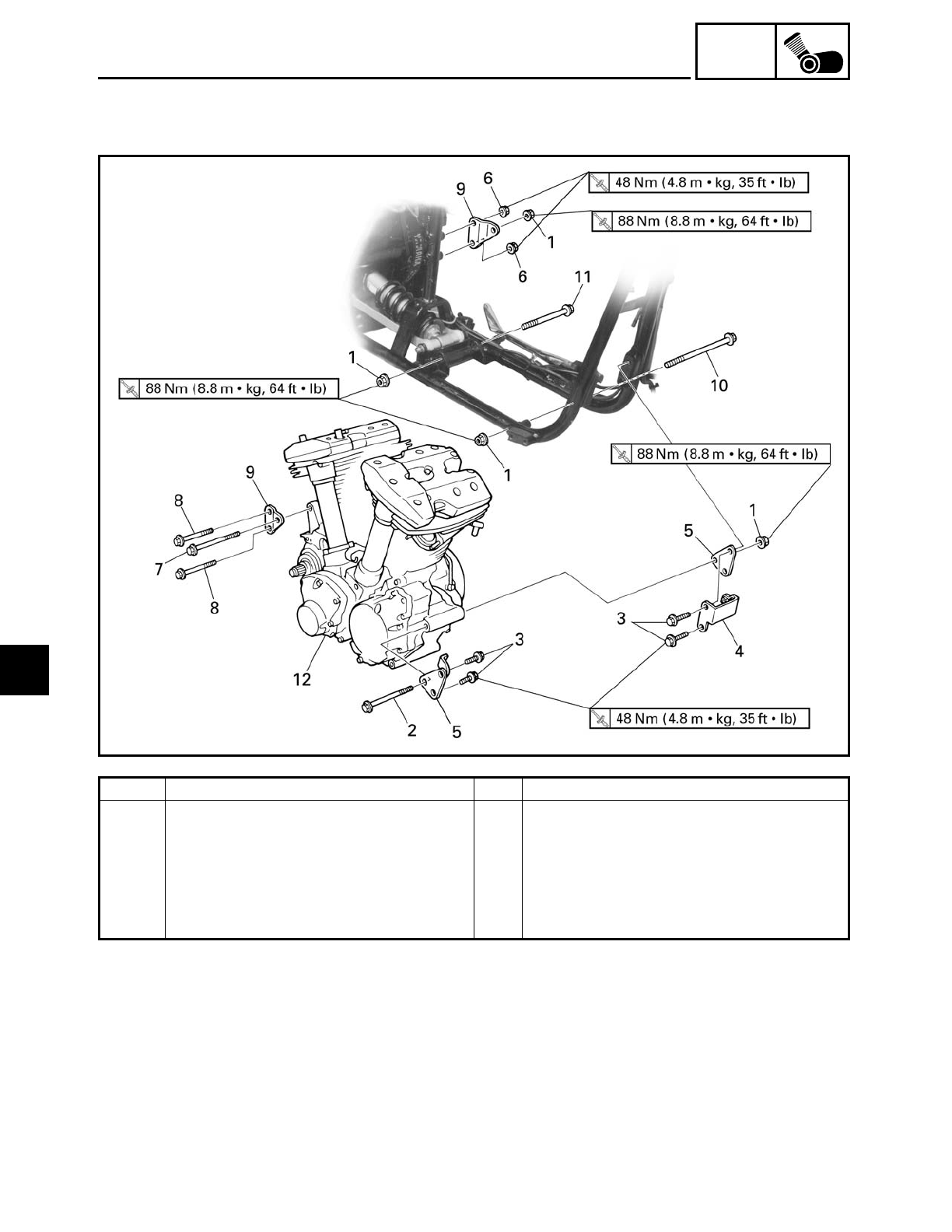
5 - 7
ENG
Order Job/Part Q’ty Remarks
9 Rear engine bracket 2
10 Lower front mounting bolt 1
11 Lower rear mounting bolt 1
12 Engine 1 Refer to “INSTALLING THE ENGINE”.
For installation, reverse the removal
procedure.
ENGINE
5
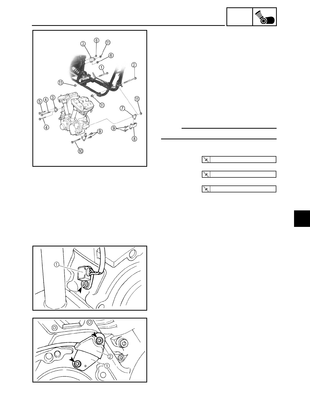
5 - 8
ENG
ENGINE
INSTALLING THE ENGINE
1. Install:
• lower rear mounting bolt
1
• lower front mounting bolt
2
• rear engine brackets 3
• rear engine bracket bolts 4
• upper rear mounting bolt 5
• self-locking nuts 6
• front engine brackets 7
• horn bracket 8
• front engine bracket bolts 9
• upper front mounting bolt 0
• self-locking nuts A
NOTE:
Do not fully tighten the bolts and nuts.
2. Tighten:
• front engine bracket bolts
9
• self-locking nut
6
• self-locking nuts
A
T
R
.
.
48 Nm (4.8 m · kg, 35 ft · lb)
T
R
.
.
48 Nm (4.8 m · kg, 35 ft · lb)
T
R
.
.
88 Nm (8.8 m · kg, 64 ft · lb)
3. Install:
• speed sensor 1
4. Install:
• neutral switch 1
• neutral switch cover 2
5
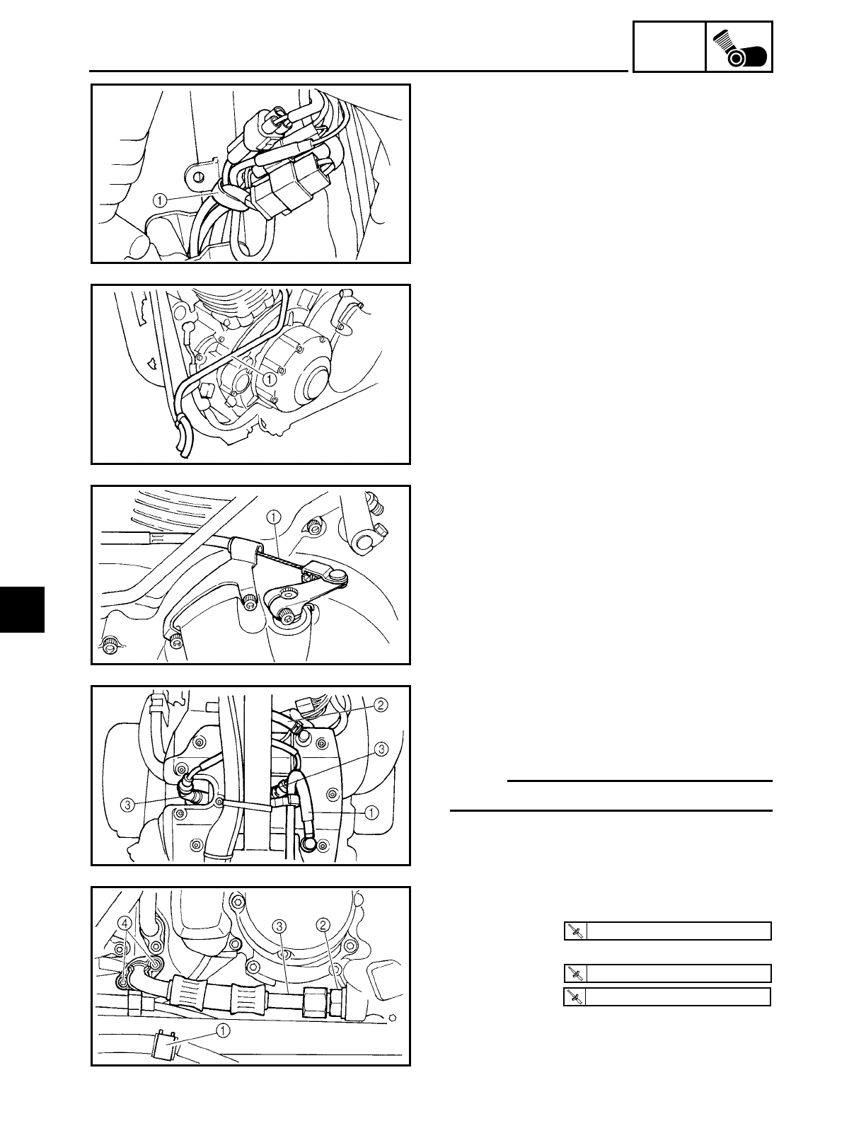
5 - 9
ENG
ENGINE
5. Connect:
• speed sensor coupler
• neutral switch connector
• pickup coil coupler
• decompression solenoid coupler
• stator coil coupler
6. Install:
• plastic clamp 1
7. Connect:
• charcoal canister hose (carburetor to
charcoal canister)
1
8. Connect:
• clutch cable
1
9. Connect:
• oil tank breather hose 1
• cylinder head breather hose 2
• spark plug caps 3
NOTE:
Refer to “CABLE ROUTING” in chapter 2.
10.Install:
• brake hose holder 1
• joint bolt 2
• oil delivery pipe 3
• bolts 4
T
R
.
.
40 Nm (4.0 m · kg, 29 ft · lb)
T
R
.
.
40 Nm (4.0 m · kg, 29 ft · lb)
T
R
.
.
10 Nm (1.0 m · kg, 7.2 ft · lb)
5
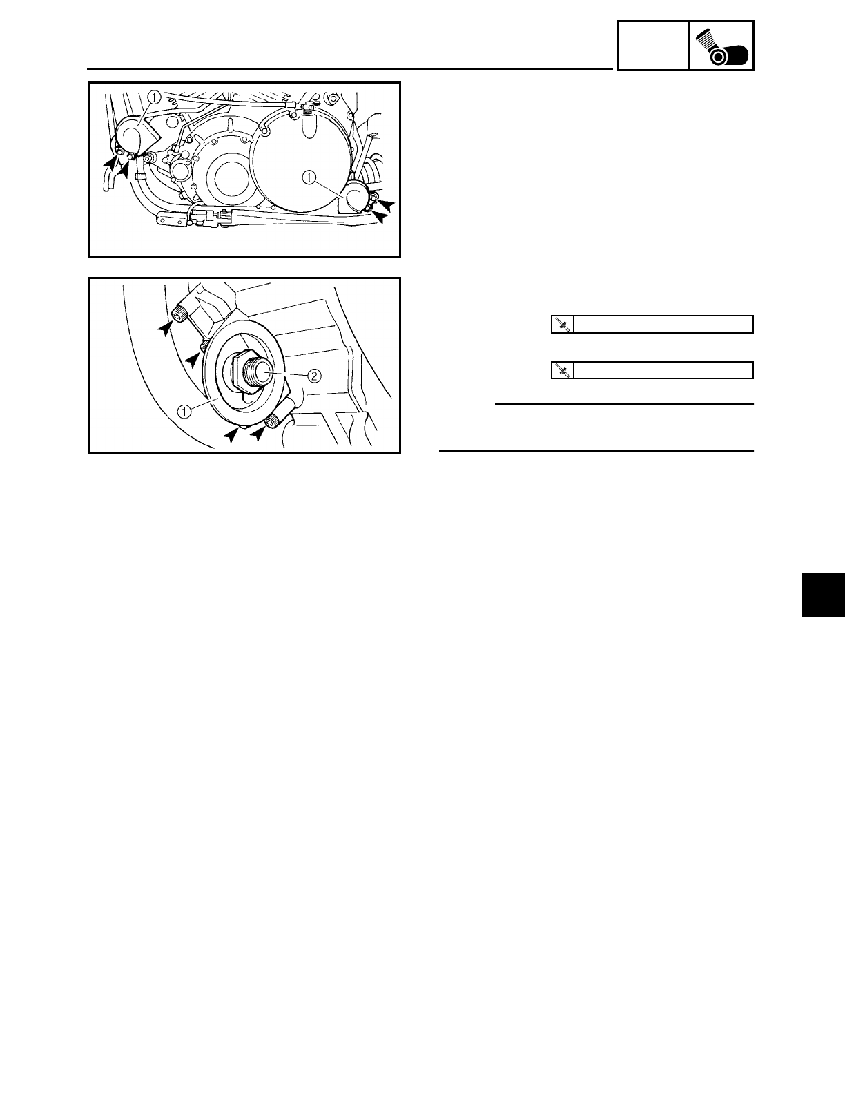
5 - 10
ENG
ENGINE
11.Install:
• horns 1
12.Connect:
• horn couplers
13.Install:
• oil filter bracket 1
• oil filter bolt 2
NOTE:
Apply locking agent (LOCTITE) to the
threads of the oil filter bracket bolts.
T
R
.
.
10 Nm (1.0 m · kg, 7.2 ft · lb)
T
R
.
.
70 Nm (7.0 m · kg, 50 ft · lb)
14.Install:
• rider footrest (right)
Refer to “GENERATOR AND STARTER
CLUTCH”.
• rider footrest (left)
Refer to “ROCKER ARMS, PUSH RODS
AND VALVE LIFTERS”.
• transfer gear case
Refer to “TRANSFER GEAR CASE”.
15.Fill:
• transfer gear case
(with the specified amount of the recom-
mended transfer gear oil)
Refer to “CHANGING THE TRANSFER
GEAR OIL” in chapter 3.
16.Install:
• oil filter cartridge
17.Fill:
• oil tank
(with the specified amount of the recom-
mended engine oil)
Refer to “CHANGING THE ENGINE OIL”
in chapter 3.
5
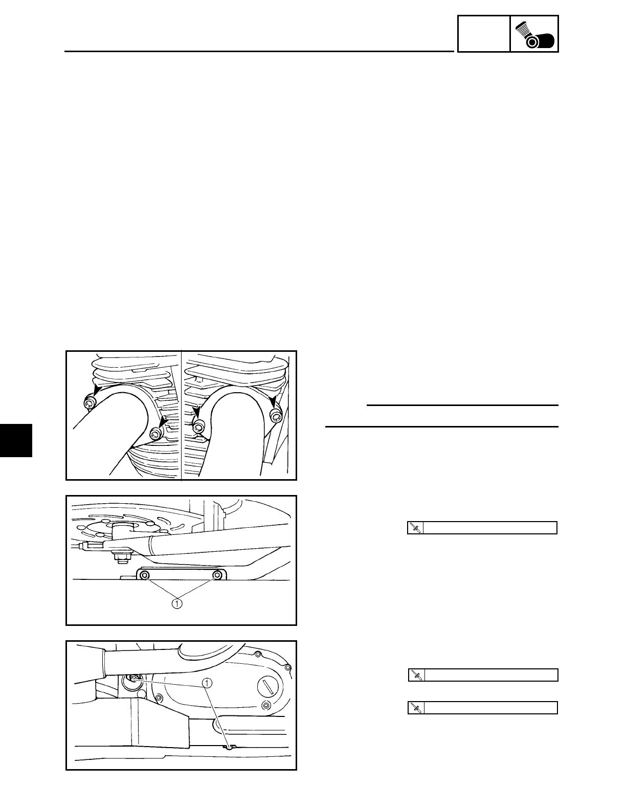
5 - 11
ENG
ENGINE
18.Install:
• starter motor
Refer to “STARTER MOTOR” in chapter
7.
• air induction system parts
Refer to “AIR INDUCTION SYSTEM” in
chapter 6.
• carburetor joint
• carburetor
Refer to “CARBURETOR” in chapter 6.
• air filter case
Refer to “AIR FILTER CASE” in chapter 3.
• fuel tank
Refer to “FUEL TANK” in chapter 3.
• side covers
• rider seat
Refer to “SEATS AND SIDE COVERS” in
chapter 3.
19.Install:
• gaskets
• exhaust pipes
NOTE:
Finger tighten the exhaust pipe nuts.
20.Install:
• muffler
• bolts 1
T
R
.
.
30 Nm (3.0 m · kg, 22 ft · lb)
21.Tighten:
• exhaust pipe nuts
• clamp bolts 1
T
R
.
.
20 Nm (2.0 m · kg, 14 ft · lb)
T
R
.
.
25 Nm (2.5 m · kg, 18 ft · lb)
5
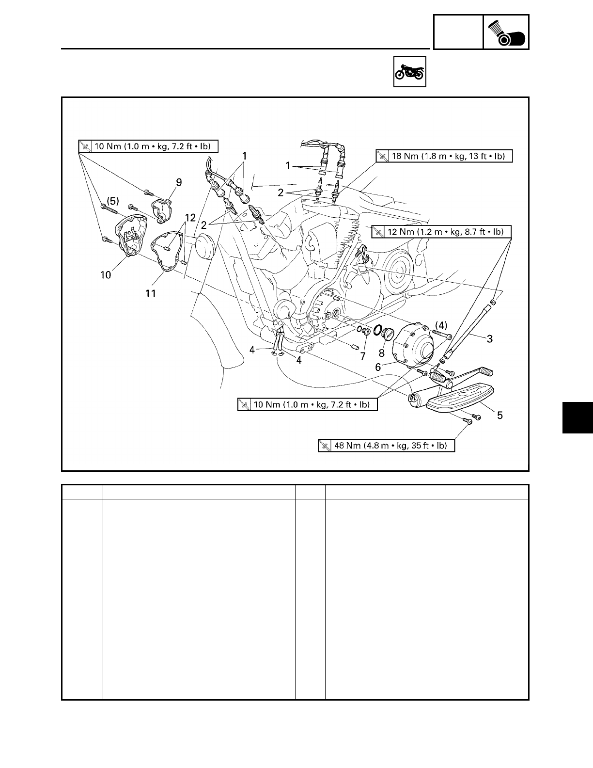
5 - 12
ENG
ROCKER ARMS, PUSH RODS AND VALVE LIFTERS
ROCKER ARMS, PUSH RODS AND VALVE LIFTERS
Order Job/Part Q’ty Remarks
Removing the engine left side cover
and camshaft sprocket cover
Remove the parts in the order listed.
Rider seat/fuel tank/air filter case Refer to “SEATS AND SIDE COVER”,
“FUEL TANK” and “AIR FILTER CASE”
in chapter 3.
Engine oil Drain.
1 Spark plug cap 4 Disconnect.
2 Spark plug 4
3 Shift rod 1
4 Charcoal canister hose 2 Disconnect.
5 Rider footrest (left) 1
6 Engine left side cover 1
7 Timing mark accessing screw 1
8 Crankshaft end cover 1
5
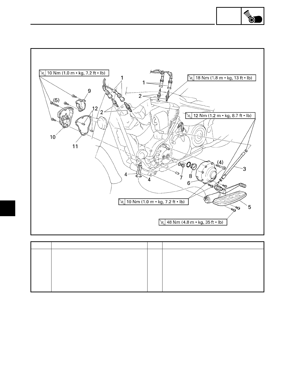
5 - 13
ENG
Order Job/Part Q’ty Remarks
9 Decompression solenoid cover 1
10 Camshaft sprocket cover 1
11 Camshaft sprocket cover gasket 1
12 Dowel pin 2
For installation, reverse the removal
procedure.
ROCKER ARMS, PUSH RODS AND VALVE LIFTERS
5
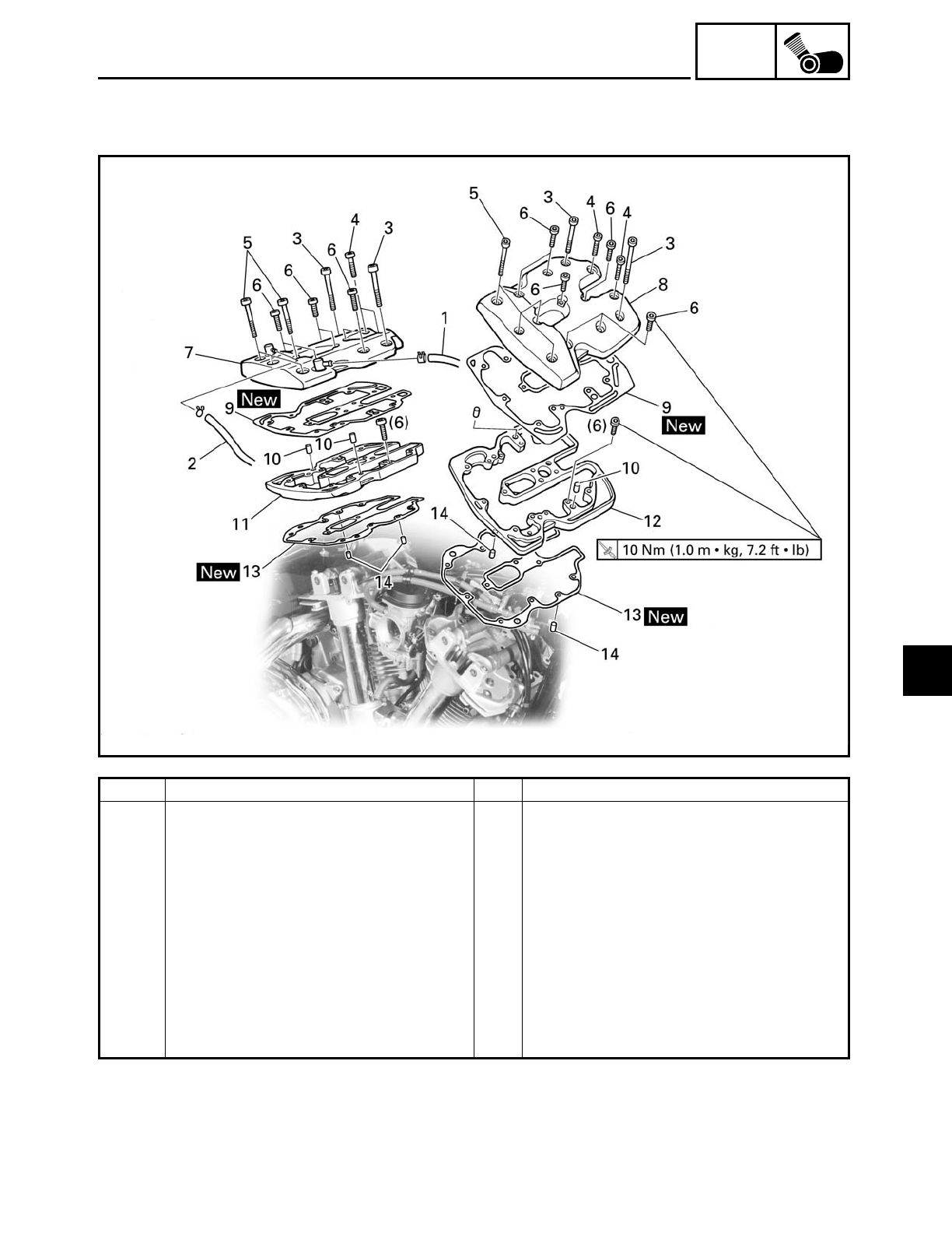
5 - 14
ENG
ROCKER ARMS, PUSH RODS AND VALVE LIFTERS
Order Job/Part Q’ty Remarks
Removing cylinder head covers Remove the parts in the order listed.
1 Cylinder head breather hose 1
2 Oil tank breather hose 1
3 Bolt 4 R = 65 mm (2.56 in)
4 Bolt 4 R = 35 mm (1.38 in)
5 Bolt 4 R = 50 mm (1.97 in)
6 Bolt 12 R = 25 mm (0.98 in)
7 Rear cylinder head cover 1
8 Front cylinder head cover 1
9 Cylinder head cover gasket 2
10 Dowel pin 4
5
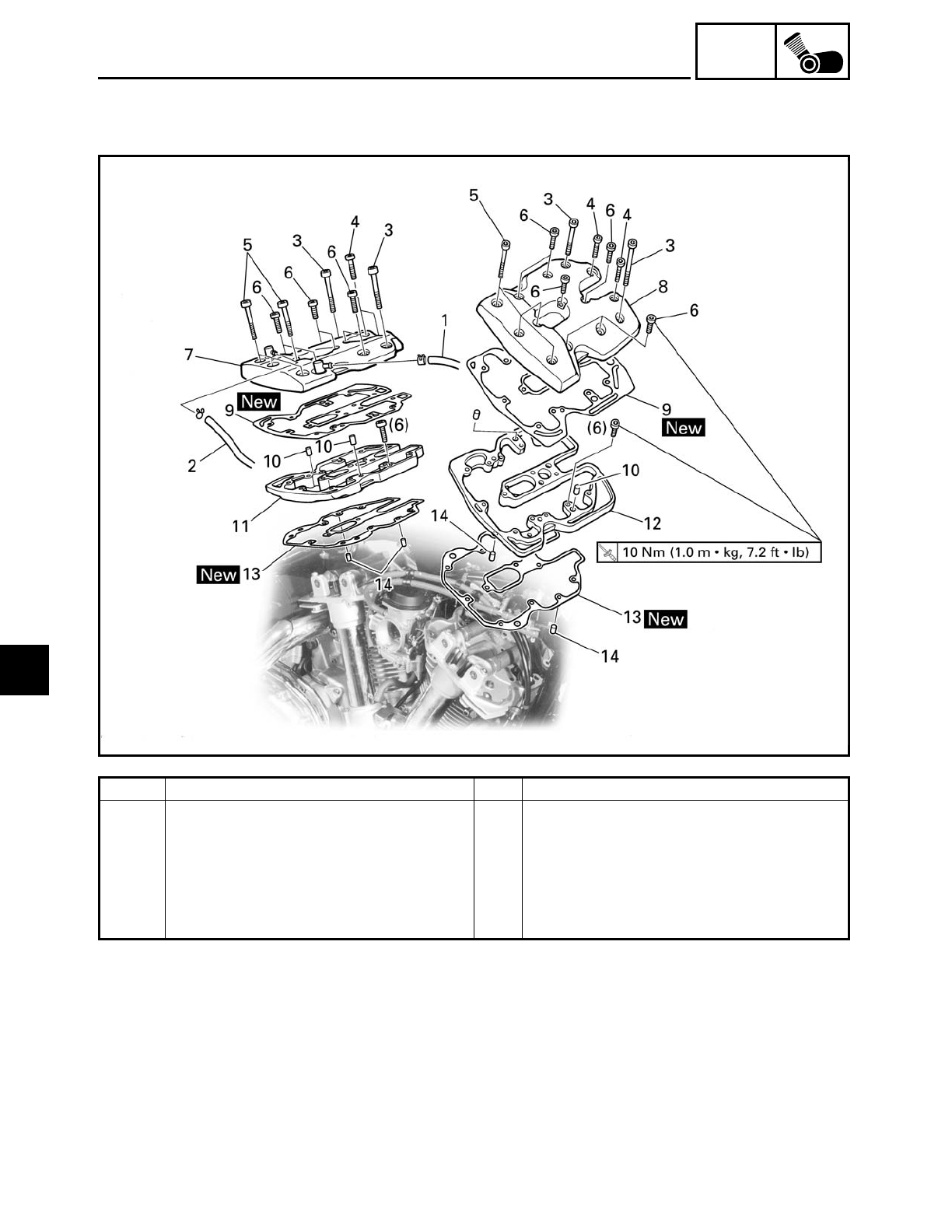
5 - 15
ENG
ROCKER ARMS, PUSH RODS AND VALVE LIFTERS
Order Job/Part Q’ty Remarks
11 Rear cylinder head cover spacer 1
12 Front cylinder head cover spacer 1
13 Cylinder head cover spacer gasket 2
14 Dowel pin 4
For installation, reverse the removal
procedure.
5
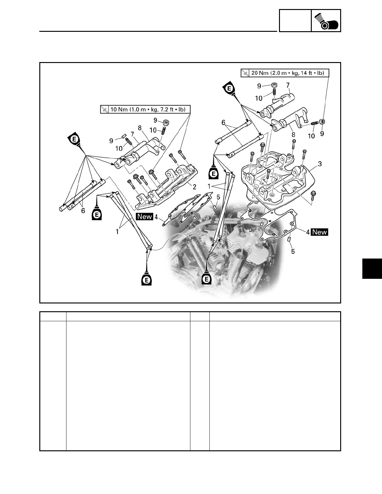
5 - 16
ENG
ROCKER ARMS, PUSH RODS AND VALVE LIFTERS
Order Job/Part Q’ty Remarks
Removing the push rods and rocker
arms
Remove the parts in the order listed.
1 Push rod 4
2 Rear rocker arm base 1
3 Front rocker arm base 1
4 Rocker arm base gasket 2
5 Dowel pin 4
6 Rocker arm shaft 4
7 Rocker arm 1 2
8 Rocker arm 2 2
9 Locknut 2
10 Adjusting screw 2
For installation, reverse the removal
procedure.
5
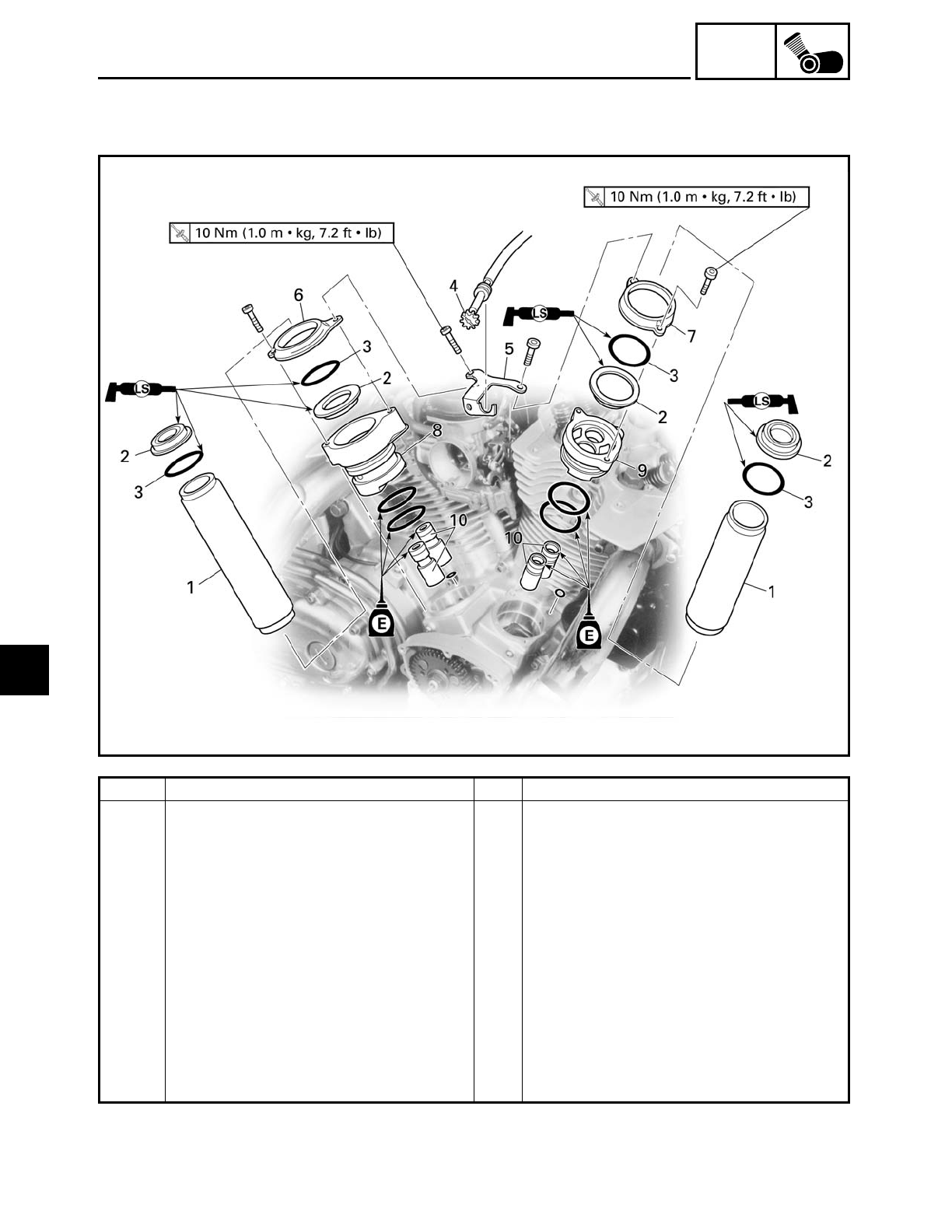
5 - 17
ENG
ROCKER ARMS, PUSH RODS AND VALVE LIFTERS
Order Job/Part Q’ty Remarks
Removing the valve lifters Remove the parts in the order listed.
1 Push rod cover 2
2 Oil seal 4
3 O-ring 4
4 Throttle stop screw 1 Unhook.
5 Throttle stop screw holder 1
6 Rear valve lifter case cover 1
7 Front valve lifter case cover 1
8 Rear valve lifter case 1
9 Front valve lifter case 1
10 Valve lifter 4
For installation, reverse the removal
procedure.
5
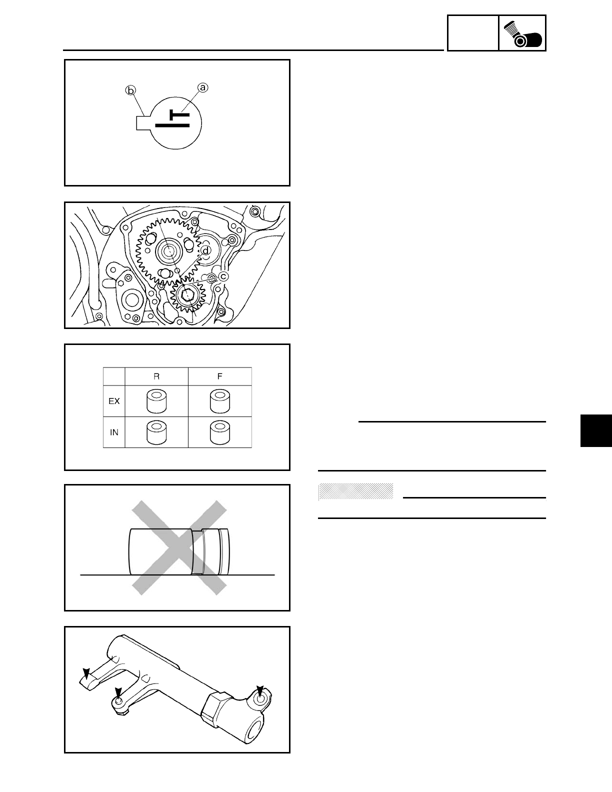
5 - 18
ENG
ROCKER ARMS, PUSH RODS AND VALVE LIFTERS
REMOVING THE ROCKER ARMS, PUSH
RODS AND VALVE LIFTERS
1. Align:
• TDC mark
a on the pickup coil rotor
(with the pointer b on the clutch/pickup
coil rotor cover)
▼ ▼ ▼ ▼ ▼ ▼ ▼ ▼ ▼ ▼ ▼ ▼ ▼ ▼ ▼ ▼ ▼ ▼ ▼ ▼ ▼ ▼ ▼ ▼ ▼ ▼ ▼ ▼
a. Turn the crankshaft clockwise.
b. When piston #1 is at TDC on the com-
pression stroke, align the TDC mark
a
on the pickup coil rotor with the pointer
b on the clutch/pickup coil rotor cover.
c. Check the camshaft drive gear mark
c
position and camshaft driven gear mark
d position as shown.
If the marks are not aligned, turn the
crankshaft counterclockwise 360 degrees
and recheck step b.
▲ ▲ ▲ ▲ ▲ ▲ ▲ ▲ ▲ ▲ ▲ ▲ ▲ ▲ ▲ ▲ ▲ ▲ ▲ ▲ ▲ ▲ ▲ ▲ ▲ ▲ ▲ ▲
2. Remove:
• rocker arm bases
(with the rocker arms)
3. Remove:
• valve lifters
NOTE:
Make a note of the position of each valve
lifter so that they can be installed in the cor-
rect place.
ACHTUNG:
CAUTION:
Do not lay the removed valve lifter on its side.
CHECKING THE ROCKER ARMS AND
ROCKER ARM SHAFTS
The following procedure applies to all of
the rocker arms and rocker arm shafts.
1. Check:
• rocker arm
Damage/wear → Replace.
5
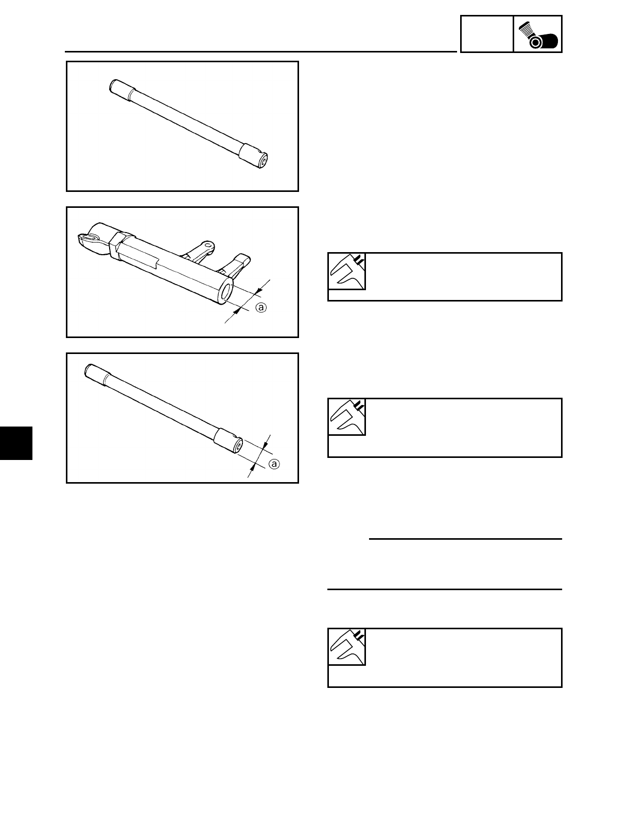
5 - 19
ENG
ROCKER ARMS, PUSH RODS AND VALVE LIFTERS
2. Check:
• rocker arm shaft
Blue discoloration/excessive wear/pit-
ting/scratches
→ Replace or check the
lubrication system.
3. Measure:
• rocker arm inside diameter
a
Out of specification
→ Replace.
Rocker arm inside diameter
15.000 ~ 15.018 mm
(0.5906 ~ 0.5913 in)
4. Measure:
• rocker arm shaft outside diameter
Out of specification → Replace.
Rocker arm shaft outside diame-
ter
14.981 ~ 14.991 mm
(0.5898 ~ 0.5902 in)
5. Calculate:
• rocker arm to rocker arm shaft clearance
NOTE:
Calculate the clearance by subtracting the
rocker arm shaft outside diameter from the
rocker arm inside diameter.
Above 0.08 mm (0.003 in)
→ Replace the
defective part(s).
Rocker arm to rocker arm shaft
clearance
0.009 ~ 0.037 mm
(0.0003 ~ 0.0015 in)
5
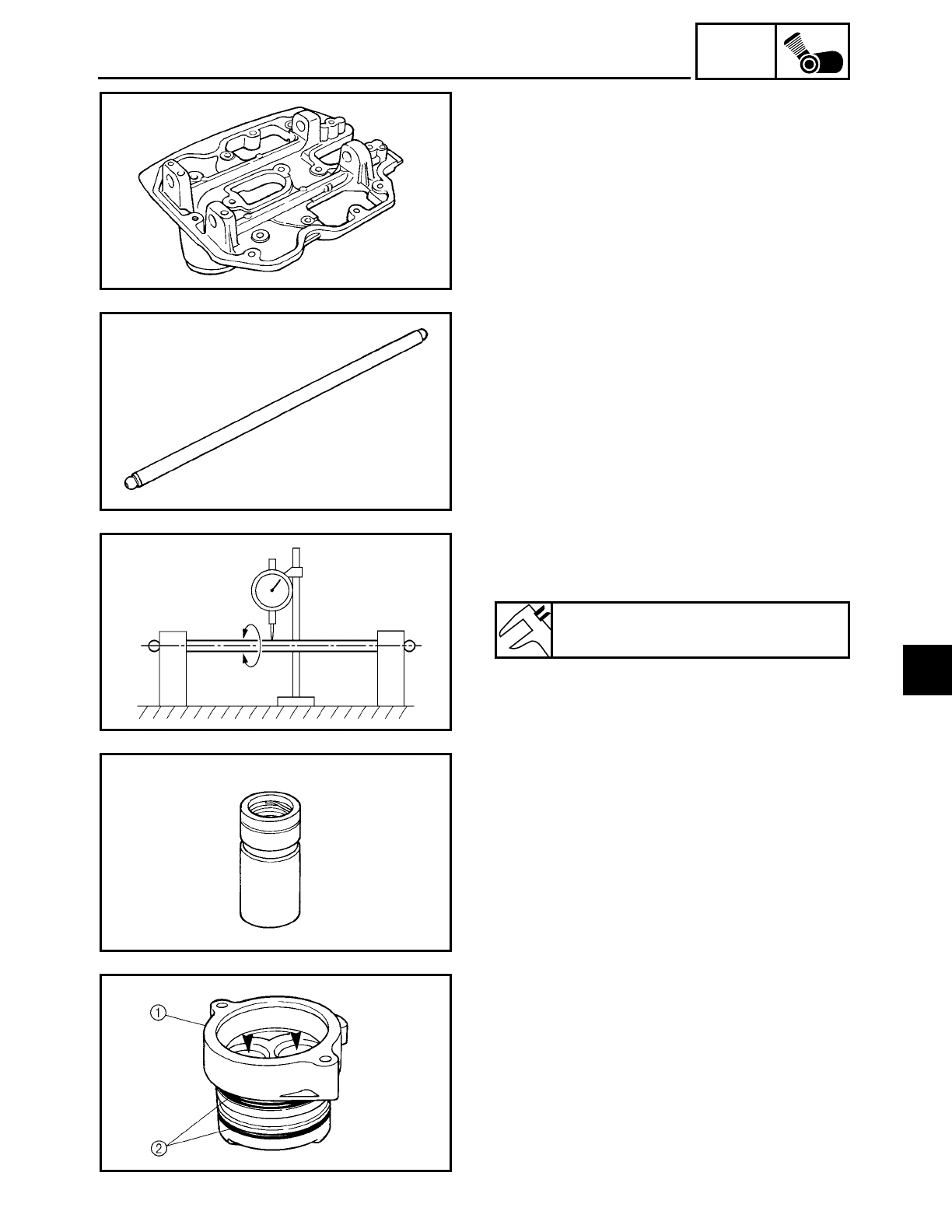
5 - 20
ENG
ROCKER ARMS, PUSH RODS AND VALVE LIFTERS
CHECKING THE ROCKER ARM BASES
1. Check:
• rocker arm base
Cracks/damage
→ Replace.
CHECKING THE PUSH RODS
1. Check:
• push rod
• push rod end
Bends/damage → Replace.
2. Measure:
• push rod runout
Out of specification → Replace.
Push rod runout
0.3 mm (0.012 in)
CHECKING THE VALVE LIFTERS AND
VALVE LIFTER CASES
1. Check:
• valve lifter
Blue discoloration/excessive wear/pit-
ting/scratches → Replace or check the
lubrication system.
2. Check:
• valve lifter case 1
Damage/wear → Replace the valve lifter
case.
• O-ring 2
Damage/wear → Replace the O-ring.
5
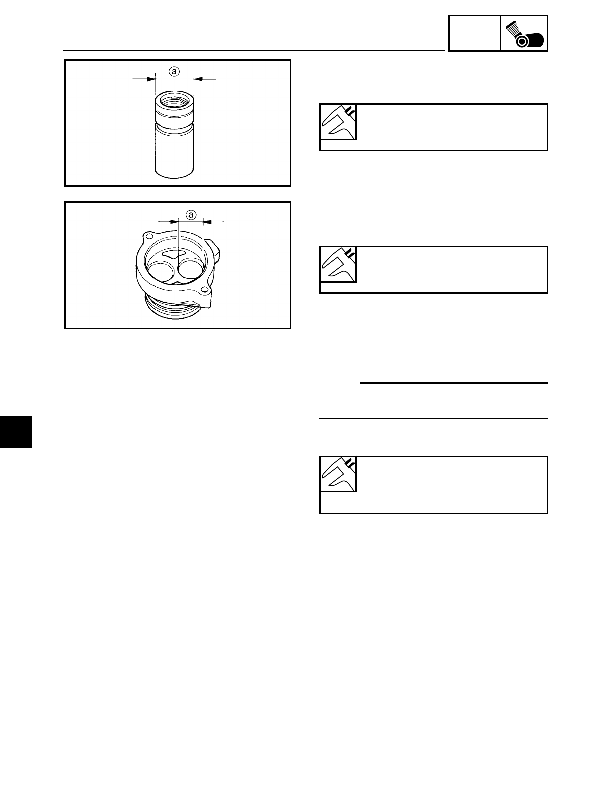
5 - 21
ENG
ROCKER ARMS, PUSH RODS AND VALVE LIFTERS
3. Measure:
• valve lifter outside diameter
a
Out of specification
→ Replace.
Valve lifter case outside diameter
22.9680 ~ 22.9744 mm
(0.9043 ~ 0.9045 in)
4. Measure:
• valve lifter case inside diameter
a
Out of specification
→ Replace.
Valve lifter case inside diameter
22.990 ~ 23.010 mm
(0.9051 ~ 0.9059 in)
5. Calculate:
• valve lifter-to-valve lifter case clearance
NOTE:
Calculate the clearance by subtracting the
valve lifter case outside diameter.
Above 0.072 mm (0.0028 in)
→ Replace
the defective part(s)
Valve lifter-to-valve lifter case
clearance
0.0156 ~ 0.042 mm
(0.0006 ~ 0.0017 in)
BLEEDING A VALVE LIFTER
A valve lifter must be bled in the following
cases.
• When installing a new valve lifter
• When the valve lifter leaks oil
5
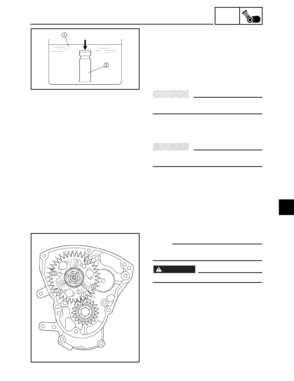
5 - 22
ENG
1. Bleed:
• valve lifter
▼ ▼ ▼ ▼ ▼ ▼ ▼ ▼ ▼ ▼ ▼ ▼ ▼ ▼ ▼ ▼ ▼ ▼ ▼ ▼ ▼ ▼ ▼ ▼ ▼ ▼ ▼ ▼
a. Fill a container with kerosene and place
the valve lifter into the container as
shown.
Pump the plunger side of the valve lifter
with a press a number of times to let in
kerosene.
ACHTUNG:
CAUTION:
• Do not pump the valve lifter excessively.
• Kerosene is highly flammable.
1Kerosene
2Valve lifter
b. Install the valve lifter into the engine.
ACHTUNG:
CAUTION:
Be sure to install the valve lifter in its
appropriate position.
c. Start the engine and warm it up.
d. Stop the engine.
e. Remove the camshaft sprocket cover.
f. Rotate the camshaft until the punch mark
1 on the camshaft driven gear aligns
with the punch mark on the camshaft
drive gear as shown. This is the condi-
tion in which piston #1 is at top dead
center (TDC).
NOTE:
The crankshaft can be rotated smoothly
when the spark plugs are removed.
WARNING
WARNING
Be careful since the engine is hot.
g. With piston #1 at TDC, count the indi-
cated number of gear teeth and place
marks
2 through
5 on the camshaft
driven gear as shown. When these marks
align between the centers of the cam-
shaft drive and driven gears, the corre-
sponding valve lifter is at its highest
point.
1Piston #1 TDC punch mark
2Cylinder #2 intake valve at its highest point
3Cylinder #1 exhaust valve at its highest point
4Cylinder #1 intake valve at its highest point
5Cylinder #2 exhaust valve at its highest point
ROCKER ARMS, PUSH RODS AND VALVE LIFTERS
5
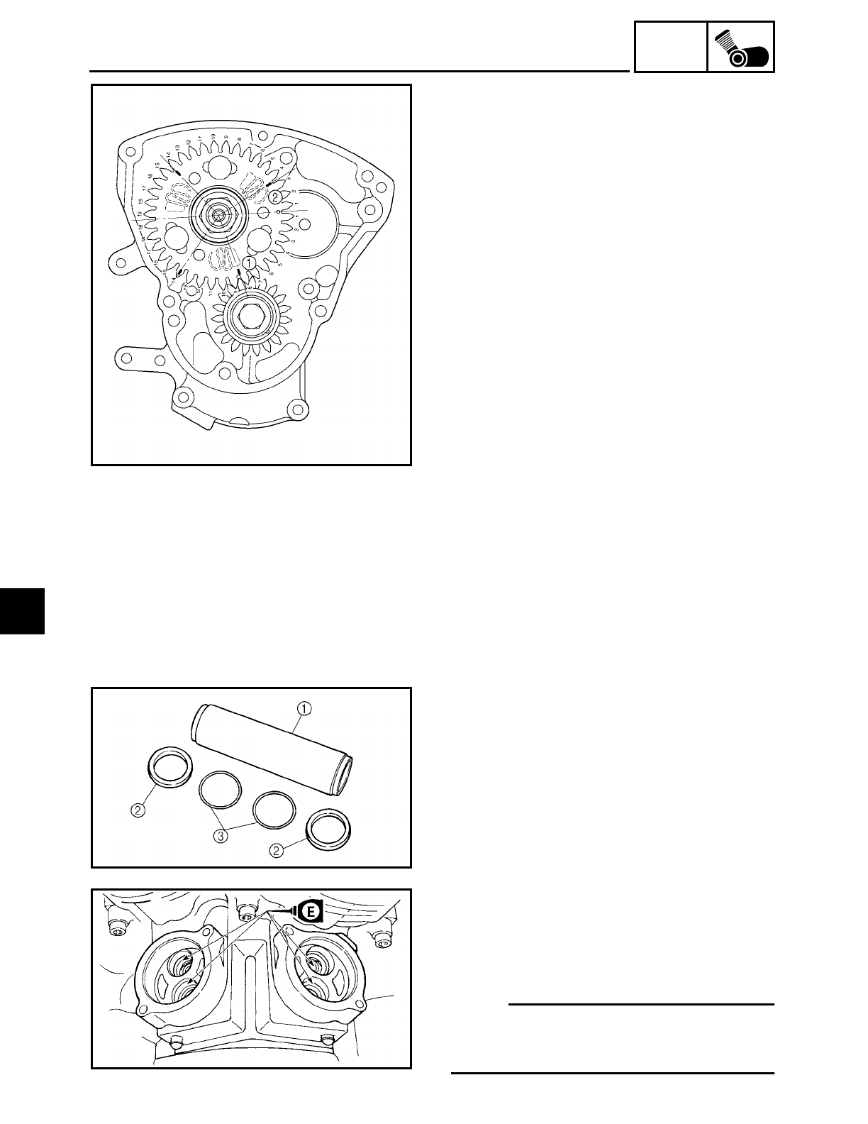
5 - 23
ENG
h. Rotate the crankshaft until the mark (on
the camshaft driven gear) for the valve
lifter to be bled aligns with the camshaft
drive gear as shown.
Example: For bleeding the cylinder #2
intake valve lifter, align mark 1 as
shown.
1Cylinder #2 intake valve at its highest point
2Piston #1 TDC punch mark
i. Leave the camshaft drive and driven
gears aligned for five minutes to allow
the valve lifter to bleed.
j. If necessary, repeat steps “h” and “i” to
bleed other valve lifters.
▲ ▲ ▲ ▲ ▲ ▲ ▲ ▲ ▲ ▲ ▲ ▲ ▲ ▲ ▲ ▲ ▲ ▲ ▲ ▲ ▲ ▲ ▲ ▲ ▲ ▲ ▲ ▲
CHECKING THE PUSH ROD COVERS
1. Check:
• push rod cover 1
Cracks/damage → Replace.
• oil seal 2
• O-ring 3
Damage/wear → Replace the oil seal and
O-ring as a set.
INSTALLING THE VALVE LIFTERS AND
PUSH ROD COVERS
1. Install:
• valve lifter cases (front and rear)
• valve lifters
NOTE:
• Install the valve lifter in the correct place.
• After installing the valve lifters, fill the
tops of them with engine oil.
ROCKER ARMS, PUSH RODS AND VALVE LIFTERS
5
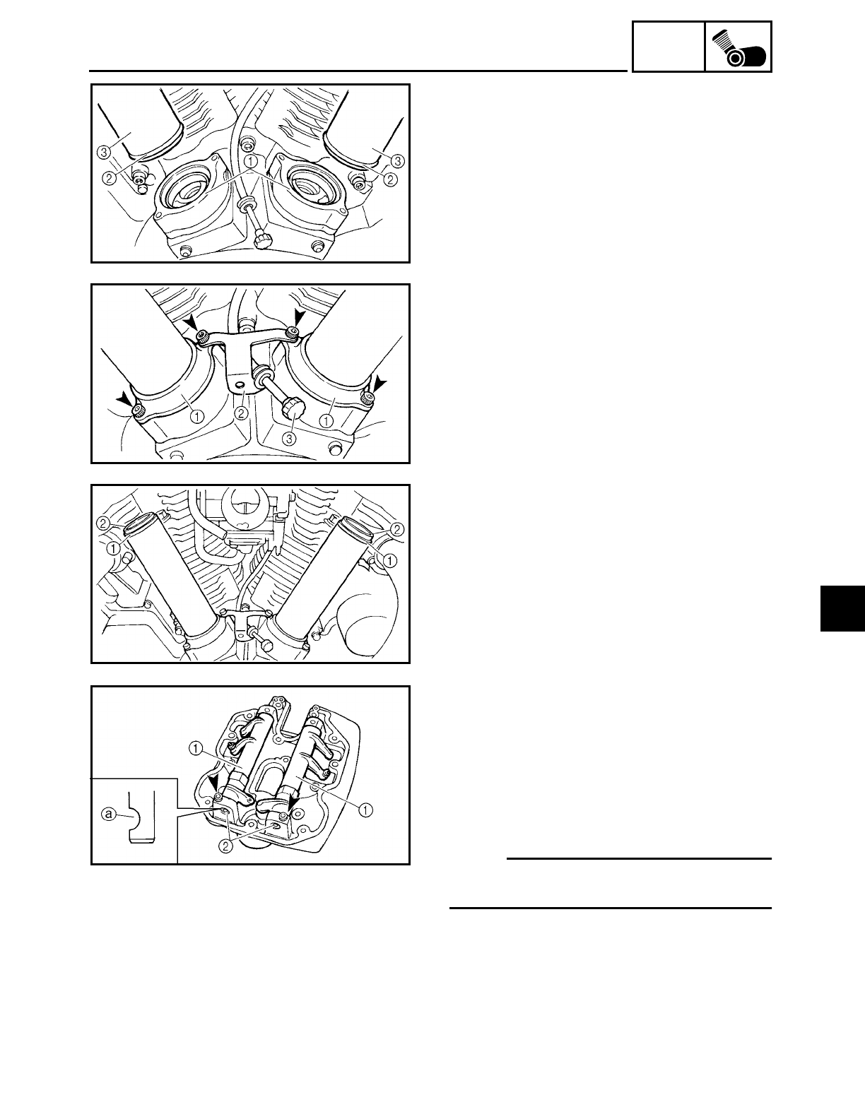
5 - 24
ENG
ROCKER ARMS, PUSH RODS AND VALVE LIFTERS
2. Install:
• oil seals 1
• O-rings 2
• push rod covers 3
3. Install:
• valve lifter case covers 1
• throttle stop screw holder 2
4. Hook:
• throttle stop screw 3
5. Install:
• O-rings 1
• oil seals 2
INSTALLING THE ROCKER ARMS AND
PUSH RODS
The following procedure applies to both
cylinders.
1. Install:
• rocker arms 1
• rocker arm shafts 2
(onto rocker arm base)
NOTE:
The thread hole a of the rocker arm shaft
must face to the outside.
5
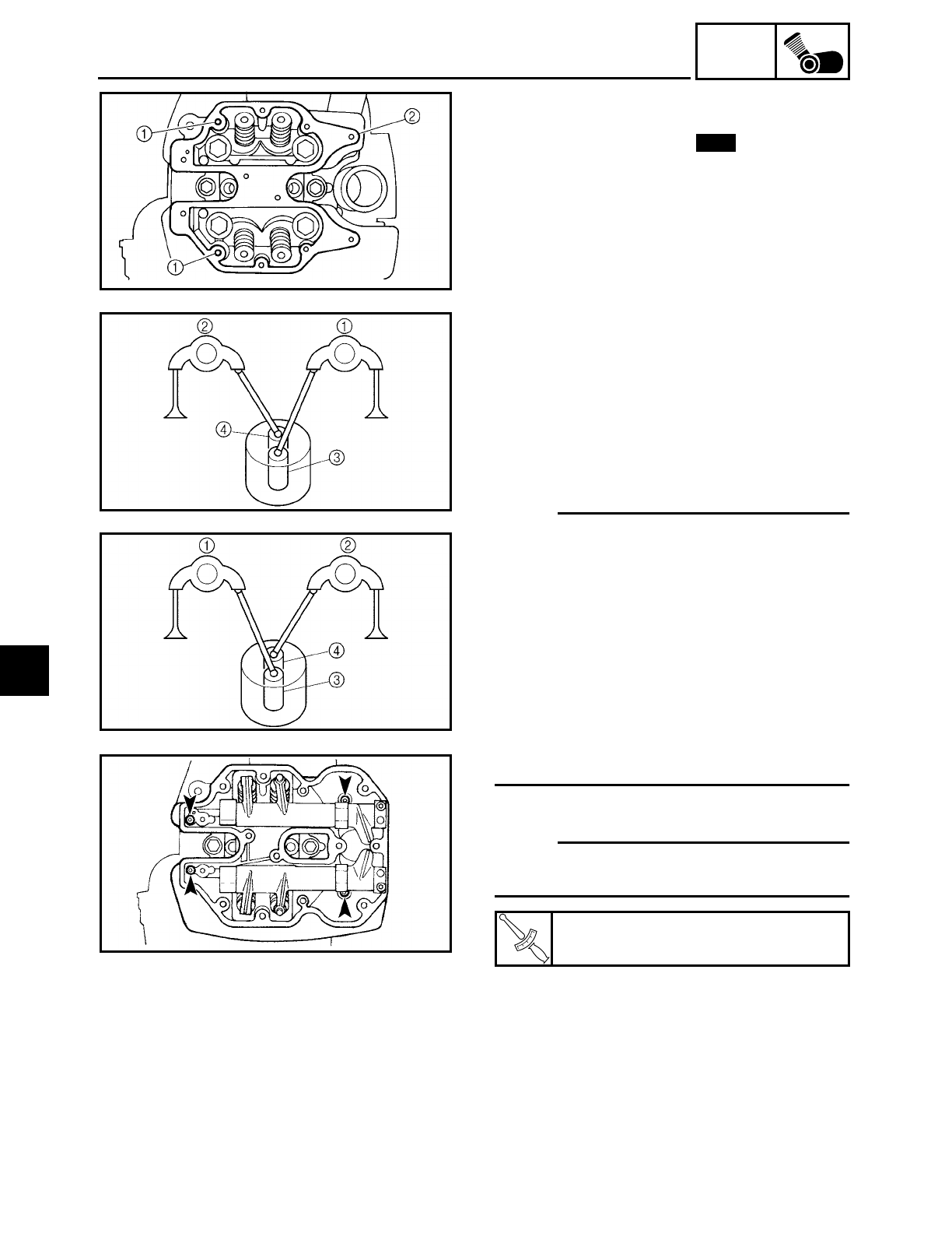
5 - 25
ENG
ROCKER ARMS, PUSH RODS AND VALVE LIFTERS
2. Install:
• dowel pins 1
• rocker arm gasket 2New
3. Install:
• rocker arm base
(with rocker arms)
• push rods
▼ ▼ ▼ ▼ ▼ ▼ ▼ ▼ ▼ ▼ ▼ ▼ ▼ ▼ ▼ ▼ ▼ ▼ ▼ ▼ ▼ ▼ ▼ ▼ ▼ ▼ ▼ ▼
a. Put the rocker arm base on the cylinder
head.
b. Install the push rods.
NOTE:
• Be sure to correctly install the push rods
between the rocker arms and valve lifters
as shown. The illustration is viewed from
the right side of the motorcycle.
ÅRear cylinder
ıFront cylinder
1Intake side rocker arm
2Exhaust side rocker arm
3Intake valve lifter
4Exhaust valve lifter
• Lubricate the push rod end balls with
engine oil.
c. Install the rocker arm base bolts.
NOTE:
Tighten the rocker arm base bolts in stages
and in a crisscross pattern.
▲ ▲ ▲ ▲ ▲ ▲ ▲ ▲ ▲ ▲ ▲ ▲ ▲ ▲ ▲ ▲ ▲ ▲ ▲ ▲ ▲ ▲ ▲ ▲ ▲ ▲ ▲ ▲
T
R
.
.
Rocker arm base bolt
10 Nm (1.0 m • kg, 7.2 ft • lb)
Å
ı
5
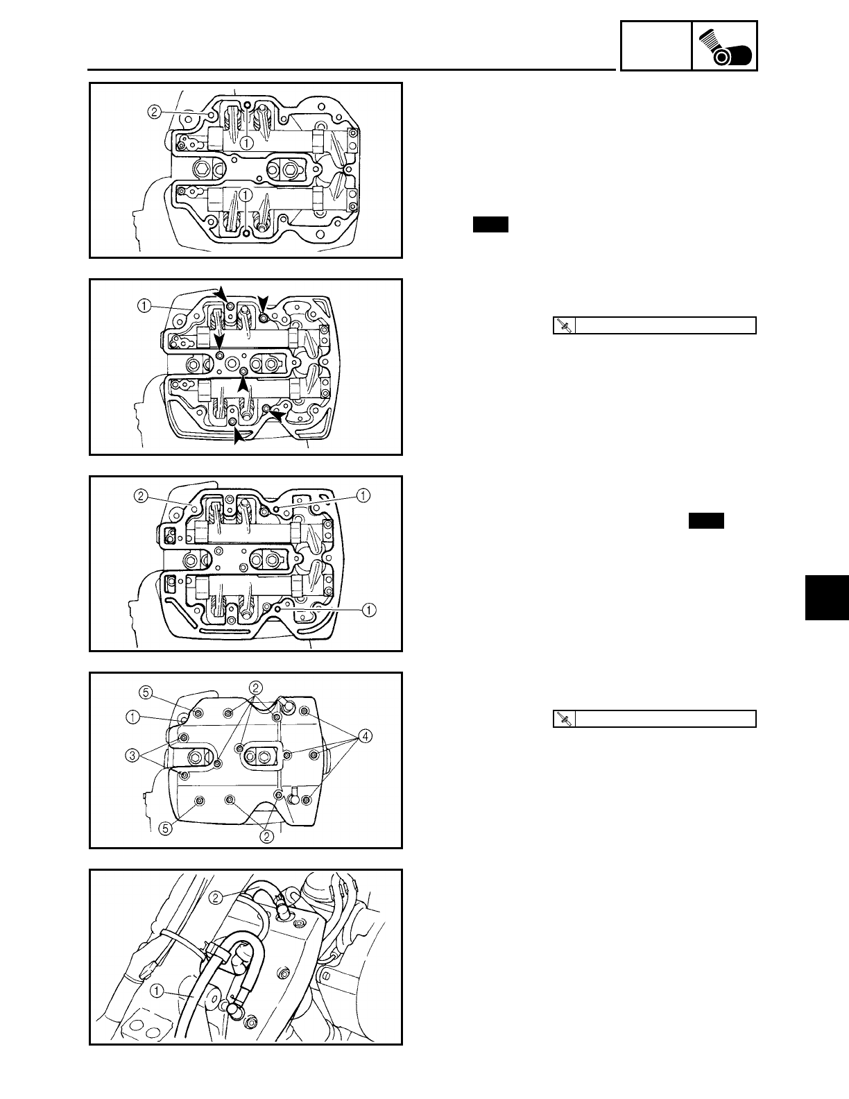
5 - 26
ENG
ROCKER ARMS, PUSH RODS AND VALVE LIFTERS
INSTALLING THE CYLINDER HEAD
COVERS
The following procedure applies to both
cylinders.
1. Install:
• dowel pins 1
• cylinder head cover spacer gasket 2
New
2. Install:
• cylinder head cover spacer 1
T
R
.
.
10 Nm (1.0 m · kg, 7.2 ft · lb)
3. Install:
• dowel pins 1
• cylinder head cover gasket 2New
4. Install:
• cylinder head cover 1
Bolts 2:R = 25 mm (0.98 in)
Bolts 3:R = 35 mm (1.38 in)
Bolts 4:R = 50 mm (1.97 in)
Bolts 5:R = 65 mm (2.56 in)
T
R
.
.
10 Nm (1.0 m · kg, 7.2 ft · lb)
5. Connect:
• oil tank breather hose 1
• cylinder head breather hose 2
5
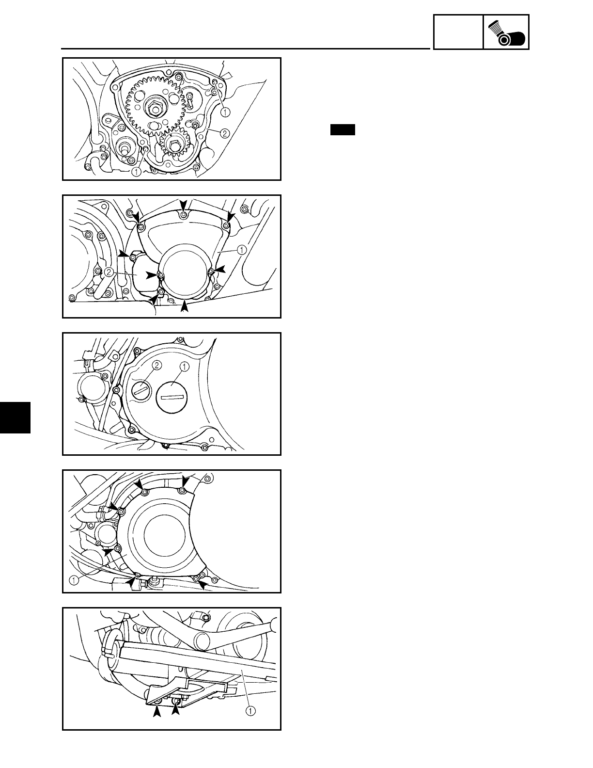
5 - 27
ENG
ROCKER ARMS, PUSH RODS AND VALVE LIFTERS
INSTALLING THE CAMSHAFT SPROCKET
COVER AND ENGINE LEFT SIDE COVER
1. Install:
• dowel pins 1
• camshaft sprocket cover gasket 2
New
2. Install:
• camshaft sprocket cover 1
• decompression solenoid cover 2
3. Install:
• crankshaft end cover 1
• timing mark accessing screw 2
4. Install:
• engine left side cover 1
5. Install:
• rider footrest (left) 1
6. Connect:
• charcoal canister hoses
5
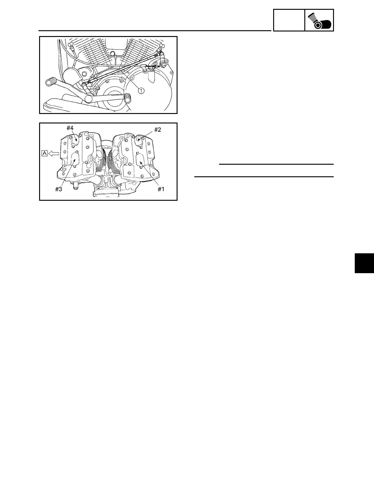
5 - 28
ENG
ROCKER ARMS, PUSH RODS AND VALVE LIFTERS
7. Install:
• shift rod 1
8. Install:
• spark plugs
9. Connect:
• spark plug caps
NOTE:
Refer to “CABLE ROUTING” in chapter 2.
ÅForward
10.Fill:
• oil tank
(with the specified amount of the recom-
mended engine oil)
Refer to “CHANGING THE ENGINE OIL”
in chapter 3.
11.Install:
• air filter case
• fuel tank
• rider seat
Refer to “AIR FILTER CASE”, “FUEL
TANK” and “SEATS AND SIDE COVERS”
in chapter 3.
12.Adjust:
• installed shift rod length
Refer to “ADJUSTING THE SHIFT
PEDAL” in chapter 3.
5
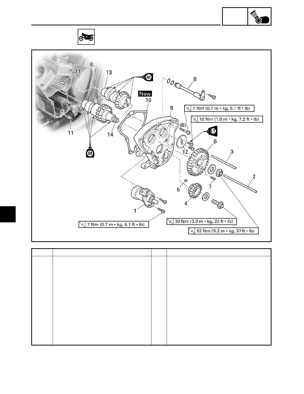
5 - 29
ENG
CAMSHAFTS
CAMSHAFTS
Order Job/Part Q’ty Remarks
Removing the camshafts
Valve lifters Refer to “ROCKER ARMS, PUSH RODS
AND VALVE LIFTERS”.
Muffler/exhaust pipes Refer to “ENGINE”.
1 Decompression solenoid 1
2 Long decompression push rod 1 92 mm (3.6 in)
3 Short decompression push rod 1 78 mm (3.1 in)
4 Camshaft drive gear 1
5 Straight key 1
6 Camshaft driven gear 1
7 Straight key 1
8 Oil delivery pipe 1
5
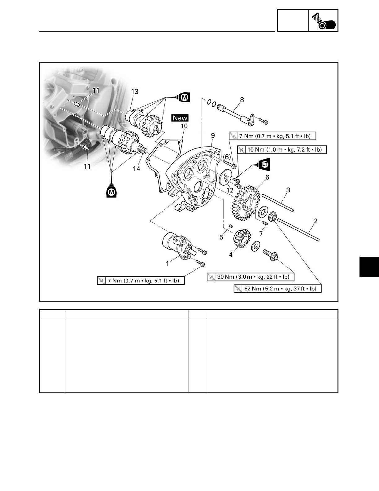
5 - 30
ENG
CAMSHAFTS
Order Job/Part Q’ty Remarks
9 Camshaft cover 1
10 Camshaft cover gasket 1
11 Dowel pin 1
12 Front cylinder camshaft end cover 1
13 Front cylinder camshaft 1
14 Rear cylinder camshaft 1
For installation, reverse the removal
procedure.
5
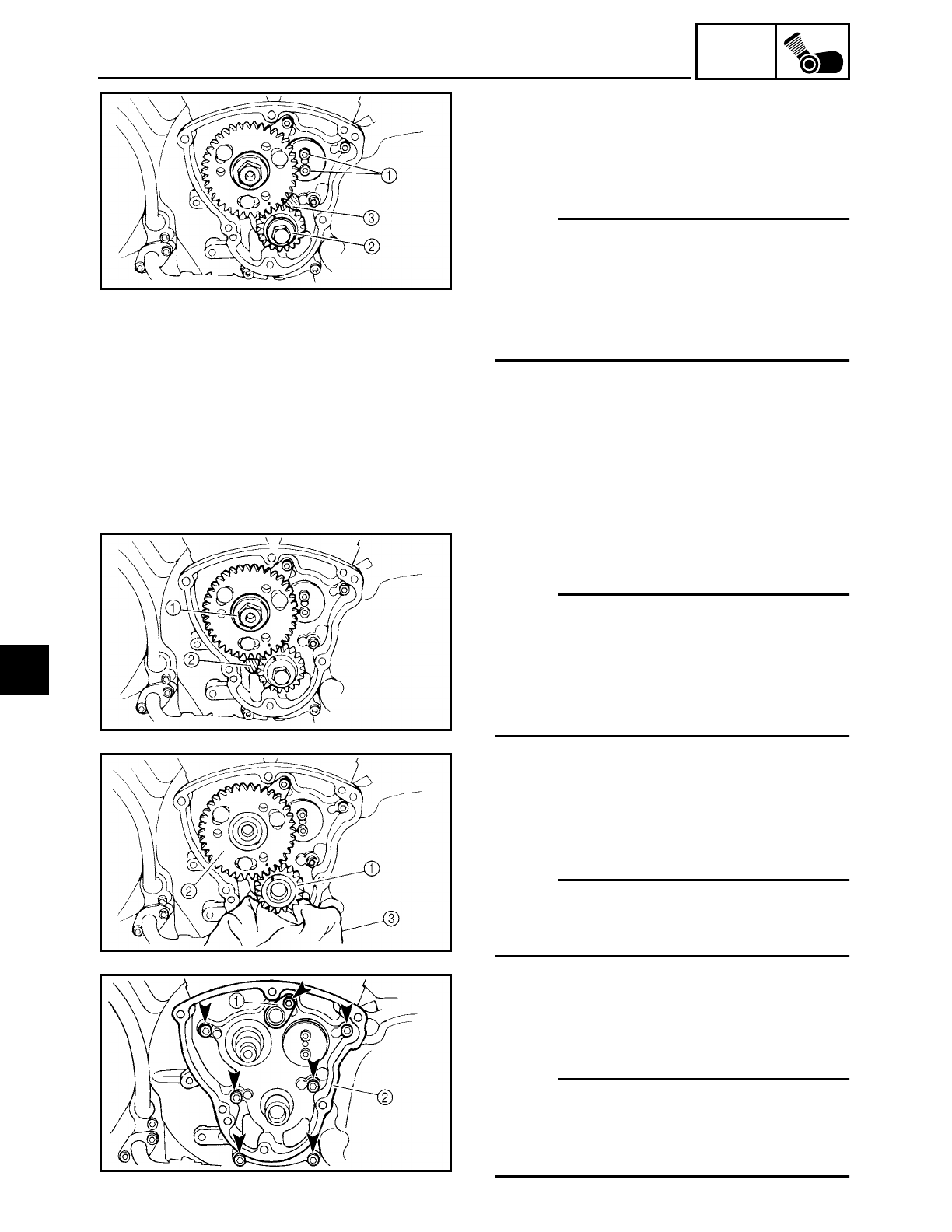
5 - 31
ENG
CAMSHAFTS
REMOVING THE CAMSHAFTS
1. Loosen:
• front cylinder camshaft end cover bolts
1
• camshaft drive gear bolt 2
NOTE:
• Place a folded copper washer
3 between
the teeth of the camshaft drive gear and
camshaft driven gear in order to lock
them.
• Do not damage the teeth of the camshaft
drive and camshaft driven gears.
2. Loosen:
• camshaft driven gear nut
1
NOTE:
• Place a folded copper washer
2 between
the teeth of the camshaft drive gear and
camshaft driven gear in order to lock
them.
• Do not damage the teeth of the camshaft
drive and camshaft driven gears.
3. Remove:
• front cylinder camshaft end cover
• camshaft drive gear 1
• camshaft driven gear 2
• straight keys
NOTE:
Cover the crankcase hole with a clean rag
3
to prevent the straight keys from falling into
the crankcase.
4. Remove:
• oil delivery pipe 1
• camshaft cover 2
(along with the camshafts)
NOTE:
Loosen each bolt 1/4 of a turn at a time, in
stages and in a crisscross pattern. After all
of the bolts are fully loosened, remove
them.
5
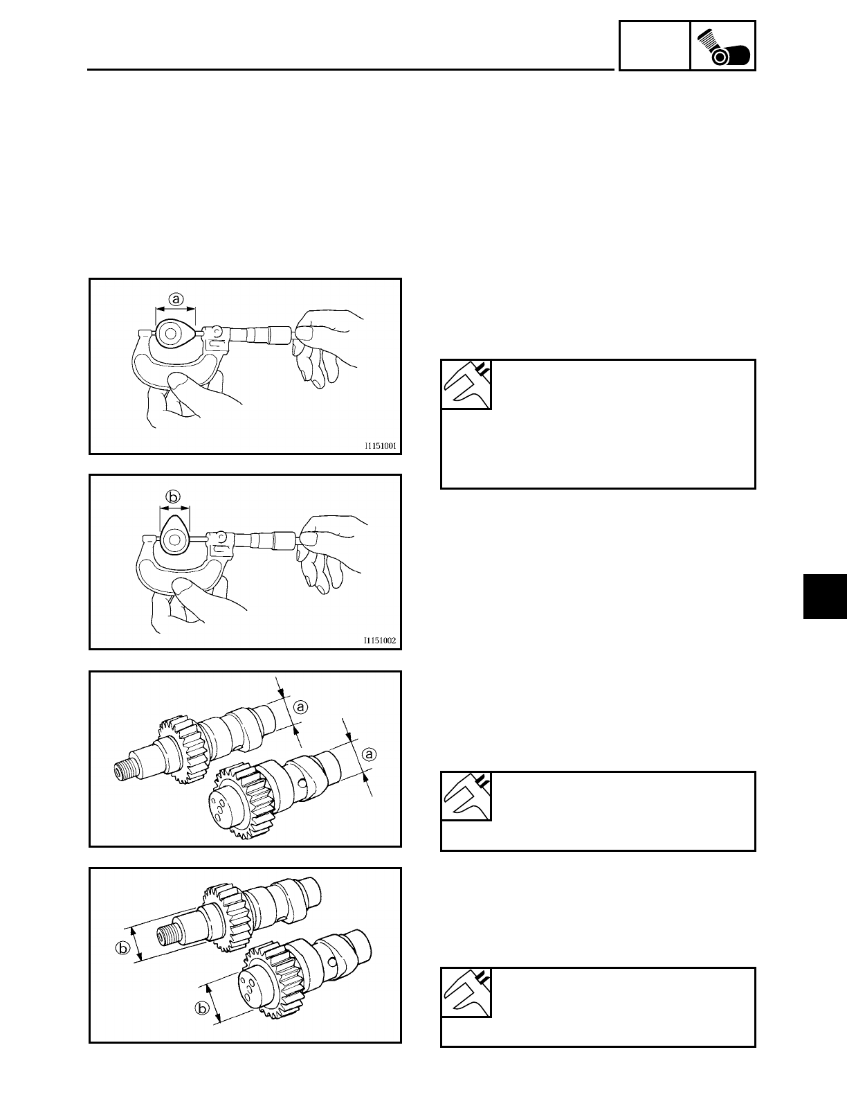
5 - 32
ENG
CAMSHAFTS
EAS00204
CHECKING THE CAMSHAFTS
1. Check:
• cams
Blue discoloration/pitting/scratches →
Replace the camshaft.
2. Measure:
• cam dimensions a and b
Out of specification → Replace the cam-
shaft.
Minimum cam lobe dimensions
Intake cam
a 36.494 mm (1.4368 in)
b 31.850 mm (1.2539 in)
Exhaust cam
a 36.454 mm (1.4352 in)
b 31.850 mm (1.2539 in)
3. Measure:
• camshaft journal diameter (crankcase
side) a
Out of specification → Replace the cam-
shaft.
Camshaft journal diameter
(crankcase side)
24.937 ~ 24.950 mm
(0.9818 ~ 0.9823 in)
4. Measure:
• camshaft journal diameter (camshaft
cover side) b
Out of specification → Replace the cam-
shaft.
Camshaft journal diameter
(camshaft cover side)
27.967 ~ 27.980 mm
(1.1011 ~ 1.1016 in)
5
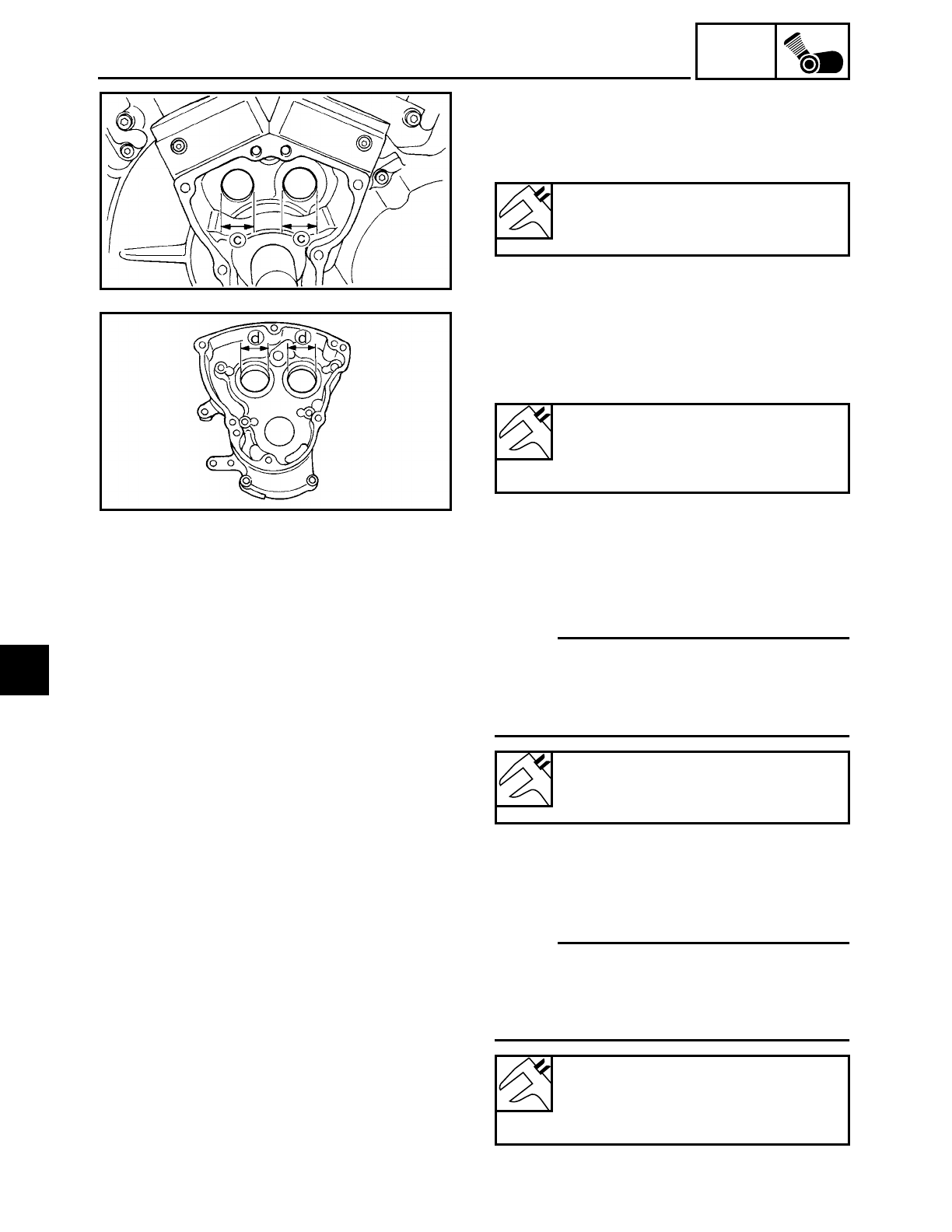
5 - 33
ENG
CAMSHAFTS
5. Measure:
• crankcase hole inside diameter
c
Out of specification
→ Replace the crank-
case.
Crankcase hole inside diameter
25.000 ~ 25.021 mm
(0.9843 ~ 0.9851 in)
6. Measure:
• camshaft cover hole inside diameter
d
Out of specification
→ Replace the cam-
shaft cover.
Camshaft cover hole inside diam-
eter
28.000 ~ 28.021 mm
(1.1024 ~ 1.1032 in)
7. Calculate:
• camshaft-to-crankcase clearance
Out of specification → Replace the defec-
tive part(s).
NOTE:
Calculate the clearance by subtracting the
crankcase side camshaft journal diameter
(crankcase side) from the crankcase hole
inside diameter.
8. Calculate:
• camshaft-to-camshaft cover clearance
Out of specification
→ Replace the defec-
tive part(s).
NOTE:
Calculate the clearance by subtracting the
camshaft journal diameter (camshaft cover
side) from the camshaft cover hole inside
diameter.
Camshaft to crankcase clearance
0.050 ~ 0.084 mm
(0.0020 ~ 0.0033 in)
Camshaft to camshaft cover
clearance
0.020 ~ 0.054 mm
(0.0008 ~ 0.0021 in)
5
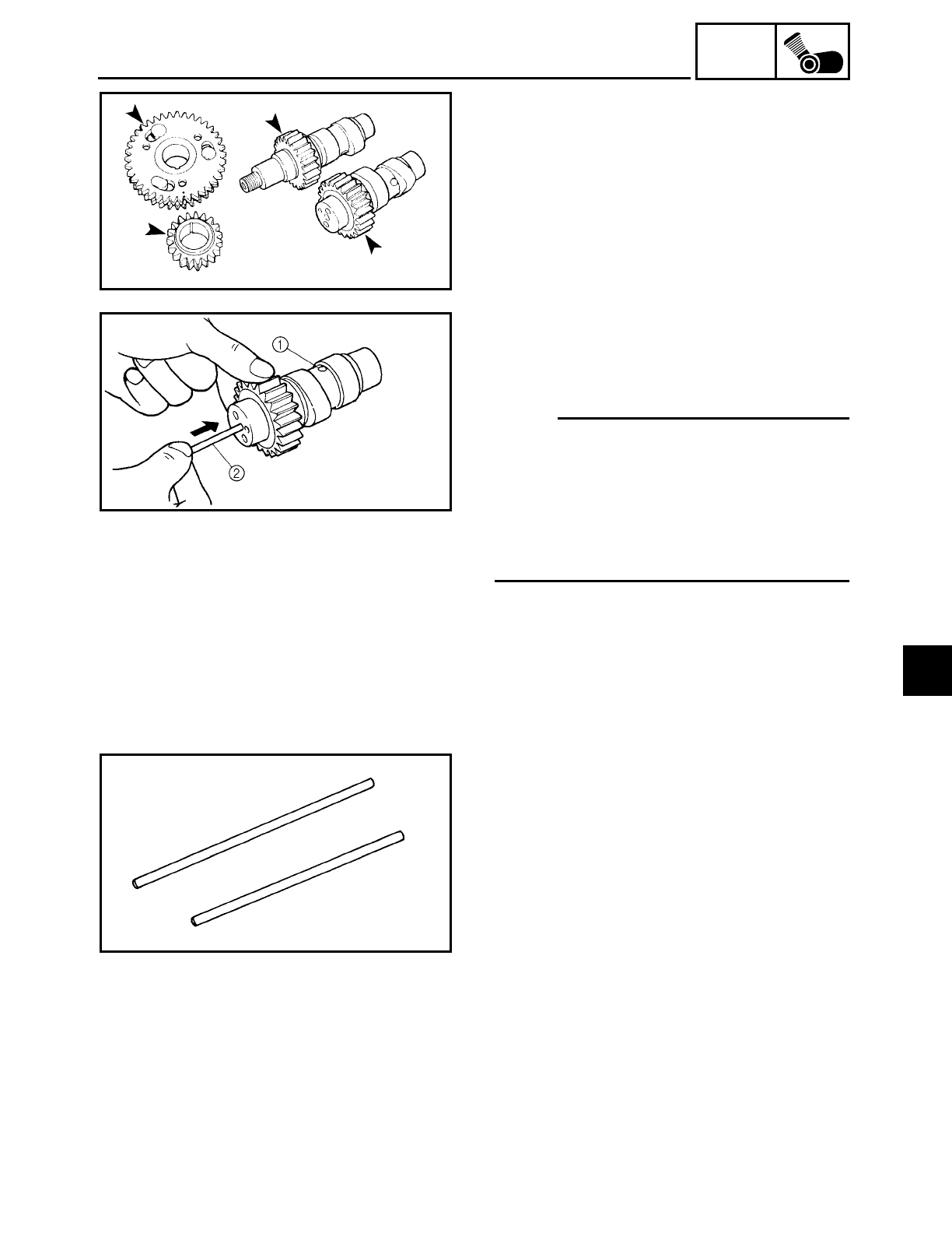
5 - 34
ENG
CAMSHAFTS
9. Check:
• camshaft drive gears
• camshaft driven gears
Chips/pitting/roughness/wear
→ Replace
the defective part(s).
CHECKING THE DECOMPRESSION
SYSTEM
1. Check:
• decompression system
NOTE:
• Check the decompression system while
the decompression push rod is installed in
the camshaft.
• Check that the decompression pin
1
projects from the camshaft.
• Check that the decompression push rod
2
moves smoothly.
2. Check:
• decompression push rods
Bends/damage → Replace.
5
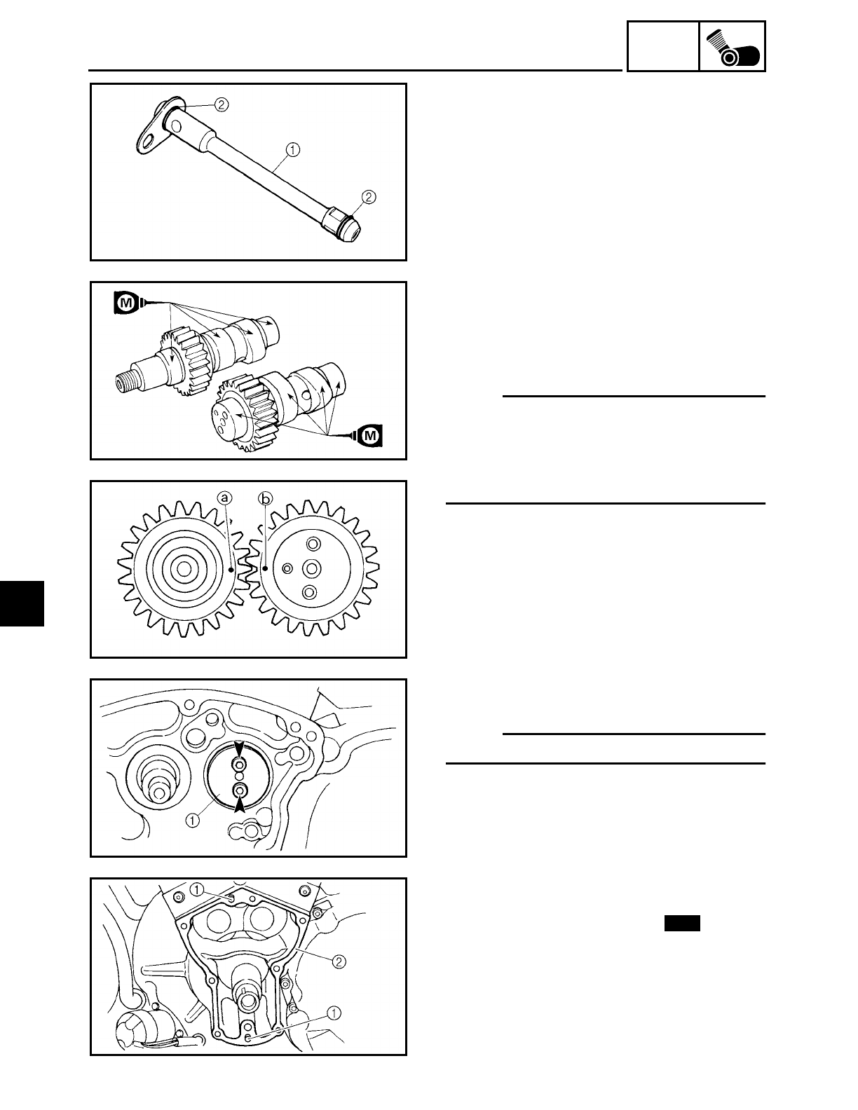
5 - 35
ENG
CAMSHAFTS
CHECKING THE OIL DELIVERY PIPE
1. Check:
• oil delivery pipe
1
Damage
→ Replace.
Obstruction → Wash and blow out with
compressed air.
• O-rings 2
Damage/wear → Replace.
INSTALLING THE CAMSHAFTS
1. Install:
• camshafts
(to the camshaft cover)
• front cylinder camshaft end cover
NOTE:
• Apply molybdenum disulfide oil onto the
camshaft journals and cam lobes.
• Align the punch mark
a on the rear cylin-
der camshaft with the punch mark b on
the front cylinder camshaft.
2. Install:
• front cylinder camshaft end cover 1
NOTE:
Finger tighten the end cover bolts.
3. Install:
• dowel pins 1
• camshaft cover gasket 2New
5
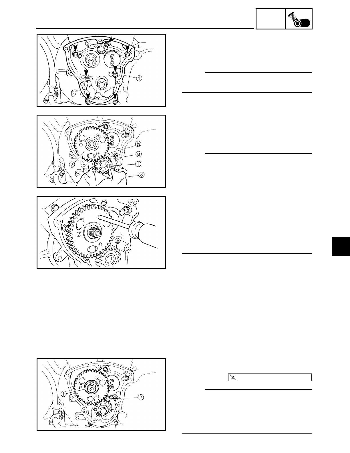
5 - 36
ENG
CAMSHAFTS
4. Install:
• camshaft cover 1
(along with the camshafts)
• oil delivery pipe 2
NOTE:
Tighten the camshaft cover bolts in stages
and in a crisscross pattern.
5. Install:
• straight keys
• camshaft drive gear 1
• camshaft driven gear 2
NOTE:
• Cover the crankcase hole with a clean rag
3 to prevent the straight keys from falling
into the crankcase.
• Align the punch mark a on the camshaft
drive gear 1 with the punch mark b on
the camshaft driven gear 2.
• Insert a cross-headed screwdriver into
one of the holes in the outer camshaft
driven gear and rotate the gear until the
teeth of both driven gears are aligned.
The teeth of both camshaft driven gears
must be aligned for installation.
6. Install:
• washers
• camshaft drive gear bolt
• camshaft driven gear nut
7. Tighten:
• camshaft driven gear nut 1
NOTE:
• Place a folded copper washer 2 between
the teeth of the camshaft drive gear and
camshaft driven gear in order to lock them.
• Do not damage the teeth of the camshaft
drive and camshaft driven gear.
T
R
.
.
52 Nm (5.2 m · kg, 37 ft · lb)
5
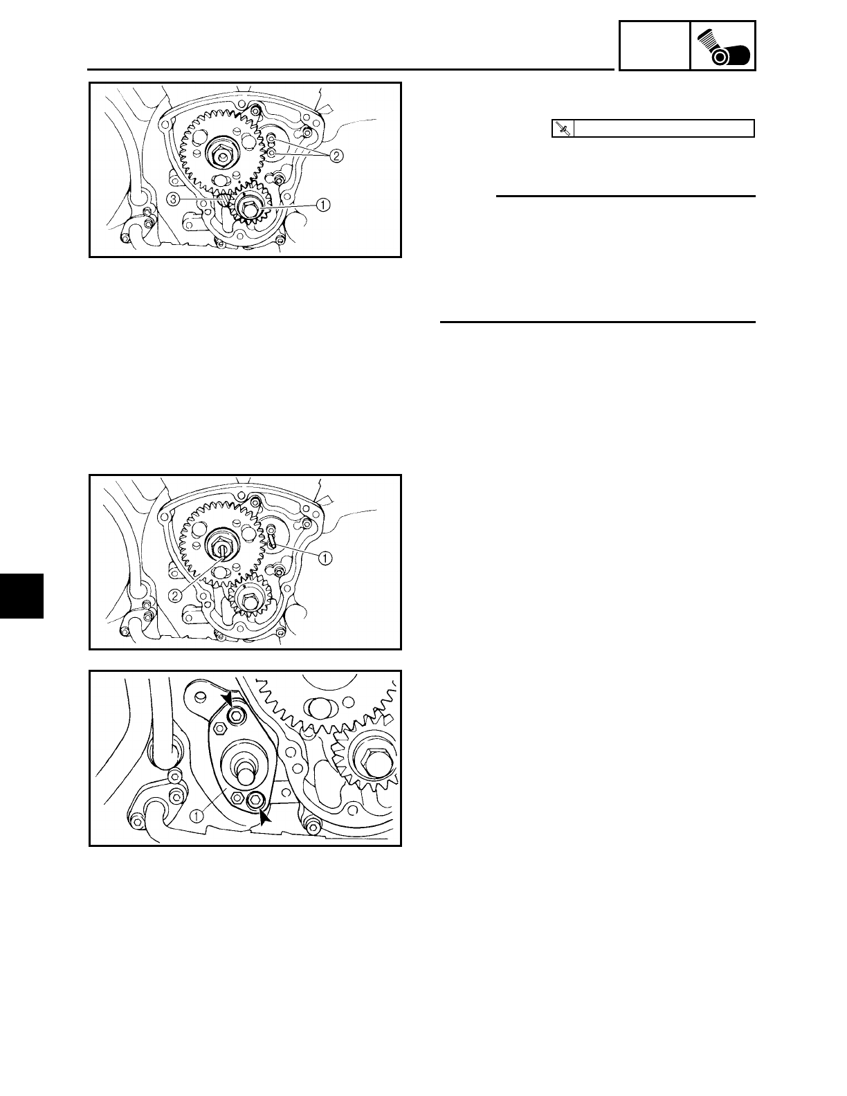
5 - 37
ENG
CAMSHAFTS
8. Tighten:
• camshaft drive gear bolt 1
• front cylinder camshaft end cover bolts
2
NOTE:
• Place a folded copper washer 3 between
the teeth of the camshaft drive gear and
camshaft driven gear in order to lock
them.
• Do not damage the teeth of the camshaft
drive and camshaft driven gear.
T
R
.
.
30 Nm (3.0 m · kg, 22 ft · lb)
9. Install:
• short decompression push rod 1
• long decompression push rod 2
10.Install:
• decompression solenoid 1
11.Install:
• valve lifters
• push rods
• rocker arms
• cylinder head covers
Refer to “ROCKER ARMS, PUSH RODS
AND VALVE LIFTERS”.
• exhaust pipes
• muffler
Refer to “ENGINE”.
5

5 - 38
ENG
CAMSHAFTS
12.Fill:
• oil tank
(with the specified amount of the recom-
mended engine oil)
Refer to “CHANGING THE ENGINE OIL”
in chapter 3.
13.Install:
• air filter case
• fuel tank
• rider seat
Refer to “AIR FILTER CASE”, “FUEL
TANK” and “SEATS AND SIDE COVERS”
in chapter 3.
5
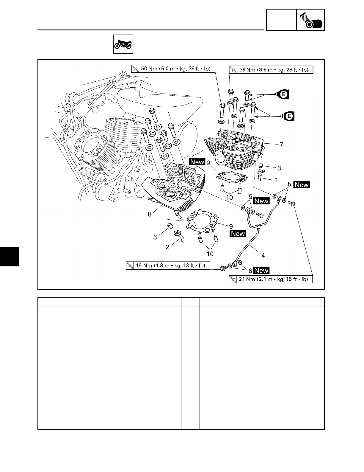
5 - 39
ENG
CYLINDER HEADS
CYLINDER HEADS
Order Job/Part Q’ty Remarks
Removing the cylinder head Remove the parts in the order listed.
Rider seat/fuel tank/air filter case Refer to “SEATS AND SIDE COVERS”,
“FUEL TANK” and “AIR FILTER CASE”
in chapter 3.
Carburetor/carburetor joint Refer to “CARBURETOR” in chapter 6.
Muffler/exhaust pipes Refer to “ENGINE”.
Rocker arms/push rod cover Refer to “ROCKER ARMS, PUSH RODS
AND VALVE LIFTERS”.
1 Reed valve case to rear cylinder pipe 1 Disconnect.
2 Reed valve case to front cylinder
pipe
1 Disconnect.
3 Gasket 2
4 Oil delivery pipe 1
5 Copper washer 4
5
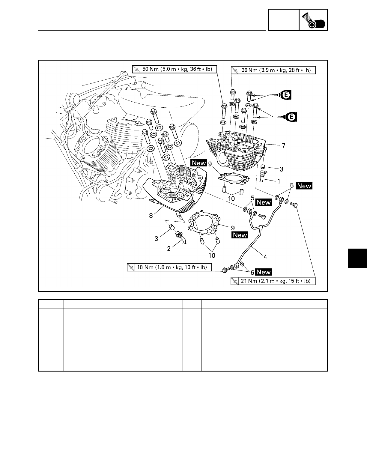
5 - 40
ENG
CYLINDER HEADS
Order Job/Part Q’ty Remarks
6 Copper washer 2
7 Rear cylinder head 1
8 Front cylinder head 1
9 Cylinder head gasket 2
10 Dowel pin 4
For installation, reverse the removal
procedure.
5
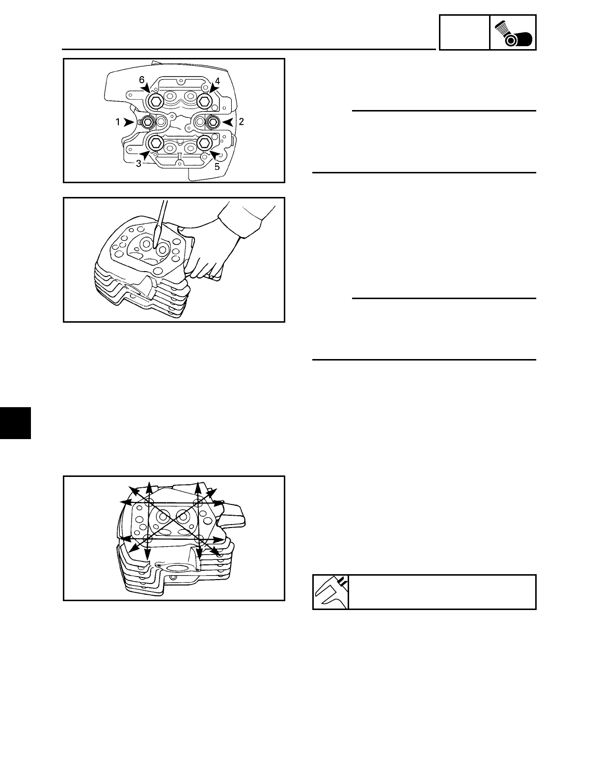
5 - 41
ENG
CYLINDER HEADS
REMOVING THE CYLINDER HEADS
1. Remove:
• cylinder head
NOTE:
• Loosen the nuts in the proper sequence.
• Follow the numerical order shown in the
illustration. Loosen each bolt 1/4 of a turn
at a time until all of the nuts are loose.
EAS00228
CHECKING THE CYLINDER HEADS
The following procedure applies to each
cylinder head.
1. Eliminate:
• combustion chamber carbon deposits
(with a rounded scraper)
NOTE:
Do not use a sharp instrument to avoid
damaging or scratching:
• spark plug bore threads
• valve seats
2. Check:
• cylinder head
Damage/scratches → Replace.
3. Measure:
• cylinder head warpage
Out of specification → Resurface the cyl-
inder head.
▼ ▼ ▼ ▼ ▼ ▼ ▼ ▼ ▼ ▼ ▼ ▼ ▼ ▼ ▼ ▼ ▼ ▼ ▼ ▼ ▼ ▼ ▼ ▼ ▼ ▼ ▼ ▼
a. Place a straightedge 1 and a thickness
gauge 2 across the cylinder head.
b. Measure the warpage.
c. If the limit is exceeded, resurface the cyl-
inder head as follows.
Maximum cylinder head warpage
0.10 mm (0.0039 in)
5
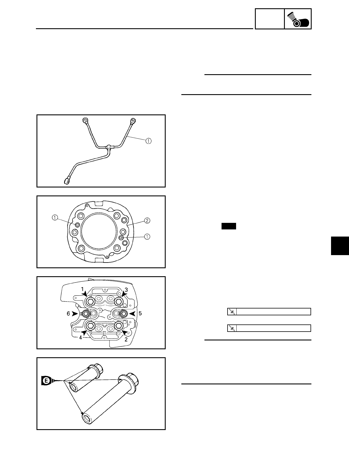
5 - 42
ENG
CYLINDER HEADS
d. Place a 400 ~ 600 grit wet sandpaper on
the surface plate and resurface the cylin-
der head using a figure-eight sanding
pattern.
NOTE:
To ensure an even surface, rotate the cylin-
der head several times.
▲ ▲ ▲ ▲ ▲ ▲ ▲ ▲ ▲ ▲ ▲ ▲ ▲ ▲ ▲ ▲ ▲ ▲ ▲ ▲ ▲ ▲ ▲ ▲ ▲ ▲ ▲ ▲
CHECKING THE OIL DELIVERY PIPE
1. Check:
• oil delivery pipe 1
Damage → Replace.
Obstruction → Wash and blow out with
compressed air.
EAS00232
INSTALLING THE CYLINDER HEADS
1. Install:
• dowel pins 1
• gasket 2New
2. Install:
• cylinder heads
• washers
• cylinder head nuts (M12: 1 ~ 4)
• cylinder head nuts (M10: 5, 6)
NOTE:
• Lubricate the cylinder head nuts with
engine oil.
• Tighten the cylinder head nuts in the
proper tightening sequence as shown and
torque them in two stages.
T
R
.
.
50 Nm (5.0 m · kg, 36 ft · lb)
T
R
.
.
39 Nm (3.9 m · kg, 28 ft · lb)
5
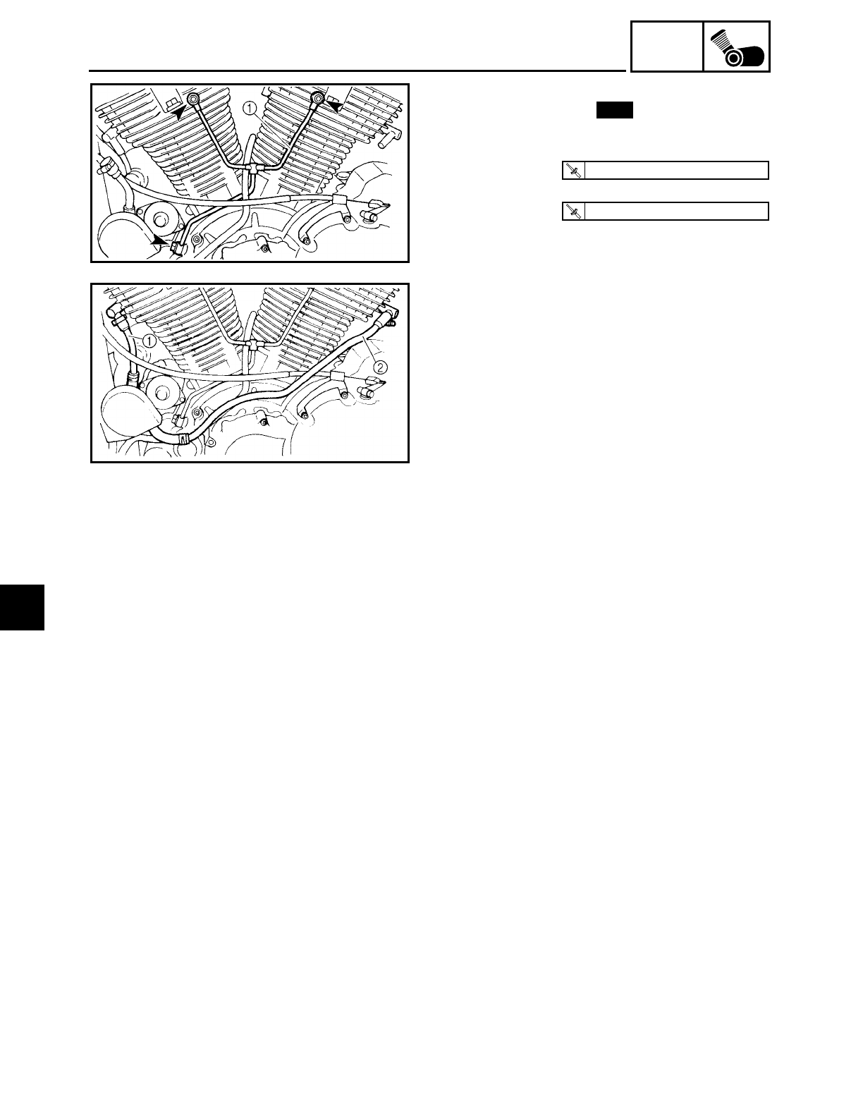
5 - 43
ENG
CYLINDER HEADS
3. Install:
• copper washers
• oil delivery pipe 1
• oil delivery pipe bolts (M10)
• oil delivery pipe bolt (M8)
New
T
R
.
.
21 Nm (2.1 m · kg, 15 ft · lb)
T
R
.
.
18 Nm (1.8 m · kg, 13 ft · lb)
4. Install:
• gaskets
• reed valve case to front cylinder pipe 1
• reed valve case to rear cylinder pipe 2
5. Install:
• rocker arms
• cylinder head covers
Refer to “ROCKER ARMS, PUSH RODS
AND VALVE LIFTERS”.
• muffler
• exhaust pipes
Refer to “ENGINE”.
• carburetor
Refer to “CARBURETOR” in chapter 6.
• air filter case
• fuel tank
• rider seat
Refer to “AIR FILTER CASE”, “FUEL
TANK” and “SEATS AND SIDE COVERS”
in chapter 3.
5
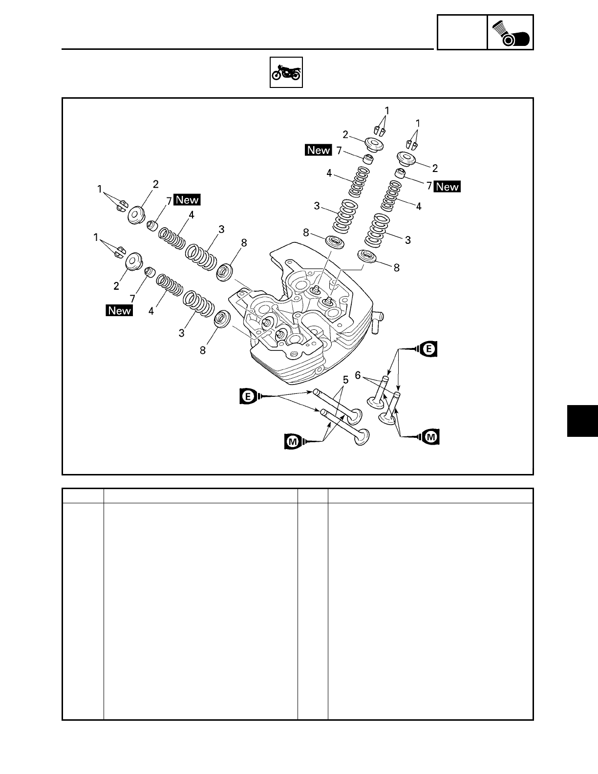
5 - 44
ENG
VALVES AND VALVE SPRINGS
VALVES AND VALVE SPRINGS
Order Job/Part Q’ty Remarks
Removing the valves and valve
springs
Remove the parts in the order listed.
The following procedure applies to
both cylinders.
Cylinder head Refer to “CYLINDER HEADS”.
1 Valve cotter 4
2 Upper spring seat 4
3 Outer valve spring 4
4 Inner valve spring 4
5 Intake valve 2
6 Exhaust valve 2
7 Valve oil seal 4
8 Lower spring seat 4
For installation, reverse the removal
procedure.
5
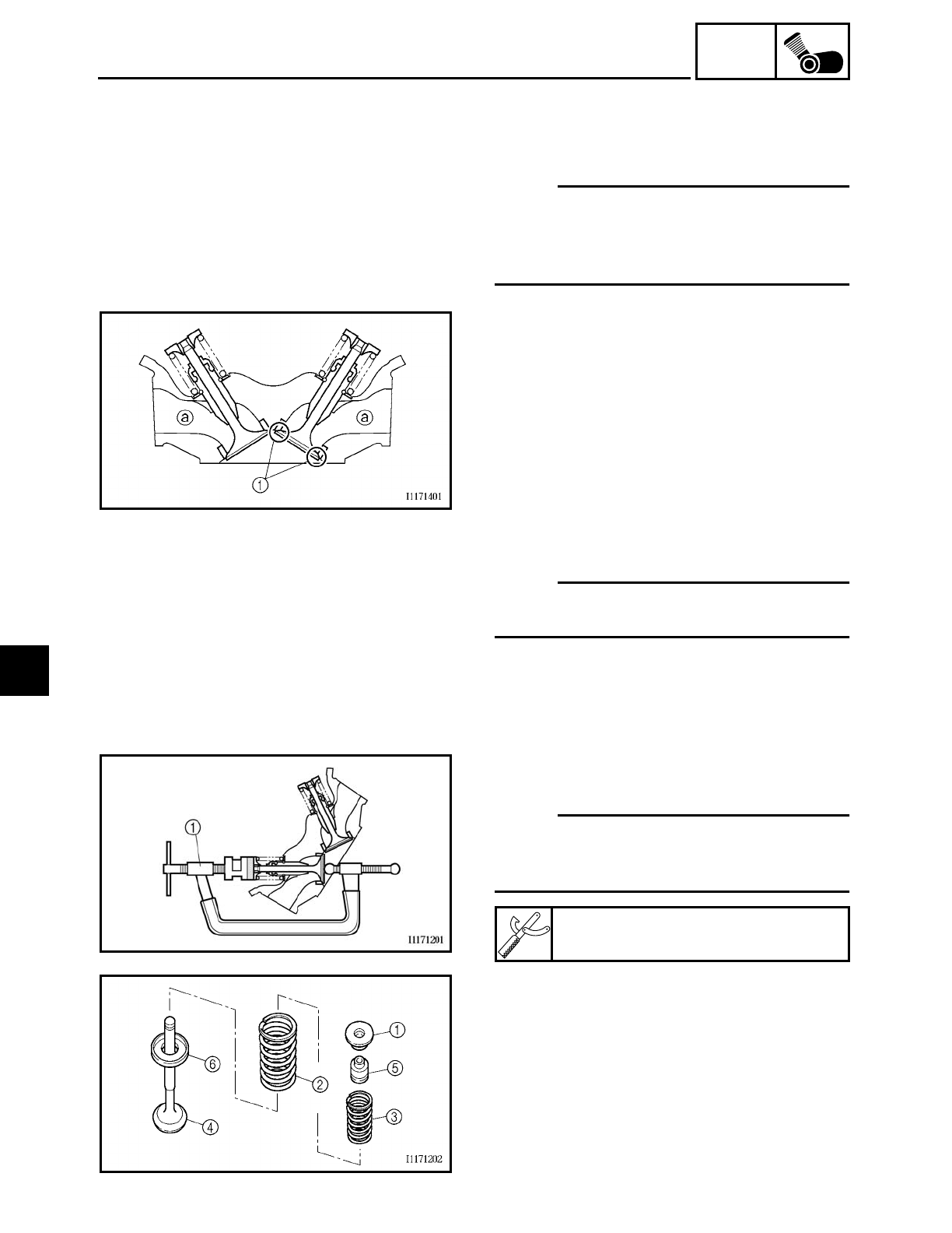
5 - 45
ENG
VALVES AND VALVE SPRINGS
EAS00238
REMOVING THE VALVES
The following procedure applies to all of
the valves and related components.
NOTE:
Before removing the internal parts of the
cylinder head (e.g., valves, valve springs,
valve seats), make sure the valves properly
seal.
1. Check:
• valve
(for leakage)
Leakage at the valve seat → Check the
valve face, valve seat, and valve seat
width.
Refer to “CHECKING THE VALVE
SEATS”.
▼ ▼ ▼ ▼ ▼ ▼ ▼ ▼ ▼ ▼ ▼ ▼ ▼ ▼ ▼ ▼ ▼ ▼ ▼ ▼ ▼ ▼ ▼ ▼ ▼ ▼ ▼ ▼
a. Pour a clean solvent a into the intake
and exhaust ports.
b. Check that the valves properly seal.
NOTE:
There should be no leakage at the valve
seat 1.
▲ ▲ ▲ ▲ ▲ ▲ ▲ ▲ ▲ ▲ ▲ ▲ ▲ ▲ ▲ ▲ ▲ ▲ ▲ ▲ ▲ ▲ ▲ ▲ ▲ ▲ ▲ ▲
2. Remove:
• valve cotters
NOTE:
Remove the valve cotters by compressing
the valve springs with the valve spring
compressor 1.
Valve spring compressor
YM-04019
3. Remove:
• upper spring seat 1
• outer valve spring 2
• inner valve spring 3
• valve 4
• oil seal 5
• lower spring seat 6
5
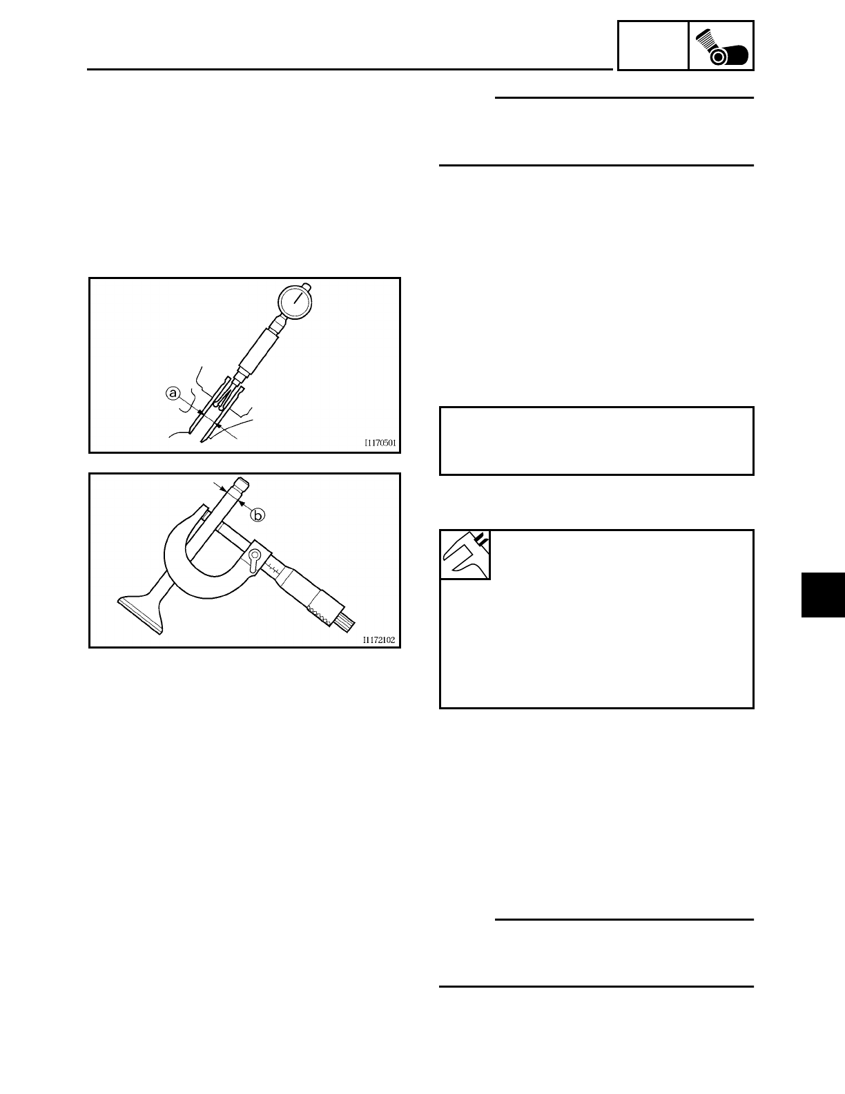
5 - 46
ENG
VALVES AND VALVE SPRINGS
NOTE:
Identify the position of each part very care-
fully so that it can be reinstalled in its origi-
nal place.
EAS00239
CHECKING THE VALVES AND VALVE
GUIDES
The following procedure applies to all of
the valves and valve guides.
1. Measure:
• valve stem-to-valve guide clearance
Out of specification → Replace the valve
guide.
Valve stem-to-valve guide clearance =
Valve guide inside diameter a –
Valve stem diameter b
Valve stem-to-valve guide clear-
ance
Intake
0.010 ~ 0.037 mm
(0.0004 ~ 0.0015 in)
<Limit>: 0.08 mm (0.0031 in)
Exhaust
0.025 ~ 0.052 mm
(0.0006 ~ 0.0020 in)
<Limit>: 0.1 mm (0.004 in)
2. Replace:
• valve guide
NOTE:
To ease valve guide removal and installa-
tion, and to maintain the correct fit, heat the
cylinder head to 100 ˚C (212 ˚F) in an oven.
5
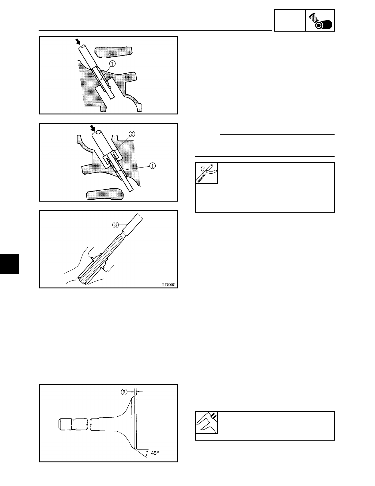
5 - 47
ENG
VALVES AND VALVE SPRINGS
▼ ▼ ▼ ▼ ▼ ▼ ▼ ▼ ▼ ▼ ▼ ▼ ▼ ▼ ▼ ▼ ▼ ▼ ▼ ▼ ▼ ▼ ▼ ▼ ▼ ▼ ▼ ▼
a. Remove the valve guide with the valve
guide remover
1.
b. Install the new valve guide with the valve
guide installer
2 and valve guide
remover
1.
c. After installing the valve guide, bore the
valve guide with the valve guide reamer
3 to obtain the proper valve-stem-to-
valve-guide clearance.
NOTE:
After replacing the valve guide, reface the
valve seat.
▲ ▲ ▲ ▲ ▲ ▲ ▲ ▲ ▲ ▲ ▲ ▲ ▲ ▲ ▲ ▲ ▲ ▲ ▲ ▲ ▲ ▲ ▲ ▲ ▲ ▲ ▲ ▲
Valve guide remover (6 mm)
YM-4064-A
Valve guide installer (6 mm)
YM-04065-A
Valve guide reamer (6 mm)
YM-04066
3. Eliminate:
• carbon deposits
(from the valve face and valve seat)
4. Check:
• valve face
Pitting/wear → Grind the valve face.
• valve stem end
Mushroom shape or diameter larger
than the body of the valve stem →
Replace the valve.
5. Measure:
• valve margin thickness a
Out of specification → Replace the valve.
Valve margin thickness
0.7 ~ 1.3 mm (0.028 ~ 0.051 in)
<Limit>: 0.4 mm (0.016 in)
5
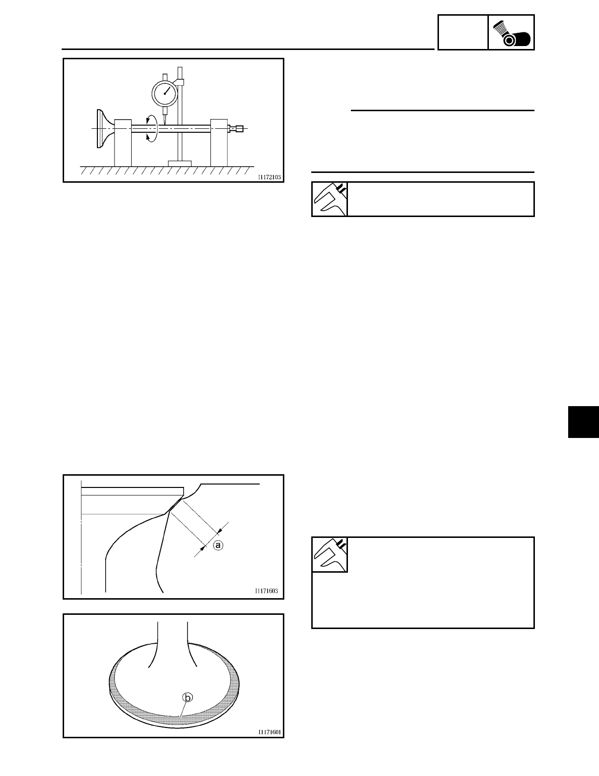
5 - 48
ENG
VALVES AND VALVE SPRINGS
6. Measure:
• valve stem runout
Out of specification
→ Replace the valve.
NOTE:
• When installing a new valve, always
replace the valve guide.
• If the valve is removed or replaced,
always replace the oil seal.
Valve stem runout
0.01 mm (0.0004 in)
EAS00240
CHECKING THE VALVE SEATS
The following procedure applies to all of
the valves and valve seats.
1. Eliminate:
• carbon deposits
(from the valve face and valve seat)
2. Check:
• valve seat
Pitting/wear → Replace the cylinder
head.
3. Measure:
• valve seat width a
Out of specification → Replace the cylin-
der head.
▼ ▼ ▼ ▼ ▼ ▼ ▼ ▼ ▼ ▼ ▼ ▼ ▼ ▼ ▼ ▼ ▼ ▼ ▼ ▼ ▼ ▼ ▼ ▼ ▼ ▼ ▼ ▼
a. Apply Mechanic’s blueing dye (Dykem)
b onto the valve face.
b. Install the valve into the cylinder head.
c. Press the valve through the valve guide
and onto the valve seat to make a clear
impression.
Valve seat width
Intake: 0.9 ~ 1.1 mm
(0.035 ~ 0.043 in)
<Limit>: 2.0 mm (0.079 in)
Exhaust: 0.9 ~ 1.1 mm
(0.035 ~ 0.043 in)
<Limit>: 2.0 mm (0.079 in)
5
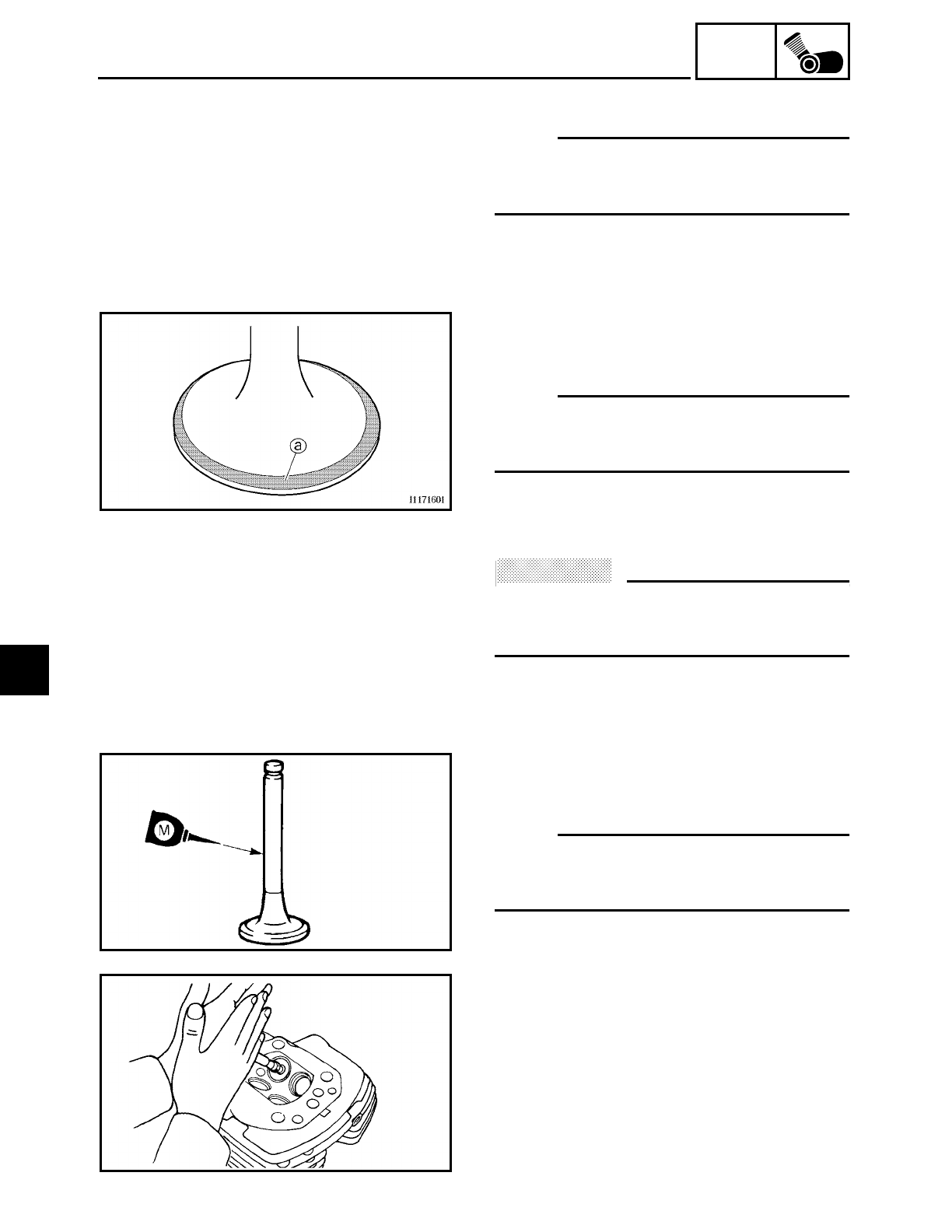
5 - 49
ENG
VALVES AND VALVE SPRINGS
d. Measure the valve seat width.
NOTE:
Where the valve seat and valve face con-
tacted one another, the blueing will have
been removed.
▲ ▲ ▲ ▲ ▲ ▲ ▲ ▲ ▲ ▲ ▲ ▲ ▲ ▲ ▲ ▲ ▲ ▲ ▲ ▲ ▲ ▲ ▲ ▲ ▲ ▲ ▲ ▲
4. Lap:
• valve face
• valve seat
NOTE:
After replacing the cylinder head or replac-
ing the valve and valve guide, the valve seat
and valve face should be lapped.
▼ ▼ ▼ ▼ ▼ ▼ ▼ ▼ ▼ ▼ ▼ ▼ ▼ ▼ ▼ ▼ ▼ ▼ ▼ ▼ ▼ ▼ ▼ ▼ ▼ ▼ ▼ ▼
a. Apply a coarse lapping compound
a to
the valve face.
ACHTUNG:
CAUTION:
Do not let the lapping compound enter the
gap between the valve stem and the valve
guide.
b. Apply molybdenum disulfide oil onto the
valve stem.
c. Install the valve into the cylinder head.
d. Turn the valve until the valve face and
valve seat are evenly polished, then
clean off all of the lapping compound.
NOTE:
For the best lapping results, lightly tap the
valve seat while rotating the valve back and
forth between your hands.
e. Apply a fine lapping compound to the
valve face and repeat the above steps.
f. After every lapping procedure, be sure to
clean off all of the lapping compound
from the valve face and valve seat.
5
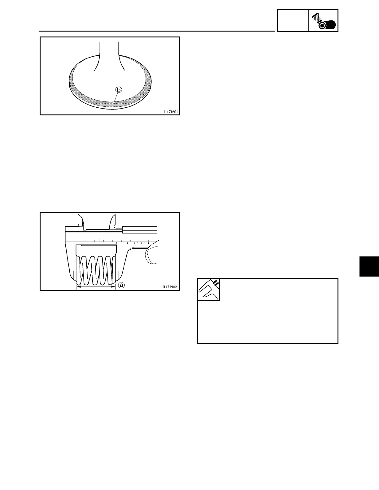
5 - 50
ENG
VALVES AND VALVE SPRINGS
g. Apply Mechanic’s blueing dye (Dykem)
b onto the valve face.
h. Install the valve into the cylinder head.
i. Press the valve through the valve guide
and onto the valve seat to make a clear
impression.
j. Measure the valve seat width again. If
the valve seat width is out of specifica-
tion, reface and lap the valve seat.
▲ ▲ ▲ ▲ ▲ ▲ ▲ ▲ ▲ ▲ ▲ ▲ ▲ ▲ ▲ ▲ ▲ ▲ ▲ ▲ ▲ ▲ ▲ ▲ ▲ ▲ ▲ ▲
EAS00241
CHECKING THE VALVE SPRINGS
The following procedure applies to all of
the valve springs.
1. Measure:
• valve spring free length a
Out of specification → Replace the valve
spring.
Valve spring free length (intake
and exhaust)
Inner valve spring
38.26 mm (1.51 in)
<Limit>: 36.26 mm (1.43 in)
Outer valve spring
43.25 mm (1.70 in)
<Limit>: 41.26 mm (1.62 in)
5
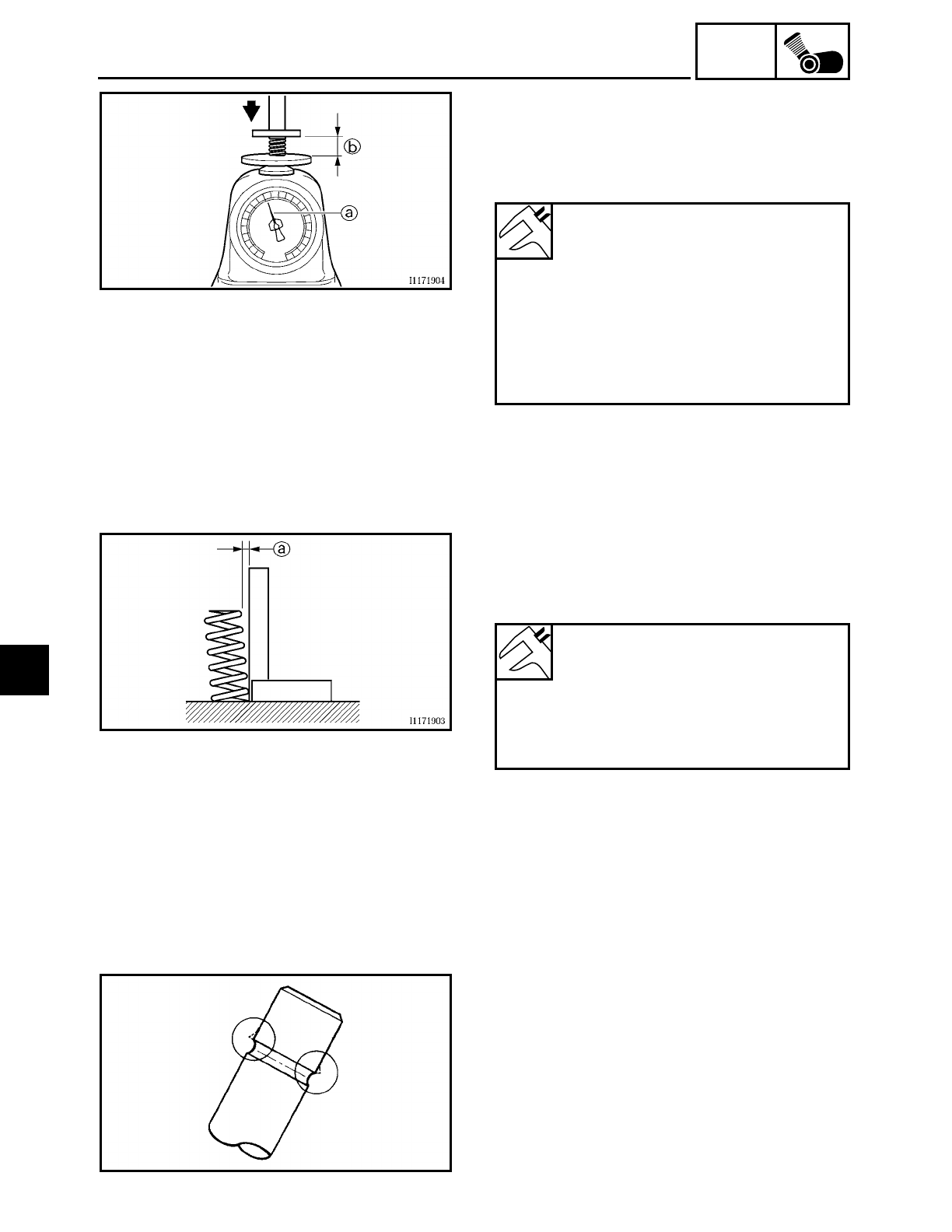
5 - 51
ENG
VALVES AND VALVE SPRINGS
2. Measure:
• compressed valve spring force
a
Out of specification
→ Replace the valve
spring.
bInstalled length
Compressed valve spring force
(installed)
Intake and exhaust inner valve
spring
6.3 ~ 7.3 kg at 29.0 mm
(13.9 ~ 16.1 lb at 1.14 in)
Intake and exhaust outer valve
spring
13.9 ~ 16.1 kg at 31.0 mm
(30.6 ~ 35.5 lb at 1.22 in)
3. Measure:
• valve spring tilt
a
Out of specification → Replace the valve
spring.
Maximum valve spring tilt
Intake and exhaust inner valve
spring
2.4 mm (0.094 in)
Intake and exhaust outer valve
spring
2.4 mm (0.094 in)
EAS00246
INSTALLING THE VALVES
The following procedure applies to all of
the valves and related components.
1. Deburr:
• valve stem end
(with an oil stone)
5
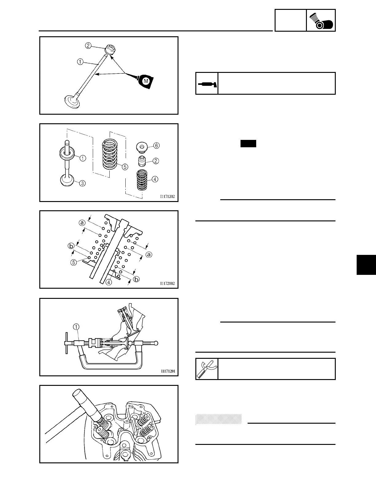
5 - 52
ENG
2. Lubricate:
• valve stem
1
• oil seal
2
(with the recommended lubricant)
Recommended lubricant
Molybdenum disulfide oil
3. Install:
• lower spring seat
1
• oil seal
2
• valve
3
• inner valve spring
4
• outer valve spring
5
• upper spring seat 6
(into the cylinder head)
NOTE:
Install the valve springs with the larger
pitch a facing up.
bSmaller pitch
New
4. Install:
• valve cotters
NOTE:
Install the valve cotters by compressing the
valve springs with the valve spring com-
pressor 1.
Valve spring compressor
YM-04019
5. To secure the valve cotters onto the
valve stem, lightly tap the valve tip with
a soft-face hammer.
ACHTUNG:
CAUTION:
Hitting the valve tip with excessive force
could damage the valve.
6. Install:
• cylinder head
Refer to “CYLINDER HEADS”.
VALVES AND VALVE SPRINGS
5
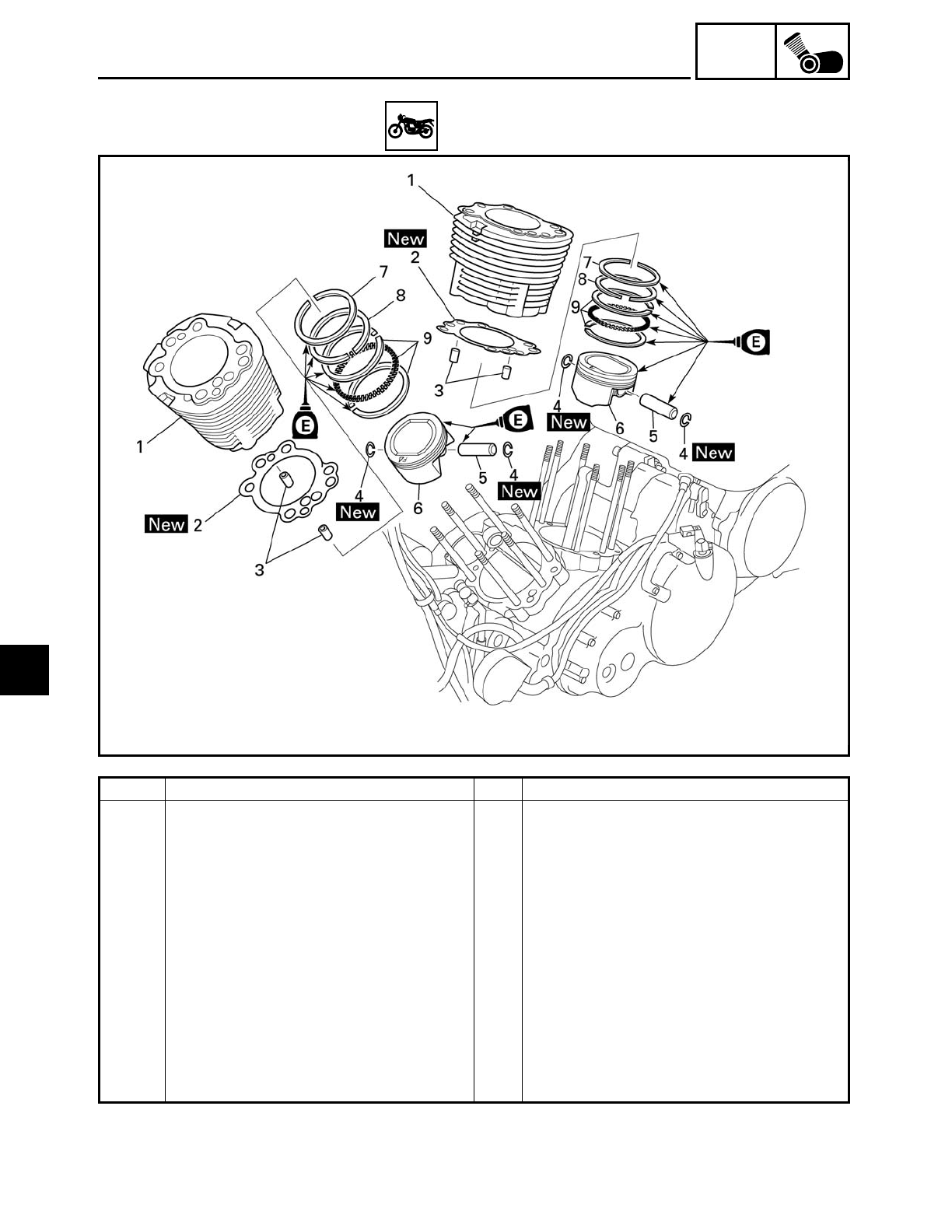
5 - 53
ENG
CYLINDERS AND PISTONS
EAS00251
CYLINDERS AND PISTONS
Order Job/Part Q’ty Remarks
Removing the cylinders and pistons Remove the parts in the order listed.
Cylinder heads Refer to “CYLINDER HEAD”.
1 Cylinder 2
2 Cylinder gasket 2
3 Dowel pin 4
4 Piston pin clip 4
5 Piston pin 2
6 Piston 2
7 Top ring 2
8 2nd ring 2
9 Oil ring 2
For installation, reverse the removal
procedure.
5
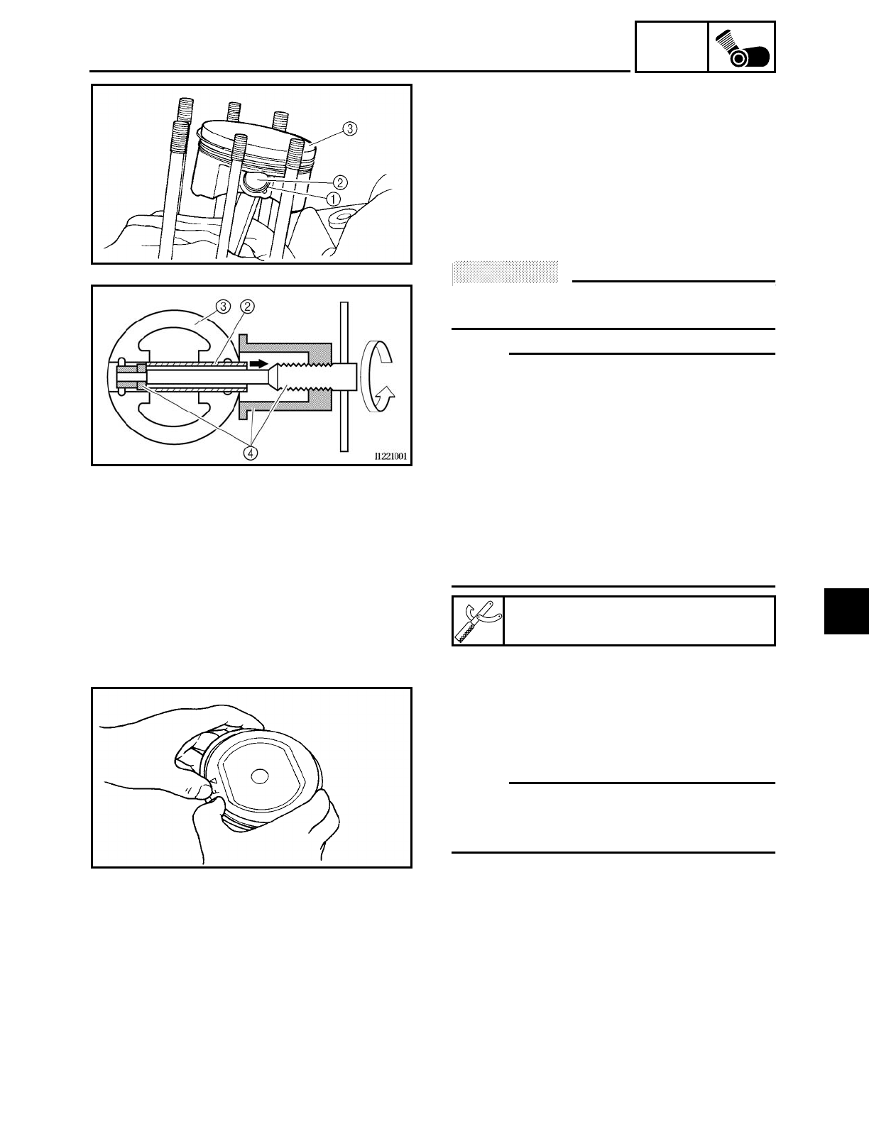
5 - 54
ENG
CYLINDERS AND PISTONS
EAS00254
REMOVING THE CYLINDERS AND
PISTONS
The following procedure applies to all of
the cylinders and pistons.
1. Remove:
• piston pin clip 1
• piston pin 2
• piston 3
ACHTUNG:
CAUTION:
Do not use a hammer to drive the piston
pin out.
NOTE:
• Before removing the piston pin clip, cover
the crankcase opening with a clean rag to
prevent the piston pin clip from falling
into the crankcase.
• For reference during installation, put an
identification mark on each piston crown.
• Before removing the piston pin, deburr
the piston pin clip groove and the piston
pin bore area. If both areas are deburred
and the piston pin is still difficult to
remove, remove it with the piston pin
puller 4.
Piston pin puller
YU-01304
2. Remove:
• top ring
• 2nd ring
• oil ring
NOTE:
When removing a piston ring, open the end
gap with your fingers and lift the other side
of the ring over the piston crown.
EAS00258
CHECKING THE CYLINDERS AND PISTONS
The following procedure applies to all of
the cylinders and pistons.
1. Check:
• piston wall
• cylinder wall
Vertical scratches → Replace the cylin-
der, and the piston and piston rings as a
set.
5
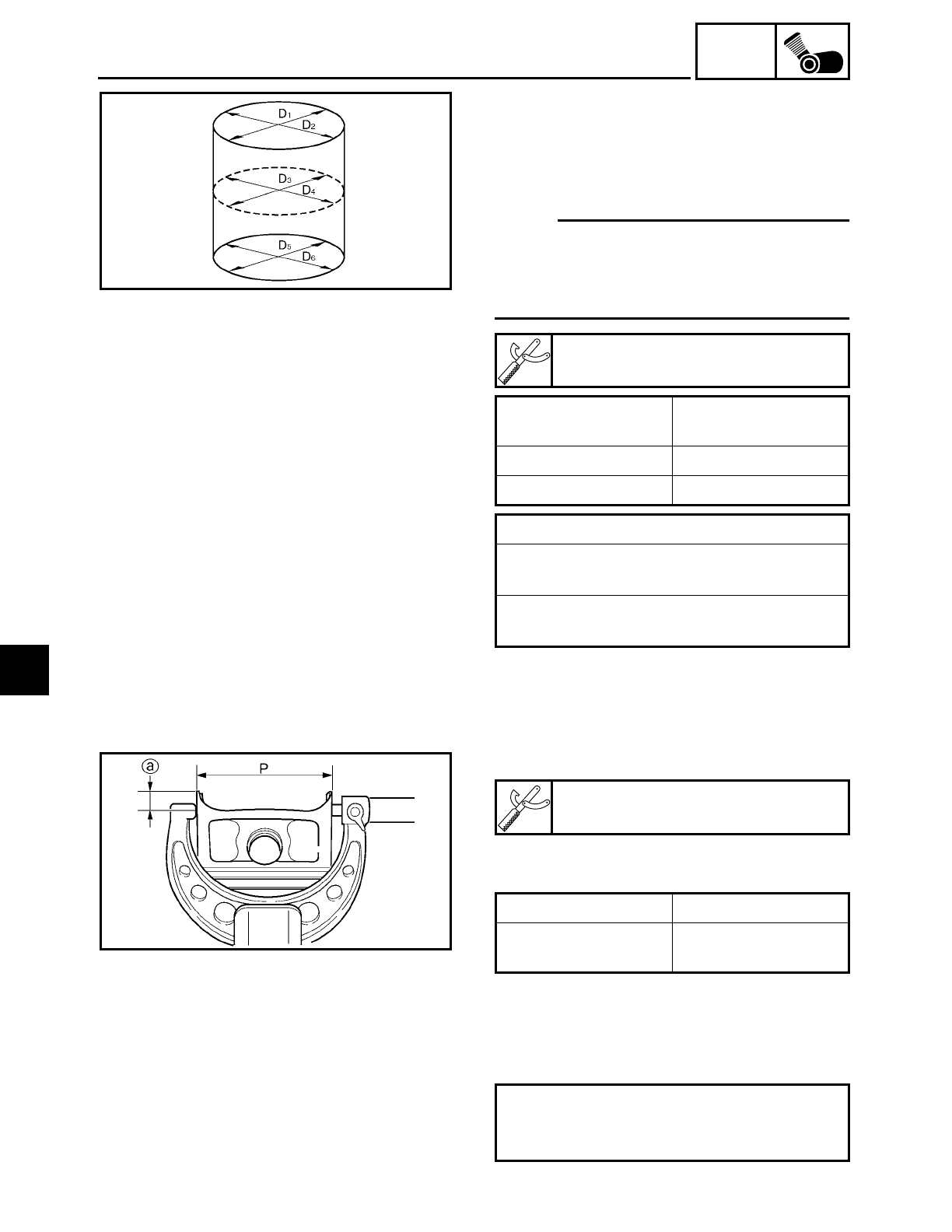
5 - 55
ENG
CYLINDERS AND PISTONS
2. Measure:
• piston-to-cylinder clearance
▼ ▼ ▼ ▼ ▼ ▼ ▼ ▼ ▼ ▼ ▼ ▼ ▼ ▼ ▼ ▼ ▼ ▼ ▼ ▼ ▼ ▼ ▼ ▼ ▼ ▼ ▼ ▼
a. Measure cylinder bore “C” with the cyl-
inder bore gauge.
NOTE:
Measure cylinder bore “C” by taking side-
to-side and front-to-back measurements of
the cylinder. Then, find the average of the
measurements.
b. If out of specification, replace the cylin-
der, and the piston and piston rings as a
set.
c. Measure piston skirt diameter “P” with
the micrometer.
a5 mm (0.20 in) from the bottom edge of the
piston
d. If out of specification, replace the piston
and piston rings as a set.
e. Calculate the piston-to-cylinder clear-
ance with the following formula.
Cylinder bore gauge
YU-03017
Cylinder bore “C” 95.000 ~ 95.010 mm
(3.7402 ~ 3.7406 in)
Maximum taper “T” 0.05 mm (0.0016 in)
Out of round “R” 0.05 mm (0.0016 in)
“C” = maximum of D1~ D6
“T” = maximum of D1 or D2 – maximum of
D5 or D6
“R” = maximum of D1, D3 or D5
– minimum of D2, D4 or D6
Micrometer
YU-03009
Piston size “P”
Standard 94.960 ~ 94.975 mm
(3.7386 ~ 3.7392 in)
Piston-to-cylinder clearance =
Cylinder bore “C” –
Piston skirt diameter “P”
5
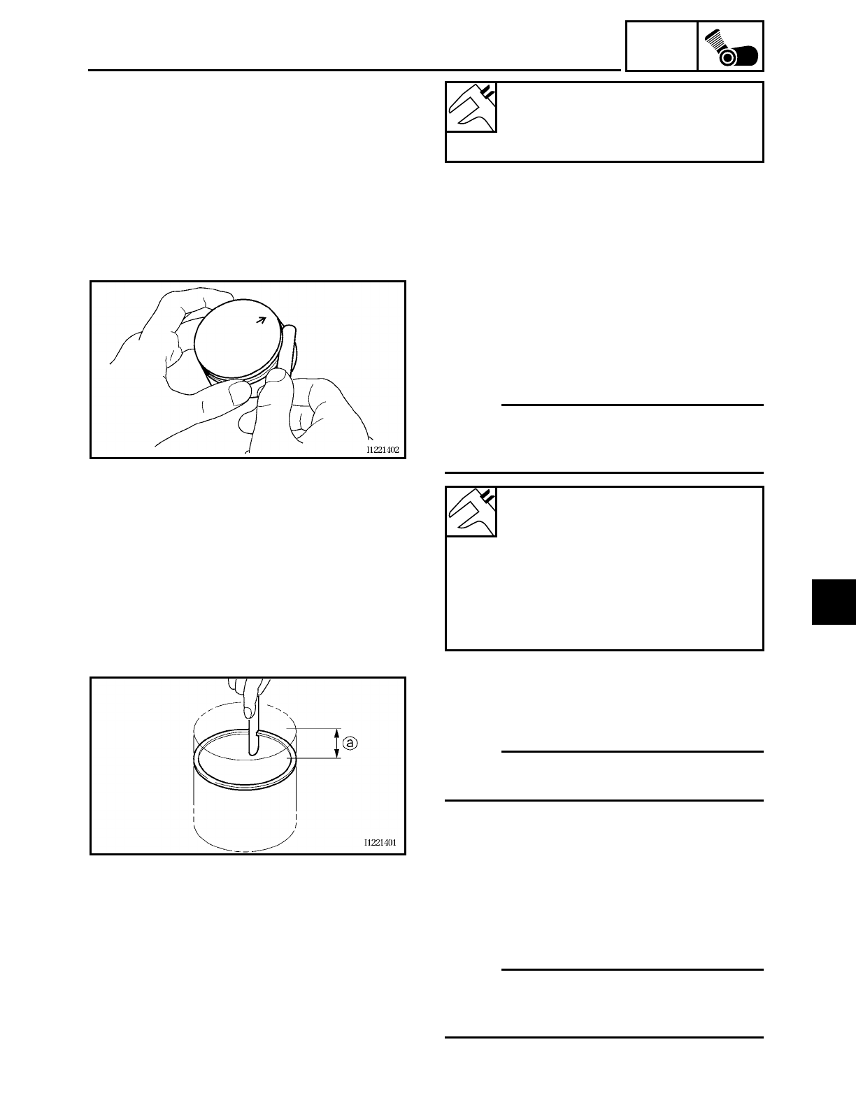
5 - 56
ENG
CYLINDERS AND PISTONS
f. If out of specification, replace the cylin-
der, and the piston and piston rings as a
set.
▲ ▲ ▲ ▲ ▲ ▲ ▲ ▲ ▲ ▲ ▲ ▲ ▲ ▲ ▲ ▲ ▲ ▲ ▲ ▲ ▲ ▲ ▲ ▲ ▲ ▲ ▲ ▲
Piston-to-cylinder clearance
0.025 ~ 0.050 mm
(0.001 ~ 0.002 in)
<Limit>: 0.15 mm (0.006 in)
EAS00263
CHECKING THE PISTON RINGS
1. Measure:
• piston ring side clearance
Out of specification → Replace the piston
and piston rings as a set.
NOTE:
Before measuring the piston ring side clear-
ance, eliminate any carbon deposits from
the piston ring grooves and piston rings.
Piston ring side clearance
Top ring
0.03 ~ 0.08 mm
(0.0012 ~ 0.0031 in)
<Limit>: 0.12 mm (0.0047 in)
2nd ring
0.03 ~ 0.07 mm
(0.0012 ~ 0.0028 in)
<Limit>: 0.12 mm (0.0047 in)
2. Install:
• piston ring
(into the cylinder)
NOTE:
Level the piston ring in the cylinder with the
piston crown.
a10 mm (0.39 in)
3. Measure:
• piston ring end gap
Out of specification → Replace the piston
ring.
NOTE:
The oil ring expander spacer’s end gap can-
not be measured. If the oil ring rail’s gap is
excessive, replace all three piston rings.
5
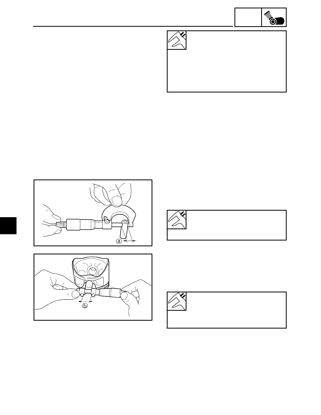
5 - 57
ENG
CYLINDERS AND PISTONS
Piston ring end gap
Top ring
0.30 ~ 0.45 mm (0.012 ~ 0.018 in)
<Limit>: 0.65 mm (0.026 in)
2nd ring
0.30 ~ 0.45 mm (0.012 ~ 0.018 in)
<Limit>: 0.80 mm (0.031 in)
Oil ring
0.2 ~ 0.7 mm (0.008 ~ 0.028 in)
EAS00266
CHECKING THE PISTON PINS
The following procedure applies to all of
the piston pins.
1. Check:
• piston pin
Blue discoloration/grooves → Replace
the piston pin and then check the lubrica-
tion system.
2. Measure:
• piston pin outside diameter a
Out of specification → Replace the piston
pin.
Piston pin outside diameter
21.991 ~ 22.000 mm
(0.8658 ~ 0.8661 in)
<Limit>: 21.971 mm (0.8650 in)
3. Measure:
• piston pin bore diameter (in the piston)
b
Out of specification → Replace the piston
pin.
Piston pin bore diameter (in the
piston)
22.004 ~ 22.015 mm
(0.8663 ~ 0.8667 in)
<Limit>: 22.045 mm (0.8679 in)
5
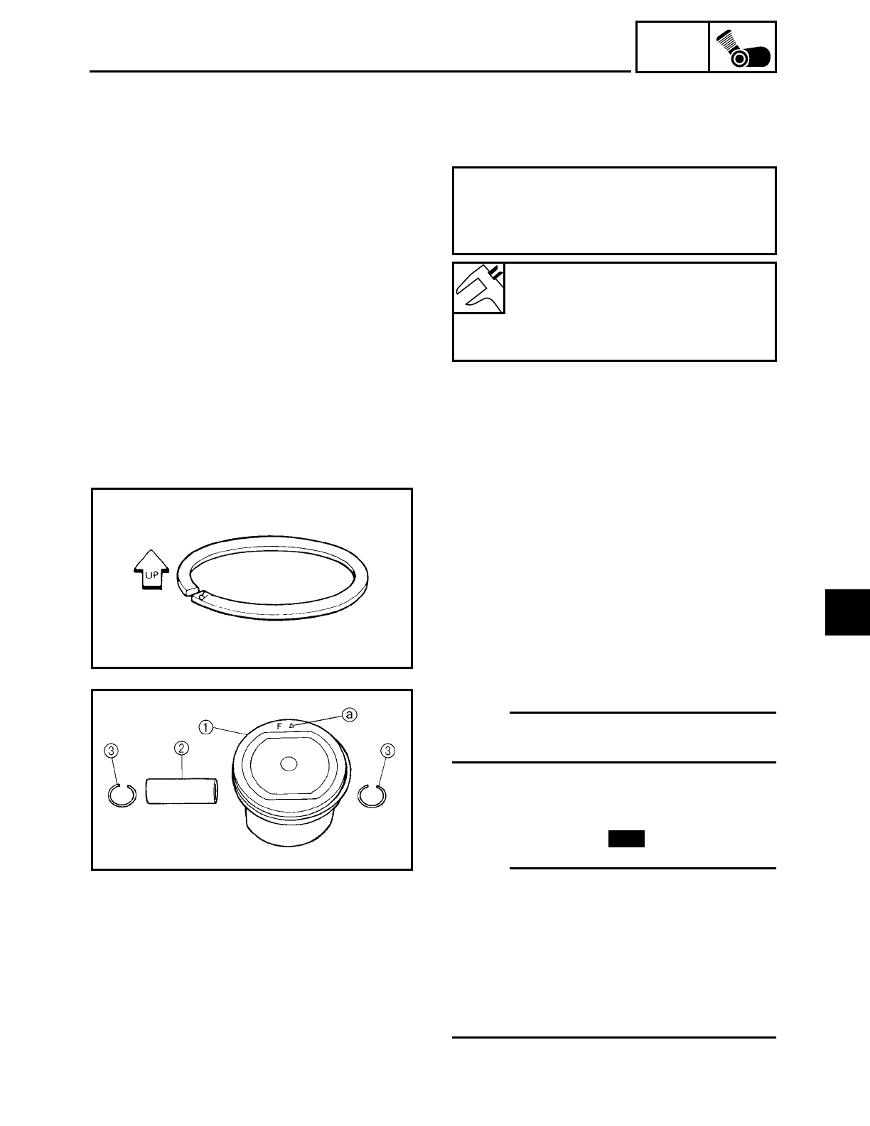
5 - 58
ENG
CYLINDERS AND PISTONS
4. Calculate:
• piston pin-to-piston pin bore clearance
Out of specification → Replace the piston
pin.
Piston pin-to-piston pin bore clearance =
Piston pin bore diameter (in the pis-
ton) b –
Piston pin outside diameter a
Piston pin-to-piston pin bore
clearance
0.004 ~ 0.024 mm
(0.00016 ~ 0.00094 in)
<Limit>: 0.074 mm (0.0029 in)
EAS00268
INSTALLING THE PISTONS AND
CYLINDERS
The following procedure applies to all of
the pistons and cylinders.
1. Install:
• top ring
• 2nd ring
• lower oil ring rail
• upper oil ring rail
• oil ring expander
NOTE:
Be sure to install the piston rings so that the
manufacturer’s marks or numbers face up.
2. Install:
• piston 1
• piston pin 2
• piston pin clip 3
NOTE:
• Apply engine oil onto the piston pin.
• Make sure the “arrow” mark a on the pis-
ton faces towards the front of the motor-
cycle.
• Before installing the piston pin clip, cover
the crankcase opening with a clean rag to
prevent the clip from falling into the
crankcase.
New
5
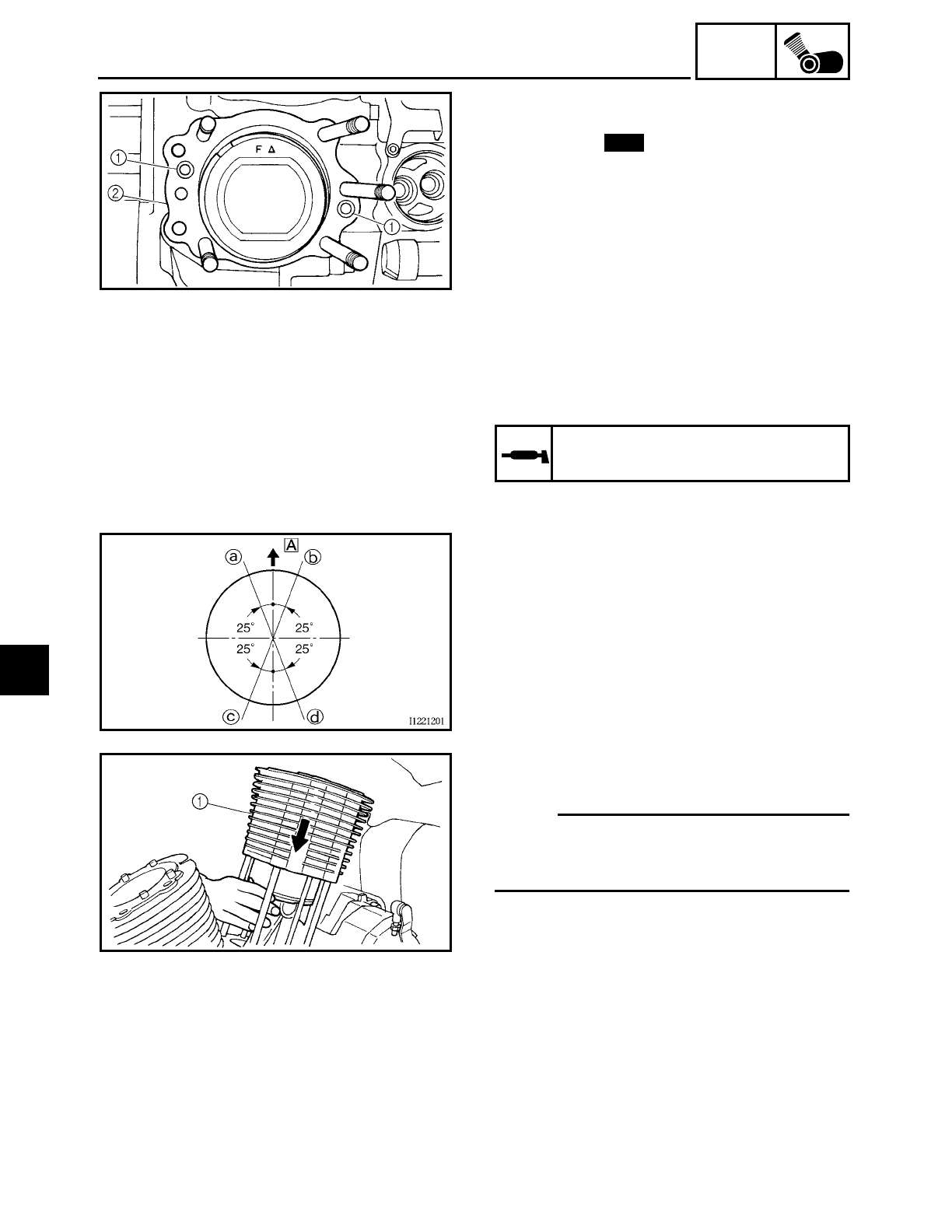
5 - 59
ENG
CYLINDERS AND PISTONS
3. Install:
• dowel pins 1
• gasket 2New
4. Lubricate:
• piston
• piston rings
• cylinder
(with the recommended lubricant)
Recommended lubricant
Engine oil
5. Offset:
• piston ring end gaps
aTop ring
bLower oil ring rail
cUpper oil ring rail
d2nd ring
ÅFront of the motorcycle
6. Install:
• cylinder 1
NOTE:
While compressing the piston rings with
one hand, install the cylinder with the other
hand.
5
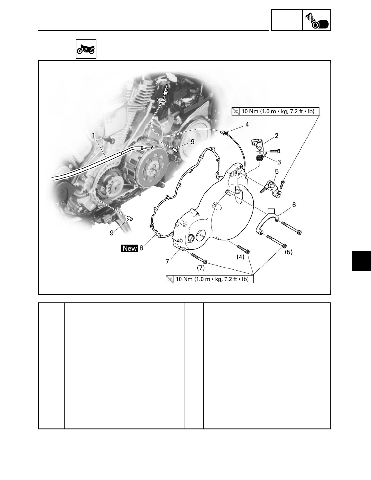
5 - 60
ENG
CLUTCH
EAS00273
CLUTCH
Order Job/Part Q’ty Remarks
Removing the clutch cover Remove the parts in the order listed.
Left side cover Refer to “SEATS AND SIDE COVERS”
in chapter 3.
Engine left side cover Refer to “ROCKER ARMS, PUSH RODS
AND VALVE LIFTERS”.
Engine oil Drain.
1 Clutch cable 1 Disconnect.
2 Pull lever 1
3 Pull lever spring 1
4 Pickup coil coupler 1 Disconnect.
5 Shift arm 1
6 Clutch cable holder 1
7 Clutch cover 1
5
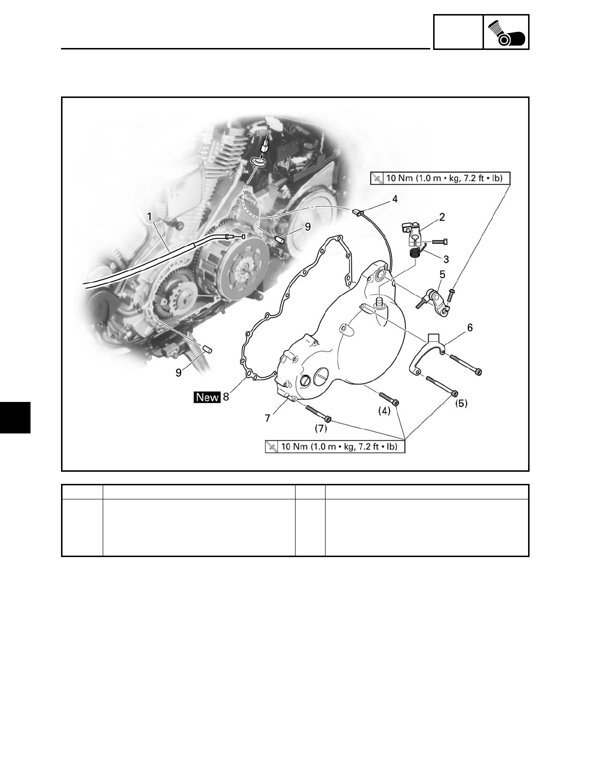
5 - 61
ENG
CLUTCH
Order Job/Part Q’ty Remarks
8 Clutch cover gasket 1
9 Dowel pin 1
For installation, reverse the removal
procedure.
5
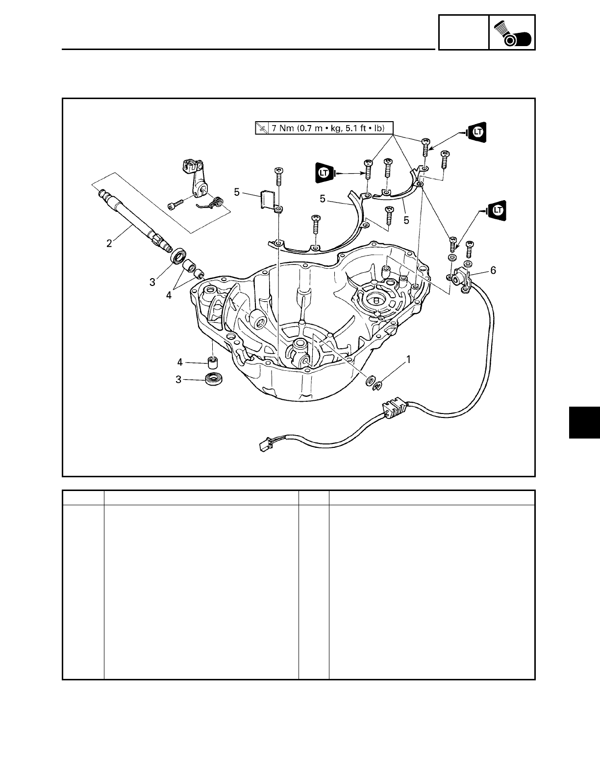
5 - 62
ENG
CLUTCH
Order Job/Part Q’ty Remarks
Removing the pull lever shaft and
pickup coil
Remove the parts in the order listed.
Pull lever 1
Pull lever spring 1
1 Circlip 1
2 Pull lever shaft 1
3 Oil seal 2
4 Bearing 3
5 Pickup coil lead holder 3
6 Pickup coil 1
For installation, reverse the removal
procedure.
5
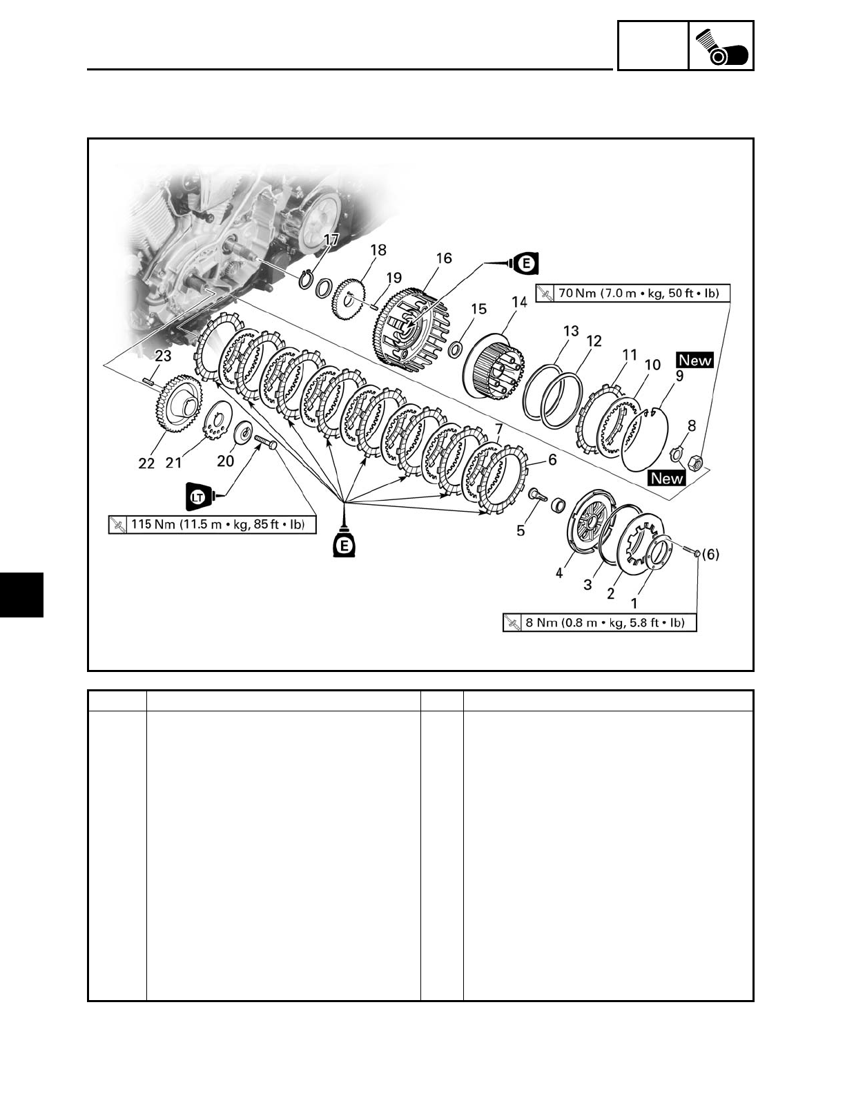
5 - 63
ENG
CLUTCH
EAS00274
Order Job/Part Q’ty Remarks
Removing the clutch Remove the parts in the order listed.
Generator rotor cover Refer to “GENERATOR”.
1 Clutch spring plate retainer 1
2 Clutch spring plate 1
3 Clutch spring plate seat 1
4 Pressure plate 1
5 Pull rod 1
6 Friction plate 7
7 Clutch plate 6
8 Lock washer 1
9 Wire circlip 1
10 Clutch plate 1
11 Friction plate 1
12 Clutch damper spring 1
5
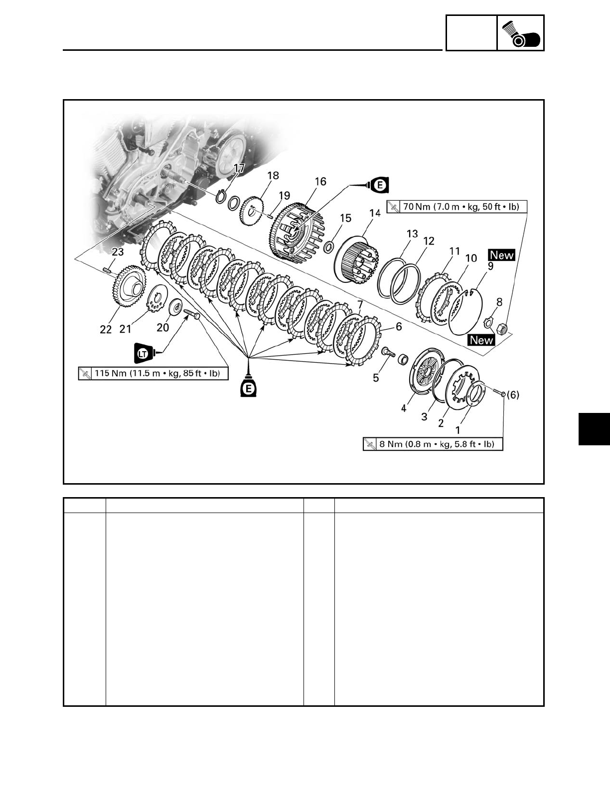
5 - 64
ENG
CLUTCH
Order Job/Part Q’ty Remarks
13 Clutch damper spring seat 1
14 Clutch boss 1
15 Thrust washer 1
16 Clutch housing 1
17 Circlip 1
18 Oil pump drive gear 1
19 Dowel pin 1
20 Spacer 1
21 Pickup coil rotor 1
22 Primary drive gear 1
23 Straight key 1
For installation, reverse the removal
procedure.
5
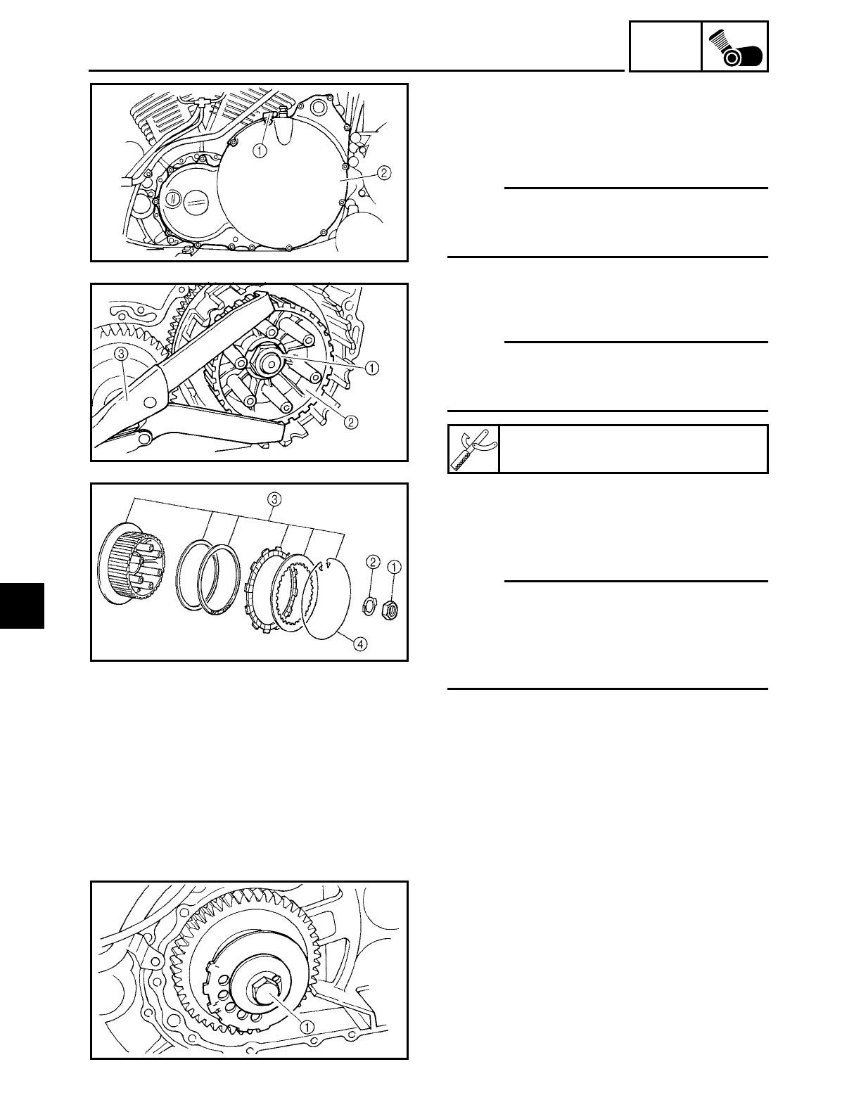
5 - 65
ENG
CLUTCH
EAS00277
REMOVING THE CLUTCH
1. Remove:
• clutch cable holder 1
• clutch cover 2
NOTE:
Loosen each bolt 1/4 of a turn at a time, in
stages and in a crisscross pattern. After all of
the bolts are fully loosened, remove them.
2. Straighten the lock washer tab.
3. Loosen:
• clutch boss nut
1
NOTE:
While holding the clutch boss
2 with the
universal clutch holder
3, loosen the clutch
boss nut.
4. Remove:
• clutch boss nut
1
• lock washer
2
• clutch boss assembly
3
NOTE:
There is a built-in damper between the
clutch boss and the clutch plate. It is not
necessary to remove the wire circlip 4 and
disassemble the built-in damper unless
there is serious clutch chattering.
Universal clutch holder
YM-91042
EAS00279
REMOVING THE PRIMARY DRIVE GEAR
1. Remove:
• pickup coil rotor bolt 1
5
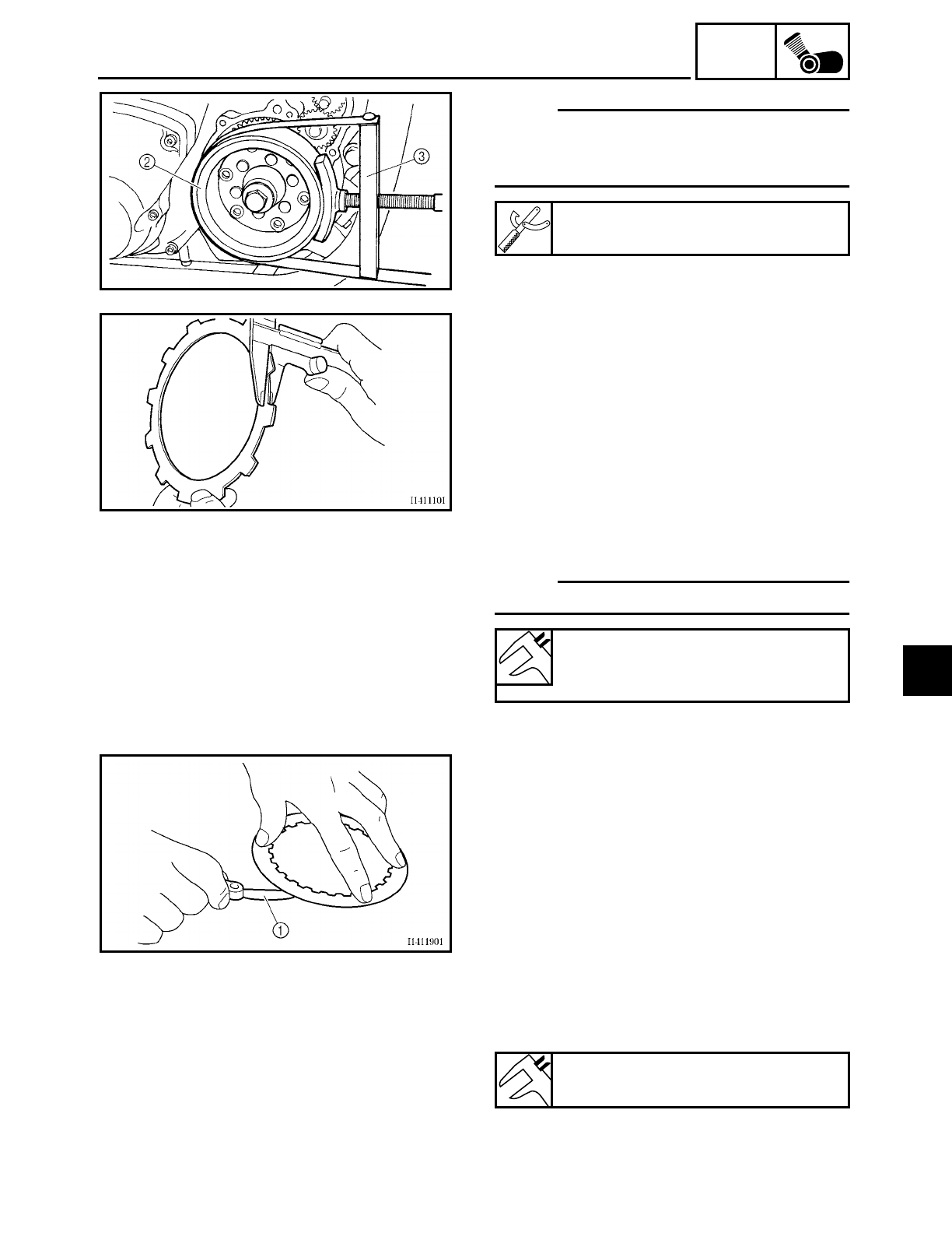
5 - 66
ENG
CLUTCH
NOTE:
While holding the generator rotor
2 with
the sheave holder 3, loosen the pickup coil
rotor bolt.
Sheave holder
YS-01880
EAS00280
CHECKING THE FRICTION PLATES
The following procedure applies to all of
the friction plates.
1. Check:
• friction plate
Damage/wear → Replace the friction
plates as a set.
2. Measure:
• friction plate thickness
Out of specification → Replace the fric-
tion plates as a set.
NOTE:
Measure the friction plate at four places.
Friction plate thickness
2.9 ~ 3.1 mm (0.114 ~ 0.122 in)
<Limit>: 2.8 mm (0.110 in)
EAS00281
CHECKING THE CLUTCH PLATES
The following procedure applies to all of
the clutch plates.
1. Check:
• clutch plate
Damage → Replace the clutch plates as a
set.
2. Measure:
• clutch plate warpage
(with a surface plate and thickness gauge
1)
Out of specification → Replace the clutch
plates as a set.
Maximum clutch plate warpage
0.2 mm (0.008 in)
5
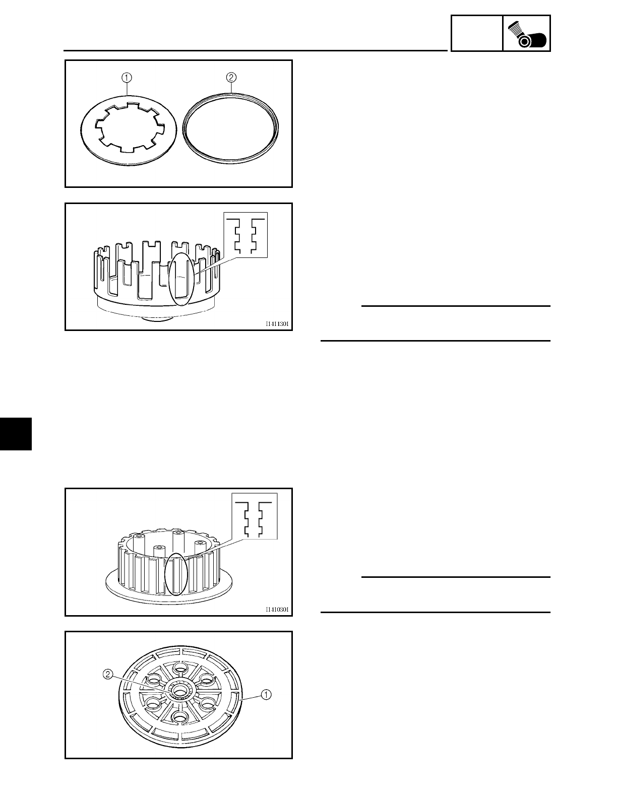
5 - 67
ENG
CLUTCH
EAS00283
CHECKING THE CLUTCH SPRING PLATE
1. Check:
• clutch spring plate 1
Damage → Replace.
2. Check:
• clutch spring plate seat 2
Damage → Replace.
EAS00284
CHECKING THE CLUTCH HOUSING
1. Check:
• clutch housing dogs
Damage/pitting/wear
→ Deburr the
clutch housing dogs or replace the clutch
housing.
NOTE:
Pitting on the clutch housing dogs will
cause erratic clutch operation.
2. Check:
• bearing
Damage/wear → Replace the bearing
and clutch housing.
EAS00285
CHECKING THE CLUTCH BOSS
1. Check:
• clutch boss splines
Damage/pitting/wear → Replace the
clutch boss.
NOTE:
Pitting on the clutch boss splines will cause
erratic clutch operation.
EAS00286
CHECKING THE PRESSURE PLATE
1. Check:
• pressure plate 1
Cracks/damage → Replace.
• bearing 2
Damage/wear → Replace.
5
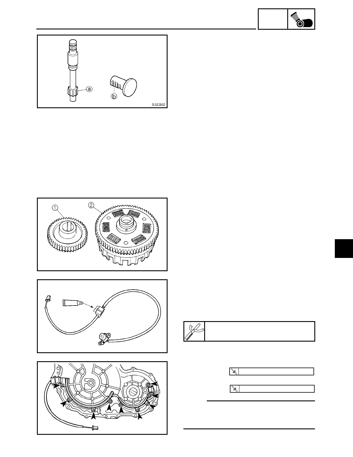
5 - 68
ENG
CLUTCH
EAS00287
CHECKING THE PULL LEVER SHAFT AND
PULL ROD
1. Check:
• pull lever shaft pinion gear teeth a
• pull rod teeth b
Damage/wear → Replace the pull lever
shaft and pull rod as a set.
2. Check:
• pull rod bearing
Damage/wear → Replace.
EAS00292
CHECKING THE PRIMARY DRIVE
1. Check:
• primary drive gear 1
• primary driven gear 2
Damage/wear → Replace the primary
drive gear and clutch housing as a set.
Excessive noise during operation →
Replace the primary drive gear and
clutch housing as a set.
INSTALLING THE PICKUP COIL AND PULL
LEVER SHAFT
1. Apply:
• sealant
(onto the pickup coil lead grommet)
Quick Gasket
ACC-11001-05-01
2. Install:
• pickup coil
• pickup coil lead holder
NOTE:
Apply locking agent (LOCTITE) to the
threads of the pickup coil bolts and pickup
coil lead holder bolts.
T
R
.
.
7 Nm (0.7 m · kg, 5.1 ft · lb)
T
R
.
.
7 Nm (0.7 m · kg, 5.1 ft · lb)
5
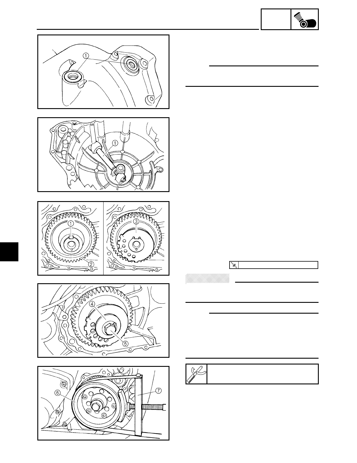
5 - 69
ENG
CLUTCH
3. Install:
• bearings
• oil seals 1
NOTE:
Lubricate the oil seal lips with lithium soap
base grease.
4. Install:
• pull lever shaft 1
• washer
• circlip
EAS00303
INSTALLING THE PRIMARY DRIVE GEAR
1. Install:
• straight key 1
• primary drive gear 2
• pickup coil rotor 3
• spacer 4
• pickup coil rotor bolt 5
ACHTUNG:
CAUTION:
The timing marks on the pickup coil rotor
must face outside.
NOTE:
• Apply locking agent (LOCTITE) to the
threads of the pickup coil rotor bolt.
• While holding the generator rotor 6 with
the sheave holder 7, tighten the pickup
coil rotor bolt.
2. Bend the lock washer tab along a flat
side of the nut.
Sheave holder
YS-01880
T
R
.
.
115 Nm (11.5 m · kg, 85 ft · lb)
5
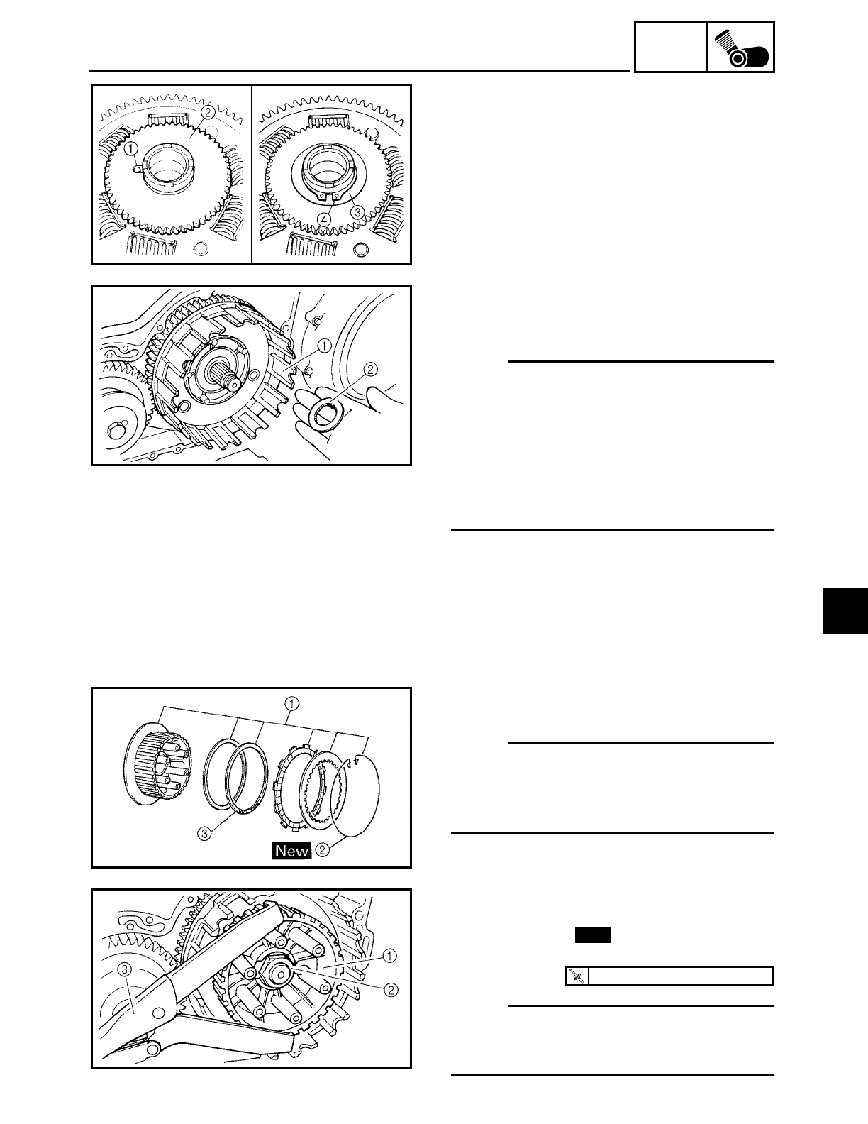
5 - 70
ENG
CLUTCH
EAS00296
INSTALLING THE CLUTCH
1. Install:
• dowel pin 1
• oil pump drive gear 2
• plate 3
• circlip 4
2. Install:
• clutch housing 1
• thrust washer 2
NOTE:
• Lubricate the clutch housing bearings
with engine oil.
• Make sure that the primary driven gear
teeth and primary drive gear teeth mesh
correctly.
• Make sure that the oil pump drive gear
teeth and oil pump driven gear teeth
mesh correctly.
3. Install:
• clutch boss assembly 1
NOTE:
• If the wire circlip 2 has been removed,
carefully install a new one.
• Install the clutch damper spring 3 with
the “OUTSIDE” mark facing out.
4. Install:
• clutch boss 1
• lock washer
• clutch boss nut 2
NOTE:
While holding the clutch boss with the uni-
versal clutch holder 3, tighten the clutch
boss nut.
New
T
R
.
.
70 Nm (7.0 m · kg, 50 ft · lb)
5
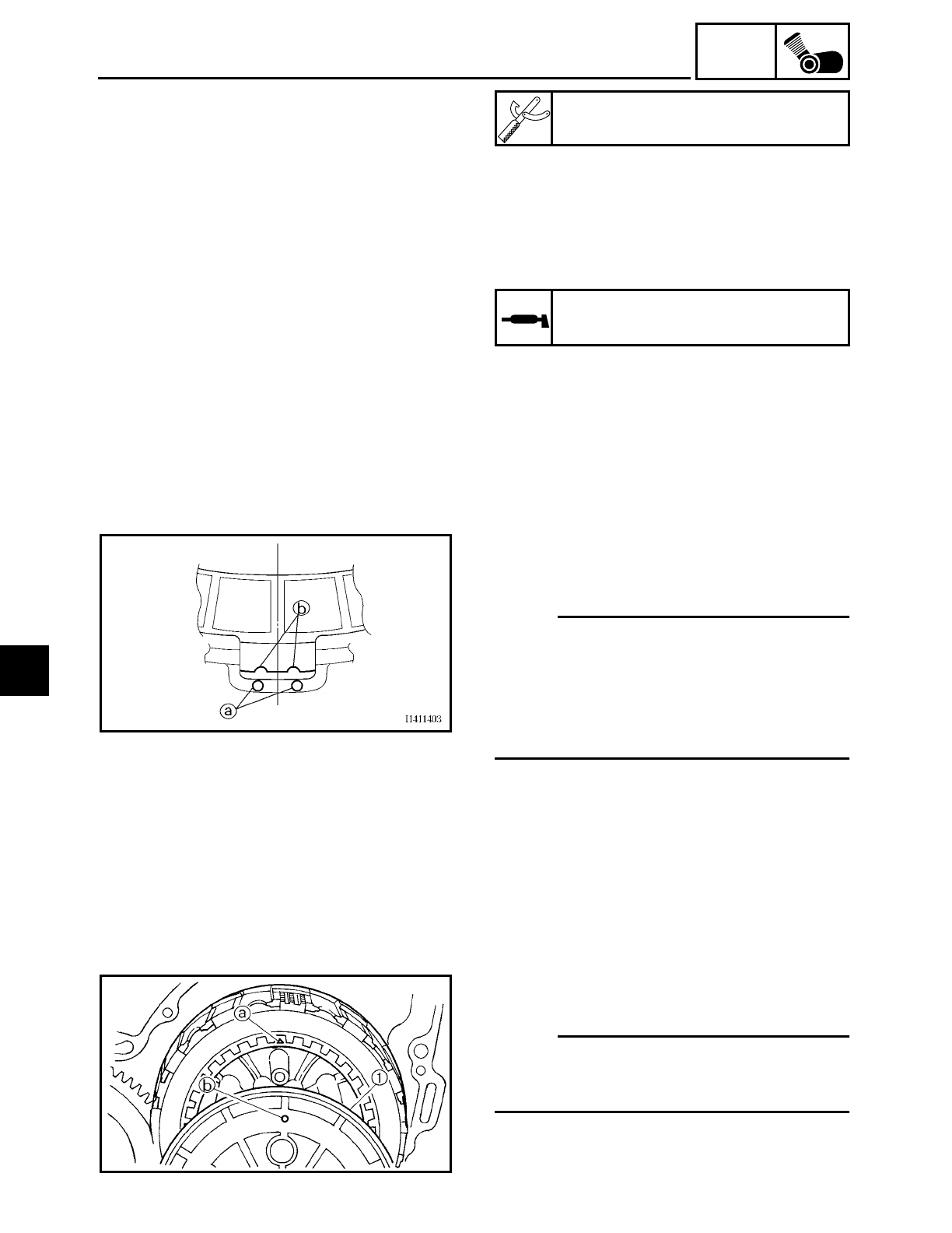
5 - 71
ENG
CLUTCH
5. Bend the lock washer tab along a flat
side of the nut.
6. Lubricate:
• friction plates
• clutch plates
(with the recommended lubricant)
Universal clutch holder
YM-91042
Recommended lubricant
Engine oil
7. Install:
• friction plates
• clutch plates
NOTE:
• First, install a friction plate and then alter-
nate between a clutch plate and a friction
plate.
• Align the two embossed mark a on the
clutch housing with the two semicircular
slots b in the friction plates.
8. Install:
• pressure plate 1
NOTE:
Align the punch mark a on the pressure
plate with the punch mark b on the clutch
boss.
5
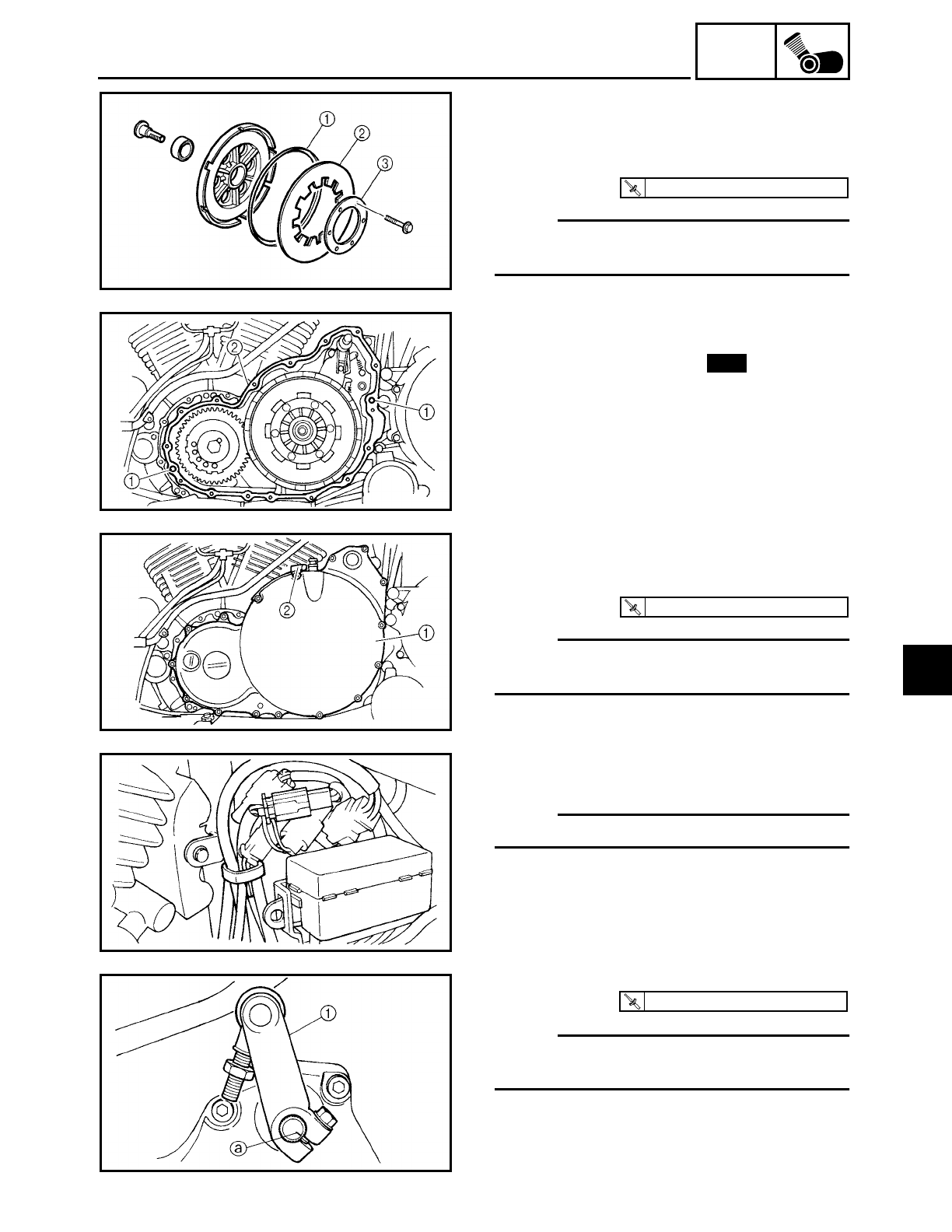
5 - 72
ENG
CLUTCH
9. Install:
• clutch spring plate seat 1
• clutch spring plate 2
• clutch spring plate retainer 3
NOTE:
Tighten the clutch spring plate retainer
bolts in stages and in a crisscross pattern.
T
R
.
.
8 Nm (0.8 m · kg, 5.8 ft · lb)
10.Install:
• dowel pins 1
• clutch cover gasket 2New
11.Install:
• clutch cover 1
• clutch cable holder 2
NOTE:
Tighten the clutch cover bolts in stages and
in a crisscross pattern.
T
R
.
.
10 Nm (1.0 m · kg, 7.2 ft · lb)
12.Connect:
• pickup coil coupler
NOTE:
Refer to “CABLE ROUTING” in chapter 2.
13.Install:
• shift arm 1
NOTE:
Align the mark a in the shift shaft with the
slot in the shift arm.
T
R
.
.
10 Nm (1.0 m · kg, 7.2 ft · lb)
5
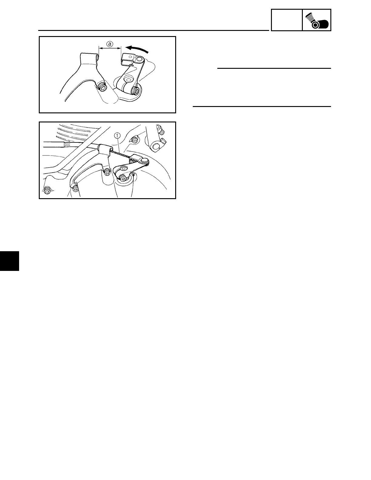
5 - 73
ENG
CLUTCH
14.Install:
• pull lever spring
• pull lever
NOTE:
If there is no free play in the clutch, install
the pull lever to the pull lever shaft in order
to get the distance a between the pull lever
and clutch cable holder to 31.8 mm (1.25 in).
15.Connect:
• clutch cable 1
16.Fill:
• oil tank
(with the specified amount of the recom-
mended engine oil)
Refer to “CHANGING THE ENGINE OIL”
in chapter 3.
17.Install:
• engine left side cover
Refer to “ROCKER ARMS, PUSH RODS
AND VALVE LIFTERS”.
• left side cover
Refer to “SEATS AND SIDE COVERS” in
chapter 3.
18.Adjust:
• clutch cable free play
Refer to “ADJUSTING THE CLUTCH
CABLE FREE PLAY” in chapter 3.
5
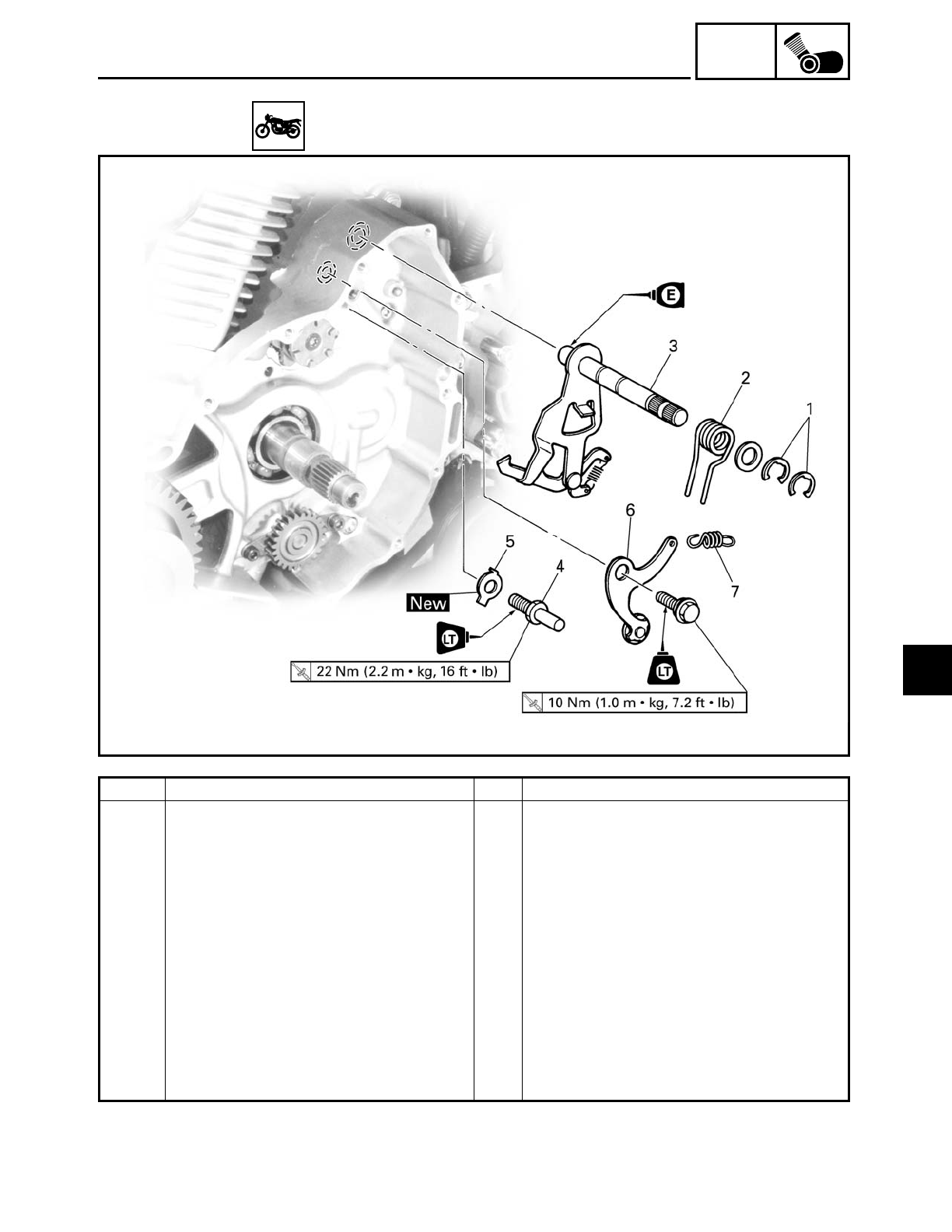
5 - 74
ENG
SHIFT SHAFT
EAS00327
SHIFT SHAFT
Order Job/Part Q’ty Remarks
Removing the shift shaft and stop-
per lever
Remove the parts in the order listed.
Engine oil Drain.
Clutch housing Refer to “CLUTCH”.
1 Circlip 2
2 Shift shaft spring 1
3 Shift shaft 1
4 Shift shaft spring stopper 1
5 Lock washer 1
6 Stopper lever 1
7 Stopper lever spring 1
For installation, reverse the removal
procedure.
5
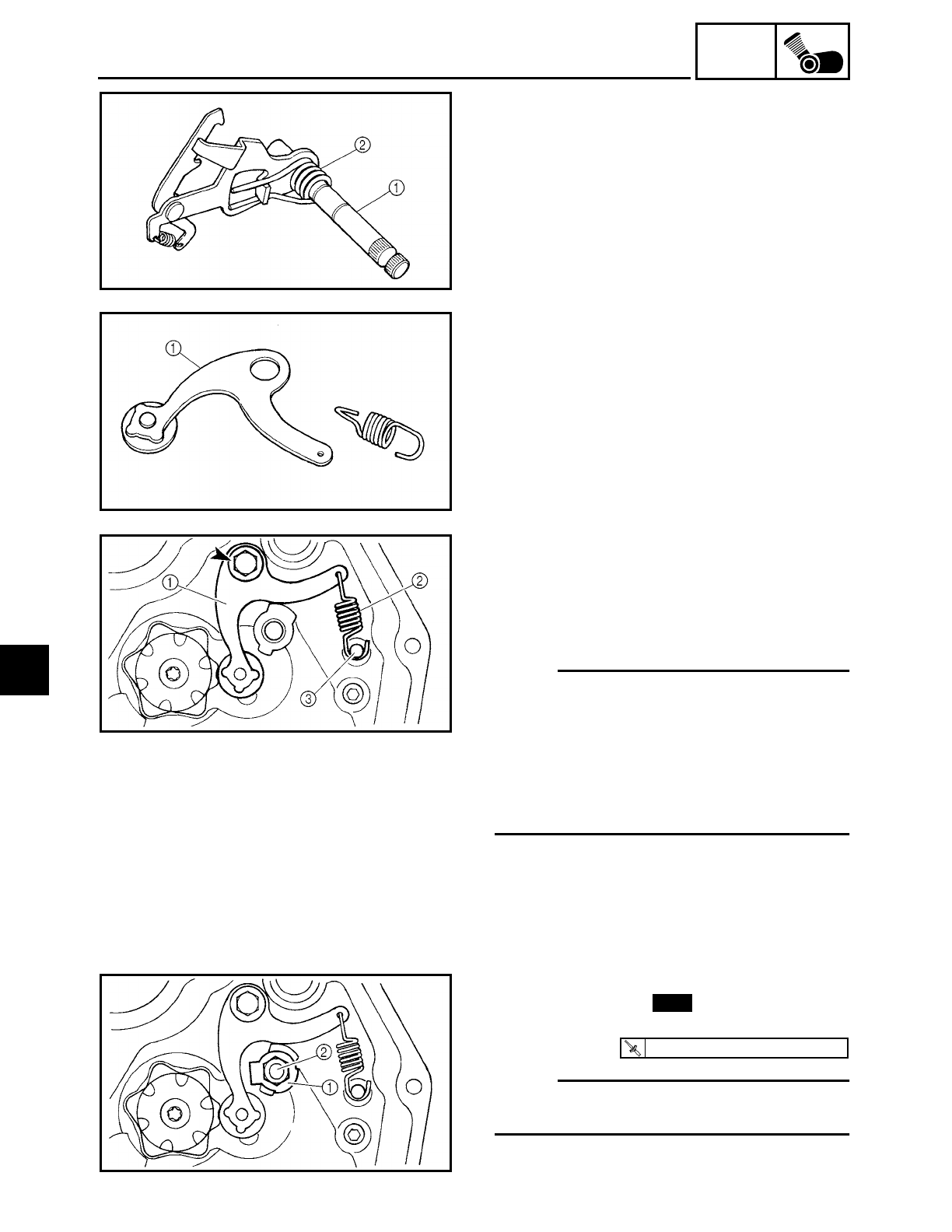
5 - 75
ENG
SHIFT SHAFT
EAS00328
CHECKING THE SHIFT SHAFT
1. Check:
• shift shaft 1
Bends/damage/wear → Replace.
• shift lever spring 2
Damage/wear → Replace.
EAS00330
CHECKING THE STOPPER LEVER
1. Check:
• stopper lever 1
Bends/damage → Replace.
Roller turns roughly → Replace the stop-
per lever.
EAS00331
INSTALLING THE STOPPER LEVER AND
SHIFT SHAFT
1. Install:
• stopper lever 1
• stopper lever spring 2
NOTE:
• Apply locking agent (LOCTITE) to the
threads of stopper lever bolt.
• Install the ends of the stopper lever spring
onto the stopper lever and the crankcase
boss 3.
• Mesh the stopper lever with the shift
drum segment assembly.
2. Install:
• lock washer 1
• shift shaft spring stopper 2
NOTE:
Apply locking agent (LOCTITE) to the
threads of shift shaft spring stopper.
3. Bend the lock washer tab along a flat
side of the shift shaft spring stopper.
New
T
R
.
.
22 Nm (2.2 m · kg, 16 ft · lb)
5
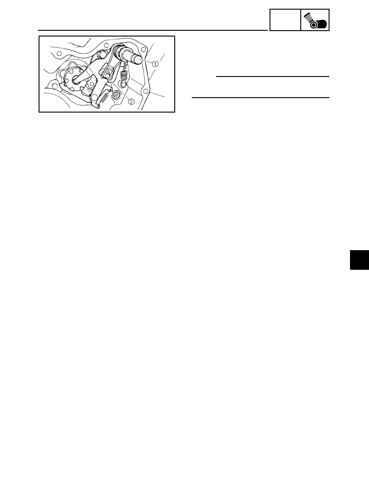
5 - 76
ENG
SHIFT SHAFT
4. Install:
• shift shaft spring
• circlips
• shift shaft 1
NOTE:
Install the end of the shift shaft spring onto
the shift shaft spring stopper 2.
5. Install:
• clutch housing
Refer to “CLUTCH”.
6. Fill:
• oil tank
Refer to “CHANGING THE ENGINE OIL”.
5
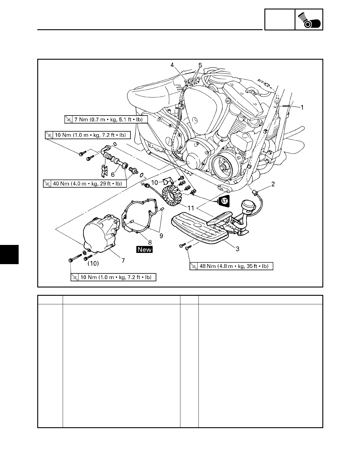
5 - 77
ENG
GENERATOR AND STARTER CLUTCH
EAS00341
GENERATOR AND STARTER CLUTCH
Order Job/Part Q’ty Remarks
Removing the stator coil assembly Remove the parts in the order listed.
Rider seat/left side cover/fuel tank Refer to “SEATS AND SIDE COVERS”
and “FUEL TANK” in chapter 3.
Muffler/exhaust pipes Refer to “ENGINE”.
Engine oil Drain.
1 Plastic locking tie 1
2 Rear brake light switch coupler 1 Disconnect.
3 Rider footrest (right) 1
4 Stator coil assembly coupler 1 Disconnect.
5 Decompression solenoid coupler 2 Disconnect.
6 Oil delivery pipe 1
7 Generator cover 1
8 Generator cover gasket 1
9 Dowel pin 2
5
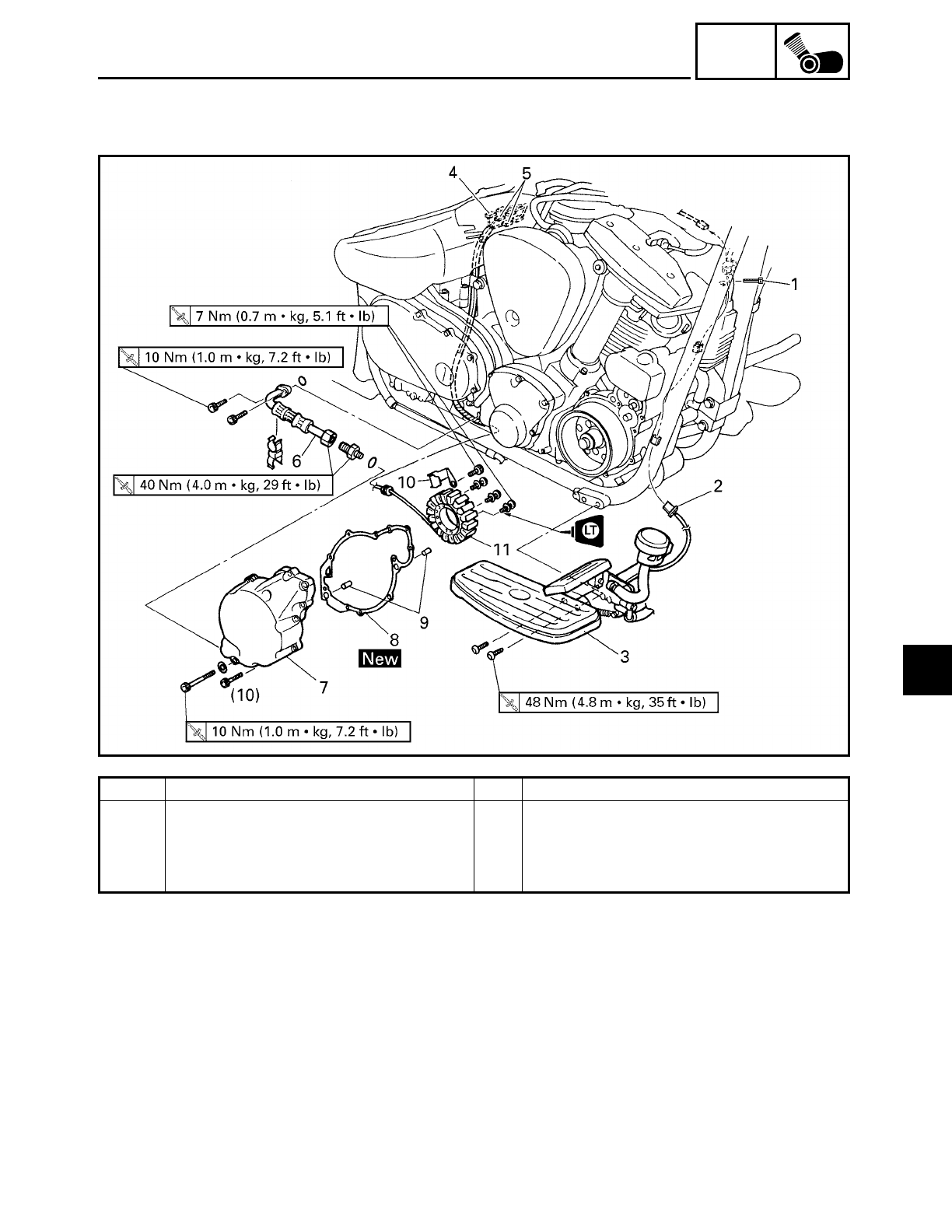
5 - 78
ENG
GENERATOR AND STARTER CLUTCH
Order Job/Part Q’ty Remarks
10 Stator coil assembly lead holder 1
11 Stator coil assembly 1
For installation, reverse the removal
procedure.
5
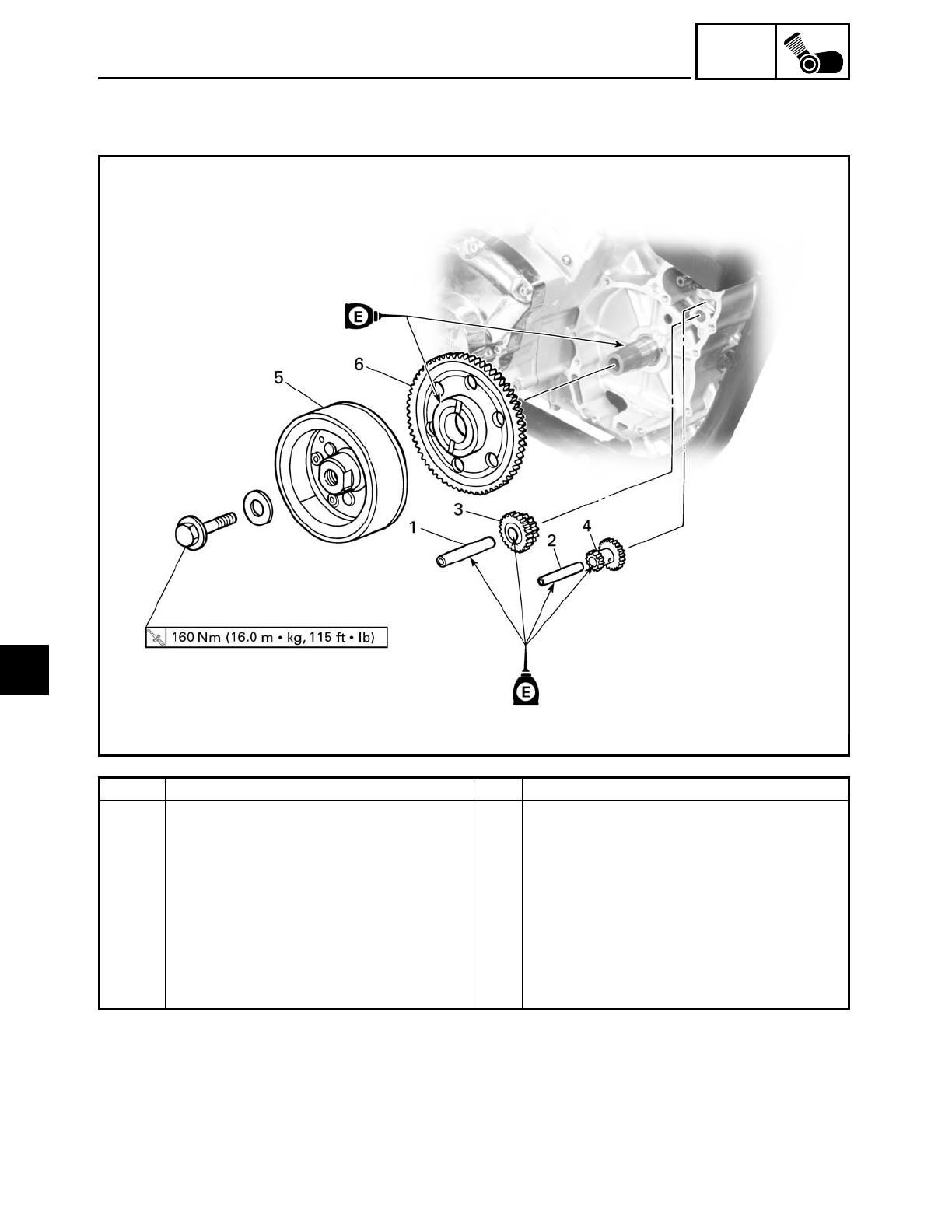
5 - 79
ENG
GENERATOR AND STARTER CLUTCH
EAS00343
Order Job/Part Q’ty Remarks
Removing the generator rotor Remove the parts in the order listed.
1 Starter clutch idle gear shaft #2 1
2 Starter clutch idle gear shaft #1 1
3 Starter clutch idle gear #2 1
4 Starter clutch idle gear #1 1
5 Generator rotor 1
6 Starter clutch gear 1
For installation, reverse the removal
procedure.
5
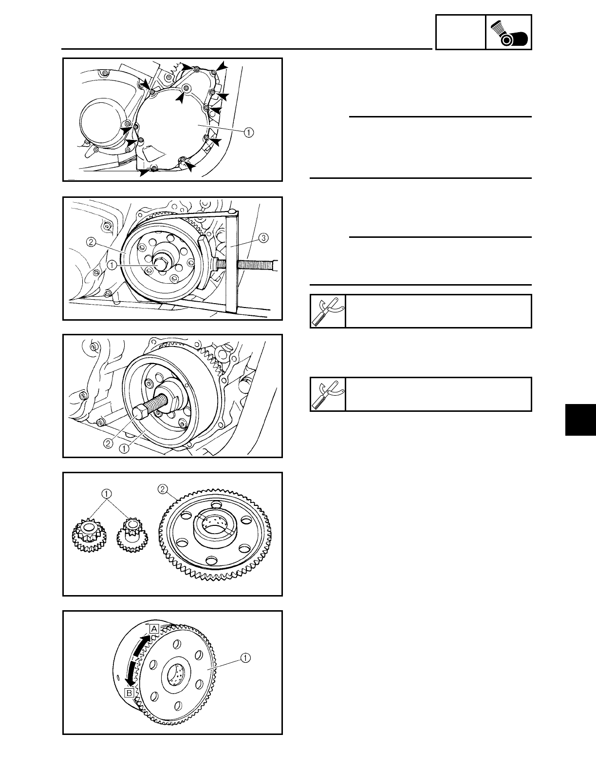
5 - 80
ENG
GENERATOR AND STARTER CLUTCH
EAS00347
REMOVING THE GENERATOR
1. Remove:
• generator cover 1
NOTE:
Loosen each bolt 1/4 of a turn at a time, in
stages and in a crisscross pattern. After all
of the bolts are fully loosened, remove
them.
2. Remove:
• generator rotor bolt 1
• washer
NOTE:
While holding the generator rotor 2 with
the sheave holder 3, loosen the generator
rotor bolt.
Sheave holder
YS-01880
3. Remove:
• generator rotor 1
(with the rotor puller 2)
Rotor puller
YM-01080-A
EAS00348
CHECKING THE STARTER CLUTCH
1. Check:
• starter clutch idle gears 1
• starter clutch gear 2
Chips/pitting/roughness/wear → Replace
the defective part(s).
2. Check:
• starter clutch operation
▼ ▼ ▼ ▼ ▼ ▼ ▼ ▼ ▼ ▼ ▼ ▼ ▼ ▼ ▼ ▼ ▼ ▼ ▼ ▼ ▼ ▼ ▼ ▼ ▼ ▼ ▼ ▼
a. Install the starter clutch gear 1 onto the
starter clutch and hold the starter clutch.
b. When turning the starter clutch gear
clockwise Å, the starter clutch and the
starter clutch gear should engage, other-
wise the starter clutch is faulty and must
be replaced.
5
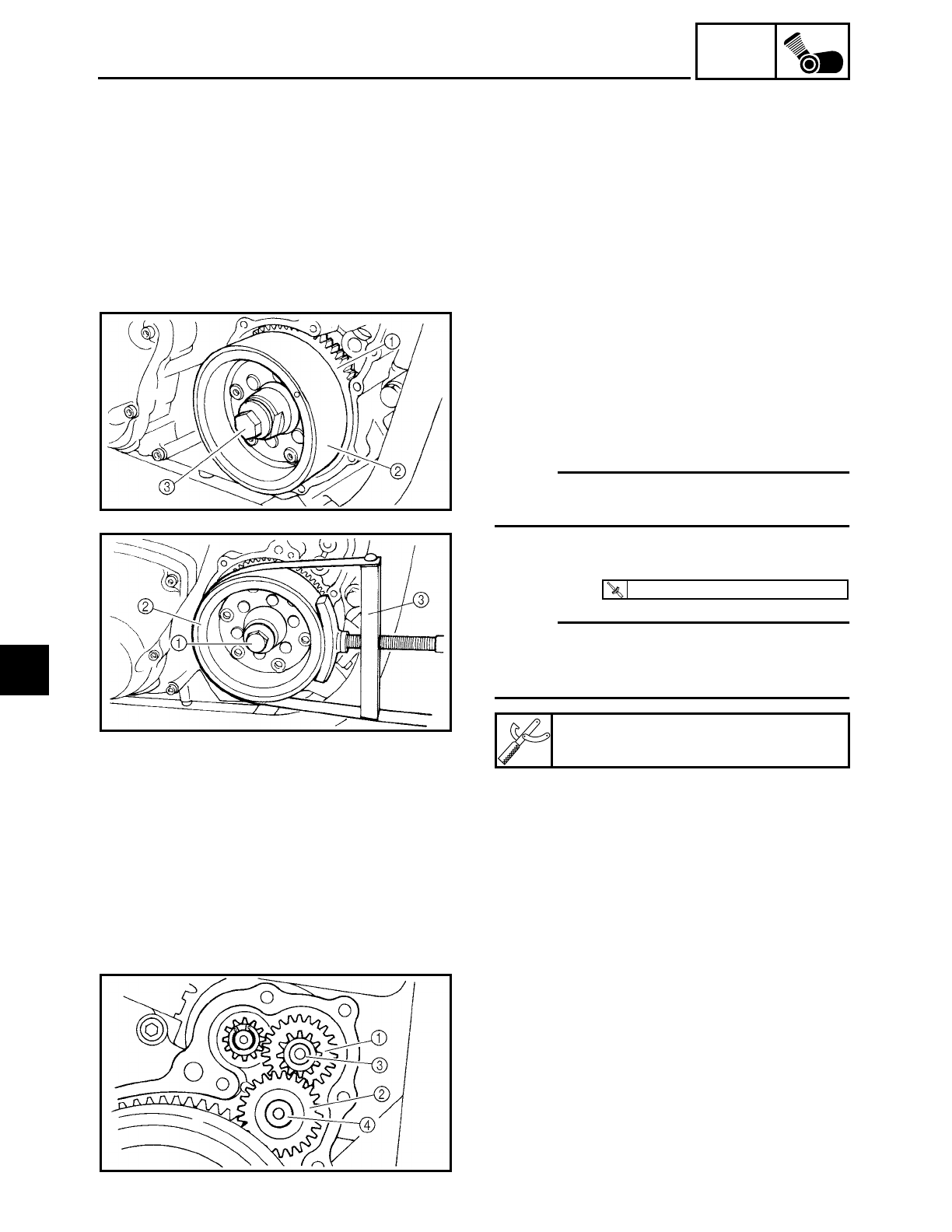
5 - 81
ENG
GENERATOR AND STARTER CLUTCH
c. When turning the starter clutch gear
counterclockwise
ı, it should turn
freely, otherwise the starter clutch is
faulty and must be replaced.
▲ ▲ ▲ ▲ ▲ ▲ ▲ ▲ ▲ ▲ ▲ ▲ ▲ ▲ ▲ ▲ ▲ ▲ ▲ ▲ ▲ ▲ ▲ ▲ ▲ ▲ ▲ ▲
EAS00354
INSTALLING THE GENERATOR
1. Install:
• starter clutch gear
1
• generator rotor
2
• washer
• generator rotor bolt 3
NOTE:
Clean the tapered portion of the crankshaft
and the generator rotor hub.
2. Tighten:
• generator rotor bolt
1
NOTE:
While holding the generator rotor
2 with
the sheave holder
3, tighten the generator
rotor bolt.
Sheave holder
YS-01880
T
R
.
.
160 Nm (16.0 m · kg, 115 ft · lb)
3. Install:
• starter clutch idle gear #1 1
• starter clutch idle gear #2 2
• starter clutch idle gear shaft #1 3
• starter clutch idle gear shaft #2 4
5
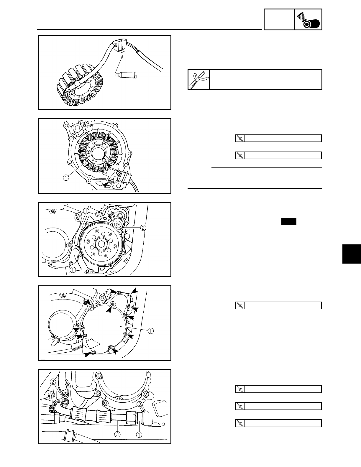
5 - 82
ENG
GENERATOR AND STARTER CLUTCH
4. Apply:
• sealant
(onto the stator coil assembly lead grom-
met)
Quick Gasket
ACC-11001-05-01
5. Install:
• stator coil assembly
1
• stator coil assembly lead holder
NOTE:
Apply locking agent (LOCTITE
) to the
threads of the stator coil assembly bolts.
T
R
.
.
7 Nm (0.7 m · kg, 5.1 ft · lb)
T
R
.
.
7 Nm (0.7 m · kg, 5.1 ft · lb)
6. Install:
• dowel pins
1
• generator cover gasket 2New
7. Install:
• generator cover 1
T
R
.
.
10 Nm (1.0 m · kg, 7.2 ft · lb)
8. Install:
• oil delivery pipe joint 1
• bolts
2
• oil delivery pipe
3
T
R
.
.
40 Nm (4.0 m · kg, 29 ft · lb)
T
R
.
.
10 Nm (1.0 m · kg, 7.2 ft · lb)
T
R
.
.
40 Nm (4.0 m · kg, 29 ft · lb)
5
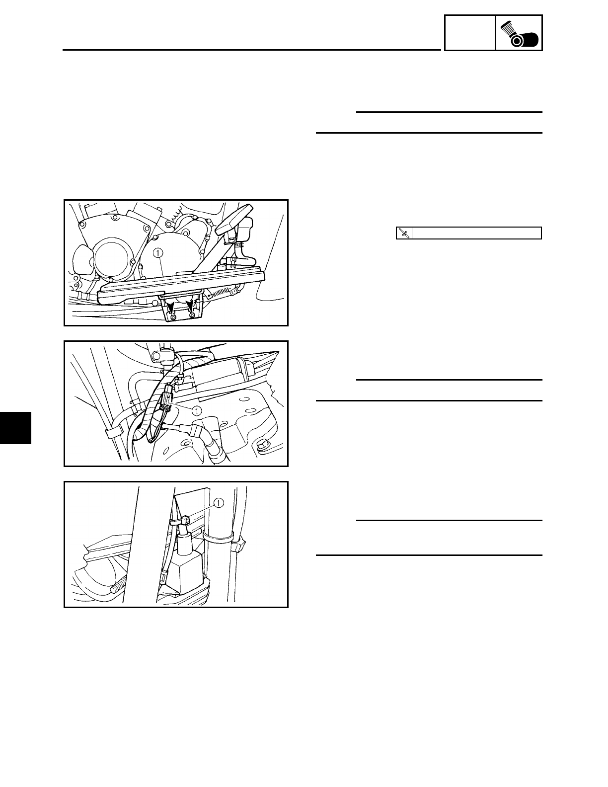
5 - 83
ENG
GENERATOR AND STARTER CLUTCH
9. Connect:
• decompression solenoid couplers
• stator coil assembly coupler
NOTE:
Refer to “CABLE ROUTING” in chapter 2.
10.Install:
• rider footrest (right)
1
T
R
.
.
48 Nm (4.8 m · kg, 35 ft · lb)
11.Connect:
• rear brake light switch coupler
1
NOTE:
Refer to “CABLE ROUTING” in chapter 2.
12.Install:
• plastic locking tie 1
NOTE:
Fasten the rear brake light switch lead and
wire harness.
13.Fill:
• oil tank
(with the specified amount of the recom-
mended engine oil)
Refer to “CHANGING THE ENGINE OIL”
in chapter 3.
5

5 - 84
ENG
GENERATOR AND STARTER CLUTCH
14.Install:
• exhaust pipes
• muffler
Refer to “ENGINE”.
15.Install:
• fuel tank
• left side cover
• rider seat
Refer to “FUEL TANK” and “SEATS AND
SIDE COVERS” in chapter 3.
5
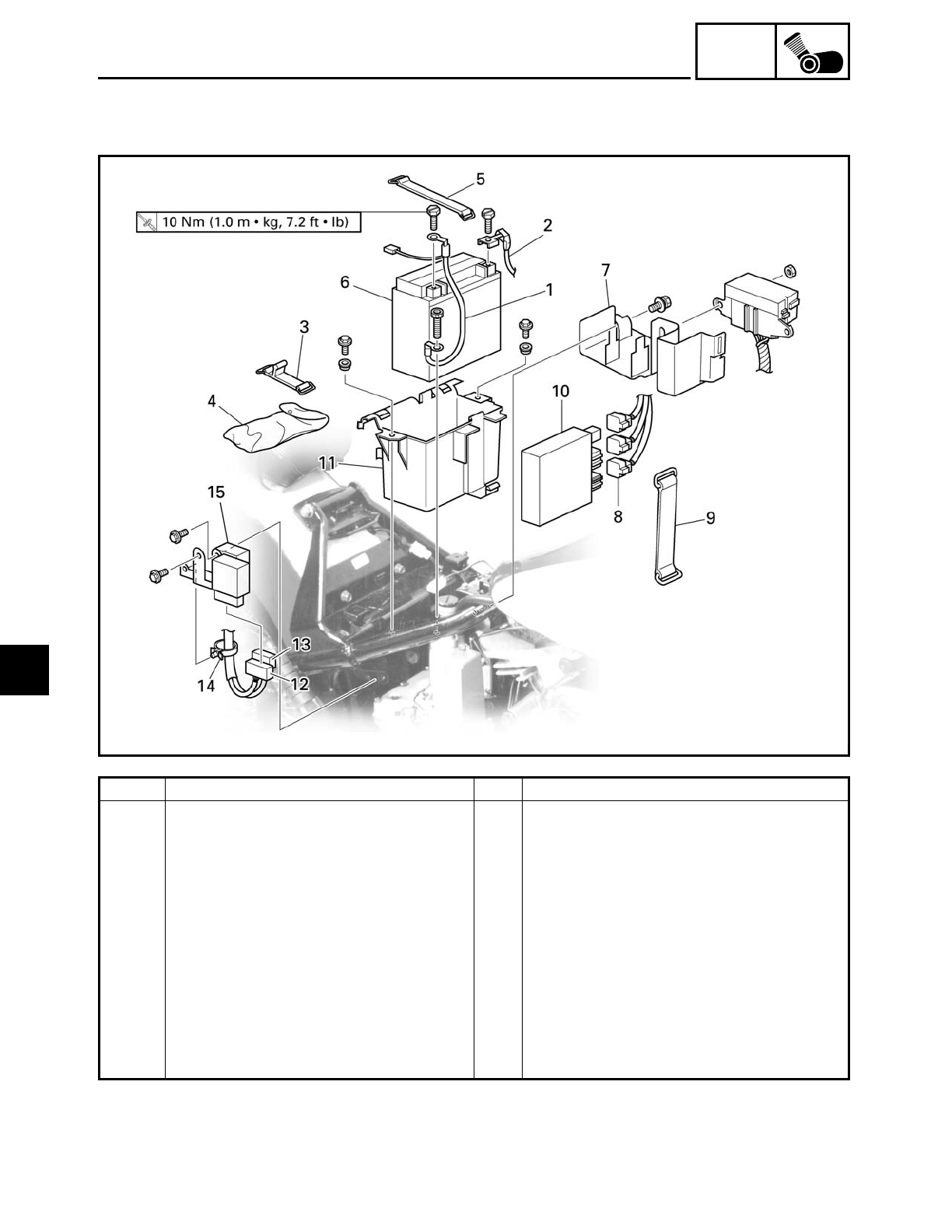
5 - 85
ENG
TRANSFER GEAR CASE
TRANSFER GEAR CASE
Order Job/Part Q’ty Remarks
Removing the battery box Remove the parts in the order listed.
Rider seat/side covers Refer to “SEATS AND SIDE COVERS”
in chapter 3.
1 Negative battery lead 1
2 Positive battery lead 1 Disconnect.
3 Tool kit holder 1
4 Tool kit 1
5 Battery holder 1
6 Battery 1
7 Plastic bracket 1
8 Ignitor unit coupler 3 Disconnect.
9 Ignitor unit holder 1
5
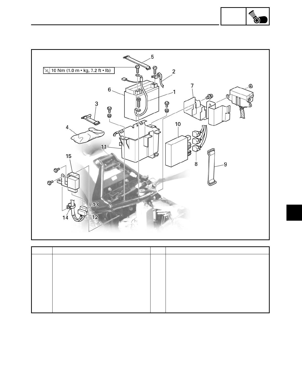
5 - 86
ENG
TRANSFER GEAR CASE
Order Job/Part Q’ty Remarks
10 Ignitor unit 1
11 Battery box 1
12 Relay unit coupler 1 Disconnect.
13 Turn signal relay coupler 1 Disconnect.
14 Plastic clamp 1
15 Relay bracket 1
For installation, reverse the removal
procedure.
5
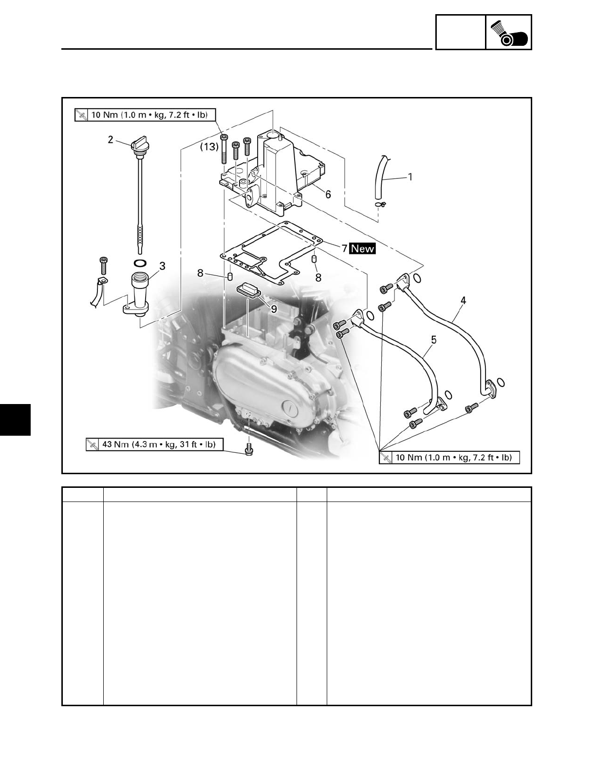
5 - 87
ENG
TRANSFER GEAR CASE
Order Job/Part Q’ty Remarks
Removing the oil tank cover Remove the parts in the order listed.
Muffler/exhaust pipes Refer to “ENGINE”.
Engine oil Drain.
1 Oil tank breather hose 1 Disconnect.
2 Dipstick 1
3 Dipstick joint 1
4 Oil pipe #1 1
5 Oil pipe #2 1
6 Oil tank cover 1
7 Oil tank cover gasket 1
8 Dowel pin 2
9 Oil strainer 1
For installation, reverse the removal
procedure.
5
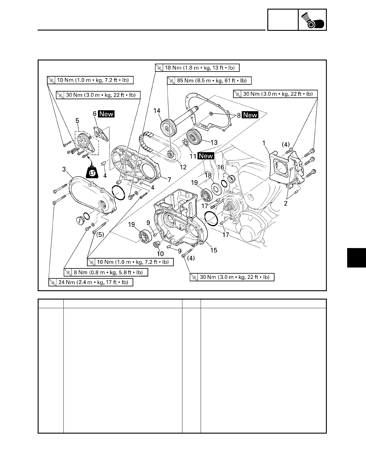
5 - 88
ENG
TRANSFER GEAR CASE
Order Job/Part Q’ty Remarks
Removing the transfer gear case Remove the parts in the order listed.
Transfer gear oil Drain.
Drive pulley Refer to “DRIVE BELT AND DRIVE PUL-
LEY” in chapter4.
1 Drive pulley case 1
2 Dowel pin 2
3 Cover 1
4 Dowel pin 2
5 Transfer gear oil pump 1
6 Transfer gear oil pump gasket 1
7 Transfer gear case cover 1
8 Transfer gear case cover gasket 1
9 Dowel pin 2
10 Oil strainer 1
5
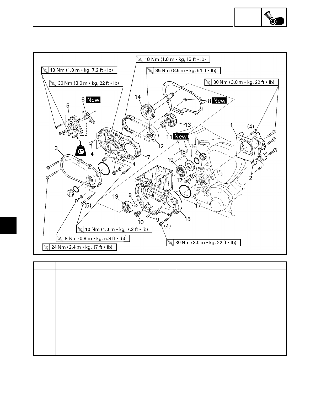
5 - 89
ENG
TRANSFER GEAR CASE
Order Job/Part Q’ty Remarks
11 Lock washer 1
12 Primary chain 1
13 Middle drive gear 1
14 Middle driven shaft 1
15 Transfer gear case 1
16 Spacer 1
17 Dowel pin 2
18 Oil seal 1
19 Bearing 2
For installation, reverse the removal
procedure.
5
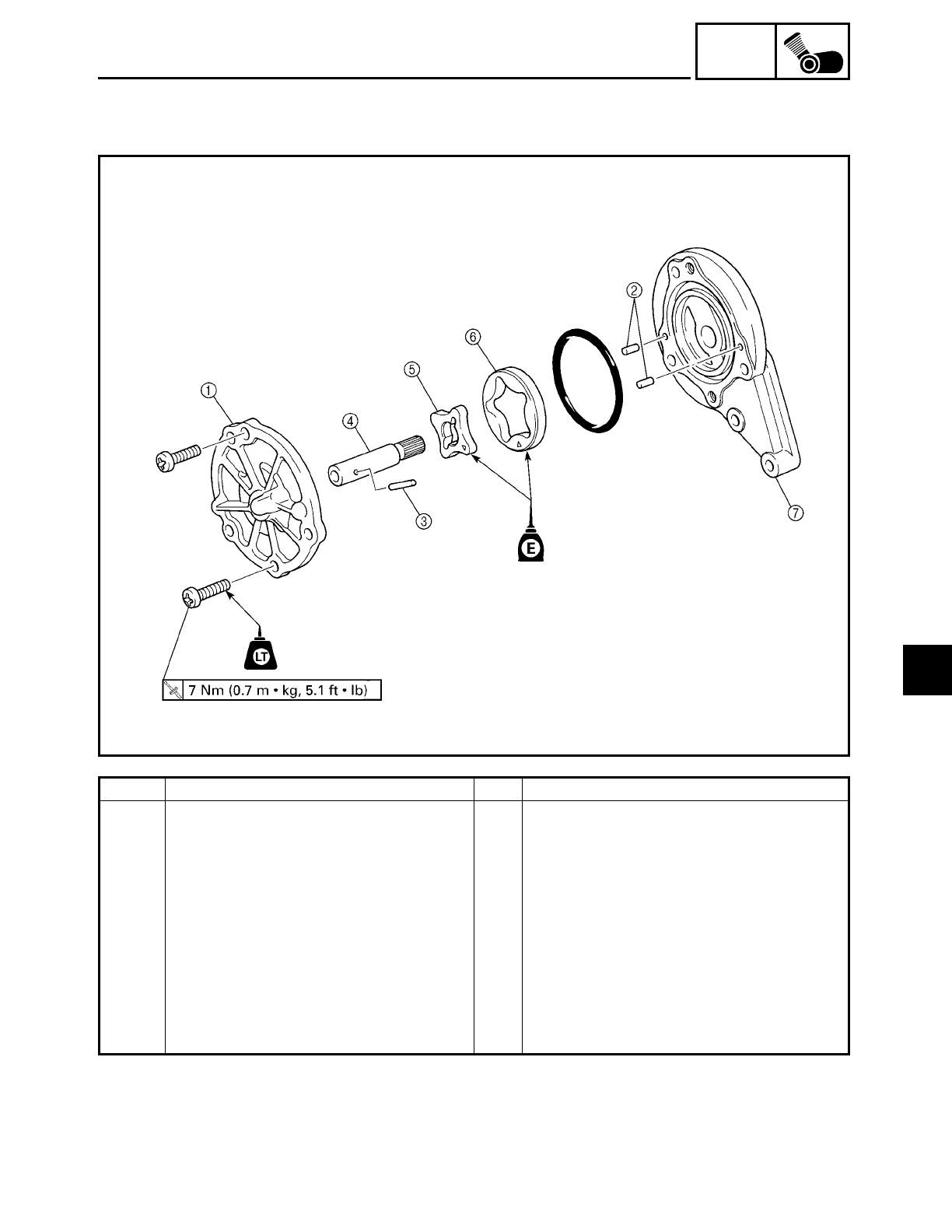
5 - 90
ENG
TRANSFER GEAR CASE
Order Job/Part Q’ty Remarks
Disassembling the transfer gear
case oil pump
Remove the parts in the order listed.
1Oil pump cover 1
2Pin 2
3Pin 1
4Oil pump shaft 1
5Oil pump inner rotor 1
6Oil pump outer rotor 1
7Oil pump housing 1
For assembly, reverse the disassembly
procedure.
5
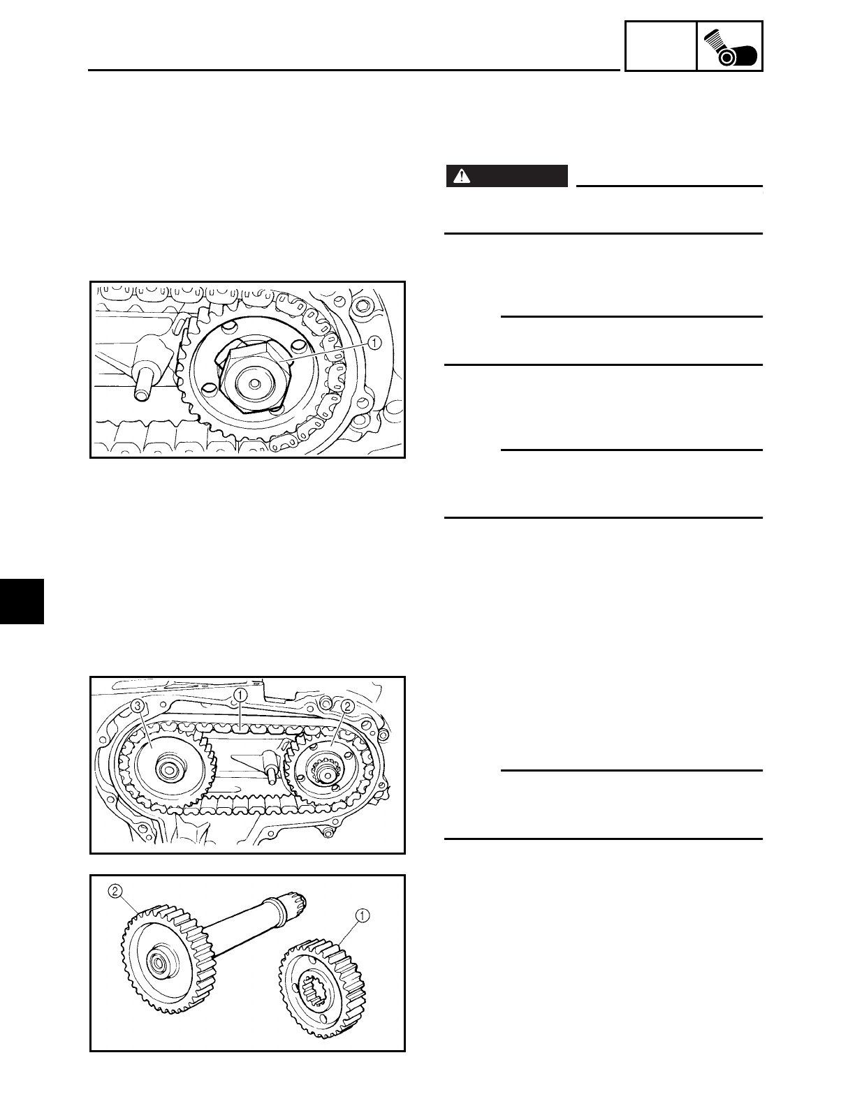
5 - 91
ENG
TRANSFER GEAR CASE
REMOVING THE BATTERY
1. Disconnect:
• battery leads
(from the battery terminals)
WARNING
WARNING
First, disconnect the negative battery lead,
then the positive battery lead.
REMOVING THE MIDDLE DRIVEN SHAFT
NOTE:
Loosen the middle drive gear nut before
removing the drive pulley.
1. Straighten the lock washer tab.
2. Loosen:
• middle drive gear nut 1
NOTE:
When loosening the middle drive gear nut,
press down on the brake pedal so the mid-
dle drive gear does not move.
3. Remove:
• primary chain 1
• middle drive gear 2
• middle driven shaft 3
NOTE:
Remove the primary chain, middle drive
gear and middle driven shaft at the same
time.
CHECKING THE MIDDLE DRIVE
1. Check:
• middle drive gear 1
• middle driven gear 2
Damage/wear → Replace the middle
drive gear, middle driven shaft and pri-
mary chain as a set.
5
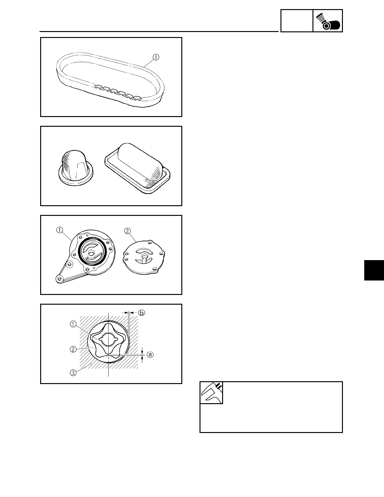
5 - 92
ENG
TRANSFER GEAR CASE
2. Check:
• primary chain 1
Damage/stiffness → Replace the primary
chain, middle drive gear and middle
driven shaft as a set.
CHECKING THE OIL STRAINER
1. Check:
• oil strainer
Damage → Replace.
Contaminants → Clean with engine oil.
CHECKING THE OIL PUMP
1. Check:
• oil pump housing 1
• oil pump cover 2
Cracks/damage/wear → Replace the
defective part(s).
2. Measure:
• inner rotor-to-outer rotor tip clearance a
• outer rotor-to-oil pump housing clear-
ance b
Out of specification → Replace the oil
pump.
1Inner rotor
2Outer rotor
3Oil pump housing
Inner rotor-to-outer rotor tip
clearance
0.07 ~ 0.12 mm (0.003 ~ 0.005 in)
Outer rotor-to-oil pump housing
clearance
0.03 ~ 0.08 mm (0.001 ~ 0.003 in)
5
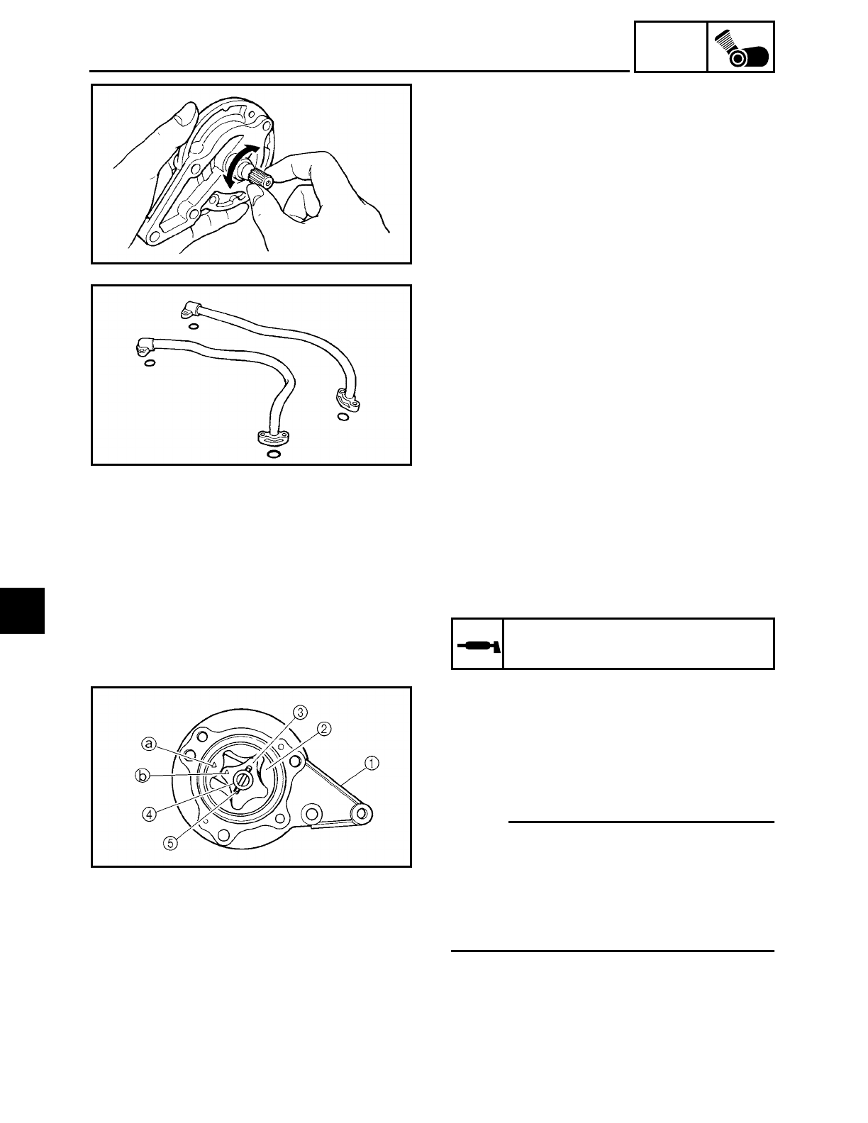
5 - 93
ENG
TRANSFER GEAR CASE
3. Check:
• oil pump operation
Unsmooth → Repair or replace the defec-
tive part(s).
CHECKING THE OIL PIPE
1. Check:
• oil pipe
Damage → Replace.
EAS00375
ASSEMBLING THE OIL PUMP
1. Lubricate:
• inner rotor
• outer rotor
• oil pump shaft
(with the recommended lubricant)
Recommended lubricant
Engine oil
2. Install:
• oil pump housing 1
• oil pump outer rotor 2
• oil pump inner rotor 3
• oil pump shaft 4
• pin 5
NOTE:
• When installing the oil pump shaft, align
the pin in the oil pump shaft with the
groove in the oil pump inner rotor.
• Align the arrow a on the oil pump outer
rotor with the arrow b on the oil pump
inner rotor.
5
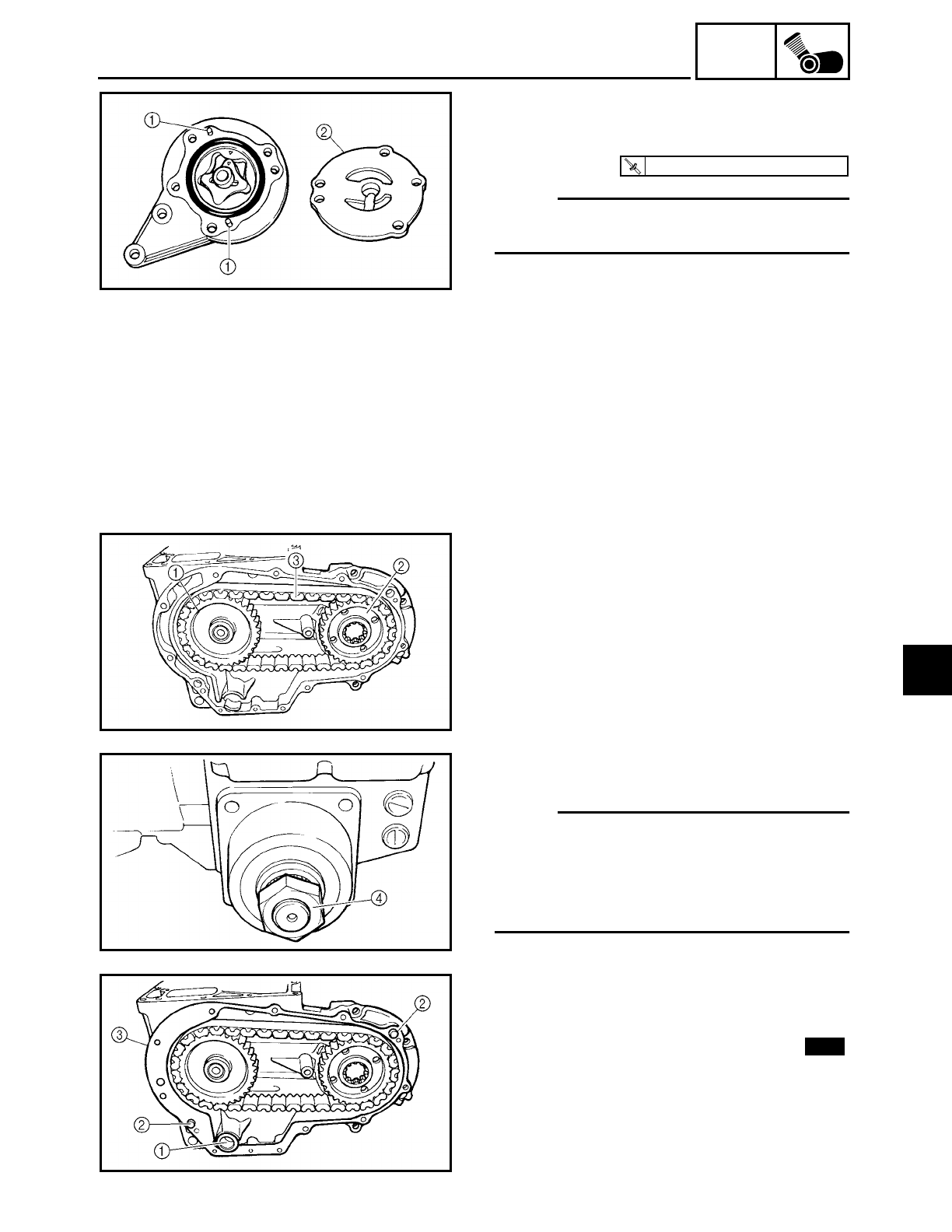
5 - 94
ENG
TRANSFER GEAR CASE
3. Install:
• pins 1
• oil pump cover 2
NOTE:
Apply locking agent (LOCTITE) to the
threads of the oil pump cover screws.
T
R
.
.
7 Nm (0.7 m · kg, 5.1 ft · lb)
4. Check:
• oil pump operation
Refer to “CHECKING THE OIL PUMP”.
INSTALLING THE TRANSFER GEAR CASE
1. Install:
• bearings
• oil seal
2. Install:
• middle driven shaft 1
• middle drive gear 2
• primary chain 3
(into the transfer gear case)
• O-ring
• spacer
• drive pulley nut 4
NOTE:
• Install the middle driven shaft, middle
drive gear and primary chain at the same
time.
• Temporarily install the drive pulley nut
onto the middle driven shaft.
3. Install:
• oil strainer 1
• dowel pins 2
• transfer gear case cover gasket 3New
5
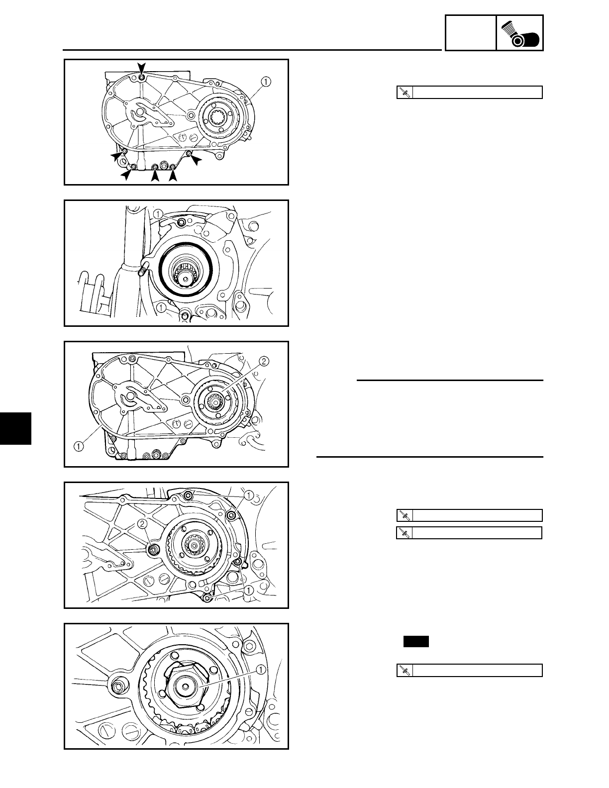
5 - 95
ENG
TRANSFER GEAR CASE
4. Install:
• transfer gear case cover 1
T
R
.
.
10 Nm (1.0 m · kg, 7.2 ft · lb)
5. Install:
• dowel pins 1
6. Install:
• transfer gear case assembly 1
NOTE:
• While installing the middle drive gear 2
onto the drive axle, install the transfer
gear case assembly onto the engine.
• Align the splines on the middle gear with
the splines on the drive axle.
7. Install:
• transfer gear case bolts 1
• nut 2
T
R
.
.
30 Nm (3.0 m · kg, 22 ft · lb)
T
R
.
.
30 Nm (3.0 m · kg, 22 ft · lb)
8. Install:
• lock washer
• middle drive gear nut 1
9. Bend the lock washer tab along a flat
side of the nut.
New
T
R
.
.
85 Nm (8.5 m · kg, 61 ft · lb)
5
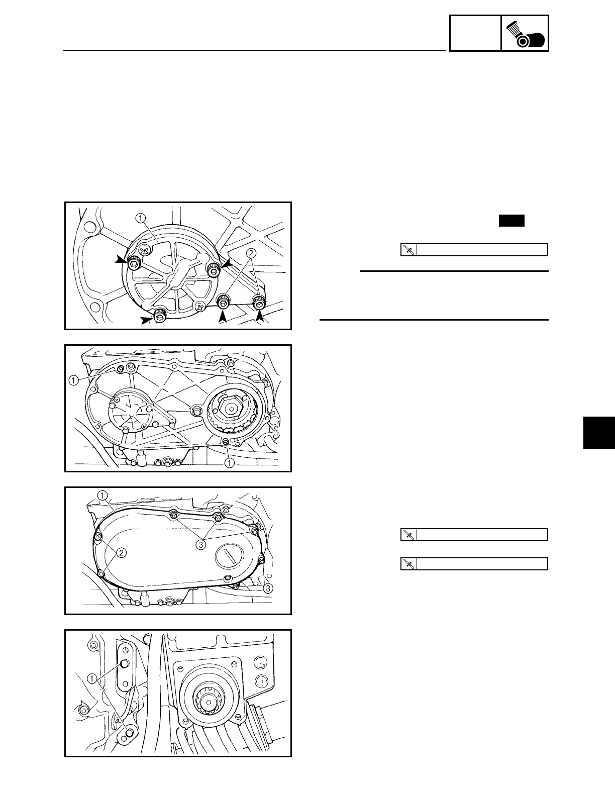
5 - 96
ENG
TRANSFER GEAR CASE
10.Remove:
• drive pulley nut
11.Install:
• transfer gear oil pump gasket
• transfer gear oil pump 1
NOTE:
Apply locking agent (LOCTITE) only to the
threads of the transfer gear oil pump bolts
2 (M6 × 25 mm bolts).
New
T
R
.
.
10 Nm (1.0 m · kg, 7.2 ft · lb)
12.Install:
• dowel pins 1
13.Install:
• cover 1
• cover bolts (M8) 2
• cover bolts (M6) 3
T
R
.
.
24 Nm (2.4 m · kg, 17 ft · lb)
T
R
.
.
10 Nm (1.0 m · kg, 7.2 ft · lb)
14.Install:
• dowel pins 1
5
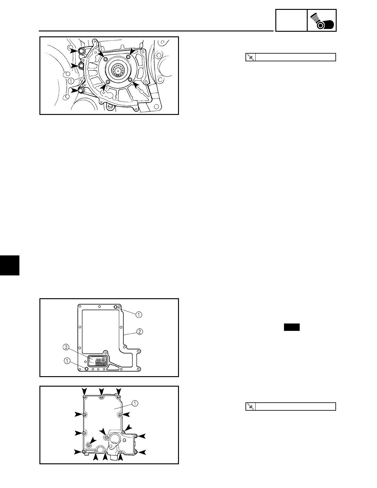
5 - 97
ENG
TRANSFER GEAR CASE
15.Install:
• drive pulley case 1
T
R
.
.
30 Nm (3.0 m · kg, 22 ft · lb)
16.Install:
• drive pulley
Refer to “DRIVE BELT AND DRIVE PUL-
LEY” in chapter 4.
17.Fill:
• transfer gear case
(with the specified amount of the recom-
mended transfer gear oil)
Refer to “CHANGING THE TRANSFER
GEAR OIL” in chapter 3.
INSTALLING THE OIL TANK COVER
1. Install:
• dowel pins 1
• oil tank cover gasket 2
• oil strainer 3
New
2. Install:
• oil tank cover 1
T
R
.
.
10 Nm (1.0 m · kg, 7.2 ft · lb)
5
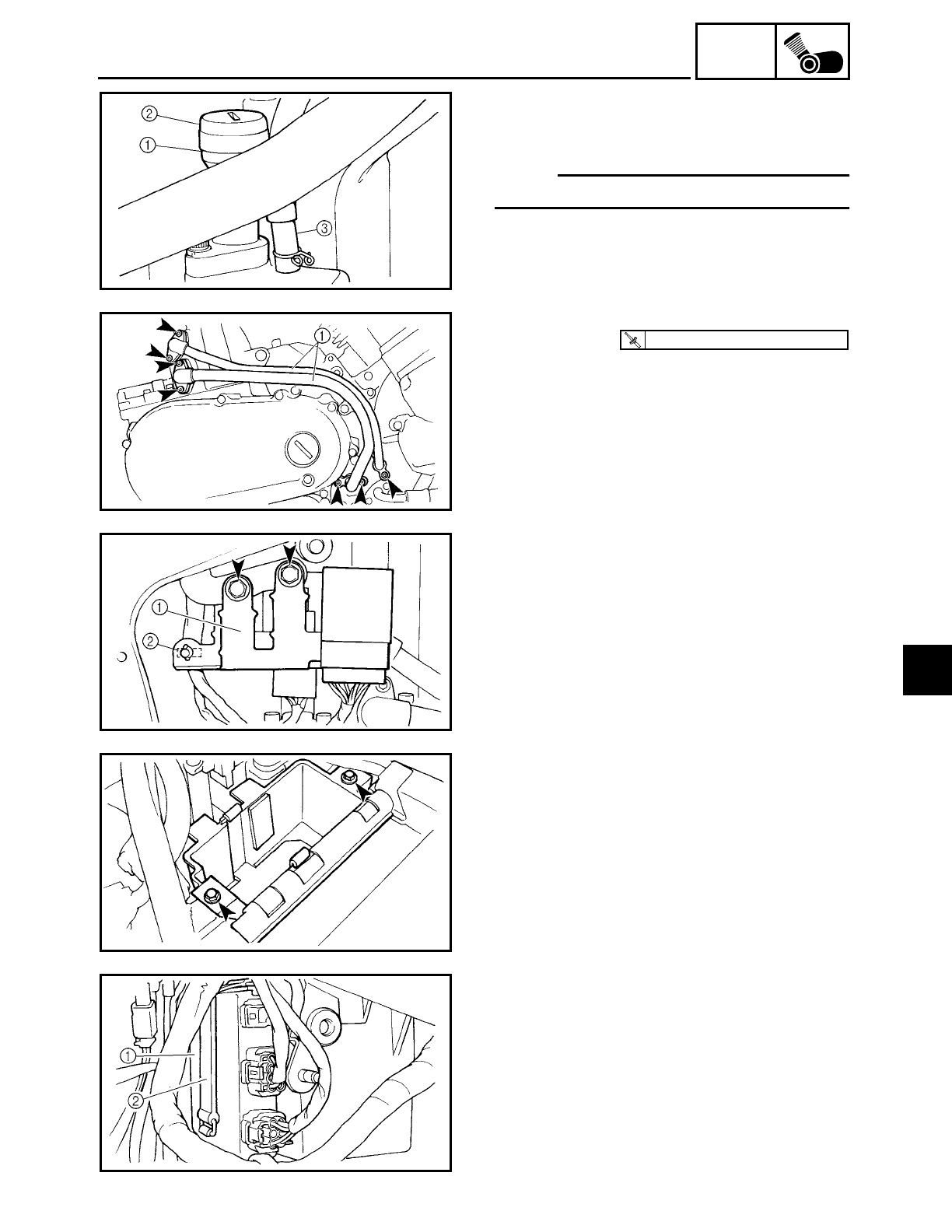
5 - 98
ENG
TRANSFER GEAR CASE
3. Install:
• dipstick joint 1
• dipstick 2
NOTE:
Finger tighten the dipstick joint bolt.
4. Connect:
• oil tank breather hose 3
5. Install:
• oil pipes 1
T
R
.
.
10 Nm (1.0 m · kg, 7.2 ft · lb)
INSTALLING THE BATTERY
1. Install:
• relay bracket 1
• plastic clamp 2
2. Connect:
• turn signal relay coupler
• relay unit coupler
3. Install:
• battery box
4. Install:
• ignitor unit 1
• ignitor unit holder 2
5. Connect:
• ignitor unit couplers
5
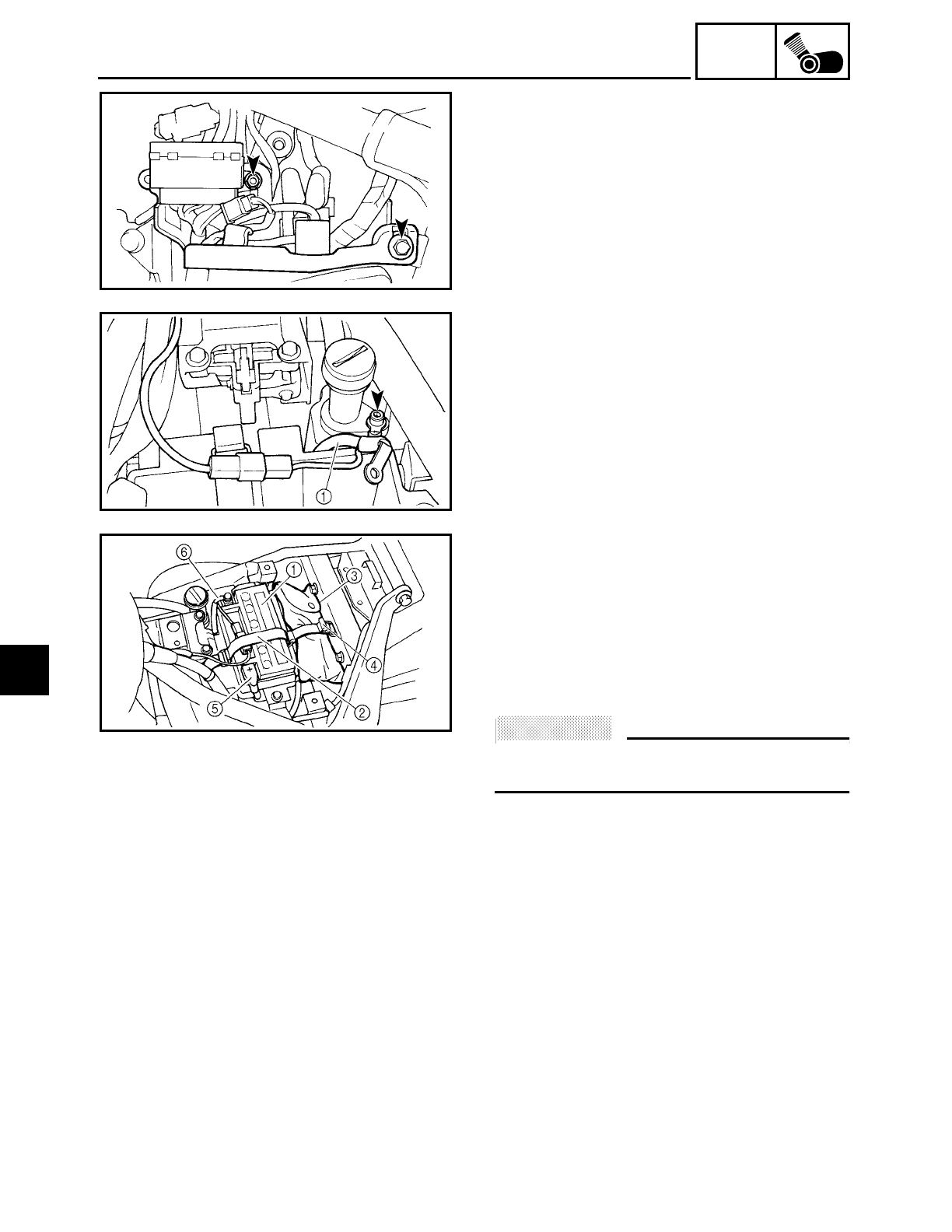
5 - 99
ENG
TRANSFER GEAR CASE
6. Install:
• plastic bracket
7. Install:
• negative battery lead 1
(to the dipstick joint)
8. Install:
• battery 1
• battery holder 2
• tool kit 3
• tool kit holder 4
9. Connect:
• battery leads
(to the battery terminals)
ACHTUNG:
CAUTION:
First, connect the positive battery lead 5,
then the negative battery lead 6.
10.Check:
• battery terminals
5
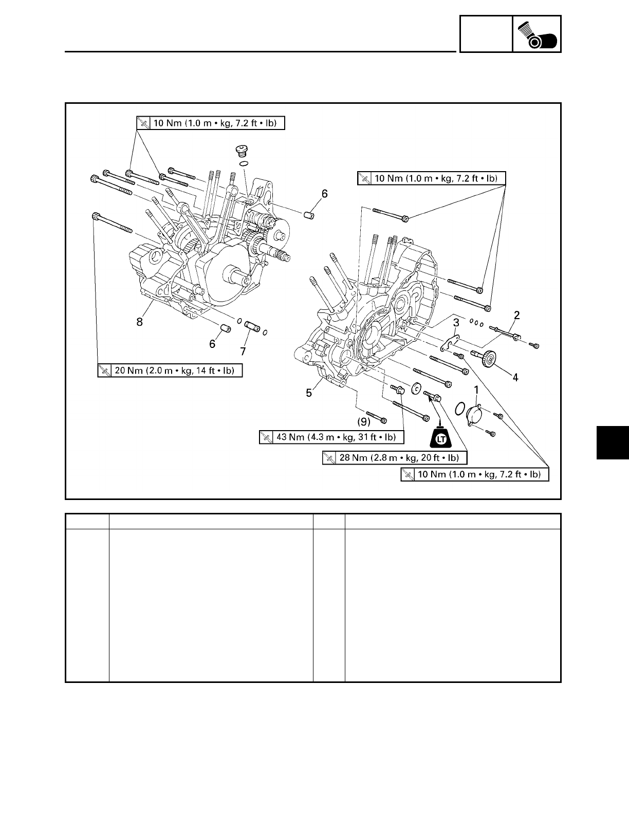
5 - 100
ENG
CRANKCASE
CRANKCASE
Order Job/Part Q’ty Remarks
Separating the crankcase Remove the parts in the order listed.
Engine Refer to “ENGINE”.
Camshaft Refer to “CAMSHAFTS”.
Piston Refer to “CYLINDERS AND PISTONS”.
Shift shaft Refer to “SHIFT SHAFT”.
Generator rotor Refer to “GENERATOR AND STARTER
CLUTCH”.
1 Generator shaft end cover 1
2 Oil delivery pipe 1
3 Engine oil pump driven gear stopper 1
5
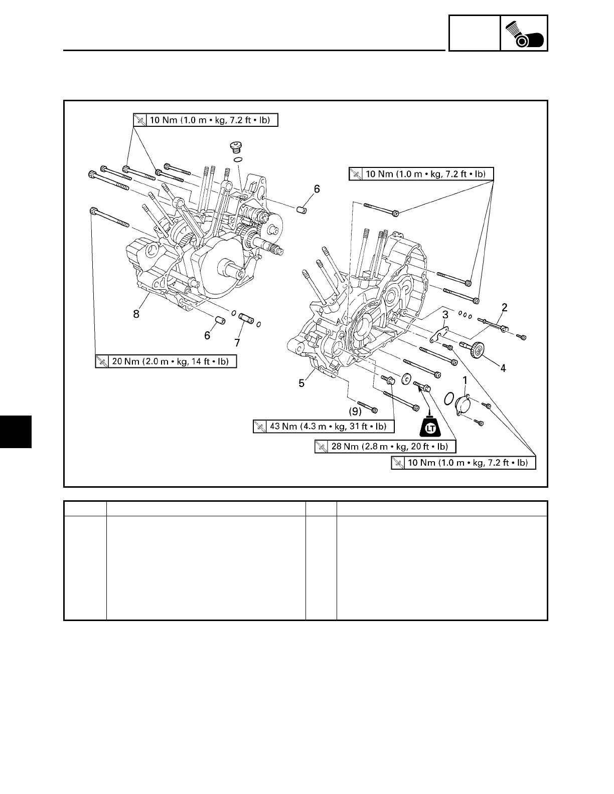
5 - 101
ENG
CRANKCASE
Order Job/Part Q’ty Remarks
4 Engine oil pump driven gear 1
5 Left crankcase 1
6 Dowel 2
7 Joint pipe 1
8 Right crankcase 1
For installation, reverse the removal
procedure.
5
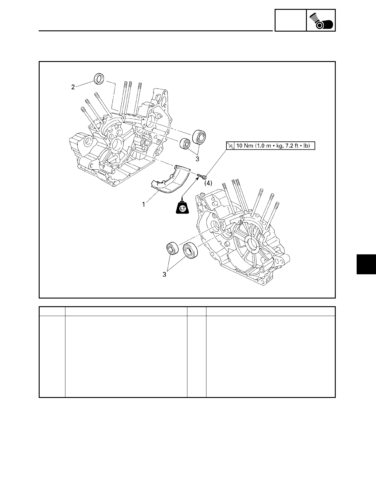
5 - 102
ENG
CRANKCASE
Order Job/Part Q’ty Remarks
Removing the baffle plate and bear-
ings
Remove the parts in the order listed.
Crankshaft Refer to “CRANKSHAFT”.
Transmission Refer to “TRANSMISSION”.
1 Baffle plate 1
2 Oil seal 1
3 Bearing 4
Installation, reverse the removal proce-
dure.
5
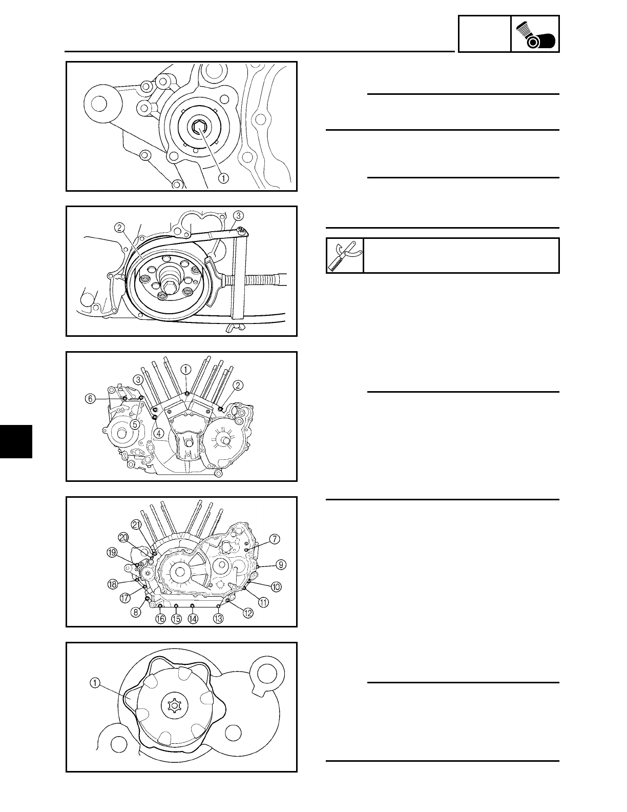
5 - 103
ENG
CRANKCASE
EAS00386
DISASSEMBLING THE CRANKCASE
NOTE:
Loosen the generator shaft bolt before
removing the generator rotor.
1. Remove:
• generator shaft bolt 1
NOTE:
While the holding the generator rotor
2
with the sheave holder
3, loosen the gen-
erator shaft bolt.
Sheave holder
YS-01880
2. Remove:
• crankcase bolts
NOTE:
• Loosen each bolt 1/4 of a turn at a time, in
stages and in a crisscross pattern. After all
of the bolts are fully loosened, remove
them.
• Loosen the bolts in decreasing numerical
order (refer to the numbers in the illustra-
tion).
ÅRight crankcase
ıLeft crankcase
M8
× 100 mm bolts:
1,
2
M8 × 80 mm bolt: 3
M6 × 105 mm bolt: K
M6 × 85 mm bolts: 9,C
M6 × 75 mm bolts: D,E
M6 × 60 mm bolts: 4 ~ 7
M6 × 40 mm bolts: 8,0 ~ B,F ~ J
Å
ı
3. Turn:
• shift drum segment
NOTE:
Turn the shift drum segment
1 to the posi-
tion shown in the illustration. In this posi-
tion, the shift drum segment’s teeth will not
contact the crankcase during crankcase sep-
aration.
5
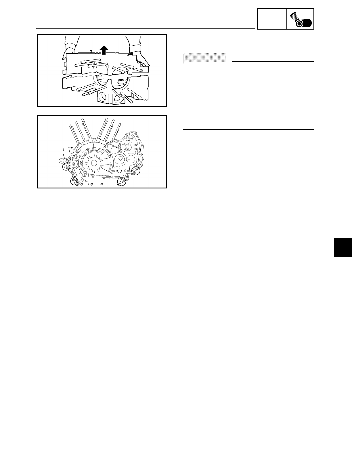
5 - 104
ENG
CRANKCASE
4. Remove:
• right crankcase
ACHTUNG:
CAUTION:
• First check that the shift drum segment’s
teeth then remove the right crankcase.
• Tap on one side of the crankcase with a
soft-face hammer. Tap only on reinforced
portions of the crankcase, not on the
crankcase mating surfaces. Work slowly
and carefully and make sure the crank-
case halves separate evenly.
EAS00399
CHECKING THE CRANKCASE
1. Thoroughly wash the crankcase halves in
a mild solvent.
2. Thoroughly clean all the gasket surfaces
and crankcase mating surfaces.
3. Check:
• crankcase
Cracks/damage → Replace.
• oil delivery passages
Obstruction → Blow out with com-
pressed air.
EAS00401
CHECKING THE BEARINGS AND OIL SEAL
1. Check:
• bearings
Clean and lubricate the bearings, then
rotate the inner race with your finger.
Rough movement → Replace.
2. Check:
• oil seal
Damage/wear → Replace.
5
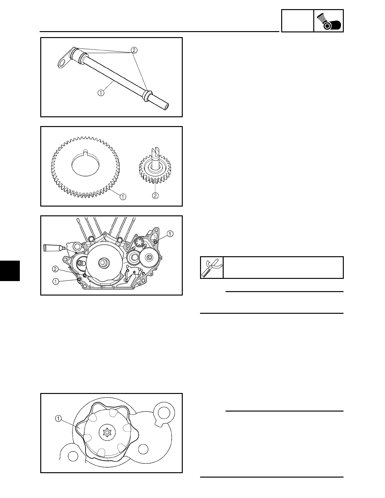
5 - 105
ENG
CRANKCASE
CHECKING THE OIL DELIVERY PIPE
1. Check:
• oil delivery pipe
1
Damage
→ Replace.
Obstruction → Wash and blow out with
compressed air.
• O-rings 2
Damage/wear → Replace.
CHECKING THE ENGINE OIL PUMP DRIVE
1. Check:
• oil pump drive gear
1
• oil pump driven gear 2
Chips/pitting/roughness/wear → Replace
the defective part(s).
EAS00416
ASSEMBLING THE CRANKCASE
1. Apply:
• sealant
(onto the crankcase mating surfaces)
NOTE:
Do not allow any sealant to come into con-
tact with the oil gallery.
2. Install:
• dowel pins 1
• joint pipe 2
Quick Gasket
ACC-11001-05-01
3. Install:
• left crankcase
(onto the right crankcase)
NOTE:
• Turn the shift drum segment 1 to the
position shown in the illustration. In this
position, the shift drum segment’s teeth
will not contact the crankcase during
crankcase installation.
• Tap lightly on the left crankcase with a
soft-face hammer.
5
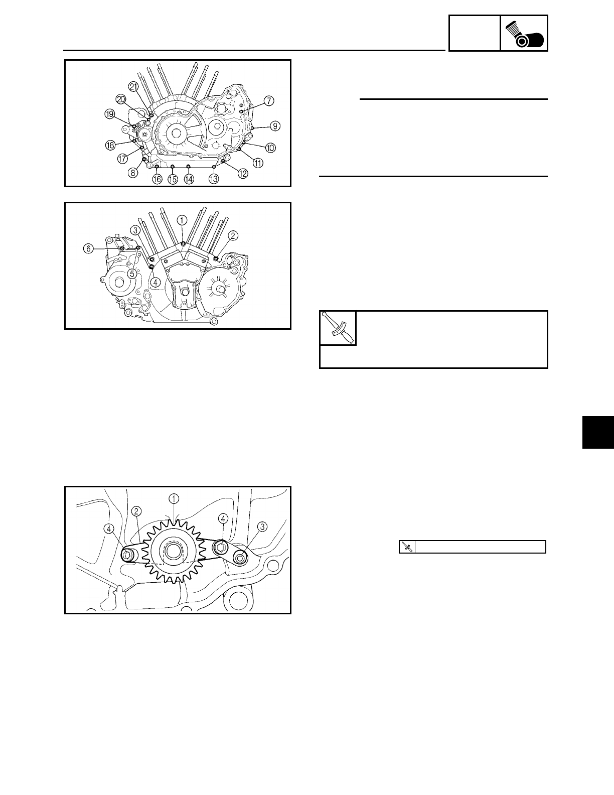
5 - 106
ENG
CRANKCASE
4. Install:
• crankcase bolts
NOTE:
• Lubricate the bolt threads with engine oil.
• Tighten each bolt 1/4 of a turn at a time, in
stages and in a crisscross pattern.
• Tighten the bolts in numerical order (refer
to the numbers in the illustration).
ÅLeft crankcase
ıRight crankcase
M8
× 100 mm bolts:
1,
2
M8 × 80 mm bolt: 3
M6 × 105 mm bolt: K
M6 × 85 mm bolts: 9,C
M6 × 75 mm bolts: D,E
M6 × 60 mm bolts: 4 ~ 7
M6 × 40 mm bolts: 8,0 ~ B,F ~ J
5. Check:
• crankshaft and transmission operation
Rough movement → Repair.
T
R
.
.
Bolt
1 ~
3
24 Nm (2.4 m • kg, 17 ft • lb)
Bolt
4 ~
K
10 Nm (1.0 m • kg, 7.2 ft • lb)
Å
ı
6. Install:
• engine oil pump driven gear 1
• engine oil pump driven gear stopper 2
• oil delivery pipe 3
• bolts 4
T
R
.
.
10 Nm (1.0 m · kg, 7.2 ft · lb)
7. Install:
• generator rotor
Refer to “GENERATOR AND STARTER
CLUTCH”.
5
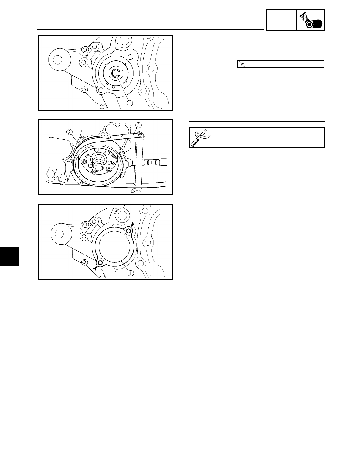
5 - 107
ENG
CRANKCASE
8. Install:
• washer
• generator shaft bolt 1
NOTE:
• Apply locking agent (LOCTITE) to the
threads of the generator shaft bolt.
• While holding the generator rotor 2 with
the sheave holder 3, tighten the genera-
tor shaft bolt.
Sheave holder
YS-01880
T
R
.
.
28 Nm (2.8 m · kg, 20 ft · lb)
9. Install:
• generator shaft end cover 1
10.Install:
• shift shaft
• clutch
Refer to “SHIFT SHAFT” and “CLUTCH”.
• pistons
• cylinders
Refer to “CYLINDERS AND PISTONS”.
• camshaft
Refer to “CAMSHAFTS”.
• cylinder head
Refer to “ROCKER ARMS, PUSH RODS
AND VALVE LIFTERS”.
11.Install:
• engine
Refer to “ENGINE”.
5
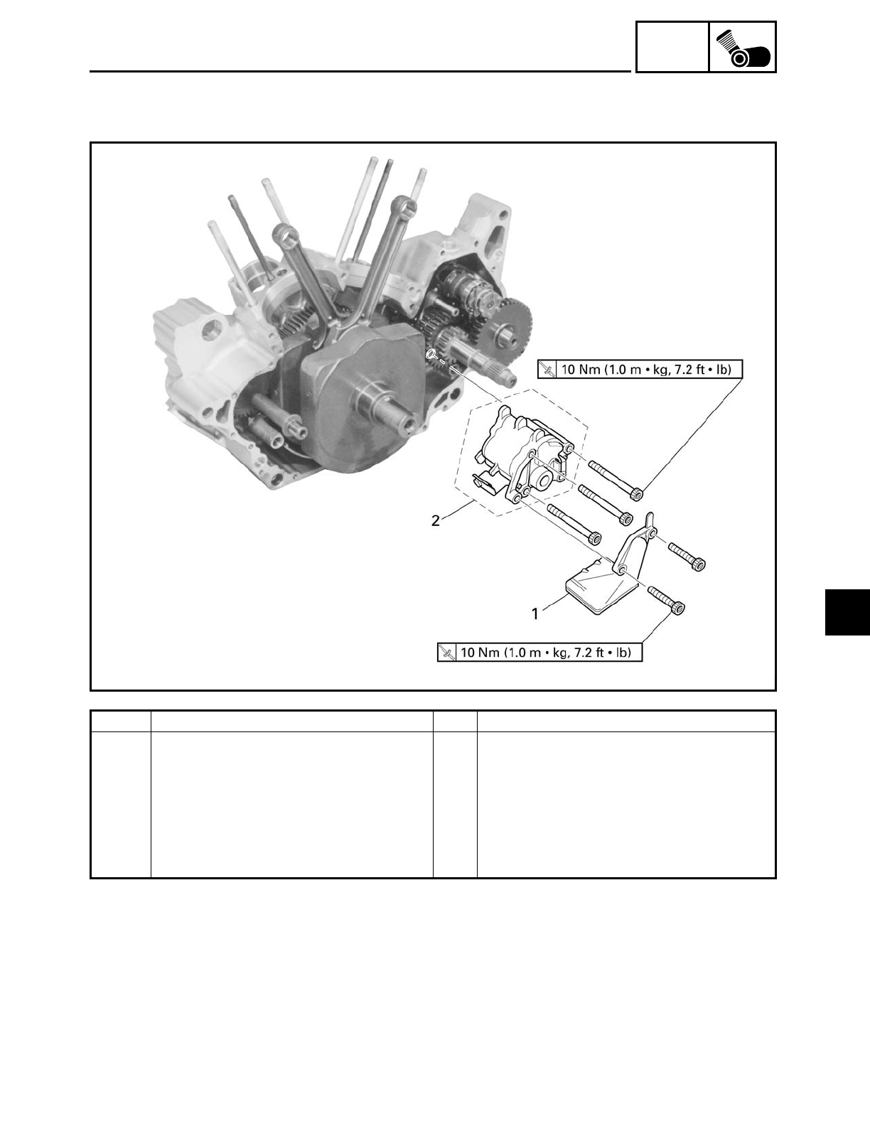
5 - 108
ENG
ENGINE OIL PUMP
ENGINE OIL PUMP
Order Job/Part Q’ty Remarks
Removing the engine oil pump Remove the parts in the order listed.
Crankcase Separate.
Refer to “CRANKCASE”.
1 Oil strainer 1
2 Engine oil pump assembly 1
Installation, reverse the removal proce-
dure.
5
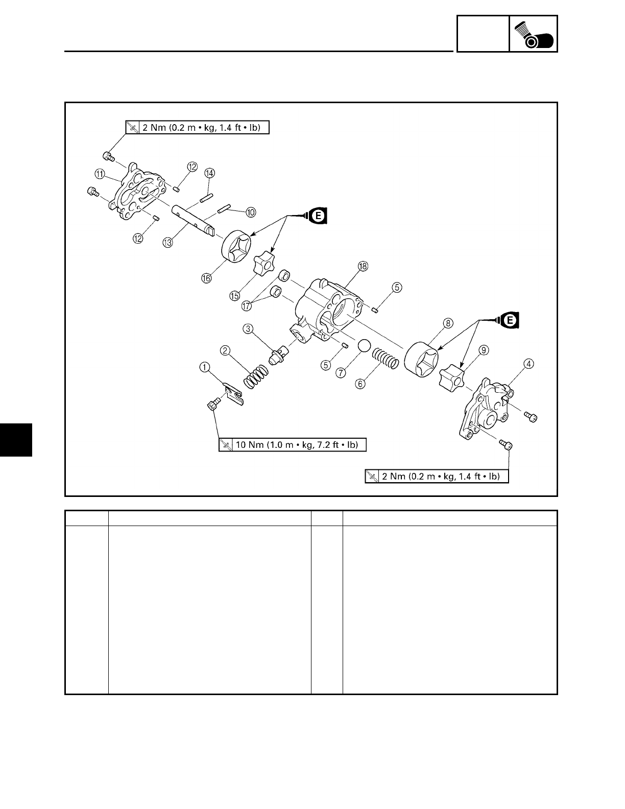
5 - 109
ENG
ENGINE OIL PUMP
Order Job/Part Q’ty Remarks
Disassembling the engine oil pump Remove the parts in the order listed.
1Spring retainer 1
2Spring 1
3Relief valve 1
4Oil pump housing cover 1 1
5Pin 2
6Spring 1
7Ball 1
8Oil pump outer rotor 1 1
9Oil pump inner rotor 1 1
0Pin 1
5
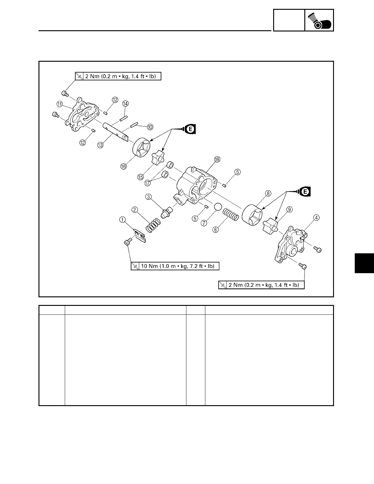
5 - 110
ENG
ENGINE OIL PUMP
Order Job/Part Q’ty Remarks
AOil pump housing cover 2 1
BPin 2
COil pump shaft 1
DPin 1
EOil pump inner rotor 2 1
FOil pump outer rotor 2 1
GOil seal 2
HOil pump housing 1
For assembly, reverse the disassembly
procedure.
5
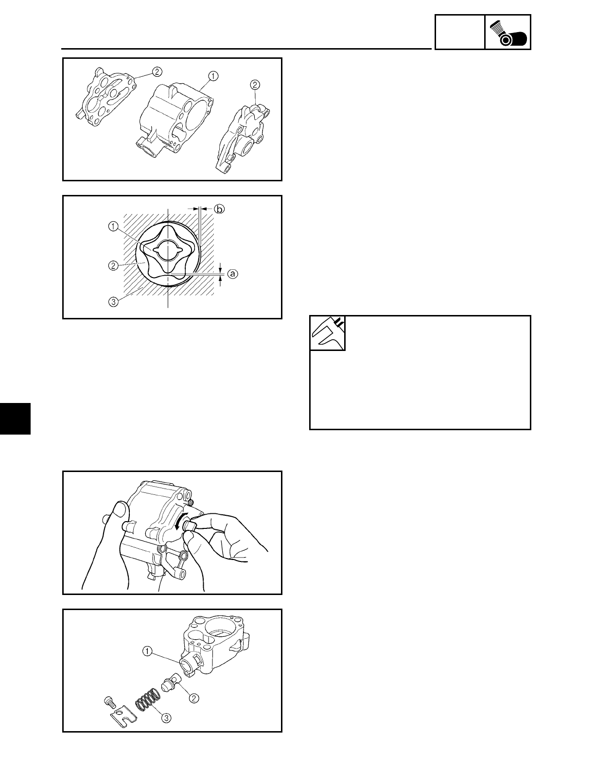
5 - 111
ENG
ENGINE OIL PUMP
EAS00363
CHECKING THE OIL PUMP
1. Check:
• oil pump housing 1
• oil pump housing covers 2
Cracks/damage/wear → Replace the
defective part(s).
2. Measure:
• inner rotor-to-outer rotor tip clearance a
• outer rotor-to-oil pump housing clear-
ance b
Out of specification → Replace the oil
pump.
1Inner rotor
2Outer rotor
3Oil pump housing
Inner rotor-to-outer rotor tip
clearance
0 ~ 0.12 mm (0 ~ 0.005 in)
Outer rotor-to-oil pump housing
clearance (feed pump)
0.03 ~ 0.08 mm (0.001 ~ 0.003 in)
Outer rotor-to-oil pump housing
clearance (scavenging pump)
0.06 ~ 0.11 mm (0.001 ~ 0.004 in)
3. Check:
• oil pump operation
Rough movement → Repeat steps (1)
and (2) or replace the defective part(s).
EAS00365
CHECKING THE RELIEF VALVE
1. Check:
• relief valve body 1
• relief valve 2
• spring 3
Damage/wear → Replace the defective
part(s).
5
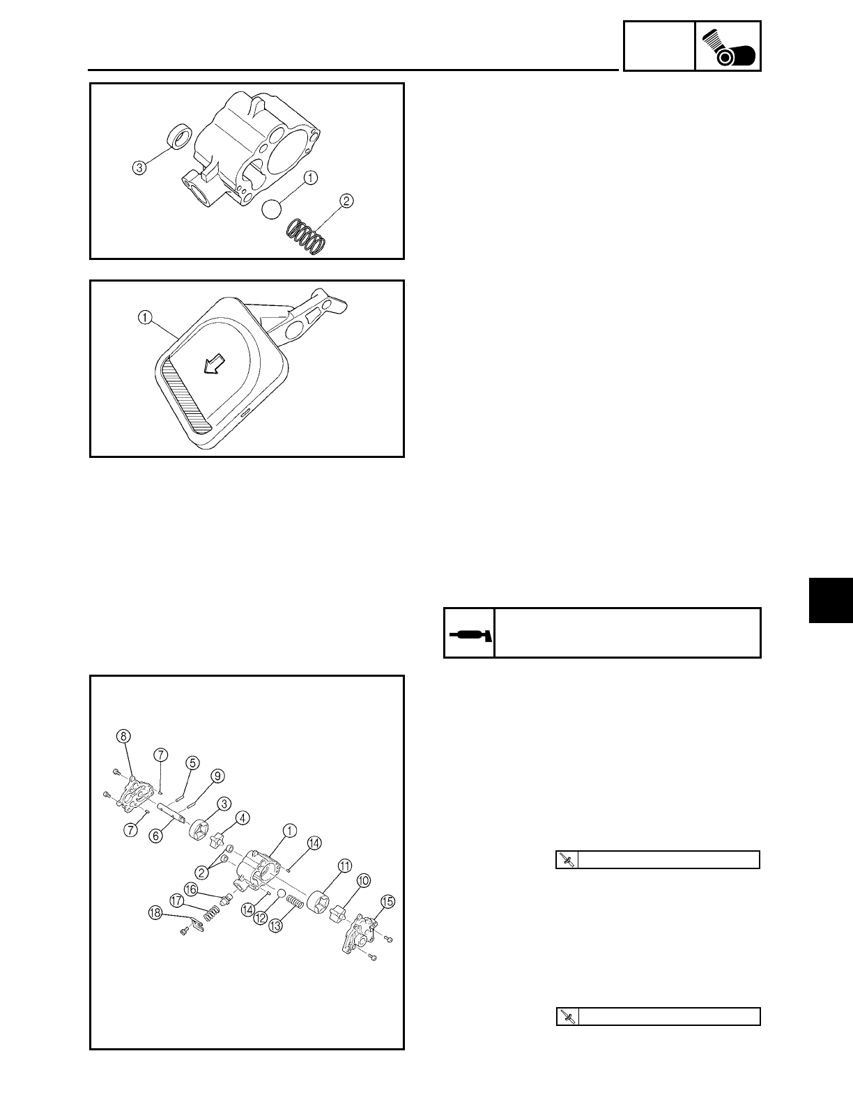
5 - 112
ENG
ENGINE OIL PUMP
2. Check:
• ball 1
• spring 2
• oil seal 3
Damage/wear → Replace the defective
part(s).
EAS00368
CHECKING THE OIL STRAINER
1. Check:
• oil strainer 1
Damage → Replace.
Contaminants → Clean with engine oil.
EAS00374
ASSEMBLING THE OIL PUMP
1. Lubricate:
• inner rotor
• outer rotor
• oil pump shaft
(with the recommended lubricant)
Recommended lubricant
Engine oil
2. Install:
• oil pump housing 1
• oil seals 2
• oil pump outer rotor 2 3
• oil pump inner rotor 2 4
• pin 5
• oil pump shaft 6
• pins 7
• oil pump housing cover 2 8
• pin 9
• oil pump inner rotor 1 0
• oil pump outer rotor 1 A
• ball B
• spring C
• pins D
• oil pump housing cover 1 E
• relief valve F
T
R
.
.
2 Nm (0.2 m · kg, 1.4 ft · lb)
T
R
.
.
2 Nm (0.2 m · kg, 1.4 ft · lb)
5
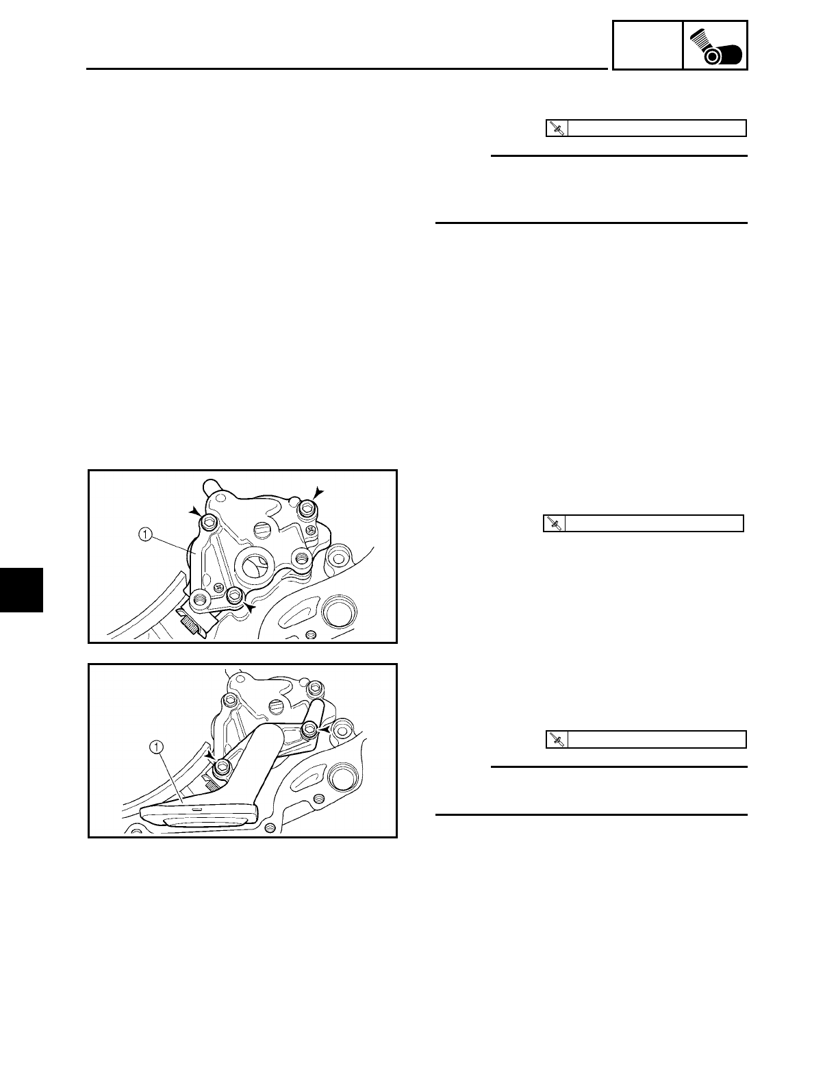
5 - 113
ENG
ENGINE OIL PUMP
• spring G
• spring retainer H
NOTE:
When installing the inner rotor, align the
pin in the oil pump shaft with the groove in
the inner rotor.
T
R
.
.
10 Nm (1.0 m · kg, 7.2 ft · lb)
3. Check:
• oil pump operation
Refer to “CHECKING THE OIL PUMP”.
EAS00376
INSTALLING THE OIL PUMP
1. Install:
• oil pump 1
T
R
.
.
10 Nm (1.0 m · kg, 7.2 ft · lb)
EAS00378
INSTALLING THE OIL STRAINER
1. Install:
• oil strainer 1
NOTE:
The arrow a on the oil strainer cover must
point towards the rear of the engine.
T
R
.
.
10 Nm (1.0 m · kg, 7.2 ft · lb)
5
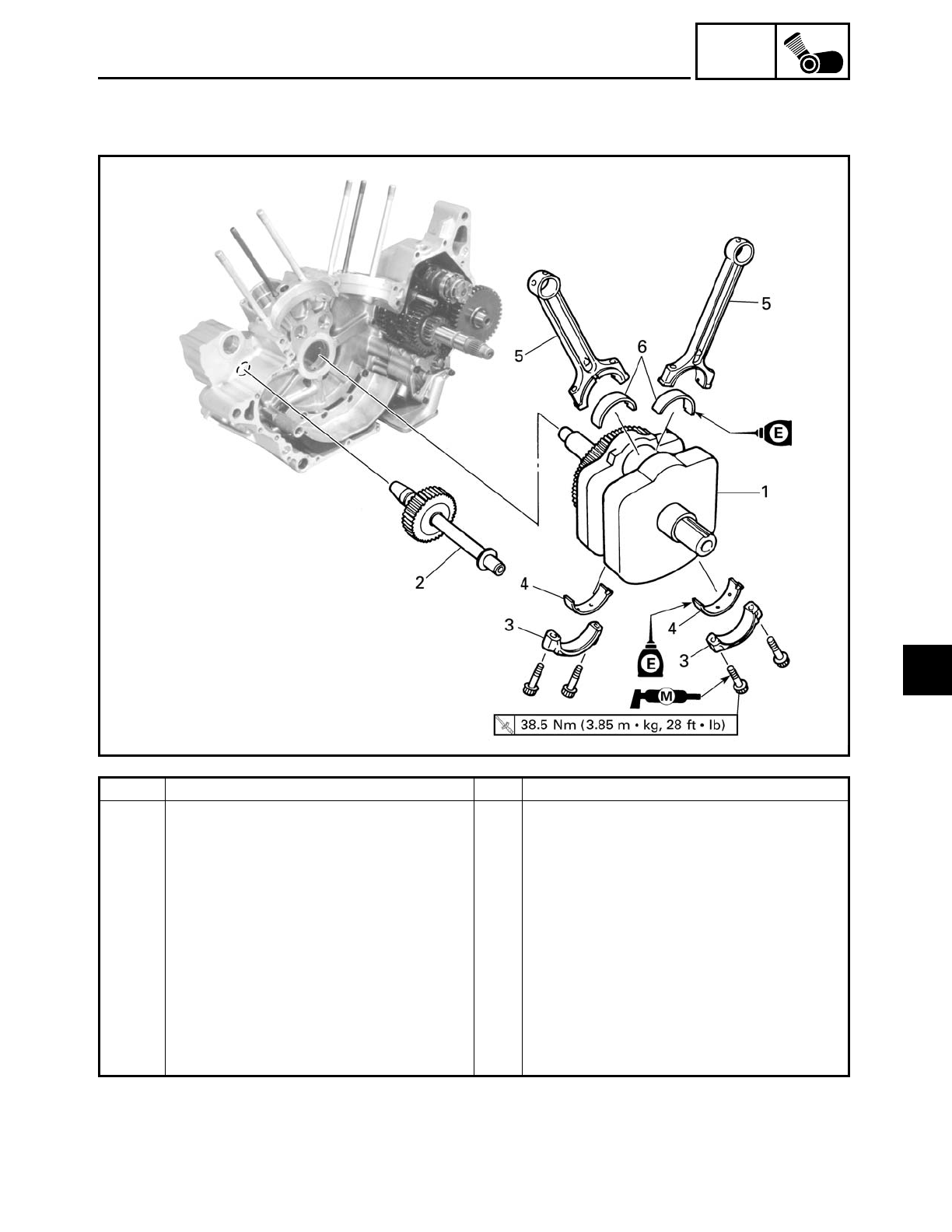
5 - 114
ENG
CRANKSHAFT AND CONNECTING RODS
CRANKSHAFT AND CONNECTING RODS
Order Job/Part Q’ty Remarks
Removing the crankshaft and con-
necting rods
Remove the parts in the order listed.
Crankcase Separate.
Refer to “CRANKCASE”.
1 Crankshaft 1
2 Generator shaft 1
3 Connecting rod cap 2
4 Big end lower bearing 2
5 Connecting rod 2
6 Big end upper bearing 2
For installation, reverse the removal
procedure.
5
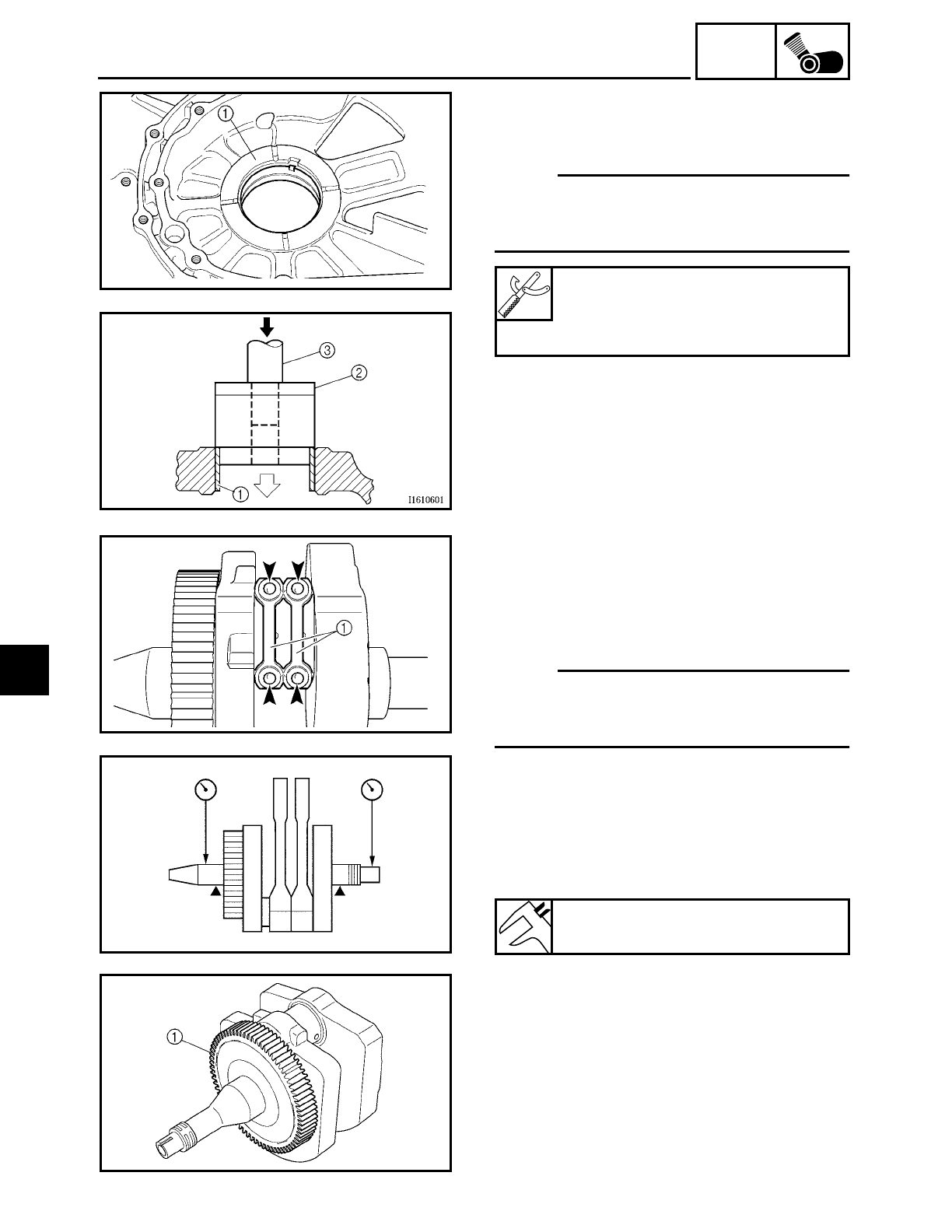
5 - 115
ENG
CRANKSHAFT AND CONNECTING RODS
REMOVING THE CRANKSHAFT
1. Remove:
• crankshaft journal bearing 1
NOTE:
Remove the crankshaft journal bearing with
the bearing remover and installer 2 and
bearing driver 3.
Bearing remover and installer
YM-28898
Bearing driver
YM-04058
EAS00391
REMOVING THE CONNECTING RODS
1. Remove:
• connecting rod caps 1
• connecting rods
• big end bearings
NOTE:
Identify the position of each big end bear-
ing so that it can be reinstalled in its origi-
nal place.
EAS00398
CHECKING THE CRANKSHAFT AND
CONNECTING RODS
1. Measure:
• crankshaft runout
Out of specification → Replace the crank-
shaft.
Maximum crankshaft runout
0.04 mm (0.0016 in)
2. Check:
• crankshaft journal surfaces
• crankshaft pin surfaces
• bearing surfaces
Scratches/wear → Replace the crankshaft
and bearings.
• generator shaft drive gear 1
Damage/wear → Replace the crankshaft.
5
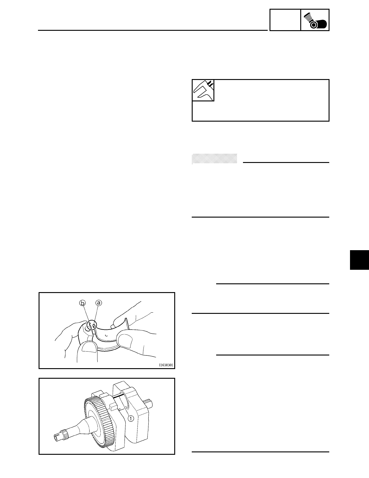
5 - 116
ENG
CRANKSHAFT AND CONNECTING RODS
3. Measure:
• crankshaft pin-to-big end bearing clear-
ance
Out of specification → Replace the big
end bearings.
▼ ▼ ▼ ▼ ▼ ▼ ▼ ▼ ▼ ▼ ▼ ▼ ▼ ▼ ▼ ▼ ▼ ▼ ▼ ▼ ▼ ▼ ▼ ▼ ▼ ▼ ▼ ▼
The following procedure applies to all of
the connecting rods.
ACHTUNG:
CAUTION:
Do not interchange the big end bearings
and connecting rods. To obtain the correct
crankshaft pin-to-big end bearing clearance
and prevent engine damage, the big end
bearings must be installed in their original
positions.
a. Clean the big end bearings, crankshaft
pins, and the inside of the connecting
rod halves.
b. Install the big end upper bearing into the
connecting rod and the big end lower
bearing into the connecting rod cap.
NOTE:
Align the projections a on the big end
bearings with the notches b in the connect-
ing rod and connecting rod cap.
c. Put a piece of Plastigauge1 on the
crankshaft pin.
d. Assemble the connecting rod halves.
NOTE:
• Do not move the connecting rod or crank-
shaft until the clearance measurement
has been completed.
• Lubricate the bolt threads and seats with
molybdenum disulfide grease.
• Make sure the projection c on the con-
necting rod faces towards the left side of
the crankshaft.
• Make sure the characters d on both the
connecting rod and connecting rod cap
are aligned.
Crankshaft pin-to-big end bearing
clearance
0.037 ~ 0.074 mm
(0.0015 ~ 0.0029 in)
<Limit>: 0.09 mm (0.0035 in)
5
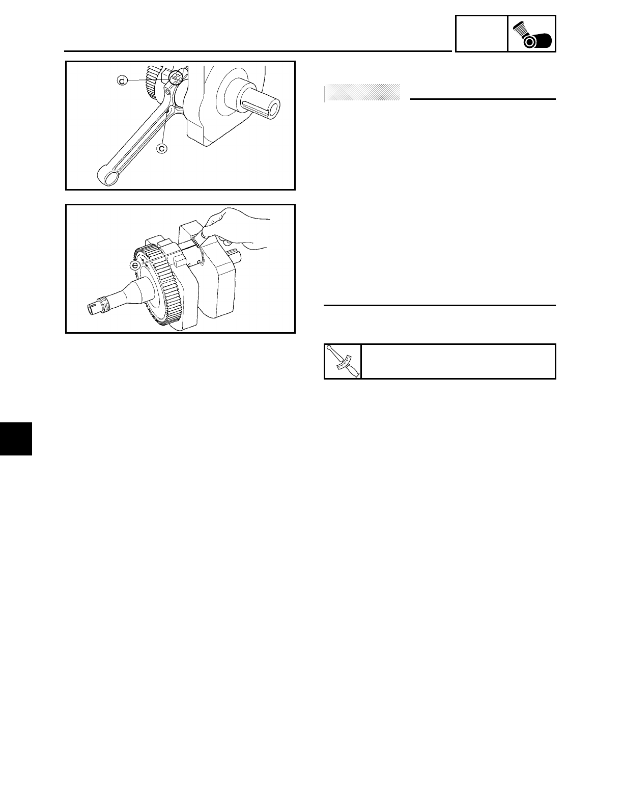
5 - 117
ENG
CRANKSHAFT AND CONNECTING RODS
e. Tighten the connecting rod bolts.
ACHTUNG:
CAUTION:
• When tightening the connecting rod
bolts, be sure to use an F-type torque
wrench.
• Without pausing, tighten the connecting
rod bolts to the specified torque. Apply
continuous torque between 3.3 and 4.0 m
• kg (24 and 29 ft • lb). Once you reach 3.3
m • kg (24 ft • lb), DO NOT STOP TIGHT-
ENING until the specified torque is
reached. If the tightening is interrupted
between 3.3 and 4.0 m • kg (24 and 29 ft •
lb), loosen the connecting rod bolts to
less than 3.3 m • kg (24 ft • lb) and start
again.
Refer to “INSTALLING THE CONNECT-
ING RODS”.
f. Remove the connecting rod and big end
bearings.
Refer to “REMOVING THE CONNECTING
RODS”.
g. Measure the compressed Plastigauge
width e on each crankshaft pin.
If the crankshaft pin-to-big end bearing
clearance is out of specification, select
replacement big end bearings.
▲ ▲ ▲ ▲ ▲ ▲ ▲ ▲ ▲ ▲ ▲ ▲ ▲ ▲ ▲ ▲ ▲ ▲ ▲ ▲ ▲ ▲ ▲ ▲ ▲ ▲ ▲ ▲
T
R
.
.
Connecting rod bolt
38.5 Nm (3.85 m • kg, 28 ft • lb)
5
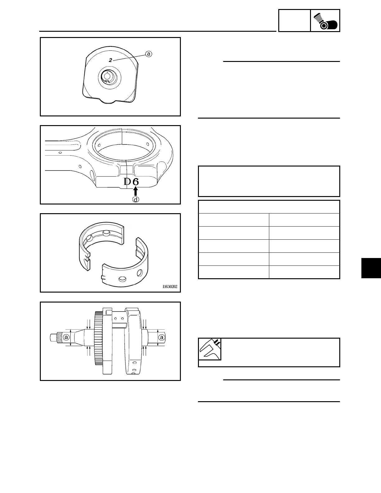
5 - 118
ENG
CRANKSHAFT AND CONNECTING RODS
4. Select:
• big end bearings (P1 ~ P2)
NOTE:
• The numbers a stamped into the crank-
shaft web and the numbers b on the con-
necting rods are used to determine the
replacement big end bearing sizes.
•“P
1” ~ “P2” refer to the bearings shown in
the crankshaft illustration.
▼ ▼ ▼ ▼ ▼ ▼ ▼ ▼ ▼ ▼ ▼ ▼ ▼ ▼ ▼ ▼ ▼ ▼ ▼ ▼ ▼ ▼ ▼ ▼ ▼ ▼ ▼ ▼
For example, if the connecting rod “P1” and
the crankshaft web “P1” numbers are “6”
and “2” respectively, then the bearing size
for “P1” is:
▲ ▲ ▲ ▲ ▲ ▲ ▲ ▲ ▲ ▲ ▲ ▲ ▲ ▲ ▲ ▲ ▲ ▲ ▲ ▲ ▲ ▲ ▲ ▲ ▲ ▲ ▲ ▲
“P1” (connecting rod) – “P1” (crank-
shaft web) =
6 – 2 = 4 (green)
BIG END BEARING COLOR CODE
1 blue
2 black
3 brown
4 green
5 yellow
5. Measure:
• crankshaft journal diameter a
Out of specification → Replace the crank-
shaft.
NOTE:
Measure the diameter of each crankshaft
journal at two places.
Crankshaft journal diameter
49.968 ~ 49.980 mm
(1.967 ~ 1.968 in)
5
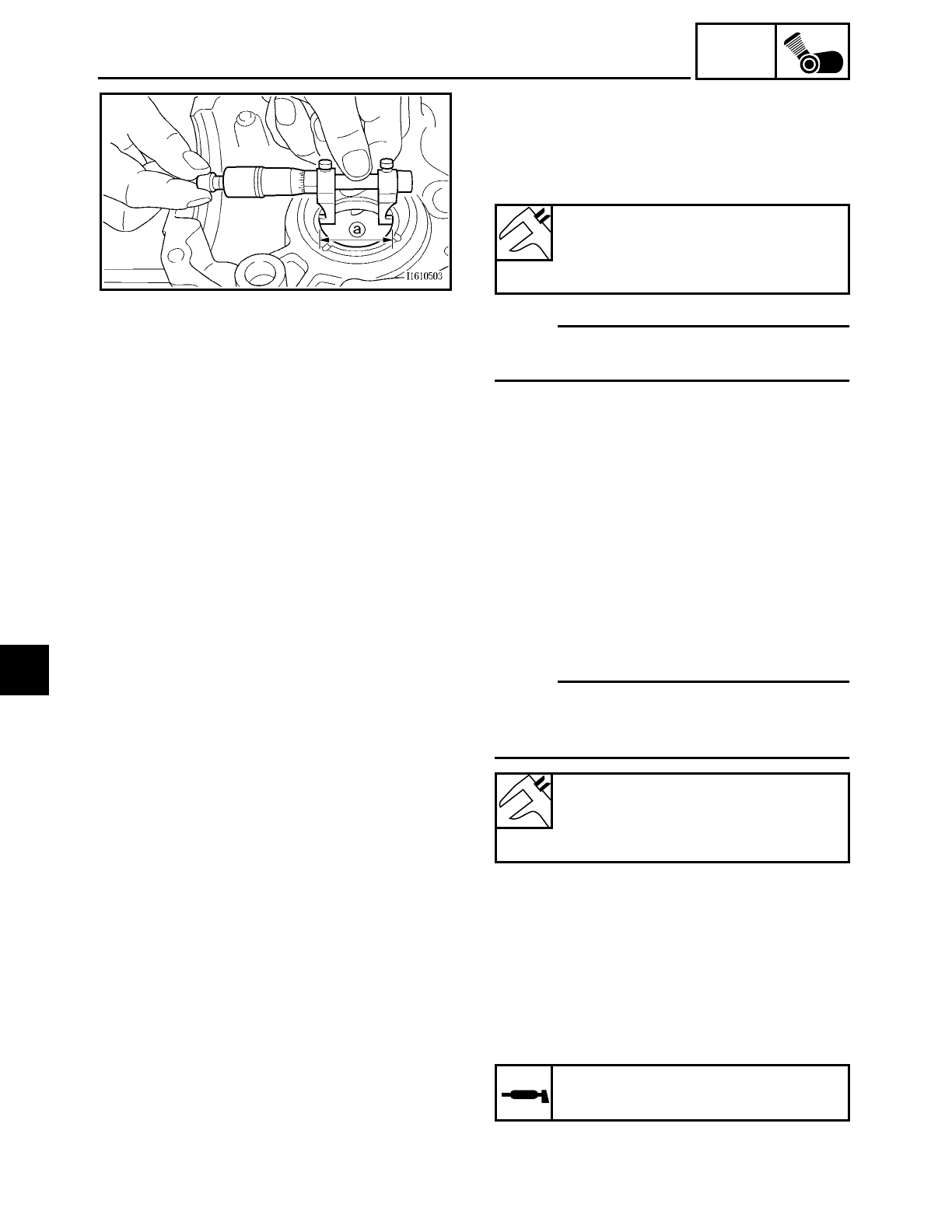
5 - 119
ENG
CRANKSHAFT AND CONNECTING RODS
6. Measure:
• crankshaft journal bearing inside diame-
ter a
Out of specification → Replace the
crankcase assembly.
NOTE:
Measure the inside diameter of each crank-
shaft journal bearing at two places.
Crankshaft journal bearing inside
diameter
50.01 ~ 50.03 mm
(1.969 ~ 1.970 in)
7. Calculate:
• crankshaft journal-to-crankshaft journal
bearing clearance
Out of specification → Replace the crank-
shaft and crankshaft journal bearings as
a set.
NOTE:
Calculate the clearance by subtracting the
crankshaft journal diameter from the crank-
shaft journal bearing inside diameter.
Crankshaft journal-to-crankshaft
journal bearing clearance
0.030 ~ 0.062 mm
(0.0012 ~ 0.0024 in)
INSTALLING THE CONNECTING RODS
1. Lubricate:
• bolt threads and seats
(with the recommended lubricant)
Recommended lubricant
Molybdenum disulfide grease
5
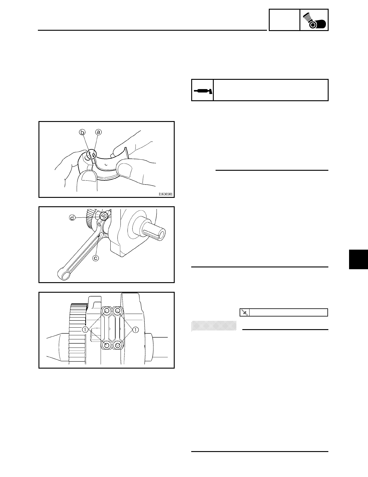
5 - 120
ENG
CRANKSHAFT AND CONNECTING RODS
2. Lubricate:
• crankshaft pins
• big end bearings
• connecting rod inner surface
(with the recommended lubricant)
Recommended lubricant
Engine oil
3. Install:
• big end bearings
• connecting rods
• connecting rod caps
(onto the crankshaft pins)
NOTE:
• Align the projections a on the big end
bearings with the notches b in the con-
necting rods and connecting rod caps.
• Be sure to reinstall each big end bearing
in its original place.
• Make sure the projection c on the con-
necting rods face towards the left side of
the crankshaft.
• Make sure the characters d on both the
connecting rod and connecting rod cap
are aligned.
4. Tighten:
• connecting rod bolt 1
ACHTUNG:
CAUTION:
• When tightening the connecting rod
bolts, be sure to use an F-type torque
wrench.
• Without pausing, tighten the connecting
rod bolts to the specified torque. Apply
continuous torque between 3.3 and 4.0 m
• kg (24 and 29 ft • lb). Once you reach 3.3
m • kg (24 ft • lb), DO NOT STOP TIGHT-
ENING until the specified torque is
reached. If the tightening is interrupted
between 3.3 and 4.0 m • kg (24 and 29 ft •
lb), loosen the connecting rod bolts to
less than 3.3 m • kg (24 ft • lb) and start
again.
T
R
.
.
40 Nm (4.0 m · kg, 29 ft · lb)
5
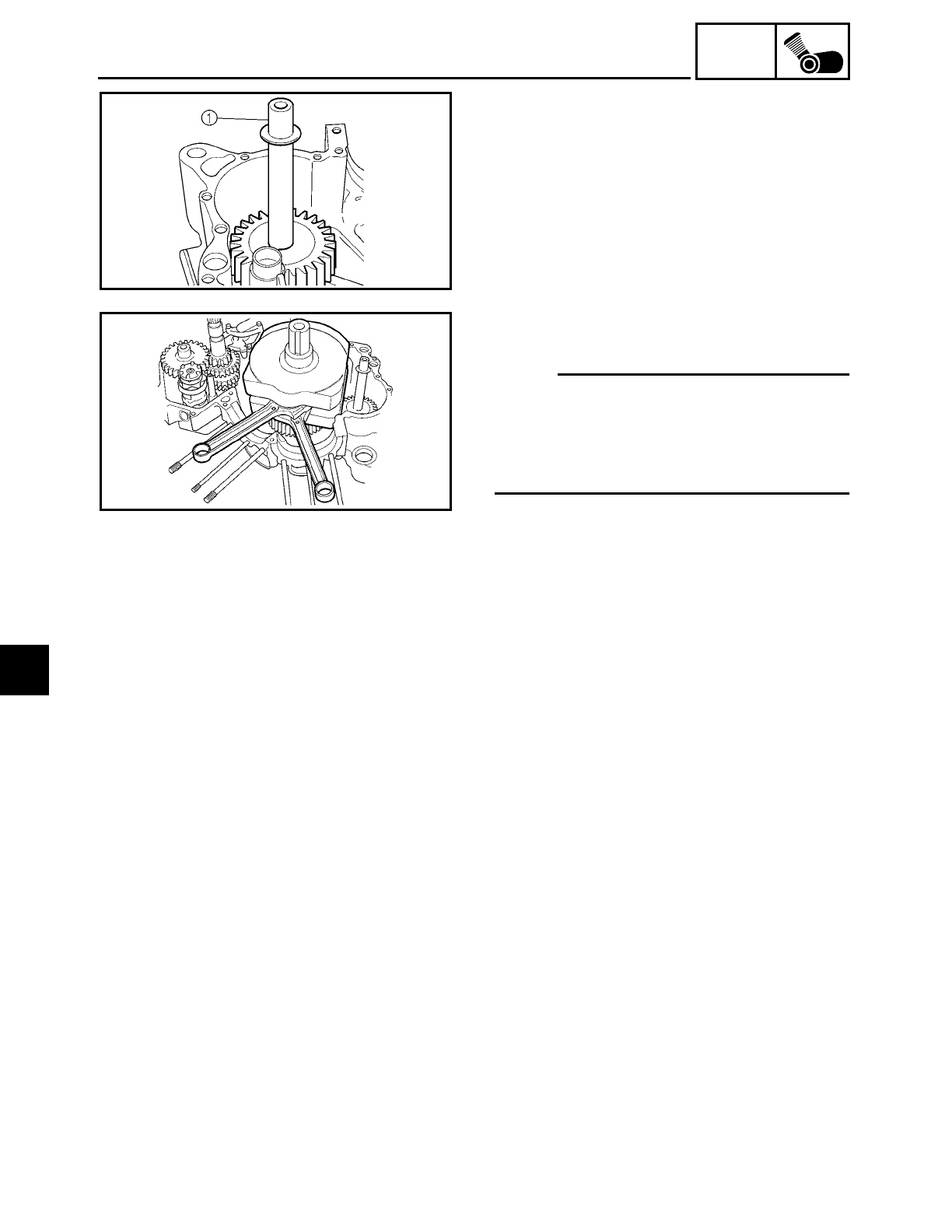
5 - 121
ENG
CRANKSHAFT AND CONNECTING RODS
INSTALLING THE CRANKSHAFT
1. Install:
• generator shaft 1
2. Install:
• crankshaft
NOTE:
• Make sure that the generator shaft drive
gear teeth and generator shaft driven gear
teeth mesh correctly.
• Align the right connecting rod with the
front cylinder sleeve hole.
5
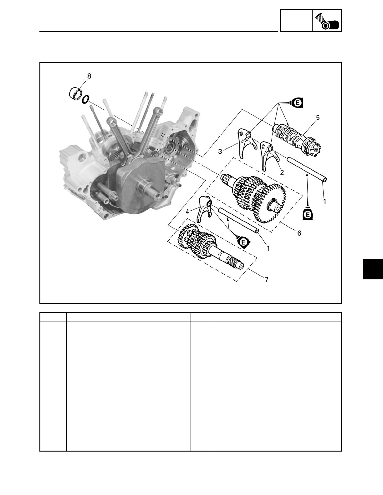
5 - 122
ENG
TRANSMISSION
TRANSMISSION
Order Job/Part Q’ty Remarks
Removing the shift forks, shift drum
assembly and transmission
Remove the parts in the order listed.
Crankcase Separate.
Refer to “CRANKCASE”.
1 Shift fork guide bar 2
2 Shift fork “L” 1
3 Shift fork “R” 1
4 Shift fork “C” 1
5 Shift drum assembly 1
6 Drive axle assembly 1
7 Main axle assembly 1
8 Spacer 1
For installation, reverse the removal
procedure.
5
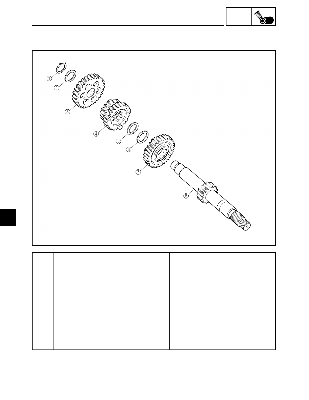
5 - 123
ENG
TRANSMISSION
Order Job/Part Q’ty Remarks
Disassembling the main axle assem-
bly
Remove the parts in the order listed.
1Circrip 1
2Washer 1
35th pinion gear 1
42nd/3rd pinion gear 1
5Circlip 1
6Washer 1
74th pinion gear 1
8Main axle/1st pinion gear 1
For assembly, reverse the disassembly
procedure.
5
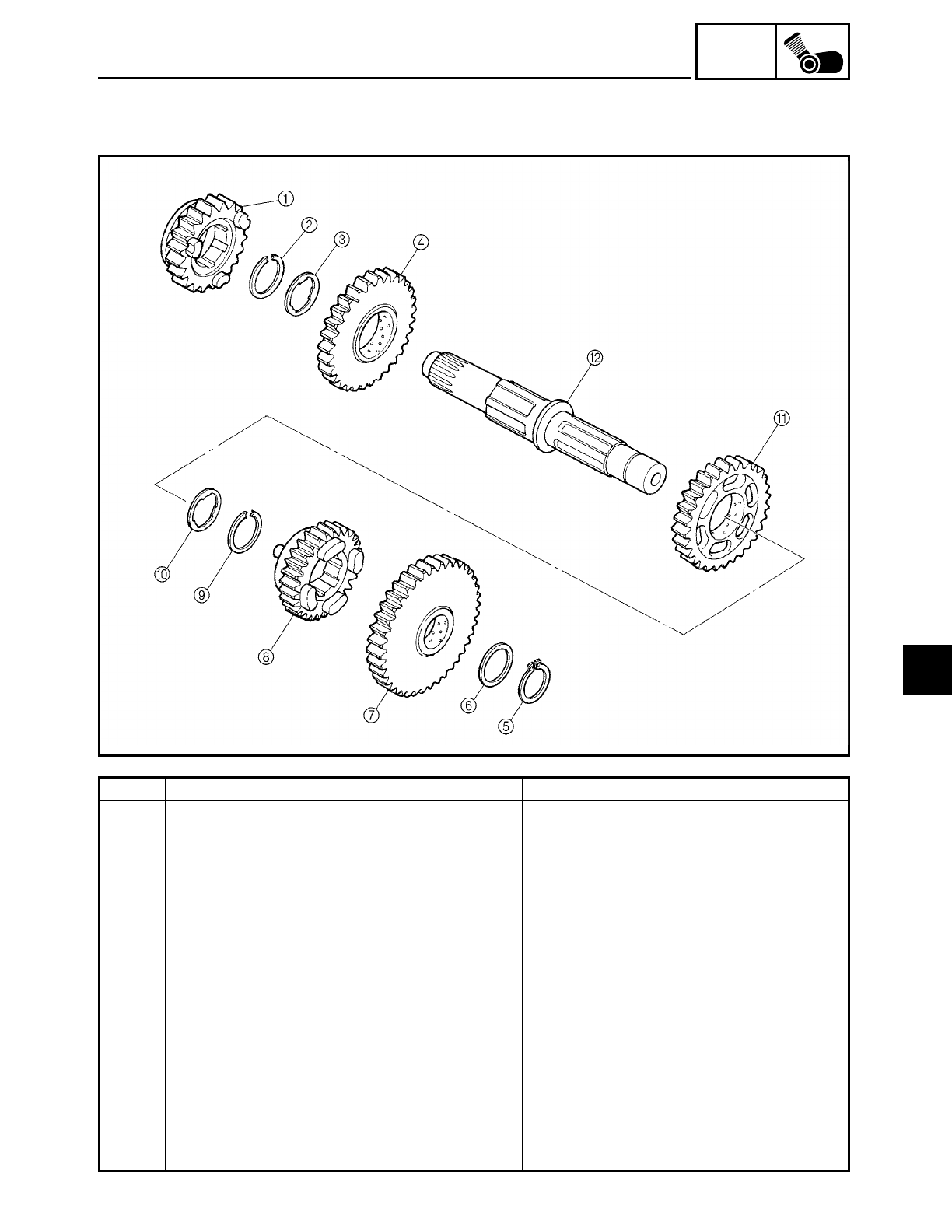
5 - 124
ENG
TRANSMISSION
Order Job/Part Q’ty Remarks
Disassembling the drive axle assem-
bly
Remove the parts in the order listed.
15th wheel gear 1
2Circlip 1
3Washer 1
42nd wheel gear 1
5Circlip 1
6Washer 1
71st wheel gear 1
84th wheel gear 1
9Circlip 1
0Washer 1
A3rd wheel gear 1
BDrive axle 1
For assembly, reverse the disassembly
procedure.
5
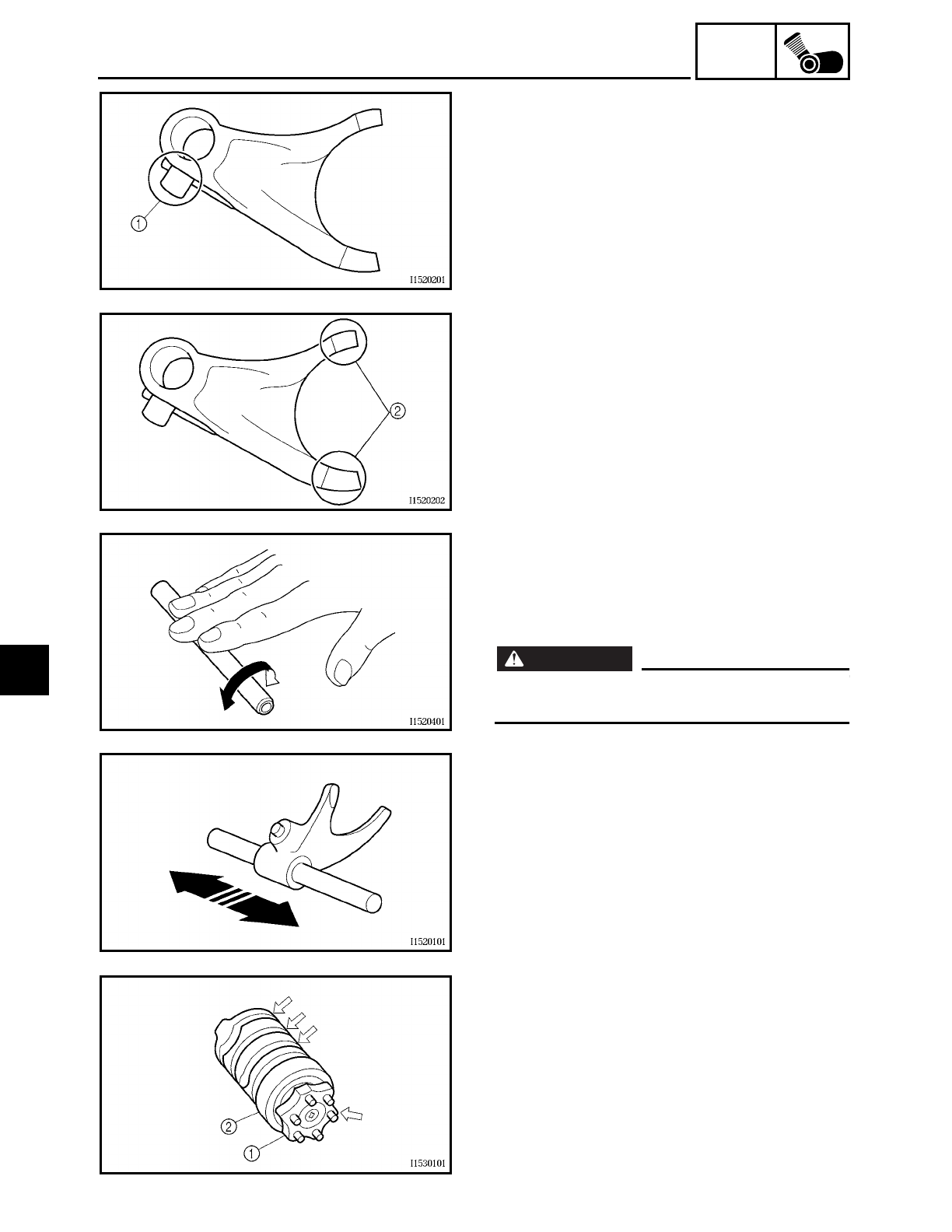
5 - 125
ENG
TRANSMISSION
EAS00421
CHECKING THE SHIFT FORKS
The following procedure applies to all of
the shift forks.
1. Check:
• shift fork cam follower 1
• shift fork pawl 2
Bends/damage/scoring/wear → Replace
the shift fork.
2. Check:
• shift fork guide bar
Roll the shift fork guide bar on a flat sur-
face.
Bends → Replace.
WARNING
WARNING
Do not attempt to straighten a bent shift
fork guide bar.
3. Check:
• shift fork movement
(along the shift fork guide bar)
Rough movement → Replace the shift
fork(s) and shift fork guide bar(s) as a set.
EAS00422
CHECKING THE SHIFT DRUM ASSEMBLY
1. Check:
• shift drum grooves
Damage/scratches/wear → Replace the
shift drum assembly.
• shift drum segment 1
Damage/wear → Replace the shift drum
assembly.
• shift drum bearing 2
Damage/pitting → Replace the shift drum
assembly.
5
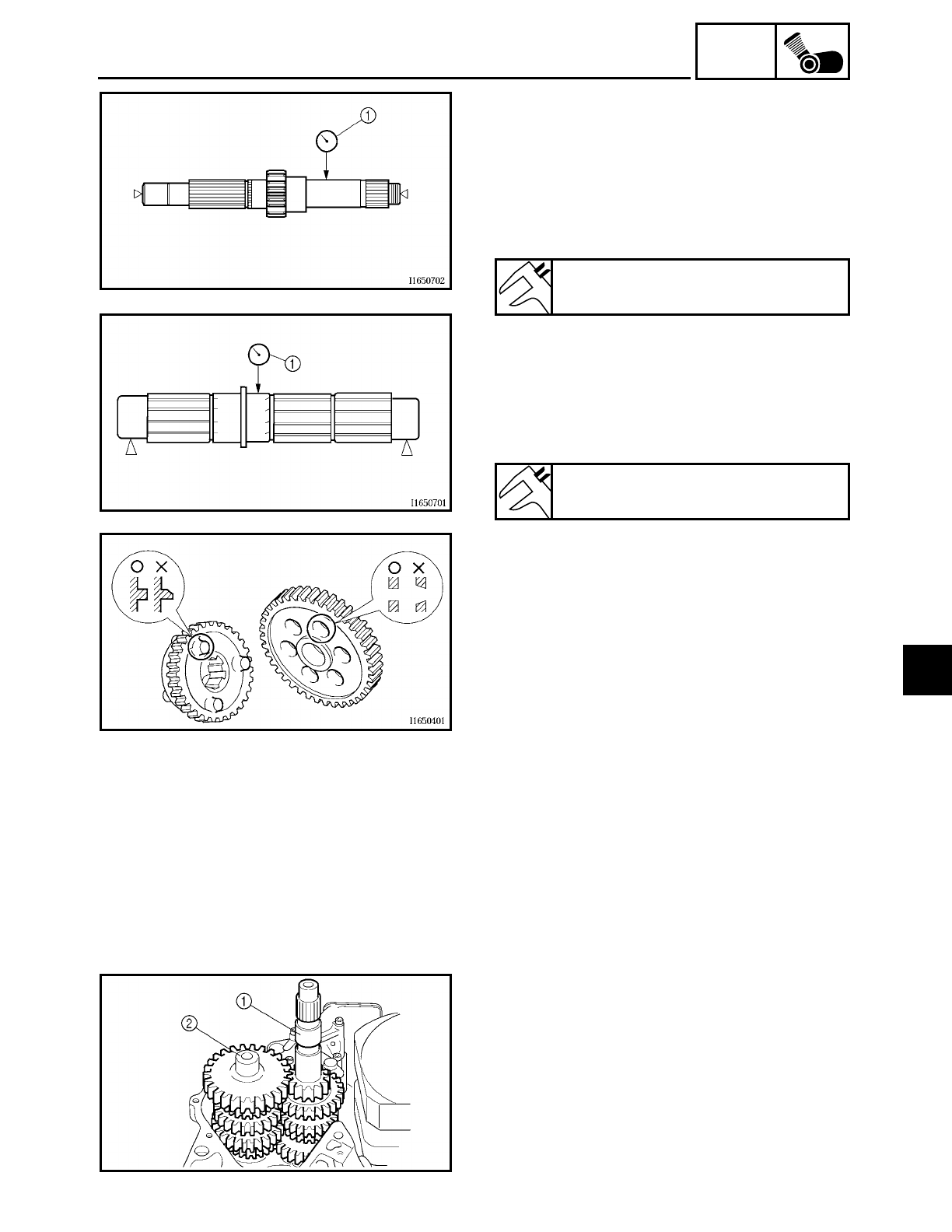
5 - 126
ENG
TRANSMISSION
EAS00425
CHECKING THE TRANSMISSION
1. Measure:
• main axle runout
(with a centering device and dial gauge
1)
Out of specification → Replace the main
axle.
2. Measure:
• drive axle runout
(with a centering device and dial gauge
1)
Out of specification → Replace the drive
axle.
Maximum main axle runout
0.08 mm (0.003 in)
Maximum drive axle runout
0.08 mm (0.003 in)
3. Check:
• transmission gears
Blue discoloration/pitting/wear →
Replace the defective gear(s).
• transmission gear dogs
Cracks/damage/rounded edges →
Replace the defective gear(s).
4. Check:
• transmission gear engagement
(each pinion gear to its respective wheel
gear)
Incorrect → Reassemble the transmis-
sion axle assemblies.
5. Check:
• transmission gear movement
Rough movement → Replace the defec-
tive part(s).
6. Check:
• circlips
Bends/damage/looseness → Replace.
INSTALLING THE TRANSMISSION, SHIFT
DRUM ASSEMBLY AND SHIFT FORKS
1. Install:
• main axle assembly 1
• drive axle assembly 2
• O-ring
• spacer
5
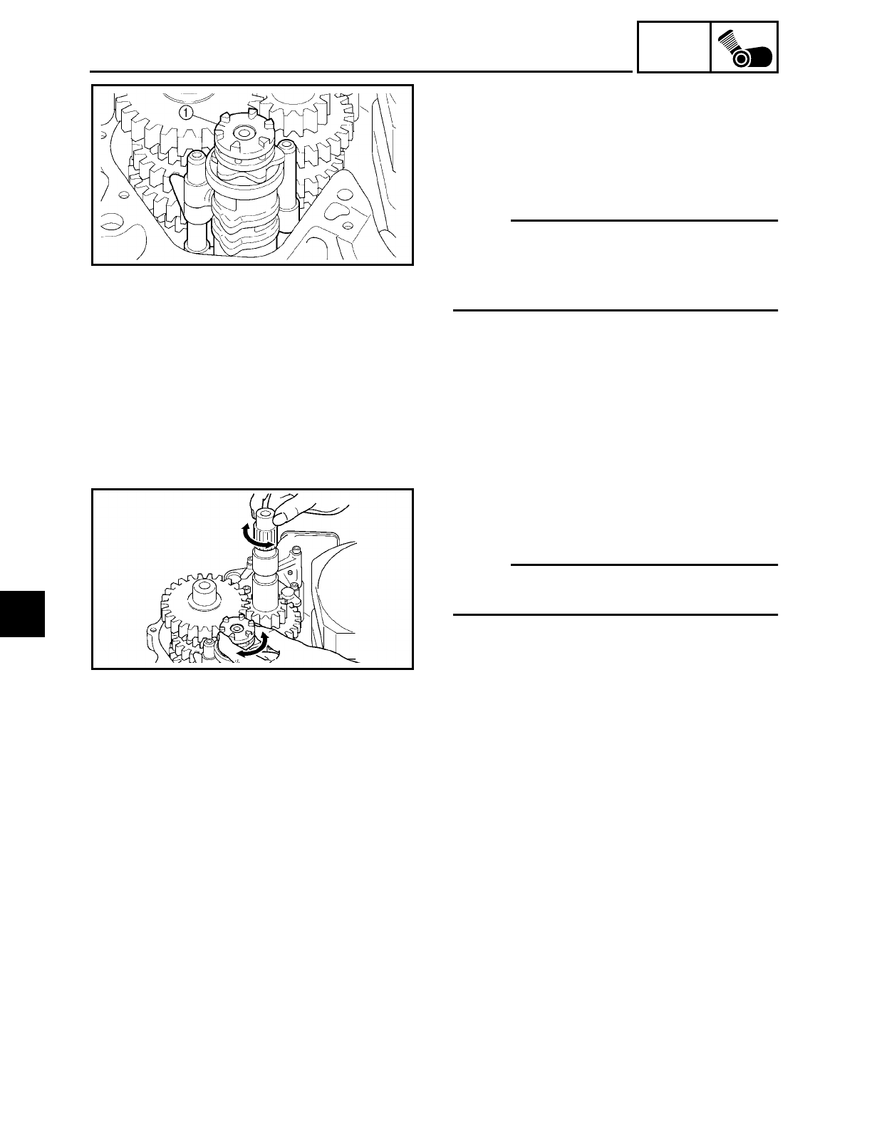
5 - 127
ENG
TRANSMISSION
2. Install:
• shift drum assembly 1
• shift fork “R”
• shift fork “C”
• shift fork “L”
• shift fork guide bars
NOTE:
The embossed marks on the shift forks
should face towards the right side of the
engine and be in the following sequence:
“R”, “C”, “L”.
3. Check:
• transmission
Rough movement → Repair.
NOTE:
Oil each gear, shaft, and bearing thor-
oughly.
5
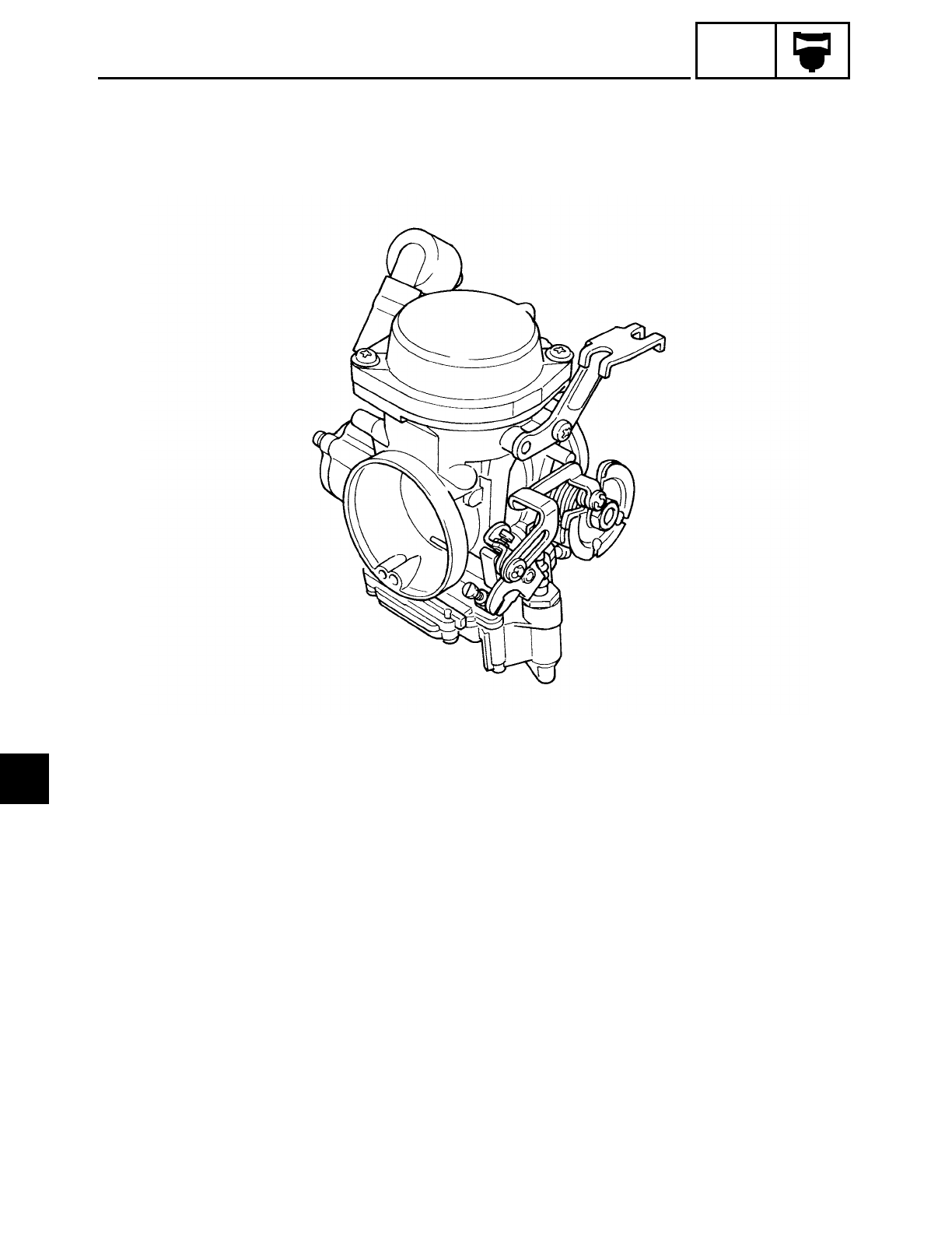
CARB
CONTENTS
CARBURETOR
CARBURETOR ..............................................................................................6-1
CHECKING THE CARBURETOR ........................................................... 6-6
CHECKING THE CARBURETOR JOINT ............................................... 6-8
ASSEMBLING THE CARBURETOR ..................................................... 6-8
INSTALLING THE CARBURETOR JOINT .......................................... 6-12
INSTALLING THE CARBURETOR ...................................................... 6-12
MEASURING AND ADJUSTING THE FUEL LEVEL .......................... 6-14
CHECKING AND ADJUSTING THE THROTTLE POSITION
SENSOR .......................................................................................... 6-15
CHECKING THE FUEL PUMP ............................................................. 6-19
CHECKING THE FUEL COCK ............................................................. 6-19
CHECKING THE FUEL COCK OPERATION ....................................... 6-20
AIR INDUCTION SYSTEM ......................................................................... 6-21
AIR INJECTION ................................................................................... 6-21
AIR CUTOFF VALVE ........................................................................... 6-21
6

CARB
CHECKING THE AIR INDUCTION SYSTEM ...................................... 6-26
INSTALLING THE AIR INDUCTION SYSTEM ................................... 6-26
6
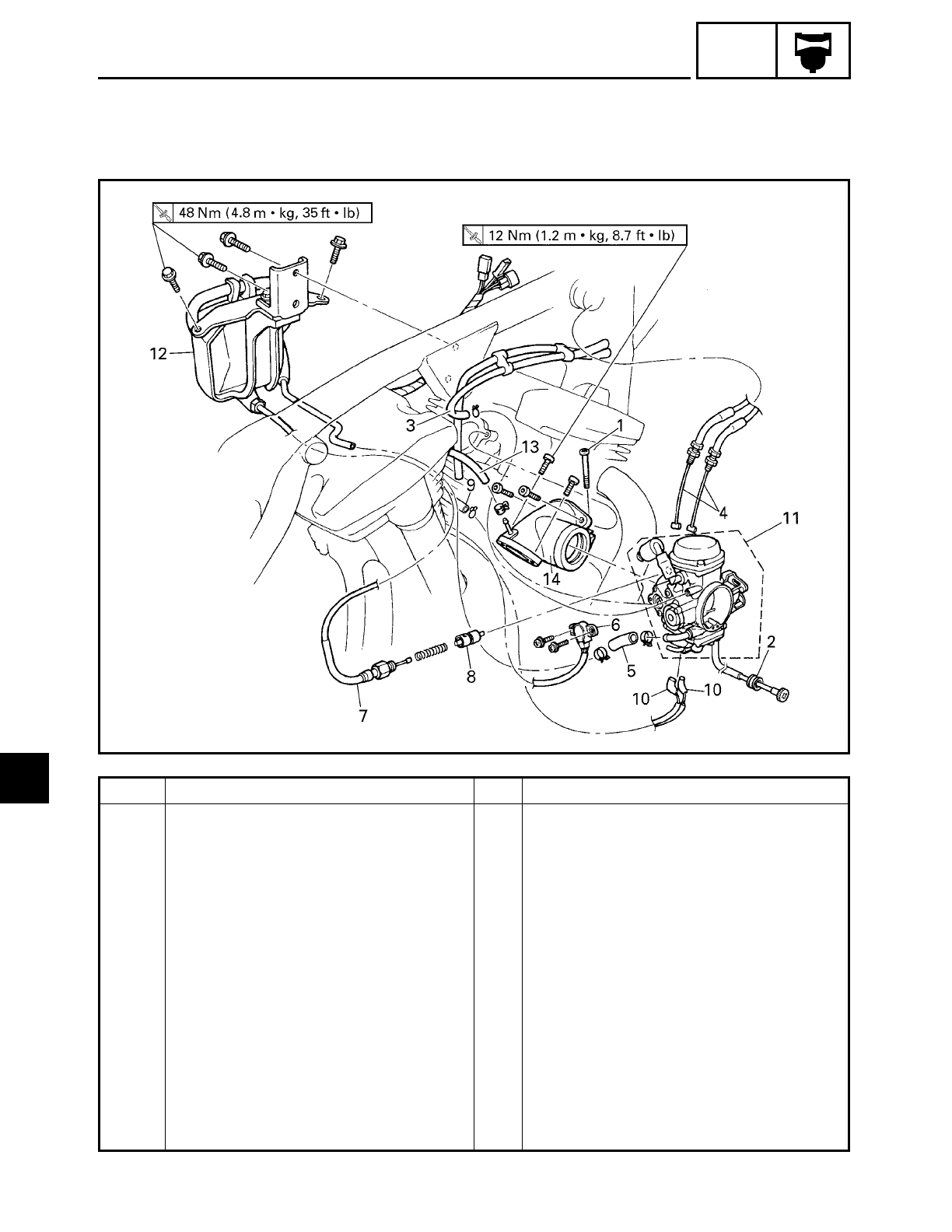
6 - 1
CARB
CARBURETOR
EAS00480
CARBURETOR
CARBURETOR
Order Job/Part Q’ty Remarks
Removing the carburetor Remove the parts in the order listed.
Rider seat Refer to “SEATS AND SIDE COVERS”
in chapter 3.
Fuel tank Refer to “FUEL TANK” in chapter 3.
Air filter case Refer to “AIR FILTER CASE” in chapter 3.
Fuel (from the carburetor) Drain.
1 Carburetor joint clamp screw 1 Loosen.
2 Throttle stop screw 1 Unhook.
3 Vacuum chamber breather hose
(carburetor to solenoid valve hose)
1 Disconnect.
4 Throttle cable 2 Disconnect.
5 Fuel hose 1
6 Throttle position sensor 1
7 Starter cable 1 Disconnect.
8 Starter plunger 1
6
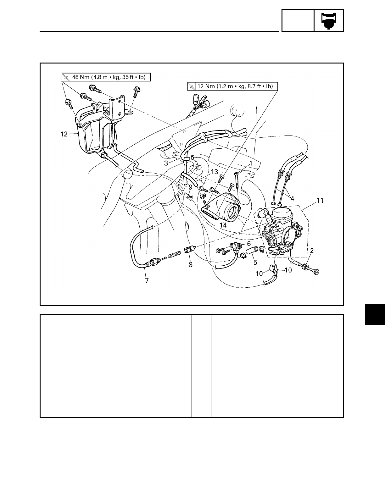
6 - 2
CARB
Order Job/Part Q’ty Remarks
9 Charcoal canister hose
(carburetor to charcoal canister)
1 Disconnect.
10 Carburetor heater connector 2 Disconnect.
11 Carburetor 1
12 Fuel pump bracket assembly
(with fuel pump)
1
13 Vacuum hose 1 Disconnect.
14 Carburetor joint 1
For installation, reverse the removal
procedure.
CARBURETOR
6
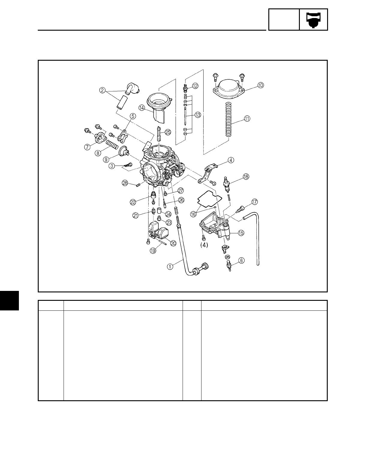
6 - 3
CARB
CARBURETOR
EAS00483
Order Job/Part Q’ty Remarks
Disassembling the carburetor Remove the parts in the order listed.
1Throttle stop screw 1
2Vacuum chamber air vent hose 1
3Fuel strainer 1
4Throttle cable holder 1
5Throttle position sensor bracket 1
6Carburetor heater 1
7Coasting enricher cover 1
8Coasting enricher spring 1
9Coasting enricher 1
6
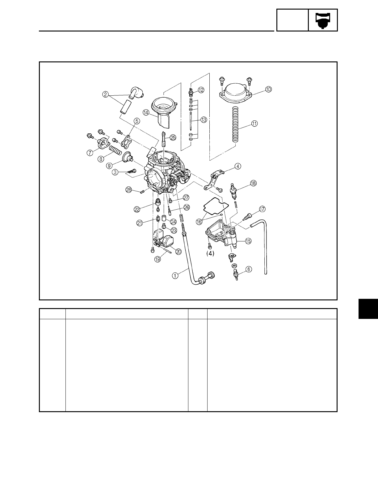
6 - 4
CARB
Order Job/Part Q’ty Remarks
0Vacuum chamber cover 1
APiston valve spring 1
BJet needle holder 1
CJet needle kit 1
DPiston valve 1
EFloat chamber 1
FFloat chamber rubber gasket 1
GDrain bolt 1
HAccelerator plunger 1
IFloat pivot pin 1
CARBURETOR
6
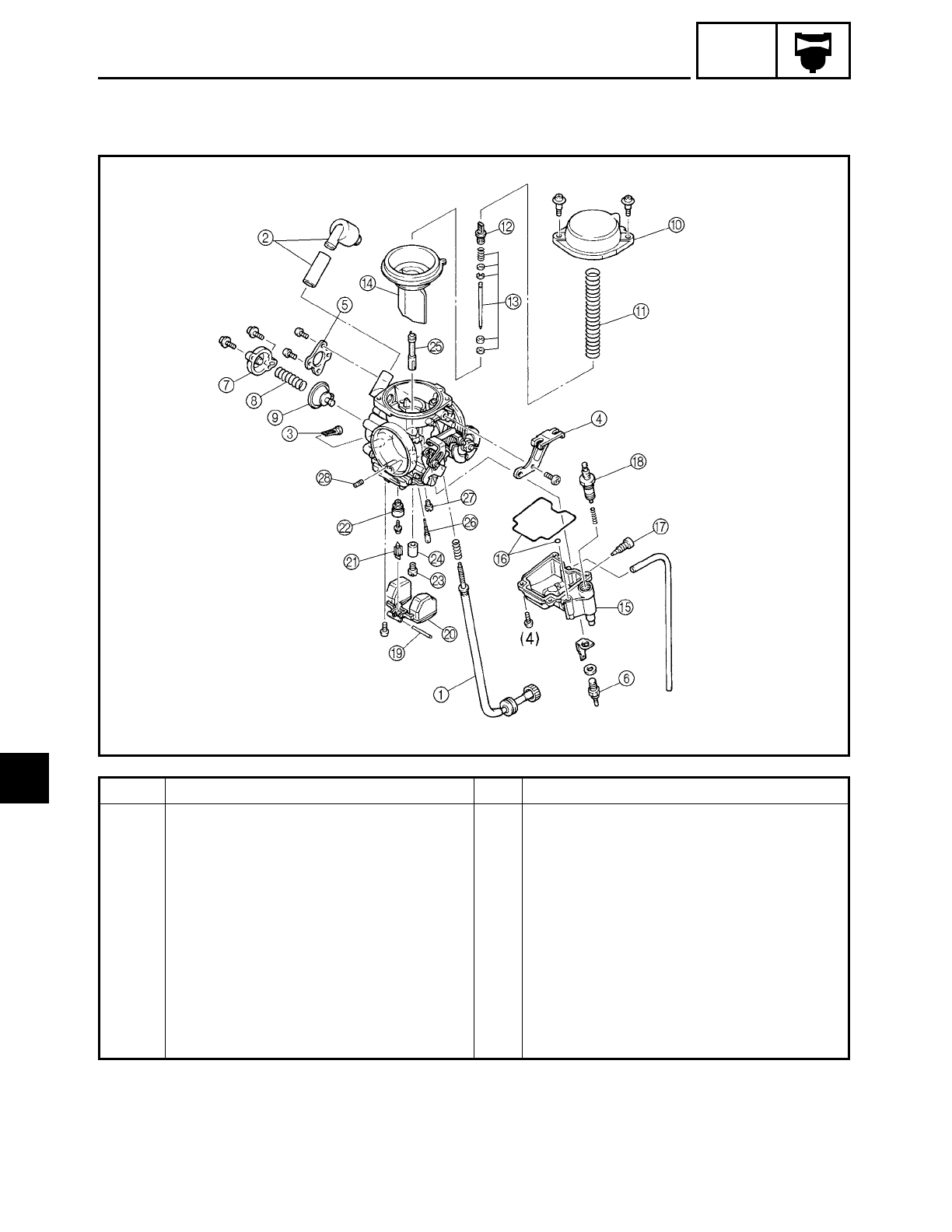
6 - 5
CARB
Order Job/Part Q’ty Remarks
JFloat 1
KNeedle valve 1
LNeedle valve seat 1
MMain jet 1
NSpacer 1
ONeedle jet 1
PPilot jet 1
QStarter jet 1
RPilot air jet 1
For assembly, reverse the disassembly
procedure.
CARBURETOR
6
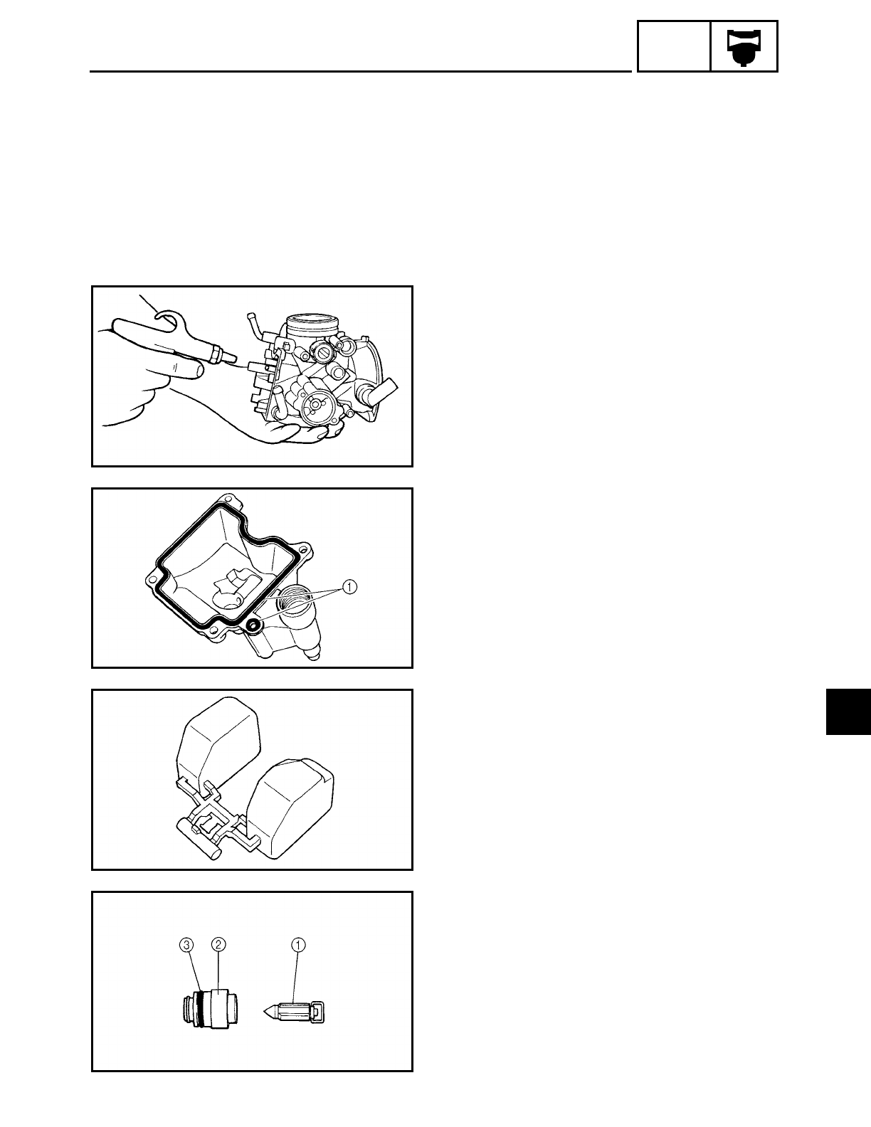
6 - 6
CARB
CARBURETOR
EAS00485
CHECKING THE CARBURETOR
1. Check:
• carburetor body
• float chamber
• jet housing
Cracks/damage → Replace.
2. Check:
• fuel passages
Obstruction → Clean.
▼ ▼ ▼ ▼ ▼ ▼ ▼ ▼ ▼ ▼ ▼ ▼ ▼ ▼ ▼ ▼ ▼ ▼ ▼ ▼ ▼ ▼ ▼ ▼ ▼ ▼ ▼ ▼
a. Wash the carburetor in a petroleum-
based solvent. Do not use any caustic
carburetor cleaning solution.
b. Blow out all of the passages and jets
with compressed air.
▲ ▲ ▲ ▲ ▲ ▲ ▲ ▲ ▲ ▲ ▲ ▲ ▲ ▲ ▲ ▲ ▲ ▲ ▲ ▲ ▲ ▲ ▲ ▲ ▲ ▲ ▲ ▲
3. Check:
• float chamber body
Dirt → Clean.
4. Check:
• float chamber rubber gasket 1
Cracks/damage/wear → Replace.
5. Check:
• float
Damage → Replace.
6. Check:
• needle valve 1
• needle valve seat 2
Damage/obstruction/wear → Replace
the needle valve, needle valve seat and
O-ring as a set.
7. Check:
• O-ring 3
Damage/wear → Replace the needle valve,
needle valve seat and O-ring as a set.
6
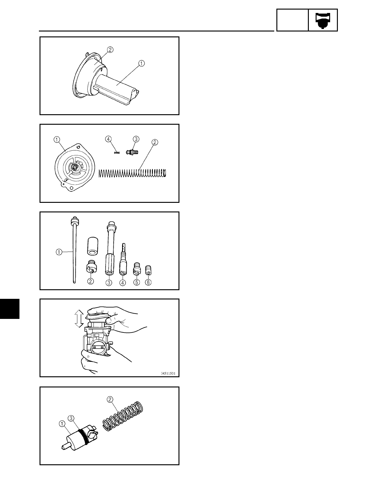
6 - 7
CARB
CARBURETOR
8. Check:
• piston valve 1
Damage/scratches/wear → Replace.
• piston valve diaphragm 2
Cracks/tears → Replace.
9. Check:
• vacuum chamber cover 1
• piston valve spring 2
• jet needle holder 3
• jet needle spring 4
Cracks/damage → Replace.
10.Check:
• jet needle kit 1
• main jet 2
• needle jet 3
• pilot jet 4
• starter jet 5
• pilot air jet 6
Bends/damage/wear → Replace.
Obstruction → Clean.
Blow out the jets with compressed air.
11.Check:
• piston valve movement
Insert the piston valve into the carbure-
tor body and move it up and down.
Tightness → Replace the piston valve.
12.Check:
• starter plunger 1
• starter plunger spring 2
Bends/cracks/damage → Replace.
• O-ring 3
Damage/wear → Replace.
6
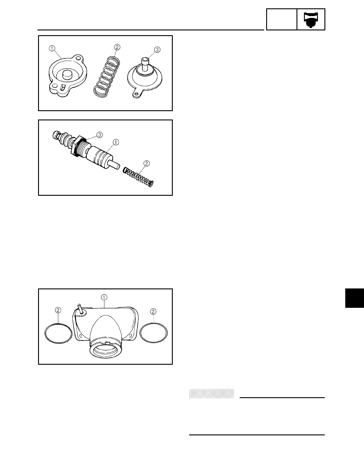
6 - 8
CARB
CARBURETOR
13.Check:
• coasting enricher cover 1
• coasting enricher spring 2
Cracks/damage → Replace.
• coasting enricher 3
Cracks/tears/damage → Replace.
14.Check:
• accelerator plunger 1
• accelerator plunger spring 2
Bends/cracks/damage → Replace.
• O-ring 3
Damage/wear → Replace.
15.Check:
• fuel hose
Cracks/damage/wear → Replace.
Obstruction → Clean.
Blow out the hoses with compressed air.
CHECKING THE CARBURETOR JOINT
1. Check:
• carburetor joint 1
Cracks/damage → Replace.
• O-rings 2
Damage/wear → Replace the O-ring.
EAS00487
ASSEMBLING THE CARBURETOR
ACHTUNG:
CAUTION:
• Before assembling the carburetor, wash
all the parts in a petroleum-based sol-
vent.
• Always use a new gasket.
6
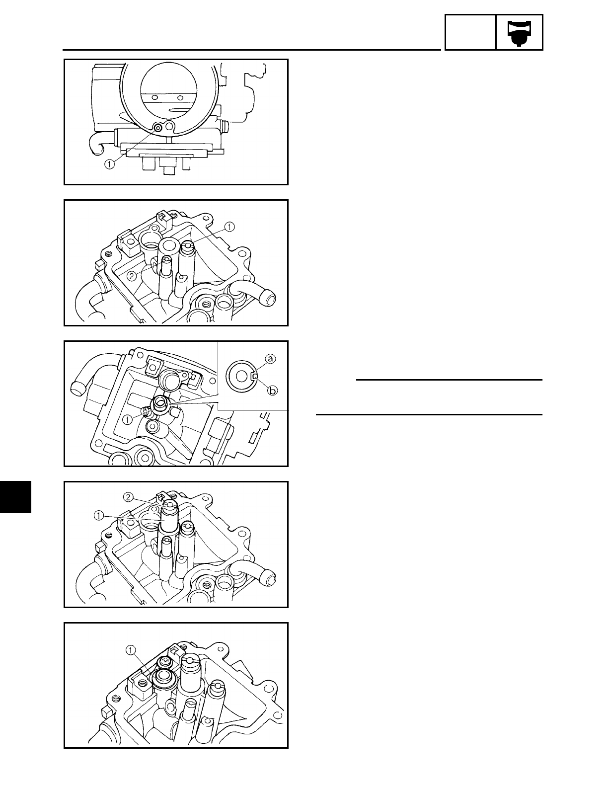
6 - 9
CARB
CARBURETOR
1. Install:
• pilot air jet 1
2. Install:
• starter jet 1
• pilot jet 2
3. Install:
• needle jet 1
NOTE:
Align the slot a on the needle jet with the
projection b on the carburetor body.
4. Install:
• spacer 1
• main jet 2
5. Install:
• needle valve seat 1
6
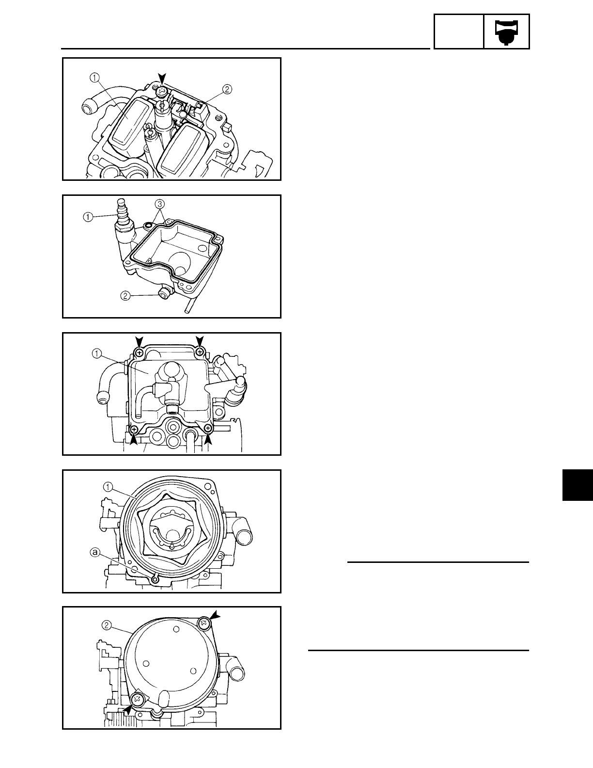
6 - 10
CARB
CARBURETOR
6. Install:
• needle valve
• float 1
• float pin 2
7. Install:
• accelerator plunger 1
• drain bolt 2
• float chamber rubber gasket 3
8. Install:
• float chamber 1
9. Install:
• piston valve 1
• jet needle kit
• jet needle holder
• piston valve spring
• vacuum chamber cover 2
NOTE:
• Install the end of the piston valve spring
onto the spring guide on the vacuum
chamber cover.
• Align the tab a on the piston valve dia-
phragm with the recess in the carburetor
body.
6
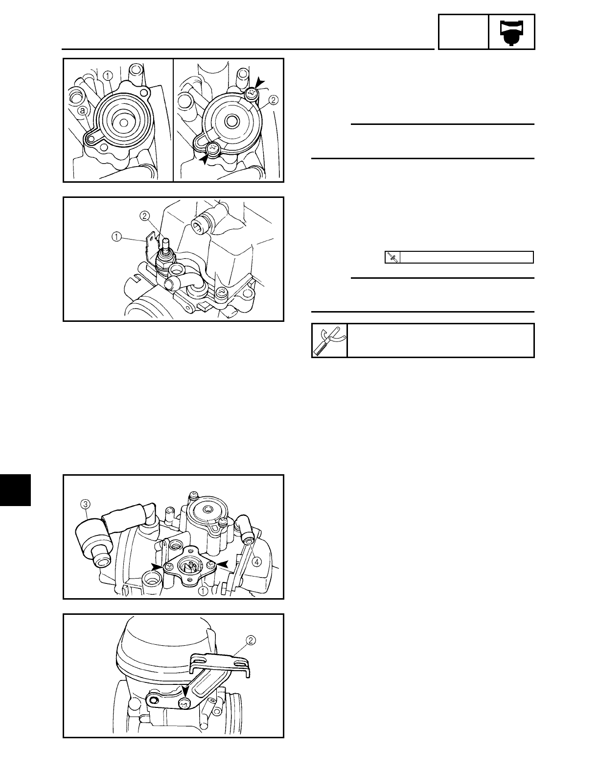
6 - 11
CARB
CARBURETOR
10.Install:
• coasting enricher 1
• coasting enricher spring
• coasting enricher cover 2
NOTE:
Align the tab a on the coasting enricher
with the recess b in the carburetor body.
11.Install:
• terminal 1
• washer
• carburetor heater 2
NOTE:
Use “Heat Sinker” when installing the car-
buretor heater.
Heat Sinker
T
R
.
.
2.5 Nm (0.25 m · kg, 2.0 ft · lb)
12.Install:
• throttle position sensor bracket 1
• throttle cable holder 2
• fuel strainer 3
• vacuum chamber air vent hose 4
6
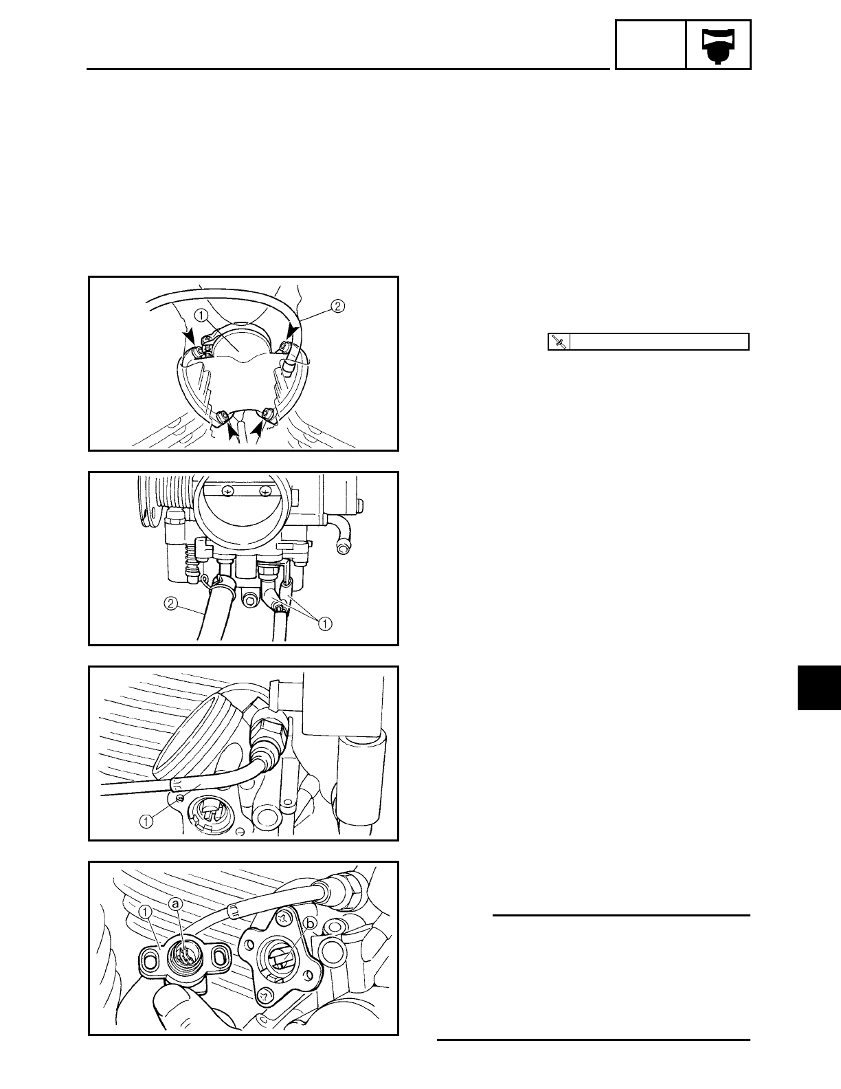
6 - 12
CARB
CARBURETOR
13.Install:
• throttle stop screw
• drain hose
INSTALLING THE CARBURETOR JOINT
1. Install:
• carburetor joint 1
2. Connect:
• vacuum hose 2
T
R
.
.
12 Nm (1.2 m · kg, 8.7 ft · lb)
EAS00492
INSTALLING THE CARBURETOR
1. Connect:
• carburetor heater connectors 1
• charcoal canister hose (carburetor to
charcoal canister) 2
2. Install:
• starter plunger
3. Connect:
• starter cable 1
4. Install:
• throttle position sensor
NOTE:
• Align the slot a of the throttle position
sensor with the projection b of the throt-
tle lever shaft.
• For the correct installation, refer to
“CHECKING AND ADJUSTING THE
THROTTLE POSITION SENSOR”.
6
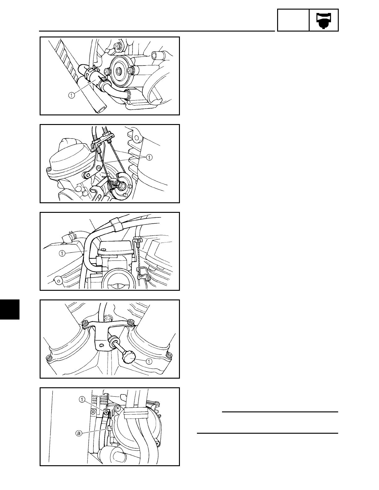
6 - 13
CARB
CARBURETOR
5. Connect:
• fuel hose 1
6. Connect:
• throttle cables 1
7. Connect:
• float chamber breather hose
(carburetor to solenoid valve) 1
8. Hook:
• throttle stop screw 1
9. Install:
• carburetor
NOTE:
Align the projection a of the carburetor
with slot of the carburetor joint.
10.Tighten:
• carburetor joint clamp screw 1
6
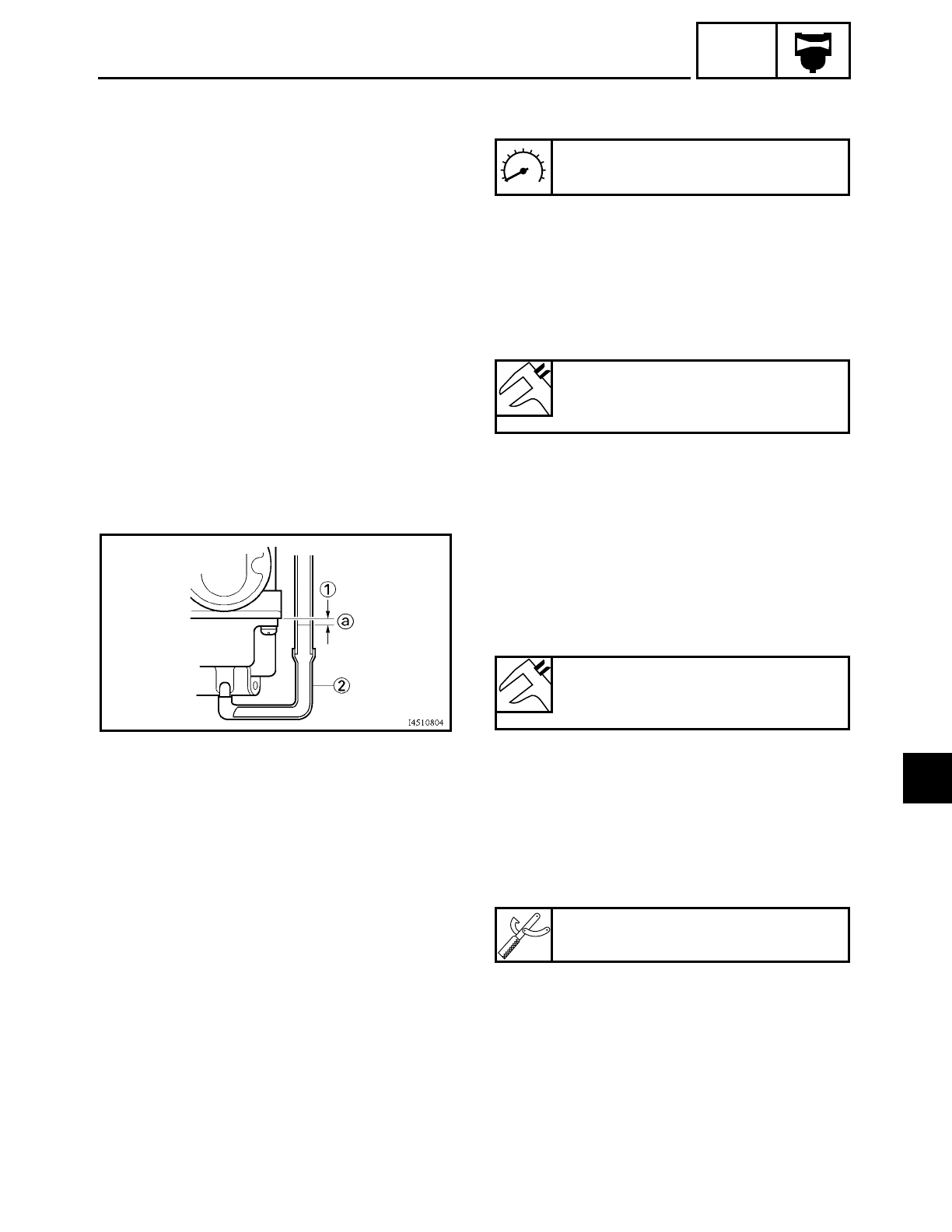
6 - 14
CARB
CARBURETOR
11.Adjust:
• engine idling speed
Refer to “ADJUSTING THE ENGINE
IDLING SPEED” in chapter 3.
Engine idling speed
850 ~ 950 r/min
12.Adjust:
• throttle cable free play
Refer to “ADJUSTING THE THROTTLE
CABLE FREE PLAY” in chapter 3.
Throttle cable free play (at the
flange of the throttle grip)
4 ~ 8 mm (0.16 ~ 0.31 in)
EAS00498
MEASURING AND ADJUSTING THE FUEL
LEVEL
1. Measure:
• fuel level a
Out of specification → Adjust.
▼ ▼ ▼ ▼ ▼ ▼ ▼ ▼ ▼ ▼ ▼ ▼ ▼ ▼ ▼ ▼ ▼ ▼ ▼ ▼ ▼ ▼ ▼ ▼ ▼ ▼ ▼ ▼
a. Stand the motorcycle on a level surface.
b. Place the motorcycle on a suitable stand
to ensure that the motorcycle is standing
straight up.
c. Install the fuel level gauge 1 onto the
fuel drain pipe 2.
d. Loosen the fuel drain bolt 3.
e. Measure the fuel level a.
▲ ▲ ▲ ▲ ▲ ▲ ▲ ▲ ▲ ▲ ▲ ▲ ▲ ▲ ▲ ▲ ▲ ▲ ▲ ▲ ▲ ▲ ▲ ▲ ▲ ▲ ▲ ▲
Fuel level (below the float cham-
ber mating surface)
2.0 ~ 3.0 mm (0.079 ~ 0.12 in)
Fuel level gauge
YM-01312-A
6
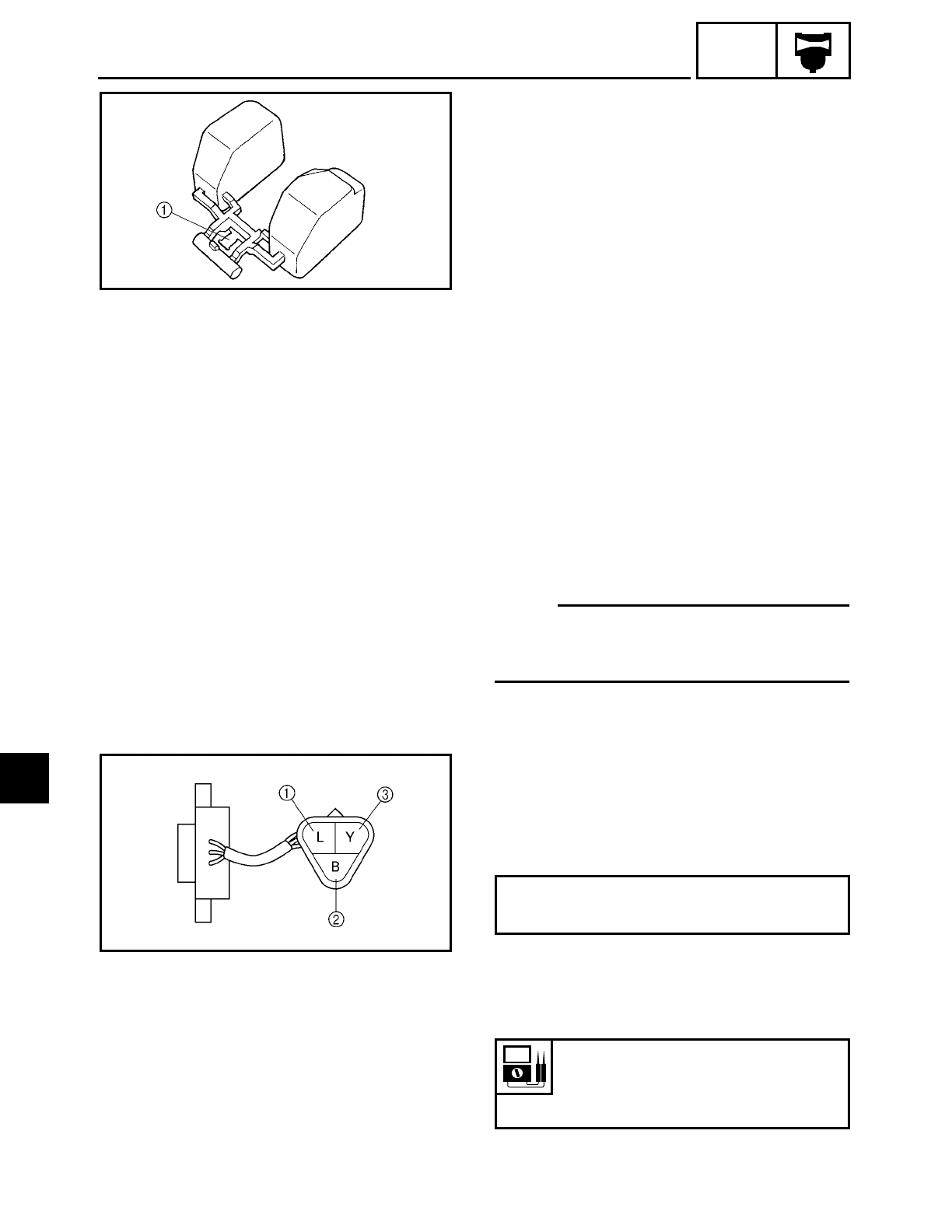
6 - 15
CARB
CARBURETOR
2. Adjust:
• fuel level
▼ ▼ ▼ ▼ ▼ ▼ ▼ ▼ ▼ ▼ ▼ ▼ ▼ ▼ ▼ ▼ ▼ ▼ ▼ ▼ ▼ ▼ ▼ ▼ ▼ ▼ ▼ ▼
a. Remove the carburetor.
b. Check the needle valve seat and needle
valve.
c. If either is worn, replace them as a set.
d. If both are fine, adjust the float level by
slightly bending the float tang 1.
e. Install the carburetor.
f. Measure the fuel level again.
g. Repeat steps (a) to (f) until the fuel level
is within specification.
▲ ▲ ▲ ▲ ▲ ▲ ▲ ▲ ▲ ▲ ▲ ▲ ▲ ▲ ▲ ▲ ▲ ▲ ▲ ▲ ▲ ▲ ▲ ▲ ▲ ▲ ▲ ▲
EAS00502
CHECKING AND ADJUSTING THE
THROTTLE POSITION SENSOR
NOTE:
Before adjusting the throttle position sen-
sor, the engine idling speed should be
properly adjusted.
1. Check:
• throttle position sensor
(installed on the carburetor)
▼ ▼ ▼ ▼ ▼ ▼ ▼ ▼ ▼ ▼ ▼ ▼ ▼ ▼ ▼ ▼ ▼ ▼ ▼ ▼ ▼ ▼ ▼ ▼ ▼ ▼ ▼ ▼
a. Disconnect the throttle position sensor
coupler from the wire harness.
b. Connect the pocket tester (Ω× 1k) to the
throttle position sensor coupler.
c. Measure the maximum throttle position
sensor resistance.
Out of specification → Replace the throt-
tle position sensor.
Positive tester probe → blue terminal 1
Negative tester probe → black terminal 2
Maximum throttle position sen-
sor resistance
4.0 ~ 6.0 kΩ at 20 ˚C (68 ˚F)
(blue — black)
6
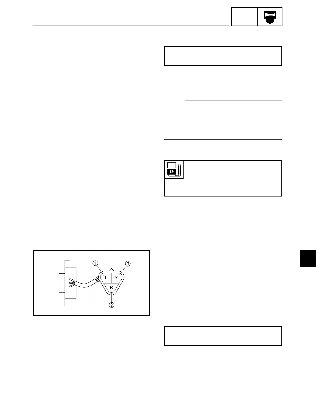
6 - 16
CARB
d. Connect the pocket tester (Ω× 1k) to the
throttle position sensor.
e. While slowly opening the throttle, check
that the throttle position sensor resis-
tance is within the specified range.
NOTE:
Check mainly that the resistance changes
gradually when turning the throttle, since
the readings (from closed to wide-open
throttle) may differ slightly from those spec-
ified.
Out of specification or the resistance
changes abruptly → Go to step 2 below.
▲ ▲ ▲ ▲ ▲ ▲ ▲ ▲ ▲ ▲ ▲ ▲ ▲ ▲ ▲ ▲ ▲ ▲ ▲ ▲ ▲ ▲ ▲ ▲ ▲ ▲ ▲ ▲
Positive tester probe → yellow terminal 3
Negative tester probe → black terminal 2
Throttle position sensor resis-
tance
(520 ~ 900 Ω) ~ (4.0 ~ 6.0 kΩ) at
20 ˚C (68 ˚F)
(yellow — black/blue)
2. Check:
• throttle position sensor
(removed from the carburetor)
▼ ▼ ▼ ▼ ▼ ▼ ▼ ▼ ▼ ▼ ▼ ▼ ▼ ▼ ▼ ▼ ▼ ▼ ▼ ▼ ▼ ▼ ▼ ▼ ▼ ▼ ▼ ▼
a. Disconnect the throttle position sensor
coupler from the wire harness.
b. Remove the throttle position sensor from
the carburetor.
c. Connect the pocket tester (Ω× 1k) to the
throttle position sensor.
Positive tester probe → blue terminal 1
Negative tester probe → black terminal 2
CARBURETOR
6
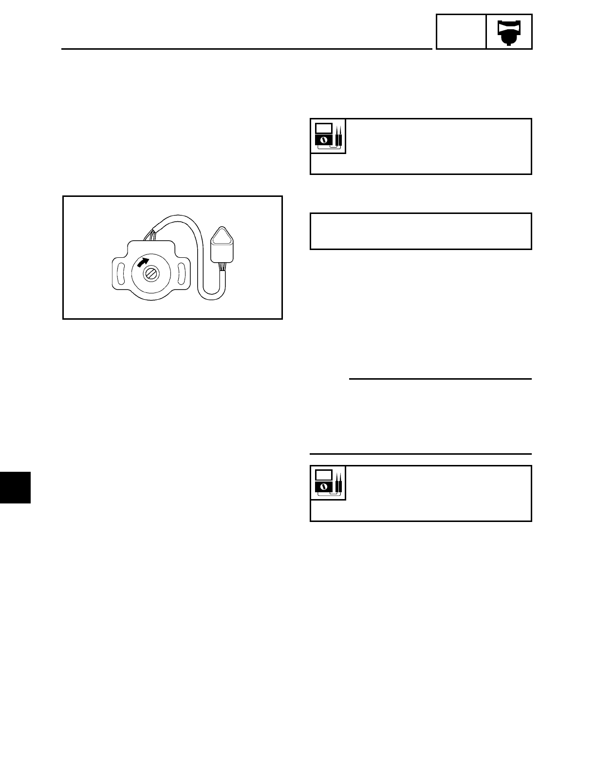
6 - 17
CARB
CARBURETOR
d. Measure the maximum throttle position
sensor resistance.
Out of specification → Replace the throt-
tle position sensor.
e. Connect the pocket tester (Ω× 1k) to the
throttle position sensor coupler.
f. While slowly opening the throttle, check
that the throttle position sensor resis-
tance is within the specified range.
The resistance does not change or it
changes abruptly → Replace the throttle
position sensor.
The slot is worn or broken → Replace the
throttle position sensor.
NOTE:
Check mainly that the resistance changes
gradually when turning the throttle, since
the readings (from closed to wide-open
throttle) may differ slightly from those spec-
ified.
▲ ▲ ▲ ▲ ▲ ▲ ▲ ▲ ▲ ▲ ▲ ▲ ▲ ▲ ▲ ▲ ▲ ▲ ▲ ▲ ▲ ▲ ▲ ▲ ▲ ▲ ▲ ▲
Maximum throttle position sen-
sor resistance
4.0 ~ 6.0 kΩ at 20 ˚C (68 ˚F)
(blue — black/blue)
Positive tester probe → yellow terminal 3
Negative tester probe → black terminal 2
Throttle position sensor resis-
tance
0 ~ 5 ± 1.0 kΩ at 20 ˚C (68 ˚F)
(yellow — black/blue)
6
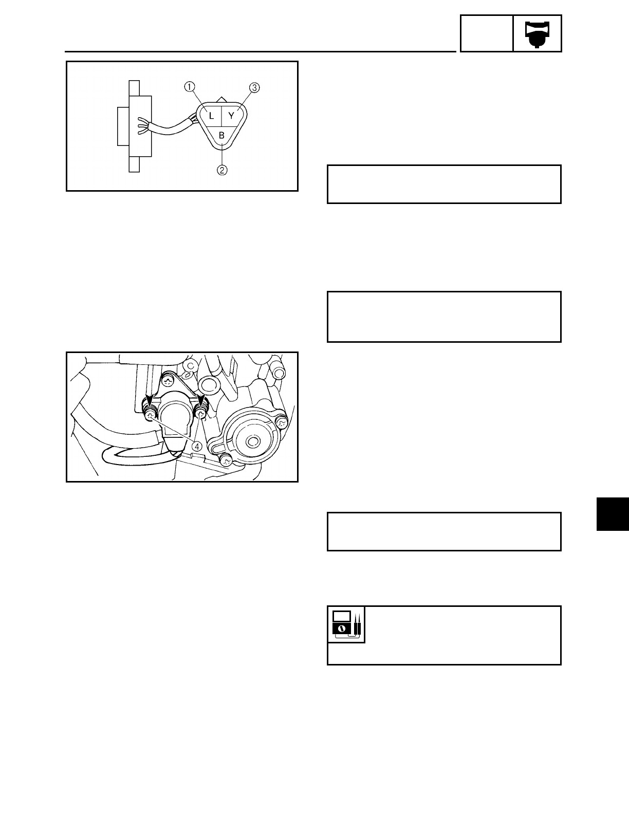
6 - 18
CARB
CARBURETOR
3. Adjust:
• throttle position sensor angle
▼ ▼ ▼ ▼ ▼ ▼ ▼ ▼ ▼ ▼ ▼ ▼ ▼ ▼ ▼ ▼ ▼ ▼ ▼ ▼ ▼ ▼ ▼ ▼ ▼ ▼ ▼ ▼
a. Disconnect the throttle position sensor
coupler from the wire harness.
b. Connect the pocket tester (Ω× 1k) to the
throttle position sensor coupler.
c. Measure the throttle position sensor
maximum resistance.
d. Calculate the throttle position sensor
maximum resistance when the throttle is
fully closed.
Example:
If the maximum resistance = 5 kΩ, then the
throttle position sensor’s maximum resis-
tance when the throttle is fully closed
should be:
5 kΩ× (0.13 ~ 0.15) = 650 ~ 750 Ω
Lift the carburetor assembly slightly out of
the intake manifolds.
Loosen the throttle position sensor screws 4.
Connect the pocket tester (Ω× 100) to the
throttle position sensor.
e. Adjust the throttle position sensor angle
so that the measured resistance is within
the specified range.
After adjusting the throttle position sensor
angle, tighten the throttle position sensor
screws.
▲ ▲ ▲ ▲ ▲ ▲ ▲ ▲ ▲ ▲ ▲ ▲ ▲ ▲ ▲ ▲ ▲ ▲ ▲ ▲ ▲ ▲ ▲ ▲ ▲ ▲ ▲ ▲
Positive tester probe → blue terminal 1
Negative tester probe → black terminal 2
Throttle position sensor maximum
resistance (throttle is fully closed) =
Maximum resistance ×(0.13 ~ 0.15)
Positive tester probe → yellow terminal 3
Negative tester probe → black terminal 1
Throttle position sensor resis-
tance
650 ~ 750 Ω
(yellow — black terminal)
6
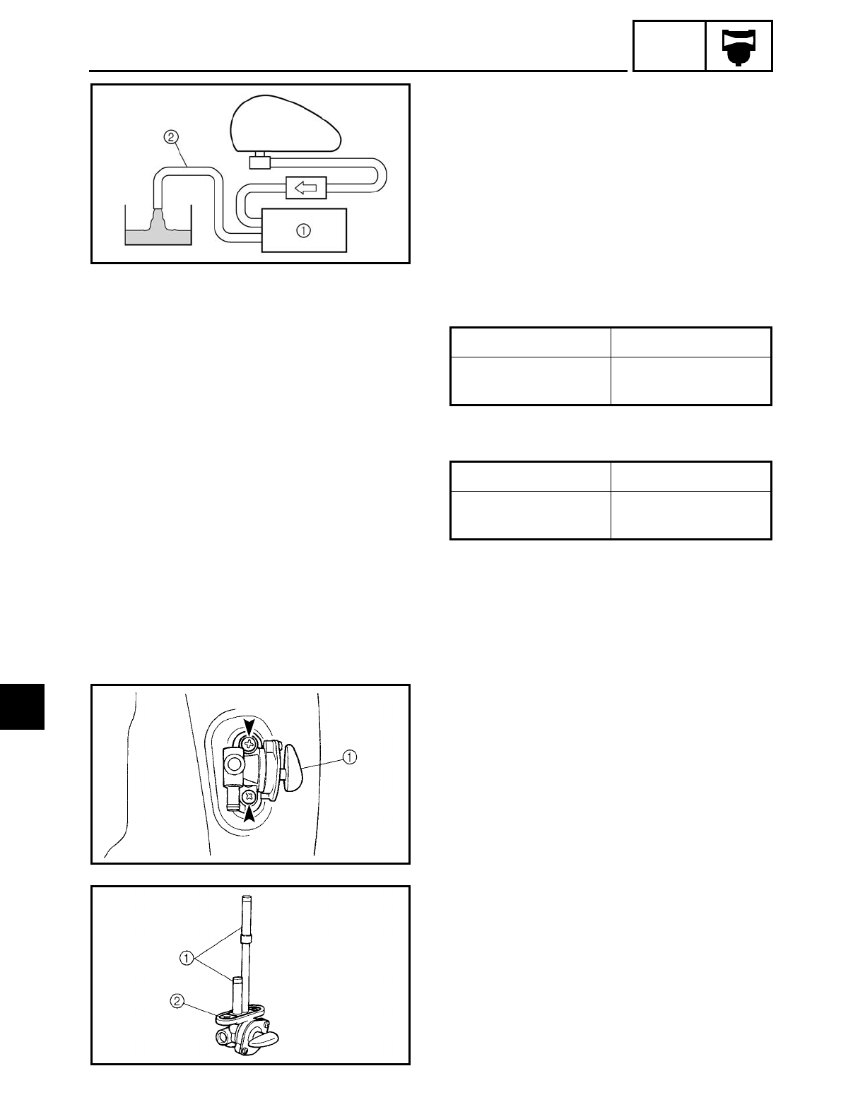
6 - 19
CARB
CARBURETOR
EAS00504
CHECKING THE FUEL PUMP
1. Check:
• fuel pump 1
▼ ▼ ▼ ▼ ▼ ▼ ▼ ▼ ▼ ▼ ▼ ▼ ▼ ▼ ▼ ▼ ▼ ▼ ▼ ▼ ▼ ▼ ▼ ▼ ▼ ▼ ▼ ▼
a. Disconnect the fuel hose (fuel pump to
carburetor) 2 from the carburetor.
b. Place a container under the end of the
fuel hose.
c. Set the fuel cock to “ON” or “RES”.
d. Start the engine and check if fuel flows
from the fuel hose 2.
e. Stop the engine and check if the fuel
stops flowing from the fuel hose 2.
▲ ▲ ▲ ▲ ▲ ▲ ▲ ▲ ▲ ▲ ▲ ▲ ▲ ▲ ▲ ▲ ▲ ▲ ▲ ▲ ▲ ▲ ▲ ▲ ▲ ▲ ▲ ▲
Fuel flows. Fuel pump is OK.
Fuel does not flow. Replace the fuel
pump.
Fuel stops flowing. Fuel pump is OK.
Fuel flows. Replace the fuel
pump.
EAS00505
CHECKING THE FUEL COCK
1. Drain:
• fuel
(from the fuel tank)
2. Disconnect:
• fuel hose
(from the fuel cock)
3. Remove:
• fuel cock 1
4. Check:
• fuel cock
Cracks/damage/wear → Replace.
5. Check:
• fuel cock strainer 1
(with compressed air)
Dirt/obstruction → Clean.
Damage → Replace the fuel cock as a set.
• rubber gasket 2
Cracks/damage/wear → Replace.
6
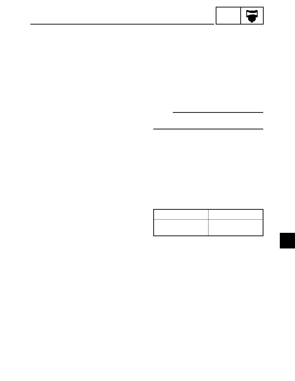
6 - 20
CARB
CARBURETOR
6. Install:
• fuel cock
7. Connect:
• fuel hose
EAS00506
CHECKING THE FUEL COCK OPERATION
NOTE:
After installing the fuel cock, check its oper-
ation.
1. Set the fuel cock to “OFF”.
2. Disconnect:
• fuel hose
(from the fuel cock)
3. Check:
• fuel cock operation
▼ ▼ ▼ ▼ ▼ ▼ ▼ ▼ ▼ ▼ ▼ ▼ ▼ ▼ ▼ ▼ ▼ ▼ ▼ ▼ ▼ ▼ ▼ ▼ ▼ ▼ ▼ ▼
a. Place a container under the end of the
fuel cock.
b. Check that the fuel cock lever is turned to
“ON” or “RES”.
▲ ▲ ▲ ▲ ▲ ▲ ▲ ▲ ▲ ▲ ▲ ▲ ▲ ▲ ▲ ▲ ▲ ▲ ▲ ▲ ▲ ▲ ▲ ▲ ▲ ▲ ▲ ▲
4. Connect:
• fuel hose
Fuel flows. Fuel cock is OK.
Fuel does not flow. Replace the fuel
cock.
6
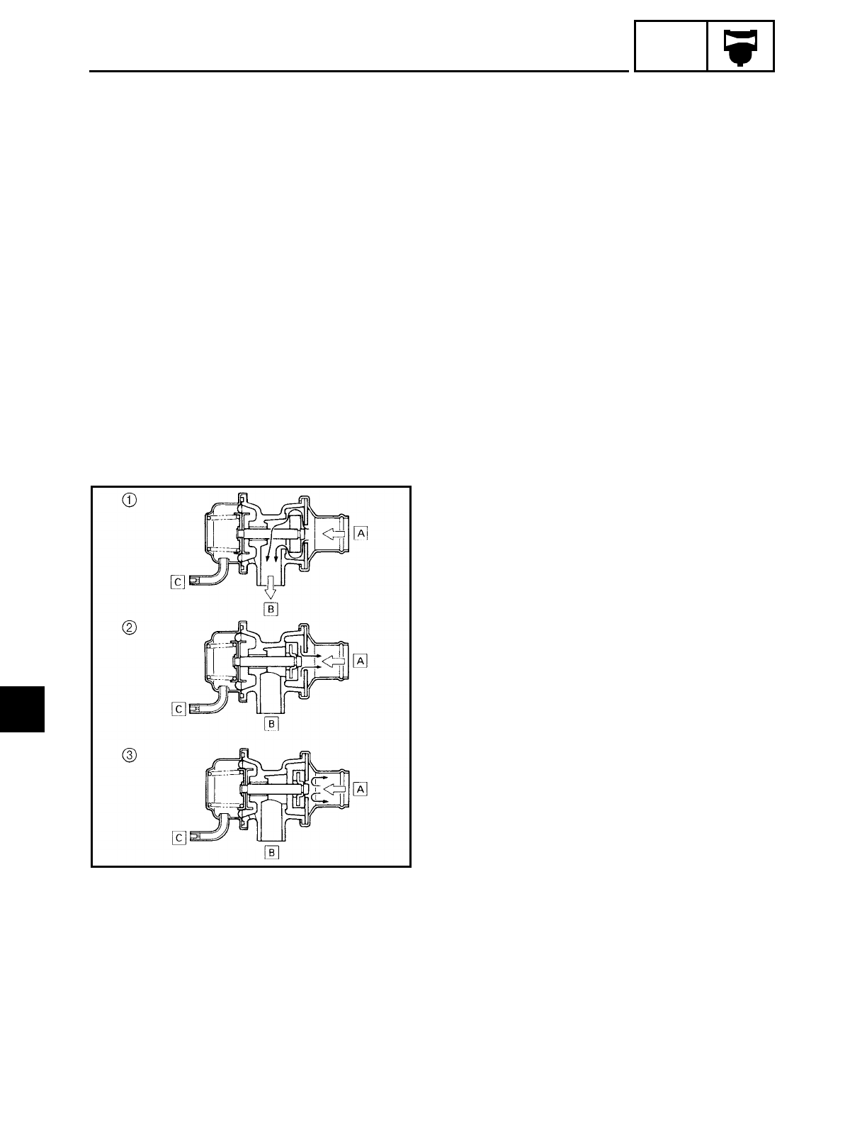
6 - 21
CARB
AIR INDUCTION SYSTEM
EAS00507
AIR INDUCTION SYSTEM
AIR INJECTION
The air induction system burns unburned
exhaust gases by injecting fresh air (sec-
ondary air) into the exhaust port, reducing
the emission of hydrocarbons.
When there is negative pressure at the
exhaust port, the reed valve opens, allow-
ing secondary air to flow into the exhaust
port. The required temperature for burning
the unburned exhaust gases is approxi-
mately 600 to 700 ˚C (1,112 to 1,292 ˚F).
EAS00508
AIR CUTOFF VALVE
The air cutoff valve is operated by the
intake gas pressure through the piston
valve diaphragm. Normally, the air cutoff
valve is open to allow fresh air to flow into
the exhaust port. During sudden decelera-
tion (the butterfly valve suddenly closes),
negative pressure is generated and the air
cutoff valve is closed in order to prevent
after-burning.
Additionally, at high engine speeds and
when the pressure decreases, the air cutoff
valve automatically closes to guard against
a loss of performance due to self-EGR
(Exhaust Gas Recirculation).
1 During normal operation, the air cutoff
valve is open.
2 During sudden deceleration (the butterfly
valve suddenly closes), the air cutoff valve
closes.
3 At high engine speeds and when the
pressure decreases, the air cutoff valve is
closed.
ÅFrom the air cleaner
ıTo the reed valve
ÇTo the carburetor joint
6
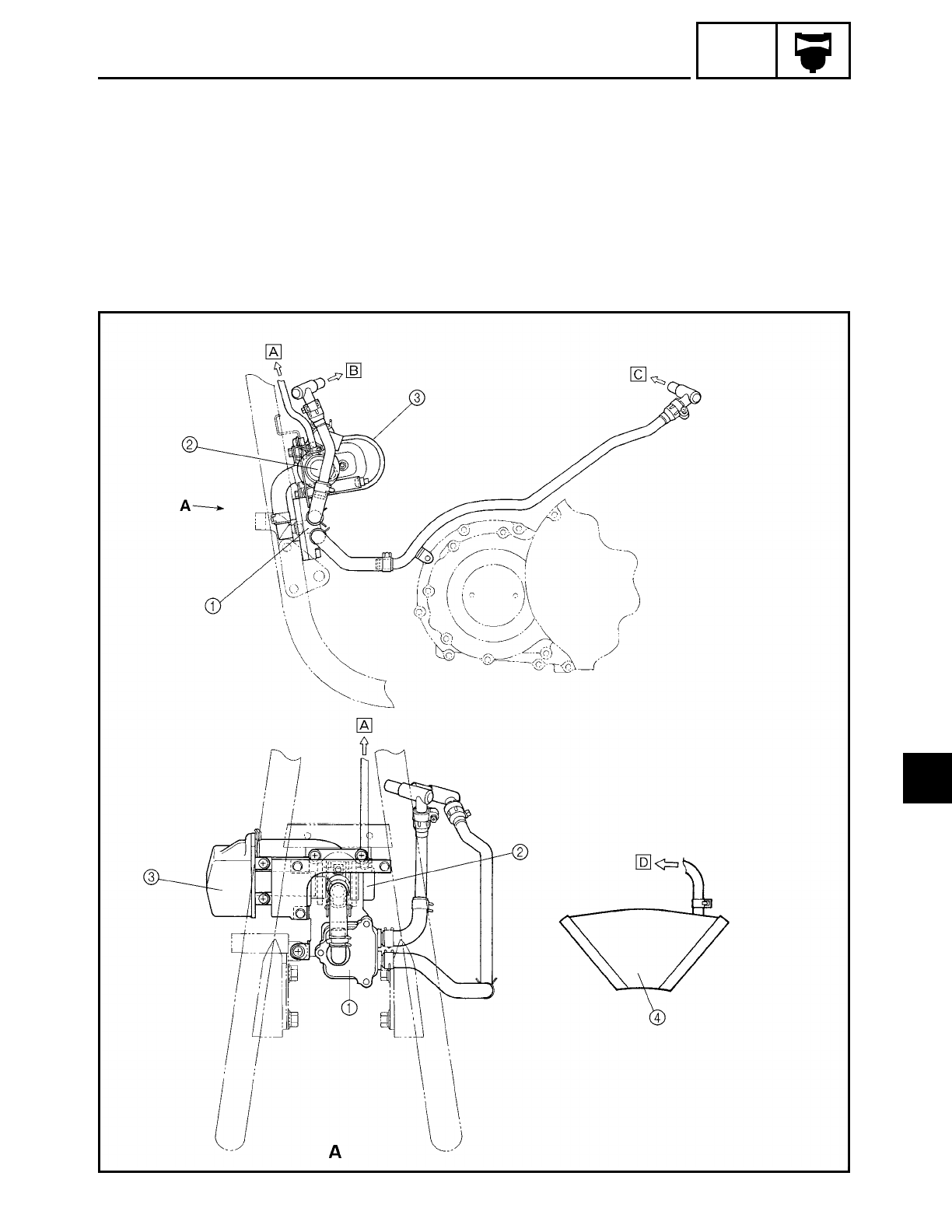
FWD
6 - 22
CARB
AIR INDUCTION SYSTEM
EAS00509
AIR INDUCTION SYSTEM DIAGRAMS
1Reed valve
2Air cut valve
3Air cleaner
4Carburetor joint
ÅTo the carburetor joint
ıTo the front cylinder head
ÇTo the rear cylinder head
ÎTo the air cut valve
6
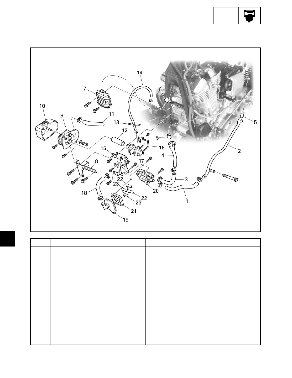
6 - 23
CARB
AIR INDUCTION SYSTEM
Order Job/Part Q’ty Remarks
Removing the air induction system Remove the parts in the order listed.
fuel tank Refer to “FUEL TANK” in chapter 3.
1 Reed valve case to rear cylinder
head hose
1
2 Reed valve case to rear cylinder
head pipe
1
3 Reed valve case to front cylinder
head hose
1
4 Reed valve case to front cylinder
head hose
1
5 Gasket 2
6 Rectifier/regulator coupler 1 Disconnect.
7 Rectifier/regulator 1
8 Air filter bracket 1
6
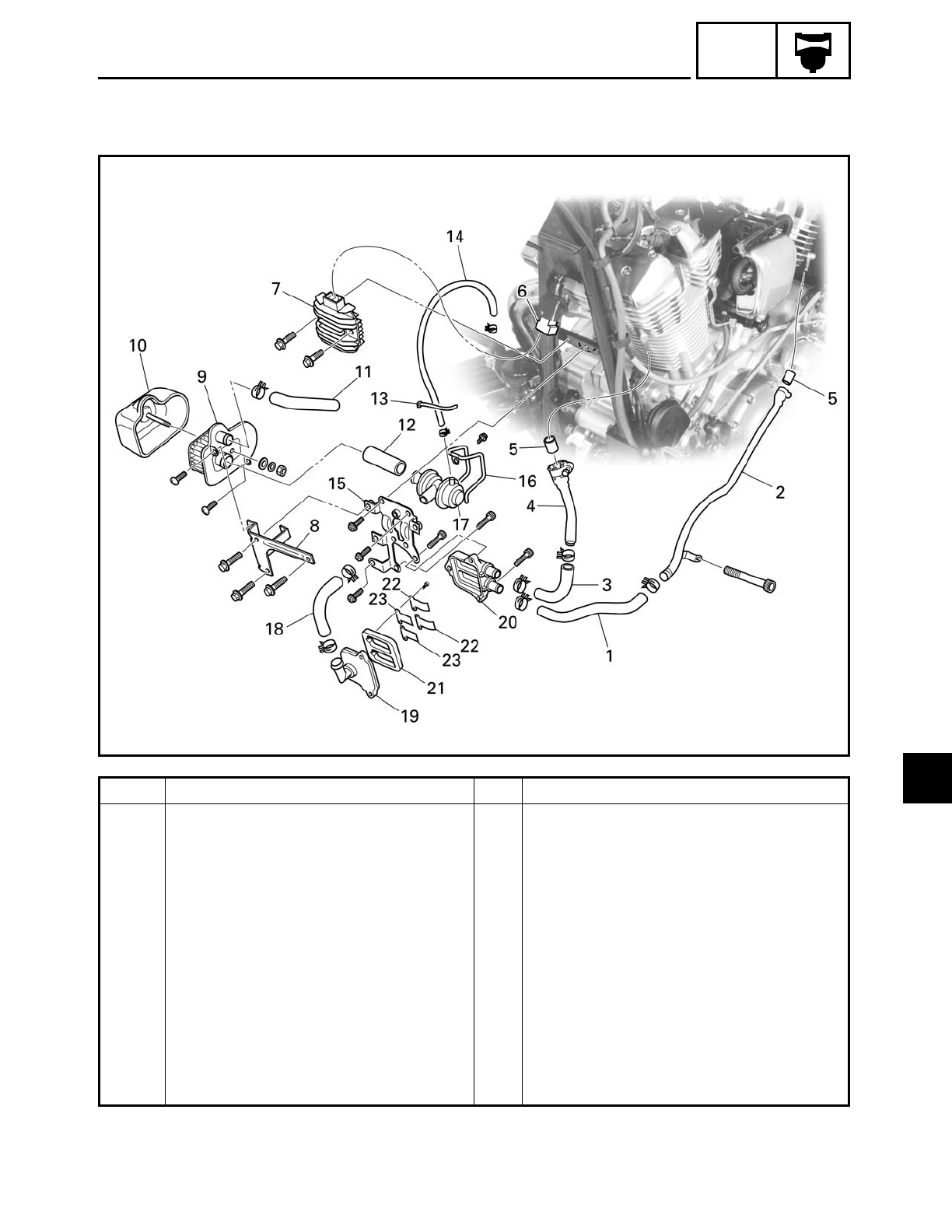
6 - 24
CARB
AIR INDUCTION SYSTEM
Order Job/Part Q’ty Remarks
9 Air filter 1
10 Air filter cover 1
11 Air filter hose 1
12 Air cut valve to air filter hose 1
13 Plastic locking tie 1
14 Vacuum hose 1
15 Bracket 1
16 Air cut valve holder 1
17 Air cut valve 1
18 Air cut valve to reed valve cover
hose
1
19 Reed valve cover 1
20 Reed valve case 1
6
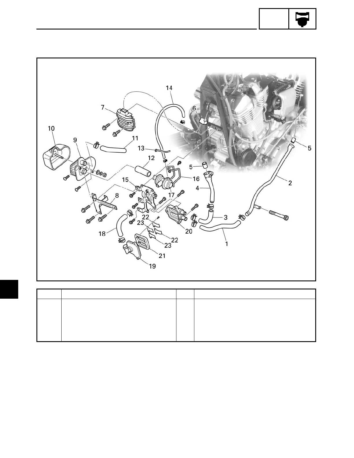
6 - 25
CARB
AIR INDUCTION SYSTEM
Order Job/Part Q’ty Remarks
21 Reed valve base 1
22 Reed valve stopper 2
23 Reed valve 2
For installation, reverse the removal
procedure.
6
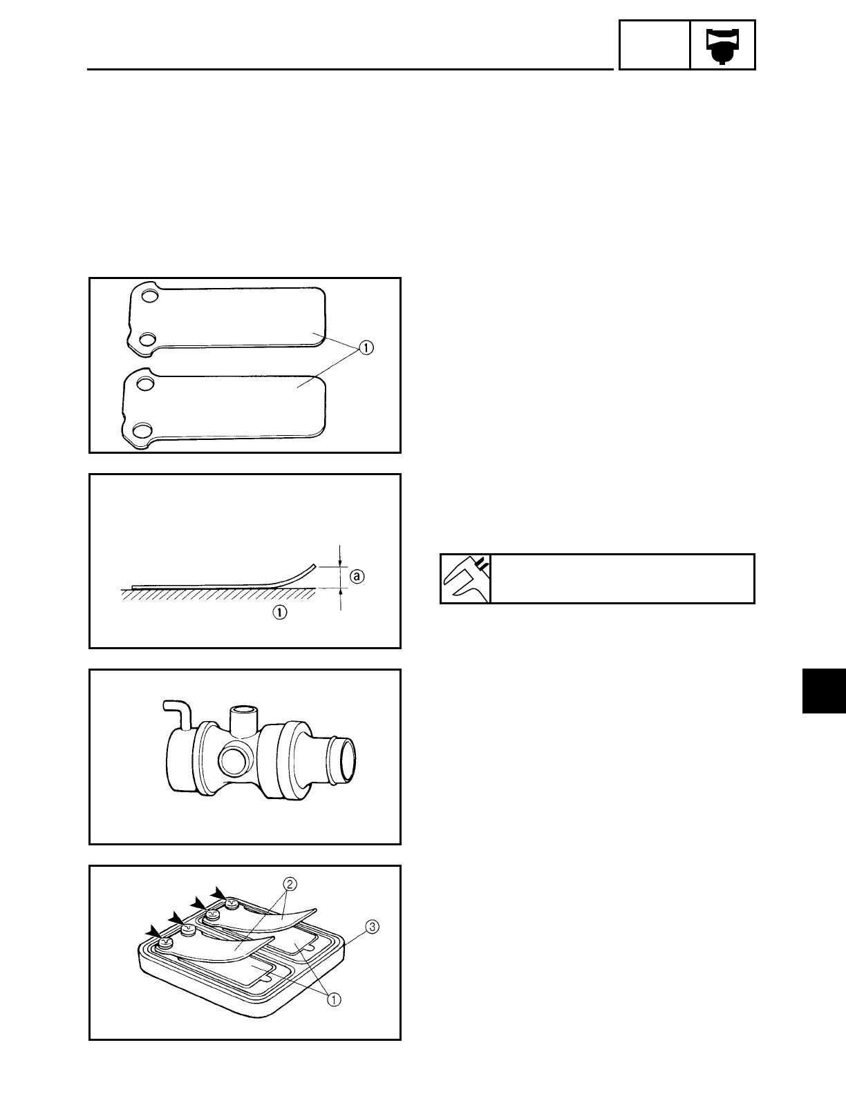
6 - 26
CARB
AIR INDUCTION SYSTEM
EAS00510
CHECKING THE AIR INDUCTION SYSTEM
1. Check:
• hoses
Loose connection → Connect properly.
Cracks/damage → Replace.
• pipes
Cracks/damage → Replace.
2. Check:
• fibre reed 1
• fibre reed stopper
• reed valve seat
Cracks/damage → Replace the reed
valve.
3. Measure:
• fibre reed bending a
Out of specification → Replace the reed
valve.
1Surface plate
Maximum fibre reed bending
0.4 mm (0.016 in)
4. Check:
• air cutoff valve
Cracks/damage → Replace.
INSTALLING THE AIR INDUCTION SYSTEM
1. Install:
• reed valves 1
• reed valve stoppers 2
• reed valve base 3
6
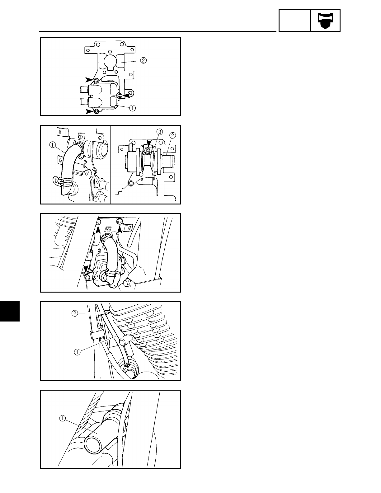
6 - 27
CARB
AIR INDUCTION SYSTEM
2. Install:
• reed valve case 1
• reed valve cover
• bracket 2
3. Install:
• air cut valve to reed valve cover hose 1
• air cut valve 2
• air cut valve holder 3
4. Install:
• bracket
(with the air cut valve and reed valve)
5. Install:
• vacuum hose 1
• plastic locking tie 2
6. Install:
• air cut valve to air filter hose 1
6
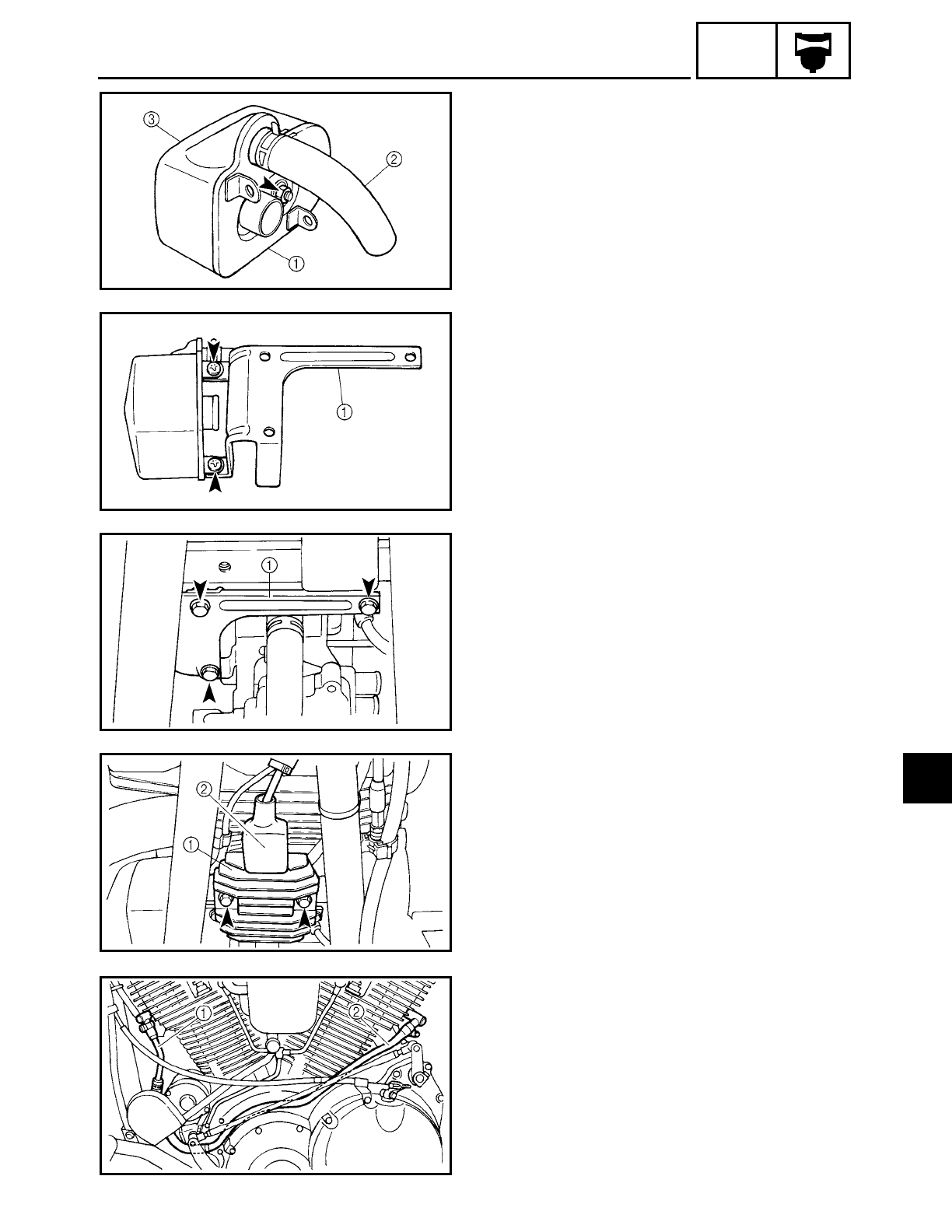
6 - 28
CARB
AIR INDUCTION SYSTEM
7. Install:
• air filter 1
• air filter hose 2
• air filter cover 3
8. Install:
• air filter bracket 1
9. Install:
• air filter case assembly 1
10.Install:
• rectifier/regulator 1
11.Connect:
• rectifier/regulator coupler 2
12.Install:
• gaskets
• reed valve case to front cylinder head
pipe 1
• reed valve case to front cylinder head
hose
• reed valve case to rear cylinder head
pipe 2
• reed valve case to rear cylinder head
hose
6

6 - 29
CARB
AIR INDUCTION SYSTEM
13.Install:
• fuel tank
Refer to “FUEL TANK” in chapter 3.
6
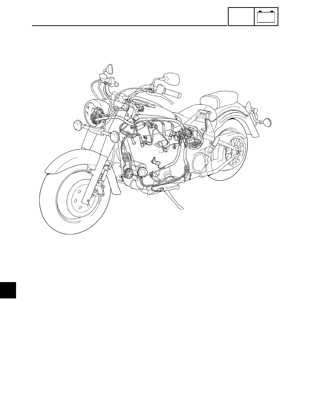
–+
ELEC
CONTENTS
ELECTRICAL SYSTEM
ELECTRICAL COMPONENTS ...................................................................... 7-1
ARRANGEMENT OF THE ELECTRICAL COMPONENTS AND
COUPLERS ................................................................................................7-2
SWITCHES ....................................................................................................7-6
CHECKING SWITCH CONTINUITY ...................................................... 7-6
CHECKING THE SWITCHES ........................................................................ 7-7
CHECKING THE BULBS AND BULB SOCKETS .......................................... 7-9
TYPES OF BULBS ................................................................................. 7-9
CHECKING THE CONDITION OF THE BULBS .................................... 7-9
CHECKING THE CONDITION OF THE BULB SOCKETS ................... 7-11
CHECKING THE LEDs ......................................................................... 7-11
7

–+
ELEC
IGNITION SYSTEM .................................................................................... 7-12
CIRCUIT DIAGRAM ............................................................................ 7-12
TROUBLESHOOTING ......................................................................... 7-13
ELECTRIC STARTING SYSTEM ................................................................. 7-17
CIRCUIT DIAGRAM ............................................................................ 7-17
STARTING CIRCUIT CUTOFF SYSTEM OPERATION ...................... 7-18
TROUBLESHOOTING ......................................................................... 7-19
STARTER MOTOR ...................................................................................... 7-23
CHECKING THE STARTER MOTOR .................................................. 7-25
ASSEMBLING THE STARTER MOTOR ............................................. 7-26
INSTALLING THE STARTER MOTOR ............................................... 7-27
CHARGING SYSTEM ................................................................................. 7-28
CIRCUIT DIAGRAM ............................................................................ 7-28
TROUBLESHOOTING ......................................................................... 7-29
LIGHTING SYSTEM .................................................................................... 7-31
CIRCUIT DIAGRAM ............................................................................ 7-31
TROUBLESHOOTING ......................................................................... 7-32
CHECKING THE LIGHTING SYSTEM ................................................ 7-33
SIGNALING SYSTEM ................................................................................. 7-37
CIRCUIT DIAGRAM ............................................................................ 7-37
TROUBLESHOOTING ......................................................................... 7-39
CHECKING THE SIGNALING SYSTEM ............................................. 7-40
FUEL PUMP SYSTEM ................................................................................ 7-46
CIRCUIT DIAGRAM ............................................................................ 7-46
FUEL PUMP CIRCUIT OPERATION ................................................... 7-47
TROUBLESHOOTING ......................................................................... 7-48
CHECKING THE FUEL PUMP ............................................................. 7-50
CARBURETOR HEATING SYSTEM ........................................................... 7-51
CIRCUIT DIAGRAM ............................................................................ 7-51
TROUBLESHOOTING ......................................................................... 7-52
SELF-DIAGNOSIS ....................................................................................... 7-55
TROUBLESHOOTING ......................................................................... 7-57
7
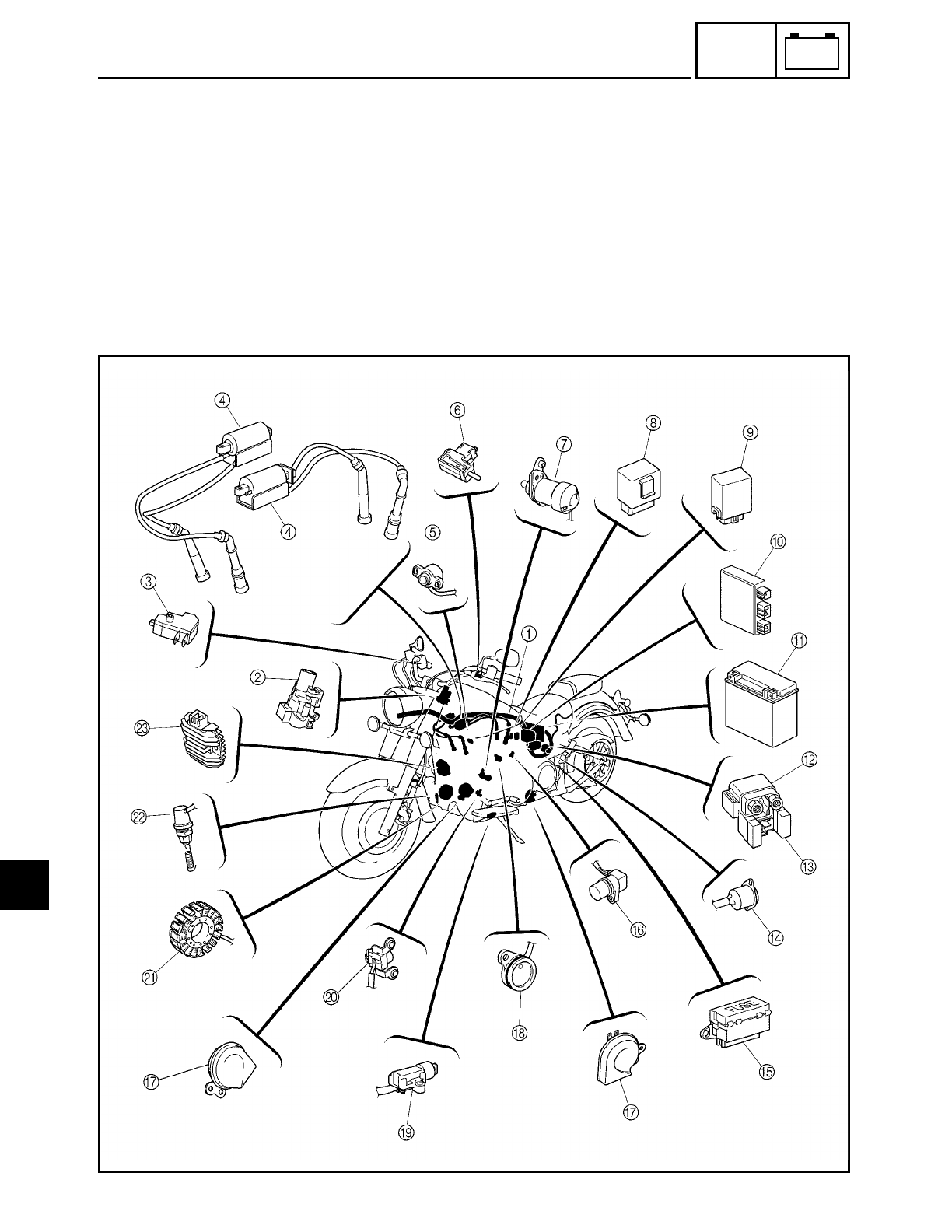
FWD
7 - 1
–+
ELEC
ELECTRICAL COMPONENTS
ESA00729
ELECTRICAL SYSTEM
ELECTRICAL COMPONENTS
1Wire harness
2Main switch
3Front brake light switch
4Ignition coils
5Throttle position sensor
6Clutch switch
7Decompression solenoid
8Relay unit
9Turn signal relay
0Ignitor unit
ABattery
BStarter relay
CMain fuse
DThermo switch
EFuse box
FSpeed sensor
GHorns
HNeutral switch
ISidestand switch
JPickup coil
KStator coil assembly
LRear brake light switch
MRectifier/regulator
7
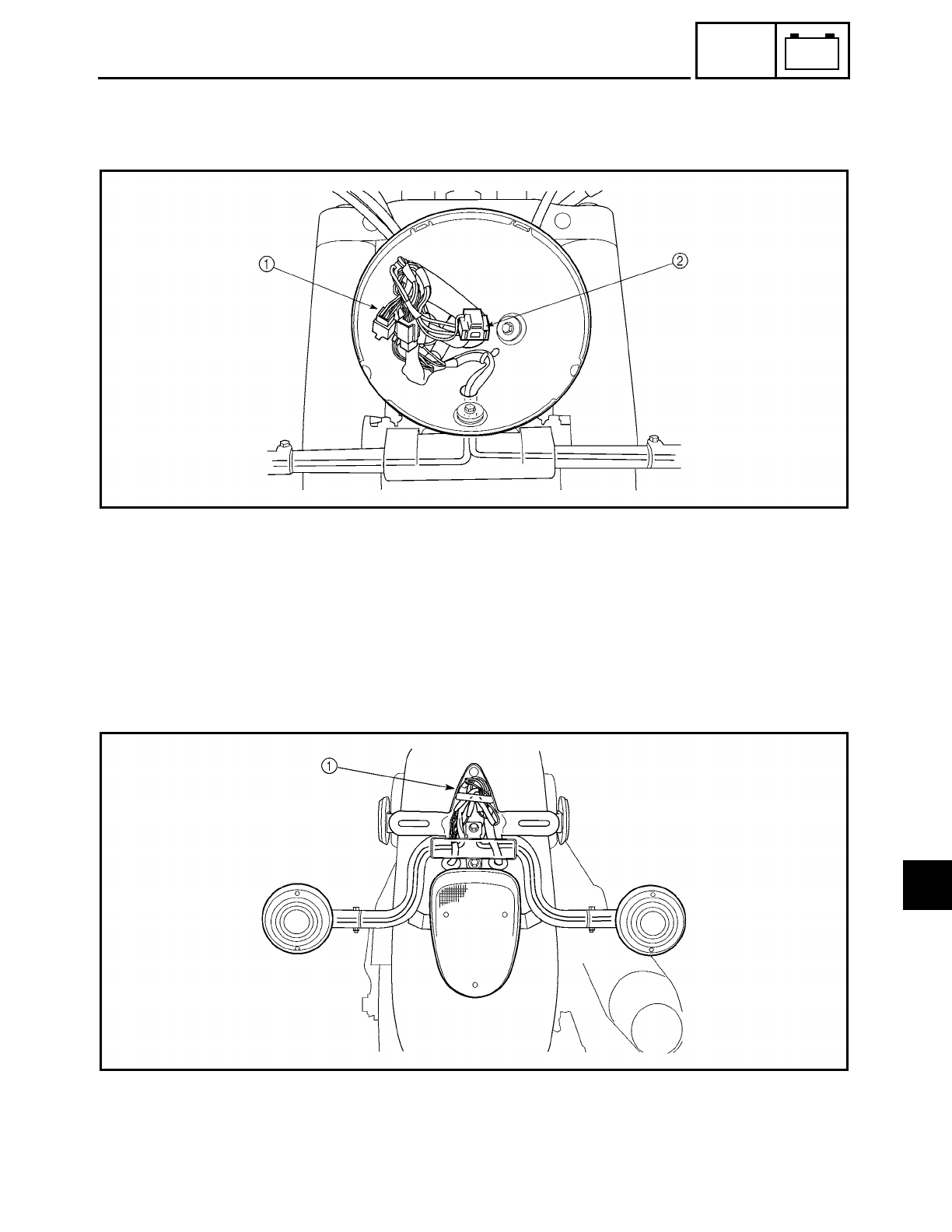
7 - 2
–+
ELEC
ARRANGEMENT OF THE ELECTRICAL COMPONENTS AND COUPLERS
1Right handlebar switch coupler, left handlebar switch couplers and front turn signal connectors
2Headlight coupler
1Tail/brake light connectors and rear turn signal connectors
ARRANGEMENT OF THE ELECTRICAL COMPONENTS
AND COUPLERS
7
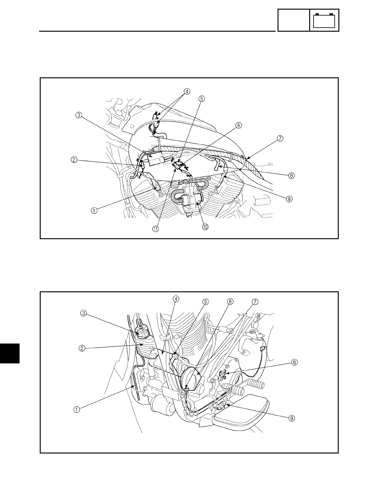
7 - 3
–+
ELEC
ARRANGEMENT OF THE ELECTRICAL COMPONENTS
AND COUPLERS
1Spark plug cap #3
2Rear brake light switch cou-
pler
3Ignition coil (front cylinder)
4Meter assembly couplers
5Carburetor heater sub-wire
harness coupler
6Throttle position sensor
coupler
7Fuel sender coupler
8Spark plug cap #2
9Spark plug cap #1
0Fuel pump
AFuel pump coupler
1Rear brake light switch lead
2Rectifier/regulator
3Rectifier/regulator coupler
4Starter motor
5Starter motor lead
6Horn coupler
7Horn
8Pickup coil
9Sidestand switch
7
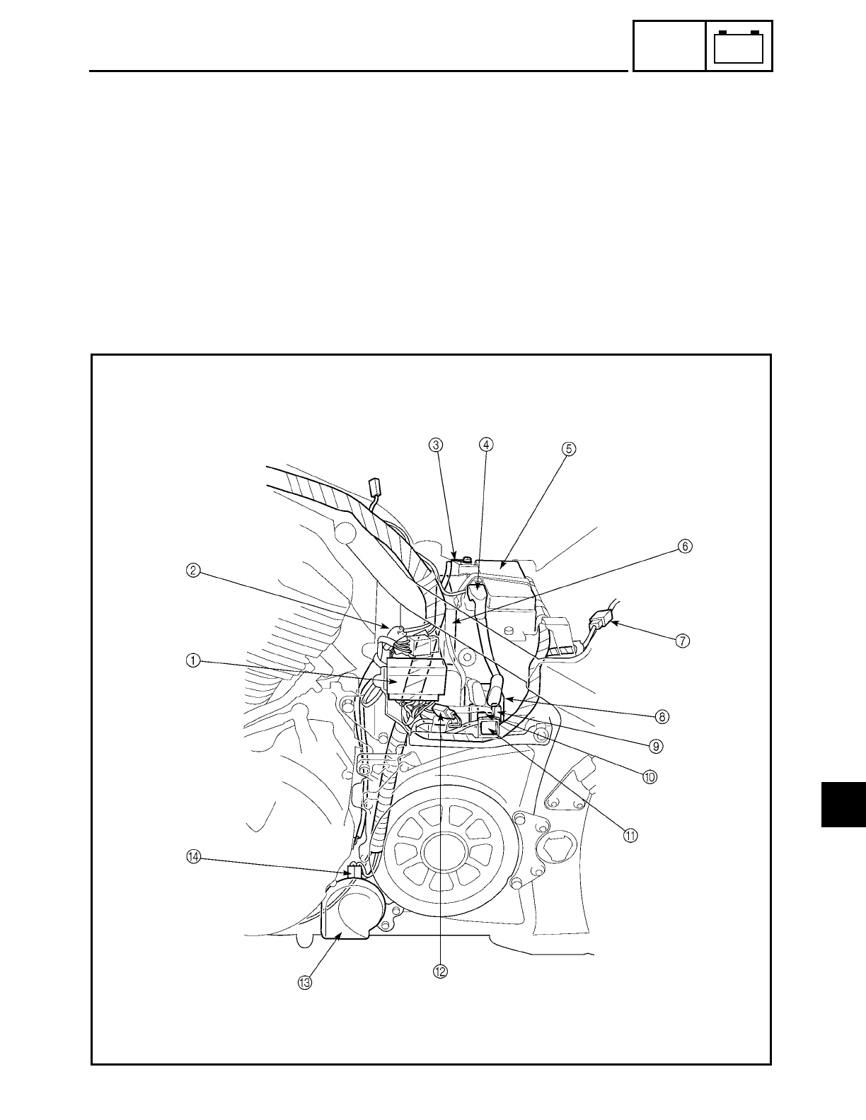
7 - 4
–+
ELEC
ARRANGEMENT OF THE ELECTRICAL COMPONENTS
AND COUPLERS
1Fuse box
2Stator coil coupler, decompression solenoid couplers, pickup coil coupler, speed sensor coupler,
neutral switch connector and sidestand switch coupler
3Battery negative lead
4Battery positive lead
5Battery
6Ignitor unit
7Tail/brake light and rear turn signal light sub-wire harness coupler
8Starter relay
9Main fuse
0Starter relay coupler
AThermo switch
BThermo switch coupler
CHorn
DHorn coupler
7
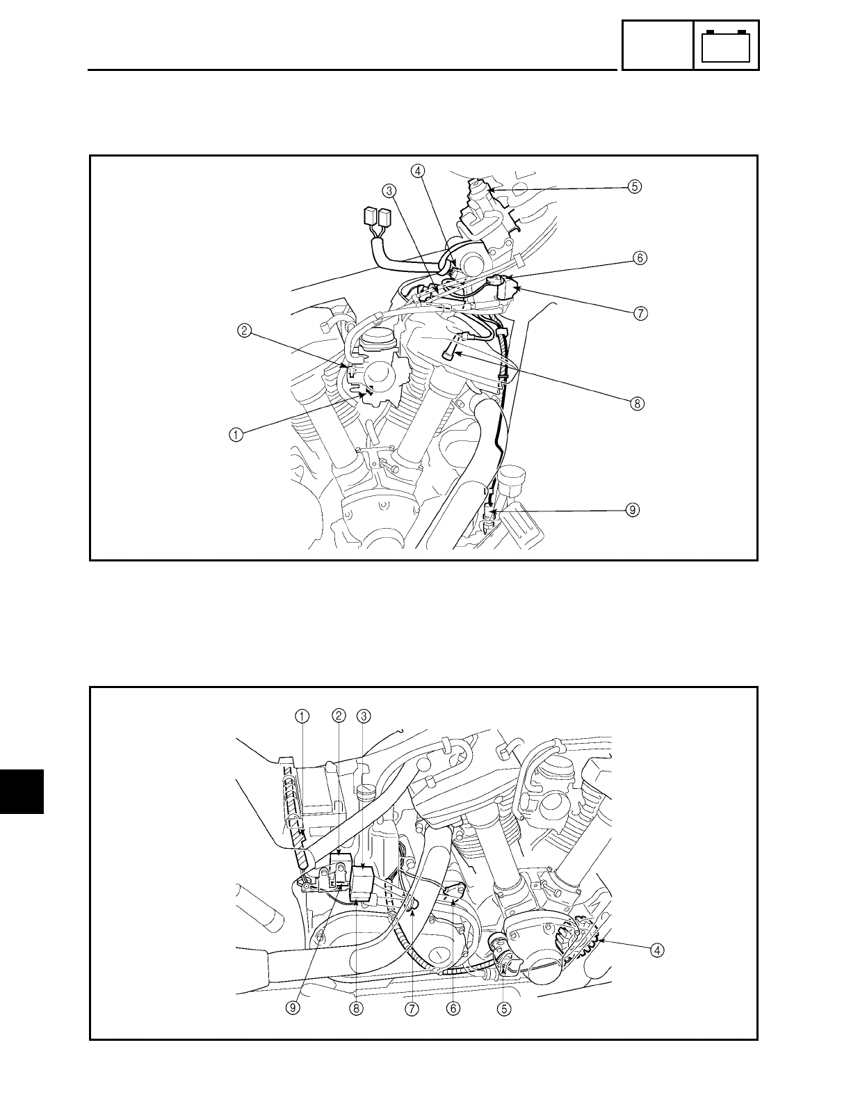
7 - 5
–+
ELEC
ARRANGEMENT OF THE ELECTRICAL COMPONENTS
AND COUPLERS
1Carburetor heater
2Throttle position sensor
3Ignition coil (rear cylinder)
4Main switch coupler
5Main switch
6Solenoid valve coupler
7Solenoid valve
8Spark plug cap #4
9Rear brake light switch
1Diode
2Turn signal relay
3Relay unit
4Stator coil
5Decompression solenoid
6Neutral switch
7Speed sensor
8Relay unit coupler
9Turn signal relay coupler
7
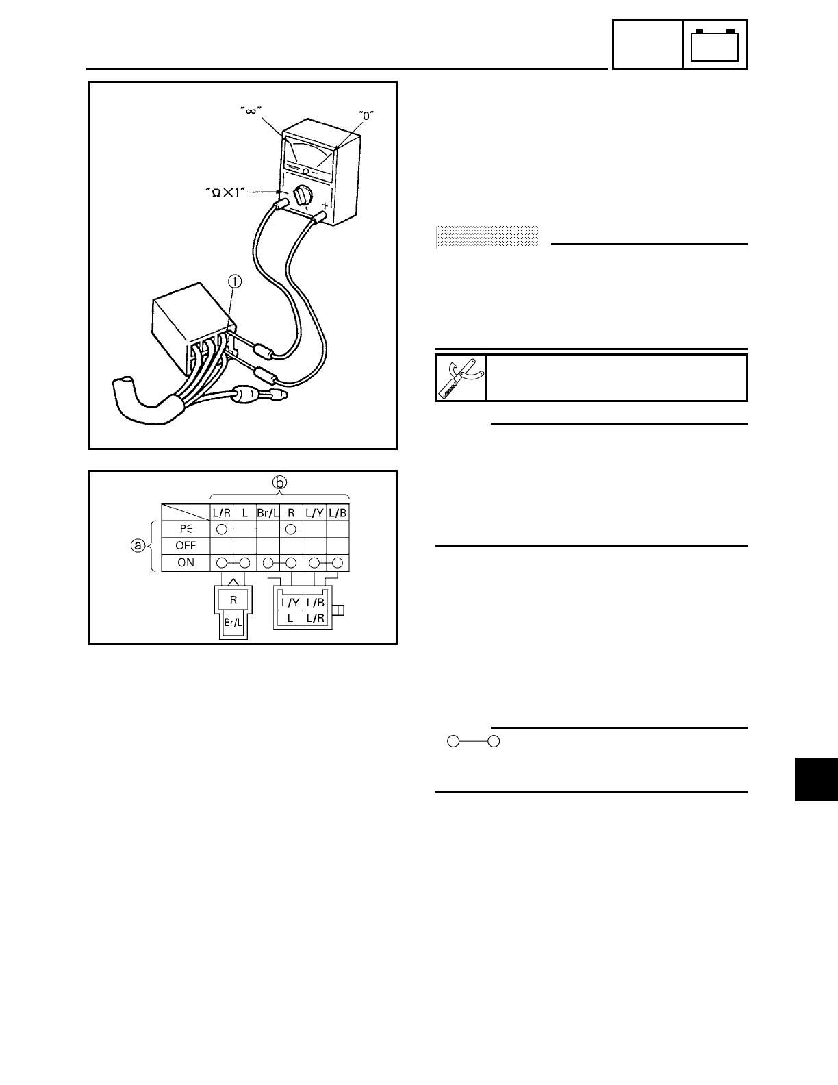
7 - 6
–+
ELEC
EAS00730
SWITCHES
CHECKING SWITCH CONTINUITY
Check each switch for continuity with the
pocket tester. If the continuity reading is
incorrect, check the wiring connections and
if necessary, replace the switch.
ACHTUNG:
CAUTION:
Never insert the tester probes into the cou-
pler terminal slots 1. Always insert the
probes from the opposite end of the cou-
pler, taking care not to loosen or damage
the leads.
NOTE:
• Before checking for continuity, set the
pocket tester to “0” and to the “Ω× 1”
range.
• When checking for continuity, switch back
and forth between the switch positions a
few times.
The terminal connections for switches (e.g.,
main switch, engine stop switch) are shown
in an illustration similar to the one on the
left.
The switch positions a are shown in the far
left column and the switch lead colors b
are shown in the top row in the switch illus-
tration.
NOTE:
“ ” indicates a continuity of electric-
ity between switch terminals (i.e., a closed
circuit at the respective switch position).
The example illustration on the left shows
that:
There is continuity between red and brown/
blue, and between blue/yellow and blue/
black when the switch is set to “ON”.
Pocket tester
YU-03112
SWITCHES
7
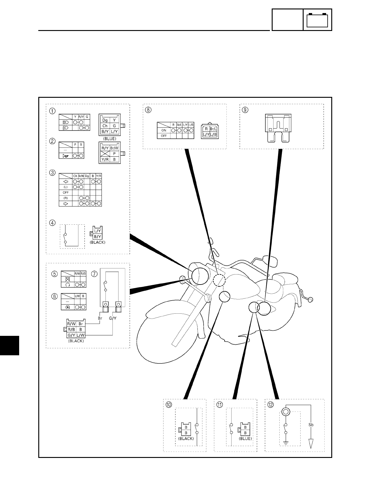
7 - 7
–+
ELEC
CHECKING THE SWITCHES
EAS00731
CHECKING THE SWITCHES
Check each switch for damage or wear, proper connections, and also for continuity between
the terminals. Refer to “CHECKING SWITCH CONTINUITY”.
Damage/wear → Repair or replace the switch.
Improperly connected → Properly connect.
Incorrect continuity reading → Replace the switch.
7

7 - 8
–+
ELEC
CHECKING THE SWITCHES
1Dimmer switch
2Horn switch
3Turn signal switch
4Clutch switch
5Engine stop switch
6Start switch
7Front brake light switch
8Main switch
9Fuse
0Rear brake light switch
ASidestand switch
BNeutral switch
7
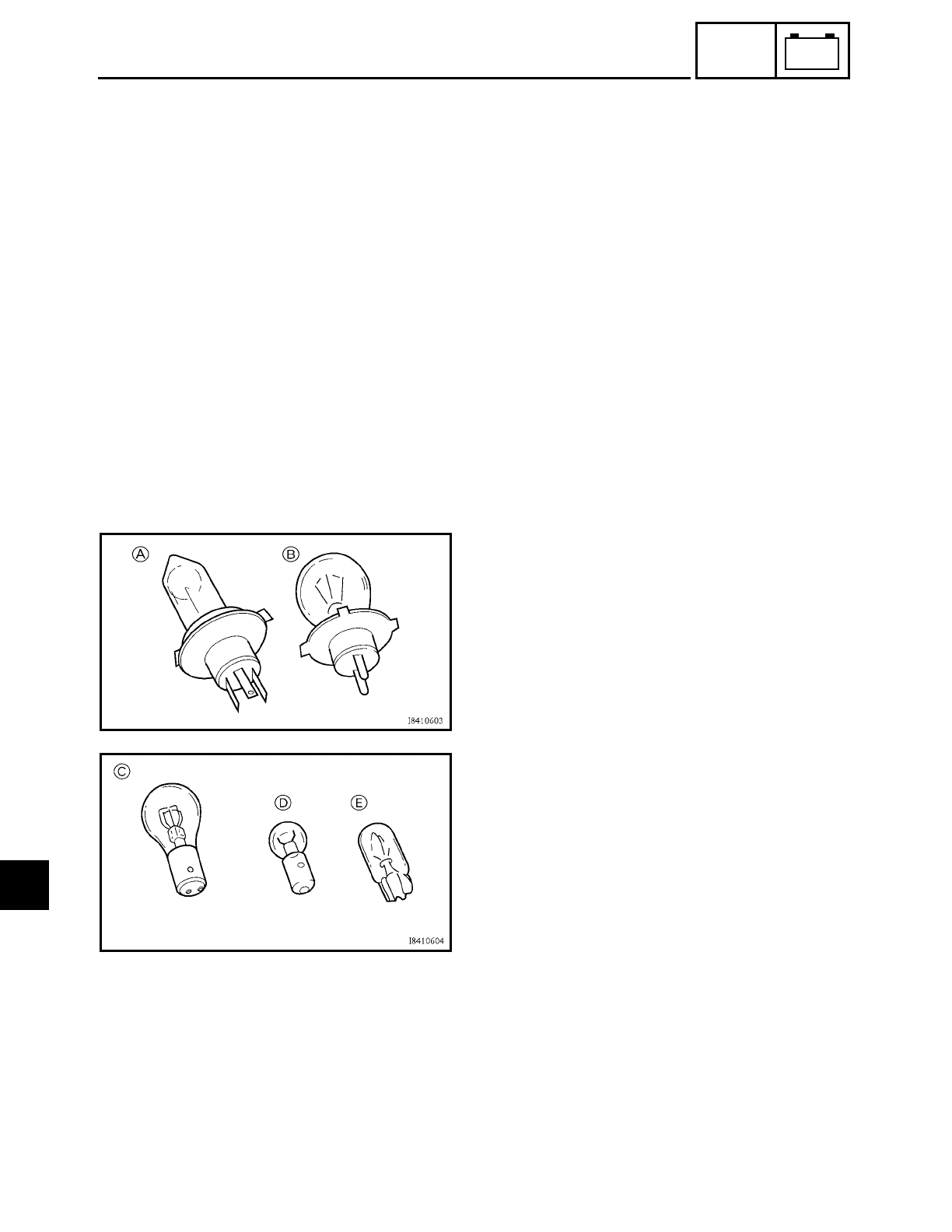
7 - 9
–+
ELEC
CHECKING THE BULBS AND BULB SOCKETS
EAS00732
CHECKING THE BULBS AND
BULB SOCKETS
Check each bulb and bulb socket for dam-
age or wear, proper connections, and also
for continuity between the terminals.
Damage/wear → Repair or replace the
bulb, bulb socket or both.
Improperly connected → Properly con-
nect.
Incorrect continuity reading → Repair or
replace the bulb, bulb socket or both.
TYPES OF BULBS
The bulbs used on this motorcycle are
shown in the illustration on the left.
• Bulbs A and B are used for the head-
lights and usually use a bulb holder
which must be detached before remov-
ing the bulb. The majority of these bulbs
can be removed from their respective
socket by turning them counterclock-
wise.
• Bulb C is used for turn signal and tail/
brake lights and can be removed from
the socket by pushing and turning the
bulb counterclockwise.
• Bulbs D and E are used for meter and
indicator lights and can be removed
from their respective socket by carefully
pulling them out.
CHECKING THE CONDITION OF THE BULBS
The following procedure applies to all of
the bulbs.
1. Remove:
• bulb
7
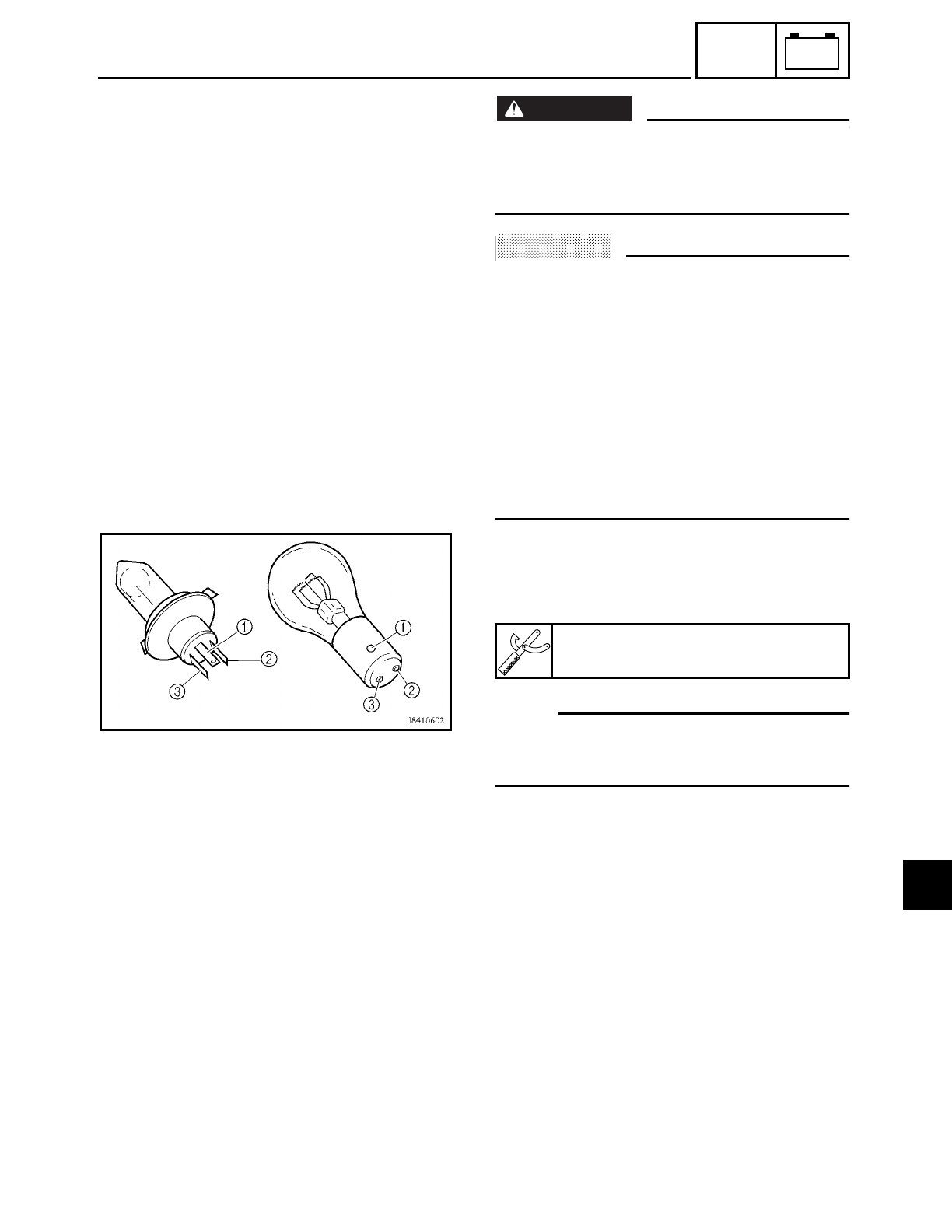
7 - 10
–+
ELEC
CHECKING THE BULBS AND BULB SOCKETS
WARNING
WARNING
Since the headlight bulb gets extremely
hot, keep flammable products and your
hands away from the bulb until it has
cooled down.
ACHTUNG:
CAUTION:
• Be sure to hold the socket firmly when
removing the bulb. Never pull the lead,
otherwise it may be pulled out of the ter-
minal in the coupler.
• Avoid touching the glass part of the head-
light bulb to keep it free from oil, other-
wise the transparency of the glass, the
life of the bulb and the luminous flux will
be adversely affected. If the headlight
bulb gets soiled, thoroughly clean it with
a cloth moistened with alcohol or lacquer
thinner.
2. Check:
• bulb (for continuity)
(with the pocket tester)
No continuity → Replace.
NOTE:
Before checking for continuity, set the
pocket tester to “0” and to the “Ω× 1”
range.
▼ ▼ ▼ ▼ ▼ ▼ ▼ ▼ ▼ ▼ ▼ ▼ ▼ ▼ ▼ ▼ ▼ ▼ ▼ ▼ ▼ ▼ ▼ ▼ ▼ ▼ ▼ ▼
a. Connect the tester positive probe to ter-
minal 1 and the tester negative probe to
terminal 2, and check the continuity.
b. Connect the tester positive probe to ter-
minal 1 and the tester negative probe to
terminal 3, and check the continuity.
c. If either of the readings indicate no conti-
nuity, replace the bulb.
▲ ▲ ▲ ▲ ▲ ▲ ▲ ▲ ▲ ▲ ▲ ▲ ▲ ▲ ▲ ▲ ▲ ▲ ▲ ▲ ▲ ▲ ▲ ▲ ▲ ▲ ▲ ▲
Pocket tester
YU-03112
7
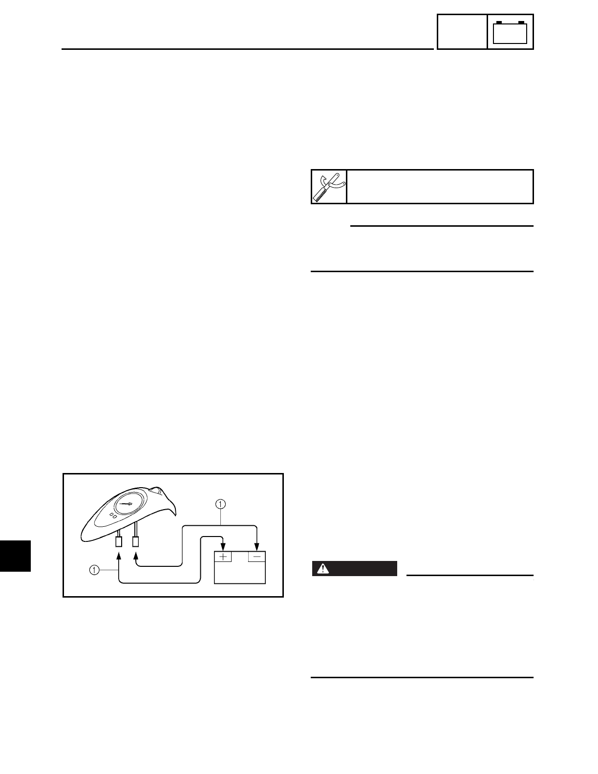
7 - 11
–+
ELEC
CHECKING THE BULBS AND BULB SOCKETS
CHECKING THE CONDITION OF THE BULB
SOCKETS
The following procedure applies to all of
the bulb sockets.
1. Check:
• bulb socket (for continuity)
(with the pocket tester)
No continuity → Replace.
NOTE:
Check each bulb socket for continuity in the
same manner as described in the bulb sec-
tion; however, note the following.
▼ ▼ ▼ ▼ ▼ ▼ ▼ ▼ ▼ ▼ ▼ ▼ ▼ ▼ ▼ ▼ ▼ ▼ ▼ ▼ ▼ ▼ ▼ ▼ ▼ ▼ ▼ ▼
a. Install a good bulb into the bulb socket.
b. Connect the pocket tester probes to the
respective leads of the bulb socket.
c. Check the bulb socket for continuity. If
any of the readings indicate no continu-
ity, replace the bulb socket.
▲ ▲ ▲ ▲ ▲ ▲ ▲ ▲ ▲ ▲ ▲ ▲ ▲ ▲ ▲ ▲ ▲ ▲ ▲ ▲ ▲ ▲ ▲ ▲ ▲ ▲ ▲ ▲
CHECKING THE LEDs
The following procedure applies to all of
the LEDs.
1. Check:
LED (for proper operation)
▼ ▼ ▼ ▼ ▼ ▼ ▼ ▼ ▼ ▼ ▼ ▼ ▼ ▼ ▼ ▼ ▼ ▼ ▼ ▼ ▼ ▼ ▼ ▼ ▼ ▼ ▼ ▼
a. Disconnect the meter assembly coupler
(meter assembly side).
b. Connect two jumper leads 1 from the
battery terminals to the respective cou-
pler terminals as shown.
WARNING
WARNING
• A wire that is used as a jumper lead must
have at least the same capacity of the
battery lead, otherwise the jumper lead
may burn.
• This check is likely to produce sparks,
therefore make sure that no flammable
gas or fluid is in the vicinity.
c. When the jumper leads are connected to
the terminals the respective LED should
illuminate.
Does not light → Replace the meter
assembly.
▲ ▲ ▲ ▲ ▲ ▲ ▲ ▲ ▲ ▲ ▲ ▲ ▲ ▲ ▲ ▲ ▲ ▲ ▲ ▲ ▲ ▲ ▲ ▲ ▲ ▲ ▲ ▲
Pocket tester
YU-03112
7
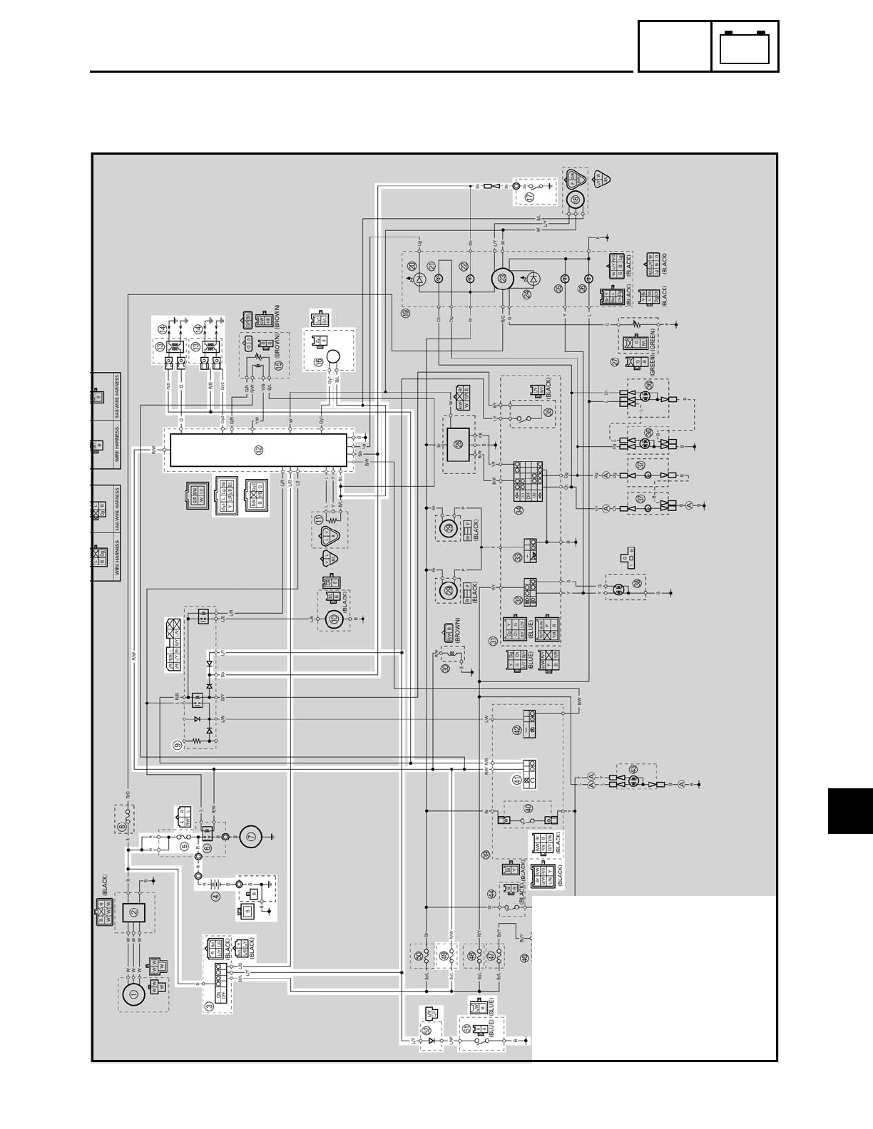
7 - 12
–+
ELEC
IGNITION SYSTEM
EB802001
IGNITION SYSTEM
CIRCUIT DIAGRAM
3Main switch
4Battery
5Main fuse
9Relay unit
BIgnitor unit
CIgnition coil
DSpark plug
FPickup coil
GNeutral switch
aEngine stop switch
iIgnition fuse
kSidestand switch
lDiode
7
7 - 13
–+
ELEC
IGNITION SYSTEM
EB802011
TROUBLESHOOTING
Check:
1. main and ignition fuses
2. battery
3. spark plugs
4. ignition spark gap
5. spark plug cap resistance
6. ignition coil resistance
7. pickup coil resistance
8. main switch
9. engine stop switch
10.neutral switch
11.sidestand switch
12.diode
13.relay unit (diode)
14.wiring
(of the entire ignition system)
NOTE:
• Before troubleshooting, remove the fol-
lowing part(s):
1) rider seat
2) fuel tank
3) side covers
4) ignition coils
5) headlight lens unit
• Troubleshoot with the following special
tool(s).
The ignition system fails to operate (no
spark or intermittent spark).
Dynamic spark tester
YM-34487
Pocket tester
YU-03112
EB802400
YES NO
1.Main and ignition fuses
• Check the main and ignition fuses for
continuity.
Refer to “CHECKING THE FUSES” in
chapter 3.
• Are the main and ignition fuses OK?
Replace the fuse(s).
EB802401
YES NO
2.Battery
• Check the condition of the battery.
Refer to “CHECKING AND CHARGING
THE BATTERY” in chapter 3.
Minimum open-circuit voltage
12.8 V or more at 20 ˚C (68 ˚F)
• Is the battery OK?
• Clean the battery
terminals.
• Recharge or
replace the battery.
EB802403
YES NO
3.Spark plugs
The following procedure applies to all of
the spark plugs.
• Check the condition of the spark plug.
• Check the spark plug type.
• Measure the spark plug gap.
Refer to “CHECKING THE SPARK
PLUGS” in chapter 3.
Standard spark plug
DPR7EA-9 (NGK)
X22EPR-U9 (DENSO)
Spark plug gap
0.8 ~ 0.9 mm (0.031 ~ 0.035 in)
• Is the spark plug in good condition, is it
of the correct type, and its gap within
specification?
Re-gap or replace
the spark plug.
7
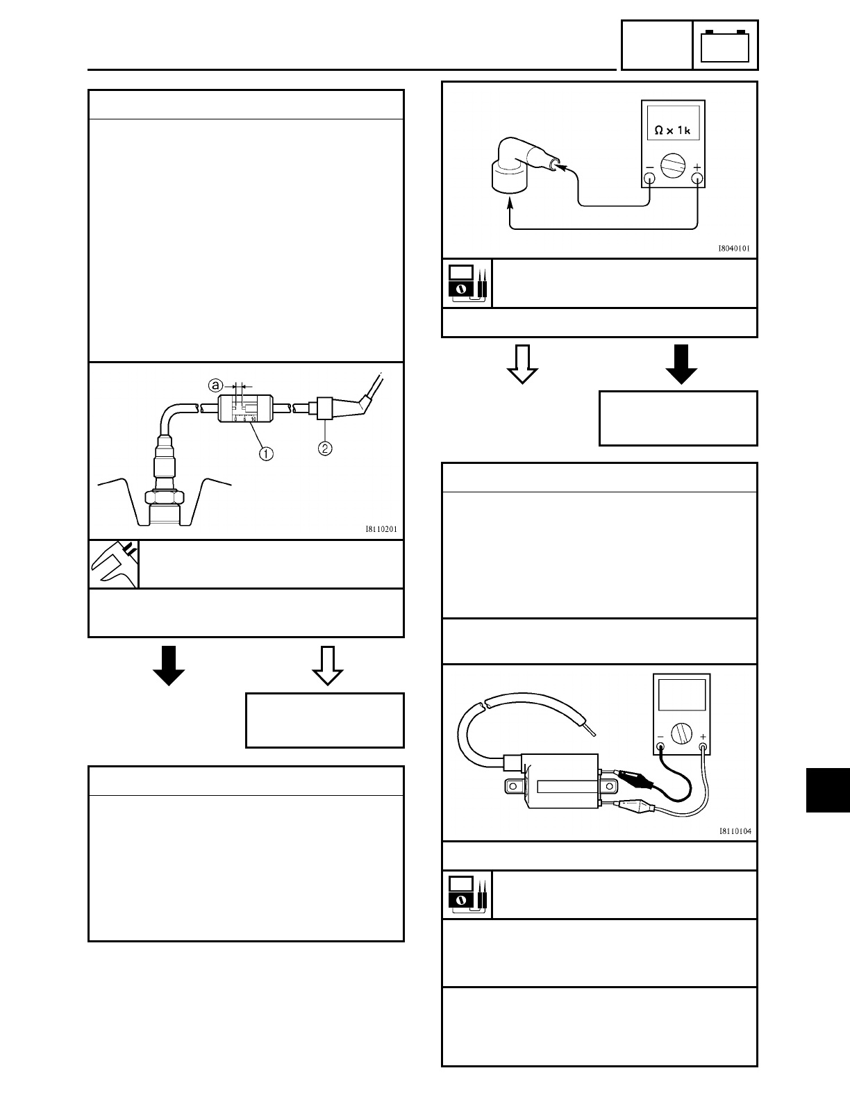
7 - 14
–+
ELEC
IGNITION SYSTEM
EB802405
NO YES
4.Ignition spark gap
The following procedure applies to all of
the spark plugs.
• Disconnect the spark plug cap from the
spark plug.
• Connect the dynamic spark tester 1 as
shown.
2 Spark plug cap
• Set the main switch to “ON”.
• Measure the ignition spark gap a.
• Crank the engine by pushing the start
switch and gradually increase the spark
gap until a misfire occurs.
Minimum ignition spark gap
6 mm (0.24 in)
• Is there a spark and is the spark gap
within specification?
The ignition system
is OK.
EB802407
5.Spark plug cap resistance
The following procedure applies to all of
the spark plug caps.
• Disconnect the spark plug cap from the
spark plug.
• Connect the pocket tester (Ω× 1k) to the
spark plug cap as shown.
• Measure the spark plug cap resistance.
YES NO
Spark plug cap resistance
10 kΩ at 20 ˚C (68 ˚F)
• Is the spark plug cap OK?
Replace the spark
plug cap.
EB802409
6.Ignition coil resistance
The following procedure applies to all of
the ignition coils.
• Disconnect the ignition coil connectors
from the ignition coil terminals.
• Connect the pocket tester (Ω× 1) to the
ignition coil as shown.
Tester positive probe → red/black
Tester negative probe → orange (gray)
• Measure the primary coil resistance.
Primary coil resistance
1.53 ~ 2.07 Ω at 20 ˚C (68 ˚F)
• Connect the pocket tester (Ω× 1k) to the
ignition coil as shown.
• Measure the secondary coil resistance.
Tester positive probe →
spark plug lead 1
Tester negative probe →
spark plug lead 2
7
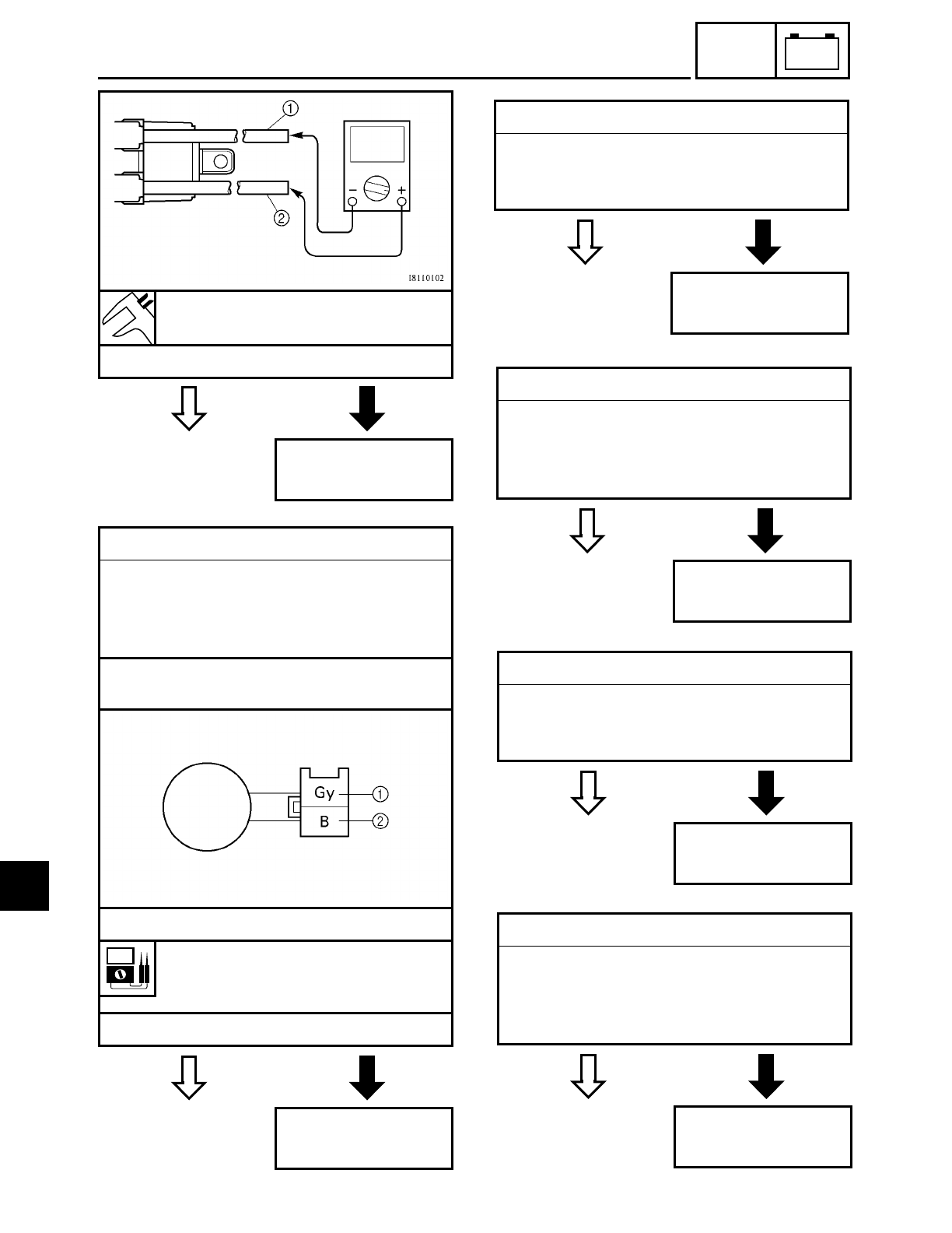
7 - 15
–+
ELEC
IGNITION SYSTEM
YES NO
Secondary coil resistance
12 ~ 18 kΩ at 20 ˚C (68 ˚F)
• Is the ignition coil OK?
Replace the ignition
coil.
EB802410
YES NO
7.Pickup coil resistance
• Disconnect the pickup coil coupler from
the wire harness.
• Connect the pocket tester (Ω× 100) to
the pickup coil coupler.
Tester positive probe → gray 1
Tester negative probe → black 2
• Measure the pickup coil resistance.
Pickup coil resistance
248 ~ 372 Ω at 20 ˚C (68 ˚F)
(between gray and black)
• Is the pickup coil OK?
Replace the pickup
coil.
EB802411
YES NO
8.Main switch
• Check the main switch for continuity.
Refer to “CHECKING THE SWITCHES”.
• Is the main switch OK?
Replace the main
switch.
EB802412
YES NO
9.Engine stop switch
• Check the engine stop switch for conti-
nuity.
Refer to “CHECKING THE SWITCHES”.
• Is the engine stop switch OK?
Replace the right
handlebar switch.
EB802413
YES NO
10.Neutral switch
• Check the neutral switch for continuity.
Refer to “CHECKING THE SWITCHES”.
• Is the neutral switch OK?
Replace the neutral
switch.
EB802414
YES NO
11.Sidestand switch
• Check the sidestand switch for continu-
ity.
Refer to “CHECKING THE SWITCHES”.
• Is the sidestand switch OK?
Replace the side-
stand switch.
7
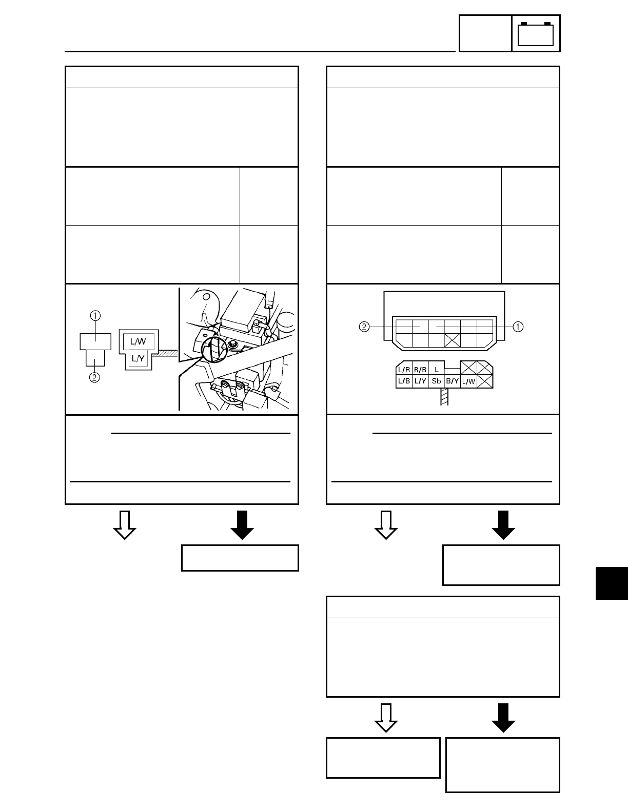
7 - 16
–+
ELEC
IGNITION SYSTEM
YES NO
12.Diode
• Remove the diode from the coupler.
• Connect the pocket tester (Ω× 1) to the
diode terminals as shown.
• Check the diode for continuity as fol-
lows.
Tester positive probe →
blue/white 1
Tester negative probe →
blue/yellow 2
Continu-
ity
Tester positive probe →
blue/yellow 2
Tester negative probe →
blue/white 1
No conti-
nuity
• Are the tester readings correct?
Replace the diode.
NOTE:
When you switch the tester’s positive
and negative probes, the readings in the
above chart will be reversed.
EB802415
YES NO
13.Relay unit (diode)
• Remove the relay unit from the coupler.
• Connect the pocket tester (Ω× 1) to the
relay unit terminals as shown.
• Check the diode for continuity as fol-
lows.
Tester positive probe →
sky blue 1
Tester negative probe →
blue/yellow 2
Continu-
ity
Tester positive probe →
blue/yellow 2
Tester negative probe →
sky blue 1
No conti-
nuity
• Are the tester readings correct?
Replace the relay
unit.
NOTE:
When you switch the tester’s positive
and negative probes, the readings in the
above chart will be reversed.
EAS00754
YES NO
14.Wiring
• Check the entire ignition system’s wir-
ing.
Refer to “CIRCUIT DIAGRAM”.
• Is the ignition system’s wiring properly
connected and without defects?
Replace the ignitor
unit.
Properly connect or
repair the ignition
system’s wiring.
7
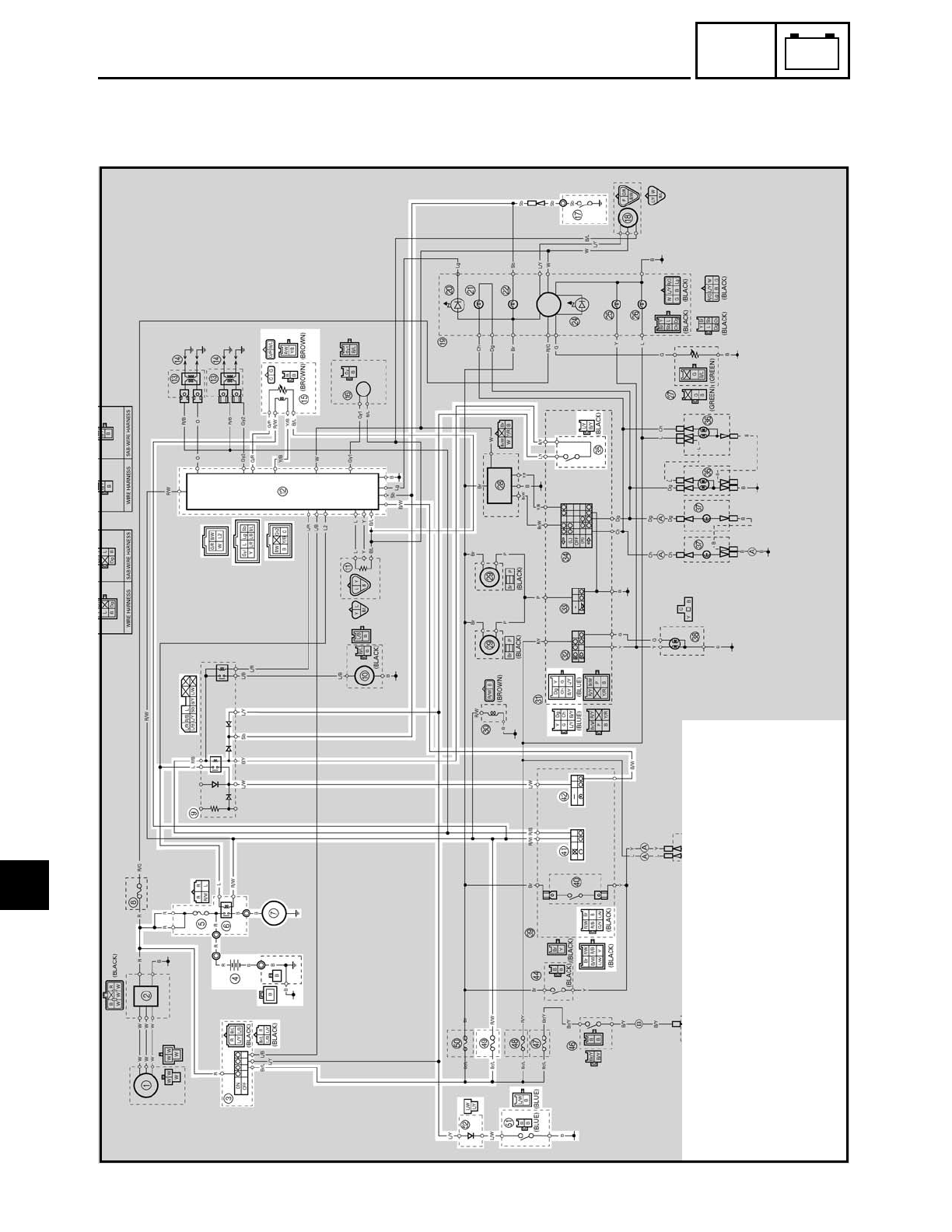
7 - 17
–+
ELEC
ELECTRIC STARTING SYSTEM
EB803000
ELECTRIC STARTING SYSTEM
CIRCUIT DIAGRAM
3Main switch
4Battery
5Main fuse
6Starter relay
7Starter motor
9Relay unit
BIgnitor unit
EDecompression solenoid
GNeutral switch
YClutch switch
aEngine stop switch
bStart switch
iIgnition fuse
kSidestand switch
lDiode
7
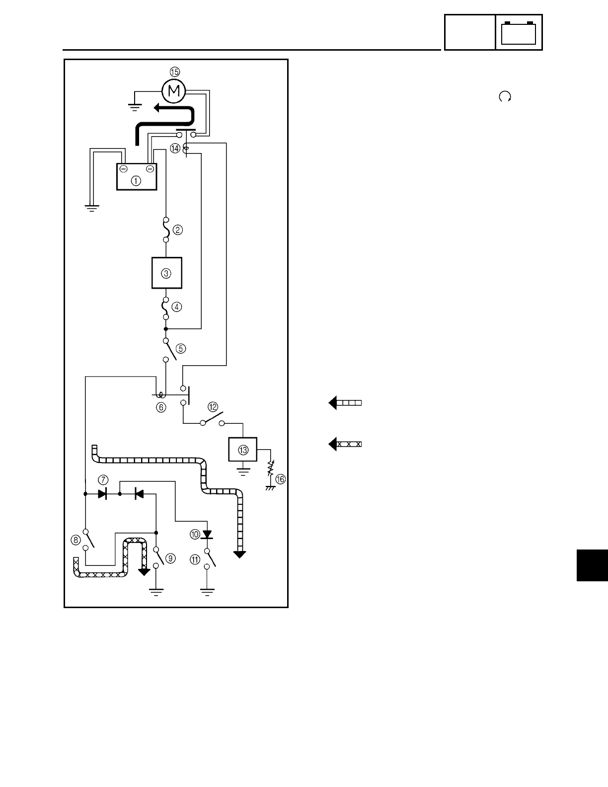
7 - 18
–+
ELEC
ELECTRIC STARTING SYSTEM
EB803010
STARTING CIRCUIT CUTOFF SYSTEM
OPERATION
If the engine stop switch is set to “ ” and
the main switch is set to “ON” (both
switches are closed), the starter motor can
only operate if at least one of the following
conditions is met:
• The transmission is in neutral (the neu-
tral switch is closed).
• The clutch lever is pulled to the handle-
bar (the clutch switch is closed) and the
sidestand is up (the sidestand switch is
closed).
The starting circuit cutoff relay prevents the
starter motor from operating when neither
of these conditions has been met. In this
instance, the starting circuit cutoff relay is
open so current cannot reach the starter
motor. When at least one of the above con-
ditions has been met the starting circuit cut-
off relay is closed and the engine can be
started by pressing the start switch.
WHEN THE TRANSMISSION IS
IN NEUTRAL
WHEN THE SIDESTAND IS UP
AND THE CLUTCH LEVER IS
PULLED TO THE HANDLEBAR
1Battery
2Main fuse
3Main switch
4Ignition fuse
5Engine stop switch
6Starting circuit cutoff relay (relay unit)
7Diode (relay unit)
8Clutch switch
9Sidestand switch
0Diode
ANeutral switch
BStart switch
CIgnitor unit
DStarter relay
EStarter motor
FDecompression solenoid thermistor
7
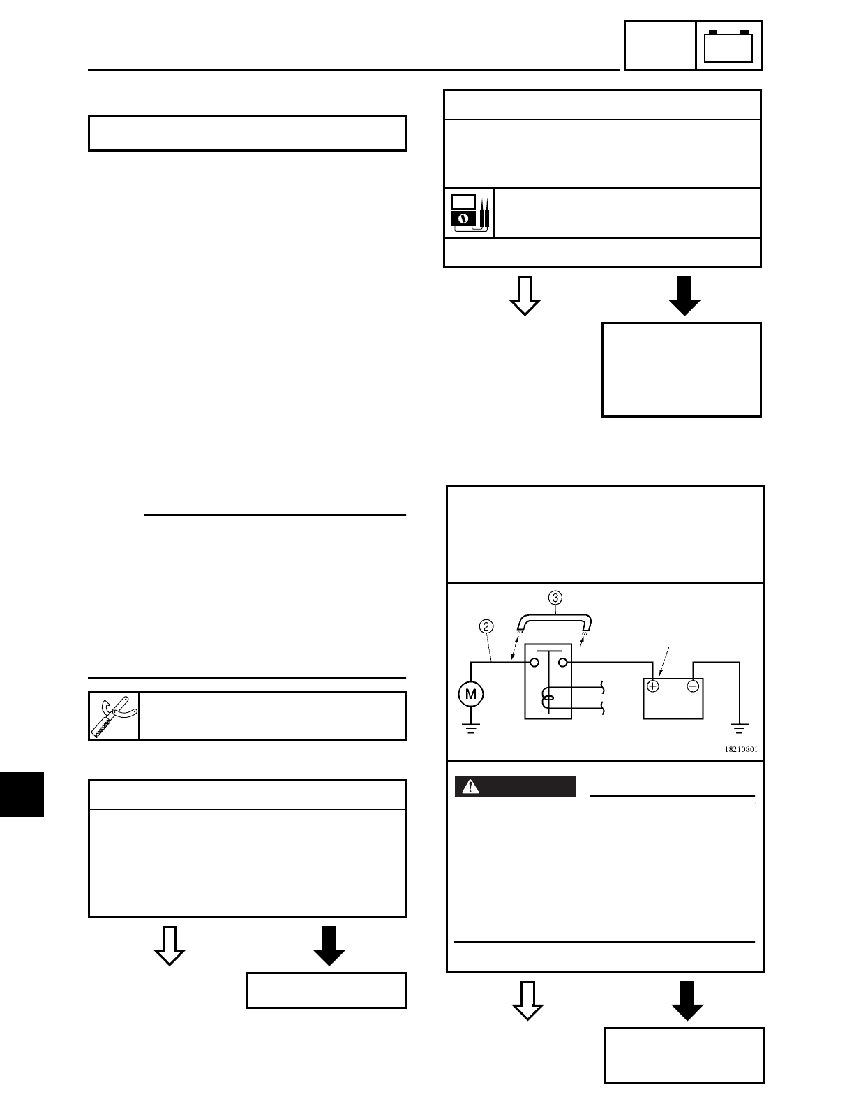
7 - 19
–+
ELEC
ELECTRIC STARTING SYSTEM
EB803020
TROUBLESHOOTING
Check:
1. main and ignition fuses
2. battery
3. starter motor
4. relay unit (starting circuit cutoff relay)
5. relay unit (diode)
6. starter relay
7. main switch
8. engine stop switch
9. neutral switch
10.sidestand switch
11.diode
12.clutch switch
13.start switch
14.wiring
(of the entire starting system)
15.decompression solenoid
NOTE:
• Before troubleshooting, remove the fol-
lowing part(s):
1) rider seat
2) fuel tank
3) side covers
4) headlight lens unit
• Troubleshoot with the following special
tool(s).
The starter motor fails to turn.
Pocket tester
YU-03112
EB802400
YES NO
1.Main and ignition fuses
• Check the main and ignition fuses for
continuity.
Refer to “CHECKING THE FUSES” in
chapter 3.
• Are the main and ignition fuses OK?
Replace the fuse(s).
EB802401
YES NO
2.Battery
• Check the condition of the battery.
Refer to “CHECKING AND CHARGING
THE BATTERY” in chapter 3.
Open-circuit voltage
12.8 V or more at 20 ˚C (68 ˚F)
• Is the battery OK?
• Clean the battery
terminals.
• Recharge or
replace the battery.
EB803400
YES NO
3.Starter motor
• Connect the battery positive terminal 1
and starter motor lead 2 with a jumper
lead 3.
• Does the starter motor turn?
Repair or replace
the starter motor.
WARNING
WARNING
• A wire that is used as a jumper lead
must have at least the same capacity of
the battery lead, otherwise the jumper
lead may burn.
• This check is likely to produce sparks,
therefore make sure that no flammable
gas or fluid is in the vicinity.
7
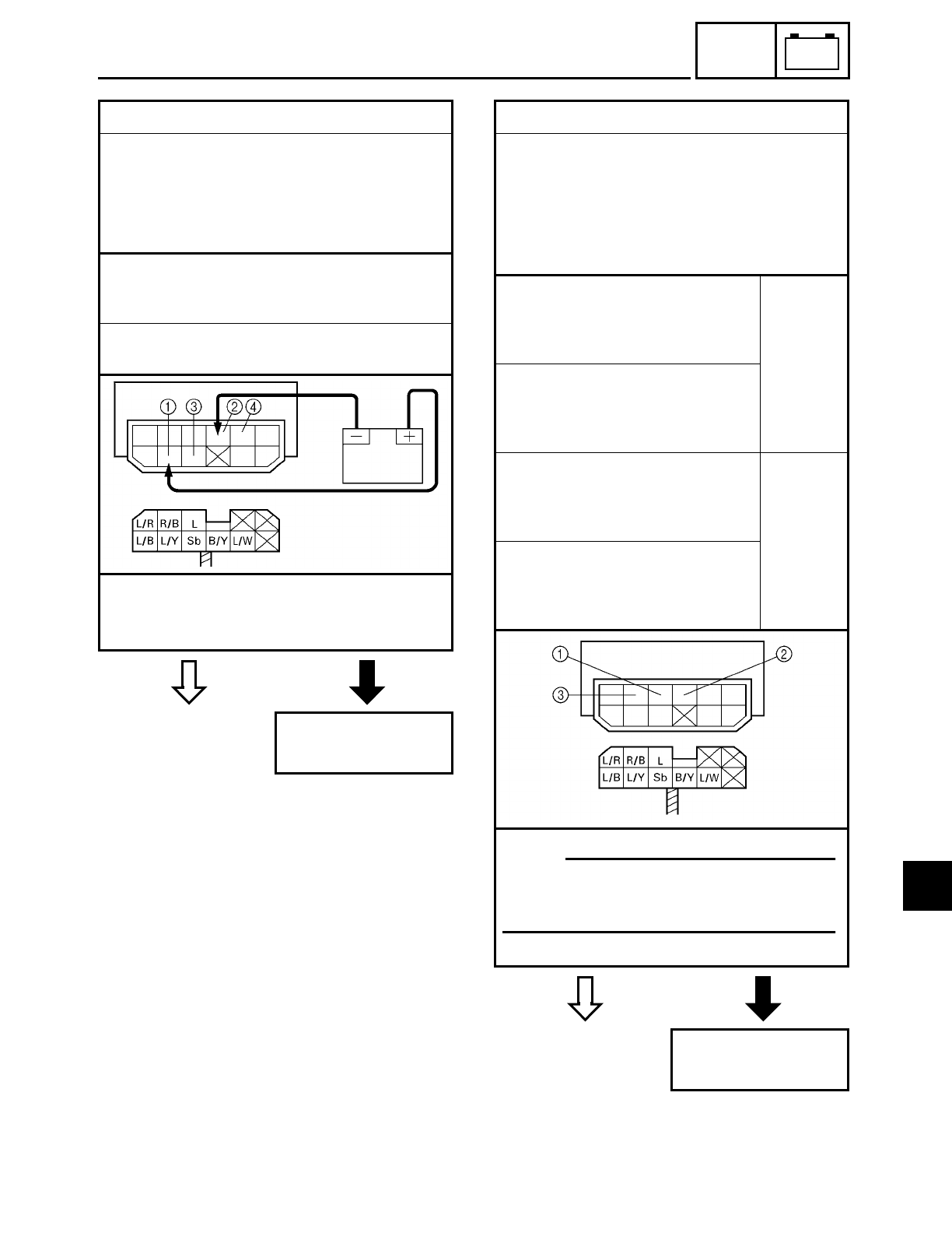
7 - 20
–+
ELEC
ELECTRIC STARTING SYSTEM
EB803402
YES NO
4.Relay unit (starting circuit cutoff relay)
• Disconnect the relay unit from the cou-
pler.
• Connect the pocket tester (Ω× 1) and
battery (12 V) to the relay unit terminals
as shown.
Battery positive terminal → red/black 1
Battery negative terminal →
black/yellow 2
Tester positive probe → blue 3
Tester negative probe → blue/white 4
• Does the starting circuit cutoff relay
have continuity between blue and blue/
white?
Replace the relay
unit.
EB803403
YES NO
5.Relay unit (diode)
• Disconnect the relay unit from the cou-
pler.
• Connect the pocket tester (Ω× 1) to the
relay unit terminals as shown.
• Check the diode for continuity as fol-
lows.
Tester positive probe →
sky blue 1
Tester negative probe →
black/yellow 2Continu-
ity
Tester positive probe →
sky blue 1
Tester negative probe →
blue/yellow 3
Tester positive probe →
black/yellow 2
Tester negative probe →
sky blue 1No conti-
nuity
Tester positive probe →
blue/yellow 3
Tester negative probe →
sky blue 1
• Are the tester readings correct?
Replace the relay
unit.
NOTE:
When you switch the tester’s positive
and negative probes, the readings in the
above chart will be reversed.
7
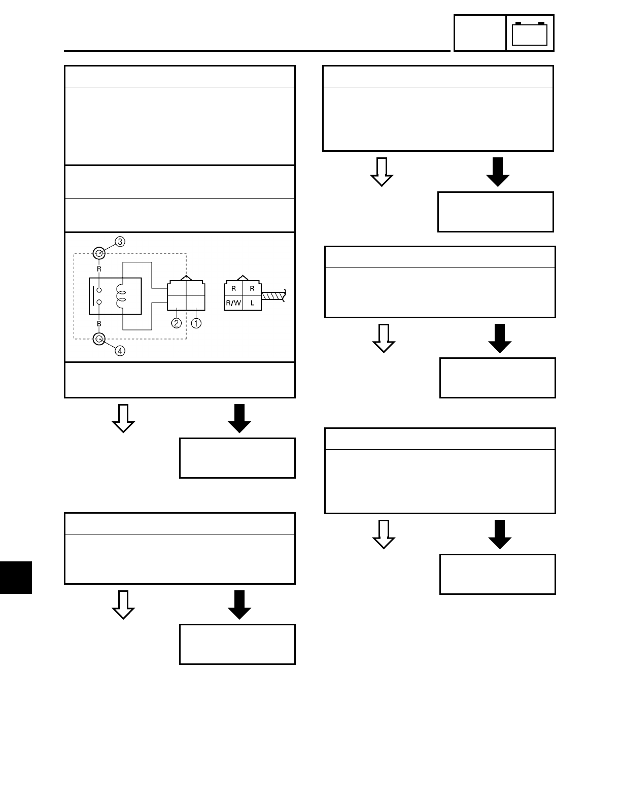
7 - 21
–+
ELEC
ELECTRIC STARTING SYSTEM
EB803404
YES NO
6.Starter relay
• Disconnect the starter relay from the
coupler.
• Connect the pocket tester (Ω× 1) and
battery (12 V) to the starter relay termi-
nals as shown.
Battery positive terminal → red/white 1
Battery negative terminal → blue 2
Tester positive probe → red 3
Tester negative probe → black 4
• Does the starter relay have continuity
between red and black?
Replace the starter
relay.
EB802411
YES NO
7.Main switch
• Check the main switch for continuity.
Refer to “CHECKING THE SWITCHES”.
• Is the main switch OK?
Replace the main
switch.
EB802412
YES NO
8.Engine stop switch
• Check the engine stop switch for conti-
nuity.
Refer to “CHECKING THE SWITCHES”.
• Is the engine stop switch OK?
Replace the right
handlebar switch.
EB802413
YES NO
9.Neutral switch
• Check the neutral switch for continuity.
Refer to “CHECKING THE SWITCHES”.
• Is the neutral switch OK?
Replace the neutral
switch.
EB802414
YES NO
10.Sidestand switch
• Check the sidestand switch for continu-
ity.
Refer to “CHECKING THE SWITCHES”.
• Is the sidestand switch OK?
Replace the side-
stand switch.
7
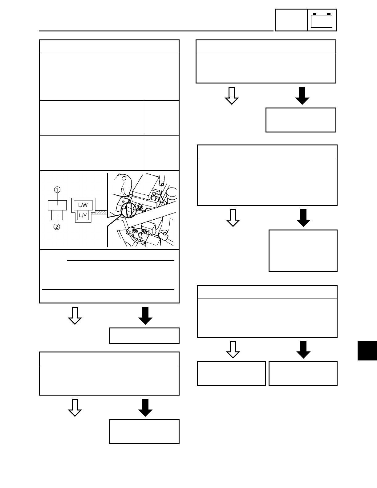
7 - 22
–+
ELEC
ELECTRIC STARTING SYSTEM
YES NO
11.Diode
• Remove the diode from the coupler.
• Connect the pocket tester (Ω× 1) to the
diode terminals as shown.
• Check the diode for continuity as fol-
lows.
Tester positive probe →
blue/white 1
Tester negative probe →
blue/yellow 2
Continu-
ity
Tester positive probe →
blue/yellow 2
Tester negative probe →
blue/white 1
No conti-
nuity
• Are the tester readings correct?
Replace the diode.
NOTE:
When you switch the tester’s positive
and negative probes, the readings in the
above chart will be reversed.
EB803405
YES NO
12.Clutch switch
• Check the clutch switch for continuity.
Refer to “CHECKING THE SWITCHES”.
• Is the clutch switch OK?
Replace the clutch
switch.
EB803406
YES NO
13.Start switch
• Check the start switch for continuity.
Refer to “CHECKING THE SWITCHES”.
• Is the start switch OK?
Replace the right
handlebar switch.
FAS00754
YES NO
14.Wiring
• Check the entire starting system’s wir-
ing.
Refer to “CIRCUIT DIAGRAM”.
• Is the starting system’s wiring properly
connected and without defects?
Properly connect
or repair the start-
ing system’s wir-
ing.
YES NO
15.Decompression solenoid (thermistor)
• Check the decompression solenoid for
continuity.
Refer to “SELF-DIAGNOSIS”.
• Is the decompression solenoid OK?
Replace the ignitor
unit.
Replace the decom-
pression solenoid.
7
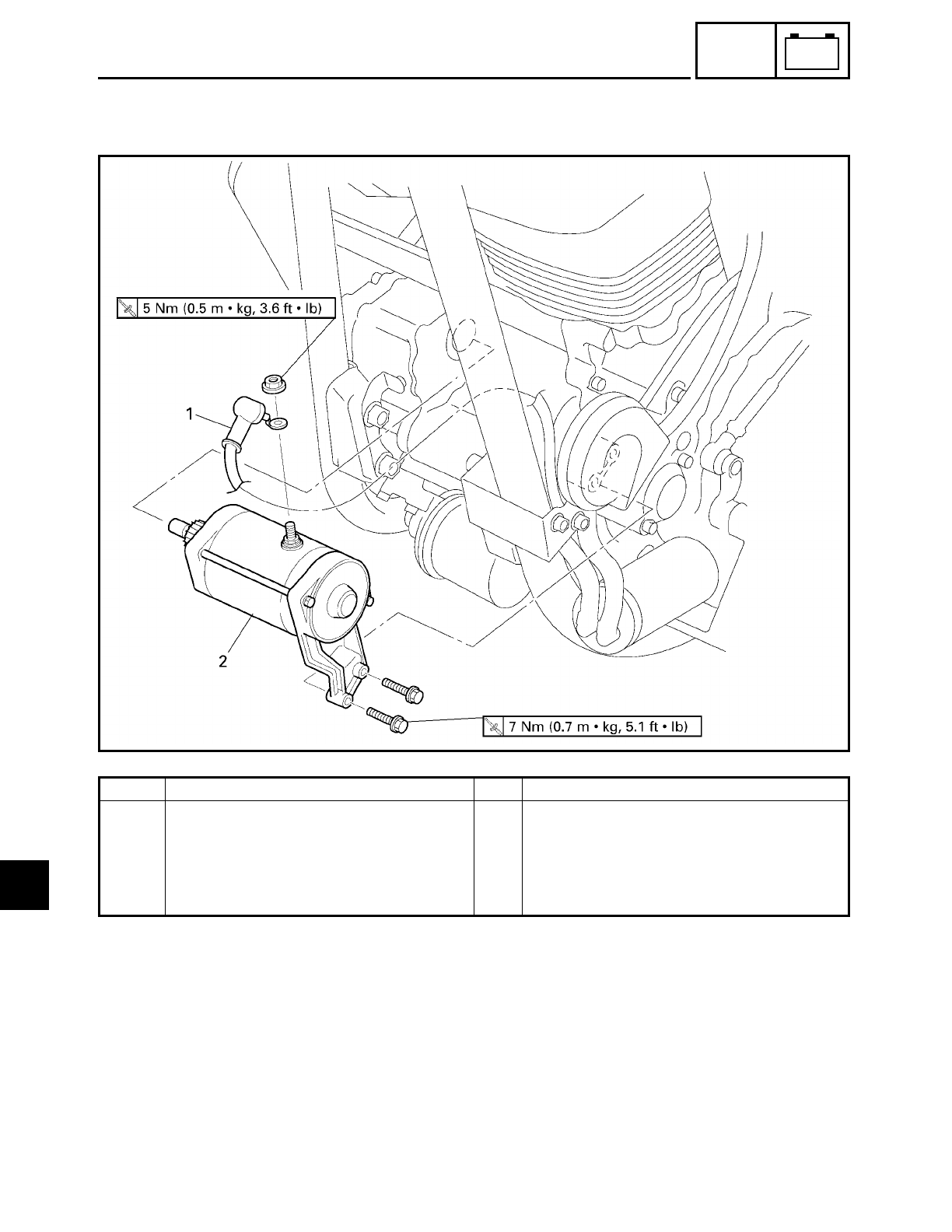
7 - 23
–+
ELEC
STARTER MOTOR
EB803500
STARTER MOTOR
Order Job/Part Q’ty Remarks
Removing the starter motor Remove the parts in the order listed.
1 Starter motor lead 1
2 Starter motor assembly 1
For installation, reverse the removal
procedure.
7
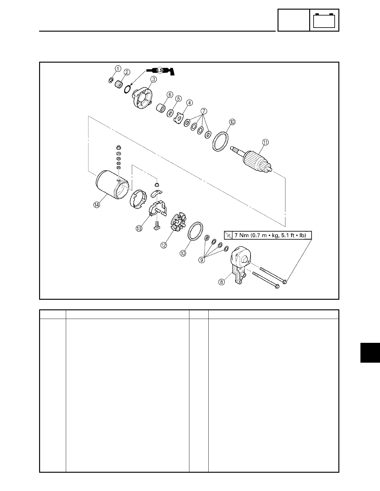
7 - 24
–+
ELEC
STARTER MOTOR
EB803501
Order Job/Part Q’ty Remarks
Disassembling the starter motor Remove the parts in the order listed.
1Circlip 1
2Starter motor 1
3Starter motor rear cover 1
4Lock washer 1
5Oil seal 1
6Bearing 1
7Washer set 1
8Starter motor front cover 1
9Washer set 1
0O-ring 2
AArmature assembly 1
BBrush seat (along with the brushes) 1
CBrush holder (along with the brushes) 1
DStarter motor yoke 1
For assembly, reverse the disassembly
procedure
7
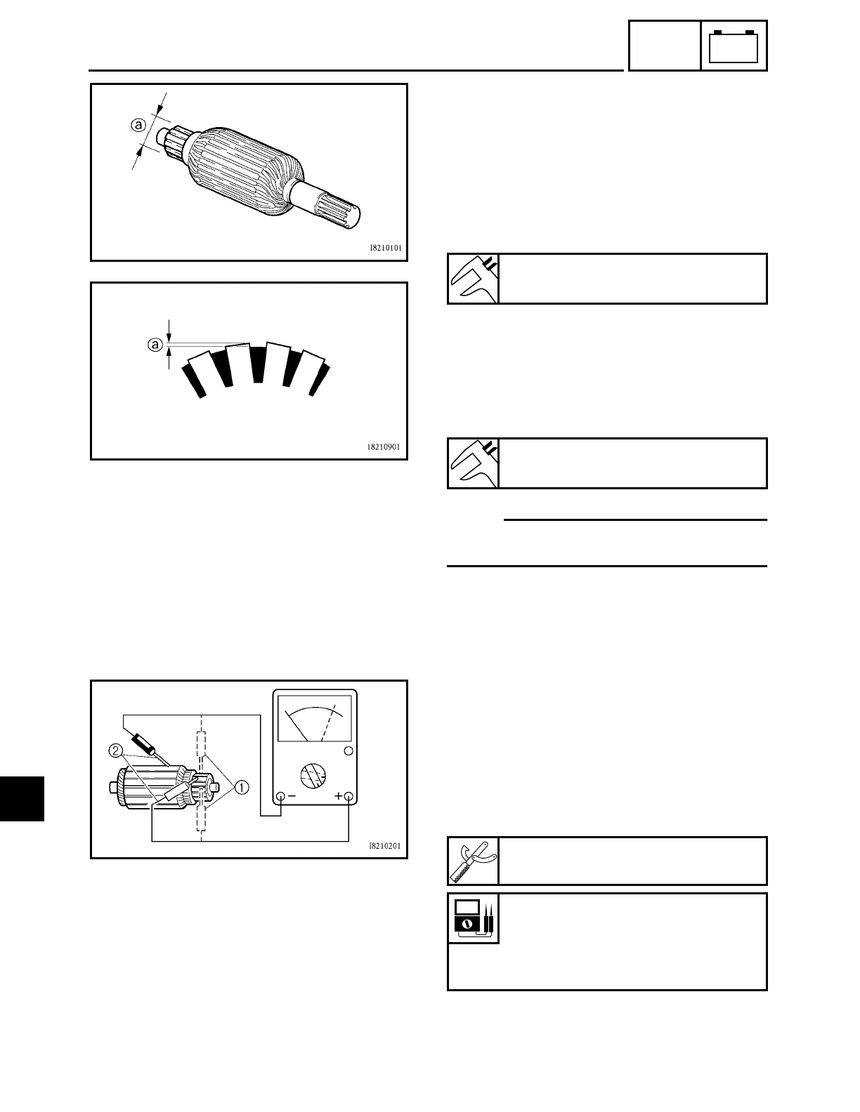
7 - 25
–+
ELEC
STARTER MOTOR
EB803511
CHECKING THE STARTER MOTOR
1. Check:
• commutator
Dirt → Clean with 600 grit sandpaper.
2. Measure:
• commutator diameter a
Out of specification → Replace the starter
motor.
3. Measure:
• mica undercut a
Out of specification → Scrape the mica to
the proper measurement with a hacksaw
blade which has been grounded to fit the
commutator.
NOTE:
The mica must be undercut to ensure
proper operation of the commutator.
Minimum commutator diameter
27 mm (1.06 in)
Mica undercut
0.7 mm (0.03 in)
4. Measure:
• armature assembly resistances (commu-
tator and insulation)
Out of specification → Replace the starter
motor.
▼ ▼ ▼ ▼ ▼ ▼ ▼ ▼ ▼ ▼ ▼ ▼ ▼ ▼ ▼ ▼ ▼ ▼ ▼ ▼ ▼ ▼ ▼ ▼ ▼ ▼ ▼ ▼
a. Measure the armature assembly resis-
tances with the pocket tester.
b. If any resistance is out of specification,
replace the starter motor.
▲ ▲ ▲ ▲ ▲ ▲ ▲ ▲ ▲ ▲ ▲ ▲ ▲ ▲ ▲ ▲ ▲ ▲ ▲ ▲ ▲ ▲ ▲ ▲ ▲ ▲ ▲ ▲
Pocket tester
YU-03112
Armature assembly
Commutator resistance 1
0.025 ~ 0.035 Ω at 20 ˚C (68 ˚F)
Insulation resistance 2
Above 1 MΩ at 20 ˚C (68 ˚F)
7
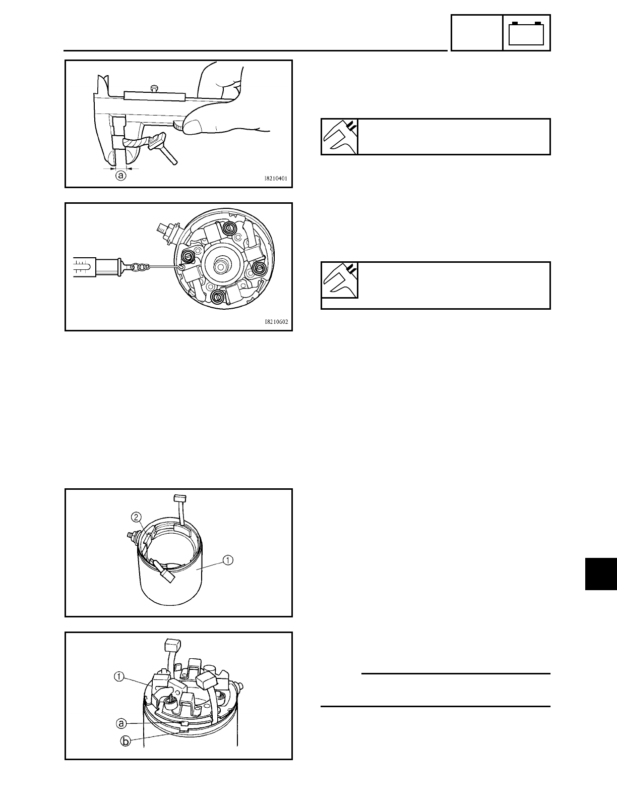
7 - 26
–+
ELEC
STARTER MOTOR
5. Measure:
• brush length a
Out of specification → Replace the
brushes as a set.
Minimum brush length
5 mm (0.20 in)
6. Measure:
• brush spring force
Out of specification → Replace the brush
springs as a set.
Brush spring force
7.65 ~ 10.01 N
(765 ~ 1,001 gf, 27.0 ~ 35.3 oz)
7. Check:
• gear teeth
Damage/wear → Replace the gear.
8. Check:
• bearing
• oil seal
Damage/wear → Replace the defective
part(s).
EB803701
ASSEMBLING THE STARTER MOTOR
1. Install:
• starter motor yoke 1
• bush holder 2
2. Install:
• brush seat 1
NOTE:
Align the tab a on the brush seat with the
slot b in the starter motor rear cover.
7
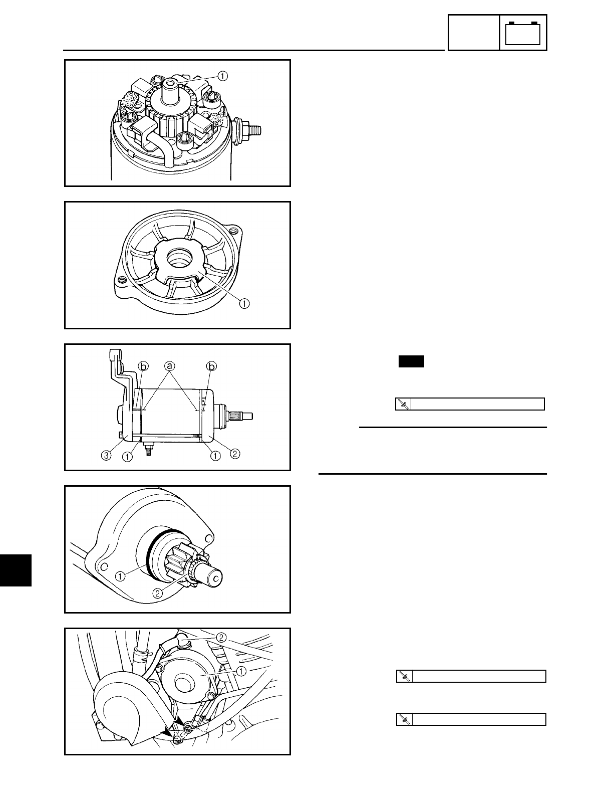
7 - 27
–+
ELEC
3. Install:
• armature assembly
4. Install:
• bearing
• oil seal
• lock washer 1
5. Install:
• O-rings 1
• starter motor rear cover 2
• starter motor front cover 3
• bolts
NOTE:
Align the match marks a on the starter
motor yoke with the match marks b on the
front and rear covers.
New
T
R
.
.
7 Nm (0.7 m · kg, 5.1 ft · lb)
6. Install:
• starter motor gear 1
• circlip 2
INSTALLING THE STARTER MOTOR
1. Install:
• starter motor 1
2. Connect:
• starter lead 2
T
R
.
.
7 Nm (0.7 m · kg, 5.1 ft · lb)
T
R
.
.
5 Nm (0.5 m · kg, 3.6 ft · lb)
STARTER MOTOR
7
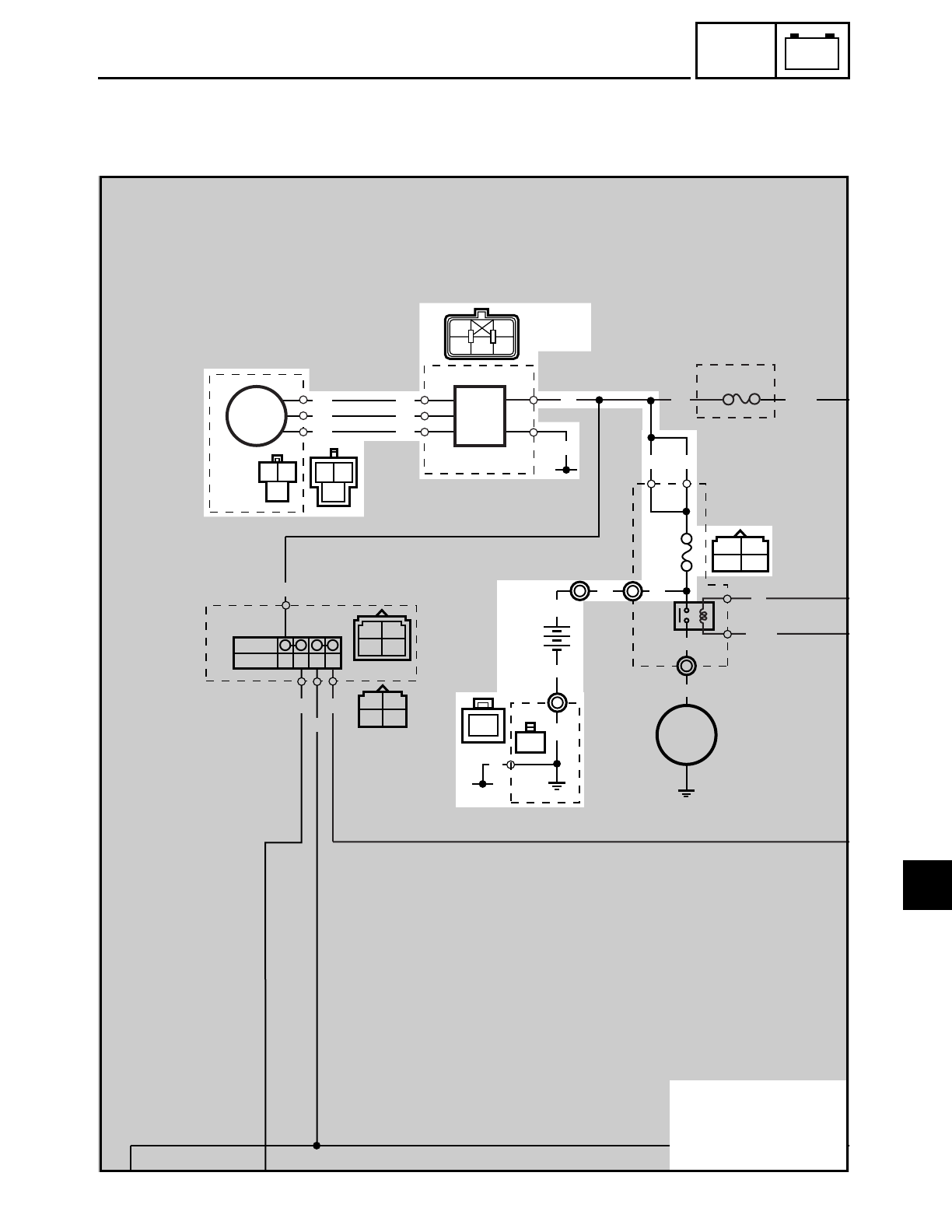
7 - 28
–+
ELEC
CHARGING SYSTEM
EB804000
CHARGING SYSTEM
CIRCUIT DIAGRAM
12
ON
OFF
3
7
5
8
46
W
W
W
W
W
W
WW
W
WW
W
Br/L
Br/L
B
B
B
R
R
R
L/Y
L/Y
L/B
L/B
Br/L
L/Y
L/B
RR
R
B
R
R
R
RL
B
B
B
B
B
RR
R/W L
BR
WWW
R/G
R/W
(BLACK)
(BLACK)
(BLACK)
1Generator
2Rectifier/regulator
4Battery
5Main fuse
7
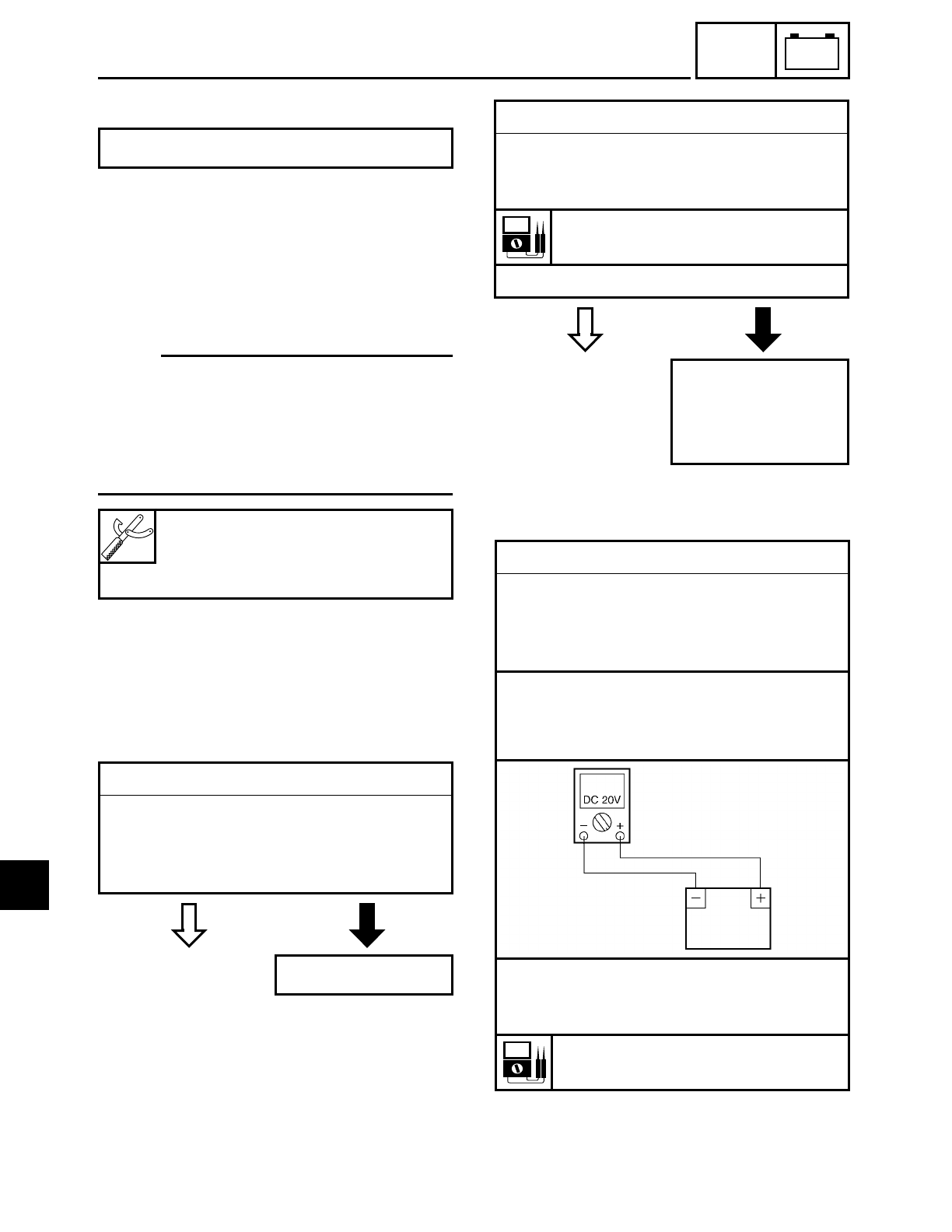
7 - 29
–+
ELEC
CHARGING SYSTEM
EB804010
TROUBLESHOOTING
Check:
1. main fuse
2. battery
3. charging voltage
4. stator coil assembly resistance
5. wiring
(of the entire charging system)
NOTE:
• Before troubleshooting, remove the fol-
lowing part(s):
1) rider seat
2) left side cover
• Troubleshoot with the following special
tool(s).
The battery is not being charged.
Inductive tachometer
YU-8036-A
Pocket tester
YU-03112
EB802400
YES NO
1.Main fuse
• Check the main fuse for continuity.
Refer to “CHECKING THE FUSES” in
chapter 3.
• Is the main fuse OK?
Replace the fuse.
EB802401
YES NO
2.Battery
• Check the condition of the battery.
Refer to “CHECKING AND CHARGING
THE BATTERY” in chapter 3.
Open-circuit voltage
12.8 V or more at 20 ˚C (68 ˚F)
• Is the battery OK?
• Clean the battery
terminals.
• Recharge or
replace the battery.
EB804400
3.Charging voltage
• Connect the inductive tachometer to the
spark plug lead of cylinder #1.
• Connect the pocket tester (DC 20V) to
the battery as shown.
Tester positive probe →
battery positive terminal
Tester negative probe →
battery negative terminal
• Start the engine and let it run at approxi-
mately 5,000 r/min.
• Measure the charging voltage.
Charging voltage
14 V at 5,000 r/min
7
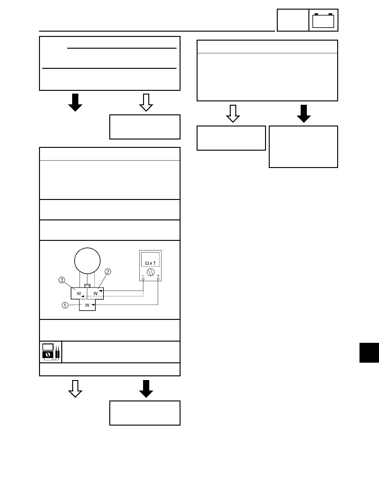
7 - 30
–+
ELEC
CHARGING SYSTEM
NO YES
• Is the charging voltage within specifica-
tion?
The charging circuit
is OK.
NOTE:
Make sure that the battery is fully
charged.
EB804401
YES NO
4.Stator coil assembly resistances
• Disconnect the generator coupler from
the wire harness.
• Connect the pocket tester (Ω× 1) to the
stator coil assembly coupler as shown.
Tester positive probe → white 1
Tester negative probe → white 2
Tester positive probe → white 1
Tester negative probe → white 3
• Measure the stator coil assembly resis-
tances.
Stator coil resistance
0.45 ~ 0.55 Ω at 20 ˚C (68 ˚F)
• Is the stator coil assembly OK?
Replace the stator
coil assembly.
EB804404
YES NO
5.Wiring
• Check the wiring connections of the
entire charging system.
Refer to “CIRCUIT DIAGRAM”.
• Is the charging system’s wiring properly
connected and without defects?
Replace the recti-
fier/regulator.
Properly connect
or repair the charg-
ing system’s wir-
ing.
7
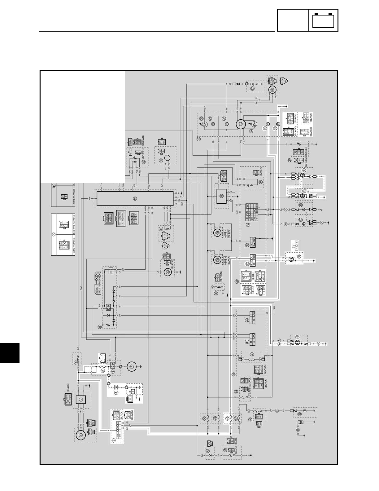
7 - 31
–+
ELEC
LIGHTING SYSTEM
EB805000
LIGHTING SYSTEM
CIRCUIT DIAGRAM
3Main switch
4Battery
5Main fuse
OHigh beam indicator light
PMeter light
VDimmer switch
ZFront turn signal/position light
\Headlight
cTail/brake light
hHeadlight fuse
7
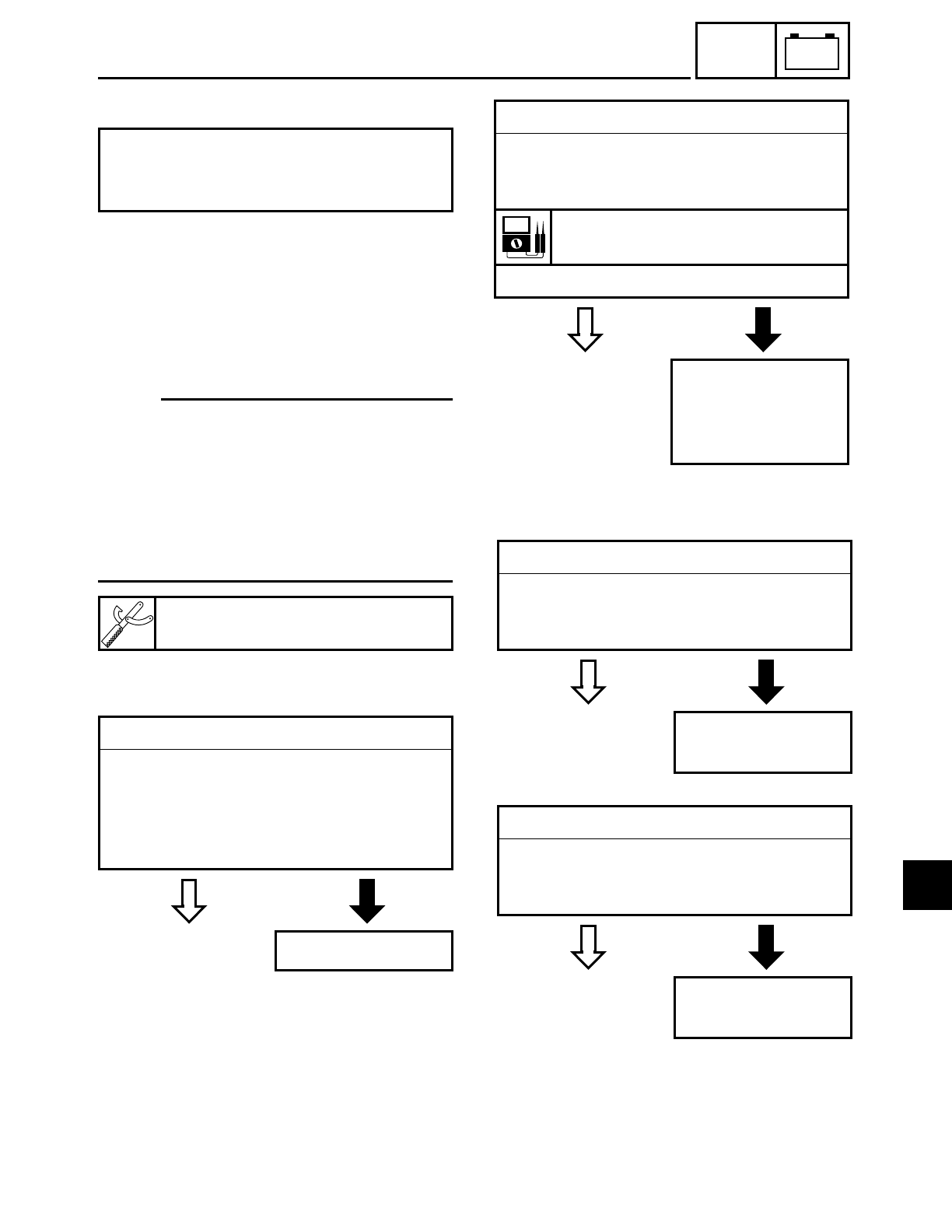
7 - 32
–+
ELEC
LIGHTING SYSTEM
EB805010
TROUBLESHOOTING
Check:
1. main, and headlight fuses
2. battery
3. main switch
4. dimmer switch
5. wiring
(of the entire charging system)
NOTE:
• Before troubleshooting, remove the fol-
lowing part(s):
1) rider seat
2) fuel tank
3) left side cover
4) headlight lens unit
• Troubleshoot with the following special
tool(s).
Any of the following fail to light: head-
light, high beam indicator light, taillight,
position light or meter light.
Pocket tester
YU-03112
EB802400
YES NO
1.Main and headlight fuses
• Check the main and headlight fuses for
continuity.
Refer to “CHECKING THE FUSES” in
chapter 3.
• Are the main and headlight fuses OK?
Replace the fuse(s).
EB802401
YES NO
2.Battery
• Check the condition of the battery.
Refer to “CHECKING AND CHARGING
THE BATTERY” in chapter 3.
Open-circuit voltage
12.8 V or more at 20 ˚C (68 ˚F)
• Is the battery OK?
• Clean the battery
terminals.
• Recharge or
replace the battery.
EB802411
YES NO
3.Main switch
• Check the main switch for continuity.
Refer to “CHECKING THE SWITCHES”.
• Is the main switch OK?
Replace the main
switch.
EB805401
YES NO
4.Dimmer switch
• Check the dimmer switch for continuity.
Refer to “CHECKING THE SWITCHES”.
• Is the dimmer switch OK?
Replace the left han-
dlebar switch.
7
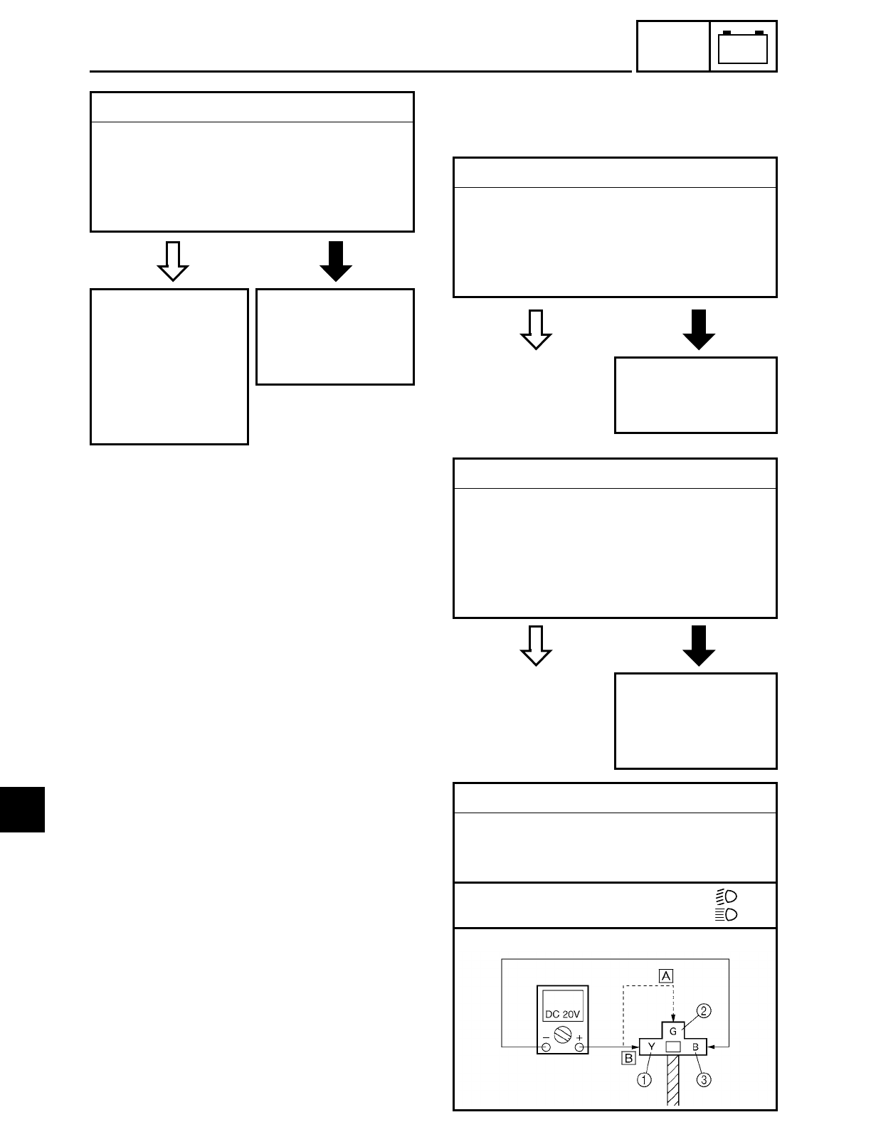
7 - 33
–+
ELEC
LIGHTING SYSTEM
EB805404
YES NO
5.Wiring
• Check the entire lighting system’s wir-
ing.
Refer to “CIRCUIT DIAGRAM”.
• Is the lighting system’s wiring properly
connected and without defects?
Check the condition
of each of the light-
ing system’s cir-
cuits.
Refer to “CHECK-
ING THE LIGHTING
SYSTEM”.
Properly connect
or repair the light-
ing system’s wir-
ing.
EB805410
CHECKING THE LIGHTING SYSTEM
1. The headlight and the high beam indica-
tor light fail to come on.
YES NO
1.Headlight bulb and socket
• Check the headlight bulb and socket for
continuity.
Refer to “CHECKING THE BULBS AND
BULB SOCKETS”.
• Is the headlight bulb and socket OK?
Replace the head-
light bulb, socket or
both.
YES NO
2.High beam indicator light bulb and socket
• Check the high beam indicator light bulb
and socket for continuity.
Refer to “CHECKING THE BULBS AND
BULB SOCKETS”.
• Is the high beam indicator light bulb and
socket OK?
Replace the high
beam indicator
light bulb, socket or
both.
3.Voltage
• Connect the pocket tester (DC 20 V) to
the headlight coupler and the meter
assembly couplers as shown.
ÅWhen the dimmer switch is set to “ ”
ıWhen the dimmer switch is set to “ ”
Headlight coupler
7
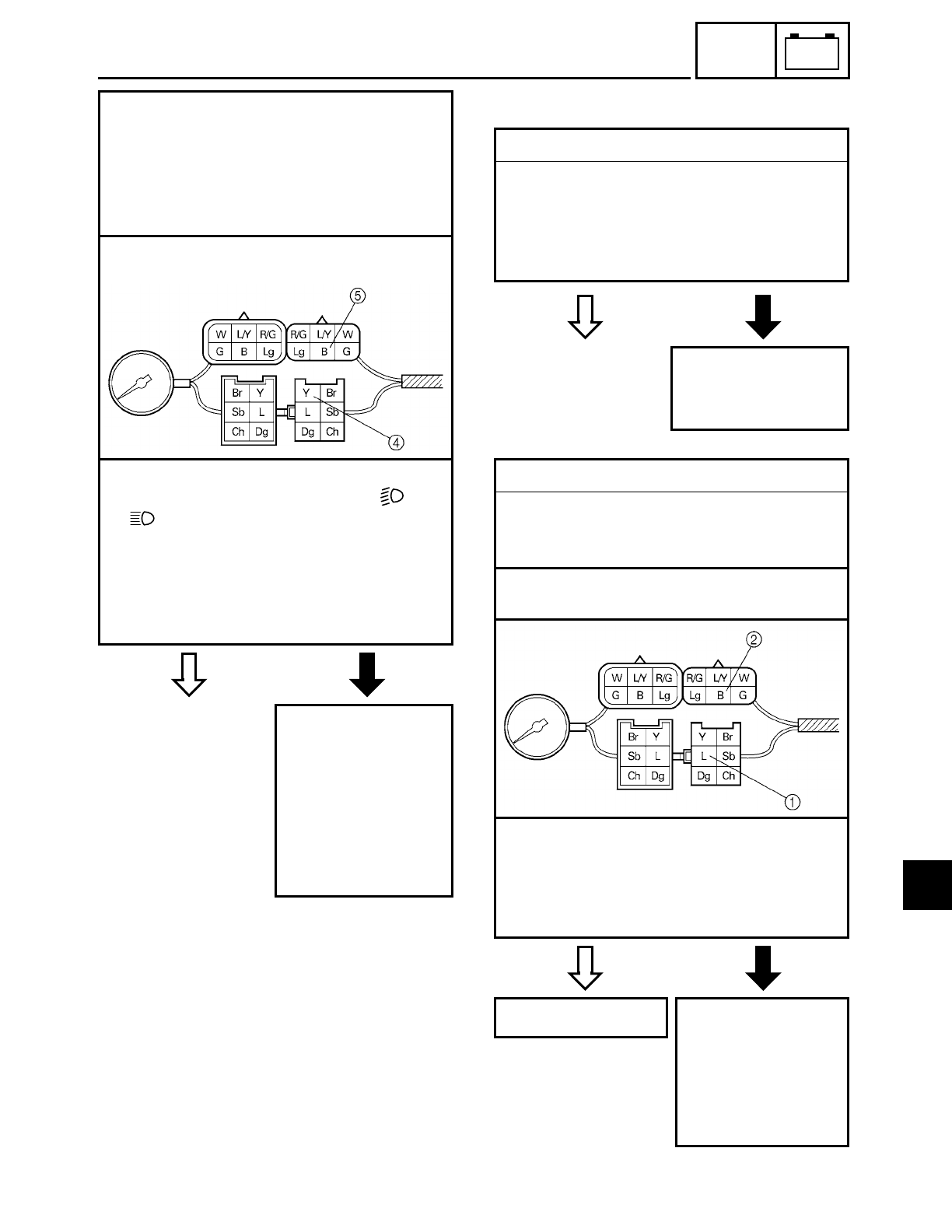
7 - 34
–+
ELEC
LIGHTING SYSTEM
YES NO
Headlight
Tester positive probe
→
yellow
1 or green
2
Tester negative probe
→ black
3
High beam indicator light
Tester positive probe → yellow 4
Tester negative probe → black 5
Meter assembly coupler (wire harness
side)
• Set the main switch to “ON”.
• Set the dimmer switch to “ ” or
“”.
• Measure the voltage (12 V) of yellow
(green) 2 on the headlight coupler and
yellow 4 on the meter assembly cou-
pler.
• Is the voltage within specification?
The wiring circuit
from the main
switch to the head-
light coupler and
meter assembly
couplers are faulty
and must be
repaired.
EB805411
2. A meter light fails to come on.
YES NO
1.Meter light bulb and socket
• Check the meter light bulb and socket
for continuity.
Refer to “CHECKING THE BULBS AND
BULB SOCKETS”.
• Are the meter light bulb and socket OK?
Replace the meter
light bulb, socket or
both.
YES NO
2.Voltage
• Connect the pocket tester (20 V) to the
meter assembly coupler (wire harness
side) as shown.
Tester positive probe → blue 1
Tester negative probe → black 2
• Set the main switch to “ON”.
• Measure the voltage (12 V) of blue
1 on
the meter assembly coupler (wire har-
ness side).
• Is the voltage within specification?
This circuit is OK. The wiring circuit
from the main
switch to the meter
assembly coupler is
faulty and must be
repaired.
7
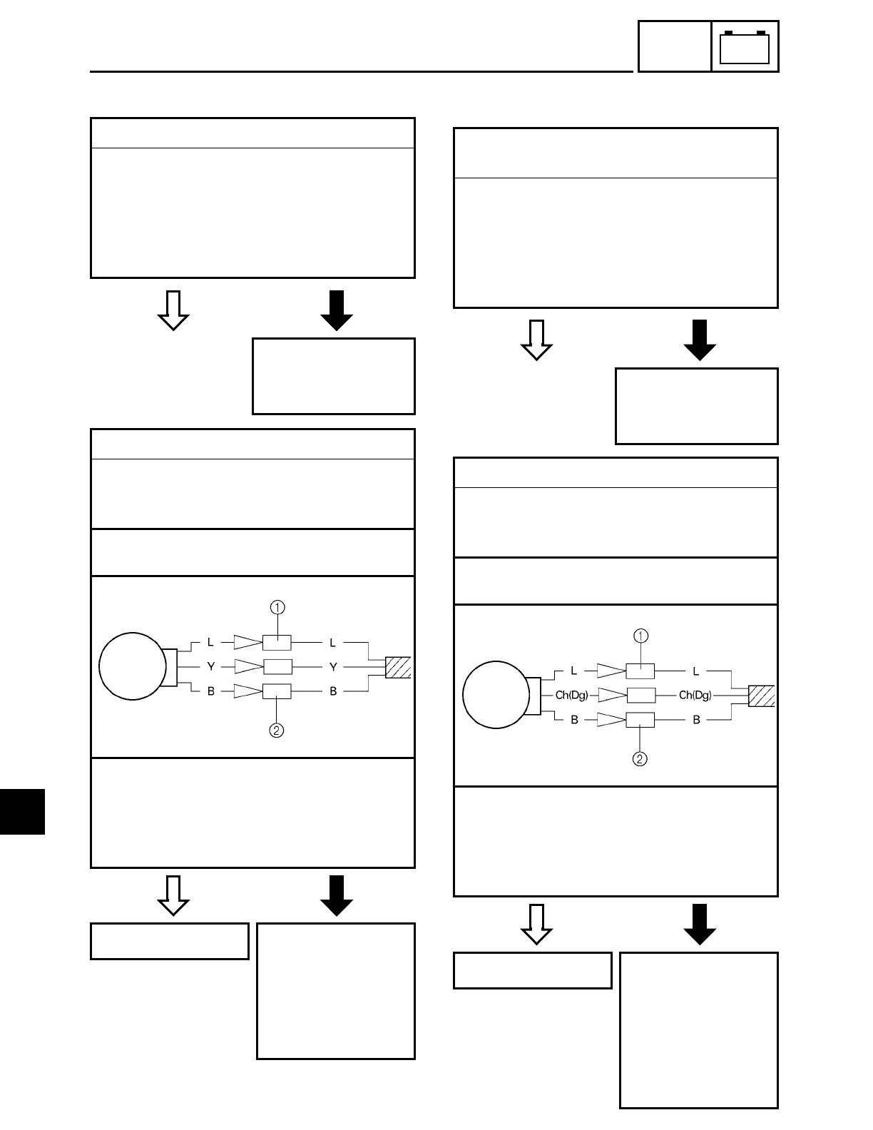
7 - 35
–+
ELEC
LIGHTING SYSTEM
EB805412
3. A tail/brake light fails to come on.
YES NO
1.Tail/brake light bulb and socket
• Check the tail/brake light bulb and socket
for continuity.
Refer to “CHECKING THE BULBS AND
BULB SOCKETS”.
• Are the tail/brake light bulb and socket
OK?
Replace the tail/
brake light bulb,
socket or both.
YES NO
2.Voltage
• Connect the pocket tester (DC 20 V) to
the tail/brake light connectors (wire har-
ness side) as shown.
Tester positive probe → blue 1
Tester negative probe → black 2
• Set the main switch to “ON”.
• Measure the voltage (12 V) of blue 1 on
the tail/brake light coupler (wire harness
side).
• Is the voltage within specification?
This circuit is OK. The wiring circuit
from the main
switch to the tail/
brake light coupler
is faulty and must
be repaired.
4. The front turn signal/position light fails
to come on.
YES NO
1.Front turn signal/position light bulb and
socket
• Check the front turn signal/position light
bulb and socket for continuity.
Refer to “CHECKING THE BULBS AND
BULB SOCKETS”.
• Are the front turn signal/position light
bulb and socket OK?
Replace the front turn
signal/position light
bulb, socket or both.
YES NO
2.Voltage
• Connect the pocket tester (DC 20 V) to
the front turn signal/position light con-
nectors (wire harness side) as shown.
Tester positive probe → blue 1
Tester negative probe → black 2
• Set the main switch to “ON”.
• Measure the voltage (12 V) of blue 1 on
the front turn signal/position light con-
nectors (wire harness side).
• Is the voltage within specification?
This circuit is OK. The wiring circuit
from the main
switch to the front
turn signal/posi-
tion light connec-
tors is faulty and
must be repaired.
7
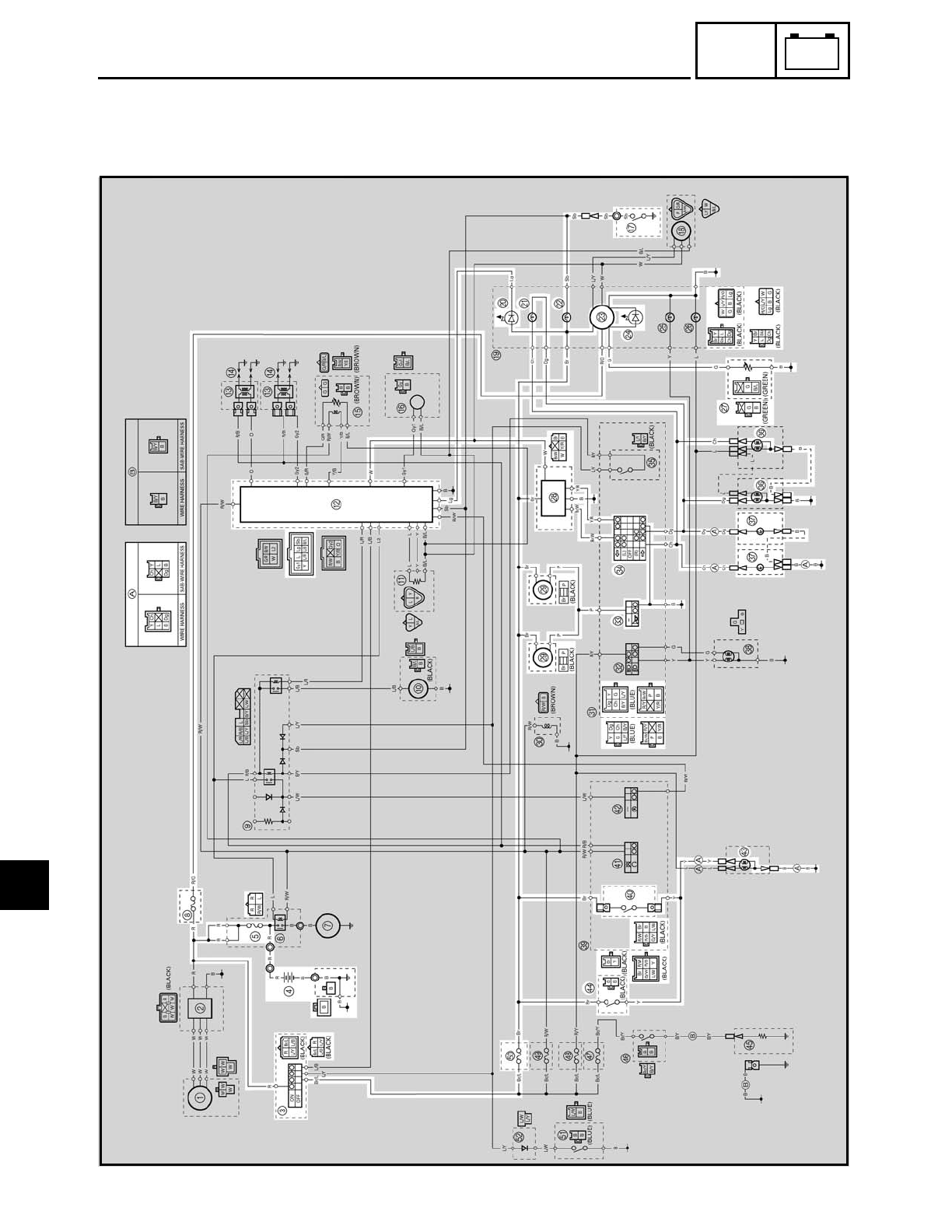
7 - 37
–+
ELEC
SIGNALING SYSTEM
EB806000
SIGNALING SYSTEM
CIRCUIT DIAGRAM
7

7 - 38
–+
ELEC
3Main switch
4Battery
5Main fuse
8Backup fuse
BIgnitor unit
GNeutral switch
JEngine trouble indicator light
KTurn signal indicator light
LNeutral indicator light
MSpeedometer assembly (speedometer, combination meter and fuel level meter)
NFuel level indicator light
QFuel sender
RTurn signal relay
SHorn
WHorn switch
XTurn signal switch
ZFront turn signal/position light
[Rear turn signal light
_Front brake light switch
cTail/brake light
dRear brake light switch
jSignaling system fuse
SIGNALING SYSTEM
7
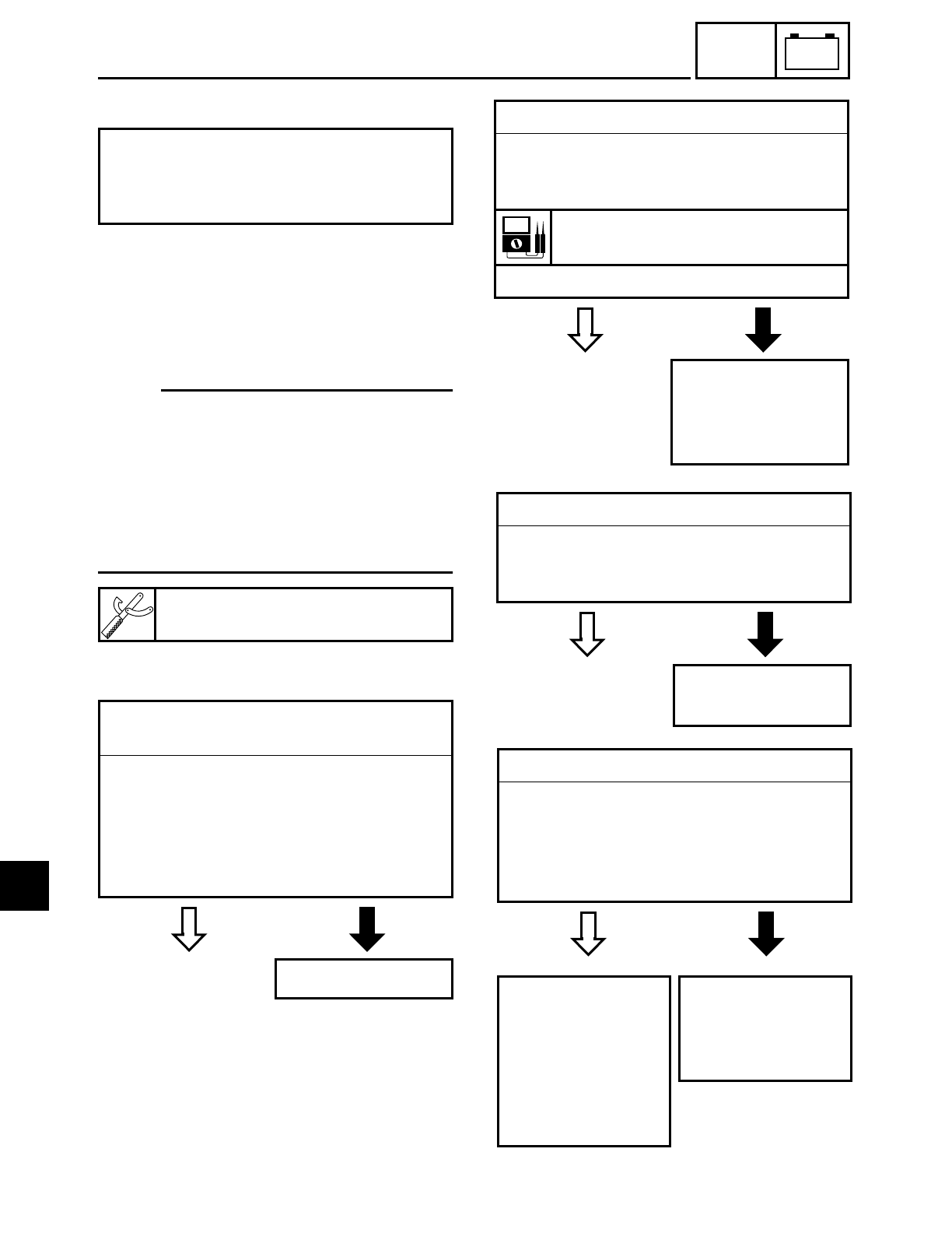
7 - 39
–+
ELEC
SIGNALING SYSTEM
EB806010
TROUBLESHOOTING
Check:
1. main, signaling system and backup fuses
2. battery
3. main switch
4. wiring
(of the entire signaling system)
NOTE:
• Before troubleshooting, remove the fol-
lowing part(s):
1) rider seat
2) fuel tank
3) side covers
4) headlight lens unit
• Troubleshoot with the following special
tool(s).
• Any of the following fail to light: turn
signal light, brake light or an indicator
light.
• The horn fails to sound.
Pocket tester
YU-03112
EB802400
YES NO
1.Main, signaling system and backup
fuses
• Check the main, signaling system and
backup fuses for continuity.
Refer to “CHECKING AND CHARGING
THE FUSES” in chapter 3.
• Are the main, signaling system and
backup fuses OK?
Replace the fuse(s).
EB802401
YES NO
2.Battery
• Check the condition of the battery.
Refer to “CHECKING THE BATTERY” in
chapter 3.
Open-circuit voltage
12.8 V or more at 20 ˚C (68 ˚F)
• Is the battery OK?
• Clean the battery
terminals.
• Recharge or
replace the battery.
EB802411
YES NO
3.Main switch
• Check the main switch for continuity.
Refer to “CHECKING THE SWITCHES”.
• Is the main switch OK?
Replace the main
switch.
EB806400
YES NO
4.Wiring
• Check the entire signaling system’s wir-
ing.
Refer to “CIRCUIT DIAGRAM”.
• Is the signaling system’s wiring properly
connected and without defects?
Check the condition
of each of the sig-
naling system’s cir-
cuits.
Refer to “CHECK-
ING THE SIGNAL-
ING SYSTEM”.
Properly connect
or repair the signal-
ing system’s wir-
ing.
7
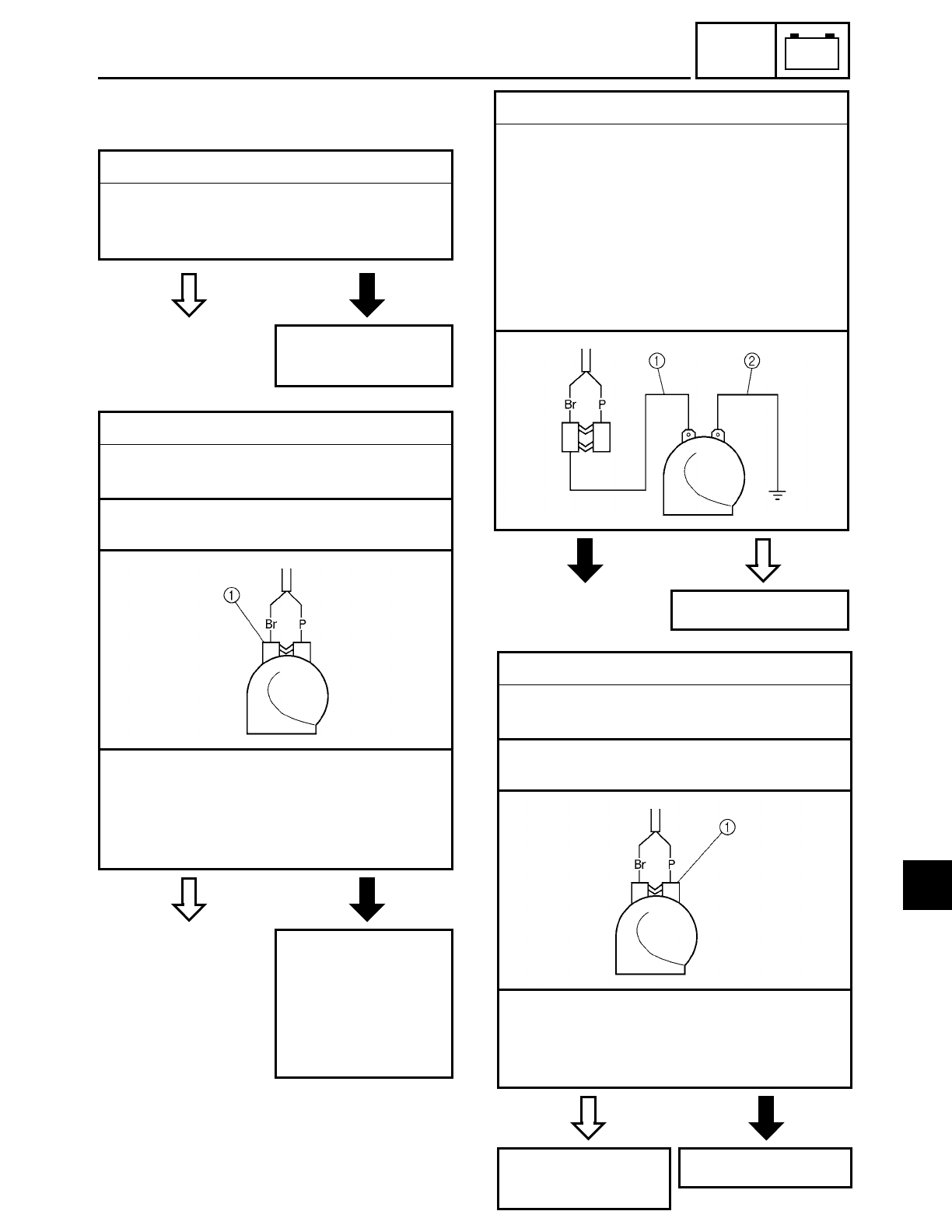
7 - 40
–+
ELEC
SIGNALING SYSTEM
EB806410
CHECKING THE SIGNALING SYSTEM
1.The horn fails to sound.
YES NO
1.Horn switch
• Check the horn switch for continuity.
Refer to “CHECKING THE SWITCHES”.
• Is the horn switch OK?
Replace the left han-
dlebar switch.
YES NO
2.Voltage
• Connect the pocket tester (DC 20 V) to
the horn coupler as shown.
Tester positive probe → brown 1
Tester negative probe → ground
• Set the main switch to “ON”.
• Push the horn switch.
• Measure the voltage (12 V) of brown on
the horn coupler.
• Is the voltage within specification?
The wiring circuit
from the main
switch to the horn
connector is faulty
and must be
repaired.
NO YES
3.Horn
• Disconnect the horn coupler at the horn.
• Connect a jumper lead 1 to the brown
terminal in the horn coupler and the
horn terminal.
• Connect a jumper lead 2 to the horn ter-
minal and ground the jumper lead.
• Set the main switch to “ON”.
• Push the horn switch.
• Does the horn sound?
The horn is OK.
YES NO
4.Voltage
• Connect the pocket tester (DC 20 V) to
the horn coupler as shown.
Tester positive probe → pink 1
Tester negative probe → ground
• Set the main switch to “ON”.
• Measure the voltage (12 V) of pink 1 on
the horn coupler.
• Is the voltage within specification?
Repair or replace
the horn.
Replace the horn.
7
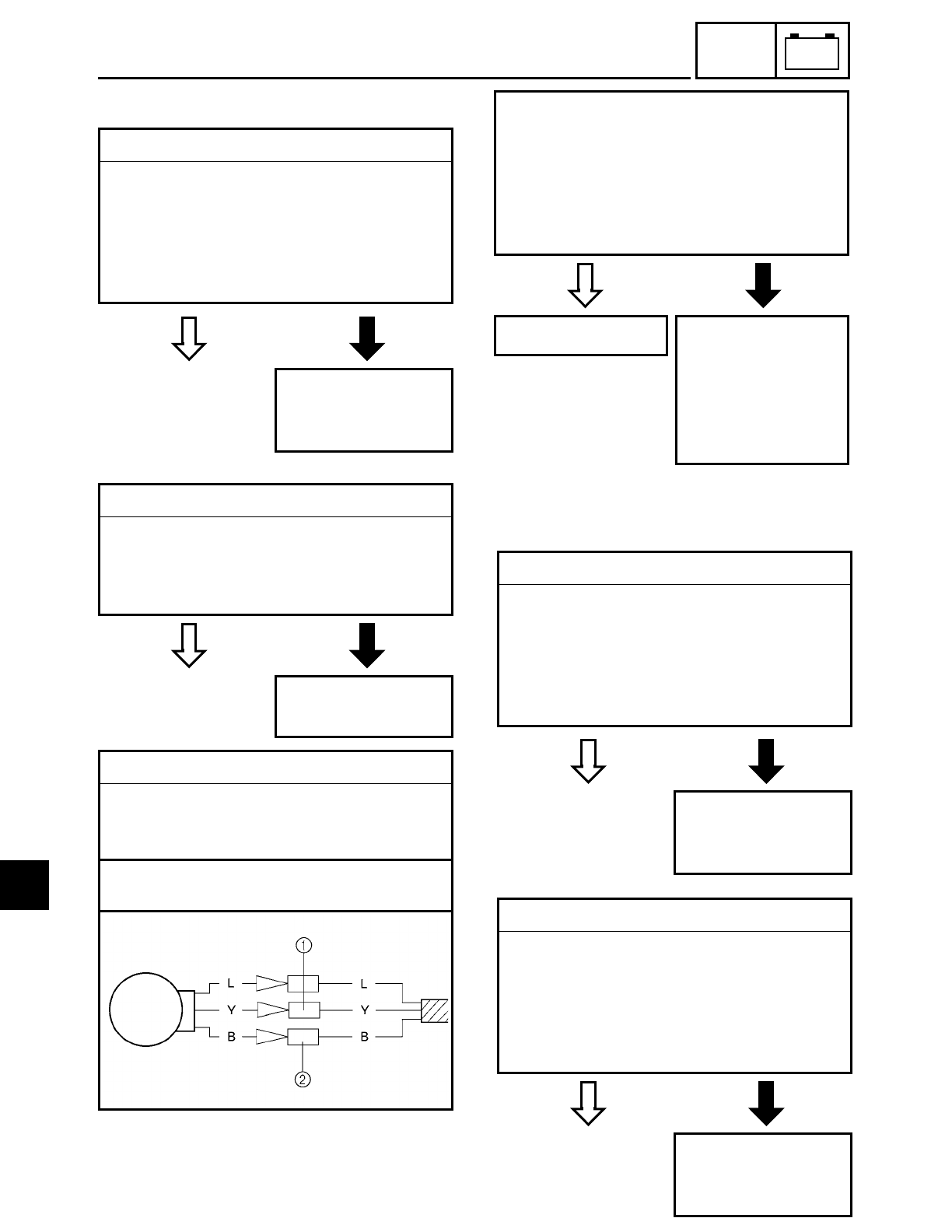
7 - 41
–+
ELEC
SIGNALING SYSTEM
EB806411
2. A tail/brake light fails to come on.
YES NO
1.Tail/brake light bulb and socket
• Check the tail/brake light bulb and socket
for continuity.
Refer to “CHECKING THE BULBS AND
BULB SOCKETS”.
• Are the tail/brake light bulb and socket
OK?
Replace the tail/
brake light bulb,
socket or both.
YES NO
2.Brake light switches
• Check the brake light switches for conti-
nuity.
Refer to “CHECKING THE SWITCHES”.
• Is the brake light switch OK?
Replace the brake
light switch.
3.Voltage
• Connect the pocket tester (DC 20 V) to
the tail/brake light coupler (wire harness
side) as shown.
Tester positive probe → yellow 1
Tester negative probe → black 2
YES NO
• Set the main switch to “ON”.
• Pull in the brake lever or push down on
the brake pedal.
• Measure the voltage (12 V) of yellow at
the tail/brake light coupler (wire harness
side).
• Is the voltage within specification?
This circuit is OK. The wiring circuit
from the main
switch to the tail/
brake light coupler
is faulty and must
be repaired.
EB806413
3. A turn signal light, turn signal indicator
light or both fail to blink.
YES NO
1.Turn signal light bulb and socket
• Check the turn signal light bulb and
socket for continuity.
Refer to “CHECKING THE BULBS AND
BULB SOCKETS”.
• Are the turn signal light bulb and socket
OK?
Replace the turn
signal light bulb,
socket or both.
YES NO
2.Turn signal indicator light bulb and socket
• Check the turn signal indicator light bulb
and socket for continuity.
Refer to “CHECKING THE BULBS AND
BULB SOCKETS”.
• Is the turn signal indicator light bulb and
socket OK?
Replace the turn sig-
nal indicator light
bulb, socket or both.
7
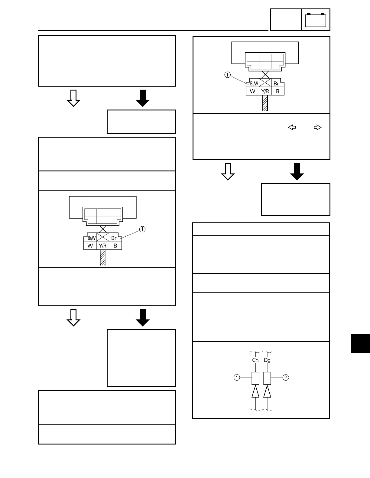
7 - 42
–+
ELEC
SIGNALING SYSTEM
YES NO
YES NO
3.Turn signal switch
• Check the turn signal switch for continu-
ity.
Refer to “CHECKING THE SWITCHES”.
• Is the turn signal switch OK?
Replace the left han-
dlebar switch.
4.Voltage
• Connect the pocket tester (DC 20 V) to
the turn signal relay coupler as shown.
Tester positive probe → brown 1
Tester negative probe → ground
• Set the main switch to “ON”.
• Measure the voltage (12 V) of brown 1
at the turn signal relay coupler.
• Is the voltage within specification?
The wiring circuit
from the main
switch to the turn
signal relay coupler
is faulty and must
be repaired.
5.Voltage
• Connect the pocket tester (DC 20 V) to
the turn signal relay coupler as shown.
Tester positive probe → brown/white 1
Tester negative probe → ground
YES NO
• Set the main switch to “ON”.
• Set the turn signal switch to “ ” or “ ”.
• Measure the voltage (12 V) of brown/
white at the turn signal relay coupler.
• Is the voltage within specification?
The turn signal
relay is faulty and
must be replaced.
6.Voltage
• Connect the pocket tester (DC 20 V) to
the turn signal light connectors (wire
harness side) or the meter assembly
coupler as shown.
ÅTurn signal light
ıTurn signal indicator light
Left turn signal light
Tester positive probe → chocolate 1
Tester negative probe → ground
Right turn signal light
Tester positive probe → dark green 2
Tester negative probe → ground
Å
7
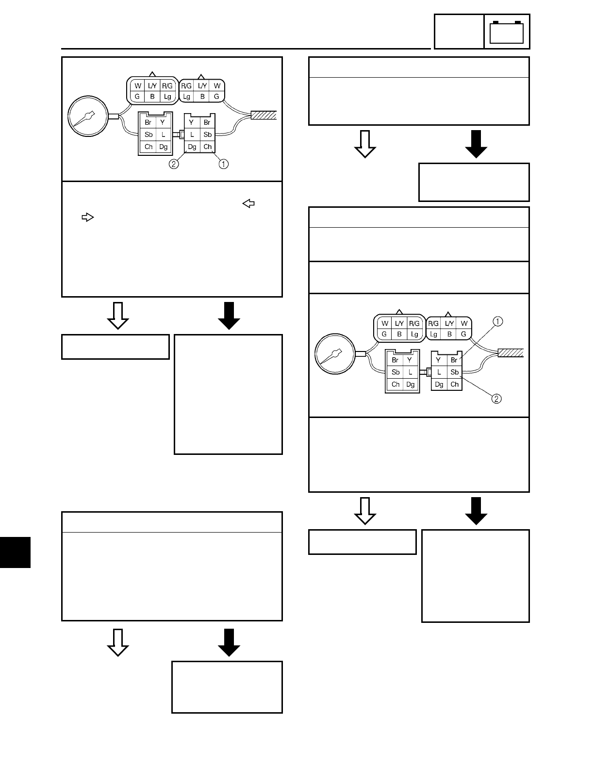
7 - 43
–+
ELEC
SIGNALING SYSTEM
YES NO
• Set the main switch to “ON”.
• Set the turn signal switch to “ ” or
“”.
• Measure the voltage (12 V) of chocolate 1
or dark green 2 at the turn signal light con-
nectors (wire harness side) or the meter
assembly coupler.
• Is the voltage within specification?
This circuit is OK. The wiring circuit
from the turn signal
switch to the turn
signal light connec-
tor or the meter
assembly coupler
are faulty and must
be repaired.
EB806414
4. The neutral indicator light fails to come
on.
YES NO
1.Neutral indicator light bulb and socket
• Check the neutral indicator light bulb
and socket for continuity.
Refer to “CHECKING THE BULBS AND
BULB SOCKETS”.
• Are the neutral indicator light bulb and
socket OK?
Replace the neutral
indicator light bulb,
socket or both.
YES NO
YES NO
2.Neutral switch
• Check the neutral switch for continuity.
Refer to “CHECKING THE SWITCHES”.
• Is the neutral switch OK?
Replace the neutral
switch.
3.Voltage
• Connect the pocket tester (DC 20 V) to
the meter assembly coupler as shown.
Tester positive probe → brown 1
Tester negative probe → sky blue 2
• Set the main switch to “ON”.
• Measure the voltage (12 V) of brown 1
and sky blue 2 at the meter assembly
coupler.
• Is the voltage within specification?
This circuit is OK. The wiring circuit
from the main
switch to the meter
assembly coupler is
faulty and must be
repaired.
ı
7
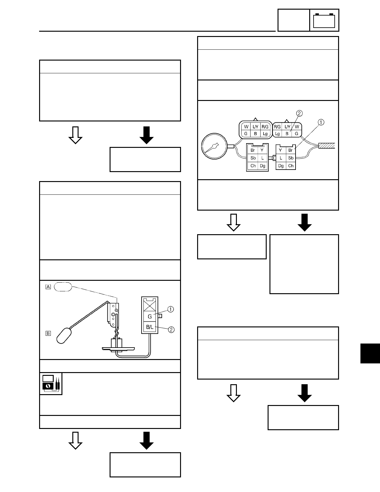
7 - 44
–+
ELEC
SIGNALING SYSTEM
EB806417
5. The fuel level indicator light, fuel level
meter or both fail to come on.
YES NO
1.Fuel level indicator light LED
• Check the LED of the fuel level indicator
light.
Refer to “CHECKING THE BULBS AND
BULB SOCKETS”.
• Is the fuel level indicator light LED OK?
Replace the meter
assembly.
YES NO
2.Fuel sender
• Disconnect the fuel sender coupler from
the wire harness.
• Drain the fuel from the fuel tank and
remove the fuel sender from the fuel
tank.
• Connect the pocket tester (Ω× 10) to the
fuel sender coupler.
Tester positive probe → green 1
Tester negative probe → black/blue 2
• Measure the fuel sender resistance.
Fuel sender resistance
Full position of the float
Å
11 ~ 13
Ω at 20 ˚C (68 ˚F)
Empty position of the float
ı
140 ~ 143
Ω at 20 ˚C (68 ˚F)
• Is the fuel sender OK?
Replace the fuel
sender.
YES NO
3.Voltage
• Connect the pocket tester (DC 20 V) to
the meter assembly coupler (wire har-
ness side) as shown.
Tester positive probe
→ brown
1
Tester negative probe
→ black
2
• Set the main switch to “ON”.
• Measure the voltage (12 V).
• Is the voltage within specification?
Replace the meter
assembly.
The wiring circuit
from the main
switch to the meter
assembly coupler is
faulty and must be
repaired.
6. An engine trouble indicator light fails to
come on.
YES NO
1.Engine trouble indicator LED
• Check the LED of the engine indicator
light.
Refer to “CHECKING THE BULBS AND
BULB SOCKETS”.
Replace the meter
assembly.
7
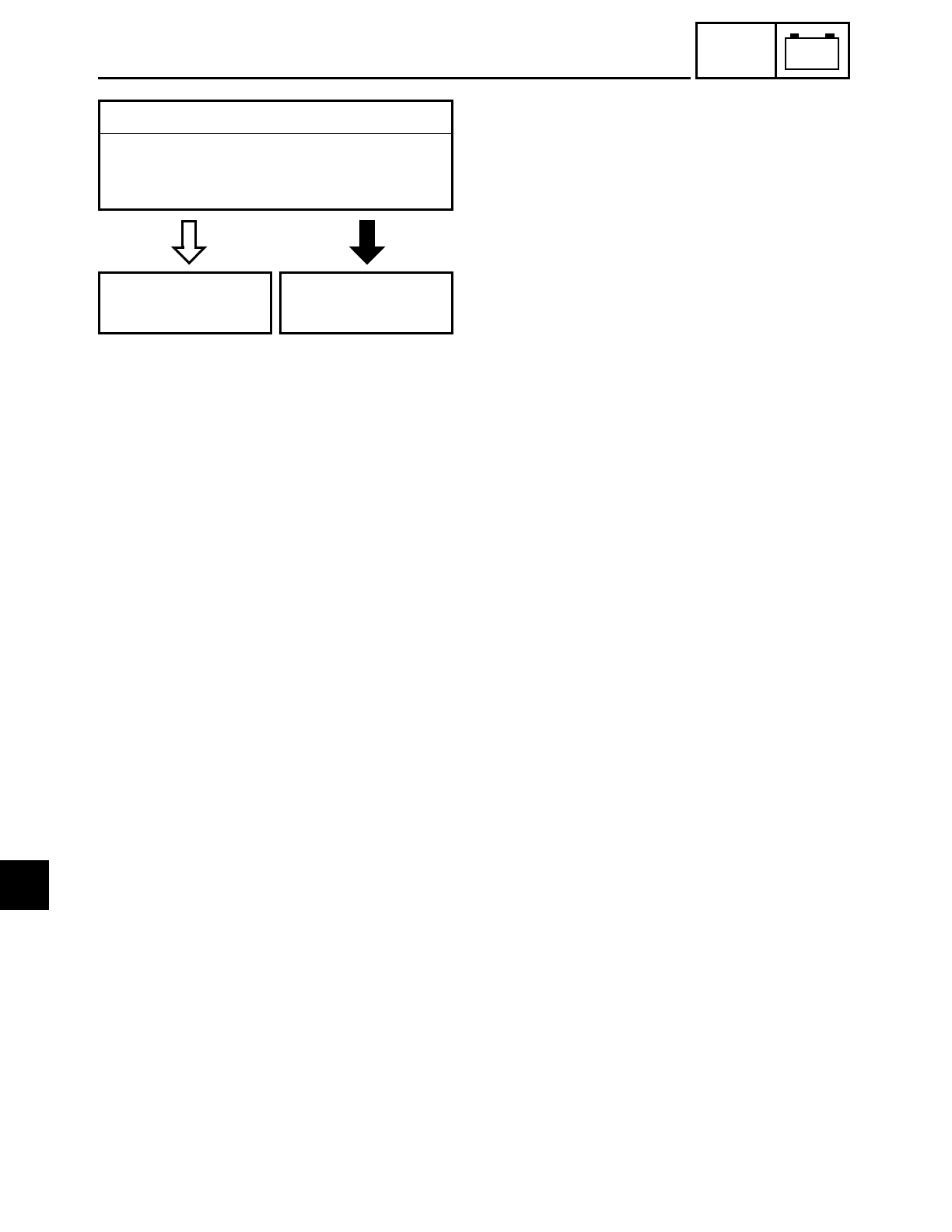
7 - 45
–+
ELEC
SIGNALING SYSTEM
EAS00843
YES NO
2.Wire harness
• Check the wire harness for continuity.
Refer to “CIRCUIT DIAGRAM”.
• Is the wire harness OK?
Replace the ignitor
unit.
Repair or replace
the wire harness.
7
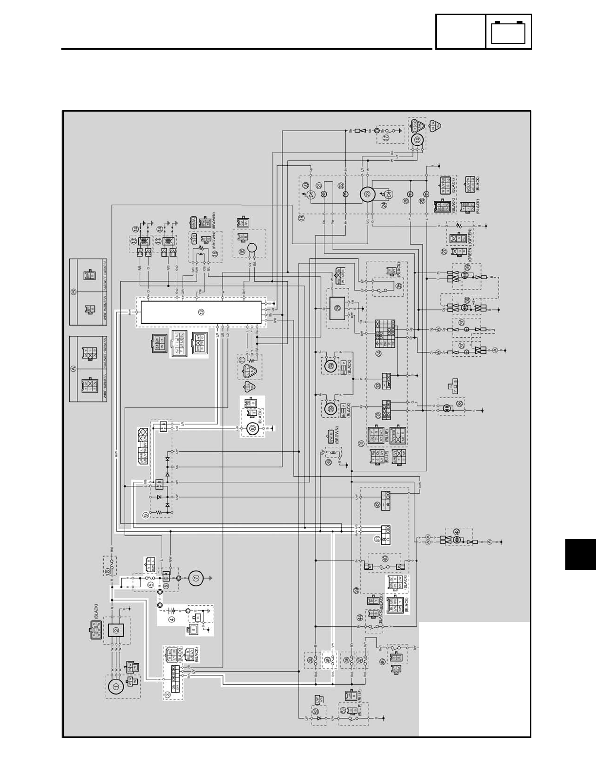
7 - 46
–+
ELEC
FUEL PUMP SYSTEM
EB808000
FUEL PUMP SYSTEM
CIRCUIT DIAGRAM
3Main switch
4Battery
5Main fuse
9Relay unit
0Fuel pump
BIgnitor unit
aEngine stop switch
iIgnition fuse
7
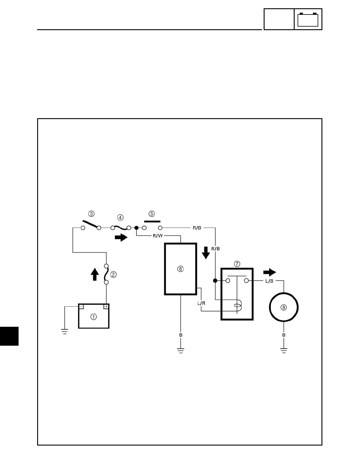
FWD
7 - 47
–+
ELEC
FUEL PUMP SYSTEM
EB808010
FUEL PUMP CIRCUIT OPERATION
The ignitor unit includes the control unit for the fuel pump.
1Battery
2Main fuse
3Main switch
4Ignition fuse
5Engine stop switch
6Ignitor unit
7Fuel pump relay
8Fuel pump
7
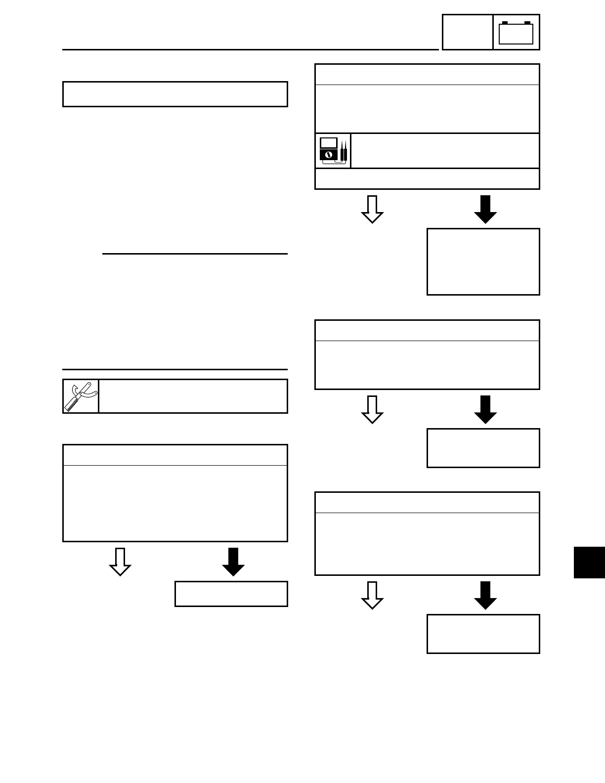
7 - 48
–+
ELEC
FUEL PUMP SYSTEM
EB808020
TROUBLESHOOTING
Check:
1. main and ignition fuses
2. battery
3. main switch
4. engine stop switch
5. relay unit (fuel pump relay)
6. fuel pump
7. wiring
(the entire fuel pump system)
NOTE:
• Before troubleshooting, remove the fol-
lowing part(s):
1) rider seat
2) fuel tank
3) side covers
4) headlight lens unit
• Troubleshoot with the following special
tool(s).
The fuel pump fails to operate.
Pocket tester
YU-03112
EAS00738
YES NO
1.Main and ignition fuses
• Check the main and ignition fuses for
continuity.
Refer to “CHECKING THE FUSES” in
chapter 3.
• Are the main and ignition fuses OK?
Replace the fuse(s).
EAS00739
YES NO
2.Battery
• Check the condition of the battery.
Refer to “CHECKING AND CHARGING
THE BATTERY” in chapter 3.
Minimum open circuit voltage
12.8 V or more at 20 ˚C (68 ˚F)
• Is the battery OK?
• Clean the battery
terminals.
• Recharge or
replace the battery.
EAS00749
YES NO
3.Main switch
• Check the main switch for continuity.
Refer to “CHECKING THE SWITCHES”.
• Is the main switch OK?
Replace the main
switch.
EAS00750
YES NO
4.Engine stop switch
• Check the engine stop switch for conti-
nuity.
Refer to “CHECKING THE SWITCHES”.
• Is the engine stop switch OK?
Replace the right
handlebar switch.
7
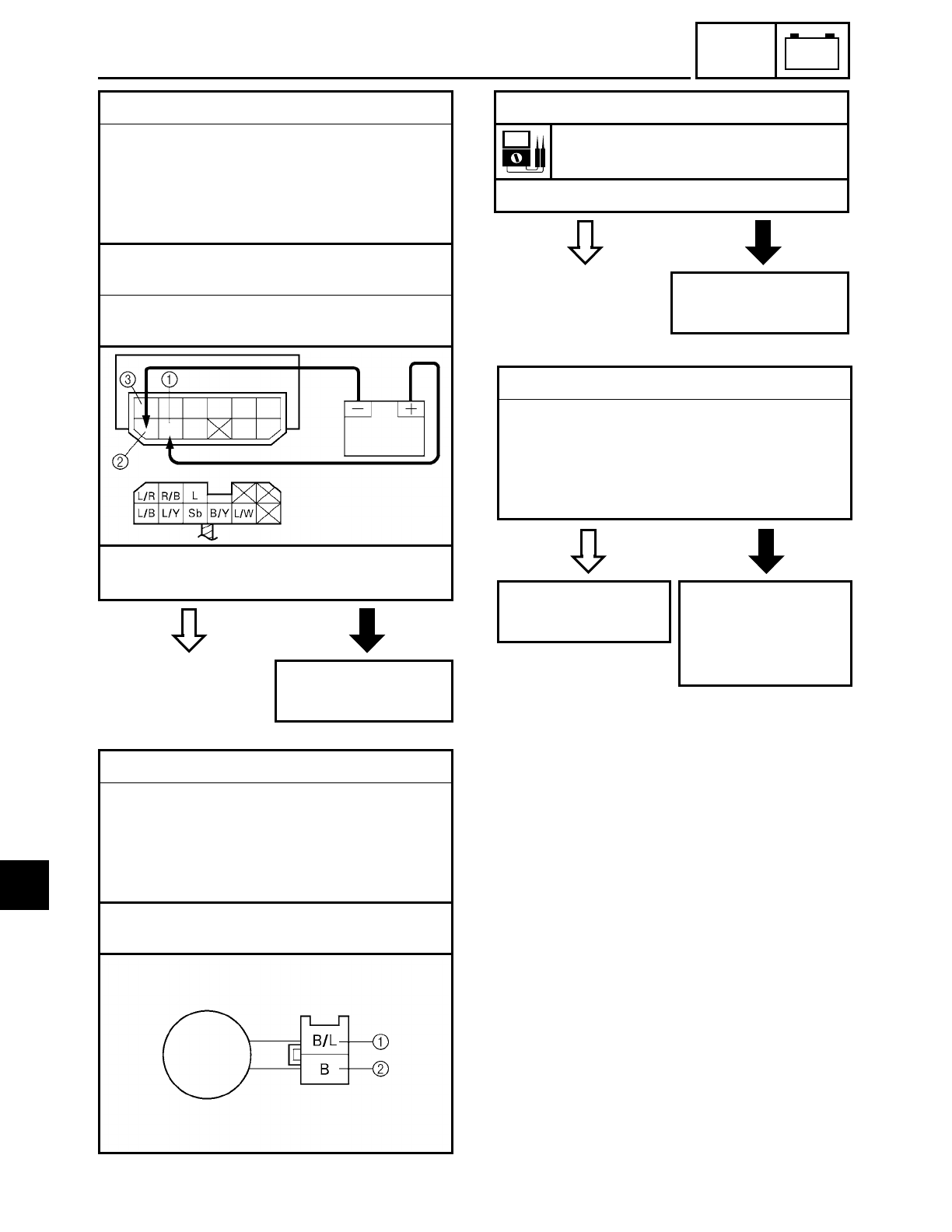
7 - 49
–+
ELEC
FUEL PUMP SYSTEM
YES NO
5.Relay unit (fuel pump relay)
• Disconnect the relay unit from the cou-
pler.
• Connect the pocket tester (Ω× 1) and
battery (12 V) to the relay unit terminals
as shown.
Battery positive terminal → red/black 1
Battery negative terminal → blue/red 2
Tester positive probe → red/black 1
Tester negative probe → blue/black 3
• Does the fuel pump relay have continu-
ity between red/black and blue/black?
Replace the relay
unit.
EB808400
6.Fuel pump resistance
• Disconnect the fuel pump coupler from
the wire harness.
• Connect the pocket tester (Ω× 1) to the
fuel pump coupler (fuel pump side) as
shown.
Tester positive probe → black/blue 1
Tester negative probe → black 2
YES NO
• Measure the fuel pump resistance.
Fuel pump resistance
1.6 ~ 2.2 Ω at 20 ˚C (68 ˚F)
• Is the fuel pump OK?
Replace the fuel
pump.
EAS00754
YES NO
7.Wiring
• Check the entire fuel pump system’s wir-
ing.
Refer to “CIRCUIT DIAGRAM”.
• Is the fuel pump system’s wiring prop-
erly connected and without defects?
Replace the ignitor
unit.
Properly connect
or repair the fuel
pump system’s wir-
ing.
7
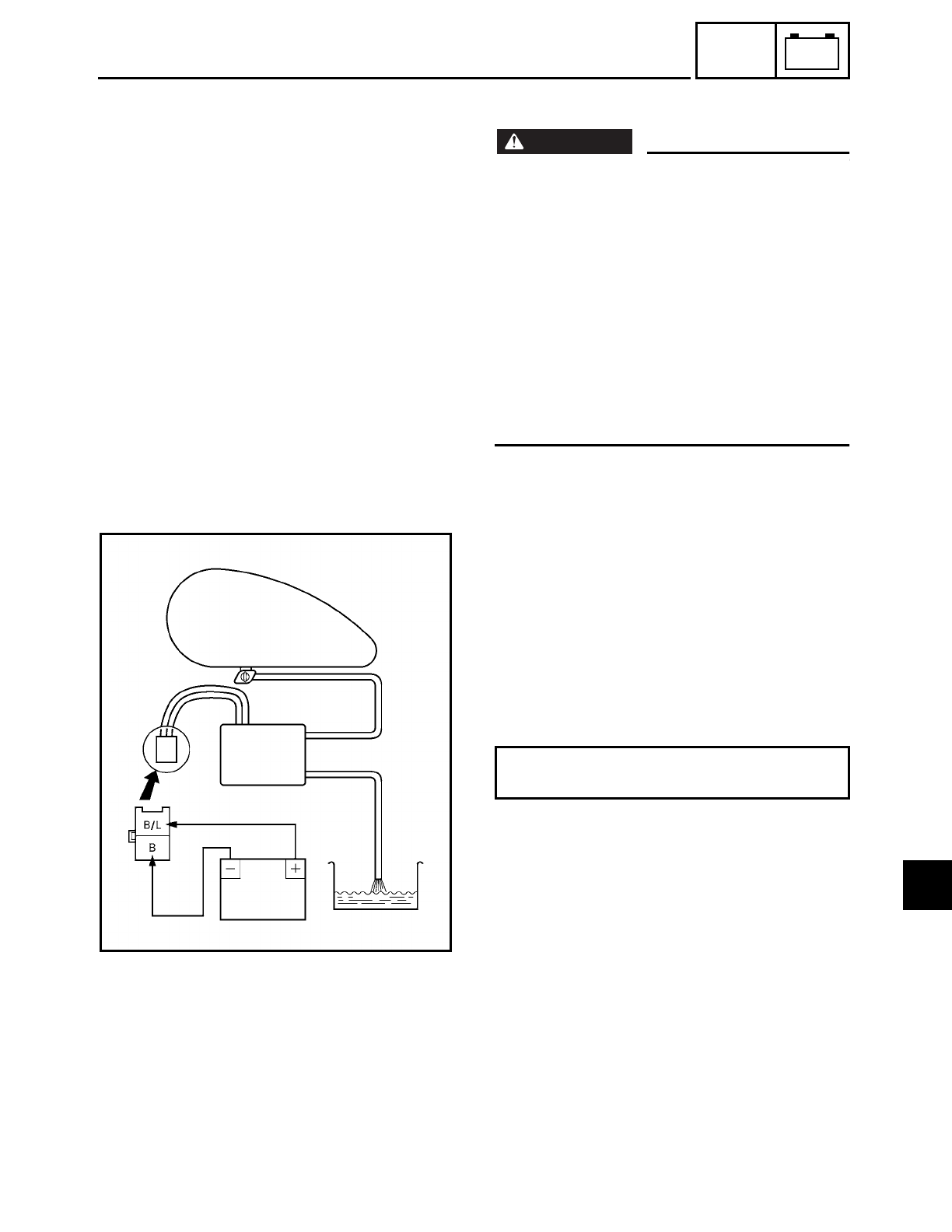
7 - 50
–+
ELEC
FUEL PUMP SYSTEM
EB808410
CHECKING THE FUEL PUMP
WARNING
WARNING
Gasoline is extremely flammable and under
certain circumstances there can be a dan-
ger of an explosion or fire. Be extremely
careful and note the following points:
• Stop the engine before refuelling.
• Do not smoke and keep away from open
flames, sparks or any other source of fire.
• If you do accidentally spill gasoline, wipe
it up immediately with dry rags.
• If gasoline touches the engine when it is
hot, a fire may occur. Therefore, make
sure that the engine is completely cool
before performing the following test.
1.Check:
• fuel pump operation
▼ ▼ ▼ ▼ ▼ ▼ ▼ ▼ ▼ ▼ ▼ ▼ ▼ ▼ ▼ ▼ ▼ ▼ ▼ ▼ ▼ ▼ ▼ ▼ ▼ ▼ ▼ ▼
a. Fill the fuel tank.
b. Put the end of the fuel hose into an open
container.
c. Turn the fuel cock to “ON” or “RES”.
d. Connect the battery (12 V) to the fuel
pump coupler as shown.
e. If fuel flows out of the fuel hose, the fuel
pump is OK. If fuel does not flow, replace
the fuel pump.
▲ ▲ ▲ ▲ ▲ ▲ ▲ ▲ ▲ ▲ ▲ ▲ ▲ ▲ ▲ ▲ ▲ ▲ ▲ ▲ ▲ ▲ ▲ ▲ ▲ ▲ ▲ ▲
Battery positive lead → black/blue 1
Battery negative lead → black 2
7
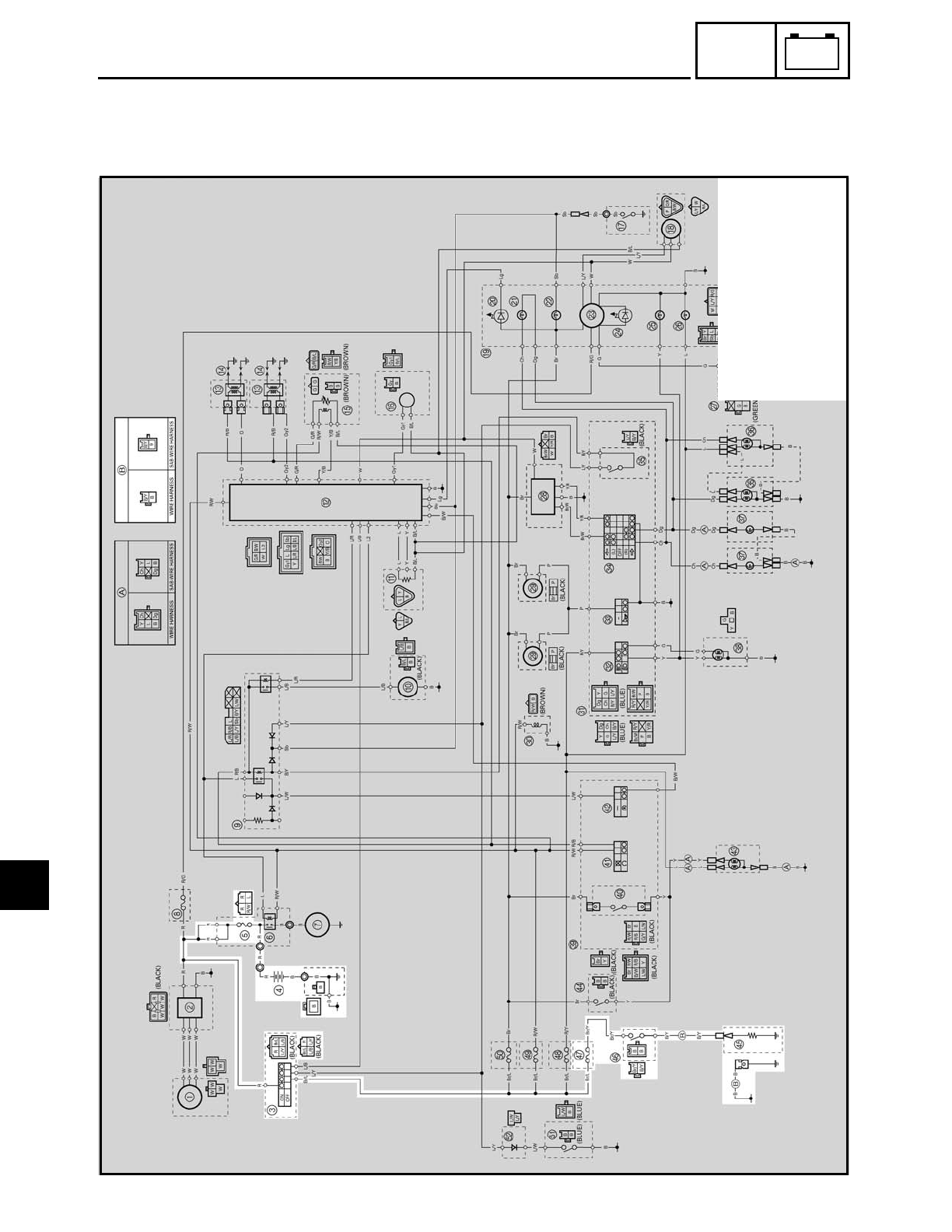
7 - 51
–+
ELEC
CARBURETOR HEATING SYSTEM
EAS00820
CARBURETOR HEATING SYSTEM
CIRCUIT DIAGRAM
3Main switch
4Battery
5Main fuse
eCarburetor heater
fThermo switch
gCarburetor heater fuse
7
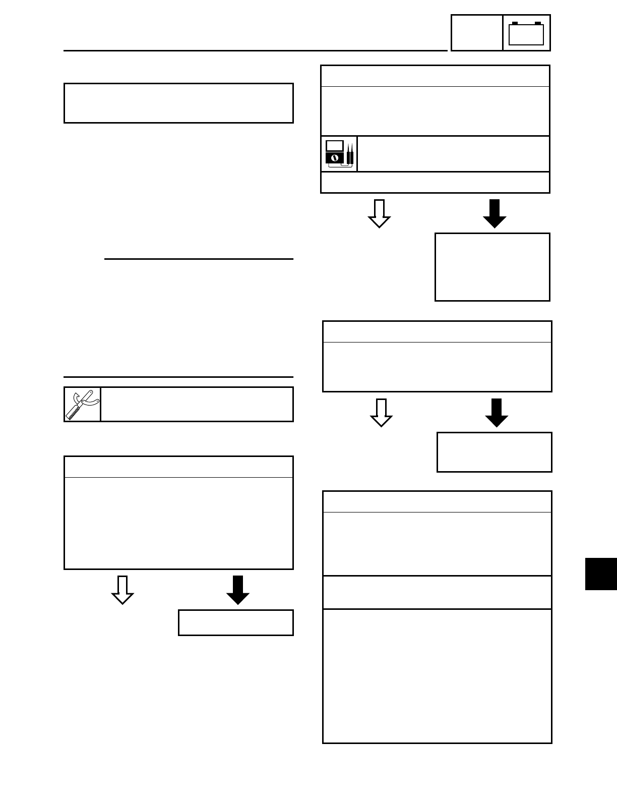
7 - 52
–+
ELEC
CARBURETOR HEATING SYSTEM
EAS00821
TROUBLESHOOTING
Check:
1. Main and carburetor heater fuses
2. Battery
3. Main switch
4. Thermo switch
5. Carburetor heater
6. Wiring
(of the entire carburetor heating system)
NOTE:
• Before troubleshooting, remove the fol-
lowing part(s).
1) rider seat
2) fuel tank
3) carburetor
4) left side cover
• Troubleshoot with the following special
tool(s).
The carburetor heating system fails to
operate.
Pocket tester
YU-03112
EAS00738
YES NO
1.Main and carburetor heater fuses
• Check the main and carburetor heater
fuses for continuity.
Refer to “CHECKING THE FUSES” in
chapter 3.
• Are the main and carburetor heater
fuses OK?
Replace the fuse(s).
EAS00739
YES NO
2.Battery
• Check the condition of the battery.
Refer to “CHECKING AND CHARGING
THE BATTERY” in chapter 3.
Minimum open circuit voltage
12.8 V or more at 20 ˚C (68 ˚F)
• Is the battery OK?
• Clean the battery
terminals.
• Recharge or
replace the battery.
EAS00749
YES NO
3.Main switch
• Check the main switch for continuity.
Refer to “CHECKING THE SWITCHES”.
• Is the main switch OK?
Replace the main
switch.
EAS00823
4.Thermo switch
• Remove the thermo switch from the
plastic bracket.
• Connect the pocket tester to the thermo
switch coupler as shown.
Tester positive lead → black 1
Tester negative lead → black 2
• Immerse the thermo switch in a con-
tainer filled with water 3.
• Place a thermometer 4 in the water.
• Slowly heat the water, than let it cool to
the specified temperature as indicated in
the table.
• Check the thermo switch for continuity
at the temperatures indicated in the
table.
7
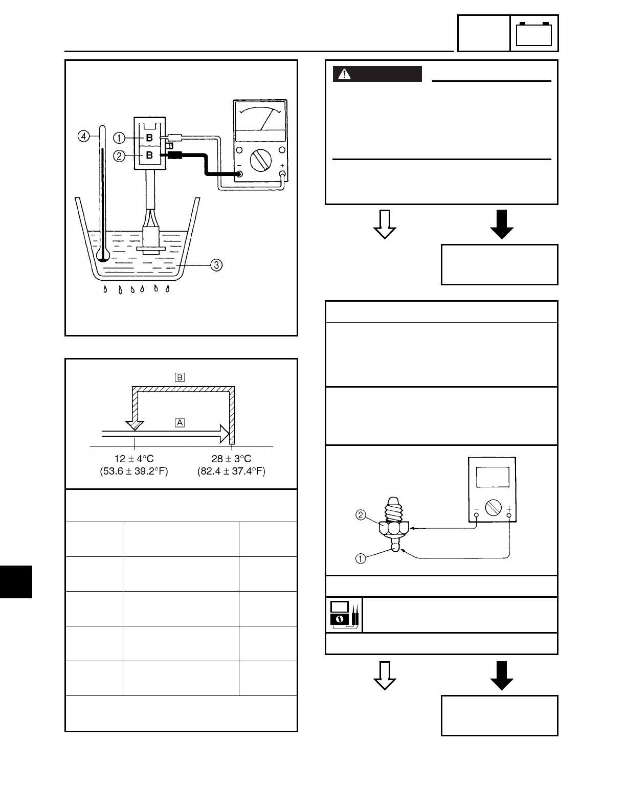
7 - 53
–+
ELEC
CARBURETOR HEATING SYSTEM
ÅThe thermo switch circuit is open.
ıThe thermo switch circuit is closed.
Test step Water temperature Continu-
ity
1Less than 23 ± 3 ˚C
(73.4 ± 5.4 ˚F) YES
2More than 23 ± 3 ˚C
(73.4 ± 5.4 ˚F) NO
3More than 12 ± 4 ˚C
(53.6 ± 7.2 ˚F) NO
4Less than 12 ± 4 ˚C
(53.6 ± 7.2 ˚F) YES
Test steps 1 & 2: Heating phase
Test steps 3 & 4: Cooling phase
YES NO
• Does the thermo switch operate prop-
erly?
Replace the thermo
switch.
WARNING
WARNING
• Handle the thermo switch with special
care.
• Never subject the thermo switch to
strong shocks. If the thermo switch is
dropped, replace it.
YES NO
5.Carburetor heater
• Remove the carburetor heater from the
carburetor.
• Connect the pocket tester to the carbure-
tor heater as shown.
Tester positive probe →
carburetor heater terminal 1
Tester negative probe →
carburetor heater body 2
• Measure carburetor heater resistance.
Carburetor heater resistance
12 V 30 W: 6 ~ 10 Ω at 20˚C (68˚F)
• Is the carburetor heater OK?
Replace the carbu-
retor heater.
7
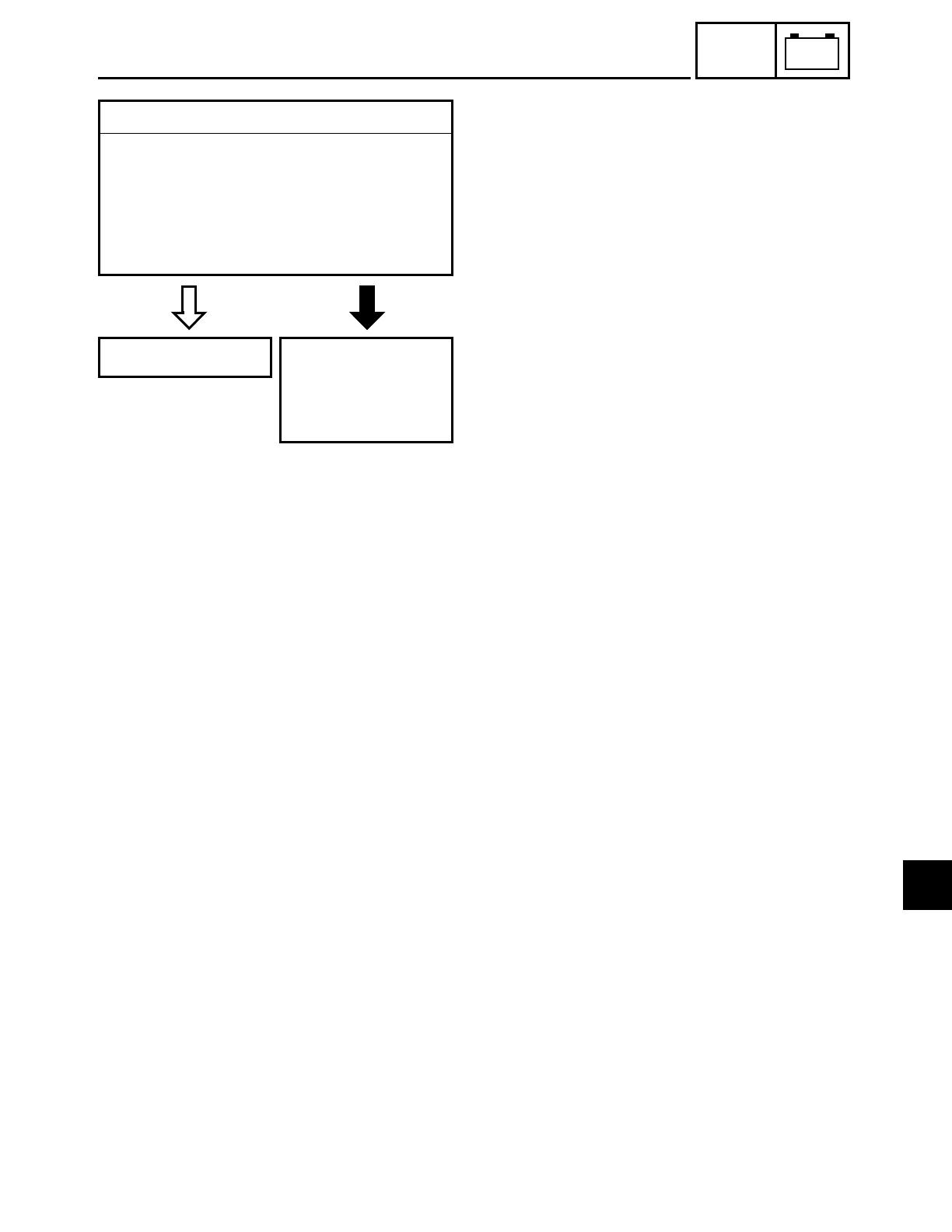
7 - 54
–+
ELEC
CARBURETOR HEATING SYSTEM
EAS00754
YES NO
6.Wiring
• Check the entire carburetor heating sys-
tem’s wiring.
Refer to “CIRCUIT DIAGRAM”.
• Is the carburetor heating system’s wir-
ing properly connected and without
defects?
This circuit is OK. Properly connect
or repair the carbu-
retor heating sys-
tem’s wiring.
7
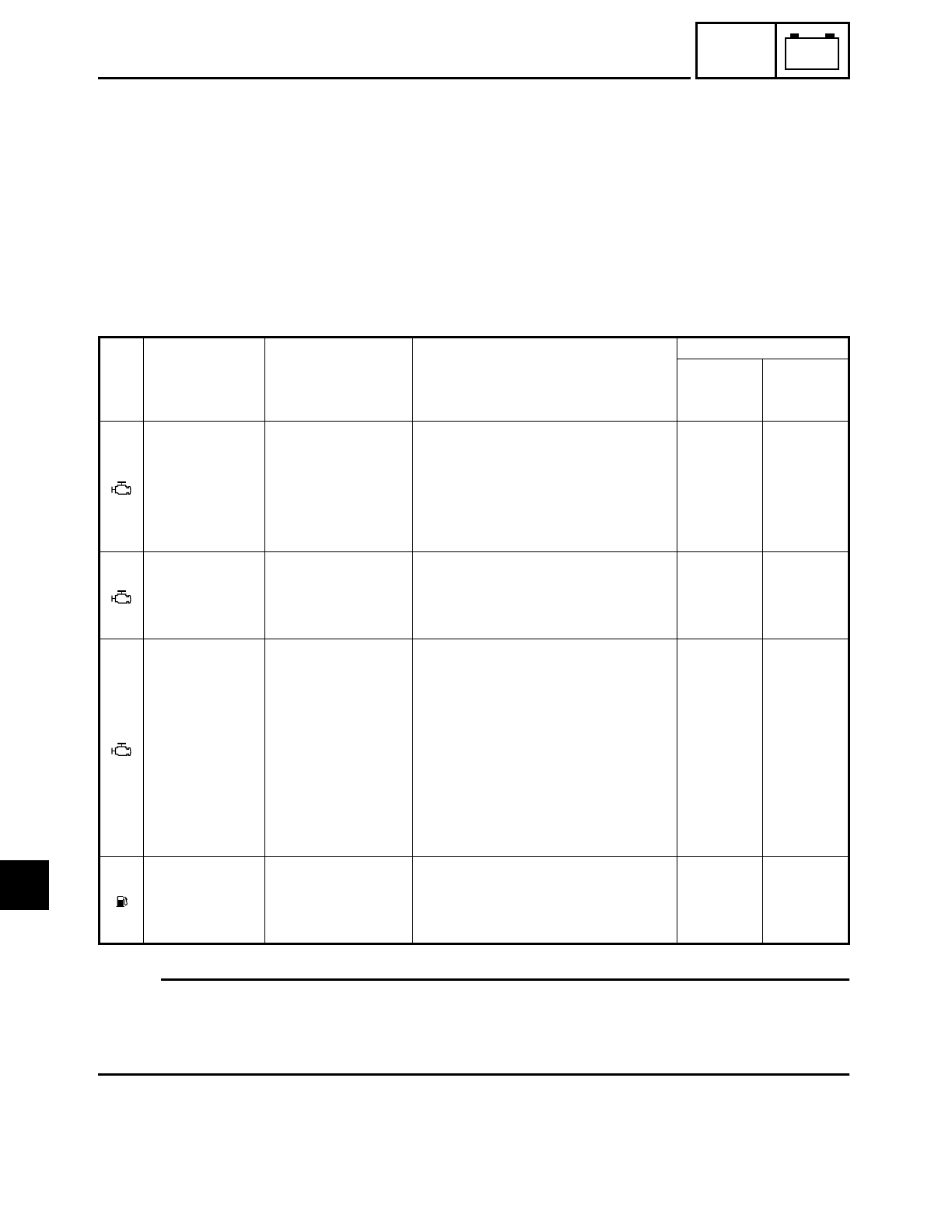
7 - 55
–+
ELEC
SELF-DIAGNOSIS
EB812000
SELF-DIAGNOSIS
The XV16AL/XV16ALC/XV16ATL/XV16ATLC features a self-diagnosing system for the follow-
ing circuit(s):
• throttle position sensor
• speed sensor
• decompression solenoid
• fuel level meter
If any of these circuits is defective, the respective condition code will be displayed by the
engine trouble indicator light or fuel level indicator light when the main switch is set to “ON”
(irrespective of whether the engine is running or not).
NOTE:
When the main switch is turned on, the engine trouble indicator light and fuel level indicator
light in the meter assembly normally come on for 1.4 seconds and then go off. However, if
there is a malfunction, the corresponding indicator light then begins flashing when the
engine is stopped or comes on when the engine is running.
Indica-
tor light Circuit Defect(s) System response
Condition code
When
engine is
stopped
When
engine is
running
Throttle posi-
tion sensor
• Disconnected
• Short-circuit
• Locked
• The ignitor unit stays set to the
wide-open throttle ignition tim-
ing. The motorcycle can be rid-
den.
• The engine trouble indicator
light displays the condition code.
Blinks in
patterns
of 3
Lights up
Speed sensor • Abnormal pulse
• Disconnected
• Short-circuit
• The engine speed limiter sets in
approximately 4,400 rpm.
• The engine trouble indicator
light displays the condition code.
Blinks in
patterns
of 4
Lights up
Decompres-
sion solenoid
• Disconnected
• Short-circuit
• Over heated
solenoid
• Disconnected
thermistor in
solenoid
• Short-circuited
thermistor in
solenoid
• The decompression solenoid
does not move.
• The starter motor does not oper-
ate.
• The engine trouble indicator
light displays the condition code.
Blinks in
patterns
of 6
Lights up
Fuel level
meter
• Disconnected
• Short-circuit
• The fuel level meter displays the
empty position.
• The fuel level indicator light dis-
plays the condition code.
Blinks in
patterns
of 8
Blinks in
patterns
of 8
7
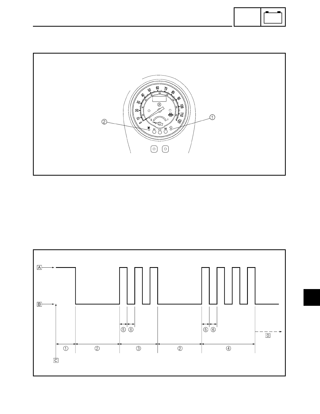
7 - 56
–+
ELEC
SELF-DIAGNOSIS
Display order on the engine trouble indicator light and fuel level indicator light
1Engine trouble indicator light
2Fuel level indicator light
1Indicator lights check...............................1.4 seconds
2Light off ....................................................3 seconds
3Condition code.........................................First fault code (3 = throttle position sensor)
4Condition code.........................................Next fault code (4 = speed sensor)
5Light on ....................................................0.5 second
6Light off ....................................................0.5 second
ÅLight on
ıLight off
ÇMain switch is turned on
ÎRepetition
7
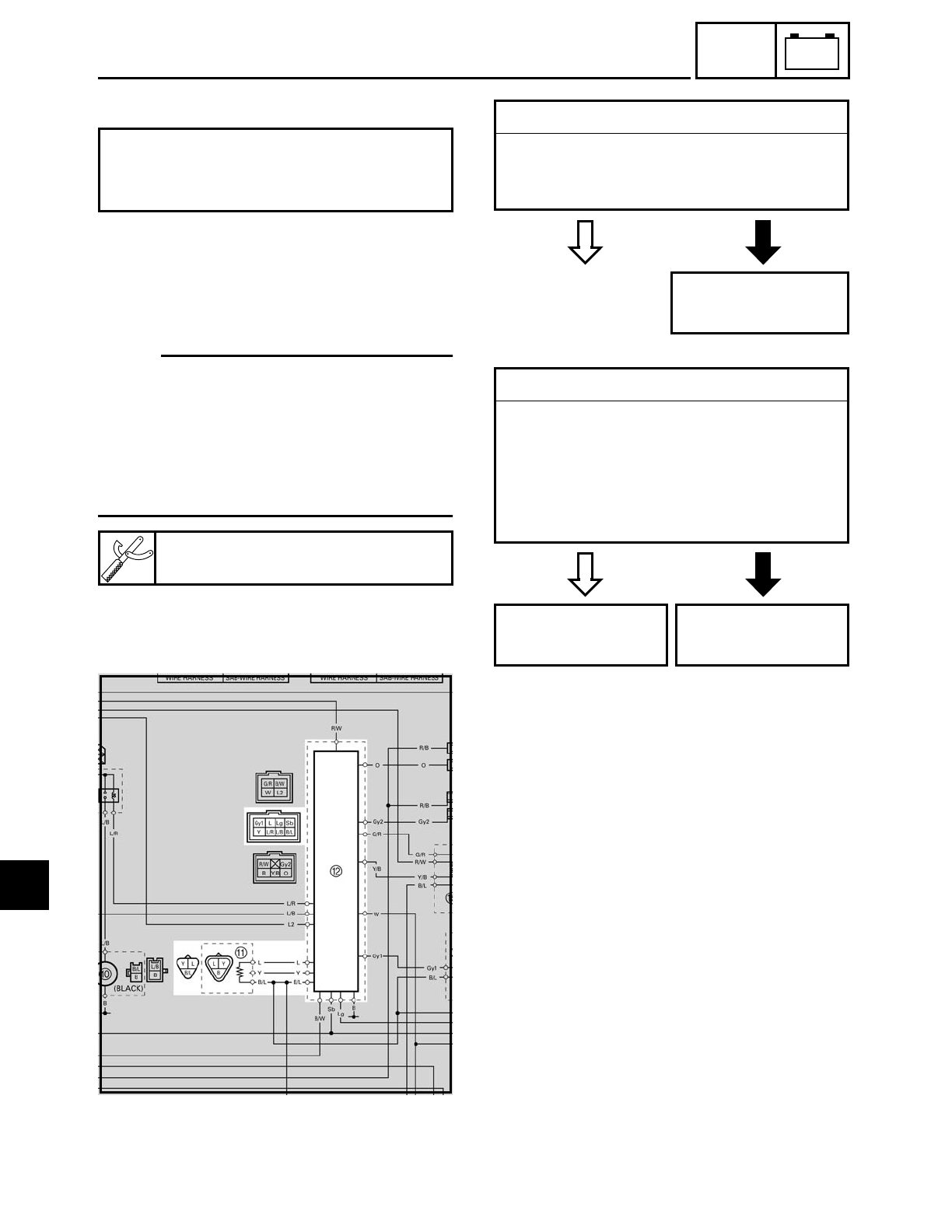
7 - 57
–+
ELEC
SELF-DIAGNOSIS
EB812010
TROUBLESHOOTING
Check:
1. throttle position sensor
2. speed sensor
3. decompression solenoid
4. fuel level meter
NOTE:
• Before troubleshooting, remove the fol-
lowing part(s):
1) rider seat
2) fuel tank
3) left side cover
• Troubleshoot with the following special
tool(s).
The engine trouble indicator light or the
fuel level indicator light starts to blink,
display the self-diagnosis sequence.
Pocket tester
YU-03112
EB812020
1. Throttle position sensor
CIRCUIT DIAGRAM
AThrottle position sensor
BIgnitor unit
EAS00843
YES NO
1.Wire harness
• Check the wire harness for continuity.
Refer to “CIRCUIT DIAGRAM”.
• Is the wire harness OK?
Repair or replace
the wire harness.
EB812401
YES NO
2.Throttle position sensor
• Check the throttle position sensor for
continuity.
Refer to “CHECKING AND ADJUSTING
THE THROTTLE POSITION SENSOR” in
chapter 6.
• Is the throttle position sensor OK?
Replace the ignitor
unit.
Replace the throt-
tle position sensor.
7
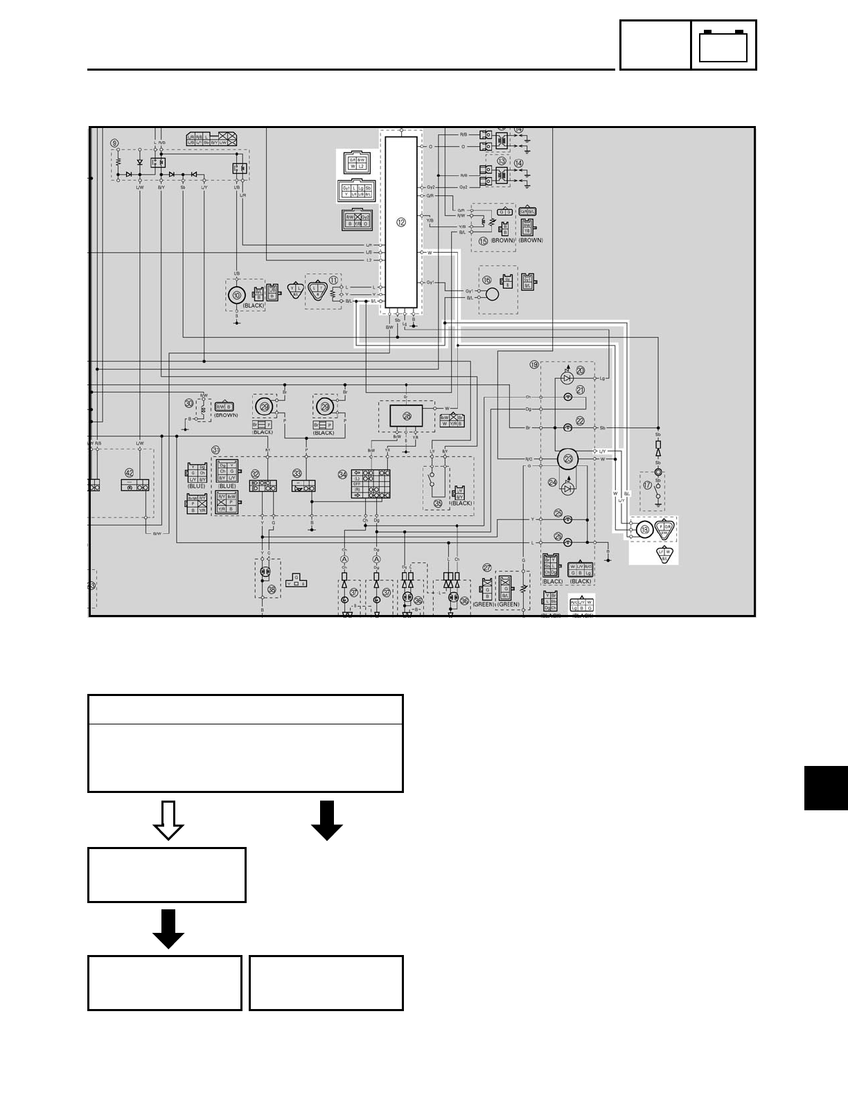
7 - 58
–+
ELEC
SELF-DIAGNOSIS
2. Speed sensor
CIRCUIT DIAGRAM
BIgnitor unit
HSpeed sensor
EAS00843
YES NO
BAD
1.Wire harness
• Check the wire harness for continuity.
Refer to “CIRCUIT DIAGRAM”.
• Is the wire harness OK?
Replace the speed
sensor.
Replace the ignitor
unit.
Repair or replace
the wire harness.
7
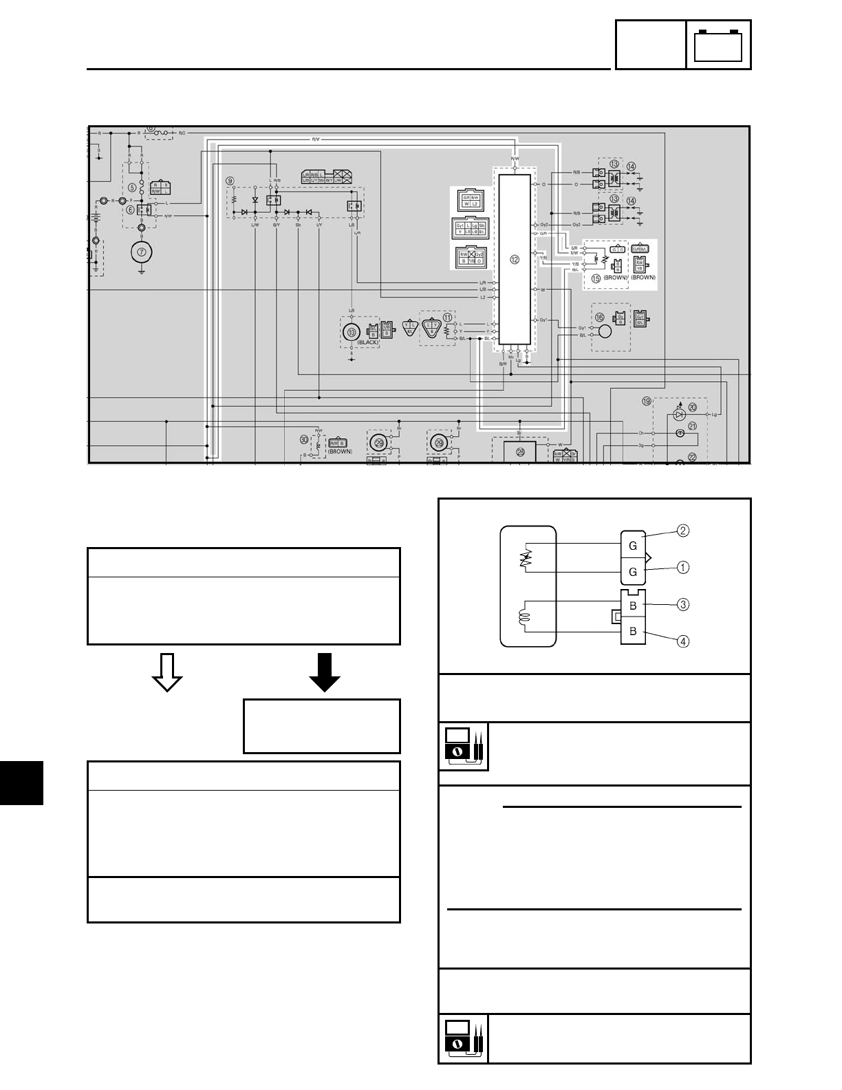
7 - 59
–+
ELEC
SELF-DIAGNOSIS
3. Decompression solenoid
CIRCUIT DIAGRAM
BIgnitor unit
EDecompression solenoid
EAS00843
YES NO
1.Wire harness
• Check the wire harness for continuity.
Refer to “CIRCUIT DIAGRAM”.
• Is the wire harness OK?
Repair or replace
the wire harness.
2.Decompression solenoid (thermistor)
• Disconnect the decompression solenoid
couplers from the wire harness.
• Connect the pocket tester (Ω× 10) to the
decompression solenoid coupler as shown.
Tester positive probe → green 1
Tester negative probe → green 2
• Measure the decompression solenoid
resistance.
Decompression solenoid resis-
tance (thermistor)
68.75 ~ 78.75
Ω at 25 ˚C (77 ˚F)
• Connect the pocket tester (
Ω
× 1) to the
decompression solenoid coupler as
shown.
Tester positive probe
→ black
3
Tester negative probe
→ black
4
Decompression solenoid resistance
1.2
Ω at 20 ˚C (68 ˚F)
NOTE:
The resistance value for the thermistor
changes when the temperature changes;
therefore, measure the decompression
solenoid resistance at the specified tem-
perature.
7
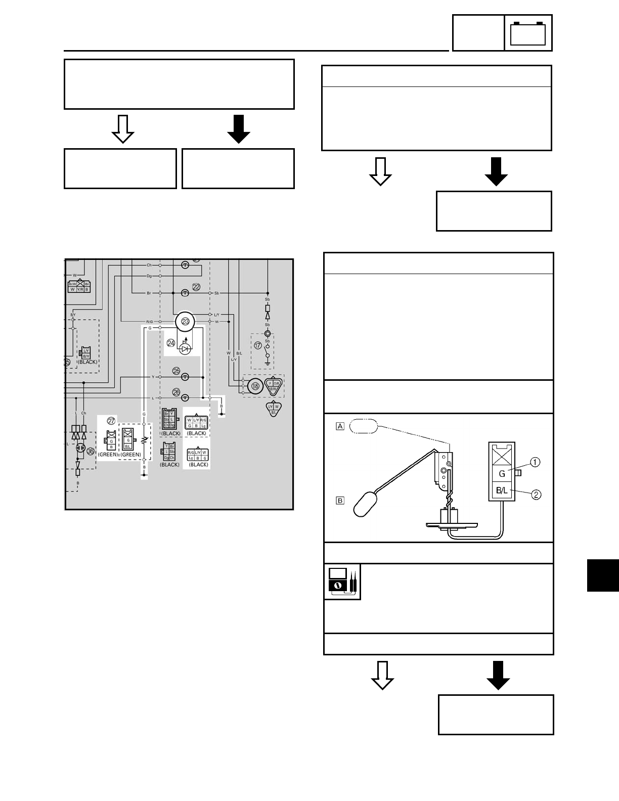
7 - 60
–+
ELEC
SELF-DIAGNOSIS
YES NO
• Check the decompression solenoid for
continuity.
• Is the decompression solenoid OK?
Replace the ignitor
unit.
Replace the decom-
pression solenoid.
EB812040
4. Fuel level meter
CIRCUIT DIAGRAM
MSpeedometer assembly (fuel level meter)
NFuel level indicator light
QFuel sender
EB812403
YES NO
1.Fuel level indicator light LED
• Check the LED of the fuel level indicator
light.
Refer to “CHECKING THE LEDs”.
• Is the fuel level indicator light LED OK?
Repair the meter
assembly.
YES NO
2.Fuel sender
• Disconnect the fuel sender coupler from
the wire harness.
• Drain the fuel from the fuel tank and
remove the fuel sender from the fuel
tank.
• Connect the pocket tester (Ω× 10) to the
fuel sender coupler.
Tester positive probe → green 1
Tester negative probe → black/blue 2
• Measure the fuel sender resistance.
Fuel sender resistance
Full position of the float Å
11 ~ 13 Ω at 20 ˚C (68 ˚F)
Empty position of the float ı
140 ~ 143 Ω at 20 ˚C (68 ˚F)
• Is the fuel sender OK?
Replace the fuel
sender.
7

7 - 61
–+
ELEC
SELF-DIAGNOSIS
EAS00843
YES NO
3.Wire harness
• Check the wire harness for continuity.
Refer to “CIRCUIT DIAGRAM”.
• Is the wire harness OK?
Replace the meter
assembly.
Replace or replace
the wire harness.
7

TRBL
SHTG
CONTENTS
TROUBLESHOOTING
STARTING PROBLEMS ................................................................................ 8-1
ENGINE ................................................................................................. 8-1
FUEL SYSTEM ...................................................................................... 8-1
ELECTRICAL SYSTEMS ....................................................................... 8-2
INCORRECT ENGINE IDLING SPEED .......................................................... 8-2
ENGINE ................................................................................................. 8-2
FUEL SYSTEM ...................................................................................... 8-2
ELECTRICAL SYSTEMS ....................................................................... 8-2
POOR MEDIUM-AND-HIGH-SPEED PERFORMANCE ................................ 8-3
ENGINE ................................................................................................. 8-3
FUEL SYSTEM ...................................................................................... 8-3
FAULTY GEAR SHIFTING ............................................................................ 8-3
SHIFTING IS DIFFICULT ....................................................................... 8-3
SHIFT PEDAL DOES NOT MOVE ......................................................... 8-3
JUMPS OUT OF GEAR ......................................................................... 8-3
FAULTY CLUTCH ......................................................................................... 8-3
CLUTCH SLIPS ...................................................................................... 8-3
CLUTCH DRAGS ................................................................................... 8-3
OVERHEATING .............................................................................................8-4
ENGINE ................................................................................................. 8-4
FUEL SYSTEM ...................................................................................... 8-4
CHASSIS ............................................................................................... 8-4
ELECTRICAL SYSTEMS ....................................................................... 8-4
POOR BRAKING PERFORMANCE................................................................ 8-4
FAULTY FRONT FORK LEGS........................................................................ 8-4
LEAKING OIL ........................................................................................ 8-4
MALFUNCTION .................................................................................... 8-4
UNSTABLE HANDLING ............................................................................... 8-5
8

TRBL
SHTG
FAULTY LIGHTING OR SIGNALING SYSTEM ........................................... 8-5
HEADLIGHT DOES NOT LIGHT ........................................................... 8-5
HEADLIGHT BULB BURNT OUT ......................................................... 8-5
TAIL/BRAKE LIGHT DOES NOT LIGHT ............................................... 8-5
TAIL/BRAKE LIGHT BULB BURNT OUT .............................................. 8-5
TURN SIGNAL DOES NOT LIGHT ....................................................... 8-5
TURN SIGNAL BLINKS SLOWLY ........................................................ 8-5
TURN SIGNAL REMAINS LIT .............................................................. 8-5
TURN SIGNAL BLINKS QUICKLY ....................................................... 8-5
HORN DOES NOT SOUND .................................................................. 8-5
8

TRBL
SHTG
8 - 1
STARTING PROBLEMS
EAS00844
TROUBLESHOOTING
NOTE:
The following guide for troubleshooting does not cover all the possible causes of trouble. It
should be helpful, however, as a guide to basic troubleshooting. Refer to the relative proce-
dure in this manual for checks, adjustments, and replacement of parts.
STARTING PROBLEMS
ENGINE
Cylinders and cylinder heads (See page
5-39 to 5-43 and 5-53 to 5-59)
• Loose spark plug
• Loose cylinder head or cylinder
• Damaged cylinder head gasket
• Damaged cylinder gasket
• Worn or damaged cylinder
• Incorrect valve clearance
• Incorrectly sealed valve
• Incorrect valve-to-valve-seat contact
• Incorrect valve timing
• Faulty valve spring
• Seized valve
Pistons and piston rings (See page 5-53 to
5-59)
• Incorrectly installed piston ring
• Damaged, worn, or fatigued piston ring
• Seized piston ring
• Seized or damaged piston
Air filter (See page 3-7 and 3-29)
• Incorrectly installed air filter
• Clogged air filter element
Crankcase and crankshaft (See page 5-100
to 5-107 and 5-114 to 5-121)
• Incorrectly assembled crankcase
• Seized crankshaft
FUEL SYSTEM
Fuel tank (See page 3-6)
• Empty fuel tank
• Clogged fuel filter
• Clogged fuel strainer
• Clogged fuel tank breather hose
• Clogged rollover valve
• Clogged rollover valve hose
• Deteriorated or contaminated fuel
Fuel pump (See page 7-46 to 7-50)
• Faulty fuel pump
• Faulty fuel pump relay
Fuel cock (See page 6-19 to 6-20)
• Clogged or damaged fuel hose
Carburetor (See page 6-1 to 6-20)
• Deteriorated or contaminated fuel
• Clogged pilot jet
• Clogged pilot air passage
• Sucked-in air
• Damaged float
• Worn needle valve
• Incorrectly installed needle valve seat
• Incorrect fuel level
• Incorrectly installed pilot jet
• Clogged starter jet
• Faulty starter plunger
• Incorrectly adjusted starter cable
8

TRBL
SHTG
8 - 2
STARTING PROBLEMS/
INCORRECT ENGINE IDLING SPEED
ELECTRICAL SYSTEMS
Battery (See page 3-51 to 3-56)
• Faulty battery
• Discharged battery
Fuses (See page 3-56 to 3-58)
• Blown, damaged, or incorrect fuse
• Incorrectly installed fuse
Spark plugs (See page 3-14 to 3-15)
• Incorrect spark plug gap
• Incorrect spark plug heat range
• Fouled spark plug
• Worn or damaged electrode
• Worn or damaged insulator
• Faulty spark plug cap
Ignition coils (See page 7-14 to 7-15)
• Damaged ignition coil
• Broken or shorted primary or secondary
coils
• Faulty spark plug lead
Ignition system (See page 7-12 to 7-16)
• Faulty ignitor unit
• Faulty pickup coil
Switches and wiring (See page 7-7 to 7-8)
• Faulty main switch
• Faulty engine stop switch
• Broken or shorted wiring
• Faulty neutral switch
• Faulty start switch
• Faulty sidestand switch
• Faulty clutch switch
• Incorrectly grounded circuit
• Loose connections
Starting system (See page 7-17 to 7-27)
• Faulty starter motor
• Faulty starter relay
• Faulty starting circuit cutoff relay
• Faulty starter clutch
EAS00846
INCORRECT ENGINE IDLING SPEED
ENGINE
Cylinders and cylinder heads (See page
5-39 to 5-43 and 5-53 to 5-59)
• Incorrect valve clearance
• Damaged valve train components
Air filter (See page 3-7 and 3-29)
• Clogged air filter element
FUEL SYSTEM
Carburetor (See page 6-1 to 6-20)
• Faulty starter plunger
• Loose or clogged pilot jet
• Loose or clogged pilot air jet
• Damaged or loose carburetor joint
• Incorrectly adjusted engine idling speed
(throttle stop screw)
• Incorrect throttle cable free play
• Flooded carburetor
• Faulty air induction system
ELECTRICAL SYSTEMS
Battery (See page 3-51 to 3-56)
• Incorrectly charged battery
• Faulty battery
Spark plugs (See page 3-14 to 3-15)
• Incorrect spark plug gap
• Incorrect spark plug heat range
• Fouled spark plug
• Worn or damaged electrode
• Worn or damaged insulator
• Faulty spark plug cap
Ignition coils (See page 7-14 to 7-15)
• Broken or shorted primary or secondary
coils
• Faulty spark plug lead
• Damaged ignition coil
Ignition system (See page 7-12 to 7-16)
• Faulty ignitor unit
• Faulty pickup coil
8

TRBL
SHTG
8 - 3
POOR MEDIUM-AND-HIGH-SPEED PERFORMANCE/
FAULTY GEAR SHIFTING/FAULTY CLUTCH
EAS00848
POOR MEDIUM-AND-HIGH-SPEED PERFORMANCE
Refer to “STARTING PROBLEMS”.
ENGINE
Air filter (See page 3-7 and 3-29)
• Clogged air filter element
FUEL SYSTEM
Carburetor (See page 6-1 to 6-20)
• Faulty diaphragm
• Incorrect fuel level
• Loose or clogged main jet
Fuel pump (See page 7-46 to 7-50)
• Faulty fuel pump
EAS00850
FAULTY GEAR SHIFTING
SHIFTING IS DIFFICULT
Refer to “CLUTCH DRAGS”.
SHIFT PEDAL DOES NOT MOVE
Shift shaft (See page 5-74 to 5-76)
• Incorrectly adjusted shift rod
• Bent shift shaft
Shift drum and shift forks (See page 5-122
to 5-127)
• Foreign object in a shift drum groove
• Seized shift fork
• Bent shift fork guide bar
Transmission (See page 5-122 to 5-127)
• Seized transmission gear
• Foreign object between transmission
gears
• Incorrectly assembled transmission
JUMPS OUT OF GEAR
Shift shaft (See page 5-74 to 5-76)
• Incorrect shift pedal position
• Incorrectly returned stopper lever
Shift forks (See page 5-122 to 5-127)
• Worn shift fork
Shift drum (See page 5-122 to 5-127)
• Incorrect axial play
• Worn shift drum groove
Transmission (See page 5-122 to 5-127)
• Worn gear dog
EAS00851
FAULTY CLUTCH
CLUTCH SLIPS
Clutch (See page 5-60 to 5-73)
• Incorrectly assembled clutch
• Incorrectly adjusted clutch cable
• Loose or fatigued clutch spring
• Worn friction plate
• Worn clutch plate
Engine oil (See page 3-20 to 3-21)
• Incorrect oil level
• Incorrect oil viscosity (low)
• Deteriorated oil
CLUTCH DRAGS
Clutch (See page 5-60 to 5-73)
• Unevenly tensioned clutch springs
• Warped pressure plate
• Bent clutch plate
• Swollen friction plate
• Bent clutch push rod
• Damaged clutch boss
• Burnt primary driven gear bushing
• Match marks not aligned
Engine oil (See page 3-20 to 3-21)
• Incorrect oil level
• Incorrect oil viscosity (high)
• Deteriorated oil
8

TRBL
SHTG
8 - 4
OVERHEATING/POOR BRAKING PERFORMANCE/
FAULTY FRONT FORK LEGS
EAS00855
OVERHEATING
ENGINE
Cylinder heads and pistons (See page 5-53
to 5-59)
• Heavy carbon buildup
Engine oil (See page 3-20 to 3-21)
• Incorrect oil level
• Incorrect oil viscosity
• Inferior oil quality
FUEL SYSTEM
Carburetor (See page 6-1 to 6-20)
• Incorrect main jet setting
• Incorrect fuel level
• Damaged or loose carburetor joint
Air filter (See page 3-7 and 3-29)
• Clogged air filter element
CHASSIS
Brakes (See page 3-34 to 3-38 and 4-22 to
4-54)
• Dragging brake
ELECTRICAL SYSTEMS
Spark plugs (See page 3-14 to 3-15)
• Incorrect spark plug gap
• Incorrect spark plug heat range
Ignition system (See page 7-12 to 7-16)
• Faulty ignitor unit
EAS00857
POOR BRAKING PERFORMANCE (See page 3-34 to 3-38 and 4-22 to 4-54)
• Worn brake pad
• Worn brake disc
• Air in hydraulic brake system
• Leaking brake fluid
• Faulty brake caliper seal
• Loose union bolt
• Damaged brake hose
• Oil or grease on the brake disc
• Oil or grease on the brake pad
• Incorrect brake fluid level
EAS00860
FAULTY FRONT FORK LEGS (See page 3-43 to 3-44 and 4-55 to 4-66)
LEAKING OIL
• Bent, damaged, or rusty inner tube
• Damaged outer tube
• Incorrectly installed oil seal
• Damaged oil seal lip
• Incorrect oil level (high)
• Loose damper rod assembly bolt
• Damaged cartridge cylinder bolt copper
washer
• Damaged cap bolt O-ring
MALFUNCTION
• Bent or damaged inner tube
• Bent or damaged outer tube
• Damaged fork spring
• Worn or damaged outer tube bushing
• Bent or damaged cartridge
• Incorrect oil viscosity
• Incorrect oil level
8

TRBL
SHTG
8 - 5
UNSTABLE HANDLING/FAULTY LIGHTING OR
SIGNALING SYSTEM
EAS00864
UNSTABLE HANDLING
Handlebar (See page 4-67 to 4-72)
• Bent or incorrectly installed handlebar
Steering head components (See page 3-41
to 3-43 and 4-73 to 4-78)
• Incorrectly installed upper bracket
• Incorrectly installed lower bracket
(incorrectly tightened ring nut)
• Bent steering stem
• Damaged ball bearing or bearing race
Front fork legs (See page 3-43 to 3-44 and
4-55 to 4-66)
• Uneven oil levels (both front fork legs)
• Unevenly tensioned fork spring (both
front fork legs)
• Damaged fork spring
• Bent or damaged inner tube
• Bent or damaged outer tube
Swingarm (See page 4-79 to 4-89)
• Worn bearing or bushing
• Bent or damaged swingarm
Rear shock absorber assembly
(See page 4-79 to 4-89)
• Faulty rear shock absorber spring
• Leaking oil or gas
Tires (See page 3-45 to 3-48)
• Uneven tire pressures (front and rear)
• Incorrect tire pressure
• Uneven tire wear
Wheels (See page 3-48 to 3-49 and
4-1 to 4-21)
• Incorrect wheel balance
• Deformed cast wheel
• Damaged wheel bearing
• Bent or loose wheel axle
• Excessive wheel runout
Frame
• Bent frame
• Damaged steering head pipe
• Incorrectly installed bearing race
EAS00866
FAULTY LIGHTING OR SIGNALING SYSTEM (See page 7-31 to 7-45)
HEADLIGHT DOES NOT LIGHT
• Wrong headlight bulb
• Too many electrical accessories
• Hard charging
• Incorrect connection
• Incorrectly grounded circuit
• Poor contacts (main or dimmer switch)
• Burnt-out headlight bulb
HEADLIGHT BULB BURNT OUT
• Wrong headlight bulb
• Faulty battery
• Faulty rectifier/regulator
• Incorrectly grounded circuit
• Faulty main switch
• Faulty dimmer switch
• Headlight bulb life expired
TAIL/BRAKE LIGHT DOES NOT LIGHT
• Wrong tail/brake light bulb
• Too many electrical accessories
• Incorrect connection
• Burnt-out tail/brake light bulb
TAIL/BRAKE LIGHT BULB BURNT OUT
• Wrong tail/brake light bulb
• Faulty battery
• Incorrectly adjusted rear brake light
switch
• Tail/brake light bulb life expired
TURN SIGNAL DOES NOT LIGHT
• Faulty turn signal switch
• Faulty turn signal relay
• Burnt-out turn signal bulb
• Incorrect connection
• Damaged or faulty wire harness
• Incorrectly grounded circuit
• Faulty battery
• Blown, damaged, or incorrect fuse
TURN SIGNAL BLINKS SLOWLY
• Faulty turn signal relay
• Faulty main switch
• Faulty turn signal switch
• Incorrect turn signal bulb
TURN SIGNAL REMAINS LIT
• Faulty turn signal relay
• Burnt-out turn signal bulb
TURN SIGNAL BLINKS QUICKLY
• Incorrect turn signal bulb
• Faulty turn signal relay
• Burnt-out turn signal bulb
HORN DOES NOT SOUND
• Incorrectly adjusted horn
• Damaged or faulty horn
• Faulty main switch
• Faulty horn switch
• Faulty battery
• Blown, damaged, or incorrect fuse
• Faulty wire harness
8
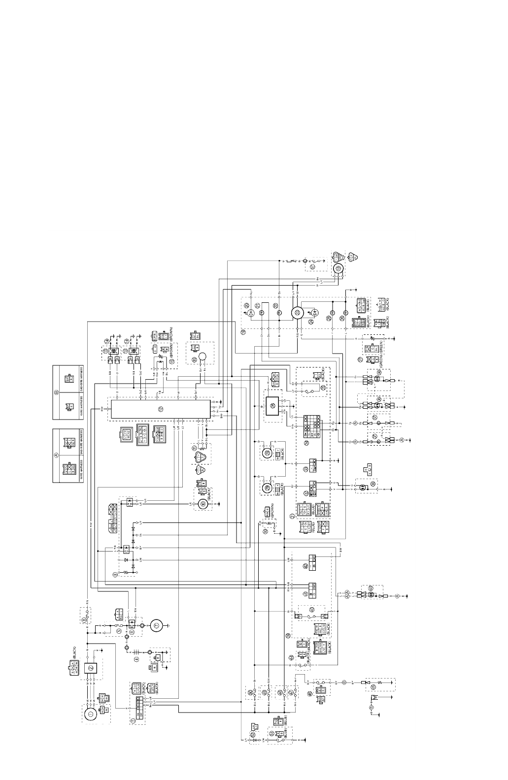
XV16AL/XV16ALC/XV16ATL/XV16ATLC WIRING DIAGRAM (For USA and CDN)
1Generator
2Rectifier/regulator
3Main switch
4Battery
5Main fuse
6Starter relay
7Starter motor
8Backup fuse
9Relay unit
0Fuel pump
AThrottle position sensor
BIgnitor unit
CIgnition coil
DSpark plug
EDecompression solenoid
FPickup coil
GNeutral switch
HSpeed sensor
IMeter assembly
JEngine trouble indicator light
KTurn signal indicator light
LNeutral indicator light
MSpeedometer assembly
(speedometer, combination
meter and fuel level meter)
NFuel level indicator light
OHigh beam indicator light
PMeter light
QFuel sender
RTurn signal relay
SHorn
TSolenoid
ULeft handlebar switch
VDimmer switch
WHorn switch
XTurn signal switch
YClutch switch
ZFront turn signal/position light
[Rear turn signal light
\Headlight
]Right handlebar switch
^Front brake light switch
aEngine stop switch
bStart switch
cTail/brake light
dRear brake light switch
eCarburetor heater
fThermo switch
gCarburetor heater fuse
hHeadlight fuse
iIgnition fuse
jSignaling system fuse
kSidestand switch
lDiode
COLOR CODE
B ........... black
Br .......... brown
Ch ......... chocolate
Dg ......... dark green
G ........... green
Gy ......... gray
L............ blue
Lg.......... light green
O ........... orange
P............ pink
R............ red
Sb ......... sky blue
W .......... white
Y............ yellow
B/L......... black/blue
B/R ........ black/red
B/W ....... black/white
B/Y ........ black/yellow
Br/B ....... brown/black
Br/L ....... brown/blue
Br/W ...... brown/white
Br/Y ....... brown/yellow
G/B ........ green/black
G/R ........ green/red
G/Y ........ green/yellow
L/B ......... blue/black
L/R ......... blue/red
L/W........ blue/white
L/Y ......... blue/yellow
R/B......... red/black
R/G ........red/green
R/W .......red/white
R/Y......... red/yellow
Y/B......... yellow/black
Y/R......... yellow/red

PRINTED IN U.S.A.
YAMAHA MOTOR CO., LTD.
2500 SHINGAI IWATA SHIZUOKA JAPAN
