Xometry 3D Printing Design Guide
User Manual:
Open the PDF directly: View PDF ![]() .
.
Page Count: 9
Design Guide: Preparing
a File for 3D Printing
VERSION 2.0

2
Technical Considerations....................................................................3
Preferred File Settings................................................................................3
STL File Resolution.......................................................................................4
Design Tips.............................................................................................5
Overlapping Geometry...............................................................................5
Minimum Thickness.....................................................................................5
Clearance Between Moving Parts.............................................................6
Conned Hollows.........................................................................................6
Fillets..............................................................................................................6
Lightweighting............................................................................................7
Build Volume..........................................................................................8
Resources at Xometry..........................................................................9
Table of Contents
3D PRINTING GUIDE V2.0
Preferred File Settings
STEP is our preferred CAD file format. Working with this
parametric format allows our team to be more inventive
creating support structures. However, we will work with
just about any CAD format, including native SolidWorks,
AutoCAD and PTC Creo (Pro/ENGINEER.)
STL is the standard file type for our 3D Printing software.
A mesh resolution of 0.01-0.03mm and a ≤0.016mm chord
length produce an optimal STL file. To change your mesh
resolution, while saving your file to STL, click on options
and choose the resolution to coarse or fine. Customize
the .stl output with manual changes to deviation & angle
to fine tune the resolution for your part.
Technical Considerations
3D PRINTING GUIDE V2.0
NOTE:
Keep in mind that higher resolution creates
larger files, and recommended settings are
given for a good mix of quality and file size.
3
4
3D PRINTING GUIDE V2.0 — TECHNICAL CONSIDERATIONS
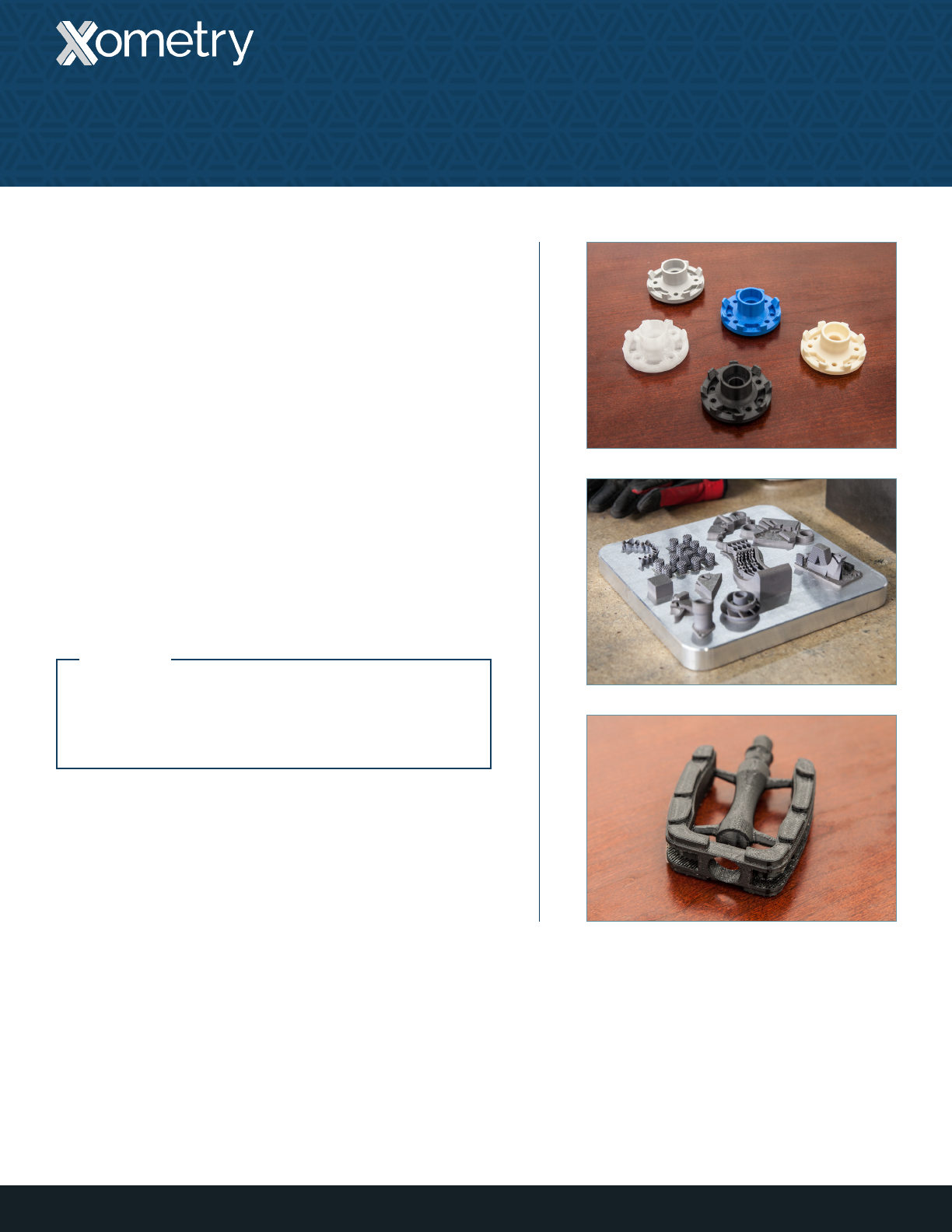
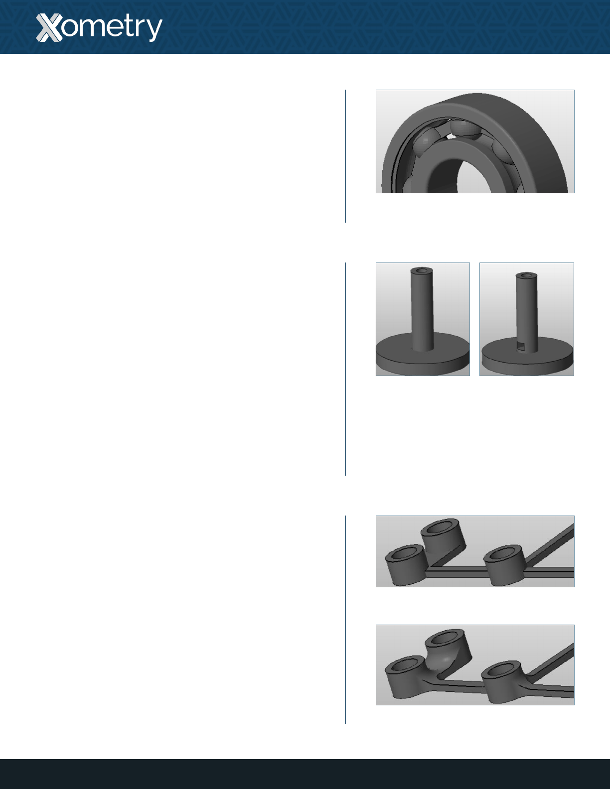
STL File Resolution
A mesh resolution of 0.01 to 0.03 mm generally produces
a good-quality STL file. Reducing mesh resolution below
this range does not necessarily mean that model accuracy
is improved. As a rule of thumb, designs that have many
contours or curved surfaces need a higher resolution than
flat, geometric surfaces.
To change mesh resolution while saving your file to STL,
click on options to set the resolution to be coarse or fine.
The STL file can also be customized with manual changes
to the deviation and angle. Keep in mind that higher
resolutions create larger files.
Low resolution
High resolution
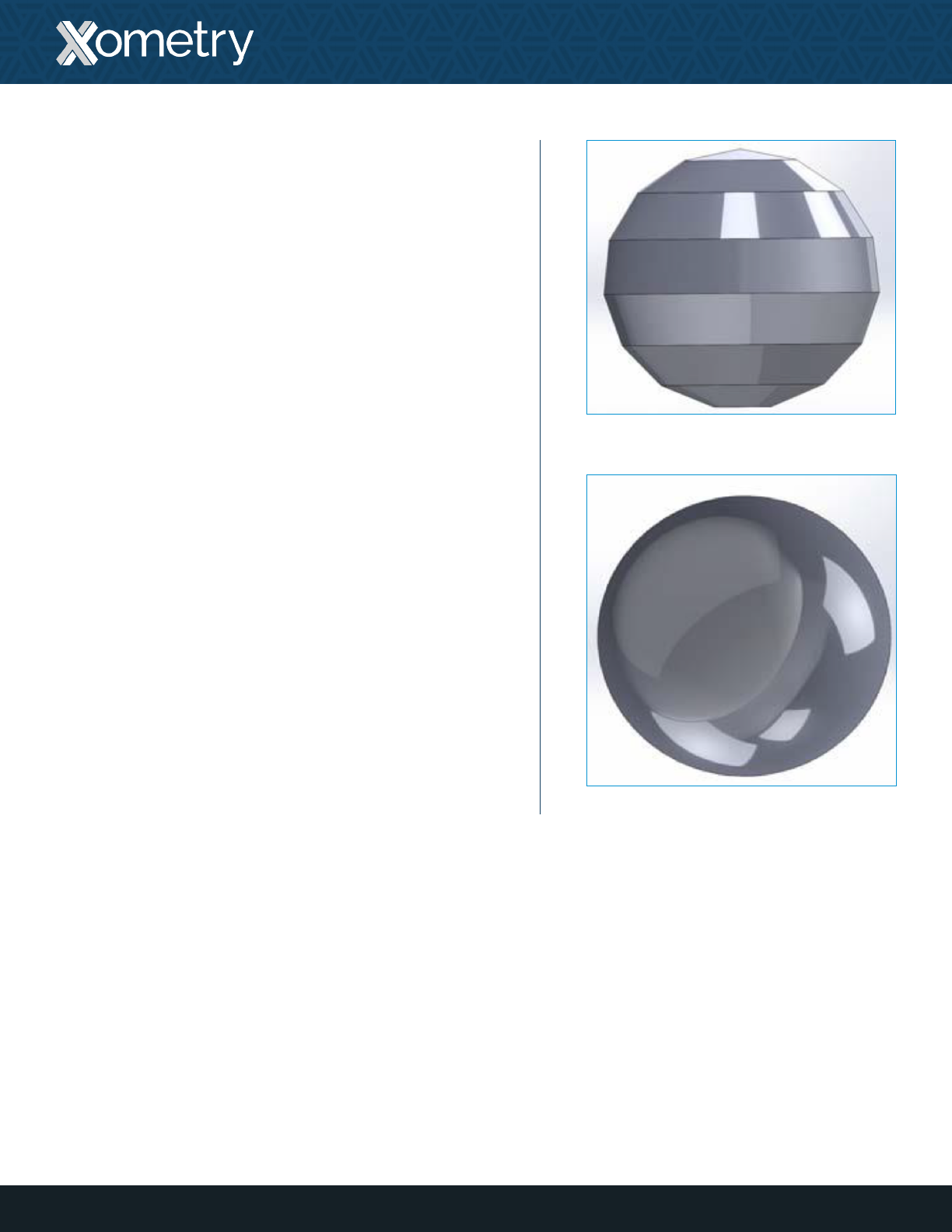
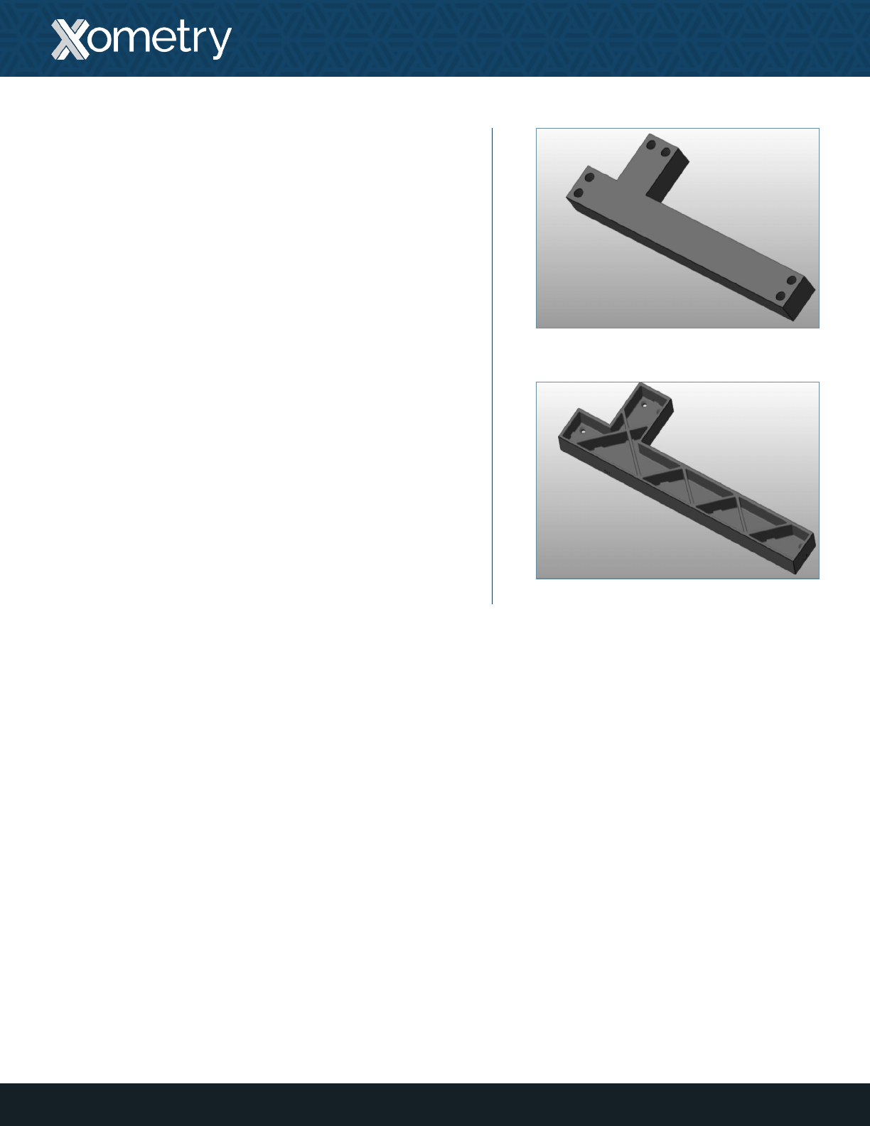
Overlapping Geometry
Overlapping geometry will sometimes cause problems,
being misinterpreted by printer software when being
converted into 2D layers. To ensure proper interpretation,
multiple bodies are always unified, merged or booleaned
together.
5
Design Tips
3D PRINTING GUIDE V2.0
Example of
overlapping geometry
Unied/merged
geometry
Cross section of model
at left demonstrates
intact data
Cross section of model
at left demonstrates
possibility of data loss
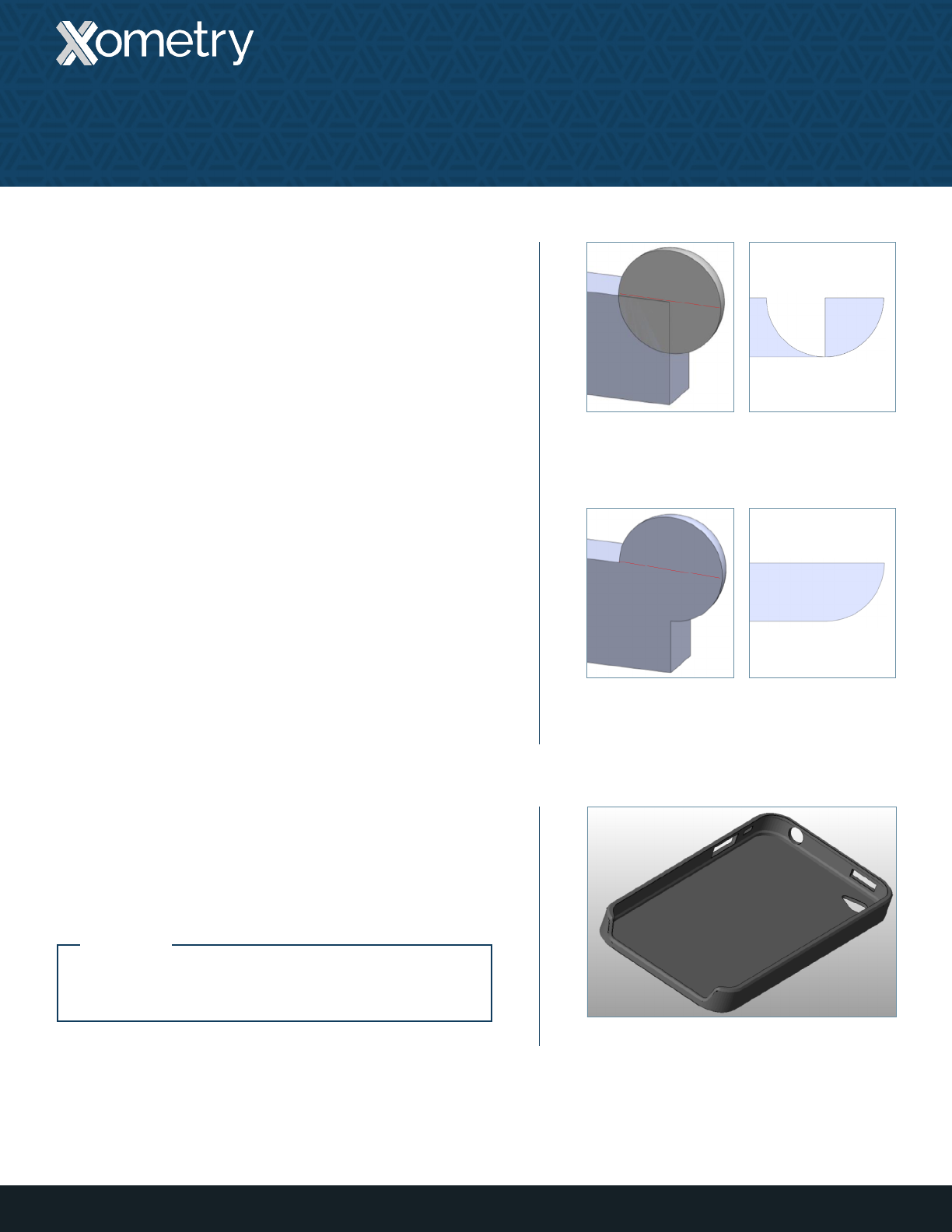
Minimum Thickness
It is recommended that the features of a design have a
minimum thickness of 0.6 mm [.024 in].
Example of a model design with thin features
NOTE:
Xometry recommends >1 mm [.039 in] for load-
bearing features.
Clearance Between
Moving Parts
A great feature of SLS and PolyJet 3D printing is the ability to
print all-in-one assemblies that feature moving parts.
For assemblies including moving parts, e.g. ne detail separation,
Xometry recommends a clearance of >0.5 mm [.02 in].
Conned Hollows
If a model design contains confined hollows, there
is no way to remove the support material. Xometry
recommends designing a model so that support material
can be removed. This is especially important when printing
moving parts and parts made from clear material.
Limiting cavities that are confined to one opening will
reduce cleaning time for support material, thus lowering
the price of the build.
Additionally, cavities having a depth of over 50.8 mm [2 in]
with only one access point are not recommended.
Fillets
Adding fillets (rounded edges) to a design will strengthen
unsupported surfaces and make parts more robust by
distributing stress over a broader area. While Xometry’s
PolyJet, SLS, and DMLS printers are capable of printing
90° corners, fillets are recommended to add strength to
any part. “Lollipop head” features, where a large mass
connects to a much smaller mass, are especially prone to
breaking, making them ideal candidates for fillets as well.
6
3D PRINTING GUIDE V2.0 — DESIGN TIPS
Example model design of an all-in-
one assembly with moving parts
Original model
Model with llets added
Original model Model with holes
added for removing
support material
7
3D PRINTING GUIDE V2.0 — DESIGN TIPS
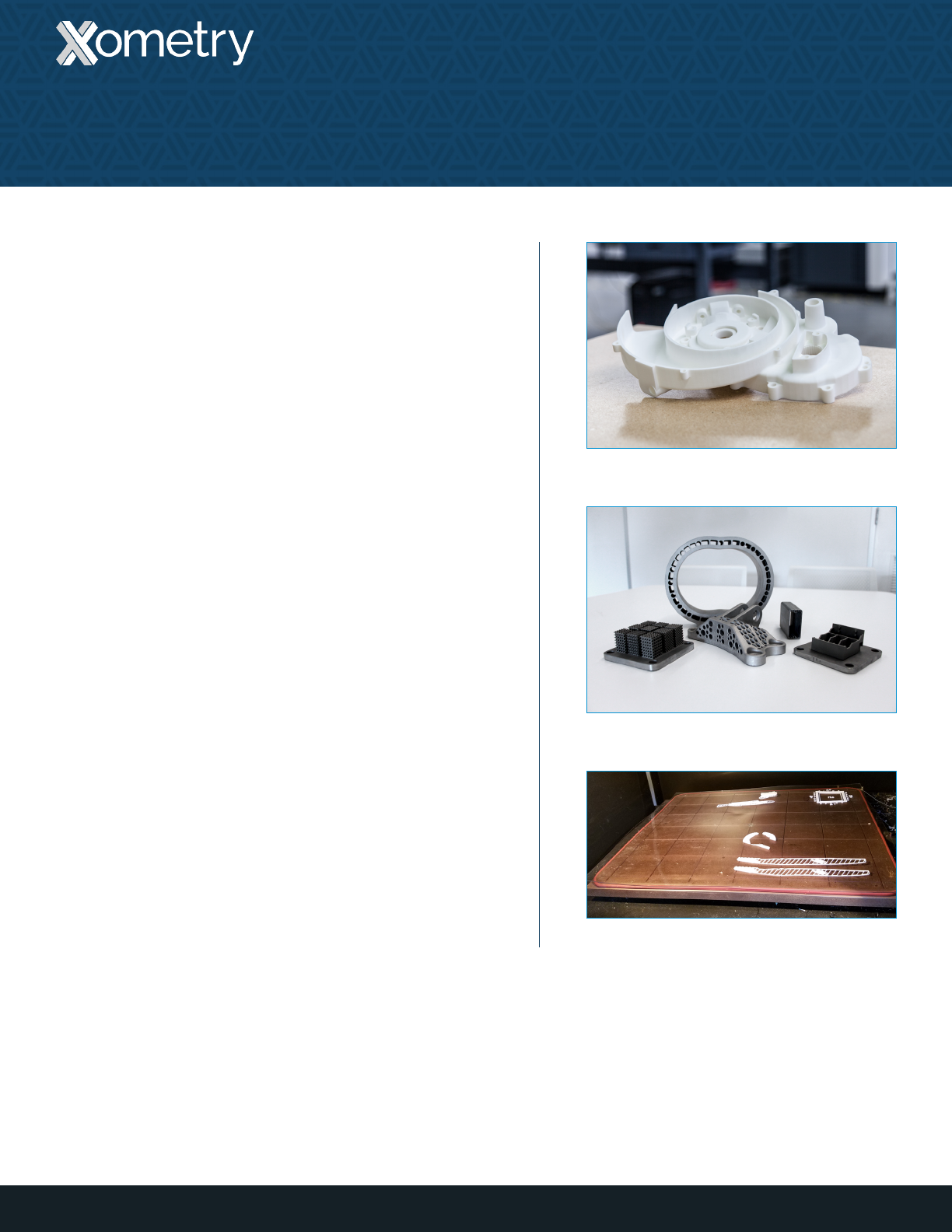
Original model
Model with lightweighting
Lightweighting
Creating pockets in designs will reduce print material and
making it more cost-effective to build. When creating a
pocket, be sure to create an exit hole for un-sintered (SLS
and DMLS) or support (PolyJet) material removal.
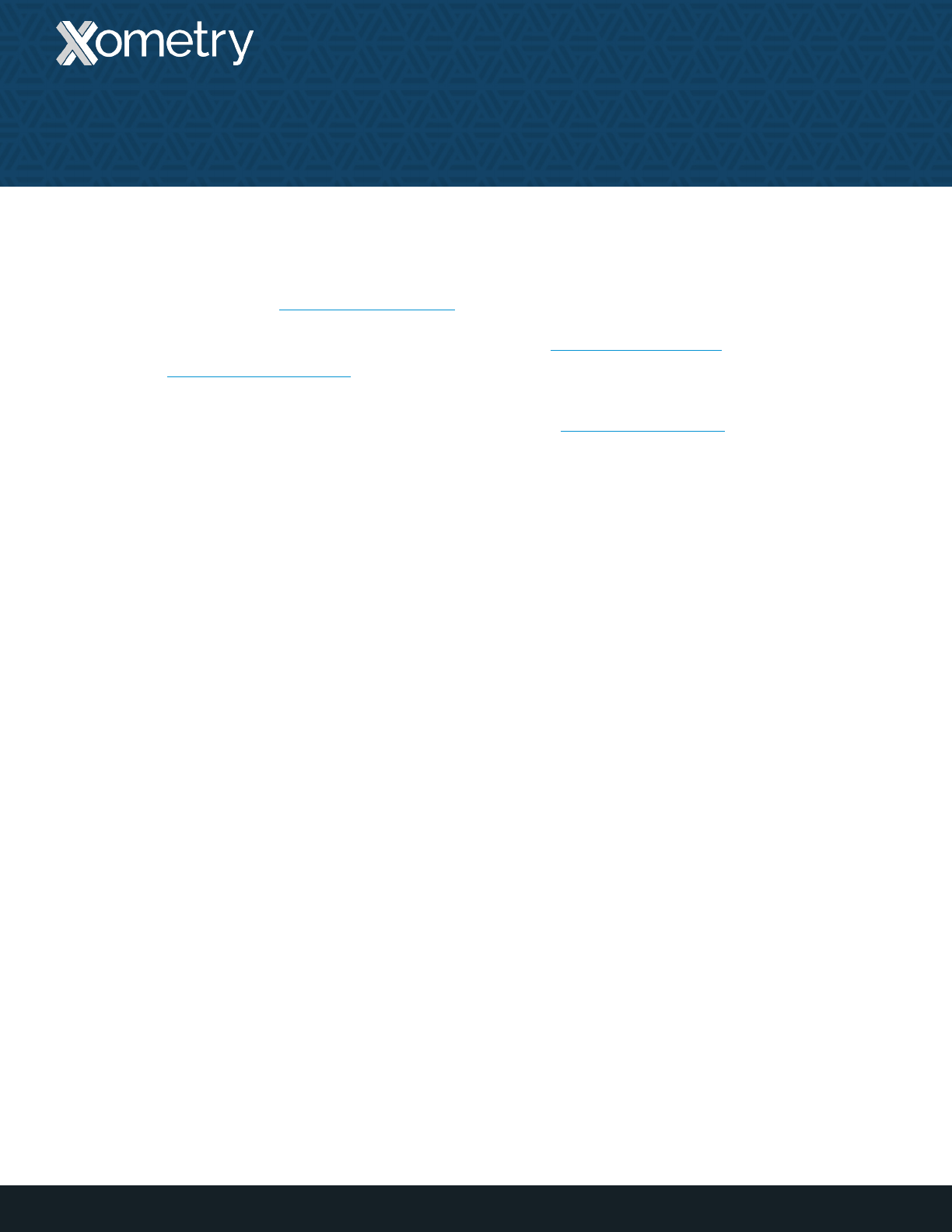
The maximum build volume of a part depends on the 3D
printing technology used:
• SLS: 13” x 13” x 20” (13” max dimension preferred)
• FDM: 24” x 36” x 36”
• PolyJet 3D: 19” x 15” x 7”
• DMLS (Aluminum): 6” x 6” x 6”
• DMLS (Stainless Steel): 9” x 6” x 6”
8
Build Volume
3D PRINTING GUIDE V2.0
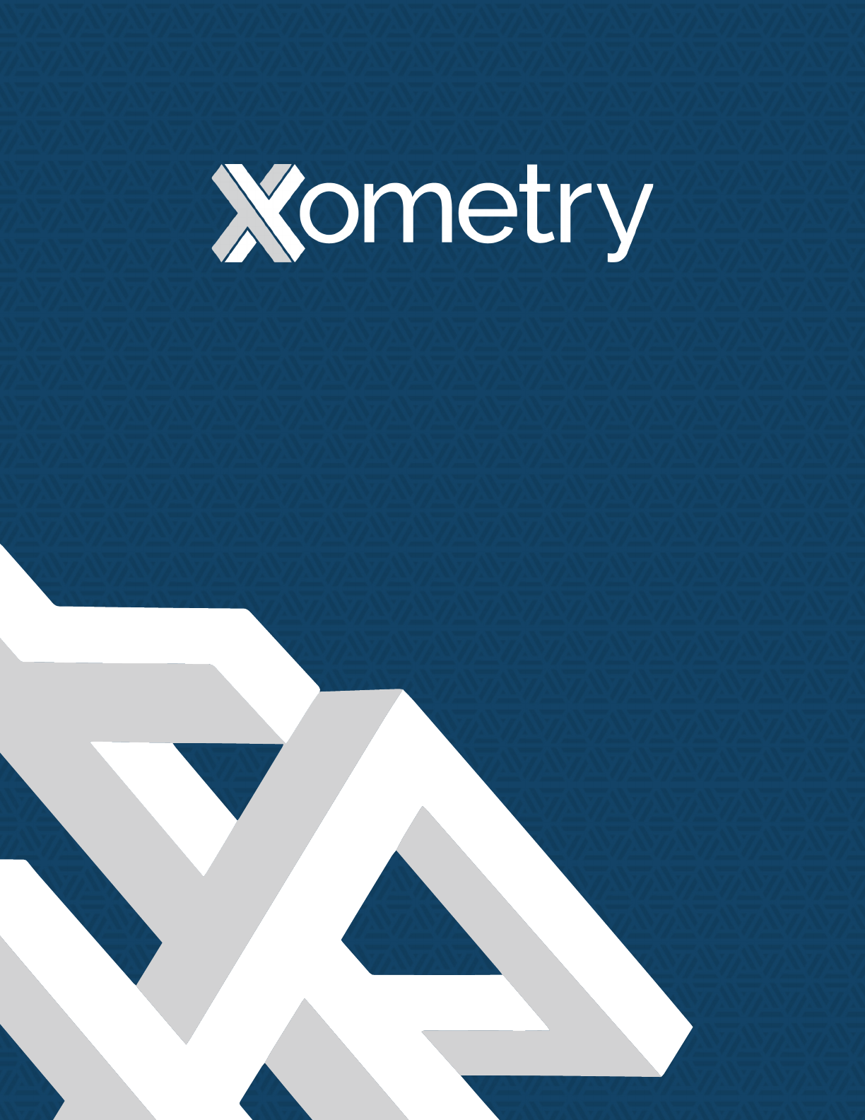
Part built with SLS
DMLS parts of various sizes
FDM parts in progress
9
Resources at Xometry
3D PRINTING GUIDE V2.0
Online Instant Quoting
Web: Upload your CAD file at get.xometry.com/quote
CAD: Download the free Xometry Add-In for
SOLIDWORKS: xometry.com/solidworks
Accepted File Types: .stl, .step, .stp, .x_t, .x_b,
.sldpart, .ipt, .prt, .sat, .catpart (max file size: 300MB)
Capabilities: CNC Machining, Sheet Metal Fabrication,
3D Printing, Urethane Casting, Injection Molding
Live Engineering Support
Hours: M-F 8:00 AM - 9:00 PM EST
Email: support@xometry.com
Phone: (240) 252-1138
Online: xometry.com/support offers live chat, FAQs,
and other helpful articles.
ITAR Registered
All uploads are secure and confidential. Contact us for assistance with large orders and existing
Xometry quotes.
Need to use a PO? We offer same day credit application processing. Contact us for details.
