Xometry Sheet Metal Design Guide
User Manual:
Open the PDF directly: View PDF ![]() .
.
Page Count: 12

Design Guide: Sheet
Metal Fabrication
VERSION 2.1

2
Overview.................................................................................................3
Tolerances..............................................................................................4
General Tolerances.....................................................................................4
Wall Thickness..............................................................................................5
Bends........................................................................................................5
Curls................................................................................................................6
Countersinks.................................................................................................6
Hems.....................................................................................................................7
Holes & Slots.................................................................................................8
Notches & Tabs............................................................................................9
Features...............................................................................................10
Corner Fillets..............................................................................................10
Relief Cuts...................................................................................................10
Finishes & Post-Processing...............................................................11
Resources at Xometry.......................................................................12
Table of Contents
SHEET METAL GUIDE V2.1
3
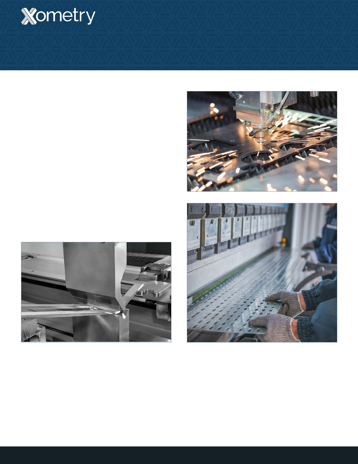
Sheet metal fabrication is the process of forming parts
from a metal sheet by punching, cutting, stamping, and/
or bending. 3D CAD les are converted into machine
code, which controls a machine to precisely cut and
form the sheets into the nal part. Sheet metal parts
are also known for their durability, which makes them
great for end-use applications (e.g. chassis). Parts used
for low volume prototypes, and high volume production
runs are most cost-eective due to large initial setup and
material costs.
Because parts are formed from a single sheet of metal,
designs must maintain a uniform thickness. Be sure to
follow design requirements and tolerances in this guide
to ensure parts fall closer to design intent.
Overview
SHEET METAL GUIDE V2.1
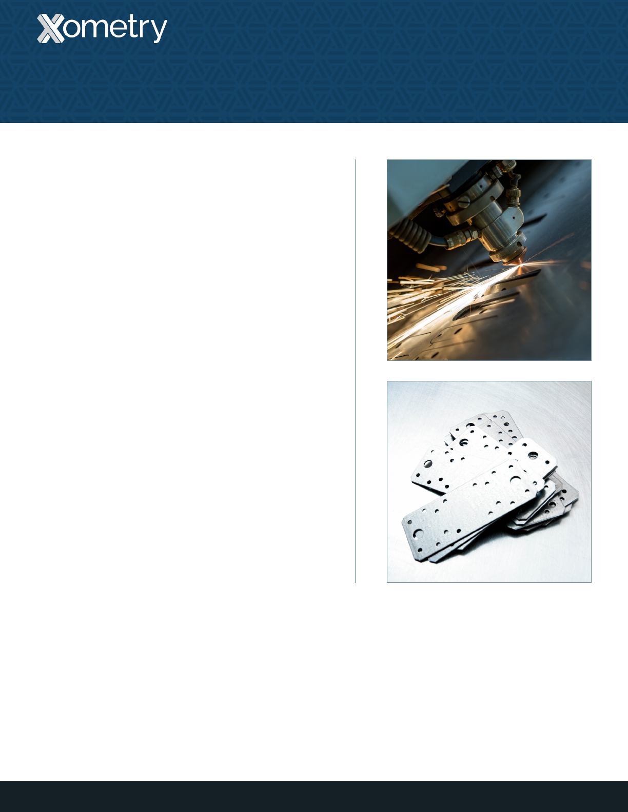
General Tolerances
If a drawing or specification sheet has not been provided
by the customer, Xometry will manufacture the product
from the model to the specifications listed below:
• Forming and bending: +/- 0.020”
• Bend to hole or feature: +/- 0.010”
• Linear dimensions excluding locations to bends: +/-
0.005”
• Diameters with inserts: +0.003/-0
• Angularity: +/- 2 degrees
• Surface roughness (blank material): Ra 125 uin max
• Surface roughness (timesave): Ra 100 uin max
4
Tolerances
SHEET METAL GUIDE V2.1
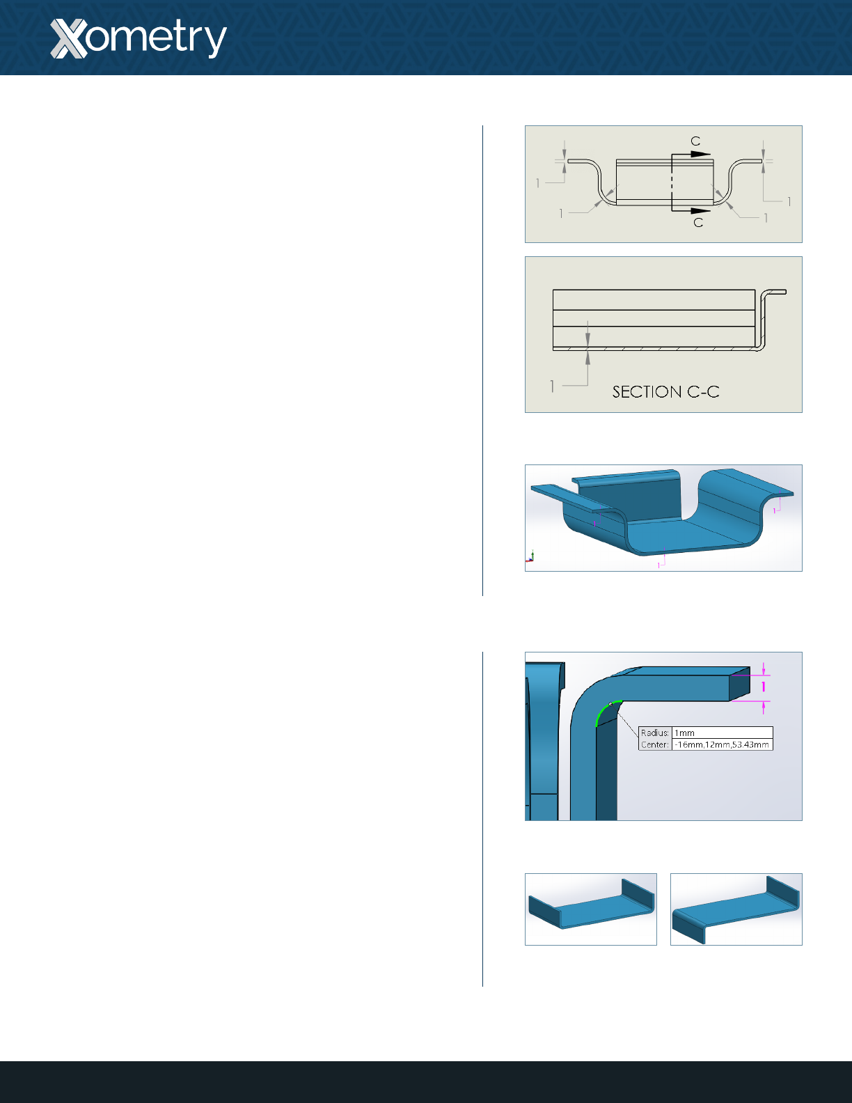
Wall Thickness
Parts must maintain a uniform wall thickness throughout
their entirety. Generally, Xometry is capable of
manufacturing sheet metal parts up to ¼” (6.35mm) in
thickness, but this tolerance mainly depends on the
geometry of the part.
When considering sheet metal thickness, a single sheet with
punches (holes) is a good rule of thumb. Some features,
such as countersinks are doable, but counterbores and
other machined features are difficult to produce as they
require post-machining.
Bends
Sheet metal brakes are used to bend material into a part’s
desired geometry. Bends in the same plane should be
designed in the same direction to avoid part reorientation,
which will save both money and time. Keeping a consistent
bend radius will also make parts more cost-effective. Small
bends to large, thick parts tend to become inaccurate, so
they should be avoided if possible.
DIMENSIONS
To prevent parts from fracturing or having distortions,
make sure to keep inside bend radius at least one
material’s thickness.
5
Drawing indicating uniform wall thickness
Model indicating uniform wall thickness
Inside bend radius
Consistent bend
orientations
Inconsistent bend
orientations
SHEET METAL GUIDE V2.1 — TOLERANCES

Curls
DIMENSIONS
Outside radius must be at least twice the material’s thickness.
CLEARANCES
Holes should be placed away from the curl at least a
distance of the radius of the curl plus the material’s
thickness. Bends should be at least 6 times the material’s
thickness plus the radius of the curl.
Countersinks
DIMENSIONS
The maximum depth a countersink may have is 3.5 times
the material’s thickness.
CLEARANCES
Countersinks must be at least 8 times the material
thickness from each other, 4 times the material’s thickness
from an edge, and 3 times the material’s thickness from a
bend.
6
Example of a curl
Example of a countersink
Center-to-center distance
Center-to-bend distance
SHEET METAL GUIDE V2.1 — TOLERANCES
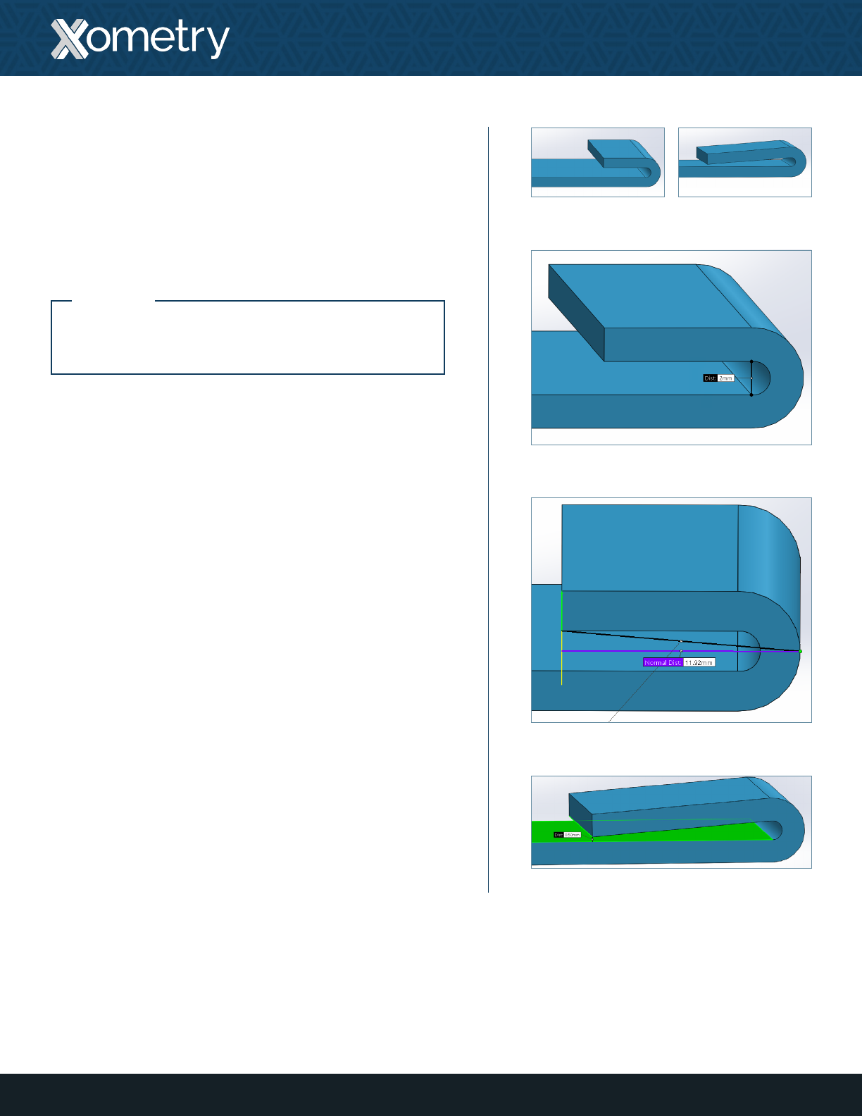
Hems
Hems are folds to the edge of a part to create a rounded,
safe edge. Hems may be open, flat, or tear-dropped, and
tolerances depend on the hem’s radius, material thickness,
and features near the hem.
DIMENSIONS
For open hems, minimum inside diameter is equal to the
material thickness (larger diameters tend to lose circular
shape), and the return length is at least 4 times the
material’s thickness. Tear-dropped hems must maintain
an inside diameter of at least one material’s thickness, an
opening of at least ¼ the material’s thickness, and return
length is also 4 times the material’s thickness.
7
Open hem inside diameter
Open hem return length
Tear-dropped hem opening distance
Open hem Tear-dropped hem
SHEET METAL GUIDE V2.1 — TOLERANCES
NOTE:
Flat hems risk fracturing the material at the
bend, and should be avoided if possible.
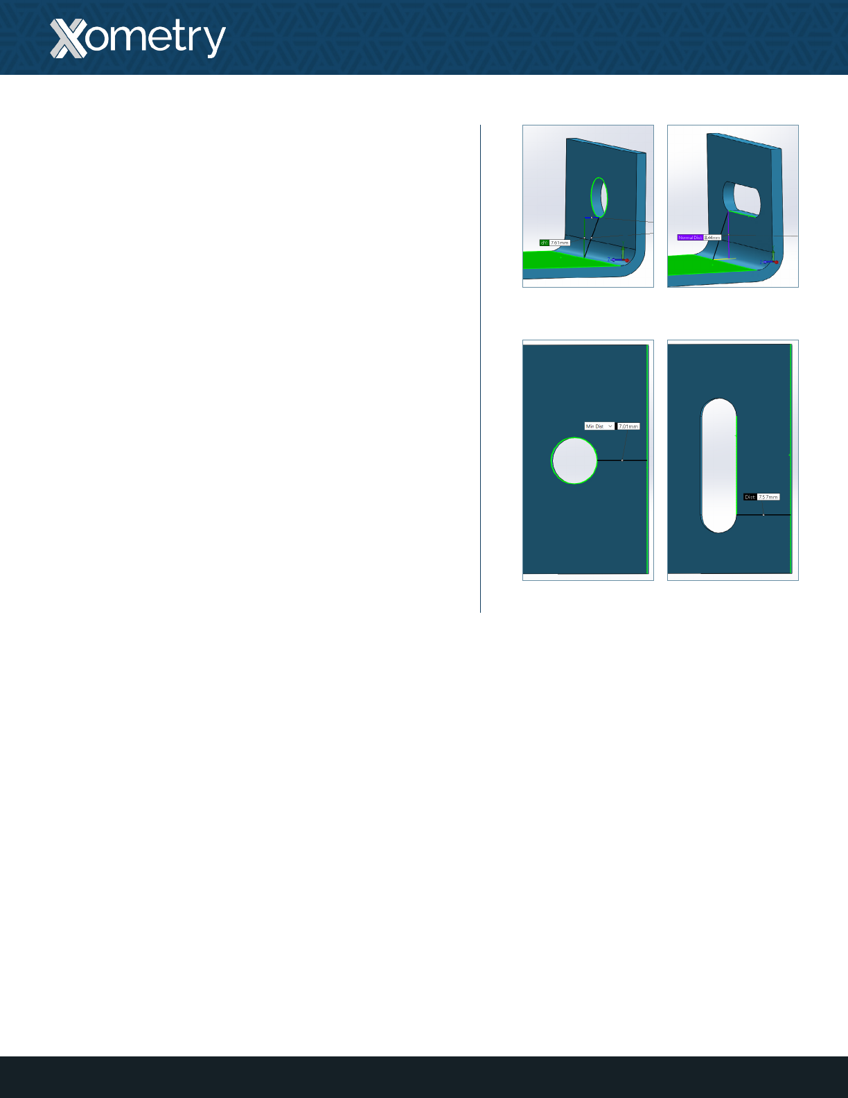
Holes & Slots
DIMENSIONS
Keep hole and slot diameters at least as large as material
thickness. Higher strength materials require larger diameters.
CLEARANCES
Holes and slots may become deformed when placed near
a bend. The minimum distance they should be placed
from a bend depends on the material thickness, the bend
radius, and their diameter. Be sure to place holes away
from bends at a distance of at least 2.5 times the material’s
thickness plus the bend radius. Slots should be placed 4
times the material’s thickness plus the bend radius away
from the bend.
Be sure to place holes and slots at least 2 times the material’s
thickness away from an edge to avoid a “bulging” eect.
Holes should be placed at least 6 times the material’s
thickness apart.
8
Hole-to-bend distance
Hole-to-edge distance
Slot-to-bend distance
Slot-to-edge distance
SHEET METAL GUIDE V2.1 — TOLERANCES
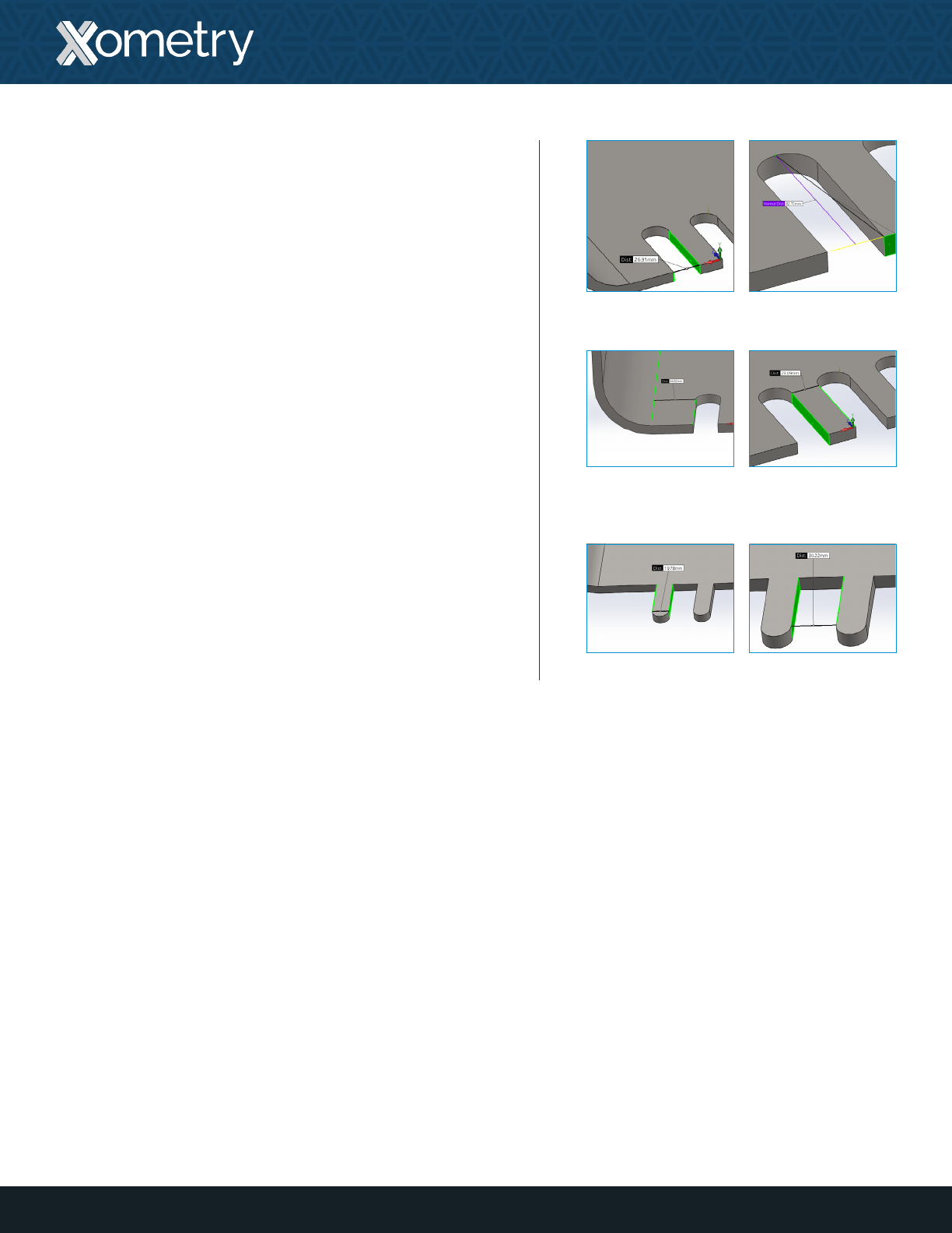
Notches & Tabs
DIMENSIONS
The minimum thickness a notch must maintain is at
least 0.04” (1mm) or the material’s thickness, whichever
is greater; the length must be no larger than 5 times its
width. Tabs must be at least 0.126” (3.2mm) thick, or two
times the material’s thickness, whichever is greater; the
length must also be no larger than 5 times its width.
CLEARANCES
Notches must be at least ⅛” (3.175mm) away from each
other. For bends, notches must be at least 3 times the
material’s thickness plus the bend radius. Tabs must have
a minimum distance from each other of 0.04” (1mm) or the
material’s thickness, whichever is greater.
9
Notch thickness
Notch-to-bend
distance
Tab thickness
Notch length
Notch-to-notch
distance
Tab-to-tab distance
SHEET METAL GUIDE V2.1 — TOLERANCES

Corner Fillets
Sheet metal parts may have sharp corners, but designing
a fillet of ½ the material’s thickness will make parts more
cost-effective.
Relief Cuts
Relief cuts help parts fall closer to design intent to avoid
“overhangs” and tearing at bends. Overhangs become
more prominent for thicker parts with a smaller bend
radius, and may even be as large as ½ the material’s
thickness. Tearing may occur when bends are made close
to an edge.
DIMENSIONS
Relief cuts for bends must be at least one material’s
thickness in width, and must be longer than the bend radius.
10
Features
SHEET METAL GUIDE V2.1
Corner llets
Bend relief to prevent tearing
Bend relief to prevent “bulging”

Xometry offers sheet metal parts in a wide array of
materials including:
• Aluminum
• Stainless steel
• Bronze/Brass
• Copper
• Steel
To further customize parts, Xometry offers post-processing
options to add to sheet metal parts such as:
• Bead Blasting
• Plating
• Welding
• Inserts
• Other custom finishes upon request
11
Finishes & Post-Processing
SHEET METAL GUIDE V2.1

12
Resources at Xometry
SHEET METAL GUIDE V2.1
Online Instant Quoting
Web: Upload your CAD file at get.xometry.com/quote
CAD: Download the free Xometry Add-In for
SOLIDWORKS: xometry.com/solidworks
Accepted File Types: .stl, .step, .stp, .x_t, .x_b,
.sldpart, .ipt, .prt, .sat, .catpart (max file size: 300MB)
Capabilities: CNC Machining, Sheet Metal Fabrication,
3D Printing, Urethane Casting, Injection Molding
Live Engineering Support
Hours: M-F 8:00 AM - 9:00 PM EST
Email: support@xometry.com
Phone: (240) 252-1138
Online: xometry.com/support offers live chat, FAQs,
and other helpful articles.
ITAR Registered
All uploads are secure and confidential. Contact us for assistance with large orders and existing
Xometry quotes.
Need to use a PO? We offer same day credit application processing. Contact us for details.
