YHJ70
User Manual: YHJ70
Open the PDF directly: View PDF ![]() .
.
Page Count: 188 [warning: Documents this large are best viewed by clicking the View PDF Link!]
PORTABLE DIGITAL AUDIO PLAYER
Basic Model : YH-J70
PORTABLE DIGITAL AUDIO PLAYER
- Confidential -
SERVICE Manual
Features
- Mass Storage Device Support
-
MP3, WMA, Audio ASF and Ogg Playback
- USB Host Function Support
- Video Playback Function
- Image & Text Viewer Function
- Direct MP3 Recording
- USB 2.0 High Speed Data Transfer
- SRS WOW Surround Sound
- 1.8-inch Color TFT LCD
- Various Games Support
- Built-in Rechargeable Li-ion Battery
- Playback Speed Control Function
- Upgradable
Model : YH-J70
* Application : YH-J70SB/SW[20GB]
YH-J70LB/LW[30GB]

ELECTRONICS
© Samsung Electronics Co.,Ltd. AUG. 2005
Printed in Korea
Code no. AH68-01654S
YH-J70SB/SW[20GB]
YH-J70LB/LW[30GB]

Ch1 Precautions
0. HDD SVC Repair Caution 1-1
1-1. Safety Precautions 1-2
1-2. Servicing Precautions 1-3
1-3. Precautions for Electrostatically
Sensitive Device (ESDs) 1-4
INDEX
Ch2 Product Descriptions
1. Product Feature 2-1
2. Specifications 2-2
3. Accessories 2-3
Ch3 Product Functions
1. Basic Functions 3-1
2. New Functions 3-3
3. PC Connection 3-6
Ch4 Adjustments
1.How to recover the device 4-1
Ch5 How to disassemble
How to disassemble 5-1
Ch6 Troubleshooting
1. It keeps being turned off 6-1
2. No Sound can be heard 6-2
3. Recording Failure (Line IN) 6-3
4. Recording Failure (Audio) 6-4
5. The buttons does not works 6-5
6. When you cannot connect the player to the PC 6-6
Ch7 Exploded View & Parts List
1. Total Exploded View 7-1
2. Parts List 7-2
Ch8 Electrical Parts List
Electrical Parts List 8-1
Ch9 Block Diagram
Block Diagram 9-1
Ch10 Wiring Diagram
Wiring Diagram 10-1
Ch11 PCB Diagram
1. MAIN 11-1
2. SUB 11-2
Ch12 Schematic Diagram
1. MAIN 12-1
2. SELF-TEST Manual 12-2
Ch13 Circuit Description
Circuit Board Description 13-1
Ch14 Basic Information of MP3
1. Operating Principle of yepp 14-1
2. MP3 Overview 14-5
3.
Understanding of Digital Audio Format
14-6
4. Type of Storage 14-9
5. Copyright 14-11
Copyright
Copyright
Fujitsu PC Corporation has made every effort to ensure
the accuracy and completeness of this document.
However, as ongoing development efforts are continually
improving the capabilities of our products, we cannot
guarantee the accuracy of the contents of this document.
We disclaim liability for errors, omissions, or future
changes.
Fujitsu, the Fujitsu logo, and LifeBook are registered
trademarks of Fujitsu Limited.
The following are registered trademarks of Microsoft
Corporation: MS, MS-DOS, Windows.
PCMCIA is a trademark of the Personal Computer
Memory Card International Association.
Intel and Pentium are registered trademarks and
SpeedStep is a trademark of Intel Corporation or its
subsidiaries in the United States and other countries.
Adobe Acrobat Reader is a registered trademark of
Adobe System Inc.
Earthlink is a registered trademark of EarthLink
Network, Inc.
Quicken is a registered trademark of Intuit, Inc.
Sony MiniDisk is a trademark of Sony Electronics, Inc.
Philips is a trademark of Koninklijke Philips
Electronics N.V.
WinDVD is a trademark of InterVideo, Inc.
Netscape 6 is a registered trademark of Netscape
Communications Corporation.
PowerQuest and Drive Image are registered trademarks
of PowerQuest Corp.
ATI and Radeon are registered trademarks of ATI
Te ch n o lo g i e s , In c .
McAfee is a registered trademark of Network Associates/
McAfee.com, Inc.
BayManager is a registered trademark of Softex, Inc.
The DVD player found in some models of the LifeBook
notebook incorporates copyright protection technology
that is protected by method claims of certain U.S.
patents and other intellectual property rights owned by
Macrovision Corporation and other rights users. Use of
this copyright protection technology must be autho-
rized by Macrovision Corporation, and is intended for
home and other limited viewing uses only unless autho-
rized by Macrovision Corporation. Reverse engineering
or disassembly is prohibited.
Dolby Headphone manufactured under license from
Dolby Laboratories. “Dolby”, “Pro Logic”, and the
double-D symbol are trademarks of Dolby Laboratories.
Confidential Unpublished works. Copyrights 1992-1999
Dolby Laboratories. All rights reserved.
All other trademarks mentioned herein are the property
of their respective owners.
© Copyright 2002 Fujitsu PC Corporation. All rights
reserved. No part of this publication may be copied,
reproduced, or translated, without prior written consent
of Fujitsu PC Corporation. No part of this publication
may be stored or transmitted in any electronic form
without the written consent of Fujitsu PC Corporation.
B5FH-5281-01EN-00
DECLARATION OF CONFORMITY
according to FCC Part 15
Responsible Party Name: Fujitsu PC Corporation
Address: 5200 Patrick Henry Drive
Santa Clara, CA 95054
Telephone: (408) 982-9500
Declares that product: Model Configurations:
LifeBook E7010
LifeBook E7110
Complies with Part 15 of the FCC Rules.
This device complies with Part 15 of the FCC rules. Operations are subject to the following two conditions: (1) This
device must not be allowed to cause harmful interference, (2) This device must accept any interference received,
including interference that may cause undesired operation.
B5FH-4491-01EN-00.book Page 1 Friday, April 19, 2002 11:24 AM

LifeBook E Series
B5FH-4491-01EN-00.book Page 2 Friday, April 19, 2002 11:24 AM

Table of Contents
Fujitsu LifeBook® E Series
Table of Contents
1
PREFACE
Preface
About This Guide . . . . . . . . . . . . . . . . . . . . . . . . .3
Fujitsu Contact Information . . . . . . . . . . . . . . . . .3
Warranty . . . . . . . . . . . . . . . . . . . . . . . . . . . . . . .3
2
GETTING TO KNOW YOUR
LIFEBOOK NOTEBOOK
Overview
Unpacking . . . . . . . . . . . . . . . . . . . . . . . . . . . . . .7
Locating the Controls
and Connectors
Top and Front Components . . . . . . . . . . . . . . . . .8
Left-Side Panel Components . . . . . . . . . . . . . . .10
Right-Side Panel Components . . . . . . . . . . . . . . 11
Back Panel Components. . . . . . . . . . . . . . . . . . .12
Bottom Components . . . . . . . . . . . . . . . . . . . . .13
Status Indicator Panel
Power Indicator . . . . . . . . . . . . . . . . . . . . . . . . .14
AC Adapter Indicator . . . . . . . . . . . . . . . . . . . . .14
Battery Level Indicators . . . . . . . . . . . . . . . . . . .14
Battery Charging Indicators . . . . . . . . . . . . . . . .15
Media Drive Access Indicator . . . . . . . . . . . . . . .15
Hard Drive or Removable
Media Drive Access Indicator . . . . . . . . . . . . 15
Floppy Disk Drive Access Indicator . . . . . . . . . . .15
PC Card Access Indicators . . . . . . . . . . . . . . . . .15
NumLk Indicator. . . . . . . . . . . . . . . . . . . . . . . . .15
CapsLock Indicator. . . . . . . . . . . . . . . . . . . . . . .16
ScrLk Indicator . . . . . . . . . . . . . . . . . . . . . . . . . .16
Security Indicator . . . . . . . . . . . . . . . . . . . . . . . .16
Keyboard
Using the Keyboard . . . . . . . . . . . . . . . . . . . . . .17
Numeric Keypad. . . . . . . . . . . . . . . . . . . . . . . . .17
Windows Keys . . . . . . . . . . . . . . . . . . . . . . . . . .17
Cursor Keys . . . . . . . . . . . . . . . . . . . . . . . . . . . .17
Function Keys. . . . . . . . . . . . . . . . . . . . . . . . . . .18
Wireless Infrared Mouse
Preparing Your IR Mouse for Use . . . . . . . . . . . .19
TouchPad Pointing Device
Clicking . . . . . . . . . . . . . . . . . . . . . . . . . . . . . . .21
Double-Clicking . . . . . . . . . . . . . . . . . . . . . . . . .21
Dragging . . . . . . . . . . . . . . . . . . . . . . . . . . . . . .22
TouchPad Control Adjustment . . . . . . . . . . . . . .22
Flexible Bay Devices
Removing and Installing Modular Devices . . . . .23
LifeBook Security/Application Panel
Setting up Your LifeBook Security Panel . . . . . . .26
Passwords . . . . . . . . . . . . . . . . . . . . . . . . . . . . .26
Operating Your LifeBook
Security Application Panel . . . . . . . . . . . . . . .27
Precautions. . . . . . . . . . . . . . . . . . . . . . . . . . . . .27
Uninstalling the Security Panel Application . . . . . 27
Launching Applications with
the Security/Application Panel . . . . . . . . . . .28
3
GETTING STARTED
Power Sources
Connecting the Power Adapters . . . . . . . . . . . . .33
Display Panel
Opening the Display Panel . . . . . . . . . . . . . . . . .34
Adjusting Display Panel Brightness . . . . . . . . . . .34
Closing the Display Panel . . . . . . . . . . . . . . . . . .34
B5FH-4491-01EN-00.book Page 5 Friday, April 19, 2002 11:24 AM

LifeBook E Series
Starting Your LifeBook Notebook
Power On . . . . . . . . . . . . . . . . . . . . . . . . . . . . . 35
Boot Sequence . . . . . . . . . . . . . . . . . . . . . . . . . . 35
BIOS Setup Utility . . . . . . . . . . . . . . . . . . . . . . . 35
Booting the System . . . . . . . . . . . . . . . . . . . . . . 36
Windows Product Activation
(Windows XP Only) . . . . . . . . . . . . . . . . . . . 36
Registering Your LifeBook Notebook . . . . . . . . . 37
Installing Click Me!. . . . . . . . . . . . . . . . . . . . . . . 37
Power Management
Power and Suspend/Resume Button . . . . . . . . . 38
Suspend Mode. . . . . . . . . . . . . . . . . . . . . . . . . . 38
Hibernation (Save-to-disk) Feature. . . . . . . . . . . 39
Display Timeout . . . . . . . . . . . . . . . . . . . . . . . . . 39
Hard Disk Timeout . . . . . . . . . . . . . . . . . . . . . . . 39
Windows 98 Second Edition
Power Management . . . . . . . . . . . . . . . . . . . 39
Restarting the System. . . . . . . . . . . . . . . . . . . . . 40
Power Off . . . . . . . . . . . . . . . . . . . . . . . . . . . . . 40
4
USER-INSTALLABLE FEATURES
Lithium ion Battery
Recharging the Batteries. . . . . . . . . . . . . . . . . . . 43
Replacing the Battery . . . . . . . . . . . . . . . . . . . . . 44
External USB Floppy Disk Drive
Loading a Disk . . . . . . . . . . . . . . . . . . . . . . . . . . 45
Ejecting a Disk . . . . . . . . . . . . . . . . . . . . . . . . . . 45
Preparing a Disk for Use. . . . . . . . . . . . . . . . . . . 45
Media Drive
Media Player Software . . . . . . . . . . . . . . . . . . . . 46
Loading a DVD, CD, CD-R,
CD-RW, or Combo (“Media”) . . . . . . . . . . . 46
Removing Media . . . . . . . . . . . . . . . . . . . . . . . . 47
Emergency DVD/CD-ROM Tray Release . . . . . . 47
Using the Media Player Software . . . . . . . . . . . . 47
Using Dolby Headphone . . . . . . . . . . . . . . . . . . 48
Using the Media Player on Battery Power . . . . . 48
Auto Insert Notification Function . . . . . . . . . . . . 49
Hard Disk Drive
Formatting the Hard Disk Drive . . . . . . . . . . . . . 50
PC Cards
Installing PC Cards. . . . . . . . . . . . . . . . . . . . . . . 51
Removing PC Cards . . . . . . . . . . . . . . . . . . . . . . 51
SmartCard Reader . . . . . . . . . . . . . . . . . . . . . . . 52
Memory Upgrade Module
Installing a Memory Upgrade Module . . . . . . . . 53
Removing a Memory Upgrade Module . . . . . . . 53
Checking the Computer Recognition
of New Memory Capacity . . . . . . . . . . . . . . 54
Device Ports
Communications Ports . . . . . . . . . . . . . . . . . . . . 55
LAN Port . . . . . . . . . . . . . . . . . . . . . . . . . . . . . . 55
IEEE 1394 Jack . . . . . . . . . . . . . . . . . . . . . . . . . . 55
Parallel Port . . . . . . . . . . . . . . . . . . . . . . . . . . . . 55
Serial Port . . . . . . . . . . . . . . . . . . . . . . . . . . . . . 55
PS/2 Port . . . . . . . . . . . . . . . . . . . . . . . . . . . . . . 55
Universal Serial Bus Ports . . . . . . . . . . . . . . . . . . 55
Infrared Port . . . . . . . . . . . . . . . . . . . . . . . . . . . 55
Wireless Infrared Mouse Port. . . . . . . . . . . . . . . 56
Microphone Jack . . . . . . . . . . . . . . . . . . . . . . . . 56
S-Video Out Port . . . . . . . . . . . . . . . . . . . . . . . . 56
Headphone/SPDIF Jack . . . . . . . . . . . . . . . . . . . 56
Docking Port . . . . . . . . . . . . . . . . . . . . . . . . . . . 57
External Monitor Port . . . . . . . . . . . . . . . . . . . . 57
5
TROUBLESHOOTING
Troubleshooting
Fujitsu Service Assistant . . . . . . . . . . . . . . . . . . . 61
Identifying the Problem . . . . . . . . . . . . . . . . . . . 61
Specific Problems . . . . . . . . . . . . . . . . . . . . . . . . 62
Troubleshooting Table . . . . . . . . . . . . . . . . . . . . 62
Power On Self Test Messages . . . . . . . . . . . . . . 70
Modem Result Codes. . . . . . . . . . . . . . . . . . . . . 71
Restoring Your Pre-installed Software
Drive Image Special Edition (DISE) . . . . . . . . . . . 72
Using DISE with Windows 2000/XP. . . . . . . . . . 72
Installing and Using DISE with Windows 98 . . . 73
B5FH-4491-01EN-00.book Page 6 Friday, April 19, 2002 11:24 AM

Table of Contents
6
CARE AND MAINTENANCE
Care and Maintenance
LifeBook Notebook. . . . . . . . . . . . . . . . . . . . . . .77
Batteries . . . . . . . . . . . . . . . . . . . . . . . . . . . . . . .78
Floppy Disks and Drives . . . . . . . . . . . . . . . . . . .78
DVDs and CDs . . . . . . . . . . . . . . . . . . . . . . . . . .78
PC Cards . . . . . . . . . . . . . . . . . . . . . . . . . . . . . .79
7
SPECIFICATIONS
Specifications
Configuration Label . . . . . . . . . . . . . . . . . . . . . . 83
Microprocessor. . . . . . . . . . . . . . . . . . . . . . . . . .83
Memory . . . . . . . . . . . . . . . . . . . . . . . . . . . . . . .83
Video . . . . . . . . . . . . . . . . . . . . . . . . . . . . . . . . .83
Audio . . . . . . . . . . . . . . . . . . . . . . . . . . . . . . . . .83
Mass Storage Device Options. . . . . . . . . . . . . . .83
Features . . . . . . . . . . . . . . . . . . . . . . . . . . . . . . .83
Device Ports . . . . . . . . . . . . . . . . . . . . . . . . . . . .84
Power. . . . . . . . . . . . . . . . . . . . . . . . . . . . . . . . .84
Dimensions. . . . . . . . . . . . . . . . . . . . . . . . . . . . .84
Environmental Requirements . . . . . . . . . . . . . . .84
Popular Accessories . . . . . . . . . . . . . . . . . . . . . .85
Pre-Installed Software . . . . . . . . . . . . . . . . . . . .86
CD-Based Software . . . . . . . . . . . . . . . . . . . . . .86
Application Descriptions . . . . . . . . . . . . . . . . . . .87
8
GLOSSARY
Glossary . . . . . . . . . . . . . . . . . . . . . . . . . . . . . . . 91
REGULATORY INFORMATION
Notice . . . . . . . . . . . . . . . . . . . . . . . . . . . . . . . .97
Appendix
INTEGRATED WIRELESS
LAN USER’S GUIDE
FCC Regulatory Information . . . . . . . . . . . . . .103
Before Using This Device . . . . . . . . . . . . . . . . .104
Connecting Windows 98/2000 Systems . . . . . .105
Network Connection: Windows 98. . . . . . . . . .106
Network Connection: Windows 2000. . . . . . . .108
Connecting Windows XP Systems . . . . . . . . . .111
Troubleshooting . . . . . . . . . . . . . . . . . . . . . . . .115
If a Second LAN Device is Installed . . . . . . . . . .121
About IP Addresses . . . . . . . . . . . . . . . . . . . . .121
Wireless LAN Specifications . . . . . . . . . . . . . . .122
B5FH-4491-01EN-00.book Page 7 Friday, April 19, 2002 11:24 AM

LifeBook E Series
B5FH-4491-01EN-00.book Page 8 Friday, April 19, 2002 11:24 AM

1
1
Preface
B5FH-4491-01EN-00.book Page 1 Friday, April 19, 2002 11:24 AM

2
LifeBook E Series - Section 1
B5FH-4491-01EN-00.book Page 2 Friday, April 19, 2002 11:24 AM
3
Preface
Preface
ABOUT THIS GUIDE
The LifeBook® E Series notebook from Fujitsu PC
Corporation is a powerful notebook computer. It is
powered by an Intel microprocessor, has a built-in color
display, a number of possible configurations, and brings
the computing power of desktop personal computers
(PCs) to a portable environment.
This manual explains how to operate your LifeBook
notebook’s hardware and built-in system software. Your
notebook is compatible with the IBM® PC AT.
It comes with Microsoft® Windows® 98 Second Edition,
Windows 2000 Professional, Windows XP Home
Edition, or Windows XP Professional pre-installed.
The LifeBook notebook is a completely self-contained
unit with either an active-matrix XGA or SXGA+ TFT
color LCD display. It has a powerful interface that
enables it to support a variety of optional features.
Conventions Used in the Guide
Keyboard keys appear in brackets.
Example: [Fn], [F1], [ESC], [ENTER] and [CTRL].
Pages with additional information about a specific topic
are cross-referenced within the text.
Example: (See page xx.)
On screen buttons or menu items appear in bold
Example: Click OK to restart your LifeBook notebook.
DOS commands you enter appear in Courier type.
Example: Shut down the computer?
FUJITSU CONTACT INFORMATION
Service and Support
You can contact Fujitsu Service and Support the
following ways:
■Toll free: 1-800-8Fujitsu (1-800-838-5487)
■Fax: 1-901-259-5700
■E-mail: 8fujitsu@fujitsupc.com
■Web site: http://www.fujitsupc.com
Before you place the call, you should have the
following information ready so that the customer
support representative can provide you with the
fastest possible solution:
■Product name
■Product configuration number
■Product serial number
■Purchase date
■Conditions under which the problem occurred
■Any error messages that have occurred
■Hardware configuration
■Type of device connected, if any
Fujitsu Online
You can go directly to the online Fujitsu Product catalog
for your LifeBook notebook by clicking on the LifeBook
Accessories Web site URL link, located in the Windows
Start menu.
You can also reach Fujitsu Service and Support online by
clicking on the Fujitsu Service and Support Web site
URL link, located in the Service and Support Software
folder of the Windows Start menu.
WARRANTY
Depending upon the configuration of your LifeBook
notebook, your system is backed by either a one-year or
three-year International Limited Warranty. Check the
information that came with your LifeBook notebook for
further warranty terms and conditions.
POINT
The point icon highlights information that will enhance
your understanding of the subject material.
CAUTION
The caution icon highlights information that is
important to the safe operation of your computer, or to
the integrity of your files. Please read all caution
information carefully.
WARNING
The warning icon highlights information that can be
hazardous to either you, your LifeBook notebook, or
your files. Please read all warning information carefully.
POINT
You must have an active internet connection to use the
on-line URL links.
B5FH-4491-01EN-00.book Page 3 Friday, April 19, 2002 11:24 AM

LifeBook E Series – Section 1
4
B5FH-4491-01EN-00.book Page 4 Friday, April 19, 2002 11:24 AM

5
2
Getting to Know
Your LifeBook Notebook
B5FH-4491-01EN-00.book Page 5 Friday, April 19, 2002 11:24 AM

6
LifeBook E Series – Section 2
B5FH-4491-01EN-00.book Page 6 Friday, April 19, 2002 11:24 AM
7
Getting to Know Your LifeBook
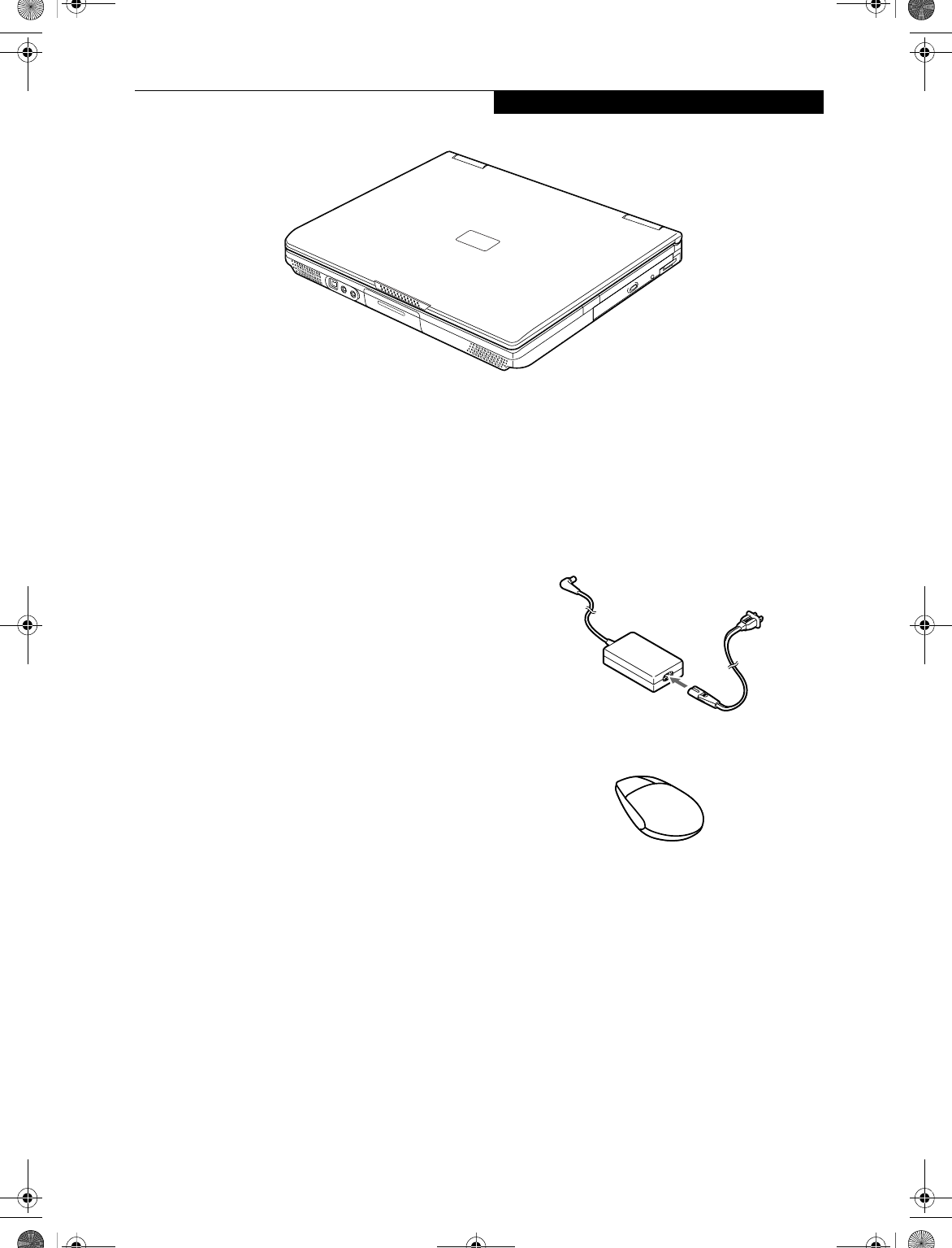
Figure 2-1. LifeBook E Series
Overview
This section describes the components of your Fujitsu
LifeBook notebook. We strongly recommend that you
read it before using your LifeBook notebook – even if
you are already familiar with notebook computers.
UNPACKING
When you receive your LifeBook notebook, unpack it
carefully, and compare the parts you have received with
the items listed below.
For a pre-configured model you should have:
■LifeBook E Series notebook computer (Figure 2-1)
■Lithium ion battery, pre-installed
■AC adapter with AC power cord (Figure 2-2)
■USB floppy disk drive
■Weight Saver
■Phone/Modem (RJ-11) telephone cable
■Drivers and Applications Restore CD
■Getting Started Guide
■User’s Guide (this guide)
■Fujitsu Service Assistant CD
■International Limited Warranty Brochure
■Microsoft-associated materials
■Premium Care registration card and envelope
Depending upon the configuration of your system, one
or more of the following items may also be included in
the box:
■Infrared (IR) Mouse (Figure 2-3)
■DVD Application CD
■CD-RW Application CD
■Additional battery(ies)
Figure 2-2. AC Adapter
Figure 2-3. Infrared Mouse
B5FH-4491-01EN-00.book Page 7 Friday, April 19, 2002 11:24 AM
8
LifeBook E Series – Section 2
Figure 2-4. LifeBook notebook with display open
Locating the Controls
and Connectors
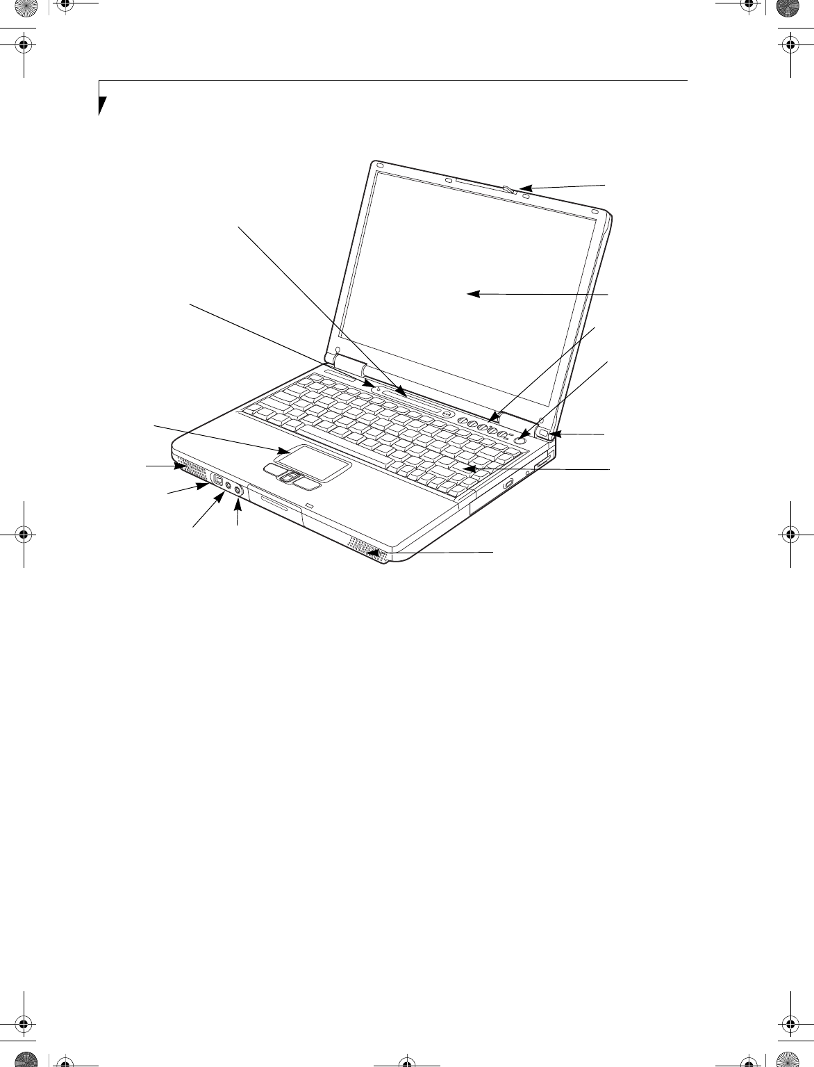
TOP AND FRONT COMPONENTS
The following is a brief description of your LifeBook
notebook’s top and front components.
Display Panel Latch
The display panel latch locks and releases the display
panel.
Display Panel
The display panel is a color LCD panel with back
lighting for the display of text and graphics.
Status Indicator Panel
The Status Indicator Panel displays symbols that
correspond with specific components of your LifeBook
notebook. (See Status Indicator Panel on page 14 for
more information)
Wireless IR Mouse Receiver
The Wireless IR Mouse Receiver allows you to use a
wireless IR Mouse.
Power and Suspend/Resume Button
The Power and Suspend/Resume button is always used
to Power On your LifeBook notebook from its Off state.
It is also used as the Suspend/Resume button. This
allows you to suspend notebook activity without
powering off, resume your notebook from suspend
mode, and power on your LifeBook notebook when it
has been shut down. (See Power On on page 35 for more
information) and (See Power and Suspend/Resume Button
on page 38 for more information)
Stereo Speakers
The built-in dual speakers allow for stereo sound.
Closed Cover Switch
The closed cover switch turns off the LCD backlighting
when the display panel is closed.
Display
Display Panel
Status
Power and
Stereo
Closed
Keyboard
LifeBook Security/
Headphone/ Microphone
Touchpad
Stereo Speaker
Wireless IR
Mouse Receiver
Suspend/
Panel Latch
Resume
Button
Indicator
Panel
Application Panel
Jack
SPDIF Jack
IEEE 1394
Jack
Cover
Switch
Pointing
Device
Speaker
B5FH-4491-01EN-00.book Page 8 Friday, April 19, 2002 11:24 AM

9
Getting to Know Your LifeBook
Keyboard
A full-size keyboard with dedicated Windows keys.
(See Using the Keyboard on page 17 for more information)
Touchpad Pointing Device
The pointing device is a Touchpad that allows you
simple cursor control. (See TouchPad Pointing Device on
page 21 for more information)
LifeBook Security/Application Panel
The LifeBook Security/Application Panel provides
hardware security and one-touch application launch
capability. (See LifeBook Security/ Application Panel on
page 26 for more information)
Microphone Jack
The microphone jack allows you to connect an external
mono microphone. (See Microphone Jack on page 56 for
more information)
Headphone/SPDIF Jack
The headphone/SPDIF jack allows you to connect head-
phones or powered external speakers. (See Headphone/
SPDIF Jack on page 56 for more information)
The SPDIF jack allows you to download digital audio
onto a MiniDisc recorder’s SPDIF (Sony Philips Digital
Interface) format. (See Optical Digital Audio-Out
Connector on page 49 for more information)
IEEE 1394 Jack
The 1394 jack is used to connect between your LifeBook
notebook and a peripheral device such as a digital video
camera. See “IEEE 1394 Jack” on page 55.
B5FH-4491-01EN-00.book Page 9 Friday, April 19, 2002 11:24 AM
10
LifeBook E Series – Section 2
Figure 2-5. LifeBook notebook left-side panel
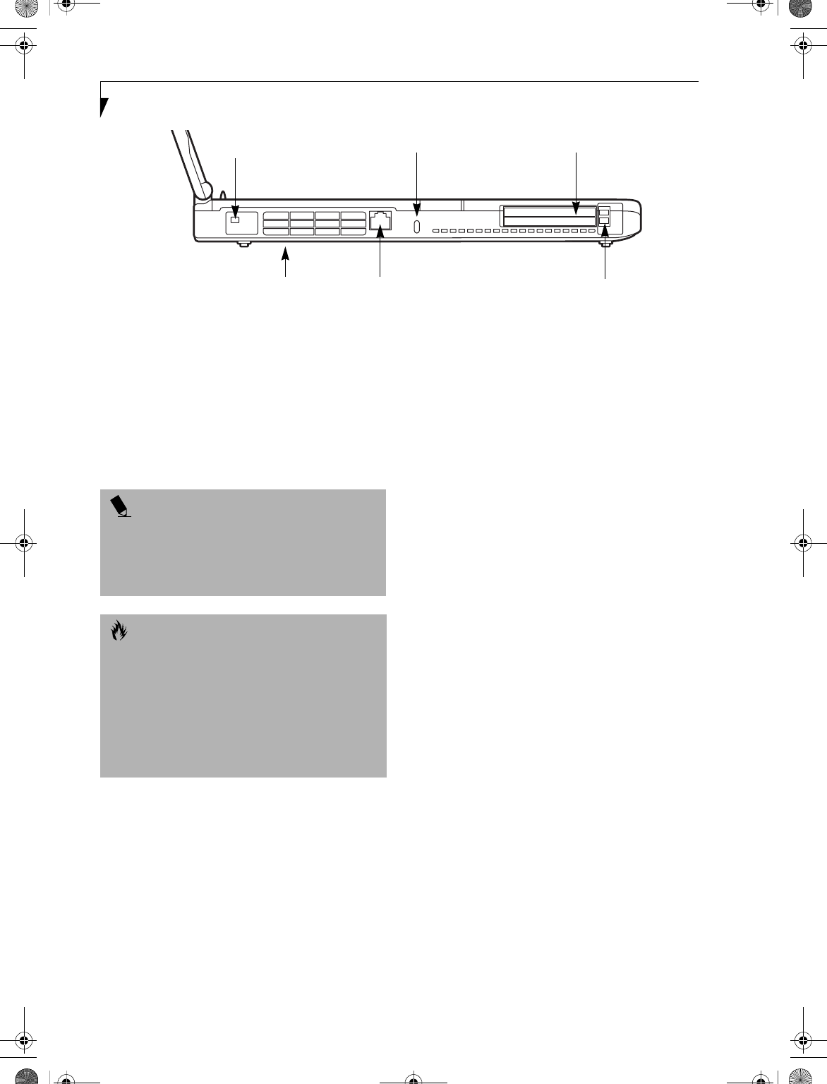
LEFT-SIDE PANEL COMPONENTS
Following is a brief description of your LifeBook note-
book’s left-side components.
Modem Port
The modem port is designed to accept a Modem (RJ-11)
telephone jack for the multi-national internal 56K
modem. (See Communications Ports on page 55 for more
information)
PC Card Slots
The PC Card Slots allow you to install two Type I or
Type II PC Cards or one Type III PC Card.
(See PC Cards on page 51 for more information)
Anti-theft Lock Slot
The anti-theft lock slot allows you to attach an optional
physical lock down device.
Fan Vents
The fan vents assist in the proper cooling of the system.
Wireless LAN On/Off Switch
(On wireless LAN models only)
The Wireless LAN On/Off Switch turns the wireless LAN
device on and off.
Modem Port
PC Card Slots
PC Card Eject Buttons
Anti-theft Lock Slot
Fan Vents
Wireless LAN with On/Off Switch
(Wireless LAN models only)
POINT
The internal modem is designed to the ITU-T V.90
standard. Its maximum speed of 53000bps is the
highest allowed by FCC, and its actual connection rate
depends on the line conditions. The maximum upload
speed is 33600bps.
CAUTION
The internal modem is not intended for use with Digital
PBX systems. Do not connect the internal modem to a
digital PBX as it may cause serious damage to the
internal modem or your entire LifeBook notebook.
Consult your PBX manufacturer’s documentation for
details. Some hotels have Digital PBX systems. Be sure
to find out BEFORE you connect your modem. Third-
party hardware is available to allow modem-to-PBX
interface.
B5FH-4491-01EN-00.book Page 10 Friday, April 19, 2002 11:24 AM
11
Getting to Know Your LifeBook
Figure 2-6. LifeBook notebook right-side panel
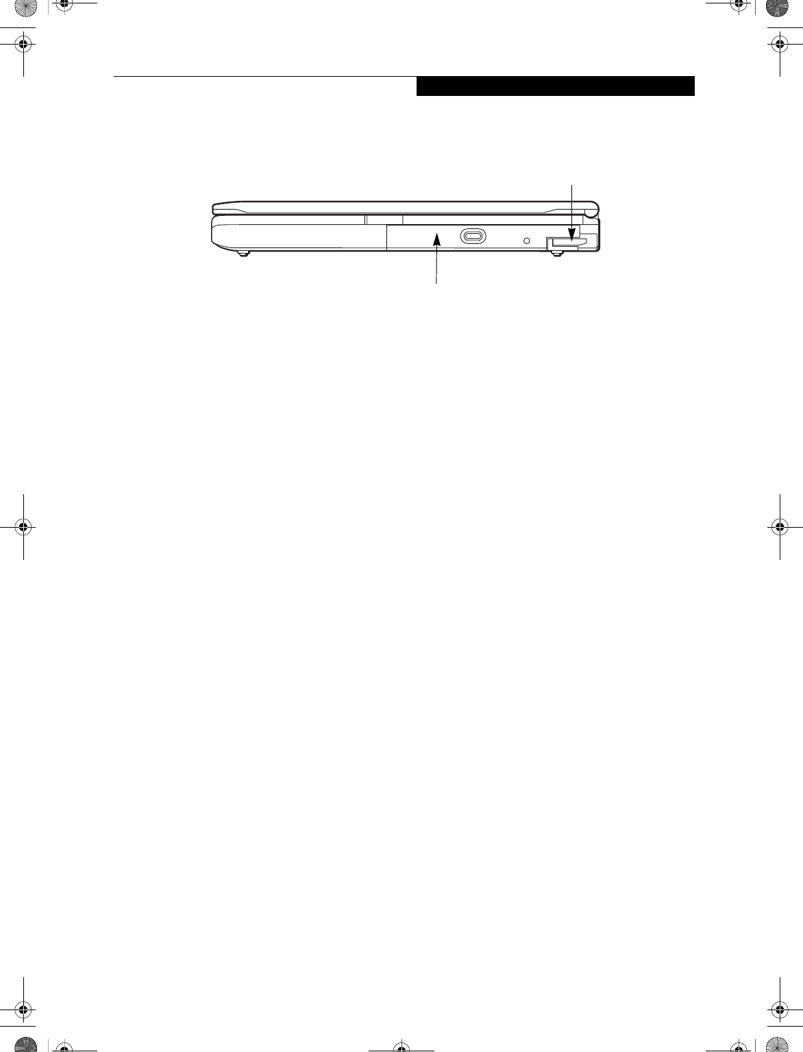
RIGHT-SIDE PANEL COMPONENTS
Following is a brief description of your LifeBook note-
book’s right-side components.
Flexible Bay
The Flexible Bay can accommodate one of the following
devices. (See Flexible Bay Devices on page 23 for more
information)
■Modular DVD/CD-RW combo drive
■Modular DVD drive
■Modular CD-ROM drive
■Modular Lithium ion bay battery
Flexible Bay Release Latch
The Flexible Bay release latch releases the Flexible Bay
device.
Flexible Bay Release Latch
Flexible Bay
B5FH-4491-01EN-00.book Page 11 Friday, April 19, 2002 11:24 AM
12
LifeBook E Series – Section 2
Figure 2-7. LifeBook notebook back panel
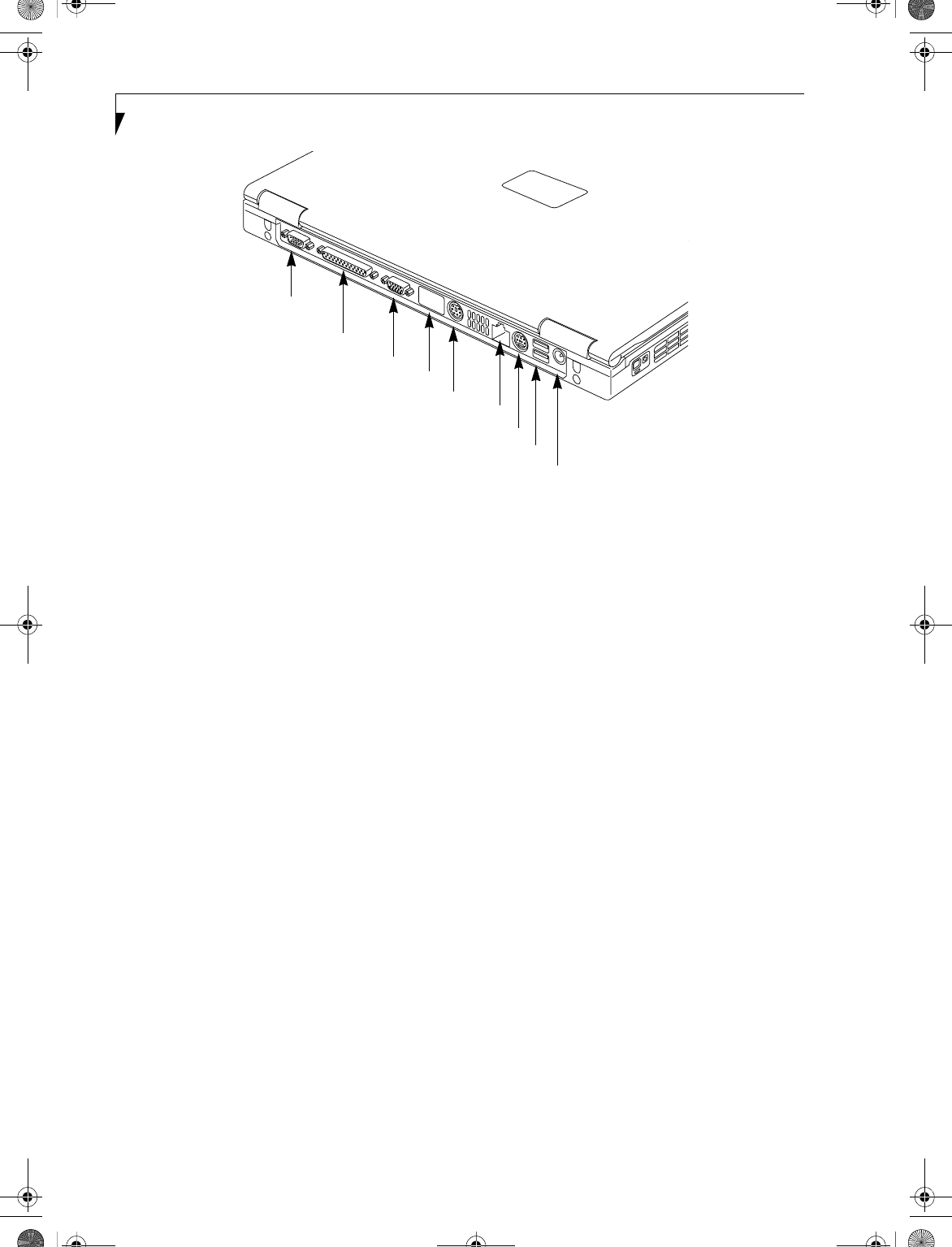
BACK PANEL COMPONENTS
Following is a brief description of your LifeBook note-
book’s rear panel components.
Serial Port
The serial port allows you to connect serial (RS-232C)
devices. (This is also sometimes referred to as a COMM
port.) (See Serial Port on page 55 for more information)
Parallel Port
The parallel port allows you to connect parallel
devices. (This is also sometimes referred to as an
LPT port.) (See Parallel Port on page 55 for more informa-
tion)
External Monitor Port
The external monitor port allows you to connect an
external monitor. (See External Monitor Port on page 57
for more information)
Infrared Port
The fast IrDA compatible port allows you to communi-
cate with another IrDA compatible infrared device
without a cable.
PS/2 Port
The PS/2 port allows you to connect an external PS/2
keyboard, mouse or numeric keypad. (See PS/2 Port on
page 55 for more information)
LAN Port
The LAN port is designed to accept a Local Area
Network (LAN) RJ-45 jack. (See Communications Ports
on page 55 for more information)
S-Video Out Port
The S-Video out port is used to transmit a higher
resolution video signal to a compatible TV or VCR.
(See S-Video Out Port on page 56 for more information)
USB Ports
The USB ports allow you to connect Universal Serial Bus
devices. (See Universal Serial Bus Ports on page 55 for
more information)
DC Power Jack
The DC power jack allows you to plug in the AC adapter
or the optional Auto/Airline adapter to power your Life-
Book notebook and charge the internal Lithium ion
battery.
PS/2 Port
Serial Port
Parallel Port
External Monitor Port
USB Ports
DC Power Jack
S-Video Out Port
LAN Port
Infrared Port
B5FH-4491-01EN-00.book Page 12 Friday, April 19, 2002 11:24 AM
13
Getting to Know Your LifeBook
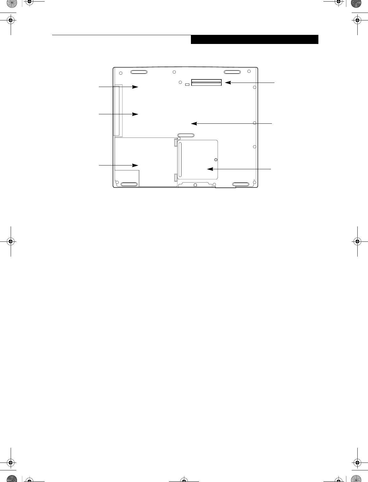
Figure 2-8. LifeBook notebook bottom panel
BOTTOM COMPONENTS
Following is a brief description of your LifeBook note-
book’s bottom panel components.
Configuration Label and Version Label
The configuration label shows the configuration part
number, the Fujitsu part number, and the various
components that make up your LifeBook notebook. The
version label contains the system part number and serial
number. These labels provide manufacturer information
that you will need to give your support representative in
the event you find it necessary to contact Fujitsu.
Lithium ion Battery Bay
The battery bay contains the internal Lithium ion
battery. It can be opened for the removal of the battery
when stored over a long period of time or for swapping
a discharged battery with a charged Lithium ion battery.
(See Lithium ion Battery on page 43 for more informa-
tion)
Docking Port
The docking port allows you to connect an optional port
replicator or docking station. (See Docking Port on
page 57 for more information)
Memory Upgrade Compartment
Your LifeBook notebook comes with high speed PC2100
DDR266 SO-DIMM memory. The memory upgrade
compartment allows you to expand the system memory
capacity of your LifeBook notebook, hence improving
overall performance. (See Memory Upgrade Module on
page 53 for more information)
Memory Upgrade
Compartment
Lithium ion
Battery Bay
Certificate of
Authencity
(approximate
location)
Part Number
Label
(approximate
location)
Main Unit
Label
(approximate
location)
Docking
Port
B5FH-4491-01EN-00.book Page 13 Friday, April 19, 2002 11:24 AM
14
LifeBook E Series – Section 2
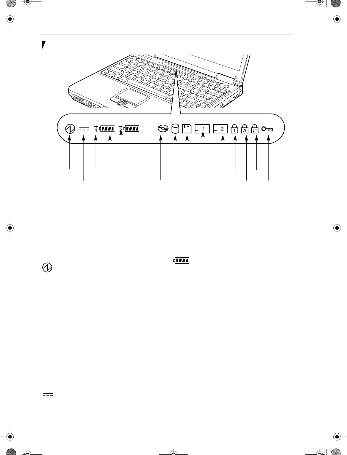
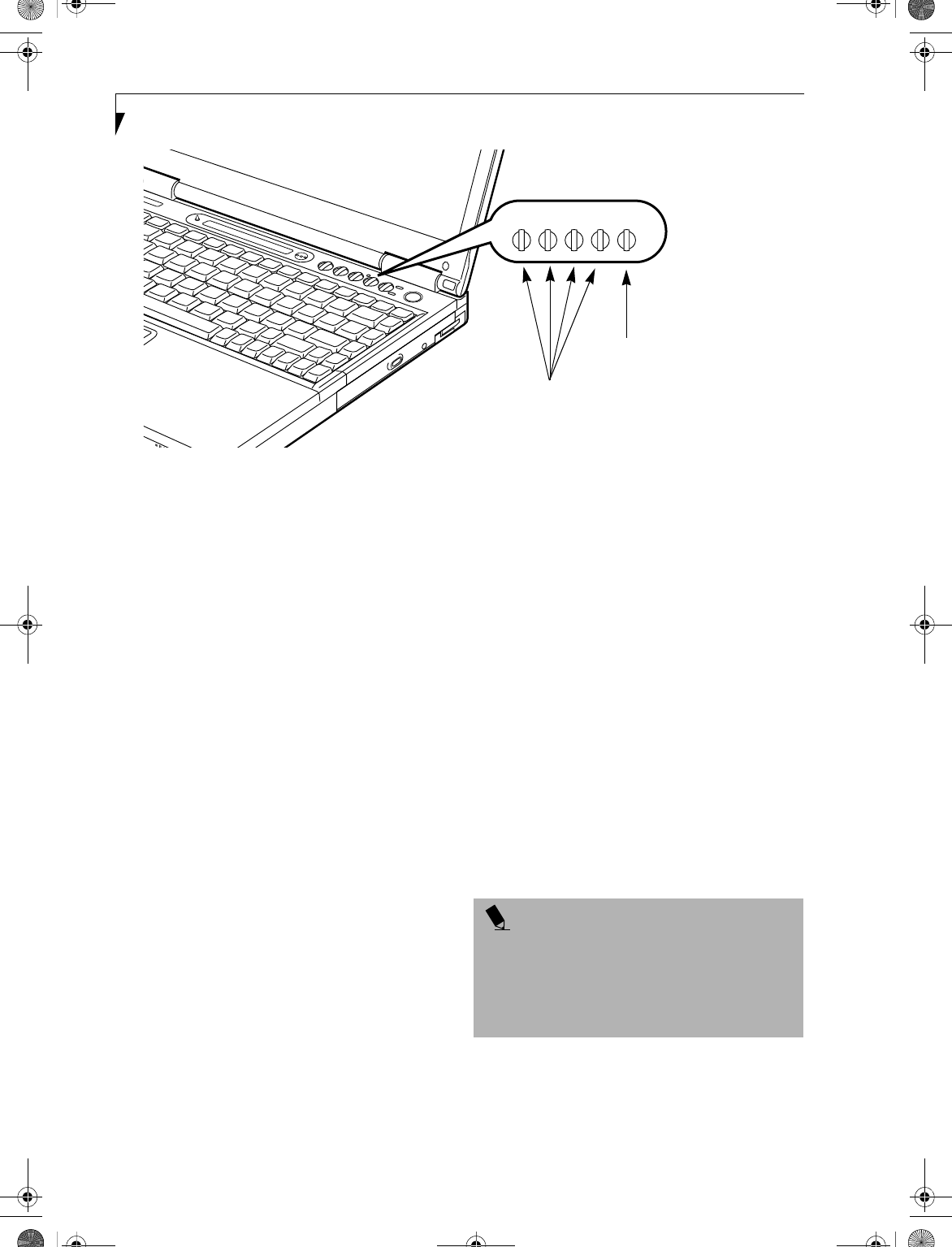
Figure 2-9 Status Indicator Panel
Status Indicator Panel
The Status Indicator panel is located in the recess just
above your keyboard. Within this panel are symbols that
correspond with a specific component of your LifeBook
notebook. These symbols tell you how each of those
components are operating. (Figure 2-9)
POWER INDICATOR
The Power indicator symbol states whether your system
is operational. It has several different states, each of
which tells you what mode your LifeBook notebook is in
at that time.
■Steady On: This means that there is power to your
LifeBook notebook and that it is ready for use.
■Flashing: This means that your LifeBook notebook is
in Suspend mode.
■Steady Off: This means that your system is either in
Save-to-Disk mode, or that your LifeBook notebook
has been turned off with the power switch.
If you are charging your battery, the Power indicator
symbol remains on even if your notebook is shut off.
The Power indicator symbol will also remain on if you
have either adapter connected and are shut down from
Windows, but have not turned off the power switch.
AC ADAPTER INDICATOR
The AC Adapter indicator states whether your LifeBook
notebook is operating from the AC adapter, the Auto/
Airline adapter or the batteries. This icon has two
different states that can tell you what power source your
LifeBook notebook is using.
■On: This means that either of the adapters are
currently in use.
■Off: Power is only coming from the batteries, and
you do not have an adapter connected.
BATTERY LEVEL INDICATORS
The two Battery Level indicators state whether or not the
primary Lithium ion battery and/or the optional second
Lithium ion battery are installed (Battery 1 refers to the
primary Lithium ion battery, while Battery 2 refers to the
Flexible Bay optional second battery). In addition, this
symbol states how much charge is available within each
installed battery. The symbol will only be displayed for a
battery that is currently installed in your LifeBook note-
book. (Figure 2-10)
Power
AC Adapter Battery
Battery
Identifier
Level
Media Drive
Access
Hard Drive
Access
Floppy Disk
Drive Access
Battery
Charging PC Card
Slot Identifier
PC Card
Access
NumLk
CapsLk
ScrLk
Security
Indicator
B5FH-4491-01EN-00.book Page 14 Friday, April 19, 2002 11:24 AM
15
Getting to Know Your LifeBook
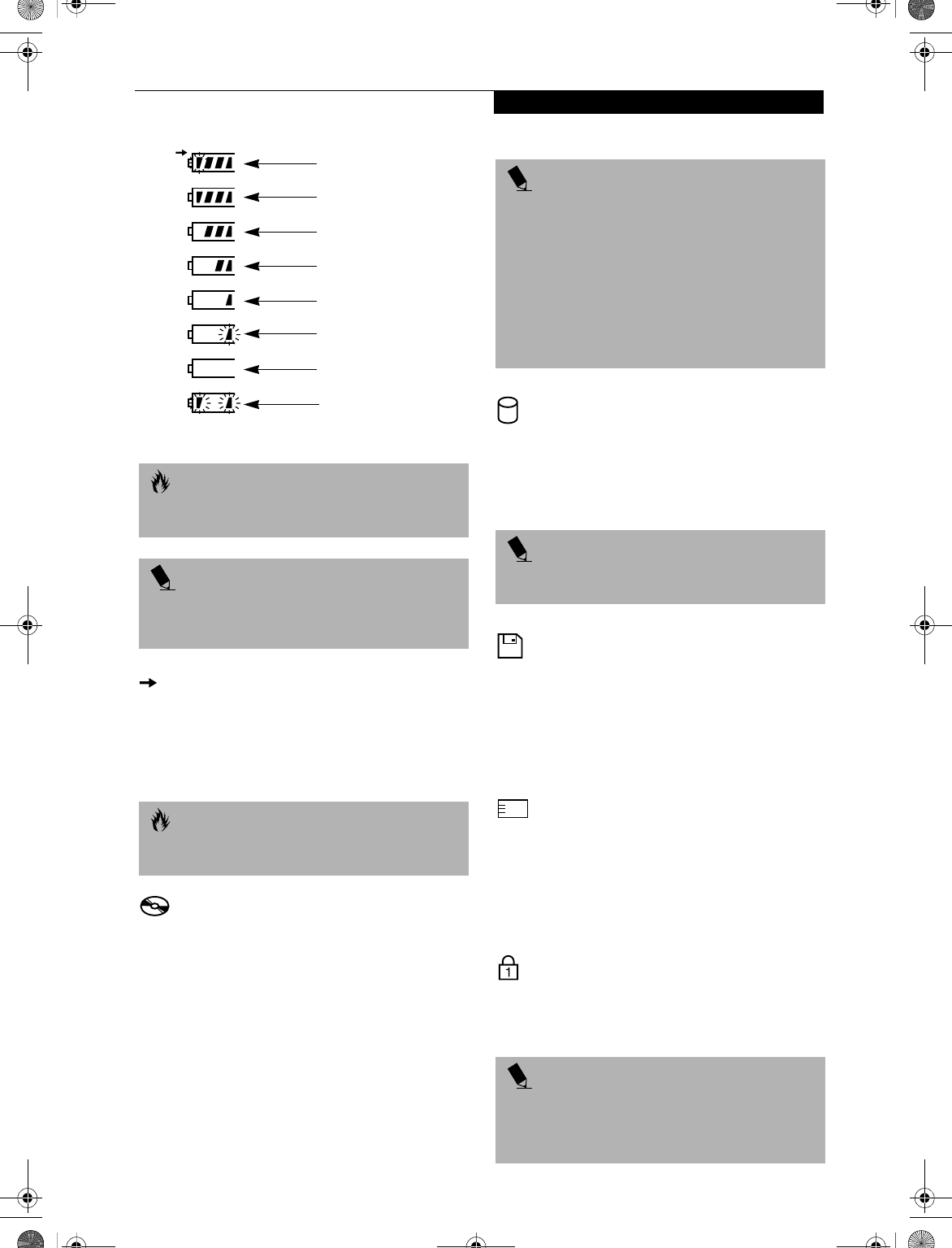
Figure 2-10 Battery Level Indicator
BATTERY CHARGING INDICATORS
Located to the left of each of the Battery Level indicators
is a small arrow symbol. This symbol states whether that
specific battery is charging. This indicator operates
whether the power switch is in the On or Off position,
and will flash if the battery is too hot or cold to charge.
MEDIA DRIVE ACCESS INDICATOR
The Media Drive Access indicator tells you that the DVD
or CD-RW drive is being accessed. If the Auto Insert
function is active, the indicator will flash periodically
when your system is checking the DVD or CD-RW
drive. If the Auto Insert Notification function is not
active, the indicator will only flash when you access the
DVD or CD-RW drive. The default setting is the Auto
Insert Notification function active. (See Auto Insert Noti-
fication Function on page 49 for more information)
HARD DRIVE OR REMOVABLE
MEDIA DRIVE ACCESS INDICATOR
The Hard Drive Access indicator states whether your
internal hard drive or optional second hard drive is
being accessed.
FLOPPY DISK DRIVE
ACCESS INDICATOR
The Floppy Disk Drive Access indicator states whether
the floppy disk drive is being accessed. This indicator
will flash if your software tries to access a disk even if no
floppy disk drive is installed. (See External USB Floppy
Disk Drive on page 45 for more information)
PC CARD ACCESS INDICATORS
The PC Card Access indicator(s) state whether or not
your LifeBook notebook is accessing a PC Card(s). The
indicator will flash if your software tries to access a PC
Card even if there is no card installed. The number
inside the indicator refers to which PC Card slot is being
accessed. (See PC Cards on page 51 for more information)
NUMLK INDICATOR
The NumLk indicator states that the internal keyboard is
set in ten-key numeric keypad mode. (See Using the
Keyboard on page 17 for more information)
CAUTION
A shorted battery is damaged and must be replaced
immediately.
POINT
If there is no battery activity, the power adapters are not
connected, and the power switch is Off, the Battery
Level indicators will also be off.
CAUTION
Batteries subjected to shocks, vibration or extreme
temperatures can be permanently damaged.
76%–100% Charging
76%–100%
51%–75%
26%–50%
11%–25%
Low Warning <11%
Critical Low or
Dead Battery
Shorted Battery
POINT
The Windows DVD/CD Auto Insert Notification
function will periodically check for a DVD/CD installed
in the drive, causing the Media Drive Access indicator to
flash. The DVD/CD Auto Insert Notification function
allows your system to automatically start a DVD/CD as
soon as it is inserted in the drive and the tray is closed. It
will begin playing an audio DVD/CD or will start an
application if the DVD/CD has an auto-run file. (See
Auto Insert Notification Function on page 49 for more
information)
POINT
The Hard Drive Access indicator does not show which
hard drive is being accessed.
POINT
If you are using the optional external numerical keypad,
pressing the [NumLk] key will activate the external
keypad. The indicator will come on, however it will not
change any of the functionality of your keyboard keys.
B5FH-4491-01EN-00.book Page 15 Friday, April 19, 2002 11:24 AM
16
LifeBook E Series – Section 2
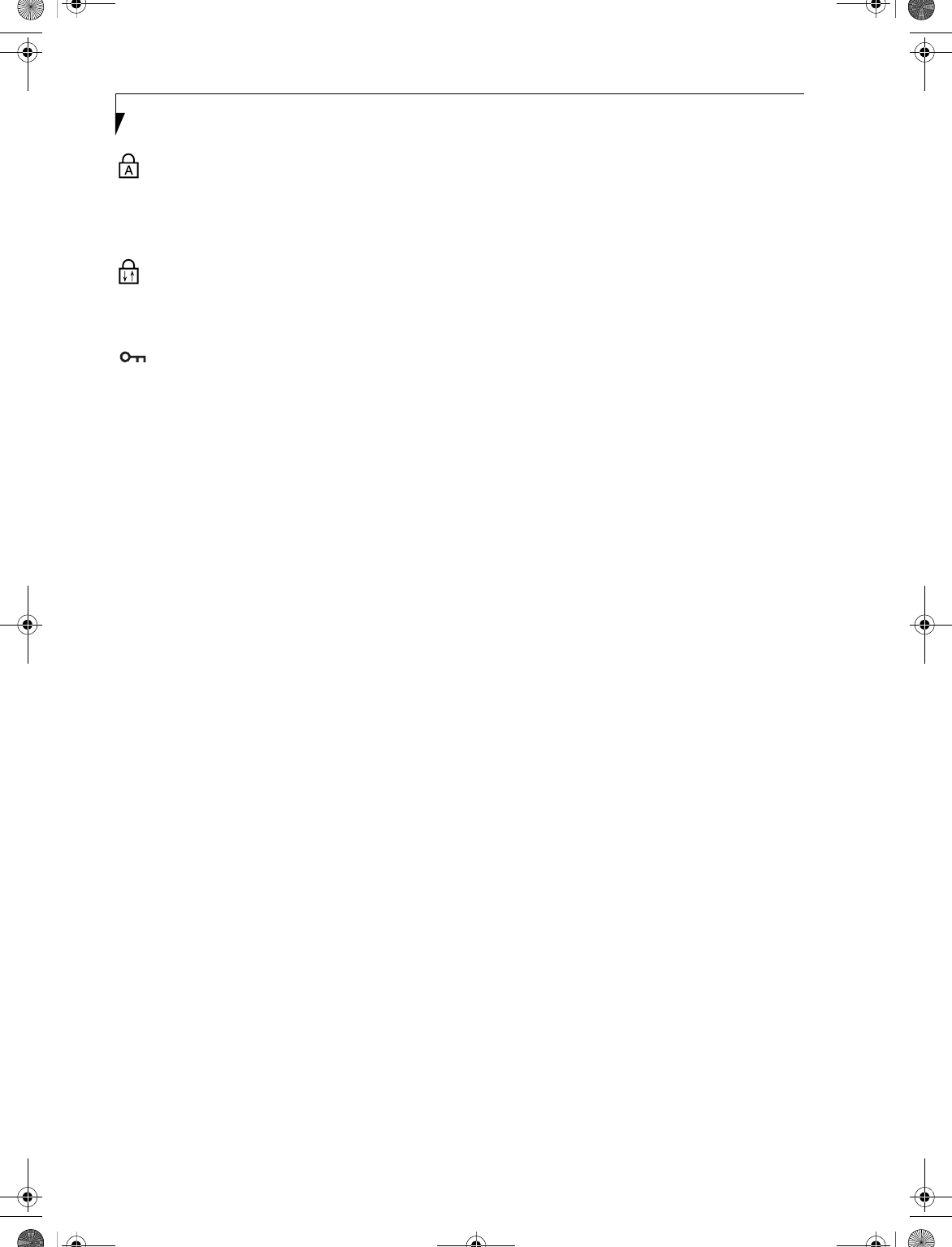
CAPSLOCK INDICATOR
The CapsLock indicator states that your keyboard is set
to type in all capital letters. (See Using the Keyboard on
page 17 for more information)
SCRLK INDICATOR
The ScrLk indicator states that your scroll lock is active.
(See Using the Keyboard on page 17 for more information)
SECURITY INDICATOR
The Security Indicator flashes (if a password was set)
when the system resumes from Off or Suspend modes.
You must enter the password that was set in the Security
Panel before your system will resume operation.
B5FH-4491-01EN-00.book Page 16 Friday, April 19, 2002 11:24 AM
17
Getting to Know Your LifeBook
Figure 2-11 Keyboard
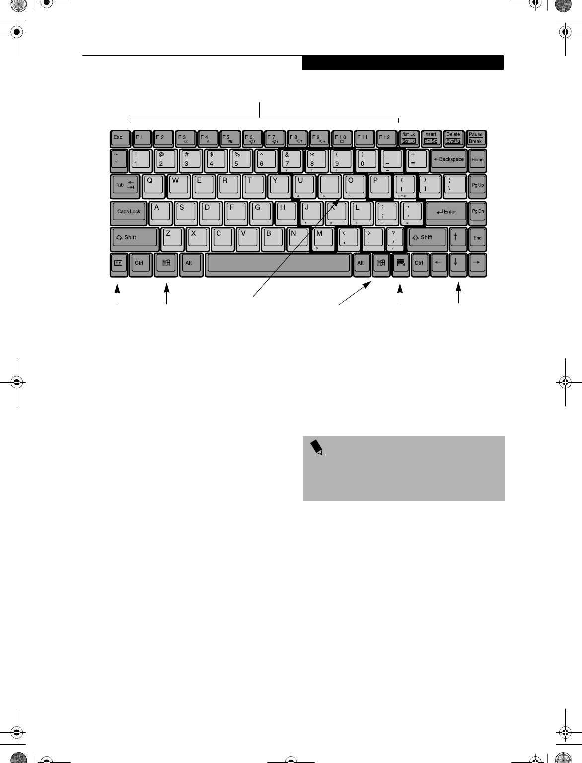
Keyboard
USING THE KEYBOARD
Your Fujitsu LifeBook notebook has an integral 87-key
keyboard. The keys perform all the standard functions
of a 101-key keyboard, including the Windows keys and
other special function keys. This section describes the
following keys.
■Numeric keypad: Your LifeBook notebook allows
certain keys to serve dual purposes, both as standard
characters and as numeric and mathematical keys.
The ability to toggle between the standard character
and numerical keys is controlled through the
[NumLk] key.
■Cursor keys: Your keyboard contains four arrow
keys for moving the cursor or insertion point to the
right, left, up, or down within windows, applications
and documents.
■Function keys: The keys labeled [F1] through [F12]
are used in conjunction with the [Fn] key to produce
special actions that vary depending on what program
is running.
■Windows keys: These keys work with your Windows
operating system and function the same as the
onscreen Start menu button, or the right button on
your pointing device.
NUMERIC KEYPAD
Certain keys on the keyboard perform dual functions as
both standard character keys and numeric keypad keys.
NumLk can be activated by pressing the [NumLk] keys.
Turning off the NumLk feature is done the same way.
Once this feature is activated you can enter numerals 0
through 9, perform addition ( + ), subtraction ( - ),
multiplication ( * ), or division ( / ), and enter decimal
points ( . ) using the keys designated as ten-key function
keys. The keys in the numeric keypad are marked on the
front edge of the key to indicate their secondary func-
tions.
WINDOWS KEYS
Your LifeBook notebook has three Windows keys: two
Start keys and an Application key. The two Start keys
display the Start menu. This button functions the same
as your onscreen Start menu button. The Application
key functions the same as your right mouse button and
displays shortcut menus for the selected item. (Please
refer to your Windows documentation for additional
infor-mation regarding the Windows keys.)
CURSOR KEYS
The cursor keys are the four arrow keys on the keyboard
which allow you to move the cursor up, down, left and
right in applications. In programs such as Windows
Explorer, it moves the “focus” (selects the next item up,
down, left, or right).
Fn Key Start Key
Function Keys
Numeric Keypad
Application Key Cursor Keys
Start Key
(surrounded with
thick black line)
POINT
If you are using the optional external numerical keypad,
pressing the [NumLk] key will activate the external key-
pad. The indicator will come on, however it will not
change any of the functionality of your keyboard keys.
B5FH-4491-01EN-00.book Page 17 Friday, April 19, 2002 11:24 AM

18
LifeBook E Series – Section 2
FUNCTION KEYS
Your LifeBook notebook has 12 function keys, F1
through F12. The functions assigned to these keys differ
for each application. You should refer to your software
documentation to find out how these keys are used.
The [Fn] key provides extended functions for the
notebook and is always used in conjunction with
another key.
■[Fn+F3]: Pressing [F3] while holding [Fn] will toggle
the Audio Mute on and off.
■[Fn+F4]: Pressing [F4] while holding [Fn] will toggle
the touchpad on and off. (This function key combina-
tion only works if the BIOS setting for Advanced>
Keyboard/Mouse Features>Internal Pointing Device is
set to Manual Setting.)
■[Fn+F5]: Pressing [F5] while holding [Fn] allows
you to toggle between video compensation and no
compensation. (Video compensation controls spacing
on the display. When it is enabled, displays with less
than 1024 x 768 or 800 x 600 pixel resolution will still
cover the entire screen.)
■[Fn+F6]: Pressing [F6] repeatedly while holding [Fn]
will lower the brightness of your display.
■[Fn+F7]: Pressing [F7] repeatedly while holding [Fn]
will increase the brightness of the display.
■[Fn+F8]: Pressing [F8] repeatedly while holding [Fn]
will decrease the volume of your LifeBook notebook.
■[Fn+F9]: Pressing [F9] repeatedly while holding [Fn]
will increase the volume of your LifeBook notebook.
■[Fn+F10]: Pressing [F10] while holding [Fn] allows
you to change your selection of where to send your
display video. Each time you press the combination
of keys you will step to the next choice. The choices,
in order, are: built-in display panel only, both built-in
display panel and external monitor or external
monitor only.
B5FH-4491-01EN-00.book Page 18 Friday, April 19, 2002 11:24 AM
19
Getting to Know Your LifeBook
Wireless Infrared Mouse
This section contains information on using the optional
Wireless Infrared (IR) Mouse with your LifeBook note-
book.
PREPARING YOUR IR MOUSE FOR USE
To prepare your IR Mouse, you need to:
1. Activate the port in your notebook’s BIOS.
2. Purchase and install two AAA batteries.
3. Turn the IR Mouse power switch to your preferred
setting.
To activate the IR Mouse Port in your BIOS
1. Power On or Restart your notebook.
2. Press [F2] as soon as the Fujitsu screen appears.
3. When you see the Phoenix® BIOS Setup Utility,
press the right arrow key once to display the
Advanced Menu.
4. Press the down arrow three times until Keyboard/
Mouse Features is highlighted.
5. Press [Enter].
6. Once the Keyboard/Mouse Features Menu appears,
press the down arrow three times until Infrared
Mouse is highlighted.
7. Press the [Spacebar] once to enable the Infrared
Mouse setting.
8. Press [F10], then [Enter] to save the changes, exit
the BIOS, and restart your notebook.
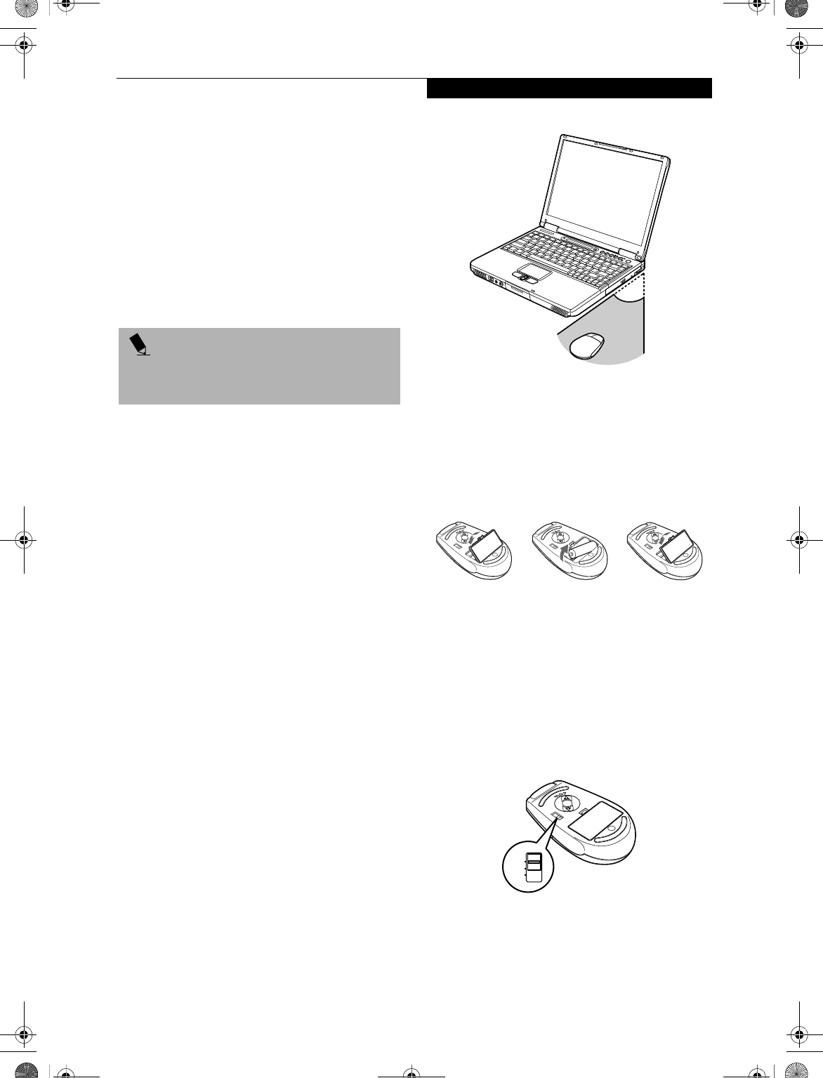
Range of Operation
Your IR Mouse communicates with the IR Mouse port
on your notebook, located at the bottom right-hand
corner of your Display Panel. In order for your mouse to
communicate effectively with your notebook, you will
need to keep it within the area in which the signals from
the mouse can be received by your notebook. This area
is pie-shaped, with the tip at the front of the mouse, and
the back approximately 1.5 feet from the port on the L
setting and 3 feet on the H setting (optimal settings).
This area, and the effective distance at either the L or the
H setting is subject to environment, type of use, and
other factors, and will vary. (Figure 2-12)
Figure 2-12. IR Mouse Area of Operation
To Install the Batteries
Turn your IR Mouse over, release the battery compart-
ment cover by depressing the tab, remove the cover, and
set it aside. Insert the batteries in the compartment,
making sure that the “+” on the batteries corresponds
with the “+” in the compartment. Replace the cover.
(Figure 2-13)
Figure 2-13. IR Mouse Battery Installation
Power Switch and Settings
The power switch is located on the bottom of the mouse.
Use your fingernail or the tip of a pen to slide it from the
off position to either the L or the H setting. (Figure 2-14)
On the L setting, your mouse can communicate with the
computer up to approximately 1.5 feet away. On the H
setting it can communicate up to approximately 3 feet
away. The H setting, however, depletes the mouse’s
batteries more quickly.
Figure 2-14. IR Mouse Power Switch
POINT
By activating the IR Mouse, your PS/2 port may not
work. If you need to use the PS/2 port, you need to
change your BIOS setting again.
OFF
L
H
B5FH-4491-01EN-00.book Page 19 Friday, April 19, 2002 11:24 AM
20
LifeBook E Series – Section 2
Extending Battery Life
The life of the batteries in your IR Mouse is subject to
many factors, including operating environment, types of
use, and consistency of use.
To extend the life of the batteries:
1. Turn the IR Mouse off when not in use.
2. Use the L setting whenever possible.
3. Keep the IR Mouse port on your notebook and the
IR port on the front of your mouse clean by wiping
with a clean, dry, soft cloth.
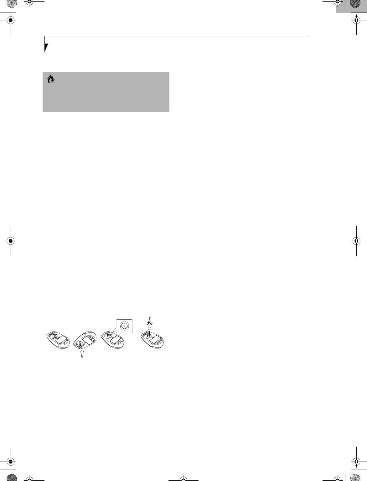
4. Keep the ball and ball chamber clean.
Cleaning the Ball and Ball Chamber
In the bottom of your IR Mouse you will find a ring,
with a ball underneath it. The ball, and the chamber in
which it rolls, may require cleaning from time to time.
In order to clean the ball and chamber (Figure 2-15):
1. Turn the ring counter-clockwise until it stops. Lift
the ring out, and set it aside.
2. Turn the mouse over, and let the ball fall into the
palm of your other hand.
3. Clean the ball, the inside of the chamber, the rollers,
and the back of the ring with a clean, dry, soft cloth.
4. Place the ball back into the chamber, replace the ring
(being careful to set the ring flush against the back of
the mouse), then turn the ring clockwise until it
stops.
Figure 2-15. Cleaning the IR Mouse
CAUTION
Be careful when using any other IR devices—such as TV
remote controls—in the vicinity of your LifeBook
notebook while using your IR Mouse. Your notebook
could have difficulty distinguishing the signals.
B5FH-4491-01EN-00.book Page 20 Friday, April 19, 2002 11:24 AM
21
Getting to Know Your LifeBook
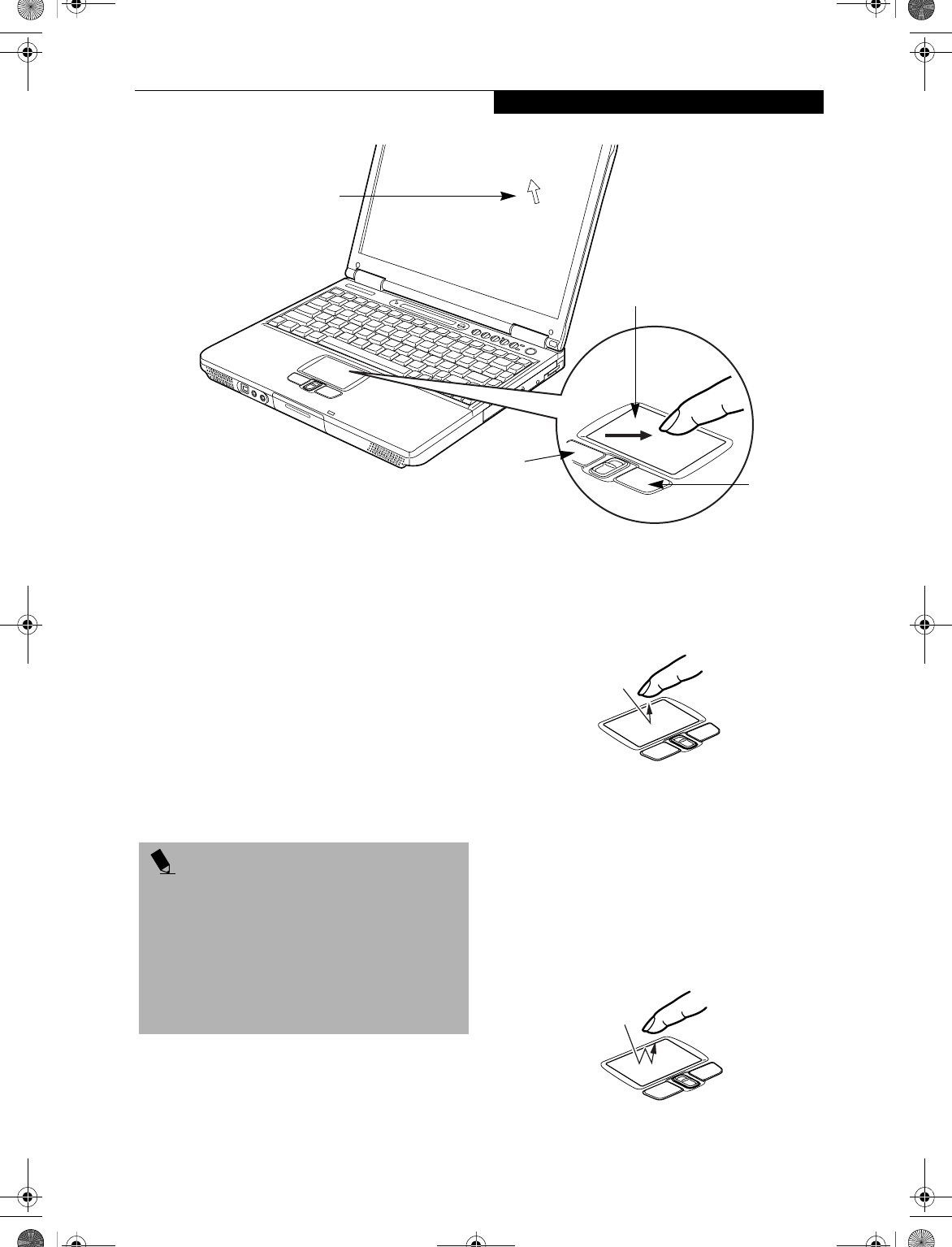
Figure 2-16. TouchPad pointing device
TouchPad Pointing Device
The TouchPad pointing device may come built into your
Fujitsu LifeBook notebook. It is used to control the
movement of the pointer to select items on your display
panel. The TouchPad is composed of a cursor control
and a left and right button. The cursor control works the
same way a mouse does, and moves the cursor around
the display. It only requires light pressure with the tip of
your finger, and the more pressure you use, the faster the
cursor will move. The left and right buttons function the
same as mouse buttons. The actual functionality of the
buttons may vary depending on the application that is
being used. (Figure 2-16)
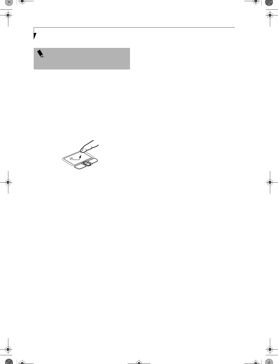
CLICKING
Clicking means pushing and releasing a button.
To left-click, move the cursor to the item you wish
to select, press the left button once, and then immedi-
ately release it. To right-click, move the mouse cursor to
the item you wish to select, press the right button once,
and then immediately release it. You also have the
option to perform the clicking operation by tapping
lightly on the TouchPad once. (Figure 2-17)
Figure 2-17. Clicking
DOUBLE-CLICKING
Double-clicking means pushing and releasing the left
button twice in rapid succession. This procedure does
not function with the right button. To double-click,
move the cursor to the item you wish to select, press
the left button twice, and then immediately release it.
You also have the option to perform the double-click
operation by tapping lightly on the TouchPad twice.
(Figure 2-18)
Figure 2-18. Double-clicking
Cursor
Cursor Control
Left Button
Right Button
POINT
An external mouse can be connected to either the
USB or PS/2 port on your LifeBook notebook, and be
used simultaneously with the TouchPad. However, if
you boot the system with an external mouse connected
the TouchPad will be disabled or enabled depending on
your BIOS settings. Also, if the Infrared Mouse is
enabled, your PS/2 external device will be disabled.
(See BIOS Setup Utility on page 35 for more informa-
tion)
B5FH-4491-01EN-00.book Page 21 Friday, April 19, 2002 11:24 AM
22
LifeBook E Series – Section 2
DRAGGING
Dragging means pressing and holding the left button,
while moving the cursor. To drag, move the cursor to
the item you wish to move. Press and hold the left
button while moving the item to its new location
and then release it. Dragging can also be done using the
TouchPad. First, tap the TouchPad twice over the item
you wish to move making sure to leave your finger on
the pad after the final tap. Next, move the object to its
new location by moving your finger across the
TouchPad, and then release your finger. (Figure 2-19)
Figure 2-19. Dragging
TOUCHPAD CONTROL ADJUSTMENT
The Windows Control Panel allows you to customize your
TouchPad with selections made from within the Mouse
Properties dialog box.
POINT
If the interval between clicks is too long, the
double-click will not be executed.
B5FH-4491-01EN-00.book Page 22 Friday, April 19, 2002 11:24 AM
23
Getting to Know Your LifeBook
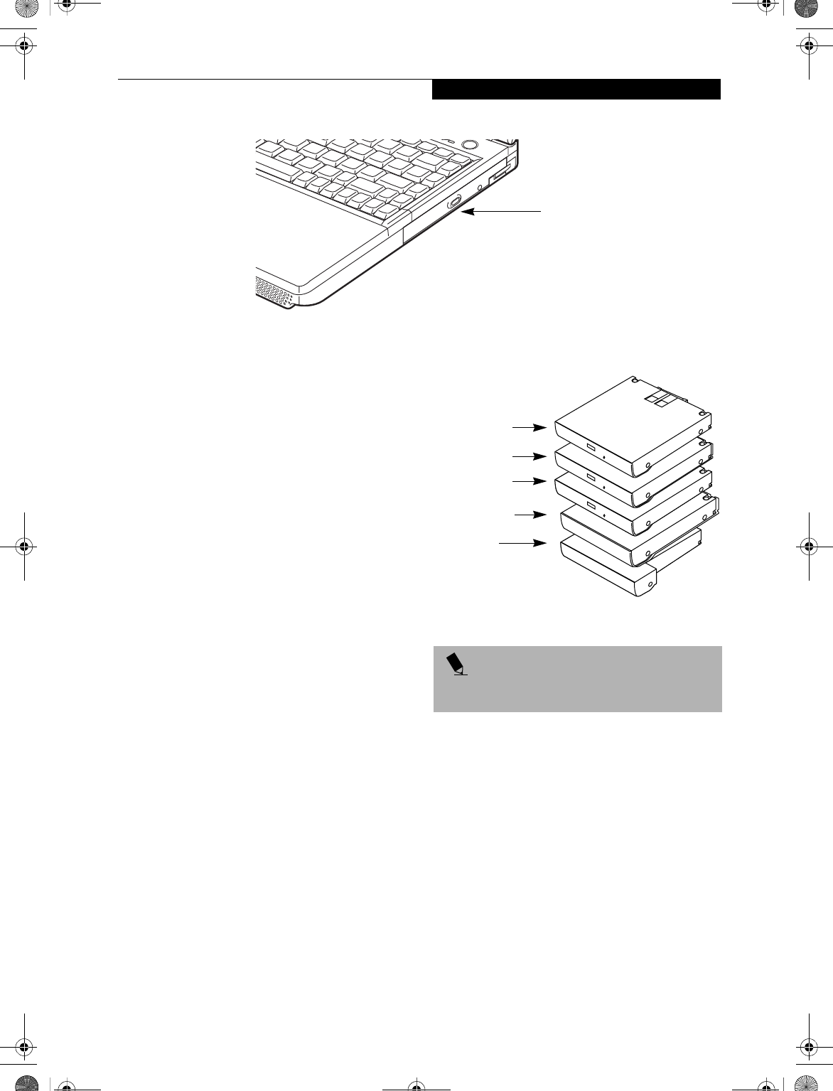
Figure 2-20 Flexible Bay
Flexible Bay Devices
Your LifeBook notebook contains a Flexible Bay. The
Flexible Bay can accommodate a modular CD-ROM
drive, DVD drive, DVD/CD-RW drive, Lithium ion
battery, or weight saver. (Figure 2-20)
You Flexible Bay will have one of the following devices
installed. All devices listed here are also options which
can be purchased separately. (Figure 2-21)
■Modular CD-ROM drive: This allows you to access
software and audio CDs.
■Modular DVD drive: This allows you to access movies,
software, and audio DVD/CDs.
■Modular DVD-CD-RW combo drive: This allows you
to access movies, software, and audio DVD/CDs as
well as to write to CDs.
■Modular Lithium ion battery: This is a rechargeable
battery that can be used to power your LifeBook note-
book when an adapter is not connected.
■Weight Saver: This is used to fill the bay when no
device is needed.
REMOVING AND INSTALLING
MODULAR DEVICES
There are two ways to remove and install modular
devices in the Flexible Bay:
■Cold-swapping: Swapping devices while your
LifeBook notebook is powered off. (Reference the
following section.)
■Hot-swapping: Swapping devices while your
system is active using BayManager™ software.
(Reference the sections of this chapter entitled "Hot-
swapping with BayManager..." and "Hot-swapping
under Windows 2000 Professional and Windows XP".)
Figure 2-21 Flexible Bay Devices
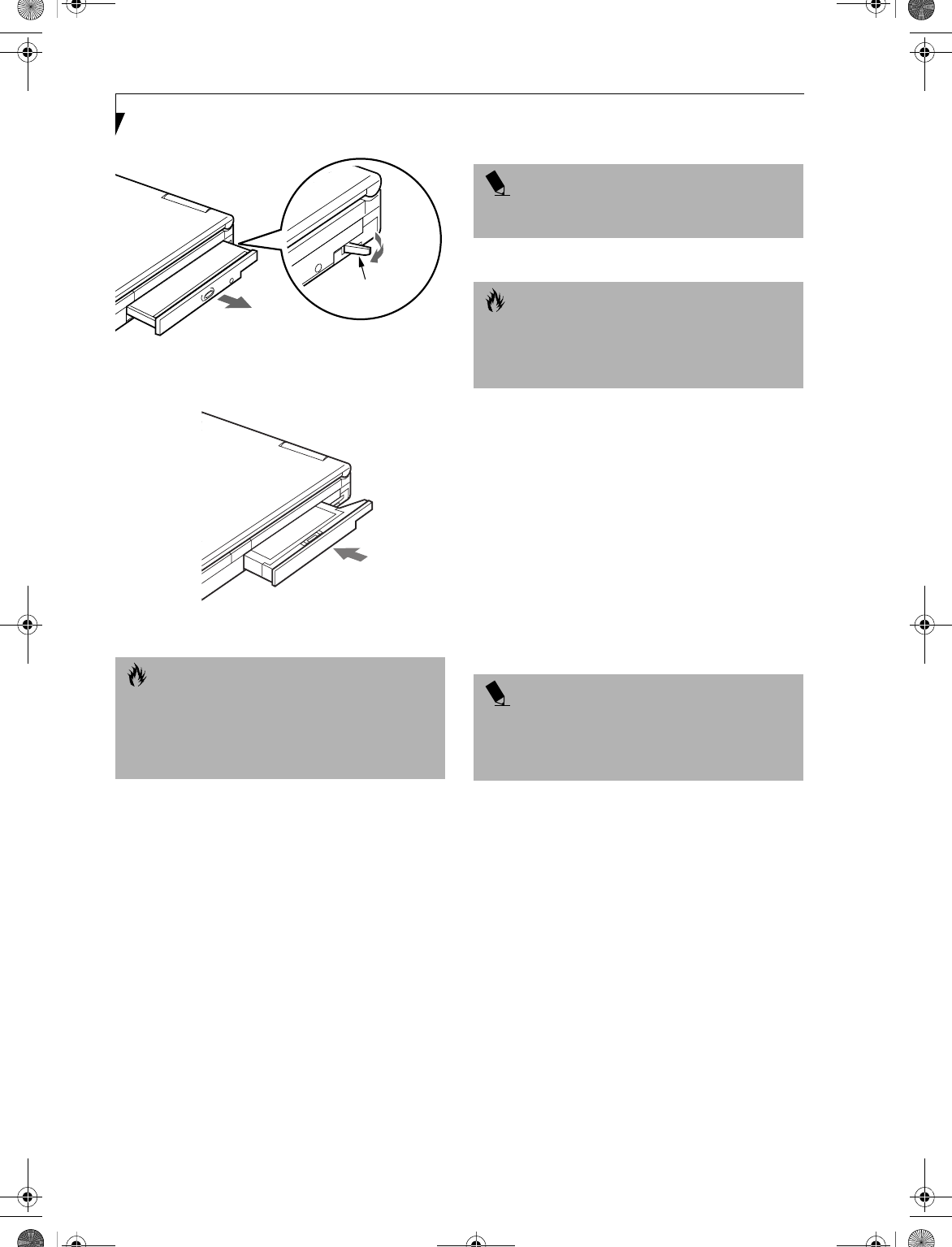
Cold-swapping
To cold-swap modular devices in your Flexible Bay
follow these easy steps: (Figure 2-22)
1. Close any open files.
2. Shut down your LifeBook notebook.
3. Pull out the Flexible Bay release latch, then press the
latch in to release the modular device. This will push
your device out slightly, allowing you to remove the
device.
4. Slide your device out until it is clear of the bay.
This will require light force.
Flexible Bay
POINT
You should never leave your Flexible Bay empty when
the LifeBook notebook is in operation.
Lithium ion
Weight Saver
DVD Drive
CD-ROM Drive
DVD/CD-RW
Combo Drive
Bay Battery
B5FH-4491-01EN-00.book Page 23 Friday, April 19, 2002 11:24 AM
24
LifeBook E Series – Section 2
Figure 2-22 Removing a device from the Flexible Bay
Figure 2-23 Installing a device in the Flexible Bay
5. Slide the device you are installing into your
LifeBook notebook until it clicks into place.
6. It is now safe to turn your notebook back on.
7. You can now access and use the device.
Your LifeBook notebook will automatically detect the
new device and activate it within your system. The drive
letters associated with the device will be created and
listed under My Computer and Windows Explorer.
Hot-swapping with BayManager
under Windows 98 Second Edition
BayManager provides a simple yet powerful method of
switching modular devices on your LifeBook notebook
without having to reboot. Windows 98 Second Edition
does not natively support hot-swapping. With BayMan-
ager, you can swap modular devices while your OS is
running, this is called hot-swapping.
Using BayManager
It’s easy to swap modular devices on your LifeBook note-
book using BayManager.
Please wait for 30 seconds after Windows 98 Second
Edition boots up or resuming from Standby/Hiberna-
tion before using the BayManager.
To hot-swap modular devices follow these easy steps:
1. Point your mouse on the BayManager icon on the
Windows Taskbar (it looks like an open laptop
computer).
2. Double-click the left mouse button to display the
Softex BayManager Window.
3. Click Remove/Swap or Insert button to change a
device in the Flexible Bay. A message appears telling
you that it is safe to swap devices.
4. Swap the modular devices.
5. Click OK button.
After the "System Device Change" message disappears,
you will be able to access and use the device.
Your LifeBook notebook will automatically detect the
new device and activate it within your system. The drive
letters associated with the device will be created and
listed under My Computer and Windows Explorer.
Key information About BayManager
You can see the type of device present in the Flexible Bay
by pointing to the BayManager icon on the taskbar or in
Storage Devices tab of BayManager Properties.
CAUTION
Be careful when aligning and seating devices in the bay.
If the fit is incorrect, you may damage the bay or the
device. If the device does not move easily in the bay,
remove it, and check for dirt or foreign objects. It will
require a firm push to latch the device in place.
Flexible Bay
Release Latch
POINT
BayManager does not support hot-swapping devices in
Full Dock II device bay.
CAUTION
If you are swapping out a bay battery module, make
sure that a charged main battery is installed or an AC
Adapter is connected to the system. Failure to do so
could result in data loss.
POINT
A device is protected from being removed while the
OS is using it. If the device is in use, an Error Message
window pops up and requests you to close any open files.
Close any open files and restart procedure at step 1.
B5FH-4491-01EN-00.book Page 24 Friday, April 19, 2002 11:24 AM

25
Getting to Know Your LifeBook
The information about BayManager will appear as
follows:
■Modular CD-RW/DVD drive:
Identified as CD-ROM.
■Modular floppy disk drive (FDD). FDD connected via
specific connector on the connector box, or USB FDD:
Identified as Floppy.
Tips About Using BayManager
■If you have BayManager installed in your notebook,
and want to enable Direct Memory Access (DMA) to a
bay device, click the device icon on the Storage
Devices tab of the BayManager dialogue box to check
DMA. Please note that not all devices support DMA.
■Before running the software to swap or remove the
current Flexible Bay device, be sure to close all open
applications that could be using the current bay
device.
■If you swapped or inserted your Flexible Bay device
with My Computer or Windows Explorer opened,
click View, and then click Refresh.
■After you swap or insert your Flexible Bay device, the
DVD Autorun might stop. To work around this
problem, double-click on My Computer, then double-
click the icon for DVD drive.
■If a LifeBook notebook with an external USB FDD
connected is put on Standby, the drive letter for the
FDD might change (from A) after the computer is
brought out of the power saving state. This
phenomenon does not affect operations adversely.
■If Windows is started on a LifeBook notebook with an
external USB FDD connected, an icon for the FDD
might not appear in My Computer or Windows
Explorer. If you encounter this problem, remove the
FDD from your LifeBook notebook then reconnect it.
■If the FDD (A:) is not shown in My Computer or
Windows Explorer even if the FDD is connected,
execute [Insert] by using BayManager.
Hot-swapping under Windows 2000 Professional,
XP Home, and XP Professional
Under Windows 2000 and XP, hot-swapping is provided
through the Unplug or Eject Hardware utility. The icon
for the utility appears on the taskbar. Refer to your
Windows manual on using this feature.
B5FH-4491-01EN-00.book Page 25 Friday, April 19, 2002 11:24 AM
26
LifeBook E Series – Section 2
Figure 2-24 LifeBook Security/Application Panel
LifeBook Security/
Application Panel
A unique feature of your LifeBook notebook is the
Security/Application Panel that allows you to secure your
notebook from unauthorized use. The Security/
Application Panel also allows you to launch applications
with the touch of a button when your system is on.
If the security system is activated, upon starting your
LifeBook notebook or resuming from suspend mode the
security system requires you to enter a password code
using the buttons on the Security/Application Panel.
After entering a correct password, your LifeBook
notebook resumes system operation. (Figure 2-24)
SETTING UP YOUR
LIFEBOOK SECURITY PANEL
When you receive your LifeBook notebook, the security
panel application is pre-installed without any passwords.
The following sections provide detailed information on
your security panel, and how to set, change or remove
passwords.
Numbered Buttons
Use these buttons to enter your password. (Figure 2-24)
Enter Button
After entering the button strokes, push this button to
enter the password into the notebook. (Figure 2-24)
PASSWORDS
The user and supervisor password may be set on this
LifeBook notebook. A supervisor password is typically
the same for all notebooks in a working group, office, or
company to allow for system management. Individual
notebooks in a group environment should not use a
common password. A password consists of one to five
button strokes plus the enter button. A valid stroke
consists of pushing one or up to four buttons simulta-
neously. The following are valid button strokes:
nPushing [4] by itself
nPushing [2] and [3] at the same time
nPushing [1], [2], and [4] at the same time
nPushing [1], [2], [3], and [4] at the same time
The following are valid passwords. The numbers
within braces ({ }) are button strokes using more
than one button.
n{[2]+[3]}, [1], [enter]
n[4], [enter]
n{[1]+[3]}, {[2]+[3]+[4]}, [1], [4], [2], [enter]
Setting Passwords
When shipped from the factory, no passwords are set.
You have a choice of having no password or setting a
supervisor and user password. You must set the super-
visor password before the user password.
1234
Enter
Numbered Buttons for
Enter Button
entering password and
launching applications
POINTS
nThe purpose of supervisor password is to be able to
bypass the user password in case the user password
is forgotten. The supervisor password alone will not
lock the system.
nYou have to set both the supervisor and user pass-
words for the security panel to work.
B5FH-4491-01EN-00.book Page 26 Friday, April 19, 2002 11:24 AM
27
Getting to Know Your LifeBook
Setting Supervisor Password
You must have set a supervisor password before setting
any user passwords. The supervisor password can bypass
the user password.
1. Go to the Start menu.
2. Click on Run.
3. Type in
"C:\Program Files\Fujitsu\
Security Panel Application\
Supervisor\FJSECS.EXE" (be sure to use
the quotation marks), then press [Enter]
4. Follow the on-screen instructions to set the
Supervisor password.
Setting User Password
1 Go to the Start menu.
2. Click on Programs.
3. Click on Security Panel Application > Security
Panel Application.
4. Follow the on-screen instructions to set the
user password.
OPERATING YOUR LIFEBOOK SECURITY
APPLICATION PANEL
The security lock feature is in effect both when the system
resumes from OFF or suspend state. You always need to
push the Suspend /Resume button to input the user pass-
word. Your system will not begin the boot sequence
without entering your supervisor/user password.
From Off State
1. Turn on your system.
2. When the Security Indicator flashes, enter the
password and press Enter button.
For example, if the password is 22222,
Press Button Number 2 five times and press Enter
button.
The LifeBook notebook will boot to normal opera-
tion.
From Suspend State
1. Press your Suspend/Resume button.
2. When the Security Indicator flashes, enter the pass-
word and press Enter button.
The notebook should resume normal operation.
Incorrect Password Entry
If an invalid supervisor or user password is entered three
times in succession, the system will “beep” for about one
minute. If a valid password is entered within a minute
(while system beeps), the beeping will stop and the Life-
Book notebook will resume normal operation. If no
password or an invalid password is entered while the
system beeps, the system will return to its previous
locked state (suspend or off) and the Security Indicator
will go off. To reactivate the LifeBook notebook after a
password failure, you must press the Suspend/Resume
button, then enter a correct password.
PRECAUTIONS
Opening and Closing the Cover
Closing the cover may place the notebook into suspend
mode. Opening the cover does not automatically place
the notebook into normal operation. Instead, you must
enter the proper security password after pushing the
Suspend/Resume button.
Low Battery Operations
If your LifeBook notebook has a low battery, pushing
the suspend/resume button only turns on the Security
Indicator. Your notebook does not unlock, and the
Security Indicator LED turns off after one minute. To
resume normal operation, first attach a power supply to
the LifeBook notebook. Then you may unlock the note-
book.
UNINSTALLING THE SECURITY
PANEL APPLICATION
You have two options when uninstalling the security
panel application:
nUninstall the security panel application software.
This will disable all security feature.
nUninstall the security panel application with
password still active. This will not allow any
changes to the password.
Uninstalling the Security Panel
Application Software
Remove passwords when User wants no password
protection whatsoever and doesn’t want to give anybody
the utility to set a password on their computer. In this
case, if passwords (supervisor, user, or both) are set, the
passwords must first be cleared BEFORE removing the
application. To clear passwords, follow same procedure
in SETTING PASSWORD CODES except this time,
select REMOVE, enter current password then click Next.
When asked to confirm select Ye s .
POINT
You may change or remove the supervisor or user
password by repeating the steps defined above.
POINT
Remember the user password you specified on the
Security Panel Application. If you forget the password
you will not be able to use your computer. The super-
visor password can override the user password.
B5FH-4491-01EN-00.book Page 27 Friday, April 19, 2002 11:24 AM
28
LifeBook E Series – Section 2
Removing Security Panel Application with
Passwords Still Active
Using this feature will not allow any changes to
the password.
User:
1. Go to Start Menu, Click on Control Panel.
2. Open Add/Remove Programs Properties in the
Control Panel.
3. Select the Security Panel Application in the list, and
click Add/Remove.
4. When the Confirm File Deletion box appears,
click Ye s .
Supervisor:
1. Go to Start Menu, Click on Control Panel.
2. Open Add/Remove Programs Properties in the
Control Panel.
3. Select the Security Panel Application for
Supervisor in the list, and click Add/Remove.
4. When the Confirm File Deletion box appears,
click Ye s .
Reinstalling the Security Application Panel
To reinstall supervisor or user security application, you
will need your Drivers and Applications Restore CD. The
Secpanel folder located in the Utilities\Security Panel
contains the setup files for supervisor and user security
application.
1. Double-click the Setup FJSECS.EXE file. The
Installing Security Panel Application window will
appear. Follow the instructions on the screen.
2. Double-click the Setup FJSECU.EXE file. The
Installing Security Panel Application window will
appear. Follow the instructions on the screen.
Supervisor and user passwords can be set by the
Windows Software which are FJSECS.EXE and
FJSECU.EXE respectively. FJSECU.EXE for user pass-
word cannot run without supervisor password.
First you need to run FJSECS.EXE to set supervisor pass-
word before setting user password. Follow instructions
under Setting Passwords on page 26.
If you forget both passwords, contact Fujitsu Service
and Support at 1-800-8Fujitsu (1-800-838-5487).
Fujitsu charges a service fee for unlocking a password
restricted LifeBook notebook. When calling please have
a valid credit card and provide proof of ownership. You
will then be given instructions on where to ship your
LifeBook notebook.
LAUNCHING APPLICATIONS WITH
THE SECURITY/APPLICATION PANEL
The security panel also enables you to launch applications
with the touch of a button when your system is on.
Pressing any of the buttons will launch a user-defined
application. Your LifeBook notebook is pre-installed with
software utilities that let you operate and configure your
LifeBook Security/Application Panel. These utilities are
found under the Start menu, under Programs, then under
LifeBook Application Panel. They include Application
Panel Setup, Guide, Activate Panel and Deactivate Panel.
Configuring your LifeBook Application Panel
When you start Windows, the LifeBook Application
Panel is automatically activated. An icon resembling a
finger pressing a button will appear on the system tray
(the indented portion of the status bar where the clock is
displayed). When you see this icon you will know that
LifeBook Application Panel is active.
As an application launcher, the LifeBook Application
Panel is very flexible, giving you a variety of options. To
set up the Panel to best suit your needs, we have
provided the Application Panel Setup utility that quickly
and easily helps you make the most of this valuable
feature.
To configure your LifeBook Application Panel with
Application Panel Setup:
1. Click on Start.
2. Click on Programs.
3. Click on LifeBook Application Panel.
4. Click on Application Panel Setup.
The Application Panel Setup utility will appear. There
are tabs that correspond to the application buttons on
the LifeBook Application Panel. When you receive your
LifeBook notebook, these buttons are pre-configured to
launch the associated programs, as defined in Chapter 7.
To change an application associated with the Application
buttons, click on the tab for the button you would like to
reconfigure – for example, Application A. Click on
Browse from Start Menu, scroll down the list of applica-
tions, click on the application you wish to launch with
this button, and then click OK. The button will now
launch the new application.
POINT
Removing the applications does not remove the
password. It simply removes the utility to change/add/
remove passwords. To change your password you must
reinstall the application.
POINT
The tabs in Application Panel Setup may not be in the
same order as the buttons on your LifeBook notebook,
please select the tab you wish to change carefully.
B5FH-4491-01EN-00.book Page 28 Friday, April 19, 2002 11:24 AM
29
Getting to Know Your LifeBook
The Internet tab is different. It comes set to launch your
Windows default Internet browser (Internet Explorer),
unless you have changed this in Windows. In order to
reconfigure it to launch another program follow these
easy steps:
1. Click on Other from the Internet browser box.
2. Click on Browse from Start Menu.
3. Scroll down the list of applications, and then click
on the application you wish to launch with this
button.
4. Click OK.
The button will now launch the new application. If you
want to return to launching your Windows default
Internet browser with this button, you need only click
on “Default Internet Browser” from the Internet
browser box. Be aware that you will erase the settings for
the “other application”. If you wish to go back to
launching the “other application” from this button, you
will need to reconfigure it as described above.
When you have finished with Application Panel Setup
click OK, and the new settings will take effect. You can
reconfigure your LifeBook Application Panel as often as
you like.
Deactivating and Activating the LifeBook
Application Panel
To deactivate the LifeBook Application Panel, follow
these easy steps:
1. Click on Start.
2. Click on Programs.
3. Click on LifeBook Application Panel.
4. Click on Deactivate Panel.
To reactivate, follow the same procedure, except for
step 4. Click on Activate Panel instead.
POINT
The Internet or E-mail buttons can be configured to
launch any application you wish, not just an Internet
browser or e-mail program.
POINT
Every time you start Windows the LifeBook Application
Panel is activated, even if you deactivated it before you
shut down.
B5FH-4491-01EN-00.book Page 29 Friday, April 19, 2002 11:24 AM

30
LifeBook E Series – Section 2
B5FH-4491-01EN-00.book Page 30 Friday, April 19, 2002 11:24 AM

31
3
Getting Started
B5FH-4491-01EN-00.book Page 31 Friday, April 19, 2002 11:24 AM

32
LifeBook E Series – Section 3
B5FH-4491-01EN-00.book Page 32 Friday, April 19, 2002 11:24 AM
33
Getting Started
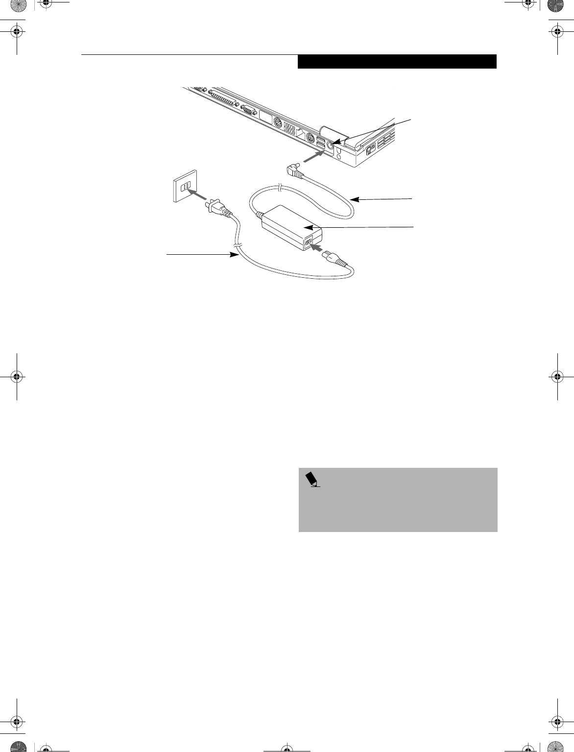
Figure 3-1 Connecting the AC Adapter
Power Sources
Your Fujitsu LifeBook notebook has four possible power
sources: a primary Lithium ion battery, a secondary
Lithium ion battery (for Flexible Bay installation), an
AC adapter, or an optional Auto/Airline adapter.
CONNECTING THE POWER ADAPTERS
The AC adapter or optional Auto/Airline adapter
provides power for operating your LifeBook notebook
and charging the batteries.
Connecting the AC Adapter
1. Plug the DC output cable into the DC power jack
of your LifeBook notebook.
2. Plug the AC adapter into an AC electrical outlet.
(Figure 3-1)
Connecting the Optional Auto/Airline Adapter
1. Plug the DC output cable into the DC power jack
on your LifeBook notebook.
2. Plug the Auto/Airline adapter into the cigarette
lighter of an automobile with the ignition key in
the On or Accessories position.
OR
3. Plug the Auto/Airline adapter into the DC power
jack on an airplane seat.
Switching from AC Adapter Power or the
Auto/Airline Adapter to Battery Power
1. Be sure that you have at least one charged
battery installed.
2. Remove the AC adapter or the Auto/Airline adapter.
DC Power Jack
DC Output Cable
AC Adapter
AC Cable
POINT
The Lithium ion battery is not charged upon purchase.
Initially, you will need to connect either the AC adapter
or the Auto/Airline adapter to use your LifeBook
notebook.
B5FH-4491-01EN-00.book Page 33 Friday, April 19, 2002 11:24 AM
34
LifeBook E Series – Section 3
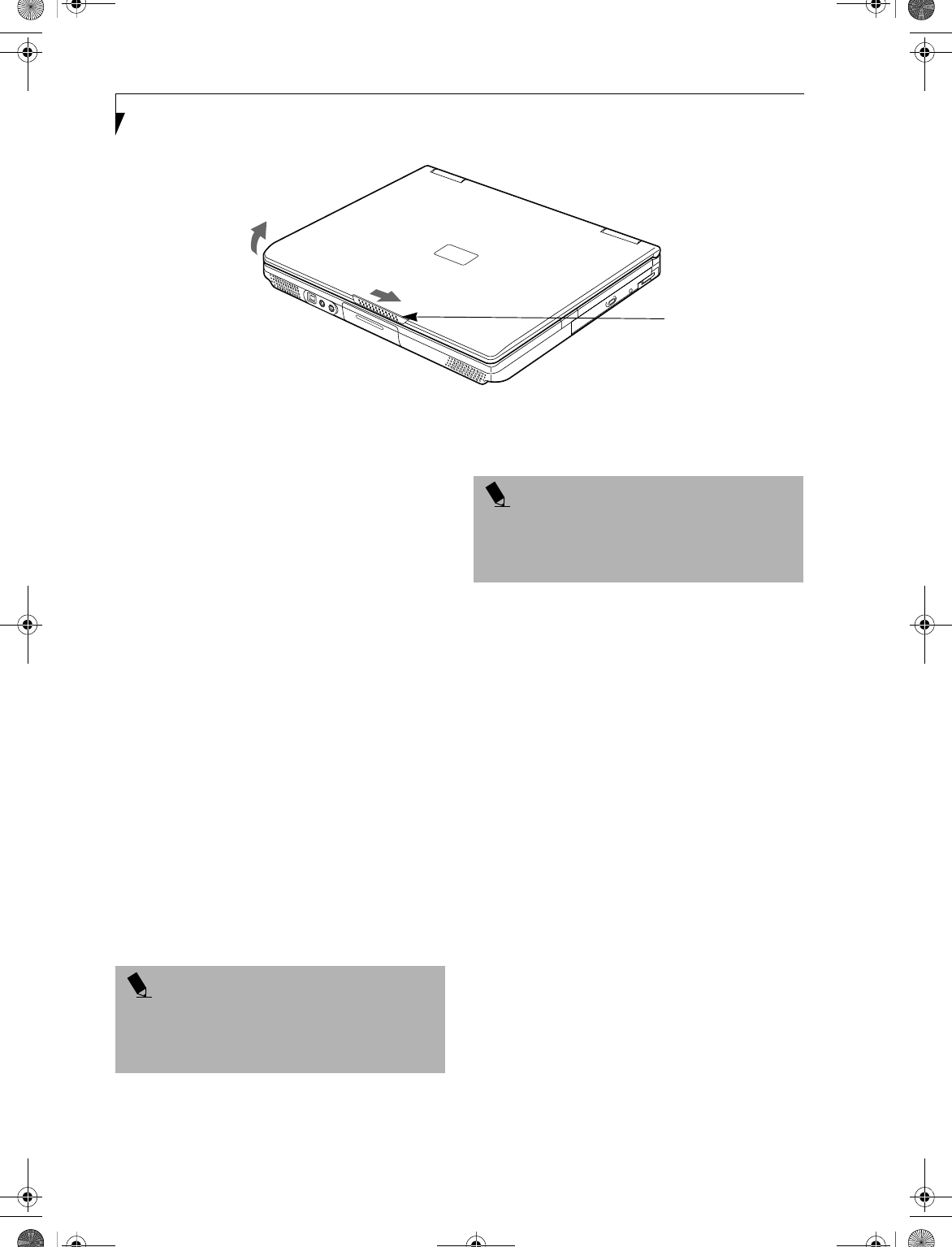
Figure 3-2 Opening the Display Panel
Display Panel
Your Fujitsu LifeBook notebook contains a display panel
that is backlit for easier viewing in bright environments
and maintains top resolution through the use of active-
matrix technology.
OPENING THE DISPLAY PANEL
1. Slide the display panel latch to the right to release
the locking mechanism.
2. Lift the display panel backwards, being careful not to
touch the screen, until it is at a comfortable
viewing angle.
ADJUSTING DISPLAY PANEL BRIGHTNESS
Once you have turned on your LifeBook notebook, you
may want to adjust the brightness level of the screen to a
more comfortable viewing level. There are two ways to
adjust the brightness keyboard and power management
utility
Keyboard
■[Fn+F6]: Pressing repeatedly will lower the
brightness of your display.
■[Fn+F7]: Pressing repeatedly will increase the
brightness of the display.
Using the BatteryAid Utility
(Windows 98 and 2000 only)
Adjusting the brightness using the Power Management
Utility changes the setting permanently.
1. Double-click the Battery Icon in the lower right
corner of your display (it looks like a small battery
with a leaf extending from the top). This will open
the BatteryAid Properties dialog box.
2. Click on the Fujitsu BatteryAid 2/2 tab and adjust
your LCD Backlighting to the desired level.
3. Click OK or Apply to permanently change
the settings.
You may need to readjust the brightness level periodi-
cally depending on your operating environment.
CLOSING THE DISPLAY PANEL
1. Holding the edge of your display panel, pull
it forward until it is flush with the body of
your LifeBook notebook.
2. Push down until you hear a click. This will
engage the locking mechanism and prevent
your display panel from opening unexpectedly.
Display Panel Latch
POINT
If using AC power, your LifeBook notebook’s brightness
setting is set to its highest level by default. If using
battery power, the brightness setting is set to its middle
level by default.
POINT
The higher the brightness level, the more power the
LifeBook notebook will consume and the faster your
batteries will discharge. For maximum battery life, set
the brightness level as low as possible.
B5FH-4491-01EN-00.book Page 34 Friday, April 19, 2002 11:24 AM
35
Getting Started
Starting Your
LifeBook Notebook
POWER ON
Power and Suspend/Resume Button
The Power and Suspend/Resume button is used to power
on your LifeBook notebook, to resume from Standby or
Save-to-Disk mode, to place your notebook in Standby or
Save-to-Disk mode or to power off. You can also turn off
your notebook by choosing Shut Down from the
Windows Start menu.
Once you have connected your AC adapter or charged
the internal Lithium ion Battery, you can press this
button to Power On your LifeBook notebook. (See
Figure 2-4 on page 8 for location)
When you Power On your notebook, it will perform a
Power On Self Test (POST) to check the internal parts
and configuration for correct functionality. If a fault is
found, your notebook will emit an audio warning and/
or an error message will be displayed. (See Power On Self
Test Messages on page 70 for more information)
Depending on the nature of the problem, you may be
able to continue by starting the operating system or by
entering the BIOS setup utility and revising the settings.
After satisfactory completion of the Power On Self Test
(POST), your LifeBook notebook will load your oper-
ating system.
BOOT SEQUENCE
The procedure for starting-up your Fujitsu LifeBook
notebook is termed the Bootup sequence and involves
your notebook’s BIOS. When your notebook is first
turned on, the main system memory is empty, and it
needs to find instructions to start up your notebook.
This information is in the BIOS program. Each time you
power up or restart your notebook, it goes through a
boot sequence which displays a Fujitsu logo until your
operating system is loaded. During booting, your note-
book is performing a standard boot sequence including
a Power On Self Test (POST). When the boot sequence is
completed without a failure and without a request for
the BIOS Setup Utility, the system displays the operating
system’s opening screen.
The boot sequence is executed when:
■You turn on the power to your LifeBook notebook.
■You restart your LifeBook notebook from the
Windows Shut Down dialog box.
■The software initiates a system restart. Example:
When you install a new application.
■You reset the system by pressing the three keys
[CTRL+ALT+DEL].
BIOS SETUP UTILITY
The BIOS Setup Utility is a program that sets up the
operating environment for your LifeBook notebook.
Your BIOS is set at the factory for normal operating
conditions, therefore there is no need to set or change
the BIOS’ environment to operate your LifeBook note-
book.
The BIOS Setup Utility configures:
■Device control feature parameters, such as changing
I/O addresses and boot devices.
■System Data Security feature parameters, such
as passwords.
Entering the BIOS Setup Utility
To enter the BIOS Setup Utility do the following:
1. Turn on or restart your LifeBook notebook.
2. Press the [F2] key once the Fujitsu logo appears
on the screen. This will open the main menu
of the BIOS Setup Utility with the current
settings displayed.
3. Press the [RIGHT ARROW] or [LEFT ARROW] key
to scroll through the other setup menus to review or
alter the current settings. Additional navigational
information is located at the bottom of the BIOS
screen.
POINT
When you turn on your LifeBook notebook be sure you
have a power source. This means that at least one
battery is installed and charged, or that the AC or Auto/
Airline adapter is connected and has power.
CAUTION
Do not carry your LifeBook notebook around with the
power on or subject it to shocks or vibration, as you risk
damaging your notebook.
POINT
Never turn off your LifeBook notebook during the
Power On Self Test (POST) or it will cause an error
message to be displayed when you turn your notebook
on the next time. (See Power On Self Test Messages on
page 70 for more information)
B5FH-4491-01EN-00.book Page 35 Friday, April 19, 2002 11:24 AM
36
LifeBook E Series – Section 3
BIOS Guide
A guide to your LifeBook notebook’s BIOS is available
online. Please visit our service and support Web site at
www.fujitsupc.com/support. Once there, select Support,
then select Notebooks under User’s Guides. Select Life-
Book BIOS Guides from the pull-down menu for your
LifeBook series. If you are unsure of your notebook’s
BIOS number, refer to your packing slip.
BOOTING THE SYSTEM
We strongly recommend that you do not attach any
external devices and do not put a CD or floppy disk in
any drive until you have gone through the initial power
on sequence.
When you turn on your LifeBook notebook for the first
time, it will display a Fujitsu logo on the screen. If you
do nothing, the system will load the operating system,
and then the Windows Welcome will begin.
Designed to accommodate the needs of users in many
different countries, Windows needs to be configured the
first time you use it. Windows has three parts:
■Getting Started: You have the opportunity to enter
custom information for your configuration file and
setup your modem so that your LifeBook notebook
will be prepared to dial out.
■Registration: Easy online registration for Windows
with Microsoft, and for your LifeBook notebook with
Fujitsu.
■Windows License Agreement and Final Settings:
You have the opportunity to review the Windows.
Getting Started
Read the instructions on the screens carefully and fill
in the information as directed. You will be asked for such
items as the language you wish to use, the country in
which you live, your first and last name, and about
how you dial out from where you will be using your
notebook. For the modem settings, enter your current
location information where you will be using your
LifeBook notebook. If you are not connected to a phone
line and plan to register at a later time, you may click the
Skip button, and you will go directly to the condition
of use page.
Once you have set up your notebook to dial out,
Windows will make a free telephone call which will test
these settings. If the call is unsuccessful, you will be
returned to the phone settings page where you may try
to fix them. If you are unable to fix the settings please
contact Fujitsu Service and Support. (See Fujitsu Contact
Information on page 3 for more information).
If you would simply like to move on, and register at a
later time, you may click the Skip button, and you will
go directly to the Condition of Use page.
Registration
If your connection is successful, you will go to the
Registration Confirmation page. On this page simply
enter the requested information, and then check the
box at the bottom to register your copy of Windows with
Microsoft. Once you have finished, click the Next button
to continue.
You will then go through the Fujitsu registration process.
Follow the instructions on the screens, and enter all of
the necessary information. Be as specific as possible so
that if you need help the service and support team will
be able to serve you better.
Final Settings
The first part of your final settings is the Windows End
User License Agreement. Read the agreement carefully.
When you finish reading you must accept or reject the
terms of the agreement and then click on the Next button.
WINDOWS PRODUCT ACTIVATION
(WINDOWS XP ONLY)
If your system has Windows XP as an operating system,
it has already been pre-installed and pre-activated when
you receive the system.
In the event you need to re-install Windows XP (e.g.,
after making significant configuration changes), it may
POINT
If your data security settings require it, you may be
asked for a password before the BIOS main menu
will appear.
POINT
If you reject the terms of the license agreement you
will be asked to review the license agreement for
information on returning Windows 2000 Professional or
to shut down your LifeBook notebook.
POINT
If you do not register at this time you can do it later
simply by double-clicking on the LifeBook Registration
icon on your desktop and following the instructions.
POINT
If you reject the terms of the license agreement you
will be asked to review the license agreement for
information on returning to Windows or to shut
down your LifeBook notebook.
B5FH-4491-01EN-00.book Page 36 Friday, April 19, 2002 11:24 AM
37
Getting Started
be necessary to reactivate the operating system. To do so,
use the following information.
■After re-installing Windows XP, you have thirty days
to activate it. Product activation ensures that you are
the only authorized user of this copy of Windows.
■Until you activate the product, you will be prompted
whenever you turn on the system that activation is
required. Follow the on-screen directions to activate
your operating system. The product only needs to be
activated once, unless significant hardware changes
are made to your system.
■Note that Product Activation and Registration are not
the same thing. Registration is optional, whereas
Product Activation is a required procedure.
REGISTERING YOUR LIFEBOOK NOTEBOOK
What are the benefits of registering?
You will receive an identification label for your LifeBook
notebook, which, if your notebook is ever lost, may help
in getting it returned to you. You also receive technical
support access and useful product mailings. Proof of
purchase is not required if you register within 30 days of
your purchase.
How do I register?
With Windows, it is a part of the Windows Welcome
process. If you do not register during the Welcome
process you can double-click on the LifeBook Registra-
tion icon on your desktop and then follow the instruc-
tions. The LifeBook Registration icon is the only way to
register Windows 2000 Professional.
You may also complete the pre-printed registration form
and either:
■Fax to 1-800-577-9989
■Mail to:
Fujitsu PC Corporation
750 139th Ave.
San Leandro, CA 94578
You may also register on our Web site:
■www.fujitsupc.com/support.
You will need to be set up with an Internet Service
Provider (ISP) to use this option.
INSTALLING CLICK ME!
The first time you boot up your system, you will see an
icon called Click Me! (The icon is located on the desktop
for Windows 98 and in the Start menu for Windows XP
systems). When you click the Click Me! icon, your
system will automatically build the icon tray in the
bottom right of the screen. These icons provide links to
utilities that you will frequently access.
The icon is automatically deleted after you launch Click
Me! and restart the system.
POINT
Make sure you have connected a phone line to your
modem before you use E-Registration.
B5FH-4491-01EN-00.book Page 37 Friday, April 19, 2002 11:24 AM
38
LifeBook E Series – Section 3
Power Management
Your LifeBook notebook has many options and features
for conserving battery power. Some of these features are
automatic and need no user intervention, such as those
for the internal modem. However, others depend on the
parameters you set to best suit your operating condi-
tions, such as those for the display brightness. Internal
power management for your LifeBook notebook may be
controlled from settings made in your operating system
or from settings made in the BIOS setup utility.
Besides the options available for conserving battery
power, there are also some things that you can do to
prevent your battery from running down as quickly.
For example, you can create an appropriate power saving
profile, put your notebook into Suspend mode when it is
not performing an operation, and you can limit the use
of high power devices. As with all mobile, battery
powered computers, there is a trade-off between
performance and power savings.
POWER AND SUSPEND/RESUME BUTTON
When your LifeBook notebook is active, the Power and
Suspend/Resume button can be used to manually put
your notebook into Suspend mode. Push the Power and
Suspend/Resume button when your notebook is active,
but not actively accessing anything, and immediately
release the button. You will hear two short beeps and
your system will enter Suspend mode.
If your notebook is suspended, pushing the Power and
Suspend/Resume button will return your notebook to
active operation. You can tell whether or not your
system is in Suspend mode by looking at the Power indi-
cator. (See Figure 2-9 on page 14 for location) If the indi-
cator is visible and not flashing, your LifeBook notebook
is fully operational. If the indicator is both visible and
flashing, your notebook is in Suspend mode. If the indi-
cator is not visible at all, the power is off or your note-
book is in Save-to-Disk mode. (See Save-to-Disk Mode)
SUSPEND MODE
Suspend or Standby mode in Windows 98 Second
Edition or Windows 2000 Professional saves the contents
of your LifeBook notebook’s system memory during
periods of inactivity by maintaining power to critical
parts. This mode will turn off the CPU, the display, the
hard drive, and all of the other internal components
except those necessary to maintain system memory and
allow for restarting. Your LifeBook notebook can be put
in Suspend mode by:
■Pressing the Power/Suspend/Resume button when
your system is turned on.
■Selecting Standby from the Windows Shut Down
menu.
■Timing out from lack of activity.
■Allowing the battery to reach the Dead Battery
Warning condition.
Your LifeBook notebook’s system memory typically
stores the file(s) on which you are working, open appli-
cation(s) information, and any other data required to
support the operation(s) in progress. When you resume
operation from Suspend mode, your LifeBook notebook
will return to the point where it left off. You must use the
Power and Suspend/Resume button to resume opera-
tion, and there must be an adequate power source avail-
able, or your LifeBook notebook will not resume.
POINTS
■If you are running your LifeBook notebook on battery
power, be aware that the battery continues to dis-
charge while your LifeBook notebook is in Suspend
mode, though not as fast as when fully operational.
■Disabling the Suspend/Resume button prevents it
from being used to put your LifeBook notebook in
Suspend or Save-to-Disk mode. The resume function
of the button cannot be disabled.
■The Suspend or Hibernation (Save-to-Disk) mode
should not be used with certain PC Cards. Check your
PC Card documentation for more information.
■When PC Cards or external devices are in use, Hiber-
nation (Save-to-Disk) mode cannot return to the
exact state prior to suspension because all of the
peripheral devices will be re-initialized when the sys-
tem re-starts.
■If your LifeBook notebook is actively accessing infor-
mation when you enter the Suspend or Hibernation
(Save-to-Disk) mode, changes to open files are not
lost. The files are left open and memory is kept active
during Suspend mode, or the memory is transferred
to the internal hard drive during Hibernation mode.
■The main advantage of using the Hibernation (Save-
to-Disk) function is that power is not required to
maintain your data. This is particularly important if
you will be leaving your LifeBook notebook in a sus-
pended state for a prolonged period of time. The
drawback of using Hibernation mode is that it length-
ens the power down and power up sequences and
resets peripheral devices.
B5FH-4491-01EN-00.book Page 38 Friday, April 19, 2002 11:24 AM
39
Getting Started
HIBERNATION (SAVE-TO-DISK) FEATURE
The Hibernation feature saves the contents of your
LifeBook notebook’s system memory to the hard drive
as a part of the Suspend/Resume mode. You can enable
or disable this feature.
Enabling or Disabling the Hibernation Feature
The default setting is not enabled. To enable or disable
the Hibernation feature follow these easy steps:
1. From the Start menu, select Settings, and then select
Control Panel.
2. From the Control Panel, select Power Management.
3. Select Hibernation tab. Select the box to enable or
disable this feature.
Using the Hibernation Feature
1. From the Start menu, select Settings, and then select
Control Panel.
2. From the Control Panel, select Power Management
-> Power Options.
3. Select Advanced tab, then select Hibernate from the
pull-down menu for Power buttons.
DISPLAY TIMEOUT
The Video Timeout is one of the power management
parameters. This feature saves power by turning off the
display if there is no keyboard or pointer activity for the
user selected timeout period. Any keyboard or pointer
activity will cause the display to restart automatically.
This feature is independent of the Power and Suspend/
Resume button and can be enabled and disabled in
Windows and BIOS setup utility. (See BIOS Setup Utility
on page 35 for more information)
HARD DISK TIMEOUT
The Hard Disk Timeout is another one of the power
management parameters. This feature saves power by
turning off the hard drive if there is no hard drive
activity for the user selected timeout period. Any
attempt to access the hard drive will cause it to restart
automatically. This feature is independent of the Power
and Suspend/Resume button and can be enabled and
disabled in Windows and BIOS setup utility. (See BIOS
Setup Utility on page 35 for more information)
WINDOWS 98 SECOND EDITION POWER
MANAGEMENT
Power Management
The Power Management icon located in the Windows 98
Second Edition Control Panel allows you to configure
some of the power management settings. For example,
you can use the Power Management to set the timeout
values for turning off the display and hard disks whether
you are running the LifeBook notebook on battery
power or one of the adapters.
ACPI and Windows 98 Second Edition
Short for Advanced Configuration & Power Interface, a
power management specification developed by Intel,
Microsoft, and Toshiba. ACPI, which is part of the
Windows 98 Second Edition operating system, enables
the operating system to control the amount of power
given to each device attached to the computer. With
ACPI, the operating system can turn off peripheral
devices, such as the CD-ROM player, when it is not in
use. Your operating system has been pre-configured for
ACPI power management.
POINT
Save-to-Disk mode requires allocating a significant
amount of hard drive capacity for saving all system
memory, which reduces your usable disk space. When
you purchase your LifeBook notebook it will have space
allocated for the memory installed. If you upgrade the
original system by adding a memory upgrade module
without changing the size of your Save-to-Disk
allocation you will get an error message when you try to
activate Save-to-Disk mode and it will not work. Use
the PHDISK Utility (Windows 98 only) to increase the
size of the Save-to-Disk file, SAVE2DSK.BIN. You can
download the Save-to-Disk File Allocation information
from our Web site at www.8fujitsu.com. If you need
help, contact your support representative for
recommendations.
B5FH-4491-01EN-00.book Page 39 Friday, April 19, 2002 11:24 AM
40
LifeBook E Series – Section 3
RESTARTING THE SYSTEM
If your system is on and you need to restart it, be sure
that you use the following procedure.
1. Click the Start button, and then click Shut Down.
2. Select the Restart option from within the Windows
Shut Down dialog box.
3. Click OK to restart your LifeBook notebook. Your
notebook will shut down and then reboot.
POWER OFF
Before turning off the power by choosing Shut Down
from the Windows 98 Second Edition or Windows 2000
Professional Start menu, check that the Hard Drive,
DVD, CD-ROM, CD-RW, PC Card and the Floppy Disk
Drive Access indicators are all Off. (See Figure 2-9 on
page 14) If you turn off the power while accessing a disk
or PC Card there is a risk of data loss. To assure that your
LifeBook notebook shuts down without error, use the
Windows shut down procedure.
Using the correct procedure to shut down from
Windows allows your LifeBook notebook to complete its
operations and turn off power in the proper sequence to
avoid errors. The proper sequence is:
1. Click the Start button, and then click Shut Down.
2. Select the Shut Down option from within the
Windows Shut Down dialog box.
3. Click OK to shutdown your LifeBook notebook.
If you are going to store your notebook for a month or
more see Care and Maintenance Section.
POINT
Turning off your LifeBook notebook without exiting
Windows or turning on your notebook within 10
seconds of the notebook being shut off may cause an
error when you start the next time.
CAUTION
Never turn your LifeBook notebook off while an
application is running. Be sure to close all files, exit all
applications, and shut down your operating system
prior to turning off the power with the power switch. If
files are open when you turn the power off, you will
lose any changes that have not been saved, and may
cause disk errors.
B5FH-4491-01EN-00.book Page 40 Friday, April 19, 2002 11:24 AM

41
4
User-Installable
Features
B5FH-4491-01EN-00.book Page 41 Friday, April 19, 2002 11:24 AM

42
LifeBook E Series – Section 4
B5FH-4491-01EN-00.book Page 42 Friday, April 19, 2002 11:24 AM
43
User-Installable Features
Lithium ion Battery
Your Fujitsu LifeBook notebook has a Lithium ion
battery that provides power for operating your note-
book when no external power source is available. The
rechargeable battery is durable and long lasting, but
should not be exposed to extreme temperatures, high
voltages, chemicals or other hazards.
The Lithium ion battery operating time may become
shorter if it is used under the following conditions:
■When used at temperatures that exceed a low of
5°C (40°F) or a high of 35°C (95°F). Extreme
temperatures not only reduce charging efficiency, but
can also cause battery deterioration. The charging
icon on the Status Indicator panel will flash when you
try to charge a battery that is outside its operating
temperature range. (See Battery Charging Indicators on
page 15 for more information)
■When using a high current device such as a modem,
DVD drive, CD-RW drive, or the hard drive, using the
AC adapter will conserve your battery life.
RECHARGING THE BATTERIES
If you want to know the condition of the primary
Lithium ion battery, check the Battery Level indicator
located on the Status Indicator panel. The indicator
changes as the battery level changes.
The Lithium ion battery is recharged internally using
the AC adapter or Auto/Airline adapter. To recharge the
battery make sure the battery that needs to be charged
is installed in your LifeBook notebook and connect the
AC or Auto/Airline adapter.
There is no memory effect on the Lithium ion battery
therefore you do not need to discharge the battery
completely before recharging. The charge times will be
significantly longer if your LifeBook notebook is in use
while the battery is charging. If you want to charge the
battery more quickly, put your LifeBook into Suspend
mode, or turn it off while the adapter is charging the
battery. (See Power Management on page 38 for more
information on Suspend mode and shutdown procedure)
Low Battery State
When the battery is running low, a low battery notifica-
tion message will appear. If you do not respond to the
low battery message, the batteries will continue to
discharge until they are too low to operate. When this
happens, your LifeBook notebook will go into Suspend
mode. There is no guarantee that your data will not be
lost once the notebook reaches this point.
CAUTION
■Do not leave a faulty battery in your LifeBook note-
book. It may damage your AC adapter, optional
Auto/Airline adapter, another battery or your note-
book itself. It may also prevent operation of your
notebook by draining all available current into the
bad battery.
■Under federal, state, or local law it may be illegal to
dispose of batteries by putting them in the trash.
Please take care of our environment and dispose of
batteries properly. Check with your local government
authority for details regarding recycling or disposing
of old batteries. If you cannot find this information
elsewhere, contact your support representative at
1-800-8FUJITSU (1-800-838-5487).
POINT
Actual battery life will vary based on screen brightness,
applications, features, power management settings,
battery condition and other customer preferences.
DVD, CD-RW drive, or hard drive usage may also have
a significant impact on battery life. The battery charging
capacity is reduced as the battery ages. If your battery is
running low quickly, you should replace it with a new
one.
POINT
Make sure that the Battery Charging indicator and the
percentage charge is shown inside the Battery Level
icon on the Status Indicator Panel.
POINT
Using heavy current devices such as a Modem or
frequent DVD or CD-RW accesses may prevent
complete charging.
CAUTION
To prevent loss of data, you should save all your active
data and put your LifeBook notebook into Suspend
mode when the low battery message first appears, until
you can provide a new power source. You should
provide power to your notebook from a charged
battery, an AC power adapter, or Auto/Airline as soon
as possible.
B5FH-4491-01EN-00.book Page 43 Friday, April 19, 2002 11:24 AM
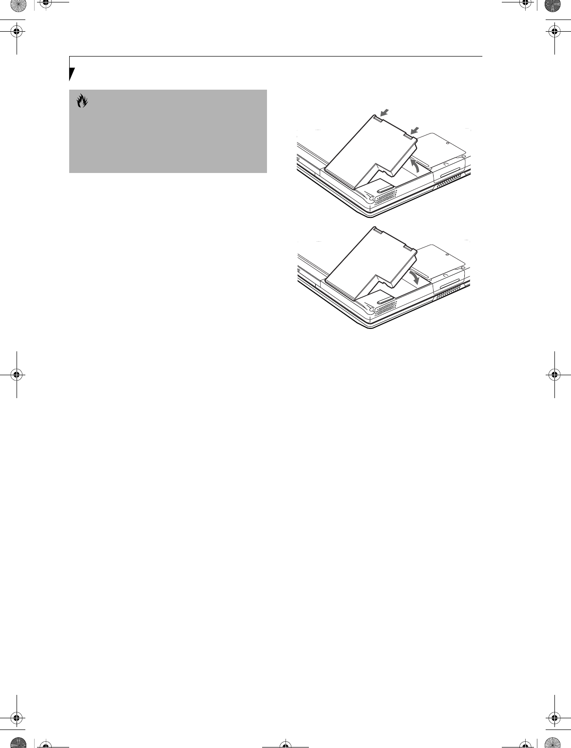
44
LifeBook E Series – Section 4
Dead Battery Suspend mode shows on the Status indi-
cator just like the normal Suspend mode. Once your
LifeBook notebook goes into Dead Battery Suspend
mode you will be unable to resume operation until you
provide a source of power either from an adapter, or a
charged battery. Once you have provided power, you will
need to press the Suspend/Resume button to resume
operation. In the Dead Battery Suspend mode, your data
can be maintained for some time, but if a power source
is not provided promptly, the Power indicator will stop
flashing and go out, meaning that you have lost the data
that was not stored. Once you provide power, you can
continue to use your LifeBook notebook while an
adapter is charging the battery.
Shorted Batteries
The Status Indicator panel uses a symbol inside the
battery outline of the Battery Level indicator to display
the operating level available in that battery.
(See Figure 2-10 on page 15) If this display shows a
Shorted Battery, it means that the battery is damaged
and must be replaced so it does not damage any other
parts of your LifeBook notebook.
REPLACING THE BATTERY
With the purchase of an additional battery, you can have
a fully charged spare to swap with one that is not
charged.
Follow the steps below to replace a battery (Figure 4-1):
1. Have a charged battery ready to install.
2. Shut down your notebook and disconnect
the AC adapter.
3. Press the battery release latches toward the battery.
4. Lift the battery by the latch end and remove it from
the bay.
5. Slide a charged battery into the bay and press it
down until the latches click into place.
6. Plug in the AC adapter and turn the power on.
Figure 4-1 Replacing the Battery
CAUTION
When you are in Suspend mode there must always be
at least one power source active. If you turn off the
power with the power switch, or remove all power
sources while your LifeBook notebook is in Suspend
mode, any data that has not been saved to the hard
drive will be lost.
Battery
Release
Latches
B5FH-4491-01EN-00.book Page 44 Friday, April 19, 2002 11:24 AM
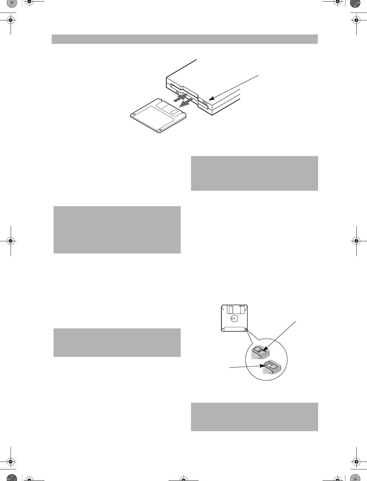
45
User-Installable Features
Figure 4-2 Loading/Ejecting a 3.5” Floppy Disk
External USB
Floppy Disk Drive
Your LifeBook notebook has an external USB floppy
disk drive which can read and write information on
removable 1.44MB and 720KB floppy disks.
LOADING A DISK
To load a disk into your disk drive, follow these easy
steps:
1. Orient the disk so that its label is facing upwards
and the shutter side is pointing towards the drive.
(Figure 4-2)
2. Push the disk into the drive until the Eject button
pops out and you hear a click.
EJECTING A DISK
To eject a disk from the disk drive, follow these easy
steps:
1. Check that the Floppy Disk Drive Access indicator
is inactive.
2. Press the Eject button. This will push your disk
partially out of the drive.
3. Remove the disk.
PREPARING A DISK FOR USE
Before you can use a new disk, it needs to be prepared
so your LifeBook notebook knows where to store infor-
mation. This preparation is called formatting or initial-
izing a disk. You will need to format new disks, unless
they are preformatted. (Please refer to your operating
system manual for step-by-step instructions on formatting a
disk)
To prevent accidental erasure of the data stored on a
disk, slide the “write protect” tab until a small hole is
exposed. This sets the disk into a protected state where
nothing can be added or removed. If you want to add or
remove data on a protected disk, slide the “write
protect” tab to close the small hole. (Figure 4-3)
Figure 4-3 Floppy Disk Write Protect
Eject Button
POINT
Your LifeBook notebook is preconfigured to boot from a
USB floppy drive. Reference the BIOS manual for fur-
ther information on changing the default boot drive.
The BIOS manual can be found on the Fujitsu PC web
site: www.FujitsuPC.com, under Support.
POINT
When there is no disk in the drive, the Eject button is
flush with your notebook.
CAUTION
If you eject the disk while the Floppy Disk Drive Access
indicator is active, there is a risk of damaging the data
on the disk, the disk itself or even the disk drive.
CAUTION
Formatting a floppy disk that already contains data will
erase all of the information on the disk.
Write Protected
Write Enabled
B5FH-4491-01EN-00.book Page 45 Friday, April 19, 2002 11:24 AM
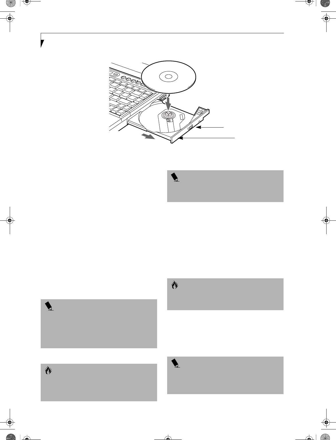
46
LifeBook E Series – Section 4
Figure 4-4. Media Player Drive
Media Drive
Your Fujitsu LifeBook notebook contains a media player
drive which is either a CD, DVD, or DVD/CD-RW
combo player. A DVD player gives you access to movie,
software, and audio DVD/CDs. A DVD/CD-RW player
allows you to write data onto recordable CDs in addition
to all of the standard DVD drive functions.
MEDIA PLAYER SOFTWARE
DVD model only: With the media player drive and media
player software you can play DVD movies on your Life-
Book notebook. The media player includes controls
which allow you to take full advantage of the features of
a DVD movie, as well as standard features such as fast
forward, fast reverse, pause, etc.
DVD/CD-RW Combo model only: With the combo drive,
you can play DVD movies, read audio CDs, and write
data onto recordable CD-R or CD-RW discs.
LOADING A DVD, CD, CD-R, CD-RW, OR
COMBO (“MEDIA”)
To load a disc into your media player drive, follow these
steps:
1. Push and release the eject button on the front of the
media player drive to open the holder tray. The tray
will come out of the notebook a short distance.
2. Gently pull the tray out until a media disc can easily
be placed in the tray.
3. Place the media into the tray, label side up, with the
hole in the center of the disc. Snap the disc onto the
raised circle in the center of the tray.
4. Gently push the holder tray back in until you hear a
click. (Figure 4-5)
DVD/CD Holder Tray
DVD/CD Eject Button
POINTS
■Prior to using your Media Player, you must install
the Media Player software. Refer to the applicable
readme file on the Driver Applications CD-ROM for
instructions on installing you Media Player software.
■You should periodically check the Fujitsu Web site at
www.fujitsupc.com for current updated drivers.
CAUTION
Do not operate your media player drive unless your
LifeBook notebook is sitting on a flat surface. Using a
drive when the system is not level may damage the
drive or prevent proper operation.
POINT
Prolonged use of the media player drive, such as
watching a DVD movie, will substantially reduce your
battery life.
CAUTION
There may be a protective sheet in the tray from when it
was shipped; please make sure it is removed before oper-
ating the drive, otherwise your drive may be damaged.
POINT
If you have disabled the Auto Insert Notification
Function, you will have to start the drive from your
desktop, since your notebook will not automatically
recognize that media has been loaded.
B5FH-4491-01EN-00.book Page 46 Friday, April 19, 2002 11:24 AM
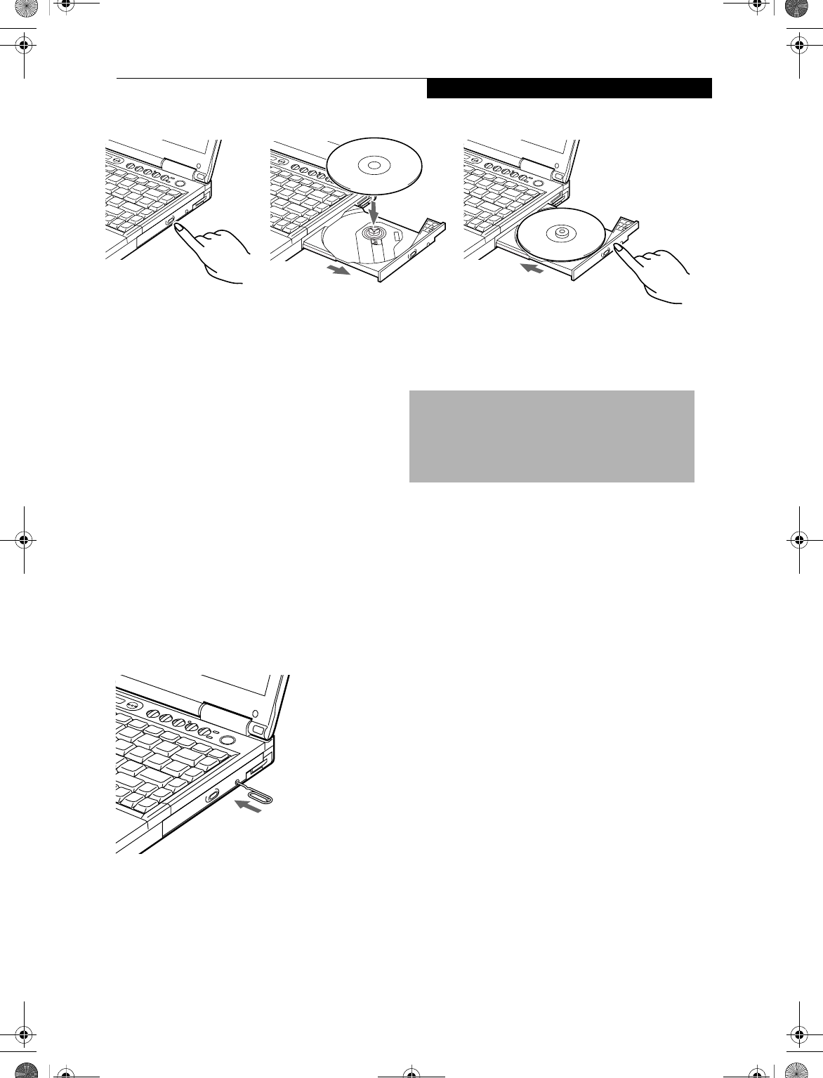
47
User-Installable Features
Figure 4-5 Loading/Ejecting Media
REMOVING MEDIA
1. Push and release the eject button on the front of
the media player drive. This will stop the drive
and the holder tray will come out of the notebook a
short distance.
2. Gently pull the tray out until the disc can easily be
removed from the tray.
3. Carefully remove the media disc from the holder
tray.
4. Gently push the holder tray back in until you
hear a click.
EMERGENCY DVD/CD-ROM TRAY RELEASE
If for some reason the eject button fails, you can open
the DVD/CD-ROM tray with a paper clip or your pen
inserted into the eject hole in the far right side of the
front of the tray. Straighten one side of a paper clip and
push it gently into the hole. The tray will pop out a short
distance.
Figure 4-6 Emergency Removal of a CD/DVD
USING THE MEDIA PLAYER SOFTWARE
Starting a DVD Movie (DVD Models only)
1. Insert the DVD movie into the media player drive of
your notebook. If the CD AutoRun feature activates,
skip Step 2.
2a.Windows 98 and 2000 only: From the Start menu,
select Programs, then select InterVideo WINDVD
and click InterVideo WINDVD or double-click on
the InterVideo WINDVD icon on the desktop. This
will launch the DVD movie.
2b. Windows XP only: The first time you insert a movie
into the DVD/CD-RW tray, you will be prompted to
select what you want the system to do when discs are
inserted (e.g., start automatically or wait for a
prompt). Until you make a selection, you will receive
the same prompt whenever you insert a disc.
3. Click OK to close the About DVD Player
Performance dialog box and the movie will begin.
Opening the DVD/CD-RW Drive Control Panel
With most DVD-ROMs, you have the option of altering
how the movie should play and what you wish to view.
You can do this by using the DVD/CD-RW Combo
Drive control panel and the mouse.
1. Right-click on the movie screen to open a
dropdown menu for options.
2. Select View, then Player for all the controls available.
This will open the control panel into the bottom of
the screen.
POINTS
■Prior to using your Media Player, you must install
the Media Player software.
■For details on using your media player, consult the
Help file that accompanies the software.
B5FH-4491-01EN-00.book Page 47 Friday, April 19, 2002 11:24 AM
48
LifeBook E Series – Section 4
Using the Media Player Control Panel
The Media Player software allows you to watch the
movie much like a VCR player. You have the option to
pause, rewind, fast-forward and stop the movie at any
point.
1. To Pause the movie, click the! button.
2. To Rewind the movie, click the " button to rewind
to a specific portion of the movie, or the # button
to return to the opening screen.
3. To Fast-forward the movie, click the $ button to
forward to a specific portion of the movie, or the%
button to jump to the ending credits.
4. To Stop the movie, click the & button.
Exiting the Media Player
1. Click on the ' located in the upper right corner of
the title bar. This will open a Media Player dialog
box.
2. Click Ye s to stop and exit the movie, or No to close the
Media Player dialog box and return to the movie.
USING DOLBYTM HEADPHONE
The Dolby Headphone utility lets you enjoy multi-
channel sound sources, such as movies, with realistic
surround sound using your conventional stereo head-
phones.
Dolby Headphone is a signal processing system that
enables your stereo headphones to realistically portray
the sound of a five-speaker playback system.
To use the Dolby Headphone feature, perform the
following steps:
1. Double click the InterVideo WinDVD icon on your
desktop.
2. On the toolbar that appears, click the Properties
button (the fourth button from the left, with the
image of a wrench).
3. On the Properties window, select the Dolby Head-
phone tab.
4. To enable Dolby Headphone, check the Enable
Dolby Headphone box. To change the type of
surround sound, select one of the radio buttons
listed under Room Filter Setting.
5. Click OK. The Dolby Headphone feature will now
be enabled until you disable it by unchecking Enable
Dolby Headphone.
USING THE MEDIA PLAYER ON
BATTERY POWER
Since media player drives consume a lot of power, your
overall battery life will be shorter when operating the
media player drive continuously (such as watching a
DVD movie). Many movie run-times are longer than
your LifeBook notebook can support on a single battery.
If you are watching a DVD movie on battery power you
may need to swap in an additional, charged battery or
attach AC power during the movie to view it in its
entirety.
To Watch a Movie on Battery Power:
1. Have an additional fully-charged battery or your AC
adapter ready for use.
2. Start watching your DVD movie.
3. When the low battery warning occurs, immediately
stop the movie and exit the media player.
4. Manually place your notebook into suspend mode
by depressing the Suspend button and replace the
discharged battery with an additional full-charged
battery. Or if you do not have an additional battery,
you may attach AC power as soon as you see the low
battery warning.
POINTS
■Media discs which do not have the Dolby Surround
5:1 symbol will not support Dolby Headphone.
■After making changes to the Dolby Headphone
feature and clicking OK, wait at least ten seconds
before making another change in order to allow the
system to stabilize.
POINTS
■Prolonged use of the media player drive, such as
watching a DVD movie, will substantially reduce your
notebook’s battery life.
■Many movie run-times are longer than your system
can support on a single battery. If you are watching a
DVD movie on battery power you may need to swap
in an additional, charged battery or attach AC power
during the movie to view it in its entirety.
■An additional fully-charged battery is highly recom-
mended if you will be watching DVD movies on bat-
tery power. If you don’t have an additional battery,
you may purchase one either on-line at www.fujit-
supc.com or call 1-877-372-3473.
CAUTION
If you do not stop the media player quickly and the
LifeBook notebook attempts to auto-suspend (critical
battery low state) the notebook will shut down
improperly. If this occurs, you will need to perform a
hard reset and follow the instruction, if any, presented
to you before the system will reboot.
B5FH-4491-01EN-00.book Page 48 Friday, April 19, 2002 11:24 AM
49
User-Installable Features
5. Resume your notebook by pressing the Suspend
button again. This step is not required if you
attached AC power without entering suspend mode.
6. Restart your media player, locate and skip to the
chapter of the movie you were last watching.
7. Continue watching your DVD movie.
AUTO INSERT NOTIFICATION FUNCTION
The Auto Insert Notification function allows your Life-
Book notebook to automatically start a DVD/CD as soon
as it is inserted in the media player drive and the tray is
closed. Your notebook will begin playing an audio DVD/
CD or will start an application if the DVD/CD includes an
auto run file.
To prevent a CD from playing automatically as soon as it
is inserted, refer to the related help file for your specific
opearting system.
POINT
Some shorter DVD movies may not require you to
swap batteries or attach AC power to complete them.
However, it is best to be prepared since actual battery life
while operating the media player drive cannot be
guaranteed.
B5FH-4491-01EN-00.book Page 49 Friday, April 19, 2002 11:24 AM
50
LifeBook E Series – Section 4
Hard Disk Drive
Your Fujitsu LifeBook notebook hard disk drive capacity
is dependent on which model you are using. Some Life-
Book notebooks may also contain a removable hard disk
drive in addition to the internal hard disk drive. (See
Specifications on page 83 for more information)
FORMATTING THE HARD DISK DRIVE
The internal hard disk drive is formatted, or initialized,
at the factory. You do not need to format it under
normal circumstances. If you decide to reformat due to
corruption or upgrade, please refer to your operating
system documentation for the correct procedure.
Before you reformat your hard disk drive, please note:
■Any data that currently resides on your hard disk drive
must be backed-up to floppy disks or other data
storage media, or it will be permanently lost. These
back-up disks can then be used to reinstall and restore
your data. (See your operating system manual for more
information on backing-up your data files)
■All application software that is installed on the
hard disk drive, must be reinstalled from the
original source.
■The factory-installed software, including the operating
system, can be restored using the Drive Image Special
Edition (DISE) software that came with your LifeBook
notebook (See Drive Image Special Edition (DISE) on
page 72 for more information).
CAUTION
Reformatting the hard disk drive will erase all of the
data currently stored on it, including the operating
system and installed programs.
B5FH-4491-01EN-00.book Page 50 Friday, April 19, 2002 11:24 AM
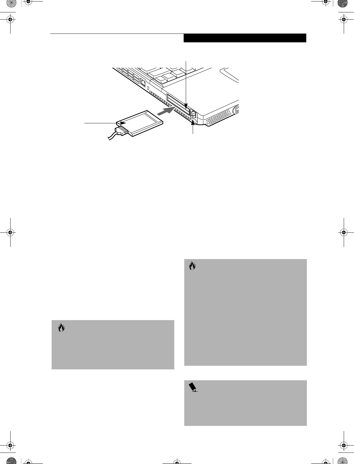
51
User-Installable Features
Figure 4-7 Installing/Removing PC Cards
PC Cards
Your LifeBook notebook supports two Type I and II and
one Type III PC Cards, which can perform a variety of
functions depending on which type of PC Card you
install.
Some types of PC Cards available on the market include:
■Fax/data modem
■Local area network (LAN)
■Wireless LAN PC card
■IDE solid-state disk
■SCSI
■Other PC Cards that conform to PCMCIA™ 2.1 or
CardBus standards.
For further information, refer to the instructions
supplied with your PC Card.
INSTALLING PC CARDS
PC Cards are installed in the PC Card slots. To install a
PC Card, follow these easy steps:
1. See your PC Card manual for specific instructions
on the installation of your card. Some PC Cards may
require your LifeBook notebook to be Off while
installing them.
2. Make sure there is no PC Card currently occupying
the slot. If there is, see Removing PC Cards.
3. If either of the eject buttons is extended, press it in
until it clicks.
4. Insert your PC Card into the slot with the product
label facing up.
5. Push the card into the slot firmly until it is seated
in the opening.
REMOVING PC CARDS
To remove a PC Card, perform the following steps:
1. See your PC Card manual for specific instructions
on removing your card. Some PC Cards may require
your notebook to be Off while removing them.
Eject Button
PC Card Slots
PC Card
CAUTIONS
■Installing or removing a PC Card during your LifeBook
notebook’s shutdown or bootup process may damage
the card and/or your notebook.
■Do not insert a PC Card if it not clean and dry. Insert-
ing a dirty or wet card could damage your notebook.
CAUTION
Loss of data could occur if proper shutdown
procedures are not observed.
Windows 98 Second Edition has a shutdown procedure
for PC Cards that must be followed before removing a
card. Review your operating system manual for
the correct procedure.
Windows 2000 Professional PC Cards should be
stopped using the Unplug or Eject Hardware utility on
the taskbar. Refer to your operating system manual for
the correct procedure.
Windows XP has a Safe Removal of Hardware utility on
the taskbar. Refer to your operating system manual for
the correct procedure.
POINT
If the dialog box states that the device cannot be
removed, you must save all of your open files, close
any open applications and shut down your LifeBook
notebook. Once your notebook has been shut down,
you must turn Off the power using the power switch.
B5FH-4491-01EN-00.book Page 51 Friday, April 19, 2002 11:24 AM
52
LifeBook E Series – Section 4
2. Unlock the PC Card from the slot by first pressing
the eject button associated with the slot the card is
in. When pressed, the button will pop up.
3. Firmly press the button again until it is flush with
the notebook. This will push the PC Card slightly
out of the slot allowing you to remove the card.
SMARTCARD READER
An embedded SmartCard Reader is provided on your
LifeBook notebook. SmartCards are the same size and
shape as credit cards, but they contain an integrated
microprocessor chip. The chip can hold a variety of
different information, and provides the user with many
possible options, such as allowing them to make secure
purchases, pay for phone calls, store security informa-
tion, and provide personal identification and informa-
tion.
CAUTION
If the PC Card has an external connector and cable, do
not pull the cable when removing the card.
POINT
In order to use the embedded SmartCard Reader, you
must purchase an optional SmartCard adapter for
installation into an available Type II PC Card slot. For
more information, visit our online store at
www.fujitsupc.com.
B5FH-4491-01EN-00.book Page 52 Friday, April 19, 2002 11:24 AM
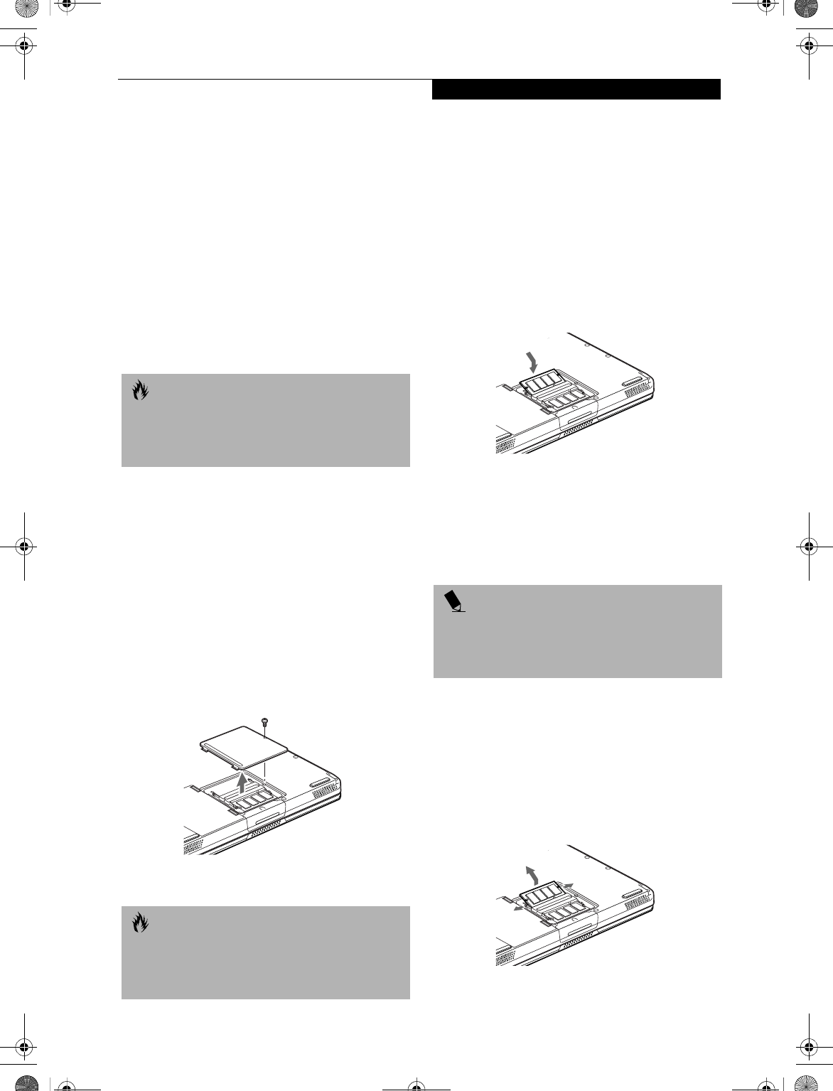
53
User-Installable Features
Memory Upgrade
Module
Your LifeBook notebook comes with 128MB or 256MB of
memory factory installed. To increase your LifeBook
notebook’s memory capacity, you may install an addi-
tional memory upgrade module. You can also replace the
original memory module with a higher capacity module.
The memory upgrade must be a PC2100 DDR266 SO-
DIMM module, but it can be any capacity up to 1024MB
(total). To ensure 100% compatibility, we recommend
that you only purchase additional memory from the
Fujitsu on-line accessory store at:
www.fujitsupc.com/accessories.
INSTALLING A MEMORY UPGRADE
MODULE
1. Turn off power to your LifeBook notebook using the
power switch, and remove any power adapter
(AC or auto/airline).
2. Make sure that all the connector covers are closed.
3. Turn the LifeBook notebook bottom side up, with
the front panel toward you.
4. Remove the screw at the front of the memory
upgrade module compartment. (Figure 4-8)
5. Remove the cover by tilting the front edge up
and then pulling forward until the tabs on the
cover are free.
Figure 4-8. Opening the Memory Upgrade Compartment
6. Remove the memory upgrade module from the
static guarded sleeve.
7. Align the memory upgrade module with the part
side up. Align the connector edge of the memory
upgrade module with the connector slot in the
compartment. The connector will be pointing
toward the rear of the LifeBook notebook.
8. Insert the memory upgrade module at a 45° angle.
Press the connector edge of the module firmly down
and into the connector until it lodges under the
retaining clip. You will hear a click when it is prop-
erly in place. (Figure 4-9)
Figure 4-9. Installing a Memory Upgrade Module
9. Replace the cover by hooking the tabs under the rear
edge of the compartment opening and tilting down
until flush with the bottom of your LifeBook note-
book.
10. Replace the screw.
REMOVING A MEMORY UPGRADE MODULE
1. Perform steps 1 through 5 of Installing a Memory
Upgrade Module.
2. Pull the clips sideways away from each side of the
memory upgrade module at the same time.
3. While holding the clips out, remove the module
from the slot by lifting it up and pulling towards the
rear of your LifeBook notebook. (Figure 4-10)
Figure 4-10. Removing a Memory Upgrade Module
CAUTION
Do not remove any screws from the memory upgrade
module compartment, except the ones specifically
shown in the directions for installing and removing
the memory upgrade module.
CAUTION
The memory upgrade module can be severely damaged
by electro-static discharge (ESD). Be sure you are
properly grounded when handling and installing the
module.
POINT
The memory upgrade module is not something you
should routinely remove from your notebook. Once it is
installed, you should leave it in place unless you want
to increase system memory capacity.
B5FH-4491-01EN-00.book Page 53 Friday, April 19, 2002 11:24 AM
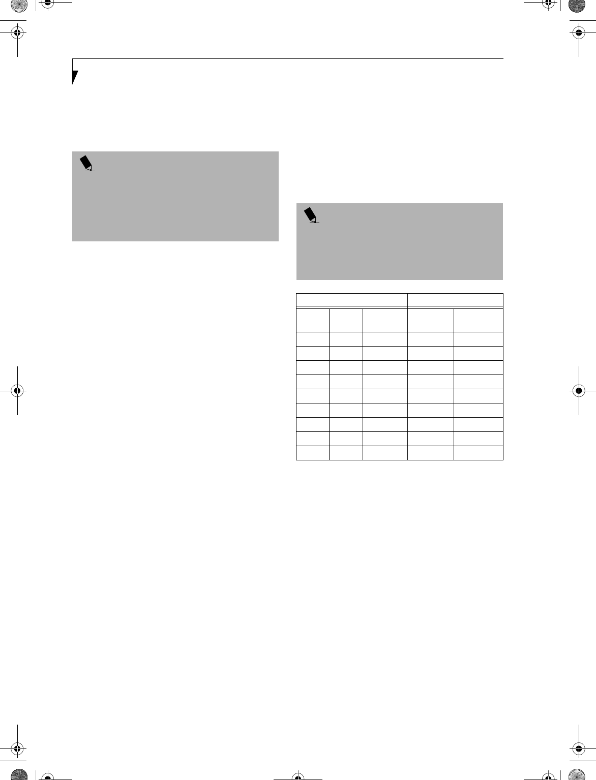
54
LifeBook E Series – Section 4
4. Store the memory upgrade module in a static
guarded sleeve.
5. Replace the cover by following steps 9 and 10 of
Installing a Memory Upgrade Module.
CHECKING THE COMPUTER RECOGNITION
OF NEW MEMORY CAPACITY
Once you have changed the system memory capacity
by either adding or removing a memory upgrade
module, be sure to check that your notebook has
recognized the change.
You can check the memory capacity by looking at the
main menu of the BIOS setup:
1. Turn on the power to your LifeBook notebook using
the power switch.
2. Allow the system to start booting and press the F2
key once the Fujitsu logo appears on the screen. This
will open the main menu of the BIOS setup with the
current settings displayed. (See BIOS Setup Utility on
page 35 for more information)
The System Memory and the Extended Memory
capacity, as detected by your LifeBook notebook during
the Power On Self Test (POST), are displayed at the
bottom of the main menu screen. The chart below shows
you the possible displays that can be shown on the main
menu screen. In the chart, Slot 1 is the original DR266
memory compartment while Slot 2 is the upgrade
compartment located in the center of your LifeBook
notebook.
POINT
After installing your added memory module, you must
complete the Resetting the Save-to-Disk Parameters
procedure in order for the Save-to-Disk mode to
operate properly on your LifeBook notebook. (See
Hibernation (Save-to-disk) Feature on page 39 for
more information)
POINT
If the total memory displayed is incorrect, check that
your memory upgrade module is properly installed. (If
the module is properly installed and the capacity is still
not correctly recognized, see the Troubleshooting
section starting on page 61)
Installed Displayed
Slot 1 Slot 2
Total RAM
Installed
System
Memory
Extended
Memory
128MB 0MB 128MB 640K 127MB
128MB 128MB 256MB 640K 255MB
128MB 256MB 384MB 640K 383MB
256MB 0MB 256MB 640K 255MB
256MB 128MB 384MB 640K 383MB
256MB 256MB 512MB 640K 511MB
512MB 128MB 640MB 640K 639MB
512MB 256MB 768MB 640K 767MB
512MB 512MB 1024MB 640K 1023MB
B5FH-4491-01EN-00.book Page 54 Friday, April 19, 2002 11:24 AM
55
User-Installable Features
Device Ports
Your LifeBook notebook comes equipped with multiple
ports to which you can connect an external device
including: disk drives, keyboards, modems, printers, etc.
COMMUNICATIONS PORTS
Your LifeBook has a Modem jack (RJ-11) and a LAN
jack (RJ-45) to accommodate external comunications.
Modem (RJ-11) Telephone Jack
The modem (RJ-11) telephone jack is used for your
internal modem. To connect the telephone cable follow
these easy steps: (See Figure 2-5 on page 10 for location)
1. Align the connector with the port opening.
2. Push the connector into the port until it is seated.
3. Plug the other end of the telephone cable into a
telephone outlet.
LAN PORT
This port allows you to connect a LAN (RJ-45) cable for
high-speed network or broadband connections (e.g.,
DSL, cable modem). When your LifeBook notebook is
connected to the Port Replicator, the LAN port on the
system is not accessible; the Port Replicator LAN port is
the only one that should be used when it as attached to
the system. (See Figure 2-5 on page 10 for location)
WIRELESS LAN PORT
The optional Wireless LAN port allows you to connect
with another device wirelessly. (See Integrated Wireless
LAN User’s Guide on page 101 for more information)
IEEE 1394 JACK
The 4-pin IEEE 1394 jack allows you to download digital
files (such as digital video and images) to the computer
at up to 400Mbps. Hot-swappable and plug-n-play, it is
much faster than USB, CardBus, or parallel port. In
order to connect a 1394 device, follow these steps: (See
Figure 2-4 on page 8 for location)
PARALLEL PORT
The parallel port, or LPT port, allows you to connect
parallel devices, such as a printer to your LifeBook note-
book. In order to connect a parallel interface device
follow these easy steps: (See Figure 2-7 on page 12 for
location)
1. Align the connector with the port opening.
2. Push the connector into the port until it is seated.
3. Tighten the two hold-down screws, located on
each end of the connector.
SERIAL PORT
The serial port, or COMM port, allows you to connect
serial devices, such as printers or scanners. In order
to connect a serial interface device follow these steps:
(See Figure 2-7 on page 12 for location)
1. Align the connector with the port opening.
2. Push the connector into the port until it is seated.
3. Tighten the two hold-down screws, located on each
end of the connector.
PS/2 PORT
The PS/2 port allows you to connect an external
keyboard, numeric keypad, or mouse. In order to
connect a PS/2 interface device follow these steps: (See
Figure 2-7 on page 12 for location)
1. Align the connector with the port opening.
2. Push the connector into the port until it is seated.
UNIVERSAL SERIAL BUS PORTS
The Universal Serial Bus ports (USB) allow you to
connect USB devices such as external game pads,
pointing devices, keyboards and/or speakers. In order
to connect a USB device follow these steps: (See Figure 2-
7 on page 12 for location)
1. Align the connector with the port opening.
2. Push the connector into the port until it is seated.
CAUTION
Do not connect the internal modem to a Digital PBX as
it may cause serious damage to the modem or your
LifeBook notebook. It should be noted that some hotels
use the Digital PBX systems, please be sure to find out
BEFORE you connect your modem. Consult your PBX
manufacturer’s documentation for more information.
POINT
The internal modem is designed to the ITU-T V.90
standard. Its maximum speed of 53000bps is the
highest allowed by the FCC, and its actual connection
rate depends on the line conditions. The maximum
speed is 33600bps at upload.
POINT
The 1393 port in this system uses a four-pin
configuration. If you intend to interface with devices
which have a six-pin configuration, you will need to
purchase an adapter.
POINTS
■A mouse, keyboard, or keypad may be installed and
automatically recognized by your notebook without
restarting or changing setups.
■The use of two PS/2 devices simultaneously from the
port requires a PS/2 splitter.
B5FH-4491-01EN-00.book Page 55 Friday, April 19, 2002 11:24 AM
56
LifeBook E Series – Section 4
INFRARED PORT
The Infrared IrDA 1.1 (4Mbps) port allows for wireless
data transfer between your LifeBook notebook and
other IrDA-compatible devices, such as another
computer or a printer, without the use of a cable.
(See Figure 2-5 on page 10 for location)
It is important to keep in mind that while carrying out
this form of communication, both devices must be
placed so their infrared ports are directly facing each
other without obstruction. The devices must also be
separated by at least 6" but no more than 36" for
maximum performance.
The following conditions may interfere with infrared
communications:
■A television, radio remote control unit, or a wireless
headphone is being used nearby.
■Direct sunlight, fluorescent light, or incandescent light
shines directly on the port.
WIRELESS INFRARED MOUSE PORT
The optional Wireless Infrared Mouse Port allows you to
use your wireless infrared (IR) Mouse. The IR Mouse
communicates directly with the IR Mouse port without
the use of a cable. (See Figure 2-4 on page 8 for location)
MICROPHONE JACK
The microphone jack allows you to connect an external
mono microphone. Your microphone must be equipped
with a 1/8"(3.5 mm) mono mini-plug in order to fit into
the microphone jack of your LifeBook notebook. In
order to connect a microphone follow these easy steps:
(See Figure 2-4 on page 8 for location)
1. Align the connector with the port opening.
2.Push the connector into the port until it is seated.
S-VIDEO OUT PORT
The S-Video port allows you to connect and use directly
any S-Video device, such as a VCR or television. The
S-Video standard provides for a higher quality picture
than NTSC or PAL. In order to connect an S-Video
device, follow these easy steps: (See Figure 2-7 on page 12
for location)
1. Align the connector with the port opening.
2. Push the connector into the port until it is seated.
HEADPHONE/SPDIF JACK
The headphone/SPDIF jack allows you to connect head-
phones, powered external speakers, or a MiniDisc
recorder to your LifeBook notebook. Your device must
be equipped with a 1/8" (3.5 mm) stereo mini-plug. In
order to connect headphones or speakers follow these
easy steps: (See Figure 2-4 on page 8 for location)
1. Align the connector with the port opening.
2. Push the connector into the port until it is seated.
The optical digital audio-out feature of this jack allows
you to download digital audio to MiniDisc recorders
using SPDIF (Sony Philips Digital Interface) format.
Please use the following setting when using the jack for
digital audio-out.
1. Click on Start -> Settings, then click on Control
Panel.
2. Select Yamaha Ds-XG Audio Configuration.
3. Click on the SPDIF tab and click ON (Digital
Sources Only). If you don’t see this setting, the
optical digital is always on by default.
CAUTIONS
■Do not move either device while communication is
active as it may interrupt data transmission.
■Be careful not to scratch the infrared port lens.
Scratches, dirt, or other surface marks can
degrade operation.
POINT
With Windows 98 Second Edition, you can use the
Infrared Recipient application for infrared file transfers.
With Windows 2000 Professional, file transfer is
provided through Wireless Link in the Control Panel.
POINT
If you plug headphones into the headphone jack, you
will disable the built-in stereo speakers.
POINTS
■The frequency of the digital sound output from the
SPDIF output connector is fixed to 48KHz. If a
sampling rate convertor is not installed in your
connecting digital electronic device (e.g., MD player),
recording is not possible. Please see the user manuals
for the electronic devices for further details.
■The sound recorded through connecting a digital
electronic device (e.g., MD player) to the SPDIF
output connector cannot be used as digital output. All
output data from the SPDIF output connector has
copyright protection information included.
■Be careful in your choice of cable, as there are several
types of cables for connecting a digital electronic
device (e.g. MD player) to the digital audio-out
connector, depending on the connector type. The
connector on your computer is a Optical Mini Plug
(3.5mm diameter mini plug).
B5FH-4491-01EN-00.book Page 56 Friday, April 19, 2002 11:24 AM
57
User-Installable Features
DOCKING PORT
The docking port is used for the connection of your
notebook to an optional port replicator or docking
station. In order to connect your notebook to one of
these devices follow the instructions that came with
your port replicator or docking station. (See Figure 2-7
on page 12 for location)
EXTERNAL MONITOR PORT
The external monitor port allows you to connect an
external monitor. In order to connect an external
monitor follow these easy steps: (See Figure 2-7 on page
12 for location)
1. Align the connector with the port opening.
2. Push the connector into the port until it is seated.
3. Tighten the two hold-down screws, located on
each end of the connector.
CAUTION
Some LifeBook notebooks have a sliding panel that
encloses the ports. The sliding panel can be damaged if
it is left open while the notebook is moved.
POINT
Pressing the [Fn] + [F10] keys allows you to change
your selection of where to send your display video. Each
time you press the key combination, you will
step to the next choice, starting with the built-in display
panel only, moving to the external monitor only, finally
moving to both the built-in display panel and an
external monitor.
B5FH-4491-01EN-00.book Page 57 Friday, April 19, 2002 11:24 AM

58
LifeBook E Series – Section 4
B5FH-4491-01EN-00.book Page 58 Friday, April 19, 2002 11:24 AM

59
5
Troubleshooting
B5FH-4491-01EN-00.book Page 59 Friday, April 19, 2002 11:24 AM

60
LifeBook E Series – Section 5
B5FH-4491-01EN-00.book Page 60 Friday, April 19, 2002 11:24 AM
61
Troubleshooting
Troubleshooting
Your LifeBook notebook is sturdy and subject to few
problems in the field. However, you may encounter
simple setup or operating problems that you can solve
on the spot, or problems with peripheral devices, that
you can solve by replacing the device. The information
in this section helps you isolate and resolve some of
these straightforward problems and identify failures that
require service.
FUJITSU SERVICE ASSISTANT
Your LifeBook notebook includes a sophisticated, full-
featured troubleshooting utility that can assist you in
solving most problems you might encounter. The
Fujitsu Service Assistant is an interactive support tool
that provides automated diagnosis and solutions for
your hardware and software problems. This tool is
located in one or more of the following locations:
nA Fujitsu Service Assistant icon on your desktop
nIn the Start -> Service and Support folder
nOn a separate Fujitsu Service Assistant CD included
with your system
New support information for the Fujitsu Service Assis-
tant tool may be available after the purchase of your
notebook. You should periodically connect to the
Internet while using the Fujitsu Service Assistant tool to
ensure that you are using the most current version.
IDENTIFYING THE PROBLEM
If you encounter a problem that cannot be solved using
the Fujitsu Service Assistant, go through the following
procedure before pursuing further troubleshooting:
1. Turn off your LifeBook notebook.
2. Make sure the AC adapter is plugged into your Life-
Book notebook and to an active AC power source.
3. Make sure that any card installed in the PC Card slot
is seated properly. You can also remove the card
from the slot, thus eliminating it as a possible cause
of failure.
4. Make sure that any devices connected to the external
connectors are plugged in properly. You can also
disconnect such devices, thus eliminating them as
possible causes of failure.
5. Turn on your LifeBook notebook. Make sure it has
been off at least 10 seconds before you turn it on.
6. Go through the boot sequence.
7. If the problem has not been resolved, refer to the
Troubleshooting Table, that follows, for more
detailed troubleshooting information.
8. If you have tried the solutions suggested in the Trou-
bleshooting Table without success, contact your
support representative:
Toll free: 1-800-8Fujitsu (1-800-838-5487)
Fax: 1-901-259-5700
E-mail: 8fujitsu@fujitsupc.com
Web site: http://www.fujitsupc.com.
Before you place the call, you should have the following
information ready so that the customer support repre-
sentative can provide you with the fastest possible solu-
tion:
nProduct name
nProduct configuration number
nProduct serial number
nPurchase date
nConditions under which the problem occurred
nAny error messages that have occurred
nHardware configuration
nType of device connected, if any
See the Configuration Label on the bottom of your
LifeBook notebook for configuration and serial
numbers. (See Figure 2-8 on page 13 for location)
POINT
If you keep notes about what you have tried, your
support representative may be able to help you more
quickly by giving additional suggestions over the
phone.
POINT
Do not return a failed LifeBook notebook to Fujitsu PC
Corporation until you have received a Return Material
Authorization (RMA) number from a support
representative.
B5FH-4491-01EN-00.book Page 61 Friday, April 19, 2002 11:24 AM
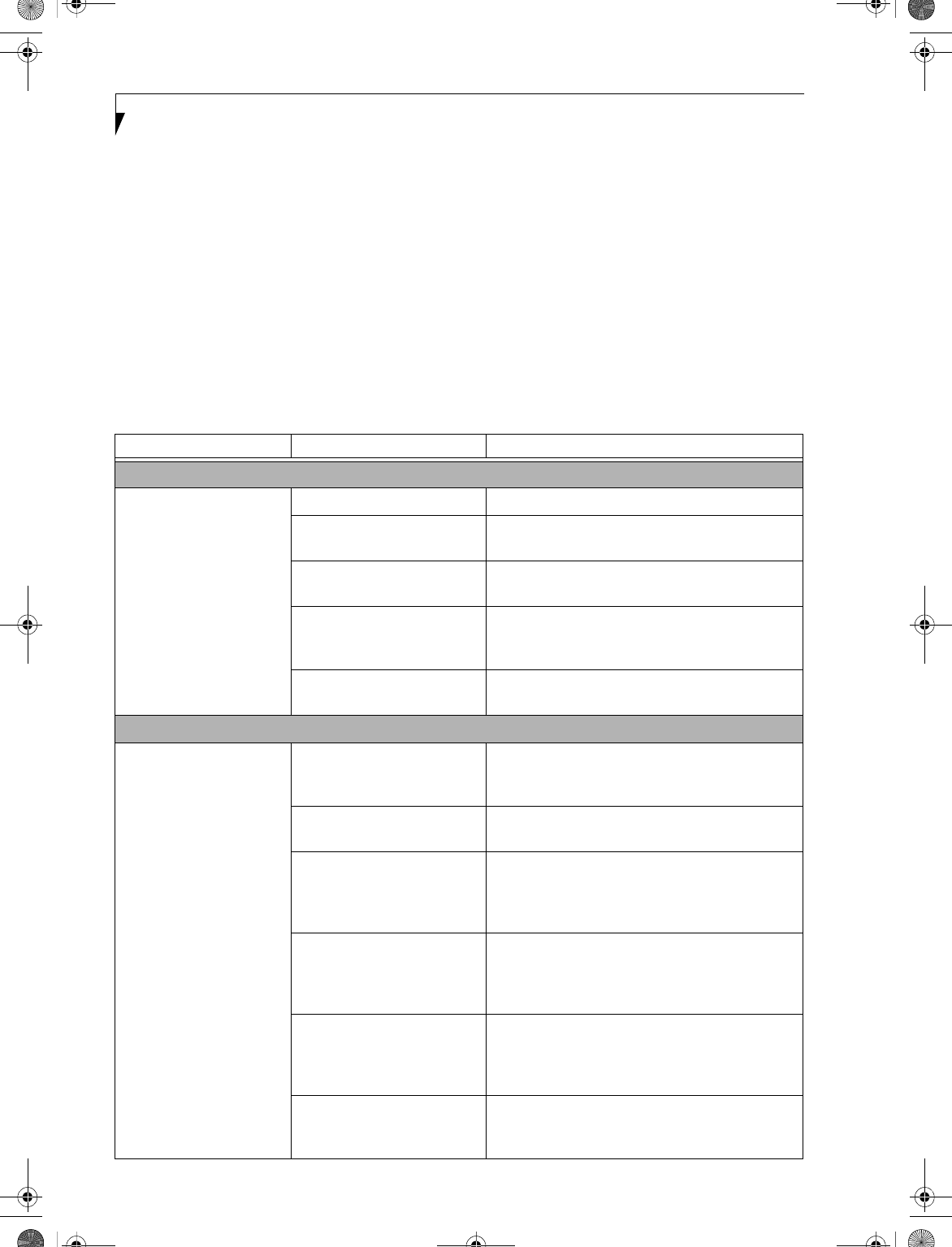
62
LifeBook E Series – Section 5
SPECIFIC PROBLEMS
Using the Troubleshooting Table
When you have problems with your LifeBook notebook,
try to find the symptoms under the Problem column of
the troubleshooting table for the feature giving you
difficulty.
TROUBLESHOOTING TABLE
You will find a description of common causes for that
symptom under the column Possible Cause and what, if
anything, you can do to correct the condition under
Possible Solutions. All possible causes or solutions may
not apply to your LifeBook notebook.
Problem Page
Audio Problems . . . . . . . . . . . . . . . . . . . . . . . . . . page 62
DVD/CD-ROM Drive Problems . . . . . . . . . . . . page 62
Docking Problems . . . . . . . . . . . . . . . . . . . . . . . . page 63
Floppy Disk Drive Problems. . . . . . . . . . . . . . . . page 63
Hard Drive Problems. . . . . . . . . . . . . . . . . . . . . . page 63
Keyboard or Mouse Problems . . . . . . . . . . . . . . page 63
Memory Problems . . . . . . . . . . . . . . . . . . . . . . . . page 64
Modem Problems. . . . . . . . . . . . . . . . . . . . . . . . . page 64
Parallel, Serial and USB Device Problems . . . . . page 64
PC Card Problems . . . . . . . . . . . . . . . . . . . . . . . . page 65
Power Failures . . . . . . . . . . . . . . . . . . . . . . . . . . . page 65
Shutdown and Start-up Problems . . . . . . . . . . . page 67
Video Problems . . . . . . . . . . . . . . . . . . . . . . . . . . page 67
Miscellaneous Problems . . . . . . . . . . . . . . . . . . . page 69
Problem Possible Cause Possible Solutions
Audio Problems
There is no sound coming
from the built-in speakers.
The volume is turned too low. Adjust the volume control on your notebook.
The software volume control is
set too low.
Adjust the sound volume control settings in your
software, operating system and applications.
Headphones are plugged into
your notebook.
Plugging in headphones disables the built-in
speakers, remove the headphones.
BIOS audio settings
are incorrect.
Set the BIOS setup utility to the default values within
the Multimedia Device Configuration menu. (See
BIOS Setup Utility on page 35 for more information)
Software driver is not config-
ured correctly.
Refer to your application and operating system
documentation for help.
DVD/CD-ROM Drive Problems
Notebook fails to recognize
DVD/CDs.
DVD/CD is not pushed down
onto raised center circle of
the drive.
Open DVD/CD-ROM tray and re-install
DVD/CD properly.
DVD/CD-ROM tray is not
latched shut.
Push on the front of the DVD/CD-ROM tray
until it latches.
Setup utility is set to some-
thing other than DVD/CD-
ROM or Auto for the
Secondary Master Controller.
Revise BIOS settings for the Secondary Master
Controller. (See BIOS Setup Utility on page 35 for
more information)
Wrong drive designator was
used for DVD/CD in the
application.
Verify that the drive designator used by the applica-
tion is the same as that used by the operating system.
When the operating system is booted from a DVD/
CD, drive designations are automatically adjusted.
Windows DVD/CD Auto
Insert Notification function is
disabled.
Start the DVD/CD from the desktop or application
software or re-enable the Windows DVD/CD Auto
Insert Notification function. (See Auto Insert Notifi-
cation Function on page 49 for more information)
DVD/CD is dirty or defective. Wipe DVD/CD with a non-abrasive CD cleaning
cloth and reinsert. If it still will not work try another
DVD/CD in the drive.
B5FH-4491-01EN-00.book Page 62 Friday, April 19, 2002 11:24 AM
63
Troubleshooting
LifeBook notebook fails to
auto-play DVD movie.
DVD Player Software is not
installed.
Install DVD Player Software using the DVD Appli-
cation.
The DVD/CD-ROM Access
indicator on the Status
Indicator Panel blinks at
regular intervals when no
disk is in the tray or the
DVD drive is not installed.
The Windows DVD/CD Auto
Insert Notification function is
active and is checking to see if
a DVD/CD is ready to run.
This is normal. However, you may disable this
feature. (See Auto Insert Notification Function on
page 49 for more information)
Docking Problems
Notebook does not turn
on when installed in
Docking Station.
LAN Dock AC adapter is not
plugged in.
Provide power to the LAN Docking Station.
Notebook is not properly
seated in the LAN Dock.
Remove and re-dock your notebook and verify that
the Docked LED illuminates.
Floppy Disk Drive Problems
You cannot access your
floppy disk.
You tried to write to a write
protected floppy disk.
Eject the floppy disk and set it to write enable. (See
External USB Floppy Disk Drive on page 45 for more
information)
Floppy disk is not
loaded correctly.
Eject floppy disk, check orientation and reinsert.
(See External USB Floppy Disk Drive on page 45 for
more information)
BIOS setup utility states
Diskette Controller:
Disabled.
Revise the setup utility Main menu settings to
enable Diskette Controller. (See BIOS Setup Utility
on page 35 for more information)
The floppy disk drive may not
be properly installed.
Remove and reinstall your floppy disk drive. (See
Flexible Bay Devices on page 23 for more information)
Security is set to protect access
to floppy disk data.
Verify your password and security settings.
Hard Drive Problems
You cannot access your
hard drive.
The setup utility is incorrectly
set for your internal hard drive.
Set Primary Master correctly in the BIOS. (See BIOS
Setup Utility on page 35 for more information)
The wrong drive designator
was used by an application
when a bootable CD-ROM was
used to start the notebook.
Verify drive designator used by application is in
use by the operating system. When the operating
system is booted from a CD, drive designations
are automatically adjusted.
Security is set so your oper-
ating system cannot be started
without a password.
Verify your password and security settings.
Keyboard or Mouse Problems
The built-in keyboard does
not seem to work.
The notebook has gone into
Suspend mode.
Push the Power and Suspend/Resume button.
Your application has locked
out your keyboard.
Try to use your intergrated pointing device to restart
your system. If this fails, turn your LifeBook note-
book off using the power switch, wait 10 seconds or
more, and then turn it back on.
The NumLock key is set. Press the NumLock key to reset it.
Problem Possible Cause Possible Solutions
B5FH-4491-01EN-00.book Page 63 Friday, April 19, 2002 11:24 AM
64
LifeBook E Series – Section 5
You have installed an
external keyboard or
mouse, and it does not
seem to work.
Your external device is not
properly installed.
Reinstall your device. (See Device Ports on page 55 for
more information)
Your operating system
software is not set up with the
correct driver for that device.
Check your device and operating system docu-
mentation and activate the proper driver.
Your mouse or keyboard is
connected to the wrong PS/2
port on the LAN Dock.
Plug the mouse into the PS/2 Mouse port and the
external keyboard or numeric key pad into the PS/2
Keyboard port. (See Device Ports on page 55 for more
information)
You have connected an
external keyboard or a
mouse and it seems to be
locking up the system.
Your operating system
software is not setup with
the correct software driver
for that device.
Check your device and operating system
documentation and activate the proper driver.
Your system has crashed. Try to restart your LifeBook notebook. If that fails,
turn off the power using the power switch, wait at
least 10 seconds, and then power on.
Memory Problems
Your Power On screen, or
Main menu of the BIOS
setup utility information,
does not show the correct
amount of installed
memory.
Your memory upgrade module
is not properly installed.
Remove and reinstall your memory upgrade
module. (See Memory Upgrade Module on page 53
for more information)
You have a memory failure. Check for Power On Self Test (POST) messages.
(See Power On Self Test Messages on page 70 for more
information)
Modem Problems
Messages about modem
operation.
Messages about modem
operation are generated by
whichever modem application
is in use.
See your application software documentation for
additional information.
Parallel, Serial, and USB Device Problems
You have installed a parallel
port device, a serial port
device or a USB device.
Your LifeBook notebook
does not recognize the
device, or the device does
not seem to work properly.
The device is not properly
installed.
Remove and reinstall the device. (See Device Ports on
page 55 for more information)
The device may have been
installed while an application
was running, so your notebook
is not aware of its installation.
Close the application and restart your LifeBook
notebook.
Your software may not have
correct software driver active.
See your software documentation and activate the
correct driver.
You may have the wrong I/O
address selected for your
device.
See your device documentation and software docu-
mentation to determine the required I/O address.
Change the settings in the BIOS setup utility. (See
BIOS Setup Utility on page 35 for more information)
Your device and another device
are assigned the same I/O
address.
Check all I/O addresses located within the BIOS
setup utility and any other installed hardware or
software to make sure there are no duplications.
Parallel port is set to
output only.
Check parallel port setting in the BIOS and set to
bi-directional or ECP.
Problem Possible Cause Possible Solutions
B5FH-4491-01EN-00.book Page 64 Friday, April 19, 2002 11:24 AM
65
Troubleshooting
PC Card Problems
A card inserted in the PC
Card slot does not work or
is locking up the system.
The card is not
properly installed.
Remove and reinstall the card. (See PC Cards on
page 51 for more information)
The card may have been
installed while an application
was running, so your notebook
is not aware of its installation.
Close the application and restart your LifeBook
notebook.
Yo ur s o f t w ar e m ay no t hav e
the correct driver active.
See your software documentation and activate the
correct driver.
Yo u m ay ha ve t h e w r on g
I/O address selected for your
PC Card device.
See your PC Card documentation to determine
the required I/O address. Change the settings in
the BIOS. (See BIOS Setup Utility on page 35 for
more information)
Your PC Card device and
another device are assigned the
same I/O address.
Check all I/O addresses located within the BIOS
setup utility and any other installed hardware or
software to make sure there are no duplications.
Power Failures
You turn on your
LifeBook notebook and
nothing seems to happen.
The installed primary battery
is completely discharged, there
is no optional second battery
installed or there is no Power
adapter (AC or Auto/Airline)
installed.
Check the Status Indicator Panel to determine the
presence and condition of the batteries. (See Status
Indicator Panel on page 14 for more information)
Install a charged battery or a Power adapter.
The primary battery is
installed but is faulty.
Use the Status Indicator panel to verify the presence
and condition of the batteries. (See Status Indicator
Panel on page 14 for more information) If a battery is
indicating a short, remove that battery and operate
from another power source or replace that battery.
The battery or batteries are low. Check the Status Indicator Panel to determine the
presence and condition of the batteries. (See Status
Indicator Panel on page 14 for more information) Use
a Power adapter to operate until a battery is charged
or install a charged battery.
The power adapter (AC or
auto/airline) is not plugged
in properly.
Verify that your adapter is connected correctly. (See
Power Sources on page 33 for more information)
The Power adapter (AC
or auto/airline) has no
power from the AC outlet,
airplane seat jack, or the car’s
cigarette lighter.
Move the AC cord to a different outlet, check for
a line switch or tripped circuit breaker for the AC
outlet. If you are using an auto/airline adapter in
a car make sure the ignition switch is in the On or
Accessories position.
The Power adapter (AC or
auto/airline) is faulty.
Try a different Power adapter or install a charged
optional second battery.
Problem Possible Cause Possible Solutions
B5FH-4491-01EN-00.book Page 65 Friday, April 19, 2002 11:24 AM
66
LifeBook E Series – Section 5
Your LifeBook notebook
turns off all by itself.
The power management
parameters are set for auto
timeouts which are too short
for your operating needs.
Press any button or key on the keyboard, or move
the mouse to restore operation. If that fails, push the
Power and Suspend/Resume button. Check your
power management settings, or close your applica-
tions and go to the Power Savings menu of the setup
utility to adjust the timeout values to better suit
your operation needs.
You are operating on battery
power only and have ignored a
low battery alarm until the
batteries are all at the dead
battery state and your machine
has gone into Dead Battery
Suspend mode.
Install a power adapter and then push the Power and
Suspend/Resume button. (See Power Sources on
page 33 for more information)
You have a battery failure. Verify the condition of the batteries using the
Status Indicator panel, and replace or remove
any batteries that are shorted. (See Status Indicator
Panel on page 14 for more information)
Your power adapter has failed
or lost its power source.
Make sure the adapter is plugged in and the outlet
has power.
Your LifeBook notebook
will not work on battery
alone.
The installed batteries
are dead.
Replace the battery with a charged one or install
a Power adapter.
No batteries are installed. Install a charged battery.
The batteries are
improperly installed.
Verify that the batteries are properly connected
by re-installing them.
Your installed batteries
are faulty.
Verify the condition of the batteries using the
Status Indicator panel and replace or remove
any batteries that are shorted. (See Status Indicator
Panel on page 14 for more information)
The batteries seem to
discharge too quickly.
You are running an application
that uses a great deal of power
due to frequent hard drive
access or DVD/CD-ROM
access, use of a modem card
or a LAN PC card.
Use both the primary battery and an optional
second battery and/or use a power adapter for this
application when at all possible.
The power savings features
may be disabled.
Check the power management and/or setup utility
settings in the Power Savings menu and adjust
according to your operating needs.
The brightness is turned all
the way up.
Turn down the brightness adjustment. The higher
the brightness the more power your display uses.
The batteries are very old. Replace the batteries.
The batteries have been
exposed to high temperatures.
Replace the batteries.
The batteries are too hot
or too cold.
Restore the LifeBook notebook to normal operating
temperature. The Charging icon on the Status Indi-
cator panel will flash when the battery is outside its
operating range.
Problem Possible Cause Possible Solutions
B5FH-4491-01EN-00.book Page 66 Friday, April 19, 2002 11:24 AM
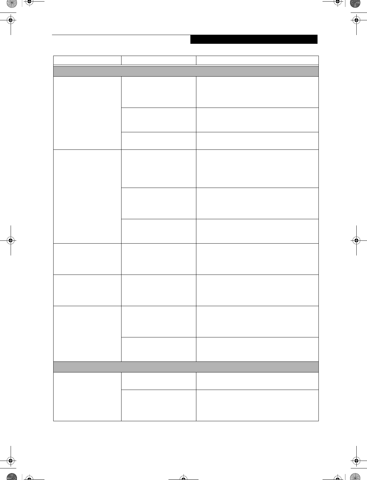
67
Troubleshooting
Shutdown and Startup Problems
The Power and Suspend/
Resume button does not
work.
The Power and Suspend/
Resume button is disabled
from the Power -> Advanced
submenu of the setup utility.
Enable the button from the setup utility.
You did not hold the button
in long enough.
Hold the button longer. This may need to be a few
seconds if your application is preventing the CPU
from checking for button pushes.
There may be a conflict with
the application software.
Close all applications and try the button again.
The system powers up, and
displays power on informa-
tion, but fails to load the
operating system.
The boot sequence settings
of the setup utility are not
compatible with your
configuration.
Set the operating source by pressing the [ESC] key
while the Fujitsu logo is on screen or use the [F2]
key and enter the setup utility and adjust the source
settings from the Boot menu. (See BIOS Setup
Utility on page 35 for more information)
You have a secured system
requiring a password to load
your operating system.
Make sure you have the right password. Enter the
setup utility and verify the Security settings and
modify them accordingly. (See BIOS Setup Utility on
page 35 for more information)
Internal hard drive was
not detected.
Use the BIOS setup utility or Primary Master
submenu, located within the Main menu, to try to
auto detect the internal hard drive.
Your system display won’t
turn on when the system is
turned on or when the
system has resumed.
The system may be password-
protected.
Check the status indicator panel to verify that the
Security icon is blinking. If it is blinking, enter your
password.
An error message is
displayed on the screen
during the notebook
(boot) sequence.
Power On Self Test (POST) has
detected a problem.
See the POST messages to determine the meaning
and severity of the problem. Not all messages are
errors; some are status indicators. (See Power On Self
Test Messages on page 70 for more information)
Your LifeBook notebook
appears to change setup
parameters when you start
it.
BIOS setup changes were not
saved when you exited the
BIOS setup utility, returning it
to previous settings.
Make sure you select Save Changes And Exit when
exiting the BIOS setup utility.
The BIOS CMOS hold-up
battery has failed.
Contact your support representative for repairs.
This is not a user serviceable part but has a normal
life of 3 to 5 years.
Video Problems
The built-in display is
blank when you turn on
your LifeBook notebook.
Something is pushing on the
Closed Cover switch.
Clear the Closed Cover switch. (See Figure 2-4 on
page 8 for location)
The angle of the display
and the brightness settings
are not adequate for your
lighting conditions.
Move the display and the brightness control until
you have adequate visibility.
Problem Possible Cause Possible Solutions
B5FH-4491-01EN-00.book Page 67 Friday, April 19, 2002 11:24 AM
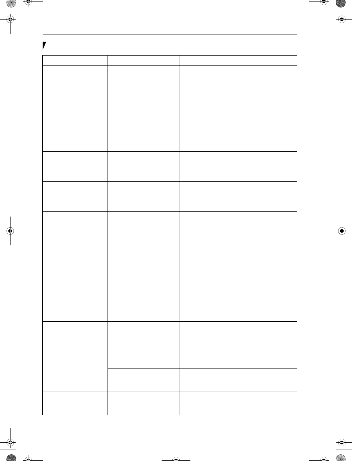
68
LifeBook E Series – Section 5
The built-in display is
blank when you turn on
your LifeBook notebook.
(continued)
The LifeBook notebook is set
for an external monitor only.
Pressing [F10] while holding down the [Fn] key
allows you to change your selection of where to
send your display video. Each time you press the
combination of keys you will step to the next
choice. The choices, in order are: built-in display
only, external monitor only, both built-in display
and external monitor.
The power management time-
outs may be set for very short
intervals and you failed to
notice the display come on
and go off again.
Press any button or key on the keyboard, or move
the mouse to restore operation. If that fails, push the
Power and Suspend/Resume button. (The display
may be shut off by Standy mode, Auto Suspend or
Video Timeout.)
The LifeBook notebook
turned on with a series of
beeps and your built-in
display is blank.
Power On Self Test (POST)
has detected a failure which
does not allow the display
to operate.
Contact your support representative.
Your system display won’t
turn on when the system is
turned on or when the
system has resumed.
The system may be password-
protected.
Check the status indicator panel to verify that the
Security icon is blinking. If it is blinking, enter your
password.
The display goes blank by
itself after you have been
using it.
The notebook has gone into
Video timeout, Standby mode,
Suspend mode or Save-to-Disk
mode because you have not
used it for a period of time.
Press any button or key on the keyboard, or move the
mouse to restore operation. If that fails, push the
Power and Suspend/Resume button. Check your
power management settings, or close your applica-
tions and go to the Power Savings menu of the setup
utility to adjust the timeout values to better suit
your operation needs. (See BIOS Setup Utility on
page 35 for more information)
Something is pushing on the
Closed Cover switch.
Check the Closed Cover switch. (See Figure 2-4 on
page 8 for location)
The power management time-
outs may be set for very short
intervals and you failed to
notice the display come on
and go off again.
Press any button or key on the keyboard, or move the
mouse to restore operation. If that fails, push the
Power and Suspend/Resume button. (The display
may be shut off by Standby Mode, Auto Suspend or
Video Timeout.)
The Built-in Display does
not close.
A foreign object, such as a
paper clip, is stuck between the
display and the keyboard.
Remove all foreign objects from the keyboard.
The Built-in Display has
bright or dark spots.
If the spots are very tiny and
few in number, this is normal
for a large LCD display.
This is normal; do nothing.
If the spots are numerous or
large enough to interfere with
your operation needs.
Display is faulty; contact your support representative.
You have connected an
external monitor and it
does not come on.
Your external monitor
is not compatible with
your LifeBook notebook.
See your monitor documentation and the External
Monitor Support portions of the Specifications
section on page 83.
Problem Possible Cause Possible Solutions
B5FH-4491-01EN-00.book Page 68 Friday, April 19, 2002 11:24 AM
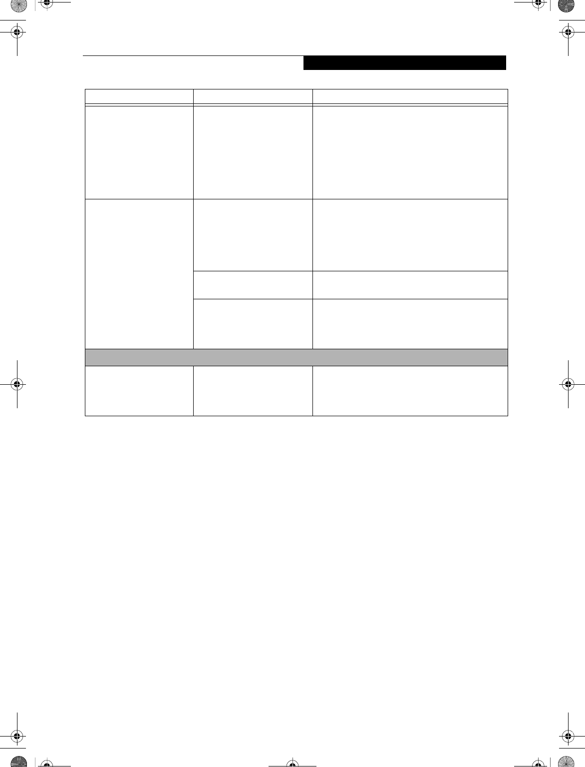
69
Troubleshooting
The application display
uses only a portion of your
screen and is surrounded
by a dark frame.
You are running an
application that does not
support 800 x 600 pixel
resolution display and display
compression is enabled.
Display compression gives a clearer but smaller
display for applications that do not support 800 x
600 pixel resolution. You can fill the screen but have
less resolution by changing your display compres-
sion setting, (See the Video Features submenu,
located within the Advanced menu of the BIOS.)
(See BIOS Setup Utility on page 35 for more informa-
tion)
You have connected an
external monitor and
it does not display
any information.
Your BIOS setup is not set to
enable your external monitor.
Try toggling the video destination by pressing [Fn]
and [F10] together, or check your BIOS setup and
enable your external monitor. (See the Video Features
submenu, located within the Advanced Menu of the
BIOS.) (See BIOS Setup Utility on page 35 for more
information)
Your external monitor is not
properly installed.
Reinstall your device. (See External Monitor Port on
page 57 for more information)
Your operating system soft-
ware is not setup with the
correct software driver for
that device.
Check your device and operating system
documentation and activate the proper driver.
Miscellaneous Problems
An error message is
displayed on the screen
during the operation of
an application.
Application software often
has its own set of error
message displays.
See your application manual and help displays
screens for more information. Not all messages are
errors some may simply be status.
Problem Possible Cause Possible Solutions
B5FH-4491-01EN-00.book Page 69 Friday, April 19, 2002 11:24 AM

70
LifeBook E Series – Section 5
POWER ON SELF TEST MESSAGES
The following is an alphabetic list of error-and-status
messages that Phoenix BIOS and/or your operating
system can generate and an explanation of each message.
Error messages are marked with an *. The most
common errors are marked with a #. If an error message
is displayed that is not in this list, write it down and
check your operating system documentation both on
screen and in the manual. If you can find no reference
to the message and its meaning is not clear, contact
your support representative for assistance.
nnnn Cache SRAM Passed
Where nnnn is the amount of system cache in kilobytes
successfully tested by the Power On Self Test. (This can
only appear if you have an SRAM PC Card installed.)
*Diskette drive A error or Diskette drive B error
Drive A: or B: is present but fails the BIOS Power On Self
Test diskette tests. Check to see that the drive is defined
with the proper diskette type in the Setup Utility, (See
BIOS Setup Utility on page 35 for more information) and
that the diskette drive is installed correctly. If the disk
drive is properly defined and installed, avoid using it and
contact your support representative.
*Extended RAM Failed at offset: nnnn
Extended memory not working or not configured prop-
erly. If you have an installed memory upgrade module,
verify that the module is properly installed. If it is
properly installed, you may want to check your
Windows Setup to be sure it is not using unavailable
memory until you can contact your support representa-
tive.
nnnn Extended RAM Passed
Where nnnn is the amount of memory in kilobytes
successfully tested.
*Failing Bits: nnnn The hex number nnnn
This is a map of the bits at the memory address (in
System, Extended, or Shadow memory) which failed the
memory test. Each 1 (one) in the map indicates a failed
bit. This is a serious fault that may cause you to lose data
if you continue. Contact your support representative.
*Fixed Disk x Failure or Fixed Disk Controller
Failure (where x = 1-4)
The fixed disk is not working or not configured properly.
This may mean that the hard drive type identified in
your setup utility does not agree with the type detected
by the Power On Self Test. Run the setup utility to check
for the hard drive type settings and correct them if
necessary. If the settings are OK and the message appears
when you restart the system, there may be a serious fault
which might cause you to lose data if you continue.
Contact your support representative.
*Incorrect Drive A type – run SETUP
Type of floppy drive A: not correctly identified in Setup.
This means that the floppy disk drive type identified in
your setup utility does not agree with the type detected
by the Power On Self Test. Run the setup utility to
correct the inconsistency.
*Incorrect Drive B type – run SETUP
Type of floppy drive B: not correctly identified in Setup.
This means that the floppy disk drive type identified in
your setup utility does not agree with the type detected
by the Power On Self Test. Run the setup utility to
correct the inconsistency.
*Invalid NVRAM media type
Problem with NVRAM access. In the unlikely case that
you see this message you may have some display prob-
lems. You can continue operating but should contact
your support representative for more information.
*Keyboard controller error
The keyboard controller test failed. You may have to
replace your keyboard or keyboard controller but may
be able to use an external keyboard until then. Contact
your support representative.
*Keyboard error
Keyboard not working. You may have to replace your
keyboard or keyboard controller but may be able to use
an external keyboard until then. Contact your support
representative.
*Keyboard error nn
BIOS discovered a stuck key and displays the scan code
for the stuck key. You may have to replace your keyboard
but may be able to use an external keyboard until then.
Contact your support representative.
*Monitor type does not match CMOS – Run SETUP
Monitor type not correctly identified in Setup. This error
probably means your BIOS is corrupted, run the setup
utility and set all settings to the default conditions. If you
still get this error, contact your support representative.
#*Operating system not found
Operating system cannot be located on either drive A: or
drive C:. Enter the setup utility and see if both the fixed
disk, and drive A: are properly identified and that the
boot sequence is set correctly. Unless you have changed
your installation greatly, the operating system should be
on drive C:. If the setup utility is correctly set, your hard
drive may be corrupted and your system may have to be
reinstalled from your back up media.
B5FH-4491-01EN-00.book Page 70 Friday, April 19, 2002 11:24 AM

71
Troubleshooting
*Parity Check 1 nnnn
Parity error found in the system bus. BIOS attempts to
locate the address and display it on the screen. If it
cannot locate the address, it displays ????. This is a
potentially data-destroying failure. Contact your
support representative.
*Parity Check 2 nnnn
Parity error found in the I/O bus. BIOS attempts to
locate the address and display it on the screen. If it
cannot locate the address, it displays ????. This is a
potentially data destroying failure. Contact your support
representative.
#*Press <F1> to resume, <F2> to SETUP
Displayed after any recoverable error message. Press the
[F1] key to continue the boot process or the [F2] key to
enter Setup and change any settings.
#*Previous boot incomplete –
Default configuration used
Previous Power On Self Test did not complete success-
fully. The Power On Self Test will load default values and
offer to run Setup. If the previous failure was caused by
incorrect values and they are not corrected, the next
boot will likely fail also. If using the default settings does
not allow you to complete a successful boot sequence,
you should turn off the power with the Power Switch
and contact your support representative.
*Real time clock error
Real-time clock fails BIOS test. May require board
repair. Contact your support representative.
*Shadow RAM Failed at offset: nnnn
Shadow RAM failed at offset nnnn of the 64k block at
which the error was detected. You are risking data corrup-
tion if you continue. Contact your support representative.
nnnn Shadow RAM Passed
Where nnnn is the amount of shadow RAM in kilobytes
successfully tested.
*System battery is dead – Replace and run SETUP
The BIOS CMOS RAM memory hold up battery is dead.
This is part of your BIOS and is a board mounted
battery which requires a support representative to
change. You can continue operating but you will have to
use setup utility default values or reconfigure your setup
utility every time you turn off your LifeBook notebook.
This battery has an expected life of 2 to 3 years.
System BIOS shadowed
System BIOS copied to shadow RAM.
*System CMOS checksum bad – run SETUP
BIOS CMOS RAM has been corrupted or modified
incorrectly, perhaps by an application program that
changes data stored in BIOS memory. Run Setup and
reconfigure the system.
*System RAM Failed at offset: nnnn
System memory failed at offset nnnn of in the 64k block
at which the error was detected. This means that there is
a fault in your built-in memory. If you continue to
operate, you risk corrupting your data. Contact your
support representative for repairs.
nnnn System RAM Passed
Where nnnn is the amount of system memory in kilo-
bytes successfully tested.
*System timer error
The timer test failed. The main clock that operates the
computer is faulty. Requires repair of system board.
Contact your support representative for repairs.
UMB upper limit segment address: nnnn
Displays the address of the upper limit of Upper
Memory Blocks, indicating released segments of the
BIOS memory which may be reclaimed by a virtual
memory manager.
Video BIOS shadowed
Video BIOS successfully copied to shadow RAM.
MODEM RESULT CODES
The operating system and application software that is
factory installed detects the modem characteristics and
provides the necessary command strings to operate the
modem. The internal modem operation is controlled by
generic AT commands from the operating system and
application software. The standard long form result
codes may, in some cases, be displayed on your screen to
keep you informed of the actions of your modem. The
operating system and application software may suppress
display of the result codes.
Examples of result codes are:
nOK
nNO CARRIER
nNO DIALTONE
nCONNECT 53000 (Connection complete
at 53,000 bps.)
nERROR
nFAX
nRING (This means an incoming call.)
nBUSY
nNO ANSWER
When using the internal modem with applications
that are not factory installed refer to the application
documentation.
B5FH-4491-01EN-00.book Page 71 Friday, April 19, 2002 11:24 AM
72
LifeBook E Series – Section 5
Restoring Your
Pre-installed Software
Your system has been loaded with a valuable utility that
allows you to restore your LifeBook notebook disk drive
contents as they were originally shipped from the
factory. Most often this is necessary if files or software
programs (only those files/programs that came pre-
installed) become corrupted or are accidentally erased.
DRIVE IMAGE SPECIAL EDITION (DISE)
PowerQuest Drive Image Special Edition® (DISE)
provides a way to restore your computer if you experi-
ence a hard disk crash or other system failure. Fujitsu has
used DISE to create an image of everything installed on
the computer at the time you purchased it. The image is
saved on a separate partition on the hard disk. You can
use DISE to restore the factory image and return your
computer to the state in which it shipped from Fujitsu.
NOTE: Systems with the Windows 98 operating system
installed have the DISE directory structure in place, but
without the disk image or the DISE software installed.
(See Installing and Using DISE With Windows 98 Systems
on page 73 for more information)
Although it is not necessary, you can use DISE to store
additional image files that you create. For example, if
you install several applications and save data files on
your hard disk, you can create a new image file that
includes them and then save that image file on the hard
disk. Then, in the event of a hard disk failure, you can
restore the image that includes the applications and data
files you use.
Fujitsu recommends that you create a DISE disk as a
“rescue disk.” If your computer fails, you can boot and
run DISE from the rescue disk.
USING DISE WITH WINDOWS 2000/XP
Creating a Drive Image SE Diskette
You can use a DISE disk to boot your machine and run
DISE if your machine is unbootable or if you do not
have access to Windows.
Insert a formatted floppy disk in your machine.
From the Drive Image Special Edition main window,
click Options > Create Drive Image SE Diskette.
Running DISE from Diskettes
1. Insert the Drive Image SE Disk 1 in the floppy drive.
2. Reboot your computer.
3. Insert Disk 2, type DISE, then press <Enter>.
Creating a Backup Image
You can create a backup image of your C:\ drive at any
time. The C:\ partition must be a FAT, FAT32, or NTFS
partition, and it must be directly before the backup
partition on your hard disk.
1. At the Drive Image Special Edition main screen,
click Options> Create New Backup.
There is also a button on the main DISE screen that
performs the same function.
2. You will be prompted to type a password. Type a
password (or leave the password fields blank), then
click OK. DISE displays a warning that it must go to
DOS to create the image.
3. Click Ye s.
DISE creates an image file in the backup partition. If
you created a backup image previously, the new
image overwrites the old one.
Enlarging the Backup Partition
If there is not enough unused space in the backup parti-
tion on your hard disk, DISE will resize the partition.
DISE will display the minimum, maximum, and recom-
mended sizes for the backup partition. You choose the
size you want.
DISE takes the space from the FAT, FAT32, or NTFS
partition that you are backing up. If there is not enough
unused space in that partition to take, you will not be
able to resize the backup partition and create an image
file. You can delete files from the FAT, FAT32, or NTFS
partition to create more unused space on the hard disk.
Restoring a Backup Image
You can restore either a factory image or a backup image
you created. Be aware that restoring a backup image will
replace the contents of the C:\ partition with the image
you restore.
1. Disable virus protection software in the BIOS. If
virus protection software is enabled, DISE will hang.
2. From the DISE main window, click Options >
Restore Backup to restore an image you created, or
click Options > Restore Factory Backup to restore
the factory image.
DISE shuts down to DOS and restores the image file.
Drivers and Applications Restore CD
The Drivers and Application CD can be used to selec-
tively re-install drivers and/or applications that may have
been un-installed or corrupted. Please refer to installa-
tion instructions located in the Drivers and Applications
Restore CD.
POINT
Look for and open files with .doc and .txt extensions.
POINT
Using the DISE feature will reduce the amount of usable
disk space on your hard disk drive.
B5FH-4491-01EN-00.book Page 72 Friday, April 19, 2002 11:24 AM
73
Troubleshooting
INSTALLING AND USING DISE WITH
WINDOWS 98 SYSTEMS
Systems with Windows 98 installed have the DISE direc-
tory structure in place, but without the disk image or the
DISE software installed.
When DISE is completely installed, the DISE backup
partition requires approximately 1.8GB of hard disk
space in Windows 98 systems. This number reflects the
size of the original Fujitsu Factory Image; if additional
applications are added by the reseller, the amount of
space required will be proportionately greater.
Factory Backup Image: This is the image that is origi-
nally delivered from the factory or the reseller.
User Backup Image: This is the modified Factory Image
containing any applications or changes that have been
added by the user.
This document outlines the procedure for creating the
Factory Backup Image on the hard drive using the DISE
utility. (The User Backup Image is designed for the end-
user, and can be invoked from the desktop using the
DISE icon.)
Creating the Backup Partition
and Installing DISE on Windows 98
In order to provide a dedicated area on the hard disk to
store the image, you must first partition the disk.
1. Go to the C:\FPC\INSTALL\POWERQUEST direc-
tory and double-click on SETUP.EXE. The Welcome
screen appears.
2. Click Next.
3. Depending upon whether you are creating a Factory
Backup Image, a User Backup Image, or both, check
the applicable box(es). Be aware that the numbers
displayed represent Megabytes of disk space that will
be reserved to store the image. The following list
indicates the approximate size of the partition
required for Windows 98 systems:
One image - 1024MB
Two images - 1.8GB
4. Click [Next]. If the information displayed is correct,
click Finish to create the partition. The system will
automatically reboot and complete the operation.
5. When the message “The operation completed
successfully” appears, click [OK]. The system will
reboot.
Creating a Factory Backup Image
To create a Factory Backup Image, first partition the
disk, as outlined above. After the disk is partitioned,
proceed with the following steps.
1. Boot the system up into DOS.
2. From the DISE directory, type and enter the
following command (Note the spaces after “DISE”,
“.T XT ”, a nd “.PQ I” ):
DISE /CMD=CREATE.TXT /IMG=FACTORY.PQI /SEC
3. After the Factory Backup Image is created, an
“Operation completed successfully” message
appears. Click [OK]. The system will reboot auto-
matically.
Creating Drive Image SE Diskettes
It is recommended that you create DISE diskettes for the
system. You can use a DISE disk to boot the machine
and run DISE in the event the machine is unbootable or
if you do not have access to Windows.
1. Insert a formatted floppy disk in the drive.
2. From the Drive Image Special Edition main
window, click Options > Create Drive Image SE
Diskette. Follow the instructions displayed.
3. After diskettes have been created, label them Disk 1
and Disk 2.
Running Drive Image SE from Diskettes
1. Insert Drive Image SE Disk 1 in the drive.
2. Reboot the computer.
3. Insert Disk 2, type DISE, then press <Enter>.
Additional information about DISE is contained in the
following location on the hard drive:
C:\DISE\dise_end.pdf. There is also a shortcut icon on
the desktop to access the DISE readme file.
POINT
Look for and open files with the extensions .WRI,
.DOC, .PDF and/or .TXT.
POINT
If a DISE backup partition is not created for Master and/
or User backups, the Factory Backup Image may not be
recoverable.
POINT
The following step may require a bootable DOS
diskette.
B5FH-4491-01EN-00.book Page 73 Friday, April 19, 2002 11:24 AM

74
LifeBook E Series – Section 5
B5FH-4491-01EN-00.book Page 74 Friday, April 19, 2002 11:24 AM

75
6
Care and Maintenance
B5FH-4491-01EN-00.book Page 75 Friday, April 19, 2002 11:24 AM

76
LifeBook E Series – Section 6
B5FH-4491-01EN-00.book Page 76 Friday, April 19, 2002 11:24 AM
77
Care and Maintenance
Care and Maintenance
If you use your LifeBook notebook carefully, you will
increase its life and reliability. This section provides
some tips for looking after the notebook and its devices.
LIFEBOOK NOTEBOOK
Caring for your Notebook
■Your LifeBook notebook is a durable but sensitive
electronic device. Treat it with respect and care.
■Make a habit of transporting it in a suitable
carrying case.
■Do not attempt to service the computer yourself.
Always follow installation instructions closely.
■Keep it away from food and beverages.
■If you accidentally spill liquid on your notebook:
1. Turn it off.
2. Position it so that the liquid can run out.
3. Let it dry out for 24 hours, or longer if needed.
4. If your notebook will not boot after it has dried
out, call your support representative.
■Do not use your LifeBook notebook in a wet environ-
ment (near a bathtub, swimming pool).
■Always use the AC adapter and batteries that are
approved for your LifeBook notebook.
■Avoid exposure to sand, dust and other
environmental hazards.
■Do not expose your LifeBook notebook to direct sun-
light for long periods of time as temperatures above
140° F (60° C) may damage your notebook.
• Keep the covers closed on the connectors and slots
when they are not in use.
■Do not put heavy or sharp objects on the computer.
■If you are carrying your LifeBook notebook in a brief-
case, or any other carrying case, make sure that there
are no objects in the case pressing on the lid.
■Do not drop your LifeBook notebook.
■Do not touch the screen with any sharp objects.
Cleaning your LifeBook notebook
■Always disconnect the power plug. (Pull the plug,
not the cord.)
■Clean your LifeBook notebook with a damp, lint-free
cloth. Do not use abrasives or solvents.
■Use a soft cloth to remove dust from the screen.
Never use glass cleaners.
Storing your LifeBook notebook
■If storing your LifeBook notebook for a month or
longer, turn your LifeBook off and remove all Lithium
ion batteries.
■Store your LifeBook notebook and batteries sepa-
rately. If you store your notebook with a battery
installed, the battery will discharge, and battery life
will be reduced. In addition, a faulty battery might
damage your notebook.
■Store your notebook in a cool, dry location.
Temperatures should remain between 13ºF (-25ºC)
and 140ºF (60ºC).
Traveling with your LifeBook notebook
■Do not transport your LifeBook notebook while it is
turned on.
■Do not check your LifeBook notebook as baggage.
Carry it with you.
■Always bring your System Recovery CD (Windows 98
and Windows 2000 systems only) that came with your
notebook when you travel. If you experience system
software problems while traveling, you may need it to
correct any problems.
■When traveling with the hard drive removed, wrap the
drive in a non-conducting materials (cloth or paper).
If you have the drive checked by hand, be ready to
install the drive if needed. Never put your hard drive
through a metal detector. Have your hard drive hand-
inspected by security personnel. You can however, put
your hard drive through a properly tuned X-ray
machine.
■Take the necessary plug adapters if you're traveling
overseas. Check the following diagram to determine
which plug adapter you'll need or ask your travel
agent.
WARNING
Electrical equipment may be hazardous if misused. Oper-
ations of this product or similar products, must always be
supervised by an adult. Do not allow children access to
the interior of any electrical products and do not permit
them to handle any cables.
B5FH-4491-01EN-00.book Page 77 Friday, April 19, 2002 11:24 AM
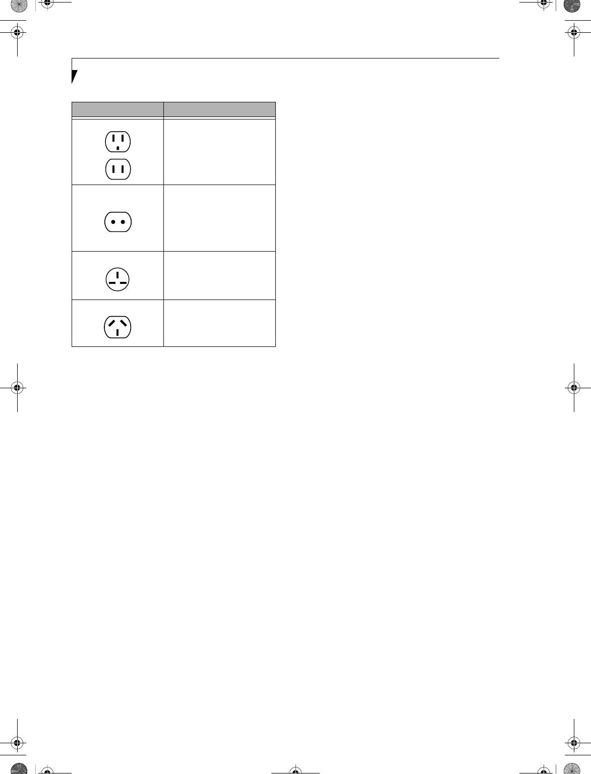
78
LifeBook E Series – Section 6
BATTERIES
Caring for your Batteries
■Always handle batteries carefully.
■Do not short-circuit the battery terminals (that is, do
not touch both terminals with a metal object). Do not
carry lose batteries in a pocket or purse where they
may mix with coins, keys, or other metal objects.
Doing so may cause an explosion or fire.
■Do not drop, puncture, disassemble, mutilate or
incinerate the battery.
■Recharge batteries only as described in this manual
and only in ventilated areas.
■Do not leave batteries in hot locations for more than a
day or two. Intense heat can shorten battery life.
■Do not leave a battery in storage for longer than 6
months without recharging it.
Increasing Battery Life
■Power your LifeBook notebook through the AC or
optional auto/airline adapter whenever possible.
■If your LifeBook notebook is running on battery
power all day, connect it to the AC adapter overnight
to recharge the battery.
■Keep brightness to the lowest level comfortable.
■Set the power management for maximum battery life.
■Put your LifeBook notebook in Suspend mode when it
is turned on and you are not actually using it.
■Limit your DVD/CD-RW/CD-ROM access.
■Disable the Windows CD Auto Insert function.
■Always use fully charged batteries.
■Eject PCMCIA cards when not in use.
FLOPPY DISKS AND DRIVES
Caring for your Floppy Disks
■Avoid using the floppy disks in damp and
dusty locations.
■Never store a floppy disk near a magnet or
magnetic field.
■Do not use a pencil or an eraser on a disk or
disk label.
■Avoid storing the floppy disks in extremely hot or cold
locations, or in locations subject to severe temperature
changes. Store at temperatures between 50º F (10ºC)
and 125ºF (52ºC).
■Do not touch the exposed part of the disk
behind the metal shutter.
Caring for your Floppy Disk Drive
■To clean, wipe the floppy disk drive clean with a dry
soft cloth, or with a soft cloth dampened with water or
a solution of neutral detergent. Never use benzene,
paint thinner or other volatile material.
■Avoid storing the floppy disk drive in extremely hot or
cold locations, or in locations subject to severe tem-
perature changes. Store at temperatures between 50º F
(10ºC) and 125ºF (52ºC).
■Keep the floppy disk drive out of direct sunlight and
away from heating equipment.
■Avoid storing the floppy disk drive in locations subject
to shock and vibration.
■Never use the floppy disk drive with any liquid, metal,
or other foreign matter inside the floppy disk
drive or disk.
■Never disassemble or dismantle your floppy disk drive.
DVDs AND CDs
Caring for your DVDs and CDs
DVDs and CDs are precision devices and will function
reliably if given reasonable care.
■Always store your DVD/CDs in its case when it
is not in use.
■Always handle DVD/CDs by the edges and avoid
touching the surface.
■Avoid storing any DVD/CDs in extreme temperatures.
■Do not bend DVD/CDs or set heavy objects on them.
■Do not spill liquids on DVD/CDs.
■Do not scratch DVD/CDs.
Outlet Type Location
United States, Canada,
parts of Latin America,
Japan, Korea,
the Philippines, Taiwan
Russia and the Commonwealth
of Independent States (CIS),
most of Europe, parts of Latin
America, the Middle East, parts
of Africa, Hong Kong, India,
most of South Asia
Mexico, United Kingdom,
Ireland, Malaysia, Singapore,
parts of Africa
China, Australia,
New Zealand
B5FH-4491-01EN-00.book Page 78 Friday, April 19, 2002 11:24 AM

79
Care and Maintenance
■Do not put a label on DVD/CDs.
■Do not get dust on DVD/CDs.
■Never write on the label surface with a ballpoint pen
or pencil. Always use a felt pen.
■If a DVD/CD is subjected to a sudden change in tem-
perature, cold to warm, condensation may form on
the surface. Wipe the moisture off with a clean, soft,
lint free cloth and let it dry at room temperature. DO
NOT use a hair dryer or heater to dry DVD/CDs.
■If a DVD/CD is dirty, use only a DVD/CD cleaner or
wipe it with a clean, soft, lint free cloth starting from
the inner edge and wiping to the outer edge.
Caring for your Media Drive
Your media drive is durable but you must treat it with
care. Please pay attention to the following points:
■The drive rotates the compact disk at a very high
speed. Do not carry it around or subject it to shock
or vibration with the power on.
■Avoid using or storing the drive where it will be
exposed to extreme temperatures.
■Avoid using or storing the drive where it is
damp or dusty.
■Avoid using or storing the drive near magnets or
devices that generate strong magnetic fields.
■Avoid using or storing the drive where it will be
subjected to shock or vibration.
■Do not disassemble or dismantle the DVD drive or
CD-RW drive.
PC CARDS
Caring for your PC Cards
PC Cards are durable, but you must treat them with
care. The documentation supplied with your PC Card
will provide specific information, but you should
pay attention to the following points:
■To keep out dust and dirt, store PC Cards in their
protective sleeves when they are not installed in
your LifeBook notebook.
■Avoid prolonged exposure to direct sunlight or
excessive heat.
■Keep the cards dry.
■Do not flex or bend the cards, and do not place heavy
objects on top of them.
■Do not force cards into the slot.
■Avoid dropping cards, or subjecting them to
excessive vibration.
B5FH-4491-01EN-00.book Page 79 Friday, April 19, 2002 11:24 AM

80
LifeBook E Series – Section 6
B5FH-4491-01EN-00.book Page 80 Friday, April 19, 2002 11:24 AM

81
7
Specifications
B5FH-4491-01EN-00.book Page 81 Friday, April 19, 2002 11:24 AM

82
LifeBook E Series – Section 7
B5FH-4491-01EN-00.book Page 82 Friday, April 19, 2002 11:24 AM
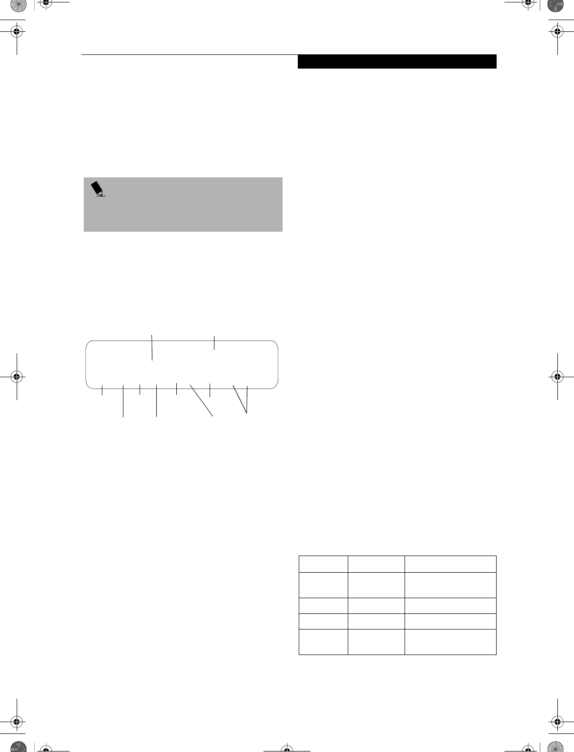
83
Specifications
Specifications
This section provides the general hardware and environ-
mental specifications for your LifeBook notebook.
Specific details about your system may vary from those
referenced here. For an updated list of current configu-
rations, please go to the Fujitsu PC Web site at:
www.fujitsupc.com.
CONFIGURATION LABEL
Your LifeBook notebook contains a configuration label
located on the bottom of the system (See Figure 2-8 on
page 13 for location). This label contains specific infor-
mation regarding the options you’ve chosen for your
notebook. Following is an example label, and informa-
tion about its various parts.
Figure 7-1 Configuration Label
MICROPROCESSOR
■Mobile Intel Pentium 4 Processor-M
■1.8GHz, 1.7GHz, 1.6GHz
MEMORY
System Memory Range:
Upgradeable to 1GB, DDR266 (512MB x 2)
2 DIMM slots
Cache Memory
512K On-die L2
BIOS Memory
1MB Flash ROM
256 Bytes CMOS-RAM with back-up battery
VIDEO
Built-in color flat-panel XGA TFT active matrix LCD
display with simultaneous display capability.
Video Color and Resolution
■Internal:
14.1" XGA - 1024 x 768 pixel resolution, 16M colors
15" SXGA+ - 1400 x 1050 pixel resolution, 64K colors
■External: 1600 x 1200 pixel resolution, 64K colors at
60Hz
Simultaneous Video: 1024 x 768, 16M colors max,
XGA, SVGA and VGA compatible
Graphics Accelerator Card
ATI® Rage® Mobility Radeon™ 7500 with 32MB
Embedded DDR Video RAM
4x AGP supported
AUDIO
■AC97 Codec Sigmatel 9767
■Optical Digital Out (SPDIF)/stereo headphone jack,
1 Vrms or less, minimum impedance 32 Ohms
■Mono microphone jack, 100mVrms or less, minimum
impedance 10K Ohms
■Two built-in stereo speakers, elliptical (~15 x 35 mm
diameter)
MASS STORAGE DEVICE OPTIONS
Floppy Disk Drive
■External USB Floppy Disk Drive
Hard Disk Drive
20GB, 30GB, or 40GB, Ultra DMA 100
Media Drive
■Modular CD, or,
■Modular DVD drive, or,
■Modular DVD/CD-RW combo drive
FEATURES
Integrated Pointing Device:
■To u c h p a d
Depending upon the configuration of your system, you
may also have:
■Wireless Infrared Mouse
LifeBook Security/Application Panel
Security Panel: 4-button security combination for both
hardware and software.
One Touch Panel: 4-button application launcher for
Internet, e-mail and software while your LifeBook note-
book is On state. Your LifeBook Application Panel
buttons are assigned the following defaults:
Table 7-1. Application Launcher Buttons
POINT
All options listed are accurate as of the date of print; sub-
stitutions may have been made subsequent to date of
publication.
E7010, P4, 1.7G, 14T, 2K, 20G, 256M, CD, WLAN
Configuration P/N: AEJxxxxxxxxxxxxx
FPC P/N: FPCM70562
Configuration ID
FPC ID
Model
Processor Screen
Size
Hard
Drive Size
Memory
Operating
System
Speed
Devices
Button Label Button Function Default Application
1 Application
A
Notepad
2 Application B Calculator
3 Internet Internet Explorer
4 E-Mail Netscape Messenger/
Outlook Express
B5FH-4491-01EN-00.book Page 83 Friday, April 19, 2002 11:24 AM

84
LifeBook E Series – Section 7
Theft Prevention Lock Slot
Lock slot for use with physical restraining security
systems. The locking system by Kensington is
recommended.
Communications
Integrated 10/100 base-Tx Ethernet LAN Internal V.90
standard 56K* fax/modem (ITU V.90, 56K data, 14.4K
fax).
Optional: Integrated Wireless LAN (802.11b)** with
On/Off button.
* Actual data transfer rate over U.S. telephone lines varies
and is less than 56Kbps due to the current FCC regula-
tions and line conditions.
** Operates at 2.4GHz; communications range may vary,
depending upon surrounding environment.
DEVICE PORTS
■Combination PC Card slot for one Type III/two Type
II cards: PCMCIA Standard 2.1 with CardBus support
■One 6-pin mini DIN PS/2 compatible connector, for
external keyboard, external mouse or external numeric
keypad
■Embedded Smart Card Reader (requires optional
Smart Card holder)
■One 25-pin D-SUB two-way Centronics type
connector for parallel input/output devices;
Bi-directional, output only or ECP
■One 120-pin connector for docking devices.
■One 15-pin D-SUB connector for VGA external
monitor (see Display specifications)
■One 9-pin D-SUB connector for RS-232C serial
input/output devices
■One IEEE 1394 (4-pin) port
■One S-Video Out port
■Two connectors for USB (Universal Serial Bus)
input/output devices
■IR Receiver for Fujitsu wireless mouse
■Fast IR (up to 4 Mbps) compatible infrared port for
wireless data transfer
■One Optical Digital Out (SPDIF)/stereo headphone
jack (See Audio specifications)
■One mono microphone jack (See Audio specifications)
■One modular modem (RJ-11) connector
■One modular LAN (RJ-45) connector
KEYBOARD
Built-in keyboard with all functions of 87 key PS/2
compatible keyboards.
■Total number of keys: 87
■Function keys: 12, [F1] through [F12]
■Feature extension key: [Fn]
■Windows keys: 3, two Start keys and an
application key
■Key pitch: 19 mm
■Key stroke: 2.7 mm
■Built-in Touchpad pointing device with left and
right buttons
External Keyboard Support
■PS/2-compatible
■USB-compatible
External Numeric Keypad Support
■PS/2-compatible
■USB-compatible
External Mouse Support
■PS/2-compatible
■USB-compatible
Management Standard
DMI 2.0-ready, WFM 2.0-compliant (LAN models only)
POWER
Batteries
Main 8-cell Lithium ion battery, rechargeable, 14.4V,
3800 mAh
Option: Second 6-cell Lithium ion battery, rechargeable,
10.8V, 3400 mAh (for Flexible Bay installation)
Adapters
AC Adapter: Autosensing 100-240V AC, 80W, supplying
19V DC, 4.22A, to the LifeBook notebook, Fujitsu
Model FPCAC33AP, which includes an AC cable.
Option: Auto/Airline Adapter: Converts the DC voltage
from an automobile cigarette lighter or aircraft DC
power outlet to the DC voltage needed to power your
notebook.
Power Management
Conforms to ACPI (Advanced Configuration & Power
Interface)
Electrostatic Discharge (ESD)
9 kV
DIMENSIONS
Overall Dimensions
12.13" x 10.39" x 1.28" (308 mm x 264 mm x 32.5 mm)
ENVIRONMENTAL REQUIREMENTS
Temp erature
Operating: 5° to 35° C (41° to 95° F)
Non-operating: –15° to 60° C (5° to 140° F)
Humidity
Operating: 20% to 85%, relative, non-condensing.
Non-operating; 8% to 85%, relative, non-condensing
Altitude
Operating: 10,000 feet (3,048 m) maximum
B5FH-4491-01EN-00.book Page 84 Friday, April 19, 2002 11:24 AM

85
Specifications
POPULAR ACCESSORIES
For ordering or additional information on
Fujitsu accessories please visit our Web site at:
www.fujitsupc.com or call 1-800-733-0884.
Memory Upgrades
PC2100 DDR266 Memory Modules:
■128MB
■256MB
■512MB
Docking
■Port Replicator
Expansions
■External USB floppy disk drive
Power
■Additional main Lithium ion battery
■Modular Lithium ion battery
■Auto/Airline Adapter
■Additional AC Adapter
Flexible Bay Devices
■Modular CD-ROM drive
■Modular DVD-ROM drive
■Modular DVD/CD-RW combo drive
■Modular Lithium ion battery (for Flexible Bay
installation)
Additional Accessories
■Wireless Infrared (IR) Mouse
■Wireless Keyboard and Mouse
■Numeric Keypad
■Presentation Audio System
■MindPath PocketPoint
■TeleAdapt 16' TeleCord
■Notebook Guardian Lock
■IBM Modem Saver
■Monitor Stand
Carrying Cases
■Diplomat
■ProPack Backpack
■Executive Plus
B5FH-4491-01EN-00.book Page 85 Friday, April 19, 2002 11:24 AM
86
LifeBook E Series – Section 7
PRE-INSTALLED SOFTWARE
* This software is located on CDs, as noted below.
** The installer is pre-loaded; the full version is included on the Fujitsu Service Assistant CD.
*** Systems with Windows 98 have the DISE files included on the hard disk drive. (See Installing and Using DISE With
Windows 98 Systems on page 73 for more information).
CD-BASED SOFTWARE
In the following table, "DAR" stands for "Drivers and Applications Restore CD".
Your Fujitsu LifeBook notebook comes with pre-
installed software for playing audio and video files of
various formats. The software configuration installed is
dependent upon the operating system that is pre-
installed on your system. (Refer to Table 7-2.) In addi-
tion, there is file transfer software, virus protection soft-
ware and Power Management software.
Software vendors occasionally update their software
packages. To ensure that you are using the optimal
version for your LifeBook in the future, visit the software
company web sites periodically.
Manuals
Included with your LifeBook notebook you will find
manuals for your operating system and other pre-
installed software. Manuals that are not included are
available online through the help system of the software.
We recommend that you review these manuals for
general information on the use of these applications.
Tutorials
All operating systems and most application software
have tutorials built-into them upon installation. We
highly recommend that you step through the tutorial
before you use an application.
Software Application (Vendor) Windows
2000
Windows
98 SE
Windows XP
Home
Windows XP
Pro
Adobe Acrobat Reader X* X* X* X*
Fujitsu BatteryAid/HotKey Utility XXXX
Fujitsu Service Assistant ** ** ** **
Softex BayManager X
PowerQuest Drive Image Special Edition X X*** X X
LifeBook Application Panel Software XXXX
Security Application Panel Software XXXX
McAfee.com Scan for Virus **XX
Earthlink X*
Netscape 6 ****
Quicken 2002 New User Edition X
Intel SpeedStep X X
Software Application (Vendor) Windows
2000
Windows
98 SE
Windows XP
Home
Windows XP
Pro
Adobe Acrobat Reader (updated version) DAR DAR DAR DAR
Fujitsu Service Assistant (separate CD) CD CD -- CD
McAfee.com Scan for Virus DAR DAR DAR DAR
Netscape 6 DAR DAR DAR DAR
Earthlink DAR DAR DAR DAR
PowerQuest Drive Image Special Edition -- DAR -- --
B5FH-4491-01EN-00.book Page 86 Friday, April 19, 2002 11:24 AM
87
Specifications
APPLICATION DESCRIPTIONS
Adobe Acrobat Reader
The Adobe Acrobat Reader allows you to view, navigate,
and print PDF files from across all of the major
computing platforms.
Fujitsu BatteryAid (Windows 98 and 2000)/
HotKey (Windows XP)
Fujitsu BatteryAid allows you to optimize system power
by monitoring and managing battery status. Fujitsu
HotKey allows you to monitor and manage the status of
the screen brightness and system volume. (See your
BatteryAid online help for more information on the correct
way to use this program)
Softex BayManager (Windows 98)
BayManager provides a simple and powerful method of
switching drives of a LifeBook notebook computer
without having to reboot the computer. Windows 98
Second Edition does not natively support hot swapping.
With BayManager, you can swap bay devices while your
OS is running, this is called hot-swapping.
BayManager Features
■Allows hot-swapping of devices on your LifeBook
notebook. You do not need to shut down the system
to exchange devices.
■Works under Windows 98 Second Edition.
■Works under ACPI and APM.
■Provides power management integrity for devices
that enter and leave the system.
Drive Image Special Edition (DISE) by PowerQuest
DISE by PowerQuest provides a way to restore your
computer if you experience a hard disk crash or other
system failure. DISE is used to restore the factory image
and restore the system to its original state. Note that on
systems with Windows 98 installed, the DISE directory
structure is in place, but the drive image and DISE soft-
ware have not yet been installed. (See Drive Image
Special Edition (DISE) on page 72 for more information)
Intel SpeedStep (Windows 98 and 2000)
Intel SpeedStep allows your Lifebook to operate in dual
mode. When connected to AC source, the system oper-
ates in Maximum Performance mode. When powered
by battery, the system switches to Battery Optimized
mode to conserve battery life. SpeedStep software is
automatically loaded when you start your system and
appears on the system tray as flags in one of two modes:
(1) A checker flag indicates that the system is set for
Maximum Performance mode. (2) A blue flag with a
green center square indicates that the system is set for
Battery Optimized mode. You can change the setting or
disable the software by double-clicking the flag icon and
changing the settings in the Intel SpeedStep Technology
window.
LifeBook Application Panel Software
Your LifeBook notebook is pre-installed with software
utilities that let you operate and configure your Life-
Book Application Panel. These utilities are found under
the Start menu, under Programs, then under LifeBook
Application Panel. They include a CD Player, Applica-
tion Panel Setup, Application Panel Guide, Activate
Panel, Deactivate Panel and E-mail LED Setup.
LifeBook Security Panel Software
LifeBook Security Panel allows you to secure your Life-
Book notebook from unauthorized use. If the security
system is activated, upon starting your LifeBook note-
book or resuming from Suspend mode the security
system requires you to enter a password code using the
buttons on the 5-button Security Panel. After entering a
correct password, your LifeBook notebook resumes
system operation.
McAfee.com Scan for Virus
Scan for Virus, by McAfee.com, is a web-based antivirus
program that can be run from the McAfee.com website
after loading data or programs onto your LifeBook note-
book. It assists in the protection of the data currently
residing on your hard disk from destruction or contami-
nation due to computer virus. (See your online help, or go
to the McAfee web site at: http://www.mcafee.com for more
information on how and when to run this program)
Netscape 6
Netscape 6 provides a suite of Internet tools.
Quicken 2002 New User Edition
Quicken 2002 by Intuit is a personal money manage-
ment program. It has features such as portfolio manage-
ment, account registries, on-line banking and bill paying
features.
Fujitsu Service Assistant
The Fujitsu Service Assistant is an interactive support
tool that provides automated diagnosis and solutions for
your hardware and software problems. The Fujitsu
Service Assistant has the ability to automatically detect
new messages when online. This tool is located in one
or both of the following locations:
■A Fujitsu Service Assistant icon on your desktop
■In the Start -> Service and Support folder.
New support information for the Fujitsu Service Assis-
tant tool may be available after the purchase of your
notebook. To receive the most up-to-date information,
please connect to the Internet prior to using the Fujitsu
POINT
As your notebook does not support the CPU Clock
control, the option is not active within the Power Control
menu of BatteryAid.
B5FH-4491-01EN-00.book Page 87 Friday, April 19, 2002 11:24 AM

88
LifeBook E Series – Section 7
Service Assistant tool for the first time. We recommend
that you periodically connect to the Internet while using
the Fujitsu Service Assistant tool.
You may occasionally receive an "Administrative Rights"
message. The network test is designed to test the config-
uration of your network card and determine your
network connection status. Due to the security features
built into the Windows 2000 operating system, only
users with Administrator level access are able to run this
particular test. Please consult your network adminis-
trator for further assistance with this issue.
For further information about the Fujitsu Service Assis-
tant, call 1-800-Fujitsu (1-800-838-5487), or visit the
FPC support website at: www.fujitsupc.com/support.
B5FH-4491-01EN-00.book Page 88 Friday, April 19, 2002 11:24 AM

89
8
Glossary
B5FH-4491-01EN-00.book Page 89 Friday, April 19, 2002 11:24 AM

90
LifeBook E Series – Section 8
B5FH-4491-01EN-00.book Page 90 Friday, April 19, 2002 11:24 AM

91
Glossary
Glossary
AC Adapter
A device which converts the AC voltage from a
wall outlet to the DC voltage needed to power
your LifeBook notebook.
ACPI
Advanced Configuration & Power Interface. A power
management tool, which is part of the Windows 98
Second Edition operating system, that enables the oper-
ating system to control the amount of power given to
each device attached to the computer. With ACPI, the
operating system can turn off peripheral devices, such as
the CD-ROM player, when it is not in use.
Active-Matrix Display
A type of technology for making flat-panel displays
which has a transistor or similar device for every pixel
on the screen.
Auto/Airline Adapter
A device which converts the DC voltage from an auto-
mobile cigarette lighter or aircraft DC power outlet to
the DC voltage needed to power your LifeBook note-
book.
BatteryAid
Utility that allows the user to change the display bright-
ness in order to optimize battery life.
BIOS
Basic Input-Output System. A program and set of
default parameters stored in ROM which tests and
operates your LifeBook notebook when you turn it on
until it loads your installed operating system from disk.
Information from the BIOS is transferred to the
installed operating system to provide it with informa-
tion on
the configuration and status of the hardware.
Bit
An abbreviation for binary digit. A single piece of
information which is either a one (1) or a zero (0).
bps
An abbreviation for bits per second. Used to describe
data transfer rates.
Boot
To start-up a computer and load its operating system
from disk, ROM or other storage media into RAM.
Bus
An electrical circuit which passes data between the CPU
and the sub-assemblies inside your LifeBook notebook.
Byte
8 bits of parallel binary information.
Cache Memory
A block of memory built into the microprocessor which
is much faster to access than your system RAM and used
in specially structured ways to make your overall data
handling time faster.
CardBus
A faster, 32-bit version of the PC Card interface
which offers performance similar to the 32-bit
PCI architecture.
CMOS RAM
Complementary metal oxide semiconductor random
access memory. This is a technology for manufacturing
random access memory which requires very low levels of
power to operate.
COMM Port
Abbreviation for communication port. This is your
serial interface connection.
Command
An instruction which you give your operating
system. Example: run a particular application or
format a floppy disk.
Configuration
The combination of hardware and software that makes
up your system and how it is allocated for use.
CRT
Cathode Ray Tube. A display device which uses a beam
of electronic particles striking a luminescent screen. It
produces a visual image by varying the position and
intensity of the beam.
Data
The information a system stores and processes.
DC
Direct current. A voltage or current that does not
fluctuate periodically with time.
DDR
Double Data Rate
Fast version of SDRAM that provides twice the band-
width of standard SDRAMs.
B5FH-4491-01EN-00.book Page 91 Friday, April 19, 2002 11:24 AM

92
LifeBook E Series
Default Value
A pre-programmed value to be used if you fail to
set your own.
DIMM
Dual-in-line memory module.
DISE
Drive Image Special Edition (DISE) by PowerQuest.
Provides a way to restore your computer if you experi-
ence a hard disk crash or other system failure. DISE is
used to restore the factory image and restore the system
to its original state.
Disk
A spinning platter of magnetic data storage media. If the
platter is very stiff it is a hard drive, if it is highly flexible
it is a floppy disk, if it is a floppy disk in a hard housing
with a shutter it is commonly called a diskette.
Disk Drive
The hardware which spins the disk and has the heads
and control circuitry for reading and writing the data
on the disk.
Diskette
A floppy disk in a hard housing with a shutter.
DMA
Direct Memory Access. Special circuitry for memory to
memory transfers of data which do not require CPU
action.
DMI
Desktop Management Interface. A standard that
provides PC management applications with a common
method of locally or remotely querying and configuring
PC computer systems, hardware and software compo-
nents, and peripherals.
DOS
Disk Operating System (MS-DOS is a Microsoft Disk
Operating System).
Driver
A computer program which converts application and
operating system commands to external devices into the
exact form required by a specific brand and model of
device in order to produce the desired results from that
particular equipment.
DVD
Digital Video Disc. This is a form of optical disc storage
for video, audio and computer data, envisioned to
replace current digital storage formats (CD-ROM, laser
and audio CD) because of its capability for storing
greater amounts of data. A typical single layer, single-
sided DVD, for example, can contain 4.7GB of data and
a maximum of 17GB for the double-sided discs.
ECP
Extended Capability Port. A set of standards for high
speed data communication and interconnection
between electronic devices.
ESD
Electrostatic Discharge. The sudden discharge of elec-
tricity from a static charge which has built-up slowly.
Example: the shock you get from a doorknob on a dry day
or the sparks you get from brushing hair on a dry day.
Extended Memory
All memory more than the 640KB recognized by
MS-DOS as system memory.
FCC
Federal Communication Commission.
Floppy Disk
A spinning platter of magnetic data storage media which
is highly flexible.
GB
Gigabyte.
Hard drive
A spinning platter of magnetic data storage media where
the platter is very stiff.
Hexadecimal
A decimal notation for the value of a 4 bit binary
number. (0-9, A, B, C, D, E, F) Example: 2F in hexa-
decimal = 00101111 in binary = 47 in decimal.
I/O
Input/Output. Data entering and leaving your LifeBook
notebook in electronic form.
I/O Port
The connector and associated control circuits for data
entering and leaving your LifeBook notebook in elec-
tronic form.
IDE
Intelligent Drive Electronics. A type of control interface
for a hard drive which is inside the hard drive unit.
IEEE 1394
A type of data transfer protocol that allows for fast
transfer of digital files and data with devices such as
digital cameras.
B5FH-4491-01EN-00.book Page 92 Friday, April 19, 2002 11:24 AM

93
Glossary
Infrared
Light just beyond the red portion of the visible light
spectrum which is invisible to humans.
IR
An abbreviation for infrared.
IrDA
Infrared Data Association. An organization which
produces standards for communication using infrared
as the carrier.
IRQ
Interrupt Request. An acronym for the hardware signal
to the CPU that an external event has occurred which
needs to be processed.
KB
Kilobyte.
LAN
Local Area Network. An interconnection of computers
and peripherals within a single limited geographic
location which can pass programs and data amongst
themselves.
LCD
Liquid Crystal Display. A type of display which makes
images by controlling the orientation of crystals in a
crystalline liquid.
Lithium ion Battery
A type of rechargeable battery which has a high power-
time life for its size and is not subject to the memory
effect as Nickel Cadmium batteries.
LPT Port
Line Printer Port. A way of referring to parallel
interface ports because historically line printers were
the first and latter the most common device connected
to parallel ports.
MB
Megabyte.
Megahertz
1,000,000 cycles per second.
Memory
A repository for data and applications which is readily
accessible to your LifeBook notebook’s CPU.
MHz
Megahertz.
MIDI
Musical Instrument Digital Interface. A standard
communication protocol for exchange of information
between computers and sound producers such
as synthesizers.
Modem
A contraction for MOdulator-DEModulator. The
equipment which connects a computer or other data
terminal to a communication line.
Monaural
A system using one channel to process sound
from all sources.
MPU-401
A standard for MIDI interfaces and connectors.
NTSC
National TV Standards Commission. The standard for
TV broadcast and reception for the USA.
Operating System
A group of control programs that convert application
commands, including driver programs, into the exact
form required by a specific brand and model of micro-
processor in order to produce the desired results from
that particular equipment.
Parallel Port
A connection to another device through which data is
transferred as a block of bits simultaneously with a wire
for each bit in the block and with other wires only for
control of the device not for transfer of data.
Partition
A block of space on a hard drive which is set aside
and made to appear to the operating system as if it
were a separate disk, and addressed by the operating
system accordingly.
PCMCIA
PCMCIA is a trademark of the Personal Computer
Memory Card International Association. The Personal
Computer Memory Card International Association is an
organization that sets standards for add-in cards for
personal computers.
Peripheral Device
A piece of equipment which performs a specific
function associated with but not integral to a computer.
Examples: a printer, a modem, a CD-ROM.
B5FH-4491-01EN-00.book Page 93 Friday, April 19, 2002 11:24 AM

94
LifeBook E Series
Pitch (keyboard)
The distance between the centers of the letter keys
of a keyboard.
Pixel
The smallest element of a display, a dot of color on your
display screen. The more pixels per area the clearer your
image will appear.
POST
Power On Self Test. A program which is part of the BIOS
which checks the configuration and operating condition
of your hardware whenever power is applied to your
LifeBook notebook. Status and error messages may be
displayed before the operating system is loaded. If the
self test detects failures that are so serious that operation
can not continue, the operating system will not be
loaded.
Program
An integrated set of coded commands to your
computers telling your hardware what to do and how
and when to do it.
PS/2
An IBM series of personal computers which established
a number of standards for connecting external devices
such as keyboards and monitors.
RAM
Random Access Memory. A hardware component of
your LifeBook notebook that holds binary information
(both program and data) as long as it has the proper
power applied to it.
RAM Module
A printed circuit card with memory and associated
circuitry which allows the user to add additional
memory to the computer without special tools.
Reset
The act of reloading the operating system. A reset erases
all information stored in RAM.
Restart
See Reset.
Resume
To proceed after interruption. In your LifeBook note-
book this refers to returning to active operation after
having been in one of the suspension states.
ROM
Read Only Memory. A form of memory in which infor-
mation is stored by physically altering the material. Data
stored in this way can not be changed by your LifeBook
notebook and does not require power to maintain it.
SDRAM
Synchronous Dynamic Random Access Memory.
Serial Port
A connection to another device through which data is
transferred one bit at a time on a single wire with any
other wires only for control of the device not for transfer
of data.
Shadow RAM
A technique of copying data or applications stored in
ROM (Read Only Memory) into RAM (Random Access
Memory) for access during actual operation. RAM is
much faster to access than ROM, however ROM
contents are not lost when power is removed.
Shadowing allows permanently stored information
to be rapidly accessed.
Smart Card
Smart Cards are the same size and shape as credit cards,
but they contain an integrated microprocessor chip. The
chip can hold a variety of different information, and
provides the user with many possible options, such as
allowing them to make secure purchases, pay for phone
calls, store security information, and provide personal
identification and information.
SRAM
Static Random Access Memory. A specific technology
of making RAM which does not require periodic
data refreshing.
Status Indicator
A display which reports the condition of some portion
of your hardware. On your LifeBook notebook this is an
LCD screen just above the keyboard.
Stereo (audio)
A system using two channels to process sound from two
different sources.
Stroke (keyboard)
The amount of travel of a key when it is pressed from
resting to fully depressed.
Suspend
To make inoperative for a period of time. Your LifeBook
notebook uses various suspension states to reduce power
consumption and prolong the charge of your battery.
SVGA
Super VGA.
B5FH-4491-01EN-00.book Page 94 Friday, April 19, 2002 11:24 AM

95
Glossary
S-Video
Super Video. A component video system for driving a
TV or computer monitor.
System Clock
An oscillator of fixed precise frequency which synchro-
nizes the operation of the system and is counted to
provide time of day and date.
TFT
Thin Film Transistor – A technology for flat display
panels which uses a thin film matrix of transistors to
control each pixel of the display screen individually.
UL
Underwriters Laboratories – An independent organiza-
tion that tests and certifies the electrical safety of
devices.
VGA
Video Graphics Array. A video display standard
originally introduced by IBM with the PS/2 series of
personal computers.
VRAM
Video Random Access Memory. A memory dedicated to
video display data and control.
WFM
Wired for Management is Intel’s broad-based initiative
to reduce the total cost of ownership(TCO) of business
computing without sacrificing power and flexibility.
Write Protect
Prevent alteration of the binary state of all bits in a
storage media. Example: all information on a device
such as a floppy diskette; a block of space in a storage
media such as a partition of a hard drive; a file or direc-
tory of floppy diskette or hard drive.
XGA
Extended VGA.
B5FH-4491-01EN-00.book Page 95 Friday, April 19, 2002 11:24 AM

96
LifeBook E Series
B5FH-4491-01EN-00.book Page 96 Friday, April 19, 2002 11:24 AM

97
Regulatory Information
Regulatory Information
NOTICE
Changes or modifications not expressly approved by
Fujitsu could void this user’s authority to operate the
equipment.
FCC NOTICES
Notice to Users of Radios and Television
These limits are designed to provide reasonable protec-
tion against harmful interference in a residential installa-
tion. This equipment generates, uses, and can radiate
radio frequency energy and, if not installed and used in
accordance with the instructions, may cause harmful
interference to radio communications. However, there is
no guarantee that interference will not occur in a partic-
ular installation. If this equipment does cause harmful
interference to radio or television reception, which can
be determined by turning the equipment off and on, the
user is encouraged to try to correct the interference by
one or more of the following measures:
nReorient or relocate the receiving antenna.
nIncrease the separation between the equipment and
receiver.
nConnect the equipment into an outlet that is on a
different circuit than the receiver.
nConsult the dealer or an experienced radio/TV
technician for help.
Shielded interconnect cables must be employed with this
equipment to ensure compliance with the pertinent RF
emission limits governing this device.
Notice to Users of the US Telephone Network
Your LifeBook notebook may be supplied with an
internal modem which complies with Part 68 of the FCC
rules. On this LifeBook notebook is a label that contains
the FCC Registration Number and the Ringer Equiva-
lence Number (REN) for this equipment among other
information. If requested, the user must provide their
telephone company with the following information:
1. The telephone number to which the LifeBook note-
book is connected.
2. The Ringer Equivalence Number (REN) for this
equipment.
3. The equipment requires a standard modular jack
type USOC RJ-11C which is FCC Part 68 compliant.
4. The FCC Registration Number.
This equipment is designed to be connected to the tele-
phone network or premises wiring using a standard
modular jack type USOC RJ-11C which is FCC Part 68
compliant and a line cord between the modem and the
telephone network with a minimum of 26AWG.
The REN is used to determine the number of devices
that you may connect to your telephone line and still
have all of those devices ring when your number is
called. Too many devices on one line may result in
failure to ring in response to an incoming call. In most,
but not all, areas the sum of the RENs of all of the
devices should not exceed five (5). To be certain of the
number of devices you may connect to your line, as
determined by the RENs, contact your local
telephone company.
If this equipment causes harm to the telephone network,
your telephone company may discontinue your service
temporarily. If possible, they will notify you in advance.
If advance notice is not practical they will notify you as
soon as possible. You will also be advised of your right to
file a complaint with the FCC.
This fax modem also complies with fax branding
requirements per FCC Part 68.
Your telephone company will probably ask you to
disconnect this equipment from the telephone network
until the problem is corrected and you are sure that the
equipment is not malfunctioning. This equipment may
not be used on coin-operated telephones provided by
your telephone company. Connection to party lines is
subject to state tariffs. Contact your state’s public utility
commission, public service commission or corporation
commission for more information.
This equipment includes automatic dialing capability.
When programming and/or making test calls to
emergency numbers:
nRemain on the line and briefly explain to the
dispatcher the reason for the call.
nPerform such activities in off-peak hours, such as early
morning or late evening.
FCC rules prohibit the use of non-hearing aid compatible
telephones in the following locations or applications:
nAll public or semipublic coin-operated or credit card
telephones.
nElevators, highways, tunnels (automobile, subway,
railroad or pedestrian) where a person with impaired
hearing might be isolated in an emergency.
nPlaces where telephones are specifically installed to
alert emergency authorities such as fire, police or
medical assistance personnel.
nHospital rooms, residential health care facilities,
convalescent homes and prisons.
nHotel, motel or apartment lobbies.
nStores where telephones are used by patrons to
order merchandise.
nPublic transportation terminals where telephones are
used to call taxis or to reserve lodging or rental cars.
nIn hotel and motel rooms as at least ten percent of the
rooms must contain hearing aid-compatible tele-
phones or jacks for plug-in hearing aid compatible
telephones which will be provided to hearing impaired
customers on request.
B5FH-4491-01EN-00.book Page 97 Friday, April 19, 2002 11:24 AM
98
LifeBook E Series
DOC (INDUSTRY CANADA) NOTICES
Notice to Users of Radios and Television
This Class B digital apparatus meets all requirements of
Canadian Interference-Causing Equipment Regulations.
CET appareil numérique de la class B respecte toutes les
exigence du Réglement sur le matérial brouilleur du
Canada.
Notice to Users of the Canadian Telephone Network
NOTICE: This equipment meets the applicable Industry
Canada Terminal Equipment Technical Specifications.
This is confirmed by the registration number. The
abbreviation, IC, before the registration number signi-
fies that registration was performed based on a Declara-
tion of Conformity indicating that Industry Canada
technical specifications were met. It does not imply that
Industry Canada approved the equipment.
Before connecting this equipment to a telephone line the
user should ensure that it is permissible to connect this
equipment to the local telecommunication facilities.
The user should be aware that compliance with the
certification standards does not prevent service
degradation in some situations.
Repairs to telecommunication equipment should be
made by a Canadian authorized maintenance facility.
Any repairs or alterations not expressly approved by
Fujitsu or any equipment failures may give the telecom-
munication company cause to request the user to
disconnect the equipment from the telephone line.
NOTICE: The Ringer Equivalence Number (REN) for
this terminal equipment is 0.0. The REN assigned to
each terminal equipment provides an indication of the
maximum number of terminals allowed to be connected
to a telephone interface. The termination on an interface
may consist of any combination of devices subject only
to the requirement that the sum of the Ringer Equiva-
lence Numbers of all the devices does not exceed five.
Avis Aux Utilisateurs Du Réseau
Téléphonique Canadien
AVIS: Le présent matériel est conforme aux spécifica-
tions techniques d’Industrie Canada applicables au
matériel terminal. Cette conformité est confirmée par le
numéro d’enregistrement. Le sigle IC, placé devant le
numéro d’enregistrement, signifie que l’enregistrement
s’est effectué conformément à une déclaration de
conformité et indique que les spécifications techniques
d’Industrie Canada ont été respectées. Il n’implique pas
qu’Industrie Canada a approuvé le matériel.
Avant de connecter cet équipement à une ligne télépho-
nique, l’utilisateur doit vérifier s’il est permis de
connecter cet équipement aux installations de télécom-
munications locales. L’utilisateur est averti que même la
conformité aux normes de certification ne peut dans
certains cas empêcher la dégradation du service.
Les réparations de l’équipement de télécommunications
doivent être eVectuées par un service de maintenance
agréé au Canada. Toute réparation ou modification, qui
n’est pas expressément approuvée par Fujitsu, ou toute
défaillance de l’équipement peut entraîner la compagnie
de télécommunications à exiger que l’utilisateur décon-
necte l’équipement de la ligne téléphonique.
AVIS: L’indice d’équivalence de la sonnerie (IES) du
présent matériel est de 0.0. L’IES assigné à chaque
dispositif terminal indique le nombre maximal de
terminaux qui peuvent être raccordés à une interface
téléphonique. La terminaison d’une interface peut
consister en une combinaison quelconque de dispositifs,
à la seule condition que la somme d’indices d’équiva-
lence de la sonnerie de tous les dispositifs n’excède pas 5.
CAUTION
For safety, users should ensure that the electrical
ground of the power utility, the telephone lines and the
metallic water pipes are connected together. Users
should NOT attempt to make such connections
themselves but should contact the appropriate electric
inspection authority or electrician. This may be
particularly important in rural areas.
AVERTISSEMENT
Pour assurer la sécurité, les utilisateurs doivent vérifier
que la prise de terre du service d’électricité, les lignes
télphoniques et les conduites d’eau métalliques sont
connectées ensemble. Les utilisateurs NE doivent PAS
tenter d’établir ces connexions eux-mêmes, mais
doivent contacter les services d’inspection d’installations
électriques appropriés ou un électricien. Ceci peut être
particulièrement important en régions rurales.
B5FH-4491-01EN-00.book Page 98 Friday, April 19, 2002 11:24 AM
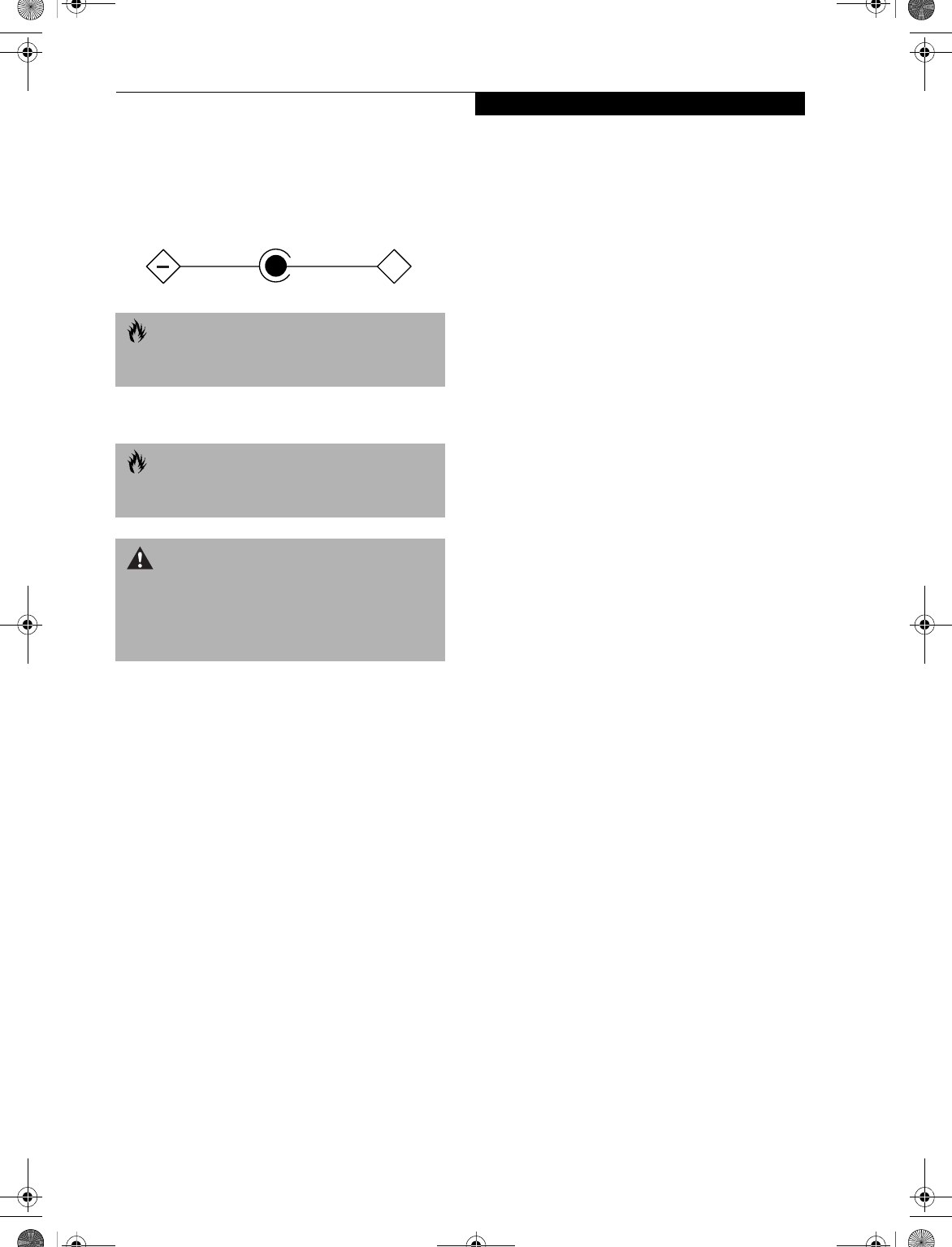
99
Regulatory Information
UL Notice
This unit requires an AC adapter to operate. Use only
UL Listed Class 2 adapter, output rating 19V DC, 4.22 A.
Refer to the illustration below for the correct AC
Adapter output polarity:
For Authorized Repair Technicians Only
CAUTION
To reduce the risk of fire, use only #26 AWG or larger
telecommunications line cord.
CAUTION
For continued protection against risk of fire, replace
only with the same type and rating fuse.
WARNING
Danger of explosion if Lithium (CMOS) battery is
incorrectly replaced. Replace only with the same or
equivalent type recommended by the manufacturer.
Dispose of used batteries according to the manufac-
turer’s instruction.
+
B5FH-4491-01EN-00.book Page 99 Friday, April 19, 2002 11:24 AM

100
LifeBook E Series
B5FH-4491-01EN-00.book Page 100 Friday, April 19, 2002 11:24 AM

101
Appendix
Integrated Wireless
LAN User’s Guide
B5FH-4491-01EN-00.book Page 101 Friday, April 19, 2002 11:24 AM

102
LifeBook E Series – Appendix
B5FH-4491-01EN-00.book Page 102 Friday, April 19, 2002 11:24 AM
103
WIreless LAN User’s Guide
FCC REGULATORY INFORMATION
Please note the following regulatory information related
to your wireless LAN device.
Regulatory Notes and Statements
Wireless LAN, Health and Authorization for use
Radio frequency electromagnetic energy is emitted from
Wireless LAN devices. The energy levels of these emis-
sions, however, are far much less than the electromag-
netic energy emissions from wireless devices such as
mobile phones. Wireless LAN devices are safe for use by
consumers because they operate within the guidelines
found in radio frequency safety standards and recom-
mendations. The use of Wireless LAN devices may be
restricted in some situations or environments, such as:
• On board an airplane, or
• In an explosive environment, or
• In situations where the interference risk to other
devices or services is perceived or identified as
harmful.
In cases in which the policy regarding use of Wireless
LAN devices in specific environments is not clear (e.g.,
airports, hospitals, chemical/oil/gas industrial plants,
private buildings), obtain authorization to use these
devices prior to operating the equipment.
Regulatory Information/Disclaimers
Installation and use of this Wireless LAN device must be
in strict accordance with the instructions included in the
user documentation provided with the product. Any
changes or modifications made to this device that are
not expressly approved by the manufacturer may void
the user’s authority to operate the equipment. The
Manufacturer is not responsible for any radio or televi-
sion interference caused by unauthorized modification
of this device, or the substitution or attachment of
connecting cables and equipment other than those spec-
ified by the manufacturer. It is the responsibility of the
user to correct any interference caused by such unautho-
rized modification, substitution or attachment. The
Manufacturer and its authorized resellers or distributors
will assume no liability for any damage or violation of
government regulations arising from failure to comply
with these guidelines.
Federal Communications Commission statement
This device complies with Part 15 of FCC Rules.
Operation is subject to the following two conditions:
(1) This device may not cause interference, and, (2) This
device must accept any interference, including interfer-
ence that may cause undesired operation of this device.
FCC Interference Statement
This equipment has been tested and found to comply
with the limits for a Class B digital device, pursuant to
Part 15 of the FCC Rules. These limits are designed to
provide reasonable protection against harmful interfer-
ence in a residential installation. This equipment gener-
ates, uses, and can radiate radio frequency energy. If not
installed and used in accordance with the instructions, it
may cause harmful interference to radio communica-
tions. However, there is no guarantee that interference
will not occur in a particular installation.
If this equipment does cause harmful interference to
radio or television reception, which can be determined
by turning the equipment off and on, the user is encour-
aged to try and correct the interference by one or more
of the following measures:
1. Reorient or relocate the receiving antenna.
2. Increase the distance between the equipment and
the receiver.
3. Connect the equipment to an outlet on a circuit
different from the one the receiver is connected to.
4. Consult the dealer or an experienced radio/TV
technician for help.
FCC Radio Frequency Exposure statement
This Wireless LAN radio device has been evaluated
under FCC Bulletin OET 65C and found compliant with
the requirements as set forth in CFR 47 Sections 2.1091,
2.1093, and 15.247 (b) (4) addressing RF Exposure from
radio frequency devices. The radiated output power of
this Wireless LAN device is far below the FCC radio
frequency exposure limits. Nevertheless, this device shall
be used in such a manner that the potential for human
contact during normal operation is minimized. When
using this device, a certain separation distance between
antenna and nearby persons must be maintained to
ensure RF exposure compliance. In order to comply with
RF exposure limits established in the ANSI C95.1 stan-
dards, the distance between the antennas and the user
should not be less than 20 cm (8 inches).
Export restrictions
This product or software contains encryption code
which may not be exported or transferred from the US
or Canada without an approved US Department of
Commerce export license. This device complies with
Part 15 of FCC Rules., as well as ICES 003 B / NMB 003
B. Operation is subject to the following two conditions:
(1) this device may not cause harmful interference, and
(2) this device must accept any interference received,
including interference that may cause undesirable oper-
ation. Modifications not expressly authorized by Fujitsu
PC Corporation may invalidate the user's right to
operate this equipment.
B5FH-4491-01EN-00.book Page 103 Friday, April 19, 2002 11:24 AM

104
LifeBook E Series – Appendix
BEFORE USING THIS DEVICE
Thank you for purchasing a Fujitsu LifeBook with an
Integrated Wireless LAN. This manual describes the
basic operating procedures for the Wireless LAN
(referred to as the “device” in this manual) and how to
set up a wireless LAN network. Before using this device,
read this manual carefully to ensure correct operation of
the device. Keep this manual in a safe place for reference
while using the device.
Characteristics of the Device
This device consists of a wireless LAN card that is
attached to the computer via a mini-PCI slot.
The main characteristics are as follows:
■It uses the power saving communications system in
the 2.4 GHz band, and does not require any license for
radio communication.
■It uses Direct Sequence Spread Spectrum (DS-SS),
which is resistant to noise.
■This device complies with Wi-Fi, and is able to com-
municate at the maximum transfer rate of 11 Mbps.
■The maximum communication range is approxi-
mately 80 feet (25 meters) inside a building. The
range may be shorter depending upon the installation
factors, such as walls and columns.
■Unauthorized access can be prevented with the use of
SSID and encryption key.
Wireless LAN Modes Using this Device
AdHoc Mode
The “AdHoc Mode” refers to the network connecting
two computers using wireless LAN cards. This connec-
tion is called an “AdHoc network.”
Using an AdHoc network, you can obtain a network
connection easily and at a low cost.
In the AdHoc mode, you can use the function supported
by Microsoft Network, such as File and Print Sharing to
exchange files and share a printer or other peripheral
devices.
To use the AdHoc Mode, you must set the same SSID
and the same encryption key for all the computers that
are connected. All connected computers can communi-
cate with each other within the communication range.
Infrastructure Mode
If a number of computers are connected simultaneously
in the AdHoc mode, the transfer rate may be reduced,
communications may become unstable, or the network
connection could fail. This is because all wireless LAN
cards are using the same radio frequency in the network.
To improve this situation, you can use a wireless LAN
access point, which is sold separately. The wireless LAN
network is in the “Infrastructure mode” when it uses an
access point, and such a connection is called the “Infra-
structure Network.”
By using an access point, you can set and use a different
communication channel for each network group. Each
channel is given a different radio frequency, and it
eliminates the collision of communications and provides
a more stable communications environment. Infrastruc-
ture mode is most suitable when you are configuring
multiple wireless LAN networks on the same floor.
To connect a wireless LAN network to a wired LAN, you
need an access point.
How to Handle This Device
The Integrated Wireless LAN device is already installed
in your LifeBook computer. Under normal circum-
stances, it should not be necessary for you to remove or
re-install it. The LAN has been configured to support the
operating system with which your system shipped.
B5FH-4491-01EN-00.book Page 104 Friday, April 19, 2002 11:24 AM
105
WIreless LAN User’s Guide
CONNECTING WINDOWS 98/2000 SYSTEMS
This chapter describes how to set the wireless LAN
connection for computers running Windows 98 or
Windows 2000.
Workflow
The proper setup of the wireless LAN requires several
steps which must be performed in the proper order.
Following is a general outline of the steps that must be
performed. Each step is detailed later in this procedure.
1. Setting parameters
■Setting the profile
■Setting the encryption
2. Network settings
■Setting the protocol and checking the network
■Setting file and printer sharing
■Checking the connection
Setting Parameters
1. Click [Start]-> [Settings] -> [Control Panel].
2. Double-click the [PRISM Settings] icon. The
[PRISM Wireless Settings] appears.
3. Set the profile as specified in Table 1. Ask your
network administrators to check the setting.
4. When you finish your entry, click [Apply].
Table 1: Profile Parameters
5. Click the [Encryption] tab.
6. Set the encryption items in accordance with Table 2.
■AdHoc Network: Specify the same value for all the
computers for which the encryption key is used for
connection.
■Infrastructure Network: Specify the identical
encryption keys to the encryption keys set for the
access point. For instructions on how to check the
encryption keys set for the access point, refer to the
access point manual.
POINT
When you receive your LifeBook, the integrated
wireless LAN device and drivers have already been
installed. This procedure outlines the steps for setting
the device parameters.
Updated drivers and/or utilities may become available
after this manual is printed; see any addenda or fliers
that may be included in the system packaging or visit
our web site at: www.fujitsupc.com for the latest
drivers..
Item Description
Profile Enter the system file name in which the
parameter information is to be saved.
Mode Ad Hoc Network: Click the down arrow
and select “802.11 AdHoc”.
Infrastructure Network: Click the down
arrow and select “Infrastructure”.
SSID Enter the network name to which you
want to connect
Transmit
Rate
Obtain the information from your
network administrator. If you do not
have a network administrator, select
“Fully Automatic”.
Power
Save
Enabled
Not supported.
AdHoc
Channel
AdHoc Network: Select the same
channel, 1-11, for all connected
computers. If there is more than one
wireless LAN nearby (such as on the
same floor), we recommend that the
channels for each LAN be 5 numbers
apart (e.g., if there are two other LANs
nearby, the channels used should be 1,
6, and 11).
Infrastructure Network: Not an option.
POINT
Make sure that you specify the encryption keys. If you
do not specify the keys, any computer with a wireless
LAN card can be connected. This presents a risk that
your data may be stolen or destroyed.
Item Description
B5FH-4491-01EN-00.book Page 105 Friday, April 19, 2002 11:24 AM
106
LifeBook E Series – Appendix
Table 2: Encryption Key Setup
7. When you finish your entry, click [Apply].
8. Click [OK]. [PRISM Wireless Settings] closes.
You have completed the parameter settings.
* 40 bit and 104 bit encryption is the wireless LAN
equivalent of 64 bit and 128 bit encryption, as set by
Microsoft and wireless LAN manufacturers. This is the
same encryption rate that is used by the Windows XP
operating system, and was selected in order to align it
closer to the wireless LAN standard. For consistency, the
Windows 98 and 2000 utilities reflect the same modes.
Outside of wireless LAN environments, encryption is
generally set at either 64 bit or 128 bit. However, the
wireless LAN standard requires that 24 bits be reserved
for fixed data. As a result, the user can only use 40 bits
(64 minus 24 ) or 104 bits (128 minus 24) for encryp-
tion. This requirement also fixes the number of charac-
ters used for 128 bit encryption to 13 which is calculated
as (13 x 8 bits = 104).
NETWORK CONNECTION: WINDOWS 98
The section describes how to set the network connection
if your computer running Windows 98.
Network Settings
In this section, you set “TCP/IP Settings,” and complete
“Checking Computer Name and Workgroup” required
for the network connection.
TCP/IP Settings
1. Click [Start]-> [Settings]->[Control Panel].
2. Double-click the [Network] icon. [Network]
appears.
3. Perform the following steps.
■Click [TCP/IP].
■Click [Properties].
4. Set an IP address. (When you are done, ask your
network administrator to check the setting).
Item Description
Encryption
(WEP)
Click the down arrow and select an
encryption option.
■Disable: Disables the encryption. In
this case, “Create keys with
Passphrase” and subsequent items
are greyed out, and you cannot
enter anything.
■40 bit*: The encryption is set.
Select either “Create keys with
Passphrase”, “Create keys manu-
ally”, or “ASCII Input”, and enter
the encryption keys.
■104 bit*: The encryption is set.
Select either “Create keys with
Passphrase”, “Create keys manu-
ally”, or “ASCII Input”, and enter
the encryption keys.
Create Keys
with
Passphrase
Not supported.
Passphrase Not supported.
Create Keys
Manually
(Hexadecimal
Input)
Select this to use hexadecimal
character codes to set the encryption
keys (Keys 1 - 4).
Enter a 10-digit value when you have
selected [40 bit]* for the encryption.
Enter a 26-digit value when you have
selected [104 bit]* for encryption.
Select if the network contains a card
that is set with the encryption key
using the character code. Specify the
encryption keys with the same value
used for other wireless LAN cards
that are already set.
ASCII Input Select to use the ASCII codes to set
encryption keys (Keys 1 - 4). Select
this if network does not contain other
wireless LAN cards that are set with
encryption key using character codes.
Enter a 5-digit value when you have
selected [40 bit]* for the encryption.
Enter a 13-digit value when you have
selected [104 bit]* for encryption.
You can use the following characters:
0 - 9, A - Z, a - z, _ (underscore).
For example, to set “ABC12” for the
encryption key, enter “ABC12.”
Default Key Click the down arrow, and select a
key from Keys 1 - 4.
POINT
When using ADSL (PPPoE) with the infrastructure
network to connect to the Internet, you must change
the computer’s MTU size set. To change MTU size, refer
to the manual that comes with the access point.
POINT
If you have more than one [TCP/IP...] entry, select
[TCP/IP -> Intersil PRISM Wireless LAN PCI Card].
[TCP/IP Properties] appears.
B5FH-4491-01EN-00.book Page 106 Friday, April 19, 2002 11:24 AM
107
WIreless LAN User’s Guide
■AdHoc Network: Select [IP address], and enter a
value for [IP address] and [Subnet Mask]. Refer to
“About IP Addresses” on page 120 to set an IP
address and subnet mask.
■Infrastructure Network: Select [Obtain an IP
address automatically].
5. Click [OK]. [Network] appears again.
In the next step, you will check the computer name and
workgroup.
Checking the Computer Name and Workgroup
1. Click the [Identification] tab on the [Network]
window.
2. Check the entry for [Computer name] and [Work-
group]. Ask your network administrator and check
the setting, if you have a network administrator.
Table 3: Computer Name and Workgroup
3. Click [OK]. When a message appears prompting you
to restart the computer, click [Yes].
Sharing
In this section, you set sharing of the drive, folder, and
printer.
You need to set this only when you are sharing files or a
printer with other computers on the network. When you
share a drive, folder, or printer, you can use these from
any computer on the network.
Setting File and Printer Sharing for Networks
1. Click [Start] -> [Settings] -> [Control Panel].
2. Double-click the [Network] icon. The [Network]
window appears.
3. Click [File and Print Sharing...]. [File and Print
Sharing] appears.
4. Click and check one or both of the options.
5. Click [OK]. [File and Printer Sharing for Microsoft
Networks] is added under [The following network
components are installed] on [Configuration] tab.
6. Click [OK]. [Network Properties] closes. Follow the
instructions on the screen.
7. When a message appears prompting you to restart
the computer, click [Yes].
Sharing Files
The following example shows how to set sharing the
“Work” folder on the c drive.
1. Double-click [My Computer] -> [C: drive] on the
desktop.
2. Right-click the “Work” folder, then click [Sharing]
from the menu that appears. The [Work Properties]
window appears.
3. Click [Sharing], and select items, as specified below.
Table 4: Password Setup
4. Click [OK]. The folder is set for sharing, and the
“Work” folder icon changes.
POINT
If this tab is not found on the [Network] window, click
[Start] -> [Settings] -> [Control Panel], and double-
click the [Network] icon.
Item Description
Computer
Name
A name to identify the computer on
the network. You can specify any
name for any computer. Use up to 15
single-byte characters. For easiest
identification, use the model name or
user name.
Workgroup The name of the network group. Use
up to 15 single-byte characters.
■AdHoc Network: Specify the same
name to all computers within the
same network.
■Infrastructure Network: Specify a
workgroup name to connect to.
Computer
Description
Additional description for the
computer. This is not necessary.
POINT
Including a period or other special characters may
prevent you from connecting to the network.
Item Description
Share Name Specify a share name for the drive or
folder that you want to share.
Access Type Limits the read/write permission for the
drive to be shared.
■Read-Only Password: Specifies read-
only for the drive to be shared.
■Full Access Password: Allows read
and write for the drive to be shared.
■Depends On Password: Identifies
either Read-Only or Full, depending
upon the password.
Passwords A password used for [Access Type].
■Read-Only Password: Specify a pass-
word to allow read.
■Full Access Password: Specify a pass-
word to allow read and write.
B5FH-4491-01EN-00.book Page 107 Friday, April 19, 2002 11:24 AM
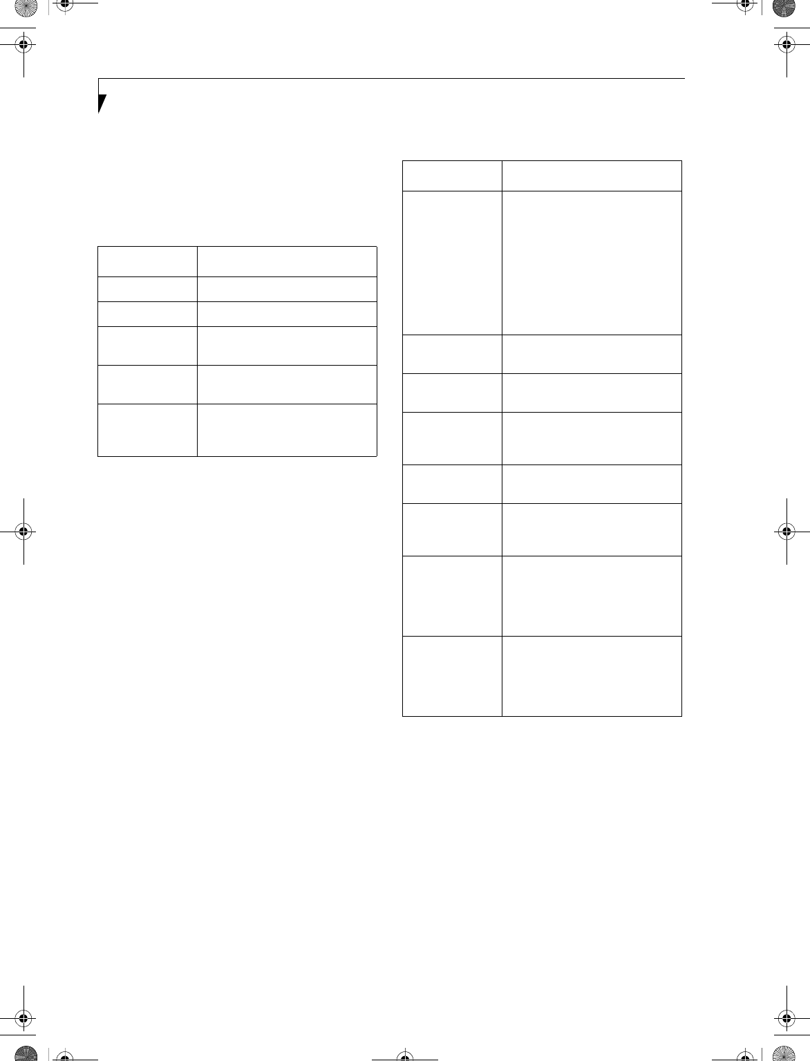
108
LifeBook E Series – Appendix
Printer Sharing
1. Click [Start] -> [Settings] -> [Printers]. [Printers]
appears, showing the printers that are connected.
2. Right click the printer that you want to share, and
then click [Sharing] from the menu that appears.
3. Click [Sharing], and select necessary items.
Table 5: Printer Sharing
4. Click [OK]. The printer is set for sharing, and the
printer icon changes.
Checking the Connection
After the network setting is completed, access the shared
drive on another computer to check the connectivity of
the wireless LAN network.
Accessing Another Computer
1. Double-click the [Network Neighborhood] on the
desktop. The computers that are connected to the
network are displayed.
2. Double-click the computer that you want to access.
The drive that you set with “Sharing” is displayed.
The drive is not displayed unless it is set for sharing,
even if it exists.
3. Double-click the drive that you want to access. The
drive is displayed showing its contents and made
available to you.
If you have a question or problem, refer to “Trouble-
shooting” on page 115.
Checking the Connectivity
1. Click [Start] -> [Settings] -> [Control Panel].
2. Double-click the [PRISM Settings] icon. [PRISM
Wireless Settings] appears.
3. Check the connectivity on the [Link] tab. The
current condition of connection is displayed.
Table 6: Connectivity Condition
NETWORK CONNECTION: WINDOWS 2000
The section describes how to set the network connection
for a computer with Windows 2000.
Network Settings
In this section, you set “TCP/IP Settings,” and complete
“Checking Computer Name and Workgroup,” required
for the network connection.
TCP/IP Settings
1. Click [Start] -> [Settings] -> [Control Panel].
Item Description
Not Shared Disables printer sharing.
Shared as Enables printer sharing
Share Name Specifies a share name for the
printer to be shared.
Comment Enter a description of the printer
to be shared.
Passwords Specify passwords. If you specify a
password, you need to enter it
when using the printer.
Item Description
State Shows the current condition of
connection.
The MAC address of the other
computer that you are connected
to is displayed, when the connec-
tion is successfully made. If you
are connected to more than one
computer, the computer that has
the best connectivity is displayed.
Current Channel Shows the current channel used
for the connection.
Current Tx Rate Shows the current transfer rate in
Mbits/sec.
[Radio Off]/
[Radio On]
Click [Radio Off] to disconnect.
Click [Radio On] to connect to
network.
Rescan Click to search for others to
connect to.
Throughput
(Bytes/sec)
Shows the actual transfer rate of
the transfer data for send (Tx) and
receive (Rx).
Link Quality Shows [Excellent], [Good], [Fair],
[Poor], or [Not Connected],
depending on the link quality. This
is not shown for the AdHoc
connection.
Signal Strength Shows [Excellent], [Good], [Fair],
[Poor], or [Not Connected],
depending on the signal strength.
This is not shown for the AdHoc
connection.
B5FH-4491-01EN-00.book Page 108 Friday, April 19, 2002 11:24 AM
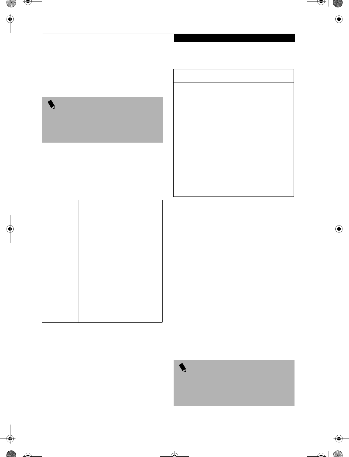
109
WIreless LAN User’s Guide
2. Double-click the [Network and Dial-up
Connections] icon. The [Network and Dial-up
Connections] window appears.
3. Right click the [Local Area Connection], then click
[Properties] from the menu that appears. The [Local
Area Connection Properties] window appears.
4. Perform the following steps.
■Click [Internet Protocol (TCP/IP)].
■Click [Properties]. The [Internet Protocol (TCP/IP)
Properties] window appears.
5. Set an IP address as indicated in Table 7. Ask your
network administrator to check the setting.
Table 7: Setting an IP Address
6. Click [OK]. The [Local Area Connection Properties]
window appears again.
7. Click [OK]. When a message appears prompting you
to restart the computer, click [Yes].
Checking the full computer name and workgroup
1. Click [Start] -> [Settings] -> [Control Panel].
2. Double-click the [System] icon. [System Properties]
appears.
3. Click the [Network Identification] tab.
4. Check [Full computer name] and [Workgroup]. Ask
your network administrator and check the setting.
Table 8: Checking computer name and workgroup
5. Click [OK]. When a message appears prompting you
to restart the computer, click [Yes].
Sharing
In this section, you set sharing of the drive, folder, and
printer.
You only need to set this when you are sharing files or a
printer with other computers on the network.
When you share a drive, folder, or printer, you can use
them from any computer on the network.
Setting [File and Printer Sharing for Microsoft
Networks]
1. Click [Start] -> [Settings] -> [Control Panel].
2. Double-click the [Network and Dial-up
Connections] icon. The [Network and Dial-up
Connections] windows appears.
3. Right click the [Local Area Connection], then click
[Properties] from the menu that appears. [Local
Area Connection Properties] appears.
POINT
More than one network adapter is installed in your
system if more than one [Local Area Connection] entry
is displayed. In this case, select the [Local Area
Connection] entry with [Intersil PRISM Wireless LAN
PCI Card] displayed under [Device Name].
Item Description
For AdHoc
Network
Set the IP address and subnet mask:
Click [Use the following IP address],
and enter a value for [IP address] and
[Subnet mask].
Refer to “Setting IP Addresses” on
page 120 to set an IP address and
subnet mask.
For
Infrastructure
Network
Select [Obtain an IP address
automatically]:
For the DNS server, select [Obtain
DNS server address automatically].
For the IP address, DNS server, and
default gateway, follow the network
administrator's instructions, if any.
Item Description
Full
Computer
Name
A name to identify the computer on
the network. You can specify any
name to each computer.
For easier identification, use the model
name or user name.
Workgroup A name for the network group:
■AdHoc Network:
Specify the same name to all com-
puters within the same network.
■Infrastructure Network: Specify a
workgroup name to connect to.
To change the setting, click
[Properties], and follow the instruc-
tions on the screen. [System Proper-
ties] appears again.
POINT
More than one network adapter is installed in your
system if more than one [Local Area Connection] entry
is displayed. In this case, select the [Local Area Connec-
tion] entry with [Intersil PRISM Wireless LAN PCI Card]
displayed under [Device Name].
B5FH-4491-01EN-00.book Page 109 Friday, April 19, 2002 11:24 AM
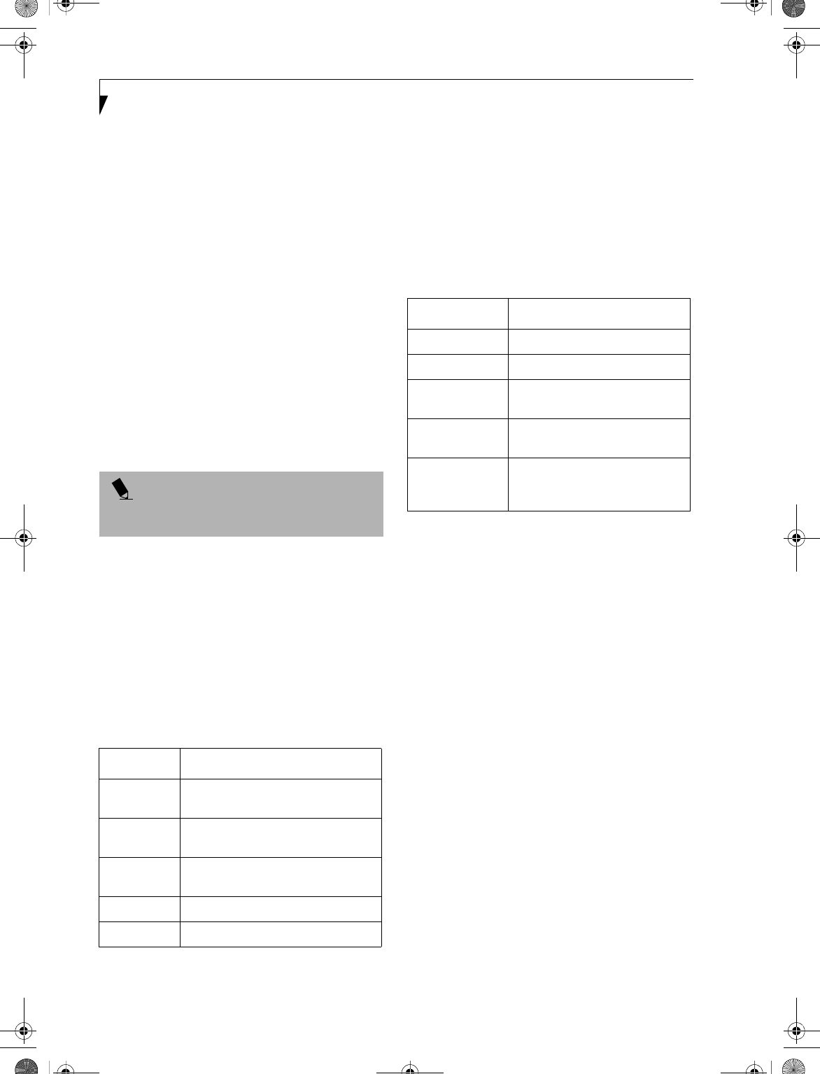
110
LifeBook E Series – Appendix
4. If [File and Printer Sharing for Microsoft Networks]
is displayed in the list, make sure that it is checked. If
it is not checked, check it and click [OK]. You do not
have to perform the following steps. Go to the next
section, entitled “Sharing Files.”
If [File and Printer Sharing for Microsoft Networks]
is not found in the list, click [Install], and perform
Step 5 and subsequent steps. When you click
[Install], the [Select Network Component Type]
window appears.
5. Perform the following steps.
■Click [Service].
■Click [Add]. The [Select Network Service] window
appears.
6. Perform the following steps.
■Click [File and Printer Sharing for Microsoft
Networks].
■Click [OK]. You will go back to [Local Area Connec-
tion Properties], and [File and Printer Sharing for
Microsoft Networks] is added to the list.
7. Click [OK].
Sharing Files
The following example shows how to set sharing the
“Work” folder on the c: drive.
1. On the desktop, double-click [My Computer]->
C: drive.
2. Right-click the “Work” folder, then click [Sharing]
from the menu. The [Work Properties] window
appears.
3. Click [Share this folder] and set necessary items, as
indicated in the following table.
Table 9: Sharing files
4. Click [OK]. The folder is set shared, and the “Work”
folder icon changes.
Printer Sharing
1. Click [Start] -> [Settings] -> [Printers]. The Printers
window appears, showing the printers that are
connected.
2. Right click the printer that you want to share, then
click [Sharing] from the menu that appears.
3. Click [Sharing], and select necessary items.
Table 10: Printer Sharing
4. Click [OK]. The printer sharing is set, and the icon
changes.
Checking the Connection
After the network setting is completed, access the shared
drive on another computer to check the connectivity of
the wireless LAN network.
Accessing Another Computer
1. Double-click the [My Network Places] icon on the
desktop. [My Network Places] appears.
2. Double-click [Computers near me]. The computers
that are connected to the network are displayed.
3. Double-click the computer that you want to access.
The drive that you set with “Sharing” are displayed.
4. Double-click the drive that you want to access. The
drive is displayed showing its contents and made
available to you. If you have any questions or prob-
lems, refer to “Troubleshooting Table” on page 115.
Checking the Connectivity
1. Click [Start] -> [Settings] -> [Control Panel].
2. Double-click the [PRISM Settings] icon. [PRISM
Wireless Settings] appears.
3. Check the connectivity on the [Link] tab. The
current condition of connection is displayed.
POINT
If you have changed the setting, [Close] is shown
instead. Click [Close].
Item Description
Share name You can specify a share name for the
drive or folder that you want to share.
Comment You can enter the description for the
drive or folder that you want to share.
User limit Specifies the limit for the number of
sharing users.
Permissions Specifies the folder access privileges.
Caching Specifies the caching for the folder.
Item Description
Not Shared Disables printer sharing.
Shared As Enables printer sharing.
Share Name Specifies a share name of the
printer to be shared.
Comment Enter the description of the printer
to be shared.
Passwords If you specify a password, you
need to enter it when using the
printer.
B5FH-4491-01EN-00.book Page 110 Friday, April 19, 2002 11:24 AM
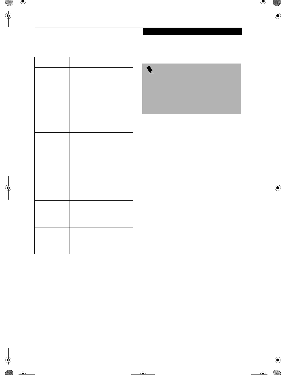
111
WIreless LAN User’s Guide
Table 11: Checking connectivity
CONNECTING WINDOWS XP SYSTEMS
This chapter describes how to set up the wireless LAN
connection for computers that are running Windows XP.
Workflow
The proper setup of the wireless LAN connection
requires that several steps be performed in the proper
order. Following is a general outline of the steps to be
performed. Each step is detailed later in this procedure.
1. Setting parameters
■Setting the profile
■Setting the encryption
2. Network settings
■Setting the protocol and checking the network
■Setting file and printer sharing
■Checking the connection
Setting Parameters
1. Click [Start] -> [Control Panel].
2. Click [Network and Internet connection].
3. Click [Network connection]. A list of networks that
are currently installed is displayed.
4. Right click [Intersil PRISM Wireless LAN PCI Card]
in the list, and click [Properties] from the menu that
is displayed. [Wireless Network Connection 2 Prop-
erties] appears.
5. Click the [Wireless Networks] tab. The [Wireless
Networks] tab appears.
6. Perform the following steps.
■Make sure that [Use Windows to configure my wire-
less network settings] is checked.
■Click [Add] under [Preferred networks]. [Wireless
Network Properties] appears.
7. Set parameters.
■For the AdHoc network, specify the same value to all
the computers, for which the encryption key is used
for connection.
■For the infrastructure network, specify the encryp-
tion key (network key) with the same value to the
encryption key of the access point. For how to check
Item Description
State Shows the current condition of
connection.
The MAC address of the other
computer to which you are
connected is displayed when the
connection is successful. If you are
connected to more than one
computer, the computer that has
the best connectivity is displayed.
Current Channel Shows the current channel used
for the connection.
Current Tx Rate Shows the current transfer rate in
Mbits/sec.
[Radio Off]/
[Radio On]
Click [Radio Off] to disconnect.
Click [Radio On] to connect to the
network.
[Rescan] button Click this button to search for
others to connect to.
Throughput
(Bytes/sec)
Shows the actual transfer rate of
the data transfer for send (Tx) and
receive (Rx).
Link Quality Shows either [Excellent], [Good],
[Fair], [Poor], or [Not Connected],
depending on the link quality.
Not shown for AdHoc connection.
Signal Strength Shows either [Excellent], [Good],
[Fair], [Poor], or [Not Connected],
depending on the signal strength.
Not shown for AdHoc connection.
POINT
When you receive your LifeBook, the integrated
wireless LAN device and drivers have already been
installed. This procedure outlines the steps for setting
the device parameters.
Updated drivers and/or utilities may become available
after this manual is printed; see any addenda or fliers
that may be included in the system packaging.
B5FH-4491-01EN-00.book Page 111 Friday, April 19, 2002 11:24 AM
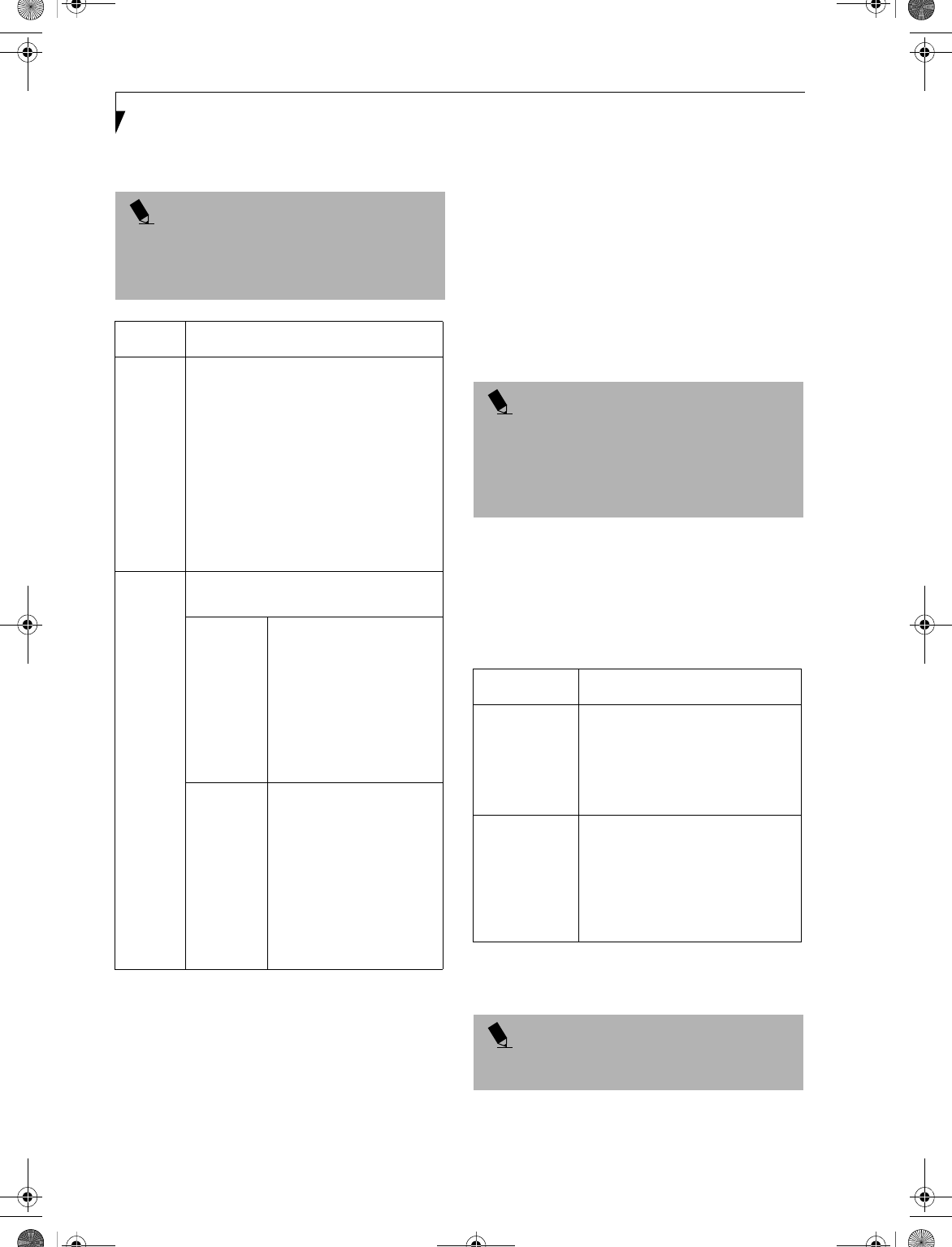
112
LifeBook E Series – Appendix
the encryption keys set for the access point, refer to
the manual supplied with the access point.
Table 12: Setting parameters
8. When you finish your entry, click [OK]. [Wireless
Network Connection 2 Properties] appears again.
9. Make sure the network name you specified for the
SSID in Step 7 is added under [Preferred networks].
Network Connection
The section describes how to set the network connection
for a computer running Windows XP.
Network Settings
In this section, you set “TCP/IP Settings,” and complete
“Checking Computer Name and Workgroup” required
for the network connection.
TCP/IP Settings
1. On [Wireless Network Connection Properties], click
[General].
2. Perform the following steps.
■Click [Internet Protocol (TCP/IP)].
■Click [Properties]. [Internet Protocol (TCP/IP)
Properties] appears.
3. Set an IP address. Ask your network administrator
and check the setting.
Table 13: Setting an IP address
5. Click [OK].
6. Close [Network Connection].
POINT
Be sure to specify the encryption keys. If you do not
specify the keys, any computer with a wireless LAN card
can be connected. This presents a risk that other users
may steal or destroy your data.
Item Description
Network
Name
SSID
Enter the network name to which you
want to connect. This is a required item.
For the network name, ask your LAN
administrator.
AdHoc network: Set the same name for all
of the computers that are to be connected.
Infrastructure network: Specify the same
name as that specified on the access point
that is to be connected. For access point
instructions, refer to the manual that
comes with the access point.
Key
Format
Click the down arrow and select the input
for the Network key.
ASCII
characters
Select this when using
ASCII characters for the
Network Key. Characters
that can be used follow:
0-9, A-Z, a-z, and
_ (underscore)
Example: To set the key to
“ABC12”, input “ABC12”.
Hexa-
decimal
characters
Select this when using
hexadecimal characters for
the Network Key.
Use this if there is a wireless
LAN card in the network
that has the Network Key
set to a character code. In
’Network Key’, input the
same value as the other
wireless LAN card.
POINT
If [Wireless Network Connection 2 Properties] is not
displayed, click [Start] -> [Settings] -> [Control Panel],
and double-click the [Network Connection] icon.
Right click the [Wireless Network Connection], and
then click [Properties] from the menu that appears.
Item Description
AdHoc
Network
Set the IP address and subnet mask.
Click [Use the following IP address].
Enter a value for [IP address] and
[Subnet mask]. See “Setting IP
Addresses” on page 120 to set IP
address and subnet mask.
For
Infrastructure
Network
Select [Obtain an IP address
automatically]. For the DNS server,
select [Obtain DNS server address
automatically]. For the IP address,
DNS server, and default gateway,
follow the network administrator's
instructions, if any.
POINT
If you have changed the setting, [Close] is shown
instead. Click [Close].
B5FH-4491-01EN-00.book Page 112 Friday, April 19, 2002 11:24 AM
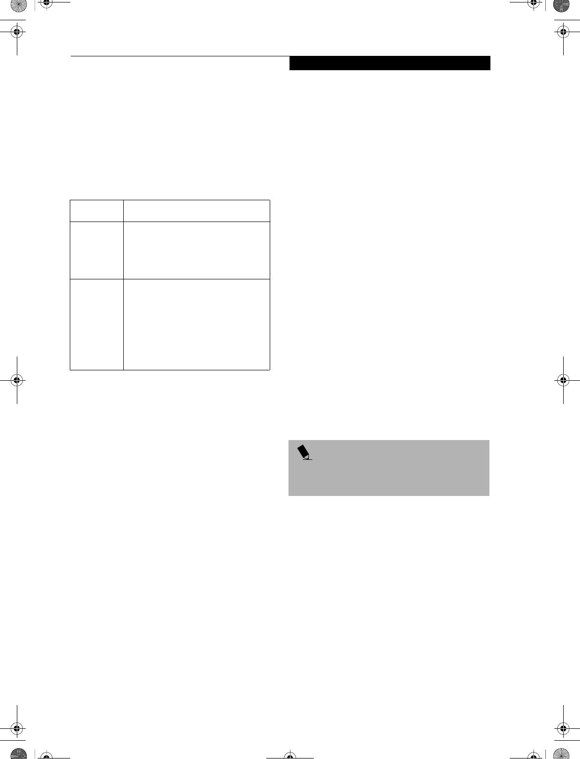
113
WIreless LAN User’s Guide
Checking the Full Computer Name and Workgroup
1. Click [Start] -> [Control Panel]. Make sure the
Classic View is selected.
2. Double-click the [System] icon. [System Properties]
appears.
3. Click the [Computer Name] tab.
4. Check [Full computer name] and [Workgroup]. Ask
your network administrator and check the setting.
Table 14: Setting computer name and workgroup
To change the setting, click [Change], and follow the
instructions on the screen. [System Properties] appears.
5. Click [OK]. When a message appears prompting you
to restart the computer, click [Yes].
Sharing
In this section, you set sharing of the drive, folder, and
printer.
You need to set this only when you are sharing files or a
printer with other computers on the network.
When you share a drive, folder, or printer, you can use
these from any computer on the network.
Setting [File and Printer Sharing for Microsoft
Networks]
1. Click [Start] -> [Control Panel]. Make sure the
Classic View is selected.
2. Double-click the [Network Connection] icon.
3. Right click the [Wireless Network Connection], and
then click [Properties] from the menu that appears.
[Wireless Network Connection Properties] appears.
4. If [File and Printer Sharing for Microsoft Networks]
is displayed in the list:
Make sure that it is checked. If it is not checked,
check it, and click [OK]. You do not have to perform
the following steps. Go to “Sharing Files” section.
If [File and Printer Sharing for Microsoft Networks]
is not found in the list, click [Install], and perform
Step 5 and the subsequent steps. When you click
[Install], [Select Network Component Type]
appears.
5. Perform the following steps.
■Click [Service].
■Click [Add]. [Select Network Service] appears.
6. Perform the following steps.
■Click [File and Printer Sharing for Microsoft
Networks].
■Click [OK]. You will go back to [Wireless Network
Connection 2 Properties], and [File and Printer
Sharing for Microsoft Networks] is added to the list.
7. Click [Close].
Sharing Files
The following example shows how to set sharing the
“Work” folder on the c: drive.
1. Click [Start] -> [My Computer].
2. Double-click the [Local Disk (c:)] icon.
3. Right click the “Work” folder, and then click
[Sharing and Security] from the menu that appears.
[Work Properties] appears.
4. Click [If you understand the security risks but want
to share files without running the wizard, click
here].
In the [Work Properties] window, the description under
[Network Sharing and security] changes.
5. Check [Share this folder on the network].
Uncheck [Allow network users to change my files], if
the shared folder is for read only.
6. Click [OK]. The folder is set shared, and the “Work”
folder icon changes.
Printer Sharing
1. Press [Start]->[Control Panel] (or [Settings], if
viewing in Classic mode)-> [Printers and Faxes].
The Printers and Faxes display will appear and the
connected printers will be displayed.
2. Right-click the printer to be shared, and click
[Sharing] from the menu that appears. The proper-
ties of the printer to be shared will be displayed. Set
printer sharing.
Item Description
Computer
Name
A name to identify the computer on the
network. You can specify any name to
each computer. Use up to 15 single-
byte characters. For easier identifica-
tion, use the model name or user name.
Workgroup A name of the network group. Use up
to 15 single-byte characters.
AdHoc Network: Specify the same
name to all computers within the same
network.
Infrastructure Network: Specify the
workgroup name to connect to.
POINT
If you have already clicked [If you understand the
security risks but want to share files without running the
wizard, click here], this window does not appear.
B5FH-4491-01EN-00.book Page 113 Friday, April 19, 2002 11:24 AM
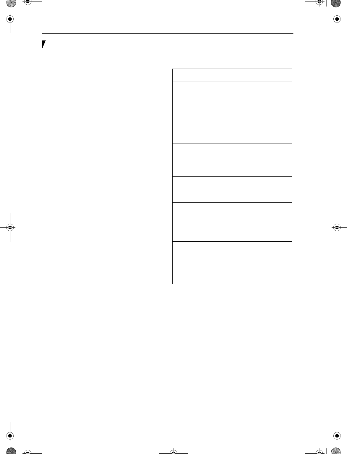
114
LifeBook E Series – Appendix
On the display, the printer sharing setting is recom-
mended by the Network Setup Wizard, but for the wire-
less LAN network, security is maintained by network
name (SSID) or network key. The following steps allow
you to set up printer sharing without using the Network
Setup Wizard.
3. Click 'If you understand the security risks but want
to share printers without running the wizard, click
here. 'Enable Printer Sharing' will be displayed.
4. Select 'Just enable printer sharing'.
5. Click 'OK'. The printer properties will be indicated.
6. Select 'Share this printer'.
7. Enter the sharing printer name in 'Share name'.
8. Click OK. The printer will be shared, and the printer
icon will become a sharing icon.
Checking the Connection
After the network setting is completed, access the shared
drive on another computer to check the connectivity of
the wireless LAN network.
Accessing Another Computer
1. Click [Start] -> [My Computer].
2. From the left menu in [Other Places], click [My
Network Places].
3. From the left menu in [Network Tasks], click [View
workgroup computers]. The workgroup in which
you are participating will appear.
4. Double click the computer to which you want to
connect. The drive that you set in [Computer
Sharing] appears.
5. Double click the drive to which you want to connect.
The contents of the drive will appear, and is available
for use.
If you have a question or problem, refer to “Trouble-
shooting Table” on page 115.
Checking the Connectivity
1. Click [Start] -> [Control Panel].
2. Double-click the [PRISM Settings] icon. [PRISM
Wireless Setting] appears.
3. Check the connectivity on the [Link] tab. The
current condition of connection is displayed.
Table 15: Checking connectivity
Item Description
State Shows the current condition of
connection.
The MAC address of the other
computer that you are connected to is
displayed, when the connection is
successfully made. If you are
connected to more than one
computer, the computer that has the
best connectivity is displayed.
Current
Channel
Shows the current channel used for
the connection.
Current Tx
Rate
Shows the current transfer rate in
Mbits/sec.
Radio Off/
Radio On
Click [Radio OFF] to disconnect.
Click [Radio On] to connect to the
network.
Rescan Click this button to search for others
to connect to.
Throughput
(Bytes/sec)
Shows the actual transfer rate of the
transfer data for send (Tx) and receive
(Rx).
Link Quality Shows the link quality. This is not
shown for the AdHoc connection.
Signal
Strength
Shows the signal strength.
This is not shown for the AdHoc
connection.
B5FH-4491-01EN-00.book Page 114 Friday, April 19, 2002 11:24 AM
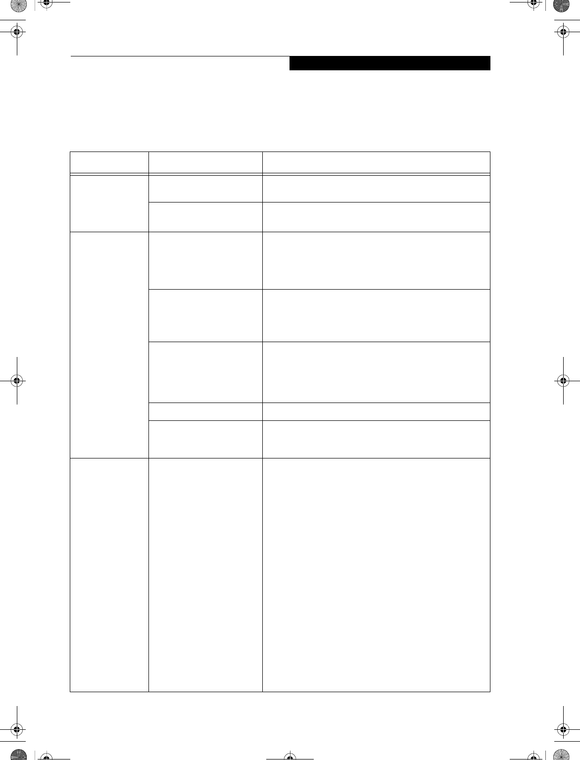
115
WIreless LAN User’s Guide
TROUBLESHOOTING
This section contains troubleshooting information, including causes and actions, for problems you may find while
using this device.
Troubleshooting Table
Problem Possible Cause Possible Solution
Exclamation mark
(!) or cross (x) is
attached to [Intersil
PRISM Wireless
LAN PCI Card].
Failure to recognize the
device.
Restart the computer.
Failure in installing the driver. Restart the computer.
Other computers
are not displayed
when the [Network
Computer] icon is
double-clicked.
You didn’t enter the password
when Windows 98 started.
You clicked [Cancel] or [ESC]
when User Name/Password
window was shown.
Make sure that you enter user name and password and click
[OK] when starting Windows 98. If you forget your password,
enter another user name. A new user name and password is
registered in the computer.
The network has not been set
up correctly.
Check the setting for the protocol, workgroup, and sharing.
To check this, you need a different procedure, depending upon
the operating system that you use. Refer to the appropriate
section of this chapter.
It takes time before the
network is searched and the
computer connected is
displayed.
Perform the following steps to search for the computer.
■Click [Start] -> [Search] -> [Other Computers].
■Enter the computer name that you are connecting to in
[Name], and click [Search].
■Double-click icon of the computer that has been searched.
Failure in installing the driver. Make sure that the driver is correctly installed.
The TCP/IP protocol is not
installed, or, the IP address is
not set correctly.
Make sure the TCP/IP protocol is installed. To check this, you
need a different procedure, depending on the operating system
that you use. Refer to the appropriate section of this manual.
Other computers
are not displayed
when the [Network
Computer] icon is
double-clicked.
The TCP/IP protocol is not
installed, or, the IP address is
not set correctly.
If the TCP/IP protocol is installed, do the following to check the
IP address:
1. Windows 98:
Click [Start] -> [Programs] -> [MS-DOS Prompt].
Windows 2000:
Click [Start] -> [Programs] -> [Accessories] -> [Command
Prompt].
Windows XP:
Click [Start] -> [All Programs] -> [Accessories] ->
[Command Prompt].
2. Enter “IPCONFIG” command, and press [Enter].
(If your hard disk is C drive, enter
C:\>ipconfig)
Check that the IP address is correctly displayed under the IP
Address.
Example:
IP address: 10.0.1.3
Subnet Mask: 255.255.255.0
Default Gateway: 10.0.1.1
B5FH-4491-01EN-00.book Page 115 Friday, April 19, 2002 11:24 AM
116
LifeBook E Series – Appendix
Other computers
are not displayed
when the [Network
Computer] icon is
double-clicked.
(continued)
No communication due to
poor radio signal.
Shorten the distance between computers or remove visible
obstacles between them, and retry the connection.
IP packet isn’t
reaching its desti-
nation
Run the PING command to
check the connection
Perform the following steps to run the PING command to check
if the IP packet is correctly delivered to the destination.
To run the PING command, the TCP/IP protocol must be
installed. First you will determine your IP address, then you will
make sure your IP address can respond, and then you will make
sure other computers can be addressed.
1. Windows 98: Click [Start] -> [Programs] -> [MS-DOS
Prompt].
Windows 2000: Click [Start] -> [Programs] -> [Accessories]
-> [Command Prompt].
Windows XP: Click [Start] -> [All Programs] -> [Accessories]
-> [Command Prompt].
2. Type: ipconfig > directory\filename
where directory and filename represent the location at
which you want to find the IP address.
3. Click [Enter], then go to the location you specified above.
The IP address for your system will be contained in the file.
4. To check that your IP address is functioning properly, go
back to the DOS prompt and type: ping <IP address>, then
press [Enter]. You will receive several replies, followed by
the PING statistics (similar to below).
5. To check that your system is communicating with other
systems, go to the DOS prompt and type:
\>ping XXX.XXX.XXX.XXX. (With the destination IP address
in place of XXX.XXX.XXX.XXX).
Example: if the destination IP address is 10.0.1.3:
C:\>ping 10.0.1.3
A message similar to the following appears if the connection is
successful.
Pinging 10.0.1.3 with 32 bytes of data:
Reply from 10.0.1.3: bytes=32 time=1ms TTL=32
Reply from 10.0.1.3: bytes=32 time<10ms TTL=32
Reply from 10.0.1.3: bytes=32 time=4ms TTL=32
Reply from 10.0.1.3: bytes=32 time<10ms TTL=32
If the connection fails, [Request timed out], [Destination host
unreachable], or a similar message appears. In this case, refer to
the “Other computers are not displayed” portion of this
chapter.
Problem Possible Cause Possible Solution
B5FH-4491-01EN-00.book Page 116 Friday, April 19, 2002 11:24 AM
117
WIreless LAN User’s Guide
Cannot connect to
the network
There are several possible
causes, as listed to the right.
Refer to the
specific section of this man-
ual or your user’s manual.
The following causes are possible. Check each one of them.
■The network name or encryption key is not right.
■The driver has not correctly started.
■The destination computer is not turned on.
■You do not have the access privilege to the destination
computer.
■The card has failed.
■Hardware conflict.
I want to remove
the driver.
(Windows 98)
Windows 98:
When removing the driver, make sure that the device is
attached to the computer. If you try to remove the driver while
the device is detached from the computer, the driver is not
removed.
1. Right click the [My Computer] icon on the desktop, and
then click [Properties] from the menu that appears. [System
Properties] appears.
2. Click the [Device Manager] tab.
3. Click [+] beside [Network adapters].
4. Perform the following steps.
■Click [Intersil PRISM Wireless LAN PCI Card].
■Click [Remove]. [Confirm Device Removal] appears.
5. Click [OK]. The device is removed, and [System Settings
Change] appears.
6. Click [No].
7. Close [System Properties].
8. Make sure that the icon has disappeared from the task tray
in the lower right corner of the screen.
9. Click [Start] -> [Settings] -> [Control Panel]. [Control Panel]
appears.
10. Double-click [Add/Remove Programs]. [Add/Remove
Programs Properties] appears.
11. Double-click [PRISM 11Mbps Wireless LAN for
Windows]. A window appears asking you if you really
want to remove the driver.
12. Click [Yes]. When the driver is removed, a window appears
showing that the driver has been removed.
13. Click [OK].
14. Close [Add/Remove Programs Properties] and [Control
Panel].
15. Shut down Windows, and turn off the computer.
Problem Possible Cause Possible Solution
B5FH-4491-01EN-00.book Page 117 Friday, April 19, 2002 11:24 AM
118
LifeBook E Series – Appendix
I want to remove
the driver
(Windows 2000)
Windows 2000:
When removing the driver, make sure that the device is
attached to the computer. If you try to remove the driver while
the device is detached from the computer, the driver is not
removed.
1. Right click the [My Computer] icon on the desktop, and
then click [Properties] from the menu that appears. [System
Properties] appears.
2. Click the [Hardware] tab.
3. Click [Device Manager...]. The [Device Manager] window
appears.
4. Click [+] beside [Network adapters].
5. Right click [Intersil PRISM Wireless LAN PCI Card], and
click [Uninstall] from the menu that is displayed. [Confirm
Device Removal] appears.
6. Click [OK].
7. Close [System Properties].
8. Make sure that the icon has disappeared from the task tray
in the lower right corner of the screen.
9. Click [Start] -> [Settings] -> [Control Panel].
10. Double-click [Add/Remove Programs]. [Add/Remove
Programs] appears.
11. Perform the following steps.
■Click [PRISM 11Mbps Wireless LAN for Windows].
■Click [Change/Remove].
A window appears asking you if you really want to remove the
driver.
12. Click [Yes].
When the driver is removed, a window appears showing that
the driver has been removed.
13. Click [OK].
14. Close [Add/Remove Programs] and [Control Panel].
15. Shut down Windows, and turn off the computer.
Problem Possible Cause Possible Solution
B5FH-4491-01EN-00.book Page 118 Friday, April 19, 2002 11:24 AM

119
WIreless LAN User’s Guide
Problem Possible Cause Possible Solution
I want to remove the
driver
(Windows XP)
Windows XP:
When removing the driver, make sure that the device is attached to
the computer. If you try to remove the driver while the device is
detached from the computer, the driver is not removed.
1. Click [Start], right click [My Computer], and then click [Properties]
from the menu that appears. [System Properties] appears.
2. Click the [Hardware] tab.
3. Click [Device Manager].
4. Click [+] beside [Network adapters].
5. Right click [Intersil PRISM Wireless LAN PCI Card], and
click [Uninstall] from the menu that is displayed. [Confirm Device
Removal] appears.
6. Click [OK].
7. Close [System Properties].
8. Make sure that the icon has disappeared from the task tray in the
lower right corner of the screen.
9. Click [Start] -> [Control Panel]. [Control Panel] appears.
10. Double-click [Add/Remove Programs]. [Add/Remove Programs]
appears.
11. Perform the following steps.
■Click [PRISM 11Mbps Wireless LAN for Windows].
■Click [Change/Remove].
A window appears asking you if you really want to remove the driver.
12. Click [Yes].
When the driver is removed, a window appears showing that the
driver has been removed.
13. Click [OK].
14. Close [Add/Remove Programs] and [Control Panel].
15. Shut down Windows, and turn off the computer.
B5FH-4491-01EN-00.book Page 119 Friday, April 19, 2002 11:24 AM
120
LifeBook E Series – Appendix
IF A SECOND LAN DEVICE IS INSTALLED
Instructions for disabling another LAN device
If you have another LAN card on your computer
running Windows 98, perform the following steps to
disable that LAN card before installing the driver.
For Windows 98
1. Click [Start] -> [Settings] -> [Control Panel].
2. Double-click [System]. [System Properties] appears.
3. Click [+] beside [Network adapters], and double-
click the standard built-in LAN device.
The following devices appear depending on your
computer model.
■[Intel(R) 82559 Fast Ethernet LOM with Alert on
LAN 2*]
■[Intel(R) 8255x-based PCI Ethernet Adapter(10/
100)]
■[Realtek RTL8139(A/B/C/8130)PCI Fast Ethernet
NIC]
■or others.
The LAN Card Properties window appears.
4. Check [Set disable with this hardware profile], and
click [OK]. An [x] mark is added to the LAN card
icon.
5. Click [OK].
6. Restart the system.
ABOUT IP ADDRESSES
Setting IP Addresses
If you are not sure how to set the IP address, refer to the
following procedure.
If you have an access point (DHCP server) on the
network, set the IP address as follows:
Windows 98: [Obtain an IP address automatically]
Windows 2000: [Obtain an IP address automatically]
Windows XP: [Obtain an IP address automatically]
If the IP address is already assigned to the computer in
the network, ask the network administrator to check the
IP address to be set for the computer.
If no access point is found in the network:
An IP address is expressed with four values in the range
between 1 and 255.
Set the each computer as follows: The value in paren-
theses is a subnet mask.
<Example>
Computer A: 192.168.100.2 (255.255.255.0)
Computer B: 192.168.100.3 (255.255.255.0)
Computer C: 192.168.100.4 (255.255.255.0)
:
:
Computer X: 192.168.100.254 (255.255.255.0)
POINT
A DHCP server is a server that automatically assigns IP
addresses to computers or other devices in the network.
There is no DHCP server for the AdHoc network.
B5FH-4491-01EN-00.book Page 120 Friday, April 19, 2002 11:24 AM
121
WIreless LAN User’s Guide
SPECIFICATIONS
Technical Specifications for Integrated Wireless LAN Device
Item Description
Network Type IEEE 802.11b
Transfer Rate 11/5.5/2/1Mbps (auto change)
Frequency Range 2,400 - 2,473 MHz
Channels Oneof11channelsisused
Card Type Non-intelligent
VCC Class B
Security Network name, encryption key
Supported Operating Systems Windows 98, Windows 2000, Windows XP
Power Current Max: 350mA
Maximum number of units recommended for
wireless LAN (AdHoc network)
10 or less
B5FH-4491-01EN-00.book Page 121 Friday, April 19, 2002 11:24 AM

122
LifeBook E Series – Appendix
B5FH-4491-01EN-00.book Page 122 Friday, April 19, 2002 11:24 AM

123
Index
B5FH-4491-01EN-00.book Page 123 Friday, April 19, 2002 11:24 AM

124
LifeBook E Series
B5FH-4491-01EN-00.book Page 124 Friday, April 19, 2002 11:24 AM

Index
125
A
AC
adapter . . . . . . . . . . . . . . . . . . . . . . . . . . . . .33, 84, 91
indicator . . . . . . . . . . . . . . . . . . . . . . . . . . . . . . . . . . 14
plug adapters . . . . . . . . . . . . . . . . . . . . . . . . . . . . . . 77
ACPI . . . . . . . . . . . . . . . . . . . . . . . . . . . . . . . . . . . . . . . 39
Anti-theft Lock Slot . . . . . . . . . . . . . . . . . . . . . . . . . . . 10
Audio . . . . . . . . . . . . . . . . . . . . . . . . . . . . . . . . . . . . . . . 83
Auto Insert Notification . . . . . . . . . . . . . . . . . . . . . . . 49
Auto/Airline Adapter . . . . . . . . . . . . . . . . . . . . . . . 33, 91
B
Battery . . . . . . . . . . . . . . . . . . . . . . . . . . . . . . . . . . . . . . 66
bay . . . . . . . . . . . . . . . . . . . . . . . . . . . . . . . . . . . . . . . 13
care . . . . . . . . . . . . . . . . . . . . . . . . . . . . . . . . . . . . . . 78
charging indicator . . . . . . . . . . . . . . . . . . . . . . . . . . 15
conserving power . . . . . . . . . . . . . . . . . . . . . . . . . . . 38
dead . . . . . . . . . . . . . . . . . . . . . . . . . . . . . . . . . . . . . . 66
faulty . . . . . . . . . . . . . . . . . . . . . . . . . . . . . . . . . . . . . 66
increasing life . . . . . . . . . . . . . . . . . . . . . . . . . . . . . . 78
level indicators . . . . . . . . . . . . . . . . . . . . . . . . . . . . . 14
lithium ion battery . . . . . . . . . . . . . . . . . . . . . . . 43, 93
low . . . . . . . . . . . . . . . . . . . . . . . . . . . . . . . . . . . . . . . 43
recharging . . . . . . . . . . . . . . . . . . . . . . . . . . . . . . . . . 43
replacing . . . . . . . . . . . . . . . . . . . . . . . . . . . . . . . . . . 44
shorted . . . . . . . . . . . . . . . . . . . . . . . . . . . . . . . . . . . 44
suspend mode . . . . . . . . . . . . . . . . . . . . . . . . . . . . . . 43
BayManager . . . . . . . . . . . . . . . . . . . . . . . . . . . . . .24, 87
BIOS . . . . . . . . . . . . . . . . . . . . . . . . . . . . . . . . . . . . . . . 91
Guide . . . . . . . . . . . . . . . . . . . . . . . . . . . . . . . . . . . . . 36
memory . . . . . . . . . . . . . . . . . . . . . . . . . . . . . . . . . . . 83
setup utility . . . . . . . . . . . . . . . . . . . . . . . . . . . . . . . . 35
Boot . . . . . . . . . . . . . . . . . . . . . . . . . . . . . . . . . . . . . . . . 91
Boot Sequence . . . . . . . . . . . . . . . . . . . . . . . . . . . . . . . 35
Built-in Speakers . . . . . . . . . . . . . . . . . . . . . . . . . . . . . 62
C
Cache Memory . . . . . . . . . . . . . . . . . . . . . . . . . . . .83, 91
CapsLock . . . . . . . . . . . . . . . . . . . . . . . . . . . . . . . . . . . . 16
CD-RW Drive . . . . . . . . . . . . . . . . . . . . . . . . . . . . . . . . 83
Clicking . . . . . . . . . . . . . . . . . . . . . . . . . . . . . . . . . . . . . 21
Closed Cover Switch . . . . . . . . . . . . . . . . . . . . . . . . . . . 8
Cold-swap . . . . . . . . . . . . . . . . . . . . . . . . . . . . . . . . . . . 23
COMM Port . . . . . . . . . . . . . . . . . . . . . . . . . . . . . . . . . 91
Communications . . . . . . . . . . . . . . . . . . . . . . . . . . . . . 83
Communications Port . . . . . . . . . . . . . . . . . . . . . . . . . 55
Configuration Label . . . . . . . . . . . . . . . . . . . . . . . . . . . 13
Control . . . . . . . . . . . . . . . . . . . . . . . . . . . . . . . . . . . . . 47
Cursor . . . . . . . . . . . . . . . . . . . . . . . . . . . . . . . . . . . . . . 21
Cursor Keys . . . . . . . . . . . . . . . . . . . . . . . . . . . . . . . . . 17
D
DC Output Cable . . . . . . . . . . . . . . . . . . . . . . . . . . . . . 33
DC Power Jack . . . . . . . . . . . . . . . . . . . . . . . . . . . . . . . 33
DC power jack . . . . . . . . . . . . . . . . . . . . . . . . . . . . . . . 12
Device Ports . . . . . . . . . . . . . . . . . . . . . . . . . . . . . . 55, 84
Disk
access indicator . . . . . . . . . . . . . . . . . . . . . . . . . . . . 15
care . . . . . . . . . . . . . . . . . . . . . . . . . . . . . . . . . . . . . . 78
Display . . . . . . . . . . . . . . . . . . . . . . . . . . . . . . . 34, 67, 68
Display Panel . . . . . . . . . . . . . . . . . . . . . . . . . . . . . . . . . 8
adjusting . . . . . . . . . . . . . . . . . . . . . . . . . . . . . . . . . . 34
brightness . . . . . . . . . . . . . . . . . . . . . . . . . . . . . . . . . 34
closing . . . . . . . . . . . . . . . . . . . . . . . . . . . . . . . . . . . . 34
latch . . . . . . . . . . . . . . . . . . . . . . . . . . . . . . . . . . . . . . . 8
opening . . . . . . . . . . . . . . . . . . . . . . . . . . . . . . . . . . . 34
Display Timeout . . . . . . . . . . . . . . . . . . . . . . . . . . . . . . 39
Docking Port . . . . . . . . . . . . . . . . . . . . . . . . . . . . . 12, 57
Docking Station . . . . . . . . . . . . . . . . . . . . . . . . . . . . . . 63
Dolby Headphone . . . . . . . . . . . . . . . . . . . . . . . . . . . . 48
Double-Clicking . . . . . . . . . . . . . . . . . . . . . . . . . . . . . . 21
Dragging . . . . . . . . . . . . . . . . . . . . . . . . . . . . . . . . . . . . 22
Drivers and Application CD . . . . . . . . . . . . . . . . . . . . 72
DVD/CD-ROM
care . . . . . . . . . . . . . . . . . . . . . . . . . . . . . . . . . . . . . . 79
drive . . . . . . . . . . . . . . . . . . . . . . . . . . . . . . . . . . . . . 46
tray release . . . . . . . . . . . . . . . . . . . . . . . . . . . . . . . . 47
DVD/CD-RW drive
Control Panel . . . . . . . . . . . . . . . . . . . . . . . . . . . . . . 47
E
Error Messages . . . . . . . . . . . . . . . . . . . . . . . . . . . . . . . 70
Extended Memory . . . . . . . . . . . . . . . . . . . . . . . . . . . . 92
External Monitor Port . . . . . . . . . . . . . . . . . . . . . . 12, 57
B
5FH-4491-01EN-00.book Page 125 Friday, April 19, 2002 11:24 AM

LifeBook E Series
126
F
F7 . . . . . . . . . . . . . . . . . . . . . . . . . . . . . . . . . . . . . . . . . 18
F8 . . . . . . . . . . . . . . . . . . . . . . . . . . . . . . . . . . . . . . . . . 18
F9 . . . . . . . . . . . . . . . . . . . . . . . . . . . . . . . . . . . . . . . . . 18
Flexible . . . . . . . . . . . . . . . . . . . . . . . . . . . . . . . . . . . . . 23
Flexible Bay . . . . . . . . . . . . . . . . . . . . . . . . . . . . . . . . . 11
cold-swapping . . . . . . . . . . . . . . . . . . . . . . . . . . . . . 23
devices . . . . . . . . . . . . . . . . . . . . . . . . . . . . . . . . . . . 23
hot-swapping . . . . . . . . . . . . . . . . . . . . . . . . . . . . . . 24
installing . . . . . . . . . . . . . . . . . . . . . . . . . . . . . . . . . . 23
release button . . . . . . . . . . . . . . . . . . . . . . . . . . . . . 11
removing . . . . . . . . . . . . . . . . . . . . . . . . . . . . . . . . . 23
Floppy Disk
ejecting . . . . . . . . . . . . . . . . . . . . . . . . . . . . . . . . . . . 45
formatting . . . . . . . . . . . . . . . . . . . . . . . . . . . . . . . . 45
initializing . . . . . . . . . . . . . . . . . . . . . . . . . . . . . . . . 45
loading . . . . . . . . . . . . . . . . . . . . . . . . . . . . . . . . . . . 45
preparing . . . . . . . . . . . . . . . . . . . . . . . . . . . . . . . . . 45
write protect . . . . . . . . . . . . . . . . . . . . . . . . . . . . . . 45
Floppy Disk Drive . . . . . . . . . . . . . . . . . . . . . . 45, 63, 83
access indicator . . . . . . . . . . . . . . . . . . . . . . . . . . . . 15
care . . . . . . . . . . . . . . . . . . . . . . . . . . . . . . . . . . . . . . 78
Fujitsu Service Assistant . . . . . . . . . . . . . . . . . . . . . . . 87
Function Key
F10 . . . . . . . . . . . . . . . . . . . . . . . . . . . . . . . . . . . . . . 18
F3 . . . . . . . . . . . . . . . . . . . . . . . . . . . . . . . . . . . . . . . 18
F4 . . . . . . . . . . . . . . . . . . . . . . . . . . . . . . . . . . . . . . . 18
F5 . . . . . . . . . . . . . . . . . . . . . . . . . . . . . . . . . . . . . . . 18
F6 . . . . . . . . . . . . . . . . . . . . . . . . . . . . . . . . . . . . . . . 18
F7 . . . . . . . . . . . . . . . . . . . . . . . . . . . . . . . . . . . . . . . 18
F8 . . . . . . . . . . . . . . . . . . . . . . . . . . . . . . . . . . . . . . . 18
F9 . . . . . . . . . . . . . . . . . . . . . . . . . . . . . . . . . . . . . . . 18
FN . . . . . . . . . . . . . . . . . . . . . . . . . . . . . . . . . . . . . . . 18
H
Hard Disk Drive . . . . . . . . . . . . . . . . . . . . . . . . . . 50, 63
access indicator . . . . . . . . . . . . . . . . . . . . . . . . . . . . 15
formatting . . . . . . . . . . . . . . . . . . . . . . . . . . . . . . . . 50
internal . . . . . . . . . . . . . . . . . . . . . . . . . . . . . . . . . . . 50
Hard Disk Timeout . . . . . . . . . . . . . . . . . . . . . . . . . . . 39
Headphone Jack . . . . . . . . . . . . . . . . . . . . . . . . . . . 9, 56
Hibernation Feature . . . . . . . . . . . . . . . . . . . . . . . . . . 39
Hot-swap . . . . . . . . . . . . . . . . . . . . . . . . . . . . . . . . . . . 24
I
Infrared Port . . . . . . . . . . . . . . . . . . . . . . . . . . . . . 12, 55
Integrated Pointing Device . . . . . . . . . . . . . . . . . . . . .83
IR Wireless Mouse Receiver . . . . . . . . . . . . . . . . . . . . . .8
IrDA . . . . . . . . . . . . . . . . . . . . . . . . . . . . . . . . . . . . . . . .55
K
Keyboard . . . . . . . . . . . . . . . . . . . . . . . . . . . . . . 9, 17, 63
cursor keys . . . . . . . . . . . . . . . . . . . . . . . . . . . . . . . . .17
function keys . . . . . . . . . . . . . . . . . . . . . . . . . . . . . . .17
numeric keypad . . . . . . . . . . . . . . . . . . . . . . . . . . . .17
windows keys . . . . . . . . . . . . . . . . . . . . . . . . . . . . . .17
L
LAN port . . . . . . . . . . . . . . . . . . . . . . . . . . . . . . . . .12, 55
LifeBook
care . . . . . . . . . . . . . . . . . . . . . . . . . . . . . . . . . . . . . . .77
storing . . . . . . . . . . . . . . . . . . . . . . . . . . . . . . . . . . . .77
traveling . . . . . . . . . . . . . . . . . . . . . . . . . . . . . . . . . . .77
LifeBook Security Application Panel . . . . . . . 9, 83, 87
buttons . . . . . . . . . . . . . . . . . . . . . . . . . . . . . . . . . . . .28
configuring . . . . . . . . . . . . . . . . . . . . . . . . . . . . . . . .28
deactivating . . . . . . . . . . . . . . . . . . . . . . . . . . . . . . . .29
launching applications . . . . . . . . . . . . . . . . . . . . . . .28
operating . . . . . . . . . . . . . . . . . . . . . . . . . . . . . . . . . .27
passwords . . . . . . . . . . . . . . . . . . . . . . . . . . . . . . . . .26
uninstalling . . . . . . . . . . . . . . . . . . . . . . . . . . . . . . . .27
LS-120
drive . . . . . . . . . . . . . . . . . . . . . . . . . . . . . . . . . . . . . .83
M
Media drive
access indicator . . . . . . . . . . . . . . . . . . . . . . . . . . . . .15
Media Player
Control Panel
loading . . . . . . . . . . . . . . . . . . . . . . . . . . . . . . . . . . . .46
removing . . . . . . . . . . . . . . . . . . . . . . . . . . . . . . . . . .47
Software . . . . . . . . . . . . . . . . . . . . . . . . . . . . . . . . . . .46
using . . . . . . . . . . . . . . . . . . . . . . . . . . . . . . . . . . . . . .48
Memory . . . . . . . . . . . . . . . . . . . . . . . . . . . . . . . . . . . . .83
capacity . . . . . . . . . . . . . . . . . . . . . . . . . . . . . . . . . . .54
compartment . . . . . . . . . . . . . . . . . . . . . . . . . . .13, 53
extended . . . . . . . . . . . . . . . . . . . . . . . . . . . . . . . . . .54
installing . . . . . . . . . . . . . . . . . . . . . . . . . . . . . . . . . .53
removing . . . . . . . . . . . . . . . . . . . . . . . . . . . . . . . . . .53
system . . . . . . . . . . . . . . . . . . . . . . . . . . . . . . . . . . . .54
upgrade module . . . . . . . . . . . . . . . . . . . . . . . . . . . .53
Memory Upgrade Module . . . . . . . . . . . . . . . . . . . . . .64
Microphone Jack . . . . . . . . . . . . . . . . . . . . . . . . . . . .9, 56
B
5FH-4491-01EN-00.book Page 126 Friday, April 19, 2002 11:24 AM

Index
127
Modem Jack . . . . . . . . . . . . . . . . . . . . . . . . . . . . . . . . . 55
Modem port . . . . . . . . . . . . . . . . . . . . . . . . . . . . . . . . . 10
Modem Result Codes . . . . . . . . . . . . . . . . . . . . . . . . . . 71
Modular Devices . . . . . . . . . . . . . . . . . . . . . . . . . . . . . . 23
installing . . . . . . . . . . . . . . . . . . . . . . . . . . . . . . . . . . 23
removing . . . . . . . . . . . . . . . . . . . . . . . . . . . . . . . . . . 23
Mouse
See ErgoTrac and/or Touchpad
N
Numeric Keypad . . . . . . . . . . . . . . . . . . . . . . . . . . . . . . 17
NumLk . . . . . . . . . . . . . . . . . . . . . . . . . . . . . . . . . . . . . 15
P
Parallel Port . . . . . . . . . . . . . . . . . . . . . . . . .12, 55, 64, 93
PC Card . . . . . . . . . . . . . . . . . . . . . . . . . . . . . . . . . . 51, 65
access indicator . . . . . . . . . . . . . . . . . . . . . . . . . . . . . 15
care . . . . . . . . . . . . . . . . . . . . . . . . . . . . . . . . . . . . . . 79
installing . . . . . . . . . . . . . . . . . . . . . . . . . . . . . . . . . . 51
removing . . . . . . . . . . . . . . . . . . . . . . . . . . . . . . . . . . 51
slot . . . . . . . . . . . . . . . . . . . . . . . . . . . . . . . . . . . . . . . 10
type II . . . . . . . . . . . . . . . . . . . . . . . . . . . . . . . . . . . . 51
unlock . . . . . . . . . . . . . . . . . . . . . . . . . . . . . . . . . . . . 52
PC Card Slots . . . . . . . . . . . . . . . . . . . . . . . . . . . . . . . . 10
Pointing Device . . . . . . . . . . . . . . . . . . . . . . . . . . . . . . . 9
POST . . . . . . . . . . . . . . . . . . . . . . . . . . . . . . . . . . . . . . . 94
Power . . . . . . . . . . . . . . . . . . . . . . . . . . . . . . . . . . . . . . . 84
AC adapter . . . . . . . . . . . . . . . . . . . . . . . . . . . . . . . . 33
Auto/Airline adapter . . . . . . . . . . . . . . . . . . . . . . . . 33
button . . . . . . . . . . . . . . . . . . . . . . . . . . . . . . . . . . . . . 8
failure . . . . . . . . . . . . . . . . . . . . . . . . . . . . . . . . . . . . 65
indicator . . . . . . . . . . . . . . . . . . . . . . . . . . . . . . . . . . 14
management . . . . . . . . . . . . . . . . . . . . . . . . . . . . . . . 38
off . . . . . . . . . . . . . . . . . . . . . . . . . . . . . . . . . . . . . . . . 40
on . . . . . . . . . . . . . . . . . . . . . . . . . . . . . . . . . . . . . . . . 35
power . . . . . . . . . . . . . . . . . . . . . . . . . . . . . . . . . . . . . . . 33
Power and Suspend/Resume button . . . . . . .35, 38, 67
Power Management . . . . . . . . . . . . . . . . . . . . . . . . . . . 39
Power On Self Test . . . . . . . . . . . . . . . . . . . . . . . . .35, 70
Pre-Installed Software . . . . . . . . . . . . . . . . . . . . . . . . . 86
manuals . . . . . . . . . . . . . . . . . . . . . . . . . . . . . . . . . . . 87
tutorials . . . . . . . . . . . . . . . . . . . . . . . . . . . . . . . . . . . 86
PS/2 . . . . . . . . . . . . . . . . . . . . . . . . . . . . . . . . . . . . . . . . 94
PS/2 Port . . . . . . . . . . . . . . . . . . . . . . . . . . . . . . . . . 12, 55
R
Registration . . . . . . . . . . . . . . . . . . . . . . . . . . . . . . 36, 37
Resolution . . . . . . . . . . . . . . . . . . . . . . . . . . . . . . . . . . . 83
Restarting . . . . . . . . . . . . . . . . . . . . . . . . . . . . . . . . . . . 40
RJ-11 . . . . . . . . . . . . . . . . . . . . . . . . . . . . . . . . . . . . . . . 55
S
ScrLk . . . . . . . . . . . . . . . . . . . . . . . . . . . . . . . . . . . . . . . 16
Security . . . . . . . . . . . . . . . . . . . . . . . . . . . . . . . . . . . . . 16
Security Indicator . . . . . . . . . . . . . . . . . . . . . . . . . . . . . 16
Security indicator . . . . . . . . . . . . . . . . . . . . . . . . . . . . . 16
Serial Port . . . . . . . . . . . . . . . . . . . . . . . . . . 12, 55, 64, 94
Setting . . . . . . . . . . . . . . . . . . . . . . . . . . . . . . . . . . . . . . 26
Shut Down . . . . . . . . . . . . . . . . . . . . . . . . . . . . . . . . . . 40
Software . . . . . . . . . . . . . . . . . . . . . . . . . . . . . . . . . . . . 46
See Pre-installed Software
Specifications . . . . . . . . . . . . . . . . . . . . . . . . . . . . . . . . 83
Status Indicator Panel . . . . . . . . . . . . . . . . . . . . . . . 8, 14
Stereo Speakers . . . . . . . . . . . . . . . . . . . . . . . . . . . . . . . . 8
Suspend . . . . . . . . . . . . . . . . . . . . . . . . . . . . . . . . . . . . . 94
Suspend Mode . . . . . . . . . . . . . . . . . . . . . . . . . . . . . . . 38
S-Video Out Port . . . . . . . . . . . . . . . . . . . . . . . . . . . . . 12
System Memory . . . . . . . . . . . . . . . . . . . . . . . . . . . . . . 83
T
Theft Prevention Lock . . . . . . . . . . . . . . . . . . . . . . . . . 84
TouchPad . . . . . . . . . . . . . . . . . . . . . . . . . . . . . . . . . . . 21
Touchpad . . . . . . . . . . . . . . . . . . . . . . . . . . . . . . . . . . . 21
buttons . . . . . . . . . . . . . . . . . . . . . . . . . . . . . . . . . . . 21
controls . . . . . . . . . . . . . . . . . . . . . . . . . . . . . . . . . . . 22
Troubleshooting . . . . . . . . . . . . . . . . . . . . . . . . . . . . . . 61
U
Universal Serial Bus Port . . . . . . . . . . . . . . . . . . . . . . . 55
USB . . . . . . . . . . . . . . . . . . . . . . . . . . . . . . . . . . . . . 55, 64
port . . . . . . . . . . . . . . . . . . . . . . . . . . . . . . . . . . . . . . 12
V
Video . . . . . . . . . . . . . . . . . . . . . . . . . . . . . . . . . . . . . . . 83
Video RAM . . . . . . . . . . . . . . . . . . . . . . . . . . . . . . . . . . 83
B
5FH-4491-01EN-00.book Page 127 Friday, April 19, 2002 11:24 AM

LifeBook E Series
128
W
Windows keys . . . . . . . . . . . . . . . . . . . . . . . . . . . . . . . 17
Application key . . . . . . . . . . . . . . . . . . . . . . . . . . . . 17
Start keys . . . . . . . . . . . . . . . . . . . . . . . . . . . . . . . . . 17
Windows Product Activation . . . . . . . . . . . . . . . . . . . 36
Wireless Infrared Mouse Port . . . . . . . . . . . . . . . . . . 56
Wireless LAN
before using . . . . . . . . . . . . . . . . . . . . . . . . . . . . . . 104
characteristics . . . . . . . . . . . . . . . . . . . . . . . . . . . . 104
Connecting Windows 98/2000 Systems . . . . . . . 105
Connecting Windows XP Systems . . . . . . . . . . . 111
Troubleshooting . . . . . . . . . . . . . . . . . . . . . . . . . . 115
B
5FH-4491-01EN-00.book Page 128 Friday, April 19, 2002 11:24 AM
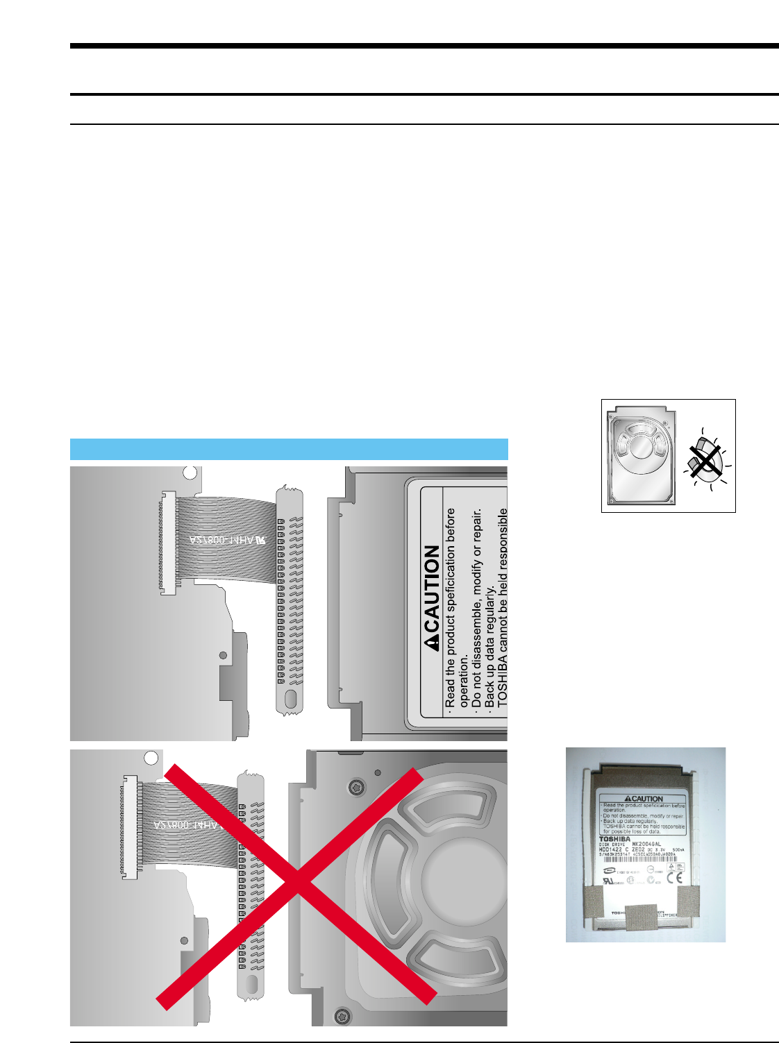
Samsung Electronics1-1
1. Precautions
0. HDD SVC Repair Cautions
1. At HDD reassembly, connect for direction decided to PCB connector necessarily.
When connect headlong, hard-disk is damaged.
When connect headlong, hard-disk is damaged.
refer below
refer below “ Hard-disk
“ Hard-disk - PCB connector connection Precation”.
- PCB connector connection Precation”.
2.HDD is very sensitive in static electricity, therefore refer static electricity prevention countermeasure
(PAGE2~4) necessarily.
3.Hard-disk is very frail in shock.
Do attention in treatment so that there may no be external shock(specially, Droping).
4.connector pin are product that is apt to be awry.
Take care disassembly or reassembly.
5.Repair being far away because it can receive effect by TV or magnet.
6.Put in safe place lest shock of data recorded to HDD should be passed after separation in substance
because data is weak in shock.
7.Since the data on the HDD is weak to mechanical shock, place the HDD in a safe location that is free from
mechanical shock once it is removed from the main unit.
8.In order to safe keep the data on the HDD, back up the data before the repair or make sure not to place
the HDD near any electrical appliance that generates a strong magnetic field.
Be backed up before repair to keep data recorded to HDD.
* Hard-Disk-PCB connection Precaution *
HDD connection of MAIN PCB
TOP side, with picture, must
assemble so that the label may
come on “CAUTION
CAUTION”.
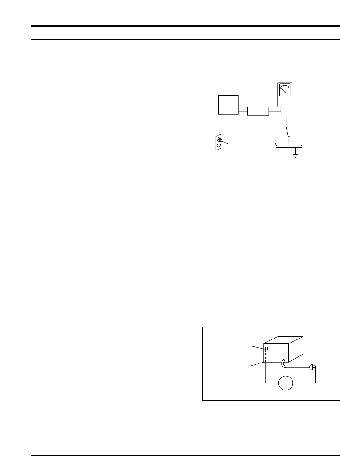
Follow these safety, servicing and ESD precautions to prevent damage and protect against potential haz-
ards such as electrical shock and X-rays.
Samsung Electronics 1-1
1-1 Safety Precautions
1. Be sure that all of the built-in protective
devices are replaced.
2. When reinstalling the chassis and its
assemblies, be sure to restore all protective
devices, including control knobs and
compartment covers.
3. Make sure that there are no cabinet
openings through which people--
particularly children--might insert fingers
and contact dangerous voltages. Such
openings include the spacing between the
picture tube and the cabinet mask,
excessively wide cabinet ventilation slots,
and improperly fitted back covers.
4. Design Alteration Warning:
Never alter or add to the mechanical or
electrical design of the unit. Example: Do
not add auxiliary audio or video connectors.
Such alterations might create a safety haz-
ard. Also, any design changes or additions
will void the manufacturer's warranty.
5. Leakage Current Hot Check (Figure 1-1):
Warning: Do not use an isolation
transformer during this test. Use a leak-
age-current tester or a metering system
that complies with American National
Standards Institute (ANSI C101.1, Leakage
Current for Appliances), and Underwriters
Laboratories (UL Publication UL1410,
59.7).
With the unit completely reassembled, plug
the AC line cord directly into a 120V AC
outlet. With the unit's AC switch first in the
ON position and then OFF, measure the
current between a known earth ground
(metal water pipe, etc.) and all exposed
metal parts. Examples: Handle brackets,
metal cabinets, screwheads and control
shafts. The current measured should not
exceed 0.5 milliamp. Reverse the power-
plug prongs in the AC outlet and repeat.
6. Insulation Resistance Cold Check:
(1) With the unit's AC plug disconnected
from the AC source, connect an electrical
jumper across the two AC prongs. (2) Set
the power switch to ON. (3) Measure the
resistance between the shorted AC plug and
any exposed metallic parts. Example:
Screwheads, antenna, control shafts or
handle brackets.
If any of the exposed metallic parts has a
return path to the chassis, the measured
resistance should be between 1 and 5.2
megohms. If there is no return path, the
measured resistance should be "infinite." If
the resistance is outside these limits, a
shock hazard might exist. See Figure 1-2
Device
Under
Test
(Reading should
not be above
0.5mA)
Leakage
Currant
Tester
Earth
Ground
Test all
exposed metal
surfaces
Also test with
plug reversed
(using AC adapter
plug as required)
2-Wire Cord
Antenna
Terminal
Exposed
Metal Part
ohm Ohmmeter
Fig. 1-1 AC Leakage Test
Fig. 1-2 Insulation Resistance Test

Samsung Electronics1-2
1-1 Safety Precautions (Continued)
7. Components, parts and wiring that appear
to have overheated or that are otherwise
damaged should be replaced with parts
that meet the original specifications.
Always determine the cause of damage or
overheating, and correct any potential
hazards
8. Observe the original lead dress, especially
near the following areas: Antenna
wiring, sharp edges, and especially the
AC and high voltage power supplies.
Always inspect for pinched, out-of-place,
or frayed wiring. Do not change the
spacing between components and the
printed circuit board. Check the AC
power cord for damage. Make sure that
no wires or components touch thermally
hot parts.
9. Product Safety Notice:
Some electrical and mechanical parts
have special safety-related characteristics
which might not be obvious from visual
inspection. These safety features and the
protection they give might be lost if the
replacement component differs from the
original--even if the replacement is rated
for higher voltage, wattage, etc.
10 Components that are critical for safety are
indicated in the circuit diagram by
shading, or . Use replacement
components that have the same ratings,
especially for flame resistance and
dielectric strength specifications. A
replacement part that does not have the
same safety characteristics as the original
might create shock, fire or other hazards.
1-2 Servicing Precautions
1. Servicing precautions are printed on the
cabinet. Follow them.
2. Always unplug the unit's AC power cord from
the AC power source before
attempting to: (a) Remove or reinstall any
component or assembly, (b) Disconnect an
electrical plug or connector, (c) Connect a
test component in parallel with an
electrolytic capacitor.
3. Some components are raised above the
printed circuit board for safety. An
insulation tube or tape is sometimes used.
The internal wiring may be clamped to
prevent contact with thermally hot
components. Reinstall all such elements to
their original position.
4. After servicing, always check that the
screws, components and wiring have been
correctly reinstalled. Make sure that the
portion around the serviced part has not
been damaged.
5. Check the insulation between the blades of
the AC plug and accessible conductive parts
(examples: metal panels, input terminals
and earphone jacks).
6. Insulation Checking Procedure: Disconnect
the power cord from the AC source and
turn the power switch ON. Connect an
insulation resistance meter (500V) to the
blades of the AC plug.
The insulation resistance between each
blade of the AC plug and accessible
conductive parts (see above) should be
greater than 1 megohm.
7. Never defeat any of the B+ voltage
interlocks. Do not apply AC power to the
unit (or any of its assemblies) unless all
solid-state heat sinks are correctly installed.
8. Always connect a test instrument's ground
lead to the instrument chassis ground
before connecting the positive lead; always
remove the instrument's ground lead last.
Precautions
Warning1: First read the "Safety Precautions" section of this manual. If some unforeseen circumstance
creates a conflict between the servicing and safety precautions, always follow the safety precautions.
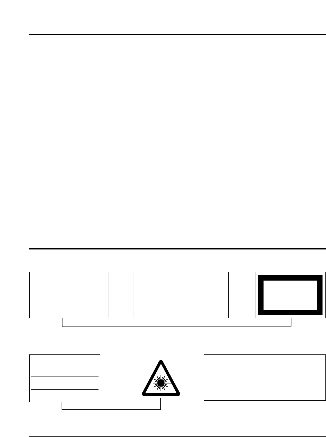
Samsung Electronics 1-3
1-3 Precautions for Electrostatically Sensitive Devices (ESDs)
1-4 Special Precautions and Warning Labels for Laser Products
1. Some semiconductor ("solid state") devices
are easily damaged by static electricity.
Such components are called Electrostatically
Sensitive Devices (ESDs). Examples
include integrated circuits and some field-
effect
transistors. The following techniques will
reduce the occurrence of component
damage caused by static electricity.
2. Immediately before handling any
semiconductor components or assemblies,
drain the electrostatic charge from your
body by touching a known earth ground.
Alternatively, wear a discharging
wrist-strap device. (Be sure to remove it
prior to applying power--this is an electric
shock precaution.)
3. After removing an ESD-equipped assembly,
place it on a conductive surface such as
aluminum foil to prevent accumulation of
electrostatic charge.
4. Do not use freon-propelled chemicals.
These can generate electrical charges that
damage ESDs.
5. Use only a grounded-tip soldering iron
when soldering or unsoldering ESDs.
6. Use only an anti-static solder removal
device. Many solder removal devices are
not rated as "anti-static" (these can
accumulate sufficient electrical charge to
damage ESDs).
7. Do not remove a replacement ESD from its
protective package until you are ready to
install it. Most replacement ESDs are
packaged with leads that are electrically
shorted together by conductive foam,
aluminum foil or other conductive
materials.
8. Immediately before removing the protective
material from the leads of a replacement
ESD, touch the protective material to the
chassis or circuit assembly into which the
device will be installed.
9. Minimize body motions when handing
unpackaged replacement ESDs. Motions
such as brushing clothes together, or lifting
a foot from a carpeted floor can generate
enough static electricity to damage an ESD.
Precautions
UL : Manufactured for U.S.A. Market.
CSA : Manufactured for Canadian Market.
EU : Manufactured for European Market.
SCAN : Manufactured for Scandinavian
Market.
This Product Complies with
DHHS Rules 21CFR, Sub
chapter J.At date of Manu-
facture
(UL)
(UL,CSA,SCAN)
(EU)
CERTIFIED ONLY TO CANADIAN
ELECTRICAL CODE.
CERTIFIE EN VERTU DU CODE
CANADIAN DE LELETRICITE
SEULEMENT
(CSA)
CLASS 1
LASER PRODUCT
(UL,CSA,EU)
Fig. 1-3 Warning Labels (Location: Enclosure Block)
Fig. 1-4 Warning Labels (Location: Disc Clamper, Inner Side of Unit Door or Nearby Unit Chassis
)
CAUTION : INVISIBLE LASER RADIATION WHEN OPEN
AND INTERLOCKS DEFEATEO AVOIDEXPOSURE TO BEAM
ADVARSEL: USYNLIG LASERSTRÅLING VED ABNING
NÅR SIKKERHEDSAFBRYDERE ER UDE AF FUNKTION
UNDGA UDSAETTELSE FOR STRALING
VARO:AVATTAESSA JA SUOJALUKITUS OHITETTAESSA
OLET ALTTINA NAKYMATTÖMALLE LASERSATEILYLLE ALA
KATSO SATEESEEN!
VARNING:OSYNLIG LASERSTRÅLNING NAR DENNA DEL
AR OPPNAD OCH SPARREN AR URKOPPLAD BETRAKTA
EJSTRÅLEN!

Samsung Electronics2-1
2. Product Descriptions
1. Product Feature
PRODUCT FEATURE
Mass Storage Device You can use the built-in hard drive to store your entire music library,
Support plus use it as an external drive for your PC to store other data files.
MP3, WMA, Audio ASF and
Your player supports playback of MP3, WMA, Audio ASF and Ogg.
Ogg Playback
USB Host Function Support
Connect external devices such as digital cameras and MP3 player directly
to the unit for easy transfer of music, images and other data files without the
need for a PC.
Video Playback Function
You can view video files after downloading using the Multimedia Studio.
Image & Text Viewer Function
You can view JPEG files and TXT file texts.
Image files edited with Multimedia Studio can be viewed as slide shows.
Direct MP3 Recording
You can convert music from CDs, cassettes, and radio into MP3 files without a
PC.
USB 2.0 High Speed Data The 3D surround(SRS) feature adds spaciousness to the sound.
Transfer SRS WOW
Surround Sound
1.8-inch Color TFT LCD You can enjoy high quality image & video files.
Various Games Support You can enjoy games such as Tetris, Omok and Othello.
Built-in Rechargeable The built-in rechargeable lithium battery provides up to 25 hours of music and
Li-ion Battery 7 hours of video files. (According to company measurement)
Playback Speed Control You can adjust the playback speed of music or voice files.
Function
Upgradable You can upgrade the built-in programs when available.
Please check the home page (www.samsung.com) for upgrades.
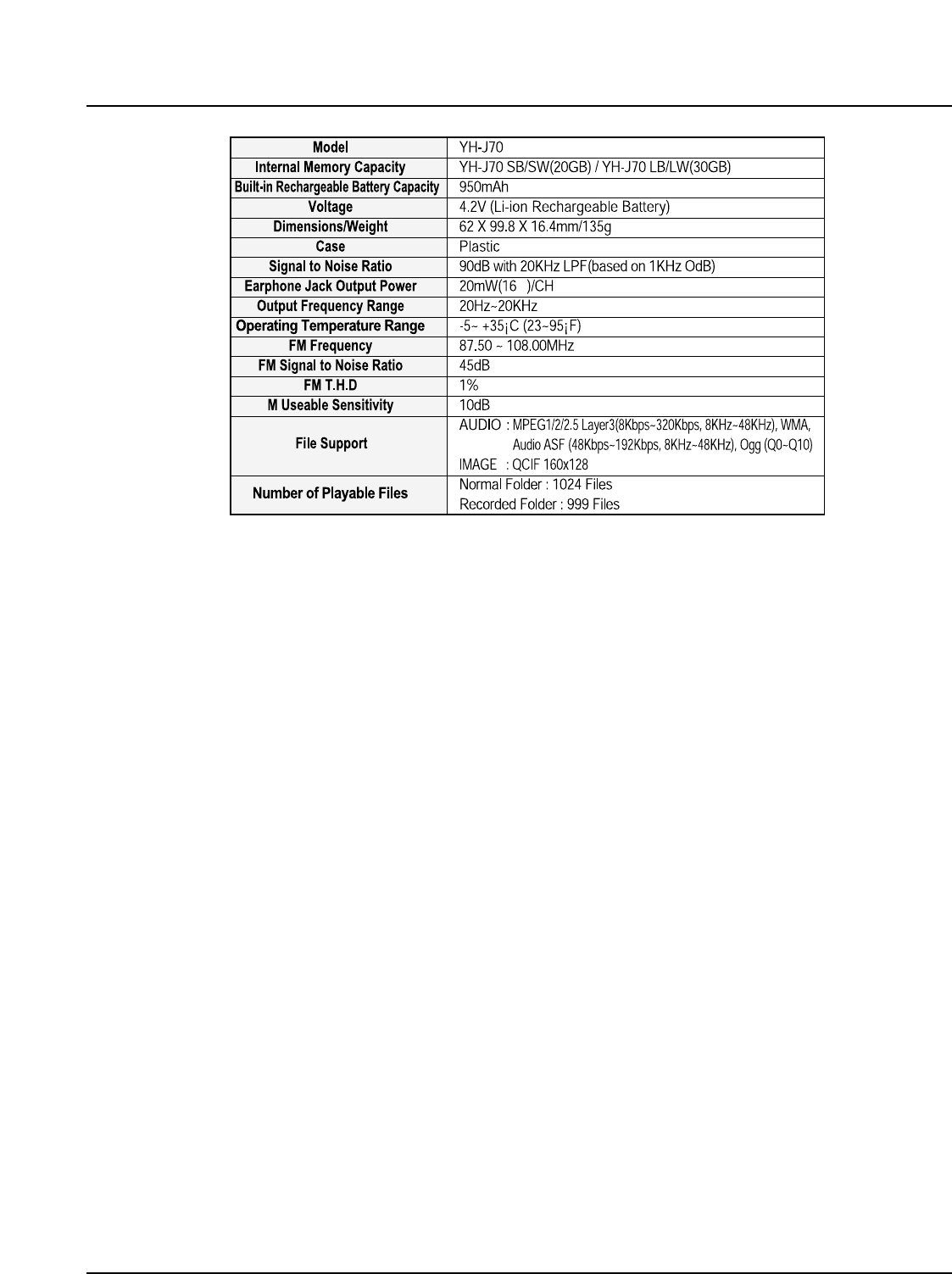
2-2Samsung Electronics
2. Specifications
The product unit accompanying this user manual is licensed under certain
intellectual property rights of certain third parties. This license is limited to
private non-commercial use by end-user consumers for licensed contents.
No rights are granted for commercial use. The license does not cover any
product unit other than this product unit and the license does not extend to any
unlicensed product unit or process conforming to ISO/IEC 11172-3 or ISO/IEC
13818-3 used or sold in combination with this product unit. The license only
covers the use of this product unit to encode and/or decode audio files
conforming to the ISO/IEC 11172-3 or ISO/IEC 13818-3. No rights are granted
under this license for product features or functions that do not conform
to the ISO/IEC 11172-3 or ISO/IEC 13818-3.
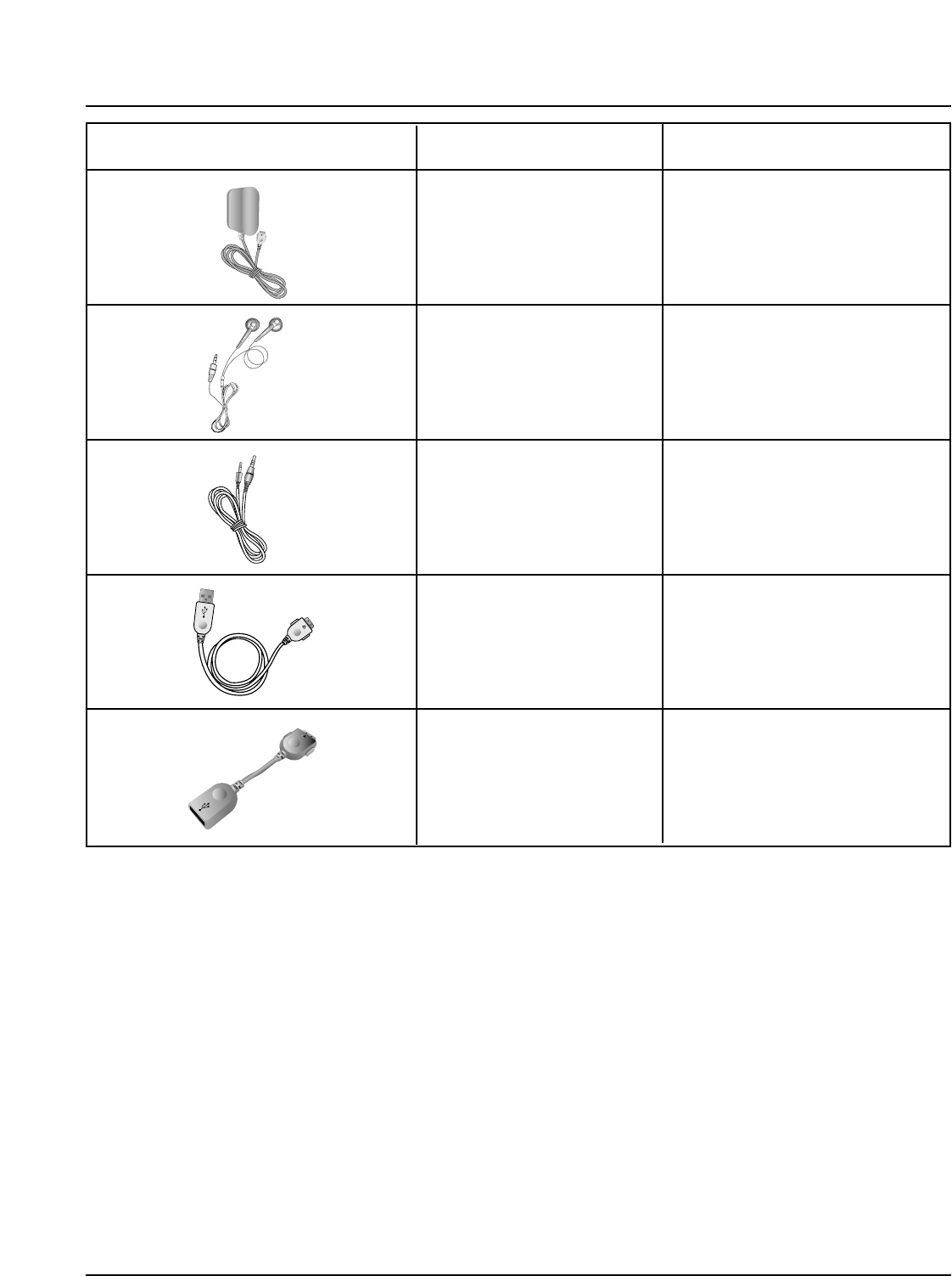
Accessories Name Code No.
Samsung Electronics2-3
3. Accessories
AH30-00069D
Earphones
AH39-00488B
Line-In Cable
AH39-00783A
USB Cable
AH39-00784A
USB Host Adaptor
AH44-00100C
Charger
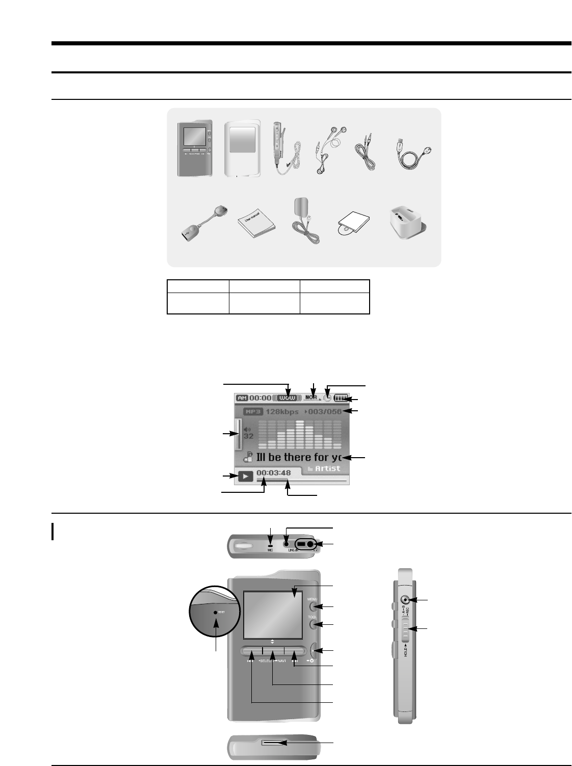
Samsung Electronics 3-1
3. Product Functions
1. Basic Functions
● The capacity of the useable built-in memory is less than indicated as the internal
firmware uses a part of the memory as well.
● The appearance of the accessories shown is subject to change for product improvement
without prior notice.
Player Earphones Line-In Cable
User Manual Charger
USB Cable
Carrying Case
USB Host Adaptor Installation CD Docking Cradle
Remocon
Model
Built-in memory
YH-J70 SB/SW
20GB
YH-J70 LB/LW
30GB
Play/Stop/Pause Indicator
Volume Indicator
Play Time Indicator
Play Mode Indicator
EQ/SRS Indicator
Battery remaining indicator
Alarm Setting Indicator
Song number display
Current Track Title
Progress Indicator
Location of Controls
Loop Repeat/
Record button
HOLD switch
MENU button
Display
Earphone Jack
TOOL button
[Back Side]
RESET Hole
Power On/Off
Play/Pause button
Skip/Search button
Select/Navigation/
Volume Control Button
Skip/Search button
USB Cable Connection Port
LINE IN Jack
MIC
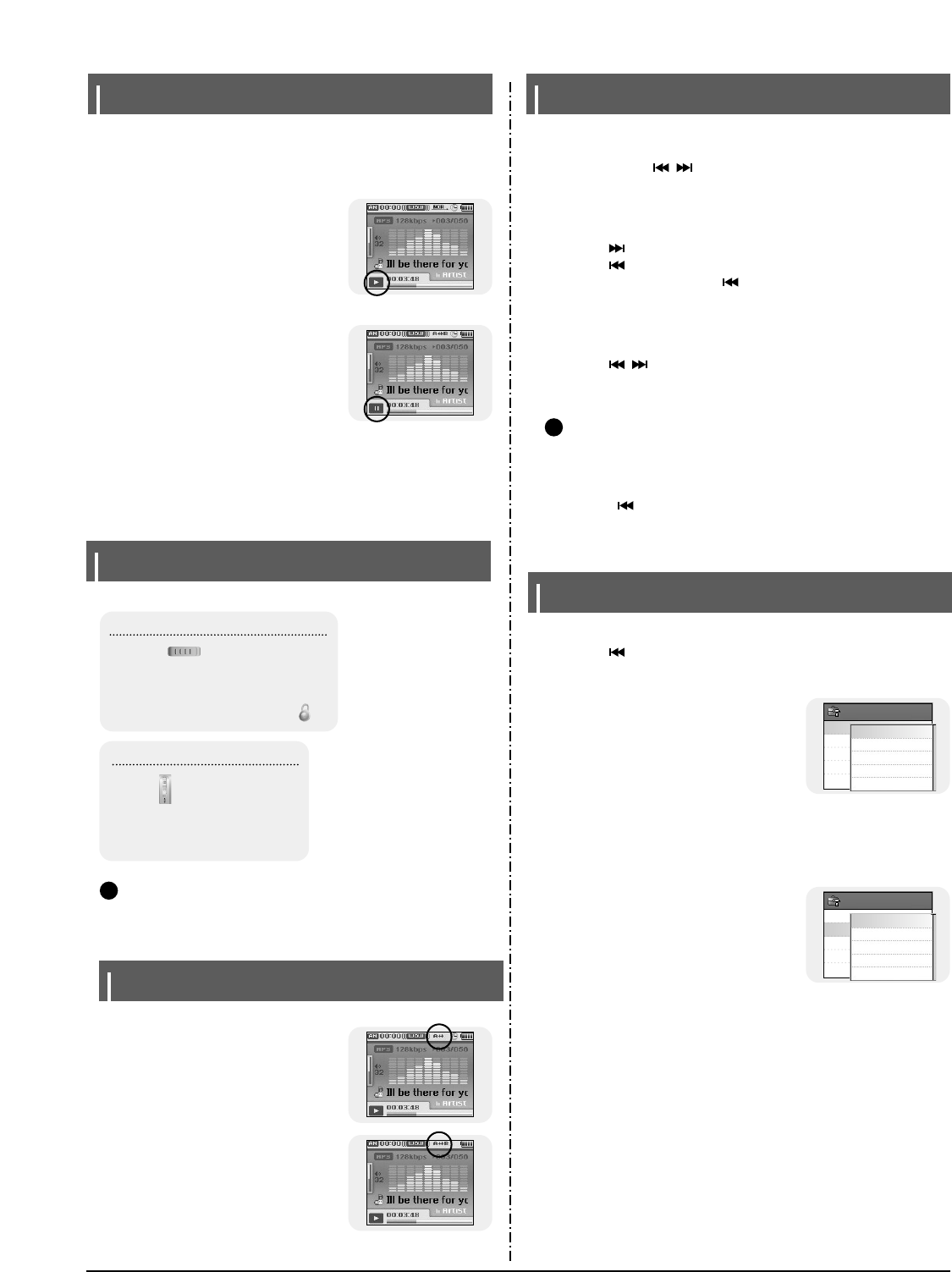
3-2 Samsung Electronics
Playing Music
I Playing Music
I Pausing Music
● Power On: Press and hold the √» button to turn on the power.
● Power Off: Press and hold the √» button to turn off the power.
Press and hold the √» button
●Playback starts automatically.
Press the √» button to pause playback.
●While in Pause mode, briefly press √» again
to resume playback.
Make sure the player is fully charged and the earphones are connected.
Adjust volume by moving the SELECT button up and down.
●The volume can be adjusted in increments between 00(MIN) and 60(MAX).
I Adjusting Volume
Hold Feature
Use the Hold feature to lock and disable all buttons.
N
No
ot
te
e
- Press and hold the √» button on the remote control to turn the power on/off using the
remote control in hold mode.
Hold Function of the Main Unit
Activate on the main unit.
❈All buttons on the main unit will be disabled,
and only the buttons on the remote control can
be used for input.
❈When you activate the HOLD switch, a " "
appears on the display.
Hold Function of the Remote Control
Activate on the remote control.
❈All buttons on the remote control will be
disabled, and only the buttons on the
main unit can be used for input.
✍
Loop Repeating
I Starting Point
While playing a music file, press the A↔B
button at the beginning of the loop you
want to set.
●A↔ appears in the display.
Press the A↔B button shortly at the point
you wish
to end Loop Repeat.
●A↔B appears in the display.
●The loop is played repeatedly.
Press the A↔B button briefly to cancel the
loop.
I Ending Point
Searching for Music/Voice Files
N
No
ot
te
e
- VBR(Variable Bit Rate) file: A file that constantly changes the compression rate
according to the type of sounds, such as their pitch, in the
file.
- When playing a VBR file, you cannot move to and play the previous track even if you
press the button within 5 seconds after playback starts.
- Files that were downloaded in MP2 or MP1 and had their file extension changed to
MP3 may not play.
● Press and hold the , button during playback to search for the part you
want to listen to.
● Release the button to resume play normally.
I To Search for Specific Parts During Play
● Press the button briefly during playback to play the next track.
● Press the button briefly within 5 seconds after playback starts to move to and
play the previous track. Press the button briefly after 5 seconds to play the
current track from the beginning.
I To Change Tracks During Play
● Press the , button in stop/pause mode to move to the previous/next track.
I To Change Tracks when Stopped
✍
Setting Main Functions in Music Mode
● You can move and select using the SELECT button.
● Press the button to move to the previous screen.
1 Press the TOOL button in music mode.
● Music Tool screen appears.
2 Press the SELECT button after moving to
[Add to Favorites].
3 Press the SELECT button after moving to
the list to save.
● The selected file will be added to the list.
● 10 Playlists can be selected.
● Added files can be found at [Navigation] → [Playlist] → [Favorites].
1 Press the TOOL button in music mode.
● Music Tool screen appears.
2 Press the SELECT button after moving
to [EQ].
3 Press the SELECT button after moving to
the desired sound effect mode.
● Normal → Jazz → Classic → Pop → Rock → Bass Boost → Bass Cut → R&B →
Club → Dance → House → High Boost → High Cut Loud → Ballad → Strings →
Vintage → Vocal Boost → Bluesy → User EQ
● When using User EQ, the desired sound effects can be set from [Settings] →’
[Sound Effect] → [User EQ Set].
I EQ
I Add to Favorites
Add to Favorites
Music - Tool
EQ
SRS
Play Mode
File Info.
Add to Favorites
Music - Tool
EQ
SRS
Play Mode
File Info.
List 2
List 3
List 4
List 5
List 1
Jazz
Classic
Pop
Rock
Normal
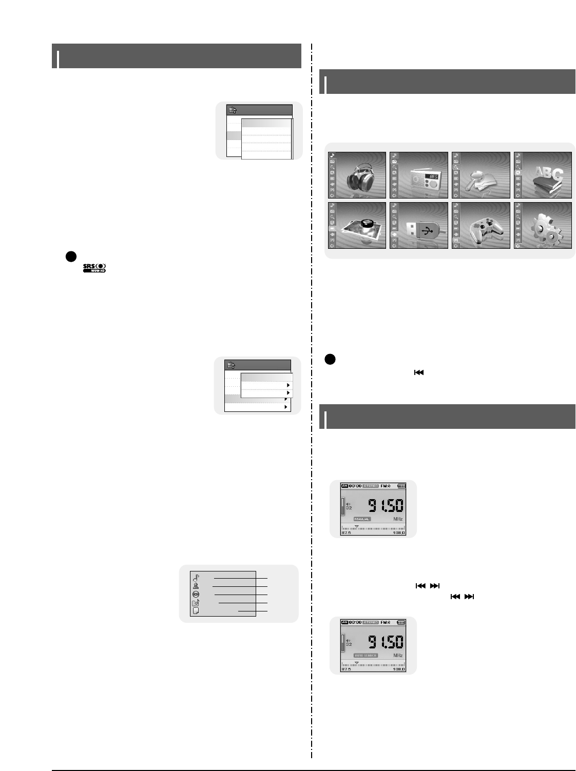
Samsung Electronics 3-3
Setting Main Functions in Music Mode
1 Press the TOOL button in music mode.
● Music Tool screen appears.
2 Press the SELECT button after
moving to [SRS].
3 Press the SELECT button after
moving to the desired SRS mode.
● Normal → SRS → TruBass → WOW → HD
● SRS: You will hear 3D Streo sound.
● TruBass: This is bass boost feature that adds fillness to the sound.
● WOW: This feature allows you to enjoy the SRS and Trubass features
simultaneously.
● HD: You can enjoy more clear voice and high tones.
Add to Favorites
Music - Tool
EQ
SRS
Play Mode
File Info.
SRS
TruBass
WOW
HD
Normal
I SRS
N
No
ot
te
e
- is a trademark of SRS Labs, Inc.
WOW technology is incorporated under license from SRS labs, Inc..
- Please adjust the volume to a suitable level, as the volume may increase in the
SRS setting.
- This unit supports sampling frequencies of 32KHz, 44.1KHz or 48KHz.
✍
1 Press the TOOL button in music mode.
● Music Tool screen appears.
2 Press the SELECT button after moving
to [Play Mode].
3 Press the SELECT button after moving
to the desired Play Mode.
● Normal : To play all the files in order one time.
● Repeat: Press the SELECT button at [Repeat].
- One : To repeat one file.
- Folder : To repeat the current folder.
- All : To repeat all files.
● Shuffle : Press the SELECT button at [Shuffle].
- Folder : To play files in the folder at random.
- All : To play files at random.
I Play Mode
1 Press the TOOL button while
the music is playing or has
stopped.
● Music Tool screen appears.
2 Press the SELECT button after
moving to [File Info.].
● Information on file currently playing/paused is displayed.
I File Info.
Blue Title
Artist
Album
Genres
File Size
Sky
Best
Dance
7782656 bytes
Add to Favorites
Music - Tool
EQ
SRS
Play Mode
File Info.
Repeat
Shuffle
Normal
2. New Functions
MENU Options
01I
Music
02I
FM Radio
03 I
Navigation
04 I
Text
05 I
Photo/Video
06 I
USB Host
07 I
Games
08 I
Settings
● Now playing : To display the song currently playing.
● FM Radio : To listen to FM radio.
● Navigation : To move to Navigation Mode and browse files and folders.
● Text : To read text files
● Photo/Video : To view saved image files or videos
● USB Host : To transfer files saved in the unit to external devices or transfer
files saved in external devices to the unit.
● Games : To play games.
● Settings : To set the functions.
Press the MENU button to switch to Menu mode.
Use the SELECT button to select the menu item you want, and then briefly press the
SELECT button.
N
No
ot
te
e
- In Menu mode, press the button to move to the previous screen.
✍
Listening to FM Radio
Press the MENU button.
In the Menu, select FM Radio and then press the SELECT button.
I Switching to FM Radio Mode
● Manual Search: Press the , buttons to change the frequency up or down.
● Automatic Search: Press and hold the , buttons to automatically search for
receiving frequencies.
I Search for a Frequency
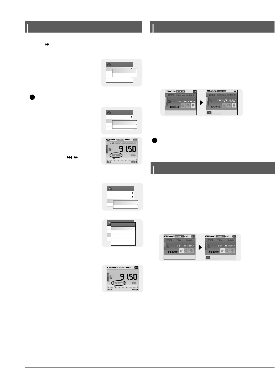
3-4 Samsung Electronics
Setting Main Functions in FM Mode
1 Press the TOOL button in FM Mode.
● FM Tool Screen appears.
2 Press the SELECT button after moving
to [Mono/Stereo].
3 Press the SELECT button after moving
to the desired FM reception mode.
Mono/Stereo
FM - Tool
Preset Mode
Edit Preset
Auto Preset
Stereo
Mono
I Mono / Stereo
You can move and select using the SELECT button
Press the button to move to the previous screen.
N
No
ot
te
e
- Mono is automatically selected in areas with weak FM reception.
1 Press the TOOL button in FM Mode.
● FM Tool Screen appears.
2 Press the SELECT button after moving
to [Preset Mode].
3 Press the SELECT button after moving
to On/Off.
● On : Preset mode is selected. Select preset
frequency using the , button
● Off : FM reception mode is selected.
I Preset Mode
Mono/Stereo
FM - Tool
Preset Mode
Edit Preset
Auto Preset
Off
On
✍
● You can manually preset desired FM frequencies.
● You can store up to 30 frequencies.
1 Press the TOOL button in FM Mode.
● FM Tool Screen appears.
2 Press the SELECT button after moving to [Edit Preset].
3 Press the SELECT button after moving to
[Save] or [Delete].
● Save : Select the desired Preset number by
using the SELECT button. The current
frequency will be saved.
● Delete : Select a saved preset number to be
deleted.
The selected preset number will be deleted.
I Edit Preset
1 Press the TOOL button in FM Mode.
● FM Tool Screen appears.
2 Press the SELECT button after moving to
[Auto Preset].
● Frequencies are automatically stored up to 30.
I Auto Preset
Mono/Stereo
FM - Tool
Preset Mode
Edit Preset
Auto Preset
Delete
Save
Mono/Stereo
FM - Tool
Preset Mode
Edit Preset
Auto Preset
Preset Memory
CH 01: 87.75
CH 02: 91.90
CH 03: 95.90
CH 04: 103.50
CH 05: 107.70
Recording Voice
-REC:Start -TOOL:Exit
1 Press and hold the REC button.
●Recording screen appears.
2 Press the REC button to start voice recording.
3 Press the REC button again.
●Recording stops and the file is created.
● Files are recorded and renamed V001.mp3, V002.mp3, and so on.
● MP3 files are added to [Navigation] → [File Search] → [RECORDED] → [VOICE REC].
● Press the √» button to play the recorded file.
N
No
ot
te
e
- Even if you set the sampling and bit rates higher, voice recording will default to 44.1KHz.
✍
V001.mp3
Recording FM Radio
1 Press and hold the REC button while receiving FM.
●Recording screen appears.
2 Press the REC button.
●Current FM broadcasting will be recorded.
3 Press the REC button again.
●Recording stops and the file is created.
● Files are recorded and renamed F001.mp3, F002.mp3, and so on.
● MP3 files are added to [Navigation] → [File Search] → [RECORDED] → [FM REC].
● Press the √» button to play the recorded file.
-REC:Start -TOOL:Exit
F001.mp3
108.00 MHz 108.00 MHz
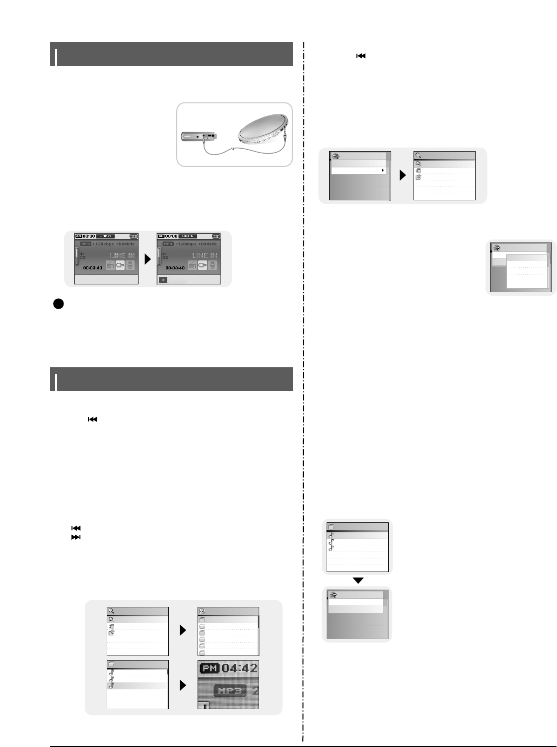
Samsung Electronics 3-5
Recording MP3s
1 Connect the Audio Output port on the external audio source (or the
Line Out port) to the LINE IN port on the device with the Line cable.
●Press the play button on the external
device to play the music to record.
2 Press and hold the REC button.
●Recording screen appears.
3 Press the REC button again.
●Recording stops and the file is created.
● Files are recorded and renamed L001.mp3, L002.mp3, and so on.
● MP3 files are added to [Navigation] → [File Search] → [RECORDED] →
[LINE REC].
● Press the √» button to play the recorded file.
N
No
ot
te
e
- Do not disconnect the Line cable during Recording.
- If the battery is not sufficiently charged, the player will not completely record the file.
- Adjust the volume of the external audio source to a suitable level and recode it.
If the volume level is too high, the sound quality may be poor.
-REC:Start -TOOL:Exit
L001.mp3
✍
Setting Main Functions in Navigation
File Search
Music Library
Playlist
Navigation
MUSIC
PHOTO
RECORDED
TEXT
VIDEO
POP
File Search
Sexy boms.mp3
blue.mp3
Ill be there for you.mp3
MUSIC
1 Press and hold the SELECT button to move to navigation mode, or
press the
MENU button to move to Menu and then select Navigation.
●File Search : You can search for a file from MUSIC, PHOTO, TEXT or VIDEO
folder.
●Music Library : You can search for a music file by Artist, Album, Genre and
Track.
●Playlist : You can search for a file specified as a Favorite in the player or PC
Playlist transmitted through yepp Studio.
2 Select the file or folder that you want to play.
●: To move to a higher-level folder.
●: To move to a lower-level folder.
●▲,▼ : To move to a file or folder in the same directory.
●SELECT : To move to the next folder down.
3 Press the SELECT button.
●The selected file will be played.
● You can move and select using the SELECT button.
● Press the button to display the previous screen.
Go to Top
Add to Favorites
Navigation - Tool
1 Press the TOOL button in Navigation Mode.
● Navigation Tool screen appears.
2 Press the SELECT button after moving to [Go to Top].
● Move to the File Navigation screen.
I Go to Top
● You can move and select using the SELECT button.
● Press the button to display the previous screen.
File Search
Music Library
Playlist
Navigation
1 Press the TOOL button after moving to the
music file in Navigation Mode.
● Navigation Tool screen appears.
2 Press the SELECT button after moving to
[Add to Favorites].
3 Press the SELECT button after moving to the list to save.
● The selected file will be added on the list.
● 10 Playlists can be selected.
● Added files can be found at [Navigation] → [Playlist] → [Favorites].
I Add to Favorites
● Recorded files can be deleted in Navigation Mode.
Other files can be deleted using Media Studio.
1 Press the TOOL button after moving recorded file to
delete in Navigation Mode.
● Navigation Tool screen appears.
2 Press the SELECT button after moving to [Delete File].
● The selected file will be deleted.
I Delete File
V001.MP3
V002.MP3
V003.MP3
VOICE REC
Go to Top
Add to
Navigation - Tool
List 1
List 2
List 3
List 4
List 5
Go to Top
Delete File
Navigation - Tool
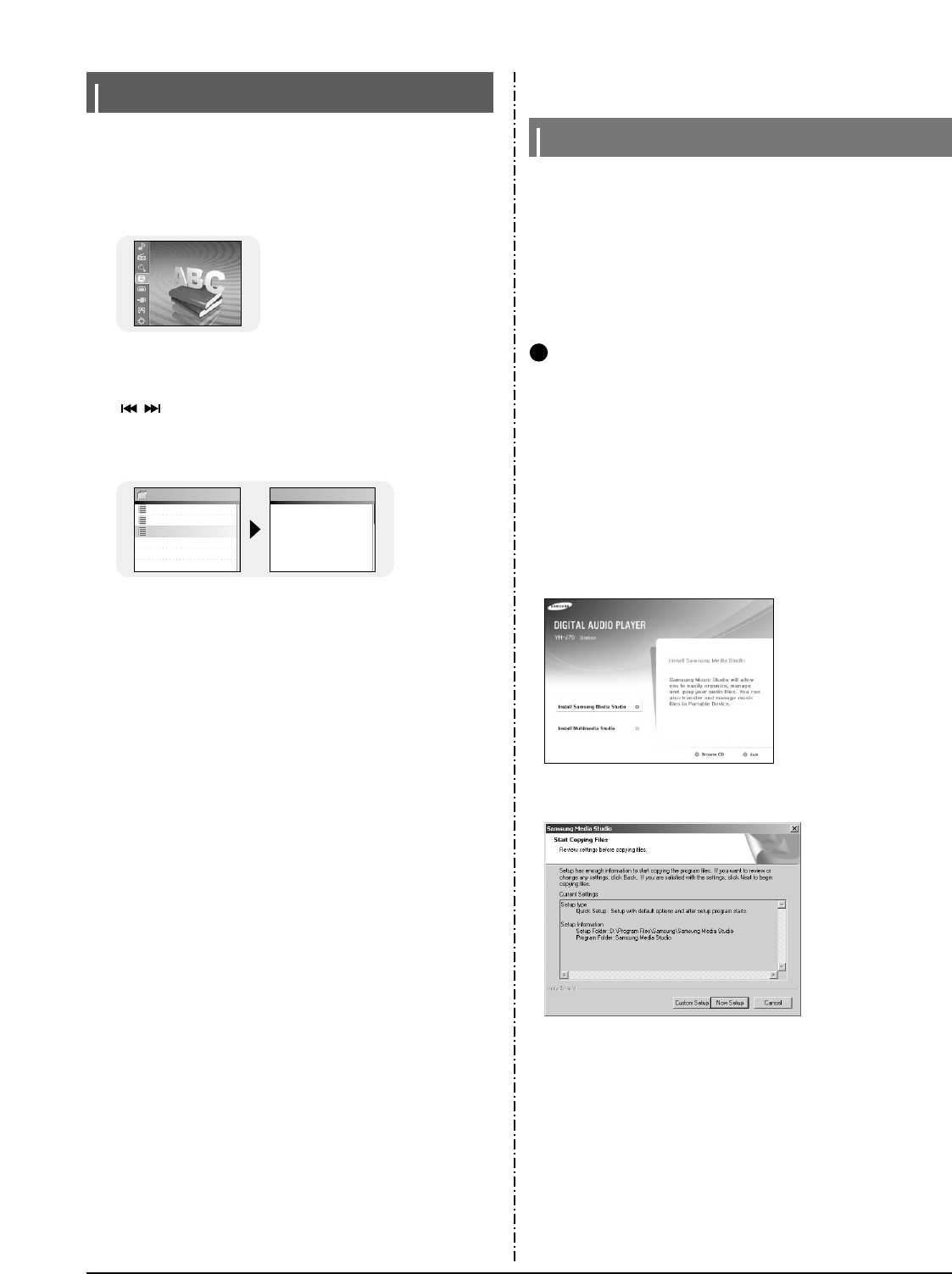
3-6 Samsung Electronics
3. PC Connection
Connecting the player to your PC
Install Samsung Media Studio prior before connecting the player to PC.
❑ System Requirements.
The PC system must meet the following specifications:
● Pentium 200MHz or greater
● Windows XP
● 50MB of available hard disk space
● CD-ROM drive (double speed or greater)
● USB port (2.0) supported
● DirectX 9.0 or above.
N
N
No
ot
te
e
- Log into your PC as an administrator (Main User) and install the supplied software
(Media / Multimedia Studio) for Windows XP.
Otherwise, the software may not install properly.
I
Installing Software
1Insert the Installation CD into CD-ROM drive.
The picture shown below appears.
Select [Install Samsung Media Studio].
✍
2Follow the instructions in the window to complete the installation.
Viewing Text
Door.txt
Identity.txt
The Little Prince.txt
TEXT The Little Prince 0011
/0102
Once when I was six
years old I saw a mag-
nificent picture in a
book, called True
Stories from Nature,
about the primeval for
1 Press the MENU button to move to menu, and then select Text.
● Navigation screen appears.
2 Move to the text you want to read, and then press the SELECT button.
● The selected text file will be displayed.
- ▲,▼ : Volume Control.
- ,: Move to Previous/Next Page.
- Text File Selection: Press and hold the SELECT button to move to navigation
during a music is playing. Move to the desired text file, and
then press the SELECT button.
04 I
Text
● Text Viewer allows you to read text files that were created on your PC.
Text files must have a .txt extension to be viewed by Text Viewer.
● You can select an text file to view while listening to the music.
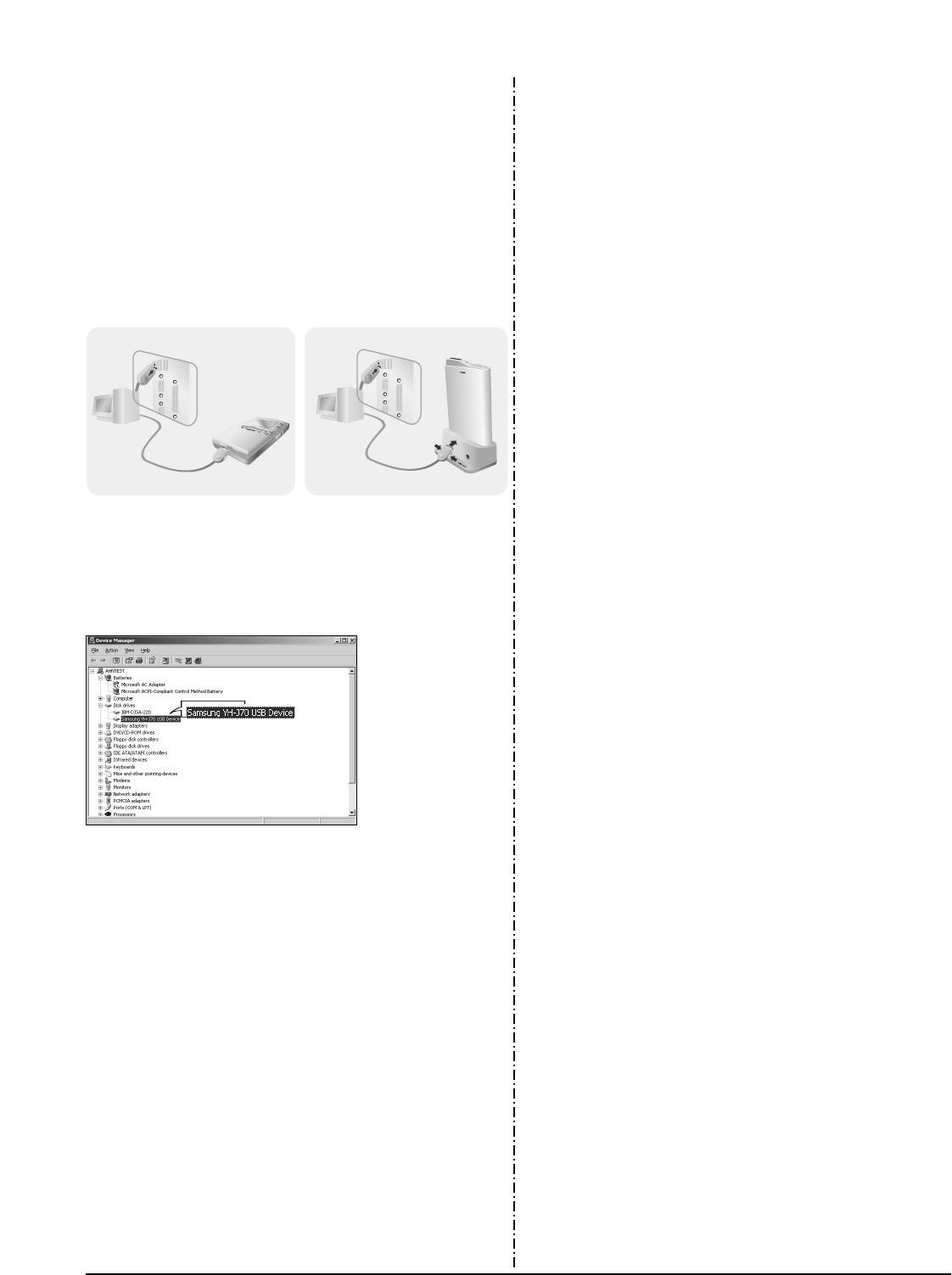
Samsung Electronics 3-7
3Connect the USB cable to the USB port of the computer.
4Connect the other end of the USB cable to the USB cable connection
port located at the bottom of the player.
● If you disconnect the USB cable from your PC while implementing a command
or initializing during USB driver installation, your PC may not function correctly.
6Upon installation of the USB driver "Samsung YH-J70 USB Device"
will appear in the [Device Manager].
5The USB driver is installed with a message saying that it is searching for
a new device. You may not see the display screen during installation.
Go to the device manager to check that installation has been successful-
ly completed.
I
Connecting the player to your PC with a USB
cable
PC PC
USB Cable USB Cable
Player
Player
How to check if USB driver is properly installed
Windows XP:
Control Panel →System →Hardware →Device Manager →Disk Drives →
Samsung YH-J70 USB Device
7When USB driver is not installed automatically, refer to next page.
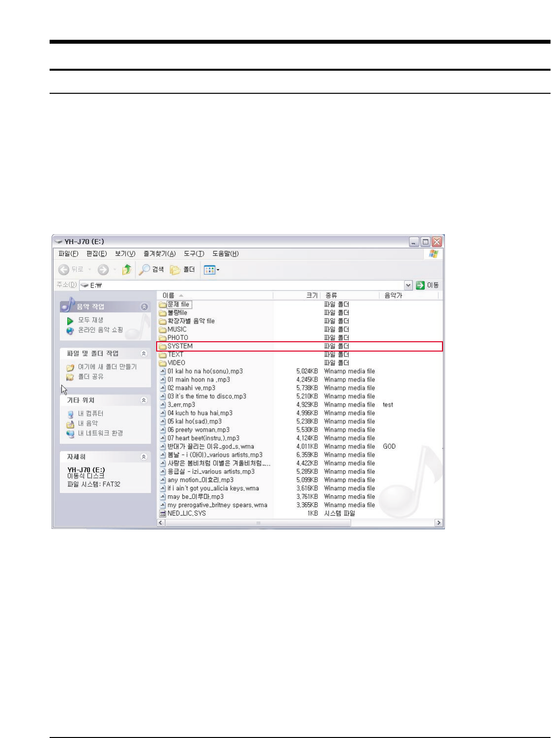
sSamsung Electronics4-1
4. Adjustments
1.How to recover the device
hen file download does not work or screen display is abnormal,
the following recovery procedure is valid for YH-J70, YH-J50, YH-J40 and their derived models.
YH-J70 has self-recovery system that saves system files in Flash memory to prevent corruption.
In addition, firmware is automatically upgraded on line.
1. "System Fail, Need Firmware Upgrade" appears on the LCD screen.
This message appears when the font file in the hard disk drives has been corrupted.
■ Countermeasure
1) Connect the player and the computer with the USB cable and copy "J70.fnt" file to the SYSTEM folder.
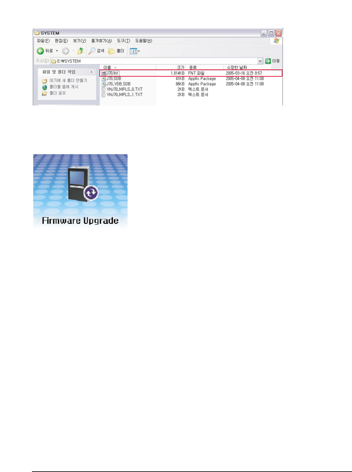
4-2
Samsung Electronics
If the same message appears even after you have copied the font file, upgrade the firmware.
2) Copy the firmware upgrade file, "j70_32.bin" to the root directory of the hard disk drive.
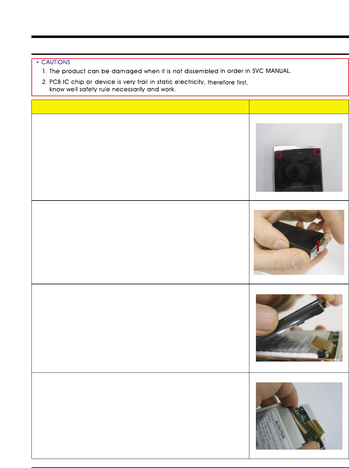
Samsung Electronics5-1
5. How to disassemble
1. Remove 2 screws from the rear panel of the player.
2. Lightly lift and slide the front part of the ASSY BOTTOM
so that the hook comes out.
3. If the hook comes out, it easily opens.
4. Separate the hard disk.
Order(Description) Picture
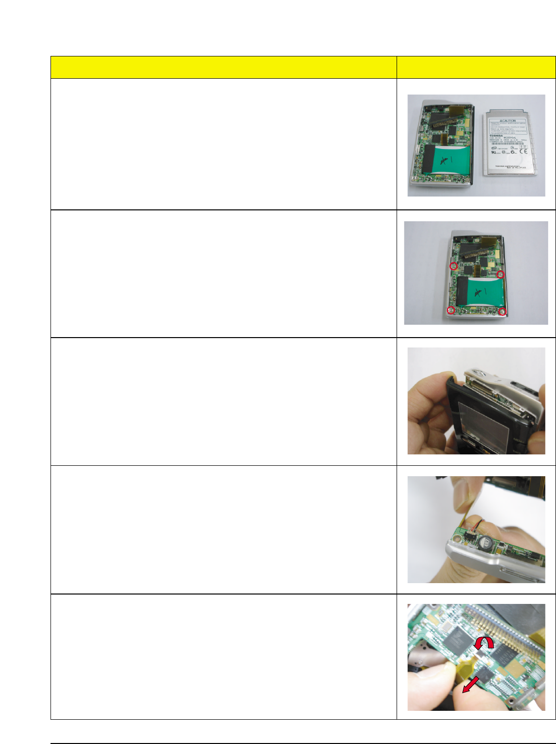
5-2Samsung Electronics
5. Picture after disassembly
6. Remove the 4 screws from the Main PCB.
7. Lightly lift and slide the front part of the ASSY TOP so
that the hook comes out.
8. Pull out and separate the Battery Pack Wire with your
hand.
9. Pull back the Front Key Connector(4P) in the direction
of the arrow and separate the Front
Order(Description) Picture
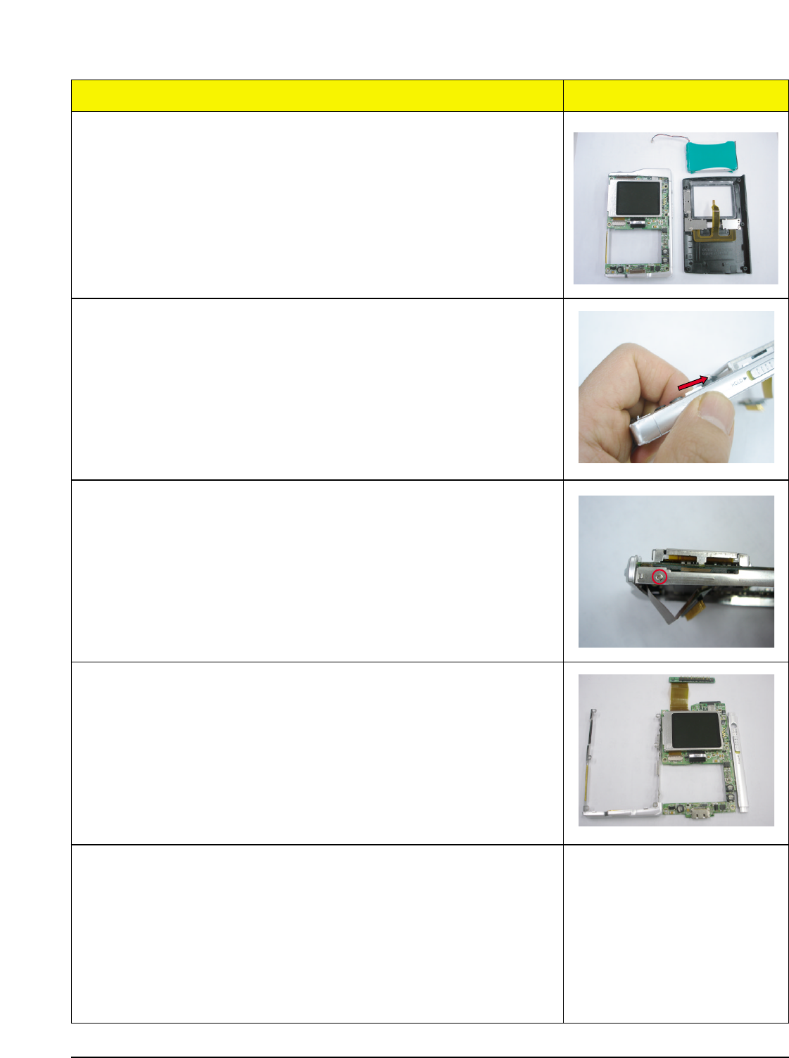
Samsung Electronics5-3
10. Picture after disassembly
11. Slide the Deco Side in the direction of the arrow to sep
arate it.
12. Remove the screws on the side of the Bracket Frame.
13. Picture after disassembly
Order(Description) Picture
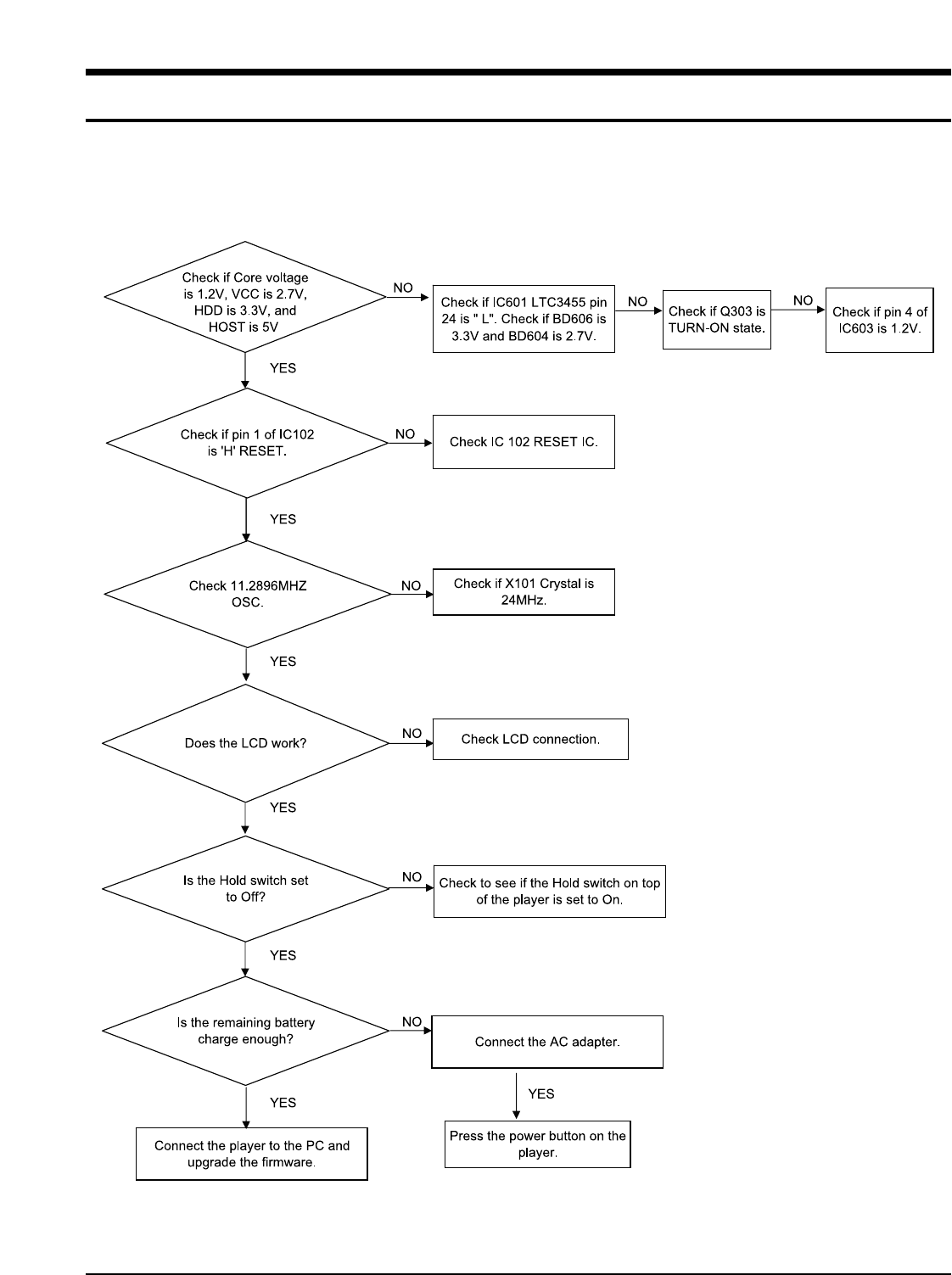
Samsung Electronics 6-1
6. Troubleshooting
1. It keeps being turned off
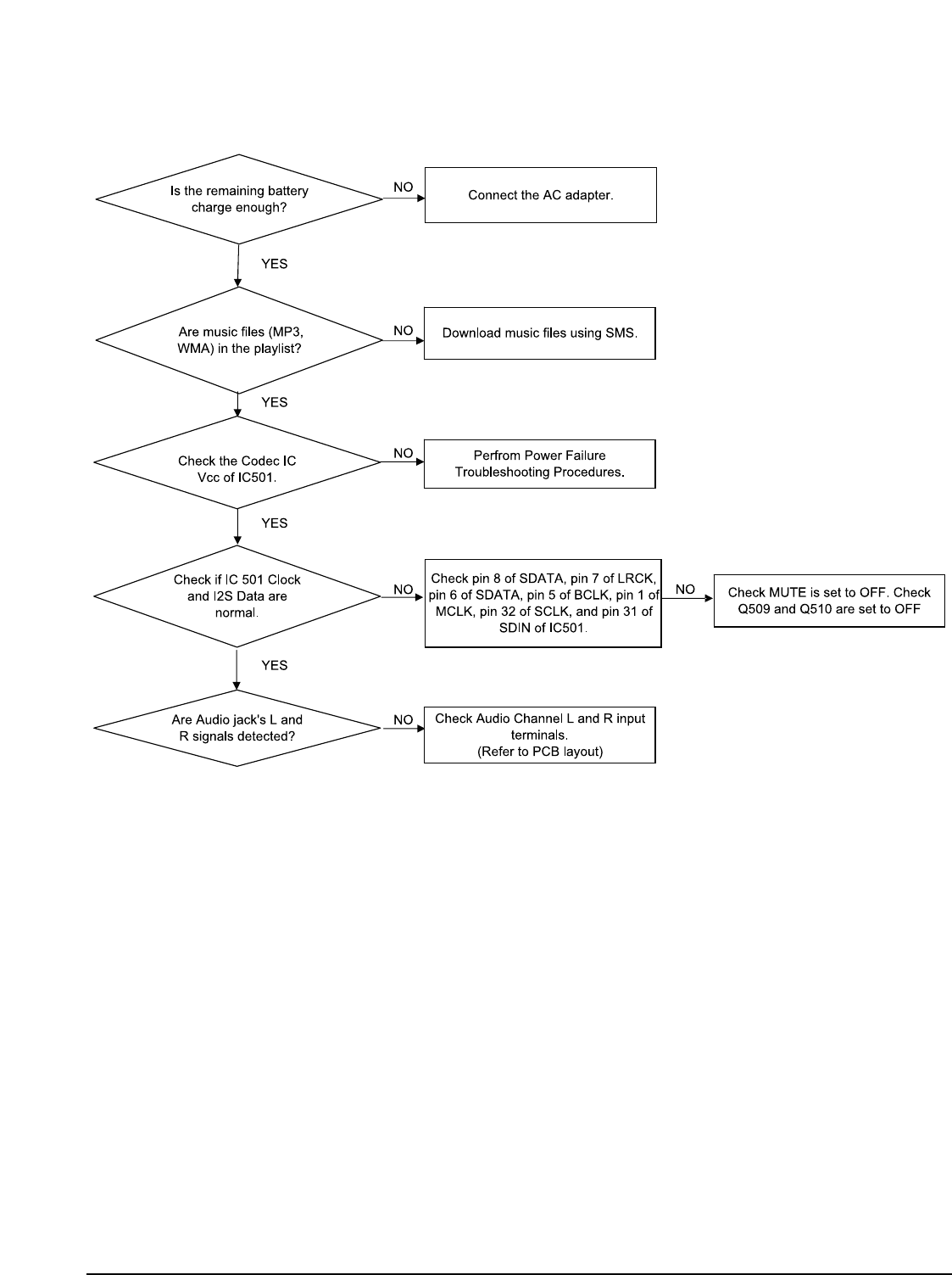
6-2 Samsung Electronics
2. No Sound can be heard
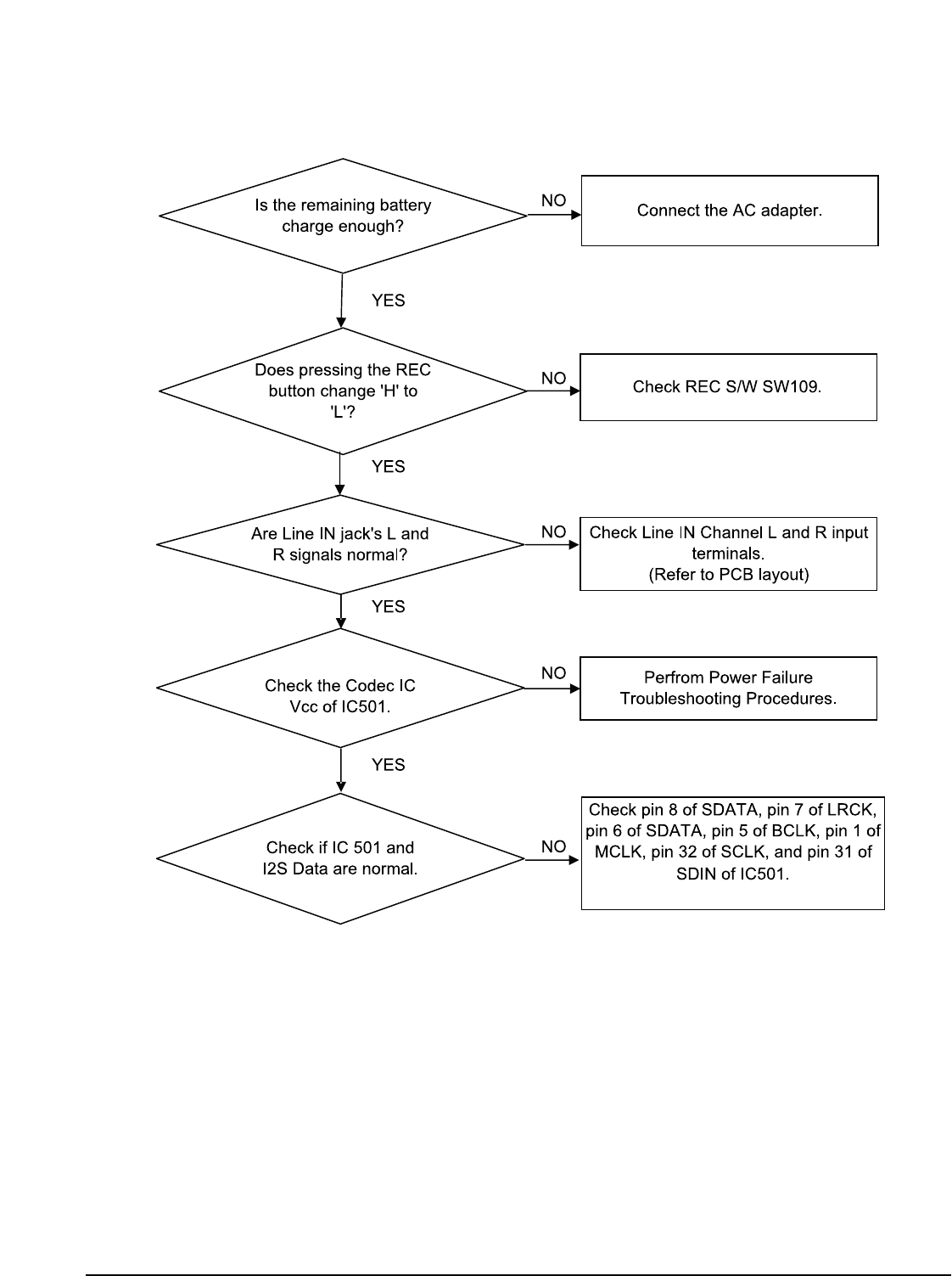
Samsung Electronics 6-3
3. Recording Failure (Line IN)
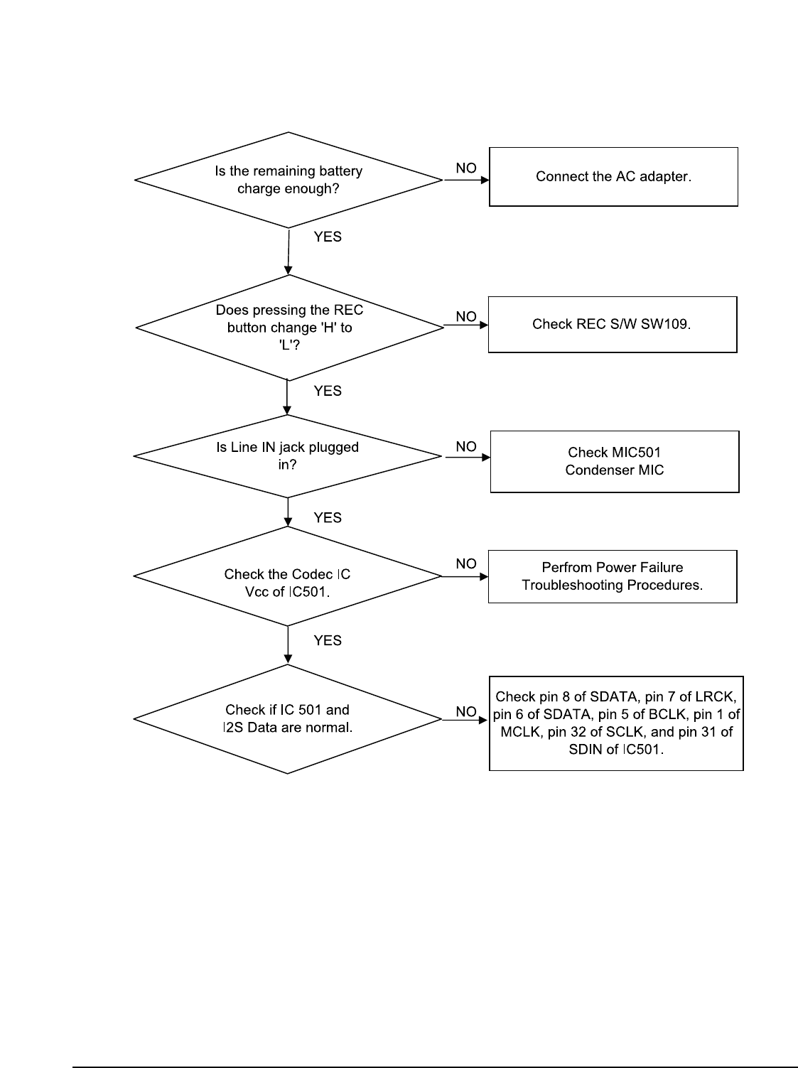
6-4 Samsung Electronics
4. Recording Failure (Audio)
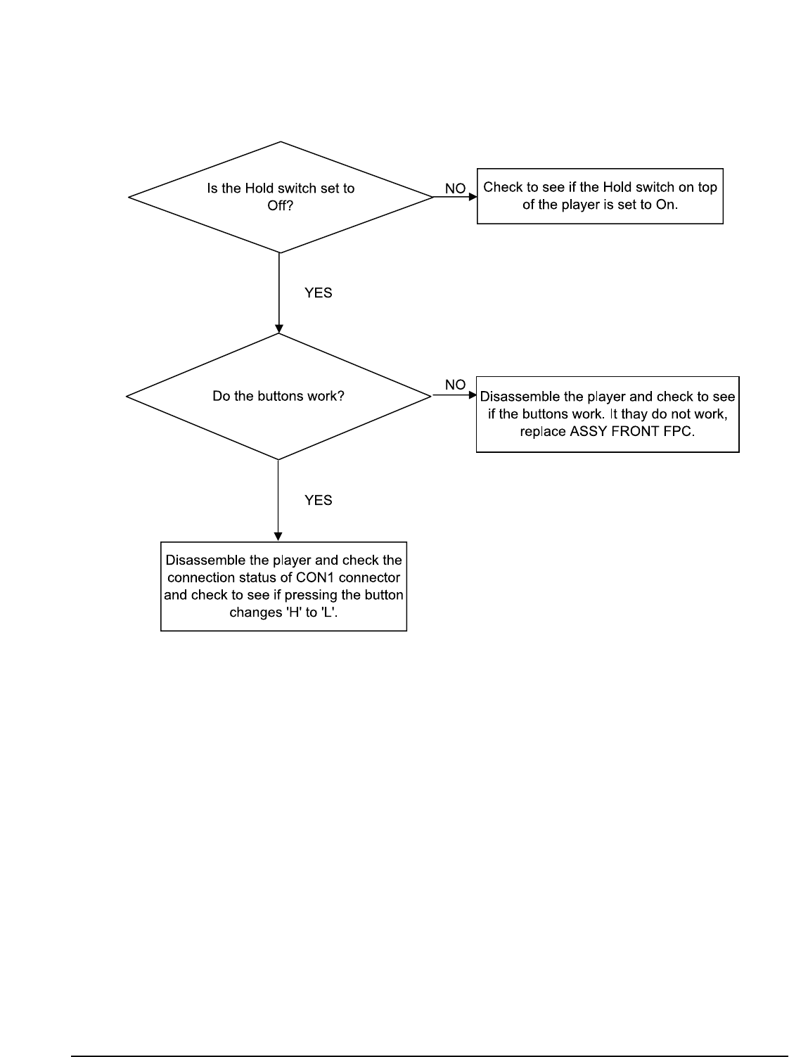
Samsung Electronics 6-5
5. The buttons does not works
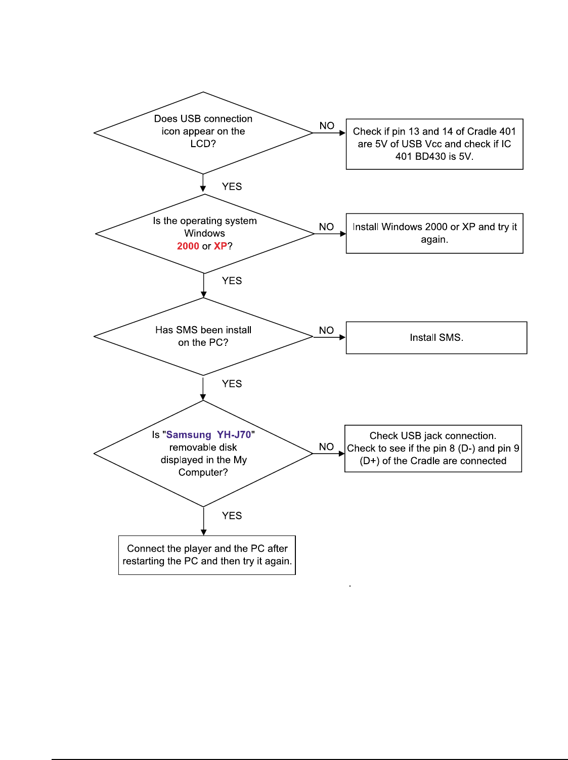
6-6
Samsung Electronics
6. When you cannot connect the player to the PC
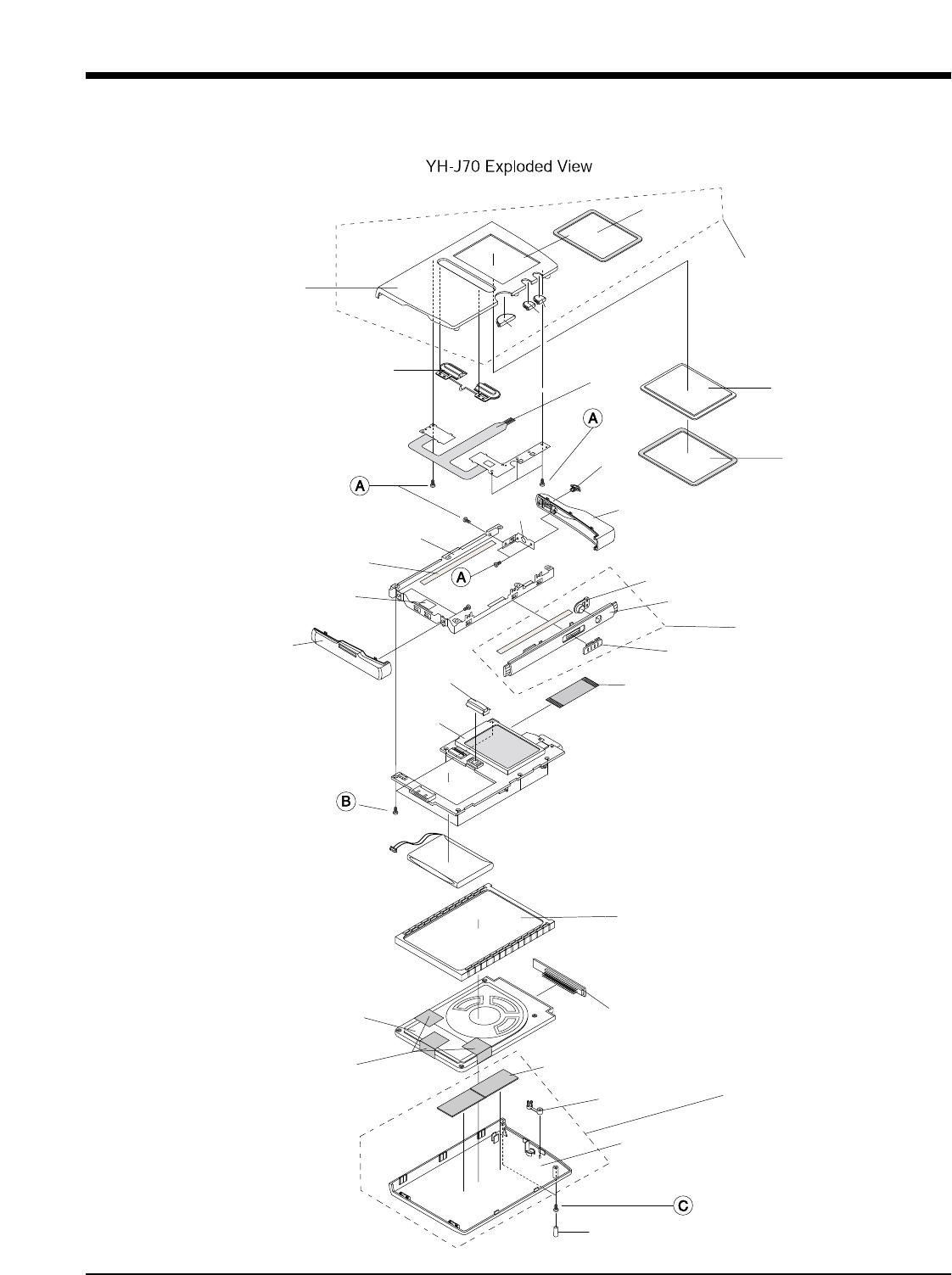
Samsung Electronics7-1
7.Exploded View & Parts List
Battery
HDD
FPC-HDD
PCB
AB153
AB250
AB335
AC000
AC010
AC020
AC065
AC080
AC300
AC324
AC357
AD358
AH264
AK200
AK240
AK290
AK300
AK315
AK327
AK335
AW120
AS161
AA005
AA055
AA130
AS100
PCB-HDD
CONNECTOR-FPC
FRONT
AS066
AS079
1. Total Exploded View

7-2Samsung Electronics
Location No. Code No. Descripion Specification Qty REMARK
AH64-03679G CABINET-BACK-ASSY PC,BLACK 1 YH-J70SB/LB
AH64-03679H CABINET-BACK-ASSY PC,WHITE 1 YH-J70SW/LW
AA055 AH64-03681A CABINET-SIDE-ASSY PC,SILVER 1
AH64-03678C CABINET-FRONT-ASSY PC,BLACK 1 YH-J70SB/LB
AH64-03678D CABINET-FRONT-ASSY PC,WHITE 1 YH-J70SW/LW
AB153 AH61-01933A BRACKET-FRAME SUS 3/4H 1
AB250 AH61-01935A BRACKET-LCD SPTE t0.3 1
AB335 AH61-01934A BRACKET-TOP SPTE t0.5 1
AH64-03432C CABINET-BACK PC,BLACK 1 YH-J70SB
AH64-03432D CABINET-BACK PC,WHITE 1 YH-J70SW
AH64-03432G CABINET-BACK PC,BLACK 1 YH-J70LB
AH64-03432H CABINET-BACK PC,WHITE 1 YH-J70LW
AH64-03433C CABINET-FRONT(N) PC,BLACK YH-J70SB/LB
AH64-03433D CABINET-FRONT(N) PC,WHITE YH-J70SW/LW
AC020 AH64-03431A CABINET-BOTTOM PC,WHITE
AC065 AH64-03436A CABINET SIDE Silver Spray 1
AC080 AH64-03437A CABINET-TOP PC 1
AH63-01032A COVER-SCREW SILICON 70 2 YH-J70SB/LB
AH63-01032B COVER-SCREW SILICON 70 2 YH-J70SW/LW
AC324 AH63-01007A SHEET-BACK PORON t1.0 + 3M t0.05 2
AC357 AH69-01518A CUSHION-LCD PORON t0.5 + 3M t0.05 1
AD358 AH64-03446A DECO STRAP Zn, PLATING 1
AH264 AH61-01932A HOLDER-HDD ELASTOMER (TRIEL 5302) 1
AK200 AH64-03441A KNOB-HOLD ABS 1
AH64-03620A KNOB-MENU PC YH-J70SB/LB
AH64-03620B KNOB-MENU PC YH-J70SW/LW
AH64-03619A KNOB-POWER PC 1 YH-J70SB/LB
AH64-03619B KNOB-POWER PC 1 YH-J70SW/LW
AK300 AH64-03443A KNOB-REC ABS 1
AA130
AK240
AK290
AC300
AA005
AC010
AC000
1
1
1
2
2
2. Parts List

Samsung Electronicsπ7-3
Location No. Code No. Descripion Specification Qty REMARK
AH64-03445A KNOB-RESET PC 1 YH-J70SB/LB
AH64-03445B KNOB-RESET PC 1 YH-J70SW/LW
AH64-03624A KNOB-SELECT ABS / PC 1 YH-J70SB/LB
AH64-03624B KNOB-SELECT ABS / PC 1 YH-J70SW/LW
AH64-03626A KNOB-SKIP ABS / PC 1 YH-J70SB/LB
AH64-03626B KNOB-SKIP ABS / PC 1 YH-J70SW/LW
AS066 AH63-01029A SHEET-CONDUCTIVE NI-SHEET 3 SNA
AS074 AH63-01028A SHEET-EMI PET(0.03T) 1 SNA
AS079 AH63-01039A SHEET-FRAME B NITRO 31CT 1 SNA
AS161 AH63-01035A SHEET-USB NITRO 31CT 1
AW120 AH64-03617A WINDOW-LCD(A) CNC ACRYL (t2.0) 1
A6003-001258 SCREW-TAPTITE M1.4*2 9
B6003-001479 SCREW-TAPTITE M1.7*4 4
C6003-001143 SCREW-TAPTITE M1.7*6 2
AK335
AK315
AK327
AS100 AH63-01026A SHEET-LCD 3M T0.05 1 SNA

Samsung Electronics 8-1
** YH-J70SB Series **
AA005 AH64-03679A CABINET-BACK-ASSY;YH-J70,-,-,-,-,-,BLACK
AA055 AH64-03681A CABINET-SIDE-ASSY;YH-J70,-,-,-,-,-,SILVE
AA130 AH64-03678A CABINET-FRONT-ASSY;YH-J70,-,-,-,-,-,BLAC
AB250 AH61-01935A BRACKET-LCD;YH-J70,SPTE,t0.3,-,-,-,PLATI
AB335 AH61-01934A BRACKET-TOP;YH-J70,SPTE,t0.5,-,-,-,-
AC020 AH64-03431A CABINET-BOTTOM;YH-J70,PC,-,-,-,-,WHITE,-
AC080 AH64-03437A CABINET-TOP;YH-J70,PC,-,-,-,-,WHITE,-
AD358 AH64-03446A DECORATION-STRAP;YH-J70,Zn,-,-,-,-,-,PLA
AH264 AH61-01932A HOLDER-HDD;YH-J70,ELASTOMER,-,-,-,-,-
AK240 AH64-03620A KNOB-MENU;YH-J70,-,-,-,-,-,-,-,TOOL ####
AK290 AH64-03619A KNOB-POWER;YH-J70,-,-,-,-,-,-,-,PLAY ###
AK315 AH64-03445A KNOB-RESET;YH-J70,PC,-,-,-,-,-,-,BLACK
AK327 AH64-03624A KNOB-SELECT;YH-J70,ABS&PC,-,-,-,-,-,-,DO
AK335 AH64-03626A KNOB-SKIP;YH-J70,ABS&PC,-,-,-,-,-,-,DOUB
AS040 6003-001143 SCREW-TAPTITE;PH,+,-,B,M1.7,L6,NI PLT,SW
AS040 6003-001258 SCREW-TAPTITE;PH,+,B,M1.4,L2.0,NI PLT,SW
AS040 6003-001479 SCREW-TAPTITE;BH,+,B,M1.7,L4,ZN
AS066 AH63-01029A SHEET-CONDUCTIVE;YH-J70,Ni-Sheet,0.09,-,
AS074 AH63-01028A SHEET-EMI;YH-J70,PET,0.02,-,-,####,BACK
AW120 AH64-03617B WINDOW-LCD;YH-J70,ACRYL,2.0T,-,-,-,-,-
BATT6 3710-001436 SOCKET-BOARD TO BOARD;2P,1R,1.27mm,SMD-A
BD418 3301-001272 BEAD-SMD;120ohm,2x1.25x1mm,-,TR,-,-,-
BD605 2007-000070 R-CHIP;0ohm,5%,1/10W,TP,1608
BD606 2007-000029 R-CHIP;0ohm,5%,1/8W,TP,2012
BUZZE 3002-001144 BUZZER-MAGNETIC;78dB,3.0V,100mA,4000Hz,R
C146 2203-002709 C-CER,CHIP;100nF,+80-20%,16V,Y5V,1005
C308 2404-001401 C-TA,CHIP;220uF,+-20,4V,SMD,REEL,3216
C436 2203-006090 C-CER,CHIP;10000nF,10%,6.3V,X5R,2012
C443 2404-001281 C-TA,CHIP;22UF,20%,6.3V,WT,TP,2012
C447 2203-005493 C-CER,CHIP;220nF,+80-20%,16V,Y5V,1005
C451 2203-000627 C-CER,CHIP;0.022NF,5%,50V,C0G,TP,1005
C458 2203-000254 C-CER,CHIP;10nF,10%,16V,X7R,1005
C504 2404-001407 C-TA,CHIP;330uF,20%,2.5V,-,REEL,3528
C506 2203-000585 C-CER,CHIP;0.22nF,10%,50V,X7R,1005
C516 2203-002885 C-CER,CHIP;33nF,+80-20%,50V,Y5V,TP,1005
C541 2203-005900 C-CER,CHIP;1000NF,+80-20%,10V,Y5V,1005
C543 2404-001244 C-TA,CHIP;4.7uF,20%,6.3V,-,TP,2012
C544 2404-001064 C-TA,CHIP;10UF,20%,6.3V,WT,TP,2012
C604 2203-001640 C-CER,CHIP;0.39nF,10%,50V,X7R,TP,1608
C605 2203-006391 C-CER,CHIP;1000NF,10%,10V,X7R,-,1608
C609 2203-000681 C-CER,CHIP;0.027nF,5%,50V,C0G,1608
C615 2203-000236 C-CER,CHIP;0.1nF,5%,50V,C0G,1608
C617 2203-002793 C-CER,CHIP;1000nF,+80-20%,25V,Y5V,2012
C627 2404-001348 C-TA,CHIP;100uF,##20%,6.3V,-,TP,3.2X1.6X
C632 2203-006818 C-CER,CHIP;47000nF,20%,6.3V,X5R,3216
C809 2404-001247 C-TA,CHIP;22UF,20%,4V,WT,TP,2012
CON-H 3711-005881 HEADER-BOARD TO CABLE;NOWALL,50P,2R,1.27
CRADL 3710-002208 CONNECTOR-INTERFACE;18P,1R,0.5mm,ANGLE,N
D408 1405-001132 VARISTOR;6Vdc,-,1x0.5x0.4mm,TP
D504 0406-001128 DIODE-TVS;MLVS-0603-E08,50V,-,-
D601 0404-001010 DIODE-SCHOTTKY;MA729,30V,200MA,DSM,TP
D603 0404-001203 DIODE-SCHOTTKY;B240A,40V,2000MA,SMA,TP
D804 0401-001090 DIODE-SWITCHING;1SS355,80V,100MA,SOD-323
FMPAC AH40-00098A TUNER;-,YH-J70,FM,-,-,-,40ohm,-,-,-,
FPC-H AH41-00872A FPC;YH-J70,FPC,1,0,0.15,15.6X22,-,
FSW1 3403-001150 SWITCH-PUSH;5V,10mA,-,CW-PUSH-CCW,-
IC101 0904-001993 IC-DSP;SCF5250VM120,16Bit,BGA,196P,15
IC102 1203-003746 IC-VOL. DETECTOR;XC61FC1912MR,SOT-23,3P,
IC202 1105-001672 IC-DRAM;EM48AM1684,16Mx16Bit,TFBGA,54P
IC203 1107-001547 IC-FLASH MEMORY;39VF3201,2Mx16Bit,TFBGA,
IC301 0801-002996 IC-CMOS LOGIC;74LVC16245A,transceiver,TV
IC302 0801-002997 IC-CMOS LOGIC;74LVC245A,transceiver,TVSO
IC401 0904-001992 IC-USC;ISP1761ET,32Bit,TFBGA,128P,9.0
IC403 1205-002517 IC-SWITCH;TPS2020D,SO,8P,-,-,5.5V,725mW,
IC404 0801-002959 IC-CMOS LOGIC;7SV32,OR GATE,SC-70,5P,2x1
IC405 0801-002800 IC-CMOS LOGIC;NC7SV08,AND GATE,SC70,5P,4
IC501 1002-001374 IC-A/D&D/A CONVERTER;WM8750L,24,QFN,32P,
IC601 1203-003254 IC-DC/DC CONVERTER;LTC3455,QFN,24P,4X4MM
IC602 1203-003257 IC-DC/DC CONVERTER;XC9103,SOT-25,5P,2.9X
IC603 1203-003726 IC-DC/DC CONVERTER;XC9216A12CMR,SOT-25,5
IC801 0909-001041 IC-REAL TIME CLOCK;RX-8564LC,8Bit,VSOJ-1
IC802 1209-001596 IC-SENSOR;MMA7260QR2,QFN,16P,6x6mm,PLAST
JACK- 3708-002076 CONNECTOR-FPC/FFC/PIC;51P,0.3mm,SMD-A,SN
JACK5 3722-002300 JACK-PHONE;11P,-,AU,-,-
KEY-P AH41-00866A FPC;YH-J70,0,FPC,4,0.8T,YH-J70
KR1 2007-001319 R-CHIP;1.2KOHM,5%,1/16W,TP,1005
KR2 2007-001320 R-CHIP;1.8KOHM,5%,1/16W,TP,1005
L401 2704-000005 INDUCTOR-SMD-ARRAY;90OHM,50V,370MA,-,0.3
L505 3301-001364 BEAD-SMD;1000ohm,1608,150mA,TP,1085ohm/
L506 2703-000275 INDUCTOR-SMD;33UH,10%,2012
L601 2703-001871 INDUCTOR-SMD;10uH,20%,6060
L603 2703-001873 INDUCTOR-SMD;4.7uH,20%,6060
L605 2703-001920 INDUCTOR-SMD;2.2uH,20%,3225
LCD1 3708-002077 CONNECTOR-FPC/FFC/PIC;33P,0.3mm,SMD-A,SN
MIC50 3003-001099 MIC-CONDENSOR;2V,130~300uA,-44dB,2.2Kohm
MKEY_ 3708-002035 CONNECTOR-FPC/FFC/PIC;4P,0.5mm,SMD-A,AU,
Q302 0504-000128 TR-DIGITAL;-,NPN,200MW,22K/22K,SOT-23,TP
Q510 0505-001174 FET-SILICON;SI2302ADS,N,20V,2.4A,65mohm,
Q515 0504-001084 TR-DIGITAL;-,NPN,200mW,2.2K,SOT-323,TP
Q601 0504-000156 TR-DIGITAL;KSR2103,PNP,200MW,22K/22K,SOT
Q602 0505-001845 FET-SILICON;Si2312DS,N,20V,3.77A,0.051oh
Q605 0504-000211 TR-DIGITAL;DTC143TU,NPN,200mW,4.7K,SC-70
Q606 0505-001426 FET-SILICON;IRLML6401,P,-12V,-4.3A,0.05o
Q802 0501-000730 TR-SMALL SIGNAL;2SA1577,PNP,200MW,SOT-32
R120 2007-007107 R-CHIP;100Kohm,1%,1/16W,TP,1005
R172 2007-008676 R-CHIP;80.6KOHM,1%,1/16W,TP,1005
R187 2007-002797 R-CHIP;560OHM,5%,1/16W,TP,1005
R262 2007-000171 R-CHIP;0ohm,5%,1/16W,TP,1005
R306 2007-001292 R-CHIP;33OHM,5%,1/16W,TP,1005
R334 2007-000636 R-CHIP;270KOHM,5%,1/16W,TP,1005
R335 2007-000982 R-CHIP;5.6KOHM,5%,1/16W,TP,1005
R402 2007-001333 R-CHIP;18KOHM,5%,1/16W,TP,1005
R415 2007-001694 R-CHIP;12Kohm,0.5%,1/10W,TP,1608
R439 2007-000092 R-CHIP;15Kohm,5%,1/10W,TP,1608
R442 2007-000148 R-CHIP;10Kohm,5%,1/16W,TP,1005
R445 2007-000170 R-CHIP;1MOHM,5%,1/16W,TP,1005
R503 2007-000162 R-CHIP;100Kohm,5%,1/16W,TP,1005
R511 2007-001325 R-CHIP;3.3Kohm,5%,1/16W,TP,1005
R518 2007-000172 R-CHIP;10ohm,5%,1/16W,TP,1005
R523 2007-000775 R-CHIP;33KOHM,5%,1/16W,TP,1005
R527 2007-000143 R-CHIP;4.7Kohm,5%,1/16W,TP,1005
R528 2007-000153 R-CHIP;22KOHM,5%,1/16W,TP,1005
R543 2007-000139 R-CHIP;220OHM,5%,1/16W,TP,1005
R545 2007-000141 R-CHIP;2.2Kohm,5%,1/16W,TP,1005
R604 2007-000104 R-CHIP;150Kohm,5%,1/10W,TP,1608
R606 2007-000309 R-CHIP;10ohm,5%,1/10W,TP,1608
R607 2007-007981 R-CHIP;180Kohm,1%,1/16W,TP,1005
R608 2007-007488 R-CHIP;75KOHM,1%,1/16W,TP,1005
R610 2007-008453 R-CHIP;1.24KOHM,1%,1/16W,TP,1005
R611 2007-002425 R-CHIP;1ohm,5%,1/10W,TP,1608
R612 2007-009079 R-CHIP;255Kohm,1%,1/16W,TP,1005
R614 2007-000045 R-CHIP;3.32Kohm,1%,1/10W,TP,1608
R618 2007-000078 R-CHIP;1Kohm,5%,1/10W,TP,1608
R621 2007-008780 R-CHIP;0.1OHM,1%,1/16W,TP,1005
R622 2007-000637 R-CHIP;270Kohm,5%,1/10W,TP,1608
R625 2007-008697 R-CHIP;2.49KOHM,1%,1/16W,TP,1005
R726 2007-000157 R-CHIP;47Kohm,5%,1/16W,TP,1005
R737 2007-000138 R-CHIP;100ohm,5%,1/16W,TP,1005
R821 2007-000140 R-CHIP;1Kohm,5%,1/16W,TP,1005
R823 2007-000758 R-CHIP;330KOHM,5%,1/16W,TP,1005
SW109 3404-001152 SWITCH-TACT;12V DC,20mA,160gf,4.5x4.0x2.
SW110 3404-001143 SWITCH-TACT;12VDC,20mA,180gf,3.2x4.9x1.7
SW801 3408-001110 SWITCH-SLIDE;5V,1mA,1,-,-
X101 2804-001641 OSCILLATOR-CLOCK;11.2896MHz,50ppm,15pF&1
X402 2801-004318 CRYSTAL-SMD;12MHz,20ppm,-,12PF,80ohm,TP
AH61-02036A BRACKET-FRAME-ASSY;YH-J70,SUS,t0.3(3/4H)
AH63-01025A SHEET-LCD SIDE;YH-J70,-,-,28,3,-,-
4302-001186 BATTERY-LI(2ND);3.7V,970mAH,-,190mA,4.2V
AH07-00163A LCD;LCD MODULE,YH-J70,-,40 x 47.6
AH30-00085D PHONE-EAR(EP-360);BLACK,EP-360,16ohm,NOR
AH39-00488B CBF CABLE-STEREO CORD;YD-11034 ,YP-60,3P
AH39-00783A CBF CABLE FORM-USB;49217-1001,YH-J70,2,1
AH39-00784A CBF CABLE FORM-USB;49291-001,YH-J70,-,10
AH44-00100F ADAPTOR;PSCV050102F,YH-J70,-,100~240Va
AH59-01259A HDD;20GB,MK2004GAL,63,4,46,160,5MM
AH63-01125A SHEET-SET;YH-J70,EVA,0.5T,-,-,-,-
AH68-01675B MANUAL USERS;YH-J70,XEU,ENG,-,-,115,115,
AH69-01509B MASTER CARTON-(XAA);YH-J70,-,-,-,-,-,-,-
AH80-00119A INSTALL;YH-J70,-,CD,INSTALL,-,-,-,-
AH92-02343A ASSY PCB-YH-J70 MAIN;YH-J70,MAIN
Location no. Code no. Description & Specification Remarks Location no. Code no. Description & Specification Remarks
8. Electrical Parts List
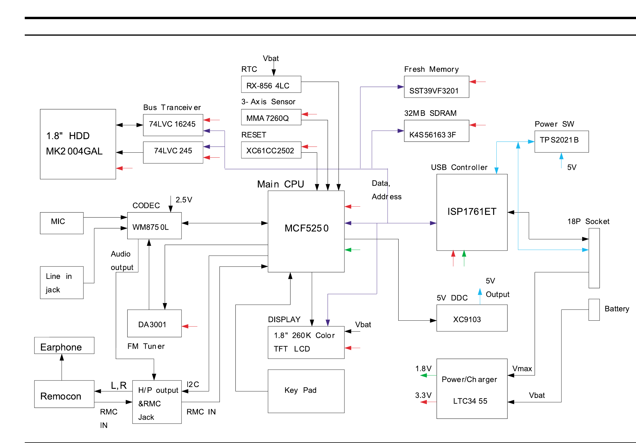
Samsung Electronics 9-1
9. Block Diagram
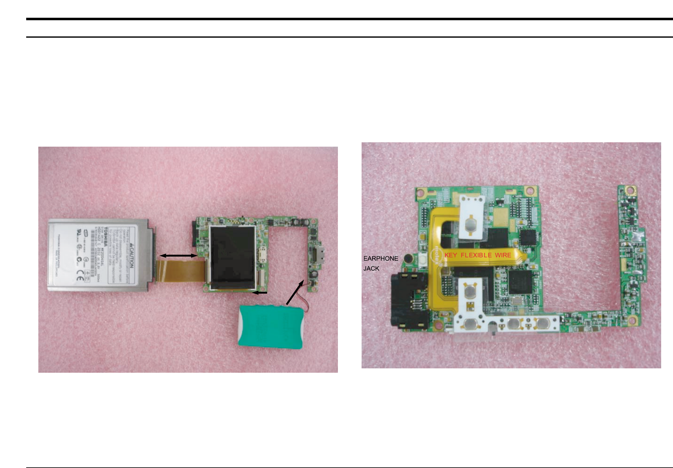
Samsung Electronics10-1
10. Wiring Diagram
HDD
BATTERY
TFT LCD
USB
JACK
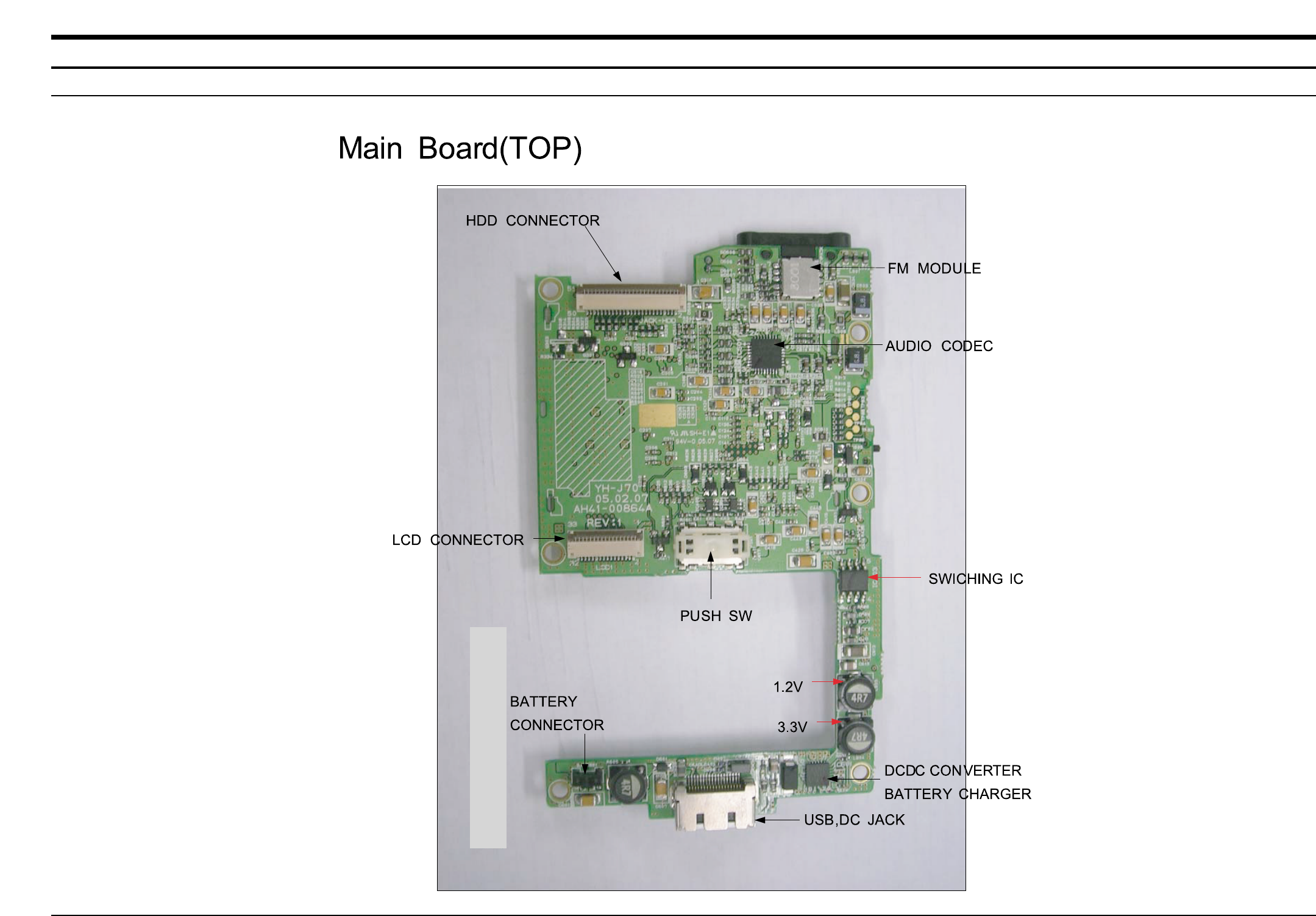
11-1
- This Document can be used without Samsung’s authorization -
Samsung Electronics
11. PCB Diagram
1. MAIN
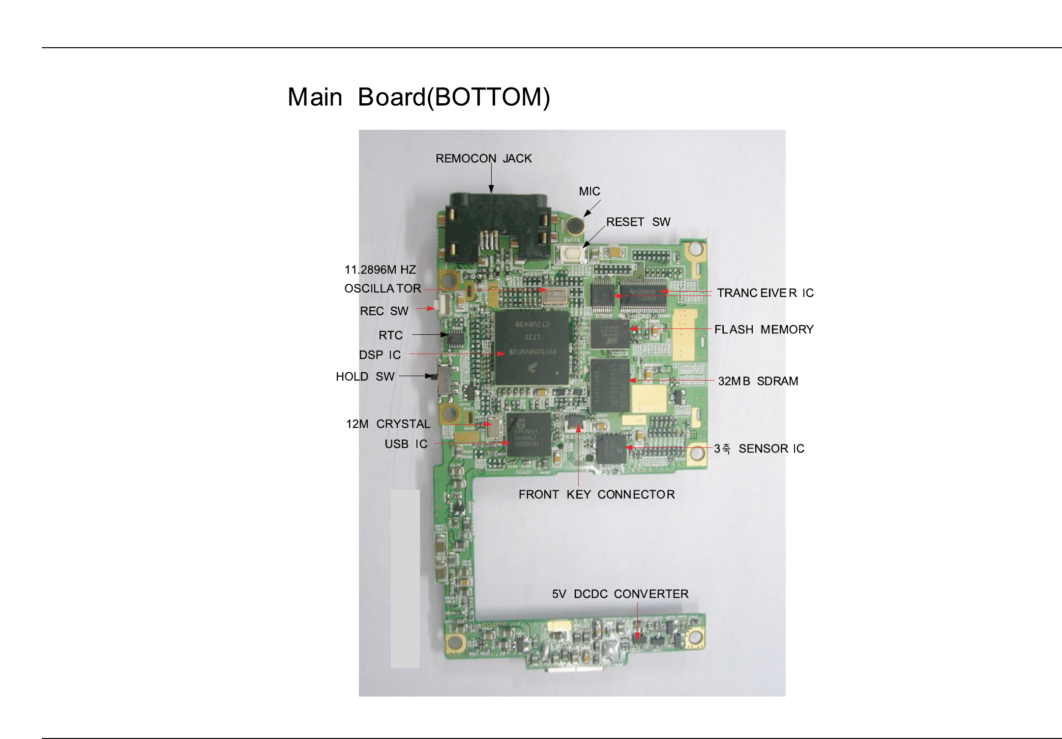
11-2 Samsung Electronics
- This Document can be used without Samsung’s authorization -
2. SUB
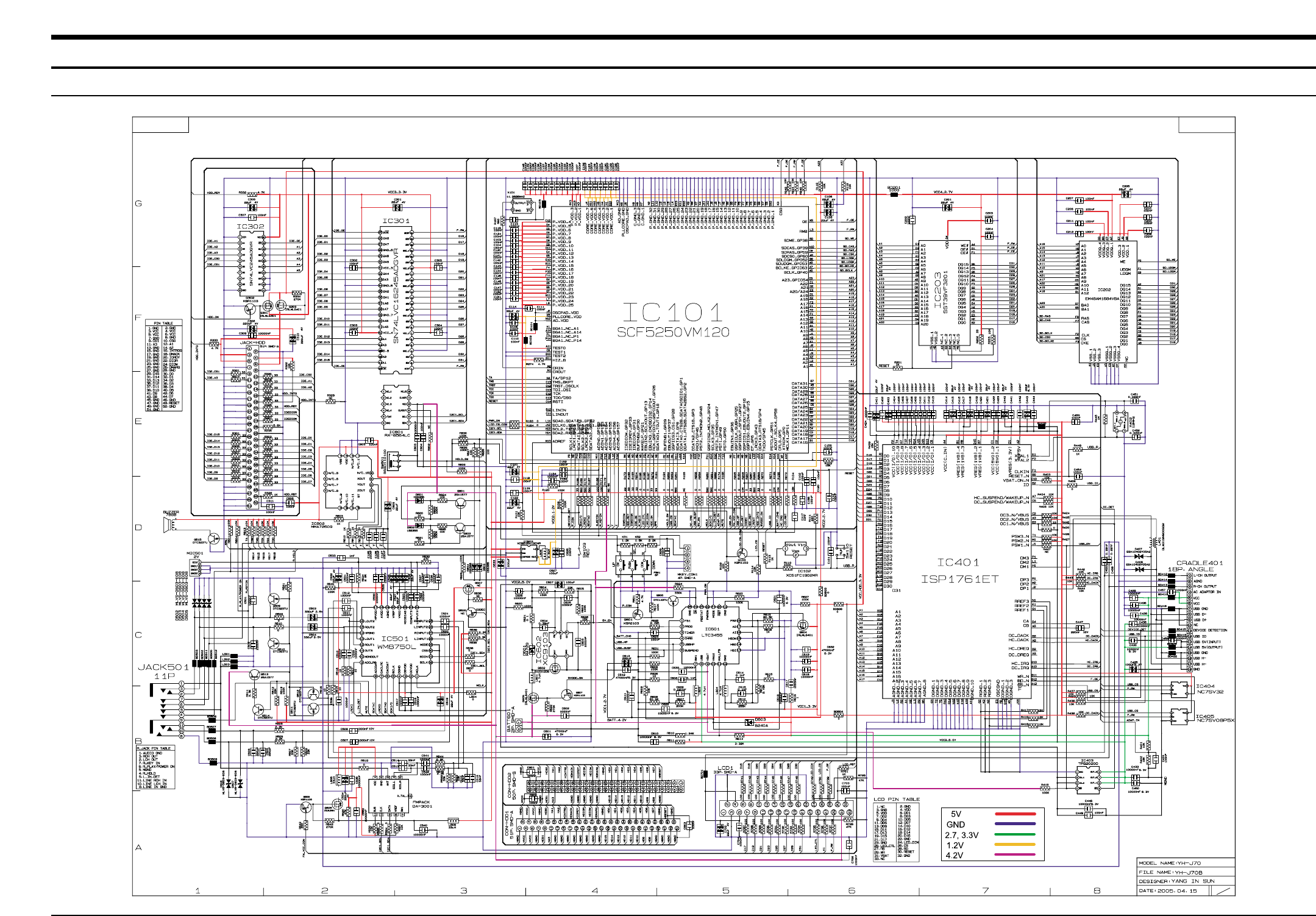
12-1
- This Document can be used without Samsung’s authorization -
Samsung Electronics
12. Schematic Diagram
1. MAIN
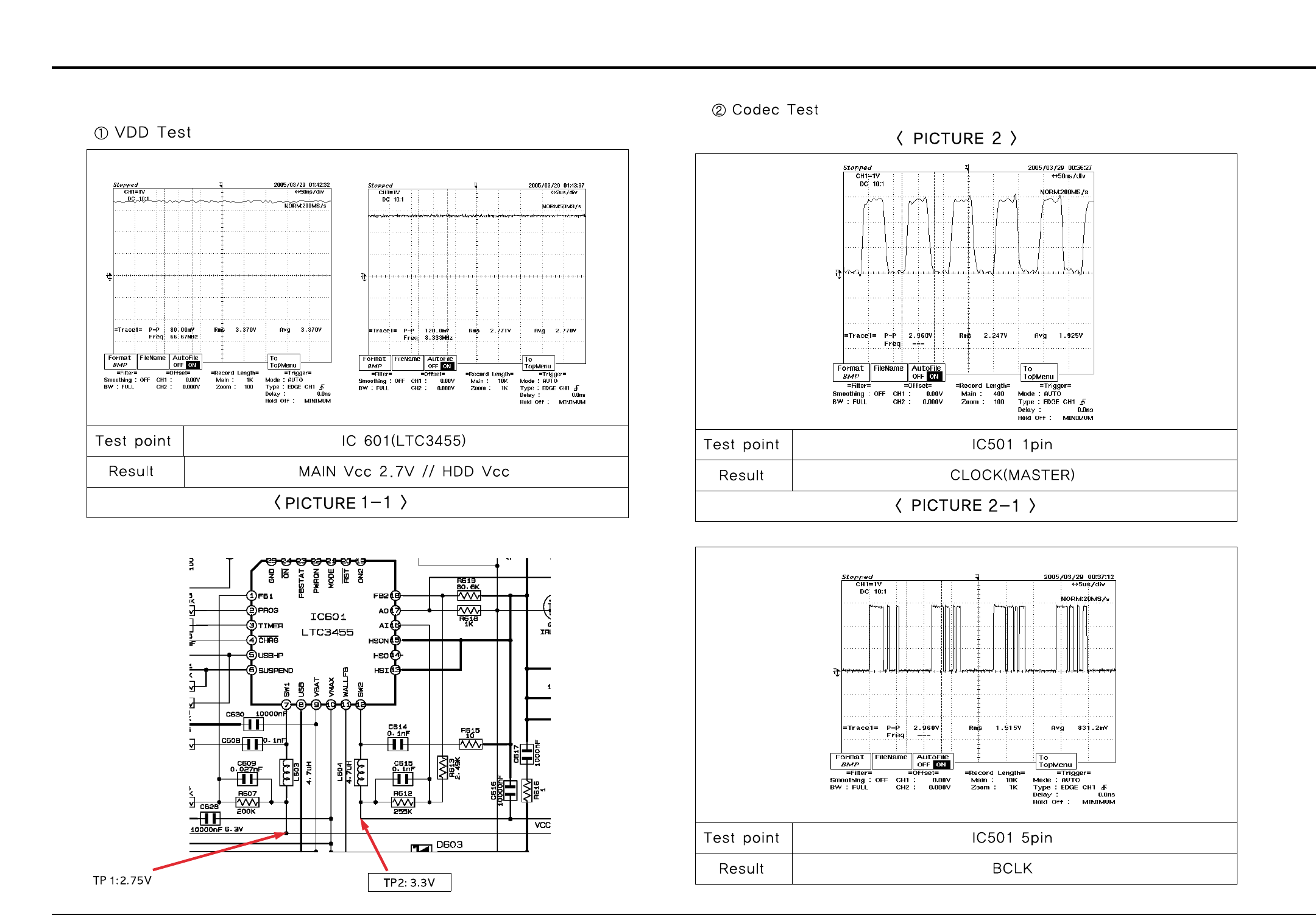
12-2 Samsung Electronics
- This Document can be used without Samsung’s authorization -
1-2. SELF-TEST Manual
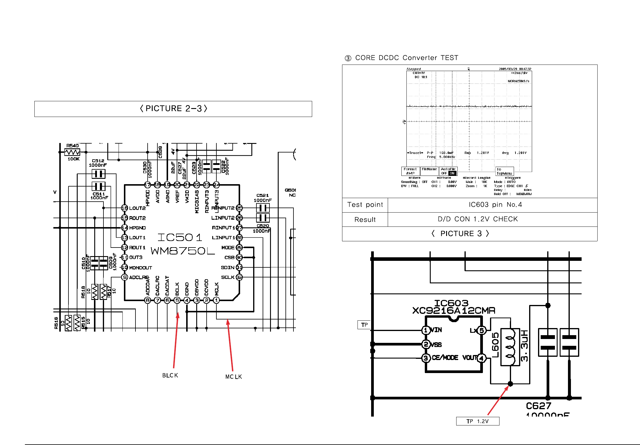
Samsung Electronics 12-3
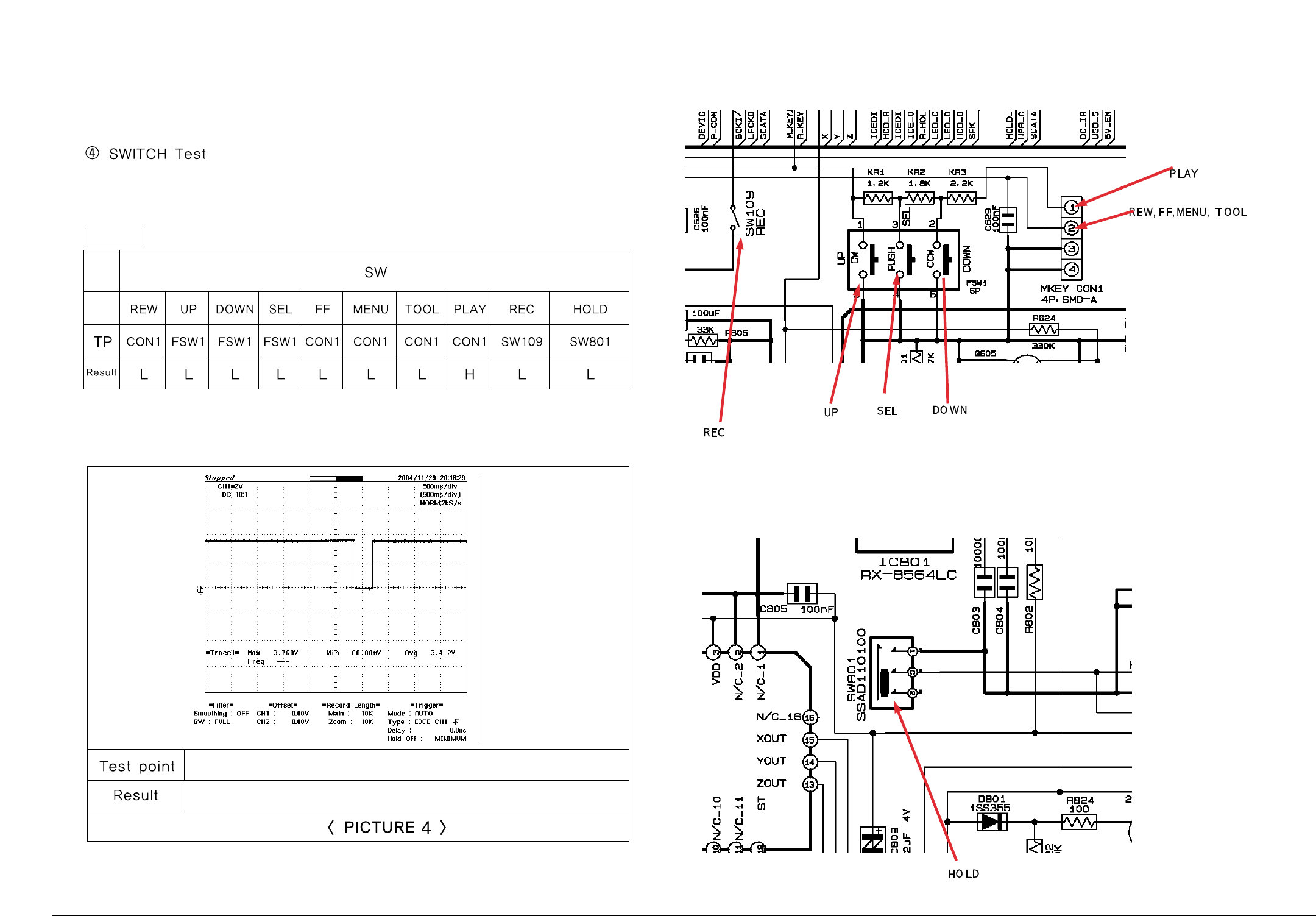
12-4 Samsung Electronics
TABLE 1
See Table 1
See Table 1
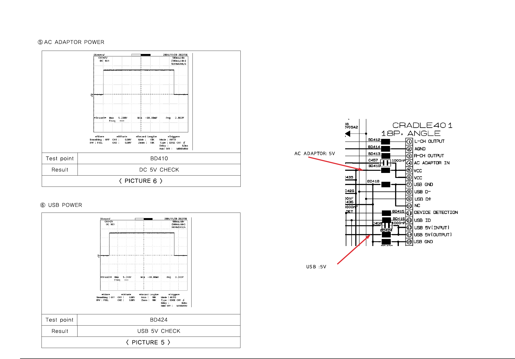
Samsung Electronics 12-5
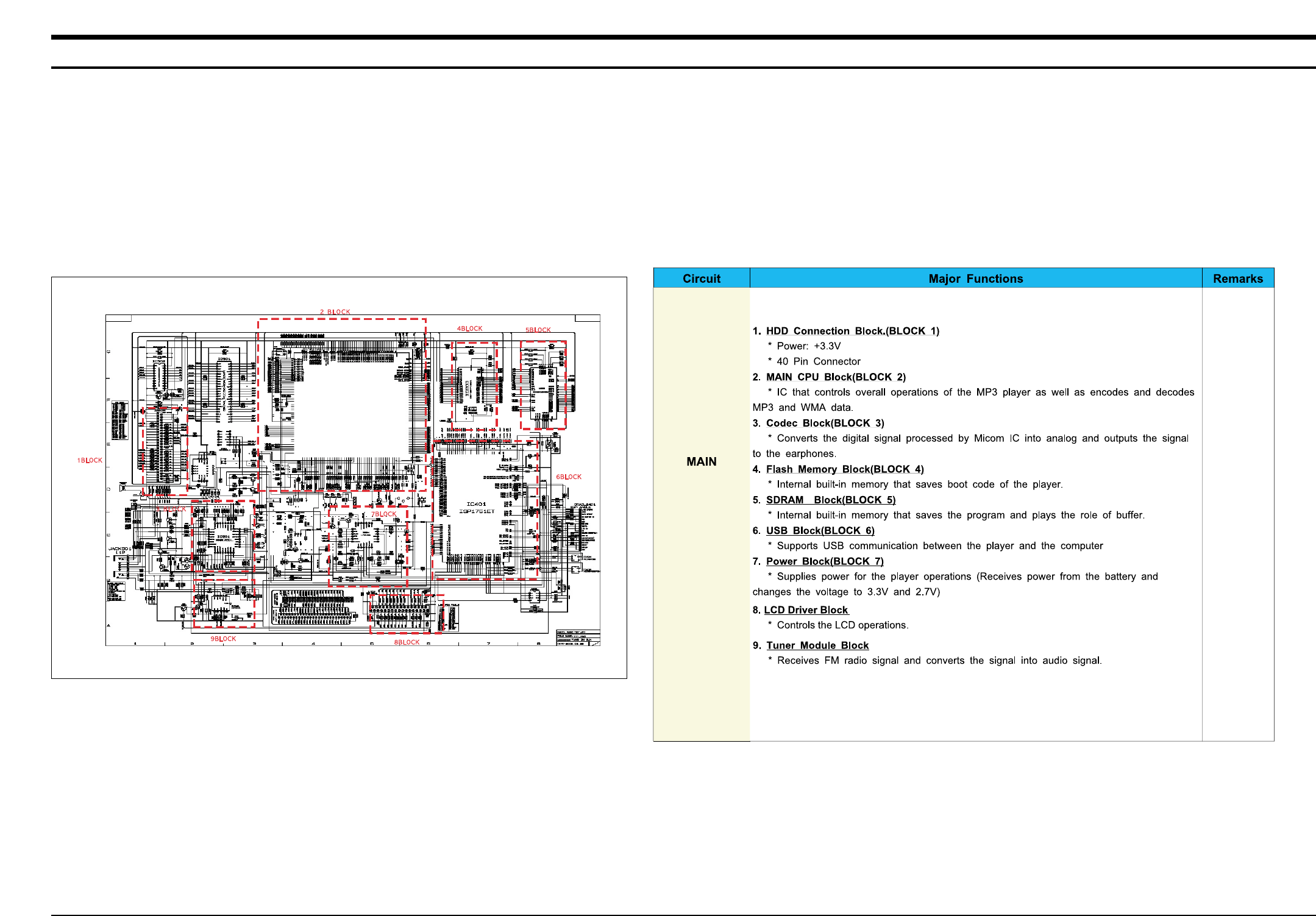
13-1
- This Document can be used without Samsung’s authorization -
Samsung Electronics
13. Circuit Description
1. Description of the Circuit
1-1. Main Blocks in the Circuit Diagram 1-2.Main Functions by Block
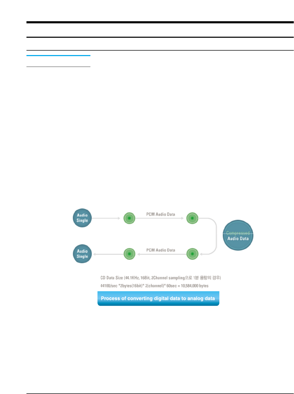
Samsung Electronics 14-1
Terms and Overview
AV Conversion: process of converting Analog Data to Digital Data
SAMPLING RATE : means precision rate of A/D conversion and is indicated in Hz, bit number and
channel number(for CD: 44.1 KHz, 16bit, 2channels)
ENCODING : process of compressing and converting digital data obtained through A/D conversion
to audio format
Compression rate: indicated in bps(bit per second)
(For MP3: sound quality of CD level with compression rate of 128kbps)
ENCODING FORMAT : MP3 : MPEG Layer3
AAC : MPEG-2 AAC
WMA : Windows Media Audio (Microsoft)
ATRAC(3) : Adaptive TRansform Acoustic Coding (SONY)
EPAC : Enhanced Perceptual Audio Coder (Luscent Technology)
OGG : Ogg Vorbis
DECODING : Process of recovering the digital data encoded to the data before encoding
D/A : Process of converting Digital Data to Analog Data
14. Basic Information of MP3
1-1. Operating Principle of yepp
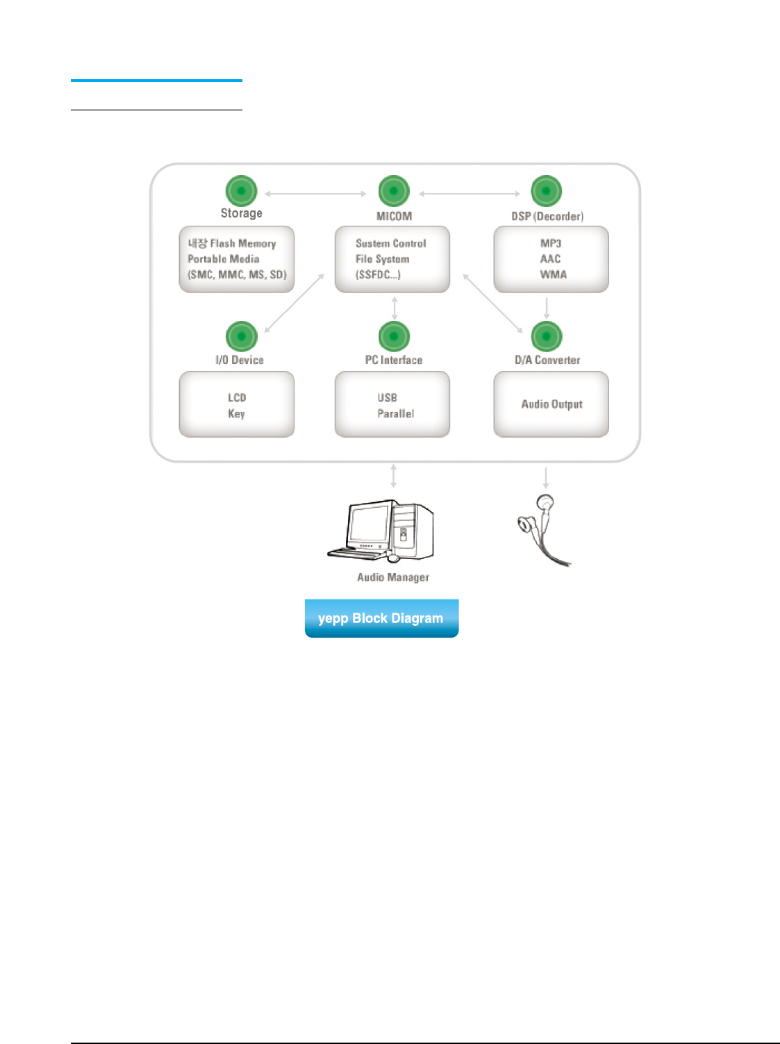
14-2 Samsung Electronics
Yepp Block Diagram

Samsung Electronics 14-3
Yepp Vocabulary
Yepp (Young Energetic Personal Passinate)
MP3 player that enables you to enjoy audio data like music file in existing CD in high quality by
compressing it to 1/12 level without loss of quality using MPEG1 Layer3(audio compression
technology of animation and sound compression technique). You can also use it for learning foreign
language and Internet broadcasting.
MPEG
MPEG is an abbreviation of Moving Picture Expert Group and means specification defining the
compression and de-compression type of animation by MPEG established in 1988.
MP3
MP3 means MPEG1 Layer3 and compression rate can be up to 96:1(phone) to 12:1(CD) depending
on sound quality with compression coding technique of audio of MPEG technology.
(file extension: "mp3") That is, up to 150 pieces of songs can be recorded in one copy of CD with
MP3 compression.
FLASH Memory
Flash memory is the memory chip where entered information will not be deleted even if the power is
turned off while data is entered, and data can be freely entered or deleted.
Smart Media Card
Compact and light semiconductor media card in dimension of 45.1 x 37.1 x 0.76mm and weight of
2.0g. It is used as a storage of portable device and high quality media storage device of digital
camera and music MP3 player.
Flash memory is embedded to store the data even if the power is turned off and it is a super-high
speed product that can record up to 250 characters per second.(mass production of 8MB, 16MB,
32MB currently at Samsung Electronics)
OTP (Once Time Programmable)
OTP is one type of micro controller(MCU) and is the customer-oriented semi-conductor on which
the customers can directly record the program. OTP type MCU is rapidly growing as its life cycle of
set product and multi-kind/small quantity production system is introduced.
Since existing type of micro controller uses Mask ROM which cannot be played or recorded again, it
requires over 5 months to develop set products, and it is not suitable for products with rapid change
of product model.
Firmware
It is a program that controls and manages hardware. Firmware is distinguished from hardware in
that it is a program but is distinguished from general applications in that it is closely related to
hardware. In general, firmware is saved in ROM.

14-4 Samsung Electronics
IP (Information Provider)
Company that provides information that users want through communication system with certain fee.
SecuMAX
As multimedia digital contents distributions become active in networks such as Internet and PC
communication, copyright issue has appeared as an important topic. It is a system that can protect
the right of copyright holders and enables the user to conveniently use contents. To receive service,
member registration is required at digital contents service site adopting SecuMAX.
When completing member registration, customer ID, password and resident registration number will
be registered at SecuMAX server and utilized as a basic data for performing user certification role.
After registration, download the dedicated player and decryption key to use service.
Music drive developed by Samsung Electronics is embedded with SecuMAX decryption module.
Decryption key will be registered during installation of music drive. Music file downloaded from digi-
tal contents music service site with SecuMAX can be played back.
Yepp Explorer
This software controls yepp player in PC. You can move or delete music list or voice saved in yepp
card or embedded memory. This software is required to use yepp.
Music Drive
Software audio player for PC embedded with MPEG II AAC Decoder first in Korea. It supports not
only playback of MPEG audio format as well as SecuMAX, encryption protection system.
CD Ripper
MP3 compression software that converts CD music in PC to MP3 file.
OGG (Ogg Vorbis)
OGG(Ogg Vorbis) is featured to have "higher compression rate than MP3', 'higher quality than
MP3', 'no limit in use, distribution and development due to open source type. The biggest feature of
Ogg Vorbis is that it has no limit in use of format itself.
The biggest feature that distinguishes Ogg Vorbis from existing music file is that it supports
VBR(Variable Bit Rate) by default.
Of course, MP3 also supports VBR format, but has effect of reducing capacity due to VBR based on
existing MP3. Ogg Vorbis file supports VBR by default and helps you enjoy high quality music
without loss due to big width of bit rate.
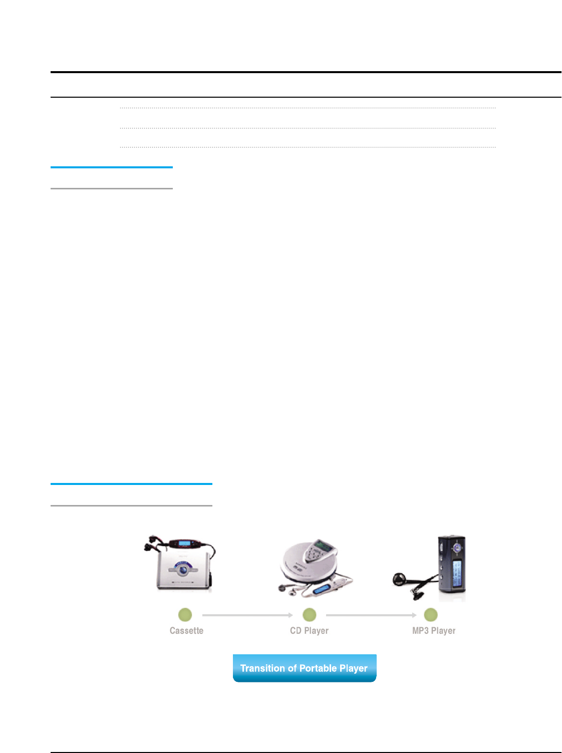
Samsung Electronics 14-5
MP3 is one of file extension like .hwp, .wav, .txt used in computer.
Exactly, it is the abbreviation of MPEG Audio Layer-3.
Origin of MP3
MPEG is Motion Pictures Expert Group and is a standard made by experts in this area under inter-
national standard organization like ISO(International Standard Organization) and IEC(International
Electric Committee). It is technical standard of compressing and transmitting video and audio sig-
nals and recovering them again.
The first specification that MPEG made is MPEG-1 in 1988. It is the technology used to produce
video CD. MP3 means the audio compression part among specification of MPEG-1(1995). MPEG-2
is used together with MPEG-1. AAC(Advanced Audio Coding or MP4) receives attention with its
excellent digital audio and is derived from MPEG-2. MPEG-4(lastests standard on movie compres-
sion for conference communication) is being established.
MP3 is most widely used and called "MPEG Audio Layer-3", which is version up from Layer-1 and
Layer-2. In general, it is called MP3 since Layer-1 has compression rate of 1:4, Layer-2 of 1:61:8,
Layer-3 of 1:101:12.
Using MP3 technology, up to 100 songs(7 hours) can be contained in one copy of empty CD of
650MB.
Transition of Portable Player
1-2. MP3 Overview
14-6 Samsung Electronics
MP3
MP3 is most widely used and called "MPEG Audio Layer-3", which is version up from Layer-1 and
Layer-2. In general, it is called MP3 since Layer-1 has compression rate of 1:4, Layer-2 of 1:61:8,
Layer-3 of 1:101:12.
AAC
MP3 is most widely used and called "MPEG Audio Layer-3", which is version up
from Layer-1 and Layer-2. In general, it is called MP3 since Layer-1 has
compression rate of 1:4, Layer-2 of 1:61:8, Layer-3 of 1:101:12.
WMA (Windows Media Audio)
Multimedia compression type of Microsoft. Only music data is compressed from
“WMT”. Streaming and file format also support this data. In a same quality as MP3,
it is about 1/2 size and contains Windows Media Rights Manager with copyright
protection technology. It can be played back with [Media Player] provided in
Windows98.
ATRAC3
Sound compression type of MD and latest specification of [ATRAC (Adaptive
TRansform Acoustic Coding)] developed by SONY. Has about 2 compression rate
than existing ATRAC.
Real Audio G2
Format type developed by Real Network. High quality can be obtained at low trans-
mission speed of 16Kbps-32Kbps using [RealAUDIO G2 Music Codec] as com-
pression type. Since streaming play in Internet radio is the main purpose, file does
not contain copyright protection technology. “Real Player G2” supports MP3 play-
back and “Real Juke Box” supports encoding from CD to MP3.
1-3. Understanding of Digital Audio Format
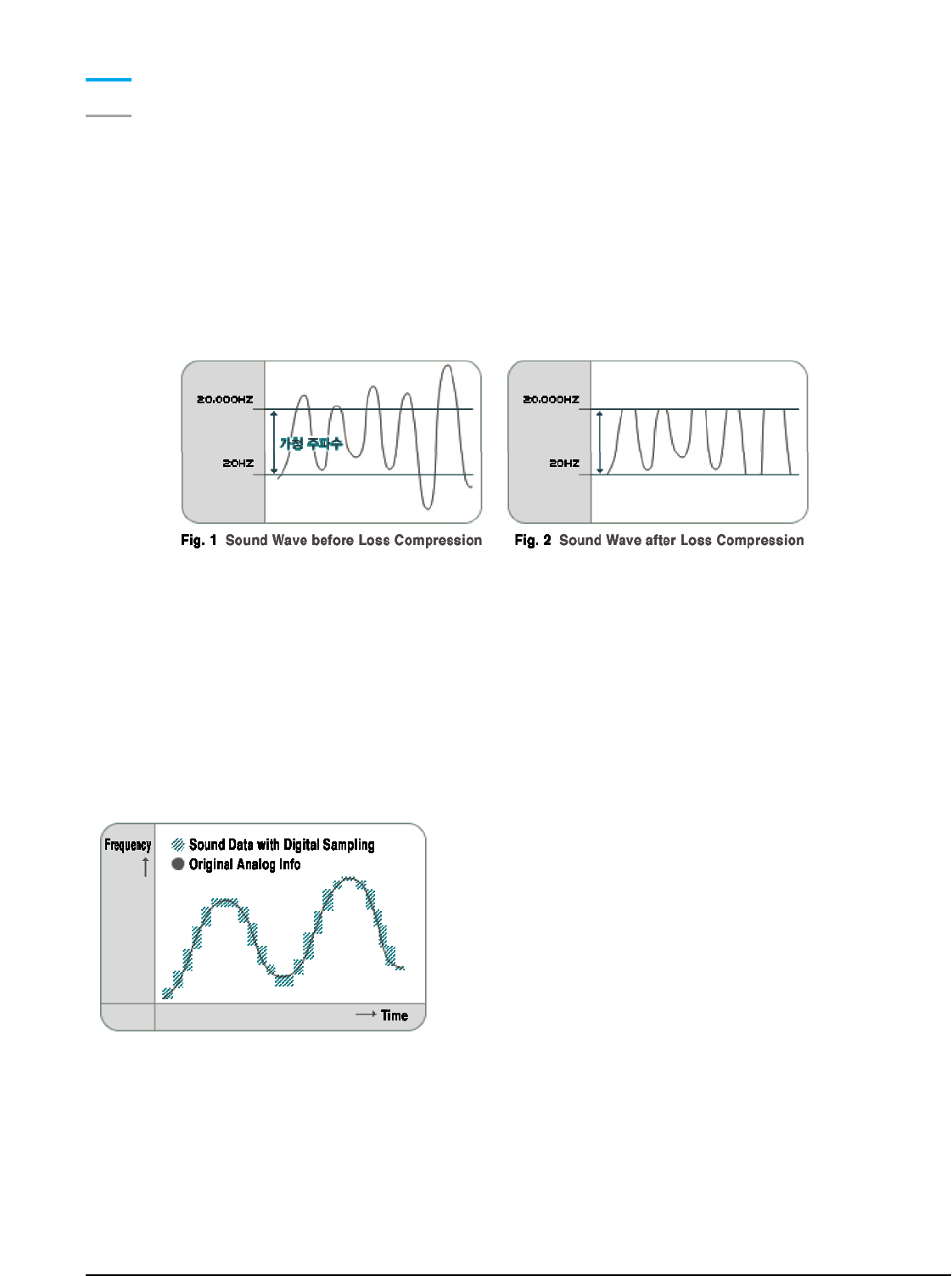
Samsung Electronics 14-7
Tips
How MP3 can produce same quality as CD?
Ears of human can listen to signal in the range of 20Hz~20KHz. It is called "audible frequency". To
convey the audible sound in digital type CD, sampling frequency of 44.1KHz, about 2 times of audi-
ble frequency, should be used. It is the task of dividing sound signal to 44,100 pieces per second
and making the signal to digital format of 0 and 1. How delicately the sample can be expressed will
be determined by number of bit per sample. Audio CD is 16 bit. It means that 1 sample can be
expressed in 65,536(16 square of 2) stage.
When converting CD music to WAV file, the capacity is about 40MB(for 4 minutes). By converting it
to MP3, it reduces to 4MB since "loss compression", the feature of MP3, is used. Loss compression
type removes the sound beyond the range of audible frequency(20Hz~20KHz). It uses the features
that small sound cannot be heard after very strong sound. <Figure 1> is the sound wave before
loss compression. It can be regarded as the sound wave of music CD or cassette tape containing
sound people cannot listen. When it is made into MP3, it is as shown in <Fig.2>.
Volume Control
Capacity can be reduced much by adjusting the degree
of loss. However, it causes deterioration of sound qual-
ity. Music CD contains sound made with 16 bit
44.1KHz of stereo sampling. Stereo is the type of divid-
ing the sound into left and right. CD should change
analog
sound to digital.
Digital information is cut between sections and location information is saved in each section.
"Sampling rate" is the standard of how many sub-section it will divide 1section. Divided frequency
part is called 8 bit and 16 bit. 8 bit sampling means that frequency is divided into 2 stage, that is,
sound pitch of 256 stage. 16 bit sampling divides into 65,536 sound pitch. In addition, 44.1KHz
means sampling of 44,100 times per second. To reduce the amount of information made at digital,
sampling bit number and frequency should be set low, but it will cause deterioration of sound quali-
ty. There is no difference in sound quality between MP3 and CD since encoding(converting CD
track to MP3) is done with 44.1KHz at 16 bit. Better CD sound quality cannot be obtained by lower-
ing the sampling rate, but the capacity can be reduced.

14-8 Samsung Electronics
OGG(Ogg Vorbis)
OGG(Ogg Vorbis) is featured to have "higher compression rate than MP3', 'higher quality than
MP3', 'no limit in use, distribution and development due to open source type. The biggest feature of
Ogg Vorbis is that it has no limit in use of format itself.
The biggest feature that distinguishes Ogg Vorbis from existing music file is that it supports
VBR( Variable Bit Rate) by default.
Of course, MP3 also supports VBR format, but has effect of reducing capacity due to VBR based on
existing MP3. Ogg Vorbis file supports VBR by default and helps you enjoy high quality music with-
out loss due to big width of bit rate.
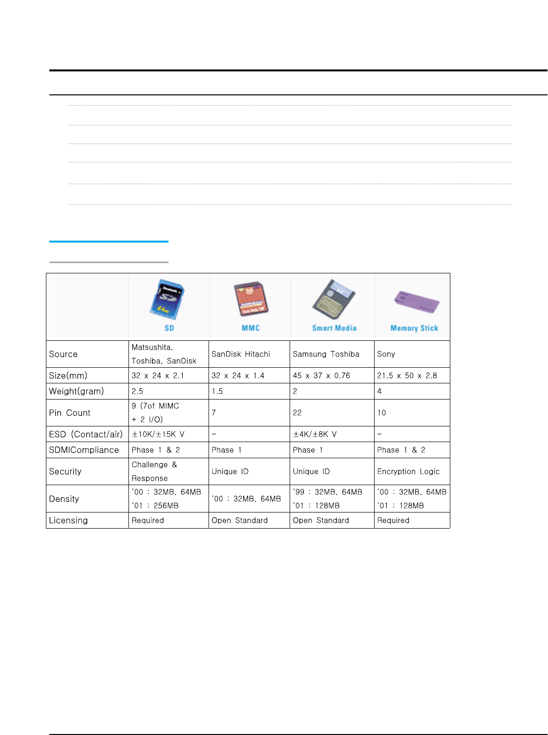
Samsung Electronics 14-9
MP3 is regarded as MP3.
Let's examine what are the types of storages currently used.
Optical Disc : CD, MD Player / Flash Memory : MP3 Player, Digital audio player
Type of Digital audio player storage.
Audio Format Table
* SSFDC (Solid State Floppy Disc Card) File System
* Standard file system for support of SMC's compatibility(DOS/FAT adopted)
1-4. Type of Storage
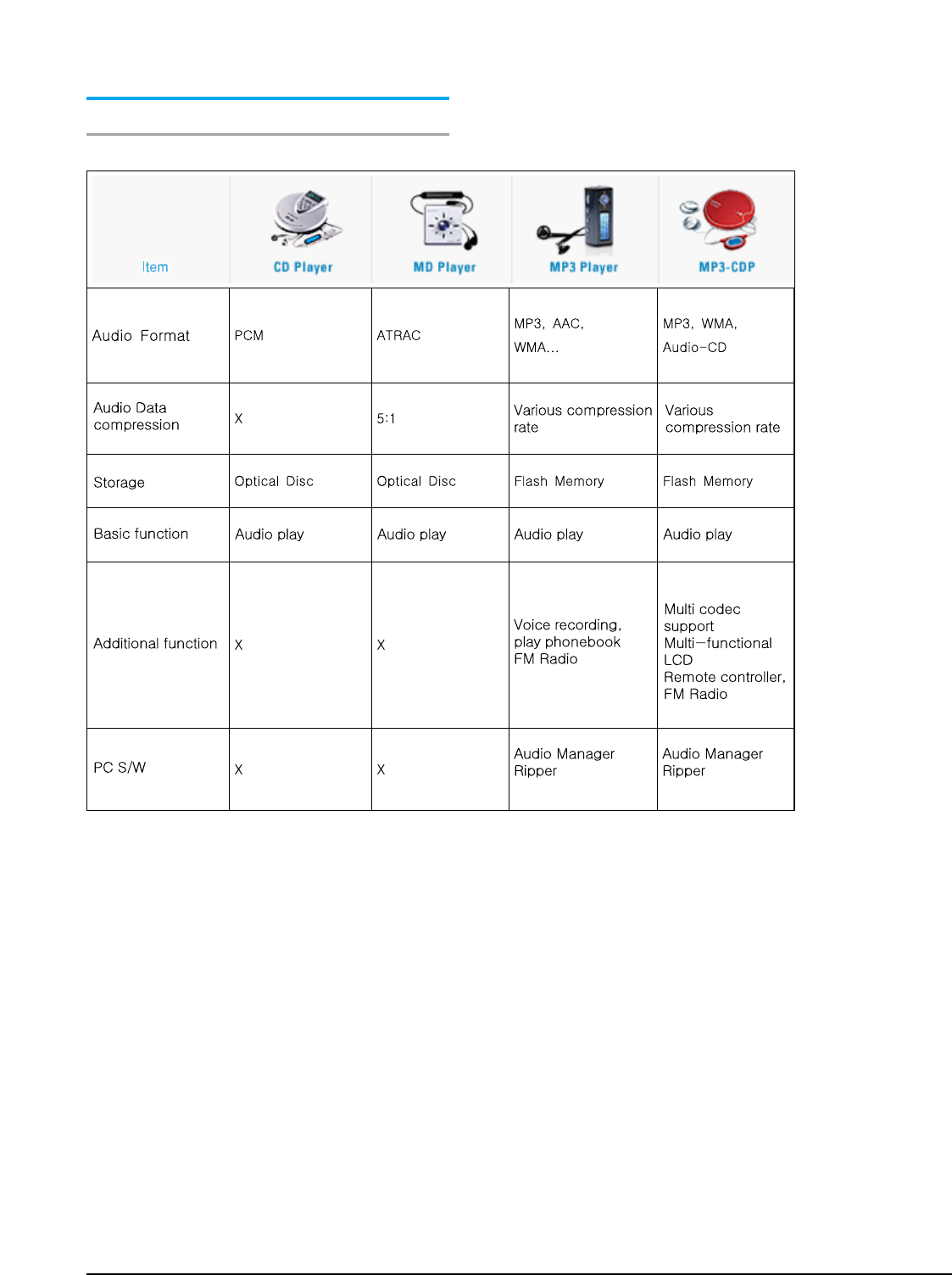
14-10 Samsung Electronics
Small Form - factor Cards Comparison

Samsung Electronics 14-11
Various kinds of methods are combined to unify technical
specification to prevent digital music data from illegal reproduction.
Let's examine groups and vocabularies related to copyright.
SDMI (Secure Digital Music Initiative)
Internet music record company consortium to pursue development of digital music file format.
World-class music makers and related groups are formed to protect copyright of music and to pre-
vent illegal reproduction.
-PD : Portable Device
-PM : Portable Media (SMC,MMC,MS,SD Card)
-UID : All PD, PM should have unique ID.
-Binding : All Digital Audio should be bounded to PD or PM.
DRM (Digital Rights Management)
Manage interests of persons related to copyright that occurs due to use of digital contents protected
from illegal use of digital contents through various channels.
WaterMarking
Technology of inserting the specific data to claim copyright of multimedia contents so that eyes and
ears of human cannot be distinguished.
SecuMAX
Digital Security Total Solution adopting Snake encoding algorithm.
Version1.0 contents in service in Korea (M4you.com, etc.)
SDMI compliant vrsion2.0 development completed
Reproduction Prevention System
Reopening of MP3 music service.
Lots of dispute have occurred in network due to copyright.
However, as online MP3 sales have resolved, the number of legal Internet site has increased.
However, reproduction prevention system is required for legal sales. All Internet sites serving
Korean song in MP3 are introducing reproduction prevention system.
1-5. Copyright
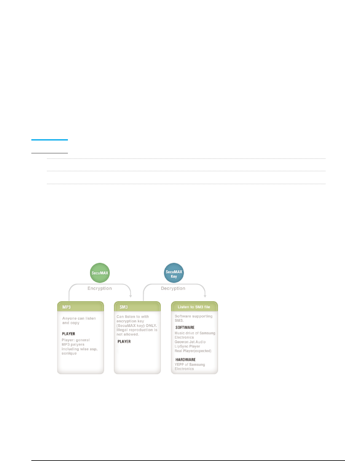
14-12 Samsung Electronics
Meaning of SecuMAX System Application
Most legal Internet MP3 service sites adopt SecuMAX and YEPP of Samsung and several compa-
nies have hardware supporting SecuMAX among MP3 players currently distributed. Then, user
needs to receive MP3 applied with SecuMAX to receive legal service. It is required to have program
that can play back MP3 applied with SecuMAX technology in MP3 player. For example, since YEPP
supports SecuMAX, it can play back, but it means that you cannot play back this at the players of
other companies that do not support SecuMAX.
At present, organization has been formed for standardization of reproduction prevention system in
foreign countries. Samsung Electronics has also participated in this standard using SecuMAX and
completed development of SecuMAX 2.0 with world compatibility.
SecuMAX
SecuMAX is the reproduction prevention system that is made for
protection of copyright in rapidly growing distribution of digital contents.
Reopening of MP3 Music Service
-Digital contents copyright protection and management service.
-Fundamentally prevent the illegal distribution
Only legal users can play back music
Dedicated software required(ex.Samsung Electronics, Music Dreve)
Prevention of usual illegal use such as file transfer, CD-R Copy and hardware reproduction.
-Report for copyright holder
Basic data for collection of copyright fee and near copyright fee
Track sales of all publications through Internet, PC communication or 3rd path.
Provide sales information per IP, song and hour real time.
-Can serve any type of files
-Can applied to Internet and PC communication equally
-Can provide copyright protection service for hardware at the same time.
